Transmission Operations - PJM
289
PJM Revision 18, Effective Date: 12/12/05 i PJM Manual 3: Transmission Operations Revision: 18 Effective Date: December 12, 2005 Prepared by System Operation Division Transmission Department © PJM 2005
-
Upload
khangminh22 -
Category
Documents
-
view
2 -
download
0
Transcript of Transmission Operations - PJM

PJM Revision 18, Effective Date: 12/12/05
i
PJM Manual 3:
Transmission Operations
Revision: 18 Effective Date: December 12, 2005 Prepared by System Operation Division Transmission Department
© PJM 2005
Transmission Operations Table of Contents
PJM Revision 18, Effective Date: 12/12/05
ii
PJM Manual 3:
Transmission Operations Manual Table of Contents
Table of Contents..................................................................................................... ii Table of Exhibits .................................................................................................... vii Approval ................................................................................................................... 1
Revision History....................................................................................................... 1
Introduction.............................................................................................................. 9 ABOUT PJM MANUALS..........................................................................................................................9 ABOUT THIS MANUAL..........................................................................................................................10 USING THIS MANUAL...........................................................................................................................11
Section 1: Transmission Operations Requirements........................................... 12 OVERVIEW .........................................................................................................................................12 RESPONSIBILITIES FOR TRANSMISSION OWNER'S OPERATING ENTITY ...................................................13 TRANSMISSION OPERATING GUIDELINES..............................................................................................15 RECLOSING EHV LINES THAT HAVE TRIPPED ......................................................................................17 PJM’S REAL-TIME RELIABILITY MODEL................................................................................................18 REAL-TIME TELEMETERED DATA REQUIREMENTS FOR SYSTEM RELIABILITY..........................................19
Section 2: Thermal Operating Guidelines............................................................ 29 THERMAL LIMIT OPERATION CRITERIA .................................................................................................29
Section 3: Voltage & Stability Operating Guidelines .......................................... 34 VOLTAGE, TRANSFER, & STABILITY LIMITS ...........................................................................................34 VOLTAGE OPERATING CRITERIA AND GUIDELINES ................................................................................35 VOLTAGE LIMITS.................................................................................................................................37 NOTIFICATION AND MITIGATION PROTOCOLS FOR NUCLEAR PLANT VOLTAGE LIMITS..............................38
Communication ............................................................................................................................39 Information Exchange..................................................................................................................39 PJM Action...................................................................................................................................39 Transmission Owner Action.........................................................................................................40 Nuclear Plant Action ....................................................................................................................40
EHV TRANSFORMER LTC OPERATION ................................................................................................43 BULK POWER CAPACITOR/SVC OPERATION ........................................................................................44 TRANSFER LIMITS (REACTIVE/VOLTAGE TRANSFER LIMITS) ..................................................................48 STABILITY LIMITS ................................................................................................................................50
Section 4: Reportable Transmission Facility Outages ....................................... 54 GENERAL PRINCIPLES.........................................................................................................................54 SCHEDULING TRANSMISSION OUTAGE REQUESTS................................................................................55 PROCESSING TRANSMISSION OUTAGE REQUESTS................................................................................60 EQUIPMENT FAILURE PROCEDURES.....................................................................................................63
Section 5: Index and Operating Procedures for PJM RTO Operation ............... 64 PJM Procedure to Review Special Protection Systems (SPS)....................................................65

Transmission Operations Table of Contents
PJM Revision 18, Effective Date: 12/12/05
iii
INDEX OF OPERATING PROCEDURES FOR PJM RTO OPERATION..........................................................70 CONSTRAINT MANAGEMENT MITIGATION DURING SCHEDULED SWITCHING PROCEDURE ........................70
PJM/NYPP PAR Operation..........................................................................................................75 PSE&G/CONED WHEEL ....................................................................................................................76
PURPOSE/BACKGROUND:........................................................................................................76 PJM/VAP VOLTAGE COORDINATION PLAN ..........................................................................................86 LOOP FLOWS......................................................................................................................................89 INDEX OF OPERATING PROCEDURES FOR ATLANTIC ELECTRIC (AE) TRANSMISSION ZONE- CONECTIV ...89 DEPTFORD 230 KV BREAKER RELAY ...................................................................................................90 INDEX OF OPERATING PROCEDURES FOR AMERICAN ELECTRIC POWER (AEP) TRANSMISSION ZONE .....91 SOUTH CANTON 765/345 KV TRANSFORMER (AEP OPERATING MEMO T-020) .....................................91 COOK UNIT ISOLATION ON SELECT CIRCUITS (AEP OPERATING MEMO T-021)......................................92 KAMMER OPERATING PROCEDURES (AEP OPERATING MEMO T026)....................................................92 CONESVILLE 345 KV PLANT OPERATING GUIDELINES (AEP OPERATING MEMO T027) ..........................95 SUNNYSIDE-TORREY 138 KV OPERATING GUIDE(AEP OPERATING MEMO T029)..................................96 CONESVILLE 138 KV BUS CONFIGURATION (AEP OPERATING MEMO T030)..........................................96 MARYSVILLE 765 KV REACTOR GUIDELINES (AEP OPERATING MEMO T031) ........................................97 KANAWHA – MATT FUNK 345 KV CIRCUIT ............................................................................................97 ROCKPORT OPERATING GUIDE............................................................................................................99
Rockport Special Controls .........................................................................................................100 Single Phase Switching (SPS):..................................................................................................100 Fast Valving Scheme: ................................................................................................................100 Quick Reactor Switching:...........................................................................................................100 Emergency Unit Tripping: ..........................................................................................................101 Rapid Unit Runback: ..................................................................................................................101 Rockport Plant Output Limits .....................................................................................................101
SMITH MOUNTAIN 138 KV STATION STABILITY....................................................................................108 GAVIN - MOUNTAINEER STABILITY .....................................................................................................108 TANNERS CREEK 345 KV STATION CONCERNS ..................................................................................109 TIDD 345 KV STATION VOLTAGE CONCERNS......................................................................................109 GALION BYPASS SWITCH ..................................................................................................................109 ADDITIONAL REGIONAL PROCEDURES................................................................................................109
Roanoke Transmission Region..................................................................................................109 Columbus Transmission Region................................................................................................110 Ft. Wayne Transmission Region................................................................................................111
INDEX OF OPERATING PROCEDURES FOR BALTIMORE GAS & ELECTRIC (BC OR BGE) TRANSMISSION ZONE ...............................................................................................................................................111 INDEX OF OPERATING PROCEDURES FOR COMMONWEALTH EDISON (COMED) TRANSMISSION ZONE....114 KINCAID STABILITY TRIP SCHEMES (COMED SPOG 1-3-A) ................................................................114 POWERTON STABILITY LIMITATIONS (COMED SPOG 1-3-B AND 1-3-B-1) ...........................................116
Multi-Phase Fault High-Speed Sectionalizing Scheme .............................................................116 Unit Trip Scheme for Output Greater Than 765 MW .................................................................117 Double-line Tower Outage.........................................................................................................117
QUAD CITIES AND CORDOVA STABILITY LIMITATIONS (COMED SPOG 1-3-C, 1-3-C-1, AND 1-3-G)......120 Quad Cities Stability Limitations ................................................................................................120 Double Contingency Unit Trip Scheme......................................................................................120 Cordova Stability Limitations......................................................................................................123
BYRON AND LEE COUNTY OPERATING GUIDES (COMED SPOG 1-3-F, 1-3-F-1, AND 1-3-H) ...............125 Byron Operating Guide ..............................................................................................................125 Recommended Operating Limits to Ensure Bryon Generator Stability .....................................126 Lee County Operating Guide .....................................................................................................132
UNIVERSITY PARK NORTH ENERGY CENTER RESTRICTION (COMED SPOG 1-3-I AND 1-3-I-1) ............133

Transmission Operations Table of Contents
PJM Revision 18, Effective Date: 12/12/05
iv
ELGIN ENERGY CENTER STABILITY BUS TIE SCHEME (COMED SPOG 1-3-J)......................................133 MARENGO 138 KV BUS OPERATION (COMED SPOG 2-2-B) ..............................................................134 DAMEN 138 KV BUS OPERATION (COMED SPOG 2-2-C)...................................................................134 NORMALLY OPEN BUS TIE CIRCUIT BREAKERS ..................................................................................134 DRESDEN 345 KV BUS OPERATION WITH LINES OUT OF SERVICE (COMED SPOG 2-17).....................140 BURNHAM – TAYLOR (L17723) 345 KV LINE OPERATION (COMED SPOG 3-6) ...................................140
Unavailability of the L17724 Shunt Inductor: .............................................................................140 ZION TDC 282 – LAKEVIEW (L28201) 138 KV TIELINE OPERATION (COMED SPOG 3-10) ..................141 107_DIXON ‘L15621’ 138 KV CB OPERATION (COMED SPOG 3-21).................................................142 138 KV PHASE SHIFTING TRANSFORMER OPERATIONS (COMED SPOG 3-22) ....................................142 MINNESOTA – EASTERN WISCONSIN PHASE ANGLE REDUCTION (COMED CAOP 2-16).......................142
Procedure-Step 1: Reducing Flow on Eau Claire-Arpin 345kV Line .........................................143 Procedure-Step 2: Reducing the Phase Angle on Eau Claire-Arpin 345kV Line ......................143
VOLTAGE CONTROL AT COMED NUCLEAR STATIONS..........................................................................144 WAUKEGAN 138 KV BUS TIE 4-14 OPERATION (COMED SPOG 2-29) ................................................144 INDEX OF OPERATING PROCEDURES FOR DELMARVA POWER & LIGHT (DPL) TRANSMISSION ZONE - CONECTIV ........................................................................................................................................145 INDIAN RIVER #4 “TRIP A UNIT” SPECIAL PROTECTION SCHEME..........................................................146 CECIL T3 230/34.5 KV TRANSFORMER OVERLOAD SCHEME...............................................................146 INDEX OF OPERATING PROCEDURES FOR DOMINION VIRGINIA POWER (DVP) COMPANY......................146 CLOVER GENERATOR SHED SCHEME ................................................................................................147 NORTHERN VIRGINIA HIGH VOLTAGE CONTROL..................................................................................148 LEXINGTON AREA LOSS-OF-LOAD CONTINGENCY MITIGATION PROCEDURE.........................................149 BATH COUNTY CONTINGENCY RESTRICTIONS ....................................................................................150 INDEX OF OPERATING PROCEDURES FOR DUQUESNE LIGHT COMPANY (DLCO) ..................................152 CARSON 138 KV BUS OPERATION .....................................................................................................152 VOLTAGE CONTROL AT BEAVER VALLEY ............................................................................................152 INDEX OF OPERATING PROCEDURES FOR JERSEY CENTRAL POWER & LIGHT (JCP&L)-FIRST ENERGY TRANSMISSION ZONE........................................................................................................................153 YARDS CREEK RELAY (PUMPING MODE)............................................................................................153 INDEX OF OPERATING PROCEDURES FOR PENNSYLVANIA ELECTRIC COMPANY (PN)-FIRST ENERGY TRANSMISSION ZONE........................................................................................................................155 PJM/NYPP TRANSFERS...................................................................................................................155
PJM Actions: ..............................................................................................................................155 FIRST ENERGY EAST TIE LINES .........................................................................................................156 PJM SPECIAL PURPOSE RELAY OPERATIONS ....................................................................................157
Warren-Falconer 115 kV Relay .................................................................................................157 North Waverly-East Sayre 115 kV Relay...................................................................................157
CONEMAUGH UNIT STABILITY ............................................................................................................157 CONEMAUGH #2 UNIT STABILITY TRIP SCHEME-CONEMAUGH-JUNIATA 500 KV OUTAGE .....................158 KEYSTONE-CONEMAUGH 5003 LINE / RE-CLOSE PROCEDURE ...........................................................159 SENECA PUMP OPERATIONS .............................................................................................................161
Procedure to approve Pumping Operation: ...............................................................................162 Pre-Contingency Switching Options to allow Seneca Pumping due to Actual Overloads.........163 Post-Contingency (post-event) Switching Options ...................................................................164
PROCEDURE TO RUN SENECA GENERATION FOR PJM/PN CONSTRAINTS ..........................................165 TMI VOLTAGE NOTIFICATION PROCEDURES.......................................................................................166 HUNTERSTOWN – CONASTONE (5013) TRANSFER TRIP SCHEME ........................................................168 INDEX OF OPERATING PROCEDURES FOR PECO ENERGY (PE) TRANSMISSION ZONE .........................169 NOTTINGHAM - GRACETON 230 KV LINE LIMITATIONS.........................................................................169 WHITPAIN 500-1 OR 500-2 TRANSFORMER OUTAGES ........................................................................172 MUDDY RUN PROTECTIVE RELAY (PUMPING/GENERATION MODE) ......................................................173

Transmission Operations Table of Contents
PJM Revision 18, Effective Date: 12/12/05
v
PEACH BOTTOM ‘45’ 500 KV CB OUTAGE..........................................................................................173 LIMERICK 4A AND 4B 500/230 KV TRANSFORMER RATINGS ...............................................................173 LINWOOD SPECIAL PROTECTION SCHEME..........................................................................................175 INDEX OF OPERATING PROCEDURES FOR PENNSYLVANIA POWER & LIGHT (PP&L) TRANSMISSION ZONE........................................................................................................................................................175 SUNBURY 500/230 KV TRANSFORMER RATINGS ................................................................................176 HOSENSACK - BUXMONT 230 KV LINE CONTINGENCY.........................................................................176 SUSQUEHANNA #1 AND #2 UNITS CONTINGENCY ...............................................................................177 5043 AND 5044 (ALBURTIS-WESCOSVILLE-SUSQUEHANNA) TRANSFER TRIP SCHEME.........................179 NORTHEAST PA (NEPA) TRANSFER LIMIT .........................................................................................179 INDEX OF OPERATING PROCEDURES FOR POTOMAC ELECTRIC COMPANY (PEPCO) TRANSMISSION ZONE........................................................................................................................................................180 POTOMAC RIVER STATION OPERATION DURING ABNORMAL CONDITIONS, ISLAND OPERATIONS, RESTORATION, AND RESYNCHRONIZATION.........................................................................................181 DOUBS – DICKERSON 230 KV LINE CONTINGENCY.............................................................................192 CHALK POINT TRANSFORMER #5 OPERATION ....................................................................................193 COMMON TRENCH CABLE RATINGS ...................................................................................................194 INDEX OF OPERATING PROCEDURES FOR PUBLIC SERVICE ELECTRIC & GAS COMPANY (PSE&G) TRANSMISSION ZONE........................................................................................................................196 BRANCHBURG/DEANS 500 KV SUBSTATION CONTINGENCY ................................................................199 BRANCHBURG SPECIAL PROTECTION SCHEME (SOMERVILLE ‘1-2’ CB) ...............................................200 BRANCHBURG SPECIAL PROTECTION SCHEME (BRIDGEWATER ‘1-2’) ..................................................202 INDEX OF OPERATING PROCEDURES FOR ALLEGHENY POWER (AP) CONTROL AREA...........................203 CONTINGENCY OVERLOADS IN THE WILLOW ISLAND AREA ..................................................................203 PLEASANTS AND WILLOW ISLAND OPERATING RESTRICTIONS .............................................................205 BREAKER DERATE TABLE..................................................................................................................206 WYLIE RIDGE SPECIAL PROTECTION SCHEME....................................................................................208 CONTROLLING THE DOUBS 500/230 KV TRANSFORMER LOADINGS .....................................................209 ELRAMA (DLCO) AND MITCHELL (AP) AREA OPERATING PROCEDURE................................................214 RONCO STABILITY ............................................................................................................................217 INDEX OF OPERATING PROCEDURES FOR UGI TRANSMISSION SYSTEM (FORMERLY KNOWN AS LUZERNE ELECTRIC, LU) .................................................................................................................................217 OPERATION OF 23030 TIE AT MOUNTAIN ...........................................................................................218 UGI/PL 66 KV TIE LINE OPERATION..................................................................................................219 HUNLOCK OUTLET OVERLOADS.........................................................................................................220 INDEX OF OPERATING PROCEDURES FOR NEW YORK POWER POOL (NYPP) CONTROL AREA..............221 INDEX OF OPERATING PROCEDURES FOR ISO NEW ENGLAND (ISO-NE) CONTROL AREA....................221 NEPEX CONTINGENCIES..................................................................................................................221
Loss of Phase II Imports ............................................................................................................222 Millstone Point Contingency ......................................................................................................222
NEPEX EMERGENCIES.....................................................................................................................226 Attachment A: Definitions and Abbreviations................................................... 229
Attachment B: 30-Minute Ratings....................................................................... 267
Attachment C: Controlling PSE&G-Con Ed Wheel............................................ 269
Attachment D: Open Circuit Terminal Voltage Control .................................... 270
Attachment E: Voltage Coordination Plan......................................................... 272
Attachment F: Requesting Voltage Limit Exceptions to the PJM Base-Line Voltage Limits ...................................................................................................... 275
Transmission Operations Table of Contents
PJM Revision 18, Effective Date: 12/12/05
vi
Attachment G: Post Contingency Congestion Management Program........... 278 Alternative Controlling Options ..................................................................................................279 Roles and Responsibilities.........................................................................................................280 Post-Contingency Congestion Management Program Constraint List ......................................280
Transmission Operations Table of Exhibits
PJM Revision 18, Effective Date: 12/12/05
vii
Table of Exhibits EXHIBIT 1: LIST OF PJM MANUALS................................................................................. 9 EXHIBIT 2: DEADLINES FOR MODELING DATA TO BE SUBMITTED ..................................... 20 EXHIBIT 3: PJM ACTUAL OVERLOAD THERMAL OPERATING GUIDELINES ........................ 33 EXHIBIT 4: PJM POST-CONTINGENCY SIMULATED THERMAL OPERATING GUIDELINES .... 33 EXHIBIT 5: PJM BASE LINE VOLTAGE LIMITS ................................................................ 38 EXHIBIT 6: CAPACITOR INSTALLATIONS WITH PLCS ....................................................... 45 EXHIBIT 7: REACTIVE TRANSFER INTERFACE LOCATIONS ............................................... 49 EXHIBIT 8: BUS-AND ZONE SPECIFIC VARIATIONS TO PJM BASE LINE VOLTAGE LIMITS.... 53 EXHIBIT 9: TRANSMISSION OUTAGE REQUEST PROCESS ............................................... 60 EXHIBIT 10: VCP CONTROL AREA VOLTAGE LIMITS ..................................................... 87 EXHIBIT 11: CALVERT CLIFFS MAXIMUM LEAD UNIT STABILITY LIMITS........................... 112 EXHIBIT 12: 5025 LINE RATINGS ............................................................................... 145 EXHIBIT 13: FIRST ENERGY EAST/AP TIE LINES ......................................................... 156 EXHIBIT 14: LIMERICK 4A & 4B POWER FLOW FROM 230 KV TO 500 KV - MVA ........... 174 EXHIBIT 15: LIMERICK 4A & 4B POWER FLOW FROM 500 KV TO 230 KV – MVA ........... 174 EXHIBIT 16: DAY OR NIGHT RATINGS – MVA.............................................................. 176 EXHIBIT 17: OPERATION OF POTOMAC RIVER DURING NORMAL AND ABNORMAL CONDITIONS
........................................................................................................................ 183 EXHIBIT 18: CONDITIONS UNDER WHICH POTOMAC RIVER’S 69 KV BUS TIE (1-6) CAN BE
CLOSED ........................................................................................................... 186 EXHIBIT 19: POTOMAC RIVER RESTORATION, ISLAND OPERATIONS & RESYNCHRON ..... 186 EXHIBIT 20: POTOMAC RIVER ISLAND FREQUENCY DEVIATIONS ................................... 187 EXHIBIT 21: POTOMAC RIVER ISLAND OPERATIONS - REINFORCE RESERVES ................ 187 EXHIBIT 22: MILLSTONE STATION UNIT CAPABILITIES .................................................. 223 EXHIBIT 23: EMS ADJUSTMENTS FOR NEPEX CONTINGENCIES .................................. 226 EXHIBIT 24: WALDWICK SUMMER RATING SETS.......................................................... 267 EXHIBIT 25: WALDWICK WINTER RATING SETS ........................................................... 268 EXHIBIT 26: CONTROLLING PSE&G-CON ED WHEEL (5018 OUT-OF-SERVICE) ............ 269 EXHIBIT 27: OPEN CIRCUIT TERMINAL VOLTAGE CONTROL .......................................... 271 EXHIBIT 28: VOLTAGE COORDINATION PLAN -AP ACTIONS .......................................... 272 EXHIBIT 29: VOLTAGE COORDINATION PLAN -PJM ACTIONS........................................ 273 EXHIBIT 30: VOLTAGE COORDINATION PLAN -VAP ACTIONS........................................ 274

Transmission Operations Revision History
PJM Revision 18, Effective Date: 12/12/05
1
Approval Approval Date: 12/12/05 Effective Date: 12/12/05
Michael Bryson, Manager Transmission Department
Revision History Revision 18 (12/12/05)
Corrected Breaker Derate Table in Section 5 AP Corrected EHV definition in Section 1 Added a Bath County contingency restriction under Section 5 DVP Added PJM Procedure to Review Special Protection Systems (SPS) under
Section 5 Edited introduction for Section 5 Edited Reportable Transmission Facility under Section 1 Updated Exhibit 2 in Section 1
Revision 17 (8/1/05) Added 500X Reactive Limit in Section 3 Added Post-contingency Congestion Management Program document Added Linwood Special Protection Scheme under Section 5 Revised Processing Transmission Outage Requests under Section 4 Corrected PECO stability limits under Section 3 Replaced Wylie Ridge Operating Procedure with Wylie Ridge Special
Protection Scheme under Section 5 Revised Quad City and Cordova Stability Limits under Section 5 Added Waukegan 138 kV Bus Tie 4-14 Operation (ComEd SPOG 2-29)
under Section 5 Revised PSE&G/ConED Wheel under Section 5 Deleted PJM/NYPP Joint Operating Procedure under Section 5 Deleted Transmission Overuse under Section 5 Deleted 5018 Branchburg- Ramapo Out-of-Service under Section 5

Transmission Operations Revision History
PJM Revision 18, Effective Date: 12/12/05
2
Added Branchburg Special Protection Scheme (Bridgewater ‘1-2’ CB) under Section 5
Deleted Brunner Island #2 Master Fuel Trip Relay under Section 5 Revised Powerton Stability Limitations (ComEd SPOG 1-3-B and 1-3-B-1)
under Section 5 Revision 16 (5/1/05)
Added Dominion Procedures to Section 5 Added PJM Southern Region under Section 1 – Reclosing 500 kV Lines That
Have Tripped Added SERC under Section 1 – Equipment Failure Procedures
Revision 15 (03/01/05) Deleted Sand Point Relay Procedure under Section 5 - AE Deleted Collins 345 kV Operating Guide under Section 5 – ComEd Revised Artificial Island Procedure in Section 5 – PSE&G Added Branchburg Special Protection Scheme in Section 5 – PSE&G Revised the Rockport Operating Guide under Section 5 - AEP Added Voltage Limit Exception Request Templates to Attachment F Added Reportable Facility Code Information Under Section 1 – Reportable
Facilities Added additional comments to Real-time Switching Notifications Procedure
under Section 4 Revision 14 (01/01/05)
Added the DQE procedures to Section 5 Added Attachment F – Requesting Voltage Limit Exceptions to the PJM Base
– Line Voltage Limits Added Hyperlinks to all the tables in Section 5
Revision 13 (11/17/04) Revised Susquehanna 1 and 2 Double Contingency to clarify reporting
requirements and PJM dispatch actions. Revision 12 (10/01/04)
Added document containing the AEP procedures added to Section 5 Revision 11 (05/08/04)
Added document containing the UGI procedures added to Section 5
Transmission Operations Revision History
PJM Revision 18, Effective Date: 12/12/05
3
Revision 10 (05/01/04) Revised to include ComEd Procedures
Added a new table reflecting ComEd's voltage exceptions Revision 09 (01/12/04)
Section 4, "Reportable Transmission Facility Outages" on Page 54 omitted Peach Bottom Unit 3 output breaker CB65 and Limerick Unit 2 output breaker CB235. This revision corrects that omission
Revision 08 (11/17/03) Modified Entire Document Changed all references of PJM IA to PJM Included guidelines on how to modify facilities in the Transmission Facilities
List Changed the central location of the Transmission Facilities List to
www.pjm.com Included both the PJM Eastern and Western philosophies on re-closing EHV
lines that have tripped Included information on how to change facility ratings Updated list of PJM Manuals Included charts to explain the thermal and voltage operating criteria Added the Bedington – Black Oak and AP South interfaces to the
explanation of PJM Transfer Interfaces Added a clear explanation of the submittal requirements for transmission
outages Added all the relevant Operating Procedures of Allegheny Power into Section
5 Added and/or changed various procedures for several different Transmission
Owners in Section 5 Removed Attachment B: Reportable Transmission Facilities. Changed the
central location of the Transmission Facilities List to www.pjm.com Remove Attachment E.
Revision 07 (06/01/02) Section 3: Voltage & Stability Operating Guidelines
Added description of new procedures for reporting generating unit reactive capability via eDART.

Transmission Operations Revision History
PJM Revision 18, Effective Date: 12/12/05
4
Attachment J: PJM Generating Unit Reactive Capability Curve Specification and Reporting Procedures
Added description of new procedures for reporting generating unit reactive capability via eDART.
Revision 06 (01/24/01) Section 1: Coordination & Direction of Transmission Operations
Added description of PJM’s Real-Time Reliability Model. Removed description of Designated Transmission Facilities. Added description of PJM Transmission Facilities.
Section 2: Thermal Operating Guidelines Revised Thermal Limit Operations. Added Thermal Operating Criteria. Relocated operating procedures to new Section 5: Operating Procedures.
Section 3: Voltage & Stability Operating Guidelines Revised Voltage Operation and Voltage Limits. Added Voltage Operating Limits. Relocated operating procedures to new Section 5: Operating Procedures. Revised Voltage Control Actions- Low Voltage Operation and Voltage Control Actions- High Voltage Operation. Added Generating Unit Reactive Capability.
Section 4: Reportable Transmission Facility Outages Revised this section for notifications and references to eDART.
Section 5: Operating Procedures Added this section which contains operating procedures from sections 2 and 3. Operating procedures are identified by Transmission Zone. Removed Keeney 500/230 kV Transformer Contingency, Keeney-Basin Road 138 kV Special Purpose Relay, Burma-Piney 115 kV Relay, Balt-Wash Scheduling Import Limit, BC/PEPCO Reactive Import Limit. Revised Transmission Overuse Calculation, Muddy Run Protective Relay (Pumping/Generation Mode). Added Constraint Management Mitigation, Cedar Special Purpose Relay Scheme, Seneca Pump Operations, Procedure to Run Seneca Generation For Constraints, Potomac River Limerick Ratings 4A &4B.
Attachment B Reportable Transmission Facilities Revised to include references to eDART. Removed multiple Exhibits which were replaced by eDART.
Attachment H: Transmission Facilities Database

Transmission Operations Revision History
PJM Revision 18, Effective Date: 12/12/05
5
Added this new section. Includes Transmission Facility List for each Transmission Zone. (This continues to be a work in progress).
Attachment I: Requesting Voltage Limit Exceptions to PJM Base-Line Limits Added this new section to complement descriptions given in Section 3.
Attachment J: PJM Generating Unit Reactive Capability Curve Specifications and Reporting Procedures
Added this new section to complement descriptions given in Section 3. Revision 05 (04/01/00)
Section 2: Coordination & Direction of Transmission Operations Revised Keeney 500/230 kV Transformer Contingency, PJM Actions. Removed step 4, Maximum Scheduled Generation is loaded.
Section 3: Voltage & Stability Operating Guidelines Revised NEPEX Emergencies. Replaced reference to Max Schedule Generation with ‘highest incremental cost of generation’.
Revision 04 (08/23/99) Section 3: Voltage & Stability Operating Guidelines
Removed “Simultaneous loss of all Hydro Quebec (HQ) HVDC interconnections linked to the HQ AC system” listed under subsection: NEPEX Contingencies.
Revision 03 (06/15/99) Section 2: Thermal Operating Guidelines
Added contingency operations for the Doubs-Dickerson 230 kV Line. Revision 02 (01/28/98)
Section 4: Designated Transmission Facility Outages Changed “The Transmission Owners have the right and obligation to maintain or repair their portion of the transmission system. PJM approves all Designated Transmission Facility outages prior to removal of the equipment from service. PJM will coordinate scheduled outages of all Designated Transmission Facilities with planned generation outages that are submitted to PJM and may affect PJM RTO operations. For purposes of scheduling, Designated Transmission Facilities include, but are not limited to, lines, transformers, phase angle regulators, buses, breakers, disconnects, bulk power capacitors, reactors, and all related equipment.”

Transmission Operations Revision History
PJM Revision 18, Effective Date: 12/12/05
6
“PJM maintains a list of Designated Transmission Facilities. Each Transmission Owner submits the tentative dates of all transmission outages of Designated Transmission Facilities to PJM as far in advance as possible.” from “The Transmission Owners have the right and obligation to maintain or repair their portion of the transmission system. The Transmission Owners rely upon PJM to coordinate scheduled outages of all Designated Transmission Facilities with planned generation outages that are submitted to PJM and may affect PJM RTO operations. For purposes of scheduling, Designated Transmission Facilities include, but are not limited to, lines, transformers, phase angle regulators, buses, breakers, disconnects, bulk power capacitors, reactors, and all related equipment.” “PJM maintains a list of Designated Transmission Facilities. Each Transmission Owner submits the tentative dates of all transmission outages of Designated Transmission Facilities to PJM as far in advance as possible. Under certain operating conditions, reportable outages are not limited to the facilities listed in the Designated Transmission Facility List (See Attachment B).” under “General Principles.” Changed “A planned transmission outage that is rescheduled or canceled because of inclement weather or at the direction or request of PJM retains its status and priority as a planned transmission outage with PJM approved rescheduled date. If an outage request is rescheduled or canceled for reasons other than inclement weather or at the direction of PJM, the rescheduled or canceled and resubmitted outage is treated as an unplanned outage request. PJM coordinates outage rescheduling with the PJM Members to minimize impacts on system operations.” from “A planned transmission outage that is rescheduled or canceled because of inclement weather or at the direction or request of PJM retains its status and priority as a planned transmission outage. If an outage request is rescheduled or canceled for reasons other than inclement weather or at the direction of PJM, the rescheduled or canceled and resubmitted outage is treated as an unplanned outage request. PJM coordinates outage rescheduling with the PJM Members to minimize impacts on system operations.”

Transmission Operations Revision History
PJM Revision 18, Effective Date: 12/12/05
7
under “Scheduling Transmission Outages.” Changed “When a thermal or reactive violation is recognized to have above average impact to system operation, PJM will communicate the projected PJM RTO impacts and offer available alternatives, that reduce or eliminate the detected condition, to the affected PJM Transmission Owners. Any alternatives offered and the resultant choice will be documented by PJM. In actual operations line loading relief procedures are utilized to control bulk transmission facility loadings and reactive constraints. The use of cost effective generation shift procedures are employed after all available zero cost options are exhausted. No outage that is determined to result in potentially unreliable operations is approved by PJM.” from “When thermal or reactive violations are recognized, PJM communicates the projected PJM RTO impacts to the affected PJM Members. An appropriate plan to control constraints is agreed upon by affected PJM Members. Line loading relief procedures are utilized to control bulk transmission facility loadings and reactive constraints. The use of cost effective generation shift procedures are employed after all available zero cost options are exhausted. No outage that is determined to result in potentially unreliable operations is approved by PJM.” under “Studying Projected System Conditions.” Changed “PJM, as system conditions warrant, identifies opportunities for, and encourages, coordination of all generator and transmission maintenance outages. When actual or anticipated system conditions change such that, at the discretion of PJM, the rescheduling of a transmission outage is advisable, PJM informs the Transmission Owner of the conditions and available alternatives. The Transmission Owner involved considers the impacts of proceeding with the outage as advised by PJM and may either proceed knowing the estimated impacts on the remaining facilities or postpone the outage. If the outage is not postponed, PJM determines and records the appropriate impacts or changes to system limits and takes the steps required to maintain established operating reliability criteria as mentioned within Section 1 of this manual.” from

Transmission Operations Revision History
PJM Revision 18, Effective Date: 12/12/05
8
“PJM, as system conditions warrant, identifies opportunities for, and encourages, coordination of all generator and transmission maintenance outages. When actual or anticipated system conditions change such that, at the discretion of PJM, the rescheduling of a transmission outage is advisable, PJM informs the Transmission Owner of the conditions. The Transmission Owner involved considers the impacts of proceeding with the outage as advised by PJM and may either proceed knowing the estimated impacts on the remaining facilities or postpone the outage. If the outage is not postponed, PJM determines the appropriate impacts or changes to system limits and takes the steps required to maintain established operating reliability criteria as mentioned within section 1 of this manual.” under “Approving Transmission Outage Requests.”
Revision 01 (06/13/97) Attachment B: Reportable Transmission Facilities (Correction made 09/12/97)
Exhibit B.1: Reportable Transmission Facilities - EHV Lines Corrected Designations for Red Lion-Hope Creek (5015) and Keeney-
Red Lion (5036) Attachment B: Reportable Transmission Facilities
Exhibit B.1: Reportable Transmission Facilities - EHV Lines Added 5036 Red Lion - Hope Creek Added 5015 Keeney - Red Lion Deleted 5015 Hope Creek - Keeney
Exhibit B.2: Reportable Transmission Facilities - Transformers Added AT-50 Red Lion 500/230
Exhibit B.3: Reportable Transmission Facilities - Busses and Breakers Added Red Lion
Exhibit B.10: Reportable Transmission Facilities - AE Added Sands Pt - Cedar
Revision 00 (05/06/97) This revision is the preliminary draft of the PJM Manual for Transmission Operations.

Transmission Operations Introduction
PJM Revision 18, Effective Date: 12/12/05
9
Introduction Welcome to the PJM Manual for Transmission Operations. In this Introduction, you will find the following information:
What you can expect from the PJM Manuals in general (see “About PJM Manuals”).
What you can expect from this PJM Manual (see “About This Manual”). How to use this manual (see “Using This Manual”).
About PJM Manuals The PJM Manuals are the instructions, rules, procedures, and guidelines established by PJM for the operation, planning, and accounting requirements of the PJM RTO and the PJM Energy Market. Exhibit 1 lists the PJM Manuals.
M01: Control Center Requirements M02: Transmission Service Requests M03: Transmission Operations
Transmission M04: PJM OASIS Operation M05: Power System Application Data M06: Financial Transmission Rights
M09: PJM eSchedules M10: Pre-Scheduling Operations M11: Scheduling Operations
M12: Dispatching Operations M13: Emergency Operations M15: Cost Development Guidelines PJM Energy Market
M36: System Restoration
M14A: Introduction to the Generation and Transmission Interconnection Process
M14B: Generation and Transmission Interconnection Planning
M14C: Generation and Transmission Interconnection Facility Construction Generation and
Transmission Interconnection M14D: Generator Operational
Requirements M14E: Merchant Transmission Specific Requirements M16: eDART Operations
M17: Capacity Obligations M19: Load Data Systems M20: PJM Reserve Requirements
M21: Rules and Procedures for Determination of Generating Capability
M22: Generator Resource Performance Indices M23: eGADS User Manual Reserve
M24: PJM eCapacity M25b: eFuel 2.0 – User Manual
Accounting & Billing
M27: Open Access Transmission Tariff Accounting M28: Operating Agreement Accounting M29: Billing
PJM M33: Administrative Services for PJM Interconnection Agreement M35: Definitions and Acronyms
Exhibit 1: List of PJM Manuals

Transmission Operations Introduction
PJM Revision 18, Effective Date: 12/12/05
10
About This Manual The PJM Manual for Transmission Operations is one of a series of manuals within the Transmission set. This manual focuses on specific transmission conditions and procedures for the operation of Designated Transmission Facilities. The PJM Manual for Transmission Operations consists of four sections. The sections are as follows:
Section 1: Transmission Operations Requirements Section 2: Thermal Operating Guidelines Section 3: Voltage & Stability Operating Guidelines Section 4: Reportable Transmission Facility Outages Section 5: Index and Operating Procedures PJM RTO Operation
Intended Audience The Intended audiences for the PJM Manual for Transmission Operations are:
PJM dispatchers PJM operations planning staff Transmission Owners Local Control Center dispatchers PJM Members
References There are several reference documents that provide both background and detail. The PJM Manual for Transmission Operations does not replace any of the information in these reference documents. These documents are the primary source for specific requirements and implementation details. The references to the PJM Manual for Transmission Operations are:
Transmission Owners Agreement Transmission Use Agreement ORNS Terminal Operating Manual EMS Users Manual TSS Users Manual PJM Manual for Emergency Operations PJM Manual for Dispatching Operations PJM Manual for Transmission Service Request

Transmission Operations Introduction
PJM Revision 18, Effective Date: 12/12/05
11
PJM Manual for Expansion Planning
Using This Manual Because we believe that explaining concepts is just as important as presenting the procedures, we start each section with an overview. Then, we present details and procedures. This philosophy is reflected in the way we organize the material in this manual. The following paragraphs provide an orientation to the manual’s structure.
What You Will Find In This Manual A table of contents An approval page that lists the required approvals and the revision history This introduction Sections containing the specific guidelines, requirements, or procedures
including PJM actions and PJM Member actions List of terms used in PJM Manual Attachments that include additional supporting documents, forms, or tables in
this PJM Manual

Transmission Operations Section 1: Transmission Operations Requirements
PJM Revision 18, Effective Date: 12/12/05
12
Section 1: Transmission Operations Requirements Welcome to the Transmission Operations Requirements section of the PJM Manual for Transmission Operations. In this section you will find the following information:
An overview of the general services provided by PJM (see “Overview”). A description of PJM’s transmission operating guidelines (see “Transmission
Operating Guidelines”). A description of PJM’s Real-Time Reliability Model (see “PJM’s Real-Time
Reliability Model”). A description of PJM Transmission Facilities (see “PJM Transmission
Facilities”). A description of Transmission Owner facilities (see “Local Transmission
Facilities”). Guidelines on how to modify facilities in the Transmission Facilities List (see
“Facilities under PJM Congestion Management Control”)
Overview PJM is the regional security coordinator for the PJM RTO and is responsible for all regional security coordination as defined in the NERC Operating Manual and applicable PJM Operating Manuals. PJM operates the transmission grid in compliance with good utility practice, NERC, and PJM standards, policies, guidelines and operating procedures, including, but not limited to:
This PJM Transmission Operations Manual, NERC Operating Manuals as references during normal and emergency
operations of the PJM transmission grid, Individual transmission owners Operating Procedures submitted to PJM to
identify specific operating problems that could affect operation of the interconnected PJM transmission grid.
Transmission Owners (TOs) shall operate the Bulk Power Transmission Facilities in accordance with the PJM Operating Manuals and follow PJM instructions related to PJM responsibilities, including, but not limited to:
Performing the physical operation and maintenance of the Bulk Power Transmission Facilities,
Directing changes in the operation of transmission voltage control equipment,

Transmission Operations Section 1: Transmission Operations Requirements
PJM Revision 18, Effective Date: 12/12/05
13
Taking those additional actions required to prevent an imminent Emergency Condition or to restore the PJM transmission grid to a secure state in the event of a PJM system emergency.
Responsibilities for Transmission Owner's Operating Entity The responsibilities for a Transmission Owner's operating entity within PJM that are defined below are required to maintain the safe and reliable operation of the transmission system within PJM. Transmission operators operate and maintain the transmission system and are responsible for local reliability. The transmission operator under PJM’s direction takes all actions required to mitigate transmission system reliability emergencies. The responsibilities identified below are consistent with the NERC Functional Model for interconnected system operation. This list is a collection of significant operational responsibilities and obligations of a Transmission owner that are included in the PJM TOA and the PJM manuals. It is not intended to be an all-inclusive list of every responsibility and obligation of a Transmission owner.
Subject to code of conduct. Establish ratings of its transmission facilities and provides these ratings to
PJM. (Section 4.8 of TOA) Operates transmission facilities in accordance with good utility practice and
PJM procedures. (Section 4.4 of TOA and TOA West) Maintains transmission facilities in accordance with good utility practice and
PJM standards. (Section 4.5 of TOA and TOA West) Maintains appropriate voltage profiles. Provides local network integrity by defining operating limits, developing
contingency plans and monitoring operations if applicable. Provides telemetry of transmission system to PJM and other Transmission
Owners. (Section 4.6 of TOA and TOA West) Operates transmission system facilities under the direction of PJM.
(Whereas statement in TOA and Witnesseth statement in TOA West; and section 2.3.4 of TOA and TOA West)
Requests PJM to assist in mitigating operating limit violations. Implement procedures called for by PJM. (Section 4.4.2 of TOA and TOA
West) Provide real-time operations information to PJM and other Transmission
Owners as required.

Transmission Operations Section 1: Transmission Operations Requirements
PJM Revision 18, Effective Date: 12/12/05
14
Provide maintenance and construction plans to PJM and other Transmission Owners as required.
Takes action to maintain local reliability and public safety. (Section 4.4.2 of TOA and TOA West)
Supplies engineering data for transmission system models to PJM and other transmission owners as required.
Develops, documents, and communicates operator guidance, as necessary. Submit outage requests to PJM according to PJM requirements (Section 4.5
of TOA and TOA West) Plan and coordinate transmission system outages with other transmission
system operators as required. (Section 4.5. of TOA and TOA West) Work with other transmission system operators and PJM to mitigate identified
reliability concerns for planned system outages The transmission owner shall maintain a continuously staffed transmission
control center. The control center should meet all of the communication and information system requirements defined in the PJM manuals. . (Section 2 of PJM Manual for Control Center Requirements)
Personnel Requirements – Transmission system operators shall: Be competent and experienced in the routine and abnormal
operation of interconnected transmission systems. Be accountable to take any action required to maintain the safe and
reliable operation of the transmission system. Have thorough knowledge of PJM procedures and their application. Have a working knowledge of NERC and applicable Regional
Council guides and how they coordinate with PJM manuals. Have a working knowledge of adjacent transmission system
operator’s switching and blocking procedures. Have an understanding of routine protection schemes for the PJM
transmission system. Have knowledge of how to evaluate desired system response to
actual system response. Have knowledge of and be able to evaluate and take action on
transmission system equipment problems. Have knowledge of the general philosophy of system restoration
and the philosophy and procedures of their company as well as that of PJM.

Transmission Operations Section 1: Transmission Operations Requirements
PJM Revision 18, Effective Date: 12/12/05
15
Have initial and continuing training that addresses the required knowledge and competencies and their application in system operations.
Develop, document and maintain switching and blocking procedures consistent with OSHA 29 CFR Part 1910.269.
Transmission system operators shall be accountable for directing field forces in transmission system switching activities.
Follow-up on significant system events with an investigative process to analyze, document and report on operating abnormalities.
Transmission Operating Guidelines PJM directs the operation of the Bulk Power Transmission Facilities in agreement with the NERC Operating Guidelines. In doing this, PJM considers transmission constraints, restrictions, and/or limitations in the overall operation of the PJM RTO. Describing this operation is the focus of this manual. The PJM RTO is operated such that the following limits are not violated:
transmission facility thermal limits voltage limits transfer limits stability limits
Although, the PJM RTO is operated such that limitations are not violated, it is recognized that occasionally, for various reasons, thermal limitations can be exceeded for short periods under controlled conditions without adversely impacting system reliability or damaging equipment. All exceptions must be documented in Section 5 of this manual. For example, the Constraint Management Mitigation procedure can be used during short time switching periods when adhering to all of the requirements and parameters. PJM operates the PJM RTO so that immediately following any single malfunction or failure, the facility loadings are within appropriate thermal limits, while maintaining an acceptable voltage profile. For details about PJM’s thermal operation, please see Section 2: Thermal Operating Guidelines. For more information about PJM’s voltage requirements, refer to Section 3: Voltage and Stability Operating Guideline. These potential malfunctions or failures, such as the sudden and unplanned loss of a generating unit, transmission line, or transformer, are called contingencies. PJM defines a contingency as a possible event resulting in the failure or malfunction of one or more Bulk Power Transmission Facilities.

Transmission Operations Section 1: Transmission Operations Requirements
PJM Revision 18, Effective Date: 12/12/05
16
Contingency Analysis Single Contingency — One event that takes one or more facilities out of
service. A Single Facility is any one component of the Bulk Power Electric Supply System, excluding bus sections that can be removed from service by its own primary relay and breaker protective equipment.
PJM Security Analysis applications simulate the single facility failure or malfunction of critical equipment (facilities simulated in contingency analysis are not restricted to the PJM monitored facility list) including lines, transformers, Phase Angle Regulators (PARs), generators, capacitors, and reactors whose loss or failure could result in limit violations on PJM Monitored Facilities.
Note: Under some unusual conditions, including severe weather or other special circumstances such a change to the Homeland Security Level, PJM should consider implementing conservative operation including control for the simultaneous occurrence of more than one contingency, substation circuit breaker outages, circuit breaker failure, and substation bus outages as appropriate.
PJM uses appropriate pre and post contingency procedures which are documented in this manual to:
maintain acceptable voltage levels maintain operation within stability limits maintain operation within transfer limits minimize the risk of cascading interruptions to the transmission system prevent physical damage to system transmission facilities eliminate thermal overloads
The consequences of violating these limits may lead to PJM RTO instability, voltage collapse, equipment damage, or loss of customer load. The objective of PJM is to operate the transmission facilities such that system reliability is maintained. Once a contingency occurs the system is readjusted as required and analysis for the next worst contingency is performed. The PJM dispatcher directs actions to restore the system to an acceptable state. For more information see Section 2: Thermal Operating Guidelines and Section 3: Voltage and Stability Operating Guidelines.
Double Contingency — Two different events that occur simultaneously and result in the loss of two or more facilities.
Note: A single contingency can consist of one or more transmission facilities. A double circuit tower line contingency is the simultaneous loss of two single contingencies.

Transmission Operations Section 1: Transmission Operations Requirements
PJM Revision 18, Effective Date: 12/12/05
17
Note: If a Transmission Owner wishes to operate to control for double circuit tower line contingencies, it may do so using its own internal equipment after communicating with the PJM dispatcher.
Reclosing EHV Lines That Have Tripped The PJM RTO uses two philosophies when reclosing EHV lines that have tripped and the automatic reclose has not been successful. These philosophies differ based on the EHV line automatic reclosing design and operating practice. PJM Eastern Region If an EHV (Extra High Voltage) aerial transmission line trips and does not automatically reclose, it should be manually reclosed within five minutes after tripping. If an EHV line trips and returns to service by automatically reclosing (or by manually reclosing if auto reclosing fails to occur and the line is tried-back once manually), the PJM dispatcher is authorized to operate at the current transfer levels or at reduced transfer levels. If an EHV line trips and does not return to service when reclosed automatically (or if manual reclosing also fails after the line is tried-back once manually), PJM performs the following activities:
immediately reduces the reactive operating limits to the level with the line out-of-service
order the line to be tried-back within about five minutes after conferring with the Transmission Owner(s) of the line
If the line returns to service after the five minute try-back, the reactive operating limits may remain reduced until a patrol of the line has been completed or until the PJM dispatcher judges that the limit reduction is no longer necessary. If the aerial patrol does not locate the cause of the tripping, the reactive operating limits should be returned to normal. The Transmission Owners, however, must complete a foot patrol of the circuit no later than the next daylight period (weather permitting). If an EHV line that was successfully reclosed 5 minutes after the trip-out trips a second time, the transfer limit should be re-evaluated and reduced if necessary until patrol is completed (or the source of the trouble is definitely determined by another means - aerial patrol, report of trouble, etc.). Manual try-backs on lines which trip a second time after having been successfully reclosed five minutes after tripping are not attempted until some period of time has elapsed (30 minutes or longer). PJM directs reclosing with the concurrence of the Transmission Owners.
PJM Western Region The majority of the Allegheny Power 345 & 500 kV circuits utilize a high speed reclose of approximately 28 cycles without sync check and 34 cycles with sync check. The time delayed reclose varies greatly from station to station and is given in

Transmission Operations Section 1: Transmission Operations Requirements
PJM Revision 18, Effective Date: 12/12/05
18
section IV.C.5 of the Allegheny Power System Operations Manual. Phase angle closing requirements also vary and are also given in the same section of the Manual. If an EHV circuit locks out after a high speed reclose and one time delay reclose; AP will patrol the circuit prior to trying it again. If a circuit utilizes supervisory control for one of its reclose attempts, AP will evaluate the weather conditions prior to trying a supervisory reclose.
PJM Southern Region The Dominion Virginia Power 500 kV transmission lines within the PJM Southern region will automatically reclose multiple times. If the line goes to lockout, it is not to be reclosed manually until the line has been patrolled by Dominion Virginia Power operations personnel.
PJM’s Real-Time Reliability Model PJM’s Real-Time Reliability Model is a computer representation of the power system facilities in the PJM RTO and other Control Areas that may impact the reliable operation of the PJM system. The model resides and is maintained by the PJM staff on the PJM Energy Management System (EMS). The PJM EMS Network Application programs utilize the model to continuously calculate the real-time state and determine the security of the PJM system. The Unit Dispatch System (UDS) dispatches every generator in the model. The model is also used to calculate real-time Locational Marginal Prices. The model is created and maintained from input data received by PJM from various sources including Transmission Owners, Generation Owners, Load Serving Entities, and other Control Areas. The model is only as accurate as the input data used to derive it; therefore, timely and accurate data updates are critical.
Model Information and Data Requirements The Transmission Owner is responsible to provide the information and data needed by PJM about the Transmission Owner System. The data and information to be submitted to PJM Operations Planning includes:
Equipment names or designations Facility physical characteristics including impedances, transformer taps, etc Facility limits and ratings Voltage control information and recommended set-points Substation topology and facility connectivity Real-Time analog and equipment status telemetry Reportable non-telemetered facility and equipment status Recommend contingencies to be studied

Transmission Operations Section 1: Transmission Operations Requirements
PJM Revision 18, Effective Date: 12/12/05
19
The Real-Time analog telemetry and equipment status required for the PJM Reliability Model includes the following:
For Buses Voltage (kV)
For Line Terminals Real power flow (MW) Reactive power flow (MVAR) Voltage (kV) if available Breaker status Other equipment status
For Transformers & Phase Shifters High-side and low-side real power flow (MW) High-side and low-side reactive power flow (MVAR) Tap position Breaker status Switches and other equipment status
For Other Equipment such as Loads, Capacitors, and Other Equipment (as much of the following, that will be included in the model, as available)
Real power flow (MW) Reactive power flow (MVAR) Voltage (kV) if available Breaker status Other equipment status
Real-Time Telemetered Data Requirements for System Reliability The following is extracted from PJM Manual M01 -PJM Manual for Control Center Requirements. PJM Manual M01 should be used as the source for the requirements. Required Data:
voltages for buses at 34 kV and above MW and MVAR values for generating units greater than 1 MW including steam, nuclear, hydro and combustion turbine units and non-utility generator units (usually individual unit generation

Transmission Operations Section 1: Transmission Operations Requirements
PJM Revision 18, Effective Date: 12/12/05
20
but total station generation may be telemetered in special approved circumstances)
MW and MVAR values (both ends) for designated transmission facilities at 69 kV and above (if single-phase metering is employed, the B-phase is preferred)
transformer phase angle regulator (PAR) tap positions for modeled and controlled transformers
MVAR values for synchronous condensers MW & MVAR injections on buses at 34 kV and above Selected station frequencies Frequency of Acquisition — <10 seconds Metering Accuracy — 1%
Required Status Data: Circuit breaker status for each modeled facility at 69 kV and above breaker and disconnect statuses as modeled transformer fixed tap settings (change in no-load tap setting)
Frequency of Acquisition — Upon change of status.
PJM Transmission System Model Update PJM performs periodic updates to the PJM Real-Time Reliability Model. The System Operations Subcommittee (SOS) representative must submit timely transmission model changes to be included in these updates. Early notification is essential. TOs should notify PJM from 6 months to 1 year in advance of changes. The EMS network model is updated twice in a year, during the months of April and November. For a facility addition, revision, or deletion to be included in an EMS model update, all technical modeling information must be submitted to the Manager of PJM’s Transmission Department before the following deadlines:
Info Submitted Before EMS Model Update Date Target In-Service Date February 15 May June 1 to December 31
September 15 December January 1 to May 31 (next year)
Exhibit 2: Deadlines for Modeling Data to be Submitted
PJM Transmission Facilities PJM Transmission Facilities are those facilities used in the transmission of electrical energy that:

Transmission Operations Section 1: Transmission Operations Requirements
PJM Revision 18, Effective Date: 12/12/05
21
Are included in the PJM tariff have demonstrated to the satisfaction of PJM to be integrated with the PJM
RTO Transmission System, and integrated into the planning and operation of the PJM RTO to serve all of the power and transmission customers within the PJM RTO
Transmission facilities that meet all other requirements including having sufficient telemetry to be deemed ‘observable’ by the PJM State Estimator, PJM Network Applications, or the PJM Real-Time Reliability Model can be considered for inclusion as monitored for real-time and contingency analysis for the purpose of identifying transmission constraints.
The Transmission Owner of a facility that meets all requirements, including observability for the Real-Time Model, (see “Monitored Transmission Facilities”) must specifically request that a facility be “Monitored” by PJM using the process and timeline identified at the end of this section.(see “Process to Change the PJM Congestion Management Facilities List).
Each Transmission Owner must specifically identify any tariff facility that is not under the operational control of PJM.
Reportable Transmission Facility Transmission Owners are required to report scheduled and forced outages for Reportable Transmission Facilities. Outage information is reported through EDART and through the status obtained via computer link to the EMS. In general, a Transmission Facility is reportable if a change of its status can affect, or has the potential to affect, a transmission constraint on any Monitored Transmission Facility or otherwise impedes the free-flowing ties within the PJM RTO and adjacent areas. All Transmission Facilities included in the PJM Reliability Model must be reported to PJM with as much advance notice as possible. The PJM Web site (http://www.pjm.com/services/transm-facilities.jsp) lists Reportable Transmission Facilities by Transmission Zone. Transmission Owners are responsible for ensuring the accuracy of this data. Updates are made as required correlating to system model updates. Note that ALL Congestion Management (monitored) and Reliability Coordination facilities are to be included by default as Reportable Transmission Facilities. As explained above, PJM has also identified other facilities as Reportable Transmission Facilities, because they can affect the overall transmission system. Instructions and a timeline for reporting outages are provided in Section 4 of this manual under the heading Reportable Transmission Facility Outages. Codes associated with Reportable Facilities are defined as: Yes, Reportable
The facility must be modeled in the PJM EMS and status information must be conveyed to the PJM EMS via the data link;

Transmission Operations Section 1: Transmission Operations Requirements
PJM Revision 18, Effective Date: 12/12/05
22
The TO must generate EDART tickets when facility outages are required; and,
Call the PJM dispatcher to ensure proper communication and coordination of switching and system security.
L, Low-Priority Reportable;
The facility must be modeled in the PJM EMS and status information must be conveyed to the PJM EMS via the data link; and,
The TO must generate EDART tickets when facility outages are required. Call the PJM dispatcher when the facility is returned to service to ensure
proper time stamp. No, Not Reportable
The facility may, or may not, be in the PJM EMS model; and, The facility is not expected to significantly impact PJM system security or
congestion management. With the growth of Reportable Facilities included in the PJM model, the Low-Priority Reportable Code is expected to accommodate the need to have facility status accurately modeled while reducing the need for phone calls to coordinate outages and streamlining this process. The Reportable Code associated with each facility will be posted to the Tariff Service Tabulations on the www.pjm.com/services/transm-facilities Web site. PJM may require that all Tariff Facilities are Reportable. All EHV (345 kV and above), 230 kV, and all tie-line facilities are flagged as Yes, Reportable and are not eligible for Low-Priority Reportable status. Tariff Facilities will generally default to Yes, Reportable. It may be acceptable to consider selected lower voltage Tariff facilities (161 kV, 138 kV, 115 kV and 69 kV) as Low-Priority Reportable depending upon the impact of the facility upon system security and/or congestion management. With recommendations from the TO, the PJM-Manager Transmission is responsible for re-assigning Tariff facilities as Low-Priority Reportable or Not Reportable. PJM operating studies focus on the impact of Reportable Facilities upon security. It is the TO's responsibility, after internal study, to ensure that system security will not be adversely impacted for the outage of a Low-Priority facility. The TO must notify PJM of a potential problem associated with a Low-Priority Reportable facility outage prior to switching. The TO should provide 30 minutes notice to the Power Director in order for PJM to confirm the TOs analysis and make the appropriate adjustments. If, as a result of a Low-Priority Reportable outage, an unanticipated system security violation occurs, PJM will direct the TO to return the facility to service.
Observable Transmission Facility
Transmission Operations Section 1: Transmission Operations Requirements
PJM Revision 18, Effective Date: 12/12/05
23
The term “observable” indicates that sufficient real-time analog and digital telemetry is supplied to PJM such that it is possible to accurately calculate the bus voltage and/or MVA flow for the facility in question.
Facility must be accurately modeled in PJM EMS Facility must have sufficient redundancy of telemetry to be “observable” in
the PJM State Estimator Monitored Transmission Facility
A Monitored Transmission Facility is an Observable Facility for which PJM accepts for congestion control and is presently monitoring and controlling for limit violations using PJM’s Security Analysis programs. Control of limit violations to Monitored Transmission Facilities may result in constrained operation including redispatch and TLR curtailments. PJM OATT Facilities operating at less than 230 kV may be monitored for any of the following criteria:
Vital to the operation of the PJM RTO Affects the PJM RTO’s interconnected operation with other Control Areas Affects the capability and reliability of generating facilities or the power
system model that is used by PJM to monitor these facilities Significantly impact transmission facilities with a nominal voltage of 230 kV or
greater if outaged Affects the PJM Energy Market if outaged May result in constrained operations to control limit violations
PJM must be provided the applicable normal, emergency, and load dump ambient ratings for the transmission facility. Applicable ratings include, sixteen ambient temperature sets (32°F – 95°F, day and night) and limiting equipment identification.
Monitoring requested by the Transmission Owner The monitored facilities are included in the Transmission Facilities List. The Transmission Facilities List is located on the PJM website (www.pjm.com). Transmission Owners may add an Observable Transmission Facility as a Monitored Transmission Facility under PJM monitoring and control by sending notice to the Manager, PJM Transmission. A Monitored Transmission Facility shall remain a Monitored Controllable Transmission Facility until the Transmission Owner requests in writing for it to be removed. See the previous information on Observable Transmission Facilities Discussion.
Transmission Operations Section 1: Transmission Operations Requirements
PJM Revision 18, Effective Date: 12/12/05
24
External Transmission Facilities Those transmission facilities outside PJM RTO and/or facilities not entitled to transmission service under the PJM OATT are, for the purpose of transmission operations, considered external transmission facilities.
Non-PJM OATT Transmission Facilities The Transmission Owners are responsible for the operation of their transmission facilities not included in the PJM OATT; provided, however, that the operation of these facilities does not compromise the reliable and secure operation of other transmission facilities within the PJM RTO. Transmission Owners are expected to comply with requests from PJM to take such actions with respect to coordination of the operation of their facilities not included in the PJM OATT as may be necessary to preserve the reliable and secure operation of the PJM RTO. At the request of the Transmission Owner, PJM will assist the Transmission Owners in alleviating any constraint within the PJM RTO. Because PJM may dispatch and schedule generation to alleviate a constraint only on a PJM OATT Facility, Transmission Owners do not rely on PJM procedures to control constraints on any facility not included in the PJM OATT. Generation assignments for transmission limitations on Non-PJM OATT facilities are the financial obligation of the Transmission Owner. Generation assignments for limits based on generating station/equipment limits on Non-PJM OATT facilities are the financial obligation of the Generation Owner requesting the limit.
Transmission Facilities Not Monitored by PJM The Transmission Owners are responsible for the operation of their Local Area Transmission Facilities and facilities that are included in the PJM tariff but not “PJM Monitored Transmission Facilities”. However, the operation of Local Area Transmission Facilities should not compromise the reliable and secure operation of other transmission facilities in the PJM RTO. Transmission Owners are expected to comply with requests from PJM to take such actions with respect to coordination of the operation of their Local Area Transmission Facilities as may be necessary to preserve the reliable and secure operation of the PJM RTO.
Local Facility Protection At the request of the Transmission Owner, PJM will assist the Transmission Owners in alleviating any local area constraint or condition. PJM may dispatch and schedule generation to alleviate a constraint only on Monitored Transmission Facilities, therefore Transmission Owners should not rely on PJM bulk power transmission procedures to control constraints on their Non-Tariff facilities, Local Transmission Facilities or non-monitored facilities. Generation assignments for transmission limitations on non-monitored facilities are the financial obligation of the Transmission Owner.

Transmission Operations Section 1: Transmission Operations Requirements
PJM Revision 18, Effective Date: 12/12/05
25
Facilities under PJM Congestion Management Control PJM has developed standards that Transmission Owners must follow in order for PJM to operate generation to control loading or voltage on transmission facilities.
Telemetry Requirements for Congestion Management Control For a transmission facility to be under PJM Congestion Management Control,
the facility must be “observable” (as defined later in this section) with sufficient telemetry redundancy in the PJM State Estimator. In general, the telemetry requirements for a line/transformer to be “observable” with sufficient redundancy are:
The branch has MW/MVAR telemetry at both ends and there is some MW/MVAR telemetry for other branches/injections at buses connecting to the branch.
OR The branch has MW/MVAR telemetry at only one end there is good
MW/MVAR telemetry for other branches/injections at buses connecting to the branch.
OR The branch has no MW/MVAR telemetry at either end but it has
almost perfect MW/MVAR telemetry for other branches/injections at buses connecting to the branch.
In general, the telemetry requirements for a bus to be “observable” are: The bus has at least one voltage telemetry point and it also has
some MW/MVAR telemetry for its branches and injections. OR
The bus does not have any voltage telemetry point but a voltage telemetry point is available at the immediate neighbor bus (of the same voltage level) AND the bus being evaluated has most of the MW/MVAR telemetry for its branches and injections.
Process to Change the PJM Congestion Management Control Facilities List The process and timeline below is to be followed by Transmission Owners (TOs) requesting PJM to:
assume congestion management control responsibility of additional transmission facilities;
alter attributes such as ratings for all, or most, facilities of a given type when fundamental changes in assumptions or philosophy are required; or,
remove facilities from the congestion management list.
Transmission Operations Section 1: Transmission Operations Requirements
PJM Revision 18, Effective Date: 12/12/05
26
By Sep 15, TO must verify that all additional transmission facilities to be turned over to PJM are properly modeled, with appropriate telemetry, in the PJM EMS model. (See Telemetry Requirements for Congestion Management Control below.) PJM staff is available to provide assistance if needed.) EMS model adjustments must be coordinated with PJM’s deadline (Sept. 15) for the November update.
Note that, as a part of the PJM EMS model update procedure, the TO must indicate whether a new construction facility will be under PJM congestion management control.
By Dec 1, TO formally submits the request, addressed to the Manager of Transmission, for PJM to:
Assume congestion management control responsibility of the additional facilities effective June 1 of the following year. All requested facilities must be transmission facilities, according to the FERC “seven-point” test, covered under Attachment H of the PJM OATT, and must be in the EMS model by the November model update. As a part of the request, the TO must submit the following:
Thermal ratings of the requested facilities, as per PJM Transmission Manual
Voltage limits of the requested facilities, as per PJM Transmission Manual.
A recommended list of contingencies to be evaluated by PJM for the requested facilities
Documentation of the special operating procedures associated with the requested facilities
For requesting an exception for PJM Operations to accept an automatic switching scheme at a specific location, the TO must submit a formal request to PJM System Operations Subcommittee (SOS) with all necessary documentation and study results demonstrating the scheme will operate under all operating conditions as designed. OR
Alter attributes such as ratings affecting all or most, facilities of a given type under PJM congestion management control effective June 1 of the following year.
The information is to consist of the facilities impacted, the current attributes (ratings), the future attributes (ratings) and a description of the drivers for the change.
OR Remove facilities currently under PJM congestion management control
effective June 1 of the following year. For TOs integrated into PJM after

Transmission Operations Section 1: Transmission Operations Requirements
PJM Revision 18, Effective Date: 12/12/05
27
September 1 of the previous year, requests to remove facilities currently under PJM congestion management will be accepted until Feb 1, to be effective June 1. Dec. 1 to 8 PJM informs internal organizations of the proposed changes, including Market Operations, Operations Planning, Transmission & Interconnection Planning, Market Monitoring, etc., as appropriate. PJM will post all pending requests on the PJM OASIS website shortly after the Dec 1 submittal deadline. The notice will be of the general form:
Special Notice: Additional facilities will be under PJM congestion management control.
Effective, June 1, 20xx PJM will assume congestion management control of additional transmission facilities in COMPANY. Click here for the list of additional facilities.
OR Special Notice: Attribute (rating) changes affecting numerous facilities under PJM congestion management control are required. Effective, June 1, 20xx PJM will begin using the revised attributes (ratings) as part of congestion management control of facilities in COMPANY. Click here for the list of facilities affected.
OR Special Notice: Facilities are scheduled to be removed from PJM congestion management control. Effective, June 1, 20xx PJM will remove the specified facilities in COMPANY. Click here for the list of facilities affected.
Dec. 1 to Feb 15 PJM Market Operations, Market Development and Market Monitoring will assess anticipated changes in congestion as a result of adding, removing or altering attributes (ratings) of facilities in the PJM congestion management control list. PJM Transmission & Interconnection Planning performs analysis to ensure that the system resulting from the changes meets the PJM Reliability Planning Criteria or if any system problems result from the proposed changes. PJM Transmission performs telemetry and observability evaluation of incorporating the proposed changes.

Transmission Operations Section 1: Transmission Operations Requirements
PJM Revision 18, Effective Date: 12/12/05
28
PJM Operations Planning performs operating studies and EMS studies to ensure reliable operations when the requested changes are included as part of PJM congestion management control. Feb. 1 Coordinate changes with upcoming ARR/FTR auction (for June 1 to May 31 of the following year). The annual network AAR/FTR nomination period ends Mid-March. Feb. 15 TO will be informed of the results of the planning, telemetry and observability evaluations. Market Operations, Market Development and Market Monitoring will report on their assessment of the impact on Congestion Management of the changes. March 1 TO will be notified by March 1 whether PJM can assume congestion management control on June 1. PJM informs appropriate internal organizations of the proposed changes, including Market Operations, Market Development, Operations Planning, Transmission & Interconnection Planning, Market Monitoring, March 1 to March 8 The list of requested facilities added, removed or re-rated will be posted on PJM website to notify market participants of the changes in the list of facilities under PJM congestion management control effective June 1. For new construction facilities, the expected in-service dates will be posted. Jun 1 PJM adjusts congestion management control to accommodate the requested facility changes. For new construction facilities, PJM will assume congestion management control when the facilities are put in service. (PJM reserves the right to grant exceptions to this timeline in order to maintain system reliability.)

Transmission Operations Section 2: Thermal Operating Guidelines
PJM Revision 18, Effective Date: 12/12/05
29
Section 2: Thermal Operating Guidelines Welcome to the Thermal Operating Guidelines section of the PJM Manual for Transmission Operations. In this section you will find the following information:
How PJM operates to prevent thermal problems (see “Thermal Limit Operations”).
Thermal Limit Operation Criteria The PJM RTO Bulk Power Electric Supply System is operated so that loading on all PJM Monitored Bulk Power Transmission Facilities are within normal continuous ratings, and so that immediately following any single facility malfunction or failure, the loading on all remaining facilities can be expected to be within emergency ratings. (All deviations from normal procedure must be approved and documented in Section 5.) This principle requires that actions should be taken before a malfunction or failure occurs in order to control post-contingency loading on a pre-contingency basis. Some examples of possible pre-contingency actions include pre-arranged approved switching, use of approved special purpose relays, Phase Angle Regulator tap adjustments (PARs), redispatch, and transaction curtailment. These actions can be used pre-contingency to control post-contingency operation so as not to exceed emergency ratings. These pre-contingency options are simulated by PJM’s Operations Planning Department when they perform the day-ahead analysis of the system. Following any malfunction or failure, all remaining facilities or procedures of PJM are utilized, as required or as practical, to restore PJM RTO conditions within 15 minutes to a level that restores operation within normal ratings and protects against the consequences of the next malfunction or failure. Transmission overloads, both actual and post-contingency, are corrected within this time requirement. PJM uses the following techniques to control contingency or system violations:
adjusting PARs switching reactive devices in/out of service or adjusting generator MVAR
output switching transmission facilities in/out of service adjusting generation MW output via redispatch adjusting imports/exports issuing a TLR (Transmission Loading Relief)

Transmission Operations Section 2: Thermal Operating Guidelines
PJM Revision 18, Effective Date: 12/12/05
30
If the above directed actions do not relieve an actual or simulated post-contingency violation, then emergency procedures may be directed, including dropping or reducing load as required. A Transmission Owner has the right to use its own devices (i.e., Phase Angle Regulators PARs) to correct for double circuit tower line contingency overload in their own system, provided that this corrective action does not aggravate an existing contingency or create a new contingency. When a Transmission Owner detects a double circuit tower line contingency and the PJM RTO detects a single contingency, both of which require different corrective strategies, the Transmission Owner and the PJM RTO dispatchers communicate to work out an overall solution for both problems, provided the net impact in MWs shifted for other Transmission Owners does not exceed that which is required for the single contingency.
Facility Ratings Three sets of thermal limits are provided for all monitored equipment:
normal limit emergency limit load dump limit
Eight ambient temperatures are used with a set for the night period and a set for the day period; thus, 16 sets of three ratings are provided for each monitored facility. Ambient temperatures of 95°, 86°, 77°, 68°, 59°, 50°, 41°, and 32°F for both day and night periods are collated to constitute the 16 rating set selections. All Transmission Owners’ and the PJM RTO’s security analysis programs must be able to handle all 16 sets and allow operating personnel to select the appropriate rating set to be used for system operation. With a minimum of two set selections required daily (day/night), the Transmission Owner and the PJM RTO security analysis programs use these 16 ambient temperature rating sets for monitoring actual and contingency overloads. All temperatures associated with the ambient temperature rating data sets are in degrees Fahrenheit. Certain facility ratings can be further adjusted by average bus voltage. The PJM RTO security analysis programs do not reflect these voltage adjustments in the 16 ambient temperature rating set selections. Coordination is required to ensure reliable PJM RTO operations. The PJM RTO examines the set of thermal ratings that apply to Monitored Transmission Facilities during all operating periods. The PJM RTO dispatcher selects the ambient temperature rating sets, using the system weather forecasts. The PJM RTO dispatcher performs the following actions:
Any discrepancy between the PJM RTO and a Transmission Owner for a facility rating is logged and reported to the PJM Transmission Department for resolution. The immediate resolution for a rating discrepancy is to use the
Transmission Operations Section 2: Thermal Operating Guidelines
PJM Revision 18, Effective Date: 12/12/05
31
lower of the two disputed values until a more permanent resolution can be affected.
If it becomes necessary in actual operations to initiate off-cost operation for a facility, the operation is based on PJM RTO security analysis program information, unless a more limiting condition is detected by the Transmission Owner’s security analysis program.
When a Transmission Owner’s facility is experiencing constraints in an area that has an actual temperature (degrees Fahrenheit) less than the ambient temperature rating set being used by the on-line programs, the actual temperature in the area is used to select a more appropriate rating set for that facility. The selection is made from the remaining 15 sets. This adjustment is exercised when both the PJM RTO and the Transmission Owner are in agreement, and have logged that agreement.
Any adjustment to facility ratings, such as the temporary use of a different rating, must be approved by PJM. These changes must be submitted by the Systems Operating Subcommittee – Transmission Representative to PJM through the Transmission Equipment Ratings Monitor (TERM). TERM is an internet-based interactive database located through eDART. The procedure and the rating are reviewed prior to approval by PJM’s Transmission and Operations Planning Departments.
Load Dump ratings are determined to aid the system operator in identifying the speed necessary to relieve overloads. Operation at a Load Dump rating should not result in any facility tripping when actually loaded at that value for at least 15 minutes. For a facility loading to approach the Load Dump rating, either multiple contingencies must have occurred or the system had been operated beyond first contingency limits. If calculated by the Transmission Owner, the Load Dump rating must be at least 3% greater than the Emergency rating. This separation is necessary to provide clear operating expectation to dispatchers. If this separation is not present, PJM staff will reduce the Emergency rating to 97% of the Load Dump rating. TERM will verify these separation requirements during data entry. If not specifically calculated by the Transmission Owner, PJM defaults the Load Dump rating to 115% of the Emergency rating. Each Transmission Owner must confirm that tripping should not occur when loaded at the load dump rating for at least 15 minutes.
Note: PJM dispatchers must return post-contingency flows below Emergency ratings within 15 minutes and below Load Dump ratings within 5 minutes, as indicated in the tables below.

Transmission Operations Section 2: Thermal Operating Guidelines
PJM Revision 18, Effective Date: 12/12/05
32
Short-time Emergency Ratings The existence of approved short–time rating can affect the time allowed before implementing load shedding. If ratings exist that have a shorter-time rating than the emergency ratings then additional time may be available prior to implementing load shedding. If the actual flow is greater than the emergency rating but less than the short-time rating then the time to correct (using load shedding) is equal to the time referenced by the short-time rating. (e.g. If a 30 minute rating is provided and the actual flow exceeds the emergency rating but does not exceed the 30 minute rating, then the time to correct, using load shedding, is 30 minutes not 15 minutes). If other real-time monitoring is available such as transformer temperature, line tension, etc, the Transmission Owner may request that special procedures for their use be evaluated by PJM, and if appropriate included in Section 5 of this manual to evaluate the urgency of identified load shed as an alternatives. If the actual flow is greater than the short-time rating but less than the Load Dump rating, then the time to correct, using load shedding is 15 minutes.
How to Change Facility Ratings Facility ratings may change due to equipment outages, equipment upgrades, or other identified reasons. Changes to facilities ratings must be requested by the transmission owner via TERM. Similar to the process for submitting a transmission outage request, the request to change ratings should be made before the 1st day of the month prior to the month the change needs to be implemented. PJM’s Transmission Department evaluates the request. The request must be evaluated before the start date of the ticket, but preferably, it is approved two business days prior to the start date. PJM’s Transmission Department evaluates the request by comparing the old and new ratings and checking them against any future outages for reasonableness. The transmission owner can look into TERM to see if their request has been approved. After a request has been approved, PJM’s Engineering Support Department implements the changes into the EMS. The transmission owner can see the actual date of implementation via TERM. If there is no implementation date listed, the change has not been put into PJM’s EMS yet. While the change is being implemented by Engineering Support, the Transmission Department will inform both PJM Dispatch and Operations Planning Departments of the upcoming change so they can account for it in their future analysis.

Transmission Operations Section 2: Thermal Operating Guidelines
PJM Revision 18, Effective Date: 12/12/05
33
Thermal Limit Exceeded
If Actual loading exceeds limit
Time to correct
Normal Use all effective actions and emergency procedures except load dump.
15 Minutes
Emergency All of the above plus, shed load if violation still exceeds emergency limit after 15 min.
15 minutes
Load Dump All of the above plus, shed load if violation still exceeds load dump limit after 5 minutes.
5 minutes
Legend NON-COST OFF-COST LOAD SHEDDING
Exhibit 3: PJM Actual Overload Thermal Operating Guidelines
Thermal Limit Exceeded
If Post-Contingency simulated loading exceeds limit
Time to correct
Normal Trend – continue to monitor. Take non-cost actions to prevent contingency from exceeding emergency limit.
N/A
Emergency Use all effective actions and emergency procedures except load shed.
15 minutes
Load Dump All of the above however, shed load only if necessary to avoid post-contingency cascading.
15 minutes
Exhibit 4: PJM Post-Contingency Simulated Thermal Operating Guidelines

Transmission Operations Section 3: Voltage & Stability Operating Guidelines
PJM Revision 18, Effective Date: 12/12/05
34
Section 3: Voltage & Stability Operating Guidelines Welcome to the Voltage & Stability Operating Guidelines section of the PJM Manual for Transmission Operations. In this section you will find the following information:
A description of the voltage, voltage related transfer, and stability limits. (see “Voltage, Transfer, & Stability Limits”)
A description of the voltage operation and voltage limits (see “Voltage Operation and Voltage Limits”).
A description of the voltage control actions for low voltage operation (see “Voltage Control Actions, Low Voltage Operation”).
A description of the voltage control actions for high voltage operation (see “Voltage Control Actions, High Voltage Operation”).
How PJM operates capacitors (see “Bulk Power Capacitor Operations”). A description of the transfer limits (see “Transfer Limits”). A description of the stability operation (see “Stability Limits”). A description of PJM’s load relief expectations for voltage concerns (see
“Load Relief Expectations”).
Voltage, Transfer, & Stability Limits In addition to the thermal limits referenced in Section 2, PJM operates the PJM RTO considering voltage and stability related transmission limits as follows:
Voltage Limits – High, Low, and Load Dump actual voltage limits, high and low emergency voltage limits for contingency simulation, and voltage drop limits for wide area transfer simulations to protect against wide area voltage collapse.
Transfer Limits – The MW flow limitation across an interface to protect the system from large voltage drops or collapse caused by any viable contingency.
Stability Limits – limit based on voltage phase angle difference to protect portions of the PJM RTO from separation or unstable operation.

Transmission Operations Section 3: Voltage & Stability Operating Guidelines
PJM Revision 18, Effective Date: 12/12/05
35
Voltage Operating Criteria and Guidelines PJM will operate the facilities that are under PJM’s operational control such that no PJM monitored facility will violate normal voltage limits on a continuous basis and that no monitored facility will violate emergency voltage limits following any simulated facility malfunction or failure. Typically, high voltage emergency limits are equipment related while low voltage limits are system related. If a limit violation develops, the system is to be returned to within normal continuous voltage limits and the system is to be returned to within emergency voltage limits for the simulated loss of the next most severe contingency. The system re-adjustment should take place within 15 minutes but a 30-minute maximum time is allowed. In addition, the post-contingency voltage, resulting from the simulated occurrence of a single contingency outage, should not violate any of the following limits:
Post-contingency simulated voltage lower than the Emergency Low voltage limit, or higher than the High voltage limit.
Post-contingency simulated voltage drop greater than the applicable Voltage Drop limit (in percent of nominal voltage).
Post-contingency simulated angular difference greater than the setting of the synchro-check relay less an appropriate safety margin (ten degrees for a 500 kV bus). The angular difference relates to the ability to reclose transmission lines.
PJM bus voltage limits by voltage level are as shown in Exhibit 5. PJM operation requires that actions should be taken on a pre-contingency basis in order to control operations after a malfunction or failure happens. Some examples of possible pre-contingency actions include pre-arranged approved switching of capacitors or reactors, Phase Angle Regulator tap adjustments (PARs), redispatch, and transaction curtailment. These actions can be used pre-contingency to control post-contingency operation so as not to exceed emergency ratings on a simulated basis. These pre-contingency options are considered by PJM for inclusion in the day-ahead analysis. Voltage Drop Violation limits are utilized to prevent voltage instability, which could result in system voltage collapse. Voltage Drop Violation limits will be evaluated by PJM based on studied system voltage characteristics. For voltage equipment levels below 500 kV, the limit can vary over a range of values depending on local transmission system characteristics. Load dump limits are provided to aid the system operator in identifying the speed necessary to relieve constraints. Operation at a load dump limit should not result in any facility tripping or voltage collapse when actually operated at that value for at

Transmission Operations Section 3: Voltage & Stability Operating Guidelines
PJM Revision 18, Effective Date: 12/12/05
36
least 15 minutes. In order for an operator to be faced with actual voltages approaching the load dump limit either multiple contingencies must have occurred or the system had been operated beyond first contingency limits. PJM will review with each TO the PJM default voltage limits and the appropriateness of using individual TO limits based on design and documented past operation. The following chart details PJM’s Voltage Operating Guidelines for an actual violation.
Voltage Limit Exceeded
If Actual voltage limits are violated
Time to correct (minutes)
High Voltage Use all effective non-cost and off-cost actions.
Immediate
Normal Low Use all effective non-cost actions, off-cost actions, and emergency procedures except load dump.
15 minutes
Emergency Low All of the above plus, shed load if voltages are decaying.
5 minutes
Load Dump Low All of the above plus, shed load if analysis indicates the potential for a voltage collapse.
Immediate
Transfer Limit Warning Point (95%)
Use all effective non-cost actions. Prepare for off-cost actions. Prepare for emergency procedures except load shed.
Not applicable
Transfer Limit All of the above, plus shed load if analysis indicates the potential for a voltage collapse.
15 minutes or less depending on the severity
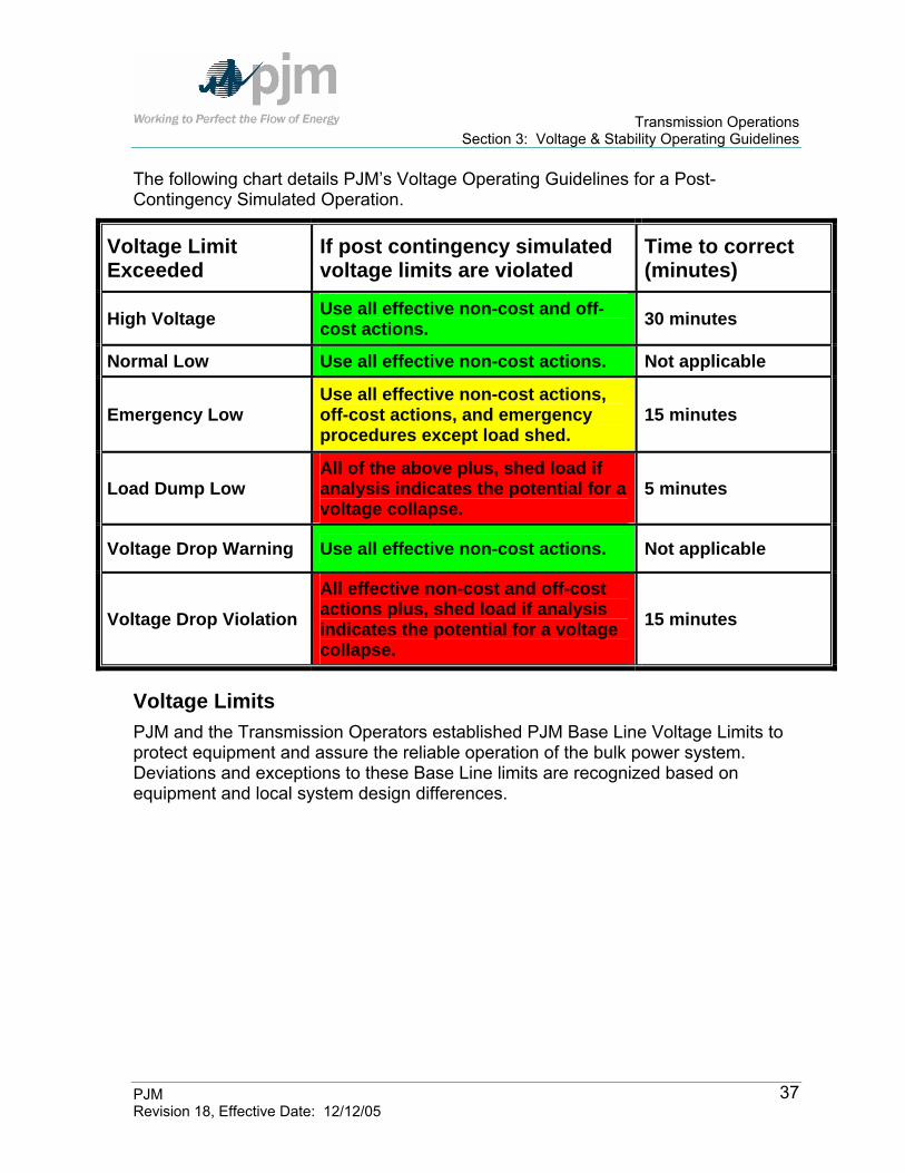
Transmission Operations Section 3: Voltage & Stability Operating Guidelines
PJM Revision 18, Effective Date: 12/12/05
37
The following chart details PJM’s Voltage Operating Guidelines for a Post-Contingency Simulated Operation.
Voltage Limit Exceeded
If post contingency simulated voltage limits are violated
Time to correct (minutes)
High Voltage Use all effective non-cost and off-cost actions. 30 minutes
Normal Low Use all effective non-cost actions. Not applicable
Emergency Low Use all effective non-cost actions, off-cost actions, and emergency procedures except load shed.
15 minutes
Load Dump Low All of the above plus, shed load if analysis indicates the potential for a voltage collapse.
5 minutes
Voltage Drop Warning Use all effective non-cost actions. Not applicable
Voltage Drop Violation All effective non-cost and off-cost actions plus, shed load if analysis indicates the potential for a voltage collapse.
15 minutes
Voltage Limits PJM and the Transmission Operators established PJM Base Line Voltage Limits to protect equipment and assure the reliable operation of the bulk power system. Deviations and exceptions to these Base Line limits are recognized based on equipment and local system design differences.

Transmission Operations Section 3: Voltage & Stability Operating Guidelines
PJM Revision 18, Effective Date: 12/12/05
38
PJM BASE LINE VOLTAGE LIMITS
PJM Base Line Voltage Limits Limit 500 kV 345 kV 230 kV 138 kV 115 kV 69 kV
High 550 (1.10)
362 (1.05)
242 (1.05)
145 (1.05)
121 (1.05)
72.5 (1.05)
Normal Low 500 (1.00)
328 (.95)
219 (.95)
131 (.95)
109 (.95)
65.5 (.95)
Emergency Low* 485 (.97)
317 (.92)
212 (.92)
127 (.92)
106 (.92)
63.5 (.92)
Load Dump* 475 (.95)
310 (.90)
207 (.90)
124 (.90)
103 (.90)
62 (.90)
Voltage Drop Warning* 2.5% 4-6% 4-6% 4-6% 4-6% 4-6% Voltage Drop Violation* 5-8%** 5-8% 5-8% 5-10% 5-10% 5-10% * Refer to PJM Manual for Emergency Procedures (M-13) ** The voltage drop violation percentage may vary dependent on PJM analysis.
Exhibit 5: PJM Base Line Voltage Limits
Voltage Limit Exceptions Some transmission systems within the PJM RTO are operated by PJM (in accordance to the design of the Transmission Zone LCC) to different voltage limits for voltage levels 230 kV and below. Transmission Zone exceptions to the PJM voltage limits are shown in Exhibit 8 at the end of this section. These limits apply on a Transmission Zone basis and are used in lieu of the PJM limits shown in Exhibit 5 In addition, there are some cases where equipment limitations impose more restrictive voltage limits that apply to a specific bus. These bus-specific voltage limits appear in Exhibit 7 at the end of this section.
Refer to Attachment F – Requesting Voltage Limit Exceptions to the PJM Base – Line Voltage Limits
Notification and Mitigation Protocols for Nuclear Plant Voltage Limits Nuclear plants may have voltage limits that are more restrictive than standard PJM voltage limits. In the case where standard PJM voltage limits, as defined by the Transmission Owner (TO), are more restrictive, PJM will direct redispatch without consultation of nuclear plants after all non-cost measures are implemented. Off-cost generation will set Locational Marginal Prices (LMP). In the case where nuclear plant voltage limits are more restrictive than standard PJM voltage limits, all costs required to mitigate the violations will be borne by the generation owner.

Transmission Operations Section 3: Voltage & Stability Operating Guidelines
PJM Revision 18, Effective Date: 12/12/05
39
PJM’s EMS models and operates to the most restrictive substation voltage limit for both actual and N-1 contingency basis. PJM will initiate notification to nuclear plants if the PJM EMS results indicate nuclear substation voltage violations and the PJM operator believes he is unable to return system voltages above established limits. This notification should occur within 15 minutes for voltage contingency violations and immediately for actual voltage violations. To the extent practical, PJM shall direct operations such that the violation is remedied within 30 minutes.
Communication All communication of future and current operations between PJM and the nuclear plant should be through the transmission owner (TO). If there is any confusion about a communication, the plant can talk directly with PJM, however, the transmission owner should be appraised of the discussion – if PJM to a nuclear plant direct discussions are needed the preferred method would be a 3-way call among all parties (i.e., inclusion of TO). If off-cost operations are required, the Nuclear Plant or their representative (Nuclear Duty Officer) may consult with the related MOC and evaluate whether an alternative such as operating at a reduced output would alleviate the voltage violation and is more cost effective. PJM will provide the approximate nuclear plant reduction, if applicable.
Information Exchange Normally, PJM does not provide information relative to transmission operation to any individual Market participant without providing that information to all. However, in this unique condition where the public safety requirement is to have a reliable source for safe unit shutdown and/or accident mitigation; it is imperative that specific information be provided to a nuclear plant (this information should not be provided to their marketing members). If PJM operators observe voltage violations or anticipate voltage violations (pre or post-contingency) at any nuclear stations; PJM operators are permitted to provide the nuclear plant with the actual voltage at that location, the post-contingency voltage at that location (if appropriate) and limiting contingency causing the violation. The operation for voltage limits at these nuclear stations should not be posted or provided to the Market via eData, once off-cost operations are initiated.
PJM Action 1. PJM notify nuclear plant, through Transmission Owner, of potential
violations to modeled voltage limits. 2. Violations of these voltage limits must be agreed upon by the nuclear plant
and logged by PJM.

Transmission Operations Section 3: Voltage & Stability Operating Guidelines
PJM Revision 18, Effective Date: 12/12/05
40
3. All non-cost actions should be implemented prior to MW adjustments. 4. All costs required to mitigate the violations will be borne by the generation
owner. 5. Controlling actions must be cost-capped, if applicable. 6. LMP shall not be used to control the voltage at these locations. 7. TLR shall not be used to control the voltage at these locations. 8. PJM will monitor the appropriate voltage limits based on changes provided. 9. PJM notify nuclear plant, through Transmission Owner, when voltage level
is restored within limits (and stable). 10. Attempt to control more restrictive nuclear plant voltage limitations within 30
minutes.
Transmission Owner Action 1. The Transmission Owner shall independently monitor for Nuclear Plant
actual and contingency voltage violations as reflected on the Transmission System.
2. Transmission Owner will communicate this notification from PJM to the nuclear plant.
3. Transmission owners will monitor the appropriate voltage limits based on changes provided.
Nuclear Plant Action 1. Nuclear plant will notify PJM, through Transmission Owner Shift Managers,
when different (new or default) voltage limits shall be used based on various plant service loading conditions, design basis calculation revisions.
2. Determine internal plant options, and if appropriate, provide revised limits. 3. Coordinate with MOC to evaluate PJM provided redispatch option (no cost
or unit information will be provided). 4. Provide PJM with decision to redispatch – if applicable. 5. Provide PJM with decision that nuclear plant will closely monitor plant
activities and will take action within the plant if conditions change and inform PJM not to implement off-cost.
6. Provide PJM with clear direction if they do not want PJM to perform redispatch.

Transmission Operations Section 3: Voltage & Stability Operating Guidelines
PJM Revision 18, Effective Date: 12/12/05
41
Note: PJM dispatch’s goal is to resolve all security violations (i.e. n-1 contingency) within 30 minutes, however; inherent communication delays related to off-cost agreement for nuclear plant voltage limits may not permit this goal to be achieved.
Voltage Control Actions
Voltage Coordination PJM is responsible for the overall coordination of the bulk power voltage scheduling. In general, since voltage schedules have a significant effect on local voltages PJM authorizes the Local Transmission Control Center to establish and adjust voltage schedules. Whenever the generator or the LCC desired voltage schedule impacts the overall PJM economic/reliable operation then PJM shall exercise its operational control and direct changes to the generation voltage/reactive schedules, capacitor/reactor schedule/status, and transformer LTC operation for the overall reliable/economic operation of PJM.
Under most situations, the local Transmission Operator will establish and coordinate voltage schedules for all generators within that LCC zone.
The typical LCC desired generating station voltage schedules should be communicated to the PJM dispatcher.
When deviating from this schedule the Transmission Operator should coordinate with the PJM dispatcher so that PJM can determine if the change is detrimental to PJM reliable/economic operation.
When PJM requests to change voltage or VAR schedule, PJM should discuss the changes with the local Transmission Operator and if the recommendation does not cause a defined limitation the Transmission Operator should implement the PJM request. PJM has operational control of the reactive facilities (transmission caps, LTC's, and generator regulation). If internal plant limits (or Transmission Operator local limits) restrict the request they should be logged so that PJM can investigate and recommend changes to plant facilities if appropriate.
Low Voltage Operation The PJM dispatcher uses PJM Real-time data and security analysis based programs as the primary tool to evaluate the current state of the PJM EHV system on a simulated post-contingency basis, as well as the anticipated future conditions of the PJM EHV system on a simulated post-contingency basis. PJM security analysis programs detect the contingencies that can cause any monitored bus to violate its low voltage and voltage drop limits. The PJM RTO uses the following techniques to control low voltage:

Transmission Operations Section 3: Voltage & Stability Operating Guidelines
PJM Revision 18, Effective Date: 12/12/05
42
switching capacitors in-service switching reactors out-of-service adjusting voltage set point of static VAR compensators (SVC) operating synchronous condensers changing transformer tap positions changing generation excitation adjusting generation MW output (i.e.: to change line flows) adjusting transactions adjusting PARs switching transmission facilities in/out of service
The PJM Base-Line Voltage Limits (see Exhibit 5) and how they would be applied to reliable system operation is:
PJM will use the “PJM Base-Line Voltage Limits” as the default “PJM Voltage Reliability Operating Limit”. If a PJM Transmission Owner identifies a specific voltage reliability limit that is more restricting than the PJM Base-Line Voltage Limits, PJM will use that voltage reliability limit provided by the Transmission Owner as the PJM Voltage Reliability Operating Limit. However, this use will depend on the condition that the facility is specifically identified as a PJM Open Access Transmission Tariff (“PJM OATT”) facility, and the limit is specifically identified as required for reliable operation.
The PJM Voltage Reliability Operating Limit will be the more restrictive of either the PJM Base-Line Voltage Limit or the Transmission Owner provided voltage reliability limit.
PJM does not charge or bill a PJM Transmission Owner for off-cost operation of a PJM OATT facility as described above. In addition, these PJM Voltage Reliability Operating Limits will be used in PJM System Planning reinforcement evaluations. PJM shall evaluate the need to upgrade any restricting facility and study the validity of that reliability limit.
High Voltage Operation The PJM dispatcher uses PJM Real-time data and security analysis based programs as the primary tool to evaluate the current state of the PJM EHV system on a simulated post-contingency basis, as well as the anticipated future conditions of the PJM EHV system on a simulated post-contingency basis. PJM security analysis programs detect the contingencies that can cause any monitored bus to violate its high voltage limits. The PJM RTO uses the following techniques to control high voltage:

Transmission Operations Section 3: Voltage & Stability Operating Guidelines
PJM Revision 18, Effective Date: 12/12/05
43
switching capacitors out-of-service switching reactors in-service adjusting voltage set point of static var compensators (SVC) operating synchronous condensers changing transformer tap positions changing generation excitation adjusting generation MW output (i.e.: to change line flows) adjusting PARs switching transmission facilities in/out of service
PJM performs the following actions to correct high voltage conditions: The PJM dispatcher requests that switchable capacitors be disconnected
and switchable reactors be connected. The PJM dispatcher requests Local Control Center operators to direct all
generators, synchronous condensers and SVCs within their zone to absorb reactive power.
The PJM dispatcher requests neighboring Control Areas to assist in reducing voltage.
The PJM dispatcher adjusts 500/230 kV transformer taps to optimize system voltage. Adjustment of transformer taps will be coordinated and agreed to between PJM and the Transmission Owner before changes are made. The greatest effect to control system voltage is attained by adjusting all 500/230 kV transformer taps.
The PJM dispatcher requests the Transmission Owners to open approved and effective EHV circuits. The PJM dispatcher performs the following tasks:
Verifies thermal conditions with on-line study programs Uses computer programs to study the simulated effects of switching and the steady state voltage response Directs operation to open both terminals by the LCC (open the terminal without a controlling source or the highest voltage bus first)
EHV Transformer LTC Operation The PJM dispatcher has operational control of and coordinates the operation of the EHV LTC transformer taps. In general, EHV LTC transformer tap changers are not operated under automatic voltage control but are operated in coordination with all other bulk power voltage control facilities.

Transmission Operations Section 3: Voltage & Stability Operating Guidelines
PJM Revision 18, Effective Date: 12/12/05
44
Operation of the PJM RTO is coordinated in an attempt to minimize capacitor switching operation and transformer tap changes. PJM coordinates with the Local Control Centers, all switching of the bulk power system capacitors & reactors to assist the system for actual or post-contingency situations. Local conditions may require some deviations.
Bulk Power Capacitor/SVC Operation The PJM dispatcher coordinates the operation of bulk power capacitors. Capacitors should be kept in service whenever they are beneficial to the PJM RTO transfer capability or reliability. Capacitors should not be switched automatically, at a predetermined time of day, or by operating voltage (except as noted below, under the direction of the PJM dispatcher).
Note: The capacitor banks at each installation operate independently of each other under normal switching operations. Under normal conditions, the PJM dispatcher does not request that both banks of capacitors at one location be brought on or off simultaneously; generally at least five minutes between switching is desirable. The PJM dispatcher monitors the system voltage profile and the transfer capability of the PJM RTO and requests capacitor switching or transformer tap changes in a timely manner.
Operation of the PJM RTO is coordinated in an attempt to minimize capacitor switching operation and transformer tap changes. PJM coordinates with the Local Control Centers, all switching of the 230 kV and 500 kV capacitors to assist the system for actual or post-contingency situations. Local conditions may require some deviations. The 500 kV LTC transformer taps should be adjusted to control the system voltage regardless of the capacitor's in or out-of-service status. A bank of capacitors should not be switched in-service if the voltage on the bus, upon which it is located, would violate voltage limits. The PJM RTO maximum voltage limits should not be exceeded on an actual or simulated post-contingency basis. As the PJM RTO voltage approaches limits, the PJM dispatcher analyzes and estimates the future system voltages and decides if there will be a need to remove any or all capacitors from service. The PJM dispatcher arranges to remove capacitors from service prior to the PJM RTO voltage reaching the maximum limits. If PJM’s simulated post-contingency analysis or a Transmission Owner’s real-time monitoring program detects that the first contingency loss of a facility results in a bulk power bus exceeding its high limit, the PJM dispatcher evaluates the removal of any or all capacitors at that bus from service as necessary. Prior to expected light-load periods, capacitors should be switched out-of-service before reaching limits if the PJM dispatcher expects that the switching operation is required in the future.

Transmission Operations Section 3: Voltage & Stability Operating Guidelines
PJM Revision 18, Effective Date: 12/12/05
45
First Energy's 230 kV capacitor banks at the Atlantic and Larrabee Substations are all under automatic control of the Atlantic Static Var Compensator (SVC). DPL’s 230 kV capacitor bank at Indian River is under automatic control of Indian River SVC. The following capacitor installations are equipped with Programmable Logic Controllers (PLCs) and are the first automatically switchable 500 kV capacitors on the PJM RTO EHV system:
Capacitor Installation Banks Juniata 2-250 MVAR Banks Conemaugh 1-200 MVAR Bank Conastone 1-200 MVAR Bank Limerick 1-200 MVAR Bank Hunterstown 1-100 MVAR Bank
Exhibit 6: Capacitor Installations with PLCs
To improve system voltages, the PJM dispatcher may switch capacitors with PLCs in service prior to switching in service non-PLC capacitors in other areas. PLC initiated switching is limited to a basic voltage scheme:
Capacitor automatic tripping generally is set to occur as follows: Voltage above 555 kV – 15 seconds Voltage at 555-550 kV – 15 to 60 seconds Voltage at 550-545 kV – 1 to 15 minutes Voltage at 545 kV – 15 minutes
Capacitor automatic closing generally is set to occur as follows: Voltage below 470 kV – 1 second Voltage at 475-470 kV – 1 to 15 seconds Voltage at 500-475 kV – 15 to 60 seconds Voltage at 510-500 kV – 1 to 15 minutes Voltage at 510 kV – 15 minutes
The PJM Operations Planning staff develops modifications to transmission limitations as necessary. As additional capacitor installations are placed into service, new transmission limitations and operating guidelines are issued.

Transmission Operations Section 3: Voltage & Stability Operating Guidelines
PJM Revision 18, Effective Date: 12/12/05
46
Allegheny Power’s EHV capacitors are operated in the manual mode but have automatic trips for high voltage:
Substation Capacitor HV Trip / Delay * Critical HV Trip / Delay ** Bedington 500 kV #2 162.5 MVAR 550 kV – 10 Sec 650 kV – 60 Sec Bedington 500 kV #3 162.5 MVAR 550 kV – 8 Sec 650 kV – 55 Sec Black Oak 500 kV #2 162.5 MVAR 550 kV – 10 Sec 650 kV – 60 Sec Black Oak 500 kV #3 162.5 MVAR 550 kV – 8 Sec 650 kV – 55 Sec Doubs 500 kV #2 246 MVAR 545 kV – 190 Sec 550 kV – 3 Sec
* Capacitors have a 5-minute time delay after tripping before they can be reclosed. ** Capacitor breaker disconnects will open making capacitor unavailable until on-site inspection is made and disconnects reclosed.
Opening EHV Lines for Voltage Control When high voltage conditions are expected on the PJM RTO, the PJM dispatcher uses PJM security analysis programs to study possible actions (i.e., opening an EHV line) and coordinates an operational plan before the situation becomes severe. If system voltages get too high, it may be difficult (if not impossible) to remove a line from service due to the voltage rise experienced at the open end of the circuit being removed from service. Corrective actions have a maximum effect only when they are accomplished prior to experiencing the problem. During high voltage conditions, opening an EHV circuit has a positive effect in reducing system voltages for two reasons:
it increases losses on the rest of the PJM EHV system it eliminates the capacitive charging of the line
PJM has identified several circuits that, in the past, have been effective in controlling general PJM RTO high voltage conditions when they are removed from service. Suggested EHV circuits to be studied are:
5008 Juniata - TMI 5009 Juniata - Alburtis 5026 TMI - Hosensack
Note: First Energy requires a person on site (TMI) when the 5008 or 5026 line is returned to service. The PJM dispatcher schedules the return time of the line at least two hours in advance of switching. High voltage problems of localized nature may be more effectively controlled by selective measures in the particular area. For example, if all Homer City units are out of service and high voltage presents a problem in the area, the PJM dispatcher may decide to open the Homer City - Stolle Road 345 kV line.

Transmission Operations Section 3: Voltage & Stability Operating Guidelines
PJM Revision 18, Effective Date: 12/12/05
47
Returning EHV Lines That Were Open For Voltage Control While a transmission line may be open-ended for only a short period of time during line energization and de-energization, the open terminal voltage may exceed acceptable levels as a result of line charging. This can cause serious equipment damage. The steady state voltage at the open end of an uncompensated transmission line is always higher than the voltage at the sending end. This phenomenon, known as the Ferranti effect, occurs because of the capacitive charging current flowing through the series inductance of the line. The equation representing the Ferranti effect is:
( )BLcosV V 2
1 =
where: V1 – Open End Voltage V2 – Closed End Voltage B – Phase Constant (0.11587/mile for all compensated transmission lines) L – Line Length in Miles
In the event PJM security analysis programs are not available, the Ferranti equation may be used as a guide to potential voltage rise during PJM 500 kV line switching operations. Voltage rise (V1) for three (3) source terminal (closed end) voltage levels (V2) are listed:
500 kV 525 kV 550 kV
Attachment D presents the open circuit terminal voltage for the 500 kV lines.
Voltage Control Options for Non-Tariff Facilities On occasion, PJM is requested to dispatch generation to protect PJM member equipment/facilities where that equipment is not included in the PJM tariff, and therefore not accommodated by standard PJM redispatch. PJM will accommodate requests for scheduling and dispatching off-cost generation. In the examples below, PJM describes conditions where charging for off-cost generation may result. Off-cost examples:
If requested to run generation for a distribution related problem PJM will accommodate a member’s request for “off-cost” operation. Appropriate billing will be made to the requestor. [A PJM Transmission Owner may request limits to PJM OATT facilities to protect their distribution system
Transmission Operations Section 3: Voltage & Stability Operating Guidelines
PJM Revision 18, Effective Date: 12/12/05
48
reliability (non-PJM OATT facilities). PJM will bill the PJM Member for any resulting off-cost operation.]
If requested to run generation to protect a generating station or other non-tariff facility, PJM can accommodate a PJM member’s request for the “off-cost” generation assignment. PJM will bill the PJM Member for any resulting off-cost operation.
If requested to run generation for a Transmission Owner determined non-PJM reliability limit, PJM will accommodate that member’s request for “off-cost” operation. Appropriate billing will be made to the requestor.
As an alternative to PJM directed off-cost generation, the requestor could enter into an agreement with any generation provider, this agreement would be treated independent from the PJM billing process.
Addressing Voltage Limits at Generators and other Non-PJM OATT Facilities (including Distribution)
For a limitation at a Generator, Generation station facility, or other non-PJM OATT facility, either the Transmission Owner or PJM Member can request PJM to operate for any requested voltage limits at a specific bus that are identified as more restricting than the PJM Base-Line Voltage Limits.
These requested voltage limits are submitted in writing by the PJM Member to the PJM Manager –Transmission.
PJM will evaluate these limits for reasonableness. PJM Transmission Department will return confirmation to the requestor when
these requested voltage limits are implemented in the PJM EMS. The PJM Member will be billed for any “Off-Cost” operation.
Transmission Owners should submit their exceptions to PJM Base-Line Voltage Limits for PJM OATT facilities by using a standardized format. Generation Owners and other PJM Members may request PJM to operate to a different Voltage Limit than the PJM Base-Line Voltage limits for a Generator or other non-PJM OATT facility by using a standardized format.
Transfer Limits (Reactive/Voltage Transfer Limits) Post-contingency voltage constraints can limit the amount of energy that can be imported from and through portions of the PJM RTO. The PJM EMS performs automated online full AC security analysis transfer studies to determine Transfer Limits for the use in real-time operation. The PJM Transfer Limit Calculator (TLC) simulates worse case transfers, with the simulation starting point being the most recent State Estimator solution. The TLC executes in the PJM EMS approximately every 5 minutes automatically recommending updated Transfer Limits to the PJM

Transmission Operations Section 3: Voltage & Stability Operating Guidelines
PJM Revision 18, Effective Date: 12/12/05
49
Dispatcher. The TLC determines a collapse point for each interface. Each interface consists of a number of 500 kV lines. PJM has established the following 500 kV interfaces in the PJM RTO:
Western Transfer Interface - Includes the Keystone-Juniata 5004 line, the Conemaugh-Juniata 5005 line, the Conemaugh-Hunterstown 5006 line, and the Doubs-Brighton 5055 line.
Central Transfer Interface - Includes the Keystone-Juniata 5004 line, the Conemaugh-Juniata 5005 line, and the Conastone-Peach Bottom 5012 line.
500X (5004+5005) – Includes the Keystone-Juniata 5004 line and the Conemaugh-Juniata 5005 line.
Eastern Transfer Interface - Includes the Wescosville-Alburtis 5044 line, Juniata-Alburtis 5009 line, TMI-Hosensack 5026 line, Peach Bottom-Limerick 5010 line and the Rock Springs – Keeney 5025 line.
Bedington – Black Oak Transfer Interface (Bed-Bla) – Includes the Bedington – Black Oak 544 line.
AP South Transfer Interface – Includes the Doubs - Mt. Storm 512 line and the Mt Storm – Meadow brook 572 line.
Exhibit 7 presents the location of the reactive transfer interfaces in the PJM RTO.
Exhibit 7: Reactive Transfer Interface Locations

Transmission Operations Section 3: Voltage & Stability Operating Guidelines
PJM Revision 18, Effective Date: 12/12/05
50
The transfers across an interface are the MW flows across the transmission paths. The transfer limits are the MW transfer beyond which reactive and voltage criteria are violated. The reactive transfer limits are used to limit the total flow over the interfaces. The reactive limits are either pre-contingency MW limits, or post-contingency MW limits, based on a post-contingency voltage drop in the PJM RTO. The PJM dispatchers continuously monitor and control the flow on each transfer interface so that the flows remain at or below the transfer limits. This ensures that no single contingency loss of generation or transmission in or outside the PJM RTO causes a voltage drop greater than the applicable voltage drop criteria. In addition, special operating procedures, addressing reactive issues, are identified in Section 5. Additional interfaces will be established by PJM Operations Planning as required.
Stability Limits The PJM RTO established stability limits for preventing electrical separation of a generating unit or a portion of the PJM RTO. PJM recognizes three types of stability:
Steady State Stability - A gradual slow change to generation that is balanced by load.
Transient Stability - The ability of a generating unit or a group of generating units to maintain synchronism following a relatively severe and sudden system disturbance. The first few cycles are the most critical time period.
Dynamic Stability - The ability of a generating unit or a group of generating units to damp oscillations caused by relatively minor disturbances through the action of properly tuned control systems.
PJM will operate the facilities that are under PJM operational control such that the PJM system will maintain angular and voltage stability following any single facility malfunction or failure. In general, stability is not a limiting constraint on the PJM RTO. Special operating procedures addressing stability limit issues are presented in Section 5.
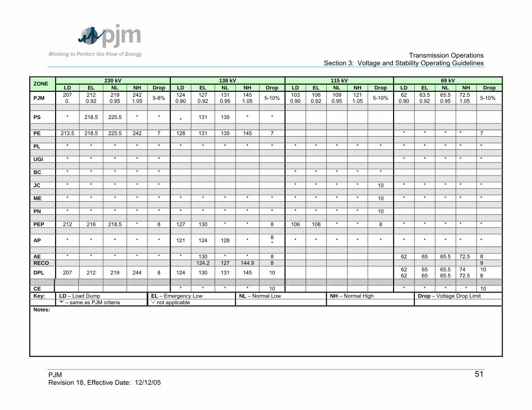
Transmission Operations Section 3: Voltage and Stability Operating Guidelines
PJM Revision 18, Effective Date: 12/12/05
51
230 kV 138 kV 115 kV 69 kV ZONE LD EL NL NH Drop LD EL NL NH Drop LD EL NL NH Drop LD EL NL NH Drop
PJM 207 0.
212 0.92
219 0.95
242 1.05 5-8% 124
0.90 127 0.92
131 0.95
145 1.05 5-10% 103
0.90 106 0.92
109 0.95
121 1.05 5-10% 62
0.90 63.5 0.92
65.5 0.95
72.5 1.05 5-10%
PS * 218.5 225.5 * * * 131 135 * *
PE 213.5 218.5 225.5 242 7 128 131 135 145 7 * * * * 7 PL * * * * * * * * * * * * * * * * * * * * UGI * * * * * * * * * * BC * * * * * * * * * * JC * * * * * * * * * 10 * * * * * ME * * * * * * * * * * * * * * 10 * * * * * PN * * * * * * * * * * * * * * 10 PEP 212 216 218.5 * 8 127 130 * * 8 106 108 * * 8 * * * * *
AP * * * * * 121 124 128 * 8 * * * * * * * * * * *
AE * * * * * * 130 * * 8 62 65 65.5 72.5 8 RECO 124.2 127 144.9 8 9
DPL 207 212 219 244 8 124 130 131 145 10 62 62
65 65
65.5 65.5
74 72.5
10 8
CE * * * * 10 * * * * 10 Key: LD – Load Dump EL – Emergency Low NL – Normal Low NH – Normal High Drop – Voltage Drop Limit ‘*’ – same as PJM criteria ‘-‘ not applicable Notes:

Transmission Operations Section 3: Voltage and Stability Operating Guidelines
PJM Revision 18, Effective Date: 12/12/05
52
765 kV 500 KV 345 kVV ZONE
LD EL NL NH Drop LD EL NL NH Drop LD EL NL NH Drop
PJM 688 0.90
703 0.92
726 0.95
803 1.05 5-8% 475
0.95 485 0.97
500 1.00
550 1.10 5-8% 310
0.90 317 0.92
328 0.95
362 1.05 5-8%
CE * 726.7 749.7 * 10 * 327.7 338.1 * 10 Key: LD – Load Dump EL – Emergency Low NL – Normal Low NH – Normal High Drop – Voltage Drop Limit ‘*’ – same as PJM criteria ‘-‘ not applicable Notes:

Transmission Operations Section 3: Voltage and Stability Operating Guidelines
PJM Revision 18, Effective Date: 12/12/05
53
Zone Station Voltage LD EL NL NH Date Reason
Exhibit 8: Bus-and Zone Specific Variations to PJM Base Line Voltage Limits

Transmission Operations Section 4: Reportable Transmission Facility Outages
PJM Revision 18, Effective Date: 12/12/05
54
Section 4: Reportable Transmission Facility Outages Welcome to the Reportable Transmission Facility Outages section of the PJM Manual for Transmission Operations. In this section, you will find the following information:
A description of the general principles of scheduling outages (see “General Principles”).
How the Transmission Owner schedules a transmission facility outage (see “Scheduling Transmission Outage Requests”).
How PJM processes a Transmission Outage Request (see “Processing Transmission Outage Requests”).
A description of the equipment failure procedures (see “Equipment Failure Procedures”).
General Principles Transmission Owners have the right and obligation to maintain and repair their portion of the transmission system. PJM approves all Reportable Transmission Facility outages prior to removal of the equipment from service. PJM will coordinate scheduled outages of all Reportable Transmission Facilities with planned generation outages that are submitted to PJM and may affect PJM RTO operation. For purposes of scheduling, Reportable Transmission Facilities include, but are not limited to, lines, transformers, phase angle regulators, buses, breakers, disconnects, bulk power capacitors, reactors, and all related equipment. PJM maintains a list of Reportable Transmission Facilities. Each Transmission Owner submits the tentative dates of all transmission outages of Reportable Transmission Facilities to PJM as far in advance as possible. Procedures and timelines are established for the scheduling, coordinating, requesting, studying, approving, and notifying of the transmission outage to/by the appropriate Transmission Owner and PJM. The procedures and timelines are identified in this section and are periodically reviewed and revised. Under certain conditions such as extreme weather, peak load, heightened homeland security, etc. PJM will evaluate the need to operate the Power Grid in a more conservative manner. Actions that may be taken in these special circumstances include, but are not limited to, canceling or rescheduling outages and returning outaged equipment to service. The status of rescheduled outages is described in detail under the subheading, “Rescheduling Outages”.

Transmission Operations Section 4: Reportable Transmission Facility Outages
PJM Revision 18, Effective Date: 12/12/05
55
Scheduling Transmission Outage Requests Each Transmission Owner shall submit the tentative dates of all planned transmission outages of Reportable Transmission Facilities to PJM via eDART as far in advance as possible and update PJM at least monthly. For transmission outages exceeding five working days or which are anticipated to result in significant system impacts, the TO shall submit the planned outage schedule one year in advance following the same procedure via eDART along with a minimum of monthly updates. PJM maintains a planned transmission outage schedule for a period of at least the next 13 months. The planned transmission outage schedule is posted, subject to change, on the PJM Open Access Same-time Information System (OASIS). PJM evaluates the outage requests and places outage requests on the planned transmission outage schedule, if they are determined to be consistent with system reliability. Planned transmission outages are given priority based on the date of submission. All planned transmission outages will be posted on OASIS by the first day of the Month prior to the Month in which the outage will occur, with further updates as new information is provided. PJM periodically reviews all submissions of planned transmission outages and considers the effect of proposed transmission outages upon the integrated operation of the transmission system using established operating reliability criteria, as described within Sections 2 and 3 of this manual. Advance notification assures that the outage is reflected in both the ATC analysis and the FTR Auction.
Requirements The TO is required to submit all outage requests by the 1st of the Month prior to the Month of the requested start date of the outage Recognizing that this may not always be possible, the following table illustrates the three different time frames in which an Outage Request can be submitted and the different Actions PJM can take. The “PJM Actions” are defined in more detail in the Section: “Processing Transmission Outage Requests, PJM Actions”.
Request Submitted Ticket Received Status PJM Actions
By the 1st of the Month prior to the Month of the outage “On Time” The outage will be approved, provided it
does not jeopardize system reliability. After the 1st of the Month prior to the Month of the outage start, and before 8 am three business days before the start of the outage
“Late” The outage may be cancelled if it causes congestion requiring off-cost operations.
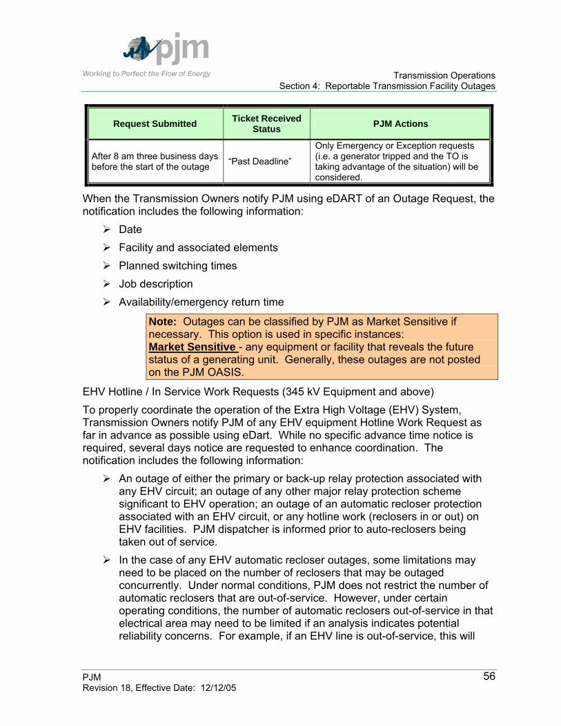
Transmission Operations Section 4: Reportable Transmission Facility Outages
PJM Revision 18, Effective Date: 12/12/05
56
Request Submitted Ticket Received Status PJM Actions
After 8 am three business days before the start of the outage “Past Deadline”
Only Emergency or Exception requests (i.e. a generator tripped and the TO is taking advantage of the situation) will be considered.
When the Transmission Owners notify PJM using eDART of an Outage Request, the notification includes the following information:
Date Facility and associated elements Planned switching times Job description Availability/emergency return time
Note: Outages can be classified by PJM as Market Sensitive if necessary. This option is used in specific instances: Market Sensitive - any equipment or facility that reveals the future status of a generating unit. Generally, these outages are not posted on the PJM OASIS.
EHV Hotline / In Service Work Requests (345 kV Equipment and above) To properly coordinate the operation of the Extra High Voltage (EHV) System, Transmission Owners notify PJM of any EHV equipment Hotline Work Request as far in advance as possible using eDart. While no specific advance time notice is required, several days notice are requested to enhance coordination. The notification includes the following information:
An outage of either the primary or back-up relay protection associated with any EHV circuit; an outage of any other major relay protection scheme significant to EHV operation; an outage of an automatic recloser protection associated with an EHV circuit, or any hotline work (reclosers in or out) on EHV facilities. PJM dispatcher is informed prior to auto-reclosers being taken out of service.
In the case of any EHV automatic recloser outages, some limitations may need to be placed on the number of reclosers that may be outaged concurrently. Under normal conditions, PJM does not restrict the number of automatic reclosers that are out-of-service. However, under certain operating conditions, the number of automatic reclosers out-of-service in that electrical area may need to be limited if an analysis indicates potential reliability concerns. For example, if an EHV line is out-of-service, this will

Transmission Operations Section 4: Reportable Transmission Facility Outages
PJM Revision 18, Effective Date: 12/12/05
57
hold true. In this case, the requesting Transmission Owners are informed of the situation and asked to reschedule the work.
Instances when relay testing or construction personnel are working in EHV substations, other than those in conjunction with scheduled facility outages previously approved by PJM, which PJM dispatcher may judge as possibly jeopardizing the reliable operation of the substation.
The Transmission Owner must communicate to PJM all outages that affect the ability of PJM to receive telemetered data.
Energizing New Facilities
NOTE: In order for PJM to properly model changes in system configuration, as much advanced notification as possible is required when a new facility, a re-conductored line that changes impedance, or a facility that has been out of service for an extended period of time is scheduled to be energized. Transmission Owners must also notify PJM by the first day of the Month prior to the Month in which the energizing of the facility will occur.
Generator Voltage Regulator Outages An outage of any unit generator voltage regulator must be communicated to PJM though eDart as far in advance as possible. The Generator Owner must submit these outages. (Refer to the Generator Operational Guidelines Manual.)
Emergency and Forced Outages PJM recognizes that Emergency Outages must be taken. If it is determined that the outage may create an unreliable operating condition the outage will not be approved, but it will be recognized by PJM that the outage will occur. Transmission Owners report forced transmission outages of Transmission Facilities to PJM, to directly connected Control Areas and to any Other PJM member that may be affected as soon as the forced transmission outage occurs or as soon as it is anticipated that forced outage will occur. The Transmission Owner also submits an eDart ticket for the outage with all pertinent information that is available at that time and updates the ticket as new information becomes available.
Rescheduling Outages A planned transmission outage that is rescheduled or canceled because of inclement weather or at the direction or request of PJM retains its status and priority as a planned transmission outage with PJM approved rescheduled date. If an outage request is rescheduled or canceled (for reasons other than inclement weather or at the direction of PJM), the rescheduled or canceled and resubmitted

Transmission Operations Section 4: Reportable Transmission Facility Outages
PJM Revision 18, Effective Date: 12/12/05
58
outage is treated as an unplanned outage request. PJM coordinates outage rescheduling with the PJM Transmission Owners to minimize impacts on system operations.
Coordinating Outage Requests with Other TOs In the event that a contemplated scheduled outage of one Transmission Owner’s facility affects the availability of another Transmission Owner’s facility, it is the responsibility of the Transmission Owner initiating the request to notify the affected TO or other Control Areas for their consideration before submitting the request to PJM. If agreeable to all Transmission Owners or Control Areas, the initiating Transmission Owner submits an outage request to PJM all other PJM Members that may be affected are notified.
Coordinating Outage Requests with other RTOs In the event of a contemplated scheduled outage of a tie between the PJM RTO, the Transmission Owner initiating the request discusses the outage with the directly connected Control Area for their consideration. Likewise, if it is expected that such an outage will be extended beyond its scheduled time, this is discussed with the directly connected Control Area. Major bulk power ties are listed under both systems above. If agreeable to the directly connected Control Area, the initiating Transmission Owner submits an outage request to PJM, all other systems that may be affected are notified. This procedure also applies to a tie between the PJM RTO and an adjacent Control Area whenever the PJM RTO initiates an outage request. Adjacent Control Areas are expected to follow a similar procedure.
Coordinating Outage Requests with Planned Nuclear Generation Outages When a Transmission Owner submits an Outage Request that will open a Nuclear Generating Station’s Unit Breaker the following guidelines shall be observed: All Nuclear Unit breaker Outage Requests shall be coordinated closely with the Nuclear Station to coincide with a Unit outage In the case that the Outage Request can not be delayed until the next Unit Outage, the Nuclear station should be given at least six weeks notice. The schedule for opening the Unit Breaker must be closely coordinated with the station. The length of time that the breaker remains open should be minimized. PJM will work with the Nuclear Station’s and the Transmission Owner’s outage needs. The Nuclear Generating Stations coordinate the scheduling of a Unit Breaker outage and internal plant equipment outages and testing to minimize station risk. Adherence to outage schedule and duration is critical to the plant during these evolutions. Emergent plant or transmission system conditions may require schedule

Transmission Operations Section 4: Reportable Transmission Facility Outages
PJM Revision 18, Effective Date: 12/12/05
59
adjustments, which should be minimized. Any change to the outage schedule that impacts the Unit Breakers shall be communicated to the nuclear generator operator. The following Nuclear Generating Stations have transmission system connections that can impact Nuclear Station Safety Systems:
Peach Bottom: Limerick: Unit 2: CB 215 Unit 1: CB 535
CB 225 CB 635 Unit 3: CB 15 Unit 2: CB 235
CB 65 CB 335 Salem: Oyster Creek:
Unit 1: 5 – 6 B.S. 10X GD1 2 – 6 B.S. 11X GC1
Unit 2: 9 – 10 B.S. 30X 1 – 9 B.S. 32X
Hope Creek: Calvert Cliffs:
BS 6 – 5 50X Unit 1: 552 – 22 BS 2 – 6 52X 552 – 23
Unit 2: 552 – 61 552 - 63
Coordinating Outage Requests with Planned Generation Outages Transmission Owners will adhere to all PJM requirements regarding Transmission Outage Requests previously detailed in this section. PJM and Transmission Owners coordinate transmission outages with planned outages for generators submitted to PJM. In the maintenance planning process, if submitted in a timely manner, planned generator outage requests are given priority over planned transmission outage requests. PJM resolves potential outage conflicts based on system reliability. PJM performs the following activities:
Reviews the transmission and generator maintenance schedules to coordinate major transmission and generator outages and communicates with submitting PJM Members to assist in attempting to minimize anticipated constrained operations
Recommends adjustments to transmission outage schedules throughout the year to coincide with planned generator outages within the PJM RTO and surrounding Control Areas

Transmission Operations Section 4: Reportable Transmission Facility Outages
PJM Revision 18, Effective Date: 12/12/05
60
Communicates with submitting PJM Members to assist in attempting to minimize the forecast PJM RTO production cost based on anticipated market-based prices
Processing Transmission Outage Requests Transmission Owners submit Outage Requests in eDart for all outages to PJM in advance of the outage start date. The Outage Request shall be submitted as far in advance as possible. PJM considers all transmission outages in the following priority order:
Forced or emergency transmission outages Transmission outage requests submitted “On Time”, i.e., those submitted by
the 1st of the Month prior to the Month of the requested start date of the outage.
Transmission outage requests submitted “Late”, i.e., those submitted after the 1st of the Month prior to the Month of the requested start of the outage, and before 8 am three business days prior to the requested start of the outage.
Exhibit 9 presents how PJM processes Transmission Outage Requests.
Transmission OwnerPrepares Work Requestand Submits to PJM OI
• Studies Outage Prior ToSubmission
• Identifies What Equipment Must Be Removed
• Coordinates With AdjoiningParticipant
PJM OI Approves Request Or MakesRecommendationsFor Alternatives
• Recommends Off-CostGeneration Scheduling
• Recommends Re-scheduling• PJM OI makes decision to
cancel or reschedule pending outage.
• Makes Final Decision• Runs Security Analysis Study• Checks for Unscheduled
Outages• Checks for Early Return
PJM OI DispatcherAnalyzes RequestPrior to Switching
• Reviews Conflict With OtherOutages
• Determines Impact on SystemOperations
PJM OI OperationsPlanning Staff Analyzes
Work Request
Exhibit 9: Transmission Outage Request Process

Transmission Operations Section 4: Reportable Transmission Facility Outages
PJM Revision 18, Effective Date: 12/12/05
61
PJM Actions PJM will inform the Transmission Owners through eDart of the status of all Outage Requests (either Approved or Denied) by no later than 1400 hours two business days before the requested start of the outage. In evaluating all Transmission Outage Requests, PJM performs the following activities:
Studies and approves all emergency outages that do not result in Emergency Procedures.
Cancels or withholds approval of any outage that is expected to result in Emergency Procedures.
Studies and approves all Transmission Outage Requests that are submitted “On Time” and do not jeopardize the reliability of the PJM System.
Studies and approves all Transmission Outage Requests that are submitted “Late” and do not cause congestion on the PJM System. PJM retains the right to deny all jobs submitted after 8 a.m. three days prior to the requested start date unless the request is an emergency job or an exception request (i.e. a generator tripped and the Transmission Owner is taking advantage of a situation that was not available before the unit trip).
Determines if a “Late” Request may cause congestion and advises the Transmission Owner of any solutions available to eliminate the congestion. If a generator Planned or Maintenance Outage request is contributing to the congestion, PJM can request the Generation Owner to defer the outage. If no solutions are available, PJM may require the Transmission Owner to reschedule the outage.
During anticipated emergency conditions, orders all work on Reportable Transmission Facilities that can be returned to service interrupted and the facilities returned to service until the emergency condition is relieved, if possible.
PJM, as system conditions warrant, identifies opportunities for, and encourages, coordination of all generator and transmission maintenance outages. When actual or anticipated system conditions change such that, at the discretion of PJM, the rescheduling of a transmission outage is advisable, PJM informs the Transmission Owner of the conditions and available alternatives. The Transmission Owner involved considers the impacts of proceeding with the outage as advised by PJM and may either proceed knowing the estimated impacts on the remaining facilities or postpone the outage. If the outage is not postponed, PJM determines and records the appropriate impacts or changes to system limits and takes the steps required to

Transmission Operations Section 4: Reportable Transmission Facility Outages
PJM Revision 18, Effective Date: 12/12/05
62
maintain established operating reliability criteria as mentioned within Section 1 of this manual.
PJM evaluates planned outages of Reportable Transmission Facilities to determine whether an outage may cause the simultaneous loss of multiple facilities. When non-reportable equipment outages at a station occur, which can lead to the simultaneous loss of more than one reportable transmission or generator facility for any single facility malfunction or failure, PJM must be informed. The Transmission Owners are responsible to report such conditions to PJM as soon as they are recognized.
Notification of Transmission Outages The Transmission Owners are responsible for reporting outages on facilities contained within the Transmission Facilities List Database (available on the PJM website – www.pjm.com). The eDART reporting system is used to inform PJM and others of the outage according to predefined indexing keys. Transmission Owners must notify PJM of the unavailability of other transmission components that affect the capability of protection of facilities on the list of Reportable Transmission Facilities. Transmission Owners report forced transmission outages of Transmission Facilities to PJM, to directly connected Control Areas that may be affected, and to a jointly-operating PJM Member as soon as the forced transmission outage occurs or as soon as it is anticipated that forced outage occurs or is imminent. Transmission Owners must report outages that under expected system conditions may affect system reliability even though these facilities may not be listed as a Reportable Transmission Facility. This includes outages that may result in multiple facility trippings. PJM dispatcher then informs all other systems that may be affected. PJM dispatcher logs all outages and, as required, reports to and makes necessary arrangements with the appropriate personnel from neighboring RTOs, ISOs, and Control Areas.
Real-Time Switching Notification Procedures Transmission Owners must request final approval from PJM Transmission Dispatcher one-half hour prior to the expected switching time of any reportable facility. In the case of any 500 kV facility outage, PJM is notified again just prior to switching to verify PJM RTO conditions and to notify other companies via the ALL-CALL. For all other scheduled transmission outages, 345 kV and below, PJM is notified again, to report that the facility is out of service, unless PJM specifically requests to be notified immediately prior to switching.

Transmission Operations Section 4: Reportable Transmission Facility Outages
PJM Revision 18, Effective Date: 12/12/05
63
If for any reason, PJM dispatch approves switching for planned maintenance, and actual or contingency violations are observed, PJM dispatch will direct the facility to be returned to service until system conditions can be adjusted and the outage permitted to continue without violating operating criteria. When a reportable facility is to be returned to service, the responsible Transmission Owner reports to the PJM Transmission Dispatcher for approval prior to returning the outaged facility to service. This is done so that any generation changes or transmission adjustments can be made to assure reliable operation of the system.
Equipment Failure Procedures Transmission Owners promptly conduct investigations of equipment malfunctions and failures and forced transmission outages in a manner consistent with good utility practice and NERC, ECAR, SERC and MAAC principles, guidelines, and standards. In order to permit other Transmission Owners to take advantage of information leading to possible trends in equipment failures the Transmission Owners supply the results of such investigation to PJM, other Transmission Owners, and the appropriate entities in NERC, ECAR, SERC and MAAC. Transmission Owners establish guidelines for the level of resources to be applied to restore equipment to service following a failure. The Transmission Owners obtain from PJM the information and support services needed to comply with their obligations.

Transmission Operations Section 5: Index and Operating Procedures for PJM RTO Operation
PJM Revision 18, Effective Date: 12/12/05
64
Section 5: Index and Operating Procedures for PJM RTO Operation Welcome to the Operating Procedures PJM RTO Operation section of the PJM Manual for Transmission Operations. In this section you will find the following information:
An overview of how special protection systems (SPS) are reviewed, approved, communicated, and documented.
An index of the specific procedures which are contained in this manual and listed or referenced by the Transmission Provider. Each Transmission Zone within the PJM RTO has a separate section for applicable Operating Procedures. Some Control Areas also have a separate section. The procedure itself that was provided by the Transmission Provider to PJM may be attached in the applicable section.

Transmission Operations Section 5: Index and Operating Procedures for PJM RTO Operation
PJM Revision 18, Effective Date: 12/12/05
65
PJM Procedure to Review Special Protection Systems (SPS) The following details the committee structure review process for Special Protection Systems (SPS) and general timeline. This structure is to ensure there is sufficient analysis, notice and training on Special Protection Systems prior to implementation. The general process is as follows:
1. PJM Participant/Committee forwards SPS to PJM for review. 2. PJM Planning, PJM Transmission Department and Transmission Owner(s)
review scheme and system impact. PJM will provide a recommendation. 3. PJM staff discusses the scheme at the following PJM Committees:
a. PJM System Operations Subcommittee - Transmission b. PJM Planning Committee c. PJM Operating Committee.
4. PJM staff/participant obtain any required Regional Reliability Council endorsement.
5. PJM staff documents the SPS scheme and revises Manual M3. 6. PJM staff discusses the scheme at the PJM Dispatcher Training Task
Force Committee review of the SPS and documentation process should be completed within 2 months. Depending upon the Regional Reliability Council review process, endorsement may require 3 to 6 months.
Type of Operating Procedure
Transmission Operations Manual Section Ref
PJM RTO Operation Constraint Management Mitigation During Scheduled Switching Procedure Constraint/Limitation Section 5 PJM
PJM/NYPP PAR Operation PARS Section 5 PJM PSE&G/ConED Wheel PARS Section 5 PJM PJM/VAP Voltage Coordination Plan Voltage Limits Section 5 PJM Loop Flows- around Lake Erie OE,NEPEX,NYPP,PJM,MECS,CEI, AEP Limitations Section 5 PJM
PJM/NYPP Transfers via First Energy Contingency/Transfers Section 5 FE -PN PJM/AP Tie Lines via First Energy Thermal Contingency Section 5 FE -PN
Atlantic Electric Company (AE)- Conectiv Deptford 230 kV Breaker Relay Special Purpose Relay Section 5 AE
American Electric Power (AEP)

Transmission Operations Section 5: Index and Operating Procedures for PJM RTO Operation
PJM Revision 18, Effective Date: 12/12/05
66
South Canton 765/345 kV Transformer Contingency Control Section 5 - AEP
Cook Unit Isolation on Select Circuits Unit Isolation Section 5 - AEP
Kammer Operating Procedures Limitations Section 5 - AEP
Conesville 345 kV Plant Operating Guidelines
Unit Stability Section 5 - AEP
Sunnyside-Torrey 138 kV Operating Guide Contingency Control Section 5 - AEP
Conesville 138 kV Bus Configuration Contingency Control Section 5 - AEP
Marysville 765 kV Reactor Guidelines Guidelines Section 5 - AEP
Kanawha – Matt Funk 345 kV Circuit Stability Section 5 - AEP
Rockport Operating Guide Unit Stability Section 5 - AEP
Smith Mountain 138 kV station Stability Stability Section 5 - AEP
Gavin - Mountaineer Stability Stability Section 5 - AEP
Tanners Creek 345 kV Station Concerns Limitations Section 5 - AEP
Tidd 345 kV Station Voltage Concerns Voltage Section 5 - AEP
Galion Bypass Switch Limitations Section 5 - AEP
Additional Regional Procedures Section 5 - AEP
Baltimore Gas & Electric Company (BC) Calvert Cliffs Voltage Limitations Voltage Limitations Section 5 BC Nottingham- Graceton 230 kV Line Limitations Line Limitation Section 5 PECO
Commonwealth Edison (ComEd) Kincaid Stability Trip Scheme Unit Stability Section 5 ComEd Powerton Stability Limitations Unit Stability Section 5 ComEd Quad Cities and Cordova Stability Limitations
Unit Stability Section 5 ComEd
Byron and Lee County Operating Guides Unit Stability Section 5 ComEd University Park North Energy Center Restriction
Unit Stability Section 5 ComEd
Elgin Energy Center Stability Bus Tie Scheme
Unit Stability Section 5 ComEd
Marengo 138 kV Bus Operation Voltage and Thermal Limitations Section 5 ComEd Damen 138 kV Bus Operation Constraints Section 5 ComEd Normally Open Bus Tie Circuit Breakers Voltage and Thermal Limitations Section 5 ComEd Dresden 345 kV Bus Operation with Lines Out of Service
Limitations Section 5 ComEd
Burnham – Taylor (L17723) 345 kV Line Operation
Voltage Section 5 ComEd
Zion TDC 282 – Lakeview (L28201) 138 kV Tieline Operation
Thermal Contingencies Section 5 ComEd
107_Dixon ‘L15621’ 138 kV CB Operation Thermal Contingencies Section 5 ComEd

Transmission Operations Section 5: Index and Operating Procedures for PJM RTO Operation
PJM Revision 18, Effective Date: 12/12/05
67
Dominion Virginia Power (DVP) Clover Generator Shed Scheme Section 5 DVP Northern Virginia High Voltage Control Section 5 DVP Lexington Area Loss-of-Load Contingency Mitigation Procedure
Section 5 DVP
Bath County Contingency Restrictions Section 5 DVP
138 kV Phase Shifting Transformer Operations
PARs Section 5 ComEd
Minnesota – Eastern Wisconsin Reduction Limitations Section 5 ComEd Voltage Control at ComEd Nuclear Stations Voltage Limitations Section 5 ComEd Waukegan 138 kV Bus Tie 4-14 Operation Voltage and Thermal Limitations Section 5 ComEd
Delmarva Power & Light (DPL)- Conectiv 5025 Keeney-Rock Springs Line Ratings Line Ratings Section 5- DPL Indian River #4 Special Purpose Relay Special Purpose Scheme Section 5 DPL Cecil T3 230/34.5 kV Transformer Overload Scheme Protection Scheme Section 5 - DPL
Jersey Central Power & Light (JCP&L)-First Energy Yards Creek Relay (Pumping Mode) Overcurrent Relay Section 5 FE-JCPL
First Energy-Pennsylvania Electric Company (FE-PN) PJM/NYPP Transfers via First Energy Contingency/Transfers Section 5 FE-PN First Energy East Tie Lines Thermal Contingency Section 5 FE-PN Warren-Falconer 115kV Inverse Time Overcurrent Relay Special Purpose Relay Section 5 FE-PN
North Waverly- East Sayre 115 kV Inverse Time Overcurrent Relay Special Purpose Relay Section 5 FE-PN
Conemaugh Unit Stability Stability Section 5 FE-PN Conemaugh #2 Unit Stability Trip Scheme-Conemaugh-Juniata 500kV Outage Stability Section 5 FE-PN
Keystone-Conemaugh 5003 Line / Re-Close Procedure Special Purpose Scheme Section 5 FE-PN
Seneca Pump Operation Generation Section 5 FE-PN Procedure To Run Seneca Generation For PJM/PN Constraints Generation Section 5 FE-PN
TMI Voltage Notification Procedures Voltage Requirements Section 5 FE-PN Hunterstown-Conastone (5013) Transfer Trip Scheme Special Purpose Relay Section 5 FE-PN
PECO Energy Company (PECO) 5025 Keeney-Rock Springs Line Ratings Line Ratings Section 5 DPL Hosensack-Buxmont 230 kV Line Contingency Section 5 PPL

Transmission Operations Section 5: Index and Operating Procedures for PJM RTO Operation
PJM Revision 18, Effective Date: 12/12/05
68
Contingency Nottingham- Graceton 230 kV Line Limitations Line Limitation Section 5 PECO
Whitpain Transformer Outages Contingency Section 5 PECO Deptford 230 kV Breaker Relay Special Purpose Relay Section 5 AE Muddy Run Protective Relay Special Purpose Relay Section 5 PECO Peach Bottom ‘45’ 500 kV CB Outage Contingency Section 5 PECO Limerick 4A and 4B 500/230 kV Transformer Banks Transformer Ratings Section 5 PECO
Linwood Special Protection Scheme Special Protection Scheme Section 5 PECO
Pennsylvania Power & Light Company (PPL) Sunbury 500/230 kV Transformer Ratings Equipment Ratings Section 5 PPL Hosensack-Buxmont 230 kV Line Contingency Contingency Section 5 PPL
Susquehanna #1 and #2 Units Contingency Contingency Section 5 PPL 5043 and 5044 (Alburtis-Wescosville-Susquehanna) Transfer Trip Scheme Special Purpose Relay Section 5 PPL
Northeast PA (NEPA) Transfer Limit Stability Section 5 PPL
Conemaugh Unit Stability Stability Section 5 FE-PN
Conemaugh #2 Unit Stability Trip Scheme-Conemaugh-Juniata 500kV Outage Stability Section 5 FE-PN
Potomac Electric Power Company (PEPCO) Potomac River Station Operation Stability Section 5 PEPCO Doubs-Dickerson 230 kV Line Contingency Contingency Section 5 PEPCO Chalk Point Transformer #5 Operation Breaker Ratings Section 5 PEPCO
Common Trench Cable Rating Cable Ratings Sections 5 PEPCO
Public Service Electric and Gas Company (PSEG) PSE & G Artificial Island Stability Stability Section 5 PSE&G Branchburg/Deans 500 kV Substation Contingency Contingency-Thermal Section 5 PSE&G
Branchburg Special Protection Scheme (Somerville ‘1-2’ CB)
Special Protection Scheme Section 5 PSE&G
Branchburg Special Protection Scheme (Bridgewater ‘1-2’ CB) Special Protection Scheme Section 5 PSE&G
PJM/NYPP PAR Operation PARS Section 5 PJM PSE&G/ConED Wheel PARS Section 5 PJM
Deptford 230 kV Breaker Relay Special Purpose Relay Section 5 AE
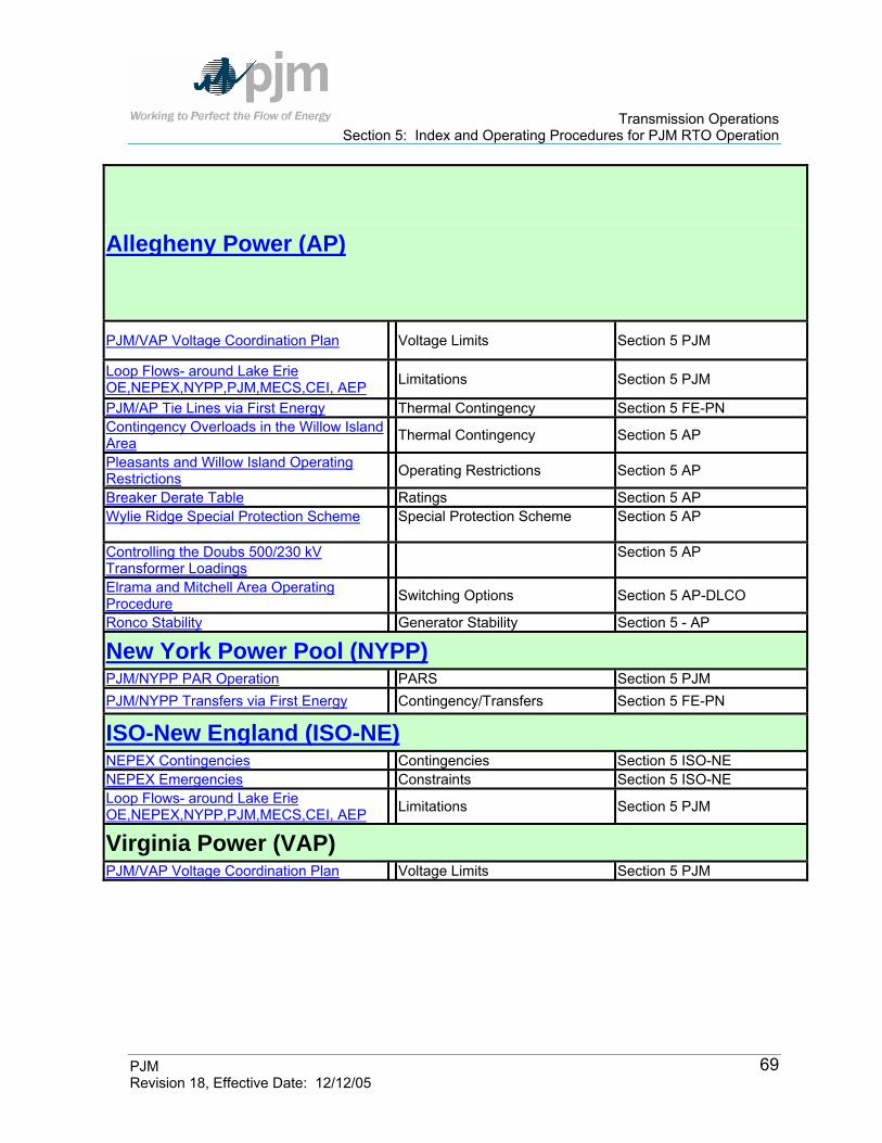
Transmission Operations Section 5: Index and Operating Procedures for PJM RTO Operation
PJM Revision 18, Effective Date: 12/12/05
69
Allegheny Power (AP)
PJM/VAP Voltage Coordination Plan Voltage Limits Section 5 PJM
Loop Flows- around Lake Erie OE,NEPEX,NYPP,PJM,MECS,CEI, AEP Limitations Section 5 PJM
PJM/AP Tie Lines via First Energy Thermal Contingency Section 5 FE-PN Contingency Overloads in the Willow Island Area Thermal Contingency Section 5 AP
Pleasants and Willow Island Operating Restrictions Operating Restrictions Section 5 AP
Breaker Derate Table Ratings Section 5 AP Wylie Ridge Special Protection Scheme Special Protection Scheme Section 5 AP
Controlling the Doubs 500/230 kV Transformer Loadings
Section 5 AP
Elrama and Mitchell Area Operating Procedure Switching Options Section 5 AP-DLCO
Ronco Stability Generator Stability Section 5 - AP
New York Power Pool (NYPP) PJM/NYPP PAR Operation PARS Section 5 PJM PJM/NYPP Transfers via First Energy Contingency/Transfers Section 5 FE-PN
ISO-New England (ISO-NE) NEPEX Contingencies Contingencies Section 5 ISO-NE NEPEX Emergencies Constraints Section 5 ISO-NE Loop Flows- around Lake Erie OE,NEPEX,NYPP,PJM,MECS,CEI, AEP Limitations Section 5 PJM
Virginia Power (VAP) PJM/VAP Voltage Coordination Plan Voltage Limits Section 5 PJM

Transmission Operations Section 5: Index and Operating Procedures for PJM RTO Operation
PJM Revision 18, Effective Date: 12/12/05
70
Index of Operating Procedures for PJM RTO Operation The PJM RTO Operation has Operating Procedures that are adhered to by PJM and in cooperation with others. These procedures include the following:
Type of Operating Procedure
Transmission Operations Manual
Section Ref
PJM RTO Operation Constraint Management Mitigation During Scheduled Switching Procedure Constraint/Limitation Section 5 PJM
PJM/NYPP PAR Operation PARS Section 5 PJM PSE&G/ConED Wheel PARS Section 5 PJM PJM/VAP Voltage Coordination Plan Voltage Limits Section 5 PJM Loop Flows- around Lake Erie OE,NEPEX,NYPP,PJM,MECS,CEI, AEP
Limitations Section 5 PJM
PJM/NYPP Transfers via First Energy Contingency/Transfers Section 5 FE-PN PJM/AP Tie Lines via First Energy Thermal Contingency Section 5 FE-PN Back To Index
Constraint Management Mitigation During Scheduled Switching Procedure
Purpose / Introduction PJM operates the Bulk Power Transmission Facilities in agreement with the NERC Operating Guidelines. In doing this, PJM considers many transmission constraints, restrictions, and/or limitations in the overall operation of the PJM RTO. The PJM RTO is operated such that the following limits are not violated:
transmission facility thermal limits reactive transfer limits voltage limits stability limits
PJM operates the PJM RTO so that immediately following any single malfunction or failure; the facility loadings are within thermal limits (under normal rating real time or under the emergency rating post-contingency), while maintaining an acceptable voltage profile. However, there are situations where exceeding thermal limits for a predetermined brief period of time would not adversely impact system or equipment reliability. Initiating this procedure in lieu of other adjustments will result in maintaining system integrity by keeping lines/facilities in service during these short-

Transmission Operations Section 5: Index and Operating Procedures for PJM RTO Operation
PJM Revision 18, Effective Date: 12/12/05
71
term excursions, and may reduce the occurrence of unnecessary off-cost operations.
Scope The intent of this procedure is to recognize that occasionally, and for various reasons facility thermal ratings can be exceeded on an actual basis for short time periods without damaging equipment. The reason these limits can be exceeded briefly is the relatively lengthy thermal time constants for heat build-up in equipment when MVA loading is the consideration. Short-term voltage deviations are less tolerable than thermal overloading issues, although past practice and LCC (Local Control Center) experience can dictate when these excursions are allowable. The keys to success of this procedure are effective communication and coordination.
Risks This procedure will not position the system in an unacceptable state. However, there is always the possibility of equipment failure resulting in unplanned situational constraints (i.e. extending the short-term nature of the job) that would necessitate immediate remediation efforts. A pre-determined solution to these constraints must be in place should any contingency occur which would negate the short-term nature of the job.
General Requirements The following are steps that should be considered and agreed upon prior to allowing the constraint management mitigation procedure.
Pre-agreement by PJM OPD, PJM and LCC Dispatch, and whatever other parties are appropriate (parties involved with the mitigating strategies).
Each planned event is pre-studied on a case by case basis. Each operation is defined in the Manuals or desk procedures as meeting the criteria of acceptable switching event, and agreed to by all parties.
Parameters
PJM will NOT allow operation over the applicable emergency rating (actual) on a planned basis for any period of time. Operation over the normal rating will be tolerated for up to 5 minutes provided a pre-determined solution to the constraint is in place should any event occur that would negate the short-term nature of the job.
PJM will NOT allow operation over the Load Dump rating on a post contingency basis for any period of time. Operation over the applicable Emergency Rating on a post contingency basis will be tolerated for up to 5

Transmission Operations Section 5: Index and Operating Procedures for PJM RTO Operation
PJM Revision 18, Effective Date: 12/12/05
72
minutes provided a pre-determined solution to the constraint is in place should any event occur that would negate the short-term nature of the job.
The LCC’s planned outage should take no longer than 5 minutes. In the event the outage does not go as planned, the LCC and PJM pre-coordinated mitigating strategy (i.e., “back out plan”) will be implemented to bring the overloaded facility within limits in 15 minutes or less from the start of the outage. The back out plan must be acceptable to all parties and should include sufficient redundancy to ensure reliable operation and provide constraint relief in this timeframe.
The agreed upon back out plan should not impact other member companies: A. switching shall not cause overloads to other company equipment not
previously studied and agreed to by all parties B. switching out company "B" equipment to avoid switching in the
requesting company area unless Company “B” is willing. The back out plan must be reevaluated for actual system conditions (a study
just prior to event might determine that the plan is no longer acceptable). LCC is responsible to provide accurate information that is mutually agreed
upon and repeatable for future operational use. Procedure Refer to the attached flow chart of the Constraint Management Mitigation Procedure.
PJM study will be used for the Bulk Power System. There may be exceptions on underlying facilities where the LCC has more detailed modeling.
PJM will operate to its standard of 15 minutes or less to return an affected facility (over normal rating real time or over the emergency rating post-contingency) to within limits. Normal off cost operations will be initiated if any event occurs which would negate the short-term nature of the job.
PJM EMS has the ability to utilize individual LCC ambient temperature facility ratings. PJM EMS can adjust ratings as required with input for local LCC temperatures. Normally the most conservative values will be used. PJM, with input from the LCC, will make the final determination of the appropriate ratings
Additionally, for those occasions where temperature sets do not conflict, but PJM system security analysis conflicts with a particular LCC analysis, PJM will consider LCC input in the final determination of which results to use.
The resolution of these issues should be done as far in advance of the actual event as possible, to eliminate any last minute confusion or unnecessary discussion.

Transmission Operations Section 5: Index and Operating Procedures for PJM RTO Operation
PJM Revision 18, Effective Date: 12/12/05
73
Note: A study too far in advance may be useless. The study just prior to switching will determine if the procedure is used. Prior arrangements do not supersede the final real-time PJM study.
The PJM PD will complete Constraint Logger studies immediately prior to the event to ensure rapid decision making and execution in the event of required system redispatch.
Example: A LCC requests an outage on a bulk power transformer with no high side circuit breaker requiring a brief outage (less than 5 minutes) of a 500 kV transmission line. Studies indicate that during the switching, a parallel 230 kV transmission line will exceed its normal rating but not its applicable emergency rating real time, and/or will exceed its applicable post contingency emergency rating but not its post contingency load dump rating for loss of another facility. PJM and the LCC determine that opening a 230 kV breaker at another substation, splitting the bus and leaving the 230 kV line isolated on a single transformer can alleviate the constraint. Opening this breaker will not impact any other transmission owners. The 230 kV breaker can be opened in a minute or two if there are problems switching the 500kV line causing the outage to take longer than expected. All affected parties are in agreement that this plan is acceptable. Immediately prior to the scheduled outage of the bulk power transformer, both PJM and the LCC repeat their studies to confirm that opening the 230 kV breaker will provide the expected relief in the event that the 500kV line switching takes longer than expected. The 500 kV line is switched out and back as expected and the job is complete. A brief violation was experienced as expected, but switching action on the 230 kV breaker was avoided and the 230 kV bus remained intact.

Transmission Operations Section 5: Index and Operating Procedures for PJM RTO Operation
PJM Revision 18, Effective Date: 12/12/05
74
1. Coordinate Mitigation Plan with PJM2. PJM OPD, and PJM and LCC Dispatch conduct real-time studies3. PJM and LCC confirm coordinated back-out plan is ready to be executed (i.e., stations/units staffed)
Will the outage last less than 5 minutes?
Are there sufficient mitigating options?
Implement mitigating strategies and/or
off-cost gen
Do pre-studies indicate that outage will not cause actual emergency violations and post-contingency
load dump violations?
Do real-time studies indicate that outage will not cause actual emergency violations and post-contingency load
dump violations?
Did the planned outage last less than 5
minutes?
Take Outage
Implement mitigating strategies and/or
off-cost gen Take Outage
Is outage manageable using
standard procedures?
No
No
No
No
No
Standard Procedures
Job Complete
LCC identifies short term outage
Cancel Job
Will the mitigating strategy have NO impact on another transmission owner's
system (without their approval)?
No
No

Transmission Operations Section 5: Index and Operating Procedures for PJM RTO Operation
PJM Revision 18, Effective Date: 12/12/05
75
PJM/NYPP PAR Operation At Waldwick substation, there are two 345 kV lines, three 345/230 kV auto transformers, and three 230 kV lines - each with a phase-angle regulator (PAR). These PARs are controlled by PSE&G operations personnel from Newark, via computer interface. Control is exercised via a local microprocessor at Waldwick. The microprocessor continuously monitors the eight facilities at Waldwick and compares the measured current with the appropriate ambient temperature circuit ratings. With the microprocessor at Waldwick in service, contingency flows for the eight facilities at Waldwick may exceed their four-hour rating and may be operated up to the 30-minute ratings. In addition, if power flows are from North to South through Waldwick and the microprocessor at Waldwick is in service, the following 230 kV lines can be operated at their 30 minute ratings:
Hinchmans Ave-Hawthorn (N2266) Jackson Rd-Hinchmans Ave (M2239) Cedar Grove-Jackson Rd (L2238)
The 30-minute ratings for these facilities are presented in Attachment B. If the microprocessor or remote terminal unit is out of service, contingency control is based on the four-hour ratings until such time as the station is manned. The PSE&G dispatcher provides information to PJM dispatcher concerning the status of the microprocessor and computer interface and information as to whether the station is manned. PJM security analysis programs use the four-hour ratings. If a contingency occurs and a facility becomes loaded at Waldwick above its four-hour rating, the microprocessor senses the overload and informs the PSE&G dispatcher that actions will automatically take place in five minutes, if the overload still exists. If remote action by the PSE&G dispatcher does not correct the overload at or below the four-hour rating within five minutes, the microprocessor begins to automatically move PAR taps to bring the flow down to the four-hour rating. In the case of multiple overloads, the microprocessor acts to change the PAR setting on the most heavily loaded PAR-controlled circuit first. The five-minute delay applies only to the initial move. Action continues until the loading on all circuits is at or below their four-hour ratings. Correction of the overload down to its normal rating is the responsibility of PJM dispatcher or PSE&G dispatcher. The microprocessor can be inhibited from acting via either the PSE&G computer or a separate remote control lockout/restore switch. If either microprocessor control path is out-of-service, PSE&G controls the flows below their four-hour ratings until the Waldwick Station is manned. The following procedures address specific operating criteria for the PARs:
PJM/NYPP Joint Operating Procedure (NYPJM-01) PSE&G/Con Ed Wheel

Transmission Operations Section 5: Index and Operating Procedures for PJM RTO Operation
PJM Revision 18, Effective Date: 12/12/05
76
Transmission overuse Operation With 5018 Line Out of Service
PSE&G/ConED Wheel
PURPOSE/BACKGROUND: This operating procedure concerns the interpretation of two transmission agreements between ConEd and PSE&G that were executed in 1975 and 1978 (the “400 MW contract” and the “600 MW contract, respectively). These two agreements are referred to collectively herein as the “600/400 MW contracts.” Together, the 600/400 MW contracts entitle ConEd to transfer up to 1,000 MW from points west of New York City through the PSE&G transmission system for re-delivery into New York City from the Southwest. The 600/400 MW contracts were developed before the advent of wholesale market competition, open-access transmission service, and locational marginal pricing. Although their implementation has been the responsibility of the NYISO and PJM there has never been a clear understanding of how the ISOs should administer the 600/400 MW contracts in the context of the advanced electricity markets that now exist in the NYISO and PJM regions, which has led to much controversy. The operating procedures address several ties between the two utilities’ systems, and thus, between the NYISO and PJM. Specifically, these are:
1. The “J and K” transmission lines, which go from ConEd’s South Mahwah substation in Rockland County, New York to PSE&G’s Waldwick substation in New Jersey. The “J” transmission line becomes the “69” line from South Mahwah to Ramapo, and the “K” transmission line becomes the “70” line from South Mahwah to Ramapo.
2. The “A line,” which goes from PSE&G’s Linden Switching Station in Union County, New Jersey to ConEd’s Goethals substation on Staten Island.
3. The “B and C lines,” which go from PSE&G’s Hudson Switching Station in Jersey City, New Jersey to ConEd’s Farragut Switching Station in Brooklyn, New York.
Flows over each of these lines are partially controllable by Phase Angle Regulators (“PARs”). Taken together, the 600/400 MW contracts provide for ConEd to deliver up to 1,000 MW of power to Waldwick, and for PSE&G to re-deliver the same amount from Waldwick to Farragut or Goethals on behalf of ConEd. The operating procedure follows the following general provisions:
1. A “desired flow” methodology will be used to schedule service under the 600/400 MW contracts,

Transmission Operations Section 5: Index and Operating Procedures for PJM RTO Operation
PJM Revision 18, Effective Date: 12/12/05
77
2. The NYISO and PJM will be responsible for maintaining the real-time desired flow at the A/B/C interface and at the J/K interface within defined bandwidths for periods when neither, or both, are facing the need to redispatch (or operating “off-cost”);
3. The NYISO and PJM will follow specific procedures in the event that they cannot maintain flows within the desired bandwidths, due to facility outages, insufficient PAR angle capability, or lack of redispatch capability;
4. The NYISO and PJM will direct the operation of the A, B, C, E, O, F and 5018 PARs, thereby exercising control over them (ConEd and PSE&G will continue to physically operate the PARs but will do so at NYISO’s and PJM’s behest);
5. The A, B, C, J, and K lines will be available for third party uses on an open-access basis;
6. ConEd will schedule service under the 600/400 MW contracts on a day-ahead basis (but will have an opportunity to make real-time changes);
7. PJM will provide reasonable advance notice of when it expects to have to redispatch to support deliveries under the 600/400 MW contracts;
8. PJM will redispatch, at PSE&G’s expense to support flows under the 600 MW contract;
9. PJM will create a special category of service for the 400 MW contract, which will have higher priority than non-firm customers willing to pay congestion, but will not be required to redispatch to support the 400 MW contract except to the extent that ConEd pays to “firm it up;”
10. The NYISO and PJM will establish the distribution of flows over the A, B, C, J, and K lines for their own day-ahead markets and will cooperate to determine a single real-time distribution of flows for the real-time market.
The Protocol’s first section specifies that the NYISO’s and PJM’s existing emergency procedures will take priority over the rules established by the Protocol in the event of a system emergency and also describes an emergency procedure under which the NYISO and PJM may agree to alleviate PJM emergencies attributable to PSE&G outages by delivering 400 MW to the NYISO at Goethals for re-delivery to PSE&G at Hudson. This “reverse wheel” provision incorporates an emergency mechanism that was always part of the 400 MW contract. Such emergency transfers would not be counted for purposes of the “Real-Time Market Desired Flow” calculation described below. 1.0 Additional Operating Procedures
1.1 Two Day-ahead Actions:

Transmission Operations Section 5: Index and Operating Procedures for PJM RTO Operation
PJM Revision 18, Effective Date: 12/12/05
78
PJM Actions
PJM shall post constraint forecast information indicating if there is the potential for off-cost operations, two days prior to the operating day by 9 pm. PJM shall analyze transmission and generation outages in accordance with Appendix 2B to determine if the 600/400 MW contract flow is expected to be feasible under a security constrained dispatch in PJM. If any portion of the flow is not expected to be feasible under a security-constrained dispatch, PJM will post (on its OASIS) the portion of the flow that is expected to be feasible.
NYISO Actions Tbd
PSE&G Actions Identify PJM posted constraint information for operational analysis.
ConEd Actions Identify PJM posted constraint information for operational analysis and election analysis.
1.2 Day Ahead Scheduling:
1.2.1 Before NY Market closes
PJM Actions
NYISO Actions
PSE&G Actions
. ConEd Actions
ConEd shall submit a contract election (NY-DAE) in the NYISO’s Day-Ahead Market for the 600/400 MW contracts.
1.2.2 After NY Market closes
PJM Actions
NYISO Actions

Transmission Operations Section 5: Index and Operating Procedures for PJM RTO Operation
PJM Revision 18, Effective Date: 12/12/05
79
The NYISO shall establish New York (aggregate A/B/C interface and aggregate J/K interface) Desired Flow (NYDF) schedules for NYISO Day Ahead.
The default distribution of flows of 1/3 each for A, B, C and ½ each for J, K. The NYISO shall establish the distribution of flows for the NYISO DAM.
The NYISO shall run the New York Day Ahead.
The NYISO shall post DAM results. The NYISO shall provide NYDF schedules and post nodal prices for the J/K (Ramapo), B/C (Farragut) and A (Goethals) pricing points.
PSE&G Actions
ConEd Actions ConEd shall submit a contract election (PJM-DAE) in the PJM Day Ahead Market prior to 12 noon:
ConEd shall submit a contract election for the 600 MW contract and ConEd shall submit a contract election for the 400 MW contract. For the 400 MW contract, ConEd shall specify whether it is willing to pay congestion (WPC) under the following options:
ConEd is not willing to pay congestion for any portion of the 400 MW ConEd willing to pay congestion up to $25 ConEd willing to pay congestion with no redispatch cost limit
1.2.3 After PJM Market closes
PJM Actions
PJM shall establish the PJM (aggregate A/B/C interface and aggregate J/K interface) Desired Flow (PJMDF) schedules for PJM Day Ahead. PJM shall establish the distribution of flows for the PJM DAM.
The default distribution of flows of 1/3 each for A, B, C and ½ each for J, K. The NYISO shall establish the distribution of flows for the NYISO DAM.
PJM shall run the PJM Day Ahead Market. The amount of the PJM-DAE which clears will become the PJM Day Ahead Schedule amount (PJM-DAS).
PJM Day Ahead results shall be posted. The PJM posting will include the PJM-DAS, nodal prices for the J/K (Waldwick), B/C (Hudson) and A (Linden) pricing points.
NYISO Actions
PSE&G Actions
ConEd Actions
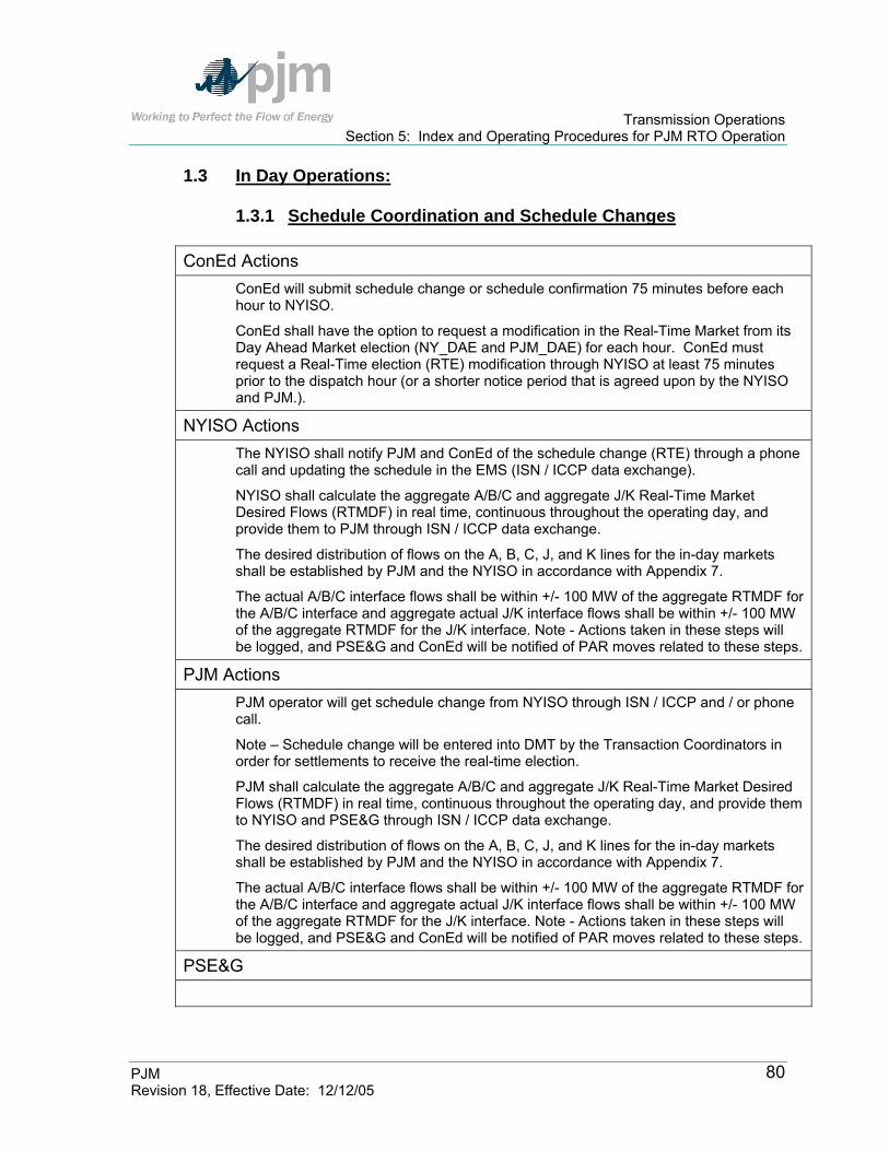
Transmission Operations Section 5: Index and Operating Procedures for PJM RTO Operation
PJM Revision 18, Effective Date: 12/12/05
80
1.3 In Day Operations:
1.3.1 Schedule Coordination and Schedule Changes
ConEd Actions ConEd will submit schedule change or schedule confirmation 75 minutes before each hour to NYISO.
ConEd shall have the option to request a modification in the Real-Time Market from its Day Ahead Market election (NY_DAE and PJM_DAE) for each hour. ConEd must request a Real-Time election (RTE) modification through NYISO at least 75 minutes prior to the dispatch hour (or a shorter notice period that is agreed upon by the NYISO and PJM.).
NYISO Actions The NYISO shall notify PJM and ConEd of the schedule change (RTE) through a phone call and updating the schedule in the EMS (ISN / ICCP data exchange).
NYISO shall calculate the aggregate A/B/C and aggregate J/K Real-Time Market Desired Flows (RTMDF) in real time, continuous throughout the operating day, and provide them to PJM through ISN / ICCP data exchange.
The desired distribution of flows on the A, B, C, J, and K lines for the in-day markets shall be established by PJM and the NYISO in accordance with Appendix 7.
The actual A/B/C interface flows shall be within +/- 100 MW of the aggregate RTMDF for the A/B/C interface and aggregate actual J/K interface flows shall be within +/- 100 MW of the aggregate RTMDF for the J/K interface. Note - Actions taken in these steps will be logged, and PSE&G and ConEd will be notified of PAR moves related to these steps.
PJM Actions PJM operator will get schedule change from NYISO through ISN / ICCP and / or phone call.
Note – Schedule change will be entered into DMT by the Transaction Coordinators in order for settlements to receive the real-time election.
PJM shall calculate the aggregate A/B/C and aggregate J/K Real-Time Market Desired Flows (RTMDF) in real time, continuous throughout the operating day, and provide them to NYISO and PSE&G through ISN / ICCP data exchange.
The desired distribution of flows on the A, B, C, J, and K lines for the in-day markets shall be established by PJM and the NYISO in accordance with Appendix 7.
The actual A/B/C interface flows shall be within +/- 100 MW of the aggregate RTMDF for the A/B/C interface and aggregate actual J/K interface flows shall be within +/- 100 MW of the aggregate RTMDF for the J/K interface. Note - Actions taken in these steps will be logged, and PSE&G and ConEd will be notified of PAR moves related to these steps.
PSE&G

Transmission Operations Section 5: Index and Operating Procedures for PJM RTO Operation
PJM Revision 18, Effective Date: 12/12/05
81
1.4 If there is In-Day Congestion:
ConEd Actions ConEd will submit schedule change or schedule confirmation 75 minutes before each hour
ConEd must request a real-time election (RTE) modification through NYISO at least 75 minutes prior to the dispatch hour (or a shorter notice period that is agreed upon by the NYISO and PJM.).
NYISO Actions If the NYISO is off-cost or expected to go off-cost for two or more consecutive hours where the off-cost could be mitigated using PAR tap adjustments , and PJM is not off-cost, then PJM and the NYISO shall consult with each other and shall redirect up to 300 MW on to the PJM system (in a mutually agreed upon amount and in mutually agreed upon increments) ; provided, however, that PJM and NYISO verify that allowing actual aggregate interface flows to deviate from the RTMDF will not result in violation of applicable PJM or NYISO reliability criteria. The process of modifying actual interface flows in incremental adjustments will continue until • The NYISO is no longer off-cost, or • PJM is about to go off-cost (i.e., PJM expects that it will have to redispatch in
response to transmission constraints in order to maintain the RTMDF), or • 300 MW have been redirected.
The outage of any A, B, C, J, or K facility will result in the NY-DAE, PJM-DAE, and/or RTE (as appropriate) being limited to a value no greater than the remaining thermal capability of the most limiting of the ABC interface or the JK interface. The remaining thermal capability of either the A/B/C interface or the J/K interface may be limited by other facilities directly in series with the A, B, C, J, or K lines.
PJM Actions If PJM is off-cost or is expected to go off-cost for two or more consecutive hours where the off-cost could be mitigated using PAR tap adjustments and the NYISO is not off-cost, then PJM and NYISO shall consult with each other and shall redirect up to 300 MW on to the NYISO system (in a mutually agreed upon amount and in mutually agreed upon increments) provided, however, that PJM and the NYISO verify that allowing actual aggregate interface flows to deviate from the RTMDF will not result in violation of applicable PJM or NYISO reliability criteria. The process of modifying actual interface flows in incremental adjustments will continue until • PJM is no longer off-cost, or • The NYISO is about to go off-cost (i.e., the NYISO expects that it will have to
redispatch in response to transmission constraints in order to maintain the RTMDF), or
• 300 MW have been redirected.
The outage of any A, B, C, J, or K facility will result in the NY-DAE, PJM-DAE, and/or RTE (as appropriate) being limited to a value no greater than the remaining thermal capability of the most limiting of the ABC interface or the JK interface. The remaining thermal capability of either the A/B/C interface or the J/K interface may be limited by

Transmission Operations Section 5: Index and Operating Procedures for PJM RTO Operation
PJM Revision 18, Effective Date: 12/12/05
82
other facilities directly in series with the A, B, C, J, or K lines.
PSE&G
2.0 Operation of the PARs
2.1 General
PJM and the NYISO have operational control of all PARs and direct the operation of the PARs, while PSE&G and ConEd have physical control of the PARs. The ConEd dispatcher adjusts the PAR taps at Ramapo, Goethals and Farragut at the direction of the NYISO. The PSE&G dispatchers set the PAR taps at Waldwick at the direction of PJM. This procedure outlines the steps taken to coordinate tap changes on the PARs in order to control power flow on selected transmission lines between New York and New Jersey. The facilities are used to provide transmission service and to satisfy the 600/400 MW contracts, other third party uses, and to provide emergency assistance as required. These tie-lines are part of the interconnection between the PJM and NYISO. These PAR operations will be coordinated with the operation of other PAR facilities including the 5018 PARs. The 5018 PAR will be operated taking into account this Operating Protocol. The ties are controlled by PARs at the following locations:
• Waldwick (F-2258, E-2257, O-2267) • Goethals (A-2253) • Farragut (C-3403, B-3402) • Ramapo (5018)
This section addresses the operation of the PARs at Waldwick, Goethals, and Farragut as these primarily impact the delivery associated with the 600/400 MW contracts between PSE&G and ConEd. PJM and the NYISO will work together to maintain reliable system operation, and to implement the “RTMDF” within the bandwidths established by this Operating Protocol while endeavoring to minimize the PAR tap changes. RTMDF calculations will be made for the ‘ABC Interface’, and the ‘JK Interface’. Desired line flow calculations will be made for A, B, and C lines (default loading is balanced each 1/3 of the ABC Interface), and for the J and K lines (default loading is balanced each ½ of the JK Interface).

Transmission Operations Section 5: Index and Operating Procedures for PJM RTO Operation
PJM Revision 18, Effective Date: 12/12/05
83
3.0 Normal Operations The desired flow calculation process is a coordinated effort between PJM and the NYISO. PJM and the NYISO have the responsibility to direct the operation of the PARs to ensure compliance with the requirements of the Operating Protocol. However, one of the objectives of this procedure is to minimize the movement of PARs while implementing the requirements of the 600/400 MW contracts. PJM and the NYISO will employ a +/- 100 MW bandwidth for each of the ABC and JK Interfaces to ensure that actual flows are maintained at acceptable levels. In general, PAR Tap movements shall be limited to 400 per month based on an average of 20 operations (per PAR) in a 24-hour period. If, in attempting to maintain the desired bandwidth, tap movements exceed these limits, then the bandwidth shall be increased in 50 MW increments until the tap movements no longer exceed 20 per day, unless PJM and the NYISO agree otherwise. It will be the responsibility of both ConEd and PSE&G to report violations of the tap movement limits to NYISO and PJM.
4.0 Emergency Operations If an emergency condition exists in either the NYISO or PJM, the NYISO dispatcher or PJM dispatcher may request that the tie line flows between New York and New Jersey be adjusted to assist directing power flows in the respective areas to alleviate the emergency situation. The taps on the PARs at Waldwick, Goethals, and Farragut may be moved either in tandem or individually as needed to mitigate the emergency condition. Cooperatively responding to emergency conditions in either the NYISO or PJM overrides any requirements of this Protocol for the duration of the declared emergency. Details describing the Emergency shall be logged.
5.0 Transmission Constraints and Outages Associated with the Contracts 5.1 Constraints The following transmission constraints are identified as potential constraints that may result in off-cost operation due to transfers associated with the 600/400 MW contracts. The constraints included in the listing should be considered representative of the kinds of constraints that may exist within PJM or NYISO. If such transmission constraints are limiting, then the affected ISO/RTO may be subject to off-cost operation due to transfers associated with the 600/400 MW contracts. Other constraints, not listed here, may arise that could cause either ISO/RTO to operate off-cost. This list may be revised by NYISO/PJM to reflect system changes or security monitoring technique changes in their respective Control Areas.

Transmission Operations Section 5: Index and Operating Procedures for PJM RTO Operation
PJM Revision 18, Effective Date: 12/12/05
84
NYISO • UPNY-ConEd Interface • Dunwoodie-South Interface • Dunwoodie-Rainey 345 KV • Rainey-Farragut 345 KV • Sprainbrook-W49th Street 345 KV • W49th Street-Farragut 345 KV • Ramapo-Ladentown 345 KV • Ramapo-Buchanan 345 KV • Buchanan-Millwood 345 KV • Buchanan-Eastview 345 KV • Millwood-Eastview 345 KV • Eastview-Sprainbrook 345 KV • East Fishkill-Pleasantville 345 KV • Pleasantville-Dunwoodie 345 KV • Pleasant Valley-East Fishkill 345 KV • Linden-Goethals 230 KV A-2253 PAR • Farragut-Hudson 345 KV B-3402 PAR • Farragut-Hudson 345 KV C-3403 PAR • Waldwick – South Mahwah 345 KV K-3411 • Waldwick – South Mahwah 345 KV J-3410
PJM
Athenia 230 KV Athenia 220-2 xformer Athenia 230 KV Athenia 220-1 xformer Bayway 138 KV Bayway Z-1352 Branchburg 500 KV Branchburg 500-1 xformer Branchburg 500 KV Branchburg 500-2 xformer Deans 500 KV Deans 500-1 xformer Deans 500 KV Deans 500-2 xformer Deans 500 KV Deans 500-3 xformer Hudson 230 KV Hudson Hudson2 xformer Interface East Athenia-E Rutherford S-1345 138 KV Bayonne-Marion L-1338 138 KV Bayonne-PVSC I-1335 138 KV Bergen-E Rutherford R-1344 138 KV Bergen-Homestead F-1306 138 KV Brunswick-Edison H-1360 138 KV Edison-Meadow Road Q-1317 138 KV Edison Meadow Road R-1318 138 KV

Transmission Operations Section 5: Index and Operating Procedures for PJM RTO Operation
PJM Revision 18, Effective Date: 12/12/05
85
Linden-North Avenue T-1346 138 KV Plainsboro-Trenton D-1330 138 KV Adams-Bennetts x-2224-3 230 KV Athenia-Clifton PS K-2263 230 KV Athenia-Saddlebrook Q-2217 230 KV Bergen-Hoboken R-2270 230 KV Bergen Leonia T-2272 230 KV Branchburg-Flagtown C-2203 230 KV Branchburg-Readington M-2265 230 KV Cedargrove-Clifton PS K-2263-3 230 KV Cedargrove-Roseland B-2228 230 KV Cedargrove-Roseland F-2206 230 KV Goethals-Linden A-2253 230 KV Greystown-Portland S1007 230 KV Hawthorn-Hinchman N-2266 230 KV Hillsdale-Newmilford V-2222 230 KV Hoboken-Newport PS R-2270 230 KV Leonia-Newmilford T-2272 230 KV Roseland-Whippany A-941 230 KV Branchburg-Ramapo 5018 500KV Goethals-Linden 230 KV A-2253 PAR or Circuit Hudson-Farragut 345 KV B-3402 PAR or Circuit Hudson-Farragut 345 KV C-3403 PAR or Circuit Waldwick-Fairlawn 230 KV O-2267 PAR or Circuit Waldwick-Hawthorne 230 KV E-2257 PAR or Circuit Waldwick-Hillsdale 230 KV F-2258 PAR or Circuit Waldwick-South Mahwah 345 KV K-3411 Waldwick-South Mahwah 345 KV J-3410
5.2 Outages 600 MW Contract – It is not anticipated that one primary facility outage will preclude PJM from providing redispatch for the 600 MW contract. However, combinations of two or more outages of the facilities, listed below, could preclude PJM from accommodating all or part of the 600 MW delivery, even with redispatch. In this case, PJM will provide notification to NYISO.
400 MW Contract – The outage of one or more facilities in the following list, may impact redispatch costs regarding the delivery of all or portions of the 400 MW contract:
• Branchburg-Ramapo 500 KV 5018 • South Mahwah-Waldwick J 345 KV J-3410/69 • South Mahwah-Waldwick K 345 KV K-3411/70

Transmission Operations Section 5: Index and Operating Procedures for PJM RTO Operation
PJM Revision 18, Effective Date: 12/12/05
86
• Hudson-Farragut B-3402 • Hudson-Farragut C-3403 • Linden-Goethals 230 KV A-2253 • Athenia-NJT Meadows Essex Hudson 230 KV C-2281-P-2216-
A-2227 • New Milford-Leonia-Bergen-Penhorn-Hudson 230 KV T-2272-X-
2250 • Waldwick-Hillsdale-New Milford 230 KV F-2258-V-2222 • Waldwick-Fairlawn 230 KV O-2267 • Waldwick-Hawthorne-Hinchman’s Ave-Cedar Grove 230 KV E-
2257 – N-2266-M-2239-L-2238 • Roseland-Cedar Grove-Clifton-Athenia B 230 KV B-2228 • Roseland-Cedar Grove-Clifton-Athenia K 230 KV F-2206-K-
2263 • Linden-Bayway 230 KV H-2234 • Linden-Minue Street R 230 KV R-2218 • Linden-Minue Street G 230 KV G-2207 • Roseland-Whippany A-941 • Branchburg-Readington-Roseland M-2265-U-2221 • Roseland-Montville-Newton-Kittatinny E-2203 – N-2214-T-2298 • Deans-Aldene W-2249
In addition, forced or maintenance outages of one or more of the following generators may impact redispatch costs regarding the deliver of all or portions of the 400 MW contract provided that any such maintenance outage is approved by PJM. Otherwise, each of these generators will be considered to be available to support the 600/400 MW contracts under a security constrained dispatch in PJM’s Day-Ahead and Real-Time Markets.
Hudson #1 Hudson #2 Bergen #1 Bergen #2 Linden #1 Linden #5, 6, 7, 8
PJM/VAP Voltage Coordination Plan The Voltage Coordination Plan (VCP) outlines the steps to coordinate the use of voltage control equipment to maintain a reliable bulk power transmission system voltage profile on the PJM, VAP, and surrounding Control Areas. Providing reactive power and proper voltage support to a large interconnected power system is a difficult and interactive process. Unlike real power, reactive support starts at the
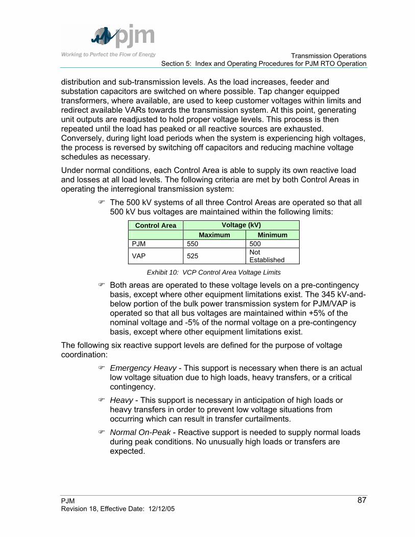
Transmission Operations Section 5: Index and Operating Procedures for PJM RTO Operation
PJM Revision 18, Effective Date: 12/12/05
87
distribution and sub-transmission levels. As the load increases, feeder and substation capacitors are switched on where possible. Tap changer equipped transformers, where available, are used to keep customer voltages within limits and redirect available VARs towards the transmission system. At this point, generating unit outputs are readjusted to hold proper voltage levels. This process is then repeated until the load has peaked or all reactive sources are exhausted. Conversely, during light load periods when the system is experiencing high voltages, the process is reversed by switching off capacitors and reducing machine voltage schedules as necessary. Under normal conditions, each Control Area is able to supply its own reactive load and losses at all load levels. The following criteria are met by both Control Areas in operating the interregional transmission system:
The 500 kV systems of all three Control Areas are operated so that all 500 kV bus voltages are maintained within the following limits:
Control Area Voltage (kV) Maximum Minimum
PJM 550 500
VAP 525 Not Established
Exhibit 10: VCP Control Area Voltage Limits
Both areas are operated to these voltage levels on a pre-contingency basis, except where other equipment limitations exist. The 345 kV-and-below portion of the bulk power transmission system for PJM/VAP is operated so that all bus voltages are maintained within +5% of the nominal voltage and -5% of the normal voltage on a pre-contingency basis, except where other equipment limitations exist.
The following six reactive support levels are defined for the purpose of voltage coordination:
Emergency Heavy - This support is necessary when there is an actual low voltage situation due to high loads, heavy transfers, or a critical contingency.
Heavy - This support is necessary in anticipation of high loads or heavy transfers in order to prevent low voltage situations from occurring which can result in transfer curtailments.
Normal On-Peak - Reactive support is needed to supply normal loads during peak conditions. No unusually high loads or transfers are expected.

Transmission Operations Section 5: Index and Operating Procedures for PJM RTO Operation
PJM Revision 18, Effective Date: 12/12/05
88
Normal Off-Peak - Reactive support is needed for normal loadings during non-peak conditions. No minimum loads or transfers are expected.
Light - Reactive support is necessary to avoid high voltage due to anticipated minimum load or transfer conditions.
Emergency Light - Reactive support is needed when there is an actual high voltage situation due to minimum loads, transfers, and/or critical contingency.
Each Control Area has a list of actions that are taken for each level or reactive support listed above
Note: The PJM/VAP Reliability Coordination Plan is described in the PJM Manual for Emergency Operations.
Control Area Actions: Each Control Area reviews its forecasted loads, transfers, and all information
on available generation and transmission reactive power sources at the beginning of each shift.
Within the range of NORMAL ON-PEAK and NORMAL OFF-PEAK, each Control Area operates independently in accordance with the above stated criteria and any individual system guidelines for the supply of their respective Control Area’s reactive power requirements.
If any of the Control Areas anticipate reactive problems after the review, they may request joint implementation of HEAVY or LIGHT reactive support levels of the Voltage Coordination Plan, depending on the Control Area’s problem. When a Control Area calls for a particular level of the plan to be implemented, that area must state the time they will start adjusting their system, the support level they are implementing, and the voltage problem area.
For example, if VAP Voltage expects a low voltage condition in northern Virginia due to high loads early in the morning on a cold winter day, they notify PJM at 5:15 a.m. that “VAP requests implementation of the HEAVY reactive support level of the PJM/VAP Voltage Coordination Plan starting at 5:45 a.m. due to an anticipated low voltage problem in northern Virginia”.
If any of the Control Areas experience an actual low or high voltage condition after initial reactive support measures are taken, then the emergency reactive support level is implemented by the area experiencing the problem. They also notify the other areas as soon as possible in the manner given in the example above. In addition, the PJM/VAP Voltage Coordination Plan is

Transmission Operations Section 5: Index and Operating Procedures for PJM RTO Operation
PJM Revision 18, Effective Date: 12/12/05
89
consulted to determine if further action is necessary to correct an undesirable voltage situation.
Loop Flows As a result of natural circulation and scheduled transactions, it is expected that moderate to heavy circulating flows around Lake Erie may result in transmission limitations. Whenever additional transfers are made between certain different Control Areas, limitations may develop that require adjustments in these transfers in order to remain within first-contingency limits. Loop power flows that occur in PJM or an adjoining operating area can result in serious difficulties that adversely affect the reliability of the member systems. It is important to have an understanding of the way in which changes in generation and transmission can influence these circulating power flows. With this knowledge and by utilizing full communication between Control Areas concerning outages to key facilities and scheduled interconnection interchanges, it is possible to correct the power flows causing the difficulties. In the event that a problem does occur, it is important to have corrective procedures that stipulate the responsibilities of affected control areas and give guidance with respect to priorities. If at any time a loop power flow condition arises which may jeopardize any individual Control Area’s reliability, then certain principles apply and are described in the PJM Dispatching Operations Manual and the PJM Emergency Operations Manual. As a NERC Security Coordinator, PJM observes and implements NERC Transmission Load Relief (TLR) Procedure in accordance with NERC Policy 9 and the NERC Operating Manual. PJM also participates in the Lake Erie Emergency Re-dispatch (LEER) Agreement to facilitate emergency re-dispatch among control areas surrounding Lake Erie (AEP, MECS, NYISO, IMO, and PJM) to avoid the shedding of firm customer load.
Index of Operating Procedures for Atlantic Electric (AE) Transmission Zone- Conectiv The Atlantic Transmission Zone has Operating Procedures that are adhered to by PJM. These procedures include the following:
Type of Operating Procedure
Transmission Operations Manual
Section Ref
Atlantic Electric Company (AE)- Conectiv Deptford 230 kV Breaker Relay Special Purpose Relay Section 5 AE Back To Index

Transmission Operations Section 5: Index and Operating Procedures for PJM RTO Operation
PJM Revision 18, Effective Date: 12/12/05
90
Deptford 230 kV Breaker Relay There is a directional overcurrent relay at Mickleton to trip the Deptford 230 kV breaker if the flow on the Delco Tap-Mickleton (220-38) 230 kV line (into Mickleton) exceeds the appropriate summer or winter rating for one minute. This relay, which is operated normally disabled, is designed to protect AE from the loss of the Delco Tap-Mickleton 230 kV line due to overload as a result of heavy imports into southern New Jersey. The relay scheme is operated normally disabled and is enabled only when required. Supervisory enable/disable and reset control functions can be operated via the AE Control Center computer. Operation of the relay scheme is under the direction of PJM dispatcher, with approval from PSE&G and AE, and notification of PECO Energy. PJM Actions:
Whenever there is a contingency overload on the Delco Tap-Mickleton 230 kV line (e.g., loss of Richmond-Camden 230 kV on the Delco Tap-Mickleton 230 kV line), PJM dispatcher obtains approval from PSE&G and AE to use the Deptford breaker procedure. The relay scheme is then enabled via supervisory at the AE Local Control Center.
PJM dispatcher then inserts the multiple contingency (e.g., loss of Richmond-Camden 230 kV and Thorofare-Deptford 230 kV) in PJM security analysis programs computer contingency list and suppresses the single contingency. The Thorofare-Deptford (0-2241-1) 230 kV line is the Deptford line used in the contingency list.
PJM dispatcher periodically runs a power flow with the single contingency unsuppressed to check the effect of the single contingency on other facilities.
Manual opening of the Deptford breaker for actual overloads on the Delco Tap-Mickleton 230 kV line is an option that can be considered, but only when control range on the New Freedom PARs is exhausted. PJM dispatcher runs a PJM security analysis and obtains concurrence from PSE&G, PECO Energy, and AE prior to opening the breaker.
When it is no longer necessary for the relay scheme to be enabled, PJM dispatcher notifies PS, PECO Energy, and AE and directs the scheme disabled via supervisory at the AE Control Center.
Local Control Center Actions: In the event the relay trips the Deptford breaker, PSE&G, PECO Energy, and AE are responsible for monitoring the actual and contingency line loadings on their respective systems and keeping PJM dispatcher informed. PJM dispatcher coordinates any necessary generation shifts. To restore the transmission system to

Transmission Operations Section 5: Index and Operating Procedures for PJM RTO Operation
PJM Revision 18, Effective Date: 12/12/05
91
its normal configuration, the Mickleton relay must be reset by AE and the Deptford CB reclosed by PSE&G.
Index of Operating Procedures for American Electric Power (AEP) Transmission Zone The American Electric Power Transmission Zone has Operating Procedures that are adhered to by PJM. These procedures include the following:
Type of Operating Procedure
Transmission Operations Manual
Section Ref
American Electric Power (AEP) South Canton 765/345 kV Transformer Contingency Control Section 5 - AEP Cook Unit Isolation on Select Circuits Unit Isolation Section 5 - AEP Kammer Operating Procedures Limitations Section 5 - AEP Sunnyside-Torrey 138 kV Operating Guide
Contingency Control Section 5 - AEP
Conesville 138 kV Bus Configuration Contingency Control Section 5 - AEP Marysville 765 kV Reactor Guidelines Guidelines Section 5 - AEP Kanawha – Matt Funk 345 kV Circuit Stability Section 5 - AEP Rockport Operating Guide Unit Stability Section 5 - AEP Smith Mountain 138 kV station Stability Stability Section 5 - AEP Gavin - Mountaineer Stability Stability Section 5 - AEP Tanners Creek 345 kV Station Concerns
Limitations Section 5 - AEP
Tidd 345 kV Station Voltage Concerns Voltage Section 5 - AEP Galion Bypass Switch Limitations Section 5 - AEP Additional Regional Procedures Section 5 - AEP Back To Index
South Canton 765/345 kV Transformer (AEP Operating Memo T-020) The South Canton 765/345kV transformer provides a major source of power to the Canton, Wooster, and New Philadelphia areas of AEP. The transformer also provides a major flow gate for interchange transactions to First Energy and flows north and northeast. After implementing normal operating procedures for contingency control but prior to issuing TLR 5, PJM will evaluate the switching of the ’A’ and ‘A2’ 765 kV CBs at Dumont, open-ending the Dumont – Marysville 765 kV circuit. The analysis of open-ending the Dumont-Marysville 765kV circuit shall include current and projected system conditions and will be coordinated with external systems.

Transmission Operations Section 5: Index and Operating Procedures for PJM RTO Operation
PJM Revision 18, Effective Date: 12/12/05
92
Cook Unit Isolation on Select Circuits (AEP Operating Memo T-021) This procedure addresses the possible need to reduce unit outputs at the Cook generating station for certain bus topologies that isolate the units on individual circuits. AEP Actions:
AEP maintains voltage schedules as appropriate PJM Actions:
PJM determines if there are unit restrictions based on the following table:
Unit isolated on single circuit Changes to Cook voltage schedules
Cook Unit maximum output
Cook Unit #1 is isolated on Cook-Collingwood 345 kV
Maintain 345 kV bus voltage schedule at 103.5%
Unit #1 max is 800 MWs
Cook Unit #1 is isolated on Cook-Twin Branch #1 345 kV
Maintain 345 kV bus voltage schedule above 102.5%
Full output allowed
Cook Unit #1 is isolated on Cook-Twin Branch #2 345 kV
Maintain 345 kV bus voltage schedule at 102.5%
Unit #1 max is 935 MWs
Cook Unit #2 is isolated on Cook – Dumont 765 kV
Maintain 765 kV bus voltage schedule above 99.5%
Full Output allowed
Kammer Operating Procedures (AEP Operating Memo T026) These procedures were developed to provide secure service to the approximately 530 MWs of load at Ormet while keeping the system within loading limits and preventing violations of the 50 kA short circuit limits on the Kammer 138 kV CBs. Ormet Load at 530 MW:
1. Two (2) Kammer units on and Kammer 138 kV station is configured normally:
PJM Actions: No action required.
2. One (1) Kammer units on and Kammer 138 kV station is configured normally: PJM Actions: PJM directs AEP to close ‘F’ 138 kV CB and close ‘D’ 138 kV CB in order to tie the T100B transformer into Bus #1 and #2. This prevents heavy loadings on Kammer-Ormet #1 138 kV line.

Transmission Operations Section 5: Index and Operating Procedures for PJM RTO Operation
PJM Revision 18, Effective Date: 12/12/05
93
3. No (0) Kammer units on and Kammer 138 kV station is configured normally: PJM Actions: PJM directs AEP to close ‘C’ 138 kV CB; open ‘B’ 138 kV CB to tie the T300 Transformer into Bus #3 and alleviate possible T100B transformer overloads; and open ‘S’ CB to stay below short circuit limitations.
4. Three (3) Kammer units on plus the outage of the following: 1.) Forced or Scheduled outage of T100B (.100 in PJM EMS)
345/138 kV transformer: PJM Actions: PJM directs AEP to close ‘D’ 138 kV CB to keep Kammer-Ormet #1 line in service.
2.) Forced (or scheduled for less than 7 days) outage of Kammer-Ormet #1 138 kV line:
PJM Actions: PJM directs AEP to open ‘E’ 138 kV CB.
3.) Scheduled Outage for longer than 7 days of Kammer-Ormet #1 138 kV line.
PJM Actions: PJM directs AEP to set controls on manual for ‘K’ 138 kV CB; open ‘L’ and ‘J’ 138 kV CBs to isolate unit #2 on Kammer-Ormet #3 138 kV line; and close ‘F’ CB to tie transformer T100B into bus 1.
4.) Forced or Scheduled outage of Kammer-George Washington 138 kV line, the George Washington ‘I’ 138 kV CB, or the George Washington ‘J’ 138 kV CB
PJM Actions: PJM directs AEP to close ‘W’ 138 kV CB to provide additioanl outlets for Kammer generation and to open ‘B’ 138 kV CB opening the low side of T300 XF to stay below short circuit limitations.
5.) Forced or Scheduled outage of Kammer-Tidd 138 kV line PJM Actions: PJM directs AEP to close ‘W’ 138 kV CB to provide additioanl outlets for Kammer generation and to open ‘B’ 138 kV CB opening the low side of T300 XF to stay below short circuit limitations.
5. Two (2) Kammer units on plus the outage of the following:

Transmission Operations Section 5: Index and Operating Procedures for PJM RTO Operation
PJM Revision 18, Effective Date: 12/12/05
94
1.) Forced or Scheduled outage of T100B (.100 in PJM EMS) 345/138 kV transformer:
PJM Actions: PJM directs AEP to close ‘D’ 138 kV CB to keep Kammer-Ormet #1 line in service; close ‘C’ 138 kV CB and Open ‘B’ 138 kV CB to tie the T300 Transformer into Bus #3 to alleviate possible Kammer-Natrium 138 kV line overloads; and open ‘I’ CB at George Washington to stay below short circuit limitations.
2.) Forced or Scheduled outage of Kammer-Ormet #1 138 kV line PJM Actions: PJM directs AEP to close ‘C’ 138 kV CB; open ‘B’ 138 kV CB to tie the T300 Transformer into Bus #3; and open ‘I’ CB at George Washington to stay below short circuit limitations.
3.) Forced or Scheduled outage of Kammer-George Washington 138 kV line, the George Washington ‘I’ 138 kV CB, or the George Washington ‘J’ 138 kV CB
PJM Actions: PJM directs AEP to close ‘F’ 138 kV CB; and close ‘D’ 138 kV CB in order to tie the T100B transformer into Bus #1 and #2. This provides an additional outlet for Kammer generation.
4.) Forced or Scheduled outage of Kammer-Tidd 138 kV line PJM Actions: PJM directs PJM to close ‘F’ 138 kV CB; and close ‘D’ 138 kV CB in order to tie the T100B transformer into Bus #1 and #2. This provides an additional outlet for Kammer generation.
6. One (1) Kammer unit on plus the outage of the following: 1.) Forced outage of T100B (.100 in PJM EMS) 345/138 kV
transformer: PJM Actions: PJM directs AEP to close ‘C’ 138 kV CB to tie the T300 Transformer into Bus #3. Close ‘W’ 138 kV CB to close the ring bus between Bus #3 and Bus #4; and open ‘I’ CB at George Washington to stay below short circuit limitations.
7. No Kammer units on plus the outage of the following: 1.) Forced outage of T100B (.100 in PJM EMS) 345/138 kV
transformer

Transmission Operations Section 5: Index and Operating Procedures for PJM RTO Operation
PJM Revision 18, Effective Date: 12/12/05
95
PJM Actions: PJM directs AEP to close ‘B’ 138 kV CB; close ‘W’ 138 kV CB, closing the ring bus between Bus #3 and Bus#4; and close ‘AA’ 138 kV Capacitor to support the bus voltage.
2.) Forced Outage of T300 345/138 kV transformer PJM Actions: PJM will direct AEP to close ‘AA’ 138 kV Capacitor to support the bus voltage.
Ormet Load at 350 MW: 1. No (0) Kammer units on and Kammer 138 kV station is configured normally:
PJM Actions: PJM will direct AEP to close ‘AA’ 138 kV Capacitor to support the bus voltage.
2. No Kammer units on plus the outage of T100B: PJM Actions: PJM will direct AEP to close ‘C’ 138 kV CB; close ‘W’ 138 kV CB to close the ring bus between Bus #3 and Bus#4; and close ‘AA’ 138 kV Capacitor to support the bus voltage.
Conesville 345 kV Plant Operating Guidelines (AEP Operating Memo T027) The Conesville 345kV generating plant has certain stability limitations on output levels under certain system conditions. In particular, outages of one or more 345 kV outlets from Conesville will result in limitations on the plants maximum output. PJM Actions: PJM to use the following table to determine if any limitations will exist at the Conesville Plant due to stability concerns.
System Operating Condition
No. Description
Maximum Net Plant Output
1. Normal 1650 MW
2. Outage of Conesville-Corridor 345 kV 1280 MW
3. Outage of Conesville-Bixby 345 kV 1280 MW
4. Outage of Conesville-Hyatt 345 kV 1410 MW
5. Outage of Conesville-Corridor 345 kV and any transformer or transmission line at Hyatt or
1230 MW

Transmission Operations Section 5: Index and Operating Procedures for PJM RTO Operation
PJM Revision 18, Effective Date: 12/12/05
96
System Operating Condition
No. Description
Maximum Net Plant Output
Bixby 345 kV stations
6. Outage of Conesville-Bixby 345 kV and any transformer or transmission line at Hyatt or Corridor 345 kV stations
1230 MW
7. Outage of Conesville-Hyatt 345 kV and any transformer or transmission line at Bixby or Corridor 345 kV stations
1320 MW
Sunnyside-Torrey 138 kV Operating Guide(AEP Operating Memo T029) Historically, the Sunnyside-Torrey 138 kV overloads on the outage of the South Canton – Torrey 138 kV line. Opening the S.E. Canton 138 kV CB at Sunnyside will help to reduce the post-contingency flow on the Sunnyside-Torrey 138 kV line. PJM Actions: PJM will study opening the ‘E’ 138 kV CB at SUNNYSOP 138 kV station (S.E. Canton 138 kV CB at Sunnyside) before initiating off-cost operations for the following contingency: Sunnyside-Torrey 138 kV line on the loss of the South Canton-Torrey 138 kV line.
Conesville 138 kV Bus Configuration (AEP Operating Memo T030) Due to unit restrictions due to Nox emission constraints a bus reconfiguration may need to take place at Conesville 138 kV station. The NOx emission period begins the first day of May and ends on the 30th day of September each year. During this period Unit #1 and #2 may be offline. If both of these units are off then it may be necessary to reconfigure the bus in order to bring support into the Delaware area from Conesville unit #3. This is done by tying unit #3 into the Trent 138 kV circuit. PJM Actions: PJM PD should consider the following switching procedures to alleviate voltage and/or thermal problems in the Delaware area when Conesville units #1 and #2 are offline.
1.) Make sure Conesville unit #2 disconnect open. 2.) Open ‘3C’ and ‘3N’ 138 kV CBs at Conesville 138 kV station. 3.) Close ‘4N’ 138 kV CB at Conesville 138 kV. 4.) Open Line disconnect #1 on Newark Center #1 Circuit. 5.) Close ‘3C’ and ‘3N’ 138 kV CBs.

Transmission Operations Section 5: Index and Operating Procedures for PJM RTO Operation
PJM Revision 18, Effective Date: 12/12/05
97
Marysville 765 kV Reactor Guidelines (AEP Operating Memo T031) Due to the results of a review of relay settings The Marysville 765 kV reactor banks must be operated in a balanced manner. There are three banks of three shunt reactors and a single spare reactor. The three banks should be operated with either all three shunt reactors in-service or all three shunt reactors out-of-service. The spare reactor (located on the Marysville – Orange 756 kV) should only be used as a replacement for an in-service reactor that has tripped or must come out of service. PJM Actions: PJM will only request changes to the status of the Marysville reactor bank, not individual reactors. Also, when performing studies, PJM will take into account the fact that the Marysville reactors cannot be operated singly and will ensure that all reactors are in service or all reactors are out of service.
Kanawha – Matt Funk 345 kV Circuit These procedures were developed to prevent a possible system collapse because of loadings on the Kanawha-Matt Funk 345 kV line. There are switching procedures to help alleviate problems on this interface by opening reactors on the 765 kV system in the area and by appropriately switching the series capacitors built into the Kanawha – Matt Funk 345 kV circuit. AEP Actions:
AEP Operator to notify PJM of any status changes that would affect the Loadability limits on Kanawha – Matt Funk 345 kV line. This should include, but not be limited to, local shunt reactor or capacitor switching on the EHV system, changes to Series compensation on the Kanawha – Matt Funk 345 kV line, and outages of relevant EHV circuits.
AEP operator to arm Automatic Load Shedding when appropriate. PJM Actions: For Voltage/Stability Loadability limits:
PJM is to monitor loadability limits for Kanawha – Matt Funk (KMF) 345 kV line in Thermal Tracking and ensure that they are correct.
PJM will use the limits as shown on the Kanawha-Matt Funk 345 kV loadability limit tables for various system topologies and load conditions. The following steps outline the process for updating limits: A. There will be four separate contingencies defined in Thermal
Tracking that will correspond to the limits defined by AEP. 1) Kanawha – Matt Funk 345 kV l/o Baker – Broadford 756 kV

Transmission Operations Section 5: Index and Operating Procedures for PJM RTO Operation
PJM Revision 18, Effective Date: 12/12/05
98
2) Kanawha–Matt Funk 345 kV l/o Broadford – Jacksons Ferry 756 kV
3) Kanawha–Matt Funk 345 kV l/o Pruntytown–Mt Storm 500 kV 4) Kanawha – Matt Funk 345 kV l/o Culloden – Wyoming 756 kV
B. Determine the most restrictive loadability limit on the Kanawha-Matt Funk 345 kV loadability limit tables.
C. Use the loadability limits from the tables to update/adjust the PJM limits on the Matt Funk 345 kV or Kanawha River 345 kV One-Lines in the PJM EMS.
PJM notifies the Shift Supervisor if the post-contingency flow on the Kanawha – Matt Funk (KMF) 345 kV circuit has exceeded the loadability limit.
PJM will evaluate the feasibility of any available switching solutions to reduce the flow on the KMF interface. Switching options to be studied should include: A. Removing Cloverdale 765 kV Shunt Reactors on the Jacksons Ferry
and Joshua Falls 765 kV circuits. B. Placing the Kanawha River series capacitors in service to achieve the
desired level of series compensation. Ensure that the chosen level of series compensation will not cause thermal overloads on the Kanawha – Matt Funk 345 kV line or cause other overloads/voltage problems on other equipment.
NOTE: With the Amos Unit 2 sub synchronous resonance (SSR) relay normally out of service, the series compensation on the Kanawha-Matt Funk 345 kV line can be restricted to a maximum of 30% for outages of the Amos 765/345kV transformer or the Sporn-Kanawha/Sporn-Amos 345 kV double circuit tower.
PJM to curtail effective non-firm transactions “Not Willing to Pay”
Congestion. PJM binds the appropriate KMF LMP interface in UDS and dispatches
available internal generation off cost. If flows continue to exceed the interface limit, PJM will utilize the TLR
process as necessary.

Transmission Operations Section 5: Index and Operating Procedures for PJM RTO Operation
PJM Revision 18, Effective Date: 12/12/05
99
For Thermal loadings: PJM notifies the Shift Supervisor if Security Analysis on the PJM EMS
determines the post-contingency flow on the Kanawha – Matt Funk (KMF) 345 kV circuit has exceeded the Long Term Emergency (LTE) rating or actual flows exceed the Normal rating.
PJM will evaluate the feasibility of any available switching solutions to reduce the flow on the KMF 345 kV line. Switching options to be studied should include: A. Removing Cloverdale 765 kV Shunt Reactors on the Jacksons Ferry
and Joshua Falls 765 kV circuits. B. Placing the Kanawha River series capacitors in service to achieve the
desired level of series compensation. Ensure that the chosen level of series compensation will not cause thermal overloads on the Kanawha – Matt Funk 345 kV line or cause other overloads/voltage problems on other equipment.
NOTE: With the Amos Unit 2 sub synchronous resonance (SSR) relay normally out of service, the series compensation on the Kanawha-Matt Funk 345 kV line can be restricted to a maximum of 30% for outages of the Amos 765/345kV transformer or the Sporn-Kanawha/Sporn-Amos 345 kV double circuit tower.
PJM to curtail effective non-firm transactions “Not Willing to Pay” Congestion.
PJM binds the Kanawha-Matt Funk 345 kV constraint in UDS and dispatches available internal generation off cost.
If flows continue to exceed the thermal limit, PJM will utilize the TLR process as necessary.
Rockport Operating Guide The Rockport Plant consists of two 1300 MW generating units. It is connected to the AEP system by two 765 kV transmission lines, the Rockport - Jefferson 765 kV circuit and the Rockport - Sullivan 765kV circuit. The Jefferson Station provides additional 765 kV outlets to the AEP System and a 765/345 kV interconnection with OVEC. The Sullivan Station provides 765/345 kV connections to the Breed Station. Since the Rockport Plant is integrated into the AEP System with only two 765 kV outlets, several special control schemes have but put in place to enhance the voltage and stability performance of the Rockport Plant and to increase the availability of the Rockport outlets.

Transmission Operations Section 5: Index and Operating Procedures for PJM RTO Operation
PJM Revision 18, Effective Date: 12/12/05
100
This operating guide is intended to provide system operators with guidelines to determine appropriate output limits at the Rockport Plant and methods to operate the nearby transmission system in order to prevent stability, voltage, or thermal violations. The guide has two sections: Rockport Special Controls and Rockport Plant Output Limits. The Rockport Special Controls describes the various control mechanisms developed for the Rockport area system and the Rockport Plant Output Limits section details the different contingencies and the associated stability, voltage or thermal limits on generation output at the Rockport station.
Rockport Special Controls AEP Actions:
AEP operator will inform PJM of changes in the status of special controls at Rockport
PJM Actions: PJM will consider the status of Rockport special controls when analyzing
real-time or study data in the Rockport area. PJM will ensure the proper contingency definitions reflect status of Rockport
special controls. The following are the various special controls for the Rockport area:
Single Phase Switching (SPS): Temporary single line-to-ground faults are the most common faults on the AEP 765kV system. For this reason single-phase switching was put in place on both 765kV outlets out of Rockport. With SPS, only the faulted phase is opened in three cycles to clear a fault while the other two healthy phases remain in service. If the fault is temporary the opened phase closes in 30 seconds. Use of SPS makes it possible to avoid the loss of the Rockport plant for temporary single line-to-ground faults on one Rockport outlet with the other outlet out of service.
Fast Valving Scheme: Fast Valving control reduces turbine mechanical power by 50% within one second following certain contingencies to prevent stability problems. Mechanical power is restored automatically within ten seconds. This control scheme is generally active at all times.
Quick Reactor Switching: The Rockport-Sullivan 150 MVAR shunt reactor bank at Rockport automatically opens within 5 cycles and recloses in 1 minute for contingencies on Rockport-

Transmission Operations Section 5: Index and Operating Procedures for PJM RTO Operation
PJM Revision 18, Effective Date: 12/12/05
101
Sullivan. This works in conjunction with the Fast Valving scheme to improve voltage and stability after select contingencies.
Emergency Unit Tripping: Intentional turbine trip of one unit to achieve rapid reduction in total output for loss of the Rockport-Jefferson 765 kV line. This control is only activated under select operating conditions.
Rapid Unit Runback: Allows for automatic reduction in unit output (50 MW within 30 seconds and total plant reduction to 200 MW within 3 minutes) to support the Rockport voltage on the loss of the Rockport – Jefferson 765 kV line.
Rockport Plant Output Limits Maximum recommended Rockport plant output based on Voltage or Stability
concerns. PJM Actions:
PJM will use the following table to determine if an equipment outage in the Rockport area will limit the plant output.
System Operating Condition
Maximum Net Plant Output
No Description
Recommended Voltage
Schedule Voltage & Stability
Considerations
Sullivan Transformer
Thermal Considerations
Breed 250 MVAR
Reactor Bank
Rock-Sull 150 MVAR
Reactor Bank at
Rockport
Generation Reduction if AK Steel
Load 15 MVA or
Less
1 Normal (No Prior Outage)
100.5% 2600 MW No Status Quo Status Quo None
2 Prior Outage of Rockport-Jefferson 765 kV Line
102% 2400 MW 2250 MW or less Status Quo Status Quo None
3 Prior Outage of Rockport-Sullivan 765 kV Line
102% 2600 MW No Status Quo N/A None
4 Prior Outage of Sullivan 765- 345 kV T-1 Transformer
102% 2600 MW 2250 MW or less Status Quo Status Quo None
5 Prior Outage of Sullivan 765- 345 kV T-2 Transformer
102% 2600 MW 2250MW or less Status Quo Status Quo None

Transmission Operations Section 5: Index and Operating Procedures for PJM RTO Operation
PJM Revision 18, Effective Date: 12/12/05
102
System Operating Condition
Maximum Net Plant Output
No Description
Recommended Voltage
Schedule Voltage & Stability
Considerations
Sullivan Transformer
Thermal Considerations
Breed 250 MVAR
Reactor Bank
Rock-Sull 150 MVAR
Reactor Bank at
Rockport
Generation Reduction if AK Steel
Load 15 MVA or
Less
6 Prior Outage of Breed-Casey 345 kV Line
102% 2400 mw No To be removed
To be removed
50 MW
7 Prior Outage of Breed-Wheatland 345 kV Line
102% 2600 MW No To be removed
To be removed
50 M
8 Prior Outage of Jefferson 765-345 kV T-1 Transformer with 765 kV Breakers A2 & B In
102% 2600 MW No Status Quo Status Quo 50 M
9 Prior Outage of Jefferson 765-345 kV T-1 Transformer with 765 kV Breaker A2 or B Out
102% 2600 MW No Status Quo Status Quo 50 M
10 Prior Outage of Jefferson-Greentown 765 kV Line
102% 2600 MW No Status Quo Status Quo 50 M
11 Prior Outage of Jefferson-Hanging Rock 765 kV Line
102% 2600 MW No Status Quo Status Quo 50 M
12 Prior Outage of Greentown - Dumont 765 kV Line
102% 2600 MW No Status Quo Status Quo 50 M
13 Prior Outage of Breed-Darwin 765 kV Line
102% 2600 MW No To be removed
Status Quo 50 M
14 Prior Outage of Darwin Road-Eugene 345 kV Line
102% 2600 MW No To be removed
Status Quo 50 M
15 Prior Outage of Breed-Dequine 345 kV Line
102% 2600 MW No To be removed
Status Quo 50 M
16 Prior Outage of Eugene-Cayuga 345 kV line
102% 2550 MW No To be removed
Status Quo 50 M

Transmission Operations Section 5: Index and Operating Procedures for PJM RTO Operation
PJM Revision 18, Effective Date: 12/12/05
103
System Operating Condition
Maximum Net Plant Output
No Description
Recommended Voltage
Schedule Voltage & Stability
Considerations
Sullivan Transformer
Thermal Considerations
Breed 250 MVAR
Reactor Bank
Rock-Sull 150 MVAR
Reactor Bank at
Rockport
Generation Reduction if AK Steel
Load 15 MVA or
Less
17 Prior Outage of Breed-Dequine/Darwin Road Double-Circuite 345 kV line
102% 2450 MW No To be removed
To be removed
50 M
18 Prior Outage of Darwin Road-Eugene & Breed-Dequine Double-Circuite 345 kV line
No To be removed
To be removed
50 M
Maximum recommended Rockport plant output based on Voltage or Stability concerns with Fast Valving (FV) off on one or both units.
AEP Actions: Inform PJM when Fast Valving is out of service on any Rockport Units.
PJM Actions: PJM will use the following table to determine Rockport plant output limits while Fast Valving is out of service.
System Operating Condition
Maximum Net Plant Output
No Description
Recommended Voltage
Schedule FV on (Both Units)
FV Off (One Unit)
FV Off (Both Units)
Breed 250
MVAR Reactor
Bank
Rock-Sull 150 MVAR
Reactor Bank at
Rockport
1 Normal (No Prior Outage) 100.5% 2680 2680
2550 2450
Status Quo In Service
2 Prior Outage of Rockport-Jefferson 765 kV Line 102% 2400 2300 2150 To Be
Removed To Be Removed
3 Prior Outage of Rockport-Sullivan 765 kV Line 102% 2600 2500 2400 Status Quo N/A
4 Prior Outage of Sullivan 765- 345 kV T-1 Transformer
102% 2600 2600
------------ 2550
2400 ---------------
2350
To be removed
In Service -------------------- Out of Service
5 Prior Outage of Sullivan 765- 345 kV T-2 Transformer
102% 2600 2450 2250 To be removed To be removed

Transmission Operations Section 5: Index and Operating Procedures for PJM RTO Operation
PJM Revision 18, Effective Date: 12/12/05
104
System Operating Condition
Maximum Net Plant Output
No Description
Recommended Voltage
Schedule FV on (Both Units)
FV Off (One Unit)
FV Off (Both Units)
Breed 250
MVAR Reactor
Bank
Rock-Sull 150 MVAR
Reactor Bank at
Rockport
6 Prior Outage of Breed-Casey 345 kV Line 102% 2400 2350 2150 To be
removed To be removed
7 Prior Outage of Breed-Wheatland 345 kV Line 102% 2600 2500 2300 To be
removed To be removed
8 Prior Outage of Jefferson 765-345 kV T-1 Transformer with 765 kV Breakers A2 & B In
102% 2680 2680
2680 --------------
2600 Status Quo
In Service -------------------- Out of Service
9 Prior Outage of Jefferson 765-345 kV T-1 Transformer with 765 kV Breaker A2 or B Out
102% 2680 2680
2680 ---------------
2600 Status Quo
In Service -------------------- Out of Service
10 Prior Outage of Jefferson-Greentown 765 kV Line
102% 2680 2680 2680
-------------- 2600
Status Quo In Service
-------------------- Out of Service
11 Prior Outage of Jefferson-Hanging 2680Rock 765 kV Line2680
102% 2680 2680 2680
-------------- 2600
Status Quo In Service
------------------- Out of Service
12 Prior Out2680age of Greentown - Dumont 765 kV Line
102% 2680 2680
2680 --------------
2600 Status Quo
In Service -------------------- Out of Service
13 Prior Outage of Breed-Darwin 765 kV Line 102% 2680
2680 -------------
2600
2450 ---------------
2350
To be removed
In Service -------------------- Out of Service
14 Prior Outage of Darwin Road-Eugene 345 kV Line
102% 2680 2680
------------- 2600
2450 ---------------
2400
To be removed
In Service -------------------- Out of Service
15 Prior Outage of Breed-Dequine 345 kV Line 102% 2680 2680
2600 ---------------
2500 Status Quo
In Service --------------------- Out of Service
16 Prior Outage of Eugene-Cayuga 345 kV Line 102% 2680 2680
2550 -------------
2450 Status Quo
In Service ----------------------Out of Service
17 Prior Outage of Breed-Dequine/Darwin Road Double- Circuit 345 kV line
102% 2550 2450 2250 To be removed To be removed

Transmission Operations Section 5: Index and Operating Procedures for PJM RTO Operation
PJM Revision 18, Effective Date: 12/12/05
105
System Operating Condition
Maximum Net Plant Output
No Description
Recommended Voltage
Schedule FV on (Both Units)
FV Off (One Unit)
FV Off (Both Units)
Breed 250
MVAR Reactor
Bank
Rock-Sull 150 MVAR
Reactor Bank at
Rockport
18 Prior Outage of Darwin Road-Eugene & Breed-Dequine Double-Circuit 345 kV Line
102% 2450 2450 2250 To be removed To be removed
Rockport plant operation with prior outage of both Rockport units. When both Rockport units are out of service there is the potential for extremely high post-contingency voltages in the Rockport area. The most severe limit is the Rockport 765 kV voltage approaching 120.3%. PJM Actions: PJM will monitor voltages and consider the following steps when any topology changes occur in the Rockport area.
1. Jefferson 765kV CB “A2” is opened when Rockport-Sullivan 765kv is outaged and any 100 MVAR reactor at Jefferson on the Jefferson-Greentown 765kv is outaged.
2. Jefferson 765kV CB “A2” is opened when Rockport-Sullivan 765kV line is outaged and any 50 MVAR reactor at either end of the Rockport-Jefferson 765kV line is outaged.
3. Rockport-Jefferson 765kV circuit should be removed from service when any 100 MVAR reactor at Jefferson 765kV station on the Greentown-Jefferson 765kV line is outaged and any 50 MVAR reactor on the same phase at Jefferson or Rockport 765kVstations are outaged.
4. Rockport-Jefferson 765kV circuit should also be removed from service when the Jefferson-Greentown 765kV line is outaged and any 50 MVAR reactor at either Jefferson, Rockport, or Sullivan 765kV stations are outaged.
5. Rockport, Jefferson, and Sullivan 765kV stations should be monitored for the occurrence of voltage levels between 105% (803kV) and 106% (811kV). If the levels continue for more than six hours, the Rockport-Jefferson 765kV circuit should be removed from service
6. If both 765kV outlets from Rockport are out of service the same time both units are out, the Rockport-Jefferson circuit should be restored first

Transmission Operations Section 5: Index and Operating Procedures for PJM RTO Operation
PJM Revision 18, Effective Date: 12/12/05
106
Rockport plant operation at Extended Capability of over 2600 MW Net PJM Actions: PJM will use the following table to help determine if the Rockport plant can operate over 2600 MW limits and what status changes may be necessary with various reactor banks.
No Description Maximum Net Plant
Output, with AK Steel
Load Larger than 15 MVA
Maximum Net Plant
Output, with AK Steel
Load 15 MVA or Less
Recommended Status of Breed
250 MVAR Reactor Bank
Recommended Status of Rockport-
Sullivan 150 MVAR Reactor
Bank at Rockport
1 Normal (No Prior Outage)
2680 2608 Remove if output is above 2650 MW
Remove if output is over 2600 MW and Breed Reactor cannot be removed from service
2 Prior Outage of Rockport-Jefferson 765 kV Line
N/A N/A
3 Prior Outage of Rockport-Sullivan 765 kV Line
Not allowed Not allowed
4 Prior Outage of Sullivan 765- 345 kV T-1 Transformer
Not allowed Not allowed
5 Prior Outage of Sullivan 765- 345 kV T-2 Transformer
Not allowed Not allowed
6 Prior Outage of Breed-Casey 345 kV Line
N/A N/A
7 Prior Outage of Breed-Wheatland 345 kV Line
Not allowed Not allowed
8 Prior Outage of Jefferson 765-345 kV T-1 Transformer with 765 kV Breakers A2 & B In
2680 Not allowed Remove if output is above 2600 MW

Transmission Operations Section 5: Index and Operating Procedures for PJM RTO Operation
PJM Revision 18, Effective Date: 12/12/05
107
No Description Maximum Net Plant
Output, with AK Steel
Load Larger than 15 MVA
Maximum Net Plant
Output, with AK Steel
Load 15 MVA or Less
Recommended Status of Breed
250 MVAR Reactor Bank
Recommended Status of Rockport-
Sullivan 150 MVAR Reactor
Bank at Rockport
9 Prior Outage of Jefferson 765-345 kV T-1 Transformer with 765 kV Breaker A2 or B Out
2680 Not allowed Remove if output is above 2600 MW
10 Prior Outage of Jefferson-Greentown 765 kV Line
2680 Not allowed Remove if output is above 2600 MW
11 Prior Outage of Jefferson-Hanging Rock 765 kV Line
2680 Not allowed Remove if output is above 2600 MW
12 Prior Outage of Greentown - Dumont 765 kV Line
2680 Not allowed Remove if output is above 2600 MW
13 Prior Outage of Breed-Darwin 765 kV Line
2680 Not allowed Remove both reactors if output is aove 2600 MW
Remove both reactors if output is aove 2600 MW
14 Prior Outage of Darwin Road-Eugene 345 kV Line
2680 Not allowed Remove both reactors if output is aove 2600 MW
Remove both reactors if output is aove 2600 MW
15 Prior Outage of Breed-Dequine 345 kV Line
2680 Not allowed Remove both reactors if output is aove 2600 MW
Remove both reactors if output is aove 2600 MW
16 Prior Outage of Eugene-Cayuga 345 kV Line
2680 2680 Remove if output is above 2600 MW
1) Remove if output is over 2600 MW and AK Steel load is 15 MVA or less 2) Remove if output is over 2659 MW and AK Steel load is above 15 MVA
17 Prior Outage of Breed-Dequine/Darwin Road Double- Circuit 345 kV line
N/A N/A

Transmission Operations Section 5: Index and Operating Procedures for PJM RTO Operation
PJM Revision 18, Effective Date: 12/12/05
108
No Description Maximum Net Plant
Output, with AK Steel
Load Larger than 15 MVA
Maximum Net Plant
Output, with AK Steel
Load 15 MVA or Less
Recommended Status of Breed
250 MVAR Reactor Bank
Recommended Status of Rockport-
Sullivan 150 MVAR Reactor
Bank at Rockport
18 Prior Outage of Darwin Road-Eugene & Breed-Dequine Double-Circuit 345 kV Line
N/A N/A
Smith Mountain 138 kV Station Stability Stability studies of the Smith Mountain 138 kV station recommend the following actions:
Following the outage of one station outlet, the high speed re-closing on the remaining circuits should be removed.
Following the outage of two station outlets, the total plant output should be limited.
PJM Actions: After the outage of Two (2) Smith Mountain Station outlets, PJM determines if there are unit restrictions based on the following table:
# of Smith Mtn. Units in Condensing Mode
Leesville Generation Maximum Smith Mtn. Generation
None 0 to 20 MW 255 MW
None > 20 MW 270 MW
One or more 0 to 20 MW 295 MW
One or more >20 MW 310 MW
Gavin - Mountaineer Stability PJM Actions: PJM to limit the total output at the Gavin-Mountaineer generation complex to 3200 MW for stability considerations when any two (2) of the following circuits are outaged:
Gavin-Culloden 765 kV

Transmission Operations Section 5: Index and Operating Procedures for PJM RTO Operation
PJM Revision 18, Effective Date: 12/12/05
109
Mountaineer-Kammer 765 kV Mountaineer-Amos 765 kV
Tanners Creek 345 kV Station Concerns There are two items to note regarding 345 kV circuits out of Tanners Creek:
The Tanners Creek-Dearborn (AEP-OVEC) 345 kV #2 circuit, operated normally open (short circuit considerations), should not be re-closed due to relaying limitations.
The Tanners Creek-E. Bend (AEP-Cin) 345 kV circuit will automatically trip whenever a close-in multi-phase fault occurs on any 345 kV Tanners Creek circuit. This procedure isolates the E. Bend Plant from Tanners Creek to maintain stable operation at E. Bend.
Tidd 345 kV Station Voltage Concerns There are short circuit considerations at the Tidd station when Tidd 345 kV voltage exceeds 103 % One possible solution to the short circuit considerations is the removal of a Tidd Unit or a 345 kV outlet from the Tidd station. Procedures: PJM Actions: PJM will study possible actions to mitigate short circuit problems at the Tidd 345 kV station and the effects of those actions on the surrounding transmission system.
Galion Bypass Switch Relay limitations on the Muskingum-Ohio Central-Galion 345 kV circuit restrict loadings to 775 MVA, when the Galion 345 kV by-pass switch is closed. The Galion 345 kV breaker by-pass switch should not be closed when actual or contingency loadings on Muskingum-Ohio Central 345 kV exceeds 775 MVA.
Additional Regional Procedures
Roanoke Transmission Region The Hancock 138 kV station can be operated split, with the Roanoke Electric Steel (RES) load served radially from Matt Funk, to reduce flicker problems in the Roanoke area. Supervisory control is available to split or close the station as necessary. Heavy loading on the Hinton-Fudge Hollow 138 kV tie may be reduced by having VP open the breakers at Fudge Hollow station.
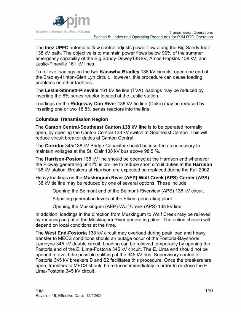
Transmission Operations Section 5: Index and Operating Procedures for PJM RTO Operation
PJM Revision 18, Effective Date: 12/12/05
110
The Inez UPFC automatic flow control adjusts power flow along the Big Sandy-Inez 138 kV path. The objective is to maintain power flows below 90% of the summer emergency capability of the Big Sandy-Dewey138 kV, Amos-Hopkins 138 kV, and Leslie-Pineville 161 kV lines. To relieve loadings on the two Kanawha-Bradley 138 kV circuits, open one end of the Bradley-Hinton-Glen Lyn circuit. However, this procedure can cause loading problems on other facilities. The Leslie-Stinnett-Pineville 161 kV tie line (TVA) loadings may be reduced by inserting the 8% series reactor located at the Leslie station. Loadings on the Ridgeway-Dan River 138 kV tie line (Duke) may be reduced by inserting one or two 18.8% series reactors into the line.
Columbus Transmission Region The Canton Central-Southeast Canton 138 kV line is to be operated normally open, by opening the Canton Central 138 kV switch at Southeast Canton. This will reduce circuit breaker duties at Canton Central. The Corridor 345/138 kV Bridge Capacitor should be inserted as necessary to maintain voltages at the St. Clair 138 kV bus above 98.5 %. The Harrison-Poston 138 kV line should be opened at the Harrison end whenever the Picway generating unit #5 is on-line to reduce short circuit duties at the Harrison 138 kV station. Breakers at Harrison are expected be replaced during the Fall 2002. Heavy loadings on the Muskingum River (AEP)-Wolf Creek (APS)-Corner (APS) 138 kV tie line may be reduced by one of several options. These include:
Opening the Belmont end of the Belmont-Riverview (APS) 138 kV circuit Adjusting generation levels at the Elkem generating plant Opening the Muskingum (AEP)-Wolf Creek (APS) 138 kV line.
In addition, loadings in the direction from Muskingum to Wolf Creek may be relieved by reducing output at the Muskingum River generating plant. The action chosen will depend on local conditions at the time. The West End-Fostoria 138 kV circuit may overload during peak load and heavy transfer to MECS conditions should an outage occur of the Fostoria-Bayshore/ Lemoyne 345 kV double circuit. Loading can be relieved temporarily by opening the Fostoria end of the E. Lima-Fostoria 345 kV circuit. The E. Lima end should not be opened to avoid the possible splitting of the 345 kV bus. Supervisory control of Fostoria 345 kV breakers B and B2 facilitates this procedure. Once the breakers are open, transfers to MECS should be reduced immediately in order to re-close the E. Lima-Fostoria 345 kV circuit.

Transmission Operations Section 5: Index and Operating Procedures for PJM RTO Operation
PJM Revision 18, Effective Date: 12/12/05
111
Ft. Wayne Transmission Region Facilities in the Greentown area may overload during contingencies. These facilities include the Kokomo 230/138/69 kV transformer (CIN), the New London-Webster 230 kV circuit (CIN), and 138 kV circuits to Wabash (CIN) and Grant. Transfers from western ECAR to MECS aggravate loadings on these facilities. Reducing the western ECAR to MECS transfers and/or opening the "E" and "C" 138 kV breakers at Greentown will reduce facility loadings.
Index of Operating Procedures for Baltimore Gas & Electric (BC or BGE) Transmission Zone The Baltimore Gas & Electric Company Transmission Zone has Operating Procedures that are adhered to by PJM. These procedures include the following:
Type of Operating Procedure
Transmission Operations Manual
Section Ref
Baltimore Gas & Electric Company (BC) Calvert Cliffs Voltage Limitations Voltage Limitations Section 5 BC Nottingham- Graceton 230 kV Line Limitations Line Limitation Section 5 PECO
Back To Index
Calvert Cliffs Voltage Limitations During normal operating conditions, the Calvert Cliffs 500 kV bus voltages can be operated using the same criteria used for other PJM 500 kV buses (within a range of 500-550 kV under normal conditions and as low as 475 in an emergency following a contingency). However, when either of the plant service transformers (P-13000-1 or P-13000-2) is out of service, the Calvert Cliffs 500 kV bus voltages should be operated within a range of 520-550 kV. Note that the Calvert Cliffs switchyard design is such that whenever the P-13000-1 plant service transformer is out of service, the 500 kV black bus is also out of service. Similarly, any time the P-13000-2 plant service transformer is out of service, the 500 kV red bus is also out of service. The Calvert Cliffs red and black busses are currently PJM reportable facilities. Operating within these voltage ranges is necessary to ensure that the Calvert Cliffs degraded and loss of voltage relays (which monitor the plant vital 4 kV system for adequate voltage) do not operate and isolate the vital 4 kV busses from their normal 500 kV transmission supplies.

Transmission Operations Section 5: Index and Operating Procedures for PJM RTO Operation
PJM Revision 18, Effective Date: 12/12/05
112
The under-excited reactive ampere limits (URAL) (at full MW load) with all lines in service are:
Unit No. 1 - 280 MVAR lead Unit No. 2 - 300 MVAR lead
Lines out-of-service (maximum lead unit stability limits) are:
Maximum Leading Reactive MVAR For Each Unit Circuit Outage 2 Units In Service 1 Unit In Service
5051 or 5052 200 Lead 265 Lead 5053 160 Lead URAL 5071 260 Lead URAL 5072 85 Lead 160 Lead
Exhibit 11: Calvert Cliffs Maximum Lead Unit Stability Limits
When the above lines are removed from service, the Calvert Cliffs units are subject to maximum lead capability stability limits. These limits must be observed prior to removing the transmission lines. Values less than the URAL setting must be observed and maintained manually. As part of the normal sequence of providing reactive transfer limits for the PJM RTO, PJM dispatcher reviews security analysis for any potential contingencies that violate the 500 kV high voltage limit. If such a contingency is found, PJM dispatcher notifies BSOP of the contingency, confirms the actual high voltage limit being observed, and helps coordinate voltage schedule changes to relieve the contingency. The overall philosophy is to maintain the Calvert Cliffs unit reactive output to ensure capability to absorb excess MVAR on the 500 kV bus for the loss of a generator, if operating in the lead (MVARs flowing into the unit step-up from the 500 kV bus), or the loss of a 500 kV bus. Minimizing MVAR flows at the high side of the unit step-up and keeping a uniform distribution on the 500 kV lines leaving the plant, ensures minimum contingency effects. Having no units operating obviously provides the most difficult operating conditions. PJM Actions:
PJM dispatcher reviews system conditions in the local area for anything abnormal that could be corrected.
PJM dispatcher utilizes adjustments in unit reactive (if units are operating) until reaching an optimum condition, which leaves enough leading reactive reserve to cover the worst reactive contingency for the 500 kV bus.
PJM dispatcher adjusts tap positions at Waugh Chapel, Brighton, and Chalk Point in a coordinated effort to reduce voltage or reactive flows towards the Calvert Cliffs bus.
Transmission Operations Section 5: Index and Operating Procedures for PJM RTO Operation
PJM Revision 18, Effective Date: 12/12/05
113
PJM dispatcher ensures that the Calvert Cliffs Plant is taking all possible measures to provide the highest 500 kV high voltage limit.
If EHV system conditions permit, PJM dispatcher makes any reasonable adjustments that can be made on the southern PJM RTO or Control Areas which do not have an adverse impact on actual PJM RTO transfers. (Capacitors not required for transfers that have a beneficial effect can be considered.)
If the study indicates that there are no adverse consequences created by selectively opening 500 kV lines in the BC/PEPCO loop, then PJM dispatcher requests the BPSO to open the transmission facility. When removing EHV lines from service there are some important things to consider. First, remember to observe the leading reactive stability limits for the Calvert Cliffs units when circuits are removed from service. Second, make sure the line removal steps always leave the Calvert Cliffs 500 kV bus more deficient of reactive power. Follow switching with on-line computer program staff to observe any system changes resulting from the switching.
Possible study suggestions include: A. if a small change is required, study opening 5051 or 5052. This
removal has one of the smaller effects on the unit leading capability and keeps the Loop intact
B. if a larger change is required, study opening the 5053 line. This removes the higher source voltage at Brighton and allows more control from tap changes at Waugh Chapel
If BGE BPSO indicates to PJM dispatcher that Calvert Cliffs 500 kV high voltage limit must be reduced below the 525 kV normal for any reason, or possibly increased above the normal under certain system conditions when plant conditions allow, PJM dispatcher changes the limit in the on-line computer program and manually initiates the real-time sequence, including security analysis.

Transmission Operations Section 5: Index and Operating Procedures for PJM RTO Operation
PJM Revision 18, Effective Date: 12/12/05
114
Index of Operating Procedures for Commonwealth Edison (ComEd) Transmission Zone The Commonwealth Edison Transmission Zone has Operating Procedures that are adhered to by PJM. These procedures include the following:
Type of Operating Procedure
Transmission Operations Manual
Section Ref
Commonwealth Edison (ComEd) Kincaid Stability Trip Scheme Unit Stability Section 5 ComEd Powerton Stability Limitations Unit Stability Section 5 ComEd Quad Cities and Cordova Stability Limitations Unit Stability Section 5 ComEd Byron and Lee County Operating Guides Unit Stability Section 5 ComEd University Park North Energy Center Restriction Unit Stability Section 5 ComEd Elgin Energy Center Stability Bus Tie Scheme Unit Stability Section 5 ComEd Marengo 138 kV Bus Operation Voltage and Thermal Limitations Section 5 ComEd Damen 138 kV Bus Operation Constraints Section 5 ComEd Normally Open Bus Tie Circuit Breakers Voltage and Thermal Limitations Section 5 ComEd Dresden 345 kV Bus Operation with Lines Out of Service
Limitations Section 5 ComEd
Burnham – Taylor (L17723) 345 kV Line Operation
Voltage Section 5 ComEd
Zion TDC 282 – Lakeview (L28201) 138 kV Tieline Operation
Thermal Contingencies Section 5 ComEd
107_Dixon ‘L15621’ 138 kV CB Operation Thermal Contingencies Section 5 ComEd 138 kV Phase Shifting Transformer Operations PARs Section 5 ComEd Minnesota – Eastern Wisconsin Reduction Limitations Section 5 ComEd Voltage Control at ComEd Nuclear Stations Voltage Limitations Section 5 ComEd Waukegan 138 kV Bus Tie 4-14 Operation Voltage and Thermal Limitations Section 5 ComEd
Back To Index
Kincaid Stability Trip Schemes (ComEd SPOG 1-3-A) There are two special protection schemes currently in place at Kincaid to prevent first swing and/or oscillatory instability of either unit for multi-phase faults or multiple line outages. For normal system conditions, these schemes should be in-service at all times.

Transmission Operations Section 5: Index and Operating Procedures for PJM RTO Operation
PJM Revision 18, Effective Date: 12/12/05
115
Multiple Lines Out of Service If Kincaid–Lanesville (Ameren) (L2101), Kincaid–Latham (IP)–Pontiac(L2102) or Kincaid–Pana (Ameren) (L2105) are out of service and both Kincaid units are in service, intentional unit trip schemes are installed to automatically trip a Kincaid unit for multiple line outage conditions listed below.
Lines Out of Service Unit Tripped L2101 & L2105 1
L2101 & L2102 2
L2102 & L2105 2
The multiple outage unit trip scheme is not required when one unit is out of service. If unit 2 is out of service, the automatic trip for unit 1 (2101 & 2105 outage) can be disabled. Similarly, if unit 1 is out of service, the automatic trip for unit 2 (2102 & 2105 outage) can be disabled and the trip for unit 2 (2101 & 2102 outage) is automatically disabled. There is an increased risk of instability if the Kincaid units are operated with the voltage regulator is out of service. ComEd Actions: ComEd should notify PJM any time the voltage regulator at Kincaid is out of service. ComEd Transmission Operations should direct Kincaid station to maintain a generator terminal voltage above 19 kV to prevent generator instability assuming otherwise normal system conditions. PJM Actions: Activate and deactivate the following contingencies:
Line Out of Service Activate Contingency(s) Deactivate Contingency(s) L2101 345L2105 & Unit 1
345L2102 & Unit 2 345L2105 345L2102
L2102 345L2105 & Unit 2 345L2101 & Unit 2
345L2105 345L2101
L2105 345L2101 & Unit 1 345L2102 & Unit 2
345L2101 345L2102
Multi-Phase Fault High-Speed Sectionalizing Scheme The Multi-Phase Fault High-Speed Sectionalizing Scheme is designed to minimize required unit trips and to prevent first-swing instability of the Kincaid units in the event of a circuit breaker failure following a multi-phase fault. This is accomplished by intentionally tripping both bus sections adjacent to the faulted line in primary time for close-in multi-phase faults on the 345 kV lines.

Transmission Operations Section 5: Index and Operating Procedures for PJM RTO Operation
PJM Revision 18, Effective Date: 12/12/05
116
Circuit Breaker Tripping Operations For Multi-Phase Fault High-Speed Sectionalizing Scheme
Equipment Tripped in Primary Time Faulted Line Normal CB
Trips(1) Additional CB
Trips(2) Additional Equipment
Tripped(2)
2101 1-2, 1-3 3-5, 2-6 Unit 1, Aux 143 & 144 2102 3-5, 5-7 1-3, 7-8 L2106, Aux 143 & 144 2105 2-6, 6-8 1-2 Unit 1 2106 5-7, 7-8 3-5, 6-8 L2102, Unit 2 (1) For all line faults. (2) Only for multi-phase faults close in to Kincaid.
Powerton Stability Limitations (ComEd SPOG 1-3-B and 1-3-B-1) The Powerton Transmission system consists of four 345 kV lines from Powerton to Dresden, Lockport and Goodings Grove. The 345 kV bus consists of two ring buses which are operated normally tied. There are several operating procedures in place in order to maintain stability of the Powerton Units.
Multi-Phase Fault High-Speed Sectionalizing Scheme The objective of the multi-phase fault high-speed sectionalizing scheme is to minimize required unit trips and ensure stable operation of the Powerton units in anticipation of a circuit breaker failure following a multi-phase fault. This is accomplished by intentionally tripping the red-blue bus-tie 4-8 circuit breaker in primary time for close-in multi-phase faults on the 345kV lines at Powerton.
Circuit Breaker Tripping Operations For Multi-Phase Fault High-Speed Sectionalizing Scheme
Equipment Tripped in Primary Time at Powerton Station Faulted Line Normal CB Trips Additional CB Trips
L0301 1-2, 1-6 4-8(1) L0302 2-3, 3-4 4-8(2) L0303 8-9, 9-10 4-8(1) L0304 8-11, 10-11 4-8(2) (1) Only for close-in three-phase faults. (2) For any close-in multi-phase faults.

Transmission Operations Section 5: Index and Operating Procedures for PJM RTO Operation
PJM Revision 18, Effective Date: 12/12/05
117
Multiple Line Outage Unit Trip Scheme The multiple line outage unit trip scheme is used at Powerton to prevent first swing instability which may occur during certain simultaneous line outage conditions. Intentional unit trip schemes are installed to automatically trip a Powerton unit for multiple line outage conditions listed below.
Multiple Line Outages Which Initiate a Powerton Unit Trip
Lines Out Unit(s) Tripped in Primary Time L0301 & L0302 with BT 4-8 open Unit #5
L0304 & L0303 with BT 4-8 open OR
L93505 @ Tazewell & L0303 with BT 4-8 open
Unit #6
L0301 & L0303 & L0304(1) Unit #6
L0301 & L0302 & L0303 & L0304 OR
L0301 & L0302 & L0303 & L93505 @ Tazewell
Unit #5 and #6
(1) Unit #6 will trip only for any L0304 faults while “L0301 & L0303 Out Unit Trip Scheme” is in-service
Unit Trip Scheme for Output Greater Than 765 MW If a close-in three-phase fault occurs on Powerton – Dresden (L0302) and Unit 5 output exceeds 765 MWs, Unit 5 will be immediately tripped. If a close-in three-phase fault occurs on Powerton – Tazewell (L0304) and Unit 6 output exceeds 765 MWs, Unit 6 will be immediately tripped. PJM Actions: Activate the following contingencies depending on which unit is exceeding 765 MWs:
Unit Exceeding 765 MWs Activate Contingency Powerton Unit 5 L0302 & Unit 5 Powerton Unit 6 L0304 & Unit 6
Double-line Tower Outage During double-line tower outages of the Powerton transmission lines the loss of a unit(s) may occur if a single line contingency would occur. The following options are available to insure stable operation of the Powerton Units during double tower outages:

Transmission Operations Section 5: Index and Operating Procedures for PJM RTO Operation
PJM Revision 18, Effective Date: 12/12/05
118
1. Outage of L-0301 and L-0303 Option A: Station Gross Output 1700 MW or Less Operate Units #5 and #6 on separate 345 kV ring buses (bus tie 4-8 open). Both units may be operated at full available capacity simultaneously with this option. However, any outage of either 345 kV Line 0302, 0304, or 10805 will result in a load-rejection trip of the associated generating unit. Option B: Station Gross Output from 1100 to 1700MW Operate Units #5 and #6 with the 345 kV bus tie 4-8 closed when the total gross output is as stated above. A "stability unit trip" shall be placed in service, which will trip Unit #6 for any relay-initiated trip of L-0304. The high speed sectionalizing scheme presently installed at Powerton shall remain operational. Therefore, a close-in 3-phase fault on L-0302 or L-10805 will result in a load rejection trip of the associated generating unit. Option C: Station Gross Output Less than 1100 MW Operate Units #5 and #6 with the bus-tie closed and remove from service the "stability unit trip" discussed in Option B when the total generation output is less than 1100 MW. With the high speed sectionalizing scheme in operation, this will result in a load-rejection trip of one unit for close-in 3-phase faults on L-0302, L-0304 or L-10805. 2. Outage of L-0302 and L-10805 Option A: Station Gross Output 1700 MW or Less Operate Units #5 and #6 on separate 345 kV ring buses (bus tie 4-8 open). Both units may be operated at full available capacity simultaneously with this option. However, any outage of either 345 kV Line 0301 or 0303 will result in a load-rejection trip of the associated generating unit. Option B: Station Gross Output 1650 MW or Less with U-5 Gross Output of 800 MW or Less Operate Units #5 and #6 with the 345 kV bus-tie 4-8 closed. U-6 may be operated at full available capacity, but U-5 gross output should be restricted to 800 MW or less. With the high speed sectionalizing scheme in operation, this option will result in a load-rejection trip of Unit #5 for a close-in 3-phase fault on L-0301, or a load-rejection trip of Unit #6 for a close-in 3-phase fault on L-0303. Additionally, if Unit #6 is operating above 800 MW gross output, it will be automatically tripped in the event of a close-in 3-phase fault on L.0304.

Transmission Operations Section 5: Index and Operating Procedures for PJM RTO Operation
PJM Revision 18, Effective Date: 12/12/05
119
3. Outage of L-0302 and L-0304 Option A: Station Gross Output 1700 MW or Less Operate Units #5 and #6 on separate 345 kV ring buses (bus-tie 4-8 open). Both units may be operated at full available capacity simultaneously with this option. However, any outage of either 345 kV Line 0301 or 0303 will result in a load-rejection trip of the associated generating unit. Option B: Station Gross Output Less than 1000 MW Operate units #5 and #6 with the bus-tie closed when the total generation output is less than 1000 MW. The gross output of any single unit, however, should not exceed 800 MW. With the high speed sectionalizing scheme in operation, this will result in result in a load-rejection trip of one unit for close-in 3-phase faults on L-0301 or L-0303. Permissible station outputs and unit tripping consequences for the operating options with two units in service are summarized in the attached table. In the event that operation with multiple line outages results in power oscillations, SPOG 1-8 should be consulted for remedial actions. Following certain single line trips during tower outages, overloads may occur in the CILCO system, and some reduction in Powerton generation would be required to correct the overloads.
Operating Options for Powerton Station Tower Outages
L.0301 & L.0303 Planned Outage Automatic Unit Trip Option Bus Tie Maximum Station
Gross Output (1) Unit 5 Unit 6 A Open 1700 MW Any Trip of L.0302 Any Trip of L.304 or
L.10805 B (2)(3) Closed 1700 MW 3-ph fault on L.0302 Any Trip of L.0304 (4)
or 3-ph fault on L.10805
C (2)(3) Closed 1700 MW 3-ph fault on L.0302 3-ph fault on L.0304 or L.10805
L.0302 & L.10805 Planned Outage Automatic Unit Trip Option Bus Tie Maximum Station
Gross Output (1) Unit 5 Unit 6 A Open 1700 MW Any Trip of L.0301 Any Trip of L.0303,
some 3-ph faults on L.0304 (7)
B (2)(3) Closed 1650 MW (5) 3-ph fault on L.0301 3-ph fault on L.0303, some 3-ph faults on L.0304 (7)

Transmission Operations Section 5: Index and Operating Procedures for PJM RTO Operation
PJM Revision 18, Effective Date: 12/12/05
120
L.0302 & L.0304 Planned Outage Automatic Unit Trip Option Bus Tie Maximum Station
Gross Output (1) Unit 5 Unit 6 A Open 1700 MW Any Trip of L.0301 Any Trip of L.0303 B (2)(3) Closed 1000 MW 3-ph fault on L.0301 3-ph fault on L.0303
Notes: (1) Assumes maximum available capacity of 850MW for each unit. (2) Assumes high-speed sectionalizing scheme in service for close-in 3-phase faults. (3) May involve a full station trip for certain circuit breaker failures. (4) A special unit trip is required to maintain stability of the Powerton units for this outage
condition. (5) U-5 output should not exceed 800 MW gross for this outage condition. (6) U-6 output should not exceed 800 MW gross for this outage condition. (7) U-6 tripped for 3-phase faults on L.0304 when unit output exceeds 800 MW.
PJM Actions: If there is a planned double tower outage on L0301 and L0303, L0302 and L10805, or L0303 and L0304, use the above table to determine if there is a restriction of the Powerton generation output or if there is a condition in which one of the units would trip with the contingency loss of a single transmission line. If there is a restriction on the Powerton generation output, PJM is to confirm and direct the Powerton generation to the appropriate output(s) If there is a condition that would trip a Powerton unit with the contingency loss of a single transmission line, activate the contingency loss of the single contingency and the appropriate Powerton unit and deactivate the contingency loss of the single transmission line by itself.
Quad Cities and Cordova Stability Limitations (ComEd SPOG 1-3-C, 1-3-C-1, and 1-3-G)
Quad Cities Stability Limitations The Quad Cities transmission system consists of five 345 kV lines. There are several operating procedures in order to maintain stability of the Quad Cities units.
Double Contingency Unit Trip Scheme The double contingency unit trip scheme will intentionally trip Unit 2 for the specific double contingency scenerios listed below when Quad City unit 1 is in service. The scheme will also trip the Cordova units anytime at least one Quad Cities unit is in-service.

Transmission Operations Section 5: Index and Operating Procedures for PJM RTO Operation
PJM Revision 18, Effective Date: 12/12/05
121
Certain operating conditions will require the unit trip schemes to be enabled with manually armed stability trip (MAST) switches located in the Quad Cities 345kV switchyard relay house. The MAST-03 switch arms the scheme representing a L15503 outage. The MAST-04 switch arms the scheme representing a L0404 or L15504 outage. These MAST switches are normally in the OFF position and are to be operated in the ON position under the direction of ComEd Transmission Operations. Conditions Which Trip Quad Cities Unit 2 (When Unit 1 Is In Service)
L0404 (Quad Cities – Sterling Steel) out-of-service L15503 (Nelson – Cordova) out-of-service
L15504 (Nelson – Sterling Steel) out-of-service L15503 (Nelson – Cordova) out-of-service
L0404 (Quad Cities – Sterling Steel) out-of-service MAST-03 switch in “ON” position
L15504 (Nelson – Sterling Steel) out-of-service MAST-03 switch in “ON” position
MAST-04 switch in “ON” position L15503 (Nelson – Cordova) out-of-service ComEd Actions: ComEd must notify PJM if either the Quad Cities MAST-03 or MAST-04 is being operated in the “ON” position. PJM Actions: Activate and deactivate the following contingencies:
Line Out of Service Activate Contingency(s) Deactivate Contingency(s) L0404 345L15503 & Unit 2
345L15503
L15503 345L0404 & Unit 2 345L15504 & Unit 2
345L0404 345L15504
L15504 345L15503 & Unit 2 345L15503

Transmission Operations Section 5: Index and Operating Procedures for PJM RTO Operation
PJM Revision 18, Effective Date: 12/12/05
122
If ComEd notifies PJM that one of the MAST switches are in the “ON” position, activate and deactivate the following contingencies:
MAST Switch in “ON” Position Activate Contingency(s) Deactivate Contingency(s) MAST-03 345L0404 & Unit 2
345L15504 & Unit 2 345L0404 345L15504
MAST-04 345L15503 & Unit 2
345L15503
Unit Trip Scheme for Close-in, Three-phase Faults on 345kV Line 0404 with L15503 Out-of-Service This trip scheme will trip Quad Cities Unit 2 if the following three conditions are met: 1) A close-in, three-phase fault occurs on 345kV line 0404. 2) Either 345kV line 15503 is out-of-service, or the MAST-03 switch is in the “ON”
position. 3) Quad Cities Unit 2 is in-service. In the event of a close-in, three-phase fault on L0404, Quad Cities Unit 2 can become unstable when L15503 is out-of-service even when Quad Cities Unit 1 is not in-service. This scenario results from sectionalizing, which occurs for a three-phase fault on L0404, as shown in Exhibit 3. This special relay protection scheme detects these conditions and trips Quad Cities Unit 2 without regard for the status of Quad Cities Unit 1.
Unit Trip Scheme for Three-phase Faults on 345kV Line 0405 with Barstow-Cordova Line Out-of-Service This trip scheme will trip Quad Cities Unit 1 if the following three conditions are met: 1) A three-phase fault occurs on 345 kV line 0405 within 70% of the line impedance. 2) Either the Barstow-Cordova line (MEC line 345-39-QC-1) is out-of-service, or the
MAST-BAR switch is in the “ON” position. 3) Quad Cities Unit 1 is in-service. In the event of a three-phase fault within 70% of the line impedance on L0405, Quad Cities Unit 1 can become unstable if the Barstow-Cordova line is out-of-service even when Quad Cities Unit 2 is not in-service. This scenario results from sectionalizing, which occurs for a three-phase fault on L0405, as shown in Exhibit 3. This special relay protection scheme detects these conditions and trips Quad Cities Unit 1 without regard for the status of Quad Cities Unit 2.
Transmission Operations Section 5: Index and Operating Procedures for PJM RTO Operation
PJM Revision 18, Effective Date: 12/12/05
123
Unit Trip Scheme for Three-phase Faults on 345kV Line 0405 with L15503 Out-of-Service This trip scheme will trip the Cordova units if the following three conditions are met: 1) A three-phase fault occurs on 345kV line 0405 within 70% of the line impedance. 2) Either the 345kV line 15503 is out-of-service, or the MAST-03 switch is in the
“ON” position. 3) Quad Cities Unit 1 is in-service. The Cordova unit trips are necessary to maintain stability in the event of a three-phase fault within 70% of the line impedance on L0405 with L15503 out-of-service. This scenario results from sectionalizing, which occurs for a three-phase fault on L0405.
Three-Phase Fault High Speed Sectionalizing Scheme In the event of a three-phase fault on 345 kV line 0404 or line 0405, the Quad Cities sectionalizing scheme operates as illustrated in Exhibit 3. When the Quad Cities switchyard is operated with the 345kV ring bus open, a close-in, three-phase fault may result in splitting the ring bus into three or more sections. Depending on where the ring is open, over-speed protection may be the only means by which an isolated unit could trip. This supports Transmission Planning’s recommendation to limit the duration that the ring bus is operated open to less than 30 minutes.
Cordova Stability Limitations There are several relay protection schemes in place that are designed to automatically trip the Cordova units.
Unit Trip Scheme for Three-phase Faults on 345kV Line 0405 with L15503 Out-of-Service This trip scheme will trip the Cordova units if the following three conditions are met: 1) A three-phase fault occurs on 345kV line 0405 within 70% of the line impedance. 2) Either the 345kV line 15503 is out-of-service, or the MAST-03 switch is in the
“ON” position. 3) Quad Cities Unit 1 is in-service.
Fault Conditions Which Trip All Cordova Units (Quad City Unit 1 is on-line)
L15503 (Nelson – Cordova) out-of-service

Transmission Operations Section 5: Index and Operating Procedures for PJM RTO Operation
PJM Revision 18, Effective Date: 12/12/05
124
L0405 (Quad Cities – Rock Creek) 3-phase fault within 70% of L0405 impedance
Mast -03 switch in “ON” position L0405 (Quad Cities – Rock Creek) 3-phase fault within 70% of L0405
impedance
Double Contingency Unit Trip Scheme The double contingency unit trip scheme should be in-service when both Quad Cities units are operating.
Conditions Which Trip All Cordova Units (Quad Cities Units 1 and 2 are on-line)
L0404 (Quad Cities – Sterling Steel) and L15503 (Nelson – Cordova) out-of-service
L15504 (Nelson – Sterling Steel) and L15503 (Nelson – Cordova) out-of-service
L0404 (Quad Cities – Sterling Steel) out-of-service and MAST-03 switch in “ON” position
L15504 (Nelson – Sterling Steel) out-of-service and MAST-03 switch in “ON” position
MAST-04 switch in “ON” position and L15503 (Nelson – Cordova) out-of-service
ComEd Actions: ComEd must notify PJM if either the Quad Cities MAST-03 or MAST-04 is being operated in the “ON” position. PJM Actions: Activate and deactivate the following contingencies:
Line Out of Service Activate Contingency(s) Deactivate Contingency(s) L0404 345L15503 & Cordova Units
345L15503
L15504 345L15503 & Cordova Units
345L15503
L15503 345L0404 & Cordova Units
345L15504 & Cordova Units
345L0404 345L15504
Transmission Operations Section 5: Index and Operating Procedures for PJM RTO Operation
PJM Revision 18, Effective Date: 12/12/05
125
If ComEd notifies PJM that one of the MAST switches are in the “ON” position, activate and deactivate the following contingencies:
MAST Switch in “ON” Position Activate Contingency(s) Deactivate Contingency(s) MAST-03 345L0404 & Cordova Units
345L15504 & Cordova Units
345L0404 345L15504
MAST-04 345L15503 & Cordova Units
345L15503
Byron and Lee County Operating Guides (ComEd SPOG 1-3-F, 1-3-F-1, and 1-3-H)
Byron Operating Guide There are unit stability operating schemes in place at Byron to prevent instability of the Bryon units. For normal system conditions, these schemes should be in service at all times. With both Byron units operating, Unit 1 will be tripped for any of the following conditions:
345 kV Line Out of Service Line Fault That Will Cause Unit Trip L15616 - 156_Cherry Valley-138_Silver Lake Any outage on L0627 or L15501 L17101 - 171_Wempletown-Paddock Any outage on L0627 or L15501 L0621 - 942_Nelson-937_Lee County A multi-phase fault on L0627 L0622 - 6_Byron-937_Lee County A multi-phase fault on L0627 L0624 - 6_Byron-171_Wempletown A multi-phase fault on L0627 L0627 - 6_Byron-156_Cherry Valley/Red A three-phase fault on L0621, L0622, or L0624 L15501 - 6_Byron-156_Cherry Valley/Blue A three-phase fault on L0621, L0622, or L0624
PJM Actions: Activate and deactivate the following contingencies:
Line Out of Service Activate Contingency(s) Deactivate Contingency(s) L15616 L0627 & Unit 1
L15501 & Unit 1 345L0627 345L15501
L17101 L0627 & Unit 1 L15501 & Unit 1
345L0627 345L15501
L0621 L0627 & Unit 1 * L0622 L0627 & Unit 1 * L0624 L0627 & Unit 1 * L0627 L0621 & Unit 1
L0622 & Unit 1 L0624 & Unit 1
*
L15501 L0621 & Unit 1 L0622 & Unit 1 L0624 & Unit 1
*

Transmission Operations Section 5: Index and Operating Procedures for PJM RTO Operation
PJM Revision 18, Effective Date: 12/12/05
126
*Do not deactivate any contingencies for this outage, if there is a single phase fault, Byron Unit #1 will NOT trip.
Recommended Operating Limits to Ensure Bryon Generator Stability It is not necessary to take any corrective measures for stability for the outage of any single line provided that the protection system is normal and all PSS are in service. This following gives recommended operating procedures for Byron Station to ensure generator stability. The stability protection schemes and power system stabilizers (PSS) on both Byron units and all Lee County units are assumed to be normally in service. Knowledge of PSS status for each Byron unit is essential for safe and reliable system operation. The following tables can be used to determine the maximum Byron station Output. ComEd Actions: ComEd is to notify PJM of any abnormal status of any of the protection schemes or any outages of the PSS. PJM Actions: If any of the protection schemes or PSS are of abnormal statuses, use the tables below to determine any limitations on the Bryon generation output. Table 1 gives recommended Byron output limitations for certain line outages when the stability trip schemes are disabled and/or PSS are out of service. Table 2 gives recommended Byron output limitations, when applicable, for a variety of conditions involving outages of elements related to the stability protection schemes. Tables 3 and 4 give the same Byron output limitations for use when Lee County units are not in service, since the operation of generators at Lee County Energy Center significantly impacts Byron stability. Recommended Operating Limits to Preserve Bryon Station Stability with Generators at Lee County Energy Center In Service
Maximum Byron Gross Output, MW Lines Out of Service Both PSS In U1 PSS Out U2 PSS Out
Line 15501 Out of Service
Both Trip Schemes In Service No Limit No Limit 2200 (5) 15501/0627 – 17101 Trip Scheme Disabled 2300 (3) 2000 (6) 2000 (6) 15501/0627 – 15616 Trip Scheme Disabled 2200 (2)(9) 1900 (5)(9) 1900 (5)(9)

Transmission Operations Section 5: Index and Operating Procedures for PJM RTO Operation
PJM Revision 18, Effective Date: 12/12/05
127
Maximum Byron Gross Output, MW Lines Out of Service Both PSS In U1 PSS Out U2 PSS Out
Line 0627 Out of Service Both Trip Schemes in Service No Limit No Limit No Limit 15501/0627 – 17101 Trip Scheme Disabled 2300 (3) 2300 (3) 2300 (3) 15501/0627 – 15616 Trip Scheme Disabled 2200 (2) 2200 (2) 2200 (2) Line 15616 Out of Service
15501/0627 – 15616 Trip Scheme In Service No Limit 2100 (6) 2100 (6)
15501/0627 – 15616 Trip Scheme Disabled 2000 (1) 1800 (4) 1800 (4) Line 17101 Out of Service
15501/0627 – 17101 Trip Scheme In Service No Limit 2100 (5) 2100 (5)
15501/0627 – 17101 Trip Scheme Disabled 2100 (1) 2050 (4) 2050 (4)
Table 1
Maximum Byron Gross Output, MW Protection Equipment Out of Service Both PSS In U1 PSS Out U2 PSS Out
The entire 15501/0627 – 17101 Stability Trip Scheme
Lines 0627, 15501 & 17101 In Service No Limit (12) No Limit (12)(13) No Limit (12)(13)
Line 0627 Out of Service 2300 (3) 2300 (3) 2300 (3) Line 15501 Out of Service 2300 (3) 2000 (6) 2000 (6) Line 17101 Out of Service 2100 (1) 2050 (4) 2050 (4) The entire 15501/0627 – 15616 Stability Trip Scheme
Lines 0627, 15501 & 15616 In Service No Limit (12) No Limit (12)(13) No Limit (12)(13)
Line 0627 Out of Service 2200 (2) 2200 (2) 2200 (2) Line 15501 Out of Service 2200 (2)(9) 1900 (5)(9) 1900 (5)(9) Line 15616 Out of Service 2000 (1) 1800 (4) 1800 (4) Equipment Monitoring Status of Line 17101 (11)
Lines 0627, 15501 & 17101 In No Limit (12) No Limit (12)(13) No Limit (12)(13)
Transmission Operations Section 5: Index and Operating Procedures for PJM RTO Operation
PJM Revision 18, Effective Date: 12/12/05
128
Service Line 0627 Out of Service 2300 (3) 2300 (3) 2300 (3) Line 15501 Out of Service 2300 (3) 2000 (6) 2000 (6) Line 17101 Out of Service 2100 (1) 2050 (4) 2050 (4) Line 17101 Out of Service, Trip Scheme Armed (10) No Limit 2100 (5) 2100 (5)
Equipment Monitoring Status of Line 15616 (11)
Lines 0627, 15501 & 15616 In Service No Limit (12) No Limit (12)(13) No Limit (12)(13)
Line 0627 Out of Service 2200 (2) 2200 (2) 2200 (2) Line 15501 Out of Service 2200 (2)(9) 1900 (5)(9) 1900 (5)(9) Line 15616 Out of Service 2000 (1) 1800 (4) 1800 (4) Line 15616 Out of Service, Trip Scheme Armed (10) No Limit 2100 (6) 2100 (6)
Equipment Monitoring Status of Line 0627 (11)
Lines 0627, 15616 & 17101 In Service No Limit (12) No Limit (12)(13) No Limit (12)(13)
Line 17101 Out of Service 2100 (1) 2100 (1)(5) 2100 (1)(5) Line 15616 Out of Service 2000 (1) 2000 (1) 2000 (1) Line 0627 Out of Service 2200 (2) 2200 (2) 2200 (2) Line 0627 Out of Service, 0627-17101 Trip Schemed Armed (10) 2200 (2) 2200 (2) 2200 (2)
Line 0627 Out of Service, 0627-15616 Trip Schemed Armed (10) 2300 (3) 2300 (3) 2300 (3)
Line 0627 Out of Service, Both Trip Schemes Armed (10) No Limit No Limit No Limit
Equipment Monitoring Status of Line 15501 (11)
Lines 15501, 15616 & 17101 In Service No Limit (12) No Limit (12)(13) No Limit (12)(13)
Line 17101 Out of Service 2100 (1) 2050 (4) 2050 (4) Line 15616 Out of Service 2000 (1) 1800 (4) 1800 (4) Line 15501 Out of Service 2200 (2)(9) 1900 (5)(9) 1900 (5)(9) Line 15501 Out of Service, 15501-17101 Trip Schemed Armed (10) 2200 (2)(9) 1900 (5)(9) 1900 (5)(9)
Line 15501 Out of Service, 15501-15616 Trip Schemed Armed (10) 2300 (3) 2000 (6) 2000 (6)
Line 15501 Out of Service, Both Trip Schemes Armed (10) No Limit No Limit 2200 (5)
Table 2
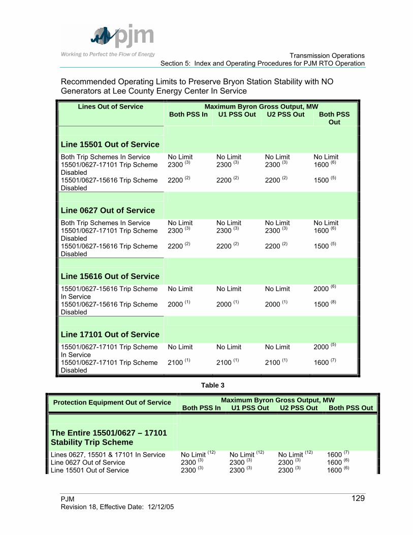
Transmission Operations Section 5: Index and Operating Procedures for PJM RTO Operation
PJM Revision 18, Effective Date: 12/12/05
129
Recommended Operating Limits to Preserve Bryon Station Stability with NO Generators at Lee County Energy Center In Service
Maximum Byron Gross Output, MW Lines Out of Service Both PSS In U1 PSS Out U2 PSS Out Both PSS
Out
Line 15501 Out of Service
Both Trip Schemes In Service No Limit No Limit No Limit No Limit 15501/0627-17101 Trip Scheme Disabled
2300 (3) 2300 (3) 2300 (3) 1600 (6)
15501/0627-15616 Trip Scheme Disabled
2200 (2) 2200 (2) 2200 (2) 1500 (5)
Line 0627 Out of Service
Both Trip Schemes In Service No Limit No Limit No Limit No Limit 15501/0627-17101 Trip Scheme Disabled
2300 (3) 2300 (3) 2300 (3) 1600 (6)
15501/0627-15616 Trip Scheme Disabled
2200 (2) 2200 (2) 2200 (2) 1500 (5)
Line 15616 Out of Service
15501/0627-15616 Trip Scheme In Service
No Limit No Limit No Limit 2000 (6)
15501/0627-15616 Trip Scheme Disabled
2000 (1) 2000 (1) 2000 (1) 1500 (8)
Line 17101 Out of Service
15501/0627-17101 Trip Scheme In Service
No Limit No Limit No Limit 2000 (5)
15501/0627-17101 Trip Scheme Disabled
2100 (1) 2100 (1) 2100 (1) 1600 (7)
Table 3
Maximum Byron Gross Output, MW Protection Equipment Out of Service Both PSS In U1 PSS Out U2 PSS Out Both PSS Out
The Entire 15501/0627 – 17101 Stability Trip Scheme
Lines 0627, 15501 & 17101 In Service No Limit (12) No Limit (12) No Limit (12) 1600 (7) Line 0627 Out of Service 2300 (3) 2300 (3) 2300 (3) 1600 (6) Line 15501 Out of Service 2300 (3) 2300 (3) 2300 (3) 1600 (6)

Transmission Operations Section 5: Index and Operating Procedures for PJM RTO Operation
PJM Revision 18, Effective Date: 12/12/05
130
Line 17101 Out of Service 2100 (1) 2100 (1) 2100 (1) 1600 (7)
The Entire 15501/0627 – 15616 Stability Trip Scheme
Lines 0627, 15501 & 15616 In Service No Limit (12) No Limit (12) No Limit (12) 1500 (8) Line 0627 Out of Service 2200 (2) 2200 (2) 2200 (2) 1500 (5) Line 15501 Out of Service 2200 (2) 2200 (2) 2200 (2) 1500 (5) Line 15616 Out of Service 2000 (1) 2000 (1) 2000 (1) 1500 (8)
Equipment Monitoring Status of Line 17101 (11)
Lines 0627, 15501 & 17101 In Service No Limit (12) No Limit (12) No Limit (12) 1600 (7) Line 0627 Out of Service 2300 (3) 2300 (3) 2300 (3) 1600 (6) Line 15501 Out of Service 2300 (3) 2300 (3) 2300 (3) 1600 (6) Line 17101 Out of Service 2100 (1) 2100 (1) 2100 (1) 1600 (7) Line 17101 Out of Service, Trip Scheme Armed (10)
No Limit No Limit No Limit 2000 (5)
Equipment Monitoring Status of Line 15616 (11)
Lines 0627, 15501 & 15616 In Service No Limit (12) No Limit (12) No Limit (12) 1500 (8) Line 0627 Out of Service 2200 (2) 2200 (2) 2200 (2) 1500 (5) Line 15501 Out of Service 2200 (2) 2200 (2) 2200 (2) 1500 (5) Line 15616 Out of Service 2000 (1) 2000 (1) 2000 (1) 1500 (8)
Line 15616 Out of Service, Trip Scheme Armed (10)
No Limit No Limit No Limit 2000 (6)
Maximum Byron Gross Output, MW Protection Equipment Out of Service Both PSS In U1 PSS Out U2 PSS Out Both PSS
Out
Equipment Monitoring Status of Line 0627 (11)
Lines 0627, 15616 & 17101 In Service No Limit (12) No Limit (12) No Limit (12) 1500 (8) Line 17101 Out of Service 2100 (1) 2100 (1) 2100 (1) 1500 (8) Line 15616 Out of Service 2000 (1) 2000 (1) 2000 (1) 1500 (8)
Line 0627 Out of Service 2200 (2) 2200 (2) 2200 (2) 1500 (5) Line 0627 Out of Service, 0627-17101 Trip Schemed Armed (10)
2200 (2) 2200 (2) 2200 (2) 1500 (5)
Line 0627 Out of Service, 0627-15616 Trip Schemed Armed (10)
2300 (3) 2300 (3) 2300 (3) 1600 (6)

Transmission Operations Section 5: Index and Operating Procedures for PJM RTO Operation
PJM Revision 18, Effective Date: 12/12/05
131
Line 0627 Out of Service, Both Trip Schemes Armed (10)
No Limit No Limit No Limit No Limit
Equipment Monitoring Status of Line 15501 (11)
Lines 15501, 15616 & 17101 In Service No Limit (12) No Limit (12) No Limit (12) 1500 (8) Line 17101 Out of Service 2400 (14) 2400 (14) 2400 (14) 1500 (8) Line 15616 Out of Service 2350 (14) 2350 (14) 2350 (14) 1500 (8) Line 15501 Out of Service 2200 (2) 2200 (2) 2200 (2) 1500 (5) Line 15501 Out of Service, 15501-17101 Trip Schemed Armed (10)
2200 (2) 2200 (2) 2200 (2) 1500 (5)
Line 15501 Out of Service, 15501-15616 Trip Schemed Armed (10)
2300 (3) 2300 (3) 2300 (3) 1600 (6)
Line 15501 Out of Service, Both Trip Schemes Armed (10)
No Limit No Limit No Limit No Limit
Table 4
Notes for Tables:
1. Limitation to prevent transient instability following a three phase fault on L0627. 2. Limitation to prevent transient instability following a three phase fault on L15616. 3. Limitation to prevent transient instability following a three phase fault on L17101. 4. Limitation to prevent dynamic instability following any trip of L15501. 5. Limitation to prevent dynamic instability following any trip of L15616. 6. Limitation to prevent dynamic instability following any trip of L17101. 7. Limitation to prevent dynamic instability following any coincident outages of L0627 or L15501
& L17101. 8. Limitation to prevent dynamic instability following any coincident outages of L0627 or L15501
& L15616. 9. A limitation is also required for Lee County units. 10. The trip scheme(s) must be manually “armed” at Byron as would normally be activated by the
microwave signal for the line outage. 11. This includes the microwave channel and any other equipment involved in communicating the
status of this transmission line to the trip scheme at Byron. 12. Extended system operation with Byron station at full output while the unit trip scheme(s) are
inoperable is not recommended. Any trip of L15616 or L17101 coincident with a three phase fault on L0627 or any trip of L15501 or L0627 coincident with a three phase fault on L15616 or L17101 may cause generator instability.
13. Extended system operation with Byron station at full output while a PSS is not in service is not recommended. Any coincident trips of L15616 or L17101 or L15501 may cause generator instability.
14. Limitation to prevent transient instability following a three phase fault on L15501.

Transmission Operations Section 5: Index and Operating Procedures for PJM RTO Operation
PJM Revision 18, Effective Date: 12/12/05
132
Lee County Operating Guide Lee County units should not operate if both Byron PSS are out of service. If only one Byron unit is on-line and operating without its PSS, Lee County units may operate provided the combined gross output of Byron and Lee County do not exceed 1500 MW. During certain single lines out of service it may be desired to disable the Byron Unit Trip Scheme(s). The following table gives recommended Lee County output limitations for certain line outages when the Byron Unit Trip Scheme(s) are disabled. The following tables also give the recommended Lee County output limitations when any Lee County units are operating without power system stabilizers (PSS).
Maximum Lee County Gross Output, MW Any Lee PSS Out Line Out of Service
All Lee PSS In 2 Byron PSS In 1 Bryon PSS InLine 15501 (Nelson – Lee County) Out of Service
Both Byron Trip Schemes In No Limit No Limit 80 15501/0627-17101 Bryon Trip Scheme Disabled No Limit 480 480
15501/0627-15616 Byron Trip Scheme Disabled 480 160 160
Line 0627 Out (Byron – Lee County) Out of Service No Limit 400 400
Line 17101 (Wempletown – Paddock) Out of Service
15501/0627-17101 Byron Trip Scheme In Service No Limit No Limit 240
15501/0627-17101 Bryon Trip Scheme Disabled No Limit 480 240
Line 15616 (Cherry Valley – Silver Lake) Out of Service
15501/0627-15616 Byron Trip Scheme In Service No Limit No Limit 240
15501/0627-15616 Byron Trip Scheme Disabled No Limit 240 240
Line 15502 ( Nelson – Electric Jct.) Out of Service No Limit 480 320
ComEd Actions: ComEd is to notify PJM of any abnormal status of any of the protection schemes or any outages of the PSS.

Transmission Operations Section 5: Index and Operating Procedures for PJM RTO Operation
PJM Revision 18, Effective Date: 12/12/05
133
PJM Actions: 1. If any of the above lines are out of service, call ComEd to determine the
following information: The Status of the Bryon Trip Scheme (dependant on the line that is out of
service) The status of Lee County PSS If any of the Lee County PSS are out of service, the status of the Byron
PSS. 2. Using the above chart, determine if there is a limit of the maximum Lee
County generation output. 3. Confirm and Direct Lee County generation to restrict the maximum generation
output.
University Park North Energy Center Restriction (ComEd SPOG 1-3-I and 1-3-I-1) The power system stabilizers (PSS) on all units at University Park North Energy Center are assumed to be normally in service. If a University Park unit is operating with a PSS out of service, that unit will be limited to a gross output of 30 MWs. ComEd Actions: ComEd is to notify PJM of any outages of the University Park Units PSS. PJM Actions: If any of the University Park Units PSS are out of service, confirm and direct that University Park Unit to a gross output of 30 MWs.
Elgin Energy Center Stability Bus Tie Scheme (ComEd SPOG 1-3-J) An interlock scheme has been installed at TSS 960 Elgin EC to prevent closing the 138kV bus tie circuit breaker unless either 138kV motor operated bus tie disconnect is open. The intent of this scheme is to prevent Elgin EC from connecting all four units to either color through a single 138kV line 96001 or 96002. It is permissible for Elgin EC to operate up to three units on either color through a single 138kV line. In the event that Elgin EC operates three units on either color, the Spaulding 2-3 138 kV bus tie circuit breaker will be operated in the closed position. This will help ensure that the 138/34.5 kV transformers at TSS 79 are connected to a balanced 138kV source.

Transmission Operations Section 5: Index and Operating Procedures for PJM RTO Operation
PJM Revision 18, Effective Date: 12/12/05
134
PJM Actions: If the L96001 or L96002 138 kV line is out of service and the Elgin bus tie is closed, confirm that only three Elgin units are in service.
Marengo 138 kV Bus Operation (ComEd SPOG 2-2-B) The 138 kV circuit breaker between Belvidere – Pleasant Valley – Marengo (L12204) and Belvidere – Marengo – Woodstock (L12205) at Marengo should be left in the closed position during summer months to avoid potential low voltage and or emergency overload conditions for the single contingency outage of Cherry Valley – Belvidere – B465 (L15624) or Silver Lake – Crystal Lake – Pleasant Valley – McHenry (L13809) during heavier load conditions.
Damen 138 kV Bus Operation (ComEd SPOG 2-2-C) The 138 kV circuit switcher ‘BT2-3 CS’ at Damen, can be closed for emergency supply to Evergreen Park, Damen and Wallace provided this operation does not form a closed 138 kV path between Blue Island or Wildwood and Bedford Park.
Normally Open Bus Tie Circuit Breakers The following stations have normally open bus tie circuit breakers that may need to be closed due to transmission equipment out of service. This should be studied and agreed upon with ComEd prior to closing. Some of the following stations have normally open bus tie breakers and associated guides that indicate studying the closing of the Normally Open breaker in the event of certain outages or other conditions. For each line or transformer outage that could affect these stations there are two contingency definitions in our EMS system. One contingency will have a ‘G’ (Guide) appended to the end of the contingency title and one will have a ‘GF’ (Guide Failed) appended to the end of the contingency title. The contingencies with a ‘G’ appended indicate the normally open bus tie breaker at the appropriate station has been closed as part of the contingency definition. The contingencies with a ‘GF’ appended indicate the normally open bus tie breaker at the appropriate station was not closed in the contingency definition. Other stations have an automatic scheme in place one contingency will be marked with an ‘S’ (Scheme) and one with an ‘SF’ (Scheme Failed). The contingencies with a ‘S’ appended indicate the normally open bus tie breaker at the appropriate station has been closed as part of the contingency definition. The contingencies with a ‘SF’ appended indicate the normally open bus tie breaker at the appropriate station was not closed in the contingency definition
Transmission Operations Section 5: Index and Operating Procedures for PJM RTO Operation
PJM Revision 18, Effective Date: 12/12/05
135
ComEd ACTIONS: Breaker outage/abnormal: ComEd will notify PJM operators whenever a normally open bus tie breaker defined in this procedure is in any abnormal status or condition that would prevent its ability to be closed according to the relevant guide. Relay or scheme change/fail/abnormal: If the automatic breaker closing is changed or disabled at Electric Junction or Lisle then ComEd must notify the PJM operator. PJM ACTIONS: Planned Outages: If removal of a line or transformer causes problems at one of the stations in this procedure with a guide in place study closing the normally open bus tie breaker and confirm/coordinate with ComEd Contingency Overloads: If a contingency appears in real time, we will need to confirm with ComEd if the normally open circuit breaker with be closed. If the normally open CB will be closed, PJM will control to the 'G' or 'S' contingencies. If the normally open CB will remain open, PJM will control to the 'GF' and 'SF' contingencies.

Transmission Operations Section 5: Index and Operating Procedures for PJM RTO Operation
PJM Revision 18, Effective Date: 12/12/05
136
N.O. Circuit Beaker Equipment Out of Service
Reason for closing the N.O. CB
Contingency w/ N.O. CB Closed
Contingency w/ N.O. CB Open
Additional Information
Dresden #82 Transformer 12 DRESDEN TR82 G 12 DRESDEN TR82
GF Dresden 2-3 138kV N.O Bus Tie CB (SPOG 1-2-E) Dresden #83
Transformer
Voltage Control 12 DRESDEN TR83 G 12 DRESDEN TR83
GF L.2311 line should also be opened
Northbrook #81 Transformer Northbrook TR 81 R G Northbrook TR 81 R
GF
Northbrook #82 Transformer Northbrook TR 82 R G Northbrook TR 82 R
GF
Northbrook – Skokie (8805) 138 kV Line 138L8805 G 138L8805 GF
Northbrook 2-3 138 kV N.O. Bus Tie CB (SPOG 2-10)
Northbrook – Skokie (8806) 138 kV Line
To Prevent Low Voltage Conditions Should Another Element Trip
138L8806 G 138L8806 GF
Prospect Heights #81 Transformer
PROSPECT HTS TR 81 R G
PROSPECT HTS TR 81 R GF Prospect Heights 2-3 138 kV
N.O. Bus Tie CB (SPOG 2-15)
Prospect Heights #84 Transformer
To Prevent Low Voltage Conditions Should Another Element Trip PROSPECT HTS TR
84 R G PROSPECT HTS TR 84 R GF

Transmission Operations Section 5: Index and Operating Procedures for PJM RTO Operation
PJM Revision 18, Effective Date: 12/12/05
137
N.O. Circuit Beaker Equipment Out of Service
Reason for closing the N.O. CB
Contingency w/ N.O. CB Closed
Contingency w/ N.O. CB Open
Additional Information
Prospect Heights - Des Plaines (11701) 138 kV Line
138L11701 G 138L11701 GF
Prospect Heights - Des Plaines (11702) 138 kV Line
138L11702 G 138L11702 GF
Fisk - Dekoven (1110) 138 kV Line 138L1110 G 138L1110 GF
Fisk - Dekoven (1111) 138 kV Line 138L1111 G 138L1111 GF
Crawford - Congress (1321) 138 kV Line 138L1321 G 138L1321 GF
Crawford - Congress (1323) 138 kV Line 138L1323 G 138L1323 GF
Jefferson - Grand (4525) 138 kV Line 138L4525 G 138L4525 GF
Jefferson - Grand (4527) 138 kV Line 138L4527 G 138L4527 GF
Grand - Dekoven (5810) 138 kV Line 138L5810 G 138L5810 GF
Grand - Dekoven (5811) 138 kV Line 138L5811 G 138L5811 GF
Grand - Crosby (5825) 138 kV Line 138L5825 G 138L5825 GF
Crosby 5-18 138 kV N.O. Bus Tie CB (SPOG 2-19)
Grand - Crosby (5826) 138 kV Line
To Prevent Emergency Thermal Overloads in the event of an additional 138 kV line outage
138L5826 G 138L5826 GF

Transmission Operations Section 5: Index and Operating Procedures for PJM RTO Operation
PJM Revision 18, Effective Date: 12/12/05
138
N.O. Circuit Beaker Equipment Out of Service
Reason for closing the N.O. CB
Contingency w/ N.O. CB Closed
Contingency w/ N.O. CB Open
Additional Information
Grand - Crosby (5827) 138 kV Line 138L5827 G 138L5827 GF
Grand - Crosby (5828) 138 kV Line 138L5828 G 138L5828 GF
Congress - Rockwell (6721) 138 kV Line 138L6721 G 138L6721 GF
Congress - Rockwell (6723) 138 kV Line 138L6723 G 138L6723 GF
Crosby - Rockwell (8221) 138 kV Line 138L8221 G 138L8221 GF
Crosby - Rockwell (8223) 138 kV Line
138L8223 G 138L8223 GF
Diversey - Clybourn (4013) 138 kV Line 138L4013 G 138L4013 GF
Diversey - Crosby (4018) 138 kV Line 138L4018 G 138L4018 GF
Crosby - Clybourn (8207) 138 kV Line 138L8207 G 138L8207 GF
Diversey - Northwest (11413) 138 kV Line 138L11413 G 138L11413 GF
Diversey 2-11 138 kV N.O. Bus Tie CB (SPOG 2-22)
Diversey - Northwest (11418) 138 kV Line
To Prevent the loss of Diversey load in the event of an additional 138 kV line outage
138L11418 G 138L11418 GF
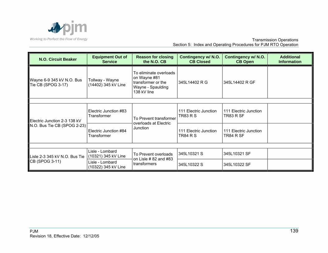
Transmission Operations Section 5: Index and Operating Procedures for PJM RTO Operation
PJM Revision 18, Effective Date: 12/12/05
139
N.O. Circuit Beaker Equipment Out of Service
Reason for closing the N.O. CB
Contingency w/ N.O. CB Closed
Contingency w/ N.O. CB Open
Additional Information
Wayne 6-9 345 kV N.O. Bus Tie CB (SPOG 3-17)
Tollway - Wayne (14402) 345 kV Line
To eliminate overloads on Wayne #81 transformer or the Wayne - Spaulding 138 kV line
345L14402 R G 345L14402 R GF
Electric Junction #83 Transformer
111 Electric Junction TR83 R S
111 Electric Junction TR83 R SF
Electric Junction 2-3 138 kV N.O. Bus Tie CB (SPOG 2-23)
Electric Junction #84 Transformer
To Prevent transformer overloads at Electric Junction
111 Electric Junction TR84 R S
111 Electric Junction TR84 R SF
Lisle - Lombard (10321) 345 kV Line 345L10321 S 345L10321 SF
Lisle 2-3 345 kV N.O. Bus Tie CB (SPOG 3-11) Lisle - Lombard
(10322) 345 kV Line
To Prevent overloads on Lisle # 82 and #83 transformers 345L10322 S 345L10322 SF

Transmission Operations Section 5: Index and Operating Procedures for PJM RTO Operation
PJM Revision 18, Effective Date: 12/12/05
140
Dresden 345 kV Bus Operation with Lines Out of Service (ComEd SPOG 2-17) If the 345 kV circuit Dresden – Electric Junction (L1223) is out of service with the ring bus closed for more than ½ hour, 345 kV bus tie circuit breaker ‘BT1114 CB’ at Station 12, Dresden, should be opened. The following are contingency pairs that differ only in whether or not the ‘BT1114 CB’ 138kV bus tie breaker is opened according to the guide:
345L1223T G 345L1223T GF
Burnham – Taylor (L17723) 345 kV Line Operation (ComEd SPOG 3-6) The high capacitance of each of these cables is compensated for by a 120 MVar shunt inductor at Calumet TSS 150. Without an inductor in service, inadvertent opening of the Burnham end of either line can result in excessive voltage at the bus at Taylor, on the open line, and associated equipment. Overvoltage would be most severe at lighter system load levels and with abnormal terminal conditions, but can also be above equipment ratings during higher system load levels depending on system configuration.
Unavailability of the L17724 Shunt Inductor: The shunt inductor for L17724 will not be available until the spring of 2005. Without this inductor, the Taylor 345 kV red-blue bus tie should be operated normally closed and the shunt inductor for line 17723 should be operated normally in service at system loads below 18,000 MWs. At system loads above 18,000 MW, if contingency analysis indicates potential first contingency overloads on the Taylor autotransformers on peak load days, the Taylor 345 kV bus tie can be opened to reduce the potential loading on the Taylor autotransformers, provided that:
138 kV bus voltage at Taylor does not exceed 142 kV. Lines 15302 and 15303 are in service. The Burnham 345 kV bus is configured normally. Both Taylor autotransformers are in service and the Taylor 345 kV bus is
configured normally. The L17723 shunt inductor may also be opened under these conditions if additional voltage support is required. The L17723 shunt inductor should be returned to service

Transmission Operations Section 5: Index and Operating Procedures for PJM RTO Operation
PJM Revision 18, Effective Date: 12/12/05
141
and the Taylor 345 kV red-blue bus tie closed when system load falls back below 17,000 MW or any of the above conditions are not met. Ratings associated with Cooling System Operating Modes
Lines 17723 and 17724 share a common oil return pipe. Operation of the forced cooling system on both lines simultaneously leaves the system susceptible to a pipe failure or dig-in, which could cause a pressure transient to trip both lines. To eliminate this possibility, it is recommended that the oil cooling systems be normally operated in static mode with all three pipes isolated from each other. ACOP must be on for 6 hours or more to obtain the full effect. After 6 hours, a single line can be operated at higher ratings. See table below.
Summer (MVA) Winter (MVA) Number of Circuits In
Service
Cooling Mode
Normal Emergency Normal Emergency
2 Static (normal configuration)
550 791 600 844
1 2-hour Emergency Rating (Static)
N/A 935 N/A 1020
1 Static (2 hours +) N/A 791 N/A 844
1 ACOP (2 – 6 hours) N/A 835 N/A 920
1 ACOP (After 6 + hours)
847 941 934 1006
2 ACOP (risk of common mode
failure)
762 856 849 922
Zion TDC 282 – Lakeview (L28201) 138 kV Tieline Operation (ComEd SPOG 3-10) The 138 kV tieline L28201 from Zion to Lakeview (WEC) can be opened to relieve contingency overloads for the loss of either of the following two lines: Zion Station 22 to Pleasant Prairie (WEC) 345 kV Red (L2221) Zion Station 22 to Arcadian (WEC) 345 kV Blue (L9922)

Transmission Operations Section 5: Index and Operating Procedures for PJM RTO Operation
PJM Revision 18, Effective Date: 12/12/05
142
Opening L28201 during either contingency is effective at relieving overloads on the following 138 kV lines: Kenosha - Bain (WEC), Kenosha - Lakeview (WEC), Waukegan - Zion (L1609), or Zion - Lakeview (WEC) (L28201). Line 28201 can be opened at either end and only implemented through mutual consent of the involved companies.
107_Dixon ‘L15621’ 138 kV CB Operation (ComEd SPOG 3-21) The L15621 138 kV circuit breaker at Dixon may be opened to reduce post-contingency loadings on the Nelson – Dixon (15507) 138 kV line or the Nelson – Dixon (15508) 138 kV line for the loss of the other.
138 kV Phase Shifting Transformer Operations (ComEd SPOG 3-22) The ComEd system includes ten 138 kV phase shifting transformers on transmission circuits around the city. The primary purpose of these phase shifters is to optimize and control power flow so as to maximize the utilization and reliability of the cables that supply the City of Chicago load center. The system has been designed so that power flows into the city from all directions. Physical control of phase shifter set points should be chosen by Operations to avoid normal and first contingency overloads on cables and phase shifters using a real time contingency analysis program. Settings should be updated as conditions change throughout the day to ensure that the most reliable configuration is maintained. PJM will have operational control of the phase shifters, where ComEd may request changes to the PARs for effective transmission control. The PJM and ComEd Dispatchers will decide on operating strategies for each day. PJM Actions: At the beginning of each shift (0630, 1430, and 2030), the PJM power dispatcher and the ComEd dispatcher should have a discussion of the phase shifter settings. This discussion should include potential issues and operating strategies for the day.
Minnesota – Eastern Wisconsin Phase Angle Reduction (ComEd CAOP 2-16) The Eau Claire-Arpin 345kv line is the only major transmission line in what is referred to as the Minnesota-Wisconsin Interface. A fault on the line, whether temporary or permanent, will cause many underlying lower voltage transmission lines to open. This guide was instituted to utilize the bilateral scheduling of energy between control areas within MAPP and MISO, to effect a reduction of the open phase angle to less than 60 degrees, which allows reclosing of the Eau Claire-Arpin 345kV line and underlying transmission circuits. The following procedure details

Transmission Operations Section 5: Index and Operating Procedures for PJM RTO Operation
PJM Revision 18, Effective Date: 12/12/05
143
PJM’s actions when requested to assist in limiting the flow on the Eau Claire-Arpin 345kV line, to below the operating security limit, until the excessive flow is relieved by the TLR process. This procedure also details PJM’s actions whenever the line opens and fails to reclose because of a large phase angle difference. Precautions
Bilateral inadvertent schedules are used. Bilateral inadvertent does require a transmission reservation. Bilateral inadvertent scheduled by PJM will be with the Alliant-West control
area. Source control area’s generation will be raised to reduce pre-contingency line
flow or the post-contingency phase angle difference. Limitations
Wholesale Energy Group (WEG) must be notified of all interchange associated with the implementation of this procedure.
Execute only Step 1 of this procedure to limit flow on an in-service Eau Claire-Arpin 345kV line pre-contingency.
Execute only Step 2 of this procedure to reclose the Eau Claire-Arpin 345kV line post-contingency.
Procedure-Step 1: Reducing Flow on Eau Claire-Arpin 345kV Line 1. “Blast” conference call is initiated. 2. Message should contain the following data:
MW loading on the line Bilateral inadvertent schedules Time schedules will begin
3. Confirm bilateral inadvertent and interchange schedule details. 4. Implement bilateral inadvertent schedule. 5. Maintain and/or adjust the schedules per MISO’s direction throughout the
event. 6. Bilateral inadvertent schedule should be ended when MISO terminates the
procedure. 7. PJM and Alliant-West, at a time mutually agreed upon, should implement a
corrective bilateral inadvertent schedule within a reasonable time frame.
Procedure-Step 2: Reducing the Phase Angle on Eau Claire-Arpin 345kV Line
1. “Blast” conference call is initiated. 2. Callable reserves are determined to reduce the phase angle difference across
the Arpin breaker.
Transmission Operations Section 5: Index and Operating Procedures for PJM RTO Operation
PJM Revision 18, Effective Date: 12/12/05
144
3. Wisconsin Public Service (WPS) will initiate the callable reserves if needed. 4. Alliant will attempt to close the Arpin breaker. 5. Alliant will report system status following the reclosing attempt on the “blast”
call. 6. If further action is needed, it will be discussed and agreed to on the “blast”
call. PJM Actions:
1. For either reducing the flow or the phase angle on the Eau Claire-Arpin 345kV line:
2. Obtain bilateral inadvertent schedule from MISO to include the MW amount and the starting time of the schedule.
3. Go to the “Emergency Schedule Screen” in the PJM EMS and enter the schedule in the MAIN RSS section.
4. This schedule will be entered the same as an ARS schedule. 5. MISO will then notify PJM when the schedule is complete.
Voltage Control at ComEd Nuclear Stations This Procedure is currently under development.
Waukegan 138 kV Bus Tie 4-14 Operation (ComEd SPOG 2-29) A high-speed relaying scheme is in place at the Waukegan station that will automatically close 138kV Bus Tie 4-14 for the loss of Unit 7 or Unit 8. This will prevent low voltages or transmission line overloads for the loss of a 138 kV line. Bus Tie 4-14 should be opened when both Waukegan Unit 7 and Unit 8 are online to prevent circuit breakers from becoming overdutied.

Transmission Operations Section 5: Index and Operating Procedures for PJM RTO Operation
PJM Revision 18, Effective Date: 12/12/05
145
Index of Operating Procedures for Delmarva Power & Light (DPL) Transmission Zone - Conectiv The Delmarva Transmission Zone has Operating Procedures that are adhered to by PJM. These procedures include the following:
Type of Operating Procedure
Transmission Operations Manual
Section Ref
Delmarva Power & Light (DPL)- Conectiv
5025 Keeney-Rock Springs Line Ratings Line Ratings Section 5- DPL
Indian River #4 Special Purpose Relay Special Purpose Scheme Section 5 DPL Cecil T3 230/34.5 kV Transformer Overload Scheme Protection Scheme Section 5 - DPL
Back To Index
5025 Keeney – Rock Springs Line Ratings If, for any reason, the Keeney 500 kV bus is operated open (breaker, disconnect, or line maintenance) adjusted line ratings are required for the 5025 Keeney-Rock Springs line due to bus equipment current limitations. The required rating set for "Keeney Bus Open" is also presented in Exhibit 14.
5025 Line Ratings Temperature (in Degrees Fahrenheit)
Configuration Rating 32 41 50 59 68 77 86 95
Normal 2962 2962 2962 2962 2728 2728 2728 2728 Normal
Emergency 3300 3300 3300 3300 3040 3040 3040 3040
Normal 2815 2815 2815 2815 2338 2338 2338 2338 Keeney Bus Open
Emergency 2966 2966 2966 2966 2576 2576 2576 2576
Exhibit 12: 5025 Line Ratings
Transmission Operations Section 5: Index and Operating Procedures for PJM RTO Operation
PJM Revision 18, Effective Date: 12/12/05
146
Indian River #4 “Trip a Unit” Special Protection Scheme A special protection scheme at the Indian River Generating Station is used to help prevent instability of Unit #4. Stability studies have shown that with Unit # 4 operating near maximum output, the loss of multiple major transmission output paths for this unit will cause stability to be compromised. This special protection scheme is put into service when either line 23069 (IR – Milford), line 23002 (IR – Piney Grove), line 13766 (IR- N. Seaford) or autotransformer AT-20 is out of service. When this special protection scheme is armed, it will trip Indian River Unit #4 upon subsequent loss of certain remaining transmission paths.
Cecil T3 230/34.5 kV Transformer Overload Scheme To prevent overload conditions during heavy load periods, a scheme is in service at Cecil to protect the T3 230/34.5 kV transformer. For the loss of several facilities, most commonly for the loss of the Keeney – Glasgow (13809) 138 kV line, flow increases significantly on the T3. The protection scheme utilizes two SEL-351 relays to monitor flows of both the T3 230/34.5 kV transformer and the T2 138/34.5 kV transformer at Cecil. For the scheme to operate, these two conditions must both be met:
Flow on the T3 must exceed 122 MVA for five minutes Flow on the T2 must exceed 20 MVA (flowing towards Glasgow) for
five minutes When both conditions are met, the scheme will open the #80 34.5 kV circuit breaker at Cecil, alleviating the overload on T3 by eliminating the flow back into Glasgow.
Index of Operating Procedures for Dominion Virginia Power (DVP) Company The Dominion Virginia Power Transmission Zone has Operating Procedures that are adhered to by PJM.
Type of Operating Procedure
Transmission Operations Manual
Section Ref
Dominion Virginia Power (DVP) Clover Generator Shed Scheme Section 5 DVP Northern Virginia High Voltage Control Section 5 DVP Lexington Area Loss-of-Load Contingency Mitigation Procedure
Section 5 DVP

Transmission Operations Section 5: Index and Operating Procedures for PJM RTO Operation
PJM Revision 18, Effective Date: 12/12/05
147
Type of Operating Procedure
Transmission Operations Manual
Section Ref
Dominion Virginia Power (DVP) Bath County Contingency Restrictions Section 5 DVP Back To Index
Clover Generator Shed Scheme There are two generating units at Clover connected to three transmission lines (Clover – Farmville 230 kV line, Clover – Halifax 230 kV line, and Clover – Carson 500 kV line). This GEN SHED (Generator Shed) scheme was installed due to studies showing problems with Clover generator unit stability and line overload problems when there is only one transmission outlet available. The studies are based on a net 441 MW (at the transmission bus) which equates to 465 MW gross output. This assumes a 25 MW station service for each unit. DVP Actions: DVP, at PJM’s direction, should arm the generation shed scheme as soon as one of the following conditions occurs when both Clover units are on line and the combined net generation of both Clover units is 441 MW or higher.
• One of the three transmission lines into Clover is automatically opened and remains open (either at both ends or at any end).
• If any of the three lines are opened manually (at either end), the GEN SHED scheme should be armed prior to opening the line.
• If the 230 kV breaker 296T2068, or line MOAB switch 29629M opens at Halifax, (automatically or manually), or the Halifax-Person 230 kV line #296 is open at the Progress Energy CP&LE end.
• If the 230 kV breaker 235T298 opens (automatically or manually), or line switch 23539 is open at Farmerville, or the Bremo -Farmville 230 kV line #298 is open at any point.
Whenever the generation shed scheme is armed (one line radial or de-energized) and either of the two remaining lines trips, 230 kV circuit breakers ‘G212’ and ‘G2TL9’ will trip and lockout along with the main transformer for unit no.2. Even with one line radial or de-energized, the generation shed scheme not armed, and one unit on line with a total generation below 441 MW, there is still a chance that the unit may not remain stable if either of the two remaining lines trip.

Transmission Operations Section 5: Index and Operating Procedures for PJM RTO Operation
PJM Revision 18, Effective Date: 12/12/05
148
PJM Actions: PJM monitors the DVP system and directs the arming/disarming of this scheme per the above listed criteria.
Northern Virginia High Voltage Control Historically, several 230 kV buses in the Northern Virginia area experience high voltage during the light load periods of the spring and fall seasons. The substations experiencing the problem include but are not limited to the following; Glebe, Glen Carlyn, Ox, Jefferson St., Braddock, Clifton, Arlington. Following are the recommended steps to lower the high voltage in the area mentioned above:
• Make sure that all distribution capacitor banks are off line unless absolutely necessary.
• Remove all transmission capacitors in the area unless required for the system condition.
• If the above steps do not lower the voltage to a satisfactory level and voltage in the area shows an increasing trend, consider taking the 230 kV Glebe-Ox line #248 underground transmission line out of service. Run contingency analysis in the State Estimator to make sure the outage does not result in any other system contingencies.
• If the voltage still stays high even after taking line #248 out of service, consider taking one of the two parallel 230 kV underground lines from Braddock to Annandale (e.g. line #297). Before the line is outaged, the Northern ROC should be consulted and the 34.5 kV tie breaker T342 at the Annandale substation be closed.
• In order to maintain integrity of the underground transmission line cables, none of the above lines should be taken out on a daily basis and the put back to service. If the load forecast shows that the load will be low for next few days then it is a good idea to keep the lines open for few days also.
PJM Actions: • PJM dispatcher monitors voltages in the area and should initiate a security
analysis study for the appropriate switching. • If the study indicates no actual or contingency overloads result from the
switching, the PJM dispatcher contacts DVP to determine if conditions permit to perform the appropriate switching.
• PJM dispatcher will request DVP to perform the appropriate switching

Transmission Operations Section 5: Index and Operating Procedures for PJM RTO Operation
PJM Revision 18, Effective Date: 12/12/05
149
Lexington Area Loss-of-Load Contingency Mitigation Procedure This procedure outlines steps to be taken to manage potential loss of load resulting from the normally open position of the Hinton – Fudge Hollow 138 kV and Balcony Falls – Skimmer 115 kV lines. These circuits are operated normally open due to high contingency loading from high West-East and/or South-North transfers and/or operation of pumps at Bath County. The normally open status of these lines creates the potential for significant loss of load under certain unusual contingency conditions. If the Lexington 500/230 kV transformer #1 is out of service, loss of the Lexington – Cloverdale 500 kV line or the other Lexington 500/230 kV transformer will cause a loss of all 115 kV load fed from Lexington as well as all load on the 230 kV lines from Lexington including the 138 kV load in the Westvaco area. Also, if either Lexington 230/115 kV transformer is out of service, loss of the other transformer will drop all 115 kV load fed from Lexington. The normally open status of these lines negatively affects stability in the Altavista area. For any extended outage of the Altavista – Halifax 115 kV line, the Balcony Falls – Skimmer 115 kV line should be closed to help maintain adequate support of the Altavista area. AEP should be notified before this line is closed. DVP Actions:
• If any of the Lexington transformers are scheduled to be out of service, DVP system operators must be aware of the potential for loss of load. Day ahead studies should be run by DVP to determine whether or not the load can be restored quickly and safely. These results should be communicated to PJM.
• DVP system load up to approximately 12000 MW: o The Hinton – Fudge Hollow 138 kV and Balcony Falls – Skimmer 115
kV lines may be able to pick up the entire load. It may be beneficial to preemptively close these lines when the potential for loss of load exists.
• DVP system load above 12000 MW: o The Hinton – Fudge Hollow 138 kV and Balcony Falls – Skimmer 115
kV lines may not be able to pick up the entire load. PJM Actions:
• PJM should be aware whenever any of the Lexington transformers are scheduled to be out of service, there is a potential for loss of load in DVP.
• PJM dispatcher should initiate a security analysis study of the appropriate switching to be performed by DVP.
• PJM dispatcher should continue to monitor the situation and assist DVP in any way possible.
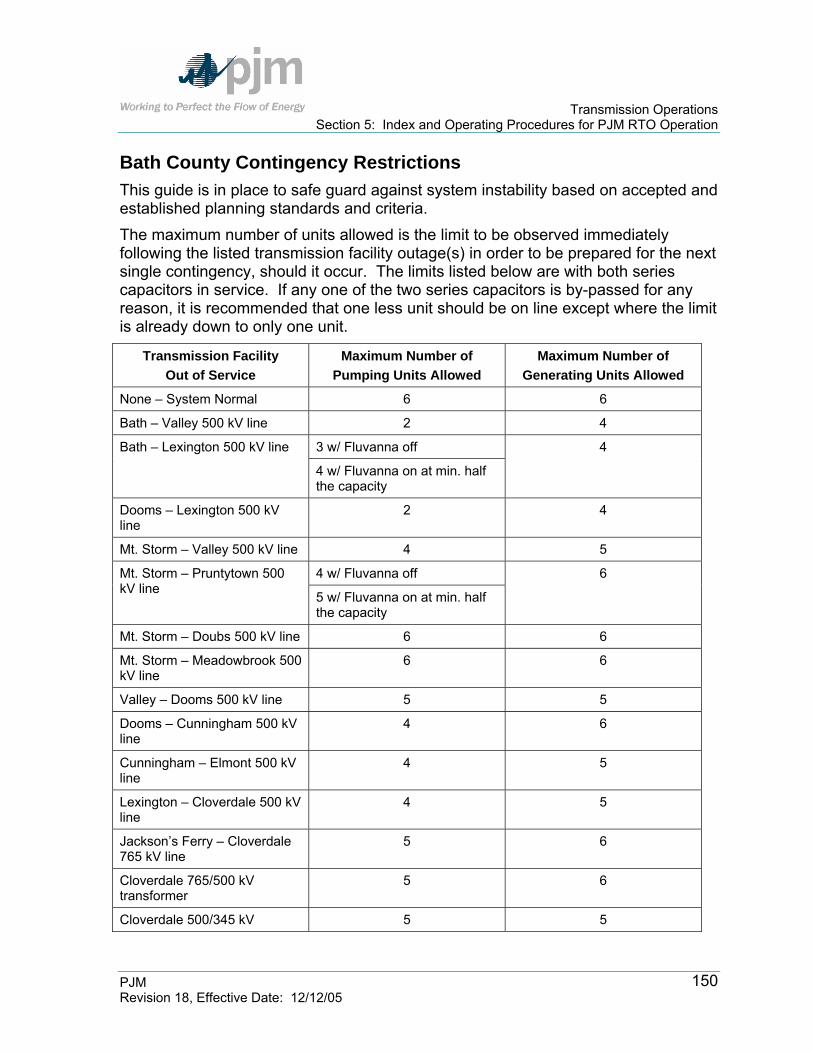
Transmission Operations Section 5: Index and Operating Procedures for PJM RTO Operation
PJM Revision 18, Effective Date: 12/12/05
150
Bath County Contingency Restrictions This guide is in place to safe guard against system instability based on accepted and established planning standards and criteria. The maximum number of units allowed is the limit to be observed immediately following the listed transmission facility outage(s) in order to be prepared for the next single contingency, should it occur. The limits listed below are with both series capacitors in service. If any one of the two series capacitors is by-passed for any reason, it is recommended that one less unit should be on line except where the limit is already down to only one unit.
Transmission Facility Out of Service
Maximum Number of Pumping Units Allowed
Maximum Number of Generating Units Allowed
None – System Normal 6 6
Bath – Valley 500 kV line 2 4
3 w/ Fluvanna off Bath – Lexington 500 kV line
4 w/ Fluvanna on at min. half the capacity
4
Dooms – Lexington 500 kV line
2 4
Mt. Storm – Valley 500 kV line 4 5
4 w/ Fluvanna off Mt. Storm – Pruntytown 500 kV line 5 w/ Fluvanna on at min. half
the capacity
6
Mt. Storm – Doubs 500 kV line 6 6
Mt. Storm – Meadowbrook 500 kV line
6 6
Valley – Dooms 500 kV line 5 5
Dooms – Cunningham 500 kV line
4 6
Cunningham – Elmont 500 kV line
4 5
Lexington – Cloverdale 500 kV line
4 5
Jackson’s Ferry – Cloverdale 765 kV line
5 6
Cloverdale 765/500 kV transformer
5 6
Cloverdale 500/345 kV 5 5

Transmission Operations Section 5: Index and Operating Procedures for PJM RTO Operation
PJM Revision 18, Effective Date: 12/12/05
151
Transmission Facility Out of Service
Maximum Number of Pumping Units Allowed
Maximum Number of Generating Units Allowed
transformer
Baker – Broadford 765 kV line 6 6
Dooms – Cunningham and Mt. Storm – Valley 500 kV lines**
1** 4**
Dooms – Cunningham and Mt. Storm – Doubs 500 kV lines
4 5
Dooms – Cunningham and Mt. Storm – Pruntytown 500 kV lines
4 5
Dooms – Cunningham and Mt. Storm – Meadowbrook 500 kV lines
4 5
Dooms – Cunningham and Lexington – Cloverdale 500 kV lines**
1** 3**
Dooms – Cunningham and One Cloverdale 500/345 kV transformer
3 5
Dooms – Cunningham and Cloverdale 765/345 kV transformer
3 5
Dooms – Cunningham and Cloverdale – Matt Funk 345 kV lines
3 5
Dooms – Cunningham and Cloverdale – Jackson’s Ferry 500 kV lines
2 4
Bath – Valley 500 kV line and Jackson’s Ferry – Cloverdale 765 kV line
1 3
Lexington – Cloverdale and Mt. Storm – Valley 500 kV lines**
1** 2**
** These are limits regardless of the status of series capacitors and they do NOT have to be reduced by one if any one of the two series capacitors is by-passed for any reason. The above analysis is based on the current maximum unit capability of 420 MW each in generating and pumping mode for units #1, #2, #3, #4, and #6. The

Transmission Operations Section 5: Index and Operating Procedures for PJM RTO Operation
PJM Revision 18, Effective Date: 12/12/05
152
maximum unit capability for Bath County unit #5 is limited to 505 MW in generating mode and 485 MW in pumping mode.
Index of Operating Procedures for Duquesne Light Company (DLCo) The Duquesne Light Company (DLCo) Transmission Zone has Operating Procedures that are adhered to by PJM.
Type of Operating Procedure
Transmission Operations Manual
Section Ref
Duquesne Light Company (DLCo)
Elrama and Mitchell Area Operating Procedure
Switching Options Section 5 AP
Carson 138 kV Bus Operation Switching Options Section 5 DLCo Voltage Control at Beaver Valley Voltage Limitations Section 5 DLCo Back To Index
Carson 138 kV Bus Operation The normally closed 2/3 bus tie breaker at Carson may be opened and the normally opened 3/4 bus tie breaker may be closed to relieve contingency overloads on the following lines:
Collier – Elwyn Z-62 Collier – Arsenal Z-67 Crescent – Mt. Nebo - North Z-20 Crescent – North Z-21
Unavailability of Cheswick generation may increase the loadings on the above lines. Note: The above switching may increase loadings on the Elrama – Mitchell circuit, which may also be opened depending on system conditions. (Refer to the Elrama – Mitchell Procedure in the APS Section of the Transmission Operation Manual)
Voltage Control at Beaver Valley This Procedure is currently under development.
Transmission Operations Section 5: Index and Operating Procedures for PJM RTO Operation
PJM Revision 18, Effective Date: 12/12/05
153
Index of Operating Procedures for Jersey Central Power & Light (JCP&L)-First Energy Transmission Zone The Jersey Central Power & Light (JC&PL)-First Energy Transmission Zone has Operating Procedures that are adhered to by PJM.
Type of Operating Procedure
Transmission Operations Manual
Section Ref
Jersey Central Power & Light (JCP&L)-First Energy
Yards Creek Relay (Pumping Mode) Overcurrent Relay Section 5 FE-JCPL Back To Index
Yards Creek Relay (Pumping Mode) This overcurrent relay installed at Kittatinny operates as follows:
When the actual flow on the Portland-Kittatinny 230 kV line exceeds 1958 Amps (equivalent to the summer rating of 782 MVA) for 60 seconds, the No. 2 pump is dropped.
If the flow still exceeds 1958 Amps for another 60 seconds (120 seconds from the initial overload), then the No. 3 pump is dropped, and if the flow still exceeds 1958 Amps for yet another 60 seconds (180 seconds from the initial overload), the No. 1 pump is dropped.
This scheme is designed so that each pump is dropped at a specific time from the initial overload as follows:
No. 1 pump - 180 seconds No. 2 pump - 60 seconds No. 3 pump - 120 seconds
PJM dispatcher must be aware that FE (East) randomly loads these pumps so that, under the worst condition, the line flow exceeds 1958 amps and the No. 1 pump is operating; it takes 180 seconds for the pump to be dropped. This tripping scheme reduces the loading on the Portland-Kittatinny 230 kV line by 60 MW to 200 MW, depending on the number of units pumping and the specific contingency involved. During the Yards Creek pumping periods, PJM dispatcher uses the following manual monitoring procedure to determine the limit to be used on the Portland-Kittatinny 230 kV circuit:
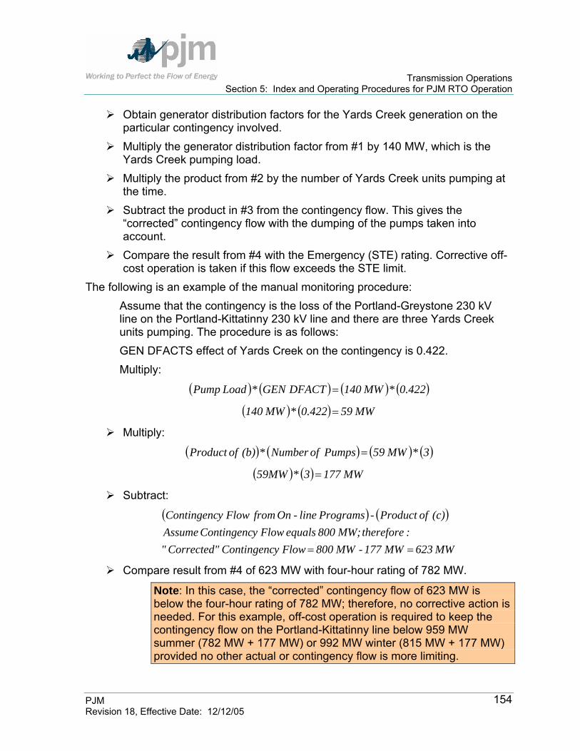
Transmission Operations Section 5: Index and Operating Procedures for PJM RTO Operation
PJM Revision 18, Effective Date: 12/12/05
154
Obtain generator distribution factors for the Yards Creek generation on the particular contingency involved.
Multiply the generator distribution factor from #1 by 140 MW, which is the Yards Creek pumping load.
Multiply the product from #2 by the number of Yards Creek units pumping at the time.
Subtract the product in #3 from the contingency flow. This gives the “corrected” contingency flow with the dumping of the pumps taken into account.
Compare the result from #4 with the Emergency (STE) rating. Corrective off-cost operation is taken if this flow exceeds the STE limit.
The following is an example of the manual monitoring procedure: Assume that the contingency is the loss of the Portland-Greystone 230 kV line on the Portland-Kittatinny 230 kV line and there are three Yards Creek units pumping. The procedure is as follows: GEN DFACTS effect of Yards Creek on the contingency is 0.422. Multiply:
( ) ( ) ( ) ( )0.422 * MW 140 DFACT GEN * Load Pump =
( ) ( ) MW 59 0.422 * MW 140 =
Multiply:
( ) ( ) ( ) ( )3 * MW 59 Pumps ofNumber * (b) of Product =
( ) ( ) MW 177 3 * 59MW =
Subtract:
( ) ( )
MW 623 MW 177 - MW 800 Flowy Contingenc Corrected"":therefore MW; 800 equals Flowy Contingenc Assume
(c) of Product - Programs line-On from Flowy Contingenc
==
Compare result from #4 of 623 MW with four-hour rating of 782 MW.
Note: In this case, the “corrected” contingency flow of 623 MW is below the four-hour rating of 782 MW; therefore, no corrective action is needed. For this example, off-cost operation is required to keep the contingency flow on the Portland-Kittatinny line below 959 MW summer (782 MW + 177 MW) or 992 MW winter (815 MW + 177 MW) provided no other actual or contingency flow is more limiting.

Transmission Operations Section 5: Index and Operating Procedures for PJM RTO Operation
PJM Revision 18, Effective Date: 12/12/05
155
Index of Operating Procedures for Pennsylvania Electric Company (PN)-First Energy Transmission Zone The Pennsylvania Electric Company (PN)- First Energy Transmission Zone has Operating Procedures that are adhered to by PJM. These procedures include the following:
Type of Operating Procedure
Transmission Operations Manual
Section Ref
First Energy-Pennsylvania Electric Company (FE-PN) PJM/NYPP Transfers via First Energy Contingency/Transfers Section 5 FE-PN PJM/AP Tie Lines via First Energy Thermal Contingency Section 5 FE-PN Warren-Falconer 115kV Inverse Time Overcurrent Relay
Special Purpose Relay Section 5 FE-PN
North Waverly- East Sayre 115 kV Inverse Time Overcurrent Relay
Special Purpose Relay Section 5 FE-PN
Conemaugh Unit Stability Stability Section 5 FE-PN Conemaugh #2 Unit Stability Trip Scheme-Conemaugh-Juniata 500kV Outage
Stability Section 5 FE-PN
Keystone-Conemaugh (5003) Reclose Procedure
Special Purpose Scheme Section 5 FE-PN
Seneca Pump Operation Generation Section 5 FE-PN Procedure To Run Seneca Generation For PJM/PN Constraints
Generation Section 5 FE-PN
TMI Voltage Notification Procedures Voltage Requirements Section 5 FE-PN Hunterstown-Conastone (5013) Transfer Trip Scheme
Special Purpose Relay Section 5 FE-PN
PJM/NYPP Transfers NYPP and PJM agree that the 115 kV facilities (North Waverly-East Sayre, Warren-Falconer, and Tiffany-Goudey) may be opened if the facility is an actual or post-contingency limit on the PJM RTO or NYPP operation. The North Waverly-East Sayre 115 kV line is equipped with an overcurrent relay with a trip setting of 128 MVA. The Warren-Falconer 115 kV line is also equipped with an overcurrent relay with trip settings for summer and winter of 116 MVA and 136 MVA, respectively. These relays are described later in this section.
PJM Actions: PJM dispatcher initiates a study for the appropriate switching.

Transmission Operations Section 5: Index and Operating Procedures for PJM RTO Operation
PJM Revision 18, Effective Date: 12/12/05
156
If the study indicates no actual or contingency overloads result from opening the tie, PJM dispatcher contacts First Energy and NYPP to determine if conditions permit the opening of the proposed facilities.
If agreed by all PJM Members (PJM, First Energy, and NYISO), PJM dispatcher instructs FIRST ENERGY to open the appropriate facilities.
PJM dispatcher logs the PJM-NYPP net tie flow in order to get an indication of the PJM-NYPP transfers so that reclosure conditions can be determined.
Based on local security reasons, PJM dispatcher initiates the reclosure of these lines at the request of FIRST ENERGY or NYPP.
PJM dispatcher initiates the reclosure of these lines as soon as practical after transfers between the PJM RTO and NYPP decline below the value noted in Step 4.
First Energy East Tie Lines FE procedures exist to control thermal contingencies that occur on the AP 138/115 kV tie lines. The following facilities may be opened if they impose an actual or post-contingency limit on PJM operation:
First Energy East/AP Tie Line Voltage Carroll – Germantown 138 kV Grand Pt. – Roxbury 138/115 kV Garrett – Tap 138/115 kV Social Hall – E. Blairsville 138 kV Burma – Piney 115 kV
Exhibit 13: First Energy East/AP Tie Lines
PJM Actions: PJM dispatcher initiates a security analysis study for the appropriate
switching. If the study indicates no actual or contingency overloads result from opening
the tie, PJM dispatcher contacts First Energy East and AP to determine if conditions permit the opening of the proposed facilities. (Note: The AP and First Energy 138 kV and 115 kV systems are modeled, but not necessarily monitored, by PJM.)
If agreed by all PJM Members (PJM, First Energy, and AP), PJM dispatcher instructs First Energy to open the appropriate facilities.
PJM dispatcher uses a power flow analysis as an indication for reclosure. Based on local security reasons, PJM dispatcher initiates the reclosure of
these lines at the request of First Energy or AP.
Transmission Operations Section 5: Index and Operating Procedures for PJM RTO Operation
PJM Revision 18, Effective Date: 12/12/05
157
PJM dispatcher initiates the reclosure of these lines to service when a power flow analysis indicates
PJM Special Purpose Relay Operations
Warren-Falconer 115 kV Relay There is an inverse time overcurrent relay installed on the Warren-Falconer 115 kV line to trip this line in case of an overload. The relay is set to operate if the flow exceeds the ratings as follows:
Relay Set Point Period of the Year 116 MVA Short-Term Emergency May 1 through October 31 136 MVA Short-Term Emergency November 1 through April 30
Exhibit 5.9: Warren-Falconer 115 kV Relay Set Points
The line trips in 1.5 seconds at 192 MVA. Whenever there is a contingency overload on the Warren-Falconer 115 kV line for the loss of some other facility (such as the Erie South-Erie East 230 kV line or the Erie East-South Ripley 230 kV line), the multiple contingency (loss of Warren-Falconer 115 kV and the other facility) is added to PJM security analysis program’s contingency list. Both single contingencies (loss of Erie South-Erie East 230 kV line and the Erie East-South Ripley 230 kV line) are suppressed. PJM dispatcher should also continue to monitor and perform studies on the single contingency losses (Erie South-Erie East and the Erie East-South Ripley) to ensure system reliability while the relay is being employed.
North Waverly-East Sayre 115 kV Relay An inverse time overcurrent relay is installed on the North Waverly-East Sayre 115 kV line. The relay trips the circuit breaker at East Sayre if flow on the line reaches 128 MVA. This relay scheme is valid for flow in either direction. Whenever there is a contingency overload on the North Waverly-East Sayre 115 kV line for the loss of some other facility (such as Hillside-East Towanda 230 kV line), the multiple contingency (loss of North Waverly-East Sayre 115 kV line and the other facility) in PJM security analysis program’s contingency list. The single contingency (loss of Hillside-East Towanda 230 kV line) is suppressed.
Conemaugh Unit Stability In April of 1987, the Capacity and Transmission Planning Subcommittee (C&TPS) completed a stability analysis for the Keystone and Conemaugh generating stations. With the four Keystone/Conemaugh units at 850 MW net/unit, transient instability results under the following conditions:

Transmission Operations Section 5: Index and Operating Procedures for PJM RTO Operation
PJM Revision 18, Effective Date: 12/12/05
158
With Keystone-Conemaugh (5003) line on maintenance, both Conemaugh units are transiently unstable for a fault on either Conemaugh-Juniata (5005) or Conemaugh-Hunterstown (5006).
With the Conemaugh-Hunterstown (5006) line on maintenance, both Conemaugh units are transiently unstable for a fault on Keystone-Conemaugh (5003).
With the Conemaugh-Juniata (5005) line on maintenance, both Conemaugh units are transiently unstable for a fault on Keystone-Conemaugh (5003), unless the Conemaugh #2 Unit Stability Trip Scheme is enabled.
The C&TPS study also concluded that for Keystone and Conemaugh, neither the number of units operating, nor the level of unit output at the other station significantly affect stability at one station. PJM Actions:
PJM dispatcher monitors and controls the Conemaugh Station net MW output to the following stability limits:
For Keystone-Conemaugh (5003) line outages, Conemaugh Station net output is limited to 1570 MW.
For Conemaugh-Hunterstown (5006) line outages, Conemaugh Station net output is limited to 1605 MW.
For Conemaugh-Juniata (5005) line outages, Conemaugh Station net output is limited to 1605 MW, unless the Conemaugh #2 Unit Stability Trip Scheme is enabled (see below).
Conemaugh #2 Unit Stability Trip Scheme-Conemaugh-Juniata 500 kV Outage
Note: In order for a stability trip scheme to function properly, Conemaugh #4 and #5 500 kV circuit breakers must be open and isolated. If line jumpers are opened and breakers #4 and #5 are closed to restore buses at Conemaugh, the stability trip scheme is defeated.
A stability trip scheme is available at Conemaugh, which allows full plant output during an outage of the 5005 Juniata-Conemaugh 500 kV line. The stability trip scheme operates to trip the Conemaugh #2 Unit upon the loss of the Keystone-Conemaugh (5003) 500 kV line, eliminating the transient instability for the Conemaugh Units. Under normal system conditions and following a pre-evaluation of the 5005 Conemaugh-Juniata 500 kV line outage, the scheme is enabled at the direction of PJM dispatcher.
Transmission Operations Section 5: Index and Operating Procedures for PJM RTO Operation
PJM Revision 18, Effective Date: 12/12/05
159
The stability trip scheme is not enabled under the following conditions: Either the Conemaugh #4 or #5 500 kV circuit breakers are closed. Upon the trip of the 500 Conemaugh-Juniata 500 kV line, until system
conditions can be studied by operations personnel. When the PJM RTO is determined to be capacity limited.
The trip scheme is disabled prior to implementing a Maximum Emergency Generation Action, but re-enabled prior to implementing a Manual Load Dump Action.
When system conditions warrant the reduction of Conemaugh generation below the 1605 MW level due to: a) economics b) reactive/thermal constraints c) plant maintenance
First Energy Energy Actions: Upon a change in status of the relay scheme (enable to disable, disable to
enable), the First Energy dispatcher notifies PJM dispatcher. First Energy reduces generation before disabling the scheme (or enable the
scheme before increasing generation) at Conemaugh, thereby maintaining maximum system reliability.
PJM Actions: PJM dispatcher directs the enabling/disabling of the stability trip scheme
based on system conditions outlined above. PJM dispatcher verifies that Conemaugh #4 and #5 500 kV circuit breakers
are open and isolated. PJM dispatcher records the stability trip scheme status on the daily log sheet. PJM dispatcher updates PJM SA to reflect change in status of the stability
trip scheme. PJM dispatcher informs all Local Control Centers via the ALL-CALL of a
change in status of the stability trip scheme.
Keystone-Conemaugh 5003 Line / Re-Close Procedure Keystone-Conemaugh (5003) line will normally be operated with recloser “in
service” on #3 CB at Conemaugh. This will allow re-closing with a sync-check angle set at 10° or less. The logic will also automatically allow closing

Transmission Operations Section 5: Index and Operating Procedures for PJM RTO Operation
PJM Revision 18, Effective Date: 12/12/05
160
at 60° or less if both Conemaugh units are off-line (there are B contacts in the Gen. Isolating Disconnect Switches). If one or both of the Conemaugh units are on and the phase angle is greater than 10°, but less than 30°, a manual breaker close can be performed from the Conemaugh Plant Control Room or from the EMS after operating a defeat switch which enables the PLU* scheme. Once the PLU defeat switch has been operated, the Control Room operator has a (2) minute time window to manually close the circuit breaker and parallel the 5003 line at Conemaugh (see step 3 below),
A General Electric study was done to investigate the Turbine-Generator shaft fatigue damage that might result from 5003 line switching. It was found that significant loss-of-life would not occur for cases of switching at less than 30°s.
In the event 5003 Keystone-Conemaugh line trips, the combined output of Conemaugh units #1 & #2 should immediately be reduced from 1605 MW’s for stability reasons (see Section 3: Voltage and Stability Operating Guidelines) and proceed as follows:
If the Keystone terminal remains open, follow established procedures to determine cause of trip, correct problem and test the line from Keystone.
If Conemaugh terminal remains closed, with the Keystone terminal open, de-energize the Conemaugh terminal, and follow established procedures to determine cause of trip, correct problem and try-back line from Keystone (5003 line right-of way is Keystone).Once the 5003 Keystone-Conemaugh line has been tested and remains energized from Keystone, or if the Keystone terminal successfully recloses, the Conemaugh terminal should not be closed to parallel the line until all reasonable actions have been taken to reduce the angle across the open CB at Conemaugh to or below 30°s.
PJM and First Energy Reading Dispatcher (hereafter referred to as FERD) should determine the phase angle across the open breaker at Conemaugh. FERD EMS telemeters the phase angle to the TSO. PJM EMS displays the 5003 phase angle across the open # 3 CB at Conemaugh.
FE at Reading studies indicate that the angle across the open terminal at Conemaugh should be acceptable if the algebraic difference of the MW flows on the Keystone-Juniata (5004) line and the Conemaugh-Juniata (5005 line is 1650 MW’s or less. See the examples below:

Transmission Operations Section 5: Index and Operating Procedures for PJM RTO Operation
PJM Revision 18, Effective Date: 12/12/05
161
Note: The reduction of Keystone units reduces the delta flow on the 5004 Keystone-Juniata, and 5005 Conemaugh-Juniata lines thereby reducing the phase angle at Conemaugh. Keystone units should be reduced until a favorable phase angle is obtained. Keystone generation should be replaced with internal generation east of Keystone/Conemaugh.
The following information is a guideline, the telemetered phase angle should be used prior to re-closing the # 3 500 kV CB at Conemaugh.
Example #1: 5004 Keystone-Juniata Flow = 1850 MW’s
400 MW’s
Difference: 1450 is less than 1650 MW”s OK
Example #2: 5004 Keystone-Juniata Flow = 2150 MW’s
5005 Conemaugh-Juniata flow = 400 MW’s
Difference: 1750 greater than 1650 MW’s NO!
*Note: Power Load Unbalance relay is designed to rapidly reduce steam pressure when unbalance exists between unit steam pressure and electrical output.
Seneca Pump Operations
Overview The purpose of this procedure is to ensure continued reliable system operations on the Erie West 345/115kV #1 transformer. while operating to a 1 hour STE rating in order to allow for a second pump at Seneca Generating Station. PJM will monitor system conditions for real-time or post-contingency overloads. First Energy has agreed to have one or both pumps off-line in 10 minutes should a contingency occur in order to return post-contingency flows to within normal ratings. FE will purchase, after the fact, Non-Firm “willing to pay congestion” transmission service anytime in which Seneca is pumping above 352 MW. PJM automatically grants FE non-firm transmission service “willing to pay congestion”. If post-contingency flows on the Erie West 345/115kV #1 transformer begin to exceed the 1 hour STE rating after starting a second pump and FECE decides that they do not

Transmission Operations Section 5: Index and Operating Procedures for PJM RTO Operation
PJM Revision 18, Effective Date: 12/12/05
162
wish to continue to pay the congestion charges, Seneca should make their own evaluation to take the pump off-line and First Energy Conversion Economics (FECE) will call and inform PJM. The amount of transmission service will be based on actual MWHrs used. FECE will obtain the actual usage from PJM accounting and will enter the request in OASIS.
Procedure to approve Pumping Operation: 1. The FECE Dispatcher shall call PJM Dispatching and First Energy Reading
Dispatch (FERD) 45 minutes prior to (desired) actual pump operations. 2. The PJM Power Dispatcher, using forecasted system conditions, will study
pump operation. This will include running a PF/SA study by turning on a Seneca pump, increasing interchange between ECAR and PJM, increasing FE generation by 220 MW, and verifying NYPP generation patterns at Dunkirk and South Ripley.
3. The PJM Power Dispatcher shall respond back to the FECE Dispatcher within 15 minutes with the results of their analysis.
a. First Pump Operations – Control to LTE & activate “line + pump” contingency
Once the pump is operating the PJM PD will activate “line + pump” contingency in EMS to monitor real-time and suppress the “normal” line-only contingency if post-contingency flows exceed LTE rating.
The FECE Dispatcher shall alert the Seneca Plant Operator that pump tripping may be required and initiate ‘pump trip’ protocol (i.e., alert station personnel to turn on beeper/cell phone in case of implementation).
FERD to take the line out-of-service at Glade to immediately dump the Seneca pump if Seneca Plant Operator does not cease Seneca pumping within 5 minutes.
b. Second Pump Operations – Control to STE & suppress “line + pump” contingency
Once the second pump is operating the PJM PD will suppress the “line + pump” contingency in EMS to monitor real-time and re-activate the “normal” line-only contingency if implemented for first pump. Control to STE rating.
The FECE Dispatcher shall alert the Seneca Plant Operator that pump tripping may be required and initiate ‘pump trip’ protocol (i.e., alert station personnel to turn on beeper/cell phone in case

Transmission Operations Section 5: Index and Operating Procedures for PJM RTO Operation
PJM Revision 18, Effective Date: 12/12/05
163
of implementation) to trip one or both pumps depending on the severity of the overload.
FERD to take line out-of-service at Glade to immediately dump both Seneca pumps if Seneca Plant Operator does not cease Seneca pumping within 10 minutes.
c. Off-cost Operations w/ Seneca Pumping First Seneca Pump – PJM PD will control to the LTE rating with
the “line + pump” contingency activated and the “normal” line-only contingency suppressed.
Second Seneca Pump – PJM PD will control to the STE rating with the “normal” line-only contingency activated. PJM PD will contact FECE to determine if FECE is willing to pay congestion charges prior to redispatch in order to maintain post-contingency flows below STE ratings with 2 pumps in-service.
Off-cost Operations – PJM will curtail non-firm transactions not willing to pay congestion, and redispatch economic generation as appropriate. PJM will implement Interregional Congestion Management with NYISO and request Dunkirk / Huntley Generation to redispatch for the Erie West 345/115kV #1 Xfmr to allow continued operation of the first Seneca pump.
Erie West 345/115 #1 kV Xfmr Ratings: Temperature Set: 95 86 77 68 59 50 41 32 Four-hour rating: 321 328 334 341 347 354 360 366 One-hour rating: 357 365 373 381 388 396 403 410
Note: PJM will request FECE to remove a pump from service if pumping results in an actual overload that cannot be controlled via redispatch.
Note: FERD installed temperature monitors and is investigating dynamic ratings on the Erie West 345/115kV #1 Xfmr.
Pre-Contingency Switching Options to allow Seneca Pumping due to Actual Overloads
Step 1: Primary Switching Option - Coordinate with FE-E opening the Handsome Lake 345kV CB at Wayne (Handsome Lake – Wayne 345kV line opened at Wayne only). This switching option exists to allow continued operation of the first Seneca pump or to maximize pumping capabilities under

Transmission Operations Section 5: Index and Operating Procedures for PJM RTO Operation
PJM Revision 18, Effective Date: 12/12/05
164
certain operating conditions (described below), which would be restricted in real-time due to actual overloads (usually on the Erie West – Erie South 345kV line). Transactions “Not Willing to Pay through Congestion” should be curtailed prior to switching. Step 2: Initiate off-cost operations to control loading. Step 3: Initiate Interregional Congestion Management procedure (if applicable). Procedure can be implemented to control loading on Erie West 345/115kV #1 xfmr. Step 4: Issue a TLR 3A/B to maintain flows at or below their current levels. Step 5: Periodically reevaluate returning opened facilities to service.
Post-Contingency (post-event) Switching Options Primary Option: FERD has agreed to open the Perry – Ashtabula 345kV line @ Perry once an actual overload can no longer be controlled via re-dispatch, there is insufficient time to control via a TLR, or no other switching options are available. This option is only available if load dump is imminent.
FE-W will open at Perry S620 and S621 (as per PJM EMS Single-line breaker designation) 345kv CBs via SCADA control (takes the Perry to Ashtabula Tap 345kv line section out of service). This will also reduce the push from the Perry nuclear unit and still allow voltage support to Erie West from Ashtabula Tap.
NOTE: FE-W indicated that the 8-T transformer at Ashtabula Tap would be left in service. This transformer is limited by reverse power flow of 270mw (per FE-W support). If this transformer needs to be opened along with the S620 and S621 CBs at Perry voltage support from Ashtabula Tap will be lost. FE-E and FE-W should perform and discuss local studies whenever PJM has declared a Load Dump Warning for Erie West #1 Xfmr to ensure there is no delay in the implementation of switching.
Secondary Option: Open the Erie West – Ashtabula 345kV line @ Erie West depending on post-contingency configuration of Erie West 345kV bus (Erie West #5 and #6 345CBs in-service) and status of Handsome Lake – Wayne 345kV line (Handsome Lake 345CB @ Wayne in-service). Erie West 345/115kV #1 xfmr must remain in-service to provide voltage support to Erie Area.
Note: Conditions may exist that would dictate switching of the Perry – Ashtabula 345kV line pre-contingency in order to maximize Seneca Pond Level. These limited operating conditions include:
Capacity Deficient Conditions on PJM or FE systems.
Transmission Operations Section 5: Index and Operating Procedures for PJM RTO Operation
PJM Revision 18, Effective Date: 12/12/05
165
Localized transmission outages requiring Seneca Generation for reliability purposes.
These conditions must be forecasted, studied and approved by PJM, ECAR MET, and LCC support staff. Switching of the Perry – Ashtabula 345kV (and Transformer) line will only occur if either of the acceptable conditions defined above are met, generation redispatch is exhausted and outaging of the line does not violate reliability criteria.
Procedure To Run Seneca Generation For PJM/PN Constraints Purpose: Provide a consistent method for utilization of Seneca Generation when required for PJM transmission control. Whenever in the opinion of PJM, Seneca Generation is required for contingency/actual facility control on the PJM system, the following procedure should be used:
If a prearranged job in the PN area will require Seneca generation, PJM will attempt to schedule the job during the hours Seneca is normally scheduled to generate. Schedules can be obtained from FE in advance.
If Emergency or must do jobs are required outside of the normal Seneca generation schedule window, PJM will determine via study how much Seneca Generation is necessary and identify what hours this generation is required.
Notify FE and request Seneca generation as per PJM study results. If real time generation requirements differ from study results, alter schedule as appropriate if outside the normal Seneca generation schedule.
PJM Transaction Coordinator will set up a bilateral schedule with FE for all Seneca Generation outside of or greater than the forecasted FE Seneca schedule.
NOTE 1: FE will be compensated based on the Seneca bus LMP whenever Seneca bilateral schedules are set up for PJM constraint control. In addition FE will be compensated for lost opportunity if applicable by requesting it in writing, detailing this lost opportunity. Request should be sent directly to the PJM Manager Market Settlements. If approved, lost opportunity will be paid out of the PJM operating reserve account. If a PJM transmission outage requiring Seneca generation is scheduled during the normal FE Seneca Generation schedule, a bilateral schedule is not required. FE reserves the right to change the Seneca Generation schedules (with proper
Transmission Operations Section 5: Index and Operating Procedures for PJM RTO Operation
PJM Revision 18, Effective Date: 12/12/05
166
notification) provided PJM has not declared Max Emergency Generation (Seneca Generation is considered to be a PJM unit. Any capacity transactions from these units to sinks outside PJM will appear as exports from PJM and are not normally available to PJM when we are in Max Emergency. External sales of internal units must be made 36 hours in advance and should appear on the Supervising Dispatcher’s Report on External Transactions and PJM Installed Capacity. NOTE 2: If Seneca is the only controlling action, the PD should note the constraint and controlling action in the PD Log #2 only, since hydro has no bid price. As a result it cannot set LMP.
TMI Voltage Notification Procedures Three Mile Island Nuclear (TMI) Plant requires that pre- and post-contingency voltages be maintained above 219kV and 207.2 kV, respectively with both offsite sources in service. TMI Limitations
TMI Normal Low Limit Basis: The TMI Plant Normal Low Limit Alarm is established at 219 kV. The TMI-1 Voltage Regulation Study results show that under worst case station service loading conditions, action is required at grid voltage levels less than 219 kV.
TMI Emergency or Post Contingency Low Limit Basis: The TMI Plant Emergency or Post Contingency Low Voltage Alarm is dependent on the number of offsite sources in service. The TMI-1 Voltage regulation Study results show that with both offsite sources (Auxiliary transformers) in service the grid low voltage limit is 207.2 kV which is below the PJM 230 kV standard emergency low limit of 212 kV, or with one (1) Auxiliary Transformer in service the minimum grid voltage at which all safety loads can be automatically started on the offsite source, post unit trip, is 218.9 kV.
Note: It is the TMI plant operator’s responsibility to notify the PJM dispatcher when only one (1) Auxiliary Transformer is in service, requiring operating to higher voltage limitations. (This will require manually changing the appropriate voltage limits in the PJM EMS).
Normal Operation (with 2 Auxiliary Transformers): Normal Low Voltage Limit: 219 kV (same as PJM base limit) Emergency Low Voltage Limit: 212 kV (same as PJM base limit) Operation with only 1 Auxiliary Transformer: Normal Low Voltage Limit: 219 kV (same as PJM base limit) Emergency Low Voltage Limit: 218.9 kV

Transmission Operations Section 5: Index and Operating Procedures for PJM RTO Operation
PJM Revision 18, Effective Date: 12/12/05
167
Notification Procedures All TMI voltage violations below the required pre and post contingency limits of 219 kV and 207.2 kV respectively for two transformer operation and the required pre and post-contingency limits of 219 kV and 218.9 respectively for single transformer operation are to be communicated to First Energy System Operators (MET ED). PJM System Operators should evaluate the effect of corrective options and agree to corrective measures (non cost corrective measures only for post-contingency single transformer limit violations) with the First Energy System Operators (MET ED). The First Energy System Operator will then inform TMI Plant Operators (Amergen) of the voltage conditions, including the contingency element (TMI generator or external contingency) and the planned corrective actions. First Energy System operator will communicate the effectiveness of those corrective actions to TMI plant operators. TMI pre-contingency voltage limits are affected by TMI balance of plant loading. TMI balance of plant loading reductions may allow TMI pre-contingency voltage limits of less than 219 kV. TMI Plant Operators are to communicate all plant corrective actions for pre- or post-contingency voltages when operating at or below the plant grid voltage limitation to the First Energy System Operator (MET ED) who will then communicate the actions to the PJM System Operator. Once system conditions begin to improve or all corrective actions have been exhausted, either as a result of operator actions or unplanned changes to operating conditions, PJM operators should notify First Energy System Operators (MET ED) who will then communicate the change in system conditions to TMI Plant Operators (Amergen). If pre- or post-contingency voltages continue to exceed Plant limitations, PJM will coordinate a reduction of MW output or the removal of TMI Unit from service to facilitate TMI’s restoring its internal voltage levels to within station limits. TMI Plant Operators may also request PJM to determine if a power reduction and MVAR increase will mitigate the low voltage condition and maintain post-contingency voltage above the minimum requirement.
Additional Notification Procedures when operating with only 1 Auxiliary Transformer: If all non-cost actions are ineffective in meeting the TMI post contingency single transformer voltage requirement, TMI Operators will communicate directly with PJM to request off-cost generation support. PJM will inform TMI if available generation has been cost capped. PJM System Operations will communicate the need to dispatch generation to support the TMI post-contingency single transformer voltage requirement via an all

Transmission Operations Section 5: Index and Operating Procedures for PJM RTO Operation
PJM Revision 18, Effective Date: 12/12/05
168
call. PECO system operations will notify key TMI personnel when they receive this all -call. Corrective Actions PJM operators should implement all non-cost and off cost measures to improve area voltages within defined TMI limitations. These measures include but are not limited to the following:
Switching of 286 MVAR of bulk capacitors located at TMI 500kV bus. Utilizing the Load Tap Changers (LTC) on the TMI 500/230kV
autotransformer. Examining other regional bulk system reconfiguration options such as the
switching of other available bulk power capacitors, adjustment of LTC’s, and voltage schedule adjustments where effective and available.
Increase the reactive reserve on the TMI #1 Unit. To realize the desired voltage effect, coordination of area generator reactive output such as Brunner Island generators must be coordinated.
Utilize “off cost” (out of merit generation) including lowering of TMI MW output as appropriate to realize the desired voltage effect.
Hunterstown – Conastone (5013) Transfer Trip Scheme A relay scheme is in place at the Conastone and Hunterstown stations which trips the Hunterstown #1 500/230 kV transformer if the Hunterstown – Conastone (5013) 500 kV line trips. An additional transfer trip scheme is in place which also removes the Hunterstown #1 500/230 kV transformer from service if both terminals at Conastone are open. Whenever a contingency exists such that both of the 5013 terminal CB’s at Conastone are opened, the on-line computer contingency list is adjusted to reflect the multiple contingency loss of the facility causing the contingency, and the 5013 and Hunterstown #1 500/230 kV Transformer. For example, loss of the Conastone #2 500 kV transformer normally opens the “K” and the “L” 500 kV CB’s. However, if the Conastone “M” 500 kV CB is out of service, the opening of the “K” and “L” CB’s results in the 5013 500 kV line being open ended. Under this condition there is a relay scheme that will cause a transfer trip of the #7 and #8 500 kV CB’s at Conemaugh and the Hunterstown #1 500/230 kV transformer resulting in the removal of the 5006, 5013, and Hunterstown #1 transformer. Therefore the multiple loss of the Conastone #2, 5006, 5013, and Hunterstown #1 transformers is added to PJM security analysis program’s contingency list.

Transmission Operations Section 5: Index and Operating Procedures for PJM RTO Operation
PJM Revision 18, Effective Date: 12/12/05
169
Index of Operating Procedures for PECO Energy (PE) Transmission Zone The PECO Energy (PE) Transmission Zone has Operating Procedures that are adhered to by PJM. These procedures include the following:
Type of Operating Procedure
Transmission Operations Manual
Section Ref
PECO Energy Company (PECO) 5025 Keeney-Rock Springs Line Ratings
Line Ratings Section 5 DPL
Hosensack-Buxmont 230 kV Line Contingency
Contingency Section 5 PPL
Nottingham- Graceton 230 kV Line Limitations
Line Limitation Section 5 PECO
Whitpain Transformer Outages Contingency Section 5 PECO
Deptford 230 kV Breaker Relay Special Purpose Relay Section 5 AE Muddy Run Protective Relay Special Purpose Relay Section 5 PECO Peach Bottom ‘45’ 500 kV CB outage Contingency Section 5 PECO Limerick 4A and 4B 500/230 kV Transformer Banks
Transformer Ratings Section 5 PECO
Linwood Special Protection Scheme Special Protection Scheme Section 5 PECO Back To Index
Nottingham - Graceton 230 kV Line Limitations The Nottingham-Nottingham Tap-Graceton 230 kV line (220-08) is modeled in PJM security analysis programs. The configuration between Nottingham and Nottingham Tap is represented in PJM security analysis programs.
When the reactor is in service, the reactor by-pass should be out of service. With the reactor by-pass out of service, MW flow must pass through the reactor.
When the reactor is out of service, the reactor by-pass should be in service. With the reactor by-pass in service, MW flow follows the path of lowest impedance and bypasses the reactor.
Note: It is not necessary to change the status of the reactor if the status of the by-pass and 220-08 line are modeled correctly.
The operation of the reactor on the 220-08 line impacts power flows by changing the impedance of the transmission system. The reactor is used as an operating tool to benefit the transmission system and minimize contingency flows. PECO Energy

Transmission Operations Section 5: Index and Operating Procedures for PJM RTO Operation
PJM Revision 18, Effective Date: 12/12/05
170
requests PJM dispatcher's approval prior to switching the reactor in or out of service. PECO Energy notifies BGE of the status of the reactor. PJM Actions: To control actual and contingency overloads on the Nottingham-Graceton 220-08 line, PJM performs the following actions:
PJM dispatcher checks the status of the Nottingham reactor. If the reactor is available but not in service, PJM dispatcher requests PECO Energy to switch it in service.
If the Nottingham reactor is out of service or unavailable and thermal overloads still exist, PJM dispatcher evaluates the possibility of opening the Conowingo 230 kV bus tie CB. In order to determine the effect of opening the Conowingo bus tie CB, a contingency analysis study program is run with only the bus tie CB taken out of service. If determined by PJM dispatcher(upon consideration of flows on critical lines, generation patterns, and the study run) that opening the Conowingo 230 kV bus tie CB will adequately reduce the flow on the 220-08 line and will not create a more severe problem in the PJM RTO, PJM dispatcher requests PECO Energy to open the Conowingo bus tie CB. Otherwise, PJM dispatcher proceeds to the next course of action, Step 3.
When opening the Conowingo Bus Tie CB, PJM dispatcher considers the following information:
Opening the Conowingo 230 kV bus tie CB usually reduces the contingency flow on the 220-08 line, but it can create contingency problems on the Nottingham-Bradford 230 kV line (220-05).
Reclosing of the Conowingo 230 kV bus tie CB is made as soon as a power flow analysis shows that the contingency flow problem on the 220-08 line no longer exists with the Conowingo bus tie CB in service.
The status of the Conowingo 230 kV bus tie CB does not change the generation that is lost with the tripping of the 220-01 or the 220-03 lines. If the Conowingo-Bradford (220-01) line trips, units #1-7 at Conowingo trip. Similarly, if the Conowingo-Nottingham (220-03) line trips, units #8-11 at Conowingo trip.
Note: Due to potential overloads on the 230/35 kV transformer at Colora substation, DPL must be notified prior to opening the Conowingo bus tie CB.
If it is determined that opening the tie CB at Conowingo does not adequately reduce the contingency flow on the 220-08 line or that it creates other more

Transmission Operations Section 5: Index and Operating Procedures for PJM RTO Operation
PJM Revision 18, Effective Date: 12/12/05
171
severe problems on the system, then PJM dispatcher evaluates the possibility of opening the 220-08 line.
PJM dispatcher considers any major transmission paths scheduled out of service. The most significant of these paths are the Peach Bottom-Rock Springs-Keeney 500 kV line (5025/5014), Peach Bottom-Limerick 500 kV line (5010), and Peach Bottom-Conastone 500 kV line (5012). If a major line is out, PJM operations planning staff re-evaluates the operating procedures for opening the 220-08 line. Unless instructed otherwise, if a major line is out of service, PJM dispatcher operates off-cost for 220-08, as required.
If conditions on the system permit the opening of the 220-08 line, PJM dispatcher runs a contingency analysis study taking the 220-08 line out of service. If determined by PJM dispatcher determines (upon consideration of flows on the reactive transfer limit interfaces, flows on critical lines, load patterns, generation patterns, and the study run) that opening the 220-08 line solves the problem without creating more severe problems on the system, PJM dispatcher contacts PECO Energy and BGE to determine if they have any local conditions which make it undesirable to open the 220-08 line. If both PECO Energy and BGE approve, PJM dispatcher requests PECO Energy to open the 230 kV CB at Nottingham on the Graceton-Peach Bottom Tap-Nottingham circuit.
If opening the 220-08 line does not solve the problem, creates worse problems, or either PECO Energy or BC do not agree to open the line, then PJM dispatcher operates off-cost, as required.
When opening the 220-08 line, PJM dispatcher considers the following information:
When the 220-08 line is open, the position of the Conowingo bus tie CB is left to the discretion of the PECO Energy operators. It is expected that the Conowingo 230 kV bus tie CB is normally to be kept closed.
Thermal overloads on the 220-08 line caused by the loss of Peach Bottom - Conastone 500 kV line (5012) can be relieved by opening the 220-08 line. However, opening this line decreases total eastern import capability.
Opening the 220-08 line increases flows on the reactive transfer limit interfaces. If the system is near a reactive limit, it may be advisable to operate off-cost for 220-08 rather than open the line.

Transmission Operations Section 5: Index and Operating Procedures for PJM RTO Operation
PJM Revision 18, Effective Date: 12/12/05
172
If the 220-08 line is open and a major line is forced out of service, PJM dispatcher attempts to close the 220-08 line. It remains closed until the effects of the outage on the system can be evaluated in terms of reopening the 220-08 line.
Reclosure of the 220-08 line is made after PJM dispatcher determines, using the contingency analysis study program, that the line can be safely returned.
Whenever the contingency loadings cannot be controlled with the above procedures, PJM dispatcher operates off-cost as required.
Whitpain 500-1 or 500-2 Transformer Outages When either the Whitpain 500-1 or the Whitpain 500-2 transformer is out of service, the contingency loss of the Whitpain-Elroy (5029) 500kV line and the associated Whitpain 500-3 transformer may subject the remaining Whitpain 500/230 kV transformer to loading in excess of its emergency rating. In order to minimize the amount of off-cost generation required to control the contingency overload on the remaining Whitpain 500/230kV transformer, the following circuit breaker openings should be analyzed:
For a Whitpain 500-1 transformer outage: Open the Whitpain ‘575’ and ‘185’ 500kV circuit breakers
For a Whitpain 500-2 transformer outage: Open the Whitpain ‘475’ and ‘285’ 500kV circuit breakers
The additional 500 kV circuit breaker openings at Whitpain result in one of the Whitpain-Limerick 500 kV lines becoming open-ended at Whitpain for the contingency loss of the Whitpain-Elroy (5029) 500 kV line and the associated Whitpain 500-3 transformer. This open-ending results in a higher impedance path seen from Limerick to Whitpain, as only one of the two Whitpain-Limerick 500 kV lines remains in-service. Without the additional 500 kV circuit breaker openings, both Whitpain-Limerick 500 kV lines would remain in-service, providing a lower impedance path for power to flow from Limerick 500 kV down through the remaining Whitpain 500/230 kV transformer. The additional 500 kV circuit breaker openings at Whitpain provide significant relief on the Whitpain transformer contingency without degrading overall system reliability. PJM Actions:
PJM dispatchers are to perform a reliability analysis modeling the appropriate switching at Whitpain.
If the analysis indicates that opening the additional Whitpain circuit breakers is a benefit to the operation of the transmission system, PJM dispatchers

Transmission Operations Section 5: Index and Operating Procedures for PJM RTO Operation
PJM Revision 18, Effective Date: 12/12/05
173
should then contact PECO to determine if local conditions permit the switching of the proposed facilities.
If agreed to, PJM dispatcher should direct PECO to perform the appropriate switching at Whitpain.
Muddy Run Protective Relay (Pumping/Generation Mode) This relay scheme trips Muddy Run pumps/generators for a fault in the Peach Bottom #1 500/230 kV transformer. All units will trip for the fault when the Peach Bottom 230 kV #675 tie breaker is closed. Otherwise, only units #5, 6, 7, and 8 will trip. The loss of the Peach Bottom 500/230 kV transformer can be ignored during Muddy Run pumping, because of the pump-dumping relay scheme. The loss of the transformer accompanied by the pump-dumping does not indicate a true contingency limit. PJM dispatcher suppresses the Peach Bottom transformer on the contingency list whenever the loss of the transformer limits another facility during the pumping mode. The loss of any other facility on the Peach Bottom transformer is a real limit and must be observed.
Peach Bottom ‘45’ 500 kV CB Outage When the ‘45’ 500 kV CB is out of service at Peach Bottom, PECO will activate a relay to trip all Muddy Run units on the loss of the Peach Bottom-TMI (5007) 500 kV line. This will result in the loss of the Peach Bottom #1 500/230 kV transformer. The PJM IO dispatcher should deactivate the Peach Bottom – TMI (5007) contingency and activate the contingency for the loss of the Peach Bottom – TMI (5007) 500 kV line and Muddy Run Units.
Limerick 4A and 4B 500/230 kV Transformer Ratings The ratings on the Limerick 4A and 4B banks are dependent upon the tertiary amp flow and the direction of MW flow. In normal operation, MWs will flow from the 500 kV side to the 230 kV. However, there are conditions in which flow on the 4A and 4B banks will be from the 230 kV side to the 500 kV. Prior to initiating off-cost operation for any actual or contingency overloads, PJM dispatcher should call the PE dispatcher to obtain the Tertiary amp flow and the direction of MW flow on the 4A and 4B banks. Exhibits below present the ratings based on Tertiary Amps and MW flow direction.

Transmission Operations Section 5: Index and Operating Procedures for PJM RTO Operation
PJM Revision 18, Effective Date: 12/12/05
174
Tert. Amps Season Load Dump(1 - 420) Summer 660(1 - 420) Winter 703
(421 - 840) Summer 652(421 - 840) Winter 695
(841 - 1255) Summer 644(841 - 1255) Winter 687
(1256 - 1675) Summer 636(1256 - 1675) Winter 679
(1676 - 2095) Summer 629(1676 - 2095) Winter 670
(2096 - 2510) Summer 621(2096 - 2510) Winter 662
Power Flow from 230 kV to 500 kV - MVA
540576
553
412
547583
590
386442
456
Emergency574611
567604
560597
Normal420478
406464
400
470
392450
Exhibit 14: Limerick 4A & 4B Power Flow from 230 kV to 500 kV - MVA
Tert. Amps Season Load Dump(1 - 420) Summer 657(1 - 420) Winter 699
(421 - 840) Summer 645(421 - 840) Winter 688
(841 - 1255) Summer 634(841 - 1255) Winter 676
(1256 - 1675) Summer 622(1256 - 1675) Winter 665
(1676 - 2095) Summer 611(1676 - 2095) Winter 653
(2096 - 2510) Summer 599(2096 - 2510) Winter 642424 558
EmergencyNormal
531
521
568376434
367
386444
541578
464
396454
598
551588
Power Flow from 500 kV to 230 kV - MVA
406 561
416474
571608
Exhibit 15: Limerick 4A & 4B Power Flow from 500 kV to 230 kV – MVA

Transmission Operations Section 5: Index and Operating Procedures for PJM RTO Operation
PJM Revision 18, Effective Date: 12/12/05
175
Linwood Special Protection Scheme The Linwood special protection scheme has been designed to reduce congestion on the Linwood-Chichester 230 kV lines for loss of one line on the other by tripping the #2 CT, #3 CT, and the steam unit at the Phillips Island station. If the Linwood station is operating at its full load of 750 MW, the operation of the SPS will result in a reduction of approximately 580 MW of Linwood generation almost instantaneously. PJM Actions: The following contingencies should be enabled whenever SA indicates that the loss of either Linwood-Chichester 230 kV line by itself will result in an overload on the parallel Linwood-Chichester 230 kV line. PJM will then control this contingency loading to account for the tripping of the Phillips Island #2 CT, #3 CT, and the steam unit. "Linwood-Chichester (220-39) & SPS (2 CTs and steam)" "Linwood-Chichester (220-43) & SPS (2 CTs and steam)".
Index of Operating Procedures for Pennsylvania Power & Light (PP&L) Transmission Zone The Pennsylvania Power & Light (PP&L) Transmission Zone has Operating Procedures that are adhered to by PJM. These procedures include the following:
Type of Operating Procedure
Transmission Operations Manual
Section Ref
Pennsylvania Power & Light Company (PPL) Sunbury 500/230 kV Transformer Ratings
Equipment Ratings Section 5 PPL
Hosensack-Buxmont 230 kV Line Contingency
Contingency Section 5 PPL
Susquehanna #1 and #2 Units Contingency
Contingency Section 5 PPL
5043 and 5044 (Alburtis-Wescosville-Susquehanna) Transfer Trip Scheme
Special Purpose Relay Section 5 PPL
Northeast PA (NEPA) Transfer Limit Stability Section 5 PPL Conemaugh Unit Stability Stability Section 5 FE-PN Conemaugh #2 Unit Stability Trip Scheme-Conemaugh-Juniata 500kV Outage
Stability Section 5 FE-PN

Transmission Operations Section 5: Index and Operating Procedures for PJM RTO Operation
PJM Revision 18, Effective Date: 12/12/05
176
Type of Operating Procedure
Transmission Operations Manual
Section Ref
Pennsylvania Power & Light Company (PPL) Back To Index
Sunbury 500/230 kV Transformer Ratings The ratings for the Sunbury 500/230 kV transformer is reduced when one of the two 230 kV CBs is open. The temperature dependent ratings applicable to the Sunbury 500/230 kV transformer change if one of the transformer's 230 kV CBs is open. Under some conditions, with one 230 kV CB open, the disconnect switches of the remaining 230 kV CB are the limiting facilities. Exhibit 5.16 presents the applicable ratings, in MVA.
Day or Night Ratings – MVA Sunbury 500/230 XFR – Both kV
CBs In Service Sunbury 500/230 XFR - One 230 kV CB
Open Temperature Norm** Emergency** Norm Emergency 95F 751 1011 707 873 86F 777 1034 752 911 77F 802 1055 797 943 68F 827 1076 827 975 59F 851 1097 851 1013 50F 874 1117 874 1045 41F 897 1138 897 1077 32F 919 1157 919 1109 *Assumes a maximum 1:3 current split in the 230 kV CBs at Sunbury **Assumes a maximum 1:2 current split in the 230 kV CBs at Sunbury
Exhibit 16: Day or Night Ratings – MVA
Hosensack - Buxmont 230 kV Line Contingency Depending on the PJM RTO dispatch and bulk power transfers, the contingency loss of either the Hosensack-Elroy (5028) or the Whitpain-Elroy (5029) 500 kV lines may load the Hosensack-Buxmont 230 kV line above its four-hour rating. The most effective and economic method of relieving this contingency is splitting the Hosensack-Buxmont-Whitpain 230 kV path at Buxmont. This is accomplished by opening the Buxmont 230 kV tie circuit breaker and the 69 kV circuit breaker on the low side of the Buxmont 230/69 kV #1 transformer. This causes the load at Buxmont to be supplied radially from Hosensack. In the event of the actual loss of the Hosensack-Buxmont 230 kV line, the Buxmont load is restored through an automatic transfer scheme by the Whitpain-Buxmont 230 kV line.

Transmission Operations Section 5: Index and Operating Procedures for PJM RTO Operation
PJM Revision 18, Effective Date: 12/12/05
177
Due to increasing load at Buxmont, splitting the Hosensack-Buxmont-Whitpain 230 kV path at Buxmont may cause an actual overload on the remaining Buxmont 230/69 kV transformer and may not be a viable solution at higher loads. Generation changes yielding the greatest benefit per cost may be required at higher loads. PJM Actions: Prior to opening the Buxmont 230 kV tie CB, the following actions are performed:
PJM dispatcher runs a security analysis study, modeling the appropriate switching.
If the study indicates that no contingency or actual overloads occur as a result of the switching, PJM dispatcher contacts PECO Energy and PPL to determine if local conditions permit the switching of the proposed facilities.
Susquehanna #1 and #2 Units Contingency PPL has identified certain auxiliary equipment outages for which the single contingency loss of another facility results in an automatic or delayed trip of both Susquehanna units. When both units are in service, the critical auxiliary equipment is normally expected to be in service. However, the forced outages of auxiliary equipment may occur. When it has been determined that a single contingency loss of one component results in the loss of both Susquehanna units within 15 to 30 minutes of each other, the following procedure is implemented. PPL Actions:
The PPL LCC dispatcher notifies PJM dispatcher via eDART and verbally, of the circumstances surrounding the outage. Specifically, if a transmission facility outage resulting in a Susquehanna #1 and #2 unit contingency. Information exchanged includes:
outaged facility which sets up the contingency reason for the outage contingency which causes the loss of both Susquehanna units start date and start time for the outage estimated end date and end time for the outage availability and/or priority (if rescheduling is possible)
The PPL MOC dispatcher notifies PJM dispatcher via eDART and verbally, of the circumstances surrounding the outage. Information exchanged includes:
outaged facility which sets up the contingency
Transmission Operations Section 5: Index and Operating Procedures for PJM RTO Operation
PJM Revision 18, Effective Date: 12/12/05
178
reason for the outage contingency which causes the loss of both Susquehanna units expected amount of time between unit trips (less than 15 minutes, 15
to 30 minutes, etc.) start date and start time for the outage estimated end date and end time for the outage availability and/or priority (if rescheduling is possible)
It is the responsibility of the PPL MOC to notify PJM when the system returns to a normal state and PJM no longer needs to carry additional-spinning or monitor for double contingency loss. This notification to PJM should include coordination with the PPL LCC and Susquehanna plant.
PJM Actions: Upon notification from the PPL dispatcher of the circumstances surrounding the outage, the following actions are performed depending on anticipated delay in single contingency loss of both units:
Auxiliary outage results in a single contingency loss of both units within 15 minutes.
The PJM Power Director models the single contingency loss of both Susquehanna 1 and 2 units in the PJM Security Analysis and Transfer Limit Calculation packages. The PJM Power Director orders off-cost generation adjustments in the most economical manner based on the Unit Dispatch System solution.
PJM Scheduling Coordinator maintains the PJM Mid-Atlantic Spinning Reserve at a value between 75 - 100% of the combined output of Units #1 and #2 for the duration of the outage, until the MOC closes the eDART ticket.
Auxiliary outage resulting in a single contingency loss of both units within 15 - 30 minutes.
PJM Scheduling Coordinator and Generation Dispatcher are to ensure 100% of the Mid-Atlantic Spin requirement is satisfied. PJM Scheduling Coordinator tracks Tier 1 estimate and adjusts as needed to ensure 100% Spin Requirement is covered.
PJM Power Director should periodically perform a powerflow study analysis to have an understanding of what the system will look like after both units are off-line. The study will detect potential voltage, reactive transfer limits, and/or thermal problems.

Transmission Operations Section 5: Index and Operating Procedures for PJM RTO Operation
PJM Revision 18, Effective Date: 12/12/05
179
PJM Power Director should determine the location of replacement energy (amount / start-up time) in the event both units would need to come off-line.
PJM Generation Dispatch should rely on quick start and shared reserves if necessary.
PJM Dispatch will continue to posture the system in reliable manner until PPL MOC closes eDART ticket.
5043 and 5044 (Alburtis-Wescosville-Susquehanna) Transfer Trip Scheme This relay scheme trips the 5043 (Susquehanna-Wescosville) circuit breakers at Susquehanna whenever the 5044 (Alburtis-Wescosville) circuit breakers at Alburtis are opened due to a fault or switching at Alburtis. This results in the removal of the Wescosville #3 500/138 kV transformer whenever both of the 5044 terminal CBs at Alburtis are open. Whenever a contingency exists such that both of the 5044 terminal CBs at Alburtis are opened, the on-line computer contingency list is adjusted to reflect the multiple contingency loss of the facility causing the contingency and the 5043 and 5044 lines (Alburtis-Wescosville-Susquehanna). By changing the contingency list in this way, the removal of the Wescosville 500/138 kV transformer is accounted for by the EMS. For example, if the Wescosville East CB at Alburtis were out-of-service, the loss of the Alburtis 500/230 kV transformer normally opens the Wescosville West CB at Alburtis, isolating the 5044 line. However, this scheme causes a transfer trip of the 5043 CBs at Susquehanna when the Wescosville West CB at Alburtis opens. This results in the removal of the 5043 and 5044 lines and the Wescosville #3 500/138 kV transformer. Therefore, the multiple contingency (loss of Alburtis 500/230 kV transformer, 5043, and 5044) is added to PJM security analysis program’s contingency list.
Northeast PA (NEPA) Transfer Limit A transfer limit indicator has been developed in order to ensure transient stability in Northeastern Pennsylvania. This indicator consists of a set of transmission lines whose total MW flow is monitored and controlled. The sum of the MW flow across the transmission lines of the NEPA interface have been determined to provide an accurate indication of the synchronous stability power export limit. The set of transmission lines in the NEPA transfer interface is:
Susquehanna-Wescosville 500 kV line Siegfried-Harwood 230 kV line Susquehanna-East Frackville 230 kV line

Transmission Operations Section 5: Index and Operating Procedures for PJM RTO Operation
PJM Revision 18, Effective Date: 12/12/05
180
Siegfried-Frackville 230 kV line Juniata-Sunbury 500 kV line Lackawanna-Peckville 230 kV line Lackawanna-Oxbow 230 kV line Montour-Elimsport 230 kV line Montour-Clinton 230 kV line Sunbury-Elimsport 230 kV line
Planned outages of key transmission facilities are normally scheduled to coincide with planned unit maintenance outages. For a forced outage of a key transmission facility, generation within the NEPA (aka Northern PL) interface may need to be reduced to protect the system from the next contingency. PJM RTO maintains the stability transfer limit and monitors and controls the transfer limit flows. Whenever it is determined that the flow across the NEPA transfer interface is exceeding its limit, PJM RTO determines where and the amount of generation that must be reduced within this interface to reduce the flow across the NEPA interface. During normal operations, the NEPA transfer export limit is adjusted based on out of service generation and transmission facilities. With all generation and transmission lines in-service, the base stability NEPA transfer limit is 3900 MW. Subtractors associated with specific generation and transmission facility outages are then applied to this base number to determine the actual transfer export limit.
Index of Operating Procedures for Potomac Electric Company (PEPCO) Transmission Zone The Potomac Electric Company (PEPCO) Transmission Zone has Operating Procedures that are adhered to by PJM. These procedures include the following:
Type of Operating Procedure
Transmission Operations Manual
Section Ref
Potomac Electric Power Company (PEPCO) Potomac River Station Operation Stability Section 5 PEPCO Doubs-Dickerson 230 kV Line Contingency
Contingency Section 5 PEPCO
Chalk Point Transformer #5 Operation Breaker Ratings Section 5 PEPCO Common Trench Cable Ratings Cable Ratings Section 5 PEPCO Back To Index

Transmission Operations Section 5: Index and Operating Procedures for PJM RTO Operation
PJM Revision 18, Effective Date: 12/12/05
181
Potomac River Station Operation During Abnormal Conditions, Island Operations, Restoration, and Resynchronization Purpose: This procedure provides an overview of the operating guidelines for the Potomac River Station to ensure reliable operations in the Potomac area, which can become an island during abnormal operating conditions or is subject to post-contingency islanding under certain maintenance conditions. The specific Operating Procedures developed and used by PEPCO are attached to this Manual for information purposes to aid in advanced planning and the actual operations at Potomac River Station to ensure reliable operations. Background: The transmission facilities at Potomac River Station are included in the PEPCO Zone Transmission Tariff; therefore, the operation for these facilities (including off-cost decisions and logging of accounting responsibilities) is under PJM control. The PEPCO Local Control Center (LCC) will coordinate with PJM all off-cost issues such as restarting Potomac River Station from a blackout, operating Potomac River Station as an island, and resynchronizing that island to the PEPCO system to ensure reliable operations. PJM will schedule generation equipment and approve scheduled transmission outages based on the PJM criteria as outlined in the procedures. The Potomac River Station serves the Potomac area and consists of five (5) generating units, two (2) - 50 MVAR reactors, radial loads (including station service), connected to the transmission system through several methods. There are four (4) normally closed 230 kV ties 23106R, 23106W, 23107R, and 23107W that run underground from Blue Plains Substation that connect to the Potomac River Station. Blue Plains is supplied from Palmers Corner Substation via two (2) 230 kV circuits, 23106 and 23107. Additionally, three normally open 69kV alternate sources are available: One 69 kV circuit, 69020 (VP184) a normally open emergency tie between the Potomac River Station and War Substation, and two (2) 69 kV circuits, 69011 and 69012 R & W normally open emergency ties to Potomac River Station via War Substation from Buzzard Point Substation. Normal operating conditions are defined as: operations when all four of the 230 kV transmission supply circuits 23106R, 23106W, 23107R, and 23107W are in service and the simultaneous loss of both 230 kV circuits is unlikely. Abnormal operating conditions are defined as: either of the four underground ties or either 230 kV transmission lines, circuits the 23106 or 23107 circuits are out of service and/or scheduled out of service and/or conditions exist that could cause the loss of both circuits thus “islanding” Potomac River Station.
Transmission Operations Section 5: Index and Operating Procedures for PJM RTO Operation
PJM Revision 18, Effective Date: 12/12/05
182
PEPCO Actions (Abnormal Operating Conditions, Island Operations, Restoration, and Resynchronizing): Under the defined abnormal operating conditions, the PEPCO LCC will ensure that generation from the Potomac River Station matches load so that the MW and MVAR flows into and out of Potomac River Station are close to zero. The outage of both 230 kV Transmission Circuits 23106 and 23107 from Palmers Corner to Blue Plains or outage of both of the Circuit pairs 23106 R&W and 23107 R&W (transmission configuration and relaying causes these circuits to operate as pairs) results in the formation of an “island.” Islanding consists of Potomac River generation and its six radial substation loads being separated from the rest of the PEPCO system. During conditions other than normal operation, the PEPCO LCC must maintain close communication with all those groups involved and coordinate all actions as described in the procedures with PJM Dispatching, Potomac River Generating Plant Operator, and others (see PEPCO procedure for specific actions). These actions include controlling frequency and voltage, while balancing generation and reactive support with load. For Restoration, there are two ways of supplying power that can also be used in resynchronizing Potomac River to the rest of the PEPCO transmission system. Either Circuit 23106 R&W or 23107 R&W via Blue Plains from Palmers Corner Substation or Circuit 69011-6604 or 69012W-6605 from Buzzard Point Substation through War Substation can be used to supply power. There is a third method of supplying power to Potomac River Station using Circuit 69020 (VP184) from Virginia Power, but this method does not allow resynchronizing. The specific Operating Procedures developed and used by PEPCO are included later in this section. PJM Actions: During abnormal operations, islanding, restoration, and resynchronizing PEPCo in coordination with PJM Dispatching will maintain a reliable system by taking actions, which include:
Evaluate all transmission outage facility requests that impact the operation of PJM Tariff facilities and PJM reliability.
Ensure that generating units are scheduled and dispatched effectively. Overseeing the effectiveness of the Potomac River Generating Plant
Operator actions to adjust generation to match load. Ensuring that PJM Area Regulation will not be assigned to the Potomac
River Generating Units during abnormal operations. Log all actions to assure proper generator cost/payment accounting.

Transmission Operations Section 5: Index and Operating Procedures for PJM RTO Operation
PJM Revision 18, Effective Date: 12/12/05
183
END PJM Procedure, PEPCO internal procedure follows:
Potomac Electric Power Company Transmission System Operations Procedure
Subject: Operation of Potomac River during Normal and Abnormal Conditions
Desk: Transmission Operations
Number: TSO-028 Effective: January 6, 2000
Exhibit 17: Operation of Potomac River during Normal and Abnormal Conditions
Purpose: To identify the steps which must be taken by the Transmission System Operator and Energy Dispatcher to maintain the stable operation of Potomac River Plant during normal and abnormal conditions. Background:
Potomac River connects to the Transmission System through: Circuits 23106 and 23107- normally closed ties (underground) to
Palmers Corner Substation Circuit 69020 (VP184) - normally open emergency tie to War
Substation Circuits 69011 and 69012 R & W - normally open emergency ties at
War Sub. to Buzzard Pt. Substation Potomac River has:
two 50 MVAR reactors on the 69 kV bus 5 cycling units (Units 1, 2, 3, 4 and 5)
Potomac River Plant supplies radial loads to: Blue Plains Substation F Street Substation Georgetown Substation I Street Substation Ninth Street Substation NRL Substation Potomac River Station Service
Normal Conditions (Circuits 23106 and 23107 in service and simultaneous loss of both circuits unlikely.)

Transmission Operations Section 5: Index and Operating Procedures for PJM RTO Operation
PJM Revision 18, Effective Date: 12/12/05
184
Transmission System Operator: Ensure generators operate in the lag:
Switch 69 kV reactors as needed Use MSVC to control generator voltages If MSVC is not available, have Plant Operator adjust generator voltage
regulator Maintain at least two of these station ties to prevent creation of
separate islands, loose-linking of the two 69kV busses through the 13kV busses of the six distribution substations:
23106 & 23107 in service at Blue Plains Unit 5 in service Bus Tie 1-6 with ability to be closed if duty rating allows
For various outages, reference attached chart, “Allowable Generating Units in Service for Various Outages”, to determine if Bus Tie 1-6 can be closed.
Energy Dispatcher: Run at least one unit between 7 a.m. and 6 p.m. on weekdays when system
loads are predicted to be above 4300 MWs. Abnormal Conditions (Circuit 23106 or 23107 are out of service and/or scheduled out of service and/or conditions exist that could cause the loss of both circuits) Transmission System Operator:
Keep Transmission Shift Supervisor apprised of the situation. Assist Energy Dispatcher in maintaining Zero MVAR Infeed.
Increase use of Blue Plains reactors Decrease use of Potomac River reactors Consider restricting use of area substation switchable capacitors
Close bus tie 1-6 if operating conditions and duty rating allow. Energy Dispatcher:
Keep Potomac River generation equal to area load: Ensure Plant Operator is adjusting generation to match load
Do not assign AR to Potomac River Units.

Transmission Operations Section 5: Index and Operating Procedures for PJM RTO Operation
PJM Revision 18, Effective Date: 12/12/05
185
Ensure Potomac River MW and MVAR infeeds are kept close to zero (0). (Reference the C23069 One-Line and the MW and MVAR Summary displays)
Add MW and MVAR flows on 230/69 kV transformers (6,7,8,9). (MW and MVARs will circulate between transformers; net sum must be 0)
Conditions Under Which Potomac River’s 69 kV Bus Tie (1-6) can be Closed (Without Over Duty of the 69 kV Breakers)
Outage Max # of Units Permissible Combinations of Units None 1 Any 1 Unit One 230/69 kV 2 1 2 Transformer 1 3 1 4 1 5 2 3 2 4 2 5 One of the following: 3 1 2 3 23106 1 3 4 23107 2 3 5 2 4 5 Both 23106 and 23107 5 All 5 Units Bus # 2 2 1 4 1 5 2 4 3 4 4 5 Bus # 3 2 1 4 1 5 2 4 2 5 4 5 Bus # 4 2 1 5 2 5
Bus # 5 1 Any 1 Unit 2 1 3 1 5
2 3 3 5 1 4 2 4 3 4
Bus Tie 1 – 2 2
4 5 Bus Tie 2 - 3 2 1 4

Transmission Operations Section 5: Index and Operating Procedures for PJM RTO Operation
PJM Revision 18, Effective Date: 12/12/05
186
Conditions Under Which Potomac River’s 69 kV Bus Tie (1-6) can be Closed (Without Over Duty of the 69 kV Breakers)
Outage Max # of Units Permissible Combinations of Units 1 5 2 4
4 5 Bus Tie 4 - 5 2 1 5 Bus Tie 5 – 6 2 1 5 2 5
Exhibit 18: Conditions under which Potomac River’s 69 kV Bus Tie (1-6) can be Closed
References: PEPCO Procedure (TSO-029) - Potomac River Station C Island Operation & Restoration
Potomac Electric Power Company Transmission System Operations Procedure
Subject: Potomac River Restoration, Island Operations & Resynchronization Desk: Transmission
Number: TSO-029 Effective: August 1, 1998
Exhibit 19: Potomac River Restoration, Island Operations & Resynchron
Potomac River connects to the Transmission System through: Circuits 23106 R&W and 23107 R&W- normally closed ties
(underground) to Palmers Corner Substation Circuit 69020 (VP184) - normally open emergency tie to Virginia Power Circuits 69011 and 69012 R&W - normally open emergency tie at War
Substation to Buzzard Point Loss of both Circuit 23106 R&W and 23107 R&W results in the formation of
an “island”, consisting of Potomac River generation and its six radial substations.
Island Operations (Loss of Circuits 23106 R&W and 23107 R&W) Transmission System Operator:
Maintain communication with all involved Keep in close contact with and coordinate all actions with the Energy
Dispatcher, the Distribution System Operator, the Transmission Shift Supervisor and the Power Plant Operator

Transmission Operations Section 5: Index and Operating Procedures for PJM RTO Operation
PJM Revision 18, Effective Date: 12/12/05
187
Stabilize the Island’s frequency deviations according to the chart below, to prevent turbine damage
Caution: Raising and lowering unit output in the procedure below must be done slowly and in small increments to allow the governors of the remaining units to have time to respond to the change.
For example: lowering the output a little will cause the governor actions of the remaining units to boost MW in response to lowering the frequency. The governors need time to fully settle before the next change occurs.
If Frequency is: Plant Operator: Transmission System Operator: Above 62 Hz Trip unit with least
output Trip unit if Plant Operator doesn’t trip unit (turbine will be damaged in 1 min at 61.8-62.4 Hz)
60.5 - 62 Hz Reduce unit output Select the generator with the highest MW output
(turbine will be damaged in 10 min at 61.2-61.8 Hz) (turbine will be damaged in 90 min at 60.5-61.2 Hz)
59.5 - 60.5 Hz and Stable
Adjust unit to restore frequency to 60.0 Hz
(no turbine damage expected)
Below 59.5 Hz Increase unit output Select the generator with the lowest MW output
Immediately shed: - Potomac River Area - If needed, also shed network group(s): 10-15 MW/.1 Hz adjustment (turbine will be damaged in 90 min at 58.8-59.5 Hz) (turbine will be damaged in 10 min at 58.2-58.8 Hz) (turbine will be damaged in 1 min at 57.6-58.2 Hz)
Exhibit 20: Potomac River Island Frequency Deviations
Reinforce the island’s reserves Maintain enough governor reserve to cover the loss of a unit Have the Energy Dispatcher keep as many Potomac River units on as
possible: If ___ Units On Line: Max Output for Each Unit:
3 40 MW 4 50 MW 5 60 MW
Exhibit 21: Potomac River Island Operations - Reinforce Reserves
If load shedding is needed, shed needed load If additional generation adjustments are needed, have the Plant
Operator make those adjustments Close Bus Tie 1-6
Transmission Operations Section 5: Index and Operating Procedures for PJM RTO Operation
PJM Revision 18, Effective Date: 12/12/05
188
Maintain generation balance between the two 69 kV buses (Bus 1-2-3 and Bus 4-5-6) to prevent reverse power flows and overloads on distribution transformers
Adjust unit output so that generation on each bus is equal Ensure all generators have approximately the same output Ensure Unit 5 transformers are not overloaded by the passage of MW
from the 69kV bus to the other busses along with Unit 5 loading Determine if load should be restored
If sufficient excess capacity is available, have Plant Operator raise frequency to between 60 and 61 Hz before restoring load
Restore load in small increments Keep voltage within limits by using
reactors capacitors generator VAR output
Adjust MVAR output in the following manner: VARs should be lagging Adjust Unit 5 for minimum VAR flow
Energy Dispatcher: Schedule all available Potomac River Units Do not assign regulation to Potomac River Units
Resynchronization of Potomac River There are 2 ways of resynchronizing Potomac River to the rest of the PEPCO transmission system:
Circuit 23106 R&W or 23107 R&W from Palmers Corner Substation (Preferred Method) using synchroscope on 69 kV secondary breakers of Trans 6, 7, 8, 9 and on 69 kV bus ties
Circuit 69011-6604 or 69012W-6605 from Buzzard Point Substation through War Substation, no synchroscope on any of these breakers - must perform switching and then get synchronizing capability from 69 kV secondary breakers of Trans 6, 7, 8, 9 and on 69 kV bus ties
To Resynchronize through Circuit 23106R&W or 23107R&W from Palmers Corner Transmission System Operator:

Transmission Operations Section 5: Index and Operating Procedures for PJM RTO Operation
PJM Revision 18, Effective Date: 12/12/05
189
Maintain communication with all involved Keep in close contact with/coordinate all actions with the Energy
Dispatcher, the Distribution System Operator , the Transmission Shift Supervisor and the Power Plant Operator
Energize either 23106 R&W or 23107 R&W from Palmers Corner Instruct Substation Technician to:
Put secondary breakers in local control Resynchronize Potomac River through Transformer 6, 7, 8 or 9
secondary breakers To Resynchronize through Circuit 69011-6604 or 69012W-6605 from Buzzard Point Transmission System Operator:
Open all breakers on Potomac River Bus 3 to de-energize the bus Switch to use Circuit 6605/69012W from Buzzard Point Substation (Do not
use Circuit 69011 for initial tie) Instruct Substation Technician to:
Synchronize Potomac River through one of the following: Bus Tie Breaker 2-3 Unit 4-3 Bus Breaker (if Unit 4 is on) Unit 5-3 Bus Breaker (if Unit 5 is on)
Adjust generation to maintain Zero flow on Circuit 6605/69012W (or 6604/69011)
Switch to use Circuit 69011 from Buzzard point Substation Ensure Potomac River Generation matches load
Maintain zero flow on 69012W and 69011 May require delaying restoration of customer load
If capacity is available, load can be restored Energy Dispatcher:
Ensure that no unit is loaded above the combined ratings of the two tie circuits to Buzzard Point (80 MVA)
Island Restoration There are 3 ways of supplying power to Potomac River:
Circuit 23106 or 23107 from Palmers Corner Substation (preferred method)

Transmission Operations Section 5: Index and Operating Procedures for PJM RTO Operation
PJM Revision 18, Effective Date: 12/12/05
190
Circuit 69011-6604 or 69012-6605 from Buzzard Point Substation Circuit 69020 (VP184)
Supply Power from Circuit 23106 or 23107 from Palmers Corner Substation: Transmission System Operator:
Open: Potomac River 69 kV circuit breakers Potomac River Reserve station service breakers Potomac River Precipitator breaker Potomac River reactor breakers
Have Distribution System Operator Open: All 4 kV and 13 kV bus breakers at:
Blue Plains “F” Street Georgetown “I” Street Ninth Street NRL
Ensure that: Generator breakers are open Bus Tie 1-6 is closed
Switch to restore Circuit 23106 and/or 23107 At peak load, one cable cannot carry the entire load of the Potomac
River area Restore load according to circuit ratings
Supply Power from Circuit 69011-6604 or 69012W-6605 from Buzzard Point: Transmission System Operator:
Open: Potomac River 69 kV circuit breakers Potomac River Reserve station service breakers Potomac River reactor breakers

Transmission Operations Section 5: Index and Operating Procedures for PJM RTO Operation
PJM Revision 18, Effective Date: 12/12/05
191
Precipitator breaker Have Distribution System Operator Open:
All 4 kV and 13 kV bus breakers at: Blue Plains “F” Street Georgetown “I” Street Ninth Street NRL
Ensure that: Generator breakers are open Bus Tie 1-6 is closed
Switch to use Circuit 6605/69012W and 6604/69011 Coordinate restoration of station service supplies with Plant Operator As units come on-line, pick up load and adjust generation to maintain Zero
flow on these 69 kV Circuits Do not load any unit above the 69 kV tie rating (40 MW each) to
Buzzard Point After a 230 kV Circuit is restored:
Adjust transformer taps at Buzzard Point and Potomac River to maintain Zero flow on circuits from Buzzard Point
After both 230 kV Circuits have been connected and the situation stabilized: Disconnect the 69 kV circuits from Buzzard Point
Supply Power from Circuit 69020 (VP184): Transmission System Operator:
Open: Potomac River 69 kV circuit breakers Potomac River Reserve station service breakers Potomac River reactor breakers Ninth Street 69 kV bus breakers Precipitator breaker

Transmission Operations Section 5: Index and Operating Procedures for PJM RTO Operation
PJM Revision 18, Effective Date: 12/12/05
192
Have Distribution System Operator Open: All 4 kV and 13 kV bus breakers at:
Blue Plains “F” Street Georgetown “I” Street Ninth Street NRL
Ensure that: Generator breakers are open Bus Tie 1-6 is closed
Contact Virginia Power and request the use of emergency tie circuit VP-184 (69020)
Coordinate switching with Virginia Power to connect 69020 to the Potomac River bus
Once first Potomac River Unit is on-line: Maintain Zero flow on 69020 Pick up small blocks of load
Disconnect 69020 prior to reconnecting Potomac River to the PEPCO system to prevent phase angle problems
References: PEPCO Procedure TSO-028 - Operation of Potomac River under normal and abnormal conditions
Doubs – Dickerson 230 kV Line Contingency Depending on the PJM system dispatch and bulk power transfers, the contingency loss of the Doubs – Aquaduct (23101) 230 kV line, Doubs – Dickerson H (23102) 230 kV line, or the Doubs – Brighton (5055) 500 kV line may load either the Doubs – Aquaduct (23101) 230 kV line or the Doubs – Dickerson H (23102) 230 kV line above its 4-hour rating. Studies have shown that opening the Dickerson – Quince Orchard (23034) 230 kV line is an effective means of controlling the Doubs – Dickerson H flows under most conditions. However, even if this line is open, off-cost generation and emergency procedures may still be required. This procedure describes the various conditions under which the Dickerson – Quince Orchard

Transmission Operations Section 5: Index and Operating Procedures for PJM RTO Operation
PJM Revision 18, Effective Date: 12/12/05
193
(23034) 230 kV line can be removed from service for control of contingency overloads on the Doubs – Dickerson H lines. Opening the line may not be appropriate when:
The Burches Hill – Possum Point - Ox 500 kV line is out of service and flows are from Pleasant View to Dickerson. This scenario may cause an overload on a Dickerson – Quince Orchard line for the loss of a Dickerson – Quince Orchard 230 kV or a Doubs – Brighton 500 kV line.
There are outages on the Quince Orchard – Bells Mill Road 230 kV lines.
There may be other conditions under which opening the line is not appropriate; therefore, prior to opening, PJM dispatcher should perform a power flow analysis (with the Dickerson – Quince Orchard (23034) 230 kV line out-of-service) to determine if any other violations are reached. This analysis would typically occur prior to the Doubs – Dickerson lines reaching their contingency limits. After reviewing the results with PEPCO, the line would then be opened prior to the implementation of off-cost generation for control of the limit. PJM Actions: Prior to opening the Dickerson – Quince Orchard (23034) 230 kV line, the following actions are performed:
PJM dispatchers are to perform a power flow analysis modeling the appropriate switching.
If the analysis indicates that no contingency overloads, actual overloads, or voltage violations would occur as a result of the switching, PJM dispatchers should then contact PEPCO to determine if local conditions permit the switching of the proposed facilities.
If agreed to, PJM dispatcher should direct the switching of the Dickerson – Quince Orchard (23034) 230 kV line. The line will be opened at Quince Orchard.
Chalk Point Transformer #5 Operation The 230 kV breakers at Chalk Point are overdutied when all steam generation at Chalk Point and Morgantown are on-line. Therefore, under normal conditions, the #4 unit at Chalk Point is operated on the 500 kV bus whenever it is on-line and both transformers at Chalk Point are in service. The operating procedures for the #5 transformer are as follows:
Normal Operation — With Chalk Point #4 off-line, the #5 transformer supplies the 230 kV bus through breaker 7a. With Chalk Point #4 on-

Transmission Operations Section 5: Index and Operating Procedures for PJM RTO Operation
PJM Revision 18, Effective Date: 12/12/05
194
line and operating on the 500 kV bus through breaker 7b, the #5 transformer load-tap-changer is used to maximize unit #4 MVAs output within voltage limits.
Abnormal Operation — When outages of transformer #5, transformer #6, or breaker 7b prevent unit #4 from being isolated on the 500 kV bus, the unit is operated on the 230 kV bus as follows:
with transformer #5 out of service, unit #4 is operated on the 230 kV bus through breaker 7c
with transformer #6 out of service, transformer #5 remains connected to the 230 kV bus to maintain a tie with the 500 kV system
with breaker 7b out of service, Chalk Point #4 is synchronized using breaker 7c. Transformer #5 is isolated from the 230 kV bus before unit #4 is synchronized
Note: To ensure operation within the 230 kV breaker ratings during abnormal operations, the two most expensive CTs (of the 3, 4, 5, and 6 CTs) are made unavailable, requiring a forced outage on those CTs
Common Trench Cable Ratings In the PEPCO system, PJM monitors four pairs of transmission cables that share a common trench. Under normal conditions, the Long Term Emergency, Short Term Emergency and Load Dump Ratings of these cables are limited by the total heating in the trench, primarily the result of the heat caused by the flow of power through two cables in the trench. If one of the cables in the shared trench is out of service, due to either maintenance or a tripping (actual or simulated by PJM's Security Analysis programs), the emergency rating of the remaining in-service cable is not limited by the overall trench heating, but instead is limited by the cable itself. This change in the limit results in a higher emergency rating. Shown below is the normal and emergency ratings for the eight PEPCO cable pairs that share a common trench. Summer/Winter ratings are provided for the “both cables in-service” condition as well as the “one cable out of service” condition.
PEPCO CABLE RATINGS w/ both cables in
service w/ one cable out of
service (1)
Cables Sharing Common Trench
Normal Emergency Load Dump
Emergency Load Dump
Benning - Oak Grove 23002/58 292 342 342 416 416 (summer)

Transmission Operations Section 5: Index and Operating Procedures for PJM RTO Operation
PJM Revision 18, Effective Date: 12/12/05
195
PEPCO CABLE RATINGS w/ both cables in
service w/ one cable out of
service (1)
Cables Sharing Common Trench
Normal Emergency Load Dump
Emergency Load Dump
Benning - Oak Grove 23002/58 316 362 362 416 416 (winter) Benning - Ritchie 23001 292 342 342 418 418 (summer)Benning - Ritchie 23001 316 362 362 441 441 (winter) Buzzard Point - Ritchie 23015 265 301 301 350 350 (summer)Buzzard Point - Ritchie 23015 268 303 303 353 353 (winter) Buzzard Point - Ritchie 13851 160 179 179 206 206 (summer)Buzzard Point - Ritchie 13851 162 180 180 208 208 (winter) Alabama Ave - Palmers Corner 23088
338 394 394 465 465 (summer)
Alabama Ave - Palmers Corner 23088
364 415 415 488 488 (winter)
Alabama Ave - Burches Hill 23089/93
338 394 394 465 465 (summer)
Alabama Ave - Burches Hill 23089/93
364 415 415 488 488 (winter)
Alabama Ave - Buzzard Point 23026
309 356 356 370 370 (summer)
Alabama Ave - Buzzard Point 23026
314 360 360 374 374 (winter)
Alabama Ave - Buzzard Point 23027
309 356 356 370 370 (summer)
Alabama Ave - Buzzard Point 23027
314 360 360 374 374 (winter)
Palmers Corner-Blue Plains 23106
338 394 394 465 465 (summer)
Palmers Corner-Blue Plains 23106
364 415 415 488 488 (winter)
Palmers Corner-Blue Plains 23107
338 394 394 465 465 (summer)
Palmers Corner-Blue Plains 364 415 415 488 488 (winter)

Transmission Operations Section 5: Index and Operating Procedures for PJM RTO Operation
PJM Revision 18, Effective Date: 12/12/05
196
PEPCO CABLE RATINGS w/ both cables in
service w/ one cable out of
service (1)
Cables Sharing Common Trench
Normal Emergency Load Dump
Emergency Load Dump
23107
(1) - cable can be out of service simulated contingency (e.g. due to tripped maintenance or facilitity) can be out of service due to
Index of Operating Procedures for Public Service Electric & Gas Company (PSE&G) Transmission Zone The Public Service Electric & Gas Company (PSE&G) Transmission Zone has Operating Procedures that are adhered to by PJM. These procedures include the following:
Type of Operating Procedure
Transmission Operations Manual
Section Ref
Public Service Electric & Gas Company (PSE&G) PSE & G Artificial Island Stability Stability Section 5 PSE&G Branchburg/Deans 500 kV Substation Contingency
Contingency-Thermal Section 5 PSE&G
Branchburg Special Protection Scheme (Somerville ‘1-2’ CB)
Special Protection Scheme Section 5 PSE&G
Branchburg Special Protection Scheme (Bridgewater ‘1-2’ CB)
Special Protection Scheme Section 5 PSE&G
PJM/NYPP PAR Operation PARS Section 5 PJM
PSE&G/ConED Wheel PARS Section 5 PJM Deptford 230 kV Breaker Relay Special Purpose Relay Section 5 AE
PSE&G Artificial Island Stability PSE&G has modified the cross trip relay scheme at Salem such that it can be used for an extended outage of either 5015 Red Lion-Hope Creek or 5021 Salem-East Windsor 500 kV lines. The cross trip relay scheme was originally placed in service at Salem to improve stability of Artificial Island generation (Salem #1, Salem #2, and Hope Creek #1) during the extended outage of 5015 Hope Creek-Keeney in 1987. The relay scheme has been modified so that it can be used during an extended outage of 5021 Salem-East Windsor line.

Transmission Operations Section 5: Index and Operating Procedures for PJM RTO Operation
PJM Revision 18, Effective Date: 12/12/05
197
When enabled with the 5015 Red Lion-Hope Creek line out-of-service, the cross trip scheme is designed to trip a Salem unit any time there is a relay operation on the 5021 Salem-East Windsor line relays or the Deans 500-2 transformer relays, or both 5021 500 kV breakers open at Salem or at East Windsor. When enabling the scheme to trip a Salem unit upon a relay operation of 5021 or at East Windsor, a First Energy operator must be sent to East Windsor to change the status. This step is in addition to the PSEG arming process. When enabled with the 5021 Salem-East Windsor line out-of-service, the cross trip scheme is designed to trip a Salem unit any time there is a relay operation on the 5015 Red Lion-Hope Creek line relay. Also, when enabled with 5021 Salem-East Windsor line out-of-service, the cross trip scheme is designed to trip a Salem unit any time both 5015 500 kV breakers open at Hope Creek or at Red Lion. The cross trip scheme can be armed to trip either the Salem #1 or the Salem #2 unit. Following operation of the cross tripping, the remaining Artificial Island generation remains stable on 5023 and 5024 (Hope Creek-New Freedom and Salem-New Freedom lines). Typically, the cross trip scheme is only enabled during extended outages of 5015 Red Lion-Hope Creek or 5021 Salem-East Windsor, and if Artificial Island generation output is restricted. With the cross trip scheme enabled, the probability of a unit tripping increases slightly. To minimize unit trippings, the scheme is disabled (after making the appropriate Artificial Island MW reductions) for the following conditions:
Unit Reductions - Operating conditions may require unit reductions below the appropriate Artificial Island stability limits for the cross trip off. Examples of such operating conditions are minimum generation problems or thermal overloads.
Storm Situations: thunder and lightning within 50 miles of Salem, Hope Creek, New Freedom,
Deans or Red Lion/Keeney ice/winter storms predicted in the area. high winds/hurricane (winds in excess of 50 mph in area) forest fires in the Salem/Deans/New Freedom (or Hope Creek/Red
Lion/Keeney) right-of-ways. Equipment Repairs on the line which initiates cross tripping (5021 or
5015). Power system stabilizers are installed on Salem No. 1, Salem No. 2
and Hope Creek No. 1 to improve the dynamic stability of the artificial island. The stabilizers are in service whenever possible. Unit

Transmission Operations Section 5: Index and Operating Procedures for PJM RTO Operation
PJM Revision 18, Effective Date: 12/12/05
198
reductions and/or increased MVAR outputs are necessary if one or both stabilizers are out-of-service during three unit operations.
Note: The artificial island complex is the only place in the PJM RTO currently subject to dynamic stability restrictions. While artificial island generation can be limited for either dynamic or transient stability, all other references in this section are to transient stability.
Generator stability limits are specified in terms of maximum gross MW output levels. The gross MW limits can change depending on:
number of units operating cross trip relay scheme status unit stabilizer status (for Salem #1, Salem #2, and Hope Creek #1) gross MVAR output levels transmission outages
PSE&G Actions: PSE&G is responsible for determining the appropriate artificial island
limitations. The PSE&G System Operator is responsible for monitoring actual conditions
and forecasted weather conditions. The PSE&G dispatcher notifies PJM dispatcher as soon as possible after it is
determined that changes in artificial island MW and/or MV outputs are required.
If and when it becomes necessary to change status of the relay scheme enabled to disabled, disabled to enabled, or enabled to trip the other Salem unit), the PSE&G dispatcher notifies PJM dispatcher.
PSE&G reduces generation before disabling the scheme (or enable the scheme before increasing generation) at Salem and Hope Creek. In this way, maximum system reliability is maintained.
First Energy Actions: Dispatch an operator to East Windsor to change status if the trip scheme is
being used in conjunction with a relay operation on the 5021 line or at East Windsor.
PJM Actions: PJM dispatcher records the relay scheme status on the daily log sheet.

Transmission Operations Section 5: Index and Operating Procedures for PJM RTO Operation
PJM Revision 18, Effective Date: 12/12/05
199
PJM dispatcher updates PJM security analysis program’s contingency list to reflect the change in status of the relay scheme.
PJM dispatcher informs all Local Control Centers via the ALL-CALL of a change in status of the relay scheme.
Branchburg/Deans 500 kV Substation Contingency Severe thermal violations exist with the loss of the Branchburg and Deans 500kV stations. Although PJM does not operate to be able to withstand Maximum Credible Disturbances, some basic good operating practices and training can be employed to lessen the impact on the PJM RTO if they occur. The guidelines included in this section provide this philosophy. Thermal violations are aggravated when limited generation is running on the PSE&G system. The thermal violations are reduced as more PSE&G generation is scheduled. The monitoring of the Maximum Credible Disturbance loss of the Branchburg and Deans 500kV stations is not performed as part of a continuous real-time analysis. However, if conditions exist for a more probable loss of either of these stations, PSE&G dispatchers notify PJM dispatchers so that an in-depth system analysis can be performed. A Maximum Credible Disturbance analysis indicates severe thermal overloads on Buckingham - Pleasant Valley 230 kV circuit for the loss of the Branchburg 500 kV station (under certain operating conditions). Severity of post contingency flows on Buckingham - Pleasant Valley (L220-12) 230kV line is dependent on steam generation running in PSE&G. The following strategy is offered to PJM dispatchers depending on the severity of post contingency flows and steam generation available:
load spinning reserves in New Jersey (PSE&G and FE East Areas) load quick start combustion turbines in New Jersey (PSE&G and FE East
Areas) increase steam generation and load available combustion turbines in New
Jersey, specifically in the PS and FE East Areas raise Trenton-Steel Tap PAR review lowering PECO Energy area generation (especially Cromby
generation) request FE East to analyze separating the 230/34.5 kV system at East
Flemington. Coordinate opening circuit switchers if analysis determines switching to be feasible.

Transmission Operations Section 5: Index and Operating Procedures for PJM RTO Operation
PJM Revision 18, Effective Date: 12/12/05
200
perform power flow analysis of opening the Buckingham-Pleasant Valley (L220-12) 230kV line. Coordinate opening Buckingham-Pleasant Valley (L220-12) 230kV line if analysis determines switching to be reliable. PSE&G, FE East , and PECO Energy must concur with the opening of Buckingham - Pleasant Valley.
A Maximum Credible Disturbance analysis also indicates thermal overloads on Branchburg-Brunswick (X-2224) 230 kV circuit for the loss of the Deans 500 kV station under certain operating conditions. Severity of post contingency flows on Branchburg-Brunswick (X-2224) 230kV line is dependent on steam generation running in PSE&G. The following strategy is offered to dispatchers depending on severity of post contingency flows and steam generation available for control.
load spinning reserves in PSE&G load quick start combustion turbines in PSE&G increase lambda for PSE&G steam and load available PSE&G combustion
turbines raise Linden-Goethals and Linden-Bayway PARs lower Ramapo-Branchburg PARs.
Note: If the preceding measures prove to be inadequate or untimely, load is interrupted in PSE&G in accordance with the PJM Manual for Emergency Operations. Load is interrupted in 500 MW increments, unless system conditions warrant otherwise.
Branchburg Special Protection Scheme (Somerville ‘1-2’ CB) A Special Protection Scheme (SPS) at the Branchburg station is used to control contingency overloads on the Branchburg #1 and #2 500/230 kV transformers. This scheme was installed to minimize the impact of the Branchburg transformer de-ratings on the operation of the transmission system. Under specific contingency events, the SPS will trip the Somerville '1-2' 230 kV circuit breaker effectively opening the Branchburg-Somerville 230 kV line which will reduce the flow of power down the Branchburg 500/230 kV transformers. The relay scheme is enabled only when required. Supervisory enable/disable control functions operate via the PSEG Control Center computer. Operation of the relay scheme is under the direction of PJM dispatcher, with approval from PSE&G.

Transmission Operations Section 5: Index and Operating Procedures for PJM RTO Operation
PJM Revision 18, Effective Date: 12/12/05
201
When the SPS scheme is enabled, there are three specific contingency events that will activate the SPS tripping of the Somerville '1-2' 230 kV circuit breaker. They are: (1) the loss of the Branchburg 500-1 500/230 kV transformer (2) the loss of the Branchburg 500-2 500/230 kV transformer (3) the loss of the Branchburg-Deans (5019) 500 kV line. Whenever there is a contingency overload on one of the Branchburg 500/230 kV transformers at or approaching the emergency rating (LTE/STE) for loss of the other Branchburg transformer or the Branchburg-Deans (5019) 500 kV line, the system operator should evaluate enabling the Branchburg SPS. Even with the Branchburg SPS in-service, off-cost operation to control the contingency flows on the Branchburg 500/230 kV transformers may still be required. Off-cost operation should be initiated when the contingency flow reaches or is at either transformers emergency rating (LTE/STE). PJM Actions:
Whenever there is a contingency overload on one of the Branchburg 500/230 kV transformers for loss of the other Branchburg transformer or the Branchburg-Deans (5019) 500 kV line, the system operator should evaluate enabling the Branchburg SPS. PJM dispatcher obtains approval from PSEG to use the Branchburg SPS and the relay scheme is then enabled via supervisory at the PSEG Local Control Center.
PJM dispatcher then enables the following multiple contingencies in PJM security analysis programs computer contingency list:
BRANCHBURG 500-1 2W TRANSFORMER & SOMERVILLE RELAY BRANCHBURG 500-2 2W TRANSFORMER & SOMERVILLE RELAY BRANCHBURG-DEANS & DEANS 500-1 & SOMERVILLE RELAY
and suppresses the following single contingencies: BRANCHBURG 500-1 2W TRANSFORMER BRANCHBURG 500-2 2W TRANSFORMER BRANCHBURG-DEANS & DEANS 500-1
When it is no longer necessary for the relay scheme to be enabled, PJM dispatcher notifies PSEG and directs the scheme disabled via supervisory at the PSEG Control Center.

Transmission Operations Section 5: Index and Operating Procedures for PJM RTO Operation
PJM Revision 18, Effective Date: 12/12/05
202
Branchburg Special Protection Scheme (Bridgewater ‘1-2’) The Branchburg SPS was designed to reduce post-contingency loadings on the Branchburg 500/230 kV transformers for loss of the 5019 line. Arming the SPS results in the tripping of the Bridgewater '1-2' 230 kV upon the loss of the Branchburg-Deans (5019) 500 kV line. Caution: Depending on system conditions, arming this scheme may result in contingency overloads in the Branchburg-Brunswick 'X' circuit. A powerflow study should be run before requesting the arming of this SPS. Whenever there is a contingency overload on one of the Branchburg 500/230 kV transformers at or approaching the emergency rating (LTE/STE) for loss of the Branchburg-Deans (5019) 500 kV line, the system operator should evaluate enabling the Bridgewater SPS. PJM Actions: When studying or enabling the SPS scheme, it will be necessary for the system operator to make the following changes to the EMS Security Analysis contingency list: DISABLE the following single contingency: BRANCHBURG-DEANS & DEANS 500-1 and ENABLE the following multiple contingency: BRANCHBURG-DEANS & DEANS 500-1 & BRIDGEWATER RELAY

Transmission Operations Section 5: Index and Operating Procedures for PJM RTO Operation
PJM Revision 18, Effective Date: 12/12/05
203
Index of Operating Procedures for Allegheny Power (AP) Control Area The Allegheny Power (AP) Control Area has Operating Procedures that are adhered to by PJM. These procedures include the following:
Type of Operating Procedure
Transmission Operations Manual
Section Ref
Allegheny Power (AP) PJM/VAP Voltage Coordination Plan Voltage Limits Section 5 PJM Loop Flows- around Lake Erie OE,NEPEX,NYPP,PJM,MECS,CEI, AEP, AP
Limitations Section 5 PJM
PJM/AP Tie Lines via First Energy Thermal Contingency Section 5 FE-PN Contingency Overloads in the Willow Island Area
Thermal Contingency Section 5 AP
Pleasants and Willow Island Operating Restrictions
Operating Restrictions Section 5 AP
Breaker Derate Table Ratings Section 5 AP Wylie Ridge Special Protection Scheme Special Protection Scheme Section 5 AP Controlling the Doubs 500/230 kV Transformer Loadings
Section 5 AP
Elrama and Mitchell Area Operating Procedure
Switching Options Section 5 AP
Ronco Stability Generator Stability Section 5 - AP Back To Index
Contingency Overloads in the Willow Island Area This chart details the AP plan for contingency overloads on the Willow Island – Eureka 138 kV line for loss of the Kammer – South Canton 765 kV line. The pre-contingency solution is to open the bus tie breaker at Willow Island and open the Belmont 614 breaker at Willow Island.
Plan for Contingency Overloads in the Willow Island Area Precautions: If possible, post-contingency reconfiguration should be modeled prior to switching. Conditions Description of
Steps Options
Contingency Kammer-South Canton 765kV line or Harrison-Belmont 500kV line or other possible contingencies

Transmission Operations Section 5: Index and Operating Procedures for PJM RTO Operation
PJM Revision 18, Effective Date: 12/12/05
204
Plan for Contingency Overloads in the Willow Island Area Precautions: If possible, post-contingency reconfiguration should be modeled prior to switching. Conditions Description of
Steps Options
Limiting facilities Willow Island-Long Reach-Paden City-Natrium 138kV lines
Precontingency switching options
Open the N-S 138kV bus tie bkr and the 614 Belmont 138kV line bkr at Willow Island.
This action will isolate the Willow Island-Long Reach 70 138kV line from the affect of the outage of Kammer-South Canton 765kV line.
Off-cost Options- PJM
Willow Island, Oak Grove, Gorsuch, Pleasants generators may have output lowered.
Load Dump Warning
Yes, for area between Willow Island and Natrium.
External load or transaction participation
AEP load at or near Natrium could be a factor, but reconfiguration will eliminate the need for Load Dump.
Post-Contingency Actions
Loading exceeds Normal (continuous) rating
PJM will issue Load Dump Order. Open the Natrium 68 138kV breaker at Paden City. Alternately, open the 64 breaker at Long Reach or the 70 breaker at Long Reach or the 70 breaker at Willow Island (in order of preference).
If unable to operate any breakers remotely, request AEP to open the Paden City 64 breaker at Natrium.
Transmission Operations Section 5: Index and Operating Procedures for PJM RTO Operation
PJM Revision 18, Effective Date: 12/12/05
205
Pleasants and Willow Island Operating Restrictions During an outage of the Belmont-Harrison 500 kV line with the Pleasants units 1 and 2 running with an output of 1150 Net MW or greater, the loss of the Belmont #5 765/500 kV transformer will result in the generators becoming unstable with potential damage to the units very likely. An outage of the Belmont #5 765/500 kV transformer and the loss of the Belmont-Harrison 500 kV line with Pleasants 1 and 2 running has the same impact. Load flow studies with worst case generation dispatch in the Parkersburg area has determined that the relay scheme must be armed and a Pleasants and/or Oak Grove generators tripped during an EHV contingency, regardless of Pleasants generator output in order to prevent severe thermal overloads on the 138 kV lines in the Parkersburg area. For an outage of the Belmont 765/500 kV transformer, the relay scheme will be armed only after all normal switching has been performed to remove the Belmont 765/500 kV transformer from service. With ONE Pleasant on, the scheme is armed and Oak Grove is tripped by removing breakers 1,3,4, and 6 from service. PJM Actions:
Deactivate the contingency , Kammer-Belmont-Mountaineer 765 kV line. Activate the contingency, Belmont – Harrison line and Oak Grove CTs.
With BOTH Pleasants on, the scheme is armed by removing a Pleasant and tripping Oak Grove by removing breakers 1, 3, 4, and 6 from service. PJM Actions:
Call AP to determine which Pleasants unit will be removed from service. Deactivate the contingency, Kammer-Belmont-Mountaineer 765 kV line. Activate the appropriate contingency.
If Pleasants #1 is to be tripped, activate contingency, Belmont – Harrison line, Oak Grove CTs, and Pleasants #1. If Pleasants #2 is to be tripped, activate contingency, Belmont – Harrison line, Oak Grove CTs, and Pleasants #2.
For an outage of the Harrison – Belmont 500 kV line, the scheme will only be armed after all normal switching has been performed to remove the Belmont-Harrison 500 kV line from service. With ONE Pleasant on, the scheme is employed by tripping Oak Grove by opening breakers 1, 3, 4, and 6.

Transmission Operations Section 5: Index and Operating Procedures for PJM RTO Operation
PJM Revision 18, Effective Date: 12/12/05
206
PJM Actions: Deactivate contingency, the Kammer-Belmont-Mountaineer 765 kV line. Activate contingency, the Belmont 765/500 kV tx and Oak Grove CTs.
With BOTH Pleasants on, the scheme is armed by turning off a Pleasant and tripping Oak Grove by opening breakers 1, 3, 4, and 6. PJM Actions:
Call AP to determine which Pleasants unit will be removed from service. Deactivate contingency, Kammer-Belmont-Mountaineer 765 kV line Activate the appropriate contingency:
If Pleasants #1 is to be tripped, activate contingency, Belmont 765/500 kV tx, Oak Grove CTs, and Pleasants #1. If Pleasants #2 is to be tripped, activate contingency, Belmont 765/500 kV tx, Oak Grove CTs, and Pleasants #2.
Breaker Derate Table For certain CB outages which isolate a line on a single CB, AP derates the line rating due to the CB limitation which becomes limiting. PJM needs to ensure line ratings are changed to reflect this single CB limitation when those CB's on the attached list are being worked on.
Derates for 500 kV Breaker Outages (MVA)
BKR LINE Temp. °F
24 Hr 4 Hr ½ Hr ¼ Hr BKR LINE Temp. °F
24 Hr 4 Hr ½ Hr ¼ Hr
Cabot Cabot
CL5 CAB-KEY 95 2065 2387 2507 2517 CL6 CAB-KEY 95 2065 2387 2507 2517 86 2100 2452 2576 2582 86 2100 2452 2576 2582 77 2177 2517 2598 2598 77 2177 2517 2598 2598 68 2252 2582 2598 2598 68 2252 2582 2598 2598 59 2324 2598 2598 2598 59 2324 2598 2598 2598 50 2359 2598 2598 2598 50 2395 2598 2598 2598 41 2465 2598 2598 2598 41 2465 2598 2598 2598
32 2532 2598 2598 2598
32 2532 2598 2598 2598 Ft Martin Ft Martin FL7 FTM-502J 95 2696 3057 3057 3516 FL8 FTM-502J 95 2696 3057 3057 3516
86 2791 3141 3141 3612 86 2791 3141 3141 3612 77 2882 3222 3222 3706 77 2882 3222 3222 3706 68 2971 3302 3302 3798 68 2971 3302 3302 3798
59 3057 3380 3380 3887
59 3057 3380 3380 3887

Transmission Operations Section 5: Index and Operating Procedures for PJM RTO Operation
PJM Revision 18, Effective Date: 12/12/05
207
Derates for 500 kV Breaker Outages (MVA) BKR LINE Temp.
°F 24 Hr 4 Hr ½ Hr ¼ Hr BKR LINE Temp.
°F 24 Hr 4 Hr ½ Hr ¼ Hr
50 3141 3455 3455 3897 50 3141 3455 3455 3897 41 3222 3530 3530 3897 41 3222 3530 3530 3897
32 3302 3603 3603 3897
32 3302 3603 3603 3897 Harrison Harrison HL1 HAR-502J
IF #1 UNIT OFF 95 2065 2434 2507 2598
HL2 HAR-502J
95 2065 2434 2507 2598 86 2100 2465 2576 2598 86 2100 2465 2576 2598 77 2177 2532 2598 2598 77 2177 2532 2598 2598 68 2252 2598 2598 2598 68 2252 2598 2598 2598 59 2324 2598 2598 2598 59 2324 2598 2598 2598 50 2395 2598 2598 2598 50 2395 2598 2598 2598 41 2465 2598 2598 2598 41 2465 2598 2598 2598
32 2532 2598 2598 2598
32 2532 2598 2598 2598 Ronco Ronco RCL1 HAT-
RON 95 2211 2507 2507 2883 RCL2 or RCL3
HAT-RON 95 2696 3057 3057 3516
86 2288 2576 2576 2962 86 2791 3141 3141 3612 77 2363 2642 2642 3039 77 2882 3222 3222 3706 68 2436 2708 2708 3114 68 2971 3302 3302 3798 59 2507 2771 2771 3187 59 3057 3380 3380 3887 50 2576 2834 2834 3345 50 3141 3455 3455 3897 41 2642 2894 2894 3329 41 3222 3530 3530 3897
32 2708 2954 2954 3397
32 3302 3603 3603 4143 Ronco Ronco RCL1 FTM-
RON 95 2211 2507 2507 2883 RCL2 or RCL3
FTM-RON 95 2696 3057 3057 3516
86 2288 2576 2576 2962 86 2791 3141 3141 3612 77 2363 2642 2642 3039 77 2882 3222 3222 3706 68 2436 2708 2708 3114 68 2971 3302 3302 3798 59 2507 2771 2771 3187 59 3057 3380 3380 3887 50 2576 2834 2834 3345 50 3141 3455 3455 3974 41 2642 2894 2894 3329 41 3222 3530 3530 4060
32 2708 2954 2954 3397
32 3302 3603 3603 4143 Wylie Ridge Wylie Ridge WL1 HAR-WR 95 2065 2285 2320 2598 WL2 HAR-WR 95 2065 2285 2320 2598
86 2100 2300 2334 2598 86 2100 2300 2334 2598 77 2177 2333 2366 2598 77 2177 2333 2366 2598 68 2252 2365 2398 2598 68 2252 2365 2398 2598 59 2324 2397 2430 2598 59 2324 2397 2430 2598 50 2365 2428 2461 2598 50 2365 2428 2461 2598 41 2397 2460 2492 2598 41 2397 2460 2492 2598
32 2428 2490 2522 2598
32 2428 2490 2522 2598 Wylie Ridge Wylie Ridge

Transmission Operations Section 5: Index and Operating Procedures for PJM RTO Operation
PJM Revision 18, Effective Date: 12/12/05
208
Derates for 500 kV Breaker Outages (MVA) BKR LINE Temp.
°F 24 Hr 4 Hr ½ Hr ¼ Hr BKR LINE Temp.
°F 24 Hr 4 Hr ½ Hr ¼ Hr
WL4 WR-CAB 95 2065 2434 2507 2799 WL5 WR-CAB 95 2065 2434 2507 2799
86 2100 2465 2576 2835 86 2100 2465 2576 2835 77 2177 2532 2642 2912 77 2177 2532 2642 2912 68 2252 2599 2708 2989 68 2252 2599 2708 2989 59 2324 2664 2771 3063 59 2324 2664 2771 3063 50 2395 2727 2834 3136 50 2395 2727 2834 3136 41 2465 2789 2894 3208 41 2465 2789 2894 3208
32 2532 2851 2954 3279
32 2532 2851 2954 3279
Wylie Ridge Special Protection Scheme The Wylie Ridge Special Protection Scheme’s (SPS) purpose is to reduce the post contingency flow on the remaining Wylie Ridge 500/345 kV transformer for the loss of the parallel Wylie Ridge 500/345 kV transformer.
Description: 345 kV circuit breakers ‘WK1’ and ‘WK6’ will trip to split the 345 kV bus for the loss of either Wylie Ridge 500/345 kV transformers when the SPS is armed. The resulting split will result in the remaining 500/345 kV transformer connected to the Wylie Ridge – Tidd 345 kV circuit, and the Sammis – Wylie Ridge 345 kV circuit connected to the three Wylie Ridge 345/138 kV transformers.
SPS Operation: 1. The SPS will be armed during normal operations with all facilities in service. The
following contingencies should be activated: Wylie Ridge #5 500/345 kV transformer – SPS Armed Wylie Ridge #7 500/345 kV transformer – SPS Armed
2. The SPS will be disarmed whenever there is any planned or unplanned outage of 500 kV or 345 kV circuits, transformers, or circuit breakers at Wylie Ridge. The following contingencies should be activated: Wylie Ridge #5 500/345 kV trans – SPS disabled Wylie Ridge #7 500/345 kV trans – SPS disabled

Transmission Operations Section 5: Index and Operating Procedures for PJM RTO Operation
PJM Revision 18, Effective Date: 12/12/05
209
Controlling the Doubs 500/230 kV Transformer Loadings BACKGROUND Both actual and simulated post-contingency thermal overloads are anticipated for the Doubs 500/230 kV transformers during high load conditions as follows:
the actual loading on any Doubs 500/230 kV transformer in excess of it’s Normal rating
the simulated post-contingency loading on any Doubs 500/230 kV transformer in excess of it’s Emergency (1-hour) rating for the loss of the Doubs-Brighton 500 kV line, another single Doubs 500/230 kV transformer or another single facility contingency
the simulated post-contingency loading on the Doubs #1 and/or Doubs #3 500/230 kV transformers in excess of their Load Dump rating for the loss of both the Doubs #2 and Doubs #4 500/230 kV transformers (with failure of the AP automatic relay scheme to reclose either the #2 or #4 transformer)
the simulated post-contingency loading on the Doubs #2 and/or Doubs #4 500/230 kV transformers in excess of their Load Dump rating for the loss of both the Doubs #1 and Doubs #3 500/230 kV transformers (with failure of the AP automatic relay scheme to reclose either the #1 or #3 transformer)
PJM will not take pre-contingency action to control for the single contingency loss of both the Doubs #1 and #3 500/230 kV transformers, or for the single contingency loss of both the Doubs #2 and #4 500/230 kV transformers since the probability of one of these contingencies actually occurring combined with the failure of AP’s automatic re-closing scheme is very small. However, since these contingencies are very severe under heavy load conditions, effective localized load shedding may be required for control after exhausting all available switching, effective off-cost generation, TLR and other Emergency Procedure options. Therefore, PJM will continue to monitor the double contingencies and keep AP informed as to their severity and a post-contingency control strategy. Studies indicate that opening both the Doubs-Dickerson (203/23102) and the Doubs-Aqueduct-Dickerson (201-1/23101) 230 kV lines is an effective means of controlling the Doubs 500/230kV transformer loadings during high load conditions. However, opening these circuits may result in actual or simulated post-contingency overloads on PEPCO facilities during periods of high load and generation unavailability. For abnormal or extremely high load conditions, effective off-cost generation, TLR and emergency procedures (including effective manual load shedding) may be required. Day-Ahead Analysis On a day-ahead basis, PJM will forecast the need for and effectiveness of switching, off-cost generation, TLR and use of emergency procedures (up through and

Transmission Operations Section 5: Index and Operating Procedures for PJM RTO Operation
PJM Revision 18, Effective Date: 12/12/05
210
including load shedding) for control. In addition to analysis of single Doubs transformer contingencies, PJM will perform a worst-case analysis and study the failure of the Doubs transformer isolation scheme to operate (single contingency loss of two Doubs 500/230 kV transformers). If PJM analysis indicates the possibility of post-contingency flows on the Doubs transformers approaching or exceeding load dump ratings, AP, PEPCO and VP will be contacted and provided with the PJM analysis results and recommended control strategy. This control strategy may require AP to staff the Doubs station to ensure that if the transformer isolation relay failed to operate, the station operator could operate the appropriate equipment and return the unfaulted Doubs facilities to service. After all parties agree to a recommended control strategy, PJM will inform PJM Dispatch verbally and via the Daily Transmission Log. Actual Overloads During real-time operation, when the actual loading on a Doubs 500/230 kV transformer approaches or exceeds it’s Normal rating, the PJM (West) PD2 will perform a study analysis to determine the best controlling action(s) based on current real-time conditions while considering the strategy recommended by PJM in the day-ahead analysis. If the study analysis indicates that switching is effective, and both AP and PEPCO agree to the switching, the PJM PD2 will inform VP and then initiate and coordinate the switching to alleviate the actual overload. If the study analysis indicates that switching fails to alleviate the actual overload, or either AP or PEPCO do not agree to the switching, then the PJM PD2 will initiate effective off-cost generation to alleviate the actual overload. If the combined effect of switching and/or effective off-cost generation fails to alleviate the contingency overload, then PJM will determine whether there is any effective relief provided by a NERC TLR. If so, PJM will use the TLR process to provide as much relief as possible. PJM will not implement multi-element TLR flow-gates. If the combined effect of switching, effective off-cost generation and/or TLR fails to alleviate the actual overload, then the PJM PD2 should verify that additional switching procedures are not available prior to initiating Emergency Procedures up through and including a Manual Load Dump Order. If a “Manual Load Dump” Warning or Order is issued, the PJM PD2 will determine the amount and location of load shedding required. Effected companies should immediately prepare and/or shed load as directed by the PJM PD2 (either through supervisory control or by staffing the necessary stations) to protect the Doubs transformers.

Transmission Operations Section 5: Index and Operating Procedures for PJM RTO Operation
PJM Revision 18, Effective Date: 12/12/05
211
Single Contingency Overloads - (Doubs transformer isolation scheme operates as designed) During real-time operation, when the simulated post-contingency loading on a Doubs 500/230 kV transformer approaches or exceeds it’s Emergency (1-hour) rating, the PJM PD2 will perform a study analysis to determine the best controlling action(s) based on current real-time conditions while considering the strategy recommended by PJM in the day-ahead analysis. If the study analysis indicates that switching is effective, and both AP and PEPCO agree to the switching, the PJM PD2 will inform VP and then initiate and coordinate the switching to alleviate the contingency overload. If the study analysis indicates that switching fails to alleviate the contingency overload, or either AP or PEPCO do not agree to the switching, then the PJM PD2 will initiate effective off-cost generation to alleviate the contingency overload. If the combined effect of switching and/or effective off-cost generation fails to alleviate the contingency overload, then PJM will determine whether there is any effective relief provided by a NERC TLR. If so, PJM will use the TLR process to provide as much relief as possible. PJM will not implement multi-element TLR flow-gates. If the combined effect of switching, effective off-cost generation and/or TLR fails to alleviate the contingency overload, then the PJM PD2 should verify that additional switching procedures are not available prior to initiating Emergency Procedures up through and including a Manual Load Dump Warning. If a “Manual Load Dump Warning” is issued, the PJM PD2 will determine the amount and location of load shedding required. As the violation above the Normal rating changes, the PJM PD2 will update the amount and location of load shedding required. Effected companies must be prepared to shed local load in the Doubs area via supervisory control or by staffing the necessary stations. If a contingency occurs and the actual loading exceeds the load dump limit for 5 minutes, the PJM PD2 will issue a “Manual Load Dump Order”. Companies that were included in the Manual Load Dump Warning should immediately shed load to protect the Doubs transformers. Doubs Double Transformer Contingencies – (Doubs transformer isolation scheme does not operate properly) Normally, PJM will not take pre-contingency action to control for the single contingency loss of both the Doubs #1 and #3 500/230 kV transformers, or for the single contingency loss of both the Doubs #2 and #4 500/230 kV transformers since the probability of one of these contingencies actually occurring combined with the failure of AP’s automatic reclosing scheme is very small. However, since these

Transmission Operations Section 5: Index and Operating Procedures for PJM RTO Operation
PJM Revision 18, Effective Date: 12/12/05
212
contingencies are very severe under heavy load conditions, effective localized load shedding may be required for control in addition to available switching and effective off-cost generation. Therefore, a post-contingency strategy including available switching, effective off-cost generation, TLR and Emergency Procedures, including effective load shedding will be determined by the PJM PD. During real-time operation, when the simulated post-contingency loading on a Doubs 500/230 kV transformer approaches or exceeds it’s Load Dump rating for the loss of the Doubs #1 and #3 500/230 kV transformers or the loss of the Doubs #2 and #4 500/230 kV transformers, the PJM PD2 will perform a study analysis to determine the best post-contingency controlling action(s) based on current real-time conditions while considering the strategy recommended by PJM in the day-ahead analysis. If the study analysis indicates that switching is effective, and AP and PEPCO agree to the switching on a post-contingency basis, the PJM PD2 will notify VP and then initiate and coordinate the switching post-contingency to alleviate the actual overload if the contingency occurs. If the study analysis indicates that switching fails to alleviate the post-contingency actual overload, or the effected parties do not agree to the switching, then the PJM PD2 will initiate effective off-cost generation post-contingency to alleviate the actual overload if the contingency occurs. If the combined effect of switching and/or effective off-cost generation fails to alleviate the contingency overload, then PJM will determine whether there is any effective relief provided by a NERC TLR. If so, PJM will use the TLR process, post-contingency, to provide as much relief as possible. PJM will not implement multi-element TLR flow-gates. If the combined effect of switching, effective off-cost generation and/or TLR fails to alleviate the post-contingency actual overload, then the PJM PD2 will inform AP that post-contingency implementation of Emergency Procedures up through and including a “Manual Load Dump” will likely be required should the Doubs transformer isolation scheme fail to operate. If the PJM PD2 determines that post-contingency implementation of a “Manual Load Dump” is likely; AP will staff the Doubs station. This action is to facilitate the return to service of unfaulted equipment at Doubs should the transformer isolation scheme fail to operate properly. Pre-contingency action may be required under abnormal or extremely high load conditions if the simulated post-contingency loading is high enough to damage the overloaded transformer(s) or cause the temperature relay protection to trip the overloaded transformer(s) before the automatic reclosing scheme operates, potentially leading to the loss of all of the Doubs 500/230 kV transformers. Pre-
Transmission Operations Section 5: Index and Operating Procedures for PJM RTO Operation
PJM Revision 18, Effective Date: 12/12/05
213
contingency load shedding will only be considered if the contingency could lead to cascading thermal overloads or voltage collapse. Switching Procedure Prior to initiating switching, the PJM PD2 will perform a study analysis to determine if there are any unanticipated pre or post-contingency thermal or voltage problems caused by the switching. The PJM PD2 will also determine the effect of the switching on the PJM transfer interfaces. The analysis must also consider the overall situation and strategy for the entire day, not just the immediate time frame. Prior to initiating switching, the PJM PD2 will contact AP and/or PEPCO for their approvals and notify VP. AP and/or PEPCO have the right at any time to disapprove or cancel the switching. After the line(s) are switched out of service, AP and/or PEPCO have the right at any time to request that the line(s) be placed back in service to protect their equipment from damage. Prior to initiating switching, the PJM PD2 will perform a study analysis to determine if there are any pre or post-contingency thermal or voltage problems caused by the switching, determine the effect of the switching on the PJM transfer interfaces, and determine and initiate any necessary corrective actions. The PJM PD2 will then give approval for and coordinate returning the lines with AP and/or PEPCO and notify VP. Switching the Dickerson-Quince Orchard (23034) 230 kV line should be considered first, unless it does not alleviate the current overload (or anticipated overload later in the day), or the net PEPCO load is anticipated to be above 5700 MW later in the day. The switching for this line is performed by PEPCO. Switching the Doubs-Dickerson and Doubs-Aqueduct-Dickerson 230kV lines should be considered if switching the Dickerson-Quince Orchard line is not effective or not acceptable. Normally, the Doubs end of the lines will be opened with the lines remaining energized from the Dickerson station, the switching will be performed by AP at the Doubs station, and the Aqueduct (AP) station load will be fed radially from the Dickerson (PEPCO) station. The breaker and one-half scheme at Doubs provides a greater probability for returning the lines back to service upon a stuck breaker or breaker failure. However, switching by PEPCO at Dickerson is allowable if the switching can’t be performed by AP at Doubs, or the analysis indicates that switching at Dickerson is desirable and acceptable. Remote switching (via supervisory control) is acceptable on a pre-contingency basis; however, for planned post-contingency switching the Doubs station should be staffed by AP. If anticipated on a day-ahead basis, PJM will request AP to staff the Doubs station.

Transmission Operations Section 5: Index and Operating Procedures for PJM RTO Operation
PJM Revision 18, Effective Date: 12/12/05
214
Line Switching Is Not Acceptable If: AP or PEPCO does not approve the switching. PJM analysis indicates that the switching should not be used due to a
planned or forced outage. (All reasonable steps should be taken to re-schedule a planned outage or to return a forced outage if possible.)
PJM analysis indicates that the switching will reduce PJM’s import/transfer capabilities during an actual or anticipated emergency capacity shortage.
PJM analysis indicates that the switching will reduce PJM’s actual or anticipated transfer capabilities resulting in excessive off-cost operation, and effective off-cost generation is available to control the Doubs transformer loading.
PJM analysis indicates that the switching creates reliability problems that are more severe than the Doubs transformer overload condition.
PJM determines that the switching should not be used due to actual or impending weather/storm conditions.
PJM analysis indicates that the switching creates reliability problems later in the day. (PJM’s intent is to avoid having to reclose lines later in the day and readjust operations.)
Elrama (DLCO) and Mitchell (AP) Area Operating Procedure This procedure documents potential switching and generation solutions to reduce the flows on the lines in the Elrama (DLCO) and Mitchell (AP) area. The Elrama-Mitchell and Mitchell-Shepler Hill Jct. 138kV lines respond to EHV contingencies such as the Wylie Ridge - Cabot 500kV line, the Ft. Martin - Hatfield 500kV line, and others. Due to the sensitivity of the DLCO system to switching within their system, and the reliance on the Elrama-Mitchell 138kV tie as an outlet for Elrama #4, the switching solution steps may not be able to be used under certain system configurations. Switching solutions: With a normal AP & DLCO system configuration, pre-contingency (simulated post-contingency): PJM Action:
request switching from DLCO, notify AP and FE. DLCO Actions:
@ Collier, open the 2A 345-138kV transformer Net effect: reduces Mitchell-Elrama 20MVA

Transmission Operations Section 5: Index and Operating Procedures for PJM RTO Operation
PJM Revision 18, Effective Date: 12/12/05
215
@ Woodville, open the Z63 and Z64 breakers (removes both Collier-Woodville lines) Net effect: reduces Elrama-Mitchell an additional 55MVA
With the DLCO Z62 line out, pre-contingency (simulated post-contingency) : PJM Actions:
request switching from DLCO, notify AP and FE. DLCO Actions:
@ Collier, open the 2A 345-138kV transformer @ Carson, close the normally open 3 - 4 138kV bus tie breaker
(with Z62 out, this tie breaker should already be closed) Net effect: reduces Elrama-Mitchell 20MVA. This combination
produces the same net effect as normal conditions with the Collier transformer open.
With a normal AP & DLCO system configuration, post-contingency (actual post-contingency) : PJM Actions:
request switching from AP and DLCO, notify AP and FE DLCO Operator action:
close the Collier transformer if open close the Collier-Woodville lines if open
AP and DLCO Actions: AP Operator action:
@ Mitchell, open the Elrama breaker (AP solution) DLCO Operator action:
@Carson, close the 3 - 4 138kV bus tie breaker OR DLCO Actions:
DLCO Operator action (only done when the DLCO system is normal): @ Elrama, open the #4 syn bus reactor breaker and then the #4 syn
bus by-pass breaker (DLCO solution) To relieve loading on Z-87 (Carson-Dravosburg) and Z-88 (Carson-Bettis): System conditions:

Transmission Operations Section 5: Index and Operating Procedures for PJM RTO Operation
PJM Revision 18, Effective Date: 12/12/05
216
All DLCO bulk power lines east of Crescent, Collier, and Brunot Island are in-service.
The 3 - 4 138kV bus tie at Carson is closed for: system support due to Cheswick outage (or similar reason) relief on Z-62, Z-67, Z-63, Z-64, or the #4 syn bus breaker (or
similar reason) The 2 - 3 138kV bus tie is open at Carson Z-73 and Z-74 are feeding from Dravosburg to West Mifflin
PJM Actions: notify AP and FE
DLCO Actions:
Notify USS before opening Z-73 and Z-74 to determine if this switching causes USS any problems.
Open Z-73 and Z-74 Check Z-15, Z-62, Z-67, Z-63, Z-64, and the #4 syn bus breaker for
overloads. Net effect: reduces the loading on Z-87 and Z-88 by 75A each;
reduces Elrama-Mitchell 20MVA. Generation solutions: Balance AETS’s Mitchell #3 generation to not exceed the limits on Elrama-Mitchell and Mitchell-Shepler Hill Jct. 138kV lines. Raising Mitchell generation helps Elrama-Mitchell, and hurts Mitchell-Shepler Hill Jct. Lowering Mitchell generation helps Mitchell-Shepler Hill Jct, and hurts Elrama-Mitchell. Raising Hatfield generation helps both Elrama-Mitchell and Mitchell- Shepler Hill Jct., but hurts the Bedington-Black Oak interface. Lower LMPs at the AEP, DLCO, and FE interfaces to reduce the imports into PJM.
Notes: Line and transformer outages may alter the switching solutions. Generation outages and derates may alter the switching solutions.

Transmission Operations Section 5: Index and Operating Procedures for PJM RTO Operation
PJM Revision 18, Effective Date: 12/12/05
217
DLCO does not have the ability to study contingencies in real-time. PJM’s model of DLCO has been updated.
Ronco Stability Stability Restriction Details: Only two of three Ronco units may be on-line when either of the following lines are out of service:
Hatfield-Yukon (518) 500 kV line
4. Ronco-Fort Martin (516) 500 kV line. If either of the above lines is removed from service (tripping, maintenance, etc) and all three Ronco units are operating, the PJM operator must notify Duke Energy to immediately shut down one unit at the Ronco facility. PJM Actions: If the Hatfield-Yukon (518) 500 kV line or the Ronco-Fort Martin (516) 500 kV line trips and all three Ronco units are on line, contact Duke Energy and request that one unit be shut down. If either line trips and fewer than three Ronco units are on line at the time, no action is necessary. Log the event and inform outage analysis group.
Index of Operating Procedures for UGI Transmission System (formerly known as Luzerne Electric, LU) UGI has Operating Procedures that are adhered to by the PJM IO. These procedures include the following:
Type of Operating Procedure
Transmission Operations Manual
Section Ref
UGI Operation of 23030 Tie at Mountain Tie Operations Section 5 UGI UGI/PL 66 kV Tie Line Operation Tie Operations Section 5 UGI Hunlock Outlet Overloads Operating Restrictions Section 5 UGI Back to Index

Transmission Operations Section 5: Index and Operating Procedures for PJM RTO Operation
PJM Revision 18, Effective Date: 12/12/05
218
Operation of 23030 Tie at Mountain The 23030 230 kV tie at Mountain is operated normally opened. The 23030 tie was intended to provide the Mountain Substation with two independent sources in the event of an outage of either the Mountain – Susquehanna T10 – Montour 230 kV line or the Mountain – Lackawanna 230 kV line. There is an interlocking feature at Mountain Substation to prevent a possible incorrect switching procedure. The 23030 tie cannot be closed unless the 23010 230 kV circuit breaker at Mountain, the 23020 230 kV circuit breaker at Mountain, and one 230 kV line disconnect (either 23021 or 23011 line disconnects) are open. The 23030 tie is also used to:
provide a source to PPL’s Susquehanna T-10 Ring Bus to feed Susquehanna T-10 transformer during an outage of the Susquehanna T-10 – Montour 230 kV line
provide a source to PPL’s Lackawanna 230 kV substation for voltage support In these two cases, the 23030 interlock feature at Mountain Substation must be defeated to permit three terminal operations at Mountain. In order to close the 23030 tie at Mountain, the following conditions must be met:
relay setting changes must be applied by sending out personnel to the Susquehanna and Stanton substations.
the 23010 230 kV circuit breaker at Mountain and the 23020 230 kV circuit breaker at Mountain must initially be open when switching the 23030 tie closed. After the 23030 tie is closed, the two circuit breakers are then closed
PJM Actions: 1. The PJM dispatcher initiates a study for the closing of the 23030 tie. This
two-part study needs to include the switching configuration required to close the 23030 and the final configuration with the 23030 closed.
2. If the studies indicate no actual or contingency violations result from closing the tie, PJM dispatcher contacts UGI and PL to determine if conditions permit the closing of the 23030 tie.
3. If agreed by PJM, UGI, and PL, the PJM dispatcher instructs UGI to close the 23030 tie.
4. If the 23030 disconnect is being closed, the PJM PD will activate the contingency “Susquehanna – Mountain – Stanton (PL) w/ 23030 closed”, and deactivate contingency “Susquehanna - Mountain - Stanton (PL) 230 kV line”.
5. PJM dispatcher initiates the opening of the tie as soon as practical.

Transmission Operations Section 5: Index and Operating Procedures for PJM RTO Operation
PJM Revision 18, Effective Date: 12/12/05
219
UGI/PL 66 kV Tie Line Operation There are three 66 kV tie lines between the PL and UGI transmission systems. The normally open ties are the Swoyersville – Stanton 66 kV line which is open at Swoyersville and the Plymouth - Jenkins 66 kV line which is open at Hanover. The Hunlock - Berwick 66 kV line is normally closed. The normal status of these ties may change to facilitate transmission outages in the area. Identified conditions that require abnormal system configuration:
For an outage of a Mountain 230/66 kV transformer (#1 or #2) or for an outage on a Mountain 66 kV bus (#1 or #2), all three of the UGI/PL tie lines must be closed.
For an outage on either the Lackawanna – Mountain 230 kV line, the Mountain - Susquehanna T-10 230 kV line, or the Susquehanna T-10 – Montour 230 kV line, one of the following two conditions must be met.
All three UGI/PL 66 kV tie lines must be closed. or
The 23030 230 kV tie at Mountain must be closed. For an outage on a Plymouth – Mountain 66 kV line (#1 or #2), Hanover –
Plymouth section of the Plymouth – Jenkins line, or for an outage of the Plymouth #1 66 kV bus, the Plymouth – Jenkins 66 kV tie must be closed at Hanover.
For an outage of the Plymouth #1 66 kV bus or the Hanover – Plymouth section of the Plymouth – Jenkins line, the Hanover #1 transformer will be fed radial from Jenkins and the Hanover 13 kV bus tie will be opened. A two-part study will need to be done to include the switching configuration (closing in the normally open Plymouth – Jenkins at Hanover) and the final configuration for taking these outages.
For an outage on the Swoyersville – Mountain #1 66 kV line or for an outage of the Swoyersville #2 66 kV bus, the Swoyersville – Stanton 66 kV tie must be closed at Swoyersville.
PJM Actions: 1. The PJM dispatcher initiates a study for the closing and/or opening of the
appropriate tie line(s). 2. If the study indicates no actual or contingency violations result from opening
and/or closing the tie line(s), the PJM dispatcher contacts UGI and PL to determine if conditions permit the opening and or closing of the tie line (s).
Transmission Operations Section 5: Index and Operating Procedures for PJM RTO Operation
PJM Revision 18, Effective Date: 12/12/05
220
3. If agreed by PJM, UGI, and PL, the PJM dispatcher instructs UGI to close and/or open the tie line(s).
4. The PJM dispatcher initiates the return of the tie lines to their normal status as soon as practical.
Hunlock Outlet Overloads The System Impact Study for the Hunlock #4 generator identified potential overload conditions to some of the 66 kV transmission outlets of this station during certain facility outages. To prevent post contingency overloads as a result of transmission outages in the UGI system, an agreement to adjust generation at Hunlock (and only at Hunlock) has been established as a result of the System Impact Study. Hunlock generation should be lowered to control for post contingency overloads for the following conditions:
Any Hunlock – Mountain 66 kV line out of service: Any contingency overload resulting from the loss of the Hunlock-
Lincoln 66 kV line. Hunlock – Lincoln 66 kV line out of service:
Any contingency overload resulting from the loss of either Hunlock-Mountain 66 kV line.
both Hunlock – Mountain 66 kV lines out of service: Any contingency overload resulting from the loss of either of the two
remaining outlets (Hunlock-Lincoln 66 kV line or Hunlock-Berwick 66 kV line).
PJM Actions: 1. If either Hunlock – Mountain 66 kV line, the Hunlock – Lincoln line, or both
Hunlock – Mountain lines are out service and the specific contingency overload conditions identified above are met, contact UGI to lower Hunlock generation accordingly so that there are no post contingency overloads.

Transmission Operations Section 5: Index and Operating Procedures for PJM RTO Operation
PJM Revision 18, Effective Date: 12/12/05
221
Index of Operating Procedures for New York Power Pool (NYPP) Control Area The New York Power Pool (NYPP) Control Area has Operating Procedures that are adhered to by PJM. These procedures include the following:
Type of Operating Procedure
Transmission Operations Manual
Section Ref New York Power Pool (NYPP)
PJM/NYPP PAR Operation PARS Section 5 PJM PJM/NYPP Transfers via First Energy Contingency/Transfers Section 5 FE-PN Back To Index
Index of Operating Procedures for ISO New England (ISO-NE) Control Area The ISO New England (ISO-NE) has Operating Procedures that are adhered to by PJM. These procedures include the following:
Type of Operating Procedure
Transmission Operations Manual
Section Ref ISO-New England (ISO-NE)
NEPEX Contingencies Contingencies Section 5 ISO-NE NEPEX Emergencies Constraints Section 5 ISO-NE Loop Flows- around Lake Erie OE,NEPEX,NYPP,PJM,MECS,CEI, AEP
Limitations Section 5 PJM
Back To Index
NEPEX Contingencies Joint NEPEX/NYPP/PJM studies identify external contingencies that can have a worse effect on the PJM RTO and NYPP than the worst internal contingency for which these individual systems are normally protected. The contingencies of concern are:
loss of the Phase II (Sandy Pond) HVDC tie loss of multiple Millstone Point generating units
Procedures to address each contingency are described in this section.

Transmission Operations Section 5: Index and Operating Procedures for PJM RTO Operation
PJM Revision 18, Effective Date: 12/12/05
222
Loss of Phase II Imports NEPEX has extended its DC tie with Hydro Quebec (HQ) from Comerford, VT to Sandy Pond, MA. The capability of the tie has been increased from 690 MW to 2000 MW. The loss of this single DC tie can have a worse effect on PJM RTO and NYPP Control Area than the worst internal contingency for the individual systems. The purpose of this procedure is to protect the PJM RTO and NYPP from the loss of the Sandy Pond (Phase II) tie. The Phase II tie can be operated with the DC converter at Radisson synchronized to the HQ AC system or with HQ generation isolated from the HQ AC system onto the Phase II tie. This procedure is applicable regardless of the mode of operation (synchronous or isolated) of the Phase II tie. The Phase II Import Limit is calculated for each of the three PJM reactive transfer limits as follows:
MarginTransfer Actual Limit y Contingenc NE/NB Base Limit y Contingenc NE/NB Adjusted Limit II Phase+=
=
The base NE/NB contingency limit is determined by PJM operations planning staff. The adjusted NE/NB contingency limit is used to limit both Phase II imports and the Millstone generator contingency, discussed later in this manual. Under normal conditions, PJM does not operate off-cost to maintain these margins. PJM Actions:
PJM dispatcher notifies the NEPEX dispatcher of any change and the effective time of that change in the base NE/NB contingency limit.
An alarm is issued if the loading on the Phase II DC tie exceeds the adjusted NE/NB contingency limit. PJM dispatcher requests NEPEX to reduce the Phase II schedule.
Other Control Area Actions: NEPEX determines the Phase II limit assuming zero margin on the PJM
transfer limits. If the Phase II limit is less than the desired Phase II imports, NEPEX
requests authorization to utilize available margin on the PJM RTO’s most limiting interface.
Millstone Point Contingency This procedure is designed to prevent the occurrence of a generation contingency at Millstone Station of a magnitude that has adverse consequences on NYPP and/or PJM reactive conditions. Through use of this procedure, the Maximum Allowable Millstone Generator Contingency (MAMGC) can be calculated and the station limited

Transmission Operations Section 5: Index and Operating Procedures for PJM RTO Operation
PJM Revision 18, Effective Date: 12/12/05
223
accordingly. This value is determined based on reactive conditions in the PJM RTO and NYPP, so that the contingency loss of generation at Millstone has no greater impact than the worst reactive contingency in either of these areas. At Millstone Station, there are three generating units with the following capabilities:
Millstone Station Units Capability (MW) Unit 1 660 Unit 2 850 Unit 3 1150 Total 2660
Exhibit 22: Millstone Station Unit Capabilities
The Severe Line Outage Detection (SLOD) system is continuously armed to trip generators at Millstone Station when the following conditions exist simultaneously:
total generation at Millstone Station is greater than 1200 MW three of the following four critical transmission paths (critical paths) are open:
Millstone-Manchester 310 line Millstone-Southington 348 line Millstone-Card Street 383 line path consisting of Millstone-Montville 371 line, Montville-4J-IT-2 circuit
breaker, and Montville-Haddam Neck 364 line (This critical path is considered open when any one or more of the three elements is open)
The loss of either pairs 348/310 and 383/371, which exit Millstone Station on common towers, are considered a single contingency for the purposes of this procedure. The loss of either pair interrupts two of the four critical paths.
If Millstone 2 is out-of-service, SLOD trips only Millstone 1. If Millstone 1 or 3 is out-of-service, SLOD trips Millstone 1 or 3,
whichever is in service. If all three Millstone units are in service, SLOD trips Millstone 1 and 3.
With all four critical paths closed, one transmission contingency is not expected to cause a Millstone generator to trip. If one of the four critical paths is open, the loss of another critical path is not expected to cause a Millstone generator to trip. However, the loss of two critical circuits on common towers is considered a single contingency. Therefore, with one critical path open, another contingency can interrupt two more critical paths and trigger SLOD, thus tripping Millstone 1 and 3 (capability 1800 MW and assuming all three units are in service). With two critical paths on different towers open, another contingency can interrupt another critical path and trigger SLOD, thus tripping Millstone 1 and 3 (if all three units are in service). However, with

Transmission Operations Section 5: Index and Operating Procedures for PJM RTO Operation
PJM Revision 18, Effective Date: 12/12/05
224
two critical paths on common towers open, a single contingency can trip all three Millstone generators (capability 2660 MW). Abnormal conditions at Millstone Station may require that loss of all on-line Millstone generators be recognized as a single contingency. Conditions that can result in simultaneous loss of all Millstone generators include severe weather conditions or severe problems with equipment in the 345 kV switchyard. When such a condition is reported to NEPEX, the Control Area coordinator asks CONVEX to request Millstone and/or Northeast Utilities Transmission Operations to assess the likelihood of the loss of the entire station. If the assessment indicates that the simultaneous loss of all Millstone generators can occur, the NEPEX Control Area coordinator makes every attempt to inform and consult with NEPEX supervision prior to ordering generation reductions at Millstone Station. If after ten minutes, the Control Area coordinator is unable to contact NEPEX supervision, the NEPEX Control Area coordinator recognizes the loss of Millstone Station as a single contingency, takes appropriate action, and, as soon as possible thereafter, advises NEPEX supervision of the action(s) taken. The Maximum Allowable Millstone Generator Contingency (MAMGC) is calculated for each of the three PJM RTO reactive transfer limits as follows:
MarginTransfer Actual Limity Cintingenc NE/NB Base Limity Contingenc NE/NB Adjusted MAMGC
+==
The base NE/NB contingency limit is determined by the operations planning staff. The adjusted NE/NB contingency limit is used to limit both the Millstone Generator Contingency and Phase II Imports. The adjusted NE/NB contingency limit (and thus MAMGC) cannot exceed 2200 MW. Other Control Area Actions: Whenever a condition exists such that the actual Millstone Generation Contingency (MGC) is greater than the Maximum Allowable Millstone Generation Contingency (MAMGC), the following actions are taken by CONVEX and NEPEX:
Reduce the flow on the Orrington-Keswick 396 line to avoid the possibility of generation rejection or tie runback in New Brunswick, if the Millstone contingency occurs.
Contact PJM dispatcher for the following purposes: to inform of the amount and unit numbers of the Millstone Generation
Contingency to confirm the actual MW loading of each of the three PJM RTO
interfaces involved in calculating MAMGC

Transmission Operations Section 5: Index and Operating Procedures for PJM RTO Operation
PJM Revision 18, Effective Date: 12/12/05
225
to request that the loading on each of the three interfaces be restricted to no more than the current loading
Inform NYPP and PJM of the generation change ordered at Millstone and the amount and unit numbers of the new MGC.
Request that NYPP and the PJM RTO study their transmission loading conditions and inform NEPEX of any transmission thermal limit violations which result from the greatest Millstone single contingency after the Millstone generation reaches the reduced output level. If thermal limit violations result from the Millstone contingency, requests NYPP and/or PJM dispatcher to inform NEPEX how much Millstone generation must be reduced to avoid post contingency thermal limit violations. MAMGC becomes this value. Direct CONVEX to reduce Millstone generation to that level. Inform NYPP and PJM dispatcher that the abnormal conditions affecting Millstone generation no longer exists.
If a transmission outage that interrupts one of the four critical paths is required for emergency maintenance purposes, NEPEX notifies NYPP and PJM dispatcher as soon as possible. When the outage occurs, the actions described above are taken, as required.
Return to normal operation on the New Brunswick tie (396 line). PJM Actions:
The PJM RTO does not increase transfers across the three reactive interfaces until informed by NEPEX that the generation reductions at Millstone have been accomplished (30 minutes maximum). PJM dispatcher adds the MGC to the contingency list in order to monitor resulting thermal contingencies. The contingency added is either the loss of Millstone Units 1 and 3 or loss of all three Millstone Units. If the Inter-Pool Network link to NEPEX goes down, information and necessary data are to be exchanged via telephone communications every 15 minutes and when significant system changes occur.
PJM dispatcher advises NYPP of current MGC and current system conditions. PJM dispatcher requests that NYPP interface loading is held at or below current levels.
PJM dispatcher calculates MAMGC based on NYPP and the PJM control reactive conditions. PJM dispatcher directs CONVEX to reduce the sum of the outputs on the Millstone generators which can be lost as a result of a single contingency to the MAMGC level.
After NEPEX reports to PJM dispatcher that the Millstone generation has been reduced, PJM dispatcher checks for thermal contingencies based on the loss of the

Transmission Operations Section 5: Index and Operating Procedures for PJM RTO Operation
PJM Revision 18, Effective Date: 12/12/05
226
Millstone generation. If thermal violations exist, PJM dispatcher determines how much further Millstone generation must be reduced, in order to relieve the thermal contingencies.
When NEPEX informs PJM dispatcher that the abnormal transmission conditions affecting Millstone generation no longer exist, PJM dispatcher deletes the Millstone generation multiple unit contingency from PJM security analysis programs.
Millstone generation is not increased until the conditions which cause the reduction are resolved (i.e., critical path(s) restored to service, SLOD relay system returned to service, or weather conditions improve such that loss of station is no longer a possible first contingency).
EMS Adjustments For NEPEX Contingencies Base NE/NB Contingency Limit PTID 9631 Chateauguay Sensitivity Factor PTID 9632 Required Margin Eastern PTID 6363 Required Margin Central PTID 1596 Required Margin Western PTID 1598
Exhibit 23: EMS Adjustments for NEPEX Contingencies
NEPEX Emergencies Significant unit outages and reduced generation reserves in the NEPEX system can result in high system imports, transmission limitations, and/or the possible need for load relief. NEPEX may ask for a reactive transfer limit margin or other assistance to permit or improve imports into any area that is transmission limited. Transmission constraints include:
PJM RTO restrictions on Phase II imports from HQ NYPP Central/East restrictions any limit where the PJM RTO can provide some assistance to NEPEX
It is important that NYPP agree that a PJM off-cost action for Central/East or any NYPP restriction results in permitting increased transfers from NYPP to NEPEX. NEPEX agrees to provide reimbursement for PJM incurred off-cost operations when providing requested support during NEPEX emergencies. Careful coordination, communication, and documentation of operations during these emergency conditions are a requirement. PJM maintains contact with NEPEX on a daily basis as required for anticipated emergency conditions. Determinations are made for anticipated emergency conditions and for the commitment of any PJM RTO equipment. Any commitment of equipment is logged and communicated to PJM dispatchers. PJM is responsible for

Transmission Operations Section 5: Index and Operating Procedures for PJM RTO Operation
PJM Revision 18, Effective Date: 12/12/05
227
coordinating any day-ahead requests for assistance and maintaining an adequate reactive transfer limit margin. When requests for a reactive transfer limit margin are made in advance and time permits, Marginal Scheduler is run with the transfer limits reflecting both the with and without margin conditions. If any units are started to provide the requested margin, the unit information is logged and passed to PJM accounting staff. Any margin requests are applied to East, Central, and West transfer limits. When NEPEX declares an Emergency and requests PJM RTO assistance, PJM dispatcher determines and coordinates a strategy with NYPP to provide any support that PJM has available to meet the request. The support can include:
supplying energy adjusting current PJM RTO conditions providing additional reactive transfer limit margin supporting NYPP in a coordinated effort to improve the NEPEX condition
The magnitude of support includes altering the PJM RTO operations to include off-cost up through the highest incremental cost of generation. PJM managers are notified when off-cost operation is required to provide NEPEX support. Normally, PJM dispatcher attempts to minimize NYPP transmission overuse when NEPEX requires a reactive transfer limit margin, but care is exercised such that both the PJM RTO and NYPP are operated to provide maximum relief for the NEPEX emergency condition. PJM, NYPP, and NEPEX communicate often to keep abreast of current and changing system conditions. The exact nature of problems and strategies to provide support to NEPEX is communicated and logged. PJM Actions:
PJM dispatcher confirms the emergency declaration with NEPEX and develops an understanding of the assistance requested.
PJM dispatcher reviews any proposed actions or adjustments with NYPP and NEPEX.
PJM dispatcher informs NEPEX when off cost operations are required and those costs are billed to NEPEX.
PJM dispatcher makes cost effective generation adjustments. PJM dispatcher logs the request for assistance and any generator or cost
assignments. PJM dispatcher notifies PJM managers.

Transmission Operations Section 5: Index and Operating Procedures for PJM RTO Operation
PJM Revision 18, Effective Date: 12/12/05
228
PJM dispatcher restores the PJM RTO to normal operations as soon as conditions permit.
PJM dispatcher notifies NEPEX when off-cost operations are no longer required to provide assistance and logs the event.
Transmission Operations Attachment A: Definitions and Abbreviations
PJM Revision 18, Effective Date: 12/12/05
229
Attachment A: Definitions and Abbreviations For purposes of this Manual, the following definitions and abbreviations shall be used:
Access — Eligible Load
Retail load anticipated to participate in a state-administered retail access program and the wholesale load for which there is no contractual commitment.
Accounted-for Deficiency
The amount by which an LSE’s accounted-for obligation exceeds its unforced capacity.
Accounted-For Excess The amount by which an LSE’s unforced Capacity exceeds its Accounted-For Obligation.
Accounted-For Obligation
This is an Obligation based on load ownership and PJM pool reserve requirements. This can result in purchases and sales of unforced Capacity. The Accounted for Obligation for each Party is equal to the LSE Obligation, across all zones, over a Planning Period, determined on a daily basis, summed monthly for billing purposes. The principle tool used in establishing the final LSE Obligation is the web based eCapacity Application.
ACE Area Control Error of the PJM RTO is the actual net interchange minus the biased scheduled net interchange.
Active Load Management (ALM)
Active Load Management applies to end-use customer load which can be interrupted at the request of PJM. Such PJM request is considered an Emergency action and is typically implemented prior to a voltage reduction. In return for nominating ALM, LSEs receive ALM credits, which offset their load obligation.
ALM Credit A credit, applied to the LSE accounted-for obligation, from the implementation of LSE active load management programs under the direction of PJM. The initiation of ALM is considered an emergency action under PJM request and is typically implemented prior to a voltage reduction.

Transmission Operations Attachment A: Definitions and Abbreviations
PJM Revision 18, Effective Date: 12/12/05
230
ALM Factor A factor that is reviewed and, if necessary, changed each planning period by the Reliability Committee for use in the determination of credit for ALM. Its purpose is to equate the load value of ALM to generation capacity.
Adjusted Primary (Calculated)
Adjusted Spinning, plus the Quick-Start Reserve total, minus Non-Capacity Interchange Purchases
This adjusts the Primary Reserve value by applying a factor to the non-Hydro Quick-Start total to account for the possible failure of equipment to start and by including the possible reduction in Non-Capacity Interchange.
Adjusted Spinning (Calculated)
Summation of the Spinning Reserve total, Non-Capacity Interchange Sales, and the A.C.E.
This accounts for deficiencies or excesses of energy, which are present at the time of the IRC.
Affiliate Any two or more entities, one of which controls the other or that are under common control.
Any generation and transmission cooperative and one of its cooperative members.
Any joint municipal agency and one of its members. Control means the possession of the power to direct the management or policies of an entity. Ownership of publicly-traded securities of another entity does not result in control or affiliation for purposes of the Interconnection Agreement if the securities are held as an investment, are less than 10 percent of the outstanding securities, there is no representation on the entity’s board of directors or vice versa, and the holder does not exercise influence over day-to-day management decisions. Representative of state or Federal government agencies are not deemed affiliates of each other and a regulatory agency will not be deemed to be in control over any PJM Participant. Control will be presumed to arise from the ownership of or the power to vote, directly or indirectly, 10 percent or more of the voting securities of an entity.

Transmission Operations Attachment A: Definitions and Abbreviations
PJM Revision 18, Effective Date: 12/12/05
231
Affiliate Group A group of signatories to the Operating Agreement of PJM Interconnection, L.L.C. treated collectively as a single PJM Participant.
Agent An entity appointed by a PJM Member to act in their stead on the Market Administrative Committee.
Agreement The Operating Agreement of PJM Interconnection, L.L.C., dated March 28, 1997, together with its schedules.
Ancillary Services Those services that are necessary to support the transmission of Capacity and energy from resources to loads, while maintaining reliable operation of the Transmission Provider's Transmission System in accordance with Good Utility Practice.
Annual Transmission Costs
The total annual cost of the Transmission System for purposes of Network Integration Transmission Service is the amount specified in the Tariff for each Zone until amended by the applicable RTO or modified by the Commission.
Applicant An entity that desires to become a PJM Participant under the Agreement.
Application A request by an Eligible Customer for transmission service pursuant to the provisions of the Tariff.
Area Regulation Signal generated by PJM control center and sent to the LSEs or other controllable entities to change generation quickly to keep PJM’s area control error within allowable limits.
Available Transfer Capability (ATC)
The amount of energy above “base case” conditions that can be transferred reliably from one area to another over all transmission facilities without violating any pre- or post-contingency criteria for the facilities in the PJM RTO under specified system conditions. ATC is the First Contingency Incremental Transfer Capability (FCITC) reduced by applicable margins.

Transmission Operations Attachment A: Definitions and Abbreviations
PJM Revision 18, Effective Date: 12/12/05
232
Base Case Conditions for Firm ATC
Power flow base case modeling that reflects all transactions of transmission customers holding firm reservations from PJM, known firm transactions that are scheduled between control areas other than PJM, and transfers used to model the Capacity Benefit Margin.
Base Case Conditions (BCC) for Non-Firm ATC
Power flow base case modeling which reflects current system conditions at the time of the calculation adjusted to reflect scheduled transactions during the 168 hour period by transmission customers holding firm reservations from PJM, firm transactions that are scheduled between control areas other than PJM, non-firm scheduled transactions, and major facility (generation and transmission) outage schedules during the period.
Bilateral Transaction An agreement between two entities (one or both being PJM Members) for the sale and delivery of a service.
Black Start Capability The ability of a generating unit or station to go from a shutdown condition to an operating condition and start delivering power without assistance from the power system.
Bulk Power Electric Supply System
All generating facilities bulk power reactive facilities, and the high voltage transmission, substation and switching facilities, as well as those underlying lower voltage facilities that affect the capability and reliability of the generating and high voltage facilities, in the PJM RTO.
Bulk Power Transmission Facilities
Those transmission facilities with nominal operating voltage of 230 kV or greater and such other transmission facilities as may have a material impact on the reliability, security or constrained operation of transmission facilities with a nominal operating voltage of 230 kV or greater.
Calculated Operating Capacity
PJM Load 1, plus total Operating Reserve, plus untelemetered generation and pumping load, minus net tie flow.
Capacity Megawatts of Capacity for both firm energy delivered to load located electrically within the Interconnection and firm energy delivered to the border of the PJM RTO for receipt by others.

Transmission Operations Attachment A: Definitions and Abbreviations
PJM Revision 18, Effective Date: 12/12/05
233
Capacity Emergency Transfer Objective (CETO)
One analysis study of two, to verify assumption that there are no PJM intra-area transmission bottlenecks. CETO analysis determines a megawatt import value and is a measure of the assistance required to meet the MAAC reliability criteria for the subarea of study. Study is typically part of Deliverability demonstration.
Capacity Resource Net Capacity from owned (or contacted) generating resources that are designated and committed by a Load Serving Entity to serve its obligation under the Reliability Assurance Agreement.
CB Circuit Breaker
CETL Capacity Emergency Transfer Limit. Part of Deliverability demonstration.
Commission The Federal Energy Regulatory Commission or the FERC.
Completed Application An Application that satisfies all of the information and other requirements of the Tariff, including any required deposit.
Contract An agreement for a seller to supply energy to a buyer for a designated period of time according to Schedules.
Contract Capacity The number of megawatts of electric power which an LSE has provided to meet its obligations for electric generating capacity.
Constrained Posted Path
Any posted path having an ATC less than or equal to 25 percent of TTC at any time during the preceding 168 hours or for which ATC has been calculated to be less than or equal to 25 percent of TTC for any period during the current hour or the next 168 hours. § 37.6 (defined in FERC Order 889.)
Transmission Operations Attachment A: Definitions and Abbreviations
PJM Revision 18, Effective Date: 12/12/05
234
Control Area An electric power system or combination of electric power systems bounded by interconnection metering and telemetry to which a common generation control scheme is applied in order to:
match the power output of the generators within the electric power system(s) and energy purchased from entities outside the electric power system(s), with the load within the electric power system(s);
maintain scheduled interchange with other Control Areas, within the limits of Good Utility Practice;
maintain the frequency of the electric power system(s) within reasonable limits in accordance with Good Utility Practice and the criteria of the applicable regional reliability council of NERC;
maintain power flows on Transmission Facilities within appropriate limits to preserve reliability; and
provide sufficient generating Capacity to maintain Operating Reserves in accordance with Good Utility Practice.
Conversational Monitor System (CMS)
The interactive user interface software for IBM’s VM operating system.
CT Combustion Turbine
Curtailment A reduction in firm or non-firm transmission service in response to a transmission capacity shortage as a result of system reliability conditions.
Daily Load and Capacity (DLC) File
A database used for storing actual hourly load data entered by the LSEs.
Day-ahead Energy Market
A day-ahead hourly forward market in which PJM Market Participants may submit offers to sell and bids to buy energy. The results of the Day-ahead Energy Market are posted daily at 4:00 PM and are financially binding. The Day-ahead Energy Market is based on the concept of Locational Marginal Pricing and is cleared using least-price security-constrained unit commitment and dispatch programs.

Transmission Operations Attachment A: Definitions and Abbreviations
PJM Revision 18, Effective Date: 12/12/05
235
Decrement Bid An hourly bid, expressed in MWh, to purchase energy in the PJM Day-ahead Energy Market if the Day-ahead LMP is less than or equal to the specified bid price. This bid must specify hourly quantity, bid price and location (Transmission Zone, Hub, Aggregate or single bus.)
Deficiency charge Cost to participant that is responsible for a non zero deficiency value in either the Accounted-for Obligation or Peak Period Maintenance Obligation process. See Schedule 7 and Schedule 11 of RAA.
Delayed Outage A Forced/Unplanned Outage that may be delayed for up to 6 hours.
Delivering Party The entity supplying capacity and energy to be transmitted at Point(s) of Receipt.
Demand Bid (Fixed) An hourly bid, expressed in MWh, that may be submitted into the Day-ahead Energy Market to purchase a certain amount of energy at Day-ahead LMP. Fixed Demand Bids must specify hourly quantity and location (transmission zone, aggregate or single bus).
Demand Bid (Price-sensitive)
An hourly bid, expressed in MWh, that may be submitted into the Day-ahead Energy Market to purchase a certain amount of energy at Day-ahead LMP only if the Day-ahead LMP value is less than or equal to the specified bid price. Price-sensitive Demand Bids must specify hourly quantity, bid price and location (transmission zone, aggregate or single bus).
Designated Agent Any entity that performs actions or functions on behalf of the Transmission Provider, an Eligible Customer, or the Transmission Customer required under the Tariff.
Transmission Operations Attachment A: Definitions and Abbreviations
PJM Revision 18, Effective Date: 12/12/05
236
Designated Transmission Facilities
Those transmission facilities owned by a Transmission Owner that are within the PJM RTO, are identified in the listing of such facilities maintained by PJM, and have a nominal operating voltage of 230 kV or greater or are facilities operating at a nominal voltage of less than 230 kV that:
are vital to the operation of the PJM RTO can, if subject to an outage, have a significant impact on
transmission facilities with a nominal operating voltage of 230 kV or greater
affect the capability and reliability of generating facilities or the power system model used by PJM
can have an affect on the PJM RTO’s interconnected operation with other Control Areas.
Direct Assignment Facilities
Facilities or portions of facilities that are constructed by an RTO at the direction of the Transmission Provider for the sole use/benefit of a particular Transmission Customer requesting service under the Tariff. Direct Assignment Facilities shall be specified in the Service Agreement that governs service to the Transmission Customer and shall be subject to Commission approval.
Dispatch Rate The control signal, expressed in dollars per megawatt-hour, calculated and transmitted continuously and dynamically to direct the output level of all generation resources dispatched by PJM in accordance with the Offer Data.
Diversified Peaks The Diversified Peaks for the PJM zones are calculated based on the PJM weather normalized actual peak, diversity factor. Adjustments are made for Summer and Winter peaking LSEs.
Diversity Factor(DF) A five-year rolling average value expressed in per-unit, quantifying seasonal (Summer to Winter) peak load shape for a given zone.

Transmission Operations Attachment A: Definitions and Abbreviations
PJM Revision 18, Effective Date: 12/12/05
237
eCapacity eCapacity is an internet application designed to fulfill the data reporting requirements of PJM participants who have retail load responsibility in the Control Area or who are participating members of the capacity market. All information entered into the application is processed according to the PJM Operating Agreement and the PJM Transmission Tariff.
EES Enhanced Energy Scheduler program records and manages the interchange of bulk power between the PJM RTO and other utilities, marketers, and brokers. PJM personnel use EES to process daily non-firm( both those electing to curtail due to congestion and those electing to pay congestion charges ) and firm Bilateral Transaction schedules that are submitted by PJM Members.
eFTR A computerized information system developed as an Internet application that is the Market Participant interface to the monthly FTR Auction. This application also facilitates trading of Fixed Transmission Rights on a bilateral basis (secondary market trading).
EHV Extra High Voltage
Electric Distributor PJM Member that owns or leases with rights equivalent to ownership electric distribution facilities that are used to provide electric distribution service to electric load within the PJM RTO.
Eligible Customer
any electric utility (including any RTO and any power marketer), Federal power marketing agency, or any person generating electric energy for sale for resale; electric energy sold or produced by such entity may be electric energy produced in the United States, Canada or Mexico; however, such entity is not eligible for transmission service that would be prohibited by Section 212(h)(2) of the Federal Power Act; and
any retail customer taking unbundled Transmission Service pursuant to a state requirement that the Transmission Provider or an RTO offer the transmission service or pursuant to a voluntary offer of unbundled retail Transmission Service by an RTO.

Transmission Operations Attachment A: Definitions and Abbreviations
PJM Revision 18, Effective Date: 12/12/05
238
Emergency an abnormal system condition requiring manual or automatic action to maintain system frequency, or to prevent loss of firm load, equipment damage, or tripping of system elements that could adversely affect the reliability of an electric system or the safety of persons or property; or
a fuel shortage requiring departure from normal operating procedures in order to minimize the use of such scarce fuel; or
a condition that requires implementation of Emergency procedures as defined in the PJM Manuals
Emergency Minimum Generation Limit
The least amount of generation which can be produced by a unit and still maintain it at a stable level of operation.
eMKT A computerized information system developed as an Internet application that is the Market Participant interface to the PJM Day-ahead Energy Market and Real-time Energy Market. This application provides an interface for Market Participants to submit Generation Offer Data Demand Bids, Increment Offers, Decrement Bids and Regulation Offers and to view Day-ahead Energy Market Results and Regulation Market Results on a daily basis.
End-Use Customer PJM Member that is a retail end-user of electricity within the PJM RTO.
Energy Imbalance Service
Used to supply energy for mismatch between scheduled delivery and actual loads that have occurred over an hour.
Equivalent Load The sum of an Internal Market Buyer’s net system requirements to serve its customer load in the PJM RTO, plus its net bilateral transactions.
eSchedules A computerized information system, developed by PJM as an Internet application, that allows Load Aggregators and LDCs to provide and obtain information needed to schedule Internal Transactions under the Customer Choice Program.
External Market Buyer A Market Buyer making purchases of energy from the PJM Interchange Market for consumption by end-users outside the PJM RTO or for load in the Control Area that is not served by Network Transmission Service.

Transmission Operations Attachment A: Definitions and Abbreviations
PJM Revision 18, Effective Date: 12/12/05
239
External Resource A generation resource located outside the metered boundaries of the PJM RTO.
External Transaction An energy transaction between two parties in which the path of the energy crosses a PJM RTO border.
Facilities Study An engineering study conducted by the Transmission Provider to determine the required modifications to the Transmission Provider's Transmission System, including the cost and scheduled completion date for such modifications, that are required to provide the requested transmission service.
FERC The Federal Energy Regulatory Commission.
FERC Order 889 This is the Federal Energy Regulatory Commission’s order issued on April 24, 1996, which defines the requirements for OASIS.
File Download Transfer of a file from the PJM eSchedules/eCapacity server to the user’s client PC.
File Upload Transfer of a file from the user’s client PC to the PJM eSchedules/eCapacity server.
Firm Point-to-Point Transmission Service
Transmission Service that is reserved and/or scheduled between specified Points of Receipt and Delivery.
Firm Transmission Service
Transmission service that is intended to be available at all times to the maximum extent practicable, subject to an Emergency, an unanticipated failure of a facility, or other event beyond the control of the owner or operator of the facility or PJM.

Transmission Operations Attachment A: Definitions and Abbreviations
PJM Revision 18, Effective Date: 12/12/05
240
First Contingency Basis
Operation of the bulk power electric supply system in the PJM RTO in a manner intended to protect against the consequences of the failure or malfunction of any single bulk power facility, such that prior to a contingency occurring
the loading on all such bulk power facilities is maintained within normal continuous ratings, and
voltages are maintained at predetermined normal schedules at all load levels; and such that
immediately following any single facility malfunction or failure
the loading on all remaining facilities can be expected to be within emergency ratings,
system stability is maintained, and an acceptable voltage profile is
maintained.
Fixed Transmission Right (FTR)
A financial instrument which entitles the holder to receive compensation for certain congestion-related transmission charges that arise when the grid is congested and differences in locational prices result from the redispatch of generators out of merit order to relieve that congestion.
Forecast LSE Obligation
Forecast LSE Obligation (MW) is a Party’s obligation established pursuant to Section 7.1(d) of the Reliability Assurance Agreement.
Forecast Obligation The amount of Capacity Resources that a PJM Member is obligated to install or contract for to satisfy the requirements for the Planning Period.
Forecast Pool Requirement (FPR)
The amount, stated in percent, equal to one hundred plus the percent reserve margin for the PJM RTO required pursuant to the Reliability Assurance Agreement (RAA), as approved by the Reliability Committee pursuant to Schedule 4 of the RAA.
Forecast Zone Requirements
Individual zonal requirements based on Forecast Pool Requirements and zonal load values.

Transmission Operations Attachment A: Definitions and Abbreviations
PJM Revision 18, Effective Date: 12/12/05
241
Forced Transmission Outage
An immediate removal from service of a Designated Transmission Facility by reason of an Emergency or threatened Emergency, unanticipated failure, or other cause beyond the control of the owner or operator of the Designated Transmission Facility (as specified in the relevant portions of the PJM Manuals), but not a removal from service of a Designated Transmission Facility in response to or in order to affect market conditions.
FTR Auction A monthly market for FTR trading that is administered by PJM in which PJM Market Participants and Transmission Customers may submit offers to sell and bids to buy on-peak or off-peak FTRs. FTRs awarded in this auction have a term of one calendar month.
GEBGE PJM reliability computer program which contains three support programs called MEGAWATT, CAPMOD, and CURTAIL.
Generating Availability Data System (GADS)
A computer program and database used for entering, storing, and reporting generating unit data concerning outages and unit performance.
Generating Capability Rating Procedures Task Force (GCRPTF)
A PJM task force responsible for maintaining the rules and procedures for determination of generating capability (Green Book).
Generating Market Buyer
An Internal Market Buyer that owns or has contractual rights to the output of generation resources capable of serving the Market Buyers load in the PJM RTO or of selling energy or related services in the PJM Interchange Energy Market or elsewhere.
Generating Unit Event Request
The “ticket” or form on which a request for any change in a generating unit’s capability is recorded by PJM.
Generation Outage Rate Program (GORP)
A computer program maintained by the Generator Unavailability Subcommittee that uses GADS data to calculate outage rates and other statistics.
Generation Owner PJM Member that owns or leases with rights equivalent to ownership facilities for generation of electric energy that are located within the PJM RTO.

Transmission Operations Attachment A: Definitions and Abbreviations
PJM Revision 18, Effective Date: 12/12/05
242
Generator Forced/Unplanned Outage
An immediate reduction in output or capacity or removal from service, in whole or in part, of a generating unit by reason of an Emergency or threatened Emergency, unanticipated failure, or other cause beyond the control of the owner or operator of the facility. A reduction in output or removal from service of a generating unit in response to changes in or to affect market conditions does not constitute a Generator Forced Outage.
Generator Maintenance Outage
The scheduled removal from service, in whole or in part, of a generating unit in order to perform necessary repairs on specific components of the facility approved by PJM.
Generator Planned Outage
The scheduled removal from service, in whole or in part, of a generating unit for inspection, maintenance or repair with the approval of PJM.
Generator Unavailability Subcommittee (GUS)
A PJM subcommittee, reporting to the Planning Committee, that is responsible for computing outage rates and other statistics needed by the Reliability Committee for calculating Obligations.
Good Utility Practice Any of the practices, methods, and acts engaged in or approved by a significant portion of the electric utility industry during the relevant time period, or any of the practices, methods and acts which, in the exercise of reasonable judgment in light of the facts known at the time the decision is made, could have been expected to accomplish the desired result at a reasonable cost consistent with good business practices, reliability, safety and expedition. Good Utility Practice is not intended to be limited to the optimum practice, method, or act to the exclusion of all others, but rather is intended to include acceptable practices, methods, or acts generally accepted in the region.
GPU Energy General Public Utilities
Green Book The “Rules and Procedures for Determination of Generating Capability”, maintained by the GCRPTF.

Transmission Operations Attachment A: Definitions and Abbreviations
PJM Revision 18, Effective Date: 12/12/05
243
Group Representative An entity appointed by agreement among a group of PJM Participants to represent them on the Management Committee.
Identifiable Load Identifiable Load is the load of a customer that has been identified in the weather normalized coincident peak load of a Party that was used in the determination of the Diversified Peak.
Immediate Outage This is a Forced/Unplanned Outage resulting in the immediate removal of the facility from service.
Inadvertent Interchange
Difference between net actual energy flow and net scheduled energy flow into or out of the Control Area.
Increment Offer An hourly offer, expressed in MWh, to sell energy into the PJM Day-ahead Energy Market if the Day-ahead LMP is greater than or equal to the specified offer price . This offer must specify hourly quantity, offer price and location (Transmission Zone, Hub, Aggregate or single bus).
Interconnection The supply systems of the PJM Members, functioning as a coordinated electrically interconnected supply system that operates as a single control area.
Interconnection Agreement
The Operating Agreement of PJM Interconnection, L.L.C.
Internal Refers to facilities or market entities that are within the PJM RTO.
Internal Market Buyer A Market Buyer making purchases of energy from the PJM Interchange Energy Market for consumption by end-users inside the PJM RTO.
Internal Transaction An energy transaction between two parties in which the path of the energy remains inside the PJM RTO borders.
Interruption A reduction in non-firm transmission service due to economic reasons.

Transmission Operations Attachment A: Definitions and Abbreviations
PJM Revision 18, Effective Date: 12/12/05
244
IRC Instantaneous Reserve Check. Activity performed and recorded daily at morning and evening shifts by operations personnel.
Load (Telemetered) -Total PJM load in MW at the time of the request
Operating Reserve — As reported by LSEs Spinning Reserve — As reported by LSEs, Spinning
Reserve is reported for both the entire region and for transmission constrained areas within the region, when applicable. PL and GPU should show both an Eastern Spinning Reserve value and a total Spinning Reserve value for their regions
Quick-Start Reserve — As reported by LSEs, Quick-Start Reserve values are reported for Hydro and non-Hydro reserves separately
Secondary Reserve — As reported by LSEs Reserve Avail. <30 — As reported by LSEs, Scheduled
Capacity not available within 30 minutes Non-Reported Cap. Reduct. — As reported by LSEs, the
total amount of Capacity reductions that have been previously reported to PJM and therefore have not caused an adjustment to be made to the Scheduled Capacity
ITS Interchange Transactions System
Load Megawatts of load for both firm energy delivered to load located electrically within the PJM RTO and firm energy delivered to the border of the PJM RTO for receipt by others. Loads are reported and verified to the tenth of a megawatt.(I.E. 0.1 MW)
Load Aggregator A licensed entity that may provide (sell) energy to retail customers within the service territory of a Local Distribution Company. Also known as Electric Generation Supplier (EGS).
Load Analysis Subcommittee (LAS)
A PJM subcommittee, reporting to the Planning Committee, that produces the PJM Load Forecast Report, normalized seasonal peaks, and peak allocation.

Transmission Operations Attachment A: Definitions and Abbreviations
PJM Revision 18, Effective Date: 12/12/05
245
Load Drop A parameter used in the calculation of LSE forecast obligation determined by the Reserve Sharing Committee defined as the difference between a system’s peak load and its average weekly loads. Load drop determines how much room is available to perform maintenance due to difference between the LSE’s and pool load shapes.
Load Serving Entity (LSE)
Any entity (or the duly designated agent of such an entity), including a load aggregator or power marketer, (I) serving end-users within the PJM RTO, and (ii) that has been granted the authority or has an obligation pursuant to state or local law, regulation or franchise to sell electric energy to end-users located within the PJM RTO.
Load Shedding The systematic reduction of system demand by temporarily decreasing load in response to transmission system or area capacity shortages, system instability, or voltage control considerations.
Load & Capacity Subcommittee (L&CS)
Performs the annual reserve requirement study and maintains the Reliability analysis documentation.
Local Area Transmission Facilities
Those transmission facilities in the PJM RTO that are not Designated Transmission Facilities.
Local Control Center (LCC)
The equipment, facilities, and personnel used by or on behalf of a Transmission Owner to communicate and coordinate with PJM on the operation of, and to operate, Bulk Power Electric Supply System facilities.
Local Control Center Dispatcher
The system operators at the LCC who direct operation of the local facilities and communicate with PJM dispatcher to coordinate operation of the Bulk Power Electric Supply system facilities.
Local Distribution Company (LDC)
A company in whose service territory Load Aggregators are providing energy to retail customers and whose distribution system is being used to transport the energy. Also known as Electric Distribution Company (EDC).
Locational Marginal Price (LMP)
The hourly integrated market clearing marginal price for energy at the location the energy is delivered or received.
LOLE Loss of Load Expectation (LOLE = 1 / LOLP)
Transmission Operations Attachment A: Definitions and Abbreviations
PJM Revision 18, Effective Date: 12/12/05
246
LOLP Loss of Load Probability (LOLP = 1 / LOLE)
Long-Term Firm Point-to-Point Transmission Service
Firm Point-To-Point Transmission Service with a term of one year or more.
LSE Reserve Margin The percent reserve for an LSE defined as (FPR).
LSE Reserve Requirement
The level of installed or purchased reserves needed to satisfy the LSE’s obligation to the PJM RTO.
MAAC The Mid-Atlantic Area Council, a reliability council under §202 of the Federal Power Act, established pursuant to the MAAC Agreement dated August 1994 or any successor.
MAAC EIA-411 Report A report filed annually with NERC for filing with the Energy Information Agency (EIA) that provides load and capacity forecasts, fuel requirements and transmission adequacy study results.
Maintenance Outage The scheduled removal from service, in whole or in part, of a generating unit in order to perform necessary repairs on specific components of the facility.
Market Buyer A PJM Member that meets reasonable creditworthiness standards established by PJM and that is otherwise able to make purchases in the PJM Interchange Energy Market.
Market Operations Center
The equipment, facilities, and personnel used by or on behalf of a Market Participant to communicate and coordinate with PJM in connection with transactions in the PJM Interchange Energy Market or the operation of the PJM RTO.
Market Participant A Market Buyer or a Market Seller, or both.
Market Seller A PJM Member that meets reasonable creditworthiness standards established by PJM and that is otherwise able to make sales in the PJM Interchange Energy Market.

Transmission Operations Attachment A: Definitions and Abbreviations
PJM Revision 18, Effective Date: 12/12/05
247
Markets Database An Oracle database that is the central repository for generating unit offer data, Demand bids, Increment Offers, Decrement Bids and technical data at PJM. Information is entered by the PJM member companies and is used for scheduling, dispatching, and accounting.
Maximum Generation Emergency
An Emergency declared by PJM in which PJM anticipates requesting one or more Capacity Resources to operate at its maximum net or gross electrical power output, subject to the equipment stress limits for such Capacity Resource, in order to manage, alleviate, or end the Emergency.
Maximum Generation Emergency Limit
The maximum net or gross electrical power that a generator can deliver for a limited period of time without exceeding specified limits of equipment stress.
Memorandum of Understanding
Agreement among Independent system organizations with responsibility to provide a reliable bulk power grid and robust marketplace to coordinate efforts. The four participating parties are PJM ISO, NYISO, NEISO and Ontario’s IEMO.
Metered Refers to facilities or market entities that are within the PJM RTO.
Metered Entity A Local Distribution Company within the PJM RTO that provides distribution and metering services to customers in its territory.
Metered Market Buyer A Market Buyer making purchases of energy from the PJM Interchange Energy Market for consumption by end-users inside the PJM RTO.
Mid-Atlantic Area Council (MAAC)
A regional reliability council of NERC responsible for ensuring the adequacy, reliability, and security of the bulk electric supply systems of the MAAC Region through coordinated operations and planning of generation and Transmission Facilities. The electric Control Area operated by PJM is the MAAC region.
Minimum Generation Emergency
An Emergency declared by PJM in which PJM anticipates requesting one or more generating resources to operate at or below Normal Minimum Generation, in order to manage, alleviate, or end the Emergency.

Transmission Operations Attachment A: Definitions and Abbreviations
PJM Revision 18, Effective Date: 12/12/05
248
Native Load Customers The wholesale and retail power customers of an RTO on whose behalf the RTO, by statute, franchise, regulatory requirement, or contract, undertakes an obligation to construct and operate the RTO's system to meet the reliable electric needs of such customers.
NEPOOL New England Pool
NERC The North American Electric Reliability Council, a reliability council responsible for the oversight of regional reliability councils established to ensure the reliability and stability of the regions.
Net Capability The number of megawatts of electric power which can be delivered by an electric generating unit of a System under conditions and criteria specified by the PJM Board upon consideration of the advice and recommendations of the Management Committee. Net Capabilities for all units are determined for both summer and winter operating conditions.
Net Capacity Verification Report (NETCAPVR)
A PC-based computer program that allows an LSE to provide Summer and Winter Net Verification Report data electronically rather than on paper forms.
Net Tie Flow (Telemetered)
Summation of the flows on all ties between PJM and the outside world (flows into PJM RTO are positive (+); out of PJM are negative (-).
Network Customer An entity receiving Transmission Service pursuant to the terms of the Transmission Provider's Network Integration Transmission Service.
Network Integration Transmission Service
Allows a Transmission Customer to integrate, plan, economically dispatch and regulate its network resources to serve its network load in a manner comparable to that in which the transmission provider utilizes its Transmission System to serve its Native Load Customers. Network Integration Transmission Service also may be used by the Transmission Customer to deliver non-firm energy purchases to its network load without additional charge.

Transmission Operations Attachment A: Definitions and Abbreviations
PJM Revision 18, Effective Date: 12/12/05
249
Network Load The load that a Network Customer designates for Network Integration Transmission Service. The Network Customer's Network Load includes all load served by the output of any Network Resources designated by the Network Customer. A Network Customer may elect to designate less than its total load as Network Load but may not designate only part of the load at a discrete Point of Delivery. Where a Eligible Customer has elected not to designate a particular load at discrete points of delivery as Network Load, the Eligible Customer is responsible for making separate arrangements for any Point-To-Point Transmission Service that may be necessary for such non-designated load.
Network Operating Agreement
An executed agreement that contains the terms and conditions under which the Network Customer operates its facilities and the technical and operational matters associated with the implementation of Network Integration Transmission Service.
Network Operating Committee
A group made up of representatives from the Network Customer(s) and the Transmission Provider established to coordinate operating criteria and other technical considerations required for implementation of Network Integration Transmission Service.
Network Resource Any designated generating resource owned or purchased by a Network Customer under the Network Integration Transmission Service Tariff. Network Resources do not include any resource, or any portion, that is committed for sale to third parties or otherwise cannot be called upon to meet the Network Customer's Network Load on a non-interruptible basis.
Network Service User An entity using Network Transmission Service.
Network Transmission Service
Transmission Service provided pursuant to the rates, terms and conditions set forth in the Tariff.
Network Upgrades Modifications or additions to transmission-related facilities that are integrated with and support the Transmission Provider's overall Transmission System for the general benefit of all users of such Transmission System.

Transmission Operations Attachment A: Definitions and Abbreviations
PJM Revision 18, Effective Date: 12/12/05
250
Non-Capacity Interchange Purchases
Amount of interchange purchases that are not capacity backed.
Non-Capacity Interchange Sales
Amount of interchange sales that are not capacity backed.
Non-Capacity Resource
A Resource that is not included as part of PJM’s installed capacity.
Non-Firm Point-to-Point Transmission Service
Point-To-Point Transmission Service under the Tariff that is reserved and scheduled on an as-available basis and is subject to curtailment or interruption. Non-Firm Point-To-Point Transmission Service is available on a stand-alone basis for periods ranging from one hour to one month.
Non-Metered Refers to facilities or market entities that are outside the PJM RTO.
Non-Metered Market Buyer
A Market Buyer making purchases of energy from the PJM Interchange Energy Market for consumption by end-users outside the PJM RTO or for load in the Control Area that is not served by Network Transmission Service.
Non-PJM-designated Transmission Facilities
The transmission facilities within the PJM RTO that are not designated for PJM operation. These are also referred to as Local Non-designated Transmission Facilities.
Normal Maximum Generation
The highest output level of a generating resource under normal operating conditions.
Normal Maximum Generation Limit
The highest output level of a generating resource under normal operating conditions.
Normal Minimum Generation
The lowest output level of a generating resource under normal operating conditions.
Normal Minimum Generation Limit
The lowest output level of a generating resource under normal operating conditions.
NPCC Northeast Power Coordinating Council
NRC Nuclear Regulatory Commission
NYPP New York Power Pool

Transmission Operations Attachment A: Definitions and Abbreviations
PJM Revision 18, Effective Date: 12/12/05
251
ISONE Independent System Operator New England. Party to Memorandum of Understanding.
NYISO New York Independent System Operator. Party to Memorandum of Understanding.
IEMO Independent Electricity Market Operator. Canada’s version of an ISO.
Off-Cost A given Load Serving Entity’s (LSE) generation is being dictated by PJM RTO security considerations.
Offer Data The scheduling, operations planning, dispatch, new resource, and other data and information necessary to schedule and dispatch generation resources for the provision of energy and other services and the maintenance of the reliability and security of the Transmission System in the PJM RTO, and specified for submission to the PJM Interchange Energy Market.
Office of Interconnection (OI)
Employees and agents of the L.L.C. engaged in implementation of the Operating Agreement and administration of the PJM RTO.
Office Working Day Any day from Monday to Friday, excluding PJM designated holidays.
Open Access Same-Time Information System (OASIS)
The computer system that is used by Transmission Providers to exchange Transmission Service and Ancillary Service information with Transmission Customers. The OASIS requirements and standard of conduct were initially defined in FERC Order 889. These requirements may be modified by subsequent FERC orders.
A computerized information system, developed as an Internet application, that allows LDCs to provide and obtain information needed to schedule transmission services.
Operating Agreement of PJM Interconnection, L.L.C.
That agreement dated as of March 28, 1997, as amended from time to time, that establishes the planning and operation of the PJM RTO, and provides for PJM.

Transmission Operations Attachment A: Definitions and Abbreviations
PJM Revision 18, Effective Date: 12/12/05
252
Operating Day The daily 24-hour period beginning at midnight for which transactions on the PJM Interchange Energy Market are scheduled.
Operating Margin Incremental adjustments, measured in MW, required in the PJM RTO operations in order to accommodate in a first come contingency basis, an operating contingency in the PJM RTO resulting from operation in an interconnected Control Area.
Operating Reserve The amounts of generating Capacity scheduled to be available for specified periods of an Operating Day to ensure the Security of the PJM RTO.
ORNS Operating Representatives of the Northeast Systems
Other Supplier An entity other than a Generation Owner selling electric energy in the PJM RTO.
Outage Transfer Distribution Factor (OTDF)
The electric power transfer distribution factor (PTDF) with a specific system facility removed from service (outage). The OTDF applies only for the post-contingency configuration of the systems under study.
PAR Phase angle regulator.
Peak Period Maintenance Deficiency
A party shall be deficient and shall pay the charge as set forth in Schedule 11 of the Reliability Assurance Agreement (RAA) if its Unforced Capacity is less than the sum of its Peak Season Maintenance Obligation and its Accounted-For Obligation (as determined pursuant to Schedule 7 of the RAA); provided, however that a Party shall be considered to be deficient only to the extent of any megawatts of deficiency in excess of the number of megawatts foe which said Party already has paid a deficiency charge related to Schedule 7 of the RAA. (RAA Schedule 8-E)

Transmission Operations Attachment A: Definitions and Abbreviations
PJM Revision 18, Effective Date: 12/12/05
253
Peak Period Maintenance Excess
For each day during the Peak Season, the Peak Season Maintenance Obligation of a Party shall be the amount, in megawatts, which shall be based on the Unforced Capacity of the Unit, of that Party's Peak Season Maintenance at the time of the Control Area daily peak, excluding outages for maintenance when released by the Office of the Interconnection for a specified period and other outages as approved by the Reliability Committee from time to time.
Peak Season Peak Season is defined to be those weeks containing the 24th through 36th Wednesdays of the calendar year. Each such week begins on a Monday and ends on the following Sunday, except for the week containing the 36th Wednesday, which ends on the following Friday.
Peak Season Maintenance
Planned outages and maintenance outages during the Peak Season
PJM PJM shall mean the PJM Board and the Office of the Interconnection. (RAA Section 1.39)
PJM Board of Managers
The PJM Board shall mean the Board of Managers of the PJM Interconnection, L.L.C. acting pursuant to the Operating Agreement. (RAA Section 1.40)
PJM RTO PJM RTO shall mean the Control Area recognized by NERC as the PJM RTO. (RAA Section 1.41(.
PJM RTO Reserve Margin (R)
The level of installed reserves needed to meet the MAAC reliability principles and Standards criteria for a loss of load expectation (LOLE) of one day, on average, every ten years.
PJM RTO-Scheduled Resource
This is a generating resource that the seller has turned over to PJM for scheduling and control.
PJM Energy Market The regional competitive market administered by PJM for the purchase and sale of spot electric energy at wholesale in interstate commerce and related services established in the PJM Operating Agreement.

Transmission Operations Attachment A: Definitions and Abbreviations
PJM Revision 18, Effective Date: 12/12/05
254
PJM Interchange
the amount by which an Internal Market Buyer’s hourly Equivalent Load is exceeded by the sum of the hourly outputs of the Internal Market Buyer’s operating generating resources; or
the hourly scheduled deliveries of Spot Market Energy by an External Market Seller from an External Resource; or
the hourly net metered output of any other Market Seller
PJM Interchange Export
the amount by which an Internal Market Buyer’s hourly Equivalent Load is exceeded by the sum of the hourly outputs of the Internal Market Buyer’s operating generating resources; or
the hourly scheduled deliveries of Spot Market Energy by a Market Seller from an External Resource; or
the hourly net metered output of any other Market Seller.
PJM Interchange Import
the amount by which an Internal Market Buyer’s hourly Equivalent Load exceeds the sum of the hourly outputs of the Internal Market Buyer’s operating generating resources; or
the hourly scheduled deliveries of Spot Market Energy to an External Market Buyer.
PJM Manuals The instructions, rules, procedures and guidelines established by PJM for the operation, planning, and accounting requirements of the PJM RTO and PJM Interchange Energy Market.
PJM Member Any entity that has completed an application and satisfies the requirements of PJM to conduct business with PJM including Transmission Owners, Generating Entities, Load Serving Entities, and Marketers.
PJM OASIS Account Administrator
This is the person to contact if you have questions or need information about PJM OASIS. Directions to contact the administrator are on the PJM OASIS web page.
PJM Office of the Interconnection (PJM)
The facilities and staff of PJM engaged in implementation of the PJM Operating Agreement and administration of the Tariff.
Transmission Operations Attachment A: Definitions and Abbreviations
PJM Revision 18, Effective Date: 12/12/05
255
PJM Control Center The equipment, facilities, and personnel used by PJM to coordinate and direct the operation of the PJM RTO and to administer the PJM Interchange Energy Market, including facilities and equipment used to communicate and coordinate with the Market Participants in connection with transactions in the PJM Interchange Energy Market or the operation of the PJM RTO.
PJM Open Access Same-Time Information System
The electronic communication system for the collection and dissemination of information about Transmission Services in the PJM RTO established and operated by PJM in accordance with FERC standards and requirements.
PJM Reserve Margin See PJM RTO reserve margin (R).
PJM Reserve Requirement
The level of installed reserves needed to maintain the desired level of reliability. See PJM RTO reserve margin (R).
PJM Tariff PJM Open Access Transmission Tariff providing Transmission Service within the PJM RTO, including schedules and exhibits.
Planned Outage The scheduled removal from service, in whole or in part, of a generating unit for inspection, maintenance or repair with approval of PJM.
Planned Transmission Outage
Any transmission outage scheduled for the performance of maintenance or repairs or the implementation of a system enhancement which is planned in advance for a pre-determined duration and which meets the notification requirements for such outages as specified by PJM.
Planned Transmission Outage Schedule
The schedule of Planned Transmission Outages, including extended outages and scheduled retirements.
Planning Period The twelve months beginning June 1 and extending through May 31 of the following year, provided as changing conditions may require, the Reliability Committee may recommend other Planning Periods to the PJM Board of Managers.
Transmission Operations Attachment A: Definitions and Abbreviations
PJM Revision 18, Effective Date: 12/12/05
256
Planning Period Peak For a summer peaking system, the Planning Period Peak and summer peak is equal. For a winter peaking system, the Planning Period Peak is equal to the average of the reduced winter peak for the Planning Period and the greater of its summer peak for the Planning Period or its reduced winter peak for the Planning Period immediately preceding.
Planning Period Peak Diversity Entitlement
For a winter peaking system, this entitlement is equal to one half the difference between it planning period peak and its summer peak. For a summer peaking system, the entitlement is equal to the ratio of the difference between the summer peak load and the reduced winter peak load to the sum of all such differences for all summer peaking systems multiplied by the sum of the planning period peak diversity entitlements of the winter peaking systems.
PLC Programmable Logic Controller
PLOTS PJM Load Ordered Time Series(PLOTS). A magnitude ordered load model consisting of a 52-week load distribution (mean and standard deviation).
Point(s) of Delivery (POD)
Point(s) on the Transmission Provider's Transmission System where capacity and energy transmitted by the Transmission Provider is made available to the Receiving Party. The Point(s) of Delivery are specified in the Service Agreement for Long-Term Point-to-Point Transmission Service.
Point(s) of Receipt (POR)
Point(s) of interconnection on the Transmission Provider's transmission system where capacity and energy are made available to the Transmission Provider by the Delivering Party. The Point(s) of Receipt are specified in the Service Agreement for Long-Term Firm Point-to-Point Transmission Service.
Point-to-Point Transmission Service
The reservation and transmission of capacity and energy on either a firm or non-firm basis from the Point(s) of Receipt to the Point(s) of Delivery.
Pool Reserve Margin (R)
See PJM RTO reserve margin.

Transmission Operations Attachment A: Definitions and Abbreviations
PJM Revision 18, Effective Date: 12/12/05
257
Pool-Scheduled Resource
This is a generating resource that the seller has turned over to PJM for scheduling and control.
Posted Path Any control area to control area interconnection; any path for which service is denied, curtailed or interrupted for more than 24 hours in the past 12 months; and any path for which a customer requests to have ATC or TTC posted (defined in FERC Order 889).
Postponed Outage This is a Forced/Unplanned Outage that may be postponed beyond 6 hours but no later than the end of the next weekend period.
Power Purchaser The entity that is purchasing the capacity and energy to be transmitted under the Tariff.
Power Transfer Distribution Factor
A measure of the responsiveness or change in electric loading on system facilities due to a change in electric power transfer from one area to another, expressed in percent (up to 100%) of the change in power transfer. The PTDF applies only for the pre-contingency configurations of the system under study.
President The President of the PJM Interconnection, L.L.C., appointed by the PJM Board of Managers, who directs and manages all of the staff and operations of PJM and reports to the PJM Board of Managers.
Primary Reserve Reserve capability that can be converted fully into energy within 10 minutes from the request of PJM. Current approved value for this objective is 1,700 MW.
Quick-Start Reserve Reserve capability that can be converted fully into energy within 10 minutes of PJM’s request and is provided by equipment not electrically synchronized to the power system.
Quorum The Quorum requirements vary among the four agreements that comprise and define PJM. Typically A Quorum requirement can be met by participants participating in person, via teleconference, or by designating an alternate.

Transmission Operations Attachment A: Definitions and Abbreviations
PJM Revision 18, Effective Date: 12/12/05
258
RAA Reliability Assurance Agreement. One of four agreements that define authorities, responsibilities and obligations of participants and PJM. This agreement defines the role of the Reliability Committee. Agreement amended from time to time, establishing obligation standards and procedures for maintaining reliable operation of the PJM RTO. The other principal PJM agreements are the Operating Agreement, The PJM Transmission Tariff, and the Transmission Owners Agreement.
Ramping Capability The sustained rate of change of generator output, in megawatts per minute.
Receiving Party The entity receiving the capacity and energy transmitted by the Transmission Provider to Point(s) of Delivery.
Reduced Winter Peak The winter peak reduced by the excess of its total zone capacity capability under winter operating conditions over its total capacity capability under summer operating conditions. The total capability is defined as net capabilities of its Capacity Resources planned in service as of December 1st.
Regional Transmission Group (RTG)
A voluntary organization of transmission owners, transmission users and other entities approved by the Commission to efficiently coordinate transmission planning (and expansion), operation and use on a regional (and interregional) basis.
Regional Transmission Owner (RTO)
Each entity (a) that owns, leases or otherwise has a possessory interest in facilities used for the transmission of electric energy in interstate commerce, (b) that provides Transmission that is a party to the PJM Transmission Owners Agreement and PJM Operating Agreement.
Regulation The capability of a specific generating unit with appropriate telecommunications, control and response capability to increase or decrease its output in response to a regulating control signal.
Reliability Principles and Standards
The principles and standards established by NERC or MAAC to define, among other things, an acceptable loss of load due to inadequate generation or transmission capability.

Transmission Operations Attachment A: Definitions and Abbreviations
PJM Revision 18, Effective Date: 12/12/05
259
Reserved Capacity The maximum amount of capacity and energy that the Transmission Provider agrees to transmit for the Transmission Customer over the Transmission Provider's Transmission System between the Point(s) of Receipt and the Point(s) of Delivery. Reserved capacity is expressed in terms of whole megawatts on a sixty- (60) minute interval (commencing on the clock hour) basis.
Reserved Transmission Capability
The maximum amount of capacity and energy reserved or agreed to be transmitted for the Transmission Customer over the PJM RTO Transmission Service Facilities between the Point(s) of Receipt and the Point(s) of Delivery. Reserved Transmission Capability shall be expressed in terms of whole megawatts on a sixty- (60) minute interval (commencing on the clock hour) basis.
Retail Load Responsibility
The agreed-upon hourly load, within the service territory of the Local Distribution Company, for which the Load Aggregator must provide energy to customers.
Retail System User An end-user of electric energy within the PJM RTO.
Retail Transaction An energy transaction scheduled between a Load Aggregator and a Local Distribution Company for the Load Aggregator to supply energy for retail load in the LDC’s service area.
Reserve Requirement documentation
Procedures for “PJM Reserve Requirements and Related Studies” - issued and maintained by the Engineering planning staff of the PJM Interconnection, L.L.C.
RTEP Regional Transmission Expansion Plan.
Sector One of five divisions of the Management Committee, which are: the Generation Owners Sector, Other Suppliers Sector, Transmission Owners Sector, Wholesale System Users Sector, and Retail System Users Sector.
Sector Votes Each Sector’s Sector Vote split into components for and against a pending motion in direct proportion to the Member Votes cast within the Sector for and against the pending motion (rounded to two decimal places).

Transmission Operations Attachment A: Definitions and Abbreviations
PJM Revision 18, Effective Date: 12/12/05
260
Schedule A set of MWh values consisting of one value for each hour of a single day.
Scheduled Capacity Not Available In 30 Minutes (Calculation)
Summation of total Reserve not available within 30 minutes and total non-reported capacity reductions.
Secondary and Communications Protocols for OASIS (S&CP)
This document contains the detailed requirements for implementation of an OASIS node. It was prepared by an EPRI-led industry working group.
Secondary Reserve Reserve capability that can be converted fully into energy within a 10 to 30 minute interval following the request of PJM. Equipment providing Secondary Reserve need not be electrically synchronized to the power system.
Secondary Transmission Provider (Reseller, or Secondary Provider)
Any customer who offers to sell transmission capacity it has purchased (defined in Standards and Communication Protocols for OASIS).
Security The agreement relating to the sharing of certain generating capacity and related services among the parties to that agreement.
Self-Scheduled Resource
A generating resource that is scheduled and controlled by the owner or operator of the facility, under the overall coordination of PJM.
Service Agreement The initial agreement and any amendments or supplements entered into by the Transmission Customer and the Transmission Provider for service under the Tariff.
Service Commencement Date
The date the Transmission Provider begins to provide service pursuant to the terms of an executed Service Agreement or the date the Transmission Provider begins to provide service.
Short-Term Firm Point-to-Point Transmission Service
Firm Point-To-Point Transmission Service under Part II of the PJM RTO Open Access Tariff with a term of less than one year.

Transmission Operations Attachment A: Definitions and Abbreviations
PJM Revision 18, Effective Date: 12/12/05
261
Simultaneous Feasibility Test (SFT)
A market feasibility test to ensure that the transmission system can support the subscribed set of FTRs during normal system conditions. The test models the flow according to the MW values of the FTRs on each line and determines if these values can be supported without causing a constraint.
Sink The bus, busses, company or pool receiving the transferred energy to evaluate ATC transfers for a given path using generation or load changes, or
The point of receipt of the energy in a PJM eSchedules Contract.
Sole-Supplier Load The portion of the Zone without choice of suppliers throughout the relevant Planning Period.
Source The bus, buses, company, or pool supplying the energy used to evaluate ATC transfers for a given path using generation or load changes, or
The point of delivery of the energy in a PJM eSchedules Contract.
Spinning Reserve Reserve capability which is required in order to enable an area to restore its tie-lines to the pre-contingency state within 10 minutes of a contingency which causes an imbalance between load and generation. During normal operation, these reserves must be provided by increasing energy output on electrically synchronized equipment or by reducing load on pumped storage hydroelectric facilities. During system restoration customer load may be classified as spinning reserve.
Spot Market Energy Energy bought or sold by Market Participants through the PJM Interchange Energy Market at Locational Marginal Prices.
Summer Peak Period The period from June 1 through September 30 of the Planning Period.
Summer Peaking Zone A system whose maximum one hour load during the period of June through September exceeds its reduced winter peak.

Transmission Operations Attachment A: Definitions and Abbreviations
PJM Revision 18, Effective Date: 12/12/05
262
SVC Static VAR Compensator
System Capacity The sum of the Net Capabilities, based on specified summer generating conditions, of all the electric generating units of the LSE, with adjustments for firm capacity commitments and decreased by the amount of the limitations imposed by transmission facilities or any other limitations.
System Impact Study An assessment by the Transmission Provider of (i) the adequacy of the Transmission System to accommodate a request for either Firm Point-To-Point Transmission Service or Network Integration Transmission Service and (ii) whether any additional costs may be incurred in order to provide transmission service.
Tariff The PJM Open Access Transmission Tariff on file with the Federal Energy Regulatory Commission, as it may be amended from time to time.
Third-Party Sale Any sale for resale in interstate commerce to a Power Purchaser that is not designated as part of Network Load under the Network Integration Transmission Service but not including a sale of energy through the interchange energy market established under the PJM Operating Agreement.
Total Transfer Capability (TTC)
TTC is the capacity of a transmission path taking into account ATC and all of the complex transmission network operating factors.
Transaction Management System (TMS)
A computerized information system developed by PJM that allows Load Aggregators to provide and obtain information needed to schedule external energy transactions, and allows LDCs to schedule internal and external energy transactions.
Transmission Congestion Charge
A charge attributable to the increased cost of energy delivered at a given load bus when the Transmission System serving that load bus is operating under constrained conditions.
Transmission Congestion Credit
The allocated share of total Transmission Congestion Charges credited to each holder of Fixed Transmission Rights.
Transmission Operations Attachment A: Definitions and Abbreviations
PJM Revision 18, Effective Date: 12/12/05
263
Transmission Customer
An entity that utilizes Point-to-Point Transmission Service.
Transmission Facilities Facilities that: within the PJM RTO, meet the definition of FERC’s
Uniform system of Accounts or have been classified as transmission facilities by FERC, or
have demonstrated to the satisfaction of PJM to be integrated with the PJM RTO Transmission System, and integrated into the planning and operation of the PJM RTO to serve all of the power and transmission customers within the PJM RTO
Transmission Owner A PJM Member that owns, leases, or otherwise has a possessory interest in facilities within the PJM RTO used for the transmission of electric energy in interstate commerce.
Transmission Owners Agreement
An Agreement amended from time to time, among Transmission Owners in the PJM RTO, providing for an Open-Access Transmission Tariff in the PJM RTO.
Transmission Provider The Office of the Interconnection
Transmission Provider’s Monthly Transmission System Peak
Maximum firm usage of the Transmission Provider’s Transmission System in a calendar month.
Transmission Reliability Margin (TRM)
The amount of total non-simultaneous transfer capability necessary to ensure that the interconnected transmission network is secure under a reasonable range of system conditions.
Transmission Security System (TSS)
PJM monitoring program that closely evaluates the integrity of the PJM transmission system on a real-time basis.
Transmission Service Point-to-Point Transmission Service provided on a firm and non-firm basis.

Transmission Operations Attachment A: Definitions and Abbreviations
PJM Revision 18, Effective Date: 12/12/05
264
Transmission Service Request (TSR)
A request made by a participant for transmission service over PJM designated facilities. Typically the request is for either short term or long term service, over a specific path for a specific megawatt amount. PJM evaluates each request and determines if it can be accommodated responding back to the requesting parting in a time frame outlined in the PJM transmission tariff.
Transmission Services Enabling Agreement
A document that gives authorization to post transmission requests on the OASIS.
Transmission Services Information
Transmission and ancillary services information that must be made available by public utilities on a non-discriminatory basis to meet the regulatory requirements of transmission open access (defined in Standards and Communication Protocols for OASIS).
Transmission System The facilities owned, controlled or operated by the transmission provider within the PJM RTO that are used to provide Transmission Service.
Unaccounted for Capacity
The capacity reported on the load and capacity printout (10), minus the calculated operating capacity, minus scheduled capacity not available in 30 minutes. This is the amount of capacity that is reported available at the time of the Instantaneous Reserve Check (IRC), but cannot be accounted for based on system conditions at the time of the IRC.

Transmission Operations Attachment A: Definitions and Abbreviations
PJM Revision 18, Effective Date: 12/12/05
265
Unavailable Capability The algebraic difference at any time between the installed and the available capability at that time. Available capability is determined according to definitions and criteria specified by the Operating Committee and approved by the PJM Board of Managers upon consideration of the recommendation of the Reliability Committee. The several component causes of unit unavailability, namely:
forced outages planned and maintenance outages miscellaneous adjustments
are determined according to definitions and criteria specified by the Operating Committee and Planning Committee and approved by the PJM Board of Managers upon consideration of the recommendation of the Reliability Committee.
Unconstrained Locational Marginal Price
A rate in dollars per MWh equal to the cost or bid price in dollars per MWh of the highest-priced increment of energy that was requested to operate by PJM during that hour if no constraints were experienced on the Transmission System, or the highest-priced increment of energy that would have been requested to operate if constraints actually experienced on the Transmission System had been disregarded.
Unconstrained Posted Path
Any posted path not determined to be a constrained posted path (defined in FERC Order 889).
Unforced Capacity Installed capacity that is not experiencing a forced outage calculated on a rolling 12-month average.
Uniform Resource Locator (URL)
The Internet addressing scheme that defines the route to a file or program. For example, a home page on the World Wide Web is accessed via its URL.
Unscheduled Transmission Service
Transmission Service that is not pre-defined in the Operating Agreement, with the compensation determined by PJM.
Untelemetered Gen. & Pumping Load
Any generation (+) or pumping load (-) that is not telemetered.
VCP Voltage Coordination Plan

Transmission Operations Attachment A: Definitions and Abbreviations
PJM Revision 18, Effective Date: 12/12/05
266
Weather Normalized Peak
An adjustment technique implemented by the Load Analysis Subcommittee, to remove the impact of varying weather conditions on seasonal peaks. The normalization procedure estimates the relationship between PJM daily peak load and weather conditions. This relationship is evaluated at average peak day weather conditions to establish a PJM weather normalized peak. PJM normalized peaks are used in the establishment of accounted-for obligations.
Weekday Period The period of the week which begins at 0800 on Monday and ends at 2200 on Friday.
Weekend Period The period of the week which begins at 2200 on Friday and ends at 0800 on Monday.
Wholesale Transaction A bulk energy transaction between two market entities.
Winter Peak Period The period from December 1 through February 29 of the Planning Period.
Winter Peaking Zone A system whose reduced winter peak is greater than its maximum one hour load during the period of June through September.
World Refers to information obtained from sources outside the PJM RTO, e.g., NERC, ECAR, NPCC, and SERC. Typically this term is used to reflect those neighboring regions electrically close to PJM facilities.
Wholesale System User
An entity that purchases electric energy for resale, or uses transmission service for such transactions, within the PJM RTO.
Zone An area within the PJM RTO, as set forth in the PJM Open Access Tariff and the Reliability Assurance Agreement. Schedule 16 of the RAA defines the ten distinct zones that comprise the PJM RTO. .
5CP (Coincident Peaks)
The unrestricted load of a zone, LSE, or end-use customer, coincident with one of the five highest loads used in the weather normalization of the PJM seasonal peak. 5CP values are used in the allocation of PJM and zonal normalized peaks.
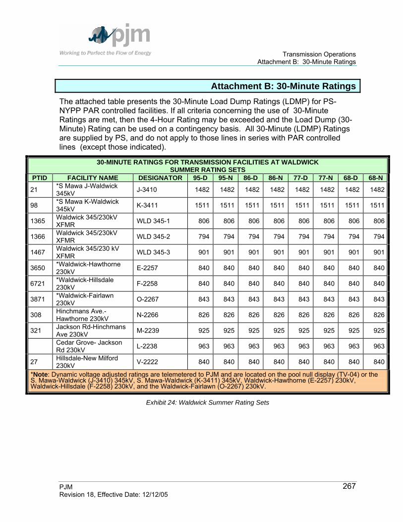
Transmission Operations Attachment B: 30-Minute Ratings
PJM Revision 18, Effective Date: 12/12/05
267
Attachment B: 30-Minute Ratings The attached table presents the 30-Minute Load Dump Ratings (LDMP) for PS-NYPP PAR controlled facilities. If all criteria concerning the use of 30-Minute Ratings are met, then the 4-Hour Rating may be exceeded and the Load Dump (30-Minute) Rating can be used on a contingency basis. All 30-Minute (LDMP) Ratings are supplied by PS, and do not apply to those lines in series with PAR controlled lines (except those indicated).
30-MINUTE RATINGS FOR TRANSMISSION FACILITIES AT WALDWICK SUMMER RATING SETS
PTID FACILITY NAME DESIGNATOR 95-D 95-N 86-D 86-N 77-D 77-N 68-D 68-N
21 *S Mawa J-Waldwick 345kV J-3410 1482 1482 1482 1482 1482 1482 1482 1482
98 *S Mawa K-Waldwick 345kV K-3411 1511 1511 1511 1511 1511 1511 1511 1511
1365 Waldwick 345/230kV XFMR WLD 345-1 806 806 806 806 806 806 806 806
1366 Waldwick 345/230kV XFMR WLD 345-2 794 794 794 794 794 794 794 794
1467 Waldwick 345/230 kV XFMR WLD 345-3 901 901 901 901 901 901 901 901
3650 *Waldwick-Hawthorne 230kV E-2257 840 840 840 840 840 840 840 840
6721 *Waldwick-Hillsdale 230kV F-2258 840 840 840 840 840 840 840 840
3871 *Waldwick-Fairlawn 230kV O-2267 843 843 843 843 843 843 843 843
308 Hinchmans Ave.-Hawthorne 230kV N-2266 826 826 826 826 826 826 826 826
321 Jackson Rd-Hinchmans Ave 230kV M-2239 925 925 925 925 925 925 925 925
Cedar Grove- Jackson Rd 230kV L-2238 963 963 963 963 963 963 963 963
27 Hillsdale-New Milford 230kV V-2222 840 840 840 840 840 840 840 840
*Note: Dynamic voltage adjusted ratings are telemetered to PJM and are located on the pool null display (TV-04) or the S. Mawa-Waldwick (J-3410) 345kV, S. Mawa-Waldwick (K-3411) 345kV, Waldwick-Hawthorne (E-2257) 230kV, Waldwick-Hillsdale (F-2258) 230kV, and the Waldwick-Fairlawn (O-2267) 230kV.
Exhibit 24: Waldwick Summer Rating Sets

Transmission Operations Attachment B: 30-Minute Ratings
PJM Revision 18, Effective Date: 12/12/05
268
30-MINUTE RATINGS FOR TRANSMISSION FACILITIES AT WALDWICK WINTER RATING SETS
PTID FACILITY NAME DESIGNATOR 59-D 59-N 50-D 50-N 41-D 41-N 32-D 32-N
21 *S Mawa J-Waldwick 345kV J-3410 1511 1511 1511 1511 1511 1511 1511 1511
98 *S Mawa K-Waldwick 345kV K-3411 1603 1603 1603 1603 1603 1603 1603 1603
1365 Waldwick 345/230kV XFMR WLD 345-1 850 850 850 850 850 850 850 850
1366 Waldwick 345/230kV XFMR WLD 345-2 841 841 841 841 841 841 841 841
1467 Waldwick 345/230 kV XFMR WLD 345-3 952 952 952 952 952 952 952 952
3650 *Waldwick-Hawthorne 230kV E-2257 859 859 859 859 859 859 859 859
6721 *Waldwick-Hillsdale 230kV F-2258 859 859 859 859 859 859 859 859
3871 *Waldwick-Fairlawn 30kV O-2267 862 862 862 862 862 862 862 862
308 Hinchmans Ave.-Hawthorne 230kV N-2266 844 844 844 844 844 844 844 844
321 Jackson Rd-Hinchmans Ave 230kV
M-2239 925 925 925 925 925 925 925 925
Cedar Grove- Jackson Rd 230kV L-2238 859 859 859 859 859 859 859 859
27 Hillsdale-New Milford 230kV V-2222 991 991 991 991 991 991 991 991
*Note: Dynamic voltage adjusted ratings are telemetered to PJM and are located on the pool null display (TV-04) or the S. Mawa-Waldwick (J-3410) 345kV, S. Mawa-Waldwick (K-3411) 345kV, Waldwick-Hawthorne (E-2257) 230kV, Waldwick-Hillsdale (F-2258) 230kV, and the Waldwick-Fairlawn (O-2267) 230kV.
Exhibit 25: Waldwick Winter Rating Sets

Transmission Operations Attachment C: Controlling PSE&G-Con Ed Wheel
PJM Revision 18, Effective Date: 12/12/05
269
Attachment C: Controlling PSE&G-Con Ed Wheel
Controlling PSE&G-Con Ed Wheel (5018 Out-of-Service) Effects of PAR Tap Raise (MW/Tap) Con Ed PARs PSE&G PARs
Line A B C E F O Linden-Gothals A-2253 -49.9 14.5 15.3 4.9 3.8 3.0Hudson-Farragut B-3402 12.1 -83.2 33.3 5.3 9.0 4.1Hudson-Farragut C-3403 12.7 33.3 -85.8 5.5 9.5 4.4PS/Con Ed Total -25.1 -35.4 -37.2 15.7 22.3 11.5Waldwick-Hawthorne 3-2257 -7.9 -10.3 -10.9 50.4 -26.7 -15.2Waldwick-Hillsdale F-2258 -5.2 -14.7 -15.4 -21.8 63.0 -14.8Waldwick-Fairlawn 0-2267 -3.0 -5.0 -5.2 -9.1 -10.9 43.4O&R/PSE&G Total -16.1 -30.0 -31.5 19.5 25.4 13.4Wheel Imbalance = (2) - (1) 9.0 5.7 5.7 3.8 3.1 1.9
Exhibit 26: Controlling PSE&G-Con Ed Wheel (5018 Out-of-Service)

Transmission Operations Attachment D: Open Circuit Terminal Voltage Control
PJM Revision 18, Effective Date: 12/12/05
270 270
Attachment D: Open Circuit Terminal Voltage Control
The attached chart contains Open Circuit Terminal Voltage Control information.Open Circuit Terminal Voltage Control Closed Terminal Voltage (V2) 500 kV (1.0 pu) 525 kV (1.05 pu) 550 kV (1.1 pu)
From Bus — To Bus Line Number Mileage
Closed End
Voltage Increase
At Switching
Chrg MVAR
(Q-Base)
V1 V1 Incr
Chrg MVAR V1 V1
Chrg Chrg
MVAR V1 V1 Incr
Keystone-Yukon 5001 39 0.9 70.8 501.6 1.6 78.1 526.7 1.7 85.7 551.7 1.7 Keystone-Cabot 5002 27 0.5 49.1 500.8 0.8 54.1 525.8 0.8 59.4 550.8 0.8 Keystone-Conemaugh 5003 29 0.6 42.1 500.8 0.8 46.4 525.9 0.9 50.9 550.9 0.9 Keystone-Juniata 5004 118 3.1 196.7 514.7 14.7 216.9 540.4 15.4 238.0 566.1 16.1 Conemaugh-Juniata 5005 121 4.9 201.2 515.4 15.4 221.8 541.1 16.1 243.5 566.9 16.9 Conemaugh-Hunterstown 5006 112 4.2 186.3 513.2 13.2 205.4 538.8 13.8 225.4 564.5 14.5 Peach Bottom-TM1 5007 42 0.8 67.2 501.8 1.8 74.1 526.9 1.9 81.3 552.0 2.0 Juniata-TM1 5008 44 2.6 73.1 502.0 2.0 80.6 527.1 2.1 88.5 552.2 2.2 Juniata-Alburtis 5009 88 3.7 146.7 508.0 8.0 161.7 533.4 8.4 177.5 558.8 8.8 Peach Bottom-Limerick 5010 57 1.9 98.1 503.3 3.3 108.1 528.5 3.5 118/7 553.6 3.6 Conastone-Brighton 5011 77 3.0 112.6 506.1 6.1 124.2 531.4 6.4 136.3 556.7 6.7 Conastone-Peach Bottom 5012 16 1.4 27.4 500.3 0.3 30.2 525.3 0.3 33.2 550.3 0.3 Hunterstown-Conastone 5013 40 1.7 73.2 501.6 1.6 80.7 526.7 1.7 88.6 551.8 1.8 Peach Bottom-Keeney 5014 34 2.2 59.1 501.2 1.2 65.1 526.3 1.3 71.5 551.3 1.3 Red Lion-Hope Creek 5015 25 1.7 49.0 500.7 0.7 54.0 525.7 0.7 59.3 550.7 0.7 Alburtis-Branchburg 5016 49 1.9 81.8 502.5 2.5 90.2 527.6 2.6 99.0 552.7 2.7 Elroy-Branchburg 5017 39 1.4 67.3 501.6 1.6 74.2 526.6 1.6 81.4 551.7 1.7 Branchburg-Ramapo 5018 69 2.8 120.7 504.9 4.9 133.1 530.1 5.1 146.0 555.4 5.4 Branchburg-Deans 5019 20 0.3 32.9 500.4 0.4 36.3 525.4 0.4 39.8 550.4 0.4 Deans-Smithburg 5020 18 1.3 31.0 500.3 0.3 34.1 525.3 0.3 37.5 552.7 0.4

Transmission Operations Attachment D: Open Circuit Terminal Voltage Control
PJM Revision 18, Effective Date: 12/12/05
271 271
Open Circuit Terminal Voltage Control Closed Terminal Voltage (V2)
500 kV (1.0 pu) 525 kV (1.05 pu) 550 kV (1.1 pu)
From Bus — To Bus Line Number Mileage Closed End Voltage
Increase At Switching
Chrg MVAR
(Q-Base)
V1 V1 Incr
Chrg MVAR V1 V1
Chrg Chrg
MVAR V1 V1 Incr
Deans-E. Windsor-Salem 5021 109 7.5 180.5 512.4 12.4 199.0 538.0 13.0 218.4 551.7 13.6 Hope Creek-New Freedom 5023 43 3.7 70.8 501.9 1.9 78.0 527.0 2.0 85.6 555.4 2.1 Salem-New Freedom 5024 50 4.1 86.5 502.6 2.6 95.4 527.7 2.7 104.7 550.4 2.9 TMI-Hosensack 5026 75 3.2 124.0 505.8 5.8 136.7 531.0 6.0 150.0 550.4 6.3 Alburtis-Hosensack 5027 5 0.0 8.2 500.0 0.0 9.0 525.0 0.0 9.9 550.0 0.0 Hosensack-Elroy 5028 18 0.7 30.1 500.3 0.3 33.2 525.3 0.3 36.4 550.3 0.3 Elroy-Whitpain 5029 9 0.4 16.1 500.1 0.1 17.8 525.1 0.1 19.5 550.1 0.1 Limerick-Whitpain 5030 16 0.4 27.4 500.3 0.3 30.2 525.3 0.3 33.1 556.3 0.3 Limerick-Whitpain 5031 16 0.4 27.4 500.3 0.3 30.2 525.3 0.3 33.1 550.3 0.3 Keeney-Red Lion 5036 Hope Creek-Salem 5037 0 0.0 0.7 500.0 0.0. 0.8 525.0 0.0 0.8 550.0 0.0 Susquehanna-Wescosville 5043 67 4.0 116.4 504.6 4.6 128.4 529.8 4.8 140.9 555.0 5.0 Wescosville-Alburtis 5044 11 0.3 21.8 500.1 0.1 24.0 525.1 0.1 26.4 550.1 0.1 Sunbury-Susquehanna 5045 44 4.4 75.6 501.9 1.9 83.3 527.0 2.0 91.4 552.1 2.1 Juniata-Sunbury 5046 38 2.0 65.6 501.5 1.5 72.3 526.6 1.6 79.3 551.6 1.6 Waugh Chapel-Calvert Cliffs 5051 48 0.6 82.7 502.4 2.4 91.1 527.5 2.5 100.0 552.6 2.6
Waugh Chapel-Calvert Cliffs 5052 48 0.6 82.7 502.4 2.4 91.1 525.5 2.5 100.0 552.6 2.6
Brighton-Waugh Chapel 5053 27 1.4 45.9 500.7 0.7 50.6 525.8 0.8 55.5 550.8 0.8 Brighton-Doubs 5055 29 1.9 60.6 500.9 0.9 66.8 525.9 0.9 73.3 551.0 1.0 Burches Hill-Possum Point 5070 32 2.4 60.4 501.1 1.1 66.6 526.1 1.1 73.1 551.2 1.2 Burches Hill-Chalk Point 5071 19 1.3 39.4 500.4 0.4 43.4 525.4 0.4 47.6 550.4 0.4 Chalk Point-Calvert Cliffs 5072 18 0.6 30.6 500.3 0.3 33.7 525.3 0.3 37.0 550.4 0.4
Exhibit 27: Open Circuit Terminal Voltage Control

Transmission Operations Attachment E: Voltage Coordination Plan
PJM Revision 18, Effective Date: 12/12/05
272
Attachment E: Voltage Coordination Plan AP Actions
AP Actions Support Level Action
Emergency Heavy Capacitors in service Reduce generation, as possible, to maximize reactive output on all units in area of concern Adjust TCUL set points to 132 kV, except Meadow Brook 135 kV
Heavy Check all capacitors in service, Adjust 138 kV voltage setpoints on Black Oak Bedinton, Ringgold, Monocacy, Doubs, and Carroll TCUL transformer to 134 kV Adjust 138 kV voltage setpoint on Meadow Brook TCUL transformer to 137 kV Maximum reactive output on all EHV generating units, Smith, and Albright units at current MW loading level and within current operating restrictions
Normal On-Peak Bring on capacitors to maintain reactive reserve on generation units Adjust TCUL transformers setpoints to keep capacitors in service Hold APS on-peak voltage schedule at all generating stations
Normal Off-Peak Switch off capacitors as necessary to keep generators at unity or lagging PF Hold APS off-peak voltage schedule at all generating stations
Light Switch all capacitors off including Doubs 230 kV Schedule Bath Co. pump operation, if conditions permit With advance warning, impose contractual minimums Allow generating units to operate with leading power factor
Emergency Light Operating Bath pumps, if conditions permit Open select 500 kV lines as defined in APS high voltage plan
Exhibit 28: Voltage Coordination Plan -AP Actions

Transmission Operations Attachment E: Voltage Coordination Plan
PJM Revision 18, Effective Date: 12/12/05
273
PJM Actions
PJM Actions Support Level Action
Emergency Heavy Check all capacitors in service Supply maximum VAR generation (if practical reduce generation to increase reactive output) Adjust 500/230 kV tap changers to maximize reactive support to the 500 kV systems Reduce transfers
Heavy Check all bulk power capacitors Request Transmission Owners dispatchers to verify that all capacitors are in service Adjust 500/230 kV tap changers to increase reactive support to the 500 kV systemIncrease generator VAR output to increase support of 500 kV voltage
Normal On-Peak Follow normal on-peak voltage schedules Operate capacitors and 500/230 kV transformers to “tune” system voltage
Normal Off-Peak Follow normal off peak voltage schedule Operate capacitors and 500/230 kV transformers to “tune” system voltages
Light Deviate from off-peak voltage schedule at generation stations to reduce system voltage without exceeding normal station limits Request Transmission Owners to switch out all underlying capacitors Switch out bulk power capacitors Operate pumped storage generation in pumping mode Adjust 500/230 kV transformers so that both 500 and 230 kV system reach their maximum limits simultaneously Request Transmission Owners to adjust available subtransmission and distribution transformers so that both the high and low side reach maximum voltage limits simultaneously
Emergency Light Open pre-studied 500 kV lines
Exhibit 29: Voltage Coordination Plan -PJM Actions

Transmission Operations Attachment E: Voltage Coordination Plan
PJM Revision 18, Effective Date: 12/12/05
274
VAP Actions
VAP Actions Support Level Action Emergency Heavy
Bath County 530 kV Other: 500 kv at 525 kV 230 kV at 235 kV 115 kV at 118 kV All Capacitors In Service
Heavy Maintain “normal” voltage schedule Exhaust up to half of the available spinning VAR reserves from Bath Co., Mt. Storm, and Possum Point Maintain units at unity power factor elsewhere
Normal On-Peak
Bath County 524 kV Mt. Storm 520 kV Other : 500 kV at 517 kV 230 kV at 232 kV 115 kV at 115 kV Maintain generating units at unity power factor to hold VAR reserves Switch area capacitors, as needed, to hold spinning VAR reserves
Normal Off-Peak
Bath County 524 kV Mt. Storm 520 kV Other: 500 kV at 517 kV 230 kV at 232 kV 115 kV at 115 kV Maintain generating units at unity power factor to hold VAR reserves Switch area capacitors, as needed, to hold spinning VAR reserves
Light Bath County 524 kV Other: 500 kV at 517 kV 230 kV at 232 kV 115 kV at 115 kV Maintain unity power factor Switchable capacitors are out-of-service
Emergency Light
All capacitors are out-of-service Dooms, Yadkin, Carson, North Anna, and Surry reactors in service All power stations operate at max lead Operate transmission lines: #555 Dooms-Lexington #552 Ox-Ladysmith Request companies to adjust available subtransmission and distribution transformers so that both the high and low side reach maximum voltage limits simultaneously Open pre-studied 500 kV lines
Exhibit 30: Voltage Coordination Plan -VAP Actions
Transmission Operations Attachment F: Requesting Voltage Limit Exceptions to the PJM Base-Line Voltage Limits
PJM Revision 18, Effective Date: 12/12/05
275
Attachment F: Requesting Voltage Limit Exceptions to the PJM Base-Line Voltage Limits
The purpose of this attachment is to provide further explanation of the how to request exceptions to the PJM Base-Line Voltage Limits as discussed in this manual Section 3: Voltage and Stability Operating Guidelines. It is proposed that two processes be implemented to address handling Voltage Limits that are more restrictive than the PJM Base-Line Voltage Limits. Addressing PJM OATT Facilities (see Exhibit F-1)
1. For a limitation at a PJM OATT facility, a Transmission Owner can request PJM to operate for any voltage reliability limits at a specific bus that are identified as more restricting than the PJM Base-Line Voltage Limits.
2. These voltage reliability limits shall be submitted in writing to the PJM, Manager Transmission Department by the Transmission Owner’s System Operations Subcommittee (SOS) representative. The request should specifically identify that the limit is required for reliable PJM operation
3. PJM will evaluate these limits for reasonableness. 4. PJM Transmission Department will return confirmation to the SOS
representative when these voltage reliability limits are implemented in the PJM Energy Management System (EMS) as the PJM Voltage Reliability Operating Limit.
5. PJM will forward these revised PJM Voltage Reliability Operating Limits to PJM System Planning for use in reinforcement evaluations.
Addressing Generators and other Non- PJM OATT Facilities (including Distribution) (see Exhibit F-2)
1. For a limitation at a Generator or other Non- PJM OATT facility, a Transmission Owner or PJM Member can request PJM to operate for any requested voltage limits at a specific bus that are identified as more restricting than the PJM Base-Line Voltage Limits.
2. These requested voltage limits are submitted in writing by the PJM Member to the PJM Manager – Transmission Department.
3. PJM will evaluate these limits for reasonableness. 4. PJM Transmission Department will return confirmation to the requestor when
these requested voltage limits are implemented in the PJM EMS. 5. The PJM Member will be billed for any “Off-Cost” operation.

Transmission Operations Attachment F: Requesting Voltage Limit Exceptions to the PJM Base-Line Voltage Limits – Exhibit F-1
PJM Revision 18, Effective Date: 12/12/05
276
To: PJM Manager- Transmission Department From: Transmission Zone SOS Representative:
RE: Request for PJM Open Access Transmission Tariff Facility Voltage Reliability Limit Exception to PJM Base-Line Voltage Limits We request that PJM operate to a voltage reliability limit different from the PJM Base-Line Voltage Limits at the specific bus identified below. This bus that has the limitation is specifically identified as a PJM Open Access Transmission Tariff Facility and the limit is required for reliable operation of the PJM transmission system.
Submitted by: (SOS Representative) Date:
Zone PJM Open Access Transmission Tariff Facility Identification
Voltage
LD EL NL NH Drop Comment or Reason for Transmission Owner voltage reliability limit exception to the PJM Base-Line Voltage Limit
Key: LD = Load Dump EL = Post Contingency Emergency Low NL = Normal Low NH = High Drop = Post Contingency Voltage Drop Limit SOS- PJM Systems Operating Subcommittee PJM OAT Tariff - PJM Open Access Transmission Tariff Submit this form to the PJM Manager-Transmission Department. Attach other pertinent documentation that would provide a complete package. PJM will contact the requestor with feedback on the status of this request or any questions. If you have any questions please call the Manager-Transmission Department at (610) 666-4659

Transmission Operations Attachment F: Requesting Voltage Limit Exceptions to the PJM Base-Line Voltage Limits – Exhibit F-2
PJM Revision 18, Effective Date: 12/12/05
277
To: PJM Manager-Transmission Department From: PJM Member Company: Requested By:
RE: Request to Operate to a Different Voltage Limit than the PJM Base-Line Voltage Limits for a Generator or Other Non-PJM Open Access Transmission Tariff Facility We request that PJM operate to a voltage limit different from the PJM Base-Line Voltage Limits at the specific bus identified below. If this bus limitation results in “off-cost” operation appropriate billing will be made to the PJM Member/Requestor.
Authorized by: (PJM Member Representative) Date:
Facility Identification Voltage
LD EL NL NH Drop Comment or Reason for voltage limit exception to the PJM Base-Line Limit
Key: LD = Load Dump EL = Post Contingency Emergency Low NL = Normal Low NH = High Drop = Post Contingency Voltage Drop Limit Submit this form to the PJM Manager-Transmission Department. Attach other pertinent documentation that would provide a complete package. PJM will contact the requestor with feedback on the status of this request or any questions. If you have any questions please call the Manager-Transmission Department at (610) 666-4659.

Transmission Operations Attachment G: Post Contingency Congestion Management Program
PJM Revision 18, Effective Date: 12/12/05
278
Attachment G: Post Contingency Congestion Management Program
PJM has historically operated on a pre-contingency basis under which it calls for off-cost generation to be run to alleviate contingency overloads. The amount of off- cost generation can total in excess of millions of dollars per year in congestion. PJM analysis indicates that the probability of contingent facility tripping during an off-cost event is less than .05%. PJM believes that it is prudent to operate to a higher pre-contingency threshold (i.e. 30-minute rating) in areas where analysis demonstrates that there is ample fast-start generation or switching actions available to eliminate an actual overload should contingent facility tripping occur. This generation must demonstrate a history of adequate availability and response as defined below. PJM is recommending the implementation of a post-contingency congestion management program on a continuing, non-pilot basis for monitored facilities that meet the following criteria:
1. Outage of the contingent facility must not cause a cascading outage or precipitate uncontrolled separation within and external to the PJM control area.
2. EHV facilities will not be included in this program. However there are cases in some areas where facilities up to and including 345kV may be studied for inclusion in the program as long as there is no adverse impact on the transmission system.
3. The transmission owner of the facility will have established a short-term emergency rating for the facility (nominally 30 minutes).
4. Facilities must have more than one fast-start combustion turbine or diesel generator in the vicinity (and off-line) to eliminate a contingency should it occur. Normally, availability of 120% of the necessary generation to obtain the required MW relief from the 30-minute rating to normal rating will need to be demonstrated to account for the possibility that some generation will not start.
5. The net area generation has to have a history of being on-line and loaded for control within 30 minutes 85% of the time. (Normally, review of the previous 12 month performance will be sufficient to establish the historical performance.)
6. Where available, condensers will be brought on-line for control once contingency flow reaches the 4-hour emergency rating.

Transmission Operations Attachment G: Post Contingency Congestion Management Program
PJM Revision 18, Effective Date: 12/12/05
279
7. This program will be implemented during non-winter months for facilities where fast-start generation is used for control. Switching procedures that demonstrate successful winter implementation may be included under the program year-round.
8. Facilities in transmission systems that were designed to operate on a post-contingency basis as outlined in the next section will be considered on a case by case basis.
Alternative Controlling Options 1. The TO may offer generation run-back schemes to control for these
facilities. These will be considered as controlling actions under this program after PJM tests the ramp-rate data as supplied by the generation owner. Further discussion and analysis is needed in this area prior to accepting these options. This document will be revised once these procedures are submitted, tested, and approved.
2. The TO may offer switching and reclosing procedures to control for these facilities in accordance with applicable regional requirements. These procedures must be studied and approved by PJM. These procedures may be implemented once PJM has the capability to properly study the impacts of these options in EMS. Local Control Centers (LCCs) must be capable of implementing the agreed upon post-contingency switching procedures via SCADA control. Additionally, LCCs must have the ability to dump sufficient load via SCADA in the event that switching procedures cannot be implemented. Load dump cannot propagate to adjacent zones. Where feasible, the switching procedures mentioned above may be implemented on a pre-contingency basis once contingency flow exceeds the 30-minute rating and all controlling generation has been called. Systems Designed for Post-Contingency Switching: a. On a pre-contingency basis off-cost operations will commence once
simulated contingency flow, using guide implemented contingency definitions, reaches the long-term emergency (LTE) rating.
b. On a pre-contingency basis off-cost operations will commence once simulated contingency flow, using guide failed contingency definitions, approaches the load dump (LD) rating.
c. In the event of a contingent facility tripping, the appropriate guide scheme will be used to ensure flow drops below the LTE rating on the monitored facility. If the post-contingency operating step does not reduce flow below the normal rating on this facility, generation re-

Transmission Operations Attachment G: Post Contingency Congestion Management Program
PJM Revision 18, Effective Date: 12/12/05
280
dispatch, where available, will be used to bring flow below the normal rating.
Roles and Responsibilities 1. PJM. PJM will be responsible for selecting the facilities for inclusion into
the program and performing the required analysis to ensure that the facilities meet the criteria for participation. PJM will consult with and communicate with the appropriate TO, as required, to ensure that the analysis is accurate. PJM will publish the list of facilities in PJM Manual M-03, Transmission Operations and will operate to the short term rating provided by the TO. If the rating is exceeded pre-contingency, PJM will operate off-cost to mitigate the simulated overload.
2. Transmission Owner. The TO will review and comment on the facilities proposed under this program. If the TO disagrees with a proposed facility they may take that facility to the PJM Dispute Resolution Process and PJM will delay implementation of that facility into the program until the completion of the process. The TO may offer additional facilities to be studied for inclusion under this program. The TO is responsible for establishing a short term rating for these facilities. These ratings will be submitted to PJM for approval. The TO will provide the necessary information to PJM to enable the appropriate analysis.
3. Generation Owner. The owners of the fast-response generation are to operate those units is accordance with the current PJM rules and procedures. When called upon to mitigate a transmission outage on a facility included in the program, the generation owner shall start the unit in accordance with PJM’s instructions.
PJM will seek the endorsement of the Reliability Committee (RC) and the Electricity Markets Committee (EMC) for the revised philosophy of the program. Upon approval, the procedures will become part of PJM Manual M-03, Transmission Operations. Subsequent additions or deletions to the criteria will follow the above process.
Post-Contingency Congestion Management Program Constraint List Following is a list of the transmission constraints included in the operation of the Post Contingency Congestion Management Program, beginning on June 1, 2005.
1. Wye Mills 138/69kV Transformer l/o Easton 138/69kV Transformer 2. Talbot – Trappe Tap 69kV l/o Indian River – Milford 230kV 3. Preston – Todd 69kV l/o Indian River – Milford 230kV

Transmission Operations Attachment G: Post Contingency Congestion Management Program
PJM Revision 18, Effective Date: 12/12/05
281
4. Talbot – Tanyard 69kV l/o Indian River – Milford 230kV 5. Preston – Tanyard 69kV l/o Indian River – Milford 230kV 6. Talbot – Trappe Tap 69kV l/o Vienna 230/138kV Transformer 7. Preston – Todd 69kV l/o Vienna 230/138kV Transformer 8. Talbot – Tanyard 69kV l/o Vienna 230/138kV Transformer 9. Preston – Tanyard 69kV l/o Vienna 230/138kV Transformer 10. Hallwood – Oak Hall 69kV l/o Oak Hall – Tasley 69kV 11. Jackson 4 BA 230/115kV Transformer l/o Jackson – Yorkana 230kV line +
Jackson 5 12. BA 230/115kV + Yorkana 3 230/115kV Transformers 13. Yorkana 1A/1B 230/115kV Transformer l/o Jackson – Yorkana 230kV line +
Jackson 5 14. BA 230/115kV + Yorkana 3 230/115kV Transformers 15. Prospect Heights 81 345/138kV Transformer l/o 138L11703 16. Prospect Heights 81 345/138kV Transformer l/o 138L11708 17. Prospect Heights 81 345/138kV Transformer l/o TR_Liber_83 18. Round Lake – Wilson Road (Red) 138L4203 l/o WA-7U 19. Silver Lake – Wilson Road (Red) 138L4203 l/o WA-7U 20. Silver Lake – Wilson Road (Red) 138L4203 l/o TR_Liber_83 21. Hanover Park – Tollway (Red) 138L7903 l/o 345L14402+TR81 22. Dixon – Nelson Tap (Red) 138L15508 l/o 138L15507 23. Dixon – Nelson (Blue) 138L15507 l/o 138L15508 24. Golf Mill – Niles (Blue) 138L8801 l/o 345L8823A_B-N 25. Golf Mill – Niles (Red) 138L8802 l/o 345L8824 26. Lombard 84 345/138kV Transformer l/o TR_Itasc_81 27. Lombard 84 345/138kV Transformer l/o TR_Lisle_82 28. Bolingbrook – Romeoville (Blue) 138L1809 l/o TR_Lisle_82 29. Will Country – Romeoville (Blue) 138L1809 l/o TR_Lisle_82 30. LaSalle – Mazon (Blue) 138L0108 l/o TR_Dresden_83 31. Davis Creek – Kankakee (Red) 138L8603 l/o 138L8605 32. Crawford 82 345/138kV Transformer l/o 345L10803

Transmission Operations Attachment G: Post Contingency Congestion Management Program
PJM Revision 18, Effective Date: 12/12/05
282
33. McCook – Ridgeland (Blue) 138L5107 l/o 345L1312 34. D799 – Ridgeland (Blue) 138L1306 l/o 138L6721