gas lift operations
66
GAS LIFT OPEARTIONS 1 CHAPTER-1 1. INTRODUCTION 1.1ARTIFICIAL LIFTING: Most oil wells in the early stages of the lives flow naturally to the surface are called flowing wells. Flowing production means that the pressure at the well bottom is sufficient to overcome the some of pressure losses occurring along the flow path to the separator. When this criterion is not met, natural flow ends and well dies Well may die for two main reasons; either their flowing bottom hole pressure drops below the total pressure looses in the well, or the opposite happens and pressure looses in the well become greater than the bottom hole pressure needed for moving the well stream to the surface. Artificial lifting methods are used to produce fluids from well already dead or to increase production rate from flowing wells; and several lifting mechanisms are available to choose from. One widely used type of artificial lift method use compressed gas, injected periodically below the liquid present in the well tubing and use the expansion energy of the gas to displace a liquid slug to the surface. Fig1.1 Artificial lift systems When a well is completed, a series of conductor pipes and accessories are installed during well completion operations. The basic components of the system are labelled in Figure 1.2. This is a simplified illustration of a cased hole single zone completion. Dual and triple completions are much more complex and will not be considered here. The inner surface of the well bore is supported by the casing string. There may be up to three separate casing strings including a surface and intermediate string. The space between the tubing and casing is called the annulus. The packer seals the annulus just above the producing zone. The casing
-
Upload
independent -
Category
Documents
-
view
5 -
download
0
Transcript of gas lift operations
GAS LIFT OPEARTIONS
1
CHAPTER-1
1. INTRODUCTION
1.1ARTIFICIAL LIFTING:
Most oil wells in the early stages of the lives flow naturally to the surface are called flowing wells. Flowing production means that the pressure at the well bottom is sufficient to overcome the some of pressure losses occurring along the flow path to the separator. When this criterion is not met, natural flow ends and well dies
Well may die for two main reasons; either their flowing bottom hole pressure drops below the total pressure looses in the well, or the opposite happens and pressure looses in the well become greater than the bottom hole pressure needed for moving the well stream to the surface. Artificial lifting methods are used to produce fluids from well already dead or to increase production rate from flowing wells; and several lifting mechanisms are available to choose from. One widely used type of artificial lift method use compressed gas, injected periodically below the liquid present in the well tubing and use the expansion energy of the gas to displace a liquid slug to the surface.
Fig1.1 Artificial lift systems
When a well is completed, a series of conductor pipes and accessories are installed during well completion operations. The basic components of the system are labelled in Figure 1.2. This is a simplified illustration of a cased hole single zone completion. Dual and triple completions are much more complex and will not be considered here. The inner surface of the well bore is supported by the casing string. There may be up to three separate casing strings including a surface and intermediate string. The space between the tubing and casing is called the annulus. The packer seals the annulus just above the producing zone. The casing
GAS LIFT OPEARTIONS
2
has been perforated adjacent to the producing zone to allow entrance of gas and liquid products into the wellbore or the tubing string may extend into the open hole. When reservoir drive does not provide enough pressure to lift fluids to the surface, additional equipment must be installed to help lift the fluids. There are four basic types of artificial lift: sucker rod pumping, hydraulic pumping, centrifugal pumping and gas lift.
1.2 GAS LIFTING:
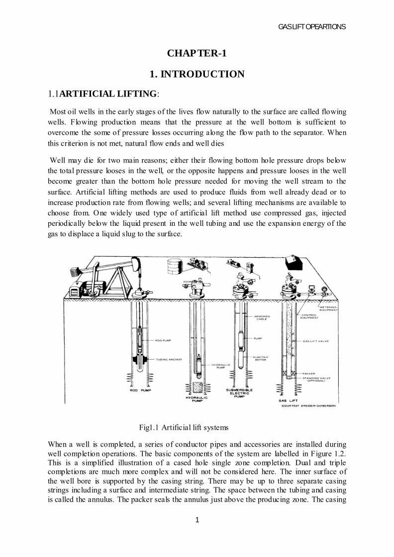
Fig 1.2 Gas lift
. Gas lifting uses natural gas compressed at the surface andinjected in the well stream at the some down whole point. The two broad categories of gas lifting are continuous flow and intermittent lift both utilizes high pressure natural gas injected from the surfaceto lift well fluids but work on different principles.
In continuous flow gas lift, a steady rate of gas is injected in the well tubing, aerating the liquid and thus reducing the pressure losses occurring along the flow path. Due to this reduction in flow resistance of the well tubing, the wells original bottom hole pressure becomes sufficient to move the gas /liquid mixture to the
surface and the well starts to flow again. In intermittent gas lift, gas is injected periodically in the tubing string whenever a sufficient length of liquid has accumulated at the well bottom. A relatively high volume of gas injected below the liquid column pushes that column to the surface as a slug. Gas injection is then interrupted until a new liquid slug of proper column length builds
up again. Production of well liquids, therefore is done by cycles
GAS LIFT OPEARTIONS
3
CHAPTER-2
LITERATURE REVIEW
In conventional oil production methods employ the injection of gas continuously or sporadically at specially chosen areas in order to lift the fluids produced in the interior of the earth's surface to the surface of the earth. The hydrostatic load of the tubing is lowered when the gas is added. The process is followed by the lowering of the pressure of the bottom hole. Well fluids are lifted by two processes. In the continuous-continuous injection flow technique, gas is continuously injected into the tubing in order to lower the pressure that opposes the production of the fluid. In the intermittent flow technique, gas is injected at high pressure into the tubes of the fluid. The gas is injected at the right volume and pressure which can help in lifting the fluid through the valve at the highest possible velocity. The gas lift technology has many advantages some of which are listed in the following paragraphs. Installing and operating gas lift techniques require little initial and running costs which can be afforded by many firms. The method is highly flexible with the capability of producing at both low rates and high rates. It is possible to produce deep and deviated wells of both high GOR and WOR wells while achieving high effectiveness. Completed wells can be dual purpose with the ability of using wire- line techniques.
The early works on IGL modeling were presented by Brown and Jessen (1962), White et al. (1963), Brill et al. (1967) and Neely et al. (1973). Those authors described the main patterns of the IGL, based on field measurements of test wells. Semi-empirical models were derived to predict some variables of the IGL operation.
Carvalho Filho and Bordalo (2003) developed a new approach to the IGL modelling. The possible occurrence of overlapping of the stages in the IGL cycle was considered according to the system dynamics. The derived model extended the simulation capabilities to a wider range of operational conditions, including those related to the IGL cycles with strictly sequential stages.
Bordello and Carvalho Filho (2004) used the same approach to model the inverted intermittent gas lift – where gas is injected through the tubing whereas liquid is lifted through the casing annulus – and presented a procedure to optimize the IGL output, maximizing either the oil production or the economic gain
Redden et al. [8] recognized the significance of an economic gas- lift operation, which should account for compressing costs, limited availability of gas, and potential failure of compressors. They conceived a method to obtain well performance curves based on two-phase measurements. They also proposed a procedure to find the most profitable distribution of lift-gas that works by iteratively perturbing the current distribution. Despite the improved operation, the procedure could produce sub-optimal solutions and could not be extended to tackle other constraints, such as lower (upper)
GAS LIFT OPEARTIONS
4
Mach et al. [9] refined the method of [8] with a nodal approach that considered pressure losses in all facilities of a gas-lift system. Their nodal procedure led to more accurate well performance curves. Bounds on gas injection.

GAS LIFT OPEARTIONS
5
CHAPTER-3
3. PRODUCTIONENGINEERINGFUNDAMENTAL
3.1 INFLOW PERFORMANCE OF OIL WELLS
The proper design of any artificial lift system requires an accurate knowledge of the fluid rates that can be produced from the reservoir through the well present and also future production rates are needed to accomplish the flowing basic tasks
• Selection of right type of lift
• Detailed design of production equipment
• Estimation of future well performance
3.2 THE PRODUCTIVITY INDEX CONCEPT
The simplest approach to describe the inflow performance of oil wells is the use of productivity index concept. It was developed using following assumptions:
• Flow is radial around the well
• A single phase liquid is flowing
• Permeability distribution in the formation is homogeneous
• The formation is fully saturated with given liquid
For the previous conditions, Darcy’s equation can be solved for the production rate
where
Q = liquid rate, STB/d
K = effective permeability, md
H = pay thickness, ft
Uo = liquid viscosity, cP
B=liquid volume factor, bbl/stb
Re = drainage radius of well, ft
Rw = radius of well bore, ft
More parameters on the right hand side are constant, which permits collecting them into single coefficient called PI
GAS LIFT OPEARTIONS
6
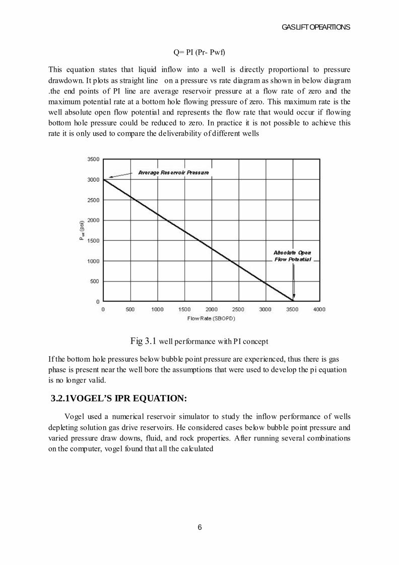
Q= PI (Pr- Pwf)
This equation states that liquid inflow into a well is directly proportional to pressure drawdown. It plots as straight line on a pressure vs rate diagram as shown in below diagram .the end points of PI line are average reservoir pressure at a flow rate of zero and the maximum potential rate at a bottom hole flowing pressure of zero. This maximum rate is the well absolute open flow potential and represents the flow rate that would occur if flowing bottom hole pressure could be reduced to zero. In practice it is not possible to achieve this rate it is only used to compare the deliverability of different wells
Fig 3.1 well performance with PI concept
If the bottom hole pressures below bubble point pressure are experienced, thus there is gas phase is present near the well bore the assumptions that were used to develop the pi equation is no longer valid.
3.2.1VOGEL’S IPR EQUATION:
Vogel used a numerical reservoir simulator to study the inflow performance of wells depleting solution gas drive reservoirs. He considered cases below bubble point pressure and varied pressure draw downs, fluid, and rock properties. After running several combinations on the computer, vogel found that all the calculated
GAS LIFT OPEARTIONS
7
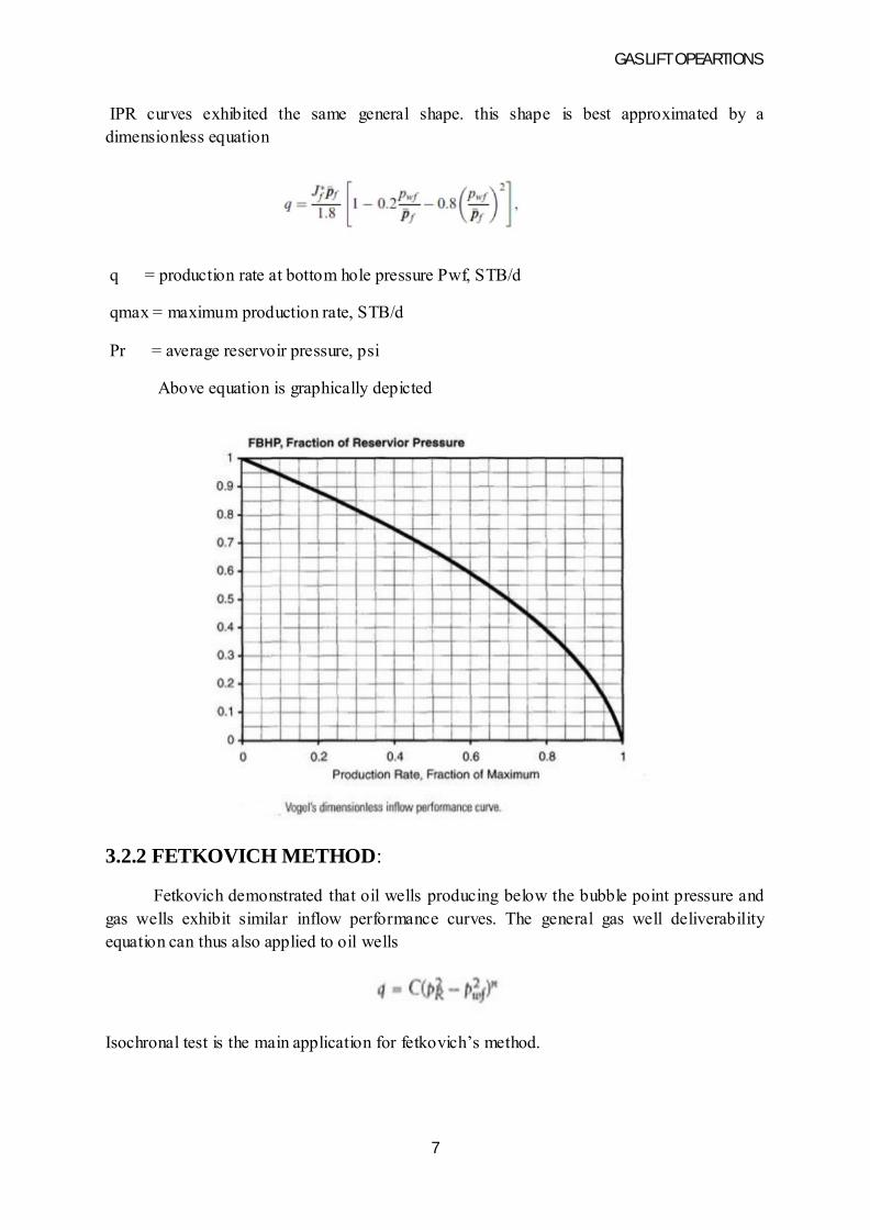
IPR curves exhibited the same general shape. this shape is best approximated by a dimensionless equation
q = production rate at bottom hole pressure Pwf, STB/d
qmax = maximum production rate, STB/d
Pr = average reservoir pressure, psi
Above equation is graphically depicted
3.2.2 FETKOVICH METHOD:
Fetkovich demonstrated that oil wells producing below the bubble point pressure and gas wells exhibit similar inflow performance curves. The general gas well deliverability equation can thus also applied to oil wells
Isochronal test is the main application for fetkovich’s method.
GAS LIFT OPEARTIONS
8
3.3 SINGLE-PHASE FLOW
Different kinds of flow problems are encountered. These involve vertical or inclined flow of a single phase fluid or of a multi-phase mixture in well tubing, as well as horizontal or inclined flow in flow lines. A special hydraulic problem is the calculation of pressure in static gas column present in a wells annulus.
3.3.1 PRESSURE DROP CALCULATIONS
3.3.1.1 SINGLE-PHASE LIQUID FLOW
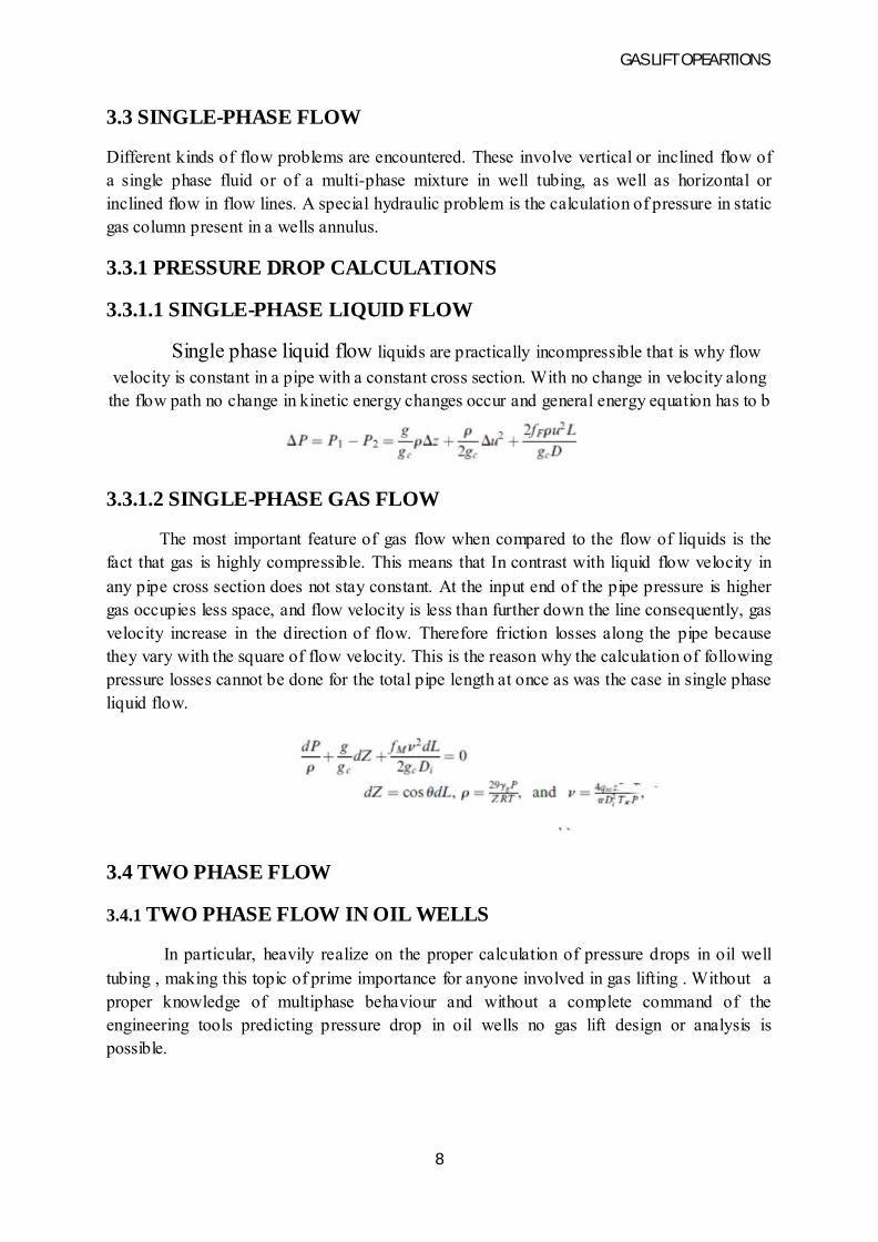
Single phase liquid flow liquids are practically incompressible that is why flow
velocity is constant in a pipe with a constant cross section. With no change in velocity along the flow path no change in kinetic energy changes occur and general energy equation has to b
3.3.1.2 SINGLE-PHASE GAS FLOW
The most important feature of gas flow when compared to the flow of liquids is the fact that gas is highly compressible. This means that In contrast with liquid flow velocity in any pipe cross section does not stay constant. At the input end of the pipe pressure is higher gas occupies less space, and flow velocity is less than further down the line consequently, gas velocity increase in the direction of flow. Therefore friction losses along the pipe because they vary with the square of flow velocity. This is the reason why the calculation of following pressure losses cannot be done for the total pipe length at once as was the case in single phase liquid flow.
3.4 TWO PHASE FLOW
3.4.1 TWO PHASE FLOW IN OIL WELLS
In particular, heavily realize on the proper calculation of pressure drops in oil well tubing , making this topic of prime importance for anyone involved in gas lifting . Without a proper knowledge of multiphase behaviour and without a complete command of the engineering tools predicting pressure drop in oil wells no gas lift design or analysis is possible.
GAS LIFT OPEARTIONS
9
3.4.2 VETICAL FLOW PATTERNS:
The flow patterns in vertical pipes have long been visually observed in transparent pipe section. Depending on the phase velocities and in-situ parameters the basic opatterns early investigators defined are bubble, slugs, transition and mist. They occur in given sequence if gas flow rate is continuously increased for a constant liquid flow rate this is very close to the conditions in an oil well because solution gas gradually escapes from the oil on it way to the surface. At or near the well bottom, therefore, single phase liquid flow exists if gas is still in solution at that pressure. Higher up, solution gas gradually escapes, resulting in an increased gas velocity. Gas already liberated from the solution expands due to a reduction of flowing pressure in the upward direction, further increasing gas velocity. The continuous increase gas velocity makes it happen that all possible flow patterns may be observed in a single well.
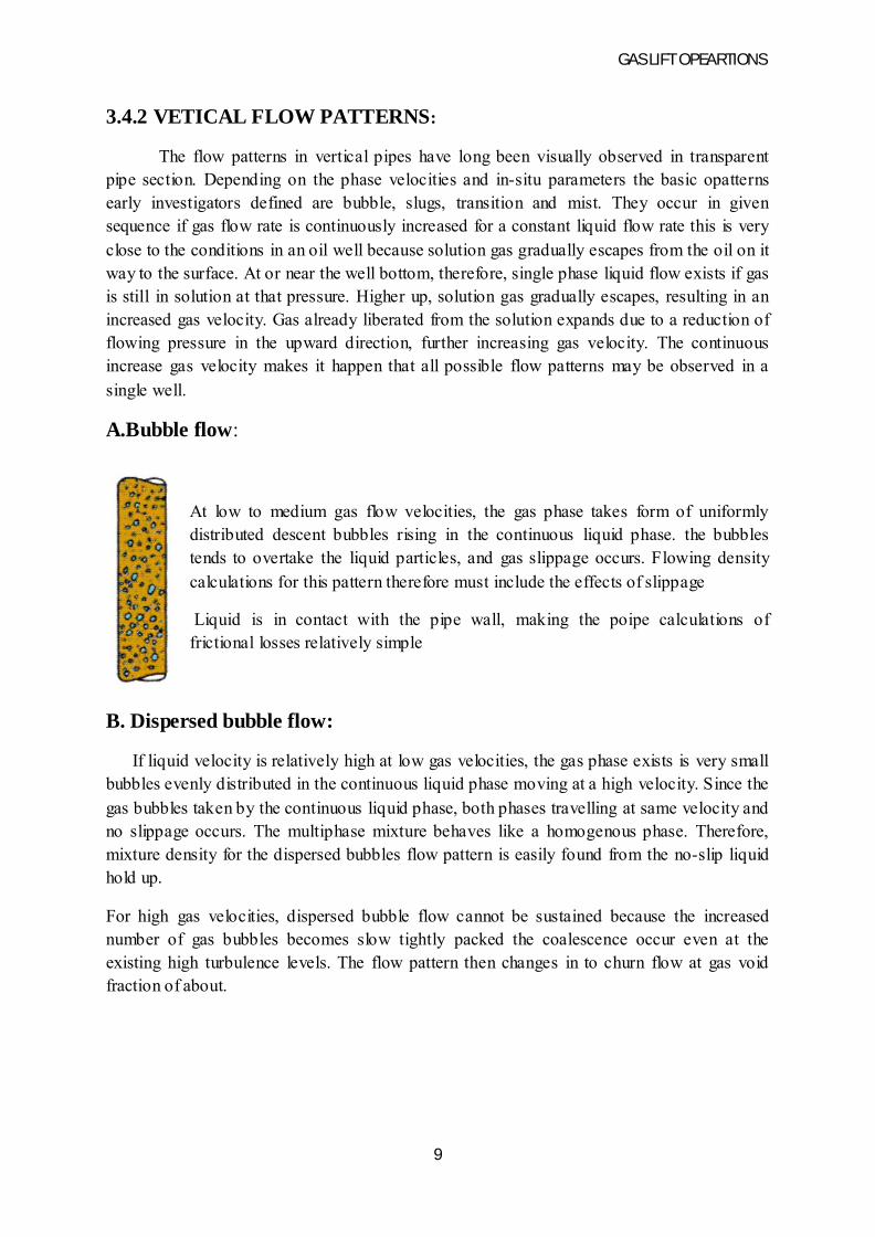
A.Bubble flow:
At low to medium gas flow velocities, the gas phase takes form of uniformly distributed descent bubbles rising in the continuous liquid phase. the bubbles tends to overtake the liquid particles, and gas slippage occurs. Flowing density calculations for this pattern therefore must include the effects of slippage
Liquid is in contact with the pipe wall, making the poipe calculations of frictional losses relatively simple
B. Dispersed bubble flow:
If liquid velocity is relatively high at low gas velocities, the gas phase exists is very small bubbles evenly distributed in the continuous liquid phase moving at a high velocity. Since the gas bubbles taken by the continuous liquid phase, both phases travelling at same velocity and no slippage occurs. The multiphase mixture behaves like a homogenous phase. Therefore, mixture density for the dispersed bubbles flow pattern is easily found from the no-slip liquid hold up.
For high gas velocities, dispersed bubble flow cannot be sustained because the increased number of gas bubbles becomes slow tightly packed the coalescence occur even at the existing high turbulence levels. The flow pattern then changes in to churn flow at gas void fraction of about.
GAS LIFT OPEARTIONS
10
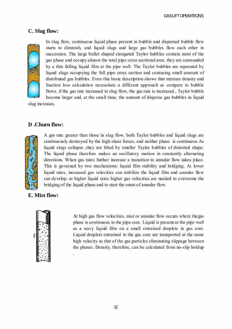
C. Slug flow:
In slug flow, continuous liquid phase present in bubble and dispersed bubble flow starts to diminish, and liquid slugs and large gas bubbles flow each other in succession. The large bullet shaped elongated Taylor bubbles contain most of the gas phase and occupy almost the total pipe cross sectional area. they are surrounded by a thin falling liquid film at the pipe wall. The Taylor bubbles are separated by liquid slugs occupying the full pipe cross section and contusing small amount of distributed gas bubbles. Even this basic description shows that mixture density and fraction loss calculation necessitate a different approach as compare to bubble flows. if the gas rate increased in slug flow, the gas rate is increased , Taylor bubbls become larger and, at the small time, the amount of disperse gas bubbles in liquid
slug increases.
D .Churn flow:
A gas rate greater than those in slug flow, both Taylor bubbles and liquid slugs are continuously destroyed by the high shear forces, and neither phase is continuous As liquid slugs collapse ,they are lifted by smaller Taylor bubbles of distorted shape. The liquid phase therefore makes an oscillatory motion in constantly alternating directions. When gas rates further increase a transition to annular flow takes place. This is governed by two mechanisms: liquid film stability and bridging. At lower liquid rates, increased gas velocities can stabilize the liquid film and annular flow can develop. at higher liquid rates higher gas velocities are needed to overcome the bridging of the liquid phase and to start the onset of annular flow.
E. Mist flow:
At high gas flow velocities, mist or annular flow occurs where thegas phase is continuous in the pipe core. Liquid is present at the pipe wall as a wavy liquid film on a small entrained droplets in gas core. Liquid droplets entrained in the gas core are transported at the same high velocity as that of the gas particles eliminating slippage between the phases. Density, therefore, can be calculated from no-slip holdup .

GAS LIFT OPEARTIONS
11
3.5 GRADIENT CURVES:
The first gradient curves were introduced by Gilbert that in 1954proposed an alternative to the calculation of multiphase flow pressure drops. His objective was to provide the field engineer with a simple tool that could be used to fine well head or bottom head pressures in flowing oil wells with a reasonable accuracy the model he proposed did not require detailed calculations, only the use of readymade gradient curve sheets.
GAS LIFT OPEARTIONS
12
CHAPTER-4
GAS LIFT VALVES
4.1 INTRODUCTION
The gas lift valve is the heart of a gas lift installation since its provides the necessary control of well production rates and its performance determines the technical and economic parameters of fluid lifting. Because of its importance, there have been a great number of varieties of gas lift valves developed over the years. The abundance of the different operating principles and technical features allows the operator to choose the proper type of valve for any case.
4.1.1 DOWNHOLE GAS INJECTION CONTROLS
This discusses the ways gas injection into the fluid column was controlled before the use of gas lift valves.
A.OPEN TUBING
In early days of gas lifting, a tubing string was suspended into the well with no packer. The well could be produced by injecting gas
• Down the casing tubing annulus and removing fluids out the tubing.
• Down the tubing string and removing fluids out the annulus.
In either case, gas had to be blown around the bottom of the tubing string, resulting in excessive and mostly uncontrollable gas usage. This is so-called open installation had several disadvantages, the most important of them being the necessity to kick the well every time it is brought back to production
a.FOOT-PIECES
These devices were run on the bottom of the tubing string and provided a more or less controlled gas injection through a special injection string run parallel to tubing. One main disadvantage that the only point of gas injection was around the bottom of tubing string
b.KICKOFF VALVES
Early gas lift valves were called kickoff valves because they were originally used in wells that needed only to be started flowing. One of the first valves of this type was the velocity control valve. Its principle of operation is that upper valves are closed by the increased mixture velocity in the tubing while lower valves remain open and inject gas.
GAS LIFT OPEARTIONS
13
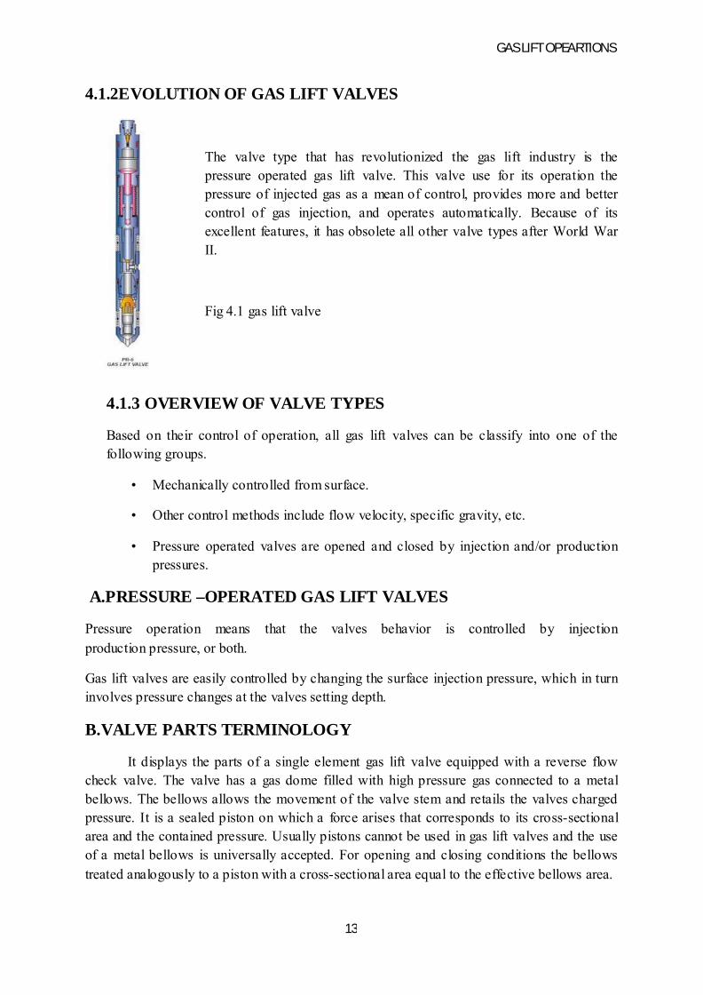
4.1.2EVOLUTION OF GAS LIFT VALVES
The valve type that has revolutionized the gas lift industry is the pressure operated gas lift valve. This valve use for its operation the pressure of injected gas as a mean of control, provides more and better control of gas injection, and operates automatically. Because of its excellent features, it has obsolete all other valve types after World War II.
Fig 4.1 gas lift valve
4.1.3 OVERVIEW OF VALVE TYPES
Based on their control of operation, all gas lift valves can be classify into one of the following groups.
• Mechanically controlled from surface.
• Other control methods include flow velocity, specific gravity, etc.
• Pressure operated valves are opened and closed by injection and/or production pressures.
A.PRESSURE –OPERATED GAS LIFT VALVES
Pressure operation means that the valves behavior is controlled by injection production pressure, or both.
Gas lift valves are easily controlled by changing the surface injection pressure, which in turn involves pressure changes at the valves setting depth.
B.VALVE PARTS TERMINOLOGY
It displays the parts of a single element gas lift valve equipped with a reverse flow check valve. The valve has a gas dome filled with high pressure gas connected to a metal bellows. The bellows allows the movement of the valve stem and retails the valves charged pressure. It is a sealed piston on which a force arises that corresponds to its cross-sectional area and the contained pressure. Usually pistons cannot be used in gas lift valves and the use of a metal bellows is universally accepted. For opening and closing conditions the bellows treated analogously to a piston with a cross-sectional area equal to the effective bellows area.
GAS LIFT OPEARTIONS
14
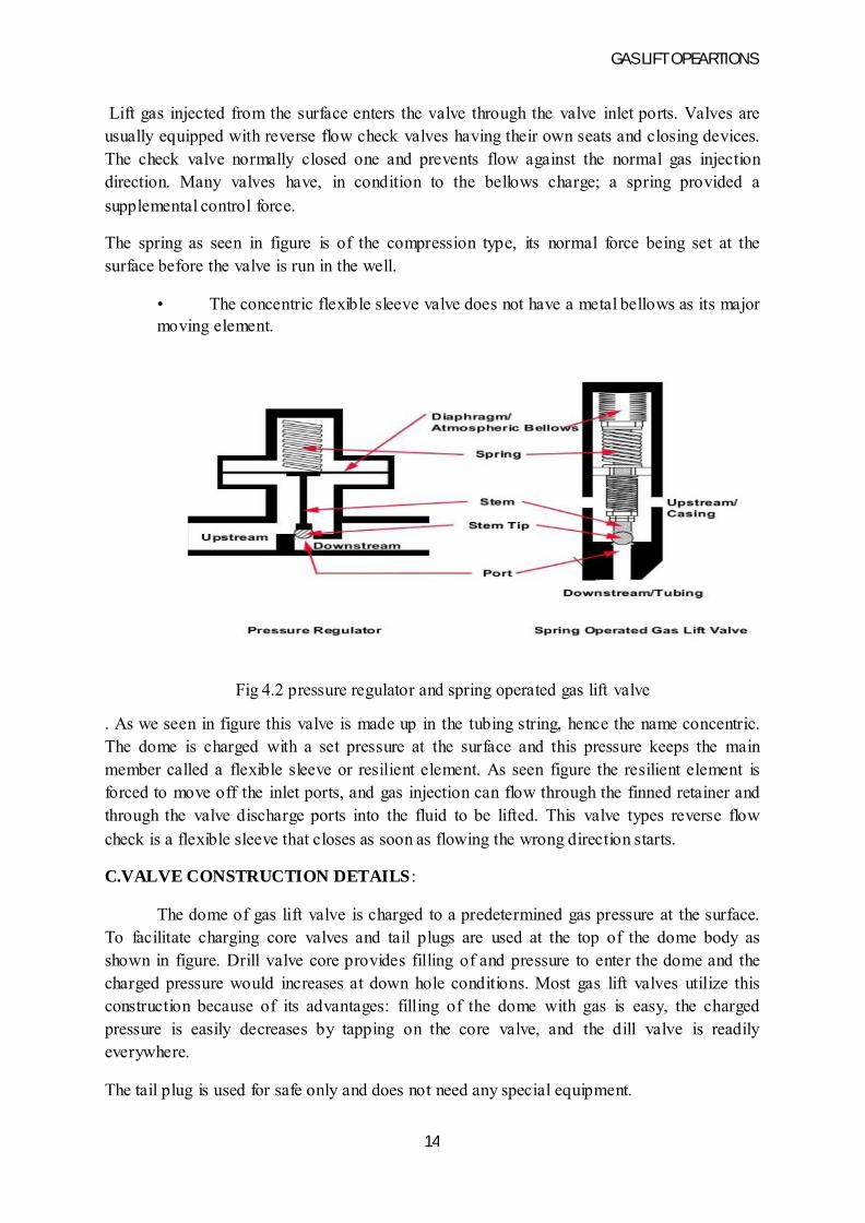
Lift gas injected from the surface enters the valve through the valve inlet ports. Valves are usually equipped with reverse flow check valves having their own seats and closing devices. The check valve normally closed one and prevents flow against the normal gas injection direction. Many valves have, in condition to the bellows charge; a spring provided a supplemental control force.
The spring as seen in figure is of the compression type, its normal force being set at the surface before the valve is run in the well.
• The concentric flexible sleeve valve does not have a metal bellows as its major moving element.
Fig 4.2 pressure regulator and spring operated gas lift valve
. As we seen in figure this valve is made up in the tubing string, hence the name concentric. The dome is charged with a set pressure at the surface and this pressure keeps the main member called a flexible sleeve or resilient element. As seen figure the resilient element is forced to move off the inlet ports, and gas injection can flow through the finned retainer and through the valve discharge ports into the fluid to be lifted. This valve types reverse flow check is a flexible sleeve that closes as soon as flowing the wrong direction starts.
C.VALVE CONSTRUCTION DETAILS :
The dome of gas lift valve is charged to a predetermined gas pressure at the surface. To facilitate charging core valves and tail plugs are used at the top of the dome body as shown in figure. Drill valve core provides filling of and pressure to enter the dome and the charged pressure would increases at down hole conditions. Most gas lift valves utilize this construction because of its advantages: filling of the dome with gas is easy, the charged pressure is easily decreases by tapping on the core valve, and the dill valve is readily everywhere.
The tail plug is used for safe only and does not need any special equipment.
GAS LIFT OPEARTIONS
15
D.GAS CHARGE:
Gas lift valves used natural gas as a dome charged medium. Most of the gas li9ft valves are charged with nitrogen gas because of its availability and other beneficial features: N2 gas is inexpensive, inflammable, and non-corrosive. The properties of N2 gas are well known and its deviation factor has been determined in a broad range of pressures and temperatures.
E.BELLOWS ASSEMBLY:
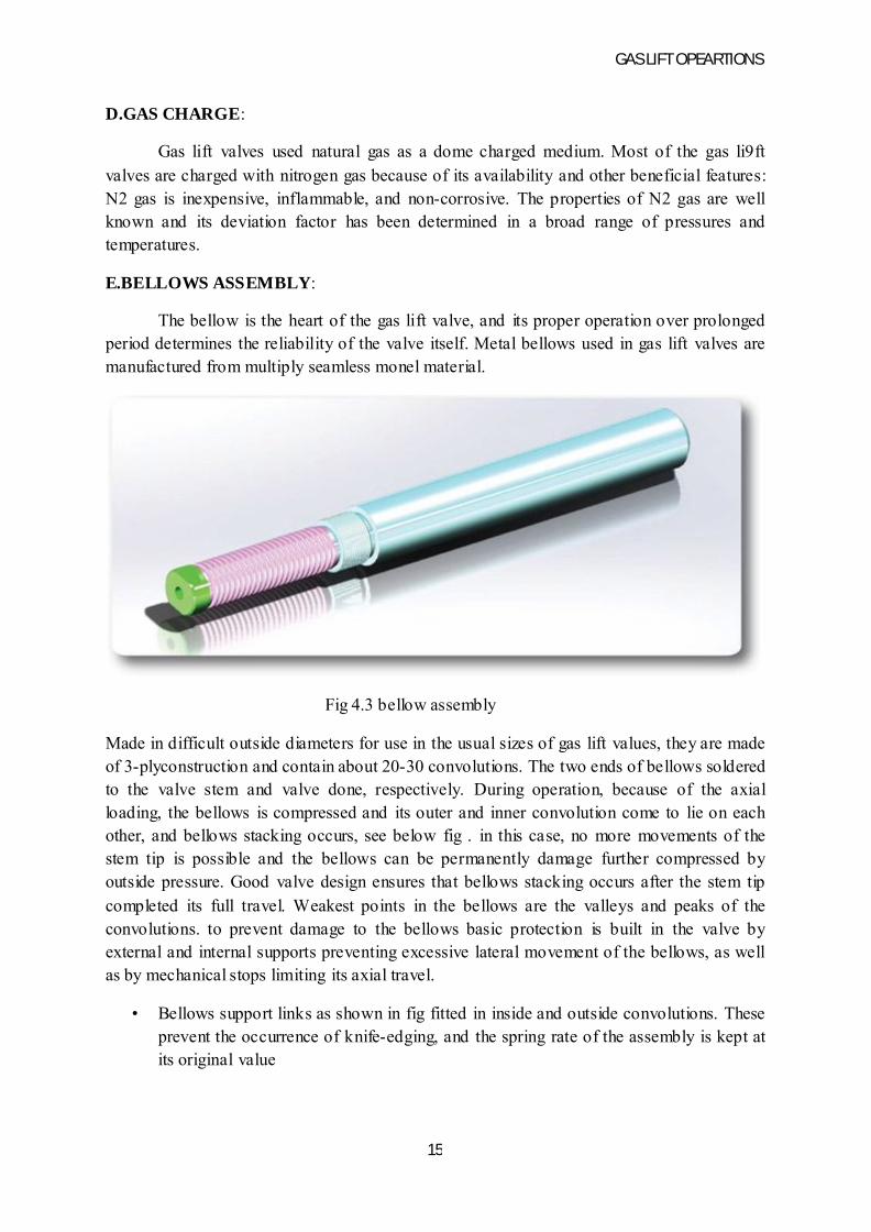
The bellow is the heart of the gas lift valve, and its proper operation over prolonged period determines the reliability of the valve itself. Metal bellows used in gas lift valves are manufactured from multiply seamless monel material.
Fig 4.3 bellow assembly
Made in difficult outside diameters for use in the usual sizes of gas lift values, they are made of 3-plyconstruction and contain about 20-30 convolutions. The two ends of bellows soldered to the valve stem and valve done, respectively. During operation, because of the axial loading, the bellows is compressed and its outer and inner convolution come to lie on each other, and bellows stacking occurs, see below fig . in this case, no more movements of the stem tip is possible and the bellows can be permanently damage further compressed by outside pressure. Good valve design ensures that bellows stacking occurs after the stem tip completed its full travel. Weakest points in the bellows are the valleys and peaks of the convolutions. to prevent damage to the bellows basic protection is built in the valve by external and internal supports preventing excessive lateral movement of the bellows, as well as by mechanical stops limiting its axial travel.
• Bellows support links as shown in fig fitted in inside and outside convolutions. These prevent the occurrence of knife-edging, and the spring rate of the assembly is kept at its original value
GAS LIFT OPEARTIONS
16
• Trapping of an incompressible liquid (silicon oil) in the bellows after it reaches its full travel prevents a high pressure differential to occur across the bellows wall
• Even the original king valve used mechanical sealing of the bellows against well fluids activated after full stem travel
Commonly occurring problem with gas lift valves is valve stem chatter, and the stem tip hits the valve seat with a high frequency as a result of resonance
F.SPRING:
Gas lift valves include a compression spring providing an additional force to keep the valve closed, In an unloading valve string, such valves are closed by the string force even if the bellows fail and can thus prevent uneconomical use of injection gas. The spring force is unaffected by temperature, which is an advantage in installation design with limited temperature data. Compression springs used in the valves are very stiff and allow very limited valve stem travel. Therefore the valve can never fully open and will always throttle that is restrict the effective area open to injection flow to less than the wall port area
G.BALL AND SEAT:
Gas lift valves inject lift gas through their main port, and the operation of the valve heavily depends on a propel seal between the valve seat and the stem tip. These parts are manufactured from Monel. Gas lift valves have sharp edged valve seats or a very shallow bevel on their seats.
H.SETTING OF GAS LIFT VALVES:
Before they are run in the well, lift valves must be set to the accurate specifications determined during the installation design calculations. The proper setting of each valve in the installation ensures that the well will operate according to the original design. Design calculation prescribe the required valve type, port size, dome charge pressure, spring adjustment etc. for bellows type gas lift valves, the most important phase of valve setting is checking of the dome charge pressure because the nitrogen gas contained in the valve domeis subjected to great changes in temperature.
Valve setting procedure necessitates the use of several pieces of special equipment:
GAS LIFT OPEARTIONS
17
A.SLEEVE TYPE VALVE TESTER:
The main steps of the sleeve type valve tester setting procedures
• While the valve is installed in the tester use proper charging equipment to charge the valve dome with nitrogen gas to a pressure close to the desired pressure. If the original dome pressure is too high use a de-airing tool to lower it to valve close to the desired pressure.
• Remove the valve from the tester and put it in the water bath whose temperature is closely controlled to the desired charging temperature usually 60 degree franheit allow the valve to reach charging temperature.
• Put the valve back in the tester and while valve A is closed there by valve B there by slowly opening the valve
• Using the de-airing tool release nitrogen pressure through the valve core until the requirement valve opening pressure is reached.
• After installing the tail plug put the valve in the ager and apply the recommended pressure (above5000psi) for the recommended time.
• Take the valve out of the ager and put it back in to the tester to check the opening pressure.
• Repeat the steps 4to 6 until a constant opening pressure is observed.
• Put a small amount of silicon fluid on the top of the core valve and properly tighten the tail plug.
B.ENCPSULATED VALVE TYPE TESTER:
Is used to find gas lift closing pressure which is very difficult to determine with the sleeve type tester. This tester simulates actual well conditions since pressure can be applied not only to the bellows but also the valve port area. The two pressure gauges measure injection and production pressure acting on the bellows and port area. Its main application is for spring loaded throttling valves without any dome charge pressure. Setting procedure involves following steps
• The valve is installed in the tester with an initial spring setting
• With valve A closed, open valve B and supply pressure to the inlet ports of gas lift valve as pressure increase at one point the gas lift valve opens and injection pressure reaches to valve A. both gauges read the same value
• Close valve B to cut to gas supply. The gas lift valve stays open and gauges show identical upstream and downstream pressure
GAS LIFT OPEARTIONS
18
• Slowly open valve A let gas trapped in the tester to bleed down to the atmosphere. Note that the pressures acting on the bellows and the valve port are identical and they balance the spring force. since the gas lift valve is still open and upstream and downstream pressures are equal the continuous pressure reduction slowly reduces the valve stem travel of gas lift valve. Finally the stem tip seats on the valve port and the gas lift closes.
• If the measured closing pressure is different from prescribed value the tester is disassembled and the spring setting of the gas lift valve is adjusted accordingly
• Steps1-5 repeated until the desired valve closing pressure is added
4.2 RUNNING AND RETREVING GAS LIFT VALVES:
Gas lifts valve mandrel types:
Types of mandrels
a. Conventional mandrels
b. Wire line retrievable mandrel.
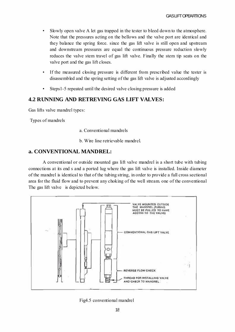
a. CONVENTIONAL MANDREL:
A conventional or outside mounted gas lift valve mandrel is a short tube with tubing connections at its end s and a ported lug where the gas lift valve is installed. Inside diameter of the mandrel is identical to that of the tubing string, in order to provide a full cross sectional area for the fluid flow and to prevent any choking of the well stream. one of the conventional The gas lift valve is depicted below.
Fig4.5 conventional mandrel

GAS LIFT OPEARTIONS
19
Where the gas lift valve is mounted with the port area connected to the tubing string. if an unbalanced gas lift valve is used then depending on the valve seat configuration , the valve becomes an IPO or PPO valve for tubing or casing flow installations. The checks valves to be used for these combinations vary with the direction of the gas injection. The gas lift mandrel given in next fig
The conventional mandrels have basic disadvantage: they can be run and retrived with the tubing string only therefore after a well dies it is necessary to pull the tubing string and to run it back into well with the mandrels in place. In addition repair of faulty valve s is only possible by pulling the tubing string with all cost and downtime associated such operations.
b. WIRE LINE RETREVIABLE MANDREL:
Wire line retrievable operations have been used for many decades for special operations like running down hole pressure and temperature surveys and running and pulling special equipment into the well. Instead of a work over rig they require a small surface unit only and allow operations to be carried out under pressure without the need to kill the well. All these are advantages of using wire line retrievable mandrel. mandrel are special subs installed in the tubing string and have an elliptical cross section allowing an obstructed fluid passage throughout their length they contain side pocket with special seating surfaces where gas lift valves can be installed.
Fig4.6 Wire line-retrievable gases lift valve and mandrel
GAS LIFT OPEARTIONS
20
The two basic versions of retrievable gas lift mandrel are those with and without a snorkel, a piece of pipe protruding from the mandrel body f shows a gas lift mandrel designated as type S in API . Without a snorkel which depending on the type of gas lift valves seat can be used for any kind of operation tubing or casing flow injection or production pressure operation. Type E mandrels are used for injecting gas on top of a down hole chamber in a chamber lift installation. Type W mandrels have a flow path from the top of the valve pocket into snorkel details of mandrel the two polished bores that allow sealing of the valves packing, the undercut with the ports of for the gas entry in to the valve and locking recess for keeping the valve in place . The gas lift has two packing’s an upper and lower one that seal against the polished surfaces of the polished bore in the mandrel. The mandrel is kept in place by a latch installed on its top when the valve is being installed. When the retrieval is necessary the valve is caught by the fishing neck on the latch and after the shear pin is broken by a sufficient pull force applied to the wire line
4.3 RUNNING AND RETREVING OPERATIONS:
The wire line is lowered into the well through a lubricator under pressure with a wire line tool assembly at its bottom. The wire line tool comprises many components: sinker bar, jars, etc the wire line tool designed for working in gas lift mandrels performs three basic functions
• It locates the mandrel
• It orients the running or pulling tool in the proper azimuth
• It provides the lateral offset required to position the tool over the side pocket
The wire line tool assembly with pulling tool at its bottom is lowered in to the well to the depth of the mandrel from which the gas lift valve is to be pulled when it enters the side pocket mandrel it is still rigid locked position .a slow pull on the wire line raises the positioning tool and the key of the tool engages the orienting sleeve situated at the top of mandrel. The sleeve while the tool s slow moved upward forces the key is to rotate the positioning tool. Finally the is stopped in its vertical movement at the top of the sleeves slot. The positioning tool is now stuck in the mandrel and this is indicated on the surface by a rapid increase in the wire line load. An additional pull on the wire line tool forces the tool to lock pivots arm to swing out and lock in position. the pulling tool is now located just above the valve pocket . By slowly lowering the positioning tool and after hammering the puling engages the fishing necks while special guides in the mandrel ensure it s proper position . After the shear pin in the valve lach is broken by an upward pull-on the wire line the valve is pulled outside of the pocket.
GAS LIFT OPEARTIONS
21
CHAPTER-5
GAS LIFT INSTALLATIONS
5.1 INTRODUCTION
Different gas lift installations contain different combinations of down hole equipment: gas lift valves, packers, mandrels, nipples. Type of gas lift installation depends type of lift used continuous or intermittent flow. Installation types are classified in two types tubing flow and casing flow.
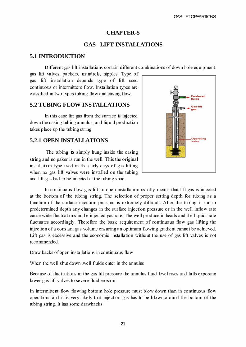
5.2 TUBING FLOW INSTALLATIONS
In this case lift gas from the surface is injected down the casing tubing annulus, and liquid production takes place up the tubing string
5.2.1 OPEN INSTALLATIONS
The tubing is simply hung inside the casing
string and no paker is run in the well. This the original installation type used in the early days of gas lifting when no gas lift valves were installed on the tubing and lift gas had to be injected at the tubing shoe.
In continuous flow gas lift an open installation usually means that lift gas is injected at the bottom of the tubing string. The selection of proper setting depth for tubing as a function of the surface injection pressure is extremely difficult. After the tubing is run to predetermined depth any changes in the surface injection pressure or in the well inflow rate cause wide fluctuations in the injected gas rate. The well produce in heads and the liquids rate fluctuates accordingly. Therefore the basic requirement of continuous flow gas lifting the injection of a constant gas volume ensuring an optimum flowing gradient cannot be achieved. Lift gas is excessive and the economic installation without the use of gas lift valves is not recommended.
Draw backs of open installations in continuous flow
When the well shut down .well fluids enter in the annulus
Because of fluctuations in the gas lift pressure the annulus fluid level rises and falls exposing lower gas lift valves to severe fluid erosion
In intermittent flow flowing bottom hole pressure must blow down than in continuous flow operations and it is very likely that injection gas has to be blown around the bottom of the tubing string. It has some drawbacks
GAS LIFT OPEARTIONS
22
When gas lift valves are used it must be assured that gas injection takes place always through the operating valve and not around the shoe
When the gas is injected in to the annulus injection pressure can directly act on the formation and thus prevent required reduction in bottom hole pressure.
5.2.2 SEMI-CLOSED INSTALLATIONS
This type of installation differs from packer set at a deep enough point in the well. The packer isolates the tubing and eliminates most of the disadvantages of an open installation. This type installation is ideal and most common for continuous flow of gas lift because it provides for a constant bottom hole pressure required for optimum conditions in intermittent lift this installation allows the reduction of bottom hole pressure below the levels attainable with an open installation . due to the injection pressure having noo effect on bottom hole pressure more liquid can be lifted from the well espically in wells exhibiting low bottom hole pressure.
5.2.3 CLOSED INSTALLATIONS
A closed gas lift installation differs from semi closed one by the application of standing valve the tubing . Most wells on intermittent gas lift employ this type of down hole construction. the standing valve eliminates the effects of gas lift pressure on the formation since during the injection of gas pressure in the tubing is isolated from formation by standing valve while in the annulus the packer seals it. The average flowing bottom hole pressure during an intermittent cycle can thus be kept to a minimum sliding side door to reduce the damage of un loading valve string is often run above the packer.
5.3 CASING FLOW INSTALLATIONS
In a casing flow installation gas is injected down the tubing and production raises in the casing tubing annulus. It is generally used in continuous flow gas lift wells producing extremely large liquid rates that exceed the capacity of tubing string run in the well its main drawback is that casing is exposed to well fluids restricting application to non-corrosive liquids. No packer is run in the well and gas lift valves can be of the conventional or wire line retrievable with check valves reversed. The tubing is bull plugged and injection gas can only enter the well through the gas lift valves. Use of bull plug also ensures that the tubing must not be unloaded after every shut in of the well.
GAS LIFT OPEARTIONS
23
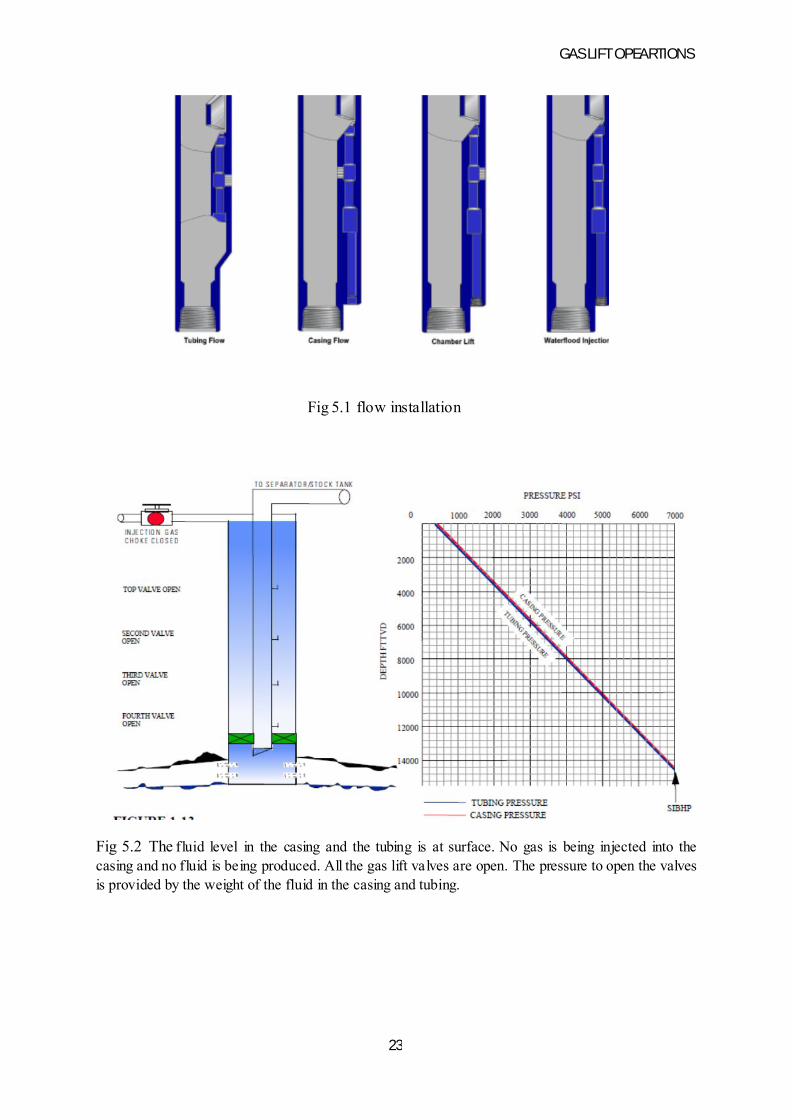
Fig 5.1 flow installation
Fig 5.2 The fluid level in the casing and the tubing is at surface. No gas is being injected into the casing and no fluid is being produced. All the gas lift valves are open. The pressure to open the valves is provided by the weight of the fluid in the casing and tubing.

GAS LIFT OPEARTIONS
24
Fig 5.3Gas injection into the casing has begun. Fluid is U-tube through all the open gas lift valves. No formation fluids are being produced because the pressure in the wellbore at perforation depth is greater than the reservoir pressure i.e. no drawdown. All fluid produced is from the casing and the tubing. All fluid unloaded from the casing passes through the open gas lift valves. Because of this, it is important that the well be unloaded at a reasonable rate to prevent damage to the gas lift valves.
Fig 5.4 pressure casing pressure tubing

GAS LIFT OPEARTIONS
25
5.4 Design methods
There are numerous gas lift installation design methods offered in the literature. Several installation designs require unique valve construction or gas lift-valve injection-gas throughput performance. Only two design techniques are illustrated in this page:
ß A design based on a constant decrease in the operating injection-gas pressure for each succeeding lower valve (this design is essentially the same as the API gas lift design technique in RP 11V6
ß An alternative design for wells requiring high injection-gas rates.
The API design can be used on the majority of wells in the US. However, when high-volume lift and high injection-gas rates are required, gas lift valve performance should be considered in the design. Both of these techniques use the simple single-element-type, unbalanced, gas lift valve with a nitrogen-charged bellows. This type of valve is the most widely used in the industry and is available from all major gas lift equipment manufacturers.
Gas lift installation design calculations are divided into two parts:
ß Determination of the gas lift valve depthsß Calculation of the test-rack opening pressures of the gas lift valves
The opening pressures are calculated after the valve depths because the operating injection-gas and flowing-production pressures and temperatures during unloading are based on these valve depths.
The primary objective of this page is to outline in detail installation design methods for calculating the valve depths and the test-rack opening pressures of the gas lift valves that will unload a well to a maximum depth of lift for the available injection-gas volume and pressure. The unloading operations, as illustrated by the two-pen pressure recorder chart in Fig. 2, should be automatic. The static- load-fluid level was near the surface in the casing and tubing before initial unloading began. The wellhead pressure remains relatively constant during U-tubing operations before injection gas enters the tubing for the first time through the top gas lift valve. A surge in wellhead tubing pressure and a decrease in the injection-gas casing pressure occur as the depth of gas injection transfers to each lower gas lift valve. As each lower gas lift valve is uncovered, the valve immediately above closes, and the point of gas injection transfers from the upper to the lower valve. All gas lift valves above an operating valve should be closed and the valves below should be open in a properly designed gas lift installation.
GAS LIFT OPEARTIONS
26
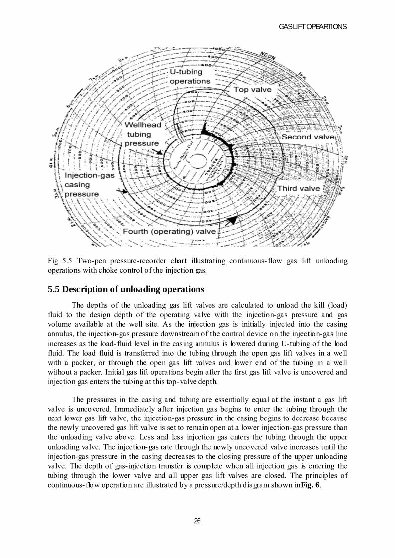
Fig 5.5 Two-pen pressure-recorder chart illustrating continuous- flow gas lift unloading operations with choke control of the injection gas.
5.5 Description of unloading operations
The depths of the unloading gas lift valves are calculated to unload the kill (load) fluid to the design depth of the operating valve with the injection-gas pressure and gas volume available at the well site. As the injection gas is initially injected into the casing annulus, the injection-gas pressure downstream of the control device on the injection-gas line increases as the load- fluid level in the casing annulus is lowered during U-tubing of the load fluid. The load fluid is transferred into the tubing through the open gas lift valves in a well with a packer, or through the open gas lift valves and lower end of the tubing in a well without a packer. Initial gas lift operations begin after the first gas lift valve is uncovered and injection gas enters the tubing at this top- valve depth.
The pressures in the casing and tubing are essentially equal at the instant a gas lift valve is uncovered. Immediately after injection gas begins to enter the tubing through the next lower gas lift valve, the injection-gas pressure in the casing begins to decrease because the newly uncovered gas lift valve is set to remain open at a lower injection-gas pressure than the unloading valve above. Less and less injection gas enters the tubing through the upper unloading valve. The injection-gas rate through the newly uncovered valve increases until the injection-gas pressure in the casing decreases to the closing pressure of the upper unloading valve. The depth of gas- injection transfer is complete when all injection gas is entering the tubing through the lower valve and all upper gas lift valves are closed. The principles of continuous-flow operation are illustrated by a pressure/depth diagram shown inFig. 6.
GAS LIFT OPEARTIONS
27
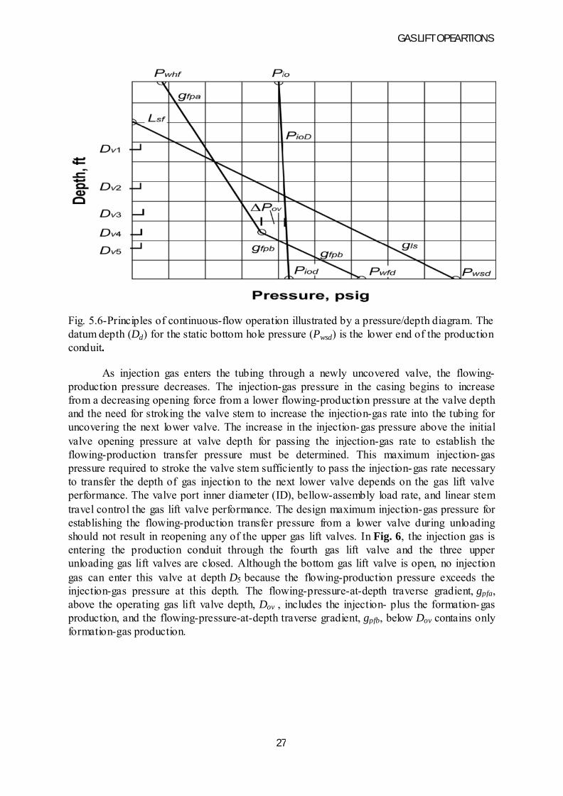
Fig. 5.6-Principles of continuous-flow operation illustrated by a pressure/depth diagram. The datum depth (Dd) for the static bottom hole pressure (Pwsd) is the lower end of the production conduit.
As injection gas enters the tubing through a newly uncovered valve, the flowing-production pressure decreases. The injection-gas pressure in the casing begins to increase from a decreasing opening force from a lower flowing-production pressure at the valve depth and the need for stroking the valve stem to increase the injection-gas rate into the tubing for uncovering the next lower valve. The increase in the injection-gas pressure above the initial valve opening pressure at valve depth for passing the injection-gas rate to establish the flowing-production transfer pressure must be determined. This maximum injection-gas pressure required to stroke the valve stem sufficiently to pass the injection-gas rate necessary to transfer the depth of gas injection to the next lower valve depends on the gas lift valve performance. The valve port inner diameter (ID), bellow-assembly load rate, and linear stem travel control the gas lift valve performance. The design maximum injection-gas pressure for establishing the flowing-production transfer pressure from a lower valve during unloading should not result in reopening any of the upper gas lift valves. In Fig. 6, the injection gas is entering the production conduit through the fourth gas lift valve and the three upper unloading gas lift valves are closed. Although the bottom gas lift valve is open, no injection gas can enter this valve at depth D5 because the flowing-production pressure exceeds the injection-gas pressure at this depth. The flowing-pressure-at-depth traverse gradient, gpfa, above the operating gas lift valve depth, Dov , includes the injection- plus the formation-gas production, and the flowing-pressure-at-depth traverse gradient, gpfb, below Dov contains only formation-gas production.
GAS LIFT OPEARTIONS
28
5.6 Initial installation design considerations
Continuous-flow installation designs vary depending on whether complete and precise well data are known. Reliable inflow well performance and an accurate multiphase-flow correlation are required to establish the approximate point of gas injection in deep wells. When the well data are limited or questionable, the exact point of gas injection cannot be calculated accurately in many wells. If there is insufficient injection-gas pressure to reach the bottom of the well, a desired depth of gas injection may not be possible. If there is no change in injection-gas pressure or well conditions, the point of gas injection should remain at the maximum depth for the life of the gas lift installation.
Retrievable gas lift valve mandrels are installed (usually with dummy valves in place) in many wells before little, if any, well-production information is available. The engineer must locate these mandrels in wells before gas lift is required. The design considerations are similar for wells with a changing point of gas injection. In general, many gas lift installations are in this category, in which accurate well data are unknown or limited and the point of gas injection is unknown and/or changing as the reservoir is depleted.
5.7 Assumptions and safety factors
Safety factors are used for continuous-flow gas lift installation design with unbalanced, single-element, gas lift valves when the load rate and the gas throughput performance of the valve are not considered in the calculations. The initial gas lift valve opening pressures are based on the static force-balance equations. Safety factors allow the injection-gas and/or the flowing-production pressure to increase at valve depth, which is needed to properly stroke the valve stem and provide the equivalent port area required to pass the injection-gas rate necessary for unloading and gas lifting most wells. The following safety factors compensate for the fact that most operators set the gas lift valves to the nearest tubing joint. The actual depth of the gas lift valve is usually within 15 ft of the calculated depth.
1. The operating injection-gas pressure used for the installation design calculations should be the average and not the maximum injection-gas pressure available at the wellsite for most wells. In special cases, a kick-off pressure can be used.
2. The unloading daily production rate is assumed equal to the design daily production rate. Generally, the actual unloading daily production rate may be less than the design production rate and can be controlled at the surface by the injection-gas rate.
3. No formation gas is produced during the unloading operations. The total gas/liquid ratio is based on the daily injection-gas rate available for unloading the well.
4. The flowing-pressure-at-depth traverses above the unloading gas lift valves are assumed to be straight lines for the design calculations.
5. The unloading flowing-temperature-at-depth traverse is assumed to be a straight rather than a curved line between an assigned unloading flowing wellhead temperature, Twhu, and the buttonhole temperature, Twsd.
The design surface unloading flowing temperature generally is assumed to be lower than the final, operating temperature. A final flowing temperature that is slightly higher than the design temperature increases the initial opening pressure of a bellows-charged gas lift valveand aids in keeping the upper valves closed while lifting from a lower gas lift valve.
GAS LIFT OPEARTIONS
29
1. An assigned valve-spacing pressure differential, ΔPsD, of 20 to 60 psi across a valve for unloading is used by many gas lift design engineers. As a result, the actual minimum flowing-production pressure required to uncover the next lower unloading gas lift valve is greater by the assigned ΔPsD.
2. The flowing-pressure traverse below the point of gas injection for locating the valve depths is normally assumed to be the static- load-fluid gradient. Once formation production occurs, the actual flowing pressure gradient decreases in most wells.
5.8 Orifice-check valve
An orifice being used for gas lifting a well should include a reverse-flow check valve. The check disk, or dart, should be closed by gravity or spring loaded. In a well with a packer, the check portion should remain closed to prevent debris from accumulating on top of the packer when this valve is below the working fluid level and is not the operating valve. An inlet screen is recommended for orifice-check valves with a small choke to prevent possible plugging. The individual openings in the inlet screen should be smaller than the choke in the orifice-check valve.
A properly designed continuous-flow gas lift installation with an orifice-check valve does not have a higher injection-gas requirement than the same well with an injection-pressure-operated gas lift valve. The injection-gas rate for lifting a well is controlled by the metering device on the injection-gas line at the surface. An orifice-check valve rather than a more expensive and complicated pressure-operated gas lift valve should be considered for the bottom valve in most continuous-flow installations.
5.8.1 Advantages of an orifice-check valve
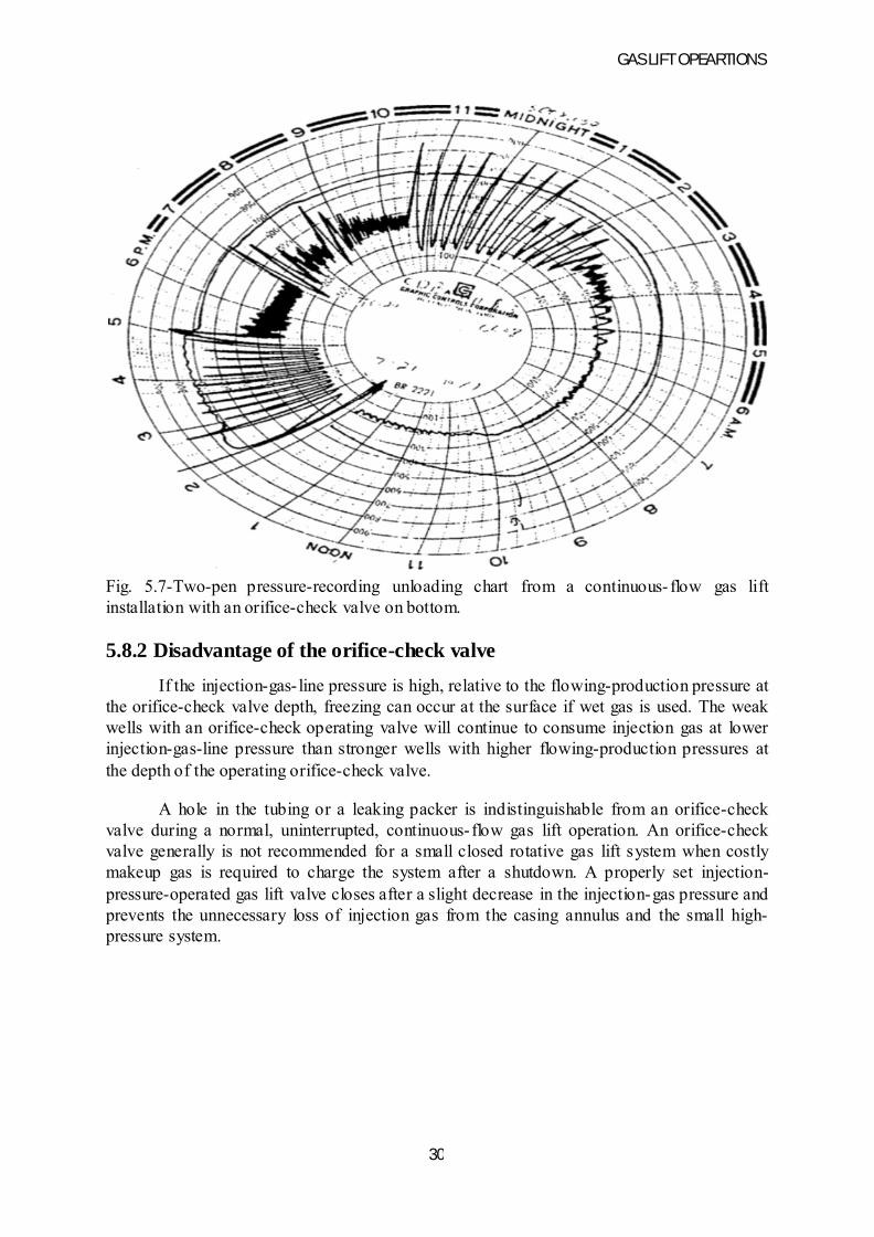
The orifice-check valve is the simplest of all types of operating valves and has a very low possibility of malfunction. It can be used as a "flag" because of the change in the surface injection-gas pressure downstream of the control valve when the orifice-check valve is uncovered and becomes the point of gas injection. Fig. 3 illustrates an unloading operation using an orifice-check valve on bottom. The heading flowing wellhead tubing pressure is the result of the opening and closing of the unloading gas lift valves because of a 24/64- in. choke in the flowline and a frictional drag mechanism in the valve to prevent stem shatter. After the orifice-check valve is uncovered at approximately 3:00 a.m., there is no heading. The operating injection-gas pressure decrease is the result of low reservoir deliverability and not the gas lift system. A properly sized orifice-check valve can prevent severe heading or surging in a continuous- flow gas lift installation by ensuring a constant orifice size. No injection-gas pressure increase is required to stroke an orifice-check valve, and the orifice size is always known because it is equal to the choke size in the valve. The orifice-check valve is always open and passes gas as long as injection-gas pressure at valve depth exceeds the flowing-production pressure at the same depth. A properly sized orifice is required to control the injection-gas volume for gas lifting some wells. One application is gas lifting one zone of a dual gas lift installation with a common injection-gas source in the casing annulus. A design pressure differential of at least 100 to 200 psi across the orifice is necessary to ensure a reasonably accurate gas-passage prediction.
GAS LIFT OPEARTIONS
30
Fig. 5.7-Two-pen pressure-recording unloading chart from a continuous- flow gas lift installation with an orifice-check valve on bottom.
5.8.2 Disadvantage of the orifice-check valve
If the injection-gas- line pressure is high, relative to the flowing-production pressure at the orifice-check valve depth, freezing can occur at the surface if wet gas is used. The weak wells with an orifice-check operating valve will continue to consume injection gas at lower injection-gas-line pressure than stronger wells with higher flowing-production pressures at the depth of the operating orifice-check valve.
A hole in the tubing or a leaking packer is indistinguishable from an orifice-check valve during a normal, uninterrupted, continuous-flow gas lift operation. An orifice-check valve generally is not recommended for a small closed rotative gas lift system when costly makeup gas is required to charge the system after a shutdown. A properly set injection-pressure-operated gas lift valve closes after a slight decrease in the injection-gas pressure and prevents the unnecessary loss of injection gas from the casing annulus and the small high-pressure system.
GAS LIFT OPEARTIONS
31
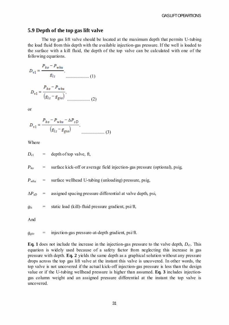
5.9 Depth of the top gas lift valve
The top gas lift valve should be located at the maximum depth that permits U-tubing the load fluid from this depth with the available injection-gas pressure. If the well is loaded to the surface with a kill fluid, the depth of the top valve can be calculated with one of the following equations.
.................... (1)
.................... (2)
or
.................... (3)
Where
Dv1 = depth of top valve, ft,
Pko = surface kick-off or average field injection-gas pressure (optional), psig,
Pwhu = surface wellhead U-tubing (unloading) pressure, psig,
ΔPsD = assigned spacing pressure differential at valve depth, psi,
gls = static load (kill)-fluid pressure gradient, psi/ft,
And
ggio = injection-gas pressure-at-depth gradient, psi/ft.
Eq. 1 does not include the increase in the injection-gas pressure to the valve depth, Dv1. This equation is widely used because of a safety factor from neglecting this increase in gas pressure with depth. Eq. 2 yields the same depth as a graphical solution without any pressure drops across the top gas lift valve at the instant this valve is uncovered. In other words, the top valve is not uncovered if the actual kick-off injection-gas pressure is less than the design value or if the U-tubing wellhead pressure is higher than assumed. Eq. 3 includes injection-gas column weight and an assigned pressure differential at the instant the top valve is uncovered.
GAS LIFT OPEARTIONS
32
The surface U-tubing wellhead pressure is less than the flowing wellhead pressure for most installations. The difference between these two pressures increases for longer flowlines and higher production rates. The wellhead U-tubing pressure is approximately equal to the separator or production-header pressure because the rate of load fluid transfer is very low during the U-tubing operation and no injection gas can enter the flowline until the top gas lift valve is uncovered. Gas lift operations do not begin until injection gas enters the production conduit through the top valve. Flowing wellhead pressure should be used to locate the depths of the remaining gas lift valves.
A load-fluid traverse based on gls can be drawn from the wellhead U-tubing pressure to the intersection of the kick-off injection-gas pressure-at-depth curve (PkoD traverse) on a pressure/depth plot. The top valve may be located at this intersection, which is the same depth as calculated with Eq. 2. An arbitrary pressure drop across the top gas lift valve can be assumed in conjunction with the graphical method, and this technique is the same as Eq. 3. If no gas pressure increase with depth is assumed, this method becomes similar to the calculation of Dv1 with Eq. 1. For simplicity, Eq. 4 is often used for top-valve spacing calculations.
.................... (4)
5.10Flowing pressure at depth
Accurate flowing-pressure-at-depth predictions are essential for good continuous- flow gas lift installation design and analysis. When computer programs for gas lift installation design and analysis are unavailable for daily routine calculations, the gas lift designers must rely on published gradient curves to determine flowing pressures at depth. Many oil-producing companies have their own multiphase-flow correlations and publish in-house gradient curves. Gradient curves are available from the gas lift manufacturers and are published in books that can be purchased. Where possible, use field data to verify the accuracy of the computer program calculations and gradient curves. It is not the purpose of this chapter to compare the various multiphase- flow correlations or published gradient curves.
The widely accepted multiphase- flow correlations and mechanistic models are based on pseudo-steady state flow without serious heading through a clean production conduit with an unrestricted cross-sectional area. Accurate pressures cannot be obtained from gradient curves based on these correlations if the conduit is partially plugged with paraffin or scale. Emulsions also can prevent the application of these correlations and gradient curves. The applicability of a particular correlation or set of gradient curves for a given well can be established only by comparing a measured flowing pressure to a pressure at depth determined from the correlation or gradient curves. The measured production data must be accurate and repeatable before discounting the multiphase-flow correlations or gradient curves.
A set of typical gradient curves is given in Fig. 4. These gradient curves are used in the example installation design calculations in Example 1. GLR and not gas/oil ratio (GOR) is used for these installation design calculations.
GAS LIFT OPEARTIONS
33
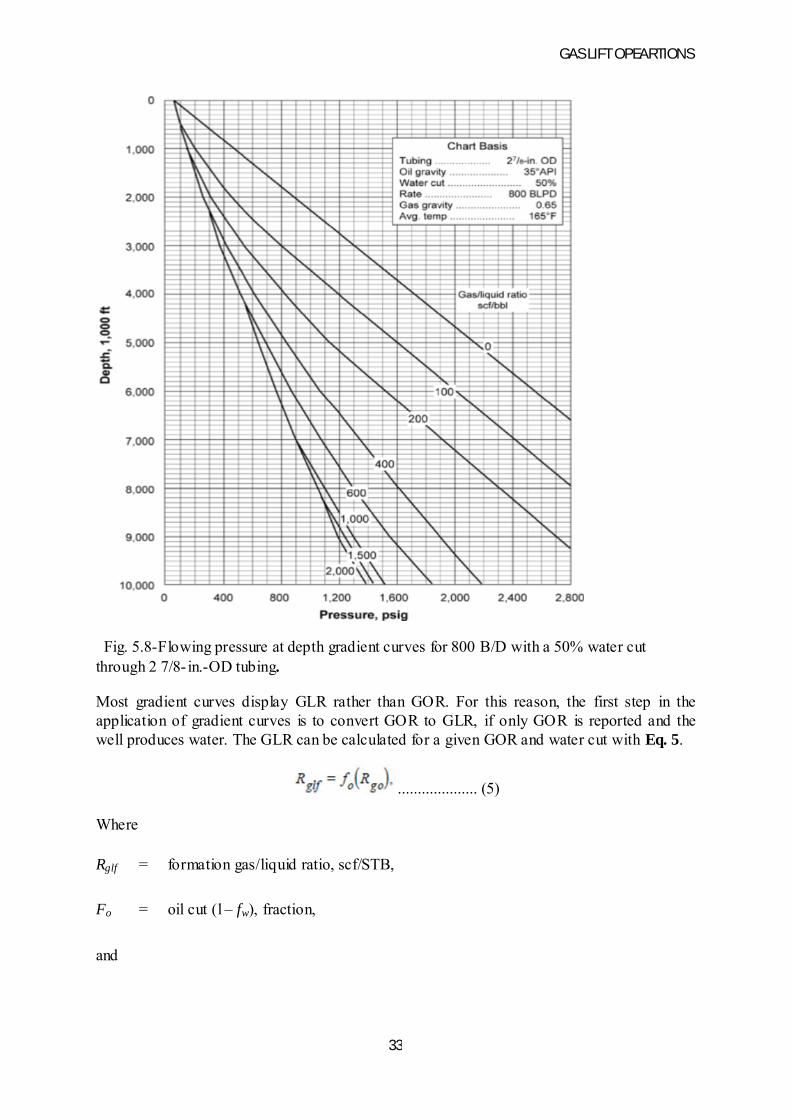
Fig. 5.8-Flowing pressure at depth gradient curves for 800 B/D with a 50% water cut through 2 7/8- in.-OD tubing.
Most gradient curves display GLR rather than GOR. For this reason, the first step in the application of gradient curves is to convert GOR to GLR, if only GOR is reported and the well produces water. The GLR can be calculated for a given GOR and water cut with Eq. 5.
.................... (5)
Where
Rglf = formation gas/liquid ratio, scf/STB,
Fo = oil cut (l – fw), fraction,
and

GAS LIFT OPEARTIONS
34
Rgo = Gas/oil ratio, scf/STB

GAS LIFT OPEARTIONS
35
CHAPTER-6
CONTINOUS FLOW GAS LIFT
Continuous flow gas lift is a continuation of natural flow with the only difference that lift gas from surface is artificially injected in to the flow conduit. The vast majority of gas-lifted wells are placed on this type of operations.
6.1 BASIC DESIGN OF CONTINOUS FLOW INSTALLATIONS:There are two basic operational parameters to be determined when designing a continuous flow gas lift installations:
• The depth of the operating valve i.e. the point of gas injection, and • The amount of lift gas to be injected at that point the exact of these quantities varies
with several given of assumed parameters detailed as follows , like surface injection pressure , required WHP , etc. in the following , a very basic case is considered where all relevant parameters are held constant.
•
• The wells desired liquid rate is given• The WHP required to move well fluids to the
surface gathering system is known • Well inflow parameters are available • Surface injection gas lift pressure is specified • The well’s tubing size is given
Fig 6.1 continuous flow installations
With the previous parameters given the two main tasks of the installation design can be accomplished by the use of a graphical procedure. Design calculations are done in a rectangular coordinate system with the ordinate representing well depth and the abscissa representing pressure. The use of this coordinate system provides a simple and easy understandable way to depict well pressures.
GAS LIFT OPEARTIONS
36
6.2 DESCRIPTION OFSYSTEM PERFORMANCE:
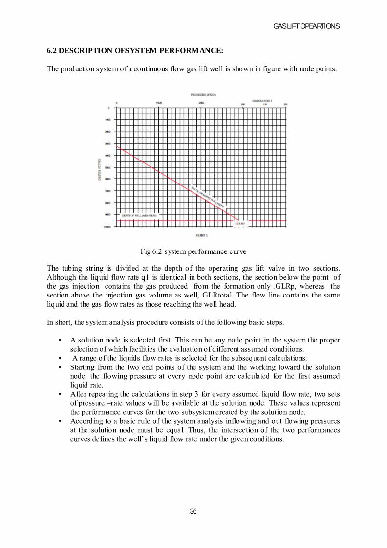
The production system of a continuous flow gas lift well is shown in figure with node points.
Fig 6.2 system performance curve
The tubing string is divided at the depth of the operating gas lift valve in two sections. Although the liquid flow rate q1 is identical in both sections, the section below the point of the gas injection contains the gas produced from the formation only .GLRp, whereas the section above the injection gas volume as well, GLRtotal. The flow line contains the same liquid and the gas flow rates as those reaching the well head.
In short, the system analysis procedure consists of the following basic steps.
• A solution node is selected first. This can be any node point in the system the proper selection of which facilities the evaluation of different assumed conditions.
• A range of the liquids flow rates is selected for the subsequent calculations.• Starting from the two end points of the system and the working toward the solution
node, the flowing pressure at every node point are calculated for the first assumed liquid rate.
• After repeating the calculations in step 3 for every assumed liquid flow rate, two sets of pressure –rate values will be available at the solution node. These values represent the performance curves for the two subsystem created by the solution node.
• According to a basic rule of the system analysis inflowing and out flowing pressures at the solution node must be equal. Thus, the intersection of the two performances curves defines the well’s liquid flow rate under the given conditions.
GAS LIFT OPEARTIONS
37
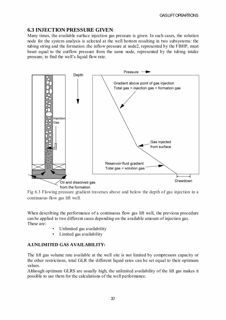
6.3 INJECTION PRESSURE GIVEN:Many times, the available surface injection gas pressure is given. In such cases, the solution node for the system analysis is selected at the well bottom resulting in two subsystems: the tubing string and the formation .the inflow pressure at node2, represented by the FBHP, must beset equal to the outflow pressure from the same node, represented by the tubing intake pressure, to find the well’s liquid flow rate.
Fig 6.3 Flowing pressure gradient traverses above and below the depth of gas injection in a continuous-flow gas lift well.
When describing the performance of a continuous flow gas lift well, the previous procedure can be applied to two different cases depending on the available amount of injection gas. These are:
• Unlimited gas availability• Limited gas availability
A.UNLIMITED GAS AVAILABILITY:
The lift gas volume rate available at the well site is not limited by compressors capacity or the other restrictions, total GLR the different liquid rates can be set equal to their optimum values.Although optimum GLRS are usually high, the unlimited availability of the lift gas makes it possible to use them for the calculations of the well performance.

GAS LIFT OPEARTIONS
38
The required steps of the calculations model are as follows in conjunction with the schematic figure.
• Plot the surface gas injection pressure, Pmj at zero depth.• Starting from the surface injection pressure, calculate the gas pressure distribution in
the well’s annulus and plot it with the well depth.• Assume a liquid production rate q1 and find the optimum total GLR belonging to that
rate and the tubing size used.• Starting from the set WHP and the using the previous rate and GLR, calculate the
pressure distribution in the tubing string.• Find the depth of gas injection of the above curve and a parallel drawn to the annulus
gas pressure at the depth. Use of a pressure differential delta p=100psi is generally accepted.
• From the point of the gas injection. Calculate the pressure traverse in the tubing string below the gas injection using the formation gas –liquid ratio GLRp.
• Find the FHBP at the perforation depth from the previous pressure traverse curve.• Repeat properly selected liquid rates and their optimum GLRs. The liquid flow rate
q1 and FBHP pairs constitute the points of the tubing performance curves, i.e.. The out flow pressures at node 2 in previous figure.
• Plot the tubing performance curve in a liquid rate-bottom hole pressure coordinate system as shown in figure
• Plot the wells in flow performance curve, representing the inflow pressure at node 2. Depending on the reservoir conditions, either a constant PI model or some other IPR method can be used.
• Find the wells liquid rate at the intersection of the inflow and outflow pressures.
B. LIMITED GAS AVILABILITY:
Many times the volumetric rate of the lift gas available at the well site is limited by compressor capacity or other restraints. In these cases, the available gas injection rate may not be sufficient to achieve the optimum GLR in the tubing string above the point gas injection. System performance calculations, therefore, cannot follow the procedure described for the unlimited gas volume case. Calculations presented in conjunction steps should be modified as follows.
• Plot the surface gas injection pressure Pinj at zero depth.• Starting from the surface injection pressure, calculate the gas pressure distribution in
the wells annulus and the plot it with depth.• Take the first value of the available lift gas rate Qg.• Assume a liquid production rate q1 and find the total GLR valid above the point of the
gas injection and the calculation from the available injection gas rate and the wells formation GLR:
GLRtotal=Qg/q1+GLRp
• Starting from the set WHP and the using the previous rate and GLR, calculate the pressure distribution in the tubing string.

GAS LIFT OPEARTIONS
39
• From the depth of gas injection determined previously, calculate the pressure traverse in the tubing string below the gas injection using the formation gas –liquid ratio GLRp.
• Find the FBHP at the perforation depth from the previous pressure traverse curve.• Repeat the steps with selected liquid rates and the total GLRs calculated from the
formula in step 4 . Plot the liquid floe rate q1 and FBHP pairs in a liquid rate-bottom hole pressure coordinate system. This constitutes the tubing performance curve belonging to the available injection gas rate Qg.
• Select the next value of the available lift gas rate Qg and repeat the points of the tubing performance curve belonging to the actual injection gas rate Qg.
• Plot the wells inflow performance curves, representing the inflow pressure at node 2 , on the same chart. Use the proper IPR either with a constant PI or using the proper model.
• Find the well’s possible liquid flow rates at the intersections of the inflow and the outflow pressures.
B. Advantages
Gas lift has the following advantages.
ß Gas lift is the best artificial lift method for handling sand or solid materials. Many wells produce some sand even if sand control is installed. The produced sand causes few mechanical problem in the gas-lift system; whereas, only a little sand plays havoc with other pumping methods, except the progressive cavity pump (PCP).
ß Deviated or crooked holes can be lifted easily with gas lift. This is especially important for offshore platform wells that are usually drilled directionally.
ß Gas lift permits the concurrent use of wireline equipment, and such downhole equipment is easily and economically serviced. This feature allows for routine repairs through the tubing.
ß The normal gas-lift design leaves the tubing fully open. This permits the use of BHP surveys, sand sounding and bailing, production logging, cutting, paraffin, etc.
ß High-formation GORs are very helpful for gas- lift systems but hinder other artificial lift systems. Produced gas means less injection gas is required; whereas, in all other pumping methods, pumped gas reduces volumetric pumping efficiency drastically.
ß Gas lift is flexible. A wide range of volumes and lift depths can be achieved with essentially the same well equipment. In some cases, switching to annular flow also can be easily accomplished to handle exceedingly high volumes.
ß A central gas-lift system easily can be used to service many wells or operate an entire field. Centralization usually lowers total capital cost and permits easier well control and testing.
ß A gas-lift system is not obtrusive; it has a low profile. The surface well equipment is the same as for flowing wells except for injection-gas metering. The low profile is usually an advantage in urban environments.
ß Well subsurface equipment is relatively inexpensive. Repair and maintenance expenses of subsurface equipment normally are low. The equipment is easily pulled and repaired or replaced. Also, major well workovers occur infrequently.
ß Installation of gas lift is compatible with subsurface safety valves and other surface equipment. The use of a surface-controlled subsurface safety valve with a 1/4-in. control line allows easy shut in of the well.

GAS LIFT OPEARTIONS
40
ß Gas lift can still perform fairly well even when only poor data are available when the design is made. This is fortunate because the spacing design usually must be made before the well is completed and tested.
C. Disadvantages
Gas lift has the following disadvantages.
ß Relatively high backpressure may seriously restrict production in continuous gas lift. This problem becomes more significant with increasing depths and declining static BHPs. Thus, a 10,000-ft well with a static BHP of 1,000 psi and a PI of 1.0 bpd/psi would be difficult to lift with the standard continuous-flow gas- lift system. However, there are special schemes available for such wells.
ß Gas lift is relatively inefficient, often resulting in large capital investments and high energy-operating costs. Compressors are relatively expensive and often require long delivery times. The compressor takes up space and weight when used on offshore platforms. Also, the cost of the distribution systems onshore may be significant. Increased gas use also may increase the size of necessary flowline and separators.
ß Adequate gas supply is needed throughout life of project. If the field runs out of gas, or if gas becomes too expensive, it may be necessary to switch to another artificial lift method. In addition, there must be enough gas for easy startups.
ß Operation and maintenance of compressors can be expensive. Skilled operators and good compressor mechanics are required for reliable operation. Compressor downtime should be minimal (< 3%).
ß There is increased difficulty when lifting low gravity (less than 15°API) crude because of greater friction, gas fingering, and liquid fallback. The cooling effect of gas expansion may further aggravate this problem. Also, the cooling effect will compound any paraffin problem.
ß Good data are required to make a good design. If not available, operations may have to continue with an inefficient design that does not produce the well to capacity.
Potential gas-lift operational problems that must be resolved include:
ß Freezing and hydrate problems in injection gas linesß Corrosive injection gasß Severe paraffin problemsß Fluctuating suction and discharge pressuresß Wire line problems
Other problems that must be resolved are:
ß Changing well conditionsß Especially declines in BHP and productivity index (PI)ß Deep high-volume liftß Valve interference (multipointing)
GAS LIFT OPEARTIONS
41
CHAPTER-7
INTERMITTENT FLOW GAS LIFT7.1Overview
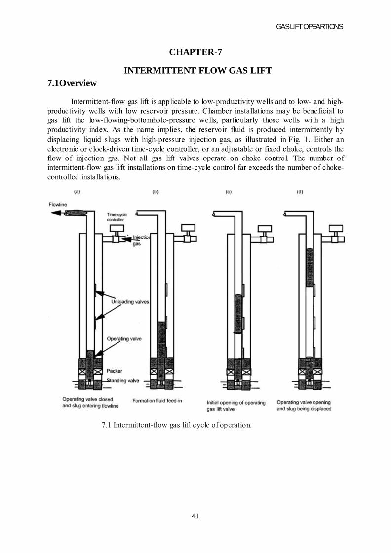
Intermittent-flow gas lift is applicable to low-productivity wells and to low- and high-productivity wells with low reservoir pressure. Chamber installations may be beneficial to gas lift the low-flowing-bottomhole-pressure wells, particularly those wells with a high productivity index. As the name implies, the reservoir fluid is produced intermittently by displacing liquid slugs with high-pressure injection gas, as illustrated in Fig. 1. Either an electronic or clock-driven time-cycle controller, or an adjustable or fixed choke, controls the flow of injection gas. Not all gas lift valves operate on choke control. The number of intermittent-flow gas lift installations on time-cycle control far exceeds the number of choke-controlled installations.
7.1 Intermittent-flow gas lift cycle of operation.
GAS LIFT OPEARTIONS
42
7.2Types of intermittent-flow gas lift installations
Intermittent-flow gas lift should be used only for tubing flow. Most installations have a packer and may include a standing valve in the tubing. If a well produces sand, a standing valve is recommended only if it is essential. A seating nipple should be installed at the lower end of the tubing string in intermittent-flow installations where a standing valve may be needed.
The working fluid level in a well should result in a minimum starting slug length that provides a production pressure at the depth of the operating gas lift valve equal to 50 to 60% of the operating injection-gas pressure at the same depth. If this is not possible, a chamber or plunger installation should be considered. In a chamber installation, the calculated depths of the unloading gas lift valves are the same as for a regular intermittent- lift installation. The chamber design converts a few feet of fluid, standing above the formation, into many feet of fluid in the tubing above the chamber. This entire liquid column is transferred into the tubing above the standing valve before injection gas enters the production conduit. The standing valve is required for efficient chamber operation to ensure U-tubing all fluid from the chamber into the tubing rather than allowing fluid to be pushed into the formation.
If a chamber installation is not installed in a low-bottomhole-pressure well, a plunger down hole stop and bumper spring can be set by wireline immediately above the operating gas lift valve. The plunger reduces the injection-gas slippage through the small liquid slug and decreases the liquid fallback. Smaller starting liquid slugs can be gas lifted more efficiently with the plunger acting as a sealing interface between the liquid slug and injection gas.
7.2.1 Prediction of daily production rates
Two basic factors control the maximum production from a high-rate intermittent-flow gas lift installation:
ß The total liquid production reaching the surface per cycleß The maximum number of injection-gas cycles per day
An intermittent gas lift installation should be designed to maximize the liquid recovery per cycle on low- and high-capacity wells. All restrictions in and near the wellhead should be eliminated. For this reason, streamlined wellheads are recommended. If the wellhead cannot be streamlined, all unnecessary ells and tees should be removed to reduce the number of bends between the tubing and flowline. If the velocity of the liquid slug is reduced before the entire column of liquid can be displaced into the horizontal flowline, additional injection-gas breakthrough, or gas slippage, will occur and decrease the liquid recovery per cycle. Performance of the operating gas lift valve, or valves, is important for efficient liquid-slug displacement. The operating gas lift valve should have a large port that opens quickly to ensure ample injection-gas volumetric throughput for efficiently displacing the liquid slug. Even though a large port is used, the valve spread (the difference between initial valve opening and closing pressure) should be kept relatively low to prevent excessive gas usage. This is especially true where large volumes of gas are stored in wells with small tubing and large casing.
GAS LIFT OPEARTIONS
43
The gas lift valve should not open slowly and meter a small injection-gas rate into the production conduit, which tends to aerate and percolate through the liquid slug rather than displace the slug. Rapid increase in the injection-gas casing pressure, after a time-cycle controller opens, improves the gas lift valve performance and ensures a more efficient displacement of a liquid slug in a time-cycle-operated intermittent-lift installation. Ample injection-gas volume must be available at the well site from the high-pressure injection-gas system. If the line pressure in the high-pressure system decreases to the casing pressure immediately after the time-cycle controller opens, poor valve action is the fault of the high-pressure system and not the gas lift installation in the well.
The size and length of the flow line can significantly affect the maximum cycle frequency. A flow line should always be at least equal to, or one size larger than, the tubing. The maximum number of injection-gas cycles per day is controlled by the time required for the wellhead pressure to return to the separator or production-header pressure after a slug surfaces. Reducing the separator pressure increases the starting slug length for the same flowing buttonhole pressure but does not solve the problem of decrease in wellhead pressure after the slug surfaces. When comparing or predicting the maximum production from two relatively high-capacity wells on intermittent gas lift, the size and length of the flowlines must be considered. If one installation requires 45 minutes and another 10 minutes for the wellhead pressure to approach the production-header pressure after a slug surfaces, the difference in maximum production (assuming that both wells have the same deliverability) is not the result of the gas lift installation in the well but of the surface facilities.
One definition of liquid fallback is the difference between the starting- liquid-slug volume, or length, and the produced slug volume, or length. The purpose of a properly designed intermittent gas lift installation is to recover a large portion of the starting slug. An important parameter that can be observed is the average slug velocity. The operating gas lift valve normally opens in less than 30 seconds after the time-cycle controller opens in most intermittent-lift installations. An approximate slug velocity can be estimated by assuming the valve opens 15 seconds after the controller opens and recording the time elapsed from this instance until the slug surfaces. In most installations, the depth of the operating gas lift valve is known or can be estimated from an acoustical fluid- level survey. If the average liquid-slug velocity is not near or exceeding 1,000 ft/min, the liquid fallback may be excessive. A slug velocity less than 800 ft/min can result in excessive fallback.
The maximum number of injection-gas cycles per day can be estimated for many wells by assuming 2 to 3 min/1,000 ft of lift for typical wells. The actual time can be less for installations on a production platform without flow lines and much longer for intermittent installations with small-ID and/or long flow lines, such as a well with 2 7/8-in.-outside diameter (OD) tubing and a 2- in. flow line that is 2 miles in length. Also, emulsions and other unique well problems can decrease the maximum number of injection cycles per day and the recoverable liquid production per cycle.
GAS LIFT OPEARTIONS
44
7.3 Intermittent-flow gas lift design
Intermittent-flow gas lift should be used only for tubing flow. Most installations have a packer and may include a standing valve in the tubing. If a well produces sand, a standing valve is recommended only if it is essential. A seating nipple should be installed at the lower end of the tubing string in intermittent-flow installations where a standing valve may be needed.
The working fluid level in a well should result in a minimum starting slug length that provides a production pressure at the depth of the operating gas lift valve equal to 50 to 60% of the operating injection-gas pressure at the same depth. If this is not possible, a chamber or plunger installation should be considered. In a chamber installation, the calculated depths of the unloading gas lift valves are the same as for a regular intermittent- lift installation. The chamber design converts a few feet of fluid, standing above the formation, into many feet of fluid in the tubing above the chamber. This entire liquid column is transferred into the tubing above the standing valve before injection gas enters the production conduit. The standingvalve is required for efficient chamber operation to ensure U-tubing all fluid from the chamber into the tubing rather than allowing fluid to be pushed into the formation.
If a chamber installation is not installed in a low-buttonhole-pressure well, a plunger down hole stop and bumper spring can be set by wire line immediately above the operating gas lift valve. The plunger reduces the injection-gas slippage through the small liquid slug and decreases the liquid fallback. Smaller starting liquid slugs can be gas lifted more efficiently with the plunger acting as a sealing interface between the liquid slug and injection gas.
Two basic factors control the maximum production from a high-rate intermittent-flow gas lift installation:
ß The total liquid production reaching the surface per cycleß The maximum number of injection-gas cycles per day
7.4 Factors affecting intermittent-flow gas lift
a. Streamlining wellheads
An intermittent gas lift installation should be designed to maximize the liquid recovery per cycle on low- and high-capacity wells. All restrictions in and near the wellhead should be eliminated. For this reason, streamlined wellheads are recommended. If the wellhead cannot be streamlined, all unnecessary ells and tees should be removed to reduce the number of bends between the tubing and flowline. If the velocity of the liquid slug is reduced before the entire column of liquid can be displaced into the horizontal flowline, additional injection-gas breakthrough, or gas slippage, will occur and decrease the liquid recovery per cycle. Performance of the operating gas lift valve, or valves, is important for efficient liquid-slug displacement. The operating gas lift valve should have a large port that opens quickly to ensure ample injection-gas volumetric throughput for efficiently displacing the liquid slug. Even though a large port is used, the valve spread (the difference between initial valve opening and closing pressure) should be kept relatively low to prevent excessive

GAS LIFT OPEARTIONS
45
gas usage. This is especially true where large volumes of gas are stored in wells with small tubing and large casing.
b. Maintaining injection gas casing pressure
The gas lift valve should not open slowly and meter a small injection-gas rate into the production conduit, which tends to aerate and percolate through the liquid slug rather than displace the slug. Rapid increase in the injection-gas casing pressure, after a time-cycle controller opens, improves the gas lift valve performance and ensures a more efficient displacement of a liquid slug in a time-cycle-operated intermittent-lift installation. Ample injection-gas volume must be available at the wellsite from the high-pressure injection-gas system. If the line pressure in the high-pressure system decreases to the casing pressure immediately after the time-cycle controller opens, poor valve action is the fault of the high-pressure system and not the gas lift installation in the well.
C .Length of flow line
The size and length of the flow line can significantly affect the maximum cycle frequency. A flow line should always be at least equal to, or one size larger than, the tubing. The maximum number of injection-gas cycles per day is controlled by the time required for the wellhead pressure to return to the separator or production-header pressure after a slug surfaces. Reducing the separator pressure increases the starting slug length for the same flowing bottomhole pressure but does not solve the problem of decrease in wellhead pressure after the slug surfaces. When comparing or predicting the maximum production from two relatively high-capacity wells on intermittent gas lift, the size and length of the flowlines must be considered. If one installation requires 45 minutes and another 10 minutes for the wellhead pressure to approach the production-header pressure after a slug surfaces, the difference in maximum production (assuming that both wells have the same deliverability) is not the result of the gas lift installation in the well but of the surface facilities.
One definition of liquid fallback is the difference between the starting- liquid-slug volume, or length, and the produced slug volume, or length. The purpose of a properly designed intermittent gas lift installation is to recover a large portion of the starting slug. An important parameter that can be observed is the average slug velocity. The operating gas lift valve normally opens in less than 30 seconds after the time-cycle controller opens in most intermittent-lift installations. An approximate slug velocity can be estimated by assuming the valve opens 15 seconds after the controller opens and recording the time elapsed from this instance until the slug surfaces. In most installations, the depth of the operating gas lift valve is known or can be estimated from an acoustical fluid- level survey. If the average liquid-slug velocity is not near or exceeding 1,000 ft/min, the liquid fallback may be excessive. A slug velocity less than 800 ft/min can result in excessive fallback.
The maximum number of injection-gas cycles per day can be estimated for many wells by assuming 2 to 3 min/1,000 ft of lift for typical wells. The actual time can be less for installations on a production platform without flowlines and much longer for intermittent installations with small- ID and/or long flowlines, such as a well with 2 7/8-in.-outside diameter (OD) tubing and a 2- in. flowline that is 2 miles in length. Also, emulsions and other
GAS LIFT OPEARTIONS
46
unique well problems can decrease the maximum number of injection cycles per day and the recoverable liquid production per cycle.
7.5 Injection-gas requirement for intermittent lift
Multiphase-flow correlations are not applicable for the prediction of the gas requirement to lift a well by intermittent gas lift. Intermittent lift is the displacement of a liquid slug by high-pressure gas. The injection-gas requirement is not based on reducing the density of the fluid column. It is based instead upon the volume of gas needed to fill the tubing between the bottom of the slug when it reaches the surface and the depth of the deepest gas lift valve that opens during an injection-gas cycle. The injection-gas pressure and volume following the liquid slug at the instant this slug surfaces are spent in the flowline.
In intermittent lift, the energy in the formation gas does little to assist in lifting most wells. One method for calculating the injection-gas requirement is to assume the produced slug to be a continuous liquid column without any after-flow production in the tail gas. The theoretical pressure under this liquid slug at the instant the slug surfaced is approximately the wellhead production pressure plus the length of the produced slug multiplied by the liquid gradient. The actual average pressure in the tubing under a liquid slug is more than this pressure based on the solid slug length and a dry-gas gradient. This results from the injection-gas penetration of the slug during the lift process and the frictional losses that occur. An average injection-gas pressure in the tubing equal to the theoretical pressure under the produced liquid slug plus the surface closing pressure of the operating gas lift valve divided by two is a realistic assumption on the basis of numerous bottomhole-pressure measurements in intermittent-flow gas lift installations.
The total volume of injection gas per cycle depends on the average pressure in the tubing under the slug and the physical capacity of the tubing. When the depth of lift is several thousand feet, compared to an equivalent produced slug length of only a few hundred feet, the length of the slug may be subtracted from the tubing length above the operating valve for calculating the capacity of tubing filled with injection gas each cycle. This assumption implies that the rate of decrease in the pressure of the expanding injection-gas volume beneath the liquid slug is less than the rate of decrease in the pressure exerted by the slug length remaining in the tubing as the upper portion of the slug enters the flowline.
7.6 Disadvantages of intermittent-flow gas lift
Intermittent-flow gas lift has several disadvantages compared to continuous-flow operations. If the desired production can be gas lifted by continuous flow, this method is preferable. It is difficult to handle the high instantaneous gas volumes properly in the low-and high-pressure sides of a closed rotative gas lift system. Choke control of the injection gas into a well eliminates the removal of injection-gas volume at high instantaneous rates from the high-pressure system. However, it does not solve the problem of the large gas volume beneath the slug that enters the low-pressure system following displacement of the liquid slug to the surface. Gas volume storage requires pressure difference and physical capacity. The difference between the compressor discharge pressure and the operating injection-gas casing pressures normally exceeds the difference between the separator and compressor suction pressures. For this reason, retaining the needed injection-gas volume in the low-pressure side
GAS LIFT OPEARTIONS
47
of a small, closed rotative gas lift system can be difficult unless the injection-gas cycles are staggered properly. Staggering of the injection-gas cycles is less precise on choke control than with a time-cycle controller. The electronic timers have improved the accuracy of controlled gas injection, whereby the injection cycles can be scheduled to prevent more than one well receiving injection gas at the same time. Therefore, total injection plus formation gas can be scheduled to enter the low-pressure system at a more constant rate with accurate time cycle than with choke control of the injection gas.
Severe surging in the flowing buttonhole pressure can present a serious production problem in unconsolidated-sand wells where sand production cannot be controlled. Sand bridging can plug off production and result in sand cleanout costs. Pressure surges in a chamber installation may be far more severe than in a regular intermittent- flow installation. A wireline release type of lock with an equalizing valve is recommended for the standing valve in a chamber to prevent the standing valve from being blown out of its seating nipple following blow down after an injection-gas cycle. Some companies have resorted to increasing the operating injection-gas pressures to lift near total depth by continuous flow rather than intermittent flow wells that produce sand.
The total energy in the formation and injection gas is not fully used with intermittent-flow gas lift. The high-pressure gas under the slug is spent in the flowline and does not contribute to the lift process. This is one reason for using continuous-flow operations for a high gas/liquid ratio (GLR) well if possible. Plunger lift may be the best method for lifting certain high-GLR wells.
The injection-gas requirements are usually higher for intermittent- flow than for continuous-flow gas lift operations. The tubing capacity beneath the slug must be filled with injection gas to displace the liquid slug to the surface. The tubing under the liquid slug cannot be one-half or two-thirds filled with high-pressure gas. For this reason, the gas requirements for intermittent lift of low-GLR wells that do not partially flow can be estimated with reasonable accuracy. Unfortunately, articles have been published that imply that a well, or group of wells, is being intermittent lifted with a certain type of gas lift valve that results in an injection-gas requirement of only a fraction of the gas volume needed to fill the tubing beneath the liquid slug. Although gas orifice meter charts are published to illustrate these claims, the truth is, these wells are partially flowing. Only minimal agitation and displacement of the liquid slug is required to lift these wells. Most of the energy needed to lift the well is being furnished by the formation and not the gas lift system. Intermittent-flow gas lift is much more labor intensive than continuous flow. In intermittent-flow gas lift, the operator should frequently adjust the injection time and cycle frequency to maintain an efficient operation.
The injection-gas requirements for intermittent-flow and continuous-flow gas lift should be compared before eliminating continuous- flow operations. With the advent of several reliable multiphase- flow correlations, the predictable range of continuous flow has been extended to much lower daily production rates. A careful investigation of the proper production conduit size for lifting a well by continuous flow may permit this type of gas lift in place of intermittent- flow gas lift.
GAS LIFT OPEARTIONS
48
7.7 Comparison of time-cycle to choke control gas lifts
The advantage of choke-controlled injection-gas volume for an intermittent-flow gas lift installation is the fact that a low volumetric injection-gas rate is required from the high-pressure system into the well. Several conditions must be met before choke control of the injection gas can be used successfully. The gas lift valve must be suited for choke-control operation, and the casing annulus must provide adequate storage capacity for the injection-gas volume needed to displace the slug. Clean, dry gas is extremely important in choke control, and low-capacity wells are more difficult to choke control because of the small surface injection-gas choke size required for the low daily injection-gas rate needed to lift the well. A pressure-reducing regulator to maintain a constant maximum valve opening casing pressure between valve operating cycles may be necessary to permit the use of a larger-sized choke in the injection-gas line. Other limitations of choke control of the injection gas include a reduction in the maximum liquid slug size that can be lifted each cycle and the maximum number of injection-gas cycles per day. Time-cycle control of the injection gas should be considered for high-rate intermittent-lift operations. Two-pen pressure recorder charts, shown in Fig. 2, illustrate time-cycle and choke-control operations:
ß Time-cycle controller opens
ß Time-cycle controller closes
ß Gas lift valve closes
Fig. 2b is choke control of the injection gas where:
Gases lift valve open
ß Gas lift valve closes
The difference in the maximum recorder tubing pressure for the time-cycle and choke-controlled installations results from different bourdon-tube range in the two pressure recorders. The pressure range for tubing pressure for time-cycle control is 0 to 1,000 psig, it is 0 to 500 psig for the choke-control chart

GAS LIFT OPEARTIONS
49
Fig. 7.22-Two-pen pressure-recording charts from intermittent gas lift installations with time-cycle and choke control of the injection gas.
Most intermittent-flow gas lift installations use time-cycle-operated controllers on the injection-gas line because of the many advantages of time-cycle over choke control of the injection gas. Rugged unbalanced, single-element, nitrogen-charged bellows gas lift valves with large ports can be used. Much larger liquid slugs can be lifted with time-cycle control because injection gas in the annulus can be supplemented with gas from the high-pressure injection-gas system during each injection-gas cycle.
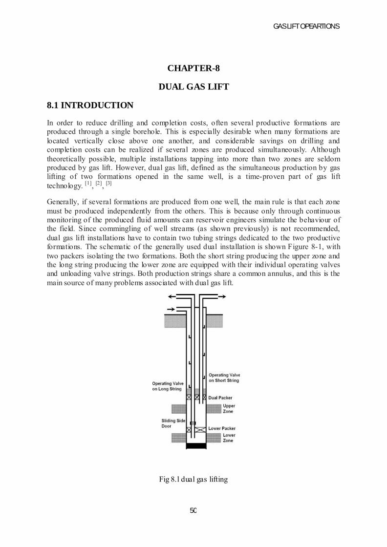
GAS LIFT OPEARTIONS
50
CHAPTER-8
DUAL GAS LIFT
8.1 INTRODUCTION
In order to reduce drilling and completion costs, often several productive formations are produced through a single borehole. This is especially desirable when many formations are located vertically close above one another, and considerable savings on drilling and completion costs can be realized if several zones are produced simultaneously. Although theoretically possible, multiple installations tapping into more than two zones are seldom produced by gas lift. However, dual gas lift, defined as the simultaneous production by gas lifting of two formations opened in the same well, is a time-proven part of gas lift technology. [1], [2], [3]
Generally, if several formations are produced from one well, the main rule is that each zone must be produced independently from the others. This is because only through continuous monitoring of the produced fluid amounts can reservoir engineers simulate the behaviour of the field. Since commingling of well streams (as shown previously) is not recommended, dual gas lift installations have to contain two tubing strings dedicated to the two productiveformations. The schematic of the generally used dual installation is shown Figure 8-1, with two packers isolating the two formations. Both the short string producing the upper zone and the long string producing the lower zone are equipped with their individual operating valves and unloading valve strings. Both production strings share a common annulus, and this is the main source of many problems associated with dual gas lift.
Fig 8.l dual gas lifting
GAS LIFT OPEARTIONS
51
8.2 GENERAL CONSIDERATIONS:
Compared to single zone gas lift installations there are of special problems associated with dual gas lift that need to be properly addressed during installation design and operations.
A.CASING SIZE
The size of casing string is greatest constrain on dual gas lift installations. Usually it is smaller than would be required to accommodate two tubing strings of proper sizes. This is why in most of the cases tubing strings of less than optimum sizes have to be run, limiting the production rates from both zones
B.RETRIEVABLE EQUIPMENT
The use of wireline retrievable equipment is highly recommended for dual wells where, because of the more complex well completion, workover operation are more costly. Original installation, replacement, and change of gas lift valves, as well as other pieces of equipment, are easier and less expensive than for conventional equipment.
C.UNLOADING
Unloading a dual gas lifting installation is slightly different from unloading a single zone installation because removal of liquids from the annulus can be accomplished through either of the two unloading valve strings. Operator chooses that spring to remove annulus liquids from the well whose bottom mandrel is at greater depth. During unloading the annulus, the other string should be closed in and can be put back into production after the first has started to produce. This implies valves needed to be installed in mandrels of the other unloading string because the valves are not required for unloading. Although this is true, proper unloading design for a dual gas lift well should make it possible to unload the well from either side.
8.3 INSTALLATION DESIGN PRINCIPLES
For dual gas lift design, the importance of accurate data is more pronounced than for single zone designs. Knowledge of exact inflow performance data for each zone and the use of an accurate multiphase flow correlation are the most important points to ensure that the installation will work exactly as designed. Otherwise, the point of gas injection, casing, and tubing pressures may change, leading to severe operational problems.
The individual design of the unloading valve string and the operating valve for one string of a dual installation is completely identical to the procedure required for a similar single-zone installation. The result of the two designs for the dual installation, however, must ensure that both valve strings will operate independently of each other without any interference. This objective can be reached only through the analysis of the operation of the individual valve strings, and the conclusions drawn can be used to set up some basic design rules.
GAS LIFT OPEARTIONS
52
8.4 BOTH ZONES ON CONTINUOUS FLOW
a. TWO STRINGS OF IPO VALVES
The proper distribution of lift gas volume into the two zones can be assured by the proper selection of the valve port sizes. In order to come to the ideal solution, the operating valve of one zone is selected with its operating point near critical flow. Changes in the injection or production pressure cause only minor fluctuations in the gas rate injected through the valve and for this required port area is selected for the design gas injection rate and a pressure differential of 100-120 psi across the valve, this valve will pass an almost constant volume of gas. The operating valve of other zone must not be choked. The unloading valve strings are usually spaced by assuming a constant surface opening pressure for both valve strings
The required surface injection control for this configuration is a simple choke on the injection line near the wellhead. If line pressures fluctuates, installation of a pressure regulator upstream of the choke is recommended.
b. ONE STRING OF IPO AND ONE STRING OF PPO VALVES
In this case, the two strings of unloading valves can easily operate independently of each other because IPO valves are opened by injection pressure whereas PPO valves open when tubing pressure increases. The IPO string can be designed with a constant surface opening pressure or with a constant drop in surface opening pressures. The PPO string, on the other hand, operates over a limited range of injection pressures and is spaced by assuming a constant surface opening pressure.
8.4 ONE INTERMITTENTAND ONE CONTINUOUS ZONE
a. TWO STRINGS OF IPO VALVES
The operating valve of the zone on continuous flow, however, would inject more gas during the operation of the intermittent zone and an inefficient operation of this zone would occur. For proper operation of both zones, therefore, the operating valve of the formation on continuous flow gas lift must be insensitive to changes in surface injection pressure.
As before the port size of the operating valve of the zone on continuous flow should be selected so that gas flow across the valve approaches critical conditions. Sizing the port for the required gas rate while maintaining a pressure differential of 100-120 psi across the valve can ensure this. Spacing of the unloading string for this should follow the procedure for constant surface opening pressure.
The operating valve of the intermittent valve string should have a large port area and a surface closing pressure higher than the operating pressure of the zone on continuous flow. The spacing of unloading valves should be based on a constant surface closing pressure
The required surface injection control arrangement is shown and it consists of an intermittent and a choke and a regulator on a bypass line. The choke and regulator provide the constant
GAS LIFT OPEARTIONS
53
injection pressure for the zone on continuous flow, while the intermitter controls the cyclic operation of the other zone on intermittent lift.
b. ONE STRING OF IPO AND ONE STRING OF PPO VALVES
Installing PPO valves on the string producing the formation on intermittent lift gives proper operation if unloading valves do not require a drop in injection (casing) pressure to close. A simple pressure regulator on the surface is needed to control gas injection.
8.5 BOTH ZONES ON INTERMITTENT LIFT
a. TWO STRINGS OF PILOT OPERATED VALVES
The use of pilot-operated gas lift valves in intermittent lift installations is advantageous because these valves can have very large port sizes while their spread can be kept under control. By selecting the proper control port sizes, the operating valves of the two strings can be adjusted to open when sufficient liquid has accumulated in the tubing string. Valve spacing for the two zones is accomplished by assuming the same surface closing pressures for both strings.
Surface injection control is simple and conforms to the choke and regulator control discussed. The regulator adjusts the valve opening pressures and the starting slug lengths, while the choke creates the drop in injection (casing) pressure necessary for the pilot valves to close.
b. TWO STRINGS OF PPO VALVES
PPO valves can only be used in wells with sufficient FBHPs that can support sufficiently large liquid columns to open the operating valve. Both strings are designed for the same surface operating pressure and only a choke is required at the surface to control gas injection.
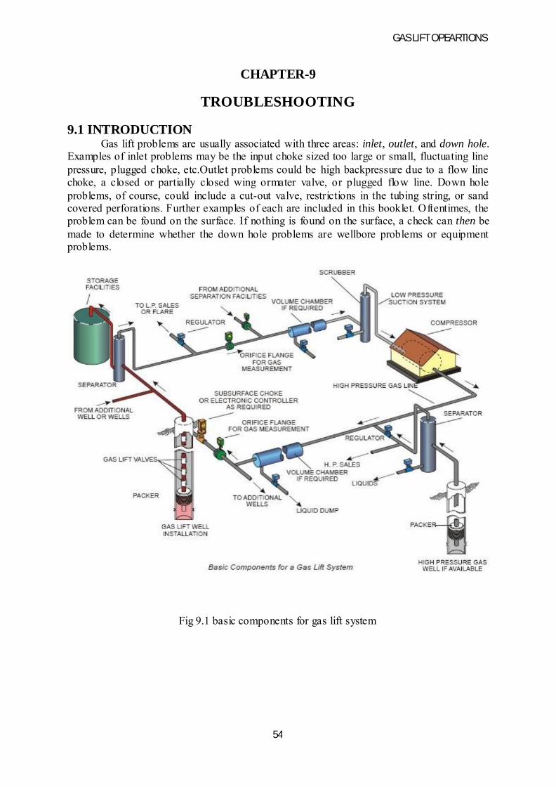
GAS LIFT OPEARTIONS
54
CHAPTER-9
TROUBLESHOOTING
9.1 INTRODUCTIONGas lift problems are usually associated with three areas: inlet, outlet, and down hole.
Examples of inlet problems may be the input choke sized too large or small, fluctuating line pressure, plugged choke, etc.Outlet problems could be high backpressure due to a flow line choke, a closed or partially closed wing ormater valve, or plugged flow line. Down hole problems, of course, could include a cut-out valve, restrictions in the tubing string, or sand covered perforations. Further examples of each are included in this booklet. Oftentimes, the problem can be found on the surface. If nothing is found on the surface, a check can then be made to determine whether the down hole problems are wellbore problems or equipment problems.
Fig 9.1 basic components for gas lift system

GAS LIFT OPEARTIONS
55
9.2 INLET PROBLEMSa. Choke sized too largeCheck for casing pressure at or above design operating pressure. This can cause reopening upper pressure valves and/or excessive gas usage. Approximate gas usages for various flow rates are included in the section on “tuning in” the well.
b. Choke sized too smallCheck for reduced fluid production as a result of insufficient gas injection. This condition can sometimes prevent the well from fully unloading. The design gas liquid ratio can often give an indication of the choke size to use as a starting point.
c. Low casing pressureThis condition can occur due to the choke being sized too small or the choke being plugged or frozen up. Choke freezing can often be eliminated by continuous injection of methanol in the gas lift gas. A check of gas volume being injected will separate this case from low casing pressure due to a hole in the tubing or cut out valve. Verify the gauge readings to be sure the problem is real.
d. High casing pressureThis condition can occur due to the choke being sized too large. Check for excessive gas usage due to Re opening upper pressure valves. If high-casing pressure is accompanied by low injection gas volumes, it is possible that the operating valve may be partially plugged or high tubing pressure may be reducing the differential between the tubing and casing. (Remove flow line choke and restriction). High casing pressure accompanying low injection gas volumes may also be caused by higher than anticipated temperatures raising the set pressures of pressure operated valves.e. Verify gaugesInaccurate gauges can cause false indications of high or low casing pressures. Always check the wellhead casing and tubing pressures with a calibrated gauge.
f. Low gas volumeCheck to insure that the gas lift line valve is fully open and that the casing chokes is not too small, frozen or plugged. Check to see if the available operating pressure is in the range required to open the valves. Be sure that the gas volume is being delivered to the well, as nearby wells may be robbing the system – especially intermittent wells. Sometimes a higher than anticipated producing rate and the resulting higher temperature will cause the valve set pressure to increase and thereby restrict the gas input.
g. Excessive gas volumeThis condition can be caused by the casing choke sized too large or excessive casing pressure. Check to see if the casing pressure is above the design pressure causing upper pressure valves to be open. A tubing leak or cut-out valve can also cause this symptom but they will generally also cause a low casing pressure.
GAS LIFT OPEARTIONS
56
9.3 OUTLET PROBLEMSa.Valve restrictionsChecks to insure that all valves at the tree and header are fully open or that an undersized valve is not in thin (i.e. 1- inch valve in 2- inch flow line). Other restrictions may result from a smashed or crimped flowline.For example, check places where the line crosses a road.b.High back pressureWellhead pressure is transmitted to the bottom of the hole, reducing the differential into the wellbore and thereby reducing production. Check to insure that no choke is in the flow line. Even with no choke bean in a choke body, it is usually restricted to less than full I.D. Remove the choke body if possible. Excessive 90oturns can cause high back pressure and should be removed where feasible. High backpressures can also result from paraffin or scale build-up in the flow line. Hot oiling the line will generally remove paraffin. However, scale may or may not be able to be removed depending on the type. Where high backpressure is due to longflowlines, it may be possible to reduce the pressure by “looping” the flow line with an inactive line. The same would apply to cases where the flow line I.D. is smaller than the tubing I.D. Sometimes a partially open check valve in the flow line can cause excessive backpressure. Common flow lines can cause excessive backpressure and should be avoided if possible. Check all possibilities and remove as many restrictions from the system as possible.
c.Separator operating pressureThe separator pressure should be maintained as low as possible for gas lift wells. Often a well may be flowing to a high or intermediate pressure system when it dies and is placed on gas lift. Insure that the well is switched to the lowest pressure system available. Sometimes an undersized orifice plate in the meter at the separator will cause high backpressure.
9.4 DOWNHOLE PROBLEMSa.Hole in tubingIndicators of a hole in the tubing include abnormally low casing pressure and excess gas usage. A hole in the tubing can be confirmed by the following procedure: Equalize the tubing pressure and casing pressure by closing the wing valve with the gas lift gas on. After the pressures are equalized, shut off the gas input valve and rapidly bleed-off the casing pressure. If the tubing pressure bleeds as the casing pressure drops, then a hole is indicated. The tubing pressure will hold if no hole is present since both the check valves and gas lift valves will be in the closed position as the casing pressure bleeds to zero. A packer leak may also cause symptoms similar to a hole in the tubing.
b.Operating pressure valve by surface closing pressure methodA pressure-operated valve will pass gas until the casing pressure drops to the closing pressure of the valve. As a result, the operating valve can often be estimated by shutting off the input gas and observing the pressure at which the casing holds. This pressure is the surface closing pressure of the operating valve. Closing pressure analysis assumes the tubing pressure to be zero, and single point injection. These assumptions limit the accuracy of this method since the tubing pressure at each valve is never zero, and multipoint injection may be occurring. This method can be useful when used in combination with other data to bracket the operatingvalve.

GAS LIFT OPEARTIONS
57
c.Well blowing dry gasFor pressure valves, check to insure that the casing pressure is not in excess of the design operating pressure, thereby causing operating from the upper valves. Insure that no hole exists in the tubing by the previously mentioned method. If the upper valves are not being held open by excess casing pressure and no hole exists, then operation is probably from the bottom valve. Additional verification can be obtained by checking the surface closing pressure as indicated above. In the case where the well is equipped with fluid valves and pressure valve on the bottom, blowing dry gas is a positive indication of operation from the bottom valve after the possibility of a hole in the tubing has been eliminated. Operation from the bottom valve generally indicates a lack of feed- in. Often it is advisable to tag bottom with wire line tools to see if the perforations have been covered by sand. When the well is equipped with a standing valve, check to insure the standing valve is not stuck in the closed position.
d.Well will not take any input gasEliminate the possibility of a frozen input choke or a closed input gas valve by measuring the pressures upstream and downstream of the choke. Also check for closed valves on the outlet side. If fluid valves were run without a pressure valve on bottom, this condition is probably an indication that all the fluid has been lifted from the tubing and not enough remains to open the valves. Check for feed- in problems. If pressure valves were run, check to see if the well started producing above the design fluid rate as the higher rate may have caused the temperature to increase sufficiently to lockout the valves. If temperature is the problem, thewell will probably produce periodically then stop. If this is not the problem, check to make sure that thevalve set pressures are not too high for the available casing pressure.
e.Well flowing in headsThis condition can occur due to several causes. With pressure valves, one cause is port sizes too large as would be the case if a well initially designed for intermittent lift were placed on constant flow due to higher than anticipated fluid volumes. In this case large tubing effects are involved and the well will lift until thefluid gradient is reduced below a value that will keep the valve open. This case can also occur due to temperature interference. For example, if the well started producing at a higher than anticipated fluid rate, the temperature could increase causing the valve set pressures to increase and thereby lock them out. When the temperature cools sufficiently the valves will open again, thus creating a condition where the well would flow by heads. With pressure valves having a high tubing effect on fluid operated valves, heading can occur as a result of limited feed-in. The valves will not open until the proper fluid load has been obtained, thus creating a condition where the well will intermit itself whenever adequate feed- in is achieved. Since over orunder injection can often cause a well to head, try “tuning” the well in.
f.Installation stymied and will not unloadThis condition generally occurs when the fluid column is heavier than the available lift pressure. Applying injection gas pressure to the top of the fluid column (usually with a jumper line) will often drive some of the fluid column back into the formation thereby reducing the height of the fluid column being lifted and allowing unloading with the available lift pressure. The check valves prevent this fluid from being displaced back into the casing. For fluid operated valves, “rocking” the well in this fashion will often open an upper valve and permit the unloading operation to continue. Sometimes a well can be “swabbed” to allow.
GAS LIFT OPEARTIONS
58
g.Valve hung openThis case can be identified when the casing pressure will bleed below the surface closing pressure of anyvalve in the hole but tests to determine if a hole exists show that no hole is present. Try shutting the wingvalve and allowing the casing pressure to build up as high as possible, then open the wing valve rapidly.This action will create high differential pressures across the valve seat, removing any trash that may beholding it open. Repeat the process several times if required. In some cases valves can be held open by saltdeposition, and pumping several barrels of fresh water into the casing will solve the problem. If the aboveactions do not help, a cut out or flat valve may be the cause.
h.Valve spacing too wideTry “rocking” the well as indicated when the well will not unload; this will sometimes allow working downto lower valves. If a high-pressure gas well is nearby, using the pressure from this well may allow unloading.If the problem is severe, respacing, installing a packoff gas lift valve, or shooting an orifice into the tubing toachieve a new point of operation may be the only solution.
9.5 GAS LIFT TROUBLESHOOTING TECHNIQUESA. Flowing Pressure and Temperature SurveysB. Casing Pressure Analysis, Calculations and Computer ModelingC. Historical Production and Multi-rate Test InterpretationD. Acoustic (Echo meter) SurveysE. Tagging Fluid LevelF. Two Pen Recorder ChartsA. Flowing Pressure and Temperature SurveysA flowing pressure survey provides the most complete and accurate representation of down hole conditions ofany methods used for gas lift analysis. A flowing survey describes what is occurring in a system so that predictions can be made as to well performance when the conditions are altered.From a graphical plot of a flowing pressure survey the following determinations can usually be made:1. The point of operation.2. The flowing bottom hole pressure.3. The P.I. of the well when test data and static bottom hole pressure data is made available along with the following pressure data.4. The confirmation and location of tubing leaks.5. the most suitable multiphase flow correlation for the well surveyed and also other wells in the same field.6. The character of the flow regime.7. Multi-point injection.
Flowing Survey Guidelines:1. Do not shut the well in during and at least 24 hours prior to running the survey. It is important that the flowing conditions be as normal as possible.2. Test the well during the survey. To calculate the P.I. or I.P.R., the production rate is required for the drawdown measured during the survey.3.If a tubing leak is suspected, at least one stop should be made between each gas lift valve and additional stops made in the area of the suspected leak.
GAS LIFT OPEARTIONS
59
4.The use of small diameter pressure instruments will minimize the restriction to flow and reduce the forces acting to “blow the tools up the hole”.5. If the well is being entered under flowing conditions, it is important to keep the tools from being “blownup the hole”. In addition to using small diameter bombs, weighted stem and “no-flow latches” should be used. Upward movement of the tool string activates a set of slips in the no-flow latch to prevent being“blown up the hole”.6. Running tandem pressure instruments can save valuable time, effort and money by providing a backup forthe event of a miss-run with the No. 1 instrument.7. Running a flowing temperature survey in conjunction with flowing pressure surveys can often providevery useful information. Temperature surveys can identify problems caused by miscalculations of test rackopening pressure due to erroneous temperature data and leaking gas lift valves or tubing can sometimes belocated or confirmed with temperature surveys. When running a temperature survey, it is a good practice tomake a stop below the mud line in addition to the stop in the lubricator for offshore wells and severalhundred feed below the surface for wells in arctic or near arctic areas so that a more accurate flowinggeothermal gradient can be determined.If it is not possible to run a temperature instrument, at the very least, a temperature measurement with a maximum recording thermometer should be obtained.8.For mechanical pressure instruments it is recommended that the maximum anticipated pressure in the well not exceed 75 percent of the maximum pressure of the instrument.9.In general, it is better to use the fastest clock possible to drive the chart and still provide the time required to run the survey.
Plotting Survey Results:The results of flowing pressure surveys are plotted on graph paper, along with other wellhead pressure data,to produce gradient curves. The plotted gradients allow visual interpretation of all the data.Procedures for Running Flowing Pressure Surveys:Continuous flow gas lift wells:1.Flow the well to a test separator for 24 hours to obtain a stabilized producing rate. (Test facilities should duplicate as nearly as possible normal production facilities).2. Place well on test before running the bottom hole pressure. The test should be long enough to provide a representative daily rate. The duration of the test depends largely on the stability of the flow rate.3. Record the pressure in the lubricator for ten minutes. Obtain a pressure reading of the lubricator pressure with a dead weight tester for comparison. Run the pressure bomb down the tubing, making stops approximately 50 feet below each gas lift valve. (Do not shut the well in while rigging up or running thesurvey).4. The pressure instrument should remain at bottom stop for an interval doubles that of the other stops.5. The casing pressure should be recorded with a dead weight tester or a calibrated two-pen recorder.6. If a static BHP is to be recorded, shut off lift gas and close the flow line wing valve. Leave the pressure instrument on bottom for time interval necessary for build-up. This could necessitate running two bombs in tandem with clocks having different speeds.
GAS LIFT OPEARTIONS
60
Continuous flow gas lifts wells:1. Flow the well to a test separator for 24 hours to obtain a stabilized producing rate. (Test facilities should duplicate as nearly as possible normal production facilities).2. Place well on test before running the bottomhole pressure. The test should be long enough to provide representative daily rate. The duration of the test depends largely on the stability of the flow rate.3. Record the pressure in the lubricator for ten minutes. Obtain a pressure reading of the lubricator pressure with a dead weight tester for comparison. Run the pressure bomb down the tubing, making stops approximately 50 feet below each gas lift valve. (Do not shut the well in while rigging up or running the survey).4. The pressure instrument should remain at bottom stop for an interval doubles that of the other stops.5. The casing pressure should be recorded with a dead weight tester or a calibrated two-pen recorder.6.If a static BHP is to be recorded, shut off lift gas and close the flow line wing valve. Leave the pressure instrument on bottom for time interval necessary for build-up. This could necessitate running two bombs in tandem with clocks having different speeds.
B. Casing Pressure Analysis, Calculations and Computer ModellingOne method of checking gas lift performance is by calculating the operating valve. This can be accomplished by calculating surface closing pressures or by comparing the valve opening pressures with theopening forces that exist at each valve downhole due to the operating tubing and casing pressures,temperatures, etc. Although this method may not be as accurate as a flowing pressure survey due toinaccuracies in the data used, it can still be a valuable tool in high grading the well selection for moreexpensive types of diagnostic methods.
C. Historical Well Production and Multi-rate Test InterpretationA well test report for troubleshooting as referred to in this text will provide the following data:1. Gross fluid production.2. Water cut.3. Oil production.4. Tubing head pressure.5. Casing head pressure.6. Produced gas. (total)7. Lift gas.8. Gas liquid ratio.9. Lift gas choke bean size.10. Flowline choke bean size. (if applicable)The well test should be of sufficient duration to provide a representative average daily producing rate. If a well is very unstable, it may require a test period of more than 24 hours to obtain a representative average24-hour rate. Flowing pressure/temperature surveys or casing/tubing pressure recordings should be made during the well test period. The well test conditions should duplicate as nearly as possible the normal producing conditions.
D. Acoustic (Echo meter) Well Sounding DevicesThe fluid level in the annulus of a gas lift well will sometimes give an indication of the depth of lift. This method involves firing a cartridge at the surface and utilizes the principle of sound waves to determine the depth of the fluid level in the annulus. Acoustic devices are

GAS LIFT OPEARTIONS
61
fairly inexpensive when compared to flowing pressure surveys. It should be noted that for wells with packers, it is possible for the well to have lifted down to a deeper valve while unloading, then returned to operation at a valve up the hole. The resulting fluid level in the annulus will be below the actual point of operation.
E. Tagging Fluid LevelTagging the fluid level in a well with wire line tools can sometimes give an estimation of the operating valve subject to several limitations. Fluid feed- in will often raise the fluid level before the wire line tools can get down the hole. In addition, fluid fallback will always occur after the gas lift gas has been shut off. Both of these factors will cause the observed fluid level to be above the operating valve. Care should be taken to insure that the input gas valve was closed prior to closing the wing valve or the gas pressure will drive the fluid back down the hole and below the point of operation. This is certainly a questionable method..F. Two Pen Recorder ChartsIn order to calculate the operating valve, it is necessary to have accurate tubing and casing pressure data. Two pen recorder charts give a continuous recording of these pressures, and can be quite useful if accompanied by an accurate well test. The two pen recorder charts can be used to optimize surface controls, locate surface problems, as well as identify down hole problems.
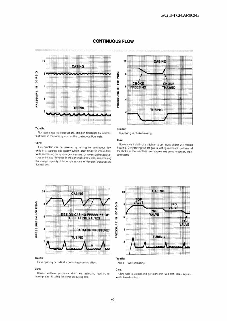
GAS LIFT OPEARTIONS
62

GAS LIFT OPEARTIONS
63
GAS LIFT OPEARTIONS
64
CONCLUSION
1.Gas lift permits the use of wire line equipment. This further allows for routine repairs through tubing, without pulling out the hole tubing. The repair and maintains cost of subsurface equipment is normally low.
2.Gas lift is flexible. A wide range of volumes and lift depths can be achieved with essentially the same equipment by increasing the injection gas.
3.Formations with high gas oil ratios are helpful rather than being a hindrance for gas lift as less injection gas is required.
4.A gas lift system can be easily used to service many wells are operate an entire Field centralisation usually lowers total capital cost.
5.Gas Lift, one of artificial methods of lifting fluid, has been applied extensively for several decades (started in 1800’s). As an artificial lift method, Gas lift can be applied to wells as deep as 15,000 ft and can lift fluid at rate of 50,000 STB/D. Gas lift aims to increase the flow rate by reducing the flowing gradient of the flowing fluid. In other words; adding supplement amount of gas (from an external source) to increase the gas-liquid ratio (GLR) to reduce the flowing fluid density (or gradient).
6.Gas lift is the only form of artificial lift that does not acquire down hole pump. Comparing to the other forms of artificial lift methods, gas lift is simpler, more flexible, and has the ability to operate at vast ranges of fluid production which makes it a good candidate for offshore applications as well. Unlike the pump-based methods, gas lift is incapable of reducing the Bottom hole pressure (BHP) very low, requires high pressure gas to operate and may encounter some production instabilities due to variations in gas injection rate and the injection depth. it depicts a schematic of a gas lift well. Gas lift can be continuous or intermittent. In this dissertation, we deal with continuous gas lift installation. In conventional intermittent gas lift, the gas injected penetrates the liquid slug and assumes a particular bullet shaped profile known as a Taylor bubble. This penetration causes some of the liquid slug fluid to slip downward around the gas bubble, with the consequent loss of production (fallback). The use of a metallic plunger in an intermittent gas lift installation provides a solid interface between the injected gas and the liquid slug. There is experimental evidence 4,5,6 that, under certain conditions, the solid interface provided by the plungers is responsible for a reduction of fallback losses associated with conventional intermittent gas lift. Further benefits, in terms of reduced gas injection requirements, can be realized when combining intermittent gas lift and plungers.
GAS LIFT OPEARTIONS
65
REFERENCES
1.Weiroilandgas.com,(2013).Weir-SPM:General-Catalog.Retrievedon1May2013from. http://www.weiroilandgas.com/pdf/WEIR%SPM%20GENERAL%20CATALOG%20(0509).pdf
2.Wongkaren, E. M. (1980). The use of operating valve differential pressure to optimize continuous flow gas lift design.
3.Infohost.nmt.edu, (2013). Gas Lift Systems. Retrieved on 30 April 2013 from http://infohost.nmt.edu/~petro/faculty/Kelly/Glf.pdf
4. Blann, J.R. and Williams, J.D. 1984. Determining the Most Profitable Gas Injection Pressure for a Gas Lift Installation (includes associated papers 13539 and 13546 ). J Pet technol 36 (8): 1305-1311. SPE-12202-PA.
5. Gas Lift, Book 6 of Vocational Training Series, third edition. 1994. Dallas, Texas: API, E&P Dept.
6. Vogel, J.V. 1968. Inflow Performance Relationships for Solution-Gas Drive Wells. J Pet technol 20 (1): 83–92. SPE 1476-PA.
7. poettmann, F.H. and Carpenter, P.G. 1952. The Multiphase Flow of Gas, Oil and Water through Vertical Flow Strings .Drilling & Prod. Prac., 257.
8. Orkiszewski, J. 1967. Predicting Two-Phase Pressure Drops in Vertical Pipe. J Pet Technol 19 (6): 829–838.SPE-1546-PA. .
9. Duns, H. Jr. and Ros, N.C.J. 1963.Vertical Flow of Gas and Liquid Mixtures from Boreholes. Proc.,Sixth World Petroleum Congress, Frankfurt, Germany, Sec. II, Paper 22-PG.
10. Hagedorn, A.R. and Brown, K.E. 1964.The Effect of Liquid Viscosity in Two-Phase Vertical Flow. J Pet Technol 16 (2): 203-210 SPE 733-PA.
11. Beggs, D.H. and Brill, J.P. 1973 A Study of Two-Phase Flow in Inclined Pipes. J Pet Techno 25 (5): 607-617. SPE-4007- PA.
12. API RP 11V2, Recommended Practice for Gas Lift Valve Performance Testing, first edition. 1995. Washington, DC: API
13. API RP 11V6, Recommended Practice for Design of Continuous Flow Gas Lift Installations Using Injection Pressure Operated Valves, second edition. 1999. Washington, DC: API.
GAS LIFT OPEARTIONS
66
14. Kirkpatrick, C.V. 1959. Advances in Gas Lift Technology. Drill. & Prod. Prac. (March): 24.
15. Sagar, R., Doty, D.R., and Schmidt, Z. 1991. Predicting Temperature Profiles in a Flowing Well. SPE Prod Eng 6 (4): 441-448. SPE-19702-PA
16. Winkler, H.W. and Eads, P.T. 1993. Applying the Basic Performance Concepts of Single-Element, Unbalanced Gas-Lift Valves for Installation Design. SPE Prod & Oper 8 (3): 211-216. SPE-21636-PA.
17.API RP 11V5, Recommended Practice for Operation, Maintenance and Troubleshooting of Gas Lift Installations, first edition. 1995. Washington, DC: API.