OPERATIONS MANUAL
45
OPERATIONS MANUAL
-
Upload
khangminh22 -
Category
Documents
-
view
4 -
download
0
Transcript of OPERATIONS MANUAL

OPERATIONS MANUAL

The Spirit of Flight Simulation
Available to buy online at www.justflight.com
www.justflight.com

Duchess Model 76 – Operations Manual3
Operations ManualPlease note that Aerofly FS 2 must be correctly installed prior to the
installation and use of this Duchess Model 76 simulation.
CONTENTS
INTRODUCTION .........................................................................................................6
Aircraft specifications .............................................................................................6
Paint schemes ........................................................................................................7
INSTALLATION, UPDATES AND SUPPORT .............................................................8
SYSTEMS GUIDE .....................................................................................................10
Airframe ................................................................................................................10
Fuel system...........................................................................................................10
Electrical system ...................................................................................................10
Vacuum system ....................................................................................................11
Pitot-static system ................................................................................................11
Lighting system ....................................................................................................11
Instrument markings .............................................................................................12
Limits ....................................................................................................................12
Landing gear .........................................................................................................14
Doors and exits ....................................................................................................14
Flight controls .......................................................................................................14
Engines .................................................................................................................15
Stall warning system ............................................................................................16
Environmental systems .........................................................................................16

Duchess Model 76 – Operations Manual4
PANEL GUIDE ...........................................................................................................17
Left instrument panel ............................................................................................18
Left lower subpanel ..............................................................................................19
Left sidewall ..........................................................................................................19
Engine instruments ...............................................................................................20
Throttle quadrant ..................................................................................................20
Centre panel .........................................................................................................21
Right instrument panel .........................................................................................21
Upper cockpit .......................................................................................................22
Lower cockpit .......................................................................................................22
Emergency landing gear extension ......................................................................23
KMA 28 – audio selector ......................................................................................23
GNS 430 – COM 1 / NAV 1 / GPS .......................................................................24
KX 165 – COM 2 / NAV 2 radio ............................................................................25
KR 87 – ADF .........................................................................................................26
KT 76A – transponder...........................................................................................27
AUTOPILOT ..............................................................................................................29
Controls ................................................................................................................29
NORMAL PROCEDURES .........................................................................................31
Airspeed (IAS) for safe operations ........................................................................31
Pre-flight ...............................................................................................................31
Before starting engines .........................................................................................32
Engine starting ......................................................................................................32
Taxiing ...................................................................................................................33
Before take-off ......................................................................................................34
Take-off .................................................................................................................34
Climb .....................................................................................................................34
Cruise ....................................................................................................................35
Descent .................................................................................................................35
Approach and landing ..........................................................................................35
After landing .........................................................................................................36
Shutdown ..............................................................................................................36
EMERGENCY PROCEDURES .................................................................................37
Airspeed (IAS) for safe operations ........................................................................37
Engine failures ......................................................................................................37

Duchess Model 76 – Operations Manual5
Emergency descent ..............................................................................................39
Maximum glide configuration ...............................................................................39
Landing emergencies ...........................................................................................40
Systems emergencies ..........................................................................................41
Landing gear manual extension ...........................................................................42
Simulated one-engine inoperative ........................................................................42
Spin recovery ........................................................................................................42
CREDITS ...................................................................................................................43
COPYRIGHT..............................................................................................................43

Duchess Model 76 – Operations Manual6
INTRODUCTION
The Duchess is a four-seater, twin-engine T-tail aircraft equipped with retractable tricycle landing gear and two 180 HP four-cylinder engines fitted with constant-speed propellers. Its IFR-capable avionics suite, excellent handling characteristics and counter-rotating propellers make it an ideal aircraft for multi-engine flight training and the perfect step up from single-engine aircraft such as the PA-28. A cruise speed of 155 knots, a range of 780 nautical miles and a service ceiling of 20,000ft also make it a very capable touring aircraft.
The Duchess was developed from the existing single-engine Musketeer and was first flown in 1977, with deliveries to customers starting in 1978. Designed with twin-engine training in mind, the Duchess competes with the PA-44 Seminole and C-310. A total of 437 aircraft were built before production ended in 1982.
Aircraft specifications
Dimensions
Length 8.85 m (29.1 ft)
Wingspan 11.6 m (38 ft)
Height (to top of tail) 2.9 m (9.5 ft)
Wing area 16.8 m2 (181 ft2)
Engine
Type 2 x Lycoming O-360 four-cylinder, horizontally opposed, air-cooled piston
Power 180 horsepower at 2,700 RPM
Propeller Two-blade, constant-speed, fully feathering. Left rotates clockwise; right rotates anti-clockwise.

Duchess Model 76 – Operations Manual7
Weights
Empty weight 2,446 lb (1,109 kg)
Maximum ramp weight 3,916 lb (1,776 kg)
Maximum take-off/landing weight 3,900 lb (1,769 kg)
Maximum baggage weight 200 lb (91 kg)
Maximum useful load 1,470 lb (667 kg)
Fuel and oil
Fuel capacity 103 US gallons
Usable fuel 100 US gallons
Oil capacity 8 US quarts per engine
Performance
VNE (never exceed speed) 194 KIAS
VNO (max. cruising speed) 154 KIAS
VA (manoeuvring speed) 132 KIAS
VFE (max. flap speed) 110 KIAS
VLE (max. gear speed) 140 KIAS
VSO (stall speed) 60 KIAS (landing configuration)
Service ceiling 19,500 ft
Range (max. payload) 780 nautical miles
Paint schemes
The Duchess Model 76 is supplied in nine paint schemes:
G-BZRT (UK)
G-GCCL (UK)
G-BNYO (UK)
G-WACJ (UK)
N671R (USA)
D-GIGY (Germany)
F-GCLJ (France)
C-GTYG (Canada)
EC-INC (Spain)

Duchess Model 76 – Operations Manual8
INSTALLATION, UPDATES AND SUPPORT
You can install this Duchess 76 software as often as you like on the same computer system:
1. Click on the ‘Account’ tab on the Just Flight website.
2. Log in to your account.
3. Select the ‘Your Orders’ button.
4. A list of your purchases will appear and you can then download the software you require.
Accessing the aircraft
To access the aircraft:
1. Load Aerofly FS 2 and click the ‘Aircraft’ tab to open the aircraft selection menu.
2. Use the left and right arrow keys on your keyboard to navigate through the available aircraft until you get to ‘Beechcraft Duchess 76’.
3. Use the left and right arrow icons above the aircraft to select the paint scheme you want.
4. Press the ‘Back’ arrow to return to the main menu and finish setting up your flight in the normal way.
Uninstalling
To uninstall this product from your system, select the appropriate option for your version of Windows from the ‘Control Panel’:
• ‘Add or Remove Programs’ (Windows XP)
• ‘Programs and Features’ (Windows Vista or 7)
• ‘Apps & features’ (Windows 10 or later)
Select the product you want to uninstall and then select the ‘Uninstall’ option, following the on-screen instructions to uninstall the product.
Uninstalling or deleting this product in any other way may cause problems when using this product in the future or with your Windows set-up.
Updates and Technical Support
For technical support (in English) please visit the Support pages on the Just Flight website.
As a Just Flight customer you can obtain free technical support for any Just Flight or Just Trains product.
If an update becomes available for this aircraft, we will post details on the Support page and we will also send a notification email about the update to all buyers who are currently subscribed to our Newsletter and emails.

Duchess Model 76 – Operations Manual9
Regular News
To get all the latest news about Just Flight products, special offers and projects in development, sign up for our Newsletter and regular emails.
We can assure you that none of your details will ever be sold or passed on to any third party and you can, of course, unsubscribe from this service at any time.
You can also keep up to date with Just Flight via Facebook and Twitter.

Duchess Model 76 – Operations Manual10
SYSTEMS GUIDE
Airframe
The Duchess 76 is a twin-engine, all-metal aircraft with retractable tricycle landing gear. The aircraft has seating for up to four occupants, a 200lb luggage compartment and two 180 HP engines.
The basic airframe is constructed out of aluminium alloy. Aerobatics are prohibited in this aircraft as the structure is not designed for aerobatic loads. The fuselage is a semi-monocoque structure.
A vertical stabiliser, a top-mounted horizontal stabiliser and a rudder make up the T-tail empennage.
Fuel system
Fuel is contained in two 51.5 US gallon tanks, one in each wing. Of the total 103-gallon capacity, only 100 gallons are usable.
The fuel system is configured in an ON-CROSSFEED-OFF arrangement. The fuel selector panel, located on the lower portion of the centre pedestal, contains the fuel selector levers for each engine.
The fuel flows from the respective tank through a fuel selector valve into the engine-driven fuel pump, from where it is delivered to the carburettor.
The fuel selector valve levers have three positions: ON, CROSSFEED and OFF.
Fuel quantity indicators on the instrument panel indicate the amount of fuel remaining in each tank. The quantity is shown as a fraction of the total tank capacity.
The electric auxiliary fuel pumps, one for each engine, are located on the pilot’s subpanel. They are controlled by separate rocker-type ON/OFF switches labelled AUX FUEL PUMP – L ON, R ON. The fuel pumps provide pressure for priming, starting, taxiing, take-off and landing, and provide sufficient pressure for continued engine operation in the case of engine-driven fuel pump failure.
Each engine is equipped with a fuel priming system. The magneto/start switches incorporate a PUSH TO PRIME function to aid in engine starting. The battery master and auxiliary fuel pump switches must be turned on before activating the fuel priming system. The PUSH TO PRIME function can be used with the magneto/start switch in either the BOTH or the START position.
The fuel lines for the engines are interconnected by crossfeed lines. During normal operation each engine uses its own fuel pump to draw fuel from its respective wing fuel tank. The crossfeed system allows either engine to consume all the available fuel from the opposite side in emergency situations but does not allow fuel to be transferred from one wing tank to the other.
The cabin heater, when in use, consumes 2/3 gallon of fuel per hour from the right wing tank.
Electrical system
The alternator switches, battery switch, magneto/start switches and auxiliary fuel pump switches are located on the pilot’s subpanel. The panel contains most of the electrical system switches and switch-type circuit breakers, each of which is labelled according to its function. The right subpanel contains the circuit breakers for the various electrical systems and all the avionics circuit breakers.
The primary electrical power source is a 28-volt, 55-ampere alternator fitted to each engine. Secondary power is provided by one 24-volt, 15.5 ampere-hour battery. The output of each alternator is controlled by a separate voltage regulator. The alternator systems are completely separate except for the mutual tie to the battery bus through two bus-isolation circuit breakers. The bus-isolation circuit breakers are used to isolate Bus 1 and Bus 2 from the battery bus circuit.
Duchess Model 76 – Operations Manual11
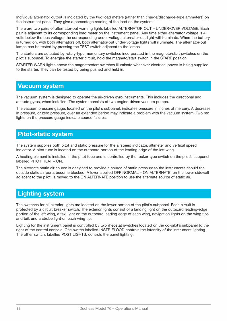
Individual alternator output is indicated by the two load meters (rather than charge/discharge-type ammeters) on the instrument panel. They give a percentage reading of the load on the system.
There are two pairs of alternator-out warning lights labelled ALTERNATOR OUT – UNDER/OVER VOLTAGE. Each pair is adjacent to its corresponding load meter on the instrument panel. Any time either alternator voltage is 4 volts below the bus voltage, the corresponding under-voltage alternator-out light will illuminate. When the battery is turned on, with both alternators off, both alternator-out under-voltage lights will illuminate. The alternator-out lamps can be tested by pressing the TEST switch adjacent to the lamps.
The starters are actuated by rotary-type momentary switches incorporated in the magneto/start switches on the pilot’s subpanel. To energise the starter circuit, hold the magneto/start switch in the START position.
STARTER WARN lights above the magneto/start switches illuminate whenever electrical power is being supplied to the starter. They can be tested by being pushed and held in.
Vacuum system
The vacuum system is designed to operate the air-driven gyro instruments. This includes the directional and attitude gyros, when installed. The system consists of two engine-driven vacuum pumps.
The vacuum pressure gauge, located on the pilot’s subpanel, indicates pressure in inches of mercury. A decrease in pressure, or zero pressure, over an extended period may indicate a problem with the vacuum system. Two red lights on the pressure gauge indicate source failures.
Pitot-static system
The system supplies both pitot and static pressure for the airspeed indicator, altimeter and vertical speed indicator. A pitot tube is located on the outboard portion of the leading edge of the left wing.
A heating element is installed in the pitot tube and is controlled by the rocker-type switch on the pilot’s subpanel labelled PITOT HEAT – ON.
The alternate static air source is designed to provide a source of static pressure to the instruments should the outside static air ports become blocked. A lever labelled OFF NORMAL – ON ALTERNATE, on the lower sidewall adjacent to the pilot, is moved to the ON ALTERNATE position to use the alternate source of static air.
Lighting system
The switches for all exterior lights are located on the lower portion of the pilot’s subpanel. Each circuit is protected by a circuit breaker switch. The exterior lights consist of a landing light on the outboard leading-edge portion of the left wing, a taxi light on the outboard leading edge of each wing, navigation lights on the wing tips and tail, and a strobe light on each wing tip.
Lighting for the instrument panel is controlled by two rheostat switches located on the co-pilot’s subpanel to the right of the control console. One switch labelled INSTR FLOOD controls the intensity of the instrument lighting. The other switch, labelled POST LIGHTS, controls the panel lighting.

Duchess Model 76 – Operations Manual12
Instrument markings
Airspeed indicator markings
MARKINGKIAS
VALUE OR RANGESIGNIFICANCE
White arc 60-110
Full flap operating range. Lower limit is maximum weight VSO in landing configuration.
Upper limit is maximum speed permissible with flaps extended.
Blue radial 85 Single-engine best rate of climb.
Red radial 65Minimum single-engine control
(VCMA).
Green arc 70-154
Normal operating range. Lower limit is maximum weight VS1 with flaps retracted. Upper limit is maximum
structural cruising speed.
Yellow arc 154-194Operations must be conducted with
caution and only in smooth air.
Red line 194 Maximum speed for all operations.
Engine indicator markings
INSTRUMENTRed line or arc
Minimum limit
Yellow arc
Caution range
Green arc
Normal operating
Red line
Maximum limit
Tachometer 500-2,700 RPM 2,700 RPM
Oil temperature 60-120°F 120-245°F 245°F
Fuel pressure 0.5 PSI 0.5-8 PSI 8 PSI
Oil pressure 25 PSI 25-60 PSI 60-100 PSI 100 PSI
Manifold pressure 15-29.6 inHg 29.6 inHg
Vacuum gauge 4.3-5.9 inHg 5.9 inHg
Limits
Weight limits
Maximum ramp weight 3,916 lb (1,776 kg)
Maximum take-off/landing weight 3,900 lb (1,769 kg)
Maximum baggage weight 200 lb (91 kg)
Maximum useful load 1,470 lb (667 kg)

Duchess Model 76 – Operations Manual13
Centre of gravity limits
Weight (lb)
Forward limit Inches aft of datum
Rearward limit Inches aft of datum
3,900 110.6 117.5
3,250 and below 106.6 117.5
The datum used is 129.4 inches ahead of the wing centre.
Manoeuvre limits
This aircraft is certificated in the normal category. The normal category is applicable to aircraft intended for non-aerobatic operations. These include any manoeuvres incidental to normal flying, stalls (except whip stalls), lazy eights, chandelles and steep turns in which the angle of bank is no more than 60° and pitch is no more than 30°.
Aerobatic manoeuvres, including spins, are not approved.
Flight load factor limits
Positive load factor (maximum – flaps up) +3.8 G
Positive load factor (maximum – flaps down) +2.0 G
Negative load factor (maximum – flaps up) -1.5 G
Types of operation
The Duchess is approved for the following operations:
• Day VFR
• Night VFR
• Day IFR
• Night IFR
• Non-icing
Fuel limitations
Total capacity 103 US gallons
Unusable fuel 3 US gallons
Usable fuel 100 US gallons (50 gallons per wing tank)

Duchess Model 76 – Operations Manual14
Landing gear
The Duchess 76 is equipped with retractable tricycle landing gear. Retraction and extension of the gear is accomplished using an electrically driven hydraulic pump. The landing gear may be hydraulically extended or retracted.
The nose gear is steerable through a 30-degree arc each side of centre by use of the rudder pedals and toe brakes.
The brake system includes toe brakes on the left and right set of rudder pedals and a parking brake control on the right subpanel, to the left of the flap switch.
The landing gear is controlled by a two-position handle on the left subpanel. The position indicator lights are located above the handle, with three green lights, which illuminate whenever the associated gear is down and locked, and one red light which illuminates whenever the gear is in transit. All the lights will be extinguished when the gear is up. Each indicator light can be pressed to test its functionality.
If the gear is retracted and either throttle lever is retarded below an engine setting sufficient for flight, the landing gear warning horn will sound. Regardless of throttle position, the horn will also be triggered whenever the flaps are extended beyond 16° if the gear is not down and locked.
There are two circuit breakers for the landing gear system: GEAR MOTOR and GEAR CONTROL.
The landing gear can be manually extended by turning the hydraulic pressure bypass valve 90° anti-clockwise. The valve is located under a door on the floor in front of the pilot’s seat. When the system pressure is released, the gear will fall into the down-and-locked position.
Doors and exits
The aircraft is fitted with a cabin door on each side of the fuselage, adjacent to the forward seats.
The passenger and baggage doors can be opened or closed from within the virtual cockpit by clicking on the door handles.
Flight controls
Dual flight controls are provided as standard equipment. A cable system provides actuation of the aileron and elevator control surfaces when the flight controls are moved.
The rudder is conventional in design and incorporates rudder trim. The rudder is operated using rudder pedals and the main landing gear wheel brakes are operated using toe brakes.
Trim tabs on the rudder and elevator are adjustable with the controls mounted on the lower centre console. Mechanical position indicators are integrated with their respective controls.
Elevator trim is adjusted using either the electric or manual pitch trim system. Manual elevator trim is controlled by a wheel between the pilot seats and the tab position indicator is adjacent to the wheel. Rotating the wheel forward gives nose-down trim and rotation aft gives nose-up trim. The electric elevator trim system is switched on using a switch located on the left subpanel.
An aileron trim control on the lower centre console is used to displace the ailerons for trimming purposes.
The wing flaps are controlled by a three-position switch (UP, OFF and DOWN) on the subpanel to the right of the control console. The switch is moved up or down to retract or extend the flaps. An indicator adjacent to the flap switch has markings for UP, 10°, 20° and DOWN.
The aircraft will experience a pitch change during flap extension. The nose will drop, the airspeed will decrease and the stall speed will be lowered.

Duchess Model 76 – Operations Manual15
Engines
The Duchess 76 is powered by two four-cylinder, horizontally opposed engines rated at 180 horsepower at 2,700 RPM.
The aircraft is equipped with two constant-speed, full-feathering, two-blade propellers. The left engine propeller rotates clockwise and the right engine propeller rotates anti-clockwise.
It is equipped with a starter, a 60-ampere 14-volt alternator, two magnetos, a vacuum pump drive and a fuel pump.
An oil cooler is located on the left rear of the engine, with the air inlet for the cooler located in the nose section of the engine cowling.
Engine controls
The engine controls consist of throttle, propeller and mixture control levers. These controls are located on the upper portion of the control console, where they are accessible to both the pilot and the co-pilot.
The carburettor heat control levers are just below the control console on the pedestal. The levers have two positions: OFF (up) and ON (down).
The manual cowl flaps are controlled by separate levers located just below the carburettor heat control levers on the pedestal. The levers have three positions: CLOSE (up), HALF and OPEN (down). The cowl flaps can be positioned to maintain the desired cylinder head temperatures.
Engine instruments
Most of the engine instruments are located in the centre of the instrument panel, including left and right instruments for fuel quantity and pressure, oil pressure and temperature, cylinder head temperature and load meters. Alternator-out annunciator lights and test switches are located adjacent to the load meters. The remainder of the engine instruments are above the left subpanel, including a manifold pressure gauge, tachometer (RPM) and exhaust gas temperature indicator.
The manifold pressure gauge indicates the pressure of the fuel/air mixture entering the engine cylinders of each engine. It is calibrated in inches of mercury.
The exhaust gas temperature (EGT) indicator can be used to assist in adjusting the fuel/air mixture during cruise. Yellow needles on the EGT gauge are used to indicate the maximum temperature. Refer to the NORMAL PROCEDURES section of this manual for more information.
Ignition and starter system
The magneto/start switches are located on the subpanel to the left of the pilot’s yoke and have R (right), L (left) and BOTH magneto positions in addition to OFF and START positions.
After engagement of the starter, the switch returns to the BOTH position. The switches also include a PUSH TO PRIME position that activates the electrical fuel priming function.
The centre of the magneto/start switch has a clickspot for controlling the rotation of the switch, and the base of the switch has a clickspot for controlling the primer.
STARTER WARN lights above the magneto/start switches illuminate whenever electrical power is being supplied to the starter.

Duchess Model 76 – Operations Manual16
Stall warning system
The stall warning system consists of a sensing vane on the leading edge of each wing, a circuit breaker on the right subpanel labelled STALL & GEAR WARN and a stall warning horn.
An approaching stall is indicated by a stall warning horn which is activated between 5-10 knots above stall speed. Mild airframe buffeting and gentle pitching may also precede the stall. Stall speeds are shown on a graph in the OPERATING DATA MANUAL.
The battery master switch must be ON for the stall warning system to function.
Environmental systems
A combustion air heater provides heated air for cabin warming and windshield defrosting. The heater system consists of a combustion air heater, three-position control switch, three push-pull control knobs, heater circuit breaker, combustion air blower, ventilation air blower and duct thermostat.
The three-position switch on the pilot’s subpanel is labelled HEATER – ON, BLOWER ONLY, OFF. It must be in the ON position to operate the heating system.
The push-pull knob on the left sidewall, labelled DEFROST – PULL ON, controls the amount of air for windshield defrosting.
The push-pull knob below the defrost knob, labelled CABIN AIR – PULL OFF, controls the amount of air entering the cabin from the heater.
The push-pull knob below the cabin air control, labelled CABIN TEMP – PULL TO INCREASE, controls the temperature of the air entering the cabin. Pulling aft on the knob increases the temperature.
To provide unheated air, push the CABIN AIR and CABIN TEMP controls forward.
For ventilation during ground operation, push the CABIN AIR control forward and place the three-position switch on the pilot’s subpanel in the BLOWER ONLY position.

Duchess Model 76 – Operations Manual17
PANEL GUIDE
The standard instrument panel consists of flight, navigation and engine instruments on the left, and an avionics section on the right.
The lower left subpanel contains the switches for control of the battery and alternators, magneto/start and primers, lights and environmental equipment. There are also controls and indicators for the auxiliary fuel pumps, instrument air and landing gear.
Located on the lower right subpanel are the rheostat switches for the instrument lighting, parking brake control, flap switch and position indicator. All the circuit breakers are on the lower right subpanel.
The flight instruments are on the left instrument panel. Instrumentation includes attitude and directional gyros, airspeed, altimeter, turn coordinator, vertical speed and gyro pressure. The magnetic compass is mounted above the instrument panel and the outside air temperature indicator is in the lower left corner of the windshield.
Most of the engine instruments are in the centre of the instrument panel. The remainder of the engine instruments are above the left subpanel.
Additional features include a pilot storm window and two sun visors.
A large baggage area behind the rear seats is accessible either from the cabin or through a large outside baggage door on the left side of the aircraft. When baggage is loaded, it is the pilot’s responsibility to ensure that the aircraft’s centre of gravity falls within the allowable CG range.

Duchess Model 76 – Operations Manual18
Left instrument panel
1. Clock
2. Airspeed indicator (ASI)
3. Attitude indicator (AI) – a pitch reference knob allows the pitch bars (aircraft symbol) position to be adjusted nose-up or nose-down
4. Altimeter – a barometric pressure scale is provided for hPa/mb. The pressure setting knob tooltip displays the currently selected pressure in hPa/mb or inHg, depending on which unit of measurement is currently active in the simulator settings.
5. Manifold pressure gauge (with left and right engine needles)
6. Standby altimeter – controlled independently from the primary altimeter
7. Turn and bank indicator
8. Horizontal situation indicator (HSI) – driven by GNS 430 (NAV 1)
9. Vertical speed indicator (VSI)
10. Low voltage light
11. Tachometer (RPM – with left and right engine needles)
12. Exhaust gas temperature (EGT) indicator
13. Compass slaving controls and starter warning lights
14. ADF indicator – driven by KR 87 ADF system. HDG knob controls rotation of the compass card.
15. VOR 2 / ILS indicator – driven by KX 165 (NAV 2)
16. Compass deviation cards
17. VOR/ILS and NAV/GPS annunciators

Duchess Model 76 – Operations Manual19
Left lower subpanel
1. Cabin air/heat controls
2. Left and right engine alternator and battery master switches
3. Left and right engine start/magneto/prime switches
4. Yoke toggle clickspot (same location on right yoke)
5. Instrument air (vacuum) gauge and warning lights
6. Landing gear position lights
7. External lighting switches
8. Environmental systems and autopilot control switches
9. Left and right engine auxiliary fuel pump switches
10. Landing gear handle
Left sidewall
1. Outside air temperature indicator
2. Storm window (note that the latch must be moved prior to opening/closing the window)
3. Door handle
4. Alternate static source lever

Duchess Model 76 – Operations Manual20
Engine instruments
1. Fuel quantity gauges
2. Fuel pressure gauges
3. Oil pressure gauges
4. Oil temperature gauges
5. Cylinder temperature gauges
6. Alternator load meters
7. Alternator-out under/over voltage warning lights
Throttle quadrant
1. Throttle levers
2. Propeller control levers
3. Mixture levers
4. Friction control (non-functional)

Duchess Model 76 – Operations Manual21
Centre panel
1. DME indicator (displays range, ground speed and time to station for NAV 1 or NAV 2)
2. Audio selector panel
3. GNS 430 COM 1 / NAV 1 radio and GPS
4. KX165 COM 2 / NAV 2 radio
5. KR87 ADF
6. KT76 transponder
Right instrument panel
1. Century IV autopilot
2. Radio master (avionics bus 1) switch
3. Weather radar power (avionics bus 2) switch
4. Weather radar unit
5. Outside air temperature indicator
6. DATCON hour meter
7. Cockpit lighting controls
8. Parking brake control
9. Flap position indicator
10. Flap position switch
11. Circuit breakers

Duchess Model 76 – Operations Manual22
Upper cockpit
1. Sun visors
2. Whiskey compass
Lower cockpit
1. Carburettor heat control levers
2. Cowl flap control levers
3. Fuel selector levers
4. Aileron trim knob – turning the trim control clockwise results in right trim and anti-clockwise rotation results in left trim
5. Rudder trim knob and indicator – turning the trim control clockwise results in nose-right trim and anti-clockwise rotation results in nose-left trim
6. Elevator trim wheel and indicator – rotating the wheel forward gives nose-down trim and rotation aft gives nose-up trim

Duchess Model 76 – Operations Manual23
Emergency landing gear extension
Left-click on the floor panel to open it, exposing the emergency landing gear extension control.
The landing gear can be manually extended by turning the hydraulic pressure bypass valve 90° anti-clockwise. When the system pressure is released, the gear will fall into the down-and-locked position.
KMA 28 – audio selector
1. Marker beacon lights
2. Power/volume knob
3. Marker beacon sensitivity and lamp test switch
4. Intercom mode select switch
5. COM audio select buttons
6. Audio source select buttons
7. Microphone selector switch
8. Transmit light
9. Swap mode light
The KMA 28 is an audio control system which provides control over transceiver and receiver outputs through the use of selector switches.
The COM 1 and COM 2 switches are used to toggle the COM 1 and COM 2 transceiver audio, allowing you to select COM 1 and/or COM 2 as the audio sources to monitor.
The NAV, DME, MKR and ADF switches are used to toggle the associated audio sources for identification tones.
The microphone selector knob connects the microphone to the selected output. Due to simulator limitations, transmissions can only be made on COM 1.
The unit features outer, middle and inner marker beacon lights. Move the marker beacon sensitivity switch to the T/M position to test the lights.

Duchess Model 76 – Operations Manual24
GNS 430 – COM 1 / NAV 1 / GPS
1. Power and COM volume knob
2. VLOC volume knob
3. Left outer and inner knobs
4. COM frequency transfer button
5. VLOC frequency transfer button
6. CDI button
7. OBS button
8. MSG button
9. Flight plan (FPL) button
10. Procedures (PROC) button
11. Range buttons
12. Direct-to button
13. Menu button
14. Clear button
15. Enter button
16. Right outer and inner knobs
The functionality of the GPS is currently limited to displaying a moving map showing your location.

Duchess Model 76 – Operations Manual25
KX 165 – COM 2 / NAV 2 radio
1. COM 2 active/standby frequency displays
2. COM 2 power/volume knob
3. COM 2 frequency transfer button
4. Channel button
5. COM 2 frequency selector knobs
6. NAV 2 active/standby frequency displays
7. NAV 2 volume knob
8. NAV 2 frequency transfer button
9. NAV 2 mode button
10. NAV 2 frequency selector knobs
The KX 165A is a simple COM/NAV radio and acts as COM 2 / NAV 2 in the Duchess.
The KX 165A also has provision to program 32 channels. Pressing the CHAN button for two or more seconds will cause the unit to enter the channel program mode. Upon entering the channel program mode, “PG” is displayed next to the channel number and the channel number will flash, indicating that it can be programmed. The desired channel can be selected by turning the comm kHz knob.
The channel frequency can be entered by pushing the frequency transfer (arrow) button, which will cause the standby frequency to flash. The comm frequency knobs are then used to enter the desired frequency. If dashes (displayed when rotating the outer knob between 136 MHz and 118 MHz) are entered instead of a frequency, the corresponding channel is skipped in channel selection mode. Additional channels may be programmed by pressing the frequency transfer button and using the same procedure.
To exit the program mode and save the channel information, momentarily push the CHAN button. This will cause the unit to return to the previous frequency entry mode. The unit will also exit the channel program mode if there is no button or knob activity for 20 seconds.
The channel selection mode can then be entered by momentarily pressing the CHAN button. “CH” is displayed next to the last used channel number. The comm frequency knobs can be used to select the desired channel. The unit will automatically default to the previous mode if no channel is selected within two seconds after entering channel selection mode.
COM controls
Rotate the power/test switch to the ON position. Turn up the volume using the volume knob and then rotate the concentric selector knobs to tune in a COM standby frequency. Press the frequency transfer button to move the frequency into the active slot.
NAV controls
Turn up the volume using the volume knob and then rotate the concentric selector knobs to tune in a NAV standby frequency. Press the frequency transfer button to move the frequency into the active slot.
Duchess Model 76 – Operations Manual26
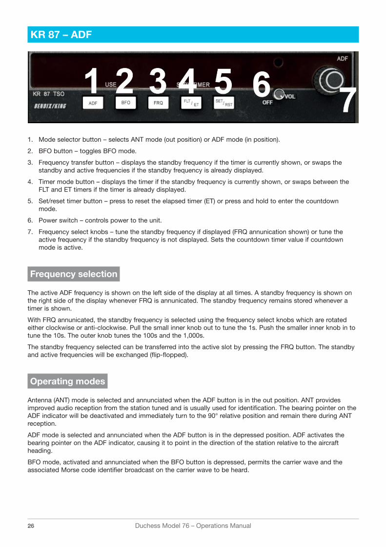
KR 87 – ADF
1. Mode selector button – selects ANT mode (out position) or ADF mode (in position).
2. BFO button – toggles BFO mode.
3. Frequency transfer button – displays the standby frequency if the timer is currently shown, or swaps the standby and active frequencies if the standby frequency is already displayed.
4. Timer mode button – displays the timer if the standby frequency is currently shown, or swaps between the FLT and ET timers if the timer is already displayed.
5. Set/reset timer button – press to reset the elapsed timer (ET) or press and hold to enter the countdown mode.
6. Power switch – controls power to the unit.
7. Frequency select knobs – tune the standby frequency if displayed (FRQ annunication shown) or tune the active frequency if the standby frequency is not displayed. Sets the countdown timer value if countdown mode is active.
Frequency selection
The active ADF frequency is shown on the left side of the display at all times. A standby frequency is shown on the right side of the display whenever FRQ is annunicated. The standby frequency remains stored whenever a timer is shown.
With FRQ annunicated, the standby frequency is selected using the frequency select knobs which are rotated either clockwise or anti-clockwise. Pull the small inner knob out to tune the 1s. Push the smaller inner knob in to tune the 10s. The outer knob tunes the 100s and the 1,000s.
The standby frequency selected can be transferred into the active slot by pressing the FRQ button. The standby and active frequencies will be exchanged (flip-flopped).
Operating modes
Antenna (ANT) mode is selected and annunciated when the ADF button is in the out position. ANT provides improved audio reception from the station tuned and is usually used for identification. The bearing pointer on the ADF indicator will be deactivated and immediately turn to the 90° relative position and remain there during ANT reception.
ADF mode is selected and annunciated when the ADF button is in the depressed position. ADF activates the bearing pointer on the ADF indicator, causing it to point in the direction of the station relative to the aircraft heading.
BFO mode, activated and annunciated when the BFO button is depressed, permits the carrier wave and the associated Morse code identifier broadcast on the carrier wave to be heard.

Duchess Model 76 – Operations Manual27
ADF test
Select ANT mode and confirm that the bearing pointer moves directly to the parked 90° position. Make sure that the unit is tuned to a usable frequency and then select ADF mode. Confirm that the needle moves to the station bearing.
Operating the timers
The flight timer will always be automatically reset to zero whenever power is interrupted, either by the radio master switch or the unit’s power switch.
Flight time or elapsed time is displayed and annunciated alternately by pressing the FLT/ET button. The flight timer continues to count up until the unit is turned off or stopped with the radio master switch. The elapsed timer may be reset back to zero by pressing the SET/RST button (even if the timer is not displayed). It will then start counting up again.
The elapsed timer also has a countdown mode. To enter countdown mode, press the SET/RST button for approximately two seconds until the ET annunciation begins to flash. With ET mode set active, a time of up to 59 minutes and 59 seconds can be preset into the elapsed timer with the concentric knobs. The preset time will be displayed and will remain unchanged until SET/RST is pressed again, which will start the elapsed timer counting down from the preset time. When the timer reaches zero it will start to count up as the display flashes for 15 seconds.
The standby frequency which is in memory while flight time or elapsed time mode is being displayed may be called back by pressing the FRQ button, then transferred to active use by pressing the FRQ button again.
While FLT or ET is shown, the ‘in use’ frequency on the left side of the display may be changed with the frequency select knobs without any effect on the stored standby frequency or the other modes.
KT 76A – transponder
1. Function selector knob
2. Reply light
3. Identification push-button
4. Code windows
5. Code knobs

Duchess Model 76 – Operations Manual28
Operating the KT 76A
The function selector knob should be in the OFF position before starting the aircraft’s engines. Select the required reply code by rotating the four code knobs (one per code digit). The code will be displayed in the four code windows.
After starting the engine, turn the function selector to standby (SBY). The transponder will take approximately 45-50 seconds to become operational. Once you are airborne, turn the function selector to ON, enabling normal Mode A operation.
Turn the function selector to the altitude (ALT) position for altitude reporting (Mode C) to ATC.
Important codes
7700: Emergency
7600: Communications failure
7500: Hijacking
0000: Reserved for military aircraft
Reply light
During normal operation the reply light will flash to indicate that the KT 76A is functioning properly and replying to interrogations from ground radar. Interrogations occur at 10-15 second intervals, corresponding to each radar sweep.

Duchess Model 76 – Operations Manual29
AUTOPILOT
1. Power switch (located on left lower subpanel)
2. On/off button
3. Heading mode button
4. Attitude mode button
5. Navigation mode button
6. Altitude mode button
7. Approach mode button
8. Glideslope mode button
9. Reverse mode button
10. Go-around mode button
11. Pitch command knob
Controls
Power to the Century IV autopilot is controlled by the autopilot power switch on the left lower subpanel.
Mode selections are made by pushing the desired mode switch. The selected mode will be illuminated. A test push-button is provided to check the valid operation of the annunciator lights.
Engage/disengage the autopilot by left-clicking on the on/off button. Attitude hold mode will be selected when the autopilot is first engaged.
In HDG (heading) mode the aircraft will track the heading selected on the HSI. In NAV, APPR, GS or REV mode the aircraft will intercept and track any valid radio-defined course.
Attitude (ATT) hold mode
Attitude hold mode will be selected automatically when the autopilot is first engaged. Pressing the ATT button to manually engage attitude hold mode will disengage other pitch modes. The autopilot will hold the pitch attitude that exists at the time that the mode is engaged.
Changes to the selected pitch can be made using the pitch command knob.
Heading hold (HDG) mode
Set the heading bug on the HSI to the desired heading and then press the HDG button. The HDG annunciator will illuminate to indicate that heading hold mode is engaged. New headings can then be selected by moving the heading bug.

Duchess Model 76 – Operations Manual30
Navigation (NAV) hold mode
In navigation (NAV) hold mode the autopilot intercepts and tracks VOR and GPS courses.
To intercept and track a VOR course:
1. Tune the frequency for the selected VOR station into the GNS 430 (NAV 1).
2. Select the desired course on the HSI.
3. Press the NAV button. The NAV annunciator will illuminate to indicate that navigation hold mode is engaged.
To intercept and track a GPS course:
1. Program a flight plan into the GPS.
2. Press the CDI button on the GNS 430 to select GPS mode.
Approach (APPR) hold mode
Approach (APPR) hold mode allows the autopilot to intercept and track ILS (localiser and glideslope).
To operate in approach hold mode:
1. Tune the frequency for the selected ILS into the GNS 530 (NAV 1).
2. Set the course on the HSI to the final approach course.
3. Press the APPR button. The APPR annunciator will illuminate to indicate that approach hold mode is engaged.
4. The glideslope (GS) annunciator will illuminate to indicate glideslope capture arming; glideslope capture is indicated by the extinguishing of the ALT annunciation.
Back course (REV) hold mode
Back course (REV) mode allows the autopilot to intercept and track a reverse course ILS.
To operate in the back course mode:
1. Tune the frequency for the selected ILS back course into the GNS 430 (NAV 1).
2. Set the course on the HSI to the final approach course. The ILS front course must be set, even though you will be flying a reciprocal heading on an ILS back course approach.
3. Press the REV button. The APPR and REV annunciators will illuminate to indicate that back course hold mode is engaged.
Altitude (ALT) hold mode
Press the ALT button to engage altitude hold mode. The ALT annunciator will illuminate to indicate that altitude hold mode is engaged. This mode maintains the pressure altitude at the time of the mode selection.
For passenger comfort, it is suggested that the rate of climb or descent be reduced to less than 500ft per minute prior to engagement.
Go-around (GA) mode
The go-around mode is used to provide a preselected climb command to the autopilot. Pressing the GA button causes the aircraft to assume a preset climb angle. Should conditions exist which make steeper climbs desirable, the attitude hold mode button can be pressed to select the desired climb angle.

Duchess Model 76 – Operations Manual31
NORMAL PROCEDURES
Airspeed (IAS) for safe operations
Maximum demonstrated crosswind 25 KIAS
Take-off:
Lift-off 71 KIAS
50ft 80 KIAS
Two-engine best angle of climb (Vx) 71 KIAS
Two-engine best rate of climb (Vy) 85 KIAS
Cruise climb 100 KIAS
Turbulent air 132 KIAS
Landing approach:
Flaps UP 87 KIAS
Flaps DOWN 76 KIAS
One-engine inoperative speed 71 KIAS
Minimum control speed (VMCA) 65 KIAS
Pre-flight
Cockpit
Parking brake SET
Avionics OFF
Mixtures IDLE CUT-OFF
Magneto/start switches OFF
Battery switch ON
Fuel gauges CHECK QUANTITY
Warning lights CHECK
Flaps CHECK OPERATION
Battery switch OFF
Flight controls CHECK OPERATION
Trims NEUTRAL
Baggage door CLOSED
Left/right wing
Flap and aileron CHECK
Wing tip and lights UNDAMAGED

Duchess Model 76 – Operations Manual32
Tie-down REMOVED
Fuel tank CHECK LEVEL
Propeller GOOD CONDITION
Oil CHECK LEVEL
Air inlets CLEAR
Landing lights CHECK
Nose section
Chocks REMOVED
Towbar REMOVED (NOSE GEAR)
Tail section
Fin CHECK CONDITION
Rudder CHECK CONTROLS
Stabiliser and trim tab CHECK CONDITION
Tail cone CHECK CONDITION
Before starting engines
Brakes SET
Landing gear handle DOWN
Circuit breakers IN
Carburettor heat OFF
Cowl flaps OPEN
Avionics OFF
Fuel selectors ON
Light switches OFF
Battery/alternator switches ON
Engine starting
Caution: If a positive oil pressure is not indicated within 30 seconds after an engine start, stop the engine and determine the cause of the trouble. In cold weather it will take a few seconds longer to get a positive oil pressure indication.
Battery switch ON
Alternator-out under-voltage lights ILLUMINATED
Mixture FULL RICH
Propeller HIGH RPM
Throttle ¼ OPEN

Duchess Model 76 – Operations Manual33
Auxiliary fuel pump ON
Magneto/start switch BOTH
Prime PUSH
Magneto/start switch START
If engine does not start within 10 seconds, prime and repeat starting procedure.
In case of engine flooding, engage the starter with mixture in the fully lean position, then repeat the normal start-up sequence.
When the engine starts:
Magneto/start switch BOTH
Throttle 1,000-1,200 RPM
Oil pressure ABOVE RED RADIAL WITHIN 30 SECS
Starter warning light EXTINGUISHED
Repeat for other engine.
Left alternator and battery switch OFF
Left alternator-out under-voltage light ILLUMINATED
Left alternator and battery switch ON
Repeat for right alternator.
Taxiing
Avionics ON, AS REQUIRED
Lights AS REQUIRED
Warning lights CHECK
Auxiliary fuel pumps OFF, THEN ON (check fuel pressure indicators)
Engine instruments CHECK
Taxi area CLEAR
Parking brake RELEASE
Throttles APPLY SLOWLY
Brakes CHECK
Steering CHECK
Steering the aircraft with the rudder pedals only is generally sufficient. The combined use of rudder pedals and brakes and differential engine power permits, if necessary, tight turns.
Check the operation of gyroscopic instruments (horizontal attitude, heading and turn and bank indicators) by means of alternate turns.

Duchess Model 76 – Operations Manual34
Before take-off
Parking brake SET
Radios CHECK
Flight instruments CHECK AND SET
Starter warning lights EXTINGUISHED
Fuel selectors ON
Controls FREE
Flaps CHECK OPERATION
Trim CHECK OPERATION
Throttles 2,200 RPM
Propellers EXERCISE (100-200 RPM drop)
Magnetos CHECK (max. drop 175 RPM)
Carburettor heat CHECK and set OFF
Throttles IDLE
Auxiliary fuel pumps ON
Doors/windows CLOSED
Parking brake RELEASE
Take-off
Lined up on runway CHECK COMPASS
Flaps SET
Trim SET
Throttles FULL, 2,700 RPM
Accelerate to 71 KIAS.
Yoke Back pressure to rotate smoothly to climb attitude
Landing gear RETRACT, CONFIRM UP
Airspeed Establish desired climb speed
Flaps UP
Climb
Maximum climb FULL, 2,700 RPM
Cruise climb FULL, 2,600 RPM
Engine temperatures MONITOR
Mixtures LEAN AS REQUIRED
Cowl flaps AS REQUIRED
Auxiliary fuel pumps OFF

Duchess Model 76 – Operations Manual35
Cruise
Refer to the OPERATING DATA MANUAL for cruise power settings.
Maximum cruise power 24.0 inHg or full throttle, 2,700 RPM
Recommended cruise power 24.0 inHg or full throttle, 2,500 RPM
Economy cruise power 20.0 inHg or full throttle, 2,300 RPM
Power SET AS DESIRED
Mixtures LEAN AS REQUIRED
Cowl flaps AS REQUIRED
For level flight at 75% power or less, the EGT gauge can be used to lean the mixture for economy.
Cruise (lean) mixture – enrich mixture (push mixture control forward) until EGT indicator shows a drop of 25-50°F on rich side of peak.
Best power mixture – enrich mixture (push mixture control forward) until EGT indicator shows a drop of 75-100°F on rich side of peak.
The pilot should monitor weather conditions while flying and should be alert to conditions which might lead to icing. If icing is expected, place the carburettor heat controls in the ON position.
Descent
Altimeter SET
Cowl flaps CLOSE
Carburettor heat ON
Power AS REQUIRED
Mixtures ENRICH AS REQUIRED
Apply engine power every 1,500ft to prevent excess engine cooling and spark plug fouling.
Approach and landing
Airspeed 87 KIAS
Fuel selectors CHECK ON
Auxiliary fuel pumps ON
Mixtures FULL RICH
Cowl flaps AS REQUIRED
Landing gear DOWN (140 KIAS max.)
Landing lights AS REQUIRED
Flaps FULL DOWN (110 KIAS max.)
Airspeed 76 KIAS
Propellers HIGH RPM

Duchess Model 76 – Operations Manual36
After landing
Landing lights AS REQUIRED
Wing flaps UP
Trims SET TO TAKE-OFF RANGE
Cowl flaps OPEN
Shutdown
Parking brake SET
Auxiliary fuel pumps OFF
Avionics OFF
Propellers HIGH RPM
Throttles 1,000 RPM
Mixtures IDLE CUT-OFF
Propellers LOW RPM
Magneto/start switches OFF
Battery/alternator switches OFF
Wheel chocks INSTALL

Duchess Model 76 – Operations Manual37
EMERGENCY PROCEDURES
Airspeed (IAS) for safe operations
One-engine inoperative best angle of climb (Vx) 85 KIAS
One-engine inoperative best rate of climb (Vy) 85 KIAS
Air minimum control speed (VCMA) 65 KIAS
One-engine inoperative en route climb 85 KIAS
Emergency descent 140 KIAS
One-engine inoperative landing:
Manoeuvring to final approach 90 KIAS
Final approach (flaps down) 85 KIAS
Intentional one-engine inoperative speed (VSSE) 71 KIAS
Maximum glide range 95 KIAS
Engine failures
Two major factors govern one-engine operations: airspeed and directional control. The aircraft can be safety manoeuvred or trimmed for normal hands-off operation and sustained in this configuration by the operative engine as long as sufficient airspeed is maintained.
Determining inoperative engine
The following checks will help determine which engine has failed:
1. Dead foot – dead engine: The rudder pressure required to maintain directional control will be on the side of the operative engine.
2. Throttle: Partially retard the throttle for the engine that is believed to be inoperative; there should be no change in control pressures or in the sound of the engine if the correct throttle has been selected.
Do not attempt to determine the inoperative engine by means of the tachometers or the manifold pressure gauges. These instruments often indicate near normal readings.
Engine failure during ground roll
Throttles IDLE
Braking MAXIMUM
Fuel selectors OFF
Battery switch OFF
Alternator switches OFF
Magneto/start switches OFF

Duchess Model 76 – Operations Manual38
Engine failure after take-off
An immediate landing is advisable, regardless of take-off weight. Continued flight cannot be assured if take-off weight exceeds the weight determined from the ‘Take-off Weight’ graph. Continued flight requires immediate pilot response to the following procedures:
Landing gear UP
Flaps UP
Throttle (inoperative engine) IDLE
Propeller (inoperative engine) FEATHER
Power (operative engine) AS REQUIRED
Airspeed ABOVE 80 KIAS
After positive control of the aircraft is established, secure inoperative engine:
Mixture IDLE CUT-OFF
Fuel selector OFF
Auxiliary fuel pump OFF
Magneto/start switch OFF
Alternator switch OFF
Cowl flap CLOSE
Airspeed ESTABLISH 85 KIAS
Electrical load MONITOR MAX. LOAD
The most important aspect of engine failure is the necessity to maintain lateral and directional control. If airspeed is below 65 KIAS, reduce power on operative engine as required to maintain control.
Air start
The pilot should determine the reason for engine failure before attempting an air start. Airspeed should be maintained at or above 100 KIAS to ensure the engine will windmill.
Fuel selector ON
Throttle ¼ OPEN
Auxiliary fuel pump ON
Magneto/start switch BOTH
Mixture FULL RICH
Propeller control MIDRANGE
Prime PUSH
Magneto/start switch START
When engine starts:

Duchess Model 76 – Operations Manual39
Throttle AS REQUIRED
Propeller AS REQUIRED
Mixture AS REQUIRED
Auxiliary fuel pump OFF
Alternator switch ON
Oil pressure/temperature CHECK
Warm up engine – approximately 2,000 RPM and 15 inHg.
Engine fire on ground
Mixture IDLE CUT-OFF
Fuel selectors OFF
Battery switch OFF
Alternator switches OFF
Engine fire in flight
Fuel selector OFF
Mixture IDLE CUT-OFF
Propeller FEATHER
Auxiliary fuel pump OFF
Magneto/start switch OFF
Alternator switch OFF
Proceed with single-engine landing procedure.
Emergency descent
Propellers 2,700 RPM
Throttles IDLE
Airspeed 140 KIAS
Landing gear DOWN
Maximum glide configuration
Propellers FEATHER
Flaps UP
Landing gear UP
Cowl flaps CLOSE
Airspeed 95 KIAS
The glide ratio in this configuration is approximately 2 nautical miles per 1,000ft.

Duchess Model 76 – Operations Manual40
Landing emergencies
Gear-up landing
Cowl flaps CLOSE
Flaps FULL DOWN
Throttles IDLE
Mixtures IDLE CUT-OFF
Battery/alternator switches OFF
Magneto/start switches OFF
Fuel selectors OFF
Keep wings level during touchdown.
One-engine inoperative landing
Once you are certain that the field can be reached:
Landing gear DOWN
Airspeed 85 KIAS
Power AS REQUIRED
Flaps FULL DOWN
Execute normal landing.
One-engine inoperative go-around
Level flight may not be possible for certain combinations of weight, temperature and altitude.
Do not attempt a one-engine inoperative go-around after flaps have been fully extended.
Power MAXIMUM
Landing gear UP
Flaps UP
Airspeed 85 KIAS MINIMUM

Duchess Model 76 – Operations Manual41
Systems emergencies
Operation on crossfeed
The fuel crossfeed system should be used during emergency conditions in level flight only.
Left engine inoperative:
Right auxiliary fuel pump ON
Left fuel selector OFF
Right fuel selector CROSSFEED
Right auxiliary fuel pump ON or OFF as required
Right engine inoperative:
Left auxiliary fuel pump ON
Right fuel selector OFF
Left fuel selector CROSSFEED
Left auxiliary fuel pump ON or OFF as required
Electrical smoke or fire
Battery/alternator switches OFF
All electrical switches OFF
Battery/alternator switches ON
Essential electrical equipment ON (isolate as required)
Complete loss of electrical power
Indicated by load meters showing 100% or greater than normal, or showing 0% accompanied by no ALTERNATOR-OUT lights.
Battery/alternator switches OFF
BUS ISO CBs PULL
Electrical loads REMOVE
Alternator switches ON
Electrical loads MINIMISE
Landing gear Use emergency extension
Land as soon as practical.

Duchess Model 76 – Operations Manual42
Illumination of alternator-out light
In the event of the illumination of a single ALTERNATOR-OUT UNDER-VOLTAGE or OVER-VOLTAGE light:
Check the respective load meter for load indication:
a. No load – turn off affected alternator.
b. Reduce load to single alternator capability.
c. Reset the affected alternator with the alternator switch. Monitor over-voltage/under-voltage lights and load meter for proper operation.
In the event of the illumination of both ALTERNATOR-OUT UNDER-VOLTAGE or OVER-VOLTAGE lights:
Check the respective load meter for load indication:
a. Both ALT switches – OFF.
b. Minimise electrical load since only battery power will be available.
c. Reset the alternators with the alternator switches. Monitor over-voltage/under-voltage lights and load meter for proper operation.
Landing gear manual extension
Reduce airspeed before attempting manual extension of the landing gear.
Landing GEAR MOTOR CB OFF
Landing gear handle DOWN
Airspeed 100 KIAS MAX.
Emergency extension valve OPEN (turn anti-clockwise)
After emergency landing gear extension, do not move any landing gear controls or reset any switches or circuit breakers until after landing.
Simulated one-engine inoperative
Use the following power setting (one engine only) to establish zero thrust.
Throttle lever 8 inHg manifold pressure
Propeller lever Retard to FEATHER
Spin recovery
Intentional spins are prohibited, but if an inadvertent spin does occur the following recovery procedure is recommended:
Rudder HOLD OPPOSITE DIRECTION OF ROTATION
Yoke FULL FORWARD, AILERONS NEUTRAL
Throttles IDLE
When spinning stops, centralise rudder, level the wings and ease out of the dive.

Duchess Model 76 – Operations Manual43
CREDITS
Project management Richard Slater
Aircraft modelling and design 3DR
Aircraft systems and cockpit programming Propair
Aircraft liveries David Sweetman
Sounds Turbine Sound Studios
Manual Martyn Northall
Installer Martin Wright
Design Fink Creative
Special thanks to all the testers, to IPACs for their support and to Flying Club Conington for giving us permission to photograph their aircraft.
COPYRIGHT
©2019 Just Flight. All rights reserved. Just Flight and the Just Flight logo are trademarks of JustFlight London Limited, St. George’s House, George Street, Huntingdon, PE29 3GH, UK. All trademarks and brand names are trademarks or registered trademarks of the respective owners and their use herein does not imply any association or endorsement by any third party.

The Spirit of Flight Simulation
Available to buy online at www.justflight.com
www.justflight.com

www.justflight.com