
BPC® Go Operations & Maintenance Manual - Bioprocess ...
29
® BPC® Go Operations & Maintenance Manual
-
Upload
khangminh22 -
Category
Documents
-
view
1 -
download
0
Transcript of BPC® Go Operations & Maintenance Manual - Bioprocess ...

®
BPC® Go Operations & Maintenance Manual


Version 2.2 February 2022
The latest version of this manual can always be downloaded from:https://www.bioprocesscontrol.com/manuals
Any questions related to this document should be directed to:BPC Instruments ABMobilvägen 10SE-223 62 LundSweden
Telephone: +46 (0)46 163950Email: [email protected]: https://www.bpcinstruments.com
This document contains proprietary information protected by copyright. No part of this publication may be redistributed in any form whatsoever or translated into any language without prior, written permission of BPC Instruments AB.
© 2022 BPC Instruments AB. All rights reserved.
Produced in Sweden.

i. Safety InformationBefore operating the BPC® Go (hereafter referred to as “the instrument”, “the system”, “the equipment” or “BPC® Go” interchangeably) from BPC Instruments AB (hereaf-ter referred to as “BPC Instruments”, “BPC”, “Bioprocess Control” or “BPC Instru-ments AB” interchangeably), carefully read this operator manual for the instrument, any separate instructions for other equipment used together or in conjunction with the instrument as well as the safety instructions for any and all chemicals used in the process of utilising the instrument.
When performing experiments with the instrument, always use protective eyewear, gloves and lab coat. Always make sure there is adequate ventilation and take proper precautions when handling electrical devices near water or explosive gases. Make sure to tie back any hanging objects, such as hair and clothing, when working near rotating or otherwise moving parts.
Do not modify the instrument without the prior consent of the manufacturer. BPC Instruments AB do not assume responsibility for any errors due to equipment mod-ification.
Do not clean or service the instrument while it is running.
Do not expose the instrument to mechanical vibrations or high frequency radio transmissions.
Never operate the instrument in a way it was not intended.
Never operate the instrument, nor let anyone else operate it, without proper training.
Never use the instrument outside or in environments with parameters outside of the instruments recommended range.
Never connect additional electrical equipment not supplied by BPC Instruments AB for the express purpose of using with the instrument. This is true even if the connections can mate.
Always back-up important data to an external device.
Always keep the instrument level and on a flat and stable surface. Failing to do so can, among other things, generate an erroneous gas reading.
Always make sure all safety guards are in place and working before operating the instrument.
Always make sure that all parts are functioning properly immediately after start-up.
Always keep the instrument clean.
Always make sure to have access to relevant chemicals before starting an experiment.
Always dispose of parts and chemicals according to applicable rules in the country of usage.
Periodic maintenance of the instrument and its various accessories is essential. Al-ways make sure they are in working condition. If service or spare parts are required, please visit https://webshop.bioprocesscontrol.com or contact BPC Instruments AB directly or one of its representatives.
Always make sure that the gas outlet of the flow cell unit (FCU) is able to release pressure in the event of pressure build-up inside of the instrument. Do not obstruct or block it.
Always make sure that the instrument is registering resonable amounts of gas before starting an experiment. This can be done by injecting air in the gas inlet using a syringe. This is especially true if dangerous gas is used. Do not depend on the gas registrations of the instrument as a safety procedure.
Always make sure to connect the power supply so that it is easy to remove from the mains power outlet and so it doesn’t risk becoming damaged.
Always wait 60 seconds between powering the system on and off. This will allow for the operating system to shut down properly and for the capacitators to properly cycle.
Always use deionised water to minimise the risk of residue or rust forming on the inside of the flow cell unit.
ii. Limited WarrantyThe product warranty provided with the instrument corresponds to the stipula-tions in Orgaline 2012, unless otherwise agreed upon with BPC Instruments AB (“BPC”). Furthermore, any removal of the outer enclosure of the base unit, without prior consent of BPC Instruments AB, is considered a breach of warranty. The flow cell unit(s) cannot be opened. Doing so is considered a breach of warranty and will render them completely unsuitable for usage. BPC Instruments AB (“BPC”) reserves the right to correct any possible errors, mistakes, changes, updates, technical data or otherwise relevant information in this manual or any other documents, where applicable by law.
iii. Electrical SafetyCompliance is required with respect to voltage, frequency and current requirements indicated on relevant parts. Improper operation, damage to the equipment, fire or otherwise undesired effects might be caused by connecting to a different pow-er source. There are no user-serviceable parts in the equipment, unless otherwise agreed upon with BPC Instruments AB (“BPC”).
iv. Declaration of ConformityHereby, BPC Instruments AB (“BPC”), declares that this device is in compliance with the essential requirements and other relevant provisions of the following direc-tives: . The full text of the EU declaration of conformity is available at the following address: https://www.bioprocesscontrol.com/compliance.
v. Technical SpecificationDimensions: 19 x 11.5 x 13 cmWeight: 0.5 kgOperating Environment: Indoor 20 - 40 °COperating Humidity: 5 – 95 % non-condensingPower Input 12 V DC / 1.0 A
Power Supply (Switching): External AC / DC Adapter PSAC12R-120 Manufacturer: Phiong Technology Co. Ltd.
No. 568, Fusing 3rd Rd., Gueishan District, Taoyuan City, TaiwanPower Input AC 100-240 V AC 50-60 Hz 0.5 A 24-32 VAPower Output: 12 V DC, 1.0 A
vi. Delivery ChecksAs soon as taking delivery of the instrument and before putting it into service, in-spect the package and make sure there is no damage. If there is any reason to believe that the instrument has not arrived in a suitable condition, inform the transport company and request that they document the issue appropriately, self-document using photographs and contact your seller for further information.
Read the operations manual in its complete form. This will assure that the instru-ment is used appropriately and will serve as a guide to identify any damage to the instrument or parts thereof.The following parts should be included in your purchase. If this is not the case, please contact your seller in order to receive the missing parts.
1 Operators manual (this document)1 Quick-guide1 BPC® Go base unit (Art No 17-0001-01)1 Flow cell unit (9 ml resolution) (Art No 12-0302-02)1 Flow cell unit (2 ml resolution) (Art No 12-0302-01)1 Power adapter main unit mk 3 (Art No 17-0002-01)4 Check-valves (Art No 01-0404-02)
vii. Optional EquipmentThe following equipment can be bought from BPC Instruments AB and its distrib-utors. They are not required to perform experiments with the instrument, but they are fully compatible and, depending on the use case, can increase the effectiveness, abilities or functions of the instrument.
Gas sampling port (Art No 05-0207-01)Tygon® Tubing 3.2 x 1.6 mm (Art No 01-0405-02)Tubing clamp 6 mm (Art No 01-0108-02)Syringe (Art No 12-0403-01)Network cable 1.0 m (Art No 01-0402-01)
For a complete listing of available systems and parts from BPC Instruments AB, for this instrument and others, please visit our online store at https://webshop.bp-cinstruments.com or contact our sales team via email at [email protected] and via phone at +46 (0)46 163950.
For assistance with usage of the system, or parts of it, please contact our support team via email at [email protected] and via phone at +46 (0)46 163950.

Please have the serial number of your instrument easily accessible as this will allow us to assist you in a quicker and more accurate fashion.
viii. Contact InformationBPC InstrumentsMobilvägen 10223 62 LundSweden
E-mail: [email protected]: +46 (0)46 163950Website: https://www.bpcinstruments.comWebshop: https://webshop.bpcinstruments.com
Swedish organisation number: 556687-2460

BPCTM Go
Max
Min
1 2 3
RYG
USB Ethernet Motors DC 12V 1 2 3
RYG
USB Ethernet Motors DC 12V
1 2 3
RYG
USB Ethernet Motors DC 12V
Max
Min
BPCTM Go
0 ml / h
0 ml 0 h 01 min
Batch Running
4
Max
Min
BPCTM Go
0 ml / h
0 ml 0 h 01 min
Batch RunningInclination [X]
Inclination [Y]
Quick Guide: Stand-alone ModeQuick Guide: Stand-alone Mode

Quick Guide: dHcP network ModeQuick Guide: dHcP network Mode
BPCTM Go
Max
Min
1 2 3
RYG
USB Ethernet Motors DC 12V 1 2 3
RYG
USB Ethernet Motors DC 12V 1 2 3
RYG
USB Ethernet Motors DC 12V
1 2 3
RYG
USB Ethernet Motors DC 12V1 2 3
RYG
USB Ethernet Motors DC 12V
http://xxx.xxx.xxx.xxx
http://xxx.xxx.xxx.xxx
BPC® Go
Max
Min
BPCTM Go
Enter password to login
Login
®
http://xxx.xxx.xxx.xxx
Max
Min
BPCTM Go
0 ml / h
0 ml 0 h 01 min
Batch Running
Max
Min
BPCTM Go
DHCP
xxx.xxx.xxx.xxx
DHCP
xxx.xxx.xxx.xxx
1 2 3
RYG
USB Ethernet Motors DC 12V
Max
Min
BPCTM Go
0 ml / h
0 ml 0 h 01 min
Batch Running
Max
Min
BPCTM Go
0 ml / h
0 ml 0 h 01 min
Batch RunningLevel X [X]
Level Y [Y]

Quick Guide: Manual iP network ModeQuick Guide: Manual iP network Mode
BPCTM Go
Max
Min
1 2 3
RYG
USB Ethernet Motors DC 12V 1 2 3
RYG
USB Ethernet Motors DC 12V 1 2 3
RYG
USB Ethernet Motors DC 12V
1 2 3
RYG
USB Ethernet Motors DC 12V1 2 3
RYG
USB Ethernet Motors DC 12V
http://192.168.10.11
http://192.168.10.11
BPC® Go
Max
Min
BPCTM Go
Enter password to login
Login
®
http://192.168.10.11
Max
Min
BPCTM Go
0 ml / h
0 ml 0 h 01 min
Batch Running
Max
Min
BPCTM Go
Manual IP
192.168.10.11
Manual IP
192.168.10.11
1 2 3
RYG
USB Ethernet Motors DC 12V
Max
Min
BPCTM Go
0 ml / h
0 ml 0 h 01 min
Batch Running
Max
Min
BPCTM Go
0 ml / h
0 ml 0 h 01 min
Batch RunningLevel X [X]
Level Y [Y]


BPCTM Go
1 2 3
RYG
USB Ethernet Motors DC 12V
Chapter 1:OverviewThe BPC® Go consists of two main parts; the BPC® Go base unit, which provides the analytical functionality of the instrument as well as a physical user interface through which the user can interact, and the flow cell unit, which provides the chamber for doing the actual physical measuring of the gas. Each of these units can be used interchangeably with any other unit (provided that calibration data is entered correctly), i.e., they are not tied to each other. However, one of each is required in order to be able to use the instrument as intended as each contain different functionalities required by the other part.
Chapter 1.1 BPC® Go Base UnitThe BPC® Go base unit is where all the physical user interface actions and cable connections take place. While considera-tions and precautions have been taken during the production of the equipment, it is important to remember that this part of the unit is not waterproof, nor can it be submerged in liquid
The play/pause button is used for starting and pausing the instrument gas detection.
The stop button is used to stop the instrument flow detection, clear data and change sub-screen.
The flow cell LED, in its default configuration, indicates that the in-strument has registered an opening. It does this by flashing at the mo-ment of detection.
Mounting fixture for the flow cell unit.
USB port used for up-grading the system.
Port for connecting the main unit power adapter.
Ethernet port for connecting Ethernet CAT cable to the instrument. Required to access the web UI.
Port for connecting external motor con-troller (Art No 01-0109-01) via a motor controller signal cable mk 3 (art no 17-0003-01).
On/off button for instrument.
Adjustable feet for making sure the instrument is level.
or have excessive liquid enter into it. Please use with caution to prolong the life of your instrument.
The power LED indi-cates if the instrument is powered on or not.
The front OLED screen will display various information intended for the operator. If the provided web UI is not used, this is the only available interface for transferring information to the operator from the instrument.
Button123
Action
Set IP adress according to DHCP serverSet IP adress to 192.168.0.1
Reset password (Factory reset if held during power on)
Three function buttons for con-trolling settings not related to gas detection. The button should be held for about three seconds for the action to register.
LED DescriptionInstrument has booted properlyFlow cell opening detectedError detected
Three LEDs used for indicating the state of the instru-ment.

Chapter 1.2 Flow Cell UnitThe flow cell unit is where the gas enters into the BPC® Go in order for it to be measured, using the volumetric method. Depending on which flow cell unit is being used, the resolu-tion is either approximately 2 or 9 ml. Please keep in mind that each version has different upper and lower bounds for gas flow. For the 2 ml flow cell unit, the applicable range is 0.2 to 1,500 ml per hour and for the 9 ml flow cell unit, it is 1 to 6,000 ml per hour.
Max
Min
Inlet for gas entering into the flow cell unit.
Outlet for gas that have been measured.Water level lines indicat-
ing recommended, max-imum and minimum amount of water the flow cell unit should contain.
Magnet used to detect flow cell openings.
Flow cell (9 ml in illus-tration) used for captur-ing gas before release.
Location where the gas enters into the water before being trapped and measured in the flow cell.
Chapter 1.3 On-Board ButtonsWhile using the web user interface is the recommended way to op-erate the BPC® Go, the most important functions can also be accessed through physical buttons located on the right-hand side of the front panel. Actions taken with these buttons will be reflected both on the built-in display and in the web user interface.
When the display is in sleep-mode (turned off), pressing any of the two buttons will turn the display on and display the default sub-screen. On this screen, current flow speed, accumulated volume and time since start of the experiment can be read. Furthermore, the
screen will display whether the system is in continuous or batch
mode as well as if the system is in pause or play mode (or if the flow cell is detached).
Briefly pressing the stop button while the screen is on will cy-cle between the available sub-screens. The second of these will dis-play the current tem-perature and pressure, the calibrated flow cell volume the instrument has been configured to use, current system date, and current system time.
The third sub-screen will display whether the instrument uses a man-ually assigned IP or an automatic IP assigned by a DHCP server as
BPCTM Go
Flow Rate
Accumulated Volume Total Time
Mode Play / Pause
Temperature
Pressure Date
Flow Cell Volume
Time
Manual / DHCP IP
IP Address
Aurora Version
Fastening hook for keeping the flow cell unit securely seated in the BPC® Go base.
IMPORTANT: The flow cell unit (FCU) can NOT be opened. Any attempt to do so will risk damaging it and ruining the gas tightness. Also, always remember to use the apropriate calibration cell volume (configurable in the web UI) associated with each FCU.

well as what IP address is currently in use and the version of the in-strument’s Aurora software.
The fourth of these will dis-play the alignment indica-tor. It is very important that
the instrument is completely level while in use. The BPC® Go base has four feet that can be individually adjusted to achieve this.
Briefly pressing the play/pause button while the display is turned on will switch the instrument between the two play/pause states. While in the play state, all openings will be registered and is the default state the instrument should be in while an experiment is run-ning. In the pause state, no openings will be registered until the state is changed to play.
While in the pause state, holding down the stop button for two seconds will bring up the “Stop experiment” menu. If no further input is recieved for five seconds, the display will revert to its previoius menu. Pressing the stop button before this time limit places the instrument in stop mode and clears all old data. In order to start a new experi-
ment, the play/pause button needs to be pressed.
Chapter 1.4 Web UIWhen the BPC® Go instrument is connected to a network, the web user interface can be accessed by entering the correct IP address into a web
Level X [X]
Level Y [Y]
BPCTM Go
browser. In order to find out which IP address is assigned to an instrument, press either the play/pause button or the stop button if the screen is in sleep-mode. With the screen on, press the stop button twice to cycle to the network information sub-screen.
Once the IP address has been entered into a web browser, the user interface will load. When asked to enter a password, the factory default one is bpc. Enter the password and click on the login button.
Chapter 1.4.1 HomeThe Aurora web UI is modelled around six different tabs that provide access to different functions of the instrument. The first one, labeled Home, is the default page to be pre-
sented after a user logs in. From here, all the other tabs can be accessed, an image of the current instrument type can be seen (in this case, a BPC® Go) and the user can log out to prevent unauthorised
access. Furthermore, the current mode in use (batch or continuous) is displayed for easy access. As there are some differences in the web UI depending on which mode is selected, this document will highlight those differences as they occur throughout the interface.
Chapter 1.4.2 ExperimentNote: The experiment tab is only available when the system is in batch mode. It is replaced by the feeding tab when the continuous mode is active. In order to change mode, see the chap-ter in this document describing the settings tab.
http://192.168.10.11
BPC® Go
Max
Min
BPCTM Go
Enter password to login
Login
®
http://192.168.10.11
BPC Instruments
Max
Min
BPCTM Go
Home Experiment Control Graph Report Settings
BPC Go - [mode]LOG OUT
http://192.168.10.11
BPC Instruments
Home Experiment Control Graph Report Settings
BPC Go - Batch mode
Experiment setup
1
Line Name Total amount Inoculum Substrate Unit of conc [%] ISR Inoculum [g] Substrate [g [g] conc. [%] conc. [%] TS VS COD inoculum [g] substrate [g

Please keep in mind, the information entered into the experiment fields are only used as a guide for the operator and for the report generation. None of the calculations that the instrument performs are dependent on these values and they can safely be left blank. In order to edit a field, left click on it with the mouse pointer or press tab on the keyboard until a suitable field is selected. As data is added, the calculated fields will be populated and thus making experiment setup easier.
1
Line Name Total amount Inoculum Substrate Unit of conc [ ] ISR Inoculum [g] Substrate [g] Organic Organic [g] conc. [ ] conc. [ ] TS VS COD inoculum [g] substrate [g]
Indicates the line or sensor of the instrument the row refers to as well as the colour associated with it. With the BPC® Go, there is always only one line, however, the Aurora software can run on many types of instru-ments, most of which have more than one line or sen-sor.
Field for entering an easy, hu-manly readable name of the particlar line or sensor. Com-mon examples are contents in reactor, gas measured and ex-periment number.
Total amount of added matter. This should include both inoc-ulum as well as substrate.
Concentration of material used as inoc-ulum. The unit referenced is selected via the three radio buttons.
Concentration of-sample that is tested. The unit referenced is selected via the three radio buttons.
The ratio based on organic matter (g COD, g TS or g VS) between the inoculum and the sample.
ISR = g TS/VS/COD inoculum divided by g TS/VS/COD sample
The amount of inocu-lum that is added to the reactor.
The amount of sample that is added to the reactor.
The amount of organic matter in the incoulum added to the reactor.
The amount of organic matter in the sample added to the reactor.
The unit used to characterise the organic matter in the sample and the inoculum.TS and VS = %COD = g / l
In order to print out a hard copy of the data stored in the experiment matrix, press the Print experiment guidelines and follow the steps native to the oper-ating system being used. This can be helpful for physically preparing the experiment as well as to store for later reference. Please note, there is also the possibility to manually enter the amount of organic inoculum and substrate by selecting the “manual” radio button near the top of the page.
= editable field

Chapter 1.4.3 FeedingNote: The feeding tab is only available when the system is in continuous mode. It is replaced by the experiment tab when the batch mode is active. In order to change mode, see the chapter in this document describing the settings tab.
The feeding tab provides the settings that facilitate the reactor feeding data entry and calculations. It can be used in two different ways: manual and automatic. The manual setting requires the operator to manually set the time and date for each individual feeding while the automatic setting uses a user-defineable timer (minimum 5 minutes between each feeding) to automatically register each feeding as they occur. Unless intervened by the user, each manual or automatic feeding will have the same sample settings as the previous one.
1
Line Name Automatic Reactor Unit of conc [ ] Interval Next Count Status volume [ml] TS VS COD
http://192.168.10.11
BPC Instruments
Home Feeding Control Graph Report Settings
BPC Go - Continuous modeLOG OUT
Inflow/Outflow
Time (UTC) Sample Sample Sample amount Organic amount Loading rate Retention time concentration [g] [g] [g/l/day] [days] [ ]
Add feeding
1
Line Name Automatic Reactor Unit of conc [ ] Interval Next Count Status volume [ml] TS VS COD
Indicates the line or sensor of the instrument the row refers to as well as the colour associated with it. With the BPC® Go, there is always only one line, however, the Aurora software can run on many types of instru-ments, most of which have more than one line or sen-sor.
Field for entering an easy, humanly readable name of the particlar line or sensor. Common examples are contents in reactor, gas measured and experiment number.
Toggle for turning on and off automatic feed-ing. If activated, a feeding will be automati-cally registered according to the user-defined (in minutes) interval variable. If not activat-ed, a reminder for performing a manual feed-ing will instead be provided.
The unit used to characterise the organic matter in the sample and the inoculum.TS and VS = %COD = g / l
Time until next feeding.
The number of registered feedings.
Notes the status of the line or sensor in question.
Total volume of the reactor.

Average hydraulic re-tention time of the feeding. It is calculated as a function of time between feedings and reactor volume.
Time (UTC) Sample Sample Sample amount Organic amount Loading rate Retention time concentration [g] [g] [g/l/day] [days] [ ]
Add feeding
The date and time the feeding was registered by the software, given in the Coordinated Uni-versal Time (UTC) notation.
In order to convert UTC to your local time zone, please see
https://www.google.com/search?q=utc+converter
Field for entering an easy, hu-manly readable name of the feeding. Common examples are contents fed or name of mixture.
Concentration of sample added during the feeding, expressed in the unit selected previously.
The amount of sample that is added to the reac-tor during the feeding.
The amount of organic matter in the sample add-ed to the reactor.
Loading rate of the feed. It is calculated based on the organic amount and the time between feedings as well as the reactor volume.
Navigation buttons for the feeding list.Add a new feeding with current time stamp and previous settings.
Remove a specific feeding.
= editable field

Chapter 1.4.4 ControlThe control tab is where direct interaction with the flow cell unit and the motor(s) are conducted. All changes here will have a direct effect on ongoing and future experiments and can not be undone as such. They can be changed back to their previous settings but any events that have taken place during the changes will be permanent.
Note: Some options are only available in batch mode.
http://192.168.10.11
BPC Instruments
Home Feeding Control Graph Report Settings
BPC Go - Batch modeLOG OUT
Lines
1
Line Name Cell volume Correction HS Volume Initial HS Final HS Status Started [UTC] Duration [ml] [ml] [%] [%]
Agitation Motor Power
Speed [%]
Phases Single Double
Speed [%] Time [min]
Phase 1
Phase 2
Lines
1
Line Name Cell volume Correction HS Volume Initial HS Final HS Status Started [UTC] Duration [ml] [ml] [%] [%]
Field for entering an easy, humanly readable name of the particlar line or sensor. Common examples are contents in reactor, gas measured and experiment number.
The volume of gas coresponding to one opening of the flow cell. This value is provided with the calibra-tion certificate provided with the flow cell unit (FCU). This value is specific to the FCU it comes with and needs to be edited if another cell is used.
Mathematical compensation of the meas-ured gas volume is necessary if the gas compounds are separated by selective absorption before measurement and the removable gas content in the reactor head-space is expected to be different at the start (i.e., flushing gas or air) and the end (i.e., generated gas) of the test.
Example: If a mixture of CH4 and CO2 is pro-duced and a flush gas with a different com-position is used (i.e., 100% N2 or 100% CO2), and CO2 is removed before measurement, this function should be activated. If CO2 is not re-moved and both CH4 and CO2 are measured, this function should be deactivated.
Time elapsed since the experiment was started (by pressing the play button).
The date and time the experi-ment was started (by pressing the play button), given in the Coordinated Universal Time (UTC) notation.
In order to convert UTC to your local time zone, please see
https://www.google.com/search?q=utc+converter
Notes the status of the line or sensor in question.
= editable field
Expected percentage of removable gas in the reactor headspace at the end of the experiment.
Example: CO2 and H2S can be removed/absorbed when NaOH solution is used as absorbing agent.
Percentage of removable gas in the reactor headspace at the begining of the experiment (i.e., flush gas or air).
Volume of head-space inside the reactor at the start of the test.
Chapter 1.4.4.1 Lines

Chapter 1.4.4.2 Control Panel
Located at the bottom right of the lines section is the control panel for the flow cell unit. These work as follows:
Start data registration. In order to be able to press this button, the status needs to be ready
Pause data registration. In order to be able to press this button, the status needs to be running
Stop data registration. In order to be able to press this button, the status needs to be paused
Clear all data registrations. In order to be able to press this button, the status needs to be stopped
Examples:
If the instrument is currently registering data (status = running), in order to start a new experiment, the following buttons need to be pressed, in order: pause, stop, clear.
If the last experiment has been ended (status = stopped), no but-ton can be pressed to put the instrument in play mode. A new experiment need to be started by pressing the following buttons, in order: clear, play.
If the instrument is currently registering data and the user wants to temporarily prevent registration and then start it after a while, the following buttons need to be pressed, in order: pause, (per-form desired action), play.
Chapter 1.4.4.3 Agitation (hardware)
While not provided by default, the BPC® Go can power and control standard motors from BPC Instruments. These can be sourced separately either from, depending on shipping location, BPC Instrument’s official distributors or directly from BPC Instrument. For more information, please see the following URLs:
https://webshop.bpcinstruments.com/produkt/39/43/50/brushless-dc-motorhttps://webshop.bpcinstruments.com/produkt/33/37/44/motor-controller-standardhttps://webshop.bpcinstruments.com/produkt/42/46/53/brushless-dc-motor-cable-1500-mmhttps://webshop.bpcinstruments.com/produkt/155/178/232/motor-controller-signal-cable-mk-3
Chapter 1.4.4.4 Agitation (software)
Located at the bottom of the control tab, the agitation settings are lo-cated. In order to be able to control motors, the setting labeled “motor power” needs to be activated. If no motors are to be controlled, it is recomended that this setting is deactivated. Motor Power
Speed [%]
Phases Single Double
Speed [%] Time [min]
Phase 1
Phase 2
By selecting single phase, it is possible to set a constant speed, in percentage, for the connect-ed motor to run at. If double phase instead is selected, two different speeds can be selected
and the motor will oscillate between the two. For example, if phase 1 is set to 100% and time is set to 10 minutes and phase 2 is set to 0% and time is set to 5 minutes, this means that the motor will run at full speed for 10 minutes and then stand still for 5, after which the cycle will repeat. Please note that the two speeds can be anything between 0-100 and so there is no requirement for full speed or complete stop.

Chapter 1.4.5 GraphThe graph tab behaves differently depending on if the instrument is in batch or continuous mode. Make sure that the correct mode is selected for the purpose of the experiment being performed.
Chapter 1.4.5.1 Graph (batch mode)
Placing the mouse pointer over the icon representing the flow cell unit and briefly hovering will present an additional information box with the name of the line, the status of the line and when the last opening of the line occured. Located in the left hand corner of this icon is also a graphical
representation of the line status , providing an easy way to make sure it is set correctly. If the line is stopped, the icon will have a grayish hue to indicate unavailability.
The radio buttons for gas normalisation affect the calculations made in the following way:
http://192.168.10.11
BPC Instruments
Home Feeding Control Graph Report Settings
BPC Go - Batch modeLOG OUT
1
Gas flow
Gas normalisation
Off Dry Wet
Accumulated gas volume [ml]
Gas flow rate [ml/h]
No adjustments to normalise the gas is made. The presented gas volume and flow rate is the same as the physically measured one.
The gas volume and flow rate is adjusted to standardised conditions (0 °C and 1 atmos-phere) with the help of the instrument’s internal sensors. It is assumed that the gas is dry and no compensation for water content is made.
The gas volume and flow rate is adjusted to standardised conditions (0 °C and 1 atmos-phere) with the help of the instrument’s internal sensors. It is assumed that the gas is saturated with water and the volume this water corre-sponds to is subtracted from the gas volume.
Off Dry Wet
The navigation row present in the graphs have the following effects on the view of the data:
By holding down the left mouse button and, at the same time, mov-ing the mouse pointer, it is possible to move the viewport of the graph.
By holding down the left mouse button and, at the same time, draw-ing a rectangle, a specific area can be made to fill the entire viewport
Pressing the magnifying glass with the plus sign will make the view-port zoom in. Pressing the magni-fying glass with the minus sign will make the viewport zoom out.
Pressing the square will make all the available data fit in the view-port.
Note: The graph requires at least two data points (i.e., flow cell openings) in order to display information. To simulate an opening during testing, briefly remove the FCU and place it right back; wait for about 20 seconds and then repeat the action one more time. If everything is working correctly, an LED should light up under the the FCU each time an opening is simulated and after two simulated openings, a line should appear in each graph.
1

Chapter 1.4.5.2 Graph (continuous mode)
Placing the mouse pointer over the icon representing the flow cell unit and briefly hovering will present an additional information box with the name of the line, the status of the line and when the last opening of the line occured. Located in the left hand corner of this icon is also a graphical representation of the line status , providing an easy way to make sure it is set correctly. If the line
is stopped, the icon will have a grayish hue to indicate unavailability.
Under the time frame heading, there are two separate fields for manually entering the start and end time and date that should be displayed in the graphs. It is also possible to press the icon shaped as a calendar (and, in the next step, a clock) to use a visual interface.
The radio buttons for gas normalisation affect the calculations made in the following way:
1
No adjustments to normalise the gas is made. The presented gas volume and flow rate is the same as the physically measured one.
The gas volume and flow rate is adjusted to standardised conditions (0 °C and 1 atmos-phere) with the help of the instrument’s internal sensors. It is assumed that the gas is dry and no compensation for water content is made.
The gas volume and flow rate is adjusted to standardised conditions (0 °C and 1 atmos-phere) with the help of the instrument’s internal sensors. It is assumed that the gas is saturated with water and the volume this water corre-sponds to is subtracted from the gas volume.
Off Dry Wet
The navigation row present in the graphs have the following effects on the view of the data:
By holding down the left mouse button and, at the same time, moving the mouse pointer, it is possible to move the viewport of the graph.
By holding down the left mouse button and, at the same time, drawing a rectangle, a specific area can be made to fill the en-tire viewport
Pressing the magnifying glass with the plus sign will make the viewport zoom in. Pressing the magnifying glass with the mi-nus sign will make the viewport zoom out.
Pressing the square will make all the available data fit in the viewport.
Pressing one of the above buttons will resize the graphs in order to fit the data from a corresponding time frame; 1 month, 1 week, 1 day or 1 hour.
Pressing the vertical arrow will keep the horizontal scale of the graphs intact but will expand the vertical scale to display all available data in that range.
1M 1W 1D 1H
http://192.168.10.11
BPC Instruments
Home Feeding Control Graph Report Settings
BPC Go - Continuous modeLOG OUT
1
Gas flow
Gas normalisation
Off Dry WetStart date
End date
Accumulated gas volume [ml]
Loading rate [g/l/day] Retention time [day]
Gas normalisation
1M 1W 1D 1H
1M 1W 1D 1H
Note: Just as the batch mode graphs, the continuous mode displays the gas flow rate in one graph area. The second graph area is displaying loading rate (in grams per litre per day) as well as retention time (in days). These latter measurements are related to the information entered into the feeding tab and is not related to the physical openings of the flow cell, nor do they affect the calculations of the gas flow rate.

Chapter 1.4.6 Report (batch and continuous mode)All export of data from the BPC® Go instrument is done through the report tab in the web user interface. Depending on if the instrument is set to batch or continuous mode, the options will behave slightly differently. The core functionality, however, will remain the same. Two file formats are available for export: CSV and XLSX. The comma separated values (CSV) file format is a plain text format without any formating and is completely platform and software neutral. XLSX (Excel Open XML) supports formating and is supported by a vast number of software. If your choice of software does not support, or has issues with, XLSX, please use CSV. Note: When downloading a CSV report in continuous mode, a compressed (ZIP) file of the accumulated files will be generated; compatible with all standard compression software.
http://192.168.10.11
BPC Instruments
Home Feeding Control Graph Report Settings
BPC Go - Batch modeLOG OUT
Download report
1
Line Name Status Started [UTC] Duration Raw data
CSV
Download report
Off Dry WetGas normalisation
Interpolation interval
Report file format
Download reports
Gas flow unit
Export the raw data in CSV format. The file will only con-tain a list of times, tempera-tures and pressures, relating to the openings of the flow cell.
Time Temperature (C) Pressure (kPa)
2021-09-29 09:45:48.125 20.9 100.9
2021-09-29 09:51:20.115 20.8 100.8
2021-09-29 09:52:50.175 20.4 100.9
2021-09-29 09:58:12.102 20.7 100.9
2021-09-29 10:03:55.355 20.7 100.7
2021-09-29 10:13:08.115 20.8 100.8
Gas normalisation options for the generated report. See chapter “Graph” for more in-formation.
General information for the line.
Affects the interpolation interval for the generated report.
Options are: 1 minute, 5 minutes, 15 minutes, 60 minutes and 1 day. Select the file format of the re-
port. Layout and interopera-bility is affected by this choice.
XLSXCSV
Neutral file with values sepa-rated by commas. Easy to use for data processing. Continu-ous mode data in three files, separated, compressed as one.
Excel file with formating to make usage easier and more clear. Continuous mode data in one file, separated by tabs.
Generation time
Software version
Instrument name
Instrument model name
Ethernet mac address
Agitation state
Agitation phase
Agitation speed
Gas normalisation
Line name
Start of experiment
End of experiment
Inoculum amount
Substrate amount
Unit of concentration
Over-/underestimation
Headspace volume
Removeable gas concentration
Flow cell opening time
Volume
Flow rate
Specific gas production
OLR
HRT
Substrate name
Substrate concentration
Substrate amount
Organic amount
Discharge amount
Select gas flow unit for graph and reports.

Chapter 1.4.7 SettingsThe settings tab is home to a host of settings for the instrument. It also contains valuable information regarding versions, licenses, a logfile and so forth. Sometimes, a blue triangle with a white exclamation mark will appear next to the settings tab in the Aurora Web UI. This symbol indicates that there is information in the logfile that needs to be reviewed or that one of the settings needs to be adjusted. If it is a setting that is in question, that particular setting will also display the same symbol; if it is the logfile, pressing the clear log button (after reviewing and potentially saving the information) will remove the warning.
!System information Software licenses Time settings Instrument level calibration Temperature calibration Pressure calibration
Instruments hardware and soft-ware versions as well as serial number. Please have this infor-mation ready if you are contacting customer support. It will make sure that any issues can be re-solved as quickly as possible.
Licenses for open source projects utilised in the instrument. For more information, please visit https://bpcinstruments.com/bpc-go-oss-licenses/
Having a correct internal time in the instrument is very important as it is used for a multitude of calculations. Make sure to always have the correct time set before an experiment is started, after a prolonged power outage or if the instrument has not been connect-ed to power for an extended time.
Calibrate the horisontal level of the instrument. A true hori-sontal level is important for ac-curate measurements. Pressing the button will present a visual representation of the instrument level to help guid adjustment of instrument feet.
Current temperature detected by the instrument. If deviating from actual ambient temperature, calibration can be performed by the user. Before re-calibrating an instrument, make sure that it has had time to reach ambient tem-perature.
Used for adjusting measured gas to standard conditions.Current pressure detected by the instrument. If deviating from ac-tual ambient pressure, calibration can be performed by the user.Used for adjusting measured gas to standard conditions.
Instrument name Experiment type Change system password System power System reset System software update
Customisable name for the instru-ment to allow for easier identifica-tion. This name will be displayed at the login screen and in the top of the Aurora Web UI.
Type of experiment. Either batch or continuous.
In batch mode, accumulated gas and gas flow rate are presented as graphs and an experiment setup page is available.
In continuous mode, gas flow rate and process parameters are presented as graphs and a feeding page is available.
Set a new password for logging in to the instrument.
Safest and best way for restarting the system. If possible, always use this option instead of physically removing and reapplying power to the instrument.
A complete reset of the instrument to its default state. Please note that all data and settings are deleted during this reset.
Update the software of the in-strument. Only ever use software files provided directly by BPC In-struments. For more information, please see https://bpcinstruments.com/bpc-go-software-downloads/

Displays IP and Mac address for the instrument. Also allows for configuring the built-in network adapter using either DHCP or manual configuration.
Please note: using DHCP requires having a DHCP server avail-able on the network . After being assigned an automatic IP ad-dress, use the display on the instrument to ascertain what ad-dress has been assigned.Do this by pressing the stop button next to the display three times.
Customisable network name for the instrument. This is used for identifying the system on a network and should not be confused with the setting called “Instrument name”.
This setting allows for accessing the unit through a name instead of an IP address.
Example: IP is 192.168.10.11 and hostname is bpcgo - this means that, in the web browser, the unit can be accessed by typ-ing either http://192.168.10.11 or http://bpcgo.local
Contains a list of events registered by the instrument which might be useful when trying to resolve an issue. Please have this information ready when contacting support
Network settings Hostname System warning log

Chapter 2:Computer Network ConfigurationIf the instrument is directly connected to a computer (and not through any additional network equipment), it is important to configure the local network settings correctly. If this is not done, it might lead to problems and, possibly, an inability to access the instrument before proper steps are taken. The exact steps to take differ from operating system to operating system but they all remain fairly similar. Below are two of the most common operating system setups outlined: Microsoft Windows 10 and Apple Mac OS 11.x.
Chapter 2.1 Windows 10
Press the Windows icon in the bottom left corner in order to bring up the Windows Start Menu.
Press the gear icon to open up the settings windows.
In the settings window, press the globe icon to open up the network & internet settings.
Press “Change adapter options” Located the suitable network adapter icon, right click and select “properties”.
Select “Internet Protocol Version 4(TCP/IPv4)” and click the button labeled “Properties”.
In the properties window, select the radio button labeled “Use the fol-lowing IP address” and enter the information listed to the right. Once confirmed to be correct, press the “OK” button.
Note: The IP assigned here is different from the IP assigned to the in-strument. The instrument IP ends with 11 and the computer IP ends with 10. To access the instrument in a web browser, make sure to enter the instrument IP in the location bar.
Use the following IP address:
IP address: 192.168.10.10
Subnet mask: 255.255.255.0
Default gateway:

Chapter 2.2 Apple Mac OS 11.x
Note: The IP assigned here is different from the IP assigned to the in-strument. The instrument IP ends with 11 and the computer IP ends with 10. To access the instrument in a web browser, make sure to enter the instrument IP in the location bar.
IP address: 192.168.10.10
Subnet mask: 255.255.255.0
Router:
Configure IPv4: Manually
Press the Apple icon in the top left corner in order to bring up the Apple menu and then select “System Preferences”.
In the preferences window, press the globe icon to open up the network settings.
Locate the suitable network adapter icon and click on it. The icon might look a bit different depending on the computer setup.
In the “Configure IPv4” dropdown menu, select “Manually” and enter the information below. Once con-firmed to be correct, press the “Apply” button.
Chapter 2.3 Network Quick Guide
Instrument Computer
IP Address
Subnet mask
Gateway / Router
192.168.10.11
255.255.255.0
Leave empty
192.168.10.10
255.255.255.0
Leave empty


Chapter 3:Spare PartsBelow is a non-exhaustive list of parts available for the BPC® Go. For a complete list of all parts (and technical specifications) for sale from BPC Intruments, please visit the webshop at https://webshop.bpcinstruments.com/shop/bpc-go/
Name Article Number Description
BPC® Go Base 17-0001-01 Main unit of the instrument.
Flow Cell Unit, 9 ml
12-0302-02
Single flow cell unit (FCU).Measurement resolution: approximately 9 ml.
Flow Cell Unit, 2 ml
12-0302-01
Single flow cell unit (FCU). Measurement resolution: approximately 2 ml.
Check Valve 01-0404-02 Check valve used to prevent reverse flow of gas or liquid.
Main Unit Pow-er Adapter MK 3
17-0002-01 Power adapter used for all Gen 3 BPC Instruments main units.
Embedded Server Kit MK 3 Go
17-0101-01
IO-board and embedded server pre-mounted in a metal holder for easy replacement.
Sensor Board Go 17-0102-01 Detects flow cell openings.
Motor Controller Signal Cable MK3
17-0003-01
Communication cable used between Gen 3 main units and motor controllers.
BPC® Go 17-0000-01 Complete BPC® Go system.

1 2 3
RYG
USB Ethernet Motors DC 12V
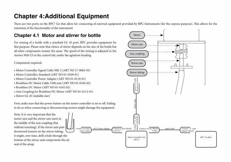
Chapter 4:Additional EquipmentThere are two ports on the BPC® Go that allow for connecting of external equipment provided by BPC Instruments (for the express purpose). This allows for the extension of the functionality of the instrument
Chapter 4.1 Motor and stirrer for bottleFor mixing of a bottle with a standard GL 45 port, BPC provides equipment for this purpose. Please note that choice of stirrer depends on the size of the bottle but all other components remain the same. The speed of the mixing is adjusted in the Aurora Web UI in the control tab, under the agitation heading.
Components required:
• Motor Controller Signal Cable MK 3 (ART NO 17-0003-01) • Motor Controller, Standard (ART NO 01-0109-01) • Motor Controller Power Adapter (ART NO 01-0110-01) • Brushless DC Motor Cable 1500 mm (ART NO 01-0104-02) • Brushless DC Motor (ART NO 01-0102-02) • Axis Coupling for Brushless DC Motor (ART NO 01-0112-01) • Stirrer GL 45 (suitable size)
First, make sure that the power button on the motor controller is set to off. Failing to do so when connecting or disconnecting motors might damage the equipment.
Connect to mainspower outlet
MCU Power Adapter Connect to port labeled “24V DC”
Motor Controller Unit(MCU)
Connect to port labeled “CTRL.”
Connect to port labeled “Motors”
BPC© Go Base
Signal cable
Mot
or c
able
Con
nect
to
po
rt
labe
led
“MO
TOR”
Con
nect
to a
vaila
-bl
e po
rt o
n m
otor
Motor
Axis coupling
Stirrer tubing
Motor axis
Stirrer axis
Note: It is very important that the motor axis and the stirrer axis meet in the middle of the axis coupling (but without touching). If the stirrer axis puts downward tension on the stirrer tubing, it might, over time, drill a hole through the bottom of the stirrer and compromise the air seal of the setup.

Chapter 5:MaintenanceIn order for the BPC® Go to perform properly and to maximise the life-span of the instrument and its constituent parts, it is important to clean and maintain it in a proper way. To clean the base unit, wipe it with a damp piece of cloth and, if required, a gentle form of detergent. The unit is not water proof and should not be exposed to liquid.
The flow cell units can not be opened and are considered consumables. Attempting to open them will irrevocable destroy the gas tightness of them. While still possible to use for some types of experiments, they can not be guaranteed to work as expected. Once they are dirty and the residue can’t be removed by injecting deionized water into them using a syringe, it is recomended that they are replaced. More flow cell units can easily be ordered directly from BPC Instruments.
If an stirring sollution from BPC Instruments is being used, the motor and motor controller unit should be cleaned the same way as the BPC® Go base. The stirrers, while also considered consumables, can be autoclaved. Their life-span will depend heavily on care being taken when mounting them and on what medium they are used to stirr. More stirrers can easily be ordered directly from BPC Instruments.
In order to further maximise the life-span and performance of the BPC® Go, remember to send it in for service at suitable intervalls and to contact BPC Instruments if there are any indication that the instrument is not working. Service intervalls heavily depend on the usage and usage patterns of the individual instru-ments but common intervalls range from one to three years. During service, the internal electronics of the instrument will be exchanged and, if a new compatible hardware version is available, upgraded to the latest version. Any other damage or issues will be resolved as seen suitable during the service examination. There are no additional charges for additional repair or replacement steps during the service. Please contact us via phone or email to recieve a quotation for your unit.