Operations, Service and Parts Manual - LeeBoy
308
Operations, Service and Parts Manual LeeBoy 4130 Road Widener Manual No. 1019539-02 Operations, Service and Parts Manual This manual applies to Serial Number 177628 and above.
-
Upload
khangminh22 -
Category
Documents
-
view
2 -
download
0
Transcript of Operations, Service and Parts Manual - LeeBoy

Operations, Service and Parts Manual
LeeBoy 4130 Road Widener
Manual No. 1019539-02
Operations, Service and Parts Manual
This manual applies to Serial Number 177628
and above.


Safety
Information and Specifications
Component Location
Operation
Maintenance
Schematics
Illustrated Parts List (IPL)
1
2
3
4
5
6
7
Thumb Index

LeeBoy 4130 Road Wideneriv
Legal Notices
DisclaimerAll information, illustrations and specifications in this manual are based on the latest information available at the time of publishing. The illustrations used in this manual are intended as representative reference views only. Moreover, because of our continuous product improvement policy, we may modify information, illustrations and/or specifications to explain and/or exemplify a product, service or maintenance improvement. We reserve the right to make any change at any time without notice. ST Engineering LeeBoy, Inc., dba LeeBoy, is referred to as LeeBoy throughout this manual.
Title 40, Code of Federal Regulations (CFR) 1068
This product meets certified-emission requirements set by the EPA (Environmental Protection Agency), governed by Title 40 CFR 1068, which specifies actions that are prohibited by law and lists civil penalties for noncompliance. As part of those regulations, modification or rendering inoperative any emission-related component can subject you to government penalties (and void your warranty). Tampering with emission controls is in violation of federal law, and can result in civil penalties of up to $3,750 each day an engine or piece of equipment is operated in violation.
Please be aware that you are responsible for maintaining the machine and the certified emission engine installation. Failure to comply to comply could result in penalties as listed above and void the warranty on this engine and this machine.
For more information, visit: https://www.epa.gov/laws-regulations/regulations
California Proposition 65 Warning
Diesel engine exhaust and some of its constituents are known to the State of California to cause cancer, birth defects, and other reproductive harm.
Battery posts, terminals and other related accessories contain lead and lead compounds, chemicals known to the State of California to cause cancer and other reproductive harm. Wash hands after handling.
2019 LeeBoy
LeeBoy reserves all copyright and other rights in this manual and its content. No part of this manual may be reproduced or used in any way without the written permission of LeeBoy, except as necessary to operate LeeBoy equipment.
iv
Legal Notices

TABLE OF CONTENTS
v
Page
Safety . . . . . . . . . . . . . . . . . . . . . . . . . . . . . . . . . . . . 1-1
Safety Precautions . . . . . . . . . . . . . . . . . . . . . . . . . . . . . 1-4
Machine Precautions . . . . . . . . . . . . . . . . . . . . . . . . . . . . 1-7
Hot Material Precautions . . . . . . . . . . . . . . . . . . . . . . . 1-7
Hydraulic Systems Precautions . . . . . . . . . . . . . . . . . . . 1-7
Refueling Precautions . . . . . . . . . . . . . . . . . . . . . . . . 1-8
Battery Precautions . . . . . . . . . . . . . . . . . . . . . . . . . 1-8
Starting and Stopping Precautions . . . . . . . . . . . . . . . . . . 1-8
Parking Precautions . . . . . . . . . . . . . . . . . . . . . . . . . 1-8
Operating Precautions . . . . . . . . . . . . . . . . . . . . . . . . 1-8
Storage Precautions . . . . . . . . . . . . . . . . . . . . . . . . . 1-9
Poor Visibility . . . . . . . . . . . . . . . . . . . . . . . . . . . . 1-9
Maintenance Precautions . . . . . . . . . . . . . . . . . . . . . . 1-9
Tire Precautions . . . . . . . . . . . . . . . . . . . . . . . . . . . 1-10
Safety Decals . . . . . . . . . . . . . . . . . . . . . . . . . . . . . . . 1-11
Safety Decals Care . . . . . . . . . . . . . . . . . . . . . . . . . 1-13
Decal Installation (Sticker Type) . . . . . . . . . . . . . . . . . . . 1-13
Decal Installation (Top Protected) . . . . . . . . . . . . . . . . . . 1-13
Information and Specifications . . . . . . . . . . . . . . . . . . . . . . . . 2-1
One Year Limited Warranty . . . . . . . . . . . . . . . . . . . . . . . . . 2-2
Contact Information . . . . . . . . . . . . . . . . . . . . . . . . . . . . 2-3
Specification Charts . . . . . . . . . . . . . . . . . . . . . . . . . . . . 2-4
Torque Specifications . . . . . . . . . . . . . . . . . . . . . . . . . . . 2-7
Standard Inch Fasteners . . . . . . . . . . . . . . . . . . . . . . . 2-7
Metric Fasteners . . . . . . . . . . . . . . . . . . . . . . . . . . . 2-8
Hydraulic Fittings . . . . . . . . . . . . . . . . . . . . . . . . . . 2-8
Determining Proper Torque . . . . . . . . . . . . . . . . . . . . . 2-9
Components . . . . . . . . . . . . . . . . . . . . . . . . . . . . . . . . . 3-1
Components Overview . . . . . . . . . . . . . . . . . . . . . . . . . . . 3-3
TABLE OF CONTENTS
LeeBoy 4130 Road Widener v

vi
Table of Contents
Operator Platform . . . . . . . . . . . . . . . . . . . . . . . . . . 3-3
Engine . . . . . . . . . . . . . . . . . . . . . . . . . . . . . . . . 3-3
Conveyor and Tilt Hopper . . . . . . . . . . . . . . . . . . . . . . 3-4
Contoured Strike-Off . . . . . . . . . . . . . . . . . . . . . . . . . 3-4
Electrical System . . . . . . . . . . . . . . . . . . . . . . . . . . 3-4
Hydrostatic Drive . . . . . . . . . . . . . . . . . . . . . . . . . . 3-4
Machine Overview . . . . . . . . . . . . . . . . . . . . . . . . . . . . . 3-5
Main Control Panel . . . . . . . . . . . . . . . . . . . . . . . . . . . . . 3-6
Strike-Off Overview . . . . . . . . . . . . . . . . . . . . . . . . . . . . 3-8
Operation . . . . . . . . . . . . . . . . . . . . . . . . . . . . . . . . . . 4-1
General Information . . . . . . . . . . . . . . . . . . . . . . . . . . . . 4-3
Receiving the Machine . . . . . . . . . . . . . . . . . . . . . . . . . . . 4-3
Initial and Daily Inspection . . . . . . . . . . . . . . . . . . . . . . 4-3
Hopper Safety Lock . . . . . . . . . . . . . . . . . . . . . . . . . 4-4
Starting and Stopping . . . . . . . . . . . . . . . . . . . . . . . . . . . 4-4
Starting the Engine . . . . . . . . . . . . . . . . . . . . . . . . . . 4-4
Stopping the Engine . . . . . . . . . . . . . . . . . . . . . . . . . 4-5
Driving the Road Widener . . . . . . . . . . . . . . . . . . . . . . . . . 4-5
Differential Lock . . . . . . . . . . . . . . . . . . . . . . . . . . . 4-7
Plus One Controller . . . . . . . . . . . . . . . . . . . . . . . . . 4-7
PV480 Digital Display . . . . . . . . . . . . . . . . . . . . . . . . . . . 4-8
Main Menu . . . . . . . . . . . . . . . . . . . . . . . . . . . . . . 4-8
Soft Keys (Buttons) . . . . . . . . . . . . . . . . . . . . . . . . . 4-8
Set Points and Throttle Speed . . . . . . . . . . . . . . . . . . . . 4-10
Diagnostics . . . . . . . . . . . . . . . . . . . . . . . . . . . . . 4-10
System Info . . . . . . . . . . . . . . . . . . . . . . . . . . . . . 4-12
User Settings . . . . . . . . . . . . . . . . . . . . . . . . . . . . 4-12
Component Operation . . . . . . . . . . . . . . . . . . . . . . . . . . . 4-14
Oscillating Push Rollers . . . . . . . . . . . . . . . . . . . . . . . 4-15
Hopper . . . . . . . . . . . . . . . . . . . . . . . . . . . . . . . 4-15
Conveyor . . . . . . . . . . . . . . . . . . . . . . . . . . . . . . 4-17
Strike-Off Assembly . . . . . . . . . . . . . . . . . . . . . . . . . . . . 4-18
Basic Strike-Off Angles . . . . . . . . . . . . . . . . . . . . . . . 4-22
Strike-Off Storage . . . . . . . . . . . . . . . . . . . . . . . . . . 4-23
Travel with Attached Strike-Off . . . . . . . . . . . . . . . . . . . . 4-23
Starting to Work . . . . . . . . . . . . . . . . . . . . . . . . . . . . . . 4-25
Basic Road Widening . . . . . . . . . . . . . . . . . . . . . . . . 4-26
LeeBoy 4130 Road Widener
vi
Table of Contents

vii
Loading and Unloading . . . . . . . . . . . . . . . . . . . . . . . . . . . 4-27
Loading . . . . . . . . . . . . . . . . . . . . . . . . . . . . . . . 4-28
Unloading . . . . . . . . . . . . . . . . . . . . . . . . . . . . . . 4-28
Tie-Down Procedure . . . . . . . . . . . . . . . . . . . . . . . . . 4-28
Options . . . . . . . . . . . . . . . . . . . . . . . . . . . . . . . . . . 4-29
Dual Strike-Off . . . . . . . . . . . . . . . . . . . . . . . . . . . . 4-29
Strike-Off Blade Remote Storage . . . . . . . . . . . . . . . . . . 4-29
Spray Down System . . . . . . . . . . . . . . . . . . . . . . . . . 4-30
All-Wheel Drive (AWD) . . . . . . . . . . . . . . . . . . . . . . . . 4-30
Truck Hitch . . . . . . . . . . . . . . . . . . . . . . . . . . . . . 4-31
Umbrella Option . . . . . . . . . . . . . . . . . . . . . . . . . . . 4-31
Topcon® Sonic Slope and Dual Grade Control . . . . . . . . . . . . 4-31
Magnetic Cup Holder . . . . . . . . . . . . . . . . . . . . . . . . 4-31
Maintenance . . . . . . . . . . . . . . . . . . . . . . . . . . . . . . . . . 5-1
Maintenance Schedule . . . . . . . . . . . . . . . . . . . . . . . . . . . 5-3
Routine Maintenance . . . . . . . . . . . . . . . . . . . . . . . . . . . . 5-4
Every 10 Hours or Daily Routine Maintenance . . . . . . . . . . . . 5-4
Every 50 Hours or Weekly Routine Maintenance . . . . . . . . . . . 5-4
Every 100 Hour or Monthly Maintenance . . . . . . . . . . . . . . . 5-4
Every 250 Hours or Quarterly Routine Maintenance . . . . . . . . . 5-5
Every 500 Hours or Semi-Annual Routine Maintenance . . . . . . . 5-5
Every 1000 Hours or Annual Routine Maintenance . . . . . . . . . . 5-5
Machine Lubrication . . . . . . . . . . . . . . . . . . . . . . . . . . . . 5-5
Lubrication Points . . . . . . . . . . . . . . . . . . . . . . . . . . 5-6
Planetary Torque Hub . . . . . . . . . . . . . . . . . . . . . . . . 5-7
Change Gear Box Oil . . . . . . . . . . . . . . . . . . . . . . . . 5-7
Machine Adjustments . . . . . . . . . . . . . . . . . . . . . . . . . . . 5-8
Conveyor Belt and Chains . . . . . . . . . . . . . . . . . . . . . . 5-8
Rubber Conveyor Scrapers and Hopper Flashing . . . . . . . . . . 5-9
Engine Maintenance . . . . . . . . . . . . . . . . . . . . . . . . . . . . 5-9
Check Engine Lubrication Oil . . . . . . . . . . . . . . . . . . . . 5-10
Change Engine Oil and Filter . . . . . . . . . . . . . . . . . . . . . 5-10
Air Filter . . . . . . . . . . . . . . . . . . . . . . . . . . . . . . . 5-11
Engine Drive Belt . . . . . . . . . . . . . . . . . . . . . . . . . . 5-12
Radiator Coolant . . . . . . . . . . . . . . . . . . . . . . . . . . . 5-13
Replace Radiator Hoses . . . . . . . . . . . . . . . . . . . . . . 5-13
Fuel System . . . . . . . . . . . . . . . . . . . . . . . . . . . . . . . . 5-14
Fuel Filter . . . . . . . . . . . . . . . . . . . . . . . . . . . . . . 5-14
Table of Contents
LeeBoy 4130 Road Widener
vii
Table of Contents

viii
Table of Contents
Fuel Water Separator . . . . . . . . . . . . . . . . . . . . . . . . 5-15
Hydraulic System . . . . . . . . . . . . . . . . . . . . . . . . . . . . . 5-16
Check Hydraulic Oil Level . . . . . . . . . . . . . . . . . . . . . . 5-16
Change Hydraulic Oil and Filter . . . . . . . . . . . . . . . . . . . 5-17
Change Hydraulic Oil Cap Strainer . . . . . . . . . . . . . . . . . . 5-18
Hydraulic Test Ports . . . . . . . . . . . . . . . . . . . . . . . . . 5-19
Electrical System . . . . . . . . . . . . . . . . . . . . . . . . . . . . . . 5-20
Battery Servicing . . . . . . . . . . . . . . . . . . . . . . . . . . . 5-20
Battery Electrolyte Level . . . . . . . . . . . . . . . . . . . . . . . 5-21
Lighting . . . . . . . . . . . . . . . . . . . . . . . . . . . . . . . 5-21
Alternator Servicing . . . . . . . . . . . . . . . . . . . . . . . . . 5-21
Dielectric Grease . . . . . . . . . . . . . . . . . . . . . . . . . . 5-22
Fuse Box Panel . . . . . . . . . . . . . . . . . . . . . . . . . . . 5-22
Chassis and Miscellaneous . . . . . . . . . . . . . . . . . . . . . . . . 5-23
Tires . . . . . . . . . . . . . . . . . . . . . . . . . . . . . . . . 5-23
Replacement Procedures . . . . . . . . . . . . . . . . . . . . . . . . . 5-24
Battery . . . . . . . . . . . . . . . . . . . . . . . . . . . . . . . . 5-24
Hydraulic Pumps . . . . . . . . . . . . . . . . . . . . . . . . . . . 5-25
Conveyor Belt . . . . . . . . . . . . . . . . . . . . . . . . . . . . 5-26
Conveyor Shaft, Bearings and Sprockets . . . . . . . . . . . . . . 5-28
Conveyor Shaft, Bearings and Sprockets . . . . . . . . . . . . . . 5-28
Conveyor Drive Motors. . . . . . . . . . . . . . . . . . . . . . . . 5-29
Winterizing for Storage . . . . . . . . . . . . . . . . . . . . . . . . . . . 5-29
Periodic Maintenance in Storage . . . . . . . . . . . . . . . . . . . 5-30
Removing from Storage . . . . . . . . . . . . . . . . . . . . . . . 5-30
Welding on Machine . . . . . . . . . . . . . . . . . . . . . . . . . . . . 5-31
Troubleshooting . . . . . . . . . . . . . . . . . . . . . . . . . . . . . . 5-32
Hydraulic Motor Installation Start-Up Procedure . . . . . . . . . . . 5-32
Conveyor Chain Tension Slack Adjustment . . . . . . . . . . . . . . 5-33
Spraydown Pump (Option) . . . . . . . . . . . . . . . . . . . . . . 5-34
Troubleshooting Chart . . . . . . . . . . . . . . . . . . . . . . . . 5-35
PV480 Diagnostic Trouble CodeS (DTC) Chart . . . . . . . . . . . . 5-39
PV480 Troubleshooting . . . . . . . . . . . . . . . . . . . . . . . 5-44
Plus One Blink Codes . . . . . . . . . . . . . . . . . . . . . . . . . . . 5-45
Schematics . . . . . . . . . . . . . . . . . . . . . . . . . . . . . . . . . 6-1
Main Harness (1 of 5) . . . . . . . . . . . . . . . . . . . . . . . . . . . . 6-3
Main Harness (2 of 5) . . . . . . . . . . . . . . . . . . . . . . . . . . . . 6-5
LeeBoy 4130 Road Widener
viii
Table of Contents
ix
Table of Contents
Main Harness (3 of 5) . . . . . . . . . . . . . . . . . . . . . . . . . . . 6-7
Main Harness (4 of 5) . . . . . . . . . . . . . . . . . . . . . . . . . . . 6-9
Main Harness (5 of 5) . . . . . . . . . . . . . . . . . . . . . . . . . . . 6-11
Control Box Assembly (1 of 3) . . . . . . . . . . . . . . . . . . . . . . . . 6-13
Control Box Assembly (2 of 3) . . . . . . . . . . . . . . . . . . . . . . . 6-15
Control Box Assembly (3 of 3) . . . . . . . . . . . . . . . . . . . . . . . 6-17
Traction Joystick . . . . . . . . . . . . . . . . . . . . . . . . . . . . . . 6-19
Left Harness (1 of 2) . . . . . . . . . . . . . . . . . . . . . . . . . . . . 6-21
Left Harness (2 of 2) . . . . . . . . . . . . . . . . . . . . . . . . . . . . 6-23
Right Harness (1 of 2) . . . . . . . . . . . . . . . . . . . . . . . . . . . . 6-25
Right Harness (2 of 2) . . . . . . . . . . . . . . . . . . . . . . . . . . . 6-27
Main Hydraulic Manifold Harness (1 of 2) . . . . . . . . . . . . . . . . . . 6-29
Main Hydraulic Manifold Harness (2 of 2) . . . . . . . . . . . . . . . . . . 6-31
Brake/2-Speed Hydraulic Manifold Harness . . . . . . . . . . . . . . . . 6-33
Hydraulic Oil Cooler Harness . . . . . . . . . . . . . . . . . . . . . . . . 6-35
OPTION - Strike Off Remote Control Box . . . . . . . . . . . . . . . . . . 6-37
Hydraulic Schematic - Propel Circuit (1 of 4) . . . . . . . . . . . . . . . . 6-39
Hydraulic Schematic - Conveyor/Steering circuit (2 of 4) . . . . . . . . . . 6-41
Hydraulic Schematic - Cylinder Circuit (3 of 4) . . . . . . . . . . . . . . . 6-43
Hydraulic Schematic - Options Circuit (4 of 4) . . . . . . . . . . . . . . . 6-45
ILLUSTRATED PARTS LIST . . . . . . . . . . . . . . . . . . . . . . . . . . 7-1
Quick Reference Guide . . . . . . . . . . . . . . . . . . . . . . . . . . 7-3
Extendable Push Roller Group . . . . . . . . . . . . . . . . . . . . . . . 7-4
Details - Front . . . . . . . . . . . . . . . . . . . . . . . . . . . . . . . 7-6
Hopper Group (1 of 2) . . . . . . . . . . . . . . . . . . . . . . . . . . . 7-8
Hopper Group (2 of 2) . . . . . . . . . . . . . . . . . . . . . . . . . . . 7-10
Conveyor Assembly (1 of 2) . . . . . . . . . . . . . . . . . . . . . . . . . 7-12
Conveyor Assembly (2 of 2). . . . . . . . . . . . . . . . . . . . . . . . . 7-14
Hopper/Conveyor Lift . . . . . . . . . . . . . . . . . . . . . . . . . . . 7-16
Front Axle Assembly . . . . . . . . . . . . . . . . . . . . . . . . . . . . 7-18
Rear Axle Assembly - 2WD . . . . . . . . . . . . . . . . . . . . . . . . . 7-20
Controls Group - 74HP/130HP . . . . . . . . . . . . . . . . . . . . . . . 7-22
Controls Group - 74HP/130HP (Cont.) . . . . . . . . . . . . . . . . . . . 7-24
Controls Group - Dash Assembly . . . . . . . . . . . . . . . . . . . . . . 7-26
Control Box . . . . . . . . . . . . . . . . . . . . . . . . . . . . . . . . 7-28
Details - Upper Deck . . . . . . . . . . . . . . . . . . . . . . . . . . . . 7-30
Details - Left Side . . . . . . . . . . . . . . . . . . . . . . . . . . . . . 7-32
LeeBoy 4130 Road Widener
ix
Table of Contents
x
Table of Contents
Fuel Tank . . . . . . . . . . . . . . . . . . . . . . . . . . . . . . . . . 7-34
Details - Right Side . . . . . . . . . . . . . . . . . . . . . . . . . . . . . 7-36
Single Battery Box Assembly, 74HP . . . . . . . . . . . . . . . . . . . . 7-38
Hydraulic Tank . . . . . . . . . . . . . . . . . . . . . . . . . . . . . . . 7-40
Details - Rear (1 of 2) . . . . . . . . . . . . . . . . . . . . . . . . . . . . 7-42
Details - Rear (2 of 2) . . . . . . . . . . . . . . . . . . . . . . . . . . . . 7-44
Engine Group, 74HP - Covers and Panels . . . . . . . . . . . . . . . . . 7-46
Engine Group, 74HP - Radiator/Cooling . . . . . . . . . . . . . . . . . . 7-48
Engine Group, 74HP - Intake/Frame . . . . . . . . . . . . . . . . . . . . 7-50
Engine Group, 74HP - Components . . . . . . . . . . . . . . . . . . . . 7-52
Engine Group, 74HP - Exhaust/Pumps . . . . . . . . . . . . . . . . . . . 7-54
Pump Covers and Panels . . . . . . . . . . . . . . . . . . . . . . . . . . 7-56
Hydraulic Manifold - Main . . . . . . . . . . . . . . . . . . . . . . . . . . 7-58
Hydraulic Manifold - Conveyor/Steering . . . . . . . . . . . . . . . . . . 7-60
Hydraulic Manifold - Brake/2-Speed . . . . . . . . . . . . . . . . . . . . 7-62
Hydraulic Oil Cooler . . . . . . . . . . . . . . . . . . . . . . . . . . . . 7-64
Strike Off Group (1 of 4) . . . . . . . . . . . . . . . . . . . . . . . . . . . 7-66
Strike Off Group (2 of 4) . . . . . . . . . . . . . . . . . . . . . . . . . . 7-68
Strike Off Group (3 of 4) . . . . . . . . . . . . . . . . . . . . . . . . . . 7-70
Strike Off Group (4 of 4) . . . . . . . . . . . . . . . . . . . . . . . . . . 7-72
OPTION - Dual Strike Off . . . . . . . . . . . . . . . . . . . . . . . . . . 7-74
OPTION - Strike Off Remote Assembly . . . . . . . . . . . . . . . . . . . 7-76
OPTION - Strike Off TopCon-Slope. . . . . . . . . . . . . . . . . . . . . 7-78
OPTION - Strike Off TopCon-Grade . . . . . . . . . . . . . . . . . . . . 7-80
OPTION - Rear Axle Assembly - 4WD w/Steering . . . . . . . . . . . . . . 7-82
OPTION - Engine Covers and Panels, 130HP . . . . . . . . . . . . . . . . 7-84
OPTION - Engine Group, 130HP - Radiator/Cooling . . . . . . . . . . . . . 7-86
OPTION - Engine Group, 130HP - Intake/Frame . . . . . . . . . . . . . . . 7-88
OPTION - Engine Group, 130HP - Components . . . . . . . . . . . . . . . 7-90
OPTION - Engine Group, 130HP - Exhaust . . . . . . . . . . . . . . . . . 7-92
OPTION - Engine Group, 130HP - Pumps . . . . . . . . . . . . . . . . . . 7-94
OPTION - Engine Group, 130HP - DEF Tank . . . . . . . . . . . . . . . . 7-96
OPTION - Dual Battery Box Assembly, 130HP . . . . . . . . . . . . . . . . 7-98
OPTION - Spray Down . . . . . . . . . . . . . . . . . . . . . . . . . . .7-100
Hydraulic Hose Kits . . . . . . . . . . . . . . . . . . . . . . . . . . . .7-102
Decal Kits . . . . . . . . . . . . . . . . . . . . . . . . . . . . . . . . .7-106
Alphabetical Parts Index . . . . . . . . . . . . . . . . . . . . . . . . . .7-108
LeeBoy 4130 Road Widener
x
Table of Contents

xi
Introduction
Section 1 - Safety: Contains general and specific safety guidelines for product and safety label locations.
Section 2 - Information and Specifications: Contains warranty, contact information, machine specification tables, and machine dimensions.
Section 3 - Component Location: Contains overview of major component locations and functions.
Section 4 - Operation: Contains instructions for safe operation and information for optional equipment.
Section 5 - Maintenance: Contains routine mainte-nance procedures, mechanical adjustments, com-ponent replacement and troubleshooting charts for common problems and corrections. (For specific engine maintenance procedures, refer to the engine manufacturer manual.)
Section 6 - Schematics: Contains electrical and hy-draulic schematics for product functionality.
Section 7 - Illustrated Parts List (IPL): Contains parts numbers and illustrations for serviceable components.
Thank you for purchasing the LeeBoy Model 4130 Road Widener. We wish you many years of safe and efficient operation of your Road Widener.
READ THIS MANUAL PRIOR TO OPERATING the ma-chine. It is an important part of the machine and should be kept with in the dedicated storage container provided at all times. Though you may be familiar with similar equipment, you MUST read and understand this manual before operating the machine to help prevent injury or damage.
This manual is intended as a guide for the safe and efficient use of your machine, including procedures for proper operation and maintenance. Use it with all relat-ed supplemental books, engine, transmission manuals, and any other manuals supplied by other manufactur-ers. Related Service Bulletins should also be reviewed to provide information regarding some of the recent changes. If any questions arise concerning this publi-cation or to order a replacement manual, contact your authorized dealer.
This manual contains information that was available at the time of printing and is subject to change without notice.
LeeBoy is also proud to be an accredited ANAB manufacturer, which is a certification process comprised of quality standards established by the American National Standards Institute (ANSI) and the American Society for Quality (ASQ). The ANSI-ASQ National Accreditation Board plays an important role in ensuring the safety and quality of goods and services, along with protecting the environment.
LeeBoy is proud to be ISO 9001 certified. The International Standards Organization (ISO) establishes guidelines to ensure that products and services are safe, reliable, and of good quality. ISO certifies companies who demonstrate compliance with all aspects of product safety, customer satisfaction, efficiency, environmental stewardship and social responsibility. Our teams work hard to deliver quality industrial machines that exceed customer expectations and we strive for continuous improvement in everything we do. The LeeBoy family of companies is committed to total quality management with a strong focus on meeting customer needs.
LeeBoy 4130 Road Widener
xi
Introduction
Section 1 - Safety: Contains general and specific safety guidelines for product and safety label locations.
Section 2 - Information and Specifications: Contains warranty, contact information, machine specification tables, and machine dimensions.
Section 3 - Component Location: Contains overview of major component locations and functions.
Section 4 - Operation: Contains instructions for safe operation and information for optional equipment.
Section 5 - Maintenance: Contains routine mainte-nance procedures, mechanical adjustments, com-ponent replacement and troubleshooting charts for common problems and corrections. (For specific engine maintenance procedures, refer to the engine manufacturer manual.)
Section 6 - Schematics: Contains electrical and hy-draulic schematics for product functionality.
Section 7 - Illustrated Parts List (IPL): Contains parts numbers and illustrations for serviceable components.

xii
NOTES
LeeBoy 4130 Road Widener
xii
NOTES

Section 1
SAFETYPage
Safety Precautions . . . . . . . . . . . . . . . . . . . . . . . . . . . . . 1-4
Machine Precautions . . . . . . . . . . . . . . . . . . . . . . . . . . . . 1-7
Hot Material Precautions . . . . . . . . . . . . . . . . . . . . . . . 1-7
Hydraulic Systems Precautions . . . . . . . . . . . . . . . . . . . 1-7
Refueling Precautions . . . . . . . . . . . . . . . . . . . . . . . . 1-8
Battery Precautions . . . . . . . . . . . . . . . . . . . . . . . . . 1-8
Starting and Stopping Precautions . . . . . . . . . . . . . . . . . . 1-8
Parking Precautions . . . . . . . . . . . . . . . . . . . . . . . . . 1-8
Operating Precautions . . . . . . . . . . . . . . . . . . . . . . . . 1-8
Storage Precautions . . . . . . . . . . . . . . . . . . . . . . . . . 1-9
Poor Visibility . . . . . . . . . . . . . . . . . . . . . . . . . . . . 1-9
Maintenance Precautions . . . . . . . . . . . . . . . . . . . . . . 1-9
Tire Precautions . . . . . . . . . . . . . . . . . . . . . . . . . . . 1-10
Safety Decals . . . . . . . . . . . . . . . . . . . . . . . . . . . . . . . 1-11
Safety Decals Care . . . . . . . . . . . . . . . . . . . . . . . . . 1-13
Decal Installation (Sticker Type) . . . . . . . . . . . . . . . . . . . 1-13
Decal Installation (Top Protected) . . . . . . . . . . . . . . . . . . 1-13
LeeBoy 4130 Road Widener1-1
1

Safety
NOTES
LeeBoy 4130 Road Widener1-2

Safety
LOOK FOR THESE SYMBOLS THROUGHOUT THIS MANUAL. THESE SAFETY NOTICES
ARE EXTREMELY IMPORTANT. READ AND UNDERSTAND THOROUGHLY. HEED THE
WARNINGS AND FOLLOW THE INSTRUCTIONS.
Indicates a hazardous situation which, if not avoided, will result in death or serious injury.
Indicates a hazardous situation which, if not avoided, could result in death or serious injury.
Indicates a hazardous situation which, if not avoided, could result in minor or moderate injury.
Indicates a situation which can cause damage to the equipment, personal property and/or the environment, or cause the machine to operate improperly.
NOTE: Indicates a procedure, practice or condition that should be followed in order for the machine or component to function in the manner intended.
This manual provides important information to familiarize you with safe operating and maintenance procedures. Even though you may be familiar with similar equipment, you MUST read and understand this manual before operating the LeeBoy 4130 Road Widener and follow its instructions.
Safety is everyone’s business and our top concern. Knowing the guidelines covered in this section will help ensure your safety, the safety of those around you, as well as proper paver operation.
Keep safety labels in good condition. If safety labels become missing or damaged, replace them with new matching labels. Replacement safety labels are available from your authorized dealer (see contact information in Section 2).
You can find more information about occupational health and safety in the paving industry on the internet. A few resources are listed below:
www.osha.gov
cdc.gov
www.asphaltpavement.org
www.safety.fhwa.dot.gov/
LeeBoy 4130 Road Widener1-3
1

Safety
SAFETY PRECAUTIONS
The safety messages that follow have CAUTION level hazards.
Pre-Operation Hazard
Read and understand this manual before operating or servicing the machine to ensure that safe operating and maintenance procedures are followed.
• DO NOT allow anyone to service or operate the machine who is not properly trained. Contact your authorized dealer for additional training if needed.
• Safety labels are important reminders for safe operating and maintenance procedures. Ensure all safety labels are legible. Contact your authorized dealer to replace worn or damaged safety labels.
• Be aware and comply with all laws and regulations for the location where the machine is operated.
• Ensure all operators have the necessary license(s) to operate the machine.
Poor Lighting Hazard
• Ensure the area is well lit for safe operation and maintenance performance.
• Always install wire cages on portable safety lights.
Tool Hazard
Always use tools appropriate for the task. Use the correct sized tool for loosening or tightening any machine parts.
The safety messages that follow have DANGER level hazards.
Power Lines Hazard
If your machine comes into contact with electric power lines, observe the following:
• Warn others to stay away and DO NOT touch any control or other parts of the machine.
• If contact can be broken, drive the machine away from the danger zone. If contact cannot be broken, stay in the operators seat until the power is off.
• Failure to observe these directions could result in electrocution or death.
Electrocution Hazard
Disconnect the battery before welding anywhere on the machine.
Suffocation Hazard
Carbon monoxide poisoning is a serious condition that occurs as a result of improper ventilation.
• Never operate the engine in an enclosed area with poor ventilation. Ensure proper ventilation to reduce risk of carbon monoxide poisoning or death.
Exhaust Hazard
All internal combustion engines create carbon monoxide gas during operation and special precautions are required to avoid carbon monoxide poisoning:
• Never block windows, vents or other means of ventilation.
• Always ensure that all connections are tightened to specifications after repair is made to the exhaust system.
LeeBoy 4130 Road Widener1-4

Safety
The safety messages that follow have WARNING level hazards.
Crush Hazard
Keep bystanders away from work area before and during operation.
Modification Hazard
Never modify the machine without the written consent of LeeBoy. Any modification can affect the safe operation of the machine and may cause personal injury or even death.
Exposure Hazard
Operators of the machine must be aware of their work environment and the equipment needed to work safely.
• Always wear personal protective equipment, including appropriate clothing, gloves, work shoes, and protection for eyes and ears, as required by the task at hand.
Explosion Hazard
While the engine is running or the battery is charging, hydrogen gas is produced that can ignite. Keep the area around the battery well-ventilated and keep sparks, open flame, and any other form of ignition away from the machine.
• Always disconnect the negative (-) battery cable before servicing the machine.
• DO NOT start the engine by “shorting” the starter circuit or any other starting method not stated in this manual.
• Never charge a frozen battery. Always warm the battery slowly to room temperature before charging.
Fire and Explosion Hazard
• Diesel fuel is flammable and explosive under certain conditions.
• Clean up fuel spills immediately.
• Never refuel while the engine is running.
• Store fuel containers in a well-ventilated area away from any combustibles or sources of ignition.
Fire Hazard
When operating machinery, there is always a risk for fire. Ensure appropriate safety equipment available.
• Keep a charged fire extinguisher within reach at all times.
• Ensure all fire extinguishers are checked periodically for proper operation and readiness.
• Always read and follow safety-related precautions on hazardous substance containers like cleaners, primers, sealants and sealant removers.
• Undersized wiring systems can cause electrical fires.
Entanglement/Sever Hazard
Sound the horn as a warning and verify there are no people, obstacles or other equipment near the machine or in its path before starting the engine.
If the engine must be serviced while it is operating, remove all jewelry and tie back long hair.
• Stay clear of moving/rotating parts.
• Always stop the engine before performing maintenance and remove the negative battery cable.
• Verify that all guards and covers are properly attached before starting the engine. DO NOT start the engine if any guards or covers are not properly installed.
• If you must operate the engine during maintenance procedures, keep bystanders clear of the area.
• Always turn the starter switch to the OFF position and remove the key after operating the machine. Secure the key when the machine is not operating.
LeeBoy 4130 Road Widener1-5
1

Safety
• Attach a “Do Not Operate” tag near the key switch while performing maintenance on the equipment.
• Never operate the engine while wearing headphones because it will be difficult to hear any warning signals.
• Start the engine and operate the controls ONLY from the operator seat.
Alcohol and Drug Hazard
Never operate the machine while under the influence of alcohol or drugs.
Piercing Hazard
High-pressure hydraulic fluid or fuel can penetrate your skin and result in serious injury. Avoid skin contact caused by a hydraulic or fuel system leak such as a
broken hydraulic hose, fuel injection or high-pressure, common-rail engine line.
• If you are exposed to high-pressure hydraulic fluid or fuel spray, obtain prompt medical treatment.
• Never check for a hydraulic fluid or fuel leak with your hands. Always use a piece of wood or cardboard. Contact your authorized distributor to repair damaged parts.
Flying Object Hazard
Always wear eye protection when cleaning the machine with compressed air or high-pressure water.
Dust, flying debris, compressed air, pressurized water or steam may cause eye injury.
Coolant Hazard
Coolant must be handled properly to ensure operator safety.
• Wear eye protection and rubber gloves when handling engine coolant.
• If eye contact occurs, flush eyes with clean water for at least 15 minutes.
• If contact with skin occurs, wash immediately with soap and water.
Burn Hazard
Some of the machine’s surfaces become very hot during operation and may remain hot for a few minutes after shutdown.
• Keep hands and other body parts away from hot machine surfaces.
• Handle hot components with heat-resistant gloves.
LeeBoy 4130 Road Widener1-6

Safety
MACHINE PRECAUTIONS
Hot Material Precautions• ALWAYS wear protective gear for face, hands, feet,
and body when operating the machine.
• Allow machine to cool before repairing or performing maintenance components.
• If hot asphalt or other material touches the skin, flush area immediately with cold water. DO NOT apply ice to the affected area. DO NOT ATTEMPT TO REMOVE ASPHALT CEMENT with products containing solvents or ammonia as natural separation will occur in 48 to 72 hours. Get medical attention immediately.
• DO NOT remove radiator cap, drain plugs, service grease fittings, or pressure taps while engine is hot. Add coolant to the radiator and perform other services only when the engine is stopped and fully cooled.
Hydraulic Systems Precautions• Ensure all components are in good working condition.
Replace any worn, cut, abraded, flattened or crimped hoses and metal lines.
• DO NOT attempt makeshift repairs using tape, clamps or cements. The hydraulic system operates under extremely high pressure and such short-term repairs can cause serious injury.
Hydraulic oil under pressure can cause serious personal injury. Check for oil leaks with a piece of cardboard. DO NOT expose hands to possible high-pressure oil. Turn off engine before attempting to tighten oil lines and fittings.
• Escaping pressurized hydraulic fluid has enough force to penetrate the skin and cause serious personal injury and toxic reactions. Ensure pressure is relieved before disconnecting lines, hoses or valves. If injury from high-pressure steam or hydraulic fluid occurs, seek medical attention immediately.
The safety messages that follow have NOTICE level hazards.
Any part that is found defective as a result of inspection or any part whose measured value does not satisfy the standard or limit must be replaced.
Always tighten components to the correct torque. (See Section 2, Torque Tables) Loose parts can cause improper operation and damage to the machine. Only use replacement parts approved by LeeBoy. Other replacement parts may affect warranty coverage. Contact your authorized dealer for assistance.
Follow EPA and local government guidelines for properly disposing of hazardous materials such as engine oil, diesel fuel, and engine coolant. Consult local authorities or reclamation facilities for more information. Never dispose of
hazardous materials by dumping them into a sewer, on the ground, or into waterways.
Clean all accumulated dirt and debris away from the body of the machine and its components before inspecting the machine or performing repairs and maintenance. Operating a machine with accumulated dirt buildup will cause premature wear of machine components and hinders effective operation.
If any alert indicator illuminates while operating, STOP the engine immediately. Determine the cause and repair the problem before continuing to operate the machine. Contact your authorized dealer for service assistance.
LeeBoy 4130 Road Widener1-7
1

Safety
Starting and Stopping Precautions• Check all around the machine to ensure there are
no people in its path before starting. DO NOT start until area is clear to prevent death or serious injury to bystanders being crushed by a moving machine.
• Always check brakes, steering and other control devices before starting the machine.
• Always sound the horn before moving forward or reverse to alert others the machine is about to move.
Parking Precautions• Park the machine on level ground whenever possible
and apply the parking brake. Park the machine with wheels securely blocked on grades.
• Remove ignition key when leaving the machine parked or unattended.
Operating Precautions• Always comply with federal and local regulations for
moving equipment and industrial machinery on public roads and highways.
• Know and use the hand signals required for a particular job. Know who has the responsibility for signaling.
• Make sure all lights and reflectors comply with state and local regulations. Lights must be clean, in good working condition and clearly visible to all traffic.
• DO NOT stand between the machine and other vehicles working at the job site. Death or serious injury can result from being crushed between two machines.
• DO NOT ride on attachments.
• Check all gauges and warning instruments for proper operation. If malfunctions are found, shut down the machine immediately and report the problem for resolution. If the failure causes loss of steering, brakes or engine power, stop immediately. Keep the machine securely parked until the failure is corrected or the machine can be safely moved.
Refueling Precautions• DO NOT overfill the fuel tank as overflow creates a fire
hazard when spilled on hot components.
• DO NOT fill tank to capacity. Allow room for expansion to reduce the risk of fuel expanding and spilling from the tank.
• DO NOT smoke when refueling. Never refuel while the engine is running. Fuel is highly flammable and should be handled with care. Death or serious injury can occur due to explosion and fire.
• Tighten fuel cap securely. Should the fuel cap be lost, replace ONLY it with original manufacturer’s cap. Pressurization of the tank may result from use of non-approved cap. Contact your authorized dealer for replacement.
• Prevent fires by keeping the machine clean of accumulated debris, grease and spilled fuel.
• Only use ultra-low sulfur diesel fuel (ULSD).
Battery Precautions• Keep all sparks and flames away from batteries as gas
given off by electrolytes is explosive.
• Acid propelled by an explosion can cause blindness.. Always wear safety glasses when working near batteries.
• If you come into contact with battery electrolyte solution, wash it off immediately to prevent burns.
• Always disconnect the battery ground cable before working on the electrical system to avoid injury from sparks or short circuit.
• To avoid electrolyte loss, DO NOT tip batteries more than 45 degrees.
• DO NOT “jump start” directly to the starter (or starter solenoid). This bypasses safety devices and safety systems. Serious injury or even death can result. NEVER “jump start” a cold battery as it could explode.
LeeBoy 4130 Road Widener1-8

Safety
• Drive the machine with care, ensuring speed is compatible with road and climate conditions. Use extra caution on rough ground, slopes and while turning.
• Be alert for hazards and obstructions such as ditches, trees, cliffs, overhead power lines, and areas where there is danger of a slide.
• Be aware and understand job site traffic flow patterns.
• Obey flagmen, road signs and traffic signals.
• Watch for bystanders. Never allow anyone near the machine during operation.
• Operator must know how to use signaling devices and understand which circumstances require use of each signal. Use tail lights, slow moving vehicle signs, and warning beacon as needed when traveling on public roads. It is recommended that you always drive with at least one escort vehicle to and from job sites.
• DO NOT tow the machine, except to remove from road or load onto a trailer.
• When moving the machine, adjust speed and direction of travel for the terrain and ground conditions present. Always consider adjusting travel speed to match ground conditions.
• Only trained personnel should operate this machine. NEVER allow anyone who lacks comprehensive training to operate or perform maintenance on this machine.
• Use extra care when attaching and lifting strike-off components. If using lifting gear, ensure it is in good working condition and adequate for component weight.
• Keep all handles, ladder rungs, operator platform and handrails free of mud, dirt, snow and ice to prevent falls.
Storage Precautions• Store machine in an area away from human activity.
• DO NOT permit children to play on or around the machine.
• Make sure the unit is stored on a surface that is firm, level, and free from debris.
• Store the machine inside a building or cover securely with a weather-proof tarpaulin.
Poor VisibilityIncreasingly, asphalt maintenance equipment is used during less than ideal lighting conditions such as fog or at night. These conditions present safety hazards for workers, bystanders and passing traffic.
When operating under restricted light conditions, equip the machine with special lighting to prevent serious injury.
• Use reflective tape on the sides of the machine when working at night. Ensure all workers wear reflective safety vests.
• Use impact barriers (movable or stationary) to protect workers and direct the traffic flow safely away from the work site.
Contact your authorized dealer for additional lighting packages if working under these conditions.
Maintenance Precautions• DO NOT attempt repairs unless trained to do so.
Refer to manuals and contact your authorized dealer for service assistance.
• Securely block the machine and any components that may fall before performing maintenance. Block any working components to prevent unexpected movement while repairs are being made.
• Always wear safety glasses and other required safety equipment when servicing or making repairs.
• Disconnect battery before working on the electrical system.
• Avoid lubrication or mechanical adjustments while the machine is in motion or the engine is operating.
• Never make repairs on pressurized components such as fluid lines, fuel system, or mechanical items until the pressure has been relieved.
• When servicing or replacing hardened pins, use a brass drift or other suitable material between the hammer and pin.
• Keep brakes and steering system in good operating condition.
LeeBoy 4130 Road Widener1-9
1

Safety
Tire Precautions DO NOT mount or demount tires
without proper training. A violent explosion can occur.
Follow all procedures and safety instructions. Charts containing mounting and demounting instructions are available from OSHA at www.osha.gov/pls/publications.
Contact your authorized dealer or a qualified tire dealer or repair service to perform required tire maintenance.
• Clean rims and repaint to stop corrosion and facilitate checking air level and tire mounting. Be careful to clean all dirt and rust from the lock ring and gutter. This is important to secure lock ring in its the proper position.
• Check rim components periodically for cracks. Replace all cracked, badly worn, severely rusted, and otherwise damaged components with new parts of the same size and type. If you are not sure about proper mating of tire and wheel parts, consult your authorized dealer or a wheel and rim expert.
DO NOT attempt to rework, weld, heat or braze any rim components that are cracked, broken or damaged. Replace damaged components with new parts of the same size and type. Mixing parts of one type with those of another is potentially dangerous.
DO NOT reinflate a tire that has been run flat without first inspecting the tire, tube, flap, rim, and wheel assembly. Double-check the side ring and O-ring for damage, ensuring they are secured in the gutter before inflation.
Mismatched rim parts are dangerous and could cause SEVERE injury.
• Remove valve core to exhaust all air from tire. ALWAYS exhaust all air from tire prior to removing rim components or wheel components such as nuts or rim clamps. Check the valve stem by running a piece of wire through the stem to make sure it is not plugged.
• DO NOT attempt to demount a tire unless you have the proper equipment and experience to do the job.
• DO NOT try to seat rings or other components by hammering unless tire is fully deflated. Double-check all components prior to inflation.
• DO NOT inflate a tire before all components are properly in place. Recheck components for proper assembly. If improperly assembled, deflate and correct.
• Never hammer on a tire/rim assembly that is not fully deflated. If assembly is proper at 10 psi (68,947.572 Pa), continue to inflate to fully seat the tire beads. Then completely deflate the tire to prevent overly stretching the tube. Reinflate to recommended operating pressure.
• NEVER sit on or stand in front of a tire/rim assembly during inflation. Use a clip-on chuck and make sure inflation hose is long enough permit the person inflating the tire to stand to the side of the tire.
• DO NOT hammer components with steel hammers. Use rubber, lead, plastic, or brass-faced mallets to tap components together.
• DO NOT try to drive an assembled or partially-assembled tire or rim over a cast spoke wheel by hammering. DEFLATE and examine to determine the reason for the improper fit. Look for distortion or components that are not properly locked or sealed.
• Block the tire and wheel on opposite sides of the vehicle before you place the jack in position. Always put hardwood blocks under the jack and crib up the vehicle in case the jack slips.
• DO NOT inflate tires beyond the maximum recommended inflation pressure.
• NEVER operate a vehicle on a single tire of a dual assembly. The carrying capacity of the single tire and rim is dangerously exceeded and operating a vehicle in this manner can result in damage to the rim and tire.
LeeBoy 4130 Road Widener1-10

Safety
SAFETY DECALSIf your machine is repainted, it is extremely important that you replace all the CAUTION, WARNING and DANGER safety decals in the proper locations. (Figure 1-1) For additional help, refer to the parts listing in Section 7 and contact your authorized dealer to order a replacement kit.
NOTE: It is the responsibility of the owner and operator to make sure that all safety labels are readable and located on the machine.
Figure 1-1. Safety Decals and Safety Decal Locations (Left Side)
#59667287
#856437
#1010090
#856631
#39168-11
#13855317
#13855275
#13437678
#13437652
#59020040
#13855275
(BOTH SIDES)
(BOTH SIDES)(BOTH SIDES)
LeeBoy 4130 Road Widener1-11
1

Safety
#39168-11
#13855275 #13855259
#13437645
#856631
(Under Hydraulic Filter on Engine
Cover)
#856446
#13855317
Figure 1-2. Safety Decals and Safety Decal Location (Right Side)
LeeBoy 4130 Road Widener1-12

Safety
Figure 1-3. Safety Decals and Safety Decal Location (Operator Station)
#1005474
#13855291
#13437728
#20959227
Safety Decals Care1. Keep safety decals clean and legible at all times.
2. Become familiar with the content and the position of each safety decal. Decals include important information.
3. Replace illegible and missing decals immediately.
4. When replacing parts that display a safety decal, ensure the new part is fitted with a decal.
5. Obtain replacement safety decals from your authorized dealer.
Decal Installation (Sticker Type)1. Be sure the application area is clean and dry. Use
hot, soapy water to clean the surface.
2. Thoroughly dry the surface.
3. Measure and fit the decal before removing the paper backing.
4. For decals with no top-protection paper, remove one side of the split-backed paper.
5. Align decal over the specified area and carefully press into place.
6. Slowly remove the rest of the backing and carefully smooth decal into place.
7. Small air pockets can be pierced with a small pin and then smoothed into place.
Decal Installation (Top Protected) 1. If the decal has protective cover paper, use hot
soapy water on the surface where the decal will be applied and leave wet.
2. Remove protective back paper and soak decal in clean soapy water to help alleviate air bubbles.
3. Smooth decal into place with a squeegee.
4. Check for air bubbles. Small air pockets can be pierced with a pin and then smoothed into place.
5. When decal is completely smooth, carefully remove top paper.
LeeBoy 4130 Road Widener1-13
1

Safety
NOTES
LeeBoy 4130 Road Widener1-14

Page
Limited Warranty Policy . . . . . . . . . . . . . . . . . . . . . . . . . . 2-2
Contact Information . . . . . . . . . . . . . . . . . . . . . . . . . . . . 2-3
Specification Charts . . . . . . . . . . . . . . . . . . . . . . . . . . . . 2-4
Torque Specifications . . . . . . . . . . . . . . . . . . . . . . . . . . . 2-7
Standard Inch Fasteners . . . . . . . . . . . . . . . . . . . . . . . 2-7
Metric Fasteners . . . . . . . . . . . . . . . . . . . . . . . . . . . 2-8
Hydraulic Fittings . . . . . . . . . . . . . . . . . . . . . . . . . . 2-8
Determining Proper Torque . . . . . . . . . . . . . . . . . . . . . 2-9
INFORMATION AND SPECIFICATIONS
LeeBoy 4130 Road Widener 2-1
Section 2

Limited WarrantyIf a manufacturing defect in factory supplied materials or factory workmanship is found and the authorized LeeBoy dealer (“Dealer”) is notified during the warranty period, LeeBoy will be responsible for repairing or replacing any part or component of the unit or part that
fails to conform to the warranty during the warranty period.
Terms and ConditionsThe warranty applies for a period of one year (for unlimited hours of usage on the unit during the one year), beginning on the date that the Dealer from which the unit is purchased submits the warranty registration form to LeeBoy (typically on the date of purchase).
The warranty is not transferable and applies only to the original purchaser of a new unit from a Dealer.
Warranty work must be performed at an authorized Dealer location.
LeeBoy has the right to repair any component or part before replacing it with a new one.
Replacement parts furnished by LeeBoy are covered for the remainder of the warranty period applicable to the unit or component in which such parts are installed.
All new replacement parts purchased from a Dealer will carry a six
(6) month warranty.
Items Not CoveredLeeBoy is not responsible for the following:
• All used units or used parts of any kind.
• Repairs due to normal wear and tear or brought about by abuse or lack of maintenance of the machine.
• Attachments not manufactured or installed by LeeBoy.
• Liability for incidental or consequential damages of any type including, but not limited to, lost profits or expenses of acquiring replacement equipment.
Exclusions and LimitationsLeeBoy has no obligation under this warranty for any defects or
failures caused by:
• Misuse, misapplication, negligence, accident or failure to maintain or use in accordance with the most current operating instructions;
• Unauthorized alterations or modifications;
• Any replacement parts or attachments not manufactured by or expressly approved by LeeBoy;
• Failure to conduct normal maintenance and operating service, including without limitation, providing lubricants, coolant, fuel, tune-ups, inspections or adjustments; or
• Unreasonable delay, as determined by LeeBoy, in making the applicable units or parts available upon notification of a service notice ordered by LeeBoy.
LeeBoy is not responsible for any of the following:
• Defects or failures with respect to any engine or truck chassis;
• Defects or failures covered by a warranty provided by a third-party, including without limitation warranties with respect to engines or truck chassis;
• Costs related to travel time, mileage or overtime;
• Costs related to transporting the unit to and from the place at which warranty work is performed;
• Airfreight charges related to transporting repair parts to the place at which warranty work is performed;
• Used units or used parts of any kind;
• Repairs due to normal wear and tear, or brought about by abuse or lack of maintenance of the equipment, except for premature failures;
• Attachments not manufactured or installed by LeeBoy; or
• Miscellaneous charges.
Exclusion of Other Warranties/Limitation of LiabilityOTHER THAN THE EXPRESS WARRANTY PROVIDED IN SECTION A. ABOVE, LEEBOY GIVES NO EXPRESS, STATUTORY, OR IMPLIED WARRANTY OR GUARANTEE AND HEREBY DISCLAIMS ALL SUCH WARRANTIES, INCLUDING WITHOUT LIMITATION ANY IMPLIED WARRANTY OF MERCHANTABILITY, FITNESS FOR A PARTICULAR PURPOSE, SUITABILITY, DURABILITY, CONDITION, QUALITY, OR FREEDOM FROM CLAIMS OF ANY PERSON BY WAY OF INTERFERENCE, INFRINGEMENT, OR THE LIKE.
IN NO EVENT OR UNDER ANY THEORY OF RECOVERY, WHETHER AS A RESULT OF BREACH OF CONTRACT OR WARRANTY, ALLEGED NEGLIGENCE, OR LIABILITY WITHOUT FAULT, SHALL LEEBOY BE LIABLE FOR ANY SPECIAL, INCIDENTAL OR CONSEQUENTIAL DAMAGES ARISING OUT OF THE SALE, USE, OR LOSS OF USE OF ANY PRODUCT, INCLUDING WITHOUT LIMITATION LOST PROFITS OR REVENUES, COST OF CAPITAL, COST OF SUBSTITUTED EQUIPMENT, FACILITIES OR SERVICES, DOWNTIME COSTS, LABOR COSTS, OR DIMINUTION OF VALUE.
ONE YEAR LIMITED WARRANTY
LeeBoy 4130 Road Widener2-2
Information and Specifications

NameplateThe nameplate contains the model and serial numbers used to identify the machine and its components for parts or service information. Refer to the Engine Operator’s Manual for the location of the engine nameplate.
CONTACT INFORMATIONFor information regarding parts and repairs about your product, contact your authorized LeeBoy dealer.
Record dealer information in the space provided. For additional information, please visit: www.leeboy.com.
Record of OwnershipPlease complete the following information for use if you contact LeeBoy for service, parts or literature.
Sales Representative:
Dealership Name:
Dealership Address:
Dealership Phone:
Machine Model Number:
Product Serial Number:
Date of Purchase:
Figure 2-1. Nameplate Location
2
LeeBoy 4130 Road Widener 2-3
Information and Specifications

SPECIFICATION CHARTSThe specifications provided in this section include machine weights, dimensions, performance, and torque values for both metric and standard inch fasteners.
Table 2-1. Machine Dimensions
ITEM SPECIFICATION
Overall Length 21 ft 3 in (6.5 m)
Overall Height 8 ft 11 in (2.6 m)
Overall WidthTransport: 8 ft 4 in (2.5 m)
Working: 9 ft 8 in (3 m)
Overall Weight With Counterweights: 22,670 lbs (10,283 kg)
Wheelbase 9 ft 9 in (3 m)
Turning Radius (Outside) 14 ft (4.3 m)
Ground Clearance 6 in (15.2 cm)
Load Angle 13°
Table 2-2. Engine Specifications
ITEM SPECIFICATION
2.8 Standard Engine 3.8 Optional Engine
Manufacturer and Model Cummins QSF 2.8 Tier 4 Final Cummins QSF 3.8 Tier 4 Final
Engine Type Vertical 4-Cycle Liquid Cooled Diesel Vertical 4-Cycle Liquid Cooled Diesel
Peak Torque 221 lb. ft. (300 N•m) @ 1600 RPMs 360 lb. ft. (488 N•m) @ 1600 RPMs
Combustion System; Intake System
Direct Injection; Turbocharged, Air Cooled
Direct Injection; Turbocharged, Air Cooled
Power Rating HP (kW) 74 HP (55 kW) @ 2200 RPMs 130 HP (97 kW) @ 2200 RPMs
Maximum Speed 2200 RPMs 2200 RPMs
Replace original equipment only with LeeBoy components.
9’ 9”(3 m)
21’ 3 “(6.5 m)
9’ 8”(3 m)
7’ 2”(2.37 m)
8’ 11 “(2.47 m)
LeeBoy 4130 Road Widener2-4
Information and Specifications

Table 2-3. Fuel and Lubricant Specifications
ITEM SPECIFICATION
Engine Oil 15W-40, API CH-4, CI-4
Hydraulic Oil All Weather All Temperature VG32
Fuel Ultra-Low Sulfer Diesel (ULSD)
Grease Shell Avania EP Grease or Equivalent
Table 2-4. System Capacity Specifications
ITEM SPECIFICATION
Fuel 55 gal (208.2 L)
Hydraulic Oil Tank 61 gal (231 L)
2-Speed Gear Box .5 gal (2 L)
Engine Items 2.8 Standard Engine 3.8 Optional Engine
Engine Lubrication Oil Refill Capacity 9.4 qts (8.9 L) 15.4 qts (14.6 L)
Engine Coolant3.4 gal (12.9 L) Glycol-Based,
Red, Extended Life5.25 gal (19.9 L) Glycol-Based,
Red, Extended Life
Table 2-5. Performance Specifications
ITEM SPECIFICATION
Travel Speed 0 - 12 mph (0 - 19.3 kph)
Working Depth 12 inches (30.4 cm) above or below grade.
Slope Control +/- 16%
Table 2-7. Electrical Specifications
ITEM SPECIFICATION
Battery 12 VDC Maintenance-Free, Negative Ground
Cold Cranking Amps (CCA) 950 CCA
Alternator Output Amperage 120 Amps
Alternator Fan Belt TensionAutomatic belt tension mechanism keeps serpentine belt under tension at all times.
Table 2-8. Hydraulic Pressure Specifications
ITEM SPECIFICATION
General Purpose Pump 2465 psi (169.9 Bar)
Conveyor and Cylinders 2465 psi (169.9 Bar)
Propel Pump 5000 psi (344.7 Bar)
Charge Pressure 320 psi (22 Bar)
2
LeeBoy 4130 Road Widener 2-5
Information and Specifications

Table 2-9. Drive System Specifications
ITEM SPECIFICATION
TransmissionElectric 2-Speed Motor, Hydraulically Controlled, Fully Reverse in Both Speed Ranges.
Steering Front Wheel Hydrostatic or Optional All-Wheel Drive (AWD)
Rear Axle Fixed or Optional Steer
Tires Two (2) 385/65R22.5 Radial, Two (2) 425/65R22.5 Radial
BrakesHydrostatic Traction Drive. Fail-Safe Park Brake. Front Service Brake
Table 2-10. Hopper and Conveyor Specifications
ITEM SPECIFICATION
Hopper
Tilts 32 degrees with 14 inches (35.5 cm) . Folding hopper wings.
Truck Entry: 9’ 3” (2.8 m)
Hopper Capacity 2.2 cu yds (3 tons)
Hopper Width Fully Extended 9’ 3” ft (2.8 m)
Conveyor
High-temperature, 24-inch (61 cm) wide conveyor belt. Travels on roller bearing support rollers. Two (2) high-torque, direct-drive hydraulic motors. Conveyor assembly hydraulically extends and retracts up to 18 inches (.457 m) on either side.
Conveyor Speed 0 - 448 FPM (0 - 136.5 MPM)
Conveyor Motor Speed 190 RPMs
Table 2-11. Strike Off Specifications
ITEM SPECIFICATION
Width of Spread 1 - 8 ft (.304 m - 2.44 m) [Outer edger plate assembly included.]
Blade Height 21 in (53.3 cm)
Blade Widths One 1-Foot (.304 m) and one 2 - 3-Foot (.7 - .9 m) Extendable Blades.
Hydraulic FunctionsRaise, lower, extend and retract strike-off with manual stops for fine adjustment of elevation and slope.
Table 2-12. Optional Equipment Specifications
ITEM SPECIFICATION
Spraydown SystemIncludes 2 hose reels with hoses and spray wands, 7-gallon (26.5 L) tank, and pump.
AWD (All-Wheel Drive)Provides full-time four-wheel drive with rear steer for improved tractive effort and maneuverability.
Additional Strike-Off Blade Options1-Foot (.304 m), 3-Foot (.9 m) or 2 - 3-Foot (.7 - .9 m) Extendable Blades.
LeeBoy 4130 Road Widener2-6
Information and Specifications

TORQUE SPECIFICATIONSThe following tables list torque values for standard hardware. This is a guide for average application involving typical stresses and machined surfaces. Values are based upon physical limitations of clean, plated and lubricated hardware. Under more extreme conditions, individual torque value should be followed.
Conversion formulas are provided below:
Conversion Formula
ft-lb to N•m [ft-lb]*1.3558 = [N•m)
ft-lb to in-lb [ft-lb]*12 = [in-lb]
N•m to in-lb [N•m]*8.8508 = [in-lb]
Standard Inch FastenersTable 2-13. Torque Specifications For Standard Inch Fasteners
SIZE THREAD
CAPSCREWS: SAE GRADE 5 CAPSCREWS: SAE GRADE 8
TORQUE (ft lb) TORQUE N•m TORQUE (ft lb) TORQUE N•m
Dry Lubed Dry Lubed Dry Lubed Dry Lubed
1/4 20 UNC 8 6 11 8 12 9 16 12
28 UNF 10 7 14 9 14 10 19 14
5/16 18 UNC 17 13 23 18 25 18 34 24
24 UNF 19 15 26 20 27 20 37 27
3/8 16 UNC 31 23 42 31 44 33 60 45
24 UNF 35 26 47 35 49 37 66 50
7/16 14 UNC 49 37 66 50 70 52 95 71
20 UNF 55 41 75 56 78 58 106 79
1/2 13 UNC 75 57 102 77 106 80 144 108
20 UNF 85 64 115 87 120 90 163 122
9/16 12 UNC 109 82 148 111 154 115 209 156
18 UNF 121 91 164 123 171 128 232 174
5/8 11 UNC 150 113 203 153 212 159 287 216
18 UNF 170 127 230 172 240 180 325 244
3/4 10 UNC 267 200 362 271 376 282 510 382
16 UNF 297 223 403 302 420 315 569 427
7/8 9 UNC 429 322 582 437 606 455 822 617
14 UNF 474 355 643 481 669 502 907 681
1 8 UNC 644 483 873 655 909 681 1232 923
14 UNF 722 542 979 735 1020 765 1383 1037
1-1/4 7 UNC 1121 840 1520 1139 1817 1363 2464 1848
12 UNF 1241 930 1683 1261 2012 1509 2728 2046
1-1/2 6 UNC 1950 1462 2644 1982 3162 2371 4287 3215
12 UNF 2194 1645 2975 2230 3557 2668 4823 3617
2
LeeBoy 4130 Road Widener 2-7
Information and Specifications

Metric Fasteners
Table 2-14. Torque Specifications for Metric Fasteners
NOMINAL SIZE AND PITCH
CLASS 8.8 [GRADE 5 EQUIVALENT] CLASS 10.9 [GRADE 8 EQUIVALENT]
TORQUE (ft lb) TORQUE N•m TORQUE (ft lb) TORQUE N•m
Dry Lubed Dry Lubed Dry Lubed Dry Lubed
M4 x 0.7 2 2 3 2 3 2 4 3
M5 x 0.8 5 3 7 4 7 5 9 7
M6 x 1 8 6 11 8 11 8 15 11
M8 x 1.25 19 14 26 19 27 20 37 27
M10 x 1.5 37 28 50 38 53 40 72 54
M12 x 1.75 65 49 88 66 93 70 126 95
M14 x 2 104 78 141 106 148 111 201 150
M16 x 2 161 121 218 164 230 173 312 235
M18 x 2.5 222 167 301 226 318 239 431 324
M20 x 2.5 314 236 426 320 449 337 609 457
M22 x 1.5 485 365 660 495 670 505 910 685
M22 x 2.5 428 321 580 435 613 460 831 624
M24 x 3 543 407 736 552 777 582 1053 789
M27 x 3 796 597 1079 809 1139 854 1544 1158
M30 x 3.5 1079 809 1463 1097 1544 1158 2093 1570
Hydraulic Fittings
Tightening Flare-Type Tube Fittings
1. Check the flare and flare seat for defects that might cause leakage.
2. Align tube with fitting before tightening.
3. Lubricate connection.
4. Hand tighten swivel nut until snug.
5. To prevent twisting the tube(s), use two wrenches. Place one wrench on the connector body and tighten the swivel nut with the second to the torque shown in the following table:
NOTE: The torque values shown are based upon lubricated connections.
Table 2-15. Torque Specifications for Steel Flare Type Tube Fittings
TUBE SIZE OUTER
DIAMETER
NUT SIZE ACROSS
FLATSTORQUE VALUE
(IN) (IN) (LB FT) (N•m)
3/16 7/16 8 11
1/4 9/16 12 16
5/16 5/8 16 22
3/8 11/16 23 31
1/2 7/8 38 52
5/8 1 54 73
3/4 1 1/4 75 102
7/8 1 3/8 83 113
LeeBoy 4130 Road Widener2-8
Information and Specifications

Determining Proper TorqueThe only reliable method of creating a consistently leak-free and long-lasting connection is to ensure the coupling is brought to the proper torque. Using a torque wrench with crowfoot is the best method, but the flats method can be used if a torque wrench is not available.
The most straightforward method of determining the correct torque setting is to multiply the desired torque by the length of the wrench from the center of the handle to the center of the drive (L); divided by the length of the wrench from the center of the handle to the crowfoot center (LA) as shown below:
LAL
Figure 2-2. Torque Wrench - Crowfoot
The minimum torque values are adequate for sealing most applications. Maximum torque values should never be exceeded.
There are several methods of determining the correct setting on the torque wrench when using a crowfoot. All of the methods involve making the setting proportional to the effective change in length of the wrench multiplied by the desired final torque. The equations and illustration below describe proper measurements.
Equations• Torque setting if the crowfoot is placed in line with
respect to the wrench:
TS = TD * L / LA
OR
TS = TD * L / (L+E)
L
E
LA
Figure 2-3. Measurements Needed
LEGENDL = Distance from center of torque wrench handle to the center of socket drive
E = Distance from center of socket drive to the center of crowfoot
LA = Distance from center of torque wrench handle to the center of crowfoot
TD = Desired torque at the fitting
TS = Torque setting indicated on wrench
2
LeeBoy 4130 Road Widener 2-9
Information and Specifications

Coupling Installation
Use the following steps for proper coupling installation:
1. Determine the correct torque value for your coupling.
NOTE: Only use the torque values specified from the manufacturer. DO NOT use SAE torque recommendations.
2. Ensure the seal face and threads are clean and in good condition. O-Rings should be lubricated with light oil, but threads should be completely dry unless making pipe thread connections (interference seal).
NOTE: Attach the male end of the hose onto the equipment first since it may be necessary to rotate the entire hose assembly to tighten the male threads. Then route the hose into position while avoiding twisting the hose.
3. Tighten the connection (by hand), bringing the seal face into contact and rotating the nut until it stops.
4. Mark a line across the coupling nut and backup hex for the flats method verification of coupling torque.
5. Apply a wrench to the backup hex to prevent the coupling and hose from moving while tightening the nut with a torque wrench.
Failure to retain the backup hex during installation will also result in additional clamp load force that could cause damage to the seal face.
NOTE: The coupling nut must be in motion for an accurate torque reading. If the nut is stopped before final torque value is achieved, it must be loosened and retightened until the torque is attained while the nut is in motion.
If a torque wrench cannot fit into the coupling area or if it is unavailable, the flats method may be used to ensure that the coupling is properly tightened.
Example 2 Flats difference
Mark Line on Nut
Figure 2-16. Flats Method Tightening
NOTE: The mark placed on the nut and backup hex after tightening by hand should rotate during final tightening according to the table below. The nut and backup hex can then be marked to indicate if the coupling loosens over time.
Table 2-17. Flats Method Values for Selected Terminations
FLATS METHOD VALUES
Termination Type
Dash Size Flats
JIC -4 1.5 - 1.75
JIC -6 1.0 - 1.5
JIC -8 1.5 - 1.75
JIC -10 1.0 - 1.5
JIC -12 1.0 - 1.5
JIC -16 .75 - 1.0
JIC -20 .75 - 1.0
JIC -24 .75 - 1.0
JIC -32 .75 - 1.0
JIS -4 .5 - 1.5
1. Seal faces must be in contact with the fitting fully tightened by hand before marking flats.
2. The flats method is most accurate for the first assembly cycle. For multiple disassembly and assembly cycles, torque values are more reliable.
3. Tightening two (2) flats or more may damage seal faces.
LeeBoy 4130 Road Widener2-10
Information and Specifications

Table 2-18. Torque Specifications For US Style Coupling Terminations
JIC, SAE 45°, ORFS, O-RING BOSS, GATES ADAPTERLESS AND MEGASEAL
DASH SIZE
JIC 37°, SAE 45° & Mega-Seal
(Steel)
JIC 37°, SAE 45° & Mega-Seal
(Brass)
Flat Face O-Ring Seal (Steel)
SAE O-Ring Boss (Steel) & Gates
Adapterless ≤ 4000 PSI
SAE O-Ring Boss (Steel) & Gates
Adapterless > 4000 PSI
Min Max Min Max Min Max Min Max Min Max
-3 8 10
-4 10 11 5 6 10 12 14 16 14 16
-5 13 15 7 9 18 20
-6 17 19 12 15 18 20 24 26 24 26
-8 34 38 20 24 32 40 37 44 50 60
-10 50 56 34 40 46 56 50 60 72 80
-12 70 78 53 60 65 80 75 83 125 135
-14 65 80 160 180
-16 94 104 74 82 92 105 111 125 200 220
-20 124 138 75 83 125 140 133 152 210 280
-24 156 173 79 87 150 180 156 184 270 360
-32 219 243 158 175
Table 2-19. Torque Specifications for DIN 24, DIN 60, and Inverted Cone Style Coupling Terminations
DIN 24, DIN 60, AND INVERTED CONE
Size (mm) Torque (lb ft)
Light Series
Tube OD
Heavy Series
Tube ODMin Max
6 7 15
8 15 26
10 8 18 30
12 10 22 33
14 12 26 37
15 14 30 52
16 30 52
18 20 44 74
22 25 59 89
28 30 74 111
38 74 162
35 133 184
42 148 221
Table 2-20. Torque Specifications for 4-Bolt Flange Connections
4-BOLT FLANGES
Dash Size Bolt Size (in) Torque (lb ft)
-8 0.31 17
-12 0.38 26
-16 0.44 43
-20 0.50 65
-24 0.63 130
-32 0.75 220
1. Align faces and tighten bolts (by hand) before applying final torque in a pattern. The seal faces must be parallel with an even bolt tension to seal properly.
2. Torque values apply to bolts that are plated or coated in light engine oil.
3. Before assembly, lubricate O-Ring with light oil (SAE 10W or 20W).
2
LeeBoy 4130 Road Widener 2-11
Information and Specifications

Table 2-22. Torque Specifications for BSP 30° Inverted Cone and JIS Coupling Terminations
BSP 30° INVERTED CONE AND JIS
Dash SizeTorque (ft-lb)
Min Max
-2 7 9
-4 11 18
-6 19 28
-8 30 36
-10 37 44
-12 50 60
-16 79 95
-20 127 152
-24 167 190
-32 262 314
Table 2-21. Torque Specifications for NPTF Dry Seal Pipe Threads
NPTF
Dash Size Max Torque (ft-lb)
-2 20
-4 25
-6 35
-8 45
-12 55
-16 65
-20 80
-24 95
-32 120
1. The torque values obtained from tightening pipe threads can vary considerably depending upon thread condition. Adequate sealing can occur at values much lower than the maximum values listed above. Only enough torque to achieve adequate sealing should be used.
2. When using a male tapered pipe thread with a female straight or parallel pipe thread, maximum values are 50% of those listed in the table above.
3. If thread sealant is used, maximum values shown should be decreased by 25%.
LeeBoy 4130 Road Widener2-12
Information and Specifications

Page
Components . . . . . . . . . . . . . . . . . . . . . . . . . . . . . . . . . 3-1
Components Overview . . . . . . . . . . . . . . . . . . . . . . . . . . . 3-3
Operator Platform . . . . . . . . . . . . . . . . . . . . . . . . . . 3-3
Engine . . . . . . . . . . . . . . . . . . . . . . . . . . . . . . . . 3-3
Conveyor and Tilt Hopper . . . . . . . . . . . . . . . . . . . . . . 3-4
Contoured Strike-Off . . . . . . . . . . . . . . . . . . . . . . . . . 3-4
Electrical System . . . . . . . . . . . . . . . . . . . . . . . . . . 3-4
Hydrostatic Drive . . . . . . . . . . . . . . . . . . . . . . . . . . 3-4
Machine Overview . . . . . . . . . . . . . . . . . . . . . . . . . . . . . 3-5
Main Control Panel . . . . . . . . . . . . . . . . . . . . . . . . . . . . . 3-6
Strike-Off Overview . . . . . . . . . . . . . . . . . . . . . . . . . . . . 3-8
LeeBoy 4130 Road Widener 3-1
Section 3
COMPONENTS
33

Components
LeeBoy 4130 Road Widener3-2
NOTES

COMPONENTS OVERVIEWThe LeeBoy 4130 Road Widener is a mid-sized, self-propelled machine primarily used for road shoulder construction and road widening projects. This machine can place a variety of materials, including asphalt, screened gravel, milled material, crusher run and aggregate. Pavement edge “drop-offs”are a road maintenance and road hazard issue on many highways, which can be more difficult to pave due to irregular grade and slope. The 4130 Road Widener is specifically designed for adding a shoulder or other narrow strip of pavement (or aggregate) onto an existing road since it can lay material uniformly one foot above or below grade at an angle of 16 degrees up or down. A properly constructed road shoulder enhances vehicular safety, facilitates emergency vehicle pull-over, adds support to make pavement structurally stronger, facilitates drainage and significantly reduces maintenance costs.
Become familiar with the machine’s components before operating.
Operator PlatformThe operator platform allows easy and convenient access for machine controls and paving functions,on a dual operator platform. The main control panel slides to either side of the platform, featuring the PV480 digital display controller, work function switches, and a vandalism cover to protect control panel components and prevent vandalism.
EngineThe 4130 Road Widener is equipped with a Cummins QSF2.8 Tier 4F diesel engine. The air cleaner removes fine particles such as dust, sand, and chaff. The fuel filter removes contaminants from diesel fuel before it flows into the injection pump. A hydraulic fan removes heat, saves horsepower and reduces noise.
This engine is the latest in engine technology. Tier 4 engines comply with emission requirements established by the U.S. Environmental Protection Agency (EPA) to reduce diesel particulate matter (DPM) and other toxins released into the air. Advanced emission-control devices and low-sulfur fuel requirements combine with new DPF (Diesel Particulate Filter) after-treatment methods.
Refer to the Engine Operator’s Manual accompanying your machine for additional engine information.
The engine cover locks to prevent unauthorized access and protects engine and associated components from the elements.
Components
LeeBoy 4130 Road Widener 3-3
33

Conveyor and Tilt HopperAsphalt (or other material) is delivered by a dump truck into the hopper, where the conveyor belt pushes it off to the right (or left) side of the machine. The entire hopper can be hydraulically tilted upward at an angle of 32 degrees to assist with loading onto a transport trailer. This feature also prevents the hopper from undercarriage damage. Using the safety lock on each side of the hopper adds additional stability and safety during transport and while performing maintenance.
The 4130 Road Widener also offers another unique feature--the operator can raise each wing individually. This feature gives you the ability to pave close to walls, fences, road barriers, buildings or other obstacles. The ability to close the hopper wings also allows for transport without a special permit.
Drive, tension and suspension for the conveyor belt is provided by various pulleys attached to the conveyor frame, using a roller chain-driven belt. Adjustable wipers and deflectors along the conveyor frame help prevent material spillage and build-up. With a heat-resistant conveyor belt width of two (2) feet (.61 m) and hydraulically extended or retracted up to 1.5 feet (.46 m), aggregate or bituminous material is conveyed to the contoured strike-off that spreads material to a controlled width, depth and slope, with minimum segregation of material. The conveyor is controlled on from the main control panel, with an ON/OFF foot pedal at each operator station for convenience.
Contoured Strike-OffOnce assembled, the contoured strike-off can be raised, lowered, extended and retracted hydraulically with manual stops for fine adjustment of elevation and slope. The strike-off also offers the ability to pave one foot (.304 m) above or below grade. The 4130 Road Widener is equipped with a one-foot blade (.304 m) and an extendable two- to three-foot blade (.6 m - 9 m) along with the outer edge plate. Additional blade options are available to configure the strike-off for widths up to eight feet (2.4 m). The strike-off can be assembled using any combination of the blades to achieve the right width for the road being surfaced. Once assembled, the entire assembly can swivel back and be secured alongside the road widener for travel between job sites. An additional strike-off assembly for the left side of the road widener is also an available option.
Electrical SystemThe electrical system is powered by a 12-volt battery mounted in a battery compartment on the frame that produces 12 volts DC and maintains 950 cold cranking amperes (CCA). An engine-mounted alternator with 120 amperes of charging capacity keeps the battery charged during normal operation.
Hydrostatic DriveA 2-speed hydrostatic motor connects to the tandem axle with a 2-speed transfer case. The front drive axle is equipped with a fail-safe park brake and a wet-disc service brake.
Components
LeeBoy 4130 Road Widener3-4

MACHINE OVERVIEW
1
2
3 4
5
6
789
Figure 4-1. Machine Overview (With Standard Strike-Off Assembly)
ITEM NO.
CONTROL NAME FUNCTION
1 Strike-OffThe contoured strike-off can be raised, lowered, extended and retracted hydraulically with manual stops for fine adjustment of elevation and slope at widths up to eight (8) feet (2.4 m).
2Strike-Off Storage (both sides)
Lockable storage bin on both sides of the machine for stowing strike-off components and hardware.
3 Beacon Light Used to alert surrounding vehicles and pedestrians. The beacon light also comes on when the work lights are turned on.
4 Engine Cover/Access Engine access cover. Lockable for vandalism protection.
5 Operator Control PanelContains all machine controls, PV480 digital controller, and joystick for speed control with neutral lock system. The control panel slides to either side of the dual operator platform with a standard steering wheel.
6 Hopper
Receives and holds paving material load as the conveyor moves material to the strike-off. Hopper wings fold out to hold asphalt material, with hopper gate on each side to manually open and close (depending on the working side). Hopper wings can be raised and lowered individually and the entire hopper can tilt upward 32 degrees to assist with loading and unloading the machine for transport.
7 Push Rollers Height can be manually adjusted for roll-up to asphalt material truck.
8 Hopper Gate (both sides)Manually open hopper gate on the side conveying material with the other hopper wing gate closed.
9 Conveyor Conveys material (on either side) to the strike-off and onto road surface.
Components
LeeBoy 4130 Road Widener 3-5
33

MAIN CONTROL PANEL
1 2 3 4 5 6
7
8
9
1011
12
13
14
15 16 17 18 19
20
21
22
2324
25
26
2728
Figure 4-2. Control Panel
ITEM NO.
CONTROL NAME FUNCTION
1PV480 Digital Controller Unit
Digital display for operational and engine monitoring functions (i.e., oil pressure, voltage, fuel level), system faults, and manual/automatic mode for machine components. (See Section 4)
2 Park Brake Light Illuminates when the park brake is on.
3 Motor 2-Speed Light Illuminates when the 2-Speed switch is ON (high gear).
4 Differential Lock Illuminates when the Differential Lock is engaged.
5 Transfer/2-Speed Light Illuminates when the 2-Speed Transfer function is turned ON.
6 Plus +1 LightIlluminates a few seconds when the engine is started as the Plus +1 system “boots.” May also blink to indicate a Plus +1 system fault. (See Section 5)
7 Ignition Starts and stops engine.
Components
LeeBoy 4130 Road Widener3-6

ITEM NO.
CONTROL NAME FUNCTION
8Rear Steer Centered Light
Illuminates when the rear tires are straight.
9Rear Steer (Right or Left)
Use this switch to turn the rear tires left ( ) or right ( ). This feature is beneficial when maneuvering in tight spaces. For tighter turns, move switch in the opposite direction you’re turning. For “crab” steering, move switch in the direction you’re turning.
10 TopCon (P32) OPTIONIf equipped with this option, push the switch up to turn ON the TopCon P-32 system. (See Page 4-31) (If not equipped, this switch is nonfunctional.)
11 Spray Down OPTIONIf equipped with this option, turns the spray down function on and off. (If not equipped, this switch is nonfunctional.)
12 Conveyor Speed DialControls conveyor speed. Turning the dial clockwise increases speed while turning counterclockwise decreases speed.
13 Conveyor ShiftUse this switch to shift conveyor to the working side (strike-off side). Choose left arrow ({) to shift to the left side (if equipped with dual strike-off option) and right arrow (}) to switch to the right side.
14 Conveyor DirectionControls the direction of material discharge. Choose left arrow ({) to discharge material to left side; choose right arrow (}) to discharge material to right side.
15Left and Right Hopper Switches
Opens and closes hopper wings.
16 Strike Off ExtensionExtends and retracts the Strike-Off (regardless of which side strike-off is attached).
17 Run/Stop Switch
The RUN/STOP switch applies parking brake when set to the STOP position and releases it in the RUN position. If the joystick remains out of neutral with the Run/Stop switch in the STOP position for more than 10 minutes, you will need to return the joystick back to neutral to resume operation.
18 2-Speed MotorThe default speed is low gear (OFF position on switch). Turning this switch ON selects high gear (used for travel). ALWAYS pave in low gear (OFF).
19 Transfer 2-SpeedShifts the transfer case to a higher gear for faster travel.. Turn the 2-Speed Transfer ON and the 2-Speed Motor OFF for a faster work speed.
20 Emergency StopImmediately stops the machine and all electronic functions. Turn clockwise to release the emergency stop.
21 Oscillating Push Rollers Extend or retract the push roller to adjust for different truck bed configurations.
22 Hopper Tilt
Moving switch to the UP position raises the front part of the hopper, tilting it at a 32-degree angle. Moving switch to the DOWN position returns hopper to its original position. This feature allows the ability to load machine via transport ramp without damaging the undercarriage or machine components when properly loading machine. See Section 4 Loading and Unloading instructions.
23 Differential LockEngage this switch when encountering road conditions where maximum traction is needed. The differential lock is intended for LIMITED use.
24 Beacon/LightsTurns on the beacon or work lights. (The beacon light also turns on when the work lights are turned on to alert others of road construction machinery.)
25 HornSounds horn. Always sound horn before moving forward or reverse to alert others.
26 Park Brake Engages park brake. Always set the park brake when the machine is parked.
27 Strike-Off Slope Adjusts strike-off slope up or down.
28 Strike-Off Grade Adjusts strike-off grade up or down.
Components
LeeBoy 4130 Road Widener 3-7
33

STRIKE-OFF OVERVIEW
SupportTube
Strike-O�Pivot
1-FootBlade
2- to 3-FootExtendable Blade
Rear MountBracket
Rear Support Beam
EdgerPlate
SlopeCylinder
Endgate Adjuster
Endgate
EndgatePin
Support Turnbuckle
GradeCylinder
Figure 4-3. Strike-Off Assembly Overview
** See Section 4, Pages 4-17 to 4-20 for assembly instructions and detailed Strike-Off information.
Components
LeeBoy 4130 Road Widener3-8

Page
Operation . . . . . . . . . . . . . . . . . . . . . . . . . . . . . . . . . . 4-1
General Information . . . . . . . . . . . . . . . . . . . . . . . . . . . . 4-3
Receiving the Machine . . . . . . . . . . . . . . . . . . . . . . . . . . . 4-3
Initial and Daily Inspection . . . . . . . . . . . . . . . . . . . . . . 4-3
Hopper Safety Lock . . . . . . . . . . . . . . . . . . . . . . . . . 4-4
Starting and Stopping . . . . . . . . . . . . . . . . . . . . . . . . . . . 4-4
Starting the Engine . . . . . . . . . . . . . . . . . . . . . . . . . . 4-4
Stopping the Engine . . . . . . . . . . . . . . . . . . . . . . . . . 4-5
Driving the Road Widener . . . . . . . . . . . . . . . . . . . . . . . . . 4-5
Differential Lock . . . . . . . . . . . . . . . . . . . . . . . . . . . 4-7
Plus One Controller . . . . . . . . . . . . . . . . . . . . . . . . . 4-7
PV480 Digital Display . . . . . . . . . . . . . . . . . . . . . . . . . . . 4-8
Main Menu . . . . . . . . . . . . . . . . . . . . . . . . . . . . . . 4-8
Soft Keys (Buttons) . . . . . . . . . . . . . . . . . . . . . . . . . 4-8
Set Points and Throttle Speed . . . . . . . . . . . . . . . . . . . . 4-10
Diagnostics . . . . . . . . . . . . . . . . . . . . . . . . . . . . . 4-10
System Info . . . . . . . . . . . . . . . . . . . . . . . . . . . . . 4-12
User Settings . . . . . . . . . . . . . . . . . . . . . . . . . . . . 4-12
Component Operation . . . . . . . . . . . . . . . . . . . . . . . . . . . 4-14
Oscillating Push Rollers . . . . . . . . . . . . . . . . . . . . . . . 4-15
Hopper . . . . . . . . . . . . . . . . . . . . . . . . . . . . . . . 4-15
Conveyor . . . . . . . . . . . . . . . . . . . . . . . . . . . . . . 4-17
Strike-Off Assembly . . . . . . . . . . . . . . . . . . . . . . . . . . . . 4-18
Basic Strike-Off Angles . . . . . . . . . . . . . . . . . . . . . . . 4-22
Strike-Off Storage . . . . . . . . . . . . . . . . . . . . . . . . . . 4-23
LeeBoy 4130 Road Widener 4-1
Section 4
OPERATION

Travel with Attached Strike-Off . . . . . . . . . . . . . . . . . . . . 4-23
Starting to Work . . . . . . . . . . . . . . . . . . . . . . . . . . . . . . 4-25
Basic Road Widening . . . . . . . . . . . . . . . . . . . . . . . . 4-26
Loading and Unloading . . . . . . . . . . . . . . . . . . . . . . . . . . . 4-27
Loading . . . . . . . . . . . . . . . . . . . . . . . . . . . . . . . 4-28
Unloading . . . . . . . . . . . . . . . . . . . . . . . . . . . . . . 4-28
Tie-Down Procedure . . . . . . . . . . . . . . . . . . . . . . . . . 4-28
Options . . . . . . . . . . . . . . . . . . . . . . . . . . . . . . . . . . 4-29
Dual Strike-Off . . . . . . . . . . . . . . . . . . . . . . . . . . . . 4-29
Strike-Off Blade Remote Storage . . . . . . . . . . . . . . . . . . 4-29
Spraydown System . . . . . . . . . . . . . . . . . . . . . . . . . 4-30
All-Wheel Drive (AWD) . . . . . . . . . . . . . . . . . . . . . . . . 4-30
Truck Hitch . . . . . . . . . . . . . . . . . . . . . . . . . . . . . 4-31
Umbrella Option . . . . . . . . . . . . . . . . . . . . . . . . . . . 4-31
Topcon® Sonic Slope and Dual Grade Control . . . . . . . . . . . . 4-31
Magnetic Cup Holder . . . . . . . . . . . . . . . . . . . . . . . . 4-31
Operation
LeeBoy 4130 Road Widener4-2
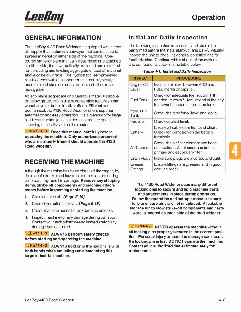
GENERAL INFORMATIONThe LeeBoy 4130 Road Widener is equipped with a front tilt hopper that features a conveyor that can be used to spread material on either side of the machine. Con-toured strike-offs are manually assembled and attached to either side, then hydraulically extended and retracted for spreading and leveling aggregate or asphalt material above or below grade. The hydrostatic, self-propelled road widener with dual operator stations is typically used for road shoulder construction and other resur-facing jobs.
Able to place aggregate or bituminous materials above or below grade, this mid-size convertible features front wheel drive for better tractive efforts. Efficient and economical, the 4130 Road Widener offers superior automation and easy operation. It’s big enough for large road construction jobs, but does not require special licensing due to its size on the roads.
Read this manual carefully before operating the machine. Only authorized personnel who are properly trained should operate the 4130 Road Widener.
RECEIVING THE MACHINEAlthough the machine has been checked thoroughly by the manufacturer, road hazards or other factors during transport may result in damage. Remove any shipping items, strike-off components and machine attach-ments before inspecting or starting the machine.
1. Check engine oil. (Page 5-10)
2. Check hydraulic fluid level. (Page 5-16)
3. Check machine hoses for any damage or leaks.
4. Inspect machine for any damage during transport. Contact your authorized dealer immediately if any damage has occurred.
ALWAYS perform safety checks before starting and operating the machine.
ALWAYS hold onto the hand rails with both hands when mounting and dismounting this large industrial machine.
Initial and Daily InspectionThe following inspection is essential and should be performed before the initial start-up (and daily). Visually inspect the unit to check its general condition and for familiarization. Continue with a check of the systems and components shown in the table below:
Table 4-1. Initial and Daily Inspection
INSPECT PROCEDURE
Engine Oil Level
Maintain oil level between ADD and FULL marks on dipstick.
Fuel TankCheck for adequate fuel supply. Fill if needed. Always fill tank at end of the day to prevent condensation in the tank.
Hydraulic Tank
Check the tank for oil level and leaks.
Radiator Check coolant level.
BatteryEnsure all cables are tight and clean. Check for corrosion on the battery terminals.
Air CleanerCheck the air filter element and hose connections. Air cleaner has both a primary and secondary filter.
Drain Plugs Make sure plugs are inserted and tight.
Grease Fittings
Ensure fittings are greased and in good working order.
The 4130 Road Widener uses many different locking pins to secure and hold machine parts
and attachments in place during operation. Follow the operation and set-up procedures care-fully to ensure pins are not misplaced. A lockable
storage bin to stow strike-off components and hard-ware is located on each side of the road widener.
NEVER operate the machine without all locking pins properly secured in the correct posi-tion. Personal injury or machine damage can occur. If a locking pin is lost, DO NOT operate the machine. Contact your authorized dealer immediately for replacement.
Operation
LeeBoy 4130 Road Widener 4-3
4

Hopper Safety LockThe RW85 Road Widener is equipped with a safety lock on each side of the hopper for added safety and stability during transport and while performing maintenance. (Figure 4-1) The safety lock mechanisms are located on the frame behind each hopper wing, and easily lock into place. The safety locks are only used when using the hopper lift feature. (Page 4-16)
Ensure safety lock is in the unlocked position before raising or lowering the hopper wings to prevent damage to the machine.
LockingMechanism
SafetyLock
Handle
Figure 4-1. Hopper Safety Lock Mechanism
To release or engage the hopper safety lock:
• Raise the hopper as described on Page 4-16.
• Release the hopper safety locking mechanism by pulling on the safety lock handle. You will hear and feel the lock release, and the locking mechanism will rotate forward to its rest on the hopper frame. Raise the locking mechanism slightly until the safety lock pin clicks into the detente. Be sure to check that the mechanism did lock into place before transporting or performing maintenance.
• To release the locking mechanism, pull safety lock handle and rotate to its upper position until the pin snaps into the detente.
STARTING AND STOPPINGIt is important for the operator to be familiar with all the features and functions of the 4130 Road Widener, including the PV480 digital display system (Page 4-8) before operating the machine. It is especially important that operators know and understand the safety warnings in Section 1 prior to operation and heed safety mes-sages throughout the content of this manual. Always inspect the machine before use for optimum operation, safety and performance.
DO NOT leave the operator station unattended while the machine is in gear or in motion.
Verify there are no people, obstacles or other equipment are in the machine’s path before starting the engine. Operator must return joystick to the neutral position and turn the RUN/STOP switch to the STOP position before leaving the operator platform.
ALWAYS wear your seat belt when operating the road widener.
ALWAYS sound the horn to alert others before moving in either direction.
Use caution when mounting and dismounting the operation platform via the ladder on either side of this large industrial machine.
Never allow anyone to climb or stand on the machine. Keep the operator platform clean and free of loose items (tools, coolers, etc.).
Starting the EngineTo start the machine:
1. Ensure the battery master disconnect switch is in the ON position. The red switch is located on the left side of the machine frame, easily accessible on the platform. (Figure 4-2)
Figure 4-2. Master Disconnect Switch
Operation
LeeBoy 4130 Road Widener4-4

2. Adjust the driver’s seat using the adjustment knob on front of the seat and fasten seat belt.
3. Adjust mirror.
4. Ensure the Emergency Stop (E-Stop) button is disengaged.
5. Ensure park brake is engaged or the engine will not start.
6. Place joystick in the NEUTRAL (center) position and the Run/Stop switch in the STOP position.
7. Insert key into the ignition, turn clockwise to the START position and release. The PV480 digital display controller will activate and begin “booting” for a few seconds. (Page 4-8)
8. After the digital display controller boots, turn key clockwise to start the engine.
DO NOT hold the starter longer than 10 - 15 seconds. If the engine does not start, allow the starter to cool two or three minutes.
Using starting additives, such as ether, is not recommended as severe engine damage can occur.
9. Allow engine to warm up a few minutes before moving the machine for more efficient operation.
Be familiar with all the controls and the PV480 digital display information on the fol-lowing pages before driving and operating the road widener.
Stopping the Engine1. Move joystick to the NEUTRAL position.
2. Stop machine motion by pressing on the brake pedal.
3. Engage the park brake switch to the ON position.
4. Turn ignition key counter-clockwise to the OFF position and remove key.
NOTE: If the engine does not shut down when key is turned OFF, press the E-Stop button on the control panel to terminate power.
Before driving on public roads, check state and local laws that may apply to industrial self-propelled machines. Additional lights, mirrors, slow-moving vehicle emblems, or reflectors may be required.
DRIVING THE ROAD WIDENERThe LeeBoy 4130 Road Widener is powered by a diesel engine with a hydrostatic drive system that propels the machine at varying speeds with dynamic braking action. The operator propels the machine using the joystick, steers with the steering wheel, and stops by applying the foot brake. (Figure 4-3)
NOTE: If paving or moving material on the left side with the optional left strike-off assembly, simply slide the main control panel across to that side.
Ensure there are no people, obstacles or other equipment in the path of the machine before moving in either direction.
Be aware of the terrain and driving conditions. Adjust speed accordingly.
1
23
4
5
Figure 4-3. Operator Control Station
1 - Control Panel
2 - Forward/Reverse Joystick
3 - Joystick Locking Collar
4 - Steering Wheel
5 - Foot Brake Pedal
• The park brake must be disengaged.
• The joystick must be in the neutral position and the Run/Stop switch must be in the STOP position. (Figure 4-4)
• The Motor 2-Speed switch is set to LOW gear by default (OFF position). Work ONLY in low gear. (Figure 4-4)
Operation
LeeBoy 4130 Road Widener 4-5
4

NOTE: You can only turn the 2-Speed Transfer switch on and off when the machine is at a complete stop, the joystick is in the neutral position, and the park brake is engaged.
1 2 3Figure 4-4. Run/Stop and 2-Speed Switches
1 - Run/Stop Switch
2 - 2-Speed Switch
3 - 2-Speed Transfer Switch
For faster travel to and from work sites, turn both the Motor 2-Speed and the 2-Speed Transfer switches to the ON position (high gear). (Figure 4-4) The 2-Speed Motor switch should only be used for traveling and never while carrying a load.
NOTE: You can only turn the 2-Speed Transfer switch on and off when the machine is at a complete stop, the joystick is in the neutral position, and the park brake is engaged.
The following table shows the speed accomplished by the combinations of 2-Speed Motor and 2-Speed Transfer switch positions:
Table 4-2.
Engine RPMs
Motor Transfer MPH KPH
1800
OFF OFF 1.9 3
ON OFF 5.1 8.2
OFF ON 3.5 5.6
0N ON 8.8 14.2
2200
OFF OFF 2.5 4
ON OFF 6.9 11.1
OFF ON 4.6 7.4
ON ON 11.9 19.1
NOTE: You can increase work speed by turning the 2-Speed Transfer ON and the 2-Speed Motor switch OFF.
If the Run/Stop switch is set to the RUN position while the joystick is in the NEUTRAL position, or the Run/Stop switch is in the STOP position and the joystick is out of neutral, the system will time-out the control box. You must place the joystick into NEUTRAL and toggle the Run/Stop switch from RUN to STOP and back to RUN again to regain control.
Before leaving the operator platform, return joystick to the neutral position and the Run/Stop switch to the STOP position.
Accelerating and decelerating is proportional to the amount of movement of the joystick (Figure 4-5):
• To drive the machine forward, pull up on joystick locking collar and push forward to reach the desired speed.
• To move in reverse, pull up on joystick locking collar and move backward to reach the desired speed. The back-up alarm will automatically turn on when in reverse.
1. Grasp �rmly.2. Lift up.3. Push forward or reverse.
Figure 4-5. Joystick
• To slow the machine, move joystick closer to the neutral position.
• Return joystick to the neutral (center) position to stop the road widener.
NOTE: If paving or moving material on the left side with the optional left strike-off assembly, simply slide the main control panel and move steering control box across to that side.
Before leaving the operator platform, return joystick to the neutral position and the Run/Stop switch to the STOP position.
Operation
LeeBoy 4130 Road Widener4-6

Differential LockWhen encountering poor road or off-highway conditions where maximum traction is needed, you can engage the Differential Lock switch on the main control panel. (Figure 4-6) This forces both wheels on the axle to turn in unison, providing significantly more traction. Unskilled drivers will need practice as locking the differential can put stress on driveline components if used improperly on terrain that does not require locked differential. This feature should only be used if working on loose, muddy or rocky terrain.
NOTE: The differential lock is intended for limited use as it adversely affects turning ability.
Proceed cautiously when using the differential lock. NEVER exceed 5 mph (8 kph). ALWAYS disengage the differential lock immediately when road conditions improve.
Di�erentialLock Switch
Figure 4-6. Differential Lock Switch
Engage the differential lock ONLY in conditions described above before the wheels start spinning, and ONLY when the vehicle is standing still:
1. Ensure the joystick is in the NEUTRAL position and the park brake switch is turned ON, then turn ON the differential lock switch. The indicator light will illuminate. (Figure 4-5)
2. Proceed cautiously, never exceeding 5 mph (8 kph), keeping in mind steering will be limited.
3. When driving conditions have improved, STOP the vehicle, place joystick in the NEUTRAL position, and turn the differential lock switch OFF.
4. Slowly move forward and resume safe driving speed.
Plus One Controller The Plus One is a 24-pin controller operating in the background that monitors control systems and alerts the operator in the event of a fault. When the Plus One controller senses a system fault, the Plus One light on the control panel illuminates green and blinks continu-ously or blinks, then pauses, then blinks again. (Figure 4-7) A fault code will display on the PV480 with cor-rective action messages are shown in Section 5, Troubleshooting.
Plus One Light
Figure 4-7. Plus One Light
When the key is turned on, the Plus One light will illuminate for approximately three seconds while the controller powers up, then turn off when the machine is ready to start. The Plus One will not allow the engine to start if any joystick is out of neutral or more than one Run/Stop switch is in the RUN position.
These faults will prevent machine movement:
• Joystick is not in neutral at start-up.
• Joystick input is not being detected by the system.
• Joystick not optimized.
• Joystick is in neutral with Run/Stop switch in the RUN position, causing a system safety time-out.
Operation
LeeBoy 4130 Road Widener 4-7
4

PV480 DIGITAL DISPLAY
Main MenuThe Main Menu screen is the first screen to appear on the PV480 digital controller when starting the engine. This is the default screen. (Figure 4-8)
Pressing the “soft key” buttons along the bottom of the controller unit allows the operator to navigate to various other screens. The banner icons along the bottom of the screen correspond with these buttons, and change accordingly when navigating to other screens as described on the following pages. Table 4-3 shows the icons that appear on the banner with descriptions.
Pressing the Set Points button navigates to the Set Point and Throttle Speed screen. (Page 4-10) Pressing the center button ( ) always navigates to the Main Menu screen.
1
2
3
4
5
6
Soft Keys
Figure 4-8. Main Menu Screen
1 - Engine Coolant Temperature
2 - Engine Speed/RPMs
3 - Hydraulic Oil Temperature
4 - Electrical Potential Voltage
5 - Actual Engine Torque Percentage
6 - Soft Key Banner
Soft Keys (Buttons)The following table shows icons appearing on the bottom banner that correspond to the soft key button, depending upon the screen mode. (Some sources may not be present on your model.)
Table 4-3. Soft Key Choices
Icon Description
Displays the default speed (RPMs) set points.
Requests freeze frame data from the ECU when faults are present.
Navigates to the Main Menu screen where you can scroll to choose action items (such as settings and diagnostics).
Use to scroll down through a list of items.
Use to up scroll through a list of items.
Select: Enters the action item selected. Also used to return to the Main Menu from any screen.
Deselect: Closes pop-up messages.
Speed Adjustment: Adjusts throttle speed in increments. Use the (+) button to increase speed or the (-) button to decrease speed.
Increases the engine speed (RPMs).
Decreases the engine speed (RPMs).
Operation
LeeBoy 4130 Road Widener4-8

The main menu screen also displays engine, torque percentage, hydraulic, total hours of operation, and fuel information in the lower left quadrant of the screen. (Figure 4-9)
1
2
3
4
Figure 4-9. Status Quadrant
1 - Oil Pressure
2 - Hydraulic Oil Level
3 - Engine Total Hours of Operation
4 - Fuel Level
Warning lights will illuminate and fault codes may also display:
• The hydraulic oil level or engine oil light is normally illuminated green, but will illuminate red if the hydraulic or engine oil level is too low and display a warning icon on the screen.
• A warning icon will also display if the hydraulic or engine oil temperature is too high.
• Other warning status icons may also illuminate. (Table 4-4)
Table 4-4. Status Icons
Status Icon
Description
Check Engine — When this lamp is illumi-nated, a fault exists within the control system.
Take action immediately to correct the fault.
Parking Brake Switch — The park icon dis-plays when the parking brake is applied.
Transmission Neutral — The neutral icon displays when the transmission is in neutral.
Exhaust High Temperature Lamp — This lamp illuminates to warn of high exhaust temperatures. Be sure engine exhaust is away from any potentially combustible materials if this symbol illuminates.
Alternator. Illuminates when the alternator isn’t charging properly.
Coolant. Illuminates when the engine is running too hot.
Fuel. Illuminates when the fuel tank is almost empty.
Hydraulic Oil. Illuminates to warn operator when the hydraulic oil is too hot.
Oil Pressure. Illuminates when the oil pres-sure is low. A wavy line underneath indicates the engine oil level is too low.
Refer to Section 5, Troubleshooting, for a complete list of Fault Codes.
Operation
LeeBoy 4130 Road Widener 4-9
4

Set Points and Throttle SpeedPressing the Set Points button on the gauge screen navigates to the Set Points and Throttle Speed screen. (Figure 410)
Set PointsButton
Figure 4-10. Navigation to Set Points
Select the desired throttle speed using the keypad buttons. The throttle speed selections are: 1200 RPMs, 1400 RPMs, 1800 RPMs, 2200 RPMs and 2400 RPMs. (Figure 4-11)
1 2 3 4 5
Figure 4-11. Engine Throttle Speeds Screen
DiagnosticsUse the UP/DOWN soft keys and stop the cursor (>) for to view either active or logged diagnostics, then press the Select ( ) soft key. (Figure 4-12)
Figure 4-12. Diagnostics Screen
Operation
LeeBoy 4130 Road Widener4-10

Active Diagnostics
The Active Diagnostics screen displays active warn-ings or faults with the appropriate Suspect Parameter Number (SPN) and Failure Mode Indicator (FMI). (Figure 4-13) It may also display text description and ID/Name of the device that transmitted the message. Use the UP/DOWN soft keys to scroll through list if needed.
Figure 4-13. Active Diagnostics Screen
Logged Diagnostics
The Logged Diagnostics screen displays nonactive warnings or faults with the appropriate Suspect Param-eter Number (SPN) and Failure Mode Indicator (FMI) that are stored in the system. (Figure 4-14) Use the UP/DOWN soft keys to scroll through list if needed.
NOTE: Select the Freeze Frame ( ) button to request that frame data from the ECU when faults are present.
Figure 4-14. Logged Diagnostics Screen
Operation
LeeBoy 4130 Road Widener 4-11
4

System InfoScroll through the Menu list using the UP/DOWN soft keys, then press the select ( ) soft key when the cursor (>) points to the desired information. (Figure 4-15) The screen displays the engine model, serial number, ECU Software ID, fuel rate, and the amount of time since the last active regeneration process was performed.
Figure 4-15. System Info Screen
Press the UP/DOWN soft keys to scroll to the screen with application and configuration information. (Figure 4-16)
Figure 4-16. Application and Configuration Information Screen
User SettingsThis screen displays the following action items: Screen Color; Brightness; Language; Units; Date and Time.
Screen Color
Use the UP/DOWN soft keys and stop the cursor (>) next to the action item Colors. (Figure 4-17 and 4-18) Set your preference for day or night vision using the +/– soft keys.
Figure 4-17. Set Night Vision Color Preferences Screen
Figure 4-18. Set Day Vision Color Preferences Screen
Operation
LeeBoy 4130 Road Widener4-12

Screen Brightness
Use the UP/DOWN soft keys and stop the cursor (>) next to the action item Brightness. (Figure 4-19) Set the brightness of the backlight by using the +/– soft keys.
Figure 4-19. Set Brightness Of Backlight Screen
Language
Use the UP/DOWN soft keys and stop the cursor (>) next to the action item Language. (Figure 4-20) Set your language preference using the +/– soft keys. (English, French, German, Spanish, Italian or Japanese)
Figure 4-20. Set Language Preferences Screen
Units
Use the UP/DOWN soft keys and stop the cursor (>) next to the action item Units. (Figure 4-21) Set your unit preference using the +/– soft keys. (US Standard, Metric kPa or Metric Bar.)
Figure 4-21. Set Unit Preferences Screen
Operation
LeeBoy 4130 Road Widener 4-13
4

Date and Time Setting
Use the UP/DOWN soft keys and stop the cursor (>) next to the action item Date or Time. (Figure 4-22)
• Press the select ( ) soft key to initiate change to the month value. Use the (+/–) soft keys to increment or decrement the number.
• Use the DOWN arrow to reach the day value and year value, using the +/– soft keys to make changes.
NOTE: A reboot is required for changes to the Date Setting to take effect.
Figure 4-22. Time Setting Screen
NOTE: Pressing the “X” button closes the pop-up messages.
COMPONENT OPERATIONRoad wideners are used for a variety of new and existing roadway construction projects, but mostly for building shoulders onto existing travel lanes. Using a road widener to do the shoulder work saves material, time and money: One machine can do the job rather than dumping material along the roadway, followed by a grader to smooth to proper elevation, followed by clean-up machinery. The 4130 Road Widener can do the job, with infinite variations of surface width up to 10 feet (3 meters). Some contractors also use the road widener for placing stone in a trench while installing drainage pipes and large landscaping projects.
It is important that operators understand machine component functions and controls before operating the machine for successful results. Pay attention to the PV480 controller screen on the main control panel for the status of various system components.
Be sure traffic control operations are in place before beginning any road construction project.
Figure 4-23. Operating the 4130 Road Widener
DO NOT allow anyone who is not prop-erly trained for operate this machine.
ALWAYS sound the horn before moving the road widener in either direction and ensure no people are in its path. Serious injury or even death can occur.
DO NOT operate the machine without all locking pins properly secured in the correct position to prevent personal injury and machine damage. If a locking pin is lost, contact your autho-rized dealer immediately for replacement.
NEVER stand or walk between the hopper and material truck. Serious injury or death can occur from being crushed between two large, industrial vehicles.
Operation
LeeBoy 4130 Road Widener4-14

Oscillating Push RollersThe connection between the material truck to the road widener hopper while paving or spreading other mate-rial is the first step for efficient and successful road surfacing. It is the operator’s job to guide the material truck as it backs up to the hopper, and signal the driver when to stop loading the asphalt material. Oscillating push rollers provide the means for the truck to be held in close proximity to the hopper, with the oscillating feature compensating for minor directional misalignment between the two. (Figure 4- 24)
NOTE: Make sure to chain the tailgate on the material truck to prevent damage to the conveyor belt.
PushRollers
Figure 4-24. Push Roller and Material Truck Tire
The truck must be compatible to prevent any interrup-tion of material supply. Always check a truck bed in relation to the hopper before beginning road construc-tion. Adjust truck push rollers to the appropriate height needed for asphalt truck (Figure 4-25):
• There are five (5) set heights on the truck push rollers.
• Remove bolts on both sides of each push roller, align with either of the five slots on the frame at desired height, and reinstall bolts.
• Both push rollers should be at the same height to prevent damage.
BoltSlots
Bolt Slots
Figure 4-25. Adjustable Push Rollers
HopperMaterial is dumped into the hopper where the conveyor at the bottom moves it to the strike-off. The hopper wings are hydraulically opened so the hopper can be filled with material. The 4130 Road Widener features hopper wings that can be individually opened and closed to facilitate material flow onto the conveyor when not connected to a material truck. (Figure 4-26)
Figure 4-26. Right Hopper Wing Closed with Left Hopper Wing Open
Ensure no people, equipment or other obstacles are in or near the hopper when raising or lowering the hopper wings to prevent injury or damage to the machine.
DO NOT close either hopper wing until the material truck has moved completely away from the machine.
A hopper gate on each wing must be manually opened and closed for receiving and discharging material. The gates slide up and down. Be sure the gate is closed when receiving material, and only the strike-off side gate is open when discharging material. (Figure 4-27)
HopperGate
Figure 4-27. Manual Hopper Gates
Operation
LeeBoy 4130 Road Widener 4-15
4

To operate the hopper wings:
1. Be sure the hopper gate is closed on the side opposite the strike-off. The gate at the strike-off should be opened to the level needed to discharge the required amount of material for the job. (Figure 4-27)
2. Use the left and right hopper switches to open and close the desired hopper wing. (Figure 4-28)
• Push the left hopper switch to the OPEN position to open the left hopper wing and to the CLOSE position to close it.
• Push the right hopper switch to the OPEN position to open the right hopper wing and to the CLOSE position to close it.
3. Push BOTH hopper wing switches to the OPEN position for loading material. Ensure both hopper wings are completely open before receiving material from the truck.
1
23
4 5
6
Figure 4-28. Hopper and Conveyor Controls
1 - Conveyor Speed Dial
2 - Conveyor Shift Switch
3 - Conveyor Direction Switch
4 - Left Hopper [Wing] Switch
5 - Right Hopper [Wing] Switch
6 - Hopper Tilt Switch
Hopper Tilt Feature
The 4130 Road Widener offers the unique ability to hydraulically tilt the hopper up at a 32-degree angle for ease of loading and unloading the machine onto ramps for trailer transport. (Figure 4-29) This feature can also be used to prevent damage to the undercarriage when encountering steep terrain. Use the Hopper Tilt switch on the main control panel to move the hopper UP or DOWN. (Figure 4-28)
NOTE: Use the hopper safety lock mechanisms on each side of the hopper during transport or while performing maintenance when the hopper is tilted for additional stability and safety. (Page 4-4)
Ensure safety lock mechanism is in the UP position and the safety lock handle pin is clicked into its detent before raising or lowering the hopper to prevent damage to the machine.
Figure 4-29. Tilt Hopper Feature
DO NOT tilt the hopper with material in it. This feature is intended for LIMITED USE to prevent damage to the machine.
Operation
LeeBoy 4130 Road Widener4-16

ConveyorThe conveyor hydraulically moves material from the hopper to the contoured strike-off, which spreads the material to a controlled width, depth and slope. This independent, variable speed conveyor can move mate-rial to either side of the machine.
When operating the conveyor:
• If paving with asphalt, spray down the conveyor drive chains with a biodegradable release agent before and during operation to prevent material from sticking to components. Asphalt material build-up can cause damage to the machine. (This is not necessary if spreading gravel or other materials.)
• Open the hopper gate ONLY on the strike-off side of the machine to allow material discharge from the conveyor to the strike-off.
• Maintain a conveyor speed that continuously feeds material to the strike-off. This not only helps distribute the material evenly, but reduces wear on the conveyor drive components.
• Irregular movement of the conveyor indicates that the conveyor chains need adjustment. (See Section 5)
Figure 4-30. Conveyor Moving Material to Strike-Off
The conveyor system can be dam-aged by setting the conveyor speed too high, which causes the conveyors to start and stop continuously, which can shock the system.
NEVER leave the road widener unat-tended or allow people in close proximity while the conveyor is operating to prevent serious injury or even death.
Use these conveyor switches on the main control panel (Figure 4-28) to operate the conveyor:
• The Conveyor Shift switch shifts the conveyor to the left ({) or right (}) for discharge through the hopper gate.
• The Conveyor Direction switch controls the belt direction to move material to the left ({) or right (}) side, and should be set in the same direction as the Conveyor Shift switch.
• Adjust the conveyor speed using the Conveyor Speed dial: Turning the dial left decreases conveyor speed while turning the dial right increases conveyor speed.
A foot switch on the platform floor at each operator station provides ON/OFF function for operating convenience while paving or spreading material. (Figure 4-31)
After setting the conveyor direction and adjusting con-veyor speed, simply tap your foot on the pedal to start and stop the conveyor as needed.
Figure 4-31. Conveyor Foot Switch
Operation
LeeBoy 4130 Road Widener 4-17
4

STRIKE-OFF ASSEMBLYThe strike-off smooths the paving material as it passes over, and can be adjusted for slope, angle and width. Depending upon the strike-off arrangement, the road widener is capable of paving widths from one (1) to eight (8) feet (.304 -2.4 m). (Figure 4-32)
Material can be screened gravel, road millings, emulsion mixes, asphalt or low-slump concrete to place or repair shoulders. The 4130 road widener can also be used to fill trenches with stone when placing drainage pipe.
Along with an assistant, assemble the strike-off com-ponents on the desired side of the machine. There are a variety of strike-off configurations, depending upon the job specifications. Adding strike-off blades extends the paving width up to eight feet. Additional extension blades are available options.
Many of the strike-off components are heavy and should be handled with extra care, especially when lifting components, to avoid entan-glement or serious injury. Wear steel-toed shoes and other appropriate safety clothing when working with the road widener. It is recommended at least two people attach and detach the strike-off.
SupportTube
Strike-O�Pivot
1-FootBlade
2- to 3-FootExtendable Blade
Rear MountBracket
Rear Support Beam
EdgerPlate
SlopeCylinder
Endgate Adjuster
Endgate
EndgatePin
Support Turnbuckle
GradeCylinder
Figure 4-32. Strike-Off Components
Strike-Off Pins
Cotter Pin
Strike-Off Pins are important to securing the strike-off and are used
in various locations.
Operation
LeeBoy 4130 Road Widener4-18

(Add optionalblades here.)
Strike-OffMount 1-Foot
Blade(.304 m) 2 to 3-Foot Extendable Blade
(.304 to .9 m)
EdgerPlate
Strike-Off Pin
RearBrace
MountAttach herefor extended
widths
Strike-OffPin
RearMountBracket
1. Insert rear mount bracket into mount tube and align holes:
• Use tube behind front wheel for short widths.
• Use tube in front of rear tire for extended widths.
2. Insert strike-off pin on top to hold mount bracket in place.
3. Insert cabled cotter pin to secure.
1
There are multiple holes on the slope cylinder beam for added slope adjustment:
• If paving or spreading at shorter widths, insert strike-off pin and secure with cabled cotter pin on top hole.
• If paving or spreading at extended widths, insert strike-off pin and secure with cabled cotter pin on lower hole.
2
3
The extension blades are very heavy. Handle with care.
Refer to Figure 4-32 and use the following procedures to install the strike-off attachment (right side shown):
1. Align the four bolt holes on the strike-off mount with the one-foot blade, insert 3/4” - 10 x 2 bolts, flat washers and lock washers.
2. Attach the 2- to 3-foot extendable blade using 3/4” - 10 x 2 bolts and flat washers on the outer side, and flat washers, lock washers 3/4” - 10 nuts on inner side, then optional blades using the same process (if applicable).
3. Attach end plate to outermost blade using 3/4” - 10 x 2 bolts, flat washers and lock washers. Ensure bolts/nuts on each extension blade are tight.
Operation
LeeBoy 4130 Road Widener 4-19
4

Strike-OffPin
Support Beam
Turnbuckle
Align turnbuckle with mount bracket on rear support beam. Insert strike-off pin as shown, then insert pin to secure.
EndgatePin
Endgate
SlopeCylinder
BeamAlign with Plate,Attach with Bolt
Strike-OffPin
4 5
76
1. Align bottom of slope cylinder beam with extendable strike-off blade plate as shown. Attach securely with 3/4”-16 x 2.5 bolt and nut.
2. Insert strike-off pin as shown.
3. Insert cotter pin into strike-off pin to secure.
1. Align the endgate with the edger plate.
2. Insert endgate pin into hinge as shown to secure. This arrangement also allows the endgate to pivot.
Align
Turnbuckle
Support Beam
Endgate
1. Align rear support beam rod end with the bottom edger plate mount bracket. Insert strike-off pin as shown, then insert cotter pin to secure.
2. Align turnbuckle with upper edger plate mount bracket. Insert strike-off pin as shown, then insert cotter pin to secure.
Operation
LeeBoy 4130 Road Widener4-20

• Align one end of the endgate adjuster with mount plate on back of outer blade and the other in one of three holes on the endgate as shown, depending upon the angle needed while paving or spreading material. The endgate adjuster can be readjusted as needed. (See Basic Strike-Off Angles on the following page.)
• Insert cotter pins to secure endgate adjuster onto blade and endgate.
8 9
Strike-OffPin
Support Beam
RearMountBracket
Align other end of rear support beam with rear mount bracket. Insert strike-off pin as shown, then insert cotter pin to secure.
10Endgate Adjuster
Additional Adjustment
Holes
Endgate
Align rear support beam tube with support beam rod and insert strike-off pin, then cotter pin.
Strike-OffPin
Turnbuckle
Support Beam
Operation
LeeBoy 4130 Road Widener 4-21
4

Figure 4-33. Strike-Off Angle
Basic Strike-Off AnglesThe strike-off angle is the angle between the strike-off and the center line of the conveyor. By angling the strike-off correctly, material will flow better and more uniformly across the surface. (Figure 4-33)
It takes experience to understand angling the strike-off for the best material flow from the conveyor across the blades to the endgate. With practice, new operators will learn how to angle and adjust the strike-off for grade, slope and elevation. Job specifications, material type, operating above or below grade, and site conditions are all factors that determine the best angle for the best results. If the strike-off has not been assembled cor-rectly, this will adversely influence the quality of the job.
• Determine strike-off angle before, ensuring the endgate is aligned parallel to the machine.
• Assemble the strike-off to a length that permits a strike-off angle from 30 to 50 degrees for extended widths.
• Adjust strike-off to less than a 30-degree angle for narrow widths.
You can adjust the angle by pivoting the endgate and inserting the endgate adjuster into one of three slots as shown in Step 10 on the previous page. The adjuster rod is also threaded on each side for additional length adjustment if needed. Simply grasp the center and turn to increase or decrease length. (Figure 4-34) With the endgate adjuster installed, simply loosen the nut(s) and slide one or both rods in either direction needed to achieve desired angle.
Grasp the center piece and turn either direction to increase or decrease
length of endgate adjuster.
Figure 4-34. Strike-Off Endgate Adjuster
You can also adjust the length of the support beam to accommodate the strike-off blade configuration and the desired angle, shown in Step 8 on Page 4-20:
1. Remove cabled cotter pin, then remove the strike-off pin and washer.
2. Slide the inner beam out and align slot at the desired support beam length with the outer beam slot as shown in Figure 4-35.
3. Insert strike-off pin and washer, then insert cotter pin to secure.
ExtendableBlade
Slide Inner Rod In or Out
Strike-OffPin
Figure 4-35. Support Beam Adjustment
Operation
LeeBoy 4130 Road Widener4-22

Strike-Off StorageLockable storage bins are located on both sides of the 4130 Road Widener for operator convenience. The bins include a shelf for strike-off blades and two shelves for smaller parts, i.e., pins and bolts, etc. (Figure 4-36)
The 4130 Road Widener uses many different locking pins and nuts/bolts to secure and hold machine parts and attachments in place during operation. Every hard-ware item is necessary for safe and proper operation. Keep all disassembled components in the storage bin(s) when not in use.
An additional remote storage option is also available for storing strike-off blades on the rear of the machine. (Page 4-29)
NEVER operate the machine without all locking pins and nuts/bolts properly secured in the correct position. Personal injury or machine damage can occur. If a locking pin is lost, DO NOT operate the machine. Contact your authorized dealer immediately for replacement.
Figure 4-36. Storage Bin (One on Each Side)
Figure 4-37. Strike-Off Attached for Travel
Travel with Attached Strike-OffIt is not necessary to assemble and disassemble the strike-off while traveling between job sites. The strike-off assembly can be pivoted back toward the rear of the machine and secured to the road widener frame.
NOTE: Attaching the strike-off to the machine frame should only be used when driving short distances. Drive slowly with the strike-off attached.
Ensure the strike-off is securely attached alongside the frame before moving in either direction to prevent personal injury or damage to the machine.
Use the following procedure to pivot the strike-off and attach securely to the frame:
1. Detach the rear support beam from the strike off plate (Page 4-19) by removing the nut and bolt securing it. (Figure 4-38)
Figure 4-38. Detaching Rear Support Beam
Operation
LeeBoy 4130 Road Widener 4-23
4

2. Detach the beam from the mount bracket. Stow the support beam and its associated hardware in the storage bin.
3. Remove locking pin, then the rear mount bracket from its mount behind the front tire. Stow in the storage bin. (Figure 4-36 on Page 4-23)
4. Detach the endgate adjuster by removing the cotter pins securing it, then lifting the adjuster from its mount. Stow adjuster and cotter pins in the storage bin.
Figure 4-39. Detaching Endgate
5. Unbolt and remove the endgate. Stow endgate and associated hardware in the storage bin, retaining one bolt, washer and nut for use in Step 8.
6. Remove clevis pin on top of the strike-off pivot (Page 4-17) and carefully swing the entire strike-off assembly back alongside the machine. (Figure 4-40) Figure 4-40. Pivot Strike-Off Rearward
Operation
LeeBoy 4130 Road Widener4-24

7. Push the clevis pin back down into place.
8. Secure the strike-off using the chain lock on the undercarriage D-Ring. (Figure 4-41)
• Insert strike-off pin into the blade joint as shown in Figure 4-41, then secure with cotter pin.
• Ensure the strike-off assembly is secure before moving in either direction.
Figure 4-41. Securing Strike-Off
Figure 4-42. Road Shoulder Work with the 4130 Road Widener
STARTING TO WORKThe LeeBoy 4130 Road Widener handles a variety of road widening materials and capabilities. Equipped with hydraulic controls and a conveyor that discharges on both sides, it can be operated to spread material from either side to meet any job site requirement. The 4130 strike-offs can surface widths up to eight (8) feet (2.4- meters) at materials heights up to one foot (.305 meter) above or below grade, with the versatility of site prepa-ration for spreading aggregate if needed, then paving road shoulders or other widening projects.
This road widener is capable of placing materials to include:
• Dirt
• Bituminous base.
• Binder or surface course.
• Lime or Portland cement-stabilized sub-base.
• Graded aggregate materials.
Before starting the construction project, keep these items in mind:
• Always pave or spread material in low gear. The Motor 2-Speed switch should be in the OFF position (low gear by default.)
Operation
LeeBoy 4130 Road Widener 4-25
4

• Maintain a consistent speed. Demands on the feeder system change if machine speed changes, which can adversely affect uniformity or mat smoothness. Most defects occur when the machine is stopped.
• If you want a quality pavement job, use quality asphalt material. Sometimes, a thick single coat of high-quality asphalt is better than two thin coats of low-quality asphalt.
• Always clean the machine after use. Asphalt material can build up and damage components. An optional spray down system is available for convenient clean-up. (Page 4-30)
• Keep your road widener and its attachments in good working condition. Perform maintenance as prescribed in this manual (and any accompanying manuals). Equipment issues on the job site costs production time and money.
• Locking pins are important items for strike-off operation. If even one pin is misplaced, DO NOT operate and contact your authorized dealer for replacement.
Avoid low limbs, power lines, and other objects that can endanger crew or machine.
DO NOT operate machine without all locking pins properly secured in the correct position. Personal injury or machine damage can occur.
Keep workers and bystanders at a safe distance from the strike-off when the machine is moving forward or reverse to prevent serious injury or even death.
Figure 4-43. Widening a Road Shoulder
Basic Road Widening1. Assemble strike-off for width of the construction
surface. This can be accomplished on site or prior to leaving for the job site. (Pages 4-18 to 4-21)
2. Slide open the hopper gate on the strike-off side. (Page 4-15)
3. Follow the start-up procedures. (Page 4-4)
4. Set the Conveyor Shift switch to the strike-off side. (Page 4-16)
5. Ensure both hopper wings are completely open for receiving material. If working with material truck, align road widener with the truck to fill hopper with desired material. (Page 4-15)
6. Set strike-off to the desired position using control switches on the main control panel. Use these controls while you pave or spread material to hydraulically position the strike-off. (Figure 4-44)
Operation
LeeBoy 4130 Road Widener4-26

LOADING AND UNLOADINGIf transporting the 4130 Road Widener on a trailer, the ramp and transporting vehicle must be strong enough to safely handle the size and weight of this large indus-trial machine. Park the trailer in a clear, level area when loading or unloading the machine. Use the Hopper Tilt switch on the main control panel to tilt the hopper UP or DOWN.
ALWAYS tilt the hopper completely UP before driving onto ramp. Be alert to uneven sur-faces and the potential reactions when transferring the machine from surface to surface to avoid serious injury or even death.
ALWAYS position an assistant to be a ground guide when loading and unloading the road widener. Work slowly and carefully to avoid acci-dents. Keep the loading area clear.
Use extra caution steering when loading and unloading the road widener as slight steering changes on ramps and trailers can cause the machine to fall off the ramp or transport trailer. Serious injury or even death can result.
Be sure the transport route avoids low bridges and other obstacles that can damage the machine in transit.
If the road widener loses power, you can manually release the park brake on the front axle by loosening the release nuts and screws clockwise. (Figure 4-45)
Release Screw
Release Screw
Loosen nut, then bolt.
Figure 4-45. Front Axle Brake Release Screws
1
2 3 4Figure 4-44. Strike-Off Controls
1 - TopCon
2 - Strike-Off Extension
3 - Strike-Off Grade
4 - Strike-Off Slope
• Use the directional Strike-Off Extension switch to extend and retract the Strike-Off to the needed width of spread.
• Use the Strike-Off Grade and Strike-Off Slope switches to adjust grade and slope (up and down).
7. Set the Conveyor Direction switch to the strike-off direction, using the Conveyor Speed dial to adjust conveyor speed. You can use the conveyor foot pedal switch to turn the conveyor on and off as needed while paving.
8. Move joystick forward and begin surfacing.
Operation
LeeBoy 4130 Road Widener 4-27
4

Loading To prevent damage to the machine
frame and components, reduce speed before wheels come into contact with loading ramps or any abrupt change in the surface. ALWAYS station an assistant to guide and help you align the machine with the ramp. DRIVE SLOWLY.
Center road widener with the ramp.
1. BEFORE moving onto the ramp:
• Ensure all strike-off attachments, mounts and cylinders have been removed or are securely attached to the machine frame.
• Close the hopper wing cylinder valves. (Figure 4-46)
Valve Valve
Figure 4-46. Hopper Wing Cylinder Valves
NOTE: You will not need a wide-load permit if the hoppers are closed during transport.
• Turn the hopper tilt switch to the UP position (tilts hopper upward at a 32-degree angle with 14 inches (35.6 cm) ground clearance).
• Turn the Motor 2-Speed switch to the OFF position (low gear).
2. SLOWLY drive the road widener forward up the ramp to position machine in the center of trailer.
3. Turn the hopper tilt switch to the DOWN position.
4. Secure machine to the transport trailer using the tie-down procedure that follows.
Figure 4-47. Correct Loading and Unloading Position
Unloading1. Remove tie-down equipment.
2. Start the engine and allow machine to warm a few minutes to ensure the hydraulic pump is providing sufficient flow to operate all functions properly.
3. BEFORE backing machine down ramp:
• Turn the hopper tilt switch to the UP position (tilts hopper upward at a 32-degree angle with 14 inches (35.6 cm) ground clearance).
• Turn the Motor 2-Speed switch to the OFF position (low gear).
4. SLOWLY move machine down the ramp.
Tie-Down Procedure1. Position road widener in center of the trailer.
2. Place chocks at wheels to prevent machine movement while securing and during transport.
3. Attach chains to the front and the rear D-Ring tie-downs. (Figure 4-48).
4. Ensure that all chains are tightly secured before transporting the road widener.
D-Ring
D-Ring
Figure 4-48. Tie-Down Locations
Operation
LeeBoy 4130 Road Widener4-28

OPTIONS
Dual Strike-OffAn additional strike-off option for the left side of the machine is also available. (Figure 4-49) This greatly reduces the time required to transfer the basic strike-off from one side of the machine to the other.
Each strike-off cylinder is equipped with 1/4-turn shut-off valves. In order to operate the strike-off on one side, the valves must be closed on the opposite side. If the valves are open when a function switch is used, both sides will operate.
• When the handle is perpendicular to the cylinder, the valve is closed.
• When the handle is parallel to the cylinder, the valve is open.
The dual strike-off option exceeds the commercial vehicle width allowed by federal law on interstate highways. Federal and state statutory pro-visions mandate that vehicle width cannot exceed 102 inches (2.6 m) for this type of vehicle.
Figure 4-49. Left Strike-Off Configuration
Strike-Off Blade Remote StorageOptions for strike-off blade storage on the rear of the RW85 Road Widener are also available in either one-foot (.304 m); three-foot (.9 m) or two- to three-foot extendable (.609 - .9 m). (Figure 4-50) Up to five feet (1.5 m) of strike-off blades can be stored.
Storage Trough Blade
LockingBracket
Ring PinCotter Pin
Storage Pin
Figure 4-50. Remote Storage
Only strike-off blades should be stored in a trough along the bottom of the blade storage bin:
1. Carefully insert blade(s) into the storage trough, leaving enough room for the storage plate to insert last.
2. Slide locking bracket to the tab on top of the strike-off blade(s).
3. Insert storage pin and secure with locking ring pin.
ALWAYS ensure the storage pin is secured with the locking ring pin before driving away to prevent possible damage or injury from the heavy blades falling off the back of the vehicle.
Operation
LeeBoy 4130 Road Widener 4-29
4

Spray Down SystemThe optional spray down system offers a convenient means of keeping road widener components clean. Always spray down the RW85 Road Widener before and after use. (Figure 4-51) Spray any part of the machine that contacts asphalt and other materials with solvent or release agent to prevent buildup that will damage the machine over time.
• Ensure the area is clear of others before spraying.
• Allow the machine to cool down at least 10 minutes before spraying.
Figure 4-51. Spray Down Reel, Hose and Wand
Keep the hose wound tightly on the retractable reel to avoid entanglement.
When using solvents and release agents, consider the environment and DO NOT allow cleaning solvent to run onto the ground. Only spray down the machine in a designated area away from the paving site.
Never spray cleaning solvent or release agent near an open flame. These agents are highly flammable and can ignite, causing serious personal injury.
To operate the Spray Down system:
1. Turn ON the Spray Down switch on the main control panel.
2. Extend hose from the reel. (Figure 4-51)
3. Squeeze the wand handle and spray area. Release the wand handle when finished.
4. Turn the Spray Down switch OFF and rewind the hose back onto the reel.
Start at the front of the machine and work rearward, using a scraper if necessary, paying particular attention to ensuring built-up material is removed from:
• Push Rollers: Rotate the rollers while cleaning and soak bearing ends to maintain free rotation.
• Hopper and Conveyor: Thoroughly clean surfaces and any material accumulating in chains, drive sprockets, bearings and areas exposed to asphalt materials. AFTER cleaning the machine, operate the conveyor briefly to carry solvent into return areas where it can help dissolve hidden asphalt material.
• Operator Platform: Be sure to wash away solvent residue so operator platforms do not remain slippery.
All-Wheel Drive (AWD)The AWD option provides additional traction in all weather conditions. The tires maintain a better grip on the road during rain or snow, in mud, and on gravel. Four-wheel drive provides better torque power for pulling or low-speed climbing and is especially useful when operating on loose, low-traction surfaces. All four wheels turns at the same low speed to power through nearly any obstacle. Four-wheel drive is also beneficial when hauling heavy loads due to the added road trac-tion.
Operation
LeeBoy 4130 Road Widener4-30

Topcon® Sonic Slope and Dual Grade Control
Sonic trackers continuously measure the elevation over the surface, automatically averaging and adjusting the tow point cylinder on the paver. Most states require this technology for state road paving jobs to ensure smooth-ness and continuity on roadways.
If equipped with this option, use the TopCon switch on the main control panel to turn the sonic grade control ON or OFF as needed.
Choose from one of three options: Sonic Grade Control (one side); Dual Grade Control or Dual Grade Control and Slope (both Topcon P-32 systems). The dual grade controls automatically maintain a set depth on both ends of the screed. The Dual Grade and Slope controls maintain a set depth on one end of the screed and a set slope to the other end.
Figure 4-53. Sonic Grade Control
Topcon® sonic grade control, dual grade control and slope options offer paving profes-sionals screed control for improving smooth-ness along with assuring accurate slope and material thickness. These controllers send signals to the screed to precisely maintain mat thickness and slope as you pave.
Magnetic Cup HolderMagnetic cup holders can be purchased for use with your road widener (and other machines in your fleet). (Figure 4-54)
See your authorized dealer for details. Ask for Part Number 1020521.
Figure 4-54. Magnetic Cup Holder
Truck HitchThe truck hitch is an optional attachment that prevents excessive and uneven braking from the material truck. (Figure 4-52) The truck hitch replaces the push roller extension capability. Use the Push Roller switch to engage and disengage the truck hitch.
Figure 4-52. Truck Hitch Attachment Option
To engage the hitch with the rear wheels of the asphalt truck:
1. Use the Truck Hitch switch on the main control panel to operate.
2. Extend the arm extensions of the truck hitch by pushing and holding the Truck switch in the OUT position.
3. The paving material truck then SLOWLY backs up to the machine until the hitch makes contact with the rear tires of the truck.
4. Retract the arm extension by pushing and holding the Truck Hitch switch in the IN position until both guide rollers are fully locked onto the truck wheel rims.
NOTE: It may be necessary to adjust the roller guides to the inside of the wheel rims.
Umbrella OptionThe umbrella kit option provides shelter from sun and other weather conditions for the operator. The umbrella kit assembly includes the mounting bracket and umbrella frame assembly that can be mounted on either side of the operator platform.
Operation
LeeBoy 4130 Road Widener 4-31
4

NOTES
Operation
LeeBoy 4130 Road Widener4-32
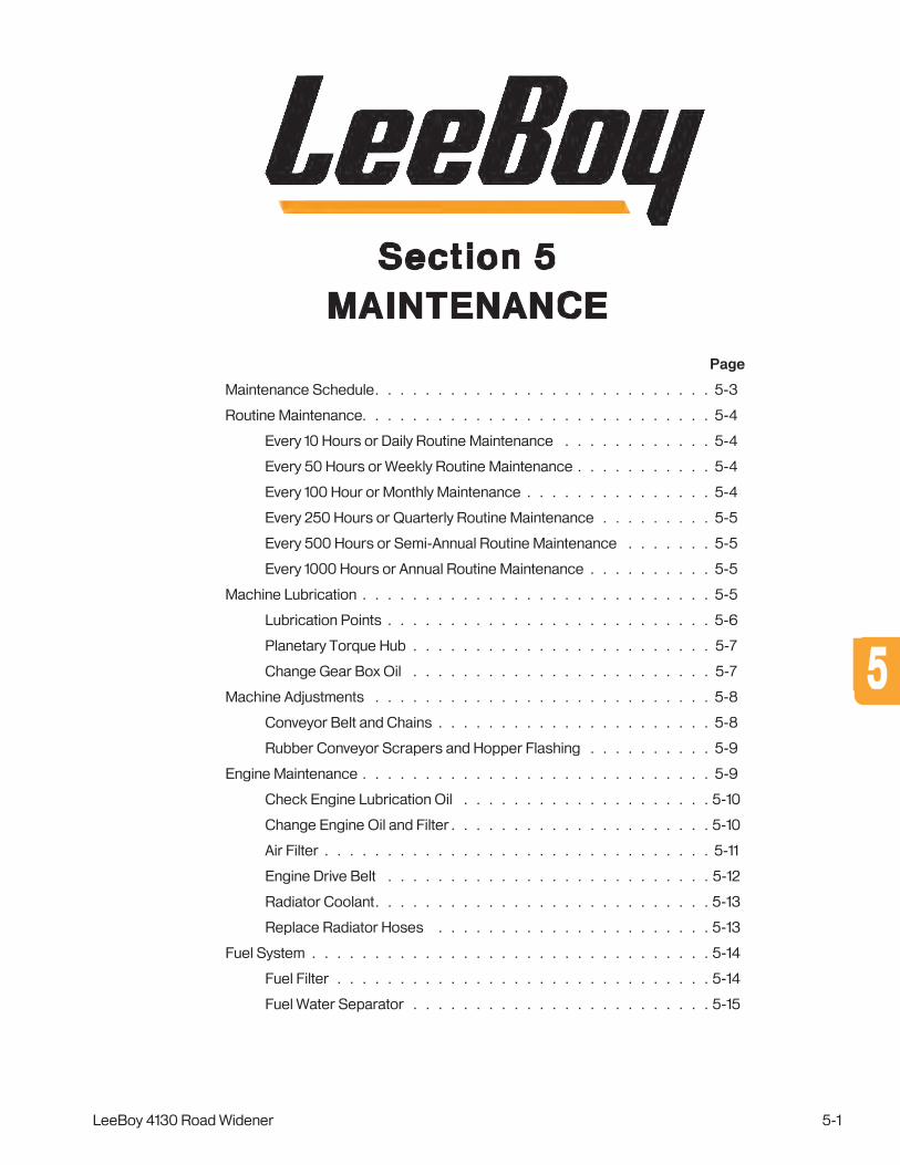
Page
Maintenance Schedule . . . . . . . . . . . . . . . . . . . . . . . . . . . 5-3
Routine Maintenance . . . . . . . . . . . . . . . . . . . . . . . . . . . . 5-4
Every 10 Hours or Daily Routine Maintenance . . . . . . . . . . . . 5-4
Every 50 Hours or Weekly Routine Maintenance . . . . . . . . . . . 5-4
Every 100 Hour or Monthly Maintenance . . . . . . . . . . . . . . . 5-4
Every 250 Hours or Quarterly Routine Maintenance . . . . . . . . . 5-5
Every 500 Hours or Semi-Annual Routine Maintenance . . . . . . . 5-5
Every 1000 Hours or Annual Routine Maintenance . . . . . . . . . . 5-5
Machine Lubrication . . . . . . . . . . . . . . . . . . . . . . . . . . . . 5-5
Lubrication Points . . . . . . . . . . . . . . . . . . . . . . . . . . 5-6
Planetary Torque Hub . . . . . . . . . . . . . . . . . . . . . . . . 5-7
Change Gear Box Oil . . . . . . . . . . . . . . . . . . . . . . . . 5-7
Machine Adjustments . . . . . . . . . . . . . . . . . . . . . . . . . . . 5-8
Conveyor Belt and Chains . . . . . . . . . . . . . . . . . . . . . . 5-8
Rubber Conveyor Scrapers and Hopper Flashing . . . . . . . . . . 5-9
Engine Maintenance . . . . . . . . . . . . . . . . . . . . . . . . . . . . 5-9
Check Engine Lubrication Oil . . . . . . . . . . . . . . . . . . . . 5-10
Change Engine Oil and Filter . . . . . . . . . . . . . . . . . . . . . 5-10
Air Filter . . . . . . . . . . . . . . . . . . . . . . . . . . . . . . . 5-11
Engine Drive Belt . . . . . . . . . . . . . . . . . . . . . . . . . . 5-12
Radiator Coolant . . . . . . . . . . . . . . . . . . . . . . . . . . . 5-13
Replace Radiator Hoses . . . . . . . . . . . . . . . . . . . . . . 5-13
Fuel System . . . . . . . . . . . . . . . . . . . . . . . . . . . . . . . . 5-14
Fuel Filter . . . . . . . . . . . . . . . . . . . . . . . . . . . . . . 5-14
Fuel Water Separator . . . . . . . . . . . . . . . . . . . . . . . . 5-15
LeeBoy 4130 Road Widener 5-1
MAINTENANCESection 5
55

Hydraulic System . . . . . . . . . . . . . . . . . . . . . . . . . . . . . 5-16
Check Hydraulic Oil Level . . . . . . . . . . . . . . . . . . . . . . 5-16
Change Hydraulic Oil and Filter . . . . . . . . . . . . . . . . . . . 5-17
Change Hydraulic Oil Cap Strainer . . . . . . . . . . . . . . . . . . 5-18
Hydraulic Test Ports . . . . . . . . . . . . . . . . . . . . . . . . . 5-19
Electrical System . . . . . . . . . . . . . . . . . . . . . . . . . . . . . . 5-20
Battery Servicing . . . . . . . . . . . . . . . . . . . . . . . . . . . 5-20
Battery Electrolyte Level . . . . . . . . . . . . . . . . . . . . . . . 5-21
Lighting . . . . . . . . . . . . . . . . . . . . . . . . . . . . . . . 5-21
Alternator Servicing . . . . . . . . . . . . . . . . . . . . . . . . . 5-21
Dielectric Grease . . . . . . . . . . . . . . . . . . . . . . . . . . 5-22
Fuse Box Panel . . . . . . . . . . . . . . . . . . . . . . . . . . . 5-22
Chassis and Miscellaneous . . . . . . . . . . . . . . . . . . . . . . . . 5-23
Tires . . . . . . . . . . . . . . . . . . . . . . . . . . . . . . . . 5-23
Replacement Procedures . . . . . . . . . . . . . . . . . . . . . . . . . 5-24
Battery . . . . . . . . . . . . . . . . . . . . . . . . . . . . . . . . 5-24
Hydraulic Pumps . . . . . . . . . . . . . . . . . . . . . . . . . . . 5-25
Conveyor Belt . . . . . . . . . . . . . . . . . . . . . . . . . . . . 5-26
Conveyor Shaft, Bearings and Sprockets . . . . . . . . . . . . . . 5-28
Conveyor Shaft, Bearings and Sprockets . . . . . . . . . . . . . . 5-28
Conveyor Drive Motors. . . . . . . . . . . . . . . . . . . . . . . . 5-29
Winterizing for Storage . . . . . . . . . . . . . . . . . . . . . . . . . . . 5-29
Periodic Maintenance in Storage . . . . . . . . . . . . . . . . . . . 5-30
Removing from Storage . . . . . . . . . . . . . . . . . . . . . . . 5-30
Welding on Machine . . . . . . . . . . . . . . . . . . . . . . . . . . . . 5-31
Troubleshooting . . . . . . . . . . . . . . . . . . . . . . . . . . . . . . 5-32
Hydraulic Motor Installation Start-Up Procedure . . . . . . . . . . . 5-32
Conveyor Chain Tension Slack Adjustment . . . . . . . . . . . . . . 5-33
Spraydown Pump (Option) . . . . . . . . . . . . . . . . . . . . . . 5-34
Troubleshooting Chart . . . . . . . . . . . . . . . . . . . . . . . . 5-35
PV480 Diagnostic Trouble CodeS (DTC) Chart . . . . . . . . . . . . 5-39
PV480 Troubleshooting . . . . . . . . . . . . . . . . . . . . . . . 5-44
Plus One Blink Codes . . . . . . . . . . . . . . . . . . . . . . . . . . . 5-45
Maintenance
LeeBoy 4130 Road Widener5-2

Maintenance
LeeBoy 4130 Road Widener 5-3
MAINTENANCE SCHEDULEBefore performing any maintenance procedures on the LeeBoy 4130 Road Widener, review the safety information in Section 1.
Always wear heat-resistant gloves when handing hot components.
Following the maintenance schedules and procedures will maintain the machine in top operating condition.
Refer to the Engine Operator’s Manual accompanying your machine for more detailed engine service informa-tion.
When performing any routine maintenance, always include the previous routine maintenance hours in the higher hourly schedule.
Table 5-1. Periodic Maintenance Schedule
SYSTEM ITEM
Eve
ry
10 H
our
s (D
aily
)
Eve
ry
50
Ho
urs
(Wee
kly)
Eve
ry
100
Ho
urs
(Mo
nthl
y)
Eve
ry
25
0 H
our
s (Q
uart
erly
)
Eve
ry
50
0 H
our
s (S
emi-
Ann
ual)
Mechanical
Check conveyor belt and chains. Adjust or replace if needed.
X
Check tire pressure. Add more air if needed.
X
Grease steering axle. X
Grease strike-off pivots and bearings. X
Hydraulic
Check hydraulic oil level. Add if needed. X
Replace hydraulic oil and charge filter. X
Check planetary hub gear oil. Add if needed.
X
Change planetary hub gear oil. X
Check drive axle oil. Add if needed. X
Change drive axle oil. X
Engine
Check oil level - Change engine oil at initial 50 hours of operation.
X X
Replace engine oil and oil filter element.
Check engine coolant. Add more if needed.
X
Change engine coolant. X
Check air filter indicator gauge. Clean or replace air filter elements if indicator is red.
X
Change air filter elements. X
Check engine drive belt. Tighten or replace if needed.
X
ElectricalCheck battery, cables and connectors. X
Service battery. X
FuelReplace fuel filter. X
Drain fuel water separator. X
55

Maintenance
LeeBoy 4130 Road Widener5-4
ROUTINE MAINTENANCEPreventive maintenance on the road widener will provide years of trouble-free operation. Adjustments can be performed in the field with ordinary tools. Engine preventive maintenance, (other than oil, air and fuel filter changes), can be found in the Engine Operator’s Manual. Refer to any additional manuals included with your machine for maintenance on other components.
Before performing any maintenance procedures, review Safety in Section 1. Follow the maintenance schedules and procedures to maintain the machine in top operating order.
NOTE: When performing any routine maintenance, always include previous routine maintenance procedures to the higher hourly schedule.
Tool Hazard! ALWAYS use tools appropriate for the task. Be sure to use the correct sized tool for loosening or tightening parts.
If any maintenance must be per-formed while the engine is running, DO NOT leave the machine unattended.
NEVER spray cleaning solvent on hot surfaces as serious injury can result.
Keep the fuel tank full to prevent con-densation. Always fill tank at the end of the day.
DO NOT operate a machine that is in need of repair. Put an information tag on the instrument panel that says “DO NOT OPERATE” and remove key from the ignition switch. Repair all damage promptly as even minor damage can result in major system failures.
ALWAYS wear eye protection when using compressed air to prevent injury.
Changing oils or coolant, greasing components and cleaning the machine should only be done in a designated area where the oils, filters and chemicals can be contained. These by-products should be discarded in accordance with environ-mental regulations.
Every 10 Hours or Daily Routine Maintenance 1. ALWAYS clean the belt and scrapers of accumu-
lated material after use. Remove any dirt or debris before operating the machine.
2. Check coolant level. Add more if needed. (Page 5-12)
3. Inspect air intake hoses and clamps. Check air filter indicator gauge. Clean or replace filter element if indicator is red. (Page 5-11) Check hydraulic hoses for leaks and wear.
4. Check hydraulic oil level. Add more if needed. (Page 5-16)
5. Check battery cables and connectors. Remove any corrosion present. (Page 5-20)
6. Check conveyor belt alignment. Adjust if needed (Page 5-8)
7. Check for loose, missing, damaged or corroded parts. Repair or replace as needed.
Every 50 Hours or Weekly Routine Maintenance1. Check engine oil level. The FIRST 50 HOURS,
change engine oil and filter, then every 500 hours thereafter. (Page 5-10)
2. Check tire pressure. Add more air if needed. (Page 5-21)
3. Grease steering axle pivot. (Page 5-6)
4. Grease strike-off pivots and bearings. (Page 5-6)
5. Drain fuel water separator. (Page 5-15)
6. Perform previous routine maintenance and any other engine preventive maintenance described in the Engine Operator’s Manual.
Every 100 Hour or Monthly Maintenance1. Check engine belt. Tighten, repair or replace if
needed. (Page 5-12)
2. Check conveyor chain. Adjust if needed. (Page 5-8)

Maintenance
LeeBoy 4130 Road Widener 5-5
3. Perform previous routine maintenance and any other engine preventive maintenance described in the Engine Operator’s Manual.
Every 250 Hours or Quarterly Routine Maintenance1. Replace fuel filter. (Page 5-14)
2. Change engine oil and filter. (Page 5-10)
3. Change the hydraulic oil and charge filter. (Page 5-17)
4. Replace air filter element. (Page 5-11)
5. Check planetary torque hub gear oil. Add more if needed. (Page 5-7)
6. Perform previous routine maintenance and any other engine preventive maintenance described in the Engine Operator’s Manual.
Every 500 Hours or Semi-Annual Routine Maintenance1. Replace engine coolant. (Page 5-13)
2. Service battery. (Page 5-20)
3. Change transfer case oil. (Page 5-7)
4. Change drive axle oil. (Page 5-7)
5. Perform previous routine maintenance and any other engine preventive maintenance described in the Engine Operator’s Manual.
Every 1000 Hours or Annual Routine Maintenance1. Replace strainers in the hydraulic tank and in the
hydraulic filler cap. (Pages 5-17 and 5-18)
2. Replace fuel water separator filter. (Page 5-15)
3. Drain and flush radiator. (Page 5-13)
4. Perform previous routine maintenance and any other engine preventive maintenance described in the Engine Operator’s Manual.
MACHINE LUBRICATIONProper lubrication is necessary to maintain the machine at top efficiency. Use a high-quality multi-purpose grease for optimum performance.
It is also important to grease the king pin bushings, tie rod ends, steering cylinder rod and steering axle pivot bushings every 100 hours of service. Also grease the drive-shaft universal joints and slip yoke every 100 hours of service using a multi-purpose grease.
Also check the gear oil level in in the planetary hub and drive axle regularly. Fill if needed. Change the drive axle oil once a year. (Page 5-7)
Use jack stands on a solid, flat surface to prevent the machine from tipping when it is raised. Block the remaining wheels using sturdy wheel chocks. DO NOT lie under the road widener while supported only by a jack. Death or serious injury can result from improperly supporting a raised machine.
Use the following procedure for greasing components:
1. Locate and clean the single grease fitting at each of the lubri-cation points.
2. Apply one shot of grease to each fitting with a manual (hand) grease gun.
3. Wipe away any excess grease.
55

Maintenance
LeeBoy 4130 Road Widener5-6
Lubrication PointsProper lubrication is critical to maintaining the machine at top efficiency. Use the lubrication information shown below to keep your machine in optimum condition:
Figure 5-1. Lubrication Points
ITEM
NO.
TYPE LUBE
DESCRIPTION AND LOCATION
INTERVALA Grease With Shell Avania EP Grease 2 or Equivalent
B Spray with Copper-Based Release or Chain Lube Agent
1 A Gear Box Quarterly
2 A King Pin Steering Pivot Knuckle (Both Sides) Weekly
3 A Planetary Hub (Both Sides) Quarterly
4 A Strike Off Pivots (Both Sides if Equipped) Daily
5 B Extendable Strike-Off Blade Slides Weekly
6 A Conveyor Shaft Couplings (1 at each conveyor motor) Quarterly
7 A Conveyor Shaft Bearings (2 on each side of conveyor) Quarterly
1
3
2
4
5
6
7
7

Maintenance
LeeBoy 4130 Road Widener 5-7
Planetary Torque HubThe torque hubs should be checked periodically to ensure they contain the proper amount of gear lube. Two drain/fill plugs are located on the outer end of each hub. The torque hub is mounted on each side of the front axle. Allow the hub to cool if needed.
You will need an assistant to properly check the gear oil level:
1. With assistance from a ground guide, slowly drive the machine forward until the torque hub plug is at the 3 o’clock or 9 o’clock position. (Figure 5-2)
Plug
Figure 5-2. Torque Hub Plug in 9 O’Clock Position
2. Shut off the engine and apply park brake.
3. Unscrew the planetary hub plug.
4. Oil should be level with bottom of plug hole.
5. Fill if needed and reinsert plug.
6. Replace the level plug.
7. Allow the axle to sit level for at least five minutes to allow the oil to flow to the hubs.
8. Remove the level plug and check oil level.
9. Add more oil if needed.
To change the oil, slowly move machine until the torque hub plug is at the 6 o’clock position, apply the park brake, remove plug, drain and reinsert plug. Then move machine slightly forward so the hub plug is in the position shown in Figure 5-2, remove plug, fill with oil and reinsert the plug.
Change Gear Box OilCheck the drive axle gear box oil level quarterly and fill if needed. Change the oil every year for optimum performance. (Figure 5-3)
Drain Plug
FillPlug
Figure 5-3. Change Drive Axle Oil
To change the drive axle oil:
1. Remove the level plug in the center of the drive axle housing.
2. Remove the breather plug inside the housing.
3. Add oil until it starts coming out of the level plug.
4. Replace the level plug.
5. Allow the axle to sit level for at least five minutes to allow the oil to flow to the hubs.
6. Remove the level plug and check oil level.
7. Add more oil if needed. 55

Maintenance
LeeBoy 4130 Road Widener5-8
Adjustment Bolt
Conveyor Motor
LockNut
Figure 5-4. Belt Tension Adjuster
There are four (4) adjustment bolts, one on each side of the conveyor. Use the following procedure to adjust the conveyor belt and chains:
1. Loosen the adjustment nut on each side of the adjustment bolts. (Figure 5-4)
2. Loosen the locking nut beside the adjustment bolt.
3. Repeat Steps 1 and 2 on the each side of the con-veyor belt until all four are loose. (Figure 5-4)
4. Turn each adjustment bolt alternately the same amount. For example, turn one bolt one half turn, then the other bolt one half turn, etc. Continue alternating tightening until the chains are tight. (The pressure on the chain will be noticeable as the bolts are tightened.)
5. After the conveyor chain tension is set, retighten locknuts and bolts.
6. Grease conveyor shaft bearings at grease point on each side of conveyor (Lubrication Chart, #6, Page 5-6).
MACHINE ADJUSTMENTSCertain components of the machine need adjustments for optimum performance, operation and general maintenance.
Entanglement hazard! NEVER perform machine adjustment while the engine is running.
Use only LeeBoy parts if replacing rubber conveyor components. Using hard rubber, old conveyor belts or any other rubber containing fabric or reinforcement will cause rapid conveyor belt wear and eventual failure.
Loose clothing or long hair can be entangled in machine components. Wear protective clothing, stay clear of rotating shafts and use caution when adjusting conveyor belts and other rotating components.
DO NOT adjust any conveyor compo-nent during operation.
Conveyor Belt and ChainsProper alignment and tension adjustment of the conveyor belt and chains is necessary to deliver proper system operation and achieve maximum life from the components. Normal working stress will cause the conveyor belts to stretch over time.
The conveyor belt and chains must be adjusted every 100 hours for optimum performance. (Figure 5-4) If you notice any conveyor chain misalignment or belt slack, an adjustment is needed regardless of the time interval to prevent premature belt wear or damage to other components. (See Page 5-31 for Slack Tension Adjustment information.)
To check for belt slack, examine the side of the belt running under the load. Belts with too much slack will bounce enough to contact the conveyor frame.
NOTE: If the conveyor adjustment bolt has reached its maximum adjustment level, remove the half link in the conveyor chain. This repair should bring the adjustment bolts back to full travel.
Keep conveyor chains properly oiled with cleaning solvent or release agent during cold weather to keep it functioning smoothly.
Make small initial adjustments, checking the adjustment before making another adjustment to avoid overshooting the desired setting.

Maintenance
LeeBoy 4130 Road Widener 5-9
Rubber Conveyor Scrapers and Hopper FlashingHeavy-duty rubber flashing and scrapers are mounted in various locations on the hopper and around each side of the conveyor that are important for operation. The rubber conveyor scrapers, deflectors and hopper flashing occasionally need adjustment due to use.
Rubber conveyor scrapers are mounted under the conveyor to reduce asphalt build-up by “scraping” the conveyor belt as it moves material. Rubber flashing strips are mounted at an angle above each side of the conveyor belt to prevent material spillage. Large rubber deflectors are mounted on each side of the machine frame below the conveyors to deflect material away from the front tires. Rubber flashing along the top of the hopper helps prevent spillage while loading material and enhances contact with the material truck. (Figure 5-5)
Scraper
De�ectors
HopperFlashing
AngledFlashing
Figure 5-5. Rubber Scrapers and Flashing
Adjust the rubber components when needed:
1. Loosen the mounting bolts on the hold-down bar holding the rubber flashing (or scraper).
2. Slide rubber flashing (or scraper) into its original position behind the hold-down bar.
3. Retighten bolts.
To replace, remove the mounting bolts, hold-down bar and worn rubber component, replacing with new rubber strip. Contact your authorized LeeBoy dealer for any replacement rubber component.
ENGINE MAINTENANCEThe 4130 Road Widener features the latest in engine technology. Tier 4 Final engines comply with emission requirements established by the U.S. Environmental Protection Agency (EPA) to reduce diesel and other toxins released into the air. This engine features advanced technology using a cooled Exhaust Gas Recirculation (EGR) and Diesel Oxidation Catalyst (DOC) after-treatment system for emission reduction. The system cleans combustion from engine exhaust by simple, flow-through oxidation in the exhaust stream. This emission control system does not require any regeneration procedures or maintenance. (Figure 5-6)
The engine is easily accessible from either side of the machine. The diesel engine manufacturer recommends several engine-specific maintenance inspections every 250 hours, or every three months. Refer to the Engine Operator’s Manual for more specific maintenance information and procedures. You can access the engine and other components via access panels on both sides of the engine compartment located on the machine platform.
DOC
Pumps
Air Filter
FuelFilter
WaterSeparator
Radiator
Figure 5-6. Engine Components
55

Maintenance
LeeBoy 4130 Road Widener5-10
Change Engine Oil and FilterThe engine lubrication oil and oil filter must be changed at the same time. The oil filter is easier to reach on the right side of the engine compartment.
Change the engine lubrication oil while the engine is WARM, not hot. Hot oil can cause serious personal injury.
DO NOT change the engine lubrication oil filter while the engine is running. Serious engine damage will occur.
To change the engine lubrication oil:
1. Park the machine on a level surface and turn off the engine.
2. If needed, wait until the engine lubrication oil has cooled a little. Oil should be warm, not hot.
3. Place a large container underneath the engine oil drain plug.
4. Remove oil plug under engine and allow oil to drain completely, then reinsert plug.
5. Wipe the area around the oil filter and its mounting base with a clean cloth and move the container under the oil filter.
6. Use a filter removal wrench to remove the oil filter, turning counterclockwise.
7. Drain and discard the oil filter, including the rubber gasket.
8. Wipe inside the oil filter head using a clean, lint-free cloth.
9. Rub a little oil on the rubber gasket area of the new filter element.
10. Fill the new filter with fresh oil.
11. Install the new filter element onto the filter head. Carefully tighten the filter (by hand only).
12. Refill the 2.8 standard engine with 9.4 quarts (8.9 liters) of oil at the oil fill cap.
• Refill with 15.4 quarts (14.6 liters) of oil at the oil fill cap if equipped with the optional 3.8 engine.
13. Check oil level using the oil dipstick.
14. Dispose of used oil and filter element in accordance with local and federal environmental laws.
Check Engine Lubrication OilThe engine lubrication oil must be kept at a level above the ADD mark, but not above the FULL mark, on the engine lubrication oil dipstick. (Figure 5-7)
To accurately check the engine oil level, park the machine on a level surface and stop the engine.
DO NOT check the oil while the engine running. Hot oil can spew and cause serious injury.
Engine OilDipstick
Figure 5-7. Engine Oil Dipstick
Wait five minutes after engine shutdown before removing the dipstick from the engine to assure oil level accuracy. This also prevents filling the engine with too much oil.
To check the engine lubrication oil level:
1. Park the machine on a level surface and turn off the engine.
2. Wait five minutes to allow the oil to return to the oil pan so you can obtain an accurate measurement of the engine oil level.
3. Open engine access door on left side.
4. Clean the area around the engine oil dipstick before removing it from the engine.
5. Remove the dipstick from the engine and checking the oil level. The oil level should be above the ADD mark--but not above the FULL mark--on the dipstick.
6. Add oil if needed.

Maintenance
LeeBoy 4130 Road Widener 5-11
Air Filter Turbo-charged engines are especially demanding on air filter performance. The operator should always be aware of the condition of the air filter system. To prolong engine life and prevent contaminants from entering the engine, inspect the air intake system components daily for damage, cracked hoses or loose clamps.
An air filter restriction indicator is mounted on the left side of the engine compartment and should be checked regularly. As the air filter becomes clogged, the air pressure increases, causing the air filter indicator to illuminate. If the red indicator is visible, it is important to clean or replace the air cleaner elements immediately to avoid possible engine component damage. (Figure 5-8)
Figure 5-8. Filter Indicator
Proper disposal of a dirty air filter is essential to preventing collected debris from becoming airborne once again. Carefully remove the air filter element, put it in a plastic bag, then tape or tie the bag before disposing into a trash receptacle.
The heavy-duty engine air filter system is mounted above the engine inside the engine compartment. (Figure 5-9) The filter cover is conveniently located on the right side of the engine compartment, with no need to open the access panel when cleaning or replacing the filter elements. Clean the filter by soaking in a non-sudsing detergent for 15 minutes (do not exceed 24 hours), then rinse thoroughly.
Be sure to clean the inside of the air cleaner body before replacing the air filter elements. Be careful not to introduce any contaminants into the engine intake tube.
Figure 5-9. Air Filter
As the air filter becomes more clogged, the air pressure increases, causing the indicator to illuminate. When this occurs, the air filter must be cleaned or replaced as follows:
1. Turn off the engine.
2. Open clamps securing the cover on the filter housing, then remove the cover. (Figure 5-9)
3. Following instructions on the cover label, remove the primary and secondary filter elements.
4. Replace with the new filter elements.
5. Reinstall cover and secure with the clamps.
6. Reset the filter indicator by pressing button on top of the indicator. (Figure 5-8)
NEVER operate machine without the air filter elements to prevent destruction of the engine.
55

Maintenance
LeeBoy 4130 Road Widener5-12
Engine Drive BeltThe engine belt drives the alternator and the cooling fan. Check the engine belt daily for any damage. The engine drive belt must be replaced if the belt appears frayed, punctured, badly cracked or breaks. Belt damage can be caused by:
Belt damage can be caused by:
• Incorrect tension.
• Incorrect size or length.
• Pulley misalignment.
• Incorrect installation.
• Severe operating environment.
• Oil or grease on the side of the belt. Tensioner
Alternator
Crankshaft Pulley
Idler Fan Pulley
WaterPump
Idler-OR-
(AC CompressorOPTION)
Figure 5-10. Engine Belt
Engine must be turned off and the wheels blocked to prevent motion when servicing the machine to prevent serious injury or death.
Inspect the drive belt for damage regularly. Inspect the belt grooves for debris, uneven/excessive rib wear or exposed belt cords. Inspect the back side of the belt for glazing (high heat), debris or exposed belt cords. Cracks across the width of the belt are acceptable, but cracks along the length of the belt intersecting with cracks across the width must be replaced.
To replace the belt:
1. Turn off engine and block the wheels to prevent movement while working on the machine.
2. Using a 3/8-inch square drive, rotate tensioner in the direction shown in Figure 5-10 to relieve pres-sure on the belt. Remove the belt.
NOTE: The spring-loaded belt tensioner must be pivoted away from the drive belt. Pivoting in the wrong direction can damage the tensioner.
3. Inspect the tensioner, idler and drive pulleys for dirt, wear and cracks.
NOTE: Do not confuse build-up road dirt with wear. Remove any debris from the grooves of the pulleys, clean, check and reuse all pulleys if not damaged rather than replacing. If pulleys are damaged, replace before operating.
4. Route the new drive belt as shown in Figure 5-10, except over the water pump pulley.
5. Rotate tensioner in the direction shown in Figure 5-9, then finish installing the belt, routing the belt over the water pump pulley LAST.
6. Slowly release the tensioner to apply tension to the drive belt.
7. Check the alignment of the belt with the tensioner and the rest of the front-end accessory drive.
8. Start the engine and listen for belt “squeal,” which indicates belt slippage. If you hear the belt squealing, recheck the routing to ensure it is installed correctly on each pulley.
Check the engine belt tensioner, pulley and arm for cracks every 500 hours. If either component shows damage, register or log onto the Cummins engine website for access to additional engine information:
https://quickserve.cummins.com/info/index.html

Maintenance
LeeBoy 4130 Road Widener 5-13
Radiator CoolantCheck the radiator coolant level daily to ensure the radiator is full and that no debris is present that could block the system and cause overheating. (Compressed air can be used to remove any debris from the radiator.) You can access the radiator surge tank fill cap behind the radiator grill at the rear of the machine. (Figure 5-11)
When the engine is cold, the coolant level should cover the radiator core. If low, fill with a solution of 50 percent water and 50 percent ethylene-glycol antifreeze.
The coolant system should be drained and replaced at least once a year to prevent rust and scale from possibly building up and clogging the system. Any commercial flushing agent can be used. (See your Engine Operator Manual for more information).
DO NOT remove the radiator cap while the engine is hot. The radiator is under pressure and the hot water will cause serious injury.
Avoid prolonged and repeated skin contact with used antifreeze as contact can cause skin disorders or injury. Wash thoroughly after any contact.
To check the radiator or add coolant:
1. Remove the radiator grill to access the radiator surge tank cap. (Figure 5-11)
2. Remove the cap to check ONLY WHEN UNIT IS COOL. Coolant level should be visible.
3. Visually check coolant level sight glass. If coolant level is low, add coolant. DO NOT overfill.
Radiator
Fill Cap
Drain Plug
HoseClamp
Clamp
Level Sight Glass
Figure 5-11. Radiator (Left Side)
Replace Radiator Hoses Radiator hoses should be replaced if worn or frayed. (Figures 5-11 and 5-12) Replacement parts and hose schedule are listed in Section 7, Illustrated Parts List (IPL).
This procedure should only be per-formed when the equipment is not operating.
1. Turn off ignition, remove key, and allow the engine to cool down before proceeding:
2. Remove the radiator surge tank fill cap.
3. Remove drain plug and drain radiator into a suitable container (5.5 gallons or 20.8 liters). (Figure 5-12)
4. Remove upper hose first by loosening the hose clamps and disconnect. If clamps are not damaged, retain for installation. (Figures 5-11 and 5-12)
5. Remove lower hoses by loosening the hose clamps and disconnect. If clamps are not damaged, retain for installation.
6. Install new lower hoses first, then upper hose, ensuring clamps are tight.
7. Refill with coolant and reinsert fill cap.
Radiator Hose
Clamp
Radiator Hose
Figure 5-12. Radiator (Right Side)
55

Maintenance
LeeBoy 4130 Road Widener5-14
FUEL SYSTEMProper maintenance of the fuel system ensures top performance and prevents damage to internal engine components. The fuel tank is located on the left side of the machine behind the operator station. An opening on the platform above the fuel tank provides access to the green fuel filler cap. (Figure 5-13)
NEVER fill the tank, check fuel level or check for fuel leaks near an open flame or near equipment that can create sparks. DO NOT SMOKE near the machine, especially while fueling. Fill the fuel tank only in a designated area where there is good ventilation and a fire extinguisher available.
Avoid skin contact and breathing diesel fuel fumes. Immediately wash hands (or any other area) that comes into contact with diesel fuel.
Use only low-sulfur diesel fuel in this machine. Any other type of diesel fuel can damage engine and other components.
Fuel CapFuel CapAccess
Figure 5-13. Fuel Cap Location
NOTE: Always fill the fuel tank FULL after use to reduce moisture accumulation and prevent condensation in the tank. Fuel contaminated by water promotes the growth of microbes that can clog fuel filters and lines over time.
NEVER loosen a fuel injector line as contents are under high pressure. DO NOT try to bleed air by loosening injector lines.
Fuel FilterProper maintenance on the fuel system ensure top performance and enhances fuel economy along with preventing damage to internal engine components. The fuel filter is located on the exterior (right side) of the engine compartment above the fuel water separator. (Figure 5-14)
Diesel fuel is very flammable. Use extra caution and DO NOT spill fuel. DO NOT change the fuel filter while the machine is running. DO NOT change the fuel filter in an area near an open flame. DO NOT smoke while changing the fuel filter.
Fuel Filter
Fuel WaterSeperator
Figure 5-14. Fuel Filter and Fuel Water Separator
Replace the fuel filter using the following general procedures:
1. Stop the engine.
2. Put a container under fuel filters before removing the filter elements.
NOTE: Consider the environment when discarding used filters and do so according to safe and lawful practices.
3. Wipe the area around the fuel filter elements and element mounting heads using a clean, lint-free cloth.

Maintenance
LeeBoy 4130 Road Widener 5-15
4. Use a filter removal wrench to loosen and remove fuel filter elements by turning in a counterclockwise direction. Drain and discard the removed elements.
5. Wipe the inside area of the filter heads with a clean, lint-free cloth. Fill the new fuel filter elements com-pletely with clean fuel.
6. Put clean fuel onto the element rubber gaskets.
7. Install the new fuel filter elements onto the filter heads. Carefully tighten the elements (by hand only).
DO NOT overtighten the fuel filter ele-ments onto the filter heads.
8. Start the engine and check for ANY fuel leaks.
STOP the engine immediately if any fuel leakage is noted. DO NOT start the engine until the leakage problem is corrected.
Fuel Water SeparatorWater and dirt that gets into fuel settles into the water separator. (Figure 5-15) As it collects, a red float rises. When the float reaches the line on the separator, an error code will appear on the PV480 digital display. It is important to drain it immediately.
If you run out of fuel, it is important to pump the water separator to prime fuel injection lines. Failure to do so can adversely affect perfor-mance.
To drain the water separator:
1. Pull retainer clip from plug to disconnect the harness.
2. Unplug the harness, then unscrew the plug.
3. Drain and reinsert components.
1
2
3
4
Figure 5-15. Water Separator
1 - Pump
2 - Filter Body
3 - Plug
4 - Clip
To clean the water separator:
1. Follow the previous steps for draining the water separator.
2. Loosen and remove the filter body and clean it with light oil.
3. Reinsert and tighten.
55

Maintenance
LeeBoy 4130 Road Widener5-16
HYDRAULIC SYSTEMThe hydraulic system is composed of two major component groups--the hydrostatic drive and the auxiliary hydraulic group. The hydraulic motors and cylinders use the same hydraulic oil reservoir and hydraulic oil supply. Solenoid valves, flow-control valves, dividers and other components allow simultaneous function and control of all hydraulic systems. A 61-gallon hydraulic tank with suction strainers, charge pressure and return filters stores and cleans the hydraulic fluid. An oil cooler is mounted on the machine to complete the hydraulic system.
The hydrostatic drive group consists of an axial piston hydrostatic pump coupled to the rear of the diesel engine. A high-torque hydraulic motor drives the planetary front axle. The auxiliary hydraulic group consists of a single load-sense pump mounted on the rear of the drive pump. Independent circuits to the hydraulic motor are provided for the conveyor drives, steering system, power brakes and hopper.
The hydraulic tank is located on the right side of the machine. An opening on the platform above the hydraulic tank provides access to the hydraulic oil strainer cap for adding hydraulic oil. (Figure 5-18)
Take care when working with the hydraulic system to ensure it is completely clean.
ALWAYS use an equivalent grade of hydraulic fluid. Using hydraulic fluids that do not have equal characteristics can result in substandard performance or possible failure of the hydrostatic system. Contact your authorized LeeBoy dealer if you need assistance.
ALWAYS wear eye protection when inspecting for leaks in the hydraulic system. Never use your hands to locate leaks as hydraulic fluid under pressure can pierce the skin and cause serious injury and toxic reaction.
NEVER attempt makeshift repairs using tape, clamps or cements in the hydraulic system. The system operates under extremely high pressure and such repairs could fail, causing serious injury.
Inspect the machine daily for hydraulic leaks. Check that all fittings are secure and tight every week. If leaking fluid is found, it is probably on the pressure side of the hydraulic system. DO NOT OPERATE the machine until any hydraulic leak detected has been repaired.
Stop the engine immediately if any hydraulic leak is noted. DO NOT start the engine until any problem noted has been corrected.
Leaks on the suction side of the hydraulic system are more difficult to find and more serious since air or dirt introduced into the system causes rapid component wear and eventual failure. Some symptoms of suction leakage are:
• Hydraulic fluid “foaming.”
• Sluggish system operation.
• Unusual noises in the hydraulic pumps or motors.
Check Hydraulic Oil Level Oil level is determined by the sight gauge on the hydraulic tank. (Figure 5-16) Hydraulic oil should be added if the oil level falls below the fill line. Never fill above the black fill line.
SightGauge Fill Strainer Cap
Figure 5-16. Hydraulic Gauge
1. Make sure that the hoppers are retracted so that oil flows to the tank, ensuring an accurate reading.
2. Wait 10 minutes after engine has been shut down before checking hydraulic oil.
Use extreme caution when removing the filler cap to prevent foreign matter from entering the hydraulic tank.
3. If level is low, clean around the hydraulic oil filler cap before removing to add hydraulic oil to the tank.

Maintenance
LeeBoy 4130 Road Widener 5-17
4. Fill tank to the black fill line on sight gauge.
5. Screw the hydraulic oil filler cap back onto the hydraulic tank.
6. Fill the hydraulic oil tank with filtered hydraulic oil. The cold oil level should be about 1/2-inch below the fill level black line on the sight gauge. (Figure 5-16)
7. Reinstall the hydraulic oil strainer filler cap.
8. Start the engine and check the hydraulic system for possible leaks.
Change Hydraulic Oil and FilterChanging the hydraulic oil removes the accumulation of dirt, water and mechanical wear particles from the hydraulic oil reservoir and system. The chemical structure of hydraulic oil changes after continuous use, therefore, new oil is important to ensure correct operation of the hydraulic system.
Never let the hydraulic oil tank run dry. Pump damage will occur.
Condensation can also build up in the hydraulic system and clog the filter elements. This could lead to insufficient hydraulic oil at the pump and degrade performance, causing damage to components.
Change the hydraulic oil and return filter after the first 100 hours of use, then every 500 hours or seasonally, whichever comes first. Also remove and clean the suction strainer (located in back of tank) at 500-hour intervals. (Figure 5-17)
Use the following procedures to change the hydraulic oil and filter:
1. Stop the engine. Allow the hydraulic oil to cool until it is at a warm temperature.
2. Slowly loosen and remove the hydraulic oil reservoir filler cap (Figure 5-16). Put a clean, lint-free cloth over the reservoir fill tube opening and secure in place with tape.
DO NOT drain the hydraulic oil from the reservoir when it is HOT. Hot hydraulic oil can cause serious injury. Drain at a warm temperature only.
3. Carefully remove the plug from bottom of the hydraulic tank. Use a drain collection container of sufficient capacity to collect the hydraulic oil under-neath. Allow all of the hydraulic oil to drain into the container.
4. Check the hydraulic suction strainer in the bottom of the hydraulic oil tank. Clean with solvent and a stiff fiber brush if necessary. (Figure 5-17)
DO NOT fill the hydraulic oil reservoir with new hydraulic oil unless the suction strainer has been cleaned.
5. Install the hydraulic oil reservoir drain plug and tighten securely.
Hydraulic Filter
Strainer
Filler CapStrainer
Drain Plug
Figure 5-17. Hydraulic Return Filter and Suction Strainers
6. Unscrew hydraulic oil filter, remove filter element and replace with new filter element. (Figure 5-18)
7. Carefully remove the cloth from the hydraulic oil res-ervoir fill tube opening.
8. Refill the hydraulic oil reservoir (recommend Citgo All Weather/All Temperature Multiviscosity hydraulic oil).
9. Check the oil level at the sight gauge and add more if needed.
DO NOT over-fill the hydraulic oil reservoir with oil.
FilterCap
Seals
Filter
FilterCover
Figure 5-18. Hydraulic Oil Filter
55

Maintenance
LeeBoy 4130 Road Widener5-18
10. Replace the hydraulic oil fill strainer cap onto the reservoir filler neck and tighten securely.
11. Start the engine and operate hydraulic controls several times.
12. Check the hydraulic system for any leaks.
13. Carefully remove the cloth from the hydraulic oil reservoir fill tube opening.
14. Refill the hydraulic oil reservoir (recommend Citgo All Weather/All Temperature Multiviscosity hydraulic oil).
15. Check the oil level at the sight gauge and add more if needed.
16. Replace the hydraulic oil fill strainer cap onto the reservoir filler neck and tighten securely.
17. Start the engine and operate hydraulic controls several times.
18. Check the hydraulic system for any leaks.
Change Hydraulic Oil Cap StrainerThe oil strainer is mounted in the hydraulic oil filler opening under the filler cap. (Figure 5-17)
DO NOT remove the hydraulic filler cap from the reservoir when it is hot as this can cause serious injury. Allow hydraulic oil to cool down to a warm temperature.
To change the hydraulic oil strainer:
1. Remove the hydraulic oil filler cap.
2. Remove the six (6) screws securing the strainer, then remove the strainer and gasket.
3. Install a new gasket, aligning the six screw holes in the gasket with the mounting holes on the reservoir.
4. Install the new strainer, aligning the holes in the strainer with the mounting holes of the gasket and secure the strainer with the six screws.
5. Fill the hydraulic oil reservoir with (recommend Citgo All Weather/All Temperature Multiviscosity hydraulic oil).
6. Check the oil level in the hydraulic oil reservoir. Add oil if needed.
7. Reinstall the hydraulic oil filler cap and tighten securely.

Maintenance
LeeBoy 4130 Road Widener 5-19
Hydraulic Test PortsHydraulic valve manifolds are one of the most complex components of the system. Situated on a manifold “block,” these valves regulate the directional, pressure and fluid flow between pumps and other components for the machine’s hydraulic systems. If the hydraulic pressure is too high, the system will use excessive energy and the fluid may overheat, stressing components and possibly cause damage. If the hydraulic pressure is too low, cylinders or even the hydraulic motor could stall.
Hydraulic test ports on the manifolds provide an easy and convenient means of checking hydraulic pressure for machine systems. Remove the platform cover(s) between the seats to access the three manifolds. (Figure 5-19)
Wear gloves and DO NOT reach hands between the front tire and frame to access manifolds as the engine must be running for proper reading. Burns or serious injury may result.
Adjusting pressure relief without sufficient training in hydraulic system maintenance and safety can result in damage to the machine or serious injury.
To check pressure:
1. Remove platform cover(s) between seats to access manifolds as shown in Figure 5-19.
2. Connect the appropriate pressure gauge to the port being tested. (Figure 5-19)
3. Start the engine, then check gauge for the proper pressure reading.
4. Refer to Table 5-2 below the correct pressure relief readings. If the hydraulic pressure is too high or low, adjustment is needed. Contact your authorized LeeBoy dealer for service.
NOTE: Be sure to use the appropriate sized gauge for pressure PSIs shown in Table 5-2.
Table 5-2. Hydraulic Test Ports
Manifold PSI Relief / Gauge
Main Cylinder Relief set at 2500 PSI.
Conveyor/Steering
Relief set at 2500 PSI.
Brake/2-SpeedRelief 250 - 400 PSI. Pressure will change based upon engine RPMs.
TestPort
Brake/2-Speed
TestPort
Conveyor/Steering Main Cylinder
TestPorts
(2)
Figure 5-19. Hydraulic Test Port Locations
55

Maintenance
LeeBoy 4130 Road Widener5-20
ELECTRICAL SYSTEM
Battery ServicingThe electrical system is a 12-volt negative ground system with the battery located on the left side of the machine in front of the rear tire. (Figure 5-20)
NOTE: The electrical system is a negative ground system. Connect the positive (+) cable to the positive (+) post of the battery. Connect the ground cable to the negative (-) post of the battery. It is advisable to disconnect the negative (-) cable first and reconnect it last. Reversed polarity can damage the electrical system.
DO NOT attach the negative (-) cable from the booster battery to the negative (-) post of the dead battery because a spark could cause an explosion.
BatteriesFigure 5-20. Battery Location
Clean terminals and battery posts thoroughly and check that battery cable terminals are tight. Dirty or loose connections can create high electrical resistance and permit arcing, which will quickly burn and pit terminals and posts.
Keep the battery clean by washing it off whenever dirt buildup is excessive. If corrosion is present around terminal connections, remove them and wash with ammonia solution or a solution consisting of 1/4 lb. (11 kg) baking soda added to one quart of warm water. Make certain the vent caps are tight to prevent solution from entering the cells. After cleaning, pour clean water over the battery and surrounding area to wash the solution away. Check vent cap breather openings to make sure they are open.
Batteries contain sulfuric acid and normally produce explosive gases that can cause
serious injury. Even the fumes can cause an explosion. DO NOT allow flames or sparks to come near the battery.
When charging or working near a battery, always shield your face and protect your eyes. In case of acid contact with skin or eyes, flush immediately with water for a minimum of 15 minutes and get prompt medical attention. If acid is swal-lowed, call a physician immediately.
When replacing the battery, discard the old battery properly. Before connecting the battery, be sure the Master Disconnect switch is turned off. The red switch is located on the left side of the machine frame, easily accessible on the platform. (Figure 5-21)
When servicing the electrical system or welding on the machine, always turn the Master Disconnect switch to the OFF position to disconnect the ground strap from the battery to prevent damage to the machine electrical system.
Figure 5-21. Master Disconnect Switch (Off Position)
Be sure to keep the battery fully charged during cold weather to keep it from freezing. Freezing weather has little effect on a fully charged battery.
When connecting a booster battery, if necessary for cold weather starting, connect one end of the first jumper cable to the positive (+) terminal of the dead battery and the other end to the positive (+) terminal of the booster battery. Connect one end of the second jumper cable to the negative (-) terminal of the booster battery and the other end to the frame of the machine with the dead battery.

Maintenance
LeeBoy 4130 Road Widener 5-21
Battery Electrolyte Level NOTE: If water is added to batteries during freezing
weather the battery must be charged immediately to prevent freezing. Charge battery using a battery charger or by running the engine.
1. If using serviceable batteries, fill each cell to speci-fied range with distilled water. DO NOT overfill.
2. Check battery charge and charging rate.
3. Shut down machine by turning ignition switch key counterclockwise to the OFF position.
4. Using a multimeter, check the battery charge by placing the positive (red) multimeter lead on the positive (+) battery terminal, and the negative (black) multimeter lead on the grounded (-) battery terminal. With the multimeter set at the 12 VDC setting, the battery should show a charge of at least 12 volts. If not, charge the battery or perform a load test.
5. Start the engine. From the operator’s seat, check the battery charge level. The multimeter should read at least 13.5 volts. If the multimeter does not indicate minimum charge, check the machine charging system.
LightingInspect lights for proper operation daily. If a light or group of lights does not function:
• Check the fuse box panel for a blown fuse.
• Examine all visible wiring connections, ensuring they are not frayed or damaged, and securely fastened.
• Check lighting mounts for proper ground.
• Remove light lens or casing and check bulb. Replace if needed.
• Inspect wiring harness for damage (see Schematics in Section 6).
If broken wires are found, solder together and cover with a shrink-wrap type of plastic covering (preferred) or electrician’s tape to prevent contamination of the solder joint by moisture.
If you make any repairs to the wiring harness, always replace or repair the protective loom covering the wiring to prevent future damage to the wiring harness. Examine the routing of the harness and ensure it is not subjected to excessive movement, which often causes broken wiring.
Alternator ServicingThe alternator supplies electrical current for charging the battery that provides electrical power to electronic controls. The built-in regulator in the alternator controls the voltage output. (Figure 5-22)
Figure 5-22. Alternator
If the wires must be disconnected from the alternator, be sure to mark them for proper reconnection.
Use the following precautions to prevent damage to the alternator for any maintenance performed:
• Always disconnect the battery before disconnecting or connecting the alternator.
• An alternator should never be polarized. DO NOT ground any alternator terminals or circuits.
• Never disconnect the alternator while the machine is operating.
• Be certain the wiring is properly connected before connecting the battery.
• Always connect a booster battery in the proper polarity: negative (-) to negative (-) and positive (+) to positive (+).
55

Maintenance
LeeBoy 4130 Road Widener5-22
Dielectric GreaseDielectric grease is a nonconductive, insulating compound applied to electrical connectors. When applied correctly, a high-quality dielectric grease displaces debris and moisture in the connector. The proper application of dielectric grease fills any gaps between pins or in the connector which prevents debris and moisture from creating corrosion of the electrical components.
Equipment damage can occur if using low-quality, incompatible dielectric grease.
If not applied or incorrectly applied, corrosion can result that causes rapid increase in resistance, intermittent connections, overheating, and a variety of electrical problems. Numerous electrical issues throughout the machine can be avoided by the proper application and use of dielectric grease.
Figure 5-24. Correct Application of Dielectric Grease
Fuse Box Panel The electrical system is protected from overload damage by fuses. If an electrical component fails to operate, check the fuse panel first to ensure that a fuse has not “blown.” The fuse box panel is located inside the main control panel. See the following table for Corresponding fuse information is shown at (Figure 5-23.
A blown fuse is an indication that there is an overload that needs to be corrected. If you replace a fuse, but it continues to blow, contact your authorized LeeBoy dealer.
Always replace a blown fuse with the same rating as specified. Never replace with a higher amperage rating. Damage to the electrical system or fire can occur from improper fuse replace-ment.
SLOPEGRADE
CONVEYORSHIFT
SPARE
15A
DIFFERENTIALLOCK
10A
HOPPERTILT
10A
PROPEL +1
10A
HOPPERWINGS
10A
LIGHTSBEACON
20A15A
PARKBRAKE
10A
2-SPEED
10A
SERVICEBRAKE
10A
CONVEYORSPEED
20A
HORN
10A
TOPCON
10A
DISPLAY
5A
SPRAY DOWN
20A
PUSHROLLER
10A
REARSTEER
10A
Figure 5-23. Fuse Panel and Fuse Sizes

Maintenance
LeeBoy 4130 Road Widener 5-23
CHASSIS AND MISCELLANEOUS
TiresThe tires should be maintained at the proper tire pressure and checked daily. (Figure 5-26) Tires should be maintained at 90 - 110 PSI. However, various operating speeds, road conditions, material truck size, tire options and other operating conditions may require different tire pressure.
Only a qualified tire specialist should service the tires.
• Use 385/65R Duplex Radial tires on the rear.
• Use 425/65R 22.5 Duplex Radial tires on the front.
• The lug nuts on the front and back tires are M22 x 1.5.
If a tire appears to be low, measure the pressure to be sure of proper inflation. Protect tires from exposure to petroleum products and other chemicals.
• Use proper tire mounting equipment and experienced personnel for tire repair service.
• Carefully inspect any tire and rim assembly for damage before inflating tire.
Figure 5-26. Properly Inflated Tire
To correctly apply dielectric grease:
• Apply a thin, visible, uniform coat using ONLY high-quality dielectric grease (Dow Corning 4 or equivalent) across the MALE connector as shown in Figure 5-24.
• Coating too thin may not fill the gaps between pins.
• Coating too thick may prevent proper connection or force pins or seals out. (Figure 5-25)
• Plug in the male connector.
DO NOT force connector to lock if too much grease has been applied.
Excessive grease application does not allow a proper connection by preventing the plugs from locking into place, and can cause damage to the connector seals.
Figure 5-25. Incorrect Application of Dielectric Grease
55

Maintenance
LeeBoy 4130 Road Widener5-24
The rim and tire assemblies for the wheels are very heavy and must be supported when lug nuts are removed.
Never exceed the tire manufacturer’s maximum recommended inflation pressure.
Never cut or weld on inflated tire/rim assembly. Heat from welding can cause an increase in pressure and may result in tire explosion.
Use jack stands on a solid, flat surface to prevent the machine from tipping when it is raised. Block the remaining wheels using sturdy wheel chocks. DO NOT lie under the machine while sup-ported only by a jack. Death or serious injury can result from improperly supporting a raised machine.
To replace the tires:
1. Loosen lug nuts.
2. Release any air that remains in the tire.
3. Use a jack or hoist to lift the side of the machine.
4. Place supports under the machine.
5. Attach a sling or other support to the tire.
6. Remove the 10 lug nuts from the wheel.
7. Release any air that remains in the tire.
8. Using standard tire removal tools, remove the tire from the wheel.
9. Install new tire on the wheel.
10. Measure PSI using tire pressure gauge and inflate to the proper PSI.
11. Align the mounting holes with the studs on the hub.
12. Reinstall the 10 lug nuts.
13. Torque the lug nuts in a diagonal pattern to 670 ft-lb (910 N•m).
14. Remove supports and lower jack.
REPLACEMENT PROCEDURES
Battery Batteries create explosive gases
when charging. DO NOT expose these gases to sparks or open flame during maintenance. Always perform battery service in a well-ventilated area or outside. Serious injury can occur from exploding batteries.
When installing batteries, always install the positive cable first followed by the negative cable. Reversed polarity can damage the electrical system.
1. Remove the black ground (-) cable from the nega-tive (-) battery terminal, followed by the red (+) cable from the positive (+) battery terminal. (Figure 5-27)
Batteries
Figure 5-27. Batteries Location
If the negative cable is grounded during removal, sparks will not occur. If the positive cable is grounded during removal, sparks will occur and could ignite explosive gases.
2. Remove the hold down bar.
3. Inspect the batteries for cracks, wear and damage that could result in leaks.
4. Carefully remove the batteries from the battery plate, noting battery position during removal.

Maintenance
LeeBoy 4130 Road Widener 5-25
DO NOT dry batteries using com-pressed air. Allow the batteries and surrounding area to dry. Battery acid can cause severe injury if blown into the face or other areas of the body. If injury occurs, seek medical attention immediately. Flush eyes and skin for 30 minutes with clean water.
5. Make sure the battery cells are sealed. Clean the batteries, battery tray, cables, and brackets with baking soda and warm water. Allow to air dry.
6. Place the batteries in proper position in the battery tray.
7. Install hold down bar. Tighten bar to retain battery, but not so tight as to damage battery.
8. Install red (+) battery cable to the positive (+) battery terminal.
9. Install the black (-) battery cable to the negative (-) battery terminal.
10. Reattach the battery box cover and reconnect the battery box locks.
Hydraulic PumpsHydraulic fluid is transmitted throughout the machine to motors and cylinders, becoming pressurized according to the resistance present. Hydraulic pumps play a significant role in producing hydraulic power as they pump hydraulic fluid to system components
The hydraulic gear pumps (and motors) generally do not require regular maintenance. (Figure 5-28) Frequent inspection for leaks will indicate the need for service of these components. If a problem develops with a pump or motor, contact your authorized dealer for assistance.
Load Sense Pump
EDC Pump
Figure 5-28. Hydraulic Pumps
Use the following procedure for replacing either of the gear pumps:
1. Access the pump slated for replacement.
2. Label and disconnect the hoses to the pump, capping the fitting on the pump.
3. Label, plug and cap the hoses.
4. Remove the two screws on the pump mount (one on each side of mount).
5. Lift the pump assembly out of the machine and place on a flat surface.
6. Remove and inspect the O-ring(s) on end of the pump for wear or damage. Replace if needed.
7. Put a small amount of hydraulic oil onto the O-Ring and reinstall.
8. Align the mounting holes with the mounting on the pump.
9. Reattach with the two mounting screws and torque to 89 ft. lbs. (12 N•).
10. Remove plug caps and reconnect hydraulic hoses to pump as previously labeled.
11. Check hydraulic oil level. Add more if needed.
12. Start the road widener and check to be sure there are no hydraulic oil leaks.
13. Let machine idle approximately 10 minutes to allow the pump and motor cases to fill with hydraulic oil. 55

Maintenance
LeeBoy 4130 Road Widener5-26
Conveyor Belt The conveyor belt is extremely heavy,
therefore, it will require more than one person to replace the belt.
NOTE: When installing a new belt, it’s easier to use the old belt to pull the new belt onto the conveyor pulleys as described below.
Ensure nobody is near the operator platform while replacing the belt to prevent someone from inadvertently stepping on the conveyor switch pedal, which is functional while the engine is running. Serious injury or even death could occur if the con-veyor is engaged while changing the belt.
Use the following procedure to replace the conveyor belt:
1. Ensure the park brake is engaged and the Run/Stop switch is in the STOP position.
2. Start the engine and raise the hopper wings. Lock both hopper wing cylinders using the hopper cylinder valves. (Figure 5-29)
Valve ValveFigure 5-29. Hopper Wing Cylinder Valves
3. Remove bolts and washers and rubber skirt hold-downs along both sides of the conveyor. (Figure 5-30) Remove rubber skirt from each side of the conveyor belt.
Skirt Hold-Down Rubber Skirt
Figure 5-30. Rubber Skirt Removal
4. Turn the hopper tilt switch to the UP position to tilt hopper completely. This will allow more room for maneuvering the heavy belt.
5. Place the conveyor belt speed drive completely left to the MIN (minimum) position. Be sure it remains in the MIN position while replacing the belt.
6. Using the foot pedal, move the conveyor belt until the belt joint is on the underside of the conveyor near the head pulley as shown in Figure 5-32 on the following page. The underside of the conveyor belt is not as tight, which will make it easier to maneuver the belt as needed.
7. Turn off the engine.
8. Loosen the four bolts on the outer and the four bolts on the inner sides of all four conveyor bearing blocks (16 bolts total).
BearingBlock
Tension Adjustment Bolt
Figure 5-31. Conveyor Bearing Block and Tension Adjustment Bolt

Maintenance
LeeBoy 4130 Road Widener 5-27
Head Pulley Head
Pulley
ConveyorMotor Conveyor
Motor
Pulleys
Conveyor ChainConveyor
Motor Mount
ConveyorMotor Mount
ConveyorBearing Block
Sprocket
ConveyorBearing Block
Belt Lacing(Underside)
Sprocket
Figure 5-32. Conveyor Pulleys and Components Overview
9. Loosen all four of the chain tension adjustment bolts on all four conveyor bearing blocks (16 total). (Figure 5-31)
10. Remove the belt joint lacing pin to disengage the belt.
11. Move each conveyor chain toward one head pulley to more easily access its chain master link. Remove clip to remove the master chain link.
12. Rotate each conveyor chain away from the assembly and remove from the head pulley sprocket. (Figure 5-32)
13. Attach one end of the new belt to the top of the old belt. Attach the belts together with the joint lacing pin.
14. Start the engine and slowly move the conveyor at MIN (minimum) conveyor speed using the foot pedal to thread the new belt around the pulleys while removing the old belt.
15. Stop the machine when the joint end of the new belt is on top of the pulley group. (Figure 5-32)
16. Remove the joint lacing pin and pull the old belt clear of the machine. Dispose of old belt.
17. Secure the two ends of the new belt together by reinserting the joint lacing pin.
18. Retighten tension adjustment bolts on each side of conveyor (four).
19. Retighten bearing block bolts on all sides (16)
20. Reinstall rubber skirt and hold-downs. (Figure 5-30)
21. Adjust and center the belt following the conveyor belt adjustment procedures on Page 5-8.
NOTE: Refer to Conveyor Chain Adjustment Slack in the Troubleshooting section at end of Section 5.
55

Maintenance
LeeBoy 4130 Road Widener5-28
Stop Block
ConveyorMotor
Figure 5-34. Conveyor Stop Block
8. Slide the conveyor motor and its mounting bracket out of the shaft coupling, then remove coupling.
9. Remove the four bolts on the outer and the four bolts on the inner sides holding the bearing block onto the conveyor frame on both sides. (Figure 5-31 on Page 5-26)
10. Slide head pulley tube and shaft assembly from the frame.
11. Insert new head pulley assembly and bearing block into the frame slot and reinstall the bolts. (Figure 5-33)
12. Torque bearing block bolts to 44 ft. lbs. (60 N.m).
13. Realign and install shaft coupling, then reinstall con-veyor motor and its mounting bracket.
14. Reinstall stop block. (Figure 5-34)
15. Grease bearing at grease fitting. (Page 5-6)
16. Reinstall the conveyor chain master link.
17. Adjust tension using the adjustment bolt. Check that the belt is properly adjusted and centered following the conveyor belt adjustment procedures on Page 5-8.
NOTE: Refer to Conveyor Chain Adjustment Slack in the Troubleshooting section at end of Section 5.
Conveyor Shaft, Bearings and Sprockets 1. Loosen chain tension adjustment bolts. (Figure
5-30)
Head PulleySprocket
ConveyorMotor
Head PulleyShaft
(inside head pulley tube)
Bearing
AdjustmentBolt
Head PulleySprocket
Figure 5-33. Conveyor Shaft, Bearings, Sprockets and Drive Motors
Conveyor Shaft, Bearings and Sprockets 1. Ensure the park brake is engaged and the Run/Stop
switch is in the STOP position.
2. Start the engine and raise the hopper wing on the side for component replacement. Lock both hopper wing cylinders using the hopper cylinder valves (Figure 5-32 on Page 5-26) and place a 12-ton jack stand under each hopper wing for additional stability and safety.
3. Move the conveyor belt until the belt joint is on the underside of the conveyor near the head pulley as shown in Figure 5-32 on the previous page. The underside of the conveyor belt is not as tight, which will make it easier to maneuver the belt as needed.
4. Turn off the engine.
5. Remove the belt joint lacing pin and chain master link on each conveyor chain to disengage the belt.
6. Rotate the conveyor chains away from the assembly.
7. On the conveyor motor side, remove the two bolts from the stop block, then remove stop block. (Figure 5-35)

WINTERIZING FOR STORAGEPerform the following procedures to prepare the machine for winterizing and storage.
1. Store the machine in a dry, protected area:
• Cover seat with plastic. Place a “DO NOT OPERATE” tag on the main control panel.
• Cover all exposed control panels with tarps or plastic.
• Ensure all cab doors and windows are closed and seal properly.
• Ensure the tires are properly inflated.
• Replace worn or damaged decals if needed.
2. Inspect the machine thoroughly and repair worn or damaged parts. Inspect all hoses, couplers, fittings and cylinders. Tighten loose fittings and replace any worn hoses found.
3. Lubricate all grease points:
• Coat all exposed cylinder shafts with lithium-based grease.
• Ensure all exposed threads are lubricated.
• Ensure cables are lubricated and move freely.
• If the machine has high- and low-speed chains, be sure they are oiled.
4. Check air filter. Clean or replace air filter elements if needed.
5. Check engine oil level and fill if needed.
• Drain dirty engine oil, fill with new oil and run the engine five minutes to allow the oil to penetrate components.
To avoid the danger of exhaust fume poi-soning, DO NOT operate the engine in a closed building without proper ventilation. Check hydraulic oil sight gauge and fill if needed.
Hydraulic oil that is contaminated must be drained, the filter elements replaced and the hydraulic tank refilled. Failure to perform this mainte-nance procedure if needed could result in premature failure of the pumps or motors.
6. Ensure the fuel tank is full to prevent condensation in the fuel tank. Add cold-weather additive when appropriate.
7. If machine is equipped with Diesel Exhaust Fluid (DEF), ensure the DEF tank is full.
Maintenance
LeeBoy 4130 Road Widener 5-29
Conveyor Drive Motors1. Disconnect hydraulic hoses from conveyor motor.
2. Remove the four bolts holding the conveyor hydraulic motor onto the motor mount. (Figure 5-35)
Bolts (4)
Figure 5-35. Conveyor Motor Mount Bolts
3. Slide motor out from the head pulley shaft coupling.
4. Slide new (or repaired) conveyor motor onto the head pulley shaft coupling.
5. Secure the new motor using the four bolts.
6. Reconnect hydraulic hoses to motor.
7. Check for leaks.
NOTE: Refer to Hydraulic Motor Installation Star-Up Troubleshooting Procedures in Section 5.
55

IF machine is equipped with DEF and is stored for more than one year, replace the DEF fluid before operating to prevent SCR system malfunction and/or damage.
8. If machine is equipped with a citrus tank, ensure the tank is full to prevent rust.
9. If machine is equipped with water tank(s), the tank should be drained. The pump and filter must also be purged to prevent freezing.
10. If machine is equipped with windshield washer bottle, ensure the bottle is full of window washer fluid with a cold-weather blend.
11. Perform specific gravity test on engine coolant. Drain and replace or fill with antifreeze mixture to prevent freeze damage if needed.
KUBOTA ENGINE NOTICE: If not using anti-freeze, open the cock at the bottom of radiator and remove the pressure cap to drain water completely. Leave the cock open. Place a “No Water” sign on the pressure cap.
12. Disconnect battery, adjust the electrolyte level, and recharge it. Store battery inside in a cool, dry place. Ensure breakers are in the OFF position.
13. Remove steering control boxes and electrical cords. Store inside in a cool, dry place.
• If equipped with any plugged-in remote sensors (i.e., sonic auger sensor), disconnect, remove and store inside in a cool dry place.
14. Cover the exhaust and intake filter. Be sure to seal the exhaust cover with tape to prevent moisture from entering, especially if storing outside.
15. If the machine is equipped with a propane system, remove the propane gas bottle and store in a safe area away from the machine. Purge the gas system and seal connection(s).
16. Lower machine components and attachments (i.e., screed, broom, blade, etc.) to the lowest position, resting on blocks to prevent ground contact or pave-ment damage.
17. Clean the machine, including the undercarriage. Paint chipped or rusty areas to prevent further rusting. Lock all lockable panels, cab doors and spare tire. Remove ignition key and store keys in a safe place.
18. If storing machine for an extended time, run the engine five minutes every two to three months (under no load) to keep engine free from rust caused by moisture in the air. If you do not run the engine for six months or longer, apply engine oil to the valve guide and stem seal before starting.
Periodic Maintenance in StorageIf storing the machine more than two months, perform the routine maintenance procedures for every 100 hours.
Also be sure to:
• Keep battery fully charged and check the electrolyte level regularly.
• Check the hydraulic fluid on a regular basis for possible moisture contamination. This is especially important in climates with varying temperatures and humidity as condensation can develop inside the hydraulic tank.
Hydraulic oil that is contaminated must be drained, the filter elements replaced and the hydraulic tank refilled. Failure to perform this maintenance procedure if needed could result in premature failure of the hydraulic pumps or motors.
• Reinstall the battery to start the engine and allow the engine to warm until all machine functions are at operating temperature at least twice per month.
• Continue to perform routine maintenance procedures as required using the Periodic Maintenance Table on Page 5-3.
Removing from Storage1. Perform maintenance procedures described above.
2. Check all fluid levels, belt tensions, and bolt torques.
3. Replace battery if needed.
4. Replace alternator belt needed.
5. Clean any excess grease or rust inhibitor from all exposed cylinder rods, seals and O-rings.
6. Start engine and allow machine to warm to oper-ating before driving out of storage.
Maintenance
LeeBoy 4130 Road Widener5-30

Before welding on the machine:
PREPARE:
• Clear the area of any fire hazards, flammable liquids and solids, or any items that could catch on fire.
• Ensure a fire extinguisher is available to the work area.
• Hang welding blanket(s) around and underneath the work area.
• Paint and rust should be removed from the welding area to prevent arcing in other areas or components. An indirect ground can cause arcing that will damage machine components. Only connect the ground to the component being welded. DO NOT connect the ground to other bolted assemblies, wheels, bearings, motors, tracks, torque hubs, etc.
DISCONNECT:
• Turn the master battery switch to the OFF position.
• Disconnect the battery positive and negative terminals.
• Disconnect Plus 1 controller(s).
• Disconnect engine ECU(s) controller (if equipped).
• Disconnect engine DEF controller (if equipped).
• If machine has truck chassis: Disconnect the battery positive and negative terminals and unplug the ECU(s) for the engine, transmission and ABS systems if equipped. Refer to the truck owner manual for any other recommendations.
DO NOT MAKE MODIFICATIONS TO THE MACHINE. ONLY weld if needed for repair purposes. Weldment modifications to the machine can void your warranty.
WELDING ON MACHINE
Figure 5-36. Welding
If the machine has been damaged or metal parts worn due to extensive use, minor welding may be necessary for repair. Welding is very dangerous. Only individuals who are properly trained should weld in a dedicated area away from others as even looking at ultraviolet light from the arcing can cause serious eye injury.
Welding hazards include toxic fumes, harmful dust, light radiation, burns, combustion from sparks and the potential for extensive damage to the eye. There is also a danger of electric shock. If combustible or flammable materials are nearby, the heat and sparks produced by welding can cause fires or explosions.
Electrical current can ignite fire, cause an explosion or damage machine components, therefore it is critical to turn off power to the machine. It is also important to grind off the paint to ensure proper ground on the area being welded.
DO NOT weld on or near fuel tanks.
DO NOT weld near electrical com-ponents and harnesses. All components should be protected from heat and welding sparks.
Maintenance
LeeBoy 4130 Road Widener 5-31
55

Maintenance
LeeBoy 4130 Road Widener5-32
Capscrew(or Bolt)
++
Grease Shaft
Splines
Capscrew(or Bolt)
O-Ring(Required)
Figure 5-37. Hydraulic Motor Mount
To avoid contamination:
• Remove all matter from around the ports of the motor and the threads of fittings.
• Fill the case of the motor being used (piston-type, gear motor, gerotor motor, geroller motor or vane motor) with clean hydraulic fluid through the highest case drain port and connect the case drain line. Failure to do so will result in damage to the motor through inadequate lubrication on start-up.
• Units that are mounted vertically with the shaft up require special attention to ensure the fluid level in the case is high enough to lubricate the front shaft bearing(s).
Once all system connections are made, the motor should be run for 15 - 30 minutes at no-load and half-speed to bleed air from the hydraulic system.
TROUBLESHOOTING
Hydraulic Motor Installation Start-Up Procedure
Pre-Start
If the hydraulic system is down as a result of a major component failure:
1. Drain and clean the tank and system components (hoses, valves, fittings and cooler) to ensure it is free from metallic debris and other contamination. Failure to do so may result in damage to the pump(s) and/or other components on start-up.
2. Change all the filters.
3. Change the fluid. On large systems where the cost of changing the fluid may be prohibitive, the fluid should be flushed until a cleanliness level of ISO 4406 18/13 or better is achieved.
Installation and Start-Up
When installing hydraulic motors, it is important that the mounting flange of the motor makes full contact with the mounting surface of the application. (Figure 5-37) Mounting hardware of the appropriate grade and size must be used:
1. Use Grade 8 socket-head capscrews to attach the motor.
2. Install lock washer over capscrew.
3. Apply Loctite 243 (blue) to the capscrew threads.
4. Install extra thick, hardened H-D thick washers over the capscrew.
5. Install the capscrew-hardened washer and lock washer in the SAE two-bolt flange.
6. Torque the capscrew to the wet torque value defined for the capscrew grade and size.
It is CRITICAL to use the correct mounting hardware.
Hubs, pulleys, sprockets and couplings must be properly aligned to avoid inducing excessive thrust or radial loads. Although the output device must fit the shaft tightly, a hammer should never be used to install any type of output device onto the shaft. The port plugs should only be removed from the motor when the system connections are ready to be made.

Maintenance
LeeBoy 4130 Road Widener 5-33
Conveyor Chain Tension Slack AdjustmentThe conveyor chains will need periodic adjustment. Generally, the slack of a roller chain should be on the lower side. (Figure 5-38)
Adequate slack (S) is about four (4) percent of the span for normal drives, but the slack should be about two (2) percent of the span for the auger chains:
• Vertical drive or close to vertical drive.
• Center distance between two shafts is greater than three (3) feet.
• Chain is operated under heavy load and high frequency of on and off drive.
• Direction of the drive is often changed.
Conveyor chains must have a slack of 1/4 to 3/8 inches. To measure deflection, exert 40 - 60 pounds of force to chain in either direction.
Tangent Length (TL) Between Sprockets in Inches (Centimeters)
10 (25) 20 (51) 30 (76) 50 (127) 70 (178) 100 (254)
Tangent Length Between Sprockets in Inches (Millimeters)
Horizontal To 45°
0.4 - 0.6
(10 - 15)
0.8 - 1.2
(20 - 30)
1.2 - 1.8
(30 - 46)
2.0 - 3.0
(51 - 76)
2.8 - 4.2
(71 - 107)
4.0 - 6.0
(102 - 152)
45° To Ver-tical
0.2 - 0.3
(5 - 8)
0.4 - 0.6
(10 - 15)
0.6 - 0.9
(15 - 23)
1.0 - 1.5
(25 - 38)
1.4 - 2.1
(36 - 53)
2.0 - 3.0
(51 - 76)
REQUIRED MID-SPAN MOVEMENT
S
S
TL45º
Horizontal to 45° Chain Tension
45° to Vertical Chain Tension
SS
45º
TL
S - SLACK
TL - TANGENT LENGTH
Figure 5-38. Chain Slack Adjustment for Proper Tension
55

Maintenance
LeeBoy 4130 Road Widener5-34
Spraydown Pump (Option)If equipped withe the optional spraydown system, the following troubleshooting information is provided for troubleshooting the spraydown pump. It is mounted inside its cover on front of the engine box behind the left side of the operator station. (Figure 5-39)
An electronic pressure sensor displays solid or flashing LED lights on top of the pressure switch for pump status notifications.
Green:
• Solid green means the pump is spraying.
• Flashing green means the pump is in a stand-by mode, ready to spray.
Yellow:
• Solid yellow means the pump is priming.
Yellow/Blue:
• Flashing yellow and blue means the pump has incorrect voltage.
Red/Blue:
• Flashing red and blue means the pump has timed-out without fluid. Cycle pump power to reset.
Red:
• Solid or flashing red light means there is an error. Consult owner’s manual for troubleshooting.
NOTE: If an overload occurs, the pump stops and a yellow-green LED will flash. The electronic system will try to reactivate the pump at preset intervals. If the overload reaches a dangerous level, the red LED will become solid and you must switch the power off and start the pump again.
NOTE: When starting the spraydown pump or emptying the tank, open the bleeder valve slightly to expel air and facilitate priming. As soon as the pump is operating, close the bleeder valve.
BleederValve
LED lights located on top of the pressure switch.
Figure 5-39. Spraydown Pump
If the spraydown pump has stopped or will not start:
1. Check the effectiveness of the battery power supply (voltage activity).
2. Check that the fuse has not blown.
3. Check for any foreign material present in the hose.
4. Avoid running the pump dry for more than a few minutes. (Pumps run dry by the absence of fluid are not covered by warranty.)
5. If the pump does not prime itself:
• Loosen the bleeder valve inside of the cut-out until the pump primes.
• Retighten the bleeder valve.

Troubleshooting ChartThe troubleshooting chart below identifies the most common symptoms of mechanical problems. If the problem persists, contact your authorized LeeBoy dealer for assistance or repair.
Table 5-3. Troubleshooting Chart
SYMPTOM CAUSE REMEDY
Engine difficult to start or does not start.
Park brake switch is not engaged. Park brake must be engaged to start engine.
Defective battery or low battery charge.
Replace or charge battery.
Insufficient fuel supply.Fill fuel tank. Check fuel system. Clean/replace fuel filter.
Faulty wiring.Inspect to ensure wires are tight. Repair or replace wiring if needed.
Starter solenoid doesn’t function properly or faulty ignition switch.
Clean solenoid plunger.Replace solenoid coil.Replace or rebuild starter or solenoid.Replace ignition switch.
Intake or exhaust system restrict-ed.
Inspect, clean and remove any debris or foreign objects in system.
Neutral start switch not activated. Move direction control level to neutral.
Insufficient fuel supply to injector. Check fuel system. Clean or replace fuel filter.
Air in the fuel system.
Check for air leaks in the low-pressure side of the fuel system.
Prime fuel system.
Fuel supply contaminated.Verify by operating engine with a known fuel quality.
Engine turns over but does not start.
Low fuel. Add fuel to fuel tank.
No voltage to fuel shut-off solenoid.
Voltage should be 9 volts with the ignition switch in the ON or START position.
No fuel to injector pump. Check fuel supply system.
Fuel connections loose on suction side of the injector pump.
Tighten fuel filter fittings and connections from the fuel tank to the injector pump.
Fuel filter plugged or restricted. Replace fuel filter.
Intake or exhaust system restricted.
Check for and remove restrictions.
Engine doesn’t shut off.
Electrical wiring fault supplying power to the fuel solenoid when key is in the OFF position.
Repair wiring.
Faulty diode in engine wire harness at alternator.
Check diode wire connection and/or replace diode.
Injection pump fuel solenoid inop-erative.
Check solenoid for defects or foreign material inhibiting proper operations.
Engine operating on fumes drawn into air intake.
Locate and isolate source of fumes.
Low idle set too high. Set idle to specifications.
Maintenance
LeeBoy 4130 Road Widener 5-35
55

SYMPTOM CAUSE REMEDY
Engine power output is low.
Excessive load for engine horsepower rating.
Reduce load on unity by reducing ground speed.
Operating engine at high altitude.De-rate engine power output for altitudes above 10,000 feet (305 meters).
Air intake piping restricted. Remove restrictions.
Air cleaner element(s) dirty. Clean or replace air cleaner element(s).
Fuel suction line or filter restricted.Check fuel line for restrictions.
Replace fuel filter.
Poor quality fuel. Verify by operating with a fuel of known quality.
Fuel return system restricted. Correct restricted fuel return system.
Fuel quality poor. Verify by operating with a known fuel quality.
Fuel transfer pump malfunctioning.Replace fuel transfer pump.
Refer to Engine Operator’s Manual.
Throttle improperly adjusted. Adjust throttle controls.
Fuel injector malfunctioning.Replace fuel injector.
Refer to Engine Operator’s Manual.
Engine oil pressure is low.
Electrical power not being supplied to gauge.
Check fuses.
Oil level too high or too low.Check for leaks. Add or drain engine oil. Check dipstick calibration.
Oil filter plugged. Change oil and replace oil filter.
Oil diluted with fuel.Replace fuel injector, fuel transfer pump and/or injection pump.
Oil pressure sender or gauge malfunctioning.
Replace oil pressure sender or gauge.
Engine coolant temperature too hot.
Coolant level too low. Add coolant.
Machine operating with excessive load.
Reduce load.
Radiator fins are damaged or obstructed with debris.
Inspect fins. Clean, repair or replace.
Collapsed or restricted radiator hose(s).
Inspect radiator hoses. Replace if needed.
Loose fan drive belt. Tighten or replace belt if needed.
Cooling fan shroud damaged or missing.
Repair or replace if needed.
Incorrect or worn radiator cap. Replace.
Temperature gauge or sensor malfunctioning.
Repair or replace sensor if needed.
Thermostat stuck in closed the position.
Test thermostat. Replace if needed.
Dirt, scale or rust in the cooling system.
Flush the cooling system.
Loose wiring or faulty connection. Repair or replace faulty wiring or connector(s).
Maintenance
LeeBoy 4130 Road Widener5-36

SYMPTOM CAUSE REMEDY
Machine “jerks” when moving forward or reverse.
Fast movement of joystick from neutral.
Move joystick slowly in either direction.
Park brake not fully disengaged. Disengage park brake.
Engine speed set too low. Operate engine at maximum RPMs.
Air leaking into hydraulic system. Tight or replace hoses, fittings or filter.
Hydrostatic pump malfunction. Repair or replace pump.
Low hydraulic oil. Fill hydraulic tank to proper level.
Park brake doesn’t hold.
Park brake switch not engaged. Turn on park brake switch.
Faulty switch or wiring allowing electrical power to the brake solenoid valve when the park brake switch is OFF.
Repair or replace faulty switch or wiring.
Faulty brake. Repair or replace brake(s) on rear axle.
Park brake won’t release.
Park brake switch engaged. Turn off park brake switch.
Faulty switch. Replace park brake switch.
Loose wiring to brake solenoid. Repair or replace wiring.
Faulty solenoid to brake valve. Replace solenoid cartridge or coil.
Charge pressure to brakes too low.
Use the manual park brake release lever to pump the pressure.
Check/adjust charge relief valves on the hydrostatic pump to 250 - 400 PSI in neutral. Engine must be running at maximum RPMs when adjusting the charge pressure.
Repair or replace hydrostatic pump.
Repair or replace brake(s) if needed.
Park brake indicator light comes on while driving.
Hydraulic brake pressure has dropped below 300 PSI. (Park brakes are spring-applied and hydraulically released.)
Check the hydrostatic charge pressure.
Steering is difficult.
Low hydraulic fluid level. Add hydraulic oil.
Hydraulic tank return filters contain contamination.
Check filters for contamination and clean or replace.
Hydraulic pump priority relief valve set incorrectly.
Check relief valve setting. It should be 1500 PSI. Adjust setting if necessary.
Worn hydraulic pump. Repair or replace.
Worn steering orbital motor. Repair or replace.
Worn steering cylinder. Repair or replace.
Machine won’t shift into high gear. (Low gear is the default range.)
Faulty switch. Replace switch.
Loose wiring or connector to the two-speed solenoid valve.
Repair or replace wiring or connections.
Faulty solenoid on two-speed solenoid valve.
Replace solenoid cartridge or coil.
Maintenance
LeeBoy 4130 Road Widener 5-37
55

SYMPTOM CAUSE REMEDY
Machine doesn’t move when the engine is running or moves in only one direction.
Park brake is engaged. Turn off park brake switch.
Insufficient pressure to release park brake.
Use the manual park brake release lever to pump the pressure.
Damaged hydraulic motor. Repair or replace motor.
Damaged hydrostatic pump. Repair or replace pump.
Damaged torque hub. Repair or replace.
Faulty control lever. Repair or replace.
Alternator not charging.
Loose wiring or fault connection. Tighten or replace loose wiring or connector.
Diode at alternator loose or faulty. Tighten connection or replace diode.
Faulty gauge or sensor. Replace gauge or sensor.
Alternator belt loose or broken. Adjust or replace belt.
Alternator malfunctioning. Rebuild or replace alternator.
Hydraulic system overheats.
Low hydraulic oil level. Refill with hydraulic fluid.
Defective temperature gauge or sensor giving wrong temperature reading.
Replace gauge or sensor.
Primary relief valve set too low or defective.
Adjust relief valve to 5800 PSI. Replace if defective.
Excessive ambient air temperature and high-duty cycle.
Operate road widener at slower ground speed and maximum engine RPMs during hot weather.
Plugged fins on fluid cooler.Clean fins and correct any other problems with cooling air flow.
Worn hydrostatic pump. Repair or replace.
Conveyor belt running off center.
Conveyor belt misaligned.Adjust conveyor belt alignment.
Adjust belt tension.
One or more trough rollers are not turning.
Clean debris from the roller(s). Replace roller(s) if flat spots or wear are noted.
Conveyor does not operate properly or not at all.
Low hydraulic fluid level. Add hydraulic oil to the proper level.
Debris in conveyor system. Clean any debris from belt and chains.
Conveyor belt out of adjustment.Adjust conveyor belt alignment.
Adjust belt tension.
Hydraulic tank suction strainers contaminated.
Inspect return filter(s) for contamination. Replace filter(s) if necessary.
No electrical power to conveyor solenoid valve.
Check for electrical power at conveyor solenoid valves. If power is noted, the problem is not hydraulic. Replace solenoid.
If no power is noted, repair or replace faulty wiring.
Worn hydraulic pump or motor. Replace if needed.
Sheared key in motor and head pulley drive coupling.
Replace key.
Fault relief cartridge on conveyor solenoid valve.
Replace relief cartridge.
Maintenance
LeeBoy 4130 Road Widener5-38

PV480 Diagnostic Trouble Codes (DTC) Chart
LEGENDSPN: Suspect Parameter Number FMI: Failure Mode Identifier EGR: Exhaust Gas Recirculation
CAN: Controller Area Network PGN: Parameter Group Number PWM: Pulse Width Modulation
FAULTCODE
SPN FMI DESCRIPTION
111 629 12 Engine control module critical internal failure. Bad intelligent device or component.
115 612 2 Engine magnetic speed/position lost both signals. Data erratic, intermittent or incorrect.
122 102 3 Intake manifold 1 pressure sensor circuit. Voltage above normal or shorted to high source.
123 102 4 Intake manifold 1 pressure sensor circuit. Voltage above normal or shorted to low source.
131 91 3Accelerator pedal or lever position sensor 1 circuit. Voltage above normal or shorted to high source.
132 91 4Accelerator pedal or lever position sensor 1 circuit. Voltage above normal or shorted to low source.
133 974 3Remote accelerator pedal or lever position sensor 1 circuit. Voltage above normal or shorted to high source.
134 974 4Remote accelerator pedal or lever position sensor 1 circuit. Voltage above normal or shorted to low source.
143 100 18Engine oil rifle pressure. Data valid but below normal operating range. Moderately severe level.
144 110 3Engine coolant temperature 1 sensor circuit. Voltage above normal or shorted to high source.
145 110 4Engine coolant temperature 1 sensor circuit. Voltage above normal or shorted to low source.
146 110 16Engine coolant temperature. Data valid but above normal operating range. Moderately severe level.
147 91 1Accelerator pedal or lever position 1 sensor circuit frequency. Data valid but below normal operational range. Most severe level.
148 91 0Accelerator pedal or lever position 1 sensor circuit frequency. Data valid but above normal operational range. Most severe level.
151 110 0Engine coolant temperature. Data valid but above normal operational range. Most severe level.
153 105 3Intake manifold 1 temperature sensor circuit. Voltage above normal or shorted to high source.
154 105 4Intake manifold 1 temperature sensor circuit. Voltage above normal or shorted to low source.
155 105 0Intake manifold 1 temperature. Data valid but above normal operational range. Most se-vere level.
187 3510 4 Sensor supply 2 circuit. Voltage below normal or shorted to low source.
195 111 3 Coolant level sensor 1 circuit. Voltage above normal or shorted to high source.
196 111 4 Coolant level sensor 1 circuit. Voltage above normal or shorted to high source.
197 111 18 Coolant level sensor 1 circuit. Voltage above normal or shorted to low source.
221 108 3 Barometric pressure sensor circuit. Voltage above normal or shorted to high source.
Maintenance
LeeBoy 4130 Road Widener 5-39
55

FAULTCODE
SPN FMI DESCRIPTION
222 108 4 Barometric pressure sensor circuit. Voltage above normal or shorted to low source.
227 3510 3 Sensor supply 2 circuit. Voltage above normal or shorted to high source.
234 190 0Engine crankshaft speed/position. Data valid but above normal operational range. Most severe level.
235 111 1 Coolant level. Data valid but below normal operational range. Most severe level.
238 3511 4 Sensor supply 3 circuit. Voltage below normal or shorted to low source.
239 3511 3 Sensor supply 3 circuit. Voltage above normal or shorted to low source.
241 84 2 Wheel-based vehicle speed. Data erratic, intermittent or incorrect.
242 84 10Wheel-based vehicle speed sensor circuit tampering has been detected. Abnormal rate of change.
245 647 4 Fan control circuit. Voltage below normal or shorted to low source.
271 1347 4Engine fuel pump pressurizing assembly 1 circuit. Voltage below normal or shorted to low source.
272 1347 3Engine fuel pump pressurizing assembly 1 circuit. Voltage below normal or shorted to high source.
281 1347 7Engine fuel pump pressurizing assembly 1 circuit. Mechanical system not responding or out of adjustment.
285 639 9 Multiplexing PGN time-out error. Abnormal update rate.
286 639 13 Multiplexing configuration error. Out of calibration.
288 974 19Multiplexing remote accelerator pedal or lever position sensor system. Received network date in error.
292 441 14 Auxiliary temperature sensor input 1 special instructions.
293 441 3Auxiliary temperature sensor input 1 circuit. Voltage above normal or shorted to high source.
294 441 4Auxiliary temperature sensor input 1 circuit. Voltage above normal or shorted to low source.
296 1388 14 Auxiliary pressure sensor input 2 special instructions.
322 651 5 Injector solenoid driver cylinder 1 circuit. Current below normal or open circuit.
324 653 5 Injector solenoid driver cylinder 3 circuit. Current below normal or open circuit.
331 652 5 Injector solenoid driver cylinder 2 circuit. Current below normal or open circuit.
332 654 5 Injector solenoid driver cylinder 4 circuit. Current below normal or open circuit.
343 629 12Engine control module warning internal hardware failure. Bad intelligent device or compo-nent.
351 3597 12 Injector power supply. Bad intelligent device or component.
415 100 1Engine oil rifle pressure. Data valid but below normal operational range. Most severe level.
418 97 15 Water in fuel indicator. Data valid but above normal operating range. Least severe level.
428 97 3 Water in fuel indicator sensor circuit. Voltage above normal or shorted to high source.
429 97 4 Water in fuel indicator sensor circuit. Voltage above normal or shorted to low source.
431 558 2 Accelerator pedal or lever idle validation switch. Data erratic, intermittent or incorrect.
Maintenance
LeeBoy 4130 Road Widener5-40

FAULTCODE
SPN FMI DESCRIPTION
432 558 13 Accelerator pedal or lever idle validation switch circuit out of calibration.
435 100 2 Engine oil rifle pressure. Data erratic, intermittent or incorrect.
441 168 18 Battery 1 voltage data valid but below normal operating range. Moderately severe level.
442 168 16 Battery 1 voltage data valid but below normal operating range. Moderately severe level.
449 157 0Injector metering rail 1 pressure. Data valid but above normal operational range. Most severe level.
451 157 3Injector metering rail 1 pressure sensor circuit voltage above normal or shorted to high source.
452 157 4Injector metering rail 1 pressure sensor circuit voltage below normal or shorted to low source.
523 611 2 Auxiliary intermediate speed switch validation data erratic, intermittent or incorrect.
527 702 3 Auxiliary input/output 2 circuit voltage above normal or shorted to high source.
528 93 2 Auxiliary alternate torque validation switch data erratic, intermittent or incorrect.
529 703 3 Auxiliary input/output 3 circuit voltage above normal or shorted to high source.
553 157 16Injector metering rail 1 pressure data valid but above normal operating range. Moderately severe level.
559 157 18Injector metering rail 1 pressure data valid but below normal operating range. Moderately severe level.
584 677 3 Starter relay driver circuit voltage above normal or shorted to high source.
585 677 4 Starter relay driver circuit voltage below normal or shorted to low source.
599 640 14 Auxiliary commanded dual output shutdown.
649 1378 31 Engine oil change interval condition exists.
689 190 2 Engine crankshaft speed/position data erratic, intermittent or incorrect.
691 1172 3Turbocharger 1 compressor intake temperature circuit voltage above normal or shorted to high source.
692 1172 4Turbocharger 1 compressor intake temperature circuit voltage above normal or shorted to low source.
697 1136 3 Engine ECU temperature sensor circuit voltage above normal or shorted to high source.
698 1136 4 Engine ECU temperature sensor circuit voltage above normal or shorted to low source.
731 723 7Engine speed/position camshaft and crankshaft misalignment. Mechanical system not responding or out of adjustment.
778 723 2 Engine camshaft speed/position sensor data erratic, intermittent or incorrect.
1117 3597 2 Power supply lost with ignition on. Data erratic, intermittent or incorrect.
1239 2623 3Accelerator pedal or lever position sensor 2 circuit voltage above normal or shorted to high source.
1241 2623 4Accelerator pedal or lever position sensor 2 circuit voltage above normal or shorted to low source.
1242 91 2 Accelerator pedal or lever position sensor 1 data erratic, intermittent or incorrect.
1515 91 19 Multiplexed accelerator pedal or lever sensor system received network data error.
1539 1387 3 Auxiliary pressure sensor input 1 circuit voltage above normal or shorted to high source.
Maintenance
LeeBoy 4130 Road Widener 5-41
55

FAULTCODE
SPN FMI DESCRIPTION
1621 1387 4 Auxiliary pressure sensor input 1 circuit voltage above normal or shorted to high source.
1695 3513 3 Sensor supply 5 voltage above normal or shorted to high source.
1696 3513 4 Sensor supply 5 voltage above normal or shorted to low source.
1852 97 16Water in fuel indicator. Data valid but above normal operating range. Moderately severe level.
1866 411 2 Exhaust gas recirculation differential pressure. Data erratic.
1852 97 16Water in fuel indicator data valid but above normal operating range. Moderately severe level.
1866 411 2 Exhaust gas recirculation differential pressure data erratic.
1893 2791 9 EGR valve control circuit abnormal update rate.
1896 2791 13 EGR valve controller out of calibration.
2182 1072 4 Engine brake actuator driver 1 circuit voltage above normal or shorted to high source.
2183 1072 4 Engine brake actuator driver 1 circuit voltage above normal or shorted to low source.
2185 3512 3 Sensor supply circuit voltage above normal or shorted to high source.
2186 3512 4 Sensor supply circuit voltage above normal or shorted to low source.
2271 27 3 EGR valve position circuit voltage above normal or shorted to high source.
2272 27 4 EGR valve position circuit voltage above normal or shorted to low source.
2273 411 3Exhaust gas recirculation differential pressure sensor circuit voltage above normal or shorted to high source.
2274 411 4Exhaust gas recirculation differential pressure sensor circuit voltage above normal or shorted to low source.
2311 633 31 Electronic fuel injection control valve circuit condition exists.
2321 190 2 Engine crankshaft speed/position data erratic, intermittent or incorrect.
2322 723 2 Engine camshaft speed/position data erratic, intermittent or incorrect.
2351 2791 4 EGR valve control circuit voltage below normal or shorted to low source.
2352 2791 3 EGR valve control circuit voltage below normal or shorted to low source.
2375 412 3Exhaust gas recirculation temperature sensor circuit voltage above normal or shorted to high source.
2376 412 4Exhaust gas recirculation temperature sensor circuit voltage above normal or shorted to low source.
2377 647 3 Fan control circuit voltage above normal or shorted to high source.
2442 651 13 Injector solenoid driver cylinder 1 out of calibration.
2443 652 13 Injector solenoid driver cylinder 2 out of calibration.
2444 653 13 Injector solenoid driver cylinder 3 out of calibration.
2445 654 13 Injector solenoid driver cylinder 4 out of calibration.
2448 111 17 Coolant level data valid but below normal operating range. Least severe level.
2555 729 3 Engine air intake air heater 1 circuit voltage above normal or shorted to high source.
2556 729 4 Engine air intake air heater 1 circuit voltage above normal or shorted to low source.
2557 697 3 Auxiliary PWM driver 1 circuits voltage above normal or shorted to high source.
2558 697 4 Auxiliary PWM driver 1 circuits voltage above normal or shorted to low source.
Maintenance
LeeBoy 4130 Road Widener5-42
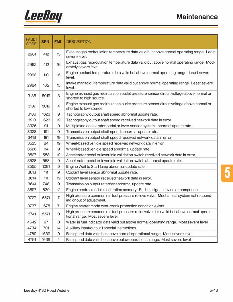
FAULTCODE
SPN FMI DESCRIPTION
2961 412 15Exhaust gas recirculation temperature data valid but above normal operating range. Least severe level.
2962 412 16Exhaust gas recirculation temperature data valid but above normal operating range. Mod-erately severe level.
2963 110 15Engine coolant temperature data valid but above normal operating range. Least severe level.
2964 105 15Intake manifold 1 temperature data valid but above normal operating range. Least severe level.
3136 5019 3Engine exhaust gas recirculation outlet pressure sensor circuit voltage above normal or shorted to high source.
3137 5019 4Engine exhaust gas recirculation outlet pressure sensor circuit voltage above normal or shorted to low source.
3186 1623 9 Tachography output shaft speed abnormal update rate.
3213 1623 19 Tachography output shaft speed received network data in error.
3326 91 9 Multiplexed accelerator pedal or lever sensor system abnormal update rate.
3328 191 9 Transmission output shaft speed abnormal update rate.
3418 191 19 Transmission output shaft speed received network data in error.
3525 84 19 Wheel-based vehicle speed received network data in error.
3526 84 9 Wheel-based vehicle speed abnormal update rate.
3527 558 19 Accelerator pedal or lever idle validation switch received network data in error.
3528 558 9 Accelerator pedal or lever idle validation switch abnormal update rate.
3555 1081 9 Engine Wait to Start lamp abnormal update rate.
3613 111 9 Coolant level sensor abnormal update rate.
3614 111 19 Coolant level sensor received network data in error.
3641 748 9 Transmission output retarder abnormal update rate.
3697 630 12 Engine control module calibration memory. Bad intelligent device or component.
3727 5571 7High pressure common rail fuel pressure relieve valve. Mechanical system not respond-ing or out of adjustment.
3737 1675 31 Engine starter mode over-crank protection condition exists.
3741 5571 0High pressure common rail fuel pressure relief valve data valid but above normal opera-tional range. Most severe level.
4642 97 0 Water in fuel indicator data valid but above normal operating range. Most severe level.
4734 701 14 Auxiliary input/output 1 special instructions.
4789 1639 0 Fan speed data valid but above normal operational range. Most severe level.
4791 1639 1 Fan speed data valid but above below operational range. Most severe level.
Maintenance
LeeBoy 4130 Road Widener 5-43
55

Maintenance
LeeBoy 4130 Road Widener5-44
PV480 TroubleshootingUnder certain conditions, the PV480 digital display can become inoperable. If the display screen is completely black, it must be replaced. If the gauges on the screen become gray, the display panel is not receiving communication over the CANbus. (FIgure 5-40) If this occurs, check the connector. If the gauges are still gray, check the ECU powering up.
Figure 5-40. Gauges Grayed on Screens
Check PV480 Connector
1. Ensure the ignition switch is in the OFF position before starting the machine.
2. Remove the main connector from the rear of the PV480 digital display controller.
3. Inspect the terminals in positions 14 (green) and 26 (yellow) for the CANbus communication.
4. If terminals are properly seated, carefully “unlock” the red retaining clip and slide away from the wires. (Figure 5-41)
Clip
Figure 5-41. PV480 Main Connector
5. Ensure all the other terminals are locked into the connector shell.
6. Push the red retaining clip back into the locked position and ensure terminals are flush with the red retaining clip. (Figure 5-42)
Figure 5-42. Terminal Seat
7. Reinstall connector on to the PV480 panel, making sure the connector shell locks into its mate on the display panel.

Maintenance
LeeBoy 4130 Road Widener 5-45
Check ECU Powering Up
Each engine has a power distribution block (PDB) on the main engine harness that provides power to the ECU through the ECU control relay; main relay; and fuses in Positions 1, 2, 3, 4 and 8. (Figure 5-43)
1
2
3
4
8
Figure 5-43. Power Distribution Box (PDB)
To check the ECU powering up:
1. Locate the PDB on the right side of the machine inside the engine access door.
2. Fuses can be checked by removing the fuse and using a continuity tester OR checking for +12VDC on each pin on the back of the fuse.
3. Confirm operation of ECU and main relays:
• If the ECU relay is not energizing, starter will not operate.
• If the main relay is not energizing, the fuel pump will not operate.
If none of these procedures correct the problem, contact your authorized LeeBoy dealer for assistance.
PLUS ONE BLINK CODESPlus One fault, blink codes, and corrective action information is shown below. See your authorized dealer for assistance if needed.
Blink Code
Reason for Fault Corrective Action
23 Joystick not calibrated.Perform optimization procedure.
24 Joystick fault.Check wiring to joystick.
29 Brake release coil fault. Check wiring to coil.
31Gear box high range coil fault.
Check wiring to coil.
32 Pump reverse coil fault. Check wiring to coil.
33 Pump forward coil fault. Check wiring to coil.
34Hydraulic motor minimum displacement coil fault.
Check wiring to coil.
37 Sensor power fault. Check wiring.
55

Maintenance
LeeBoy 4130 Road Widener5-46
NOTES

Page
Schematics . . . . . . . . . . . . . . . . . . . . . . . . . . . . . . . . . 6-1
Main Harness (1 of 5) . . . . . . . . . . . . . . . . . . . . . . . . . . . . 6-3
Main Harness (2 of 5) . . . . . . . . . . . . . . . . . . . . . . . . . . . . 6-5
Main Harness (3 of 5) . . . . . . . . . . . . . . . . . . . . . . . . . . . 6-7
Main Harness (4 of 5) . . . . . . . . . . . . . . . . . . . . . . . . . . . 6-9
Main Harness (5 of 5) . . . . . . . . . . . . . . . . . . . . . . . . . . . 6-11
Control Box Assembly (1 of 3) . . . . . . . . . . . . . . . . . . . . . . . . 6-13
Control Box Assembly (2 of 3) . . . . . . . . . . . . . . . . . . . . . . . 6-15
Control Box Assembly (3 of 3) . . . . . . . . . . . . . . . . . . . . . . . 6-17
Traction Joystick . . . . . . . . . . . . . . . . . . . . . . . . . . . . . . 6-19
Left Harness (1 of 2) . . . . . . . . . . . . . . . . . . . . . . . . . . . . 6-21
Left Harness (2 of 2) . . . . . . . . . . . . . . . . . . . . . . . . . . . . 6-23
Right Harness (1 of 2) . . . . . . . . . . . . . . . . . . . . . . . . . . . . 6-25
Right Harness (2 of 2) . . . . . . . . . . . . . . . . . . . . . . . . . . . 6-27
Main Hydraulic Manifold Harness (1 of 2) . . . . . . . . . . . . . . . . . . 6-29
Main Hydraulic Manifold Harness (2 of 2) . . . . . . . . . . . . . . . . . . 6-31
Brake/2-Speed Hydraulic Manifold Harness . . . . . . . . . . . . . . . . 6-33
Hydraulic Oil Cooler Harness . . . . . . . . . . . . . . . . . . . . . . . . 6-35
OPTION - Strike Off Remote Control Box . . . . . . . . . . . . . . . . . . 6-37
Hydraulic Schematic - Propel Circuit (1 of 4) . . . . . . . . . . . . . . . . 6-39
Hydraulic Schematic - Conveyor/Steering circuit (2 of 4) . . . . . . . . . . 6-41
Hydraulic Schematic - Cylinder Circuit (3 of 4) . . . . . . . . . . . . . . . 6-43
Hydraulic Schematic - Options Circuit (4 of 4) . . . . . . . . . . . . . . . 6-45
Section 6SCHEMATICS
6
LeeBoy 4130 Road Widener 6-1

NOTES
LeeBoy 4130 Road Widener6-2
Schematics
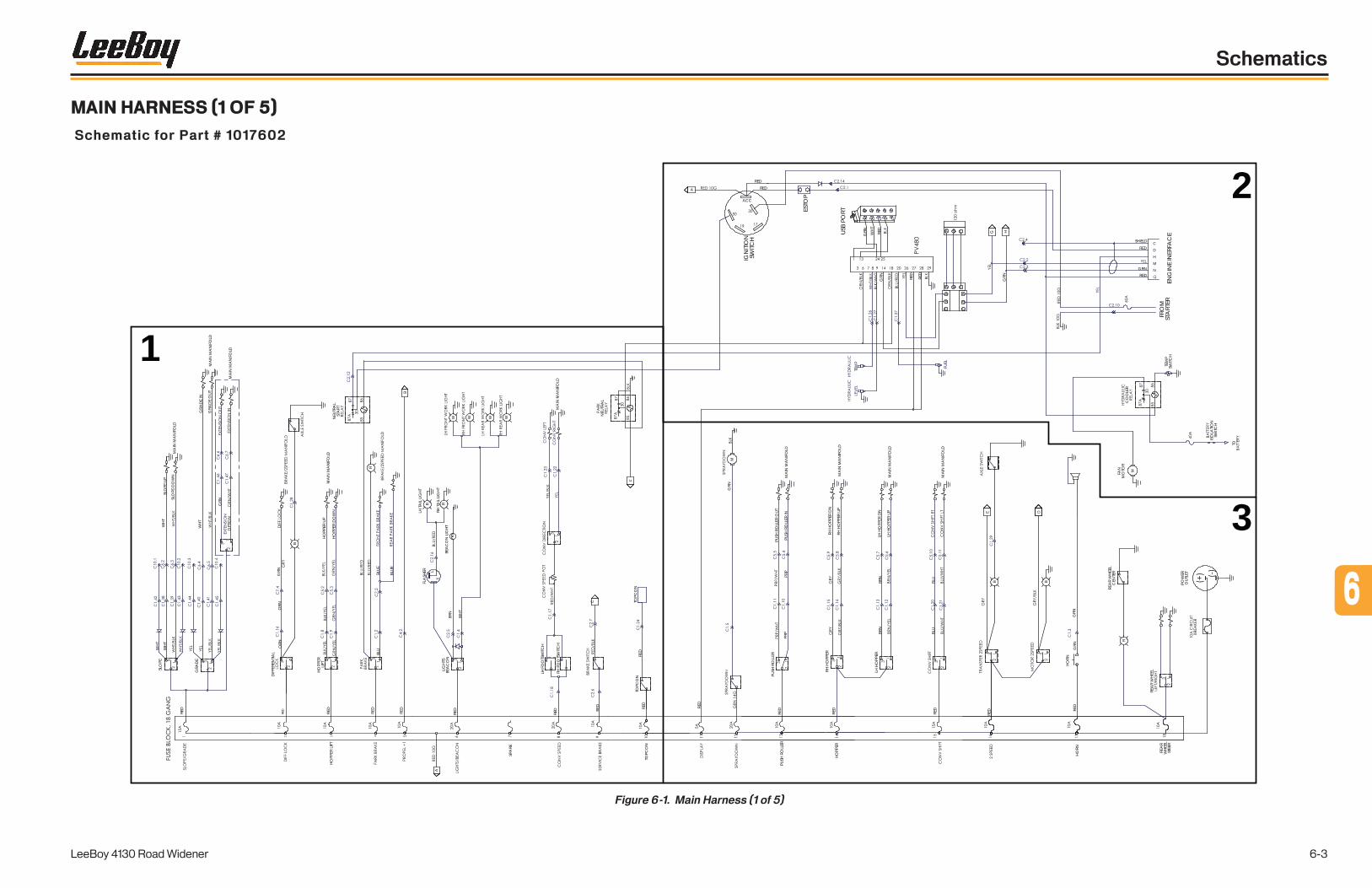
Figure 6-1. Main Harness (1 of 5)
RED RE
D
RED
HORN
RED
PUSH
RO
LLER
BEA
CO
N L
IGHT
LH H
OPP
ER
MA
IN M
AN
IFO
LD
RED
MG
RN
GRN
RED
RED RE
D
B
RED
SLO
PE
A
WHT
SLO
PE U
P
SLO
PE D
OW
N
DIF
FERE
NTIA
LG
RN
HOPP
ER L
IFT
HOPP
ER U
P
HOPP
ER D
OW
N
BLUE
RED
RED
RED
RED
WHT
MA
IN M
AN
IFO
LD
MA
IN M
AN
IFO
LD
WHT
GRA
DE
OUT
MA
IN M
AN
IFO
LD
GRA
DE
GRA
DE
IN
ORN
ORN
WHT
R
BLU
NEU
TRA
LST
ART
IGN
ITIO
NSW
ITCH
ACC
USB
PORT
GRN WHT
RED
G
GRN
LIG
HTS
BEA
CO
N
WHT
BRN
FLA
SHER L
A
HOPP
ER L
IFT
SPA
RE
TOPC
ON
PUSH
RO
LLER
HORN
REA
RW
HEEL
STEE
R
GRN
RR
LH T
AIL
LIG
HT
RH T
AIL
LIG
HT
WW WW
RH F
OO
TSW
ITCH
LH F
OO
TSW
ITCH
OPT
ION
GRN
MA
IN M
AN
IFO
LD
C
B
TOPC
ON
RED
RED
TOPC
ON
RED
RED
RED
PRP
PRP
PUSH
RO
LLER
OUT
PUSH
RO
LLER
INM
AIN
MA
NIF
OLD
MA
IN M
AN
IFO
LD
MA
IN M
AN
IFO
LD
RH H
OPP
ER
BRN
BRN
LH H
OPP
ER D
N
RH H
OPP
ER U
P
RH H
OPP
ER D
N
LH H
OPP
ER U
P
HOPP
ER
BLU
MA
IN M
AN
IFO
LD
BLU
B
E D
NEU
TRA
L
C
D
H
M
N
ENG
INE
INER
FAC
E
F
TEM
P
GRN
BA C
C
A
B
C
A
B
BA C G H
FUEL
ESTO
P
RED
RED
FRO
MST
ART
ER
REDGRN
RED
SHIELD
CO
OLE
R
TEM
PSW
ITCH
FAN
MO
TOR
M
ISO
LATIO
NSW
ITCH
TO
POW
ERO
UTLE
TBLUE
REA
R W
HEEL
R
REA
R W
HEEL
CEN
TER
B
1
2
3
MAIN HARNESS (1 OF 5)
Schematic for Part # 1017602
6
LeeBoy 4130 Road Widener 6-3
Schematics

NOTES
LeeBoy 4130 Road Widener6-4
Schematics

Figure 6-2. Main Harness (2 of 5)
BEA
CO
N L
IGHT
RED
RED RE
D
RED
SLO
PE
A
WHT
SLO
PE U
P
SLO
PE D
OW
N
DIF
FERE
NTIA
LG
RN
HOPP
ER L
IFT
HOPP
ER U
P
HOPP
ER D
OW
N
BLUE
RED
RED
RED
RED
WHT
MA
IN M
AN
IFO
LD
MA
IN M
AN
IFO
LD
WHT
GRA
DE
OUT
MA
IN M
AN
IFO
LD
GRA
DE
GRA
DE
IN
ORN
ORN
WHT
R
BLU
NEU
TRA
LST
ART
LIG
HTS
BEA
CO
N
WHT
BRN
FLA
SHER L
HOPP
ER L
IFT
SPA
RE
TOPC
ON
RR
LH T
AIL
LIG
HT
RH T
AIL
LIG
HT
WW WW
RH F
OO
TSW
ITCH
LH F
OO
TSW
ITCH
OPT
ION
GRN
MA
IN M
AN
IFO
LD
C
B
TOPC
ON
RED
RED
TOPC
ON
MA
IN M
AN
IFO
LD
NEU
TRA
L
F
BLUE
B
1
MAIN HARNESS (2 OF 5)
Schematic for Part # 1017602
6
LeeBoy 4130 Road Widener 6-5
Schematics

NOTES
LeeBoy 4130 Road Widener6-6
Schematics

Figure 6-3. Main Harness (3 of 5)
IGN
ITIO
NSW
ITCH
ACC
USB
PORT
GRN WHT
RED
G
GRN
A
RED
RED
C
D
H
M
N
ENG
INE
INER
FAC
E
TEM
P
GRN
BA C
C
A
B
C
A
B
BA C G H
FUEL
ESTO
P
RED
RED
FRO
MST
ART
ER
REDGRN
RED
SHIELD
CO
OLE
R
TEM
PSW
ITCH
FAN
MO
TOR
M
ISO
LATIO
NSW
ITCH
TO
2
MAIN HARNESS (3 OF 5)
Schematic for Part # 1017602
6
LeeBoy 4130 Road Widener 6-7
Schematics

NOTES
LeeBoy 4130 Road Widener6-8
Schematics

Figure 6-4. Main Harness (4 of 5)
RED RE
D
RED
HORN
RED
PUSH
RO
LLER
LH H
OPP
ER
MA
IN M
AN
IFO
LD
RED
MG
RN
GRN
B
PUSH
RO
LLER
HORN
REA
RW
HEEL
STEE
R
GRN
RED
PRP
PRP
PUSH
RO
LLER
OUT
PUSH
RO
LLER
INM
AIN
MA
NIF
OLD
MA
IN M
AN
IFO
LD
RH H
OPP
ER
BRN
BRN
LH H
OPP
ER D
N
RH H
OPP
ER U
P
RH H
OPP
ER D
N
LH H
OPP
ER U
P
HOPP
ER
BLU
MA
IN M
AN
IFO
LD
BLU
B
E D
POW
ERO
UTLE
T
REA
R W
HEEL
R
REA
R W
HEEL
CEN
TER
3
MAIN HARNESS (4 OF 5)
Schematic for Part # 1017602
6
LeeBoy 4130 Road Widener 6-9
Schematics

NOTES
LeeBoy 4130 Road Widener6-10
Schematics

MAIN HARNESS (5 OF 5)
Schematic for Part # 1017602
Figure 6-5. Main Harness (5 of 5)
ENGINE ENABLE
PWR
PUMPPUMP REVFWDD
C
A
B
BACKUP ALARM
BRAKE RELEASE/PUMP NEUTRALBYPASS VALVE
FWD
REV
OUTPUTGND
+5 VDC
NEUTRAL N.O.NEUTRAL N.C. "B"
NEUTRAL COM
JOYSTICK
STATUS LIGHT
RUN/STOP SWNEUTRAL SW
JOYSTICK mV
BRAKE RELEASE
PUMP REVPUMP FWD
ENGINE START ENABLE
STATUS LIGHT
BACKUP ALARM
DIFF LOCK
DIFF LOCK
PWMOUT/DOUT/PVEOUT2
C4-P2C4-P1
C4-P3C4-P4C4-P5C4-P6C4-P7C4-P8C4-P9
C4-P10C4-P11C4-P12
POWER GROUND -12 PIN DEUTSCH DTM06-12S
POWER SUPPLY +
CAN -
DIN
5V DC sensor power +DIN
AIN/CAN SHIELD
CAN +
Sensor power ground -DIN/AIN/FreqIN
C3-P12C3-P11C3-P10C3-P9C3-P8C3-P7C3-P6C3-P5C3-P4C3-P3C3-P2C3-P1
12 PIN DEUTSCH DTM06-12SB DIN/AIN/FreqIN
MC024-020-00000 NODE
DIN/AIN/FreqIN
PWMOUT/DOUT/PVEOUT2
GRE
YBL
ACK PWMOUT/DOUT/PVE pwr 1
PWMOUT/DOUT/PVE pwr 2PWMOUT/DOUT/PVEOUT1PWMOUT/DOUT/PVEOUT1PWMOUT/DOUT/PVEOUT1PWMOUT/DOUT/PVEOUT2
POWER SUPPLY +POWER SUPPLY +
DIN/AIN/FreqINDIN/AIN/FreqIN
GEARBOX HI RANGE SW
GEARBOX HI RANGE SW
SERVICE BRAKE INPUT
SERVICE BRAKE PRESSURE SW
GEARBOX HI RANGEDIFFERENTIAL LOCK ENABLE
GEARBOX HI RANGE
DIFFERENTIAL LOCK
GND
C4
C3
C8
12546
B
C
E
D
F
GH 6
1
54
2
RUN/STOP SW
C1.31
C1.28C1.30
C1.32
LT BLUBLK
PNKREDBLK
BLKREDYELGRNLT BLUORNPNKREDBLKGRY/BLK
GRY
RED/BLKBLU/WHTWHTORN/WHTORNBRNBRNORN/BLKBLUREDRED
PARK BRAKE
PARK BRAKE FUSE
BLU/RED PARK BRAKE
6
LeeBoy 4130 Road Widener 6-11
Schematics

NOTES
LeeBoy 4130 Road Widener6-12
Schematics
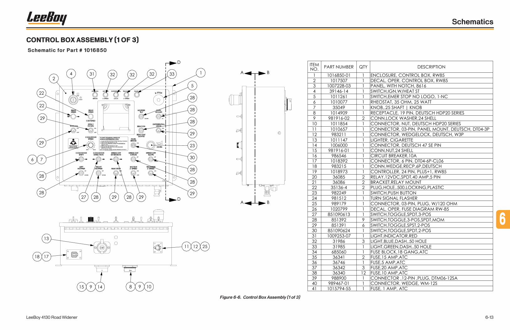
CONTROL BOX ASSEMBLY (1 OF 3)
Schematic for Part # 1016850
Figure 6-6. Control Box Assembly (1 of 3)
OFFRUN
START
REARSTEER
TOPCON-ON
-OFF
MIN MAX
CONVEYORSPEED
-ON
-OFF
SPRAYDOWN
HORN
PARKBRAKE
-ON
-OFF
-UP
-DOWN
HOPPERTILT
DIFFERENTIALLOCK
-ON
-OFF
BEACON
BEACON/LIGHTS
-UP
-DOWN
STRIKE OFFSLOPE
STRIKE OFFGRADE
-UP
-DOWN
STRIKE OFFEXTENSION
CONVEYORDIRECTION
CONVEYORSHIFT
LEFTHOPPER
-UP
-DOWN
RIGHTHOPPER
-UP
-DOWN
RUN/STOP-RUN
-STOP
MOTOR2-SPEED
-ON
-OFF
TRANSFER2-SPEED
-ON
-OFF
PLUS+1®
LOCK
MOTOR
2-SPEED
PARKING
BRAKE
DIFFERENTIAL
2-SPEED
TRANSFER
REARSTEER
PUSHROLLER
-OUT
-IN
CENTERED
1017507
TO SHIFT TRANSFER 2-SPEED OR OPERATE DIFFERENTIAL LOCK:1. PLACE THE FNR JOYSTICK TO THE “NEUTRAL” POSITION2. SWITCH THE PARK BRAKE TO “ON”3. SWITCH THE TRANSFER 2-SPEED OR DIFFERENTIAL LOCK TO “ON”4. SWITCH THE PARK BRAKE TO “OFF”5. ENGAGE THE FNR JOYSTICK IN THE REQUIRED DIRECTION OF TRAVELNOTE: THE MOTOR 2 SPEED CAN BE OPERATED ON THE FLY
READ OPERATIONSMANUAL BEFORE
OPERATING MACHINE
6
LeeBoy 4130 Road Widener 6-13
Schematics

NOTES
LeeBoy 4130 Road Widener6-14
Schematics

CONTROL BOX ASSEMBLY (2 OF 3)
Schematic for Part # 1016850
Figure 6-7. Control Box Assembly (2 of 3)
6
LeeBoy 4130 Road Widener 6-15
Schematics

NOTES
LeeBoy 4130 Road Widener6-16
Schematics

CONTROL BOX ASSEMBLY (3 OF 3)
Schematic for Part # 1016850
Figure 6-8. Control Box Assembly (3 of 3)
6
LeeBoy 4130 Road Widener 6-17
Schematics

NOTES
LeeBoy 4130 Road Widener6-18
Schematics

TRACTION JOYSTICK
Schematic for Part # 1016937
Figure 6-9. Traction Joystick
5
JOYSTICK
NEUTRAL COM
"B"NEUTRAL N.C.
NEUTRAL N.O.
+5 VDC
GND
OUTPUT
REV
FWDDT06-6S
6
LeeBoy 4130 Road Widener 6-19
Schematics

NOTES
LeeBoy 4130 Road Widener6-20
Schematics
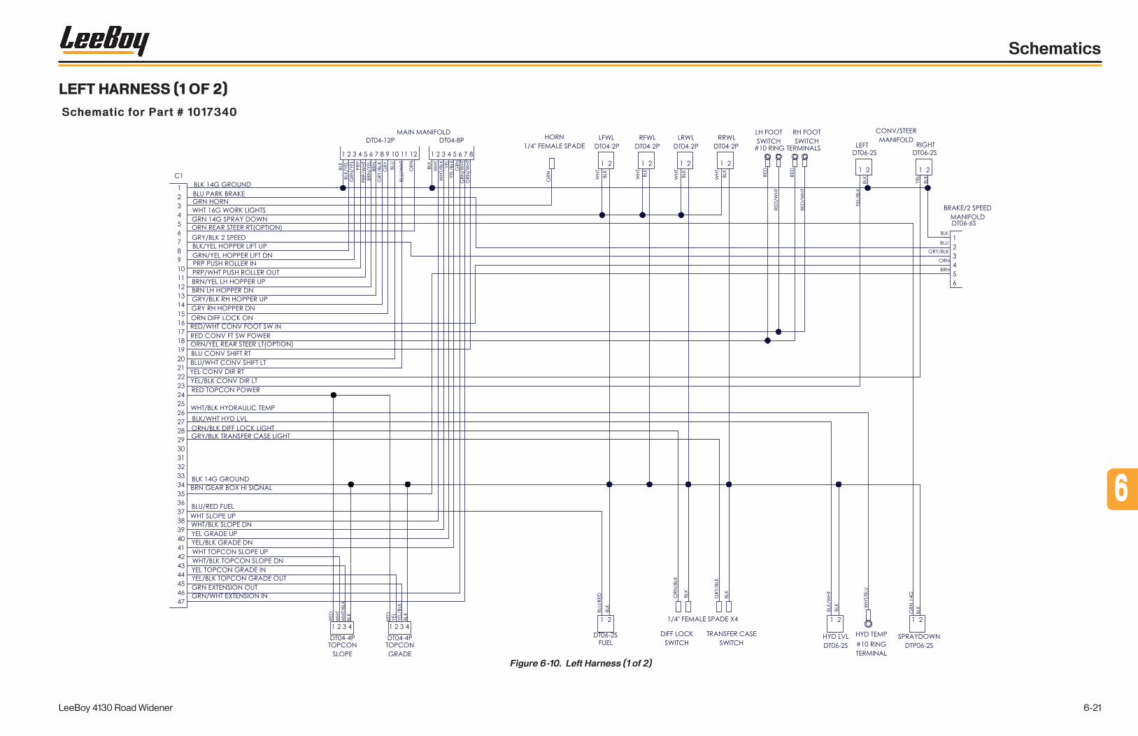
LEFT HARNESS (1 OF 2)
Schematic for Part # 1017340
Figure 6-10. Left Harness (1 of 2)
6
LeeBoy 4130 Road Widener 6-21
Schematics

NOTES
LeeBoy 4130 Road Widener6-22
Schematics

LEFT HARNESS (2 OF 2)
Schematic for Part # 1017340
Figure 6-11. Left Harness (2 of 2)
6
LeeBoy 4130 Road Widener 6-23
Schematics

NOTES
LeeBoy 4130 Road Widener6-24
Schematics
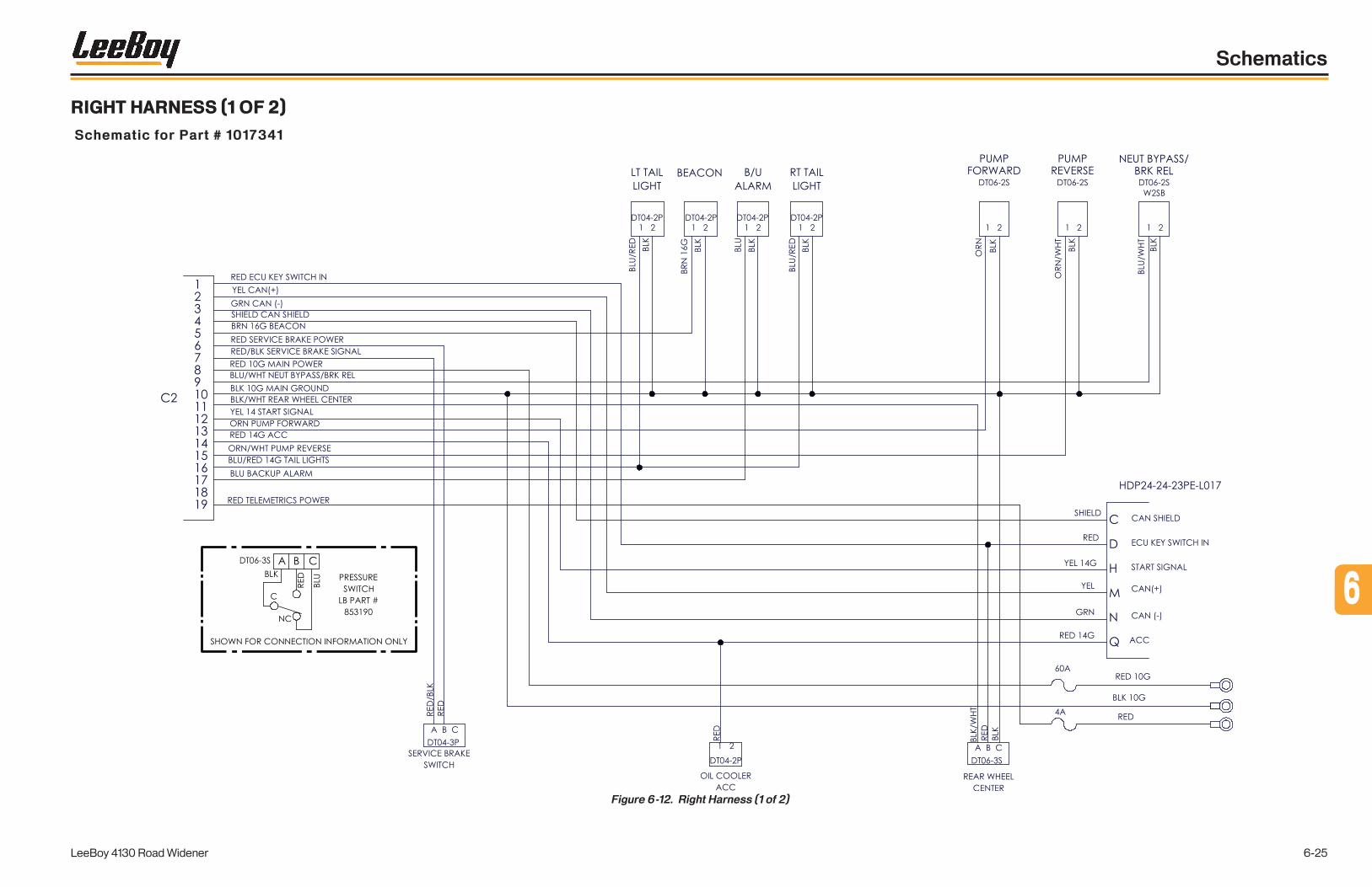
RIGHT HARNESS (1 OF 2)
Schematic for Part # 1017341
Figure 6-12. Right Harness (1 of 2)
6
LeeBoy 4130 Road Widener 6-25
Schematics

NOTES
LeeBoy 4130 Road Widener6-26
Schematics

RIGHT HARNESS (2 OF 2)
Schematic for Part # 1017341
Figure 6-13. Right Harness (2 of 2)
6
LeeBoy 4130 Road Widener 6-27
Schematics

NOTES
LeeBoy 4130 Road Widener6-28
Schematics
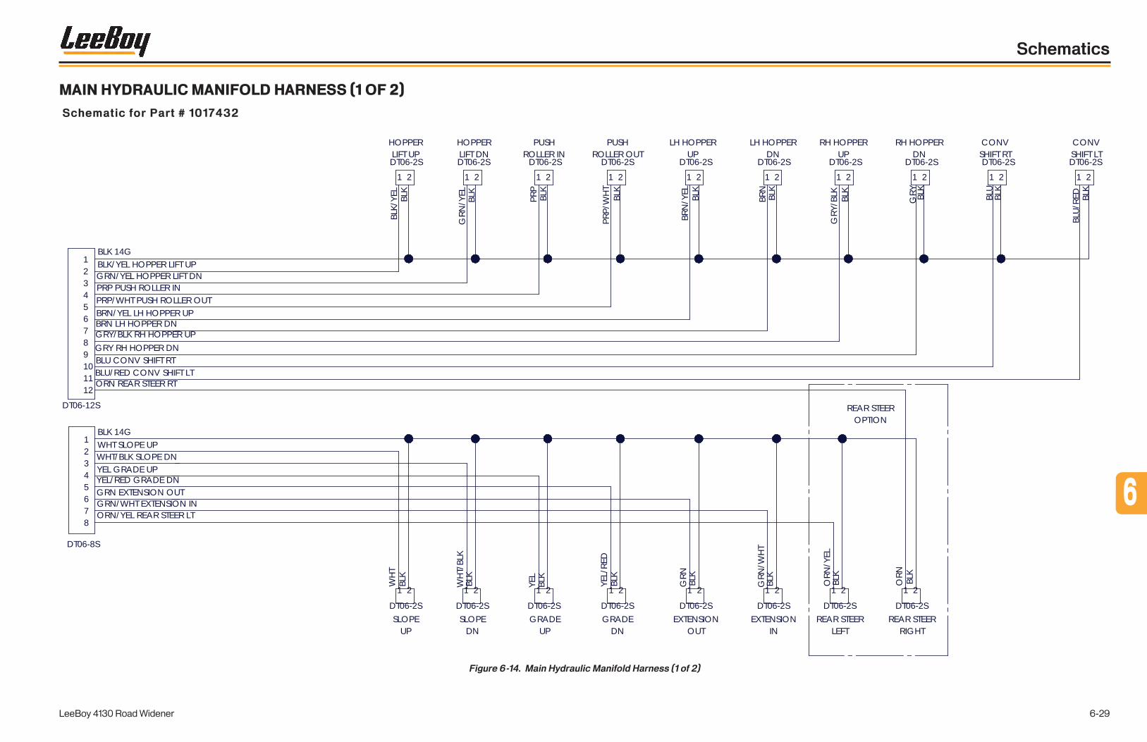
MAIN HYDRAULIC MANIFOLD HARNESS (1 OF 2)
Schematic for Part # 1017432
Figure 6-14. Main Hydraulic Manifold Harness (1 of 2)
123456789101112
12345678
BLK 14G
BLK 14G
BLK/YEL HOPPER LIFT UPGRN/YEL HOPPER LIFT DNPRP PUSH ROLLER INPRP/WHT PUSH ROLLER OUTBRN/YEL LH HOPPER UPBRN LH HOPPER DNGRY/BLK RH HOPPER UPGRY RH HOPPER DNBLU CONV SHIFT RTBLU/RED CONV SHIFT LT
WHT SLOPE UPWHT/BLK SLOPE DNYEL GRADE UPYEL/RED GRADE DNGRN EXTENSION OUTGRN/WHT EXTENSION IN
1 2
DT06-2S
HOPPERLIFT UP
HOPPERLIFT DN
1 2
DT06-2S
PUSHROLLER IN
1 2
DT06-2S
PUSHROLLER OUT
1 2
DT06-2S
LH HOPPERUP
1 2
DT06-2S
LH HOPPERDN
1 2
DT06-2S
RH HOPPERUP
1 2
DT06-2S
RH HOPPERDN
1 2
DT06-2S
CONVSHIFT RT
1 2
DT06-2S
CONVSHIFT LT
1 2
DT06-2S
SLOPEUP
DT06-2S
1 2 1 2
DT06-2SSLOPE
DN
1 2
DT06-2SGRADE
UP
1 2
DT06-2SGRADE
DN
1 2
DT06-2SEXTENSION
OUT
1 2
DT06-2SEXTENSION
IN
DT06-2S
1 2
REAR STEERLEFT
DT06-2S
1 2
REAR STEERRIGHT
ORN REAR STEER RT
ORN/YEL REAR STEER LT
DT06-8S
DT06-12SBL
K BL
K/YE
L
GRN
/YEL
BLK
PRP
BLK
PRP/
WHT BLK
BRN
/YEL
BLK
BRN
BLK
GRY
/BLK BLK
GRY BL
K
BLU
BLK
BLU/
RED
BLK
BLK
ORN
BLK
ORN
/YEL
BLK
GRN
/WHT
BLK
GRN
BLK
YEL/
RED
YEL
BLK
BLK
WHT
/BLK
BLK
WHT
REAR STEEROPTION
6
LeeBoy 4130 Road Widener 6-29
Schematics

NOTES
LeeBoy 4130 Road Widener6-30
Schematics

MAIN HYDRAULIC MANIFOLD HARNESS (2 OF 2)
Schematic for Part # 1017342
Figure 6-15. Main Hydraulic Manifold Harness (2 of 2)
DT06-8S
DT06-12S
AUX(REAR STEER)
HOPPERLEFT
HOPPERTILT
STRIKE OFFSLOPE
STRIKE OFFEXTEND
HOPPERRIGHT
PUSHROLLER
ROLLEROUT
ROLLERIN
RH HOPPERDN
RH HOPPERUP
EXTENSIONIN
EXTENSIONOUT
SLOPEUP
SLOPEDN
HOPPERDN
HOPPERUP
HOPPERUP
HOPPERDN
AUX2RIGHT
AUX1LEFT
SHIFTLEFT
SHIFTRIGHT
CONVSHIFT
GRADEDN
STRIKE OFFGRADE
GRADEUP
T T T T T T
T T T
B B B B B B
BBB
T = TOP COIL
B = BOTTOM COIL
6
LeeBoy 4130 Road Widener 6-31
Schematics

NOTES
LeeBoy 4130 Road Widener6-32
Schematics

BRAKE/2-SPEED HYDRAULIC MANIFOLD HARNESS
Schematic for Part # 1017344
Figure 6-16. Brake/2-Speed Hydraulic Manifold Harness
1
2
3
4
5
6
DT04-6P
1 2
DT06-2S DT06-2S
1 2
DT06-2S
1 2
DT06-2S
1 2
BLK
BLU PARK BRAKE
ORN 2 SPEED
GRN DIFF LOCK
BRN GEAR BOX HI
BLK
BLK
BLK
BLK
BLU
ORN
GRN
ORN
BRN
PARKBRAKE2 SPEED
DIFFERENTIALLOCK
GEAR BOX HITRANSFER CASE
DT04-6P
DT06-2S
PARKBRAKE
DT06-2S
2 SPEED
DT06-2S
DIFFERENTIALLOCK
DT06-2S
GEAR BOX HITRANSFER CASE
6
LeeBoy 4130 Road Widener 6-33
Schematics

NOTES
LeeBoy 4130 Road Widener6-34
Schematics

HYDRAULIC OIL COOLER HARNESS
Schematic for Part # 1019017
Figure 6-17. Hydraulic Oil Cooler Harness
6
LeeBoy 4130 Road Widener 6-35
Schematics

NOTES
LeeBoy 4130 Road Widener6-36
Schematics
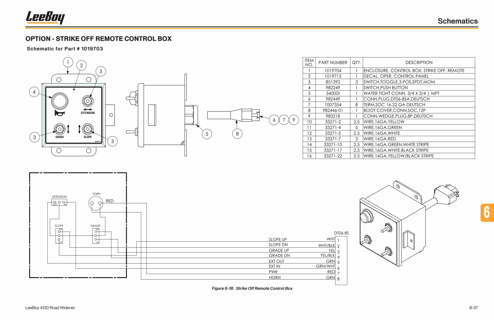
OPTION - STRIKE OFF REMOTE CONTROL BOX
Schematic for Part # 1019703
Figure 6-18. Strike Off Remote Control Box
GRADE
EXTENSION
SLOPE1019713
OUT IN
6
LeeBoy 4130 Road Widener 6-37
Schematics

NOTES
LeeBoy 4130 Road Widener6-38
Schematics

HYDRAULIC SCHEMATIC - PROPEL CIRCUIT (1 OF 4)
Schematic for Part # 1019295
Figure 6-19. Hydraulic Schematic - Propel Circuit (1 of 4)
min.disp.
MAX DISP:MIN DISP:
GP
GD
GB
GS
cw
flow out A
C2C1
345 BAR
345BAR
22 BAR
/2.D7
/2.A
12
/2.A
5
COOL
ER
/3.E
3
/2.F
9
MBX1M4M5
L2
L1 MAA
B
-M130cc80cc
1015841
DRIVE MOTOR
1019523-F1
11 MICRONSUCTION/RETURN FILTER
A1
B1
B2
-M3
BRAKE / 2 SPEED1015852
BRF
T
P
DFL2SP
TCA
TCB
-P2
PROPEL PUMP1015848
45cc
A
B
S L1
L2
M4
M5
X7
M3
M1
M2
M14
AM3UV
KLKR
P2L
P1
-A1
FRON
T AXL
E10
1583
9
P3
P2R
-M21015933
RETURN MANIFOLD
1
234
5
ConvReturn-M4:T
Servi
ceBr
ake
-V12
:OUT
LET
Stee
rRigh
t-S
T1:R
Stee
rLeft
-ST1
:L
IN OUT
-C1
HYD O
IL COO
LER
1015
757
95,00
0 BTU
@ 75
GPM
MainR
eturn
-M5:T
PARK BRAKE-A2#1:P1
GP D
rain
-P1:L
2
Brak
eLS
-M4:B
R1LS
PROPELCIRCUIT
6
LeeBoy 4130 Road Widener 6-39
Schematics

NOTES
LeeBoy 4130 Road Widener6-40
Schematics

HYDRAULIC SCHEMATIC - CONVEYOR/STEERING CIRCUIT (2 OF 4)
Schematic for Part # 1019295
Figure 6-20. Hydraulic Schematic - Conveyor/Steering Circuit (2 of 4)
CONVEYOR / STEERCIRCUIT
cw
GST
2800 PSI
7 GPM
2000 PSI
GP
.019
.019
.031
1000 PSI
/3.D3/1.A3
/1.F2
/1.B1
/1.C
6
X
X
L1S
L2
M2
B
1012222
60cc247/2465 PSI
General Purpose Pump
-P1
INOUT 10
0709
5-F2 12
5 MES
H, 40
GPM
SUCT
ION S
TRAINE
R
-M4
CONV
EYOR
/STEE
R10
1585
1
BR1L
SBR
2LS
TP
LS
STRSTLSSTC1
LS1
PB
C2 BR2
BR1
A
B
-M61016757
LH CONV MOTOR477cc (29.1 in3)
A
B
-M71016757
RH CONV MOTOR477cc (29.1 in3)
PowerBeyond-M5:P
LoadSense1-M5:LS1
TP A
-V1
RH BR
AKE P
EDAL
8533
50
TPA
-V2
LH BR
AKE P
EDAL
8533
50
ConvReturn-M2:5
ServiceBrake-A1:P2R
-ST1
Steering1003798
PLRT
LS
Stee
rRigh
t-A
1:KL
Stee
rLeft
-A1:K
R
INLET
1IN
LET2
OUTLE
T
-V12
Servi
ce Br
ake S
huttle
1015
127
GP D
rain
-M2:2
BrakeLS-A1:P2L
6
LeeBoy 4130 Road Widener 6-41
Schematics

NOTES
LeeBoy 4130 Road Widener6-42
Schematics

HYDRAULIC SCHEMATIC - CYLINDER CIRCUIT (3 OF 4)
Schematic for Part # 1019295
Figure 6-21. Hydraulic Schematic - Cylinder Circuit (3 of 4)
GP
BOTT COIL TOP COIL BOTT COIL TOP COIL BOTT COIL TOP COIL BOTT COIL TOP COIL BOTT COIL TOP COIL
BOTT COIL TOP COILBOTT COIL TOP COILBOTT COIL TOP COILBOTT COIL TOP COIL
X
0.078.050 .050 .050 .078
.050 .050
3000 PSI
/2.D3
/1.C5
-M5
Main Manifold1015850
AUX2AUX1PROPRICSRCSLHTDHTU
T
PLS
LSTU RSTU LSTD RSTD LSLU RSLU LSLD RSLD LEXO REXO LEXI REXI HLU HLD HRU HRD
PowerBeyond-M4:PB
LoadSense1-M4:LS1
MainReturn-M2:3
EXT
RET
8514
36 -C2
LH HO
PPER
EXT
RET
8514
36-C
3
RH HO
PPER
EXT
RET
1017
059
-C4
CONV
SHIFT
EXT RET
981504-C5
HOPPER TILT
EXT RET
1010145-C6
PUSH ROLLER
EXT
RET
1009
057
-C7
RH ST
RIKE O
FF EX
T
EXT
RET
1015
957
-C8
RH SL
OPE
EXT
RET
1015
956
-C9
RH G
RADE
-V5
2092
6564
OUT
IN
-V6
2092
6564
OUT
IN
-V3
2092
6564
OUT
IN
-V7
2092
6564
OUT
IN
-V820926564
OUTIN
CYLINDERCIRCUIT
6
LeeBoy 4130 Road Widener 6-43
Schematics

NOTES
LeeBoy 4130 Road Widener6-44
Schematics

HYDRAULIC SCHEMATIC - OPTIONS CIRCUIT (4 OF 4)
Schematic for Part # 1019295
Figure 6-22. Hydraulic Schematic - Options Circuit (4 of 4)
OPTIONS
GP
BOTT COIL TOP COIL BOTT COIL TOP COIL BOTT COIL TOP COIL BOTT COIL TOP COIL BOTT COIL TOP COIL
BOTT COIL TOP COILBOTT COIL TOP COILBOTT COIL TOP COILBOTT COIL TOP COIL
X
0.078.050 .050 .050 .078
.050 .050
3000 PSI
-M5#1
Main Manifold1015850
AUX2AUX1PROPRICSRCSLHTDHTU
T
PLS
LSTU RSTU LSTD RSTD LSLU RSLU LSLD RSLD LEXO REXO LEXI REXI HLU HLD HRU HRD
EXT
RET
1009
057
-C10
#1
LH ST
RIKE O
FF EX
T
EXT
RET
1015
957
-C11
#1
LH SL
OPE
EXT
RET
1015
956
-C12
#1
LH G
RADE
-V9#
120
9265
64
OUT
IN
-V10
#120
9265
64
OUT
IN
-V11
#120
9265
64
OUT
IN
KRKL
P2RP1
P2L
-A2#1
REAR AXLE1017760
PARK BRAKE-M3:BRF
LH STRIKE OFF OPTION
4WD OPTION 6
LeeBoy 4130 Road Widener 6-45
Schematics

NOTES
LeeBoy 4130 Road Widener6-46
Schematics
Page
ILLUSTRATED PARTS LIST . . . . . . . . . . . . . . . . . . . . . . . . . . 7-1
Quick Reference Guide . . . . . . . . . . . . . . . . . . . . . . . . . . 7-3
Extendable Push Roller Group . . . . . . . . . . . . . . . . . . . . . . . 7-4
Details - Front . . . . . . . . . . . . . . . . . . . . . . . . . . . . . . . 7-6
Hopper Group (1 of 2) . . . . . . . . . . . . . . . . . . . . . . . . . . . 7-8
Hopper Group (2 of 2) . . . . . . . . . . . . . . . . . . . . . . . . . . . 7-10
Conveyor Assembly (1 of 2) . . . . . . . . . . . . . . . . . . . . . . . . . 7-12
Conveyor Assembly (2 of 2). . . . . . . . . . . . . . . . . . . . . . . . . 7-14
Hopper/Conveyor Lift . . . . . . . . . . . . . . . . . . . . . . . . . . . 7-16
Front Axle Assembly . . . . . . . . . . . . . . . . . . . . . . . . . . . . 7-18
Rear Axle Assembly - 2WD . . . . . . . . . . . . . . . . . . . . . . . . . 7-20
Controls Group - 74HP/130HP . . . . . . . . . . . . . . . . . . . . . . . 7-22
Controls Group - 74HP/130HP (Cont.) . . . . . . . . . . . . . . . . . . . 7-24
Controls Group - Dash Assembly . . . . . . . . . . . . . . . . . . . . . . 7-26
Control Box . . . . . . . . . . . . . . . . . . . . . . . . . . . . . . . . 7-28
Details - Upper Deck . . . . . . . . . . . . . . . . . . . . . . . . . . . . 7-30
Details - Left Side . . . . . . . . . . . . . . . . . . . . . . . . . . . . . 7-32
Fuel Tank . . . . . . . . . . . . . . . . . . . . . . . . . . . . . . . . . 7-34
Details - Right Side . . . . . . . . . . . . . . . . . . . . . . . . . . . . . 7-36
Single Battery Box Assembly, 74HP . . . . . . . . . . . . . . . . . . . . 7-38
Hydraulic Tank . . . . . . . . . . . . . . . . . . . . . . . . . . . . . . . 7-40
Details - Rear (1 of 2) . . . . . . . . . . . . . . . . . . . . . . . . . . . . 7-42
Details - Rear (2 of 2) . . . . . . . . . . . . . . . . . . . . . . . . . . . . 7-44
Engine Group, 74HP - Covers and Panels . . . . . . . . . . . . . . . . . 7-46
Engine Group, 74HP - Radiator/Cooling . . . . . . . . . . . . . . . . . . 7-48
Engine Group, 74HP - Intake/Frame . . . . . . . . . . . . . . . . . . . . 7-50
LeeBoy 4130 Road Widener 7-1
ILLUSTRATED PARTS LISTSection 7
7-1
77

Engine Group, 74HP - Components . . . . . . . . . . . . . . . . . . . . 7-52
Engine Group, 74HP - Exhaust/Pumps . . . . . . . . . . . . . . . . . . . 7-54
Pump Covers and Panels . . . . . . . . . . . . . . . . . . . . . . . . . . 7-56
Hydraulic Manifold - Main . . . . . . . . . . . . . . . . . . . . . . . . . . 7-58
Hydraulic Manifold - Conveyor/Steering . . . . . . . . . . . . . . . . . . 7-60
Hydraulic Manifold - Brake/2-Speed . . . . . . . . . . . . . . . . . . . . 7-62
Hydraulic Oil Cooler . . . . . . . . . . . . . . . . . . . . . . . . . . . . 7-64
Strike Off Group (1 of 4) . . . . . . . . . . . . . . . . . . . . . . . . . . . 7-66
Strike Off Group (2 of 4) . . . . . . . . . . . . . . . . . . . . . . . . . . 7-68
Strike Off Group (3 of 4) . . . . . . . . . . . . . . . . . . . . . . . . . . 7-70
Strike Off Group (4 of 4) . . . . . . . . . . . . . . . . . . . . . . . . . . 7-72
OPTION - Dual Strike Off . . . . . . . . . . . . . . . . . . . . . . . . . . 7-74
OPTION - Strike Off Remote Assembly . . . . . . . . . . . . . . . . . . . 7-76
OPTION - Strike Off TopCon-Slope. . . . . . . . . . . . . . . . . . . . . 7-78
OPTION - Strike Off TopCon-Grade . . . . . . . . . . . . . . . . . . . . 7-80
OPTION - Rear Axle Assembly - 4WD w/Steering . . . . . . . . . . . . . . 7-82
OPTION - Engine Covers and Panels, 130HP . . . . . . . . . . . . . . . . 7-84
OPTION - Engine Group, 130HP - Radiator/Cooling . . . . . . . . . . . . . 7-86
OPTION - Engine Group, 130HP - Intake/Frame . . . . . . . . . . . . . . . 7-88
OPTION - Engine Group, 130HP - Components . . . . . . . . . . . . . . . 7-90
OPTION - Engine Group, 130HP - Exhaust . . . . . . . . . . . . . . . . . 7-92
OPTION - Engine Group, 130HP - Pumps . . . . . . . . . . . . . . . . . . 7-94
OPTION - Engine Group, 130HP - DEF Tank . . . . . . . . . . . . . . . . 7-96
OPTION - Dual Battery Box Assembly, 130HP . . . . . . . . . . . . . . . . 7-98
OPTION - Spray Down . . . . . . . . . . . . . . . . . . . . . . . . . . .7-100
Hydraulic Hose Kits . . . . . . . . . . . . . . . . . . . . . . . . . . . .7-102
Decal Kits . . . . . . . . . . . . . . . . . . . . . . . . . . . . . . . . .7-106
Alphabetical Parts Index . . . . . . . . . . . . . . . . . . . . . . . . . .7-108
LeeBoy 4130 Road Widener7-2
Illustrated Parts List
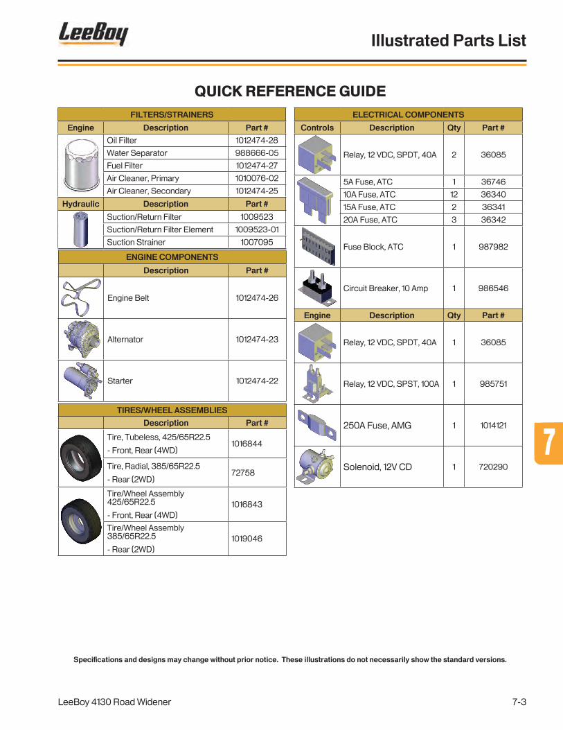
Specifications and designs may change without prior notice. These illustrations do not necessarily show the standard versions.
FILTERS/STRAINERS
Engine Description Part #
Oil Filter 1012474-28
Water Separator 988666-05
Fuel Filter 1012474-27
Air Cleaner, Primary 1010076-02
Air Cleaner, Secondary 1012474-25
Hydraulic Description Part #
Suction/Return Filter 1009523
Suction/Return Filter Element 1009523-01
Suction Strainer 1007095
ENGINE COMPONENTS
Description Part #
Engine Belt 1012474-26
Alternator 1012474-23
Starter 1012474-22
ELECTRICAL COMPONENTS
Controls Description Qty Part #
Relay, 12 VDC, SPDT, 40A 2 36085
5A Fuse, ATC 1 36746
10A Fuse, ATC 12 36340
15A Fuse, ATC 2 36341
20A Fuse, ATC 3 36342
Fuse Block, ATC 1 987982
Circuit Breaker, 10 Amp 1 986546
Engine Description Qty Part #
Relay, 12 VDC, SPDT, 40A 1 36085
Relay, 12 VDC, SPST, 100A 1 985751
250A Fuse, AMG 1 1014121
Solenoid, 12V CD 1 720290
TIRES/WHEEL ASSEMBLIES
Description Part #
Tire, Tubeless, 425/65R22.5
- Front, Rear (4WD)1016844
Tire, Radial, 385/65R22.5
- Rear (2WD)72758
Tire/Wheel Assembly 425/65R22.5
- Front, Rear (4WD)1016843
Tire/Wheel Assembly 385/65R22.5
- Rear (2WD)1019046
Quick Reference Guide
LeeBoy 4130 Road Widener
Illustrated Parts List
7-3
77

Figure 7-1 . Extendable Push Roller Group
Extendable Push Roller Group
7,9
16
17,18,19
20
21 22
23,24
2526,2728
29,2728
12
2
2
3
4
4
6
4
4 5
7,8
7,8
10
1113,14,15
1
LeeBoy 4130 Road Widener
Illustrated Parts List
7-4

Extendable Push Roller GroupItem No.
Part Number Qty. Description Remarks
GRP 1015480 Group - Extendable Push Roller
1 1016325 1 Adjustable Push Roller
2 1016324 4 Adjustable Roller Mounting Plate
3 980033 2 Push Bar Roller Assembly - 24" Includes Item 4 (x2)
4 850130 8 Insert Bearing, 1.50
5 980035 2 Push Bar Roller Assembly - 4" Includes Item 4 (x2)
6 980034 2 Push Bar Roller Shaft
7 100-8-13-24-5 4 CSHH, 1/2-13 x 1.50, GR5
8 1017118 4 Washer, 1/2 ID x 2.00 OD
9 200-8-13-5 12 Nut, Hex, 1/2-13, GR5
10 1018312 2 Large Roller Scraper Bracket
11 1018310 2 Large Push Roller Scraper
12 1018311 2 Small Push Roller Scraper
13 100-6-16-12-5F 10 CSHH, 3/8-16 x .75, GR5, FT
14 302-6 10 Washer, Lock, 3/8
15 300-6 10 Washer, Flat, SAE, 3/8
16 810081SRV 1 Push Bar Swivel Pin
17 100-10-11-16-5F 1 CSHH, 5/8-11 x 1.00, GR5, FT
18 302-10 1 Washer, Lock, 5/8
19 1012165 1 Washer, Flat, .688 x 2.25 x .188
20 1020357 1 Extendable Push Roller Weldment
REF 1019106 1 Push Roller Cylinder Assembly Includes Items 21, 22
21 1010145 1 Hydraulic Cylinder, 3.00 x 14.00 x 1.50
- 1010140-01 1 Hydraulic Cylinder Seal Kit Repair Part - Not Shown
22 FS6400-06-06-O 2 Straight Adapter, -6 ORFS/-6 O-Ring
23 1000365 2 Clevis Pin, ø1.00 x 3.25
24 80336 2 Cotter Pin, .188 x 1.50
25 1020355 1 Push Roller Mount
26 100-8-13-20-8F 4 CSHH, 1/2-13 x 1.25, GR8, FT
27 302-8 8 Washer, Lock, 1/2
28 300-8 8 Washer, Flat, SAE, 1/2
29 100-8-13-28-8 4 CSHH, 1/2-13 x 1.75, GR8
LeeBoy 4130 Road Widener
Illustrated Parts List
7-5
77

Details - Front
1010489
PINCH POINT
PUNTO DE APRIETEPOINT DE PINCEMENT
DANGERPELIGRODANGER
WARNING
13437645G7
Conveyor movement can cause serious injury or death.
Do not stand in hopper with engine running.
DANGER
DANGER
PELIGRO
856437
PINCH POINT
PUNTO DE APRIETE
POINT DE PINCEMENT
59246603
WARNING
Crush area can cause serious injury.
Stay clear.13437678
WARNING
13437652G7
Crush area can cause serious injury or death.
Stay clear of front of machine, truck hitch, and rear of trucks while loading.
6
99
10
11
10
767
88
12 34
5 5
Figure 7-2 . Details - Front
LeeBoy 4130 Road Widener
Illustrated Parts List
7-6

Details - FrontItem No.
Part Number Qty. Description Remarks
1 1019538-03 1 Decal - Deco, Logo - Left Hopper
2 1019538-04 1 Decal - Deco, Logo - Right Hopper
3 1019039-09 1 Decal - Deco, LeeBoy Logo, 18"
4 13437645 1 Decal - Warning, Conveyor
5 1010489 2 Decal - Danger, Pinch Point
6 1019538-05 2 Decal - Deco, 4130 Logo
7 13437652 2 Decal - Warning, Crush Area
8 856437 2 Decal - Danger, Pinch Point
9 59246603 2 Decal - Tie Down
10 13855317 2 Decal - Warning, Rotating Parts
11 13437678 2 Decal - Warning, Crush Area
LeeBoy 4130 Road Widener
Illustrated Parts List
7-7
77

Figure 7-3. Hopper Group (1 of 2)
Hopper Group (1 of 2)
12,
3,4,
5
6
7
89
2,3,
4
10,3
,4
12
11
12
1311
14
15
2,3,
4
1314
15
2,3,
4
1617
1819
,20
19,2
0
21
2224
23
18
25
2627
,3,4
25,2
6 27,3
,4
2829
30,3
,431
3233
,34,
35
36
36
3233
,34,
353738
2,3,
4
LeeBoy 4130 Road Widener
Illustrated Parts List
7-8

Hopper Group (1 of 2)Item No.
Part Number Qty. Description Remarks
GRP 1020520 Group - Hopper
1 1016830 1 Plate, Blanking, Hopper
2 100-6-16-24-5 A/R CSHH, 3/8-16 x 1.50, GR5
3 302-6 A/R Washer, Lock, 3/8
4 300-6 A/R Washer, Flat, SAE, 3/8
5 200-6-16-5 6 Nut, Hex, 3/8-16, GR5
6 1020119 1 Hopper Wiper - Right
7 1020120 1 Hopper Wiper - Left
8 1020126 2 Rubber Wiper
9 1020127 2 Hopper Wiper Strip
10 100-6-16-16-5F 14 CSHH, 3/8-16 x 1.00, GR5, FT
11 1018781 2 Flowgate
12 120-6-16 2 Wing Screw, Type C, 3/8-16 x 1.00
13 1016831 2 Plate, Hold Down, Rubber Cut Off
14 1016829 2 Rubber, Cut Off, Hopper
15 1021181 2 Hopper Rubber Support Plate
16 FS2701-06-06-FG 4 Bulkhead Elbow Adapter, 90°, -6 ORFS/-6 ORFS
17 FS0306-06 4 Bulkhead Locknut, -06 ORFS
REF 1019105 1 Hopper Wing Cylinder Assembly Includes Items 18-22
18 851436SRV 2 Cylinder, Hydraulic, 2.00 x 12.00 x 1.00 Rod
- 910145-01 1 Hydraulic Cylinder Seal Kit Repair Part - Not Shown
19 FS2501-06-06-FG 2 Elbow Adapter, 90°, -6 ORFS/-6 NPTF
20 FS2404-06-04 2 Connector Adapter, -6 ORFS/-4 NPTF
21 20926564 2 Ball Valve, 1/4
22 5500-6-4 2 Elbow Adapter, 90°, -6 NPTF/-4 NPTF
23 1000365 4 Pin, Clevis, ø1.00 x 3.25
24 80338 4 Pin, Cotter, .188 x 2.00
25 1016832 2 Hopper Flashing Hold Down Plate
26 1020674 2 Rubber Flashing - Outside
27 100-6-16-32-5 10 CSHH, 3/8-16 x 2.00, GR5
28 1019427 1 Hopper Frame Hold Down Plate
29 1020673 1 Rubber Flashing - Center
30 100-6-16-40-5 4 CSHH, 3/8-16 x 2.50, GR5
31 1020140 1 Hopper Rubber Cover - Center
32 40447 10 Washer, 2.25 OD x .562 ID x 7 GA
33 100-8-13-20-5F 10 CSHH, 1/2-13 x 1.25, GR5, FT
34 302-8 10 Washer, Lock, 1/2
35 300-8 10 Washer, Flat, SAE, 1/2
36 1020139 2 Hopper Rubber Cover - Left/Right
37 1016834 2 Conveyor Rubber Hold Down Plate
38 1016833 2 Conveyor Rubber Scraper
LeeBoy 4130 Road Widener
Illustrated Parts List
7-9
77

Hopper Group (2 of 2)
Figure 7-4. Hopper Group (2 of 2)
1
2
3,45,4
6 6
7,8,9
10
11
12,13,14
12,13,14
1516
7,8,9
161518
17
LeeBoy 4130 Road Widener
Illustrated Parts List
7-10

Hopper Group (2 of 2)Item No.
Part Number Qty. Description Remarks
GRP 1020520 Group - Hopper
1 1016803 1 Hopper Wing - Right
2 1016804 1 Hopper Wing - Left
3 100-16-8-96-8 2 CSHH, 1-8 x 6.00, GR8
4 204-16-8-8 4 Nut Lock, Stover, 1-8, GR8
5 100-16-8-104-8 2 CSHH, 1-8 x 6.50, GR8
6 1020054 2 Hopper Gap Guard
7 100-6-16-24-5 A/R CSHH, 3/8-16 x 1.50, GR5
8 302-6 A/R Washer, Lock, 3/8
9 300-6 A/R Washer, Flat, SAE, 3/8
10 1018480 1 Wing Pivot Mount Bracket
11 1018482 1 Hopper Frame Brace
12 100-8-13-18-5F 10 CSHH, 1/2-13 x 1.13, GR5, FT
13 302-8 10 Washer, Lock, 1/2
14 300-8 10 Washer, Flat, SAE, 1/2
15 1019368 2 Hopper Flashing Hold Down Plate
16 1019369 2 Hopper Flashing Rubber
17 1019104 1 Conveyor Cylinder Assembly See Fig. 7-5
18 1020245 1 Hopper Conveyor Assembly See Fig. 7-5
LeeBoy 4130 Road Widener
Illustrated Parts List
7-11
77

1
2
1
3
1
1
23
4,5,6
7
89
10
11
12
13
14
16
15
1721,5,6 18
1920
22a
2324,25
27
26
28,29,30
3132
33
22b
Figure 7-5 . Conveyor Assembly (1 of 2)
Conveyor Assembly (1 of 2)
LeeBoy 4130 Road Widener
Illustrated Parts List
7-12

Conveyor Assembly (1 of 2)Item No.
Part Number Qty. Description Remarks
REF 1020245 1 Hopper Conveyor Assembly
1 1016772 4 Rubber Hold Down Plate - Small
2 1016774 2 Rubber Hold Down Plate - Large
3 1016768 2 Rubber Conveyor Skirt
4 100-6-16-24-5 A/R CSHH, 3/8-16 x 1.50, GR5
5 302-6 A/R Washer, Lock, 3/8
6 300-6 A/R Washer, Flat, SAE, 3/8
7 1020364 1 Conveyor Belt Assembly
8 1019104 1 Conveyor Cylinder Assembly Includes Items 9-11
9 1017059 1 Hydraulic Cylinder,
- 1017059-03 1 Hydraulic Cylinder Seal Kit Repair Part - Not Shown
10 FS6400-06-06-O 1 Straight Adapter, -6 ORFS/-6 O-Ring
11 FS6801-06-06-NWO-FG 1 Elbow Adapter, 90°, -6 ORFS/-6 O-Ring
12 1000285 2 Clevis Pin, ø1.00 x 2.50
13 1017841 2 Cotter Pin, ø.174 x 3.75
14 1019971 4 Flange Bearing Support
15 119-10-11-56 4 Square Head Set Screw, Flat, 5/8-11 x 3.50
16 202-10-11-5 4 Nut, Hex, Jam, 5/8-11, GR5
17 1019968 4 Flange Bearing, 1.25
REF 1020300SRV 2 Conveyor Pulley Coupling Bearing Includes Items 18-20
18 1020301 2 Conveyor Pulley Coupling
19 400-4-32 2 Roll Pin, 1/4" x 2.00
20 140610 2 Lube Fitting, Straight, 1/4"-25
21 100-6-16-28-8 16 CSHH, 3/8-16 x 1.75, GR5
22a 1021237 1 Conveyor Motor Bracket - Left
22b 1021236 1 Conveyor Motor Bracket - Right
23 1021235 2 Conveyor Stop Block
24 102-8-13-20-F 4 CSSH, 1/2-13 x 1.25, FT
25 307-8 4 Washer, Lock, Hi-Collar, 1/2
REF 1016794 2 Conveyor Motor Assembly Includes Items 26-27
26 1016757 2 Conveyor Motor
27 FS6802-10-10-NWO-FG 4 Elbow Adapter, 90°, -10 ORFS/-10 O-Ring
28 100-8-13-28-5 8 CSHH, 1/2-13 x 1.75, GR5
29 302-8 8 Washer, Lock, 1/2
30 200-8-13-5 8 Nut, Hex, 1/2-13, GR5
31 1012624 4 V-Groove Track Roller
32 20922969 8 Machine Bushing, 3/4 x 1.25, LT 18
33 219-12-16-5 4 Nut, Hex, Nylon, Thin, GR5, 3/4-16
LeeBoy 4130 Road Widener
Illustrated Parts List
7-13
77

Figure 7-6 . Conveyor Assembly (2 of 2)
Conveyor Assembly (2 of 2)
22
2
22
22
2
2
1
1
3
53
4
7 68,9
LeeBoy 4130 Road Widener
Illustrated Parts List
7-14

Conveyor Assembly (2 of 2)Item No.
Part Number Qty. Description Remarks
REF 1020245 1 Hopper Conveyor Assembly Not All Items Shown
1 1016756 2 Weldment, Head Pulley
2 1016765SRV 9 Assembly, Idler Roller, 24" Includes Items 3,4,5
3 850130 A/R Bearing, Insert, 1.50 (2) Per Assembly
4 1016763 A/R Shaft, Idler Roller, 24" (1) Per Assembly
5 1016764 A/R Tube, Idler Roller, 24" (1) Per Assembly
6 1020352 18 Idler Roller Block
7 113-16-8 18 Set Screw, Hex Socket, Cup, 3/8-16 x .50
8 100-6-16-24-5 A/R CSHH, 3/8-16 x 1.50, GR5
9 300-6 A/R Washer, Flat, SAE, 3/8
LeeBoy 4130 Road Widener
Illustrated Parts List
7-15
77

Figure 7-7 . Hopper/Conveyor Lift
Hopper/Conveyor Lift
1
2
2
36
5
54
7
89
10,1
1,12
13,1
1,14
15
1617
17
18
19
19
19
20
21
2223
24
25,2
6,27
29,3
0,31
2828 29
,30,
31
LeeBoy 4130 Road Widener
Illustrated Parts List
7-16

Hopper/Conveyor LiftItem No.
Part Number Qty. Description Remarks
1 1016412 1 Hopper Weldment
2 1020023 2 Conveyor Idler Assembly Includes Items 3-12
3 1016765SRV 2 Idler Roller Assembly - 24" Includes Items 4-6
4 1016764 2 Idler Roller Tube, 20"
5 850130 4 Insert Bearing, 1.50"
6 1016763 2 Idler Roller Shaft, 24"
7 1020024 2 Conveyor Idler Weldment
8 1020352 4 Idler Roller Block
9 113-6-16-8 4 Set Screw, Hex Socket, Cup, 3/8-16 x .50
10 100-6-16-24-5 8 CSHH, 3/8-16 x 1.50, GR5
11 302-6 16 Washer, Lock, 3/8
12 300-6 8 Washer, Flat, SAE, 3/8
13 100-6-16-20-8 8 CSHH, 3/8-16 x 1.25, GR8
14 301-6 8 Washer, Flat, USS, 3/8
15 1019103 1 Hopper Lift Cylinder Assembly Includes Items 3,4
16 981504 1 Hydraulic Cylinder, 2.50 x 14.50 x 1.50
- 981504-03 1 Hydraulic Cylinder Seal Kit Repair Part - Not Shown
17 FS2404-06-06 2 Connector Adapter, -6 ORFS/-6 NPTF
18 980737 2 Cylinder Pin
19 1017841 4 Cotter Pin, ø.172 x 3.75
20 FS2701-06-06-FG 8 Elbow Bulkhead Adapter, 90°, -6 ORFS/-6 ORFS
21 0306-06 8 Bulkhead Lock Nut, -6
22 FS2701-10-10-FG 4 Elbow Bulkhead Adapter, 90°, -10 ORFS/-10 ORFS
23 0306-10 4 Bulkhead Lock Nut, -10
24 1020093 2 Hopper Safety Bar
25 100-16-8-88-8 2 CSHH, 1-8 x 5.50, GR8
26 300-16 4 Washer, Flat, SAE, 1"
27 204-16-8-8 2 Nut, Lock, Stover, 1-8, GR8
28 1021223 4 Keeper Plate
29 100-8-13-36-8 8 CSHH, 1/2-13 x 2.25, GR8
30 302-8 8 Washer, Lock, 1/2
31 300-8 8 Washer, Flat, SAE, 1/2
LeeBoy 4130 Road Widener
Illustrated Parts List
7-17
77

Front Axle Assembly
Figure 7-8. Front Axle Assembly
1
2 34
5
6,7
8
91011
12 13
14
9
15
10
11
16,1
7,18
19
20
20
LeeBoy 4130 Road Widener
Illustrated Parts List
7-18

Front Axle AssemblyItem No.
Part Number Qty. Description Remarks
GRP 1015461 Group - Front Drive
1 1015839* 1 Axle Assembly, 26.25 Axle Ratio *Contact LeeBoy for Service Parts Manual
2 1015841 1 Hydraulic Motor, W35 DIN, H1B, 80CC
3 1902-16-M12 2 Clamp Kit, Split Flange, Code 62
4 FS6400-12-10-O 1 Straight Adapter, -12 ORFS / -10 O-Ring
5 FS6801-04-06-NWO-FG 1 Elbow Adapter, 90°, -4 ORFS / -6 O-Ring
6 100-M12-1.75-45-8.8F 4 CSHH, M12x1.75 x 45, C8.8, FT
7 302-M12 4 Washer, Lock, M12
8 FS7005-06-14 2 Straight Adapter, -6 ORFS / 14mm
9 FS7005-08-18 2 Straight Adapter, -8 ORFS / 18mm
10 FS7215-06-14-06-NWO-FG 3 Run Tee Adapter, -6 ORFS / 14mm / -6 ORFS
11 FS6602-06-06-06-FG 2 Run Tee Adapter, -6 ORFS / -6 ORFS / -6 ORFS
12 6 G6L 1 Pipe Swivel Adapter, Female, -6 ORFS / -4 NPTF
13 853190 1 Low Pressure Switch, 200 PSI
14 FS7205-06-14-NWO-FG 1 Elbow Adapter, 90°, -6 ORFS / 14mm
15 FS6400-06-06-O 1 Straight Adapter, -6 ORFS/-6 O-Ring
16 100-12-10-144-8 8 CSHH, 3/4-10 x 9.00, GR8
17 300-12 16 Washer, Flat, SAE, 3/4
18 204-12-10-8 8 Nut, Lock, Stover, 3/4-10, GR8
19 1017075 2 Front Axle Mounting Bracket
20 1016843 2 Front Tire/Wheel Assembly
REF 1016844 2 Tire, 425/65R22.5
REF 1016256 2 Front Rim
REF 1015311 2 Valve Stem, 90°
REF 20942769 A/R M22x1.5 Flanged Wheel Nut Not Shown
LeeBoy 4130 Road Widener
Illustrated Parts List
7-19
77

Rear Axle Assembly - 2WD
Figure 7-9. Rear Axle Assembly - 2WD
1
32
4
4
5,6,
7
8,6,
9,10
11,1
2
11,1
2
LeeBoy 4130 Road Widener
Illustrated Parts List
7-20

Rear Axle Assembly - 2WDItem No.
Part Number Qty. Description Remarks
GRP 1017397 Group - Rear Axle, Fixed
1 1016839* 1 Rear Axle Weldment *Contact LeeBoy for Service Parts Manual
2 1020033 2 Brake Lever Mount
3 1020035 2 Brake Lever
4 1019046 2 Wheel/Tire Assembly
- 20942769 A/R M22x1.5 Flanged Wheel Nut Not Shown
5 100-12-10-40-8F 8 CSHH, 3/4-10 x 2.50, GR8, FT
6 300-12 24 Washer, Flat, SAE, 3/4
7 204-12-10-8 8 Nut, Lock, Stover, 3/4-10, GR8
8 100-12-10-32-8F 4 CSHH, 3/4-10 x 2.00, GR8, FT
9 302-12 4 Washer, Lock, 3/4
10 200-12-10-5 4 Nut, Hex, 3/4-10, GR5
11 100-8-13-22-5 4 CSHH, 1/2-13 x 1.375, GR5
12 204-8-13-5 4 Nut, Lock, Stover, 1/2-13, GR5
LeeBoy 4130 Road Widener
Illustrated Parts List
7-21
77

Controls Group - 74HP/130HP
Figure 7-10. Controls Group - 74HP/130HP
1
3
2
8
7
6a
5 4
9
10
11
12
13
14
15
14
15
16,17,18
19,20
21,17,22,18
23
16,24
19,25,2619,25,26
29,24,30
31,32,33
27,28
34
34
THIS MACHINE IS EQUIPPED
WITH SPRING APPLIED
HYDRAULICALLY RELEASED
SECONDARY/PARKING BRAKES.
BRAKES ARE APPLIED
MANUALLY BY A SWITCH ON THE
OPERATOR’S CONSOLE OR
AUTOMATICALLY WHEN ENGINE
IS OFF.20959227
36
37WARNING
13855291G7
Runaway machine can cause serious injury or death.
Do not operate machine in travel speed ranges on grades of 6% or greater.
Shift transmission to low range before entering grade.
WARNING
13437728G7
Improper operation of this equipment can cause serious injury or death.
Read operation and maintenance manual and safety manual supplied with this equipment before operating or servicing.
38
39
39135-8
39135-9
40
41
35
6b
LeeBoy 4130 Road Widener
Illustrated Parts List
7-22

Controls Group - 74HP/130HPItem No.
Part Number Qty. Description Remarks
GRP 1015917 Group - Controls, 74HP All Items Not Shown
1 1016850 1 Control Box Assembly See Figure 7-13
2 1007337 1 Vandalism Latch Bar
3 1007339 1 Vandalism Cover Assembly
4 20944062 1 Steering Wheel Cap
5 115772 1 Steering Wheel - 14"
6a 300040 1 Steering Column - 6"
6b 300020 1 Hex Nut, 13/16-20
7 120-6-16-16 2 Wing Screw, Type C, 3/8-16 x 1.00, Cup (2) Included with Item 8
8 1016917 1 Steering Plate Weldment
9 1003798 1 Steering Valve, LS, 200 CCM
REF 1018454 1 Joystick Box Assembly Includes Items 10-12,19,25,26
10 1016937 1 Traction Joystick
11 1018456 1 Joystick Enclosure
12 1018634 1 Joystick Mounting Bracket
13 112374 1 Insulated Clamp, 5/8
14 853350 2 Brake Valve w/Pedal, 1000 PSI
15 20940938 2 Momentary Foot Switch
16 100-6-16-16-5F 2 CSHH, 3/8-16 x 1.00, GR5, FT
17 300-6 8 Washer, Flat, SAE, 3/8
18 204-6-16-5 4 Nut, Lock, Stover, 3/8-16, GR5
19 100-4-20-16-5 4 CSHH, 1/4-20 x 1.00, GR5
20 200-4-20-5 8 Nut, Hex, 1/4-20, GR5
21 100-6-16-26-5 2 CSHH, 3/8-16 x 1.63, GR5
22 1007338 2 Vandalism Cover Spacer Tube
23 100-5-18-16-5 2 CSHH, 5/16-18 x 1.00, GR5
24 302-6 8 Washer, Lock, 3/8
25 300-4 9 Washer, Flat, SAE, 1/4
26 205-4-20-5 5 Nut, Lock, Nylon, 1/4-20, GR5
27 100-6-16-18-5 2 CSHH, 3/8-16 x 1.13, GR5
28 202-6-16-5 2 Nut, Hex, Jam, 3/8-16, GR5
29 100-6-16-20-5 4 CSHH, 3/8-16 x 1.25, GR5
30 200-6-16-5 4 Nut, Hex, 3/8-16, GR5
31 121-#10-24-12F 4 RHMS, Cross, #10-24 x .75, FT
32 302-#10 4 Washer, Lock, #10
33 209-#10-24 4 Nut, Hex, Machine, #10-24, GR5
34 FS6400-06-06-O 6 Straight Adapter, -6 ORFS/-6 O-Ring
35 1020521 2 Magentic Cupholder
36 20959227 1 Decal - Parking Brake Safety
37 1005474 1 Decal - No Unattended
38 13437728 1 Decal - Warning, Improper Operation
39 13855291 1 Decal - Warning, Runaway Machine
LeeBoy 4130 Road Widener
Illustrated Parts List
7-23
77

Controls Group - 74HP/130HP (Cont.)
Figure 7-10. Controls Group - 74HP/130HP (Cont.)
1
3
2
8
7
6a
5 4
9
10
11
12
13
14
15
14
15
16,17,18
19,20
21,17,22,18
23
16,24
19,25,2619,25,26
29,24,30
31,32,33
27,28
34
34
THIS MACHINE IS EQUIPPED
WITH SPRING APPLIED
HYDRAULICALLY RELEASED
SECONDARY/PARKING BRAKES.
BRAKES ARE APPLIED
MANUALLY BY A SWITCH ON THE
OPERATOR’S CONSOLE OR
AUTOMATICALLY WHEN ENGINE
IS OFF.20959227
36
37WARNING
13855291G7
Runaway machine can cause serious injury or death.
Do not operate machine in travel speed ranges on grades of 6% or greater.
Shift transmission to low range before entering grade.
WARNING
13437728G7
Improper operation of this equipment can cause serious injury or death.
Read operation and maintenance manual and safety manual supplied with this equipment before operating or servicing.
38
39
39135-8
39135-9
40
41
35
6b
LeeBoy 4130 Road Widener
Illustrated Parts List
7-24

Controls Group - 74HP/130HPItem No.
Part Number Qty. Description Remarks
40 39135-08 1 Decal - Up Arrow
41 39135-09 1 Decal - Down Arrow
REF 1020618 1 Signle Battery Box Assembly, 74HP Not Shown-See Fig. 7-17
OPT 1020685 1 Group - Controls, 130HP Includes Items 1-41
REF 1020598 1 Dual Battery Box Assembly, 130HP Not Shown, See Fig. 7-47
LeeBoy 4130 Road Widener
Illustrated Parts List
7-25
77

Figure 7-11. Controls Group - Dash Assembly
1
2
3
4
15,16,17
57
8
9
10,11
10,1112,13,14
6
18,19,20
21,20
10,11,22
Controls Group - Dash Assembly
LeeBoy 4130 Road Widener
Illustrated Parts List
7-26

Controls Group - Dash AssemblyItem No.
Part Number Qty. Description Remarks
GRP 1015917 Group - Controls All Items Not Shown
1 1016895 1 Dash Weldment
2 1016898 2 Dash Slide Rail w/Holes
3 1008093 2 Dash Slide Stop Bracket
4 1018758 1 Control Box Mounting Plate
5 1007333 1 Dash Pin Lock Plate
6 1000835 1 Spring Loaded Pull Pin
7 1007266 3 V-Guide Wheel - 45mm
8 1016909 1 Dash Mount Weldment
9 1016910 1 Dash Mount Cover
10 100-4-20-12-5F A/R CSHH, 1/4-20 x .75, GR5, FT
11 302-4 A/R Washer, Lock, 1/4
12 100-7-14-24-5 3 CSHH, 7/16-14 x 1.50, GR5
13 300-7 12 Washer, Flat, SAE, 7/16
14 204-7-14-5 3 Nut, Lock, Stover, 7/16-14, GR5
15 100-5-24-12-5F 2 CSHH, 5/16-24 x .75, GR5, FT
16 302-5 2 Washer, Lock, 5/16
17 300-5 2 Washer, Flat, SAE, 5/16
18 100-8-13-24-5 8 CSHH, 1/2-13 x 1.50, GR5
19 302-8 8 Washer, Lock, 1/2
20 300-8 16 Washer, Flat, SAE, 1/2
21 100-8-13-28-5F 8 CSHH, 1/2-13 x 1.75, GR5, FT
22 300-4 8 Washer, Flat, SAE, 1/4
LeeBoy 4130 Road Widener
Illustrated Parts List
7-27
77

Figure 7-12 . Control Box
Control Box
OFFRUN
START
REARSTEER
TOPCON-ON
-OFF
MIN MAX
CONVEYORSPEED
-ON
-OFF
SPRAYDOWN
HORN
PARKBRAKE
-ON
-OFF
-UP
-DOWN
HOPPERTILT
DIFFERENTIALLOCK
-ON
-OFF
BEACON
BEACON/LIGHTS
-UP
-DOWN
STRIKE OFFSLOPE
STRIKE OFFGRADE
-UP
-DOWN
STRIKE OFFEXTENSION
CONVEYORDIRECTION
CONVEYORSHIFT
LEFTHOPPER
-OPEN
-CLOSE
RIGHTHOPPER
-OPEN
-CLOSE
RUN/STOP-RUN
-STOP
MOTOR2-SPEED
-ON
-OFF
TRANSFER2-SPEED
-ON
-OFF
PLUS+1®
LOCK
MOTOR
2-SPEED
PARKING
BRAKE
DIFFERENTIAL
2-SPEED
TRANSFER
REARSTEER
PUSHROLLER
-OUT
-IN
CENTERED
1017507
TO SHIFT TRANSFER 2-SPEED OR OPERATE DIFFERENTIAL LOCK:1. PLACE THE FNR JOYSTICK TO THE “NEUTRAL” POSITION2. SWITCH THE PARK BRAKE TO “ON”3. SWITCH THE TRANSFER 2-SPEED OR DIFFERENTIAL LOCK TO “ON”4. SWITCH THE PARK BRAKE TO “OFF”5. ENGAGE THE FNR JOYSTICK IN THE REQUIRED DIRECTION OF TRAVELNOTE: THE MOTOR 2 SPEED CAN BE OPERATED ON THE FLY
READ OPERATIONSMANUAL BEFORE
OPERATING MACHINE
43a/3b*
2 155567 16,17,18 19,17,20
8a/8c*
9
9
10,11
12
8a/8b*
32 13149
12
15
21,22 24,2523
272826
29 30 31
33
1020799
REARSTEER10A
2-SPEED
10A
HORN
10A
CONVSHIFT15A
HOPPERWINGS
10APUSH
ROLLER10A
SPRAYDOWN
20ADISPLAY
5ATOPCON
10A
SERVICEBRAKE
10A
SPARE
10A
CONVSPEED20A
LIGHTS/BEACON
20APROPEL +1
10APARKBRAKE
10AHOPPER
TILT10ADIFF
LOCK10A
SLOPE/GRADE
15A
34
LeeBoy 4130 Road Widener
Illustrated Parts List
7-28

Control BoxItem No.
Part Number Qty. Description Remarks
REF 1016850 Control Box Assembly
1 1016850-01 1 Control Box Enclosure
2 1017507 1 Decal - Control Box Operation
3a 1012500 1 Display - PV480 74HP Engine - Standard
3b 1018307 1 Display - PV480 130HP Engine - Option
4 31985 1 Dash Light - Green
5 31986 3 Dash Light - Blue
6 1009253-07 1 Indicator Light - Red
7 39146-14 1 Ignition Switch
REF 982008-04 1 Ignition Key
8a 35136-4 2 Hole Plug Standard
8b 31985 1 Dash Light - Green Added w/4WD-Rear Steer Option
8c 851392 1 Toggle Switch, 3-POS, SPDT, MOM Added w/4WD-Rear Steer Option
9 851391 6 Toggle Switch, 2-POS, SPST
10 35049 1 Knob
11 1010077 1 Potentiometer, 35Ω/25W
12 851392 9 Toggle Switch, 3-POS, SPDT, MOM
13 851090624 1 Toggle Switch, 2-POS, SPDT
14 982249 1 Horn Button
15 1011261 1 Emergency Stop Switch, 1-NC
16 1014909 1 Receptacle, 19 Pin, Deutsch
17 981916-02 2 Connector, Lockwasher, 24 Shell
18 1011854 1 Connector, Nut, HDP20, Deutsch
19 1006000 1 Connector, 47 SE Pin, Deutsch
20 981916-01 1 Connector, Nut, 24 Shell
21 1018392 1 Connector, 6 Pin, DT04-6P-L012
22 983215 1 Connector, Wedge, Receptacle, 6 Pin
23 1011147 1 Receptacle, 12V
24 1010657 1 Connector, 3 Pin, Panel Mount
25 983211 1 Connector, Wedge, W3P
26 1007228-03 1 Panel w/Notch
27 36086 2 Relay Mounting Bracket
28 36085 2 Relay, 12VDC/40A, 5 Pin, SPDT
29 1018973 1 Plus+1 Controller, 24 Pin
30 981512 1 Turn Signal Flasher
31 986546 1 Circuit Breaker w/Mount, 10A
32 851090613 1 Toggle Switch, 3-POS, SPDT
33 685060 1 Fuse Block, ATC, 18 Gang
34 1020799 1 Decal - Fuse Layout
REF 36746 1 Fuse, ATC - 5A
REF 36340 12 Fuse, ATC - 10A
REF 36341 2 Fuse, ATC - 15A
REF 36342 3 Fuse, ATC - 20A
LeeBoy 4130 Road Widener
Illustrated Parts List
7-29
77

Details - Upper Deck
12
13
14
16,1718
17
19
20
21,2215
23
1
5
26,7,8
4
3
10,11
9
9
Figure 7-13 . Details - Upper Deck
LeeBoy 4130 Road Widener
Illustrated Parts List
7-30
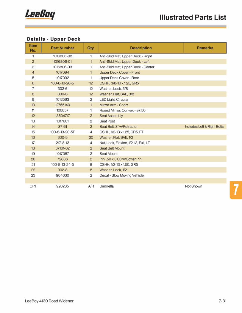
Details - Upper DeckItem No.
Part Number Qty. Description Remarks
1 1016806-02 1 Anti-Skid Mat, Upper Deck - Right
2 1016806-01 1 Anti-Skid Mat, Upper Deck - Left
3 1016806-03 1 Anti-Skid Mat, Upper Deck - Center
4 1017094 1 Upper Deck Cover - Front
5 1017092 1 Upper Deck Cover - Rear
6 100-6-16-20-5 12 CSHH, 3/8-16 x 1.25, GR5
7 302-6 12 Washer, Lock, 3/8
8 300-6 12 Washer, Flat, SAE, 3/8
9 1012563 2 LED Light, Circular
10 12755140 1 Mirror Arm - Short
11 100857 1 Round Mirror, Convex - ø7.50
12 13504717 2 Seat Assembly
13 1017601 2 Seat Post
14 37161 2 Seat Belt, 3" w/Retractor Includes Left & Right Belts
15 100-8-13-20-5F 4 CSHH, 1/2-13 x 1.25, GR5, FT
16 300-8 20 Washer, Flat, SAE, 1/2
17 217-8-13 4 Nut, Lock, Flexloc, 1/2-13, Full, LT
18 37161-02 2 Seat Belt Mount
19 1017087 2 Seat Mount
20 72836 2 Pin, .50 x 3.00 w/Cotter Pin
21 100-8-13-24-5 8 CSHH, 1/2-13 x 1.50, GR5
22 302-8 8 Washer, Lock, 1/2
23 984630 2 Decal - Slow Moving Vehicle
OPT 920235 A/R Umbrella Not Shown
LeeBoy 4130 Road Widener
Illustrated Parts List
7-31
77

Details - Left Side
WARNING
13855275G7
Falling off machine can cause serious injury or death.
Use steps and walkways provided for mounting and dismounting machine.
TOOLBOX
CAJA DE HERRAMIENTAS
BOÎTEÀOUTILS
859781-04
ULTRA LOW SULFUR FUEL
ONLY
1
2,3,4
5
6
7
8
9
10
11
12
Decal Under FlapOf Deck Hole Kit
Figure 7-14 . Details - Left Side
LeeBoy 4130 Road Widener
Illustrated Parts List
7-32

Details - Left SideItem No.
Part Number Qty. Description Remarks
1 1017080 1 Ladder
2 100-8-13-20-5F 4 CSHH, 1/2-13 x 1.25, GR5, FT
3 302-8 4 Washer, Lock, 1/2
4 300-8 4 Washer, Flat, SAE, 1/2
5 980460 1 Lever Latch
REF 35560 A/R Replacement Key
6 1004816 1 Deck Hole Kit - ø6"
7 1012563 1 LED Light, Circular
8 1016251 1 Fuel Tank Assembly See Fig. 7-15 for Details
9 1019039-10 1 Decal - Deco, Leeboy Logo, 11"
10 859781-04 1 Decal - Tool Box
11 13855275 1 Decal - Warning, Fall
12 1010090 1 Decal - Low Sulfur Fuel
LeeBoy 4130 Road Widener
Illustrated Parts List
7-33
77

Fuel Tank
1
2,3,4
5
6,7,3
8
9
10
11
12
13
14,15
11
1016
17
18
19
D856631
FLAMMABLEDiesel FuelKeep Clean
DANGERULTRA LOW SULFUR FUEL
ONLY
2120
Figure 7-15 . Fuel Tank
LeeBoy 4130 Road Widener
Illustrated Parts List
7-34

Fuel TankItem No.
Part Number Qty. Description Remarks
REF 1016251 1 Assembly, Fuel Tank, RW85
1 1016252 1 Weldment, Fuel Tank, RW85 Includes Items 12-15
2 100-8-13-32-5 2 CSHH, 1/2-13 x 2.00, GR5
3 300-8 4 Washer, Flat, SAE, 1/2
4 200-8-13-5 2 Nut, Hex, 1/2-13, GR5
5 1011971 1 Plug, Magnetic Drain, -16 SAE Orb
6 100-8-13-20-5F 2 CSHH, 1/2-13 x 1.25, GR5, FT
7 302-8 2 Washer, Lock, 1/2
8 1016871 1 Sending Unit, Fuel, 16"
9 122-#10-32-8F 5 PHMS, Cross, #10-32 x .50, FT
10 1014538-17 2 Tube, Fuel, Pick Up, 17"
11 2404-6-6 2 Adapter, Connector, -6 JIC / -6 NPTF
12 1015465 1 Cover
13 985688 1 Gasket, Hydraulic Tank, 20 GAL
14 204-4-20-5 12 Nut, Lock, Stover, 1/4-20, GR5
15 300-4 12 Washer, Flat, SAE, 1/4
16 140030FL 1 Cap, Fuel Tank, Lockable
17 140030FN 1 Filler, Neck, Hydraulic Oil/Cuel Cap
18 140030GK 1 Strainer & Gasket Kit
19 116-#12-12 6 Screw, Self, Drilling, HWH, #12 x .75
20 1010090 1 Decal - Ultra Low Sulfur Fuel Only
21 856631 1 Decal - Danger, Flammable Fuel
LeeBoy 4130 Road Widener
Illustrated Parts List
7-35
77

Details - Right Side
859781-03
ENGINE OILDRAIN
856446
Hydraulic oil onlyKeep clean
Huile hydrauliqueseulementMaintenir propre
PRECAUCION
ATTENTION
Aceite hidráulico solamenteMantener limpio
CAUTION
TOOLBOX
CAJA DE HERRAMIENTAS
BOÎTEÀOUTILS
859781-04
WARNING
13855275G7
Falling off machine can cause serious injury or death.
Use steps and walkways provided for mounting and dismounting machine.
Decal under flapof Deck Hole Kit
1
2,3,4
5
6
7
8/20
9
1011
12
13
14
15
16
17
19
18
Figure 7-16 . Details - Right Side
LeeBoy 4130 Road Widener
Illustrated Parts List
7-36

Details - Right SideItem No.
Part Number Qty. Description Remarks
1 1017080 1 Ladder
2 100-8-13-20-5F 4 CSHH, 1/2-13 x 1.25, GR5, FT
3 302-8 4 Washer, Lock, 1/2
4 300-8 4 Washer, Flat, SAE, 1/2
5 980460 1 Lever Latch
REF 35560 A/R Replacement Key
6 1004816 1 Deck Hole Kit - ø6"
7 1012563 1 LED Light, Circular
8 1020616 1 Battery Box Assembly - Single See Fig. 7-17 for Details
9 R801NRNR000008-72 1 Hose Assembly, 72", Tag# 58, Engine Oil Drain
10 33164 2 Hose Clamp, #10 (.56-1.06) (1) @ Engine - Not Shown
11 31109 1 Fitting, Straight, 08FJX-08HB, Push-On
12 2701-8-8-LN 1 Bulkhead Elbow Adapter, 90°, -8 JIC/-8 JIC
13 304-C-8 1 Adapter, Cap, -8 JIC
14 1016242 1 Hydraulic Tank Assembly See Fig. 7-18 for Details
15 1018906-05 1 Decal - Deco, LeeBoy Logo, 11"
16 859781-04 1 Decal - Tool Box
17 13855275 1 Decal - Warning, Fall
18 856446 1 Decal - Caution, Hydraulic Oil
19 859781-03 1 Decal - Engine Oil Drain
20 1020596 1 OPTION - Battery Box Assembly - Dual See Fig. 7-47 for Details
LeeBoy 4130 Road Widener
Illustrated Parts List
7-37
77
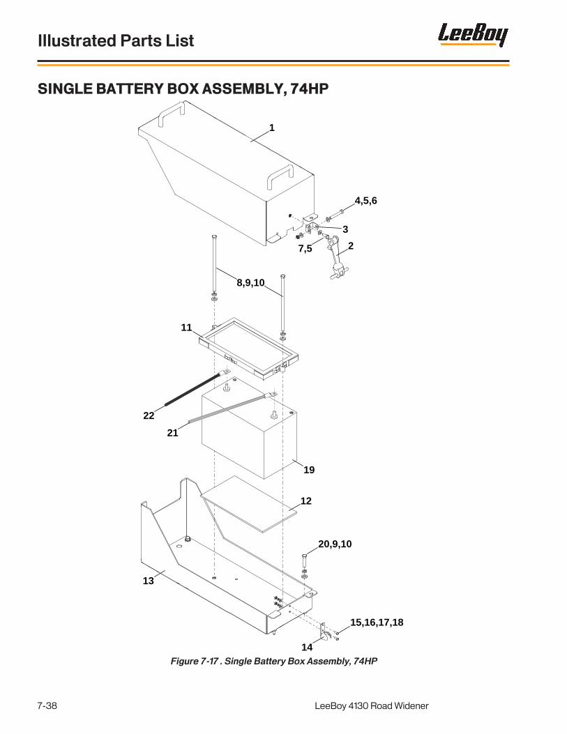
Single Battery Box Assembly, 74HP
1
2
3
4,5,6
7,5
8,9,10
11
12
13
14
15,16,17,18
19
20,9,10
21
22
Figure 7-17 . Single Battery Box Assembly, 74HP
LeeBoy 4130 Road Widener
Illustrated Parts List
7-38

Single Battery Box Assembly, 74HPItem No.
Part Number Qty. Description Remarks
REF 1020616 1 Single Battery Box Assembly Includes Items 1-18
1 1020598 1 Battery Box Cover
2 007020096 1 Rubber Hook
3 007020097 1 Anchor Bracket
4 100-5-18-36-5 1 CSHH, 5/16-18 x 2.25, GR5
5 300-5 3 Washer, Flat, SAE, 5/16
6 217-5-18 1 Nut, Lock, Flexloc, 5/16-18, Full, LT
7 100-5-18-12-5F 1 CSHH, 5/16-18 x .75, GR5, FT
8 100-6-16-152-5 2 CSHH, 3/8-16 x 9.50, GR5
9 302-6 6 Washer, Lock, 3/8
10 300-6 6 Washer, Flat, SAE, 3/8
11 72313 1 Battery Hold Down
12 720130 1 Battery Tray Pad
13 1020597 1 Battery Box Base
14 007020098 1 Hood Bracket
15 122-#10-32-8F 2 PHMS, Cross, #10-32 x .50, FT
16 300-#10 2 Washer, Flat, SAE, #10
17 302-#10 2 Washer, Lock, #10
18 209-#10-32 2 Nut, Hex, Machine, #10-32
19 PURCHASE LOCALLY 1 Battery, 12V, Group 31, 950 CCA
20 100-6-16-28-5 4 CSHH, 3/8-16 x 1.75, GR5
21 1016783 1 Battery Cable (+), Eye/Eye, 78" Battery to Cutoff
22 1019883 1 Battery Cable (-), Eye/Eye, 72" Battery to Starter
23 1019737 1 Battery Cable (-), Eye/Eye, 32" Frame Grd to Engine Grd - Not Shown
24 1019881 1 Battery Cable (+), Eye/Eye, 70" Cutoff to ECU - Not Shown
25 1019882 1 Battery Cable (+), Eye/Eye, 42" Cutoff to Start - Not Shown
LeeBoy 4130 Road Widener
Illustrated Parts List
7-39
77

Hydraulic Tank
Figure 7-18 . Hydraulic Tank Tank
856446
Hydraulic oil onlyKeep clean
Huile hydrauliqueseulementMaintenir propre
PRECAUCION
ATTENTION
Aceite hidráulico solamenteMantener limpio
CAUTIONLeak detection dye added to hydraulic tank.
1013275
NOTICE
7
33
32
1
2
35
4
29
30,21,31
16
17
18
19,20,21
22
23 24
25
26
2728
6a
98
9
10,11
14,15
13
12
6b
LeeBoy 4130 Road Widener
Illustrated Parts List
7-40

Hydraulic TankItem No.
Part Number Qty. Description Remarks
REF 1016242 1 Assembly, Hydraulic Tank, RW85
1 1016243 1 Weldment, Hydraulic Tank, RW85 Includes Items 12-15
2 140030HL 1 Cap, Hydraulic, Lockable
3 140030FN 1 Filler, Neck, Hydraulic Oil/Fuel Cap
4 140030GK 1 Strainer & Gasket Kit
5 116-#12-12 6 Screw, Self-Drilling, HWH, #12 x .75
6a 1009523 1 Filter, Hydraulic, FIK04-300 Includes Item 6b
6b 1009523-01 1 Filter Element
7 FS6400-20-20-O 1 Adapter, Straight, -20 ORFS/-20 O-Ring
8 FS6400-16-16-O 1 Adapter, Straight, -16 ORFS/-16 O-Ring
9 6408-16-O 2 Adapter, Plug, O-Ring, -16
10 204-6-16-5 4 Nut, Lock, Stover, 3/8-16, GR5
11 300-6 4 Washer, Flat, SAE, 3/8
12 1015465 1 Cover
13 985688 1 Gasket, Hydraulic Tank, 20 GAL
14 204-4-20-5 12 Nut, Lock, Stover, 1/4-20, GR5
15 300-4 12 Washer, Flat, SAE, 1/4
16 FS6801-12-12-NWO-FG 1 Adapter, Elbow, 90°, -12 ORFS/-12 O-Ring
17 6802-32-32 NWO 1 Adapter, Elbow, 45°, -32 JIC/-32 O-Ring
18 6408-32-O 1 Adapter, Plug, O-Ring, -32
19 100-8-13-24-5 2 CSHH, 1/2-13 x 1.25, GR5
20 302-8 2 Washer, Lock, 1/2
21 300-8 4 Washer, Flat, SAE,
22 1014643 1 Sensor, Level, Hydraulic
23 6408-6-O 1 Adapter, Plug, O-RIng, -6
24 1010402 1 Sender, Temperature, Hydraulic Oil, 100-250°F
25 6401-16-16-O 1 Adapter, Straight, -16 O-Ring/-16 NPTF
26 280210 1 Ball Valve, 1.00”
27 2501-16-16 1 Adapter, Elbow, 90°, -16 JIC/-16 NPTF
28 304-C-16 1 Adapter, Cap, -16 JIC
29 500070 1 Gauge, Sight Leve/Temperature, Hydraulic Oil
30 100-8-13-32-5 2 CSHH, 1/2-13 x 2.00, GR5
31 200-8-13-5 2 Nut, Hex, 1/2-13, GR5
32 856446 1 Decal - Caution, Hydraulic Oil Only
33 1013275 1 Decal - Notice, Hydraulic Dye
LeeBoy 4130 Road Widener
Illustrated Parts List
7-41
77

Details - Rear (1 of 2)
Figure 7-19 . Details - Rear (1 of 2)
WARNING
13855275G7
Falling off machine can cause serious injury or death.
Use steps and walkways provided for mounting and dismounting machine.
59246603
59246611
78
9
3
10
10
11
11
12
13
14
10,11,12,13,14
1
2
3
78
9
4
65
LeeBoy 4130 Road Widener
Illustrated Parts List
7-42

Details - Rear (1 of 2)Item No.
Part Number Qty. Description Remarks
1 1019538-01 1 Decal - Deco, Panel Logo - Left
2 1019538-02 1 Decal - Deco, Panel Logo - Right
3 1019538-06 2 Decal - Deco, Leeboy Logo, 24"
4 1019538-05 1 Decal - Deco, Logo, 4130
5 1019039-10 1 Decal - Leeboy Logo, 11”
6 13855275 1 Decal - Warning, Fall
7 940002 2 Decal - Deco, Flag
8 59246611 2 Decal - Lift Point
9 59246603 2 Decal - Tie Down
10 217-6-16 8 Nut, Lock, Flexloc, 3/8-16, Full, LT
11 300-6 8 Washer, Flat, SAE, 3/8
12 31878 4 Eye Bolt, 3/8-16 x 2.50, .75 ID
13 1013339 4 Snap Link, ø3/8"
14 70395-04 2 Chain, Proof Coil, .25 x 17 Link
LeeBoy 4130 Road Widener
Illustrated Parts List
7-43
77

Details - Rear (2 of 2)
Figure 7-20 . Details - Rear (2 of 2)
1
4,5
2
3
6
4,5,7
10
11,5,12
5,7,13
8
9
14
14
1516
16
1718a/18b
4,5,7
LeeBoy 4130 Road Widener
Illustrated Parts List
7-44

Details - Rear (2 of 2)Item No.
Part Number Qty. Description Remarks
1 1018753 1 Rear Ladder
2 1016806-07 1 Anti-Skid Mat, Ladder - Rear
3 1020053 2 Railing Clamp
4 100-6-16-20-5F 12 CSHH, 3/8-16 x 1.25, GR5,FT
5 302-6 14 Washer, Lock, 3/8
6 1018913 1 Strike Off Storage
7 300-6 8 Washer, Flat, SAE, 3/8
8 20214383 1 Back up Alarm Assembly
9 1005940 2 Signal Light, LED, Red
10 1018919 1 Strike Off Hold Down Pivot Pin
11 100-6-16-16-5F 2 CCHH, 3/8-16 x 1.00, GR5, FT
12 308-6-24 2 Washer, Flat, Fender, 3/8 x 1.50
13 204-6-16-5 1 Nut, Lock, Stover, 3/8-16, GR5
14 1016806-06 2 Anti-Skid Mat, Lower Deck - Rear
15 1013231 1 Beacon Light, Strobe, Amber
16 1016806-05 2 Anti-Skid Mat, Lower Deck - Front
17 1016806-04 1 Anti-Skid Mat, Lower Deck - Center
18a 1017254 1 Deck Cover - Rear, 74HP Engine
18b 1017750 1 OPTION - Deck Cover - Rear, 130HP Engine Not Shown
LeeBoy 4130 Road Widener
Illustrated Parts List
7-45
77

Figure 7-21 . Engine Group, 74HP - Covers and Panels
Engine Group, 74HP - Covers and Panels
39168-11
CAUTIONCerti�ed Emission Engine Installation:
This engine installation complies with the Clean Air Act 40 CFR 1068. You may not knowingly remove or render inoperative any device or element of design. You may not knowingly install any part that bypasses, impairs, defeats, or disables the control of emissions of any regulated pollutant. Failure to comply with these regulations may violate federal or state law and may result in �nes or other penalties per 40 CFR 1068 101 (b).
WARNING
59020040
Hot pressurized fluid.Can cause severe burns.Do not open radiatorwhile hot.
UPI
856608
RADIATOR
D856631
FLAMMABLEDiesel FuelKeep Clean
DANGER
859795
Check engine oil
level dailySAE
15W-40
API SERVICE CJ-4
CJ-4 ONLY
CHECK LISTA. Check diesel fuel.B. Check hydraulic oil (AW32 or Equivalent).C. Check engine oil (15W-40, CJ-4 Only).D. Check propane tank level (Regulator Pressure 15lbs.).E. Check air cleaner every 100 hours.F. Check gearbox oil (50 wt).G. Grease all fittings daily except on bearings. Refer to manual on greasing.H. Check conveyor chains every 100 hours (If equipped).I. Check battery cables and drive cables daily for wear.J. Check hoses for leaks or wear.K. Check all safety switches.L. Clean machine at end of day and lubricate. (DO NOT spray on ground)
A. Revisar el combustible diesel.B. Revisar el aceite hidráulico (AW32 ou Equivalente).C. Revisar el aceite del motor (15W40).D. Revisar el nivel de gas propano en el tanque (presión en el regulador: 103 kPa [15 psi]).E. Revisar el filtro de aire cada 100 horas.F. Revisar el aceite de la caja de engranajes (viscosidad 50).G. Engrasar todas las graseras diariamente, salvo en los cojinetes. Consultar el manual de
mantenimiento en cuanto al engrase.H. Revisar las cadenas del transportador cada 100 horas.I. Revisar los cables de la batería y los cables de mando diariamente en busca de desgaste.J. Revisar las mangueras en busca de fugas y desgaste.K. Revisar todos los interruptores de seguridad.L. Limpiar y lubricar la máquina al final del día. (NO rociar combustible en el suelo.)
LISTA DE VERIFICACION
A. Vérifier le niveau de fuel.B. Vérifier le niveau d’huile hydraulique (AW32 ou équivalent).C. Vérifier le niveau d’huile moteur (15W40).D. Vérifier le niveau de propane (pression au détendeur 103 kPa [15 lpc]).E. Vérifier le filtre à air toutes les 100 heures.F. Vérifier le niveau d’huile dans la boîte d’engrenages (densité 50).G. Lubrifier tous les graisseurs quotidiennement, sauf ceux des roulements. Se reporter au
manuel d'opérations.H. Vérifier les chaînes du convoyeur toutes les 100 heures.I. Vérifier les câbles de batterie et de commande quotidiennement pour voir si usure
prématurée.J. Vérifier les boyaux pour voir s’ils fuient ou sont usés.K. Vérifier tous les disjoncteurs (interrupteurs) de sûreté.L. Nettoyer la machine à la fin de la journée et la graisser. (NE PAS pulvériser de sur le sol)
LISTE DE CONTRÔLE
856439
Certi�ed Emission Engine Installation:This engine installation complies with the Clean Air Act 40 CFR 1068. You may not knowingly remove or render inoperative any device or element of design. You may not knowingly install any part that bypasses, impairs, defeats, or disables the control of emissions of any regulated pollutant. Failure to comply with these regulations may violate federal or state law and may result in �nes or other penalties per 40 CFR 1068 101 (b).
1
2
3
4
5
8
7
9
11
9
11
12
13
1514
16
17
18
6
19
20
19
21
22
23 24
25
39168-11
CAUTION
20
10
LeeBoy 4130 Road Widener
Illustrated Parts List
7-46

Engine Group, 74HP - Covers and PanelsItem No.
Part Number Qty. Description Remarks
1 1016121-51 1 Top Panel - Left
2 1016121-52 1 Top Panel - Right
3 1016121-55 1 Top Cover
4 1016121-54 1 Top Panel - Rear
5 1016121-53 1 Top Panel - Front
6 1016121-64 1 DOC Cover
7 1016121-49 2 Enclosure Cover
8 1016121-44 1 Enclosure Panel - Top
9 1016121-47 2 Enclosure Door
10 1016121-56 1 Radiator Screen
11 1016121-46 2 Enclosure Lift Bracket
12 1016121-43 1 Enclosure Panel - Right
13 1016121-42 1 Enclosure Panel - Left
14 1016121-57 1 Control Box Cover
15 1016121-50 1 Enclosure Panel - Front
16 1016121-45 1 Enclosure Panel - Rear
17 1016121-48 4 Door Enclosure Latch
18 856439 1 Decal - Oper, Check List
19 1010091 2 Decal - Caution, Emissions
20 39168-11 2 Decal - Caution, Hot Surface
21 59020040 1 Decal - Warning - Hot Pressurized Fluid
22 856608 1 Decal - Radiator
23 856631 1 Decal - Danger, Flammable
24 1010089 1 Decal - Oil Info
25 859795 1 Decal - Check Oil Daily
LeeBoy 4130 Road Widener
Illustrated Parts List
7-47
77

Figure 7-22 . Engine Group, 74HP - Radiator/Cooling
Engine Group, 74HP - Radiator/Cooling
12
11
1112
3,4
18
11
1112
3
76
6
4
5
8
9
10
11
1112
13
111112
14
14
15
16
17
16
LeeBoy 4130 Road Widener
Illustrated Parts List
7-48
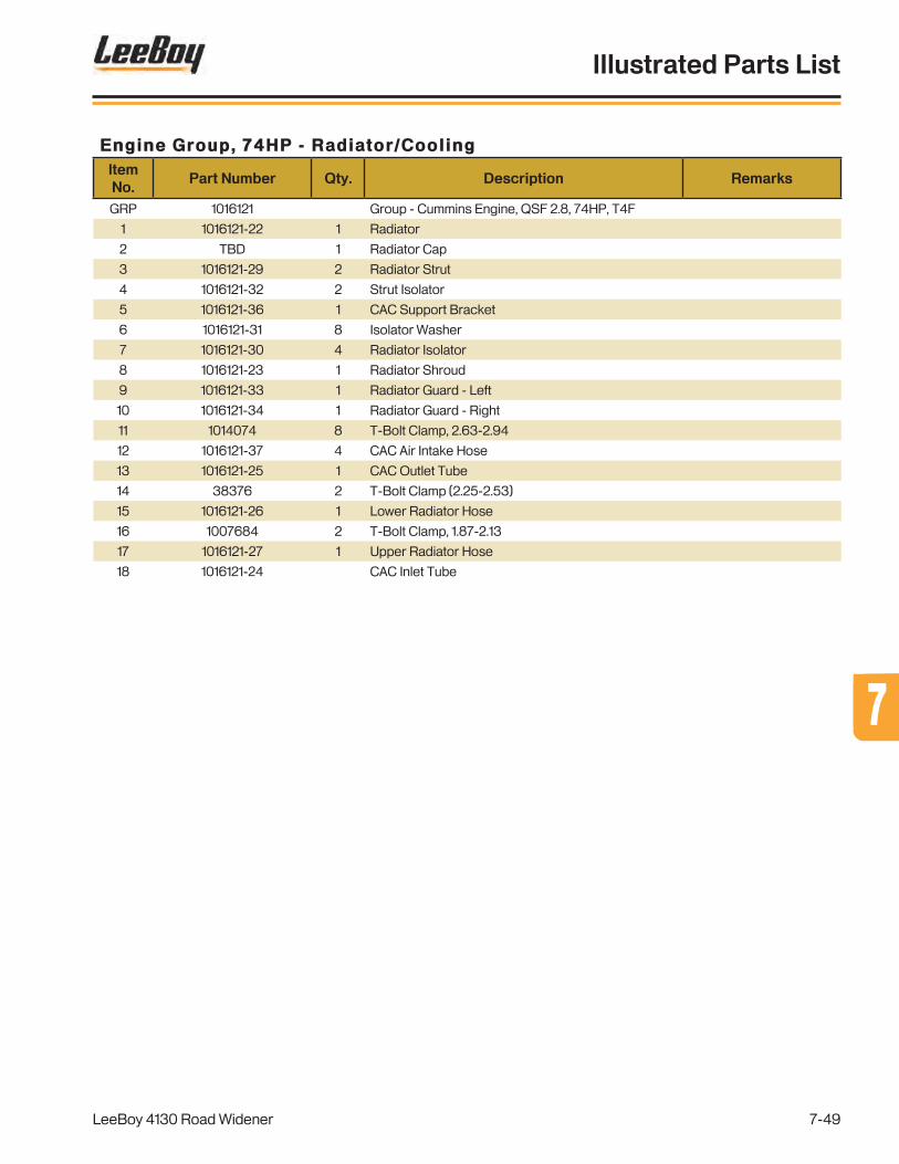
Engine Group, 74HP - Radiator/CoolingItem No.
Part Number Qty. Description Remarks
GRP 1016121 Group - Cummins Engine, QSF 2.8, 74HP, T4F
1 1016121-22 1 Radiator
2 TBD 1 Radiator Cap
3 1016121-29 2 Radiator Strut
4 1016121-32 2 Strut Isolator
5 1016121-36 1 CAC Support Bracket
6 1016121-31 8 Isolator Washer
7 1016121-30 4 Radiator Isolator
8 1016121-23 1 Radiator Shroud
9 1016121-33 1 Radiator Guard - Left
10 1016121-34 1 Radiator Guard - Right
11 1014074 8 T-Bolt Clamp, 2.63-2.94
12 1016121-37 4 CAC Air Intake Hose
13 1016121-25 1 CAC Outlet Tube
14 38376 2 T-Bolt Clamp (2.25-2.53)
15 1016121-26 1 Lower Radiator Hose
16 1007684 2 T-Bolt Clamp, 1.87-2.13
17 1016121-27 1 Upper Radiator Hose
18 1016121-24 CAC Inlet Tube
LeeBoy 4130 Road Widener
Illustrated Parts List
7-49
77

Figure 7-23 . Engine Group, 74HP - Intake/Frame
Engine Group, 74HP - Intake/Frame
1
2
2
3
4
5
6
7
8
9
10
9
1112
1211
13
14,1516,17
LeeBoy 4130 Road Widener
Illustrated Parts List
7-50

Engine Group, 74HP - Intake/FrameItem No.
Part Number Qty. Description Remarks
GRP 1016121 Group - Cummins Engine, QSF 2.8, 74HP, T4F
1 1016121-05 1 Air Filter
REF 1010076-02 1 Primary Air Filter Not Shown
REF 1012474-25 Secondary Air Filter Not Shown
2 1016121-06 2 Air Filter Mounting Bracket
3 1016121-08 1 Filter Harness
4 1013667-17 1 Air Restriction Indicator
5 953521243 1 T-Bolt Clamp, 4.31-4.59
6 1000834 1 Elbow, Rubber, 90°, 4.00 x 3.00
7 171090 1 T-Bolt Clamp, 3.31-3.59
8 1016121-04 1 Intake Pipe
9 38376 2 T-Bolt Clamp, 2.25-2.53
10 38387 1 Elbow, Rubber, 90°, 2.00
11 1016121-02 2 Engine Support Frame - Front
12 1016121-01 2 Engine Support Frame - Rear
13 1016121-03 1 Engine Frame
14 100-10-11-64-8 4 CSHH, 5/8-11 x 4.00, GR5, FT
15 1016121-58 4 Engine Isolator
16 986811 4 Washer, Lock, .670, Nord Wedge
17 200-10-11-5 4 Nut, Hex, 5/8-11, GR5
LeeBoy 4130 Road Widener
Illustrated Parts List
7-51
77

Figure 7-24 . Engine Group, 74HP - Components
Engine Group, 74HP - Components
1
2
3
4
7
8
5
6
9
10
12
11
13
14,15
16
17
1819
20
LeeBoy 4130 Road Widener
Illustrated Parts List
7-52

Engine Group, 74HP - ComponentsItem No.
Part Number Qty. Description Remarks
GRP 1016121 Group - Cummins Engine, QSF 2.8, 74HP, T4F
1 1016121-28 1 Radiator Fan
2 118811 2 Fan Spacer
3 1012474-26 1 Fan Belt
4 1012474-28 1 Oil Filter
5 1012474-10 1 Fuel Filter Head
6 1012474-27 1 Fuel Filter
7 1012474-11 1 Fuel/Water Seperator Head
8 988666-05 1 Fuel/Water Filter
9 1012474-18 1 ECM
10 1012474-29 1 Filler Cap
11 1012474-23 1 Alternator
12 1012474-19 1 EGR Valve
13 1012474-22 1 Starter
14 36085 1 Relay, 12VDC, SPDT, 40A, 5-Pin
15 36086 1 Relay Mounting Bracket
16 985751 1 Relay, 12VDC, SPST, 100A, HD
17 1000867-31 2 Isolator
18 1016121-18 1 Fuse Block
19 1014121 1 Fuse, 250A, AMG
20 720290 1 Solenoid, 12V, Constant Duty
LeeBoy 4130 Road Widener
Illustrated Parts List
7-53
77

Figure 7-25 . Engine Group, 74HP - Exhaust/Pumps
Engine Group, 74HP - Exhaust/Pumps
18
19
20
21
24,17
22
9
10
10
14
12
15,168
6
5
7
4
4
1
23
23
11
11
13
17
LeeBoy 4130 Road Widener
Illustrated Parts List
7-54

Engine Group, 74HP - Exhaust/PumpsItem No.
Part Number Qty. Description Remarks
1 1010076-31 1 Diesel Particulate Filter (DPF)
2 1016121-40 2 DOC Mounting Clamp
3 1016121-63 1 Muffler Cap
4 1016121-39 2 DOC Mounting Bracket
5 1016121-38 1 Exhaust Pipe
6 988666-15 1 Exhaust Clamp
7 36600 1 T-Bolt Clamp (ø3.09-ø3.35)
8 1010076-67 1 Pump Plate Adapter, 4 CI HSG, SAE 10 6H FBA 15T
REF 1015498 1 Pumps Assembly Includes Items 9-24
9 1015848 1 Pump, MP1, EDC, 45CC
10 FS6801-16-16-NWO-FG 3 Elbow Adapter, 90°, -16 ORFS / -16 O-Ring
11 DP6400-06-O 2 Test Point Coupling, -6 O-Ring
12 FS6804-12-12-12-NWO-FG 1 Run Tee Adapter, -12 ORFS/-12 O-Ring/-12 ORFS
13 FS0304-C-12 1 Adapter, Cap, ORFS, -12
14 FS6400-04-06-O 1 Straight Adapter, -4 ORFS / -6 ORFS
15 102-8-13-24-F 2 CSSH, 1/2-13 x 1.50, FT
16 986810 4 Washer, Lock, 1/2 Nord Wedge
17 12757410 1 O-Ring, FKM/Viton, 75D, .103 x 3.737
18 1012222 1 Pump, Load Sense - 60CC
19 1901-32 1 Split Flange Clamp, Code 61, -32
20 1901-16 1 Split Flange Clamp, Code 61, -16
21 4 C5OLO-S 1SF100 1 Adapter, 90°, 100µ Screen, -4 ORFS/-4 O-Ring
22 FS6804-10-10-10-NWO-FG 1 Run Tee Adapter, -10 ORFS/-10 O-Ring/-10 ORFS
23 FS0304-C-10 1 Adapter, Cap, ORFS, -10
24 100-M12-1.75-35-8.8F 2 CSHH, M12x1.75 x 35, C8.8, FT
24 FS0304-C-10 1 Adapter, Cap, ORFS, -10
25 100-M12-1.75-35-8.8F 2 CSHH, M12x1.75 x 35, C8.8, FT
LeeBoy 4130 Road Widener
Illustrated Parts List
7-55
77

Figure 7-26 . Pump Covers and Panels
Pump Covers and Panels
1
2
5
10,11,1210,11,12
6
9
4
7
8
6
310,11,12
13
13
LeeBoy 4130 Road Widener
Illustrated Parts List
7-56
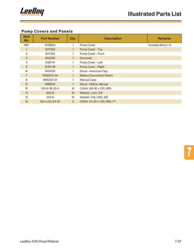
Pump Covers and PanelsItem No.
Part Number Qty. Description Remarks
REF 1019904 1 Pump Cover Includes Items 1-3
1 1017250 1 Pump Cover - Top
2 1017252 1 Pump Cover - Front
3 852350 1 Grommet
4 1018747 1 Pump Cover - Left
5 1018748 1 Pump Cover - Right
6 940002 1 Decal - American Flag
7 1009253-34 1 Battery Disconnect Switch
8 985234-01 1 Manual Case
9 988634 1 Decal - Notice, Manual
10 100-6-16-20-5 10 CSHH, 3/8-16 x 1.25, GR5
11 302-6 10 Washer, Lock, 3/8
12 301-6 10 Washer, Flat, USS, 3/8
13 100-4-20-24-5F 2 CSHH, 1/4-20 x 1.50, GR5, FT
LeeBoy 4130 Road Widener
Illustrated Parts List
7-57
77

Figure 7-27 . Hydraulic Manifold - Main
Hydraulic Manifold - Main
32
1
65
3
9
10
7,8
3*
* - (2) Additional adapters added when 4WD Axle (1017398) is installed.
3,4
LeeBoy 4130 Road Widener
Illustrated Parts List
7-58

Hydraulic Manifold - MainItem No.
Part Number Qty. Description Remarks
REF 1019085 1 Hydraulic Manifold Assembly - Main Includes Items 1-6
1 DP6400-06-O 1 Test Point Coupling, -6 O-Ring
2 FS6802-12-12-NWO-FG 1 Elbow Adapter, 45°, -12 ORFS/-12 O-Ring
3* FS6400-06-06-O 22/24* Straight Adapter, -6 ORFS/-6 O-Ring * - See Note
4 FS0304-06 6 Cap Adapter, -06 ORFS
5 FS6400-04-06-O 1 Straight Adapter, -4 ORFS/-6 O-Ring
6 FS6400-08-08-O 1 Straight Adapter, -8 ORFS/-8 O-Ring
REF 1015850 1 Hydraulic Manifold Includes Items 6-9
7 1001686-03 18 Coil, 12VDC Deutsch 3 Series (2) Per Solenoid
8 1016206-16 9 Solenoid, 4W3P
9 1015850-01 18 Counterbalance Valve, 2.5:1
10 1015852-02 1 Cross-Over Relief Valve
LeeBoy 4130 Road Widener
Illustrated Parts List
7-59
77

Figure 7-28 . Hydraulic Manifold - Conveyor/Steering
Hydraulic Manifold - Conveyor/Steering
1
1
2
2
34
5
5
6
6
4
6
6
8
7
9
10
11
1213
14,1514,15 14,1514,1516
LeeBoy 4130 Road Widener
Illustrated Parts List
7-60
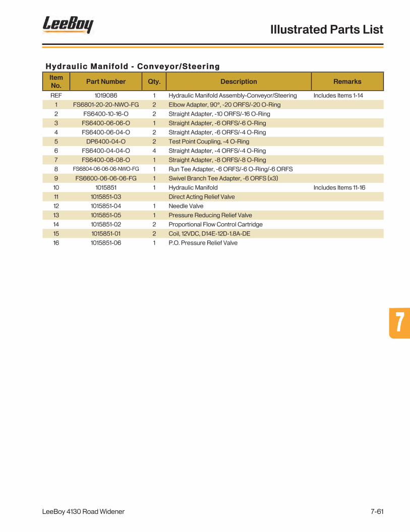
Hydraulic Manifold - Conveyor/SteeringItem No.
Part Number Qty. Description Remarks
REF 1019086 1 Hydraulic Manifold Assembly-Conveyor/Steering Includes Items 1-14
1 FS6801-20-20-NWO-FG 2 Elbow Adapter, 90°, -20 ORFS/-20 O-Ring
2 FS6400-10-16-O 2 Straight Adapter, -10 ORFS/-16 O-Ring
3 FS6400-06-06-O 1 Straight Adapter, -6 ORFS/-6 O-Ring
4 FS6400-06-04-O 2 Straight Adapter, -6 ORFS/-4 O-Ring
5 DP6400-04-O 2 Test Point Coupling, -4 O-Ring
6 FS6400-04-04-O 4 Straight Adapter, -4 ORFS/-4 O-Ring
7 FS6400-08-08-O 1 Straight Adapter, -8 ORFS/-8 O-Ring
8 FS6804-06-06-06-NWO-FG 1 Run Tee Adapter, -6 ORFS/-6 O-Ring/-6 ORFS
9 FS6600-06-06-06-FG 1 Swivel Branch Tee Adapter, -6 ORFS (x3)
10 1015851 1 Hydraulic Manifold Includes Items 11-16
11 1015851-03 Direct Acting Relief Valve
12 1015851-04 1 Needle Valve
13 1015851-05 1 Pressure Reducing Relief Valve
14 1015851-02 2 Proportional Flow Control Cartridge
15 1015851-01 2 Coil, 12VDC, D14E-12D-1.8A-DE
16 1015851-06 1 P.O. Pressure Relief Valve
LeeBoy 4130 Road Widener
Illustrated Parts List
7-61
77
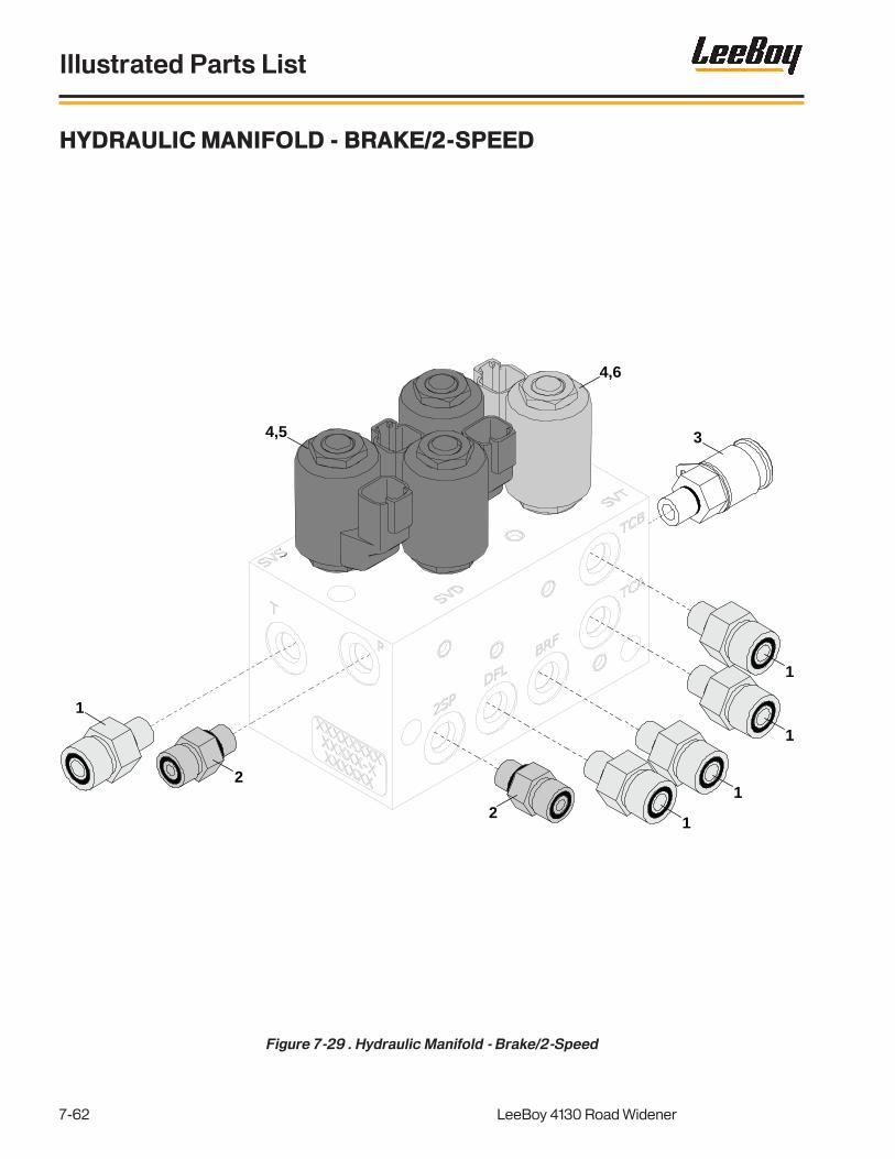
Figure 7-29 . Hydraulic Manifold - Brake/2-Speed
Hydraulic Manifold - Brake/2-Speed
1
2
34,5
4,6
21
1
1
1
LeeBoy 4130 Road Widener
Illustrated Parts List
7-62

Hydraulic Manifold - Brake/2-SpeedItem No.
Part Number Qty. Description Remarks
REF 1019096 1 Hydraulic Manifold Assembly - Brake/2 Speed Includes Items 1-6
1 FS6400-06-04-O 5 Straight Adapter, -6 ORFS/-4 O-Ring
2 FS6400-04-04-O 2 Straight Adapter, -4 ORFS/-4 O-Ring
3 DP6400-04-O 1 Test Point Coupling, -4 O-Ring
REF 1015852 1 Hydraulic Manifold Includes Items 4-6
4 1005448-02 4 Coil, 12VDC Deutsch P Series
5 1015852-01 3 Solenoid, 3W2P
6 1015852-02 1 Solenoid, 4W2P
LeeBoy 4130 Road Widener
Illustrated Parts List
7-63
77

Figure 7-30 . Hydraulic Oil Cooler
Hydraulic Oil Cooler
1
3
2
3
4,56,7
LeeBoy 4130 Road Widener
Illustrated Parts List
7-64

Hydraulic Oil CoolerItem No.
Part Number Qty. Description Remarks
REF 1019097 1 Hydraulic Oil Cooler Assembly Includes 1-8
1 1015757 1 Hydraulic Oil Cooiler, 45k BTU
REF 1015757-01 1 Hydraulic Oil Cooler Heat Exchanger Included With Item 1
REF 1015757-02 1 Hydraulic Oil Cooler Pusher Fan Included With Item 1
2 1015163 1 Temperature Switch, -8 MORB, 115°F Included With Item 1
3 FS6801-20-16-NWO-FG 2 Elbow Adapter, 90°, -20 ORFS/-16 O-Ring
4 100-6-16-20-5 4 CSHH, 3/8-16 x 1.25, GR5
5 300-6 8 Washer, Flat, SAE, 3/8
6 302-6 4 Washer, Lock, 3/8
7 200-6-16-5 4 Nut, Hex, 3/8-16, GR5
LeeBoy 4130 Road Widener
Illustrated Parts List
7-65
77

Figure 7-31 . Strike Off Group (1 of 4)
Strike Off Group (1 of 4)
1
2
3
5
68
7
9
10
8
6
6
6
4
6
LeeBoy 4130 Road Widener
Illustrated Parts List
7-66

Strike Off Group (1 of 4)Item No.
Part Number Qty. Description Remarks
GRP 1020392 Group - Strike Off Some Items Omitted for Clarity
1 1020400 1 Strike Off Mount, Rear
2 1020403 1 Rear Support Assembly, Outer
3 1020401 1 Rear Support Assembly, Inner
4 1020405 1 Turnbuckle Support Assembly
5 1016614 1 Strike Off Storage Tab Assembly
6 1016825 5 Strike Off Pin Assembly Includes Items 7,8
7 1017457 5 Strike Off Pin
8 1006850 6 Lynch Pin w/Chain Assemly
9 1020414 1 Strike Off Pin Assembly Includes Items 7,10
10 1020415 1 Strike Off Pin
LeeBoy 4130 Road Widener
Illustrated Parts List
7-67
77

Figure 7-32 . Strike Off Group (2 of 4)
Strike Off Group (2 of 4)
2
43
56
7
8
3,4
9 10
11,12
3,4
8
1
567
1314
17
15
1819
20,21
22
23
24
16
LeeBoy 4130 Road Widener
Illustrated Parts List
7-68

Strike Off Group (2 of 4)Item No.
Part Number Qty. Description Remarks
GRP 1020392 Group - Strike Off Some Items Omitted for Clarity
1 1016612 1 Grade Cylinder Assembly Includes Items 2-8
2 1015956 1 Hydraulic Cylinder, 2.00 Bore x 24.00 Stroke Includes Items 3,4 (x2)
- 1015956-03 A/R Hydraulic Cylinder Seal Kit Repair Part - Not Shown
3 20925244 3 Clevis Pin
4 15491939 3 Cotter Pin
5 6806-6-4 NWO 2 Elbow Adapter, 90°, -6 O-Ring/-4 NPTF
6 20926564 2 Ball Valve, On/Off, 1/4"
7 FS2404-06-04 2 Coneector Adapter, -6 ORFS/-4 NPTF
8 FS6801-06-06-NWO-FG 2 Elbow Adapter, 90°, -6 ORFS/-6 O-Ring
9 1018885 1 Strike Off Pivot Includes Item 10
10 20934832 1 Hydraulic Lube Fitting, 1/8
11 204-16-8-5 1 Nut, Lock, Stover, 1-8, GR5
12 300-16 2 Washer, Flat, SAE, 1"
13 1016613 1 Slope Cylinder Assembly Includes Items 3-8,14
14 1015957 1 Hydraulic Cylinder, 2.00 Bore x 16.00 Stroke Includes Items 3,4 (x1)
- 1015956-03 A/R Hydraulic Cylinder Seal Kit Repair Part - Not Shown
15 1020395 1 Strike Off Slope Beam
16 1020396 1 Strike Off Slope Includes Items 17-19
17 1020397 1 Strike Off Inner Tube
18 202-16-12-5 1 Nut, Hex, Jam, 3/4-16, GR5
19 1020398 1 Strike Off Yoke
20 100-12-16-40-5 1 CSHH, 3/4-16 x 2.50, GR5
21 200-12-10-5 1 Nut, Hex, 3/4-16, GR5
22 1016852 1 Strike Off Pin Assembly Includes Items 23,24
23 1017457 1 Strike Off Pin
24 1006850 1 Lynch Pin w/Chain Assembly
LeeBoy 4130 Road Widener
Illustrated Parts List
7-69
77
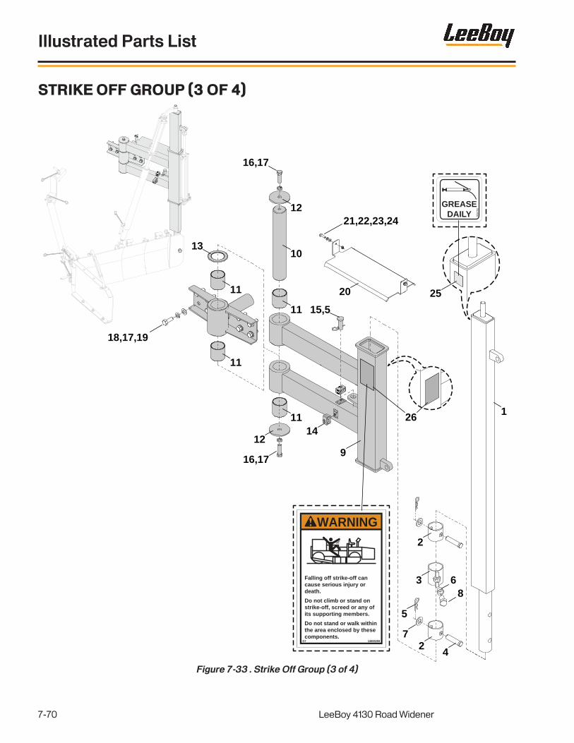
Figure 7-33 . Strike Off Group (3 of 4)
Strike Off Group (3 of 4)
8597
93
GREASEDAILY
WARNING
13855259G7
Falling off strike-off can cause serious injury or death.
Do not climb or stand on strike-off, screed or any of its supporting members.
Do not stand or walk within the area enclosed by these components.
1
2
3
2
68
4
7
5
9
14
16,17
10
12
11
11
12
15,5
18,17,19
20
21,22,23,24
26
25
11
11
13
16,17
LeeBoy 4130 Road Widener
Illustrated Parts List
7-70

Strike Off Group (3 of 4)Item No.
Part Number Qty. Description Remarks
GRP 1020392 Group - Strike Off Some Items Omitted for Clarity
1 1018462 1 Inner Tube Strike Off
2 1018466 2 Retainer End Tube
3 1018796 1 Strike Off Pivot
4 20182218 2 Clevis Pin, ø1.00 x 4.00
5 95458329 3 Cotter Pin, Split
6 1018903 1 Flanged Bushing, ø1.00 Shaft x 1.00 Long
7 300-16 2 Washer, Flat, SAE, 1
8 100-16-14-28-5F 1 CSHH, 1-14 x 1.75, GR5, FT
9 1018589 1 Strike Off Swing Arm Includes Items 10-13
10 1017116 1 Strike Off Pivot Shaft
11 107114 4 Bushing
12 1017264 2 Strike Off Pivot Plate
13 1017107 Thrust Bearing
14 1017323 2 Hose Clamp Kit
15 210060 1 Clevis Pin, ø1.00 x 2.63 w/ø1.50 Head
16 100-12-16-40-5 2 CSHH, 3/4-16 x 2.50, GR5
17 302-12 10 Washer, Lock, 3/4
18 100-12-10-32-5 8 CSHH, 3/4-10 x 2.00, GR5
19 300-12 8 Washer, Flat, SAE, 3/4
20 1017461 1 Hose Support Plate
21 100-6-16-20-5 2 CSHH, 3/8-16 x 1.25, GR5
22 302-6 2 Washer, Lock, 3/8
23 300-6 2 Washer, Flat, SAE, 3/8
24 200-6-16-5 2 Nut, Hex, 3/8-16, GR5
25 859793 1 Decal - Grease Daily
26 13855259 2 Decal - Warning, Falling Off
LeeBoy 4130 Road Widener
Illustrated Parts List
7-71
77

1
2
3,4
5
6
78
8 9
10 11
2525
2726
25
27
26
30
28
29
31
21,23
32,3334,35
14
15,16
21,22,23,2421,23,22
17181920
12
13
36
372526
27
21,22,23,24
Strike Off Group (4 of 4)
Figure 7-34 . Strike Off Group (4 of 4)
LeeBoy 4130 Road Widener
Illustrated Parts List
7-72

Strike Off Group (4 of 4)Item No.
Part Number Qty. Description Remarks
GRP 1020392 Group - Strike Off Some Items Omitted for Clarity
1 1020410 1 End Gate
2 1018888 1 End Gate Wear Plate
3 204-8-13-5 3 Nut, Lock, Stover, 1/2-13, GR5
4 301-8 3 Washer, Flat, USS, 1/2
5 1020411 1 End Gate Pin
6 1020399 1 End Gate Mount
7 1020413 1 End Gate Rod - Right
8 95458329 2 Cotter Pin - Split
9 1020440 1 End Gate Turnbuckle
10 1020412 1 End Gate Rod - Left
11 1018465 1 Strike Off Inner Support
12 1020393 1 Strike Off Assembly, 2-3 Foot Includes Items 13-29
13 1020394 1 Strike Off, 2-3 Foot
14 1009057 1 Hydraulic Cylinder, 1.50 Bore x 12.00 Stroke Includes Items 15,16
- 1009057-06 A/R Hydraulic Cylinder Seal Kit Repair Part - Not Shown
15 1009057-01 2 Clevis Pin
16 95989380 4 Cotter Pin, 5/32 x 1.00
17 FS6801-06-06-NWO-FG 1 Elbow Adapter, 90°, -6 ORFS, -6 O-Ring
18 FS2404-06-04 1 Connector Adapter, -6 ORFS/-4 NPTF
19 20926564 1 Ball Valve, On-Off, 1/4"
20 6806-6-4 NWO 1 Elbow Adapter, 90°, -6 O-Ring/-4 NPTF
21 100-12-10-32-5 16 CSHH, 3/4-10 x 2.00, GR5
22 300-12 A/R Washer, Flat, SAE, 3/4
23 302-12 16 Washer, Lock, 3/4
24 200-12-10-5 8 Nut, Hex, 3/4-10, GR5
25 1018916 3 Strike Off Hold Down
26 1006850 3 Lynch Pin Assembly w/Chain
27 1007776 3 Strike Off Swing Cylinder Pin
28 1016600 1 Strike Off Assembly - 1 Ft. Includes Items 21,23,25-27-29-36
29 1016925 1 Strike Off, 1 Ft.
30 1019032 1 Strike Off Storage Tab
31 148-223 1 Insulated Band Clamp, 1-1/2"
32 100-6-16-20-5 1 CSHH, 3/8-16 x 1.25, GR5
33 302-6 1 Washer, Lock, 3/8
34 300-6 2 Washer, Flat, SAE, 3/8
35 200-6-16-5 1 Nut, Hex, 3/8-16, GR5
REF 1019322 1 Strike Off Hose Kit
36 1016611 1 OPTION - Strike Off Assembly - 3 Ft.
37 1016926 1 Strike Off, 3 FT.
LeeBoy 4130 Road Widener
Illustrated Parts List
7-73
77

OPTION - Dual Strike Off
Figure 7-35. OPTION - Dual Strike Off
LeeBoy 4130 Road Widener
Illustrated Parts List
7-74

The Dual Strike Off Option consists of a second Strike Off Group (P/N 1020392). All components are the same between the Right Configuration (Standard) and the Left Configuration (Option).
Reference Figure 7-31 through 7-34 for parts and assembly assistance.
Contact your LeeBoy/LB Performance dealer with any questions.
OPTION - Dual Strike OffItem No.
Part Number Qty. Description Remarks
OPT 1020392 OPTION- Strike Off
LeeBoy 4130 Road Widener
Illustrated Parts List
7-75
77

OPTION - Strike Off Remote Assembly
Figure 7-36. OPTION - Strike Off Remote Assembly
GRADE
EXTENSION
SLOPE1019713
3
2
3
1
4
3
24”FROM REAR OFENCLOSURE TO
END OF HARNESS
10
11
12
13,14,15
5
7,8,9
6
LeeBoy 4130 Road Widener
Illustrated Parts List
7-76

OPTION - Strike Off Remote AssemblyItem No.
Part Number Qty. Description Remarks
OPT 1019702 1 OPTION - Strike Off Remote Assmebly
REF 1019703 1 Strike Off Remote Control Box Assmebly Includes Items 1-9
1 1019704 1 Control Box Enclosure
2 1019713 1 Decal - Operation, Control Box
3 851392 3 Toggle Switch, 3-POS, SPDT, MOM
4 982249 1 Push Button Switch
5 3400DI 1 Connector, Water Tight, 3/4 x 3/4
6 982446-01 1 Boot Cover, Conn, SOC, 12P
7 982449 1 Conn, Plug, DT06-8SA, Deutsch
8 1007354 1 Term, SOC 16-22 GA Deutsch
9 983218 1 Conn, Wedge, Plug, 8P, Deutsch
10 1019705 1 Remote Strike Off Mounting Plate
11 1019706 1 U-Bolt, Vibration Reducing, 1-5/16"
12 212-4-20 2 Wing Nut, 1/4-20
13 100-4-20-12-5F 4 CSHH, 1/4-20 x .75, GR5, FT
14 300-4 4 Washer, Flat, SAE, 1/4
15 204-4-20-5 4 Nut, Lock, Stover, 1/4-20, GR5
LeeBoy 4130 Road Widener
Illustrated Parts List
7-77
77

OPTION - Strike Off TopCon-Slope
Figure 7-37. OPTION - Strike Off TopCon-Slope
1
2
3a
4,5,6
8,9,10
3b
8,9,10
7,5,6
7,5,6
LeeBoy 4130 Road Widener
Illustrated Parts List
7-78

OPTION - Strike Off TopCon-SlopeItem No.
Part Number Qty. Description Remarks
OPT 1021173 1 OPTION - TopCon Slope
1 1010499-08 1 GC-35 Controller Assembly
REF 983414-09 1 System 5 Paver Control Box Bracket Not Shown
2 1010499-09 1 P-32 Slope Module
3a 1021155 1 TopCon Slope Mount - Right
3b 1021156 1 TopCon Slope Mount -Left For Left Mounted/Dual Strike Offs
4 100-5-18-20-5 2 CSHH, 5/16-18 x 1.25, GR5
5 302-5 4 Washer, Lock, 5/16
6 300-5 4 Washer, Flat, SAE, 5/16
7 100-5-18-16-5 2 CSHH, 5/16-18 x 1.00, GR5
8 100-12-10-40-8 4 CSHH, 3/4-10 x 2.50, GR8
9 302-12 4 Washer, Lock, 3/4
10 300-12 4 Washer, Flat, SAE, 3/4
REF 1010499-10 1 Slope Module Cable - 8' Not Shown
REF 851265 1 Carrying Case - Sonic Tracker Not Shown
LeeBoy 4130 Road Widener
Illustrated Parts List
7-79
77

OPTION - Strike Off TopCon-Grade
Figure 7-38. OPTION - Strike Off TopCon-Grade
1
2
7
3
4,5,6
8
9
10
11
1213
14,15,16
17a
17b
18,5,6
LeeBoy 4130 Road Widener
Illustrated Parts List
7-80

OPTION - Strike Off TopCon-GradeItem No.
Part Number Qty. Description Remarks
OPT 1021174 1 OPTION - TopCon Grade
1 1010499-08 1 GC-35 Controller Assembly
REF 983414-09 1 System 5 Paver Control Box Bracket Not Shown
2 1010499-06 1 Sonic Tracker II Assembly
3 851578 1 TopCon Sonic Tracker Bracket
4 100-12-10-64-8 1 CSHH, 3/4-10 x 4.00, GR8
5 302-12 5 Washer, Lock, 3/4
6 300-12 5 Washer, Flat, SAE, 3/4
7 9090-1125 1 TopCon ZArm Bracket Includes Items 8-10
8 1011443 1 Z Arm - Upper
9 1011444 1 Z Arm - Lower
10 920070 1 Thumb Screw, 3/8-16 x 1.00
11 851575 1 TopCon/Spectra Pivot Mount
12 300060 1 Handle Nut, 5/8-11
13 100-12-10-32-5 1 CSHH, 3/4-10 x 2.00, GR5
14 100-8-13-24-8 2 CSHH, 1/2-13 x 1.50, GR8
15 302-8 2 Washer, Lock, 1/2
16 300-8 2 Washer, Flat, SAE, 1/2
17a 1021158 1 TopCon Grade Mount - Right
17b 1021157 1 TopCon Grade Mount - Left For Left Mounted/Dual Strike Offs
18 100-12-10-40-8 1 CSHH, 3/4-10 x 2.50, GR8
REF 1010499-04 1 GC-35/Tracker Coil Cord - 15'. Not Shown
REF 983414-10 1 Temp Bail w/Sleeves Assembly Not Shown
REF 851265 1 Carrying Case - Sonic Tracker Not Shown
LeeBoy 4130 Road Widener
Illustrated Parts List
7-81
77

OPTION - Rear Axle Assembly - 4WD w/Steering
Figure 7-39. OPTION - Rear Axle Assembly - 4WD w/Steering
1
22
3
4
6,7,
8
5
9
10
VIE
W A
-A
A
A
11
12
1110
12
1311
10
12
14
15
15
LeeBoy 4130 Road Widener
Illustrated Parts List
7-82

OPTION - Rear Axle Assembly - 4WD w/SteeringItem No.
Part Number Qty. Description Remarks
OPT 1017398 OPTION - Rear Axle, 4WD w/Steering
1 1017760* 1 Axle Assembly, 26.25 Ratio *Contact LeeBoy forService Parts Manual
2 FS7005-08-18 2 Straight Adapter, -8 ORFS/18mm
3 FS7005-06-14 2 Straight Adapter, -6 ORFS/14mm
4 FS7215-06-14-06-NWO-FG 1 Run Tee Adapter, -6 ORFS/14mm O-Ring/-6 ORFS
5 1016624 2 Rear Axle Mounting Bracket
6 100-12-10-128-8 8 CSHH, 3/4-10 x 8.00, GR8
7 300-12 16 Washer, Flat, SAE, 3/4
8 204-12-10-8 8 Nut, Lock, Stover, 3/4-10, GR8
REF 1019238 1 Drive Shaft Assembly, 2 Pc. Inline Includes Items 9-14
9 1019238-03 1 Drive Shaft Assembly - Long Includes Item 10,11 (x2)
10 1006348-02 3 U-Joint, 1410 - Greaseable
11 1019238-04 6 Retaining Clip
12 39032 3 Drive Shaft Strap Kit
13 1019238-02 1 Drive Shaft Assembly - Short Includes Items 10,11 (x1)
14 1019238-01 1 Bearing Assembly
15 1016843 2 Front Tire/Wheel Assembly
REF 851392 1 Toggle Switch, 3-POS, SPDT, MOM Not Shown - See Fig. 7-13
REF 31985 1 Green Dash Light Not Shown - See Fig. 7-13
REF FS6602-06-06-06-FG 1 Swivel Run Tee Adapter, -6 ORFS (x3) Not Shown
REF FS6400-06-06-O 2 Straight Adapter, -6 ORFS/-6 O-Ring Not Shown
REF 1019817 1 Rear Axle Hose Kit Not Shown
LeeBoy 4130 Road Widener
Illustrated Parts List
7-83
77

Figure 7-40 . OPTION - Engine Covers and Panels, 130HP
OPTION - Engine Covers and Panels, 130HP
856608
RADIATOR
WARNING
59020040
Hot pressurized fluid.Can cause severe burns.Do not open radiatorwhile hot.
UPI
39168-11
CAUTION
SAE15W-40
API SERVICE CJ-4
CJ-4 ONLY
859795
Check engine oil
level daily
D856631
FLAMMABLEDiesel FuelKeep Clean
DANGER
Certi�ed Emission Engine Installation:This engine installation complies with the Clean Air Act 40 CFR 1068. You may not knowingly remove or render inoperative any device or element of design. You may not knowingly install any part that bypasses, impairs, defeats, or disables the control of emissions of any regulated pollutant. Failure to comply with these regulations may violate federal or state law and may result in �nes or other penalties per 40 CFR 1068 101 (b).
1
2
3
45
6
7
8
9
1011
12
13
14
16
15
17
18
19
20
21
22
2324
2526
27
28
LeeBoy 4130 Road Widener
Illustrated Parts List
7-84

OPTION - Engine Covers and Panels, 130HPItem No.
Part Number Qty. Description Remarks
1 1013528-57 1 Aftertreatment Cover, Main
2 1013528-67 1 Cover
3 1013528-59 1 Aftertreatment Support, Top
4 1013528-54 1 Radiator Fill Cover
5 1013528-68 1 Thumb Screw
6 1013528-80 1 Grommet
7 1013528-65 1 A/T Chimney Mid
8 1013528-66 1 Cover
9 1013528-61 1 Aftertreatment Cover - Right
10 1013528-63 1 Door Assembly - Right
11 1013528-55 1 Panel - Right
12 1013528-53 1 Foam Air Dam Kit
13 1013528-69 1 Radiator Screen
14 1013528-56 1 Corner Panel - Left
15 1013528-81 1 Grommet
16 1013528-64 1 Door Assembly - Left
17 1013528-52 4 Door Latch
18 1013528-62 1 Aftertreatment Cover - Left
19 1013528-60 1 Panel - Rear
20 1013528-58 1 Aftertreatment Cover - Rear
21 39168-11 2 Decal - Caution, Hot Surface
22 1010091 2 Decal - Caution, Emissions
23 59020040 1 Decal - Warning - Hot Pressurized Fluid
24 856608 1 Decal - Radiator
25 856631 1 Decal - Danger, Flammable
26 1010089 1 Decal - Oil Info
27 859795 1 Decal - Check Oil Daily
28 856439 1 Decal - Oper, Check List
LeeBoy 4130 Road Widener
Illustrated Parts List
7-85
77

Figure 7-41 . OPTION - Engine Group, 130HP- Radiator/Cooling
OPTION - Engine Group, 130HP - Radiator/Cooling
12
3
4
3
4
5
6
7
8
9,10
11
12
25
24
23
3132 33
32 32
32
3436
3235
3233
32
13
14
1715
1516
1615
15
18
18
19
20
18
1819
21
22
2627
26
28
2626 27
29
30
36
363738
36
36
37
39
40
9,10
12
11
33
LeeBoy 4130 Road Widener
Illustrated Parts List
7-86

OPTION - Engine Group, 130HP - Radiator/CoolingItem No.
Part Number Qty. Description Remarks
OPT 1016628 OPTION - Cummins Engine, QSF 3.8, 130HP, T4F
1 1013528-91 1 Radiator, Power Unit
2 1021629 1 Radiator Cap
3 1013528-22 2 Isolator
4 1013528-100 2 Washer, Cinch, .66ID x 2.75 OD x .19
5 1013528-92 1 Fan Shroud - Top
6 1013528-93 1 Fan Guard- Left
7 1013528-94 1 Fan Guard - Right
8 1013528-95 2 Radiator Strut
9 1013528-108 3 Bolt, Hex Head Flange, 3/8-16 x 2.25
10 1013528-107 3 Nut, Hex Head Flange, Lock, 3/8-16
11 1013528-23 3 Isolator
12 1013528-105 3 Washer,
13 1013528-32 1 Cooling Tube Bracket
14 36894 1 Clamp, Insulated, ø2.00”
15 1013528-21 4 Hose Clamp, #40
16 1013528-26 2 Coolant Hose
17 1013528-31 1 Formed Inlet Tube
18 1013528-34 4 Constant Torque Clamp
19 1013528-24 2 CAC Hose
20 1013528-29 1 CAC Outlet Tube
21 1013528-19 1 Air Transfer Pipe
22 1013528-20 1 V-Band Clamp
23 1013528-96 2 Fan Spacer, 1.50”
24 1013528-97 1 Cooling Fan
25 1013528-106 4 Bolt, Hex Head Flange, M10x1.5 x 100
26 33170 4 Hose Clamp, #32 (1.56-2.50)
27 1013528-25 2 Coolant Hose
28 1013528-30 1 Formed Outlet Tube
29 1013528-98 1 Coolant Level Harness
30 1013528-99 1 Coolant Level Sensor
31 1013528-104 2 Fitting, 1/4-NPT-M x 3/8” Beaded Hose Barb
32 33162 6 Hose Clamp, #6 (.44-.78)
33 1013528-102 A/R Hose, Bulk, 3/8” Heater Hose
34 1013528-109 1 Fitting, Tee, 1/4 NPT Female
35 1013528-101 2 Fitting, Hose Barb, 1/4 NPT-M x 3/8
36 1014083 4 Worm Drive Clamp (2.06-3.00)
37 1013528-27 2 CAC Air Intake Hose
38 1013528-28 1 CAC Formed Inlet Tube
39 1013528-35 1 U-Bolt Clamp, 2.50
40 1013528-33 1 Intercooler Hose Bracket
LeeBoy 4130 Road Widener
Illustrated Parts List
7-87
77

Figure 7-42 . OPTION - Engine Group, 130HP- Intake/Frame
OPTION - Engine Group, 130HP - Intake/Frame
1
2
3
4
3
3
5
6
7
8
9
10
11
1211
13
17,181920
14
15
16
LeeBoy 4130 Road Widener
Illustrated Parts List
7-88

OPTION - Engine Group, 130HP - Intake/FrameItem No.
Part Number Qty. Description Remarks
OPT 1016628 OPTION - Cummins Engine, QSF 3.8, 130HP, T4F
1 1013528-05 1 Direct Flow Air Cleaner
REF 1010076-02 1 Primary Air Filter
REF 1012474-25 1 Secondary Air Filter
2 1013667-17 1 Air Restriction Indicator
3 1013528-82 3 Clamp, T-Bolt, 4.50”
4 1013528-04 1 Elbow Hose
5 1013528-06 1 Air Intake Tube
6 1013528-83 1 Reducer Hose, 4.00” ID to 3.00” ID
7 171090 1 T-Bolt Clamp (3.31-3.59)
8 1013528-07 1 Air Filter Mounting Bracket
9 1013528-03 1 Baserail Assembly
10 1013528-84 2 Isolator Spacer
11 1013528-85 4 Isolator
12 1013528-86 2 Engine Frame Support - Rear
13 1013528-02 1 Engine Frame Support - Front Right
14 1013528-01 1 Engine Frame Support - Front Left
15 1013528-09 4 ECM Isolator
16 1013528-10 ECM Mounting Plate
17 100-8-13-56-5 6 CSHH, 1/2-13 x 3.50, GR5
18 200-8-13-5 6 Nut, Hex, 1/2-13, GR5
19 1016121-58 6 Engine Isolator, CB-1203-3
20 986811 6 Washer, Lock, .670 Nord Wedge
LeeBoy 4130 Road Widener
Illustrated Parts List
7-89
77

Figure 7-43 . OPTION - Engine Group, 130HP- Components
OPTION - Engine Group, 130HP - Components
11
14
15
8
7
9
10
3
1
2
4
56
6
12
13
16
17
18
19
LeeBoy 4130 Road Widener
Illustrated Parts List
7-90

OPTION - Engine Group, 130HP - ComponentsItem No.
Part Number Qty. Description Remarks
OPT 1016628 OPTION - Cummins Engine, QSF 3.8, 130HP, T4F
1 1013528-72 1 Alternator Mount
2 1013528-73 1 Alternator
3 1013528-71 1 Belt Tensioner
4 1008650-01 1 Starter
5 985751 1 Relay, 12VDC, SPST, 100A, HD
6 1000867-31 2 Isolator
7 720290 1 Solenoid, 12V, Constant Duty
8 1013528-16 1 Wire - Relay to Grid Heater
9 1013528-15 1 Wire - Alternator to Relay
10 1013528-13 1 Wire - Alternator (+)
11 1013528-12 1 Starter Relay Loop Harness
12 1013528-14 1 Wire - Alternator Ground to Starter (-)
13 1013528-75 1 Oil Level Gauge
14 1013528-76 1 Oil Filter
15 1013528-70 1 Oil Filler
16 1012474-11 1 Fuel/Water Separator Filter
17 988666-05 1 Fuel/Water Separator Filter Element
18 1012474-10 1 Fuel Filter Head
19 1012474-27 1 Fuel Filter
REF 1013528-11 1 Engine Harness Not Shown
REF 1013528-08 1 Mini Relay, 12V Not Shown
LeeBoy 4130 Road Widener
Illustrated Parts List
7-91
77

Figure 7-44 . OPTION - Engine Group, 130HP - Exhaust
OPTION - Engine Group, 130HP - Exhaust
1
2
3
4
56
7
89
10
11
12
13
14
14
15
16
17
18
18
LeeBoy 4130 Road Widener
Illustrated Parts List
7-92

OPTION - Engine Group, 130HP - ExhaustItem No.
Part Number Qty. Description Remarks
OPT 1016628 OPTION - Cummins Engine, QSF 3.8, 130HP, T4F
1 1013528-36 1 Aftertreatment, 12V
2 1012526-38 1 Clamp, ø4.00”
3 1013528-43 1 Elbow, 90°, 4.00 OD
4 1013528-42 1 Rain Cap
5 1013528-38 1 Spherical Gasket, 4.00”
6 1013667-08 1 V-Band Clamp, 4.00”
7 1013528-87 1 Decomp Reactor Tube
8 1013528-39 1 Spherical Gasket, 3.00”
9 1013528-40 1 V-Band Clamp, 3.00”
10 1013528-49 1 Clamp, ø3.00”
11 1013528-88 1 Exhaust Bellows Tube
12 1013985 1 Clamp, ø3.00”
13 1013528-41 2 Strap Clamp, 13”
14 1013528-47 2 Aftertreatment Cradle
15 1013528-44 1 Chimney
16 1013528-45 1 Bracket Mounting
17 1013528-46 1 Aftertreatment Support
18 1013528-48 2 Strut
LeeBoy 4130 Road Widener
Illustrated Parts List
7-93
77

Figure 7-45 . OPTION - Engine Group, 130HP - Pumps
OPTION - Engine Group, 130HP - Pumps
1
2
9,10
36
7
54
4 811
12
13
15
14
16
17
18,10
LeeBoy 4130 Road Widener
Illustrated Parts List
7-94
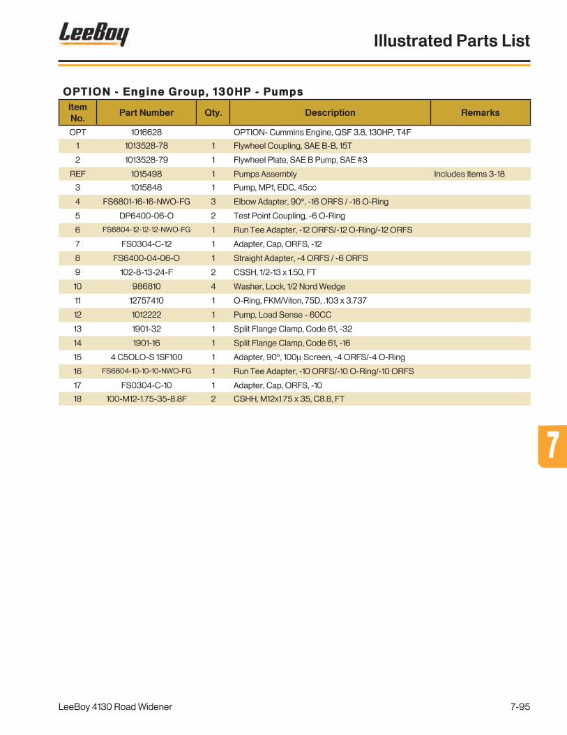
OPTION - Engine Group, 130HP - PumpsItem No.
Part Number Qty. Description Remarks
OPT 1016628 OPTION- Cummins Engine, QSF 3.8, 130HP, T4F
1 1013528-78 1 Flywheel Coupling, SAE B-B, 15T
2 1013528-79 1 Flywheel Plate, SAE B Pump, SAE #3
REF 1015498 1 Pumps Assembly Includes Items 3-18
3 1015848 1 Pump, MP1, EDC, 45cc
4 FS6801-16-16-NWO-FG 3 Elbow Adapter, 90°, -16 ORFS / -16 O-Ring
5 DP6400-06-O 2 Test Point Coupling, -6 O-Ring
6 FS6804-12-12-12-NWO-FG 1 Run Tee Adapter, -12 ORFS/-12 O-Ring/-12 ORFS
7 FS0304-C-12 1 Adapter, Cap, ORFS, -12
8 FS6400-04-06-O 1 Straight Adapter, -4 ORFS / -6 ORFS
9 102-8-13-24-F 2 CSSH, 1/2-13 x 1.50, FT
10 986810 4 Washer, Lock, 1/2 Nord Wedge
11 12757410 1 O-Ring, FKM/Viton, 75D, .103 x 3.737
12 1012222 1 Pump, Load Sense - 60CC
13 1901-32 1 Split Flange Clamp, Code 61, -32
14 1901-16 1 Split Flange Clamp, Code 61, -16
15 4 C5OLO-S 1SF100 1 Adapter, 90°, 100µ Screen, -4 ORFS/-4 O-Ring
16 FS6804-10-10-10-NWO-FG 1 Run Tee Adapter, -10 ORFS/-10 O-Ring/-10 ORFS
17 FS0304-C-10 1 Adapter, Cap, ORFS, -10
18 100-M12-1.75-35-8.8F 2 CSHH, M12x1.75 x 35, C8.8, FT
LeeBoy 4130 Road Widener
Illustrated Parts List
7-95
77

Figure 7-46 . OPTION - Engine Group, 130HP - DEF Tank
OPTION - Engine Group, 130HP - DEF Tank
1
2
34
5
6
7
11
8,9,10
LeeBoy 4130 Road Widener
Illustrated Parts List
7-96

OPTION - Engine Group, 130HP - DEF TankItem No.
Part Number Qty. Description Remarks
OPT 1016628 OPTION - Cummins Engine, QSF 3.8, 130HP, T4F
1 1017509-05 1 DEF Tank
2 1013528-17 1 Module Supply, 12V
3 1013528-89 3 Def Module Isolator - Front
4 1013528-90 3 Def Module Isolator - Rear
5 1013528-18 2 DEF Coolant Manifold
6 1013667-03 1 Coolant Control Valve
7 1019321 1 DEF Tank Tray
8 100-6-16-20-5 4 CSHH, 3/8-16 x 1.25, GR5
9 302-6 4 Washer, Lock, 3/8
10 300-6 4 Washer, Flat, SAE, 3/8
11 1019690 1 DEF Relay Mounting Plate
LeeBoy 4130 Road Widener
Illustrated Parts List
7-97
77

Figure 7-47 . OPTION - Dual Battery Box Assembly, 130HP
OPTION - Dual Battery Box Assembly, 130HP
1
2
3
4,5,6
7,58,9,10
11
1213
1414
15
16,17,18
19
20
21,22,23,24
25
26,9,10
28
27
LeeBoy 4130 Road Widener
Illustrated Parts List
7-98

OPTION - Dual Battery Box Assembly, 130HPItem No.
Part Number Qty. Description Remarks
OPT 1020596 1 OPTION - Dual Battery Box Assembly Includes Items 1-24
1 1020598 1 Battery Box Cover
2 007020096 1 Rubber Hook
3 007020097 1 Anchor Bracket
4 100-5-18-36-5 1 CSHH, 5/16-18 x 2.25, GR5
5 300-5 3 Washer, Flat, SAE, 5/16
6 217-5-18 1 Nut, Lock, Flexloc, 5/16-18, Full, LT
7 100-5-18-12-5F 1 CSHH, 5/16-18 x .75, GR5, FT
8 100-6-16-152-5 2 CSHH, 3/8-16 x 9.50, GR5
9 302-6 6 Washer, Lock, 3/8
10 300-6 6 Washer, Flat, SAE, 3/8
11 982962 1 Battery Hold Down
12 122795 1 Battery Cable (+), Eye/Eye, 17"
13 1019675 1 Battery Cable (-), Eye/Eye, 12.5"
14 1020603 2 Battery Tray Pad
15 1020594 1 Battery Box Spacer
16 100-4-20-8-5F 2 CSHH, 1/4-20 x .50, GR5, FT
17 302-4 2 Washer, Lock, 1/4
18 300-4 2 Washer, Flat, SAE, 1/4
19 1020597 1 Battery Box Base
20 007020098 1 Hood Bracket
21 122-#10-32-8F 2 PHMS, Cross, #10-32 x .50, FT
22 300-#10 2 Washer, Flat, SAE, #10
23 302-#10 2 Washer, Lock, #10
24 209-#10-32 2 Nut, Hex, Machine, #10-32
25 PURCHASE LOCALLY 2 Battery, 12V, Group 24, 800 CCA
26 100-6-16-28-5 4 CSHH, 3/8-16 x 1.75, GR5
27 1016783 1 Battery Cable (+), Eye/Eye, 78" Battery to Cutoff
28 1019883 1 Battery Cable (-), Eye/Eye, 72" Battery to Starter
29 1019737 1 Battery Cable (-), Eye/Eye, 32" Frame Grd to Engine Grd - Not Shown
30 1019881 1 Battery Cable (+), Eye/Eye, 70" Cutoff to ECU - Not Shown
31 1019882 1 Battery Cable (+), Eye/Eye, 42" Cutoff to Start - Not Shown
LeeBoy 4130 Road Widener
Illustrated Parts List
7-99
77

Figure 7-48 . OPTION - Spray Down
OPTION - Spray Down
NOTE FOR PRIMING PUMP:
pump isspraying
pump is instand-by mode
pump is priming
pump has voltage error
pump has timed out for no fluid. cycle power to reset.
pump has error see manual for troubleshooting
Pump Lights
LED lights located on top of the pressure switch.
Bleeder ValveScrew
If necessary, raise the screed all the way to
the up position to assistwith priming. If the pump does not prime, loosen
the bleeder valve screw inside of the cut out
until the pump primes, then tighten the
bleeder valve screw.
SPRAYDOWN PUMP
1016094
WASH DOWNFLUID TANK
1014057
27
28
29
29
4
4
30
31
31
32
25
26
27
6,8,7,15
1
1
2
2
3 4
6,7,8
43
5 4
9
10
12
1314
6,1516
17,18,193
20
2122
4
23
24
33
11
534
LeeBoy 4130 Road Widener
Illustrated Parts List
7-100

OPTION - Spray DownItem No.
Part Number Qty. Description Remarks
OPT 1019319 1 OPTION - Spray Down
1 920200 2 Spray Down Reel w/Hose
2 920220 2 Handle & Nozzle
REF 901210A A/R Wash Down Nozzle Included With Item 2
3 2501-6-6 3 Elbow Adapter, 90°, -6 JIC/-6 NPTF
4 6LOC/-6RFJX 6 Push Lok Fitting, -6LOC/-6RFJX
5 6LOC-6RFJX90S 2 Push Lok Fitting, 90°, -6LOC/-6RFJSX
6 100-5-18-16-5 13 CSHH, 5/16-18 x 1.00, GR5
7 302-5 12 Washer, Lock, 5/16
8 300-5 16 Washer, Flat, SAE, 5/16
9 2704-6-6-6-LN 1 Run Tee Bulkhead Adapter, -6 JIC (x3)
10 988731 1 Citrus Tank, 7 Gallon, Poly
11 1019320 1 Citrus Tank Tray
12 140030FL 1 Tank Cap, Lockable
13 140030FN 1 Filler Neck
14 853930 1 Filler Neck Gasket
15 200-5-18-5 5 Nut, Hex, 5/16-18, GR5
16 129-#10-24-8 6 Machine Screw, Hex Head, #10-24 x .50
17 100-6-16-20-5F 2 CSHH, 3/8-16 x 1.25, GR5, FT
18 302-6 2 Washer, Lock, 3/8
19 300-6 2 Washer, Flat, SAE, 3/8
20 6505-6-6 1 Male Pipe Swivel Adapter, -6 NPTF/-6 JIC
21 480160 1 Ball Valve, 3/8
22 2404-6-6 1 Connector Adapter, -6 JIC/-6 NPTF
23 1016704 1 Spray Down Pump Cover
REF 1016094 1 Decal - Instructional, Pump
24 1015438 1 Spray Down Pump w/Pressure Switch Includes Items 25-28
25 1015438-01 1 Spray Down Pump Body
26 1015438-02 1 Spray Down Pump Pressure Sensor
27 1015089-04 2 Straight Adapter, -6 BSPP/-6 NPT
28 1015089-05 4 Isolator
29 2502-6-6 4 Elbow Adapter, 90°, -6 JIC/-6 NPTF
30 71812 1 Push-On Hose, 05
31 33277 2 Hose Clamp, #4 (.22-.62)
32 986537-31 1 In Line Filter
33 852350 1 Rubber Grommet
34 1014057 1 Decal - Wash Down Info
LeeBoy 4130 Road Widener
Illustrated Parts List
7-101
77

Hydraulic Hose Kits
HoseNo. Qty. Part Number Description
GRP 1 1019080 MAIN HOSE KIT
FROM TO
CONVEYOR, STEERING MANIFOLD
1 1 K811HTJCJ9202020-33 CONV/STR MANIFOLD, T MANIFOLD, RETURN
2 1 F387TCJCJC101010-46 CONV/STR MANIFOLD, C1 LH, BLKHD, POS 6
3 1 F387TCJCJC101010-46 CONV/STR MANIFOLD, C2 RH, BLKHD, POS 6
4 1 F387TCJ9JC040604-24 CONV/STR MANIFOLD, BR1LS AXLE, FRONT, P2 TEE
5 1 F387TCJ9JC060606-48 CONV/STR MANIFOLD, BR2 RIGHT BRAKE PEDAL, P
6 1 F387TCJ9JC060606-30 CONV/STR MANIFOLD, BR1 LEFT BRAKE PEDAL, P
7 1 F387TCJCJ9060606-70 CONV/STR MANIFOLD, ST STR MOTOR, P
8 1 F387TCJCJ1060606-76 CONV/STR MANIFOLD, STR TEE STR MOTOR, T
9 1 F387TCJCJ9060606-48 CONV/STR MANIFOLD, STR TEE RIGHT BRAKE PEDAL, T
10 1 F387TCJCJ9060606-30 CONV/STR MANIFOLD, STR TEE LEFT PARK BRAKE, T
11 1 F387TCJCJC040404-73 CONV/STR MANIFOLD, STLS STR MOTOR, LS
12 1 F387TCJC19161616-116 CONV/STR MANIFOLD, P PUMP PRESSURE, GP
MAIN MANIFOLD
13 1 F387TCJCJ9121212-21 MANIFOLD, MAIN, T MANIFOLD, RETURN, TOP CENTER
14 1 F387TCJCJC040404-24 MANIFOLD, MAIN, LS CONV/STR MANIFOLD, LS1
15 1 F387TCJCJC080808-24 MANIFOLD, MAIN, PB MANIFOLD, MAIN, P
16 1 F387TCJCJC060606-54 MANIFOLD, MAIN, HLD LH, BLKHD, POS 1
17 1 F387TCJCJC060606-54 MANIFOLD, MAIN, HLU LH, BLKHD, POS 2
18 1 F387TCJCJC060606-59 MANIFOLD, MAIN, PRO LH, BLKHD, POS 3
19 1 F387TCJCJC060606-59 MANIFOLD, MAIN, PRI LH, BLKHD, POS 4
20 1 F387TCJCJC060606-52 MANIFOLD, MAIN, CSL RH, BLKHD, POS 1
21 1 F387TCJCJC060606-58 MANIFOLD, MAIN, CSR RH, BLKHD, POS 4
22 1 F387TCJCJC060606-53 MANIFOLD, MAIN, HRD RH, BLKHD, POS 2
23 1 F387TCJCJC060606-53 MANIFOLD, MAIN, HRU RH, BLKHD, POS 3
24 1 F387TCJCJC060606-68 MANIFOLD, MAIN, HTU CYL, HOPPER TILT, REAR
25 1 F387TCJCJC060606-70 MANIFOLD, MAIN, HTD CYL, HOPPER TILT, FRONT
2 SPEED/BRAKE MANIFOLD
26 1 F387TCJCJ9060606-23 MANIFOLD, 2SP/BRK, TCA GEARBOX SHIFT, REAR
27 1 F387TCJCJ9060606-24 MANIFOLD, 2SP/BRK, TCB GEARBOX SHIFT, FRONT
28 1 F387TCJCJ1060606-42 MANIFOLD, 2SP/BRK, DFL STEERING AXLE, P3
29 1 F387TCJCJ7040404-58 MANIFOLD, 2SP/BRK, BRF STEERING AXLE, P1
30 1 F387TCJCJC040404-24 MANIFOLD, 2SP/BRK, 2SP DRIVE MOTOR, X1
31 1 F387TCJCJ9060606-20 MANIFOLD, 2SP/BRK, T COOLER, FRONT, LEFT
LeeBoy 4130 Road Widener
Illustrated Parts List
7-102

HoseNo. Qty. Part Number Description
FROM TO
COOLER/RETURN MANIFOLD
32 1 F387TCJCJ9101010-22 DRIVE MOTOR, CASE DRAIN MANIFOLD, RETURN, TOP FRONT
33 1 K811HTJCJ9202020-16.5 COOLER, FRONT MANIFOLD, RETURN, REAR
34 1 K811HTJCJ9202020-26 COOLER, REAR FILTER, TANK INLET
BULKHEAD ADAPTER
35 1 F387TCJCJ9060606-117 LH, CONVEYOR, POS 1 LH, BLKHD, POS 1
36 1 F387TCJCJ9060606-117 RH, CONVEYOR, POS 1 RH, BLKHD, POS 1
37 1 F387TCJCJ9060606-117 LH, CONVEYOR, POS 2 LH, BLKHD, POS 2
38 1 F387TCJCJ9060606-117 RH, CONVEYOR, POS 2 RH, BLKHD, POS 2
39 1 F387TCJCJ9060606-61 CYL, PUSH ROLLER, REAR LH, BLKHD, POS 3
40 1 F387TCJCJC060606-74 CYL, CONVEYOR, OUTER RH, BLKHD, POS 3
41 1 F387TCJCJ9060606-77 CYL, PUSH ROLLER, FRONT LH, BLKHD, POS 4
42 1 F387TCJCJ9060606-34 CYL, CONVEYOR, INNER RH, BLKHD, POS 4
43 1 F387TCJCJC101010-43 RH, CONV MOTOR, INNER LH, BLKHD, POS 5
44 1 F387TCJCJC101010-43 LH, CONV MOTOR, INNER RH, BLKHD, POS 5
45 1 F387TCJCJC101010-83 LH, BLKHD, POS 5 RH, BLKHD, POS 5
46 1 F387TCJCJC101010-44 RH, CONV MOTOR, OUTER LH, BLKHD, POS 6
47 1 F387TCJCJC101010-44 LH, CONV MOTOR, OUTER RH, BLKHD, POS 6
48 1 F387TCJCJC060606-29 HOPPER WING CYL, RETRACT, LH LH, BLKHD, POS 1
49 1 F387TCJCJC060606-29 HOPPER WING CYL, RETRACT, RH RH, BLKHD, POS 1
50 1 F387TCJCJC060606-32 HOPPER WING CYL, EXTEND, LH LH, BLKHD, POS 2
51 1 F387TCJCJC060606-32 HOPPER WING CYL, EXTEND, RH RH, BLKHD, POS 2
FRONT AXLES
52 1 F387TCJ1J9060806-108-180 FRONT AXLE, STR LEFT STEER MOTOR, L
53 1 F387TCJCJ9060806-120 FRONT AXLE, STR RIGHT STEER MOTOR, R
54 1 F387TCJCJ9060606-62 FRONT AXLE, RIGHT P2 RIGHT BRAKE PEDAL, A
55 1 F387TCJCJ9060606-52 FRONT AXLE, LEFT P2 LEFT BRAKE PEDAL, A
56 1 F387TCJCJC060606-12 FRONT AXLE LEFT P1 FRONT AXLE RIGHT P1
57 1 F387TCJCJ9060606-18 FRONT AXLE LEFT P2 FRONT AXLE RIGHT P2
ENGINE OIL DRAIN
58 1 R801NRNR000008-72 ENGINE FITTING BULKHEAD ON FRAME
LeeBoy 4130 Road Widener
Illustrated Parts List
7-103
77

HoseNo. Qty. Part Number Description
GRP 1 1019815 PUMPS - 74 HP HOSE KIT
FROM TO
1 1 F387TCJCJC060606-112 CYL, GRADE - UPPER STU - MANIFOLD, CYL
2 1 F387TCJCJC060606-128 CYL, GRADE - LOWER STD - MANIFOLD, CYL
3 1 F387TCJCJC060606-190 CYL, SLOPE - LOWER SLU - MANIFOLD, CYL
4 1 F387TCJCJC060606-171 CYL, SLOPE - UPPER SLD - MANIFOLD, CYL
5 1 F387TCJCJC060606-176 CYL, EXTENSION - IN EXI - MANIFOLD, CYL
6 1 F387TCJCJC060606-162 CYL, EXTENSION - OUT EXO - MANIFOLD, CYL
HoseNo. Qty. Part Number Description
GRP 1 1019816 PUMPS - 130 HP HOSE KIT
FROM TO
1 1 K811HTJCJC161616-36 PROPEL PUMP, SUCTION TANK, TOP FILTER, OUT
2 1 K811HT0619323232-43 GP PUMP, SUCTION TANK, STRAINER
3 1 F797TCJC6F161616-71 PROPEL PUMP, A DRIVE MOTOR, A
4 1 F797TCJC6F161616-71 PROPEL PUMP, B DRIVE MOTOR, B
5 1 F387TCJCJ9101010-80 GP PUMP, CASE DRAIN, L2 MANIFOLD, RETURN, TOP REAR
6 1 F387TCJCJC121212-63 PROPEL PUMP, CASE DRAIN, L2 TANK, BOTTOM FRONT
7 1 F387TCJCJ9040404-107 GP PUMP, X CONV/STR MANIFOLD, LS
8 1 F387TCJC19161616-116 GP PUMP, PRESSURE CONV/STR MANIFOLD, P
9 1 F387TCJCJ9040404-71 PROPEL PUMP, M3 MANIFOLD, 2SP/BRK, P
HoseNo. Qty. Part Number Description
GRP 1 1019817 REAR AXLE HOSE KIT
FROM TO
1 1 F387TCJCJC060606-120 REAR AXLE, LEFT, P1 FRONT AXLE, LEFT, P1 TEE
2 1 F387TCJ9JC060606-12 REAR AXLE, LEFT, P1 REAR AXLE, RIGHT, P1
3 1 F387TCJCJ1080808-120 REAR STR, R MANIFOLD, MAIN, AUX 2
4 1 F387TCJCJ1080808-114 REAR STR, L MANIFOLD, MAIN, AUX 1
HoseNo. Qty. Part Number Description
GRP 1 1019322 STRIKE OFF HOSE KIT
FROM TO
1 1 F387TCJCJC060606-112 CYL, GRADE - UPPER STU - MANIFOLD, CYL
2 1 F387TCJCJC060606-128 CYL, GRADE - LOWER STD - MANIFOLD, CYL
3 1 F387TCJCJC060606-190 CYL, SLOPE - LOWER SLU - MANIFOLD, CYL
4 1 F387TCJCJC060606-171 CYL, SLOPE - UPPER SLD - MANIFOLD, CYL
5 1 F387TCJCJC060606-176 CYL, EXTENSION - IN EXI - MANIFOLD, CYL
6 1 F387TCJCJC060606-162 CYL, EXTENSION - OUT EXO - MANIFOLD, CYL
LeeBoy 4130 Road Widener
Illustrated Parts List
7-104

PAGE INTENTIONALLY BLANK
LeeBoy 4130 Road Widener
Illustrated Parts List
7-105
77

Decal KitsItem No.
Part Number Qty. Description
KIT 1019049 1 Safety/Operations Decal Kit
94004-21 1 PLATE, INFO, SERIAL NUMBER
940002 6 DECAL, DECO, FLAG
859795 1 DECAL, CHECK ENGINE OIL DAILY
859781-04 2 DECAL, TOOL BOX
859781-03 1 DECAL, ENGINE OIL DRAIN
859764 2 DECAL, CAUTION, TRANSPORT LOCK
856631 2 DECAL, DANGER, FLAMMABLE, DIESEL FUEL
856446 2 DECAL, CAUTION, HYDRAULIC OIL ONLY
856439 1 DECAL, OPER, CHECK LIST, FUSEBOX
856437 2 DECAL, DANGER, PINCH POINT
59667287 1 DECAL, WARNING, DON'T SIT ON RAIL
59246611 2 DECAL: LIFT POINT
59246603 4 DECAL: TIE DOWN
39168-11 2 DECAL, CAUTION, BURN HAZARD
20959227 1 DECAL: PARKING BRAKES, HYDRAULIC
13855317 2 DECAL: WARNING-ROTATING PARTS
13855291 1 DECAL WARNING RUNAWAY MACHINE
13855275 3 DECAL: WARNING, FALLING OFF MACHINE
13855259 2 DECAL: WARNING FALLING OFF
13437728 1 DECAL, WARNING IMPROPER OPER
13437678 2 DECAL, WARNING, CRUSH AREA
13437652 2 DECAL, WARNING CRUSH AREA
13437645 1 DECAL, WARNING CONVEYOR
1013275 1 DECAL, NOTICE, HYDRAULIC DYE
1010489 2 DECAL, DANGER, PINCH POINT, WEIGHT BLOCK
1010091 2 DECAL, CERTIFIED EMISSION ENGINE INSTALLATION
1010090 2 DECAL, ULTRA LOW SULFUR FUEL ONLY
1010089 1 DECAL, CJ-4 OIL ONLY
1005474 1 DECAL, NO UNATTENDED
988634 1 DECAL, NOTICE OPERATOR'S MANUAL
859793 1 DECAL, GREASE DAILY
856608 1 DECAL, RADIATOR
59020040 1 DECAL: PRESSURE HAZARD WARNING
LeeBoy 4130 Road Widener
Illustrated Parts List
7-106

Item No.
Part Number Qty. Description
KIT 1019538 1 Decorative Decal Kit
1018538-01 1 DECAL, DECO, PANEL, LEFT, 4130
1019538-02 1 DECAL, DECO, PANEL, RIGHT, 4130
1019538-03 1 DECAL, DECO, HOPPER LEFT, 4130
1019538-04 1 DECAL, DECO, HOPPER, RIGHT, 4130
1019538-05 3 DECAL, DECO, LOGO, 4130
1019538-06 2 DECAL, LEEBOY LOGO, 24”
1019039-09 1 DECAL, LEEBOY LOGO, 18”
1019039-10 3 DECAL, LEEBOY LOGO, 11”
LeeBoy 4130 Road Widener
Illustrated Parts List
7-107
77

Alphabetical Parts Index
Description Part No.ItemNo.
FIgureNo.
-A-
A/T Chimney Mid 1013528-65 7 7-40
Adapter, 90°, 100µ Screen, -4 ORFS/-4 O-Ring 4 C5OLO-S 1SF100 21 7-25
Adapter, 90°, 100µ Screen, -4 ORFS/-4 O-Ring 4 C5OLO-S 1SF100 15 7-45
Adapter, Cap, -16 JIC 304-C-16 28 7-18
Adapter, Cap, -8 JIC 304-C-8 13 7-16
Adapter, Cap, ORFS, -10 FS0304-C-10 23 7-25
Adapter, Cap, ORFS, -10 FS0304-C-10 17 7-45
Adapter, Cap, ORFS, -12 FS0304-C-12 13 7-25
Adapter, Cap, ORFS, -12 FS0304-C-12 7 7-45
Adapter, Connector, -6 JIC / -6 NPTF 2404-6-6 11 7-15
Adapter, Elbow, 45°, -32 JIC/-32 O-Ring 6802-32-32 NWO 17 7-18
Adapter, Elbow, 90°, -12 ORFS/-12 O-Ring F S 6 8 0 1 -1 2-1 2- N WO - FG 16 7-18
Adapter, Elbow, 90°, -16 JIC/-16 NPTF 2501-16-16 27 7-18
Adapter, Plug, O-Ring, -16 6408-16-O 9 7-18
Adapter, Plug, O-Ring, -32 6408-32-O 18 7-18
Adapter, Plug, O-RIng, -6 6408-6-O 23 7-18
Adapter, Straight, -16 ORFS/-16 O-Ring FS6400-16-16-O 8 7-18
Adapter, Straight, -16 O-Ring/-16 NPTF 6401-16-16-O 25 7-18
Adapter, Straight, -20 ORFS/-20 O-Ring F S 6 4 0 0 -2 0 -2 0 - O 7 7-18
Adjustable Push Roller 1016325 1 7-1
Adjustable Roller Mounting Plate 1016324 2 7-1
Aftertreatment Cover - Left 1013528-62 18 7-40
Aftertreatment Cover - Rear 1013528-58 20 7-40
Aftertreatment Cover - Right 1013528-61 9 7-40
Aftertreatment Cover, Main 1013528-57 1 7-40
Aftertreatment Cradle 1013528-47 14 7-44
Aftertreatment Support 1013528-46 17 7-44
Aftertreatment Support, Top 1013528-59 3 7-40
Aftertreatment, 12V 1013528-36 1 7-44
Air Filter 1016121-05 1 7-23
Air Filter Mounting Bracket 1016121-06 2 7-23
Air Filter Mounting Bracket 1013528-07 8 7-42
Air Intake Tube 1013528-06 5 7-42
Air Restriction Indicator 1013667-17 4 7-23
Air Restriction Indicator 1013667-17 2 7-42
Air Transfer Pipe 1013528-19 21 7-41
Alternator 1012474-23 11 7-24
LB Performance RW-85 Road Widener
Alphabetical Parts Index
7-108

Description Part No.ItemNo.
FIgureNo.
Alternator 1013528-73 2 7-43
Alternator Mount 1013528-72 1 7-43
Anchor Bracket 007020097 3 7-17
Anchor Bracket 007020097 3 7-47
Anti-Skid Mat, Ladder - Rear 1016806-07 2 7-20
Anti-Skid Mat, Lower Deck - Center 1016806-04 17 7-20
Anti-Skid Mat, Lower Deck - Front 1016806-05 16 7-20
Anti-Skid Mat, Lower Deck - Rear 1016806-06 14 7-20
Anti-Skid Mat, Upper Deck - Center 1016806-03 3 7-13
Anti-Skid Mat, Upper Deck - Left 1016806-01 2 7-13
Anti-Skid Mat, Upper Deck - Right 1016806-02 1 7-13
Assembly, Fuel Tank, RW85 1016251 REF 7-15
Assembly, Hydraulic Tank, RW85 1016242 REF 7-18
Assembly, Idler Roller, 24" 1016765SRV 2 7-6
Axle Assembly, 26.25 Axle Ratio 1015839* 1 7-8
Axle Assembly, 26.25 Ratio 1017760* 1 7-39
-B-
Back up Alarm Assembly 20214383 8 7-20
Ball Valve, 1.00” 280210 26 7-18
Ball Valve, 1/4 20926564 21 7-3
Ball Valve, 3/8 480160 21 7-48
Ball Valve, On/Off, 1/4" 20926564 6 7-32
Ball Valve, On-Off, 1/4" 20926564 19 7-34
Baserail Assembly 1013528-03 9 7-42
Battery Box Assembly - Single 1020616 8 7-16
Battery Box Base 1020597 13 7-17
Battery Box Base 1020597 19 7-47
Battery Box Cover 1020598 1 7-17
Battery Box Cover 1020598 1 7-47
Battery Box Spacer 1020594 15 7-47
Battery Cable (-), Eye/Eye, 12.5" 1019675 13 7-47
Battery Cable (-), Eye/Eye, 32" 1019737 23 7-17
Battery Cable (-), Eye/Eye, 32" 1019737 29 7-47
Battery Cable (-), Eye/Eye, 72" 1019883 22 7-17
Battery Cable (-), Eye/Eye, 72" 1019883 28 7-47
Battery Cable (+), Eye/Eye, 17" 122795 12 7-47
Battery Cable (+), Eye/Eye, 42" 1019882 25 7-17
Battery Cable (+), Eye/Eye, 42" 1019882 31 7-47
LB Performance RW-85 Road Widener
Alphabetical Parts Index
7-109
77
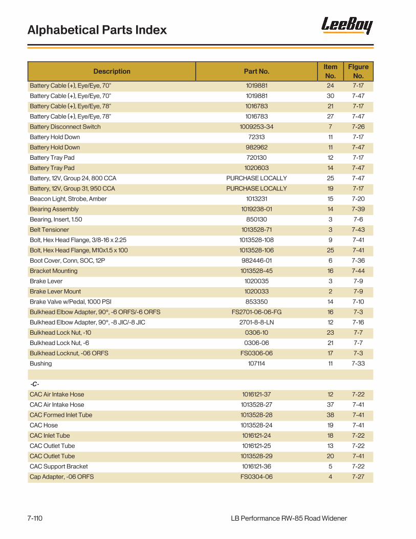
Description Part No.ItemNo.
FIgureNo.
Battery Cable (+), Eye/Eye, 70" 1019881 24 7-17
Battery Cable (+), Eye/Eye, 70" 1019881 30 7-47
Battery Cable (+), Eye/Eye, 78" 1016783 21 7-17
Battery Cable (+), Eye/Eye, 78" 1016783 27 7-47
Battery Disconnect Switch 1009253-34 7 7-26
Battery Hold Down 72313 11 7-17
Battery Hold Down 982962 11 7-47
Battery Tray Pad 720130 12 7-17
Battery Tray Pad 1020603 14 7-47
Battery, 12V, Group 24, 800 CCA PURCHASE LOCALLY 25 7-47
Battery, 12V, Group 31, 950 CCA PURCHASE LOCALLY 19 7-17
Beacon Light, Strobe, Amber 1013231 15 7-20
Bearing Assembly 1019238-01 14 7-39
Bearing, Insert, 1.50 850130 3 7-6
Belt Tensioner 1013528-71 3 7-43
Bolt, Hex Head Flange, 3/8-16 x 2.25 1013528-108 9 7-41
Bolt, Hex Head Flange, M10x1.5 x 100 1013528-106 25 7-41
Boot Cover, Conn, SOC, 12P 982446-01 6 7-36
Bracket Mounting 1013528-45 16 7-44
Brake Lever 1020035 3 7-9
Brake Lever Mount 1020033 2 7-9
Brake Valve w/Pedal, 1000 PSI 853350 14 7-10
Bulkhead Elbow Adapter, 90°, -6 ORFS/-6 ORFS FS2701-06-06-FG 16 7-3
Bulkhead Elbow Adapter, 90°, -8 JIC/-8 JIC 2701-8-8-LN 12 7-16
Bulkhead Lock Nut, -10 0306-10 23 7-7
Bulkhead Lock Nut, -6 0306-06 21 7-7
Bulkhead Locknut, -06 ORFS FS0306-06 17 7-3
Bushing 107114 11 7-33
-C-
CAC Air Intake Hose 1016121-37 12 7-22
CAC Air Intake Hose 1013528-27 37 7-41
CAC Formed Inlet Tube 1013528-28 38 7-41
CAC Hose 1013528-24 19 7-41
CAC Inlet Tube 1016121-24 18 7-22
CAC Outlet Tube 1016121-25 13 7-22
CAC Outlet Tube 1013528-29 20 7-41
CAC Support Bracket 1016121-36 5 7-22
Cap Adapter, -06 ORFS FS0304-06 4 7-27
LB Performance RW-85 Road Widener
Alphabetical Parts Index
7-110

Description Part No.ItemNo.
FIgureNo.
Cap, Fuel Tank, Lockable 140030FL 16 7-15
Cap, Hydraulic, Lockable 140030HL 2 7-18
Carrying Case - Sonic Tracker 851265 REF 7-37
Carrying Case - Sonic Tracker 851265 REF 7-38
CCHH, 3/8-16 x 1.00, GR5, FT 100-6-16-16-5F 11 7-20
Chain, Proof Coil, .25 x 17 Link 70395-04 14 7-19
Chimney 1013528-44 15 7-44
Circuit Breaker w/Mount, 10A 986546 31 7-12
Citrus Tank Tray 1019320 11 7-48
Citrus Tank, 7 Gallon, Poly 988731 10 7-48
Clamp Kit, Split Flange, Code 62 1902-16-M12 3 7-8
Clamp, Insulated, ø2.00” 36894 14 7-41
Clamp, ø3.00” 1013528-49 10 7-44
Clamp, ø3.00” 1013985 12 7-44
Clamp, ø4.00” 1012526-38 2 7-44
Clamp, T-Bolt, 4.50” 1013528-82 3 7-42
Clevis Pin 20925244 3 7-32
Clevis Pin 1009057-01 15 7-34
Clevis Pin, ø1.00 x 2.50 1000285 12 7-5
Clevis Pin, ø1.00 x 2.63 w/ø1.50 Head 210060 15 7-33
Clevis Pin, ø1.00 x 3.25 1000365 23 7-1
Clevis Pin, ø1.00 x 4.00 20182218 4 7-33
Coil, 12VDC Deutsch 3 Series 1001686-03 7 7-27
Coil, 12VDC Deutsch P Series 1005448-02 4 7-29
Coil, 12VDC, D14E-12D-1.8A-DE 1015851-01 15 7-28
Coneector Adapter, -6 ORFS/-4 NPTF FS2404-06-04 7 7-32
Conn, Plug, DT06-8SA, Deutsch 982449 7 7-36
Conn, Wedge, Plug, 8P, Deutsch 983218 9 7-36
Connector Adapter, -6 JIC/-6 NPTF 2404-6-6 22 7-48
Connector Adapter, -6 ORFS/-4 NPTF FS2404-06-04 20 7-3
Connector Adapter, -6 ORFS/-4 NPTF FS2404-06-04 18 7-34
Connector Adapter, -6 ORFS/-6 NPTF FS2404-06-06 17 7-7
Connector, 3 Pin, Panel Mount 1010657 24 7-12
Connector, 47 SE Pin, Deutsch 1006000 19 7-12
Connector, 6 Pin, DT04-6P-L012 1018392 21 7-12
Connector, Lockwasher, 24 Shell 981916-02 17 7-12
Connector, Nut, 24 Shell 981916-01 20 7-12
Connector, Nut, HDP20, Deutsch 1011854 18 7-12
Connector, Water Tight, 3/4 x 3/4 3400DI 5 7-36
LeeBoy 4130 Road Widener
Illustrated Parts List
7-111
77

Description Part No.ItemNo.
FIgureNo.
Connector, Wedge, Receptacle, 6 Pin 983215 22 7-12
Connector, Wedge, W3P 983211 25 7-12
Constant Torque Clamp 1013528-34 18 7-41
Control Box Assembly 1016850 1 7-10
Control Box Assembly 1016850 REF 7-12
Control Box Cover 1016121-57 14 7-21
Control Box Enclosure 1016850-01 1 7-12
Control Box Enclosure 1019704 1 7-36
Control Box Mounting Plate 1018758 4 7-11
Conveyor Belt Assembly 1020364 7 7-5
Conveyor Cylinder Assembly 1019104 17 7-4
Conveyor Cylinder Assembly 1019104 8 7-5
Conveyor Idler Assembly 1020023 2 7-7
Conveyor Idler Weldment 1020024 7 7-7
Conveyor Motor 1016757 26 7-5
Conveyor Motor Assembly 1016794 REF 7-5
Conveyor Motor Bracket - Left 1021237 22a 7-5
Conveyor Motor Bracket - Right 1021236 22b 7-5
Conveyor Pulley Coupling 1020301 18 7-5
Conveyor Pulley Coupling Bearing 1020300SRV REF 7-5
Conveyor Rubber Hold Down Plate 1016834 37 7-3
Conveyor Rubber Scraper 1016833 38 7-3
Conveyor Stop Block 1021235 23 7-5
Coolant Control Valve 1013667-03 6 7-46
Coolant Hose 1013528-26 16 7-41
Coolant Hose 1013528-25 27 7-41
Coolant Level Harness 1013528-98 29 7-41
Coolant Level Sensor 1013528-99 30 7-41
Cooling Fan 1013528-97 24 7-41
Cooling Tube Bracket 1013528-32 13 7-41
Corner Panel - Left 1013528-56 14 7-40
Cotter Pin 15491939 4 7-32
Cotter Pin - Split 95458329 8 7-34
Cotter Pin, .188 x 1.50 80336 24 7-1
Cotter Pin, 5/32 x 1.00 95989380 16 7-34
Cotter Pin, ø.172 x 3.75 1017841 19 7-7
Cotter Pin, ø.174 x 3.75 1017841 13 7-5
Cotter Pin, Split 95458329 5 7-33
Counterbalance Valve, 2.5:1 1015850-01 9 7-27
LeeBoy 4130 Road Widener
Illustrated Parts List
7-112
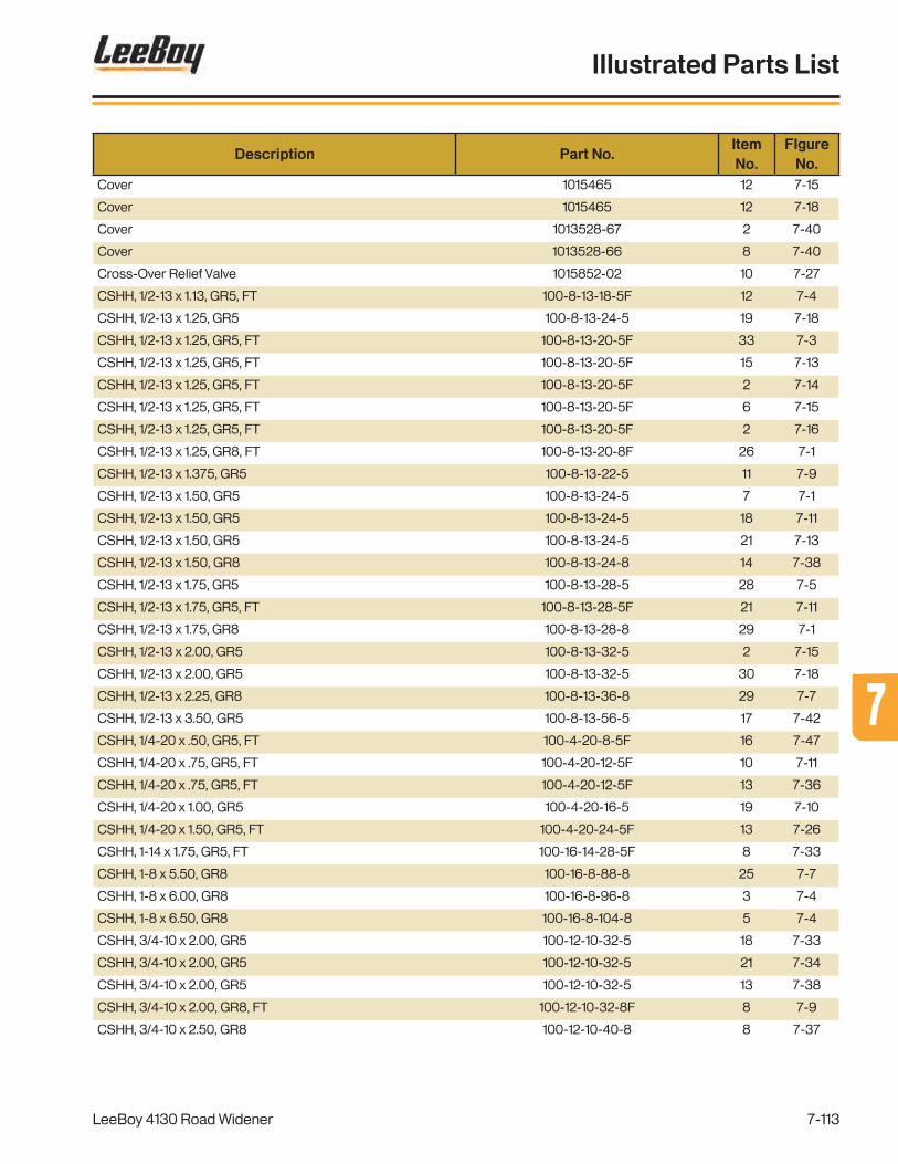
Description Part No.ItemNo.
FIgureNo.
Cover 1015465 12 7-15
Cover 1015465 12 7-18
Cover 1013528-67 2 7-40
Cover 1013528-66 8 7-40
Cross-Over Relief Valve 1015852-02 10 7-27
CSHH, 1/2-13 x 1.13, GR5, FT 100-8-13-18-5F 12 7-4
CSHH, 1/2-13 x 1.25, GR5 100-8-13-24-5 19 7-18
CSHH, 1/2-13 x 1.25, GR5, FT 100-8-13-20-5F 33 7-3
CSHH, 1/2-13 x 1.25, GR5, FT 100-8-13-20-5F 15 7-13
CSHH, 1/2-13 x 1.25, GR5, FT 100-8-13-20-5F 2 7-14
CSHH, 1/2-13 x 1.25, GR5, FT 100-8-13-20-5F 6 7-15
CSHH, 1/2-13 x 1.25, GR5, FT 100-8-13-20-5F 2 7-16
CSHH, 1/2-13 x 1.25, GR8, FT 100-8-13-20-8F 26 7-1
CSHH, 1/2-13 x 1.375, GR5 100-8-13-22-5 11 7-9
CSHH, 1/2-13 x 1.50, GR5 100-8-13-24-5 7 7-1
CSHH, 1/2-13 x 1.50, GR5 100-8-13-24-5 18 7-11
CSHH, 1/2-13 x 1.50, GR5 100-8-13-24-5 21 7-13
CSHH, 1/2-13 x 1.50, GR8 100-8-13-24-8 14 7-38
CSHH, 1/2-13 x 1.75, GR5 100-8-13-28-5 28 7-5
CSHH, 1/2-13 x 1.75, GR5, FT 100-8-13-28-5F 21 7-11
CSHH, 1/2-13 x 1.75, GR8 100-8-13-28-8 29 7-1
CSHH, 1/2-13 x 2.00, GR5 100-8-13-32-5 2 7-15
CSHH, 1/2-13 x 2.00, GR5 100-8-13-32-5 30 7-18
CSHH, 1/2-13 x 2.25, GR8 100-8-13-36-8 29 7-7
CSHH, 1/2-13 x 3.50, GR5 100-8-13-56-5 17 7-42
CSHH, 1/4-20 x .50, GR5, FT 100-4-20-8-5F 16 7-47
CSHH, 1/4-20 x .75, GR5, FT 100-4-20-12-5F 10 7-11
CSHH, 1/4-20 x .75, GR5, FT 100-4-20-12-5F 13 7-36
CSHH, 1/4-20 x 1.00, GR5 100-4-20-16-5 19 7-10
CSHH, 1/4-20 x 1.50, GR5, FT 100-4-20-24-5F 13 7-26
CSHH, 1-14 x 1.75, GR5, FT 100-16-14-28-5F 8 7-33
CSHH, 1-8 x 5.50, GR8 100-16-8-88-8 25 7-7
CSHH, 1-8 x 6.00, GR8 100-16-8-96-8 3 7-4
CSHH, 1-8 x 6.50, GR8 100-16-8-104-8 5 7-4
CSHH, 3/4-10 x 2.00, GR5 100-12-10-32-5 18 7-33
CSHH, 3/4-10 x 2.00, GR5 100-12-10-32-5 21 7-34
CSHH, 3/4-10 x 2.00, GR5 100-12-10-32-5 13 7-38
CSHH, 3/4-10 x 2.00, GR8, FT 100-12-10-32-8F 8 7-9
CSHH, 3/4-10 x 2.50, GR8 100-12-10-40-8 8 7-37
LeeBoy 4130 Road Widener
Illustrated Parts List
7-113
77

Description Part No.ItemNo.
FIgureNo.
CSHH, 3/4-10 x 2.50, GR8 100-12-10-40-8 18 7-38
CSHH, 3/4-10 x 2.50, GR8, FT 100-12-10-40-8F 5 7-9
CSHH, 3/4-10 x 4.00, GR8 100-12-10-64-8 4 7-38
CSHH, 3/4-10 x 8.00, GR8 100-12-10-128-8 6 7-39
CSHH, 3/4-10 x 9.00, GR8 100-12-10-144-8 16 7-8
CSHH, 3/4-16 x 2.50, GR5 100-12-16-40-5 20 7-32
CSHH, 3/4-16 x 2.50, GR5 100-12-16-40-5 16 7-33
CSHH, 3/8-16 x .75, GR5, FT 100-6-16-12-5F 13 7-1
CSHH, 3/8-16 x 1.00, GR5, FT 100-6-16-16-5F 10 7-3
CSHH, 3/8-16 x 1.00, GR5, FT 100-6-16-16-5F 16 7-10
CSHH, 3/8-16 x 1.13, GR5 100-6-16-18-5 27 7-10
CSHH, 3/8-16 x 1.25, GR5 100-6-16-20-5 29 7-10
CSHH, 3/8-16 x 1.25, GR5 100-6-16-20-5 6 7-13
CSHH, 3/8-16 x 1.25, GR5 100-6-16-20-5 10 7-26
CSHH, 3/8-16 x 1.25, GR5 100-6-16-20-5 4 7-30
CSHH, 3/8-16 x 1.25, GR5 100-6-16-20-5 21 7-33
CSHH, 3/8-16 x 1.25, GR5 100-6-16-20-5 32 7-34
CSHH, 3/8-16 x 1.25, GR5 100-6-16-20-5 8 7-46
CSHH, 3/8-16 x 1.25, GR5, FT 100-6-16-20-5F 17 7-48
CSHH, 3/8-16 x 1.25, GR5,FT 100-6-16-20-5F 4 7-20
CSHH, 3/8-16 x 1.25, GR8 100-6-16-20-8 13 7-7
CSHH, 3/8-16 x 1.50, GR5 100-6-16-24-5 2 7-3
CSHH, 3/8-16 x 1.50, GR5 100-6-16-24-5 7 7-4
CSHH, 3/8-16 x 1.50, GR5 100-6-16-24-5 4 7-5
CSHH, 3/8-16 x 1.50, GR5 100-6-16-24-5 8 7-6
CSHH, 3/8-16 x 1.50, GR5 100-6-16-24-5 10 7-7
CSHH, 3/8-16 x 1.63, GR5 100-6-16-26-5 21 7-10
CSHH, 3/8-16 x 1.75, GR5 100-6-16-28-8 21 7-5
CSHH, 3/8-16 x 1.75, GR5 100-6-16-28-5 20 7-17
CSHH, 3/8-16 x 1.75, GR5 100-6-16-28-5 26 7-47
CSHH, 3/8-16 x 2.00, GR5 100-6-16-32-5 27 7-3
CSHH, 3/8-16 x 2.50, GR5 100-6-16-40-5 30 7-3
CSHH, 3/8-16 x 9.50, GR5 100-6-16-152-5 8 7-17
CSHH, 3/8-16 x 9.50, GR5 100-6-16-152-5 8 7-47
CSHH, 5/16-18 x .75, GR5, FT 100-5-18-12-5F 7 7-17
CSHH, 5/16-18 x .75, GR5, FT 100-5-18-12-5F 7 7-47
CSHH, 5/16-18 x 1.00, GR5 100-5-18-16-5 23 7-10
CSHH, 5/16-18 x 1.00, GR5 100-5-18-16-5 7 7-37
CSHH, 5/16-18 x 1.00, GR5 100-5-18-16-5 6 7-48
LeeBoy 4130 Road Widener
Illustrated Parts List
7-114

Description Part No.ItemNo.
FIgureNo.
CSHH, 5/16-18 x 1.25, GR5 100-5-18-20-5 4 7-37
CSHH, 5/16-18 x 2.25, GR5 100-5-18-36-5 4 7-17
CSHH, 5/16-18 x 2.25, GR5 100-5-18-36-5 4 7-47
CSHH, 5/16-24 x .75, GR5, FT 100-5-24-12-5F 15 7-11
CSHH, 5/8-11 x 1.00, GR5, FT 100-10-11-16-5F 17 7-1
CSHH, 5/8-11 x 4.00, GR5, FT 100-10-11-64-8 14 7-23
CSHH, 7/16-14 x 1.50, GR5 100-7-14-24-5 12 7-11
CSHH, M12x1.75 x 35, C8.8, FT 100-M12-1.75-35-8.8F 24 7-25
CSHH, M12x1.75 x 35, C8.8, FT 100-M12-1.75-35-8.8F 18 7-45
CSHH, M12x1.75 x 45, C8.8, FT 100-M12-1.75-45-8.8F 6 7-8
CSSH, 1/2-13 x 1.25, FT 102-8-13-20-F 24 7-5
CSSH, 1/2-13 x 1.50, FT 102-8-13-24-F 15 7-25
CSSH, 1/2-13 x 1.50, FT 102-8-13-24-F 9 7-45
Cylinder Pin 980737 18 7-7
Cylinder, Hydraulic, 2.00 x 12.00 x 1.00 Rod 851436SRV 18 7-3
-D-
Dash Light - Blue 31986 5 7-12
Dash Light - Green 31985 4 7-12
Dash Light - Green 31985 8b 7-12
Dash Mount Cover 1016910 9 7-11
Dash Mount Weldment 1016909 8 7-11
Dash Pin Lock Plate 1007333 5 7-11
Dash Slide Rail w/Holes 1016898 2 7-11
Dash Slide Stop Bracket 1008093 3 7-11
Dash Weldment 1016895 1 7-11
Decal - American Flag 940002 6 7-26
Decal - Caution, Emissions 1010091 19 7-21
Decal - Caution, Emissions 1010091 22 7-40
Decal - Caution, Hot Surface 39168-11 20 7-21
Decal - Caution, Hot Surface 39168-11 21 7-40
Decal - Caution, Hydraulic Oil 856446 18 7-16
Decal - Caution, Hydraulic Oil Only 856446 32 7-18
Decal - Check Oil Daily 859795 25 7-21
Decal - Check Oil Daily 859795 27 7-40
Decal - Control Box Operation 1017507 2 7-12
Decal - Danger, Flammable 856631 23 7-21
Decal - Danger, Flammable 856631 25 7-40
Decal - Danger, Flammable Fuel 856631 21 7-15
LeeBoy 4130 Road Widener
Illustrated Parts List
7-115
77

Description Part No.ItemNo.
FIgureNo.
Decal - Danger, Pinch Point 1010489 5 7-2
Decal - Danger, Pinch Point 856437 8 7-2
Decal - Deco, 4130 Logo 1019538-05 6 7-2
Decal - Deco, Flag 940002 7 7-19
Decal - Deco, Leeboy Logo, 11" 1019039-10 9 7-14
Decal - Deco, LeeBoy Logo, 11" 1018906-05 15 7-16
Decal - Deco, LeeBoy Logo, 18" 1019039-09 3 7-2
Decal - Deco, Leeboy Logo, 24" 1019538-06 3 7-19
Decal - Deco, Logo - Left Hopper 1019538-03 1 7-2
Decal - Deco, Logo - Right Hopper 1019538-04 2 7-2
Decal - Deco, Logo, 4130 1019538-05 4 7-19
Decal - Deco, Panel Logo - Left 1019538-01 1 7-19
Decal - Deco, Panel Logo - Right 1019538-02 2 7-19
Decal - Down Arrow 39135-09 41 7-10
Decal - Engine Oil Drain 859781-03 19 7-16
Decal - Fuse Layout 1020799 34 7-12
Decal - Grease Daily 859793 25 7-33
Decal - Instructional, Pump 1016094 REF 7-48
Decal - Leeboy Logo, 11” 1019039-10 5 7-19
Decal - Lift Point 59246611 8 7-19
Decal - Low Sulfur Fuel 1010090 12 7-14
Decal - No Unattended 1005474 37 7-10
Decal - Notice, Hydraulic Dye 1013275 33 7-18
Decal - Notice, Manual 988634 9 7-26
Decal - Oil Info 1010089 24 7-21
Decal - Oil Info 1010089 26 7-40
Decal - Oper, Check List 856439 18 7-21
Decal - Oper, Check List 856439 28 7-40
Decal - Operation, Control Box 1019713 2 7-36
Decal - Parking Brake Safety 20959227 36 7-10
Decal - Radiator 856608 22 7-21
Decal - Radiator 856608 24 7-40
Decal - Slow Moving Vehicle 984630 23 7-13
Decal - Tie Down 59246603 9 7-2
Decal - Tie Down 59246603 9 7-19
Decal - Tool Box 859781-04 10 7-14
Decal - Tool Box 859781-04 16 7-16
Decal - Ultra Low Sulfur Fuel Only 1010090 20 7-15
Decal - Up Arrow 39135-08 40 7-10
LeeBoy 4130 Road Widener
Illustrated Parts List
7-116

Description Part No.ItemNo.
FIgureNo.
Decal - Warning - Hot Pressurized Fluid 59020040 21 7-21
Decal - Warning - Hot Pressurized Fluid 59020040 23 7-40
Decal - Warning, Conveyor 13437645 4 7-2
Decal - Warning, Crush Area 13437652 7 7-2
Decal - Warning, Crush Area 13437678 11 7-2
Decal - Warning, Fall 13855275 11 7-14
Decal - Warning, Fall 13855275 17 7-16
Decal - Warning, Fall 13855275 6 7-19
Decal - Warning, Falling Off 13855259 26 7-33
Decal - Warning, Improper Operation 13437728 38 7-10
Decal - Warning, Rotating Parts 13855317 10 7-2
Decal - Warning, Runaway Machine 13855291 39 7-10
Decal - Wash Down Info 1014057 34 7-48
Deck Cover - Rear, 74HP Engine 1017254 18a 7-20
Deck Hole Kit - ø6" 1004816 6 7-14
Deck Hole Kit - ø6" 1004816 6 7-16
Decomp Reactor Tube 1013528-87 7 7-44
DEF Coolant Manifold 1013528-18 5 7-46
Def Module Isolator - Front 1013528-89 3 7-46
Def Module Isolator - Rear 1013528-90 4 7-46
DEF Relay Mounting Plate 1019690 11 7-46
DEF Tank 1017509-05 1 7-46
DEF Tank Tray 1019321 7 7-46
Diesel Particulate Filter (DPF) 1010076-31 1 7-25
Direct Acting Relief Valve 1015851-03 11 7-28
Direct Flow Air Cleaner 1013528-05 1 7-42
Display - PV480 1012500 3a 7-12
Display - PV480 1018307 3b 7-12
DOC Cover 1016121-64 6 7-21
DOC Mounting Bracket 1016121-39 4 7-25
DOC Mounting Clamp 1016121-40 2 7-25
Door Assembly - Left 1013528-64 16 7-40
Door Assembly - Right 1013528-63 10 7-40
Door Enclosure Latch 1016121-48 17 7-21
Door Latch 1013528-52 17 7-40
Drive Shaft Assembly - Long 1019238-03 9 7-39
Drive Shaft Assembly - Short 1019238-02 13 7-39
Drive Shaft Assembly, 2 Pc. Inline 1019238 REF 7-39
Drive Shaft Strap Kit 39032 12 7-39
LeeBoy 4130 Road Widener
Illustrated Parts List
7-117
77
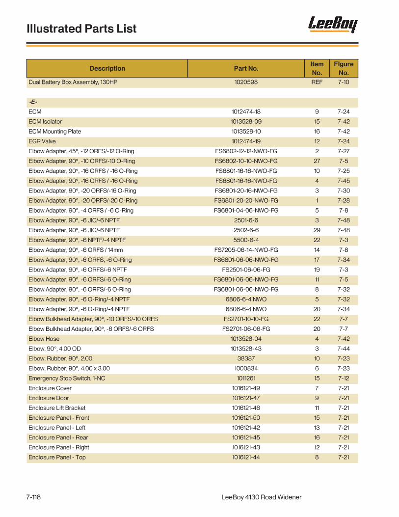
Description Part No.ItemNo.
FIgureNo.
Dual Battery Box Assembly, 130HP 1020598 REF 7-10
-E-
ECM 1012474-18 9 7-24
ECM Isolator 1013528-09 15 7-42
ECM Mounting Plate 1013528-10 16 7-42
EGR Valve 1012474-19 12 7-24
Elbow Adapter, 45°, -12 ORFS/-12 O-Ring FS6802-12-12-NWO-FG 2 7-27
Elbow Adapter, 90°, -10 ORFS/-10 O-Ring FS6802-10-10-NWO-FG 27 7-5
Elbow Adapter, 90°, -16 ORFS / -16 O-Ring FS6801-16-16-NWO-FG 10 7-25
Elbow Adapter, 90°, -16 ORFS / -16 O-Ring FS6801-16-16-NWO-FG 4 7-45
Elbow Adapter, 90°, -20 ORFS/-16 O-Ring FS6801-20-16-NWO-FG 3 7-30
Elbow Adapter, 90°, -20 ORFS/-20 O-Ring FS6801-20-20-NWO-FG 1 7-28
Elbow Adapter, 90°, -4 ORFS / -6 O-Ring FS6801-04-06-NWO-FG 5 7-8
Elbow Adapter, 90°, -6 JIC/-6 NPTF 2501-6-6 3 7-48
Elbow Adapter, 90°, -6 JIC/-6 NPTF 2502-6-6 29 7-48
Elbow Adapter, 90°, -6 NPTF/-4 NPTF 5500-6-4 22 7-3
Elbow Adapter, 90°, -6 ORFS / 14mm FS7205-06-14-NWO-FG 14 7-8
Elbow Adapter, 90°, -6 ORFS, -6 O-Ring FS6801-06-06-NWO-FG 17 7-34
Elbow Adapter, 90°, -6 ORFS/-6 NPTF FS2501-06-06-FG 19 7-3
Elbow Adapter, 90°, -6 ORFS/-6 O-Ring FS6801-06-06-NWO-FG 11 7-5
Elbow Adapter, 90°, -6 ORFS/-6 O-Ring FS6801-06-06-NWO-FG 8 7-32
Elbow Adapter, 90°, -6 O-Ring/-4 NPTF 6806-6-4 NWO 5 7-32
Elbow Adapter, 90°, -6 O-Ring/-4 NPTF 6806-6-4 NWO 20 7-34
Elbow Bulkhead Adapter, 90°, -10 ORFS/-10 ORFS FS2701-10-10-FG 22 7-7
Elbow Bulkhead Adapter, 90°, -6 ORFS/-6 ORFS FS2701-06-06-FG 20 7-7
Elbow Hose 1013528-04 4 7-42
Elbow, 90°, 4.00 OD 1013528-43 3 7-44
Elbow, Rubber, 90°, 2.00 38387 10 7-23
Elbow, Rubber, 90°, 4.00 x 3.00 1000834 6 7-23
Emergency Stop Switch, 1-NC 1011261 15 7-12
Enclosure Cover 1016121-49 7 7-21
Enclosure Door 1016121-47 9 7-21
Enclosure Lift Bracket 1016121-46 11 7-21
Enclosure Panel - Front 1016121-50 15 7-21
Enclosure Panel - Left 1016121-42 13 7-21
Enclosure Panel - Rear 1016121-45 16 7-21
Enclosure Panel - Right 1016121-43 12 7-21
Enclosure Panel - Top 1016121-44 8 7-21
LeeBoy 4130 Road Widener
Illustrated Parts List
7-118

Description Part No.ItemNo.
FIgureNo.
End Gate 1020410 1 7-34
End Gate Mount 1020399 6 7-34
End Gate Pin 1020411 5 7-34
End Gate Rod - Left 1020412 10 7-34
End Gate Rod - Right 1020413 7 7-34
End Gate Turnbuckle 1020440 9 7-34
End Gate Wear Plate 1018888 2 7-34
Engine Frame 1016121-03 13 7-23
Engine Frame Support - Front Left 1013528-01 14 7-42
Engine Frame Support - Front Right 1013528-02 13 7-42
Engine Frame Support - Rear 1013528-86 12 7-42
Engine Isolator 1016121-58 15 7-23
Engine Isolator, CB-1203-3 1016121-58 19 7-42
Engine Support Frame - Front 1016121-02 11 7-23
Engine Support Frame - Rear 1016121-01 12 7-23
Exhaust Bellows Tube 1013528-88 11 7-44
Exhaust Clamp 988666-15 6 7-25
Exhaust Pipe 1016121-38 5 7-25
Extendable Push Roller Weldment 1020357 20 7-1
Eye Bolt, 3/8-16 x 2.50, .75 ID 31878 12 7-19
-F-
Fan Belt 1012474-26 3 7-24
Fan Guard - Right 1013528-94 7 7-41
Fan Guard- Left 1013528-93 6 7-41
Fan Shroud - Top 1013528-92 5 7-41
Fan Spacer 118811 2 7-24
Fan Spacer, 1.50” 1013528-96 23 7-41
Filler Cap 1012474-29 10 7-24
Filler Neck 140030FN 13 7-48
Filler Neck Gasket 853930 14 7-48
Filler, Neck, Hydraulic Oil/Cuel Cap 140030FN 17 7-15
Filler, Neck, Hydraulic Oil/Fuel Cap 140030FN 3 7-18
Filter Element 1009523-01 6b 7-18
Filter Harness 1016121-08 3 7-23
Filter, Hydraulic, FIK04-300 1009523 6a 7-18
Fitting, 1/4-NPT-M x 3/8” Beaded Hose Barb 1013528-104 31 7-41
Fitting, Hose Barb, 1/4 NPT-M x 3/8 1013528-101 35 7-41
Fitting, Straight, 08FJX-08HB, Push-On 31109 11 7-16
LeeBoy 4130 Road Widener
Illustrated Parts List
7-119
77

Description Part No.ItemNo.
FIgureNo.
Fitting, Tee, 1/4 NPT Female 1013528-109 34 7-41
Flange Bearing Support 1019971 14 7-5
Flange Bearing, 1.25 1019968 17 7-5
Flanged Bushing, ø1.00 Shaft x 1.00 Long 1018903 6 7-33
Flowgate 1018781 11 7-3
Flywheel Coupling, SAE B-B, 15T 1013528-78 1 7-45
Flywheel Plate, SAE B Pump, SAE #3 1013528-79 2 7-45
Foam Air Dam Kit 1013528-53 12 7-40
Formed Inlet Tube 1013528-31 17 7-41
Formed Outlet Tube 1013528-30 28 7-41
Front Axle Mounting Bracket 1017075 19 7-8
Front Rim 1016256 REF 7-8
Front Tire/Wheel Assembly 1016843 20 7-8
Front Tire/Wheel Assembly 1016843 15 7-39
Fuel Filter 1012474-27 6 7-24
Fuel Filter 1012474-27 19 7-43
Fuel Filter Head 1012474-10 5 7-24
Fuel Filter Head 1012474-10 18 7-43
Fuel Tank Assembly 1016251 8 7-14
Fuel/Water Filter 988666-05 8 7-24
Fuel/Water Separator Filter 1012474-11 16 7-43
Fuel/Water Separator Filter Element 988666-05 17 7-43
Fuel/Water Seperator Head 1012474-11 7 7-24
Fuse Block 1016121-18 18 7-24
Fuse Block, ATC, 18 Gang 685060 33 7-12
Fuse, 250A, AMG 1014121 19 7-24
Fuse, ATC - 10A 36340 REF 7-12
Fuse, ATC - 15A 36341 REF 7-12
Fuse, ATC - 20A 36342 REF 7-12
Fuse, ATC - 5A 36746 REF 7-12
-G-
Gasket, Hydraulic Tank, 20 GAL 985688 13 7-15
Gasket, Hydraulic Tank, 20 GAL 985688 13 7-18
Gauge, Sight Leve/Temperature, Hydraulic Oil 500070 29 7-18
GC-35 Controller Assembly 1010499-08 1 7-37
GC-35 Controller Assembly 1010499-08 1 7-38
GC-35/Tracker Coil Cord - 15'. 1010499-04 REF 7-38
Grade Cylinder Assembly 1016612 1 7-32
LeeBoy 4130 Road Widener
Illustrated Parts List
7-120

Description Part No.ItemNo.
FIgureNo.
Green Dash Light 31985 REF 7-39
Grommet 852350 3 7-26
Grommet 1013528-80 6 7-40
Grommet 1013528-81 15 7-40
Group - Controls 1015917 GRP 7-11
Group - Controls, 130HP 1020685 OPT 7-10
Group - Controls, 74HP 1015917 GRP 7-10
Group - Cummins Engine, QSF 2.8, 74HP, T4F 1016121 GRP 7-22
Group - Cummins Engine, QSF 2.8, 74HP, T4F 1016121 GRP 7-23
Group - Cummins Engine, QSF 2.8, 74HP, T4F 1016121 GRP 7-24
Group - Extendable Push Roller 1015480 GRP 7-1
Group - Front Drive 1015461 GRP 7-8
Group - Hopper 1020520 GRP 7-3
Group - Hopper 1020520 GRP 7-4
Group - Rear Axle, Fixed 1017397 GRP 7-9
Group - Strike Off 1020392 GRP 7-31
Group - Strike Off 1020392 GRP 7-32
Group - Strike Off 1020392 GRP 7-33
Group - Strike Off 1020392 GRP 7-34
-H-
Handle & Nozzle 920220 2 7-48
Handle Nut, 5/8-11 300060 12 7-38
Hex Nut, 13/16-20 300020 6b 7-10
Hole Plug 35136-4 8a 7-12
Hood Bracket 007020098 14 7-17
Hood Bracket 007020098 20 7-47
Hopper Conveyor Assembly 1020245 18 7-4
Hopper Conveyor Assembly 1020245 REF 7-5
Hopper Conveyor Assembly 1020245 REF 7-6
Hopper Flashing Hold Down Plate 1016832 25 7-3
Hopper Flashing Hold Down Plate 1019368 15 7-4
Hopper Flashing Rubber 1019369 16 7-4
Hopper Frame Brace 1018482 11 7-4
Hopper Frame Hold Down Plate 1019427 28 7-3
Hopper Gap Guard 1020054 6 7-4
Hopper Lift Cylinder Assembly 1019103 15 7-7
Hopper Rubber Cover - Center 1020140 31 7-3
Hopper Rubber Cover - Left/Right 1020139 36 7-3
LeeBoy 4130 Road Widener
Illustrated Parts List
7-121
77

Description Part No.ItemNo.
FIgureNo.
Hopper Rubber Support Plate 1021181 15 7-3
Hopper Safety Bar 1020093 24 7-7
Hopper Weldment 1016412 1 7-7
Hopper Wing - Left 1016804 2 7-4
Hopper Wing - Right 1016803 1 7-4
Hopper Wing Cylinder Assembly 1019105 REF 7-3
Hopper Wiper - Left 1020120 7 7-3
Hopper Wiper - Right 1020119 6 7-3
Hopper Wiper Strip 1020127 9 7-3
Horn Button 982249 14 7-12
Hose Assembly, 72", Tag# 58, Engine Oil Drain R801NRNR000008-72 9 7-16
Hose Clamp Kit 1017323 14 7-33
Hose Clamp, #10 (.56-1.06) 33164 10 7-16
Hose Clamp, #32 (1.56-2.50) 33170 26 7-41
Hose Clamp, #4 (.22-.62) 33277 31 7-48
Hose Clamp, #40 1013528-21 15 7-41
Hose Clamp, #6 (.44-.78) 33162 32 7-41
Hose Support Plate 1017461 20 7-33
Hose, Bulk, 3/8” Heater Hose 1013528-102 33 7-41
Hydraulic Cylinder Seal Kit 1010140-01 - 7-1
Hydraulic Cylinder Seal Kit 910145-01 - 7-3
Hydraulic Cylinder Seal Kit 1017059-03 - 7-5
Hydraulic Cylinder Seal Kit 981504-03 - 7-7
Hydraulic Cylinder Seal Kit 1015956-03 - 7-32
Hydraulic Cylinder Seal Kit 1015956-03 - 7-32
Hydraulic Cylinder Seal Kit 1009057-06 - 7-34
Hydraulic Cylinder, 1017059 9 7-5
Hydraulic Cylinder, 1.50 Bore x 12.00 Stroke 1009057 14 7-34
Hydraulic Cylinder, 2.00 Bore x 16.00 Stroke 1015957 14 7-32
Hydraulic Cylinder, 2.00 Bore x 24.00 Stroke 1015956 2 7-32
Hydraulic Cylinder, 2.50 x 14.50 x 1.50 981504 16 7-7
Hydraulic Cylinder, 3.00 x 14.00 x 1.50 1010145 21 7-1
Hydraulic Lube Fitting, 1/8 20934832 10 7-32
Hydraulic Manifold 1015850 REF 7-27
Hydraulic Manifold 1015851 10 7-28
Hydraulic Manifold 1015852 REF 7-29
Hydraulic Manifold Assembly - Brake/2 Speed 1019096 REF 7-29
Hydraulic Manifold Assembly - Main 1019085 REF 7-27
Hydraulic Manifold Assembly-Conveyor/Steering 1019086 REF 7-28
LeeBoy 4130 Road Widener
Illustrated Parts List
7-122

Description Part No.ItemNo.
FIgureNo.
Hydraulic Motor, W35 DIN, H1B, 80CC 1015841 2 7-8
Hydraulic Oil Cooiler, 45k BTU 1015757 1 7-30
Hydraulic Oil Cooler Assembly 1019097 REF 7-30
Hydraulic Oil Cooler Heat Exchanger 1015757-01 REF 7-30
Hydraulic Oil Cooler Pusher Fan 1015757-02 REF 7-30
Hydraulic Tank Assembly 1016242 14 7-16
-I, J, K-
Idler Roller Assembly - 24" 1016765SRV 3 7-7
Idler Roller Block 1020352 6 7-6
Idler Roller Block 1020352 8 7-7
Idler Roller Shaft, 24" 1016763 6 7-7
Idler Roller Tube, 20" 1016764 4 7-7
Ignition Key 982008-04 REF 7-12
Ignition Switch 39146-14 7 7-12
In Line Filter 986537-31 32 7-48
Indicator Light - Red 1009253-07 6 7-12
Inner Tube Strike Off 1018462 1 7-33
Insert Bearing, 1.50 850130 4 7-1
Insert Bearing, 1.50" 850130 5 7-7
Insulated Band Clamp, 1-1/2" 148-223 31 7-34
Insulated Clamp, 5/8 112374 13 7-10
Intake Pipe 1016121-04 8 7-23
Intercooler Hose Bracket 1013528-33 40 7-41
Isolator 1000867-31 17 7-24
Isolator 1013528-22 3 7-41
Isolator 1013528-23 11 7-41
Isolator 1013528-85 11 7-42
Isolator 1000867-31 6 7-43
Isolator 1015089-05 28 7-48
Isolator Spacer 1013528-84 10 7-42
Isolator Washer 1016121-31 6 7-22
Joystick Box Assembly 1018454 REF 7-10
Joystick Enclosure 1018456 11 7-10
Joystick Mounting Bracket 1018634 12 7-10
Keeper Plate 1021223 28 7-7
Knob 35049 10 7-12
LeeBoy 4130 Road Widener
Illustrated Parts List
7-123
77

Description Part No.ItemNo.
FIgureNo.
-L, M-
Ladder 1017080 1 7-14
Ladder 1017080 1 7-16
Large Push Roller Scraper 1018310 11 7-1
Large Roller Scraper Bracket 1018312 10 7-1
LED Light, Circular 1012563 9 7-13
LED Light, Circular 1012563 7 7-14
LED Light, Circular 1012563 7 7-16
Lever Latch 980460 5 7-14
Lever Latch 980460 5 7-16
Low Pressure Switch, 200 PSI 853190 13 7-8
Lower Radiator Hose 1016121-26 15 7-22
Lube Fitting, Straight, 1/4"-25 140610 20 7-5
Lynch Pin Assembly w/Chain 1006850 26 7-34
Lynch Pin w/Chain Assembly 1006850 24 7-32
Lynch Pin w/Chain Assemly 1006850 8 7-31
M22x1.5 Flanged Wheel Nut 20942769 REF 7-8
M22x1.5 Flanged Wheel Nut 20942769 - 7-9
Machine Bushing, 3/4 x 1.25, LT 18 20922969 32 7-5
Machine Screw, Hex Head, #10-24 x .50 129-#10-24-8 16 7-48
Magentic Cupholder 1020521 35 7-10
Male Pipe Swivel Adapter, -6 NPTF/-6 JIC 6505-6-6 20 7-48
Manual Case 985234-01 8 7-26
Mirror Arm - Short 12755140 10 7-13
Module Supply, 12V 1013528-17 2 7-46
Momentary Foot Switch 20940938 15 7-10
Muffler Cap 1016121-63 3 7-25
-N-
Needle Valve 1015851-04 12 7-28
Nut Lock, Stover, 1-8, GR8 204-16-8-8 4 7-4
Nut, Hex Head Flange, Lock, 3/8-16 1013528-107 10 7-41
Nut, Hex, 1/2-13, GR5 200-8-13-5 9 7-1
Nut, Hex, 1/2-13, GR5 200-8-13-5 30 7-5
Nut, Hex, 1/2-13, GR5 200-8-13-5 4 7-15
Nut, Hex, 1/2-13, GR5 200-8-13-5 31 7-18
Nut, Hex, 1/2-13, GR5 200-8-13-5 18 7-42
Nut, Hex, 1/4-20, GR5 200-4-20-5 20 7-10
Nut, Hex, 3/4-10, GR5 200-12-10-5 10 7-9
LeeBoy 4130 Road Widener
Illustrated Parts List
7-124

Description Part No.ItemNo.
FIgureNo.
Nut, Hex, 3/4-10, GR5 200-12-10-5 24 7-34
Nut, Hex, 3/4-16, GR5 200-12-10-5 21 7-32
Nut, Hex, 3/8-16, GR5 200-6-16-5 5 7-3
Nut, Hex, 3/8-16, GR5 200-6-16-5 30 7-10
Nut, Hex, 3/8-16, GR5 200-6-16-5 7 7-30
Nut, Hex, 3/8-16, GR5 200-6-16-5 24 7-33
Nut, Hex, 3/8-16, GR5 200-6-16-5 35 7-34
Nut, Hex, 5/16-18, GR5 200-5-18-5 15 7-48
Nut, Hex, 5/8-11, GR5 200-10-11-5 17 7-23
Nut, Hex, Jam, 3/4-16, GR5 202-16-12-5 18 7-32
Nut, Hex, Jam, 3/8-16, GR5 202-6-16-5 28 7-10
Nut, Hex, Jam, 5/8-11, GR5 202-10-11-5 16 7-5
Nut, Hex, Machine, #10-24, GR5 209-#10-24 33 7-10
Nut, Hex, Machine, #10-32 209-#10-32 18 7-17
Nut, Hex, Machine, #10-32 209-#10-32 24 7-47
Nut, Hex, Nylon, Thin, GR5, 3/4-16 219-12-16-5 33 7-5
Nut, Lock, Flexloc, 1/2-13, Full, LT 217-8-13 17 7-13
Nut, Lock, Flexloc, 3/8-16, Full, LT 217-6-16 10 7-19
Nut, Lock, Flexloc, 5/16-18, Full, LT 217-5-18 6 7-17
Nut, Lock, Flexloc, 5/16-18, Full, LT 217-5-18 6 7-47
Nut, Lock, Nylon, 1/4-20, GR5 205-4-20-5 26 7-10
Nut, Lock, Stover, 1/2-13, GR5 204-8-13-5 12 7-9
Nut, Lock, Stover, 1/2-13, GR5 204-8-13-5 3 7-34
Nut, Lock, Stover, 1/4-20, GR5 204-4-20-5 14 7-15
Nut, Lock, Stover, 1/4-20, GR5 204-4-20-5 14 7-18
Nut, Lock, Stover, 1/4-20, GR5 204-4-20-5 15 7-36
Nut, Lock, Stover, 1-8, GR5 204-16-8-5 11 7-32
Nut, Lock, Stover, 1-8, GR8 204-16-8-8 27 7-7
Nut, Lock, Stover, 3/4-10, GR8 204-12-10-8 18 7-8
Nut, Lock, Stover, 3/4-10, GR8 204-12-10-8 7 7-9
Nut, Lock, Stover, 3/4-10, GR8 204-12-10-8 8 7-39
Nut, Lock, Stover, 3/8-16, GR5 204-6-16-5 18 7-10
Nut, Lock, Stover, 3/8-16, GR5 204-6-16-5 10 7-18
Nut, Lock, Stover, 3/8-16, GR5 204-6-16-5 13 7-20
Nut, Lock, Stover, 7/16-14, GR5 204-7-14-5 14 7-11
-O, P, Q-
Oil Filler 1013528-70 15 7-43
Oil Filter 1012474-28 4 7-24
LeeBoy 4130 Road Widener
Illustrated Parts List
7-125
77

Description Part No.ItemNo.
FIgureNo.
Oil Filter 1013528-76 14 7-43
Oil Level Gauge 1013528-75 13 7-43
OPTION - Strike Off 1020392 OPT 7-35
OPTION - Battery Box Assembly - Dual 1020596 20 7-16
OPTION - Cummins Engine, QSF 3.8, 130HP, T4F 1016628 OPT 7-41
OPTION - Cummins Engine, QSF 3.8, 130HP, T4F 1016628 OPT 7-42
OPTION - Cummins Engine, QSF 3.8, 130HP, T4F 1016628 OPT 7-43
OPTION - Cummins Engine, QSF 3.8, 130HP, T4F 1016628 OPT 7-44
OPTION - Cummins Engine, QSF 3.8, 130HP, T4F 1016628 OPT 7-45
OPTION - Cummins Engine, QSF 3.8, 130HP, T4F 1016628 OPT 7-46
OPTION - Deck Cover - Rear, 130HP Engine 1017750 18b 7-20
OPTION - Dual Battery Box Assembly 1020596 OPT 7-47
OPTION - Rear Axle, 4WD w/Steering 1017398 OPT 7-39
OPTION - Spray Down 1019319 OPT 7-48
OPTION - Strike Off Assembly - 3 Ft. 1016611 36 7-34
OPTION - Strike Off Remote Assmebly 1019702 OPT 7-36
OPTION - TopCon Grade 1021174 OPT 7-38
OPTION - TopCon Slope 1021173 OPT 7-37
O-Ring, FKM/Viton, 75D, .103 x 3.737 12757410 17 7-25
O-Ring, FKM/Viton, 75D, .103 x 3.737 12757410 11 7-45
P.O. Pressure Relief Valve 1015851-06 16 7-28
P-32 Slope Module 1010499-09 2 7-37
Panel - Rear 1013528-60 19 7-40
Panel - Right 1013528-55 11 7-40
Panel w/Notch 1007228-03 26 7-12
PHMS, Cross, #10-32 x .50, FT 122-#10-32-8F 9 7-15
PHMS, Cross, #10-32 x .50, FT 122-#10-32-8F 15 7-17
PHMS, Cross, #10-32 x .50, FT 122-#10-32-8F 21 7-47
Pin, .50 x 3.00 w/Cotter Pin 72836 20 7-13
Pin, Clevis, ø1.00 x 3.25 1000365 23 7-3
Pin, Cotter, .188 x 2.00 80338 24 7-3
Pipe Swivel Adapter, Female, -6 ORFS / -4 NPTF 6 G6L 12 7-8
Plate, Blanking, Hopper 1016830 1 7-3
Plate, Hold Down, Rubber Cut Off 1016831 13 7-3
Plug, Magnetic Drain, -16 SAE Orb 1011971 5 7-15
Plus+1 Controller, 24 Pin 1018973 29 7-12
Potentiometer, 35Ω/25W 1010077 11 7-12
Pressure Reducing Relief Valve 1015851-05 13 7-28
Primary Air Filter 1010076-02 REF 7-23
LeeBoy 4130 Road Widener
Illustrated Parts List
7-126
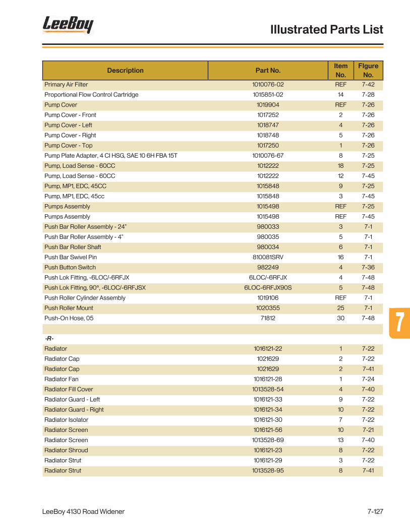
Description Part No.ItemNo.
FIgureNo.
Primary Air Filter 1010076-02 REF 7-42
Proportional Flow Control Cartridge 1015851-02 14 7-28
Pump Cover 1019904 REF 7-26
Pump Cover - Front 1017252 2 7-26
Pump Cover - Left 1018747 4 7-26
Pump Cover - Right 1018748 5 7-26
Pump Cover - Top 1017250 1 7-26
Pump Plate Adapter, 4 CI HSG, SAE 10 6H FBA 15T 1010076-67 8 7-25
Pump, Load Sense - 60CC 1012222 18 7-25
Pump, Load Sense - 60CC 1012222 12 7-45
Pump, MP1, EDC, 45CC 1015848 9 7-25
Pump, MP1, EDC, 45cc 1015848 3 7-45
Pumps Assembly 1015498 REF 7-25
Pumps Assembly 1015498 REF 7-45
Push Bar Roller Assembly - 24" 980033 3 7-1
Push Bar Roller Assembly - 4" 980035 5 7-1
Push Bar Roller Shaft 980034 6 7-1
Push Bar Swivel Pin 810081SRV 16 7-1
Push Button Switch 982249 4 7-36
Push Lok Fitting, -6LOC/-6RFJX 6LOC/-6RFJX 4 7-48
Push Lok Fitting, 90°, -6LOC/-6RFJSX 6LOC-6RFJX90S 5 7-48
Push Roller Cylinder Assembly 1019106 REF 7-1
Push Roller Mount 1020355 25 7-1
Push-On Hose, 05 71812 30 7-48
-R-
Radiator 1016121-22 1 7-22
Radiator Cap 1021629 2 7-22
Radiator Cap 1021629 2 7-41
Radiator Fan 1016121-28 1 7-24
Radiator Fill Cover 1013528-54 4 7-40
Radiator Guard - Left 1016121-33 9 7-22
Radiator Guard - Right 1016121-34 10 7-22
Radiator Isolator 1016121-30 7 7-22
Radiator Screen 1016121-56 10 7-21
Radiator Screen 1013528-69 13 7-40
Radiator Shroud 1016121-23 8 7-22
Radiator Strut 1016121-29 3 7-22
Radiator Strut 1013528-95 8 7-41
LeeBoy 4130 Road Widener
Illustrated Parts List
7-127
77

Description Part No.ItemNo.
FIgureNo.
Radiator, Power Unit 1013528-91 1 7-41
Railing Clamp 1020053 3 7-20
Rain Cap 1013528-42 4 7-44
Rear Axle Hose Kit 1019817 REF 7-39
Rear Axle Mounting Bracket 1016624 5 7-39
Rear Axle Weldment 1016839* 1 7-9
Rear Ladder 1018753 1 7-20
Rear Support Assembly, Inner 1020401 3 7-31
Rear Support Assembly, Outer 1020403 2 7-31
Receptacle, 12V 1011147 23 7-12
Receptacle, 19 Pin, Deutsch 1014909 16 7-12
Reducer Hose, 4.00” ID to 3.00” ID 1013528-83 6 7-42
Relay Mounting Bracket 36086 27 7-12
Relay Mounting Bracket 36086 15 7-24
Relay, 12VDC, SPDT, 40A, 5-Pin 36085 14 7-24
Relay, 12VDC, SPST, 100A, HD 985751 16 7-24
Relay, 12VDC, SPST, 100A, HD 985751 5 7-43
Relay, 12VDC/40A, 5 Pin, SPDT 36085 28 7-12
Remote Strike Off Mounting Plate 1019705 10 7-36
Replacement Key 35560 REF 7-14
Replacement Key 35560 REF 7-16
Retainer End Tube 1018466 2 7-33
Retaining Clip 1019238-04 11 7-39
RHMS, Cross, #10-24 x .75, FT 121-#10-24-12F 31 7-10
Roll Pin, 1/4" x 2.00 400-4-32 19 7-5
Round Mirror, Convex - ø7.50 100857 11 7-13
Rubber Conveyor Skirt 1016768 3 7-5
Rubber Flashing - Center 1020673 29 7-3
Rubber Flashing - Outside 1020674 26 7-3
Rubber Grommet 852350 33 7-48
Rubber Hold Down Plate - Large 1016774 2 7-5
Rubber Hold Down Plate - Small 1016772 1 7-5
Rubber Hook 007020096 2 7-17
Rubber Hook 007020096 2 7-47
Rubber Wiper 1020126 8 7-3
Rubber, Cut Off, Hopper 1016829 14 7-3
Run Tee Adapter, -10 ORFS/-10 O-Ring/-10 ORFS FS6804-10-10-10-NWO-FG 22 7-25
Run Tee Adapter, -10 ORFS/-10 O-Ring/-10 ORFS FS6804-10-10-10-NWO-FG 16 7-45
Run Tee Adapter, -12 ORFS/-12 O-Ring/-12 ORFS FS6804-12-12-12-NWO-FG 12 7-25
LeeBoy 4130 Road Widener
Illustrated Parts List
7-128

Description Part No.ItemNo.
FIgureNo.
Run Tee Adapter, -12 ORFS/-12 O-Ring/-12 ORFS FS6804-12-12-12-NWO-FG 6 7-45
Run Tee Adapter, -6 ORFS / 14mm / -6 ORFS FS7215-06-14-06-NWO-FG 10 7-8
Run Tee Adapter, -6 ORFS / -6 ORFS / -6 ORFS FS6602-06-06-06-FG 11 7-8
Run Tee Adapter, -6 ORFS/14mm O-Ring/-6 ORFS FS7215-06-14-06-NWO-FG 4 7-39
Run Tee Adapter, -6 ORFS/-6 O-Ring/-6 ORFS FS6804-06-06-06-NWO-FG 8 7-28
Run Tee Bulkhead Adapter, -6 JIC (x3) 2704-6-6-6-LN 9 7-48
-S-
Screw, Self, Drilling, HWH, #12 x .75 116-#12-12 19 7-15
Screw, Self-Drilling, HWH, #12 x .75 116-#12-12 5 7-18
Seat Assembly 13504717 12 7-13
Seat Belt Mount 37161-02 18 7-13
Seat Belt, 3" w/Retractor 37161 14 7-13
Seat Mount 1017087 19 7-13
Seat Post 1017601 13 7-13
Secondary Air Filter 1012474-25 REF 7-23
Secondary Air Filter 1012474-25 REF 7-42
Sender, Temperature, Hydraulic Oil, 100-250°F 1010402 24 7-18
Sending Unit, Fuel, 16" 1016871 8 7-15
Sensor, Level, Hydraulic 1014643 22 7-18
Set Screw, Hex Socket, Cup, 3/8-16 x .50 113-16-8 7 7-6
Set Screw, Hex Socket, Cup, 3/8-16 x .50 113-6-16-8 9 7-7
Shaft, Idler Roller, 24" 1016763 4 7-6
Signal Light, LED, Red 1005940 9 7-20
Signle Battery Box Assembly, 74HP 1020618 REF 7-10
Single Battery Box Assembly 1020616 REF 7-17
Slope Cylinder Assembly 1016613 13 7-32
Slope Module Cable - 8' 1010499-10 REF 7-37
Small Push Roller Scraper 1018311 12 7-1
Snap Link, ø3/8" 1013339 13 7-19
Solenoid, 12V, Constant Duty 720290 20 7-24
Solenoid, 12V, Constant Duty 720290 7 7-43
Solenoid, 3W2P 1015852-01 5 7-29
Solenoid, 4W2P 1015852-02 6 7-29
Solenoid, 4W3P 1016206-16 8 7-27
Sonic Tracker II Assembly 1010499-06 2 7-38
Spherical Gasket, 3.00” 1013528-39 8 7-44
Spherical Gasket, 4.00” 1013528-38 5 7-44
Split Flange Clamp, Code 61, -16 1901-16 20 7-25
LeeBoy 4130 Road Widener
Illustrated Parts List
7-129
77

Description Part No.ItemNo.
FIgureNo.
Split Flange Clamp, Code 61, -16 1901-16 14 7-45
Split Flange Clamp, Code 61, -32 1901-32 19 7-25
Split Flange Clamp, Code 61, -32 1901-32 13 7-45
Spray Down Pump Body 1015438-01 25 7-48
Spray Down Pump Cover 1016704 23 7-48
Spray Down Pump Pressure Sensor 1015438-02 26 7-48
Spray Down Pump w/Pressure Switch 1015438 24 7-48
Spray Down Reel w/Hose 920200 1 7-48
Spring Loaded Pull Pin 1000835 6 7-11
Square Head Set Screw, Flat, 5/8-11 x 3.50 119-10-11-56 15 7-5
Starter 1012474-22 13 7-24
Starter 1008650-01 4 7-43
Starter Relay Loop Harness 1013528-12 11 7-43
Steering Column - 6" 300040 6a 7-10
Steering Plate Weldment 1016917 8 7-10
Steering Valve, LS, 200 CCM 1003798 9 7-10
Steering Wheel - 14" 115772 5 7-10
Steering Wheel Cap 20944062 4 7-10
Straight Adapter, -10 ORFS/-16 O-Ring FS6400-10-16-O 2 7-28
Straight Adapter, -12 ORFS / -10 O-Ring FS6400-12-10-O 4 7-8
Straight Adapter, -4 ORFS / -6 ORFS FS6400-04-06-O 14 7-25
Straight Adapter, -4 ORFS / -6 ORFS FS6400-04-06-O 8 7-45
Straight Adapter, -4 ORFS/-4 O-Ring FS6400-04-04-O 6 7-28
Straight Adapter, -4 ORFS/-4 O-Ring FS6400-04-04-O 2 7-29
Straight Adapter, -4 ORFS/-6 O-Ring FS6400-04-06-O 5 7-27
Straight Adapter, -6 BSPP/-6 NPT 1015089-04 27 7-48
Straight Adapter, -6 ORFS / 14mm FS7005-06-14 8 7-8
Straight Adapter, -6 ORFS/14mm FS7005-06-14 3 7-39
Straight Adapter, -6 ORFS/-4 O-Ring FS6400-06-04-O 4 7-28
Straight Adapter, -6 ORFS/-4 O-Ring FS6400-06-04-O 1 7-29
Straight Adapter, -6 ORFS/-6 O-Ring FS6400-06-06-O 22 7-1
Straight Adapter, -6 ORFS/-6 O-Ring FS6400-06-06-O 10 7-5
Straight Adapter, -6 ORFS/-6 O-Ring FS6400-06-06-O 15 7-8
Straight Adapter, -6 ORFS/-6 O-Ring FS6400-06-06-O 34 7-10
Straight Adapter, -6 ORFS/-6 O-Ring FS6400-06-06-O 3* 7-27
Straight Adapter, -6 ORFS/-6 O-Ring FS6400-06-06-O 3 7-28
Straight Adapter, -6 ORFS/-6 O-Ring FS6400-06-06-O REF 7-39
Straight Adapter, -8 ORFS / 18mm FS7005-08-18 9 7-8
Straight Adapter, -8 ORFS/18mm FS7005-08-18 2 7-39
LeeBoy 4130 Road Widener
Illustrated Parts List
7-130

Description Part No.ItemNo.
FIgureNo.
Straight Adapter, -8 ORFS/-8 O-Ring FS6400-08-08-O 6 7-27
Straight Adapter, -8 ORFS/-8 O-Ring FS6400-08-08-O 7 7-28
Strainer & Gasket Kit 140030GK 18 7-15
Strainer & Gasket Kit 140030GK 4 7-18
Strap Clamp, 13” 1013528-41 13 7-44
Strike Off Assembly - 1 Ft. 1016600 28 7-34
Strike Off Assembly, 2-3 Foot 1020393 12 7-34
Strike Off Hold Down 1018916 25 7-34
Strike Off Hold Down Pivot Pin 1018919 10 7-20
Strike Off Hose Kit 1019322 REF 7-34
Strike Off Inner Support 1018465 11 7-34
Strike Off Inner Tube 1020397 17 7-32
Strike Off Mount, Rear 1020400 1 7-31
Strike Off Pin 1017457 7 7-31
Strike Off Pin 1020415 10 7-31
Strike Off Pin 1017457 23 7-32
Strike Off Pin Assembly 1016825 6 7-31
Strike Off Pin Assembly 1020414 9 7-31
Strike Off Pin Assembly 1016852 22 7-32
Strike Off Pivot 1018885 9 7-32
Strike Off Pivot 1018796 3 7-33
Strike Off Pivot Plate 1017264 12 7-33
Strike Off Pivot Shaft 1017116 10 7-33
Strike Off Remote Control Box Assmebly 1019703 REF 7-36
Strike Off Slope 1020396 16 7-32
Strike Off Slope Beam 1020395 15 7-32
Strike Off Storage 1018913 6 7-20
Strike Off Storage Tab 1019032 30 7-34
Strike Off Storage Tab Assembly 1016614 5 7-31
Strike Off Swing Arm 1018589 9 7-33
Strike Off Swing Cylinder Pin 1007776 27 7-34
Strike Off Yoke 1020398 19 7-32
Strike Off, 1 Ft. 1016925 29 7-34
Strike Off, 2-3 Foot 1020394 13 7-34
Strike Off, 3 FT. 1016926 37 7-34
Strut 1013528-48 18 7-44
Strut Isolator 1016121-32 4 7-22
Swivel Branch Tee Adapter, -6 ORFS (x3) FS6600-06-06-06-FG 9 7-28
Swivel Run Tee Adapter, -6 ORFS (x3) FS6602-06-06-06-FG REF 7-39
LeeBoy 4130 Road Widener
Illustrated Parts List
7-131
77
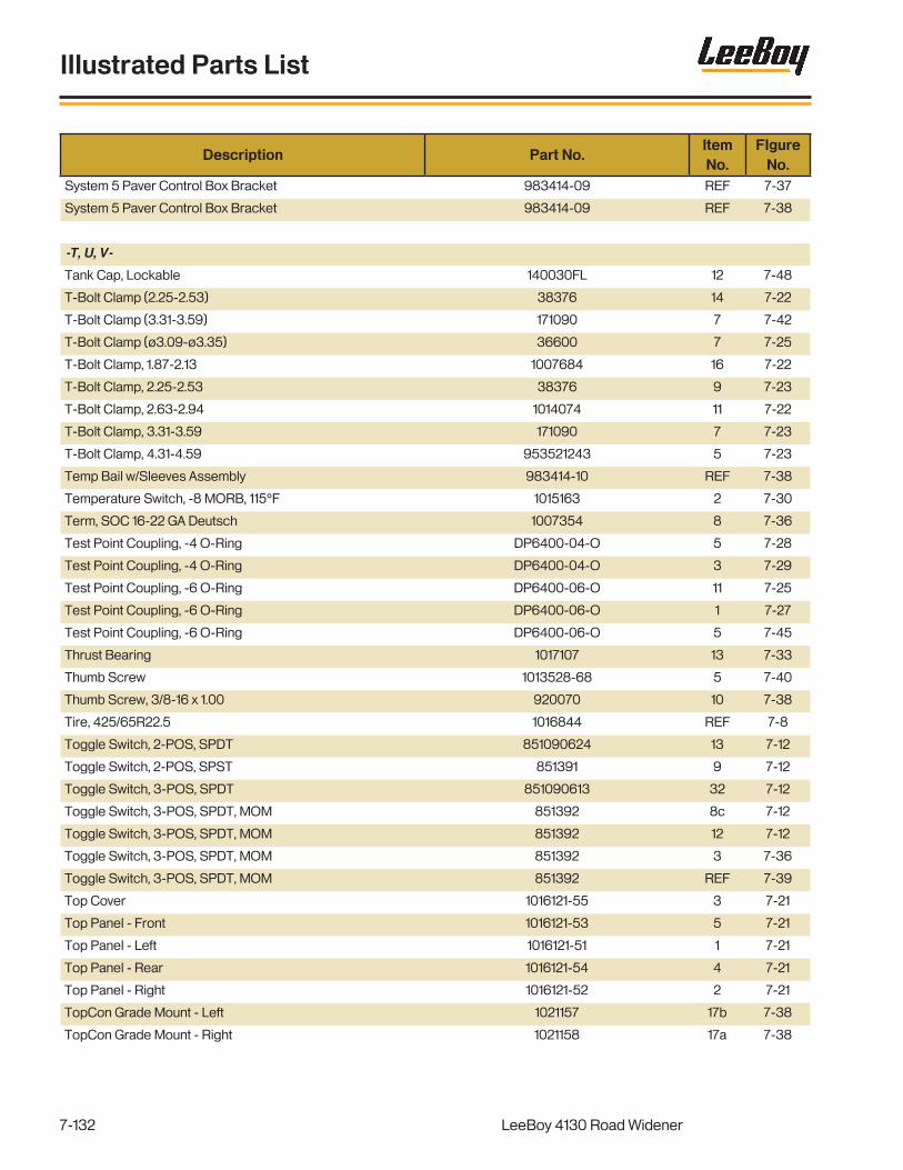
Description Part No.ItemNo.
FIgureNo.
System 5 Paver Control Box Bracket 983414-09 REF 7-37
System 5 Paver Control Box Bracket 983414-09 REF 7-38
-T, U, V-
Tank Cap, Lockable 140030FL 12 7-48
T-Bolt Clamp (2.25-2.53) 38376 14 7-22
T-Bolt Clamp (3.31-3.59) 171090 7 7-42
T-Bolt Clamp (ø3.09-ø3.35) 36600 7 7-25
T-Bolt Clamp, 1.87-2.13 1007684 16 7-22
T-Bolt Clamp, 2.25-2.53 38376 9 7-23
T-Bolt Clamp, 2.63-2.94 1014074 11 7-22
T-Bolt Clamp, 3.31-3.59 171090 7 7-23
T-Bolt Clamp, 4.31-4.59 953521243 5 7-23
Temp Bail w/Sleeves Assembly 983414-10 REF 7-38
Temperature Switch, -8 MORB, 115°F 1015163 2 7-30
Term, SOC 16-22 GA Deutsch 1007354 8 7-36
Test Point Coupling, -4 O-Ring DP6400-04-O 5 7-28
Test Point Coupling, -4 O-Ring DP6400-04-O 3 7-29
Test Point Coupling, -6 O-Ring DP6400-06-O 11 7-25
Test Point Coupling, -6 O-Ring DP6400-06-O 1 7-27
Test Point Coupling, -6 O-Ring DP6400-06-O 5 7-45
Thrust Bearing 1017107 13 7-33
Thumb Screw 1013528-68 5 7-40
Thumb Screw, 3/8-16 x 1.00 920070 10 7-38
Tire, 425/65R22.5 1016844 REF 7-8
Toggle Switch, 2-POS, SPDT 851090624 13 7-12
Toggle Switch, 2-POS, SPST 851391 9 7-12
Toggle Switch, 3-POS, SPDT 851090613 32 7-12
Toggle Switch, 3-POS, SPDT, MOM 851392 8c 7-12
Toggle Switch, 3-POS, SPDT, MOM 851392 12 7-12
Toggle Switch, 3-POS, SPDT, MOM 851392 3 7-36
Toggle Switch, 3-POS, SPDT, MOM 851392 REF 7-39
Top Cover 1016121-55 3 7-21
Top Panel - Front 1016121-53 5 7-21
Top Panel - Left 1016121-51 1 7-21
Top Panel - Rear 1016121-54 4 7-21
Top Panel - Right 1016121-52 2 7-21
TopCon Grade Mount - Left 1021157 17b 7-38
TopCon Grade Mount - Right 1021158 17a 7-38
LeeBoy 4130 Road Widener
Illustrated Parts List
7-132

Description Part No.ItemNo.
FIgureNo.
TopCon Slope Mount - Right 1021155 3a 7-37
TopCon Slope Mount -Left 1021156 3b 7-37
TopCon Sonic Tracker Bracket 851578 3 7-38
TopCon ZArm Bracket 9090-1125 7 7-38
TopCon/Spectra Pivot Mount 851575 11 7-38
Traction Joystick 1016937 10 7-10
Tube, Fuel, Pick Up, 17" 1014538-17 10 7-15
Tube, Idler Roller, 24" 1016764 5 7-6
Turn Signal Flasher 981512 30 7-12
Turnbuckle Support Assembly 1020405 4 7-31
U-Bolt Clamp, 2.50 1013528-35 39 7-41
U-Bolt, Vibration Reducing, 1-5/16" 1019706 11 7-36
U-Joint, 1410 - Greaseable 1006348-02 10 7-39
Umbrella 920235 OPT 7-13
Upper Deck Cover - Front 1017094 4 7-13
Upper Deck Cover - Rear 1017092 5 7-13
Upper Radiator Hose 1016121-27 17 7-22
Valve Stem, 90° 1015311 REF 7-8
Vandalism Cover Assembly 1007339 3 7-10
Vandalism Cover Spacer Tube 1007338 22 7-10
Vandalism Latch Bar 1007337 2 7-10
V-Band Clamp 1013528-20 22 7-41
V-Band Clamp, 4.00” 1013667-08 6 7-44
V-Band Clamp, 3.00” 1013528-40 9 7-44
V-Groove Track Roller 1012624 31 7-5
V-Guide Wheel - 45mm 1007266 7 7-11
-W, X, Y, Z-
Wash Down Nozzle 901210A REF 7-48
Washer, 1013528-105 12 7-41
Washer, 1/2 ID x 2.00 OD 1017118 8 7-1
Washer, 2.25 OD x .562 ID x 7 GA 40447 32 7-3
Washer, Cinch, .66ID x 2.75 OD x .19 1013528-100 4 7-41
Washer, Flat, .688 x 2.25 x .188 1012165 19 7-1
Washer, Flat, Fender, 3/8 x 1.50 308-6-24 12 7-20
Washer, Flat, SAE, 300-8 21 7-18
Washer, Flat, SAE, #10 300-#10 16 7-17
Washer, Flat, SAE, #10 300-#10 22 7-47
Washer, Flat, SAE, 1 300-16 7 7-33
LeeBoy 4130 Road Widener
Illustrated Parts List
7-133
77

Description Part No.ItemNo.
FIgureNo.
Washer, Flat, SAE, 1" 300-16 26 7-7
Washer, Flat, SAE, 1" 300-16 12 7-32
Washer, Flat, SAE, 1/2 300-8 28 7-1
Washer, Flat, SAE, 1/2 300-8 35 7-3
Washer, Flat, SAE, 1/2 300-8 14 7-4
Washer, Flat, SAE, 1/2 300-8 31 7-7
Washer, Flat, SAE, 1/2 300-8 20 7-11
Washer, Flat, SAE, 1/2 300-8 16 7-13
Washer, Flat, SAE, 1/2 300-8 4 7-14
Washer, Flat, SAE, 1/2 300-8 3 7-15
Washer, Flat, SAE, 1/2 300-8 4 7-16
Washer, Flat, SAE, 1/2 300-8 16 7-38
Washer, Flat, SAE, 1/4 300-4 25 7-10
Washer, Flat, SAE, 1/4 300-4 22 7-11
Washer, Flat, SAE, 1/4 300-4 15 7-15
Washer, Flat, SAE, 1/4 300-4 15 7-18
Washer, Flat, SAE, 1/4 300-4 14 7-36
Washer, Flat, SAE, 1/4 300-4 18 7-47
Washer, Flat, SAE, 3/4 300-12 17 7-8
Washer, Flat, SAE, 3/4 300-12 6 7-9
Washer, Flat, SAE, 3/4 300-12 19 7-33
Washer, Flat, SAE, 3/4 300-12 22 7-34
Washer, Flat, SAE, 3/4 300-12 10 7-37
Washer, Flat, SAE, 3/4 300-12 6 7-38
Washer, Flat, SAE, 3/4 300-12 7 7-39
Washer, Flat, SAE, 3/8 300-6 15 7-1
Washer, Flat, SAE, 3/8 300-6 4 7-3
Washer, Flat, SAE, 3/8 300-6 9 7-4
Washer, Flat, SAE, 3/8 300-6 6 7-5
Washer, Flat, SAE, 3/8 300-6 9 7-6
Washer, Flat, SAE, 3/8 300-6 12 7-7
Washer, Flat, SAE, 3/8 300-6 17 7-10
Washer, Flat, SAE, 3/8 300-6 8 7-13
Washer, Flat, SAE, 3/8 300-6 10 7-17
Washer, Flat, SAE, 3/8 300-6 11 7-18
Washer, Flat, SAE, 3/8 300-6 11 7-19
Washer, Flat, SAE, 3/8 300-6 7 7-20
Washer, Flat, SAE, 3/8 300-6 5 7-30
Washer, Flat, SAE, 3/8 300-6 23 7-33
LeeBoy 4130 Road Widener
Illustrated Parts List
7-134

Description Part No.ItemNo.
FIgureNo.
Washer, Flat, SAE, 3/8 300-6 34 7-34
Washer, Flat, SAE, 3/8 300-6 10 7-46
Washer, Flat, SAE, 3/8 300-6 10 7-47
Washer, Flat, SAE, 3/8 300-6 19 7-48
Washer, Flat, SAE, 5/16 300-5 17 7-11
Washer, Flat, SAE, 5/16 300-5 5 7-17
Washer, Flat, SAE, 5/16 300-5 6 7-37
Washer, Flat, SAE, 5/16 300-5 5 7-47
Washer, Flat, SAE, 5/16 300-5 8 7-48
Washer, Flat, SAE, 7/16 300-7 13 7-11
Washer, Flat, USS, 1/2 301-8 4 7-34
Washer, Flat, USS, 3/8 301-6 14 7-7
Washer, Flat, USS, 3/8 301-6 12 7-26
Washer, Lock, #10 302-#10 32 7-10
Washer, Lock, #10 302-#10 17 7-17
Washer, Lock, #10 302-#10 23 7-47
Washer, Lock, .670 Nord Wedge 986811 20 7-42
Washer, Lock, .670, Nord Wedge 986811 16 7-23
Washer, Lock, 1/2 302-8 27 7-1
Washer, Lock, 1/2 302-8 34 7-3
Washer, Lock, 1/2 302-8 13 7-4
Washer, Lock, 1/2 302-8 29 7-5
Washer, Lock, 1/2 302-8 30 7-7
Washer, Lock, 1/2 302-8 19 7-11
Washer, Lock, 1/2 302-8 22 7-13
Washer, Lock, 1/2 302-8 3 7-14
Washer, Lock, 1/2 302-8 7 7-15
Washer, Lock, 1/2 302-8 3 7-16
Washer, Lock, 1/2 302-8 20 7-18
Washer, Lock, 1/2 302-8 15 7-38
Washer, Lock, 1/2 Nord Wedge 986810 16 7-25
Washer, Lock, 1/2 Nord Wedge 986810 10 7-45
Washer, Lock, 1/4 302-4 11 7-11
Washer, Lock, 1/4 302-4 17 7-47
Washer, Lock, 3/4 302-12 9 7-9
Washer, Lock, 3/4 302-12 17 7-33
Washer, Lock, 3/4 302-12 23 7-34
Washer, Lock, 3/4 302-12 9 7-37
Washer, Lock, 3/4 302-12 5 7-38
LeeBoy 4130 Road Widener
Illustrated Parts List
7-135
77

Description Part No.ItemNo.
FIgureNo.
Washer, Lock, 3/8 302-6 14 7-1
Washer, Lock, 3/8 302-6 3 7-3
Washer, Lock, 3/8 302-6 8 7-4
Washer, Lock, 3/8 302-6 5 7-5
Washer, Lock, 3/8 302-6 11 7-7
Washer, Lock, 3/8 302-6 24 7-10
Washer, Lock, 3/8 302-6 7 7-13
Washer, Lock, 3/8 302-6 9 7-17
Washer, Lock, 3/8 302-6 5 7-20
Washer, Lock, 3/8 302-6 11 7-26
Washer, Lock, 3/8 302-6 6 7-30
Washer, Lock, 3/8 302-6 22 7-33
Washer, Lock, 3/8 302-6 33 7-34
Washer, Lock, 3/8 302-6 9 7-46
Washer, Lock, 3/8 302-6 9 7-47
Washer, Lock, 3/8 302-6 18 7-48
Washer, Lock, 5/16 302-5 16 7-11
Washer, Lock, 5/16 302-5 5 7-37
Washer, Lock, 5/16 302-5 7 7-48
Washer, Lock, 5/8 302-10 18 7-1
Washer, Lock, Hi-Collar, 1/2 307-8 25 7-5
Washer, Lock, M12 302-M12 7 7-8
Weldment, Fuel Tank, RW85 1016252 1 7-15
Weldment, Head Pulley 1016756 1 7-6
Weldment, Hydraulic Tank, RW85 1016243 1 7-18
Wheel/Tire Assembly 1019046 4 7-9
Wing Nut, 1/4-20 212-4-20 12 7-36
Wing Pivot Mount Bracket 1018480 10 7-4
Wing Screw, Type C, 3/8-16 x 1.00 120-6-16 12 7-3
Wing Screw, Type C, 3/8-16 x 1.00, Cup 120-6-16-16 7 7-10
Wire - Alternator (+) 1013528-13 10 7-43
Wire - Alternator Ground to Starter (-) 1013528-14 12 7-43
Wire - Alternator to Relay 1013528-15 9 7-43
Wire - Relay to Grid Heater 1013528-16 8 7-43
Worm Drive Clamp (2.06-3.00) 1014083 36 7-41
Z Arm - Lower 1011444 9 7-38
Z Arm - Upper 1011443 8 7-38
LeeBoy 4130 Road Widener
Illustrated Parts List
7-136


Printed in the U.S.A.
500 Lincoln County Parkway Ext.
Lincolnton, North Carolina 28092
Phone: (704) 966-3300 - Fax Sales: (704) 483-5802
www.LeeBoy.com
ST Engineering LeeBoy, Inc., dba LeeBoy