Microwave Oven Service Manual - Appliance Factory Parts
49
삼 흥 정 판 Microwave Oven Service Manual JVM1790BK/CK/SK/WK CAUTION BEFORE SERVICING THE UNIT, READ THE SAFETY PRECAUTIONS IN THIS MANUAL.
-
Upload
khangminh22 -
Category
Documents
-
view
0 -
download
0
Transcript of Microwave Oven Service Manual - Appliance Factory Parts

삼 흥정 판
Microwave OvenService Manual
JVM1790BK/CK/SK/WK
CAUTIONBEFORE SERVICING THE UNIT, READ THESAFETY PRECAUTIONS IN THIS MANUAL.

CAUTIONSAFETY PRECAUTIONS
PRECAUTIONS TO BE OBSERVED BEFORE ANDDURING SERVICING TO AVOID POSSIBLE EXPOSURE
TO EXCESSIVE MICROWAVE ENERGY
a. Do not operate or allow the oven to be operated with the door open.
b. Make the following safety checks on all ovens to be serviced before activating themagnetron or other microwave source, and make repairs as necessary; (1) Interlockoperation, (2) proper door closing, (3) seal and sealing surfaces (arcing, wear, andother damage), (4) damage to or loosening of hinges and latches, (5) evidence ofdropping or abuse.
c. Before turning on microwave power for any service test or inspection within themicrowave generating compartments, check the magnetron, wave guide ortransmission line, and cavity for proper alignment, integrity, and connections.
d. Any defective or misadjusted components in the interlock, monitor, door seal, andmicrowave generation and transmission systems shall be repaired, replaced, oradjusted by procedures described in this manual before the oven is released to theowner.
e. A Microwave leakage check to verify compliance with the Federal performance standard shouldbe performed on each oven prior to release to the owner.
• Proper operation of the microwave ovens requires that the magnetron be assembled to thewave guide and cavity. Never operate the magnetron unless it is properly installed.
• Be sure that the magnetron gasket is properly installed around the dome of the tube wheneverinstalling the magnetron.
• Routine service safety procedures should be exercised at all times.
• Untrained personnel should not attempt service without a thorough review of the testprocedures and safety information contained in this manual.

TABLE OF CONTENTS(Page)
SAFETY PRECAUTIONS - - - - - - - - - - - - - - - - - - - - - - - - - - - - - - - - - - - - - - - - - - - - - - - - - - - - - - - - - - - - - - - - - - - - - - - - - - - - - - - - - - - - - - - - - - - - - - - - - - - - Inside front page
SPECIFICATIONS - - - - - - - - - - - - - - - - - - - - - - - - - - - - - - - - - - - - - - - - - - - - - - - - - - - - - - - - - - - - - - - - - - - - - - - - - - - - - - - - - - - - - - - - - - - - - - - - - - - - - - - - - - - - - - - - - - - - - - - - - - - - - - - - 1-1
CAUTIONS - - - - - - - - - - - - - - - - - - - - - - - - - - - - - - - - - - - - - - - - - - - - - - - - - - - - - - - - - - - - - - - - - - - - - - - - - - - - - - - - - - - - - - - - - - - - - - - - - - - - - - - - - - - - - - - - - - - - - - - - - - - - - - - - - - - - - - - - - - 2-1
INSTALLATIONS - - - - - - - - - - - - - - - - - - - - - - - - - - - - - - - - - - - - - - - - - - - - - - - - - - - - - - - - - - - - - - - - - - - - - - - - - - - - - - - - - - - - - - - - - - - - - - - - - - - - - - - - - - - - - - - - - - - - - - - - - - - - - - - - - - 3-1
OPERATING INSTRUCTIONS - - - - - - - - - - - - - - - - - - - - - - - - - - - - - - - - - - - - - - - - - - - - - - - - - - - - - - - - - - - - - - - - - - - - - - - - - - - - - - - - - - - - - - - - - - - - - - - - - - - - - - - - - - - - - - - - 4-1
CONTROL PANEL - - - - - - - - - - - - - - - - - - - - - - - - - - - - - - - - - - - - - - - - - - - - - - - - - - - - - - - - - - - - - - - - - - - - - - - - - - - - - - - - - - - - - - - - - - - - - - - - - - - - - - - - - - - - - - - - - - - - - - - - - 4-1
CONTROL PANEL INSTRUCTIONS - - - - - - - - - - - - - - - - - - - - - - - - - - - - - - - - - - - - - - - - - - - - - - - - - - - - - - - - - - - - - - - - - - - - - - - - - - - - - - - - - - - - - - - - - - - - - - - - 4-2
OVERALL CIRCUIT DIAGRAM - - - - - - - - - - - - - - - - - - - - - - - - - - - - - - - - - - - - - - - - - - - - - - - - - - - - - - - - - - - - - - - - - - - - - - - - - - - - - - - - - - - - - - - - - - - - - - - - - - - - - - - - - - - - - - - 5-1
SCHEMATIC DIAGRAM - - - - - - - - - - - - - - - - - - - - - - - - - - - - - - - - - - - - - - - - - - - - - - - - - - - - - - - - - - - - - - - - - - - - - - - - - - - - - - - - - - - - - - - - - - - - - - - - - - - - - - - - - - - - - - - - - 5-1
MATRIX CIRCUIT FOR TOUCH KEY BOARD - - - - - - - - - - - - - - - - - - - - - - - - - - - - - - - - - - - - - - - - - - - - - - - - - - - - - - - - - - - - - - - - - - - - - - - - - - - - - - - - - - - 5-2
GENERAL INFORMATION FOR SERVICE - - - - - - - - - - - - - - - - - - - - - - - - - - - - - - - - - - - - - - - - - - - - - - - - - - - - - - - - - - - - - - - - - - - - - - - - - - - - - - - - - - - - - - - - - - - - - - - 6-1
GENERAL PRECAUTIONS IN USE - - - - - - - - - - - - - - - - - - - - - - - - - - - - - - - - - - - - - - - - - - - - - - - - - - - - - - - - - - - - - - - - - - - - - - - - - - - - - - - - - - - - - - - - - - - - - - - - - 6-1
TRIAL OPERATION - - - - - - - - - - - - - - - - - - - - - - - - - - - - - - - - - - - - - - - - - - - - - - - - - - - - - - - - - - - - - - - - - - - - - - - - - - - - - - - - - - - - - - - - - - - - - - - - - - - - - - - - - - - - - - - - - - - - - - - 6-1
FEATURES AND SPECIFICATIONS FEATURES - - - - - - - - - - - - - - - - - - - - - - - - - - - - - - - - - - - - - - - - - - - - - - - - - - - - - - - - - - - - - - - - - - - - - - - - - - - - - - - 6-1
SERVICE INFORMATION - - - - - - - - - - - - - - - - - - - - - - - - - - - - - - - - - - - - - - - - - - - - - - - - - - - - - - - - - - - - - - - - - - - - - - - - - - - - - - - - - - - - - - - - - - - - - - - - - - - - - - - - - - - - - - - - - - - - - - 7-1
PRECAUTIONS AND REPAIR SERVICE TIPS - - - - - - - - - - - - - - - - - - - - - - - - - - - - - - - - - - - - - - - - - - - - - - - - - - - - - - - - - - - - - - - - - - - - - - - - - - - - - - - - - - - 7-1
MICROWAVE LEAKAGE TEST - - - - - - - - - - - - - - - - - - - - - - - - - - - - - - - - - - - - - - - - - - - - - - - - - - - - - - - - - - - - - - - - - - - - - - - - - - - - - - - - - - - - - - - - - - - - - - - - - - - - - - - 7-2
POWER OUTPUT MEASUREMENT - - - - - - - - - - - - - - - - - - - - - - - - - - - - - - - - - - - - - - - - - - - - - - - - - - - - - - - - - - - - - - - - - - - - - - - - - - - - - - - - - - - - - - - - - - - - - - - - 7-3
DISASSEMBLY INSTRUCTIONS - - - - - - - - - - - - - - - - - - - - - - - - - - - - - - - - - - - - - - - - - - - - - - - - - - - - - - - - - - - - - - - - - - - - - - - - - - - - - - - - - - - - - - - - - - - - - - - - - - - - - 7-4
INTERLOCK SYSTEM - - - - - - - - - - - - - - - - - - - - - - - - - - - - - - - - - - - - - - - - - - - - - - - - - - - - - - - - - - - - - - - - - - - - - - - - - - - - - - - - - - - - - - - - - - - - - - - - - - - - - - - - - - - - - - - - - - 7-12
INTERLOCK CONTINUITY TEST - - - - - - - - - - - - - - - - - - - - - - - - - - - - - - - - - - - - - - - - - - - - - - - - - - - - - - - - - - - - - - - - - - - - - - - - - - - - - - - - - - - - - - - - - - - - - - - - - - - 7-14
TEST AND CHECKOUT PROCEDURES AND TROUBLE SHOOTING - - - - - - - - - - - - - - - - - - - - - - - - - - - - - - - - - - - - - - - - - - - - - - - - - 7-15
A. TEST PROCEDURES - - - - - - - - - - - - - - - - - - - - - - - - - - - - - - - - - - - - - - - - - - - - - - - - - - - - - - - - - - - - - - - - - - - - - - - - - - - - - - - - - - - - - - - - - - - - - - - - - - - - - - - - 7-15
B. CHECKOUT PROCEDURES - - - - - - - - - - - - - - - - - - - - - - - - - - - - - - - - - - - - - - - - - - - - - - - - - - - - - - - - - - - - - - - - - - - - - - - - - - - - - - - - - - - - - - - - - - - - - - 7-19
C. TROUBLE SHOOTING - - - - - - - - - - - - - - - - - - - - - - - - - - - - - - - - - - - - - - - - - - - - - - - - - - - - - - - - - - - - - - - - - - - - - - - - - - - - - - - - - - - - - - - - - - - - - - - - - - - - - - 7-24
EXPLODED VIEW - - - - - - - - - - - - - - - - - - - - - - - - - - - - - - - - - - - - - - - - - - - - - - - - - - - - - - - - - - - - - - - - - - - - - - - - - - - - - - - - - - - - - - - - - - - - - - - - - - - - - - - - - - - - - - - - - - - - - - - - - - - - - - - - 8-1
PART REFERENCE LIST - - - - - - - - - - - - - - - - - - - - - - - - - - - - - - - - - - - - - - - - - - - - - - - - - - - - - - - - - - - - - - - - - - - - - - - - - - - - - - - - - - - - - - - - - - - - - - - - - - - - - - - - - - - - - - - - - - - - - - 9-1
SCHEMATIC DIAGRAM OF PCB - - - - - - - - - - - - - - - - - - - - - - - - - - - - - - - - - - - - - - - - - - - - - - - - - - - - - - - - - - - - - - - - - - - - - - - - - - - - - - - - - - - - - - - - - - - - - - - - - - - - - - - - - - 10-1
PRINTED CIRCUIT BOARD - - - - - - - - - - - - - - - - - - - - - - - - - - - - - - - - - - - - - - - - - - - - - - - - - - - - - - - - - - - - - - - - - - - - - - - - - - - - - - - - - - - - - - - - - - - - - - - - - - - - 10-2
PCB PARTS LIST - - - - - - - - - - - - - - - - - - - - - - - - - - - - - - - - - - - - - - - - - - - - - - - - - - - - - - - - - - - - - - - - - - - - - - - - - - - - - - - - - - - - - - - - - - - - - - - - - - - - - - - - - - - - - - - - - - - - - - - - - - - - - - - 11-1
FOREWORD
Read this Manual carefully. Failure to adhere to or observe the information in this Manual may result in exposingyourself to the Microwave Energy normally contained within the oven cavity.

1-1
Rated Power Consumption - - - - - - - - - - - - - - - - - - - - - - - - - - - - - - - - - - 1600W (Microwave oven only) 1650W (Convection only)Microwave Output - - - - - - - - - - - - - - - - - - - - - - - - - - - - - - - - - - - - - - - - - - - - - - - - 1000W (IEC60705)
Adjustable 100W through 1000W, 10 stepsFrequency - - - - - - - - - - - - - - - - - - - - - - - - - - - - - - - - - - - - - - - - - - - - - - - - - - - - - - - - - 2450 MHz ± 50 MHzPower Supply - - - - - - - - - - - - - - - - - - - - - - - - - - - - - - - - - - - - - - - - - - - - - - - - - - - 120 VAC, 60 HzRated Current - - - - - - - - - - - - - - - - - - - - - - - - - - - - - - - - - - - - - - - - - - - - - - - - - - - 13.5 Amp. (Microwave oven+Cook top lamp+Ventilation fan)Magnetron Cooling - - - - - - - - - - - - - - - - - - - - - - - - - - - - - - - - - - - - - - - - - - - - Forced Air CoolingRectification - - - - - - - - - - - - - - - - - - - - - - - - - - - - - - - - - - - - - - - - - - - - - - - - - - - - - - Rectification Voltage Double Half-WaveDoor Sealing - - - - - - - - - - - - - - - - - - - - - - - - - - - - - - - - - - - - - - - - - - - - - - - - - - - - - Choke SystemSafety Devices - - - - - - - - - - - - - - - - - - - - - - - - - - - - - - - - - - - - - - - - - - - - - - - - - - Magnetron Thermal Fuse:
Open at 150°C ± 6°COven Cavity Thermostat:
Open at 145°C ± 6°CFuse(20A)Primary Interlock SwitchSecondary Interlock SwitchInterlock Monitor
Magnetron - - - - - - - - - - - - - - - - - - - - - - - - - - - - - - - - - - - - - - - - - - - - - - - - - - - - - - - - 2M246-21CTHigh Voltage Capacitor - - - - - - - - - - - - - - - - - - - - - - - - - - - - - - - - - - - - - - Capacitor: 0.95µF, 2.1 KV ACHigh Voltage Diode - - - - - - - - - - - - - - - - - - - - - - - - - - - - - - - - - - - - - - - - - - - Diode; 350mA, 9.0 KVCook top Lamp - - - - - - - - - - - - - - - - - - - - - - - - - - - - - - - - - - - - - - - - - - - - - - - - - 130 V, 50 WCavity Lamp - - - - - - - - - - - - - - - - - - - - - - - - - - - - - - - - - - - - - - - - - - - - - - - - - - - - - 130 V, 35 WTimer - - - - - - - - - - - - - - - - - - - - - - - - - - - - - - - - - - - - - - - - - - - - - - - - - - - - - - - - - - - - - - - Digital, up to 95 mim. 00 sec. (in each cooking stage)Tray - - - - - - - - - - - - - - - - - - - - - - - - - - - - - - - - - - - - - - - - - - - - - - - - - - - - - - - - - - - - - - - - - Tempered Safety GlassOverall Dimensions - - - - - - - - - - - - - - - - - - - - - - - - - - - - - - - - - - - - - - - - - - - 2915/16"(W)x167/16"(H)x153/8"(D)
Effective Capacity of Oven Cavity - - - - - - - - - - - - - - - - - - - - - - - 1.7 Cu.ft.Accessories - - - - - - - - - - - - - - - - - - - - - - - - - - - - - - - - - - - - - - - - - - - - - - - - - - - - - - Owner’s Manual & Cooking Guide, Installation Manual,
Exhaust Adapter, Exhaust Damper, Mounting Kit and TwoFilters, Rotating Ring Assembly, Metal Racks.
SPECIFICATIONS

• DO NOT operate on a 2-wire extension cord duringrepair and use.
• NEVER TOUCH any oven components or wiring duringoperation.
• BEFORE TOUCHING any parts of the oven, alwaysremove the power plug from the outlet.
• For about 30 seconds after the oven stops, an electriccharge remains in the high voltage capacitor. Whenreplacing or checking, you must discharge the highvoltage capacitor by shorting across the two terminalswith an insulated screwdriver.
• Remove your watches whenever working close to orreplacing the Magnetron.
• DO NOT touch any parts of the control panel circuit. Aresulting static electric discharge may damage thisP.C.B.
• NEVER operate the oven with no load.• NEVER injure the door seal and front plate of the oven
cavity.• NEVER put iron tools on the magnetron.• NEVER put anything into the latch hole and the interlock
switches area.
• Proper operation of the microwave oven requires thatthe magnetron be assembled to the waveguide andcavity. Never operate the magnetron unless it isproperly installed.
• Be sure that the magnetron gasket is properlyinstalled around the dome of the tube wheneverinstalling the magnetron.
2-1
CAUTIONS
Unlike other appliances, the microwave oven ishigh-voltage and high-current equipment.Though it is free from danger in ordinary use,extreme care should be taken during repair.
GasketANTENNA
COOLING FIN
MAGNETRONCHASSIS GROUND
FILAMENTTERMINALS
MAGNETRON
MICROWAVE RADIATIONPersonnel should not be exposed to themicrowave energy which may radiate from themagnetron or other microwave generatingdevice if it is improperly used or connection.All input and output microwave connections,waveguide, flange, and gasket must be securenever operate the device without a microwaveenergy absorbing load attached.Never look into an open waveguide or antennawhile the device is energized.
THE OVEN IS TO BE SERVICED ONLYBY PROPERLY QUALIFIED SERVICEPERSONNEL.
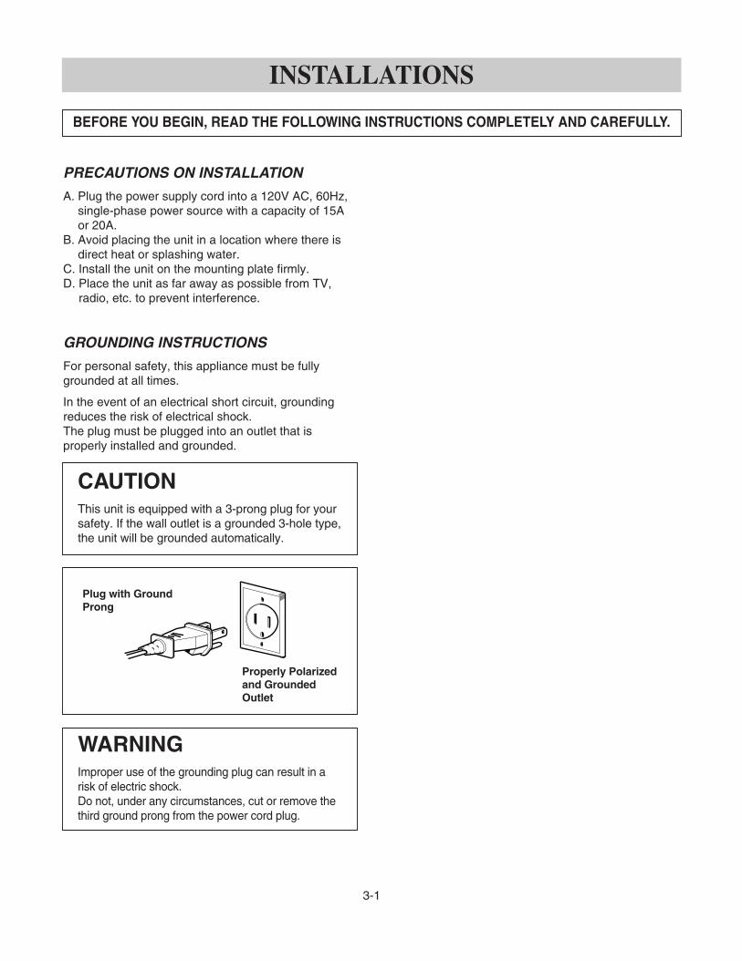
PRECAUTIONS ON INSTALLATION
A. Plug the power supply cord into a 120V AC, 60Hz,single-phase power source with a capacity of 15Aor 20A.
B. Avoid placing the unit in a location where there isdirect heat or splashing water.
C. Install the unit on the mounting plate firmly.D. Place the unit as far away as possible from TV,
radio, etc. to prevent interference.
GROUNDING INSTRUCTIONS
For personal safety, this appliance must be fullygrounded at all times.
In the event of an electrical short circuit, groundingreduces the risk of electrical shock.The plug must be plugged into an outlet that isproperly installed and grounded.
3-1
INSTALLATIONS
BEFORE YOU BEGIN, READ THE FOLLOWING INSTRUCTIONS COMPLETELY AND CAREFULLY.
CAUTIONThis unit is equipped with a 3-prong plug for yoursafety. If the wall outlet is a grounded 3-hole type,the unit will be grounded automatically.
WARNINGImproper use of the grounding plug can result in arisk of electric shock.Do not, under any circumstances, cut or remove thethird ground prong from the power cord plug.
Properly Polarizedand GroundedOutlet
Plug with GroundProng

4-1
OPERATING INSTRUCTIONS
CONTROL PANEL
For Model: JVM1790BKJVM1790CKJVM1790SKJVM1790WK
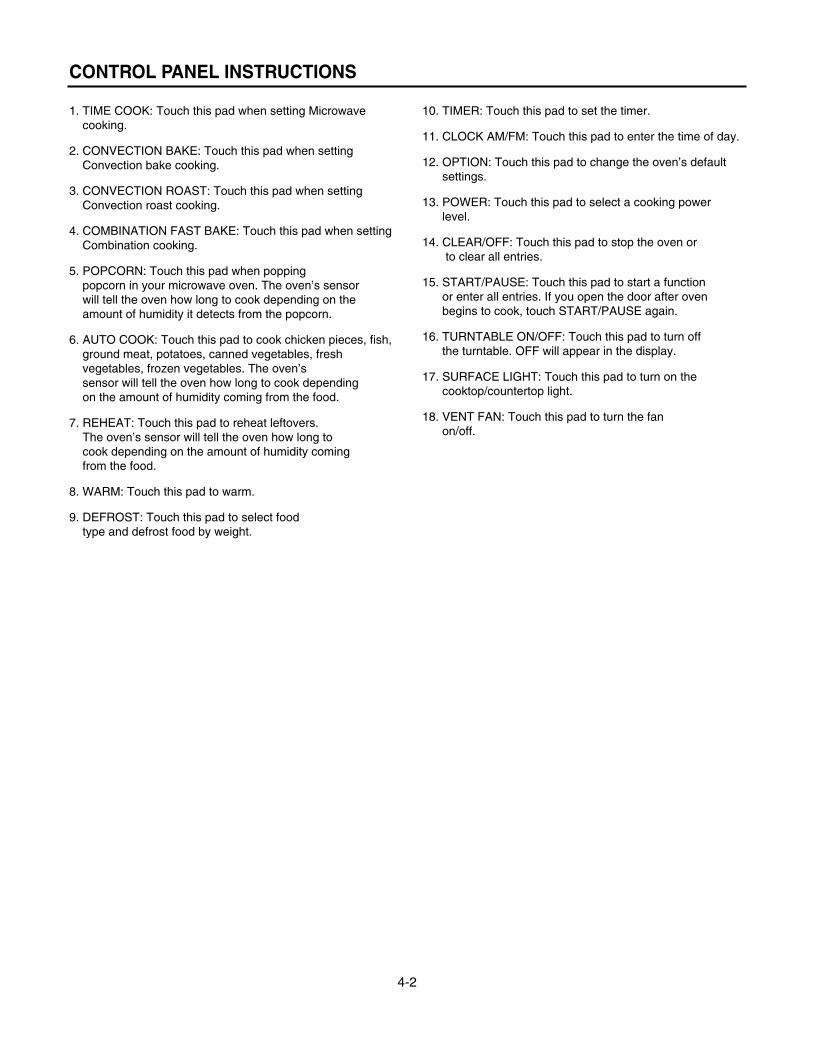
1. TIME COOK: Touch this pad when setting Microwavecooking.
2. CONVECTION BAKE: Touch this pad when settingConvection bake cooking.
3. CONVECTION ROAST: Touch this pad when settingConvection roast cooking.
4. COMBINATION FAST BAKE: Touch this pad when settingCombination cooking.
5. POPCORN: Touch this pad when poppingpopcorn in your microwave oven. The oven’s sensorwill tell the oven how long to cook depending on theamount of humidity it detects from the popcorn.
6. AUTO COOK: Touch this pad to cook chicken pieces, fish,ground meat, potatoes, canned vegetables, freshvegetables, frozen vegetables. The oven’ssensor will tell the oven how long to cook dependingon the amount of humidity coming from the food.
7. REHEAT: Touch this pad to reheat leftovers.The oven’s sensor will tell the oven how long tocook depending on the amount of humidity comingfrom the food.
8. WARM: Touch this pad to warm.
9. DEFROST: Touch this pad to select foodtype and defrost food by weight.
10. TIMER: Touch this pad to set the timer.
11. CLOCK AM/FM: Touch this pad to enter the time of day.
12. OPTION: Touch this pad to change the oven’s defaultsettings.
13. POWER: Touch this pad to select a cooking powerlevel.
14. CLEAR/OFF: Touch this pad to stop the oven orto clear all entries.
15. START/PAUSE: Touch this pad to start a functionor enter all entries. If you open the door after ovenbegins to cook, touch START/PAUSE again.
16. TURNTABLE ON/OFF: Touch this pad to turn offthe turntable. OFF will appear in the display.
17. SURFACE LIGHT: Touch this pad to turn on thecooktop/countertop light.
18. VENT FAN: Touch this pad to turn the fanon/off.
4-2
CONTROL PANEL INSTRUCTIONS

5-1
OVERALL CIRCUIT DIAGRAM
SCHEMATIC DIAGRAM
ERROR MODEDISPLAYF1F2F3F4F5
THERMAL SENSOR OPENTHERMAL SENSOR SHORTKEYPANEL SHORTED FOR > 60 SECONDSHUMIDITY SENSOR OPENHUMIDITY SENSOR SHORT
For Model: JVM1790BKJVM1790CKJVM1790SKJVM1790WK

5-2
MATRIX CIRCUIT FOR TOUCH KEY BOARD
For Model: JVM1790BK / JVM1790CKJVM1790SK / JVM1790WK

GENERAL PRECAUTIONS IN USE
A. Never operate the unit when it is empty.Operating the oven with no load may shorten thelife of the magnetron. Whenever cooking dry foods(dried fish, bread, etc.) or a small amount of food,be sure to put a glass of water into the cookingcompartment. The glass turntable may become hotafter operating, be careful when touching it.
B. Aluminum foil should be avoided because it willdisrupt cooking and may cause arcing. However,small pieces may be used to cover some parts offood to slow the cooking. Any aluminum foil usedshould never be closer than 2.5 cm to any side wallof the oven.
TRIAL OPERATION
After installation, the following sequences and resultsshould be checked carefully.
A. Put a container filled with water (about 1 liter) intothe oven, and close the door tightly.
B. Set cooking time for 10 minutes by touching “1”and then “0” three times. “1, 0, 0, 0” appears inthe display window.
C. Touch the START key.Make sure the cavity light comes on. The unit willbegin cooking and the display window will show thetime counting down by seconds.
D. After about 5 minutes, make sure the primaryinterlock switch, the secondary interlock switch andthe interlock monitor switch operate properly byopening and closing the door several times. Touchthe START key each time the door is closed.
E. Continue operating the unit. Four long beep soundsignal is heard when the time is up. The unit willshut off automatically.
F. Confirm the water is hot.G. Finally, measure the output power according to
“POWER OUTPUT MEASUREMENT” onpage 7-3.
FEATURES AND SPECIFICATIONSFEATURES
A. The safety systems incorporated in this model are:(1) Primary interlock switch(2) Secondary interlock switch(3) Interlock monitor switch(4) Choke system(5) Magnetron thermostat(6) Oven cavity thermostat
(Note: This thermostat located on the ovencavity will open and stop the unit from operationonly if a high temperature is reached, such as,a fire created by overcooking food.)
B. Any one of 10 power output levels ranging 100W to1000W can be selected by the touch control andelectronic computer system.
STANDARD TEST LOAD
The standard test load is one liter (1000ml.) water withstarting temperature of 59°F ~ 75°F in a 1000mlbeaker.(DO NOT USE ANY OTHER LOAD OR DISH ASRESULTS WILL VARY FROM STANDARD.)
PERFORMANCE TEST FOR MICROWAVE
1. Use Glass Tray and the beaker WB64 x 0073.2. Record initial water temperature.3. Run at high power for 2:03.4. Record end water temperature.
The minimum difference between the initial andending temperature should be: 38°F @ 120V
6-1
GENERAL INFORMATION FOR SERVICE
TO PREVENT ELECTRICAL SHOCK. USE EXTREMECAUTION WHEN DIAGNOSING OVEN WITH OUTERCASE REMOVED AND POWER “ON”. THE HIGHVOLTAGE SECTION OF THE POWER SUPPLYINCLUDING FILAMENT LEADS IS 4000 VOLTSPOTENTIAL WITH RESPECT TO GROUND.

PRELIMINARY
A. SINCE NEARLY 2,100 VOLTS EXISTS IN SOMECIRCUITS OF THIS UNIT REPAIRS SHOULD BECARRIED OUT WITH GREAT CARE.The filament leads of magnetron carry HighVoltage with respect to ground. Extreme cautionmust be exercised. Never plug the unit into apower source to determine which component isdefective in high voltage section.
B. TO AVOID POSSIBLE EXPOSURE TOMICROWAVE ENERGY LEAKAGE, THEFOLLOWING PRECAUTIONS MUST BE TAKENBEFORE SERVICING.
(1) Before the power is applied:(a) Make sure the primary interlock switch, the
secondary interlock switch and the interlockmonitor switch operate properly by openingand closing the door several by opening andclosing the door several times.
(b) Make sure the perforated screen and thedielectric choke of the door are correctly andfirmly mounted.
(2) After power is applied:(a) Make sure the interlock switch mechanism
is operating properly by opening and closingthe door.
(b) Check microwave energy leakage mustbe belowthe limit of 5 mW/cm2. (All service adjustments should be made forminimum microwave energy leakagereadings).
(3) Do not operate the unit until it is completelyrepaired, if any of the following conditions exist.The unit must not be operated.(a) The door does not close firmly.(b) The hinge is broken.(c) The door seal is damaged.(d) The door is bent or warped, or there is any
other visible damage on the unit that maycause microwave energy leakage.
NOTE: Always keep the seal clean.(e) Make sure that there are no defective parts
in the interlock mechanism.(f) Make sure that there are no detective parts
in the microwave generating and transmissionassembly (especially waveguide).
(4) The following items should be checked after theunit is repaired:(a) The interlock monitor switch is connected
correctly and firmly.(b) The magnetron gasket is properly positioned
and mounted.(c) The waveguide and the oven cavity are intact.
(no microwave energy leakage)(d) The door can be properly closed and the
safety switches work properly.(e) The unit must stop when the door is opened or
the time is up.
The unit must not be operated with any of the abovecomponents removed or by-passed.
7-1
SERVICE INFORMATION
PRECAUTIONS AND REPAIR SERVICE TIPS

CAUTIONS
• Be sure to check microwave leakage prior toservicing the oven if the oven is operative prior toservicing.
• The service personnel should inform themanufacture importer, or assembler of any certifiedoven unit found to have a microwave emission levelin excess of 5 mW/cm2 and should repair any unitfound to have excessive emission levels at no cost tothe owner and should ascertain the cause of theexcessive leakage. The service personnel shouldinstruct the owner not to use the unit until the oven hasbeen brought into compliance.
• If the oven operates with the door open, the servicepersonnel should:- Tell the user not to operate the oven.
• The service personnel should check all surface andvent openings for microwave leakage.
• Check for microwave leakage after every servicing. Thepower density of the microwave radiation leakageemitted by the microwave oven should not exceed4 mW/cm2. Always start measuring of an unknown fieldto assure safety for operating personnel from radiationleakage.
EQUIPMENT
• TESTER (VOLTS-DC, AC, Ohmmeter)• Microwave survey meter
- Holaday HI-1500HI-1501
- Narda 81008200
• 600 cc non conductive material beaker (glass orplastic), inside diameter: approx. 8.5 cm (31/2 in.)
• Glass thermometer: 100°C or 212°F (1 deg scale)
MEASURING MICROWAVE ENERGYLEAKAGE
• Pour 275±15cc of 20±5°C(68±9°F) water in a beakerwhich is graduated to 600 cc, and place the beakeron the center of the turntable.
• Set the energy leakage monitor to 2,450 MHz anduse it following the manufacturer's recommendedtest procedure to assure correct result.
• When measuring the leakage, always use the 2-inch(5cm) spacer supplied with the probe.
• Operate the oven at its maximum output.• Measure the microwave radiation using and
electromagnetic radiation monitor by holding theprobe perpendicular to the surface being measured.
Move probe along shaded area.
Probe scanning speedLess than 2.5 cm/sec. ( 1 in/sec)
• It should not exceed 4 mW/cm2.
7-2
MICROWAVE LEAKAGE TEST

MEASUREMENT WITH THE OUTER CASEREMOVED(1) When you replace the magnetron, measure for
microwave energy leakage before the outer caseis installed and after all necessary componentsare replaced or adjusted. Special care should betaken in measuring the following parts.- Around the magnetron- The waveguide
WARNING: AVOID CONTACTING ANY HIGHVOLTAGE PARTS.
MEASUREMENT WITH A FULLYASSEMBLED OVEN(1) After all components, including the outer
panels, are fully assembled, measure formicrowave energy leakage around the doorviewing window, the exhaust opening and airinlet openings.
(2) Microwave energy leakage must not exceed thevalues prescribed below.NOTES:Leakage with the outer panels removed - lessthan 5 mW/cm2.Leakage for a fully assembled oven (“Before thelatch switch (primary) is interrupted”) with the doorin a slightly opened position - less than 2 mW/cm2.
NOTE WHEN MEASURING(1) Do not exceed meter full scale deflection.(2) The test probe must be removed no faster than
1 inch/sec (2.5cm/sec) along the shaded area,otherwise a false reading may result.
(3) The test probe must be held with the grip portionof the handle. A false reading may result if theoperator’s hand is between the handle and theprobe.
(4) When testing near a corner of the door, keepthe probe perpendicular to the surface makingsure the probe horizontally along the ovensurface, this may possibly cause probe damage.
RECORD KEEPING AND NOTIFICATIONAFTER MEASUREMENT(1) After adjustment and repair of any microwave
energy interruption or microwave energy blockingdevice, record the measured values for futurereference. Also enter the information on theservice invoice.
(2) Should the microwave energy leakage not bemore than 2 mW/cm2 after determining that allparts are in good condition, functioning properlyand genuine replacement parts which are listed inthis manual have been used.
(3) At least once a year, have the electromagneticenergy leakage monitor checked for calibrationby its manufacturer.
7-3

IMPORTANT NOTES:
UNIT MUST BE DISCONNECTED FROM ELEC-TRICAL OUTLET WHEN MAKING REPAIRS, RE-PLACEMENTS, ADJUSTMENTS AND CONTIN-UITY CHECKS. WAIT AT LEAST ONE MINUTE,UNTIL THE HIGH VOLTAGE CAPACITOR IN THEHIGH VOLTAGE POWER SUPPLY HAS FULLYDISCHARGED.THE CAPACITOR SHOULD BE DISCHARGED BYUSING INSULATED WIRE - I.E. TEST PROBECONNECTED TO 10K-OHM RESISTOR IN SERIESTO GROUND.WHEN RECONNECTING THE WIRE LEADS TOANY PART, MAKE SURE THE WIRING CONNE-CTIONS AND LEAD COLORS ARE CORRECTLYMATCHED ACCORDING TO THE OVERALL CIR-CUIT DIAGRAM. (ESPECIALLY SWITCHES ANDHIGH VOLTAGE CIRCUIT.)
A. REMOVING POWER AND CONTROLCIRCUIT BOARD (Figures 1, 2 and 3)
(1) Disconnect power at the main fuse or circuitbreaken, or pull the plug. Remove the top grille byremoving the two screws that hold it in place.
(2) Remove a screw securing the control panelassembly to the oven cavity.
(3) Remove the control panel with pushing it upward.(4) Remove the six connectors (CN1, CN2, CN3, CN5,
CN6, CN8) and wire leads (Relay2, Relay11) fromthe circuit board.
(5) Remove 7 screws securing the circuit board.
(6) Remove the FPC connector from the terminalsocket following “HOW TO REMOVE THE FPCCONNECTOR” on the next page.
(7) Remove the knob.(8) Remove the circuit board from the control bracket
carefully.
7-4
DISASSEMBLY INSTRUCTIONS
Figure 1
Control PanelScrew
PowerTransformer
(CN2)
(CN1)
(Relay 2)
(CN6)
(Relay 11)
(CN5)
(CN3)
(CN8)
Circuit Board
Figure 2
FPC Connector(S1)
Control Bracket
Circuit Board
Figure 3

7-5
HOW TO REMOVE THE F.P.C. CONNECTOR
Follow the steps below as illustrated in Figures 4and 5 to remove the F.P.C. connector.
(1) Hold the edges of the plastic fastener withthumb and forefinger. (Figure 4)
(2) Lift up the lever of the plastic fastener fromthe terminal socket by lightly pressing thelever end with forefinger.(Figure 5)
(3) Remove the F.P.C. connector from theterminal socket.
HOW TO INSERT THE F.P.C. CONNECTOR
Follow the steps below as illustrated in Figures 6and 7 to insert the F.P.C. connector.
(1) Insert the F.P.C. connector into the terminalsocket securely with the fingers.
(2) Hold the plastic fastener with thumb andforefinger of the other hand, and push itslowly into the terminal socket. (Figure 6)NOTE: When reconnecting the F.P.C
connector make sure that the holeson the F.P.C. connector are properlyengaged with the hooks on the plasticfastener
(3) Lock the level of the plastic fastener into thehook of the terminal socket securely byreleasing the fingers.(Figure 7)
Figure 4
Figure 5
Figure 7
Figure 6

B. REMOVING OVEN FROM WALL(2 PERSONS REQUIRED)
Oven is hooked on metal tabs at bottom of wallmounting plate and fastened to cabinet by (3) topcabinet bolts.
CAUTION: Oven weights 77 lbs. Requires 2persons for removal
1. Disconnect Power Cord, Top exhausted modelsdisconnect duct and remove damper assembly.
2. Remove (3) top cabinet bolts while supporting unit.3. Lift off back hooks and pull unit forward slowly
providing adequate support to prevent dropping unitduring removal.
C. REMOVING THE OUT CASE(Figure 8)(1) Remove the vent grille by removing two screws
securing it to the out case.(2) Remove two screws securing it to the air duct.(3) Remove the base plate by removing four screws
securing it to the out case. Remove the Mount,All from the out case by removing two screwssecuring it to the out case.
(4) Remove four screws from the rear section.(5) Remove the outcase with pushing it back.(6) Remove the outcase with disconnecting power
cord connector.
7-6
Vent Grille
Controller (3 screws)
Door
MountingPlate
(1 or 2 screws)
Out Case
Mount,All
Figure 8

D. REMOVING THE DOOR INTERLOCKSWITCHES (Figures 9, 10)
(1) Disconnect the wire leads from the interlockswitches.
(2) Remove two screws securing the Latch Board.(3) Make necessary replacements and check
microwave energy leakage according to“ADJUSTMENT PROCEDURE” on page 7-12. Latch Board
PrimaryInterlock Switch
InterlockMonitor Switch
SecondaryInterlock Switch
Latch Board
BK(CN1)RD(Bottom TCO)RD(H.V.Transformer)
WH(from Convection Heater)
Primary Interlock Switch
Monitor Interlock Switch
Secondary Interlock Switch
PK(from P.C.B)GN(from P.C.B)
WH(from H.V.Transformer)
RD (from H.V.Transformer/
Figure 9
Figure 10
WIRE COLORSYMBOL COLOR
WHBKBRRDBLPKGYGNN.P.
WHITEBLACKBROWNREDBLUEPINKGREYGREENNot Provided
7-7

E. REMOVING MAGNETRON(Figures 11 Through 13)
(1) Remove the vent grille by loosening two screws.(Figure 11)
(2) Remove the outcase. See Figure 13-b.(3) Remove four tap tite screws securing the
magnetron to the wave guide.(4) Remove the magnetron VERY CAREFULLY.
NOTES:• When removing the magnetron, make sure that its
dome does not hit any adjacent parts, or it may bedamaged.
• When replacing the magnetron, be sure to install themagnetron gasket in the correct position and be surethat the gasket is in good condition.
• After replacing the magnetron, check for microwaveenergy leakage with a survey meter Checkmicrowave energy leakage must be below the limitof 5 mW/cm2. (All service adjustments should bemade for minimum microwave energy leakagereadings.)
7-8
Figure 11
Figure 13-a Figure 13-b
Figure 12
Vent Grille
Controller (3 screws)
Door
MountingPlate
(1 or 2 screws)
Out Case
Mount,All
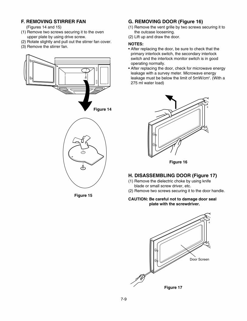
F. REMOVING STIRRER FAN(Figures 14 and 15)
(1) Remove two screws securing it to the ovenupper plate by using drive screw.
(2) Rotate slightly and pull out the stirrer fan cover.(3) Remove the stirrer fan.
G. REMOVING DOOR (Figure 16)(1) Remove the vent grille by two screws securing it to
the outcase loosening.(2) Lift up and draw the door.
NOTES:• After replacing the door, be sure to check that the
primary interlock switch, the secondary interlockswitch and the interlock monitor switch is in goodoperating normally.
• After replacing the door, check for microwave energyleakage with a survey meter. Microwave energyleakage must be below the limit of 5mW/cm2. (With a275 ml water load)
H. DISASSEMBLING DOOR (Figure 17)(1) Remove the dielectric choke by using knife
blade or small screw driver, etc.(2) Remove two screws securing it to the door handle.
CAUTION: Be careful not to damage door sealplate with the screwdriver.
7-9
Figure 16
Figure 15
Figure 14
Door Screen
Figure 17
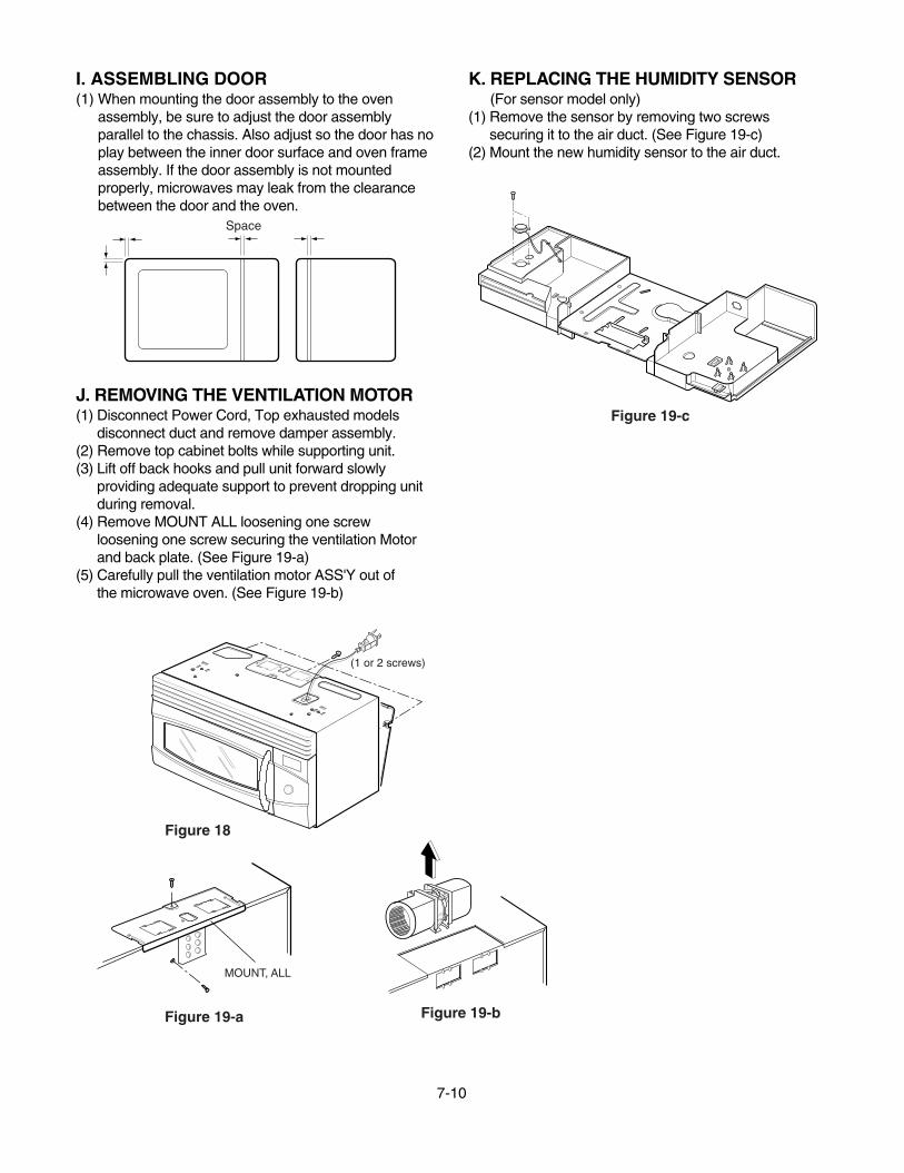
I. ASSEMBLING DOOR(1) When mounting the door assembly to the oven
assembly, be sure to adjust the door assemblyparallel to the chassis. Also adjust so the door has noplay between the inner door surface and oven frameassembly. If the door assembly is not mountedproperly, microwaves may leak from the clearancebetween the door and the oven.
J. REMOVING THE VENTILATION MOTOR(1) Disconnect Power Cord, Top exhausted models
disconnect duct and remove damper assembly.(2) Remove top cabinet bolts while supporting unit.(3) Lift off back hooks and pull unit forward slowly
providing adequate support to prevent dropping unitduring removal.
(4) Remove MOUNT ALL loosening one screwloosening one screw securing the ventilation Motorand back plate. (See Figure 19-a)
(5) Carefully pull the ventilation motor ASS'Y out ofthe microwave oven. (See Figure 19-b)
K. REPLACING THE HUMIDITY SENSOR(For sensor model only)
(1) Remove the sensor by removing two screwssecuring it to the air duct. (See Figure 19-c)
(2) Mount the new humidity sensor to the air duct.
7-10
Space
(1 or 2 screws)
MOUNT, ALL
Figure 18
Figure 19-a Figure 19-b
Figure 19-c

L. REMOVING THE TURNTABLE MOTOR(1) Remove the turntable.(2) Remove the turntable shaft VERY CAREFULLY
with a slotted screwdriver. (Figure 21)(3) Remove the base plate by removing 7 screws
securing it to the oven cavity. (Figure 22-a)(4) Disconnect the leadwire from the turntable motor
terminals.(5) Remove the 2 screws securing the turntable motor
to the oven cavity ASS'Y. (Figure 22-b)
NOTES:• Remove the leadwire from the turntable motor
VERY CAREFULLY.• Be sure to grasp the connector not the wires when
removing.• Warp the blade with tape to avoid scratching the
cavity.
M. REMOVING CONVECTION HEATER,THERMISTOR AND DAMPER MOTOR(Figure 23)
(1) Remove the outer case.(2) Remove the air duct by removing six screws
securing it to the oven front plate, guide air andglasswool-L cover.
(3) Disconnect the wire leads of air duct.(4) Remove the magnetron.(5) Remove the latch board assembly.(6) Remove the bottom plate by removing four screws.(7) Remove the four net screws securing chamber
assembly.(8) Lift the chamber assembly from the oven cavity.(9) Remove three screws securing the heater of the
chamber assembly.(10) Lift the convection heater from the chamber
assembly.(11) Lift the damper motor from the chamber
assembly.
7-11
Wire Leads
Turntable Motor
Figure 22-b
Figure 20
Figure 21-a
Figure 23

ADJUSTMENT PROCEDURESTo avoid possible exposure to microwave energyleakage, adjust the door latches and interlockswitches, using the following procedure.
The Interlock Monitor and Secondary Interlock Switchact as the final safety switch protecting the user frommicrowave energy. The terminals between “COM” and“NC” of the Interlock Monitor must close when the dooris opened. After adjusting the Interlock Monitor Switch,make sure that it is correctly connected.Mounting of the primary/monitor/secondary switches tothe latch board.
CHECK THE DOOR LATCH AND SWITCHCLOSING.
NOTE:The outer cover of the microwave oven isremoved.
(1) Set the microwave oven on its side so that you cansee the latch board and the switches, as shown inFigure 24-a.
(2) Close the door tightly and check gaps A and B tobe sure they are no more than 1/64" (0.5 mm).See Figure 23 for close-up view of gaps A and B(door latches). If all gaps are less than 1/64"(0.5 mm), adjustment of the latch board may notbe necessary. Go to Steps 5 and 6 to check thesequence of the switches.
NOTE:To correct sequence of the Primary InterlockSwitch, Secondary Interlock Switch and theInterlock Monitor Switch is very important.If any gap is larger than 1/64" (0.5 mm), you willneed to adjust the latch board”. Go to step 3and follow all steps in order.
ADJUST THE LATCH AND SWITCH CLOSING
(3) Loosen the two screws holding the plastic latchboard as shown.
(4) With the oven door closed tightly, move the latchboard upward toward the top of the oven and/oraway from the door latch until the gaps are lessthan 1/64" (0.5 mm).Hold the latch board tightly in this position until youcheck the sequence of the switches in steps 5and 6.
7-12
INTERLOCK SYSTEM
INTERLOCK MECHANISMThe door lock mechanism is a device which has been specially designed to eliminate completely microwaveactivity when the door is opened during cooking and thus to prevent the danger resulting from the microwaveleakage.
LATCH
LATCH BOARD
0-1/64"
0-1/64"
Latch Board
PrimaryInterlock Switch
Monitor SwitchInterlock
SecondaryInterlock Switch
Figure 24-a
Figure 24-b

TEST THE LATCH AND SWITCH SEQUENCE
(5) Open the oven door slowly. Watch the door latch,the Secondary Switch. Release Rod and Leveron the switches to make sure they are zero to thebody of the switches in the following sequence:
- Primary Interlock Switch- Secondary Interlock Switch- Interlock Monitor Switch
Adjust the latch board until the switches operate inthis sequence. See Steps 3 and 4.
(6) Close the oven door slowly and be sure it is tightlyclosed. Watch the three switches to make surethey are zero to the body of the switches in thefollowing sequence:
- Interlock Monitor Switch- Secondary Interlock Switch- Primary Interlock Switch
NOTE: The Interlock Monitor Switch is an addedsafety check on the Primary andSecondary Interlock Switches. If thePrimary and Secondary Interlock Switchesallow the oven to operate with the dooropen, the Monitor Switch will blow thefuse.
(7) When you achieve the proper sequence ofswitches in Steps 5 and 6, tighten the latch boardscrews at that point.
TEST THE MICROWAVE ENERGY LEAKAGE
Make sure the microwave energy leakage is below thelimit of 1mW/cm2 (with a 275 ml water load) and5mW/cm2 (with a 275 ml water load without thecabinet) when measured with a survey meter.
7-13

A. PRIMARY INTERLOCK SWITCH TEST
When the door is opened slowly, an audible clickshould be heard at the same time or successivelyat intervals and the latches should activate theswitches with an audible click.If the latches do not activate the switches when thedoor is closed, the switches should be a adjustedin accordance with the adjustment procedure.Disconnect the wire lead from the primary switch.Connect the ohmmeter leads to the common(COM) and normally open (NO) terminal of theswitch. The meter should indicate an open circuitin the door open condition.When the door is closed, the meter should indicatea closed circuit.When the primary switch operation is abnormal,make the necessary adjustment or replace theswitch only with the same type of switch.
B. SECONDARY INTERLOCK SWITCH TEST
Disconnect the wire lead from the secondaryswitch.Connect the ohmmeter leads to the common(COM) and normally open (NO) terminals of theswitch. The meter should indicate a open circuit inthe door open condition. When the door is closed,meter should indicate an closed circuit. When thesecondary switch operation is abnormal, make thenecessary adjustment or replace the switch onlywith the same type of switch.
C. MONITOR SWITCH TEST
Disconnect the wire lead from the monitor switch.Connect the ohmmeter leads to the common(COM) and normally closed (NC) terminals of theswitch. The meter should indicate closed circuit inthe door open condition. When the door is closed,meter should indicate an open circuit. When themonitor switch operation is abnormal, replace withthe same type of switch.NOTE: After repairing the door or the interlocksystem, it is necessary to do this continuitytest before operating the oven.
7-14
INTERLOCK CONTINUITY TEST
COMPONENTS TEST PROCEDURE RESULTSSWITCHES Check for continuity of the Door Door(Wire leads removed) switch with an Ohm-meter open closed
PrimarySwitch
MonitorSwitch
SecondarySwitch
NOTE: After checking for the continuity of switches, make sure that they areconnected correctly.
WARNING : FOR CONTINUED PROTECTION AGAINST EXCESSIVE RADIATIONEMISSION, REPLACE ONLY WITH IDENTICAL REPLACEMENT PARTS.
TYPE NO. SZM-V16-FA-63, VP-533A-OF OR V-5230Q FOR PRIMARY SWITCHTYPE NO. SZM-V16-FA-62, VP-532A-OF OR V-5220Q FOR MONITOR SWITCHTYPE NO. SZM-V16-FA-63, VP-533A-OF OR V-5230Q FOR SECONDARY SWITCH
NOCOM
NC
COM
NOCOM

7-15
TEST AND CHECKOUT PRECEDURES AND TROUBLESHOOTING
A. TEST PROCEDURES
- CAUTIONS -
- DISCONNECT THE POWER SUPPLY CORDFROM THE WALL OUTLET WHENEVERREMOVINGING THE CABINET FROM THE UNIT.PROCEED WITH THE TESTS ONLY AFTERDISCHARGING THE HIGH VOLTAGE CAPACITORAND REMOVING THE WIRE LEADS FROM THEPRIMARY WINDING OF THE HIGH VOLTAGETRANSFORMER. (SEE FIGURE 24)
- ALL OPERATIONAL CHECKS WITH MICROWAVEENERGY MUST BE DONE WITH A LOAD (1 LITEROF WATER IN CONTAINER) IN THE OVEN.
COMPONENTS TEST PROCEDURES RESULTS
NOTE: A MICROWAVE ENERGY LEAKAGE TEST MUST ALWAYS BE PERFORMED WHEN THE UNIT ISSERVICED FOR ANY REASON.
MAGNETRON(Wire leads are
removed)
HIGH-VOLTAGETRANSFORMER(Wire leads are
removed)
1. Remove wire leads. Install the magnetronseal in the correct position. Check that theseal is in good condition.
2. Measure resistance. (ohm meter scale:Rx1)• Filament terminal
3. Measure resistance. (ohm meter scale:Rx1000)• Filament to chassis
1. Remove wire leads.2. Measure resistance. (ohm meter scale: Rx1)
• Primary winding• Secondary winding to ground• Filament winding
3. Measure resistance. (ohm meter scale:Rx1000)• Primary winding to ground• Filament winding to ground
Normal reading:Less than 1 ohm.
Normal reading:Infinite ohms.
NOTE: Replace the magnetron, if themagnetron checks and all of thehigh voltage component tests aregood, but the unit still does not heata load.
Normal(Approximately)0.3 ~ 0.5 ohm65 ~ 120 ohmLess than 0.2 ohm
Normal readings:Infinite ohms.Infinite ohms.
PrimaryWinding
SecondaryWinding
FilamentWinding
Figure 24

7-16
COMPONENTS TEST PROCEDURES RESULTS
HIGH-VOLTAGECAPACITOR
HIGH-VOLTAGEDIODE
CONVECTIONHEATER
1. Remove wire leads.2. Measure resistance. (ohm meter scale:
Rx1000)(1) Terminal to terminal
(2) Terminal to case
1. Measure continuity. Forward.(ohm meter scale: Rx1000)
1. Measure continuity. Reverse.(ohm meter scale: Rx1000)
1. Remove wire leads.2. Measure resistance.
(ohm meterscale:Rx1)
Normal:Momentarily indicates several ohm, andthen gradually returns to infinite
Normal: Infinite.
Normal:Continuity.Abnormal: Infinite.
Normal: Infinite.Abnormal: Continuity.
Normal readingsResistance: Approx. 6 to 13 ohmCurrent: Approx. 13A
Abnormal: Infinite or several.
Ohm-meter
Figure 25-a
Ohm-meter
Figure 25-b
Ohm-meter
Figure 26-a
Ohm-meter
Figure 26-b

7-17
COMPONENTS TEST PROCEDURES RESULTS
TOUCH KEYBOARD
SENSOR(For sensor model only)
Measure the resistance between terminalpins of connector KEY CONNECTOR.NOTE:When reconnecting the FPC connector,make sure that the holes on the FPCconnector are properly engaged with hookson the plastic fastener.
MATRIX CIRCUIT FORTOUCH KEY BOARD
CONNECTOR(KEY CON)
1. Remove the 3 pin connector from PCB.2. Measure resistance across pins 1 & 2.3. Across pins 2 & 3.
(ohm meter scale:Rx1)
Normal:Approximately
at 68 ± 35°FAbnormal:Infinite or several.
FPC CONNECTORTop
Resistancevalue
Whentouched
Less than400 ohms
When nottouched
More than1 mega ohm
123
Figure 27
Figure 29
Figure 28
11
1
1 & 23.1 Kohm
2 & 3∞

COMPONENTS TEST PROCEDURES RESULTS
FAN MOTOR(F.M)
CIRCULATIONMOTOR
(C.M)
VENTILATIONMOTOR
DAMPER MOTOR(D.M)
TURNTABLEMOTOR (T.M)
STIRRER MOTOR(S.M)
THERMISTOR
1. Remove wire leads.2. Measure resistance.
(ohm meter scale: Rx1)
1. Remove wire leads.2. Measure resistance.
(ohm meter scale: Rx1)
1. Remove wire leads.2. Measure resistance.
(ohm meter scale: Rx1000)
1. Remove the connector from PCB.2. Measure resistance across pins 1 & 3.
(ohm meter scale: Rx1)
Normal:Approximately
ohmAbnormal:Infinite or several.
Normal: Approximately
Abnormal:Infinite or several.
Normal:Approximately250 to 350 Kohm at 68 ± 35°F
Abnormal:Infinite or several.
F.M
35-55ohm
C.M
20-35ohm
High (Black-Blue)
Medium (White-Blue)
Slow (Gray-Blue)
35-45 ohm
50-60 ohm
75-90 ohm
D.M
2.3-3.5Kohm
T.M
2.6-3.5Kohm
S.M
100-170Kohm
7-18

NOTES:• A MICROWAVE ENERGY TEST MUST ALWAYS BE PERFORMED WHEN THE UNIT IS SERVICED FOR
ANY REASON.• MAKE SURE THE WIRE LEADS ARE IN THE CORRECT POSITION.• WHEN REMOVING THE WIRE LEADS FROM THE PARTS, BE SURE TO GRASP THE CONNECTOR, NOT
THE WIRES.
B. CHECKOUT PROCEDURES(1) CHECKOUT PROCEDURES FOR FUSE BLOWING
CAUTION: REPLACE BLOWN FUSE WITH 20 AMPERE FUSE.
NOTES:• If the fuse is blown by an improper switch operation, replace the all Interlock switches, PCB Ass’y and the
fuse at the same time. After replacing the the all Interlock switches, PCB Ass’y,Fuse with new ones, makesure that they are correctly connected.
• Check for microwave energy leakage according to INTERLOCK ADJUSTMENT PROCEDURES on page 7-12 when the primary interlock, secondary interlock switches and/or the interlock monitor switches areadjusted or replaced.
7-19
COMPONENTS TEST PROCEDURES RESULTS
RELAY 2
RELAY 11
1. Measure continuity.(ohm meter scale: Rx1)
2. Remove the lead wires and operateoven at power level 1 through powerlevel 10.
1. Measure continuity.(ohm meter scale: Rx1)
2. Remove the lead wiresand operate oven atConvection Cooking.
POWERLEVEL
12345678910
4 sec6 sec8 sec10 sec12 sec14 sec16 sec18 sec20 sec22 sec
18 sec16 sec14 sec12 sec10 sec8 sec6 sec4 sec2 sec
0
PROBLEMS CAUSES
Fuse blows immediately afterthe door is closed.
Fuse blows immediately afterthe door is opened.
Fuse blows when the door is closed and STARTkey is touched.
Improper operation of the primary interlock, secondaryinterlock switches and/or the interlock monitor switch.
Malfunction of the high voltage transformer; the highvoltage capacitor including the diode, the magnetron,the blower motor or the circuit board.
ConvectionCooking Start
OFF

7-20
(2) CHECKOUT PROCEDURES FOR RELAY.
- PROBLEM (A) -FAN motor and oven lamp turn on without touching
START key when the door is closed.
Remove the mate connector of I/OCON from the circuit board.Does the unit still operate?
Replace thecircuit board
ReplaceRELAY1
NO
NO
YES
YES
GOOD
DefectiveRELAY1
- PROBLEM (B) -FAN motor and oven lamp turn on When the door is
closed and START key is touched.
Replace thecircuit board
YES NO
GOOD

• Display “PREHEAT 225 DEG”• Ready beep• Cycle 225°F• Cbserve neon light• Press start
7-21
- PROBLEM (A) -Convection or Combination does not operate.
ConvectionCook
• Remove neon light• Program bake cook• 225°F (use dial)• Press start
• Program fast bake cook• 225°F (use dial)• Press start
• Do not clear• Program fast back cook
time 2 min.• Press start
• Neon cycle• MW “ON” 13 sec then
MW “OFF” & heater “ON”17 sec
• Auto turn “OFF” (2 min)
• Display “PREHEAT OFFSET ON”• Ready beep• Cycle 225°F
• Do not clear• Program cook time 1 min• Press start• Auto shut-off at set cook
time
CombinationCook
YES NO
Controlsystemnormal
YES
Replacesmartboard
Veritycontrolxmfr
RepairorReplace
NO
Controlsystemnormal
YES
•Verify controlxfmr &
• Oven circuit
NO
• All normal except• MW power
Notnormal
High volt.Section
Repair or Replace
(3) CHECKOUT PROCEDURES FOR CIRCUITBOARDThe following symptoms indicate a defective circuitboard.
1) The start function fails to operate but the highvoltage Systems, the interlock switches, the doorsensing and the relay check good.
2) The unit with a normal relay continuously operates.3) Proper temperature measurement is not obtained.4) The buzzer does not sound or continues to sound.5) Some segments of one or more digits do not light
up, or they continue to light up, or segments lightwhen they should not.
6) Wrong figures appear.7) The figures of all digits.8) Some of the indicators do no flicker light up.9) The clock does not keep time properly.
NOTE: A MICROWAVE ENERGY LEAKAGE TEST MUST ALWAYS BE PERFORMED WHEN THE UNIT ISSERVICED FOR ANY REASON.
(4) CHECKOUT PROCEDURES FOR CONVECTION

• Display “PREHEAT 225 DEG”• Ready beep• Cycle 225°F• Cbserve neon light• Press start
7-22
- PROBLEM (B) -Actual oven temperature is not displayed.
ConvectionCook
• Remove neon light• Program bake cook• 225°F (use dial)• Press start
• Program fast bake cook• 225°F (use dial)• Press start
• Press Fast Bake• Actual oven temperature
will be displayed.
• Display “PREHEAT OFFSET ON”• Ready beep• Cycle 225°F
• Press Convection Bake• Actual oven temperature
will be displayed.
CombinationCook
YES
Controlsystemnormal
YES
Replacethermistor
NO
Controlsystemnormal
YES
Replacesmartboard
NO
Controlsystemnormal
YES
Replacethermistor
NO
Controlsystemnormal
YES
Replacesmartboard
NO
7-23
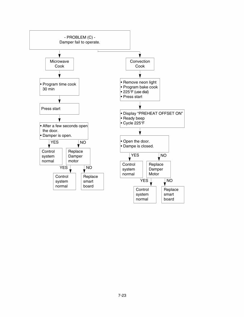
- PROBLEM (C) -Damper fail to operate.
MicrowaveCook
• Program time cook30 min
Press start
• After a few seconds openthe door.
• Damper is open.
Controlsystemnormal
YES
ReplaceDampermotor
NO
Controlsystemnormal
YES
Replacesmartboard
NO
ConvectionCook
• Remove neon light• Program bake cook• 225°F (use dial)• Press start
• Display “PREHEAT OFFSET ON”• Ready beep• Cycle 225°F
• Open the door.• Dampe is closed.
Controlsystemnormal
YES
ReplaceDamperMotor
NO
Controlsystemnormal
YES
Replacesmartboard
NO

7-24
C. T
RO
UB
LE S
HO
OTI
NG
Bef
ore
follo
win
g th
is tr
oubl
esho
otin
g re
ad T
RIA
L O
PE
RA
TIO
N o
n pa
ge 6
- 1.
• DIS
PLA
Y P
robl
ems,
A th
ru C
• HE
LP U
P P
robl
ems,
D th
ru E
• B
UZZ
ER
Pro
blem
s, F
PR
OB
LEM
- A
: PLE
AS
E E
NTE
R T
IME
OF
DA
Y d
oes
not a
ppea
r in
disp
lay
win
dow
whe
n po
wer
sup
ply
cord
ispl
ugge
d in
to w
all o
utle
t.
PR
OB
LEM
- B
: Dis
play
doe
s no
t sho
w c
orre
ct n
umbe
rs a
nd/ o
rco
rrec
t ind
icat
ions
whe
n pr
ogra
mm
ed.
Che
ck: 1
. PO
WE
R S
UP
PLY
2. F
US
E (S
ee C
HE
CK
OU
T P
RO
CE
DU
RE
S F
OR
FU
SE
BLO
WIN
G: o
n pa
ge 7
- 18)
3. O
VE
N C
AV
ITY
TH
ER
MO
STA
T
1 1
LB/
KB
DR
1 nip neewteb egatlo v erusae
M.1
NC rotcennoc fo 3 nip dna
snuR
snuR
0021
0021
V021ecalpe
Rdraob tiucric
lamro
Ndraob tiucric
lamro
Necnatsiser
egatloV
tcerrocnitcerro
Csnoitcennoc
snuR
snuR
snuR
hc uot fo ec natsis er er usaeM
gnivomer retfa draob yek
.1S r otcenno c
)71-7 d na 4-7 eg ap eeS(
lamro
Necnats iser
ecnatsiseR
tcerro cn ihcuot ecalpe
R.draob ye k
hcuot lamro
Ndraob yek
rooP
tcatnoctc erro
Cgnitaes
tcatnoC
koe calpe
Rdraob t iucric
lamro
Ndraob tiucric
lamro
Ntcatnoc
t catnoc k cehC
1S rotcenno c fo

7-25
PR
OB
LEM
- C
: D
ispl
ay d
oes
not s
tart
coun
tdow
n w
hen
STA
RT
key
is to
uche
d.
Che
ck: 1
. TO
UC
H K
EY
BO
AR
D (S
TAR
T K
EY
FU
NC
TIO
N)
Che
ck: 1
. AIR
VE
NTS
1 1
rotcennoc fo ytiunitnoc kcehC
dna )N
G( 1 niP nee
wteb 5N
Csi rood eht n eh
w )K
P( 3 nipdesol c
ytiun itnoC
KO
fo tc atnoc k cehC
1S rotc ennoc
tcatnoC
KO
ec alpeR
draob tiucriC
tce rroC
tcerroC
gnit aes
l amro
Ndraob tiucric
l amro
Ntcatnoc
rooP
yra dnoceS la
mr oN
hctiws
oN
ytiunitnocrood ec alper ro tsujd
A.hcti
ws gnisnes
snuR
snuR
snuR
naf fo no itarepo kcehC
yek T
RAT
S nehw roto
m.dehcuo t s i
ecnat siser eru saeM
roticapac.V.H fo
)61 -7 egap ees(
ecn atsiseR
tcerr ocni
ecnatsiser erusaeM
rotom naf fo
mho 06 ot 03 :C
~A lani
mreTmho 02 ot 01 :
B~
A lan imre T
ecnat siseR
tcerrocnieca lpe
Rroto
m naf
lamro
Ndrao b tiucric
ecalpeR
lamro
N roto
m naf
draob ti ucricla
mroN
ecn atsis er
.C.V.
H ecalpeR
.C.V.
H lamro
N
lamro
Nno rte nga
mecalpe
R
lamro
Nnoitarepo
oN
no itarepo
snuR
snuR
snuR
snuR
3 3lamro
Ne:cnatsiser In
finite
33
PR
OB
LEM
- D
: Uni
t ope
ratio
n se
ems
to b
e no
rmal
but
no h
eatin
g is
pro
duce
d in
ove
n lo
ad.

7-26
PR
OB
LEM
- E
: U
nit d
oes
not h
eat u
p ev
en if
dis
play
cou
nts
dow
n w
hen
STA
RT
key
is to
uche
d fo
r HIG
H P
OW
ER
coo
king
.
Che
ck: 1
. PR
IMA
RY
AN
D S
EC
ON
DA
RY
INTE
RLO
CK
SW
ITC
HE
S2.
TH
ER
MO
STA
T1 2
snuR
snuR
snuR
tcatnoC
KO
ON
yt iun itnoce cal pe
Rdraob tiucric
lamro
Ndraob t iucr ic
tcatnoc rooP
e calpeR
draob tiucricla
mroN
draob tiucricK
O tcat noC
lamr o
Ntcatnoc
tce rroC
gnitaes
fo tcatnoc kcehC
rot cenno c
fo tcatnoc eht kce hC
)81 -7 egap e es (1 1 ,2 yaler
ecnats iseR
tcerrocn i
fo ytiunitno c eht kcehC
)61-7 egap ees( .C.V.
H
.T.V.H la
mroN
ecnatsiseR
tcerrocni.
C.V.H la
m roN
lamronb
A.
D.V.H ecalpe
R
l amro
Nnortenga
Mecalpe
Rnortenga
Mla
mroN
lamro
N.
D.V.H
eht kcehC
.D.V.
H fo ytiunitnoc)61-7 egap ees(
.C.V.
H ecalpeR
l amr o
Necnatsiser
.T. V.H e calpe
R
lamro
Ne cnat si se r
snuR
snuR
snuR
snuR
fo ecnatsiser erusaeM
remrofsnarT. V.
H)51 -7 egap ees (

7-27
snu RP
RO
BLE
M -
F: N
o bu
zzin
g w
hen
touc
hing
the
key,
bet
wee
nst
ages
or a
t end
of c
ooki
ng
1
lamro
Ndraob tiucric
lamron kceh
Cnoita rep o
draob tiucr ic
ecalpeR
drao b tiucricsnu
R

7-28
PR
OB
LEM
- G
: Ven
tilat
ion
fan
does
not
ope
rate
whe
n FA
N H
IGH
/ ME
DIU
M/ L
OW
key
is to
uche
d.
1
snuR
snuR
snuR
tcatnoC
KO
ON
tcatnocecalpe
R esuf la
mreht nortengam
tatsomre ht nevo dna
tcatno c rooP
e calp eR
draob ti ucricl a
mroN
draob tiucricK
O t catnoC
lamro
Ntcatnoc
tc erroC
gni taes
tcatnoc kcehC
rot ce nno c fo)4-7 egap ee s(
snuR
ecalpeR
noitalitnevY
SS
A r otom
snur O
Nla
mroN
noitalitnevY
SS
A rotom
fo t catno c eht kce hC
lamreht nortenga
mtatso
mreht nevo dna esuf
snuR
snuR
t catnoC
KO
ON
tcatnoc
Che
ck th
e co
ntac
t of
hood
ther
mos
tat
hood
ther
mos
tat
ecalpeR
Che
ck: 1
. PO
WE
R S
UP
PLY
2. F
US
E

-8-1-
#EV#
13581A
HARDWARE BAG
13581A
9383EA
13551A
13551A
13213A
WTP004
WTP004
13213A
13552A
13552A
14026A
14026A
13651A
14970AWTT028
136502136501
14970A
WSZ131
WWS016
WWS016
EXPLODED VIEWDOOR PARTS
FOR MODEL: JVM1790BKJVM1790CKJVM1790WK
FOR MODEL: JVM1790SK

-8-2-
#EV#
24781M
24781M
23572A
23551A
23551A
WTP013
WTP015
WTP013
24810P
23506A
24810P
268711
268711
249401
WTT029
WTT027
WTT027
249401
For ModelJVM1790BK
For ModelJVM1790WKJVM1790CK
CONTROLLER PARTS
FOR MODEL: JVM1790BKJVM1790CKJVM1790WK
FOR MODEL: JVM1790SK

-8-3-
#EV#
For ModelJVM1790BKJVM1790SKFor ModelJVM1790WKJVM1790CK
34021A
63302A
34810T
35230A
35230A
330341
948503
WTT027
WTT028
WTT027
WTP013
WTT021
WMP004
WNH001
WTT029
WTT027
33550P
36549S
34890C
36912C
33112U
33809A
53035B
63303A
34931A
34930R
33740B
33530A
34960AWTT029
WTT027
For ModelJVM1790WKJVM1790CK
For ModelJVM1790BKJVM1790SK
WTT020
WTT022
For ModelJVM1790WKJVM1790CK
For ModelJVM1790BKJVM1790SK
WTT020
WTT022
For ModelJVM1790BKJVM1790SKFor ModelJVM1790WKJVM1790CK
WTT029
WTT027
33740A
OVEN CAVITY PARTS
-8-4-
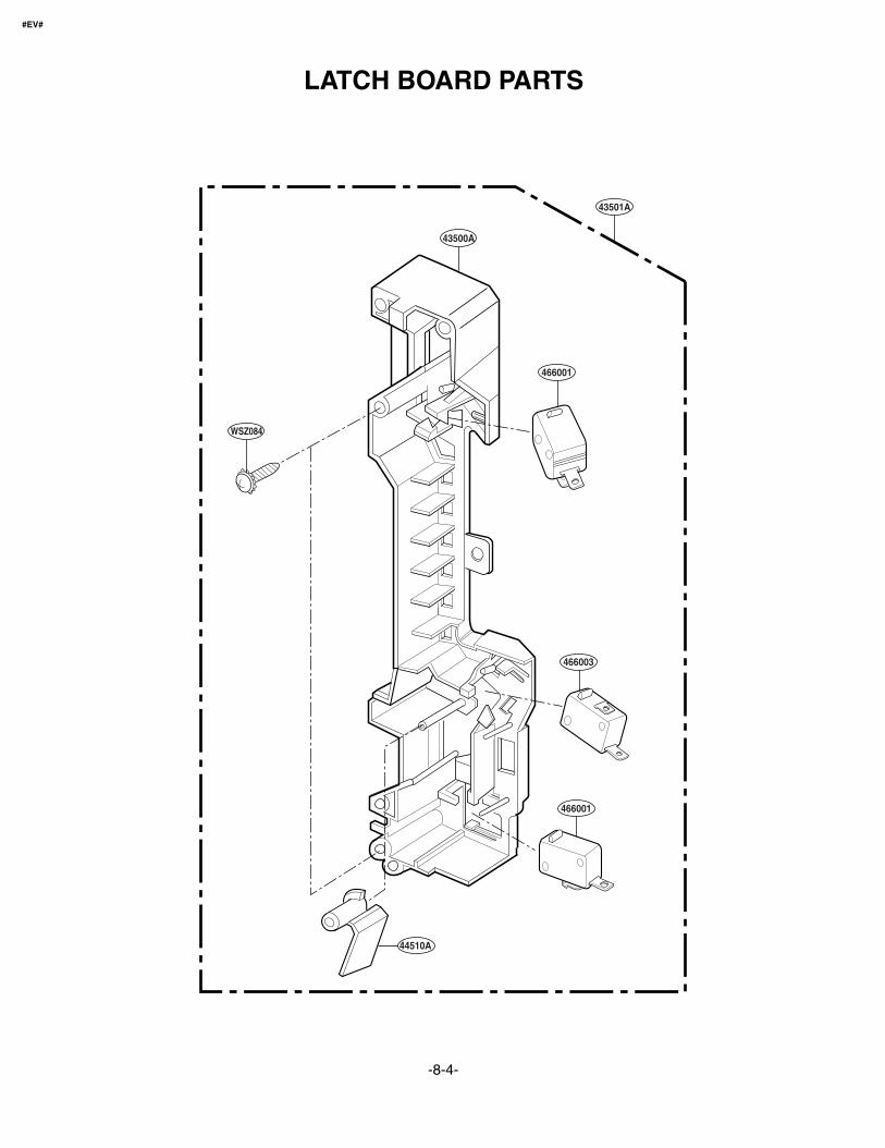
#EV#
WSZ084
43500A
43501A
466001
466003
466001
44510A
LATCH BOARD PARTS

-8-5-
#EV#
33390G
WTT021
WTT028
WSZ002
WTT028
WTT022
WTT028
WTT021
WTT037
54974S
568772
35026G
55900A
548101
948501948502
54810A
56208A
56549F
55238A
55013L
55300S
55900C
WNH003WWS005
34370T
35889A
56851D
34930W
56324A
56549B
55012A
466002
548102
54810S
36549R
36549C
56322A
53551S
WTT022
WSZ002
WTP013
WTP004
WTP013
WTP013
WSZ002
WNH002
53300B
50CZZH
54810C
53504A
549801
56170D
569302
569301
56930V
WTT011
WSZ002
WNH002
WTP013
56930155893A
INTERIOR PARTS (I)

-8-6-
#EV#
53550L
WTT030
WMP004
56912E
53551F
54980H
34931A
WNH001
3550W1A264A
3034W1A004A
4931W1A009E
• Discord original for parts supplied.• Change pieces simultaneously.
After
Before
WTP004
WTT030
WTT028
WTT028
WTT028
352641
56930G
352642
55262A
56501A
50CZZM
56411A
55013U
568771
50FZZA
56201A
WTP018
WSZ002
WSZ002
WTT028
WTT028
WTP004 WTT028
36549V
INTERIOR PARTS (II)

-8-7-
#EV#
*01USE &
CARE
*06-1 *06-2WALLTEMPLATE
UPPERTEMPLATE
*07MINIMANUAL
*04INSTALLATIONMANUAL
VINYLBAG
63300M
65862B
WTT028
63861A
65862D
INSTALLATION PARTS

10-1
SCHEMATIC DIAGRAM OF P.C.B

10-2
PRINTED CIRCUIT BOARD

Printed in KoreaP/NO : 3828W5S4595