Transparent Factory
108
1 Schneider Electric Contents Transparent Factory Transparent Factory b Introduction . . . . . . . . . . . . . . . . . . . . . . . . . . . . . . . . . . . . . . . . . . . . . . . . . . . . . . . . . . . . . . . pages 2 to 5 b Transparent Factory Product Table . . . . . . . . . . . . . . . . . . . . . . . . . . . . . . . . . . . . . . . pages 6 to 9 b Selection Guides. . . . . . . . . . . . . . . . . . . . . . . . . . . . . . . . . . . . . . . . . . . . . . . . . . . . . . . pages 10 to 27 b Architecture v Overview . . . . . . . . . . . . . . . . . . . . . . . . . . . . . . . . . . . . . . . . . . . . . . . . . . . . . . . . . . . . pages 28 to 31 v Ethernet TCP/IP Standard Services . . . . . . . . . . . . . . . . . . . . . . . . . . . . . . . . pages 32 to 39 v Ethernet TCP/IP Enhanced Services . . . . . . . . . . . . . . . . . . . . . . . . . . . . . . . pages 40 to 48 v Network Systems . . . . . . . . . . . . . . . . . . . . . . . . . . . . . . . . . . . . . . . . . . . . . . . . . . . pages 49 to 55 b Communications v Quantum automation platform . . . . . . . . . . . . . . . . . . . . . . . . . . . . . . . . . . . . . . pages 56 to 57 v Premium automation platform . . . . . . . . . . . . . . . . . . . . . . . . . . . . . . . . . . . . . . . pages 58 to 60 v Momentum automation platform . . . . . . . . . . . . . . . . . . . . . . . . . . . . . . . . . . . . pages 61 to 62 v Micro automation platform . . . . . . . . . . . . . . . . . . . . . . . . . . . . . . . . . . . . . . . . . . . . . . . . . page 63 v ConneXium Industrial Ethernet . . . . . . . . . . . . . . . . . . . . . . . . . . . . . . . . . . . . . pages 64 to 69 v Schneider Electric Ethernet . . . . . . . . . . . . . . . . . . . . . . . . . . . . . . . . . . . . . . . . . . pages70 to 75 b Customer Reference Notes (CRNs) v Great Dane . . . . . . . . . . . . . . . . . . . . . . . . . . . . . . . . . . . . . . . . . . . . . . . . . . . . . . . . . . . . . . . . . page77 v Ford Motor Company . . . . . . . . . . . . . . . . . . . . . . . . . . . . . . . . . . . . . . . . . . . . . . . . . . . . . . . page 80 v Hooper Engineering. . . . . . . . . . . . . . . . . . . . . . . . . . . . . . . . . . . . . . . . . . . . . . . . . . . . . . . . page 83 v Bethel Grain . . . . . . . . . . . . . . . . . . . . . . . . . . . . . . . . . . . . . . . . . . . . . . . . . . . . . . . . . . . . . . . . page 86 v South Africa Breweries . . . . . . . . . . . . . . . . . . . . . . . . . . . . . . . . . . . . . . . . . . . . . . . . . . . . . page 89 v Cargill Nutri-Products . . . . . . . . . . . . . . . . . . . . . . . . . . . . . . . . . . . . . . . . . . . . . . . . . . . . . . page 92 v Versatruss Americas LLC . . . . . . . . . . . . . . . . . . . . . . . . . . . . . . . . . . . . . . . . . . . . . . . . . . page95 v Sun Metals Corporation . . . . . . . . . . . . . . . . . . . . . . . . . . . . . . . . . . . . . . . . . . . . . . . . . . . . page 97 v Glaxo Smith-Kline . . . . . . . . . . . . . . . . . . . . . . . . . . . . . . . . . . . . . . . . . . . . . . . . . . . . . . . . . . page 99 v Large Telephone Network. . . . . . . . . . . . . . . . . . . . . . . . . . . . . . . . . . . . . . . . . . . . . . . . . page 102 b Network Certification Services . . . . . . . . . . . . . . . . . . . . . . . . . . . . . . . . . . . . . . . . . . . . . . . page 105 b Schneider Alliances. . . . . . . . . . . . . . . . . . . . . . . . . . . . . . . . . . . . . . . . . . . . . . . . . . . . . . . . . . page 107
-
Upload
khangminh22 -
Category
Documents
-
view
0 -
download
0
Transcript of Transparent Factory

1Schneider Electric
Contents Transparent Factory
Transparent Factory
b Introduction . . . . . . . . . . . . . . . . . . . . . . . . . . . . . . . . . . . . . . . . . . . . . . . . . . . . . . . . . . . . . . . p a g e s 2 t o 5
b Transparent Factory Product Table . . . . . . . . . . . . . . . . . . . . . . . . . . . . . . . . . . . . . . . p a g e s 6 t o 9
b Selection Guides. . . . . . . . . . . . . . . . . . . . . . . . . . . . . . . . . . . . . . . . . . . . . . . . . . . . . . . pages 10 to 27
b Architecture
v Overview . . . . . . . . . . . . . . . . . . . . . . . . . . . . . . . . . . . . . . . . . . . . . . . . . . . . . . . . . . . . pages 28 to 31
v Ethernet TCP/IP Standard Services . . . . . . . . . . . . . . . . . . . . . . . . . . . . . . . . pages 32 to 39
v Ethernet TCP/IP Enhanced Services . . . . . . . . . . . . . . . . . . . . . . . . . . . . . . . pages 40 to 48
v Network Systems . . . . . . . . . . . . . . . . . . . . . . . . . . . . . . . . . . . . . . . . . . . . . . . . . . . pages 49 to 55
b Communications
v Quantum automation platform . . . . . . . . . . . . . . . . . . . . . . . . . . . . . . . . . . . . . . pages 56 to 57
v Premium automation platform . . . . . . . . . . . . . . . . . . . . . . . . . . . . . . . . . . . . . . . pages 58 to 60
v Momentum automation platform . . . . . . . . . . . . . . . . . . . . . . . . . . . . . . . . . . . . pages 61 to 62
v Micro automation platform . . . . . . . . . . . . . . . . . . . . . . . . . . . . . . . . . . . . . . . . . . . . . . . . . p a g e 6 3
v ConneXium Industrial Ethernet . . . . . . . . . . . . . . . . . . . . . . . . . . . . . . . . . . . . . pages 64 to 69
v Schneider Electric Ethernet . . . . . . . . . . . . . . . . . . . . . . . . . . . . . . . . . . . . . . . . . . pages70 to 75
b Customer Reference Notes (CRNs)
v Great Dane . . . . . . . . . . . . . . . . . . . . . . . . . . . . . . . . . . . . . . . . . . . . . . . . . . . . . . . . . . . . . . . . . p a g e 7 7
v Ford Motor Company . . . . . . . . . . . . . . . . . . . . . . . . . . . . . . . . . . . . . . . . . . . . . . . . . . . . . . . p a g e 8 0
v Hooper Engineering. . . . . . . . . . . . . . . . . . . . . . . . . . . . . . . . . . . . . . . . . . . . . . . . . . . . . . . . p a g e 8 3
v Bethel Grain . . . . . . . . . . . . . . . . . . . . . . . . . . . . . . . . . . . . . . . . . . . . . . . . . . . . . . . . . . . . . . . . p a g e 8 6
v South Africa Breweries . . . . . . . . . . . . . . . . . . . . . . . . . . . . . . . . . . . . . . . . . . . . . . . . . . . . . p a g e 8 9
v Cargill Nutri-Products . . . . . . . . . . . . . . . . . . . . . . . . . . . . . . . . . . . . . . . . . . . . . . . . . . . . . . p a g e 9 2
v Versatruss Americas LLC . . . . . . . . . . . . . . . . . . . . . . . . . . . . . . . . . . . . . . . . . . . . . . . . . . p a g e 9 5
v Sun Metals Corporation . . . . . . . . . . . . . . . . . . . . . . . . . . . . . . . . . . . . . . . . . . . . . . . . . . . . p a g e 9 7
v Glaxo Smith-Kline . . . . . . . . . . . . . . . . . . . . . . . . . . . . . . . . . . . . . . . . . . . . . . . . . . . . . . . . . . p a g e 9 9
v Large Telephone Network. . . . . . . . . . . . . . . . . . . . . . . . . . . . . . . . . . . . . . . . . . . . . . . . . p a g e 1 0 2
b Network Certification Services . . . . . . . . . . . . . . . . . . . . . . . . . . . . . . . . . . . . . . . . . . . . . . . p a g e 1 0 5
b Schneider Alliances. . . . . . . . . . . . . . . . . . . . . . . . . . . . . . . . . . . . . . . . . . . . . . . . . . . . . . . . . . p a g e 1 0 7

2 Schneider Electric
Schneider Electric’s Transparent Factory is an open automation framework based on Internet technologies that provides seamless communication between plant floor and business systems
Q: “Why do I need Transparent Factory?”A: With Transparent Factory you can:
b Use a common Ethernet infrastructure from Manufacturing to MES
b Gain competitive advantage through proven real-time performance
b Reduce downtime through Web-based diagnostics
b Create secure inter-plant communication worldwide
b Cut training cost with everyday tools
b Contain cost through open standards
Innovation Network
ComputerworldSmithsonian
Award Winner
This catalog is specifically designed to introduce you to Transparent Factory - a world where products are compatible, interoperable and easy to maintain.Where performance is high and overallcosts are low. The detailed informationinside includes not only individual product specifications but selection guides, and sample architectures that demonstrate how Transparent Factory automation solutions harness the power of the Internet to optimize productivity in virtually any manufacturing application.

3Schneider Electric
Over thirty years ago, Schneider Electricrevolutionized manufacturing with the intro-duction of the first PLC, the Modicon 084.
Continued dedication to customer focusedinnovation once again places SchneiderElectric at the forefront of the current revolution –the Internet. With a clear vision of the future, Schneider Electric introduced Transparent Factory automation solutions and became the first automation supplier to bring Web-based technologies to the factory floor.
By exposing real-time information at the source, Transparent Factory eliminates proprietary barriers, allowing business systems to access real-time production data not just from anywhere on the plant floor, but from anywhere in the world.

4 Schneider Electric
The Value ofOpen Standards
True Standards
Ethernet
It’s fast, cost effectiveand reliable. Designedfor the factory floor,Industrial Ethernethas helped constructopen networks that nolonger face bandwidthrestrictions, and bringthe benefits of IP tothe factory floor.
TCP/IP
TCP/IP is the Internetstandard as well asthe global networkingstandard for allcomputing needs.Its optimal flexibilityallows it to act as acarrier for HTTP,Modbus, FTP andmany other protocols.
Modbus
The industry’s serialde facto standard since 1979, Modbus contin-ues to enable millions of automation devices to communicate. To-day, support for the simple andelegant structure ofMODBUS continuesto grow. The Internetcommunity has adopt-ed MODBUS by giving it a reserved port on the TCP/IP stack. Users can download theMODBUS/TCPprotocol specifica-tions and sourcecode free fromSchneider Electric’sIndustrial AutomationBusiness web site.(See URL below.)
Transparent Factory
When a versatile,scaleable physicalnetwork (Ethernet) iscombined with avendor-neutral datarepresentation(MODBUS), the result is a truly open, accessi-ble network. A network so powerful it can ex-change process data right down to the sensor level.Schneider Electriccontinues to pioneeropen standards withthe world’s first auto-mation embeddedweb server. Newenhancements to theTransparent Factoryplatform providecritical new servicesincluding real-timePublish/Subscribe,Faulty Device Re-placement, NetworkManagement andResource Monitoring.
Quantum NOEModule
Momentum M1E
ConneXium499NOS17100
Premium ETYModule
Transparent Factorytechnology from
Schneider Electricdelivers seamlessconnectivity to the
“multi vendor”environment of
today’s factory floor.
www.schneiderautomation.com

5Schneider Electric
Accessing Information inthe Transparent Factory

6 Schneider Electric
Selection Guide Product table 0
NOE771 00
NOE771 10
NOE771 01
NOE771 11
DescriptionEthernet10/100
FactoryCast Ethernet10/100
FactoryCast
ModbusClient/Server � � � �
XwayClient/ServerEmbedded WebServer � � � �
User Web Pages� �
I/O Scanner� � �
FDR Client
FDR Server� �
SNMP� � � �
Publish/Subscribe � �
Bandwidth Monitor� �
Hot Swap� � � �
Hot Standby� �
Available inFuture Release
Available inFuture Release
Warm Standby

7Schneider Electric
Selection Guide Product table 0
ETY110
ETY110WS
ETY210
ETY4102
ETY5102
TSXP57
2623M
TSXP57
2823M
TSXP57
3623M
TSXP57
4823MEthernet
10Ethernet
10FactoryCast
Ethernet10
Ethernet10/100
Ethernet10/100
FactoryCast
Ethernet10/100
Ethernet10/100
Ethernet10/100
Ethernet10/100
� � � � � � � � �
� � � � � � � � �
� � � � � � �
� �
� � � � � �
� � � � � �
� � � � � �
� � � � � � � � �
� � � � � �
� � � � � �
� � � � � � � � �
�

8 Schneider Electric
Selection Guide Product table 0
TSX ETZ 410 TSX ETZ 510 MomentumM1E
Ethernet CommAdapter
170ENT1100
Ethernet CommAdapter
170ENT1101
DescriptionEthernet 10/100 FactoryCast Ethernet
10 Base-TEthernet
10 Base-TEthernet10/100
MODBUSClient/Server � � � � �
XwayClient/Server � �
Embedded WebServer � � �
User Web Pages�
I/O Scanner�
FDR Client� � �
FDR Server
SNMP� �
Publish/SubscribeBandwidthMonitorHot Swap
Hot Stand by
Warm Stand by

9Schneider Electric
Selection Guide Product table 0
499NEH10410
499NEH14100
499NOH10510
499NES17100
499NOS17100
499NES18100
499NTR10010
499NTR10100
DescriptionHub Hub Hub Switch Switch Switch Trans-
ceiverTrans-ceiver
Ethernet10 � � � � � �
Ethernet100 � � � � �
Fiber Ring� �

10 Schneider Electric
Product Type TCP/IP MODBUS Ethernet
Module Function Embedded Web Diagnostics, MODBUS/TCP, Network Management, I/O Scanner
FactoryCast Custom Web Pages, Embedded Web Diagnostics, MODBUS/TCP, Network Management
Interfaces 1 10Base-T/100Base-TX Port and 1 100Base-FX Port
Connection Type Twisted Pair Cable and fiber optic cable
Connector Type Shielded RJ45 for 100Base-TX and MT/RJ for 100Base-FX
Power Consumption 1 0 0 0 m A
Controller Compatibility All Quantum CPU controllers, Executive 2.0 or higher
Software Compatibility Concept version 2.0 or higher ProWORX NxT version 2.0 of higher
Model Numbers 140 NOE771 00 140 NOE771 10
Pages 5 6 5 6
Quantum automation platform 0 _ t i t l e L e v 1 1
Communication Modules
Selection Guide

11Schneider Electric
TCP/IP MODBUS Ethernet
Embedded Web Diagnostics, MODBUS/TCP, Network Management, I/O Scanner, Global Data, FDR
FactoryCast Custom Web Pages, Embedded Web Diagnostics, MODBUS/TCP, Network Management, I/O Scanner, Global Data, FDR
140 NOE 771 01 140 NOE 771 11
57 5 7
Quantum automation platform 0
Communication Modules
Selection Guide

12 Schneider Electric
P1210.tif
Product Type TCP/IP MODBUS Ethernet
Module Function MODBUS/TCP, NetworkManagement ETHWAY
FactoryCast, MODBUS/TCP, NetworkManagement, TCPOpen, ETHWAY
MODBUS/TCP, Network Management, ETHWAY,Premium Warm Standby
Interfaces 1 10Base (AUI) and 1 10Base-T (RJ45)
Connection Type Triaxial cable and Double twisted-pair
Connector Type Shielded RJ45 for 10Base-T and DB-15S for AUI
Power Consumption 8 0 0 / 1 2 0 0 m A
Controller Compatibility All types of Premium processors
Software Compatibility PL7 version 3.3 or higher PL7 version 4.0 or higher
Model Numbers TSX ETY 110 TSX ETY 110 WS TSX ETY 210
Pages 5 8
Premium automation platform 0
Communication Modules
Selection Guide

13Schneider Electric
Embedded Web Diagnostics, I/O Scanner, MODBUS/TCP,Network Management, Global Data, FDR
Embedded Web Diagnostics, I/O Scanner, MODBUS/TCP,Network Management, Global Data, FDR, FactoryCast Custom Web Pages
1 10Base-T/100Base-TX Port
Twisted Pair Cable
Shielded RJ45 for 10/100Base-TX
3 7 0 m A
PL7 version 4.1 or higher
TSX ETY 4102 (replaces TSX ETY 410) TSX ETY 5102 (replaces TSX ETY 5101)
5 9
Premium automation platform 0
Communication Modules
Selection Guide

14 Schneider Electric
Premium automation platform 0
Communication Modules
Product Type TCP/IP MODBUS Ethernet
Module Function Embedded Web Diagnostics, I/O Scanner, MODBUS/TCP, Network Management, Global Data, FDR
Interfaces 1 10Base-T/100 Base-TX Port
Connection Type Twisted Pair Cable
Connector Type Shielded RJ45 for 10/100Base-TX
Software Compatibility PL7 version 4.3 or higher
Model Numbers TSX P57 2623M TSX P57 3623M
Pages 6 0
Selection Guide

15Schneider Electric
Premium automation platform 0
Communication Modules
Premium CPU with Embedded Ethernet
Embedded Web Diagnostics, I/O Scanner, MODBUS/TCP, Network Management, Global Data, FDR, Embedded FIPIO
TSX P57 2823M TSX P57 4823M
Selection guide

16 Schneider Electric
Momentum automation platform 0
Communication Modules
Product Type TCP/IP Modbus Ethernet
Module Function 984LL CPU
Interfaces 1 10Base-T Port
Connection Type Ethernet Twisted Pair Cable, I/O Bus Ethernet Twisted Pair Cable, RS485 MODBUS
Connector Type Shielded RJ45 for 10Base-TX, 9Pin for I/O Bus Shielded RJ45 for 10BASE-TX, 9Pin for MODBUS RS485
Operating Voltage --
Power Consumption --
Software Compatibility Concept version 2.5 or higher ProWORX NxT version 2.0 or higher
Model Numbers 171 CCC 960 20 171 CCC 980 20
Pages 6 2
Selection Guide

17Schneider Electric
Momentum automation platform 0
Communication Modules
TCP/IP Modbus Ethernet
\
IEC and 984LL CPU I/O Communication Adapter Enhanced I/O Communication Adapter
1 10/100Base-TX Port
Ethernet Twisted Pair Cable,I / O b u s
Ethernet Twisted Pair Cable,R S 4 8 5 M O D B U S
Twisted Pair Cable
Shielded RJ45 for 10Base-TX, 9Pin for I / O B u s
Shielded RJ45 for 10Base-TX, 9Pin for M O D B U S R S 4 8 5
Shielded RJ45 for 10/100Base-TX
Supplied from the Momentum I/O Base.
Supplied from the Momentum I/O Base.
Concept version 2.5 or higher ProWORX NxT version 2.0 or higher
--
171 CCC 960 30 171 CCC 980 30 170 ENT 110 00 170 ENT 110 01
62 61
Selection Guide

18 Schneider Electric
Micro automation platform 0
Communication Modules
Product Type TCP/IP MODBUS Ethernet
Module Function Ethernet TCP/ICP, Embedded Web Diagnostics, Network Management
Interfaces 1 10/100Base-TX (RJ45), 1 RS-485 (RJ45), 1 RS-232 (DB-9)
Connection Type Twisted Pair Cable
Connector Type Shielded RJ45 for 10/100Base-TX, DB-9S, Mini-DIN
Terminal Block 1 x 3 pin pluggable
Operating Voltage 19.2 to 32 VDC (24VDC nominal)
Power Consumption 200 mA maximum
Controller Compatibility TSX-37-10/21/22 Controllers
Software Compatibility PL7 version 4.2 or higher
Model Numbers TSX ETZ 410
Pages 6 3
Selection Guide

19Schneider Electric
Micro automation platform 0
Communication Modules
Ethernet TCP/ICP, Embedded Web Diagnostics, Network Management, FactoryCast Custom Web Pages
TSX ETZ 510
Selection Guide

20 Schneider Electric
Product Type H u b s
Module Function Network hub
Interfaces 4-10Base-T Ports 3 10Base-T Ports2 10Base-FL Ports
4-100Base-TX Ports
Connection Type Twisted Pair Cable Twisted Pair Cable and redundant fiber-optic ring
Twisted Pair Cable
Connector Type Shielded RJ45 for 10Base-T Shielded RJ45 for 10Base-T and BFOC for 10Base-FL
Shielded RJ45 for 100Base-TX
Terminal Block 1 x 5 pin pluggable
Operating Voltage 18 to 32 VDC Safe Extra-low voltage 9.6 to 57.6 VDC SafeExtra-low voltage
Power Consumption 80 mA typical, 130 mAm a x i m u m a t 2 4 V D C
160 mA typical, 350 mAmaximum at 24 VDC
200 mA typical, 270 mAmaximum at 24 VDC
Model Numbers 499 NEH 104 10 499 NOH 105 10 499 NEH 141 00
Pages 6 5
ConneXium industrial Ethernet 0
ConneXium
Selection Guide

21Schneider Electric
Switches
Network switches
5 10Base-T / 100Base-TX and 2 100Base-TX Ports 5 10Base-T / 100BaseW-TX and 2 100Base-FX Ports
8 10BASE-T / 100Base-TX Ports
Twisted Pair Cable and redundant fiber-optic ring Twisted Pair Cables
Shielded RJ45 Shielded RJ45 for 10Base-T / 100Base-TX and SC for 100Base-FX
Shielded RJ45 for 10Base-T / 100Base-TX
18 to 32 VDC Safe Extra-low voltage
800 mA maximum at 24 VDC 125 mA typical, 290 mA maximum at 24VDC
499 NES 171 00 499 NOS 171 00 499 NES 181 00
6 6
ConneXium industrial Ethernet 0
ConneXium
Selection Guide

22 Schneider Electric
ConneXium industrial Ethernet 0
ConneXium
Product Type Transceivers
Module Function Network transceiver
Interfaces 1 10Base-T Port and 1 10Base-FL Port 1 100Base-TX Port and 1 100Base-FX Port
Connection Type Twisted Pair Cable and fiber-optic cable
Connector Type Shielded RJ45 for 10Base-T and ST (BFOC) for 10Base-FL
Shielded RJ45 for 100Base-TX and SC for 100Base-FX
Terminal Type 1 x 5 pin pluggable
Operating Voltage 18 to 32 VDC Safe Extra-low voltage
Power Consumption 80 mA typical, 100 mA maximum at 24 VDC 160 mA typical, 190 mA maximum at 24 VDC
Model Numbers 499 NTR 100 10 499 NTR 101 00
Pages 6 7
Selection Guide

23Schneider Electric
ConneXium industrial Ethernet 0
ConneXium
Bridges
Modbus to Ethernet Bridge Modbus Plus to Ethernet Bridge
1 10Base-T port with shielded RJ45 connector and 1 serial RS-232/RS-485 port with RJ45 connector
1 10Base-T, 10Base-2, AUI port; 1 single/dual cable MODBUS Plus port
Twisted Pair Cable Twisted Pair Cable and redundant fiber-optic ring
Shielded RJ45 1 RJ45, AUI, BNC Ethernet cable; 1/2 DB-9S MODBUS Plus cable(s)
3 screw terminals, fixed --
24 VDC 110/220 VAC (-15%to/ 10%) 47 to 63 Hz
1 2 5 m A m a x i m u m a t 2 4 V D C 1000 mA maximum
174 CEV 300 10 174 CEV 200 30
6 8
Selection Guide

24 Schneider Electric
Product Type Optical Cables
Cable Type Standard Glass Fiber Optic
Pre-assembled Connector Type MT/RJ-SC Duplex MT/RJ-ST Duplex MT/RJ-MT/RJ Duplex
Cable Length 5 m (16.4 ft)
Radiation Susceptibility No radiation along the cable
Agency Approvals Category 5 of cabling standard EIA/TIA-568; Class D of IEC 11801 / EN50173
Model Numbers 490 NOC 000 05 490 NOT 000 05 490 NOR 000 05
Pages 6 9
ConneXium industrial Ethernet 0
ConneXium
Selection Guide

25Schneider Electric
ConneXium industrial Ethernet 0
ConneXium
Electrical Cables
Shielded and foiled twisted pair straight-through cable Shielded and foiled twisted pair crossed-over cable
RJ45 (Two per cable)
2, 5, 12, 40, 80 m (6.5, 16.4, 39.4, 131.2, 262.4 ft) 5, 15, 40, 80 m (16.4, 49.2, 131.2, 262.4 ft)
UL, CSA 22.1 and NFPA 70 approval indicated by “U” after part number (example: 490 NTW 00040U); Category 5 of international cabling standard EIA/TIA-568; Class D of IEC 11801 / EN50173; Low Smoke Zero Halogen (LSZH); flame retardant of NFC32 070 #1 (C2) and CEI 322/1
490 NTW 000 xx 490 NTC 000 xx
Selection Guide

26 Schneider Electric
Product Type Drives
Module Function Ethernet Communication
Interfaces 1 10Base-T / 100Base-TX Port
Connection Type Twisted Pair Cable
Connector Type Shielded RJ45
Terminal Block --
Operating Voltage --
Power Consumption --
Model Numbers VW3A58310U
Pages 7 0
Transparent Factory 0
Communication Devices
Selection Guide

27Schneider Electric
Circuit Monitor and Gateways
Power Meter MODBUS to Ethernet Gateway
1 10Base-T / 100Base-TX Port 1 10Base-T / 100Base-TX and 2 MODBUS Serial Ports
1 10Base-T / 100Base-TX and 2 MODBUS Serial Ports
Shielded RJ45 for 10Base-T / 100Base-TX Shielded RJ45 for 10Base-T / 100Base-TX and SC for 100Base-FX
1 x 3 pin pluggable
90-305 VAC, 100-300 VDC 21.6 to 26.4 VDC Safe Extra-low voltage
50 mA maximum for VAC and 30 W maximum for VDC
300 mA maximum at 24 VDC
CM4000 EGX200 EGX400
7 1 7 2
Transparent factory 0
Communication Devices
Selection Guide

28 Schneider Electric
Overview Transparent Factory 0
Architecture
TF Service Selection Guide
Transparent Factory Services Enable:
Communication between PLC stations, computers and other devices
b MODBUS TCP/IP
Configuration, Diagnostics and HMI pages forTransparent Factory devices
b HTTP Web Pages
Transfer of custom user web pages to a Transparent Factory device
b FTP (File Transfer Protocol)
Management of the networking features of aTransparent Factory device using industry stan-dard Network Management Software
b SNMP (Simple Network Management)
Automatic Network Address allocation for devices on the network
b BOOTP/DHCP
Automatic transfer of Information between a PLC and other field devices such as Momentum I/O Blocks, Variable Speed Drives and any other MODBUS compliant devices.
b I/O Scanning
Real Time data transfer between devices for data transfer and plant synchronization.
b Global Data
User customizable Web pages to showlive data from a Transparent Factory device.
b FactoryCast
Automatic configuration and addressing of a replacement device to allow direct replace-ment of a failed device without user configuration.
b Faulty Device Replacement (FDR)
Open TCP protocol implementation allowing users to implement a Transparent Factory device on any TCP protocol.
b TCP Open

29Schneider Electric
Overview Transparent Factory 0
Architecture
Presentation
Introduced by Schneider Electric, Transparent Factory provides seamless communica-tion among automation, manufacturing and business systems. Networking Technolo-gies and new services make the sharing of information among sensors, controllers, workstations, Third Party and Business systems more efficient than ever. Integrated WEB servers in automation controllers, networking components, and field devices pro-vide transparent access to configuration information, remote diagnostic data, and inte-grated HMI features. The Transparent Factory cornerstone is industry standards and the heart of this foundation is the network - Ethernet TCP/IP. Ethernet TCP/IP provides a single, uniform network capable of satisfying all the communication needs from automa-tion sensors to factory management systems.
When many diverse systems are involved, Transparent Factory's use of standard tech-nologies provides for important cost reductions in design, installation, maintenance and training.
Just as Ethernet TCP/IP has been built to fulfill all the needs of Industrial Systems, the physical Ethernet network has also been expanded to include products suited for harsh industrial environments.
The Transparent Factory offer consists of the following:
b TF Ethernet Services - These services are built on Ethernet TCP/IP to meet the d e m a n d s
of the automation user in terms of functionality, performance and quality of service.b TF products for automation - Schneider offers a full range of PLCs, distributed I/O,
motor speed controllers, IPCs, gateways, and other devices that implementTransparent Factory services.
b ConneXium, a complete Ethernet networking system - ConneXium offers a robust range of hubs, switches, transceivers, and Ethernet cables well-adapted to harsh factory environments.

30 Schneider Electric
Overview Transparent Factory 0
Architecture
Note - The numbers at the beginning of the following paragraphs refer to the corresponding numbers in the diagram at left.
1. Vertical Communication to the devices: PLC, PC ? ? Peripheral devices
Application program is concerned with the control of I/O Devices. Data must be trans-ferred to and from a large number of different I/O devices in a fast, deterministic, repeat-able manner. Response times are required to be in the range of 0.01 – 0.1seconds.
Services Available:b I/O Scannerb Open MODBUS TCP/IP Messaging
1. Simple SCADA Services: PC ? ? PLC, Peripheral devices
A simple SCADA package is required to monitor or control a device or field equipment.
Services Available:b HTTP Server – Custom Web Pages.
1. Automatic Replacement of Faulty Devices: PLC ? ? Peripheral devices
Assigning of Ethernet Address and configuration Parameters to a replacement device.
The system is required to automatically recognize and configure a replacement device that is installed without the need for user intervention or configuration.
Services Available:b FDR – Faulty Device Replacement
2. Horizontal communication: PLC ? ? PLC application sychronization, data
transfer
Communication is required to transfer data between PLC applications and to sychronise several PLC applications. Data must be exchanged between several PLC stations in a time critical manner. Response times are required to be in the range of 0.01 – 0.5 sec-onds.
Services Available:b Global Data
3. Horizontal communication: PLC ? ? PLC programming, diagnostic, data transfer
Simple communication interfaces are required to allow for the transfer of data between PLC applications. Data must be sent from one PLC station to another when required, but the frequency of the data transfer may vary. Response times are required to be in the range of 0.2 – 1 second.
Services Available:b M O D B U S T C P I P M e s s a g i n g
4. Vertical Configuration of Devices: PLC, PC ? ? Peripheral devices
A device needs to have an IP address and associated parameters assigned automatically.
Services Available:b B O O T Pb D H C P
NetworkManager
PC + Internet Browser
4
23
1
1
Schneider PLCsSchneider P L C s
Schneider PLCs
ATV-58
T XTB-FMagelis
Schneider PLCs
NetworkManager

31Schneider Electric
Overview Transparent Factory 0
Architecture
4. PC to PLC Communication: PLC ? ? Computers MES, ERP
Communications of this type utilize standard networking infrastructure and protocols to exchange large data amounts with supervision or management systems. The PLC sys-tem may be required to implement a protocol that is custom to the connected system. Re-sponse time is not critical.
Services Available:b HTTP – Web Pages and Java Appletsb OPCb Open MODBUS TCP/IP Messagingb T C P O p e n
4. PC to PLC Communication: PLC ? ? Computers SCADA
Communications of this type utilize standard networking infrastructure and protocols to exchange large data amounts with multiple PLC systems. Response times are required to be in the range of 0.5 – 2 seconds.
4. Configuration, Monitoring and Troubleshooting of Devices: PC ?? PLC, Peripheral devices
A simple method is needed to configure, monitor or diagnose a device or PLC via a standard PC.
Services Available:

32 Schneider Electric
Ethernet TCP/IP Standard Services
Transparent Factory 0
Architecture
Modbus - The open standard in the automation industry since 1979, Modbus has been combined with the backbone of the Internet revolution, Ethernet TCP/IP. Together these produce Modbus TCP/IP, a completely open, flexible Ethernet networking protocol. There are no proprietary chipsets or licensing fees required to develop a Modbus TCP/IP device. Modbus TCP/IP can be implemented on any device that supports a standard Ethernet TCP/IP stack. The Modbus TCP/IP protocol document can be downloaded from www.MODBUS.org .
Modbus TCP is simple and open
The Modbus application layer is very basic, and well known. There are thousands of manufacturers currently implementing the Modbus standard, hundreds of these part-ners have already implemented Modbus TCP/IP as well as hundreds of new products that have chosen Modbus TCP/IP as the Ethernet standard. The simplicity of Modbus TCP/IP allows any simple field device like an I/O module to communicate on Ethernet, without a large amount of memory or high processing capacity. There are no proprietary chipsets or licensing fees required to develop a Modbus TCP/IP device.
The Modbus Application protocol specification (that is used for both Ethernet and Serial communications) is controlled by MODBUS.org, a group dedicated to developing the Modbus specification.
Modbus TCP is Performance oriented.
Due to the simplicity of the Modbus application layer, and the capacity of Ethernet 100 Mb, the performance of Modbus TCP is excellent. This allows the use of Modbus TCP/IP in time critical point to point applications like I/O scanning.
The Modbus Application Protocol is Standard.
The application protocol layer of Modbus is the same on Modbus serial line, Modbus Plus or Modbus TCP. This allows message routing from one network to another without the need for protocol conversion. Now that Modbus is implemented over TCP/IP, the addi-tional benefits of IP routing become available to users. Modbus can now be routed be-tween devices anywhere in the world, without regard for the distance or the different physical networks.
Schneider offers a full range of gateways to connect Modbus TCP/IP networks to exist-ing Modbus Plus or Modbus serial networks.

33Schneider Electric
Ethernet TCP/IP Standard Services
Transparent Factory 0
Architecture
Modbus Client / Server Messaging
All NOE 771 xx Quantum Ethernet TCP/IP modules provide the user with the ability to ac-cess data from the controller using the standard ModbusModbus/TCP protocol. Any de-vice - a PC, HMI package, another PLC, or any Modbus/TCP compliant device - can access data from the PLC. The Modbus/TCP Server also allows programming panels to log into the controller over Ethernet.
The Quantum and Premium Ethernet modules support up to 64 simultaneous Modbus/TCP Client and Server connections. They allow only one programming panel to be logged in at a time to guarantee consistency of changes to the controller configura-tion.
Momentum supports up to 14 simultaneous Modbus/TCP Client and Server connections and allows only one programming panel to be logged in at a time to guaran-tee consistency of changes to the controller configuration.
Assigned well known port:
IANA (Internet Assigned Numbers Authority) has assigned well known port number TCP 502 to the Modbus protocol. Port 502 on the Ethernet TCP/IP Stack is now dedicated to the Modbus protocol. This ensures compatibility to a wide variety of devices and the Modbus protocol. Today the Modbus protocol is the single most supported protocol among automation devices.
HTTP – Embedded Web Server (RFC 1945)
HTTP (Hypertext Transfer Protocol) is a protocol used to transmit web pages between a web server and a browser. HTTP has been used on the Web since 1990.
The embedded web is one of the core elements of Transparent Factory and allows direct viewing of device information from anywhere in the world and from any level in an organi-zation, all using a standard Internet browser such as Microsoft Explorer or Netscape Navigator.
Tasks that can be completed with a Web Browser include:
b View the Devices configurationb Read Data from the deviceb Modify the Device Configurationb Access embedded HMI Pages for monitoring and controlb View Historical Error Logsb Configure additional user-defined web pages
BOOTP / DHCP (RFC 1531)
BOOTP/DHCP is used to dynamically provide IP addresses to devices. This removes the need to individually manage the IP address of each device and moves this management into a central IP Address server.
The Dynamic Host Configuration Protocol (DHCP) provides Internet hosts with configuration parameters. DHCP is an extension of BOOTP. DHCP consists of two com-ponents: a protocol for delivering host-specific configuration parameters from a DHCP server to a host and a mechanism for allocation of network addresses to hosts.
Schneider devices can be:
b BOOTP clients, enabling the automatic assignment of an IP address to eachdevice.
b a BOOTP server, enabling a Schneider Electric device to manage and assign IP addresses to other devices in the system.
b Schneider Electric builds on the BOOTP/DHCP protocol to implement FaultyDevice Replacement.

34 Schneider Electric
Ethernet TCP/IP Standard Services
Transparent Factory 0
Architecture
FTP – File Transfer Protocol (RFC 959, 2228, 2640)
The File Transfer Protocol (FTP) provides the basic elements of file sharing. FTP is used by many systems to transfer files between devices.
Transparent Factory devices implement FTP as a standard method of transferring information to and from the device. This includes downloading new firmware and custom web pages.
SNMP – Simple Network Management Protocol (RFC 1155, 1156, and 1157)
The Internet community developed the SNMP (Simple Network Management Protocol) standard to allow management of many diverse network devices using a single system. Network Management Systems can exchange information with SNMP compliant devic-es. This information allows the management system to monitor the state of the network and attached devices, to modify the configuration of devices, and to alarm failures of net-work devices.
Transparent Factory Devices are SNMP compliant to allow them to fully integrate into a Managed Network.
Embedded Web Diagnostics
Schneider Automation controllers supporting Ethernet communication include an integrated, real-time data Web Server. The Embedded Web Diagnostics permit online access to Ethernet interface and controller configuration and diagnostics.
None of the functions provided by the Web server require any configuration or programming of either the Schneider controller or the PC supporting the Internet browser. Moreover, this capability can be used in an existing application without any modification of the resident program. The following device monitoring / diagnostic capa-bility is provided by the integrated Web Server:
b Configuration menus for the DHCP server and SNMP.b The Ethernet statistics for the interface.b The Configuration of the Controllerb The Register Values in the Controllerb The configuration, status and value of the Remote I/O registersb The configuration, status and value of the Distributed I/O registersb Interface Crash Log statistics
Data from the integrated Web Server is presented as a standard HTML-based Web page. These web pages can be viewed across the Internet using Microsoft Explorer or Netscape Navigator version 4.0 or greater and Sun JDK 1.1.4 or greater.
Factory Levelor Intranet site
Workshop/Machine Level
EthernetTCP/IP
Quantum + Web serverPremium + Web server
PC compatible+ InternetBrowser
Intersite Intranet
Router

35Schneider Electric
Ethernet TCP/IP Standard Services
Transparent Factory 0
Architecture
Configured Local Rack – Premium Rack Viewer – Momentum I/O Status
The Local Rack screen displays the current configuration of the local rack, including the controller, embedded server module and any I/O modules. The rack display can contain up to 16 slots.
Each module is displayed in its configured slot in the rack and the following information is provided:
b A label at the top of the Quantum module tells what type it is. Question marks indicate that the module type is unknown or the slot is empty. A vertical label displays the Pre-mium module type and part number.
b An LED below the Quantum module label reports the module status
v Green indicates that the module is functioning properlyv Red indicates that the module is not functioning properly
b The box in the upper left hand corner of the Premium module displays the slot number and module health:
v A yellow box indicated the module is functioning properly.v A red box indicated the module is not functioning properly.
Click on a module icon to obtain detailed information about that module.
The Quantum CPU module icon contains two links. The top link leads to the Controller Status. The lower link leads to the Distributed I/O display. The Premium CPU module icon (slot 1) contains two links. The top link leads to the FIP I/O Module Diagnos-tics page. The lower link leads to the PLC Personality page.
A line leading down from the Rack#0 icon (to the left of the rack) is a link to the next rack. When you place your mouse over this link, it turns into a red arrow. Each rack in the con-figuration may be viewed in turn. Upward links will take you back toward Rack#0.
Controller Status (Quantum – Premium – Momentum)
The CPU Configuration Page provides up-to-date information about the controller and its configuration. Access this page by selecting the CPU module or the hyperlink at the bottom of the page.
The Status message displays the operational status of the Quantum Controller in a clear easy-to-read message display.
The LED indicators in the upper left-hand corner of the Premium screen provide a dynamic report on the controller status:
Some of the data provided on this page is dynamic. Dynamic data is constantly refreshed at a rate determined by the performance of the Embedded Server, network, and client C P U .
LED Color if On Meaning if On Meaning if Blinking Meaning if OffRun Green Application Running Stopped PLC Error
ERR Red PLC Error Not configured No ErrorI/O Red I/O Event --- No Error
COM Yellow Communication Error --- No Error

36 Schneider Electric
Ethernet TCP/IP Standard Services
Transparent Factory 0
Architecture
Distributed I/O
Several Web pages provide information about configured distributed I/O, including:
b Distributed I/O Drops page
Distributed I/O pages can be accessed by selecting either the CPU or a NOM from the Configured Local Rack page assuming that Distributed I/O is configured in the con-troller.
When you select a module on the Configured Local Rack page configured for distrib-uted I/O, you reach a page with detailed information about the distributedI/O networked drops controlled by that module.
The top half of the screen provides the current status (dynamic) and other data about the controller or NOM module running the distributed I/O network.
The bottom half of the screen displays an icon for each distributed I/O drop.
b Distributed I/O Specific Drop page
When you click on a drop icon on the Distributed I/O Network page, you reach a Distributed I/O Drop page with information about that drop.
The top part of the page reports the current status of the drop and the number ofmodules in the drop.
The bottom part of the page provides an icon for each module in the drop. A labelat the top of the module identifies the module type.
b Green indicates that the module is functioning properlyb Red indicates that the module is not functioning properly
b Distributed I/O module pages
When you click on a module icon on a Distributed I/O Drop page, you reach aDistributed I/O Module page with information about that module.
The top part of the screen provides information about the current status of theI/O module, its location, module type and input or output offset.
The LED panel in the lower part of the screen displays the status of the discreteI/O points:
b Green indicates the point is activeb Off indicates the point is not activeb It displays analog register values in integer format.
Ethernet Statistics (Quantum – Premium – Momentum)
The Ethernet Module Statistics page provides information about the status, transmit and receive statistics and errors for the Embedded Server module. Access this page by se-lecting the NOE module from the local rack or use the hyperlink at the bottom of the page.
These statistics are for information only. To retain the information, it must be copied of-fline. The counters on the Quantum and Momentum Ethernet interface may be reset to zero by clicking the Reset Counter button.
The Status message displays the operational status of the Quantum Ethernet interface in a clear easy-to-read message display.
The LED indicators in the upper left-hand corner of the Premium Ethernet Statistics screen provide a dynamic report on the Embedded Server module status:
Some of the data provided on this page is dynamic. Dynamic data is constantly refreshed at a rate determined by the performance of the Embedded Server, network, and client CPU.
LED Color If On Meaning If On Meaning If Blinking Meaning If OffRun Green Running Normally --- Power Off
ERR Red Module Default Not Configured Running normallyADR Red Network Address fault or
station out of range--- No Error

37Schneider Electric
Ethernet TCP/IP Standard Services
Transparent Factory 0
Architecture
Remote I/O Status
Several default Web pages provide information about configured remote I/O, including:
b Remote I/O Status Page
The Remote I/O Status page gives an overview of the status and health of the Remote I/O network communications. Access this page by selecting the CRPDrop down menu item, “Remote I/O Status”.
Some of the data provided on this page is dynamic. Dynamic data is constantlyrefreshed at a rate determined by the performance of the Embedded Server,network, and client CPU.
b Configured Remote I/O Page
The Configured Remote I/O page displays information about the Remote I/OHead Processor and the number of remote I/O drops. This page can be accessedby selecting the CRP (RIO Head) module in the Configured Local Rack Pagedescribed previously.
The top half of the screen provides the current status (dynamic) and other dataabout the Remote I/O Head Processor.
The bottom half of the screen displays an icon for each Remote I/O Drop and thedrop number. Moving the cursor across the icons will display a text message inthe Browser status window indicating whether the drop is 800 series or QuantumI/O.
b Remote I/O Drop Page
When you click on the icon for a Remote I/O Drop Adapter on the ConfiguredRemote I/O page, you reach a Remote I/O Drop page with detailed informationabout that drop.
The top part of the page reports the current status of the drop adapter and thenumber of modules in the drop.
The bottom part of the page provides an icon for each module in the drop. A labelat the top of the module identifies the module type. Question marks indicate thatthe module type is unknown or the slot is empty. A colored LED reports modulestatus:
b Green indicates that the module is functioning properlyb Red indicates that the module is not functioning properly
b Remote I/O Drop Module Page
When you click on a specific module on a Remote I/O Drop page, you reach aRemote I/O Module page with information about that module.
The top part of the screen provides information about the current status of the I/O module, its location, module type and input or output offset.
The LED panel in the lower part of the screen displays the status of the discreteI/O points:
b Green indicates the point is activeb Off indicates the point is not activeb It displays analog register values in integer format.

38 Schneider Electric
Ethernet TCP/IP Standard Services
Transparent Factory 0
Architecture
Data Monitor
The access to PLC variables is a predefined, password-protected function, which enables real-time read/write access to all PLC data.
These variables can be effectively entered and displayed in symbolic or physical reference formats. It is also possible to access unlocated variables. To modify these vari-ables, they have to be declared «authorized» by the configuration software included with the Web Server module (Web Utility). To modify the values of these authorized variables, you have to enter an additional password.
Dynamic animation tables, containing the variables of the application to be monitored or modified, can be created by the user and saved in the module.
Configure NOE (Quantum)
The Configure NOE web page provides configuration support information for SNMP, DHCP, and Global Data.
b The Configure SNMP page allows the configuration of the SNMP agent database. b The Configure DHCP page allows the configuration of the IP Address server
database. b The Configure Global Data page allows the configuration of the Publish /
Subscribe database.
Support (Quantum – Momentum)
The Support page provides information on contacting Schneider Automation and obtaining assistance regarding the 140NOE771xx Ethernet Interface module.
Alarm Display (Premium)
The Alarm Display is a predefined secure function (password-protected). Available with Premium controllers, it can be used to process alarms (display, acknowledgment and clear) managed at PLC level using monitoring function blocks known as Diagnostic De-rived Function Blocks (DFB). These alarms are processed in exactly the same way as those for the “viewer” screens included in PL7 Pro and Monitor Pro software, CCX 17 op-erator panels or Magelis XBT-F/ T XBT-F terminals.

39Schneider Electric
Ethernet TCP/IP Standard Services
Transparent Factory 0
Architecture
FactoryCast Graphic Object Editor
The graphic object editor function can be used to create graphic views, which include an-imated graphic objects relating to PLC variables. These customizable views can be used in user Web pages (see “Displaying predefined Web pages” below). These views are created by simple copy/paste operations, and the object parameters are defined ac-cording to the user's requirements of color, PLC variables, name, etc. Views created in this way can be saved transparently to TSX ETY 110 WS/5101 NOE 771 01, NOE 77111 Ethernet modules.
FactoryCast Custom Web Pages
Both the Premium TSX ETY 110WS / 5102 and Quantum 140 NOE 771 10 / 11 Ethernet Embedded Web Server modules include a RAM based flash file system. This flash based file system provides storage for User defined Web pages accessible via FTP.
User defined Web pages can be created with any standard tool designed to create HTML pages (FrontPage, Word 97, PowerPoint, etc.). Web pages created in this manner allow the user to:
b Display all PLC variables in real time.b Create hyperlinks with external servers (documentation creators, suppliers, etc.).
This feature is particularly suited to the creation of graphics and pictures for the eventual purposes of:· b Control, display, and diagnostics.b Development of production reports in real time.b Maintenance or operator guides.
FactoryCast Configuration Tool (Quantum, Premium)
The FactoryCast software supplied on a CD-ROM, with the Premium TSX ETY 110 WS / 5102 and Quantum 140 NOE 771 10 / 11 modules, is the tool used to configureand administer the Embedded Web server. It is common to the Premium and Quantum automation platforms and is compatible with Windows 95/98 and Windows NT.
FactoryCast provides the following functions:b Definition of user names and associated passwords.b Definition of the variables to be modified by the userb Save/restore of the whole Web siteb Transfer Web pages created locally by the user on a PC-compatible system to or from
the Premium TSX ETY 110 WS / 5102 module and the Quantum 140 NOE 771 10 / 11 m o d u l e .
Embedded Web Server Configuration Tools – Web Page Loader (Momentum)
T h e M 1 E w e b p a g e s c a n b e d o w n l o a d e d o r u p d a t e d v i a a W e b P a g e L o a d e r .

40 Schneider Electric
Ethernet TCP/IP Enhanced Services
Transparent Factory 0
Architecture
Overview-I/O Scanning
I/O Scanning
The I/O Scanning service is used to exchange information between distributed I/O on the Ethernet network. No special programming is required to utilize this service, only a sim-ple configuration operation.
The distributed I/O modules are scanned transparently by means of Modbus/TCP Read, Write, or Read / Write requests. This principle of scanning via a standard protocol en-ables communication with any device, which supports a Modbus server on TCP/IP.
During operation, the I/O Scanner Service:
b Manages the TCP/IP connections with each of the distributed devices with thefollowing I/O Scanner limits: Quantum, 128 entries; Premium and Momentum, 64 entries.
b Scans the devices and copies the I/O to and from the configured local register / wordzone
b Provides service status words so that the PLC application can monitor the scanner operation
b Applies pre-configured fallback values in the event of a communication problem
Within the framework of the Schneider Alliances partnership program, Schneider Elec-tric has developed an offer of hardware and software products which enable the I/O Scanning protocol to be implemented on any type of product which can be connected to the Ethernet network. Please consult your Regional Sales Office for details.
I/O Scanning diagnostics
I/O Scanning diagnostics are provided using 3 methods:
b To the PLC Application Program: Diagnostics are provided using a data areainside the PLC.
b To the User via the Programming Package: Diagnostics are provided using agraphical representation of the I/O Scanning system in the Programming Packagedebug screen.
b To the User via a Web Page: Diagnostics are provided to all users via a simplegraphical web page that can be accessed with any standard web browser.
Transparent Factory includes a comprehensive set of enhanced Ethernet services to customize Ethernet TCP/IP to the automation environment.
ATV-58P r e m i u mMomentum
Input wordsDeviceoutput words
TXBT-F
Ethernet TCP/IP
WriteR e a d Premium

41Schneider Electric
Ethernet TCP/IP Enhanced Services
Transparent Factory 0
Architecture
Faulty Device Replacement
Faulty Device Replacement
Faulty Device Replacement combines BOOTP, DHCP, File Storage and TFTP technologies to create a unique maintenance system for Ethernet devices.
Faulty Device Replacement creates a system where a replacement device is automati-cally detected, configured and brought into operation by the system, with no user inter-vention required.
The steps taken by FDR are outline below:b A device that is configured as part of the FDR system fails
b Another device is taken from the shelf, assigned the failed unit’s role name andinstalled on the network.
b The FDR Server (either a Quantum or Premium Ethernet module) will worktogether with the new device to configure its IP address and transfer necessaryconfiguration settings, such as Analog Type and Ranges, to the new device.
b The new unit will check that it is a compatible replacement with the configureddevice for this role and then commence operation.

42 Schneider Electric
Ethernet TCP/IP Enhanced Services
Transparent Factory 0
Architecture
Global Data
Presentation
The Global Data service is a real time publish / subscribe mechanism for distributing data among stations in a common distribution group. Global Data permits the synchroniza-tion of PLCs, or the sharing of a common database between different applications.
The exchanges are based on a standard publish / subscribe protocol, which provides the best performance with a minimum network workload. This RTPS (Real Time Publish Subscribe) protocol is promoted by the IDA organization (Interface for Distributed Auto-mation), and is already a standard, adopted by many other companies.
Global Data characteristics:
Up to 64 stations can participate in Global Data within the same distribution group.
Each station can:
b Publish 1 variable up to 1024 bytes. Publish period is configurable from 1 to nM A S T s c a n .
b Subscribe to 1 to 64 variables. Refresh checking of each variable (health Time-Out from 50ms to 1s) is performed using Health Status bits. Total size of sub-scribed variables: up to 4 k contiguous bytes.
The Global Data can be configured with the “multicast filtering Option” which, when com-bined with ConneXium switches that support multicast filtering, will greatly enhance the Ethernet network performance. Please refer to the Connexium rangeSelection Guide for a list of compatible switches. If multicast filtering switches are not used, then multicast traffic will be treated as a broadcast.
Data Distribution
Distribution Group: IP Multicast
MomentumQuantumPremium
Distribution
Control Intranet
Distribution
Data Distribution
Distribution Group: IP Multicast

43Schneider Electric
Ethernet TCP/IP Enhanced Services
Transparent Factory 0
Architecture
Global Data
Global data diagnostics:
The diagnostics screens presents the status of the Global Data with different colors:
b Configured / not configured / In defaultb Publish / Subscribe

44 Schneider Electric
Ethernet TCP/IP Enhanced Services
Transparent Factory 0
Architecture
Bandwidth Monitoring
Bandwidth monitoring.
Bandwidth Monitoring shows the loading of the Ethernet module. This allows users to monitor the load and anticipate problems before they occur. The load of an Ethernet module is shown in 3 ways:
b As an expected load in the programming software: (Premium)
b As a real-time graph via a web page:
b Via the SNMP interface to allow Network Management software to monitorthe Module load.
The bandwidth is displayed as a percentage of the module’s available bandwidth that is dedicated to:
b MODBUS Messagingb I/O Scanningb Global Datab O t h e r

45Schneider Electric
Ethernet TCP/IP Enhanced Services
Transparent Factory 0
Architecture
SNMP-Transparent Factory MIB
SNMP – Simple Network Management Protocol
Network management software allows a network manager to monitor and control network components and thus make it possible to isolate problems and find their causes. It allows a manager to:
b Interrogate devices such as host computers, routers, switches, and bridges todetermine their status
b Obtain statistics about the networks to which they attach
Network management software follows the conventional client-server model. To avoid confusion with other network communication protocols that use the client/server terminology, network management software uses the terms:
b Manager for the client application that runs on the manager’s computer
b Agent for the application that runs on a network device.
Transparent Factory devices can be managed by any SNMP compliant Network Management system.
The Simple Network Management Protocol (SNMP) standard addresses the MIB ob-jects basic issue regarding device management and configuration. The complexity of each device may require the device manufacturer to provide additional management objects not envisioned by the writers of the original SNMP specification.
The Schneider Electric Transparent Factory Private MIB (Management Information Base) provides Schneider Automation specific management objects. These manage-ment objects facilitate the installation, configuration, and maintenance of Schneider Automation TF products in an open environment using standard, open plat-form SNMP Management tools.
Transparent Factory devices implement 2 levels of SNMP Network Management.
Standard MIB II Interface – A basic level of network management is provided using a standard MIB II Ethernet interface MIB. This allows Network Management systems to identify the device on the network and gather general information about the configura-tion and operation of the Ethernet interface.
Transparent Factory Private MIB – Management of Transparent Factory devices is enhanced by the Transparent Factory Private MIB. This MIB is a collection of information that allows network management systems to monitor the configuration and operation of all the Transparent Factory enhanced services.
The Schneider Electric Transparent Factory Private MIB can be uploaded from the Web Server of any PLC Transparent Factory Ethernet communication module. Standard SNMP Managers include HP OpenView and IBM NetView.

46 Schneider Electric
Ethernet TCP/IP Enhanced Services
Transparent Factory 0
Architecture
Premium-TCP Open
TCP Open Access
The Premium Ethernet modules support a number of communication protocols based on the TCP/IP standard. Among these, the MODBUS protocol has public specifications and its simplicity recommends it for the needs of communication with third-party devic-es. Consult the Schneider Alliance partners’ program for details.
However, for certain applications, it may prove necessary to use other protocols. This is the case when, for example, users wish to integrate Premium platforms into exist-ing architectures which use a particular communication protocol, possibly aproprietary one.
To meet these needs for open access, two interface levels are included in the Schneider Electric offer:
b A library of basic functions, which can be used in C language, enables direct access to the socket interface on TCP. Users can create their own com-munication functions using SDKC development software and take advantage ofthe ease of use this program offers in terms of development and debug.Once generated, these function blocks are used in the application like any standard PL7 programming software function block.
b A library of basic function blocks known as EFs, which can be used directly in the application programs with PL7 language. These are the same as functions de-veloped in C language described earlier, but are designed for use by non-computerspecialists. These EF function blocks are not modifiable.
Functions
Operating in TCP connection client/server mode, the basic functions on the Berkeley socket interface enable:
b Management of 16 connections on the Open profile out of a maximum of 32b Creation of sockets and their attachment to any TCP portb Passage of these sockets to “listen for a connection request from a remote client”
modeb Opening of a connectionb Transmission and reception of data on these connections (240 bytes max.)b Closing this connection
Description
The TCP Open offer consists of a CD-ROM containing the TCP/IP function libraries. With open access on TCP, all the basic functions of TSX ETY 110 WS and TSX ETY 5102 modules can be used.
The TCP/IP TLX CD TCPA 33 E function library comprises:
b The SDK C program enhancement library provides access to the module TCP/IPsocket functions.
b The user manual in English (no printed version).b EF elementary communication function blocks (Socket/Bind/Listen/Accept/Shut
down/Close/Send/Receive/Select/Set_Socket_Option/Connect) for installation using PL7 software (version ³ V3.3).
b Higher level EF function blocks, provided by way of example, which can performmore advanced functions such as the complete sequence for establishing orclosing a connection, or sending or receiving data. The source files for all theseEF blocks are also supplied.
b An example of a PL7 application communicating with a TELNET application on a P C .
If dedicated function blocks need to be created, the SDKC program for C language func-tion development, version V3.3 should be installed on the development station.

47Schneider Electric
Ethernet TCP/IP Enhanced Services
Transparent Factory 0
Architecture
Premium-TCP Open
Setup Precautions
The development of C language functions requires compliance with certain setup precautions:
b To set up these services, the user should be familiar with the TCP/IP profile. In addition, since the SDK C program enables access to all the PLC internal resources, all the necessary precautions should be taken when developing EFcommunication blocks to avoid endangering the PL7 application, especially onthe commonly fragile operating modes such as cold/warm restarts, responseto a fault, etc.
b The user should also take care to maintain the requests from the different com-munication profiles at a level compatible with the performance required by theapplication.
b Finally, it is the responsibility of the client application software (PL7 or C program)to manage the operating modes for communication, which may be specific to theapplication. For example, what would be the result if a remote device failed to respond,or in the event of a break in a connection.
For these reasons, we recommend that you consult your Regional Sales Office to ensure that your TCP protocol open access project is feasible.

48 Schneider Electric
Ethernet TCP/IP Enhanced Services
Transparent Factory 0
Architecture
Protocol Drivers
As Transparent Factory is based on open Ethernet standards there are no custom drivers that are required to operate a system.
A general summary of the drivers used and how they are supplied is shown below:
PC Services – Drivers Required
MODBUS TCP/IP – Open Standard, supplied by each product vendor.HTTP – Open Standard, included in common operating system such as MS WindowsFTP – Open Standard, included in common operating system such as MS WindowsDHCP/BOOTP – Open Standard, included in common operating system such as MS WindowsSNMP – Open Standard, included in common operating system such as MS Windows
PLC Services – No Drivers required for a PC
I/O Scanning – Implement on the Modbus TCP/IP StandardGlobal Data – Implemented using the NDDS Protocol, Driver included with each
Ethernet module.Faulty Device Replacement – Based on DHCP and FTP/TFTP.
Legacy Drivers
Premium: All the drivers for Premium are available on a single CD ROM. PL7 is delivered with UNI-TELWAY driver only.
MODBUS Plus - Drivers are available on a single CD Rom.M O D B U S - No drivers required

49Schneider Electric
Network Systems Transparent Factory 0
Architecture
Transparent Factory can be implemented using any standard Ethernet Network layout.
Transparent Factory networks can be constructed using any combination of Network topologies or physical connections.
Schneider provides a complete range of industrially enhanced networking components.
An Ethernet network can be constructed using any of the following layouts or a combination of several network layouts.
Line Topology
The 499 NxS 171 00 ConneXium switch can be used to create a IEEE 802.3u Twisted-pair or Fiber-optic network. The connections are made via Port 6 and Port 7 of the ConneXium switch.
Star Topology
The 499 NEH 104 10 ConneXium Hub allows the connection of up to four IEEE 802.3 data terminal devices or additional twisted-pair Ethernet segments via twisted-pair ca-ble. The 499 NEH 141 00 ConneXium Hub allows the connection of up to four IEEE 802.3u data terminal devices or one additional 499 NEH 141 00 ConneXium Hub via twisted-pair cable.
line structure
ConneXium499NxS17100
Shielded twisted paircord (499NTW000pp )
ConneXium499NEH14100 ConneXium
499NEH14100
ConneXium499NEH14100
P r e m i u mQ u a n t u m
Sh iel ded tw is ted pa ir c ros s ed c ore ( 499N TW000 pp)
Optical Fiber
MomentumP r e m i u m
Shielded twisted pair cord(499NTM000 pp)
Quantum
Twisted pairtransceiver
Ethernet Hub 4 port

50 Schneider Electric
Network Systems Transparent Factory 0
Architecture
Ring Topology
Transparent Factory network systems can be designed with higher availability using specific hubs or switches linked on a redundant copper or optical ring. If the ring is dam-aged, the communication will be maintained transparently in less than 500 ms.
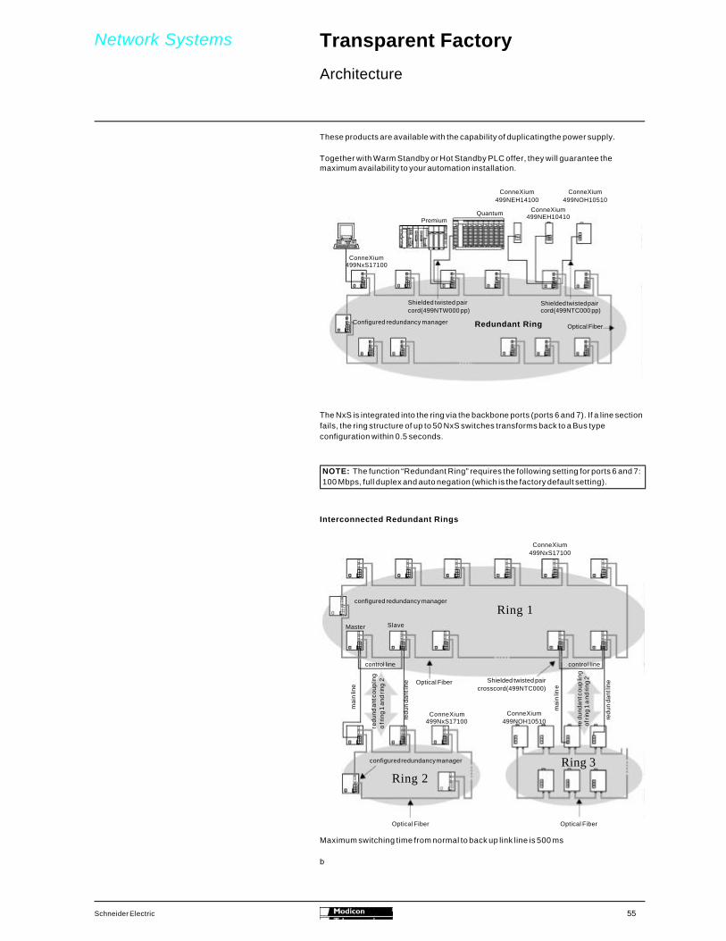
The NxS is integrated into the ring via the backbone ports (ports 6 and 7). If a line section fails, the ring structure of up to 50 NxS switches transforms back to a Bus type configura-tion within 0.5 seconds.
These products are available with the possibility to duplicate the power supply.
Together with Warm Standby or Hot Standby PLC offer, they will guarantee the maxi-mum of availability to your automation installation.
Momentum
EthernetHub 10 Mbps
4TP
Shielded twisted paircrossed cord (499NTC000pp)Ethernet
H u b 1 0 M b p s3 T P / 2 F L
Shielded twisted paircord (499NTW000pp)Optical Fiber
Quantum Premium
Ring of Hubswith redundant link
ConneXium499NOH10510
ConneXium499NEH14100
PremiumQ u a n t u m
ConneXium499NxS17100
ConneXium499NEH10410
Shielded twisted paircord(499NTW000pp)
Shielded twisted paircord(499NTC000pp)
Configured redundancy managerOptical FiberRedundant Ring
NOTE: The function “Redundant ring” requires the following setting for ports 6 and 7: 100 Mbps, full duplex and auto negation (which is the factory default setting).

51Schneider Electric
Network Systems Transparent Factory 0
Architecture
Interconnected Redundant Rings Topology
Maximum switching time from normal to back up link line is 500 ms.
configured redundancy manager
Master Slave
Ring 1
Optical Fiber Shielded twisted paircrosscord(499NTC000)
control line control line
Ring 2Ring 3
Optical FiberOptical Fiber
configured redundancy manager
ConneXium499NxS17100
ConneXium499NOH10510
ConneXium499NxS17100
mai
n lin
e
mai
n lin
e
redu
ndan
t cou
plin
gof
ring
1 a
nd ri
ng 2
red
unda
nt c
oupl
ing
of ri
ng 1
an
d rin
g 2
redu
ndan
t line
redu
ndan
t line

52 Schneider Electric
Network Systems Transparent Factory 0
Architecture
The Collision Domain
Layer 2 Ethernet protocol is based on a collision detection mechanism called CSMA/CD Carrier – Sense Multiple Access/Collision Detect. Each station sends a message when needed and listens to see if the message is interrupted by a message from another sta-tion. This interruption is called a collision. If a collision occurs, the station will retransmit the data after waiting an appropriate time. This results in an increased network load.
Due to the data transmission time from one end of the network to the other, there is a maximum network length beyond which undetected collisions may occur. For that reason, for each technology, a maximum network extension is defined. Considering the topology, we speak about “maximum network diameter” in the same collision domain. This maximum network diameter must be calculated for the worst-case distance, between the most distant stations in term of transmission time. This transmission time depends on:
b The physical distance between the stationsb The number of intermediate stations (hubs, transceiver).
In order to extend a network beyond the limits of a collision domain, a switch or router is required.
Methods for reducing collisions include:
b Implement a Full Duplex network allowing simultaneous transmission andreception of data.
b Constructing a Switched Ethernet network with switches instead of hubs willremove collisions from the network.
Each Ethernet Network topology and physical layer are limited by several factors. Some limits are imposed by standard Ethernet design rules. Additional limits are imposed in the automation environment to ensure real time operation.

53Schneider Electric
Network Systems Transparent Factory 0
Architecture
Network Components
Hubs
Hubs are used to connect several 10BaseT or 100Base-TX devices together in a star configuration. Several hubs can be connected together to form a tree configuration, however all devices connected to a series of hubs belong to the same collision domain and hence the size of a hub-based network is limited.
Switches
Switches are used to connect several 10/100Base-T devices together in a star configu-ration. Many switches can be connected together to form large tree structures. As a switch limits the collision domain they are used to increase network size and perfor-mance.
Transceivers
Connecting to existing networks – interference insensitive fiber optic cables can connect network end devices (controllers, drives, electric meters, etc.) in an industrial environment.
The 499 NTR 100 10 ConneXium Transceiver can be integrated into an existing 10 Mbit/s network with:
b 4 9 9 N E H 1 0 4 1 0 C o n n e X i u m 4 P o r t H u bb 4 9 9 N O H 1 0 5 1 0 C o n n e X i u m 5 P o r t H u bb 499 NxS 171 00 ConneXium 7 Port Switchb 499 NES 181 00 ConneXium 8 Port Switch
The 499 NTR 101 00 ConneXium Transceiver can be integrated into an existing 100 Mbit/s network with:
b 4 9 9 N E H 1 4 1 0 0 C o n n e X i u m 4 P o r t H u bb 499 NxS 171 00 ConneXium 7 Port Switchb 499 NES 181 00 ConneXium 8 Port Switch
The maximum number of cascaded ConneXium Transceivers between network end devices or repeaters is two.
Quantum
Premium
or
Optical Fiber
Twisted pair transceiver
Shielded twisted paircord(499NTW000pp ) Ethernet
transceiver1 0 M b p s T P / F L
Premium
Quantum
or
Optical Fiber
Twisted pair transceiver
Shielded twisted paircord (499NTW000pp ) Ethernet
transceiver100 Mbps TX/FX

54 Schneider Electric
Network Systems Transparent Factory 0
Architecture
Routers
Routers are generally used at the enterprise backbone level, to link different depart-ments or different sites. They are sometimes associated with functions like the firewall for filtering remote access. A router needs to be configured in order to route the messag-es to the appropriate destination. The routing mechanisms are based on the IP address. The stations are grouped on the same sub network according to their IP address. Any message to a remote network will be sent to the router which will route the message to the correct destination. All our Ethernet modules can be configured with a gateway default address and a subnet mask, to allow IP routing.
RAS Servers
RAS Servers are designed to provide access to an Ethernet network from a remote loca-tion. In general RAS servers are used to link either a remote device to an existing network or to join two Ethernet networks via phone or ISDN lines.
General characteristics of physical Ethernet standards used in the Automation industry:
Note: For additional information regarding network design and installation, consultb Network Design Services Team in North Andoverb Transparent Factory User Guide (available on Enterprise)b Network Design and Installation Guide (available on Enterprise)
Redundancy
Transparent Factory network systems can be designed with higher availability using specific hubs or switches linked on a redundant copper or optical ring. If the ring is damaged, the communication will be maintained transparently in less than 500 ms.
Data Rate(Mdb)
Medium Connector Type Duplex Advantage
10Base-T 10 Twisted Pair (SFTP) RJ45 Cost
1 0 B a s e - F L 10 Optical Fiber (generally 62.5/125 multimode 1300 nano meter)
ST or BFOC Immunity, Security
100Base-TX 1 0 0 Twisted Pair (SFTP) RJ45 F u l l Data Rate (x50)100Base-FX 1 0 0 Optical fiber (Multi
mode or Single Mode)SC or MT-RJ F u l l Noise Immunity,
Security
Momentum
EthernetHub 10 Mbps
4TP
Shielded twisted paircrossed cord (499NTC000pp)Ethernet
Hub 10 Mbps3TP/2FL
Shielded twisted paircord (499NTW000pp)Optical Fiber
Quantum Premium
Ring of Hubswith redundant link
55Schneider Electric
Network Systems Transparent Factory 0
Architecture
These products are available with the capability of duplicatingthe power supply.
Together with Warm Standby or Hot Standby PLC offer, they will guarantee the maximum availability to your automation installation.
The NxS is integrated into the ring via the backbone ports (ports 6 and 7). If a line section fails, the ring structure of up to 50 NxS switches transforms back to a Bus type configuration within 0.5 seconds.
Interconnected Redundant Rings
b
ConneXium499NOH10510
ConneXium499NEH14100
PremiumQuantum
ConneXium499NxS17100
ConneXium499NEH10410
Shielded twisted paircord(499NTW000 pp)
Shielded twisted paircord(499NTC000 pp)
Configured redundancy managerOptical FiberRedundant Ring
NOTE: The function “Redundant Ring” requires the following setting for ports 6 and 7: 100 Mbps, full duplex and auto negation (which is the factory default setting).
Maximum switching time from normal to back up link line is 500 ms
configured redundancy manager
Master Slave
Ring 1
Optical Fiber Shielded twisted paircrosscord(499NTC000)
control line control line
Ring 2Ring 3
Optical FiberOptical Fiber
configured redundancy manager
ConneXium499NxS17100
ConneXium499NOH10510
ConneXium499NxS17100
mai
n lin
e
mai
n lin
e
redu
ndan
t cou
plin
go
f rin
g 1
and
ring
2
redu
ndan
t cou
plin
gof
ring
1 a
nd ri
ng 2
redu
nda
nt lin
e
redu
nda
nt lin
e

56 Schneider Electric
Description, Characteristics, References
Quantum automation platform 0
Communications
TCP/IP Modbus Ethernet Communication
DescriptionThe module 140 NOE 771 00/10 comprises on the front panel:
Mechanical ConstructionModel 140 NOE 771 00 140 NOE 771 10Operating Temperature 0 C ( F ) 0 to 60 (32 to 140)
Relative Humidity 0 … 95% (non-condensing)Dimensions (W x H x D) mm (in) 250 x 103.85 x 40.34 (9.84 x 4.09 x 1.59)
Weight g (lb) 345 (0.76)Enclosure IP 20Agency Approvals and Compliance UL 508, CSA 22.2-142, FM Class 1 Division 2, CE
CharacteristicsModule Type I/O Scanner Embedded Web ServerTechnology Ethernet 100 Mbit/s
Interfaces 1 100BASE-TX port with shielded RJ45 connectors, 1 100BASE-FX with MT/RJ connector
Connection Types Twisted pair cable and Fiber Optic cablePower Consumption m A 750 typical, 1000 maximum
Maximum Range m (ft) 100BASE-TX – 100 (328) and 100BASE-FX – 100 (326)LED Indicators Active, Ready, Fault, Run, Collision, Link, Transmit Active,
Receive Active, Kernel, 10MB, 100MB, Fduplex, Appl.
1 Model number and color code.
2 LED array
3 Removable, hinged door and customer identification.
4 Fiber Optic transmit cable port.
5 Fiber Optic receive cable port.

57Schneider Electric
Description, Characteristics and References
Quantum automation platform 0
Communications
TCP/IP Modbus Ethernet Communication
DescriptionThe module 140 NOE 771 01/11 comprises on the front panel:
Mechanical ConstructionModel 140 NOE 771 01 140 NOE 771 11
Operating Temperature 0 C (F) 0 to 60 (32 to 140)Relative Humidity 0 … 95% (non-condensing)Dimensions (W x H x D) mm (in) 250 x 103.85 x 40.34 (9.84 x 4.09 x 1.59)
Weight g (lb) 345 (0.76)Enclosure IP 20
Agency Approvals and Compliance UL 508, CSA 22.2-142, FM Class 1 Division 2, CE
CharacteristicsFactoryCast Supported No YesTechnology Ethernet 100 Mbit/s
Memory size M B 8Interfaces 1 100BASE-TX port with shielded RJ45 connectors,
1 100BASE-FX with MT/RJ connector
Connection Types Twisted pair cable and Fiber Optic cablePower Consumption m A 750 typical, 1000 maximumMaximum Range m (ft) 100BASE-TX and 100BASE-FX - 100 (326)
LED Indicator Active, Ready, Fault, Run, Collision, Link, Transmit Active, Receive Active, Kernel, 10MB, 100MB, Fduplex, Appl.
1 Model number and color code.
2 LED array
3 Removable, hinged door and customer identification.
4 Fiber Optic transmit cable port.
5 Fiber Optic receive cable port.

58 Schneider Electric
Description, Characteristics, References
Premium automation platform 0
Communications
MODBUS/TCP Ethernet Communication
DescriptionThe TSX ETY 110/110 WS modules are single format modules, which are installed in a rack slot of a Premium PLC station.
The front panel on the TSX ETY 110/110 WS module comprises:
The maximum number of modules permitted (1 to 4) per configuration depends on the type of processor.
Mechanical ConstructionModel TSX ETY 110 TSX ETY 110 WSOperating Temperature o C ( F ) 0 to 60 °C (32 to 140)
Relative Humidity 30% to 95% (non-condensing)Dimensions (W x H x D) mm (in) Single Format Module
Weight g (lb) 370 (0.8)Enclosure IP 20Agency Approvals and Compliance UL 508, CSA 22.2-213, FM Class 1 Division 2, CE
CharacteristicsTechnology C S M A / C DFactoryCast Supported No Yes
Interfaces 1 10BASE-T interface (RJ45) and 1 10BASE-5 interface (AUI)Connection Types Twisted pair cable and AUI cablePower Consumption m A 800 typical, 1200 maximum
Maximum Range m (ft) RJ45 = 100 (328), AUI = 50 (164)LED Indicator RUN, ERR (Error), STS (Status)
1. A display block indicating the state of the module.
2. A standard connector for 10BASE-T interface (RJ45)
3. A standard connector for 10BASE-5 interface (AUI)
4. Four thumbwheels for defining the station number and network number.

59Schneider Electric
Description, Characteristics, References
Premium automation platform 0
Communications
MODBUS/TCP Ethernet Communication
DescriptionThe TSX ETY 4102/5102 modules are single format modules, which are installed in a rack slot of a Premium PLC station.
The front panel on the TSX ETY 4102/5102 module comprises:
The maximum number of modules permitted (1 to 4) per configuration depends on the type of processor.
Mechanical ConstructionModel TSX ETY 4102 TSX ETY 5102Operating Temperature 0 C (F) 0 to 60 (32 to 140)
Relative Humidity 30% to 95% (non-condensing)Dimensions (W x H x D) mm (in) Single Format Module
Weight g (lb) 370 (0.8)Enclosure IP 20Agency Approvals and Compliance UL 508, CSA 22.2-213, FM Class 1 Division 2, CE
CharacteristicsTechnology C S M A / C DFactoryCast Supported No Y es
Interfaces 1 10/100BASE-TX interface (RJ45); I/O Scanner Connection Types Twisted-pair cable
Power Consumption m A 3 6 0Maximum Range m (ft) 100 (328) LED Indicator RUN, ERR (Error), STS (Status)
1. A display block indicating the state of the module.
2. A standard connector for 100BASE-TX interface (RJ45)

60 Schneider Electric
Description, Characteristics, References
Premium automation platform 0
Communications
Premium CPU with Ethernet Integrated Communication
DescriptionThe TSX P57 2623M / 2823M / 3623M / 4823M modules are double format modules, which are installed in a rack slot of a Premium PLC station.
The front panel on the TSX P57 2623M / 2823M / 3623M / 4823M module comprises:
The maximum number of modules permitted (1 to 4) per configuration depends on the type of processor.
Mechanical ConstructionModel TSX P57 2623M / 2823M / 3623M / 4823MOperating Temperature ºC (F) 0 to 60 (32 to 140)
Relative Humidity 30% to 95% (non-condensing)Dimension W x H x D mm (in) Double Format Module
Weight g (lb) 560 (1.233)Enclosure IP 20Agency Approvals and Compliance CE, UL, CSA, IEC 61131-2
CharacteristicsTechnology C S M A / C DInterfaces 1 10/100BASE-TX interface (RJ45)
RAM Memory 2623 - 48K; 2823 and 36 23 - 64K; 4823 - 96K Maximum Extended Memory 2623 and 2823 - 160K; 3623 - 384K; 4823 - 512K FIPIO support 2823 and 4823 only
Number of third-party Fieldbuses supported
2623 and 2823 - one; 3623 and 4823 - two
Connection Types Twisted pair cable
Maximum Range m (ft) 100 (328) LED Indicator RUN, ERR (Error), COL (Collision), STS (Status), TX
(Transmission, and RX (Reception)
1. Display block with 5 indicator lamps:b RUN lamp (green): on if the processor is operating (program
execution)b ERR lamp (red): signals faults relating to the processor and
its on-board devices (PCMCIA memory card and PCMCIAcommunication card)
b I/O lamp (red): signals faults on another station module or aconfiguration fault
b TER lamp (yellow): signals activity on the terminal portb FIP lamp (red): when flashing, it signals activity on the
integrated Fipio bus
2. Display block for integrated Ethernet port with 5 indicator l a m p s :
b RUN lamp (green): Ethernet port ready.b ERR lamp (red): fault Ethernet portb COL lamp (red): detection of collision.b STS lamp (yellow): Ethernet link diagnostic.b Two lamps TX and RX (yellow): transmission or reception of
data.3. RESET button causing a cold restart of the PLC when it is
activated4. A 8-way female mini-DIN connector (TER): for connecting a
programming or adjustment terminal.5. A 8-way female mini-DIN connector (AUX): for connecting a
peripheral device6. A RJ45 connector for connection to Ethernet network7. Slot for a type 1 PCMCIA format memory extension card.8. Slot for a type 3 PCMCIA format communication card9. A 9-way SUB-D connector(on TSX P57 2823/4823M only) for
Fipio bus manager communication.

61Schneider Electric
Description, Characteristics, References
Momentum automation platform 0
Communications
Modbus/TCP Ethernet Communications
DescriptionThe 170 ENT 110 00/01 Ethernet Communication Adapter comprises on the front panel:
Mechanical ConstructionModel 170 ENT 110 00 170 ENT 110 01Operating Temperature °C (F) 0 to 60 (32 to 140)
Relative Humidity 5…95% (non-condensing)Dimensions (W x H x D) mm (in) 125 x 61.02 x 25.9 (4.86 x 2.37 x 1.01)
Weight g (lb) 42.5 (0.0938)Enclosure IP 20 conforming to IEC529Agency Approvals and Compliance
UL, CE, CSA, FM Class 1, Division 2
UL, CE, CSA
CharacteristicsTechnology Ethernet 10 Mbit/s Ethernet 10/100 Mbit/sInterfaces 1 10BASE-T port with shielded RJ45 connectors
Connection Types Twisted-pair cable Power Consumption m A Power supplied by Momentum I/O BaseMaximum Range m (ft) 10BASE-T - 100 (328)
LED Indicator RUN, LAN, ACT
1. Ethernet network connector interface ( R J 4 5 )
2. Area for label (label shipped with I/O base).
3. LED Status indicators comprising:
b RUN (Green), module healthb LAN ACT (Green), Ethernet network
status.

62 Schneider Electric
Description, Characteristics, References
Momentum automation platform 0
Communications
Modbus/TCP Ethernet Communication
DescriptionThe 171 CCC 960 20/30 and 171 CCC 980 20/30 Momentum controller comprises on the front panel:
Mechanical ConstructionModel 171 CCC 960 20 171 CCC 980 20 171 CCC 960 30 171 CCC 980 30
Operating Temperature 0 C (F) 0 to 60 (32 to 140)Relative Humidity 5 … 95% (non-condensing)
Dimension W x H x D mm (in) 125 x 61.02 x 25.9 (4.86 x 2.37 x 1.01)Weight g (lb) 42.5 (0.0938)Enclosure IP 20 conforming to IEC529
Agency Approvals and Compliance UL, CE, CUL, FM Class 1 Division 2, NEMA 250 Type , and IP20 conforming to IEC52
CharacteristicsTechnology Ethernet 10 Mbit/s
Interfaces 1 10BaseT Ethernet port with shielded RJ45connector
1 10BaseT Ethernet port with shielded RJ45connector, 1 RS 485 p o r t
1 10BaseT Ethernet port with shielded RJ45connector
1 10BaseT Ethernet port with shielded RJ45connector, 1 RS 485 p o r t
Memory 5 1 2 K 5 1 2 K 1Mb 1 MbConnection Types Twisted pair cable
Power Consumption m A Power supplied by Momentum I/O baseMaximum Range m (ft) 10BaseT – 100 (328)
LED Indicator RUN, LAN ACT, LAN STS
1. Ethernet network connector interface (RJ45)
2. Optional second Port (Modbus or I/O Bus)
3. LED Status indicators comprising:
b RUN (Green) controller healthb LAN STS (Green) Ethernet network statusb LAN ACT (Green) detected Ethernet traffic

63Schneider Electric
Description, Characteristics, References
Micro automation platform 0
Communications
TCP/IP Ethernet Communication
DescriptionThe Ethernet TSX ETZ 410/510 modules are autonomous and thus do not fit into a Micro PLC rack, but fit onto a DIN profile or on an AM1-PA perforated mounting plate.
The front of the TSX ETZ 410/510 modules are arranged as follows:
1. Three display LEDs indicating the module’s status (RUN, ERR, RX/TX).
2. A screened-on label indicating the module’s MAC address (default address set in the factory).
3. A mini-DIN connector for terminal port (TER address).
4. An RJ45 connector for Uni-Telway auxiliary port RS485 serial link (RS 485 address).
5. An RJ45 normalized connector for connecting to the Ethernet network (10/100Base-TX address).
6. A 9 pin male sub-D connector for RS232 serial link ( m o d e m ) .
7. A screw terminal block for connecting to the external 24VDC power supply.
8. A support plate enabling it to be fixed to the module.
Mechanical ConstructionModel TSX ETZ 410 TSX ETZ 510
Operating Temperature 0C (F) 0 to 60 (32 to 140)Relative Humidity 30% to 95% (non-condensing)
Dimensions (W x H x D) mm (in) 34.63 x 150 x 116.7 (1.36 x 5.91 x 4.59)Weight g (lb) 280 (0.65)Enclosure IP 20
Agency Approvals and Compliance
CE, UL508, CSA 22.2-213 Class 1 Division 2
CharacteristicsTechnology CSMA/CD
Ethernet Capability I/O Scanner I/O Scanner and Embedded Web ServerInterfaces 1 10/1000BASE-TX interface (RJ45), RS485 (RJ45), RS232 (DB-9M), Mini-DIN (Uni-Telway)
Connection Types Twisted pair cable Power Consumption m A 200 @ 24 VDCMaximum Range m (ft) 100 m (328) Ethernet, 10 m (33) TER/AUX Port, 16.6 m (50) RS232 serial, 2.5 m (7.6) Uni-Telway
LED Indicator RUN, ERR (ERROR), RT/TX

64 Schneider Electric
Presentation ConneXium industrial Ethernet 0
ConneXium Hubs, Switches, Transceivers, Bridges, and Cabling
As part of the Transparent Factory family of products, Schneider Electric offers ConneXium – industrially hardened hubs, switches, transceivers, bridges, and cables. Standard Ethernet communication components enable integrated Ethernet solutions from the device level to the control network, and beyond to the corporate intranet. Each ConneXium Industrial Ethernet product is designed with compliance to Ethernet standards, and with third-party compatibility in mind.
b ConneXium Hubs connect devices and segments to provide shared communica-tion among programmable controllers and control devices (i.e., Momentum I/O orvariable frequency drives).
b ConneXium Switches segment the application in different zones, groups, or cells/machines. The proper placement of switches can increase network performanceby relieving network congestion. ConneXium switches implement SNMP protocol, allowing standard network management tools to monitor and diagnose the network, and thus are key architectural components for real-time and deterministic network communication.
b ConneXium Transceivers provide connections to Fiber Optic networks in areas of high electromagnetic interference. Multiple transceivers enable long distancesbetween process areas.
b ConneXium Bridges enable Ethernet communication with existing Modbus de-vices and Modbus Plus networks. ConneXium Bridges enable Modbus toEthernet and Modbus Plus to Ethernet communications, with multiple portsallowing flexibility among network components.
b ConneXium Cables connect each automation device to the ConneXium hub, switch, transceiver or bridge. Cables are available in Fiber Optic and twisted pairoptions, with a wide variety of connectors and cable lengths.
All Ethernet cabling system components are built to rigorous industrial standards, and are designed to perform in harsh environments. ConneXium Switches and Hubs sup-port a high level of resilience. Their scalable redundant features - from single to double ring structure - make it easy to build the fault-tolerant network that meets specific environmental requirements of the application.
Presentation

65Schneider Electric
Description, Characteristics, References
ConneXium industrial Ethernet 0
ConneXium Hubs
Description
Mechanical ConstructionModel 499 NEH 104 10 499 NEH 141 00 499 NOH 105 10
Operating Temperature 0C ( F ) 0 to 60 (32 to 140)Relative Humidity 10 … 95% (non-condensing)Dimensions (W x H x D) mm (in) 40 x 125 x 80
(1.57 x 4.92 x 3.15)47 x 135 x 111(1.85 x 5.31 x 4.37)
80 x 140 x 85(3.15 x 5.51 x 3.35)
Weight g (lb) 530 (1.167) 240 (0.529) 900 (1.982)Enclosure IP 30 IP 20 IP 30
Agency Approvals andCompliance
cUL 1950, FM 3810, FM 3611 Class 1 Division 2, CE, Germanischer Lloyd, IEC 61131-2
CharacteristicsTechnology Ethernet 10 Mbit/s Ethernet 100 Mbit/s Ethernet 10 Mbit/sInterfaces 4 10BASE-T ports with
shielded RJ45 connectors4 100BASE-TX ports withshielded RJ45 connectors
3 10BASE-T ports withshielded RJ45 connectorsand 2 10BASE-FL withBFOC (ST) connectors
Connection Types Twisted pair cable Twisted pair cable andredundant fiber optic ring
Terminal Block 1 x 5 pole mountable terminal blockOperating Voltage VDC 18 to 32Safe Extra-low voltage (SELV)
Redundancy Power Supply Power Supply and Fiber Opticring
Power Consumption at 24 VDC m A 80 typical, 130 maximum 210 typical, 270 maximum 160 typical, 350 maximumMaximum Range m (ft.) 10BASE-T – 100 (328) 100BASE-TX – 100 (328) 10BASE-T – 100 (328)
10BASE-FL – 3100 (10170)
Number of cascade hubs 4 2 4Number of Hubs in a Ring -- 1 1
Link Budget -- 11.5 db for 50/125 and62.5/125 ? m fiber
Fault Indicator One of the two power supplies has failed, permanent fault in hub, faulty link status of at leastone TP port, or at least one port has auto-partitioned.
LED Indicator P1, P2: power, DA/STAT 1 to DA/STAT 4: data, collision, segmentation, and link status per port
P1, P2: power, DA/STAT 1to DA/STAT 5: data,collision, segmentation, andlink status per port

66 Schneider Electric
Description, Characteristics, References
ConneXium industrial Ethernet 0
ConneXium Switches
Description
Mechanical ConstructionModel 499 NES 181 00 499 NES 171 00 499 NOS 171 00
Operating Temperature 0C (F) 0 to 60 (32 to 140) 0 to 55 (32 to 131)Relative Humidity 10 … 95% (non-condensing)Dimensions (W x H x D) mm (in) 47 x 135 x 111
(1.85 x 5.31 x 4.37)110 x 131 x 111 (4.3 x 5.2 x 4.4)
Weight g (lb) 230 (0.507) 850 (1.87)Enclosure IP 20Agency Approvals andCompliance
cUL 1950, cUL 508, cUL1604 Class 1 Division 2, CE, Germanischer Lloyd, IEC 61131-2
CharacteristicsTechnology Ethernet 10/100 Mbit/sInterfaces 8 10BASE-T/100BASE-TX
ports with shielded RJ45connectors
5 10BASE-T/100BASE-TXports with shielded RJ45connectors and 2 100BASE-TX ports with shielded RJ45 con-nectors
5 10BASE-T/100BASE-TX ports with shielded RJ45connectors and 2 100BASE-FX ports with SC Fiber Optic con-nectors
Connection Types Twisted pair cable Twisted pair cable andredundant Fiber Optic ring
Terminal Block 1 x 5 pole mountable terminal blockOperating Voltage V D C 18 to 32 Safe Extra-low voltage (SELV)Redundancy Power Supply Power Supply and Copper or Fiber Optic ring
Power Consumption at 24 VDC
m A 125 typical, 290 maximum 800 maximum
Maximum Range m (ft) 100 (328) 100 (328) 100BASE-TX – 100 (328)100BASE-FX – 3100 (10170)
Number of Hubs in a Ring -- 5 0 5 0Link Budget -- 8 db for 50/125 ? m fiber
11 db for 62.5/125 ? m fiberFault Indicator One of the two power
supplies has failed,permanent fault in switch,faulty link status of at leastone TP port, or at least oneport has auto-partitioned.
One of the two power supplies has failed, permanent fault inswitch, faulty link status of at least one TP port, at least oneport has auto-partitioned, self-test error, or ring monitoringnot possible.
LED Indicator P1, P2: power, DA/STAT 1to DA/STAT 8: data, collision, segmentation, and link status per port
P1, P2: power, Port 1 to 7 status, Redundancy Manager, and Standby

67Schneider Electric
Description, Characteristics, References
ConneXium industrial Ethernet 0
ConneXium Transceivers
Description
Mechanical ConstructionModel 499 NTR 100 10 499 NTR 101 00
Operating Temperature 0 C ( F ) 0 to 60 (32 to 140)Relative Humidity 10 … 95% (non-condensing)Dimensions (W x H x D) mm (in) 40 x 134 x 80 (1.7 x 5.28 x 3.35) 47 x 135 x 111 (1.9 x 5.3 x 4.4)
Weight g (lb) 520 (1.15) 230 (0.51)Enclosure IP 30 IP 20
Agency Approvals andCompliance
cUL 1950, FM 3810, FM 3611 Class 1 Division 2, CE, Germanischer Lloyd, IEC 61131-2
cUL 1950, cUL 508, cUL 1604 Class 1 Division 2, CE, Germanischer Lloyd, IEC 61131-2
CharacteristicsTechnology Ethernet 10 Mbit/s Ethernet 100 Mbit/sInterfaces 1 10BASE-T port with
shielded RJ45 connectorand 1 10BASE-FL port withBFOC (ST) connector.
1 100BASE-TX port withshielded RJ45 connectorand 1 100BASE-FX portwith SC connector
Connection Types Twisted pair cable and Fiber Optic cableTerminal Block 1 x 5 pole mountable terminal blockOperating Voltage VDC 18 to 32 Safe Extra-low voltage (SELV)
Redundancy Power SupplyPower Consumption at 24 VDC
m A 80 typical, 100 maximum 160 typical, 190 maximum
Maximum Range m (ft) 10BASE-T 100 (328)10BASE-FL 3100 (10170)
100BASE-TX 100 (328)100BASE-FX 3100 (10170)
Link Budget 11.5 db for 50/125 and62.5/125 um fiber
8 db for 50/125 ? m fiber11 db for 62.5/125 ? m fiber
Fault Indicator One of the two power supplies has failed, permanent fault intransceiver, faulty link status on TP port or FO port.
LED Indicator P1, P2: power, DA STAT 1 status and DA STAT 2 status.

68 Schneider Electric
Description, Characteristics, References
ConneXium industrial Ethernet 0
ConneXium Bridges
Description
Mechanical ConstructionModel 174 CEV 200 30 174 CEV 300 10
Operating Temperature 0 C (F) 0 to 50 (32 to 122) 0 to 60 (32 to 140)Relative Humidity 10 to 95% (non-condensing) 20 to 90% (non-condensing)Dimensions (W x H x D) mm (in) 122 x 229 x 248 (4.8 x 9 x 9.8) 35 x 95 x 60 (1.4 x 3.7 x 2.4)
Weight g (lb) 4263 (9.4) 500 (1.0)Enclosure IP 20
Agency Approvals andCompliance
UL, CSA, CE
CharacteristicsTechnology Ethernet 10 Mbit/sInterfaces 1 10BASE-T, 10BASE-2, AUI port; 1 single/dual
cable Modbus Plus port1 10BASE-T port with shielded RJ45 connector and 1 Serial RS-232/RS-485 port with RJ45 con-nector
Connection Types 1 RJ45, AUI, BNC Ethernetcable; 1/2 DB-9S Modbus Plus cables
Twisted-pair cable
Operating Voltage 110/220 VAC (-15% / 10%),47 to 63 Hz
24 VDC
Redundancy -- Power Supply
Power Consumption at 24 VDC
1 A typical 125 mA maximum
Maximum Range M (ft) 10BASE-T 100 (328)10BASE-2 100 (328)10BASE-5 100 (328)Modbus Plus 450 (1500)
10BASE-T 100 (328)

69Schneider Electric
Description, Characteristics, References
ConneXium industrial Ethernet 0
ConneXium Hubs, Switches, Transceivers, Bridges, and Cabling
Description
Electrical CablesModel 490 NTW 000 xx 490 NTC 000 xx
Cable Type Shielded and foiled twisted pair straight-through cable
Shielded and foiled twisted pair crossed cable
Available Cable Lengths m (ft) 2, 5, 12, 40, 80(6.5, 16.4, 39.4, 131.2, 262.4)
5, 15, 40, 80 (16.4, 49.2, 131.2, 262.4)
Pre-assembled Connector Type RJ45 (two per cable)
Agency Approvals andCompliance
UL, CSA 22.1 and NFPA 70 approval indicated by “U” after part number (example: 490 NTW 000 40U); Category 5 of internation-al cabling standard EIA/TIA-568; Class D of IEC 11801 / EN50173; Low Smoke Zero Halogen (LSZH); flame retardant of NFC32 070 #1 (C2) and CEI 322/1
Optical CablesModel 490 NOC 000 05 490 NOT 000 05 490 NOR 000 05
Cable Type Standard glass Fiber OpticAvailable Cable Lengths m (ft) 5 (16.4)
Pre-assembled Connector Type MT/RJ-SC Duplex MT/RT-ST Duplex MT/RJ-MT/RJ DuplexRadiation Susceptibility No radiation along the cable

70 Schneider Electric
Description, Characteristics, References
Schneider Electric Ethernet 0
Communication
Altivar Drive Ethernet Interface
Description
Mechanical ConstructionModel VW3A58310U
Operating Temperature 0C (F) -10 to 50 (14 to 122)Relative Humidity 0 … 95% (non-condensing)Dimensions (W x H x D) mm (in) 101.6 x 152.4 x 12.7 (4.0 x 6.0 x 0.5)
Enclosure Determined by the DriveAgency Approvals andCompliance
UL 508c, CSA 22.2, No. 14, CE, NEMA ICS, NFPA, IEC and ISO9001
CharacteristicsTechnology Ethernet 10/100 Mbit/sInterfaces 1 10BASE-T ports with shielded RJ45 connectorsConnection Types Twisted pair cable
Maximum Range m (ft) 10BASE-T/100BASE-TX – 100 (328)Fault Indicator Provided by the Drive
LED Indicator Collision Detected, Data Transmit, Data Receive, 10 Mbit/s, 100 Mbit/s

71Schneider Electric
Description, Characteristics, References
Schneider Electric Ethernet 0
Communication
Circuit Monitor 4000
Description
Mechanical ConstructionModel CM4000
Operating Temperature 0C (F) -20 to 70 (-4 to 158)Relative Humidity 5 … 95% (non-condensing)Dimensions (W x H x D) mm (in) 231.4 x 202.9 x 133.1 (9.11 x 7.99 x 5.24)
Weight g (lb.) 1900 (4.2)Enclosure IP 20
Agency Approvals andCompliance
UL 508, CSA 22.2-2-4-M1987, CE (EN61010)
CharacteristicsTechnology Ethernet 10/100 Mbit/sInterfaces 8 10BASE-T/100BASE-TX ports with shielded RJ45 connectors
Connection Types Twisted pair cableTerminal Block 1 x 3 pole mountable terminal block
Operating Voltage 90 – 305 VAC or 100 – 300 VDCPower Consumption 50 mA at 90 – 305 VAC, 30 W at 100 – 300 VDCMaximum Range m (ft) 100 (328)
LED Indicator RS-485 (COM1) TX, RX; RS-232 (COM2) TX, RX; Power; Maintenance

72 Schneider Electric
Description, Characteristics, References
Schneider Electric Ethernet 0
Communication
PowerLogic MODBUS/TCP Gateway
Description
Mechanical ConstructionModel EGX200 EGX400
Operating Temperature 0C (F) -30 to 80 (-22 to 176)Relative Humidity 5 … 95% (non-condensing)Dimensions (W x H x D) mm (in) 200.2 x 122.2 x 27.2 (7.88 x 4.81 x 1.07)
Weight g (lb.) 680 (1.5)Enclosure IP 20
Agency Approvals andCompliance
UL 508, cUL (complies with CSA 22.2, #14-M91)CE
CharacteristicsTechnology Ethernet 10/100 Mbit/sInterfaces 1 10BASE-T port with shielded RJ45 connector
and 1 10BASE-FL port with BFOC (ST) connec-tor.
1 100BASE-TX port with shielded RJ45 connec-tor and 1 100BASE-FX port with SCconnector
Connection Types Twisted pair cable and Fiber Optic cableTerminal Block 1 x 5 pole mountable terminal block
Operating Voltage V D C 21.6 to 26.4Redundancy Power SupplyPower Consumption m A 300 maximum at 24 VDC
Maximum Range m (ft) 10BASE-T 100 (328) 10BASE-FL 3100 (10170)LED Indicator Ethernet LK, TX, RX; Power; COM1 TX, RX; COM2 TX, RX; RS-485

73Schneider Electric
References Schneider Electric Ethernet 0
References
Memory Communication Ports Clock SpeedReference Weight
kg (lb.)
512 K 1 Ethernet, 1 I/O Bus 50 MHz 171 CCC 960 20 0.043 (0.0938)
512 K, IEC Exec 1 Ethernet, 1 Modbus 50 MHz 171 CCC 980 20 0.043 (0.0938)171 CCC 980 30
1 Mb 1 Ethernet, 1 I/O Bus 50 MHz 171 CCC 960 30 0.043 (0.0938)
1 Mb, IEC Exec 1 Ethernet, 1 Modbus 50 MHz 171 CCC 980 30 0.043 (0.0938)
DescriptionReference Weight
kg (lb.)
Ethernet TCP/IP Communication Adapter – Basic 170 ENT 110 00 0.043 (0.0938)
Ethernet TCP/IP Communication Adapter – Enhanced 170 ENT 110 01 0.043 (0.0938)170 ENT 110 0x
ReferencesHubs
Description Reference Weightkg (lb.)
Ethernet Hub 10 Mbps, 4 10BASE-T ports 499 NEH 104 10 0.530 (1.167)
Ethernet Hub 10 Mbps, 3 10BASE-T ports, 2 10BASE- FL port
499 NOH 105 10 0.900 (1.982)
Ethernet Hub 100 Mbps, 4 100BASE-TX ports 499 NEH 141 00 0.240 (0.529)499 NEH 104 10
ReferencesSwitchesDescription Reference Weight
kg (lb.)
Ethernet Switch 10/100 Mbps, 7 100BASE-TX ports 499 NES 171 00 0.850 (1.87)
Ethernet Switch 10/100 Mbps, 5 100BASE-TX ports, 2 100BASE-FX ports 499 NOS 171 00 0.850 (1.87)
Ethernet Switch 10/100 Mbps, 8 100BASE-TX ports 499 NES 181 00 0.230 (0.507)
499 NES 171 00 Transceivers
Description Reference Weightkg (lb.)
Ethernet Transceiver 10 Mbps, 1 10BASE-T port, 1 10BASE-FL port 499 NTR 100 10 0.520 (1.15)
Ethernet Transceiver 100 Mbps, 1 100BASE-TX port, 1 100BASE-FX port 499 NTR 101 00 0.230 (0.507)
499 NTR 100 10

74 Schneider Electric
References Schneider Electric Ethernet 0
References Module
Bridges
Description Reference Weightkg (lb.)
Modbus Plus to Ethernet Bridge 174 CEV 200 30 4.263 (9.4)
Modbus to Ethernet Bridge 174 CEV 300 10 0.500 (1.0)
CablesDescription Length m (ft) Reference Weight
kg (lb.)
174 CEV 300 10Shielded and foiled twisted pair cable 2 (6.5) 490 NTW 000 02 -
5 (16.4) 490 NTW 000 05 -
12 (39.3) 490 NTW 000 12 -40 (131.2) 490 NTW 000 40 -
80 (262.4) 490 NTW 000 80 -
Shielded and foiled twisted crossed over cable 5 (16.4) 490 NTC 000 05 -
15(9.2) 490 NTC 000 15 -490 NTW 000 xx 40 (131.2) 490 NTC 000 40 -
80 (262.4) 490 NTC 000 80 -
Fiber Optic cable, MT/RJ-SC Duplex connectors 5 (16.4) 490 NOC 000 05 -
Fiber Optic cable, MT/RJ-ST Connectors 5 (16.4) 490 NOT 000 05
Fiber Optic cable, MT/RJ-MT/RJ Connectors 5 (16.4) 490 NOR 000 05490 NOC 000 05

75Schneider Electric
References Schneider Electric Ethernet 0
Description Platform Reference Weightkg (lb.)
140NOE77111
TCP/IP Ethernet module with I/O Scanner Quantum 140 NOE 771 00 0.345 (0.76)
TCP/IP Ethernet module with Embedded Web Server 140 NOE 771 10 0.345 (0.76)
TCP/IP Ethernet module with I/O Scanner 140 NOE 771 01 0.345 (0.76)
TCP/IP Ethernet module with Embedded Web Server 140 NOE 771 11 0.345 (0.76)
TCP/IP Ethernet module with MODBUS/TCP Premium TSX ETY 110 0.370 (0.8)
TCP/IP Ethernet module with Embedded Web Server TSX ETY 110 WS 0.370 (0.8)
TSXETY5102
TCP/IP Ethernet module with Warm Standby TSX ETY 210 0.370 (0.8)
TCP/IP Ethernet module with I/O Scanner TSX ETY 4102 0.370 (0.8)
TCP/IP Ethernet module with Embedded Web Server TSX ETY 5102 0.370 (0.8)
TCP/IP Ethernet CPU with Embedded Web Server TSX P57 2623M 0.56 (1.233)TCP/IP Ethernet CPU with Embedded Web Server TSX P57 2823M 0.56 (1.233)
TCP/IP Ethernet CPU with Embedded Web Server TSX P57 3623M 0.56 (1.233)TCP/IP Ethernet CPU with Embedded Web Server TSX P57 4823M 0.56 (1.233)

76 Schneider Electric
Customer reference notes 0
(CRNs)
Schneider Electric operates in over 130 countries. Our automation customers include original equipment manufacturers (OEMs), who use our products in their equipment and systems. Our customers include both the end users of our products, who often specify Schneider Electric in their orders for new equipment, and the manufacturers who directly specify our products.
The application of Internet and Ethernet technologies on the factory floor has been nothing short of revolutionary. Schneider Electric's Automation Business is proud to have pioneered the use of these revolutionary technologies in the automation industry with Transparent Factory®.
Read on and discover examples of how Transparent Factory is helping Schneider Automation customers be more productive, cost-efficient and competitive.

77Schneider Electric
Web-based Motion Control Solution Keeps Great Dane Truckin’ 0
ManufacturingGreat Dane
Status Quo
Great Dane’s North American manufacturing plants are located in Georgia, Tennessee, Indiana, Nebraska, Illinois and Mississippi. Mo-tion engineering headquarters are in Savannah, Georgia, making for long trips to the outlying plants.
The plants lacked qualified technicians who could address complex motion control issues, forcing them to rely heavily on their Savannah-based motion engineers. For many years, the plants used identical motion control systems based on traditional architecture, separate motion controllers, and an existing automation platform. Nei-ther motion suppliers nor their motion engineers had remote access to the equipment.
A motion-related problem at any of these facilities had a significant im-pact on operations, as downtime accumulated during hours of “blind” troubleshooting over the telephone. Particularly serious pro-blems re-quired emergency travel while unrecoverable manufacturing time slipped away. Even incremental process improvements were prob-lematic because they required costly, time-consuming travel by a limit-ed staff.
It was clear Great Dane had a variety of challenges. They had been un-able to identify a practical wide-area engineering solution, until they learned of Schneider Electric’s motion control system integrated into a full-featured programmable logic controller (PLC) platform.

78 Schneider Electric
0
Schneider Electric’s web-based solution provides Great Dane Trailer Truck Company with easy access to their control network while maintaining maximum security. The Schneider solution does all this WITHOUT additional support software and WITH only minimal train-ing. The key to the solution is the "openness" of the system architec-ture. This openness allows Great Dane to leverage significant benefits from Internet and TCP/IP technology.
Wide-Area Engineering
Great Dane installed Modicon Telemecanique Quantum PLCs and SERCOS-compliant Lexium® Servo drives to create a motion system that was a natural extension of the existing automation platform. With a Modicon Sercos module added to the PLC, Great Dane’s servo drive system integrates motion control into the PLC architecture.
The system’s programming software, working in tandem with an Modi-con Motion Framework (MMF) Start library, made programming com-plex motion profiles as easy as configuring and arranging graphical “movement” function blocks. This architecture simplified develop-ment and diagnostics as motion and automation programming were merged into a single application program for each PLC.
To get the most from their new open architecture, Great Dane aug-mented the new motion control system with Schneider’s Transparent Factory® technology. Web servers within the PLCs tie into Great Dane’s existing Ethernet-based Intranet. That interface allows them to use any Web connection to diagnose the cause of system failures at any plant, and to get the plant running again in record time. The system allows Great Dane to monitor processes for red flags, pre-empt down-time and adjust motion profiles and machine sequences easily and in-stantly.
Using a wireless Ethernet card to dial into an Internet service provider and then into the plants over Ethernet speeds transmissions that once moved more slowly through modems and over telephone lines. Re-mote access for diagnostics and data collection has proven invaluable to Great Dane.

79Schneider Electric
Seamless Integration
The concept of transparency applies not just to remote monitoring but also to system integration. Open component hardware and software products allow seamless integration with equipment from different suppliers. For example, bridges from several vendors can be used to connect older machines to Ethernet.
Using an open Ethernet network is a nice fit for plants that have no com-mon manufacturing network, but whose Intranet provides an existing fiber backbone. Great Dane already had an existing Token Ring net-work for their office systems. Like Ethernet, Token Ring is a Modbus TCP/IP network, but in order to bridge the two networks and allow them to "see" each other, a router was installed.
The open nature of Schneider’s solution allowed Great Dane to use the existing wire and cable structure to collect manufacturing data through a common secondary protocol, Modbus TCP/IP. Plant floor data now runs through an OPC server to office systems, where it can be moni-tored and archived.
By basing the system on standard, off-the-shelf hardware and soft-ware that was already in place with the current office network, Great Dane avoided having to purchase special routers, bridges, switches, hubs and cables. Costs were contained by eliminating the need to buy, maintain, and repair new equipment.
Transparent Factory allows Great Dane to use the existing Ethernet firewall to monitor and control access to their manufacturing operation. They can also use existing industrial switches to control network traffic. Switching Ethernet traffic off their Intranet avoids delays that result from too much communication over our Ethernet cable. As switches have become more affordable, Ethernet has become cost effective for industrial control.
Web-enabled motion control provides Great Dane with a wide-area engineering network that saves time and money. It’s a unique capabil-ity that’s relatively simple to implement and undeniably practical. It is a long-term solution that works
.

80 Schneider Electric
Ford Picks Schneider Electric 0
for a Material Call System
AutomotiveFord Motor Company
The Solution
Ford Motor Company’s Sharonville, Ohio, plant chose Schneider Electric to provide a unique, low-cost, open-architecture material call system for a transmission gearset assembly line.
Working on the new Model 4F27E automatic transmission for the 2000 Ford Focus™, the PLC-based material call system permits operators on the assembly line to quickly and reliably call for pallet-loads of gear-set components.
This Transparent Factory® solution uses 23 Momentum CPUs with Seriplex™ distributed I/O bases that serve material call pushbuttons and pilotlights. Rather than individual channels, each base has an open Seriplex device-level network for the I/O function.
For the controller, there is one distributed I/O base fitted with a proces-sor adapter that serves as the system PLC. The processor adapter also includes an integral Ethernet communications port and an option-al Modbus Plus ® communications port.
For the network, special Ethernet communication adapters on the 23 Seriplex I/O bases serve as the I/O. An open 10BaseT TCP/IP network with Modbus ® open data representation links the PL base to the I/O bases.
The project was relatively inexpensive because a full size PLC was not necessary. The network could be piggybacked on an existing plant Ethernet backbone. Conventional field-device parallel wiring and I/O module channels were eliminated.

81Schneider Electric
0
Pushbuttons Call for Parts
The material call system alerts forklift drivers to deliver pallets of parts to 27 locations along the automated gearset assembly line. At each lo-cation, an operator can call for a replacement pallet by pushing an illu-minated button that is mounted on, or close to, a nearby assembly machine control cabinet.
Each illuminated button is connected to a short run of Seriplex cable wired back to a Momentum Seriplex field I/O base. The compact base and its power supply are mounted on the inside of the control cabinet door to simplify installation. The Momentum Ethernet adapter snaps into the Seriplex base and one of four existing Category 5 Ethernet ca-bles in the cabinet connects to the adapter. Of the three other Ethernet cables available in each cabinet, one networksw Quantum controllers running the assembly machines, and another is for PC-based HMIs. The remaining cable is a spare.
The Ethernet cable from the Momentum Seriplex base connects to one of six existing roof beam-mounted Ethernet intermediate distribution facilities (IDFs). Each IDF in turn is linked to a main distribution facility (MDF) in a computer room near the center of the plant. The Momentum I/O base/processor adapter unit that serves as the PLC is also located in the computer room and is likewise connected to the MDF. The plant’s Ethernet backbone consists of a combination of fiber optic and Category 5 cables, depending on the distances covered.
Picking Gearset ComponentsFast Response
Each call system pushbutton is individually addressed by the PLC. Communications with the I/O over Ethernet is through direct mapping of references (cyclic data exchange), allowing all 23 I/O bases to be serviced in a single PLC scan. This Peer Cop Ethernet architecture, coupled with the bit level architecture of Seriplex, makes for fast, real time response.
When the controller notes the closing of a pushbutton, it pushes the ad-dress to a PC-based OPC factory server via a 1.0 Mbps Modbus Plus RS485 link. The server matches the address to a lineside location, part number, part description, pallet storage location, date, and time. This information is forwarded to a plantwide, minicomputer-based Ford Smart database server to request a new pallet. At the same time, the OPC factory server issues a signal to the PLC to turn on the pushbut-ton’s confirmation light to inform the operator that the parts request has been received. Response is about 1/8 second from button pushing to light activation. There is no need for the line operator to depress the pushbutton until the confirmation light appears.
The SM A R T Server sends a signal via the OPC factory server to a PC that prints a picking-ticket in the parts storage area. A call request is then displayed on a touch screen. The forklift driver acknowl-edges the request, which erases the request from the display and prints a picking ticket. The driver’s action is also relayed back to the PLC, which turns off the confirmation light to indicate that parts are on the way. To eliminate the need for the driver to constantly check the monitor for requests, the PLC also flashes multiple overhead beacons via Seriplex relays as parts requests are posted and acknowledged on the monitor. The beacons can be seen from anywhere in the Gear De-partment.

82 Schneider Electric
Useful in Other Plants, Applications
The material call system’s architecture is flexible and can be used any-where that parts must be delivered to a machining or assembly line. The relative contributions of the Ethernet and Seriplex communica-tions technologies can easily be varied. In an engine plant, for in-stance, overhead conveyors may permit the low-level Seriplex cable to run along rails and thereby serve as the backbone of the system.
Plants with fieldbus communications other than Ethernet, such as Modbus Plus, FIPIO, Interbus, and Profibus DP, could also be mated to the Seriplex I/O bases.
Sharonville’s hybrid Ethernet/Seriplex call system was implemented quickly and has proved rugged and reliable. Programming the system was accomplished by a Ford engineer in less than two days because basic material call system software was already available and could be configured and mapped to suit the Sharonville application. Seriplex is easy to use, and its single four-wire cable means adding or moving but-ton boxes is also easy.
This new material call system fit nicely into an existing facility where control cabinet space is at a premium. It also makes use of the plant’s existing investment in communications, control, and computer equip-ment, which reduced the cost of implementing and bringing the system on line.
Line Operator Activates Pushbuton

83Schneider Electric
Hooper Engineering Says 0
Schneider Solution Lets Them"See Through Walls"
PackagingHooper Engineering
Remote Monitoring of Processing Operations
When Hooper Engineering told Schneider Electric they wanted the ability to “see through walls” from a central control room or remote com-puter, Schneider responded with a customized Transparent Factory® solution. The solution enables Hooper to prevent machinery break-downs, respond to glitches practically in real time and manage energy costs more shrewdly.
To Hooper Engineering customers who package food, pharmaceuti-cals or medical devices, being able to remotely monitor an environ-mentally controlled processing operation is extremely valuable.
Sarasota, Florida-based Hooper Engineering uses Schneider technology in the newest version of its N2500 packaging machine. The machine is designed to package convenience foods, medical supplies and consumer products.

84 Schneider Electric
0
A Nice Neat Package
Hooper Engineering touts the NC2500 as the world’s first Web-en-abled packaging machine. It integrates a Schneider Electric Premium PLC with an embedded Web server. The result gives an OEM and its customer Transparent Factory capabilities for programming the ma-chine, reducing system downtime, troubleshooting and accessing real-time production data.
Transparent Factory is Schneider’s open automation strategy that combines the universal and open Modbus TCP/IP Internet protocol with a web server embedded in the PLC. This vendor-neutral architec-ture allows a company to easily transmit factory floor data to its busi-ness systems. It also allows the user to remotely perform remote diagnostics on a single machine or an entire production operation.
Hooper Engineering’s N2500 forms product holding pockets from roll stock such as formable film, foil, paper or synthetic protective material. The machine has a loading area where the product is placed in the pockets manually or by pick-and-place machines. The machine covers the pockets with a top sheet of film, then seals the pocket using heat and pressure. Automatic knives then cut the pockets into individual packages. Hooper’s equipment allows ad-justable index lengths and package widths, reducing material waste and enabling a single machine to package products of different sizes.
Affordable Real-Time Access
“Although the machine has been automated for some time, it’s the inte-gration of the Web server in the PLC that makes remote data collection economically feasible,” said Hooper Engineering’s Michael Wilm-shurst. The Web-enabled controller lets packagers with Internet ac-cess monitor the machine’s performance from anywhere, determining if the machine is on or off, how many pieces it is producing, how many cycles it is running and how efficiently it is operating. “Web-enabled au-tomation gives our customers distinct benefits,” he explained. “They have access to information they couldn’t get in a timely way before and it helps them use that information in a more efficient manner. The most important benefit is that the PLC’s built-in web pages allow perfor-mance data to be viewed by everyone in the organization, without any additional software,” Wilmshurst added. Wilmshurst said web-en-abled control also means safer and more flexible work conditions, be-cause machines can be monitored and in some cases maintained remotely.
Maximizing "Up Time"
The ability to monitor machine performance remotely is critical for Hooper customers. “We can assist them on-line in the case of a stop-page. For example, if a sensor has been knocked out of position we can assist in realigning it,” Wilmshurst said. Remote access also benefits Hooper customers who maintain modified atmospheres in their plants. For instance, packaging of pharmaceutical and medical devices takes place in so-called “clean” rooms, while food packaging often takes place in “cold” rooms. In either case, being able to diagnose system status remotely helps maintain the atmosphere.

85Schneider Electric
Controlling Programming Costs
Wilmshurst said Schneider’s Transparent Factory architecture also helps control the costs of machine data integration into plantwide su-pervisory control and data acquisition systems. This is accomplished by providing the data in an open format. “All the information the cus-tomer needs to control the equipment can be accessed using the web browser already built into his PC,” said Wilmshurst. “There’s no need to call in high level programmers – just go in and build a little PCML (Pro-gram Call Markup Language) screen and the basics are already there. Our customers can usually perform their own enhancements very quickly. We can give them the first course of building blocks, then they build onto their system as they like,” he added. The web-enabled Hooper packaging machines can also be linked into the common data-base from a customer’s other facilities.
Simplified Motion Control
Another advantage of the Schneider Electric PLC is built-in motion control programming software that allows the Hooper machine to sim-ulate, validate and manage a number of packaging operations along a range of axes. The pre-programmed motion software manages Schneider’s servo drive system. These application-specific routines enable a wide variety of sophisticated multi-axis packaging opera-tions. By integrating hardware and software functions, including mo-tion control and loop control, Schneider has enabled Hooper Engineering and its customers to shorten application development and start-up time by several months.
“The software, using modular function blocks in a single programming package, simplifies system design and replication,” Wilmshurst said. “A common user interface is employed for entering and adjusting pa-rameters and performing diagnostics, which makes programming easier for everyone on the project design team,” he explained.
Easy Maintenance
When downtime occurs, or in preparation for scheduled maintenance, the Premium PLC also provides a hyperlink to the operator manual for the machine. From there, embedded Web pages including the N2500’s actual Auto CAD drawings in PDF format can be read from the customer’s PC.
Web-enabled automation technology from Schneider Electric is now part of the N2500’s standard offering. “Sometimes an application is simply a matter of fulfilling the customer’sspecifications,” said Wilmshurst. “Other times, they tell us what they want to do but don’t know how to do it. We tell them there’s an excellent controller that allows us to slip an embedded web module into the rack. Our customers have been quick to recognize the advantages of that capability.”

86 Schneider Electric
Web-enabled MCC Moves Grain 0
Mill into New Market
Food and BeverageBethel Grain
Intelligent Motor Control Center
The Goal is Optimized Productivity
When Bethel Grain Company in Benton, Illinois decided to diversify into a new market that required the company’s first automated produc-tion line, they turned to Schneider Electric for a fast-track solution. That solution, a web-enabled multi-network OMNI Motor Con-trol Center, allowed Bethel Grain to take a quick first step toward becoming a fully integrated, Transparent Factory® .
Bethel Grain moves fast. The company grew rapidly from its start in 1997, expanding from 30 to 70 employees in two years. It buys dry grain from nearby farms in southern Illinois, grinds it into meals and flours, then processes it into food ingredients. Initially, the business fo-cused entirely on supplying U.S. government contracts for a corn-soy meal blend used for foreign food aid. Bethel Grain made its mark quick-ly, winning the United States Department of Agriculture’s 1999 award as Commodity Operation Small Business of the Year.
The thriving young company had its sights set on diversifying to grow its business domestically. To enter the market for breakfast cereal in-gredients, Bethel Grain needed to expand. Specifically, they needed a new hammer mill to grind corn meal and an extruder to modify it into pre-gelatinized corn flour. With quality control the top priority, Bethel Grain sought out an intelligent motor control system that would help im-prove process performance and allow optimum in-line processing control.

87Schneider Electric
0
Consulting engineers advised Bethel Grain on conceptual electrical layout and design and later handled software programming. But it was Bethel Grain’s own engineers who zeroed in on a supplier. They saw a Schneider Electric OMNI Motor Control Center at work in a colleague’s North Carolina mill, liked the layout and contacted Schneider Electric about a system to fit their own needs.
Teamwork is the Key
Working out of his St. Louis office, Schneider Electric Field Engineer John Maue became the liaison between the consultants and the engineers at the motor control center manufacturing plant in Seneca, S.C. He supplied data to the engineering team at the plant, enabling them to expedite the order to fit a tight deadline.
“There was a consensus that Schneider Electric could provide a rug-ged, reliable solution that was customized but wasn’t over-engineered,” said Brian Anderson, Bethel Grain’s operations director. “The OMNI Center was pre-wired, assembled and tested at the factory and came in as a complete unit,” Anderson said.“We could bolt it to the floor and get it going right away.”
Transparent Factory at Work
The Omni Center for Bethel Grain embodies what Schneider Electric calls its Transparent Factory automation architecture. It combines a versatile, scaleable and widespread physical network with a universal networking standard and a vendor-neutral data protocol. The result is a truly open, Web-accessible network for the ex-change of process data between the factory floor and the comp-any’s business systems.
The Schneider solution supports a TCP/IP-compatible Ethernet back-bone and boasts best in-class products from three Schneider Electric master brands including Modicon, Telemecanique and Square D. The web-enabled Modicon Telemecanique Quantum PLC communicates and controls the Square D Altivar 66 AC drives, remote analog and dig-ital I/O, and the Motorlogic Plus solid state overload relays. The system gives Bethel Grain technicians real-time information on current load-ing, voltage, power factor, trip indication and history, as well as thermal capacity and ground fault through the system’s Schneider’s Monitor-Pro SCADA software.

88 Schneider Electric
“The advanced protection we get through the Motorlogic Plus relay simplifies preventive maintenance, which is real important to us. Maintaining a consistent process flow is critical,” Anderson said. “The system also helps us be more productive because we can detect and correct process problems before they become serious.”
Schneider’s Concept programming software inside the Quantum PLC tells the motor starters when to turn on and turn off. The software pro-vides easy-to-use interfaces, power search functions, and on-line help that simplifies writing, documenting and maintaining Bethel Grain’s control system.
The Quantum PLC is connected to color graphic terminals that display process data on a control room PC. The system also uses MonitorPro software to retrieve the data and display it on the monitor.
Ethernet/TCP/IP Key to data access
Besides automating motor control on the plant floor, Ethernet TCP/IP capability built into the Quantum PLC allows Bethel Grain to easily analyze and share process data in real time. Access to that data is available throughout the company over a secure Extranet link, even from offsite PCs and laptops. That kind of instant access is designed to help the company boost its processing uptime and, ultimately, its bot-tom line.
Designing, manufacturing, delivering, and installing the system within a few short months presented challenges that Schneider Electric met. Engineers designed the system based on raw data from the customer and Schneider Electric representatives, without the usual detailed lay-out from a consulting engineer.
“Instead of a consulting engineer providing detailed specifications to the plant, our engineers in Seneca had to do it,” said Schneider Elec-tric’s Maue. “The timing factor further complicated the task of supplying a large, complex lineup. The engineers at the plant played key roles and really performed like heroes to get the job done.”
Up and Running Fast
Schneider Electric got the OMNI Center up and running on schedule. It’s an upgrade Bethel Grain needed to remain competitive and to grow. In terms of sound capital investment, Anderson said the web-en-abled Omni Center already adds value, with the flexibility to help Bethel easily move forward toward full integration in the future.
“This system is working out for us,” Anderson said. “Anytime you automate, it will really help with quality control and give you much more in-line processing control. That helps us achieve the diversification we need for the company’s long-term stability.”
In choosing the Omni Motor Control Center, Bethel Grain found a custom-designed solution. Quick delivery and installation time added value to their choice. Equipped with an automated production line aug-mented with an Ethernet TCP/IP open architecture network, Bethel Grain is a better, stronger mill. It is a “Transparent Factory” poised for continued success.

89Schneider Electric
Schneider Electric Solution is the Right Recipe for a South African Brewery Upgrade
Food and BeverageSouth Africa Breweries
Introduction
The South African Breweries (SAB) is one of the largest breweries in the world. Their facility in Chamdor, Gauteng, South Africa was in need of an upgrade. E’nI Projects, an authorized System Integrator for Schneider Automation South Africa, was contracted by SAB for the job. The brew-houses were controlled by Modicon 984 PLCs and a proprietary DOS-based sequence control software system called Ma-gus. The project covered malt intake, silo block, malt conveying, mill-ing and the brew-houses. The Magus system was the logic sequence controller executing the recipe-based control and management of the brewing process. The PLC system consists of three Modicon 984-785E CPU’s, was used for the plant I/O control. The PLCs were run-ning Modsoft programs which were only used for register transfers to and from the Magus system.
The Magus system was not Y2K compliant and was only supported by one vendor in the country. Maintenance had become extremely diffi-cult for the SAB personnel and they were anxious to replace it with a new user-friendly system.

90 Schneider Electric
The Objective
The objective of the project was to implement an open, state-of-the-art control system in order to relieve the client of their dependence on the Magus system and improve plant operation. The client however was reluctant to replace the 984 PLC I/O cards, because of the cost associ-ated with installing new I/O, and also because of the downtime that would result from rewiring new I/O cards. The brewery is a 24 hour op-eration and the requirement from SAB was to strictly adhere to pre-planned shutdown periods for the implementation of the new control system. The brewery needed a solution that would accommodate a change-over with only a few shutdowns.
SCADA screen The Solution
The solution was based on the existing 984 I/O cards but replacing the 785E processors with Quantum processors. The Quantum proces-sors were installed in separate 4 slot racks with remote I/O communication to the existing racks. Modicon’s Concept software re-placed the Magus sequence logic and controls the plant via the Quan-tum processors.
A commissioning schedule was drawn up to accommodate the brew-ery’s production requirements. The schedule was made up of a num-ber of short shutdowns to test the new programs section by section. At the end of each commissioning period, the brewery was placed back on the existing control systems. The commissioning periods were done using water brews to test each section of the plant. After final test-ing on water brews, the plant was placed on full production utilizing the new Quantum processor and Concept software system.
During the testing phases the existing I/O ran using Modbus Plus to connect the new Quantum processor to the existing 984 system. This ensured a quick return path to the existing system after testing be-cause no hardware changes had been made to the existing systems. When final testing was completed, the plant ran from the Quantum processors still using the Modbus Plus / Peer Cop system. This would allow us to rapid return to control the existing system if it be-came necessary. The plant was run on this system for a one month ver-ification period to ensure the integrity of the new system.
After the verification period the final shutdown involved removing the 984 CPUs and installing the remote I/O communications between the Quantum processor racks and the 984 I/O racks.

91Schneider Electric
The control architecture for the South African Breweries’ Chamdor facility
The Benefits
b Y2K compliance
b Removal of the Magus system
b Vast improvement in plant maintenance from the ease of under- standing of the new Concept programs
b The new Quantum racks were fitted with Ethernet cards and there was a great improvement in the communications to the InTouch SCADA system
b The Modbus Plus and Ethernet communications effectively provide a redundant communications system
b Concept software enables internal maintenance and modifications and can now maintain and modify the system internally (i.e. no more dependence on outside software vendors)
b Modifications to the control system are now possible doing very short shutdowns, whereas previously lengthy shutdowns and testing procedures were necessary
b The new Quantum PLCs support open Ethernet communications for data transfers to an MES system
b Reliability and production efficiencies have improved significantly

92 Schneider Electric
Now Cargill’s Talking with 0
Modbus to Ethernet Connectivityfrom Schneider Electric
One of the team’s primary goals was interfacing the plant’s power meter and eight heat trace controllers, which were not connected to the plant’s distributed control system (DCS). The heat trace controllers use electric heating cables to keep liquid process ingredients from solidifying in piping systems and holding vessels and prevent stagnant water from freezing during winter.
PharmaceuticalCargill Nutri-Products
An Issue of Connectivity
Cargill’s Eddyville, Iowa plant turns out natural Vitamin E from co-prod-ucts of soybean oil. Cargill Foods soybean processing plants through-out the United States supply feedstock. The plant sells all its output to its pharmaceutical partner, which targets the growing worldwide mar-ket for antioxidant vitamins.
When the plant opened in 1997, Cargill Nutri-Products committed to achieving supply chain efficiency and to employing state of the art technology to optimize productivity. Ensuring that this commitment became reality fell, in part, to automation manager Tom Shaw and his four-person team. They contacted Schneider Electric.
93Schneider Electric
Making the upgrade would eliminate the laborious task of manually re-cording power data. But to interface devices from different vendors was cost-prohibitive when the plant first opened.
For more than three years, Cargill electricians and engineers took clip-boards and pens in hand and trekked around the plant, recording data from its power meter and heat trace controllers. They recorded volt-age, current, power factor and energy usage at the meter. At the heat trace controllers they monitored the temperatures of all 40 circuits in each panel. One of Shaw’s team would then pour over the heat trace figures and issue work orders if they found problems with circuits. They manually entered power meter data into a spreadsheet for internal bill-ing.
OPC is the answer
“We were looking for an economical solution,” Shaw said. “But when the plant was built, I would have had to do a custom interface because nothing standard existed – OPC didn’t exist. I’d have had to buy a whole CPU to do what we can now do with OPC software. Just a few mouse clicks collects that data, compiles it into a spreadsheet and feeds it to our data historian for tracking.”
Shaw installed OFS (OPC Factory Server) software from Schneider Electric to interface simple Modbus devices. OPC software is de-signed to provide business applications with common local or remote access to industrial plant floor data. Using the OPC open standard, software and hardware manufacturers, as well as system integrators, will spend less time on communication and database integration is-sues.
Pushing the Envelope
“It was our first experiment with OPC and a bit of a gamble to get dissim-ilar systems talking to each other over OPC. We talked to our Schneider account rep and he said it was doable with the technology I had in mind. From Schneider, we purchased OFS software and Square D Powerlogic ® circuit monitors and away we went,” said Shaw.
Powerlogic is a power quality analysis system that includes power meters, circuit monitors, software and hardware for managing power. In Cargill’s application, circuit monitors talk on Ethernet through a gate-way. The OPC server seeks out the register values in the power meter, and then serves these Circuit Monitor values up to Cargill’s batch con-trol system. The OPC server is essentially a conduit between the two devices. It lets the Circuit Monitor be communicated in a standard format that the DCS can understand.
Bridging Modbus to Ethernet was a key step for Shaw’s team. “The uniqueness of our installation comes from the way we communicate with the Modbus devices,” Shaw said. “Instead of using a PLC and a Modbus network, we used a simple and inexpensive Modbus-to-Ethernet bridge from Schneider Electric.” The bridge converts Modbus to Modbus/TCP, an Ethernet-based network.

94 Schneider Electric
Having used the bridge to convert to Modbus/TCP, Shaw’s team then connected their equipment using standard Ethernet cabling to an Ethernet switch. “Using the OFS software, we were able to easily con-figure the Modbus/TCP devices and test the configuration,” Shaw ex-plained. “After we completed those steps, the remaining steps were a breeze.”
Those steps entailed configuring communication software points in the plant’s DCS and using OPC mirror software to pipe the Modbus/TCP registers to the communication software points. “The actual con-figuration was simple,” Shaw said. “When you start the mirror software, the program asks you to define a pipe. We configured the pipe by se-lecting OFS as the source OPC server and our other server as the des-tination server.”
After completing that step, Shaw’s team browsed the Modbus/TCP registers and the communication software point attributes, then dragged and dropped the pipe from the correct Modbus/TCP register to the correct communication software point attribute. Finally, they configured the points in the plant’s data historian.
“We could have bought a third party OPC but the comfort factor of working with Schneider Electric trumped all that,” said Shaw. “I felt that if we needed any technical help, we could count on Schneider.”
Piping System for Liquid Process Ingredients
With a conservative initial investment, Cargill Nutri-Products now can interface more than 7,000 Modbus/TCP registers. Shaw’s team also can enhance the plant’s OPC interface at a fraction of the initial invest-ment.
“We had all these devices that communicate via Modbus and expected that if we could use OPC/Ethernet technology to interface them, we could get a wealth of information very inexpensively,” Shaw said. “We can just call that information up from our data historian just like the rest of our process data. That’s where the real savings is – doing with soft-ware what we used to need hardware to do. To achieve that in 1997, there wasn’t enough money in a bank.”

95Schneider Electric
Modicon® PLCs and I/O Monitor Offshore Heavy Lift Systems 0
Oil & GasVersatruss Americas LLC
The installation
Versatruss Americas LLC, Belle Chasse, Louisiana, designs and manufactures “one of a kind” offshore heavy lift systems primarily for use in the installation and removal of large offshore oil production facil-ities. To ensure structural soundness and personnel safety during this installation/ removal process, the object being lifted must be kept level and planar with the barge(s).
The Magelis interface on board a Versatruss lifting barge.
The current installation consists of two inclinometers on each barge and lift subject and a wireless Ethernet network. Schneider Electric was chosen by the customer to develop a low-cost method of remotely monitoring the attitude (pitch/roll) of the two barges and lift subject, and to provide a visual interface for the system operator which accurately depicts this information.
The objective
The project objective was to provide a functional control system, oper-ating without downtime, at the least possible cost, installed within a six week time-frame.

96 Schneider Electric
0
The solution
Designed by Bill Thrift and Jim Lester, Versatruss Americas, LLC; Bill Wang, TEST Inc.; and Steven Wetzel, NU-LITE Electrical Wholesal-ers, LLC, the Schneider Electric solution includes a Modicon Telemecanique Quantum PLC with three remote Modicon Telemecanique Momentum I/O modules, each equipped with an Ethernet adapter for data collection and a Magelis operator interface.
Pitch and roll data is gathered by each Momentum I/O module, trans-mitted over the Ethernet network, and read by the Quantum PLC. This data is in turn given to the Magelis HMI to provide the system operator with an accurate and graphical depiction of the attitude at each loca-tion.
Customer benefits
b Speed of communicationsb Low cost of each unitb High degree of accuracyb Ease of upgrading Momentum
The control system architecture for the barge lift system.
Versatruss Americas LLC designs and builds offshore heavy lift systems

97Schneider Electric
Sun Metals Zinc Refinery is 0
"Open for Business"
Zinc RefinerySun Metals Corporation
When the Sun Metals zinc refinery decided to embark on the largest in-vestment in Australia by a Korean company, they knew an open archi-tecture control system would need to be implemented, providing constant access to data to minimize downtime and operation costs. The new $350 million zinc refinery was projected to generate estimat-ed export revenues of $225 million per year.
Schneider Electric was chosen to supply Modicon Telemecanique Quantum PLCs, including hot standby redundant processors, a Monitor Pro SCADA system, PLC cubicles, control desks and UPS equipment.
The entire Schneider Electric solution includes: design of the commu-nication and control system, development of the PLC and SCADA software, as well as installation and commissioning of the sys-tem.
Sun Metals Corporation is a wholly owned subsidiary of Korea Zinc Company Limited, one of the world’s largest zinc producers.

98 Schneider Electric
0
The Refinery
This particular refining process is modeled after the world’s most mod-ern operation that encompasses roasting, leaching, purification, elec-trolysis, and melting and casting. The plant will use some 400,000 tons per year of zinc concentrate primarily from North West Queensland. Other products generated by the process include sulphuric acid and cadmium (from the purification process).
The refinery is expected to be a catalyst for additional projects in the ar-ea, including power generation and other downstream metal product industries.
The control system
System availability is critical for the plant. To offer the high levels of re-dundancy required, the control system employs hot standby systems on crucial processes and a dual Ethernet and dual fiber optic self-healing ring.
Linked on the dual TCP/IP Ethernet network, the 15 Quantum PLCs control the roasting, gas cleaning sulphuric acid, concentrate leach-ing, utilities, purification, electrolysis, zinc dust and water treatment processes. There are a total of 6000 I/O points throughout the plant.
In the roasting plants, a Quantum Hot Standby system ensures uninterrupted transfer from one PLC to another (in less than 45 msec) should one PLC fail. The dual Ethernet is linked via hubs to the 100MHz dual fiber optic self-healing ring – the communication network for the SCADA system. The system can withstand four breaks without any downtime. For extra durability, dual redundant cabling is used for all re-mote I/O.
Schneider Electric’s Concept PLC programming software uses de-rived function blocks on repetitive functions such as motor control cen-ters and alarming.
The Quantum Ethernet modules will also allow Sun Metals to monitor the plant from anywhere in the world via the Internet.

99Schneider Electric
Pharmaceutical Manufacturer 0
Meets Tough FDA Standardswith Schneider Electric Solution
The existing installation
Glaxo Smith-Kline’s new 215,000 sq. ft. product development and manufacturing center located at its Canadian headquarters in Missis-sauga, Ontario, may well be a world first: a high-rise automated stor-age retrieval system (AS/RS). This big-league AS/RS serves as a spine for the various production processes and packaging lines, as well as a direct link to the shipping and receiving areas of an FDA-vali-dated manufacturing control system.
PharmaceuticalGlaxo Smith-Kline

100 Schneider Electric
Keeping Things Moving
Having 3,400 storage slots, each with 15 height levels of storage, the AS/RS handles loads in all production stages, from raw material to the finished product. Loads enter and exit at various levels along the sides, not at pick-up and delivery points at the ends. Raw materials arriving on wooden pallets are transferred to dedicated aluminum pallets. The re-palletized loads are deposited onto a chain-drive pallet roller convey-or, and travel to a sizing station. From here, loads pass through an automated door and into the AS/RS. In the AS/RS section, two cranes – capable of traveling 600 ft. per min. horizontally and 200 ft. per min. vertically – patrol the aisles, one on each side of the back-to-back racks. Storage within the AS/RS is random, but zoned. A nightly optimi-zation program shifts loads around so they will be in the best position for the next day’s production.
The objective
Production activities and support operations occur on five levels in var-ious “suites” located in the building surrounding the AS/RS. Communi-cations between each area and the AS/RS is critical. Glaxo Smith-Kline required a fully automated PLC system for storage and retrieval of material, as well as a fully integrated suite of software packages to control manufacturing procedures. The pro-ject was also driven by the need for efficiency, productivity and reduced cycle time. The goal was to install a comprehensive system, capable of monitoring and commu-nicating between all processes, increasing efficiency and productivity.
The solution
Schneider Electric’s Automation Business provided the PLCs, pro-gramming software, and training required to develop a system that could be validated to FDA standards. Approximately 150 Modicon PLCs are installed at the facility, working in conjunction with other con-trol devices via Modbus Plus communications. The PLCs collect infor-mation from numerous sources and maintain the batch record for all processes, from raw material to finished product. Schneider Canada played a key role in helping Glaxo Smith-Kline achieve the levels of consistency and conformity required by the strict validation audits of the FDA.
There are 52 manufacturing cells, each containing at least two PLCs from Schneider Electric. Packaging cells are also equipped with PLCs, as is an automated bin washer.
Schneider Electric’s Telemecanique sensors are installed on auto-mated doors, conveyors and other machinery to sense bin and pallet position, and then send a signal to the PLC to initiate the next stage. Most of the automated controls were provided by Schneider Canada, including inductivity devices, proximity sensors, photoelectric con-trols, motor starters and emergency stops. Movement of material through the building’s six floors and 52 cells is handled by a completely automated material handling system, which includes numerous con-veyors, two AS/RS cranes, through-floor feeders and receivers.

1 0 1Schneider Electric
Schneider has Things Under Control
The doors linking the production and packaging suites with the AS/RS are fully automated, opening only for the loads passing through. The crane software signals a door to open and sensors con-firm the action. There are either one or two pickup-and-delivery stands per door, and the original relay logic for door control has been replaced by Schneider Electric PLCs.
Communication is facilitated via five Modbus Plus networks which gather data from 2700 I/O points. The interface supplied by Schneider allows delivery of data to Glaxo Smith-Kline’s MIS Ethernet network. Because packaging and production occur under strict envi-ronmental conditions, building management systems are subject to close control. The Schnedier Electric solution also included PLCs to control the low voltage power distribution throughout the building.
Customer Benefits
Schneider Canada cooperated closely in the design of the logic control network, providing assistance in the Modbus Plus technical design, and proving very responsive to service needs, including emer-gency repairs and technical expertise. The end result was the installation of a PLC-based manufacturing system with an easily validated, state-of-the-art networking capability.
Software for the new installation offers the flexibility to upgrade from small to large PLCs, and to connect them to the same Modbus Plus net-work.
The open architecture and common processing language used for all Schneider Electric PLCs is an added benefit, especially for the interna-tional OEMs with whom Glaxo Smith-Kline regularly does business.

102 Schneider Electric
PLC-based Monitoring Provides 0
Peak Power to Phone Systems
TelecommunicationsLarge Telephone Company
The Existing Installation
This massive telephone network is comprised of 1,340 phone switch buildings called Central Offices or “C.O.s.” The C.O.s are distributed over a six-state area.The telephone system is powered by a 48 VDC battery located at the Central Office – the connection point for all phones from the surrounding community. If local utility power fails, the battery continues to power the system for several minutes, until a genset or generating unit that supplies off-grid electricity starts auto-matically to maintain AC power feed to the charge system. The remote capability is provided by a dial-up 1200 baud modem link to the battery charging control system. Although it provides formatted ASCII text re-ports of battery system status, alarms, and operating statistics, the 1980’s technology interface is slow and incapable of presenting large amounts of near real-time current and voltage information. The data it provides is limited to the DC part of the battery system. There are no ca-pabilities for monitoring the genset, for running its required monthly test, or for monitoring/controlling of the AC power circuit breakers in the main switchboard.

1 0 3Schneider Electric
The Objective
b Provide more detailed, real-time and historical data to power engineers for maintaining and designing upgrades to the DC system.
b Track AC power, voltage, current and harmonic content.
b Deliver a complete overview of alarm status and power trends of all central offices in a multi-state operating region for central control room operators, engineers and managers.
b Provide manual load shedding capabilities to reduce utility power costs.
b Reduce engineering costs via remote testing of the genset.
b Provide on-line coordination with purchasing and equipment databases to simplify tracking and scheduling the purchase and installation of DC power components.
b Offer easy expansion options that include monitoring for other central office components (security, HVAC, etc.)
Central Office
The SolutionThe Schneider Automation Industrial Applications Group (IAT) was chosen to design the new monitoring/control system. The PC system monitors all aspects of the power supply for the phone switch network utilizing the following equipment and instrumentation:
b Quantum PLC with Remote I/O and Momentum I/O modules
b Power meters for monitoring and analyzing the utility and emerg ency AC bus
b Current transformers for monitoring the AC branch circuits
b Current transducers for monitoring AC and DC branch circuits
b Voltage transducers for monitoring AC and DC branch circuits
b Temperature probes for environmental and engine temperature monitoring
b Pressure transducers for engine pressure monitoring
b Serial ASCII interface for communicating with existing rectifier controller
b Ethernet module for network access.
b Assorted discrete I/O for monitor and control
The solution has three major components in each central office:
b The AC panel monitors circuit breaker status in the main switch- board and AC and emergency bus power using circuit monitors to measure power and 31 harmonic values for all three phases of current and voltage. It also provides supervisory control for the circuit breakers.

104 Schneider Electric
b The DC panel reads battery string voltages and currents directly, and collects historical and current data from the battery control- ler, which is a microprocessor system manufactured by Bell Labs.
b The genset panel monitors the status of the generator starter battery, operating parameters, such as cooling water and ex- haust temperatures, oil pressure, fuel level and status points from the genset controller. It also provides supervisory control for running the generator.
All controls are manually entered from the HMI. The new system inter-faces with the hard-wired control circuits from the current system. For example, the genset is started by interrupting the Utility Voltage Present signal and activating automatic failover relay logic. All control circuits connected to the PLC are wired through a local overide switch. If a local user overrides the PLC controls, all controls revert to the origi-nal phone company configuration.
Telephone Switch Room Communications occur via an Ethernet card in the PLC to a router con-nected to the phone company frame relay network allocated for moni-toring the systems. The control application was developed using FactoryLink software and an add-on package to manage log-on secu-rity and user access, which is set by the system administrator in the log-on database. The HMI is any PC connected to the phone company’s dedicated power monitoring system frame relay network and running the FactoryLink WebClient software. The displays are downloaded from the server(s) running the phone company application. After a graphic display is downloaded, only dynamic data is passed over the network to keep the display up to date.
The application includes links to Excel spreadsheets and ACCESS databases. Data obtained from the PLCs can be saved to Excel spreadsheets for off-line analysis. In future applications, ACCESS data will be used to update certain operating parameters and/or alarms.
A power modeling tool enables the power engineer to evaluate the ad-equacy of existing battery strings to support current peak load and to analyze the operation with different numbers of batteries.
Customer Benefits
Panelboard Phone b More varied and complete information - Power engineers can better analyze the operation of their assigned central offices.
b Comprehensive, graphic representation of the health of all cen- tral offices being monitored with easy access to any particular of- fice, resulting in more efficient operation and more timely main- tenance.
b Expansion possibilities to include the addition of servers sup- porting FactoryLink software.

1 0 5Schneider Electric
Network Certification Services 0
Why Network Certification Services?
Network Certification Services provide Microsoft/Cisco Certified Design Engineers to customers seeking optimized performance design for mission-critical industrial networks.
Benefits of NetworkCertification Services
Feature Benefit
b Industrial Ethernet network designs are performed by Microsoft/Cisco Certified Design Engineers with years of Ether-net experience. These engineers are also trained in automation products and industrial control over Ethernet.
b Optical network performance through certified designs using correct applica-tion of the latest network technology and automation equipment.
b Available Lab Services allow custom-ers to conduct critical performance test-ing.
b Optimizes and establishes the custom-ers network performance before instal-lation of the system.
b Online certification of Ethernet N e t w o r k s
b Customer receives verification that network is properly installed and the system will achieve maximum throughput.

106 Schneider Electric
Network Certification Services 0
Network Certification Services has four main service offerings that are billable on a time and materials basis:
1. Ethernet Network Design2. On-site troubleshooting and data throughput enhancement3. Field certification of installed networks4. Network laboratory use
Questions and Answers Q. Why is there a group in Schneider Electric Automation handling Ethernet network designs?
A. Customers have been requesting network design assistance, or help with trouble shooting existing problem networks.
Q. Why do customers use Schneider Network Certification Services rather than a local System Integrator?
A. We would suggest the customer use both the local Systems integrator and Network Certification Services. The local Systems integrator can hire Network Certification Services as a subcontractor and get the Ethernet design expertise for their customers’ needs. Customers benefit from using our Schneider Network Certifi-cation Services because of our in-depth knowledge of both our automation products and Ethernet networks. Our Certified Engineers are experts in both Schneider Auto-mation Products and industrial Ethernet network designs.
Q. What is typically the most important aspect of designing industrial control Ethernet networks?
A. High performance indicated through maximum data throughput, and fastest deterministic response times.
Q. How do I get more information?
A. Either go to the support website at http://eclipse.modicon.com and click on the Ether-net Network Design link or contact Schneider Automation Technical support at 888-266-8705 or +1 978-794-0800 and ask for Network Certification Services.
Ordering Procedure Contact Schneider Automation Technical Support at 888-266-8705 or +1 978-794-0800 and ask for Network Certification Services.
Network Certification Services works directly with customers and the Schneider country sales force to create a quote. The customer must place the order for network certification services through Schneider country sales organization.

1 0 7Schneider Electric
Schneider Alliances Transparent Factory 0
Schneider Alliances
The Schneider Alliances Partnership Program is both an industrial and commercial program between Schneider Electric and its partners. It provides hardware andsoftware automation products, system integration and services complementary to the offering of Schneider Electric’s Industrial Automation Business.
Thanks to Schneider Alliances , customers are able to choose among the best in class products with an assurance of seamless integration within Schneider architectures. Partners also have access to a network of system integrators that specialize in a wide va-riety of industries and applications to fit the requirements of a broad base of customer re-quirements.
The Schneider Alliances partners network is a win-win association, that brings to ev-eryone, product vendor or system integrator, a distinct competitive advantage.
The Transparent Factory Partners Program within Schneider Alliances has enjoyed tre-mendous growth. Capitalizing on Schneider Electric’s pioneering role in bringing Inter-net and Ethernet technologies to the factory floor, the Transparent Factory Partnership Program offers members the opportunity to develop products complementary with lead-ing technologies including the Modbus TCP/IP standard. This program also offers mem-bers access to MODBUS.ORG, ‘the Community for Modbus users created by Modbus users”.
To learn more about Schneider Alliances and its Transparent Factory PartnershipProgram, please visit us at: http://www.Modicon.com

108 Schneider Electric
Transparent factory 0
Community regulations and protective treatment
Community regulationsEuropean Directives
The opening of European markets implies a harmonization of regulations in the various European Union member states. European Directives are documents used to remove obstacles to the free movement of goods and their application is compulsory in all states of the European Union. Member states are obliged to transcribe each Directive into their national legislation and, at the same time, to withdraw any conflicting regulations. The Directives, particularly those of a technical nature with which we are concerned, only set objectives, called “general requirements”.The manufacturer must take all necessary measures to ensure that his products con-form to the requirements of each Directive relating to his equipment.As a general rule, the manufacturer affirms that his product conforms to the necessary requirements of the Directive(s) by applying the e label to his product. e marking is applied to Telemecanique products where relevant.
The significance of e markingb e marking on a product means that the manufacturer certifies that his product conforms to the relevant European Directives ; it is necessary in order that a product which is subject to a Directive(s) can be marketed and freely moved within the European Union.b e marking is intended solely for the national authorities responsible for market regulation.
For electrical equipment, only conformity of the product to standards indicates that it is suitable for use, and only a guarantee by a recognised manufacturer can ensure a high level of quality.One or more Directives, as appropriate, may apply to our products, in particular :b The Low Voltage Directive 72/23/EEC amended by Directive 93/68/EEC : e marking under the terms of this Directive could not be applied before 1 January 1995and is compulsory as of 1 January 1997.b The Electromagnetic Compatibility Directive 89/336/EEC, amended by Directives 92/31/EEC and 93/68/EEC : e marking on the products covered by this Directive has been compulsory since 1 January 1996.
Protective treatment of equipmentPremium and Quantum PLCs meet the requirements of “TC” treatment (1).For installations in industrial production workshops or in an environment whichcorresponds to “TH” treatment (2), Premium PLCs should be enclosed in casingswith a minimum of IP 54 protection as prescribed by standards IEC 664 andNF C 20 040.Premium and Quantum PLCs are supplied with an IP 20 protection index. They cantherefore be installed without enclosure in locations with restricted access which donot exceed pollution degree 2 (control room which does not contain a machine or dust-producing activity).
(1) “TC” treatment : all climate treatment.(2) “TH” treatment : treatment for hot and humid environments.
© Copyright Schneider Automation 2002.
All rights reserved. No part of this work may be translated and/orreproduced or copied in any form or by any means - graphic, electronic ormechanical including photocopying, recording, taping or storage in aninformation retrieval system.
All products, hardware, software and services shown in this documentare subject to modification and change without notice. Any descriptionsor specifications given herein shall not be capable as being interpreted aspart of or a condition of any contract relative to such product, software orservice.
All software quoted in this document is the property of SchneiderAutomation, or a third party which has granted rights to SchneiderAutomation. The supply of such software confers a non-exclusive licenceon the recipient to use such software solely for the purpose for which itwas supplied.Any copying of such software, etc. (except solely for the purpose ofproducing back-up and security copies) is totally forbidden.
Concept, Lexium, Modbus, Mosbus Plus, Monitor, Uni-Telway, Uni-TEare registered trademarks of Schneider Automation.Magelis, Modicon, NUM, Telefast, Telemecanique, XBT are registeredtrademarks of Schneider Electric.All other products and brands quoted in this document are registeredtrademarks of their respective holders.