
Steelhead Appliance Deployment Guide March 2010
354
Steelhead Appliance Deployment Guide March 2010
-
Upload
khangminh22 -
Category
Documents
-
view
1 -
download
0
Transcript of Steelhead Appliance Deployment Guide March 2010

Steelhead Appliance Deployment Guide
March 2010

© 2003-2010 Riverbed Technology, Incorporated. All rights reserved.
Riverbed Technology, Riverbed, Steelhead, RiOS, Interceptor, Cascade, and the Riverbed logo are trademarks or registered trademarks of Riverbed Technology, Inc. All other trademarks used or mentioned herein belong to their respective owners.
Linux is a trademark of Linus Torvalds in the United States and in other countries. VMware is a trademark of VMware, Incorporated. Oracle and JInitiator are trademarks or registered trademarks of Oracle Corporation. Microsoft, Windows, Vista, Outlook, and Internet Explorer are trademarks or registered trademarks of Microsoft Corporation. UNIX is a registered trademark in the United States and in other countries, exclusively licensed through X/Open Company, Ltd.
Parts of this product are derived from the following software:Apache © 2000-2003. The Apache Software Foundation. All rights reserved. Busybox © 1999-2005 Eric Andersenethtool © 1994, 1995-8, 1999, 2001, 2002 Free Software Foundation, IncLess © 1984-2002 Mark NudelmanLibevent © 2000-2002 Niels Provos. All rights reserved. LibGD, Version 2.0 licensed by Boutell.Com, Inc. Libtecla © 2000, 2001 by Martin C. Shepherd. All rights reserved. Linux Kernel © Linus Torvaldslogin 2.11 © 1993 The Regents of the University of California. All rights reserved.md5, md5.cc © 1995 University of Southern California, © 1991-2, RSA Data Security, Inc. my_getopt.{c,h} © 1997, 2000, 2001, 2002, Benjamin Sittler. All rights reserved.NET-SNMP © Copyright 1989, 1991, 1992 by Carnegie Mellon University. All rights reserved. Derivative Work - 1996, 1998-2000 Copyright 1996, 1998-2000 The Regents of the University of California. All rights reserved.OpenSSH © 1983, 1990, 1992, 1993, 1995, 1993 The Regents of the University of California. All rights reserved.pam © 2002-2004 Tall Maple Systems, Inc. All rights reserved.pam-radius © 1989, 1991 Free Software Foundation, Inc.pam-tacplus © 1997-2001 by Pawel Krawczyksscep © 2003 Jarkko Turkulainen. All rights reserved.ssmtp © GNU General Public Licensesyslogd © 2002-2005 Tall Maple Systems, Inc. All rights reserved.Vixie-Cron © 1988, 1990, 1993, 1994 by Paul Vixie. All rights reserved.Zile © 1997-2001 Sandro Sigalam © 2003 Reuben Thomas. All rights reserved.
This product includes software developed by the University of California, Berkeley (and its contributors) and Comtech AHA Corporation. This product is derived from the RSA Data Security, Inc. MD5 Message-Digest Algorithm.
For detailed copyright and license agreements or modified source code (where required), see the Riverbed Support site at https://support.riverbed.com. Certain libraries were used in the development of this software, licensed under GNU Lesser General Public License, Version 2.1, February 1999. For a list of libraries, see the Riverbed Support at https://support.riverbed.com. You must log in to the support site to request modified source code.
Other product names, brand names, marks, and symbols are registered trademarks or trademarks of their respective owners.
The content of this manual is furnished on a RESTRICTED basis and is subject to change without notice and should not be construed as a commitment by Riverbed Technology, Incorporated. Use, duplication, or disclosure by the U.S. Government is subject to restrictions set forth in Subparagraphs (c) (1) and (2) of the Commercial Computer Software Restricted Rights at 48 CFR 52.227-19, as applicable. Riverbed Technology, Incorporated assumes no responsibility or liability for any errors or inaccuracies that may appear in this book.
Riverbed Technology 199 Fremont StreetSan Francisco, CA 94105
Fax: 415.247.8801Web: http://www.riverbed.com
Phone: 415.247.8800
Part Number712-00003-06
Part Number712-00003-06

Contents
Preface.......................................................................................................................................................11
About This Guide ........................................................................................................................................11Types of Users .......................................................................................................................................11Document Conventions .......................................................................................................................12
Hardware and Software Dependencies....................................................................................................12
Additional Resources ..................................................................................................................................12Online Notes..........................................................................................................................................13Riverbed Documentation ....................................................................................................................13Online Documentation.........................................................................................................................13Riverbed Knowledge Base ..................................................................................................................13
Contacting Riverbed....................................................................................................................................13Internet ...................................................................................................................................................13Riverbed Support..................................................................................................................................14Riverbed Professional Services ...........................................................................................................14Documentation......................................................................................................................................14
Chapter 1 - Steelhead Appliance Design Fundamentals ......................................................................15
How Steelhead Appliances Optimize Data .............................................................................................15Data Streamlining.................................................................................................................................16Transport Streamlining ........................................................................................................................17Application Streamlining ....................................................................................................................18Management Streamlining ..................................................................................................................18
Choosing the Right Steelhead Appliance.................................................................................................19
Deployment Modes for the Steelhead Appliance ...................................................................................20
The Auto-Discovery Protocol.....................................................................................................................21Overview of Auto-Discovery..............................................................................................................21Original Auto-Discovery Process .......................................................................................................22Enhanced Auto-Discovery ..................................................................................................................24
Controlling Optimization ...........................................................................................................................24In-Path Rules .........................................................................................................................................24Peering Rules.........................................................................................................................................25High Bandwidth, Low Latency Environment Example .................................................................26
Steelhead Appliance Deployment Guide iii

Contents
Pass-Through Transit Traffic Example...............................................................................................28
Fixed-Target In-Path Rules .........................................................................................................................29Fixed-Target In-Path Rule to an In-Path Address ............................................................................29Fixed-Target In-Path Rule to a Primary Address.............................................................................30
Network Integration Tools .........................................................................................................................30Redundancy and Clustering ...............................................................................................................30Datastore Synchronization ..................................................................................................................32Fail-to-Wire and Fail-to-Block.............................................................................................................33Link State Propagation.........................................................................................................................33Connection Forwarding.......................................................................................................................33
Best Practices for Steelhead Appliance Deployments ............................................................................36
Chapter 2 - Physical In-Path Deployments.............................................................................................39
Overview of In-Path Deployments ...........................................................................................................39
The Logical In-Path Interface .....................................................................................................................40Failure Modes........................................................................................................................................41In-Path IP Address Selection...............................................................................................................43In-Path Default Gateway and Routing..............................................................................................43Link State Propagation.........................................................................................................................44Cabling and Duplex .............................................................................................................................45
Basic Physical In-Path Deployments.........................................................................................................46
Simplified Routing.......................................................................................................................................47
In-Path Redundancy and Clustering ........................................................................................................49Master and Backup Deployments ......................................................................................................49Serial Cluster Deployments ...............................................................................................................51
Multiple WAN Router Deployments ........................................................................................................55Multiple WAN Router Deployments without Connection Forwarding ......................................56Multiple WAN Router Deployments with Connection Forwarding ............................................61
802.1q Trunk Deployments.........................................................................................................................65VLAN Trunk Overview .......................................................................................................................66Configuration Example .......................................................................................................................67Using tcpdump .....................................................................................................................................68
L2 WAN Deployments ................................................................................................................................68Broadcast L2 WANs .............................................................................................................................69
Chapter 3 - Virtual In-Path Deployments................................................................................................71
Overview of Virtual In-Path Deployments ..............................................................................................71
Configuring an In-Path, Load Balanced, Layer-4 Switch Deployment ...............................................72Basic Steps (Client-Side) ......................................................................................................................73Basic Steps (Server-Side)......................................................................................................................73
Configuring Flow Data Exports in Virtual In-Path Deployments ........................................................74
iv Steelhead Appliance Deployment Guide

Contents
Chapter 4 - Out-of-Path Deployments.....................................................................................................75
Overview of Out-of-Path Deployments ...................................................................................................75Limitations of Out-of-Path Deployments .........................................................................................76
Out-of-Path Deployment Example............................................................................................................77
Chapter 5 - WCCP Deployments .............................................................................................................79
Overview of WCCP .....................................................................................................................................79Cisco Hardware and IOS Requirements ...........................................................................................80The Advantages and Disadvantages of WCCP................................................................................80WCCP Fundamentals...........................................................................................................................81
Configuring WCCP .....................................................................................................................................86Basic Steps..............................................................................................................................................86Configuring a Simple WCCP Deployment.......................................................................................87Configuring a WCCP High Availability Deployment.....................................................................89Basic WCCP Router Configuration Commands ..............................................................................94Steelhead Appliance WCCP CLI Commands ..................................................................................95
Configuring Additional WCCP Features .................................................................................................98Setting the Service Group Password..................................................................................................98Configuring Multicast Groups ...........................................................................................................99Configuring Group Lists to Limit Service Group Members ........................................................100Configuring Access Lists ...................................................................................................................100Configuring Load Balancing in WCCP ...........................................................................................103Flow Data in WCCP ...........................................................................................................................106
Verifying and Troubleshooting WCCP Configurations .......................................................................106
Chapter 6 - Configuring SCEP and Managing CRLs ...........................................................................109
Using SCEP to Configure On-Demand and Automatic Re-Enrollment ............................................109Configuring On-Demand Enrollment ............................................................................................. 111Configuring Automatic Re-Enrollment...........................................................................................112Viewing SCEP Settings and Alarms.................................................................................................112
Managing Certificate Revocation Lists...................................................................................................113
Chapter 7 - Policy-Based Routing Deployments .................................................................................119
Overview of PBR........................................................................................................................................119PBR Failover and CDP.......................................................................................................................120
Connecting the Steelhead Appliance in a PBR Deployment...............................................................121
Configuring PBR ........................................................................................................................................121Configuring PBR Overview ..............................................................................................................122Steelhead Appliance Directly Connected to the Router ...............................................................122Steelhead Appliance Connected to Layer-2 Switch with a VLAN to the Router......................124Steelhead Appliance Connected to a Layer-3 Switch....................................................................126Steelhead Appliance with Object Tracking.....................................................................................127Steelhead Appliance with Multiple PBR Interfaces.......................................................................128
Exporting Flow Data and Virtual In-Path Deployments .....................................................................129
Steelhead Appliance Deployment Guide v

Contents
Chapter 8 - Data Protection Deployments............................................................................................131
Overview of Data Protection....................................................................................................................131
Planning for a Data Protection Deployment.........................................................................................132Understanding the LAN-side Throughput and Data Reduction Requirements.......................132Predeployment Questionnaire..........................................................................................................134
Configuring Steelhead Appliances for Data Protection.......................................................................137Adaptive Data Streamlining .............................................................................................................138CPU Settings........................................................................................................................................139Best Practices for Data Streamlining and Compression................................................................140Choosing MX-TCP Settings...............................................................................................................140Choosing the Steelhead Appliance WAN Buffer Settings ............................................................141Choosing Router WAN Buffer Settings ...........................................................................................141Choosing Settings for Storage Optimization Modules .................................................................142
Common Data Protection Deployments ................................................................................................146Remote Office, Branch Office Backups ............................................................................................146Network Attached Storage Replication...........................................................................................147Storage Area Network Replication ..................................................................................................147
Designing for Scalability and High Availability ...................................................................................156Overview of N+M Architecture .......................................................................................................156Using MX-TCP in N+M Deployments ............................................................................................156
Troubleshooting and Fine-Tuning ...........................................................................................................158
Chapter 9 - Proxy File Services Deployments .....................................................................................161
Overview of Proxy File Services ..............................................................................................................161When to Use PFS.................................................................................................................................162PFS Terms.............................................................................................................................................162
Upgrading V2.x PFS Shares......................................................................................................................163
Domain and Local Workgroup Settings .................................................................................................164Domain Mode .....................................................................................................................................164Local Workgroup Mode.....................................................................................................................165
PFS Share Operating Modes.....................................................................................................................165Lock Files .............................................................................................................................................166
Configuring PFS.........................................................................................................................................167Configuration Requirements ............................................................................................................167Basic Steps............................................................................................................................................167
Chapter 10 - SSL Deployment ...............................................................................................................169
The Riverbed SSL Solution .......................................................................................................................169
Overview of SSL.........................................................................................................................................170How Steelhead Appliances Terminate SSL.....................................................................................171
Configuring SSL on Steelhead Appliances ............................................................................................173SSL Required Components ...............................................................................................................173Setting Up a Simple SSL Deployment .............................................................................................174
vi Steelhead Appliance Deployment Guide

Contents
Configuring SSL in a Production Environment .............................................................................177CMC and SSL ......................................................................................................................................180Steelhead Mobile SSL High-Security Mode....................................................................................183
Troubleshooting and Verification ............................................................................................................185
Interacting with SSL-Enabled Web Servers............................................................................................186Obtaining the Server Certificate and Private Key..........................................................................186Generating Self-Signed Certificates .................................................................................................187
Chapter 11 - Protocol Optimization in the Steelhead Appliance........................................................189
CIFS Optimization .....................................................................................................................................189
HTTP Optimization ...................................................................................................................................190Basic Steps............................................................................................................................................192
Oracle Forms Optimization......................................................................................................................193Determining the Deployment Mode................................................................................................193
MAPI Optimization...................................................................................................................................194
MS-SQL Optimization...............................................................................................................................194
NFS Optimization......................................................................................................................................194Implementing NFS Optimization.....................................................................................................195Configuring IP Aliasing.....................................................................................................................196
Lotus Notes Optimization ........................................................................................................................196
Citrix ICA Optimization ...........................................................................................................................197
Chapter 12 - QoS Configuration and Integration.................................................................................199
Overview of QoS .......................................................................................................................................199Introduction to QoS............................................................................................................................199Introduction to Riverbed QoS...........................................................................................................200
Integrating Steelhead Appliances into Existing QoS Architectures ...................................................200WAN-Side Traffic Characteristics and QoS.....................................................................................201QoS Integration Techniques ..............................................................................................................202QoS Marking .......................................................................................................................................202
Enforcing QoS Policies Using Riverbed QoS.........................................................................................204QoS Classes..........................................................................................................................................204QoS Rules.............................................................................................................................................210Guidelines for the Maximum Number of QoS Classes and Rules ..............................................211QoS in Virtual In-Path and Out-of-Path Deployments .................................................................211QoS in Multi-Steelhead Appliance Deployments..........................................................................212Riverbed QoS Enforcement Best Practices ......................................................................................212
QoS Classification for Citrix Traffic.........................................................................................................212Identifying Outgoing Citrix Server Traffic Using the Source Port Example..............................213
Configuring Riverbed QoS.......................................................................................................................221Basic Steps............................................................................................................................................221Riverbed QoS Configuration Example ............................................................................................222
Steelhead Appliance Deployment Guide vii

Contents
Chapter 13 - WAN Visibility Modes .......................................................................................................227
Overview of WAN Visibility Modes .......................................................................................................227
Correct Addressing....................................................................................................................................228
Transparent Addressing............................................................................................................................229Port Transparency...............................................................................................................................230Full Address Transparency ...............................................................................................................231Full Address Transparency with Forward Reset............................................................................236
Configuring WAN Visibility Modes .......................................................................................................237WAN Visibility CLI Commands.......................................................................................................238
Implications of Transparent Addressing ................................................................................................239Stateful Systems ..................................................................................................................................239Network Design Issues ......................................................................................................................240Integration into Networks using NAT ............................................................................................243
Chapter 14 - Authentication, Security, Operations, and Monitoring..................................................253
Overview of Authentication.....................................................................................................................253Authentication CLI Commands .......................................................................................................254Authentication Features ....................................................................................................................254
Configuring a RADIUS Server.................................................................................................................255Configuring a RADIUS Server with FreeRADIUS ........................................................................255Configuring RADIUS Authentication in the Steelhead Appliance.............................................256
Configuring a TACACS+ Server..............................................................................................................257Configuring a TACACS+ Server with Free TACACS+ .................................................................257Configuring TACACS+ with Cisco Secure Access Control Servers............................................258Configuring TACACS+ Authentication in the Steelhead Appliance..........................................259
Securing Steelhead Appliances................................................................................................................260Overview .............................................................................................................................................260Best Practices for Securing Access to Steelhead Appliances ........................................................261Best Practices for Enabling Steelhead Appliance Security Features ...........................................266Best Practices for Policy Controls.....................................................................................................269Best Practices for Security Monitoring ............................................................................................269
Exporting Flow Data Overview...............................................................................................................271
Chapter 15 - NSV Deployments.............................................................................................................273
NSV with VRF Select Overview ..............................................................................................................273VRF .....................................................................................................................................................273NSV with VRF Select .........................................................................................................................274
Configuring NSV .......................................................................................................................................278Overview .............................................................................................................................................278Configuring the Data Center Router ...............................................................................................278Configuring the PBR Route Map......................................................................................................280Decouple VRF from the Subinterface to Implement NSV ............................................................280Configuring the Branch Office Router ............................................................................................281Configuring the Data Center Steelhead Appliance ......................................................................282
viii Steelhead Appliance Deployment Guide

Contents
Configuring the Branch Office Steelhead Appliance ...................................................................282
Chapter 16 - Configuring Branch Warming..........................................................................................285
Overview of Branch Warming .................................................................................................................285Licensing ..............................................................................................................................................286
Configuring Branch Warming..................................................................................................................287Requirements ......................................................................................................................................287Configuring Automatic Peering .......................................................................................................289
Verifying Branch Warming .......................................................................................................................290
Chapter 17 - Troubleshooting Deployment Problems .........................................................................293
Duplex Mismatches ...................................................................................................................................293Solution: Manually Set Matching Speed and Duplex ...................................................................294Solution: Use an Intermediary Switch.............................................................................................295
Inability to Access Files During a WAN Disruption.............................................................................296Solution: Use Proxy File Service .......................................................................................................296
Network Asymmetry ................................................................................................................................296Solution: Use Connection Forwarding ............................................................................................297Solution: Use Virtual In-Path Deployment .....................................................................................297Solution: Deploy a Four-Port Steelhead Appliance.......................................................................298
Unknown (or Unwanted) Steelhead Appliance Appears on the Current Connections List ..........298
Old Antivirus Software.............................................................................................................................299Solution: Upgrade Antivirus Software............................................................................................299Similar Problems.................................................................................................................................299
Packet Ricochets.........................................................................................................................................299Solution: Add In-Path Routes ...........................................................................................................300Solution: Use Simplified Routing.....................................................................................................300
Router CPU Spikes After WCCP Configuration ...................................................................................300Solution: Use Mask Assignment instead of Hash Assignment ...................................................300Solution: Check Internetwork Operating System Compatibility ................................................301Solution: Use Inbound Redirection..................................................................................................301Solution: Use Inbound Redirection with Fixed-Target Rules.......................................................301Solution: Use Inbound Redirection with Fixed-Target Rules and Redirect List........................301Solution: Base Redirection on Ports Rather than ACLs ................................................................301Solution: Use PBR...............................................................................................................................302
Server Message Block Signed Sessions...................................................................................................302Solution: Enable Secure-CIFS............................................................................................................302Solution: Disable SMB Signing with Active Directory..................................................................303Similar Problems.................................................................................................................................306
Unavailable Opportunistic Locks............................................................................................................306Solution: None Needed......................................................................................................................307Similar Problems.................................................................................................................................307
Underutilized Fat Pipes ............................................................................................................................307Solution: Enable High-Speed TCP ...................................................................................................307
Steelhead Appliance Deployment Guide ix

Contents
Appendix A - Deployment Examples ....................................................................................................309
Physical In-Path Deployments.................................................................................................................309Simple, Physical In-Path Deployment.............................................................................................309Physical In-Path with Dual Links.....................................................................................................310...............................................................................................................................................................311Serial Cluster Deployment with Multiple Links............................................................................311
Resolving Transit Traffic Issues................................................................................................................312
Appendix B - Understanding Exported Flow Data ..............................................................................317
Custom Flow Records ...............................................................................................................................317
Flow Formats..............................................................................................................................................319Non-Optimized Flows .......................................................................................................................319Non-Optimized Flow Templates ......................................................................................................321Optimized Flows ................................................................................................................................322Optimized Flow Templates ...............................................................................................................330
Acronyms and Abbreviations................................................................................................................343
Index ........................................................................................................................................................349
x Steelhead Appliance Deployment Guide

Preface
Welcome to the Steelhead Appliance Deployment Guide. Read this preface for an overview of the information provided in this guide and the documentation conventions used throughout, hardware and software dependencies, and contact information. This preface includes the following sections:
“About This Guide,” next
“Hardware and Software Dependencies” on page 12
“Additional Resources” on page 12
“Contacting Riverbed” on page 13
About This Guide
The Steelhead Appliance Deployment Guide describes how to configure the Steelhead appliance in complex in-path and out-of-path deployments such as failover, multiple routing points, static clusters, connection forwarding, WCCP, Layer-4 and PBR, and PFS.
The Steelhead Appliance Deployment Guide is a part of a document set that includes the following:
Interceptor Appliance Deployment Guide
Steelhead Mobile Deployment Guide
The guides are available on the Riverbed Support site.
Types of Users
This guide is written for storage and network administrators familiar with administering and managing WANs using common network protocols such as TCP, CIFS, HTTP, FTP, and NFS.
This document assumes you are familiar with:
the Management Console. For details, see the Steelhead Management Console User’s Guide.
connecting to the RiOS CLI. For details, see the Riverbed Command-Line Interface Reference Manual.
the installation and configuration process for the Steelhead appliance. For details, see the Steelhead Appliance Installation and Configuration Guide.
Steelhead Appliance Deployment Guide 11

Preface Hardware and Software Dependencies
Document Conventions
This manual uses the following standard set of typographical conventions.
Hardware and Software Dependencies
The following table summarizes the hardware and software requirements for the Steelhead appliance.
Additional Resources
This section describes resources that supplement the information in this guide. It includes the following sections:
“Online Notes,” next
“Riverbed Documentation” on page 13
Convention Meaning
italics Within text, new terms and emphasized words appear in italic typeface.
boldface Within text, CLI commands and GUI controls appear in bold typeface.
Courier Code examples appears in Courier font. For example:
login as: adminRiverbed SteelheadLast login: Wed Jan 20 13:02:09 2010 from 10.0.1.1amnesiac > enableamnesiac # configure terminal
< > Values that you specify appear in angle brackets. For example:
interface <ipaddress>
[ ] Optional keywords or variables appear in brackets. For example:
ntp peer <addr> [version <number>]
{ } Required keywords or variables appear in braces. For example:
{delete <filename> | upload <filename>}
| The pipe symbol represents a choice to select one keyword or variable to the left or right of the symbol. (The keyword or variable can be either optional or required.) For example:
{delete <filename> | upload <filename>}
Riverbed Component Hardware and Software Requirements
Steelhead Appliance 19 inch (483 mm) two or four-post rack.
Steelhead Management Console, Steelhead Central Management Console
Any computer that supports a Web browser with a color image display.
The Management Console has been tested with Mozilla Firefox v2.x, v3.x and Microsoft Internet Explorer v6.x, and v7.x.
Note: JavaScript and cookies must be enabled in your Web browser.
12 Steelhead Appliance Deployment Guide

Contacting Riverbed Preface
“Online Documentation” on page 13
“Riverbed Knowledge Base” on page 13
“Contacting Riverbed” on page 13
Online Notes
The following online file supplements the information in this manual. It is available on the Riverbed Support site at https://support.riverbed.com.
Examine this file before you begin the installation and configuration process. It contains important information about this release of the Steelhead appliance.
Riverbed Documentation
For a complete list of Riverbed documentation log in to the Riverbed Support Web site located athttps://support.riverbed.com.
Online Documentation
The Riverbed documentation set is periodically updated with new information. To access the most current version of Riverbed documentation and other technical information, consult the Riverbed Support site located at https://support.riverbed.com.
Riverbed Knowledge Base
The Riverbed Knowledge Base is a database of known issues, how-to documents, system requirements, and common error messages. You can browse titles or search for key words and strings.
To access the Riverbed Knowledge Base, log in to the Riverbed Support site located at https://support.riverbed.com.
Contacting Riverbed
This section describes how to contact departments within Riverbed.
Internet
You can find out about Riverbed products through our Web site at http://www.riverbed.com.
Online File Purpose
<product>_<version_number>.pdf Describes the product release and identifies fixed problems, known problems, and workarounds. This file also provides documentation information not covered in the manuals or that has been modified since publication.
Steelhead Appliance Deployment Guide 13

Preface Contacting Riverbed
Riverbed Support
If you have problems installing, using, or replacing Riverbed products contact Riverbed Support or your channel partner who provides support. To contact Riverbed Support, please open a trouble ticket at https://support.riverbed.com or call 1-888-RVBD-TAC (1-888-782-3822) in the United States and Canada or +1 415 247 7381 outside the United States.
Riverbed Professional Services
Riverbed has staff of professionals who can help you with installation assistance, provisioning, network redesign, project management, custom designs, consolidation project design, and custom coded solutions. To contact Riverbed Professional Services go to http://www.riverbed.com or email [email protected].
Documentation
We continually strive to improve the quality and usability of our documentation. We appreciate any suggestions you may have about our online documentation or printed materials. Send documentation comments to [email protected].
14 Steelhead Appliance Deployment Guide

CHAPTER 1 Steelhead Appliance Design Fundamentals
This chapter describes how the Steelhead appliance optimizes data, the factors you need to consider when designing your Steelhead appliance deployment, and how and when to use the most commonly used Steelhead appliance features. It includes the following sections:
“How Steelhead Appliances Optimize Data,” next
“Choosing the Right Steelhead Appliance” on page 19
“Deployment Modes for the Steelhead Appliance” on page 20
“The Auto-Discovery Protocol” on page 21
“Controlling Optimization” on page 24
“Fixed-Target In-Path Rules” on page 29
“Network Integration Tools” on page 30
“Best Practices for Steelhead Appliance Deployments” on page 36
How Steelhead Appliances Optimize Data
This section describes how the Steelhead appliance optimizes data. It includes the following sections:
“Data Streamlining,” next
“Transport Streamlining” on page 17
“Application Streamlining” on page 18
“Management Streamlining” on page 18
The causes for slow throughput in WANs are well known: high delay (round-trip time or latency), limited bandwidth, and chatty application protocols. Large enterprises spend a significant portion of their information technology budgets on storage and networks, much of it spent to compensate for slow throughput by deploying redundant servers and storage, and the required backup equipment. Steelhead appliances enable you to consolidate and centralize key IT resources to save money, reduce capital expenditures, simplify key business processes, and improve productivity.
RiOS is the software that powers the Steelhead appliance and Steelhead Mobile. With RiOS, you can solve a range of problems effecting WANs and application performance, including:
insufficient WAN bandwidth.
Steelhead Appliance Deployment Guide 15

Steelhead Appliance Design Fundamentals How Steelhead Appliances Optimize Data
inefficient transport protocols in high-latency environments.
inefficient application protocols in high-latency environments.
RiOS intercepts client-server connections without interfering with normal client-server interactions, file semantics, or protocols. All client requests are passed through to the server normally, while relevant traffic is optimized to improve performance.
RiOS the following optimization techniques:
Data Streamlining
Transport Streamlining
Application Streamlining
Management Streamlining
Data Streamlining
Steelhead appliances and Steelhead Mobile can reduce WAN bandwidth utilization by 65% to 98% for TCP-based applications using Data Streamlining.
Scalable Data Referencing
In addition to traditional techniques like data compression, RiOS also uses a Riverbed proprietary algorithm called Scalable Data Referencing (SDR). RiOS SDR breaks up TCP data streams into unique data chunks that are stored on the hard disks (datastore) of the device running RiOS (a Steelhead appliance or Steelhead Mobile host system). Each data chunk is assigned a unique integer label (reference) before it is sent to a peer RiOS device across the WAN. When the same byte sequence is seen again in future transmissions from clients or servers, the reference is sent across the WAN instead of the raw data chunk. The peer RiOS device (a Steelhead appliance or Steelhead Mobile host system) uses this reference to find the original data chunk on its datastore, and reconstruct the original TCP data stream.
Files and other data structures can be accelerated by Data Streamlining even when they are transferred using different applications. For example, a file that is initially transferred through CIFS is accelerated when it is transferred again through FTP.
Applications that encode data in a different format when they transmit over the WAN can also be accelerated by Data Streamlining. For example, Microsoft Exchange uses the MAPI protocol to encode file attachments prior to sending them to Microsoft Outlook clients. As a part of its MAPI-specific optimizations, RiOS un-encodes the data before applying SDR. This enables the Steelhead appliance to recognize byte sequences in file attachments in their native form when the file is subsequently transferred through FTP, or copied to a CIFS file share.
Bi-Directional Synchronized Datastore
Data and references are maintained in persistent storage in the datastore within each RiOS device and are stable across reboots and upgrades. To provide further longevity and safety, local Steelhead appliance pairs optionally keep their data stores fully synchronized bi-directionally at all times. Bi-directional synchronization ensures that the failure of a single Steelhead appliance does not force remote Steelhead appliances to send previously transmitted data chunks. This feature is especially useful when the local Steelhead appliances are deployed in a network cluster, such as a master and backup deployment, a serial cluster, or a WCCP cluster.
For details on master and backup deployments, see “Redundancy and Clustering” on page 30. For details on serial cluster deployments, see “Serial Cluster Deployments” on page 51. For details on WCCP deployments, see “WCCP Deployments” on page 79.
16 Steelhead Appliance Deployment Guide

How Steelhead Appliances Optimize Data Steelhead Appliance Design Fundamentals
Unified Datastore
A key Riverbed innovation is the unified datastore which Data Streamlining uses to reduce bandwidth usage. After a data pattern is stored on the disk of a Steelhead appliance or Steelhead Mobile peer, it can be leveraged for transfers to any other Steelhead appliance or Steelhead Mobile peer, across all accelerated applications. Data is not duplicated within the datastore, even if it is used in different applications, in different data transfer directions, or with new peers. The unified datastore ensures that RiOS uses its disk space as efficiently as possible, even with thousands of remote Steelhead appliances or Steelhead Mobile peers.
QoS
Data Streamlining includes optional QoS enforcement. QoS enforcement allows bandwidth and latency requirements to be decoupled through the implementation of Hierarchical Fair Service Curve (HFSC) queuing technology. QoS enforcement can be applied to both optimized and unoptimized traffic, both TCP and UDP, and is uniquely suited to the low latency requirements of VoIP, Video, and Citrix traffic.
Enabling QoS enforcement is optional. RiOS offers the ability to either pass through existing DSCP and DiffServe markings, or to apply new DSCP markings.
Transport Streamlining
Steelhead appliances use a generic latency optimization technique called Transport Streamlining. Transport Streamlining uses a set of standards and proprietary techniques to optimize TCP traffic between Steelhead appliances. These techniques:
ensure that efficient retransmission methods, such as TCP selective acknowledgements, are used.
negotiate optimal TCP window sizes to minimize the impact of latency on throughput.
maximize throughput across a wide range of WAN links.
By default, the Steelhead appliances use standard TCP, as defined in RFC 793, to communicate between peers. The Steelhead appliances also have the capability to enable high-speed TCP (HS-TCP), as defined in RFC 3649, to achieve high throughput for links with high bandwidth and high latency.
You can selectively use the Maximum TCP (MX-TCP) feature on traffic you want to transmit at a specific rate over the WAN, regardless of the presence of other traffic. While not appropriate for all environments, MX-TCP can maintain data transfer throughput where adverse network conditions, such as abnormally-high packet loss, impair the performance and throughput of normal TCP connections. MX-TCP effectively handles packet loss without loss of throughput typically experienced with TCP.
Connection Pooling
Some application protocols, such as HTTP, often use many rapidly created, short lived TCP connections. To optimize these protocols, Steelhead appliances create pools of idle TCP connections. When a client tries to creates a new connection to a previously visited server, Steelhead appliances use one from its pool of connections. Thus the client and the Steelhead appliance do not have to wait for a three-way TCP handshake to finish across the WAN. This feature, called connection pooling, is available for connections using the correct addressing WAN visibility mode.
For details on WAN visibility modes, see “WAN Visibility Modes” on page 227.
Transport Streamlining ensures that there is always a one-to-one ratio for active TCP connections between Steelhead appliances and the TCP connections to clients and servers. Regardless of the WAN visibility mode in use, Steelhead appliances do not tunnel or perform multiplexing and demultiplexing of data across connections.
Steelhead Appliance Deployment Guide 17

Steelhead Appliance Design Fundamentals How Steelhead Appliances Optimize Data
DSCP and ToS QoS Mirroring
In addition, DSCP or ToS QoS markings on the LAN-side connections, by default, are mirrored onto the WAN-side, Steelhead appliance to Steelhead appliance connections. These two architectural components allow existing network-based QoS or prioritization systems to treat traffic with the same granularity as before any Steelhead appliances were deployed.
Application Streamlining
In addition to Data and Transport Streamlining optimizations, RiOS can apply application-specific optimization for specific application protocols. For Steelhead appliances using RiOS v6.0 and later, application streamlining includes:
CIFS latency and print optimization, and SMB for Windows file sharing.
CIFS latency optimization and SMB for Mac OSX 10.5.x and later clients.
MAPI for Outlook and Exchange 2000.
MAPI 2003 for Outlook and Exchange 2003.
MAPI 2007 for Outlook and Exchange 2007.
NFS v3 for Unix file sharing.
TDS for Microsoft SQL Server.
HTTP.
HTTPS and SSL.
IMAP-over-SSL
Oracle 6i, which comes with Oracle Applications 11i.
Oracle10gR2, which comes with Oracle E-Business Suite R12.
Lotus Notes r6.0 and later.
Citrix ICA optimization with transparent decryption and decompression of native ICA traffic.
Protocol-specific optimization reduces the number of round trips over the WAN for common actions and help move through data obfuscation and encryption by:
opening and editing documents on remote file servers (CIFS).
sending and receiving attachments (MAPI and Lotus Notes).
viewing remote intranet sites (HTTP).
securely performing RiOS SDR for SSL-encrypted transmissions (HTTPS).
Management Streamlining
Management Streamlining refers to the methods that Riverbed has developed to simplify the deployment and management of RiOS devices. These methods include:
Auto-Discovery Protocol - Auto-discovery enables Steelhead appliances and Steelhead Mobile to automatically find remote Steelhead appliances, and to optimize traffic using them. Auto-discovery avoids the requirement of having to define lengthy and complex network configurations on Steelhead appliances. The auto-discovery process enables administrators to:
– control and secure connections.
18 Steelhead Appliance Deployment Guide

Choosing the Right Steelhead Appliance Steelhead Appliance Design Fundamentals
– specify which traffic is to be optimized.
– specify peers for optimization.
Central Management Console (CMC) - The CMC enables new, remote Steelhead appliances to be automatically configured and monitored. It also gives you a single view of the overall benefit and health of the Steelhead appliance network.
Steelhead Mobile Controller - The Mobile Controller is the management appliance you use to track the individual health and performance of each deployed software client and to manage enterprise client licensing. The Mobile Controller enables you to see who is connected, view their data reduction statistics, and perform support operations such as resetting connections, pulling logs, and automatically generating traces for troubleshooting. You can perform all of these management tasks without end user input.
Choosing the Right Steelhead Appliance
Generally, you select a Steelhead appliance model based on the number of users, the bandwidth requirements, and the applications used at the deployment site. However:
if you do not want to optimize applications that transfer large amounts of data (for example, WAN-based backup or restore operations, system image or update distribution), choose your Steelhead appliance model based on the amount of bandwidth and number of connections at your site.
if you do want to optimize applications that transfer large amounts of data, choose your Steelhead appliance model based on the amount of bandwidth and number of connections at your site, as well as on the size of the Steelhead appliance datastore.
After you consider these factors, you might also consider high availability, redundancy, data protection, or other requirements.
If no single Steelhead appliance model meets your requirements, and depending on your deployment model, there are many ways to cluster Steelhead appliances together to provide scaling, and if needed, redundancy. Steelhead appliance models vary according to the following attributes:
Number of concurrent TCP connections that can be optimized
Amount of disk storage available for RiOS SDR
Amount of WAN bandwidth that can be used for optimized bandwidth
Maximum possible in-path interfaces
Availability of fiber interfaces
Availability of RAID for datastore
Availability of redundant power supplies
Upgrade options through software licenses
Support for PFS shares
Possibility of 64-bit RSP images
All Steelhead appliance models have the following specifications that determine the amount of traffic a single Steelhead appliance can optimize:
Number of Concurrent TCP Connections - Each Steelhead appliance model can optimize a certain number of concurrent TCP connections.
Steelhead Appliance Deployment Guide 19

Steelhead Appliance Design Fundamentals Deployment Modes for the Steelhead Appliance
The number of TCP connections you need for optimization depends on the number of users at your site, the applications you use, and whether you want to optimize all applications or just a few of them. When planning corporate enterprise deployments, Riverbed recommends you use ratios of 5-15 connections per user if full optimization is desired, depending on the applications being used.
Note: If the number of connections you want to optimize exceeds the limit of the Steelhead appliance model, the Steelhead appliance allows excess connections to pass through unoptimized.
WAN Bandwidth Rating - Each Steelhead appliance model has a limit on the rate at which it pushes optimized data towards the WAN. You must select a Steelhead appliance model that is at least rated for the same bandwidth available at the deployment site. This limit does not apply to pass-through traffic.
Note: When a Steelhead appliance reaches its rate limit, it does not start passing through traffic, but it begins shaping optimized traffic to this limit. New optimized connections can be set up if the connection limit allows.
Datastore Size - Each Steelhead appliance model has a fixed amount of disk space available for RiOS SDR. Because SDR stores unique patterns of data, the amount of datastore needed by a deployed Steelhead appliance differs from the amount needed by applications or file servers. For the best optimization possible, the Steelhead appliance datastore must be large enough to hold all of the commonly accessed data at a site. Old data that is recorded in the Steelhead appliance datastore might eventually be overwritten by new data, depending on traffic patterns.
At sites where applications transfer large amounts of data (for example, WAN-based backup or restore operations, system image, or update distribution) you must not select the Steelhead appliance model based only on the amount of bandwidth and number of connections at the site, but also on the size of Steelhead appliance datastore. Sites without these applications are typically sized by considering the bandwidth and number of connections.
If you need help planning, designing, deploying, or operating your Steelhead appliances, Riverbed offers consulting services directly and through Riverbed authorized partners. For details, contact Riverbed Professional Services, located at http://www.riverbed.com, or contact them at [email protected].
Deployment Modes for the Steelhead Appliance
You can deploy Steelhead appliances into the network in many different ways. Deployment modes available for the Steelhead appliances include:
Physical In-Path - In a physical in-path deployment, the Steelhead appliance is physically in the direct path between clients and servers. In-path designs are the simplest to configure and manage, and the most common type of Steelhead appliance deployment, even for large sites. Many variations of physical in-path deployments are possible, to account for redundancy, clustering, and asymmetric traffic flows. For details, see “Physical In-Path Deployments” on page 39.
Virtual In-Path - In a virtual in-path deployment, a redirection mechanism (like WCCP, PBR, or Layer-4 switching) is used to place the Steelhead appliance virtually in the path between clients and servers. For details, see “Virtual In-Path Deployments” on page 71.
Out-of-Path - In an out-of-path deployment, the Steelhead appliance is not in the direct path between the client and the server. In an out-of-path deployment, the Steelhead appliance acts as a proxy. This type of deployment might be suitable for locations where physical in-path or virtual in-path configurations are not possible. However, out-of-path deployments have several drawbacks you need to be aware of. For details, see “Out-of-Path Deployments” on page 75.
20 Steelhead Appliance Deployment Guide

The Auto-Discovery Protocol Steelhead Appliance Design Fundamentals
The Auto-Discovery Protocol
This chapter describes the Steelhead appliance auto-discovery protocol. It includes the following sections:
“Overview of Auto-Discovery,” next
“Original Auto-Discovery Process” on page 22
“Enhanced Auto-Discovery” on page 24
Overview of Auto-Discovery
Auto-discovery enables Steelhead appliances to automatically find remote Steelhead appliances and to optimize traffic with them. Auto-discovery relieves you of having to manually configure the Steelhead appliances with large amounts of network information.
The auto-discovery process enables you to:
control and secure connections.
specify which traffic is optimized.
specify how remote peers are selected for optimization.
There are two types of auto-discovery, original and enhanced:
Original Auto-Discovery -Automatically finds the first remote Steelhead appliance along the connection path.
Enhanced Auto-Discovery (available in RiOS v4.0.x or later) - Automatically finds the last Steelhead appliance along the connection path.
Most Steelhead appliance deployments use auto-discovery. You can also manually configure Steelhead appliance pairing using fixed-target in-path rules, but this approach requires on-going configuration. Fixed-target rules also require tracking new subnets that are present in the network and which Steelhead appliances are responsible for optimizing the traffic.
For details on fixed-target in-path rules, see “Fixed-Target In-Path Rules” on page 29.
Steelhead Appliance Deployment Guide 21

Steelhead Appliance Design Fundamentals The Auto-Discovery Protocol
Original Auto-Discovery Process
The following section describes how a client connects to a remote server when the Steelhead appliances have auto-discovery enabled. In this example, each Steelhead appliance uses correct addressing and a single subnet.
Figure 1-1. The Auto-Discovery Process
Note: This example does not show asymmetric routing detection or enhanced auto-discovery peering.
In the original auto-discovery process:
1. The client initiates the TCP connection by sending a TCP SYN packet.
2. The client-side Steelhead appliance receives the packet on its LAN interface, examines the packet, discovers it is a SYN, and continues processing the packet.
22 Steelhead Appliance Deployment Guide

The Auto-Discovery Protocol Steelhead Appliance Design Fundamentals
Using information from the SYN packet (for example, the source or destination address, or VLAN tag), the Steelhead appliance performs an action based on a configured set of rules, called in-path rules. In this example, because the matching rule for the packet is set to auto, the Steelhead appliance uses auto-discovery to find the remote Steelhead appliance.
The Steelhead appliance appends a TCP option to the packet TCP option field. This is the probe query option. The probe query option contains the in-path IP address of the client-side Steelhead appliance. Nothing else in the packet changes, only the option is added.
3. The Steelhead appliance forwards the modified packet (denoted as SYN_probe_query) out of the WAN interface. Because neither the source or destination fields are modified, the packet is routed in the same manner as if there was no Steelhead appliance deployed.
4. The server-side Steelhead appliance receives the SYN_probe_query packet on its WAN interface, examines the packet, discovers that it is a SYN packet, and therefore searches for a TCP probe query. If found, the server-side Steelhead appliance:
Uses the packet fields and the IP address of the client-side Steelhead appliance to determine what action to take based on its peering rules. In this example, because the matching rule is set to accept (or auto, depending on the RiOS version), the server-side Steelhead appliance communicates to the client-side Steelhead appliance that it is the remote optimization peer for this TCP connection.
The server-side Steelhead appliance removes the probe_query option from the packet, and replaces it with a probe_response option (the probe_query and probe_response use the same TCP option number). The probe_response option contains the in-path IP address of the server-side Steelhead appliance.
The Steelhead appliance then reverses all of the source and destination fields (TCP and IP) in the packet header. The packet sequence numbers and flags are modified to make the packet look like a normal SYN/ACK server response packet.
If no server-side Steelhead appliances are present, the server ignores the TCP probe that was added by the client-side Steelhead appliance, responds with a regular SYN/ACK resulting in a pass-through connection, and sends the SYN/ACK.
5. The server-side Steelhead appliance transmits the packet to the client-side Steelhead appliance. Because the destination IP address of the packet is now the client IP address, the packet is routed through the WAN just as if the server was responding to the client.
6. The client-side Steelhead appliance receives the packet on its WAN interface, examines it, and discovers that it is a SYN/ACK. The client-side Steelhead appliance scans for and finds the probe_response field, and reads the in-path IP address of the server-side Steelhead appliance. Now client-side Steelhead appliance knows all the parameters of the packet TCP flow, including the:
IP addresses of the client and server.
TCP source and destination ports for this connection.
in-path IP address of the server-side Steelhead appliance for this connection.
7. The Steelhead appliances now establish three TCP connections, the:
client-side Steelhead appliance completes the TCP connection setup with the client, as if it were the server.
Steelhead appliances complete the TCP connection between each other.
server-side Steelhead appliance completes the TCP connection with the server, as if it were the client.
Steelhead Appliance Deployment Guide 23

Steelhead Appliance Design Fundamentals Controlling Optimization
After the three TCP connections are established, optimization begins. The data sent between the client and server for this specific connection is optimized and carried on its own individual TCP connection between the Steelhead appliances.
Enhanced Auto-Discovery
In RiOS v4.0.x or later, enhanced auto-discovery is available. Enhanced auto-discovery automatically discovers the last Steelhead appliance in the network path of the TCP connection. In contrast, the original auto-discovery protocol automatically discovers the first Steelhead appliance in the path. The difference is only seen in environments where there are three or more Steelhead appliances in the network path for connections to be optimized.
Enhanced auto-discovery works with Steelhead appliances running the original auto-discovery protocol. Enhanced auto-discovery ensures that a Steelhead appliance only optimizes TCP connections that are being initiated or terminated at its local site, and that a Steelhead appliance does not optimize traffic that is transiting through its site. For details on passing through transit traffic using enhanced auto-discovery and peering rules, see “Resolving Transit Traffic Issues” on page 312.
To enable enhanced auto-discovery
1. Connect to the Steelhead CLI and enter the following commands:
enableconfigure terminalin-path peering auto
Controlling Optimization
There are two ways to configure what traffic a Steelhead appliance optimizes and what other actions it performs:
In-Path rules - In-path rules determine the action a Steelhead appliance takes when a connection is initiated, usually by a client.
Peering rules - Peering rules determine how a Steelhead appliance reacts when it sees a probe query.
In-Path Rules
In-path rules are used only when a connection is initiated. Because connections are usually initiated by clients, in-path rules are configured for the initiating, or client-side Steelhead appliance. In-path rules determine Steelhead appliance behavior with SYN packets.
In-path rules are an ordered list of fields a Steelhead appliance uses to match with SYN packet fields (for example, source or destination subnet, IP address, VLAN, or TCP port). Each in-path rule has an action field. When a Steelhead appliance finds a matching in-path rule for a SYN packet, the Steelhead appliance treats the packet according to the action specified in the in-path rule.
There are five types of in-path rule actions, each with different configuration possibilities:
Auto - Use the auto-discovery process to determine if a remote Steelhead appliance is able to optimize the connection attempting to be created by this SYN packet.
Pass - Allow the SYN packet to pass through the Steelhead appliance. No optimization is performed on the TCP connection initiated by this SYN packet.
24 Steelhead Appliance Deployment Guide

Controlling Optimization Steelhead Appliance Design Fundamentals
Fixed-Target - Skip the auto-discovery process and use a specified remote Steelhead appliance as an optimization peer. Fixed-target rules require the input of at least one remote target Steelhead appliance; an optional backup Steelhead appliance can also be specified. For details on fixed-target in-path rules, see “Fixed-Target In-Path Rules” on page 29.
Deny - Drop the SYN packet and send a message back to its source.
Discard - Drop the SYN packet silently.
In-path rules are used only in the following scenarios:
TCP SYN packet arrives on the LAN interface of physical in-path deployments.
TCP SYN packet arrives on the WAN interface of virtual in-path deployments.
Again, both of these scenarios are associated with the first, or initiating, SYN packet of the connection. In-path rules are only applicable to the client-side Steelhead appliance. In-path rules have no effect on connections that are already established, regardless of whether the connections are being optimized.
In-path rule configurations differ depending on the action. For example, both the fixed-target and the auto-discovery actions allow you to choose configurations such as what type of optimization is applied, what type of data reduction is used, and what type of latency optimization is applied. For an example of how in-path rules are used, see “High Bandwidth, Low Latency Environment Example” on page 26.
Default In-Path Rules
There are three default in-path rules that ship with Steelhead appliances. Default rules pass through certain types of traffic unoptimized because these protocols (telnet, ssh, https) are typically used when you deploy and configure your Steelhead appliances. The default in-path rules can be removed or overwritten by altering or adding other rules to the in-path rule list, or by changing the port groups that are used. The default rules allow the following traffic to pass through the Steelhead appliance without attempting optimization:
Encrypted Traffic - Includes HTTPS, SSH, and others.
Interactive Traffic - Includes telnet, ICA, and others.
Riverbed Protocols - Includes the TCP ports used by Riverbed products (that is, the Steelhead appliance, the Interceptor appliance, and the Steelhead Mobile Controller).
Peering Rules
Peering rules control Steelhead appliance behavior when it sees probe queries.
Peering rules (displayed using the show in-path peering rules CLI command) are an ordered list of fields a Steelhead appliance uses to match with incoming SYN packet fields (for example, source or destination subnet, IP address, VLAN, or TCP port) as well as the IP address of the probing Steelhead appliance. Peering rules are especially useful in complex networks.
There are the following types of peering rule actions:
Pass - The receiving Steelhead appliance does not respond to the probing Steelhead appliance, and allows the SYN+probe packet to continue through the network.
Accept - The receiving Steelhead appliance responds to the probing Steelhead appliance and becomes the remote-side Steelhead appliance (that is, the peer Steelhead appliance) for the optimized connection.
Steelhead Appliance Deployment Guide 25

Steelhead Appliance Design Fundamentals Controlling Optimization
Auto - If the receiving Steelhead appliance is not using enhanced auto-discovery, this has the same effect as the Accept peering rule action. If enhanced auto-discovery is enabled, the Steelhead appliance only becomes the optimization peer if it is the last Steelhead appliance in the path to the server.
If a packet does not match any peering rule in the list, the default rule applies.
High Bandwidth, Low Latency Environment Example
To show how in-path and peering rules might be used when designing Steelhead appliance deployments, consider a network that has high bandwidth, low latency, and a large number of users.
The following figure shows this scenario occurring between two buildings at the same site. In this situation, you want to select Steelhead appliance models to optimize traffic going to and from the WAN. However, you do not want to optimize traffic flowing between Steelhead appliance A and Steelhead appliance B. There are two ways to achieve this result.
Figure 1-2. High Bandwidth Utilization, Low Latency, and Many Connections Between Steelhead Appliances
You can use:
In-path Rules - You can configure in-path rules on each of the Steelhead appliances (in Building A and Building B) so that the Steelhead appliances do not perform auto-discovery on any of the subnets in Building A and Building B. This option requires knowledge of all subnets within the two buildings, and also requires that you update the list of subnets as the network is modified.
Peering Rules - You can configure peering rules on Steelhead A and Steelhead B that pass through probe packets with in-path IP addresses of the other Steelhead appliance (Steelhead A passes through probe packets with in-path IP addresses of Steelhead B, and vice versa). Using peering rules would require:
– less initial configuration.
– less on-going maintenance because you do not need to update the list of subnets in the list of peering rules for each of the Steelhead appliances.
26 Steelhead Appliance Deployment Guide

Controlling Optimization Steelhead Appliance Design Fundamentals
The following figure shows how to use peering rules to prevent optimization from occurring between two Steelhead appliances and still allow optimization for traffic going to and from the WAN.
Figure 1-3. Peering Rules for High Utilization Between Steelhead Appliances
Steelhead A has a Pass peering rule for all traffic coming from the Steelhead B in-path interface. When this happens Steelhead A allows connections from Steelhead B pass through it unoptimized.
Steelhead B has a Pass peering rule for all traffic coming from the Steelhead A in-path interface. When this happens Steelhead B allows connections from Steelhead A pass through it unoptimized.
To configure Steelhead A
1. On Steelhead A, connect to the CLI and enter the following commands:
enableconfigure terminalin-path peering rule pass peer 10.11.2.25 rulenum end
To configure Steelhead B
2. On Steelhead B, connect to the CLI and enter the following commands:
enableconfigure terminalin-path peering rule pass peer 14.102.11.5 rulenum end
Note: If a packet does not apply to any of the configured peering rules, the auto peering rule is used.
Steelhead Appliance Deployment Guide 27

Steelhead Appliance Design Fundamentals Controlling Optimization
Pass-Through Transit Traffic Example
Transit traffic is data that is flowing through a Steelhead appliance whose source or destination is not local to the Steelhead appliance. For details, see “Resolving Transit Traffic Issues” on page 312.
A Steelhead appliance must only optimize traffic that is initiated or terminated at the site where it resides—any extra WAN hop between the Steelhead appliance and the client or server greatly reduces the optimization benefits seen by those connections.
For example, in the following figure the Steelhead appliance at the Chicago site sees transit traffic between San Francisco and New York. You want the initiating Steelhead appliance (San Francisco) and the terminating Steelhead appliance (New York) to optimize this traffic, rather than the Steelhead appliance in Chicago. To ensure that the Chicago Steelhead appliance only optimizes traffic that is locally initiated or terminated, you configure peering rules and in-path rules only on the Chicago Steelhead appliance.
In this example, assume that the default in-path rules are configured on all three Steelhead appliances. Because the default action for in-path rules and peering rules is to use auto-discovery, two in-path and two peering rules must be configured on the Chicago Steelhead appliance.
The following figure shows how to use peering rules and in-path rules to resolve a transit traffic issue on the Chicago Steelhead appliance.
Figure 1-4. Peering Rules for Transit Traffic
You can configure peering rules for transit traffic using the CLI.
To configure the Chicago Steelhead Appliance
1. Connect to the Steelhead CLI and enter the following commands:
enableconfigure terminalin-path rule auto srcaddr 10.0.0.0/24 rulenum endin-path rule pass rulenum endin-path peering rule auto dest 10.0.0.0/24 rulenum endin-path peering rule pass rulenum end
28 Steelhead Appliance Deployment Guide

Fixed-Target In-Path Rules Steelhead Appliance Design Fundamentals
For details on transit traffic, see “Resolving Transit Traffic Issues” on page 312.
Fixed-Target In-Path Rules
A fixed-target in-path rule allows you to manually specify a remote Steelhead appliance to use for optimization. As with all in-path rules, fixed-target in-path rules are only executed for SYN packets, and therefore are configured on the initiating or client-side Steelhead appliance.
For details on in-path rules, see “In-Path Rules” on page 24.
Fixed-target in-path rules can be used in environments where the auto-discovery process cannot work.
A fixed-target rule requires the input of at least one target Steelhead appliance; an optional backup Steelhead appliance can also be specified.
Fixed-target in-path rules have several disadvantages compared to auto-discovery:
Difficulty in determining which subnets to include in the fixed-target rule.
Ongoing modifications to rules are needed as new subnets or Steelhead appliances are added to the network.
Currently, only two remote Steelhead appliances can be specified. All traffic is directed to the first Steelhead appliance until it reaches capacity, or until it stops responding to requests to connect. Traffic is then directed to the second Steelhead appliance (until it reaches capacity, or until it stops responding to requests to connect).
Because of these disadvantages, fixed-target in-path rules are used less frequently than auto-discovery. In general, fixed-target rules are used only when auto-discovery cannot be used.
There is a significant difference in LAN data flow depending on whether the fixed-target (or backup) IP address listed in the fixed-target in-path rule is for a Steelhead appliance primary interface or its in-path interface.
Fixed-Target In-Path Rule to an In-Path Address
Fixed-target in-path rules that target a remote (physical or virtual) in-path Steelhead appliance in-path interface IP address are used in environments where the auto-discovery process cannot work. For example:
Traffic traversing the WAN passes through a satellite or other device that strips off TCP options, including those used by auto-discovery.
Traffic traversing the WAN goes through a device that proxies TCP connections and uses its own TCP connection to transport the traffic. For example, some satellite-based WANs use built-in TCP proxies in their satellite uplinks.
When the target IP address of a fixed-target in-path rule is a Steelhead appliance in-path interface, the traffic between the server-side Steelhead appliance and the server looks like client to server traffic; that is, the server sees connections coming from the client IP address. This process is the same as when auto-discovery is used.
The following figure shows how to use a fixed-target in-path rule to the Steelhead appliance in-path interface. In this example, a fixed-target in-path rule is used to resolve an issue with a satellite. The satellite gear strips the TCP option from the packet, which means the Steelhead appliance does not see the TCP option, and the connection cannot be optimized.
Steelhead Appliance Deployment Guide 29

Steelhead Appliance Design Fundamentals Network Integration Tools
To enable the Steelhead appliance to see the TCP option, you configure a fixed-target in-path rule on the initiating Steelhead appliance (Steelhead A) that targets the terminating Steelhead appliance (Steelhead B) in-path interface.
Figure 1-5. Fixed-Target In-Path Rule to the Steelhead Appliance In-Path Interface
The fixed-target in-path rule specifies that only SYN packets destined for 192.168.0.0/16, Steelhead B subnets, are allowed through to the Site B Steelhead appliance. All other packets are passed through the Steelhead appliance.
You can configure in-path rules using the Riverbed CLI.
To configure Steelhead A
1. On Steelhead A, connect to the CLI and enter the following commands:
enableconfigure terminalin-path rule fixed-target target-addr 10.11.2.25 dstaddr 192.168.0.0/16 rulenum end
Fixed-Target In-Path Rule to a Primary Address
Fixed-target in-path rules whose target is the primary IP address of a remote Steelhead appliance are used only when the remote Steelhead appliance has out-of-path mode enabled. The most important caveat to this deployment method is that traffic to the remote server no longer uses the client IP address. Instead, the server sees connections coming to it from the out-of-path Steelhead appliance primary IP address.
For details on out-of-path deployments, see “Out-of-Path Deployments” on page 75.
Network Integration Tools
This section describes Steelhead appliance tools you can use to integrate with your network.
Redundancy and Clustering
You can deploy redundant Steelhead appliances in your network to ensure optimization continues in case of a Steelhead appliance failure. Redundancy and clustering options are available for each type of deployment.
30 Steelhead Appliance Deployment Guide

Network Integration Tools Steelhead Appliance Design Fundamentals
Physical In-Path Deployments
The following redundancy options for physical in-path deployments are available:
Master and Backup In-Path Deployment - In a master and backup deployment, two Steelhead appliances are placed in a physical in-path mode. One of the Steelhead appliances is configured as a master, and the other as the backup. The master Steelhead appliance (usually the Steelhead appliance closest to the LAN) optimizes traffic, and the backup Steelhead appliance constantly checks to make sure the master Steelhead appliance is functioning. If the backup Steelhead appliance cannot reach the master, it begins optimizing new connections until the master comes back up. After the master has recovered, the backup Steelhead appliance stops optimizing new connections, and allows the master to resume optimizing. However, the backup Steelhead appliance continues to optimize connections that were made while the master was down. This is the only time, immediately after a recovery from a master failure, that connections are optimized by both the master Steelhead appliance and the backup. For details, see “Master and Backup Deployments” on page 49.
Serial Cluster In-Path Deployment - In a serial cluster deployment, two or more Steelhead appliances are placed in a physical in-path mode, and the Steelhead appliances concurrently optimize connections. Because the Steelhead appliance closest to the LAN sees the combined LAN bandwidth of all of the Steelhead appliances in the series, serial clustering is only supported on the higher-end Steelhead appliance models. For details, see “Serial Cluster Deployments” on page 51. Serial clustering requires configuring peering rules on the Steelhead appliances to prevent them from choosing each other as optimization peers.
Note: Deployments that use connection forwarding with multiple Steelhead appliances, each covering different links to the WAN, do not necessarily provide redundancy. For details on connection forwarding and multiple Steelhead appliance deployment, see “Connection Forwarding” on page 33 and “Multiple WAN Router Deployments with Connection Forwarding” on page 61.
Virtual In-Path Deployments
For virtual in-path deployments, the clustering and redundancy options vary depending on which redirection method is being used. WCCP, the most common virtual in-path deployment method, allows options like N+1 redundancy and 1+1 redundancy. For details on virtual in-path deployments, see “Virtual In-Path Deployments” on page 71.
Out-Of-Path Deployments
For an out-of-path deployment, two Steelhead appliances, a primary and a backup, can be configured using fixed-target rules that specify traffic for optimization. If the primary Steelhead appliance becomes unreachable, new connections are optimized by the backup Steelhead appliance. If the backup Steelhead appliance is down, no optimization occurs, and traffic is passed through the network unoptimized.
The master Steelhead appliance uses an Out-of-Band (OOB) connection. The OOB connection is a single, unique TCP connection that communicates internal information only; it does not contain optimized data. If the master Steelhead appliance becomes unavailable, it loses this OOB connection and the OOB connection times out in approximately 40-45 seconds. Once the OOB connection times out, the client-side Steelhead appliance declares the master Steelhead appliance unavailable and connects to the backup Steelhead appliance.
During the 40-45 second delay before the client-side Steelhead appliance declares a peer unavailable, it passes through any incoming new connections; they are not blackholed.
Steelhead Appliance Deployment Guide 31

Steelhead Appliance Design Fundamentals Network Integration Tools
While the client-side Steelhead appliance is using the backup Steelhead appliance for optimization, it attempts to connect to the master Steelhead appliance every 30 seconds. If the connection succeeds, the client-side Steelhead appliance reconnects to the master Steelhead appliance for any new connections. Existing connections remain on the backup Steelhead appliance for their duration. This is the only time, immediately after a recovery from a master failure, that connections are optimized by both the master Steelhead appliance and the backup.
If both the master and backup Steelhead appliances become unreachable, the client-side Steelhead appliance tries to connect to both appliances every 30 seconds. Any new connections are passed through the network unoptimized.
For details on out-of-path deployments, see “Out-of-Path Deployments” on page 75.
Datastore Synchronization
Important: The features of datastore synchronization and how it interacts with the system have changed with each release of the RiOS software. If you are running an earlier version of RiOS software (that is, other than v5.x), please consult the appropriate documentation for that software release.
Datastore synchronization enables pairs of local Steelhead appliances to synchronize their data stores with each other, even while they are optimizing connections. Datastore synchronization is typically used to ensure that if a Steelhead appliance fails, no loss of potential bandwidth savings occurs, because the data segments and references are on the backup Steelhead appliance.
You can use datastore synchronization for physical in-path, virtual in-path, or out-of-path deployments. You enable synchronization on two Steelhead appliances, one as the synchronization master, and the other as the synchronization backup.
The traffic for datastore synchronization is transferred through either the Steelhead appliance primary or auxiliary network interfaces, not the in-path interfaces.
Tip: The terms master and backup are used both in datastore synchronization and in the master and backup physical in-path deployment. There is no requirement that the master in one role also be the master in the other. Datastore synchronization can be used in any deployment, not just in physical in-path deployments.
Datastore Synchronization Requirements
The synchronization master and its backup:
must have the same hardware model.
must be running the same version of the RiOS software.
do not have to be in the same physical location. If they are in different physical locations, they must be connected via a fast, reliable LAN connection with minimal latency.
Important: Before you replace a synchronization master for any reason, Riverbed recommends that you make the synchronization backup the new synchronization master. This is so that the new master (the former backup) can warm the new (replacement) Steelhead appliance, ensuring that the most data is optimized and none is lost.
32 Steelhead Appliance Deployment Guide

Network Integration Tools Steelhead Appliance Design Fundamentals
Fail-to-Wire and Fail-to-Block
In physical in-path deployments, the Steelhead appliance LAN and WAN ports that traffic flows through are internally connected by circuitry that can take special action in the event of a disk failure, a software crash, a runaway software process, or even loss of power to the Steelhead appliance.
All Steelhead appliance models and in-path network interface cards support fail-to-wire mode, where, in the event of a failure or loss of power, the LAN and WAN ports become internally connected as if they were the ends of a crossover cable, thereby providing uninterrupted transmission of data over the WAN. The default failure mode is fail-to-wire mode.
Certain in-path network interface cards also support a fail-to-block mode, where in the event of a failure or loss of power, the Steelhead appliance LAN and WAN interfaces completely lose link status. When fail-to-block is enabled, a failed Steelhead appliance blocks traffic along its path, forcing traffic to be re-routed onto other paths (where the remaining Steelhead appliances are deployed). For details on fail-to-block mode, see “Fail-to-Block Mode” on page 42.
For details on Steelhead appliance LAN and WAN ports and physical in-path deployments, see “The Logical In-Path Interface” on page 40.
For details on physical in-path deployments, see “Link State Propagation” on page 44.
Link State Propagation
In physical in-path deployments, link state propagation (LSP) can shorten the recovery time of a link failure. Link state propagation communicates link status between the devices connected to the Steelhead appliance. When this feature is enabled, the link state of each Steelhead appliance LAN/WAN pair is monitored. If either physical port loses link status, the other corresponding physical port brings its link down. Allowing link failure to quickly propagate through a chain of devices, LSP is useful in environments where link status is used for fast failure detection.
In RiOS v6.0, link state propagation is enabled by default.
For details on physical in-path deployments, see “Physical In-Path Deployments” on page 39 and
Connection Forwarding
In order for a Steelhead appliance to optimize a TCP connection, the Steelhead appliance must see all of the packets for that connection. When you use connection forwarding, multiple Steelhead appliances work together and share information about what connections are being optimized by each Steelhead appliance. With connection forwarding the LAN interface forwards and receives connection forwarding packets.
Steelhead appliances that are configured to use connection forwarding with each other are known as connection forwarding neighbors. If a Steelhead appliance sees a packet belonging to a connection that is optimized by a different Steelhead appliance, it forwards it to the correct Steelhead appliance. When a neighbor Steelhead appliance reaches its optimization capacity limit, that Steelhead appliance stops optimizing new connections, but continues to forward packets for TCP connections being optimized by its neighbors.
You can use connection forwarding both in physical in-path deployments and in virtual in-path deployments. In physical in-path deployments, it is used between Steelhead appliances that are deployed on separate parallel paths to the WAN. In virtual in-path deployments, it is used when the redirection mechanism does not guarantee that packets for a TCP connection are always sent to the same Steelhead appliance. This includes the WCCP protocol, a commonly used virtual in-path deployment method.
Steelhead Appliance Deployment Guide 33
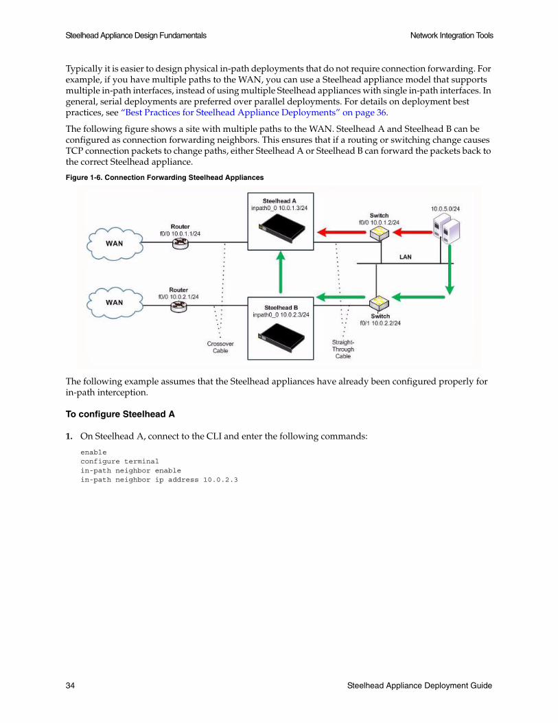
Steelhead Appliance Design Fundamentals Network Integration Tools
Typically it is easier to design physical in-path deployments that do not require connection forwarding. For example, if you have multiple paths to the WAN, you can use a Steelhead appliance model that supports multiple in-path interfaces, instead of using multiple Steelhead appliances with single in-path interfaces. In general, serial deployments are preferred over parallel deployments. For details on deployment best practices, see “Best Practices for Steelhead Appliance Deployments” on page 36.
The following figure shows a site with multiple paths to the WAN. Steelhead A and Steelhead B can be configured as connection forwarding neighbors. This ensures that if a routing or switching change causes TCP connection packets to change paths, either Steelhead A or Steelhead B can forward the packets back to the correct Steelhead appliance.
Figure 1-6. Connection Forwarding Steelhead Appliances
The following example assumes that the Steelhead appliances have already been configured properly for in-path interception.
To configure Steelhead A
1. On Steelhead A, connect to the CLI and enter the following commands:
enableconfigure terminalin-path neighbor enablein-path neighbor ip address 10.0.2.3
34 Steelhead Appliance Deployment Guide

Network Integration Tools Steelhead Appliance Design Fundamentals
To configure Steelhead B
1. On Steelhead B, connect to the CLI and enter the following commands:
enableconfigure terminalin-path neighbor enablein-path neighbor ip address 10.0.1.3
When Steelhead A begins optimizing a new TCP connection, it communicates this to Steelhead B, provides the IP addresses and TCP port numbers for the new TCP connection, and defines a dynamic TCP port on which to forward packets.
If Steelhead B sees a packet that matches the connection, it takes the packet, alters its destination IP address to be the in-path IP address of Steelhead A, alters its destination TCP port to be the specific dynamic port that Steelhead A specified for the connection, and transmits the packet using its routing table.
Tip: To ensure the connection-forwarding-neighbor Steelhead appliance sends traffic to each of their in-path IP addresses through the LAN, install a static route for the addresses whose next hop is the LAN gateway device. (The LAN interface forwards and receives connection forwarding packets.)
Note: For details on connection forwarding in multiple WAN routers, see “Basic Example of Connection Forwarding” on page 61.
Failure Handling within Connection Forwarding
By default, if a Steelhead appliance loses connectivity to a connection forwarding neighbor, the Steelhead appliance stops attempting to optimize new connections. This behavior can be changed with the in-path neighbor allow-failure CLI command. If the allow-failure command is enabled, a Steelhead appliance continues to optimize new connections, regardless of the state of its neighbors.
For virtual in-path deployments with multiple Steelhead appliances, including WCCP clusters, connection forwarding and you must use the allow-failure command. This is because certain events, such as network failures, and router or Steelhead appliance cluster changes, can cause routers to change the destination Steelhead appliance for TCP connection packets. When this happens, Steelhead appliances must be able to redirect traffic to each other to insure that optimization continues.
For parallel physical in-path deployments, where multiple paths to the WAN are covered by different Steelhead appliances, connection forwarding is needed because packets for a TCP connection might be routed asymmetrically; that is, the packets for a connection might sometimes go through one path, and other times go through another path. The Steelhead appliances on these paths must use connection forwarding to ensure that the traffic for a TCP connection is always sent to the Steelhead appliance that is performing optimization for that connection.
If the allow-failure command is used in a parallel physical in-path deployment, Steelhead appliances only optimize those connections that are routed through the paths with operating Steelhead appliances. TCP connections that are routed across paths without Steelhead appliances (or with a failed Steelhead appliance) are detected by the asymmetric routing detection feature.
Steelhead Appliance Deployment Guide 35

Steelhead Appliance Design Fundamentals Best Practices for Steelhead Appliance Deployments
For physical in-path deployments, the allow-failure command is commonly used with the fail-to-block feature (on supported hardware). When fail-to-block is enabled, a failed Steelhead appliance blocks traffic along its path, forcing traffic to be re-routed onto other paths (where the remaining Steelhead appliances are deployed). For an example configuration, see “Connection Forwarding with Allow-Failure and Fail-to-Block” on page 62.
Note: You can configure your Steelhead appliances to automatically detect and report asymmetry within TCP connections as seen by the Steelhead appliance. Asymmetric route auto-detection does not solve asymmetry; it simply detects and reports it, and passes the asymmetric traffic unoptimized. For details about enabling asymmetric route auto-detection, see the Steelhead Management Console User’s Guide.
Best Practices for Steelhead Appliance Deployments
The following list represents best practices for deploying your Steelhead appliances. These best practices are not requirements, but Riverbed recommends you follow these suggestions as they lead to designs that require the least amount of initial and on-going configuration:
Use in-path designs - Whenever possible, use a physical in-path deployment—the most common type of Steelhead appliance deployment. Physical in-path deployments are easier to manage and configure than WCCP, PBR, and L4 designs. In-path designs generally require no extra configuration on the connected routers or switches. If desired, you can limit traffic to be optimized on the Steelhead appliance. For details, see “Physical In-Path Deployments” on page 39.
Use the right cables - To ensure that traffic flows not only when the Steelhead appliance is optimizing traffic, but also when the Steelhead appliance transitions to fail-to-wire mode, use the appropriate crossover or straight-through cable to connect the Steelhead appliance to a router or switch. Verify the cable selection by removing power from the Steelhead appliance and then test connectivity through it. For details, see “Choosing the Right Cables” on page 45.
Set matching duplex speeds - The number one cause of performance issues is duplex mismatch on the Steelhead appliance WAN or LAN interfaces, or on the interface of a device connected to the Steelhead appliance. Most commonly it is the interface of a network device deployed prior to the Steelhead appliance. For details on duplex settings, see “Cabling and Duplex” on page 45. For details on troubleshooting duplex mismatch, see “Physical In-Path Deployments” on page 39.
Minimize the effect of link state transition - Use the Cisco spanning-tree portfast command on Cisco switches, or similar configuration options on your routers and switches that minimize the amount of time an interface stops forwarding traffic when the Steelhead appliance transitions to failure mode. For details, see “Fail-to-Wire Mode” on page 41.
Use serial rather than parallel designs - Parallel designs are physical in-path designs in which a Steelhead appliance has some, but not all, of the WAN links passing through it, and other Steelhead appliances have the remaining WAN links passing through them. Connection forwarding must be configured for parallel designs. In general, it is easier to use physical in-path designs where one Steelhead appliance has all of the links to the WAN passing through it. For details on serial designs, see “Physical In-Path Deployments” on page 39. For details on connection forwarding, see “Connection Forwarding” on page 33.
36 Steelhead Appliance Deployment Guide

Best Practices for Steelhead Appliance Deployments Steelhead Appliance Design Fundamentals
Do not optimize transit traffic - Ideally, Steelhead appliances only optimize traffic that is initiated or terminated at its local site. To avoid optimizing transit traffic, deploy the Steelhead appliances where the LAN connects to the WAN and not where LAN-to-LAN or WAN-to-WAN traffic can pass through (or be redirected to) the Steelhead appliance. For details, see “Resolving Transit Traffic Issues” on page 312.
Position your Steelhead appliances close to your network end points - For optimal performance, minimize latency between Steelhead appliances and their respective clients and servers. By deploying Steelhead appliances as close as possible to your network end points (that is, place client-side Steelhead appliances as close to your clients as possible, and place server-side Steelhead appliances as close to your servers as possible).
Use correct addressing or port transparency modes - Performance trade-offs exist for each of the WAN visibility modes, but the inherent issues with full transparency are generally greater. For details, see “WAN Visibility Modes” on page 227.
Use datastore synchronization - Regardless of the deployment type or clustering used at a site, datastore synchronization can allow significant bandwidth optimization even after a Steelhead appliance or hard drive failure. For details, see “Datastore Synchronization” on page 32.
Use connection forwarding and allow-failure in a WCCP cluster - In a WCCP cluster, use connection forwarding and the allow-failure CLI option between Steelhead appliances. For details, see “Connection Forwarding” on page 33.
Avoid using fixed-target in-path rules - Use the auto-discovery feature whenever possible, thus avoiding the need to define fixed-target, in-path rules. For details on auto-discovery, see “The Auto-Discovery Protocol” on page 21. For details on fixed-target in-path rules, see “Fixed-Target In-Path Rules” on page 29.
Understand in-path rules versus peering rules - Use in-path rules to modify Steelhead appliance behavior when a connection is initiated. For details, see “In-Path Rules” on page 24. Use peering rules to modify Steelhead appliance behavior when it sees auto-discovery tagged packets. For details, see “Peering Rules” on page 25.
Use Riverbed Professional Services or an authorized Riverbed Partner - Training (both standard and custom) and consultation are available for small to large, and extra-large deployments. For details, go to the Riverbed Professional Services site located at http://www.riverbed.com, or contact them at [email protected].
Steelhead Appliance Deployment Guide 37

Steelhead Appliance Design Fundamentals Best Practices for Steelhead Appliance Deployments
38 Steelhead Appliance Deployment Guide

CHAPTER 2 Physical In-Path Deployments
This chapter describes a physical in-path Steelhead appliance deployment. It includes the following sections:
“Overview of In-Path Deployments,” next
“The Logical In-Path Interface” on page 40
“Basic Physical In-Path Deployments” on page 46
“Simplified Routing” on page 47
“In-Path Redundancy and Clustering” on page 49
“Multiple WAN Router Deployments” on page 55
“802.1q Trunk Deployments” on page 65
“L2 WAN Deployments” on page 68
This chapter assumes you are familiar with:
Hot Standby Router Protocol (HSRP)
Virtual Router Redundancy Protocol (VRRP)
Gateway Load Balancing Protocol (GLBP)
Overview of In-Path Deployments
In a physical in-path Steelhead appliance deployment, a Steelhead appliance LAN interface connects to a LAN-side device (usually a switch), and a corresponding Steelhead appliance WAN interface connects to a WAN connecting device (usually a router). This allows the Steelhead appliance to see all traffic flowing to and from the WAN, and perform optimization.
Depending on the Steelhead appliance model and its hardware configuration, multiple pairs of WAN and LAN interfaces can be used simultaneously, which can be connected to multiple switches and routers.
Steelhead Appliance Deployment Guide 39

Physical In-Path Deployments The Logical In-Path Interface
The following figure shows the simplest type of physical in-path Steelhead appliance deployment.
Figure 2-1. Single Subnet, Physical In-Path Deployment
Most Steelhead appliance deployments are physical in-path deployments. Physical in-path configurations are the easiest to deploy and do not require on-going maintenance as other configurations do (such as virtual in-path configurations: WCCP, PBR, and L4 redirection).
The Logical In-Path Interface
All Steelhead appliances ship with at least one pair of ports that are used for in-path deployments. This pair of ports forms the logical in-path interface. The logical in-path interface acts as an independent, two-port bridge, with its own IP address.
The following figure shows the Steelhead appliance logical in-path interface and how it is physically connected to network devices in a single subnet, in-path deployment.
Figure 2-2. The Logical In-Path Interface in a Single Subnet In-Path Deployment
The simplest in-path Steelhead appliance has two IP addresses:
Primary - Used for the system management, datastore synchronization, and SNMP.
InPath0_0 - Used for optimized data transmission.
Several types of network interface cards (bypass cards) are available for Steelhead appliances. The desktop Steelhead appliances have network bypass functionality built-in. With 1U and 3U systems, you can choose the type of bypass card. Steelhead appliances can have both copper and fiber Ethernet bypass cards.
40 Steelhead Appliance Deployment Guide

The Logical In-Path Interface Physical In-Path Deployments
For details on bypass cards, see the Network Interface Card Installation Guide on the Riverbed Support site.
Failure Modes
All Steelhead appliance models and in-path network interface cards support fail-to-wire mode. In the event of a disk failure, a software crash, a runaway software process, or even loss of power to the Steelhead appliance, the LAN and WAN ports that form the logical in-path interface become internally connected as if they were the ends of a crossover cable, thereby providing uninterrupted transmission of data over the WAN.
Certain in-path network interface cards also support a fail-to-block mode, where in the case of a failure or loss of power, the Steelhead appliance LAN and WAN interfaces completely lose link status, blocking traffic along its path and forcing it to be re-routed onto other paths (where the remaining Steelhead appliances are deployed). The default failure mode is fail-to-wire mode.
For a list of in-path network interface cards or bypass cards that support fail-to-block mode, see “Fail-to-Block Mode” on page 42.
If a Steelhead appliance transitions to fail-to-wire or fail-to-block mode, you are notified in the following ways:
The Intercept/Bypass status light is active. For details about the status lights for each of the bypass cards, see the Network Interface Card Installation Guide.
Critical appears in the Management Console status bar.
SNMP traps are sent (if you have set this option).
The event is logged to system logs (syslog) (if you have set this option).
Email notifications are sent (if you have set this option).
Fail-to-Wire Mode
Fail-to-wire mode allows the Steelhead appliance WAN and LAN ports to serve as an Ethernet crossover cable. In fail-to-wire mode, Steelhead appliances cannot view or optimize traffic. Instead, all traffic is passed through the Steelhead appliance unoptimized.
All Steelhead appliance in-path interfaces support fail-to-wire mode. Fail-to-wire mode is the default setting for Steelhead appliances.
When a Steelhead appliance transitions from normal operation to fail-to-wire mode, Steelhead appliance circuitry physically moves in order to electrically connect the Steelhead appliance LAN and WAN ports to each other, and physically disconnects these two ports from the rest of the Steelhead appliance. During the transition to fail-to-wire mode, devices connected to the Steelhead appliance momentarily see their links to the Steelhead appliance go down, then immediately come back up. After the transition, traffic resumes flowing as quickly as the connected devices are able. For example, spanning-tree configuration and routing-protocol configuration influence how quickly traffic resumes flowing. Traffic that was passed-through is uninterrupted. Traffic that was optimized might be interrupted, depending on the behavior of the application-layer protocols. When connections are restored, the traffic resumes flowing, although without optimization.
After the Steelhead appliance returns to normal operation, it transitions the Steelhead appliance LAN and WAN ports out of fail-to-wire mode. The devices connected to the Steelhead appliance perceive this as another link state transition. After they are back online, new connections that are made are optimized. However, connections made during the failure are not optimized.
Steelhead Appliance Deployment Guide 41
Physical In-Path Deployments The Logical In-Path Interface
To force all connections to be optimized, you can enable the kickoff feature. This feature resets established connections to force them to go through the connection creation process again. For this reason, before enabling the kickoff feature in production deployments you must understand and accept that all TCP connections are reset. Generally, connections are short lived and kickoff is not necessary. For details about enabling the kickoff feature, see the Steelhead Management Console User’s Guide.
Fail-to-Wire Mode Effect on Connected Devices
When a Steelhead appliance transitions to fail-to-wire mode, the transition can have an effect on devices connected to the Steelhead appliance. For example, one common implication pertains to the spanning-tree protocol. In many physical in-path deployments, the Steelhead appliance LAN port is connected to an Ethernet switch, and the Steelhead appliance WAN port is connected to a router.
When a Steelhead appliance transitions from bridging mode to failure mode, a switch might force the port that is connected to the Steelhead appliance to go through the 30-45 second, non-forwarding states of spanning tree. This can result in packet delay or packet loss.
You can resolve this issue by making configuration modifications on your switch. Depending on your switch vendor, there are many different methods to alleviate this issue, ranging from skipping the non-forwarding states (for example, running the spanning-tree portfast command on Cisco switches), to using newer 802.1d STP protocols that converge faster on link transitions.
RiOS v5.0.x and later only has this mode transition issue when the Steelhead appliance experiences a power loss. RiOS v4.1 and earlier has this transition state issue when the Steelhead appliance experiences a power loss, software failure, or when the optimization service is restarted.
Fail-to-Block Mode
Some network interfaces support fail-to-block mode. In fail-to-block mode, if the Steelhead appliance has an internal software failure or power loss, the Steelhead appliance LAN and WAN interfaces power down and stop bridging traffic. fail-to-block mode is only useful if the network has a routing or switching infrastructure that can automatically divert traffic off of the link once the failed Steelhead appliance blocks it. You can use fail-to-block mode with connection forwarding, the allow-failure CLI command, and an additional Steelhead appliance on another path to the WAN to achieve redundancy. For details, see “Connection Forwarding with Allow-Failure and Fail-to-Block” on page 62.
Check the Network Interface Card Installation Guide on the Riverbed Support site for a current list of Steelhead appliance in-path interfaces that support fail-to-block mode. The desktop Steelhead appliance models (50, 100, 200, and 300) do not support fail-to-block mode. The desktop Steelhead appliance models 250 and 550 do support fail-to-block mode.
To enable fail-to-block mode
1. Connect to the Steelhead CLI and enter the following commands:
enableconfigure terminalno interface inpath0_0 fail-to-bypass enablewrite memory
Note: The changes take effect immediately. Changes must be saved or they are lost upon reboot.
42 Steelhead Appliance Deployment Guide

The Logical In-Path Interface Physical In-Path Deployments
To change from fail-to-block mode back to fail-to-wire mode
1. Connect to the Steelhead CLI and enter the following commands:
enableconfigure terminalinterface inpath0_0 fail-to-bypass enablewrite memory
Note: The changes take effect immediately. Changes must be saved or they are lost upon reboot.
To check failure mode status
1. Connect to the Steelhead CLI and enter the following commands:
enableshow interface inpath0_0
In-Path IP Address Selection
An IP address is required for each Steelhead appliance in-path interface. When using correct addressing or port transparency, the IP address must be reachable by remote Steelhead appliances for optimization to occur. For details on correct addressing and port transparency, see “WAN Visibility Modes” on page 227.
In some environments, the link between the switch and the router might reside in a subnet that has no available IP address. There are several ways to accommodate the IP address requirement, including:
Creating a secondary interface, with a new subnet and IP address on the router or switch, and pulling the Steelhead appliance in-path interface IP address from the new subnet.
Creating a new 802.1q VLAN interface and subnet on the router and switch link, and pulling the Steelhead appliance in-path interface IP address from the new subnet. This also requires entering the appropriate in-path VLAN tag on the Steelhead appliance.
Note: With RiOS v5.0.x and later you can deploy Steelhead appliances so that the in-path interface IP address is not actually used. This deployment option can be useful for integrating with certain network configurations, such as NAT. However, an IP address must be configured for each enabled in-path interface. For details, see “Configuring WAN Visibility Modes” on page 237.
Note: For additional details on deploying a Steelhead appliance into an existing network, see the Riverbed Knowledge Base article, Steelhead Deployment onto an Existing /30 Network, at https://support.riverbed.com/kb/solution.htm?id=501300000006tck&categoryName=Networking.
In-Path Default Gateway and Routing
Almost all in-path deployments require the configuration of a default gateway for the in-path interfaces. A physical in-path Steelhead appliance might need to transmit packets from its in-path interface to any:
local hosts, for the LAN-side of any optimized connections.
remote Steelhead appliances, for the WAN-side of any optimized connections.
Steelhead Appliance Deployment Guide 43

Physical In-Path Deployments The Logical In-Path Interface
remote Hosts, when transmitting packets during auto-discovery.
local Steelhead appliances, when communicating with connection forwarding neighbors.
If any of these devices are on a different subnet from the in-path interface, an in-path gateway must be configured.
In small branches, where a Steelhead appliance is physically placed between an access switch and a router or firewall, and all hosts are on the same subnet, then the in-path default gateway must use the same IP address that the local hosts use—that of the router or firewall. With this configuration, the Steelhead appliance uses the gateway as the L2 next-hop when transmitting to remote hosts or Steelhead appliances, and directly to the local hosts (via MAC address discovery through ARP) when transmitting packets to them.
In larger branches where the Steelhead appliance are deployed between two L3 devices (for example: between an L3 switch and a WAN-side router), then the Steelhead appliance can be configured with a specific in-path gateway, static routes, and simplified routing to ensure that it always transmits packets to the optimal next hop. While it is impossible to generalize for all environments, a typical configuration for locations that minimize packet ricochet and ensure the best performance:
use the WAN-side L3 device as the in-path default gateway.
use the simplified routing destination only option.
use the enhanced auto-discovery feature.
Some environments require different settings or additional configuration.
Link State Propagation
In physically in-path deployments, link state propagation helps communicate link status between the devices connected to the Steelhead appliance. When this feature is enabled, the link state of each Steelhead appliance LAN and WAN pair is monitored. If either physical port loses link status, the link of the corresponding physical port is also brought down. Link state propagation allows link failure to quickly propagate through the Steelhead appliance, and is useful in environments where link status is used as a fast-fail trigger.
For example, in a physical in-path deployment where the Steelhead appliance is connected to a router on its WAN port and a switch on its LAN port, if the cable to the router is disconnected, the Steelhead appliance deactivates the link on its LAN port. This causes the switch interface that is connected to the Steelhead appliance to also lose the link. The reverse is also true: if the cable to the switch is disconnected; the router interface that is connected to the Steelhead appliance loses the link.
In a serial cluster deployment, link state propagation can be useful to quickly propagate failure if the cables between Steelhead appliances are disconnected. For example, in a two Steelhead appliance serial cluster, by disconnecting the cable between the Steelhead appliances, then both the WAN-side router and the LAN-side switch lose link.
Link state propagation is supported on either all or none of the interfaces of a Steelhead appliance; it cannot be used to selectively activate an in-path interface.
Note: In RiOS v6.0, link state propagation is enabled by default.
44 Steelhead Appliance Deployment Guide

The Logical In-Path Interface Physical In-Path Deployments
To enable link state propagation on a Steelhead appliance
1. Connect to the Steelhead CLI and enter the following commands:
enableconfigure terminalin-path lsp enablewrite memory
Note: The changes take effect immediately. Changes must be saved or they are lost upon reboot.
Cabling and Duplex
In most physical in-path deployments the Steelhead appliance is connected to a router and a switch. The Steelhead appliance WAN port is connected to the router with a crossover cable, and the Steelhead appliance LAN port is connected to the switch with a straight-through cable. For details on the in-path interface, see “The Logical In-Path Interface” on page 40.
Choosing the Right Cables
The following table summarizes the correct cable (either a crossover or a straight-through) usage in the Steelhead appliance.
The number one cause of poor performance is a duplex mismatch. To avoid duplex mismatch for 10/100 Mbps, you must manually configure the same speed and duplex settings for your:
router
switch
the Steelhead appliance primary interface
the Steelhead appliance LAN interface
the Steelhead appliance WAN interface
Note: Check the speed and duplex are set to the default value auto/auto on the above interfaces. This setting ensures there are no duplex mismatch for Gbit (1000Mbps) interfaces.
Riverbed recommends you do not rely on Auto MDI/MDI-X to auto-sense the cable type. The installation might work when the Steelhead appliance is optimizing traffic, but it might not if the in-path bypass card transitions to fail-to-wire mode.
Devices Cable
Steelhead appliance to Steelhead appliance Crossover
Steelhead appliance to router Crossover
Steelhead appliance to switch Straight-through
Steelhead appliance to host Crossover
Steelhead Appliance Deployment Guide 45

Physical In-Path Deployments Basic Physical In-Path Deployments
Signs of a duplex mismatch:
You cannot connect to an attached device.
You can connect to a device when you choose auto-negotiation, but you cannot connect to that same device when you manually set the speed or duplex.
Slow performance across the network. To verify if slow performance on the network is due to a speed and duplex problem on a Steelhead appliance, go to the Reports > Networking > Interface Counters page of the Management Console. Look for positive values for the following fields:
– Discards
– Errors
– Overruns
– Frame
– Carrier counts
– Collisions
The above values are zero (0) on a healthy network unless you use half duplex, which Riverbed does not recommend.
Note: Speed and duplex issues may be present at other points in the network path besides the interfaces directly connected to the Steelhead appliance. At other potential locations, there may be longstanding interface errors within the LAN, whose symptoms might have been incorrectly blamed on WAN performance.
Basic Physical In-Path Deployments
Perform the following basic steps to deploy a physical in-path Steelhead appliance.
Figure 2-3. Simple, Physical In-Path Deployment
1. Determine the speed for the:
switch interface
router interface
46 Steelhead Appliance Deployment Guide

Simplified Routing Physical In-Path Deployments
Steelhead appliance primary interface
Steelhead appliance WAN interface
Steelhead appliance LAN interface
Riverbed recommends the following speeds:
Fast Ethernet Interfaces: 100 megabits full duplex
Gigabit Interfaces: 1000 megabits full duplex
2. Determine the IP addresses for the Steelhead appliance. A Steelhead appliance that is deployed in a physical in-path mode requires two IP addresses, one each for the:
Steelhead appliance in-path interface
Steelhead appliance primary interface (this interface is used for managing the Steelhead appliance)
3. Manually configure the speed for the:
switch interface
router interface
Steelhead appliance primary interface
Steelhead appliance WAN interface
Steelhead appliance LAN interface
Important: Riverbed strongly recommends that you manually configure the speed for each interface.
4. Configure the appropriate Default Gateway for the Primary and in-path interfaces.
Primary Port Gateway IP - Specify the primary gateway IP address. The primary gateway must be in the same network as the primary interface. You must set the primary gateway for in-path configurations.
In-Path Gateway IP - Specify the IP address for the in-path gateway. If you have a router (or a L3 switch) on the WAN-side of your network, specify this device as the in-path gateway.
Note: For details, see “In-Path Default Gateway and Routing” on page 43.
Simplified Routing
Packet ricochet occurs when a packet traverses a Steelhead appliance more than once. Consider the deployment in Figure 2-4, where the default gateway on Steelhead appliance A is set to Router 2. When the Steelhead appliance attempts to reach IP address 172.30.2.1, it sends the packet to Router 2. Router 2 sends the packet out through its G0/0 interface. The packet traverses the Steelhead appliance again before arriving on Router 1. Packet ricochet occurs because the packet has traversed the Steelhead appliance more than once.
Steelhead Appliance Deployment Guide 47
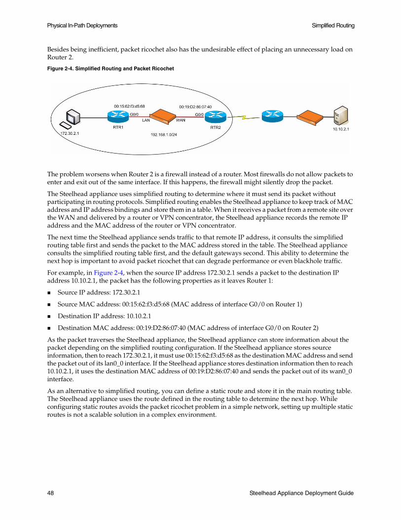
Physical In-Path Deployments Simplified Routing
Besides being inefficient, packet ricochet also has the undesirable effect of placing an unnecessary load on Router 2.
Figure 2-4. Simplified Routing and Packet Ricochet
The problem worsens when Router 2 is a firewall instead of a router. Most firewalls do not allow packets to enter and exit out of the same interface. If this happens, the firewall might silently drop the packet.
The Steelhead appliance uses simplified routing to determine where it must send its packet without participating in routing protocols. Simplified routing enables the Steelhead appliance to keep track of MAC address and IP address bindings and store them in a table. When it receives a packet from a remote site over the WAN and delivered by a router or VPN concentrator, the Steelhead appliance records the remote IP address and the MAC address of the router or VPN concentrator.
The next time the Steelhead appliance sends traffic to that remote IP address, it consults the simplified routing table first and sends the packet to the MAC address stored in the table. The Steelhead appliance consults the simplified routing table first, and the default gateways second. This ability to determine the next hop is important to avoid packet ricochet that can degrade performance or even blackhole traffic.
For example, in Figure 2-4, when the source IP address 172.30.2.1 sends a packet to the destination IP address 10.10.2.1, the packet has the following properties as it leaves Router 1:
Source IP address: 172.30.2.1
Source MAC address: 00:15:62:f3:d5:68 (MAC address of interface G0/0 on Router 1)
Destination IP address: 10.10.2.1
Destination MAC address: 00:19:D2:86:07:40 (MAC address of interface G0/0 on Router 2)
As the packet traverses the Steelhead appliance, the Steelhead appliance can store information about the packet depending on the simplified routing configuration. If the Steelhead appliance stores source information, then to reach 172.30.2.1, it must use 00:15:62:f3:d5:68 as the destination MAC address and send the packet out of its lan0_0 interface. If the Steelhead appliance stores destination information then to reach 10.10.2.1, it uses the destination MAC address of 00:19:D2:86:07:40 and sends the packet out of its wan0_0 interface.
As an alternative to simplified routing, you can define a static route and store it in the main routing table. The Steelhead appliance uses the route defined in the routing table to determine the next hop. While configuring static routes avoids the packet ricochet problem in a simple network, setting up multiple static routes is not a scalable solution in a complex environment.
48 Steelhead Appliance Deployment Guide

In-Path Redundancy and Clustering Physical In-Path Deployments
Note that when you combine static routes and simplified routing, simplified routing takes precedence over static routes by default. To override the default behavior and have the static routes take precedence over simplified routing, enter the following CLI command:
in-path simplified mac-def-gw-only
Note: After you enable simplified routing, sometimes the simplified routing table may not have information about a host. When a Steelhead appliance cannot find host information from the simplified routing table, it relies on its default gateway to route the initial packets. Once the Steelhead appliance can find host information in the simplified routing table, it uses the table instead of the default gateway to determine where to send the data.
In-Path Redundancy and Clustering
There are two general techniques used for configuring multiple Steelhead appliances in physical in-path deployments. These deployments achieve redundancy and clustering for optimization. This section covers the following scenarios:
“Master and Backup Deployments,” next
“Serial Cluster Deployments” on page 51
Each scenario can be used to provide optimization across several physical links, and can be used in conjunction with connection forwarding when all of the physical links to and from the WAN are unable to pass through a single Steelhead appliance (for details on connection forwarding, see “Connection Forwarding” on page 33).
Master and Backup Deployments
In a master and backup deployment, two equivalent model Steelhead appliances are placed physically in-path. The Steelhead appliance closest to the LAN is configured as a master, and the other Steelhead appliance as the backup. The master Steelhead appliance optimizes traffic while the backup Steelhead appliance checks to make sure the master Steelhead appliance is functioning and not in admission control. Admission control means the Steelhead appliance has stopped trying to optimize new connections, due to hitting its TCP connection limit, or due to some abnormal condition. If the backup Steelhead appliance cannot reach the master, or if the master has entered admission control, the backup Steelhead appliance begins optimizing new connections until the master recovers. After the master has recovered, the backup Steelhead appliance stops optimizing new connections, but continues to optimize any existing connections that were made while the master was down. The recovered master optimizes any newly formed connections.
Figure 2-5. Master and Backup Deployment
Steelhead Appliance Deployment Guide 49

Physical In-Path Deployments In-Path Redundancy and Clustering
The master and backup deployment can be used with Steelhead appliances that have multiple active in-path links. Add peering rules to both Steelhead appliances for each in-path interface; these peering rules must have an action pass for a peer IP address of each of the in-path IP addresses. This setting ensures during any small window of time where both Steelhead appliances are active (for example, during a master recovering) that the Steelhead appliances do not try to optimize connections between themselves.
Typically, datastore synchronization is used in master and backup deployments. Datastore synchronization ensures that any data written to one Steelhead appliance eventually is pushed to the other Steelhead appliance. While both the master and backup deployment option and the datastore synchronization feature use the terms master and backup, the uses are different and separate. It is typical for one Steelhead appliance to be both configured as a master for both, but it is not a requirement. For details on, see “Datastore Synchronization” on page 32.
Consider using a master and backup deployment instead of a serial cluster when all of the following are true:
Only two Steelhead appliances are placed physically in-path.
The capacity of a single Steelhead appliance is sufficient for the site.
Only a single in-path link is used to optimize connections.
Some environments might require additional considerations.
Note: For details on serial clusters, see “Serial Cluster Deployments” on page 51.
Example Master and Backup Configuration
This section describes how to configure the master and backup deployment shown in Figure 2-5.
To configure the master Steelhead appliance
1. Connect to the connect to the Steelhead CLI and enter the following commands:
# -- Master Steelheadinterface primary ip address 10.0.1.2/24ip default gateway 10.0.1.1interface inpath0_0 ip address 10.0.1.3/24ip in-path-gateway inpath0_0 10.0.1.1# -- Failover should point to the inpath0_0 address.failover buddy addr 10.0.1.5failover masterfailover enablein-path enable# -- While not required, datastore synchronization is usually enabled in master/backup deploymentsdatastore sync master# -- Datastore should point to peer's primary or aux interface address.datastore sync peer-ip 10.0.1.4datastore sync enablewrite memoryrestart
50 Steelhead Appliance Deployment Guide

In-Path Redundancy and Clustering Physical In-Path Deployments
To configure the backup Steelhead appliance
Connect to the connect to the Steelhead CLI and enter the following commands:
# -- Backup Steelheadinterface primary ip address 10.0.1.4/24ip default gateway 10.0.1.1interface inpath0_0 ip address 10.0.1.5/24ip in-path-gateway inpath0_0 10.0.1.1# -- Failover should point to the inpath0_0 address.failover buddy addr 10.0.1.3no failover masterfailover enablein-path enable# -- While not required, datastore synchronization is usually enabled in master/backup deploymentsno datastore sync master# -- Datastore should point to peer's primary or aux interface address.datastore sync peer-ip 10.0.1.2datastore sync enablewrite memoryrestart
Note: For additional details on configuring master and backup deployment, see the Failover Support commands in the Riverbed Command-Line Interface Reference Manual, and the Enabling Failover section in the Steelhead Management Console User’s Guide.
Serial Cluster Deployments
You can provide increased optimization by deploying two or more Steelhead appliances back-to-back in an in-path configuration to create a serial cluster. Appliances in a serial cluster process the peering rules you specify in a spillover fashion. When the maximum number of TCP connections for a Steelhead appliance is reached, that appliance stops intercepting new connections. This allows the next Steelhead appliance in the cluster the opportunity to intercept the new connection, if it has not reached its maximum number of connections.
The in-path peering rules and in-path rules tell the Steelhead appliance in a cluster not to intercept connections between themselves. You configure peering rules that define what to do when a Steelhead appliance receives an auto-discovery probe from another Steelhead appliance. You can deploy serial clusters on the client or server-side of the network.
Note: For additional details on working with serial clusters, see the Riverbed Knowledge Base article, Working with Serial Clustering, at https://support.riverbed.com/kb/solution.htm?id=501500000007wSY&categoryName=Install.
Important: For environments where want to optimize MAPI or FTP traffic, which require all connections from a client to be optimized by one Steelhead appliance, Riverbed strongly recommends using the master and backup redundancy configuration instead of a serial cluster deployment. For larger environments that require multi-appliance scalability and high availability, Riverbed recommends using the Interceptor appliance to build multi-appliance clusters. For details, see “Physical In-path Failover Deployment” on page 35 and the Interceptor Appliance User’s Guide.
Steelhead Appliance Deployment Guide 51

Physical In-Path Deployments In-Path Redundancy and Clustering
Before you configure a serial cluster deployment, consider the following factors:
A serial cluster has the same bandwidth specification as the Steelhead appliance model deployed in the cluster. The bandwidth capability does not increase because the cluster contains more than one Steelhead appliance.
If the active Steelhead appliance in the cluster enters a degraded state because the CPU load is too high, it continues to accept new connections.
Serial Cluster Rules
The in-path peering rules and in-path pass-through rules tell the Steelhead appliances in a serial cluster not to intercept connections between each other. The peering rules define what happens when a Steelhead appliance receives an auto-discovery probe from another Steelhead appliance in the same cluster.
You can deploy serial clusters on the client or server-side of the network.
Figure 2-6. Serial Cluster Deployment
In this example, Steelhead 1, Steelhead 2, and Steelhead 3 are configured with in-path peering rules so they do not answer probe requests from one another, and with in-path rules so they do not accept their own WAN connections. Similarly, Steelhead 4, Steelhead 5, and Steelhead 6 are configured so that they do not answer probes from one another and do not intercept inner connections from one another. The Steelhead appliances are configured to perform to find an available peer Steelhead appliance on the other side of the WAN.
52 Steelhead Appliance Deployment Guide

In-Path Redundancy and Clustering Physical In-Path Deployments
A Basic Serial Cluster Deployment
The following figure shows how to configure a serial cluster deployment of three in-path Steelhead appliances in a data center.
Figure 2-7. Serial Cluster in a Data Center
This example uses the following parameters:
Steelhead 1 in-path IP address is 10.0.1.1
Steelhead 2 in-path IP address is 10.0.1.2
Steelhead 3 in-path IP address is 10.0.1.3
In this example, you configure each Steelhead appliance with in-path peering rules to prevent peering with another Steelhead appliance in the cluster, and with in-path rules to not optimize connections originating from other Steelhead appliances in the same cluster.
Steelhead Appliance Deployment Guide 53

Physical In-Path Deployments In-Path Redundancy and Clustering
To configure Steelhead 1
1. On Steelhead 1, connect to the CLI and enter the following commands:
enableconfigure terminalin-path peering rule pass peer 10.0.1.2 rulenum 1in-path peering rule pass peer 10.0.1.3 rulenum 1in-path rule pass-through srcaddr 10.0.1.2/32 rulenum 1in-path rule pass-through srcaddr 10.0.1.3/32 rulenum 1write memoryshow in-path peering rulesRule Type Source Network Dest Network Port Peer Addr----- ------ ------------------ ------------------ ----- --------------- 1 pass * * * 10.0.1.3 2 pass * * * 10.0.1.2 def auto * * * *
show in-path rulesRule Type Source Addr Dest Addr Port Target Addr Port----- ---- ------------------ ------------------ ----- --------------- ----- 1 pass 10.0.1.3/24 * * -- -- 2 pass 10.0.1.2/24 * * -- -- def auto * * * -- --
Note: The changes take effect immediately. Changes must be saved or they are lost upon reboot.
To configure Steelhead 2
1. On Steelhead 2, connect to the CLI and enter the following commands:
Note: Port 7800 is the default pass through port. The Steelhead appliances by default will pass through and not intercept SYN packets arriving on port 7800. These in-path pass through rules are necessary only if the Steelhead appliances have been configured to use service port(s) other than 7800 for the Steelhead-to-Steelhead connections.
enableconfigure terminalin-path peering rule pass peer 10.0.1.1 rulenum 1in-path peering rule pass peer 10.0.1.3 rulenum 1in-path rule pass-through srcaddr 10.0.1.1/32 rulenum 1in-path rule pass-through srcaddr 10.0.1.3/32 rulenum 1write memory
show in-path peering rulesRule Type Source Network Dest Network Port Peer Addr----- ------ ------------------ ------------------ ----- --------------- 1 pass * * * 10.0.1.3 2 pass * * * 10.0.1.1 def auto * * * *
54 Steelhead Appliance Deployment Guide
Multiple WAN Router Deployments Physical In-Path Deployments
show in-path rulesRule Type Source Addr Dest Addr Port Target Addr Port----- ---- ------------------ ------------------ ----- --------------- ----- 1 pass 10.0.1.3/24 * * -- -- 2 pass 10.0.1.1/24 * * -- -- def auto * * * -- --
Note: The changes take effect immediately. Changes must be saved or they are lost upon reboot.
To configure Steelhead 3
1. On Steelhead 3, connect to the CLI and enter the following commands:
enableconfigure terminalin-path peering rule pass peer 10.0.1.1 rulenum 1in-path peering rule pass peer 10.0.1.2 rulenum 1in-path rule pass-through srcaddr 10.0.1.1/32 rulenum 1in-path rule pass-through srcaddr 10.0.1.2/32 rulenum 1write memory
show in-path peering rulesRule Type Source Network Dest Network Port Peer Addr----- ------ ------------------ ------------------ ----- --------------- 1 pass * * * 10.0.1.2 2 pass * * * 10.0.1.1 def auto * * * *
show in-path rulesRule Type Source Addr Dest Addr Port Target Addr Port----- ---- ------------------ ------------------ ----- --------------- ----- 1 pass 10.0.1.2/24 * * -- -- 2 pass 10.0.1.1/24 * * -- -- def auto * * * -- --
Note: The changes take effect immediately. Changes must be saved or they are lost upon reboot.
Multiple WAN Router Deployments
Typically, multiple WAN routers are used at locations where redundancy or high availability is preferred so that the loss of a single WAN link, or a single WAN router, does not prevent hosts at the locations from reaching WAN resources. Steelhead appliances can be deployed and configured to maintain the high availability for network access. Additionally, multiple Steelhead appliances can be deployed and configured so that a Steelhead appliance failure allows new connections to be optimized. This section covers the following sections:
“Multiple WAN Router Deployments without Connection Forwarding,” next
“Multiple WAN Router Deployments with Connection Forwarding” on page 61
Steelhead Appliance Deployment Guide 55

Physical In-Path Deployments Multiple WAN Router Deployments
If one or more Steelhead appliances is deployed to cover all the links between the LAN switches and the WAN connecting routers, connection forwarding is not required. These deployments are referred to as serial deployments, and can use multiple Steelhead appliances (in a “Master and Backup Deployments” on page 49 or “Serial Cluster Deployments” on page 51) to achieve optimization high availability.
If it is impossible or impractical to have all the WAN links covered by a single Steelhead appliance, multiple Steelhead appliances are used. They must have connection forwarding configured (for details, see “Connection Forwarding” on page 33). These deployments are known as parallel deployments. High availability for optimization is achieved by using either the connection forwarding fail-to-block (for details, see “Fail-to-Block Mode” on page 42) configuration, or by using master and backup, or serial clustering on each of the parallel links to the WAN.
As stated in the overall best practices (for details, see “Best Practices for Steelhead Appliance Deployments” on page 36), use designs that do not require connection forwarding (that is, serial designs) whenever possible. Serial designs require less configuration, and are easier to troubleshoot, than parallel designs. If a parallel design is required, a deployment using the Interceptor appliance might have several advantages, including policy-based load balancing and failover handling.
The choice of a default gateway is very important in locations with multiple WAN routers. In addition to choosing a default gateway (and simplified routing) that minimizes packet ricochet, HSRP (or similar protocols) may be used to ensure the loss of a single WAN router does not prevent the Steelhead appliance from transmitting packets over the WAN. Most WAN devices that support HSRP or similar protocols have a link tracking option that allows them to relinquish the HSRP virtual IP address if a WAN link fails; this option should be used when possible.
Note: In a high availability environment, there are often multiple gateways or next-hops to choose from. To minimize the disruption to any existing optimized connections when a network device fails, it is important that the correct settings are configured on the Steelhead appliances.
Multiple WAN Router Deployments without Connection Forwarding
The following section describes best practices for serial Steelhead appliance deployments at locations with multiple routers. Each of the scenarios below can be modified to use multiple Steelhead appliances, either in master and backup or serial cluster configurations. This section covers the following scenarios:
“Single Steelhead Appliance and Single L2 Switch Deployment,” next
“Single Steelhead Appliance and Dual L2 Switches Deployment” on page 58
“Single Steelhead Appliance and Single L3 Switch Deployment” on page 59
“Single Steelhead Appliance and Dual L3 Switches Deployment” on page 60
56 Steelhead Appliance Deployment Guide

Multiple WAN Router Deployments Physical In-Path Deployments
Single Steelhead Appliance and Single L2 Switch Deployment
Figure 2-8 shows a topology where there are two routers, a single L2 switch, and one Steelhead appliance with a 4-port card at the remote location. The client and the Steelhead appliance are all in the same subnet. The client uses the HSRP virtual IP as its default gateway (10.0.0.1).
In this environment, the in-path gateway for both the inpath0_0 and inpath0_1 interfaces must point to the HSRP virtual IP (10.0.0.1). You do not need to enable simplified routing as the client is on the same subnet as the Steelhead appliance.
Figure 2-8. Single Steelhead Appliance, Single L2 Switch, Dual Router Deployment
Steelhead Appliance Deployment Guide 57

Physical In-Path Deployments Multiple WAN Router Deployments
Single Steelhead Appliance and Dual L2 Switches Deployment
Figure 2-9 shows a topology where there are two routers, two L2 switches, and one Steelhead appliance with a 4-port card at the remote location. The client and the Steelhead appliance are all in the same subnet. The client uses the HSRP virtual IP as its default gateway (10.0.0.1).
In this environment, the in-path gateway for both the inpath0_0 and inpath0_1 interfaces must point to the HSRP virtual IP (10.0.0.1). You do not need to enable simplified routing as the clients are on the same subnet as the Steelhead appliance.
Figure 2-9. Single Steelhead Appliance, Dual L2 Switches, Dual Router Deployment
58 Steelhead Appliance Deployment Guide

Multiple WAN Router Deployments Physical In-Path Deployments
Single Steelhead Appliance and Single L3 Switch Deployment
Figure 2-10 shows a topology where there are two routers, a single L3 switch, and a single Steelhead appliance at the remote location. The client and the Steelhead appliance are in different subnets. The client is using the L3 switch as its default gateway. The L3 switch does not having any routing protocols configured and is relying on the default route to reach other subnets. The default route uses the HSRP IP address as the next-hop.
In this environment, the in-path gateway on the inpath0_0 and inpath0_1 interface must use the L3 switch as its default gateway (10.0.0.11) while configuring simplified routing to populate its table based on destination MAC address (CLI command: in-path simplified routing dest-only).
Figure 2-10. Single Steelhead Appliance, Single L3 Switch, Static Routing, Dual Router Deployment
Steelhead Appliance Deployment Guide 59

Physical In-Path Deployments Multiple WAN Router Deployments
Single Steelhead Appliance and Dual L3 Switches Deployment
Figure 2-11 shows a topology where there are two routers, two L3 switches, and a single Steelhead appliance at the remote location. The clients and the Steelhead appliances are in different subnets. The clients are using the L3 switch as its default gateway. The L3 switch does not having any routing protocols configured and is relying on the default route to reach other subnets. The default route uses the HSRP IP address as the next-hop.
In this environment, the in-path gateway on the inpath0_0 and inpath0_1 interface must use the HSRP address of the L3 switches as its default gateway (10.0.0.254) while configuring simplified routing to populate its table based on destination MAC address (CLI command: in-path simplified routing dest-only).
Figure 2-11. Single Steelhead Appliance, Dual L3 Switches, Dual HSRP, Static Routing, Dual Router Deployment
60 Steelhead Appliance Deployment Guide
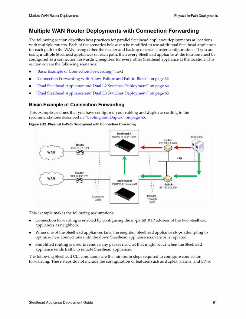
Multiple WAN Router Deployments Physical In-Path Deployments
Multiple WAN Router Deployments with Connection Forwarding
The following section describes best practices for parallel Steelhead appliance deployments at locations with multiple routers. Each of the scenarios below can be modified to use additional Steelhead appliances for each path to the WAN, using either the master and backup or serial cluster configurations. If you are using multiple Steelhead appliances on each path, then every Steelhead appliance at the location must be configured as a connection forwarding neighbor for every other Steelhead appliance at the location. This section covers the following scenarios:
“Basic Example of Connection Forwarding,” next
“Connection Forwarding with Allow-Failure and Fail-to-Block” on page 62
“Dual Steelhead Appliance and Dual L2 Switches Deployment” on page 64
“Dual Steelhead Appliance and Dual L3 Switches Deployment” on page 65
Basic Example of Connection Forwarding
This example assumes that you have configured your cabling and duplex according to the recommendations described in “Cabling and Duplex” on page 45.
Figure 2-12. Physical In-Path Deployment with Connection Forwarding
This example makes the following assumptions:
Connection forwarding is enabled by configuring the in-path0_0 IP address of the two Steelhead appliances as neighbors.
When one of the Steelhead appliances fails, the neighbor Steelhead appliance stops attempting to optimize new connections until the down Steelhead appliance recovers or is replaced.
Simplified routing is used to remove any packet ricochet that might occur when the Steelhead appliance sends traffic to remote Steelhead appliances.
The following Steelhead CLI commands are the minimum steps required to configure connection forwarding. These steps do not include the configuration of features such as duplex, alarms, and DNS.
Steelhead Appliance Deployment Guide 61
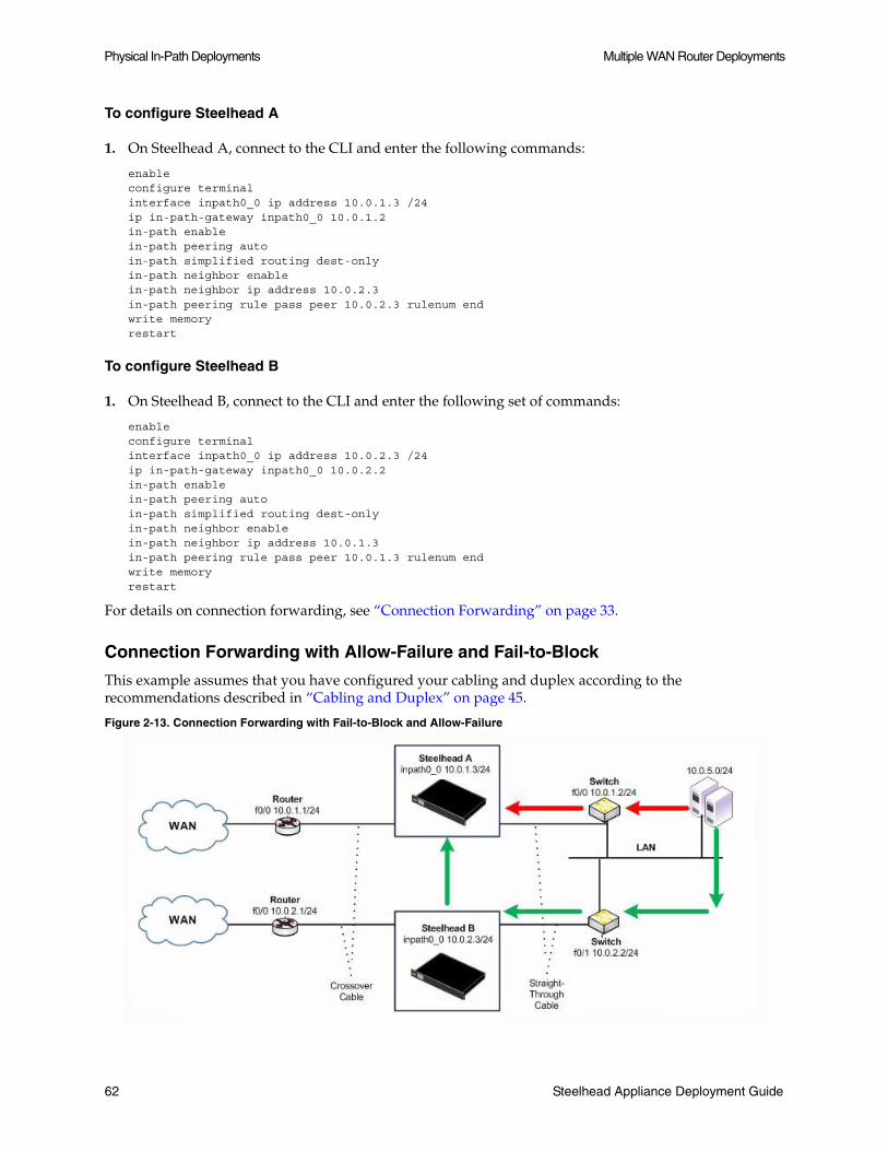
Physical In-Path Deployments Multiple WAN Router Deployments
To configure Steelhead A
1. On Steelhead A, connect to the CLI and enter the following commands:
enableconfigure terminalinterface inpath0_0 ip address 10.0.1.3 /24ip in-path-gateway inpath0_0 10.0.1.2in-path enablein-path peering autoin-path simplified routing dest-onlyin-path neighbor enable in-path neighbor ip address 10.0.2.3in-path peering rule pass peer 10.0.2.3 rulenum endwrite memoryrestart
To configure Steelhead B
1. On Steelhead B, connect to the CLI and enter the following set of commands:
enableconfigure terminalinterface inpath0_0 ip address 10.0.2.3 /24ip in-path-gateway inpath0_0 10.0.2.2in-path enablein-path peering autoin-path simplified routing dest-onlyin-path neighbor enable in-path neighbor ip address 10.0.1.3in-path peering rule pass peer 10.0.1.3 rulenum endwrite memoryrestart
For details on connection forwarding, see “Connection Forwarding” on page 33.
Connection Forwarding with Allow-Failure and Fail-to-Block
This example assumes that you have configured your cabling and duplex according to the recommendations described in “Cabling and Duplex” on page 45.
Figure 2-13. Connection Forwarding with Fail-to-Block and Allow-Failure
62 Steelhead Appliance Deployment Guide

Multiple WAN Router Deployments Physical In-Path Deployments
The following example represents the minimum steps required to configure a Steelhead appliance deployment in which connection forwarding is configured, and both fail-to-block and allow-failure are enabled. This example does not include configurations of features such as the management interface, DNS, and SNMP.
This example makes the following assumptions:
Connection forwarding is enabled by configuring the in-path0_0 IP address of the two Steelhead appliances as neighbors.
Fail-to-block option is enabled. (This is not supported with all in-path hardware and Steelhead appliance models.)
The allow-failure CLI command is enabled. This specifies that a Steelhead B continues to optimize new connections, if Steelhead appliance A down.
Simplified routing is used to remove any packet ricochet that might occur when the Steelhead appliance sends traffic to remote Steelhead appliances.
The following Steelhead CLI commands are the minimum steps required to configure connection forwarding. These steps do not include the configuration of features such as duplex, alarms, and DNS.
To configure Steelhead A
1. On Steelhead A, connect to the CLI and enter the following commands:
enableconfigure terminalinterface inpath0_0 ip address 10.0.1.3 /24ip in-path-gateway inpath0_0 10.0.1.2in-path enablein-path simplified routing dest-onlyin-path neighbor enable in-path neighbor ip address 10.0.2.3in-path neighbor allow-failurein-path peering autoin-path peering rule pass peer 10.0.2.3 rulenum endno interface inpath0_0 fail-to-bypass enablewrite memoryrestart
To configure Steelhead B
1. On Steelhead B, connect to the CLI and enter the following commands:
enableconfigure terminalinterface inpath0_0 ip address 10.0.2.3 /24ip in-path-gateway inpath0_0 10.0.2.2in-path enablein-path simplified routing dest-onlyin-path neighbor enable in-path neighbor ip address 10.0.1.3in-path neighbor allow-failurein-path peering autoin-path peering rule pass peer 10.0.1.3 rulenum endno interface inpath0_0 fail-to-bypass enablewrite memoryrestart
For details on connection forwarding, see “Connection Forwarding” on page 33.
Steelhead Appliance Deployment Guide 63

Physical In-Path Deployments Multiple WAN Router Deployments
Dual Steelhead Appliance and Dual L2 Switches Deployment
Figure 2-14 shows a topology where there are two routers, two L2 switches, and two Steelhead appliances at the remote location. The client and the Steelhead appliances are all in the same subnet. The client uses the HSRP virtual IP as its default gateway (10.0.0.1).
In this environment, the in-path gateway on both Steelhead appliances must point to the HSRP virtual IP (10.0.0.1). You do not need to enable simplified routing as the client is on the same subnet as the Steelhead appliance. You must configure connection forwarding between the two Steelhead appliances. The connection forwarding path must use the LAN interface of the Steelhead appliances.
Figure 2-14. Dual Steelhead Appliances, Dual L2 Switches, Dual Router Deployment
64 Steelhead Appliance Deployment Guide

802.1q Trunk Deployments Physical In-Path Deployments
Dual Steelhead Appliance and Dual L3 Switches Deployment
Figure 2-15 shows a topology where there are two routers, two L3 switches, and two Steelhead appliances at the remote location. The clients and the Steelhead appliances are in different subnets. The clients are using the L3 switch as its default gateway. The L3 switch does not having any routing protocols configured and is relying on the default route to reach other subnets. The default route uses the HSRP IP address as the next-hop.
In this environment, the in-path gateway on both Steelhead appliances must use the HSRP address of the L3 switches as its default gateway (10.0.0.254) while configuring simplified routing to populate its table based on destination MAC address (CLI command: in-path simplified routing dest-only). You must configure connection forwarding between the two Steelhead appliances. The connection forwarding path must use the LAN interface of the Steelhead appliances.
Figure 2-15. Dual Steelhead Appliances, Dual L3 Switches, Static Routing, Dual Router Deployment
802.1q Trunk Deployments
This section describes the use of Virtual LAN's (VLANs) and 802.1q, which allows multiple logical networks to span a single physical link. IEEE 802.1q is a networking standard that allows multiple bridged networks to transparently share the same physical network. IEEE 802.1Q is also known as VLAN Tagging, and dot1q. It includes the following sections:
“VLAN Trunk Overview,” next
Steelhead Appliance Deployment Guide 65

Physical In-Path Deployments 802.1q Trunk Deployments
“Configuration Example” on page 67
“Using tcpdump” on page 68
Note: The Steelhead appliance does not support overlapping IP address spaces even if the overlapping IPs are kept separate via VLAN tags. For details on alternative configurations, see “NSV Deployments” on page 273.
VLAN Trunk Overview
A Steelhead appliance can be deployed physically in-path on an 802.1q trunk links, and can optimize connections where packets have been tagged with an 802.1q header. As in other physical in-path deployments, the Steelhead appliances in-path interface must be configured with an IP address and a default gateway. If the Steelhead appliances in-path IP address is in a subnet whose traffic is normally tagged when present on the in-path link, the Steelhead appliance's in-path interface must be configured with the VLAN for that subnet. This allows the Steelhead appliance to appropriately tag packets transmitted from the in-path interface that use the in-path IP address as the source address. The Steelhead appliance can optimize traffic on the VLAN's different from the VLAN containing the in-path IP address.
Steelhead appliances can be deployed across multiple 802.1q trunk links. Each in-path interface requires an IP address, default gateway; and, if required for the in-path IP address subnet, a VLAN ID. Steelhead appliances configured as connection forwarding neighbors might also be deployed on 802.1q trunk links.
Steelhead appliances maintain the VLAN ID when transmitting packets for the LAN-side of optimized connections. When using the full address transparency WAN visibility mode, Steelhead appliances maintain the VLAN ID (along with IP address and TCP ports) when transmitting packets on the WAN-side of optimized connections. The Steelhead appliance can maintain the VLAN IDs even if there is a difference between the packets going to the WAN and those returning from the WAN. There is no requirement that the VLAN ID configured on the in-path interface match any of those seen for optimized connections.
For example, assume that the SYN packet for a TCP connection traveling towards the WAN has a VLAN ID of 100, and the SYN/ACK packet returning from the WAN has a VLAN of 200. If a Steelhead appliance were optimizing this connection, then the Steelhead appliance transmits packets towards the LAN using VLAN ID 200. If full address transparency is used for the connection, then the Steelhead appliance transmits packets towards the WAN using VLAN ID 100. If correct addressing or port transparency is used, the Steelhead appliance uses the configured in-path VLAN ID when transmitting packets towards the WAN.
Maintaining the VLAN IDs in this manner requires using the vlan-conn-based CLI command, which is enabled by default in RiOS 6.0 and later factory installs, as well as the other commands listed in the configuration example below (for details, see “Configuration Example,” next).
Both the in-path and peering rules can use VLAN tags as matching parameters. This allows an administrator to control optimization based on VLAN tags, along with other information such as IP addresses, subnets, or TCP ports.
66 Steelhead Appliance Deployment Guide

802.1q Trunk Deployments Physical In-Path Deployments
Configuration Example
Figure Figure 2-16 shows a Steelhead appliance deployed physically in-path on an 802.1q trunk link. Two VLANS are present on the in-path link: VLAN 10 that contains subnet 192.168.10.0/24, and VLAN 20, that contains subnet 192.168.20.0/24. The Steelhead appliance is given an in-path IP address in the 192.168.10.0/24 subnet. It is configured to use VLAN 10 for its in-path interface, and to use the routers sub interface IP address as its default gateway. Even though the Steelhead appliance has an in-path IP address in subnet 192.168.10.0/24 and VLAN 10, it can optimize traffic in VLAN 20.
Figure 2-16. Steelhead Appliance Deployed in Physical In-Path on an 802.1q Trunk Link
To deploy a Steelhead appliance physically in-path on an 802.1q trunk link, enter the following CLI commands:
#--- Enable and configure the in-path Interfacein-path enableinterface inpath0_0 ip address 192.168.10.2 /24#--- Set the default gateway for the inpath0_0 interface to be the WAN#--- side router VLAN 10 interfaceip in-path-gateway inpath0_0 192.168.10.1#--- Assign VLAN 10 to the inpath0_0 interfacein-path interface inpath0_0 vlan 10#--- Enable Simplified Routing All. (Simplified Routing destination only is on#--- by default with new 6.x RiOS installs)in-path simplified routing all
#--- New factory installs of RiOS 6.0.1 and greater will have all of the following#--- configuration parameters set already. If you have upgraded a Steelhead to that#--- level or more recent, you will need to apply some or all of the following.
#--- Enable Enhanced Auto Discoveryin-path peering auto#--- Ensure the Steelhead performs autodiscovery probing for the FTP and MAPI data channels. in-path probe-ftp-datain-path probe-mapi-data#--- Allow static routes to take precedence over Simplified Routingin-path simplified mac-def-gw-only#--- Ensure Steelhead transmits to LAN hosts with the same vlan tags as receivedin-path mac-match-vlanin-path vlan-conn-based#--- Ensure autodiscovery probing happens whenever possible, to learn vlan to IP mappings.no in-path peer-probe-cach no in-path probe-caching enable #--- Ensure interoperability with remote Steelheads whose inpath address is #--- in the same subnet or vlanin-path mac-except-locl
Steelhead Appliance Deployment Guide 67

Physical In-Path Deployments L2 WAN Deployments
Using tcpdump
Use caution when taking network traces on trunk links. If you configure a tcp dump filter that restricts the captured packets to a specified set (for example, based on IP addresses, or ports), by default tcpdump does not capture packets with an 802.1Q tag.
To capture packets with an 802.1Q tag, you must prefix the filter string with the keyword vlan. Enter the following CLI command:
tcpdump -i wanX_Y vlan and host
For details, see the Riverbed Command-Line Interface Reference Manual.
L2 WAN Deployments
On an L2 WAN, Riverbed recommends setting the LAN router closest to the Steelhead appliance as its in-path default gateway. For example, in Figure 2-17, Steelhead appliance A must use 192.168.255.1 as its in-path default gateway and Steelhead appliance B must use 192.168.255.2 as its in-path default gateway.
Figure 2-17. Steelhead Appliances Deployed in an L2 WAN
If the links to the WAN carry 802.1q tagged packets, and if the WAN service provider routes packets based on 802.1q tags, it is necessary to configure the Steelhead appliances for 802.1q deployment, and to use the full address transparency mode (for details, see “Full Address Transparency” on page 231).
68 Steelhead Appliance Deployment Guide

L2 WAN Deployments Physical In-Path Deployments
Broadcast L2 WANs
An L2 Broadcast network over the WAN is very similar to an L2 WAN. However, an L2 Broadcast WAN behaves like a hub whereby packets from each site are replicated over the WAN to all the other sites. For example, in Figure 2-18, Router 2 can see traffic between 172.30.2.1 and 10.10.2.1.
Figure 2-18. An L2 Broadcast WAN Deployment
When deploying Steelhead appliances in an L2 Broadcast WAN, you must ensure that the correct Steelhead appliance is handling the traffic. Furthermore, an L2 Broadcast WAN is not compatible with simplified routing and therefore you must use static routes to avoid packet ricochet.
In Figure 2-18, when 172.30.2.1 sends a SYN packet towards 10.10.2.1, Steelhead appliance A adds its probe option to the SYN packet (SYN+). The correct Steelhead appliance that responds to this packet is Steelhead appliance B as it is closest to the 10.10.2.1 server. However, because of the L2 Broadcast WAN, Steelhead appliance C would also see the SYN+ packet and respond to Steelhead appliance A. This behavior creates two probe-responses (SYN/ACK+) from two separate Steelhead appliances.
If the latency between Steelhead appliance A and Steelhead appliance C is lower than that of Steelhead appliance A and Steelhead appliance B, then Steelhead appliance A receives the probe response from Steelhead appliance C first. When the probe response Steelhead appliance B arrives at Steelhead appliance A, Steelhead appliance A ignores the probe response as it has already received a probe response from Steelhead appliance C.
This is clearly an undesirable situation as Steelhead appliance A must be peering with Steelhead appliance B and not Steelhead appliance C when trying to reach the 10.10.2.1 server. To avoid this situation enter the following CLI command:
in-path broadcast support enable
When broadcast support is enabled, the Steelhead appliance checks its routing table to see whether it uses its LAN or WAN interface to reach the destination IP. If the destination IP is reachable through the LAN, it sends a probe response back to the sender. Otherwise, it simply ignores the probe request.
Alternatively, it is possible to use fixed-target rules to define the Steelhead appliance peers. However, fixed-target rules might not be scalable for larger deployments.
Steelhead Appliance Deployment Guide 69

Physical In-Path Deployments L2 WAN Deployments
70 Steelhead Appliance Deployment Guide

CHAPTER 3 Virtual In-Path Deployments
This chapter describes virtual in-path deployments and summarizes the basic steps for configuring an in-path, load balanced, Layer-4 switch deployment. It includes the following sections:
“Overview of Virtual In-Path Deployments,” next
“Configuring an In-Path, Load Balanced, Layer-4 Switch Deployment” on page 72
“Configuring Flow Data Exports in Virtual In-Path Deployments” on page 74
This chapter provides the basic steps for configuring one type of virtual in-path deployment. It does not provide detailed procedures for all virtual in-path deployments. Use this chapter as a general guide to virtual in-path deployments.
For details on the factors you must consider before you design and deploy the Steelhead appliance in a network environment, see “Choosing the Right Steelhead Appliance” on page 19.
Overview of Virtual In-Path Deployments
In a virtual in-path deployment, the Steelhead appliance is virtually in the path between clients and servers. Traffic moves in and out of the same WAN interface, and the LAN interface is not used. This deployment differs from a physical in-path deployment in that a packet redirection mechanism is used to direct packets to Steelhead appliances that are not in the physical path of the client or server.
Figure 3-1. Virtual In-Path Deployment on the Server-Side of the Network
Steelhead Appliance Deployment Guide 71

Virtual In-Path Deployments Configuring an In-Path, Load Balanced, Layer-4 Switch Deployment
Redirection mechanisms include:
Layer-4 Switch - You enable Layer-4 switch (or server load-balancer) support when you have multiple Steelhead appliances in your network to manage large bandwidth requirements. For details, see “Configuring an In-Path, Load Balanced, Layer-4 Switch Deployment,” next.
Hybrid - A hybrid deployment is a deployment in which the Steelhead appliance is deployed either in a physical or virtual in-path mode, and has out-of-path mode enabled. A hybrid deployment is useful where the Steelhead appliance must be referenced from remote sites as an out-of-path device (for example, to bypass intermediary Steelhead appliances). For details, see Chapter 4, “Out-of-Path Deployments.”
PBR - PBR enables you to redirect traffic to a Steelhead appliance that is configured as a virtual in-path device. PBR allows you to define policies that override routing behavior. For example, instead of routing a packet based on routing table information, it is routed based on the policy applied to the router. You define policies to redirect traffic to the Steelhead appliance and policies to avoid loop-back. For details, see Chapter 7, “Policy-Based Routing Deployments.”
WCCP - WCCP was originally implemented on Cisco routers, multi-layer switches, and Web caches to redirect HTTP requests to local Web caches (Version 1). Version 2, which is supported on Steelhead appliances, can redirect any type of connection from multiple routers to multiple Web caches. For example, if you have multiple routers or if there is no in-path place for the Steelhead appliance, you can place the Steelhead appliance in a virtual in-path mode through the router so that they work together. For details, see Chapter 5, “WCCP Deployments.”
Interceptor Appliance - The Interceptor appliance is a load balancer specifically used to distribute optimized traffic to a local cluster of Steelhead appliances. The Interceptor is Steelhead appliance-aware, and so offers several benefits over other clustering techniques like WCCP and PBR. The Interceptor appliance is dedicated to redirecting packets for optimized connections to Steelhead appliances, but does not perform optimization itself. As a result, the Interceptor appliance can be used in extremely demanding network environments with extremely high throughput requirements. For details on the Interceptor appliance, see Interceptor Appliance User’s Guide and the Interceptor Appliance Deployment Guide.
Configuring an In-Path, Load Balanced, Layer-4 Switch Deployment
An in-path, load balanced, Layer-4 switch deployment serves high traffic environments or environments with large numbers of active TCP connections. It handles failures, scales easily, and supports all protocols.
When you configure the Steelhead appliance using a Layer-4 switch, you define the Steelhead appliances as a pool where the Layer-4 switch redirects client and server traffic. Only one WAN interface on the Steelhead appliance is connected to the Layer-4 switch, and the Steelhead appliance is configured to send and receive data through that interface.
72 Steelhead Appliance Deployment Guide

Configuring an In-Path, Load Balanced, Layer-4 Switch Deployment Virtual In-Path Deployments
The following figure shows the server-side of the network where load balancing is required.
Figure 3-2. In-Path, Load-Balanced, Layer-4 Switch Deployment
Basic Steps (Client-Side)
Configure the client-side Steelhead appliance as an in-path device. For details, see the Steelhead Appliance Installation and Configuration Guide.
Basic Steps (Server-Side)
Perform the following steps for each Steelhead appliance in the cluster.
1. Install and power on the Steelhead appliance. For details, see the Steelhead Appliance Installation and Configuration Guide.
2. Connect to the Steelhead appliance. For details, see the Steelhead Appliance Installation and Configuration Guide. Make sure you properly connect to the Layer-2 switch. For example:
On Steelhead A, plug the straight-through cable into the Primary port of the Steelhead appliance and connect it to the LAN-side switch.
On Steelhead B, plug the straight-through cable into the Primary port of the Steelhead appliance and connect it to the LAN-side switch.
3. Configure the Steelhead appliance in an in-path configuration. For details, see the Steelhead Management Console User’s Guide.
4. Connect the Layer-4 switch to the Steelhead appliance:
On Steelhead A, plug the straight-through cable into the WAN port of the Steelhead appliance and the Layer-4 switch.
On Steelhead B, plug the straight-through cable into the WAN port of the Steelhead appliance and the Layer-4 switch.
5. Connect to the Management Console. For details, see the Steelhead Management Console User’s Guide.
Steelhead Appliance Deployment Guide 73

Virtual In-Path Deployments Configuring Flow Data Exports in Virtual In-Path Deployments
6. Go to the Configure > Optimization > General Service Settings page and enable Layer-4 switch support. For example, click Enable In-Path Support and Enable L4/PBR/WCCP Support.
7. Apply and save the new configuration in the Management Console.
8. Configure your Layer-4 switch. For details, refer to your switch documentation.
9. Go to the Configure > Maintenance > Services page and restart the optimization service.
10. View performance reports and system logs.
Configuring Flow Data Exports in Virtual In-Path Deployments
The Steelhead appliance supports the export of data flows to any compatible flow data collector. During data flow export, the flow data fields provide information such as the interface index that corresponds to the input and output traffic. An administrator can use the interface index to determine how much traffic is flowing from the LAN to the WAN and from the WAN to the LAN.
In virtual in-path deployments, such as the server-side of the network shown in Figure n on page 72, traffic moves in and out of the same WAN interface; the LAN interface is not used. As a result, when the Steelhead appliance exports data to a flow data collector, all traffic has the WAN interface index. Though it is technically correct for all traffic to have the WAN interface index because the input and output interfaces are the same, this makes it impossible for an administrator to use the interface index to distinguish between LAN-to-WAN and WAN-to-LAN traffic.
You can work around this issue by using the CLI to turn on the Steelhead appliance fake index feature, which inserts the correct interface index before exporting data to a flow data collector. The fake index feature works only for optimized traffic, not unoptimized or passed through traffic.
This feature can be configured only using the CLI.
Note: Subnet side rules are necessary for correct unoptimized or passed through traffic reporting. For details, see the Steelhead Management Console User’s Guide.
To configure the fake index feature
1. Connect to the Steelhead CLI.
2. Configure the Steelhead appliance to capture optimized LAN traffic on the WAN0_0 interface. For example, at the system prompt enter the following command:
ip flow-export destination 192.168.8.4 2055 interface wan0_0 capture optimized-lan
3. Turn on the fake index feature on the Steelhead appliance. For example:
ip flow-export destination 192.168.8.4 2055 interface wan0_0 fakeindex on
For details on exporting flow data, see “Exporting Flow Data Overview” on page 271.
74 Steelhead Appliance Deployment Guide

CHAPTER 4 Out-of-Path Deployments
This chapter describes out-of-path deployments and summarizes the basic steps for configuring them. It includes the following sections:
“Overview of Out-of-Path Deployments,” next
“Out-of-Path Deployment Example” on page 77
For details on the factors you must consider before you design and deploy the Steelhead appliance in a network environment, see “Choosing the Right Steelhead Appliance” on page 19.
Note: Riverbed refers to WCCP and PBR deployments as virtual in-path deployments. This chapter discusses out-of-path deployments, which do not include WCCP or PBR deployments.
This chapter assumes you are familiar with the installation and configuration process for the Steelhead appliance. For details, see the Steelhead Appliance Installation and Configuration Guide.
This chapter provides the basic steps for out-of-path network deployments. It does not provide detailed procedures. Use this chapter as a general guide to these deployments.
Overview of Out-of-Path Deployments
In an out-of-path deployment, only a Steelhead appliance primary interface is required to connect to the network. The Steelhead appliance can be connected anywhere in the LAN. There is no redirecting device in an out-of-path Steelhead appliance deployment. You configure fixed-target in-path rules for the client-side Steelhead appliance. The fixed-target in-path rules point to the primary IP address of the out-of-path Steelhead appliance. The out-of-path Steelhead appliance uses its primary IP address when communicating to the server. The remote Steelhead appliance must be deployed either in a physical or virtual in-path mode.
Figure 4-1 shows an out-of-path deployment.
You can achieve redundancy by deploying two Steelhead appliances out-of-path at one location, and by using both of their primary IP addresses in the remote Steelhead appliance fixed-target rule. The fixed-target rule allows the specification of a primary and a backup Steelhead appliance. If the primary Steelhead appliance becomes unreachable, the remote Steelhead appliances use the backup Steelhead appliance until the primary comes back online. If both out-of-path Steelhead appliances in a specific fixed-target rule are unavailable, the remote Steelhead appliance passes through this traffic unoptimized. The remote Steelhead appliance does not look for another matching in-path rule in the list.
Steelhead Appliance Deployment Guide 75

Out-of-Path Deployments Overview of Out-of-Path Deployments
You can use datastore synchronization between the out-of-path Steelhead appliances for additional benefits in case of a failure. For details, see “Datastore Synchronization” on page 32.
You can also implement load balancing with out-of-path deployments by using multiple out-of-path Steelhead appliances, and configuring different remote Steelhead appliances to use different target out-of-path Steelhead appliances.
You can target an out-of-path Steelhead appliance for a fixed-target rule. This can be done simultaneously for physical in-path, and virtual in-path deployments. This is referred to as a hybrid deployment.
For details on fixed-target in-path rules, see “Fixed-Target In-Path Rules” on page 29.
Limitations of Out-of-Path Deployments
While the ease of deploying an out-of-path Steelhead appliance might seem appealing, there are serious disadvantages to this method:
Connections initiated from the site with the out-of-path Steelhead appliance cannot be optimized.
Servers at the site see the optimized traffic coming not from a client IP address, but from the out-of-path Steelhead appliance primary IP address.
In certain network environments, a change in the source IP address can be problematic. For some commonly used protocols, Steelhead appliances automatically make protocol-specific adjustments to account for the IP address change. For example, with CIFS, MAPI, and FTP, there are various places where the IP address of the connecting client can be used within the protocol itself. Because the Steelhead appliance uses application-aware optimization for these protocols, it is able to make the appropriate changes within optimized connections and ensure correct functioning when used in out-of-path deployments. However, there are protocols, such as NFS, that cannot function appropriately when optimizing in an out-of-path configuration.
Important: If you use out-of-path deployments, ensure correct operation by carefully selecting which applications you optimize. Even with protocols where RiOS specifically adjusts for the change in source IP address on the LAN, there might be authentication, IDS, or IPS systems that generate alarms when this change occurs.
Because of the disadvantages specific to out-of-path deployments, and the requirement of using fixed-target rules, out-of-path deployment is not as widely used as physical or virtual in-path deployments. Out-of-path is primarily used as a way to rapidly deploy a Steelhead appliance in a site with very complex or numerous connections to the WAN.
76 Steelhead Appliance Deployment Guide

Out-of-Path Deployment Example Out-of-Path Deployments
Out-of-Path Deployment Example
The following figure shows a scenario where fixed-target in-path rules are configured for an out-of-path Steelhead appliance primary interface.
Figure 4-1. A Fixed-Target In-Path Rule to an Out-of-Path Steelhead Appliance Primary IP Address
In this example, you configure:
Steelhead A with a fixed-target in-path rule specifying that traffic destined to a particular Web server at the data center is optimized by the out-of-path Steelhead B.
The TCP connection between the out-of-path Steelhead appliance, Steelhead B, and the server uses the Steelhead appliance primary IP address as the source, instead of the client IP address.
To configure Steelhead A
1. On Steelhead A, connect to the CLI and enter the following commands:
enableconfigure terminalin-path rule fixed-target target-addr 12.3.0.5 dstaddr 192.168.50.0/24 dstport 80 rulenum end
To configure Steelhead B
1. On Steelhead B, connect to the CLI and enter the following commands:
enableconfigure terminalout-of-path enable
Steelhead Appliance Deployment Guide 77

Out-of-Path Deployments Out-of-Path Deployment Example
78 Steelhead Appliance Deployment Guide

CHAPTER 5 WCCP Deployments
This chapter describes how to configure WCCP to redirect traffic to one or more Steelhead appliances. It includes the following sections:
“Overview of WCCP,” next
“Configuring WCCP” on page 86
“Configuring Additional WCCP Features” on page 98
“Verifying and Troubleshooting WCCP Configurations” on page 106
This chapter provides basic information about WCCP network deployments, and examples for configuring WCCP deployments. Use this chapter as a general guide to WCCP deployments.
For details on the factors you must consider before you design and deploy the Steelhead appliance in a network environment, see “Choosing the Right Steelhead Appliance” on page 19.
For details on WCCP, see the Cisco documentation Web site at http://www.cisco.com/univercd/home/home.htm.
Overview of WCCP
This section provides an overview of WCCP. It includes the following sections:
“Cisco Hardware and IOS Requirements,” next
“The Advantages and Disadvantages of WCCP” on page 80
“WCCP Fundamentals” on page 81
WCCP Version 1 was originally implemented on Cisco routers, multi-layer switches, and Web caches to redirect HTTP requests to local Web caches.
WCCP Version 2, which Steelhead appliances support, can redirect any type of connection from multiple routers to multiple Web caches. Steelhead appliances deployed with WCCP can interoperate with remote Steelhead appliances deployed in any way, such as WCCP, PBR, in-path, and out-of-path.
Steelhead Appliance Deployment Guide 79

WCCP Deployments Overview of WCCP
Cisco Hardware and IOS Requirements
WCCP requires either a Cisco router or a switch.
The most important factors in a successful WCCP implementation are the Cisco hardware platform and the IOS revision you use. There are many possible combinations of Cisco hardware and IOS revisions, and each combination has different capabilities.
Cisco platforms and IOS do not support all assignment methods, redirection methods, use of ACLs to control traffic, and interface interception directions. You can expect the Cisco minimum recommended IOS to change as WCCP becomes more widely used, and new IOS technical issues are discovered.
Cisco recommends the following minimum IOS releases for specific hardware platforms:
Important: Regardless of how you configure a Steelhead appliance, if the Cisco IOS version on the router or switch is below the current Cisco minimum recommendations, it might be impossible to have a functioning WCCP implementation or the implementation might not have optimal performance.
The Advantages and Disadvantages of WCCP
Physical in-path deployments require less initial and ongoing configuration and maintenance than out-of-path or virtual in-path deployments. This is because physical in-path Steelhead appliances are placed at the points in your network where data already flows. Thus, with in-path deployments you do not need to alter your existing network infrastructure.
For details on physical in-path deployments, see “Physical In-Path Deployments” on page 39.
Virtual in-path techniques, such as WCCP, require more time to configure because the network infrastructure must be configured to redirect traffic to the Steelhead appliances.
WCCP has several advantages:
No rewiring required - You do not need to move any wires during installation. At large sites with multiple active links, you can adjust wiring by moving individual links, one at a time, through the Steelhead appliances.
An option when no other is available - At sites where a physical in-path deployment is not possible, WCCP might achieve the integration you need. For example, if your site has a WAN link terminating directly into a large access switch, there is no place to install a physical in-path Steelhead appliance.
Cisco Hardware Cisco IOS
ASR 1000 2.2XE
ISR and 7200 Routers 12.1(14), 12.2(26), 12.3(13), 12.4(10), 12.1(3)T, 12.2(14)T, 12.3(14)T5, 12.4(15)T8
Catalyst 6500 with Sup720 or Sup32 12.2(18)SXF14, 12.2(33)SXH4
Catalyst 6500 with Sup2 12.1(27b)E, 12.2(18)SXF13
Catalyst 4500 12.2(31)SG
Catalyst 3750 12.2(46)SE
80 Steelhead Appliance Deployment Guide

Overview of WCCP WCCP Deployments
WCCP has several disadvantages:
Network design changes required -WCCP deployments with multiple routers can require significant network changes (for example, spanning VLANs and GRE tunnels).
Hardware and IOS upgrades required - To avoid hardware limitations and IOS issues, you must keep the Cisco platform and IOS revisions at the current minimum recommended levels. Otherwise, it might be impossible to create a stable deployment, regardless of how you configure the Steelhead appliance. For future IOS feature planning you must consider compatibility with WCCP.
Additional evaluation overhead - More time can be required to evaluate the integration of the Steelhead appliances. This is in addition to evaluating Steelhead appliance performance gains. Riverbed Professional Services might be needed to test and perform network infrastructure upgrades before any optimization can be performed. This is especially true when WCCP is deployed at numerous sites.
Additional configuration management - You must create access lists and manage them on an ongoing basis. At small sites, it might be feasible to redirect all traffic to the Steelhead appliances. However, at larger sites, access lists might be required to ensure that traffic that cannot be optimized (for example, LAN-to-LAN traffic) is not sent to the Steelhead appliances.
GRE encapsulation - If your network design does not support the presence of the Steelhead appliances and the Cisco router or switch interface in a common subnet, you must use GRE encapsulation for forwarding packets. Steelhead appliances can accommodate the subsequent extra performance utilization, but your existing router or switch might experience large resource utilization.
WCCP Fundamentals
This section describes some of the fundamental concepts for configuring WCCP. It includes the following sections:
“Service Groups,” next
“Assignment Methods” on page 82
“Redirection and Return Methods” on page 84
Service Groups
A central concept of WCCP is the service group. The service group logically consists of the routers and the Steelhead appliances that work together to redirect and optimize traffic. You might use one or more service groups to redirect traffic to the Steelhead appliances for optimization.
Service groups are differentiated by a service group number. The service group number is local to the site where WCCP is used. The service group number is not transmitted across the WAN.
When a router participates in a WCCP service group, it is configured to monitor traffic passing through a user-defined set of interfaces. When a router receives traffic of interest, it redirects the IP packets to be transmitted to a designated interface in another system in the WCCP service group.
Note: Riverbed recommends that you use WCCP service groups 61 and 62.
Routers redirect traffic to the Steelhead appliances in their WCCP service group. The assignment method and the load balancing configuration determine which Steelhead appliance the router redirects traffic to.
Steelhead Appliance Deployment Guide 81

WCCP Deployments Overview of WCCP
Assignment Methods
This section describes WCCP assignment methods. It includes the following sections:
“Hash Assignment,” next
“Mask Assignment with RiOS v5.0.1 or Earlier” on page 82
“Mask Assignment with RiOS v5.0.2 or Later” on page 83
“Determining an Assignment Method” on page 84
Routers participating in WCCP support two assignment methods. The assignment method affects how a router redirects traffic when multiple target systems are specified in a service group. Assignment methods are important when two or more Steelhead appliances are deployed at the same site for high availability or load balancing. The assignment methods are as follows:
Hash assignment - Uses the CPU switch to calculate part of the load distribution, placing a significant load on the switch CPU.
Mask assignment - Processes traffic entirely in hardware, so that the impact on the switch CPU is minimal. Mask assignment was specifically designed for hardware-based switches and routers.
Note: Do not confuse assignment methods with forwarding methods. Assignment methods determine how packets are distributed across multiple Steelhead appliances (through mask or hash), while forwarding methods determine how intercepted packets are forwarded from the router or switch to the Steelhead appliance (through GRE or Layer-2).
Hash Assignment
The hash assignment method redirects traffic based on a hashing scheme and the weight of the Steelhead appliances. A hashing scheme is a combination of the source IP address, destination IP address, source port, or destination port. The hash assignment method is commutative: a packet with a source IP address X, and a destination IP address Y, hashes to the same value as a packet with a source IP address Y, and a destination IP address X. (Thus, a single WCCP service group is usually sufficient to configure a WCCP cluster that uses the hash assignment method because the same Steelhead appliance sees both inbound and outbound traffic for any given connection.)
The weight of a Steelhead appliance is determined by the number of connections the Steelhead appliance supports. The default weight is based on the Steelhead appliance model number. The more connections a Steelhead appliance model supports, the heavier the weight of that model. You can modify the default weight.
The hash assignment method supports failover and load balancing. In a failover configuration, you configure one or more Steelhead appliances to be used only if no other Steelhead appliances within the WCCP service group are operating. To configure a Steelhead appliance to be a failover appliance, you set the Steelhead appliance weight to 0.
If a Steelhead appliance has a weight of 0, and another Steelhead appliance in the same WCCP service group has a non-zero weight, the Steelhead appliance with the 0 weight does not receive redirected traffic. If all of the Steelhead appliances have a weight of 0, traffic is redirected equally among them.
Mask Assignment with RiOS v5.0.1 or Earlier
With RiOS v5.0.1 or earlier, a single Steelhead appliance receives redirected traffic when you use the mask assignment method. The other Steelhead appliances function as failover appliances. The Steelhead appliance that receives traffic is the Steelhead appliance with the lowest in-path IP address.
82 Steelhead Appliance Deployment Guide

Overview of WCCP WCCP Deployments
Unlike the hash assignment method, the mask assignment method processes the first packet for a connection in the router hardware.
To force mask redirection, you use the assign-scheme option for the wccp service-group CLI command. For example:
wccp service-group 61 routers 10.0.0.1 assign-scheme mask
Some Cisco platforms, such as the Catalyst 4500 and the Catalyst 3750, only support the mask assignment method.
Mask Assignment with RiOS v5.0.2 or Later
The mask assignment method in RiOS v5.0.2 or later supports load balancing across multiple active Steelhead appliances. As with the hash assignment method, each Steelhead appliance is configured with the appropriate service groups and router bindings.
Load balancing decisions (that is, deciding which Steelhead appliance in a cluster is to optimize a given new connection) are based on administrator-specified bits pulled, or masked, from the IP address and TCP port fields. Unlike the hash assignment method, these bits are not hashed. Instead, the Cisco switch concatenates the bits to construct an index into the load balancing table. Thus, you must carefully choose these bits. Mask assignment uses up to seven bits, which allows for a maximum of 128 buckets (2^7=128) for load balancing across Steelhead appliances in the same service group.
Unlike the hash assignment method, the mask assignment method is not commutative.
When you use the mask assignment method, you configure failover in the same manner as you do with the hash assignment method.
The mask assignment method requires that, for every connection, packets are redirected to the same Steelhead appliance in both directions (client-to-server and server-to-client). To achieve redirection you configure the following:
Because only one set of masks can be used per service group,Riverbed recommends you use two different service groups for outbound and inbound traffic (that is, service groups 61 and 62).
Configure the Cisco switch to redirect packets to a WCCP service group in the client-to-server direction, and to redirect packets to another WCCP group in the server-to-client direction. In most cases, service group 61 must be placed on the inbound interface closest to the client while service group 62 must be placed on the inbound interface closest to the server. For example:
wccp service-group 61 routers 10.0.0.1 assign-scheme mask src-ip-mask 0x1741wccp service-group 62 routers 10.0.0.1 assign-scheme mask dst-ip-mask 0x1741
The following figure shows the reversed mask redirection technique.
Figure 5-1. Mask Assignment Method Packet Redirection
Steelhead Appliance Deployment Guide 83

WCCP Deployments Overview of WCCP
For details on mask assignment method parameters, see “WCCP Service Group Parameters” on page 96.
Determining an Assignment Method
Unless otherwise specified in the Steelhead appliance WCCP service group setting, and if the router supports it, Steelhead appliances prefer the hash assignment method. The hash assignment method generally achieves better load distribution than the mask assignment method. There are instances when the mask assignment method is preferable:
Certain lower-end Cisco switches do not support hash assignment (3750, 4000, 4500-series, among others).
The hash assignment method uses a NetFlow table entry on the switch for every connection. The NetFlow table entry can support up to 256K connections, depending on the hardware. However, when the switch runs out of NetFlow table entries, every WCCP-redirected packet is process-switched, which has a crippling effect on the switch CPU and very large WCCP deployments are constrained to the mask assignment load distribution method.
The hash assignment method switches the first packet of every new redirected TCP connection. The switch CPU installs the NetFlow table entry that is used to hardware-switch subsequent packets for a given connection. This process limits the number of connection set ups a switch can perform per unit of time. Thus, in WCCP deployments where the connection set up rate is very high, the mask assignment method is the only option.
Redirection and Return Methods
WCCP supports two methods for transmitting packets between a router or switch and Steelhead appliances: the GRE encapsulation method, and the L2 method. Steelhead appliances support both the L2 and GRE encapsulation methods, in both directions, to and from the router or switch.
The L2 method is generally preferred from a performance standpoint because it requires fewer resources from the router or switch than the GRE encapsulation does. The L2 method modifies only the destination Ethernet address. However, not all combinations of Cisco hardware and IOS revisions support the L2 method. Also, the L2 method requires the absence of L3 hops between the router or switch and the Steelhead appliance.
The GRE encapsulation method appends a GRE header to a packet before it is forwarded. This can cause fragmentation and imposes a performance penalty on the router and switch, especially during the GRE packet de-encapsulation process. This performance penalty can be too great for production deployments.
If your deployment requires the use of GRE return, the Steelhead appliance can be configured to automatically change the Maximum Segment Size (MSS) for connections to port 1432. The command wccp adjust-mss enable must be enabled to avoid fragmentation due to the additional overhead of GRE encapsulation.
You can avoid using the GRE encapsulation method for the traffic return path from the Steelhead appliance by using the Steelhead appliance wccp override-return route-no-gre or wccp override-return sticky-no-gre CLI commands. The wccp override-return route-no-gre CLI command enables the Steelhead appliance to return traffic without GRE encapsulation to a Steelhead appliance in-path gateway, determined by the in-path routing table. The wccp override-return sticky-no-gre CLI command enables the Steelhead appliance to return traffic without GRE encapsulation to the router that forwarded the traffic. This occurs regardless of the method negotiated for returning traffic to the
84 Steelhead Appliance Deployment Guide
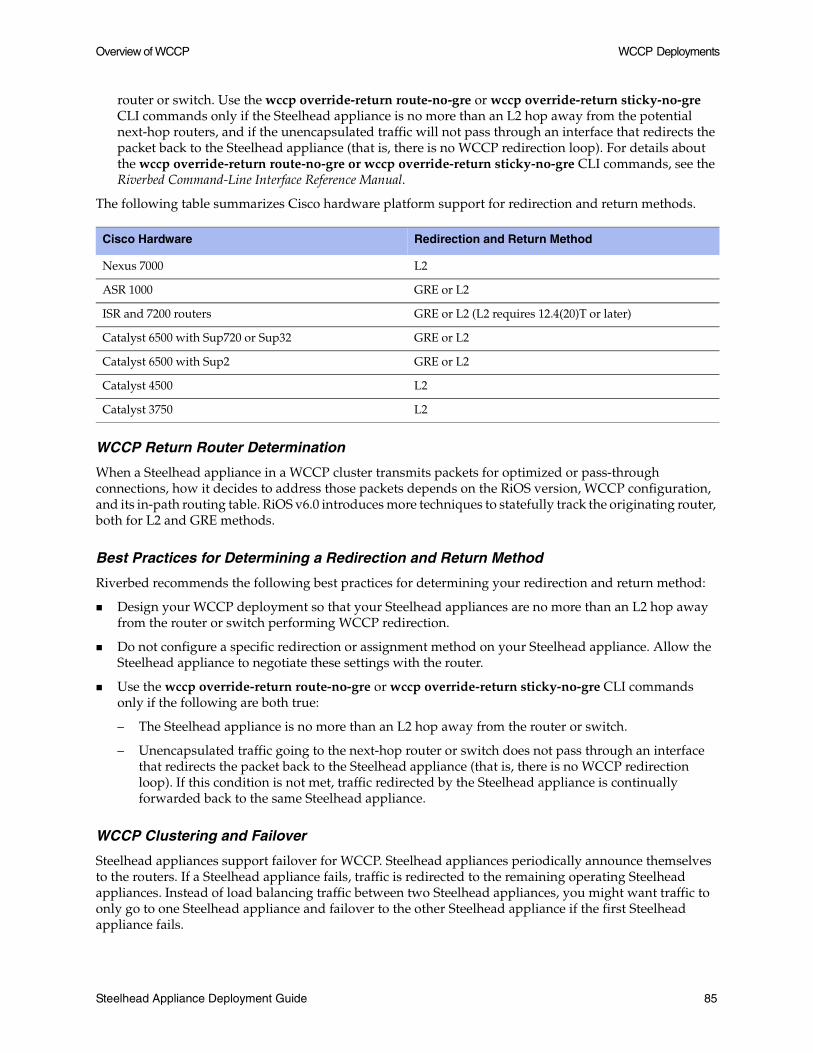
Overview of WCCP WCCP Deployments
router or switch. Use the wccp override-return route-no-gre or wccp override-return sticky-no-gre CLI commands only if the Steelhead appliance is no more than an L2 hop away from the potential next-hop routers, and if the unencapsulated traffic will not pass through an interface that redirects the packet back to the Steelhead appliance (that is, there is no WCCP redirection loop). For details about the wccp override-return route-no-gre or wccp override-return sticky-no-gre CLI commands, see the Riverbed Command-Line Interface Reference Manual.
The following table summarizes Cisco hardware platform support for redirection and return methods.
WCCP Return Router Determination
When a Steelhead appliance in a WCCP cluster transmits packets for optimized or pass-through connections, how it decides to address those packets depends on the RiOS version, WCCP configuration, and its in-path routing table. RiOS v6.0 introduces more techniques to statefully track the originating router, both for L2 and GRE methods.
Best Practices for Determining a Redirection and Return Method
Riverbed recommends the following best practices for determining your redirection and return method:
Design your WCCP deployment so that your Steelhead appliances are no more than an L2 hop away from the router or switch performing WCCP redirection.
Do not configure a specific redirection or assignment method on your Steelhead appliance. Allow the Steelhead appliance to negotiate these settings with the router.
Use the wccp override-return route-no-gre or wccp override-return sticky-no-gre CLI commands only if the following are both true:
– The Steelhead appliance is no more than an L2 hop away from the router or switch.
– Unencapsulated traffic going to the next-hop router or switch does not pass through an interface that redirects the packet back to the Steelhead appliance (that is, there is no WCCP redirection loop). If this condition is not met, traffic redirected by the Steelhead appliance is continually forwarded back to the same Steelhead appliance.
WCCP Clustering and Failover
Steelhead appliances support failover for WCCP. Steelhead appliances periodically announce themselves to the routers. If a Steelhead appliance fails, traffic is redirected to the remaining operating Steelhead appliances. Instead of load balancing traffic between two Steelhead appliances, you might want traffic to only go to one Steelhead appliance and failover to the other Steelhead appliance if the first Steelhead appliance fails.
Cisco Hardware Redirection and Return Method
Nexus 7000 L2
ASR 1000 GRE or L2
ISR and 7200 routers GRE or L2 (L2 requires 12.4(20)T or later)
Catalyst 6500 with Sup720 or Sup32 GRE or L2
Catalyst 6500 with Sup2 GRE or L2
Catalyst 4500 L2
Catalyst 3750 L2
Steelhead Appliance Deployment Guide 85

WCCP Deployments Configuring WCCP
To configure failover support, set the backup Steelhead appliance weight to 0.
Configuring WCCP
This section describes how to configure WCCP and provides example deployments. It includes the following sections:
“Basic Steps,” next
“Configuring a Simple WCCP Deployment” on page 87
“Configuring a WCCP High Availability Deployment” on page 89
“Basic WCCP Router Configuration Commands” on page 94
“Steelhead Appliance WCCP CLI Commands” on page 95
“WCCP Service Group Parameters” on page 96
Basic Steps
Perform the following basic steps to configure WCCP.
1. Configure the Steelhead appliance as an in-path device. For details, see “Physical In-Path Deployments” on page 39 and the Steelhead Appliance Installation and Configuration Guide.
2. Create a service group on the router and set the router to use WCCP to redirect traffic to the WCCP Steelhead appliance.
3. Attach the WCCP Steelhead appliance wan0_0 interface to the network. The wan0_0 interface must be able to communicate with the switch or router where WCCP is configured and where WCCP redirection takes place.
4. Configure the WCCP Steelhead appliance to be a virtual in-path device with WCCP support. For example, use the Steelhead appliance CLI command in-path oop enable.
5. Add the service group on the WCCP Steelhead appliance.
6. Enable WCCP on the WCCP Steelhead appliance.
86 Steelhead Appliance Deployment Guide

Configuring WCCP WCCP Deployments
Configuring a Simple WCCP Deployment
The following figure shows a WCCP deployment that is simple to deploy and administer, and achieves high performance. This example includes a single router and a single Steelhead appliance.
Figure 5-2. A Single Steelhead Appliance and A Single Router
In this example:
The router and the Steelhead appliance use WCCP service groups 61 and 62. In this example, as long as the Steelhead appliance is a member of all of the service groups, and the service groups include all of the interfaces on all of the paths to and from the WAN; it does not matter whether a single service group, or multiple service groups, are configured.
The Steelhead appliance wan0_0 interface is directly attached to the router with a crossover cable.
The Steelhead appliance virtual inpath0_0 interface uses the IP information that is visible to the router and the remote Steelhead appliances for data transfer.
The Steelhead appliance does not have an encapsulation scheme in the WCCP service group configuration. Therefore, the Steelhead appliance informs the router that it supports both the GRE and the L2 redirection methods. The method negotiated and used depends on the methods that the router supports.
The Steelhead appliance default gateway return override is enabled with the wccp override-return route-no-gre CLI command. Enabling this CLI command decreases the resource utilization on the router. In this example, this is possible because returning packets do not match any subsequent WCCP interface redirect statements. For details on the wccp override-return route-no-gre CLI command, see “Redirection and Return Methods” on page 84.
Note: If you are using RiOS v4.x or earlier, see the following Riverbed Knowledge Base article, What WCCP Redirect and Return Method Should I Use?, located at https://support.riverbed.com/kb/solution.htm?id=50150000000830H&categoryName=WCCP.
Steelhead Appliance Deployment Guide 87

WCCP Deployments Configuring WCCP
The router uses the ip wccp redirect exclude CLI command on the router interface connected to the Steelhead appliance wan0_0 interface. This CLI command configures the router to never redirect packets arriving on this interface, even if they are later sent out of an interface with an ip wccp redirect out command. Although this is not required for this deployment, Riverbed recommends you use it as a best practice.
Note: Although the primary interface is not included in this example, Riverbed recommends that you connect the primary interface for management purposes. For details about configuring the primary interface, see the Steelhead Management Console User’s Guide.
To configure WCCP on the Steelhead appliance
1. On the Steelhead appliance, connect to the CLI and enter the following commands:
enableconfigure terminal#--- Configure the basic IP addressing of the Steelheadinterface primary ip address 10.0.0.2 /24ip default-gateway 10.0.0.1interface inpath0_0 ip address 10.0.1.2 /24ip in-path-gateway inpath0_0 10.0.1.1in-path enable#--- Enables virtual In-path support for WCCP / PBR / or L4 switchin-path oop enable#--- Enable WCCP and create Service Groups 61 & 62; assign#--- router IP addresses for each service group.#--- If the Steelhead is L2 adjacent use the interface IP of the routerwccp enablewccp service-group 61 routers 10.0.1.1 wccp service-group 62 routers 10.0.1.1#--- If the router negotiates GRE return use route-no-gre to return#--- the packets to the MAC of the next hop in the routing table instead#--- of using GRE return. Alternately “wccp override-return sticky-no-gre”#--- will return packets to the MAC address of the router that forwarded#--- the packet to the Steelhead.wccp override-return route-no-grewrite memoryrestart
Note: Changes must be saved or they are lost upon reboot. Restart the optimization service for the changes to take effect.
To configure WCCP on the Cisco router
Note: In this example, only traffic to or from IP address 192.168.1.1 is sent to the Steelhead appliance.
On the router, at the system prompt, enter the following set of commands:
enableconfigure terminal!--- Create the access lists that determine what traffic to redirect!--- to the Steelheads. Creating two separate ACLs is optional, but!--- might help if the ACLs are complexip access-list extended wccp_acl_61
88 Steelhead Appliance Deployment Guide

Configuring WCCP WCCP Deployments
!--- Deny all traffic sourced from or destined to the Steelhead!--- in-path IP addresses and allow traffic from the client subnets to!--- the server subnetsdeny tcp 10.0.1.0 0.0.0.255 anydeny tcp any 10.0.1.0 0.0.0.255permit tcp <client subnets> <server subnets>ip access-list extended wccp acl 62!--- Deny all traffic sourced from or destined to the Steelhead!--- in-path IP addresses and allow traffic from the client subnets to!--- the server subnetsdeny tcp 10.0.1.0 0.0.0.255 anydeny tcp any 10.0.1.0 0.0.0.255permit tcp <client subnets> <server subnets>!--- Enable WCCPv2 and service groups 61 & 62; define the redirect!--- lists for each service groupip wccp version 2ip wccp 61 redirect-list wccp_acl_61ip wccp 62 redirect-list wccp_acl_62!--- Add WCCP service group 62 to the server facing interfacesinterface s0/0 ip wccp 62 redirect in!--- Add WCCP service group 61 to the client facing interfacesinterface f0/0 ip wccp 61 redirect in!--- As a best practice use “redirect exclude in” on the interfaces or VLANs!--- that are connected to the Steelheads. If you are using!--- redirect out on any interface this command is REQUIRED.interface f0/1 ip wccp redirect exclude inendwrite memory
Tip: Enter configuration commands, one per line. End each command with Ctrl-Z.
For details on how to verify the WCCP configuration, “Verifying and Troubleshooting WCCP Configurations” on page 106.
Configuring a WCCP High Availability Deployment
The following figure shows a WCCP deployment in which two Steelhead appliances and two routers are used in a WCCP configuration to provide high availability in the event of a Steelhead appliance or router failure.
Steelhead Appliance Deployment Guide 89

WCCP Deployments Configuring WCCP
Datastore synchronization is commonly used in high availability designs, and is also used in this example. You can configure datastore synchronization between any two local Steelhead appliances, regardless of how they are deployed: physical in-path, virtual in-path, or out-of-path. For details on datastore synchronization, see “Datastore Synchronization” on page 32.
Figure 5-3. High Availability WCCP with Datastore Synchronization
In this example:
The Steelhead appliances are both directly connected to their associated WAN routers.
The WCCP cluster is comprised of two routers redirecting traffic and two Steelhead appliances acting as the cache engines.
If a single Steelhead appliance fails, all traffic is forwarded to the operating Steelhead appliance.
Because the two Steelhead appliances synchronize their data stores, the remaining Steelhead appliance provides the same level of acceleration as the failed Steelhead appliance.
Note: If you are using a cluster of WCCP-attached Steelhead appliances, all remote client-side Steelhead appliances must have probe caching disabled: no in-path probe-caching enable
90 Steelhead Appliance Deployment Guide

Configuring WCCP WCCP Deployments
To configure WCCP on Steelhead 1
1. On the Steelhead appliance, connect to the CLI and enter the following commands:
enableconfigure terminal#--- Configure the basic IP addressing of the Steelheadinterface primary ip address 10.10.1.10 /24ip default-gateway 10.10.1.2interface inpath0_0 ip address 10.10.1.11 /24ip in-path-gateway inpath0_0 10.10.1.2in-path enable#--- Enables virtual In-path support for WCCP/PBR/ or L4 switchin-path oop enable#--- Enables Connection Forwarding to neighbor 10.10.1.12#--- allow-failure allows the Steelhead to continue optimizing#--- traffic even if the neighbor is downin-path neighbor enablein-path neighbor name SH2 main-ip 10.10.1.12in-path neighbor allow-failurein-path neighbor advertiseresync#--- Enable WCCP and create Service Groups 61 & 62; assign#--- router IP addresses for each service group.#--- If the Steelhead is L2 adjacent use the interface IP of the router#--- If the Steelhead is not L2 adjacent use the RID (highest loopback) addresswccp enablewccp service-group 61 routers 10.10.1.2,10.10.1.3wccp service-group 62 routers 10.10.1.2,10.10.1.3#--- If the router negotiates GRE return use route-no-gre to return#--- the packets to the MAC of the next hop in the routing table instead#--- of using GRE return. Alternately “wccp override-return sticky-no-gre”#--- will return packets to the MAC address of the router that forwarded#--- the packet to the Steelhead.wccp override-return route-no-gre#--- Enable data store synchronization and set this Steelhead as the masterdatastore sync masterdatastore sync peer-ip 10.10.1.13datastore sync enablewrite memoryrestart
Note: Changes must be saved or they are lost upon reboot. Restart the optimization service for the changes to take effect.
To configure WCCP on Steelhead 2
1. On the Steelhead appliance, connect to the CLI and enter the following commands:
enableconfigure terminal#--- Configure the basic IP addressing of the Steelheadinterface primary ip address 10.10.1.13 /24ip default-gateway 10.10.1.3interface inpath0_0 ip address 10.10.1.12 /24ip in-path-gateway inpath0_0 10.10.1.3in-path enable#--- Enables virtual In-path support for WCCP / PBR / or L4 switchin-path oop enable#--- Enables Connection Forwarding to neighbor 10.10.1.12#--- allow-failure allows the Steelhead to continue optimizing#--- traffic even if the neighbor is down
Steelhead Appliance Deployment Guide 91
WCCP Deployments Configuring WCCP
in-path neighbor enablein-path neighbor name SH1 main-ip 10.10.1.11in-path neighbor allow-failurein-path neighbor advertiseresync#--- Enable WCCP and create Service Groups 61 & 62; assign#--- router IP addresses for each service group.#--- If the Steelhead is L2 adjacent use the interface IP of the router#--- If the Steelhead is not L2 adjacent use the RID (highest loopback) addresswccp enablewccp service-group 61 routers 10.10.1.2,10.10.1.3wccp service-group 62 routers 10.10.1.2,10.10.1.3#--- If the router negotiates GRE return use route-no-gre to return#--- the packets to the MAC of the next hop in the routing table instead#--- of using GRE return. Alternately “wccp override-return sticky-no-gre”#--- will return packets to the MAC address of the router that forwarded#--- the packet to the Steelhead.wccp override-return route-no-gre#--- Enables datastore synchronization and sets this Steelhead as the slaveno datastore sync masterdatastore sync peer-ip 10.10.1.10datastore sync enablewrite memoryrestart
Note: Changes must be saved or they are lost upon reboot. Restart the optimization service for the changes to take effect.
To configure WCCP on Cisco router 1
On the router, at the system prompt, enter the following set of commands:
enableconfigure terminal!--- Create the access lists that determine what traffic to redirect!--- to the Steelheads. Creating two separate ACLs is optional but!--- might help if the ACLs are complexip access-list extended wccp_acl_61!--- Deny all traffic sourced from or destined to the Steelhead!--- in-path IP addressesdeny tcp 10.10.1.0 0.0.0.255 anydeny tcp any 10.10.1.0 0.0.0.255! Replace this permit any with the subnets of remote sites! That will have Steelheads – DO NOT use permit any any! Use “permit tcp” instead of “permit ip”permit tcp <client subnets> <server subnets>ip access-list extended wccp_acl_62!--- Deny all traffic sourced from or destined to the Steelhead!--- in-path IP addressesdeny tcp 10.10.1.0 0.0.0.255 anydeny tcp any 10.10.1.0 0.0.0.255!--- Replace this permit any with the subnets of the servers!--- That will have Steelheads – DO NOT leave in the permit any!--- Use “permit tcp” instead of “permit ip”permit tcp <server subnets> <client subnets>!--- Enable WCCPv2 and service groups 61 & 62; define the redirect!--- lists for each service groupip wccp version 2ip wccp 61 redirect-list wccp_acl_61ip wccp 62 redirect-list wccp_acl_62!--- As a best practice use “redirect exclude in” on the interfaces or VLANs!--- that are connected to the Steelheads. If you are using!--- redirect out on any interface this command is REQUIRED.
92 Steelhead Appliance Deployment Guide
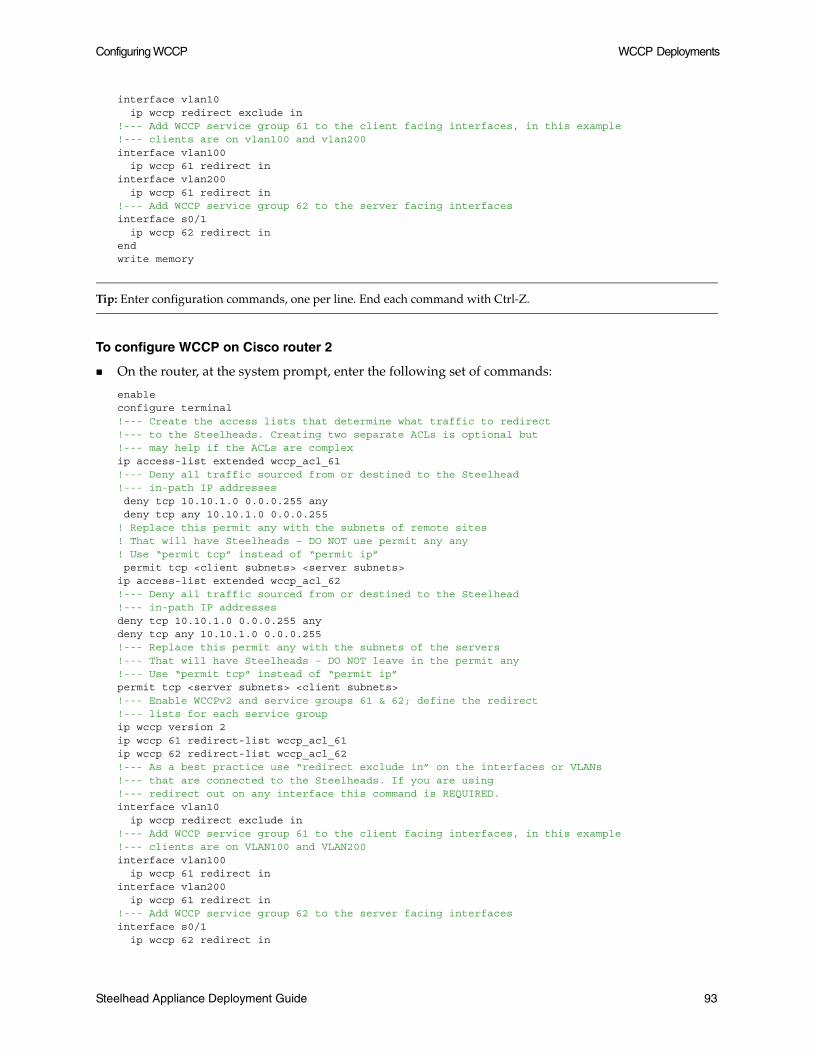
Configuring WCCP WCCP Deployments
interface vlan10 ip wccp redirect exclude in!--- Add WCCP service group 61 to the client facing interfaces, in this example!--- clients are on vlan100 and vlan200interface vlan100 ip wccp 61 redirect ininterface vlan200 ip wccp 61 redirect in!--- Add WCCP service group 62 to the server facing interfacesinterface s0/1 ip wccp 62 redirect inendwrite memory
Tip: Enter configuration commands, one per line. End each command with Ctrl-Z.
To configure WCCP on Cisco router 2
On the router, at the system prompt, enter the following set of commands:
enableconfigure terminal!--- Create the access lists that determine what traffic to redirect!--- to the Steelheads. Creating two separate ACLs is optional but!--- may help if the ACLs are complexip access-list extended wccp_acl_61!--- Deny all traffic sourced from or destined to the Steelhead!--- in-path IP addresses deny tcp 10.10.1.0 0.0.0.255 any deny tcp any 10.10.1.0 0.0.0.255! Replace this permit any with the subnets of remote sites! That will have Steelheads – DO NOT use permit any any! Use “permit tcp” instead of “permit ip” permit tcp <client subnets> <server subnets>ip access-list extended wccp_acl_62!--- Deny all traffic sourced from or destined to the Steelhead!--- in-path IP addressesdeny tcp 10.10.1.0 0.0.0.255 anydeny tcp any 10.10.1.0 0.0.0.255!--- Replace this permit any with the subnets of the servers!--- That will have Steelheads – DO NOT leave in the permit any!--- Use “permit tcp” instead of “permit ip”permit tcp <server subnets> <client subnets>!--- Enable WCCPv2 and service groups 61 & 62; define the redirect!--- lists for each service groupip wccp version 2ip wccp 61 redirect-list wccp_acl_61ip wccp 62 redirect-list wccp_acl_62!--- As a best practice use “redirect exclude in” on the interfaces or VLANs!--- that are connected to the Steelheads. If you are using!--- redirect out on any interface this command is REQUIRED.interface vlan10 ip wccp redirect exclude in!--- Add WCCP service group 61 to the client facing interfaces, in this example!--- clients are on VLAN100 and VLAN200interface vlan100 ip wccp 61 redirect ininterface vlan200 ip wccp 61 redirect in!--- Add WCCP service group 62 to the server facing interfacesinterface s0/1 ip wccp 62 redirect in
Steelhead Appliance Deployment Guide 93

WCCP Deployments Configuring WCCP
endwrite memory
Tip: Enter configuration commands, one per line. End each command with Ctrl-Z.
For details on how to verify the WCCP configuration, “Verifying and Troubleshooting WCCP Configurations” on page 106.
Basic WCCP Router Configuration Commands
This section summarizes some of the basic WCCP router configuration commands. For details about WCCP router configuration commands, refer to your router documentation.
To enable WCCP and define a service group on the router
On the router, at the system prompt, enter the following set of commands:
enableconfigure terminalip wccp <service_group> <redirect list>endwrite memory
Important: The service group you specify on the router must also be set on the WCCP Steelhead appliance.
Note: The WCCP protocol allows you to add up to 32 Steelhead appliances and 32 routers to a service group.
To specify inbound traffic redirection for each router interface
On the router, at the system prompt, enter the following set of commands:
enableconfigure terminal!--- Add WCCP service group 61 to the client-facing interfacesinterface FastEthernet 0/0ip wccp 61 redirect in!--- Add WCCP service group 62 to the server-facing interfacesinterface serial 0ip wccp 62 redirect inendwrite memory
About the ip wccp Router Command
The ip wccp [NR] router command is not additive. After you end and write memory for an ip wccp [NR] command, you cannot use another ip wccp [NR] command to augment information you previously specified. To retain information you previously specified with ip wccp [NR], you must enter a new ip wccp [NR] command that includes the information you previously specified, as well as whatever you want to configure.
94 Steelhead Appliance Deployment Guide

Configuring WCCP WCCP Deployments
For example, you configure your router using the following set of commands:
enableconfigure terminalip wccp 61 redirect-list 100endwrite memory
If you want to specify a password on the router later, the command ip wccp 61 password <your_password> overwrites the previous redirect list configuration.
To retain the previous redirect list configuration and set a password, you must use the following command:
ip wccp 61 redirect-list 100 password <your_password>
For example:
enableconfigure terminalip wccp 61 redirect-list 100 password XXXYYYZZendwrite memory
Steelhead Appliance WCCP CLI Commands
The table in this section summarizes the Steelhead appliance WCCP CLI commands.
Steelhead Appliance CLI Command Description
[no] wccp enable Enables or disables WCCP.
wccp mcast-ttl 10 Specifies the multicast Time To Live (ttl) value of 10 for WCCP.
[no] wccp service-group <service-id> {routers <routers> | assign-scheme [either | hash | mask] | src-ip-mask <mask> | dst-ip-mask <mask> | src-port-mask <mask> | dst-port-mask <mask>} protocol [tcp | icmp] | encap-scheme [either | gre | l2] | dst-ip-mask <mask> flags <flags> | password <password> | ports <ports> | priority <priority> | weight <weight>}
Configures a WCCP service group.
in-path neighbor allow-failure Ensures that if a Steelhead appliance fails the neighbor Steelhead appliance continues to optimize new connections (for in-path deployments that use connection forwarding with WCCP).
show wccp Displays WCCP settings.
Steelhead Appliance Deployment Guide 95

WCCP Deployments Configuring WCCP
WCCP Service Group Parameters
The following table summarizes the parameters for configuring a WCCP service group.
Parameter Description
service-group
<service-id>
Specifies the service group ID (from 0 to 255). The service group ID must match the value set on the router. A value of 0 specifies the standard http service group.
To enable WCCP, the Steelhead appliance must join a service group at the router. A service group is a group of routers and Steelhead appliances which define the traffic to redirect, and the routers and Steelhead appliances the traffic goes through.
Note: Riverbed recommends that you use WCCP service groups 61 and 62.
routers
<IP addresses>
Specifies a comma-separated list of router IP addresses (maximum of 32).
assign-scheme
[hash | mask]
Specifies the assignment method to use:
• either - Specifies either hash or mask. This is the default setting (hash first, then mask).
• hash - Specifies a hash assignment method. For details on the hash assignment method, see “Hash Assignment” on page 82.
• mask - Specifies a mask assignment method. For details on the mask assignment method, see “Mask Assignment with RiOS v5.0.1 or Earlier” on page 82, and “Mask Assignment with RiOS v5.0.2 or Later” on page 83.
For details on assignment methods, see “Assignment Methods” on page 82.
protocol
[tcp | icmp]
Specifies the protocol: TCP or ICMP.
encap-scheme [either|gre|12]
Specifies the traffic forwarding and redirection scheme:
• gre - Generic Routing Encapsulation.
• l2 - Layer-2 redirection.
Note: To work around a router or switch that does not support L2 return negotiation, you can configure your Steelhead appliance to not encapsulate return packets. For details, see “Redirection and Return Methods” on page 84.
• either -Layer-2 first; if Layer-2 is not supported, then gre. This is the default value.
96 Steelhead Appliance Deployment Guide

Configuring WCCP WCCP Deployments
For detailed information about WCCP CLI commands, see the Riverbed Command-Line Interface Reference Manual.
flags <flags> Specifies the fields the router must hash on and if certain ports must be redirected. Specify a combination of src-ip-hash, dst-ip-hash, src-port-hash, dst-port-hash, ports-dest, or ports-source. You can set one or more flags.
The default setting is src-ip-hash, dst-ip-hash, which ensures that all of the packets for a particular TCP connection are redirected to the same Steelhead appliance. If you use a different setting, you might need to enable connection forwarding among the Steelhead appliances in the WCCP service group. The following hashing options are available:
• src-ip-hash - Specifies that the router hash the source IP address to determine traffic to redirect.
• dst-ip-hash - Specifies that the router hash the destination IP address to determine traffic to redirect.
• src-port-hash - Specifies that the router hash the source port to determine traffic to redirect.
• dst-port-hash - Specifies that the router hash the destination port to determine traffic to redirect.
• ports-dest - Specifies that the router determines traffic to redirect based on destination ports.
• ports-source - Specifies that the router determines traffic to redirect based on source ports.
If the source or destination flags are set, the router redirects only the TCP traffic that matches the source or destination ports specified.
Note: Flags cannot set destination ports and source ports simultaneously.
ports <ports> Specifies a comma-separated list of up to seven ports that the router redirects. Use only if the ports-dest or ports-source service flag is set.
priority <priority> Specifies the WCCP priority for traffic redirection. If a connection matches multiple service groups on a router, the router chooses the service group with the highest priority. The range is 0-255. The default value is 200.
password <password> Specifies the WCCP password. This password must be the same as the password on the router. Additionally, WCCP requires that all routers in a service group have the same password. Passwords are limited to eight characters.
weight <weight> Specifies the percentage of connections that are redirected to a particular Steelhead appliance. A higher weight redirects more traffic to that Steelhead appliance. The ratio of traffic redirected to a Steelhead appliance is equal to its weight divided by the sum of the weights of all the Steelhead appliances in the same service group. For example, if there are two Steelhead appliances in a service group and one has a weight of 100 and the other has a weight of 200, the one with the weight 100 receives 1/3 of the traffic and the other receives 2/3 of the traffic. The range is 0-65535. The default value corresponds to the number of TCP connections your appliance supports.
To enable failover support with WCCP groups, define the service group weight to be 0 on the backup Steelhead appliance. If one Steelhead appliance has a weight 0, but another one has a non-zero weight, the Steelhead appliance with weight 0 does not receive any redirected traffic. If all the Steelhead appliances have a weight 0, the traffic is redirected equally among them.
src-ip-mask <mask> Specifies the source IP mask address.
dst-ip-mask <mask> Specifies the destination IP mask address.
src-port-mask <mask> Specifies the source-port mask.
dst-port-mask <mask> Specifies the destination-port mask.
Parameter Description
Steelhead Appliance Deployment Guide 97

WCCP Deployments Configuring Additional WCCP Features
Configuring Additional WCCP Features
This section describes additional WCCP features and how to configure them. It includes the following sections:
“Setting the Service Group Password,” next
“Configuring Multicast Groups” on page 99
“Configuring Group Lists to Limit Service Group Members” on page 100
“Configuring Access Lists” on page 100
“Configuring Load Balancing in WCCP” on page 103
“Flow Data in WCCP” on page 106
Setting the Service Group Password
You can configure password authentication of WCCP protocol messages between the router and the Steelhead appliance:
The router service group must match the service group password configured on the WCCP Steelhead appliance.
The same password must be configured on the router and the WCCP Steelhead appliance.
Passwords must be no more than eight characters.
Important: The following router commands are not required for the example network configurations in this chapter. Use caution when you enter the ip wccp [NR] router command because each ip wccp [NR] router command overwrites the previous ip wccp [NR] router command. You cannot use an ip wccp [NR] router command to augment ip wccp [NR] router commands you previously issued. For details, see “About the ip wccp Router Command” on page 94.
To set the service group password on the WCCP router
On the router, at the system prompt, enter the following set of commands:
enableconfigure terminalip wccp <service_group> password <your_password>endwrite memory
Tip: Enter configuration commands, one per line. End each command with Ctrl-Z.
To set the service group password on the WCCP Steelhead appliance
1. Connect to the Riverbed CLI on the WCCP Steelhead appliance and enter the following commands:
enableconfigure terminalwccp service-group <service-id> routers <IP address> password <your_password>write memoryrestart
98 Steelhead Appliance Deployment Guide
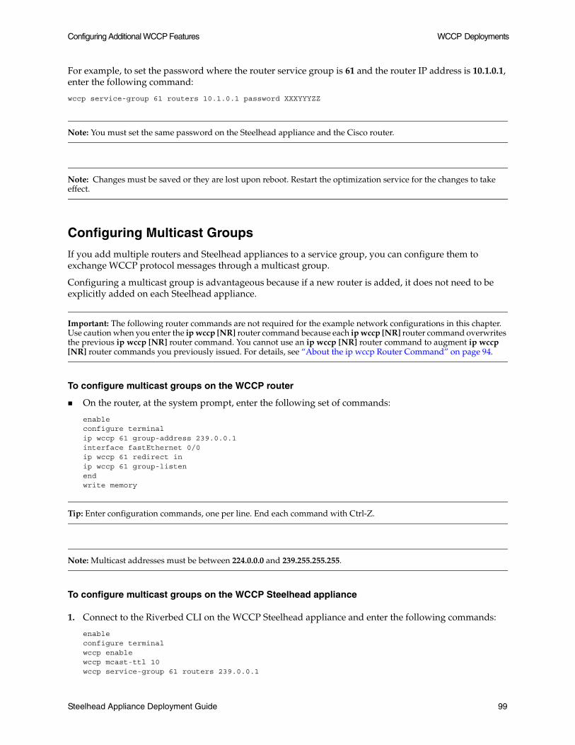
Configuring Additional WCCP Features WCCP Deployments
For example, to set the password where the router service group is 61 and the router IP address is 10.1.0.1, enter the following command:
wccp service-group 61 routers 10.1.0.1 password XXXYYYZZ
Note: You must set the same password on the Steelhead appliance and the Cisco router.
Note: Changes must be saved or they are lost upon reboot. Restart the optimization service for the changes to take effect.
Configuring Multicast Groups
If you add multiple routers and Steelhead appliances to a service group, you can configure them to exchange WCCP protocol messages through a multicast group.
Configuring a multicast group is advantageous because if a new router is added, it does not need to be explicitly added on each Steelhead appliance.
Important: The following router commands are not required for the example network configurations in this chapter. Use caution when you enter the ip wccp [NR] router command because each ip wccp [NR] router command overwrites the previous ip wccp [NR] router command. You cannot use an ip wccp [NR] router command to augment ip wccp [NR] router commands you previously issued. For details, see “About the ip wccp Router Command” on page 94.
To configure multicast groups on the WCCP router
On the router, at the system prompt, enter the following set of commands:
enableconfigure terminalip wccp 61 group-address 239.0.0.1interface fastEthernet 0/0ip wccp 61 redirect inip wccp 61 group-listenendwrite memory
Tip: Enter configuration commands, one per line. End each command with Ctrl-Z.
Note: Multicast addresses must be between 224.0.0.0 and 239.255.255.255.
To configure multicast groups on the WCCP Steelhead appliance
1. Connect to the Riverbed CLI on the WCCP Steelhead appliance and enter the following commands:
enableconfigure terminalwccp enablewccp mcast-ttl 10wccp service-group 61 routers 239.0.0.1
Steelhead Appliance Deployment Guide 99

WCCP Deployments Configuring Additional WCCP Features
write memoryrestart
Note: Changes must be saved or they are lost upon reboot. Restart the optimization service for the changes to take effect.
Note: You must set the same password on the Steelhead appliance and the Cisco router.
Configuring Group Lists to Limit Service Group Members
You can configure a group list on your router to limit service group members (for instance, Steelhead appliances) by IP address.
For example, if you want to allow only Steelhead appliances with IP addresses 10.1.1.23 and 10.1.1.24 to join the router service group, you create a group list on the router.
Important: The following router commands are not required for the example network configurations in this chapter. Use caution when you enter the ip wccp [NR] router command because each ip wccp [NR] router command overwrites the previous ip wccp [NR] router command. You cannot use an ip wccp [NR] router command to augment ip wccp [NR] router commands you previously issued. For details, see “About the ip wccp Router Command” on page 94.
To configure a WCCP router group list
On the WCCP router, at the system prompt, enter the following set of commands:
enableconfigure terminalaccess-list 1 permit 10.1.1.23access-list 1 permit 10.1.1.24ip wccp 61 group-list 1interface fastEthernet 0/0ip wccp 61 redirect inendwrite memory
Tip: Enter configuration commands, one per line. End each command with Ctrl-Z.
Configuring Access Lists
This section describes how to configure access lists (ACLs). It includes the following sections:
“Using Access Lists for Specific Traffic Redirection,” next
“Access List Command Parameters” on page 101
“Using Access Lists with WCCP” on page 102
100 Steelhead Appliance Deployment Guide

Configuring Additional WCCP Features WCCP Deployments
When you configure ACLs, consider the following:
ACLs are processed in order, from top to bottom. As soon as a particular packet matches a statement, it is processed according to that statement and the packet is not evaluated against subsequent statements. The order of your access list statements is very important.
If port information is not explicitly defined, all ports are assumed.
By default all lists include an implied deny all Cisco command at the end, which ensures that traffic that is not explicitly included is denied. You cannot change or delete this implied entry.
Using Access Lists for Specific Traffic Redirection
If redirection is based on traffic characteristics other than ports, you can use ACLs on the router to define what traffic is redirected.
If you only want the traffic for IP address 10.2.0.0/16 to be redirected to the WCCP Steelhead appliance, configure the router according to the following example.
Important: The following router commands are not required for the example network configurations in this chapter. Use caution when you enter the ip wccp [NR] router command because each ip wccp [NR] router command overwrites the previous ip wccp [NR] router command. You cannot use an ip wccp [NR] router command to augment ip wccp [NR] router commands you previously issued. For details, see “About the ip wccp Router Command” on page 94.
To configure specific traffic redirection on the router
On the router, at the system prompt, enter the following set of commands:
enableconfigure terminalaccess-list 101 permit tcp any 10.2.0.0 0.0.255.255access-list 101 permit tcp 10.2.0.0 0.0.255.255 anyip wccp 61 redirect-list 101interface fastEthernet 0/0ip wccp 61 redirect inendinterface serial0ip wccp 61 redirect inendwrite memory
Important: If you have defined fixed-target rules, redirect traffic in one direction, as shown this example.
Tip: Enter configuration commands, one per line. End each command with Ctrl-Z.
Access List Command Parameters
This section describes the Cisco access-list router command for using ACLs to configure WCCP redirect lists. For details about ACL commands, refer to your router documentation.
Steelhead Appliance Deployment Guide 101
WCCP Deployments Configuring Additional WCCP Features
The access-list router command has the following syntax:
access-list <access_list_number> [permit | deny] tcp <source IP/mask> <source_port> <destination IP/mask> <destination_port>
Using Access Lists with WCCP
To avoid requiring the router to do extra work, Riverbed recommends that you create an ACL that only routes traffic that you intend to optimize to the Steelhead appliance.
access_list_number Specifies the number from 1-199 that identifies the access list. Standard access lists are numbered 1-99; extended access lists are numbered 100-199. A standard access list matches traffic based on source IP address. An extended access list matches traffic based on source or destination IP address.
Riverbed recommends that you use extended IP access lists.
permit|deny Specifies whether the redirect list allows or stops traffic redirection. Specify permit to allow traffic redirection; specify deny to stop traffic redirection.
tcp Specifies the traffic to redirect. WCCP only redirects TCP traffic. Use only this option when configuring a redirect list for WCCP.
source IP/mask Specifies the source IP address and mask. To set the mask, specify 0 or 1, where 0 = match and 1 = does not matter. For example:
• any - Matches any IP address.
• 10.1.1.0 0.0.0.255 - Matches any host on the 10.1.1.0 network.
• 10.1.1.1 0.0.0.0 - Matches host 10.1.1.1 exactly.
• 10.1.1.1 - Matches host 10.1.1.1 exactly. This option is identical to specifying 10.1.1.1 0.0.0.0.
source_port Specifies the source port number or corresponding keyword. Cisco routers support many keywords. For details, refer to your router documentation. For example:
• eq 80 or eq www - Identical options that match port 80.
• gt 1024 - Matches any port greater than 1024.
• lt 1024 - Matches any port less than 1024.
• neq 80 - Matches any port except port 80.
• range 80 90 - Matches any port between and including 80 through 90.
destination IP/mask Specifies the destination IP address and mask. To set the mask, specify 0 or 1, where 0 = match and 1 = does not matter. For example:
• any - Matches any IP address.
• 10.1.1.0 0.0.0.255 - Matches any host on the 10.1.1.0 network.
• 10.1.1.1 0.0.0.0 - Matches host 10.1.1.1 exactly.
• 10.1.1.1 - Matches host 10.1.1.1 exactly. This option is identical to specifying 10.1.1.1 0.0.0.0.
destination_port Specifies the destination port number or corresponding keyword. Cisco routers support several keywords. For details, refer to your router documentation. For example:
• eq 80 or eq www - Identical options that match port 80.
• gt 1024 - Matches any port greater than 1024.
• lt 1024 - Matches any port less than 1024.
• neq 80 - Matches any port except port 80.
• range 80 90 - Matches any port between and including 80 through 90.
102 Steelhead Appliance Deployment Guide

Configuring Additional WCCP Features WCCP Deployments
Suppose your network is structured so that all Internet traffic passes through the WCCP-configured router, and all intranet traffic is confined to 10.0.0.0/8. Because it is unlikely that remote Internet hosts have a Steelhead appliance, do not redirect Internet traffic to the Steelhead appliance. The following is an example ACL that achieves this goal.
Important: The following router commands are not required for the example network configurations in this chapter. Use caution when you enter the ip wccp [NR] router command because each ip wccp [NR] router command overwrites the previous ip wccp [NR] router command. You cannot use an ip wccp [NR] router command to augment ip wccp [NR] router commands you previously issued. For details, see “About the ip wccp Router Command” on page 94.
To configure an ACL to route intranet traffic to your WCCP-enabled Steelhead appliance
On the WCCP router, at the system prompt, enter the following set of commands:
enableconfigure terminalaccess-list 101 deny ip host <WCCP_Steelhead_IP> anyaccess-list 101 deny ip any host <WCCP_Steelhead_IP>access-list 101 permit tcp 10.0.0.0 0.255.255.255 anyaccess-list 101 permit tcp any 10.0.0.0 0.255.255.255access-list 101 deny ip any any!ip wccp 61 redirect-list 101!endwrite memory
Repeat these commands for each WCCP Steelhead appliance in the service group.
Note: Enter configuration commands, one per line. Enter CTRL-Z to end the configuration
Configuring Load Balancing in WCCP
You can perform load balancing using WCCP. WCCP supports load balancing using either the hash assignment method or the mask assignment method.
Load Balancing Using the Hash Assignment Method
With the hash assignment method, traffic is redirected based on a hashing scheme and the weight of the Steelhead appliances. You can hash on a combination of the source IP address, destination IP address, source port, or destination port. The default weight is based on the Steelhead appliance model (for example, for the Model 5000 the weight is 5000). You can modify the default weight.
To change the hashing scheme and assign a weight on a WCCP Steelhead Appliance
1. Connect to the Riverbed CLI on the WCCP Steelhead applianceand enter the following command:
wccp service-group 61 routers 10.1.0.1 flags dst-ip-hash,src-ip-hash
2. To change the weight on the WCCP Steelhead appliance, at the system prompt, enter the following command:
wccp service-group 61 routers 10.1.0.1 weight 20
Steelhead Appliance Deployment Guide 103

WCCP Deployments Configuring Additional WCCP Features
Load Balancing Using the Mask Assignment Method
Mask assignment uses 7 bits, which allows for a maximum of 128 buckets (2 ^ 7 = 128) for load balancing across Steelhead appliances in the same service group. When deciding the number of bits to use, always keep in mind the number of Steelhead appliances in the cluster. Ensure that you create enough buckets for all the Steelhead appliances in the cluster. For example, with 6 Steelhead appliances in a cluster, use at least 3 bits for mask assignment to create 8 buckets (2 ^ 3 = 8). Having more buckets than Steelhead appliances is not a problem; in fact, it might be necessary to do so to distribute the load correctly. However, if there are more Steelhead appliances than available buckets, some Steelhead appliances will remain idle.
Mask assignments have two subcategories:
Address mask - A 4-byte value - each byte in the address mask corresponds to each octet of the IP address.
Port mask - A 2-byte value used to match on the port number.
You can combine address masks with port masks, as long as the total number of bits used for the mask assignment value does not exceed 7 bits.
Note: The algorithm used for determining bucket allocation and assignment is vendor-specific; there is no common standard in the industry. The following explanation is specific to Steelhead appliances. Other vendors who support load distribution with mask assignment might use a different algorithm to distribute the loads amongst their own devices.
When determining bucket allocations, mask assignment uses the WCCP weight parameter. The higher the weight, the more buckets are allocated to that Steelhead appliance. However, even if all the Steelhead appliances in the cluster share the same weight, the distribution among the Steelhead appliances might not be perfectly equal if the number of buckets is not divisible by the number of Steelhead appliances in the cluster.
When the number of buckets is not divisible by the number of Steelhead appliances in the cluster, the remaining buckets are assigned to the Steelhead appliance with the highest IP address. In other words, the remainder from the operation:
<number of buckets> modulo <the number of Steelhead appliances>
is assigned to the Steelhead appliance with the highest IP address.
Example—Bucket Allocation for 8 Buckets and 3 Steelhead Appliances of Equal Weight
When there are 8 buckets and 3 Steelhead appliances of equal weight (Steelhead 1.1.1.1, 2.2.2.2, and 3.3.3.3), the initial bucket allocation is:
Steelhead 1.1.1.1 - two buckets
Steelhead 2.2.2.2 - two buckets
Steelhead 3.3.3.3 - two buckets
Using the expression 8 mod 3 = 2, the remaining two buckets are assigned to Steelhead 3.3.3.3. The final allocation is:
Steelhead 1.1.1.1 - two buckets (25%)
Steelhead 2.2.2.2 - two buckets (25%)
Steelhead 3.3.3.3 - four buckets (50%)
104 Steelhead Appliance Deployment Guide

Configuring Additional WCCP Features WCCP Deployments
Example—Bucket Allocation for 16 Buckets and 3 Steelhead Appliances of Equal Weight
The same operation applies to sixteen buckets and three Steelhead appliances of equal weight.
Using the expression 16 mod 3 = 1, the final allocation is:
Steelhead 1.1.1.1 - five buckets (31.25%)
Steelhead 2.2.2.2 - five buckets (31.25%)
Steelhead 3.3.3.3 - six buckets (37.5%)
The example shows that the number of bits used for the mask and the number of Steelhead appliances in the cluster affect the accuracy of the load distribution.
Using the Weight Parameter
To assign weight in the mask assignment method you use the weight parameter in the same way as the hash assignment method, for example:
wccp service-group 61 routers 10.1.0.1 weight 20
You can also assign weight to each Steelhead appliance so the larger model Steelhead appliances are assigned more buckets. WCCP uses the following formula to assign buckets to each Steelhead appliance:
Bucket allocation = (bucket/size/sum of weight) * configured weight of the Steelhead appliance
Example—Bucket Allocation for 8 Buckets and 2 Steelhead Appliances with Different Weights
In this example, Steelhead appliance A has a weight of 25 and Steelhead appliance B has a weight of 50.
8 buckets
Total Steelhead appliance weight: 25 + 50 = 75
Steelhead A weight is 25
(8/75) * 25 = 2.7 buckets
Steelhead B weight is 50
(8/75) * 50 = 5.3 buckets
However, because the number of allocated buckets must be integers, WCCP allocates two buckets to Steelhead A and five buckets to Steelhead B. One unallocated bucket remains, so WCCP allocates it to the Steelhead appliance with the highest weight (Steelhead B), bringing the final bucket allocation for Steelhead B to six buckets.
Example—Bucket Allocation for 16 Buckets and 3 Steelhead Appliances with Different Weights
In this example, Steelhead appliance A has an IP address of 89.1.1.2 and a weight of 25. Steelhead appliance B has an IP address of 89.1.1.6 and a weight of 25. Steelhead appliance C has an IP address of 89.1.1.5 and a weight of 50.
16 buckets
Total Steelhead appliance weight: 25 + 25 + 50 = 100
(16/100) * 50 = 8 buckets for 89.1.1.5 (Steelhead C)
(16/100) * 25 = 4 buckets for 89.1.1.2 and 89.1.1.6 (Steelheads A and B)
Steelhead Appliance Deployment Guide 105

WCCP Deployments Verifying and Troubleshooting WCCP Configurations
Flow Data in WCCP
In virtual in-path deployments such as WCCP, traffic moves in and out of the same WAN interface. The LAN interface is not used. When the Steelhead appliance exports data to a data flow collector, all traffic has the WAN interface index. Although it is technically correct for all traffic to have the WAN interface index because the input and output interfaces are the same, it is impossible to use the interface index to distinguish between LAN-to-WAN and WAN-to-LAN traffic.
You can configure the fake index feature on your Steelhead appliance to insert the correct interface index before exporting data to a data flow collector.
For details on configuring the fake index feature, see “Configuring Flow Data Exports in Virtual In-Path Deployments” on page 74.
Verifying and Troubleshooting WCCP Configurations
This section describes the basic commands for verifying WCCP configuration on the router and the WCCP Steelhead appliance.
To verify the router configuration
On the router, at the system prompt, enter the following set of commands:
enableshow ip wccpshow ip wccp 61 detailshow ip wccp 61 view
To verify the WCCP configuration on an interface
On the router, at the system prompt, enter the following set of commands:
enableshow ip interface
Look for WCCP status messages near the end of the output.
To verify the access list configuration
On the router, at the system prompt, enter the following set of commands:
enableshow access-lists <access_list_number>
To trace WCCP packets and events on the router
On the router, at the system prompt, enter the following set of commands:
enabledebug ip wccp eventsWCCP events debugging is ondebug ip wccp packetsWCCP packet info debugging is onterm mon
106 Steelhead Appliance Deployment Guide

Verifying and Troubleshooting WCCP Configurations WCCP Deployments
To verify the WCCP Steelhead appliance configuration
1. Connect to the Riverbed CLI on the WCCP Steelhead appliance and enter the following command:
show wccp service-group 61 detailWCCP Support Enabled: yesWCCP Multicast TTL: 1WCCP Return via Gateway Override: no
Router IP Address: 89.1.1.1 Identity: 1.1.1.1 State: Connected Redirect Negotiated: l2 Return Negotiated: l2 Assignment Negotiated: mask i-see-you Message Count: 20 Last i-see-you Message: 2008/07/06 22:05:16 (1 second(s) ago) Removal Query Message Count: 0 Last Removal Query Message: N/A (0 second(s) ago) here-i-am Message Count: 20 Last here-i-am Message: 2008/07/06 22:05:16 (1 second(s) ago) Redirect Assign Message Count: 1 Last Redirect Assign Message: 2008/07/06 22:02:21 (176 second(s) ago)
Web Cache Client Id: 89.1.1.2 Weight: 25 Distribution: 1 (25.00%)
Mask SrcAddr DstAddr SrcPort DstPort ---- ------- ------- ------- ------- 0000: 0x02000000 0x00000000 0x0000 0x0001
Value SrcAddr DstAddr SrcPort DstPort Cache-IP ----- ------- ------- ------- ------- -------- 0000: 0x00000000 0x00000000 0x0000 0x0000 89.1.1.2
Web Cache Client Id: 89.1.1.6 Weight: 25 Distribution: 2 (50.00%)
Mask SrcAddr DstAddr SrcPort DstPort ---- ------- ------- ------- ------- 0000: 0x02000000 0x00000000 0x0000 0x0001
Value SrcAddr DstAddr SrcPort DstPort Cache-IP ----- ------- ------- ------- ------- -------- 0002: 0x00000000 0x00000000 0x0000 0x0001 89.1.1.6 0003: 0x02000000 0x00000000 0x0000 0x0001 89.1.1.6
Web Cache Client Id: 89.1.1.5 Weight: 25 Distribution: 1 (25.00%)
Mask SrcAddr DstAddr SrcPort DstPort ---- ------- ------- ------- ------- 0000: 0x02000000 0x00000000 0x0000 0x0001
Value SrcAddr DstAddr SrcPort DstPort Cache-IP ----- ------- ------- ------- ------- -------- 0001: 0x02000000 0x00000000 0x0000 0x0000 89.1.1.5
Steelhead Appliance Deployment Guide 107
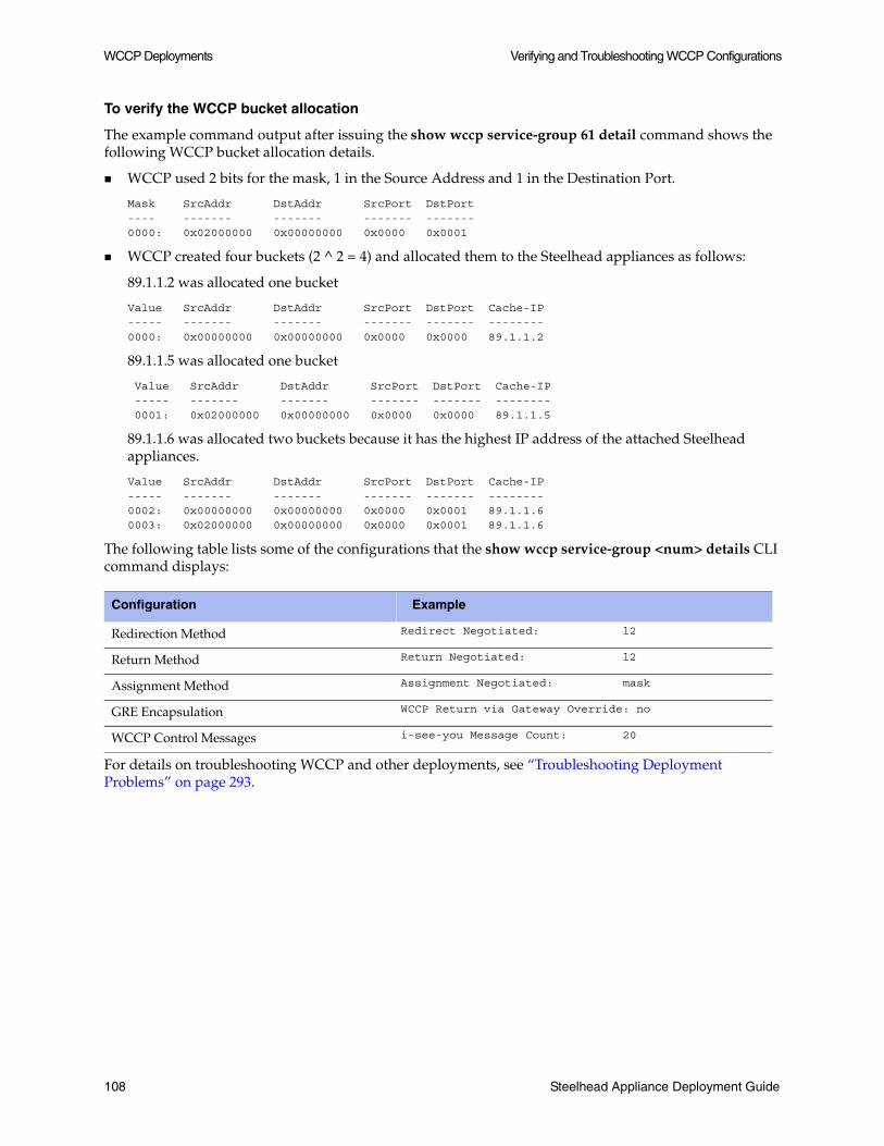
WCCP Deployments Verifying and Troubleshooting WCCP Configurations
To verify the WCCP bucket allocation
The example command output after issuing the show wccp service-group 61 detail command shows the following WCCP bucket allocation details.
WCCP used 2 bits for the mask, 1 in the Source Address and 1 in the Destination Port.
Mask SrcAddr DstAddr SrcPort DstPort---- ------- ------- ------- -------0000: 0x02000000 0x00000000 0x0000 0x0001
WCCP created four buckets (2 ^ 2 = 4) and allocated them to the Steelhead appliances as follows:
89.1.1.2 was allocated one bucket
Value SrcAddr DstAddr SrcPort DstPort Cache-IP----- ------- ------- ------- ------- --------0000: 0x00000000 0x00000000 0x0000 0x0000 89.1.1.2
89.1.1.5 was allocated one bucket
Value SrcAddr DstAddr SrcPort DstPort Cache-IP ----- ------- ------- ------- ------- -------- 0001: 0x02000000 0x00000000 0x0000 0x0000 89.1.1.5
89.1.1.6 was allocated two buckets because it has the highest IP address of the attached Steelhead appliances.
Value SrcAddr DstAddr SrcPort DstPort Cache-IP----- ------- ------- ------- ------- --------0002: 0x00000000 0x00000000 0x0000 0x0001 89.1.1.60003: 0x02000000 0x00000000 0x0000 0x0001 89.1.1.6
The following table lists some of the configurations that the show wccp service-group <num> details CLI command displays:
For details on troubleshooting WCCP and other deployments, see “Troubleshooting Deployment Problems” on page 293.
Configuration Example
Redirection Method Redirect Negotiated: l2
Return Method Return Negotiated: l2
Assignment Method Assignment Negotiated: mask
GRE Encapsulation WCCP Return via Gateway Override: no
WCCP Control Messages i-see-you Message Count: 20
108 Steelhead Appliance Deployment Guide

CHAPTER 6 Configuring SCEP and Managing CRLs
This chapter describes how to configure the Simple Certificate Enrollment Protocol (SCEP) and how to manage Certification Revocation Lists (CRLs) using the Riverbed CLI. It includes the following sections:
“Using SCEP to Configure On-Demand and Automatic Re-Enrollment,” next
“Managing Certificate Revocation Lists” on page 113
This chapter makes the following assumptions:
You are familiar with configuring SSL in the Steelhead appliance.
You have already configured SSL on the Steelhead appliance (for details, see “SSL Deployment” on page 169.
You have set up a SCEP server. For detailed information, see http://www.klake.org/~jt/sscep/w2kca.html.
Using SCEP to Configure On-Demand and Automatic Re-Enrollment
The Steelhead appliance uses SCEP to configure on-demand enrollment and automatic re-enrollment of SSL peering certificates.
Note: Currently, the Steelhead appliance can only enroll peering certificates.
This section describes how to configure on-demand and automatic re-enrollment of SSL peering certificates.
Steelhead Appliance Deployment Guide 109

Configuring SCEP and Managing CRLs Using SCEP to Configure On-Demand and Automatic Re-Enrollment
The following table summarizes the SCEP commands.
SCEP Commands Parameters Definition
secure-peering scep auto-reenroll
enable Enables automatic re-enrollment of a certificate to be signed by a CA.
exp-threshold <num of days>
Specify the amount of time (in days) to schedule re-enrollment before the certificate expires.
last-result clear-alarm
Clears the automatic re-enrollment last-result alarm. The last result is the last completed enrollment attempt.
secure-peering scep max-num-polls
<max number polls>
Specify the maximum number of polls before the Steelhead appliance cancels the enrollment. The peering certificate is not modified. The default value is 5.
A poll is a request to the server for an enrolled certificate by the Steelhead appliance. The Steelhead appliance polls only if the server responds with pending. If the server responds with fail then the Steelhead appliance does not poll.
secure-peering scep on-demand cancel
None Cancels any active on-demand enrollment.
secure-peering scep on-demand gen-key-and-csr
rsa Generates a new private key and CSR for on-demand enrollment using the Rivest-Shamir-Adleman algorithm.
state <string> Specify the state. No abbreviations allowed.
org-unit <string> Specify the organizational unit (for example, the department).
org <string> Specify the organization name (for example, the company).
locality <string> Specify the city.
email <email addr>
Specify an email address of the contact person.
country <string> Specify the country (2-letter code only).
common-name <string>
Specify the hostname of the peer.
key-size <512 | 1024 | 2048>
Specify the key size in bits (for example, 512, 1024, 2048).
secure-peering scep on-demand start
Starts an on-demand enrollment (in the background by default).
foreground Starts an on-demand enrollment in the foreground.
secure-peering scep passphrase
<pass phrase> Specify the challenge password phrase.
secure-peering scep poll-frequency
<minutes> Specify the poll frequency in minutes. The default value is 5.
110 Steelhead Appliance Deployment Guide

Using SCEP to Configure On-Demand and Automatic Re-Enrollment Configuring SCEP and Managing CRLs
Configuring On-Demand Enrollment
The following example configures the most common on-demand enrollment SCEP settings.
Note: You can only perform one enrollment of a certificate at a time. You must stop enrollment before you begin the enrollment process for another certificate.
To configure on-demand enrollment of certificates
1. To configure SCEP settings, connect to the Steelhead CLI and enter the following commands:
enableconfigure terminalsecure-peering scep url <http://host[:port/path/to/service>secure-peering scep trust peering-ca < name of a peering CA >secure-peering scep poll-frequency 10secure-peering scep max-num-polls 6secure-peering scep passphrase “device unique passphrase”
2. To perform an on-demand enrollment you must first generate a new key and Certificate Signing Request (CSR), at the system prompt enter the command:
secure-peering scep on-demand gen-key-and-csr rsa 1048 country us org mycompany org-unitengineering
3. To display the CSR (including the fingerprint), at the system prompt enter the command:
show secure-peering scep peering on-demand csr
4. To start an on-demand enrollment, at the system prompt enter the command:
secure-peering scep on-demand start
5. To view current status and the result of the last attempt (since boot), at the system prompt enter the following set of commands:
show secure-peering scep enrollment statusshow secure-peering scep on-demand last-result
6. To stop enrollment, at the system prompt enter the following command:
secure-peering scep on-demand cancelshow secure-peering scep on-demand last-result
You must stop enrollment before you can begin the enrollment process for another certificate.
secure-peering scep trust
peering-ca <peer ca>
Specify the name of the existing peering CA.
secure-peering scep url <url> Specify the URL of the SCEP responder. Use the following format: http://host[:port/path/to/service]
SCEP Commands Parameters Definition
Steelhead Appliance Deployment Guide 111

Configuring SCEP and Managing CRLs Using SCEP to Configure On-Demand and Automatic Re-Enrollment
Configuring Automatic Re-Enrollment
The following example configures the most common automatic re-enrollment SCEP settings.
To configure automatic re-enrollment of certificates
1. To configure SCEP settings, connect to the Steelhead CLI and enter the following command:
enableconfigure terminalsecure-peering scep url http://entrust-connector/cgi-bin/pkiclient.exesecure-peering scep trust peering-ca < name of a peering CA >secure-peering scep poll-frequency 10secure-peering scep max-num-polls 6secure-peering scep passphrase “device unique passphrase”
2. To configure automatic re-enrollment, at the system prompt enter the following set of commands:
secure-peering scep auto-reenroll exp-threshold 30secure-peering scep auto-reenroll enable
3. To view current automatic re-enrollment settings, at the system prompt enter the following set of commands:
show secure-peering scep peering auto-reenroll csrshow secure-peering scep peering on-demand last-result
Viewing SCEP Settings and Alarms
This section describes how view SCEP settings and alarms.
The following table summarizes the commands for SCEP settings.
An SCEP alarm is triggered when the Steelhead appliance requests a SCEP server to dynamically re-enroll an SSL peering certificate and the request fails. The Steelhead appliance uses SCEP to dynamically re-enroll a peering certificate to be signed by a certificate authority. The alarm clears automatically when the next automatic re-enrollment succeeds.
Command Parameters Definition
show secure-peering scep
None Displays SCEP information.
show secure-peering scep auto-reenroll
csr Displays the automatic re-enrollment CSR.
last-result Displays the result of the last completed automatic re-enrollment.
show secure-peering scep ca
<ca name> certificate Displays a specified SCEP peering CA certificate.
show secure-peering scep enrollment status
None Displays enrollment status information.
show secure-peering scep on-demand
csr Displays on-demand enrollment information.
last-result Displays result of the last completed on-demand enrollment.
112 Steelhead Appliance Deployment Guide

Managing Certificate Revocation Lists Configuring SCEP and Managing CRLs
To view SCEP alarm status
1. Connect to the Steelhead CLI and enter enable mode.
2. Enter the following the command:
show stats alarm ssl_peer_scep_auto_reenrollAlarm ssl_peer_scep_auto_reenroll: Enabled: yes Alarm state: ok Rising error threshold: no Rising clear threshold: no Falling error threshold: no Falling clear threshold: no Rate limit bucket counts: { 5, 20, 50 } Rate limit bucket windows: { 3600, 86400, 604800 } Last checked at: 2009/07/30 17:43:07 Last checked value: true Last event at: Last rising error at: Last rising clear at: Last falling error at: Last falling clear at:
To clear the SCEP alarm
1. Connect to the Steelhead CLI and enter configuration mode.
2. Enter the following the command:
secure-peering scep auto-reenroll last-result clear-alarm
Managing Certificate Revocation Lists
Certificate Revocation Lists allow CAs to revoke issued certificates (for example, when the private key of the certificate has been compromised).
A CRL is a database that contains a list of digital certificates that have been invalidated before their expiration date, including the reasons for the revocation, and the names of the issuing certificate signing authorities. The CRL is issued by the CA which issues the corresponding certificates. All CRLs have a lifetime during which they are valid (often 24 hours or less).
CRLs are used with client-side and server-side Steelhead appliance SSL connections only. When a SSL connection attempts a handshake and encounters a revoked certificate, the handshake fails and the connection is not optimized.
Note: Currently, the Steelhead appliance only supports downloading CRLs from Lightweight Directory Access Protocol (LDAP) servers.
Steelhead Appliance Deployment Guide 113

Configuring SCEP and Managing CRLs Managing Certificate Revocation Lists
The following table summarizes CRL CLI management commands.
CRL Commands Parameters Definition
protocol ssl crl ca Configures CRL for automatically discovered CAs. You can update automatically discovered CRLs using this command.
<ca name> Specify the name of a SSL CA certificate.
cdp <integer> Specify an integer index of a Cisco Distribution Point (CDP) in a CA certificate.
The no protocol ssl crl ca * cdp * command option removes the update.
ldap server <IP addr or hostname>
Specify the LDAP server IP address or hostname to modify a CDP URI.
port <port> Optionally, specify the LDAP service port.
crl-attr-name <attr-name>
Optionally, specify the attribute name of CRL in a LDAP entry.
protocol ssl crl cas enable
Enables CRL polling and use of CRL in handshake verifications of CA certificates. Enabling CRL allows the CA to revoke a certificate. For example, when the private key of the certificate has been compromised, the CA can issue a CRL that revokes the certificate.
protocol ssl crl handshake
Configures handshake behavior for a CRL.
fail-if-missing If a relevant CRL cannot be found the handshake fails.
[no] protocol ssl crl manual
ca Specify the CA name to manually configure the CDP.
The no protocol ssl crl manual command removes manually configured CDPs.
uri <uri> Specify the complete CDP URI to manually configure the CDP for the CA.
peering ca Specify the CA name to manually configure the CDP for the peering CA.
uri <uri> Specify the complete CDP URI to manually configure the CDP for the peering CA.
114 Steelhead Appliance Deployment Guide

Managing Certificate Revocation Lists Configuring SCEP and Managing CRLs
protocol ssl crl peering ca <ca name> Configures a CRL for an automatically discovered peering CA.
cdp <integer> Specify an integer index of a cdp in a peering CA certificate.
The no protocol ssl crl peering ca * cdp * removes the update.
ldap server <ip-addr or hostname> <cr>
Specify the IP address or hostname of a LDAP server.
crl-attr-name <string> | port <port num>
Optionally, specify an attribute name of CRL in a LDAP entry.
port <port num> Optionally, specify the LDAP service port.
cas enable Enables CRL polling and use of CRL in handshake verification.
protocol ssl crl query-now
ca <string> cdp <integer>
Download CRL issued by SSL CA. Specify the CA name and CDP integer.
peering ca <ca name> cdp <integer>
Download CRL issued by SSL peering CA. Specify the CA name and CDP integer.
show protocol ssl crl ca <ca name> Display current state of CRL polling of a CA.
crl cas <cr> | crl-file <string> text
Display the CRL in text format version.
crl peering ca <ca name> | cas crl-file <string> text
Display current state of CRL polling for peering
crl report ca <ca name> | peering ca <peering ca name>
Display reports of CRL polling from the CA or display reports of CRL polling from peering CA.
CRL Commands Parameters Definition
Steelhead Appliance Deployment Guide 115

Configuring SCEP and Managing CRLs Managing Certificate Revocation Lists
Managing CRLs
This section describes how to manage CRLs using the CLI.
To update an incomplete CDP
1. To enable CRL polling and handshakes, connect to the Steelhead CLI and enter configuration mode.
2. Enter the following set commands:
protocol ssl crl cas enableprotocol ssl crl peering cas enable
3. To view the CRL polling status of all CAs, enter the following command:
show protocol ssl crl ca cas<<this example lists two CDPs: one complete CDP and one incomplete CDP>> CA: Comodo_Trusted_Services CDP Index: 1 DP Name 1: URI:http://crl.comodoca.com/TrustedCertificateServices.crl Last Query Status: unavailable CDP Index: 2 DP Name 1: URI:http://crl.comodo.net/TrustedCertificateServices.crl Last Query Status: unavailable<<an incomplete CDP is indicated by the DirName format>> CA: Entrust_Client CDP Index: 1 DP Name 1: DirName:/C=US/O=Entrust.net/OU=www.entrust.net/Client_CA_Info/CPS incorp. by ref.limits liab./OU=(c) 1999 Entrust.net Limited/CN=Entrust.net Client Certification Authority CN=CRL1 Last Query Status: unavailable CDP Index: 2 DP Name 1: URI:http://www.entrust.net/CRL/Client1.crl Last Query Status: unavailable
In this case, the Entrust Client is an incomplete CDP as indicated by DirName format. Currently, the Steelhead appliance only supports updates in the DirName format.
4. To update the incomplete CDP URI, enter the following set of commands:
protocol ssl crl ca Entrust_Client cdp 1 ldap-server 192.168.172.1 protocol ssl crl peering ca Entrust_Client cdp 1 ldap-server 192.168.172.1
5. To view the status of the updated CDP, enter the following command:
show protocol ssl crl ca Entrust_Client
The status of CRL polling can be either pending, success, or error.
6. To check CRL polling status of all CA(s), enter the following command:
show protocol ssl crl cas
Viewing CRL Alarm Status
This section describes how to view a CRL alarm and how to clear a CRL alarm.
To view CRL alarm status
1. Connect to the Steelhead CLI and enter enable mode.
116 Steelhead Appliance Deployment Guide

Managing Certificate Revocation Lists Configuring SCEP and Managing CRLs
2. Enter the following the command:
show stats alarm crl_errorAlarm crl_error: Enabled: yes Alarm state: ok Rising error threshold: 1 Rising clear threshold: 1 Falling error threshold: no Falling clear threshold: no Rate limit bucket counts: { 5, 20, 50 } Rate limit bucket windows: { 3600, 86400, 604800 } Last checked at: 2009/07/30 17:40:34 Last checked value: 0 Last event at: Last rising error at: Last rising clear at: Last falling error at: Last falling clear at:
To clear a CRL alarm, you must either rectify the problem by updating the incomplete CDP or you must disable CRL polling.
To disable CRL polling and clear a CRL alarm
1. Connect to the Steelhead CLI and enter configuration mode.
2. Enter the following the command:
no protocol ssl crl cas enable
Steelhead Appliance Deployment Guide 117

Configuring SCEP and Managing CRLs Managing Certificate Revocation Lists
118 Steelhead Appliance Deployment Guide

CHAPTER 7 Policy-Based Routing Deployments
This chapter describes how to configure policy-based routing (PBR) to redirect traffic to a Steelhead appliance or group of Steelhead appliances. It includes the following sections:
“Overview of PBR,” next
“Connecting the Steelhead Appliance in a PBR Deployment” on page 121
“Configuring PBR” on page 121
“Exporting Flow Data and Virtual In-Path Deployments” on page 129
This chapter provides the basic steps for PBR network deployments.
For details on the factors you must consider before you design and deploy the Steelhead appliance in a network environment, see “Choosing the Right Steelhead Appliance” on page 19.
Overview of PBR
PBR is a packet redirection mechanism that allows you to define policies to route packets instead of relying on routing protocols. PBR is used to redirect packets to Steelhead appliances that are in a virtual in-path deployment.
You define PBR policies on your router for switching packets. PBR policies can be based on identifiers available in access lists, such as the source IP address, destination IP address, protocol, source port, or destination port.
When a PBR-enabled router interface receives a packet that matches a defined policy, PBR switches the packet according to the rule defined for the policy. If a packet does not match a defined policy, PBR routes the packet to the IP address specified in the routing table entry that most closely matches the packet.
Important: To avoid an infinite loop, PBR must be enabled on the router interfaces where client traffic arrives, and disabled on the router interface that is connected to the Steelhead appliance.
PBR is enabled as a global configuration and applied on an interface basis. Each virtual in-path interface can be used simultaneously for receiving traffic redirected via PBR; physically, the WAN port is cabled and used to receive the redirected traffic. To support multiple in-path ports, each in-path interface must be enabled, have an IP address, and the global command in-path oop all-ports must be issued.
Steelhead Appliance Deployment Guide 119

Policy-Based Routing Deployments Overview of PBR
The Steelhead appliance that intercepts traffic redirected by PBR is configured with both in-path and virtual in-path support enabled.
PBR Failover and CDP
A major issue with PBR is that it can blackhole traffic; that is, it drops all packets to a destination if the device it is redirecting to fails. You can avoid the blackholing of traffic by enabling PBR to track whether or not the PBR next hop IP address is available. You configure the PBR-enabled router to use the Cisco Discovery Protocol (CDP). CDP is a protocol used by Cisco routers and switches to obtain information such as neighbor IP addresses, models, and IOS versions. The protocol runs at the OSI Layer-2 using the 802.3 Ethernet frame.You also enable CDP on the Steelhead appliance. Instead of CDP, another method that may be used is the IOS feature known as Object Tracking. Using this method, a Cisco router can use a variety of methods (HTTP GET, ping, TCP connect, etc.) to determine if the Steelhead appliance interface is available.
Note: CDP must be enabled on the Steelhead appliance that is used in the PBR deployment. You enable CDP using the in-path cdp enable CLI command. For details, see the Riverbed Command-Line Interface Reference Manual.
CDP enables Steelhead appliances to provide automatic failover for PBR deployments. You configure the Steelhead appliance to send out CDP frames. The PBR-enabled router uses these frames to determine whether the Steelhead appliance is operational. If the Steelhead appliance is not operational, the PBR-enabled router stops receiving the CDP frames, and PBR stops switching traffic to the Steelhead appliance.
The Steelhead appliance must be physically connected to the PBR-enabled router for CDP to send frames. If a switch or other Layer-2 device is located between the PBR-enabled router and the Steelhead appliance, CDP frames cannot reach the router. If the CDP frames do not reach the router, the router assumes the Steelhead appliance is not operational.
Note: CDP is not supported as a failover mechanism on all Cisco platforms. For details about whether your Cisco device supports this feature, refer to your router documentation.
To enable CDP on the Steelhead appliance
1. Connect to the Steelhead CLI and enter the following commands:
enableconfigure terminalin-path cdp enablewrite memoryrestart
Note: You must save your changes to memory and restart the Steelhead appliance for your changes to take effect.
120 Steelhead Appliance Deployment Guide

Connecting the Steelhead Appliance in a PBR Deployment Policy-Based Routing Deployments
To enable CDP failover on the router
On the PBR router, at the system prompt, use the set ip next-hop verify-availability command. For details, refer to your router documentation.
Note: ICMP and HTTP GET can both also be used to track whether or not the PBR next hop IP address is available.
PBR Failover Process
When you configure the set ip next-hop verify-availability Cisco router command, PBR sends a packet in the following manner:
PBR checks the CDP neighbor table to verify that the PBR next hop IP address is available.
If the PBR next hop IP address is available, PBR sends an ARP request for the address, obtains an answer for it, and redirects traffic to the PBR next hop IP address (the Steelhead appliance).
PBR continues sending traffic to the next hop IP address as long as the ARP requests obtain answers for the next hop IP address.
If the ARP request fails to obtain an answer, PBR checks the CDP table. If there is no entry in the CDP table, PBR stops using the route map to send traffic. This verification provides a failover mechanism.
Note: A Cisco 6500 router and switch combination that is configured in hybrid mode does not support PBR with CDP. A hybrid setup requires that you use a native setup for PBR with CDP to work. This configuration fails because all routing is performed on the MSFC. The MSFC card is treated as an independent system in a hybrid setup. Therefore, when you run the show cdp neighbors Cisco command on the MSFC, it displays the supervisor card as its only neighbor. PBR does not see the devices that are connected to the switch ports. As a result, PBR does not redirect any traffic for route maps that use the set ip next-hop verify-availability Cisco command. For details, refer to your router documentation.
Connecting the Steelhead Appliance in a PBR Deployment
There are two Ethernet cables attached to the Steelhead appliance in PBR deployments:
A straight-through cable to the primary interface. You use this connection to manage the Steelhead appliance, reaching it through HTTPS or SSH.
A straight-through cable to the WAN0_0 interface if you are connecting to a switch.
A crossover cable to the WAN0_0 interface if you are connecting to a router. You assign an IP address to the in-path interface; this is the IP address that you redirect traffic to (the target of the router PBR rule).
Configuring PBR
This section describes how to configure PBR and provides example deployments. It includes the following sections:
Steelhead Appliance Deployment Guide 121

Policy-Based Routing Deployments Configuring PBR
“Configuring PBR Overview,” next
“Steelhead Appliance Directly Connected to the Router” on page 122
“Steelhead Appliance Connected to Layer-2 Switch with a VLAN to the Router” on page 124
“Steelhead Appliance Connected to a Layer-3 Switch” on page 126
“Steelhead Appliance with Object Tracking” on page 127
“Steelhead Appliance with Multiple PBR Interfaces” on page 128
Configuring PBR Overview
You can use access lists to specify which traffic is redirected to the Steelhead appliance. Traffic that is not specified in the access list is switched normally. If you do not have an access list, or if your access list is not correctly configured in the route map, traffic is not redirected. For details on access lists, see “Configuring Access Lists” on page 100.
Important: Riverbed recommends that you define a policy based on the source or destination IP address rather than on the TCP source or destination ports, because certain protocols use dynamic ports instead of fixed ones.
Steelhead Appliance Directly Connected to the Router
The following figure shows a Steelhead appliance deployment in which the Steelhead appliance is configured with PBR, and is directly connected to the router.
Figure 7-1. Steelhead Appliance Directly Connected to the Router
In this example:
The router fastEthernet0/0 interface is attached to the Layer-2 switch.
The router fastEthernet0/1 interface is attached to the Steelhead appliance.
122 Steelhead Appliance Deployment Guide
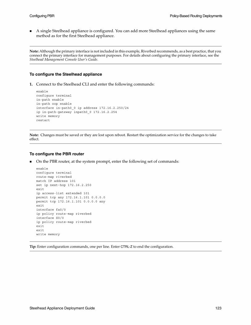
Configuring PBR Policy-Based Routing Deployments
A single Steelhead appliance is configured. You can add more Steelhead appliances using the same method as for the first Steelhead appliance.
Note: Although the primary interface is not included in this example, Riverbed recommends, as a best practice, that you connect the primary interface for management purposes. For details about configuring the primary interface, see the Steelhead Management Console User’s Guide.
To configure the Steelhead appliance
1. Connect to the Steelhead CLI and enter the following commands:
enableconfigure terminalin-path enablein-path oop enableinterface in-path0_0 ip address 172.16.2.250/24ip in-path-gateway inpath0_0 172.16.2.254write memoryrestart
Note: Changes must be saved or they are lost upon reboot. Restart the optimization service for the changes to take effect.
To configure the PBR router
On the PBR router, at the system prompt, enter the following set of commands:
enableconfigure terminalroute-map riverbedmatch IP address 101set ip next-hop 172.16.2.250exitip access-list extended 101permit tcp any 172.16.1.101 0.0.0.0permit tcp 172.16.1.101 0.0.0.0 anyexitinterface fa0/0ip policy route-map riverbedinterface S0/0ip policy route-map riverbedexitexitwrite memory
Tip: Enter configuration commands, one per line. Enter CTRL-Z to end the configuration.
Steelhead Appliance Deployment Guide 123

Policy-Based Routing Deployments Configuring PBR
Steelhead Appliance Connected to Layer-2 Switch with a VLAN to the Router
The following figure shows a Steelhead appliance deployment in which the Steelhead appliance is configured with PBR, and is directly connected to the router through a switch. This deployment also has a trunk between the switch and the router.
Figure 7-2. Steelhead Appliance Connected to a Layer-2 Switch with a VLAN
In this example:
The switch logically separates the server and the Steelhead appliance by placing:
– the server on VLAN 10.
– the Steelhead appliance on VLAN 20.
The router fastEthernet0/1 interface is attached to the Layer-2 switch.
The router performs inter-VLAN routing; that is, the router switches packets from one VLAN to the other.
The link between the router and the switch is configured as a dot1Q trunk to transport traffic from multiple VLANs.
Note: Although the primary interface is not included in this example, Riverbed recommends as a best practice that you connect the primary interface for management purposes. For details about configuring the primary interface, see the Steelhead Management Console User’s Guide.
124 Steelhead Appliance Deployment Guide

Configuring PBR Policy-Based Routing Deployments
To configure the Steelhead appliance
1. Connect to the Steelhead CLI and enter the following commands:
enableconfigure terminalin-path enablein-path oop enableinterface in-path0_0 ip address 172.16.2.250/24ip in-path-gateway inpath0_0 172.16.2.254write memoryrestart
Note: Changes must be saved or they are lost upon reboot. Restart the optimization service for the changes to take effect.
To configure the PBR router
On the PBR router, at the system prompt, enter the following set of commands:
enableconfigure terminalroute-map riverbedmatch IP address 101set ip next-hop 172.16.2.250exitip access-list extended 101permit tcp any 172.16.1.101 0.0.0.0permit tcp 172.16.1.101 0.0.0.0 anyexitinterface fa0/1.10encapsulation dot1Q 10ip address 172.16.1.254 255.255.255.0interface fa0/1.20encapsulation dot1Q 20ip address 172.16.2.254 255.255.255.0exitinterface fa0/1.10ip policy route-map riverbedinterface S0/0ip policy route-map riverbedexitexitwrite memory
Tip: Enter configuration commands, one per line. Enter CTRL-Z to end the configuration.
Note: In this example, it is assumed that both the Steelhead appliance and the server are connected to the correct VLAN. It is also assumed that these VLAN connections are established through the switch port configuration on the Layer-2 switch.
Steelhead Appliance Deployment Guide 125

Policy-Based Routing Deployments Configuring PBR
Steelhead Appliance Connected to a Layer-3 Switch
The following figure shows a Steelhead appliance deployment in which the Steelhead appliance is configured with PBR, and is directly connected to a Layer-3 switch.
Figure 7-3. Steelhead Appliance Connected to a Layer-3 Switch
In this example:
The Layer-3 switch fastEthernet0/0 interface is attached to the server, and is on VLAN 10.
The Layer-3 switch fastEthernet0/1 interface is attached to the Steelhead appliance, and is on VLAN 20.
A single Steelhead appliance is configured. More appliances can be added using the same method as for the first Steelhead appliance.
Note: Although the primary interface is not included in this example, Riverbed recommends as a best practice that you connect the primary interface for management purposes. For details about configuring the primary interface, see the Steelhead Management Console User’s Guide.
To configure the Steelhead appliance
1. Connect to the Steelhead CLI and enter the following commands:
enableconfigure terminalin-path enablein-path oop enablein-path CDP enableinterface in-path0_0 ip address 172.16.2.250/24ip in-path-gateway inpath0_0 172.16.2.254write memory restart
126 Steelhead Appliance Deployment Guide

Configuring PBR Policy-Based Routing Deployments
Note: Changes must be saved or they are lost upon reboot. Restart the optimization service for the changes to take effect.
To configure the Layer-3 switch
On the Layer-3 switch, at the system prompt, enter the following set of commands:
enableconfigure terminalroute-map riverbedmatch IP address 101set ip next-hop 172.16.2.250set ip next-hop verify-availabilityexitip access-list extended 101permit tcp any 172.16.1.101 0.0.0.0permit tcp 172.16.1.101 0.0.0.0 anyexitinterface vlan 10ip address 172.16.1.254 255.255.255.0ip policy route-map riverbedinterface vlan 20ip address 172.16.2.254 255.255.255.0interface S0/0ip policy route-map riverbedexitexitwrite memory
Tip: Enter configuration commands, one per line. Enter CTRL-Z to end the configuration.
Steelhead Appliance with Object Tracking
In this deployment, the Steelhead appliance is connected to the router, and the router tracks whether the Steelhead appliance is reachable using the Object Tracking feature of Cisco IOS. Object Tracking allows the use of methods such as HTTP GET, and ping, to determine whether the PBR next hop IP address is available.
Note: Object Tracking is not available on all Cisco devices. For details about whether your Cisco device supports this feature, refer to your router documentation.
To configure the Steelhead appliance
1. Connect to the Steelhead CLI and enter the following commands:
enableconfigure terminalinterface in-path0_0 ip address 172.16.2.250/24ip in-path-gateway inpath0_0 172.16.2.254in-path enablein-path oop enablein-path oop all-port enable
Steelhead Appliance Deployment Guide 127

Policy-Based Routing Deployments Configuring PBR
no interface inpath0_0 fail-to-bypass enablewrite memory
To configure the PBR router
On the PBR router, at the system prompt, enter the following set of commands:
enableconfigure terminalip sla 1icmp-echo 172.16.2.250ip sla schedule 1 life forever start-time nowtrack 101 rtr 1 reachabilityroute-map riverbedmatch IP address 101set ip next-hop 172.16.2.250exitip access-list extended 101permit tcp any 172.16.1.101 0.0.0.0permit tcp 172.16.1.101 0.0.0.0 anyexitinterface fa0/0ip policy route-map riverbedinterface S0/0ip policy route-map riverbedexitexitwrite memory
Steelhead Appliance with Multiple PBR Interfaces
In a deployment that uses multiple PBR interfaces, the Steelhead appliance is connected to two routers, each of which is configured to redirect traffic to a separate interface on the Steelhead appliance. Each router is configured similarly to the single router deployment, except you specify a different next-hop IP address that corresponds to the interface to which the Steelhead appliance connects.
To configure the Steelhead appliance
1. Connect to the Steelhead CLI and enter the following commands:
enableconfigure terminalin-path enableInterface inpath0_1 enablein-path oop enablein-path oop all-port enableinterface in-path0_0 ip address 172.16.2.250/24ip in-path-gateway inpath0_0 172.16.2.254interface in-path0_1 ip address 172.16.3.250/24ip in-path-gateway inpath0_1 172.16.3.254write memoryrestart
Note: Changes must be saved or they are lost upon reboot. Restart the optimization service for the changes to take effect.
128 Steelhead Appliance Deployment Guide

Exporting Flow Data and Virtual In-Path Deployments Policy-Based Routing Deployments
To configure the first PBR router
On the first PBR router, at the system prompt, enter the following set of commands:
enableconfigure terminalroute-map riverbedmatch IP address 101set ip next-hop 172.16.2.250exitip access-list extended 101permit tcp any 172.16.1.101 0.0.0.0permit tcp 172.16.1.101 0.0.0.0 anyexitinterface fa0/0ip policy route-map riverbedinterface S0/0ip policy route-map riverbedexitexitwrite memory
To configure the second PBR router
On the second PBR router, at the system prompt, enter the following set of commands:
enableconfigure terminalroute-map riverbedmatch IP address 101set ip next-hop 172.16.3.250exitip access-list extended 101permit tcp any 172.16.1.101 0.0.0.0permit tcp 172.16.1.101 0.0.0.0 anyexitinterface fa0/0ip policy route-map riverbedinterface S0/0ip policy route-map riverbed
Exporting Flow Data and Virtual In-Path Deployments
In virtual in-path deployments, such as PBR, traffic moves in and out of the same WAN0_0 interface. The LAN interface is not used. When the Steelhead appliance exports data to a flow data collector, all traffic has the WAN0_0 interface index making it impossible for an administrator to use the interface index to distinguish between LAN-to-WAN and WAN-to-LAN traffic.
You can configure the fake index feature on your Steelhead appliance to insert the correct interface index before exporting data to a flow data collector.
For details, see “Configuring Flow Data Exports in Virtual In-Path Deployments” on page 74.
Steelhead Appliance Deployment Guide 129

Policy-Based Routing Deployments Exporting Flow Data and Virtual In-Path Deployments
130 Steelhead Appliance Deployment Guide

CHAPTER 8 Data Protection Deployments
This chapter describes the configuration and deployment of Steelhead appliances for data protection solutions. By leveraging Steelhead appliances, you can achieve higher levels of data protection, streamlined IT operations, and reduce WAN bandwidth. It includes the following sections:
“Overview of Data Protection,” next
“Planning for a Data Protection Deployment” on page 132
“Configuring Steelhead Appliances for Data Protection” on page 137
“Common Data Protection Deployments” on page 146
“Designing for Scalability and High Availability” on page 156
“Troubleshooting and Fine-Tuning” on page 158
Overview of Data Protection
To secure and recover important files and data, more data center-to-data center environments (or branch office-to-data center environments) are using WAN-based backup and data replication (DR). WAN optimization is now a critical part of data protection environments because it can substantially reduce the time it takes to replicate data, perform backups, and recover data. Backup and replication over the WAN ensures that you can protect data safely at a distance from the primary site, but it can also introduce new performance challenges. To meet these performance challenges, Riverbed provides hardware and software capabilities that help data protection environments in the following ways:
Reduce WAN Bandwidth - By reducing WAN bandwidth, Steelhead appliances can lower the total cost of current data protection procedures and, in some cases, make WAN-based backup or replication possible where it was not before.
Steelhead Appliance Deployment Guide 131

Data Protection Deployments Planning for a Data Protection Deployment
Accelerate Data Transfer - By accelerating data transfer, Steelhead appliances meet or improve time targets for protecting data.
Figure 8-1. A Data Protection Deployment Using WAN-Based Replication
Planning for a Data Protection Deployment
This section describes methods for planning a successful data protection deployment. There are many variables to consider, each of which can have a significant impact on the model, number, and configuration of Steelhead appliances required to deliver the required result. It includes the following sections:
“Understanding the LAN-side Throughput and Data Reduction Requirements,” next
“Predeployment Questionnaire” on page 134
Riverbed strongly recommends that you read both of these sections and complete the questionnaire. Riverbed also recommends that you consult with Riverbed Professional Services or an authorized Riverbed Delivery Partner when planning for a data protection deployment.
For details on the other factors to consider before you design and deploy the Steelhead appliance in a network environment, see “Choosing the Right Steelhead Appliance” on page 19.
Understanding the LAN-side Throughput and Data Reduction Requirements
The basis for correctly qualifying, sizing, and configuring Steelhead appliances for use in a data protection environment depends on the following constraints:
The deployed Steelhead appliances must be able to:
receive and process data on the LAN at the required rate (LAN-side throughput), and
132 Steelhead Appliance Deployment Guide

Planning for a Data Protection Deployment Data Protection Deployments
reduce the data by a certain X-Factor, in order to
transfer data given certain WAN-side bandwidth constraints.
These constraints are defined by the following formula:
LAN-side Throughput / X-Factor <= WAN-side Bandwidth
You derive the LAN-side throughput requirements from an understanding of the maximum amount of data that must be transferred during a given time period. Often, the time allotted to transfer data is defined as a target Recovery Point Objective (RPO) for your organization.
The RPO describes the acceptable amount of data loss measured in time. It is the point in time to which you must recover data. This is generally a definition of what an organization determines is an acceptable data loss following a disaster; it is measured in minutes, hours, days, or weeks. For example, an RPO of 2 hours means that you can always recover the state of data 2 hours in the past.
Note: The following link provides an Excel throughput calculator that you can use to calculate bandwidth requirements expressed in other forms of time objectives:
https://forums.riverbed.com/discus/messages/349/1435.html?1209506129
Example—A Nightly Full Database Backup
Objective:
“I want to copy 1.8 TB of nightly database dumps over my OC-3 within a 10-hour window.”
Formula:
1.8 TB / 10 hours = 400 Mbps
Solution:
An OC-3 link has a capacity of 155 Mbps. In order to deliver 400 Mbps, the Steelhead appliance must reduce the total bandwidth over the WAN by 400/155 = 2.58x.
Example—A Daily File Server Replication
Objective:
“After consolidating the NetApp file servers from branch offices, I expect daily SnapMirror updates from my data center to go from 400 GB to 4 TB per day. I have a designated DS-3 that is nearly maxed out. Can the Steelhead appliance help me replicate all 4 TB each day using my DS-3?”
Formula:
4 TB / 1 day = 370 Mbps
Solution:
A DS-3 link has a capacity of 45 Mbps. To deliver 370 Mbps, the Steelhead appliance must reduce the total bandwidth over the WAN by 370/45 = 8.2x. This level of bandwidth reduction is certainly possible using RiOS SDR. The result of RiOS SDR depends on how repetitive the data sequences are across the SnapMirror updates.
Steelhead Appliance Deployment Guide 133

Data Protection Deployments Planning for a Data Protection Deployment
Example—A Very Large Nightly Incremental Backup
Objective:
“The incremental Tivoli Storage Manager (TSM) backup at a remote site is typically 600 GB and the backup window each night is 8 hours. Can I perform these backups over the WAN using a T1 link?”
Formula:
600 GB / 8 hours = 166 Mbps
Solution:
A T1 link has a capacity of 1.5 Mbps. To deliver 166 Mbps, the Steelhead appliances must reduce the total bandwidth over the WAN by 166/1.5 = 110x. This is a very high level of reduction that is typically out of range for data protection deployments.
In order to support backups over the WAN, you need to upgrade the WAN link. A T3 link, for example, has a capacity of 45 Mbps. Using a T3 link, the Steelhead appliances needs to achieve a data reduction of 166/45 = 3.7x, which is attainable for many deployments.
Predeployment Questionnaire
Use the predeployment questionnaire in the following table to organize a survey of the WAN-side, LAN-side, and X-Factor factors. Discuss your completed survey with Riverbed Professional Services or an authorized delivery partner, to determine the best model, number, and initial configuration of the Steelhead appliances to deploy.
Note: For a Microsoft Word version of the Data Protection questionnaire go: https://supportforum.riverbed.com/showthread.php?p=3623#post3623
s
Question Why This Is Important
WAN-Side Considerations
Is this a two-site or a multi-site (fan-in, fan-out) data protection opportunity?
In a two-site deployment, the same Steelhead appliance models are often selected for each site. In a multi-site (fan-in, fan-out) deployment, the Steelhead appliance at the central site is sized to handle the data transfers to and from the edge sites.
What is the WAN link size?
Once the LAN-side throughput and time constraints for the environment are established, knowing the WAN link size is key to determining the level of data reduction the Steelhead appliances need to deliver to meet the ultimate data protection objective. Because the Steelhead appliances specifications are partially based on the WAN rating, knowing the link size is also essential in determining which models are feasible for deployment.
What is the network latency between sites?
Network latency and WAN link size are used together to calculate buffer sizes on the Steelhead appliance to provide optimal link utilization. Also, while Steelhead appliances are generally able to overcome the effects of latency for network protocols used in data protection solutions, some are still latency sensitive. Therefore, knowing the latency in the environment is essential for providing accurate performance estimates.
Is there a dedicated link for disaster recovery?
Environments with a dedicated link are typically easier to configure. Environments with shared links need to employ features such as QoS to ensure that data protection traffic receives an adequate amount of bandwidth necessary to meet the ultimate objective.
134 Steelhead Appliance Deployment Guide

Planning for a Data Protection Deployment Data Protection Deployments
LAN-Side Considerations
Which backup or replication products are you using?
Riverbed has experience with many different data protection products and business relationships with many different replication vendors. Many have similar configuration options and network utilization behaviors. Some require special configuration; therefore, knowing what is in use is essential for being able to provide configuration recommendations and performance estimates.
Some examples of backup and replication products:
• EMC - SRDF/A
• Network Appliance - SnapMirror
• Symantec - NetBackup
• NSI - Double-Take
• Computer Associates - XOsoft
• HP - Continuous Access (CA)
• HDS - TrueCopy
• IBM - PPRC
Are you using synchronous or asynchronous replication?
Synchronous replication has very stringent latency requirements and is rarely a good fit for WAN optimization. By comparison, asynchronous replication is typically a very good fit.
Many types of data protection traffic are not typically considered replication of either type, such as backup jobs.
What is your backup methodology?
Knowing the backup type and schedule provides insight into the frequency of heavy data transfers and the level of repetition within these transfers.
Some examples of backup methodologies are:
• A single full backup and an incremental backup for life (synthetic full).
• A daily full backup.
• A weekly full backup and a daily incremental backup.
Are your data streams single or multi-stream?
What is the total number of replication streams?
Because Steelhead appliances proxy TCP/IP, the number of TCP streams created by the data protection solution can impact the Steelhead appliance resource utilization.
• RiOS versions v5.0 and earlier have a constraint that each TCP session (stream) is serviced by a single CPU core, so splitting the load across many streams is essential to fully use the resources in larger, multi-core Steelhead appliances.
• RiOS v5.5 and later has multi-core features that allow multiple CPU cores to process a single stream.
However, regardless of the RiOS version, knowing the number of TCP streams is essential in providing a configuration recommendation and performance estimate.
When considering the number of streams, of primary importance is the number of heavyweight data streams that carry significant amounts of traffic. In addition, consider that any smaller control streams that carry a small amount of traffic (such as these present in many backup systems and some FCIP systems).
Finally, depending on the data protection technology in use, there may be options to increase the number of streams in use. As a first step, determine how many streams are observed in the current environment. Also, determine whether there is a willingness to increase the number of data streams if a method to do so is suggested.
Question Why This Is Important
Steelhead Appliance Deployment Guide 135

Data Protection Deployments Planning for a Data Protection Deployment
Is there a FCIP/iFCP gateway?
If yes, what is the make, model, and firmware version?
Some FCIP/iFCP gateways (or particular firmware versions of some gateways) do not adhere fully to the TCP/IP or FCIP standards. Depending on what is in use they may require firmware upgrades, special configuration, or cannot be optimized at this time.
Gateways are mainly seen in fiber channel SAN replication environments such as SRDF/A, MirrorView, and TrueCopy.
Typical firmware versions: Cisco MDS, FCIP v4.1(3) Brocade 7500 FOS v6.3.1, QLogic isr6142 v2.4.3.2.
Is compression enabled on the gateway or the replication product?
If yes, what is the current compression ratio?
Most data protection environments using FCIP or iFCP gateways also use their built-in compression method, as this is a best practice of the product vendors and the SAN vendors who configure them. However, the best practice for WAN optimization of these technologies is to disable any compression currently in use and employ the Steelhead appliance optimization instead.
The first-pass LZ compression in the Steelhead appliance typically matches the compression already in use and then RiOS SDR allows for an overall level of data reduction that improves the previous compression ratio.
Knowing the current compression ratio achieved using the built-in compression method is important in determining whether the Steelhead appliances can improve upon it.
Are Steelhead appliances already deployed?
If yes, what is their make and RiOS version?
If the environment already has Steelhead appliances deployed and data protection is a new requirement, knowing the current appliance models in use can determine if adequate system resources are available to meet the objectives without adding additional hardware.
Additionally, knowing the current RiOS version is essential in determining what features and tuning opportunities are available in the RiOS release to provide the optimal configuration for data protection. If the environment does not already use Steelhead appliances, Riverbed can recommend the ideal RiOS version based on the environment and data protection objective.
X-Factor Considerations
What is the total size of the dataset?
For some data protection solutions such as backup, knowing the dataset size is extremely important for datastore sizing. Ideally you want to select Steelhead appliances that can find the data patterns for the entire dataset without continuously wrapping the datastore.
For SAN-based solutions this information can be more difficult to gather, but even rough estimates can help. For example, you can estimate the size of the Logical Unit Number (LUNs) that are subject to replication or the size of the databases stored on an array.
What is the dataset type? For example, Exchange, VMware, SQL, or file system.
Different types of data exhibit different characteristics when they appear on the network as backup or replication traffic. For example, file system data or VMware images often appear as large, sequential bulk transfers, and lend themselves well to disk-based data reduction.
On the other hand, real-time replication of SQL database updates can often present a workload that requires heavy amounts of disk seeks. These types of workloads can lend themselves better to a memory-based approach to data reduction.
Is the data pre-compressed?
Data stored at the point of origin in a precompressed format (such as JPEG images, video, or any type of data that has been compressed separately with utility tools such as WinZip), might see limited data reduction from Steelhead appliances. It is essential to determine if precompressed data is present for accurate performance estimates.
Is the data encrypted? Data stored at the point of origin in a pre-encrypted format (such as DPM-protected documents or encrypted database fields and records) might see limited data reduction from the Steelhead appliance. It is essential to determine if pre-encrypted data is present for accurate performance estimates.
Question Why This Is Important
136 Steelhead Appliance Deployment Guide

Configuring Steelhead Appliances for Data Protection Data Protection Deployments
Configuring Steelhead Appliances for Data Protection
After you deploy the Steelhead appliances and perform the initial configuration, you can use the features described in this section to deliver an optimal data protection deployment. This section includes the following data protection features:
“Adaptive Data Streamlining,” next
“CPU Settings” on page 139
“Best Practices for Data Streamlining and Compression” on page 140
“Choosing MX-TCP Settings” on page 140
“Choosing the Steelhead Appliance WAN Buffer Settings” on page 141
“Choosing Router WAN Buffer Settings” on page 141
“Choosing Settings for Storage Optimization Modules” on page 142
How repeatable is the data?
Data that contains internal repetition (such as frequent, small updates to large document templates) typically provide very high levels of data reduction.
How much new incremental data is added daily or hourly?
This rate of change information is often useful alongside the dataset size information to provide accurate performance estimates. For example, if a dataset is too large for a single Steelhead appliance datastore to find the data patterns for the entire dataset without wrapping continuously, Riverbed can plan system resources based on servicing the amount of data that changes hourly or daily.
What LAN-side throughput is needed to meet the data protection goal?
While the WAN throughput and level of data reduction represent the level of optimization, it is the speed of data going in and out of the systems on the LAN that establishes whether the data protection objectives can be met.
Question Why This Is Important
Steelhead Appliance Deployment Guide 137

Data Protection Deployments Configuring Steelhead Appliances for Data Protection
Configure the Steelhead appliance features relevant to data protection in the Management Console in the Configure > Optimization > Performance page.
Figure 8-2. The Configure > Optimization > Performance Page Data Protection Features
Note: For details about all Performance page features, see the Steelhead Management Console User’s Guide. For a description of the CLI commands relevant to data protection, see the Riverbed Command-Line Interface Reference Manual.
Adaptive Data Streamlining
Adaptive data streamlining provide you with the ability to fine tune the data streamlining capabilities, and enables you to obtain the right balance between optimal bandwidth reduction and optimal throughput.
The following table describes the adaptive data streamlining settings.
Adaptive Data Streamlining Setting
Benefit Description
Default Excellent bandwidth reduction
By default, Steelhead appliances use their disk-based datastore to find data patterns that traverse the network. Previously seen data patterns do not traverse the network in their fully-expanded form. Instead, a Steelhead appliance sends a unique identifier for the data to its peer Steelhead appliance, which sends the fully-expanded data. In this manner, data is streamlined over the WAN because unique content only traverses the link once. The Steelhead appliance disk-based datastore is able to maintain a large dictionary of segments and identifiers.
138 Steelhead Appliance Deployment Guide

Configuring Steelhead Appliances for Data Protection Data Protection Deployments
CPU Settings
CPU settings provide you with the ability to balance throughput with the amount of data reduction and balance the connection load. The CPU settings are useful with high-traffic loads to scale back compression, increase throughput, and maximize Long Fat Network (LFN) utilization.
Compression Level
The compression level specifies the relative trade-off of LZ data compression for LAN throughput speed. Compression levels 1-9 can be specified for fine-tuning. Generally, a lower number provides faster throughput and slightly less data reduction. Setting the optimal compression level provides greater throughput while maintaining acceptable data reduction.
Riverbed recommends setting the compression to level 1 in high-throughput environments such as data-center-to-data-center replication.
Adaptive Compression
The adaptive compression feature detects the LZ data compression performance for a connection dynamically and turns it off (that, is sets the compression level to 0) momentarily if it is not achieving optimal results. Enabling this feature can improve end-to-end throughput in cases where the data streams are not further compressible.
RiOS SDR-Adaptive
Good bandwidth reduction and LAN-side throughput
Dynamically blends different data streaming modes to enable sustained throughput during periods of high disk-intensive workloads.
Legacy: Monitors disk I/O response times, and based on statistical trends, employs a blend of disk-based de-duplication and compression-based data reduction techniques.
Important: Use caution with this setting, particularly when optimizing CIFS or NFS with pre-population. For more information, contact Riverbed Support.
Advanced: Monitors disk I/O response times and WAN utilization, and based on statistical trends, employs a blend of disk-based de-duplication, memory-based de-duplication and compress-based data reduction techniques.
RiOS SDR-M Excellent LAN-side throughput
Performs data reduction entirely in memory, which prevents the Steelhead appliance from reading and writing to and from the disk. Enabling this option can yield high LAN-side throughput because it eliminates all disk latency. RiOS SDR-M is typically the preferred configuration mode for SAN replication environments.
RiOS SDR-M is most efficient between two identical high-end Steelhead appliance models; for example, 6050 - 6050. When SDR-M is configured between two different Steelhead appliance models, the smaller model limits the performance.
Important: You cannot use datastore synchronization with RiOS SDR-M. For details on datastore synchronization, see “Datastore Synchronization” on page 32.
Adaptive Data Streamlining Setting
Benefit Description
Steelhead Appliance Deployment Guide 139

Data Protection Deployments Configuring Steelhead Appliances for Data Protection
Multi-Core Balancing
Multi-core balancing distributes the load across all CPUs, therefore maximizing throughput. Multi-core balancing improves performance in cases where there are fewer connections than the total number of CPU cores on the Steelhead appliance. Without multi-core balancing, the processing of a given connection is bound to a single core for the life of the connection. With multi-core balancing, even a single connection leverages all CPU cores in the system.
There are no adverse affects of enabling multi-core balancing in cases where there are a large number of connections. For this reason, multi-core balancing can be enabled in most (if not all) scenarios.
Best Practices for Data Streamlining and Compression
Riverbed recommends the following best practices for data protection scenarios:
When replicating database log files, the LZ-only compression level typically provides optimal results because database log files contain few repetitive data sequences that can be deduplicated using RiOS SDR.
Replication of databases like Exchange and Oracle typically works with RiOS SDR, but high-throughput environments can require additional configuration.
For SAN replication environments (especially with high bandwidth), start with an RiOS SDR-M setting and deploy the same model Steelhead appliance on each side. For details on SAN replication deployments, see “Storage Area Network Replication” on page 147.
Always set the compression level to 1 in high-throughput data center-to-data center replication scenarios.
After the initial configuration, you can monitor disk performance by reviewing the datastore performance reports accessible from the Management Console. Symptoms of disk performance issues include:
– The Datastore Disk Load report shows 100% for a sustained time or multiple times a day that coincide with periods of lower performance.
– The Datastore Cost report y-axis shows a high peak value (above 10,000) or values of 5,000 and higher for significant periods of time. The Datastore Disk Load graph for the same time periods shows values consistently higher than 100.
If you see symptoms of disk performance issues, switch to RiOS SDR-Adaptive mode to alleviate disk pressure.
Note: For more details on best practice guidelines and configuration settings, see “Common Data Protection Deployments” on page 146.
Choosing MX-TCP Settings
Maximum TCP (MX-TCP) enables data flows to reliably reach a designated level of throughput. This is useful in data protection scenarios where either:
A dedicated link is used for data protection traffic.
—or—
A known percentage of a given link can be fully consumed by data protection traffic.
140 Steelhead Appliance Deployment Guide

Configuring Steelhead Appliances for Data Protection Data Protection Deployments
For example, if an EMC SRDF/A replication deployment is using peer 6050 Steelhead appliances that are connected to a dedicated OC-1 link (50 Mbps), then you can create a MX-TCP class of 50 Mbps on each Steelhead appliance. In this example, SRDF/A uses port 1748 for data transfers.
On both the client and server-side Steelhead appliances, enter the following commands:
qos classification interface wan0_0 rate 50000qos classification interface wan0_0 enableqos classification enableqos classification class add class-name "blast" priority realtime min-pct 99.0000000 link-share 100.0000000 upper-limit-pct 100.0000000 queue-type mxtcp queue-length 100 parent "root"qos classification rule add class-name "blast" traffic-type optimized destination port 1748 rulenum 1qos classification rule add class-name "blast" traffic-type optimized source port 1748 rulenum 1 write memrestart
If you cannot allocate a given amount of bandwidth for data protection traffic, but you still require high bandwidth, enable High-Speed TCP (HS-TCP) on peer Steelhead appliances. For details, see “Underutilized Fat Pipes” on page 307.
For details on MX-TCP, see “MX-TCP” on page 210.
Choosing the Steelhead Appliance WAN Buffer Settings
In all data protection scenarios, set the Steelhead appliance WAN buffers to at least 2 x BDP. For example, if NetApp SnapMirror traffic is using a dedicated OC-1 link (50 Mbps) with 30 ms of latency (60 ms round-trip time) between sites, then set the Steelhead appliance WAN-side buffers to:
2*BDP = 2 * 50 Mb/s * 1,000,000 b/Mb * 60 ms * (1/1000) s/ms * (1/8) Bytes/bit = 750,000 Bytes
On all Steelhead appliances in this environment that send or receive the data protection traffic, enter the following commands:
protocol connection wan send def-buf-size 750000protocol connection wan receive def-buf-size 750000write memrestart
Choosing Router WAN Buffer Settings
In environments where a small number of connections are transmitting high-throughput data flows, you must increase the WAN-side queues on the router to the BDP.
For example, consider an OC-1 link (50 Mbps) with 60 ms latency (RTT):
BDP = 50 Mbps * 1,000,000 b/Mb * 60 ms * (1/1000) s/ms * (1/8) Bytes/bit * (1/1500) Bytes/packet = 250 Packets
On the Cisco router, enter the following hold-queue interface configuration command:
hold-queue 250 out
Note: It is not necessary to increase the router setting when using MX-TCP because MX-TCP moves bottleneck queuing onto the Steelhead appliance. This feature WAN traffic to enter the network at a constant rate, eliminating the need for excess buffering on router interfaces.
Steelhead Appliance Deployment Guide 141

Data Protection Deployments Configuring Steelhead Appliances for Data Protection
Choosing Settings for Storage Optimization Modules
RiOS 6.0.1 and later includes storage optimization modules for the FCIP and SRDF protocols. These modules provide enhanced data reduction capabilities. The modules use explicit knowledge of where protocol headers appear in the storage replication data stream to separate out headers from the payload data that was written to storage. In absence of a module, these headers represent an interruption to the network stream, reducing the ability of RiOS SDR to match on large, contiguous data patterns.
The modules must be configured based on the types of storage replication traffic present in the network environment. The following sections describe these options and when they would be applied.
Storage Optimization for FCIP
The module for FCIP is appropriate for environments using storage technology that originates traffic as fibre channel (FC) and then uses a Cisco MDS or Brocade 7500 FCIP gateway to convert the FC traffic to TCP for WAN transport.
For details on storage technologies that originate traffic via FC see, “Storage Area Network Replication” on page 147. For configuration best practices details on Cisco MDS and Brocade 7500 software releases, and FCIP, see “SAN Replication Using FCIP ” on page 149.
Note: Environments with SRDF traffic originated via Symmetrix FC ports (RF ports) only require configuration of the RiOS FCIP module. The SRDF module only applies to traffic originated via Symmetrix GigE ports (RE ports). For details, see “Storage Optimization for SRDF” on page 144.
All configuration for FCIP must be applied on the Steelhead appliance closest to the FCIP gateway that opens the FCIP TCP connection by sending the initial SYN packet. If you are unsure which gateway initiates the SYN in your environment, Riverbed recommends you apply the module configuration to the Steelhead appliances on both ends of the WAN.
Configuring the Base FCIP Module
To enable the base FCIP module, connect to the Steelhead CLI and enter the following command:
protocol fcip <enable/disable>
By default, the FCIP module is disabled. When only the base FCIP module has been enabled, all traffic on the well-known FCIP TCP destination ports 3225, 3226, 3227, and 3228 are directed through the module for enhanced FCIP header isolation. In most environments, no further FCIP module configuration is required beyond enabling the base module.
If an environment uses one or more non-standard TCP ports for FCIP traffic, the module can be configured to handle traffic on additional ports by entering the following command:
protocol fcip ports <port-list>
Where <port-list> is a comma-separated list of TCP ports. Prefix this command with no to remove one or more TCP ports from the list of those currently directed to the FCIP module.
Observing Current Base FCIP Module Settings
To show current base FCIP module setting, connect to the Steelhead CLI and enter the following command:
show protocol fcip settings
This command shows whether the module is currently enable or disabled, and on which TCP ports the module is looking for FCIP traffic.
142 Steelhead Appliance Deployment Guide
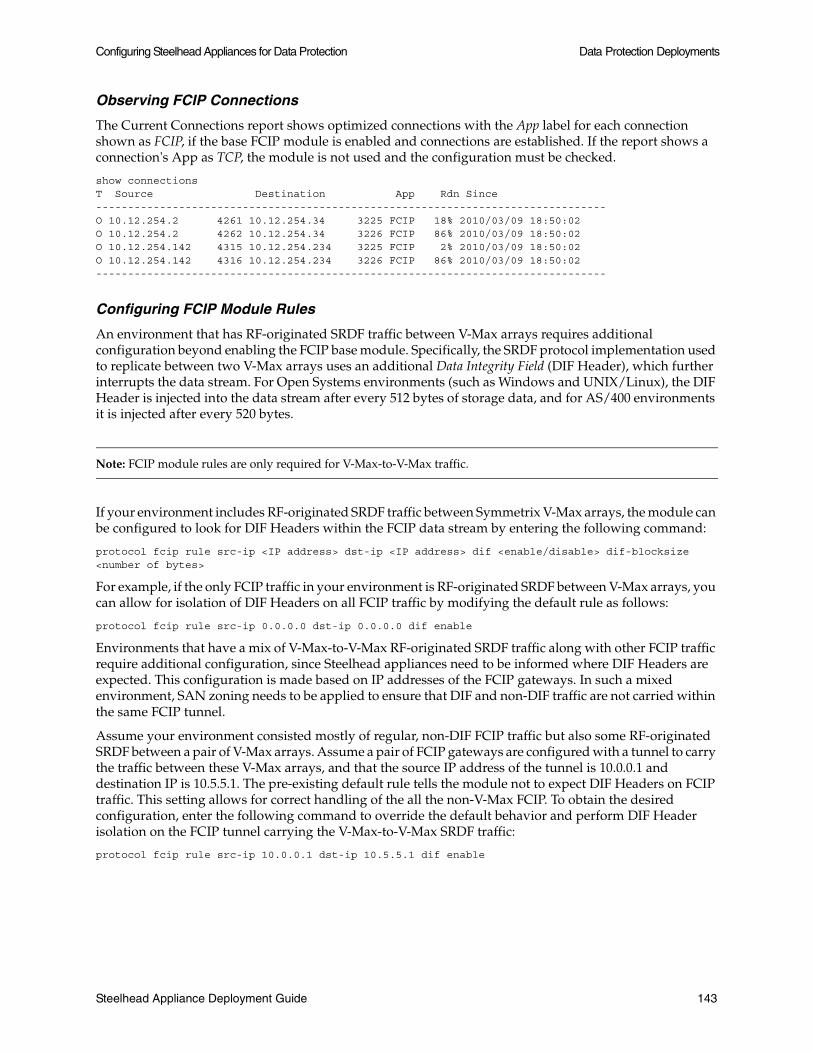
Configuring Steelhead Appliances for Data Protection Data Protection Deployments
Observing FCIP Connections
The Current Connections report shows optimized connections with the App label for each connection shown as FCIP, if the base FCIP module is enabled and connections are established. If the report shows a connection's App as TCP, the module is not used and the configuration must be checked.
show connectionsT Source Destination App Rdn Since--------------------------------------------------------------------------------O 10.12.254.2 4261 10.12.254.34 3225 FCIP 18% 2010/03/09 18:50:02O 10.12.254.2 4262 10.12.254.34 3226 FCIP 86% 2010/03/09 18:50:02O 10.12.254.142 4315 10.12.254.234 3225 FCIP 2% 2010/03/09 18:50:02O 10.12.254.142 4316 10.12.254.234 3226 FCIP 86% 2010/03/09 18:50:02--------------------------------------------------------------------------------
Configuring FCIP Module Rules
An environment that has RF-originated SRDF traffic between V-Max arrays requires additional configuration beyond enabling the FCIP base module. Specifically, the SRDF protocol implementation used to replicate between two V-Max arrays uses an additional Data Integrity Field (DIF Header), which further interrupts the data stream. For Open Systems environments (such as Windows and UNIX/Linux), the DIF Header is injected into the data stream after every 512 bytes of storage data, and for AS/400 environments it is injected after every 520 bytes.
Note: FCIP module rules are only required for V-Max-to-V-Max traffic.
If your environment includes RF-originated SRDF traffic between Symmetrix V-Max arrays, the module can be configured to look for DIF Headers within the FCIP data stream by entering the following command:
protocol fcip rule src-ip <IP address> dst-ip <IP address> dif <enable/disable> dif-blocksize <number of bytes>
For example, if the only FCIP traffic in your environment is RF-originated SRDF between V-Max arrays, you can allow for isolation of DIF Headers on all FCIP traffic by modifying the default rule as follows:
protocol fcip rule src-ip 0.0.0.0 dst-ip 0.0.0.0 dif enable
Environments that have a mix of V-Max-to-V-Max RF-originated SRDF traffic along with other FCIP traffic require additional configuration, since Steelhead appliances need to be informed where DIF Headers are expected. This configuration is made based on IP addresses of the FCIP gateways. In such a mixed environment, SAN zoning needs to be applied to ensure that DIF and non-DIF traffic are not carried within the same FCIP tunnel.
Assume your environment consisted mostly of regular, non-DIF FCIP traffic but also some RF-originated SRDF between a pair of V-Max arrays. Assume a pair of FCIP gateways are configured with a tunnel to carry the traffic between these V-Max arrays, and that the source IP address of the tunnel is 10.0.0.1 and destination IP is 10.5.5.1. The pre-existing default rule tells the module not to expect DIF Headers on FCIP traffic. This setting allows for correct handling of the all the non-V-Max FCIP. To obtain the desired configuration, enter the following command to override the default behavior and perform DIF Header isolation on the FCIP tunnel carrying the V-Max-to-V-Max SRDF traffic:
protocol fcip rule src-ip 10.0.0.1 dst-ip 10.5.5.1 dif enable
Steelhead Appliance Deployment Guide 143
Data Protection Deployments Configuring Steelhead Appliances for Data Protection
When configured, the FCIP module looks for a DIF Header after every 512 bytes of storage data, which is typical for an Open Systems environment. If your environment uses AS/400 hosts, use the dif-blocksize to inform the module to look for a DIF Header after every 520 bytes of storage data. Enter the following command to modify the default rule to look for DIF Headers on all FCIP traffic in a V-Max based, AS/400 environment:
protocol fcip rule src-ip 0.0.0.0 dst-ip 0.0.0.0 dif enable dif-blocksize 520
Observing Current FCIP Rule Settings
To show the current FCIP module rules, connect to the Steelhead CLI and enter the following command:
show protocol fcip rules
You can display each rule currently configured, whether DIF Header isolation is enabled or disabled for that rule, and how much storage data is expected before each DIF Header in traffic matching that rule.
Storage Optimization for SRDF
The module for SRDF is appropriate for environments using EMC's Symmetrix Remote Data Facility (SRDF) with DMX and V-Max storage arrays when the traffic is originated directly from GigE ports on the arrays (also known as RE ports). When in this configuration, the SRDF traffic appears on the network immediately as TCP.
Note: Environments with SRDF traffic originated via Symmetrix fibre channel ports (RF ports) require configuration of the RiOS FCIP module, not the SRDF module. For details on RF ports, see “Storage Optimization for FCIP” on page 142.
All configuration for SRDF must be applied on the Steelhead appliance closest to the Symmetrix array that opens the SRDF TCP connection by sending the initial SYN packet. If you are unsure which array initiates the SYN in your environment, Riverbed recommends you apply module configuration to the Steelhead appliances on both ends of the WAN.
Configuring the Base SRDF Module
Enable the base SRDF module by entering the following command:
protocol srdf <enable/disable>
By default, the SRDF module is disabled. When only the base SRDF module has been enabled, all traffic on the well-known SRDF TCP destination port 1748 is directed through the module for enhanced header isolation. In most environments using SRDF only between DMX arrays or V-Max-to-DMX, no further SRDF module configuration is required beyond enabling the base module.
If an environment used one or more non-standard TCP ports was for RE-originated SRDF traffic, the module can be configured to handle traffic on additional ports by entering the following command:
protocol srdf ports <port-list>
Where <port-list> is a comma-separated list of TCP ports. Prefix this command with no to remove one or more TCP ports from the list of those currently directed to the SRDF module.
Observing Current Base SRDF Module Settings
Show current base SRDF module settings by entering the following command:
show protocol srdf settings
144 Steelhead Appliance Deployment Guide

Configuring Steelhead Appliances for Data Protection Data Protection Deployments
This command shows whether the module is currently enabled or disabled, and on which TCP ports the module is looking for SRDF traffic.
Observing SRDF Connections
The Current Connections report shows optimized connections with the App label for each connection shown as SRDF, if the base SRDF module is enabled and connections are established. If the report shows a connection's App as TCP, the module is not used and the configuration must be checked.
show connectionsT Source Destination App Rdn Since--------------------------------------------------------------------------------O 10.12.254.80 4249 10.12.254.102 1748 SRDF 82% 2010/03/09 16:35:40O 10.12.254.80 4303 10.12.254.202 1748 SRDF 83% 2010/03/09 16:35:40O 10.12.254.180 4250 10.12.254.102 1748 SRDF 85% 2010/03/09 16:35:40O 10.12.254.180 4304 10.12.254.202 1748 SRDF 86% 2010/03/09 16:35:40--------------------------------------------------------------------------------
Configuring SRDF Module Rules
An environment that has RE-originated SRDF traffic between V-Max arrays requires additional configuration beyond enabling the base module. Specifically, the SRDF protocol implementation used to replicate between two V-Max arrays employs an additional Data Integrity Field (DIF Header), which further interrupts the data stream. For Open Systems environments (such as Windows and UNIX/Linux), the DIF Header is injected into the data stream after every 512 bytes of storage data, and for AS/400 environments it is injected after every 520 bytes.
Note: SRDF module rules are only required for V-Max-to-V-Max traffic.
If your environment includes RE-originated SRDF traffic between V-Max arrays, the module can be configured to look for DIF Headers by entering the following command:
(config) # protocol srdf rule src-ip <IP address> dst-ip <IP address> dif <enable/disable> dif-blocksize <number of bytes>
For example, if the only RE-originated SRDF traffic in your environment is between V-Max arrays, you can allow for isolation of DIF Headers on all SRDF traffic by modifying the default rule as follows:
(config) # protocol srdf rule src-ip 0.0.0.0 dst-ip 0.0.0.0 dif enable
Environments that have a mix of V-Max-to-V-Max and DMX-based SRDF traffic require additional configuration, since Steelhead appliances need to be informed where DIF Headers are expected. This configuration is made based on RE port IP addresses.
Assume your environment contained RE-originated SRDF traffic mostly between DMX arrays but also some between a pair of V-Max arrays. Assume the V-Max array in the primary location had RE ports of IP addresses 10.0.0.1 and 10.0.0.2 and the V-Max array in the secondary location had RE ports of IP addresses 10.5.5.1 and 10.5.5.2. The pre-existing default rule tells the module not to expect DIF Headers on all RE-originated SRDF traffic. This allows for correct handling of the main DMX-based SRDF traffic. To obtain the desired configuration, enter the following commands to override the default behavior and perform DIF Header isolation on the V-Max SRDF connections:
(config) # protocol srdf rule src-ip 10.0.0.1 dst-ip 10.5.5.1 dif enable(config) # protocol srdf rule src-ip 10.0.0.1 dst-ip 10.5.5.2 dif enable(config) # protocol srdf rule src-ip 10.0.0.2 dst-ip 10.5.5.1 dif enable(config) # protocol srdf rule src-ip 10.0.0.2 dst-ip 10.5.5.2 dif enable
Steelhead Appliance Deployment Guide 145

Data Protection Deployments Common Data Protection Deployments
When configured, the SRDF module looks for a DIF Header after every 512 bytes of storage data, which is typical for an Open Systems environment. If your environment uses AS/400 hosts, rules that use the dif-blocksize to inform the module to look for a DIF Header after every 520 bytes of storage data. Enter the following command to modify the default rule to look for DIF Headers on all SRDF traffic in a V-Max based, AS/400 environment:
(config) # protocol srdf rule src-ip 0.0.0.0 dst-ip 0.0.0.0 dif enable dif-blocksize 520
Observing Current SRDF Rule Settings
To show the current SRDF module rules, connect to the Steelhead CLI and enter the following command:
show protocol srdf rules
This shows each rule currently configured, whether DIF Header isolation is enabled or disabled for that rule, and how much storage data is expected before each DIF Header in traffic matching that rule.
Common Data Protection Deployments
This section describes common data protection deployments. It includes the following sections:
“Remote Office, Branch Office Backups,” next
“Network Attached Storage Replication” on page 147
“Storage Area Network Replication” on page 147
Remote Office, Branch Office Backups
The remote office, branch office (ROBO) data protection deployment is characterized by one or more small branch office locations, each of which backs up file data from one or more file servers, PCs, and laptops to a central data center. Common applications include Veritas NetBackup, EMC Legato, CommVault Simpana, Sun StorageTek, as well as backups performed over standard protocols like CIFS and FTP.
In these deployments, WAN links are relatively small, commonly ranging from 512 Kbps on the low end to 10 Mbps on the high end. Also distinct from data center-to-data center replication scenarios where dedicated Steelhead appliances are typically used exclusively for replication, ROBO backup procedures commonly use the same branch office Steelhead appliances that are used to accelerate other applications, like CIFS and MAPI. For both of these reasons, ROBO backups commonly require relatively larger levels of WAN bandwidth reduction.
In the Performance page (Figure 8-2 on page 138), enter the initial configuration of the peer Steelhead appliances as follows:
Set the Adaptive Streamlining Mode to Default: Due to limited WAN bandwidth in these deployments, it is important to maximize WAN data reduction. The default setting uses disk-based RiOS SDR to provide maximum data reduction. File backup workloads typically result in sequential disk access which works well for disk-based RiOS SDR.
Set the Compression Level to 6: Start with aggressive compression to minimize WAN bandwidth.
Enable Multi-Core Balancing: This option allows the Steelhead appliance to use all CPU cores even when there are a small number of connections. Small connection counts can occur if backups are performed nightly, when little to no additional traffic is generated.
146 Steelhead Appliance Deployment Guide
Common Data Protection Deployments Data Protection Deployments
Network Attached Storage Replication
Network attached storage (NAS) data protection deployment sends primary file data over the WAN to online replicas. Common applications include NetApp SnapMirror and EMC Celerra Replicator.
Note: For details on EMC’s qualification matrix for Riverbed Technology, see the Riverbed Knowledge Base article, Deploying Steelhead Appliances with EMC Storage, at https://support.riverbed.com/kb/solution.htm?id=501A0000000DMQB&categoryName=Third-party+software+compatibility.
In NAS replication deployments, WAN links are typically large, ranging from T3 (45 Mbps) to OC-48 (2.5 GB). Often NAS replication solutions require dedicated links used exclusively by the NAS replication solution.
Disable any data compression applied on the storage device so that data enters the Steelhead appliance in its raw form. Disabling data compression enables the Steelhead appliance to perform additional bandwidth reduction using RiOS SDR.
Dedicated Steelhead appliances of the same model must be used for this type of data protection scenario.
In the Performance page (Figure 8-2 on page 138), enter the initial configuration of the peer Steelhead appliances as follows:
Set the Compression Level to 1: Higher compression levels produce additional gains in WAN-side bandwidth reduction, but often at a large cost to the CPU resources, which ultimately throttles LAN-side throughput.
Enable Multi-Core Balancing: Often there are a small number of connections made between storage devices. This option enables the optimization services to balance their processing across all CPU cores.
Enable MX-TCP or HS-TCP: If there is a dedicated WAN-link for the NAS replication traffic or if you know how much bandwidth on a shared link can be allocated to the data transfer, create an MX-TCP class covering the data traffic. If not, enable HS-TCP. If HS-TCP is enabled, increase the router queue length to the BDP.
Note: MX-TCP is configured on the QoS Classification page.
Set the Steelhead appliance WAN buffers to 2 x BDP: This option allows the Steelhead appliances to buffer enough data to continue accepting data from the LAN—even in cases of WAN packet loss.
In cases where WAN links exhibit high-packet loss, you might need to increase the Steelhead appliance WAN buffers higher than 2 x the BDP for optimal throughput.
Storage Area Network Replication
Storage area network (SAN) data protection deployment includes SAN replication products such as EMC Symmetrix Remote Data Facility/Asynchronous (SRDF/A), IBM PPRC, and HDS TrueCopy, including full and incremental back ups of databases like Oracle and Exchange.
Note: For details on EMC’s qualification matrix for Riverbed Technology, see the Riverbed Knowledge Base article, Deploying Steelhead Appliances with EMC Storage, at https://support.riverbed.com/kb/solution.htm?id=501A0000000DMQB&categoryName=Third-party+software+compatibility.
Steelhead Appliance Deployment Guide 147

Data Protection Deployments Common Data Protection Deployments
In these deployments, WAN links are typically large, often ranging from T3 (45 Mbps) to OC-48 (2.5 Gbps) or more. Often SAN replication solutions require dedicated links used exclusively by the SAN replication solution.
SAN Replication traffic can be transferred using direct TCP/IP or FCIP connectivity. For details on best-practice configuration settings to use for each type of connectivity, see “Best Practice Configuration with TCP/IP Connectivity Directly From Storage Array” on page 148, “Best Practice Configurations for Cisco MDS FCIP” on page 149, and “Best Practice Configuration for Brocade 7500” on page 153.
Disable any data compression on the SAN array (for example, EMC Symmetrix GigE connectivity) and on the FCIP or iFCP gateways (for example, Cisco MDS, Brocade, QLogic, and McData Eclipse), so the data enters the Steelhead appliance in raw form. Disabling data compression allows the Steelhead appliances the opportunity to perform additional bandwidth reduction using RiOS SDR.
Use dedicated Steelhead appliances of the same model for this type of data protection scenario. Consult with your SAN vendor's customer service representative for best practice configuration of their arrays for use with Steelhead appliances.
SAN Replication Using TCP/IP
Many SAN arrays support replication using direct connectivity via TCP/IP. In this case, Steelhead appliances optimize connections that are initiated directly between the SAN arrays participating in the replication. Follow the best-practice Steelhead configuration guidelines specified in the table below.
Best Practice Configuration with TCP/IP Connectivity Directly From Storage Array
The following table shows a best practice configuration running RiOS 5.5.3 (and later) with TCP/IP connectivity directly from storage array.
Feature CLI Commands
Enable RiOS SDR-M
Note: Optional: When using the Steelhead appliance 7050, select default RiOS SDR for higher data reduction
datastore sdr-policy sdr-m
Set compression level (LZ1) datastore codec compression level 1
Multi-Core Balancing datastore codec multi-core-bal
Enable MX-TCP class covering replication traffic
Note: Replace <XXXX> with the port used by the replication application.
qos classification class add class-name “blast” priority realtime min-pct 99.0000000 link-share 100.0000000 upper-limit-pct 100 “root”
qos classification rule add class-name “blast” traffic-type optimized destination port <XXXX> rulenum 1
qos classification rule add class-name “blast” traffic-type optimized source port <XXXX> rulenum 1
Set WAN TCP buffers protocol connection wan receive def-buf-size <2*BDP>
protocol connection wan send def-buf-size <2*BDP>
Set LAN TCP buffers protocol connection lan send def-buf-size 1048576
tcp adv-win-scale -1
Note: tcp adv-win-scale -1 is for RiOS 5.5.6c and later.
148 Steelhead Appliance Deployment Guide

Common Data Protection Deployments Data Protection Deployments
SAN Replication Using FCIP
FCIP is a transparent FC tunneling protocol over TCP/IP. It can be used across both high and low-speed links, and across long and short distances and latencies. When considering various transports of differing speed and distance, it is important to tune the FCIP transport to ensure expected performance and resiliency, which is directly related to TCP. This section explains some of the design factors you need to consider when designing an FCIP SAN.
The following examples deployments described:
“Best Practice Configurations for Cisco MDS FCIP,” next
“Best Practice Configuration for Brocade 7500” on page 153
Best Practice Configurations for Cisco MDS FCIP
This section describes the key concepts and recommended settings in the MDS.
FCIP Profiles
An FCIP profile defines characteristics of FCIP tunnels that are defined through a particular MDS GigE interface. Profile characteristics include the:
IP address of the MDS GigE interface that is originating the tunnel.
TCP port number.
bandwidth and latency characteristics of the WAN link.
advanced settings that are typically left to their default values.
The MDS allows you to define up to three FCIP profiles per physical MDS GigE interface. Because a tunnel can be created for each profile, a Cisco MDS switch with two physical GigE ports can have up to six profiles. Most configurations have only one profile per GigE interface. Riverbed recommends the one-profile-per-GigE option running RiOS v5.5 or later with multi-core balancing to get optimal performance, despite the low number of TCP flows.
Reset existing connections on start up in-path kickoff
in-path kickoff-resume
Note: in-path kickoff-resume is for 6.0.1a and later.
Never pass-through SYN packets in-path always-probe enable
Increase encoder buffer sizes datastore codec multi-codec encoder max-ackqlen 20
datastore codec multi-codec encoder global-txn-max 128
SRDF/A optimization
Note: Use only with SRDF/A Replication and RiOS 6.0.1 and later.
protocol srdf enable
V-Max DIF Header optimization protocol srdf rule src-ip <x.x.x.x> dst-ip <y.y.y.y> dif enable
Replace <x.x.x.x> and <y.y.y.y> with IP address pairs for RE ports. For details, see “Choosing Settings for Storage Optimization Modules” on page 142.
Note: Use only with EMC V-Max and RiOS 6.0.1 and later.
Restart the optimization service restart
Feature CLI Commands
Steelhead Appliance Deployment Guide 149

Data Protection Deployments Common Data Protection Deployments
In the profile setting, the default maximum and minimum bandwidth settings per FCIP profile are 1000 mbit/second and 500 mbit/second, respectively. You can achieve better performance for unoptimized and optimized traffic using 1000 mbit/second and 800 mbit/second. This is the rate of the LAN-side TCP entering the Steelhead appliance, so that setting it aggressively high does not have any downside, because the Steelhead appliance terminates TCP locally on the LAN-side and the MDS can slow down if it tries to go too fast by advertising a smaller TCP window.
Similarly, leave the round-trip setting at its default (1000 msec in the Management Console, 1 ms in the CLI), because the network in this context is effectively the LAN connection between the MDS and the Steelhead appliance.
If you are doing unoptimized runs, configure the bandwidth and latency settings in the MDS to reflect the actual network conditions of the WAN link. These settings improve performance in terms of enabling the MDS to fill-the-pipe with unoptimized runs in the presence of latency.
FCIP Tunnels
An FCIP tunnel configuration is attached to a profile and defines the IP address and TCP port number of a far-side MDS to which an FCIP connection is established. You can keep the tunnel configuration default settings, with the following key exceptions:
In the Advanced tab of the MDS GUI:
– Turn on the Write Accelerator option. Always use this option when testing with Steelhead appliances in the presence of latency. This is an optimization in the MDS (and similar features exist in other FCIP/iFCP products) to reduce round trips.
– Set the FCIP configuration for each tunnel to Passive on one of the MDS switches. By default, when first establishing FCIP connectivity, each MDS normally tries to constantly initiate new connections in both directions, and it is difficult to determine which side ends up with the well-known destination port (for example, 3225). This behavior can make it difficult to interpret Steelhead appliance reports. When you set one side to Passive, the non-passive side always initiates connections, hence the behavior is deterministic.
FCIP settings allow you to specify the number of TCP connections associated with each FCIP tunnel. By default, this setting is 2: one for Control traffic, and one for the Data traffic. Do not change the default value. The single-TCP mode only exists to maintain compatibility with older FCIP implementations. Separating the Control and Data traffic has performance implications because FC is highly jitter-sensitive.
Finally, you can set whether the MDS compresses the FCIP data within the FCIP tunnel configuration. You must disable it when the Steelhead appliance is optimizing. On the MDS the default setting is off. The best practices of common SAN replication vendors (for example, EMC) recommend turning on this setting when there are no WAN optimization controller (WOC) systems present. However, when adding Steelhead appliances to an existing environment, it should be disabled.
The following example shows a Cisco MDS FCIP gateway configuration. Cisco-style configurations, typically does not show the default values (for example, compression is off by default, and is not present in this configuration dump). Also, this configuration does not show any non-FCIP elements (such as the FC ports that connect to the SAN storage array and VSANs). This example shows a standard and basic topology that includes an MDS FCIP gateway at each end of a WAN link, MDS1, and MDS2.
MDS1 Example
fcip profile 1 ip address 10.12.254.15 tcp max-bandwidth-mbps 1000 min-available-bandwidth-mbps 800 round-trip-time-ms 1fcip profile 2 ip address 10.12.254.145 tcp max-bandwidth-mbps 1000 min-available-bandwidth-mbps 800 round-trip-time-ms 1interface fcip1 use-profile 1
150 Steelhead Appliance Deployment Guide

Common Data Protection Deployments Data Protection Deployments
peer-info ipaddr 10.12.254.45 write-accelerator no shutdowninterface fcip2 use-profile 2 peer-info ipaddr 10.12.254.245 write-accelerator no shutdownip route 10.12.254.32 255.255.255.224 10.12.254.30ip route 10.12.254.224 255.255.255.224 10.12.254.130interface GigabitEthernet1/1 ip address 10.12.254.15 255.255.255.224 switchport description LAN side of mv-emcsh1 no shutdowninterface GigabitEthernet1/2 ip address 10.12.254.145 255.255.255.224 switchport description LAN side of mv-emcsh1 no shutdown
MDS2 Example
fcip profile 1 ip address 10.12.254.45 tcp max-bandwidth-mbps 1000 min-available-bandwidth-mbps 800 round-trip-time-ms 1fcip profile 2 ip address 10.12.254.245 tcp max-bandwidth-mbps 1000 min-available-bandwidth-mbps 800 round-trip-time-ms 1interface fcip1 use-profile 1 passive-mode peer-info ipaddr 10.12.254.15 write-accelerator no shutdowninterface fcip2 use-profile 2 passive-mode peer-info ipaddr 10.12.254.145 write-accelerator no shutdownip route 10.12.254.0 255.255.255.224 10.12.254.60ip route 10.12.254.128 255.255.255.224 10.12.254.230interface GigabitEthernet1/1 ip address 10.12.254.45 255.255.255.224 switchport description LAN side of mv-emcsh2 no shutdowninterface GigabitEthernet1/2 ip address 10.12.254.245 255.255.255.224 switchport description LAN side of mv-emcsh2 no shutdown
Best Practice Configuration Running RiOS v5.5.3 (and later) with Cisco MDS FCIP
Riverbed recommends the following best practices regarding a Cisco MDS FCIP configuration:
Enable the RiOS v5.5 or later multi-core balancing feature due to the small number of data connections.
Use an in-path rule to specify the neural-mode as never for FCIP traffic.
Set the always-probe port to 3225 to ensure that MDS aggressive SYN-sending behavior does not result in unwanted pass-through connections.
Steelhead Appliance Deployment Guide 151

Data Protection Deployments Common Data Protection Deployments
The following table summarizes the CLI commands for RiOS v5.5.3 and later with Cisco MDS FCIP.
If you increase the number of FCIP profiles, you must also create separate in-path rules to disable Nagle for other TCP ports (for example, 3226 and 3227).
Feature CLI Commands
EnableRiOS SDR-M
Optional: When using the Steelhead appliance 7050, select default RiOS SDR for higher data reduction.
datastore sdr-policy sdr-m
Set compression level (LZ1) datastore codec compression level 1
Multi-Core Balancing datastore codec multi-core-bal
Turn Off Nagle in-path rule auto-discover srcaddr all dstaddr alldstport “3225” preoptimization “none” optimization“normal” latency-opt “normal” vlan -1 neural-mode“never” wan-visibility “correct” description “”rulenum start
MX-TCP class covering FCIP traffic qos classification class add class-name “blast”priority realtime min-pct 99.0000000 link-share100.0000000 upper-limit-pct 100.0000000 queue-typemxtcp queue-length 100 parent “root”
qos classification rule add class-name “blast”traffic-type optimized destination port 3225rulenum 1
qos classification rule add class-name “blast”traffic-type optimized source port 3225 rulenum 1
Set WAN TCP buffers protocol connection wan receive def-buf-size <2*BDP>
protocol connection wan send def-buf-size <2*BDP>
Set LAN TCP buffers protocol connection lan send def-buf-size 1048576
tcp adv-win-scale -1
Note: tcp adv-win-scale -1 is for RiOS 5.5.6c and later.
Reset existing connections on startup in-path kickoff
in-path kickoff-resume
Note: in-path kickoff-resume is for 6.0.1a and later.
Never pass-through SYN packets in-path always-probe enable
Change always-probe port to FCIP in-path always-probe port 3225
Increase encoder buffer sizes codec multi-codec encoder max-ackqlen 20
datastore codec multi-codec encoder global-txn-max 128
FCIP optimization protocol fcip enable
Note: Use only with RiOS 6.0.1 and later.
DIF Header optimization protocol fcip rule src-ip <x.x.x.x> dst-ip <y.y.y.y> dif enable
Replace <x.x.x.x> and <y.y.y.y> with IP address pairs for MDS Gigabit Ethernet ports. For details, see “Choosing Settings for Storage Optimization Modules” on page 142.
Note: Use only with EMC V-Max and RiOS 6.0.1 and later.
Restart the optimization service restart
152 Steelhead Appliance Deployment Guide

Common Data Protection Deployments Data Protection Deployments
Similarly, if you decide to set QoS rules to focus on port 3225 to drive traffic into a particular class, you need to create rules for both ports 3226 and 3227. Riverbed does not recommend a multi-profile-per-GigE-port configuration.
Best Practice Configuration for Brocade 7500
This section provides example steps to complete a Brocade 7500 configuration. It does not include any commands for configuration such as commands for the Fibre Channel ports, LSAN zones, and aliases.
The following settings must be specified for the Brocade 7500 Extension Switch.:
Compression disabled
FCIP Fastwrite enabled
FCIP bandwidth set to 900 Mbps
1 FCIP tunnel on one GigE Interface
Byte streaming mode enabled (required)
Note: If you are installing Steelhead appliances into an existing FCIP SAN extension configuration where previously there were no WOC systems present, some of these settings may be different and will need to be changed.
To configure FCIP tunnels on Brocade 7500
1. On the Brocade 7500, connect to the CLI.
2. Assign an IP address to a Gigabit Ethernet interface by entering the following command (the Brocade 7500 has Gigabit Ethernet interfaces ge0 and ge1):
portcfg ipif ge0 create 11.1.1.2 255.255.255.0 1500
Where the following is true:
Interface IP being applied to = ge0
IP address assigned to interface = 11.1.1.2
Network Mask = 255.255.255.0
MTU size = 1500
3. To verify the IP configuration on ge0, enter the following command:
portshow ipif ge0
4. Create a static route for FCIP tunnel if the peer IP address of the remote Brocade 7500 is on a different subnet by entering the following command:
portcfg iproute ge0 create 12.1.1.0 255.255.255.0 11.1.1.1
Where the following is true:
Interface = ge0
Destination Network = 12.1.1.0
Destination IP Mask = 255.255.255.0
Next Hop IP = 11.1.1.1
Steelhead Appliance Deployment Guide 153

Data Protection Deployments Common Data Protection Deployments
5. To verify the static route configured on ge0, enter the following command:
portshow iproute ge0
6. Enable virtual port for the GigE interface.
When a FCIP tunnel is defined, each FCIP tunnel is associated to a virtual port. Each GigE interface can have up to 8 FCIP tunnels defined: tunnel ID 0-7. On GigE 0, tunnels 0 through 7 are tied to virtual ports 16 to 23. On GigE 1, tunnels 0 through 7 are tied to virtual ports 24 thru 31. Enable the associated virtual port with the FCIP tunnel ID defined. To create tunnel 0 on physical port GigE 0, connect to the CLI and enter the following command:
portcfgpersistentenable 16
Where the following is true:
Virtual ports 16-23 correspond to ge0 tunnels 0-7
Virtual ports 24-31 correspond to ge1 tunnels 0-7
Note: The Brocade 7500 does not allow multiple equal-cost FCIP tunnels in the same zone when using FCIP Fastwrite. Since FCIP Fastwrite is essential for the end-to-end WAN throughput when using Steelhead optimization, the best practice configuration uses only a single FCIP tunnel on a single Brocade GigE port.
7. Create the FCIP tunnel on ge0 by entering the following command:
portcfg fciptunnel ge0 create 0 11.1.1.4 11.1.1.2 900000 -f -bstr
Where the following is true:
Interface = ge0
Tunnel ID = 0
Destination IP = 11.1.1.4
Source IP = 11.1.1.2
Committed Rate (comm._rate) in kilobits = 900 Mbps
-f (enables FCIP Fastwrite)
-bstr (enables byte streaming mode)
By default compression is disabled and cannot be enabled when byte streaming mode is configured.
To modify a parameter on any FCIP tunnel that has been created, use the modify option of the portcfg command. In the following example the committed rate on the fciptunnel is modified to 800 Mbps.
portcfg fciptunnel ge0 modify 0 11.1.1.4 800000
Best Practice Configuration Running RiOS v5.5.6c (and later) with Brocade 7500
This section provides the best practices regarding a Brocade 7500 configuration:
Enable the RiOS Multi-Core Balancing feature due to the small number of data connections.
Turn off Nagle on TCP port 3226 to significantly increase FCIP performance because of the claimed latency/jitter-sensitivity of FC/FCIP.
Set the always-probe port to 3226. Brocade 7500 has an aggressive SYN-sending behavior that can sometimes cause pass-through connections.
The Brocade 7500 does not support closing TCP connections with FINs. Instead, it only uses RSTs.
154 Steelhead Appliance Deployment Guide

Common Data Protection Deployments Data Protection Deployments
The Brocade 7500 uses two different TCP connections for one FCIP tunnel. TCP port 3225 is used for control and port 3226 is used for data. It is advised that port 3225 is passed through by the Steelhead appliance since the control connection typically does not have data to reduce.
Increase the TCP buffer space reserved for overhead. Due to the way that Brocade 7500 sends traffic, increasing the TCP buffer space reserved for overhead supplies a more stable throughput.
Because the Brocade 7500 tends to use the same source TCP port to set up a connection, in cases where error recovery is required, the timer on the Steelhead appliance that holds on to optimized connections needs to be better aligned with the Brocade 7500. Steelhead appliances by default hold on to idle connections for 15 minutes. Adjust the time to be less than one minute.
The following table summarizes the CLI commands for RiOS v5.5.6c and later with Brocade 7500.
Feature CLI Commands
EnableRiOS SDR-M
Optional: When using the Steelhead appliance 7050, select default RiOS SDR for higher data reduction.
datastore sdr-policy sdr-m
Set compression level (LZ1) datastore codec compression level 1
Multi-Core Balancing datastore codec multi-core-bal
Turn Off Nagle in-path rule auto-discover srcaddr all dstaddr alldstport “3226” preoptimization “none” optimization“normal” latency-opt “normal” vlan -1 neural-mode“never” wan-visibility “correct” description “”rulenum start
MX-TCP class for FCIP traffic qos classification class add class-name “blast”priority realtime min-pct 99.0000000 link-share100.0000000 upper-limit-pct 100.0000000 queue-typemxtcp queue-length 100 parent “root”
qos classification rule add class-name “blast”traffic-type optimized destination port 3226rulenum 1
qos classification rule add class-name “blast”traffic-type optimized source port 3226 rulenum 1
Set WAN TCP buffers protocol connection wan receive def-buf-size <2*BDP>
protocol connection wan send def-buf-size <2*BDP>
Set LAN TCP buffers protocol connection lan send def-buf-size 1048576
tcp adv-win-scale -1
Note: tcp adv-win-scale -1 is for RiOS 5.5.6c and later.
Use RST to terminate connections sport splice-policy outer-rst-port port 3226
Pass-through control traffic in-path rule pass-through srcaddr all dstaddr all dstport “3225” vlan -1 description “” rulenum start
Reduce TCP timout value tcp max-time-out 45
tcp max-time-out mode enable
Reset existing connections on startup
in-path kickoff
in-path kickoff-resume (RiOS 6.0.1a+ only)
Never pass-through SYN packets in-path always-probe enable
Steelhead Appliance Deployment Guide 155

Data Protection Deployments Designing for Scalability and High Availability
Designing for Scalability and High Availability
Scalability and high availability are often required in data protection deployments. This section discusses the design of data protection solutions which address both requirements. It includes the following sections:
“Overview of N+M Architecture,” next
“Using MX-TCP in N+M Deployments” on page 156
Note: For details on high availability, see “Multiple WAN Router Deployments” on page 55.
Overview of N+M Architecture
The most cost-effective way to provide scalability and high availability is using a N+M Steelhead appliance architecture, or an N+M Deployment. In an N+M architecture, N represents the minimum number of Steelhead appliances that are required in order to process the total amount of traffic from site to site. M represents the number of additional Steelhead appliances needed to provide a desired amount of redundancy. For example, a common requirement is to maintain availability in the presence of a single failure. In this case, a N+1 Steelhead appliance deployment architecture can be used.
Using MX-TCP in N+M Deployments
MX-TCP is typically used in data protection deployments when all or part of the WAN bandwidth is dedicated to the data transfers. When using MX-TCP with multiple Steelhead appliances, MX-TCP settings are set on each Steelhead appliance so that the collection of Steelhead appliances uses the available WAN bandwidth. For details, see “QoS in Multi-Steelhead Appliance Deployments” on page 212.
Note: For details on MX-TCP, see “MX-TCP” on page 210.
Change always-probe port to FCIP in-path always-probe port 3226
Increase encoder buffer sizes codec multi-codec encoder max-ackqlen 20
datastore codec multi-codec encoder global-txn-max 128
FCIP optimization protocol fcip enable
Note: Use only with RiOS 6.0.1 and later.
DIF Header optimization protocol fcip rule src-ip <x.x.x.x> dst-ip <y.y.y.y> dif enable
Replace <x.x.x.x> and <y.y.y.y> with IP address pairs for MDS Gigabit Ethernet ports. For details, see “Choosing Settings for Storage Optimization Modules” on page 142.
Note: Use only with EMC V-Max and RiOS 6.0.1 and later.
Restart the optimization service restart
Feature CLI Commands
156 Steelhead Appliance Deployment Guide

Designing for Scalability and High Availability Data Protection Deployments
In an N+M deployment, the following options effect how to configure MX-TCP:
All Active, or N+M Active
Active and Backup, or N Primary + M Backup
All Active
In an All Active deployment, all N+M Steelhead appliances participate in optimizing the data transfer. Configure MX-TCP on each Steelhead appliance to use 1/(N+M)th of the total available WAN bandwidth. For example, in a 2+1 All Active deployment, configure MX-TCP on each Steelhead appliance to use 1/3rd of the available bandwidth. Less WAN bandwidth is used when one or more Steelhead appliances are offline. For example, in a 2+1 All Active deployment with one Steelhead appliance offline, 2/3 of the allocated WAN bandwidth is used by the Steelhead appliances that remain online.
Active and Backup
Exactly N Steelhead appliances participate in optimizing the data transfer. Configure MX-TCP on each Steelhead appliance to use 1/Nth of the total available WAN bandwidth. If one or more active Steelhead appliances are offline, backup Steelhead appliances are used to keep the WAN fully utilized. For example, in a 2+1 Active and Backup deployment, configure MX-TCP on each Steelhead appliance to use 1/2 of the available bandwidth. If one active Steelhead appliance is offline, the backup Steelhead appliance participates in optimizing the data transfer, keeping the WAN fully utilized.
An Active and Backup deployment can be configured using the Interceptor appliance (for details, see “The Interceptor Appliance and N+M Active and Backup Deployment,” next).
The Interceptor Appliance and N+M Active and Backup Deployment
When configuring the Interceptor appliance for an N+M Active and Backup deployment using the Interceptor appliance, load-balance rules are defined which carry out the following actions:
Balance load across the primary Steelhead appliances
Use backup Steelhead appliance in the event of a failure
Figure 8-3 shows a 2+1 Active and Backup deployment.
Figure 8-3. Interceptor Appliance N+M
In each site there is an Interceptor appliance and three Steelhead appliances: two are primary and one is the backup. Connections are established from Site A to Site B, and there are four hosts (not depicted) at each site that process equal amounts of data. The following is a list IP addresses for the hosts and Steelhead appliances at Site A:
Hosts 1-4: 10.30.50.11 - 10.30.50.14
Primary Steelhead 1: 10.30.50.15
Primary Steelhead 2: 10.30.50.16
Steelhead Appliance Deployment Guide 157

Data Protection Deployments Troubleshooting and Fine-Tuning
Backup Steelhead: 10.30.50.17
The following load-balance rules are used on each Interceptor to evenly split the connections established from the four hosts at Site A across the two primary Steelhead appliances (odd-numbered hosts are redirected to primary Steelhead 1, and even-numbered hosts are redirected to primary Steelhead 2).
load balance rule redirect addrs 10.30.50.15 src 10.30.50.11/32load balance rule redirect addrs 10.30.50.16 src 10.30.50.12/32load balance rule redirect addrs 10.30.50.15 src 10.30.50.13/32load balance rule redirect addrs 10.30.50.16 src 10.30.50.14/32
The following load-balance rules allow the Interceptor appliance to use the backup Steelhead appliance in case either of the primary Steelhead appliances fails:
load balance rule redirect addrs 10.30.50.17 src 10.30.50.11/32load balance rule redirect addrs 10.30.50.17 src 10.30.50.12/32load balance rule redirect addrs 10.30.50.17 src 10.30.50.13/32load balance rule redirect addrs 10.30.50.17 src 10.30.50.14/32
The same configuration would be used for the Interceptor at Site B, using instead of the IP addresses for the Steelhead appliances in site B.
The Interceptor Appliance and Pass-Through Connection Blocking Rules
In some data protection deployments, it is important to prevent backup and replication connections from being established as un-optimized, or pass-through, connections. These un-optimized connections can have a negative impact on meeting LAN and WAN throughput objectives. Interceptor 2.0.3 and later supports Pass-through Connection Blocking Rules. This feature adds a set of rules that can break existing pass-through connections and prevent formation of new ones.
For example, you can create a pass-through blocking rule for port 1748, connect to the Interceptor CLI and enter the following command:
in-path passthrough rule block port start 1748 end 1748
For details, see the Interceptor Appliance User’s Guide and Riverbed Command-Line Interface Reference Manual.
Troubleshooting and Fine-Tuning
If your data protection deployment is not meeting performance targets after configuring the Steelhead appliances using the methods described in this chapter, examine the following system components for potential bottlenecks:
Application Servers - Are the server and client fast enough? To perform a LAN baseline check, put the Steelhead appliances in bypass mode and connect the servers directly through a high-bandwidth network with zero latency to see how fast they are. Time permitting, you might want to do this LAN baselining before introducing the Steelhead appliances into the test environment.
LAN-side Network - Make sure that there are no issues with the LAN-side network between the Steelhead appliances and any data protection hosts. In particular, on the LAN, there should be no packet loss, and the round trip latency between the Steelhead appliances and hosts should be less than one millisecond for the fastest possible throughput. Interface errors, especially those related to Ethernet duplex negotiation, are a leading factors of LAN-side network issues.
WAN-side Network - Use MX-TCP to overcome any WAN-side packet loss caused by deficient links or undersized router interface queues. If the WAN bandwidth is being fully utilized during optimized data transfers, then the WAN is the bottleneck. If the WAN link is not fully utilized, options like RiOS SDR-A or SDR-M can increase the LAN-side throughput.
158 Steelhead Appliance Deployment Guide

Troubleshooting and Fine-Tuning Data Protection Deployments
CPU - Check the CPU reports to see if the CPU cores is the bottleneck. If some cores are busy but some are not, enable multi-core load balancing. If multi-core load balancing is enabled and all cores are fully utilized, a larger model Steelhead appliance will likely be required.
Disk - You can use disk-related metrics to determine that the disk is the bottleneck for higher levels of throughput. Always assess these metrics relative to empirical application performance. Even if they indicate heavy disk utilization, it does not necessarily mean that the disk is the bottleneck. In cases where the disk is the bottleneck, then you can adjust the adaptive data streamlining settings progressively upward to either RiOS SDR-Adaptive, SDR-M or, finally, compression-only. In some cases, you might need to upgrade to a higher model Steelhead appliance. Consult with your Riverbed Sales or Professional Services representative.
Datastore Cost - If the Datastore Cost report, accessible from the Management Console, shows any peaks above 10,000 or values of 5,000 and higher for sustained periods of time, and the Datastore Disk Load report graph shows high utilization for the same period of time, then the disk might be throttling throughput.
Datastore I/O - If the Datastore I/O report, accessible from the Management Console, shows heavy disk utilization, but the page cluster sizes are below three, this could indicate that the disk is the bottleneck.
Datastore Efficiency - If the Datastore Read Efficiency report, accessible from the Management Console, shows that Read Efficiency falls below 50% consistently, this might indicate that the disk is the bottleneck.
Steelhead Appliance Deployment Guide 159

Data Protection Deployments Troubleshooting and Fine-Tuning
160 Steelhead Appliance Deployment Guide

CHAPTER 9 Proxy File Services Deployments
This chapter describes PFS and the basic steps for configuring PFS. It includes the following sections:
“Overview of Proxy File Services,” next
“Upgrading V2.x PFS Shares” on page 163
“Domain and Local Workgroup Settings” on page 164
“PFS Share Operating Modes” on page 165
“Configuring PFS” on page 167
Overview of Proxy File Services
This section describes Proxy File Services (PFS) and how it works. It includes the following sections:
“When to Use PFS,” next
“PFS Terms” on page 162
PFS is an integrated virtual file server that allows you to store copies of files on the Steelhead appliance with Windows file access, creating several options for transmitting data between remote offices and centralized locations with improved performance. Data is configured into file shares that are periodically synchronized transparently in the background, over the optimized connection of the Steelhead appliance. PFS leverages the integrated disk capacity of the Steelhead appliance to store file-based data in a format that allows it to be retrieved by NAS clients.
Note: PFS is supported on Steelhead appliance models 1010, 1020, 1050, 1520, 2010, 2011, 2020, 2050, 2510, 2511, 3010, 3020, 3030, 3510, 3520, 5010, 5050, 250, 520, 550, and 6050.
Steelhead Appliance Deployment Guide 161
Proxy File Services Deployments Overview of Proxy File Services
When to Use PFS
Before you configure PFS, evaluate whether it is suitable for your network needs. The advantages of using PFS are:
LAN access to data residing across the WAN - File access performance is improved between central and remote locations. PFS creates an integrated file server, enabling clients to access data directly from the proxy filer on the LAN instead of the WAN. Transparently in the background, data on the proxy filer is synchronized with data from the origin file server over the WAN.
Continuous access to files in the event of WAN disruption - PFS provides support for disconnected operations. In the event of a network disruption that prevents access over the WAN to the origin server, files can still be accessed on the local Steelhead appliance.
Simple branch infrastructure and backup architectures - PFS consolidates file servers and local tape backup from the branch into the data center. PFS enables a reduction in number and size of backup windows running in complex backup architectures.
Automatic content distribution - PFS provides a means for automatically distributing new and changed content throughout a network.
If any of these advantages can benefit your environment, then enabling PFS in the Steelhead appliance is appropriate.
However, PFS requires pre-identification of files and is not appropriate in environments in which there is concurrent read-write access to data from multiple sites:
Pre-identification of PFS files - PFS requires that files accessed over the WAN are identified in advance. If the data set accessed by the remote users is larger than the specified capacity of your Steelhead appliance model or if it cannot be identified in advance, end-users must access the origin server directly through the Steelhead appliance without PFS. (This configuration is also known as Global mode.)
Concurrent read-write data access from multiple sites - In a network environment where users from multiple branch offices update a common set of centralized files and records over the WAN, the Steelhead appliance without PFS is the most appropriate solution because file locking is directed between the client and the server. The Steelhead appliance always consults the origin server in response to a client request; it never provides a proxy response or data from its datastore without consulting the origin server.
PFS Terms
The following terms are used to describe PFS processes and devices.
PFS Term Description
Proxy File Server A virtual file server that resides on the Steelhead appliance and provides Windows file access (with ACLs) capability at a branch office on the LAN. The proxy file server is populated over an optimized WAN connection with data from the origin server.
Origin File Server A server located in the data center that hosts the origin data volumes.
Domain Mode A PFS configuration in which the Steelhead appliance joins a Windows domain (typically your company domain) as a member.
Domain Controller (DC) The host that provides user login service in the domain. (Typically, with Windows 2000 Active Directory Service domains, given a domain name, the system automatically retrieves the DC name.)
162 Steelhead Appliance Deployment Guide

Upgrading V2.x PFS Shares Proxy File Services Deployments
Upgrading V2.x PFS Shares
By default, when you configure PFS shares with Steelhead appliance software v3.x and later, you create v3.x PFS shares. PFS shares configured with Steelhead appliance software v2.x are v2.x shares. V2.x shares are not upgraded when you upgrade Steelhead appliance software.
If you have shares created with v2.x software, Riverbed recommends that you upgrade them to v3.x shares in the Management Console. If you upgrade any v2.x shares, you must upgrade all of them. Once you have upgraded shares to v3.x, you can only create v3.x shares.
If you do not upgrade your v.2.x shares:
Do not create v3.x shares.
Install and start the RCU on the origin server or on a separate Windows host with write-access to the data PFS uses. The account that starts the RCU must have write permissions to the folder on the origin file server that contains the data PFS uses. You can download the RCU from the Riverbed Support site at https://support.riverbed.com. For details, see the Riverbed Copy Utility Reference Manual.
In Steelhead appliance software v3.x and later, you do not need to install the RCU service on the server for synchronization purposes. All RCU functionality has been moved to the Steelhead appliance.
Configure domain settings, not workgroup settings, as described in “Domain and Local Workgroup Settings,” next. Domain mode supports v2.x PFS shares but Workgroup mode does not.
Local Workgroup Mode A PFS configuration in which you define a workgroup and add individual users who have access to the PFS shares on the Steelhead appliance.
Share The data volume exported from the origin server to the remote Steelhead appliance.
Important: The PFS share and the origin-server share name cannot contain Unicode characters. The Management Console does not support Unicode characters.
Local Name The name that you assign to a share on the Steelhead appliance. This is the name by which users identify and map a share.
Important: The PFS share and the origin-server share name cannot contain Unicode characters. The Management Console does not support Unicode characters.
Remote Path The path to the data on the origin server or the UNC path of a share you want to make available to PFS.
Share Synchronization The process by which data on the proxy file server is synchronized with the origin server. Synchronization runs periodically in the background, based on your configuration. You can configure the Steelhead appliance to refresh the data automatically at an interval you specify or manually at any time.
There are two levels of synchronization:
• Incremental Synchronization - In incremental synchronization, only new and changed data is sent between the proxy file server and the origin file server.
• Full Synchronization - In full synchronization, a full directory comparison is performed. The last full synchronization is sent between the proxy file server and the origin file server.
PFS Term Description
Steelhead Appliance Deployment Guide 163
Proxy File Services Deployments Domain and Local Workgroup Settings
For details, see the Steelhead Management Console User’s Guide.
Domain and Local Workgroup Settings
When you configure your PFS Steelhead appliance, set either domain or local workgroup settings.
Domain Mode
In Domain mode, you configure the PFS Steelhead appliance to join a Windows domain (typically, your company’s domain). When you configure the Steelhead appliance to join a Windows domain, you do not have to manage local accounts in the branch office, as you do in Local Workgroup mode.
Domain mode allows a DC to authenticate users accessing its file shares. The DC can be located at the remote site or over the WAN at the main data center. The Steelhead appliance must be configured as a Member Server in the Windows 2000, or later, ADS domain. Domain users are allowed to access the PFS shares based on the access permission settings provided for each user.
Data volumes at the data center are configured explicitly on the proxy file server and are served locally by the Steelhead appliance. As part of the configuration, the data volume and ACLs from the origin server are copied to the Steelhead appliance. PFS allocates a portion of the Steelhead appliance datastore for users to access as a network file system.
Before you enable Domain mode in PFS:
configure the Steelhead appliance to use NTP to synchronize the time. For details, see the Steelhead Management Console User’s Guide.
configure the DNS server correctly. The configured DNS server must be the same DNS server to which all the Windows client machines point.
have a fully-qualified domain name for which PFS is configured. This domain name must be the domain name for which all the Windows desktop machines are configured.
set the owner of all files and folders in all remote paths to a domain account and not to a local account.
Using PFS in Domain Mode
PFS does not support local user and group accounts. These accounts reside only on the host where they are created. During an initial copy from the origin file server to the PFS Steelhead appliance, if PFS encounters a file or folder with permissions for both domain and local accounts, the Steelhead appliance preserves only the domain account permissions. If your DC is across the WAN, in the event of a WAN outage, you cannot perform user authentication. To prevent this, you either need a local DC (perhaps running in RSP), or you can switch to Local Workgroup mode, which requires you to configure local usernames and passwords or use shares that are open to everyone. For details, see “Local Workgroup Mode” on page 165.
Regarding the user account required to join the Steelhead appliance to the domain:
This account does not need to be a domain admin. Any account that has sufficient privileges to join a machine to Active Directory works (that is; if you have created a non-domain Admin account that has permission to add machines accounts, and it works for regular Windows computers).
Regardless of what account is entered, RiOS does not store the account on the Steelhead appliance. RiOS uses it for a one-time attempt to join the domain.
If you ever need to rejoin the computer (for example, if the account was deleted from the Active Directory), you need to re-enter your credentials.
164 Steelhead Appliance Deployment Guide

PFS Share Operating Modes Proxy File Services Deployments
For details about the how ACLs are propagated from the origin server to a PFS share, refer to the Riverbed Support site at https://support.riverbed.com.
Local Workgroup Mode
In Local Workgroup mode you define a workgroup and add individual users that have access to the PFS shares on the Steelhead appliance.
Use Local Workgroup mode in environments where you do not want the Steelhead appliance to be a part of a Windows domain.
Note: If you use Local Workgroup mode, you must manage the accounts and permissions for the branch office on the Steelhead appliance. The local workgroup account permissions might not match the permissions on the origin file server.
PFS Share Operating Modes
PFS provides Windows file service in the Steelhead appliance at a remote site. When you configure PFS, you specify an operating mode for each individual file share on the Steelhead appliance. The proxy file server can export data volumes in Local mode, Broadcast mode, and Stand-Alone mode. After the Steelhead appliance receives the initial copy of the data and ACLs, shares can be made available to local clients. In Broadcast and Local mode only, shares on the Steelhead appliance are periodically synchronized with the origin server at intervals you specify, or manually if you choose. During the synchronization process, the Steelhead appliance optimizes this traffic across the WAN. The following modes are available:
Broadcast Mode - Use Broadcast mode for environments seeking to broadcast a set of read-only files to many users at different sites. Broadcast mode quickly transmits a read-only copy of the files from the origin server to your remote offices.
The PFS share on the Steelhead appliance contains read-only copies of files on the origin server. The PFS share is synchronized from the origin server according to parameters you specify when you configure it. However, files deleted on the origin server are not deleted on the Steelhead appliance until you perform a full synchronization. Additionally, if you perform directory moves on the origin server (for example, move.\dir1\dir2\dir3\dir2) regularly, incremental synchronization does not reflect these directory changes. In this case, you must perform a full synchronization frequently to keep the PFS shares in synchronization with the origin server.
Local Mode - Use Local mode for environments that need to efficiently and transparently copy data created at a remote site to a central data center, perhaps where tape archival resources are available to back up the data. Local mode enables read-write access at remote offices to update files on the origin file server.
After the PFS share on the Steelhead appliance receives the initial copy from the origin server, the PFS share copy of the data becomes the master copy. New data generated by clients is synchronized from the Steelhead appliance copy to the origin server based on parameters you specify when you configure the share. The folder on the origin server essentially becomes a backup folder of the share on the Steelhead appliance. If you use Local mode, users must not directly write to the corresponding folder on the origin server.
Steelhead Appliance Deployment Guide 165

Proxy File Services Deployments PFS Share Operating Modes
Caution: In Local mode, the Steelhead appliance copy of the data is the master copy; do not make changes to the shared files from the origin server while in Local mode. Changes are propagated from the remote office hosting the share to the origin server.
Important: Riverbed recommends that you do not use Windows file shortcuts if you use PFS. For detailed information, contact Riverbed Support at https://support.riverbed.com.
Stand-Alone Mode - Use Stand-Alone mode for network environments where it is more effective to maintain a separate copy of files that are accessed locally by the clients at the remote site. The PFS share also creates additional storage space.
The PFS share on the Steelhead appliance is a one-time, working copy of data copied from the origin server. You can specify a remote path to a directory on the origin server, creating a copy at the branch office. Users at the branch office can read from or write to stand-alone shares but there is no synchronization back to the origin server because a stand-alone share is an initial and one-time only synchronization.
Figure 9-1. PFS Deployment
Lock Files
When you configure a v3.x Local mode share or any v2.x share (except a Stand-Alone share in which you do not specify a remote path to a directory on the origin server), a text file (._rbt_share_lock. txt) that keeps track of which Steelhead appliance owns the share is created on the origin server. Do not remove this file. If you remove the._rbt_share_lock. txt file on the origin file server, PFS does not function properly. (V3.x Broadcast and Stand-Alone shares do not create these files.)
166 Steelhead Appliance Deployment Guide

Configuring PFS Proxy File Services Deployments
Configuring PFS
The following section describes Steelhead appliance requirements for configuring PFS, and basic steps for configuring PFS shares using the Management Console. For details, see the Steelhead Management Console User’s Guide.
Configuration Requirements
This section describes prerequisites and tips for using PFS:
Before you enable PFS, configure the Steelhead appliance to use NTP to synchronize the time. To use PFS, the Steelhead appliance and DC clocks must be synchronized. For details, see the Steelhead Management Console User’s Guide.
The PFS Steelhead appliance must run the same version of the Steelhead appliance software as the server-side Steelhead appliance.
PFS traffic to and from the Steelhead appliance travels through the Primary interface. For details, see the Steelhead Appliance Installation and Configuration Guide.
The PFS share and origin-server share names cannot contain Unicode characters; the Management Console does not support Unicode characters.
Ensure that the name of the Steelhead appliance is entered into your DNS server, and that a host record exists for it. The Steelhead appliance name must either resolve to your Primary or your Auxiliary interface. Failure to resolve the Steelhead appliance name results in an inability to join a Windows 2000 or 2003 domain.
Basic Steps
Perform the following basic steps on the client-side Steelhead appliance to configure PFS.
Note: For the server-side Steelhead appliance, you need only verify that it is intercepting and optimizing connections. No configuration is required for the server-side Steelhead appliance.
1. Configure the Steelhead appliance to use NTP to synchronize the time in the Management Console. For details, see the Steelhead Management Console User’s Guide.
2. Go to Configure > Branch Services > PFS Settings page:
Enable PFS.
Restart the optimization service.
Configure either domain or local workgroup settings, as described in “Domain and Local Workgroup Settings” on page 164.
Steelhead Appliance Deployment Guide 167

Proxy File Services Deployments Configuring PFS
If you configured domain settings, join a domain. If you configured local workgroup settings, join a workgroup.
Note: To join a domain, the Windows domain account must have the correct privileges to perform a join domain operation.
Start PFS.
Optionally, configure additional PFS settings such as security signature settings, the number of minutes after which to time-out idle connections, and the local administrator password.
3. Create and manage PFS shares in the Configure > Branch Services > PFS Shares page.
4. Configure PFS share details in the Configure > Branch Services > PFS Shares Details page:
Enable and synchronize PFS shares.
If you have v2.x PFS shares (created by Steelhead appliance software v2.x), upgrade them to v3.x shares. By default, Steelhead appliance software v3.x and later create v3.x shares, which you do not need to upgrade.
Optionally, modify PFS share settings.
Optionally, perform manual actions such as full synchronization, cancelling an operation, and deleting shares.
For details, see the Steelhead Management Console User’s Guide.
168 Steelhead Appliance Deployment Guide

CHAPTER 10 SSL Deployment
This chapter describes how to configure SSL support. It includes the following sections:
“The Riverbed SSL Solution,” next
“Overview of SSL” on page 170
“Configuring SSL on Steelhead Appliances” on page 173
“Troubleshooting and Verification” on page 185
“Interacting with SSL-Enabled Web Servers” on page 186
Note: For configuration information on other protocols for the Steelhead appliance, see “Protocol Optimization in the Steelhead Appliance” on page 189.
The Riverbed SSL Solution
The Riverbed SSL solution can accelerate data transfers that are encrypted using SSL, provided Steelhead appliances are deployed locally to both the client-side and server-side. All of the same optimizations that they previously applied to normal non-encrypted TCP traffic can now be applied to encrypted SSL traffic. Steelhead appliances accomplish this without compromising end-to-end security and the established trust model. The customer's sensitive private keys remain in the data center and do not have to be exposed in the remote branch office location where they can be compromised.
The Riverbed SSL solution starts with Steelhead appliances that have a configured trust relationship, so they can exchange information securely over their own dedicated SSL connection. Each client uses unchanged server addresses and each server uses unchanged client addresses; no application changes or explicit proxy configuration is required. What is unique is the technique Riverbed uses to split the SSL handshake, the sequence of message exchanges at the start of an SSL connection.
In an ordinary SSL handshake, the client and server first establish identity using public-key cryptography, then negotiate a symmetric session key to use for data transfer. When using Riverbed's SSL acceleration, the initial SSL message exchanges take place between the client Web browser and the server-side Steelhead appliance. Prior to RiOS v6.0, the SSL handshakes from the client are always handled by the server-side Steelhead appliance.
Steelhead Appliance Deployment Guide 169

SSL Deployment Overview of SSL
RiOS v6.0 provides an alternative handshake, called distributed termination, which terminates full handshakes on the server-side Steelhead appliance. The master secret containing information that allows the computation of the session key for reusing the session is transported to the session cache of the client-side Steelhead appliance. The subsequent handshakes are reused and the client’s SSL connection is physically and logically terminated on the client-side Steelhead appliance.
Distributed termination improves performance by lessening the CPU load because it eliminates expensive asymmetric key operations. It also shortens the key negotiation process by avoiding WAN round trips to the server. You can find the setting to reuse a client-side session for distributed termination on the Configure > Optimization > Advanced Settings page in the Management Console.
Riverbed has worked with large enterprise design partners to ensure that SSL acceleration delivers real world benefits in real-world deployments, specifically:
Sensitive cryptographic information is kept in a separate, encrypted store on the disk.
Built-in support for popular Certificate Authorities (CAs) such as VeriSign, Thawte, Entrust, and GlobalSign. In addition, Steelhead appliances allow the installation of other commercial or privately-operated CAs.
Import of existing server certificates and keys in PEM, PKCS12, or DER formats. Steelhead appliances also support the generation of new keys and self-signed certificates.
Separate control of cipher suites for client connections, server connections, and peer connections. Server configurations (including keys and certificates) can be bulk-exported from or bulk-imported to the server-side Steelhead appliance.
You can use the Steelhead Central Management Console (CMC) to streamline setup of Steelhead appliance trust relationships.
Note: For more information, see the Steelhead Management Console User’s Guide and Steelhead Central Management Console User’s Guide.
The Steelhead appliance also contains a secure vault which stores all SSL server settings, other certificates (that is, the CA, peering trusts, and peering certificates), and the peering private key. The secure vault protects your SSL private keys and certificates when the Steelhead appliance is not powered on. You set a password for the secure vault which is used to unlock it when the Steelhead appliance is powered on. After rebooting the Steelhead appliance, SSL traffic is not optimized until the secure vault is unlocked with the correct password.
Overview of SSL
While a complete description of SSL is outside the scope of this guide, this section provides a brief overview of relevant SSL components.
SSL provides a way for client and server applications to communicate securely over a potentially insecure network. It provides authentication, and prevents eavesdropping and tampering. In the most common use case, SSL is used to transport HTTP traffic, and provides one-way authentication: only the Web server authenticates itself to the Web browser.
170 Steelhead Appliance Deployment Guide
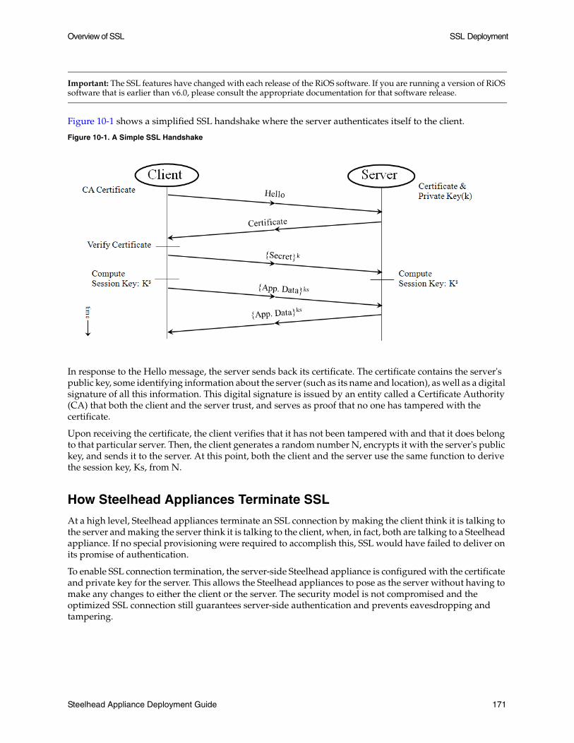
Overview of SSL SSL Deployment
Important: The SSL features have changed with each release of the RiOS software. If you are running a version of RiOS software that is earlier than v6.0, please consult the appropriate documentation for that software release.
Figure 10-1 shows a simplified SSL handshake where the server authenticates itself to the client.
Figure 10-1. A Simple SSL Handshake
In response to the Hello message, the server sends back its certificate. The certificate contains the server's public key, some identifying information about the server (such as its name and location), as well as a digital signature of all this information. This digital signature is issued by an entity called a Certificate Authority (CA) that both the client and the server trust, and serves as proof that no one has tampered with the certificate.
Upon receiving the certificate, the client verifies that it has not been tampered with and that it does belong to that particular server. Then, the client generates a random number N, encrypts it with the server's public key, and sends it to the server. At this point, both the client and the server use the same function to derive the session key, Ks, from N.
How Steelhead Appliances Terminate SSL
At a high level, Steelhead appliances terminate an SSL connection by making the client think it is talking to the server and making the server think it is talking to the client, when, in fact, both are talking to a Steelhead appliance. If no special provisioning were required to accomplish this, SSL would have failed to deliver on its promise of authentication.
To enable SSL connection termination, the server-side Steelhead appliance is configured with the certificate and private key for the server. This allows the Steelhead appliances to pose as the server without having to make any changes to either the client or the server. The security model is not compromised and the optimized SSL connection still guarantees server-side authentication and prevents eavesdropping and tampering.
Steelhead Appliance Deployment Guide 171

SSL Deployment Overview of SSL
When transferring data over the WAN on behalf of an optimized SSL connection, the client and server-side Steelhead appliances must ensure that their inner connection provides all the security features the original SSL connection would have had it not been optimized. Steelhead appliances accomplish this by establishing their own SSL connection between themselves. To secure the connection, each Steelhead appliance is configured with the certificate of the peer Steelhead appliance.
To summarize, to securely terminate an SSL connection to an SSL server, the server-side Steelhead appliance has the following pieces of configuration:
The certificate and private key pair of the server. Note that this certificate and private key pair does not have to be the same as the one used by the actual server. In a production environment, it would typically be signed by a CA trusted by the client.
The certificate of the client-side Steelhead appliance. (The client-side Steelhead appliances just have the server-side Steelhead appliance's certificate.)
Distributed termination works as follows:
Full SSL handshakes are terminated on the server-side Steelhead appliance.
The master secret containing information that allows the computation of the session key for reusing the session is transported to the session cache of the client-side Steelhead appliance.
The subsequent handshakes are reused and terminated on the client-side Steelhead appliance.
Once the SSL connection is terminated, there are just three session keys involved: kc, ks, and kt. Figure 10-2 shows a high-level view of the steps taken as data crosses the network from the client to the server.
Figure 10-2. Typical Data Transfer Operations on an SSL Connections Accelerated by Steelhead Appliances
172 Steelhead Appliance Deployment Guide

Configuring SSL on Steelhead Appliances SSL Deployment
Figure 10-3 shows in time sequence, the complete set of actions to set up and SSL connection.
Figure 10-3. Time Sequence Diagram
Configuring SSL on Steelhead Appliances
This section describes how to deploy SSL on the Steelhead appliances and provides common configuration examples. It includes the following sections:
“SSL Required Components,” next
“Setting Up a Simple SSL Deployment” on page 174
“Configuring SSL in a Production Environment” on page 177
“Steelhead Mobile SSL High-Security Mode” on page 183
SSL Required Components
You need the following SSL components to deploy SSL on Steelhead appliances:
An Enhanced Cryptography License Key - US export restrictions require that this license is installed on each Steelhead appliance that has SSL enabled. You can acquire Enhanced Cryptography License Keys by filling out the online form available at: http://sslcert.riverbed.com.
Server certificate and private key - The server certificate can either be self-signed, signed by a well-known CA, or signed by your organization's own CA. It can also either be the same as or different than the certificate used by the actual server. The correct type of certificate depends on your deployment.
Steelhead Appliance Deployment Guide 173

SSL Deployment Configuring SSL on Steelhead Appliances
RiOS v6.0 simplifies the SSL configuration process because it eliminates the need to add each server certificate individually. Prior to v6.0, you need to provide an IP address, port, and certificate to enable SSL optimization for a server. In RiOS v6.0, you need only to add unique certificates to a Certificate Pool on the server-side Steelhead appliance. When a client initiates an SSL connection with a server, the Steelhead appliance matches the common name of the certificate on the server with one in its certificate pool. If it finds a match, it adds the server name to the list of discovered servers that are optimizable and all subsequent connections to that server are optimized.
If it does not find a match, it adds the server name to the list of bypassed servers and all subsequent connections to that server are not optimized. The discovered and bypassed server lists appear on the SSL Main Settings page.
Certificate Authority certificates - When the server-side Steelhead appliance establishes a connection to the server, it needs to validate the certificate on the server. It is common to have this certificate signed by a commercial CA such as VeriSign. Certificates for these common CAs are preinstalled on Steelhead appliances, which allows the appliance to validate the authenticity of the server certificate without any additional configuration. When a proprietary CA is used, the certificate for this CA must be installed on the server-side Steelhead appliance.
Peer certificates - These certificates are required on each Steelhead appliance participating in SSL optimization. The peer certificates enable the client and the server-side Steelhead appliances to peer with each other securely. These certificates can be distributed in several different ways (manual cut-and-paste, using the white, gray, and black peering lists, or through the Central Management Console). The following sections discuss these methods in detail.
Setting Up a Simple SSL Deployment
This section describes the steps required to configure the simplest of all the SSL deployments. This simple deployment consciously makes a trade-off between simplicity and security in favor of the former and installs a self-signed server certificate on the server-side Steelhead appliance.
Important: The configuration in this section shows a simple deployment used to quickly set up a test environment for an already-deployed enterprise SSL-based Web application. Because this deployment actually breaks the SSL security model, it is best suited for scenarios where the focus is on quantifying performance improvement and not security.
Using two Steelhead appliances, a WAN simulator, and a LAN connection to the Web server, you have all the tools necessary to conduct a series of performance tests. It is not necessary to acquire or generate a valid certificate for the server.
This configuration assumes the SSL server is set up and running and that the client-side and the server-side Steelhead appliances can already optimize non-SSL TCP traffic.
To set up a simple SSL deployment
1. On the client-side Steelhead appliance, choose Configure > Networking > Port Labels to display the Port Labels page.
2. Select the Secure label, remove port 443, click Remove Selected, and click Apply.
3. On the server-side Steelhead appliance, choose Configure > Optimization > SSL Main Settings to display the SSL Main Settings page.
174 Steelhead Appliance Deployment Guide

Configuring SSL on Steelhead Appliances SSL Deployment
4. Select Enable SSL Optimization and click Apply.
Figure 10-4. SSL Main Settings Page
Steelhead Appliance Deployment Guide 175

SSL Deployment Configuring SSL on Steelhead Appliances
5. Click Add a New SSL Certificate, specify the common name of the server (or specify a wildcard server name), select Generate New Private Key and Self-Signed Public Certificate, and click Add.
Figure 10-5. SSL Main Settings Page
6. Choose Configure > Optimization > Secure Peering (SSL) to display the Secure Peering (SSL) page.
7. Under Certificate, click PEM, and press Ctrl+C to copy the certificate to the clipboard.
Figure 10-6. PEM Certificate
176 Steelhead Appliance Deployment Guide

Configuring SSL on Steelhead Appliances SSL Deployment
8. On the client-side Steelhead appliance, choose Configure > Optimization > SSL Main Settings, select Enable SSL Optimization and click Apply.
9. Choose Configure > Optimization > Secure Peering (SSL).
10. Under Peering Trust, click Add a New Trusted Entity.
Figure 10-7. Adding a New Trusted Entity
11. Select Trust New Certificate, enter an Optional Local Name, paste your copied certificate into the Cert Text box (Ctrl+V), and click Add.
12. Save the configuration and restart the optimization service on both Steelhead appliances.
13. In the Management Console on the server-side Steelhead appliance, verify that the connections are being optimized by viewing the SSL report. This report summarizes the SSL connection requests and connection rate.
In the Management Console on the server-side Steelhead appliance, the Current Connections report lists connections as optimized without a Protocol Error flag (new statistics appear every 60 seconds).
Another sign that SSL is working is receiving a warning pop-up from the browser, notifying the user that the authenticity of the server cannot be established. This is expected, because the server-side Steelhead appliance does not have a valid server certificate, but is using one that was automatically generated.
For details on troubleshooting and verification, see “Troubleshooting and Verification” on page 185.
Note: Prior to RiOS v5.5, port 443 was not in the list of ports that had HTTP-specific optimizations enabled. To turn these on for an SSL-enabled Web application in these earlier versions of RiOS, you had to add the appropriate in-path rule on the client-side Steelhead appliance to turn on HTTP optimizations in addition to the above steps.
Configuring SSL in a Production Environment
A production SSL deployment requires more configuration steps to provide a secure SSL trust model. The configuration complexity arises for the following reasons:
Steelhead Appliance Deployment Guide 177

SSL Deployment Configuring SSL on Steelhead Appliances
Because there are typically more than two Steelhead appliances involved, there are more trust relationships to manage.
It is unacceptable to break the SSL trust model. Self-signed certificates cannot be used. When this happens you must install a real certificate and private key for each server on each server-side Steelhead appliance.
You might want to incorporate other features; for example, you might encrypt the datastore in the branch office or in both the branch office and the data center. You might also want to change the secure vault password on the server-side Steelhead appliance.
In an SSL deployment consisting of 100 branch sites all linked to a single data center that hosts an SSL server, each branch Steelhead appliance needs to have a copy of the peer certificate for the server-side Steelhead appliance, and the server-side Steelhead appliance needs each a peer certificate for each branch Steelhead appliance. If you configure the system as described in “To set up a simple SSL deployment” on page 174, you need to do too much cut-and-pasting.
Fortunately, Riverbed provides more streamlined methods of installing all of the certificates. Some of these reduce the cost of adding one Steelhead appliance or location to the deployment and others involve a fixed startup cost, but allow for a virtually zero-cost scale-out.
The right choice depends on the size of your deployment. In a smaller deployment, you can use the approaches detailed in “To manage Steelhead appliance trust using the white, gray, and black peering lists” on page 179, but Riverbed recommends you configure a large SSL deployment with the help of a Central Management Console.“To manage Steelhead appliance trust with a CMC” on page 180 explains how you can use the CMC to simplify SSL configuration.
Deployment Example—Managing Steelhead Appliance Trust using the White, Gray, and Black Peering Lists
In a production environment it is unacceptable to have WAN optimization equipment make SSL less secure. Thus, using a self-signed server key on the server-side Steelhead appliance is not an option, because it does not allow the client to authenticate the server.
You can use peering lists to configure peer certificates on Steelhead appliances running v5.0 and later. Whenever a Steelhead appliance fails to establish a secure SSL channel to its peer due to the lack of a peer certificate, that peer, along with its certificate, is put into the self-signed peer gray list. This indicates that the Steelhead appliance does not know whether it can trust the peer. If a peer is in the gray list, a Steelhead appliance still intercepts an SSL connection, and applies transport streamlining to it, but not data or application streamlining.
The system administrator can examine the stored peer certificate for authenticity and move any peer from the gray list to either the white list or the black list. Presence in the white list indicates that the peer is trusted, and its certificate is valid. When two Steelhead appliances that are attempting to peer with each other have each other in their respective white lists, they can establish a secure SSL channel between themselves. Presence in the black list indicates that the peer is not trusted, and that the Steelhead appliance cannot create a secure SSL channel to it.
Important: Riverbed highly recommends verifying the fingerprint on the peer certificate to confirm that it does indeed belong to the peer Steelhead appliance.
Using self-signed peer lists is a reasonable way to deploy SSL optimization in smaller deployments. This method also allows for the simplest set-up, as is shown in the following procedure.
178 Steelhead Appliance Deployment Guide

Configuring SSL on Steelhead Appliances SSL Deployment
To manage Steelhead appliance trust using the white, gray, and black peering lists
1. Optionally, enable the Steelhead appliances to reuse the original client-side SSL session key. This setting improves connection setup performance. Both the client-side Steelhead appliance and the server-side Steelhead appliance must be running RiOS v6.0 or later.
In the Management Console of the client-side Steelhead appliance, choose Configure > Optimization > Advanced Settings and select Client Side Session Reuse. Reusing the session key provides two benefits: it lessens the CPU load because it eliminates expensive asymmetric key operations and it shortens the key negotiation process. By default, this option is disabled. The timeout value specifies the amount of time the client can reuse a session with an SSL server after the initial connection ends. The range is 2 minutes to 24 hours. The default value is 10 hours.
2. Reuse the server's actual certificate and private key. For details on how to obtain these on a production Apache or IIS server, see “Interacting with SSL-Enabled Web Servers” on page 186.
—or—
Create a new, valid certificate and private key for the server. This certificate needs to be signed by a Certificate Authority that is recognized by the client.
3. On the client-side Steelhead appliances, choose Configure > Networking > Port Labels to display the Port Labels page.
4. Select the Secure label, remove port 443, click Remove Selected, and click Apply.
5. On both the client-side and the server-side Steelhead appliances, choose Configure > Optimization > SSL Main Settings and click Enable SSL Optimization.
6. On the server-side Steelhead appliance, open Configure > Optimization > SSL Main Settings page and add the SSL server.
7. Restart the optimization service on both Steelhead appliances.
8. Establish an SSL connection from a client behind the client-side Steelhead appliance to the server.
9. On both the server-side and the client-side Steelhead appliances, choose Configure > Optimization > Secure Peering (SSL).
10. Under Self-Signed Peer Gray List, identify the peer Steelhead appliance. Optionally, you can examine this certificate on the peer and make sure both copies match. Once you verify the authenticity of the certificate, select Trust from the Actions drop-down menu.
Steelhead Appliance Deployment Guide 179

SSL Deployment Configuring SSL on Steelhead Appliances
Important: Before moving a peer from the gray list to the trusted peers white list, it is critical to verify that the certificate fingerprint does indeed belong to a peer Steelhead appliance, particularly to avoid the potential risk of a man-in-the-middle attack.
Figure 10-8. Self-Signed Peer Gray List
11. Save the configuration.
The Steelhead appliances are now able to optimize connections to the configured SSL servers. To see successful SSL connections, view the Reports > Optimization > SSL to view the SSL report. For details on verifying SSL connections, see “Troubleshooting and Verification” on page 185.
CMC and SSL
For larger Steelhead appliance deployments, the Central Management Console (CMC) can enable an SSL deployment to scale to an arbitrary size. The following deployment example uses the CMC to manage trust.
Deployment Example—Managing Steelhead Appliance Trust with a CMC
In this example, you create a policy on the CMC that automatically configures each Steelhead appliance with the peer certificates of all the other Steelhead appliances. Thus, after the initial CMC-based configuration, each Steelhead appliance now trusts all the other Steelhead appliances in the deployment.
To manage Steelhead appliance trust with a CMC
1. Choose Manage > Policies, and click Create New Policy to display the Create New Policy page.
2. Enter the policy name into the Policy Name box, and click Add.
3. Select Optimization for policy type.
180 Steelhead Appliance Deployment Guide

Configuring SSL on Steelhead Appliances SSL Deployment
4. Click the peer trust name to display a list of the policy pages.
Figure 10-9. Using a CMC to Manage Trust
5. Select SSL Peering to enable the policy page to take effect for a policy push.
6. Click Apply.
7. Select the SSL Peering policy page.
Steelhead Appliance Deployment Guide 181

SSL Deployment Configuring SSL on Steelhead Appliances
8. Select either specific Steelhead appliances to trust each other, or click Trust All Peers.
Figure 10-10. SSL Peering Page
9. Click Update.
10. Choose Manage > Appliances.
11. Click Global to display the Edit Group Global page.
12. Select peer trust from the Optimization Policy drop-down list.
Figure 10-11. Global Appliance Option
182 Steelhead Appliance Deployment Guide

Configuring SSL on Steelhead Appliances SSL Deployment
13. Click Appliance Operations, select Push Policies from the drop-down list, select Global, and click Push.
Figure 10-12. Pushing Policies
14. When the policy push succeeds, all the Steelhead appliance peers now trust each other. When you deploy a new Steelhead appliance, it automatically inherits the peer trust policy, and is included in the Web of trust once the policy is updated across all the Steelhead appliances. You must push the policy again to have the new Steelhead appliance receive all of the peering trust certificates from other appliances. You must push the policy again if any the Steelhead appliances peering certificates are updated on either the CMC or the Steelhead appliance.
Note: You can check whether the policy push has succeeded by checking the Operations History page.
15. To complete the SSL configuration, on the client-side Steelhead appliances, choose Configure > Optimization > SSL Main Settings, select Enable SSL Optimization, and then install the server certificates and private keys on the server-side Steelhead appliance. You can do this manually, or you can use the CMC.
Note: For details on the CMC, see Steelhead Central Management Console User’s Guide.
Steelhead Mobile SSL High-Security Mode
Steelhead Mobile v2.0x and later provides a high-security mode that accelerates SSL-encrypted traffic while maintaining the preferred trust model. Using high-security mode, Steelhead Mobile 2.0 can apply its data streamlining, transport streamlining, and application streamlining mechanisms to SSL-encrypted traffic while keeping all private keys within the data center and without requiring fake certificates in branch offices. High-security mode is enabled by default.
In high-security mode, Steelhead Mobile uses two Certificate Authority certificates. The Steelhead Mobile Controller CA resides on the Controller and is used to sign the certificate on the inner channel. The other CA certificate is self-signed and is generated by and resides on each client. Steelhead Mobile ensures that this self-signed certificate is trusted by Internet Explorer and Firefox. This Steelhead Mobile Internal CA Certificate is used to generate and sign proxy certificates dynamically.
Steelhead Appliance Deployment Guide 183

SSL Deployment Configuring SSL on Steelhead Appliances
The authentication process is essentially identical to how a Steelhead appliance verifies the identity of other client-side Steelhead appliances: CAs are used to verify the identity of the certificates presented to the Steelhead appliances. However, when the Mobile Controller does not want a client to optimize SSL traffic (the equivalent of placing the CA in the black peering list on the Steelhead appliance), it simply assigns the client a package and acceleration policy that does not have SSL enabled. (You could also simply disable SSL on a client-side appliance if you do not want it to optimize SSL traffic.)
The following sequence of operations occur before Steelhead Mobile optimizes a connection:
1. Steelhead Mobile automatically adds the Steelhead Mobile CA Certificate into the Windows Cert store (used by Internet Explorer) and into the Firefox browser trusted CA list.
2. The browser makes a connection to the server, the connection is intercepted, and splices are set up.
3. The browser initiates an SSL handshake by sending a client_hello message.
4. Steelhead Mobile establishes a secure inner channel over the existing inner TCP connection using the certificate signed by the Controller CA.
5. Steelhead Mobile sends the begin_handshake(cn) message to the server-side Steelhead appliance.
6. The server-side Steelhead appliance performs a handshake with the server and sends the server's(cn) to Steelhead Mobile.
7. Steelhead Mobile receives the server's(cn) and generates a proxy server certificate signed by the internal Steelhead Mobile CA.
8. Steelhead Mobile completes a handshake with the browser.
Three separate secure connections are now established and traffic can now be optimized.
Note: For instructions on how to enable high-security mode for Steelhead Mobile, see the Steelhead Mobile Controller User’s Guide and the Steelhead Mobile Deployment Guide.
184 Steelhead Appliance Deployment Guide

Troubleshooting and Verification SSL Deployment
Troubleshooting and Verification
Use the following tools to verify that you have configured SSL support correctly:
SSL Optimization - After completing the SSL configuration on both the Steelhead appliances and restarting the Steelhead service, access the secure server from the Web browser. The following events take place in a successful optimization:
– If you specified a self-signed proxy certificate for the server on the server-side Steelhead appliance, a pop-up window appears on the Web browser. View the certificate details to ensure that it is the same as the certificate on the server-side Steelhead appliance.
– In the Management Console, the Current Connections report lists the new connection as optimized without a Protocol Error flag (new statistics appear every 60 seconds).
– In the Management Console, the Traffic Summary report displays encrypted traffic (typically, HTTPS).
– Verify that the backend server IP appears in the SSL Discovered Server Table (Optimizable) in the SSL Main Settings page.
Note: Because all the SSL handshake operations are processed by the server-side Steelhead appliance, all the SSL statistics are reported on the server-side Steelhead appliance. No SSL statistics are reported on the client-side Steelhead appliance.
Monitoring SSL Connections - Use the following tools to verify SSL optimization and to monitor SSL progress:
– On the client Web browser, click the Lock icon to obtain certificate details. The certificate must match the proxy certificate installed on server-side Steelhead appliance.
– In the Current Connections report verify the destination IP address, port 443, the Connection Count as Established (three yellow arrows on the left side of the table), SDR Enabled (three cascading yellow squares on the right side of the table), and that there is no Protocol Error (a red triangle on the right side of the table).
– In the SSL Statistics report (on the server-side Steelhead appliance only) look for connection requests (established and failed connections), connection establishment rate, and concurrent connections.
Monitoring Secure Inner Channel Connections - Use the following tools to verify that secure inner channels are in use for the selected application traffic types:
– Navigate to Reports > Networking > Current Connections. Look for the Lock icon and three yellow arrows, which indicate the connection is encrypted and optimized. If the Lock icon is not visible or is dimmed, click the magnifying glass to view a failure reason that explains why the Steelhead appliance is not using the secure inner channel to encrypt the connection. If there is a red protocol error, click the magnifying glass to view the reason for the error.
– Search the client-side and server-side Steelhead appliance logs for ERR and WARN.
– Check the peering trust lists on the client-side and server-side Steelhead appliances. Both Steelhead appliances should have the other Steelhead in their white list, indicating that they trust each other.
Steelhead Appliance Deployment Guide 185

SSL Deployment Interacting with SSL-Enabled Web Servers
Interacting with SSL-Enabled Web Servers
This section describes how to obtain the server certificate and private key on two Web servers: Apache and Microsoft IIS. It includes the following sections:
“Obtaining the Server Certificate and Private Key,” next
“Generating Self-Signed Certificates” on page 187
Obtaining the Server Certificate and Private Key
SSL is a protocol that enables the underlying application to transmit data securely over an insecure network. At the very foundation of SSL is the assumption that an authenticated party (for example, a Web server) has exclusive access to its private key. If any other entity has this private key, it will be able to mount a man-in-the-middle attack on a connection to the authenticated party.
This is how Steelhead appliances are able to optimize SSL traffic: the server-side Steelhead appliance is configured with the server's certificate and private key, which enables it to intercept all SSL connections to the server.
Apache Certificates and Private Keys
The following procedures explain how to locate the Apache server certificate and private key and import them into the server-side Steelhead appliance.
To obtain the server certificate and private key from an Apache-based Web server:
1. Locate the Apache httpd.conf configuration file.
2. Look through the file for lines beginning with SSLCertificateFile and SSLCertificateKeyFile. For example:
SSLCertificateFile /etc/foo/bar/server.crtSSLCertificateKeyFile /etc/foo/bar/server.key
The filename following SSLCertificateFile is the server certificate. The filename following SSLCertificateKeyFile is the server private key. After you locate these files, you can import them into the server-side Steelhead appliance configuration.
To import the certificate and private key
1. On the server-side Steelhead appliance, choose Configure > Optimization > SSL Main Settings.
2. Click Add a New SSL Certificate.
3. Click Import Existing Private Key and CA-Signed Public Certificate (Two Files in PEM or DER formats).
4. Under Import Private Key, click Local File, click Browse, and go to the certificate key file.
5. Under Import Public Certificate, click Local File, click Browse, and go to the server certificate file.
6. Click Add.
186 Steelhead Appliance Deployment Guide

Interacting with SSL-Enabled Web Servers SSL Deployment
IIS Certificates and Private Keys
The following procedures explain how obtain the server certificate and private key from a IIS Web server and import them into the server-side Steelhead appliance.
To obtain the server certificate and private key from an IIS Web server:
1. From the Windows Start > Run menu, type mmc to launch the Microsoft Management Console (MMC).
2. Within the IIS snap-in, go through the tree to the Web server in question. (If the IIS snap-in does not exist, choose File > Add/Remove Snap-in, select the Web server, and click Add.)
3. Right-click the server item and select Properties.
4. Click the Directory Security tab.
5. Click View Certificate.
6. Click the Details tab.
7. Click Copy to File.
8. Select Yes, export private key.
Both the certificate and the private key are now stored in a single file with the filename you specified. The filename ends with the .pfx extension.
To import the certificate and private key
1. On the server-side Steelhead appliance, choose Configure > Optimization > SSL Main Settings.
2. Under SSL Server Certificates, click Add a New SSL Certificate.
3. Click Import Existing Private Key and CA-Signed Public Certificate (One File in PEM or PKCS12 formats).
4. Under Import Single File, click Local File, click Browse, and go to the .pfx file.
Note: Because the file .pfx file is not scrambled with a password, you can leave the Decryption Password field blank.
5. Click Add.
Generating Self-Signed Certificates
In certain situations you might not want to or might not be able to use the server's real private key. If that is the case, you can generate a self-signed certificate and private key pair for the server and install them on the server-side Steelhead appliance. This certificate is not signed by any real certificate authority, but is instead signed by the private key itself, and is thus called a self-signed certificate.
During SSL connection establishment, when the server-side Steelhead appliance presents the self-signed certificate to the client (for example, a Web browser), the client cannot verify the authenticity of the certificate. From the client's point of view, security may have been compromised, and the user is typically alerted with a message to this effect.
Steelhead Appliance Deployment Guide 187

SSL Deployment Interacting with SSL-Enabled Web Servers
Generating Self-Signed Certificates with Apache
A typical SSL-enabled Apache installation comes with a utility called openssl, which you can use to generate the self-signed certificate. Enter the following command:
$ openssl req -new -x509 -nodes -out server.crt -keyout server.key
This adds two files to the current directory, server.crt and server.key. These files correspond to the certificate and the private key, respectively. The next step is to import the files into the server-side Steelhead appliance configuration.
To import the certificate and private key
1. On the server-side Steelhead appliance, Steelhead appliance, choose Configure > Optimization > SSL Main Settings.
2. Under SSL Server Certificates, click Add a New SSL Certificate.
3. Click Import Existing Private Key and CA-Signed Public Certificate (Two Files in PEM or DER formats).
Note: Because the file server.key is not scrambled with a password, you can leave the Decryption Password field blank.
4. Click Add.
Generating Self-Signed Certificates with IIS
If you want to generate a self-signed certificate for an IIS-based Web server, you have two options.
To generate self-signed certificates with IIS
Install Cygwin from http://www.cygwin.com and include the openssl package in the installation. This gives you access to the openssl utility from X.2.1, which you can use to generate the certificate and private key.
—or—
Download and install a set of IIS 6.0 Resource Kit Tools from Microsoft athttp://www.microsoft.com/downloads/details.aspx?FamilyID=56fc92ee-a71a-4c73-b628-ade629c89499&DisplayLang=en.
This package contains a utility called SelfSSL which you can use to generate a self-signed certificate and private key for a Web server. SelfSSL also automatically installs the certificate for that Web server instance of IIS, so you need to follow the steps in X.1.2 to extract the certificate into a file.
Note: SelfSSL will replace an existing certificate for a Web server instance.
188 Steelhead Appliance Deployment Guide

CHAPTER 11 Protocol Optimization in the Steelhead Appliance
This chapter describes the basic steps for configuring Steelhead appliance protocol optimization. It includes the following sections:
“CIFS Optimization,” next
“HTTP Optimization” on page 190
“Oracle Forms Optimization” on page 193
“MAPI Optimization” on page 194
“MS-SQL Optimization” on page 194
“NFS Optimization” on page 194
“Lotus Notes Optimization” on page 196
“Citrix ICA Optimization” on page 197
This chapter assumes you are familiar with:
CIFS, HTTP, MAPI, MS-SQL, NFS, and SSL protocols.
By default, Steelhead appliances optimize CIFS, MAPI, HTTP, and Oracle Forms protocols, and MS-SQL for Microsoft Project 2003.
You can also configure Steelhead appliances to optimize MS-SQL, NFS, Lotus, Citrix ICA, and SSL protocols. For details on optimizing SSL, see Chapter 10, “SSL Deployment.”
CIFS Optimization
You can display and modify CIFS optimization and SMB signing settings on the Configure > Optimization > CIFS page.
RiOS v5.5x and later includes settings to optimize Microsoft Office and CIFS traffic with SMB signing enabled.
RiOS v6.0 supports CIFS latency optimization and SMB Signing settings for Mac OS X 10.5.x and later clients.
CIFS latency optimization does not require a separate license and is enabled by default.
Typically, you disable CIFS optimizations only to troubleshoot the system.
Steelhead Appliance Deployment Guide 189

Protocol Optimization in the Steelhead Appliance HTTP Optimization
For details about configuring CIFS optimization, see the Steelhead Management Console User’s Guide.
HTTP Optimization
A typical Web page is not a single file that is downloaded all at once. Instead, Web pages are composed of dozens of separate objects—such as .jpg and .gif images, JavaScript code, and cascading style sheets—each of which must be requested and retrieved separately, one after the other. Given the presence of latency, this behavior is highly detrimental to the performance of Web-based applications over the WAN. The higher the latency, the longer it takes to fetch each individual object and, ultimately, to display the entire page.
HTTP optimization works for most HTTP and HTTPS applications, including SAP, Customer Relationship Management, Enterprise Resource Planning, Financials, Document Management, and Intranet portals.
The RiOS v5.0 and later HTTP latency optimizations include features that target different types of Web applications. The following features can be used individually or in combination with each other.
URL Learning - The Steelhead appliance learns associations between a base request and a follow-on request. This feature is most effective for Web applications with large amounts of static content, for example, images, style sheets, and so forth. Instead of saving each object transaction, the Steelhead appliance saves only the request URL of object transactions in a Knowledge Base and then generates related transactions from the list. This feature uses the Referer header field to generate relationships between object requests and the base HTML page that referenced them and to group embedded objects. This information is stored in an internal HTTP database. The following objects are retrieved by default: .gif, .jpg, .css, .js, .png. You can add more object types to be retrieved.
Parse and Prefetch - The Steelhead appliance includes a specialized algorithm that determines which objects are going to be requested for a given Web page and prefetches them so that they are readily available when the client makes its requests. This feature complements the URL Learning feature by handling dynamically generated pages and URLs that include state information.
Parse and Prefetch essentially reads a page, finds HTML tags that it recognizes as containing a prefetchable object, and sends out prefetch requests for those objects. Typically, a client would need to request the base page, parse it, and then send out requests for each of these objects. This still occurs, but with Parse and Prefetch the Steelhead appliance has quietly perused the page before the client receives it and has already sent out the requests. This allows it to serve the objects as soon as the client requests them, rather than forcing the client to wait on a slow WAN link.
For example, when an HTML page contains the tag <img src=”my_picture.gif”>, the Steelhead appliance prefetches the image my_picture.gif because it parses an img tag with an attribute of src by default. The HTML tags that are prefetched by default are base/href, body/background, img/src, link/href, and script/src. You can add additional object types to be prefetched.
Removal of Unfetchable Objects - The Steelhead appliance removes unfetchable objects from the URL Learning Knowledge Base.
Object Prefetch Table - The Steelhead appliance stores object prefetches from HTTP GET requests for cascading style sheets, static images, and JavaScript files. This helps the client-side Steelhead appliance respond to If-Modified-Since (IMS) requests and regular requests from the client, thus cutting back on round trips across the WAN. This feature is useful for applications that use a lot of cacheable content.
190 Steelhead Appliance Deployment Guide

HTTP Optimization Protocol Optimization in the Steelhead Appliance
Persistent Connections - The Steelhead appliance uses an existing TCP connection between a client and a server to prefetch objects from the Web server that it determines are about to be requested by the client. Many Web browsers open multiple TCP connections to the Web server when requesting embedded objects. Typically, each of these TCP connections go through a lengthy authentication dialog before the browser can request and receive objects from the Web server on that connection. NTLM is a Microsoft authentication protocol which employs a challenge-response mechanism for authentication, in which clients are required to prove their identities without sending a password to a server. NTLM requires the transmission of three messages between the client (wanting to authenticate) and the server (requesting authentication).
Because these authentication dialogs are time consuming, if your Web servers require NTLM authentication you can configure your Steelhead appliance to re-use existing NTLM authenticated connections to avoid unnecessarily authenticating extra connections.
All HTTP optimization features are driven by the client-side Steelhead appliance. The client-side Steelhead appliance sends the prefetched information to the server-side Steelhead appliance. Prefetched data and object prefetches are served from the client-side Steelhead appliance upon request from the browser. The client-side Steelhead appliance must be running RiOS v5.0.x or later. The server-side Steelhead appliance must be running RiOS v4.0.x or later.
You can set up an optimization scheme that applies to all HTTP traffic, or create individual schemes for each server subnet. Therefore, you can configure an optimization scheme that includes your choice of prefetch optimizations for one range of server addresses, with that range encompassing as large a network as you need, from a single address to all possible addresses.
The following situations might affect HTTP optimization:
Fat Client - Not all applications accessed through a Web browser use the HTTP protocol. This is especially true for fat clients that run inside a Web browser which might use proprietary protocols to communicate with a server. HTTP optimization does not improve performance in such cases.
Digest for Authentication - Some Web servers might require users to authenticate themselves before allowing them access to certain Web content. Digest Authentication is one of the less popular authentication schemes, although it is still supported by most Web servers and browsers. Digest authentication requires the browser to include a secret value which only the browser and server know how to generate and decode. Because the Steelhead appliance cannot generate these secret values, it cannot prefetch objects protected by Digest authentication.
Object Authentication - It is uncommon for Web servers to require separate authentication for each object requested by the client, but occasionally Web servers are configured to use per object authentication. In such cases, the HTTP prefetch does not improve HTTP performance.
Comparing the HTTP Optimization Features
The following table compares the HTTP optimization features.
URL Learning Parse and Prefetch
Object Prefetch Table
The application includes dynamic URLs
Not effective Good results Good results
Is there a learning phase (first user transaction)?
Yes No Yes
Steelhead Appliance Deployment Guide 191

Protocol Optimization in the Steelhead Appliance HTTP Optimization
Basic Steps
The following procedures summarize the basic steps for configuring HTTP optimization.
1. Enable HTTP optimization for prefetching Web objects. This is the default setting.
2. Enable strip compression. This is the default setting. Strip compression enables the HTTP blade to remove the Accept-Encoding lines from the HTTP header that contain gzip or deflate. These Accept-Encoding directives allow Web browsers and servers to send and receive compressed content rather than raw HTML.
3. Specify object extensions that represent pre-fetched objects for URL Learning. By default the Steelhead appliance prefetches .jpg, .gif, .js, .png, and .css objects.
4. Select Insert Keep Alive to maintain persistent connections. Often this feature is turned off even though the Web server can support it. This is especially true for Apache Web servers that serve HTTPS to Microsoft Internet Explorer browsers.
5. Enable cookies to track repeat requests from the client.
6. Optionally, specify which HTML tags to prefetch for Parse and Prefetch. By default the Steelhead appliance prefetches base/href, body/background, img/src, link/href, and script/src HTML tags.
7. Optionally, set an HTTP optimization scheme for each server subnet. For example, an optimization scheme can include a combination of the URL Learning, Parse and Prefetch, or metadata response features. The default setting is URL Learning only.
8. If necessary, define in-path rules that specify when to apply HTTP optimization and whether to enable HTTP latency support for HTTPS.
Note: In order for the Steelhead appliance to optimize HTTPS traffic (HTTP over SSL), you must configure a specific in-path rule that enables both SSL optimization and HTTP optimization.
9. Click the Save icon to save your settings permanently.
10. View and monitor HTTP statistics in the Management Console Reports > Optimization > HTTP Statistics page.
For details about configuring HTTP optimization, see the Steelhead Management Console User’s Guide.
When does the prefetch occur? With the base request, after the learning phase
After one Round-Trip Time
N/A
Does the application include embedded object requests from JavaScript and CSS?
Yes No Yes
URL Learning Parse and Prefetch
Object Prefetch Table
192 Steelhead Appliance Deployment Guide

Oracle Forms Optimization Protocol Optimization in the Steelhead Appliance
Oracle Forms Optimization
You can display and modify Oracle Forms optimization settings in the Configure > Optimization > Oracle Forms page.
Oracle Forms is a platform for developing user interface applications to interact with an Oracle database. It uses a Java applet to interact with the database in either native, HTTP, or HTTPS mode. The Steelhead appliance decrypts, optimizes, and then re-encrypts the Oracle Forms traffic.
You can configure Oracle Forms optimization in the following modes:
Native -The Java applet communicates with the backend server, typically over port 9000. Native mode is also known as socket mode.
HTTP -The Java applet tunnels the traffic to the Oracle Forms server over HTTP, typically over port 8000.
HTTPS - The Java applet tunnels the traffic to the Oracle Forms server over HTTPS, typically over port 443. HTTPS mode is also known as SSL mode.
Use Oracle Forms optimization to improve Oracle Forms traffic performance. RiOS v5.5.x and later supports 6i, which comes with Oracle Applications 11i. RiOS v6.0 and later supports 10gR2, which comes with Oracle E-Business Suite R12.
This feature does not need a separate license and is enabled by default. However, you must also set an in-path rule to enable this feature.
Note: Optionally, you can enable IPsec encryption to protect Oracle Forms traffic between two Steelhead appliances over the WAN or use the Secure Inner Channel on all traffic.
Determining the Deployment Mode
Before enabling Oracle Forms optimization, you need to know the mode in which Oracle Forms is running at your organization.
To determine the Oracle Forms deployment mode
1. Start the Oracle application that uses Oracle Forms.
2. Click a link in the base HTML page to download the Java applet to your browser.
3. On the Windows taskbar, right-click the Java icon (a coffee cup) to access the Java console.
4. Choose Show Console (JInitiator) or Open <version> Console (Sun JRE).
Steelhead Appliance Deployment Guide 193

Protocol Optimization in the Steelhead Appliance MAPI Optimization
5. Locate the “connectMode=” message in the Java Console window. This message indicates the Oracle Forms deployment mode at your organization, for example:
connectMode=HTTP, nativeconnectMode=SocketconnectMode=HTTPS, native
For details about configuring Oracle Forms optimization, see the Steelhead Management Console User’s Guide.
MAPI Optimization
MAPI optimization is enabled by default. Typically, you only disable MAPI optimization to troubleshoot the system.
Note: For RiOS v5.5 and later, you can enable encrypted MAPI optimization and you do not need to disable Outlook encryption. If you are running a version of RiOS prior to v5.5, the best practice is to disable encryption for Outlook. For details, see the following Riverbed Knowledge Base article, Disabling Outlook encryption, located at https://support.riverbed.com/kb/solution.htm?id=501700000008VT8AAM.
For details about configuring MAPI optimization, see the Steelhead Management Console User’s Guide.
MS-SQL Optimization
MS-SQL optimization improves optimization for Microsoft Project.
You can also use MS-SQL protocol optimization to optimize other database applications, but you must define SQL rules to obtain maximum optimization. If you are interested in enabling the MS-SQL feature for other database applications, contact Riverbed Professional Services at http://www.riverbed.com.
For details about configuring MS-SQL optimization, see the Steelhead Management Console User’s Guide.
NFS Optimization
NFS optimization provides latency optimization improvements for NFS operations by pre-fetching data, storing it on the client Steelhead appliance for a short amount of time, and using it to respond to client requests. You enable NFS optimization in high-latency environments.
You can configure NFS settings globally for all servers and volumes or you can configure NFS settings that are specific to particular servers or volumes. When you configure NFS settings for a server, the settings are applied to all volumes on that server unless you override settings for specific volumes.
194 Steelhead Appliance Deployment Guide

NFS Optimization Protocol Optimization in the Steelhead Appliance
Important: NFS optimization is not supported in an out-of-path deployment.
Note: NFS optimization is only supported for NFS v3.
For each Steelhead appliance, you specify a policy for pre-fetching data from NFS servers and volumes. You can set the following policies for NFS servers and volumes:
Global Read/Write - Choose this policy when the data on the NFS server or volume can be accessed from any client, including LAN clients and clients using other file protocols. This policy ensures data consistency but does not allow for the most aggressive data optimization. Global Read/Write is the default value.
Custom - Create a custom policy for the NFS server.
Read-only - Any client can read the data on the NFS server or volume but cannot make changes.
After you add a server, the Management Console includes options to configure volume policies.
For detailed information, see the Steelhead Management Console User’s Guide.
Implementing NFS Optimization
This section describes the basic steps for using the Management Console to implement NFS. For detailed information, see the Steelhead Management Console User’s Guide.
Basic Steps
Perform the following basic steps to configure NFS optimizations.
1. Enable NFS in the Configure > Optimization > NFS page.
Enable NFS on all desired client and server Steelhead appliances.
2. For each client Steelhead appliance you desire, configure NFS settings that apply by default to all NFS servers and volumes. For details, see the Steelhead Management Console User’s Guide.
Configure these settings on all desired client Steelhead appliances. These settings are ignored on server Steelhead appliances. If you have enabled NFS optimization (as described in the previous step) on a server Steelhead appliance, NFS configuration information for a connection is uploaded from the client Steelhead appliance to the server Steelhead appliance when the connection is established.
Important: If NFS is disabled on a server-side Steelhead appliance, the appliance does not perform NFS optimization.
3. For each client Steelhead appliance you desire, override global NFS settings for a server or volume that you specify. You do not need to configure these settings on server Steelhead appliances. If you have enabled NFS optimization on a server Steelhead appliance, NFS configuration information for a connection is uploaded from the client Steelhead appliance to the server Steelhead appliance when the connection is established.
Steelhead Appliance Deployment Guide 195

Protocol Optimization in the Steelhead Appliance Lotus Notes Optimization
If you do not override settings for a server or volume, the global NFS settings are used. If you do not configure NFS settings for a volume, the server-specific settings, if configured, are applied to the volume. If server-specific settings are not configured, the global settings are applied to the server and its volumes.
Note: When you configure a prefetch policy for an NFS volume, you specify the desired volume by an FSID number. An FSID is a number NFS uses to distinguish mount points on the same physical file system. Because two mount points on the same physical file system have the same FSID, more than one volume can have the same FSID.
For details, see the Steelhead Management Console User’s Guide.
4. If you have configured IP aliasing for an NFS server, specify all of the server IP addresses in the Steelhead appliance NFS-protocol settings.
5. View and monitor NFS statistics in the Management Console Reports > Optimization > NFS Statistics page.
Configuring IP Aliasing
If you have configured IP aliasing (multiple IP addresses) for an NFS server, you must specify all of the server IP addresses in the Steelhead appliance NFS protocol settings in order for NFS optimization to work properly.
To configure IP aliasing on a Steelhead appliance
1. In the Management Console, choose Configure > Optimization > NFS.
2. Click Add New NFS Server to expand the page.
3. In the Name box, type the name of the NFS server.
4. Enter each server IP address in a comma separated list in the Server IP box.
5. Click Add Server.
Lotus Notes Optimization
You can enable and modify Lotus Notes optimization settings on the Configure > Optimization > Lotus Notes page.
Lotus Notes is a client-server collaborative application that provides email, instant messaging, calendar, resource, and file sharing. RiOS provides latency and bandwidth optimization for Lotus Notes v6.0 and later traffic across the WAN, accelerating email attachment transfers and server-to-server or client-to-server replications.
RiOS saves bandwidth by automatically disabling socket compression (which makes SDR more effective), and by decompressing Huffman-compressed attachments and LZ-compressed attachments when they are sent or received and recompressing them on the other side. This allows SDR to recognize attachments which have previously been sent in other ways, that is; over CIFS, HTTP, or other protocols, and also allows SDR to optimize the sending and receiving of attachments that are slightly changed from previous sends and receives.
196 Steelhead Appliance Deployment Guide

Citrix ICA Optimization Protocol Optimization in the Steelhead Appliance
To use this feature both the client-side and server-side Steelhead appliances must be running RiOS v5.5.x or later.
Enabling Lotus Notes provides latency optimization regardless of the compression type (Huffman, LZ, or none).
Before enabling Lotus Notes optimization:
Be aware that Riverbed cannot optimize encrypted Lotus Notes connections.
Lotus Notes Optimization automatically disables socket level compression for connections going through Steelheads that have this feature enabled.
For details about configuring Lotus Notes optimization, see the Steelhead Management Console User’s Guide.
Citrix ICA Optimization
You can enable and modify Citrix ICA optimization settings in the Configure > Optimization > Citrix ICA page.
To consolidate operations, some organizations install thin clients in their branch offices and install a Citrix Presentation Server in the data center to front-end the applications. The proprietary protocol that Citrix uses to move updates between the client and the server is called ICA (Independent Computing Architecture). The thin clients at the branch offices have a Citrix ICA client accessing the services at the data center which are front-ended by a Citrix Presentation Server (also called Citrix Metaframe Server in earlier versions).
RiOS v6.0 provides the following ways to recognize, prioritize, and optimize Citrix traffic:
Optimize the native ICA traffic bandwidth.
Classify and shape Citrix ICA traffic using QoS.
For details on configuring Citrix optimization, see the Steelhead Management Console User’s Guide. For details on QoS classification for Citrix traffic, see “QoS Classification for Citrix Traffic” on page 212.
Steelhead Appliance Deployment Guide 197

Protocol Optimization in the Steelhead Appliance Citrix ICA Optimization
198 Steelhead Appliance Deployment Guide

CHAPTER 12 QoS Configuration and Integration
This chapter describes how to integrate Steelhead appliances into existing Quality of Service (QoS) architectures, and how to configure Riverbed QoS. Additionally, this chapter describes how to use and configure MX-TCP. It includes the following sections:
“Overview of QoS,” next
“Integrating Steelhead Appliances into Existing QoS Architectures” on page 200
“Enforcing QoS Policies Using Riverbed QoS” on page 204
“QoS Classification for Citrix Traffic” on page 212
Overview of QoS
This section introduces QoS and Riverbed QoS. It includes the following sections:
“Introduction to QoS,” next
“Introduction to Riverbed QoS” on page 200
Introduction to QoS
QoS is a reservation system for network traffic in which you create QoS classes to distribute network resources. The classes are based on traffic importance, bandwidth needs, and delay-sensitivity. You allocate network resources to each of the classes. Traffic flows according to the network resources allocated to its class.
Steelhead appliances enforce QoS policies or co-exist in networks where QoS classification and enforcement is performed outside the Steelhead appliances.
Many QoS implementations use some form of Packet Fair Queueing (PFQ), such as Weighted Fair Queueing or Class-Based Weighted Fair Queueing. As long as high-bandwidth traffic requires a high priority (or vice-versa), PFQ systems perform adequately. However, problems arise for PFQ systems when the traffic mix includes high-priority, low-bandwidth traffic, or high-bandwidth traffic that does not require a high priority, particularly when both of these traffic types occur together. Features such as low-latency queueing (LLQ) attempt to address these concerns by introducing a separate system of strict priority queueing that is used for high-priority traffic. However, LLQ is not a principled way of handling bandwidth and latency trade-offs. LLQ is a separate queueing mechanism meant as a work around for PFQ limitations.
Steelhead Appliance Deployment Guide 199

QoS Configuration and Integration Integrating Steelhead Appliances into Existing QoS Architectures
Introduction to Riverbed QoS
The Riverbed QoS system is not based on PFQ, but rather on Hierarchical Fair Service Curve (HFSC). HFSC delivers low latency to traffic without wasting bandwidth and delivers high bandwidth to delay-insensitive traffic without disrupting delay-sensitive traffic. The Riverbed QoS system achieves the benefits of LLQ without the complexity and potential configuration errors of a separate queuing mechanism.
The Steelhead appliance HFSC-based QoS enforcement system provides the flexibility needed to simultaneously support varying degrees of delay requirements and bandwidth usage. For example, you can enforce a mix of high-priority, low-bandwidth traffic patterns (for example, SSH, Telnet, Citrix, RDP, and CRM systems) with lower priority, high-bandwidth traffic (for example, FTP, backup, and replication). This allows you to protect delay-sensitive traffic such as VoIP, as well as other delay-sensitive traffic such as RDP and Citrix. You can do this without having to reserve large amounts of bandwidth for the traffic classes. For details, see “QoS Classification for Citrix Traffic” on page 212.
QoS classification occurs during connection setup for optimized traffic, before optimization and compression. QoS shaping and enforcement occurs after optimization and compression.
By design, QoS can be applied to both pass-through and optimized traffic. QoS is implemented in the operating system; it is not directly a part of the optimization service. QoS classification occurs during connection setup for optimized traffic - before optimization and compression. QoS shaping and enforcement occurs after optimization and compression. Some Steelhead appliance models have a limit to their outbound optimized throughput, therefore keep in mind that optimized traffic may be subject to limits before QoS shaping and enforcement is applied. Pass-through traffic by definition is not optimized and therefore is not subject to any outbound optimized throughput limit of the Steelhead appliance, but pass-through traffic has the QoS shaping and enforcement applied appropriately. Deployment of Steelhead appliance, with QoS enabled, on WAN links that have a larger bandwidth than the Steelhead appliance, can be achieved without affecting the QoS shaping and enforcement of pass-through traffic.
Since the RiOS QoS system is not part of the optimization service, when the optimization service is disabled, all the traffic is pass-through and is still shaped and enforced by the QoS system.
Integrating Steelhead Appliances into Existing QoS Architectures
This section describes the integration of Steelhead appliances into existing QoS architectures. It includes the following sections:
“WAN-Side Traffic Characteristics and QoS,” next
“QoS Integration Techniques” on page 202
“QoS Marking” on page 202
When you integrate Steelhead appliances into your QoS architecture you can:
Choose whether to enforce QoS in the WAN or WAN infrastructure, or on the Steelhead appliance.
Have your optimized connections appear the same way that unoptimized connections appear to the WAN infrastructure.
Selectively apply different QoS policies depending on whether a connection is optimized or not.
Control the appearance of Steelhead appliance-optimized connections based on the following values of the original TCP connection: DSCP, IP ToS, IP address, port, and VLAN tag.
Steelhead appliances enable you to perform the following functions:
200 Steelhead Appliance Deployment Guide

Integrating Steelhead Appliances into Existing QoS Architectures QoS Configuration and Integration
Retain the original DSCP or IP precedence values
Choose the DSCP or IP precedence values
Retain the original destination TCP port
Choose the destination TCP port
Retain all of the original IP addresses and TCP ports
You do not have to use all of the Steelhead appliance functions on your optimized connections. You can selectively apply functions to different optimized traffic, based on attributes such as IP addresses, TCP ports, DSCP, and VLAN tags.
WAN-Side Traffic Characteristics and QoS
When you integrate Steelhead appliances into an existing QoS architecture, it is helpful to understand how optimized and pass-through traffic appear to the WAN, or any WAN-side infrastructure. The following figure shows how traffic appears on the WAN when Steelhead appliances are present.
Figure 12-1. How Traffic Appears to the WAN When Steelhead Appliances are Present
When Steelhead appliances are present in a network:
The optimized data for each LAN-side connection is carried on a unique WAN-side TCP connection.
The IP addresses, TCP ports, and DSCP or IP precedence values of the WAN connections are determined by the QoS marking configuration, and the Steelhead appliance WAN visibility mode configured for the connection.
When you enable Riverbed QoS enforcement, the amount of bandwidth and delay assigned to traffic is determined by the Riverbed QoS enforcement configuration. This applies to both pass-through and optimized traffic. However, this configuration is separate from the WAN traffic appearance features such as QoS marking, and Steelhead appliance WAN visibility modes. For details on WAN visibility modes, see “Overview of WAN Visibility Modes” on page 227.
Steelhead Appliance Deployment Guide 201

QoS Configuration and Integration Integrating Steelhead Appliances into Existing QoS Architectures
QoS Integration Techniques
In some networks, QoS policies do not differentiate traffic that is optimized by the Steelhead appliance. For example, because VoIP traffic is passed through the Steelhead appliance, a QoS policy that only gives priority to VoIP traffic, without differentiating between non-VoIP traffic, is unaffected by the introduction of Steelhead appliances. In these networks no QoS configuration changes are needed to maintain the existing policy, because the configuration treats all non-VoIP traffic identically, regardless of whether it is optimized by the Steelhead appliance.
Another example of a network that might not require QoS configuration changes to integrate Steelhead appliances is where traffic is marked with DSCP or ToS values before reaching the Steelhead appliance, and enforcement is made after reaching the Steelhead appliances based only on DSCP or ToS. The default Steelhead appliance configuration reflects the DSCP/ToS values from the LAN-side to the WAN-side of an optimized connection.
For example, if the QoS configuration is performed by marking the DSCP values at the source or on LAN-side switches, and enforcement is performed on WAN routers, the WAN routers see the same DSCP values for all classes of traffic, optimized or not.
These examples assume that the post-integration goal is to treat optimized and non-optimized traffic in the same manner with respect to QoS policies; some administrators might want to allocate different network resources to optimized traffic.
For details on QoS marking, see “QoS Marking” on page 202.
In networks where both classification or marking and enforcement are performed on traffic after it passes through the Steelhead appliance, you have several configuration options:
In a network where classification and enforcement is based only on TCP ports, you can use port mapping, or the port transparency WAN visibility mode. For details on port transparency, see “Port Transparency” on page 230.
In a network where classification and enforcement is based on IP addresses, you can use the full address transparency WAN visibility mode. For details on full address transparency, see “Full Address Transparency” on page 231.
For details on WAN visibility modes, see “WAN Visibility Modes” on page 227.
QoS Marking
This section describes how to use Steelhead appliance QoS marking when integrating Steelhead appliances into an existing QoS architecture. It includes the following sections:
“QoS Marking Default Setting,” next
“QoS Marking and Optimized Traffic” on page 203
“QoS Marking and Pass-Through Traffic” on page 204
Steelhead appliances can retain or alter the DSCP or IP ToS value of both pass-through traffic and optimized traffic.
To alter the DSCP or IP ToS value of optimized or pass-through traffic, you create a list that maps which traffic receives a certain DSCP value. The first matching mapping is applied.
202 Steelhead Appliance Deployment Guide

Integrating Steelhead Appliances into Existing QoS Architectures QoS Configuration and Integration
QoS Marking Default Setting
By default, Steelhead appliances reflect the DSCP or IP ToS value found on pass-through traffic and optimized connections. The DSCP or IP ToS value on pass-through traffic is unchanged when it passes through the Steelhead appliance.
The following figure shows reflected DSCP or IP ToS values seen on a network.
Figure 12-2. Reflected DSCP/IP ToS Values
QoS Marking and Optimized Traffic
For optimized connections, the packets on the WAN-side TCP connection between the Steelhead appliances are marked with the same DSCP or IP ToS value seen on the incoming LAN-side connection. You can control when and how often the Steelhead appliance reads the DSCP/IP ToS value on the LAN-side connection. The Steelhead appliance reads the DSCP/IP ToS value to determine what value to place on the WAN-side connection.
The following figure shows the DSCP values seen on a network when Steelhead 1 is configured to mark traffic with DSCP value 10, and a connection is initiated at the site where Steelhead 1 resides.
Figure 12-3. QoS Marking Applied to Optimized Traffic
The connection on the LAN has a DSCP value X. On optimized traffic the DSCP value changes to DSCP 10 when it passes through Steelhead 1. The traffic for the WAN connection has a DSCP value 10. This QoS marking is also seen on the LAN-side of Steelhead 2, and on the WAN-side from Steelhead 2. This is because Steelhead 1 communicates the QoS marking to Steelhead 2 when it creates the optimized connection. Any DSCP value arriving to Steelhead 2 from its LAN is overwritten.
Steelhead Appliance Deployment Guide 203

QoS Configuration and Integration Enforcing QoS Policies Using Riverbed QoS
QoS Marking and Pass-Through Traffic
The following figure shows the DSCP values seen on a network when Steelhead 1 has a QoS marking for pass-through traffic. The DSCP value is set on WAN-side traffic leaving the Steelhead appliance.
Figure 12-4. QoS Marking Applied to Pass-Through Traffic
For details about configuring QoS marking, see the Steelhead Management Console User’s Guide.
Enforcing QoS Policies Using Riverbed QoS
This section describes how to enforce QoS policies using Riverbed QoS. It includes the following sections:
“QoS Classes,” next
“QoS Rules” on page 210
“Guidelines for the Maximum Number of QoS Classes and Rules” on page 211
“QoS in Virtual In-Path and Out-of-Path Deployments” on page 211
“Riverbed QoS Enforcement Best Practices” on page 212
The main components of the Riverbed QoS enforcement system are QoS classes and QoS rules. A QoS class represents an arbitrary aggregation of traffic that is treated the same way by the QoS scheduler. QoS rules determine membership of traffic in a particular QoS class, and are based on the following parameters: IP addresses, protocols, ports, DSCP, traffic type (optimized and pass-through), and VLAN tags. The QoS scheduler uses the constraints and parameters configured on the QoS classes, such as minimum bandwidth guarantee and latency priority, to determine in what order packets are transmitted from the Steelhead appliance.
QoS Classes
This section describes Riverbed QoS classes. It includes the following sections:
“Hierarchical Mode,” next
“Flat Mode” on page 207
“Choosing a QoS Enforcement System” on page 207
“QoS Class Parameters” on page 208
There is no requirement that QoS classes represent applications, traffic to remote sites, or any other particular aggregation.
There are two QoS classes that are always present on the Steelhead appliance:
204 Steelhead Appliance Deployment Guide

Enforcing QoS Policies Using Riverbed QoS QoS Configuration and Integration
Root Class - The root class is used to constrain the total outbound rate of traffic leaving the Steelhead appliance to the configured, per-link WAN bandwidth. This class is not configured directly, but is created when you enable QoS classification and enforcement on the Steelhead appliance.
Built-in Default Class - The QoS scheduler applies the built-in default class constraints and parameters on traffic not otherwise placed in a class by the configured QoS rules. You must adjust the minimum bandwidth value for the default class to the appropriate value for your deployment. The default class cannot be deleted, and has a bandwidth of 0.01% which cannot be reduced.
Note: Because you cannot reduce the default class bandwidth to less than 0.01%, the sum of minimum bandwidth allocation in hierarchical mode cannot exceed 99.99% for the children of the root class. For details on hierarchical mode, see “Hierarchical Mode,” next.
QoS classes are configured in one of two different modes: flat mode and hierarchical mode. The difference between the two modes primarily consists of how QoS classes are created.
Hierarchical Mode
In hierarchical mode, you can create QoS classes as children of QoS classes other than the root class. This allows you to create overall parameters for a certain traffic type, and specify parameters for subtypes of that traffic. There is no enforced limit to the number of QoS class levels you can create.
In hierarchical mode, the following relationships exist between QoS classes:
Sibling classes - Classes that share the same parent class.
Leaf classes - Classes at the bottom of the class hierarchy.
Inner classes - Classes that are neither the root class nor leaf classes.
In hierarchical mode, QoS rules can only specify leaf classes as targets for traffic. The following figure shows the hierarchical mode structure and the relationships between the QoS classes.
Figure 12-5. Hierarchical Mode Class Structure
Riverbed QoS controls the traffic of hierarchical QoS classes in the following manner:
QoS rules assign active traffic to leaf classes.
The QoS scheduler:
– applies active leaf class parameters to the traffic.
– applies parameters to inner classes that have active leaf class children.
Steelhead Appliance Deployment Guide 205

QoS Configuration and Integration Enforcing QoS Policies Using Riverbed QoS
– continues this process up the class hierarchy.
– constrains the total output bandwidth to the WAN rate specified on the root class.
How Class Hierarchy Controls Traffic
In this example there are six QoS classes. The root and default QoS classes are built in and are always present. The following figure shows the hierarchical mode structure for this example.
Figure 12-6. Example of QoS Class Hierarchy
In this example there is active traffic beyond the overall WAN bandwidth rate. The following figure shows a scenario in which the QoS rules place active traffic into three QoS classes: classes 2, 3, and 6.
Figure 12-7. QoS Classes 2, 3, and 6 Have Active Traffic
Riverbed QoS rules place active traffic into QoS classes in the following manner:
The QoS scheduler:
first applies the constraints for the lower leaf classes.
applies bandwidth constraints to all leaf classes. The QoS scheduler awards minimum guarantee percentages among siblings, after which the QoS scheduler awards excess bandwidth, after which the QoS scheduler applies upper limits to the leaf class traffic.
applies latency priority to the leaf classes. For example, if class 2 is configured with a higher latency priority than class 3, the QoS scheduler gives traffic in class 2 the chance to be transmitted before class 3. Bandwidth guarantees still apply for the classes.
applies the constraints of the parent classes. The QoS scheduler treats the traffic of the children as one traffic class. The QoS scheduler uses class 1 and class 4 parameters to determine how to treat the traffic. The following figure shows the following points:
206 Steelhead Appliance Deployment Guide

Enforcing QoS Policies Using Riverbed QoS QoS Configuration and Integration
– Traffic from class 2 and class 3 is logically combined, and treated as if it were class 1 traffic.
– Because class 4 only has active traffic from class 6, the QoS scheduler treats the traffic as if it were class 4 traffic.
Figure 12-8. How the QoS Scheduler Applies Constraints of Parent Class to Child Classes
Flat Mode
In flat mode, you cannot define parent classes. All of the QoS classes you create have the same parent class, the root class. All of the QoS classes you create are siblings. The following figure shows the flat mode structure.
Figure 12-9. Flat Mode Class Structure
The QoS scheduler treats QoS classes in flat mode the same way that it does in hierarchical mode. However, only a single class level is defined. QoS rules place active traffic into the leaf classes. Each active class has their own QoS rule parameters which the QoS scheduler applies to traffic.
Choosing a QoS Enforcement System
The appropriate QoS enforcement system to use depends on the location of WAN bottlenecks for traffic leaving the site.
The following model is typically used for implementing QoS:
A site that acts as a data server for other locations, such as a data center or regional hub, typically uses hierarchical mode. The first level of classes represents remote sites, and those remote site classes have child classes that either represent application types, or are indirectly connected remote sites.
A site that typically receives data from other locations, such as a branch site, typically uses flat mode. The classes represent different application types.
Steelhead Appliance Deployment Guide 207

QoS Configuration and Integration Enforcing QoS Policies Using Riverbed QoS
For example, suppose you have a network with ten locations, and you want to choose the correct mode for site 1. Traffic from site 1 normally goes to two other sites: sites 9 and 10. If the WAN links at sites 9 and 10 are at a higher bandwidth than the link at site 1, the WAN bottleneck rate for site 1 is always the link speed for site 1. In this case, you can use flat mode to enforce QoS at site 1, because the bottleneck that needs to be managed is the link at site 1. In flat mode, the parent class for all created classes is the root class that represents the WAN link at site 1.
In the same network, site 10 sends traffic to sites 1 through 8. Sites 1 through 8 have slower bandwidth links than site 10. Because the traffic from site 10 faces multiple WAN bottlenecks (one at each remote site), you configure hierarchical mode for site 10.
Note: Changing the QoS enforcement mode while QoS is enabled can cause disruption to traffic flowing through the Steelhead appliance. Riverbed recommends that you configure QoS while the QoS functionality is disabled and only enable it after you are ready for the changes to take effect.
QoS Class Parameters
The QoS scheduler uses the per-class configured parameters to determine how to treat traffic belonging to the QoS class. The per-class parameters are:
Latency Priority - There are five QoS class latency priorities. For details, see “QoS Class Latency Priorities” on page 209.
Queue Types - For details, see “QoS Queue Types” on page 209.
Guaranteed Bandwidth (GBW) - When there is bandwidth contention, specifies the minimum amount of bandwidth as a percentage of the parent class bandwidth. The QoS class might receive more bandwidth if there is unused bandwidth remaining. In hierarchical mode, excess bandwidth is allocated based on the relative ratios of guaranteed bandwidth. The total minimum guaranteed bandwidth of all QoS classes must be less than or equal to 100% of the parent class. The smallest value you can assign is 0.01%.
Link Share Weight - This applies to flat mode only. Specifies how excess bandwidth is allocated among sibling classes. In flat QoS, link share does not depend on the minimum guaranteed bandwidth. By default, all link shares are equal. QoS classes with a larger link-share weight are allocated more of the excess bandwidth than QoS classes with a lower link share weight. The link share weight does not apply to MX-TCP queues. The link share weight does not apply to hierarchical QoS because hierarchical QoS allocates excess bandwidth based on the minimum guarantee for each class.
Upper Bandwidth (UBW) - Specifies the maximum allowed bandwidth a QoS class receives as a percentage of the parent class guaranteed bandwidth. The upper bandwidth limit is applied even if there is excess bandwidth available. The upper bandwidth limit must be greater than or equal to the minimum bandwidth guarantee for the class. The smallest value you can assign is 0.01%. The upper bandwidth limit does not apply to MX-TCP queues.
Connection Limit - Specifies the maximum number of optimized connections for the QoS class. When the limit is reached, all new connections are passed through unoptimized. In hierarchical mode, a parent class connection limit does not affect its child. Each child-class optimized connection is limited by the connection limit specified for their class. For example, if B is a child of A, and the connection limit for A is set to 5, while the connection limit for B is set to 10, the connection limit for B is 10. Connection limit is supported only in in-path configurations. It is not supported in out-of-path or virtual-in-path configurations.
208 Steelhead Appliance Deployment Guide

Enforcing QoS Policies Using Riverbed QoS QoS Configuration and Integration
QoS Class Latency Priorities
Latency priorities indicate how delay-sensitive a traffic class is. A latency priority does not control how bandwidth is used or shared among different QoS classes. You can assign a QoS class latency priority when you create a QoS class, or modify it later.
Riverbed QoS has five QoS class latency priorities. The following table summarizes the QoS class latency priorities in descending order.
Typically, applications such as VoIP and video conferencing are given real-time latency priority, while applications that are especially delay-insensitive, such as backup and replication, are given low latency priority.
Important: The latency priority describes only the delay sensitivity of a class, not how much bandwidth it is allocated, nor how important the traffic is compared to other classes. Therefore, it is common to configure low latency priority for high-throughput, delay-insensitive applications such as ftp, backup, and replication.
QoS Queue Types
Each QoS class has a configured queue type parameter. There are three types of parameters available:
Stochastic Fairness Queueing (SFQ) - Determines Steelhead appliance behavior when the number of packets in a QoS class outbound queue exceeds the configured queue length. When SFQ is used, packets are dropped from within the queue in a round-robin fashion, among the present traffic flows. SFQ ensures that each flow within the QoS class receives a fair share of output bandwidth relative to each other, preventing bursty flows from starving other flows within the QoS class. SFQ is the default queue parameter.
First-in First-Out (FIFO) - Determines Steelhead appliance behavior when the number of packets in a QoS class outbound queue exceeds the configured queue length. When FIFO is used, packets received after this limit is reached are dropped, hence the first packets received are the first packets transmitted.
MX-TCP - MX-TCP is a QoS class queue parameter. For details, see “MX-TCP,” next.
Packet-order - Protects the TCP stream order by keeping track of flows that are currently inside the packet-shaping infrastructure. Packet-order protection allows only one packet from each flow into the HFSC traffic shaper at a time. The backlog for each flow stores the packets from the flow in order until the packet inside the HFSC infrastructure is dequeued for delivery to the network interface. This packet order protection works for both TCP and UDP streams. Select this queue with the Citrix QoS classes for best performance. You must also specify the Citrix server IP address or server port number to locate Citrix traffic, because the Steelhead appliance does not identify Citrix traffic automatically.
Latency Priority Example
Real-Time VoIP, video conferencing.
Interactive Citrix, RDP, telnet, and ssh.
Business Critical Thick client applications, ERPs, CRMs.
Normal Priority Internet browsing, file sharing, email.
Low Priority FTP, back up, replication, other high-through put data transfers, and recreational applications such as audio file sharing.
Steelhead Appliance Deployment Guide 209

QoS Configuration and Integration Enforcing QoS Policies Using Riverbed QoS
MX-TCP
MX-TCP is a QoS class queue parameter, but with very different use cases than the other queue parameters. MX-TCP also has secondary effects that you need to understand before configuration.
When optimized traffic is mapped into a QoS class with the MX-TCP queuing parameter, the TCP congestion control mechanism for that traffic is altered on the Steelhead appliance. The normal TCP behavior of reducing the outbound sending rate when detecting congestion or packet loss is disabled, and the outbound rate is made to match the minimum guaranteed bandwidth configured on the QoS class.
You can use MX-TCP to achieve high throughput rates even when the physical medium carrying the traffic has high loss rates. For example, a common usage of MX-TCP is for ensuring high throughput on satellite connections where no lower layer loss recovery technique is in use.
Another usage of MX-TCP is to achieve high throughput over high-bandwidth, high-latency links, especially when intermediate routers do not have properly tuned interface buffers. Improperly tuned router buffers cause TCP to perceive congestion in the network, resulting in unnecessarily dropped packets, even when the network can support high throughput rates.
Important: Use caution when specifying MX-TCP. The outbound rate for the optimized traffic in the configured QoS class immediately increases to the specified bandwidth, and does not decrease in the presence of network congestion. The Steelhead appliance always tries to transmit traffic at the specified rate. If no QoS mechanism (either parent classes on the Steelhead appliance, or another QoS mechanism in the WAN or WAN infrastructure) is in use to protect other traffic, that other traffic might be impacted by MX-TCP not backing off to fairly share bandwidth.
When MX-TCP is configured as the queue parameter for a QoS class, the following parameters for that class are also affected:
Link share weight - The link share weight parameter has no effect on a QoS class configured with MX-TCP.
Upper limit - The upper limit parameter has no effect on a QoS class configured with MX-TCP.
QoS Rules
QoS rules map different types of network traffic to QoS classes. After you define a QoS class, you can create one or more QoS rules to assign traffic to it. QoS rules can match traffic based on:
a source address, port, or subnet.
a destination address, port, or subnet.
the IP protocol in use: TCP, UDP, GRE, or all.
whether or not the traffic is optimized.
a VLAN tag.
a DSCP/IP ToS value.
application-specific bits in the payload. Citrix payloads can be examined for the application priority.
QoS rules are processed in the order in which they are shown on the QoS Classification page of the Management Console. The first matching rule determines what QoS class the traffic is assigned to. A QoS class can have many rules assigning traffic to it.
In hierarchical mode, QoS rules can only be defined for, and map traffic to, the leaf classes. Also, you cannot associate QoS rules to inner classes.
210 Steelhead Appliance Deployment Guide

Enforcing QoS Policies Using Riverbed QoS QoS Configuration and Integration
A default QoS rule always exists at the end of the QoS rule list and cannot be deleted. This default rule is used for traffic that does not match any rules in the QoS rule list. The default rule assigns this traffic to the built-in default QoS class.
Guidelines for the Maximum Number of QoS Classes and Rules
The number of QoS classes and rules you can create on a Steelhead appliance depends on the appliance model number, the traffic flow, and what other RiOS features you have enabled.
The following table describes general guidelines for the number of QoS classes and rules.
QoS in Virtual In-Path and Out-of-Path Deployments
You can use QoS enforcement in virtual in-path deployments (for example, WCCP and PBR) and out-of-path deployments. In both of these types of deployments, you connect the Steelhead appliance to the network through a single interface: the WAN interface for WCCP deployments, and the primary interface for out-of-path deployments. You enable QoS for these types of deployments as follows:
Use hierarchical mode for the QoS enforcement system.
Set the WAN throughput for the network interfaces to the total speed of the LAN+WAN interfaces, or to the speed of the local link, whichever number is lower.
Create two top-level classes:
– A LAN class to classify LAN traffic - Set the class UBW to the LAN link rate. The GBW depends on your network and QoS policies. If the total LAN + WAN bandwidth is less than the interface rate, typically the LAN class GBW is equal to the UBW. Create one or more QoS rules so that all LAN-destined traffic is sent to the LAN class or LAN class siblings. Ensure that the subnets containing any in-path IP addresses of the Steelhead appliances will be classified into the LAN class.
– A WAN class to classify WAN traffic - Set the class UBW to the WAN link rate. The GBW depends on your network and QoS policies. If the total LAN + WAN bandwidth is less than the interface rate, typically the WAN class GBW is equal to the UBW. Create a hierarchy of classes under the WAN class as if the Steelhead appliance were deployed in a physical in-path mode. Create all QoS classes as children of the WAN class. Create QoS rules for the WAN classes, including one or more that send all WAN-destined traffic to the WAN class or WAN class siblings.
Steelhead Appliance Model Maximum Allowable QoS Classes Maximum Allowable QoS Rules
2xx and lower 20 60
5x0, 1xx0 60 180
2xx0 80 240
3xx0 120 360
5xx0 and higher 200 600
Steelhead Appliance Deployment Guide 211

QoS Configuration and Integration QoS Classification for Citrix Traffic
QoS in Multi-Steelhead Appliance Deployments
QoS can be used when multiple Steelhead appliances are optimizing traffic for the same WAN link. In these cases, QoS settings must be configured so the Steelhead appliances share the available WAN bandwidth. For example, if traffic is to be load-balanced evenly across two Steelhead appliances, then the maximum WAN bandwidth configured for each Steelhead appliance would be one-half of the total available WAN bandwidth.
This scenario is often found in Multi-Steelhead appliance Data Protection deployments. For details, see “Designing for Scalability and High Availability” on page 156.
Riverbed QoS Enforcement Best Practices
Riverbed recommends the following guidelines because they ensure optimal performance and require the least amount of initial and ongoing configuration:
Configure QoS while the QoS functionality is disabled and only enable it after you are ready for the changes to take effect.
Steelhead appliances at larger sites, such as data centers and regional hubs, use hierarchical mode.
Steelhead appliances at branch locations use flat mode.
Increase the Minimum Guaranteed Bandwidth (MGBW) and define the link share for the built-in default class. The built-in default class is configured with a MGBW of 0.01%, and has no defined link share. These default values typically need to be altered. For example, in hierarchical mode, another QoS class allocated at the top-level with a MGBW of 5% receives 500 times more of the link share than any QoS class found in the default class. A typical indication that the default class must be adjusted is when traffic that is not specified in the QoS classes (typical examples include Web browsing and routing updates) receives very little bandwidth during times of congestion.
In hierarchical mode, if you are using a model where the top-level QoS classes represent sites:
– For each site, create a site-specific default class. Create a QoS rule that comes after any other QoS rules that are specific to that site and that captures traffic to that site. Specify the per-site default class as the target so that no traffic is assigned to the built-in default class. The default class is also used to dequeue important packets such as ARPs. All traffic must be dequeued from the default class.
– Configure the first level classes to represent remote sites, and the second level classes to represent applications. For example, at data centers the first level class represents regional hubs, and the second level class represents indirectly connected sites.
QoS Classification for Citrix Traffic
RiOS v6.0 lets you classify Citrix traffic using QoS to differentiate between different traffic types within a Citrix session. QoS classification for Citrix traffic is beneficial in mixed-use environments where Citrix users perform printing and use drive-mapping features. Using QoS to classify Citrix traffic in a mixed-use environment provides optimal network performance for end users. If the Citrix sessions in your environment carry only interactive traffic, you can use conventional QoS.
Citrix QoS classification provides support for Presentation Server v4.5, XenApp v5.0, and the v10.x and 11.x clients.
The essential RiOS capabilities that ensure optimal delivery of Citrix traffic over the network are:
212 Steelhead Appliance Deployment Guide

QoS Classification for Citrix Traffic QoS Configuration and Integration
Latency priority - The Citrix traffic application priority affects traffic latency. Latency priority enables you to assign interactive traffic a higher priority than print or drive-mapping traffic. A typical application priority for interactive Citrix sessions, such as screen updates, is real-time or interactive. Keep in mind that priority is relative to other classes in your QoS configuration.
Bandwidth allocation (also known as traffic shaping) - When configuring QoS for Citrix traffic, it is important to allocate the correct amount of bandwidth for each QoS traffic class. The amount you specify reserves a pre-determined amount of bandwidth for each traffic class. Bandwidth allocation is important for ensuring that a given class of traffic cannot consume more bandwidth than it is allowed. It is also important to ensure that a given class of traffic has a minimum amount of bandwidth available for delivery of data through the network.
Packet-order queue -The packet-order queue protects the TCP stream order by keeping track of flows that are currently inside the packet-shaping infrastructure. The ordering within the TCP stream is preserved. It is important to use this queue for Citrix traffic because if part of the Citrix session falls into a non-packet ordered class, the Citrix TCP stream might be rearranged, affecting performance and the ability to classify the remaining packets in the stream.
You create one QoS class for each Citrix traffic type that you want to differentiate, and one default class to catch any Citrix traffic that cannot be classified. The Citrix default class is important because when Citrix traffic cannot be classified it falls into the default class, which uses the packet-order queue. (The general QoS default traffic class uses the SFQ queue instead of the packet-order queue.) You can use one of the existing Citrix classes as the default class, as long as it uses the packet-order queue.
The default ports for the Citrix service are 1494 (native ICA traffic) and 2598 (session reliability).
Identifying Outgoing Citrix Server Traffic Using the Source Port Example
In this example:
You create three QoS classes: one for interactive traffic, one for normal, non-interactive traffic, and one default class to catch any Citrix traffic that cannot be classified.
You create five QoS rules: two for interactive traffic that use slightly different latency priorities, two for non-interactive traffic that use slightly different latency priorities, and one default rule.
To define an interactive QoS class for Citrix
1. Choose Configure > Networking > QoS Classification to display the QoS Classification page.
2. Under QoS Classes, click Add a New QoS Class.
3. Specify the class name, for example
CitrixInteractive
4. Select Real-Time from the Latency Priority drop-down list.
5. Specify a guaranteed bandwidth of 20%.
Note: This example might not reflect the correct bandwidth allocation for your environment.
6. Select packet-order from the Queue drop-down list.
Steelhead Appliance Deployment Guide 213

QoS Configuration and Integration QoS Classification for Citrix Traffic
7. Click Add.
Figure 12-10. Defining a Citrix QoS Class for Interactive Traffic
To define a non-interactive QoS class for Citrix
1. Choose Configure > Networking > QoS Classification to display the QoS Classification page.
2. Under QoS Classes, click Add a New QoS Class.
3. Specify the class name, for example
CitrixNormal
4. Select Normal Priority from the Latency Priority drop-down list.
5. Specify a guaranteed bandwidth of 40%.
Note: This example might not reflect the correct bandwidth allocation for your environment.
6. Select packet-order from the Queue drop-down list.
214 Steelhead Appliance Deployment Guide

QoS Classification for Citrix Traffic QoS Configuration and Integration
7. Click Add.
Figure 12-11. Defining a Citrix QoS Class for Normal Traffic
To define a default QoS class for Citrix
1. Choose Configure > Networking > QoS Classification to display the QoS Classification page.
2. Under QoS Classes, click Add a New QoS Class.
3. Specify the class name, for example
DefaultCitrix
4. Select Low Priority from the Latency Priority drop-down list.
5. Specify a guaranteed bandwidth of 20%.
Note: This example might not reflect the correct bandwidth allocation for your environment.
6. Select packet-order from the Queue drop-down list.
7. Click Add.
When you are finished, the QoS classes appear as shown in Figure 12-12.
Figure 12-12. Citrix QoS Classes
Next, you define QoS rules that assign an application priority to certain types of traffic. This directs traffic to the classes, ensuring that all Citrix traffic is diverted to one of the packet-ordered classes.
Steelhead Appliance Deployment Guide 215

QoS Configuration and Integration QoS Classification for Citrix Traffic
Important: Each rule that specifies an ICA priority must also identify Citrix traffic using IP addresses and port numbers.
Note: The following example defines QoS rules on the server-side Steelhead appliance. You could adapt this example to a client-side Steelhead appliance by identifying traffic using the service destination port instead of the service source port.
This example defines five QoS rules:
Two rules for interactive traffic (Citrix application priorities 0 and 1) such as screen updates, mouse movements, and multi-media services.
Two rules for non-interactive, normal traffic (Citrix application priorities 2 and 3) such as drive mapping and printing services.
One rule for all Citrix traffic without an application priority.
To define QoS rules for interactive Citrix traffic
1. Choose Configure > Networking > QoS Classification to display the QoS Classification page.
2. Under QoS Rules, click Add a New QoS Rule.
3. Select CitrixInteractive from the Class Name drop-down list.
4. Specify the source port (the default service port number is 1494).
When you are using session reliability (port number 2598), you must enable Citrix optimization on the Steelhead appliance in order to classify the traffic correctly. You can enable and modify Citrix ICA optimization settings in the Configure > Optimization > Citrix ICA page. For details, see the Steelhead Management Console User’s Guide.
Important: Each rule that specifies an ICA priority must also identify Citrix traffic using IP addresses and port numbers.
5. Under Application Protocols, select Citrix ICA.
6. Select the ICA Priority. For the first rule, select 0 - High.
7. Click Add.
216 Steelhead Appliance Deployment Guide

QoS Classification for Citrix Traffic QoS Configuration and Integration
8. Repeat steps 2 through 7 to define another QoS rule for interactive traffic. In step 6, select the ICA priority 1 - Medium for the second interactive rule.
Figure 12-13. Adding a Citrix QoS Interactive Rule
To define QoS rules for non-interactive Citrix traffic
1. Choose Configure > Networking > QoS Classification to display the QoS Classification page.
2. Under QoS Rules, click Add a New QoS Rule.
3. Select CitrixNormal from the Class Name drop-down list.
4. Specify the source port (the default service port number is 1494).
When you are using session reliability (port number 2598), you must enable Citrix optimization on the Steelhead appliance to classify the traffic correctly. You can enable and modify Citrix ICA optimization settings in the Configure > Optimization > Citrix ICA page. For details, see the Steelhead Management Console User’s Guide.
5. Under Application Protocols, select Citrix ICA from the drop-down list.
6. Select the ICA Priority. For the first non-interactive rule, select 2 - Low.
7. Click Add.
Steelhead Appliance Deployment Guide 217

QoS Configuration and Integration QoS Classification for Citrix Traffic
8. Repeat steps 2 through 7 to define another QoS rule for non-interactive traffic. In step 6, select the ICA priority 3 - Background for the second non-interactive rule.
Figure 12-14. Adding a Citrix QoS Non-Interactive Rule
To define a default QoS rule for all Citrix traffic without an application priority
1. Choose Configure > Networking > QoS Classification to display the QoS Classification page.
2. Under QoS Rules, click Add a New QoS Rule.
3. Select End from the Insert Rule At drop-down menu. This rule does not have to be at the end of the rules list as long as it follows all other Citrix rules. This rule must follow the other Citrix rules to optimize all remaining Citrix traffic that has not been selected by another rule.
4. Select CitrixDefault from the Class Name drop-down menu.
5. Specify the source port (the default service port number for Citrix is 1494).
218 Steelhead Appliance Deployment Guide

QoS Classification for Citrix Traffic QoS Configuration and Integration
6. Click Add.
Figure 12-15. Adding a Citrix QoS Default Rule
When you are finished, the QoS rules appear as shown in Figure 12-16 and your Citrix QoS configuration is complete.
Figure 12-16. A Citrix QoS Rule List
QoS Classification for the FTP Data Channel
When configuring QoS classification for FTP, the QoS rules differ depending on whether the FTP data channel is using active or passive FTP. Active versus passive FTP determines whether the FTP client or the FTP server select the port connection for use with the data channel, which has implications for QoS classification.
Steelhead Appliance Deployment Guide 219

QoS Configuration and Integration QoS Classification for Citrix Traffic
Active FTP Classification
With active FTP, the FTP client logs in and issues the PORT command, informing the server which port it must use to connect to the client for the FTP data channel. Next, the FTP server initiates the connection towards the client. From a TCP perspective, the server and the client swap roles. The FTP server becomes the client because it sends the SYN packet, and the FTP client becomes the server because it receives the SYN packet.
Although not defined in the RFC, most FTP servers use source port 20 for the active FTP data channel.
For active FTP, configure a QoS rule on the server-side Steelhead appliance to match source port 20. On the client-side Steelhead appliance, configure a QoS rule to match destination port 20.
Passive FTP Classification
With passive FTP, the FTP client initiates both connections to the server. First, it requests passive mode by entering the PASV command after logging in. Next, it requests a port number for use with the data channel from the FTP server. The server agrees to this mode, selects a random port number, and returns it to the client. Once the client has this information, it initiates a new TCP connection for the data channel to the server-assigned port. Unlike active FTP, there is no role swapping and the FTP client initiates the SYN packet for the data channel.
The FTP client receives a random port number from the FTP server. Because the FTP server cannot return a consistent port number to use with the FTP data channel, RiOS does not support QoS Classification for passive FTP in versions earlier than RiOS v4.1.8, v5.0.6, or v5.5.1. Newer RiOS releases support passive FTP and the QoS Classification configuration for passive FTP is the same as active FTP.
When configuring QoS Classification for passive FTP, port 20 on both the server and client-side Steelhead appliances simply means the port number being used by the data channel for passive FTP, as opposed to the literal meaning of source or destination port 20.
Note: The Steelhead appliance must intercept the FTP control channel (port 21), regardless of whether the FTP data channel is using active or passive FTP.
220 Steelhead Appliance Deployment Guide
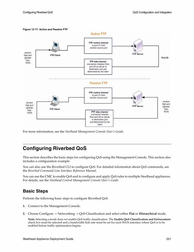
Configuring Riverbed QoS QoS Configuration and Integration
Figure 12-17. Active and Passive FTP
For more information, see the Steelhead Management Console User’s Guide.
Configuring Riverbed QoS
This section describes the basic steps for configuring QoS using the Management Console. This section also includes a configuration example.
You can also use the Riverbed CLI to configure QoS. For detailed information about QoS commands, see the Riverbed Command-Line Interface Reference Manual.
You can use the CMC to enable QoS and to configure and apply QoS rules to multiple Steelhead appliances. For details, see the Steelhead Central Management Console User’s Guide.
Basic Steps
Perform the following basic steps to configure Riverbed QoS.
1. Connect to the Management Console.
2. Choose Configure > Networking > QoS Classification and select either Flat or Hierarchical mode.
Note: Selecting a mode does not enable QoS traffic classification. The Enable QoS Classification and Enforcement check box must be selected and a bandwidth link rate must be set for each WAN interface where QoS is to be enabled before traffic optimization begins.
Steelhead Appliance Deployment Guide 221

QoS Configuration and Integration Configuring Riverbed QoS
3. Select each WAN interface and define the bandwidth link rate for each interface.
4. Define the QoS classes for each traffic flow. For details, see “QoS Class Parameters” on page 208.
5. Define rules for each class or subclass. For details, see “QoS Rules” on page 210.
6. Click the Enable QoS Classification and Enforcement box.
7. Click Apply. Your changes take effect immediately.
Important: If you delete or add new rules, the existing optimized connections are not affected; the changes only affect new optimized connections.
For details about configuring QoS, see the Steelhead Management Console User’s Guide.
Riverbed QoS Configuration Example
The following figure shows a Steelhead appliance deployment in which QoS best practices are applied. It includes the following sections:
“Data Center Specifications,” next
“Branch Office Specifications” on page 223
“Configuring the Data Center Steelhead Appliance” on page 223
“Configuring the Branch Office Steelhead Appliance” on page 225
For details on best practices, see “Riverbed QoS Enforcement Best Practices” on page 212.
In this example, traffic between the data center and the remote office branches includes VoIP, Citrix, software updates, and other traffic.
Figure 12-18. Steelhead Appliance Configuration Example
Data Center Specifications
The data center:
has Citrix servers located in the 10.1.0.0/24 subnet.
222 Steelhead Appliance Deployment Guide

Configuring Riverbed QoS QoS Configuration and Integration
transmits software updates from a server with IP address 10.1.1.100.
Steelhead appliance:
– is deployed physical in-path.
– has a WAN link with 10 Mbps of bandwidth.
– serves 20 remote branch offices.
uses Riverbed QoS hierarchical mode.
has the following QoS policies for outbound traffic:
– For each site. VoIP traffic is guaranteed at least 100 Kbps when active.
– For each site, Citrix traffic is guaranteed at least 100 Kbps when active.
– VoIP traffic is guaranteed the highest latency priority, and Citrix gets the second highest.
– Software updates are allocated the lowest latency priority.
Branch Office Specifications
Each branch office has:
a 2 Mbps WAN link.
Steelhead appliances that are deployed physical in-path.
a separate 10.16.X.0/24 subnet, where X is the number of the site.
VoIP phones that are always in the 10.16.X.128/25 subnet.
Riverbed QoS flat mode enabled.
Configuring the Data Center Steelhead Appliance
To configure Riverbed QoS for the data center Steelhead appliance:
Use the class per site model, where each of the created child classes from the root class represent a site. Each site-level class has child classes that represent a type of application.
Each site class has a child default class that is configured to receive any traffic not otherwise specified for the site. Because this includes important traffic such as routing updates, Riverbed recommends that such a class be created, and that it receive some bandwidth guarantee. The actual amount needed for the bandwidth guarantee depends on the total amount of bandwidth used at the site, what other classes are configured, and the guaranteed bandwidth (GBW) of the other classes.
In hierarchical mode, bandwidth is allocated first based on the minimum bandwidth guarantee of the active classes. Excess bandwidth is allocated according to the minimum bandwidth guarantee ratios. For this reason, it is important to keep the minimum bandwidth guarantees relatively close to each other. For example, suppose class A is configured with a minimum bandwidth guarantee of 1%, and class B is configured with 10%. When they are the only active classes, class B is allocated ten times the bandwidth of class A.
Configuring the Data Center Site-Based Classes
Each site in this example needs 400 Kbps of guaranteed bandwidth, which is the sum of guarantees for VoIP, Citrix, Software updates, and the site default class.
Steelhead Appliance Deployment Guide 223

QoS Configuration and Integration Configuring Riverbed QoS
Each site must also be configured with an upper limit of 2 Mbps. Specifying the upper limit for the QoS class ensures that any queueing for the site traffic occurs on the data center Steelhead appliance, instead of on the WAN. Each site is configured with a GBW of 4% (400 Kbps / 10 Mbps) and an UBW of 20% (2 Mbps / 10 Mbps).
Configuring the Data Center Application-Based Classes
Each site-based class has four child classes:
VoIP - The VoIP class is created with a GBW of 25% (100 Kbps / 400 kbps), and a real-time latency priority.
Citrix - The Citrix class is created with a GBW of 25% (100 Kbps / 400 Kbps), and an interactive latency priority.
Note: This example does not use classification based on Citrix ICA priority levels, and so it does not need to use the packet-order queue described previously in this section
Software Updates - A Software Updates class is needed to give this class a lower latency priority than the other classes. When you create a class, a GBW must be specified. In this example, a GBW of 10% is specified. Using a low GBW such as this ensures that when the Software Updates class and the site default class are both active, the Software Updates class receives a quarter (10% is a quarter of the GBW of the site default class) of any excess bandwidth over the minimum allocated to both QoS classes.
Default. The site default class receives a GBW of 40%, and a Normal latency priority.
Configuring the Data Center QoS Rules
The QoS rules are constructed based on the previously described network information. The rule that directs traffic to the site default class must be the last rule on the list, because it is the rule that directs any traffic not otherwise specified to the site default class.
224 Steelhead Appliance Deployment Guide

Configuring Riverbed QoS QoS Configuration and Integration
You can view QoS settings on the Configure > Networking > QoS Classification page of the Management Console. The following figure shows the subsequent QoS configuration for the data center Steelhead appliance.
Figure 12-19. Data Center Steelhead Appliance QoS Configuration
You can verify the QoS configuration on the Reports > Appliance > QoS Statistics Dropped page, and the Reports > Appliance > QoS Statistics Sent page of the Management Console.
For details about configuring QoS, see the Steelhead Management Console User’s Guide.
Configuring the Branch Office Steelhead Appliance
Flat mode is used at the branch office Steelhead appliances because the branch office Steelhead appliances only send data to the data center. There is a single WAN bottleneck to consider, the local 2 Mbps WAN link. No hierarchy is needed to encode a single WAN bottleneck.
Configuring the Branch Office Application-Based Classes
The QoS classes are created similarly to the data center Steelhead appliance, with a few exceptions. Each site class has four child classes:
VoIP - The VoIP class is created with a GBW of 5% (100 Kbps / 2 Mbps), and a latency priority of real-time.
Citrix - The Citrix class is created with a GBW of 5% (100 Kbps / 2 Mbps), and a latency priority of Interactive.
Steelhead Appliance Deployment Guide 225
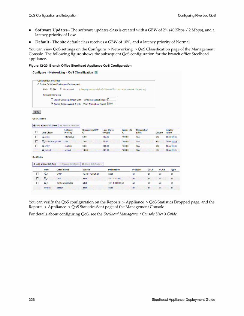
QoS Configuration and Integration Configuring Riverbed QoS
Software Updates - The software updates class is created with a GBW of 2% (40 Kbps / 2 Mbps), and a latency priority of Low.
Default - The site default class receives a GBW of 10%, and a latency priority of Normal.
You can view QoS settings on the Configure > Networking > QoS Classification page of the Management Console. The following figure shows the subsequent QoS configuration for the branch office Steelhead appliance.
Figure 12-20. Branch Office Steelhead Appliance QoS Configuration
You can verify the QoS configuration on the Reports > Appliance > QoS Statistics Dropped page, and the Reports > Appliance > QoS Statistics Sent page of the Management Console.
For details about configuring QoS, see the Steelhead Management Console User’s Guide.
226 Steelhead Appliance Deployment Guide

CHAPTER 13 WAN Visibility Modes
This chapter describes Steelhead appliance WAN visibility modes, and how to configure them. It includes the following sections:
“Overview of WAN Visibility Modes,” next
“Correct Addressing” on page 228
“Transparent Addressing” on page 229
“Configuring WAN Visibility Modes” on page 237
“Implications of Transparent Addressing” on page 239
This chapter provides the basic steps for configuring WAN visibility modes.
For details on the factors you must consider before you design and deploy the Steelhead appliance in a network environment, see “Choosing the Right Steelhead Appliance” on page 19.
Overview of WAN Visibility Modes
Each LAN-side TCP connection that is optimized by a Steelhead appliance is carried on a unique WAN-side connection. By configuring a WAN visibility mode for some or all optimized connections, you can control what IP addresses and TCP ports are used on these WAN-side TCP connections.
RiOS 6.0 and later offer the following options for configuring WAN visibility modes:
Correct Addressing - WAN-side connections use Steelhead appliance IP addresses and Steelhead appliance server ports.
Port Transparency - WAN-side connections use Steelhead appliance IP addresses but use TCP server ports that mirror the LAN-side connection.
Full Transparency - WAN-side connections mirror all IP addresses and TCP ports used on the LAN-side connection.
Full Transparency with Reset - The same as Full Transparency, plus adds an additional packet during auto-discovery to aid with integration of stateful network devices on the WAN.
Steelhead Appliance Deployment Guide 227

WAN Visibility Modes Correct Addressing
The most suitable WAN visibility mode depends primarily on your existing network configuration. For example, if you manage IP address-based or TCP port-based QoS policies for optimized traffic on your WAN or WAN routers, you might use full address transparency or port transparency. However, if you need your optimized traffic to pass through a content-scanning firewall that creates alarms when application ports are used on optimized traffic payload, you might use correct addressing instead. You can configure WAN visibility modes on the client-sideSteelhead appliance (where the connection is initiated).
Note: There can be different types of addressing modes on the same Steelhead appliance. Choose the most appropriate addressing mode for your configuration, based on IP addresses, subnets, TCP ports, and VLAN.
Correct Addressing
Correct addressing uses Steelhead appliance IP addresses and port numbers in the TCP/IP packet header fields for optimized traffic in both directions across the WAN. By default, Steelhead appliances use correct addressing.
The following figure shows TCP/IP packet headers when correct addressing is used. The IP addresses and port numbers of your Steelhead appliances are visible across your WAN.
Refer to this figure to compare it to port transparency and full address transparency packet headers.
Figure 13-1. Correct Addressing
Correct addressing uses the following values in your TCP/IP packet headers in both directions:
Client to client-side Steelhead appliance: Client IP address and port + Server IP address and port.
Client-side Steelhead appliance to server-side Steelhead appliance: Client-side Steelhead appliance IP address and port + Server-side Steelhead appliance IP address and port.
Server-side Steelhead appliance to server: Client IP address and port + Server IP address and port.
For details on configuring correct addressing, see “Configuring WAN Visibility Modes” on page 237.
Correct addressing avoids networking risks that are inherent to enabling transparent addressing. For details, see “Implications of Transparent Addressing” on page 239.
228 Steelhead Appliance Deployment Guide

Transparent Addressing WAN Visibility Modes
Correct addressing enables you to use the connection pooling optimization feature. Connection pooling works only for connections optimized using correct addressing. Connection pooling enables Steelhead appliances to create a number of TCP connections between each other before they are needed. When transparent addressing is enabled, Steelhead appliances cannot create the TCP connections in advance because they do not know what types of client and server IP addresses and ports are needed. For details on connection pooling, see “Connection Pooling” on page 17.
Transparent Addressing
This section describes transparent addressing: port transparency and full address transparency. It includes the following sections:
“Port Transparency,” next
“Full Address Transparency” on page 231
“Full Address Transparency with Forward Reset” on page 236
Transparent addressing reuses client and server addressing for optimized traffic across the WAN. Traffic is optimized while addressing appears to be unchanged. Both optimized and pass-through traffic present identical addressing information to the router and network monitoring devices.
In RiOS v5.0.x and later, transparent addressing can be used in conjunction with many deployment configurations and feature, including, but not limited to:
Physical In-path deployments (serial clusters, master/backup, and deployments using connection forwarding)
Virtual In-Path deployments (WCCP, PBR, Layer 4 switching, and Interceptor deployments)
Auto-discovery, including enhanced auto-discovery
Asymmetric route detection
QoS marking and classification
Flow data export
Transparent addressing does not support the following deployment configurations:
Server-side out-of-path Steelhead appliance configurations
Fixed-target rules
Connection pooling
You configure transparent addressing on the client-side Steelhead appliance (where the connection is initiated). Both the server-side and the client-side Steelhead appliances must support transparent addressing (RiOS v5.0.x or later) for transparent addressing to work. You can configure a Steelhead appliance for transparent addressing even if its peer does not support it. The connection is optimized but it is not transparent.
When you use full or port transparency, Steelhead appliances add a TCP option field to the packet headers of optimized traffic. This TCP option field is sent between the Steelhead appliances. For transparency to work, this option must not be stripped off by intermediate network devices.
Steelhead Appliance Deployment Guide 229
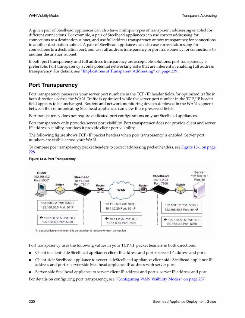
WAN Visibility Modes Transparent Addressing
A given pair of Steelhead appliances can also have multiple types of transparent addressing enabled for different connections. For example, a pair of Steelhead appliances can use correct addressing for connections to a destination subnet, and use full address transparency or port transparency for connections to another destination subnet. A pair of Steelhead appliances can also use correct addressing for connections to a destination port, and use full address transparency or port transparency for connections to another destination subnet.
If both port transparency and full address transparency are acceptable solutions, port transparency is preferable. Port transparency avoids potential networking risks that are inherent in enabling full address transparency. For details, see “Implications of Transparent Addressing” on page 239.
Port Transparency
Port transparency preserves your server port numbers in the TCP/IP header fields for optimized traffic in both directions across the WAN. Traffic is optimized while the server port number in the TCP/IP header field appears to be unchanged. Routers and network monitoring devices deployed in the WAN segment between the communicating Steelhead appliances can view these preserved fields.
Port transparency does not require dedicated port configurations on your Steelhead appliances.
Port transparency only provides server port visibility. Port transparency does not provide client and server IP address visibility, nor does it provide client port visibility.
The following figure shows TCP/IP packet headers when port transparency is enabled. Server port numbers are visible across your WAN.
To compare port transparency packet headers to correct addressing packet headers, see Figure 13-1 on page 228.
Figure 13-2. Port Transparency
Port transparency uses the following values in your TCP/IP packet headers in both directions:
Client to client-side Steelhead appliance: client IP address and port + server IP address and port.
Client-side Steelhead appliance to server-sideSteelhead appliance: client-side Steelhead appliance IP address and port + server-side Steelhead appliance IP address with server port.
Server-side Steelhead appliance to server: client IP address and port + server IP address and port.
For details on configuring port transparency, see “Configuring WAN Visibility Modes” on page 237.
230 Steelhead Appliance Deployment Guide

Transparent Addressing WAN Visibility Modes
Use port transparency if you want to manage and enforce QoS policies that are based on destination ports. If your WAN router is following traffic classification rules that are written in terms of TCP destination port numbers, port transparency enables your routers to use existing rules to classify the traffic without any changes.
Port transparency enables network analyzers deployed within the WAN (between the Steelhead appliances) to monitor network activity, and to capture statistics for reporting, by inspecting traffic according to its original TCP destination port number.
Note: Port transparency does not support active FTP.
Full Address Transparency
This section describes full address transparency. It includes the following sections:
“Overview of Full Address Transparency,” next
“VLANs and Full Address Transparency” on page 233
“The Out-of-Band Connection” on page 233
Overview of Full Address Transparency
Full address transparency preserves your client and server IP addresses and port numbers in the TCP/IP header fields for optimized traffic in both directions across the WAN. VLAN tags can also be preserved. Traffic is optimized while these TCP/IP header fields appear to be unchanged. Routers and network monitoring devices deployed in the WAN segment between the communicating Steelhead appliances can view these preserved fields.
The following figure shows an example of how TCP/IP packet headers might be addressed when full address transparency is enabled. In this example, Steelhead appliance IP addresses and port numbers are no longer visible on the optimized connections. Client and server IP addresses and port numbers are now visible in both directions across the WAN.
When you enable full address transparency, you have several addressing options for the out-of-band (OOB) connection. The type of addressing you configure for your OOB connection ultimately determines whether the Steelhead appliance in-path IP addresses are used in the TCP/IP packet headers. For details, see “The Out-of-Band Connection” on page 233.
Steelhead Appliance Deployment Guide 231

WAN Visibility Modes Transparent Addressing
To compare full address transparency packet headers to correct addressing packet headers, see Figure 13-1 on page 228.
Figure 13-3. Full Address Transparency
In this example, full address transparency uses the following values in the TCP/IP packet headers in both directions:
Client to client-side Steelhead appliance: Client IP address and port + Server IP address and port.
Client-side Steelhead appliance to Server-side Steelhead appliance: Client IP address and port + Server IP address and port.
Server-side Steelhead appliance to server: Client IP address and port + Server IP address and port.
For details on configuring full address transparency, see “Configuring WAN Visibility Modes” on page 237.
If both port transparency and full address transparency are acceptable solutions, port transparency is preferable. Port transparency mitigates potential networking risks that are inherent in enabling full address transparency. For details, see “Implications of Transparent Addressing” on page 239.
However, if you must use your client or server IP addresses across your WAN, full address transparency is your only configuration option. Full address transparency enables network monitoring applications deployed within the WAN (between the Steelhead appliances) to measure traffic load issued to the WAN by the end-host. Network routers can also perform load balancing and policy-based routing. Full address transparency also enables you to manage and enforce QoS policies based on port numbers or IP addresses.
Important: When full address transparency is enabled, router QoS policies cannot distinguish between optimized and unoptimized traffic, even though an optimized packet might represent much more data.
Full address transparency also enables the use of Network Address Translation (NAT). With correct addressing, Steelhead appliances use their own IP addresses in the packet header, which NAT does not recognize. When full address transparency is enabled the original client and server IP addresses are used, and the connections are recognizable to NAT. However, the type of addressing you configure for your OOB connection ultimately determines whether the Steelhead appliance in-path IP addresses are used in the TCP/IP packet headers. For details, see “The Out-of-Band Connection” on page 233.
Full address transparency also supports several transparency options for the out-of-band (OOB) connection. For details, see “The Out-of-Band Connection” on page 233.
232 Steelhead Appliance Deployment Guide

Transparent Addressing WAN Visibility Modes
Important: Some firewalls, QoS devices, and other stateful devices may require additional configuration to successfully allow optimize full transparency connections to operate. Search the Riverbed Knowledge Base for information about any particular device.
VLANs and Full Address Transparency
Full address transparency supports transparent VLANs. You can configure full address transparency so that optimized traffic remains on the original VLANs. Because you can keep traffic on the original VLANs, full address transparency enables you to perform VLAN-based QoS on the WAN-side of the Steelhead appliance.
Note: You must first configure WAN visibility full address transparency for VLAN transparency to function correctly.
To configure full address transparency for a VLAN
1. On the Steelhead appliance, connect to the CLI and enter the following commands:
enableconfigure terminalin-path peering autoin-path simplified routing allin-path vlan-conn-basedin-path mac-match-vlanno in-path probe-caching enablein-path probe-ftp-datain-path probe-mapi-data write memoryrestart
Note: Changes must be saved or they are lost upon reboot. Restart the optimization service for the changes to take effect.
Note: If packets on your network use two different VLANs in the forward and reverse directions, see the following Riverbed Knowledge Base article, Understanding VLANs and Transparency, located at https://support.riverbed.com/kb/solution.htm?id=501700000009DdD.
The Out-of-Band Connection
This section describes transparency options for the Out-of-Band (OOB) connection. It includes the following sections:
“Overview of OOB Connections and Addressing Modes,” next
“OOB Connection Destination Transparency” on page 234
“OOB Connection Full Transparency” on page 235
Steelhead Appliance Deployment Guide 233

WAN Visibility Modes Transparent Addressing
Overview of OOB Connections and Addressing Modes
A Steelhead appliance OOB connection is a TCP connection that Steelhead appliances establish with each other when they begin optimizing traffic to exchange capabilities and feature information, and to detect failures. A Steelhead appliance creates an OOB connection for each pair of local and remote in-path interfaces that are used when optimizing connections. OOB connections are created by the Steelhead appliance closest to the initiating side of the optimized connection.
The addresses and ports used by OOB connections depend on the addressing mode used for the first optimized connection between Steelhead appliances. If the addressing mode for the first connection is correct addressing or port transparency, the OOB connection uses correct addressing. If the first connection is full transparency, the default behavior is to make the OOB connection use correct addressing, but this behavior can be altered such that the connection uses a form of network transparency.
In some environments, it may be necessary to make OOB connections use some form of network transparency. An example is if the network is unable to route between the in-path IP addresses or VLANs of Steelhead appliances that are optimizing traffic. Two options for OOB transparency exist:
Destination transparency
Full transparency
The two options differ on what source IP address and TCP port are used. For details see “OOB Connection Destination Transparency,” next and “OOB Connection Full Transparency” on page 235.
OOB Connection Destination Transparency
The following figure shows TCP/IP packet headers when OOB connection destination transparency is enabled.
Figure 13-4. OOB Connection Destination Transparency
OOB connection destination transparency uses the following values in the TCP/IP packet headers in both directions across the WAN:
Client-side Steelhead appliance IP address and an ephemeral port number chosen by the Client-side Steelhead appliance + Server IP address and port number.
Steelhead appliances use the server IP address and port number from the first optimized connection.
Use OOB connection destination transparency if the client-side Steelhead appliance cannot establish the OOB connection to the server-side Steelhead appliance.
234 Steelhead Appliance Deployment Guide

Transparent Addressing WAN Visibility Modes
To enable OOB connection destination transparency
Note: You must first configure WAN visibility full address transparency for OOB connection destination transparency to function correctly.
1. Connect to the Riverbed CLI on the client-side Steelhead appliance and enter the following commands:
enableconfigure terminalin-path peering oobtransparency mode destinationwrite memory
Note: The changes take effect immediately. Changes must be saved or they are lost upon reboot.
To disable OOB connection destination transparency
1. Connect to the Riverbed CLI on the client-side Steelhead appliance and enter the following commands:
enableconfigure terminalin-path peering oobtransparency mode nonewrite memory
Note: The changes take effect immediately. Changes must be saved or they are lost upon reboot.
OOB Connection Full Transparency
The following figure shows TCP/IP packet headers when OOB connection full transparency is enabled.
Figure 13-5. OOB Connection Full Transparency
OOB connection full transparency uses the following values in the TCP/IP packet headers in both directions across the WAN:
Client IP address and Client-side Steelhead appliance predetermined port number 708 + Server IP address and port number.
Steelhead Appliance Deployment Guide 235

WAN Visibility Modes Transparent Addressing
Steelhead appliances use the client IP address, and the server IP address and port number from the first optimized connection.
If the client is already using port 708 to connect to the destination server, enter the following CLI command to change the client-side Steelhead appliance predetermined port number:
in-path peering oobtransparency port <port number>
OOB connection full transparency supports Steelhead appliances deployed on trunks. Because you can configure full address transparency so that optimized traffic remains on the original VLAN, there is no longer a need for a Steelhead appliance VLAN.
Use OOB connection full transparency if your network is unable to route between Steelhead appliance in-path IP addresses or in-path VLANs, or you do not want to see Steelhead appliance IP addresses used for the OOB connection.
To enable OOB connection full transparency
Note: You must first configure WAN visibility full address transparency for OOB connection destination transparency to function correctly. For details, see “Full Address Transparency” on page 231.
1. Connect to the Riverbed CLI on the client-side Steelhead appliance and enter the following commands:
enableconfigure terminalin-path peering oobtransparency mode fullwrite memory
Note: The changes take effect immediately. Changes must be saved or they are lost upon reboot.
To disable OOB connection full transparency
1. Connect to the Riverbed CLI on the client-side Steelhead appliance and enter the following commands:
enableconfigure terminalin-path peering oobtransparency mode nonewrite memory
Note: The changes take effect immediately. Changes must be saved or they are lost upon reboot.
Full Address Transparency with Forward Reset
The Full Address Transparency with Forward Reset is similar to the Full Address Transparency WAN visibility mode. Like Full Address Transparency, this mode is used to have the client and server IP addresses and TCP ports used for the WAN-side TCP connections between Steelhead appliances. The difference between the two modes happens during the auto-discovery phase, during which TCP reset packets are transmitted on the WAN. These packets help network devices, like stateful firewalls, separate TCP state between the Steelhead appliances discovery phase and their the data transmission phase.
236 Steelhead Appliance Deployment Guide

Configuring WAN Visibility Modes WAN Visibility Modes
Except for the TCP reset packets during the discovery phase, there are no other differences between Full Transparency and Full Transparency with Forward Reset, including the addressing of the WAN-side TCP connection, considerations for 802.1q VLAN tracking, and OOB transparency.
Figure 13-6 shows the auto-discovery packet flow when using the Full Transparency with Forward Reset mode and enhanced auto discovery. The packet marked Forward Reset is the only difference between this this mode and the Full Transparency mode.
Figure 13-6. Full Transparency with Forward Reset
In this mode, TCP reset packets are transmitted by the initiating Steelhead appliance immediately after the remote Steelhead appliance is discovered. The reset packets traverse the WAN and are absorbed by the remote Steelhead appliance. The packets aid any TCP aware device on the WAN to understand that the sequence numbers used during the auto-discovery phase is different from the sequence numbers used during the data transmission phase. Example devices include:
Firewalls or other network security devices on the WAN that statefully track TCP sessions, and devices that might block WAN-side Steelhead appliance connections from being created due to seeing different sequence numbers in use.
QoS devices that alter TCP headers to affect congestion. Examples include Blue Coat Packetshaper appliances using rate policies, and the Allot Netenforcer.
Important: Some firewalls, QoS devices, and other stateful devices may require additional configuration to successfully allow optimize connections using the full transparency with forward reset connections to operate. Search the Riverbed Knowledge Base for information about any particular device.
Configuring WAN Visibility Modes
The following section describes how to configure WAN visibility modes using the RiOS CLI.
Steelhead Appliance Deployment Guide 237

WAN Visibility Modes Configuring WAN Visibility Modes
You configure WAN visibility modes by creating an in-path rule on the client-side Steelhead appliance (where the connection is initiated). By default, the rule is placed before the default in-path rule, and after the Secure, Interactive, and RBT-Proto rules.
For transparent addressing to function correctly, both of the Steelhead appliances must have RiOS v5.0.x or later installed. If one Steelhead appliance does not support transparent addressing (that is, it has RiOS v4.1 or earlier installed), the Steelhead appliance attempting to optimize a connection in one of the transparent addressing modes automatically reverts to correct addressing mode, and optimization continues.
Note: If you configure transparent addressing on any of your Steelhead appliances, Riverbed recommends that all of your Steelhead appliances have RiOS v5.0.x or later installed.
By default, Steelhead appliances use correct addressing (for all RiOS versions).
WAN Visibility CLI Commands
This section summarizes the WAN visibility CLI commands. The following figure shows the IP addresses and ports used in the following tables.
Figure 13-7. Configuring WAN Visibility Modes
The following table summarizes the port transparency CLI commands.
Action CLI Commands
To enable port transparency for a specific server
in-path rule auto-discover wan-visibility port dstaddr 192.168.50.1/32 dstport 80
To enable full address transparency for a specific group of servers, and port transparency for servers not in the group
in-path rule auto-discover wan-visibility full dstaddr 192.168.0.0/24
in-path rule auto-discover wan-visibility port
Important: In this example, the first in-path rule must precede the second in-path rule in the rule list. To specify the placement of a rule in the list, use the rulenum CLI option. For details, see the Riverbed Command-Line Interface Reference Manual.
To disable port transparency Delete the in-path rule that enables it. For details about deleting in-path rules, see the Riverbed Command-Line Interface Reference Manual.
238 Steelhead Appliance Deployment Guide

Implications of Transparent Addressing WAN Visibility Modes
The following table summarizes the full address transparency CLI commands.
Implications of Transparent Addressing
This section describes some of the common problems that are inherent to transparent addressing. It includes the following sections:
“Stateful Systems,” next
“Network Design Issues” on page 240
“Integration into Networks using NAT” on page 243
Note: The problems described in this section occur with all proxy-based solutions.
Stateful Systems
Transparent addressing can have an impact on systems that monitor or alter the state of TCP connections on the WAN for reporting, security, or congestion control. For example, some stateful firewalls might see the difference in sequence numbers between the auto-discovery phase and the data transmission phase of fully transparent connections, and react by raising alarms or disallowing connections between the Steelhead appliances. Using the Full Transparency with Forward Reset may alleviate this issue, but may also cause monitoring systems to record more TCP connections being created and closed across the WAN than is actually present.
Transparent addressing also does not work with intrusion detection and prevention systems which perform stateful packet inspection. Steelhead appliances use a proprietary Riverbed application protocol to communicate. When intrusion detection and prevention systems perform stateful packet inspections, they expect to see an application protocol based on the port numbers of the original client and server connection. When these systems discover the Riverbed proprietary application protocol, they perceive this as a mismatch, causing it to log the packet, drop it, trigger an alarm, or they perform all of the above.
Action Command
To enable full address transparency globally in-path rule auto-discover wan-visibility full
To enable full address transparency for servers in a specific IP address range
in-path rule auto-discover wan-visibility full dstaddr 192.168.0.0/16
To enable full address transparency for a specific server
in-path rule auto-discover wan-visibility full dstaddr 192.168.50.1/32
To enable full address transparency for a specific group of servers, and port transparency for servers not in the group
in-path rule auto-discover wan-visibility full dstaddr 192.168.0.0/24
in-path rule auto-discover wan-visibility port
Important: In this example, the first in-path rule must precede the second in-path rule in the rule list. To specify the placement of a rule in the list, use the rulenum CLI option. For details, see the Riverbed Command-Line Interface Reference Manual.
To disable full address transparency Delete the in-path rule that enables it. For details about deleting in-path rules, see the Riverbed Command-Line Interface Reference Manual.
Steelhead Appliance Deployment Guide 239

WAN Visibility Modes Implications of Transparent Addressing
You can avoid these problems with stateful systems, which are inherent to transparent addressing, by using correct addressing.
Network Design Issues
This section describes some of the common networking problems that are inherent to transparent addressing. It includes the following sections:
“Network Asymmetry,” next
“Misrouting Optimized Traffic” on page 241
“Firewalls Located Between Steelhead Appliances” on page 243
Network Asymmetry
Enabling full address transparency increases the likelihood of problems inherent to asymmetric routing.
For a connection to be optimized, its packets to and from its LAN hosts must pass through either:
One or more in-path interfaces on the same Steelhead appliance, or
One or more in-path interfaces on Steelhead appliances that are configured as connection forwarding neighbors.
When full address transparency is used, WAN-side routers see the client or server addresses in the optimized connections packets, and use those address to make routing decisions. If the router has an route to the client or server that does not pass through a Steelhead appliance, and it transmits the optimized packets on that route, the optimized and LAN-side connections may fail.
Figure 13-8 shows an network where a link to the server location does not have a Steelhead appliance installed. Depending on the exact routing configuration below, it is possible that correct addressing would work, but full transparency would not, since the optimized traffic from the client side may be sent through the link that does not have the Steelhead appliance.
Figure 13-8. Server-Side Asymmetric Network
To ensure that all required traffic is optimized and accelerated, a Steelhead appliance must be installed on every possible path that a packet traverses. Connection forwarding must also be configured and enabled for each Steelhead appliance. For details, see “Connection Forwarding” on page 33.
If there is a path that does not have a Steelhead appliance, it is possible that some traffic will not be optimized.
240 Steelhead Appliance Deployment Guide
Implications of Transparent Addressing WAN Visibility Modes
For details on how to eliminate asymmetric routing problems, see “Troubleshooting Deployment Problems” on page 293.
You can avoid this type of asymmetric routing problem, which is inherent to transparent addressing, by using correct addressing.
Note: With RiOS v3.0.x and later, you can configure your Steelhead appliances to automatically detect and report asymmetric routes within your network. For details, see the Steelhead Management Console User’s Guide.
Misrouting Optimized Traffic
Enabling transparent addressing introduces the likelihood of misrouting optimized traffic in the event of a Steelhead appliance failure.
Steelhead appliances use a proprietary Riverbed protocol to communicate. Normally, a functioning server-side Steelhead appliance receives a packet from the WAN, and converts the packet to its native format before forwarding it to the server.
In an environment in which transparent addressing is used, if the server-side Steelhead appliance is not functioning, or if a packet is routed along an alternative network path, the packet might go from the client-side Steelhead appliance directly to the server. Because the server-side Steelhead appliance does not have an opportunity to convert the packet to its native format, the server cannot recognize it, and the connection fails.
In most cases, the server is able to detect whether a packet contains invalid payload information or, in this case, has an unrecognizable format, and rejects the packet. Assuming the server does detect that it is unrecognizable, the server rejects the packet and resets the TCP connection. If the client TCP connection is reset, the client can reconnect to the server without any Steelhead appliance involvement.
This type of traffic mis-routing can occur in both directions across the WAN. If the client-side Steelhead appliance experiences a failure, or if an alternate network path exists from the server to the client, traffic might go from the server-side Steelhead appliance directly to the client.
Important: Before enabling and utilizing full address transparency, carefully consider the risks and exposures in the event that a server accepts and routes a packet that has an unrecognizable format.
Steelhead Appliance Deployment Guide 241

WAN Visibility Modes Implications of Transparent Addressing
The following figure shows a traffic misroute when the server-side Steelhead appliance fails on a network using transparent addressing.
Figure 13-9. Transparent Addressing and Misrouting Optimized Traffic
The failure scenario is show below:
1. Client A sends HTTP data to the server.
2. Steelhead B receives the HTTP data, and performs optimization on it. Steelhead B eventually transmits packets carrying the optimized data toward Steelhead C, but due to the transparent addressing mode, they are addressed to Server D.
3. Steelhead C suffers a failure, and is in fail-to-wire mode, so all packets are traversing it, including the packets from Steelhead B.
4. Server D receives the packets from Steelhead B, but does not recognize the packet format, so the connection may fail, or suffer an application dependent error.
You can avoid this type of mis-routing problem, which is inherent to transparent addressing, by using correct addressing.
If correct addressing is configured for this scenario, the client-side Steelhead appliance detects that the server-side Steelhead appliance has failed. The client-side Steelhead appliance automatically resets the client connection, allowing the client to connect directly to the server without Steelhead appliance involvement.
242 Steelhead Appliance Deployment Guide

Implications of Transparent Addressing WAN Visibility Modes
Firewalls Located Between Steelhead Appliances
If your firewall inspects traffic between two Steelhead appliances, there are addressing issues that you need to be aware of.
Figure 13-10. Firewalls and Transparent Addressing
The following table summarizes configuration issues that might arise when a firewall inspects traffic between two Steelhead appliances. Firewall behavior differs depending on the type of addressing being used. A Yes value indicates that your firewall will perform as expected.
For details on stateful firewalls and intrusion detection and prevention systems, see “Stateful Systems” on page 239.
Integration into Networks using NAT
NAT affects the addresses used by the Steelhead appliance in different ways, depending on which addressing mode is in use. This section provides several NAT deployment scenarios using various addressing modes.
Firewall Configuration
Full Address Transparency
Port Transparency Correct Addressing
Firewall Rules Based on a Server Port
Yes Yes
Note: This configuration does not support active FTP.
Yes, if the following conditions are true:
• The firewall checks on the session establishment.
• The firewall is enabled.
• The firewall allows port 7800 traffic.
Firewall Rules Based on IP Addresses
Yes Yes, if the following conditions are true:
• IP-based rules are based only on server addresses,
• Probe caching is disabled. For details about disabling probe caching, see the following Riverbed Command-Line Interface Reference Manual.
Yes, if the following conditions are true:
• The firewall checks on the session establishment.
• The firewall is enabled.
• Probe caching is disabled. For details about disabling probe caching, see the following Riverbed Command-Line Interface Reference Manual.
Steelhead Appliance Deployment Guide 243

WAN Visibility Modes Implications of Transparent Addressing
NAT Deployment using Correct and Port Transparency Modes
In both correct and port transparency addressing modes, whatever IP addresses are seen on the initiating side Steelhead appliance (usually, this is the client side) are used by the corresponding Steelhead appliance on the remote side, as Figure 13-11 shows. This deployment can bypass any NAT that occurs in the WAN between the Steelhead appliances. To ensure that NAT is still used for the optimized traffic, you must configure the full transparency addressing mode for this traffic.
Figure 13-11. Auto-Discovery in Correct and Port Transparency Modes
In this example, the TCP connection request travels the following route:
The packet is created coming from the initiator client (C) IP address to the destination server (S) IP address.
The client-side Steelhead appliance adds a probe to the TCP connection request.
The server-side Steelhead appliance responds to the probe and adds its IP address.
The client-side Steelhead appliance sends a packet to port 7800 on the server-side Steelhead appliance requesting to open.
244 Steelhead Appliance Deployment Guide

Implications of Transparent Addressing WAN Visibility Modes
The server-side Steelhead appliance acknowledges the connection request.
The client-side Steelhead appliance acknowledges the connection.
The client-side Steelhead appliance sends session setup information to the server-side Steelhead appliance.
The server-side Steelhead appliance forwards the original connection request to the destination server.
The destination server acknowledges the client connection request.
The server-side Steelhead appliance intercepts the return packet.
– The server-side Steelhead appliance sends a packet acknowledgement to the destination server on behalf of the client.
– The server-side Steelhead appliance connection sends an acknowledgement to the client-side Steelhead appliance.
The client-side Steelhead appliance sends the acknowledgement packet to the requesting client.
The client sends an acknowledgement to the destination server.
The client-side Steelhead appliance discards the client acknowledgement.
Steelhead Appliance Deployment Guide 245

WAN Visibility Modes Implications of Transparent Addressing
NAT Deployment using Fixed-Target Rules
A similar issue exists when using fixed-target rules. When using a fixed-target rule to the primary IP address of a remote Steelhead appliance, the remote Steelhead appliance makes a connection to the destination IP address seen on the initiating side Steelhead appliance. The source address will be the remote Primary IP address of the Steelhead appliance, as Figure 13-12 shows. When using a fixed-target rule to the in-path IP address of a remote Steelhead appliance, the remote Steelhead appliance makes a connection to destination IP address seen on the initiating side Steelhead appliance, and uses the same source address seen on the initiating side Steelhead appliance.
Figure 13-12. Fixed-Target Rule to Primary IP Address
In this example, the out-of-path packet flow on incoming connection requests is very similar to an established in-path partnership, with the important distinction that the IP address of the server-side Steelhead appliance replaces the IP address of the client in communication between the server-side Steelhead appliance and the destination server. The traffic travels the following route:
246 Steelhead Appliance Deployment Guide

Implications of Transparent Addressing WAN Visibility Modes
The packet is created coming from the initiator client (C) IP address to the destination server (S) IP address.
The client-side Steelhead appliance sends a packet to port 7810 on the server-side Steelhead appliance, requesting to open a session.
The server-side Steelhead appliance acknowledges the connection request.
The client-side Steelhead appliance acknowledges the connection.
The client-side Steelhead appliance sends session setup information to the server-side Steelhead appliance.
The server-side Steelhead appliance forwards the original connection request to the destination server, replacing the client IP address with the server-side Steelhead appliance IP address.
The destination server acknowledges the connection request.
The server-side Steelhead appliance sends a packet acknowledgement to the destination server.
The server-side Steelhead appliance sends the connection acknowledgement to the client-side Steelhead appliance.
The client-side Steelhead appliance sends the acknowledgement packet to the requesting client.
The client sends an acknowledgement to the destination server.
The client-side Steelhead appliance discards the client acknowledgement.
Some applications and protocols require that the server initiate a new session or that they see the IP address of the requesting client. These applications and protocols will not function in this configuration. Consider using an in-path deployment, a WCCP deployment, or use rules on the Steelhead appliance to pass through this traffic.
Steelhead Appliance Deployment Guide 247

WAN Visibility Modes Implications of Transparent Addressing
Client-Side Source NAT using Auto-Discovery and Correct Addressing Mode
Figure 13-13 shows how auto-discovery with correct addressing can skip client-side source NAT. In this example, the client-side Steelhead appliance sends the client and server addresses it sees during the “Setup Info” transmission of data. Whether or not this configuration works depends on how the server reacts when it sees the correct addressing address and how that address is routed in the server-side LAN.
Figure 13-13. Auto-Discovery, Correct Addressing, and Client-Side Source
248 Steelhead Appliance Deployment Guide

Implications of Transparent Addressing WAN Visibility Modes
Failed Dual NAT Deployment using Auto-Discovery and Correct Addressing
Figure 13-14 shows a deployment where NAT is occurring at both the client and server locations. In this example, auto-discovery with correct addressing is unlikely to work, as the probe response from the server-side Steelhead appliance included the WA2a “internal” IP address for the server-side Steelhead appliance.
Figure 13-14. Auto-Discovery, Correct Addressing, Dual NAT, Resulting in Half-Opened Connection
Steelhead Appliance Deployment Guide 249

WAN Visibility Modes Implications of Transparent Addressing
Client-Side Source NAT using Auto-Discovery and Full Transparency
Figure 13-15 shows a client-side source NAT deployment using auto-discovery and full address transparency. In this configuration, the presence of the full transparency TCP option 77 is a signal to the server-side Steelhead appliance that it can use the addresses arriving from the WAN. Because the server-side addresses are reachable from the client side, when the client-side Steelhead appliance makes its OOB connection to the server-side Steelhead appliance, the address it uses is valid and is properly NATed across the WAN.
Figure 13-15. Auto-Discovery, Full Transparency, and Client-Side Source NAT
250 Steelhead Appliance Deployment Guide

Implications of Transparent Addressing WAN Visibility Modes
Dual NAT Deployment using Auto-Discovery and Correct Addressing
Figure 13-16 shows NAT used at both locations. In this network, full transparency and some form of OOB transparency is required for successful connection establishment and optimization.
Figure 13-16. Auto-Discovery, Correct Addressing, Dual NAT
Steelhead Appliance Deployment Guide 251

WAN Visibility Modes Implications of Transparent Addressing
252 Steelhead Appliance Deployment Guide

CHAPTER 14 Authentication, Security, Operations, and Monitoring
This chapter describes how to configure RADIUS or TACACS+ authentication for the Steelhead appliance, including best practices for securing the Steelhead appliance, and provides information on operations and flow data monitoring. It includes the following sections:
“Overview of Authentication,” next
“Configuring a RADIUS Server” on page 255
“Configuring a TACACS+ Server” on page 257
“Securing Steelhead Appliances” on page 260
“Exporting Flow Data Overview” on page 271
Overview of Authentication
The Steelhead appliance can use a RADIUS or TACACS+ authentication system for logging in administrative and monitor users. The following methods for user authentication are provided with the Steelhead appliance:
Local
RADIUS
TACACS+
For details about per-command authorization and per-command accounting, see the Riverbed Command-Line Interface Reference Manual.
The order in which authentication is attempted is based on the order specified in the AAA method list. The authentication list provides backup authentication methods in case a method fails to authenticate the server. If the first server is unavailable, the next server in the list is contacted depending on the RADIUS/TACACS+ settings.
If there are multiple servers within a method (assuming the method is contacting authentication servers) and a server time-out is encountered, the next server in the list is tried. If the current server being contacted issues an authentication reject, another server is contacted according to the RADIUS/TACACS+ setting. If none of the methods validate a user, the user is not allowed access to the server.
The Steelhead appliance does not have the ability to set a per interface authentication policy. The same default authentication method list is used for all interfaces. You cannot configure authentication methods with subsets of the RADIUS or TACACS+ servers specified (that is, there are no server groups).
Steelhead Appliance Deployment Guide 253

Authentication, Security, Operations, and Monitoring Overview of Authentication
Authentication CLI Commands
The following CLI commands are available for RADIUS and TACACS+ authentication:
Authentication Features
RiOS v5.0.x or later supports the following features (available only through the CLI):
Per-command Authorization - When per-command authorization (aaa authorization per-command default) is enabled the authorization method decides whether or not the user can enter this command. The two methods currently available for per-command authorization are local and tacacs+.
Per-command Accounting - When per-command accounting (aaa accounting per-command default) is enabled every CLI command that is entered by the user is sent to the TACACS+ server. If the accounting method is local the command is logged to the local logs.
Category CLI Commands
Authentication aaa accounting per-command default
aaa authentication cond-fallback
aaa authentication console-login default
aaa authentication login default
aaa authorization map default-user
aaa authorization map order
aaa authorization per-command default
show authentication method
RADIUS Configuration radius-server host
radius-server key
radius-server retransmit
radius-server timeout
show radius
TACACS+ Configuration tacacs-server first-hit
tacacs-server host
tacacs-server key
tacacs-server retransmit
tacacs-server timeout
show tacacs
User Accounts username disable
username privilege
username nopassword
username password
username password 0
username password 7
username password cleartext
username password encrypted
254 Steelhead Appliance Deployment Guide

Configuring a RADIUS Server Authentication, Security, Operations, and Monitoring
TACACS+ Server First Hit - When the first server hit CLI command (tacacs-server first-hit) is enabled the Steelhead appliance rejects authentication after the first rejection received from a TACACS+ server rather than continuing through all the TACACS+ servers in the list.
Fallback - The fallback option decides how the successive authentication methods are tried. Without fallback, if authentication fails the system continues through all authentication methods (TACACS+, RADIUS, local in the order they are configured in the authentication method list) until a valid authentication response is received. When you enable fallback (aaa authentication cond-fallback) the administrator can optionally configure the system to only proceed beyond TACACS+/RADIUS if the servers are unreachable.
Remote and Console Method Lists - There are two method lists: remote (ssh, Web UI) and console (serial, terminal, Steelhead appliance). The console method requires a local method to be present but the remote list does not. You enable the remote method using the aaa authentication login default command. You enable the console method using the aaa authentication console-login default command.
Configuring a RADIUS Server
This section describes how to configure a RADIUS server for the Steelhead appliance. It includes the following sections:
“Configuring a RADIUS Server with FreeRADIUS,” next
“Configuring RADIUS Authentication in the Steelhead Appliance” on page 256
Configuring a RADIUS Server with FreeRADIUS
On a per user basis, you can specify a different local account mapping by using a vendor specific attribute. This section describes how to configure the FreeRADIUS server to return an attribute (which specifies the local user account as an ASCII string). The file paths are the default values. If the RADIUS server installation has been customized, the paths might differ.
Dictionary files are stored in the directory /usr/local/share/freeradius. You can define RADIUS attributes in this directory. Assuming the vendor does not have an established dictionary file in the FreeRADIUS distribution, begin the process by creating a file called: dictionary.<vendor> in this directory.
The contents of the dictionary.<vendor> file define a vendor identifier (which ought to be the Structure of Management Information (SMI) Network Management Private Enterprise Code of the Vendor), and the definitions for any vendor specific attributes.
In the following example, the Vendor Enterprise Number for Riverbed is 17163 and the Enterprise Local User Name Attribute is 1. These numbers specify that a given user is an admin or monitor user in the RADIUS server (instead of using the Steelhead appliance default for users not named admin and monitor).
These instructions assume you are running FreeRADIUS, v.1.0, which is available from http://www.freeradius.org.
To install FreeRADIUS on a Linux computer
1. Download FreeRADIUS from http://www.freeradius.org.
2. At your system prompt, enter the following set of commands:
tar xvzf freeradius-$VERSION.tar.gz
Steelhead Appliance Deployment Guide 255
Authentication, Security, Operations, and Monitoring Configuring a RADIUS Server
cd freeradius-$VERSION ./configure make make install #as root
To add acceptance requests on the RADIUS server
1. In a text editor, open the /usr/local/etc/raddb/clients.conf file.
2. To create the key for the RADIUS server, add the following text to the clients.conf file:
client 10.0.0.0/16 {secret = testradiusshortname = main-networknastype = other
}
The secret you specify here must also be specified in the Steelhead appliance when you set up RADIUS server support. For details, see the Steelhead Management Console User’s Guide.
3. In a text editor, create a /usr/local/share/freeradius/dictionary.rbt file for Riverbed.
4. Add the following text to the dictionary.rbt file.
VENDOR RBT 17163ATTRIBUTE Local-User 1 string RBT
5. Add the following line to the /usr/local/share/freeradius/dictionary:
$INCLUDE dictionary.rbt
6. Add users to the RADIUS server by editing the /usr/local/etc/raddb/users file. For example:
“admin” Auth-Type := Local, User-Password == "radadmin" Reply-Message = "Hello, %u""monitor" Auth-Type := Local, User-Password == "radmonitor" Reply-Message = "Hello, %u""raduser" Auth-Type := Local, User-Password == "radpass" Local-User = "monitor", Reply-Message = "Hello, %u"
7. Start the server using /usr/local/sbin/radiusd. Use the -X option if you want to debug the server.
Note: The raduser is the monitor user as specified by Local, User-Password.
Configuring RADIUS Authentication in the Steelhead Appliance
The following describes the basic steps for configuring RADIUS authentication in the Steelhead appliance. For details, see the Steelhead Appliance Installation and Configuration Guide and the Steelhead Management Console User’s Guide.
You prioritize RADIUS authentication methods for the system and set the authorization policy and default user.
256 Steelhead Appliance Deployment Guide

Configuring a TACACS+ Server Authentication, Security, Operations, and Monitoring
Important: Make sure to put the authentication methods in the order in which you want authentication to occur. If authorization fails on the first method, the next method is attempted, and is continued until all the methods have been attempted.
Basic Steps
Perform the following basic steps to configure RADIUS support.
1. Configure the Steelhead appliance.
2. Connect to the Management Console.
3. In the Configure > Security > General Security Settings page, define the default login and the authentication methods.
4. In the Configure > Security > RADIUS page, specify:
server IP address
authentication type
authentication port
server key
time-out interval
retry interval
optionally, global settings
Configuring a TACACS+ Server
This section describes how to configure a TACACS+ server for the Steelhead appliance. It includes the following sections:
“Configuring a TACACS+ Server with Free TACACS+,” next
“Configuring TACACS+ with Cisco Secure Access Control Servers” on page 258
“Configuring TACACS+ Authentication in the Steelhead Appliance” on page 259
Configuring a TACACS+ Server with Free TACACS+
The TACACS+ Local User Service is rbt-exec. The Local User Name Attribute is local-user-name. This attribute controls whether a user who is not named admin or monitor is an administrator or monitor user (instead of using the Steelhead appliance default value). For the Steelhead appliance, the users listed in the TACACS+ server must have PAP authentication enabled.
The following procedures install the free TACACS+ server on a Linux computer. Cisco Secure can be used as a TACACS+ server as described in “Configuring TACACS+ with Cisco Secure Access Control Servers” on page 258.
Steelhead Appliance Deployment Guide 257

Authentication, Security, Operations, and Monitoring Configuring a TACACS+ Server
To download TACACS+
1. Download TACACS+ from:http://www.gazi.edu.tr/tacacs/get.php?src=tac_plus_v9a.tar.gz.
2. At your system prompt, enter the following set of commands:
tar xvzf tac_plus_v9a.tar.gz cd tac_plus_v9a ./configure
3. In a text editor, open the Makefile and uncomment the OS=-DLINUX line (or other lines appropriate for the host’s operating system).
4. On Linux, in a text editor, open the tac_plus.h file and uncomment the #define CONST_SYSERRLIST line.
5. At the system prompt, enter:
make tac_plus
6. As the root user, enter the following command:
make install
7. Add users to the TACACS+ server by editing the /usr/local/etc/tac_plus.conf file. For example:
key = testtacacsuser = admin {
pap = cleartext "tacadmin" }
user = monitor { pap = cleartext "tacmonitor" }
user = tacuser { pap = cleartext "tacpass" service = rbt-exec { local-user-name = "monitor" }}
The secret you specify here must also be specified in the Steelhead appliance when you set up TACACS+ server support. For details, see the Steelhead Management Console User’s Guide.
The tacuser is a monitor user as specified by local-user-name.
Note: The chap, opap, and arap variables can be specified in a similar manner, but only pap is needed.
8. Start the server by executing:
/usr/local/sbin/tac_plus -C /usr/local/etc/tac_plus.conf
Configuring TACACS+ with Cisco Secure Access Control Servers
The following section assumes you are running a Cisco Secure Access Control Server (ACS) and you want to configure it for TACACS+.
The TACACS+ Local User Service is rbt-exec. The Local User Name Attribute is local-user-name. This attribute controls whether a user who is not named admin or monitor is an administrator or monitor user (instead of using the Steelhead appliance default value). For the Steelhead appliance, the users listed in the TACACS+ server must have PAP authentication enabled.
258 Steelhead Appliance Deployment Guide
Configuring a TACACS+ Server Authentication, Security, Operations, and Monitoring
The following procedures configure TACACS+ with Cisco Secure ACS.
To configure TACACS+ with Cisco Secure ACS
1. Log in to Cisco Secure ACS.
2. Click Interface Configuration.
3. Click TACACS+(CiscoIOS).
4. Under New Services:
Click the User box.
Under Service, type: rbt-exec
Under Protocol, type: unknown
5. Click Submit.
6. Click User Setup and locate the name of the user you want to grant administrative access to the Steelhead appliance.
7. At the bottom of the window, locate the TACACS+ Settings box.
8. Click the rbt-exec unknown and Custom attributes boxes.
9. In the small Custom Attributes window, type:
local-user-name=admin
10. Click Submit.
To update Steelhead appliance configuration
• Add the following line to the Steelhead appliance configuration:
aaa authorization map default-user admin
Configuring TACACS+ Authentication in the Steelhead Appliance
The following describes the basic steps for configuring TACACS+ authentication in the Steelhead appliance. For more information and detailed procedures, see the Steelhead Appliance Installation and Configuration Guide and the Steelhead Management Console User’s Guide.
You prioritize TACACS+ authentication methods for the system and set the authorization policy and default user.
Important: Make sure to put the authentication methods in the order in which you want authentication to occur. If authorization fails on the first method, the next method is attempted, and is continued until all the methods have been attempted.
Steelhead Appliance Deployment Guide 259

Authentication, Security, Operations, and Monitoring Securing Steelhead Appliances
Basic Steps
Perform the following basic steps to configure TACACS+ support.
1. Configure the Steelhead appliance.
2. Connect to the Management Console.
3. In the Configure > Security > General Security Settings page, define the authentication methods.
4. In the Configure > Security > TACACS+ page, specify:
server IP address
authentication port
authentication type
server key
time-out interval
retry interval
optionally, global settings
Securing Steelhead Appliances
This section describes security features you can use to harden your network, including ways to secure the Steelhead appliances and some common sense security policies. It includes the following sections:
“Overview,” next
“Best Practices for Securing Access to Steelhead Appliances” on page 261
“Best Practices for Enabling Steelhead Appliance Security Features” on page 266
“Best Practices for Policy Controls” on page 269
“Best Practices for Security Monitoring” on page 269
Overview
In the past, organizations have focused attention on securing their networks by providing security for and preventing attacks against hosts. Unfortunately, there are also many security risks associated with networking devices. Attacks against such devices can be used to gather valuable information. For example, an attacker could use tools to fill up the MAC address tables of Ethernet switches, causing the switches to flood packets. These packets might contain passwords that can easily be captured.
The Steelhead appliance has been certified and subsequently deployed for internal use by a number of highly security-conscious organizations, including military, government, and financial organizations. However, Steelhead appliances are complex network-facing systems and must be treated accordingly.
260 Steelhead Appliance Deployment Guide

Securing Steelhead Appliances Authentication, Security, Operations, and Monitoring
Important: Because security requirements vary by organization, consider these recommendations with your particular security goals in mind. Before implementing any security measure described in this section, you must have a thorough understanding of its impact. For example, you do not want to disable access to a Steelhead appliance by mistake and not be able to undo the change because you inadvertently blocked your own access.
If you have a specific security concern, Riverbed recommends you consult with Riverbed Professional Services.
Best Practices for Securing Access to Steelhead Appliances
This section describes best practices for securing access to your Steelhead appliances. These practices are not requirements, but Riverbed recommends you consider these suggestions as implementing them can enforce a secure deployment:
Restrict physical access - It is important to restrict physical access to any network device. An unauthorized user can easily gain access to a Steelhead appliance if that person has physical access. Every device has the ability to recover lost passwords. By acquiring physical access to a device, an attacker can gain control by using the lost password recovery procedures. Even without breaking into the Steelhead appliance software, it is possible to gain access to the contents of disks by gaining access to the Steelhead appliance itself. It is sensible to treat the Steelhead appliance as comparable in value to the servers or clients that hold sensitive data. For example, if servers are in locked rooms with armed guards, Riverbed recommends the Steelhead appliances also be in locked rooms.
Another issue with allowing physical access is that it is possible for someone to remove the Steelhead appliance without authorization, allowing an attacker to gain access to confidential data. In general, Steelhead appliances are less valuable to an attacker than application servers or file servers because of an intrinsic scrambling of the RiOS datastore. Steelhead appliances also support encryption of the datastore to further reduce the likelihood of a successful attack, and Steelhead Mobile likewise allows the use of file encryption for the datastore on a Window PC.
A third issue related to allowing physical access is the increased susceptibility of the networking device to denial-of-service attacks. A disgruntled employee could conceivably power the appliance down, disarrange the cabling, swap hard drives, or even steal the appliance.
Use an appropriate login message - The login message appears on the Management Console Home page. It is important to display a login message that reinforces your organization’s access and security policies. Have your organization’s legal council approve a more appropriate login message.
Typical login messages include, but are not limited to:
– Statements pertaining to authorized access only
– Consequences of unauthorized access
– Elimination of right to privacy
– Acknowledgement that they may be monitored
The default login message is “Welcome to the Management Console for Steelhead_name!” You can change this by navigating to the Configure > System Settings > Announcements page in the Management Console and specifying another message. Or, you can use the CLI, as shown in the following example.
Syntax:
[no] banner login <message string>
Steelhead Appliance Deployment Guide 261

Authentication, Security, Operations, and Monitoring Securing Steelhead Appliances
Example:
banner login. "This computer system is the property of Company XYZ Inc. Disconnect NOW if you have not been expressly authorized to use this system. Unauthorized use is a criminal offence under the Computer Misuse Act 1990.Communications on or through Company XYZ Inc.'s computer systems may be monitored or recorded to secure effective system operation and for other lawful purposes.”
Allow management only from the Primary interface - Limiting SSH and HTTPS access to the Primary interface allows administrators to restrict who can access the Steelhead appliances by the use of filters or Access Control Lists. These filters are typically based on the source IP addresses of hosts and are applied on network devices like routers, Layer-3 switches, or firewalls. Limiting remote management access to Steelhead appliances helps prevent unauthorized user access.
Syntax:
[no] web httpd listen enable[no] web httpd listen interface <interface>[no] ssh server listen enable[no] ssh server listen interface <interface>
Example:
web httpd listen enableweb httpd listen interface primaryssh server listen enablessh server listen interface primary
Use SSH version 2 - SSH version 2 is more secure that previous versions of SSH. The major differences between SSH1 and SSH2 fall into two main categories: technical and licensing. Technically speaking, SSH2 uses different encryption and authentication algorithms.
SSH1 offers four encryption algorithms (DES, 3DES, IDEA and Blowfish), while SSH2 dropped support for DES and IDEA, but added three algorithms. SSH1 also used the RSA authentication algorithm, while SSH2 switched to the Digital Signature Algorithm (DSA). These changes were designed to increase the base level of security in SSH2 by using stronger algorithms.
Syntax:
[no] ssh server v2-only enable
Example:
ssh server v2-only enable
Disable unencrypted communication protocols such as Telnet and HTTP - An attacker can easily gain access to user names and passwords by sniffing network communications. You might consider a switched Ethernet environment secure, since packets are only forwarded out ports based on the destination MAC address; however, this is not necessarily the case.
Several hacking tools are available that can generate large amounts of bogus MAC addresses. These packets flood the switch's MAC address table in an attempt to overflow the table. A switch will typically flood packets out all ports if it does not have an entry in its MAC address table. Therefore, once the MAC address table for the switch is filled, the switch floods packets out all ports.
The attacker can now use a packet-capturing application to capture the flooded packets. They can then look for remote management connections. Once discovered, the attacker can reset those TCP connections, causing the user to log in again allowing them to capture the user name and password.
If only HTTPS and SSH are used, the attacker cannot obtain the user names and passwords because they are encrypted.
Syntax:
[no] telnet-server enable
262 Steelhead Appliance Deployment Guide

Securing Steelhead Appliances Authentication, Security, Operations, and Monitoring
[no] web http enable
Example:
no telnet-server enableno web http enable
Use TLSv1 only for the Management Console - Only permit TLSv1 between the browser and the Management Console.
Syntax:
web ssl protocol tlsv1no web ssl protocol sslv3
Restrict user roles - Be sure to restrict the roles of users. For example, if a Help desk administrator is supposed to only view statistics and generate reports, their account restricts them to those roles.
Syntax:
[no] rbm user <username> role <role> permissions <permissions>[no] rbm role <role> primitive <primitive>
Example:
Refer to the Riverbed Command-Line Interface Reference Manual for more details about this command.
Remove the default user name from the Web preference settings - The default user name in the login field is admin. Do not display a default user name because it gives an attacker an example of a user name against which to wage a brute-force password attack. Brute-force attacks typically go through an extensive list of words (for example, a dictionary attack) in an attempt to guess the password.
Syntax:
web prefs login default
Example:
web prefs login default ""
Change all default passwords and community strings - Be sure to change the default password for the administrator and monitor accounts. The monitor account is disabled by default, unless the Steelhead appliance is upgraded from an older release where the monitor account was enabled.
The most common problem with SNMP is that it uses the default community string of public. Change the default to something different.
Syntax:
username <userid> password 0 <cleartext>
Example:
username admin password 0 o2fMu5TS!
Syntax:
snmp-server community
Example:
snmp-server community o2fMu5TS!
Use strong passwords - Strong passwords typically include combinations of letters, numbers, special characters and combinations of upper and lower case with at least eight characters in length. Strong passwords reduce the likelihood of a successful brute-force attack because they are not be found in dictionaries and exponentially increase the complexity of the passwords.
An example of a strong password is o2fMu5TS!
Steelhead Appliance Deployment Guide 263
Authentication, Security, Operations, and Monitoring Securing Steelhead Appliances
Use AAA authentication - One of the challenges with using local user names and passwords is that when an employee leaves an organization, an administrator must touch every device that has a user name and password configured for that former employee.
By leveraging TACACS+, you gain the advantage of having a single location for configuring user names and passwords. When a person leaves your organization, you can simply disable that single account thereby preventing the user from access to all of the network devices configured to use TACACS+. Another benefit of TACACS+ is the ability to lock out an account after several unsuccessful login attempts.
TACACS+ also provides greater reporting capabilities regarding who is accessing which devices at what time. With a global user name and password, you have no idea which administrator actually logged in at a specific time. These reports can be invaluable for tracking network changes and identifying who is making changes. Therefore, it is a critical tool for change management controls.
Refer to Riverbed Command-Line Interface Reference Manual and the Steelhead Management Console User’s Guide for more detailed information on how to configure AAA.
Configure the CLI session time-out - By default, the Steelhead appliance closes the SSH session to the command line after 15 minutes. You can configure this interval to be more or less with the following command:
Syntax:
cli default auto-logut *
Example:
cli default auto-logut 10
This command only affects new SSH sessions. If you want to modify the time-out session only for the current session (and not affect the default settings), use the following command:
Syntax:
cli session auto-logout *
You can turn off the auto-logout feature with the following command:
no cli default auto-logout
Note: Note: This command changes both the current and the default settings.
You can display the current auto-logout settings with the following command:
show cli
Use strong SSL ciphers for management communications - Be sure to use strong encryption ciphers for any HTTPS management communications. The cipher is the key that is used to encrypt management communications to the Steelhead appliance. An attacker could still use the hacking tools to crack the encrypted user name and password if the encryption ciphers are too weak. An example of a weak cipher is only 56 or 64 bits. A strong cipher is greater than 128 bits.
Syntax:
web ssl cipher
Example:
web ssl cipher "HIGH:-aNULL:-kKRB5:-MD5"
Set an inactivity timer for console, SSH, and HTTPS sessions - Be sure to set a proper inactivity time-out value for management sessions. Do not set a console inactivity time-out value to 0. This could allow an attacker to take over a previous management session if the previous administrator did not manually log off.
264 Steelhead Appliance Deployment Guide

Securing Steelhead Appliances Authentication, Security, Operations, and Monitoring
Syntax:
[no] web auto-logout <minutes>[no] cli default auto-logout <minutes>
Example:
web auto-logout 10cli default auto-logout 10
Ensure SNMP is listening on the management interface only - To prevent unauthorized SNMP access, Riverbed recommends enabling SNMP access on the Primary interface only. This allows administrators to control who can access Steelhead appliances through SNMP by way of using filters applied to routers, L3 switches, or firewalls.
Syntax:
[no] snmp-server listen enable[no] snmp-server listen interface <interface>
Example:
snmp-server listen enablesnmp-server listen interface Primary
Enable link state alarms - Enable the link state alarms, which are disabled by default. This can alert you to any attempt to modify the cabling on the Steelhead appliances by inserting a tap for illegal sniffing functions.
Syntax:
[no] stats alarm {<type> <options>}
Example:
stats alarm linkstate enable
Disable the auto-discover CMC feature - By default, all Steelhead appliances try to register with the Riverbed Central Management Console (CMC) using the default hostname riverbedcmc. If you do not have a CMC, disable this feature.
If you do have a CMC, Riverbed recommends that you use it to manually discover Steelhead appliances, thereby reducing the possibility that an attacker could compromise the DNS environment and change the IP address of the riverbedcmc 'A' record to a rogue CMC.
Syntax:
[no] cmc enable
Example:
no cmc enable
SSL Issues with Internet Explorer 6 and Oracle R12 - By default, RiOS used to fix a vulnerability found in CBC-based ciphers prior to versions 0.9.6e by inserting an empty frame on the wire to avoid a Chosen Plaintext Attack on CBC ciphers. Some versions of client and server applications do not understand the insertion of empty frames into the encrypted stream and close the connection when they detect these frames. Therefore, RiOS no longer inserts empty frames by default. Examples of applications that close the connection when they detect these empty frames are IE6 and Oracle R12. Sharepoint under IIS has also exhibited this behavior.
The failure occurs when the SSL application fails to understand the data payload when either the client or server is using a block cipher using cipher-block chaining (CBC) mode as the chosen cipher. This can be with DES, AES, or 3DES using CBC. Note that when Steelhead appliances are deployed, the chosen cipher can be different than when the client is negotiating directly with the SSL server.
Steelhead Appliance Deployment Guide 265

Authentication, Security, Operations, and Monitoring Securing Steelhead Appliances
Important: Because current Web browsers do not protect themselves from this vulnerability, Steelhead appliances are no less secure than other vendors. From a security perspective, fixing this vulnerability is the responsibility of a server, not a patched client.
To determine if the Steelhead appliances are inserting empty frames to avoid an attack, capture TCPdumps on the server-side Steelhead LAN interface and look at the Server Hello message where it displays the selected cipher. Verify that DES, AES, or 3DES is the cipher. Also, check for the existence of 32-byte length SSL application data (this is the empty frame) on the LAN traces followed by an SSL Alert.
To change the default and insert empty frames, enter the CLI command no protocol ssl bug-work-around dnt-insrt-empty.
Note: For details on the vulnerability, see http://www.openssl.org/~bodo/tls-cbc.txt.
Best Practices for Enabling Steelhead Appliance Security Features
The following best practices enable important security features provided by the RiOS software. These best practices are not requirements, but Riverbed recommends you follow these suggestions as implementing them can enforce a secure deployment:
Use peering rules to control enhanced auto-discovery - Enhanced auto-discovery is a feature that allows Steelhead appliances or Steelhead Mobile Clients to discover other Steelhead appliances using TCP options. This feature greatly reduces the complexities and time it takes to deploy Steelhead appliances. It works so seamlessly that it can occasionally have the undesirable effect of peering with Steelhead appliances on the Internet that are not in your organization's management domain.
Another scenario could be that your organization has a decentralized management approach where different business units may make their own purchasing and management decisions. You may not want Steelhead appliances from two or more business units to peer with one another.
In these situations, Riverbed recommends using peering rules. Peering rules determine which connections your Steelhead appliance optimizes connections with, based on the source and destination IP addresses or TCP ports. This lets you deny peering with any unwanted connections. Another option is to create an Accept peering rule for your corporate network that allows peering from your own IP addresses, and denies it otherwise.
Syntax:
[no] in-path peering rule {auto | pass | accept} peer <peerip> ssl-capability {cap | in-cap | nocheck] src <subnet> | dest <subnet> | dest-port <port> rulenum <rulenum> description <desc>
Example:
in-path peering rule accept peer xxx.xxx.xxxx.xxxx/xx
For more information on using peering rules, see the Steelhead Management Console User’s Guide.
Enable a secure inner channel between Steelhead appliances when using the SMB-signing proxy feature - When sharing files, Windows provides the ability to sign CIFS messages to prevent man-in-the-middle attacks. Each CIFS message has a unique signature which prevents the message from being tampered with. This security feature is called SMB signing.
SMB signing is mandatory on all CIFS connections to domain controllers. Therefore, any CIFS connection to a domain controller must use SMB-signed packets.
266 Steelhead Appliance Deployment Guide
Securing Steelhead Appliances Authentication, Security, Operations, and Monitoring
You can enable the RiOS SMB signing feature on the server-side Steelhead appliances communicating with servers that have SMB signing set to Required. This alleviates latency in file access with CIFS acceleration while maintaining message security signatures. With SMB signing on, the Steelhead appliance optimizes CIFS traffic by providing bandwidth optimizations (RiOS SDR and LZ), TCP optimizations, and CIFS latency optimizations—even when the CIFS messages are signed.
However, because there is no packet signing taking place between the Steelhead appliances for these connections, Riverbed recommends you configure a secure inner channel to encrypt the traffic between the Steelhead appliances. For details, see the Steelhead Management Console User’s Guide.
Enable a secure inner channel between Steelhead appliances when using Exchange 2007 encryption - Outlook 2007 has encryption enabled by default. The Steelhead appliances are able to decrypt this traffic; however, the connections between the Steelhead appliances are unencrypted by default. Configure a secure inner channel to encrypt all MAPI traffic between the Steelhead appliances. For details, see the Steelhead Management Console User’s Guide.
Enable a secure inner channel to encrypt all optimized traffic between Steelhead appliances - When you enable a secure inner channel, all data between the client-side and the server-side Steelhead appliances is sent over the secure inner channel. You configure the peer Steelhead appliance as SSL peers so that they are trusted entities. The Steelhead appliances authenticate each other by exchanging certificates as part of the encrypted inner-channel setup. Once the Steelhead appliances establish the secure inner channel, you can encrypt and optimize all optimized traffic between Steelhead appliances using the channel. The trust between the Steelhead appliances is bi-directional; the client-side Steelhead appliance trusts the server-side Steelhead appliance, and vice versa. For details, see the Steelhead Management Console User’s Guide
Authenticate WCCP service groups - By default, WCCP peers in a WCCP group do not use authentication when registering. This could allow an attacker to join a WCCP group and potentially cause a denial of service attack. Also an administrator could accidentally misconfigure a router to use a WCCP group that already is in use. Authentication controls would prevent these rogue devices from peering, thereby preventing possible network outages or degradation of performance.
Syntax:
[no] wccp service-group <service-id> {routers <routers> | assign-scheme [either | hash | mask]| src-ip-mask <mask> | dst-ip-mask <mask> | src-port-mask <mask> | dst-port-mask <mask>} protocol [tcp | icmp] | encap-scheme [either | gre | l2] | dst-ip-mask <mask> flags <flags> | password <password> | ports <ports> | priority <priority> | weight <weight> | assign-scheme [either | hash | mask] | src-ip-mask <mask> | dst-ip-mask <mask> | src-portmask <mask> | dst-port-mask <mask>}
Example:
wccp service-group 91 routers x.x.x.x password S3cuRity!
Encrypt the datastore - RiOS SDR takes all TCP traffic and segments using a rolling data-driven computation. The segmentation produced is not readily predictable without running the computation, so an attacker interested in reconstructing a particular file will not know how many segments are involved or what the file boundaries are within the segments. The segmentation is stable, so that two identical bit sequences produce the same segmentation. Each new segment identified is written to the Steelhead appliance datastore, while each previously seen segment is reused.
Even though there is inherent security in the obfuscation of the datastore, Riverbed still provides a mechanism for enabling strong encryption of the datastore. Encrypting the datastore significantly limits the exposure of sensitive data in the event an appliance is compromised by loss, theft, or other types of security violations. The secured data is impossible for a third party to retrieve.
Syntax:
[no] datastore encryption type {NONE |AES_128 | AES_192 | AES_256}
Steelhead Appliance Deployment Guide 267
Authentication, Security, Operations, and Monitoring Securing Steelhead Appliances
Example:
datastore encryption type AES_256
Next, select Clear the Datastore on Reboot and reboot the Steelhead appliance.
Enable the secure vault - The secure vault contains sensitive information from your Steelhead appliance configuration, including SSL private keys and the datastore encryption key. These configuration settings are encrypted on the disk at all times using AES 256-bit encryption.
Initially the secure vault is keyed with a default password known only to the RiOS software. This allows the Steelhead appliance to automatically unlock the vault during system start up. You can change the password, but the secure vault does not automatically unlock on start up. To optimize SSL connections or to use datastore encryption, the secure vault must be manually unlocked if the Steelhead appliance is rebooted.
Therefore, Riverbed recommends using this feature only in conjunction with a Central Management Console (CMC). The CMC can automatically unlock the Secure Vault when the Steelhead appliance connects to the CMC after a reload.
Syntax:
secure vault {[new-password <password> | reset-password <old password> | unlock <password>]}
Example:
Secure vault unlock o2fMu5TS!
Disable unused features - Disable any features that are not in use. For example, MAPI Exchange is on by default. If your organization uses Lotus Notes, Riverbed recommends you disable Exchange optimizations.
Refer to the Riverbed Command-Line Interface Reference Manual or the Steelhead Management Console User’s Guide for the specific features you might want to disable.
Disable automatic email notification - This feature proactively sends email notification of critical issues on the Steelhead appliance (such as significant alarms and events) to Riverbed Support. Your organization might not want to send these automatic notifications.
Syntax:
[no] email autosupport enable
Example:
no email autosupport enable
Disable Steelhead reporting - This feature proactively reports some very basic information back to Riverbed Support once a week. This reporting is initially disabled, however, if the user configures nameserver IP addresses for the Steelhead appliance it is automatically enabled. Your organization might not want to send this report.
Syntax:
[no] support uptime-report enable
Example:
no support uptime-report enable
Delete the preconfigured NTP servers - If your organization has NTP configured internally, Riverbed recommends removing the preconfigured NTP servers.
Syntax:
[no] ip name-server <IP addr>
268 Steelhead Appliance Deployment Guide

Securing Steelhead Appliances Authentication, Security, Operations, and Monitoring
Example:
no ip name-server 66.187.224.4
Disable any interfaces not in use - Be sure to disable any interfaces that are not being used. Examples include the Auxiliary interface and any unused in-path interfaces.
Syntax:
[no] interface <interfacename> <options>
Example:
interface inpath0_1 shutdown
Best Practices for Policy Controls
This section includes the best practices for implementing secure policy controls:
Use the Simple Certificate Enrollment Protocol (SCEP) - In RiOS v5.5.2 and later, SCEP allows Steelhead appliances to request signed certificates for enrollment and re-enrollment from the certificate server. For details, see Chapter 6, “Configuring SCEP and Managing CRLs.”
Use a Certificate Revocation List (CRL) - In RiOS v5.5.2 and later, Steelhead appliances can download CRL lists which contain revoked certificates from certificate servers through LDAP. Revoked certificates are considered invalid, and are not used by the Steelhead appliance. For details, see Chapter 6, “Configuring SCEP and Managing CRLs.”
Best Practices for Security Monitoring
After implementing security measures for your organization, Riverbed recommends enabling the following security monitoring features:
Enable Logging - Be sure to enable logging and log to a syslog server. At a minimum, set logging to the notice level to capture failed login attempts.
Example—A failed login attempt:
Apr 13 05:19:49 BRANCH webasd[6004]: [web.NOTICE]: web: Attempt to Authenticate adminApr 13 05:19:49 BRANCH webasd(pam_unix)[6004]: authentication failure; logname= uid=0 euid=0 tty= ruser= rhost= user=adminApr 13 05:19:49 BRANCH webasd[6004]: [web.NOTICE]: web: Failed to authenticate user admin: You must provide a valid account name and password.
After you enable syslog and log to a server, remember to review the logs daily.
Note: RiOS v6.0 also includes several SNMP traps to notify you of Steelhead appliance configuration changes, successful logins, and system dump initiation. For more information, see the Steelhead Management Console User’s Guide.
Syntax:
[no] logging <IP addr> [trap <log level>]
Example:
logging x.x.x.x trap notice
Email alerts - Be sure to enable email alerts internally.
Syntax:[no] email mailhub <hostname or IP addr>[no] email notify events enable[no] email notify failures enable[no] email notify events recipient <email addr>
Steelhead Appliance Deployment Guide 269

Authentication, Security, Operations, and Monitoring Securing Steelhead Appliances
[no] email notify failures recipient <email addr>
Example:
email mailhub x.x.x.xemail notify events enableemail notify failures enableemail notify events recipient [email protected] notify failures recipient [email protected]
Refer to the Riverbed Command-Line Interface Reference Manual for more details on configuring email alerts.
Register with the Riverbed forums - Riverbed has several forums which enable you to receive advanced notifications for:
– General Announcements and updates
– Software releases
– Features
To register with Riverbed forums, visit https://supportforum.riverbed.com/forumdisplay.php?f=2.
Sample Configuration Commandscli session auto-logout 10web auto-logout 10web session renewal 10web session timeout 10no ntp server 192.6.38.127no ntp server 206.169.144.6no ntp server 66.187.224.4no ntp server 66.187.233.4no cmc enablessh server listen enablessh server listen interface primarysnmp-server listen enablesnmp-server listen interface primarysnmp-server community qre456#fdhweb httpd listen enableweb httpd listen interface primaryssh server v2-only enableno web http enableweb ssl protocol tlsv1no web ssl protocol sslv3no web ssl protocol sslv2web ssl cipher "HIGH:-aNULL:-kKRB5:-MD5"no telnet enableemail mailhub smtp.comanyxyz.comemail notify events enableemail notify failures enableemail notify events recipient [email protected] notify failures recipient [email protected] email autosupport enablelogging syslog.companyxyz.com trap noticedatastore encryption type AES_256banner login "This network system is the property of Company XYZ Inc. Disconnect NOW if you have not been expressly authorized to use this system. Unauthorized use is a criminal offence under the Computer Misuse Act 1990. Communications on or through Company XYZ Inc.'s network systems may be monitored or recorded to secure effective system operation and for other lawful purposes."no support uptime-report enable
270 Steelhead Appliance Deployment Guide

Exporting Flow Data Overview Authentication, Security, Operations, and Monitoring
Exporting Flow Data Overview
NetFlow and other Flow Data Collectors gather network statistics about network hosts, protocols and ports, peak usage times, and traffic logical paths. The flow data collectors update flow records with information pertaining to each packet traversing the specified network interface.
The flow data components are as follows:
Exporter - When you enable flow data support on a Steelhead appliance, it becomes a flow data Exporter. The Steelhead appliance exports raw flow data records to a flow data collector. You only need one Steelhead appliance with flow data enabled to report flow records.
Collector - A server or appliance designed to aggregate the data the Steelhead appliance exports. The Cascade Profiler or Cascade Gateway are examples of flow data collectors, which process and present this data in a meaningful way to the administrator. The collector captures
– Enough information to map the outer-connection to its corresponding inner-connection.
– The byte and packet reduction for each optimized connection
– Information on which Steelhead appliance interface optimized the connection, including which peer it used during optimization.
Analyzer - A collection of tools used to analyze the data and provide relevant data summaries and graphs. Flow data analyzers are available for free or from commercial sources. An analyzer is often provided in conjunction with a collector.
For smaller networks, the flow data collector and analyzer are typically combined into a single device. For larger networks, a more distributed architecture may be used. In a distributed design, multiple flow data exporters export their data to several flow data collectors which in turn send data back to the flow data analyzer.
Some environments configure NetFlow on the WAN routers to monitor the traffic traversing the WAN. However, when the Steelhead appliances are in place, the WAN routers only see the inner-channel traffic and not the real IP addresses and ports of the client and server. By enabling flow data on the Steelhead appliance, this becomes a non-issue altogether. The Steelhead appliance can export the flow data instead of the router without compromising any functionality. By doing so, the router can spend more CPU cycles on its core functionality: routing and switching of packets.
Before you enable flow data support in your network, consider the following:
Generating flow data can use large amounts of bandwidth, especially on low bandwidth links and thereby impact Steelhead appliance performance.
To reduce the amount of data exported, you can export only optimized traffic.
Note: For details on flow record formats, see Appendix B, “Understanding Exported Flow Data.” For information on Steelhead appliance MIB and SNMP traps, see the Steelhead Management Console User’s Guide.
Steelhead Appliance Deployment Guide 271

Authentication, Security, Operations, and Monitoring Exporting Flow Data Overview
272 Steelhead Appliance Deployment Guide

CHAPTER 15 NSV Deployments
This chapter describes how to deploy Steelhead appliances in an MPLS/VRF environment using Not-So-VRF (NSV). It includes the following sections:
“NSV with VRF Select Overview,” next
“Configuring NSV” on page 278
NSV with VRF Select Overview
This section provides an overview of NSV. It includes the following sections:
“VRF ,” next
“NSV with VRF Select ” on page 274
VRF
Virtual Routing and Forwarding (VRF) is a technology used in computer networks that allows multiple instances of a routing table to co-exist within the same router at the same time. VRF partitions a router by creating multiple routing tables and multiple forwarding instances. Because the routing instances are independent, the same or overlapping IP addresses can be used without conflicting with each other.
Figure 15-1. Partitioned Router using Two Routing Tables
Steelhead Appliance Deployment Guide 273

NSV Deployments NSV with VRF Select Overview
VRF can be implemented in a network device by having distinct routing tables, one per VRF. Dedicated interfaces are bound to each VRF.
In Figure 15-1, the red table can forward packets between interfaces E1/0, E1/2,and S2/0.102. The green table, on the other hand, forwards between interfaces E4/2, S2/0.103, and S2/1.103.
The simplest form of VRF implementation is VRF Lite, as shown in Figure 15-2. VRF Lite uses VRFs without Multiprotocol Label Switching (MPLS). In this implementation, each router within the network participates in the virtual routing environment in a peer-based fashion. This extends multiple VPNs from a Provider Edge (PE) device onto non-MLPS Customer Edge (CE) devices, which support multiple VRFs. It also replaces the requirement for separate, physical CE devices.
Figure 15-2. VRF Lite
NSV with VRF Select
NSV is a Riverbed network design option that leverages the Riverbed WDS solution by deploying Steelhead appliances in an existing MPLS deployment using VRF. Riverbed recommends using NSV in a MPLS/VRF environment to deploy Steelhead appliances while retaining existing overlapping address spaces.
The concept of NSV originates in an MPLS VPN environment with multiple hosts in the same source VPN. The hosts require access to different servers in various destination VPNs. This is a difficult deployment to implement if a particular subinterface is VRF-attached. A subinterface is a way to partition configuration information for certain subsets of traffic that arrive or leave a physical interface.
NSV uses the IOS MPLS VPN VRF Select feature, which essentially eases the requirement of a VRF-attached subinterface.
The VRF Select feature uses Policy-Based Routing (PBR) at the ingress interface of the VRF router to determine which VRF to forward traffic to. In most cases, the VRF router is a PE device. In a VRF-lite implementation, the VRF router is a CE device. The VRF router determines the routing and forwarding of packets coming from the customer networks (or VPNs). The access control list (ACL) defined in the PBR route map matches the source IP address of the packet. If it finds a match, it sends the packet to the appropriate MPLS VPN (the VRF table).
274 Steelhead Appliance Deployment Guide

NSV with VRF Select Overview NSV Deployments
The VRF table contains the virtual routing and forwarding information for the specified VPN. It forwards the selected VPN traffic to the correct MPLS Label Switched Path (LSP), based upon the destination IP address of the packet.
Note: The VRF table is also known as the VPNv4 routing table.
NSV with VRF Select removes the association between the VRF and the subinterface. Decoupling the VRF and the subinterface allows you associate more than one MPLS VPN to the subinterface. The subinterface remains in the IPv4 dimension in VRF Select (as compared to the VPNv4 address space in which it resides when it is VRF-attached). The subinterface is still IPv4-based, but it becomes aware of VRF Select by replacing the
ip vrf forwarding
Cisco command with
ip vrf receive
The result is that the subinterface becomes Not-So-VRF. The subinterface still resides in the global IPv4 table, but it now uses PBR for the VRF switch. The PBR route map matches criteria based on traffic flows to be optimized.
IOS Requirements
Cisco recommends the following minimum IOS releases for a MLPS VPN VRF Selection using PBR deployment:
Important: Regardless of how you configure a Steelhead appliance, if the Cisco IOS version on the router or switch is below the current Cisco minimum recommendations, it might be impossible to have a functioning NSV implementation, or, the implementation might not have optimal performance.
Prerequisites
Before configuring NSV, review the following information:
A detailed network diagram illustrating the logical connectivity between the data centers and branch offices.
A running configuration of the multi-VRF CE devices
The exact IOS versions and hardware platforms in use
Sample NSV Network Setup
The example network configurations in this chapter include:
One Steelhead appliance, configured as a logical in-path (data center)
Cisco Hardware Cisco IOS
Most Router Platforms 12.3(7)T and later
C76xx 12.2(33)SRB1, 12.2(33)SRB2, 12.2(33)SRC, 12.2(33)SRC1, 12.2(33)SRC2
ASR 1000 Series Router XE 2.1.0, 2.1.1, 2.1.2, 2.2.1
Steelhead Appliance Deployment Guide 275

NSV Deployments NSV with VRF Select Overview
One Steelhead appliance, configured as a physical in-path (branch office)
Both Steelhead appliances are running RiOS v5.0.3 or later
The operating system is 12.3(15)T7
Two units of 3640 series routers
Two units of WinXP VM hosts
IP Service Level Agreement (SLA)
Static routes with tracking
The following figure shows a logical in-path NSV deployment in a VRF network environment (for details, see “Configuring NSV,” next).
Figure 15-3. Sample NSV Network Setup
276 Steelhead Appliance Deployment Guide

NSV with VRF Select Overview NSV Deployments
The following figure shows the NSV deployment shown in Figure 15-3 with intercepted and optimized flows.
Figure 15-4. NSV Deployment with Intercepted and Optimized Flows
Figure 15-5 shows the NSV deployment with bypassed flows in the event the data center Steelhead appliance fails.
Figure 15-5. NSV Deployment with Bypassed Flows
Steelhead Appliance Deployment Guide 277

NSV Deployments Configuring NSV
Configuring NSV
This section describes how to configure NSV. It includes the following sections:
“Overview,” next
“Configuring the Data Center Router” on page 278
“Configuring the PBR Route Map” on page 280
“Decouple VRF from the Subinterface to Implement NSV” on page 280
“Configuring the Branch Office Router ” on page 281
“Configuring the Data Center Steelhead Appliance ” on page 282
“Configuring the Branch Office Steelhead Appliance ” on page 282
Overview
Perform the following basic steps to configure NSV with VRF select:
1. Configure the data center PE or CE router, which includes defining:
the VRF tables.
the subinterfaces.
the PBR route map.
PBR.
static routes.
and monitoring the Steelhead appliance availability.
2. Configure the branch office router.
3. Configure the data center Steelhead appliance.
4. Configure the branch office Steelhead appliance.
The following sections describe each of these steps in detail.
Configuring the Data Center Router
The data center PE or CE router determines the routing and forwarding of packets coming from the customer networks or VPNs. This device requires the most configuration.
The first step is to define the VRF tables for the Steelhead appliance. For example, you define two VRF tables for Steelhead appliance 40: custa for the customer and wds_a to use as a dummy VRF table. The dummy VRF table is not tied to any interface. It redirects traffic with a corresponding default route, which points to or exits at the subinterface to the Steelhead appliance.
Note: You cannot enter the set ip next-hop Cisco command on a PBR route map configured for VRF select.
278 Steelhead Appliance Deployment Guide

Configuring NSV NSV Deployments
The next step configures the subinterfaces and VRF routing protocol. In this example, you configure the following subinterfaces and define the OSPF VRF routing protocol:
f0/0.40 (the LAN-to-Steelhead appliance 40)
e1/0 (the WAN)
Note: This example uses OSPF as the routing protocol, but you can use other protocols such as RIP, EIGRP, ISIS, and BGP as well. OSPF uses a different routing process for each VRF. For the other protocols, a single process can manage all the VRFs.
To define the VRF tables and subinterfaces
1. Define the VRF tables for the Steelhead appliance. On the data center router (in this example P4R1), enter the following commands:
hostname p4R1!ip cef!ip vrf custa
rd 4:1 !
ip vrf wds_a rd 4:9 !
2. Configure the VRF subinterfaces and corresponding VRF routing protocol. On the data center router, at the system prompt, enter the following set of commands:
interface FastEthernet0/0.40 encapsulation dot1Q 40 ip vrf forwarding custa ip address 10.4.40.1 255.255.255.0 !interface Ethernet1/0 ip vrf forwarding custa ip address 10.254.4.1 255.255.255.0 half-duplex! router ospf 4 vrf custa redistribute static subnets network 10.4.40.0 0.0.0.255 area 0 network 10.254.4.0 0.0.0.255 area 0
This example configures the LAN subinterface f0/0.40, which interconnects Steelhead appliance 40 to use VRF custa. Later, you point the dummy VRF wds_a to a default route (in this example, f0/0.40). This enables a PBR route map at f0/0.49 to redirect incoming traffic from Server 49 to Client 42 to Steelhead appliance 40 for optimization.
In this example, because Client 42 is in the VPN custa (VRF custa), the traffic must return to the VRF custa routing path after optimization. For this redirection to work, the Steelhead appliance 40 must reside in VRF custa and not VRF wds_a.
Steelhead Appliance Deployment Guide 279

NSV Deployments Configuring NSV
Configuring the PBR Route Map
VRF Select requires a control mechanism such as PBR to select which particular VRF table a data packet goes to. The next step is to configure a PBR route map, which provides a matching criteria for incoming traffic and sets the VRF table.
To configure the PBR route map
On the data center router, enter the following commands:
route-map wds_a permit 10 match ip address 104 set vrf wds_a !route-map wds_a permit 20 set vrf custa!access-list 104 permit tcp host 10.4.49.88 host 10.4.42.99
The route map wds_a matches incoming traffic from Server 49 to Client 42. When it finds a match, it sets the VRF to wds_a, which, in turn, points to default route f0/0.40 where Steelhead appliance 40 resides. Binding f0/0.40 with VRF custa ensures the returning optimized traffic eventually reaches Client 42. The route map also sets any incoming traffic to VRF custa—except Server 49 to Client 42.
Important: Ensure that the PBR route map contains a default (or last resort line) set vrf in the PBR route map to always match a packet that does not match any of the previous criteria.
Important: Since BGP control packets are required to remain as global-ipv4, use an ACL to ensure these packets do not get forwarded to a VRF table.
Decouple VRF from the Subinterface to Implement NSV
The following step decouples the association between VRF and a subinterface. It implements NSV by replacing the
ip vrf forwarding
Cisco command with
ip vrf receive
The result is that the subinterface is becomes Not-So-VRF. The subinterface still resides in the global IPv4 table, but it now uses PBR for the VRF switch. The PBR route map matches criteria based on traffic flows to be optimized.
Important: You must have already defined the PBR route map as described in “To configure the PBR route map” on page 280 before completing the next step.
To implement VRF select and PBR
On the data center router, enter the following commands:
interface FastEthernet0/0.49 encapsulation dot1Q 49 ip vrf receive custa
280 Steelhead Appliance Deployment Guide

Configuring NSV NSV Deployments
ip address 10.4.49.1 255.255.255.0ip policy route-map wds_a
The absence of the ip vrf forwarding command in this example configuration implies f0/0.49 is not associated with any particular VRF and remains in the IPv4 global address space. This makes it possible for the Steelhead appliances to communicate with the subinterface.
Configuring Static Routes
Static routes play a crucial role in an NSV deployment, as you use them to fine-tune the routing. The primary, default static route points to the in-path interface to redirect incoming traffic for optimization. (In the following example, traffic is redirected to 10.4.40.101 of Steelhead appliance 40).
The command keyword track 1 determines whether the in-path IP address of the Steelhead appliance is reachable. The primary, default static route is used only when the in-path IP address for the Steelhead appliance is reachable. If it becomes unreachable, the primary route is removed from the routing table. The second, floating route serves as a backup to avoid blackholing traffic and ensure flow continuity.
In this example, when the primary route is removed from the routing table because the Steelhead appliance is unreachable, the second route becomes effective at an administrative weight of 250, points to the WAN interface e1/0, and avoids blackholing traffic to ensure flow continuity.
Also, in this example, because f0/0.49 (where Server 49 is connected) is still in the IPv4 global address space, you need to make it visible in VRF custa. To do this, you assign a third static route associating it with VRF custa. The third static route points to Server 49 (10.4.49.88) in VRF custa and redistributes it into OSPF.
To define static routes
On the data center router, enter the following commands:
ip route vrf wds_a 0.0.0.0 0.0.0.0 FastEthernet0/0.40 10.4.40.101 track 1 ip route vrf wds_a 0.0.0.0 0.0.0.0 Ethernet1/0 10.254.4.2 250 ip route vrf custa 10.4.49.88 255.255.255.255 FastEthernet0/0.49 10.4.49.88 !
To monitor Steelhead appliance availability
On the P4R1, at the system prompt, enter the following set of commands:
ip sla monitor 1 type echo protocol ipIcmpEcho 10.4.40.101 vrf custafrequency 5 !
ip sla monitor schedule 1 life forever start-time now! track 1 rtr 1 reachability
IP SLA uses the ICMP echo protocol to monitor the availability status of the Steelhead appliance in-path IP address every 5 seconds (in this example, IP address 10.4.40.101 for Steelhead appliance 40:custa). This is tied to the primary default route through the tracking mechanism. The tracking mechanism prevents routing to an unavailable IP destination when the in-path IP address for the Steelhead appliance is down (in this example, Steelhead 40:custa).
Configuring the Branch Office Router
A typical branch office router is a PE VRF or CE VRF-Lite device. Its configuration is minimal and standard. In most environments you probably do not need to configure this device.
On the P4R2, enter the following commands:
Steelhead Appliance Deployment Guide 281

NSV Deployments Configuring NSV
hostname P4R2ip cefip vrf custa rd 4:1interface FastEthernet0/0.42 encapsulation dot1Q 42 ip vrf forwarding custa ip address 10.4.42.1 255.255.255.0interface FastEthernet0/0.254 encapsulation dot1Q 254 ip vrf forwarding custa ip address 10.254.4.2 255.255.255.0router ospf 4 vrf custa network 10.4.42.0 0.0.0.255 area 0 network 10.254.4.0 0.0.0.255 area 0
Configuring the Data Center Steelhead Appliance
The data center Steelhead appliance (in this example, VRF custa) is another vital component of an NSV deployment. Its configuration is very simple; you simply enable the logical in-path interface.
1. On the server-side Steelhead appliance, connect to the CLI and enter the following commands:
hostname "SH40" interface inpath0_0 ip address 10.4.40.101 /24 ip in-path-gateway inpath0_0 "10.4.40.1" in-path enable in-path oop enable
write memoryrestart
Note: Changes must be saved or they are lost upon reboot. Restart the optimization service for the changes to take effect.
Configuring the Branch Office Steelhead Appliance
The Steelhead appliance deployed at the branch office needs slightly more configuration than the data center Steelhead appliance. Because you are only implementing VRF Select for redirecting the data center LAN-side traffic, you need to define fixed-target rules for the WAN-side traffic.
1. On the client-side Steelhead appliance, connect to the CLI and enter the following commands:
hostname "SH42" interface inpath0_0 ip address 10.4.42.101 /24 ip default-gateway "10.4.42.1 in-path enable in-path rule fixed-target target-addr 10.4.40.101 target-port 7800 dstaddr 10.4.49.88/32 dstport "all" srcaddr 10.4.42.99/32 rulenum 4
(in this example, Steelhead 42:custa).
282 Steelhead Appliance Deployment Guide

Configuring NSV NSV Deployments
Tip: You can also use auto-discovery to eliminate configuring fixed-target rules if you disassociate the WAN interface (in this example, P4R1 e1/0) from the VRF (in this example, custa) the same way you disassociated the LAN interface using VRF select, as described in “Decouple VRF from the Subinterface to Implement NSV” on page 280.
Note: The branch office Steelhead appliance could also be a Steelhead Mobile Client. In this deployment, you could use the Steelhead Mobile Controller to facilitate configuring the fixed-target rules. For details, see the Steelhead Mobile Controller User’s Guide.
Note: Changes must be saved or they are lost upon reboot. Restart the optimization service for the changes to take effect.
Steelhead Appliance Deployment Guide 283

NSV Deployments Configuring NSV
284 Steelhead Appliance Deployment Guide
CHAPTER 16 Configuring Branch Warming
This chapter describes how to configure branch warming on the Steelhead appliance v6.0 and the Steelhead Mobile Controller v3.0. It includes the following sections:
“Overview of Branch Warming,” next
“Configuring Branch Warming” on page 287
“Verifying Branch Warming” on page 290
This chapter assumes you are familiar with the Steelhead Mobile Controller User’s Guide.
Overview of Branch Warming
Branch warming enables you to experience warm acceleration regardless of your location. Branch warming keeps track of data segments created while a Steelhead Mobile Client is in a Steelhead appliance-enabled branch office and shares the new data between the client and the branch Steelhead appliance. When you leave the branch office, you still receive warm performance.
Branch warming enhances the Location Awareness feature. Location Awareness enables Steelhead Mobile v2.0 clients to detect they are in a branch office and allow the branch-side Steelhead appliance to optimize their traffic. Branch warming works only in Steelhead appliances running RiOS v6.0. Earlier versions of the Steelhead appliance provide only the Location Awareness function.
In branch warming, the Steelhead Mobile Client and the branch-side Steelhead appliance co-operate to provide warm data for out-of-branch use. The Steelhead Mobile Client shares segments with the branch-side Steelhead appliance, thereby providing warm data wherever possible. Branch warming populates new data transfers between the client and server in the Steelhead Mobile datastore, the branch Steelhead appliance datastore, and the server-side Steelhead appliance datastore.
When you download data from the server, the server-side Steelhead appliance checks if either the Steelhead Mobile Client or the branch office Steelhead appliance has the data in its datastore. If either device already has the data segments, the server-side Steelhead appliance sends only references to the data. The Mobile Client and the branch Steelhead appliance communicate with each other to resolve the references.
Other clients at the branch office also benefit from branch warming, because data transferred by one client at a branch office also populates the branch Steelhead appliance datastore. Performance improves with all clients at the branch office because they receive warm performance for that data.
Steelhead Appliance Deployment Guide 285

Configuring Branch Warming Overview of Branch Warming
The following figure shows how branch warming enables mobile workers to optimize traffic with the server Steelhead appliance, while feeding segments they generate into the branch Steelhead appliance datastore:
Figure 16-1. Branch Warming Example
For each data request, the server-side Steelhead appliance checks whether the branch-side Steelhead appliance or the Steelhead Mobile datastore of the client making the request already has the data.
If either one has it, the Steelhead appliance sends a reference to the Steelhead Mobile. After the Steelhead Mobile gets the reference, it checks if its datastore already has the reference. If it does, the Steelhead Mobile communicates with the server-side Steelhead appliance that it need not send the data again. Simultaneously, it checks whether the branch-side Steelhead appliance has the same reference. If the branch-side Steelhead appliance has the reference, the communication concludes; otherwise, the Steelhead Mobile shares the reference and data with it.
If the Steelhead Mobile does not have the reference or if its datastore is deleted, it checks with the branch-side Steelhead appliance to determine if it has the reference. If it does, then the Steelhead Mobile Client takes the data segments from the branch-side Steelhead appliance and communicates with the server-side Steelhead appliance that it need not send the data again.
However, if the branch-side Steelhead appliance does not have the reference, the Steelhead Mobile Client requests the new data from the server-side Steelhead appliance and shares the new data and reference with the branch-side Steelhead appliance so that at the end this communication, all three—the server-side Steelhead appliance, branch-side Steelhead appliance, and the Steelhead Mobile have the reference.
Licensing
A Steelhead Mobile Client with branch warming enabled (inside a branch office using the branch Steelhead appliance) uses one connection on the server-side Steelhead appliance and one connection on the client-side Steelhead appliance. It does not use a Steelhead Mobile license in the branch mode. A single Steelhead Mobile license allows an unlimited number of connections.
The Steelhead Mobile Client uses a license only when it detects that the Steelhead appliance with which it has optimized connections is not in the branch mode.
Steelhead Appliance
Steelhead Mobile ControllerData segments
286 Steelhead Appliance Deployment Guide

Configuring Branch Warming Configuring Branch Warming
Configuring Branch Warming
This section describes how to configure branch warming on the Steelhead Mobile Controller and the client-side and server-side Steelhead appliances.
Branch warming does not improve performance for configurations using:
out-of-path connections with fixed-target rules.
Steelhead Mobile Clients that communicate with multiple server-side Steelhead appliances in different scenarios. For example, if a Steelhead Mobile Client home user peers with one server-side Steelhead appliance after logging in through a VPN network and peers with a different server-side Steelhead appliance after logging in from the branch office, branch warming does not improve performance.
Requirements
Your network must meet the following requirements to configure branch warming. You must:
enable latency-based location awareness and branch warming in the acceleration policy assigned to the Steelhead Mobile Client from the Steelhead Mobile Controller.
enable branch warming on both the client-side and server-side Steelhead appliances.
ensure that both the client-side and server-side Steelhead appliances are deployed in-path or virtual in-path (that is, no fixed-target rules).
enable automatic peering on both the client-side and server-side Steelhead appliances. For details, see the Steelhead Management Console User’s Guide.
ensure that the Steelhead Mobile Controller appliance is running Steelhead Mobile v3.0.
ensure that the Steelhead appliances are running RiOS v6.0.
ensure that the Steelhead Mobile Client is running v3.0.
To configure branch warming on the Steelhead Mobile Controller:
1. Log in to the Steelhead Mobile Controller.
2. Click Manage Endpoints to expand the Manage Endpoints menu.
3. Click Acceleration Policies to display the Manage Endpoints - Acceleration Policies page. Acceleration policies are used as configuration templates to configure groups of Mobile Clients that have the same performance requirements.
Steelhead Appliance Deployment Guide 287

Configuring Branch Warming Configuring Branch Warming
For example, you might use the default acceleration policy for the majority of your Mobile Clients and create another acceleration policy for a group of Mobile Clients that need to pass-through a specific type of traffic.
Figure 16-2. Manage Endpoints - Acceleration Policies Page
4. Click New to open the Acceleration Policy wizard and create a new acceleration policy.
5. Click Location Awareness (step 5) to display the New Policy - Location Awareness page. Location awareness is a new rule set that defines cases where optimization and license usage occur. By default, Location Awareness and Branch Warming are disabled in the Steelhead Mobile Controller.
Figure 16-3. New Policy - Location Awareness Page
6. Click Enable Latency-based location awareness to enable location awareness.
288 Steelhead Appliance Deployment Guide

Configuring Branch Warming Configuring Branch Warming
7. Specify a latency threshold value in ms in the Optimize over adapters specified above if latency to Steelhead appliance is more than textbox.
8. Click Enable Branch Warming to enable branch warming.
9. Click Finalize (step 7), enter a policy name, and click Apply Policy.
The main Acceleration Policy page appears listing the policy you created. You can assign this policy to a client or group of clients.
To configure branch warming on the client- and server-side Steelhead appliances:
1. Connect to the client- and server-side Steelhead appliances.
2. On both the client-side and the server-side Steelhead appliances, choose Configure > Optimization > Datastore to display the Datastore page.
Figure 16-4. Datastore Page
3. Under General Settings, select Enable Branch Warming for Steelhead Mobile Clients.
4. Click Apply to apply your settings.
5. Click Save to save your settings permanently.
6. Restart the optimization service.
Note: To enable branch warming, ensure that the client- and server-side Steelhead appliances are deployed as in-path or virtual in-path devices.
Configuring Automatic Peering
Enable automatic peering on both the client-side and server-side Steelhead appliances for branch warming to work.
With automatic peering the Steelhead appliance automatically finds the furthest Steelhead appliance in a network and optimization occurs there. By default, automatic peering is enabled.
Steelhead Appliance Deployment Guide 289

Configuring Branch Warming Verifying Branch Warming
You can display, add, and modify automatic peering settings in the Configure > Optimization > Peering Rules page.
To enable automatic peering on the client- and server-side Steelhead appliances
1. Choose Configure > Optimization > Peering Rules to display the Peering Rules page.
Figure 16-5. Peering Rules Page
2. Under Settings, complete the configuration as described in the following table.
3. Click Apply to apply your settings.
4. Click Save to save your settings permanently.
Verifying Branch Warming
You can verify branch warming status on your Steelhead Mobile Clients.
Control Description
Enable Automatic Peering Enables enhanced automatic peering. With automatic peering the Steelhead appliance automatically finds the furthest Steelhead appliance along the connection path of the TCP connection and optimization occurs there. For example, in a deployment with four Steelhead appliances (A, B, C, D), where D represents the appliance that is furthest from A, the Steelhead appliance automatically finds D. This simplifies configuration and makes your deployment more scalable.
By default, automatic peering is enabled.
290 Steelhead Appliance Deployment Guide
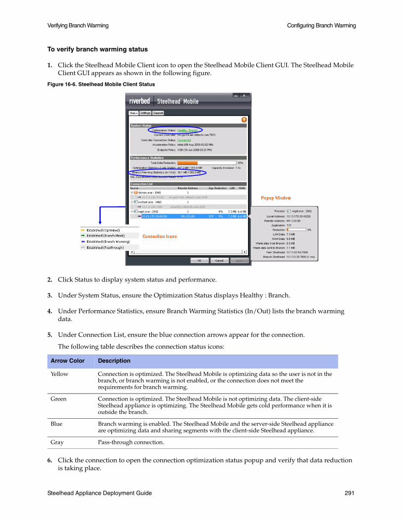
Verifying Branch Warming Configuring Branch Warming
To verify branch warming status
1. Click the Steelhead Mobile Client icon to open the Steelhead Mobile Client GUI. The Steelhead Mobile Client GUI appears as shown in the following figure.
Figure 16-6. Steelhead Mobile Client Status
2. Click Status to display system status and performance.
3. Under System Status, ensure the Optimization Status displays Healthy : Branch.
4. Under Performance Statistics, ensure Branch Warming Statistics (In/Out) lists the branch warming data.
5. Under Connection List, ensure the blue connection arrows appear for the connection.
The following table describes the connection status icons:
6. Click the connection to open the connection optimization status popup and verify that data reduction is taking place.
Arrow Color Description
Yellow Connection is optimized. The Steelhead Mobile is optimizing data so the user is not in the branch, or branch warming is not enabled, or the connection does not meet the requirements for branch warming.
Green Connection is optimized. The Steelhead Mobile is not optimizing data. The client-side Steelhead appliance is optimizing. The Steelhead Mobile gets cold performance when it is outside the branch.
Blue Branch warming is enabled. The Steelhead Mobile and the server-side Steelhead appliance are optimizing data and sharing segments with the client-side Steelhead appliance.
Gray Pass-through connection.
Steelhead Appliance Deployment Guide 291

Configuring Branch Warming Verifying Branch Warming
292 Steelhead Appliance Deployment Guide
CHAPTER 17 Troubleshooting Deployment Problems
This chapter describes common deployment problems and solutions. It includes the following sections:
“Duplex Mismatches,” next
“Inability to Access Files During a WAN Disruption” on page 296
“Network Asymmetry” on page 296
“Unknown (or Unwanted) Steelhead Appliance Appears on the Current Connections List” on page 298
“Old Antivirus Software” on page 299
“Packet Ricochets” on page 299
“Router CPU Spikes After WCCP Configuration” on page 300
“Server Message Block Signed Sessions” on page 302
“Unavailable Opportunistic Locks” on page 306
“Underutilized Fat Pipes” on page 307
For details about Steelhead appliance installation issues, see the Steelhead Appliance Installation and Configuration Guide.
For details on the factors to consider before you deploy the Steelhead appliance, see “Choosing the Right Steelhead Appliance” on page 19.
Duplex Mismatches
This section describes common problems that can occur in networks in which duplex settings do not match. Duplex mismatch occurs when the speed of a network interface that is connected to the Steelhead appliance does not match.
The number one cause of poor performance issues with Steelhead appliance installations is duplex mismatch. A duplex mismatch can cause performance degradation and packet loss.
Signs of duplex mismatch:
You cannot connect to an attached device.
You can connect with a device when you choose auto-negotiation, but you cannot connect with the same device when you manually set the speed or duplex.
Steelhead Appliance Deployment Guide 293

Troubleshooting Deployment Problems Duplex Mismatches
Little or no performance gains.
Loss of network connectivity.
Intermittent application or file errors.
All of your applications are slower after you have installed in-path Steelhead appliances.
To determine whether the slowness is caused by a duplex mismatch
1. Create a pass-through rule for the application on the client-side Steelhead appliance and ensure that the rule is at the top of the in-path rules list. You add a pass-through rule with the CLI command in-path rule pass-through or you can use the Management Console.
2. Restart the application.
3. Check that all connections related to the application are being passed-through. If all connections related to the application are being passed-through and the performance of the application does not return to the original levels, the slowness is most likely due to duplex mismatch.
The following sections describe several possible solutions to duplex mismatch:
“Solution: Manually Set Matching Speed and Duplex” on page 294
“Solution: Use an Intermediary Switch” on page 295
Solution: Manually Set Matching Speed and Duplex
One solution for mismatched speed and duplex settings is to manually configure the settings.
1. Manually set (that is, hard set) matching speed and the duplex settings for the following four ports:
Devices (switches) connected on the Steelhead appliance LAN port.
Devices (routers) connected on the Steelhead appliance WAN port.
The Steelhead appliance LAN port
The Steelhead appliance WAN port
Riverbed recommends the following speeds:
Fast Ethernet Interfaces: 100 megabits full duplex
Gigabit Interfaces: 1000 megabits full duplex
Note: For additional details, see the Riverbed Knowledge Base article, Problems manually setting 1000Mbps/Full on Steelhead, at https://support.riverbed.com/kb/solution.htm?id=50170000000ANIX&categoryName=Hardware.
Riverbed recommends that you avoid using half-duplex mode whenever possible. If you are using a modern interface, and it appears to not support full duplex, double check the duplex setting. It is likely that one side is set to auto and the other is set to fixed. To manually change interface speed and duplex settings, use the CLI command interface. For details, see the Riverbed Command-Line Interface Reference Manual
2. Verify that each of the above devices:
have settings that match in optimizing mode.
294 Steelhead Appliance Deployment Guide

Duplex Mismatches Troubleshooting Deployment Problems
view interface speed and duplex settings, using the CLI command show configuration. By default, the Steelhead appliance auto-negotiates speed and duplex mode for all data rates and supports full duplex mode and flow control. To change interface speed and duplex settings, use the CLI command interface.
have settings that match in bypass mode.
are not showing any errors or collisions.
does not have a half-duplex configuration (forced or negotiated) on either the WAN or the LAN.
has at least 100 Mbps speed, forced or negotiated, on the LAN.
has network connectivity in optimization and in failure mode. For details on failure mode, see “Failure Modes” on page 41.
3. Test connectivity with the Steelhead appliance powered off. This ensures that the Steelhead appliance does not sever the network in the event of a hardware or software problem. This must be done last, especially after making any duplex changes on the connected devices.
4. If the Steelhead appliance is powered off and you cannot pass traffic through it, verify that you are using the correct cables for all devices connected to the Steelhead appliance. The type of cable is determined by the device connecting to the Steelhead appliance:
Router to Steelhead appliance: use a crossover cable.
Switch to Steelhead appliance: use a straight-through cable.
Do not rely on Auto MDI/MDI-X to determine which cables you are using.
For details on cables, see “Choosing the Right Cables” on page 45.
5. Use a cable tester to verify that the Steelhead appliance in-path interface is functioning properly: turn off the Steelhead appliance, and connect the cable tester to the LAN and WAN port. The test result must show a crossover connection.
6. Use a cable tester to verify that all of the cables connected to the Steelhead appliance are functioning properly.
For details on how to choose the right cables, see “Choosing the Right Cables” on page 45.
Solution: Use an Intermediary Switch
If you have tried to manually set matching speed and duplex settings, and duplex mismatch still causes slow performance and lost packets after you deploy in-path Steelhead appliances, introduce an intermediary switch that is more compatible with both existing network interfaces. Riverbed recommends that you use this option only as a last option.
Important: To use an intermediary switch, you must also change your network cables appropriately.
Steelhead Appliance Deployment Guide 295

Troubleshooting Deployment Problems Inability to Access Files During a WAN Disruption
Inability to Access Files During a WAN Disruption
If your network requires that clients have continuous access to files, even in the event of network disruptions that prevent access over the WAN to the origin server on which the files are located, consider using PFS.
PFS is an optional integrated virtual file server that allows you to store copies of files on the Steelhead appliance with Windows file access, creating several options for transmitting data between remote offices and centralized locations with improved performance and functions. Data is configured into file shares by PFS, and the shares are periodically synchronized transparently in the background, over the optimized connection of the Steelhead appliance. PFS leverages the integrated disk capacity of the Steelhead appliance to store file-based data in a format that allows it to be retrieved by NAS clients.
For details, see Chapter 9, “Proxy File Services Deployments.”
Solution: Use Proxy File Service
If you are using Steelhead appliance Models 520, 1010, 1020, 1520, 2020, 3010, 3020, 3520, 5010, or 6120, you can configure PFS to ensure that remote sites can access files even when a WAN disruption prevents access to the origin server on which files are located. For details on configuring PFS, see Chapter 9, “Proxy File Services Deployments.”
Network Asymmetry
If some of the connections in a network are optimized and some are passed through unoptimized, it might be due to network asymmetry. Network asymmetry causes a client request to traverse a different network path than the server response. Network asymmetry can also break connections.
If SYN packets that traverse from one side of the network are optimized, but SYN packets that traverse from the opposite side of the network are passed-through unoptimized, it is a symptom of network asymmetry.
The following figure shows an asymmetric server-side network in which a server response can traverse a path (the bottom path) in which a Steelhead appliance is not installed.
Figure 17-1. Server-Side Asymmetric Network
The following sections describe several possible solutions to network asymmetry:
“Solution: Use Connection Forwarding” on page 297
296 Steelhead Appliance Deployment Guide
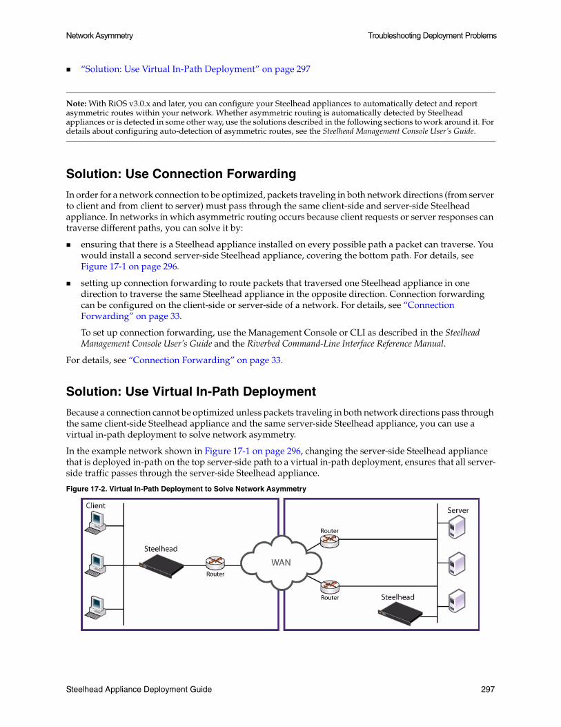
Network Asymmetry Troubleshooting Deployment Problems
“Solution: Use Virtual In-Path Deployment” on page 297
Note: With RiOS v3.0.x and later, you can configure your Steelhead appliances to automatically detect and report asymmetric routes within your network. Whether asymmetric routing is automatically detected by Steelhead appliances or is detected in some other way, use the solutions described in the following sections to work around it. For details about configuring auto-detection of asymmetric routes, see the Steelhead Management Console User’s Guide.
Solution: Use Connection Forwarding
In order for a network connection to be optimized, packets traveling in both network directions (from server to client and from client to server) must pass through the same client-side and server-side Steelhead appliance. In networks in which asymmetric routing occurs because client requests or server responses can traverse different paths, you can solve it by:
ensuring that there is a Steelhead appliance installed on every possible path a packet can traverse. You would install a second server-side Steelhead appliance, covering the bottom path. For details, see Figure 17-1 on page 296.
setting up connection forwarding to route packets that traversed one Steelhead appliance in one direction to traverse the same Steelhead appliance in the opposite direction. Connection forwarding can be configured on the client-side or server-side of a network. For details, see “Connection Forwarding” on page 33.
To set up connection forwarding, use the Management Console or CLI as described in the Steelhead Management Console User’s Guide and the Riverbed Command-Line Interface Reference Manual.
For details, see “Connection Forwarding” on page 33.
Solution: Use Virtual In-Path Deployment
Because a connection cannot be optimized unless packets traveling in both network directions pass through the same client-side Steelhead appliance and the same server-side Steelhead appliance, you can use a virtual in-path deployment to solve network asymmetry.
In the example network shown in Figure 17-1 on page 296, changing the server-side Steelhead appliance that is deployed in-path on the top server-side path to a virtual in-path deployment, ensures that all server-side traffic passes through the server-side Steelhead appliance.
Figure 17-2. Virtual In-Path Deployment to Solve Network Asymmetry
Steelhead Appliance Deployment Guide 297

Troubleshooting Deployment Problems Unknown (or Unwanted) Steelhead Appliance Appears on the Current Connections List
A virtual in-path deployment differs from a physical in-path deployment in that a packet redirection mechanism is used to direct packets to Steelhead appliances that are not in the physical path of the client or server. Redirection mechanisms include a Layer-4 switch (or server load balancer), WCCP, and PBR. These redirection mechanisms are described in:
Chapter 3, “Virtual In-Path Deployments.”
Chapter 4, “Out-of-Path Deployments.”
Chapter 5, “WCCP Deployments.”
Chapter 7, “Policy-Based Routing Deployments.”
Solution: Deploy a Four-Port Steelhead Appliance
If you have a Steelhead appliance that supports a Four-Port Copper Gigabit-Ethernet Bypass card, you can deploy it to solve network asymmetry in which a two-port Steelhead appliance or one of the solutions described in previous sections is not successful.
For example, instead of the two-port Steelhead appliance deployed to one server-side path as shown Figure 17-1 on page 296, you deploy a four-port Steelhead appliance on the server-side of the network. All server-side traffic passes through the four-port Steelhead appliance and asymmetric routing is eliminated.
For details about two and four-port Steelhead appliances, see the Bypass Card Installation Guide.
Unknown (or Unwanted) Steelhead Appliance Appears on the Current Connections List
Enhanced automatic peering greatly reduces the complexities and time it takes to deploy Steelhead appliances. It works so seamlessly that occasionally it has the undesirable effect of peering with Steelheads on the Internet that are not in your organization's management domain or your corporate business unit. When an unknown (or unwanted) Steelhead appears connected to your network, you can create a peering rule to prevent it from peering and remove it from your list of connnected appliances. The peering rule defines what to do when a Steelhead appliance receives an auto-discovery probe from the unknown Steelhead appliance.
To prevent an unknown Steelhead appliance from peering
1. Choose Configure > Optimization > Peering Rules.
2. Click Add a New Peering Rule.
3. Select Passthrough as the rule type.
4. Specify the source and destination subnets. The source subnet is your local network subnet (in the format XXX.XXX.XXX.XXX/XX). The destination subnet is the remote location network subnet (in the format XXX.XXX.XXX.XXX/XX).
5. Click Add.
In this example, the peering rule passes through traffic from the unknown Steelhead appliance in the remote location.
298 Steelhead Appliance Deployment Guide

Old Antivirus Software Troubleshooting Deployment Problems
When you use this method and add a new remote location in the future, you need to create a new peering rule that accepts traffic from the remote location. Place this new Accept rule before the Pass-through rule.
If you do not know the network subnet for the remote location, there is another option: you can create a peering rule that allows peering from your corporate network subnet and denies it otherwise. For example, create a peering rule that accepts peering from your corporate network subnet and place it as the first rule in the list. Next, create a second peering rule to pass-through all other traffic. In this example, when the local Steelhead appliance receives an auto-discovery probe, it checks the peering rules first (from top to bottom). If it matches the first Accept rule, the local Steelhead appliance peers with the other Steelhead. If it does not match the first Accept rule, the local Steelhead appliance checks the next peering rule, which is the pass-through rule for all other traffic. In this case, the local Steelhead appliance just passes through the traffic, and does not peer with the other Steelhead appliance.
After you add the peering rule, the unknown Steelhead appliance appears in the Current Connections report as a Connected Appliance until the connection times out. Once the connection becomes inactive, it appears dimmed. To remove the unknown appliance completely, restart the optimization service.
Old Antivirus Software
After installing Steelhead appliances, if application access over the network does not speed up or certain operations on files (such as dragging and dropping) speed up greatly but application access does not, it might be due to old antivirus software installed on a network client.
Solution: Upgrade Antivirus Software
If it is safe to do so, temporarily disable the antivirus software and try opening files. If performance improves with antivirus software disabled, Riverbed recommends that you upgrade the antivirus software.
If performance does not improve with antivirus software disabled or after upgrading antivirus software, contact Riverbed Support at https://support.riverbed.com.
Similar Problems
For similar problems, see:
“Server Message Block Signed Sessions” on page 302
“Unavailable Opportunistic Locks” on page 306
Packet Ricochets
Signs of packet ricochet are:
Network connections fail on their first attempt but succeed on subsequent attempts.
The Steelhead appliance on one or both sides of a network has an in-path interface that is different from that of the local host.
There are no in-path routes defined in your network.
Steelhead Appliance Deployment Guide 299

Troubleshooting Deployment Problems Router CPU Spikes After WCCP Configuration
Connections between the Steelhead appliance and the clients or server are routed through the WAN interface to a WAN gateway, and then they are routed through a Steelhead appliance to the next-hop LAN gateway.
The WAN router drops SYN packets from the Steelhead appliance before it issues an ICMP redirect.
Solution: Add In-Path Routes
To prevent packet ricochet, add in-path routes to local destinations. For details, see Steelhead Management Console User’s Guide.
For details on packet ricochet, see “Simplified Routing” on page 47.
Solution: Use Simplified Routing
You can also use simplified routing to prevent packet ricochet. To configure simplified routing, use the CLI command in-path simplified routing or the Management Console.
For details about simplified routing and how to configure it, see the Riverbed Command-Line Interface Reference Manual or the Steelhead Management Console User’s Guide.
Router CPU Spikes After WCCP Configuration
If the CPU usage of the router spikes after WCCP configuration, it might be because you are not using a WCCP-compatible Cisco IOS release, or because you need to use inbound redirection.
The following sections describe several possible solutions to router CPU spike after WCCP configuration:
“Solution: Use Mask Assignment instead of Hash Assignment,” next
“Solution: Check Internetwork Operating System Compatibility” on page 301
“Solution: Use Inbound Redirection” on page 301
“Solution: Use Inbound Redirection with Fixed-Target Rules” on page 301
“Solution: Use Inbound Redirection with Fixed-Target Rules and Redirect List” on page 301
“Solution: Base Redirection on Ports Rather than ACLs” on page 301
“Solution: Use PBR” on page 302
Solution: Use Mask Assignment instead of Hash Assignment
The major difference between the hash and mask assignment methods lies in the way traffic is processed within the router/switch. With a mask assignment, traffic is processed entirely in the hardware, which means the CPU of the switch is minimal. A hash assignment uses the switch CPU for part of the load distribution calculation and hence places a significant load on the switch CPU. The mask assignment method was specifically designed for hardware-based switches and routers (such as Cisco 3560, 3750, 4500, 6500, and 7600).
For details on mask assignment, see “WCCP Deployments” on page 79.
300 Steelhead Appliance Deployment Guide

Router CPU Spikes After WCCP Configuration Troubleshooting Deployment Problems
Solution: Check Internetwork Operating System Compatibility
Because WCCP is not fully integrated in every IOS release and on every platform, ensure that you are running a WCCP-compatible IOS release. If you have questions about the WCCP compatibility of your IOS release, contact Riverbed Support at https://support.riverbed.com.
If you are certain that you are running a WCCP-compatible IOS release and you experience router CPU spike after WCCP configuration, review the following sections for possible solutions.
“Solution: Use Inbound Redirection,” next
“Solution: Use Inbound Redirection with Fixed-Target Rules” on page 301
“Solution: Use Inbound Redirection with Fixed-Target Rules and Redirect List” on page 301
“Solution: Base Redirection on Ports Rather than ACLs” on page 301
“Solution: Use PBR” on page 302
Solution: Use Inbound Redirection
One possible solution to router CPU spike after WCCP configuration is to use inbound redirection instead of outbound redirection. Inbound redirection ensures that the router does not waste CPU cycles consulting the routing table before handling the traffic for WCCP redirection.
For details on redirection, see Chapter 5, “WCCP Deployments.”
Solution: Use Inbound Redirection with Fixed-Target Rules
If inbound redirection, as described in “Solution: Use Inbound Redirection” on page 301, does not solve router CPU spike after WCCP is configured, try using inbound redirection with a fixed-target rule between Steelhead appliances. The fixed-target rule can eliminate one redirection interface.
Fixed-target rules directly specify server-side Steelhead appliances near the target server that you want to optimize. You determine which servers you would like the Steelhead appliance to optimize (and, optionally, which ports), and add fixed-target rules to specify the network of servers, ports, and out-of-path Steelhead appliances to use.
For details on how to configure inbound redirection and fixed-target rules, see Chapter 5, “WCCP Deployments.”
Solution: Use Inbound Redirection with Fixed-Target Rules and Redirect List
If the solutions described in the previous sections do not solve router CPU spike after WCCP is configured, try using inbound redirection with a fixed-target rule and a redirect list. A redirect list can reduce the load on the router by limiting the amount of unnecessary traffic that is redirected by the router.
For details, see Chapter 5, “WCCP Deployments.”
Solution: Base Redirection on Ports Rather than ACLs
If the solutions described in the previous sections do not solve router CPU spike after WCCP configuration, consider basing traffic redirection on specific port numbers rather than using ACLs.
Steelhead Appliance Deployment Guide 301

Troubleshooting Deployment Problems Server Message Block Signed Sessions
Solution: Use PBR
If the solutions described in the previous sections do not solve router CPU spike after WCCP configuration, consider using PBR instead of WCCP.
For details on PBR, see Chapter 7, “Policy-Based Routing Deployments.”
Server Message Block Signed Sessions
This section provides a brief overview of problems that can occur with Windows Server Message Block (SMB) signing. For details about SMB signing, the performance cost associated with it, and solutions to it, see the Steelhead Management Console User’s Guide.
If network connections appear to be optimized but there is no performance difference between a cold and warm transfer, it might be due to SMB-signed sessions.
SMB-signed sessions support compression and RiOS SDR, but render latency optimization (for example read-ahead, and write-behind) unavailable.
Signs of SMB signing:
Access to some Windows file servers across a WAN is slower than access to other Windows file servers across the WAN.
Connections are shown as optimized in the Management Console.
The results of a tcpdump show low WAN utilization for files where their contents do not match existing segments in the segment store.
Copying files via FTP from the slow server is much faster than copying the same files via mapped network drives (CIFS).
When copying FTP from a slow server is much faster than copying from the same server via a mapped network drive, the possibility of other network problems (such as duplex mismatch or network congestion) with the server is ruled out.
Log messages in the Management Console such as:
error=SMB_SHUTDOWN_ERR_SEC_SIG_ENABLED
The following sections describe possible solutions to SMB-signed sessions:
“Solution: Enable Secure-CIFS” on page 302
“Solution: Disable SMB Signing with Active Directory” on page 303
Solution: Enable Secure-CIFS
Enable Secure-CIFS using the CLI command protocol cifs secure-sig-opt enable.
The Secure-CIFS feature automatically stops Windows SMB signing. SMB signing prevents the Steelhead appliance from applying full optimization on CIFS connections and significantly reduces the performance gain from a Steelhead appliance deployment (SMB-signed sessions support compression and RiOS SDR, but render latency optimization (read-ahead, write-behind unavailable).
With Secure-CIFS enabled, you must consider the following factors:
If the client-side machine has Required signing, enabling the Secure-CIFS feature prevents the client from connecting to the server.
302 Steelhead Appliance Deployment Guide

Server Message Block Signed Sessions Troubleshooting Deployment Problems
If the server-side machine has Required signing, the client and the server connect but you cannot perform full latency optimization with the Steelhead appliance. (Domain Controllers default to Required.)
For details about SMB signing, see the Steelhead Appliance Installation and Configuration Guide.
Alternatively, if your deployment requires SMB signing, you can optimize signed CIFS messages by selecting Enable SMB Signing in the Optimization > CIFS page of the Management Console. Before you enable SMB signing, make sure you disable Optimize Connections with Security Signatures. For detailed information about optimizing signed CIFS messages, including procedures for your Windows server, see the Steelhead Management Console User’s Guide.
Note: Secure-CIFS is enabled by default beginning with RiOS v2.x.
Tip: If a log file shows messages such as error=SMB_SHUTDOWN_ERR_SEC_SIG_REQUIRED, use the solution described in “Solution: Disable SMB Signing with Active Directory” on page 303. Enabling secure-CIFS has no effect when SMB signing has been set to required.
For details, see the Steelhead Management Console Online Help or the Steelhead Management Console User’s Guide.
Solution: Disable SMB Signing with Active Directory
If you have tried enabling Secure-CIFS as described in “Solution: Enable Secure-CIFS” on page 302 but SMB signing still occurs, consider using Active Directory (AD) to disable SMB signing requirements on servers or clients.
If the Security Signature feature does not disable SMB signing, you must revise the default SMB registry parameters. SMB signing is controlled by the following registry parameters:
enablesecuritysignature (SSEn)requiresecuritysignature (SSReq)
The registry settings are located in:
HKEY_LOCAL_MACHINE\SYSTEM\CurrentControlSet\Services\lanmanserver\parameters
The following table summarizes the default SMB signing registry parameters.
With these default registry parameters, SMB signing is negotiated in the following manner:
SMB/CIFS exchanges between the Client/Workstation and the Member Server are not signed.
SMB/CIFS exchanges between the Client/Workstation and the Domain Controller are always signed.
Machine Role SSEn SSReq
Client/Workstation ON OFF
Member Server OFF OFF
Domain Controller ON ON
Steelhead Appliance Deployment Guide 303

Troubleshooting Deployment Problems Server Message Block Signed Sessions
The following table lists the complete matrix for SMB registry parameters that ensure full optimization (that is, bandwidth and latency optimization) using the Steelhead appliance.
Note: Rows with an asterisk (*) and a plus sign (+) are illegal combinations of SSReq and SSen on the server and the workstation respectively.
This table represents behavior for Windows 2000 workstations and servers with service pack 3 and Critical Fix Q329170. Prior to the critical fix, the security signature feature was not enabled or enforced even on domain controllers.
There are two sets of these parameters on each computer: one set for the computer as a server and the other set for the computer as a client.
Note: On the client, if SMB signing is set to Required, do not disable it on the server. For the best performance, enable the clients, disable the file servers, and enable domain controllers.
The following procedures assume that you have installed and configured the Steelhead appliances in your network.
Number Parameters on Workstation
Parameters on Server
Result
SSReq SSEn SSReq SSEn
1 OFF OFF OFF OFF Signature Disabled: Steelhead full optimization
2 OFF OFF OFF ON Signature Disabled: Steelhead full optimization
3 OFF OFF ON ON Cannot establish session
4* OFF OFF ON ON Cannot establish session
5 OFF ON OFF OFF Signature Disabled: Steelhead full optimization
6 OFF ON OFF ON Signature Enabled; Steelhead bandwidth optimization
7 OFF ON ON ON Signature Enabled; Steelhead bandwidth optimization
8* OFF ON OFF ON Signature Enabled; Steelhead bandwidth optimization
9 ON ON OFF OFF Cannot establish session
10* ON ON OFF ON Signature Enabled; Steelhead bandwidth optimization
11 ON ON ON ON Signature Enabled; Steelhead bandwidth optimization
12 ON ON OFF ON Signature Enabled; Steelhead bandwidth optimization
13+ ON OFF OFF OFF Cannot establish session
14+ ON OFF OFF ON Signature Enabled; Steelhead bandwidth optimization
15+ ON OFF ON ON Signature Enabled; Steelhead bandwidth optimization
16+ ON OFF OFF ON Signature Enabled; Steelhead bandwidth optimization
304 Steelhead Appliance Deployment Guide

Server Message Block Signed Sessions Troubleshooting Deployment Problems
To disable SMB signing on Windows 2000 Domain Controllers, member servers, and clients
1. Open Active Directory Users and Computers on the Domain Controller.
2. Right-click Domain Controllers and select Properties.
3. Click the Group Policy tab.
4. Click Default Domain Controllers Policy and select Edit.
5. Click Default Domain Controllers Policy/Computer Configuration/Windows Settings/Security Settings/Local Policies/Security Options.
6. Disable Digitally sign client communication (always) and Digitally sign server communication (always).
7. Disable Digitally sign client communication (when possible) and Digitally sign server communication (when possible).
8. Reboot all the Domain Controllers and member servers that you want to optimize.
Tip: You can also open a command prompt and enter gpupdate.exe /Force that forces the group policy you just modified to become active without rebooting.
You can verify that SMB signing has been disabled on your domain controllers, member servers, and clients. The following procedures assume that you have installed and configured the Steelhead appliances in your network.
To verify that SMB signing has been disabled
1. Copy some files in Windows from the server to the client through the Steelhead appliances.
2. Connect to the Management Console. For detailed information, see the Steelhead Management Console User’s Guide.
3. On the server-side Steelhead appliance choose Reports > Diagnostics > System Logs.
4. Look for the SMB signing warnings (in red). For example, look for the following text:
SFE: error=SMB_SHUTDOWN_ERR_SEC_SIG_ENABLED
5. If you see error messages, repeat Step 6 and Step 7.
To disable SMB signing on Windows 2003 Domain Controllers, member servers, and clients
1. Open Active Directory Users and Computers on the Domain Controller.
2. Right-click Domain Controllers and select Properties.
3. Click the Group Policy tab.
4. Click Default Domain Controllers Policy and select Edit.
Steelhead Appliance Deployment Guide 305

Troubleshooting Deployment Problems Unavailable Opportunistic Locks
5. Click Default Domain Controllers Policy/Computer Configuration/Windows Settings/Security Settings/Local Policies/Security Options.
6. Reboot all the Domain Controllers and member servers that you want to optimize.
Similar Problems
For similar problems, see:
“Unknown (or Unwanted) Steelhead Appliance Appears on the Current Connections List” on page 298
“Unavailable Opportunistic Locks” on page 306
Unavailable Opportunistic Locks
If a file is not optimized for more than one user at a time, it might be because an application lock on it prevents other applications and the Steelhead appliance from obtaining exclusive access to it. Without an exclusive lock, the Steelhead appliance cannot perform latency (for example, read-ahead and write-behind) optimization on the file.
Without opportunistic locks (oplocks), RiOS SDR and compression are performed on file contents, but the Steelhead appliance cannot perform latency optimization because data integrity cannot be ensured without exclusive access to file data.
The following are signs of unavailable oplocks:
Within a WAN:
– A client, PC1, in a remote office across the WAN can open a file it previously opened in just a few seconds.
– Another client, PC2, on the WAN has also previously opened the file but cannot open it quickly while PC1 has it open. While PC1 has the file open, it takes PC2 significantly longer to open the file.
– When PC1 closes the file, PC2 can once again open it quickly. However, while PC2 has the file open, PC1 cannot open it quickly; it takes significantly longer for PC1 to open the file while PC2 has it open.
– If no client has the file open and PC1, PC2, and a third client on the WAN (PC3) simultaneously copy but do not open the file, each client can copy the file quickly and in nearly the same length of time.
The results of a tcpdump show that WAN utilization is low for files that take a long time to open.
In the Management Console, slow connections appear optimized.
Tip: You can check connection bandwidth reduction in the Bandwidth Reduction report in the Management Console.
306 Steelhead Appliance Deployment Guide

Underutilized Fat Pipes Troubleshooting Deployment Problems
Solution: None Needed
To prevent any compromise to data integrity, the Steelhead appliance only accelerates access to data when exclusive access is available. When unavailable oplocks prevent the Steelhead appliance from performing latency optimization, the Steelhead appliance still performs RiOS SDR and compression on the data. Therefore, even without the benefits of latency optimization, Steelhead appliances might still increase WAN performance, but not as effectively as when application optimizations are available.
Similar Problems
For similar problems, see:
“Unknown (or Unwanted) Steelhead Appliance Appears on the Current Connections List” on page 298
“Server Message Block Signed Sessions” on page 302
Underutilized Fat Pipes
A fat pipe is a network that can carry large amounts of data without significantly degrading transmission speed. If you have a fat pipe that is not being fully utilized and you are experiencing WAN congestion, latency, and packet loss as a result of the limitations of regular TCP, consider the solutions outlined in this section.
Solution: Enable High-Speed TCP
To better utilize fat pipes such as in GigE WANs, consider enabling High Speed TCP (HS-TCP). HS-TCP is a feature that you can enable on Steelhead appliances to ease WAN congestion caused by limitations with regular TCP that results in packet loss. Enabling the HS-TCP feature enables more complete utilization of long fat pipes (high-bandwidth, high-delay networks).
Important: Riverbed recommends that you enable HS-TCP only after you have carefully evaluated whether it will benefit your network environment. For detailed information about the trade-offs of enabling HS-TCP see, tcp highspeed enable in the Riverbed Command-Line Interface Reference Manual.
To display HS-TCP settings, use the CLI command show tcp highspeed. To configure HS-TCP, use the CLI command tcp highspeed enable. Alternatively, you can configure HS-TCP in the Management Console.
For details, see the Riverbed Command-Line Interface Reference Manual or the Steelhead Management Console User’s Guide.
Steelhead Appliance Deployment Guide 307

Troubleshooting Deployment Problems Underutilized Fat Pipes
308 Steelhead Appliance Deployment Guide

APPENDIX A Deployment Examples
This appendix describes Steelhead appliance deployments. It includes the following sections:
“Physical In-Path Deployments,” next
“Resolving Transit Traffic Issues” on page 312.
Physical In-Path Deployments
The following section describes common deployment options.
Simple, Physical In-Path Deployment
This example assumes that you have configured your cabling and duplex according to the recommendations described in “Cabling and Duplex” on page 45.
The simplest physical in-path Steelhead appliance deployment is also the most commonly deployed.
The following figure shows the simplest physical in-path Steelhead appliance deployment.
Figure 17-3. Simple, Physical In-Path Deployment
The following Steelhead CLI commands are the minimum steps required to configure the simplest physical in-path Steelhead appliance deployment.
Steelhead Appliance Deployment Guide 309

Deployment Examples Physical In-Path Deployments
To configure the Steelhead appliance
1. On the Steelhead appliance, connect to the CLI and enter the following commands:
enableconfigure terminalinterface inpath0_0 ip address 10.0.0.2 /24ip in-path-gateway inpath0_0 10.0.0.1interface primary ip address 10.0.0.3 /24ip default-gateway 10.0.0.1in-path enable
Physical In-Path with Dual Links
This example assumes that you have configured your cabling and duplex according to the recommendations described in “Cabling and Duplex” on page 45.
The following figure shows a physical in-path with dual links Steelhead appliance deployment.
Note: Simplified routing is used to remove any packet ricochet that occurs when the Steelhead appliance sends traffic to the 10.0.5.0/24 LAN.
Figure 17-4. Physical In-Path with Dual Links Deployment
The following Steelhead CLI commands are the minimum steps required to configure the physical in-path with dual links Steelhead appliance. These steps do not include the configuration of features such as duplex, alarms, SNMP, and DNS.
To configure Steelhead 1
1. On Steelhead 1, connect to the CLI and enter the following commands:
enableconfigure terminalinterface inpath0_0 ip address 10.0.1.3 /24ip in-path-gateway inpath0_0 10.0.1.2interface inpath0_1 ip address 10.0.2.3 /24ip in-path-gateway inpath0_1 10.0.2.2in-path enablein-path peering autoin-path simplified routing allwrite memory
310 Steelhead Appliance Deployment Guide

Physical In-Path Deployments Deployment Examples
restart
Serial Cluster Deployment with Multiple Links
This example assumes that you have configured your cabling and duplex according to the recommendations described in “Cabling and Duplex” on page 45.
The following figure shows a serial cluster deployment with multiple WAN links. Each of the two links are on different subnets, but they might also be in the same subnet.
Note: Link state propagation is enabled between the Steelhead appliances. For details, see Steelhead Management Console User’s Guide.
Figure 17-5. Physical In-Path, Multi-Link Serial Cluster Deployment
The following Steelhead CLI commands are the minimum steps required to configure a serially clustered Steelhead appliance deployment with multiple WAN links. These steps do not include the configuration of features such as duplex, alarms, and DNS.
To configure Steelhead 1
1. On Steelhead 1, connect to the CLI and enter the following commands:
enableconfigure terminalinterface inpath0_0 ip address 10.0.1.4 /24ip in-path-gateway inpath0_0 10.0.1.2interface inpath0_1 ip address 10.0.2.4 /24ip in-path-gateway inpath0_1 10.0.2.2in-path enablein-path peering autoin-path simplified routing dest-onlyin-path peering rule pass peer 10.0.1.3 rulenum endin-path peering rule pass peer 10.0.2.3 rulenum endwrite memoryrestart
Steelhead Appliance Deployment Guide 311

Deployment Examples Resolving Transit Traffic Issues
To configure Steelhead 2
1. On Steelhead 2, connect to the CLI and enter the following commands:
enableconfigure terminalinterface inpath0_0 ip address 10.0.1.3 /24ip in-path-gateway inpath0_0 10.0.1.2interface inpath0_1 ip address 10.0.2.3 /24ip in-path-gateway inpath0_1 10.0.2.2in-path enablein-path simplified routing dest-onlyin-path peering autoin-path peering rule pass peer 10.0.1.4 rulenum endin-path peering rule pass peer 10.0.2.4 rulenum endwrite memoryrestart
Resolving Transit Traffic Issues
Transit traffic is data that is flowing through a Steelhead appliance whose source or destination is not local to the Steelhead appliance.
A Steelhead appliance must only optimize traffic that is initiated or terminated at the site where it resides—any extra WAN hops between the Steelhead appliance and the client or server greatly reduces the optimization benefits seen by those connections.
For example, in the following figure the Steelhead appliance at the Chicago site sees transit traffic to and from San Francisco and New York (traffic that is not initiated or terminated in Chicago). You want the initiating Steelhead appliance (San Francisco) and the terminating Steelhead appliance (New York) to optimize the connection. You do not want the Steelhead appliance in Chicago to optimize the connection.
Figure 17-6. Transit Traffic
312 Steelhead Appliance Deployment Guide

Resolving Transit Traffic Issues Deployment Examples
There are several possible solutions to resolve this transit traffic example.
The following example describes the minimum steps required to address a transit traffic issue. These steps do not include the configuration for features such as duplex, alarms, and DNS.
Using the example described, you can:
Adjust network infrastructure - This is the best solution. Relocate the Chicago Steelhead appliance so that traffic initiated from San Francisco and destined for New York does not pass through the Chicago Steelhead appliance. The Chicago Steelhead appliance only sees traffic that is initiated or terminated at the Chicago site. The following figure shows relocating the Chicago Steelhead appliance to only see traffic that is initiated or terminated at the Chicago site.
Figure 17-7. Resolving Transit Traffic by Adjusting Network Infrastructure
Steelhead Appliance Deployment Guide 313

Deployment Examples Resolving Transit Traffic Issues
Adjust traffic flow - Configure the two routers at the Chicago site to bypass the Chicago Steelhead appliance. The following figure shows the flow of traffic (initiated or terminated in San Francisco or New York) when the routers at the Chicago site are configured to bypass the Chicago Steelhead appliance.
Figure 17-8. Resolving Transit Traffic by Adjusting Traffic Flow
Adjust peering rules on the Chicago Steelhead appliance - Change the Chicago Steelhead appliance peering rules (show in-path peering rules) so that the Chicago Steelhead appliance only responds to probe queries for traffic destined for the Chicago site, and passes through all other traffic. (The default peering rule configuration is to respond to all traffic probe queries.)
314 Steelhead Appliance Deployment Guide

Resolving Transit Traffic Issues Deployment Examples
For details on peering rules, see “Peering Rules” on page 25. The following figure shows how to use peering rules so that all traffic initiated or terminated in San Francisco and New York is passed through the Chicago Steelhead appliance.
Figure 17-9. Resolving Transit Traffic by Adjusting Peering Rules
Enable enhanced auto-discovery - Enable auto-discovery on all of the Steelhead appliances (in San Francisco, Chicago, and New York). Enhanced auto-discovery enables Steelhead appliances to automatically find the first and the last Steelhead appliance a given packet must traverse. This ensures that a packet does not become transit traffic. This feature is available in RiOS v4.0.x or later. For details on enhanced auto-discovery, see “Enhanced Auto-Discovery” on page 24.
Steelhead Appliance Deployment Guide 315

Deployment Examples Resolving Transit Traffic Issues
316 Steelhead Appliance Deployment Guide

APPENDIX B Understanding Exported Flow Data
This appendix describes the flow data packets and performance data that a Steelhead appliance can export. It includes the following sections:
“Custom Flow Records,” next
“Flow Formats” on page 319
Custom Flow Records
NetFlow v9 offers the ability to create custom flow records. To interpret the custom fields in the flow records, Riverbed provides flow templates that describe the contents of the subsequent flows. Each flow record contains a identifier instructing the collector which template to use to interpret it.
Though v9 records can be parsed by any collector that supports the v9 format, Riverbed has added Steelhead-only fields to these flows. This section describes these additional fields and their identifiers so your organization can make use of the additional data. In the optimal case, you could write an interface to make it easy to correlate inner and outer traffic, give statistics on the optimization benefits, and so on.
The following fields are Riverbed-specific. The number next to each field is the field ID, used to identify the field in a flow record.
Riverbed-Specific Field Name ID Explanation Flow in Which Field Exists
Passthrough reason 100 The reason the connection was passed through as marked by the Steelhead appliance.
Non-optimized.
Visibility 101 Indicates whether this optimized flow is using correct, port, or full-transparent addressing.
Inner optimized.
Inner connection client-side Steelhead ip
102 IP address of the client-side interface responsible for this optimized connection. This is the IP address that is used by the client-side Steelhead appliance to form the inner connection with the server-side Steelhead appliance.
Inner optimized.
Steelhead Appliance Deployment Guide 317
Understanding Exported Flow Data Custom Flow Records
Inner connection server-side Steelhead ip
103 IP address used by the server-side Steelhead appliance to form the inner connection with the client-side Steelhead appliance.
Inner optimized.
Inner connection client-side Steelhead port
104 TCP port used by the client-side optimization device on the inner connections.
Inner optimized.
Inner connection server-side Steelhead port
105 TCP port used by the server-side optimization device on the inner connections.
Inner optimized.
Outer connection Steelhead ip 106 IP address used internally by the Steelhead appliance to communicate with the client and server. The address to which packets addressed to the server from the client are NATted at client-side Steelhead appliance, and packets addressed to client from server are NATted at server-side Steelhead appliance.
Outer optimized.
Outer connection Steelhead port 107 Port used internally by the Steelhead appliance to communicate with the client and server.
Outer optimized.
TCP packet retransmission count 108 Number of retransmits performed by the local host.
Egress optimized inner and outer flows.
Note: This field is exported only when Cascade flow export is selected.
TCP retransmission byte count 109 Number of bytes retransmitted by the local host.
Egress optimized inner and outer flows (Not currently exported).
Note: This field is exported only when Cascade flow export is selected.
TCP connection RTT 110 Round Trip Time per connection from socket information in the kernel.
Egress optimized inner and outer flows (Not currently exported).
Note: This field is exported only when Cascade flow export is selected.
FE type 111 Indicates whether the Steelhead appliance is located on the client or server-side:
1 = Client-side
3 = Server-side
Optimized inner and outer flows.
Riverbed-Specific Field Name ID Explanation Flow in Which Field Exists
318 Steelhead Appliance Deployment Guide

Flow Formats Understanding Exported Flow Data
Packet Header
Every packet the exporter sends includes the NetFlow v9 packet header. At least one or more templates or data Flow Sets follow the header.
Flow Formats
To allow NetFlow to give complete visibility into the network, Riverbed uses the flexibility of templates in NetFlow v9 to describe the different flows that could go to or from a Steelhead appliance. This comes down to five different flow records and templates (presented in four categories), as described below.
This section includes the following:
“Non-Optimized Flows,” next
“Non-Optimized Flow Templates” on page 321
“Optimized Flows” on page 322
“Optimized Flow Templates” on page 330
Non-Optimized Flows
This section describes flows for both pass-through and locally terminated connections. It includes the following sections:
“Non-Optimized Flow Records,” next
“Non-Optimized Flow Templates” on page 321
Bytes Field Name Value Description
2 version 9 The version of NetFlow used.
2 count Number of flow records (both template and data) contained within this packet.
4 uptime Time, in milliseconds, since this device was first booted.
4 seconds Seconds since 0000 Coordinated Universal Time (UTC) 1970.
4 seqnum Incremental sequence counter of all export packets sent; this value is cumulative, and it can be used to identify whether any export packets have been missed.
4 source id 0xBEEF2002 This field contains 0xBEEF2002, which serves the purpose of identifying the flow as originating from a Steelhead appliance.
Steelhead Appliance Deployment Guide 319

Understanding Exported Flow Data Flow Formats
Non-Optimized Flow Records
Bytes Field Name Value Description Riverbed Defined
2 template ID 300 The ID used to correlate flow record with its corresponding template.
Yes
2 length 52 The length of the flow. No
4 src ip address Source IP address as seen on the network packet.
No
4 dst ip address Destination IP address as seen on the network packet.
No
4 next hop ip IP address of next-hop router. No
4 pkts Ingress and egress packets tracked in interval.
No
4 bytes Ingress and egress bytes tracked in interval.
No
4 start time The time of start of flow in seconds since epoch.
No
4 end time The time of end of flow in seconds since epoch.
No
2 src port Source port as seen on the network packet.
No
2 dst port Destination port as seen on the network packet.
No
2 input interface The ingress interface SNMP index. No
2 output interface The egress interface SNMP index. No
1 tcp flags Cumulative TCP flags seen for this flow in interval.
No
1 protocol IP protocol byte. No
1 tos The ToS byte on ingress and egress packet.
No
1 direction Flow direction of the ingress and egress.
No
2 vlan Virtual LAN ID associated with interface.
No
1 min ttl Minimum TTL value seen among all packets of this flow.
No
1 max ttl Maximum TTL value seen among all packets of this flow.
No
1 passthrough reason The reason the connection was pass-through as marked by the Steelhead appliance.
Yes
1 padding1 0 Not applicable. No
2 padding2 0 Not applicable. No
320 Steelhead Appliance Deployment Guide

Flow Formats Understanding Exported Flow Data
Non-Optimized Flow Templates
Bytes Field Name Field ID/Value
Description Riverbed Defined
2 set id 0 ID used to differentiate a template record from a flow record.
No
2 length 84 Length of this template. No
2 template ID 300 The ID used to correlate flow record with its corresponding template.
Yes
2 fields 19 The number of fields carried in this template.
No
2 src ip address 8 Source IP address as seen on the network packet.
No
2 src ip length 4 The length of the src IP field.
2 dst ip address 12 Destination IP address as seen on the network packet.
No
2 dst ip length 4 The length of the dst IP field.
2 next hop ip 15 IP address of next-hop router. No
2 next hop ip length 4 The length of the next hop IP field.
2 pkts 2 Ingress and egress packets tracked in interval.
No
2 pkts length 4 The length of the packets field.
2 bytes 1 Ingress and egress bytes tracked in interval.
No
2 bytes length 4 The length of the bytes field.
2 start time 22 The time of start of flow in seconds since epoch.
No
2 start time length 4 The length of the start time field.
2 end time 21 The time of end of flow in seconds since epoch.
No
2 end time length 4 The length of the end time field.
2 src port 7 Source port as seen on the network packet.
No
2 src port length 2 The length of the src port field.
2 dst port 11 Destination port as seen on the network packet.
No
2 dst port length 2 The length of the dst port field.
2 input interface 10 The ingress interface SNMP index.
No
2 input interface length 2 The length of the input interface field.
Steelhead Appliance Deployment Guide 321

Understanding Exported Flow Data Flow Formats
Optimized Flows
This section describes the optimized flows. It includes the following sections:
“Optimized Outer Connections Flow,” next
“Optimized Inner Connections Flow” on page 326
Optimized Outer Connections Flow
It includes the following sections:
“Optimized Outer Connections Ingress Flow,” next
“Optimized Outer Connections Egress Flow” on page 325
2 output interface 14 The egress interface SNMP index.
No
2 output interface length 2 The length of the output interface field.
2 tcp flags 6 Cumulative TCP flags seen for this flow in interval.
No
2 tcp flags length 1 The length of the TCP flag field.
2 protocol 4 IP protocol byte. No
2 protocol length 1 The length of the protocol field.
2 tos 5 The ToS byte on ingress and egress packet.
No
2 tos length 1 The length of the ToS field.
2 direction 61 Flow direction of the ingress and egress.
No
2 direction length 1 The length of the direction field.
2 vlan 58 Virtual LAN ID associated with interface.
No
2 vlan length 2 The length of the VLAN field.
2 min ttl 52 Minimum TTL value seen among all packets of this flow.
No
2 min ttl length 1 The length of the min TTL field.
2 max ttl 53 Maximum TTL value seen among all packets of this flow.
No
2 max ttl length 1 The length of the max TTL field.
2 passthrough reason 100 The reason the connection was pass-through as marked by the Steelhead appliance.
Yes
2 passthrough reason length
1 The length of the pass-through reason field.
Bytes Field Name Field ID/Value
Description Riverbed Defined
322 Steelhead Appliance Deployment Guide

Flow Formats Understanding Exported Flow Data
Optimized Outer Connections Ingress FlowBytes Field Name Value Description Riverbed Defined
2 template ID 301 The ID used to correlate flow record with its corresponding template.
Yes
2 length 56 The length of the flow. No
4 src ip address Source IP address of original client-server connection.
No
4 dst ip address Destination IP address of original client-server connection.
No
4 next hop ip IP address of next-hop router. No
4 pkts The ingress packets tracked in interval. No
4 bytes The ingress bytes tracked in interval. No
4 start time The time of start of flow in seconds since epoch.
No
4 end time The time of end of flow in seconds since epoch.
No
2 src port Source port of original client-server connection.
No
2 dst port Destination port of original client-server connection.
No
2 input interface The ingress interface SNMP index. No
2 output interface
The egress interface SNMP index. No
1 tcp flags Cumulative TCP flags seen for this flow in interval.
No
1 protocol IP protocol byte. No
1 tos The ToS byte on ingress packet. No
1 direction 0 The ingress. No
2 vlan Virtual LAN ID associated with interface. No
1 min ttl Minimum TTL value seen among all packets of this flow.
No
1 max ttl Maximum TTL value seen among all packets of this flow.
No
4 Outer Steelhead ip
IP address used internally by the Steelhead appliance to communicate with the client and server. The address to which packets addressed to the server from the client are NATted at client-side Steelhead appliance, and packets addressed to client from server are NATted at server-side Steelhead appliance.
Yes
2 Outer Steelhead port
Port used internally by the Steelhead appliance to communicate with the client and server.
Yes
Steelhead Appliance Deployment Guide 323

Understanding Exported Flow Data Flow Formats
1 FE type Indicates whether the Steelhead appliance is located on the client or server-side:
1 = Client-side
3 = Server-side
Yes
2 padding 0 Not applicable. Not applicable.
Bytes Field Name Value Description Riverbed Defined
324 Steelhead Appliance Deployment Guide

Flow Formats Understanding Exported Flow Data
Optimized Outer Connections Egress FlowBytes Field Name Value Description Riverbed Defined
2 template ID 302 The ID used to correlate flow record with its corresponding template.
Yes
2 length 68 The length of the flow. No
4 src ip address Source IP address of original client-server connection.
No
4 dst ip address Destination IP address of original client-server connection.
No
4 next hop ip IP address of next-hop router. No
4 pkts The egress packets tracked in interval. No
4 bytes The egress bytes tracked in interval. No
4 start time The time of start of flow in seconds since epoch.
No
4 end time The time of end of flow in seconds since epoch.
No
2 src port Source port of original client-server connection.
No
2 dst port Destination port of original client-server connection.
No
2 input interface The ingress interface SNMP index. No
2 output interface The egress interface SNMP index. No
1 tcp flags Cumulative TCP flags seen for this flow in interval.
No
1 protocol IP protocol byte. No
1 tos The ToS byte on egress packet. No
1 direction 1 The egress. No
2 vlan Virtual LAN ID associated with interface. No
1 min ttl Minimum TTL value seen among all packets of this flow.
No
1 max ttl Maximum TTL value seen among all packets of this flow.
No
4 RTT Round Trip Time per connection from socket information in the kernel.
Yes
4 retransmitted pkts Number of retransmits performed by the local host.
Yes
4 retransmitted bytes Number of bytes retransmitted by the local host.
Yes
Steelhead Appliance Deployment Guide 325

Understanding Exported Flow Data Flow Formats
Optimized Inner Connections Flow
This section includes the following:
“Optimized Inner Connections Ingress Flow,” next
“Optimized Inner Connections Egress Flow” on page 329
4 Outer Steelhead ip IP address used internally by the Steelhead appliance to communicate with the client and server. The address to which packets addressed to the server from the client are NATted at client-side Steelhead appliance, and packets addressed to client from server are NATted at server-side Steelhead appliance.
Yes
2 Outer Steelhead port Port used internally by the Steelhead appliance to communicate with the client and server.
Yes
1 FE type Indicates whether the Steelhead appliance is located on the client or server-side:
1 = Client-side
3 = Server-side
Yes
2 padding 0 Not applicable. Not applicable.
Bytes Field Name Value Description Riverbed Defined
326 Steelhead Appliance Deployment Guide

Flow Formats Understanding Exported Flow Data
Optimized Inner Connections Ingress FlowBytes Field Name Value Description Riverbed Defined
2 template ID 303 The ID used to correlate flow record with its corresponding template.
Yes
2 length 64 The length of the flow. No
4 src ip address Source IP address of original client-server connection.
No
4 dst ip address Destination IP address of original client-server connection.
No
4 next hop ip IP address of next-hop router. No
4 pkts The ingress packets tracked in interval. No
4 bytes The ingress bytes tracked in interval. No
4 start time The time of start of flow in seconds since epoch.
No
4 end time The time of end of flow in seconds since epoch.
No
2 src port Source port of original client-server connection.
No
2 dst port Destination port of original client-server connection.
No
2 input interface The ingress interface SNMP index. No
2 output interface
0 The egress interface SNMP index. No
1 tcp flags Cumulative TCP flags seen for this flow in interval.
No
1 protocol IP protocol byte. No
1 tos The ToS byte on ingress packet. No
1 direction 0 The ingress. No
2 vlan Virtual LAN ID associated with interface. No
1 min ttl Minimum TTL value seen among all packets of this flow.
No
1 max ttl Maximum TTL value seen among all packets of this flow.
No
4 Inner server-side Steelhead ip
IP address used by the server-side Steelhead appliance to form the inner connection with the client-side Steelhead appliance.
Yes
4 Inner client-side Steelhead ip
IP address of the client-side interface responsible for this optimized connection. This is the IP that is used by the client-side Steelhead appliance to form the inner connection with the server-side Steelhead appliance.
Yes
2 Inner server-side Steelhead port
TCP port used by the server-side optimization device on the inner connections.
Yes
Steelhead Appliance Deployment Guide 327

Understanding Exported Flow Data Flow Formats
2 Inner client-side Steelhead port
TCP port used by the client-side optimization device on the inner connections.
Yes
1 FE type Indicates whether the Steelhead appliance is located on the client or server-side:
1 = Client-side
3 = Server-side
Yes
1 visibility Indicates whether this optimized flow is using correct, port, or full-transparent addressing.
Yes
2 padding 0 Not applicable. Not applicable.
Bytes Field Name Value Description Riverbed Defined
328 Steelhead Appliance Deployment Guide

Flow Formats Understanding Exported Flow Data
Optimized Inner Connections Egress FlowBytes Field Name Value Description Riverbed Defined
2 template ID 304 The ID used to correlate flow record with its corresponding template.
Yes
2 length 76 The length of the flow. No
4 src ip address Source IP address of original client-server connection.
No
4 dst ip address Destination IP address of original client-server connection.
No
4 next hop ip IP address of next-hop router. No
4 pkts The egress packets tracked in interval. No
4 bytes The egress bytes tracked in interval. No
4 start time The time of start of flow in seconds since epoch.
No
4 end time The time of end of flow in seconds since epoch.
No
2 src port Source port of original client-server connection.
No
2 dst port Destination port of original client-server connection.
No
2 input interface 0 The ingress interface SNMP index No
2 output interface
The egress interface SNMP index. No
1 tcp flags Cumulative TCP flags seen for this flow in interval.
No
1 protocol IP protocol byte. No
1 tos The ToS byte on egress packet. No
1 direction 1 The egress. No
2 vlan No
1 min ttl Minimum TTL value seen among all packets of this flow.
No
1 max ttl Maximum TTL value seen among all packets of this flow.
No
4 Inner server-side Steelhead ip
IP address used by the server-side Steelhead appliance to form the inner connection with the client-side Steelhead appliance.
Yes
4 Inner client-side Steelhead ip
IP address of the client-side interface responsible for this optimized connection. This is the IP that is used by the client-side Steelhead appliance to form the inner connection with the server-side Steelhead appliance.
Yes
2 Inner server-side Steelhead port
TCP port used by the server-side optimization device on the inner connections.
Yes
Steelhead Appliance Deployment Guide 329

Understanding Exported Flow Data Flow Formats
Optimized Flow Templates
This section describes the optimized flow templates. It includes the following sections:
“Optimized Outer Connection Flow Templates,” next
“Optimized Inner Connection Flow Templates” on page 335
Optimized Outer Connection Flow Templates
This section describes the outer connection flows. It includes the following sections:
“Optimized Outer Connection Ingress Flow Template,” next
“Optimized Outer Connection Egress Flow Template” on page 333
2 Inner client-side Steelhead port
TCP port used by the client-side optimization device on the inner connections.
Yes
4 RTT Round Trip Time per connection from socket information in the kernel.
Yes
4 retransmitted pkts
Number of retransmits performed by the local host.
Yes
4 retransmitted bytes
Number of bytes retransmitted by the local host.
Yes
1 FE type Indicates whether the Steelhead appliance is located on the client or server-side:
1 = Client-side
3 = Server-side
Yes
1 visibility Indicates whether this optimized flow is using correct, port, or full-transparent addressing.
Yes
2 padding Not applicable. No
Bytes Field Name Value Description Riverbed Defined
330 Steelhead Appliance Deployment Guide

Flow Formats Understanding Exported Flow Data
Optimized Outer Connection Ingress Flow TemplateBytes Field Name Field ID/Value Description Riverbed Defined
2 set id 0 ID used to differentiate a template record from a flow record.
No
2 length 92 Length of this template. No
2 template ID 301 The ID used to correlate flow record with its corresponding template.
Yes
2 fields 21 The number of fields carried in this template.
No
2 src ip address 8 Source IP address of original client-server connection.
No
2 src ip length 4 The length of the src IP field.
2 dst ip address 12 Destination IP address of original client-server connection.
No
2 dst ip length 4 The length of the dst IP field.
2 next hop ip 15 IP address of next-hop router. No
2 next hop ip length
4 The length of the next hop IP field.
2 pkts 2 The ingress packets tracked in interval. No
2 pkts length 4 The length of the packet field.
2 bytes 1 The ingress bytes tracked in interval. No
2 bytes length 4 The length of the byte field.
2 start time 22 The time of start of flow in seconds since epoch.
No
2 start time length
4 The length of the start time field.
2 end time 21 The time of end of flow in seconds since epoch.
No
2 end time length 4 The length of the end time field.
2 src port 7 Source port of original client-server connection.
No
2 src port length 2 The length of the src port field.
2 dst port 11 Destination port of original client-server connection.
No
2 dst port length 2 The length of the dst port field.
2 input interface 10 The ingress interface SNMP index. No
2 input interface length
2 The length of the input interface field.
2 output interface
14 The egress interface SNMP index. No
2 output interface length
2 The length of the output interface field.
Steelhead Appliance Deployment Guide 331

Understanding Exported Flow Data Flow Formats
2 tcp flags 6 Cumulative TCP flags seen for this flow in interval.
No
2 tcp flags length 1 The length of the TCP flags field.
2 protocol 4 IP protocol byte. No
2 protocol length 1 The length of the protocol field.
2 tos 5 The ToS byte on ingress packet. No
2 tos length 1 The length of the ToS field.
2 direction 61 The ingress. No
2 direction length 1 The length of the direction field.
2 vlan 58 Virtual LAN ID associated with interface. No
2 vlan length 2 The length of the VLAN field.
2 min ttl 52 Minimum TTL value seen among all packets of this flow.
No
2 min ttl length 1 The length of the min TTL field.
2 max ttl 53 Maximum TTL value seen among all packets of this flow.
No
2 max ttl length 1 The length of the max TTL field.
2 Outer Steelhead ip
106 IP address used internally by the Steelhead appliance to communicate with the client and server. The address to which packets addressed to the server from the client are NATted at client-side Steelhead appliance, and packets addressed to client from server are NATted at server-side Steelhead appliance.
Yes
2 Outer Steelhead ip length
4 The length of the outer Steelhead appliance IP field.
2 Outer Steelhead port
107 Port used internally by the Steelhead appliance to communicate with the client and server.
Yes
2 Outer Steelhead port length
2 The length of the outer Steelhead appliance port field.
2 FE type 111 Indicates whether the Steelhead appliance is located on the client or server-side:
1 = Client-side
3 = Server-side
Yes
2 FE type length 1 The length of the FE type field.
Bytes Field Name Field ID/Value Description Riverbed Defined
332 Steelhead Appliance Deployment Guide

Flow Formats Understanding Exported Flow Data
Optimized Outer Connection Egress Flow TemplateBytes Field Name Field ID/Value Description Riverbed Defined
2 set id 0 ID used to differentiate a template record from a flow record.
No
2 length 104 Length of this template. No
2 template ID 302 The ID used to correlate flow record with its corresponding template.
Yes
2 fields 24 The number of fields carried in this template.
No
2 src ip address 8 Source IP address of original client-server connection.
No
2 src ip length 4 The length of the src IP field.
2 dst ip address 12 Destination IP address of original client-server connection.
No
2 dst ip length 4 The length of the dst IP field.
2 next hop ip 15 IP address of next-hop router. No
2 next hop length 4 The length of the next hop IP field.
2 pkts 2 The egress packets tracked in interval. No
2 pkts length 4 The length of the packet field.
2 bytes 1 The egress bytes tracked in interval. No
2 bytes length 4 The length of the byte field.
2 start time 22 The time of start of flow in seconds since epoch.
No
2 start time length
4 The length of the start time field.
2 end time 21 The time of end of flow in seconds since epoch.
No
2 end time length 4 The length of the end time field.
2 src port 7 Source port of original client-server connection.
No
2 src port length 2 Not applicable.
2 dst port 11 Destination port of original client-server connection.
No
2 dst port length 2 The length of the dst port field.
2 input interface 10 The ingress interface SNMP index. No
2 input interface length
2 The length of the input interface field.
2 output interface
14 The egress interface SNMP index. No
2 output interface length
2 The length of the output interface field.
Steelhead Appliance Deployment Guide 333

Understanding Exported Flow Data Flow Formats
2 tcp flags 6 Cumulative TCP flags seen for this flow in interval.
No
2 tcp flags length 1 The length of the TCP flags field.
2 protocol 4 IP protocol byte. No
2 protocol length 1 The length of the protocol field.
2 tos 5 The ToS byte on ingress packet. No
2 tos length 1 The length of the ToS field.
2 direction 61 The egress. No
2 direction length 1 The length of the direction field.
2 vlan 59 Virtual LAN ID associated with interface. No
2 vlan length 2 The length of the VLAN field.
2 min ttl 52 Minimum TTL value seen among all packets of this flow.
No
2 min ttl length 1 The length of the min TTL field.
2 max ttl 53 Maximum TTL value seen among all packets of this flow.
No
2 max ttl length 1 The length of the max TTL field.
2 RTT 110 Round Trip Time per connection from socket information in the kernel.
Yes
2 RTT length 4 The length of the RTT field.
2 retransmitted pkts
108 Number of retransmits performed by the local host.
Yes
2 retransmitted pkts length
4 The length of the retransmitted package field.
2 retransmitted bytes
109 Number of bytes retransmitted by the local host.
Yes
2 retransmitted bytes length
4 The length of the retransmitted bytes field.
2 Outer Steelhead ip
106 IP address used internally by the Steelhead appliance to communicate with the client and server. The address to which packets addressed to the server from the client are NATted at client-side Steelhead appliance, and packets addressed to client from server are NATted at server-side Steelhead appliance.
Yes
2 Outer Steelhead ip length
4 The length of the outer Steelhead appliance IP field.
2 Outer Steelhead port
107 Port used internally by the Steelhead appliance to communicate with the client and server.
Yes
Bytes Field Name Field ID/Value Description Riverbed Defined
334 Steelhead Appliance Deployment Guide

Flow Formats Understanding Exported Flow Data
Optimized Inner Connection Flow Templates
This section includes the following:
“Optimized Inner Connection Ingress Flow Template,” next
“Optimized Outer Connection Egress Flow Template” on page 339
2 Outer Steelhead port length
2 The length of the outer Steelhead appliance port field.
2 FE type 111 Indicates whether the Steelhead appliance is located on the client or server-side:
1 = Client-side
3 = Server-side
Yes
2 FE type length 1 The length of the FE type field.
Bytes Field Name Field ID/Value Description Riverbed Defined
Steelhead Appliance Deployment Guide 335

Understanding Exported Flow Data Flow Formats
Optimized Inner Connection Ingress Flow TemplateBytes Field Name Field ID/Value Description Riverbed Defined
2 set id 0 ID used to differentiate a template record from a flow record.
No
2 length 104 Length of this template. No
2 template ID 303 The ID used to correlate flow record with its corresponding template.
Yes
2 fields 24 The number of fields carried in this template.
No
2 src ip address 8 Source IP address of original client-server connection.
No
2 src ip length 4 The length of the src IP field.
2 dst ip address 12 Destination IP address of original client-server connection.
No
2 dst ip length 4 The length of the dst IP field.
2 next hop ip 15 IP address of next-hop router. No
2 next hop length 4 The length of the next hop IP field.
2 pkts 2 The ingress packets tracked in interval. No
2 pkts length 4 The length of the packet field.
2 bytes 1 The ingress bytes tracked in interval. No
2 bytes length 4 The length of the bytes field.
2 start time 22 The time of start of flow in seconds since epoch.
No
2 start time length
4 The length of the start time field.
2 end time 21 The time of end of flow in seconds since epoch.
No
2 end time length 4 The length of the end time field.
2 src port 7 Source port of original client-server connection.
No
2 src port length 2 The length of the src port field.
2 dst port 11 Destination port of original client-server connection.
No
2 dst port length 2 The length of the dst port field.
2 input interface 10 The ingress interface SNMP index. No
2 input interface length
2 The length of the input interface field.
2 output interface
14 The egress interface SNMP index. No
2 output interface length
2 The length of the output interface field.
336 Steelhead Appliance Deployment Guide

Flow Formats Understanding Exported Flow Data
2 tcp flags 6 Cumulative TCP flags seen for this flow in interval.
No
2 tcp flags length 1 The length of the TCP flags field.
2 protocol 4 IP protocol byte. No
2 protocol length 1 The length of the protocol field.
2 tos 5 The ToS byte on ingress packet. No
2 tos length 1 The length of the ToS field.
2 direction 61 The ingress. No
2 direction length 1 The length of the direction field.
2 vlan 58 Virtual LAN ID associated with interface. No
2 vlan length 2 The length of the VLAN.
2 min ttl 52 Minimum TTL value seen among all packets of this flow.
No
2 min ttl length 1 The length of the min TTL field.
2 max ttl 53 Maximum TTL value seen among all packets of this flow.
No
2 max ttl length 1 The length of the max TTL field.
2 Inner server-side Steelhead ip
103 IP address used by the server-side Steelhead appliance to form the inner connection with the client-side Steelhead appliance.
Yes
2 Inner server-side Steelhead ip length
4 The length of the inner server-side Steelhead appliance IP field.
2 Inner client-side Steelhead ip
102 IP address of the client-side interface responsible for this optimized connection. This is the IP that is used by the client-side Steelhead appliance to form the inner connection with the server-side Steelhead appliance.
Yes
2 Inner client-side Steelhead ip length
4 The length of the inner client-side Steelhead appliance IP field.
2 Inner server-side Steelhead port
105 TCP port used by the server-side optimization device on the inner connections.
Yes
2 Inner server-side Steelhead port length
2 The length of the inner server-side Steelhead appliance port field.
2 Inner client-side Steelhead port
104 TCP port used by the client-side optimization device on the inner connections.
Yes
2 Inner client-side Steelhead port length
2 The length of the inner client-side Steelhead appliance port field.
Bytes Field Name Field ID/Value Description Riverbed Defined
Steelhead Appliance Deployment Guide 337

Understanding Exported Flow Data Flow Formats
2 FE type 111 Indicates whether the Steelhead appliance is located on the client or server-side:
1 = Client-side
3 = Server-side
Yes
2 FE type length 1 The length of the FE type field.
2 visibility 101 Indicates whether this optimized flow is using correct, port, or full-transparent addressing.
Yes
2 visibility length 1 The length of the visibility field.
Bytes Field Name Field ID/Value Description Riverbed Defined
338 Steelhead Appliance Deployment Guide

Flow Formats Understanding Exported Flow Data
Optimized Outer Connection Egress Flow TemplateBytes Field Name Field ID/Value Description Riverbed Defined
2 set id 0 ID used to differentiate a template record from a flow record.
No
2 length 116 Length of this template. No
2 template ID 304 The ID used to correlate flow record with its corresponding template.
Yes
2 fields 27 The number of fields carried in this template.
No
2 src ip address 8 Source IP address of original client-server connection.
No
2 src ip address length
4 The length of the src IP field.
2 dst ip address 12 Destination IP address of original client-server connection.
No
2 dst ip length 4 The length of the dst IP field.
2 next hop ip 15 IP address of next-hop router. No
2 next hop ip length
4 The length of the next hop IP field.
2 pkts 2 The egress packets tracked in interval. No
2 pkts length 4 The length of the packet field.
2 bytes 1 The egress bytes tracked in interval. No
2 bytes length 4 The length of the byte field.
2 start time 22 The time of start of flow in seconds since epoch.
No
2 start time length
4 The length of the start time field.
2 end time 21 The time of end of flow in seconds since epoch.
No
2 end time length 4 The length of the end time field.
2 src port 7 Source port of original client-server connection.
No
2 src port length 2 The length of the src port field.
2 dst port 11 Destination port of original client-server connection.
No
2 dst port length 2 The length of the dst port field.
2 input interface 10 The ingress interface SNMP index. No
2 input interface length
2 The length of the input interface field.
2 output interface
14 The egress interface SNMP index. No
Steelhead Appliance Deployment Guide 339

Understanding Exported Flow Data Flow Formats
2 output interface length
2 The length of the output interface field.
2 tcp flags 6 Cumulative TCP flags seen for this flow in interval.
No
2 tcp flags length 1 The length of the TCP flags field.
2 protocol 4 IP protocol byte. No
2 protocol length 1 The length of the protocol field.
2 tos 5 The ToS byte on egress packet. No
2 tos length 1 The length of the ToS field.
2 direction 61 The egress. No
2 direction length 1 The length of the direction field.
2 vlan 59 Virtual LAN ID associated with interface. No
2 vlan length 2 The length of the VLAN field.
2 min ttl 52 Minimum TTL value seen among all packets of this flow.
No
2 min ttl length 1 The length of the min TTL field.
2 max ttl 53 Maximum TTL value seen among all packets of this flow.
No
2 max ttl length 1 The length of the max TTL field.
2 Inner server-side Steelhead ip
103 IP address used by the server-side Steelhead appliance to form the inner connection with the client-side Steelhead appliance.
Yes
2 Inner server-side Steelhead ip length
4 The length of the inner server-side Steelhead appliance IP field.
2 Inner client-side Steelhead ip
102 IP address of the client-side interface responsible for this optimized connection. This is the IP that is used by the client-side Steelhead appliance to form the inner connection with the server-side Steelhead appliance.
Yes
2 Inner client-side Steelhead ip length
4 The length of the inner client-side Steelhead appliance IP field.
2 Inner server-side Steelhead port
105 TCP port used by the server-side optimization device on the inner connections.
Yes
2 Inner server-side Steelhead port length
2 The length of the inner server-side Steelhead appliance port field.
2 Inner client-side Steelhead port
104 TCP port used by the client-side optimization device on the inner connections.
Yes
Bytes Field Name Field ID/Value Description Riverbed Defined
340 Steelhead Appliance Deployment Guide

Flow Formats Understanding Exported Flow Data
2 Inner client-side Steelhead port length
2 The length of the inner CRE port field.
2 RTT 110 Round Trip Time per connection from socket information in the kernel.
Yes
2 RTT length 4 The length of the RTT field.
2 retransmitted pkts
108 Number of retransmits performed by the local host.
Yes
2 retransmitted pkts length
4 The length of the retransmitted package field.
2 retransmitted bytes
109 Number of bytes retransmitted by the local host.
Yes
2 retransmitted bytes length
4 The length of the retransmitted byte field.
2 FE type 111 Indicates whether the Steelhead appliance is located on the client or server-side:
1 = Client-side
3 = Server-side
Yes
2 FE type length 1 The length of the FE type field.
2 visibility 101 Indicates whether this optimized flow is using correct, port, or full-transparent addressing.
Yes
2 visibility length 1 The length of the visibility field.
Bytes Field Name Field ID/Value Description Riverbed Defined
Steelhead Appliance Deployment Guide 341

Understanding Exported Flow Data Flow Formats
342 Steelhead Appliance Deployment Guide

Acronyms and Abbreviations
AAA. Authentication, Authorization, and Accounting.
ACL. Access Control List.
ACK. Acknowledgment Code.
ACS. (Cisco) Access Control Server.
AD. Active Directory.
ADS. Active Directory Services.
AES. Advanced Encryption Standard.
APT. Advanced Packaging Tool.
AR. Asymmetric Routing.
ARP. Address Resolution Protocol.
BDP. Bandwidth-Delay Product.
BW. Bandwidth.
CA. Certificate Authority.
CAD. Computer Aided Design.
CDP. Cisco Discovery Protocol.
CHD. Computed Historical Data.
CIFS. Common Internet File System.
CLI. Command-Line Interface.
CMC. Central Management Console.
CPU. Central Processing Unit.
Steelhead Appliance Deployment Guide 343

Acronyms and Abbreviations
CRM. Customer Relationship Management.
CSR. Certificate Signing Request.
CSV. Comma-Separated Value.
DC. Domain Controller.
DES. Data Encryption Standard.
DID. Deployment ID.
DMZ. Demilitarized Zone.
DER. Distinguished Encoding Rules.
DES. Data Encryption Standard.
DHCP. Dynamic Host Configuration Protocol.
DNS. Domain Name Service.
DR. Data Replication.
DSA. Digital Signature Algorithm.
DSCP. Differentiated Services Code Point.
ECC. Error-Correcting Code.
ERP. Enterprise Resource Planning.
ESD. Electrostatic Discharge.
FCIP. Fiber Channel over IP
FDDI. Fiber Distributed Data Interface.
FIFO. First in First Out.
FIPS. Federal Information Processing Standards.
FSID. File System ID.
FTP. File Transfer Protocol.
GB. Gigabytes.
GMT. Greenwich Mean Time.
GRE. Generic Routing Encapsulation.
GUI. Graphical User Interface.
344 Steelhead Appliance Deployment Guide

Acronyms and Abbreviations
HFSC. Hierarchical Fair Service Curve.
HSRP. Hot Standby Routing Protocol.
HS-TCP. High-Speed Transmission Control Protocol.
HTTP. HyperText Transport Protocol.
HTTPS. HyperText Transport Protocol Secure.
ICA. Independent Computing Architecture.
ICMP. Internet Control Message Protocol.
ID. Identification Number.
IETF. Internet Engineering Task Force.
IGP. Interior Gateway Protocol.
IOS. (Cisco) Internetwork Operating System.
IKE. Internet Key Exchange.
IP. Internet Protocol.
IPMI. Intelligent Platform Management Interface.
IPSec. Internet Protocol Security Protocol.
ISL. InterSwitch Link. Also known as Cisco InterSwitch Link Protocol.
L2. Layer-2.
L4. Layer-4.
LAN. Local Area Network.
LED. Light-Emitting Diode.
LRU. Least Recently Used.
LZ. Lempel-Ziv.
MAC. Media Access Control.
MAPI. Messaging Application Protocol Interface.
MDI, MDI-X. Medium Dependent Interface-Crossover.
MEISI. Microsoft Exchange Information Store Interface.
MIB. Management Information Base.
Steelhead Appliance Deployment Guide 345

Acronyms and Abbreviations
MOTD. Message of the Day.
MS GPO. Microsoft Group Policy Object.
MS SMS. Microsoft Systems Management Server.
MS-SQL. Microsoft Structured Query Language.
MSFC. Multilayer Switch Feature Card.
MSI Package. Microsoft Installer Package.
MTU. Maximum Transmission Unit.
MX-TCP. Max-Speed TCP.
NAS. Network Attached Storage.
NAT. Network Address Translate.
NFS. Network File System.
NIS. Network Information Services.
NSPI. Name Service Provider Interface.
NTLM. Windows NT LAN Manager.
NTP. Network Time Protocol.
OSI. Open System Interconnection.
OSPF. Open Shortest Path First.
PAP. Password Authentication Protocol.
PBR. Policy-Based Routing.
PCI. Peripheral Component Interconnect.
PEM. Privacy Enhanced Mail.
PFS. Proxy File Service.
PKCS12. Public Key Cryptography Standard #12.
PRTG. Paessler Router Traffic Grapher.
PSU. Power Supply Unit.
QoS. Quality of Service.
RADIUS. Remote Authentication Dial-In User Service.
346 Steelhead Appliance Deployment Guide
Acronyms and Abbreviations
RAID. Redundant Array of Independent Disks.
RCU. Riverbed Copy Utility.
ROFS. Read-Only File System.
RPC. Remote Procedure Call.
RSA. Rivest-Shamir-Adleman Encryption Method by RSA Security.
RSP. Riverbed Services Platform.
SA. Security Association.
SAP. System Application Program.
SCP. Secure Copy Program.
SCPS. Space Communications Protocol Standards.
SDR. Scalable Data Referencing.
SDR-A. Scalable Data Referencing - Adaptive.
SDR-M. Scalable Data Referencing - Memory.
SEL. System Event Log.
SFQ. Stochastic Fairness Queuing.
SMB. Server Message Block.
SMI. Structure of Management Information.
SMTP. Simple Mail Transfer Protocol.
SNMP. Simple Network Management Protocol.
SPAN. Switched Port Analyzer.
SQL. Structured Query Language.
SRDF. Symmetric Remote Data Facility
SRDF/A. Symmetric Remote Data Facility/Asynchronous
SSH. Secure Shell.
SSL. Secure Sockets Layer.
SYN. Synchronize.
SYN/ACK. Synchronize/Acknowledgement.
Steelhead Appliance Deployment Guide 347

Acronyms and Abbreviations
TA. Transaction Acceleration.
TACACS+. Terminal Access Controller Access Control System.
TCP. Transmission Control Protocol.
TCP/IP. Transmission Control Protocol/Internet Protocol.
TP. Transaction Prediction.
TTL. Time to Live.
ToS. Type of Service.
U. Unit.
UDP. User Diagram Protocol.
UNC. Universal Naming Convention.
URL. Uniform Resource Locator.
UTC. Universal Time Code.
VGA. Video Graphics Array.
VLAN. Virtual Local Area Network.
VoIP. Voice over IP.
VWE. Virtual Window Expansion.
WAN. Wide Area Network.
WCCP. Web Cache Communication Protocol.
WOC. WAN Optimization Controller.
XOR. Exclusive OR logic.
348 Steelhead Appliance Deployment Guide

Index
Numerics802.1q
trunk deployments 65VLANs 65
AACLs, router command parameters for 101Active and backup
Interceptor 157N+M architecture 157
Additional resources 12Admission control 49All active
N+M architecture 157allow-failure command
connection forwarding and 35fail-to-block and 62
Analyzer for NetFlow 271Antivirus software
network slowdown and 299Application slowdown 294, 299Application Streamlining, overview of 18assign-scheme command 83Asymmetric
network 296routing, auto-detection of 241, 297
AuthenticationCLI commands for 254new features for 254using RADIUS 253
Auto in-path rule 24Auto-detection of asymmetric routes 241,
297Auto-discovery
enhanced auto-discovery 24original auto-discovery process 22overview of 21
Automatic peering 290
BBasic steps to configure
HTTP 192in-path, load balanced, layer-4 switch
deployment 73IP aliasing 196NFS 195PFS 167physical in-path deployment 46QoS 221
Steelhead Appliance Deployment Guide
RADIUS 257TACACS+ 260virtual in-path, load balanced, layer-4
switch deployment 72WCCP 86
Best practicesfor Brocade 7500 153for Cisco MDS FCIP 149for data streamlining and
compression 140for deploying Steelhead appliances 36for determining redirection and return
method 85for enabling steelhead appliance
security 266for policy control 269for primary interface 123for QoS 212for SAN-to-steelhead TCP/IP
connectivity 148for securing access to steelhead
appliances 261for security monitoring 269for using ip wccp redirect exclude
command 88best practices 140Bi-directional synchronized datastore 16Brocade 7500
best practices 153
CCable and duplex, overview of 45Cables, which type to use 45Caching
HTTP responses 190CDP
enabling on the router 121enabling on the Steelhead
appliance 120overview of 120
CIFSdefault registry parameters 303disabling SMB signing on Windows
2003 305SMB signing, disabling on Windows
2000 305Cisco MDS FCIP
best practices 149
349

Index
Citrix optimization 197Client request 296Clustering 30, 49Compression 140Configuring
a layer-4 switch 72a TACACS+ server 257fake index feature 74full address transparency for a
VLAN 233IP aliasing 196load-balancing 72NetFlow 74PFS 167RADIUS 255, 256TACACS+ 259transparent addressing 229WAN visibility modes 237WCCP 86WCCP, specific redirection 101
Connection forwardingasymmetric networks and 297failure handling with 35sample configurations 61
Connection limit and QoS 208Connection pooling 17Controlling optimization 24Correct addressing
configuring 237overview of 228
Crossover cables, overview of 45
DData protection
common deployments 146overview 131
Data streamlining 140overview of 16QoS and 17
Data, synchronization of 296Datastore
adaptive compression 139bi-directional synchronization for 16compression level 139CPU settings 139planning size for 20synchronization of 32synchronization requirements for 32synchronization with high availability
deployments 89unified 17
Default in-path rule 25Deny in-path rule 25Dependencies, hardware and software 12Deployment example
common problems and solutions 293connection forwarding with allow-fail-
ure and fail-to-block 62connection forwarding, basic 61data protection 146high bandwidth, low latency
environment 26in-path redundancy and clustering 49multiple WAN router without connec-
tion forwarding 56
350
multiple WAN routers with connection forwarding 61
out-of-path 77passing through transit traffic 28PBR, with layer-2 switch and
VLAN 124PBR, with layer-3 switch 126PBR, with Steelhead appliance con-
nected to router 122physical in-path with dual links 310physical in-path, simple 309resolving a transit traffic issue 312serial cluster with multiple links 311using in-path and peering rules 26WCCP, high availability deployments
with datastore synchronization 89WCCP, simple 87
Deployment modes for the Steelhead appliance 20
Direct SAN-to-steelhead TCP/IP connec-tivity
best practices 148Discard in-path rule 25Document conventions 12Documentation, related 11Dropped packets 300DSCP and ToS QoS mirroring 18Duplex mismatch, signs of 46
EEnhanced auto-discovery 24, 315Enhanced automatic peering 290Exclusive access 306
FFail-to-block mode
allow-failure and 36bypass cards for 42connection forwarding and 62detailed description of 42enabling 42in-path network interface cards and 33introduction to 41overview of 33
Fail-to-wire modecables for 36effect on connected devices 42introduction to 41overview of 33
Failure modeschecking mode status of 43default setting for 33fail-to-block 42fail-to-wire 41overview of 41transition notification of 41
Fake index feature, configuring 74Fat clients, enabling HTTP optimization
for 191Fat pipe 307FCIP
profiles 149storage optimization 142tunnels on brocade 7500 153tunnels on Cisco MDS 150
Index

Index
File shares, synchronization of 296Files, ensuring continuous access to 296Fixed-target in-path rules
overview of 25, 29to a primary address 30to an in-path IP address 29to primary IP address 77WCCP router CPU spike and 301
Flat mode 207Four-port appliance, as solution to network
asymmetry 298FTP
QoS classification 219Full address transparency
configuring 237disabling 239overview of 231VLANs and 232, 233
full address transparency with forward reset 236
GGRE encapsulation method
avoiding use of 84overview of 84
Guaranteed bandwidth and QoS 208
HHierarchical mode
overview of 205traffic control process for 206
High availability deploymentsdatastore synchronization and 89master and backup deployments 49multiple WAN router 55parallel deployments 56serial cluster 51, 55serial cluster deployments 51serial deployment 56WCCP and 89
High-Speed TCP 141as solution to underutilized fat pipe 307
HTTPconfiguring 192selecting optimization methods 191
HTTPS Modefor Oracle Forms 193
Hybrid deployment 72
IInbound redirection, as solution to router
CPU spike after WCCP configuration 301
In-path default gateway and routing 43In-path deployments, overview of 39In-path interface, IP address for 43In-path routes, as solution to packet
ricochet 300In-path rules, types of 24In-path0_0 interface, overview of 40Interceptor appliance 72, 157Interfaces
in-path IP address for 43in-path0_0 40primary 40
Steelhead Appliance Deployment Guide
Intermediaryhub 295switch 295
IOS compatibility, and router CPU spike after WCCP configuration 301
IP address, for in-path interface 43IP aliasing 196ip wccp router command
how to use 98overview of 94
IPsec encryptionwith Oracle Forms 193
KKickoff feature 42
LL2 method 84Latency priority 208Layer-4 switch, configuring 72Link share weight 208Link state propagation 33, 44
enabling on physical in-path appliance 45
in physical in-path deployment 44overview of 33
Load-balancing, configuring 72Logical in-path deployment
load balanced, Layer-4 switch deploy-ment, configuring 72
PBR, overview of 72WCCP, overview of 72
Logical in-path interface, overview of 40Long fat pipe 307Lotus Notes optimization 196
MMac OS support for 189Management Streamlining, overview
of 18MAPI optimization 194Mask assignment
forcing redirection with 83with RiOS v5.0.1 and earlier 82with RiOS v5.0.2 and later 83
Master and backup deployment 31overview of 49
MS Project optimization 194MS-SQL optimization 194MX-TCP 140, 210
N+M architecture 156overview of 210queue parameters for 210
NN+M architecture 156
active and backup 157all active 157interceptor appliance 157MX-TCP 156
Native mode 193NetFlow
configuring 74PBR and 129
Network
351

Index
asymmetry 296connection failure 299connections 296path 296
Network integration tools 30NFS
optimization, enabling 194prefetch policies for 195server IP aliasing 196
NTLM 191NTP 167
OOnline documentation 13OOB connection
destination transparency 234full transparency 235overview of 233
Opportunistic lock, symptoms of unavailable 306
Optimizationcontrolling with in-path rules 24controlling with peering rules 25Lotus Notes 196, 197MAPI 194MS Project 194MS-SQL 194NFS 194NFS IP aliasing 196overview of 15protocol 189tools for controlling 24
Oracle Formsdetermining the deployment mode 193optimizing 193
Out-of-path deploymentsclusters and 31example of 77limitations of 76overview of 75redundancy and 31
PPacket Fair Queueing 199Packet ricochet 299Parallel cluster deployments
overview of 61Parallel deployments
overview of 56Path, network 296PBR
as solution to router CPU spike after WCCP configuration 302
avoiding infinite loop with 119configuring 121connecting appliances for 121enabling CDP for 120failover for 120failover process for 121overview of 72, 119, 169, 183with layer-2 switch and VLAN 124with Steelhead appliance connected to
layer-3 switch 126with Steelhead appliance connected to
router 122
352
Peering rules 25, 314Per-command accounting 254Per-command authorization 254PFS
as solution to unavailable files 296Broadcast mode 165configuring 167domain and local workgroup settings
for 164Domain mode 164Local mode 165Local Workgroup mode 165models supported for 161overview of 161share operating modes 165share settings 168share synchronization 163shares, overview of 163shares, upgrading from v2.x 163Stand-Alone mode 166terms for 162when to use 162
Physical in-path deployment 20basic steps to deploying 46examples of 309failure modes for 41master and backup 31overview of 39redundancy options for 30serial clusters and 31
Port transparencyconfiguring 237disabling 238overview of 230
Port-based redirection 301Primary interface, overview of 40Protocol
CIFS 189SSL, verifying optimization for 185
Protocol optimization 189Proxy file services 161
QQoS
best practices for 212class and rule limitations for 211class parameters for 208class priorities for 209class, default 205classes, maximum number
allowed 211classes, overview of 204configuration example for 222configuring 221connection limit parameter 208Data Streamlining for 17enabling 221enforcement system for 207enforcing policies using Riverbed
QoS 204FIFO 209flat mode 207guaranteed bandwidth 208HFSC and 200hierarchical mode 205
Index

Index
integrating Steelhead appliances into existing 200
integration techniques 202latency priorities 209link share weight parameter 208LLQ and 199marking 202marking and optimized traffic 203marking and pass-through traffic 204marking default setting 203MX-TCP 209out-of-path deployments and 211overview of 199PFQ and 199queue types 209Riverbed QoS 200root class 205rules 210rules, maximum number allowed 211SFQ 209upper bandwidth parameter 208virtual in-path deployments and 211WAN-side traffic characteristics 201
RRADIUS
configuring 255, 256fallback option 255overview of 253per-command accounting 254per-command authorization 254remote and console method lists 255
Redirect list 301Redirection and return methods
best practices for determining 85Cisco hardware that supports 85overview of 84
Redundancy 30Related reading 13Release notes 13Reversed mask redirection 83Riverbed Professional Services,
contacting 14Riverbed QoS
configuration example 222enforcement best practices 212
RouterCPU spike 300multicast groups 99
SSCEP
automatic re-enrollment 112on-demand enrollment 111overview 109settings and alarms 112
SDR, overview of 16Serial cluster deployment 53Serial cluster deployments
overview of 51Server response 296Share
overview of 163settings, PFS 168synchronization 163
Steelhead Appliance Deployment Guide
Simplified routing, as solution to packet ricochet 300
SMB signingdisabling 303overview of 302problem symptoms of 302
SMB signing, default registry parameters 303
Socket mode 193Spanning-tree, and fail-to-wire mode 41,
42SRDF
storage optimization 144SSL
mode in Oracle Forms 193verifying 185
Steelhead applianceschoosing the right model 19concurrent TCP connections 19datastore sizes for 20deployment modes 20failure modes 41optimization process of 15WAN bandwidth rating 20weight 82
Steelhead Mobilewarm performance for 285
Storage optimization modules 142FCIP 142SRDF 144
Straight-through cables, overview of 45subinterface 274Sun JRE 193Synchronization
data 296file share 296
TTACACS+
configuring 257, 259fallback option 255first hit rejection 255overview of 253per-command accounting 254per-command authorization 254remote and console method lists 255
TCP connections, concurrent connections in 19
Technical Publications, contacting 14Technical Support, contacting 14Transparent addressing
compatible configurations for 229configuring 237firewalls between appliances and 243full address transparency 231full address transparency with forward
reset 236implications of 239mis-routing optimized traffic 241network asymmetry and 240overview of 229port transparency 230stateful systems and 239
Transport Streamlining, overview of 17Troubleshooting deployments 293
353

Index
network asymmetry 296old antivirus software 299packet ricochets 299router CPU spikes after WCCP
configuration 300SMB signing 302unavailable opportunistic locks 306underutilized fat pipes 307
UUnified datastore 17Unoptimized
connections 296files 306
Upper bandwidth and QoS 208URL Learning 190Users, types of 11
VVirtual in-path deployment 20
as solution to network asymmetry 297clusters and 31hybrid 72overview of 71redundancy and 31
VLAN tracking 44VLANs
802.1q 65full address transparency and 233
WWAN bandwidth rating 20WAN buffer 141WAN disruption, inability to access files
during 296WAN visibility modes
configuring 237correct addressing 228full address transparency 231overview of 227port transparency 230
WCCPaccess lists 100, 101ACLs for Steelhead appliances 102additional features of 98assignment methods for 82assign-scheme 83Cisco hardware and IOS requirements
for 80clustering and failover for 85configuring 86enabling on the router 94enabling on the Steelhead appliance 95fundamentals of 81GRE encapsulation method 84GRE, avoiding the use of 84group lists 100hash assignment 82high availability deployment for 89ip wccp router command 94L2 method 84load-balancing and 103mask assignment with RiOS v5.0.1 and
earlier 82mask assignment with RiOS v5.0.2 and
354
later 83multicast groups of 99NetFlow and 106overview of 72, 79port-based redirection for 301pros and cons of 80redirection and return methods for 84reversed mask redirection for 83router configuration commands for 94router CPU spike after configuration
of 300service group password 98service group, overview of 81simple deployment example of 87specific traffic redirection with 101Steelhead appliance CLI commands
for 95traffic redirection and 94verifying configuration of 106wccp service-group command 83
Windows 2000, disabling SMB signing 305
Windows 2003, disabling SMB signing 305
Index