
FortiNAC Deployment Guide - AWS
80
1 FortiNAC Deployment Guide Version: 8.5, 8.6, 8.7, 8.8, 9.1, 9.2 Date: April 20, 2022 Rev: R
-
Upload
khangminh22 -
Category
Documents
-
view
2 -
download
0
Transcript of FortiNAC Deployment Guide - AWS
1
FortiNAC
Deployment Guide
Version: 8.5, 8.6, 8.7, 8.8, 9.1, 9.2
Date: April 20, 2022
Rev: R

2
FORTINET DOCUMENT LIBRARY
http://docs.fortinet.com
FORTINET VIDEO GUIDE
http://video.fortinet.com
FORTINET KNOWLEDGE BASE
https://community.fortinet.com/t5/Knowledge-Base/ct-p/knowledgebase
FORTINET BLOG
http://blog.fortinet.com
CUSTOMER SERVICE & SUPPORT
http://support.fortinet.com
FORTINET COOKBOOK
http://cookbook.fortinet.com
NSE INSTITUTE
http://training.fortinet.com
FORTIGUARD CENTER
http://fortiguard.com
FORTICAST
http://forticast.fortinet.com
END USER LICENSE AGREEMENT
http://www.fortinet.com/doc/legal/EULA.pdf

3
Contents
Overview ............................................................................................................................................... 5
Deployment Procedure Overview ...................................................................................................... 5
Terminology ....................................................................................................................................... 6
Requirements .................................................................................................................................... 6
Step 1: Product Registration ................................................................................................................ 7
Step 2: Appliance Installation ........................................................................................................... 31
Step 3: Generate and Download Keys ............................................................................................... 31
Step 4: Appliance Configuration ........................................................................................................ 36
Step 5: Operating System Updates ................................................................................................... 38
Requirements .................................................................................................................................. 38
Procedure ......................................................................................................................................... 38
Step 6: Create and Install SSL Certificates ...................................................................................... 39
Requirements .................................................................................................................................. 39
Procedure ......................................................................................................................................... 40
Step 7: High Availability (Optional) .................................................................................................. 42
Requirements .................................................................................................................................. 42
Procedure ......................................................................................................................................... 42
Step 8: Control Manager (Optional) .................................................................................................. 42
Requirements .................................................................................................................................. 42
Procedure ......................................................................................................................................... 42
Step 9: Software Upgrade .................................................................................................................. 43
Requirements .................................................................................................................................. 43
Procedure ......................................................................................................................................... 43
Step 10: System Settings .................................................................................................................... 43
Requirements .................................................................................................................................. 43
Procedure ......................................................................................................................................... 43
Step 11: Network Visibility................................................................................................................ 46
Requirements .................................................................................................................................. 46
Procedure ......................................................................................................................................... 46
Appendix ............................................................................................................................................. 49
Requirements Task List .................................................................................................................. 49
FNAC Part Numbers ....................................................................................................................... 56
FortiNAC Appliance Deployment Configurations .......................................................................... 57
License Keys .................................................................................................................................... 58

4
Perpetual and Subscription Licenses .............................................................................................. 58
License Distribution in Multiple Appliance Deployments ............................................................. 59
License Key Files and Locations ..................................................................................................... 62
Open Ports ....................................................................................................................................... 64
Appliance Password Requirements................................................................................................. 66
SSL Certificates ............................................................................................................................... 67
Determine FortiNAC Service Configuration (Network Type) ........................................................ 68
FortiNAC “Isolation” VLANs .......................................................................................................... 70
Appliance Operating System........................................................................................................... 75
Prerequisite Checklist (Printable Version) ..................................................................................... 76

5
Overview The information contained in this document provides the steps necessary for deploying a new FortiNAC appliance in a network. This guide references other documents located in the Fortinet Document Library as necessary for more detailed information or instruction.
Important: Steps are cumulative and should be executed in the specified order.
Deployment Procedure Overview
1. Product Registration - Register all products in FortiCare.
2. Appliance Installation - Build virtual appliances/stack physical.
3. Generate and Download Keys – Appliance and license key creation.
4. Appliance Configuration - Install keys, Basic network configuration, passwords and eth1 configuration.
5. Perform Operating System Updates - Update appliance(s) to the latest CentOS patches.
6. SSL Certificates - Generate and install SSL certificates on all appliances.
7. High Availability - Optional. Configure FortiNAC appliances to operate in Active/Passive
mode.
8. Control Manager - Optional. Configure Control Manager to manage multiple appliances
at various sites.
9. Software Upgrade - Upgrade appliance(s) to the latest FortiNAC software version.
10. System Settings - Configure system level settings in the Administration UI.
11. Network Visibility - Configure FortiNAC to communicate with the wired infrastructure
devices in order to gather basic information about connecting endpoints.

6
Terminology
Term Definition
“Isolation” VLAN Used for network segmentation of unknown and untrusted
endpoints. Provides limited network access
FortiNAC Service Network
Interface
Configured on the eth1 interface of the appliance. Serves DHCP,
DNS and the Captive Portal to the “isolation” VLANs
FortiNAC Service Network
VLAN
VLAN where the FortiNAC Service Network Interface resides in
L3 Network Configurations. For more information, see
Determine FortiNAC Service Configuration (Network Type) in the
Appendix
Requirements
The Requirements Task List in the Appendix outline the requirements that must be in place in
order for that specific step to be completed. The length of time it takes to complete deployment is
dependent upon each customer, their requirements and time constraints. Customers can complete
all requirements prior to deployment, or during the deployment as time permits for those
requirements not needed until later steps.

7
Step 1: Product Registration Products must be registered in order for the appropriate keys to be generated for the appliances.
Without these keys, the appliances will not start.
Registration Procedure Overview
1: Register the Managing Server
2: Register Support Contract for Managing Server
3: Register Licenses
4: Register Support Contract for License
5: Register Remaining Appliances
Requirements Checklist
Virtual and Physical Appliances: Email from [email protected] with
attached .zip files containing registration codes for all products
Example

8
File name examples: FNC-M-VM-XXX.zip = Manager Server (virtual)
FC-10-NCxxM-xxx.zip = Support & Maintenance for Manager Server
FNC-CA-VM_XXX.zip = Control & Application Server (virtual)
FC-10-NCVCA-xxx.zip = Support & Maintenance for Control & Application Server (virtual)
FC-10-NC500-xxx.zip = Support & Maintenance for Control & Application Server (physical)
LIC-FNAC-BASE-xxx.zip = License, Base level
FC1-10-FNAC0-xxx.zip = Support & Maintenance for Base Licenses
FCx-10-FNAC1-215-xx-xx.zip = Support & Maintenance for Base Licenses (Subscription)
LIC-FNAC-PLUS-xxx.zip = License, Plus level
FC2-10-FNAC0-xxx.zip = Support & Maintenance for Plus Licenses
FCx-10-FNAC1-213-xx-xx.zip = Support & Maintenance for Plus Licenses (Subscription)
LIC-FNAC-PRO-xxx.zip = License, Pro level
FC3-10-FNAC0-xxx.zip = Support & Maintenance for Pro Licenses
FCx-10-FNAC1-209-xx-xx.zip = Support & Maintenance for Pro Licenses (Subscription)
FP-10-PS-801-01-01.zip = Professional Service Days
FP-10-PS-830-01-01.zip = Professional Service Days
Within the zip files are one or more PDFs which contain the Registration Code.
Tip: If multiple appliances were purchased, save these files in separate folders for each appliance.
Example A – CAVM Example B – Support for CAVM

9
Physical Appliances Only
Serial number (FNxxxxxxxxxx). The serial number (S/N) is located on the label that
shipped with the hardware. This label also contains the Product Name, Model/SKU,
Fortinet P/N and HW ID.
Register the “Managing” Server
1. Use the chart below to determine the “managing” server (appliance to which the Endpoint
License Key will be installed). The remaining servers in multiple appliance deployments
are installed with an Appliance (Base) License Key.
For more information on how licenses are distributed for each system configuration, see section
License Distribution in the Appendix.
Deployment Configuration Managing Server Part Number
Standalone CA Server FNC-CA-VM or FNC-CA
Standalone with High
Availability (HA)
Primary CA Server FNC-CA-VM or FNC-CA
Multiple Independent
Standalones
Each CA Server FNC-CA-VM or FNC-CA
Multiple Independent with
High Availability (HA)
Each Primary CA Server FNC-CA-VM or FNC-CA
Distributed Control Manager
FNC-M-VM or FNC-M
Distributed with High
Availability (HA)
Primary Control Manager FNC-M-VM or FNC-M
2. Log into the Customer Portal at https://support.fortinet.com/
3. Click Register Product.
4. In the Registration Code field, enter the appropriate value
Virtual appliance: Registration code from the pdf found in file FNC-CA-VM_xxx
(or if a Manager FNC-M-VM.xxx).
Physical appliance: Serial number on label.
5. Click Next.

10

11
This page may appear if there was a POC or active evaluation license.
If you are converting your POC to production, select Convert Evaluation.
If you not converting your POC to production, select Register.

12
6. Under Product Description, enter managing server’s hostname or “Managing Server” (this
can be edited later)
7. Select Fortinet Partner (ignore all other fields).
8. Click Next.

13
9. Read terms and conditions.
10. Click on radio button.
11. Click Next.

14
Note: “No Entitlement” will display. This is correct.
12. Click on radio button to accept.
13. Click Confirm.

15
CA(VM) product registration is now complete.
14. Note the Serial Number (will be used in a future step).
15. Proceed to register the support contract for the appliance. Click Register More.

16
Register Support Contract for Managing Server
1. Enter registration code found on pdf from file FC-10-NCxx_xxx.
2. Click Next.
17
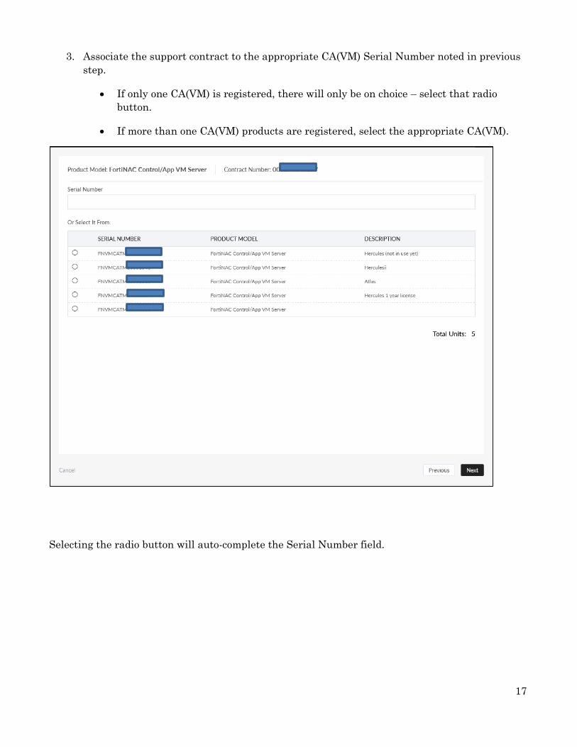
3. Associate the support contract to the appropriate CA(VM) Serial Number noted in previous
step.
If only one CA(VM) is registered, there will only be on choice – select that radio
button.
If more than one CA(VM) products are registered, select the appropriate CA(VM).
Selecting the radio button will auto-complete the Serial Number field.

18
4. Click Next.

19
5. Click on radio button in the lower left corner.
6. Click Confirm.

20
Support contract registration is now complete and applied to the CA(VM).
7. Next step: Register the License. Click Register More.

21
Register Licenses
1. Enter registration code from the pdf found in the appropriate License file:
LIC-FNAC-BASE-100_xxx
LIC-FNAC-PLUS-100_xxx
LIC-FNAC-PRO-100_xxx
2. Click on Next.

22
3. Associate the License to the Primary or Control server CA(VM).
If only one CA(VM) is registered, there will only be one choice – select that radio
button.
If more than one CA(VM) is registered, select the appropriate CA(VM)
(Primary/Control server).
Important: DO NOT license the secondary server. The secondary server (high availability)
will obtain its license from the Primary. This will occur during Professional Services Session
One.
4. Click Next.

23
License registration is complete.
5. Next step: Register the support contract for the License. Click Register More.

24
Register Support Contract for License
1. Enter registration code from the pdf found in the appropriate License Support file:
FC1-10-FNAC0-240_xxx (support for Base license)
FC2-10-FNAC0-240_xxx (support for Plus license)
FC3-10-FNAC0-240_xxx (support for Pro license)
2. Click Next.

25
3. Associate the License Support contract to the same serial number as the License (in
previous step).
4. Click Next.

26
5. Click on radio button in lower left corner.
6. Click Confirm.

27
Registration the License support contract is complete.
The page will display the products and support contracts registered.
7. Close the PDF files used in the previous steps.
8. If there are additional CA(VM)s to register (and its support contracts), click on Register
More. Otherwise, click Done.

28
Register Remaining Appliances
1. Open the folder for the next appliance to be registered.
2. Open the 2 PDF files
3. Register the appliance
a. Click Register Product.
b. Enter registration code from the pdf found in file FNC-CA-xx_xxx
(or if there is a Manager FNC-M-xx.xxx).
c. Click Next.
d. If there was a POC or active evaluation license, a special page may display. If you
are converting your POC to production, select Convert Evaluation. If you not
converting your POC to production, select Register.
e. Enter “Managing Server” under Product Description (this can be edited later)
f. Select Fortinet Partner (ignore all other fields).
g. Click Next.
h. Read terms and conditions.
i. Click on radio button.
j. Click Next.
Note: “No Entitlement” will display. This is correct.
k. Click on radio button to accept.
l. Click Confirm.
CA(VM) product registration is now complete.
m. Note the Serial Number (will be used to register the appliance support contract).
n. Proceed to register the support contract for the appliance. Click Register More.

29
4. Register Support Contract for Appliance
a. Enter registration code found on pdf from file FC-10-NCxx_xxx.
b. Click Next.
c. Associate the support contract to the appropriate CA(VM) Serial Number noted in
previous step.
d. If only one CA(VM) is registered, there will only be on choice – select that radio
button.
e. If more than one CA(VM) products are registered, select the appropriate CA(VM).
f. Click Next.
g. Click on radio button in the lower left corner.
h. Click Confirm.
i. Support contract registration is now complete and applied to the CA(VM).
j. Close the PDF files used in the previous steps.
If there are additional CA(VM)s to register (and its support contracts), click on Register More. If
registering more Otherwise, click Done
* DO NOT REGISTER THE PROFESSIONAL SERVICES CONTRACTS *
Important: If a file for Professional Services (FP-10-PS-801-01-01.zip or FP-10-PS-830-01-01.zip)
was included in the email, do not attempt to register. These are ONLY to be registered one at a
time and on the day of the Professional Services session. One contract is like an “admission ticket”
to the Professional Services session.

30
End result:
Once product registrations are complete, the summary page for each appliance will look similar to
the example below. Note only the managing server (example below) will have license information
listed.
If assistance is needed with registering devices, contact Fortinet Customer Service.
Product Registration is complete. Proceed to next step.
31
Step 2: Appliance Installation
1. Important: If building virtual appliances, ensure there are sufficient resources available
for the hosting machine and the appliance.
a. Open the FortiNAC Data Sheet available online.
b. Determine the appropriate parameters for the virtual environment. It is
recommended they be comparable to those of hardware-based FortiNAC appliances.
i. Identify the hardware server part number most appropriate for the target
environment (FortiNAC-CA-500/600/700 or M-550). Refer to the Hardware
Server Sizing table on page 11.
ii. See the Specifications table for details regarding that part number on pages
9 and 10.
c. Determine the appropriate amount of memory and CPU to allocate for the virtual
appliance. See the VM Server Resource Sizing table for suggested values on page
11.
Note: Virtual appliance settings will vary depending on the underlying hardware being
used for the hosting server and the type of FortiNAC server being run in the virtual
appliance. The ideal result is to yield a virtual environment where the average load does
not exceed the Total GHz Rating of CPU Resources Allocated.
2. Follow the instructions in the appropriate installation guide in the Fortinet Document
Library:
VMware
HyperV
AWS
Azure
KVM
Physical
These steps guide the user through the building of virtual appliances/stacking physical appliances.
Once completed, proceed to next step.
Step 3: Generate and Download Keys This step updates the product records in FortiCare with the required information for each
appliance in order to generate the appropriate key files.
Key Generation Procedure Overview
1: Collect appliance information
2: Generate Key for Managing Server
3: Generate Key for Remaining Servers (VMs Only)

32
Collect Appliance Information
Collect the appropriate appliance information using one of the methods below.
UI Method
1. Launch the Configuration Wizard by opening a browser on your PC and navigating to:
FortiNAC version 9.1 and below: https://<FortiNAC hostname>:8443/configWizard
FortiNAC version 9.2 and greater: https://<FortiNAC hostname>:8443
2. Enter the Configuration Wizard credentials. The License Key window is displayed.
3. Click Obtain a license key. The UUID (virtual appliances only) and eth0 MAC address
are displayed.
4. After recording the information, close browser window.
CLI Method
1. Login to the appliance CLI as root.
2. Record eth0 MAC Address. Type ifconfig eth0
Example output eth0: flags=4163<UP,BROADCAST,RUNNING,MULTICAST> mtu 1500
inet 10.254.0.1 netmask 255.255.0.0 broadcast 10.254.255.255
ether 70:4C:A5:ff:00:01 txqueuelen 1000 (Ethernet)
3. Record UUID (virtual appliances only). Type
sysinfo –v | grep –i uuid
4. After recording the information, logout of CLI. Type logout
Physical Appliances
Eth 0 MAC address (xx:xx:xx:xx:xx:xx or xx-xx-xx-xx-xx-xx) can also be found in the following
locations:
Shipping label
Appliance Identification Details document
On the back or the top of the metal casing of the appliance

33
Generate Key for Managing Server
1. Log into the Customer Portal at https://support.fortinet.com/
2. Under products, click the serial number for the managing appliance.
3. Edit the record by clicking the pencil icon.
4. Enter the following:
Description (if modification is required)
Eth0 MAC Address
UUID (Virtual appliances only)
Note: Once MAC Address and/or UUID is entered and saved, it cannot be changed online. If
assistance is needed with registering devices or changing these entries, contact Fortinet Customer
Service.
5. Click Save.

34
The summary page has updated with the link to “Get The License File”
Important: Customers with new appliances should select the FortiNAC License File.
6. Click Get the License File.

35
If a Control Manager is registered, this screen may appear.
7. Click the radio button for the serial number of the Control Manager that will be managing
this appliance (select Primary Control Manager if Managers are configured for High
Availability).
8. Click Download License Key File.
9. The .lic filename will reflect the appliance serial number.
10. Once the file is downloaded, click Close.
11. Save the .lic file to the appliance folder.
Remaining Servers
Virtual Appliances: Repeat the previous steps to update each appliance record and download the
key, saving each key file to their appropriate folder.
Physical Appliances: Repeat the previous steps to update each appliance record with the MAC
Address. Do not download any additional keys. The remaining appliances use the installed key
shipped with the hardware.
Note: Once a MAC address or UUID is entered and saved, it cannot be changed online. If
assistance is needed with registering devices or changing existing MAC address entries, contact
Fortinet Customer Service.
Key generation is complete. Proceed to next step.

36
Step 4: Appliance Configuration 1. Follow the instructions in the appropriate document below:
Software version 9.1 and lower: Configuration Wizard Guide in the Document Library.
Software version 9.2 and greater: Guided Install in the Administration Guide.
These steps guide the user through the following tasks:
License key installation
Network settings configuration
Password creation
Eth1 interface configuration
2. Verify appliance with the Endpoint License Key has the correct entitlements.
a. In the appliance with the Endpoint License Key installed, access the Administration UI using one of the following URLs:
https://<IP Address>:8443/
https://<Host Name of the virtual appliance>:8443/
b. Enter the following UI credentials (User Name and Password fields are case
sensitive). These credentials are independent of the passwords previously set in
Configuration Wizard.
User Name = root
Password = YAMS
If “Processes are Down” is displayed, there may be a UUID or MAC address mismatch. See related KB article 192992.
c. Once logged into FortiNAC, review the End User License Agreement and click Accept to continue.
d. On the Password screen, create a new Administrator user name and password and click Apply.
e. Review the License Information panel in the Dashboard to confirm proper entitlements.

37
If entitlements are populated but not correct, review the entitlements in the customer portal (https://support.fortinet.com/) for that product. Contact Customer Service for assistance.
Subscription License: If panel is blank, see KB article 191745 for troubleshooting steps.
For more information regarding the different license types, see Perpetual and Subscription Licenses in Appendix.
Proceed to next step.

38
Step 5: Operating System Updates
Requirements
Administration UI password
FQDN(s) of the FortiNAC server(s) are added to the production DNS server(s).
HTTP access to centos.org and updates.bradfordnetworks.com from each appliance or
virtual machine.
Note: FortiNAC can be configured via CLI to use FTP or HTTPS for OS updates instead of
HTTP.
The following options are also available with additional configuration. For instructions, refer to
the Updating CentOS reference manual in the Fortinet Document Library:
Change Transfer Protocol from HTTP to FTP/HTTPS
Update Using a Proxy Server
Update Procedure for Sites without External Access
Procedure
1. If not already logged in, access the Administration UI of appliance with the Endpoint License Key installed. Use the newly created Administrator user name and password.
https://<IP Address>:8443/
https://<Host Name of the virtual appliance>:8443/
2. Navigate to System > Settings > Updates > Operating System.
3. Click Check for Updates to check for available updates and assess whether the FortiNAC server is up to date or not.
4. Click Update All to begin downloading and installing the operating system updates.
5. A warning is displayed indicating that this is a long process and that you must reboot the server after the update. Click Yes to continue.
6. Use Show Log at the bottom of the table to view a log of the update process.

39
7. When the update is complete, select System Management > Power Management from the tree.
8. Select the server and click Reboot to reboot the FortiNAC Server.
9. Once rebooted, login to the UI again and navigate to System > Settings > Updates > Operating System.
10. Click Check for Updates. Status should now display “Up to Date”.
Multiple Appliances
Update the Operating System on the remaining appliances.
1. Access the UI using https://<IP Address>:8443/
https://<Host Name of the virtual appliance>:8443/
2. Enter the default login credentials below.
User Name = root
Password = YAMS
3. Once logged into FortiNAC, review the End User License Agreement and click Accept to continue.
4. On the Password screen, create a new Administrator user name and password and click Apply.
5. Navigate to System > Settings > Updates > Operating System and update using the same steps as previous.
Once all appliances are updated, proceed to next step.
Step 6: Create and Install SSL Certificates
Requirements
FortiNAC hostnames to be secured by the certificates (certificates required on all FortiNAC appliances)
Hostname used for the Portal can be different than the actual hostname of the appliance. This is beneficial when using a combination of internal and external certificates. Setting the Portal hostname differently also prevents revealing the actual appliance hostname to users interacting with the Portal. See uses cases below for examples
High Availability (HA) environments:
o For ease of configuration, it is recommended to install certificates in both appliances prior to configuring HA. If some certificates must be installed after HA is configured, see pages 5 and 6 of the SSL Certificates How To in the Fortinet Document Library for instructions.
o If a Virtual IP Address (VIP) will be used in a L2 HA configuration, VIP hostname will also need to be secured

40
Procedure
1. Determine use cases so the appropriate certificates can be acquired. FortiNAC can use SSL certificates issued by either an internal or public (external) Certificate Authority (CA). Note: Different certificates can be installed for different components.
Components secured by SSL Certificates
Component Function Certificate to Use
Administration UI Access to the FortiNAC UI Internal or External
Persistent Agent Persistent Agent communication
Internal or External
Portal Captive Portal access and Dissolvable Agent communication
External
Local RADIUS Server (EAP)
For use when FortiNAC is acting as the 802.1x EAP termination point.
Internal or External (avoid wildcard certificates)
RADIUS Endpoint Trust
Client-side certificate validation (EAP-TLS)
Internal or External (avoid wildcard certificates)
Use Case Examples
Internal domain: servername1.intdomainname.com
External domain: servername2.extdomainname.com
Use Case Example 1: Internal CA & 3rd Party RADIUS Server
Computers to be used for Administration UI access have the company’s internal CA root certificate installed
Company owned computers require the Persistent Agent be installed also have the internal CA root certificate
BYOD devices will be on-boarded via Captive Portal
FortiNAC will manage wireless clients but will proxy RADIUS to 3rd party RADIUS Server
In this use case, 2 certificates will be required (1 internal and 1 external).
Hostname to Secure (Subject)
Certificate Component(s)
FNACname1.intdomainname.com Internal Administration UI
Persistent Agent
FNACname2.extdomainname.com External Portal

41
Use Case Example 2: Internal CA & Local RADIUS Server
Computers to be used for Administration UI access have the company’s internal CA root certificate installed
Company owned computers require the Persistent Agent be installed also have the internal CA root certificate
BYOD devices will be on-boarded via Captive Portal
FortiNAC will manage wireless clients but will proxy RADIUS to 3rd party RADIUS Server
In this use case, 2 certificates will be required (1 internal and 1 external).
Hostname to Secure (Subject)
Certificate Component(s)
FNACname1.intdomainname.com Internal Administration UI
Persistent Agent
Local RADIUS Server (EAP)
RADIUS Endpoint Trust
FNACname2.extdomainname.com External Portal
Use Case Example 3: No Internal CA & Local RADIUS Server
Admin UI: Use external certificate
Persistent Agent: Use internal certificate
Portal: Use external certificate
Local RADIUS Server (EAP): Use external certificate
RADIUS Endpoint Trust: Use external certificate
In this use case, 1 certificate will be required (external).
Hostname to Secure (Subject)
Certificate Component(s)
FNACname2.extdomainname.com External Administration UI
Persistent Agent
Portal
Local RADIUS Server (EAP)
RADIUS Endpoint Trust

42
2. Navigate to System > Settings > Security > Certificate Management.
3. Request certificates (if not already generated) and install on all appliances. For instructions, refer to the SSL Certificates How To in the Fortinet Document Library.
4. Upload certificates to the Admin UI first (if UI is going to be secured).
5. Logout of the Admin UI and reconnect using the following URL:
https:// <FortiNAC Server Host Name included in certificate>:8443/
If browser reports certificate is not secure, an intermediate certificate may be missing. See related KB article 190860.
Proceed to next step.
Step 7: High Availability (Optional)
Requirements
Open Ports
All previous steps have been completed for both appliances to be configured for High
Availability
Procedure
For details and instructions to configure High Availability, see section Configuration of the High
Availability reference manual in the Fortinet Document Library.
Once High Availability is configured and validated, proceed to next step.
Step 8: Control Manager (Optional)
Requirements
Open ports
All previous steps have been completed for the Manager as well as the appliances to be
managed.
Procedure
For details and instructions, refer to the Control Manager Admin Guide in the Fortinet Document
Library.

43
Step 9: Software Upgrade
Requirements
Open Ports
Procedure
Upgrade all appliances to the latest version. For details and instructions, refer to the following
documents in the Fortinet Document Library:
Release Notes
Upgrade Instructions and Considerations
Once all appliances are upgraded, proceed to next step.
Step 10: System Settings
Requirements
SSL certificates
Authentication Directory account and details
Email Account and details
Remote backup server
Procedure
1. Configure communication settings for the appropriate authentication source.
LDAP/Active Directory Navigate to System > Settings > Authentication > LDAP
For additional details see section Directories Configuration of the Administration Guide.
Connections Considerations
MAC Address: A valid MAC address must be used for the LDAP server. This will
ensure the LDAP server model is properly created in Topology/Inventory.
LDAP login: include domain (example: domain/userid)
Secondary field contains information regarding a secondary directory containing the same
user information.
Integration with multiple directories for authentication to distinct domains utilizes the
“Domain Name” field in the Connection tab of each LDAP directory configuration.
Suggested LDAP Timeout: 30

44
Search Branch Considerations Client Search Branches
For simplicity, the root (i.e., dc=domain,dc=com) can be used.
Granular search branches should be used when
o A limited number of user information is required for authentication.
o Lookups from the root take an extended period of time due to the size of the
directory.
When using multiple search branches, order the Client Search Branches with the most
used branch first and least used last.
Group Search Branches
Configure Group Search Branches only if intending to utilize LDAP/Active Directory
group membership to assign Network Access or Endpoint Compliance policies.
Granular search branches are suggested if there are a large number of groups in the
directory. Otherwise, the root (i.e., dc=domain,dc=com) can be used.
RADIUS Server
Navigate to System > Settings > Authentication > Radius
For additional details see section Configure RADIUS settings of the Administration Guide.
Navigate to System > Settings > Authentication > Google
Note: This integration requires configuration in the Google Developer’s Console in addition to the
FortiNAC Administration UI. For instructions, refer to the Google Authentication for the Captive
Portal reference manual in the Fortinet Document Library.
2. Create Administrative Profiles and Users (optional).
To provide access to the FortiNAC user interface, Administrative Users can be placed in special
groups that set the appropriate privileges. This is done by placing users in special groups within the
directory that correspond to matching groups in FortiNAC. When the Directory is synchronized with
FortiNAC, users in the appropriate groups will be given Administrator or Administrative privileges
based on their group settings and the Admin Profile Mapping that matches the user's group.
For configuration instructions, refer to the Setting admin privileges by directory group reference
manual in the Fortinet Document Library.
To validate, logout of Administration UI and login using the new Admin User account with
Administrator access.
3. Configure FortiNAC send email. This function is used for notification in features such as
Alarm mappings and Guest registration.
Navigate to System > Settings > System Communication > Email Settings
For additional details see section Email settings of the Administration Guide.

45
To validate, use “Test Email Settings” button at the bottom of the view.
4. (Optional) Configure FortiNAC to send Event and Alarm records to an external server.
Navigate to System > Settings > System Communication > Log Receivers
For additional details see section Log receivers of the Administration Guide.
5. (Optional) Configure FortiNAC to respond to SNMP queries of appliance system information from
an external Management System.
Navigate to System > Settings > System Communication > SNMP
For additional details see section SNMP of the Administration Guide.
6. Configure FortiNAC database backup schedule, storage duration and restoring of archives.
Navigate to System > Settings > System Management > Database Archive
Navigate to System > Settings > System Management > Database Backup/Restore
For additional details see sections Database archive and Backup or restore a database of the
Administration Guide.
Best Practice: Perform database backups daily.
7. (Physical) Configure FortiNAC Remote System Backups. Virtual appliances should have snapshots
scheduled.
Backups by default are stored locally on the appliances. Remote backup stores the system
configuration and database on a remote server for use in disaster recovery.
Note: Administrator of remote server is responsible for file management.
Navigate to System > Settings > System Management > Remote Backup Configuration
For additional details see section Backup to a remote server of the Administration Guide.
8. Configure FortiNAC system backup schedule and storage duration.
Navigate to System > Settings > System Management > System Backups
For additional details see section System backups of the Administration Guide.
Best Practice: Perform system backups weekly.
9. (Optional) Ensure System Update settings are accurate and download FortiNAC Agent
Package updates to ensure the latest Agent version is available.
a. Navigate to System > Settings > Updates > System
b. Change Host to updates.bradfordnetworks.com and Save.

46
c. Refer to the latest Agent Release Notes for the appropriate Product Distribution
Directory setting.
d. Navigate to System > Settings > Updates > Agent Packages and review the versions
of the listed packages. For instructions on downloading new agent packages, see section
Agent packages of the Administration Guide.
Proceed to next step.
Step 11: Network Visibility Through communication with the wired infrastructure devices (switches, routers, wireless
controllers and access points), FortiNAC gathers basic who, what, when and where information
about connecting endpoints.
Requirements
SNMP credentials
CLI credentials
Procedure
1. Modify System Defined Uplink Count.
When devices are added to Topology, FortiNAC determines whether or not switch ports
should be considered uplinks based on specific criteria. The System Defined Uplink Count
is the threshold value FortiNAC uses to convert a port to a Threshold Uplink. (Note:
Uplinks will be discussed further in later steps).
Before adding devices to Topology, the best practice is to change the System Defined Uplink
Count from its default of 20 to 2000. This helps avoid ports changing to uplinks due to
connecting computers generating an unusually high number of MAC addresses.
a. Navigate to System > Settings > Network Device.
b. Change System Defined Uplink Count to 2000.
c. Click Save Settings at the bottom of the view.
2. Create Containers for logical grouping of network devices in Topology.
Navigate to Network Devices > Topology
3. Perform Network Discovery of wired infrastructure.
Add devices individually (Add or modify a device) or in bulk (Discovery).
Related KB article: Troubleshooting SNMP Communication Issues

47
Note: If a “?” appears as the icon, then support needs to be added for that device. See KB article
Options for Devices Unable to Be Modeled in Topology for instructions.
4. Validate communication between FortiNAC and newly added devices.
a. Correct any credential issues found during the discovery.
i. Select the device model in tree in the left panel and click the Credentials
tab.
ii. Make the appropriate corrections and click the Validate Credentials
button.
b. Verify FortiNAC can read VLANS configured on the devices.
i. Right click on the model and select Network Access/VLANs.
ii. Click Read VLANs.
5. Perform Network Discovery of wireless infrastructure.
Note: When defining the IP Range, do not include AP’s managed by controllers.
Add devices individually (Add or modify a device) or in bulk (Discovery).
Note: If a “?” appears as the icon, then support needs to be added for that device. See KB article
Options for Devices Unable to Be Modeled in Topology for instructions.
6. Configure L3 (IPMAC) sources.
Navigate to System > Groups > L3 (IPMAC)
a. L3 (IPMAC) group should contain all devices that are a source of FortiNAC ARP
information. This includes routers, L3 switches, wireless controllers and
autonomous AP’s that are a source of ARP data.
b. Perform Network Discovery for any devices not already discovered.
7. Look for any “L2 Poll Failed” and “L3 Poll Failed” events.
Navigate to Logs > Events
Related KB article: Troubleshooting Poll Failures
8. Uplink Review
Identify ports in the network where FortiNAC has determined that the number of MAC
addresses on the port exceeds the System Defined Uplink count. Review these ports and
verify whether or not these are legitimate.
Navigate to Network Devices > Topology.
a. Filter on the Connection Status “Threshold Uplinks” under the Ports tab. This can
be done at the top level or container level.
b. Click Update to apply filter.

48
c. Manually set ports that should be an uplink to “Always Uplink.” This is a way to
keep track of which uplinks have been verified. If any ports display “Threshold
Uplink” as a Connection State in the future, it will indicate a new connection and
should be verified.
Switches with a mix of servers and access ports: Mark server ports as user
defined uplinks if ports are physically secure and there is no interest in visibility of
those servers.
For instructions see section Port properties of the Administration Guide.
There are different types of uplinks. Each uplink type is triggered by different criteria. For a
complete list of uplink types and how they are detected, see section Port uplink types of the
Administration Guide.

49
Appendix
Requirements Task List
FortiNAC deployment takes place in several steps. This list is broken out into these steps as
outlined in this document.
The components listed under each step are the requirements that must be in place in order for that
specific step to be completed. The length of time it takes to complete deployment is dependent
upon each customer, their requirements and time constraints. Customers can complete all
requirements prior to deployment, or during the deployment as time permits for those
requirements not needed until later steps.
Click here for a printable version of the checklist.
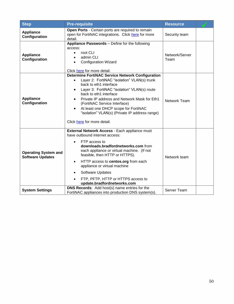
Step Pre-requisite Resource
Appliance Installation and Configuration
Appliance Network Addressing - Define the following for each FortiNAC appliance:
Hostname (Important: for internal name resolution reasons, avoid using “nac” as name. It is used for internal name resolution)
o Example of correct usage: IT-NAC-HQ o Example of incorrect usage: NAC
Private IP address and Network Mask for Eth0 (Management Interface) – Requires network access for the following functions:
o Administration UI access o Communication with Network
Infrastructure (SNMP, CLI, API) o SNMP Traps o Syslog o Radius o LDAP o FSSO o REST API
Default Gateway
Domain name
DNS server(s)
NTP server(s)
Network Team
50
Step Pre-requisite Resource
Appliance Configuration
Open Ports - Certain ports are required to remain open for FortiNAC integrations. Click here for more detail.
Security team
Appliance Configuration
Appliance Passwords – Define for the following access:
root CLI
admin CLI
Configuration Wizard Click here for more detail.
Network/Server Team
Appliance Configuration
Determine FortiNAC Service Network Configuration
Layer 2: FortiNAC “isolation” VLAN(s) trunk back to eth1 interface
Layer 3: FortiNAC “isolation” VLAN(s) route back to eth1 interface
Private IP address and Network Mask for Eth1 (FortiNAC Service Interface)
At least one DHCP scope for FortiNAC “isolation” VLAN(s) (Private IP address range)
Click here for more detail.
Network Team
Operating System and Software Updates
External Network Access - Each appliance must have outbound internet access:
FTP access to downloads.bradfordnetworks.com from each appliance or virtual machine. (If not feasible, then HTTP or HTTPS).
HTTP access to centos.org from each appliance or virtual machine
Software Updates
FTP, PFTP, HTTP or HTTPS access to update.bradfordnetworks.com
Network team
System Settings DNS Records: Add host(s) name entries for the FortiNAC appliances into production DNS system(s).
Server Team

51
Step Pre-requisite Resource
System Settings
SSL certificates Have a resource available that can issue Internally signed certificates and/or request publicly signed certificates.
Admin UI o Corporate Internal Certificate Authority
(recommended) Individual SAN
o 3rd Party Public Certificate Authority Individual SAN Wildcard
Local RADIUS Server (EAP) o Corporate Internal Certificate Authority
(recommended) Individual SAN
o 3rd Party Public Certificate Authority Individual SAN Wildcard (Not recommended:
some supplicants will not accept wildcard certificates)
Agent o Corporate Internal Certificate Authority
(recommended) Individual SAN
o 3rd Party Public Certificate Authority Individual SAN Wildcard
Portal o 3rd Party Public Certificate Authority
Individual SAN Wildcard
RADIUS Endpoint Trust (EAP-TLS) o Corporate Internal Certificate Authority
(recommended) Individual SAN
o 3rd Party Public Certificate Authority Individual SAN Wildcard (Not recommended:
some supplicants will not accept wildcard certificates)
Click here for more detail.
Server Team

52
Step Pre-requisite Resource
System Settings
Authentication Directory Account and Details Provide the following for Directory Authentication integration
Identify IP, MAC Address and Hostname of Directory server(s)
LDAP/Active Directory service account (account must have read access to all requested search branches)
Provide specific User search branch(es)
Provide specific Group search branch(es) (if needed)
Identify any non-standard directory attributes used
Server Team
System Settings
Email Account and Details Provide the following to enable FortiNAC to send email notifications.
Email Server
Email address for FortiNAC (may want to configure an alias for this address to better identify sender as FortiNAC)
Username and password if authentication is desired
Port used on email server.
Encryption used on email server for email communication (if any).
Server Team
System Settings Remote Backup Server Provide an FTP or SSH remote server for FortiNAC database and system configuration backup.
Server Team
Network Visibility
SNMP Credentials Create if one does not already exist: SNMP community name (v1/v2) or account (v3) for all network infrastructure devices:
Devices FortiNAC will control: Read/write privileges
L3 devices from which FortiNAC will obtain ARP information but not control: Read privileges
Network Team
Network Visibility PING Response Network devices must be able to respond to PING requests from FortiNAC eth0 IP address.
Network Team

53
Step Pre-requisite Resource
Network Visibility
CLI Credentials Create if one does not already exist: CLI access account (SSH or Telnet) for all network infrastructure devices:
Devices FortiNAC will control: Read/write privileges (Cisco must be level 15 local user account)
L3 devices from which FortiNAC will obtain ARP information but not control: Read access (level 7)
Important: When configuring the hardware device itself, use only letters, numbers and hyphens (-) in names for items within the device configuration, in SNMP and CLI credentials. Other characters may prevent FortiNAC from reading the device configuration. For example, in many cases the # sign is interpreted by FortiNAC as a prompt. Cisco restricts the use of @ and #.
Network Team
Network Visibility
Network Device IP’s Be able to provide the IP’s of all specific network devices (routers, switches, firewalls, Access Points or controllers) that will be controlled or queried by FortiNAC.
Network Team
Endpoint Classification
Required for distributing Persistent Agents: Line up resource responsible for deployment of software packages (i.e. SCCM administrator, Microsoft GPO).
Server Team
Endpoint Classification
DHCP Fingerprints (Optional) FortiNAC can listen to DHCP exchanges and collect enhanced information about endpoints (hostname and operating system). Configure IP Helper addresses on L3 switches or routers for all production VLANs that use DHCP. Use the IP address of FortiNAC eth0 interface. Note: • Fingerprint collection is not required in order to achieve visibility, but does provide additional information. • FortiNAC updates or creates a Host record when it hears a DHCP packet (discover, request or inform) that provides OS and/or hostname. It does not matter if the host is offline or online. • Not all DHCP fingerprints provide hostname and FortiNAC is not always able to determine OS for all DHCP packets. The device’s DHCP fingerprint may be unknown or too similar to other devices to name an OS.
Network Team

54
Step Pre-requisite Resource
Enforcement
SNMP Traps The following must be done on all wired network devices FortiNAC will control:
Trap Receivers: Configure trap receivers for the eth0 interface of the FortiNAC Server.
All devices: Enable Cold start and Warm start traps.
Enable one of the following traps to notify FortiNAC of endpoints connecting and disconnecting from the network:
o MAC Notification traps (recommended) on supported devices. For a list of devices supported for MAC Notification traps, refer to the SNMP Trap Support chart in the Fortinet Document Library. For general configuration details, see Configuring Traps for MAC Notification in the Fortinet Document Library.
o All other vendors - Enable Linkup/Linkdown traps.
Network/Security Team
Enforcement
Define and configure “isolation” VLANs:
Registration
Remediation
Dead End or alternatively
Isolation (one “isolation” VLAN for all states) Note: Layer 3 deployments require a VLAN per state per location that is separated by an L3 device Ensure routing/firewall policies are configured for:
FortiNAC Service Network Interface (eth1)
"Isolation" VLANs o Block outbound DNS except for eth1
interface Click here for more detail.
Network/Security Team

55
Step Pre-requisite Resource
Enforcement
Production Network Access (available with Plus and Pro licensing) Identify network segmentation for
Who
What
Where
When Examples:
Employees with corporate assets connecting to the network at either Site 1 or Site 2 require internal network access. They are assigned VLAN 10 (CorpData).
Visitors connecting to the network at either Site 1 or Site 2 are allowed internet access only. They are assigned VLAN 20 (Guest).
Network Team
Enforcement
Wireless Integrations For instructions on managing wireless networks using FortiNAC, review the applicable integration guide under the Reference Manual section of the Fortinet Document Library.
Review FortiNAC Integration Guides
Create test wireless environment identical to production environment & validate network access
Determine authentication method for FortiNAC integrations
o MAC Authentication o 802.1X
Provide Radius Server IP Configured FortiNAC ‘s eth0
IP as a Radius Client on the Radius Server
Network Team
Enforcement
VPN Integrations (Optional) For instructions on managing VPN networks using FortiNAC, review the applicable integration guide under the Reference Manual section of the Fortinet Document Library.
Review FortiNAC Integration Guides
Supported for FortiGate and Cisco ASA only
SSL or IPSec
Create test VPN environment identical to production environment & validate network access
Network Team

56
FNAC Part Numbers
Virtual Appliance (VM) Part Numbers
Part Number Description
FNC-M-VM Control Manager
FNC-CA-VM Control and Application Server (CA)
Physical Part Numbers
Part Number Description
FNC-M-550C Control Manager
FNC-CA-500C Control and Application Server (CA)
FNC-CA-600C Control and Application Server (CA)
FNC-CA-700C Control and Application Server (CA)
57
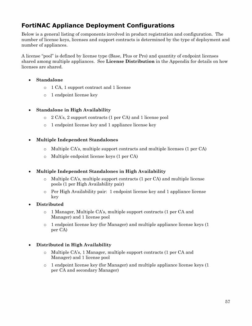
FortiNAC Appliance Deployment Configurations
Below is a general listing of components involved in product registration and configuration. The
number of license keys, licenses and support contracts is determined by the type of deployment and
number of appliances.
A license “pool” is defined by license type (Base, Plus or Pro) and quantity of endpoint licenses
shared among multiple appliances. See License Distribution in the Appendix for details on how
licenses are shared.
Standalone
o 1 CA, 1 support contract and 1 license
o 1 endpoint license key
Standalone in High Availability
o 2 CA’s, 2 support contracts (1 per CA) and 1 license pool
o 1 endpoint license key and 1 appliance license key
Multiple Independent Standalones
o Multiple CA’s, multiple support contracts and multiple licenses (1 per CA)
o Multiple endpoint license keys (1 per CA)
Multiple Independent Standalones in High Availability
o Multiple CA’s, multiple support contracts (1 per CA) and multiple license pools (1 per High Availability pair)
o Per High Availability pair: 1 endpoint license key and 1 appliance license key
Distributed
o 1 Manager, Multiple CA’s, multiple support contracts (1 per CA and Manager) and 1 license pool
o 1 endpoint license key (for Manager) and multiple appliance license keys (1 per CA)
Distributed in High Availability
o Multiple CA’s, 1 Manager, multiple support contracts (1 per CA and Manager) and 1 license pool
o 1 endpoint license key (for Manager) and multiple appliance license keys (1 per CA and secondary Manager)
58
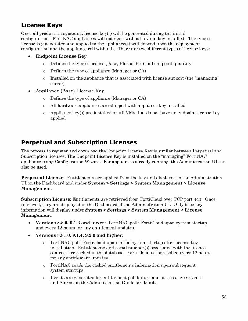
License Keys
Once all product is registered, license key(s) will be generated during the initial configuration. FortiNAC appliances will not start without a valid key installed. The type of license key generated and applied to the appliance(s) will depend upon the deployment configuration and the appliance roll within it. There are two different types of license keys:
Endpoint License Key
o Defines the type of license (Base, Plus or Pro) and endpoint quantity
o Defines the type of appliance (Manager or CA)
o Installed on the appliance that is associated with license support (the “managing”
server)
Appliance (Base) License Key
o Defines the type of appliance (Manager or CA)
o All hardware appliances are shipped with appliance key installed
o Appliance key(s) are installed on all VMs that do not have an endpoint license key
applied
Perpetual and Subscription Licenses
The process to register and download the Endpoint License Key is similar between Perpetual and
Subscription licenses. The Endpoint License Key is installed on the “managing” FortiNAC
appliance using Configuration Wizard. For appliances already running, the Administration UI can
also be used.
Perpetual License: Entitlements are applied from the key and displayed in the Administration
UI on the Dashboard and under System > Settings > System Management > License
Management.
Subscription License: Entitlements are retrieved from FortiCloud over TCP port 443. Once
retrieved, they are displayed in the Dashboard of the Administration UI. Only base key
information will display under System > Settings > System Management > License
Management.
Versions 8.8.9, 9.1.3 and lower: FortiNAC polls FortiCloud upon system startup and every 12 hours for any entitlement updates.
Versions 8.8.10, 9.1.4, 9.2.0 and higher:
o FortiNAC polls FortiCloud upon initial system startup after license key installation. Entitlements and serial number(s) associated with the license contract are cached in the database. FortiCloud is then polled every 12 hours for any entitlement updates.
o FortiNAC reads the cached entitlements information upon subsequent system startups.
o Events are generated for entitlement poll failure and success. See Events and Alarms in the Administration Guide for details.

59
Perpetual + Subscription Licenses: A combination of both Perpetual and Subscription
Licenses can be purchased to apply to the same appliance. The Perpetual license information is
read from the license key and the subscription license pulled from FortiCloud. The two license
totals are then added together.
License Distribution in Multiple Appliance Deployments
This section describes how a license pool’s license type and endpoint quantity are shared among
appliances in a multiple appliance deployment.
Standalone in High Availability – Perpetual License
Endpoint License Key is installed on the Primary Server. When the High Availability configuration is performed, the Primary Server updates the Secondary Server.
Standalone in High Availability – Subscription License
Versions 8.8.10, 9.1.4, 9.2.0 and higher:
Cached entitlement information is replicated to the Secondary Server.
If Secondary Server is in control and the contract is valid, the secondary uses the cached entitlements. This ensures the state of the Secondary Server's licensing entitlements are the same as the Primary Server at the time of failover.
FortiCloud is then polled every 12 hours for any entitlement updates.
Multiple Independent Standalones in High Availability
Same as above for each High Availability pair.
Primary Server
(Endpoint License Key)
Secondary Server (Appliance (Base) License
Key)
Base, Plus or Pro License
X Concurrent Endpoint Licenses
Primary Server
(Endpoint License Key)
Secondary Server (Appliance (Base) License
Key)
Base, Plus or Pro License
X Concurrent Endpoint Licenses
Primary and Secondary Serial Numbers

60
Distributed
Endpoint License Key is installed on the Manager. CA’s are updated by the Manager as
they are added to the Server List in the Dashboard panel.
If the Manager goes off line or is unreachable by the managed servers, all services will
continue to function using the previously shared licenses from the Manager.
Manager removes license and endpoint quantity from CA’s as they are removed from the
Server List.
CA
(Appliance (Base) License Key)
Manager
(Endpoint License Key)
CA (Appliance (Base)
License Key)
CA (Appliance (Base)
License Key)
• Base, Plus or Pro License
• X Concurrent Endpoint Licenses

61
Distributed in High Availability
Endpoint License Key is installed on the Manager. CA’s not in High Availability pair and
Primary Servers are updated as they are added to the Server List in the Dashboard panel.
Once the Primary Server is added to the Server List, the Manager updates the Secondary Server upon the next failover of the High Availability pair.
If the Manager goes off line or is unreachable by the managed servers, all services will
continue to function using the previously shared licenses from the Manager.
Manager removes license and endpoint quantity from CA’s not in High Availability pair and
Primary Servers as they are removed from the Server List.
Primary Server
(Appliance (Base) License Key)
Primary
Manager (Endpoint License
Key)
Secondary Server (Appliance (Base)
License Key)
CA
(Appliance (Base) License Key)
Base, Plus or Pro License
X Concurrent endpoint licenses
Primary Server
(Appliance (Base) License Key)
Secondary Server (Appliance (Base)
License Key)
Secondary
Manager (Appliance (Base)
License Key)

62
License Key Files and Locations
File Descriptions
.licenseKeyHW = Key file shipped with appliance hardware (only). File contains certificates used
for authentication and required for many functions. DO NOT DELETE.
.licenseKey = License or appliance (base) key currently in use by the appliance.
Used in both virtual and hardware appliances.
When hardware appliances are shipped, the contents of .licenseKeyHW and .licenseKey files
are the same.
.licenseKeyPrimary = Located on Secondary Server. Key file contains Endpoint License
entitlements from Primary Server.
Key file is created during High Availability configuration.
If Primary Server Endpoint License is updated, .licenseKeyPrimary is updated once the
High Availability configuration is re-applied or manually updated via CLI. For instructions,
refer to the FortiNAC License Upgrade Guide.
Note: This file should not be located on the Primary Server. See related KB article 203021.
.licenseKeyNCM = Located on all Control and ControlApplication Servers managed by a
Manager. Key file containing Endpoint License entitlements from Manager.
FortiNAC Versions 8.7.5, 8.8.1, 9.1.0 and greater
o Primary Server
Key file is added once server is added to the Manager’s Server List.
Key file is removed once server is removed from the Manager’s Server List.
Key file is automatically updated once license is updated on Manager.
o Secondary Server
Key file is added or removed if added or removed from the Primary Server.
Key file is automatically updated from the Primary Server.
Prior Versions
o Primary Server
Key file is added once server is added to the Manager’s Server List.
Key file is removed once server is removed from the Manager’s Server List.
Key file is automatically updated once license is updated on Manager.
o Secondary Server
Key file is automatically updated from Manager upon the next failover.

63
File Locations
Standalone Server /bsc/campusMgr/.licenseKey
/bsc/campusMgr/.licenseKeyHW Hardware appliances only
Primary Server (no Manager) /bsc/campusMgr/.licenseKey
/bsc/campusMgr/.licenseKeyHW Hardware appliances only
Secondary Server (no Manager) /bsc/campusMgr/.licenseKey
/bsc/campusMgr/.licenseKeyPrimary
/bsc/campusMgr/.licenseKeyHW Hardware appliances only
Manager (Primary Server) /bsc/campusMgr/.licenseKey
/bsc/campusMgr/.licenseKeyHW Hardware appliances only
Manager (Secondary Server) /bsc/campusMgr/.licenseKey
/bsc/campusMgr/.licenseKeyPrimary
/bsc/campusMgr/.licenseKeyHW Hardware appliances only
Standalone and Primary Server (under a Manager) /bsc/campusMgr/.licenseKey
/bsc/campusMgr/.licenseKeyNCM
/bsc/campusMgr/.licenseKeyHW Hardware appliances only
Secondary Server (under a Manager) /bsc/campusMgr/.licenseKey
/bsc/campusMgr/.licenseKeyPrimary
/bsc/campusMgr/.licenseKeyNCM
/bsc/campusMgr/.licenseKeyHW Hardware appliances only

64
Open Ports
The number of open (listening) TCP/UDP ports configured by default on the FortiNAC
appliance is based on current best practices. These ports are kept to a minimum to provide
maximum security by explicitly restricting unnecessary access from the outside. The best
practice is to keep the number of open ports to a minimum, and block all other ports. If there is
a need to provide users access to network resources through a static port (e.g., from outside a
firewall), the best option is to allow users to connect by VPN.
Related Documents
http://www.iana.org/assignments/service-names-port-numbers/service-names-port-numbers.xhtml
Validate Open Ports
The current listening port configuration can be viewed by running an nmap of the appliance.
Another useful command is “netstat” to list all listening and connected ports on the current
appliance (e.g. netstat -ln lists just the listening ports).
In the FortiNAC CLI logged in as root, use the “netstat” command to verify that a TCP/UDP port is
open.
netstat -ln | grep <port number>
For example, use netstat -ln | grep 4568 to verify that the port used for Agent communications to
FortiNAC is open.
tcp 0 0 0.0.0.0:4568 0.0.0.0:* LISTEN
Open Port List
The tables on the following pages list ports that should be open to end users, and ports that
need to be open for FortiNAC communications.

65
Port Protocol Description Direction
All ports outbound All Used by Device Profiler to classify devices. Uses NMAP as one of the profiling choices. Also can use SNMP to profile.
eth0: Outbound eth1: Outbound
UDP 21 FTP Product Updates eth0: Outbound to internet
TCP 21 FTP Product Updates eth0: Outbound to internet
TCP 22 SSH
High Availability: MYSQL replication from Primary Server to Secondary Server Control Manager (M) eth0: Manage FortiNAC Servers
Primary Server eth0: Outbound to Secondary Server eth0 Bi-directional between Managed Servers eth0 and Manager eth0
TCP 23 Telnet Network Device Management eth0: Outbound
UDP 53 DNS Name Service eth0: Outbound eth1: Inbound
TCP 53 DNS Name Service eth0: Outbound eth1: Inbound
UDP 67 DHCP eth0: DHCP Fingerprinting eth1: Serving IP Addresses for Isolation Scopes
eth0: Inbound eth1: Inbound
UDP 68 DHCP eth0: DHCP Fingerprinting eth1: Serving IP Addresses for Isolation Scopes
eth0: Inbound eth1: Outbound
TCP 80 HTTP Web Server (Portal) eth0: Inbound eth1: Inbound
TCP 22 SFTP Product Updates eth0: Outbound to internet
UDP 123 NTP Time Service eth0: Outbound
UDP 161 SNMP Network Device Management
eth0: Outbound (Bi-directional if FortiNAC is configured to respond to SNMP queries. See section SNMP of the Administration Guide).
UDP 162 SNMP Traps
Device Changes Notification (Mostly Host Access Notification)
eth0: Inbound
TCP 443 HTTPS
Product Updates Web Server (Portal) Secure HTTP License Entitlements (fds1.fortinet.com) IoT data collection
eth0: Outbound to internet eth1: Inbound
UDP 514 Syslog Device Change Notification and RTR (inbound) Logging of events to external server (outbound)
eth0: Bi-directional
TCP 514 OFTP Communication with FortiAnalyzer (Available in FortiNAC version 8.5 and higher)
eth0: Outbound
TCP 1050 CORBA Server Communication (See note on page 5) High Availability
Bi-directional between Primary and Secondary Server eth0 Bi-directional between Managed Servers and Manager eth0
UDP 1645 RADIUS Host/User Authentication (Local RADIUS Server default)
eth0: Bi-directional
UDP 1812 RADIUS Host/User Authentication (Proxy RADIUS mode default)
eth0: Bi-directional
UDP 1813 RADIUS Accounting
Host/User Authentication Changes and RTR (Proxy RADIUS Mode default)
eth0: Inbound
UDP 3799 RADIUS COA
Host/User Authentication Action (Moving/Removing)
eth0: Outbound
UDP 4567 Agent Server
Persistent Agent Communication (No longer used by agent 5.x and above with NAC 8.2 and above – TCP 4568 only)
eth0: Bi-directional eth1: Bi-directional

66
Note: FortiNAC uses port 1050 for CORBA (Common Object Request Broker Architecture)
Management for accessing server objects and for interprocess communication between FortiNAC
subsystems and servers. When a requestor connects to this port, the appliance dynamically
reassigns it to a port in the 30000-64000 range.
Appliance Password Requirements
Define passwords to be used to access appliance(s):
admin: CLI/SSH password customer uses to log into the appliance.
root: CLI/SSH password Support uses to log into the appliance.
Configuration Wizard: Password used to log into the Configuration Wizard.
Administration UI: User Name and password used to log into the Administration UI with
full access.
Password Requirements
Must be at least 8 characters and no more than 64 characters.
Contain a lowercase letter, an uppercase letter, a number, and one required symbol.
Port Protocol Description Direction
TCP 4568 Agent Server
Used to establish the Persistent Agent Communication (SSL) connection (Used by agent 3.x and above)
eth0: Bi-directional eth1: Bi-directional
TCP 5555 Fortinet Server
Internally used by FortiNAC High Availability
Bi-directional between Primary and Secondary Server eth0 Bi-directional between Managed Servers and Manager eth0
TCP 5986 (user modifiable)
WinRM WMI profiling method (Available in FortiNAC version 8.5 and higher)
eth0 and eth1: Outbound
TCP 8000 Private Protocol
Fortinet Security Fabric (FSSO) communications (Available in FortiNAC version 8.5 and higher)
eth0: Inbound
TCP 8443 HTTPS
Web Server Secure HTTP (Admin UI) FortiGuard (globaldevquery.fortinet.net) (Versions 8.8.9, 9.1.3 and above) Control Manager (M): Manage FortiNAC Servers
eth0: inbound eth0: Outbound to internet (Versions 8.8.9, 9.1.3 and above) Bi-directional between Managed Servers eth0 and Manager eth0
TCP 8080 HTTP Alternative
Web Server (Admin UI) eth0: Inbound
TCP 8180 Analytics Server
Used to update/download the agent. eth0: Inbound
TCP 8543 Analytics Server
Used to transfer data to the Analytics Server and for queries from the web browser.
eth0: Bi-directional

67
Required Symbols Prohibited Symbols
! exclamation point
@ at
_ underscore
# pound
$ dollar
~ tilde
% percent
^ caret
- hyphen
* asterisk
? question mark
( open parenthesis
space
{ open curly bracket
) close parenthesis
; semicolon
} close curly bracket
' back quote
: colon
[ open square bracket
& ampersand
" double quote
] close square bracket
+ plus
' single quote
, comma
= equal
< less than
. period
| pipe
> greater than
/ forward slash
\ back slash
SSL Certificates
Required for securing FortiNAC communications for the components listed below. Have a resource
available that can issue Internally Signed certificates and/or request publically signed SSL
certificates. For additional details regarding the certificate installation process, refer to the SSL
Certificates How To in the Fortinet Document Library.
Admin UI: Secures the Administration User Interface.
Local RADIUS Server (EAP): Available for FortiNAC versions 8.8 and higher. For use when FortiNAC is acting as the 802.1x EAP termination point. Note: Wildcard certificates are not recommended. For details about this feature see section Local RADIUS Server of the Administration Guide.
Persistent Agent: Secures the communications between FortiNAC and the Persistent Agent.
Portal: Secures the captive portal and communications between FortiNAC and the Dissolvable
Agent.
RADIUS Endpoint Trust: Endpoint Trust Certificate used by FortiNAC to validate the client-side certificate when Local RADIUS Server is configured and EAP-TLS is used for authentication. Note: Wildcard certificates are not recommended. For details about this feature see section Local RADIUS Server of the Administration Guide.

68
Determine FortiNAC Service Configuration (Network Type)
The FortiNAC Service Interface (Eth1) can be configured for either a Layer 2 or Layer 3
implementation. This configuration is referred to as Network Type in the Configuration Wizard.
See below for descriptions and logical diagrams for each implementation type. The most common
Network Type used by customers is Layer 3.
Layer 3 Implementation
Required for Layer 3 High Availability configurations. See Configuration Wizard reference
manual or Guided Install in the 9.2 Administration Guide.
The FortiNAC Service Interface is a standard interface (IP and VLAN values below are for
illustration purposes)
o The interface exists on a single network
o The interface is not within the same broadcast domain as a host assigned to an
isolation network
o The interface uses multiple IP addresses within the same subnet
o DHCP relays must be configured on each isolation network pointing back to the
isolation interface
o The individual IP address is used by DNS
RegistrationSite1 VLAN 30 Network: 10.10.30.0/24
IP helper 10.10.100.2
RemediationSite1 VLAN 40 Network: 10.10.40.0/24
IP helper 10.10.100.3
DeadEndSite1 VLAN 50 Network: 10.10.50.0/24
IP helper 10.10.100.4
Service Network VLAN:
VLAN 100
Gateway: 10.10.100.1
eth1 IP 10.10.100.2/28
Registration DHCP
S1 Scope: 10.10.30.100-10.10.30.200
S2 Scope: 10.20.30.100-10.20.30.200
Registration DNS
Registration Captive Portal
eth1:1 IP 10.10.100.3/28
Remediation DHCP
S1 Scope: 10.10.40.100-10.10.40.200
S2 Scope: 10.20.40.100-10.20.40.200
Remediation DNS
Remediation Captive Portal
eth1:2 IP 10.10.100.4/28
Dead End DHCP
S1 Scope: 10.10.50.100-10.10.50.200
S2 Scope: 10.20.50.100-10.20.50.200
DeadEnd DNS DeadEnd Captive Portal
RegistrationSite2 VLAN 30 Network: 10.20.30.0/24 IP helper 10.10.100.2 RemediationSite2 VLAN 40 Network: 10.20.40.0/24 IP helper 10.10.100.3 DeadEndSite2 VLAN 50 Network: 10.20.50.0/24 IP helper 10.10.100.4
WAN
Eth1
Data Center Site 1
Site 2

69
Layer 2 Implementation
The FortiNAC Service Interface
o 802.1q trunk
o The interface accepts traffic tagged from any of the isolation VLANs
o Same broadcast domain as hosts
o IP address for each “isolation” subnet
Building 1 Registration VLAN 30 IP Subnet 10.10.30.x Remediation VLAN 40 IP Subnet 10.10.40.x DeadEnd VLAN 50 IP Subnet 10.10.50.x
Building 2 Registration VLAN 30 IP Subnet 10.10.30.x Remediation VLAN 40 IP Subnet 10.10.40.x DeadEnd VLAN 50 IP Subnet 10.10.50.x
Registration, Remediation and DeadEnd VLANs are tagged across the network.
Data Center
FortiNAC Service Interfaces eth1 IP 10.10.30.2/24 VLAN 30 (Registration) Registration DHCP (Scope 10.10.30.100-10.10.30.200) Registration DNS Registration Captive Portal eth1:1 IP 10.10.40.3/24 VLAN 40 (Remediation) Remediation DHCP (Scope 10.10.40.100-10.10.40.200) Remediation DNS Remediation Captive Portal eth1:2 IP 10.10.50.4/24 VLAN 50 (DeadEnd) DeadEnd DHCP (Scope 10.10.50.100-10.10.50.200) DeadEnd DNS DeadEnd Captive Portal
Eth1

70
FortiNAC “Isolation” VLANs
In the switches to be controlled by FortiNAC, configure the appropriate “isolation” VLANs.
A single VLAN (Isolation) for restricting network access for the following host states
(The following are possible options – not all may be used)
o Unknown hosts (hosts not registered in FortiNAC)
o Untrusted registered hosts (hosts marked "At-Risk")
o Disabled registered hosts
o Untrusted or unknown hosts connecting over VPN tunnel managed by FortiNAC
o Registered hosts requiring user authenticated by FortiNAC. Validates user
accessing the computer prior to allowing full network access
Alternatively, separate VLANs for each host state
(The following are possible options – not all may be used)
o Registration: Isolates unknown hosts (hosts not registered in FortiNAC)
o Remediation: Isolates untrusted registered hosts (hosts marked "At-Risk")
o Dead End: Isolates disabled registered hosts
o Virtual Private Network (VPN): Isolates untrusted or unknown hosts connecting
over VPN tunnel managed by FortiNAC
o Authentication: Isolates registered hosts until user is authenticated by
FortiNAC. Validates user accessing the computer prior to allowing full network
access
o Access Point Management (Hub): Manages clients connected to hubs or simple
access points by using DHCP as a means to control or restrict host network access.
FortiNAC acts as the DHCP server for both known/trusted and unknown/untrusted
hosts. See section Access point management of the Administration Guide for
additional configuration instructions.
Layer 3 deployments require a VLAN per state per location that is separated by an L3 device.
The FortiNAC Service Network Interface is configured on the eth1 interface of the appliance.
Serves DHCP, DNS and the Captive Portal to devices in the “isolation” VLANs.
Note: To prevent isolated devices from resolving DNS from any other server, block outbound DNS
except to the FortiNAC Service Network Interface (eth1) interface.
See following pages for logical network diagram examples.

71
Single FortiNAC “Isolation” Network Configuration Shared VLAN for all States
(L3 Network Type)

72
Single FortiNAC “Isolation” Network Configuration Shared VLAN for all States
(L3 Network Type) (High Availability Configuration)

73
Multiple FortiNAC “Isolation” Network Configuration
Individual VLANs per State
(L3 Network Type)
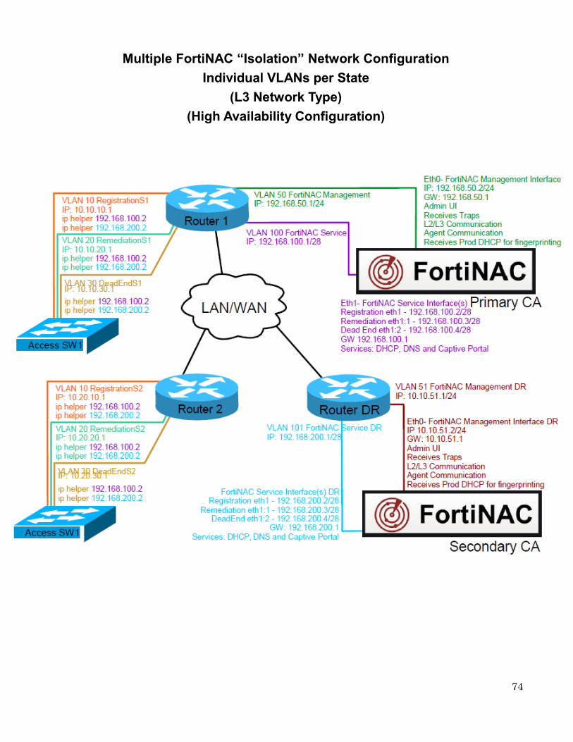
74
Multiple FortiNAC “Isolation” Network Configuration
Individual VLANs per State
(L3 Network Type)
(High Availability Configuration)

75
Appliance Operating System
Virtual appliance licenses for operating system, database and other FortiNAC services included in the virtual package (VMware/Hyper-V) are supported until the operating system is end of life.
FortiNAC currently ships with the CentOS 7 Linux operating system. Fortinet relies on the CentOS organization to publish periodic bug fixes and security updates for the CentOS Distribution.
Effective June 30 2024, CentOS will no longer provide updates for CentOS 7. Any vulnerabilities found with CentOS 7 after June 30th will not be addressed. Software releases will continue to be supported on CentOS 7 through December 31 2026.

76
Prerequisite Checklist (Printable Version)
Step Pre-requisite Resource
Appliance Installation and Configuration
FNAC Hostname Network Team
Appliance Installation and Configuration
IP address and Network Mask for FNAC Eth0 (Management Interface)
Network Team
Appliance Installation and Configuration
FNAC Default Gateway
Network Team
Appliance Installation and Configuration
Domain name
Network Team
Appliance Installation and Configuration
DNS server(s)
Network Team
Appliance Installation and Configuration
NTP server(s)
Network Team
Appliance Configuration
Apply firewall policies ensuring ports are open for FortiNAC integrations.
Security Team
Appliance Configuration
FNAC root CLI password Network/Server Team
Appliance Configuration
FNAC admin CLI password
Network/Server Team
Appliance Configuration
FNAC Configuration Wizard
Network/Server Team
Appliance Configuration
Determine FortiNAC Service Network Configuration (L2 or L3 Network Type)
Network Team
Appliance Configuration
IP address and Network Mask for FNAC Eth1 (FortiNAC Service Interface)
Network Team
Appliance Configuration
At least one DHCP scope for FortiNAC “isolation” Network.
Network Team

77
Step Pre-requisite Resource
Operating System and Software Updates
External network access (FTP, HTTP or HTTPS) from each appliance to downloads.bradfordnetworks.com
Network Team
Operating System and Software Updates
External network access (HTTP) from each appliance to HTTP access to centos.org
Network Team
Operating System and Software Updates
External network access (FTP, PFTP, HTTP or HTTPS) from each appliance to update.bradfordnetworks.com
Network Team
Step Pre-requisite Resource
System Settings
Add host(s) name entries for the FortiNAC appliances into production DNS system(s).
Server Team
System Settings
Have a resource available that can issue Internally signed certificates and/or request publically signed certificates.
Server Team
System Settings LDAP/Active Directory Server(s) IP Address
Server Team
System Settings LDAP/Active Directory Server(s) MAC Address
Server Team
System Settings LDAP/Active Directory Server(s) Hostname
Server Team
System Settings
LDAP/Active Directory service account (account must have read access to all requested search branches)
Server Team
System Settings
LDAP/Active Directory User search branch(es)
Server Team
System Settings
LDAP/Active Directory Group search branch(es) (if needed)
Server Team
System Settings Non-standard LDAP/Active Directory attributes used
Server Team
System Settings Email Server (example: smtp.googlemail.com)
Server Team
System Settings
Email address for FortiNAC (may want to configure an alias for this address to better identify sender as FortiNAC)
Server Team

78
Step Pre-requisite Resource
System Settings
FNAC email account User Name (if authentication is desired).
Server Team
System Settings
FNAC email account Password (if authentication is desired).
Server Team
System Settings Port used on email server.
Server Team
System Settings
Encryption used on email server for email communication (if any).
Server Team
System Settings
Remote Backup Server (Physical only) Provide an FTP or SSH remote server for FortiNAC database and system configuration backup.
Server Team
Step Pre-requisite Resource
Network Visibility
SNMP community name (v1/v2) or account (v3) for all network infrastructure devices
Network Team
Network Visibility
Network devices must be able to respond to PING requests from FortiNAC eth0 IP address.
Network Team
Network Visibility
CLI access account (SSH or Telnet) for all network infrastructure devices.
Network Team
Network Visibility
IP’s of all specific network devices (routers, switches, firewalls, Access Points or controllers) that will be controlled or queried by FortiNAC.
Network Team
Step Pre-requisite Resource
Endpoint Classification
Required for distributing Persistent Agents: Line up resource responsible for deployment of software packages (i.e. SCCM administrator, Microsoft GPO).
Server Team
Endpoint Classification
DHCP Fingerprints: Configure IP Helper addresses on L3 switches or routers for all production VLANs that use DHCP. Use FortiNAC eth0 IP Address.
Network Team

79
Step Pre-requisite Resource
Enforcement
On all wired network devices FortiNAC will control, configure trap receivers for the FortiNAC eth0 IP Address
Network/Security Team
Enforcement
On all wired network devices FortiNAC will control, enable Cold start and Warm start traps.
Network/Security Team
Enforcement
On all wired network devices FortiNAC will control, enable either MAC Notification or Link State traps.
Network/Security Team
Enforcement Define and configure “isolation” VLANs Network/Security Team
Enforcement
Ensure routing/firewall policies are configured for:
FortiNAC Service Network Interface (eth1)
"Isolation" VLANs
Network/Security Team
Enforcement
Identify network segmentation for
Who
What
Where
When
Network Team
Enforcement
(Wireless integrations) Review applicable FortiNAC Integration Guides
Network Team
Enforcement
(Wireless integrations) Create test wireless environment identical to production environment
Network Team
Enforcement
(Wireless integrations) Determine authentication method for FortiNAC integrations (MAC Auth or 802.1x)
Network Team
Enforcement
(802.1X Wireless integrations) RADIUS Server IP Address
Network Team
Enforcement
(802.1X Wireless integrations) Configure FortiNAC ‘s eth0 IP as a RADIUS Client on the RADIUS Server
Network Team
Enforcement
(VPN integrations) Review applicable FortiNAC Integration Guides
Network Team
Enforcement
(VPN integrations) Create test VPN environment identical to production environment
Network Team

80
Copyright© 2020 Fortinet, Inc. All rights reserved. Fortinet®, FortiGate®, FortiCare® and FortiGuard®, and certain other marks are registered trademarks of Fortinet, Inc., in the U.S. and other jurisdictions,
and other Fortinet names herein may also be registered and/or common law trademarks of Fortinet. All other product or company names may be trademarks of their respective owners. Performance and
other metrics contained herein were attained in internal lab tests under ideal conditions, and actual performance and other results may vary. Network variables, different network environments and other
conditions may affect performance results. Nothing herein represents any binding commitment by Fortinet, and Fortinet disclaims all warranties, whether express or implied, except to the extent Fortinet
enters a binding written contract, signed by Fortinet’s General Counsel, with a purchaser that expressly warrants that the identified product will perform according to certain expressly-identified performance
metrics and, in such event, only the specific performance metrics expressly identified in such binding written contract shall be binding on Fortinet. For absolute clarity, any such warranty will be limited to
performance in the same ideal conditions as in Fortinet’s internal lab tests. In no event does Fortinet make any commitment related to future deliverables, features or development, and circumstances may
change such that any forward-looking statements herein are not accurate. Fortinet disclaims in full any covenants, representations, and guarantees pursuant hereto, whether express or implied. Fortinet
reserves the right to change, modify, transfer, or otherwise revise this publication without notice, and the most current version of the publication shall be applicable.