
Pulse Policy Secure : Juniper Networks Deployment Guide
76
Product Release 9.1R8 Published August 2020 Document Version 1.0 Pulse Policy Secure: Juniper Networks Integration Guide
-
Upload
khangminh22 -
Category
Documents
-
view
0 -
download
0
Transcript of Pulse Policy Secure : Juniper Networks Deployment Guide

Product Release 9.1R8
Published August 2020
Document Version 1.0
Pulse Policy Secure: Juniper NetworksIntegration Guide

© 2020 Pulse Secure, LLC.
Pulse Policy Secure: Juniper Networks
Pulse Secure, LLC2700 Zanker Road,Suite 200 San JoseCA 95134
www.pulsesecure.net
© 2020 by Pulse Secure, LLC. All rights reserved.
Pulse Secure and the Pulse Secure logo are trademarks of Pulse Secure, LLC in the United States.All other trademarks, service marks, registered trademarks, or registered service marks are theproperty of their respective owners.
Pulse Secure, LLC assumes no responsibility for any inaccuracies in this document. Pulse Secure, LLCreserves the right to change, modify, transfer, or otherwise revise this publication withoutnotice.
Pulse Policy Secure: Juniper Networks
The information in this document is current as of the date on the title page.
END USER LICENSE AGREEMENT
The Pulse Secure product that is the subject of this technical documentation consists of (or isintended for use with) Pulse Secure software. Use of such software is subject to the terms andconditions of the End User License Agreement (“EULA”) posted athttp://www.pulsesecure.net/support/eula/. By downloading, installing or using such software,you agree to the terms and conditions of that EULA.

© 2019 Pulse Secure, LLC. 1
Pulse Policy Secure: Juniper Networks
PURPOSE OF THIS GUIDE . . . . . . . . . . . . . . . . . . . . . . . . . . . . . . . . . . . . . . . . . . . . . . . . . . . . . . . . . . . . . 1
ENFORCEMENT USING SRX SERIES FIREWALL . . . . . . . . . . . . . . . . . . . . . . . . . . . . . . . . . . . . . . . . 3OVERVIEW . . . . . . . . . . . . . . . . . . . . . . . . . . . . . . . . . . . . . . . . . . . . . . . . . . . . . . . . . . . . . . . . . . . . . . . . 3DEPLOYMENT OF PPS USING SRX FIREWALL . . . . . . . . . . . . . . . . . . . . . . . . . . . . . . . . . . . . . . . . . 3CONFIGURING PPS WITH SRX FIREWALL . . . . . . . . . . . . . . . . . . . . . . . . . . . . . . . . . . . . . . . . . . . . 4
CONFIGURING SRX INFRANET ENFORCER IN PPS . . . . . . . . . . . . . . . . . . . . . . . . . . . . . . . . . 4CONFIGURING AUTH TABLE MAPPING POLICIES. . . . . . . . . . . . . . . . . . . . . . . . . . . . . . . . . . . 5CONFIGURING RESOURCE ACCESS POLICY. . . . . . . . . . . . . . . . . . . . . . . . . . . . . . . . . . . . . . . . 6
CONFIGURING SRX FIREWALL . . . . . . . . . . . . . . . . . . . . . . . . . . . . . . . . . . . . . . . . . . . . . . . . . . . . . . 9CONFIGURING SRX AS AN ENFORCER . . . . . . . . . . . . . . . . . . . . . . . . . . . . . . . . . . . . . . . . . . . . 9
ENFORCEMENT USING SCREEN OS FIREWALL . . . . . . . . . . . . . . . . . . . . . . . . . . . . . . . . . . . . . . .11OVERVIEW . . . . . . . . . . . . . . . . . . . . . . . . . . . . . . . . . . . . . . . . . . . . . . . . . . . . . . . . . . . . . . . . . . . . . . .11DEPLOYMENT OF PPS USING SCREENOS FIREWALL . . . . . . . . . . . . . . . . . . . . . . . . . . . . . . . . .11CONFIGURING PPS WITH SCREENOS FIREWALL . . . . . . . . . . . . . . . . . . . . . . . . . . . . . . . . . . . . .11
CONFIGURING SCREENOS INFRANET ENFORCER IN PPS . . . . . . . . . . . . . . . . . . . . . . . . . .12CONFIGURING AUTH TABLE MAPPING POLICIES. . . . . . . . . . . . . . . . . . . . . . . . . . . . . . . . . .13CONFIGURING RESOURCE ACCESS POLICY. . . . . . . . . . . . . . . . . . . . . . . . . . . . . . . . . . . . . . .13
CONFIGURING SCREENOS FIREWALL . . . . . . . . . . . . . . . . . . . . . . . . . . . . . . . . . . . . . . . . . . . . . . .13CONFIGURING SCREENOS AS AN ENFORCER. . . . . . . . . . . . . . . . . . . . . . . . . . . . . . . . . . . . .14CONFIGURING THE SCREENOS IN ROUTE MODE . . . . . . . . . . . . . . . . . . . . . . . . . . . . . . . . .14CONFIGURING THE SCREENOS IN TRANSPARENT MODE . . . . . . . . . . . . . . . . . . . . . . . . . .17VERIFYING THE PPS CONFIGURATION ON SCREENOS ENFORCER . . . . . . . . . . . . . . . . . .19
APPENDIX . . . . . . . . . . . . . . . . . . . . . . . . . . . . . . . . . . . . . . . . . . . . . . . . . . . . . . . . . . . . . . . . . . . . . . .20INFRANET ENFORCER POLICIES OVERVIEW . . . . . . . . . . . . . . . . . . . . . . . . . . . . . . . . . . . . . . .20UNDERSTANDING INFRANET ENFORCER SOURCE IP SECURITY POLICIES . . . . . . . . . . . .21CONFIGURING DYNAMIC AUTH TABLE POLICIES . . . . . . . . . . . . . . . . . . . . . . . . . . . . . . . . . .26BINDING AN INTERFACE TO A SECURITY ZONE ON A JUNOS ENFORCER . . . . . . . . . . . . .27
CAPTIVE PORTAL . . . . . . . . . . . . . . . . . . . . . . . . . . . . . . . . . . . . . . . . . . . . . . . . . . . . . . . . . . . . . . . . .28CONFIGURING CAPTIVE PORTAL . . . . . . . . . . . . . . . . . . . . . . . . . . . . . . . . . . . . . . . . . . . . . . . .28CREATING A REDIRECT POLICY ON THE JUNOS ENFORCER . . . . . . . . . . . . . . . . . . . . . . . . .29CREATING A REDIRECT POLICY ON THE SCREENOS ENFORCER. . . . . . . . . . . . . . . . . . . . .30
ENFORCEMENT USING EX SERIES ETHERNET SWITCHES . . . . . . . . . . . . . . . . . . . . . . . . . . . .31OVERVIEW . . . . . . . . . . . . . . . . . . . . . . . . . . . . . . . . . . . . . . . . . . . . . . . . . . . . . . . . . . . . . . . . . . .31
CONFIGURING EX SWITCH WITH PPS . . . . . . . . . . . . . . . . . . . . . . . . . . . . . . . . . . . . . . . . . . . . . . .31CONFIGURING EX SWITCH AS AN INFRANET ENFORCER . . . . . . . . . . . . . . . . . . . . . . . . . . . . . . .32
CONFIGURING AN AUTHENTICATION TABLE . . . . . . . . . . . . . . . . . . . . . . . . . . . . . . . . . . . . . .33CONFIGURING RESOURCE ACCESS POLICY. . . . . . . . . . . . . . . . . . . . . . . . . . . . . . . . . . . . . . .33

Pulse Policy Secure: Juniper Networks
2 © 2019 Pulse Secure, LLC.
USING IPSEC . . . . . . . . . . . . . . . . . . . . . . . . . . . . . . . . . . . . . . . . . . . . . . . . . . . . . . . . . . . . . . . . . . . . . . . . . .34IPSEC AND THE JUNOS ENFORCER . . . . . . . . . . . . . . . . . . . . . . . . . . . . . . . . . . . . . . . . . . . . . .34IPSEC POLICIES ON THE JUNOS ENFORCER . . . . . . . . . . . . . . . . . . . . . . . . . . . . . . . . . . . . . .35USING IPSEC WITH THE JUNOS ENFORCER . . . . . . . . . . . . . . . . . . . . . . . . . . . . . . . . . . . . . . .35IPSEC ENFORCEMENT ON THE JUNOS ENFORCER . . . . . . . . . . . . . . . . . . . . . . . . . . . . . . . . .35BEFORE CONFIGURING IPSEC ON THE JUNOS ENFORCER. . . . . . . . . . . . . . . . . . . . . . . . . .36IPSEC ROUTING POLICIES FOR THE JUNOS ENFORCER . . . . . . . . . . . . . . . . . . . . . . . . . . . .36BEFORE CONFIGURING IPSEC ROUTING POLICIES . . . . . . . . . . . . . . . . . . . . . . . . . . . . . . . .37CONFIGURING AN IPSEC ROUTING POLICY FOR THE JUNOS ENFORCER . . . . . . . . . . . . .37USING IP ADDRESS POOL POLICIES FOR IPSEC IN A NAT ENVIRONMENT . . . . . . . . . . .38UNDERSTANDING IP ADDRESS POOL POLICIES . . . . . . . . . . . . . . . . . . . . . . . . . . . . . . . . . .41CONFIGURING AN IP ADDRESS POOL POLICY . . . . . . . . . . . . . . . . . . . . . . . . . . . . . . . . . . . .41CONFIGURING JUNOS ENFORCER IPSEC ROUTING POLICIES . . . . . . . . . . . . . . . . . . . . . . .42
DEPLOYMENTS WITH JUNIPER IDP . . . . . . . . . . . . . . . . . . . . . . . . . . . . . . . . . . . . . . . . . . . . . . . . . . .47ABOUT IDP TECHNOLOGY . . . . . . . . . . . . . . . . . . . . . . . . . . . . . . . . . . . . . . . . . . . . . . . . . . . . . . . .47IDP DEPLOYMENT SCENARIOS OVERVIEW. . . . . . . . . . . . . . . . . . . . . . . . . . . . . . . . . . . . . . . . . . .48UNDERSTANDING PPS DEPLOYMENTS WITH IDP DEVICES . . . . . . . . . . . . . . . . . . . . . . . . . . . .48
ABOUT IDP DEVICES. . . . . . . . . . . . . . . . . . . . . . . . . . . . . . . . . . . . . . . . . . . . . . . . . . . . . . . . . .49COORDINATED THREAT CONTROL OVERVIEW . . . . . . . . . . . . . . . . . . . . . . . . . . . . . . . . . . . .49DEPLOYMENTS WITH IDP SERIES DEVICES . . . . . . . . . . . . . . . . . . . . . . . . . . . . . . . . . . . . . . .49DEPLOYMENTS WITH IDP-ENABLED INFRANET ENFORCERS . . . . . . . . . . . . . . . . . . . . . . . .50MONITORING IDP-REPORTED EVENTS . . . . . . . . . . . . . . . . . . . . . . . . . . . . . . . . . . . . . . . . . .50
ACTIVATING IDP FOR THE SCREENOS OR JUNOS ENFORCER . . . . . . . . . . . . . . . . . . . . . . . . . .51MANAGING INTEROPERATION WITH IDP DEVICES . . . . . . . . . . . . . . . . . . . . . . . . . . . . . . . . . . . .51
CONFIGURING COMMUNICATION WITH AN IDP DEVICE . . . . . . . . . . . . . . . . . . . . . . . . . . .51ENABLING OR DISABLING IDP SENSORS . . . . . . . . . . . . . . . . . . . . . . . . . . . . . . . . . . . . . . . .52RECONNECTING TO AN IDP SENSOR. . . . . . . . . . . . . . . . . . . . . . . . . . . . . . . . . . . . . . . . . . . .52REFRESHING AND DISPLAYING THE CONNECTION STATUS . . . . . . . . . . . . . . . . . . . . . . . . .53DELETING AN IDP SENSOR ENTRY. . . . . . . . . . . . . . . . . . . . . . . . . . . . . . . . . . . . . . . . . . . . . .53
IDENTIFYING AND MANAGING QUARANTINED USERS MANUALLY . . . . . . . . . . . . . . . . . . . . . .53USING ROLE-BASED POLICIES TO MONITOR USER ACTIVITY . . . . . . . . . . . . . . . . . . . . . . . . . .54
ALERT BASED ADMISSION CONTROL USING JUNIPER SDSN . . . . . . . . . . . . . . . . . . . . . . . .55OVERVIEW . . . . . . . . . . . . . . . . . . . . . . . . . . . . . . . . . . . . . . . . . . . . . . . . . . . . . . . . . . . . . . . . . . . . . . .55
BENEFITS . . . . . . . . . . . . . . . . . . . . . . . . . . . . . . . . . . . . . . . . . . . . . . . . . . . . . . . . . . . . . . . . . . . .55DEPLOYMENT OF PPS IN JUNIPER SDSN ENVIRONMENT . . . . . . . . . . . . . . . . . . . . . . . . . . . . .55CONFIGURING PPS WITH JUNIPER SDSN . . . . . . . . . . . . . . . . . . . . . . . . . . . . . . . . . . . . . . . . . . .57
ADMISSION CONTROL TEMPLATE . . . . . . . . . . . . . . . . . . . . . . . . . . . . . . . . . . . . . . . . . . . . . . .57ADMISSION CONTROL POLICIES . . . . . . . . . . . . . . . . . . . . . . . . . . . . . . . . . . . . . . . . . . . . . . . .58ADMISSION CONTROL CLIENT . . . . . . . . . . . . . . . . . . . . . . . . . . . . . . . . . . . . . . . . . . . . . . . . . .60

© 2019 Pulse Secure, LLC. 3
Pulse Policy Secure: Juniper Networks
CONFIGURING JUNIPER SDSN . . . . . . . . . . . . . . . . . . . . . . . . . . . . . . . . . . . . . . . . . . . . . . . . . . . . .61CONFIGURING PPS WITH JUNIPER SD . . . . . . . . . . . . . . . . . . . . . . . . . . . . . . . . . . . . . . . . . .61PRE-REQUISITE . . . . . . . . . . . . . . . . . . . . . . . . . . . . . . . . . . . . . . . . . . . . . . . . . . . . . . . . . . . . . . .61CONFIGURING JUNIPER POLICY ENFORCER WITH SKY ATP . . . . . . . . . . . . . . . . . . . . . . . .66
TROUBLESHOOTING . . . . . . . . . . . . . . . . . . . . . . . . . . . . . . . . . . . . . . . . . . . . . . . . . . . . . . . . . . . . . .66

Pulse Policy Secure: Juniper Networks
4 © 2019 Pulse Secure, LLC.

© 2019 Pulse Secure, LLC. 1
Pulse Policy Secure: Access Control with Fortinet Products Deployment Guide
Purpose of this Guide
This guide describes how to configure Pulse Policy Secure (PPS) to provide Identity- and Alert-based protection for your network using Juniper Networks products.
Prerequisites
This guide assumes you are familiar with the use of the following products and their related terminology.
• Pulse Policy Secure at version
• Juniper Networks SRX Firewall
• Juniper Networks SDSN
• Juniper Networks EX switch
• Juniper Networks ScreenOS

Pulse Policy Secure: Access Control with Fortinet Products Deployment Guide
2 © 2019 Pulse Secure, LLC.

© 2020 Pulse Secure, LLC. 3
Pulse Policy Secure: Administration Guide
Enforcement using SRX Series Firewall
• Overview . . . . . . . . . . . . . . . . . . . . . . . . . . . . . . . . . . . . . . . . . . . . . . . . . . . . . . . . . . . . . . . . . . . . . . 3• Deployment of PPS using SRX Firewall . . . . . . . . . . . . . . . . . . . . . . . . . . . . . . . . . . . . . . . . . . . . . 3• Configuring PPS with SRX Firewall . . . . . . . . . . . . . . . . . . . . . . . . . . . . . . . . . . . . . . . . . . . . . . . . 4• Configuring SRX Firewall. . . . . . . . . . . . . . . . . . . . . . . . . . . . . . . . . . . . . . . . . . . . . . . . . . . . . . . . . 9
OverviewPPS delivers a layer 3 network access control solution when deployed with Juniper SRX firewall. The PPS is the Layer 2 or Layer 3 policy decision point that determines which users and endpoints can access protected resources. You can use Juniper Networks SRX firewall to serve as the enforcement point to provide the protection to ensure that network assets are secured. PPS authenticates users, ensures that endpoints meet security policies, and serves resource access policy information to Juniper Networks SRX devices.
Deployment of PPS using SRX FirewallThis section describes the integration of PPS with SRX firewall. The PPS and SRX firewall solution provides functionality for enforcing application level security policies on a per user and role basis. It also delivers granular level access control so that it can be easily managed through PPS.
Figure 1 Deployment using SRX Firewall
The authentication process is described below:
1. The endpoint connects to switch to perform the layer 2 authentication with PPS.
2. PPS communicates with authentication server and performs the layer 3 authentication along with host check to ensure that the endpoints meets the corporate policy.

Pulse Policy Secure: Administration Guide
4 © 2020 Pulse Secure, LLC.
3. The external authentication server such as AD/LDAP confirms the role and sends the entries to PPS.
4. PPS provisions the auth table on SRX firewall with changes in role information if any.
5. The SRX series firewall maps the user to a specific resource access policy and then provides the required access.
Configuring PPS with SRX FirewallThe PPS connects with the SRX device over an SSL connection. To enable the connection between the two devices, you must specify the password and serial number of the SRX firewall. The SRX firewall initiates the connection to PPS. PPS presents its SSL server certificate to the SRX device. Optionally, you can configure the SRX device to verify the certificate and to specify constraints with which PPS must comply.
The SRX device and PPS perform mutual authentication with the proprietary JUEP-MAUTH challenge-response authentication based on the password configured. For security reasons, the password is not included in the message sent to PPS. After the SSL handshake, all further communication between the PPS device and the SRX device occurs over the SSL connection. The SRX device acts as a client and the PPS device as server.
This section covers the following topics:
• “Configuring SRX Infranet Enforcer in PPS” on page 4
• “Configuring Auth Table Mapping Policies” on page 5
• “Configuring Resource Access Policy” on page 6
Configuring SRX Infranet Enforcer in PPSTo configure a SRX Firewall Infranet Enforcer in PPS:
1. Select Endpoint Policy > Infranet Enforcer.
Figure 2 Infranet Enforcer
2. Click New Infranet Enforcer and select Junos SRX Firewall in the Platform drop down.

© 2020 Pulse Secure, LLC. 5
Pulse Policy Secure: Administration Guide
Figure 3 SRX Firewall
3. Enter the name of the Infranet Enforcer in the Name box.
4. Enter the password for the SRX enforcer.
5. Enter the serial number of the Junos SRX Enforcer. You can view the serial number on the SRX device using the command: user@host show chassis hardware
6. Ensure that the server certificate for PPS is configured for the interface to which the SRX device is connecting.
7. Click Save Changes. You must create security policies on the SRX device for traffic enforcement.
Configuring Auth Table Mapping Policies An auth table consists of username, a set of roles, and IP address of the wired adapter, wireless adapter, or virtual adapter of the user device. Using SRX series firewall you can dynamically create auth table entries when a user tries to access the protected resource. An auth table mapping policy specifies which enforcer device can be used for each user role. These policies prevent the PPS from creating unnecessary auth table entries on all connected enforcer devices.
PPS's default configuration includes only one default auth table mapping policy. When the default auth table mapping policy is enabled, PPS pushes one auth table entry for each authenticated user to all SRX firewalls configured as Infranet Enforcers in PPS.
To configure auth table mapping policies:
1. Select Endpoint Policy > Infranet Enforcer > Auth Table Mapping.
2. Select the default auth table mapping policy called Default Policy and click Delete.
On the New Policy page:
1. For Name, enter a name to label this auth table mapping policy.
2. (Optional) For Description, enter a description.

Pulse Policy Secure: Administration Guide
6 © 2020 Pulse Secure, LLC.
3. In the Enforcer section, specify the Infranet Enforcer device(s) to which you want to apply this auth table mapping policy.
4. In the Roles section, specify:
• Policy applies to ALL roles-To apply this auth table mapping policy to all users.
• Policy applies to SELECTED roles-To apply this auth table mapping policy only to users who are mapped to roles in the Selected roles list. Be sure to add roles to this list from the Available roles list.
• Policy applies to all roles OTHER THAN those selected below-To apply this auth table mapping policy to all users except for those who map to the roles in the Selected roles list. Be sure to add roles to this list from the Available roles list.
5. In the Action section, specify auth table mapping rules for the specified Infranet Enforcer device:
• Always Provision Auth Table-To automatically provision auth table entries for chosen roles on the specified Infranet Enforcer.
• Provision Auth Table as Needed-To provision auth table entries only when a user with a chosen role attempts to access a resource behind the specified Infranet Enforcer.
• Never Provision Auth Table-To prevent chosen roles from accessing resources behind the specified Infranet Enforcer.
• Make sure you delete the Default Policy if you configure any of your own auth table mapping policies. PPS includes this default auth table mapping policy that allows all source IP endpoints to use all Infranet Enforcer devices.
6. If you created a vsys on a ScreenOS Enforcer, enter the ID of the vsys in the vsys text box. To view the enforcers or vsys that are associated with each policy, select Infranet Enforcer > Auth Table Mapping.
7. Click Save Changes.
For more information on dynamic authentication table, see “Configuring Dynamic Auth Table Policies” on page 26
Configuring Resource Access PolicyA resource access policy specifies which users are allowed or denied access to a set of protected resources. You can specify which users you want to allow or deny by choosing the roles for each resource access policy.
To configure Infranet Enforcer resource access policies:

© 2020 Pulse Secure, LLC. 7
Pulse Policy Secure: Administration Guide
1. Select Endpoint Policy > Infranet Enforcer > Resource Access Policy and click New Policy.
Figure 4 Infranet Enforcer
On the New Policy page:
2. For Name, enter a name to label this Infranet Enforcer resource access policy.
3. (Optional) For Description, enter a description.

Pulse Policy Secure: Administration Guide
8 © 2020 Pulse Secure, LLC.
For Resources, specify the protocol, IP address, network mask, and port of each resource (or range of addresses) for which this Infranet Enforcer resource access policy applies, one per line. Do not insert any spaces in your entries, or the policy may not be applied correctly.
You cannot specify a host name in a resource access policy. You can specify only an IP address. You can use TCP, UDP, or ICMP.
4. Under Infranet Enforcer, specify the Infranet Enforcer to which this policy applies by using Add.
5. Specify one of the following in the Roles section:
• Policy applies to ALL roles-To apply this Infranet Enforcer resource access policy to all users.
• Policy applies to SELECTED roles-To apply this Infranet Enforcer resource access policy only to users who are mapped to roles in the Selected roles list. You must add roles to this list from the Available roles list.
• Policy applies to all roles other than those selected below- To apply this Infranet Enforcer resource access policy to all users except those who map to the roles in the Selected roles list. You must add roles to this list from the Available roles list.
6. In the Action section, specify whether you want to use this Infranet Enforcer resource access policy to allow or deny access to the specified resources.
If you select deny, a text box is displayed that allows you to customize a deny message for users.
With ScreenOS Enforcer Release 6.3 r13 or later, you can also select Reject Access. The customized deny message is available with the reject action.
The reject action is designed for clients that hang for a long period while waiting for connection initiations that the firewall is blocking. With the deny action, the Enforcer drops traffic in accordance with the PPS policy, but does not send back reject information. The policy action of "reject" denies the traffic and sends a TCP RST to the traffic originator for TCP traffic, or ICMP unreachable for UDP traffic. In earlier versions of ScreenOS and on the Junos Enforcer, the selection of reject results in a deny action.
To record deny actions in the User Access Log, select the Infranet Enforcer Deny Messages check box on the Log/monitoring > User Access > Settings page. The log records the user, source IP, destination IP, protocol, and destination port.
1. For ScreenOS Enforcers, in the ScreenOS Options section, use the option buttons to select the policy options that you want to apply to selected roles. Use the Add and Remove buttons to specify antispam, logging, IDP, web filtering, antivirus, and deep inspection.
2. By default, all policy options are enabled. To enforce the policies, you must create corresponding policies on the ScreenOS Enforcer. If PPS is upgraded from a previous version, all ScreenOS options are enabled for the resource access policies that were available prior to the upgrade.
3. If you have created a vsys on a ScreenOS Enforcer, enter the ID of the vsys in the VSYS text box, if applicable. The Infranet Enforcer > Resource Access Policy page displays the Enforcers and/or vsys that are associated with each policy.

© 2020 Pulse Secure, LLC. 9
Pulse Policy Secure: Administration Guide
Configuring SRX Firewall PPS can utilize a SRX device as a policy enforcement point to work as a Layer 3 Enforcer. When the SRX is configured to work as an enforcer with PPS, the following takes place:
• PPS provisions resource access policies.
• SRX gets the user's role membership information from authentication table entries that are sent by PPS when the user authenticates with the PPS or when the user tries to access resources through SRX.
• SRX does a policy lookup in resource access policies, which is sent by PPS and accordingly takes allow/deny decisions.
For the SRX to perform a PPS policy lookup, the uac-policy application service needs to be turned on in the SRX firewall rule and the firewall rule's action should be set to permit. The SRX security policies have to be manually configured on SRX.
Configuring SRX as an Enforcer The SRX enforcer works with the PPS device for Layer 3 connectivity. You can connect with source IP or IPsec. For the initial setup, you must specify the PPS device name, IP address, port number over which the Junos Enforcer and PPS device will connect, the interface, the password (the same password as entered on the PPS device), and, optionally, the CA profile and server certificate subject. Use the Junos CLI to add this information.
You can configure the SRX device in "test only" mode. In test only mode, the SRX device does not enforce PPS policies and allows all traffic to pass. However, all policy decisions are logged. This allows you to set up the devices before actual deployment and determine how the PPS solution works using different configuration options. For example, the PPS device and endpoints can reside on different physical interfaces of the Junos Enforcer or on the same interface.
PPS device policies are role based. Each policy specifies a destination (the resources that are being protected), a set of roles, and an action (allow or deny). To determine the roles for users, an auth table maps source IP addresses to roles. When an endpoint accesses the PPS device, the PPS device populates the Junos Enforcer with an auth table entry mapping the endpoint's IP address to the endpoint's set of roles. When evaluating a flow, the source IP address of the initial packet is used to look up the roles. Then the first policy that matches both the destination (resource) and the roles is used to determine whether to permit or deny the flow.
To use IPsec with the SRX device, you must enable IKE services for the gateway. If you have multiple IPsec tunnels with multiple gateways, the hostname for each gateway must be unique.
Note: SRX Series communication to PPS is not supported on an interface that is in a routing instance or VRF instance.
To configure the Junos Enforcer:
1. Set up the trusted interface. The trusted interface connects to the protected resource. The untrusted interface connects to PPS.
2. Ensure that the DHCP server is disabled or enabled as required for the deployment.

Pulse Policy Secure: Administration Guide
10 © 2020 Pulse Secure, LLC.
3. Create a PPS configuration on the Junos security device, and provide the network information required for connecting using the CLI. This information includes PPS host name, the IP address, and the interface to which the device will connect. The default port for communication with PPS is 11123, you cannot change the port. You must also specify a password, that matches the password configured on PPS.
4. For complete CLI instructions and syntax, see the Junos Software CLI Reference.
• Specify PPS hostname:user@host# set services unified-access-control infranet-controller hostname
• Specify PPS IP address:user@host# set services unified-access-control infranet-controller hostname address ip-address
• Specify the Junos interface to which PPS should connect:user@host# set services unified-access-control infranet-controller hostname interface interface-name
• Specify the password that the SRX Series or J Series device should use to initiate secure communications with PPS:user@host# set services unified-access-control infranet-controller hostname password password
5. Set the appropriate timeout and interval values, and specify a timeout action. The timeout that you set specifies the elapsed time beyond which the Junos Enforcer attempts to reconnect with PPS if no communication is received. The interval specifies how often PPS sends a heartbeat to the Junos Enforcer.
6. (Optional) Verify that the certificate of the CA that signed PPS's server certificate is loaded in the Junos Enforcer and that the path to the certificate is specified.
Note: Although certificate verification is optional, there are three different certificate options on the Junos Enforcer that will produce different results.
• If certificate-verification is set to required, it is required that the device verify any PPS server certificate. If any PPS ca-profile is not configured, the commit check fails.
• If certificate-verification is set to warning (the default), and PPS ca-profile is not configured, the commit check displays a warning about the security risk with a similar warning in the syslog.
• If certificate-verification is set to optional, there is no warning.
7. Verify routing from PPS to the untrusted interface.
8. Ensure that both the Junos Enforcer and PPS are set to the correct time. If possible, use a Network Time Protocol (NTP) Server to set the date and time of both appliances.
When you finish configuring PPS instance, the Junos Enforcer can initiate the connection with PPS. The Junos Enforcer optionally validates PPS server certificate if so configured. The device sends the serial number to authenticate with PPS.
For the Junos Enforcer to establish communication, you must configure the Junos Enforcer on PPS.

© 2020 Pulse Secure, LLC. 11
Pulse Policy Secure: Administration Guide
Enforcement using Screen OS Firewall
• Overview . . . . . . . . . . . . . . . . . . . . . . . . . . . . . . . . . . . . . . . . . . . . . . . . . . . . . . . . . . . . . . . . . . . . . 11• Deployment of PPS using ScreenOS Firewall . . . . . . . . . . . . . . . . . . . . . . . . . . . . . . . . . . . . . . 11• Configuring PPS with ScreenOS Firewall . . . . . . . . . . . . . . . . . . . . . . . . . . . . . . . . . . . . . . . . . . 11• Configuring ScreenOS Firewall . . . . . . . . . . . . . . . . . . . . . . . . . . . . . . . . . . . . . . . . . . . . . . . . . . 13• Appendix. . . . . . . . . . . . . . . . . . . . . . . . . . . . . . . . . . . . . . . . . . . . . . . . . . . . . . . . . . . . . . . . . . . . . 20• Captive Portal . . . . . . . . . . . . . . . . . . . . . . . . . . . . . . . . . . . . . . . . . . . . . . . . . . . . . . . . . . . . . . . . . 28
OverviewPPS delivers a layer 3 network access control solution when deployed with Screen OS firewall device. The PPS is the policy decision point that determines which users and endpoints can access protected resources. You can use Screen OS firewalls to serve as the enforcement point to provide the ultimate protection to ensure that network assets are secured.
Deployment of PPS using ScreenOS FirewallThis section describes the integration of PPS with ScreenOS firewall. The PPS and Screen OS firewall solution provides functionality for enforcing security policies on a per user and role basis. It also delivers granular level access control so that it can be easily managed through PPS.
The authentication process is described below:
1. The endpoint connects to switch to perform the layer 2 authentication with PPS.
2. PPS communicates with authentication server and performs the layer 3 authentication along with host check to ensure that the endpoints meets the corporate policy.
3. The external authentication server such as AD/LDAP confirms the role and sends the entries to PPS.
4. PPS provisions the auth table on ScreenOS firewall with changes in role information if any.
5. The ScreenOS firewall maps the user to a specific resource access policy and then provides the required access.
Configuring PPS with ScreenOS FirewallThe ScreenOS Enforcer connects to PPS over an SSH connection that uses the NetScreen Address Change Notification (NACN) protocol. PPS uses the NACN password and serial number for a connection from the ScreenOS Enforcer. When the ScreenOS Enforcer first turns on, it sends an NACN message containing the NACN password and serial number to PPS. PPS uses the serial number to determine which ScreenOS Enforcer is attempting to connect, and PPS uses the NACN password to authenticate the ScreenOS Enforcer. PPS then begins communicating with the ScreenOS Enforcer using SSH.
This section covers the following topics:
Pulse Policy Secure: Administration Guide
12 © 2020 Pulse Secure, LLC.
• “Configuring ScreenOS Infranet Enforcer in PPS” on page 12
• “Configuring Auth Table Mapping Policies” on page 13
• “Configuring Resource Access Policy” on page 13
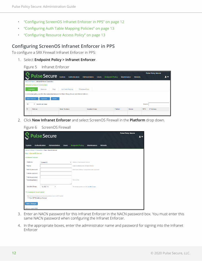
Configuring ScreenOS Infranet Enforcer in PPSTo configure a SRX Firewall Infranet Enforcer in PPS:
1. Select Endpoint Policy > Infranet Enforcer.
Figure 5 Infranet Enforcer
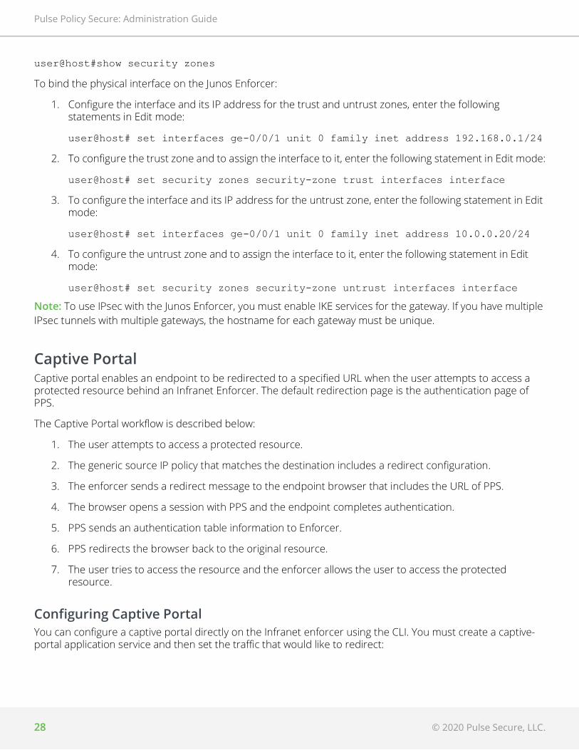
2. Click New Infranet Enforcer and select ScreenOS Firewall in the Platform drop down.
Figure 6 ScreenOS Firewall
3. Enter an NACN password for this Infranet Enforcer in the NACN password box. You must enter this same NACN password when configuring the Infranet Enforcer.
4. In the appropriate boxes, enter the administrator name and password for signing into the Infranet Enforcer

© 2020 Pulse Secure, LLC. 13
Pulse Policy Secure: Administration Guide
5. Enter the name of the Infranet Enforcer in the Name box.
6. Enter the password for the ScreenOS enforcer.
7. Enter the serial number of the ScreenOS Enforcer. You can view the serial number on the ScreenOS device using the command: get system
8. Select No 802.1X from the Location Group list if you are not using an Infranet Enforcer as an 802.1X RADIUS client.
9. Ensure that the server certificate for PPS is configured for the interface to which the SRX device is connecting.
10. Click Save Changes.
When you finish configuring the Infranet Enforcer, the Infranet Enforcer attempts to connect to PPS. If the connection is successful, a green dot is displayed next to the Infranet Enforcer icon. Under Enforcer Status select System > Status > Overview. The Infranet Enforcer IP address is also displayed in Endpoint Policy > Infranet Enforcer > Connection.
Configuring Auth Table Mapping Policies An auth table consists of username, a set of roles, and IP address of the wired adapter, wireless adapter, or virtual adapter of the user device. Using SRX series firewall you can dynamically create auth table entries when a user tries to access the protected resource. An auth table mapping policy specifies which enforcer device can be used for each user role. These policies prevent the PPS from creating unnecessary auth table entries on all connected enforcer devices.
For complete configuration information, see “Configuring Auth Table Mapping Policies” on page 5
Configuring Resource Access PolicyA resource access policy specifies which users are allowed or denied access to a set of protected resources. You can specify which users you want to allow or deny by choosing the roles for each firewall enforcer access policy.
For complete configuration procedure, see “Configuring Resource Access Policy” on page 6
Configuring ScreenOS Firewall PPS can utilize a ScreenOS device as a policy enforcement point to work as a Layer 3 Enforcer. When the ScreenOS device is configured to work as an enforcer with PPS, the following takes place:
• PPS provisions resource access policies.
• Screen OS device gets the user's role membership information from authentication table entries that are sent by PPS when the user authenticates with the PPS or when the user tries to access resources through ScreenOS.
• ScreenOS device does a policy lookup in resource access policies, which is sent by PPS and accordingly takes allow/deny decisions.
This section covers the following topics:

Pulse Policy Secure: Administration Guide
14 © 2020 Pulse Secure, LLC.
• “Configuring ScreenOS as an Enforcer” on page 14
• “Configuring the ScreenOS in Route Mode” on page 14
• “Configuring the ScreenOS in Transparent Mode” on page 17
• “Verifying the PPS Configuration on ScreenOS Enforcer” on page 19
Configuring ScreenOS as an EnforcerYou can configure basic Infranet auth Enforcer policies that specify a source zone and a destination zone on the PPS Series device and then push the policies to the ScreenOS Enforcer to add additional policy details, or you can use the ScreenOS Enforcer to configure the policies with the CLI or Web UI. We recommend that you use the PPS Series device to set up the policies for source IP enforcement on the Infranet Enforcer.
Before setting a policy, you must create address book entries for the destination and source addresses unless you use address book entries that already exist, such as Any.
The following example, sets an Infranet auth policy and adds it to the top of the list of policies. The policy allows all traffic of any type from any host to another host. The policy allows traffic according to the Infranet Enforcer resource access policies that you configure on the PPS Series device.
set policy top from untrust to trust any permit Infranet-auth
The following example sets two address book entries and a policy between them for anyone in the 10.64.0.0/16 range can reach the 10.65.0.0/16 range.
set address Trust "10.64 Range" 10.64.0.0 255.255.0.0
set address Untrust "10.65 Range" 10.65.0.0 255.255.0.0
set policy from trust to untrust "10.64 Range" "10.65 Range" any permit Infranet-auth
You can use Route mode or Transparent mode to configure a Juniper Networks ScreenOS Enforcer. By default, the ScreenOS Enforcer operates in Route mode. For more information on ScreenOS, see the ScreenOS Reference Guide.
This sections covers the following information:
1. “Creating a Route based interface with ScreenOS” on page 15
2. “Creating a Transparent Mode instance on the ScreenOS” on page 18
Configuring the ScreenOS in Route ModeThe PPS can reside on trust/untrust interface side of the Infranet Enforcer. If PPS resides on the trust interface side, and users come in through the untrust interface, the administrator must configure a policy (untrust to trust) on the Infranet Enforcer that allows traffic to pass between PPS and Pulse Client. By default, Infranet Enforcer traffic from the untrust interface to the trust interface is denied.
The following procedure describes the setup with PPS on the untrust interface side (same side as users).
To configure an Infranet Enforcer in Route mode:

© 2020 Pulse Secure, LLC. 15
Pulse Policy Secure: Administration Guide
1. Set up the trust interface. The trust interface connects to the protected resource. The untrust interface connects to PPS. Set the following interface (ethernet1/1) settings:
• Set routing
• Enable management of the following services:
• SSL
• SSH
• IP (options)
2. Ensure that the DHCP server is disabled or enabled, as appropriate for the deployment.
3. Import the certificate of the CA that signed PPS's server certificate into the Infranet Enforcer.
4. If you set up an NSRP cluster before you import the CA certificate into the Infranet Enforcer, the CA certificate is automatically synchronized to all Infranet Enforcers in the cluster. However, if you set up the NSRP cluster after you import the CA certificate, you must manually synchronize the certificate to the other Infranet Enforcers in the cluster by typing the following CLI command:
exec nsrp sync pki
You cannot load the self-signed SSL certificate into the Juniper security device.
The certificate of the CA that signed PPS's certificate must be imported on the Infranet Enforcer because the Infranet Enforcer must be able to trust PPS during an SSL session. When a user signs into a server by means of SSL, the server displays a dialog box in which the user can manually accept the certificate that is associated with that server. For the Infranet Enforcer to skip that manual step and automatically accept PPS's certificate, the Infranet Enforcer must have the certificate of the CA that signed PPS's certificate.
5. Create an instance of PPS on the Juniper security device.
6. Enable SSH.
7. Verify routing from PPS to the untrust interface.
8. Ensure that both the Infranet Enforcer and PPS have the correct time. If possible, use a Network Time Protocol (NTP) server to set the date and time of both appliances.
Creating a Route based interface with ScreenOSWhen an interface is in route mode, the security device routes traffic between different zones without performing source NAT.
To create a PPS instance on ScreenOS, you must configure the following items:
• IP address or hostname of PPS
• Password to use when the Infranet Enforcer uses NACN to contact PPS
• Source interface
• CA index number (ca-idx)
You can set these items using the Web UI or the CLI.

Pulse Policy Secure: Administration Guide
16 © 2020 Pulse Secure, LLC.
In the following procedure, you first set interface management options and disable the DCHP server option. Then you enable SSHv2 and configure an PPS server named controller1. Next, you set the host IP address, which is the IP address of the server, to 10.64.12.1. The NACN password is 8!JsP37cK9a*_HiEwe. The NACN password must match the NACN password that you entered for PPS server. The source interface is the interface that the Infranet Enforcer uses to communicate with PPS, and the CA index number is 001.
For this example, the source interface is ethernet 1/1. For a descriptive list of CA index numbers by typing the following command at the ScreenOS CLI:
get ssl ca-list
To change SSH versions, delete SSH settings by typing the following CLI command:
delete ssh device all
When you use the Web UI, you do not need to fill in the Full Subject Name of PPS Cert field. If you do fill it in, be sure to enter the entire certificate subject. For example:
CN=ic1.sample.net,CN=14087306185,CN=06990218,OU=Software,O=Comp,S=CA, C=US
To create the instance using the Web UI:
1. Select Network > Interfaces > Edit > Services from the left navigation bar to set management options.
2. Select Network > DHCP > Edit to disable the DHCP server for both interfaces (Trust and Untrust).
3. Select and load the CA if you have not already done so.
4. Select Objects > Certificates.
5. Click Browse to find and select the certificate. Then click Load.
6. Select CA from the show list.
7. Click Server Settings and make sure Check Method is set correctly for the certificate you are using.
8. Click OK.
9. Create PPS instance.
10. Select Configuration > Infranet Auth > Controllers (List) > New.
11. Type controller1 in PPS instance box.
12. Type IP/domain name: 10.64.12.1 in the IP/Domain Name box.
13. For the NACN Parameters, select ethernet1/1 from the Source Interface list.
14. Type 8!JsP37cK9a*_HiEwe in the Password box.
15. Select the CA from the Selected CA list.
16. Enable SSH version 2.
17. Select Configuration > Admin > Management > Enable SSH (v2).
To create the instance using the CLI:

© 2020 Pulse Secure, LLC. 17
Pulse Policy Secure: Administration Guide
Type the following commands:
Configuring the ScreenOS in Transparent ModeThe ScreenOS device is usually installed between a core router and an access distribution device in a transparent mode. The services are enabled at the zone level, and VLAN1 is used for management.
Transparent mode permits you to implement the following functionality:
• The device can act as a Layer 2 forwarding device, such as a bridge.
• You can control traffic flow between Layer 2 security zones by defining policies.
To configure a ScreenOS Enforcer in Transparent mode:
1. Set up Transparent mode using the predefined security zones, v1-trust and v1- untrust.
2. Assign interfaces to v1-trust and v1-untrust.
3. Configure the IP address for a source interface to establish connectivity with PPS. You can use V1-trust, V1-untrust, or V1-dmz.
4. Configure the broadcast mechanism to flooding (default) or ARP/traceroute. ARP/trace-route is more secure than broadcast.
5. Enable management of the following services for VLAN1:
• SSL
• SSH
• Web (optional)
set interface ethernet1/1 manage ssl
set interface ethernet1/1 manage ssh
set interface ethernet1/1 manage ip
set interface ethernet2/1manage ping
set interface ethernet2/1 dhcp server disable
set interface ethernet1/1 dhcp server disable
delete ssh device all
set ssh version v2
set ssh enable
set infranet controller name controller1 host-name 10.64.12.1
set infranet controller name controller1 password 8!JsP37cK9a*_HiEwe
set infranet controller name controller1 src-interface ethernet1/1
set infranet controller name controller1 ca-idx 001
save

Pulse Policy Secure: Administration Guide
18 © 2020 Pulse Secure, LLC.
6. Set up the Juniper Networks security device zones. The protected resources can be in either zone (v1-trust or v1-untrust) as long as the protected resources are in a zone different from the endpoints.PPS can also reside in either zone. If PPS resides in a zone different from the endpoints, configure a policy that allows traffic to the endpoints through the ScreenOS Enforcer.
7. Import the certificate of the CA that signed PPS's server certificate into the ScreenOS Enforcer.Do not import PPS SSL certificate into the Juniper Networks security device.
8. Create an instance of PPS on the ScreenOS Enforcer.
9. Enable SSH.
10. Verify routing from PPS to the V1-untrust zone.To use IPsec enforcement with a ScreenOS Enforcer in Transparent mode, you might need to configure a source interface policy on PPS.
11. Ensure that both the Infranet Enforcer and PPS have the correct time. If possible, use a Network Time Protocol (NTP) server to set the date and time of both appliances.
Creating a Transparent Mode instance on the ScreenOSTo create a PPS instance in transparent mode, use the CLI to perform the following actions:
• Assign all interfaces to Layer 2 zones.
• Assign an IP address to vlan1 and set the route command.
• Set interface management options.
• Configure a PPS instance named controller1.
• Set the host IP address, which is the IP address of PPS, to 10.64.12.1.
• Enter the NACN password. The NACN password is 8!JsP37cK9a*_HiEwe. The NACN password must match the NACN password that you entered for PPS.
• The source interface, vlan1, is the interface that the Infranet Enforcer uses to communicate with PPS. The CA index number is 001. For a descriptive list of CA index numbers type the following CLI command: get ssl ca-list
You can use the following sample configuration to create the instance using the CLI.

© 2020 Pulse Secure, LLC. 19
Pulse Policy Secure: Administration Guide
Note: For the firewall to operate in Transparent (Layer 2) mode, all interfaces must be in a Layer 2 zone, such as v1-trust or in the null zone. Interfaces cannot remain in a Layer 3 zone.
Verifying the PPS Configuration on ScreenOS EnforcerYou can view the configuration of a PPS instance through the Web UI and the CLI. You can view the following information:
• Name of PPS instance
• IP address or domain name of PPS
• Port number (Default 11122)
• Timeout (60 seconds by default)
• Source interface
The Web UI also allows you to view the NACN password.
Web UITo view configuration information on the Web UI select the following:
1. Configuration > Infranet Auth > Controllers from the left navigation bar.
2. Configuration > Infranet Auth > General Settings from the left navigation bar.
CLITo view configuration information at the CLI, type the following command:
get infranet controller name controller1
set interface eth1 zone v1-trustset interface eth2 zone v1-untrustset interface vlan1 ip 10.64.12.xset interface vlan1 routeset interface vlan1 ip manageableunset interface vlan1 manage pingunset interface vlan1 manage telnetunset interface vlan1 manage snmpunset interface vlan1 manage webset infranet controller name controller1 host-name 10.64.12.1set infranet controller name controller1 password 8!JsP37cK9a*_HiEweset infranet controller name controller1 src-interface vlan1set infranet controller name controller1 ca-idx 0001

Pulse Policy Secure: Administration Guide
20 © 2020 Pulse Secure, LLC.
Appendix
Infranet Enforcer Policies OverviewAfter you set up user roles, authentication servers, realms and sign-in policies, you deploy the Infranet Enforcer in front of servers and resources that you want to protect. You control access through a number of different security policies that you configure on Pulse Policy Secure.
All policy options are supported on the ScreenOS Enforcer.
Resource access policy-Specifies which users are allowed or denied access to a set of protected resources. You specify which users you want to allow or deny by choosing roles for each resource access policy.
Source IP policy-This is an infranet auth policy the on ScreenOS Enforcer or a security policy on the Junos Enforcer that contains a source and destination that permits the Infranet Enforcer to route clear text traffic between source and destination zones. You can set up a source IP policy on Pulse Policy Secure and push the policy to the Infranet Enforcer, or you can set up the policy using ScreenOS Web UI or the command line.
Auth table mapping policy-Specifies which Infranet Enforcer device an endpoint must use to access resources when the endpoint is using source IP enforcement. If you are using either a ScreenOS Enforcer with Release 6.1 or later or the Junos Enforcer, you do not need to configure auth table mapping policies. Instead, you can use dynamic auth table provisioning.
Note: You can use a username with spaces, a username with quotation marks, a username with UTF-8 characters, or a username with a backslash (\). Each of these conventions is accepted by the firewall with a valid corresponding auth table entry.
Figure 7 demonstrates how policies on the Infranet Enforcer and Pulse Policy Secure interact when a user has an auth table entry on the Infranet Enforcer.

© 2020 Pulse Secure, LLC. 21
Pulse Policy Secure: Administration Guide
Figure 7 Policy Interaction
The Infranet Enforcer detects a flow to a specific resource and compares the source IP of the packet with IP addresses in the auth tables. The IP address is associated with a set of roles in the auth table. The destination IP of the packet is matched with the destination IP of a resource access policy to which a set of roles has been assigned. The Infranet Enforcer parses the roles in the resource access policy to determine whether or not the role can access the resource.
Understanding Infranet Enforcer Source IP Security PoliciesThis topic provides an overview of Infranet Enforcer source IP security policies. It includes the following information:
• “Source IP Security Policy Overview” on page 21
• “ScreenOS Infranet Enforcer Configuration Summary” on page 22
• “Junos Infranet Enforcer Configuration Summary” on page 23
Source IP Security Policy OverviewSource IP enforcement permits users to access resources that are protected by the Infranet Enforcer. IPsec provides an encrypted tunnel for bidirectional traffic, while source IP enforcement allows unencrypted (clear text) traffic between endpoints and the Infranet Enforcer. You can use source IP enforcement alone on the Infranet Enforcer to protect resources alone, or with IPsec on the ScreenOS Enforcer.

Pulse Policy Secure: Administration Guide
22 © 2020 Pulse Secure, LLC.
To use source IP enforcement, you configure Pulse Policy Secure policies. On a ScreenOS Enforcer, a Pulse Policy Secure policy is an infranet auth policy (a policy that includes an infranet-auth statement). On a Junos Enforcer, a Pulse Policy Secure policy is a Pulse Policy Secure -policy security policy (a security policy that includes an application-services Pulse Policy Secure-policy statement, and may or may not also include a match source-identity statement for user-role firewall functionality).
Pulse Policy Secure policies control which zones use Infranet Enforcer resource access policies to allow or deny traffic. By default, traffic is denied through the Infranet Enforcer. With Pulse Policy Secure policies, you control the traffic that is permitted to pass.
When you first set up the Infranet Enforcer and Policy Secure, you bind zones to interfaces. Pulse Policy Secure policies control the traffic flow between zones. For example, you can configure a Pulse Policy Secure policy on the ScreenOS Enforcer to enforce traffic from the Untrust zone to the Trust zone. Then, you configure resource access policies and specify resources that are within the Trust zone. The roles that you assign to the resource access policy are permitted to access the specified resources.
Note: Source IP enforcement does not work if there is a NAT device between the endpoint and Pulse Policy Secure.
In a case where the endpoint is behind a NAT device and Pulse Policy Secure and the Infranet Enforcer are both on the other side of the NAT device, only one configuration is supported. Source IP enforcement works only with agentless access, and only if it is "one-to-one" NAT, since Pulse Policy Secure and the Infranet Enforcer both see the external (translated) address, and there will be only one user session per IP address.
Source IP enforcement with agentless access might appear to work, but does not operate properly, if an endpoint is behind a NAT device performing is "many-to-one" NAT. The first user that authenticates from behind the NAT external IP address will get access, but only as long as they are the only authenticated user. If a second user authenticates from behind the same external (translated) IP address, the previous user's session is terminated. The web browser shows that their session was terminated, the same as if an Pulse Policy Secure administrator deleted their session from the active user table.
If the endpoint is behind a NAT device, Source IP enforcement with Pulse Secure client does not work at all, regardless of the type of NAT. The agent reports the internal IP address of the endpoint, but the IC will see the external IP of the endpoint. The user can authenticate, and the active user table displays X.X.X.X-Y.Y.Y.Y, where X.X.X.X is the IP address reported by the agent and Y.Y.Y.Y is the IP address detected by the IC. However, no auth table entry will be provisioned to the firewall, since Pulse Policy Secure detects that the endpoint is behind a NAT.
To provide access for Pulse Secure client behind a NAT device, you must use the IPsec policy feature. The IPsec enforcement section provides instructions on how to accommodate users in this use case.
ScreenOS Infranet Enforcer Configuration SummaryYou can configure Source IP security policies in either of the following ways:
• You can configure basic Source IP policies (source and destination zone) on Pulse Policy Secure and then push the policies to the ScreenOS Enforcer to add additional policy details. (Recommended)
• You can configure the policies directly on the ScreenOS Enforcer (using the ScreenOS Web UI or CLI).

© 2020 Pulse Secure, LLC. 23
Pulse Policy Secure: Administration Guide
Note: To use ScreenOS global policies as infranet auth policies, you must configure them directly on the ScreenOS Enforcer. ScreenOS global policies do not include source and destination zones, and policies pushed from Pulse Policy Secure must include source and destination zones, so the infranet auth policy pushed by Pulse Policy Secure is not useful when configuring ScreenOS global policies.
Note: On ScreenOS, you create a policy using address book entries for the destination and source addresses, as well as policy wildcards, such as Any.
The following example sets an infranet auth policy and adds it to the top of the list of policies controlling traffic from the Untrust zone to the Trust zone. The policy applies to all traffic of any type from any host to another host. The policy allows traffic according to the Infranet Enforcer resource access policies that you configure on Pulse Policy Secure.
set policy top from untrust to trust any permit infranet-auth
The following example sets two address book entries and a policy for anyone in the 10.64.0.0/16 range to reach the 10.65.0.0/16 range, subject to resource access policies.
set address Trust "10.64 Range" 10.64.0.0 255.255.0.0
set address Untrust "10.65 Range" 10.65.0.0 255.255.0.0
set policy from trust to untrust "10.64 Range" "10.65 Range" any permit infranet-auth
Junos Infranet Enforcer Configuration SummaryOn the Junos Enforcer, security policies enforce rules for the transit traffic. From the perspective of security policies, traffic enters one security zone and exits another. This combination of a from-zone and a to-zone is called a context on the Junos Enforcer.
A security zone is a logical group of interfaces with identical security requirements. Each security zone contains an address book. Before you can set up policies between two zones, you must define the addresses for each of the zone's address books. A zone's address book must contain entries for the addressable networks and end hosts belonging to the zone.
Each security policy that you create must contain at a minimum match criteria and an action. You can specify additional policy options as required.
You can create security policies on the Junos Enforcer from the Junos Web interface, or from the CLI.
The following example sets a Pulse Policy Secure-policy security policy controlling traffic from the Untrust zone to the Trust zone. The policy applies to all traffic of any type from any host to another host. The policy allows traffic according to the Infranet Enforcer resource access policies that you configure on Pulse Policy Secure.
set security policies from-zone Untrust to-zone Trust policy ENFORCE_ALL match source-address any
set security policies from-zone Untrust to-zone Trust policy ENFORCE_ALL match destination-address any
set security policies from-zone Untrust to-zone Trust policy ENFORCE_ALL match application any

Pulse Policy Secure: Administration Guide
24 © 2020 Pulse Secure, LLC.
set security policies from-zone Untrust to-zone Trust policy ENFORCE_ALL then permit application-services uac-policy
The following example sets two address book entries and a policy for anyone in the 10.64.0.0/16 range to reach the 10.65.0.0/16 range, subject to resource access policies.
set security zones security-zone Trust address-book address 10.64_Range 10.64.0.0/16
set security zones security-zone Untrust address-book address 10.65_Range 10.65.0.0/16
set security policies from-zone Trust to-zone Untrust policy ENFORCE_ALL match source-address 10.64_Range
set security policies from-zone Trust to-zone Untrust policy ENFORCE_ALL match destination-address 10.65_Range
set security policies from-zone Trust to-zone Untrust policy ENFORCE_ALL match application any
set security policies from-zone Trust to-zone Untrust policy ENFORCE_ALL then permit application-services uac-policy
Understanding Infranet Enforcer Auth TablesThe Infranet Enforcer holds auth tables for valid sessions on Pulse Policy Secure. Auth tables consist of a unique identification number, the source IP address of the endpoint that initiated the session, the username, and a list of roles that the user has been assigned.
When a user with a username containing spaces or quotes authenticates with Pulse Policy Secure, the device removes spaces and quotes from the username in the authentication table entry that is sent to Infranet Enforcers.
You can allow the Infranet Enforcer to automatically generate auth tables whenever users are authenticated, or you can configure dynamic auth table allocation. With dynamic auth table allocation, auth tables are provisioned only as a response to a valid request from an authenticated user for a resource behind the Infranet Enforcer.
Dynamic auth table allocation is available on all Junos Enforcers, and on ScreenOS Enforcers with Release 6.1 or later.
Dynamic auth table allocation is required to use IF-MAP Federation.
Understanding Dynamic Auth Table AllocationYou can use the dynamic auth table allocation feature to push auth table entries to the Infranet Enforcer only when a user attempts to access a protected resource. This is more efficient than the Auth Table Mapping Policies option, which requires administrators to provision auth table entries for authenticated users whether they are accessing resources or not. Dynamic auth table allocation reduces auth table entries to only those that are needed, enabling you to deploy smaller firewalls with a larger user population.

© 2020 Pulse Secure, LLC. 25
Pulse Policy Secure: Administration Guide
When dynamic auth table allocation is used and a user attempts to access a protected resource, the Infranet Enforcer does not yet have an auth table entry for the user, so it sends a drop notification to Pulse Policy Secure to prompt it to send an auth table entry. Unlike captive portal redirect, which only occurs when the user sends HTTP traffic, drop notifications are triggered by any type of traffic for which the destination is a protected resource.
After the user disconnects, the Infranet Enforcer automatically expires the auth table entry.
Note: On the Junos Enforcer, whenever traffic matches a security policy that includes an application-services uac-policy statement, then the firewall sends a drop notification to Pulse Policy Secure if there is no auth table entry associated with that traffic. This applies in the captive portal use case, and for all policies that include the application-services uac-policy statement.
However, this behavior changes if user role firewall is configured. When a match source-identity statement is included in any policy within a zone pair (source zone + destination zone), user and role information must be retrieved before policy lookup can proceed. (If all policies in the zone pair are set to match source-identity any, or have no match source-identity state, user and role information is not required and the five standard match criteria are used for policy lookup.) Therefore, for any zone pair in which a security policy is configured that contains a match source-identity statement, the firewall sends a drop notification for all traffic matching that source and destination zone, whether or not the traffic matches the specific security policy containing the match source-identity statement. This can result in an unexpected number of drop notifications if a single zone contains a mix of protected and unprotected resources.
In most deployments, it is recommended that you use dynamic auth table allocation. The benefits of dynamic auth table allocation are based on many factors within the network deployment: the number of Infranet Enforcers, the anticipated number of sessions, and the persistence of user sessions.
The following requirements and limitations apply:
• Dynamic auth table allocation is supported for all deployments with Junos Enforcer and with ScreenOS Enforcers running ScreenOS 6.1 or later.
• Dynamic auth table allocation does not work with HTTP traffic if the captive portal feature is configured to redirect user traffic to an external web server other than Pulse Policy Secure. Pulse Policy Secure must be aware of a user login/session before it can provision an auth table entry.
• If you configure dynamic auth table allocation on Pulse Policy Secure, and the DNS server for the network is behind the Infranet Enforcer, endpoints might occasionally experience DNS time-out issues before resources are provisioned.
• Dynamic auth table allocation is required to use IF-MAP Federation.
One scenario in which static auth tables are more practical is a deployment that forces every endpoint to go through a single Infranet Enforcer for all access. In this case, static auth tables can reduce overall traffic between Pulse Policy Secure servers and Infranet Enforcers.
For deployments that use static auth table mapping policies (for example, if you are using a ScreenOS Release 6.1 or earlier), we recommend no more than 100 connected Infranet Enforcers. For deployment scenarios with more than 100 Infranet Enforcers, we recommend a deployment strategy using dynamic auth table allocation.
Testing has shown that with 5,000 active sessions, performance is impacted significantly when dynamic auth table allocation is not configured and 100 connected firewalls are deployed.
Performance metrics vary for each Pulse Policy Secure release.

Pulse Policy Secure: Administration Guide
26 © 2020 Pulse Secure, LLC.
Configuring Dynamic Auth Table PoliciesYou can use the dynamic auth table allocation feature to push auth table entries to the Infranet Enforcer only when a user attempts to access a protected resource. This is more efficient than the Auth Table Mapping Policies option, which requires administrators to provision auth table entries for authenticated users whether they are accessing resources or not. Dynamic auth table allocation reduces auth table entries to only those that are needed, enabling you to deploy smaller firewalls with a larger user population.
When dynamic auth table allocation is used and a user attempts to access a protected resource, the Infranet Enforcer does not yet have an auth table entry for the user, so it sends a drop notification to PPS to prompt it to send an auth table entry. Unlike captive portal redirect, which only occurs when the user sends HTTP traffic, drop notifications are triggered by any type of traffic for which the destination is a protected resource.
After the user disconnects, the Infranet Enforcer automatically expires the auth table entry.
Note: On the SRX device, whenever traffic matches a security policy that includes an application-services uac-policy statement, then the firewall sends a drop notification to PPS if there is no auth table entry associated with that traffic. This applies in the captive portal use case, and for all policies that include the application-services uac-policy statement.
However, this behavior changes if user role firewall is configured. When a match source-identity statement is included in any policy within a zone pair (source zone + destination zone), user and role information must be retrieved before policy lookup can proceed. (If all policies in the zone pair are set to match source-identity any, or have no match source-identity state, user and role information is not required and the five standard match criteria are used for policy lookup.) Therefore, for any zone pair in which a security policy is configured that contains a match source-identity statement, the firewall sends a drop notification for all traffic matching that source and destination zone, whether or not the traffic matches the specific security policy containing the match source-identity statement. This can result in an unexpected number of drop notifications if a single zone contains a mix of protected and unprotected resources.
In most deployments, it is recommended that you use dynamic auth table allocation. The benefits of dynamic auth table allocation are based on many factors within the network deployment: the number of Infranet Enforcers, the anticipated number of sessions, and the persistence of user sessions.
The following requirements and limitations apply:
• Dynamic auth table allocation is supported for all deployments with Junos Enforcer and with ScreenOS Enforcers running ScreenOS 6.1 or later.
• Dynamic auth table allocation does not work with HTTP traffic if the captive portal feature is configured to redirect user traffic to an external web server other than PPS. PPS must be aware of a user log in/session before it can provision an auth table entry.
• If you configure dynamic auth table allocation on PPS, and the DNS server for the network is behind the Infranet Enforcer, endpoints might occasionally experience DNS time-out issues before resources are provisioned.
• Dynamic auth table allocation is required to use IF-MAP Federation.
One scenario in which static auth tables are more practical is a deployment that forces every endpoint to go through a single Infranet Enforcer for all access. In this case, static auth tables can reduce overall traffic between PPS servers and Infranet Enforcers.

© 2020 Pulse Secure, LLC. 27
Pulse Policy Secure: Administration Guide
For deployments that use static auth table mapping policies, we recommend not more than 100 connected Infranet Enforcers. For deployment scenarios with more than 100 Infranet Enforcers, we recommend a deployment strategy using dynamic auth table allocation. Testing has shown that with 5,000 active sessions, performance is impacted significantly when dynamic auth table allocation is not configured and 100 connected firewalls are deployed. Performance metrics vary for each PPS release.
To enable dynamic auth table allocation:
1. Select Infranet Enforcer > Auth Table Mapping in the admin console. Either delete the Default Policy or specify an Enforcer for which you do not want to configure this feature.
2. Click Save Changes.
Binding an Interface to a Security Zone on a Junos EnforcerInterfaces are the doorways through which traffic enters and exits an Enforcer. Many interfaces share the same security requirements. However, different interfaces can have different security requirements for inbound and outbound data packets. Interfaces with identical security requirements can be grouped together in a single security zone.
A security zone is a collection of network segments that require the regulation of inbound and outbound traffic through policies. Security zones are logical entities to which one or more interfaces are bound. Many types of Enforcers let you define multiple security zones based on network requirements.
You can configure multiple security zones by dividing the network into segments to which you can then apply various security options to satisfy the needs of each segment. At a minimum, you must define two security zones, basically to protect one area of the network from the other. On some security platforms, you can define many security zones, bringing finer granularity to the network security design without deploying multiple security appliances to do so.
From the perspective of security policies, traffic enters one security zone and exits through another security zone. This combination of a "from-zone" and a "to-zone" is defined as a context. Each context contains an ordered list of policies. On the Junos Enforcer, you must define at least two zones to protect one area of the network from another.
You might need to bind the physical interfaces on a Juniper security device to security zones or you might need to change a binding to accommodate your deployment.
Note: Slot numbering varies by platform, and interface numbering varies by module type. For numbering information, see the user guide that accompanied the device for slot and interface numbering information or visit www.pulsesecure.net/techpubs/ to obtain a copy of the user guide specific to your device.
Endpoints must reside in a different security zone from your protected resources. PPS can reside in any security zone. If you place PPS in a different security zone from the one that contains endpoints, you must set a policy allowing traffic from the endpoints to PPS.
Through the policies you define, you can permit traffic between zones to flow in one or both directions. The routes that you define specify the interfaces that traffic from one zone to another must use. Because you can bind multiple interfaces to a zone, the routes you chart are important for directing traffic to the interfaces of your choice.
To view the zones on a Junos Enforcer, type the following command in the CLI:
Pulse Policy Secure: Administration Guide
28 © 2020 Pulse Secure, LLC.
user@host#show security zones
To bind the physical interface on the Junos Enforcer:
1. Configure the interface and its IP address for the trust and untrust zones, enter the following statements in Edit mode:
user@host# set interfaces ge-0/0/1 unit 0 family inet address 192.168.0.1/24
2. To configure the trust zone and to assign the interface to it, enter the following statement in Edit mode:
user@host# set security zones security-zone trust interfaces interface
3. To configure the interface and its IP address for the untrust zone, enter the following statement in Edit mode:
user@host# set interfaces ge-0/0/1 unit 0 family inet address 10.0.0.20/24
4. To configure the untrust zone and to assign the interface to it, enter the following statement in Edit mode:
user@host# set security zones security-zone untrust interfaces interface
Note: To use IPsec with the Junos Enforcer, you must enable IKE services for the gateway. If you have multiple IPsec tunnels with multiple gateways, the hostname for each gateway must be unique.
Captive Portal Captive portal enables an endpoint to be redirected to a specified URL when the user attempts to access a protected resource behind an Infranet Enforcer. The default redirection page is the authentication page of PPS.
The Captive Portal workflow is described below:
1. The user attempts to access a protected resource.
2. The generic source IP policy that matches the destination includes a redirect configuration.
3. The enforcer sends a redirect message to the endpoint browser that includes the URL of PPS.
4. The browser opens a session with PPS and the endpoint completes authentication.
5. PPS sends an authentication table information to Enforcer.
6. PPS redirects the browser back to the original resource.
7. The user tries to access the resource and the enforcer allows the user to access the protected resource.
Configuring Captive PortalYou can configure a captive portal directly on the Infranet enforcer using the CLI. You must create a captive-portal application service and then set the traffic that would like to redirect:

© 2020 Pulse Secure, LLC. 29
Pulse Policy Secure: Administration Guide
• unauthenticated-Select this option if your deployment uses source IP only or a combination of source IP and IPsec. The Infranet Enforcer redirects clear-text traffic from unauthenticated users to the currently connected PPS, or to an IP address or domain name that you specify in a redirect URL.
• all-Select this option if your deployment uses IPsec only. The Infranet Enforcer redirects all clear-text traffic to the currently connected PPS, or to an IP address or domain name that you specify in a redirect URL.
Note:
• The captive portal feature redirects HTTP traffic only. If the user attempts to access a protected resource using HTTPS or another protocol such as SMTP, the Infranet Enforcer does not redirect the user's traffic. When using HTTPS or another application, the user must manually sign into PPS first before attempting to access protected resources.
• If there is an HTTP proxy between the endpoint and the Infranet Enforcer, the Infranet Enforcer might not redirect the HTTP traffic.
Example: Junos SRX CLITo use captive portal with the Junos Enforcer, Release 10.2 is required.
To enable captive portal. associate an instance of a captive portal with a security zone use the following command format:
user@host# set security policies from-zone zone-name to-zone zone-name policy policy-name
To create the captive portal use the following command format:
user@host# permit application-services uac-policy captive-portal captive-portal-name
You can redirect all traffic, or only unauthenticated traffic on the Junos Enforcer using the following command format:
# edit services unified-access-control captive-portal policy redirect-traffic (all | unauthenticated)
Example: ScreenOS CLITo configure a redirect infranet auth policy for deployments that use either source IP only or a combination of source IP and IPsec type the following command:
set policy from source-zone to dest-zone src_addr dst_addr any permit infranet-auth redirect-unauthenticated
To configure a redirect infranet auth policy for deployments that use IPsec only type the following command:
set policy from source-zone to dest-zone src_addr dst_addr any permit infranet-auth redirect-all
Creating a Redirect Policy on the Junos EnforcerIn a Junos Enforcer security policy, specify the redirect URL in the following format:

Pulse Policy Secure: Administration Guide
30 © 2020 Pulse Secure, LLC.
user@host# set services unified-access-control captive-portal policy redirect-url url
By default, after you configure a captive portal policy, the Junos Enforcer redirects HTTP traffic to the currently connected PPS by using HTTPS. To perform the redirection, the Junos Enforcer uses the IP address or domain name that you specified when you configured PPS instance on the Junos Enforcer.
You specify the redirect URL in a Junos Enforcer security policy using the following hierarchy:
user@host# set services unified-access-control captive-portal cap-policy redirect-url "https://%pps-ip%/?target=%dest-url%&enforcer=%enforcer-id%&policy=%policy-id%"
These are the four available parameters for redirection.
• target
• enforcer
• policy
• dest-ip
Target, enforcer, and policy are required. Dest-ip is optional. For example:
redirect-url "https://sample.net/?target=%dest-url%&enforcer=%enforcer-id%&policy=%policy-id%"
If you do not specify the redirect URL, the Junos Enforcer uses the default configuration.
Note: To set a redirect URL for the Junos Enforcer, use escape characters instead of dot (.).
For configuration instructions and examples, see the Junos OS Initial Configuration Guide for Security Devices.
Creating a Redirect Policy on the ScreenOS Enforcer
From the ScreenOS CLI
1. To specify the redirect URL, enter: set infranet controller name controller1 url "http://10.64.12.1/?target=%dest-url%"
2. To specify the redirect URL without the ?target=%dest-url% string, enter: set infranet controller name controller1 url http://abc.company.com

© 2020 Pulse Secure, LLC. 31
Pulse Policy Secure: Administration Guide
Enforcement using EX Series Ethernet Switches
• Configuring EX switch with PPS . . . . . . . . . . . . . . . . . . . . . . . . . . . . . . . . . . . . . . . . . . . . . . . . . . 31• Configuring EX switch as an Infranet Enforcer . . . . . . . . . . . . . . . . . . . . . . . . . . . . . . . . . . . . . 32
OverviewYou can use the EX Series switch as an Infranet Enforcer with PPS. With this solution, PPS is the policy decision point, while the switch is the policy enforcement point. In prior releases, Layer 3 firewalls were the only option for policy enforcement points. This scenario allows enforcement with 802.1X deployments.
To employ the switch as an Infranet Enforcer, you configure a connection between the EX Series switch and the PPS, establish communication, set up 802.1X, configure PPS parameters for admission to the network, and configure resource access policies.
Upon successful configuration, the following occurs:
• The EX Series switch sends a connection request to PPS.
• The EX Series switch shares its RADIUS configuration with PPS from the CLI configuration on the switch.
• PPS creates the RADIUS client for the EX Series switch using the information provided.
• When a user successfully authenticates, PPS provides an auth table entry to the connected EX Series switch. The auth table includes the MAC address of the user, the assigned roles and the port index.
• PPS must receive the attributes Calling Station ID and Network Access Server (NAS) Port from the switch to successfully make the connection.
Configuring EX switch with PPSThe EX Series switch serves as a policy enforcement point. PPS sends auth table entries and resource access policies when an endpoint successfully completes 802.1X authentication or MAC authentication (unmanaged devices). Access for any endpoint is governed by the resource access policies that you configure on PPS. Because resource access policies are employed, firewall filters are not required for the EX Series switch configuration.
This section covers the following topics:
• “Configuring EX switch as an Infranet Enforcer” on page 32
• “Configuring an Authentication Table” on page 33
• “Configuring Resource Access Policy” on page 33

Pulse Policy Secure: Administration Guide
32 © 2020 Pulse Secure, LLC.
Configuring EX switch as an Infranet EnforcerThe EX-series switches will permit or deny network access based on policies developed and distributed by PPS, including those policies based on user authentication status, endpoint posture compliance, user/device role and other policies. The EX-series switches provide standards-based 802.1X port-level access control.
To configure a Juniper EX switch as an Infranet Enforcer in PPS:
1. Select Endpoint Policy > Infranet Enforcer.
Figure 8 Infranet Enforcer
2. Click New Infranet Enforcer and select Junos EX in the Platform drop down.
Figure 9 Juniper EX Enforcer
3. Enter the name of the EX Series switch in the Name box.
4. Enter the password for the EX Series switch. This password is a shared secret that administrators of both the switch and PPS can use for connectivity between the two devices.
5. Enter the serial number of the EX Series switch.
6. Select the location group.
7. Click Save Changes.
On the EX Series switch, you use the CLI to configure the connection with PPS.

© 2020 Pulse Secure, LLC. 33
Pulse Policy Secure: Administration Guide
Configuring an Authentication Table The EX Series switch receives and maintains auth tables for valid user sessions with PPS. An auth tables consist of a unique identification number, the MAC address of the endpoint that initiated the session, and a list of roles that the user has been assigned.
Auth tables are sent from PPS to the EX Series switch when a user is authenticated on the network.
Note: Always Provision and Never Provision Auth table mapping policies are supported for the EX Series switch.
For complete configuration information, see Configuring Auth Table Mapping Policies.
Configuring Resource Access PolicyUsing resource access policies with an EX Series switch you can configure authorization for protected resources. If you have configured the EX Series switch as an Infranet Enforcer, select the switch in the resource access policy.
A resource is a single entry in the resource field of the resource access policy. This could be a MAC address, or it could be a combination of IP address ranges, ports, and protocol. A filter term is the access/deny detail for a single resource. The number of terms you can configure per firewall filter will vary, depending on which EX Series switch you are configuring. The below table shows the number of terms allowed per firewall filter for different EX Series switches.
Table 1 EX Series Switches and Filter Term Limitations
If you create resource access policies with the number of resources greater than the maximum number of filter terms allowed, the filter is not installed, and 802.1X authentication fails.
EX Switch Number of Terms Allowed
EX2200 switch 512
EX3200 and 4200 switches
7,042
EX4500 switch 1,536
EX8200 switch 32,768
EX3300 switch 1,436
EX6200 switch 1,400

Pulse Policy Secure: Administration Guide
34 © 2020 Pulse Secure, LLC.
Using IPsec
• “IPsec Enforcement on the Junos Enforcer” on page 35• “IPsec Policies on the Junos Enforcer” on page 35• “Using IPsec with the Junos Enforcer” on page 35• “IPsec Enforcement on the Junos Enforcer” on page 35• “Before Configuring IPsec on the Junos Enforcer” on page 36• “IPsec Routing Policies for the Junos Enforcer” on page 36• “Before Configuring IPsec Routing Policies” on page 37• “Configuring an IPsec Routing Policy for the Junos Enforcer” on page 37• “Using IP Address Pool Policies for IPsec in a NAT Environment” on page 38• “Understanding IP Address Pool Policies” on page 41• “Configuring an IP Address Pool Policy” on page 41• “Configuring Junos Enforcer IPsec Routing Policies” on page 42
IPsec and the Junos EnforcerIP Security (IPsec) is a suite of related protocols for cryptographically securing communications at the IP Packet Layer.
Pulse Desktop Client support IPsec using IKEv1 with XAuth. For the client to establish an IPsec tunnel, it must retrieve configuration information from the Junos Enforcer. This information is forwarded to The Pulse Policy Secure device by the respective device.
When a user with Pulse Desktop Client signs in to the Pulse Policy Secure device, these configuration details are passed on to the client to establish an IPsec tunnel with the Junos Enforcer.
IPsec is supported on the Junos Enforcer beginning in version 10.0. You configure IPsec routing policies and IP address pool policies on the Pulse Policy Secure device. You configure security policies on the Junos Enforcer.
Note: IPsec enforcement is supported only with the SRX Series Services Gateway Junos Enforcer. The EX Series Ethernet Switch Junos Enforcer does not support IPsec enforcement; only Source IP enforcement is supported on the EX Series Junos Enforcer.
IPsec policies allow you to specify the parameters between endpoints and the Junos Enforcer.
To set up IPsec for endpoints with Pulse Desktop Client, you configure policies on the Pulse Policy Secure device, and on the security device.
The Pulse Policy Secure device pushes the required IPsec configuration parameters to the client when the client first attempts to connect to a protected resource behind and Pulse Policy Secure device for which IPsec has been configured.
IPsec Policies on the Junos EnforcerThis section details the policies that you configure in association with using IPsec on the Junos Enforcer.

© 2020 Pulse Secure, LLC. 35
Pulse Policy Secure: Administration Guide
• IPsec Routing Policy-This type of policy specifies which Junos Enforcer an endpoint must use to access a resource. This policy also specifies whether that resource requires an IPsec tunnel for endpoints to access it. Note that an IPsec tunnel does not automatically give the endpoint access. You configure IPsec routing policies on the Pulse Policy Secure device.
• IP Address Pools Policy-This type of policy specifies a pool of virtual IP addresses that you want the Pulse Policy Secure device to automatically assign to endpoints in NAT environments that use IPsec tunnels to the Junos Enforcer. You configure IP address pools policies on the Pulse Policy Secure device.
• Junos Enforcer Security Policy-On the Junos Enforcer, security policies are used to define the source and destination address, the application, and the phase 2 policy. You configure security policies on the Junos Enforcer. You cannot configure security policies on the Pulse Policy Secure device.
Using IPsec with the Junos EnforcerOn supported endpoints that use Pulse Desktop Client, you can use IPsec enforcement to encrypt the traffic between an endpoint and the Junos Enforcer, adding an additional layer of protection for network assets.
IPsec is not supported on agentless or Java agent endpoints, or on endpoints that connect with non-PPS software. Instead, you must use source IP enforcement for these clients.
To use IPsec enforcement, you set up a VPN tunnel with IKE (Internet Key Exchange) on the Junos Enforcer. You can configure IPsec enforcement by creating IPsec routing policies on the Pulse Policy Secure device. For IPsec with the Junos Enforcer, you create security policies on the device.
For IPsec with the Junos Enforcer you use the CLI to create security policies.
With the Junos Enforcer, the Pulse Policy Secure device uses the destination zone to match the IPsec Routing policies configured on the Pulse Policy Secure device.
IPsec Enforcement on the Junos EnforcerThe Pulse Policy Secure device is the policy decision point that determines which users and endpoints can access protected resources.
The Junos Enforcer is the enforcement point to provide the ultimate protection to ensure that your network assets are secured.

Pulse Policy Secure: Administration Guide
36 © 2020 Pulse Secure, LLC.
Before Configuring IPsec on the Junos Enforcer
IPsec Routing Policies for the Junos EnforcerAn IPsec routing policy specifies which Junos Enforcer device endpoints must use to access resources when using IPsec. The IPsec routing policy also specifies that endpoints must use an IPsec tunnel to the Junos Enforcer to access resources.
For example, you might create an IPsec routing policy that uses IPsec for 0.0.0.0/0 (the entire network). In the same policy, you could specify the resources that are exceptions and do not use IPsec, such as 172.24.80.30 (the Pulse Policy Secure device), 172.24.80.31 (the Junos Enforcer), and 172.24.144/21 (a wireless network).
The Junos Enforcer and the Pulse Policy Secure device must be connected before you use the Pulse Policy Secure device to set up IPsec enforcement on the Junos Enforcer
Topic Details
Connection The Junos Enforcer and the Pulse Policy Secure device must be connected before you use the Pulse Policy Secure device to set up IPsec enforcement on the Junos Enforcer.
Multiple interfaces If you configure IPsec enforcement for a Junos Enforcer that has multiple interfaces in the source zone, the Pulse Policy Secure device configures a unique IKE gateway, VPN, and tunnel policy for each interface. To distinguish between the tunnel policies, the Pulse Policy Secure device displays the name of the VPN for each tunnel policy in the VPN column on the UAC > Infranet Enforcer > Enforcer Policies page after you click Save Changes.
CLI commands To include the CLI commands that the Pulse Policy Secure device sends to the Junos Enforcer in the Pulse Policy Secure device event
logs, select the Enforcer Command Trace option on the System > Log/Monitoring > Events > Settings page.
Junos Enforcer zone limitation
On the Junos Enforcer, only one IPsec VPN tunnel per “from-zone” to “to-zone” is supported.
Troubleshooting To troubleshoot your IPsec configuration, you can view the Event logs on the Pulse Policy Secure device. You can also view IPsec information on the endpoint by choosing Tools > Diagnostics > IPsec Diagnostics.

© 2020 Pulse Secure, LLC. 37
Pulse Policy Secure: Administration Guide
Before Configuring IPsec Routing Policies
Configuring an IPsec Routing Policy for the Junos EnforcerTo configure an IPsec routing policy:
1. In the Pulse Policy Secure device admin console, select Endpoint Policy > Infranet Enforcer > IPsec Routing.
2. Click New Policy.
3. On the New Policy page:
a. For Name, enter a name to label this IPsec routing policy.
b. For Description, enter an optional description.
4. For Resources, enter the IP address and netmask of each resource that requires endpoints to use IPsec, one per line, in the following format:
<ip address>[/netmask]
You cannot specify a host name in an IPsec routing policy. You must specify an IP address.
5. For Exceptions, use the following format, one per line, to specify the IP address and netmask of each resource that has traffic which you do not want to flow through the Junos Enforcer:
<ip address>[/netmask]
Each exception must be a subset of what you specify for Resources.
6. For Destination Zone, enter the zone that is configured on the Junos Enforcer where the protected resources specified in this IPsec routing policy are located. For example: trust
Topic Details
IP address exceptions Do not use IPsec for the Pulse Policy Secure device, the Junos Enforcer, and networks where your endpoints are located. For example, if you create an IPsec routing policy that uses IPsec on an entire network range (such as 0.0.0.0/0) for your protected resources, be sure to specify exceptions in the same policy for the IP addresses assigned to IC Series device, Junos Enforcer, and the endpoint subnets.
UDP encapsulation and virtual adapters
For maximum interoperability with other third-party IPsec clients, select both Always use UDP encapsulation and Always use a virtual adapter. When both options are selected, NAT is simulated even if a NAT device is not present. Pulse Secure recommends that you select both options or neither option. For example, assume an endpoint containing two network interfaces, such as a wired and a wireless interface, where a NAT device is not present between the endpoint and the Junos Enforcer. If the endpoint doesn't access a protected resource by using the interface that is connected to the network where the Junos Enforcer is installed, then the user will not be able to access the protected resource through either interface without a virtual adapter. Because the Pulse Policy Secure device does not automatically install a virtual adapter unless a NAT device is detected, enable the Always use a virtual adapter option to simulate NAT and force the use of a virtual adapter for this use case.

Pulse Policy Secure: Administration Guide
38 © 2020 Pulse Secure, LLC.
7. Select these options to configure IPsec interoperability and tunnel persistence:
• Always use UDP encapsulation-This option allows the client and the Junos Enforcer to create an IPsec tunnel inside a third-party IPsec tunnel by using UDP encapsulation even if a NAT device is not present. For example, for inter-operability with third-party IPsec clients running on the endpoint, the Pulse Policy Secure device uses port 4500 for UDP encapsulation in compliance with RFC 3948.
Always use a virtual adapter-This option forces the use of a virtual adapter on the endpoint. If you select this option, you must also set up IP address pools even if a NAT device is not present.
• Persistent Tunnel Mode-This option allows you to determine whether or not a tunnel is established when a user first connects to the Pulse Policy Secure device. If the check box is selected, an IPsec tunnel is established when a user authenticates to the Pulse Policy Secure device regardless of whether users are accessing protected resources behind the Junos Enforcer. If the check box is not selected, the tunnel is not automatically set up: a tunnel will not be initiated until there is a request for traffic accessing potential resources.
8. From the Enforcer drop-down list, choose the Junos Enforcer to which endpoints connect to access the resources specified in this IPsec routing policy.
9. In the Roles section, specify:
• Policy applies to ALL roles-Choose this option to apply this IPsec routing policy to all users.
• Policy applies to SELECTED roles-Choose this option to apply this IPsec routing policy only to users who are mapped to roles in the Selected roles list. Be sure to add roles to this list from the Available roles list.
• Policy applies to all roles OTHER THAN those selected below-Choose this option to apply this IPsec routing policy to all users except for those who map to the roles in the Selected roles list. Be sure to add roles to this list from the Available roles list.
10. Click Save Changes.
Using IP Address Pool Policies for IPsec in a NAT EnvironmentThe Pulse Policy Secure device supports the use of IPsec tunnels through NAT devices to allow users secure access to protected resources. In a NAT environment, a virtual IP address must be used for the IPsec tunnel¡¦s inner address.
You can configure a pool of virtual IP addresses that the Pulse Policy Secure device can automatically assign to endpoints by creating IP address pool policies. An IP address pool is a contiguous range of IP addresses which you configure by specifying the starting address and the number of addresses in the pool. You can associate an IP address pool with one or more Junos Enforcers.
IP address pool policies are required if one of the following is true:
• You are using IPsec in a NAT environment.
• You selected the Always use a virtual adapter option in an IPsec routing policy to enable interoperability with other third-party IPsec clients running simultaneously on the endpoint, such as Pulse Secure Network Connect or Microsoft IPsec.
To use NAT devices in the PPS solution, the endpoints must be located on one side of the NAT devices, and both the Pulse Policy Secure device and Junos Enforcer must be located on the other side of the devices.

© 2020 Pulse Secure, LLC. 39
Pulse Policy Secure: Administration Guide
Also note the following if you are using NAT:
• NAT is not supported between the Pulse Policy Secure device and Junos Enforcer.
• If there is a NAT device between the endpoint and the Pulse Policy Secure device, but not between the endpoint and the Junos Enforcer, source IP enforcement does not work. This is also true if there is a NAT device between the endpoint and the Junos Enforcer, but not between the endpoint and the Pulse Policy Secure device.
If NAT is not detected (and Always use UDP encapsulation / Always use a virtual adapter are not set), the client uses the endpoint¡¦s physical IP address when creating the IPsec tunnel to the Junos Enforcer. The Pulse Policy Secure device does not allocate an IP address from the pool.
Figure 2 on page 40 shows an example of a NAT environment where endpoints 1 and 2 have the same physical IP address: 192.168.1.1. By using an IP address pool policy, you can configure the Pulse Policy Secure device to assign a unique, routable, virtual IP address to each endpoint.
Figure 10 Using an IP Address Pool in a NAT Environment
The following sequence of events occur when the Pulse Policy Secure device and a Pulse Secure client use an IPsec tunnel through a NAT device:
• When the client connects to the Pulse Policy Secure device and authenticates the user, the client returns the endpoint¡¦s source IP address that is used to access the Junos Enforcer to the Pulse Policy Secure device. The Pulse Policy Secure device saves the source IP address internally.
• When the user attempts to access a protected resource, an IKE exchange occurs to set up an IPsec tunnel between the endpoint and the Junos Enforcer.
• During the IKE exchange, the Junos Enforcer detects the source IP address of the endpoint and sends that IP address to the Pulse Policy Secure device.

Pulse Policy Secure: Administration Guide
40 © 2020 Pulse Secure, LLC.
• The Pulse Policy Secure device compares its saved source IP address for the endpoint with the endpoint¡¦s IP address sent from the Junos Enforcer. If the addresses do not match, the Pulse Policy Secure device determines that there is a NAT device between the endpoint and the Junos Enforcer. The Pulse Policy Secure device automatically provisions an IP address from an IP address pool policy that you configured (for example, 10.11.0.10-100). The Pulse Policy Secure device assigns the IP address to the endpoint based on the IP address pool policy that applies to the users role. The Pulse Policy Secure device then sends the IP address to the Junos Enforcer.
• The Junos Enforcer sends that IP address from the IP address pool (for example, 10.11.0.10) to the client on the endpoint during the XAuth authentication exchange.
• The client on the endpoint configures a virtual network adapter using the IP address sent from the Junos Enforcer.
• The endpoint initiates an IPsec connection to the Junos Enforcer, and the Junos Enforcer sets up dynamic routes for each IP address. The user can now use the endpoint to access protected resources.
The Pulse Policy Secure device allocates one IP address for the duration of each client session, which lasts as long as the client is connected to the Pulse Policy Secure device. After a session ends, the Pulse Policy Secure device can reuse the allocated address for a different endpoint.
When the Pulse Policy Secure device must provide an inner IP address for a new IPsec tunnel, it attempts to reuse an existing inner IP address assigned to the endpoint before allocating a new one. The Pulse Policy Secure device checks all of the inner IPs allocated from IP address pools for the endpoint. For each IP address, the Pulse Policy Secure device determines whether the policy from which that address was allocated applies to the user and the Junos Enforcer for the new IPsec tunnel. If a compliant IP address is found, it is used and no new IP address is allocated. If a compliant IP address is not found, a new IP address is allocated.

© 2020 Pulse Secure, LLC. 41
Pulse Policy Secure: Administration Guide
Understanding IP Address Pool Policies
Configuring an IP Address Pool PolicyTo configure an IP address pool policy:
1. In the Pulse Policy Secure device admin console, select Endpoint Policy > Infranet Enforcer > IP Address Pools.
2. Click New Policy.
3. On the New Policy page:
a. For Name, enter a name to label this IP address pool policy.
b. (Optional) For Description, enter a description.
4. For IP address pool, specify IP addresses or a range of IP addresses for the Pulse Policy Secure device to assign to endpoints. The IP address range can be specified as shown in Table 15 where the last component of the IP address is a range delimited by a hyphen (-). Special characters are not allowed.
Topic Details
Multiple Infranet Enforcers
If you are using multiple Infranet Enforcers across a LAN, make sure that the IP address pool contains addresses that are valid for each Infranet Enforcer.
Multiple unclustered Pulse Policy Secure devices
If you are using multiple unclustered Pulse Policy Secure devices across a LAN, make sure that the IP address pool contains addresses that are unique for each Pulse Policy Secure device. The endpoint is assigned a virtual IP address for each unclustered Pulse Policy Secure device.
IP address conflicts Make sure that the IP pool addresses do not conflict with addresses of hosts that the endpoint might access.
Deleting IP addresses in an IP pool
If you change or delete the IP addresses in an IP address pool, you must delete all user sessions in order to stop using those addresses. To delete all user sessions, select System > Status > Active Users page of the Pulse Policy Secure device admin console and click Delete All.
Number of available IP addresses
Be sure to specify a sufficient number of addresses in the IP address pool for all of the endpoints in your deployment. When all of the addresses in the pool are assigned to endpoints, additional endpoints cannot obtain a virtual IP address and are blocked from accessing protected resources. The Pulse Policy Secure device logs a message in the Event log when an IP address cannot be assigned to an endpoint.
Address Range Description
a.b.c.d A single IP address
a.b.c.d-e.f.g.h All IP addresses from the first address to the last address, inclusive
a.b.c.d-f.g.h An abbreviated form that specifies the range a.b.c.d through a.f.g.h
a.b.c.d-g.h An abbreviated form that specifies the range a.b.c.d through a.b.g.h
a.b.c.d-h An abbreviated form that specifies the range a.b.c.d through a.b.c.h

Pulse Policy Secure: Administration Guide
42 © 2020 Pulse Secure, LLC.
For example, to allocate all addresses in the range 172.20.0.0 through 172.20.3.255, specify 172.20.0.0-3.255. To allocate all addresses in a class C network, specify 10.20.30.0/24.
5. Under Infranet Enforcer, select the Junos Enforcer to which you want to apply this IP address pool policy and click Add. To apply the policy to all Junos Enforcers, do not add any Junos Enforcers, and leave the default setting (all) listed in the Selected Enforcers list.
6. In the Roles section, specify:
• Policy applies to ALL roles- To apply this IP address pool policy to all users.
• Policy applies to SELECTED roles-To apply this IP address pool policy only to users who are mapped to roles in the Selected roles list. Be sure to add roles to this list from the Available roles list.
• Policy applies to all roles OTHER THAN those selected below-To apply this IP address pool policy to all users except for those who map to the roles in the Selected roles list. Be sure to add roles to this list from the Available roles list.
7. Click Save Changes.
If the IP addresses you specify in the IP address pool policies (that is, the virtual IP addresses) are not routable from the network where your protected resources are located, make sure you enable Source Network Address Translation (NAT-src) on the infranet auth tunnel policies that configure IPsec on the Junos Enforcer.
To enable NAT-src using the Junos Enforcer Web UI:
1. Click Policies.
2. Click Edit on the infranet auth tunnel policy.
3. Click Advanced.
4. Select Source Translation and click OK.
For information about enabling NAT-src on the infranet auth tunnel policy, see Juniper's Network Address Translation Feature Guide for Security Devices.
Configuring Junos Enforcer IPsec Routing PoliciesThis topic describes how to configure Junos Enforcer IPsec routing policies. It includes the following information:
Configuration SummaryYou use the Junos OS CLI to configure IPsec routing policies on the Junos Enforcer. Unlike the ScreenOS Enforcer, you cannot create policies on the Pulse Policy Secure device and push the policies to the Junos Enforcer.
The source interface is specified in the IKE gateway configuration on the Junos Enforcer. In security policies you specify a VPN, and you specify the IKE gateway in the VPN. For more information see Juniper’s Junos OS Initial Configuration Guide for Security Devices.
a.b.c.d/mask All addresses in a network
Address Range Description
© 2020 Pulse Secure, LLC. 43
Pulse Policy Secure: Administration Guide
Note:
• IPsec on the Junos Enforcer can handle up to 5,000 concurrent IKE gateways.
• Dynamic IPsec is not supported on the Junos Enforcer.
To configure IPsec on the Junos Enforcer, you must perform three primary tasks:
• Configure the Pulse Policy Secure device as a RADIUS server for the Junos Enforcer RADIUS client to enable XAUTH. You must use the internal interface on the Pulse Policy Secure device, the external interface does not support XAUTH.
• Configure IKE and IPsec parameters to specify security restrictions for PCS.
• Configure security policies to route traffic between the security gateway and the interface for endpoints.
The Pulse Policy Secure device polls the Junos Enforcer to retrieve the following configuration information:
The IKE gateway interface
• The destination zone
• Identity
• The pre-shared seed
• The RADIUS shared secret
The Pulse Policy Secure device pushes these details to the client to allow establishment of a dial-up VPN tunnel.
Configuration ExampleThe following example describes a sample configuration for setting up IPsec on the Junos Enforcer.
To use IPsec with the ScreenOS Enforcer, you can configure basic IPsec security policies on the Pulse Policy Secure device and then push the policies to the firewall. On the Junos Enforcer, this functionality does not exist. For the Junos Enforcer, you use the CLI to configure settings to create on the Junos Enforcer that are negotiated with Pulse Desktop Client.
Before you begin, ensure that security zones and interfaces are set up, and that IPsec routing policies and optional IP address pool policies have been configured on the Pulse Policy Secure device.
Junos Enforcer devices support up to four proposals for Phase 2 negotiations, allowing you to define the range of tunnel parameter restrictions that endpoints will accept.
For a complete description of IPsec on the Junos Enforcer see the Junos OS Initial Configuration Guide for Security Devices.
To configure IPsec on the Junos Enforcer:
1. Configure the Pulse Policy Secure device as a RADIUS server for the Junos Enforcer RADIUS client.
In this example, you create an instance of the Pulse Policy Secure device hostname dev1086 as the RADIUS server. The IP address is 192.168.100.5. You need to provide a shared secret, which is used to permit the Pulse Policy Secure device to accept RADIUS packets from the device. Enter the following commands:
Pulse Policy Secure: Administration Guide
44 © 2020 Pulse Secure, LLC.
user@host# set access profile dev1086 authentication-order radius
user@host# set access profile dev1086 radius-server 192.168.100.5 secret some-shared-secret
If you are configuring Pulse Policy Secure devices in an active/active cluster, you must configure all IP addresses for individual Pulse Policy Secure devices. The shared secret must be the same, as in the following example:
user@host# set access profile dev1086 authentication-order radius
user@host# set access profile dev1086 radius-server 192.168.100.5 secret some-shared-secret
user@host# set access profile dev1086 radius-server 192.168.100.6 secret some-shared-secret
If you are configuring an active/passive cluster, configure the Pulse Policy Secure device’s VIP as the RADIUS server IP address.
2. Configure IKE and IPsec security parameters.
Note:
• IPsec with the Junos Enforcer is supported only with aggressive mode and Encapsulation Security Payload (ESP).
• In aggressive mode, phase 1 security proposals are negotiated with two exchanges and a total of three messages:
• First message-The initiator proposes, initiates a Diffie-Hellman exchange, and sends a pseudorandom number and the IKE identity.
• Second message-The recipient accepts; authenticates the initiator; and sends a pseudorandom number, the IKE identity, and, if using certificates, the recipient's certificate.
• Third message-The initiator authenticates the recipient, confirms the exchange, and, if using certificates, sends the initiator's certificate.
Because the participants' identities are exchanged in the clear (in the first two messages), Aggressive mode does not provide identity protection.
• ESP protects the inner IP packet, while the outer header remains unprotected.
You define the security proposals, including all of the IKE parameters that determine the strength of the IPsec tunnels.
Set up a phase 1 IKE proposal named prop, using Diffie-Hellman Group 2, authentication algorithm SHA1, and encryption algorithm 3DES-CBC. Enter the following series of commands.
a. user@host# set security ike proposal prop1 authentication-method pre-shared-keys
The client supports only the preshared key authentication method.
b. user@host# set security ike proposal prop1 dh-group group2
The client supports group1, group2, and group5.
c. user@host# set security ike proposal prop1 authentication-algorithm sha1
The client supports md5 and sha1.
d. user@host# set security ike proposal prop1 encryption-algorithm 3des-cbc
The client supports des-cbc, 3des-dbc, aes-128-cbc, aes-192-cbc, and aes-256 -cbc
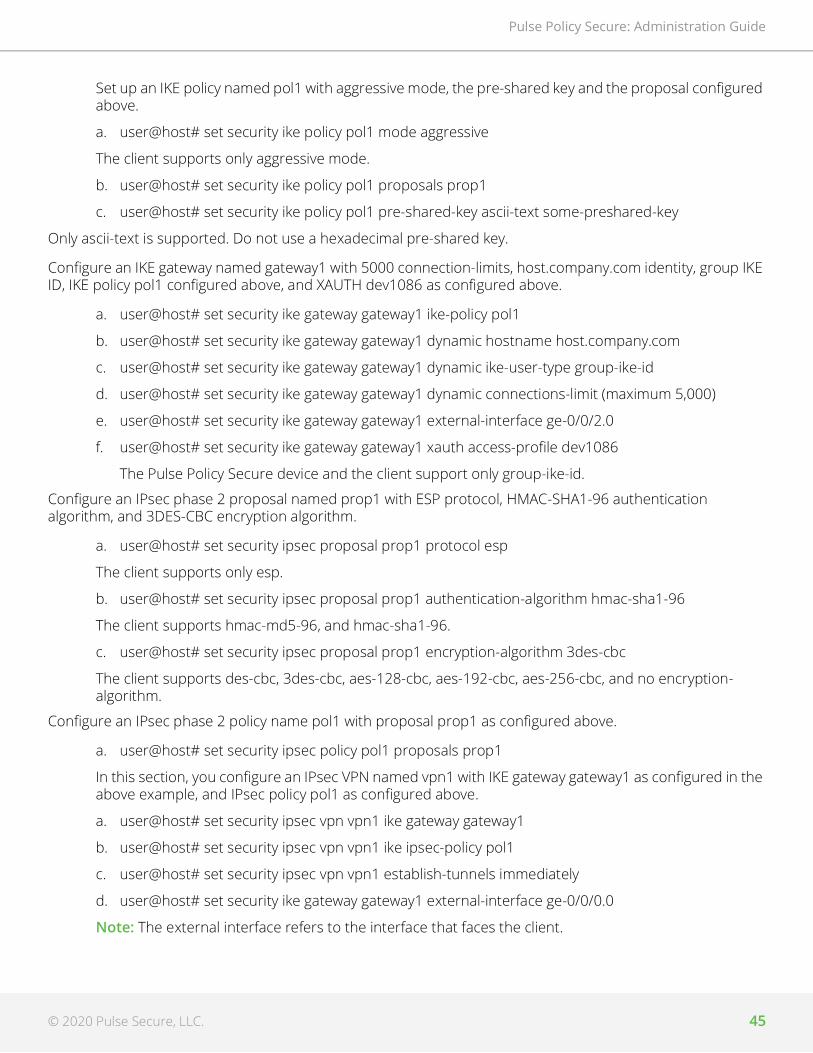
© 2020 Pulse Secure, LLC. 45
Pulse Policy Secure: Administration Guide
Set up an IKE policy named pol1 with aggressive mode, the pre-shared key and the proposal configured above.
a. user@host# set security ike policy pol1 mode aggressive
The client supports only aggressive mode.
b. user@host# set security ike policy pol1 proposals prop1
c. user@host# set security ike policy pol1 pre-shared-key ascii-text some-preshared-key
Only ascii-text is supported. Do not use a hexadecimal pre-shared key.
Configure an IKE gateway named gateway1 with 5000 connection-limits, host.company.com identity, group IKE ID, IKE policy pol1 configured above, and XAUTH dev1086 as configured above.
a. user@host# set security ike gateway gateway1 ike-policy pol1
b. user@host# set security ike gateway gateway1 dynamic hostname host.company.com
c. user@host# set security ike gateway gateway1 dynamic ike-user-type group-ike-id
d. user@host# set security ike gateway gateway1 dynamic connections-limit (maximum 5,000)
e. user@host# set security ike gateway gateway1 external-interface ge-0/0/2.0
f. user@host# set security ike gateway gateway1 xauth access-profile dev1086
The Pulse Policy Secure device and the client support only group-ike-id.
Configure an IPsec phase 2 proposal named prop1 with ESP protocol, HMAC-SHA1-96 authentication algorithm, and 3DES-CBC encryption algorithm.
a. user@host# set security ipsec proposal prop1 protocol esp
The client supports only esp.
b. user@host# set security ipsec proposal prop1 authentication-algorithm hmac-sha1-96
The client supports hmac-md5-96, and hmac-sha1-96.
c. user@host# set security ipsec proposal prop1 encryption-algorithm 3des-cbc
The client supports des-cbc, 3des-cbc, aes-128-cbc, aes-192-cbc, aes-256-cbc, and no encryption-algorithm.
Configure an IPsec phase 2 policy name pol1 with proposal prop1 as configured above.
a. user@host# set security ipsec policy pol1 proposals prop1
In this section, you configure an IPsec VPN named vpn1 with IKE gateway gateway1 as configured in the above example, and IPsec policy pol1 as configured above.
a. user@host# set security ipsec vpn vpn1 ike gateway gateway1
b. user@host# set security ipsec vpn vpn1 ike ipsec-policy pol1
c. user@host# set security ipsec vpn vpn1 establish-tunnels immediately
d. user@host# set security ike gateway gateway1 external-interface ge-0/0/0.0
Note: The external interface refers to the interface that faces the client.

Pulse Policy Secure: Administration Guide
46 © 2020 Pulse Secure, LLC.
e. user@host# set security ike gateway gateway1 xauth access-profile name
3. Create the security policy.
• Enable the VPN vpn1 configured above and add Pulse Policy Security enforcement in a security policy named pol1, from the zone named untrust to the zone named trust.
user@host# set security policies from-zone untrust to-zone trust policy pol1 match source-address any
Note: Always specify any with the following command.
user@host# set security policies from-zone untrust to-zone trust policy pol1 match destination-address any
user@host# set security policies from-zone untrust to-zone trust policy pol1 match application any
user@host# set security policies from-zone untrust to-zone trust policy pol1 then permit tunnel ipsec-vpn vpn1
user@host# set security policies from-zone untrust to-zone trust policy pol1 then permit application-services uac-policy

© 2020 Pulse Secure, LLC. 47
Pulse Policy Secure: Administration Guide
Deployments with Juniper IDP
• About IDP Technology. . . . . . . . . . . . . . . . . . . . . . . . . . . . . . . . . . . . . . . . . . . . . . . . . . . . . . . . . . 47• IDP Deployment Scenarios Overview . . . . . . . . . . . . . . . . . . . . . . . . . . . . . . . . . . . . . . . . . . . . . 48• Understanding PPS Deployments with IDP Devices. . . . . . . . . . . . . . . . . . . . . . . . . . . . . . . . . 48• Activating IDP for the ScreenOS or Junos Enforcer. . . . . . . . . . . . . . . . . . . . . . . . . . . . . . . . . . 51• Managing Interoperation with IDP Devices . . . . . . . . . . . . . . . . . . . . . . . . . . . . . . . . . . . . . . . . 51• Identifying and Managing Quarantined Users Manually . . . . . . . . . . . . . . . . . . . . . . . . . . . . . 53• Using Role-Based Policies to Monitor User Activity . . . . . . . . . . . . . . . . . . . . . . . . . . . . . . . . . 54
About IDP TechnologySecuring intranet work application and resource traffic is vital to protecting the network. You can add levels of application security to detect internal threats coming from users who are authenticated through the system by integrating PPS with a Juniper Networks IDP Series sensor.
PPS supports standalone IDP and IDP through the Juniper Networks ISG Series Integrated Security Gateways Infranet Enforcer with the IDP Security Module (supported in ScreenOS Release 6.2 or greater).
The IDP sensor monitors the network on which the IDP system is installed. The sensor’s primary task is to detect suspicious and anomalous network traffic based on specific rules defined in IDP rulebases.
The IDP device provides the following types of protection (some of which depend upon the specific configuration):
• Protects against attacks from user to application.
• Detects and blocks most network worms based on software vulnerabilities.
• Detects and blocks non-file-based Trojan Horses.
• Detects and blocks effects of spyware. adware, and key loggers.
• Detects and blocks many types of malware.
• Detects and blocks zero day attacks through the use of anomaly detection.
Note: An IDP Sensor can send logs to one PPS only. However, a PPS device can receive logs from more than one IDP Sensor.
Using the admin console, you can configure and manage interaction attributes between PPS and an IDP, including the following:
• (With standalone IDP) Global configuration parameters such as the IDP hostname or IP address, the TCP port over which the sensor communicates with PPS, and the one-time password PPS and IDP use to authenticate with one another.
• Various levels of attack severity warnings and the action that PPS takes.
The IDP sits within the network and monitors traffic from endpoints that are connected through PPS. You can position the IDP in-line, or you can configure the IDP in sniffer mode.

Pulse Policy Secure: Administration Guide
48 © 2020 Pulse Secure, LLC.
After PPS connects with the IDP sensor, PPS registers all of the IP addresses to be monitored for potential threats. With standalone IDP, you enter the IP addresses to monitor.
Any abnormal events detected by the IDP Sensor are reported to PPS, which you configure to take appropriate action based on the severity level of the reported events. The IDP Sensor performs reporting functions to allow you to determine what IP address within the network has launched the attacks in addition to any normal logging the IDP has been configured to undertake.
With a large number of connected users IDP can overwhelm PPS with more alert logs than it can process. In this situation, the number of logs sent by the IDP to PPS can be controlled by decreasing the severity level setting in the IDP connection settings.
With IDP deployments using the Infranet Enforcer and the IDP Security Module, the Infranet Enforcer can send messages to Pulse debug log.
IDP Deployment Scenarios OverviewThree possible deployment scenarios are shown in the following figure.The standalone IDP is located within the internal network. All network traffic originating from endpoints that are registered with the IDP is monitored. You can deploy IDP in sniffer mode, or inline mode. You can use transparent mode or route mode with an inline mode configuration. In the first deployment example, the IDP does not monitor IPsec traffic from the user to protected resources.
To monitor all IPsec traffic from users to protected resources, deploy the IDP behind the Infranet Enforcer, as shown in figure.
You can deploy up to ten IDP devices in a network with PPS. Performance is based on how rapidly sessions are created or changed, the number of events that IDP sends to PPS, and the efficiency of the network links that connect the devices. IDP devices must be connected over a high-speed LAN link.
In a clustering environment, only one member of an PPS cluster exchanges information with an IDP sensor. If the connected PPS fails or is shut down, another cluster member will assume the load.
Understanding PPS Deployments with IDP DevicesThis topic provides and overview of deployments with IDP devices. It includes the following content:
• “About IDP Devices” on page 49
• “Coordinated Threat Control Overview” on page 49
• “Deployments with IDP Series Devices” on page 49
• “Deployments with IDP-Enabled Infranet Enforcers” on page 50
• “Monitoring IDP-Reported Events” on page 50

© 2020 Pulse Secure, LLC. 49
Pulse Policy Secure: Administration Guide
About IDP DevicesThe IDP Sensor is a powerful tool to counteract users who initiate attacks. The IDP sensor monitors the network on which the IDP system is installed. The IDP sits within the network and monitors traffic from endpoints that are connected through PPS. You can position the IDP in-line, or you can configure the IDP in sniffer mode. The sensor’s primary task is to detect suspicious and anomalous network traffic based on specific rules defined in IDP rulebases.
The IDP device provides the following types of protection (some of which depend upon the specific configuration):
• Protects against attacks from user to application.
• Detects and blocks most network worms based on software vulnerabilities.
• Detects and blocks non-file-based Trojan Horses.
• Detects and blocks effects of spyware, adware, and key loggers.
• Detects and blocks many types of malware.
• Detects and blocks zero day attacks through the use of anomaly detection.
Coordinated Threat Control OverviewIn a coordinated threat control deployment, the IDP device reports abnormal events to PPS. The attack logs sent by the IDP device include the source and destination IP addresses and port numbers of the attacking host, and the resource against which the attack was launched, along with the attack identifier, severity of the attack, and the time at which the attack was launched.
PPS displays the attack information received from the IDP sensor on the Active Users page. Based on the attackers IP address and port number, PPS can uniquely identify the user’s session.
When you learn that an attack has been launched by an active user, you can disable the user’s account, end the user’s session, or remediate to a different role. You can choose automatic or manual actions for attacks detected by the IDP sensor. For manual action, you look up the information available on the Active Users page and decide on an action. For automatic action, you configure the action in advance when you define IDP policies.
PPS displays an error message to the user whose account has been disabled indicating the reason.
Deployments with IDP Series DevicesYou can deploy PPS with IDP Series devices in coordinated threat control deployments and user-role-based IDP policy deployments. User-role-based IDP policy deployments require IDP Series 5.0 or later. To display the version of an associated IDP device in PPS admin console, select System > Configuration > Sensors.
Note: An IDP Sensor can send logs to one PPS only. However, PPS can receive logs from more than one IDP Sensor.
Using the admin console, you can configure and manage interaction attributes between PPS and an IDP Series device, including the following:

Pulse Policy Secure: Administration Guide
50 © 2020 Pulse Secure, LLC.
• Global configuration parameters such as the IDP hostname or IP address, the TCP port over which the sensor communicates with PPS, and the one-time password PPS and IDP use to authenticate with one another.
• Various levels of attack severity warnings and the action that PPS takes
• IP addresses to monitor.
With a large number of connected users IDP can overwhelm PPS with more alert logs than it can process. In this situation, the number of logs sent by the IDP to PPS can be controlled by decreasing the severity level setting in the IDP connection settings.
Deployments with IDP-Enabled Infranet EnforcersPPS also supports IDP through the Juniper Networks ISG Series Integrated Security Gateways Infranet Enforcer with the IDP Security Module (supported in ScreenOS Release 6.2 or later).
Unlike a standalone IDP which requires manual configuration on the IDP to allow communication with the PPS, the ScreenOS Enforcer or the Junos Enforcer use the existing communication channel with PPS.
If you are using integrated IDP with the ISG-1000 or ISG-2000, see, https://www.juniper.net/techpubs/en_US/release-independent/screenos/information-products/pathway-pages/screenos/product/index.html. If you are using Junos IDP with Junos OS Release 10.0, see Junos OS Initial Configuration Guide for Security Devices. ISG-IDP and CTC are configured the same on PPS.
When ISG-IDP or Junos IDP are activated, ScreenOS or Junos notifies PPS when an attack event is detected from any endpoint. To avoid overwhelming the SSH connection between PPS and the Infranet Enforcer, the number of attack notifications is limited to ten per second. If additional attacks are detected, the Infranet Enforcer holds an additional ten notifications in a queue.
ISG-IDP or Junos devices attached to any node in a cluster may send messages regarding sessions attached to any node in the cluster.
There is a Use IDP module as Sensor check box on the Infranet Enforcer admin console page. If you select the check box and there is no IDP module or if the Enforcer is not running a compatible version, PPS logs an appropriate message.
With IDP deployments using the Infranet Enforcer and the IDP Security Module, the Infranet Enforcer can send messages to Pulse debug log.
Monitoring IDP-Reported EventsAfter the IDP Sensor has been set up, you can specify the events you want the IDP to watch for and the actions that Pulse Policy Secure takes once a particular event has been noted and reported.
In two locations on Pulse Policy Secure, you can specify actions to be taken in response to users that perform attacks:
• Sensor Event policies page—Define the policy on this page to generate an automatic response to users who perform attacks.
• Users page—Manually identify and quarantine or disable users on the Active Users page, which lists users who have performed attacks.

© 2020 Pulse Secure, LLC. 51
Pulse Policy Secure: Administration Guide
Activating IDP for the ScreenOS or Junos EnforcerTo activate ISG-IDP or Junos IDP on Pulse Policy Secure:
1. Select Pulse Policy Secure > Infranet Enforcer.
2. Select the name of the Enforcer on which you want to activate IDP.
3. Select the Use IDP Module as Sensor check box. Additional options are presented.
4. Select For sessions provisioned for this Enforcer only to limit monitored sessions to this device. This is applicable in an IF-MAP Federation network.
5. Select 1 - INFO through 5 - Critical from the Severity menu. The severity filter allows you to specify the level of attacks that the Infranet Enforcer reports to Pulse Policy Secure. For example, if you select 3, only level 3 attacks or higher are reported.
Managing Interoperation with IDP DevicesThe Sensors tab allows you to specify the system settings Pulse Policy Secure uses to establish a connection to an IDP device. Select System > Configuration > Sensors > Sensors. The main Sensor page displays the sensor, the network address, the state (enabled), the version, and the status of any configured sensors. The following sections describe tasks related to configuring and managing interaction between Pulse Policy Secure and an IDP Sensor:
• “Configuring Communication with an IDP Device” on page 51
• “Enabling or Disabling IDP Sensors” on page 52
• “Reconnecting to an IDP Sensor” on page 52
• “Refreshing and Displaying the Connection Status” on page 53
• “Deleting an IDP Sensor Entry” on page 53
Configuring Communication with an IDP DeviceTo configure communication with an IDP device and a IDP log monitoring policy:
Note: To use the IDP sensor with Pulse Policy Secure you must enable logging for the applicable policies.
1. Select System > Configuration > Sensors
2. Click New Sensor. The admin console displays the New Sensor page.
3. Under Sensor Properties, specify the following information:
• Name—A name Pulse Policy Secure uses to identify the new connection entry.
• Hostname—The hostname or IP address of the IDP Sensor to which Pulse Policy Secure connects in order to receive application and resource attack alert messages.
• Port—The TCP port on the IDP Sensor to which PPS listens when receiving application and resource attack alert messages.

Pulse Policy Secure: Administration Guide
52 © 2020 Pulse Secure, LLC.
• One-time password—The encrypted password PPS uses when conducting the initial Transport Layer Security (TLS) handshake with the IDP Sensor. You must enter the encrypted PPS OTP password as displayed on the IDP ACM configuration summary screen.
Note: The hostname, TCP port, and one-time password must already be configured on the IDP Sensor before this configuration can be successful.
4. Under Monitoring Options, specify IP addresses to monitor and the minimum alert severity level the IDP Sensor records and submits to PPS:
• In the Addresses to Monitor field, specify individual IP addresses and address ranges, one entry per line. IDP reports attack information only for the IP addresses that you specify. For IDP to report all events to PPS, enter 0.0.0.0/0. For IDP to report only selected events, enter <default> to permit IDP to report events for events with source IPs that have an active user session on PPS, and /or enter one or more addresses or address ranges for any endpoint that you want the IDP sensor to report.
Note: With ISG-IDP or Junos IDP, you do not need to specify which IP addresses to monitor. The Infranet Enforcer monitors all IP address for which auth tables exist.
• Select one of the severity options available in the Severity filter drop down list. The severity level is a number on a scale from 1 to 5, where 1 is informational and 5 is critical. This option represents the severity of messages the IDP should send to PPS.
5. Click Save Changes.
Enabling or Disabling IDP SensorsTo enable or disable existing IDP Sensor entries on PPS:
1. Select System > Configuration > Sensors.
2. Select the check box for one or more IDP Sensor entries to enable or disable.
3. Click Enable or Disable to enable or disable the specified IDP Sensor entries, respectively.
Reconnecting to an IDP SensorWhen the connection to an IDP Sensor is down, you can use the admin console on PPS to re-establish the connection. You can also use the admin console to refresh the status of existing connections between PPS and the IDP Sensor.
To re-establish communication with an IDP Sensor, you must generate a new One-time Password.
To reconnect to an associated IDP Sensor:
1. Select the check box next to the IDP Sensor to which you want to reconnect.
2. Click Reconnect.
The admin console displays a message indicating that PPS is currently attempting to re-establish connection to the specified IDP Sensor. This page automatically refreshes each second during the reconnection process. Otherwise, the connection status page automatically refreshes once every 30 seconds.
© 2020 Pulse Secure, LLC. 53
Pulse Policy Secure: Administration Guide
Refreshing and Displaying the Connection StatusTo refresh and display the connection status for the specified IDP Sensor:
1. Select the check box for one or more IDP Sensor entries to display current connection status
2. Click Refresh.
Deleting an IDP Sensor EntryYou can delete existing IDP Sensor entries that define a connection between PPS and an IDP Sensor.
To delete one or more existing IDP Sensor entries from PPS:
1. Select the check box for the IDP Sensor entry or entries to delete.
2. Click Delete, then confirm that you want to delete the sensor entry or entries.
Identifying and Managing Quarantined Users ManuallyWhen PPS quarantines a user based on an attack, you can display and manage the states by locating the user link in the Active Users page.
• A small warning icon is displayed in front of the username.
• The linked username.
• An enabled Quarantined option button on the specific user’s page. If the user is not quarantined, the option button is disabled.
To manage quarantined users:
1. Locate Identify quarantined users at System > Status > Active Users.
2. The quarantined user and click on the username link. The user page opens, showing a number of options.
3. Click Disabled to disallow a user from authenticating.
4. Click Quarantined to leave a user in a quarantined state. The Quarantined option is enabled only if the user is already quarantined.
Note: PPS assigns quarantined users to the quarantined role, regardless of their log in realm.
5. Click Save Changes.
To re-enable previously quarantined or disabled users, select Authentication > Auth. Servers > Select Server > Users and click the link for the given user.
Note: You can also disable users from this location.
6. Click Enabled to release the user from quarantine.
7. Click Save Changes.
All Sensor events are logged at System > Log/Monitoring > Sensors > Log.

Pulse Policy Secure: Administration Guide
54 © 2020 Pulse Secure, LLC.
Using Role-Based Policies to Monitor User ActivityIf you are using IDP Release 5.0 or later or ScreenOS ISG-IDP Release 6.3 or later, you can add enhanced user management capabilities to your PPS IDP deployment. This feature is supported for endpoints using Pulse Client and users who connect with agentless access.
When a user session is established on PPS, PPS pushes session information including IP address, username and the roles to which the user is assigned to the IDP. The session information allows IDP to apply policies based on user roles, or on the username which is added to the IDP log.
Since role selection for a user can be based on the results of Host Checker policies, you can set policies that are based on Host Checker results. For example, if a user is assigned to a restrictive role based on the results of a Host Checker policy requiring a instant messaging software patch, you can restrict instant messenger traffic for that role.
PPS keeps the IDP device updated when a user’s role changes or when a session is deleted. IDP’s application policy enforcement reflects the most currently available information about a user.
If role-based policies are less restrictive than IP address based policies, some users could be inadvertently blocked during this period. Once session information is obtained about the endpoint IDP re-evaluates the endpoint and applies the less restrictive policies.
If role-based policies are more restrictive than IP address based policies, IDP cannot apply the more restrictive policies, and an endpoint could engage in potentially damaging behavior prior to session information being sent.
If you are using PPS and IDP in a network that employs IF-MAP client and server Federation, and IDP detects an attack that is attributed to a session, IDP informs PPS about the attack. Upon notification, PPS publishes the information to any attached IF-MAP servers. The IF-MAP server notifies PPS that originally published the session and PPS takes the appropriate action based on the applicable Sensor Event Policies.

© 2020 Pulse Secure, LLC. 55
Pulse Policy Secure: Administration Guide
Alert Based Admission Control using Juniper SDSN
• Overview . . . . . . . . . . . . . . . . . . . . . . . . . . . . . . . . . . . . . . . . . . . . . . . . . . . . . . . . . . . . . . . . . . . . . 55• Deployment of PPS in Juniper SDSN Environment . . . . . . . . . . . . . . . . . . . . . . . . . . . . . . . . . . 55• Configuring PPS with Juniper SDSN . . . . . . . . . . . . . . . . . . . . . . . . . . . . . . . . . . . . . . . . . . . . . . 57• Configuring Juniper SDSN . . . . . . . . . . . . . . . . . . . . . . . . . . . . . . . . . . . . . . . . . . . . . . . . . . . . . . 61• Troubleshooting . . . . . . . . . . . . . . . . . . . . . . . . . . . . . . . . . . . . . . . . . . . . . . . . . . . . . . . . . . . . . . 66
OverviewThe SDSN solution provides end-to-end network visibility, allowing enterprises to secure their entire network, both physical and virtual. Using threat detection and policy enforcement, PPS and SDSN solution automates and centrally manages security in a multi-vendor environment.
PPS integrates with Juniper SDSN solution through REST API mechanism and takes appropriate action based on the admission control policies. The PPS integration with SDSN solution detects and enforces threat prevention policies and provides a collaborative and comprehensive approach toward complete network security. It enables users to leverage existing, trusted threat feed sources to provide consistent, automated defense across diverse environments.
BenefitsAs PPS has more visibility of the endpoint connected to the network. PPS integration with SDSN enhances the security by isolating or acting at the endpoint level based on threat alerts received from Juniper SDSN.
Note: PPS connector is supported by Junos Space from version 18.3 onwards.
Deployment of PPS in Juniper SDSN EnvironmentThis section describes the integration of PPS in Juniper SDSN environment. PPS receives the threat alert information from Juniper SDSN solution and takes an action at the endpoint based on the admission control policies.

Pulse Policy Secure: Administration Guide
56 © 2020 Pulse Secure, LLC.
Figure 11 Deployment of PPS in Juniper SDSN Environment
In this example, the endpoint is connected to a third-party switch. The switch has 802.1X authentication enabled. The switch authenticates 802.1X requests through a PPS server.
1. The endpoint authenticates to the network through 802.1X or through MAC-based authentication.
2. User downloads a file from the Internet. The perimeter firewall (SRX Series device) scans the file and, based on user-defined policies, sends the file to Sky ATP for analysis.
3. Sky ATP detects that the file contains malware, identifies the endpoint as an infected host, and notifies the SRX Series device and Policy Enforcer.
4. Policy Enforcer downloads the infected host feed and sends a threat action to PPS.
5. The PPS server quarantines/blocks the endpoint. PPS keeps track of the infected host and won’t allow an infected host to acquire full access until the endpoint gets disinfected. When the host is disinfected and cleared from Sky ATP or Juniper PE, PPS receives ‘clear’ event from Juniper PE (Connector), PPS also removes from its infected host list, and host will now be authenticated and gets assigned an appropriate role.
Note: The enforcement of the user is also updated on the firewall.

© 2020 Pulse Secure, LLC. 57
Pulse Policy Secure: Administration Guide
Configuring PPS with Juniper SDSNThe network security devices are configured with PPS for admission access control. A high-level overview of the configuration steps needed to set up and run the integration is described below:
• The Administrator configures the basic PPS configurations such as creating an authentication server, authentication realm, user roles, and role mapping rules.
• Configure Juniper Policy Enforcer as a client in PPS. PPS acts as a REST API Server for Juniper Policy Enforcer. The REST API access for the admin user needs to be enabled by accessing the serial console or alternatively from the PPS admin UI (Authentication > Auth Server > Administrators > Users > click “admin”, enable Allow access to REST APIs).
• Configure PPS to block/quarantine the endpoint based on the threat prevention policy.
• Configure the Switches/WLC as RADIUS Client in PPS (Endpoint Policy > Network Access > Radius Clients > New Radius Client). Switch should be configured with PPS as a RADIUS server.
• Configure RADIUS return attribute policies to define the action upon receiving the event.
Note:
• Ensure that PPS has the endpoint IP Address for the enforcement to work correctly.
• As the endpoint IP Address is mandatory, deployments where the user is behind a NAT might not work well as PPS might have actual IP address whereas SDSN may send NAT'ed IP address.
This section covers the following topics:
• “Admission Control Template” on page 57
• “Admission Control Policies” on page 58
• “Admission Control Client” on page 60
Admission Control TemplateThe admission control template provides the list of possible events that can be received from the network security device along with regular expression to parse the message. The template also provides possible actions that can be taken for an event.
PPS is loaded with default templates for Juniper Policy Enforcer. Admin can create templates for other security devices and can upload to templates.
You can view the list of configured integration templates that provides the list of network security devices and the supported protocol type using Endpoint Policy > Admission Control > Templates.
To view the admission control templates:

Pulse Policy Secure: Administration Guide
58 © 2020 Pulse Secure, LLC.
1. Select Endpoint Policy > Admission Control > Templates.
Figure 12 Existing Template
Admission Control PoliciesThe admission control policies define the list of actions to be performed on PPS for the user sessions. The actions are based on the event and the severity information received from the network security device.
To view and add the new integration policy:
1. Select Endpoint Policy > Admission Control > Policies.
2. Click New Policy.
3. Enter the policy name.
4. Select Juniper Networks Policy Enforcer as a template.
5. Under Rule on Receiving, select the event type (block-endpoint, quarantine-endpoint, clear-blocked-endpoint, clear-quarantined-endpoint) and the severity level. The event types and the severity level are based on the selected template.
The actions on sessions supported are:
• Block Endpoint: Blocks the host MAC Address on the PPS permanently. If admin choose to clear this, it can be cleared either by using Juniper Security Director application or by using the PPS Admin UI.
• Quarantine Endpoint (Change user roles): Changes the roles assigned to the user on PPS so that restriction/privileges for the user can be changed. The Administrator can choose to apply these roles permanently or temporarily. If it is permanent, host will be added to infected host list and will be tracked for subsequent login attempts. Whereas quarantining temporarily is specific to that particular user session (Not tracked in Infected host list and subsequent login attempts will succeed).

© 2020 Pulse Secure, LLC. 59
Pulse Policy Secure: Administration Guide
• Clear Blocked Endpoint - Clears a previously blocked MAC Address.
• Clear Quarantined Endpoint - Clears a previously quarantined MAC Address.
6. Under then perform this action, select the desired action.
• Ignore (log the event) —Received syslog event details are logged on the PPS and no specific action is taken.
• Terminate user session— Terminates the user session on the PPS for the received messages.
• Disable user account— Terminates the user session and disables the user on the PPS for the received messages.
• Replace user role with this role— Changes the roles assigned to the user on PPS so that restriction/privileges for the user can be changed.
• Specify whether to apply the role assignment permanently or only for the session.
Note: Admission Control Policy action is not taken for endpoints behind Network Address Translation (NAT).
7. Under Roles, specify:
• Policy applies to ALL roles—To apply the policy to all users.
• Policy applies to SELECTED roles—To apply this policy only to users who are mapped to roles in the Selected roles list. You must add roles to this list from the Available roles list.
• Policy applies to all roles OTHER THAN those selected below—To apply this policy to all users except for those who map to the roles in the Selected roles list. You must add roles to this list from the Available roles list.
8. Click Save changes.
Figure 13 Configuration Policies
Once the policy is created. You can see the summary page as shown below. The following page shows the different policies created for different events with different user roles.

Pulse Policy Secure: Administration Guide
60 © 2020 Pulse Secure, LLC.
Figure 14 Configuration Policies
Admission Control ClientThe admission control clients are the network security devices on which the syslog forwarding is enabled. The messages are received by the syslog server module running on PPS.
To add a client:
1. Select Endpoint Policy > Admission Control > Clients.
2. Click New Client.
3. Enter the name of the Juniper Policy Enforcer that will be added as a client in the PPS.
4. Enter the description.
5. Enter the IP address of the client.
6. Select the template used by the client.
• Juniper-Policy Engine-HTTP
7. Click Save Changes.

© 2020 Pulse Secure, LLC. 61
Pulse Policy Secure: Administration Guide
Figure 15 New Client
Configuring Juniper SDSN• “Configuring PPS with Juniper SD” on page 61
• “Configuring Juniper Policy Enforcer with SKY ATP” on page 66
Configuring PPS with Juniper SDThe Pulse Policy Secure(PPS) connector must be added as a connector while configuring the Juniper SDSN for sending the event information. You must add Juniper Policy Enforcer as a client on PPS.
Pre-requisitePulse Policy Secure(PPS) Connector is supported beginning with Junos Space release version 18.3.
To configure Juniper SDSN using Junos Space Security Director:
1. Select Policy Enforcer > Connectors and create a connector.
a. Select the Collector type as Pulse Policy Secure
b. Enter the IP address of PPS.
c. Retain the default port number as 443.
d. Enter the username and password of PPS. Note that you must have enabled the REST API access on PPS (Authentication > Auth Server > Administrators > Users > click “admin”, enable Allow access to REST APIs).

Pulse Policy Secure: Administration Guide
62 © 2020 Pulse Secure, LLC.
Figure 16 Create Connector
2. Enter the subnet details of the network.
Figure 17 Subnet details page

© 2020 Pulse Secure, LLC. 63
Pulse Policy Secure: Administration Guide
3. Once the configuration is successful the following page is displayed.
4. Create an advanced threat prevention policy, such as blocking infected hosts and malware, monitoring and remediation of infected hosts and apply them on group of devices. Select Configure > Guided Setup > Threat Prevention.
Figure 18 Threat Prevention
5. Add the SRX device and the PPS device as enforcement points. As a prerequisite, you must have configured the SRX device and the PPS device as Enforcement points.
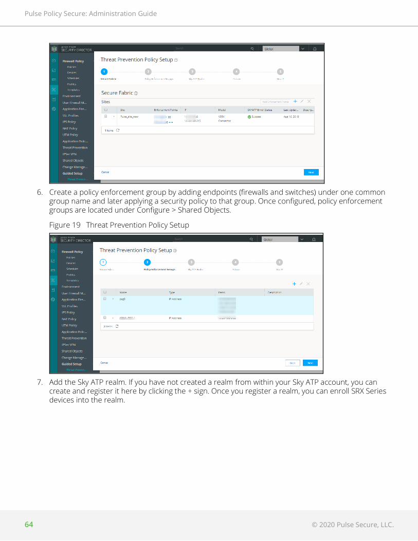
Pulse Policy Secure: Administration Guide
64 © 2020 Pulse Secure, LLC.
6. Create a policy enforcement group by adding endpoints (firewalls and switches) under one common group name and later applying a security policy to that group. Once configured, policy enforcement groups are located under Configure > Shared Objects.
Figure 19 Threat Prevention Policy Setup
7. Add the Sky ATP realm. If you have not created a realm from within your Sky ATP account, you can create and register it here by clicking the + sign. Once you register a realm, you can enroll SRX Series devices into the realm.

© 2020 Pulse Secure, LLC. 65
Pulse Policy Secure: Administration Guide
8. Assign the policies to groups. A threat prevention policy requires you to create a name for the policy, choose one or more profile types depending on the type of threat prevention this policy provides (C&C Server, Infected Host, Malware), and select a log setting. Once configured, you apply policies to policy enforcement groups.
The following page is displayed after completing the Threat Prevention policy setup configuration.

Pulse Policy Secure: Administration Guide
66 © 2020 Pulse Secure, LLC.
Configuring Juniper Policy Enforcer with SKY ATPEnroll the SRX device and Juniper Policy Enforcer using SKY ATP.
For more information on Juniper SDSN configuration, see Juniper Documentation.
TroubleshootingTo verify the event logs on PPS, select System > Log/Monitoring > Events.
You can verify that the event logs are generated every time when an event is received from Juniper Policy Enforcer.

© 2020 Pulse Secure, LLC. 67
Pulse Policy Secure: Administration Guide
To verify the user access logs, select System >Logs & Monitoring > User Access to verify the user login related logs like realm, roles, username and IP address.
You can also verify whether the quarantined/blocked host is listed in the Infected Devices report, which lists the mac address, IP address, and the device status. To verify the reports, select System > Reports > Infected Hosts.
You can also enable debug logs to troubleshoot any issues. Select Maintenance > Troubleshooting > Monitoring > Debug Log to enable debug logs.
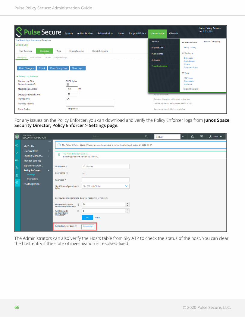
Pulse Policy Secure: Administration Guide
68 © 2020 Pulse Secure, LLC.
For any issues on the Policy Enforcer, you can download and verify the Policy Enforcer logs from Junos Space Security Director, Policy Enforcer > Settings page.
The Administrators can also verify the Hosts table from Sky ATP to check the status of the host. You can clear the host entry if the state of investigation is resolved-fixed.

© 2020 Pulse Secure, LLC. 69
Pulse Policy Secure: Administration Guide

Pulse Policy Secure: Administration Guide
70 © 2020 Pulse Secure, LLC.