
proNX Service Manager User Guide - Juniper Networks
553
proNX Service Manager User Guide Juniper Networks, Inc. 1133 Innovation Way Sunnyvale, CA 94089 USA tel: 408-745-2000 www.juniper.net Part Number: Document Version: Published: Type: BP2A64PA 01 June 2016 STANDARD product release 7.0 Copyright © 2016 Juniper Networks, Inc. ALL RIGHTS RESERVED.
-
Upload
khangminh22 -
Category
Documents
-
view
1 -
download
0
Transcript of proNX Service Manager User Guide - Juniper Networks

proNX Service Manager User Guide
Juniper Networks, Inc. 1133 Innovation Way Sunnyvale, CA 94089 USA
tel: 408-745-2000
www.juniper.net
Part Number:Document Version:Published:Type:
BP2A64PA 01 June 2016 STANDARD
product release 7.0
Copyright © 2016 Juniper Networks, Inc. ALL RIGHTS RESERVED.


Contents
Preface xiii
1.0 proNX Service Manager 1-1 1.1 About PSM .................................................................................................................................................................................. 1-21.2 PSM model ................................................................................................................................................................................. 1-31.3 Running with multiple servers ..................................................................................................................................................... 1-4
1.3.1 Running multiple servers without server replication ........................................................................................................... 1-41.3.2 Running multiple servers with server replication ................................................................................................................ 1-5
1.4 Supported network elements ...................................................................................................................................................... 1-7
2.0 Getting started 2-1 2.1 Starting the PSM client ............................................................................................................................................................... 2-22.2 PSM Client navigation ................................................................................................................................................................. 2-42.3 PSM window system ................................................................................................................................................................... 2-5
2.3.1 Working with the PSM window system ............................................................................................................................... 2-52.4 Quick access toolbar ................................................................................................................................................................... 2-7
2.4.1 Customizing the quick access toolbar ................................................................................................................................ 2-82.5 Displaying the online Help .......................................................................................................................................................... 2-92.6 Viewing the list of supported devices ........................................................................................................................................ 2-10
3.0 Managing PSM users 3-1 3.1 Adding a user .............................................................................................................................................................................. 3-23.2 Modifying a user .......................................................................................................................................................................... 3-43.3 Deleting a user ............................................................................................................................................................................ 3-63.4 Editing user attributes on the local RADIUS server .................................................................................................................... 3-7
Product Release 7.0 STANDARD iii
4.0 Managing network discovery and Ethernet domains 4-1 4.1 Discovering network elements .................................................................................................................................................... 4-24.2 Undiscovering a network element ............................................................................................................................................... 4-64.3 Rediscovering a network element ............................................................................................................................................... 4-74.4 Polling discovered network elements .......................................................................................................................................... 4-84.5 Ethernet network domains .......................................................................................................................................................... 4-9
4.5.1 Creating an Ethernet domain .............................................................................................................................................. 4-94.5.2 Checking domain membership for a network element ..................................................................................................... 4-10
4.6 Scheduling network element discoveries .................................................................................................................................. 4-114.6.1 Scheduling a network element discovery task .................................................................................................................. 4-114.6.2 Viewing scheduled tasks .................................................................................................................................................. 4-144.6.3 Deleting scheduled tasks .................................................................................................................................................. 4-15
5.0 Managing network topology 5-1 5.1 Icons and definitions ................................................................................................................................................................... 5-25.2 Understanding the network topology view .................................................................................................................................. 5-45.3 Learning the network topology .................................................................................................................................................. 5-11
5.3.1 Deriving optical topology using DOL or ROADM data ...................................................................................................... 5-115.3.2 Deriving Ethernet topology using LLDP data .................................................................................................................... 5-115.3.3 Deriving topology using Remote IDs ................................................................................................................................ 5-12
5.3.3.1 Setting the Remote ID .............................................................................................................................................. 5-135.3.3.2 Deleting the Remote ID ............................................................................................................................................ 5-155.3.3.3 Interactions with LLDP ............................................................................................................................................. 5-165.3.3.4 Viewing external devices .......................................................................................................................................... 5-175.3.3.5 Detecting Remote ID errors ..................................................................................................................................... 5-18
5.4 Network element groups and sites ............................................................................................................................................ 5-195.4.1 Creating a new group ....................................................................................................................................................... 5-195.4.2 Moving network elements, groups, and/or sites to a different group ................................................................................ 5-205.4.3 Adding network elements to a new group or site .............................................................................................................. 5-205.4.4 Adding groups and/or sites to a new group ...................................................................................................................... 5-215.4.5 Navigating between parent and child groups ................................................................................................................... 5-21
5.5 Changing the background view ................................................................................................................................................. 5-24
6.0 Working with network elements 6-1 6.1 Editing notes for a network element ............................................................................................................................................ 6-26.2 Identifying services associated with a network element ............................................................................................................. 6-36.3 Viewing network element inventory information .......................................................................................................................... 6-46.4 Searching for a network element ................................................................................................................................................ 6-66.5 Managing information for a network element .............................................................................................................................. 6-76.6 Enabling or disabling network element maintenance modes .................................................................................................... 6-186.7 Marking or unmarking a network element ................................................................................................................................. 6-196.8 Enabling or disabling provisioning mode on a network element ............................................................................................... 6-206.9 Connecting to the CLI on a network element ............................................................................................................................ 6-216.10 Provisioning OSPF on a BTI7000 Series management network ............................................................................................ 6-22
6.10.1 Adding OSPF management ............................................................................................................................................ 6-22
iv proNX Service Manager User Guide – Document Version 01
Contents

6.10.2 Editing OSPF management settings .............................................................................................................................. 6-236.10.3 Deleting OSPF management .......................................................................................................................................... 6-246.10.4 Adding an OSPF management interface ........................................................................................................................ 6-246.10.5 Editing an OSPF management interface ........................................................................................................................ 6-266.10.6 Deleting an OSPF management interface ...................................................................................................................... 6-28
7.0 Working with the Shelf view 7-1 7.1 Displaying network elements in the Shelf view ........................................................................................................................... 7-27.2 Displaying alarms from the Shelf view ........................................................................................................................................ 7-57.3 Setting the Remote ID from the Shelf view ................................................................................................................................. 7-67.4 Deleting the Remote ID from the Shelf view ............................................................................................................................... 7-8
8.0 Nodal management 8-1 8.1 Nodal management overview ..................................................................................................................................................... 8-28.2 Nodal management for BTI7000 Series network elements ........................................................................................................ 8-3
8.2.1 Launching the proNX 900 Node Controller ........................................................................................................................ 8-38.2.2 Provisioning a BTI7000 Series shelf ................................................................................................................................... 8-4
8.2.2.1 Adding a shelf ............................................................................................................................................................ 8-48.2.2.2 Deleting a shelf .......................................................................................................................................................... 8-5
8.2.3 Provisioning a slot on a BTI7000 Series shelf .................................................................................................................... 8-58.2.3.1 Adding a module ........................................................................................................................................................ 8-58.2.3.2 Deleting a module ...................................................................................................................................................... 8-7
8.2.4 Provisioning a transponder on a BTI7000 Series shelf ...................................................................................................... 8-78.2.4.1 Provisioning ports on a BTI7000 Series transponder ................................................................................................. 8-78...1 Adding a transponder port .............................................................................................................................................. 8-78...2 Editing a transponder port .............................................................................................................................................. 8-98...3 Deleting a transponder port .......................................................................................................................................... 8-118.2.4.2 Provisioning cross-connects on a BTI7000 Series transponder .............................................................................. 8-118...1 Adding a transponder cross-connect ........................................................................................................................... 8-118...2 Deleting a transponder cross-connect ......................................................................................................................... 8-128.2.4.3 Provisioning line protection groups on a BTI7000 Series transponder .................................................................... 8-138...1 Adding a transponder protection group ........................................................................................................................ 8-138...2 Editing a transponder protection group ........................................................................................................................ 8-138...3 Deleting a transponder protection group ...................................................................................................................... 8-148...4 Executing a protection switch command ...................................................................................................................... 8-148.2.4.4 Provisioning client protection groups on a BTI7000 Series transponder ................................................................. 8-158...1 Adding a client protection group ................................................................................................................................... 8-158...2 Editing a client protection group ................................................................................................................................... 8-168...3 Deleting a client protection group ................................................................................................................................. 8-178...4 Executing a client protection switch command ............................................................................................................ 8-17
8.2.5 Provisioning a muxponder on a BTI7000 Series shelf ...................................................................................................... 8-188.2.5.1 Provisioning ports on a BTI7000 Series muxponder ................................................................................................ 8-188...1 Adding a muxponder port ............................................................................................................................................. 8-188...2 Editing a muxponder port ............................................................................................................................................. 8-208...3 Deleting a muxponder port ........................................................................................................................................... 8-228.2.5.2 Provisioning virtual concatenation groups on a BTI7000 Series muxponder ........................................................... 8-22
Product Release 7.0 STANDARD v
Contents

8...1 Adding a muxponder virtual concatenation group ........................................................................................................ 8-228...2 Editing a muxponder virtual concatenation group ........................................................................................................ 8-248...3 Deleting a muxponder virtual concatenation group ...................................................................................................... 8-248.2.5.3 Provisioning cross-connects on a BTI7000 Series muxponder ................................................................................ 8-258...1 Adding a muxponder cross-connect ............................................................................................................................. 8-258...2 Deleting a muxponder cross-connect ........................................................................................................................... 8-268.2.5.4 Provisioning protection groups on a BTI7000 Series muxponder ............................................................................ 8-278...1 Adding a muxponder protection group ......................................................................................................................... 8-278...2 Editing a muxponder protection group ......................................................................................................................... 8-278...3 Deleting a muxponder protection group ....................................................................................................................... 8-288.2.5.5 Provisioning synchronization on a BTI7000 Series muxponder ............................................................................... 8-28
8.2.6 Provisioning a multiplexer/demultiplexer on a BTI7000 Series shelf ................................................................................ 8-298.2.6.1 Adding or viewing a multiplexer/demultiplexer ......................................................................................................... 8-298.2.6.2 Deleting a multiplexer/demultiplexer ........................................................................................................................ 8-31
8.2.7 Provisioning GCC on a BTI7000 Series network element ................................................................................................ 8-318.2.7.1 Provisioning GCC ..................................................................................................................................................... 8-318.2.7.2 Deleting GCC ........................................................................................................................................................... 8-32
8.2.8 Viewing port PMs on a BTI7000 Series network element ................................................................................................ 8-328.2.9 Provisioning the BTI7000 Series Dynamic Optical Layer (DOL) ...................................................................................... 8-34
8.2.9.1 Provisioning optical groups ...................................................................................................................................... 8-348...1 Creating an optical group ............................................................................................................................................. 8-348...2 Assigning or unassigning equipment ........................................................................................................................... 8-368...3 Deleting an optical group ............................................................................................................................................. 8-378.2.9.2 Editing WDM parameters in an optical group ........................................................................................................... 8-378.2.9.3 Adding and deleting the C2 port ............................................................................................................................... 8-398.2.9.4 Editing optical port parameters ................................................................................................................................ 8-408.2.9.5 Configuring a split ROADM node ............................................................................................................................. 8-428.2.9.6 Editing OSC parameters in an optical group ............................................................................................................ 8-44
8.2.10 Enabling or disabling a port ............................................................................................................................................ 8-478.3 Nodal management for BTI7800 Series network elements ...................................................................................................... 8-48
8.3.1 Provisioning a BTI7800 chassis ....................................................................................................................................... 8-488.3.1.1 Adding a shelf .......................................................................................................................................................... 8-488.3.1.2 Editing a shelf ........................................................................................................................................................... 8-508.3.1.3 Deleting a shelf ........................................................................................................................................................ 8-51
8.3.2 Provisioning a Universal Forwarding Module on a BTI7800 ............................................................................................. 8-518.3.2.1 Adding a UFM .......................................................................................................................................................... 8-528.3.2.2 Editing a UFM .......................................................................................................................................................... 8-548.3.2.3 Deleting a UFM ........................................................................................................................................................ 8-558.3.2.4 Adding a BIC ............................................................................................................................................................ 8-558.3.2.5 Editing a BIC ............................................................................................................................................................ 8-578.3.2.6 Cloning a BIC ........................................................................................................................................................... 8-588.3.2.7 Deleting a BIC .......................................................................................................................................................... 8-598.3.2.8 Adding a transceiver ................................................................................................................................................ 8-598.3.2.9 Editing a transceiver ................................................................................................................................................. 8-618.3.2.10 Cloning a transceiver ............................................................................................................................................. 8-638.3.2.11 Deleting a transceiver ............................................................................................................................................ 8-648.3.2.12 Adding an interface ................................................................................................................................................ 8-64
vi proNX Service Manager User Guide – Document Version 01
Contents

8.3.2.13 Editing an interface ................................................................................................................................................ 8-678.3.2.14 Configuring a multiplexed interface ........................................................................................................................ 8-708.3.2.15 Cloning an interface ............................................................................................................................................... 8-728.3.2.16 Deleting an interface .............................................................................................................................................. 8-738.3.2.17 Viewing interface PMs on a UFM ........................................................................................................................... 8-73
8.3.3 Provisioning a ROADM node on a BTI7800 ..................................................................................................................... 8-748.3.3.1 General provisioning procedure ............................................................................................................................... 8-758.3.3.2 Adding a ROADM or an ILA module ........................................................................................................................ 8-768.3.3.3 Editing a ROADM or an ILA module ........................................................................................................................ 8-778.3.3.4 Deleting a ROADM or an ILA module ...................................................................................................................... 8-778.3.3.5 Adding a PRE module .............................................................................................................................................. 8-788.3.3.6 Editing a PRE module .............................................................................................................................................. 8-798.3.3.7 Deleting a PRE module ............................................................................................................................................ 8-808.3.3.8 Adding or viewing a multiplexer/demultiplexer ......................................................................................................... 8-808.3.3.9 Deleting a multiplexer/demultiplexer ........................................................................................................................ 8-828.3.3.10 Editing a port .......................................................................................................................................................... 8-838.3.3.11 Editing the OMS ..................................................................................................................................................... 8-838.3.3.12 Editing the OSC ..................................................................................................................................................... 8-848.3.3.13 Adding a fiber connection on a ROADM or an ILA client port ................................................................................ 8-858.3.3.14 Editing a fiber connection on a ROADM or an ILA client port ................................................................................ 8-868.3.3.15 Deleting a fiber connection on a ROADM or an ILA client port .............................................................................. 8-878.3.3.16 Adding a fiber connection on a ROADM or an ILA line port ................................................................................... 8-878.3.3.17 Editing a fiber connection on a ROADM or an ILA line port ................................................................................... 8-888.3.3.18 Deleting a fiber connection on a ROADM or an ILA line port ................................................................................. 8-898.3.3.19 Adding a fiber connection on a UFM interface ....................................................................................................... 8-898.3.3.20 Editing a fiber connection on a UFM interface ....................................................................................................... 8-908.3.3.21 Deleting a fiber connection on a UFM interface ..................................................................................................... 8-918.3.3.22 Viewing fiber connections ...................................................................................................................................... 8-928.3.3.23 Adding an optical channel ...................................................................................................................................... 8-928.3.3.24 Bulk adding optical channels .................................................................................................................................. 8-938.3.3.25 Editing an optical channel ...................................................................................................................................... 8-948.3.3.26 Deleting an optical channel .................................................................................................................................... 8-958.3.3.27 Viewing port PMs ................................................................................................................................................... 8-968.3.3.28 Viewing OMS PMs ................................................................................................................................................. 8-978.3.3.29 Viewing OSC PMs .................................................................................................................................................. 8-978.3.3.30 Viewing optical channel PMs ................................................................................................................................. 8-98
8.3.4 Provisioning a 96-Channel Amplifier on a BTI7800 .......................................................................................................... 8-998.3.4.1 Adding an amplifier .................................................................................................................................................. 8-998.3.4.2 Creating an optical group for a BTI7800 Series amplifier ...................................................................................... 8-1008.3.4.3 Assigning or unassigning an amplifier .................................................................................................................... 8-1018.3.4.4 Editing an amplifier port ......................................................................................................................................... 8-1038.3.4.5 Editing WDM parameters for an amplifier .............................................................................................................. 8-1048.3.4.6 Editing OSC parameters for an amplifier ............................................................................................................... 8-1058.3.4.7 Changing an amplifier's group ................................................................................................................................ 8-1078.3.4.8 Viewing port PMs ................................................................................................................................................... 8-108
8.3.5 Provisioning a Wavelength Protection Switch module on a BTI7800 ............................................................................. 8-1088.3.5.1 Adding a WPS module ........................................................................................................................................... 8-108
Product Release 7.0 STANDARD vii
Contents

8.3.5.2 Adding a protection group ...................................................................................................................................... 8-1098.3.5.3 Editing a protection group ...................................................................................................................................... 8-1118.3.5.4 Deleting a protection group .................................................................................................................................... 8-1128.3.5.5 Editing a port .......................................................................................................................................................... 8-112
8.3.6 Enabling or disabling a port ............................................................................................................................................ 8-1148.4 Nodal management for BTI800 Series network elements ...................................................................................................... 8-115
8.4.1 Enabling or disabling a port ............................................................................................................................................ 8-115
9.0 Configuring PSM client options 9-1 9.1 Configuring general options ........................................................................................................................................................ 9-2
9.1.1 Setting auto-logout ............................................................................................................................................................. 9-29.2 Configuring alerts options ........................................................................................................................................................... 9-3
9.2.1 Setting alarm alerts options ................................................................................................................................................ 9-39.3 Configuring display options ......................................................................................................................................................... 9-4
9.3.1 Setting alarm display options .............................................................................................................................................. 9-49.3.2 Setting auto-categorization options .................................................................................................................................... 9-59.3.3 Setting device display options ............................................................................................................................................ 9-89.3.4 Setting overlay display options ........................................................................................................................................... 9-99.3.5 Setting service display options ......................................................................................................................................... 9-109.3.6 Setting topology display options ....................................................................................................................................... 9-10
9.4 Configuring performance monitoring options ............................................................................................................................ 9-129.4.1 Setting historical PM graphing options ............................................................................................................................. 9-129.4.2 Setting optical graphing options ....................................................................................................................................... 9-129.4.3 Setting real-time collections options ................................................................................................................................. 9-13
9.5 Configuring utilities .................................................................................................................................................................... 9-159.5.1 Configuring the proNX 900 Node Controller .................................................................................................................... 9-16
10.0 Bulk Configuration of Network Elements 10-1 10.1 Creating new users on multiple network elements ................................................................................................................. 10-210.2 Configuring RADIUS server parameters on multiple network elements ................................................................................. 10-610.3 Configuring NTP server parameters on multiple network elements ...................................................................................... 10-11
11.0 Managing optical and transport services 11-1 11.1 Optical services ....................................................................................................................................................................... 11-2
11.1.1 Visualizing an optical service .......................................................................................................................................... 11-211.1.2 Activating an optical service on a BTI7000 Series network ............................................................................................ 11-6
11.1.2.1 Examples of path selection .................................................................................................................................... 11-811.1.3 Activating an optical service on a BTI7800 network ..................................................................................................... 11-1211.1.4 Viewing the cross-connects in an optical service ......................................................................................................... 11-1311.1.5 Updating an optical service .......................................................................................................................................... 11-1311.1.6 Deleting an optical service ............................................................................................................................................ 11-1411.1.7 Viewing the optical services table ................................................................................................................................. 11-1411.1.8 Viewing the optical services per span table .................................................................................................................. 11-1411.1.9 Viewing the optical topology table ................................................................................................................................ 11-15
11.2 Transport services ................................................................................................................................................................ 11-17
viii proNX Service Manager User Guide – Document Version 01
Contents

11.2.1 Visualizing a transport service ...................................................................................................................................... 11-1711.2.2 Activating a transport service ....................................................................................................................................... 11-1911.2.3 Updating a transport service ......................................................................................................................................... 11-2011.2.4 Deleting a transport service .......................................................................................................................................... 11-2011.2.5 Viewing the transport services table ............................................................................................................................. 11-2111.2.6 Viewing the transport services per span table .............................................................................................................. 11-2111.2.7 Viewing the transport topology table ............................................................................................................................ 11-2111.2.8 Viewing the transponder tuning grid ............................................................................................................................. 11-22
11.3 Working with optical/transport services and topology tables ................................................................................................ 11-2311.4 Saving a service image ......................................................................................................................................................... 11-25
12.0 Managing Ethernet services 12-1 12.1 Service visualization ............................................................................................................................................................... 12-2
12.1.1 Visualizing an Ethernet service ...................................................................................................................................... 12-212.1.2 Service visualization scheme ......................................................................................................................................... 12-5
12.2 Understanding Ethernet service states ................................................................................................................................... 12-712.3 Service activation .................................................................................................................................................................... 12-8
12.3.1 Service types .................................................................................................................................................................. 12-912.3.2 Auto-provisioning NNIs ................................................................................................................................................. 12-1012.3.3 Activating an Ethernet service ...................................................................................................................................... 12-1112.3.4 Example: Activating an EVPLINE service .................................................................................................................... 12-24
12.3.4.1 Part 1: Setting up the EVPLINE service with CVLAN translation ......................................................................... 12-2512.3.4.2 Part 2: Setting up the EVPLINE service with the virtual untagged option ............................................................ 12-32
12.3.5 Example: Activating an Ethernet service on a multi-chassis LAG ................................................................................ 12-3912.3.6 Example: Activating EVPLAN and EVPLINE services using service maps for flow redirection ................................... 12-43
12.3.6.1 Part 1: Setting up the service maps ..................................................................................................................... 12-4412.3.6.2 Part 2: Setting up the EVPLINE services ............................................................................................................. 12-5112.3.6.3 Setting up the EVPLAN service ........................................................................................................................... 12-55
12.4 Modifying a service ............................................................................................................................................................... 12-6112.4.1 Modifying a port in a service ......................................................................................................................................... 12-6112.4.2 Adding a port to a service ............................................................................................................................................. 12-6112.4.3 Removing a port from a service .................................................................................................................................... 12-62
12.5 Deleting a service ................................................................................................................................................................. 12-6412.6 Adding SLA/CFM to a service ............................................................................................................................................... 12-6512.7 Running a Y.1731 link trace .................................................................................................................................................. 12-7012.8 Running a Y.1731 loopback .................................................................................................................................................. 12-7112.9 Running an RFC 2544 benchmarking test ............................................................................................................................ 12-7212.10 Ethernet Ring Protection Switching (ERPS) ....................................................................................................................... 12-76
12.10.1 Visualizing an ERPS service ...................................................................................................................................... 12-7612.10.2 Viewing the ERPS services table ............................................................................................................................... 12-7912.10.3 Adding VLANs to an ERPS ring ................................................................................................................................. 12-80
12.11 Routing considerations in mixed networks .......................................................................................................................... 12-8312.11.1 GVRP - GARP VLAN Registration Protocol ............................................................................................................... 12-8312.11.2 Mixed networks - BTI7000 Series with BTI700 Series or BTI800 Series elements .................................................... 12-83
12.11.2.1 Creating services in BTI7000 Series packetVX only networks .......................................................................... 12-8412.11.2.2 Creating services over BTI700 Series and/or BTI800 Series only networks ...................................................... 12-85
Product Release 7.0 STANDARD ix
Contents

12.11.2.3 Activating services over combinations of BTI7000 Series packetVX and BTI700 Series or BTI800 Seriesnetworks ............................................................................................................................................................. 12-86
12.12 Managing profiles ................................................................................................................................................................ 12-8812.12.1 About profile manager ................................................................................................................................................ 12-8812.12.2 Managing profile templates ........................................................................................................................................ 12-90
12.12.2.1 Creating a profile template ................................................................................................................................. 12-9012.12.2.2 Editing an existing profile template .................................................................................................................... 12-9212.12.2.3 Creating a profile template through cloning ....................................................................................................... 12-9312.12.2.4 Deleting a profile template ................................................................................................................................. 12-93
12.12.3 Bandwidth profile templates ....................................................................................................................................... 12-9312.12.3.1 TCM bandwidth profiles ..................................................................................................................................... 12-9412.12.3.2 Two-rate TCM .................................................................................................................................................... 12-9512.12.3.3 Single-rate TCM ................................................................................................................................................. 12-9512.12.3.4 CAR bandwidth profile template ......................................................................................................................... 12-9512.12.3.5 Color mode and actions ..................................................................................................................................... 12-9512.12.3.6 Setting DEI on exceed traffic .............................................................................................................................. 12-9612.12.3.7 Internal priority for bandwidth profile templates ................................................................................................. 12-96
12.12.4 Class map profile templates ....................................................................................................................................... 12-9612.12.5 Service policy profile templates .................................................................................................................................. 12-9712.12.6 Service map profile templates .................................................................................................................................... 12-9912.12.7 SLA measurement profile templates ........................................................................................................................ 12-100
13.0 Managing pseudowire services 13-1 13.1 Visualizing a pseudowire service ............................................................................................................................................ 13-213.2 Service activation .................................................................................................................................................................... 13-4
13.2.1 Activating a pseudowire service ..................................................................................................................................... 13-513.3 Modifying a pseudowire service ............................................................................................................................................ 13-1013.4 Deleting a pseudowire service .............................................................................................................................................. 13-11
14.0 Managing customers 14-1 14.1 Adding a customer .................................................................................................................................................................. 14-214.2 Modifying a customer .............................................................................................................................................................. 14-414.3 Deleting a customer ................................................................................................................................................................ 14-5
15.0 Managing network element alarms 15-1 15.1 Alarm visualization .................................................................................................................................................................. 15-2
15.1.1 Viewing current alarms ................................................................................................................................................... 15-315.1.2 Understanding alarm timestamps ................................................................................................................................... 15-515.1.3 Working with the alarms table ........................................................................................................................................ 15-615.1.4 Understanding the alarms summary bar ...................................................................................................................... 15-10
15.2 Acknowledging, emailing, and clearing alarms ..................................................................................................................... 15-1315.3 Assigning an alarm to a user ................................................................................................................................................ 15-1415.4 Viewing historical alarms ...................................................................................................................................................... 15-1515.5 Viewing alarms through an RSS feed ................................................................................................................................... 15-1715.6 Sending traps on the northbound interface ........................................................................................................................... 15-18
x proNX Service Manager User Guide – Document Version 01
Contents

15.6.1 Adding a trap receiver for alarms ................................................................................................................................. 15-1815.6.2 Modifying a trap receiver for alarms ............................................................................................................................. 15-1915.6.3 Deleting a trap receiver for alarms ............................................................................................................................... 15-20
16.0 Managing Network Element system software and FTP servers 16-1 16.1 Adding an FTP or SFTP server ............................................................................................................................................... 16-216.2 Modifying an FTP or SFTP server's configuration .................................................................................................................. 16-516.3 Deleting an FTP or SFTP server ............................................................................................................................................. 16-616.4 Manually backing up a network element configuration database ........................................................................................... 16-716.5 Restoring a configuration database to a network element ...................................................................................................... 16-916.6 Upgrading system software for a network element ............................................................................................................... 16-1116.7 Restoring a database to factory defaults on a BTI7800 network element ............................................................................ 16-14
17.0 Managing reports 17-1 17.1 Generating alarms reports ...................................................................................................................................................... 17-2
17.1.1 Generating an active alarms report ................................................................................................................................ 17-217.1.2 Generating a historical alarms report ............................................................................................................................. 17-3
17.2 Generating Ethernet reports ................................................................................................................................................... 17-617.3 Generating pseudowire reports ............................................................................................................................................... 17-717.4 Generating transport reports ................................................................................................................................................... 17-817.5 Generating NE logs reports .................................................................................................................................................... 17-917.6 Generating optical reports ..................................................................................................................................................... 17-1117.7 Generating inventory reports ................................................................................................................................................ 17-1217.8 Generating task history reports ............................................................................................................................................. 17-13
18.0 Performance monitoring 18-1 18.1 Viewing real-time optical service PMs .................................................................................................................................... 18-218.2 Viewing real-time transport service PMs ................................................................................................................................. 18-918.3 Viewing real-time Ethernet PMs and SLAs ........................................................................................................................... 18-1418.4 Viewing real-time pseudowire PMs ....................................................................................................................................... 18-2218.5 Collecting and viewing historical PMs ................................................................................................................................... 18-26
19.0 Troubleshooting 19-1 19.1 Managing task status .............................................................................................................................................................. 19-2
19.1.1 Discovering task status ................................................................................................................................................... 19-319.1.2 Clearing completed tasks ............................................................................................................................................... 19-3
19.2 Exporting client and server logs .............................................................................................................................................. 19-419.3 Performing diagnostics ........................................................................................................................................................... 19-519.4 Viewing the PSM Client log ..................................................................................................................................................... 19-619.5 Testing network element connectivity ..................................................................................................................................... 19-719.6 Verifying PSM client-server connectivity ................................................................................................................................. 19-819.7 Collecting and viewing NE logs ............................................................................................................................................... 19-919.8 Saving network element configuration information ............................................................................................................... 19-1119.9 Troubleshooting server replication ........................................................................................................................................ 19-12
Product Release 7.0 STANDARD xi
Contents

19.9.1 Loss of connectivity to the cluster ................................................................................................................................. 19-1219.9.2 Loss of synchronization with a cluster member ............................................................................................................ 19-1219.9.3 Re-establishment of connectivity to the cluster ............................................................................................................ 19-1219.9.4 Synchronizing replicated data manually ....................................................................................................................... 19-1219.9.5 Restarting the cluster .................................................................................................................................................... 19-13
Appendix A: Service activation error messages A-1
Appendix B: PSM alarms B-1
Appendix C: Alarm details C-1
Appendix D: Historical PM counters D-1
Appendix E: Installing Net-SNMP E-1
Appendix F: Configuring historical PM collection on BTI800 Series network elements F-1
Appendix G: Regular expressions G-1
xii proNX Service Manager User Guide – Document Version 01
Contents
Preface
This preface explains who should read this guide, how this guide is organized, relateddocumentation, documentation conventions, how to obtain documentation, and how to obtaintechnical support.
Audience
This guide is primarily intended for technicians and network operation center (NOC) staff.
Revision history
The following table tracks the revision history for each product release modification to thisdocument.
Release Date Modifications2.0 October 2011 Added the following topics:
• Managing information for a network element
• Managing trap receivers for alarms
• Adding a trap receiver for alarms
• Modifying a trap receiver for alarms
• Deleting a trap receiver for alarms
• Managing Network Element system software and FTP servers
• Configuring automated database-backup operations for multiple networkelements
• Downloading system software to a BTI7000 Series or BTI700 Seriesnetwork element
• Adding an FTP server
• Modifying an FTP server's configuration
• Deleting an FTP server
Product Release 7.0 STANDARD xiii

Release Date Modifications• Manage task status
• Viewing active logs
• Viewing current and historical alarms
• Generating alarm reports
• Generating optical reports
• Generating inventory reports
Added the following chapter:
• Optical services
2.1 February 2012 This document has been updated for the following:
• Added a new chapter "Managing users"
• Updated section "Managing information for a network element"
• Updated the procedure "Activating an Ethernet service"
• Added the procedure "Backing up a NE database"
• Added the procedure "Restoring a NE database"
• Added the procedure "Upgrading system software for a NE"
• Added the section "Adding an SFTP host server to the PSM client"
• Added the procedure "Viewing real-time PMs"
• Added the procedure "Using service/alarm correlation"
• Added the procedure "Collecting and viewing NE logs"
2.1 v02 February 2012 Minor updates and corrections.
2.2 April 2012 This document has been updated for the following:
• Alarm Improvements
• Context based alarm filtering views in Alarm panel
• Ability to suspend alarm notifications in Alarm panel
• New Email northbound interface for alarms
• Unreachable NE alarms reported in client GUI and via northbound interfaces
• Y1731 Introduction
• Y.1731 setup as part of an Ethernet Service activation on BTI7000 Seriesequipment
• Y.1731 MEP/RMEP configuration on BTI700 Series devices as part of anEthernet Service Activation
• Y.1731 real-time PM retrieval and display for BTI7000 Series devices
• proNX 900 launch improvements
• NTP configuration for BTI700 Series devices
• Selection of previously used PSM Server from the PSM client login screen
• Increased character support for Passwords in PSM, aligning with theBTI7000 Series CLI specification
• Support for multiple external RADIUS servers configuration
3.0 July 2012 This document has been updated for the following:
• Support for the BTI800 NE
xiv proNX Service Manager User Guide – Document Version 01
Preface

Release Date Modifications• Automated path selection
• Topology for TPR/MXP connections
• Real-time optical PMs (data and graphs)
• Real-time Ethernet PMs (graphs)
• Bulk configuration of NEs using scripts
• Limits on the number of concurrent software backups, restores, upgrades
• Check, Load, Invoke, Commit software upgrade enhancements
3.1 December 2012 This document has been updated for the following:
• Topology for packetVX, BTI800 NEs, and external devices
• BTI800 PMs (data and graphs)
• Alarm deltas and displaying cleared alarms
• Ethernet service activation examples
• (S)FTP subdirectories for NE backup, restore, and software upgrades
• Listing of PSM alarms
3.2 March 2013 This document has been updated for the following:• Ethernet topology based on LLDP
• BTI800 Y.1731 support
• BTI800 shelf view
• ERPS service visualization
• Minor changes to align with this release
3.3 May 2013 This document has been updated for the following:
• Basic support for BTI718E
• Historical PMs
• Auto-provisioning of NNIs during Ethernet service activation
• Minor changes to align with this release
4.0 July 2013 This document has been updated for the following:
• Support of BTI718E for service discovery and activation, RADIUSprovisioning, real-time PMs and SLAs
• Additional historical PMs (protocol)
• Transponder tuning grid
• Initial support for BTI7800 Series network elements
October 2013 This document has been updated for the following:
• Additional features for BTI7800 Series network elements
• Minor changes to align with this release
4.1 December 2013 This document has been updated for the following:
• BTI800 Series pseudowire service activation, PMs, reports
• Ethernet link trace
• Additional options for Etherent SLA/CFM configuration
• DOL and packetVX historical PMs
4.2 February 2014 This document has been updated for the following:
Product Release 7.0 STANDARD xv
Preface

Release Date Modifications• Remote IDs for multiplexer/demultiplexers
• BTI718E, BTI800 Series, and additional packetVX historical PMs
• Ethernet loopback
• ERPS service table
• NE maintenance mode
• Support for third-party devices RAMAN, EDFA, and OPS
• BTI7800 Series real-time PMs, interface cloning, optical tables and reports
5.0 April 2014 This document has been updated for the following:
• Server replication
• Transceiver, optical group, and amplifier configuration for the BTI7800Series network elements
• Viewing interface PMs for the BTI7800 Series network elements
5.1 July 2014 This document has been updated for the following:
• Ethernet service activation for services with NNI endpoints
• VLAN repair option for ERPS node insertion
• Ethernet virtual untagged option for BTI718E devices
• Connection layer filtering in topology map
• Split ROADM node
• Additional nodal management capabilities for BTI7000 Series and BTI7800Series network elements
• Minor updates to align with the release
5.2 October 2014 This document has been updated for the following:
• Provisioning BTI7000 Series transponders
• Renaming fixed optical services to transport services
• Editing BTI7800 Series shelves
• System information for Juniper Networks BTI805 devices
• Sites and groups
• New ERPS representation in topology view
• S-VLAN translation for NNI services
• Change from HTTP to HTTPS for client-server communication
• Minor changes to align with the release
5.3 December 2014 This document has been updated for the following:
• Juniper Networks BTI805 Ethernet services
• Provisioning BTI7000 Series transponder client y-cable protection
• Provisioning BTI7000 Series muxponders
• System information for Juniper Networks BTI821 and Juniper NetworksBTI822 devices
• Bulk provisioning covers more network elements
• Minor changes to align with the release
5.4 March 2015 This document has been updated for the following:
xvi proNX Service Manager User Guide – Document Version 01
Preface

Release Date Modifications• Juniper Networks BTI821 and Juniper Networks BTI822 Ethernet services
• Support for ENNI on BTI7000 Series network elements
• Provisioning of BTI7000 Series muxponder synchronization
• Provisioning of addtional DOL parameters and equipment
• Custom auto-categorization using regular expressions
• Setting of the Remote ID from the Network tree
• Support for network element connectivity test
• Support for a new mode to mark a network element
• Minor changes to align with the release
6.0 June 2015 This document has been updated for the following:
• Nodal management for Wavelength Protection Switch modules on aBTI7800 Series network element
• Support for viewing port PMs for transponders, muxponders, and packetVXmodules using nodal management procedures on a BTI7000 Series networkelement
• Minor changes to align with the release
6.1 September 2015 This document has been updated for the following:
• Initial support for MPLS on a BTI7800 Series network element
• Addition of CESOP for BTI800 Series pseudowire services
• Improved topology layer views
• Minor changes to align with the release
6.2 December 2015 This document has been updated for the following:
• ROADM support for BTI7800 Series network elements
• Multi-chassis LAGs on Juniper Networks BTI805, Juniper Networks BTI821and Juniper Networks BTI822 devices
• Loopback and link trace on Juniper Networks BTI805, Juniper NetworksBTI821 and Juniper Networks BTI822 devices
• OSPF management and GCC configuration for BTI7000 Series networkelements
• Factory database restore for BTI7800 Series network elements
• Detailed alarm views
• Task history reports
• Editing user idle timeout values on the local RADIUS server
• ODU sub-interfaces (multiplexed) on BTI7800 Series network elements
• Minor changes to align with the release
6.3 March 2016 This document has been updated for the following:
• NE database backup to local chassis storage and NE database restore fromlocal chassis storage (for the BTI7801)
• Port enable/disable from the Network tree
• RFC 2544 benchmarking tests on the BTI805, BTI821, and BTI822 devices
• Removal of BTI7800 Series MPLS configuration
• Minor changes to align with the release
Product Release 7.0 STANDARD xvii
Preface
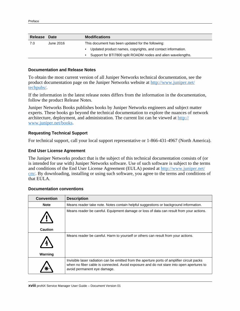
Release Date Modifications7.0 June 2016 This document has been updated for the following:
• Updated product names, copyrights, and contact information.
• Support for BTI7800 split ROADM nodes and alien wavelengths.
Documentation and Release Notes
To obtain the most current version of all Juniper Networks technical documentation, see theproduct documentation page on the Juniper Networks website at http://www.juniper.net/techpubs/.If the information in the latest release notes differs from the information in the documentation,follow the product Release Notes.Juniper Networks Books publishes books by Juniper Networks engineers and subject matterexperts. These books go beyond the technical documentation to explore the nuances of networkarchitecture, deployment, and administration. The current list can be viewed at http://www.juniper.net/books.
Requesting Technical Support
For technical support, call your local support representative or 1-866-431-4967 (North America).
End User License Agreement
The Juniper Networks product that is the subject of this technical documentation consists of (oris intended for use with) Juniper Networks software. Use of such software is subject to the termsand conditions of the End User License Agreement (EULA) posted at http://www.juniper.net/cm/. By downloading, installing or using such software, you agree to the terms and conditions ofthat EULA.
Documentation conventions
Convention DescriptionNote Means reader take note. Notes contain helpful suggestions or background information.
Caution
Means reader be careful. Equipment damage or loss of data can result from your actions.
Warning
Means reader be careful. Harm to yourself or others can result from your actions.
Invisible laser radiation can be emitted from the aperture ports of amplifier circuit packswhen no fiber cable is connected. Avoid exposure and do not stare into open apertures toavoid permanent eye damage.
xviii proNX Service Manager User Guide – Document Version 01
Preface

Convention DescriptionLaser Warning
Product Release 7.0 STANDARD xix
Preface

Copyright © 2016 Juniper Networks, Inc. ALL RIGHTS RESERVED.This product is the property of Juniper Networks, Inc. and its licensors, and is protected by copyright. Any reproductionin whole or in part is strictly prohibited. Juniper, Juniper Networks, BTI, BTI SYSTEMS, packetVX, proNX, and TheNetwork You Need are trademarks or registered trademarks of Juniper Networks, Inc. and/or its subsidiaries in theU.S. and/or other countries.Juniper Networks assumes no responsibility for any inaccuracies in this document. Juniper Networks reserves the rightto change, modify, transfer, or otherwise revise this publication without notice.
Copyright 2003-2016 BTI Systems, Inc. All rights reserved.
Copyright 1997-2001 Lumos Technologies Inc. All rights reserved.Unpublished - All rights reserved under the copyright laws of the United States. This software is furnished under alicense and use, duplication, disclosure and all other uses are restricted to the rights specified in the written licensebetween the licensee and Lumos Technologies Inc.
Copyright 1998-2006 NuDesign Team Inc. All rights reserved. Copyright 1982-2001 QNX Software Systems Ltd. Allrights reserved.
Copyright 1990-2001 Sleepycat Software. All rights reserved.Redistribution and use in source and binary forms, with or without modification, are permitted provided that thefollowing conditions are met: 1. Redistributions of source code must retain the above copyright notice, this list ofconditions and the following disclaimer. 2.Redistributions in binary form must reproduce the above copyright notice,this list of conditions and the following disclaimer in the documentation and/or other materials provided with thedistribution. 3. Redistributions in any form must be accompanied by information on how to obtain complete sourcecode for the DB software and any accompanying software that uses the DB software. The source code must either beincluded in the distribution or be available for no more than the cost of distribution plus a nominal fee, and must befreely redistributable under reasonable conditions. For an executable file, complete source code means the source codefor all modules it contains. It does not include source code for modules or files that typically accompany the majorcomponents of the operating system on which the executable file runs. THIS SOFTWARE IS PROVIDED BYSLEEPYCAT SOFTWARE "AS IS" AND ANY EXPRESS OR IMPLIED WARRANTIES, INCLUDING, BUT NOTLIMITED TO, THE IMPLIED WARRANTIES OF MERCHANTABILITY, FITNESS FOR A PARTICULARPURPOSE, OR NON-INFRINGEMENT, ARE DISCLAIMED. IN NO EVENT SHALL SLEEPYCAT SOFTWAREBE LIABLE FOR ANY DIRECT, INDIRECT, INCIDENTAL, SPECIAL, EXEMPLARY, OR CONSEQUENTIALDAMAGES (INCLUDING, BUT NOT LIMITED TO, PROCUREMENT OF SUBSTITUTE GOODS ORSERVICES; LOSS OF USE, DATA, OR PROFITS; OR BUSINESS INTERRUPTION) HOWEVER CAUSED ANDON ANY THEORY OF LIABILITY, WHETHER IN CONTRACT, STRICT LIABILITY, OR TORT (INCLUDINGNEGLIGENCE OR OTHERWISE) ARISING IN ANY WAY OUT OF THE USE OF THIS SOFTWARE, EVEN IFADVISED OF THE POSSIBILITY OF SUCH DAMAGE.
Copyright 1990, 1993, 1994, 1995 The Regents of the University of California. All rights reserved.Redistribution and use in source and binary forms, with or without modification, are permitted provided that thefollowing conditions are met: 1. Redistributions of source code must retain the above copyright notice, this list ofconditions and the following disclaimer. 2. Redistributions in binary form must reproduce the above copyright notice,this list of conditions and the following disclaimer in the documentation and/or other materials provided with thedistribution. 3. Neither the name of the University nor the names of its contributors may be used to endorse or promoteproducts derived from this software without specific prior written permission. THIS SOFTWARE IS PROVIDED BYTHE REGENTS AND CONTRIBUTORS "AS IS" AND ANY EXPRESS OR IMPLIED WARRANTIES,INCLUDING, BUT NOT LIMITED TO, THE IMPLIED WARRANTIES OF MERCHANTABILITY AND FITNESSFOR A PARTICULAR PURPOSE ARE DISCLAIMED. IN NO EVENT SHALL THE REGENTS ORCONTRIBUTORS BE LIABLE FOR ANY DIRECT, INDIRECT, INCIDENTAL, SPECIAL, EXEMPLARY, OR
xx proNX Service Manager User Guide – Document Version 01
Preface

CONSEQUENTIAL DAMAGES (INCLUDING, BUT NOT LIMITED TO, PROCUREMENT OF SUBSTITUTEGOODS OR SERVICES; LOSS OF USE, DATA, OR PROFITS; OR BUSINESS INTERRUPTION) HOWEVERCAUSED AND ON ANY THEORY OF LIABILITY, WHETHER IN CONTRACT, STRICT LIABILITY, OR TORT(INCLUDING NEGLIGENCE OR OTHERWISE) ARISING IN ANY WAY OUT OF THE USE OF THISSOFTWARE, EVEN IF ADVISED OF THE POSSIBILITY OF SUCH DAMAGE.
Copyright 1995, 1996 The President and Fellows of Harvard University. All rights reserved.Redistribution and use in source and binary forms, with or without modification, are permitted provided that thefollowing conditions are met: 1. Redistributions of source code must retain the above copyright notice, this list ofconditions and the following disclaimer. 2. Redistributions in binary form must reproduce the above copyright notice,this list of conditions and the following disclaimer in the documentation and/or other materials provided with thedistribution. 3. Neither the name of the University nor the names of its contributors may be used to endorse or promoteproducts derived from this software without specific prior written permission. THIS SOFTWARE IS PROVIDED BYHARVARD AND ITS CONTRIBUTORS "AS IS" AND ANY EXPRESS OR IMPLIED WARRANTIES,INCLUDING, BUT NOT LIMITED TO, THE IMPLIED WARRANTIES OF MERCHANTABILITY AND FITNESSFOR A PARTICULAR PURPOSE ARE DISCLAIMED. IN NO EVENT SHALL HARVARD OR ITSCONTRIBUTORS BE LIABLE FOR ANY DIRECT, INDIRECT, INCIDENTAL, SPECIAL, EXEMPLARY, ORCONSEQUENTIAL DAMAGES (INCLUDING, BUT NOT LIMITED TO, PROCUREMENT OF SUBSTITUTEGOODS OR SERVICES; LOSS OF USE, DATA, OR PROFITS; OR BUSINESS INTERRUPTION) HOWEVERCAUSED AND ON ANY THEORY OF LIABILITY, WHETHER IN CONTRACT, STRICT LIABILITY, OR TORT(INCLUDING NEGLIGENCE OR OTHERWISE) ARISING IN ANY WAY OUT OF THE USE OF THISSOFTWARE, EVEN IF ADVISED OF THE POSSIBILITY OF SUCH DAMAGE.
Copyright 1998 The NetBSD Foundation, Inc. All rights reserved.This code is derived from software contributed to The NetBSD Foundation by Christos Zoulas. Redistribution and usein source and binary forms, with or without modification, are permitted provided that the following conditions are met:1. Redistributions of source code must retain the above copyright notice, this list of conditions and the followingdisclaimer. 2. Redistributions in binary form must reproduce the above copyright notice, this list of conditions and thefollowing disclaimer in the documentation and/or other materials provided with the distribution. 3. All advertisingmaterials mentioning features or use of this software must display the following acknowledgement: This productincludes software developed by the NetBSD Foundation, Inc. and its contributors. 4. Neither the name of The NetBSDFoundation nor the names of its contributors may be used to endorse or promote products derived from this softwarewithout specific prior written permission. THIS SOFTWARE IS PROVIDED BY THE NETBSD FOUNDATION,INC. AND CONTRIBUTORS "AS IS"' AND ANY EXPRESS OR IMPLIED WARRANTIES, INCLUDING, BUTNOT LIMITED TO, THE IMPLIED WARRANTIES OF MERCHANTABILITY AND FITNESS FOR APARTICULAR PURPOSE ARE DISCLAIMED. IN NO EVENT SHALL THE FOUNDATION ORCONTRIBUTORS BE LIABLE FOR ANY DIRECT, INDIRECT, INCIDENTAL, SPECIAL, EXEMPLARY, ORCONSEQUENTIAL DAMAGES (INCLUDING, BUT NOT LIMITED TO, PROCUREMENT OF SUBSTITUTEGOODS OR SERVICES; LOSS OF USE, DATA, OR PROFITS; OR BUSINESS INTERRUPTION) HOWEVERCAUSED AND ON ANY THEORY OF LIABILITY, WHETHER IN CONTRACT, STRICT LIABILITY, OR TORT(INCLUDING NEGLIGENCE OR OTHERWISE) ARISING IN ANY WAY OUT OF THE USE OF THISSOFTWARE, EVEN IF ADVISED OF THE POSSIBILITY OF SUCH DAMAGE.
Copyright 2003 Maxim Sobolev [email protected]. All rights reserved.Redistribution and use in source and binary forms, with or without modification, are permitted provided that thefollowing conditions are met: 1. Redistributions of source code must retain the above copyright notice, this list ofconditions and the following disclaimer. 2. Redistributions in binary form must reproduce the above copyright notice,this list of conditions and the following disclaimer in the documentation and/or other materials provided with thedistribution. THIS SOFTWARE IS PROVIDED BY THE AUTHOR AND CONTRIBUTORS "AS IS'' AND ANYEXPRESS OR IMPLIED WARRANTIES, INCLUDING, BUT NOT LIMITED TO, THE IMPLIED WARRANTIESOF MERCHANTABILITY AND FITNESS FOR A PARTICULAR PURPOSE ARE DISCLAIMED. IN NO EVENT
Product Release 7.0 STANDARD xxi
Preface

SHALL THE AUTHOR OR CONTRIBUTORS BE LIABLE FOR ANY DIRECT, INDIRECT, INCIDENTAL,SPECIAL, EXEMPLARY, OR CONSEQUENTIAL DAMAGES (INCLUDING, BUT NOT LIMITED TO,PROCUREMENT OF SUBSTITUTE GOODS OR SERVICES; LOSS OF USE, DATA, OR PROFITS; ORBUSINESS INTERRUPTION) HOWEVER CAUSED AND ON ANY THEORY OF LIABILITY, WHETHER INCONTRACT, STRICT LIABILITY, OR TORT (INCLUDING NEGLIGENCE OR OTHERWISE) ARISING INANY WAY OUT OF THE USE OF THIS SOFTWARE, EVEN IF ADVISED OF THE POSSIBILITY OF SUCHDAMAGE.
Copyright 1995,1996,1997,1998 Lars Fenneberg [email protected] to use, copy, modify, and distribute this software for any purpose and without fee is hereby granted, providedthat this copyright and permission notice appear on all copies and supporting documentation, the name of LarsFenneberg not be used in advertising or publicity pertaining to distribution of the program without specific priorpermission, and notice be given in supporting documentation that copying and distribution is by permission of LarsFenneberg. Lars Fenneberg makes no representations about the suitability of this software for any purpose. It is provided"as is" without express or implied warranty.
Copyright 1992 Livingston Enterprises, Inc. Livingston Enterprises, Inc. 6920 Koll Center Parkway Pleasanton, CA94566.Permission to use, copy, modify, and distribute this software for any purpose and without fee is hereby granted, providedthat this copyright and permission notice appear on all copies and supporting documentation, the name of LivingstonEnterprises, Inc. not be used in advertising or publicity pertaining to distribution of the program without specific priorpermission, and notice be given in supporting documentation that copying and distribution is by permission ofLivingston Enterprises, Inc. Livingston Enterprises, Inc. makes no representations about the suitability of this softwarefor any purpose. It is provided "as is" without express or implied warranty.
The Regents of the University of Michigan and Merit Network, Inc. 1992, 1993, 1994, 1995. All Rights Reserved.Permission to use, copy, modify, and distribute this software and its documentation for any purpose and without fee ishereby granted, provided that the above copyright notice and this permission notice appear in all copies of the softwareand derivative works or modified versions thereof, and that both the copyright notice and this permission and disclaimernotice appear in supporting documentation. THIS SOFTWARE IS PROVIDED "AS IS" WITHOUT WARRANTYOF ANY KIND, EITHER EXPRESS OR IMPLIED, INCLUDING WITHOUT LIMITATION WARRANTIES OFMERCHANTABILITY AND FITNESS FOR A PARTICULAR PURPOSE. THE REGENTS OF THE UNIVERSITYOF MICHIGAN AND MERIT NETWORK, INC. DO NOT WARRANT THAT THE FUNCTIONS CONTAINEDIN THE SOFTWARE WILL MEET LICENSEE'S REQUIREMENTS OR THAT OPERATION WILL BEUNINTERRUPTED OR ERROR FREE. The Regents of the University of Michigan and Merit Network, Inc. shall notbe liable for any special, indirect, incidental or consequential damages with respect to any claim by Licensee or anythird party arising from use of the software.
Copyright 1991-2, RSA Data Security, Inc. Created 1991. All rights reserved.License to copy and use this software is granted provided that it is identified as the "RSA Data Security, Inc. MD5Message-Digest Algorithm" in all material mentioning or referencing this software or this function. License is alsogranted to make and use derivative works provided that such works are identified as "derived from the RSA DataSecurity, Inc. MD5 Message-Digest Algorithm" in all material mentioning or referencing the derived work. RSA DataSecurity, Inc. makes no representations concerning either the merchantability of this software or the suitability of thissoftware for any particular purpose. It is provided "as is" without express or implied warranty of any kind. These noticesmust be retained in any copies of any part of this documentation and/or software.
All other product and company names are trademarks or registered trademarks of their respective companies. All ofthe above-referenced components are not necessarily included in all versions of the product.
xxii proNX Service Manager User Guide – Document Version 01
Preface
1.0 proNX Service Manager
The following sections introduce the proNX Service Manager (PSM).• 1.1, “About PSM”• 1.2, “PSM model”• 1.3, “Running with multiple servers”• 1.4, “Supported network elements”
Product Release 7.0 STANDARD 1-1
C H A P T E R 1

1.1 About PSM
The proNX Service Manager (PSM) provides proactive, service-centric management of networkresources using tools closely aligned with service providers’ own business processes. It isdesigned to simplify network operations from visualization and activation of services totroubleshooting and supporting end customers.PSM is Java-based and uses a client-server architecture.
PSM client
The PSM client is a Java-based GUI that communicates with the PSM server using an HTTPS-based protocol to provide the full functionality of the proNX Service Manager. The PSM clientruns on the desktop or laptop of the technician or NOC staff.
proNX Dashboard
The proNX Dashboard is a thin HTTPS Web-based client that is used to provide a quick view ofthe health of the managed network. It offers a subset of the functionality of the PSM client, andruns on supported browsers. It does not require Juniper Networks software packages to run.
PSM server
The PSM server communicates with network elements using SNMP or NETCONF. The PSMserver runs on Red Hat (CentOS) Linux on x86-64 servers from vendors such as Oracle, HP,Dell, or IBM.The number of clients and nodes supported is determined by the hardware, and a calculator isavailable to determine the correct hardware for specific deployments.The PSM server has the following components:• One or more Java-based processes (depending on the performance requirements of the platform)• MySQL database (automatically backed up daily)
Red Hat (CentOS) Linux
PSM is supported on Red Hat (CentOS) Linux. To facilitate configuration of the operatingsystem, the PSM ISO includes a setup script that configures Red Hat (CentOS) Linux and installsthe software packages required by the PSM server.
Support for RADIUS server
Included in the PSM server software package is a local instance of a RADIUS serverimplementation. When PSM is installed, the PSM server is configured by default to use this localRADIUS server to provide authentication and authorization mechanisms for access to PSMfeatures.
1-2 proNX Service Manager User Guide – Document Version 01
proNX Service Manager

1.2 PSM model
In the proNX Service Manager paradigm, network element configuration data resides solely onthe network elements themselves. PSM does not keep a separate network element configurationdatabase. This absence of a centralized database allows PSM to achieve better scaling and betterconcurrency.When management systems operate directly on configuration data stored on the networkelements, there is added assurance that the data is accurate and up to date. Because there is onlyone set of data, issues with synchronizing an external copy of the data with the actual data on thenetwork element do not exist. Furthermore, since the actual data is manipulated directly, it is asimple matter for the management software to detect and handle situations where multiple usersattempt to make conflicting changes, regardless of whether the conflicting users are using TL1,CLI, a separate nodal manager, or other PSM Servers.Figure 1-1 shows a network managed by two PSM Servers and multiple clients, along with anexternal RADIUS server.
Figure 1-1 PSM managed network
When a server comes up, it registers itself as a trap listener on all network elements it is told todiscover. It then receives traps from, and reports on, these network elements, and draws topologyand discovers services based on configuration and operational data it reads from these networkelements. This information is then made available to PSM clients that log in to this server.Clients logging in to a different server might see different network elements altogether,depending on what this other server is configured to discover.
Product Release 7.0 STANDARD 1-3
proNX Service Manager
1.3 Running with multiple servers
To provide a level of redundancy, PSM supports the use of multiple servers to manage a network.In a multi-server configuration, each server receives traps from, and reports on, the networkelements that it has discovered. The set of discovered network elements can be the same or canbe different from server to server, depending purely on how you choose to divide your networkfor management. The servers can be geographically distinct for better disaster recovery or be partof a geographically-based management scheme.
Note Some Juniper Networks network elements have limits on the number of PSMservers that are used to manage them. See the proNX Service ManagerInstallation and Administration Guide for details.
Since the servers operate directly on configuration data stored on the network elementsthemselves, each server has the latest view, and is able to detect and recover from conflicts (inthe unlikely event that two or more servers are changing the same set of attributes on the samenetwork element).While the PSM server does not store network element configuration data, it does storeconfiguration data associated with the PSM server itself. This PSM configuration data relates touser interface interactions and the presentation of information, and includes the following:• users for the server• the list of network elements to discover and domain/group membership, which relate to what
network elements to manage and how they are organized• alarm assignment/acknowledgment and maintenance modes, which relate to management
actions that a user can take• customer details and association, which can be optionally defined and associated with services• profiles, which are network-wide to provide consistency across network elements• various options related to the display of data, the locations of tools, and other attributes
specific to the serverThe PSM server stores this set of information in the local mySQL database, which is set up andinitialized during the PSM server installation process, and which persists through PSM serversoftware upgrades.How this data behaves when you run with multiple servers depends on whether you choose torun these servers independently (without server replication), or loosely coupled (with serverreplication).• 1.3.1, “Running multiple servers without server replication”• 1.3.2, “Running multiple servers with server replication”
1.3.1 Running multiple servers without server replicationWhen you run multiple servers without server replication, each server is unaware of the otherservers, and each has its own set of PSM configuration data.
1-4 proNX Service Manager User Guide – Document Version 01
proNX Service Manager
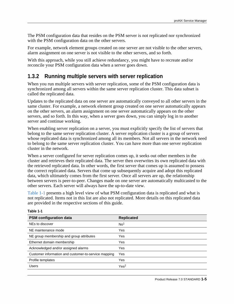
The PSM configuration data that resides on the PSM server is not replicated nor synchronizedwith the PSM configuration data on the other servers.For example, network element groups created on one server are not visible to the other servers,alarm assignment on one server is not visible to the other servers, and so forth.With this approach, while you still achieve redundancy, you might have to recreate and/orreconcile your PSM configuration data when a server goes down.
1.3.2 Running multiple servers with server replicationWhen you run multiple servers with server replication, some of the PSM configuration data issynchronized among all servers within the same server replication cluster. This data subset iscalled the replicated data.Updates to the replicated data on one server are automatically conveyed to all other servers in thesame cluster. For example, a network element group created on one server automatically appearson the other servers, an alarm assignment on one server automatically appears on the otherservers, and so forth. In this way, when a server goes down, you can simply log in to anotherserver and continue working.When enabling server replication on a server, you must explicitly specify the list of servers thatbelong to the same server replication cluster. A server replication cluster is a group of serverswhose replicated data is synchronized among all its members. Not all servers in the network needto belong to the same server replication cluster. You can have more than one server replicationcluster in the network.When a server configured for server replication comes up, it seeks out other members in thecluster and retrieves their replicated data. The server then overwrites its own replicated data withthe retrieved replicated data. In other words, the first server that comes up is assumed to possessthe correct replicated data. Servers that come up subsequently acquire and adopt this replicateddata, which ultimately comes from the first server. Once all servers are up, the relationshipbetween servers is peer-to-peer. Changes made on one server are automatically multicasted to theother servers. Each server will always have the up-to-date view.Table 1-1 presents a high level view of what PSM configuration data is replicated and what isnot replicated. Items not in this list are also not replicated. More details on this replicated dataare provided in the respective sections of this guide.
Table 1-1 PSM configuration data ReplicatedNEs to discover No1
NE maintenance mode Yes
NE group membership and group attributes Yes
Ethernet domain membership Yes
Acknowledged and/or assigned alarms Yes
Customer information and customer-to-service mapping Yes
Profile templates Yes
Users Yes2
Product Release 7.0 STANDARD 1-5
proNX Service Manager

Table 1-1 (Continued) PSM configuration data ReplicatedVarious PSM user preferences and options that relate tothe display and presentation of information
No
1To support geographically-based management schemes, NE discovery is not replicated.2In order for user replication to work correctly, all servers in a cluster must use the same RADIUS server for authentication.
For information on how to configure server replication, see the proNX Service ManagerInstallation and Administration Guide.
1-6 proNX Service Manager User Guide – Document Version 01
proNX Service Manager

1.4 Supported network elements
You can use the proNX Service Manager to manage the following Juniper Networks devices:• BTI7800 Series• BTI7000 Series• BTI800 Series• BTI700 SeriesManagement capabilities and device response vary depending on the device. Differences insupport or behavior are stated in the respective procedures in this document.To obtain a detailed up-to-date list of all supported devices, see 2.6, “Viewing the list ofsupported devices”.
Product Release 7.0 STANDARD 1-7
proNX Service Manager

1-8 proNX Service Manager User Guide – Document Version 01
proNX Service Manager

2.0 Getting started
This section describes how to start the PSM Client and provides an overview of the client'slayout and windowing system. This section covers these topics:• 2.1, “Starting the PSM client”• 2.2, “PSM Client navigation”• 2.3, “PSM window system”• 2.4, “Quick access toolbar”• 2.5, “Displaying the online Help”• 2.6, “Viewing the list of supported devices”
Product Release 7.0 STANDARD 2-1
C H A P T E R 2

2.1 Starting the PSM client
Use this procedure to log in and start the PSM client on Windows, Linux, or OS X.Before you can perform this procedure, the client software must be installed. Refer to the proNXService Manager Installation and Administration Guide for instructions on installing the client.
Step 1 Launch the psmclient executable file as follows:• Windows: navigate to the bin folder and double-click the psmclient.exe file.• OS X or Linux: open a terminal window, navigate to the PSM client installation
directory and launch from the command line: bin/psmclient. Alternatively launchthe client from the Desktop icon that is created by the PSM client installer.
The PSM installation starts by displaying the splash screen.
The PSM then displays the login screen.
Step 2 In the Server field, enter the IP address for the PSM server, or choose a previously used
server from the drop-down menu. Step 3 Enter the Username and Password. Step 4 Click Login.
After successful login, the PSM client navigation window is displayed. The followingscreen shows a newly installed server with no pre-discovered network elements.
2-2 proNX Service Manager User Guide – Document Version 01
Getting started
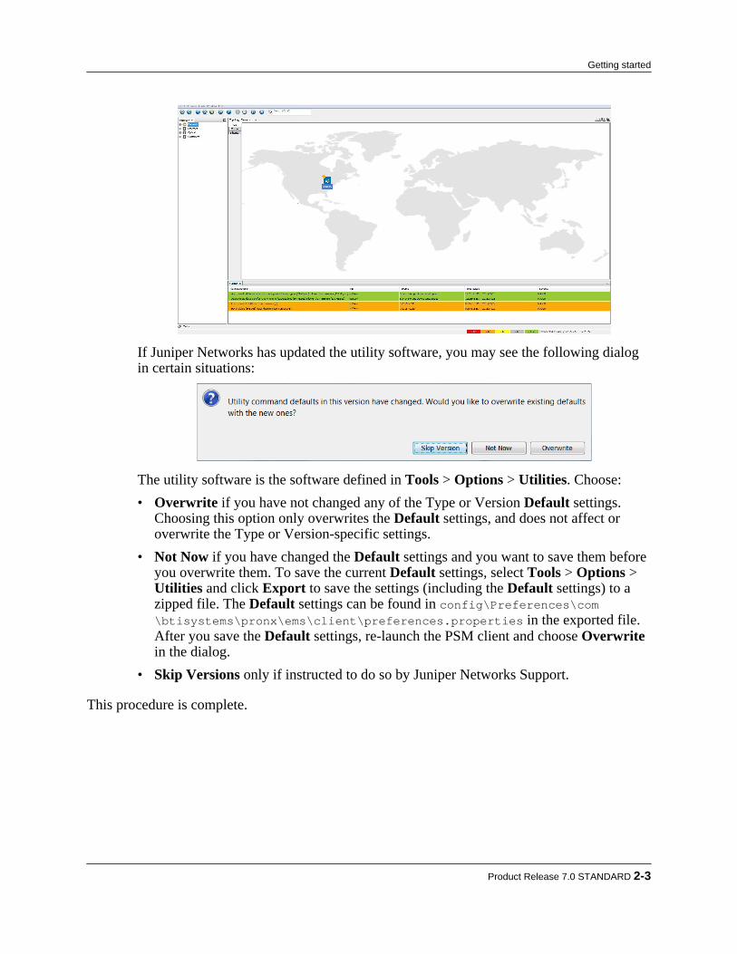
If Juniper Networks has updated the utility software, you may see the following dialogin certain situations:
The utility software is the software defined in Tools > Options > Utilities. Choose:• Overwrite if you have not changed any of the Type or Version Default settings.
Choosing this option only overwrites the Default settings, and does not affect oroverwrite the Type or Version-specific settings.
• Not Now if you have changed the Default settings and you want to save them beforeyou overwrite them. To save the current Default settings, select Tools > Options > Utilities and click Export to save the settings (including the Default settings) to azipped file. The Default settings can be found in config\Preferences\com\btisystems\pronx\ems\client\preferences.properties in the exported file.After you save the Default settings, re-launch the PSM client and choose Overwritein the dialog.
• Skip Versions only if instructed to do so by Juniper Networks Support. This procedure is complete.
Product Release 7.0 STANDARD 2-3
Getting started
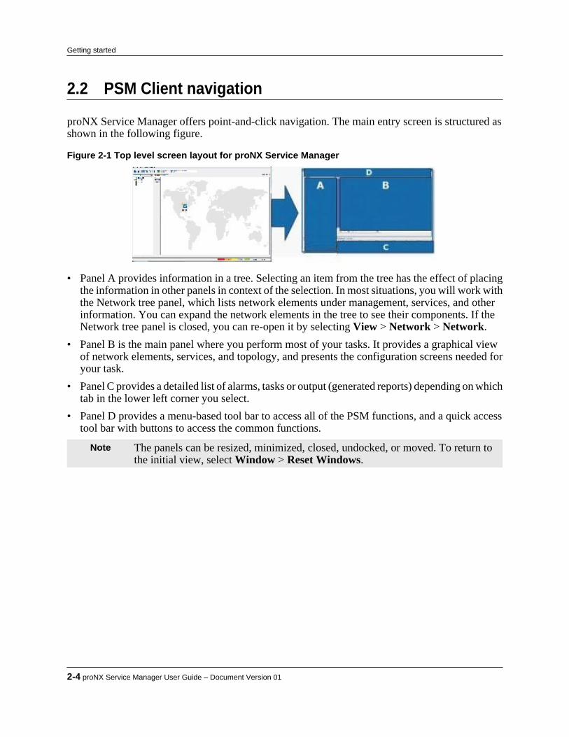
2.2 PSM Client navigation
proNX Service Manager offers point-and-click navigation. The main entry screen is structured asshown in the following figure.
Figure 2-1 Top level screen layout for proNX Service Manager
• Panel A provides information in a tree. Selecting an item from the tree has the effect of placingthe information in other panels in context of the selection. In most situations, you will work withthe Network tree panel, which lists network elements under management, services, and otherinformation. You can expand the network elements in the tree to see their components. If theNetwork tree panel is closed, you can re-open it by selecting View > Network > Network.
• Panel B is the main panel where you perform most of your tasks. It provides a graphical viewof network elements, services, and topology, and presents the configuration screens needed foryour task.
• Panel C provides a detailed list of alarms, tasks or output (generated reports) depending on whichtab in the lower left corner you select.
• Panel D provides a menu-based tool bar to access all of the PSM functions, and a quick accesstool bar with buttons to access the common functions.
Note The panels can be resized, minimized, closed, undocked, or moved. To return tothe initial view, select Window > Reset Windows.
2-4 proNX Service Manager User Guide – Document Version 01
Getting started
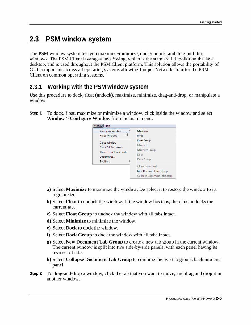
2.3 PSM window system
The PSM window system lets you maximize/minimize, dock/undock, and drag-and-dropwindows. The PSM Client leverages Java Swing, which is the standard UI toolkit on the Javadesktop, and is used throughout the PSM Client platform. This solution allows the portability ofGUI components across all operating systems allowing Juniper Networks to offer the PSMClient on common operating systems.
2.3.1 Working with the PSM window systemUse this procedure to dock, float (undock), maximize, minimize, drag-and-drop, or manipulate awindow.
Step 1 To dock, float, maximize or minimize a window, click inside the window and select Window > Configure Window from the main menu.
a) Select Maximize to maximize the window. De-select it to restore the window to itsregular size.
b) Select Float to undock the window. If the window has tabs, then this undocks thecurrent tab.
c) Select Float Group to undock the window with all tabs intact.d) Select Minimize to minimize the window.e) Select Dock to dock the window.f) Select Dock Group to dock the window with all tabs intact.g) Select New Document Tab Group to create a new tab group in the current window.
The current window is split into two side-by-side panels, with each panel having itsown set of tabs.
h) Select Collapse Document Tab Group to combine the two tab groups back into onepanel.
Step 2 To drag-and-drop a window, click the tab that you want to move, and drag and drop it in
another window.
Product Release 7.0 STANDARD 2-5
Getting started

As you drag the tab, you will see a changing red outline showing the target window.Once the desired destination is outlined in red, release the mouse.
Step 3 To reset the windows back to their initial configuration, select Window > Reset
Windows. Step 4 To close the current window, select Window > Close Window, or simply click the x on
the right side of the tab. Step 5 To close the current window and all its tabs, select Window > Close All Documents. Step 6 To close all tabs in the current window except for the current tab, select Window >
Close Other Documents. Step 7 To bring up the Documents dialog, select Window > Documents....
a) To switch to a specific window, highlight its entry and select Switch to Document.b) To close a specific window, highlight its entry and select Close Document(s).
2-6 proNX Service Manager User Guide – Document Version 01
Getting started

2.4 Quick access toolbar
The quick access toolbar is found at the top of the client display, and can be used to launchcommon tasks.The following table lists the initial shortcut buttons on the toolbar. The toolbar can becustomized with more or fewer buttons. The buttons provide a way to quickly access functionsthat are also available from the menu toolbar. A tool tip and, in some cases, a shortcut keysequence, are displayed when you hover the mouse over a button.
Table 2-1 Quick access toolbar buttons Button Function
Refresh from Server
The PSM Client and the PSM Server communicate at regularintervals to ensure the client has the most recent view of the network.Additionally, the server updates the client automatically when theserver detects changes in the managed network. The Refresh fromServer button provides a manual way for you to force the PSM Clientto request (and refresh itself with) the latest PSM Server data.
Resync Network
The PSM Server and the network elements that it managescommunicate at regular intervals to ensure the server has the mostrecent view of the network. Additionally, the managed networkelements update the server automatically when changes occur. TheResync Network button provides a manual way for you to force thePSM Server to resynchronize itself with the managed networkelements.
Network Element Discovery
4.1, “Discovering network elements”
Service Activation
11.1.2, “Activating an optical service on a BTI7000 Series network”
11.1.3, “Activating an optical service on a BTI7800 network”
11.2.2, “Activating a transport service”
12.3.3, “Activating an Ethernet service”
13.2.1, “Activating a pseudowire service”
Profile Manager
12.12, “Managing profiles”
Add Customer
14.1, “Adding a customer”
Schedule List
4.6, “Scheduling network element discoveries”
Save Configuration
19.8, “ Saving network element configuration information”
Product Release 7.0 STANDARD 2-7
Getting started
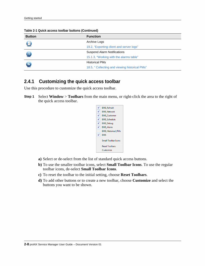
Table 2-1 Quick access toolbar buttons (Continued) Button Function
Archive Logs
19.2, “Exporting client and server logs”
Suspend Alarm Notifications
15.1.3, “Working with the alarms table”
Historical PMs
18.5, “ Collecting and viewing historical PMs”
2.4.1 Customizing the quick access toolbarUse this procedure to customize the quick access toolbar.
Step 1 Select Window > Toolbars from the main menu, or right-click the area to the right ofthe quick access toolbar.
a) Select or de-select from the list of standard quick access buttons.b) To use the smaller toolbar icons, select Small Toolbar Icons. To use the regular
toolbar icons, de-select Small Toolbar Icons.c) To reset the toolbar to the initial setting, choose Reset Toolbars.d) To add other buttons or to create a new toolbar, choose Customize and select the
buttons you want to be shown.
2-8 proNX Service Manager User Guide – Document Version 01
Getting started

2.5 Displaying the online Help
Use this procedure to display the PSM online Help.
Step 1 Select Help > Open Help.The online Help is launched in your default Web browser.
Product Release 7.0 STANDARD 2-9
Getting started

2.6 Viewing the list of supported devices
Use this procedure to view the list of devices supported by the proNX Service Manager.
Step 1 From the top menu bar, select Help > Server Info.The list of supported devices and their software releases are shown in the SupportedNetwork Elements pane.
Step 2 To see the list of software versions supported for each device, expand the device type in
the Supported Network Elements pane.
Step 3 Use the scroll bar on the right side of the pane to scroll through the list of devices and
versions supported.
2-10 proNX Service Manager User Guide – Document Version 01
Getting started

3.0 Managing PSM users
PSM performs user authentication using either the local pre-packaged RADIUS server orexternal RADIUS servers. By default, PSM is configured to use the local pre-packaged RADIUSserver.To help you work with the local RADIUS server, PSM provides you with an interface to add,modify and delete users from the local RADIUS server database. This capability to makechanges to the local RADIUS server database is supported even if you are not using the localRADIUS server for authentication. In this latter case, the changes have no effect onauthentication, but are still applicable for creating users for tasks like assigning an alarm to auser.You cannot use PSM to add, modify, or delete users from external RADIUS servers. An externalRADIUS server is any RADIUS server that is not the local, co-resident RADIUS server. Notethat the local, co-resident RADIUS server may act as an external RADIUS server to other PSMServers.The above is true even if you run with server replication. When you run with server replication,you also cannot add, modify, or delete users from external RADIUS servers. In order to add,modify, or delete users, you must be logged on to the PSM Server on which the RADIUS serveris running.
Note It is recommended that the same PSM login credentials (username and password)be added to the network elements under management. Some PSM server tasksrequire the server to log in to the network element using the PSM user’s logincredentials.
For information on configuring PSM to work with RADIUS servers (local or external), see theproNX Service Manager Installation and Administration Guide.
Product Release 7.0 STANDARD 3-1
C H A P T E R 3

3.1 Adding a user
Use this procedure to add a user to the local RADIUS server database.You cannot use this procedure to add a user to an external RADIUS server database. An externalRADIUS server is any RADIUS server that is not the local, co-resident RADIUS server. Notethat the local, co-resident RADIUS server may act as an external RADIUS server to other PSMServers.
Step 1 To add a user, from the main menu choose Edit > User Management.The User Management window appears.
Step 2 Right-click in the Users row and choose Add User.
The Add User dialog box is displayed.
Step 3 In the Add User dialog box, specify the following information.
• Username• Password, can consist of alphanumeric characters and the following special
characters:
3-2 proNX Service Manager User Guide – Document Version 01
Managing PSM users

! @ # $ % ^ & ( ) _ + [ ] { } . ~• Confirm Password• Role, one of:
• Administrator - this role has complete access to all functions• Service Provider - this role allows the user to create services, and has the
following limitations:▪ The Service Provider role can read, create, and update everything, except
device discoveries and scheduled device discoveries▪ The Service Provider role cannot create new users.▪ The Service Provider role can update its own user record, but no other user
records. It also cannot change its own role.▪ The Service Provider role cannot move network element group members.▪ The Service Provider role cannot delete anything except for Bandwidth Profile
Templates, Class Map Profile Templates, Service Policy (and Map) ProfileTemplates, and Customers.
• NOC - this role provides read-only access• First name of the user (optional)• Last name of the user(optional)• Email address for the user (optional)• Telephone number for the user (optional)
Step 4 Click OK.
The user is added to the local RADIUS server database. Users in the local RADIUSserver database have a Yes entry in the Locally Managed User column.
Product Release 7.0 STANDARD 3-3
Managing PSM users
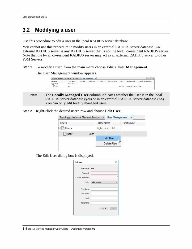
3.2 Modifying a user
Use this procedure to edit a user in the local RADIUS server database.You cannot use this procedure to modify users in an external RADIUS server database. Anexternal RADIUS server is any RADIUS server that is not the local, co-resident RADIUS server.Note that the local, co-resident RADIUS server may act as an external RADIUS server to otherPSM Servers.
Step 1 To modify a user, from the main menu choose Edit > User Management.The User Management window appears.
Note The Locally Managed User column indicates whether the user is in the localRADIUS server database (yes) or in an external RADIUS server database (no).You can only edit locally managed users.
Step 2 Right-click the desired user's row and choose Edit User.
The Edit User dialog box is displayed.
3-4 proNX Service Manager User Guide – Document Version 01
Managing PSM users
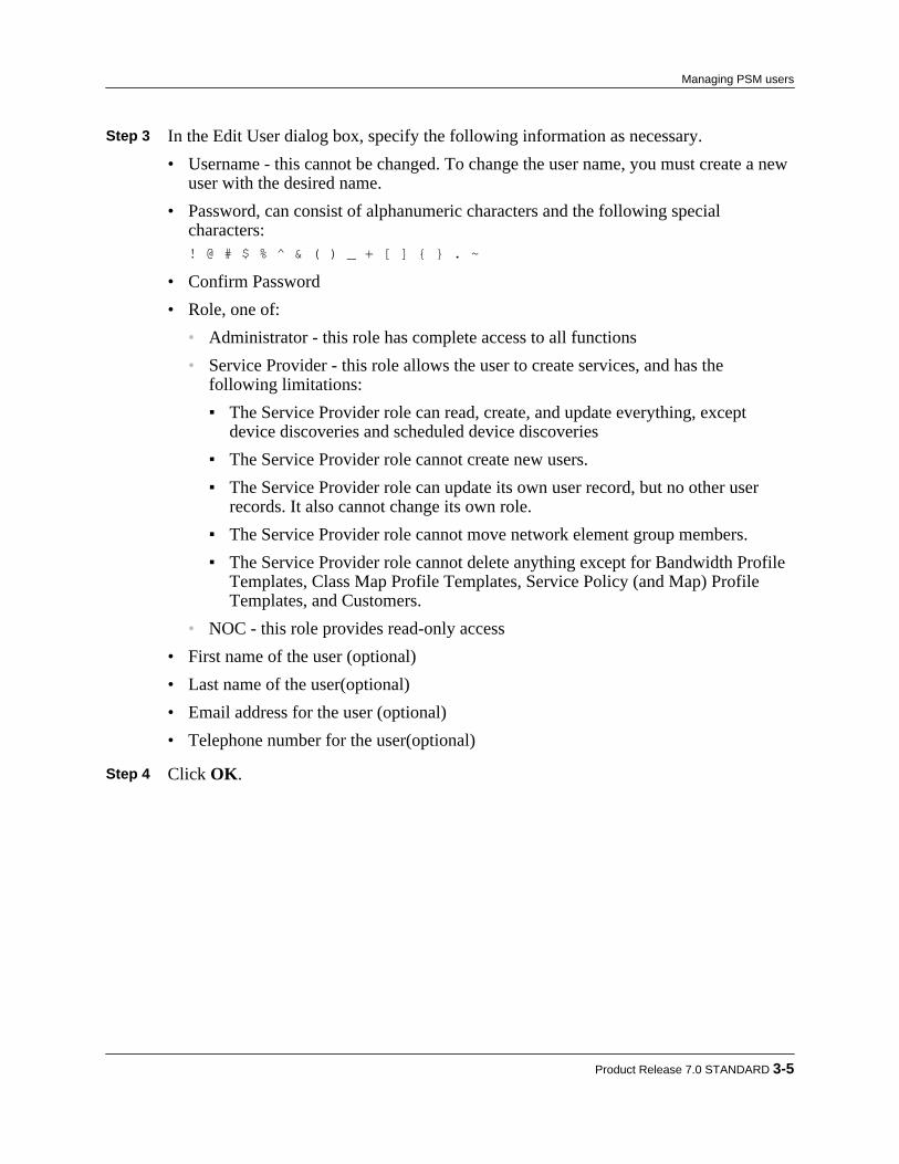
Step 3 In the Edit User dialog box, specify the following information as necessary.• Username - this cannot be changed. To change the user name, you must create a new
user with the desired name.• Password, can consist of alphanumeric characters and the following special
characters:! @ # $ % ^ & ( ) _ + [ ] { } . ~
• Confirm Password• Role, one of:
• Administrator - this role has complete access to all functions• Service Provider - this role allows the user to create services, and has the
following limitations:▪ The Service Provider role can read, create, and update everything, except
device discoveries and scheduled device discoveries▪ The Service Provider role cannot create new users.▪ The Service Provider role can update its own user record, but no other user
records. It also cannot change its own role.▪ The Service Provider role cannot move network element group members.▪ The Service Provider role cannot delete anything except for Bandwidth Profile
Templates, Class Map Profile Templates, Service Policy (and Map) ProfileTemplates, and Customers.
• NOC - this role provides read-only access• First name of the user (optional)• Last name of the user(optional)• Email address for the user (optional)• Telephone number for the user(optional)
Step 4 Click OK.
Product Release 7.0 STANDARD 3-5
Managing PSM users
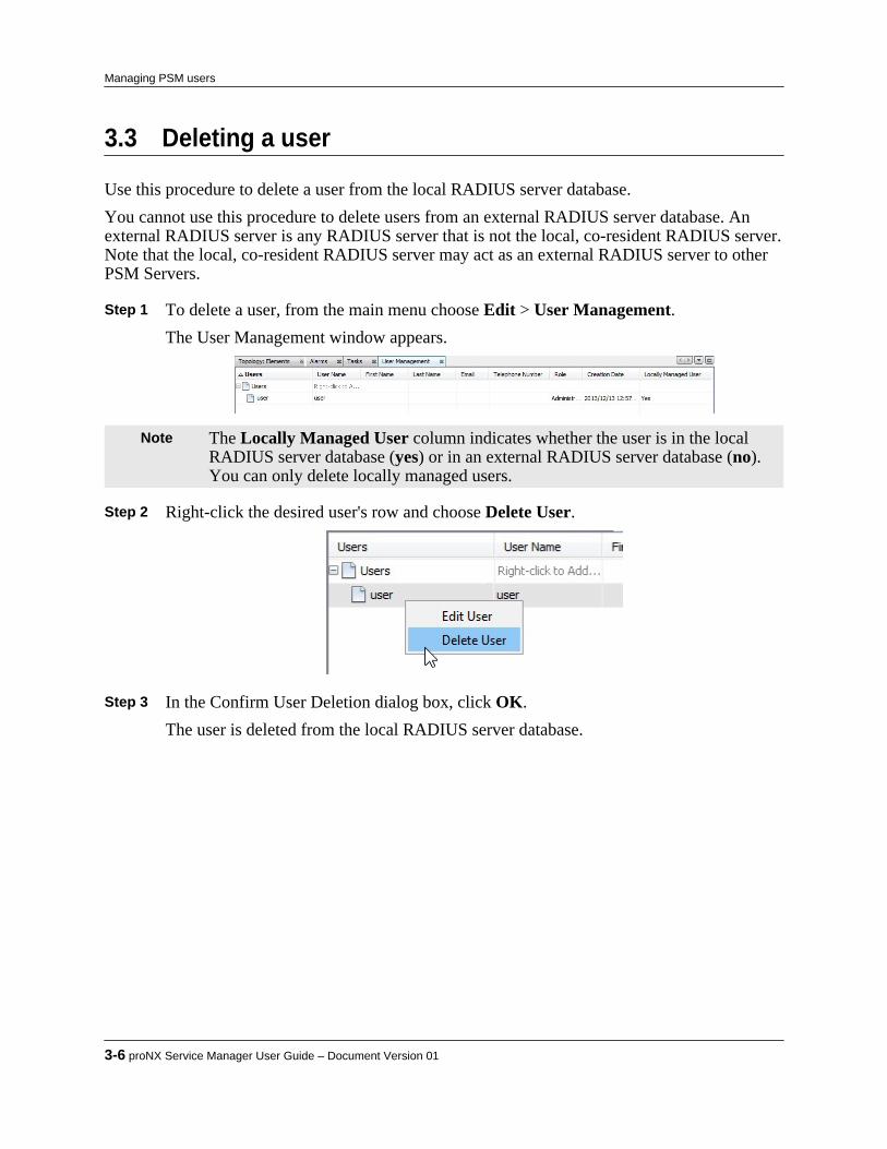
3.3 Deleting a user
Use this procedure to delete a user from the local RADIUS server database.You cannot use this procedure to delete users from an external RADIUS server database. Anexternal RADIUS server is any RADIUS server that is not the local, co-resident RADIUS server.Note that the local, co-resident RADIUS server may act as an external RADIUS server to otherPSM Servers.
Step 1 To delete a user, from the main menu choose Edit > User Management.The User Management window appears.
Note The Locally Managed User column indicates whether the user is in the localRADIUS server database (yes) or in an external RADIUS server database (no).You can only delete locally managed users.
Step 2 Right-click the desired user's row and choose Delete User.
Step 3 In the Confirm User Deletion dialog box, click OK.
The user is deleted from the local RADIUS server database.
3-6 proNX Service Manager User Guide – Document Version 01
Managing PSM users
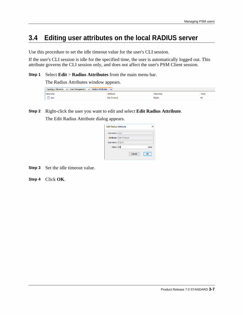
3.4 Editing user attributes on the local RADIUS server
Use this procedure to set the idle timeout value for the user's CLI session.If the user's CLI session is idle for the specified time, the user is automatically logged out. Thisattribute governs the CLI session only, and does not affect the user's PSM Client session.
Step 1 Select Edit > Radius Attributes from the main menu bar.The Radius Attributes window appears.
Step 2 Right-click the user you want to edit and select Edit Radius Attribute.
The Edit Radius Attribute dialog appears.
Step 3 Set the idle timeout value. Step 4 Click OK.
Product Release 7.0 STANDARD 3-7
Managing PSM users

3-8 proNX Service Manager User Guide – Document Version 01
Managing PSM users

4.0 Managing network discovery andEthernet domains
The first step to using PSM to manage a network is to discover the network elements you want tomanage. PSM supports the discovery of the following network elements:• BTI7800 Series network elements• BTI7000 Series network elements• BTI800 Series network elements• BTI700 Series network elementsAdditionally, PSM can discover any SNMP MIB-II compliant device.This section covers the following topics:• 4.1, “Discovering network elements”• 4.2, “Undiscovering a network element”• 4.3, “Rediscovering a network element”• 4.4, “Polling discovered network elements”• 4.5, “Ethernet network domains”• 4.6, “Scheduling network element discoveries”
Product Release 7.0 STANDARD 4-1
C H A P T E R 4
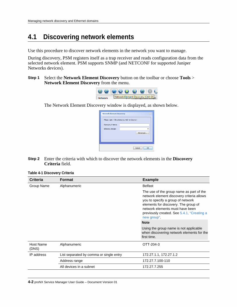
4.1 Discovering network elements
Use this procedure to discover network elements in the network you want to manage.During discovery, PSM registers itself as a trap receiver and reads configuration data from theselected network element. PSM supports SNMP (and NETCONF for supported JuniperNetworks devices).
Step 1 Select the Network Element Discovery button on the toolbar or choose Tools > Network Element Discovery from the menu.
The Network Element Discovery window is displayed, as shown below.
Step 2 Enter the criteria with which to discover the network elements in the Discovery
Criteria field.
Table 4-1 Discovery Criteria Criteria Format ExampleGroup Name Alphanumeric Belfast
The use of the group name as part of thenetwork element discovery criteria allowsyou to specify a group of networkelements for discovery. The group ofnetwork elements must have beenpreviously created. See 5.4.1, “Creating anew group”. Note Using the group name is not applicablewhen discovering network elements for thefirst time.
Host Name(DNS)
Alphanumeric OTT-204-3
IP address List separated by comma or single entry 172.27.1.1, 172.27.1.2
Address range 172.27.7.100-110
All devices in a subnet 172.27.7.255
4-2 proNX Service Manager User Guide – Document Version 01
Managing network discovery and Ethernet domains

Step 3 Optionally, specify the Ethernet domain.
Domains are used when creating Ethernet services. For more information on domains,see 4.5, “Ethernet network domains”.If you do not plan on creating Ethernet services, you do not need to specify a domain.
Step 4 Click the Advanced button to specify additional parameters.
The Advanced Discovery Settings dialog appears.
Step 5 Optionally, specify the SNMP parameters.
You can specify an SNMP Write Community string and a Port, or you can leave themblank to use the defaults. The default write community string is private. The defaultport is 161.
Note Because PSM uses SNMP for the initial communications with the networkelement, the SNMP parameters must be correct even if PSM is using NETCONFto manage the network element.
Step 6 Optionally, specify the NETCONF parameters.
You can specify the NETCONF Username, Password, and Port, or you can leave themblank to use the defaults. The defaults are set to match the defaults on the devices beingmanaged.
Step 7 Optionally, select Auto-Discovery of Connected Devices if you want PSM to
automatically discover all network elements connected to the network element you arediscovering.
Product Release 7.0 STANDARD 4-3
Managing network discovery and Ethernet domains

If you select this option, PSM will automatically discover all connected networkelements in a BTI7000 Series DOL network, and all connected network elements in aBTI7800 Series ROADM network or a BTI7800 Series transport network .
Step 8 Optionally, select Configure Topology Discovery if you want to enable LLDP on the
NE.If you select this option, PSM will enable LLDP on the NE after the NE is discovered. Ifyou do not select this option, PSM will not enable LLDP on the NE after the NE isdiscovered. In this latter case, the LLDP setting on the NE is left unchanged.This setting applies to BTI7000, BTI800, and BTI700 network elements only.
Step 9 Click OK to accept the input and exit the Advanced Discovery Settings dialog. Step 10 Click OK to start device discovery.The following figure shows PSM when network elements are discovered successfully.
The Elements branch in the Network tree can be expanded to show all the componentson the network element.If PSM is unsuccessful in discovering a network element, the font below the networkelement icon is red. Common reasons for failure include invalid credentials or portnumbers, or if the network element cannot be reached.
4-4 proNX Service Manager User Guide – Document Version 01
Managing network discovery and Ethernet domains

Note The first discovery of a new network element type or version may take longerthan subsequent discoveries. The reason for this is that PSM builds a databaseschema for each new network element type or version it encounters.
Product Release 7.0 STANDARD 4-5
Managing network discovery and Ethernet domains

4.2 Undiscovering a network element
Use this procedure to undiscover a network element.Discovered network elements can be undiscovered, which deregisters PSM as a trap receiver andremoves the network element from under PSM management. Undiscovered network elementscontinue to appear in PSM, but with a distinctive icon.
Step 1 Right-click the network element you want to undiscover and select Discovery > Undiscover.The Undiscover confirmation dialog appears:
Step 2 Click OK to confirm.
The network element is no longer under PSM management, and is shown with a icon. You can leave the network element as is, or you can completely remove it fromview.
Step 3 To remove the NE completely from view, right-click the NE and select Remove from
Group.
4-6 proNX Service Manager User Guide – Document Version 01
Managing network discovery and Ethernet domains

4.3 Rediscovering a network element
Use this procedure to rediscover a network element.Discovered network elements can be rediscovered, which manually forces PSM to retrieveinformation from the network elements being rediscovered. Rediscovering a network element isusually not required under normal situations because the network element updates PSMasynchronously with any changes as they occur.
Step 1 Right-click the network element you want to rediscover and select Discovery > Rediscover.PSM rediscovers the network element.
Product Release 7.0 STANDARD 4-7
Managing network discovery and Ethernet domains

4.4 Polling discovered network elements
PSM supports an automatic NE polling operation that is not user configurable. The server checksIP, SNMP and/or NETCONF connectivity with each network element every 2 minutes. If thechecks fail, the text beside the NE in the Network tree, and beneath the NE in the Topology Mapview, turns red and the NE is declared unreachable.
4-8 proNX Service Manager User Guide – Document Version 01
Managing network discovery and Ethernet domains

4.5 Ethernet network domains
PSM uses the concept of Ethernet network domains to support one PSM server managing morethan one Ethernet network. A domain is a mechanism used to segregate network elements indiverse networks that are not interconnected, and where there is reuse of service VLAN IDs.This allows for the proper handling of reused service VLAN IDs in service visualization andactivation operations.Network elements can be added to an Ethernet domain during network element discovery.Ethernet domains are not used and do not need to be defined for optical networks.
Note Ethernet domains are part of the replicated data set when running with multipleservers. For more information on replicated data, see 1.3.2, “Running multipleservers with server replication”.
4.5.1 Creating an Ethernet domainUse this procedure to create an Ethernet domain for an Ethernet network.During a discovery operation, if the specified domain does not already exist, it is created, and alldevices discovered during that operation are added to it. Domains appear in the Ethernet branchof the network tree when Ethernet services are created.If you do not explicitly specify a domain, all devices discovered during this operation will beassigned to the Default domain.
Step 1 From the main menu, choose Tools > Network Element Discovery. Step 2 Enter a name for the domain in the Domain field of the Network Element Discovery
window.The domain name is case insensitive. You must not create multiple domains where thedomain names differ only in the case. For example, if you create a domain called Belfast, you must not create a new domain called belfast as this differs only in casewith the existing Belfast domain name.
Step 3 Enter the discovery criteria. Step 4 Click OK.
The discovered network elements are added to the new domain.
Note Once a new domain is created, it cannot be deleted.
Product Release 7.0 STANDARD 4-9
Managing network discovery and Ethernet domains
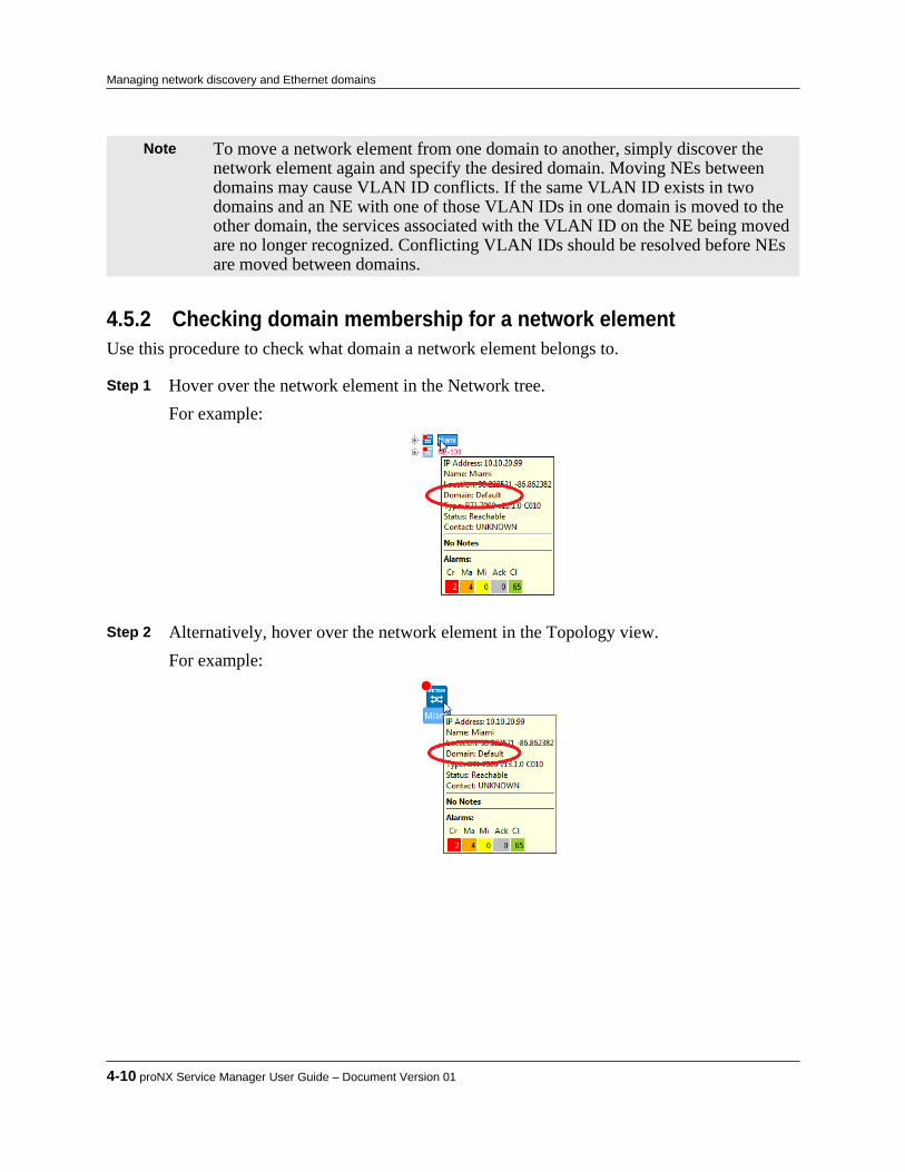
Note To move a network element from one domain to another, simply discover thenetwork element again and specify the desired domain. Moving NEs betweendomains may cause VLAN ID conflicts. If the same VLAN ID exists in twodomains and an NE with one of those VLAN IDs in one domain is moved to theother domain, the services associated with the VLAN ID on the NE being movedare no longer recognized. Conflicting VLAN IDs should be resolved before NEsare moved between domains.
4.5.2 Checking domain membership for a network elementUse this procedure to check what domain a network element belongs to.
Step 1 Hover over the network element in the Network tree.For example:
Step 2 Alternatively, hover over the network element in the Topology view.
For example:
4-10 proNX Service Manager User Guide – Document Version 01
Managing network discovery and Ethernet domains

4.6 Scheduling network element discoveries
You can schedule the proNX Service Manager to rediscover network elements periodically.
Note You do not normally need to schedule discoveries because the network elementsautomatically update PSM of any changes.
4.6.1 Scheduling a network element discovery taskUse this procedure to schedule a discovery task for a network element.
Step 1 From the main menu, choose Edit > Schedules.The Scheduler window is displayed.
Step 2 In the Scheduler window, right-click the Discovery Schedules entry in the table and
choose Add Schedule. The Scheduling dialog window is displayed.
Step 3 Specify the discovery criteria as described in 4.1, “Discovering network elements”. Step 4 Specify the start date and time using the calendar drop-down list shown below.
Product Release 7.0 STANDARD 4-11
Managing network discovery and Ethernet domains

a) Select the current day or a date in the future in the calendar. If you select a date in thepast, the discovery runs immediately.
b) Specify the start time in the Time field below the calendar. Step 5 An end date is optional. To set an end date, use the buttons in the lower left corner of
the Schedule section to set a specific end date, or to set the schedule to end after adefined number of occurrences.
Step 6 The Recurrence Pattern panel lets you set a schedule to recur at a specific interval, as
follows:
a) Hourly – The schedule executes at the start time selected and recurs for the numberof hours specified, until the end date is reached.
b) Daily – The schedule executes at the start time selected and recurs for the number ofdays specified, until the end date is reached.
4-12 proNX Service Manager User Guide – Document Version 01
Managing network discovery and Ethernet domains
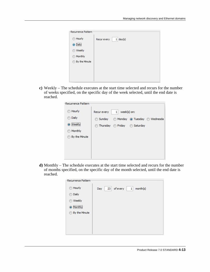
c) Weekly – The schedule executes at the start time selected and recurs for the numberof weeks specified, on the specific day of the week selected, until the end date isreached.
d) Monthly – The schedule executes at the start time selected and recurs for the numberof months specified, on the specific day of the month selected, until the end date isreached.
Product Release 7.0 STANDARD 4-13
Managing network discovery and Ethernet domains

e) By the Minute – The schedule executes at the start time selected and recurs for thenumber of minutes specified, until the end date is reached.
Caution Use this feature sparingly as it could overload the server needlessly depending onthe frequency chosen and the task to be executed.
Step 7 When you are done, click OK.
The new discovery task is added to the Schedules table.
4.6.2 Viewing scheduled tasksTo view a scheduled task for a network element:
Step 1 Access the Scheduler screen using the toolbar button, or from the main menu choose Edit > Schedules.
The Scheduler tab is displayed:
Step 2 In the Scheduler tab, expand the entries in the schedule list to view all the tasks
currently scheduled on the server.
4-14 proNX Service Manager User Guide – Document Version 01
Managing network discovery and Ethernet domains
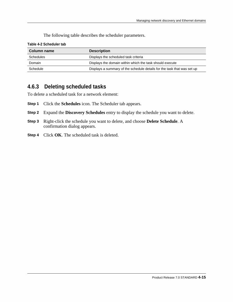
The following table describes the scheduler parameters.
Table 4-2 Scheduler tab Column name DescriptionSchedules Displays the scheduled task criteria
Domain Displays the domain within which the task should execute
Schedule Displays a summary of the schedule details for the task that was set up
4.6.3 Deleting scheduled tasksTo delete a scheduled task for a network element:
Step 1 Click the Schedules icon. The Scheduler tab appears. Step 2 Expand the Discovery Schedules entry to display the schedule you want to delete. Step 3 Right-click the schedule you want to delete, and choose Delete Schedule. A
confirmation dialog appears. Step 4 Click OK. The scheduled task is deleted.
Product Release 7.0 STANDARD 4-15
Managing network discovery and Ethernet domains

4-16 proNX Service Manager User Guide – Document Version 01
Managing network discovery and Ethernet domains

5.0 Managing network topology
The proNX Service Manager provides a view of the network, including topology for supportednetwork elements. The topology window is the main window you see when logging on to PSM.PSM displays all discovered network elements and, additionally, displays topology for thefollowing:• BTI7800 Series network elements• BTI7000 Series network elements• BTI800 Series network elements• BTI700 Series network elementsThis section covers the following topics:• 5.1, “Icons and definitions”• 5.2, “Understanding the network topology view”• 5.3, “Learning the network topology”• 5.4, “Network element groups and sites”• 5.5, “Changing the background view”
Product Release 7.0 STANDARD 5-1
C H A P T E R 5
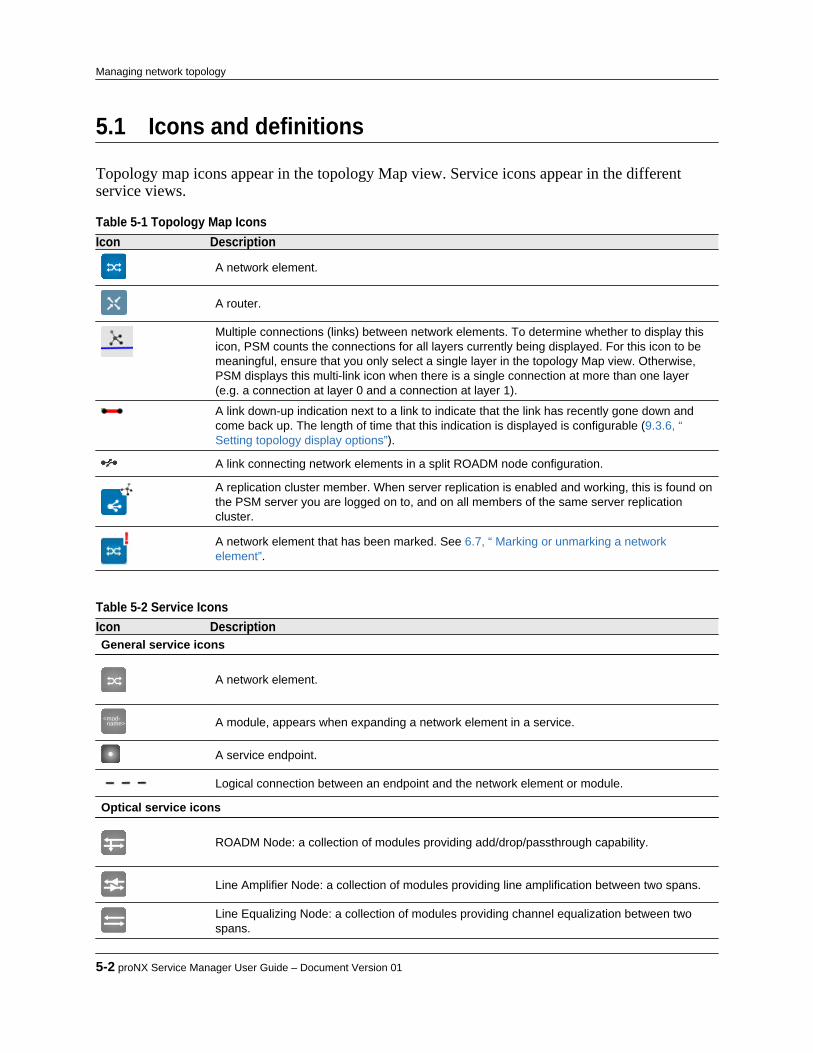
5.1 Icons and definitions
Topology map icons appear in the topology Map view. Service icons appear in the differentservice views.
Table 5-1 Topology Map Icons Icon Description
A network element.
A router.
Multiple connections (links) between network elements. To determine whether to display thisicon, PSM counts the connections for all layers currently being displayed. For this icon to bemeaningful, ensure that you only select a single layer in the topology Map view. Otherwise,PSM displays this multi-link icon when there is a single connection at more than one layer(e.g. a connection at layer 0 and a connection at layer 1).
A link down-up indication next to a link to indicate that the link has recently gone down andcome back up. The length of time that this indication is displayed is configurable (9.3.6, “Setting topology display options”).
A link connecting network elements in a split ROADM node configuration.
A replication cluster member. When server replication is enabled and working, this is found onthe PSM server you are logged on to, and on all members of the same server replicationcluster.
A network element that has been marked. See 6.7, “ Marking or unmarking a networkelement”.
Table 5-2 Service Icons Icon DescriptionGeneral service icons
A network element.
name><mod- A module, appears when expanding a network element in a service.
A service endpoint.
Logical connection between an endpoint and the network element or module.
Optical service icons
ROADM Node: a collection of modules providing add/drop/passthrough capability.
Line Amplifier Node: a collection of modules providing line amplification between two spans.
Line Equalizing Node: a collection of modules providing channel equalization between twospans.
5-2 proNX Service Manager User Guide – Document Version 01
Managing network topology

Table 5-2 Service Icons (Continued) Icon Description
ROADM Terminal Node: a collection of modules providing add/drop capability with channelequalization in a linear span.
An optical service endpoint.
Fiber connection between nodes (with span length displayed in kilometers).
A link connecting network elements in a split ROADM node configuration.
Ethernet service icons
A UNI endpoint.
An NNI endpoint.
An RPL link passing traffic in an ERPS service.
A blocked RPL link in an ERPS service.
A failed link in an ERPS service.
Product Release 7.0 STANDARD 5-3
Managing network topology

5.2 Understanding the network topology view
PSM provides a main Topology window that displays network elements and links in themanaged network. The topology overlays a background image that can be changed to suit yourparticular needs. The Topology window is the initial view you see when first logging on to thePSM server. You can always go back to the Topology window from other windows by choosing View > Network > Topology.
In the upper left corner, you can select from the following topology views:• Map: The topology Map view is used to display the topology of the network. PSM builds the
topology map based on discovered information as well as through manual specification.Manual specification allows you to supplement the discovered view to suit your needs.
• Ethernet: The Ethernet services view is used to display the topology of a specific Ethernetservice. To see a service, select the desired Ethernet service from the Network tree. For moreinformation on the Ethernet services view, see Chapter 12, “Managing Ethernet services”.
• Transport: The Transport services view is used to display the topology of a specific transportservice. To see a service, select the desired transport service from the Network tree. For moreinformation on the Transport services view, see 11.2, “Transport services”.
• Optical: The Optical services view is used to display the topology of a specific optical service.To see a service, select the desired optical service from the Network tree. For moreinformation on the Optical services view, see 11.1, “Optical services”.
• Pseudowire: The Pseudowire services view is used to display the topology of a specificpseudowire service. To see a service, select the desired pseudowire service from the Networktree. For more information on the Pseudowire services view, see Chapter 13, “Managingpseudowire services”.
The topology Map view shows the following:• discovered network elements
5-4 proNX Service Manager User Guide – Document Version 01
Managing network topology
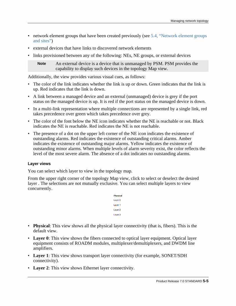
• network element groups that have been created previously (see 5.4, “Network element groupsand sites”)
• external devices that have links to discovered network elements• links provisioned between any of the following: NEs, NE groups, or external devices
Note An external device is a device that is unmanaged by PSM. PSM provides thecapability to display such devices in the topology Map view.
Additionally, the view provides various visual cues, as follows:• The color of the link indicates whether the link is up or down. Green indicates that the link is
up. Red indicates that the link is down.• A link between a managed device and an external (unmanaged) device is grey if the port
status on the managed device is up. It is red if the port status on the managed device is down.• In a multi-link representation where multiple connections are represented by a single link, red
takes precedence over green which takes precedence over grey.• The color of the font below the NE icon indicates whether the NE is reachable or not. Black
indicates the NE is reachable. Red indicates the NE is not reachable.• The presence of a dot on the upper left corner of the NE icon indicates the existence of
outstanding alarms. Red indicates the existence of outstanding critical alarms. Amberindicates the existence of outstanding major alarms. Yellow indicates the existence ofoutstanding minor alarms. When multiple levels of alarm severity exist, the color reflects thelevel of the most severe alarm. The absence of a dot indicates no outstanding alarms.
Layer views
You can select which layer to view in the topology map.From the upper right corner of the topology Map view, click to select or deselect the desiredlayer . The selections are not mutually exclusive. You can select multiple layers to viewconcurrently.
• Physical: This view shows all the physical layer connectivity (that is, fibers). This is thedefault view.
• Layer 0: This view shows the fibers connected to optical layer equipment. Optical layerequipment consists of ROADM modules, multiplexer/demultiplexers, and DWDM lineamplifiers.
• Layer 1: This view shows transport layer connectivity (for example, SONET/SDHconnectivity).
• Layer 2: This view shows Ethernet layer connectivity.
Product Release 7.0 STANDARD 5-5
Managing network topology
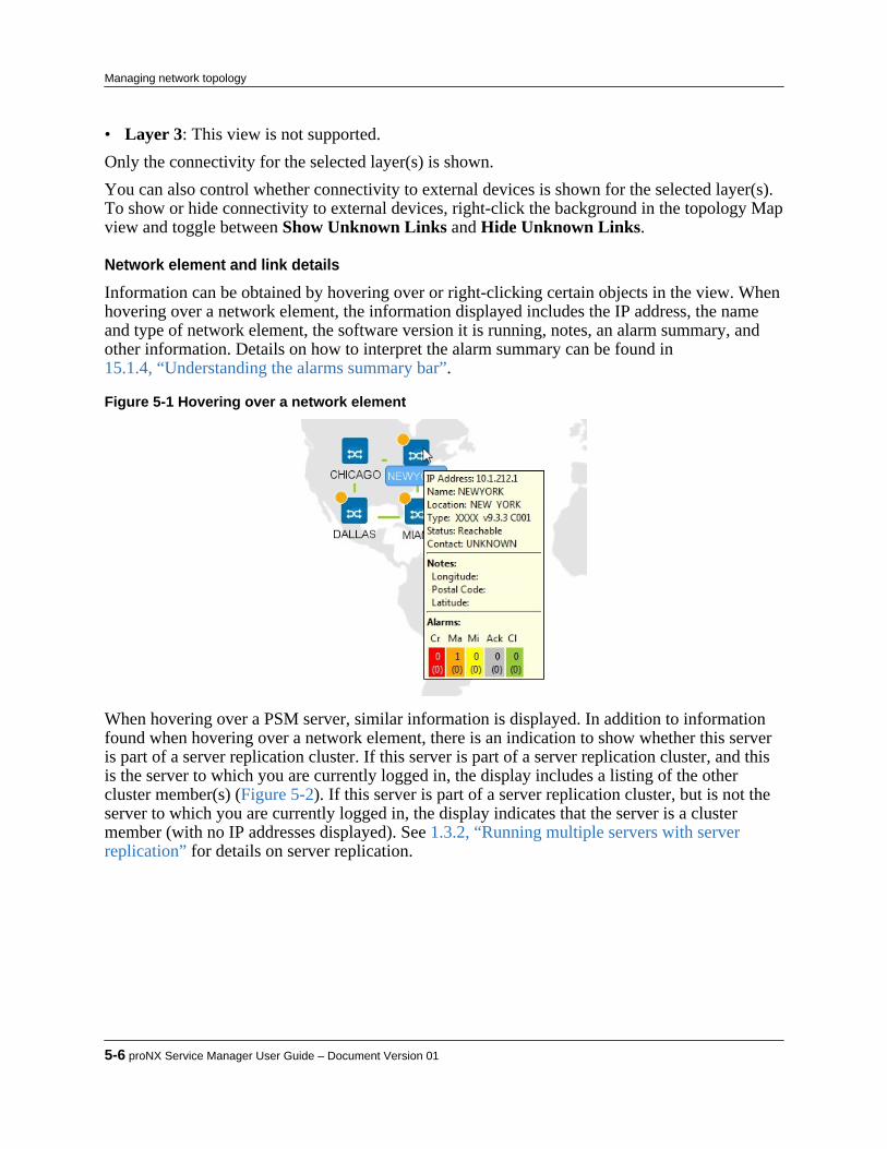
• Layer 3: This view is not supported.Only the connectivity for the selected layer(s) is shown.You can also control whether connectivity to external devices is shown for the selected layer(s).To show or hide connectivity to external devices, right-click the background in the topology Mapview and toggle between Show Unknown Links and Hide Unknown Links.
Network element and link details
Information can be obtained by hovering over or right-clicking certain objects in the view. Whenhovering over a network element, the information displayed includes the IP address, the nameand type of network element, the software version it is running, notes, an alarm summary, andother information. Details on how to interpret the alarm summary can be found in15.1.4, “Understanding the alarms summary bar”.
Figure 5-1 Hovering over a network element
When hovering over a PSM server, similar information is displayed. In addition to informationfound when hovering over a network element, there is an indication to show whether this serveris part of a server replication cluster. If this server is part of a server replication cluster, and thisis the server to which you are currently logged in, the display includes a listing of the othercluster member(s) (Figure 5-2). If this server is part of a server replication cluster, but is not theserver to which you are currently logged in, the display indicates that the server is a clustermember (with no IP addresses displayed). See 1.3.2, “Running multiple servers with serverreplication” for details on server replication.
5-6 proNX Service Manager User Guide – Document Version 01
Managing network topology

Figure 5-2 Hovering over a PSM server
When hovering over a network element group, an alarm summary is displayed.
Figure 5-3 Hovering over a network element group
When right-clicking on a link, an option is presented to Show Link Details.
Figure 5-4 Show link details
When selecting that option, a Link Details data widget title bar is presented.
Figure 5-5 Link details data widget title bar
Product Release 7.0 STANDARD 5-7
Managing network topology

When clicking on the Link Details title bar, a Link Details window is presented.
Figure 5-6 Link details data widget window
Each connection can be expanded to show detailed link information. The type of informationshown depends on the type of port. Figure 5-7 through Figure 5-12 show examples of the linkinformation provided. Some attributes are optional, and are only shown if they are configured.
Figure 5-7 BTI7000 Series DOL link details data widget
Figure 5-8 BTI7000 Series PVX link details data widget
5-8 proNX Service Manager User Guide – Document Version 01
Managing network topology

Figure 5-9 BTI7000 Series transponder link details data widget
Figure 5-10 BTI7000 Series muxponder link details data widget
Figure 5-11 BTI7800 layer 3 link details data widget
Figure 5-12 External device link details data widget
You can hide Link Details by right-clicking on the same link and selecting Hide Link Details, oroptionally, right-clicking anywhere in the background and selecting Hide All Link Details.
Product Release 7.0 STANDARD 5-9
Managing network topology
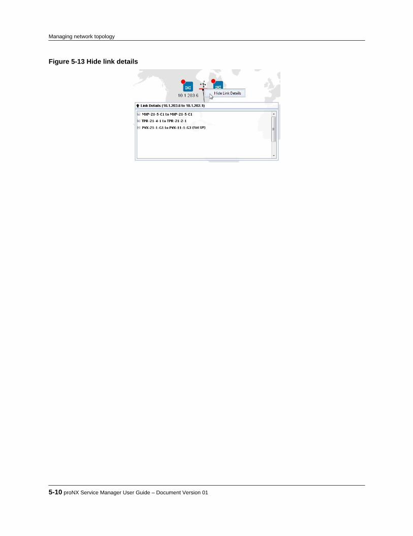
Figure 5-13 Hide link details
5-10 proNX Service Manager User Guide – Document Version 01
Managing network topology

5.3 Learning the network topology
PSM learns the topology of the network in different ways:• For optical links on ROADM nodes, PSM learns the topology automatically from the DOL or
ROADM neighbor information tables retrieved from the nodes. See 5.3.1, “Deriving opticaltopology using DOL or ROADM data”.
• For Ethernet links on NEs with LLDP enabled, PSM learns the topology automatically fromthe LLDP neighbor tables retrieved from the NEs. See 5.3.2, “Deriving Ethernet topologyusing LLDP data”.
• Additionally, PSM supports a manual specification method that allows you to specify thetopology directly for BTI7000 Series and BTI800 Series network elements. See5.3.3, “Deriving topology using Remote IDs”.
5.3.1 Deriving optical topology using DOL or ROADM dataJuniper Networks ROADM nodes advertise and identify themselves to their optical neighbors byexchanging information over the optical service channel (OSC). Each node builds a table of itsneighbors. PSM uses this information to build and display an accurate, up-to-date opticaltopology of the network.
5.3.2 Deriving Ethernet topology using LLDP dataSome Juniper Networks BTI Series network elements can be configured to discover theirEthernet neighbors using the Link Layer Discovery Protocol (LLDP). LLDP runs over Ethernet,and allows network elements to advertise and identify themselves to their peers. Each NE buildsa table of its Ethernet neighbors that PSM can retrieve. PSM uses this information to build anddisplay an accurate, up-to-date Ethernet topology of the network.This capability is supported in PSM for network elements running the following releases:• BTI7000 Series release 10.3 or later• BTI700 Series release 1.5 or later (BTI718E all releases)• BTI800 Series release 1.1 or laterPSM can only display this topology if the NEs have been configured to use LLDP. You canconfigure LLDP on the NEs directly using the proNX 900 or the CLI. Alternatively, you can usePSM to enable LLDP on the NEs during initial NE discovery. For information on how to do this,see 4.1, “Discovering network elements”.Be aware that this method produces an Ethernet topology of the network, which may notnecessarily reflect the physical topology. Where the two topologies do not align, you will need touse manual specification to change the discovered Ethernet topology to align with the physicaltopology. Failure to do so may result in a Topology Map view that shows confusing andmisleading information.
Product Release 7.0 STANDARD 5-11
Managing network topology

5.3.3 Deriving topology using Remote IDsPSM allows you to specify the topology manually by configuring the Remote ID. There are twoprimary reasons for specifying the topology in this manner:
1 To include, in the topology map, equipment that is not automatically discovered, such asmuxponders, transponders, and multiplexers/demultiplexers.
2 To change an automatically discovered topology to align with the actual physical topology,such as changing the discovered Ethernet topology.
This capability is supported in PSM for network elements running the following releases:• BTI7000 Series release 9.2.0 or later• BTI800 Series release 1.1 or laterThe Remote ID is a string that references the remote end of the connection (fiber). The string isnot used by the NE itself, but is read and correlated by PSM to determine the connectionendpoints. For this reason, the accuracy with which PSM derives the topology is dependent onproper configuration of this field. If improperly configured, the topology shown by PSM may notreflect the actual topology.The NE treats the configuration of the Remote ID as an opaque string, and does not otherwiseperform any syntactical or semantic checking on the configured value. All syntactical andsemantic checking is performed by PSM.The following table shows where the Remote ID can be configured and what endpoint it canreference. The Remote ID is not configured on BTI700 Series or external devices. For aconnection from a valid source port to a BTI700 Series or an external device port, PSM uses theRemote ID configured at the valid source port to derive the topology. PSM does not require anyinformation from the BTI700 Series or the external device itself, nor does the BTI700 Series orexternal device need to be reachable. See 5.3.3.4, “Viewing external devices” for more details onexternal devices.
Remote ID can be configured on: Remote ID can reference:muxponder, transponder, DOL1, packetVX, and BTI800Series ports
muxponder, transponder, DOL1, packetVX, BTI700Series, BTI800 Series, and external device ports
1Remote IDs can be specified on multiplexer/demultiplexer channel ports to show equipment (for example, PVX) connectivity to a ROADM node.Remote IDs can also be specified on the C2 port of a ROADM module to show a split ROAM node (8.2.9.5, “Configuring a split ROADM node”).
Note The Remote ID cannot be used for connections between two BTI700 Seriesdevices or between two external devices or between a BTI700 Series device andan external device.
PSM provides great flexibility on how you build your topology with Remote IDs. As long as theRemote ID configuration conforms to the required syntax, and as long as the Remote IDs at eachend refer to each other, PSM will display the connection. Therefore, you must provision theRemote ID with great care or the topology may not turn out as you intend.The general format of the Remote ID is as follows:<IP Address>-<Circuit Pack Type>-<Shelf>-<Slot>-<Port>
5-12 proNX Service Manager User Guide – Document Version 01
Managing network topology

where the <IP Address> is the remote IP address of the connection in dotted decimal notation,the <Circuit Pack Type> is the type of card at the remote location, and <Shelf>, <Slot>, and <Port> represent the shelf, slot, and port identifiers of the remote end.The following table shows the allowed values for the possible remote endpoints. All charactersin the syntax are case-insensitive.
Note The table lists the values that PSM considers to be valid (for the purpose ofdetermining whether or not to raise an "Invalid Remote ID alarm"). Not allvalues that PSM considers to be valid are applicable for certain circuit packtypes. See 5.3.3.5, “Detecting Remote ID errors” for more information on howPSM determines what is considered valid.
RemoteEndpoint
Circuit PackType
ShelfRange
Slot Range Port Range Example
muxponder MXP 0, 1, 11, 21,31
1-20 1-12, L1-L2,
C1-C1010.1.121.24-MXP-11-3-L2
transponder TPR, WM, WR,WT
0, 1, 11, 21,31
1-20 1-4 10.1.121.24-TPR-1-3-3
packetVX PVX 0, 1, 11, 21,31
1-20 X1-X4,
G1-G2410.1.121.24-PVX-21-3-G7
multiplexer/demultiplexer
D32MD1 toD32MD4
D40MD
D96MD
0, 1, 11, 21,31
1-20 CH135 toCH610
10.1.121.24-D40MD-0-1-CH280
ROADM ROB 0, 1, 11, 21,31
1-20 C2 10.1.121.24-ROB-1-3-C21
BTI800Series
N/A 1, 11, 21, 31 1-20 G1-G28 10.1.111.4-BTI800-1-2-G3
BTI700Series
N/A not validated not validated not validated 10.1.121.24-BTI700-1-1-6-X2
external EXT not validated not validated not validated 10.1.121.24-EXT-2-3-6-X3
1For information on where to use this, see 8.2.9.5, “Configuring a split ROADM node”.2A BTI700 Series NE is treated like an external device, and requires a trailing -X or -x in the Remote ID. See 5.3.3.4, “Viewing externaldevices” for more details on external devices.3An external device requires a trailing -X or -x in the Remote ID. See 5.3.3.4, “Viewing external devices” for more details on external devices.
5.3.3.1 Setting the Remote IDUse this procedure to set the Remote ID on an existing port on a BTI7000 Series or BTI800Series network element.There are different ways by which you can set the Remote ID. You can configure the Remote IDfrom the Network tree or from the NE Shelf view or from nodal provisioning windows.This procedure describes how to set the Remote ID from the Network tree.
Product Release 7.0 STANDARD 5-13
Managing network topology
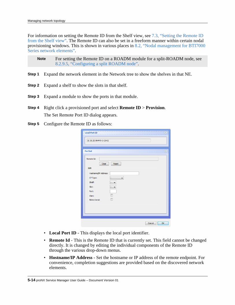
For information on setting the Remote ID from the Shelf view, see 7.3, “Setting the Remote IDfrom the Shelf view”. The Remote ID can also be set in a freeform manner within certain nodalprovisioning windows. This is shown in various places in 8.2, “Nodal management for BTI7000Series network elements”.
Note For setting the Remote ID on a ROADM module for a split-ROADM node, see8.2.9.5, “Configuring a split ROADM node”.
Step 1 Expand the network element in the Network tree to show the shelves in that NE. Step 2 Expand a shelf to show the slots in that shelf. Step 3 Expand a module to show the ports in that module. Step 4 Right click a provisioned port and select Remote ID > Provision.
The Set Remote Port ID dialog appears. Step 5 Configure the Remote ID as follows:
• Local Port ID - This displays the local port identifier.• Remote Id - This is the Remote ID that is currently set. This field cannot be changed
directly. It is changed by editing the individual components of the Remote IDthrough the various drop-down menus.
• Hostname/IP Address - Set the hostname or IP address of the remote endpoint. Forconvenience, completion suggestions are provided based on the discovered networkelements.
5-14 proNX Service Manager User Guide – Document Version 01
Managing network topology

• CP Type - Set the circuit pack type from the drop-down menu.
Note Only the circuit pack types described in 5.3.3, “Deriving topology using RemoteIDs” are supported.
• Shelf, Slot, Port - Set the shelf, slot, and port indexes respectively.• Alien - This specifies whether the remote ID refers to an external device. Selecting
this attribute causes an -X to be appended to the end of the Remote ID.• Bidirectional - This option allows you to specify whether you want PSM to
automatically set the remote ID on the remote port to point back to this local port.This attribute should only be selected if the circuit pack type is one of MXP, TPR,WR, WM, WT, PVX, ROB, BTI800. You cannot select both Alien and Bidirectionalat the same time.
Step 6 Click OK.
Note If you select Bidirectional and you specify a Remote ID that cannot bereconciled, PSM will be unable to configure the remote endpoint, and the taskwill fail.
Note The task may fail if you try to use this procedure on a card that has not beenprovisioned.
5.3.3.2 Deleting the Remote IDUse this procedure to delete the Remote ID from an existing port on a BTI7000 Series or BTI800Series network element.There are different ways by which you can delete the Remote ID. You can delete the Remote IDfrom the Network tree or from the NE shelf view or from nodal provisioning windows. Thisprocedure describes how to delete the Remote ID from the Network tree. For information ondeleting the Remote ID from the shelf view, see 7.4, “Deleting the Remote ID from the Shelfview”. The Remote ID can also be deleted in a freeform manner within certain nodalprovisioning windows. This is shown in various places in 8.2, “Nodal management for BTI7000Series network elements”.
Step 1 Expand the network element in the Network tree view to show the shelves in that NE. Step 2 Expand a shelf to show the slots in that shelf. Step 3 Expand a module to show the ports in that module. Step 4 Right click a provisioned port and select Remote ID > Delete.
The Delete Remote Port ID dialog appears.
Product Release 7.0 STANDARD 5-15
Managing network topology
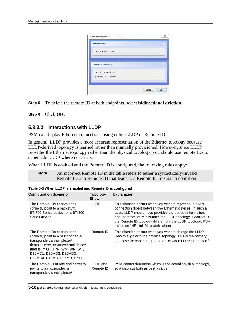
Step 5 To delete the remote ID at both endpoints, select bidirectional deletion. Step 6 Click OK.
5.3.3.3 Interactions with LLDPPSM can display Ethernet connections using either LLDP or Remote ID.In general, LLDP provides a more accurate representation of the Ethernet topology becauseLLDP-derived topology is learned rather than manually provisioned. However, since LLDPprovides the Ethernet topology rather than the physical topology, you should use remote IDs tosupersede LLDP where necessary.When LLDP is enabled and the Remote ID is configured, the following rules apply:
Note An incorrect Remote ID in the table refers to either a syntactically-invalidRemote ID or a Remote ID that leads to a Remote ID mismatch condition.
Table 5-3 When LLDP is enabled and Remote ID is configured Configuration Scenario Topology
ShownExplanation
The Remote IDs at both endscorrectly point to a packetVX,BTI700 Series device, or a BTI800Series device.
LLDP This situation occurs when you want to represent a directconnection (fiber) between two Ethernet devices. In such acase, LLDP should have provided the correct information,and therefore PSM assumes the LLDP topology is correct. Ifthe Remote ID topology differs from the LLDP topology, PSMraises an "NE Link Mismatch" alarm.
The Remote IDs at both endscorrectly point to a muxponder, atransponder, a multiplexer/demultiplexer, or an external device(that is, MXP, TPR, WM, WR, WT,D32MD1, D32MD2, D32MD3,D32MD4, D40MD, D96MD, EXT).
Remote ID This situation occurs when you want to change the LLDPview to align with the physical topology. This is the primaryuse case for configuring remote IDs when LLDP is enabled.1
The Remote ID at one end correctlypoints to a muxponder, atransponder, a multiplexer/
LLDP andRemote ID
PSM cannot determine which is the actual physical topology,so it displays both as best as it can.
5-16 proNX Service Manager User Guide – Document Version 01
Managing network topology

Table 5-3 When LLDP is enabled and Remote ID is configured (Continued) Configuration Scenario Topology
ShownExplanation
demultiplexer, or an external device(that is, MXP, TPR, WM, WR, WT,D32MD1, D32MD2, D32MD3,D32MD4, D40MD, D96MD, EXT) butthe Remote ID at the other end doesnot, either because it is incorrect, orbecause it points correctly to apacketVX, BTI700 Series device, ora BTI800 Series device.
The Remote ID at one end correctlypoints to a packetVX, BTI700 Seriesdevice, or a BTI800 Series device,but the Remote ID at the other end isincorrect.
LLDP PSM assumes the LLDP topology is the physical topology,and raises an "NE Link Mismatch" alarm.
The Remote IDs at both ends areincorrect.
LLDP PSM cannot resolve the Remote IDs, and assumes the LLDPtopology is the physical topology.
1Be aware that you may run into situations where PSM displays a broken path due to incorrect Remote ID configuration on the second orsubsequent hops, up to and including the penultimate hop.
5.3.3.4 Viewing external devicesPSM provides the capability to display external devices in the topology Map view if the externaldevice is connected to a network element that supports remote IDs. An external device is anydevice that is unmanaged by PSM.PSM displays an external device whenever an EXT-formatted Remote ID has been provisionedon a discovered network element. A Remote ID in the form <IP Address>-EXT-<Shelf>-<Slot>-<Port>-<X|x> denotes an external device at the remote end of the connection. Thetrailing X is case-insensitive.When PSM encounters an EXT-formatted Remote ID (for example, 10.1.121.24-EXT-1-3-2-x), it creates an icon for the specified IP address if one does not already exist, and draws a linkfrom the network element in which this Remote ID has been provisioned to the external device.
Note PSM has no way of verifying if the Remote ID is properly referencing theexternal device.
The external device is displayed as an undiscovered network element. You manipulate theexternal device in the same way you manipulate an undiscovered network element, such asediting notes or adding or removing the device from groups.You can delete an external device as you delete an undiscovered network element, but theexternal device will reappear when PSM performs a topology refresh and reprocesses all theconfigured Remote IDs. To delete an external device permanently, you must first delete it fromthe Remote ID on all network elements that reference this external device. You can then proceedto delete the external device by right-clicking the device and selecting delete.
Product Release 7.0 STANDARD 5-17
Managing network topology

5.3.3.5 Detecting Remote ID errorsThe PSM server performs validation of the Remote ID during topology discovery.The following errors are detected:• PSM raises an "Invalid Remote ID" alarm upon detection of malformed fields. The alarm is
raised against the port where the invalid Remote ID was found. Specifically, PSM performsthe following (case-insensitive) syntax checks:• ensures the IP address is of the form <0-255>.<0-255>.<0-255>.<0-255>• ensures the circuit pack type is <MXP|TPR|WR|WM|WT|D32MD1|D32MD2|D32MD3|D32MD4|
D40MD|D96MD|PVX|BTI800|BTI700|EXT>• ensures that both BTI700 and EXT circuit pack types contain a trailing case-insensitive -x• ensures the shelf index is <0|1|11|21|31> for all devices other than for BTI700 and EXT
devices• ensures the slot index is <1-20> for all devices other than for BTI700 and EXT devices• ensures the port index is <1-24> or <L1-L24> or <G1-G24> or <X1-X24> or <C1-C22> or
<CH135-CH610> for all devices other than for BTI700 and EXT devicesThis alarm does not identify contextual errors, such as a Remote ID referring to an impossibleport identifier for that circuit pack type (for example, port 24 on a remote transponder).
• PSM raises a "Remote ID Mismatch" alarm if the Remote ID at each end of the connection isnot referring to each other. This alarm implicitly identifies contextual errors when PSMcorrelates both ends of the connection. A Remote ID referring to an impossible port isdetected as a mismatch.
Note PSM cannot detect configuration errors where the Remote IDs are properlyformed and referencing each other, but where no connection is actuallyprovisioned between the stated endpoints.
5-18 proNX Service Manager User Guide – Document Version 01
Managing network topology
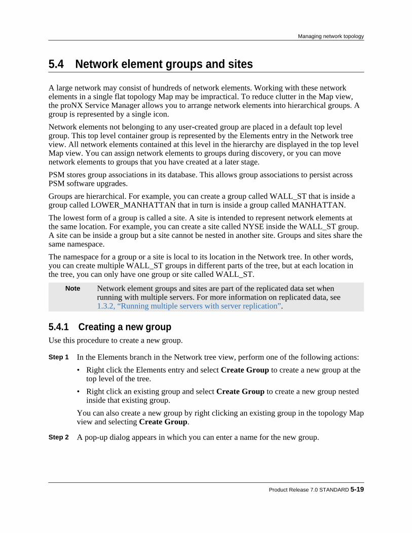
5.4 Network element groups and sites
A large network may consist of hundreds of network elements. Working with these networkelements in a single flat topology Map may be impractical. To reduce clutter in the Map view,the proNX Service Manager allows you to arrange network elements into hierarchical groups. Agroup is represented by a single icon.Network elements not belonging to any user-created group are placed in a default top levelgroup. This top level container group is represented by the Elements entry in the Network treeview. All network elements contained at this level in the hierarchy are displayed in the top level Map view. You can assign network elements to groups during discovery, or you can movenetwork elements to groups that you have created at a later stage.PSM stores group associations in its database. This allows group associations to persist acrossPSM software upgrades.Groups are hierarchical. For example, you can create a group called WALL_ST that is inside agroup called LOWER_MANHATTAN that in turn is inside a group called MANHATTAN.The lowest form of a group is called a site. A site is intended to represent network elements atthe same location. For example, you can create a site called NYSE inside the WALL_ST group.A site can be inside a group but a site cannot be nested in another site. Groups and sites share thesame namespace.The namespace for a group or a site is local to its location in the Network tree. In other words,you can create multiple WALL_ST groups in different parts of the tree, but at each location inthe tree, you can only have one group or site called WALL_ST.
Note Network element groups and sites are part of the replicated data set whenrunning with multiple servers. For more information on replicated data, see1.3.2, “Running multiple servers with server replication”.
5.4.1 Creating a new groupUse this procedure to create a new group.
Step 1 In the Elements branch in the Network tree view, perform one of the following actions:• Right click the Elements entry and select Create Group to create a new group at the
top level of the tree.• Right click an existing group and select Create Group to create a new group nested
inside that existing group.You can also create a new group by right clicking an existing group in the topology Mapview and selecting Create Group.
Step 2 A pop-up dialog appears in which you can enter a name for the new group.
Product Release 7.0 STANDARD 5-19
Managing network topology
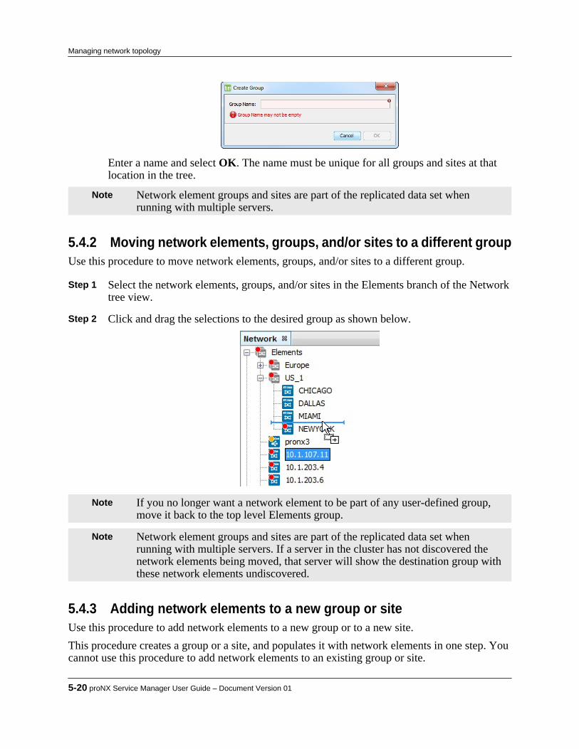
Enter a name and select OK. The name must be unique for all groups and sites at thatlocation in the tree.
Note Network element groups and sites are part of the replicated data set whenrunning with multiple servers.
5.4.2 Moving network elements, groups, and/or sites to a different groupUse this procedure to move network elements, groups, and/or sites to a different group.
Step 1 Select the network elements, groups, and/or sites in the Elements branch of the Networktree view.
Step 2 Click and drag the selections to the desired group as shown below.
Note If you no longer want a network element to be part of any user-defined group,move it back to the top level Elements group.
Note Network element groups and sites are part of the replicated data set whenrunning with multiple servers. If a server in the cluster has not discovered thenetwork elements being moved, that server will show the destination group withthese network elements undiscovered.
5.4.3 Adding network elements to a new group or siteUse this procedure to add network elements to a new group or to a new site.This procedure creates a group or a site, and populates it with network elements in one step. Youcannot use this procedure to add network elements to an existing group or site.
5-20 proNX Service Manager User Guide – Document Version 01
Managing network topology

Step 1 Select one or more network elements from the same level in the topology Map view orin the Elements branch of the Network tree view. Right click and choose Add to... > Group or Add to... > Site as desired.
Step 2 A pop-up dialog appears in which you can enter a name for the group or site. Enter the
name and click OK. The name must be unique for all groups and sites at that location inthe tree.
The new group or site is created at that location and the selected network elements aremoved into it.
Note Network element groups and sites are part of the replicated data set whenrunning with multiple servers. If a server in the cluster has not discovered thenetwork elements being added, that server will show the new group or site withthese network elements undiscovered.
5.4.4 Adding groups and/or sites to a new groupUse this procedure to add groups and/or sites to a new group.This procedure creates a group and populates it with other groups and/or sites in one step. Youcannot use this procedure to add groups and/or sites to an existing group.
Step 1 Select one or more groups and/or sites from the same level in the topology Map view orin the Elements branch of the Network tree view. Right click and choose Add to NewGroup.
Step 2 A pop-up dialog appears in which you can enter a name for the group. Enter the name
and click OK. The name must be unique for all groups and sites at that location in thetree.The new group is created at that location and the selected groups and/or sites are movedinto it.
Note Network element groups and sites are part of the replicated data set whenrunning with multiple servers.
5.4.5 Navigating between parent and child groupsUse this procedure to navigate between a child view of network elements inside a group and aparent view of the group itself.
Step 1 To view the contents of a group in the topology Map view, select the group in the Elements branch of the Network tree view or double-click the group in the topology Map view.
Product Release 7.0 STANDARD 5-21
Managing network topology
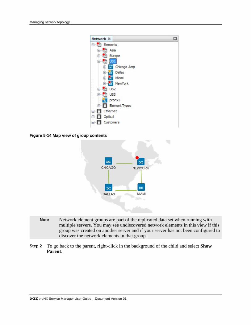
Figure 5-14 Map view of group contents
Note Network element groups are part of the replicated data set when running withmultiple servers. You may see undiscovered network elements in this view if thisgroup was created on another server and if your server has not been configured todiscover the network elements in that group.
Step 2 To go back to the parent, right-click in the background of the child and select Show
Parent.
5-22 proNX Service Manager User Guide – Document Version 01
Managing network topology
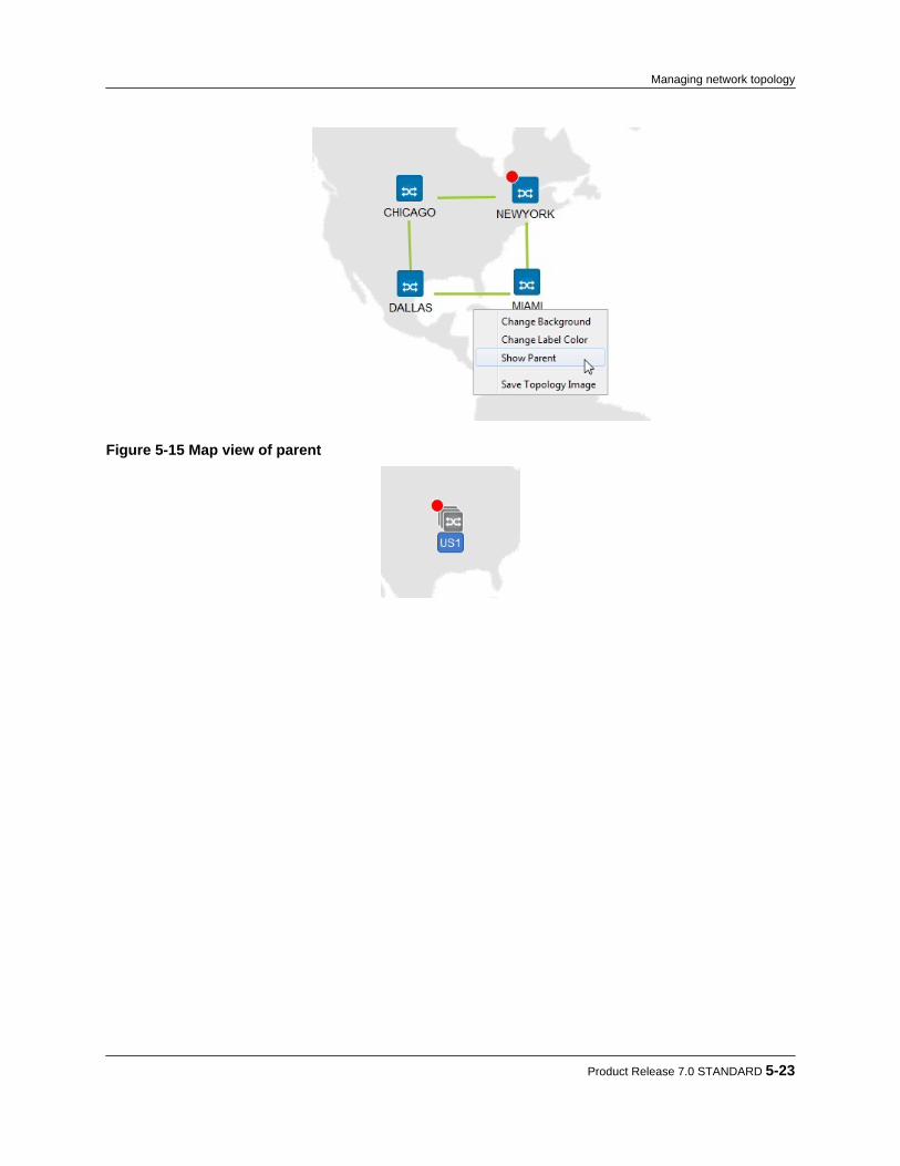
Figure 5-15 Map view of parent
Product Release 7.0 STANDARD 5-23
Managing network topology

5.5 Changing the background view
Use this procedure to change the background view in the topology window.
Note The background view is part of the replicated data set when running withmultiple servers. For more information on replicated data, see 1.3.2, “Runningmultiple servers with server replication”.
Step 1 To change map view elements, right-click anywhere on the background map to displaythe menu as shown.
Step 2 To change the default background map:
a) Create a .gif, .jpg or .png image that you want as your background.b) Click Change Background in the menu shown above and navigate to the image you
want as your background.c) Click Open. The new background image displays in the map view. The tool
automatically saves the new image file in the backgrounds folder in your PSMClient installation directory chain.
Step 3 Changing the default background map may also require changing the default text color
of the elements. To change the color of the text under each element in the map view:
a) Click Change Label Color. The "Select New Label Color" window appears asshown.
5-24 proNX Service Manager User Guide – Document Version 01
Managing network topology

b) Choose a color category using the tabs Swatches, HSB or RGB.c) Click a text color and click OK. The text under each element in the map view
changes to the selected color.d) To revert to the default text color, click Reset.
Product Release 7.0 STANDARD 5-25
Managing network topology

5-26 proNX Service Manager User Guide – Document Version 01
Managing network topology
6.0 Working with network elements
This section covers the following topics:• 6.1, “Editing notes for a network element”• 6.2, “Identifying services associated with a network element”• 6.3, “Viewing network element inventory information”• 6.4, “ Searching for a network element”• 6.5, “Managing information for a network element”• 6.6, “ Enabling or disabling network element maintenance modes”• 6.7, “ Marking or unmarking a network element”• 6.8, “ Enabling or disabling provisioning mode on a network element”• 6.9, “ Connecting to the CLI on a network element”• 6.10, “Provisioning OSPF on a BTI7000 Series management network”
Product Release 7.0 STANDARD 6-1
C H A P T E R 6

6.1 Editing notes for a network element
Use this procedure to add, delete, or modify notes on a discovered or undiscovered networkelement.Notes are informational text that can be used to describe a network element.
Step 1 To access the Notes window for an NE, right-click the NE in the Network tree or in theTopology Map view and choose Node > Notes > Edit.The Notes window is displayed.
Step 2 As desired, enter values for the existing note types (Longitude, Latitude, Postal Code)
by clicking in the Note field and typing your data. Step 3 To add a new note, right-click in the window and choose New.
A new row named New Meta Key is displayed. Click inside the New Meta Key boxand enter a name for the new note. In the Note column, enter the applicable information.The new note is stored on the server.
Step 4 To delete a note, right-click the note and choose Delete.
6-2 proNX Service Manager User Guide – Document Version 01
Working with network elements
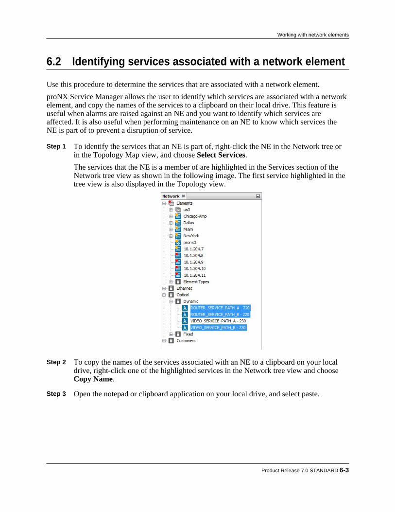
6.2 Identifying services associated with a network element
Use this procedure to determine the services that are associated with a network element.proNX Service Manager allows the user to identify which services are associated with a networkelement, and copy the names of the services to a clipboard on their local drive. This feature isuseful when alarms are raised against an NE and you want to identify which services areaffected. It is also useful when performing maintenance on an NE to know which services theNE is part of to prevent a disruption of service.
Step 1 To identify the services that an NE is part of, right-click the NE in the Network tree orin the Topology Map view, and choose Select Services.The services that the NE is a member of are highlighted in the Services section of theNetwork tree view as shown in the following image. The first service highlighted in thetree view is also displayed in the Topology view.
Step 2 To copy the names of the services associated with an NE to a clipboard on your local
drive, right-click one of the highlighted services in the Network tree view and choose Copy Name.
Step 3 Open the notepad or clipboard application on your local drive, and select paste.
Product Release 7.0 STANDARD 6-3
Working with network elements

6.3 Viewing network element inventory information
Use this procedure to display inventory information for the managed network.
Step 1 To view inventory information for the devices in your network, from the main menuchoose View>Network->Inventory.
Figure 6-1 Network inventory
6-4 proNX Service Manager User Guide – Document Version 01
Working with network elements
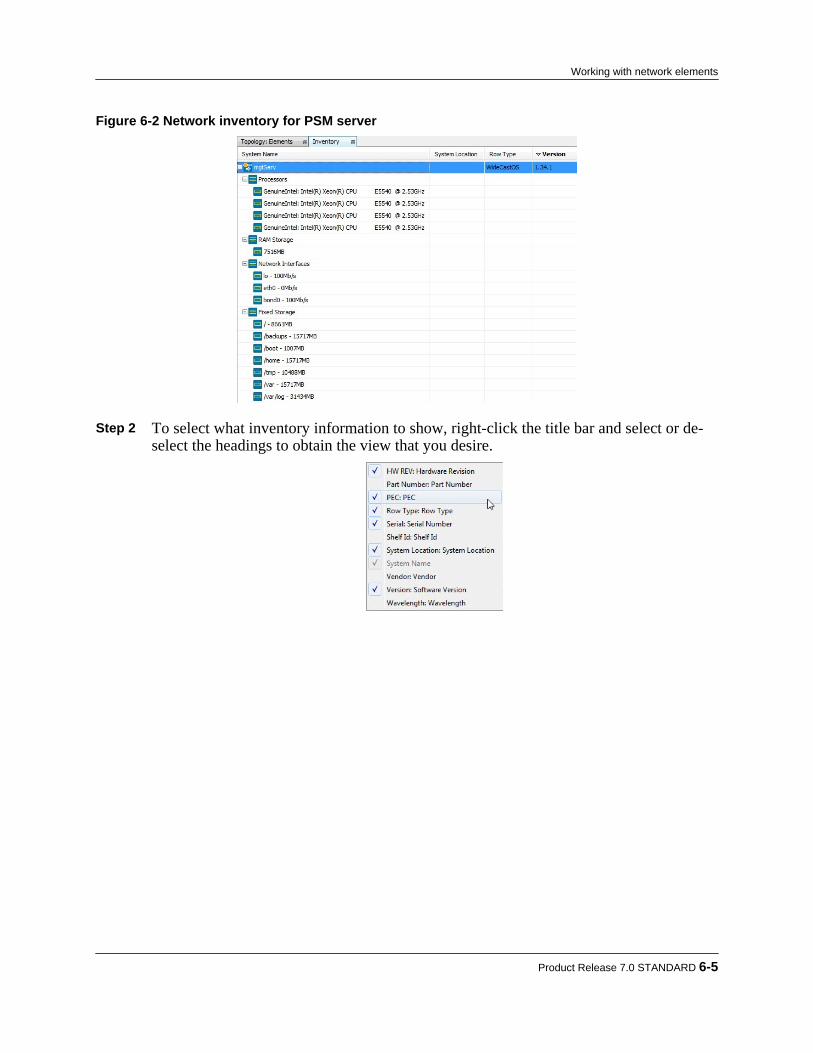
Figure 6-2 Network inventory for PSM server
Step 2 To select what inventory information to show, right-click the title bar and select or de-
select the headings to obtain the view that you desire.
Product Release 7.0 STANDARD 6-5
Working with network elements

6.4 Searching for a network element
Use this procedure to search for a network element.
Step 1 Type a search string in the Search field in the toolbar. The results are displayed as youtype.You can search based on NE name, IP address, group, site, or service type. You can alsosearch for unreachable network elements by typing in unreachable in the text box.
Figure 6-3 Searching for an IP Address
Figure 6-4 Selecting the Search Category
Figure 6-5 Searching for a Service Type
The search results are highlighted in the Network tree and Topology Map view.
6-6 proNX Service Manager User Guide – Document Version 01
Working with network elements
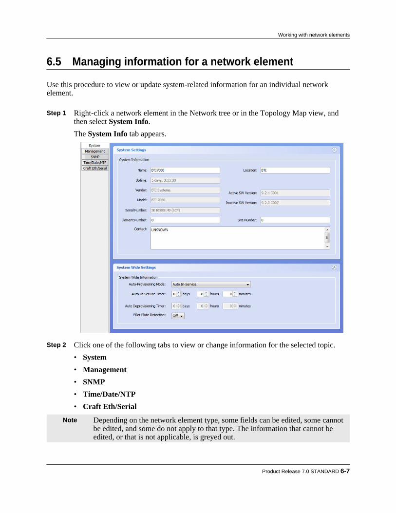
6.5 Managing information for a network element
Use this procedure to view or update system-related information for an individual networkelement.
Step 1 Right-click a network element in the Network tree or in the Topology Map view, andthen select System Info.The System Info tab appears.
Step 2 Click one of the following tabs to view or change information for the selected topic.
• System• Management• SNMP• Time/Date/NTP• Craft Eth/Serial
Note Depending on the network element type, some fields can be edited, some cannotbe edited, and some do not apply to that type. The information that cannot beedited, or that is not applicable, is greyed out.
Product Release 7.0 STANDARD 6-7
Working with network elements
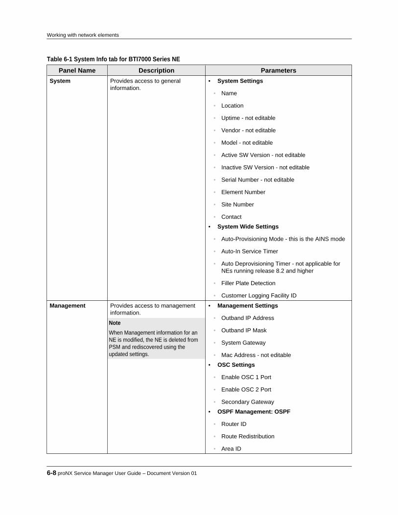
Table 6-1 System Info tab for BTI7000 Series NE
Panel Name Description ParametersSystem Provides access to general
information.• System Settings
• Name
• Location
• Uptime - not editable
• Vendor - not editable
• Model - not editable
• Active SW Version - not editable
• Inactive SW Version - not editable
• Serial Number - not editable
• Element Number
• Site Number
• Contact
• System Wide Settings
• Auto-Provisioning Mode - this is the AINS mode
• Auto-In Service Timer
• Auto Deprovisioning Timer - not applicable forNEs running release 8.2 and higher
• Filler Plate Detection
• Customer Logging Facility ID
Management Provides access to managementinformation. Note When Management information for anNE is modified, the NE is deleted fromPSM and rediscovered using theupdated settings.
• Management Settings
• Outband IP Address
• Outband IP Mask
• System Gateway
• Mac Address - not editable
• OSC Settings
• Enable OSC 1 Port
• Enable OSC 2 Port
• Secondary Gateway
• OSPF Management: OSPF
• Router ID
• Route Redistribution
• Area ID
6-8 proNX Service Manager User Guide – Document Version 01
Working with network elements

Table 6-1 System Info tab for BTI7000 Series NE (Continued)
Panel Name Description Parameters• State
• Delete OSPF
• Add OSPF
• OSPF Management: OSPF Interfaces
• This is the list of OSPF interfaces configured onthe network element.
• Add, edit, or delete interfaces as desired.
• OSPF Management: LSDB
• This is the link state database. It is read-only.
• OSPF Management: Neighbors
• This is the list of OSPF neighbors. It is read-only. Note For more information on provisioning OSPF, see6.10, “Provisioning OSPF on a BTI7000 Seriesmanagement network”
SNMP Provides access to read-onlycommunity and trap receiverinformation.
• Communities
• Private - not editable
• Public - not editable
• Trap Receivers
• Trap Receivers - not editable
• IP Address - not editable
• Community - not editable
• Version - not editable
• Port - not editable
• Notification - not editable
Time/Date/NTP Provides access to time, date, andNTP (Network Timing Protocol)settings.
• Time and Date Settings
• Adjust time for daylight savings changes
• Time
• Time Zone
• Date
• NTP Settings
• Poll Period
• Authorization Key (0 to 65535)
• Sync State - not editable
Product Release 7.0 STANDARD 6-9
Working with network elements
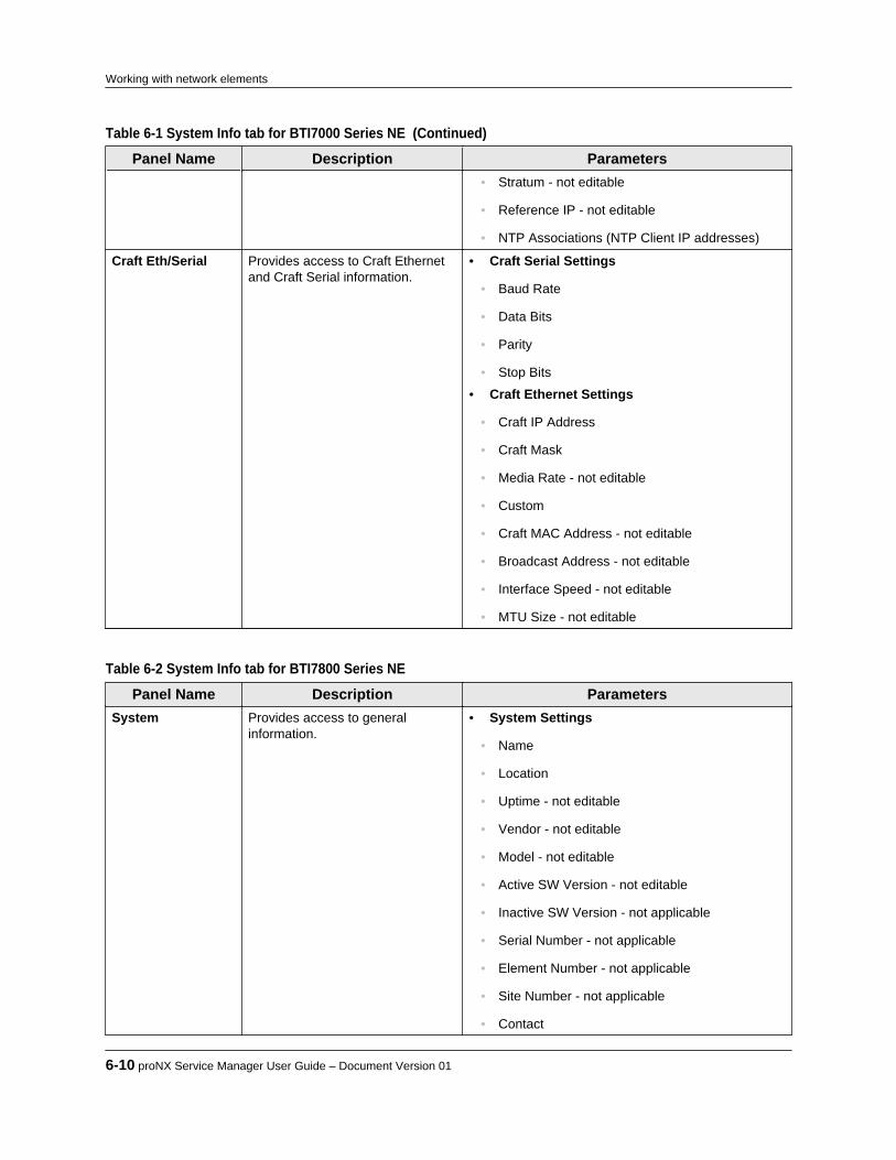
Table 6-1 System Info tab for BTI7000 Series NE (Continued)
Panel Name Description Parameters• Stratum - not editable
• Reference IP - not editable
• NTP Associations (NTP Client IP addresses)
Craft Eth/Serial Provides access to Craft Ethernetand Craft Serial information.
• Craft Serial Settings
• Baud Rate
• Data Bits
• Parity
• Stop Bits
• Craft Ethernet Settings
• Craft IP Address
• Craft Mask
• Media Rate - not editable
• Custom
• Craft MAC Address - not editable
• Broadcast Address - not editable
• Interface Speed - not editable
• MTU Size - not editable
Table 6-2 System Info tab for BTI7800 Series NE
Panel Name Description ParametersSystem Provides access to general
information.• System Settings
• Name
• Location
• Uptime - not editable
• Vendor - not editable
• Model - not editable
• Active SW Version - not editable
• Inactive SW Version - not applicable
• Serial Number - not applicable
• Element Number - not applicable
• Site Number - not applicable
• Contact
6-10 proNX Service Manager User Guide – Document Version 01
Working with network elements

Table 6-2 System Info tab for BTI7800 Series NE (Continued)
Panel Name Description Parameters• Facility ID
• System Wide Settings
• Auto-Provisioning Mode - this is the AINS mode
• Auto-In Service Timer
• Auto Deprovisioning Timer - not applicable
• Filler Plate Detection - not applicable
• Customer Logging Facility ID
Management Provides access to managementinformation. Note When Management information for anNE is modified, the NE is deleted fromPSM and rediscovered using theupdated settings.
• Management Settings
• Outband IP Address - not editable
• Outband IP Mask - not editable
• System Gateway - not editable
• Mac Address - not applicable
SNMP Provides access to read-onlycommunity and trap receiverinformation.
• Communities
• Private - not editable
• Public - not editable
• Trap Receivers
• Trap Receivers - not editable
• IP Address - not editable
• Community - not editable
• Version - not editable
• Port - not editable
• Notification - not editable
Time/Date/NTP Provides access to time, date, andNTP (Network Timing Protocol)settings.
• Time and Date Settings
• Adjust time for daylight savings changes - noteditable
• Time - not editable
• Time Zone - not editable
• Date - not editable
• NTP Settings
• NTP Status - not editable
• NTP Servers - not editable
Product Release 7.0 STANDARD 6-11
Working with network elements

Table 6-3 System Info tab for BTI800 Series NE
Panel Name Description ParametersSystem Provides access to general
information.• System Settings
• Name
• Location
• Uptime - not editable
• Vendor - not editable
• Model - not editable
• Active SW Version - not editable
• Inactive SW Version - not applicable
• Serial Number - not applicable
• Element Number - not applicable
• Site Number - not applicable
• Contact
• System Wide Settings - not applicable
Management Provides read-only access tomanagement information.
• Management Settings
• Outband IP Address - not editable
• Outband IP Mask - not editable
• System Gateway - not editable
• Mac Address - not editable
• In-band Settings
• IP Address - not editable
• IP Mask - not editable
• Outer VLAN Name - not editable
• Inner VLAN Name - not editable
• Network Address - not editable
• Mac Address - not editable
• Outer VLAN Id (Priority) - not editable
• Inner VLAN Id (Priority) - not editable
SNMP Provides access to read-onlycommunity and trap receiverinformation.
• Communities
• Private - not editable
• Public - not editable
• Trap Receivers
• Trap Receivers - not editable
6-12 proNX Service Manager User Guide – Document Version 01
Working with network elements

Table 6-3 System Info tab for BTI800 Series NE (Continued)
Panel Name Description Parameters• IP Address - not editable
• Community - not editable
• Port - not editable
Time/Date/NTP Provides access to time and datesettings.
• Time and Date Settings
• Time
• Time Zone
• Date
• NTP Settings Note You must disable NTP on the BTI810 prior to makingany changes. Note NTP is always enabled on the BTI805, BTI821, andBTI822 devices.
• Poll Period - read-only for the BTI805, BTI821,and BTI822.
• Status - read-only for the BTI805, BTI821, andBTI822.
• Preferred Server
• Server1 IP Address
• Server2 IP Address
• Server3 IP Address
Craft Eth/Serial Provides read-only access to CraftSerial information.
• Craft Serial Settings
• Baud Rate - not editable
• Data Bits - not editable
• Parity - not editable
• Stop Bits - not editable
Table 6-4 System Info tab for BTI700 Series NE
Panel Name Description ParametersSystem Provides access to general
information.• System Settings
• Name
• Location
• Uptime - not editable
Product Release 7.0 STANDARD 6-13
Working with network elements

Table 6-4 System Info tab for BTI700 Series NE (Continued)
Panel Name Description Parameters• Vendor - not editable
• Model - not editable
• Active SW Version - not editable
• Inactive SW Version - not applicable
• Model - not editable
• Serial Number - not editable
• Element Number - not applicable
• Site Number - not applicable
• Contact
• System Wide Settings - not applicable
Management Provides read-only access tomanagement information.
• Management Settings
• Outband IP Address - not editable
• Outband IP Mask - not editable
• System Gateway - not editable
• Mac Address - not editable
SNMP Provides access to read-onlycommunity and trap receiverinformation.
• Communities
• Private - not editable
• Public - not editable
• Trap Receivers
• Trap Receivers - not editable
• IP Address - not editable
• Community - not editable
• Version - not editable
• Port - not editable
• Notification - not applicable
Time/Date/NTP Provides access to time, date, andNTP (Network Timing Protocol)settings.
• Time and Date Settings
• Adjust time for daylight savings changes - notapplicable
• Time
• Time Offset - not editable
• Date
• NTP Settings (BTI700 Series except forBTI718E)
6-14 proNX Service Manager User Guide – Document Version 01
Working with network elements
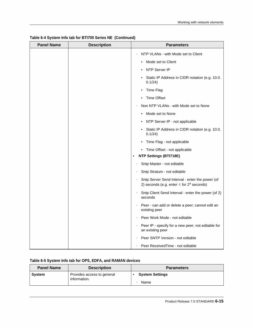
Table 6-4 System Info tab for BTI700 Series NE (Continued)
Panel Name Description Parameters
• NTP VLANs - with Mode set to Client
▪ Mode set to Client
▪ NTP Server IP
▪ Static IP Address in CIDR notation (e.g. 10.0.0.1/24)
▪ Time Flag
▪ Time Offset
• Non NTP VLANs - with Mode set to None
▪ Mode set to None
▪ NTP Server IP - not applicable
▪ Static IP Address in CIDR notation (e.g. 10.0.0.1/24)
▪ Time Flag - not applicable
▪ Time Offset - not applicable
• NTP Settings (BTI718E)
• Sntp Master - not editable
• Sntp Stratum - not editable
• Sntp Server Send Interval - enter the power (of2) seconds (e.g. enter 4 for 24 seconds)
• Sntp Client Send Interval - enter the power (of 2)seconds
• Peer - can add or delete a peer; cannot edit anexisting peer
• Peer Work Mode - not editable
• Peer IP - specify for a new peer; not editable foran existing peer
• Peer SNTP Version - not editable
• Peer ReceivedTime - not editable
Table 6-5 System Info tab for OPS, EDFA, and RAMAN devices
Panel Name Description ParametersSystem Provides access to general
information.• System Settings
• Name
Product Release 7.0 STANDARD 6-15
Working with network elements
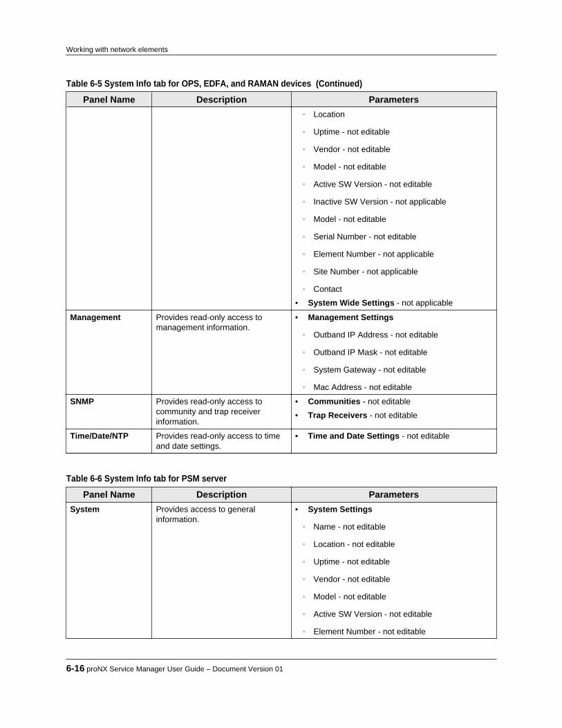
Table 6-5 System Info tab for OPS, EDFA, and RAMAN devices (Continued)
Panel Name Description Parameters• Location
• Uptime - not editable
• Vendor - not editable
• Model - not editable
• Active SW Version - not editable
• Inactive SW Version - not applicable
• Model - not editable
• Serial Number - not editable
• Element Number - not applicable
• Site Number - not applicable
• Contact
• System Wide Settings - not applicable
Management Provides read-only access tomanagement information.
• Management Settings
• Outband IP Address - not editable
• Outband IP Mask - not editable
• System Gateway - not editable
• Mac Address - not editable
SNMP Provides read-only access tocommunity and trap receiverinformation.
• Communities - not editable
• Trap Receivers - not editable
Time/Date/NTP Provides read-only access to timeand date settings.
• Time and Date Settings - not editable
Table 6-6 System Info tab for PSM server
Panel Name Description ParametersSystem Provides access to general
information.• System Settings
• Name - not editable
• Location - not editable
• Uptime - not editable
• Vendor - not editable
• Model - not editable
• Active SW Version - not editable
• Element Number - not editable
6-16 proNX Service Manager User Guide – Document Version 01
Working with network elements
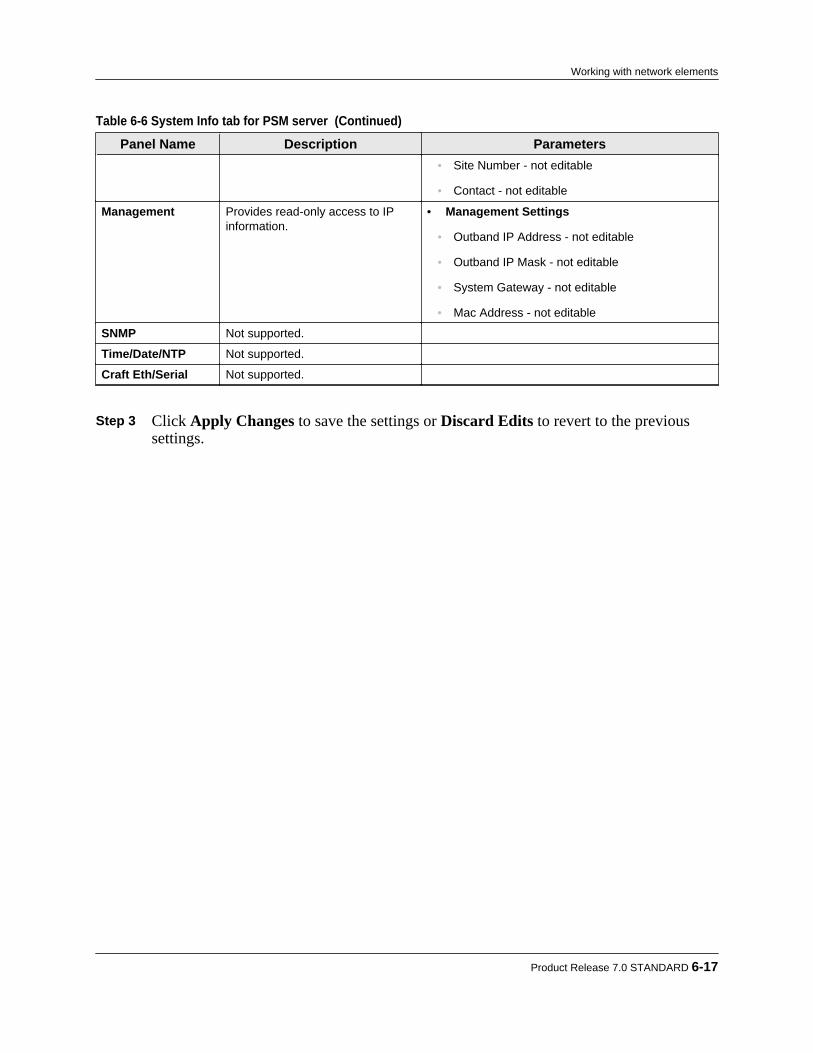
Table 6-6 System Info tab for PSM server (Continued)
Panel Name Description Parameters• Site Number - not editable
• Contact - not editable
Management Provides read-only access to IPinformation.
• Management Settings
• Outband IP Address - not editable
• Outband IP Mask - not editable
• System Gateway - not editable
• Mac Address - not editable
SNMP Not supported.
Time/Date/NTP Not supported.
Craft Eth/Serial Not supported.
Step 3 Click Apply Changes to save the settings or Discard Edits to revert to the previous
settings.
Product Release 7.0 STANDARD 6-17
Working with network elements

6.6 Enabling or disabling network element maintenancemodes
Use this procedure to enable or disable maintenance modes for a network element.Network elements can be placed into one of three maintenance modes:• Maintenance - When a network element is placed into Maintenance mode, all
communications between PSM and the network element are disabled with the exception ofalarms, which continue to be processed.
• Out of Service - When a network element is placed in Out of Service mode, allcommunications between PSM and the network element are disabled (including alarms).
• Quiet - When a network element is placed into Quiet mode, alarms are not processed.
Note These modes are internal to PSM, and govern how PSM responds to and acts onnetwork element messages. These modes are not set on the actual networkelements themselves.
Note Maintenance modes are part of the replicated data set when running withmultiple servers. For more information on replicated data, see 1.3.2, “Runningmultiple servers with server replication”.
Step 1 To place one or more network elements into a maintenance mode:
a) Select the network element(s) in the Network tree or in the Topology Map view, thenright-click and choose Mode > Maintenance Mode, Mode > Out of Service, or Mode > Quiet.
Note Modes are mutually exclusive. Only one mode can be selected at a time.
b) Click OK in the ensuing dialog to confirm the action.The NE(s) is placed in the specified mode and shown in a lighter shade.
Step 2 To confirm that the NE(s) is in the desired mode, hover over the NE.
In the tooltip that appears, check the setting under Mode. Step 3 To disable a maintenance mode on one or more network elements:
a) Select the network element(s) in the Network tree or in the Topology Map view, thenright-click and select Mode > Disable Maintenance Mode, Mode > Disable Out ofService, or Mode > Disable Quiet, as applicable.
The NE(s) is shown back in its regular shade.
6-18 proNX Service Manager User Guide – Document Version 01
Working with network elements

6.7 Marking or unmarking a network element
Use this procedure to mark or unmark a network element. A marked network element allows you to visually distinguish that network element from other network elements, such as tohighlight an important node or nodes in the network, or to flag a node to other users in thesystem.
Note Marking is implemented as a mode, which is part of the replicated data set whenrunning with multiple servers. For more information on replicated data, see1.3.2, “Running multiple servers with server replication”.
Step 1 To mark one or more network elements:
a) Select the network element(s) in the Network tree or in the Topology Map view, thenright-click and choose Mode > Marked.
Note Modes are mutually exclusive. Only one mode can be selected at a time.
b) Click OK in the ensuing dialog to confirm the action.The NE(s) is now shown with a mark in the Topology Map view and in the Networktree.
Step 2 To remove a mark on one or more network elements:
a) Select the network element(s) in the Network tree or in the Topology Map view, thenright-click and select Mode > Disable Marked.
The NE(s) is shown with the mark removed.
Product Release 7.0 STANDARD 6-19
Working with network elements

6.8 Enabling or disabling provisioning mode on a networkelement
Use this procedure to enable or disable provisioning mode on a network element. If youconfigure a network element while provisioning mode is enabled, you will see the newconfiguration data in PSM immediately (without having to wait for the next NE discovery cycle).In general, only one NE in the managed network should be in provisioning mode at any giventime.
Note Provisioning mode is part of the replicated data set when running with multipleservers. For more information on replicated data, see 1.3.2, “Running multipleservers with server replication”.
Step 1 To enable provisioning mode on a network element:
a) Select the network element in the Network tree or in the Topology Map view, thenright-click and choose Mode > Provisioning > 5 Minutes, 10 Minutes, or 15Minutes.
Note Provisioning mode settings are mutually exclusive. Only one time period can beselected.
b) Click OK in the ensuing dialog to confirm the action.PSM enables provisioning mode for the selected NE for the specified time period.
Step 2 To disable provisioning mode on a network element:
a) Select the network element in the Network tree or in the Topology Map view, thenright-click and select Mode > Provisioning > Disable 5 Minutes, Disable 10Minutes, or Disable 15 Minutes, as applicable.
PSM disables provisioning mode for the selected NE.
6-20 proNX Service Manager User Guide – Document Version 01
Working with network elements

6.9 Connecting to the CLI on a network element
Use this procedure to connect to the CLI on a network element.
Note To connect to the CLI, you must first set up the appropriate command andcommand parameters. See 9.5, “Configuring utilities”.
Step 1 Right-click a network element in the Network tree or in the topology Map view andselect Utilities > CLI.The CLI is launched using the application specified in 9.5, “Configuring utilities”.
Product Release 7.0 STANDARD 6-21
Working with network elements

6.10 Provisioning OSPF on a BTI7000 Series managementnetwork
6.10.1 Adding OSPF managementUse this procedure to add OSPF to the management network of a BTI7000 Series networkelement.
Step 1 Right-click a network element in the Network tree or in the Topology Map view, andthen select System Info.The System Info window appears.
Step 2 Click the Management tab to see the management parameters.
The Management panel appears.
Step 3 Select Add OSPF to add OSPF.
Note If OSPF has previously been added, the Add OSPF button is not available forselection.
Step 4 Configure OSPF parameters as follows:
• Router ID: Specify the OSPF router identifier.• Route Redistribution: Use the drop-down menu to specify how routes are
redistributed.
6-22 proNX Service Manager User Guide – Document Version 01
Working with network elements

• Area ID: Specify the OSPF area identifier.• State: Set to Enabled or Disabled.
Step 5 When you are finished, click Apply Changes.
6.10.2 Editing OSPF management settingsUse this procedure to edit OSPF management settings on a BTI7000 Series network element.
Step 1 Right-click a network element in the Network tree or in the Topology Map view, andthen select System Info.The System Info window appears.
Step 2 Click the Management tab to see the management parameters.
The Management panel appears.
Step 3 Configure OSPF parameters as follows:
• Router ID: Specify the OSPF router identifier.• Route Redistribution: Use the drop-down menu to specify how routes are
redistributed.• Area ID: The OSPF area identifier is read-only. It is set when you initially add OSPF
management.• State: Set to Enabled or Disabled.
Product Release 7.0 STANDARD 6-23
Working with network elements

Step 4 When you are finished, click Apply Changes.
6.10.3 Deleting OSPF managementUse this procedure to delete OSPF from the management network on a BTI7000 Series networkelement.
Step 1 Right-click a network element in the Network tree or in the Topology Map view, andthen select System Info.The System Info window appears.
Step 2 Click the Management tab to see the management parameters.
The Management panel appears.
Step 3 Click Delete OSPF. Step 4 Click Yes in the confirmation dialog. Step 5 When you are finished, click Apply Changes.
6.10.4 Adding an OSPF management interfaceUse this procedure to add an OSPF management interface to a BTI7000 Series network element.
6-24 proNX Service Manager User Guide – Document Version 01
Working with network elements
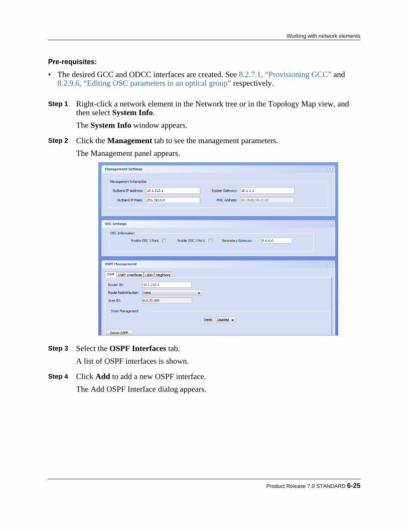
Pre-requisites:
• The desired GCC and ODCC interfaces are created. See 8.2.7.1, “Provisioning GCC” and8.2.9.6, “Editing OSC parameters in an optical group” respectively.
Step 1 Right-click a network element in the Network tree or in the Topology Map view, andthen select System Info.The System Info window appears.
Step 2 Click the Management tab to see the management parameters.
The Management panel appears.
Step 3 Select the OSPF Interfaces tab.
A list of OSPF interfaces is shown. Step 4 Click Add to add a new OSPF interface.
The Add OSPF Interface dialog appears.
Product Release 7.0 STANDARD 6-25
Working with network elements
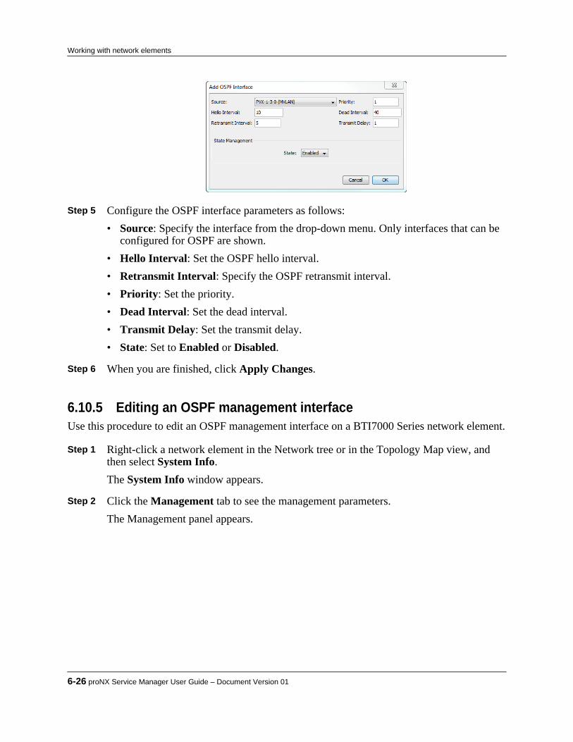
Step 5 Configure the OSPF interface parameters as follows:
• Source: Specify the interface from the drop-down menu. Only interfaces that can beconfigured for OSPF are shown.
• Hello Interval: Set the OSPF hello interval.• Retransmit Interval: Specify the OSPF retransmit interval.• Priority: Set the priority.• Dead Interval: Set the dead interval.• Transmit Delay: Set the transmit delay.• State: Set to Enabled or Disabled.
Step 6 When you are finished, click Apply Changes.
6.10.5 Editing an OSPF management interfaceUse this procedure to edit an OSPF management interface on a BTI7000 Series network element.
Step 1 Right-click a network element in the Network tree or in the Topology Map view, andthen select System Info.The System Info window appears.
Step 2 Click the Management tab to see the management parameters.
The Management panel appears.
6-26 proNX Service Manager User Guide – Document Version 01
Working with network elements
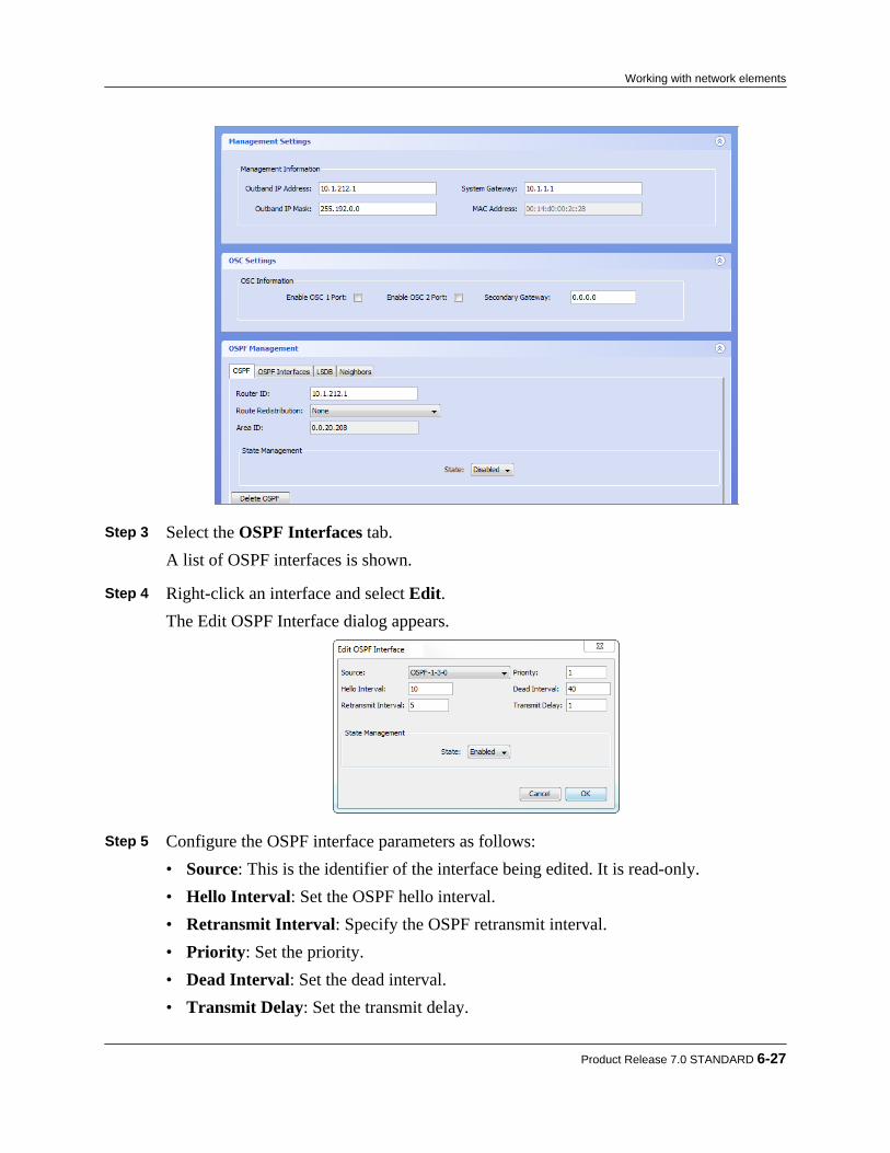
Step 3 Select the OSPF Interfaces tab.
A list of OSPF interfaces is shown. Step 4 Right-click an interface and select Edit.
The Edit OSPF Interface dialog appears.
Step 5 Configure the OSPF interface parameters as follows:
• Source: This is the identifier of the interface being edited. It is read-only.• Hello Interval: Set the OSPF hello interval.• Retransmit Interval: Specify the OSPF retransmit interval.• Priority: Set the priority.• Dead Interval: Set the dead interval.• Transmit Delay: Set the transmit delay.
Product Release 7.0 STANDARD 6-27
Working with network elements
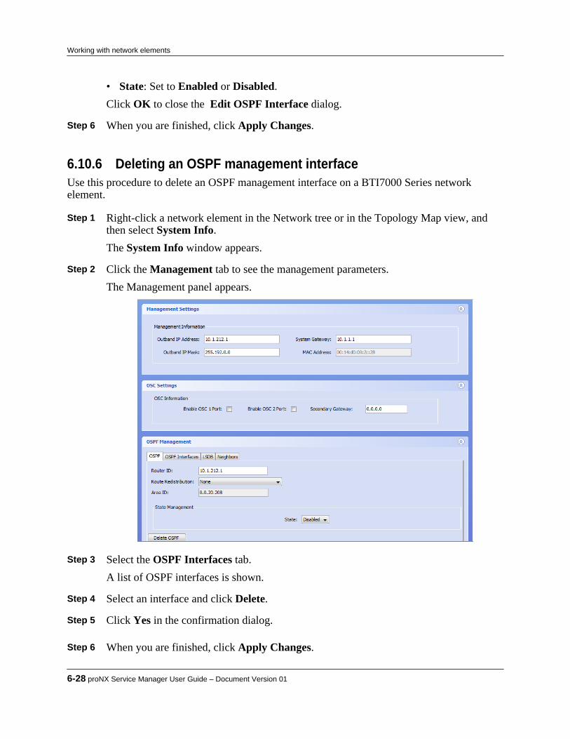
• State: Set to Enabled or Disabled.Click OK to close the Edit OSPF Interface dialog.
Step 6 When you are finished, click Apply Changes.
6.10.6 Deleting an OSPF management interfaceUse this procedure to delete an OSPF management interface on a BTI7000 Series networkelement.
Step 1 Right-click a network element in the Network tree or in the Topology Map view, andthen select System Info.The System Info window appears.
Step 2 Click the Management tab to see the management parameters.
The Management panel appears.
Step 3 Select the OSPF Interfaces tab.
A list of OSPF interfaces is shown. Step 4 Select an interface and click Delete. Step 5 Click Yes in the confirmation dialog. Step 6 When you are finished, click Apply Changes.
6-28 proNX Service Manager User Guide – Document Version 01
Working with network elements

Product Release 7.0 STANDARD 6-29
Working with network elements

6-30 proNX Service Manager User Guide – Document Version 01
Working with network elements

7.0 Working with the Shelf view
PSM can display a visual representation of a discovered network element, along with visualindications of alarmed ports or components on that shelf. If the selected network element isunreachable, PSM displays the last known state for that element.PSM supports the Shelf view for the following:• BTI7800 Series network elements• BTI7000 Series network elements• BTI800 Series network elements• BTI700 Series network elementsThis section covers the following topics:• 7.1, “Displaying network elements in the Shelf view”• 7.2, “Displaying alarms from the Shelf view”• 7.3, “Setting the Remote ID from the Shelf view”• 7.4, “Deleting the Remote ID from the Shelf view”
Product Release 7.0 STANDARD 7-1
C H A P T E R 7

7.1 Displaying network elements in the Shelf view
Use this procedure to display the shelf view for a network element.
Step 1 To display the shelf view of an NE, right-click the NE in either the Network tree or thetopology Map view and choose Node > View.If one or more alarms exist on a component, the component is colored red (critical),amber (major), or yellow (minor) to indicate the highest severity alarm on thatcomponent.The following figures show the shelf view for various network elements.
Figure 7-1 Shelf View for a BTI7814 Network Element
7-2 proNX Service Manager User Guide – Document Version 01
Working with the Shelf view
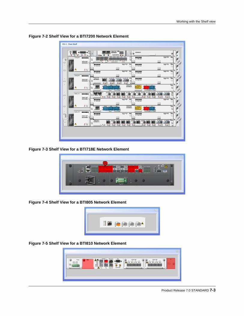
Figure 7-2 Shelf View for a BTI7200 Network Element
Figure 7-3 Shelf View for a BTI718E Network Element
Figure 7-4 Shelf View for a BTI805 Network Element
Figure 7-5 Shelf View for a BTI810 Network Element
Product Release 7.0 STANDARD 7-3
Working with the Shelf view

Figure 7-6 Shelf View for a BTI821 Network Element
Figure 7-7 Shelf View for a BTI822 Network Element
Note You can also use Quick View to bring up the Shelf view. First, select thenetwork element in the Network tree, and then depress <ctl> <alt> v. The shelfview comes up in a modal window. To close the modal window, click anywhereoutside the modal window.
Step 2 Hover over the alarmed component to see an alarm summary.
7-4 proNX Service Manager User Guide – Document Version 01
Working with the Shelf view

7.2 Displaying alarms from the Shelf view
Use this procedure to display the outstanding alarms on the selected component in the Shelf view.
Step 1 To display alarm details for the alarmed component from the Shelf view, right-click thealarmed component and choose Select or Filter.
When Select is chosen, the alarms pane appears with the alarm(s) for the selectedcomponent highlighted. When Filter is chosen, PSM applies a filter to the alarms paneto show only alarms for the selected component. For information on managing alarms,see Chapter 15, “Managing network element alarms”.
Product Release 7.0 STANDARD 7-5
Working with the Shelf view

7.3 Setting the Remote ID from the Shelf view
Use this procedure to set the Remote ID on an existing port in the Shelf view.This is supported on BTI7000 Series and BTI800 Series NEs only. For more information onRemote IDs, see 5.3.3, “Deriving topology using Remote IDs”.
Note PSM connects to the NE using the login credentials that you supplied when youconnected to the PSM server. Therefore this NE must be configured with thosesame login credentials for this procedure to be successful.
To use this procedure, the cards and ports must already be provisioned.
Step 1 To set the Remote ID on a port, right-click the port and choose Remote Id > SetRemote Port Id.
The Set Remote Port ID dialog appears. Step 2 Configure the Remote ID as follows:
• Local Port ID - This displays the local port identifier.
7-6 proNX Service Manager User Guide – Document Version 01
Working with the Shelf view
• Remote Id - This is the Remote ID that is currently set. This field cannot be changeddirectly. It is changed by editing the individual components of the Remote IDthrough the various drop-down menus.
• Hostname/IP Address - Set the hostname or IP address of the remote endpoint. Forconvenience, completion suggestions are provided based on the discovered networkelements.
• CP Type - Set the circuit pack type from the drop-down menu.
Note Only the circuit pack types described in 5.3.3, “Deriving topology using RemoteIDs” are supported.
• Shelf, Slot, Port - Set the shelf, slot, and port indexes respectively.• Alien - This specifies whether the remote ID refers to an external device. Selecting
this attribute causes an -X to be appended to the end of the Remote ID.• Bidirectional - This option allows you to specify whether you want PSM to
automatically set the remote ID on the remote port to point back to this local port.This attribute should only be selected if the circuit pack type is one of MXP, TPR,WR, WM, WT, PVX, ROB, BTI800. You cannot select both Alien and Bidirectionalat the same time.
Step 3 Click OK.
Note If you select Bidirectional and you specify a Remote ID that cannot bereconciled, PSM will be unable to configure the remote endpoint, and the taskwill fail.
Note The task may fail if you try to use this procedure on a card that has not beenprovisioned.
Product Release 7.0 STANDARD 7-7
Working with the Shelf view

7.4 Deleting the Remote ID from the Shelf view
Use this procedure to delete the Remote ID from a port in the Shelf view.This is supported on BTI7000 Series and BTI800 Series NEs only.
Note PSM connects to the NE using the login credentials that you supplied when youconnected to the PSM server. Therefore the NE must be configured with thosesame login credentials for this procedure to be successful.
Step 1 To delete the Remote ID, right-click the port and choose Remote Id > Delete RemotePort Id.
The Delete Remote Port ID dialog appears.
Step 2 To delete the remote ID at both endpoints, select bidirectional deletion. Step 3 Click OK.
7-8 proNX Service Manager User Guide – Document Version 01
Working with the Shelf view

8.0 Nodal management
• 8.1, “Nodal management overview”• 8.2, “Nodal management for BTI7000 Series network elements”• 8.3, “Nodal management for BTI7800 Series network elements”• 8.4, “Nodal management for BTI800 Series network elements”
Product Release 7.0 STANDARD 8-1
C H A P T E R 8

8.1 Nodal management overview
PSM supports nodal management for the BTI7000 Series, BTI7800 Series, and BTI800 Seriesequipment (minimally).When a network element is discovered, PSM displays the network element and all of itscomponents in the Network tree. This includes all provisioned and installed components, all auto-provisioned components, and all pre-provisioned components (when operators provisionequipment in advance of hardware installation).The Network tree lists the components hierarchically. You can expand a component to seecontained components, or minimize a component to hide its contents.
PSM provides an indication of whether a component has been provisioned and/or has beeninstalled. A provisioned component has its mnemonic displayed (e.g. TPR) . An unprovisionedcomponent is shown with a none indication. A component that has been physically installed isshown with its hardware mnemonic in parentheses (e.g. (DTPR)). A component that has notbeen installed is displayed with an (empty) indication.You can use PSM to provision installed components or to pre-provision components. There is ashort delay from the time you finish configuring a component to the time when the configurationappears in the Network tree. PSM only displays the new configuration in the Network tree whenthe network element reports its changes to PSM as part of the regular notification process. To seethe changes in PSM immediately, place the network element into provisioning mode beforemaking the changes. See 6.8, “ Enabling or disabling provisioning mode on a network element”.
Note This document only provides a cursory explanation of the various configurationparameters. For a more detailed explanation, consult the documentation suite forthe respective products.
8-2 proNX Service Manager User Guide – Document Version 01
Nodal management
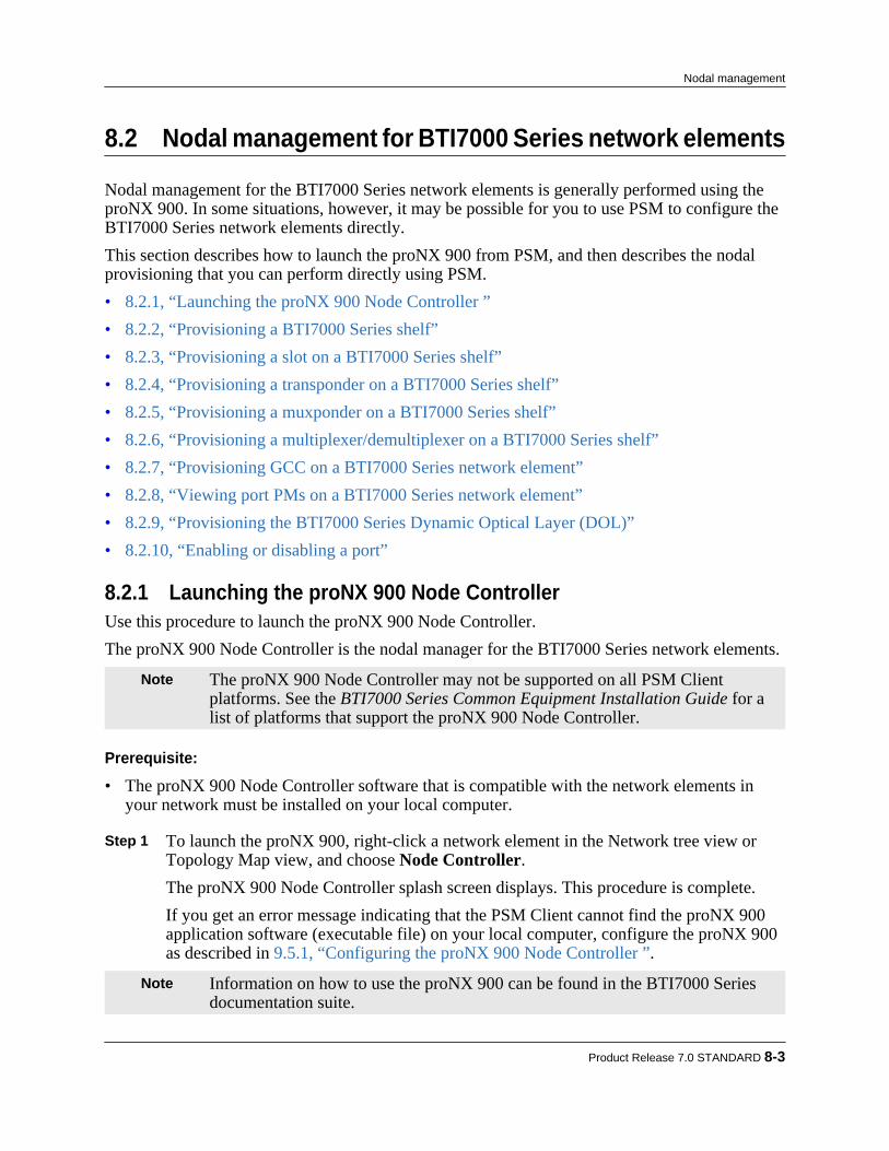
8.2 Nodal management for BTI7000 Series network elements
Nodal management for the BTI7000 Series network elements is generally performed using theproNX 900. In some situations, however, it may be possible for you to use PSM to configure theBTI7000 Series network elements directly.This section describes how to launch the proNX 900 from PSM, and then describes the nodalprovisioning that you can perform directly using PSM.• 8.2.1, “Launching the proNX 900 Node Controller ”• 8.2.2, “Provisioning a BTI7000 Series shelf”• 8.2.3, “Provisioning a slot on a BTI7000 Series shelf”• 8.2.4, “Provisioning a transponder on a BTI7000 Series shelf”• 8.2.5, “Provisioning a muxponder on a BTI7000 Series shelf”• 8.2.6, “Provisioning a multiplexer/demultiplexer on a BTI7000 Series shelf”• 8.2.7, “Provisioning GCC on a BTI7000 Series network element”• 8.2.8, “Viewing port PMs on a BTI7000 Series network element”• 8.2.9, “Provisioning the BTI7000 Series Dynamic Optical Layer (DOL)”• 8.2.10, “Enabling or disabling a port”
8.2.1 Launching the proNX 900 Node ControllerUse this procedure to launch the proNX 900 Node Controller.The proNX 900 Node Controller is the nodal manager for the BTI7000 Series network elements.
Note The proNX 900 Node Controller may not be supported on all PSM Clientplatforms. See the BTI7000 Series Common Equipment Installation Guide for alist of platforms that support the proNX 900 Node Controller.
Prerequisite:
• The proNX 900 Node Controller software that is compatible with the network elements inyour network must be installed on your local computer.
Step 1 To launch the proNX 900, right-click a network element in the Network tree view orTopology Map view, and choose Node Controller.The proNX 900 Node Controller splash screen displays. This procedure is complete.If you get an error message indicating that the PSM Client cannot find the proNX 900application software (executable file) on your local computer, configure the proNX 900as described in 9.5.1, “Configuring the proNX 900 Node Controller ”.
Note Information on how to use the proNX 900 can be found in the BTI7000 Seriesdocumentation suite.
Product Release 7.0 STANDARD 8-3
Nodal management

8.2.2 Provisioning a BTI7000 Series shelf
8.2.2.1 Adding a shelfUse this procedure to add a new shelf on a BTI7000 Series network element.
Step 1 Right-click a network element in the Network tree view or in the topology Map viewand select Node > Shelf > Provision.The Provision Shelf dialog appears:
Figure 8-1 BTI7000 Series Provision Shelf
Step 2 Configure the shelf as follows:
• PEC - Select the PEC from the list of available PECs in the drop-down menu.• Shelf Number - Select the shelf number from the drop-down menu. The drop-down
menu only displays the shelf numbers that are available and not already in use.• ID - Optionally, enter a string identifying the shelf.• Initial State - Specify whether the initial state of the shelf is IS (in-service) or OOS
(out-of-service).
8-4 proNX Service Manager User Guide – Document Version 01
Nodal management
Step 3 Optionally, specify the Custom fields. These fields are for operator use and are opaqueto the system.
a) Click the Custom Settings tab.b) In the Custom Settings panel, specify the Custom 1, Custom 2, and Custom 3
settings as desired. Step 4 When you are finished, click OK.
The PSM server sends the configuration request to the network element. You canmonitor the status of the request through the View > Server > Tasks window. The newprovisioning appears in the Network tree view a short while after the task completessuccessfully.
8.2.2.2 Deleting a shelfUse this procedure to delete a shelf on a BTI7000 Series network element.
Pre-requisites:
All components on the shelf must be deleted before you can delete the shelf.
Step 1 Expand the network element in the Network tree view to show the shelves in that NE. Step 2 Right-click a shelf and select Shelf > Delete. Step 3 Click OK in the Delete Shelf confirmation dialog.
The PSM server sends the configuration request to the network element. You canmonitor the status of the request through the View > Server > Tasks window. The newprovisioning appears in the Network tree view a short while after the task completessuccessfully.
8.2.3 Provisioning a slot on a BTI7000 Series shelf
8.2.3.1 Adding a moduleUse this procedure to add a new module on a BTI7000 Series shelf.
Step 1 Expand the network element in the Network tree view to show the shelves in that NE. Step 2 Expand a shelf to show the slots in that shelf. Step 3 Right-click an unprovisioned slot and select Slot > Provision to add a module in that
slot.The Provision Slot dialog appears:
Product Release 7.0 STANDARD 8-5
Nodal management

Figure 8-2 BTI7000 Series Provision Slot
Step 4 Configure the slot as follows:
• Name - Select the module type from the list of available module types in the drop-down menu.
• PEC/CLEI Code - Select the PEC from the list of available PECs for the selectedmodule type.
• Shelf Number and Slot Number- These read-only fields display the shelf and slotnumbers for the slot you selected.
• ID - Optionally, specify an identifier for the module.• Initial State - Specify the initial state of the module.
Step 5 Optionally, specify the Custom fields. These fields are for operator use and are opaque
to the system.
a) Click the Custom Settings tab.b) In the Custom Settings panel, specify the Custom 1, Custom 2, and Custom 3
settings as desired. Step 6 When you are finished, click OK.
8-6 proNX Service Manager User Guide – Document Version 01
Nodal management
The PSM server sends the configuration request to the network element. You canmonitor the status of the request through the View > Server > Tasks window. The newprovisioning appears in the Network tree view a short while after the task completessuccessfully.
8.2.3.2 Deleting a moduleUse this procedure to delete a module on a BTI7000 Series shelf.
Pre-requisites:
All components in the module must be deleted before you can delete the module.
Step 1 Expand the network element in the Network tree view to show the shelves in that NE. Step 2 Expand a shelf to show the slots in that shelf. Step 3 Right-click a provisioned slot and select Slot > Delete. Step 4 Click OK in the Delete Slot confirmation dialog.
The PSM server sends the configuration request to the network element. You canmonitor the status of the request through the View > Server > Tasks window. The newprovisioning appears in the Network tree view a short while after the task completessuccessfully.
8.2.4 Provisioning a transponder on a BTI7000 Series shelfPSM supports provisioning of the Dual 2.5G, Dual 4G, 10G, and Dual 10G multiprotocoltransponders.This section contains the following topics:• 8.2.4.1, “Provisioning ports on a BTI7000 Series transponder”• 8.2.4.2, “Provisioning cross-connects on a BTI7000 Series transponder”• 8.2.4.3, “Provisioning line protection groups on a BTI7000 Series transponder”• 8.2.4.4, “Provisioning client protection groups on a BTI7000 Series transponder”To add a transponder, follow the steps in 8.2.3.1, “Adding a module” and select the desiredtransponder from the PEC drop-down list.
8.2.4.1 Provisioning ports on a BTI7000 Series transponderBTI7000 Series transponders consist of 2 or 4 ports divided equally between client and line ports.
Adding a transponder port:Use this procedure to add a new port on a BTI7000 Series transponder.
Product Release 7.0 STANDARD 8-7
Nodal management
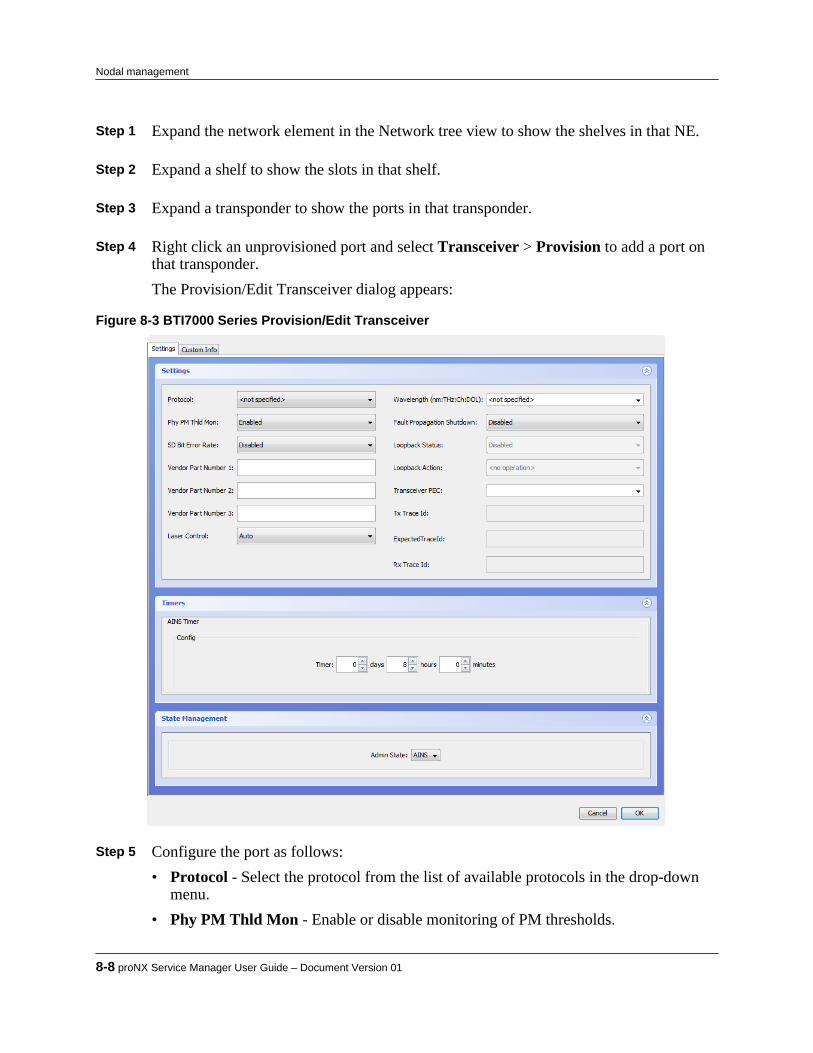
Step 1 Expand the network element in the Network tree view to show the shelves in that NE. Step 2 Expand a shelf to show the slots in that shelf. Step 3 Expand a transponder to show the ports in that transponder. Step 4 Right click an unprovisioned port and select Transceiver > Provision to add a port on
that transponder.The Provision/Edit Transceiver dialog appears:
Figure 8-3 BTI7000 Series Provision/Edit Transceiver
Step 5 Configure the port as follows:
• Protocol - Select the protocol from the list of available protocols in the drop-downmenu.
• Phy PM Thld Mon - Enable or disable monitoring of PM thresholds.
8-8 proNX Service Manager User Guide – Document Version 01
Nodal management
• SD Bit Error Rate - Optionally, select the signal degrade bit error rate.• Vendor Part Number 1 to 3 - Optionally, specify the vendor part numbers.• Laser Control - Select Auto to let software control the laser. Select Manual On to
turn on the laser. Select Manual Off to turn off the laser.• Wavelength - Specify the wavelength to use. Set to NONE for copper.• Fault Propagation Shutdown - Enable or disable FPSD. If you enable FPSD, you
must also set Laser Control to Auto and Wavelength to a value other than NONE.• Loopback Status - This attribute cannot be set when adding a port.• Loopback Action - This attribute cannot be set when adding a port.• Transceiver PEC - Optionally, specify the transceiver PEC.• Tx Trace Id - Optionally, specify the transmit trace ID (only available on certain
modules).• Expected Trace Id - Optionally, specify the expected trace ID (only available on
certain modules).• Rx Trace Id - This attribute is read only.• Auto-In Service Timer - Optionally, specify the AINS timer. This attribute is only
applicable if the Admin State is AINS.• Admin State - Specify the initial state of the module.
Step 6 Optionally, click the Custom Info tab to see the Custom Info panel.
a) Specify the port identifiers ID 1 and ID 2.b) Specify the Fiber Type.c) Specify the Custom 1, Custom 2, and Custom 3 settings as desired.d) Specify the Remote Id. For information on how to use this field, see 5.3.3, “Deriving
topology using Remote IDs”. Step 7 Click OK.
The PSM server sends the configuration request to the network element. You canmonitor the status of the request through the View > Server > Tasks window. The newprovisioning appears in the Network tree view a short while after the task completessuccessfully.
Editing a transponder port:Use this procedure to edit a port on a BTI7000 Series transponder.
Step 1 Expand the network element in the Network tree to show the shelves in that NE. Step 2 Expand a shelf to show the slots in that shelf.
Product Release 7.0 STANDARD 8-9
Nodal management

Step 3 Expand a transponder to show the ports for that transponder. Step 4 Right click a provisioned port and select Transceiver > Edit.
The Provision/Edit Transceiver dialog appears. Step 5 Change one or more port settings as follows:
• Protocol - Select the protocol from the list of available protocols in the drop-downmenu.
• Phy PM Thld Mon - Enable or disable monitoring of PM thresholds.• SD Bit Error Rate - Select the signal degrade bit error rate.• Vendor Part Number 1 to 3 - Specify the vendor part numbers.• Laser Control - Select Auto to let software control the laser. Select Manual On to
turn on the laser. Select Manual Off to turn off the laser.• Wavelength - Specify the wavelength to use. Set to NONE for copper.• Fault Propagation Shutdown - Enable or disable FPSD. If you enable FPSD, you
must also set Laser Control to Auto and Wavelength to a value other than NONE.• Loopback Status - This field is read only, and indicates what kind of loopback, if
any, is in effect.• Loopback Action - This is an action command. It will always default to <no
operation>, meaning that no command is issued. Set to Terminal or Facility to setthe port to terminal or facility loopback respectively.
• Transceiver PEC - Specify the transceiver PEC.• Tx Trace Id - Specify the transmit trace ID (only available on certain modules).• Expected Trace Id - Specify the expected trace ID (only available on certain
modules).• Rx Trace Id - This attribute is read only.• Auto-In Service Timer - Specify the AINS timer. This attribute is only applicable if
the Admin State is AINS.• Active Auto-In Service Timer - This attribute is read only.• Admin State - Set the admin state of the module.• Operational State - This attribute is read only.• Secondary State - This attribute is read only.• Laser Status - This attribute is read only.
Step 6 To change the Custom Info settings , click the Custom Info tab.
a) Specify the port identifiers ID 1 and ID 2.b) Specify the Fiber Type.
8-10 proNX Service Manager User Guide – Document Version 01
Nodal management

c) Specify the Custom 1, Custom 2, and Custom 3 settings as desired.d) Specify the Remote Id. For information on how to use this field, see 5.3.3, “Deriving
topology using Remote IDs”. Step 7 Click Apply.
The PSM server sends the configuration request to the network element. You canmonitor the status of the request through the View > Server > Tasks window. The newprovisioning appears in the Network tree view a short while after the task completessuccessfully.
Deleting a transponder port:Use this procedure to delete a port on a BTI7000 Series transponder.Before a port can be deleted, it must be removed from any protection groups and cross-connects.
Step 1 Expand the network element in the Network tree view to show the shelves in that NE. Step 2 Expand a shelf to show the slots in that shelf. Step 3 Expand a transponder to show the ports for that transponder. Step 4 Right click a provisioned port and select Transceiver > Delete. Step 5 Click OK in the Delete Transceiver confirmation dialog.
The PSM server sends the configuration request to the network element. You canmonitor the status of the request through the View > Server > Tasks window. The newprovisioning appears in the Network tree view a short while after the task completessuccessfully.
8.2.4.2 Provisioning cross-connects on a BTI7000 Series transponderThere are various rules that govern what ports and protocols can be cross-connected. See theBTI7000 Series Transponder Solutions Guide for information.
Adding a transponder cross-connect:Use this procedure to add a cross-connect on a BTI7000 Series transponder.
Step 1 Expand the network element in the Network tree view to show the shelves in that NE. Step 2 Expand a shelf to show the slots in that shelf. Step 3 Right click a transponder and select Cross Connects > Edit.
The Cross Connections dialog appears, displaying the existing cross-connects.
Product Release 7.0 STANDARD 8-11
Nodal management

Step 4 Click Add... to add a cross-connect.
The Add Cross Connection dialog appears.
Step 5 Specify the Source port, the Destination port, and the Direction. Step 6 Click Apply.
The PSM server sends the configuration request to the network element. You canmonitor the status of the request through the View > Server > Tasks window. The newprovisioning appears in the Network tree view a short while after the task completessuccessfully.
Deleting a transponder cross-connect:Use this procedure to delete a cross-connect on a BTI7000 Series transponder.
Step 1 Expand the network element in the Network tree view to show the shelves in that NE. Step 2 Expand a shelf to show the slots in that shelf. Step 3 Right click a transponder and select Cross Connects > Edit.
The Cross Connections dialog appears. Step 4 Select the cross-connect you want to delete and click Delete.
The Deleting Cross Connection confirmation dialog appears. Step 5 Click OK to confirm the deletion.
The PSM server sends the configuration request to the network element. You canmonitor the status of the request through the View > Server > Tasks window. The newprovisioning appears in the Network tree view a short while after the task completessuccessfully.
8-12 proNX Service Manager User Guide – Document Version 01
Nodal management
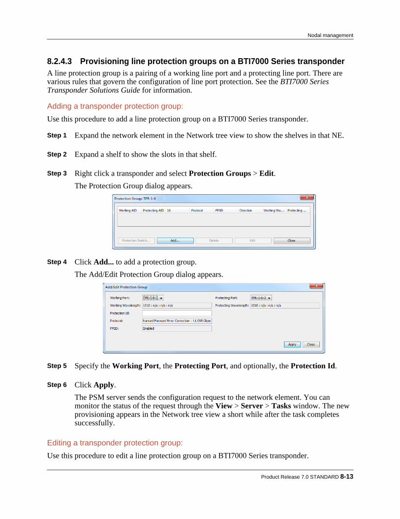
8.2.4.3 Provisioning line protection groups on a BTI7000 Series transponderA line protection group is a pairing of a working line port and a protecting line port. There arevarious rules that govern the configuration of line port protection. See the BTI7000 SeriesTransponder Solutions Guide for information.
Adding a transponder protection group:Use this procedure to add a line protection group on a BTI7000 Series transponder.
Step 1 Expand the network element in the Network tree view to show the shelves in that NE. Step 2 Expand a shelf to show the slots in that shelf. Step 3 Right click a transponder and select Protection Groups > Edit.
The Protection Group dialog appears.
Step 4 Click Add... to add a protection group.
The Add/Edit Protection Group dialog appears.
Step 5 Specify the Working Port, the Protecting Port, and optionally, the Protection Id. Step 6 Click Apply.
The PSM server sends the configuration request to the network element. You canmonitor the status of the request through the View > Server > Tasks window. The newprovisioning appears in the Network tree view a short while after the task completessuccessfully.
Editing a transponder protection group:Use this procedure to edit a line protection group on a BTI7000 Series transponder.
Product Release 7.0 STANDARD 8-13
Nodal management

Step 1 Expand the network element in the Network tree view to show the shelves in that NE. Step 2 Expand a shelf to show the slots in that shelf. Step 3 Right click a transponder and select Protection Groups > Edit.
The Protection Group dialog appears, displaying the existing protection group. Step 4 Select a protection group and click Edit.
The Add/Edit Protection Group dialog appears. Step 5 Edit the Protection Id. Step 6 Click Apply.
The PSM server sends the configuration request to the network element. You canmonitor the status of the request through the View > Server > Tasks window. The newprovisioning appears in the Network tree view a short while after the task completessuccessfully.
Deleting a transponder protection group:Use this procedure to delete a protection group on a BTI7000 Series transponder.
Step 1 Expand the network element in the Network tree view to show the shelves in that NE. Step 2 Expand a shelf to show the slots in that shelf. Step 3 Right click a transponder and select Protection Groups > Edit.
The Protection Group dialog appears, displaying the existing protection group. Step 4 Select the protection group you want to delete and click Delete.
The Deleting Protection Group confirmation dialog appears. Step 5 Click OK to confirm the deletion.
The PSM server sends the configuration request to the network element. You canmonitor the status of the request through the View > Server > Tasks window. The newprovisioning appears in the Network tree a short while after the task completessuccessfully.
Executing a protection switch command:Use this procedure to execute a protection switch command on a BTI7000 Series transponderport.
Step 1 Expand the network element in the Network tree view to show the shelves in that NE.
8-14 proNX Service Manager User Guide – Document Version 01
Nodal management

Step 2 Expand a shelf to show the slots in that shelf. Step 3 Right click a transponder and select Protection Groups > Edit.
The Protection Group dialog appears, displaying the existing protection group. Step 4 Select a protection group and click Protection Switch....
The Protection Switch dialog appears.
Step 5 Select the port on which you want to apply the command. Step 6 Select from the following actions:
• Manual Switch - Switch the working and protecting ports. This is only allowedwhen the protecting port is free of faults.
• Forced Switch - Switch the working and protecting ports even if the protecting porthas a Signal Degrade condition.
• Lockout - Make the specified port unavailable. If the specified port is the workingport, a protection switch occurs. If the specified port is the protecting port, the port isno longer available for protecting.
• Release - Release the lockout. Step 7 Click Apply.
The PSM server sends the configuration request to the network element. You canmonitor the status of the request through the View > Server > Tasks window. The newprovisioning appears in the Network tree a short while after the task completessuccessfully.
8.2.4.4 Provisioning client protection groups on a BTI7000 Series transponderA client protection group is a pairing of a working client port and a protecting client port. Thereare various rules that govern the configuration of client port protection. See the BTI7000 SeriesTransponder Solutions Guide for information.
Note Not all transponders support client protection.
Adding a client protection group:Use this procedure to add a client protection group on a BTI7000 Series transponder.
Product Release 7.0 STANDARD 8-15
Nodal management

Step 1 Expand the network element in the Network tree view to show the shelves in that NE. Step 2 To add a group across shelves, right click a network element and select Client
Protection Groups > Edit. To add a group within a shelf, right click a shelf and select Client Protection Groups > Edit.The Protection Group dialog appears.
Step 3 Click Add... to add a client protection group.
The Add/Edit Protection Group dialog appears.
Step 4 Specify the Working Port, the Protecting Port, and optionally, the Protection Id. Step 5 Click Apply.
The PSM server sends the configuration request to the network element. You canmonitor the status of the request through the View > Server > Tasks window. The newprovisioning appears in the Network tree view a short while after the task completessuccessfully.
Editing a client protection group:Use this procedure to edit a client protection group on a BTI7000 Series transponder.
Step 1 Expand the network element in the Network tree view to show the shelves in that NE. Step 2 Right click the network element or a shelf and select Client Protection Groups > Edit.
The Protection Group dialog appears, displaying the existing protection groups. Step 3 Select a protection group and click Edit.
The Add/Edit Protection Group dialog appears. Step 4 Edit the Protection Id.
8-16 proNX Service Manager User Guide – Document Version 01
Nodal management

Step 5 Click Apply.The PSM server sends the configuration request to the network element. You canmonitor the status of the request through the View > Server > Tasks window. The newprovisioning appears in the Network tree a short while after the task completessuccessfully.
Deleting a client protection group:Use this procedure to delete a client protection group on a BTI7000 Series transponder.
Step 1 Expand the network element in the Network tree view to show the shelves in that NE. Step 2 Right click the network element or shelf and select Client Protection Groups > Edit.
The Protection Group dialog appears, displaying the existing protection groups. Step 3 Select the protection group you want to delete and click Delete.
The Deleting Protection Group confirmation dialog appears. Step 4 Click OK to confirm the deletion.
The PSM server sends the configuration request to the network element. You canmonitor the status of the request through the View > Server > Tasks window. The newprovisioning appears in the Network tree a short while after the task completessuccessfully.
Executing a client protection switch command:Use this procedure to execute a client protection switch command on a BTI7000 Seriestransponder port.
Step 1 Expand the network element in the Network tree view to show the shelves in that NE. Step 2 Right click the network element or a shelf and select Client Protection Groups > Edit.
The Protection Group dialog appears, displaying the existing protection group. Step 3 Select a protection group and click Protection Switch....
The Protection Switch dialog appears.
Step 4 Select the port on which you want to apply the command. Step 5 Select from the following actions:
Product Release 7.0 STANDARD 8-17
Nodal management
• Manual Switch - Switch the working and protecting ports. This is only allowedwhen the protecting port is free of faults.
• Forced Switch - Switch the working and protecting ports even if the protecting porthas a Signal Degrade condition.
• Lockout - Make the specified port unavailable. If the specified port is the workingport, a protection switch occurs. If the specified port is the protecting port, the port isno longer available for protecting.
• Release - Release the lockout. Step 6 Click Apply.
The PSM server sends the configuration request to the network element. You canmonitor the status of the request through the View > Server > Tasks window. The newprovisioning appears in the Network tree a short while after the task completessuccessfully.
8.2.5 Provisioning a muxponder on a BTI7000 Series shelfPSM supports provisioning of the 2-port, 8-port, and 10-port muxponders.This section contains the following topics:• 8.2.5.1, “Provisioning ports on a BTI7000 Series muxponder”• 8.2.5.2, “Provisioning virtual concatenation groups on a BTI7000 Series muxponder”• 8.2.5.3, “Provisioning cross-connects on a BTI7000 Series muxponder”• 8.2.5.4, “Provisioning protection groups on a BTI7000 Series muxponder”• 8.2.5.5, “Provisioning synchronization on a BTI7000 Series muxponder”To add a muxponder, follow the steps in 8.2.3.1, “Adding a module” and select the desiredmuxponder from the PEC drop-down list.
8.2.5.1 Provisioning ports on a BTI7000 Series muxponderBTI7000 Series muxponders consist of a set of client ports and 2 line ports.
Adding a muxponder port:Use this procedure to add a new port on a BTI7000 Series muxponder.
Step 1 Expand the network element in the Network tree view to show the shelves in that NE. Step 2 Expand a shelf to show the slots in that shelf. Step 3 Expand a muxponder to show the ports in that muxponder. Step 4 Right click an unprovisioned port and select Port > Provision to add a port on that
muxponder.
8-18 proNX Service Manager User Guide – Document Version 01
Nodal management
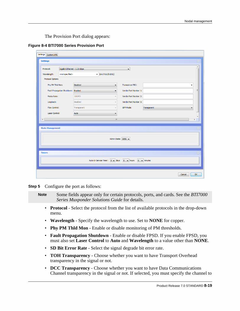
The Provision Port dialog appears:
Figure 8-4 BTI7000 Series Provision Port
Step 5 Configure the port as follows:
Note Some fields appear only for certain protocols, ports, and cards. See the BTI7000Series Muxponder Solutions Guide for details.
• Protocol - Select the protocol from the list of available protocols in the drop-downmenu.
• Wavelength - Specify the wavelength to use. Set to NONE for copper.• Phy PM Thld Mon - Enable or disable monitoring of PM thresholds.• Fault Propagation Shutdown - Enable or disable FPSD. If you enable FPSD, you
must also set Laser Control to Auto and Wavelength to a value other than NONE.• SD Bit Error Rate - Select the signal degrade bit error rate.• TOH Transparency - Choose whether you want to have Transport Overhead
transparency in the signal or not.• DCC Transparency - Choose whether you want to have Data Communications
Channel transparency in the signal or not. If selected, you must specify the channel to
Product Release 7.0 STANDARD 8-19
Nodal management

transport the DCC bytes. This option is automatically selected if TOHTransparency is selected.
• Laser Control - Select Auto to let software control the laser. Select Manual On toturn on the laser. Select Manual Off to turn off the laser.
• Line Mapping - Specify the line mapping for line ports.• Transceiver PEC - Optionally, specify the transceiver PEC.• Vendor Part Number 1 to 3 - Optionally, specify the vendor part numbers.• Loopback - This attribute cannot be set when adding a port.• GFP Mode - Set the Generic Framing Procedure mapping mode.• Media Rate - Set the media rate.• Flow Control - Set the flow control mode.• Admin State - Specify the initial state of the port.• Auto-In Service Timer - Specify the AINS timer. This attribute is only applicable if
the Admin State is AINS. Step 6 Optionally, click the Custom Info tab to see the Custom Info panel.
a) Specify the port identifier ID 1.b) Specify the Fiber Type.c) Specify the Custom 1 field as desired.d) Specify the Remote Id. For information on how to use this field, see 5.3.3, “Deriving
topology using Remote IDs”. Step 7 Click OK.
The PSM server sends the configuration request to the network element. You canmonitor the status of the request through the View > Server > Tasks window. The newprovisioning appears in the Network tree view a short while after the task completessuccessfully.
Editing a muxponder port:Use this procedure to edit a port on a BTI7000 Series muxponder.
Step 1 Expand the network element in the Network tree view to show the shelves in that NE. Step 2 Expand a shelf to show the slots in that shelf. Step 3 Expand a muxponder to show the ports for that muxponder. Step 4 Right click a provisioned port and select Port > Provision.
The Provision Port dialog appears.
8-20 proNX Service Manager User Guide – Document Version 01
Nodal management

Step 5 Change one or more port settings as follows:
Note Some fields appear only for certain protocols, ports, and cards. See the BTI7000Series Muxponder Solutions Guide for details.
• Protocol - This attribute cannot be changed.• Wavelength - Specify the wavelength to use. Set to NONE for copper.• Phy PM Thld Mon - Enable or disable monitoring of PM thresholds.• Fault Propagation Shutdown - Enable or disable FPSD. If you enable FPSD, you
must also set Laser Control to Auto and Wavelength to a value other than NONE.• SD Bit Error Rate - Select the signal degrade bit error rate.• TOH Transparency - Choose whether you want to have Transport Overhead
transparency in the signal or not.• DCC Transparency - Choose whether you want to have Data Communications
Channel transparency in the signal or not. If selected, you must specify the channel totransport the DCC bytes. This option is automatically selected if TOHTransparency is selected.
• Laser Control - Select Auto to let software control the laser. Select Manual On toturn on the laser. Select Manual Off to turn off the laser.
• Line Mapping - Specify the line mapping for line ports.• Transceiver PEC - Optionally, specify the transceiver PEC.• Vendor Part Number 1 to 3 - Optionally, specify the vendor part numbers.• Loopback - Set to Terminal for terminal loopback, Facility for facility loopback, or
Disabled. The port must be out of service before you can set this option.• GFP Mode - Set the Generic Framing Procedure mapping mode.• Media Rate - Set the media rate.• Flow Control - Set the flow control mode.• Admin State - Set the admin state of the port.• Operational State - This attribute is read only.• Secondary State - This attribute is read only.• Laser Status - This attribute is read only.• Auto-In Service Timer - Specify the AINS timer. This attribute is only applicable if
the Admin State is AINS. Step 6 To change the Custom Info settings , click the Custom Info tab.
a) Specify the port identifiers ID 1 and ID 2.b) Specify the Fiber Type.c) Specify the Custom 1, Custom 2, and Custom 3 settings as desired.
Product Release 7.0 STANDARD 8-21
Nodal management
d) Specify the Remote Id. For information on how to use this field, see 5.3.3, “Derivingtopology using Remote IDs”.
Step 7 Click Apply.
The PSM server sends the configuration request to the network element. You canmonitor the status of the request through the View > Server > Tasks window. The newprovisioning appears in the Network tree view a short while after the task completessuccessfully.
Deleting a muxponder port:Use this procedure to delete a port on a BTI7000 Series muxponder.Before a port can be deleted, it must be removed from any protection groups and cross-connects.
Step 1 Expand the network element in the Network tree view to show the shelves in that NE. Step 2 Expand a shelf to show the slots in that shelf. Step 3 Expand a muxponder to show the ports for that muxponder. Step 4 Right click a provisioned port and select Port > Delete. Step 5 Click OK in the Delete Port confirmation dialog.
The PSM server sends the configuration request to the network element. You canmonitor the status of the request through the View > Server > Tasks window. The newprovisioning appears in the Network tree view a short while after the task completessuccessfully.
8.2.5.2 Provisioning virtual concatenation groups on a BTI7000 Seriesmuxponder
A virtual concatenation group (VCG) is a collection of virtual tributaries that are concatenated tocreate a higher bit rate stream. The tributaries in a VCG do not need to be contiguous.
Adding a muxponder virtual concatenation group:Use this procedure to add a virtual concatenation group (VCG) on a BTI7000 Series muxponder.
Step 1 Expand the network element in the Network tree view to show the shelves in that NE. Step 2 Expand a shelf to show the slots in that shelf. Step 3 Right click a muxponder and select Virtual Concatenation Groups > Edit.
The Virtual Concatenation Groups dialog appears, displaying the existing virtualconcatenation groups.
8-22 proNX Service Manager User Guide – Document Version 01
Nodal management
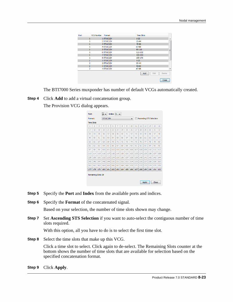
The BTI7000 Series muxponder has number of default VCGs automatically created. Step 4 Click Add to add a virtual concatenation group.
The Provision VCG dialog appears.
Step 5 Specify the Port and Index from the available ports and indices. Step 6 Specify the Format of the concatenated signal.
Based on your selection, the number of time slots shown may change. Step 7 Set Ascending STS Selection if you want to auto-select the contiguous number of time
slots required.With this option, all you have to do is to select the first time slot.
Step 8 Select the time slots that make up this VCG.
Click a time slot to select. Click again to de-select. The Remaining Slots counter at thebottom shows the number of time slots that are available for selection based on thespecified concatenation format.
Step 9 Click Apply.
Product Release 7.0 STANDARD 8-23
Nodal management

The PSM server sends the configuration request to the network element. You canmonitor the status of the request through the View > Server > Tasks window. The newprovisioning appears in the Network tree view a short while after the task completessuccessfully.
Editing a muxponder virtual concatenation group:Use this procedure to edit a virtual concatenation group on a BTI7000 Series muxponder.
Step 1 Expand the network element in the Network tree view to show the shelves in that NE. Step 2 Expand a shelf to show the slots in that shelf. Step 3 Right click a muxponder and select Virtual Concatenation Groups > Edit.
The Virtual Concatenation Groups dialog appears, displaying the existing virtualconcatenation groups.
Step 4 Select a virtual concatenation group and click Edit.
The Provision VCG dialog appears. Step 5 Specify the Format of the concatenated signal.
Based on your selection, the number of time slots shown may change. Step 6 Set Ascending STS Selection if you want to auto-select the contiguous number of time
slots required.With this option, all you have to do is to select the first time slot.
Step 7 Select the time slots that make up this VCG.
Click a time slot to select. Click again to de-select. The Remaining Slots counter at thebottom shows the number of time slots that are available for selection based on thespecified concatenation format.
Step 8 Click Apply.
The PSM server sends the configuration request to the network element. You canmonitor the status of the request through the View > Server > Tasks window. The newprovisioning appears in the Network tree view a short while after the task completessuccessfully.
Deleting a muxponder virtual concatenation group:Use this procedure to delete a virtual concatenation group on a BTI7000 Series muxponder.
Step 1 Expand the network element in the Network tree view to show the shelves in that NE. Step 2 Expand a shelf to show the slots in that shelf.
8-24 proNX Service Manager User Guide – Document Version 01
Nodal management
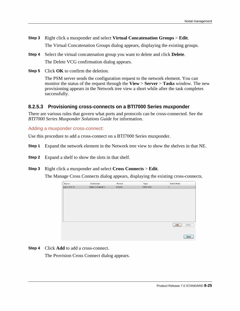
Step 3 Right click a muxponder and select Virtual Concatenation Groups > Edit.
The Virtual Concatenation Groups dialog appears, displaying the existing groups. Step 4 Select the virtual concatenation group you want to delete and click Delete.
The Delete VCG confirmation dialog appears. Step 5 Click OK to confirm the deletion.
The PSM server sends the configuration request to the network element. You canmonitor the status of the request through the View > Server > Tasks window. The newprovisioning appears in the Network tree view a short while after the task completessuccessfully.
8.2.5.3 Provisioning cross-connects on a BTI7000 Series muxponderThere are various rules that govern what ports and protocols can be cross-connected. See theBTI7000 Series Muxponder Solutions Guide for information.
Adding a muxponder cross-connect:Use this procedure to add a cross-connect on a BTI7000 Series muxponder.
Step 1 Expand the network element in the Network tree view to show the shelves in that NE. Step 2 Expand a shelf to show the slots in that shelf. Step 3 Right click a muxponder and select Cross Connects > Edit.
The Manage Cross Connects dialog appears, displaying the existing cross-connects.
Step 4 Click Add to add a cross-connect.
The Provision Cross Connect dialog appears.
Product Release 7.0 STANDARD 8-25
Nodal management

Step 5 Specify the concatenation Type.
If you specify contiguous concatenation (CCAT), then you will select the timeslot using Set Time Slot and the CCAT type using the CRS Type pulldown menu. If you specifyvirtual concatenation ( VCAT), then you will select the virtual concatenation groupthrough the Source pulldown menu. The timeslots and VCAT type for the virtualconcatenation group are set when you create the virtual concatenation group. See8.2.5.2, “Provisioning virtual concatenation groups on a BTI7000 Series muxponder”.
Step 6 Specify the Source, the Destination, and the Direction. Step 7 Click Apply.
The PSM server sends the configuration request to the network element. You canmonitor the status of the request through the View > Server > Tasks window. The newprovisioning appears in the Network tree view a short while after the task completessuccessfully.
Deleting a muxponder cross-connect:Use this procedure to delete a cross-connect on a BTI7000 Series muxponder.
Step 1 Expand the network element in the Network tree view to show the shelves in that NE. Step 2 Expand a shelf to show the slots in that shelf. Step 3 Right click a muxponder and select Cross Connects > Edit.
The Manage Cross Connects dialog appears. Step 4 Select the cross-connect you want to delete and click Delete.
The Delete Cross Connect confirmation dialog appears. Step 5 Click OK to confirm the deletion.
The PSM server sends the configuration request to the network element. You canmonitor the status of the request through the View > Server > Tasks window. The newprovisioning appears in the Network tree view a short while after the task completessuccessfully.
8-26 proNX Service Manager User Guide – Document Version 01
Nodal management
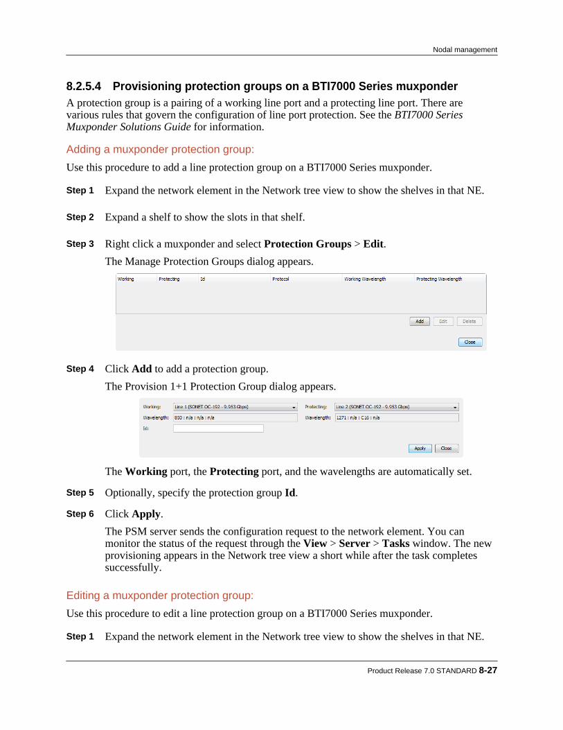
8.2.5.4 Provisioning protection groups on a BTI7000 Series muxponderA protection group is a pairing of a working line port and a protecting line port. There arevarious rules that govern the configuration of line port protection. See the BTI7000 SeriesMuxponder Solutions Guide for information.
Adding a muxponder protection group:Use this procedure to add a line protection group on a BTI7000 Series muxponder.
Step 1 Expand the network element in the Network tree view to show the shelves in that NE. Step 2 Expand a shelf to show the slots in that shelf. Step 3 Right click a muxponder and select Protection Groups > Edit.
The Manage Protection Groups dialog appears.
Step 4 Click Add to add a protection group.
The Provision 1+1 Protection Group dialog appears.
The Working port, the Protecting port, and the wavelengths are automatically set. Step 5 Optionally, specify the protection group Id. Step 6 Click Apply.
The PSM server sends the configuration request to the network element. You canmonitor the status of the request through the View > Server > Tasks window. The newprovisioning appears in the Network tree view a short while after the task completessuccessfully.
Editing a muxponder protection group:Use this procedure to edit a line protection group on a BTI7000 Series muxponder.
Step 1 Expand the network element in the Network tree view to show the shelves in that NE.
Product Release 7.0 STANDARD 8-27
Nodal management

Step 2 Expand a shelf to show the slots in that shelf. Step 3 Right click a muxponder and select Protection Groups > Edit.
The Manage Protection Groups dialog appears, displaying the existing protection group. Step 4 Select a protection group and click Edit.
The Provision 1+1 Protection Group dialog appears. Step 5 Edit the protection Id. Step 6 Click Apply.
The PSM server sends the configuration request to the network element. You canmonitor the status of the request through the View > Server > Tasks window. The newprovisioning appears in the Network tree view a short while after the task completessuccessfully.
Deleting a muxponder protection group:Use this procedure to delete a protection group on a BTI7000 Series muxponder.
Step 1 Expand the network element in the Network tree view to show the shelves in that NE. Step 2 Expand a shelf to show the slots in that shelf. Step 3 Right click a muxponder and select Protection Groups > Edit.
The Manage Protection Groups dialog appears, displaying the existing protection group. Step 4 Select the protection group you want to delete and click Delete.
The Delete Line Protection confirmation dialog appears. Step 5 Click OK to confirm the deletion.
The PSM server sends the configuration request to the network element. You canmonitor the status of the request through the View > Server > Tasks window. The newprovisioning appears in the Network tree view a short while after the task completessuccessfully.
8.2.5.5 Provisioning synchronization on a BTI7000 Series muxponderClient traffic must be properly synchronized when multiplexing into a SONET/SDH network.This procedure shows how synchronization can be configured.
Step 1 Expand the network element in the Network tree view to show the shelves in that NE. Step 2 Expand a shelf to show the slots in that shelf.
8-28 proNX Service Manager User Guide – Document Version 01
Nodal management
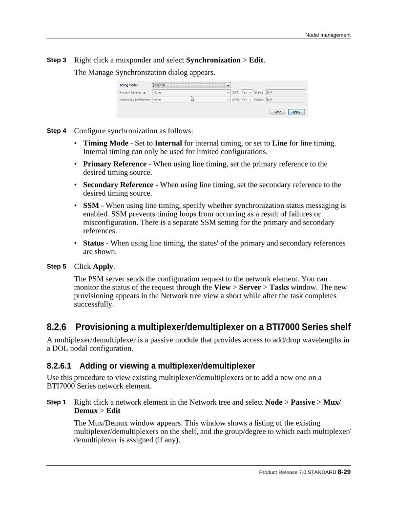
Step 3 Right click a muxponder and select Synchronization > Edit.The Manage Synchronization dialog appears.
Step 4 Configure synchronization as follows:
• Timing Mode - Set to Internal for internal timing, or set to Line for line timing.Internal timing can only be used for limited configurations.
• Primary Reference - When using line timing, set the primary reference to thedesired timing source.
• Secondary Reference - When using line timing, set the secondary reference to thedesired timing source.
• SSM - When using line timing, specify whether synchronization status messaging isenabled. SSM prevents timing loops from occurring as a result of failures ormisconfiguration. There is a separate SSM setting for the primary and secondaryreferences.
• Status - When using line timing, the status' of the primary and secondary referencesare shown.
Step 5 Click Apply.
The PSM server sends the configuration request to the network element. You canmonitor the status of the request through the View > Server > Tasks window. The newprovisioning appears in the Network tree view a short while after the task completessuccessfully.
8.2.6 Provisioning a multiplexer/demultiplexer on a BTI7000 Series shelfA multiplexer/demultiplexer is a passive module that provides access to add/drop wavelengths ina DOL nodal configuration.
8.2.6.1 Adding or viewing a multiplexer/demultiplexerUse this procedure to view existing multiplexer/demultiplexers or to add a new one on aBTI7000 Series network element.
Step 1 Right click a network element in the Network tree and select Node > Passive > Mux/Demux > EditThe Mux/Demux window appears. This window shows a listing of the existingmultiplexer/demultiplexers on the shelf, and the group/degree to which each multiplexer/demultiplexer is assigned (if any).
Product Release 7.0 STANDARD 8-29
Nodal management

Step 2 Click on the plus icon to add a new multiplexer/demultiplexer.
The Provision Mux/Demux window appears.
8-30 proNX Service Manager User Guide – Document Version 01
Nodal management
Step 3 Specify the Slot for the multiplexer/demultiplexer. Step 4 Select a PEC from the list of available PECs. Step 5 Optionally, specify the Custom fields. These fields are for operator use and are opaque
to the system.
a) Click the Custom tab.b) In the Custom panel, specify the Id, Custom 1, Custom 2, and Custom 3 settings as
desired. Step 6 When you are finished, click Apply.
The newly added multiplexer/demultiplexer appears in the Mux/Demux window. Toassign the multiplexer/demultiplexer to an optical group and degree, see8.2.9.1, “Assigning or unassigning equipment”.
Step 7 Click OK.
The PSM server sends the configuration request to the network element. You canmonitor the status of the request through the View > Server > Tasks window. The newprovisioning appears in PSM a short while after the task completes successfully.
8.2.6.2 Deleting a multiplexer/demultiplexerUse this procedure to delete a multiplexer/demultiplexer from a BTI7000 Series network element.
Step 1 Right click a network element in the Network tree and select Node > Passive > Mux/Demux > EditThe Mux/Demux window appears.
Step 2 Select a multiplexer/demultiplexer and click on the minus icon to delete it.
The selected multiplexer/demultiplexer disappears from the window. Step 3 Click OK.
The PSM server sends the configuration request to the network element. You canmonitor the status of the request through the View > Server > Tasks window. The newprovisioning takes effect a short while after the task completes successfully.
8.2.7 Provisioning GCC on a BTI7000 Series network element
8.2.7.1 Provisioning GCCUse this procedure to provision GCC on a transponder, muxponder, or PVX port on a BTI7000Series network element. GCC is used to carry management traffic inband.
Step 1 Expand the network element in the Network tree to show the shelves in that NE.
Product Release 7.0 STANDARD 8-31
Nodal management
Step 2 Expand a shelf to show the slots in that shelf. Step 3 Expand a transponder, muxponder, or PVX to see the ports on that module. Step 4 Right click a provisioned port and select GCC > Provision.
Note GCC is only available for selection when the transceiver is configured for certainprotocols.
The Manage GCC dialog appears. Step 5 Configure GCC as follows:
• Mode: The mode is set at Full Rate and cannot be changed.• Admin State: Select Enabled or Disabled.• Operational State: The operational state is read-only.• Secondary State: The secondary state is read-only.
Step 6 When you are finished, click Apply.
The PSM server sends the configuration request to the network element. You canmonitor the status of the request through the View > Server > Tasks window. The newprovisioning appears in PSM a short while after the task completes successfully.
8.2.7.2 Deleting GCCUse this procedure to delete GCC from a transponder, muxponder, or PVX port on a BTI7000Series network element.
Step 1 Expand the network element in the Network tree to show the shelves in that NE. Step 2 Expand a shelf to show the slots in that shelf. Step 3 Expand a transponder, muxponder, or PVX to see the ports on that module. Step 4 Right click a provisioned port and select GCC > Delete. Step 5 Click OK in the confirmation dialog.
The PSM server sends the configuration request to the network element. You canmonitor the status of the request through the View > Server > Tasks window. The newprovisioning appears in PSM a short while after the task completes successfully.
8.2.8 Viewing port PMs on a BTI7000 Series network elementUse this procedure to view current port PMs on transponder, muxponder, and packetVX moduleson a BTI7000 Series network element.
8-32 proNX Service Manager User Guide – Document Version 01
Nodal management
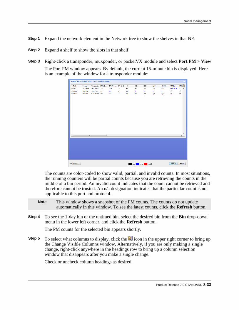
Step 1 Expand the network element in the Network tree to show the shelves in that NE. Step 2 Expand a shelf to show the slots in that shelf. Step 3 Right-click a transponder, muxponder, or packetVX module and select Port PM > View
The Port PM window appears. By default, the current 15-minute bin is displayed. Hereis an example of the window for a transponder module:
The counts are color-coded to show valid, partial, and invalid counts. In most situations,the running counters will be partial counts because you are retrieving the counts in themiddle of a bin period. An invalid count indicates that the count cannot be retrieved andtherefore cannot be trusted. An n/a designation indicates that the particular count is notapplicable to this port and protocol.
Note This window shows a snapshot of the PM counts. The counts do not updateautomatically in this window. To see the latest counts, click the Refresh button.
Step 4 To see the 1-day bin or the untimed bin, select the desired bin from the Bin drop-down
menu in the lower left corner, and click the Refresh button.The PM counts for the selected bin appears shortly.
Step 5 To select what columns to display, click the icon in the upper right corner to bring up
the Change Visible Columns window. Alternatively, if you are only making a singlechange, right-click anywhere in the headings row to bring up a column selectionwindow that disappears after you make a single change.Check or uncheck column headings as desired.
Product Release 7.0 STANDARD 8-33
Nodal management

Step 6 To sort the PMs based on column values, click on the column heading that you want tosort.
Step 7 To export the PM data to a CSV file, click Export and save the file.
8.2.9 Provisioning the BTI7000 Series Dynamic Optical Layer (DOL)The BTI7000 Series Dynamic Optical Layer provides reconfigurable optical add/dropmultiplexing, reach extension, and end-to-end service management for the BTI7000 Seriesoptical network. The Dynamic Optical Layer consists of ROADM modules that providewavelength routing, line amplifier modules that provide reach extension, and passive multiplexer/demultiplexer modules that provide wavelength access. A DOL node can be configured to be achannel equalizing terminal, a channel equalizing line node, a line amplifier node, or a ROADMnode.Before you can provision DOL, you must first add optical modules to the shelf. To add a module,follow the steps in 8.2.3.1, “Adding a module” and select the desired module from the PEC drop-down list. Once all the modules are added, use the procedures in this section to create the desiredoptical nodal function.Once the nodal function is created, you can activate DOL services using the proceduresdescribed in 11.1, “Optical services”.
8.2.9.1 Provisioning optical groupsAn optical group is a representation of an optical node (i.e. a collection of modules that togetherprovide a specific nodal function in the optical network). An optical node can be a DOL or a non-DOL node.The following optical group types are supported:• NON_EQUALIZING_TERM - This is a non-channel equalizing terminal that consists of
non-equalizing amplifiers that do not support DOL.• CHANNEL_EQUALIZING_TERMINAL - This is a channel equalizing terminal that
consists of DOL equipment.• LINE_AMPLIFIER_NODE - This is a non-channel equalizing line node that consists of
DOL equipment.• CHANNEL_EQUALIZING_LINE_NODE - This is a channel equalizing terminal that
consists of DOL equipment.• ROADM - This is a ROADM node that consists of DOL equipment.
Creating an optical group:Use this procedure to create an optical group on a BTI7000 Series network element.
Step 1 Expand the network element in the Network tree to show the shelves in that NE. Step 2 Right-click on Optical Groups and select Group/Degree > Provision.
8-34 proNX Service Manager User Guide – Document Version 01
Nodal management

The Provision Optical Group dialog appears:
Figure 8-5 Provision Optical Group
Step 3 Configure the group as follows:
• Group ID - Specify the Group ID to distinguish the new group from the other opticalgroups on the node.
• Group Type - Specify the function for the group from the drop-down menu. Step 4 Optionally, specify the Custom fields. These fields are for operator use and are opaque
to the system.
a) Click the Custom Settings tab.b) In the Custom Settings panel, specify the Id, Custom 1, Custom 2, and Custom 3
settings as desired. Step 5 When you are finished, click OK.
The PSM server sends the configuration request to the network element. You canmonitor the status of the request through the View > Server > Tasks window. The newoptical group appears in the Network tree a short while after the task completessuccessfully.
Product Release 7.0 STANDARD 8-35
Nodal management

Assigning or unassigning equipment:Use this procedure to assign or unassign equipment to or from an optical group on a BTI7000Series network element. An optical group is a collection of modules that together provide aspecific nodal function in the optical network. Modules must belong to an optical group in orderto provide the nodal function.
Step 1 Expand the network element in the Network tree. Step 2 Expand the Optical Groups to see the optical groups on that NE. Step 3 Right-click the optical group in which you want to assign equipment, and select Group/
Degree > Edit.The Update Optical Group dialog appears.
The Group ID is set during optical group creation, and cannot be edited. Step 4 Assign or unassign equipment from the group.
• To assign equipment to the group, click on the plus icon. This brings you to the Assign Optical Equipment window where you can assign equipment by selecting thedegree and the equipment. Click Apply when you are done. The newly assignedequipment appears in the Equipment list.
8-36 proNX Service Manager User Guide – Document Version 01
Nodal management

Note If the degree that you select does not yet exist, the degree is created and willappear in the Network tree.
• To unassign equipment, select the equipment from the list and then click on theminus icon. The unassigned equipment is removed from the Equipment list.
Step 5 Configure the Custom fields. These fields are for operator use and are opaque to the
system.
a) Click the Custom Settings tab.b) In the Custom Settings panel, edit the Id, Custom 1, Custom 2, and Custom 3
settings as desired. Step 6 When you are finished, click Apply.
The PSM server sends the configuration request to the network element. You canmonitor the status of the request through the View > Server > Tasks window. Thechanges appear in PSM a short while after the task completes successfully.
Deleting an optical group:Use this procedure to delete an optical group on a BTI7000 Series network element.
Step 1 Expand the network element in the Network tree to show the shelves in that NE. Step 2 Expand Optical Groups to show the optical groups in that NE. Step 3 Right-click an optical group and select Group/Degree > Delete. Step 4 Click OK in the confirmation dialog.
The PSM server sends the configuration request to the network element. You canmonitor the status of the request through the View > Server > Tasks window. Thedeleted group disappears from the Network tree a short while after the task completessuccessfully.
8.2.9.2 Editing WDM parameters in an optical groupUse this procedure to edit WDM parameters on a BTI7000 Series network element. WDMparameters apply to the respective line span for equipment in optical groups.
Step 1 Expand the network element in the Network tree. Step 2 Expand Optical Groups to see the optical groups on that NE. Step 3 Expand an optical group to see the degrees in that group. Step 4 Expand a degree to see the equipment in that degree.
Product Release 7.0 STANDARD 8-37
Nodal management
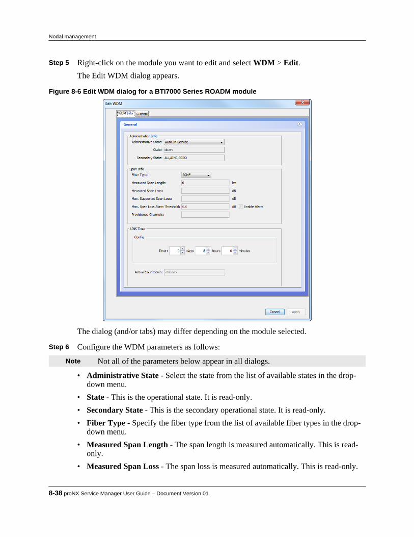
Step 5 Right-click on the module you want to edit and select WDM > Edit.The Edit WDM dialog appears.
Figure 8-6 Edit WDM dialog for a BTI7000 Series ROADM module
The dialog (and/or tabs) may differ depending on the module selected. Step 6 Configure the WDM parameters as follows:
Note Not all of the parameters below appear in all dialogs.
• Administrative State - Select the state from the list of available states in the drop-down menu.
• State - This is the operational state. It is read-only.• Secondary State - This is the secondary operational state. It is read-only.• Fiber Type - Specify the fiber type from the list of available fiber types in the drop-
down menu.• Measured Span Length - The span length is measured automatically. This is read-
only.• Measured Span Loss - The span loss is measured automatically. This is read-only.
8-38 proNX Service Manager User Guide – Document Version 01
Nodal management

• Max. Supported Span Loss - The maximum supported span loss is calculatedautomatically. This is read-only.
• Max. Span Loss Alarm Threshold - Specify the span loss threshold beyond whichan alarm is raised. This field can only be edited if Enable Alarm is selected.
• Loss Rx High Threshold- Similar to Max. Span Loss Alarm Threshold. Specifythe span loss threshold beyond which an alarm is raised. Set to 0 to disable.
• Enable Alarm - Select to enable the span loss threshold alarm.• Provisioned Channels - This is the number of channels that can be carried. This is
read-only.• Amp Tilt Trim - Set to fine tune the system gain tilt.• Post Amp Gain - Set the system gain.• Auto-In Service Timer - Optionally, specify the AINS timer. This attribute is only
applicable if the Administrative State is Auto-In-Service.• Active Countdown - This is the countdown for the AINS timer. It is read-only.
Step 7 Configure the Custom fields. These fields are for operator use and are opaque to the
system.
a) Click the Custom Settings tab.b) In the Custom Settings panel, edit the Id, Custom 1, Custom 2, and Custom 3
settings as desired. Step 8 When you are finished, click Apply.
The PSM server sends the configuration request to the network element. You canmonitor the status of the request through the View > Server > Tasks window. Thechanges appear in PSM a short while after the task completes successfully.
8.2.9.3 Adding and deleting the C2 portIn some BTI7000 Series nodal configurations, the C2 port of a ROADM module is optional. Inthese situations, PSM does not automatically create the C2 port, but leaves it up to the user tocreate it manually.Use this procedure to create and/or delete the optional C2 port on a BTI7000 Series ROADMmodule for the optical group type CHANNEL_EQUALIZING_TERMINAL. In thisconfiguration, the C2 port can be used to connect to alien wavelengths. See the BTI7000 SeriesDynamic Optical Layer Engineering Guideline for details.
Step 1 Expand the network element in the Network tree. Step 2 Expand the Optical Groups to see the optical groups on that NE. Step 3 Expand an optical group to see the degrees in that group.
Product Release 7.0 STANDARD 8-39
Nodal management

Step 4 Expand a degree to see the equipment in that degree. Step 5 To add the C2 port, right-click on the ROADM module and select C2 > Provision.
The PSM server sends the configuration request to the network element. You canmonitor the status of the request through the View > Server > Tasks window. The C2port is added to the ROADM in that degree a short while after the task completessuccessfully.
Step 6 To delete a previously-added optional C2 port, right-click on the ROADM module and
select C2 > Delete.The PSM server sends the configuration request to the network element. You canmonitor the status of the request through the View > Server > Tasks window. The C2port is deleted from the ROADM in that degree a short while after the task completessuccessfully.
8.2.9.4 Editing optical port parametersUse this procedure to edit optical port parameters on a BTI7000 Series network element. Anoptical port can be a line port, a client port, or a DCM port.
Step 1 Expand the network element in the Network tree. Step 2 Expand the Optical Groups to see the optical groups on that NE. Step 3 Expand an optical group to see the degrees in that group. Step 4 Expand a degree to see the equipment in that degree. Step 5 Expand a module to see the ports on that module. Step 6 Right-click on an optical port you want to edit and select Optical Port > Edit.
The Edit Optical Layer Port dialog appears.
8-40 proNX Service Manager User Guide – Document Version 01
Nodal management

Figure 8-7 Edit Optical Layer Port dialog for a BTI7000 Series ROADM line port
The dialog (and/or tabs) may differ depending on the module and port selected. Step 7 Configure the optical port parameters as follows:
Note Not all of the parameters below appear in all dialogs.
• State - This is the operational state. It is read-only.• Secondary State - This is the secondary operational state. It is read-only.• DWDM Type - This is the type of DWDM composite signal expected on the port. It
is set to native when connected to DOL equipment. It is set to alien when connectedto other equipment. This is read-only.
• Grid Type - This is the DWDM grid spacing for the port. If the equipment onlysupports a specific grid spacing, then this field is read-only.
• Fiber Connection - This shows the equipment at the other end of the fiberconnection. This is read-only.
• Wavelength - The wavelength for the port. This is read-only.• Frequency - The frequency for the port. This is read-only.• Tx Loss - Specify the optical loss in the transmit direction. Set to 0 for no loss.• Auto-In Service Timer - Optionally, specify the AINS timer.
Product Release 7.0 STANDARD 8-41
Nodal management

• Active Countdown - This is the countdown for the AINS timer. It is read-only. Step 8 Optionally, configure the Custom fields. These fields are for operator use and are
opaque to the system (with the exception of the Remote ID).
a) Click the Custom Settings tab.b) In the Custom Settings panel, edit the Id, Custom 1, Custom 2, and Custom 3
settings as desired.c) Set the Remote Id to describe the equipment at the other end of the fiber. PSM uses
the Remote Id when determining topology. Step 9 When you are finished, click Apply.
The PSM server sends the configuration request to the network element. You canmonitor the status of the request through the View > Server > Tasks window. Thechanges appear in PSM a short while after the task completes successfully.
8.2.9.5 Configuring a split ROADM nodeA split ROADM node is a highly survivable configuration where each ROADM module in aBTI7000 Series ROADM node is located in a separate network element, managed by a separatemanagement module. While these network elements are distinct in every other aspect, PSMtreats this combination as a single ROADM node during optical service activation.Creating a split ROADM node is essentially a hardware installation function where the ROADMmodules are installed on separate network elements and connected together by fiber over theirC2 ports. There is no provisioning required except to enable PSM to recognize the split ROADMnode. In order for PSM to recognize the split ROADM node as a single ROADM node, theRemote ID configuration on the C2 ports of the ROADM modules must point to each other. Thisis shown in the following figure. By configuring the Remote IDs on the C2 ports in this manner,PSM is able to recognize this as a split ROADM node configuration.
Use the following procedure to configure a split ROADM node on a BTI7000 Series system. Asplit ROADM node can be configured for the CHANNEL_EQUALIZING_LINE_NODE andROADM optical group types.
Step 1 Expand the network element in the Network tree. Step 2 Expand the Optical Groups branch to see the configured optical groups. Step 3 Expand an optical group to see the degrees in that group.
8-42 proNX Service Manager User Guide – Document Version 01
Nodal management

Step 4 Expand a degree to see the ROADM module in that degree. Step 5 Expand the ROADM module to see the ports in that module. Step 6 Right-click the Client: 2 port and select Remote ID > Provision.
Figure 8-8 Selecting the C2 port
The Provision Remote ID window appears. Step 7 Configure the Remote ID using the drop-down menus to point to the C2 port of the
second ROADM module.
Figure 8-9 Setting the Remote ID
By selecting the Bidirectional option, PSM automatically configures the C2 port at theother end to point back to this C2 port.
Step 8 Click OK.
Product Release 7.0 STANDARD 8-43
Nodal management

Note If you select Bidirectional and you specify a Remote ID that cannot bereconciled, PSM will be unable to configure the remote endpoint, and the taskwill fail.
Note The task may fail if you try to use this procedure on a card that has not beenprovisioned.
8.2.9.6 Editing OSC parameters in an optical groupUse this procedure to edit OSC parameters on a BTI7000 Series network element. The opticalservice channel (OSC) is used as a communications medium for control information betweenoptical equipment at both ends of a line span. Through the OSC, optical elements shareinformation and automatically measure span loss, adjust the system gain, and leverage a multi-span feedback loop that enables per-channel pre-emphasis to address wavelength tilt and ripple.
Step 1 Expand the network element in the Network tree. Step 2 Expand the Optical Groups to see the optical groups on that NE. Step 3 Expand an optical group to see the equipment in that group. Step 4 Right-click on the module you want to edit and select OSC > Edit.
The Edit OSC dialog appears.
8-44 proNX Service Manager User Guide – Document Version 01
Nodal management

Figure 8-10 Edit OSC dialog for a BTI7000 Series ROADM module
The dialog (and/or tabs) may differ depending on the module selected. Step 5 In the General tab, configure the OSC parameters as follows:
Note Not all of the parameters below appear in all dialogs.
• Administrative State or Admin Status - Select the state from the list of availablestates in the drop-down menu.
• State or Oper Status - This is the operational state. It is read-only.• Secondary State - This is the secondary operational state. It is read-only.• AINS Timer - Optionally, specify the AINS timer. This attribute is only applicable if
the Administrative State is Auto-In-Service.• Active Countdown - This is the countdown for the AINS timer. It is read-only.
Step 6 In the OSC Info tab, configure the OSC parameters as follows:
Note Not all of the parameters below appear in all dialogs.
• Admin Status - Select the state from the list of available states in the drop-downmenu.
• Oper Status - This is the operational state. It is read-only.
Product Release 7.0 STANDARD 8-45
Nodal management

• FE IM Mon - Select if you want the near end to validate the identity of the far endwith the expected far end parameters. If the identity does not match, the system willraise an alarm or condition.
• System Name (actual) - This is the actual system name of the far end. It is read-only.• IP Address (actual) - This is the actual NMS IP address of the far end. It is read-
only.• Group (actual) - This is the actual optical group identifier of the far end. It is read-
only.• Degree (actual) - This is the actual optical degree of the far end. It is read-only.• Group Type (actual)- This is the actual group type of the far end. It is read-only.• System Name (expected) - Set to the expected system name of the far end.• IP Address (expected) - Set to the expected NMS IP address of the far end.• Group (expected) - Set to the expected optical group identifier of the far end.• Degree (expected) - Set to the expected optical degree of the far end.
Step 7 In the FarEnd tab, configure the OSC parameters as follows:
Note Not all of the parameters below appear in all dialogs.
• Far-End Monitoring - Select if you want the near end to validate the identity of thefar end with the expected far end parameters. If the identity does not match, thesystem will raise an alarm or condition.
• System Name (actual) - This is the actual system name of the far end. It is read-only.• NMS IP Address (actual) - This is the actual NMS IP address of the far end. It is
read-only.• Optical Group (actual) - This is the actual optical group identifier of the far end. It
is read-only.• Optical Degree (actual) - This is the actual optical degree of the far end. It is read-
only.• Group Type (actual)- This is the actual group type of the far end. It is read-only.• System Name (expected) - Set to the expected system name of the far end.• NMS IP Address (expected) - Set to the expected NMS IP address of the far end.• Optical Group (expected) - Set to the expected optical group identifier of the far
end.• Optical Degree (expected) - Set to the expected optical degree of the far end.
Step 8 In the ODCC tab, configure the ODCC parameters as follows:
Note Not all of the parameters below appear in all dialogs.
8-46 proNX Service Manager User Guide – Document Version 01
Nodal management
The optical data communications channel (ODCC) is used to carry inband managementtraffic between Juniper Networks network elements.• Enable - Select to enable ODCC within the OSC.• Admin Status - Select the state from the list of available states in the drop-down
menu.• Oper Status - This is the operational state of the ODCC. It is read-only.
Step 9 Optionally, configure the Custom fields. These fields are for operator use and are
opaque to the system.
a) Click the Custom Settings tab.b) In the Custom Settings panel, edit the Id, Custom 1, Custom 2, and Custom 3
settings as desired. Step 10 When you are finished, click Apply.
The PSM server sends the configuration request to the network element. You canmonitor the status of the request through the View > Server > Tasks window. Thechanges appear in the Network tree (if applicable) a short while after the task completessuccessfully.
8.2.10 Enabling or disabling a portUse this procedure to administratively enable or disable a port on a BTI7000 Series networkelement.
Step 1 Expand the network element in the Network tree to show the shelves in that NE. Step 2 Expand a shelf to show the slots in that shelf. Step 3 Expand a module to show the ports on that module. Step 4 Enable or disable a port as follows.
a) To enable a provisioned port, right click the port and select Admin State > Enable.For PVX ports, you have the option of enabling the port at layer 1 or at layer 2.
b) To disable a provisioned port, right click the port and select Admin State > Disable.For PVX ports, you have the option of disabling the port at layer 1 or at layer 2.
Product Release 7.0 STANDARD 8-47
Nodal management

8.3 Nodal management for BTI7800 Series network elements
This section covers the following topics:• 8.3.1, “Provisioning a BTI7800 chassis”• 8.3.2, “Provisioning a Universal Forwarding Module on a BTI7800”• 8.3.3, “Provisioning a ROADM node on a BTI7800”• 8.3.4, “Provisioning a 96-Channel Amplifier on a BTI7800”• 8.3.5, “Provisioning a Wavelength Protection Switch module on a BTI7800”• 8.3.6, “Enabling or disabling a port”
Note The BTI7800 typically provisions modules automatically when the modules arephysically installed. This is called auto-provisioning. See the BTI7800 SeriesSoftware Configuration Guide for details.
8.3.1 Provisioning a BTI7800 chassis
8.3.1.1 Adding a shelfUse this procedure to add a new chassis on a BTI7800 Series network element.
Step 1 Right-click a network element in the Network tree view or in the Topology Map viewand select Node > Shelf > Provision.The Provision Shelf dialog appears:
8-48 proNX Service Manager User Guide – Document Version 01
Nodal management

Figure 8-11 BTI7800 Series Provision Shelf
Step 2 Configure the shelf as follows:
• PEC - Select the PEC from the list of available PECs in the drop-down menu.• Shelf Number - Select the shelf number from the drop-down menu. The drop-down
menu only displays the shelf numbers that are available and not already in use.• Alias - Optionally, enter a string identifying the shelf.• Location - Optionally, enter a string describing the location of the NE.• Chassis Type - The chassis type is automatically populated based on the PEC.• Admin Status - Specify whether the initial state of the shelf is Up or Down or
Testing. Step 3 Optionally, specify the Custom fields. These fields are for operator use and are opaque
to the system.
a) Click the Custom Settings tab.b) In the Custom Settings panel, specify the Custom 1, Custom 2, and Custom 3
settings as desired. Step 4 When you are finished, click OK.
Product Release 7.0 STANDARD 8-49
Nodal management

The PSM server sends the configuration request to the network element. You canmonitor the status of the request through the View > Server > Tasks window. The newprovisioning appears in the Network tree view a short while after the task completessuccessfully.
8.3.1.2 Editing a shelfUse this procedure to edit a chassis on a BTI7800 Series network element.
Step 1 Expand a network element in the Network tree view to show the shelves on that networkelement.
Step 2 Right-click a shelf and select Shelf > Edit.
The Edit Shelf dialog appears:
Figure 8-12 BTI7800 Series Provision Shelf
Step 3 Edit the shelf as follows:
• PEC - This field is read-only.• Shelf Number - This field is read-only.• Alias - Enter a string identifying the shelf.• Location - Enter a string describing the location of the NE.
8-50 proNX Service Manager User Guide – Document Version 01
Nodal management
• Chassis Type This field is read-only.• Admin Status - Specify whether the state of the shelf is Up or Down or Testing.
Step 4 Optionally, specify the Custom fields. These fields are for operator use and are opaque
to the system.
a) Click the Custom Settings tab.b) In the Custom Settings panel, specify the Custom 1, Custom 2, and Custom 3
settings as desired. Step 5 When you are finished, click Apply.
The PSM server sends the configuration request to the network element. You canmonitor the status of the request through the View > Server > Tasks window. The newprovisioning appears in the Network tree view a short while after the task completessuccessfully.
8.3.1.3 Deleting a shelfUse this procedure to delete a chassis on a BTI7800 Series network element.
Pre-requisites:
All components on the shelf must be deleted before you can delete the shelf.
Step 1 Expand the network element in the Network tree view to show the shelves in that NE. Step 2 Right-click a shelf and select Shelf > Delete. Step 3 Click OK in the Delete Shelf confirmation dialog.
The PSM server sends the configuration request to the network element. You canmonitor the status of the request through the View > Server > Tasks window. The newprovisioning appears in the Network tree view a short while after the task completessuccessfully.
8.3.2 Provisioning a Universal Forwarding Module on a BTI7800This section covers the following topics:• 8.3.2.1, “Adding a UFM”• 8.3.2.2, “Editing a UFM”• 8.3.2.3, “Deleting a UFM”• 8.3.2.4, “Adding a BIC”• 8.3.2.5, “Editing a BIC”• 8.3.2.6, “Cloning a BIC”
Product Release 7.0 STANDARD 8-51
Nodal management
• 8.3.2.7, “Deleting a BIC”• 8.3.2.8, “Adding a transceiver”• 8.3.2.9, “Editing a transceiver”• 8.3.2.10, “Cloning a transceiver”• 8.3.2.11, “Deleting a transceiver”• 8.3.2.12, “Adding an interface”• 8.3.2.13, “Editing an interface”• 8.3.2.14, “Configuring a multiplexed interface”• 8.3.2.15, “Cloning an interface”• 8.3.2.16, “Deleting an interface”• 8.3.2.17, “Viewing interface PMs on a UFM”
8.3.2.1 Adding a UFMUse this procedure to add a new UFM on a BTI7800 Series network element.
Step 1 Expand the network element in the Network tree to show the shelves in that NE. Step 2 Expand a shelf to show the slots in that shelf. Step 3 Right-click an unprovisioned slot and select Slot > Provision to add a module in that
slot.The Provision Slot dialog appears:
8-52 proNX Service Manager User Guide – Document Version 01
Nodal management
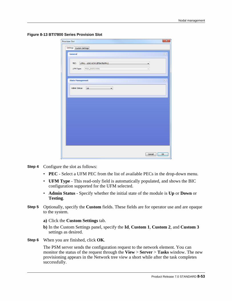
Figure 8-13 BTI7800 Series Provision Slot
Step 4 Configure the slot as follows:
• PEC - Select a UFM PEC from the list of available PECs in the drop-down menu.• UFM Type - This read-only field is automatically populated, and shows the BIC
configuration supported for the UFM selected.• Admin Status - Specify whether the initial state of the module is Up or Down or
Testing. Step 5 Optionally, specify the Custom fields. These fields are for operator use and are opaque
to the system.
a) Click the Custom Settings tab.b) In the Custom Settings panel, specify the Id, Custom 1, Custom 2, and Custom 3
settings as desired. Step 6 When you are finished, click OK.
The PSM server sends the configuration request to the network element. You canmonitor the status of the request through the View > Server > Tasks window. The newprovisioning appears in the Network tree view a short while after the task completessuccessfully.
Product Release 7.0 STANDARD 8-53
Nodal management

8.3.2.2 Editing a UFMUse this procedure to edit an existing UFM on a BTI7800 Series network element.
Step 1 Expand the network element in the Network tree view to show the shelves in that NE. Step 2 Expand a shelf to show the slots in that shelf. Step 3 Right-click a UFM and select Slot > Edit to edit the module in that slot.
The Edit Slot dialog appears.
Figure 8-14 BTI7800 Series Edit Slot (UFM)
Step 4 Edit the slot as follows:
• PEC - This field is read-only.• UFM Type - This field is read-only.• Admin Status - Change the state of the module to Up or Down or Testing.
Step 5 Optionally, edit the Custom fields. These fields are for operator use and are opaque to
the system.
a) Click the Custom Settings tab.
8-54 proNX Service Manager User Guide – Document Version 01
Nodal management
b) In the Custom Settings panel, specify the Id, Custom 1, Custom 2, and Custom 3settings as desired.
Step 6 When you are finished, click Apply.
The PSM server sends the configuration request to the network element. You canmonitor the status of the request through the View > Server > Tasks window. The newprovisioning appears in the Network tree view a short while after the task completessuccessfully.
8.3.2.3 Deleting a UFMUse this procedure to delete a UFM on a BTI7800 Series network element.
Pre-requisites:
All components in the UFM must be deleted before you can delete the UFM.
Step 1 Expand the network element in the Network tree view to show the shelves in that NE. Step 2 Expand a shelf to show the slots in that shelf. Step 3 Right-click a UFM and select Slot > Delete. Step 4 Click OK in the Delete Slot confirmation dialog.
The PSM server sends the configuration request to the network element. You canmonitor the status of the request through the View > Server > Tasks window. The newprovisioning appears in the Network tree view a short while after the task completessuccessfully.
8.3.2.4 Adding a BICUse this procedure to add a BTI Interface Card (BIC) to a UFM on a BTI7800 Series networkelement.
Step 1 Expand the network element in the Network tree view to show the shelves in that NE. Step 2 Expand a shelf to show the slots in that shelf. Step 3 Expand a UFM to show the BICs in that UFM. Step 4 Right-click an unprovisioned BIC and select BIC > Provision.
The Provision BIC dialog appears:
Product Release 7.0 STANDARD 8-55
Nodal management

Figure 8-15 BTI7800 Series Provision BIC
Step 5 Configure the BIC as follows:
• Type - Specify the type of BIC.• PEC - Select the PEC from the list of available PECs in the drop-down menu. Only
the list of PECs for the specified type is shown.• Admin Status - Specify whether the initial state of the module is Up or Down or
Testing. Step 6 Optionally, specify the Custom fields. These fields are for operator use and are opaque
to the system.
a) Click the Custom Settings tab.b) In the Custom Settings panel, specify the Id, Custom 1, Custom 2, and Custom 3
settings as desired. Step 7 When you are finished, click OK.
The PSM server sends the configuration request to the network element. You canmonitor the status of the request through the View > Server > Tasks window. The newprovisioning appears in the Network tree view a short while after the task completessuccessfully.
8-56 proNX Service Manager User Guide – Document Version 01
Nodal management

8.3.2.5 Editing a BICUse this procedure to edit an existing BTI Interface Card (BIC) on a UFM on a BTI7800 Seriesnetwork element.
Step 1 Expand the network element in the Network tree view to show the shelves in that NE. Step 2 Expand a shelf to show the slots in that shelf. Step 3 Expand a UFM to show the BICs in that UFM. Step 4 Right-click an existing BIC and select BIC > Edit.
The Edit BIC dialog appears.
Figure 8-16 BTI7800 Series Edit BIC
Step 5 Edit the BIC as follows:
• Type - This field is read-only.• PEC - This field is read-only.• Admin Status - Change the state of the BIC to Up or Down or Testing.
Product Release 7.0 STANDARD 8-57
Nodal management
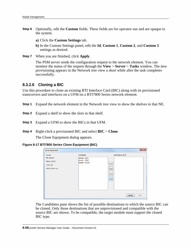
Step 6 Optionally, edit the Custom fields. These fields are for operator use and are opaque tothe system.
a) Click the Custom Settings tab.b) In the Custom Settings panel, edit the Id, Custom 1, Custom 2, and Custom 3
settings as desired. Step 7 When you are finished, click Apply.
The PSM server sends the configuration request to the network element. You canmonitor the status of the request through the View > Server > Tasks window. The newprovisioning appears in the Network tree view a short while after the task completessuccessfully.
8.3.2.6 Cloning a BICUse this procedure to clone an existing BTI Interface Card (BIC) along with its provisionedtransceivers and interfaces on a UFM on a BTI7800 Series network element.
Step 1 Expand the network element in the Network tree view to show the shelves in that NE. Step 2 Expand a shelf to show the slots in that shelf. Step 3 Expand a UFM to show the BICs in that UFM. Step 4 Right-click a provisioned BIC and select BIC > Clone.
The Clone Equipment dialog appears.
Figure 8-17 BTI7800 Series Clone Equipment (BIC)
The Candidates pane shows the list of possible destinations to which the source BIC canbe cloned. Only those destinations that are unprovisioned and compatible with thesource BIC are shown. To be compatible, the target module must support the clonedBIC type.
8-58 proNX Service Manager User Guide – Document Version 01
Nodal management

Step 5 From the list of Candidates, use the arrow buttons to move one or more interfaces to the Destinations pane.
Note All provisioned transceivers and interfaces that belong to the selected source BICwill be cloned as well.
Step 6 When you are finished, click Apply.
The PSM server sends the configuration requests to the network element. You canmonitor the status of the requests through the View > Server > Tasks window. The newprovisioning appears in the Network tree view a short while after the tasks completesuccessfully.
8.3.2.7 Deleting a BICUse this procedure to delete a BTI Interface Card (BIC) on a UFM on a BTI7800 Series networkelement.
Pre-requisites:
All transceivers and interfaces for that BIC must be deleted before you can delete the BIC.
Step 1 Expand the network element in the Network tree view to show the shelves in that NE. Step 2 Expand a shelf to show the slots in that shelf. Step 3 Expand a UFM to show the BICs in that UFM. Step 4 Right-click a provisioned BIC and select BIC > Delete. Step 5 Click OK in the Delete BIC confirmation dialog.
The PSM server sends the configuration request to the network element. You canmonitor the status of the request through the View > Server > Tasks window. The newprovisioning appears in the Network tree view a short while after the task completessuccessfully.
8.3.2.8 Adding a transceiverUse this procedure to add a transceiver to a BIC on a UFM on a BTI7800 Series network element.
Step 1 Expand the network element in the Network tree view to show the shelves in that NE. Step 2 Expand a shelf to show the slots in that shelf. Step 3 Expand a UFM to show the BICs in that UFM. Step 4 Expand a BIC to show the ports for that BIC.
Product Release 7.0 STANDARD 8-59
Nodal management

Step 5 Right-click an unprovisioned port and select Transceiver > Provision.
The Provision Transceiver dialog appears:
Figure 8-18 BTI7800 Series Provision Transceiver
Step 6 Configure the transceiver as follows:
• Type - Specify the type of transceiver from the drop-down menu. This selection isgreyed out if it has already been pre-determined by the BIC type.
• Optical Format - Select the optical format from the drop-down menu.• Admin Status - Specify whether the initial state of the module is Up or Down or
Testing. Step 7 Optionally, specify the Custom fields.
a) Click the Custom Settings tab. These fields are for operator use and are opaque tothe system.
b) In the Custom Settings panel, specify the Id, Custom 1, Custom 2, and Custom 3settings as desired.
Step 8 When you are finished, click OK.
8-60 proNX Service Manager User Guide – Document Version 01
Nodal management

The PSM server sends the configuration request to the network element. You canmonitor the status of the request through the View > Server > Tasks window. The newprovisioning appears in the Network tree view a short while after the task completessuccessfully.
8.3.2.9 Editing a transceiverUse this procedure to edit an existing transceiver on a UFM port on a BTI7800 Series networkelement.
Step 1 Expand the network element in the Network tree view to show the shelves in that NE. Step 2 Expand a shelf to show the slots in that shelf. Step 3 Expand a UFM to show the BICs in that UFM. Step 4 Expand a BIC to show the ports for that BIC. Step 5 Right-click an existing port and select Transceiver > Edit.
The Edit Transceiver dialog appears.
Product Release 7.0 STANDARD 8-61
Nodal management

Figure 8-19 BTI7800 Series Edit Transceiver
Step 6 Edit the transceiver as follows:
• Type - This field is read-only.• Optical Format - This field is read-only.• Admin Status - Change the state of the module to Up or Down or Testing.
Step 7 Optionally, edit the Custom fields.
a) Click the Custom Settings tab. These fields are for operator use and are opaque tothe system.
b) In the Custom Settings panel, edit the Id, Custom 1, Custom 2, and Custom 3settings as desired.
Step 8 When you are finished, click Apply.
The PSM server sends the configuration request to the network element. You canmonitor the status of the request through the View > Server > Tasks window. The newprovisioning appears in the Network tree view a short while after the task completessuccessfully.
8-62 proNX Service Manager User Guide – Document Version 01
Nodal management

8.3.2.10 Cloning a transceiverUse this procedure to clone an existing transceiver along with its provisioned interfaces on aUFM on a BTI7800 Series network element.
Step 1 Expand the network element in the Network tree view to show the shelves in that NE. Step 2 Expand a shelf to show the slots in that shelf. Step 3 Expand a UFM to show the BICs in that UFM. Step 4 Expand a BIC to show the ports for that BIC. Step 5 Right-click a provisioned port and select Transceiver > Clone.
The Clone Equipment dialog appears:
Figure 8-20 BTI7800 Series Clone Equipment (transceiver)
The Candidates pane shows the list of possible destinations to which the sourcetransceiver can be cloned. Only those destinations that are unprovisioned andcompatible with the source transceiver are shown. To be compatible, the source andtarget transceiver must have the same BIC type.
Step 6 From the list of Candidates, use the arrow buttons to move one or more interfaces to the
Destinations pane.
Note All provisioned interfaces that belong to the selected source transceiver will becloned as well.
Step 7 When you are finished, click Apply.
The PSM server sends the configuration requests to the network element. You canmonitor the status of the requests through the View > Server > Tasks window. The newprovisioning appears in the Network tree view a short while after the tasks completesuccessfully.
Product Release 7.0 STANDARD 8-63
Nodal management

8.3.2.11 Deleting a transceiverUse this procedure to delete a transceiver on a UFM on a BTI7800 Series network element.
Pre-requisites:
All interfaces for that transceiver must be deleted before you can delete the transceiver.
Step 1 Expand the network element in the Network tree view to show the shelves in that NE. Step 2 Expand a shelf to show the slots in that shelf. Step 3 Expand a UFM to show the BICs in that UFM. Step 4 Expand a BIC to show the ports for that BIC. Step 5 Right-click a provisioned port and select Transceiver > Delete. Step 6 Click OK in the Delete Transceiver confirmation dialog.
The PSM server sends the configuration request to the network element. You canmonitor the status of the request through the View > Server > Tasks window. The newprovisioning appears in the Network tree view a short while after the task completessuccessfully.
8.3.2.12 Adding an interfaceUse this procedure to add an interface to a UFM port on a BTI7800 Series network element.Before you can add an interface, you must add the associated transceiver first.
Note This procedure adds an OTU4 interface as an example. The interface parameterswill be different for other interfaces.
Step 1 Expand the network element in the Network tree to show the shelves in that NE. Step 2 Expand a shelf to show the slots in that shelf. Step 3 Expand a UFM to show the BICs in that UFM. Step 4 Expand a BIC to show the ports for that BIC. Step 5 Right-click a provisioned port and select Interface > Provision.
The Provision Interface dialog appears. For example, the following shows the dialog foran OTU4 interface:
8-64 proNX Service Manager User Guide – Document Version 01
Nodal management
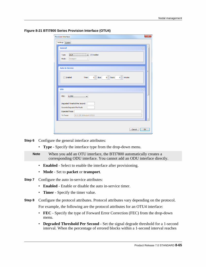
Figure 8-21 BTI7800 Series Provision Interface (OTU4)
Step 6 Configure the general interface attributes:
• Type - Specify the interface type from the drop-down menu.
Note When you add an OTU interface, the BTI7800 automatically creates acorresponding ODU interface. You cannot add an ODU interface directly.
• Enabled - Select to enable the interface after provisioning.• Mode - Set to packet or transport.
Step 7 Configure the auto in-service attributes:
• Enabled - Enable or disable the auto in-service timer.• Timer - Specify the timer value.
Step 8 Configure the protocol attributes. Protocol attributes vary depending on the protocol.
For example, the following are the protocol attributes for an OTU4 interface:• FEC - Specify the type of Forward Error Correction (FEC) from the drop-down
menu.• Degraded Threshold Per Second - Set the signal degrade threshold for a 1-second
interval. When the percentage of errored blocks within a 1-second interval reaches
Product Release 7.0 STANDARD 8-65
Nodal management

this value, the interval is considered a degraded interval. The valid range is 1 to 100(percent) inclusive.
• Seconds Degraded For Fault - Set the signal degrade fault threshold. When thenumber of consecutive degraded 1-second intervals reaches this value, a signaldegrade fault is raised. Valid values are 0 (no fault is raised) and 2 through 10(seconds) inclusive.
• Expected Trace - Specify the trace message that is expected to be received.• Tx Trace - Specify the trace message that is to be transmitted.
Step 9 Configure the physical attributes.
Many of these attributes can only be configured if the Enabled check box is uncheckedin the General attributes section. De-select Enabled , change the physical attributes,and then re-select Enabled .• Grid - Specify the grid spacing from the drop-down menu. The grid spacing can only
be specified for tunable transceivers.• Wavelength or Frequency - Specify either the desired wavelength or the desired
frequency. The wavelength or frequency can only be specified for tunabletransceivers.
• Loopback - Select the type of loopback, if any, from the drop-down menu. Thisattribute can only be set if the Enabled check box is unchecked in the Generalattributes section. If the Enabled check box is selected, this value automaticallychanges to NO_LOOPBACK.
• CPRWS - Select the carrier phase recovery window size from the drop-down menu.This attribute is not applicable to all transceiver types.
• Laser Enabled - Select to enable the transmit laser after provisioning.• FPSD - Select to enable Fault Propagation Shutdown (FPSD). When a failure occurs
and FPSD is enabled, the interface shuts down its laser instead of transmitting amaintenance signal. This attribute is only available for selection for Ethernetinterfaces.
Step 10 To configure packet interface parameters when the interface Mode is packet, click the
MPLS tab.
a) Set the IP Address / Mask for the interface.b) Specify the MTU size.c) Add ARP entries by clicking Add in the ARP section, and specifying the IP Address
and MAC address pair.The IP Address in the ARP entry should be on the same subnet as the IP Address ofthe interface. The MAC address is specified with colon delimiters between each pairof hex digits.
Step 11 Optionally, specify the Custom fields.
8-66 proNX Service Manager User Guide – Document Version 01
Nodal management

a) Click the Custom Settings tab. These fields are for operator use and are opaque tothe system.
b) In the Custom Settings panel, specify the Id, Custom 1, Custom 2, and Custom 3settings as desired.
Step 12 When you are finished, click OK.
The PSM server sends the configuration request to the network element. You canmonitor the status of the request through the View > Server > Tasks window. The newprovisioning appears in PSM a short while after the task completes successfully.
8.3.2.13 Editing an interfaceUse this procedure to edit an existing interface on a UFM on a BTI7800 Series network element.
Note This procedure edits an OTU4 interface as an example. The interface parameterswill be different for other interfaces.
Step 1 Expand the network element in the Network tree to show the shelves in that NE. Step 2 Expand a shelf to show the slots in that shelf. Step 3 Expand a UFM to show the BICs in that UFM. Step 4 Expand a BIC to show the ports for that BIC. Step 5 Expand a port to show the interfaces for that port. Step 6 Right-click a provisioned interface and select Interface > Edit.
The Edit Interface dialog appears.
Product Release 7.0 STANDARD 8-67
Nodal management
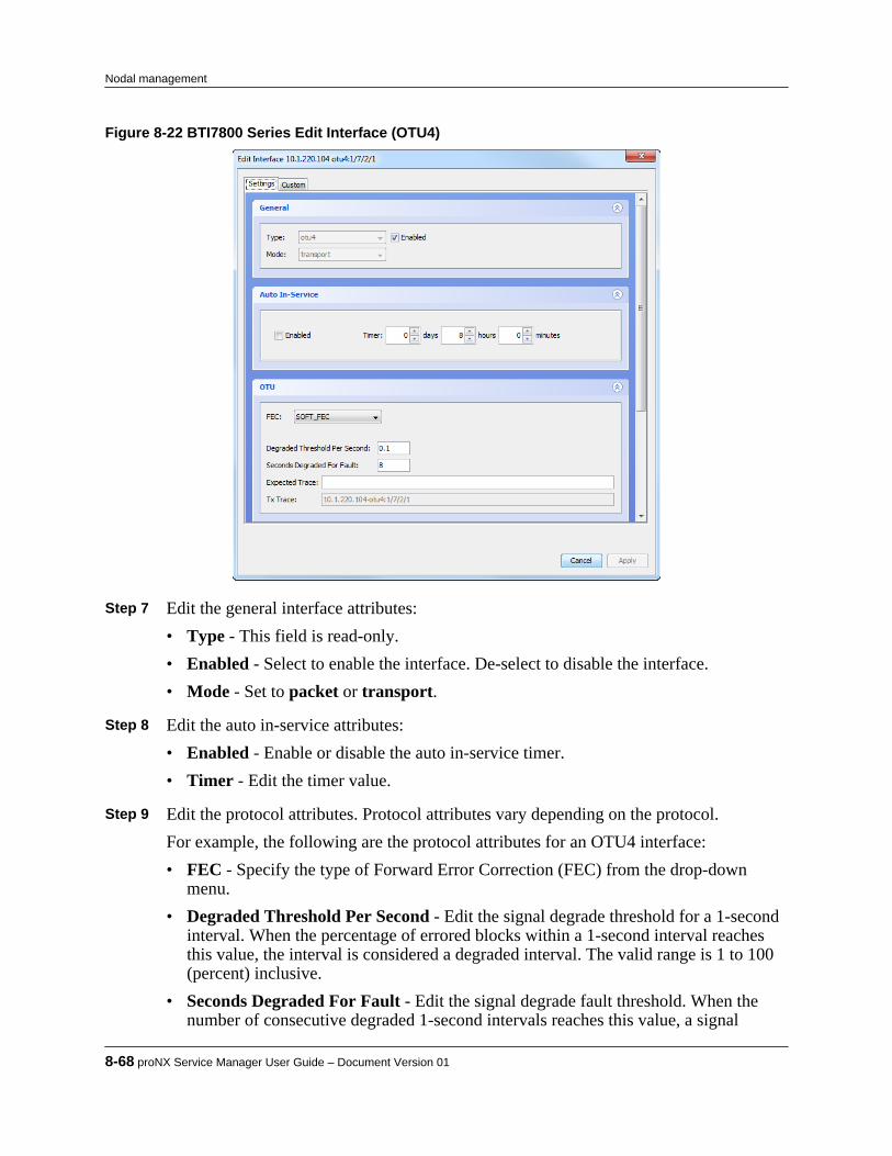
Figure 8-22 BTI7800 Series Edit Interface (OTU4)
Step 7 Edit the general interface attributes:
• Type - This field is read-only.• Enabled - Select to enable the interface. De-select to disable the interface.• Mode - Set to packet or transport.
Step 8 Edit the auto in-service attributes:
• Enabled - Enable or disable the auto in-service timer.• Timer - Edit the timer value.
Step 9 Edit the protocol attributes. Protocol attributes vary depending on the protocol.
For example, the following are the protocol attributes for an OTU4 interface:• FEC - Specify the type of Forward Error Correction (FEC) from the drop-down
menu.• Degraded Threshold Per Second - Edit the signal degrade threshold for a 1-second
interval. When the percentage of errored blocks within a 1-second interval reachesthis value, the interval is considered a degraded interval. The valid range is 1 to 100(percent) inclusive.
• Seconds Degraded For Fault - Edit the signal degrade fault threshold. When thenumber of consecutive degraded 1-second intervals reaches this value, a signal
8-68 proNX Service Manager User Guide – Document Version 01
Nodal management

degrade fault is raised. Valid values are 0 (no fault is raised) and 2 through 10(seconds) inclusive.
• Expected Trace - Edit the trace message that is expected to be received.• Tx Trace - This field is read-only.
Step 10 Edit the physical attributes:
• Grid - This field can only be edited when the interface is disabled. This attribute isonly available for selection for tunable lasers.
• Wavelength or Frequency - This field can only be edited when the interface isdisabled. This attribute is only available for selection for tunable lasers.
• Loopback - This field can only be edited when the interface is disabled.• CPRWS - This field can only be edited when the interface is disabled. This attribute
is not applicable to all transceiver types.• Laser Enabled - Select to enable the transmit laser. De-select to disable the transmit
laser.• FPSD - This field can only be edited for Ethernet interfaces.When changing an attribute that requires the interface to be disabled, follow these steps:
a) Disable the interface by de-selecting Enabled in the General attributes section.b) Change the desired physical attributes and click Apply to apply the changes to the
network element.c) After the changes are reflected in PSM, edit the interface again, re-select Enabled in
the General attributes section, and click Apply. Step 11 To configure packet interface parameters when the interface Mode is packet, click the
MPLS tab.
a) Set the IP Address / Mask for the interface.b) Specify the MTU size.c) Add an ARP entry by clicking Add in the ARP section, and specifying the IP
Address and MAC address pair.The IP Address in the ARP entry should be on the same subnet as the IP Address ofthe interface. The MAC address is specified with colon delimiters between each pairof hex digits.
d) Delete an ARP entry by clicking anywhere within the ARP entry and clicking Delete. Step 12 Optionally, edit the Custom fields.
a) Click the Custom Settings tab. These fields are for operator use and are opaque tothe system.
b) In the Custom Settings panel, edit the Id, Custom 1, Custom 2, and Custom 3settings as desired.
Product Release 7.0 STANDARD 8-69
Nodal management
Step 13 When you are finished, click Apply.The PSM server sends the configuration request to the network element. You canmonitor the status of the request through the View > Server > Tasks window. The newprovisioning appears in PSM a short while after the task completes successfully.
8.3.2.14 Configuring a multiplexed interfaceUse this procedure to configure a multiplexed ODU interface on a UFM on a BTI7800 Seriesnetwork element.
Pre-requisites:
• The corresponding OTU interface is created.
Note You do not need to create an ODU interface explicitly. An ODU interface isautomatically created when you create the corresponding OTU interface.
Only some ODU interfaces can be configured for multiplexing.
Step 1 Expand the network element in the Network tree to show the shelves in that NE. Step 2 Expand a shelf to show the slots in that shelf. Step 3 Expand a UFM to show the BICs in that UFM. Step 4 Expand a BIC to show the ports for that BIC. Step 5 Expand a port to show the OTU interfaces for that port. Step 6 Expand an OTU interface to see the corresponding ODU interface. Step 7 Right-click the ODU interface and select Interface > Edit.
The Edit Interface dialog appears.
8-70 proNX Service Manager User Guide – Document Version 01
Nodal management
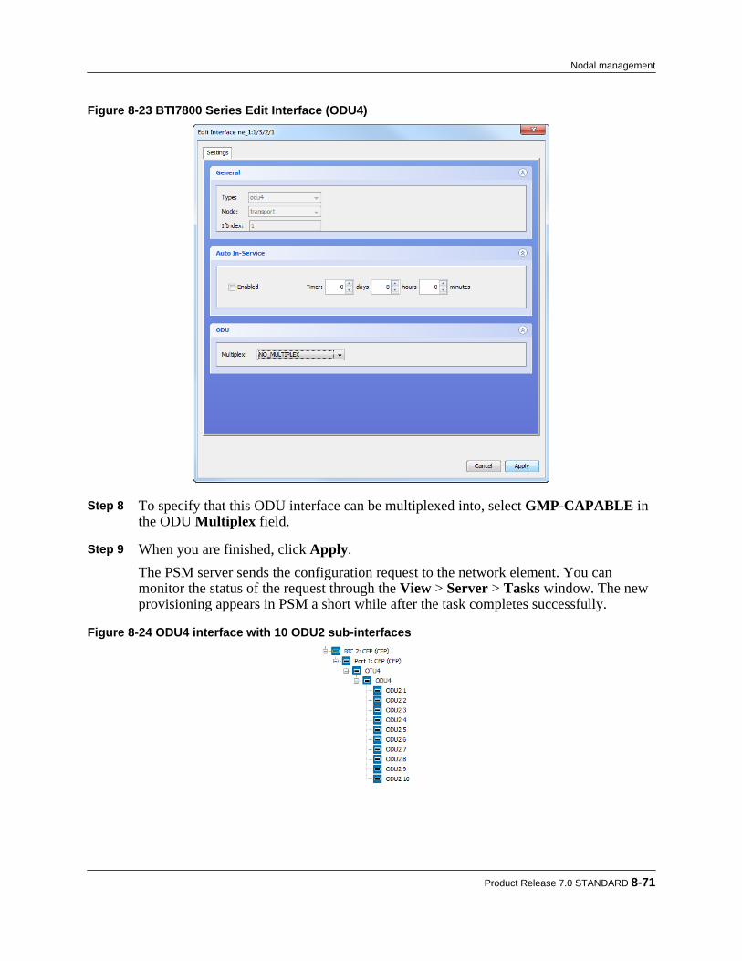
Figure 8-23 BTI7800 Series Edit Interface (ODU4)
Step 8 To specify that this ODU interface can be multiplexed into, select GMP-CAPABLE in
the ODU Multiplex field. Step 9 When you are finished, click Apply.
The PSM server sends the configuration request to the network element. You canmonitor the status of the request through the View > Server > Tasks window. The newprovisioning appears in PSM a short while after the task completes successfully.
Figure 8-24 ODU4 interface with 10 ODU2 sub-interfaces
Product Release 7.0 STANDARD 8-71
Nodal management

8.3.2.15 Cloning an interfaceUse this procedure to clone an existing interface on a UFM on a BTI7800 Series networkelement.
Step 1 Expand the network element in the Network tree view to show the shelves in that NE. Step 2 Expand a shelf to show the slots in that shelf. Step 3 Expand a UFM to show the BICs in that UFM. Step 4 Expand a BIC to show the ports for that BIC. Step 5 Expand a port to show the interfaces. Step 6 Right-click a provisioned interface and select Interface > Clone.
The Clone Equipment dialog appears:
Figure 8-25 BTI7800 Series Clone Equipment (interface)
The Candidates pane shows the list of possible destinations to which the sourceinterface can be cloned. Only those destinations that are unprovisioned and compatiblewith the source interface are shown. To be compatible, the source and target interfacesmust have the same BIC type and the same optical format (fixed/tunable).
Step 7 From the list of Candidates, use the arrow buttons to move one or more interfaces to the
Destinations pane. Step 8 When you are finished, click Apply.
The PSM server sends the configuration requests to the network element. You canmonitor the status of the requests through the View > Server > Tasks window. The newprovisioning appears in the Network tree view a short while after the tasks completesuccessfully.
8-72 proNX Service Manager User Guide – Document Version 01
Nodal management

8.3.2.16 Deleting an interfaceUse this procedure to delete an interface on a UFM on a BTI7800 Series network element.
Step 1 Expand the network element in the Network tree view to show the shelves in that NE. Step 2 Expand a shelf to show the slots in that shelf. Step 3 Expand a UFM to show the BICs in that UFM. Step 4 Expand a BIC to show the ports for that BIC. Step 5 Expand a port to show the interfaces for that port. Step 6 Right-click a provisioned interface and select Interface > Delete. Step 7 Click OK in the Delete Interface confirmation dialog.
The PSM server sends the configuration request to the network element. You canmonitor the status of the request through the View > Server > Tasks window. The newprovisioning appears in the Network tree view a short while after the task completessuccessfully.
8.3.2.17 Viewing interface PMs on a UFMUse this procedure to view current interface PMs on a UFM on a BTI7800 Series networkelement.
Step 1 Expand the network element in the Network tree to show the shelves in that NE. Step 2 Expand a shelf to show the slots in that shelf. Step 3 Expand a UFM slot to show the BICs in that UFM. Step 4 Expand a BIC to show the ports for that BIC. Step 5 Expand a port to show the interfaces. Step 6 Right-click a provisioned interface and select Interface PMs > View.
The Interface Current PM window appears:
Product Release 7.0 STANDARD 8-73
Nodal management

The PMs are listed for the interface selected.
Note This window shows a snapshot of the PM counts. The counts do not updateautomatically in this window. To see the latest counts, click the Refresh button.
Step 7 To select what columns to display, right-click anywhere in the headings row to bring up
a column selection window.Check or uncheck column headings as desired.
Step 8 To sort the PMs based on column values, click on the column heading that you want to
sort. Step 9 To export the PM data to a CSV file, click Export and save the file.
8.3.3 Provisioning a ROADM node on a BTI7800The following sections describe how to provision a ROADM node and how to perform otherROADM-related tasks on a BTI7800.• 8.3.3.1, “General provisioning procedure”• 8.3.3.2, “Adding a ROADM or an ILA module”• 8.3.3.3, “Editing a ROADM or an ILA module”• 8.3.3.4, “Deleting a ROADM or an ILA module”• 8.3.3.5, “Adding a PRE module”• 8.3.3.6, “Editing a PRE module”• 8.3.3.7, “Deleting a PRE module”• 8.3.3.8, “Adding or viewing a multiplexer/demultiplexer”• 8.3.3.9, “Deleting a multiplexer/demultiplexer”• 8.3.3.10, “Editing a port”• 8.3.3.11, “Editing the OMS”• 8.3.3.12, “Editing the OSC”
8-74 proNX Service Manager User Guide – Document Version 01
Nodal management

• 8.3.3.13, “Adding a fiber connection on a ROADM or an ILA client port”• 8.3.3.14, “Editing a fiber connection on a ROADM or an ILA client port”• 8.3.3.15, “Deleting a fiber connection on a ROADM or an ILA client port”• 8.3.3.16, “Adding a fiber connection on a ROADM or an ILA line port”• 8.3.3.17, “Editing a fiber connection on a ROADM or an ILA line port”• 8.3.3.18, “Deleting a fiber connection on a ROADM or an ILA line port”• 8.3.3.19, “Adding a fiber connection on a UFM interface”• 8.3.3.20, “Editing a fiber connection on a UFM interface”• 8.3.3.21, “Deleting a fiber connection on a UFM interface”• 8.3.3.22, “Viewing fiber connections”• 8.3.3.23, “Adding an optical channel”• 8.3.3.24, “Bulk adding optical channels”• 8.3.3.25, “Editing an optical channel”• 8.3.3.26, “Deleting an optical channel”• 8.3.3.27, “Viewing port PMs”• 8.3.3.28, “Viewing OMS PMs”• 8.3.3.29, “Viewing OSC PMs”• 8.3.3.30, “Viewing optical channel PMs”
8.3.3.1 General provisioning procedureThe procedure for provisioning a ROADM node can be summarized as follows:
1 Provision all required modules. This is covered in sections 8.3.3.2, “Adding a ROADM or anILA module” through 8.3.3.12, “Editing the OSC”. It is usually not necessary for you toperform this step explicitly because the BTI7800 automatically provisions modules when themodules are physically installed. This is called auto-provisioning.
2 Provision all required fiber connections. This is covered in sections 8.3.3.13, “Adding a fiberconnection on a ROADM or an ILA client port” through 8.3.3.22, “Viewing fiberconnections”. Fiber connections represent the physical fiber connectivity within a ROADMnode and across ROADM nodes. Auto-provisioning provisions fiber connections when thefibers are physically installed, so it is usually not necessary for you to perform this stepexplicitly either.
3 Provision the optical channels that make up the optical service. This is covered in sections8.3.3.23, “Adding an optical channel” through 8.3.3.26, “Deleting an optical channel”. Anoptical channel is a user-traffic-bearing bidirectional channel that is defined by its centralfrequency (wavelength) and bandwidth. It is cross-connected within the node as part of anoverall optical service. Optical channels exist on both ROADM module line ports and
Product Release 7.0 STANDARD 8-75
Nodal management
ROADM module client ports, but you only need to explicitly create optical channels on theROADM module line ports.
4 Provision the optical channel cross-connects. This is part of service activation and is coveredin 11.1.3, “Activating an optical service on a BTI7800 network”. When using PSM serviceactivation, you just select the endpoints. PSM will create all the necessary cross-connects inthe service path from end to end.
For information on auto-provisioning, see the BTI7800 Series Software Configuration Guide.
8.3.3.2 Adding a ROADM or an ILA moduleUse this procedure to add a new ROADM or ILA module on a BTI7800 Series network element.
Step 1 Expand the network element in the Network tree to show the shelves in that NE. Step 2 Expand a shelf to show the slots in that shelf. Step 3 Right-click an unprovisioned slot and select Slot > Provision to add a module in that
slot.The Provision Slot dialog appears.
Step 4 Configure the slot as follows:
• PEC - Select a ROADM or an ILA PEC from the list of available PECs in the drop-down menu.
• Admin Status - Specify the initial state of the module as Up or Down or Testing. Step 5 Optionally, specify the Custom fields. These fields are for operator use and are not used
by the system.
a) Click the Custom tab.b) In the Custom panel, specify the Custom 1, Custom 2, and Custom 3 settings as
desired. Step 6 When you are finished, click OK.
The PSM server sends the configuration request to the network element. You canmonitor the status of the request through the View > Server > Tasks window. The newprovisioning appears in the Network tree a short while after the task completessuccessfully.
The module is added along with its client, line, and PRE ports, and the respective OMS and OSCwhere applicable.
8-76 proNX Service Manager User Guide – Document Version 01
Nodal management
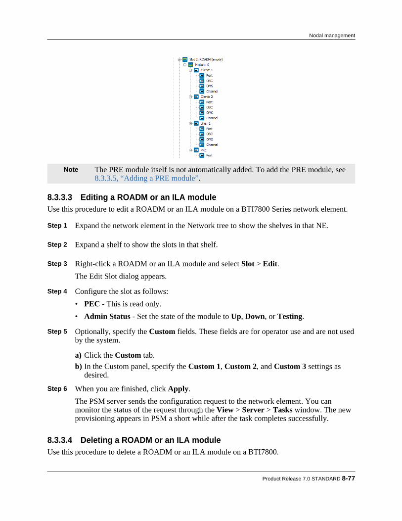
Note The PRE module itself is not automatically added. To add the PRE module, see8.3.3.5, “Adding a PRE module”.
8.3.3.3 Editing a ROADM or an ILA moduleUse this procedure to edit a ROADM or an ILA module on a BTI7800 Series network element.
Step 1 Expand the network element in the Network tree to show the shelves in that NE. Step 2 Expand a shelf to show the slots in that shelf. Step 3 Right-click a ROADM or an ILA module and select Slot > Edit.
The Edit Slot dialog appears. Step 4 Configure the slot as follows:
• PEC - This is read only.• Admin Status - Set the state of the module to Up, Down, or Testing.
Step 5 Optionally, specify the Custom fields. These fields are for operator use and are not used
by the system.
a) Click the Custom tab.b) In the Custom panel, specify the Custom 1, Custom 2, and Custom 3 settings as
desired. Step 6 When you are finished, click Apply.
The PSM server sends the configuration request to the network element. You canmonitor the status of the request through the View > Server > Tasks window. The newprovisioning appears in PSM a short while after the task completes successfully.
8.3.3.4 Deleting a ROADM or an ILA moduleUse this procedure to delete a ROADM or an ILA module on a BTI7800.
Product Release 7.0 STANDARD 8-77
Nodal management

Step 1 Expand the network element in the Network tree to show the shelves in that NE. Step 2 Expand a shelf to show the slots in that shelf. Step 3 Right-click a ROADM or ILA module and select Slot > Delete. Step 4 Click OK in the confirmation dialog.
The PSM server sends the configuration request to the network element. You canmonitor the status of the request through the View > Server > Tasks window. The newprovisioning appears in PSM a short while after the task completes successfully.
8.3.3.5 Adding a PRE moduleUse this procedure to add a new PRE module to a ROADM or ILA on a BTI7800 Series networkelement.
Step 1 Expand the network element in the Network tree to show the shelves in that NE. Step 2 Expand a shelf to show the slots in that shelf. Step 3 Right-click a ROADM or ILA module and select Preamplifier > Provision to add a
PRE module to the ROADM or ILA.In the ensuing dialog, the PEC and Oper Status cannot be changed.
Step 4 Optionally, specify the Custom fields. These fields are for operator use and are opaque
to the system.
a) Click the Custom tab.b) In the Custom panel, specify the Custom 1, Custom 2, and Custom 3 settings as
desired. Step 5 When you are finished, click OK to add the PRE module.
The PSM server sends the configuration request to the network element. You canmonitor the status of the request through the View > Server > Tasks window. The newprovisioning appears in the Network tree a short while after the task completessuccessfully.
The PRE module and its port are added.
8-78 proNX Service Manager User Guide – Document Version 01
Nodal management
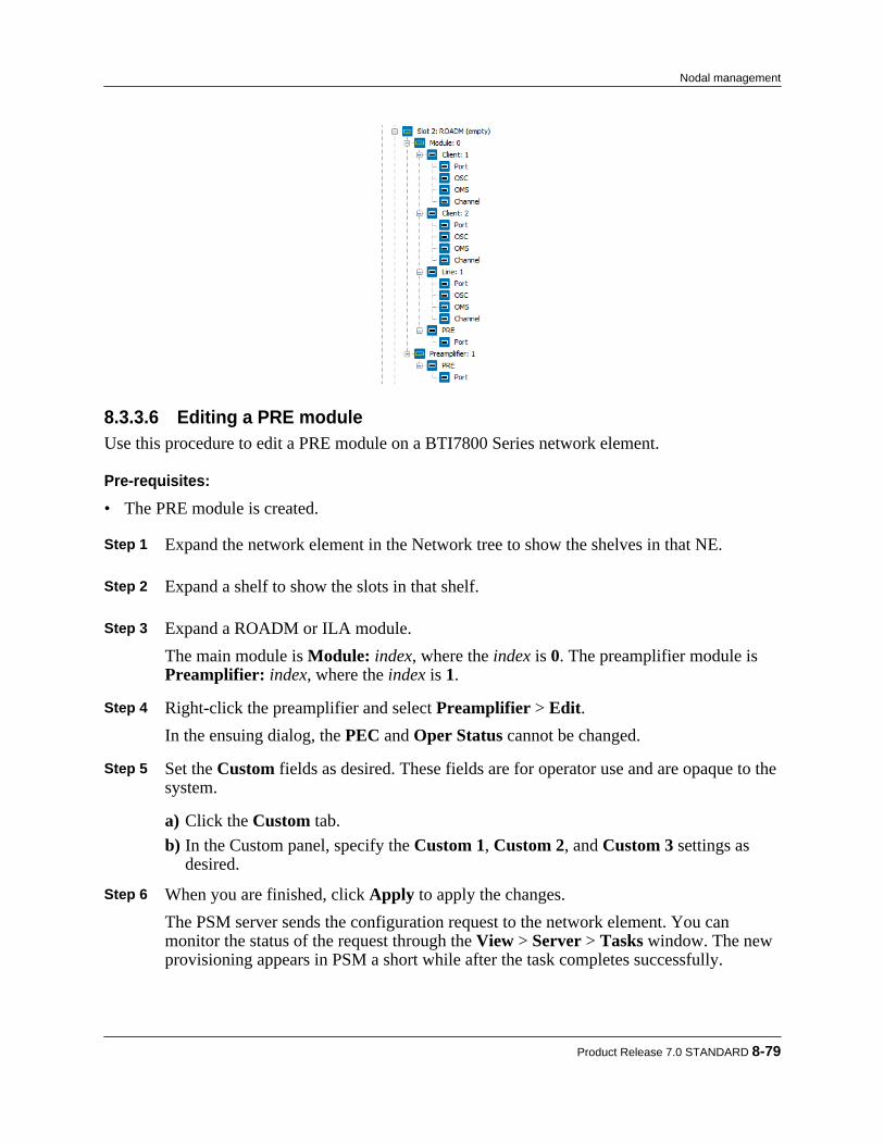
8.3.3.6 Editing a PRE moduleUse this procedure to edit a PRE module on a BTI7800 Series network element.
Pre-requisites:
• The PRE module is created.
Step 1 Expand the network element in the Network tree to show the shelves in that NE. Step 2 Expand a shelf to show the slots in that shelf. Step 3 Expand a ROADM or ILA module.
The main module is Module: index, where the index is 0. The preamplifier module isPreamplifier: index, where the index is 1.
Step 4 Right-click the preamplifier and select Preamplifier > Edit.
In the ensuing dialog, the PEC and Oper Status cannot be changed. Step 5 Set the Custom fields as desired. These fields are for operator use and are opaque to the
system.
a) Click the Custom tab.b) In the Custom panel, specify the Custom 1, Custom 2, and Custom 3 settings as
desired. Step 6 When you are finished, click Apply to apply the changes.
The PSM server sends the configuration request to the network element. You canmonitor the status of the request through the View > Server > Tasks window. The newprovisioning appears in PSM a short while after the task completes successfully.
Product Release 7.0 STANDARD 8-79
Nodal management

8.3.3.7 Deleting a PRE moduleUse this procedure to delete a PRE module on a ROADM or ILA.
Pre-requisites:
• The PRE module is created.
Step 1 Expand the network element in the Network tree to show the shelves in that NE. Step 2 Expand a shelf to show the slots in that shelf. Step 3 Expand a ROADM or ILA module.
The main module is Module: index, where the index is 0. The preamplifier module isPreamplifier: index, where the index is 1.
Step 4 Right-click the preamplifier and select Preamplifier > Delete. Step 5 Click OK in the confirmation dialog.
The PSM server sends the configuration request to the network element. You canmonitor the status of the request through the View > Server > Tasks window. The newprovisioning appears in PSM a short while after the task completes successfully.
8.3.3.8 Adding or viewing a multiplexer/demultiplexerUse this procedure to view existing multiplexer/demultiplexers or to add a new one on aBTI7800 Series network element.
Step 1 Right click a network element in the Network tree and select Node > Passive > Mux/Demux > EditThe Mux/Demux window appears. This window shows a listing of the existingmultiplexer/demultiplexers on the shelf.
8-80 proNX Service Manager User Guide – Document Version 01
Nodal management

Note The Group/Degree is not applicable to BTI7800 ROADM nodes. Step 2 Click on the plus icon to add a new multiplexer/demultiplexer.
The Provision Mux/Demux window appears.
Product Release 7.0 STANDARD 8-81
Nodal management

Step 3 Specify the Slot for the multiplexer/demultiplexer. Step 4 Select a PEC from the list of available PECs. Step 5 Optionally, specify the Custom fields. These fields are for operator use and are opaque
to the system.
a) Click the Custom tab.b) In the Custom panel, specify the Id, Custom 1, Custom 2, and Custom 3 settings as
desired. Step 6 When you are finished, click Apply.
The newly added multiplexer/demultiplexer appears in the Mux/Demux window. Step 7 Click OK.
The PSM server sends the configuration request to the network element. You canmonitor the status of the request through the View > Server > Tasks window. The newprovisioning appears in PSM a short while after the task completes successfully.
8.3.3.9 Deleting a multiplexer/demultiplexerUse this procedure to delete a multiplexer/demultiplexer on a BTI7000 Series network element.
8-82 proNX Service Manager User Guide – Document Version 01
Nodal management

Step 1 Right click a network element in the Network tree and select Node > Passive > Mux/Demux > EditThe Mux/Demux window appears.
Step 2 Select a multiplexer/demultiplexer and click on the minus icon to delete it.
The selected multiplexer/demultiplexer disappears from the window. Step 3 Click OK.
The PSM server sends the configuration request to the network element. You canmonitor the status of the request through the View > Server > Tasks window. The newprovisioning appears in PSM a short while after the task completes successfully.
8.3.3.10 Editing a portUse this procedure to edit a port on a ROADM, ILA, or PRE module on a BTI7800 Seriesnetwork element.All ports on a module are automatically added when you add the module.
Step 1 Expand the network element in the Network tree to show the shelves in that NE. Step 2 Expand a shelf to show the slots in that shelf. Step 3 Expand a ROADM or ILA module.
The main module is Module: index, where the index is 0. The preamplifier module (ifpresent) is Preamplifier: index, where the index is 1.
Step 4 Expand the main module to see the ports on the main module, or expand the
preamplifier to see the port on the PRE module. Step 5 Expand the desired client, line, or PRE port container, right-click Port and select
Optical Port > Edit Step 6 Specify the Id and Custom fields as desired. These fields are for operator use and are
opaque to the system. Step 7 When you are finished, click Apply to apply the changes.
The PSM server sends the configuration request to the network element. You canmonitor the status of the request through the View > Server > Tasks window. The newprovisioning appears in PSM a short while after the task completes successfully.
8.3.3.11 Editing the OMSUse this procedure to edit the Optical Multiplex Section (OMS) on a ROADM or an ILA clientor line port on a BTI7800 Series network element.
Product Release 7.0 STANDARD 8-83
Nodal management
Step 1 Expand the network element in the Network tree to show the shelves in that NE. Step 2 Expand a shelf to show the slots in that shelf. Step 3 Expand a ROADM or ILA module.
The main module is Module: index, where the index is 0. The preamplifier module (ifpresent) is Preamplifier: index, where the index is 1.
Step 4 Expand the main module to see the ports on the main module. Step 5 Expand the desired client or line port container to see the OMS for that port. Step 6 Right-click OMS and select OMS > Edit
The Edit OMS dialog appears. Step 7 Configure the OMS as follows:
• Oper Status - The operational status is read only.• Admin Status - Specify whether the OMS state is In-Service or Out-Of-Service or
Testing.• Preamplifier State - Specify whether the preamplifier is Enabled or Disabled. This
is only applicable for line ports. Client ports do not have a preamplifier. Step 8 Optionally, specify the Custom fields. These fields are for operator use and are opaque
to the system.
a) Click the Custom tab.b) In the Custom panel, specify the Id, Custom 1, Custom 2, and Custom 3 settings as
desired. Step 9 When you are finished, click Apply to apply the changes.
The PSM server sends the configuration request to the network element. You canmonitor the status of the request through the View > Server > Tasks window. The newprovisioning appears in PSM a short while after the task completes successfully.
8.3.3.12 Editing the OSCUse this procedure to edit the Optical Service Channel (OSC) on a ROADM or an ILA client orline port on a BTI7800 Series network element.
Step 1 Expand the network element in the Network tree to show the shelves in that NE. Step 2 Expand a shelf to show the slots in that shelf. Step 3 Expand a ROADM or ILA module.
8-84 proNX Service Manager User Guide – Document Version 01
Nodal management
The main module is Module: index, where the index is 0. The preamplifier module (ifpresent) is Preamplifier: index, where the index is 1.
Step 4 Expand the main module to see the ports on the main module. Step 5 Expand the desired client or line port container to see the OSC for that port. Step 6 Right-click OSC and select OSC > Edit
The Edit OSC dialog appears. Step 7 Configure the OSC as follows:
• Oper Status - The operational status is read only.• Admin Status - Specify whether the OSC state is In-Service or Out-Of-Service.
Step 8 Optionally, specify the Custom fields. These fields are for operator use and are opaque
to the system.
a) Click the Custom tab.b) In the Custom panel, specify the Id, Custom 1, Custom 2, and Custom 3 settings as
desired. Step 9 When you are finished, click Apply to apply the changes.
The PSM server sends the configuration request to the network element. You canmonitor the status of the request through the View > Server > Tasks window. The newprovisioning appears in PSM a short while after the task completes successfully.
8.3.3.13 Adding a fiber connection on a ROADM or an ILA client portUse this procedure to add a fiber connection on a ROADM or an ILA client port on a BTI7800Series network element.Fiber connections are mandatory. All fiber connections must exist before you can create anoptical service.
Step 1 Expand the network element in the Network tree to show the shelves in that NE. Step 2 Expand a shelf to show the slots in that shelf. Step 3 Expand a ROADM or ILA module.
The main module is Module: index, where the index is 0. The preamplifier module (ifpresent) is Preamplifier: index, where the index is 1.
Step 4 Expand the main module to see the ports on the main module. Step 5 Right-click the desired client port container and select Fiber Connection > Provision.
Product Release 7.0 STANDARD 8-85
Nodal management

The Provision Fiber Connection dialog appears, listing all client ports in the network.
Step 6 Select the other end of the fiber connection.
For a ROADM client port, the other end can be a multiplexer/demultiplexer line port oranother ROADM client port. To create a split ROADM node, configure a fiberconnection between ROADM client ports on two different network elements.For an ILA client port, the other end can be another ILA client port.
Step 7 When you are finished, click OK to create the fiber connection.
The PSM server sends the configuration request to the network element. You canmonitor the status of the request through the View > Server > Tasks window. The newprovisioning appears in PSM a short while after the task completes successfully.
8.3.3.14 Editing a fiber connection on a ROADM or an ILA client portUse this procedure to edit a fiber connection on a ROADM or an ILA client port on a BTI7800Series network element.
Step 1 Expand the network element in the Network tree to show the shelves in that NE. Step 2 Expand a shelf to show the slots in that shelf. Step 3 Expand a ROADM or ILA module.
The main module is Module: index, where the index is 0. The preamplifier module (ifpresent) is Preamplifier: index, where the index is 1.
Step 4 Expand the main module to see the ports on the main module. Step 5 Right-click the desired client port container and select Fiber Connection > Edit. Step 6 Configure the fiber connection as follows:
• Port - The port at the other end of the fiber connection. This is read only.
8-86 proNX Service Manager User Guide – Document Version 01
Nodal management

• IP Address - The IP address of the NE at the other end of the fiber connection. For aregular ROADM node, this is the local IP address. For a split ROADM node, this isthe IP address of the NE at the other end of the fiber.
• FE Monitoring - Check to enable far end monitoring. Uncheck to disable far endmonitoring. When far end monitoring is enabled, the BTI7800 checks to see if theconfigured fiber connection matches the actual physical fiber connection. If there is amismatch, an alarm is raised.
• Fiber Type - This is not applicable to client ports. Step 7 When you are finished, click OK to apply the changes.
The PSM server sends the configuration request to the network element. You canmonitor the status of the request through the View > Server > Tasks window. The newprovisioning appears in PSM a short while after the task completes successfully.
8.3.3.15 Deleting a fiber connection on a ROADM or an ILA client portUse this procedure to delete a fiber connection on a ROADM or an ILA client port on a BTI7800Series network element.
Step 1 Expand the network element in the Network tree to show the shelves in that NE. Step 2 Expand a shelf to show the slots in that shelf. Step 3 Expand a ROADM or ILA module.
The main module is Module: index, where the index is 0. The preamplifier module (ifpresent) is Preamplifier: index, where the index is 1.
Step 4 Expand the main module to see the ports on the main module. Step 5 Right-click the desired client port container and select Fiber Connection > Delete. Step 6 Click OK in the confirmation dialog.
The PSM server sends the configuration request to the network element. You canmonitor the status of the request through the View > Server > Tasks window. The newprovisioning appears in PSM a short while after the task completes successfully.
8.3.3.16 Adding a fiber connection on a ROADM or an ILA line portUse this procedure to add a fiber connection on a ROADM or an ILA line port on a BTI7800Series network element.Fiber connections are mandatory. All fiber connections must exist before you can create anoptical service.
Step 1 Expand the network element in the Network tree to show the shelves in that NE.
Product Release 7.0 STANDARD 8-87
Nodal management
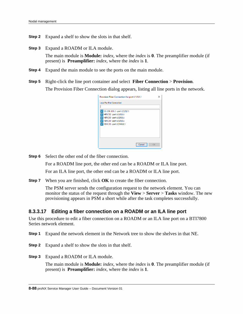
Step 2 Expand a shelf to show the slots in that shelf. Step 3 Expand a ROADM or ILA module.
The main module is Module: index, where the index is 0. The preamplifier module (ifpresent) is Preamplifier: index, where the index is 1.
Step 4 Expand the main module to see the ports on the main module. Step 5 Right-click the line port container and select Fiber Connection > Provision.
The Provision Fiber Connection dialog appears, listing all line ports in the network.
Step 6 Select the other end of the fiber connection.
For a ROADM line port, the other end can be a ROADM or ILA line port.For an ILA line port, the other end can be a ROADM or ILA line port.
Step 7 When you are finished, click OK to create the fiber connection.
The PSM server sends the configuration request to the network element. You canmonitor the status of the request through the View > Server > Tasks window. The newprovisioning appears in PSM a short while after the task completes successfully.
8.3.3.17 Editing a fiber connection on a ROADM or an ILA line portUse this procedure to edit a fiber connection on a ROADM or an ILA line port on a BTI7800Series network element.
Step 1 Expand the network element in the Network tree to show the shelves in that NE. Step 2 Expand a shelf to show the slots in that shelf. Step 3 Expand a ROADM or ILA module.
The main module is Module: index, where the index is 0. The preamplifier module (ifpresent) is Preamplifier: index, where the index is 1.
8-88 proNX Service Manager User Guide – Document Version 01
Nodal management

Step 4 Expand the main module to see the ports on the main module. Step 5 Right-click the line port container and select Fiber Connection > Edit. Step 6 Configure the fiber connection as follows:
• Port - The port at the other end of the fiber connection. This is read only.• IP Address - The IP address of the NE at the other end of the fiber connection.• FE Monitoring - Check to enable far end monitoring. Uncheck to disable far end
monitoring. When far end monitoring is enabled, the BTI7800 checks to see if theconfigured fiber connection matches the actual physical fiber connection. If there is amismatch, an alarm is raised.
• Fiber Type - Select the fiber type from the pulldown menu. Step 7 When you are finished, click OK to apply the changes.
The PSM server sends the configuration request to the network element. You canmonitor the status of the request through the View > Server > Tasks window. The newprovisioning appears in PSM a short while after the task completes successfully.
8.3.3.18 Deleting a fiber connection on a ROADM or an ILA line portUse this procedure to delete a fiber connection on a ROADM or an ILA line port on a BTI7800Series network element.
Step 1 Expand the network element in the Network tree to show the shelves in that NE. Step 2 Expand a shelf to show the slots in that shelf. Step 3 Expand a ROADM or ILA module.
The main module is Module: index, where the index is 0. The preamplifier module (ifpresent) is Preamplifier: index, where the index is 1.
Step 4 Expand the main module to see the ports on the main module. Step 5 Right-click the line port container and select Fiber Connection > Delete. Step 6 Click OK in the confirmation dialog.
The PSM server sends the configuration request to the network element. You canmonitor the status of the request through the View > Server > Tasks window. The newprovisioning appears in PSM a short while after the task completes successfully.
8.3.3.19 Adding a fiber connection on a UFM interfaceUse this procedure to add a fiber connection on a UFM interface on a BTI7800 Series networkelement.
Product Release 7.0 STANDARD 8-89
Nodal management
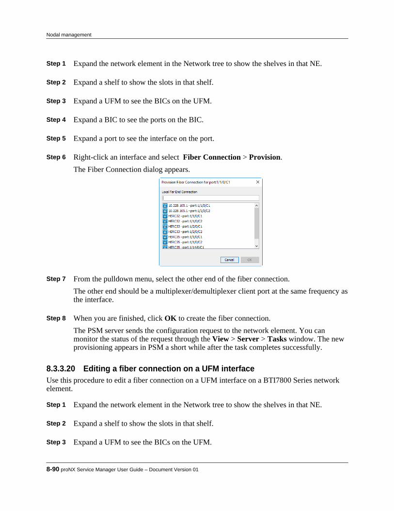
Step 1 Expand the network element in the Network tree to show the shelves in that NE. Step 2 Expand a shelf to show the slots in that shelf. Step 3 Expand a UFM to see the BICs on the UFM. Step 4 Expand a BIC to see the ports on the BIC. Step 5 Expand a port to see the interface on the port. Step 6 Right-click an interface and select Fiber Connection > Provision.
The Fiber Connection dialog appears.
Step 7 From the pulldown menu, select the other end of the fiber connection.
The other end should be a multiplexer/demultiplexer client port at the same frequency asthe interface.
Step 8 When you are finished, click OK to create the fiber connection.
The PSM server sends the configuration request to the network element. You canmonitor the status of the request through the View > Server > Tasks window. The newprovisioning appears in PSM a short while after the task completes successfully.
8.3.3.20 Editing a fiber connection on a UFM interfaceUse this procedure to edit a fiber connection on a UFM interface on a BTI7800 Series networkelement.
Step 1 Expand the network element in the Network tree to show the shelves in that NE. Step 2 Expand a shelf to show the slots in that shelf. Step 3 Expand a UFM to see the BICs on the UFM.
8-90 proNX Service Manager User Guide – Document Version 01
Nodal management

Step 4 Expand a BIC to see the ports on the BIC. Step 5 Expand a port to see the interface on the port. Step 6 Right-click an interface and select Fiber Connection > Edit. Step 7 Configure the fiber connection as follows:
• Port - The port at the other end of the fiber connection. This is read only.• IP Address - The IP address of the NE at the other end of the fiber connection. For a
UFM interface, this is the local IP address since the other end is on the same node.• FE Monitoring - Check to enable far end monitoring. Uncheck to disable far end
monitoring. When far end monitoring is enabled, the BTI7800 checks to see if theconfigured fiber connection matches the actual physical fiber connection. If there is amismatch, an alarm is raised.
• Fiber Type - This is not applicable to UFM interfaces. Step 8 When you are finished, click OK to apply the changes.
The PSM server sends the configuration request to the network element. You canmonitor the status of the request through the View > Server > Tasks window. The newprovisioning appears in PSM a short while after the task completes successfully.
8.3.3.21 Deleting a fiber connection on a UFM interfaceUse this procedure to delete a fiber connection on a UFM interface on a BTI7800 Series networkelement.
Step 1 Expand the network element in the Network tree to show the shelves in that NE. Step 2 Expand a shelf to show the slots in that shelf. Step 3 Expand a UFM to see the BICs on the UFM. Step 4 Expand a BIC to see the ports on the BIC. Step 5 Expand a port to see the interface on the port. Step 6 Right-click an interface and select Fiber Connection > Delete. Step 7 Click OK in the confirmation dialog.
The PSM server sends the configuration request to the network element. You canmonitor the status of the request through the View > Server > Tasks window. The newprovisioning appears in PSM a short while after the task completes successfully.
Product Release 7.0 STANDARD 8-91
Nodal management
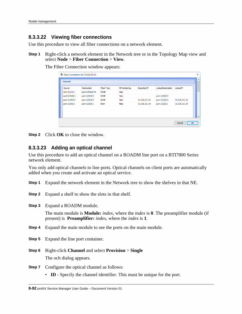
8.3.3.22 Viewing fiber connectionsUse this procedure to view all fiber connections on a network element.
Step 1 Right-click a network element in the Network tree or in the Topology Map view andselect Node > Fiber Connection > View.The Fiber Connection window appears:
Step 2 Click OK to close the window.
8.3.3.23 Adding an optical channelUse this procedure to add an optical channel on a ROADM line port on a BTI7800 Seriesnetwork element.You only add optical channels to line ports. Optical channels on client ports are automaticallyadded when you create and activate an optical service.
Step 1 Expand the network element in the Network tree to show the shelves in that NE. Step 2 Expand a shelf to show the slots in that shelf. Step 3 Expand a ROADM module.
The main module is Module: index, where the index is 0. The preamplifier module (ifpresent) is Preamplifier: index, where the index is 1.
Step 4 Expand the main module to see the ports on the main module. Step 5 Expand the line port container. Step 6 Right-click Channel and select Provision > Single
The och dialog appears. Step 7 Configure the optical channel as follows:
• ID - Specify the channel identifier. This must be unique for the port.
8-92 proNX Service Manager User Guide – Document Version 01
Nodal management

• Bandwidth - Specify the bandwidth of the channel. This is the grid spacing.• Channel Name - Specify the channel name. When this field is changed, Frequency
and Wavelength are automatically changed to be consistent with this value.• Wavelength - Specify the central wavelength of the channel. When this field is
changed, Frequency and Channel Name are automatically changed to be consistentwith this value.
• Frequency - Specify the central frequency of the channel. When this field ischanged, Channel Name and Wavelength are automatically changed to beconsistent with this value.
• Enable - Check to enable the ODCC. Uncheck to disable the ODCC.• Admin Status - Specify whether the optical channel state is In-Service or Out-Of-
Service or Testing.• Oper Status - The operational status is read only.
Step 8 Optionally, specify the Custom fields. These fields are for operator use and are opaque
to the system.
a) Click the Custom tab.b) In the Custom panel, specify the Id, Custom 1, Custom 2, and Custom 3 settings as
desired. Step 9 When you are finished, click Apply to apply the changes.
The PSM server sends the configuration request to the network element. You canmonitor the status of the request through the View > Server > Tasks window. The newprovisioning appears in PSM a short while after the task completes successfully.
8.3.3.24 Bulk adding optical channelsUse this procedure to add optical channels in bulk on a ROADM line port on a BTI7800 Seriesnetwork element.When you use this method to create optical channels, PSM automatically sets the Channel ID forthe created optical channels to the Channel Name, which is derived from the frequency that youspecify. Addtionally, PSM sets the Admin Status of the created optical channels to In-Service.If you want to set a different Channel ID or Admin Status, then you should not use this methodto create optical channels.
Step 1 Expand the network element in the Network tree to show the shelves in that NE. Step 2 Expand a shelf to show the slots in that shelf. Step 3 Expand a ROADM module.
The main module is Module: index, where the index is 0. The preamplifier module (ifpresent) is Preamplifier: index, where the index is 1.
Product Release 7.0 STANDARD 8-93
Nodal management
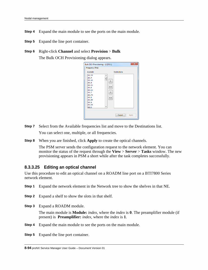
Step 4 Expand the main module to see the ports on the main module. Step 5 Expand the line port container. Step 6 Right-click Channel and select Provision > Bulk
The Bulk OCH Provisioning dialog appears.
Step 7 Select from the Available frequencies list and move to the Destinations list.
You can select one, multiple, or all frequencies. Step 8 When you are finished, click Apply to create the optical channels.
The PSM server sends the configuration request to the network element. You canmonitor the status of the request through the View > Server > Tasks window. The newprovisioning appears in PSM a short while after the task completes successfully.
8.3.3.25 Editing an optical channelUse this procedure to edit an optical channel on a ROADM line port on a BTI7800 Seriesnetwork element.
Step 1 Expand the network element in the Network tree to show the shelves in that NE. Step 2 Expand a shelf to show the slots in that shelf. Step 3 Expand a ROADM module.
The main module is Module: index, where the index is 0. The preamplifier module (ifpresent) is Preamplifier: index, where the index is 1.
Step 4 Expand the main module to see the ports on the main module. Step 5 Expand the line port container.
8-94 proNX Service Manager User Guide – Document Version 01
Nodal management

Step 6 Expand Channel to see the channels. Step 7 Right-click a channel and select Channel > Edit Step 8 Configure the optical channel as follows:
• ID - This is read only.• Bandwidth - This is read only.• Channel Name - This is read only.• Wavelength - This is read only.• Frequency - This is read only.• Enable - Check to enable the ODCC. Uncheck to disable the ODCC.• Admin Status - Specify whether the optical channel state is In-Service or Out-Of-
Service or Testing.• Oper Status - This is read only.
Step 9 Optionally, specify the Custom fields. These fields are for operator use and are opaque
to the system.
a) Click the Custom tab.b) In the Custom panel, specify the Id, Custom 1, Custom 2, and Custom 3 settings as
desired. Step 10 When you are finished, click Apply to apply the changes.
The PSM server sends the configuration request to the network element. You canmonitor the status of the request through the View > Server > Tasks window. The newprovisioning appears in PSM a short while after the task completes successfully.
8.3.3.26 Deleting an optical channelUse this procedure to delete an optical channel on a ROADM line port on a BTI7800 Seriesnetwork element.Optical channels that are part of an existing service cannot be deleted.
Step 1 Expand the network element in the Network tree to show the shelves in that NE. Step 2 Expand a shelf to show the slots in that shelf. Step 3 Expand a ROADM module.
The main module is Module: index, where the index is 0. The preamplifier module (ifpresent) is Preamplifier: index, where the index is 1.
Step 4 Expand the main module to see the ports on the main module.
Product Release 7.0 STANDARD 8-95
Nodal management

Step 5 Expand the line port container. Step 6 Expand Channel to see the channels. Step 7 Right-click a channel and select Channel > Delete Step 8 Click OK in the confirmation dialog.
The PSM server sends the configuration request to the network element. You canmonitor the status of the request through the View > Server > Tasks window. The newprovisioning appears in PSM a short while after the task completes successfully.
8.3.3.27 Viewing port PMsUse this procedure to view PMs on a ROADM, ILA, or PRE port on a BTI7800 Series networkelement.
Step 1 Expand the network element in the Network tree to show the shelves in that NE. Step 2 Expand a shelf to show the slots in that shelf. Step 3 Expand a ROADM or ILA module.
The main module is Module: index, where the index is 0. The preamplifier module (ifpresent) is Preamplifier: index, where the index is 1.
Step 4 Expand the main module to see the ports on the main module, or expand the
preamplifier module to see the port on the PRE module. Step 5 Expand the desired client, line, or PRE port container, right-click Port and select
Optical Port PMs > ViewA snapshot of the current PMs is displayed.
Step 6 To refresh the counters, click Refresh. Step 7 To select what columns to display, right-click anywhere in the headings row to bring up
a column selection window.Check or uncheck column headings as desired.
Step 8 To sort the PMs based on column values, click on the column heading that you want to
sort. Step 9 To save the counters to a CSV file, click Export.
8-96 proNX Service Manager User Guide – Document Version 01
Nodal management
8.3.3.28 Viewing OMS PMsUse this procedure to view Optical Multiplexing Section (OMS) PMs on a ROADM or an ILAclient or line port on a BTI7800 Series network element.
Step 1 Expand the network element in the Network tree to show the shelves in that NE. Step 2 Expand a shelf to show the slots in that shelf. Step 3 Expand a ROADM or ILA module.
The main module is Module: index, where the index is 0. The preamplifier module (ifpresent) is Preamplifier: index, where the index is 1.
Step 4 Expand the main module to see the ports on the main module. Step 5 Expand the desired client or line port container to see the OMS for that port. Step 6 Right-click OMS and select OMS PMs > View.
A snapshot of the current PMs is displayed. Step 7 To refresh the counters, click Refresh. Step 8 To select what columns to display, right-click anywhere in the headings row to bring up
a column selection window.Check or uncheck column headings as desired.
Step 9 To sort the PMs based on column values, click on the column heading that you want to
sort. Step 10 To save the counters to a CSV file, click Export.
8.3.3.29 Viewing OSC PMsUse this procedure to view Optical Service Channel (OSC) PMs on a ROADM or an ILA clientor line port on a BTI7800 Series network element.
Step 1 Expand the network element in the Network tree to show the shelves in that NE. Step 2 Expand a shelf to show the slots in that shelf. Step 3 Expand a ROADM or ILA module.
The main module is Module: index, where the index is 0. The preamplifier module (ifpresent) is Preamplifier: index, where the index is 1.
Step 4 Expand the main module to see the ports on the main module.
Product Release 7.0 STANDARD 8-97
Nodal management
Step 5 Expand the desired client or line port container to see the OSC for that port. Step 6 Right-click OSC and select OSC PMs > View.
A snapshot of the current PMs is displayed. Step 7 To refresh the counters, click Refresh. Step 8 To select what columns to display, right-click anywhere in the headings row to bring up
a column selection window.Check or uncheck column headings as desired.
Step 9 To sort the PMs based on column values, click on the column heading that you want to
sort. Step 10 To save the counters to a CSV file, click Export.
8.3.3.30 Viewing optical channel PMsUse this procedure to view optical channel PMs on a ROADM line port on a BTI7800 Seriesnetwork element.
Step 1 Expand the network element in the Network tree to show the shelves in that NE. Step 2 Expand a shelf to show the slots in that shelf. Step 3 Expand a ROADM module.
The main module is Module: index, where the index is 0. The preamplifier module (ifpresent) is Preamplifier: index, where the index is 1.
Step 4 Expand the main module to see the ports on the main module. Step 5 Expand line port container. Step 6 Expand Channel to see the channels. Step 7 Right-click a channel and select Channel PMs > View
A snapshot of the current PMs is displayed. Step 8 To refresh the counters, click Refresh. Step 9 To select what columns to display, right-click anywhere in the headings row to bring up
a column selection window.Check or uncheck column headings as desired.
8-98 proNX Service Manager User Guide – Document Version 01
Nodal management

Step 10 To sort the PMs based on column values, click on the column heading that you want tosort.
Step 11 To save the counters to a CSV file, click Export.
8.3.4 Provisioning a 96-Channel Amplifier on a BTI7800The BTI7800 96-Channel Amplifier is provisioned as follows:
1 Add the amplifier module.2 Create an optical group for the amplifier if the desired optical group does not already exist.3 Assign the amplifier to the optical group.4 Edit the amplifier's port, WDM and OSC settings .
8.3.4.1 Adding an amplifierUse this procedure to add a 96-Channel Amplifier on a BTI7800 Series network element.
Step 1 Expand the network element in the Network tree to show the shelves in that NE. Step 2 Expand a shelf to show the slots in that shelf. Step 3 Right-click an unprovisioned slot and select Slot > Provision to add a module in that
slot.The Provision Slot dialog appears. This dialog may change depending on the PEC thatyou select in the next step.
Step 4 Configure the slot as follows:
• PEC - Select the 96-Channel Amplifier PEC from the list of available PECs in thedrop-down menu.
• Admin Status - Specify whether the initial state of the module is Up or Down or Testing.
Step 5 Optionally, specify the Custom fields. These fields are for operator use and are opaque
to the system.
a) Click the Custom Settings tab.b) In the Custom Settings panel, specify the Id, Custom 1, Custom 2, and Custom 3
settings as desired. Step 6 When you are finished, click OK.
The PSM server sends the configuration request to the network element. You canmonitor the status of the request through the View > Server > Tasks window. The newprovisioning appears in the Network tree a short while after the task completessuccessfully.
Product Release 7.0 STANDARD 8-99
Nodal management
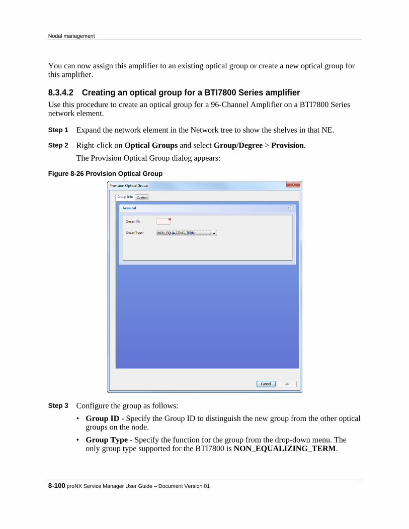
You can now assign this amplifier to an existing optical group or create a new optical group forthis amplifier.
8.3.4.2 Creating an optical group for a BTI7800 Series amplifierUse this procedure to create an optical group for a 96-Channel Amplifier on a BTI7800 Seriesnetwork element.
Step 1 Expand the network element in the Network tree to show the shelves in that NE. Step 2 Right-click on Optical Groups and select Group/Degree > Provision.
The Provision Optical Group dialog appears:
Figure 8-26 Provision Optical Group
Step 3 Configure the group as follows:
• Group ID - Specify the Group ID to distinguish the new group from the other opticalgroups on the node.
• Group Type - Specify the function for the group from the drop-down menu. Theonly group type supported for the BTI7800 is NON_EQUALIZING_TERM.
8-100 proNX Service Manager User Guide – Document Version 01
Nodal management

Step 4 Optionally, specify the Custom fields. These fields are for operator use and are opaqueto the system.
a) Click the Custom Settings tab.b) In the Custom Settings panel, specify the Id, Custom 1, Custom 2, and Custom 3
settings as desired. Step 5 When you are finished, click OK.
The PSM server sends the configuration request to the network element. You canmonitor the status of the request through the View > Server > Tasks window. The newoptical group appears in the Network tree a short while after the task completessuccessfully.
8.3.4.3 Assigning or unassigning an amplifierUse this procedure to assign a 96-Channel Amplifier to an optical group or to unassign a 96-Channel Amplifier from an optical group on a BTI7800 Series network element.
Step 1 Expand the network element in the Network tree. Step 2 Expand the Optical Groups to see the optical groups on that NE. Step 3 Right-click the optical group in which you want to assign the amplifier, and select
Group/Degree > Edit.The Update Optical Group dialog appears.
Product Release 7.0 STANDARD 8-101
Nodal management
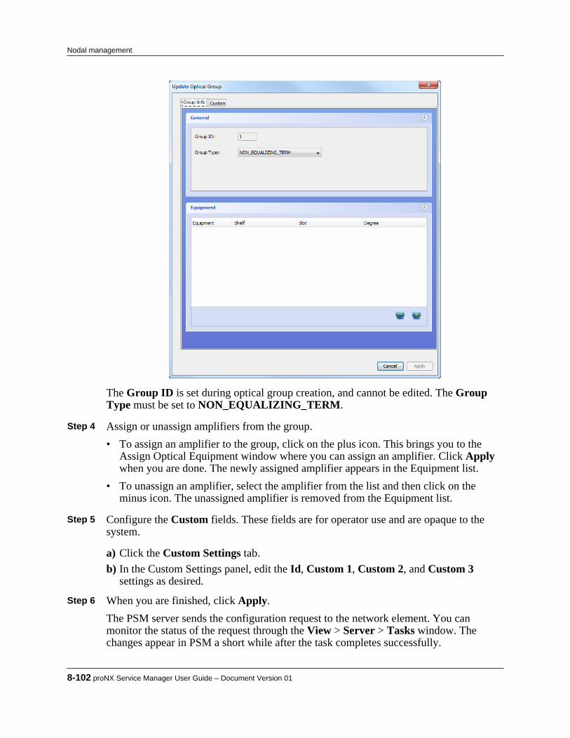
The Group ID is set during optical group creation, and cannot be edited. The GroupType must be set to NON_EQUALIZING_TERM.
Step 4 Assign or unassign amplifiers from the group.
• To assign an amplifier to the group, click on the plus icon. This brings you to the Assign Optical Equipment window where you can assign an amplifier. Click Applywhen you are done. The newly assigned amplifier appears in the Equipment list.
• To unassign an amplifier, select the amplifier from the list and then click on theminus icon. The unassigned amplifier is removed from the Equipment list.
Step 5 Configure the Custom fields. These fields are for operator use and are opaque to the
system.
a) Click the Custom Settings tab.b) In the Custom Settings panel, edit the Id, Custom 1, Custom 2, and Custom 3
settings as desired. Step 6 When you are finished, click Apply.
The PSM server sends the configuration request to the network element. You canmonitor the status of the request through the View > Server > Tasks window. Thechanges appear in PSM a short while after the task completes successfully.
8-102 proNX Service Manager User Guide – Document Version 01
Nodal management

8.3.4.4 Editing an amplifier portUse this procedure to edit an amplifier port on a 96-Channel Amplifier on a BTI7800 Seriesnetwork element.
Step 1 Expand the network element in the Network tree view to show the shelves in that NE. Step 2 Expand Optical Groups to show the optical groups in that NE. Step 3 Expand an optical group to show the degree in that group. Step 4 Expand a degree to show the amplifier associated with that degree.
Step 5 Expand an amplifier to show the ports on that amplifier. Step 6 Right-click a port and select Optical Port > Edit.
The Edit Optical Layer Port dialog appears. Step 7 Configure the optical port parameters as follows:
• State - This is the operational state. It is read-only.• DWDM Type - This is the type of DWDM composite signal expected on the port. It
is set to native. This is read-only.• Grid Type - This is the DWDM grid spacing for the port. If the equipment only
supports a specific grid spacing, then this field is read-only.• Tx Loss - Specify the optical loss in the transmit direction. Set to 0 for no loss.• AINS Timer - Optionally, specify the auto-in-service timer.• Active Countdown - This is the countdown for the AINS timer. It is read-only.
Step 8 Optionally, configure the Custom fields. These fields are for operator use and are
opaque to the system.
a) Click the Custom Settings tab.b) In the Custom Settings panel, edit the Id, Custom 1, Custom 2, and Custom 3
settings as desired. Step 9 When you are finished, click Apply.
The PSM server sends the configuration request to the network element. You canmonitor the status of the request through the View > Server > Tasks window. Thechanges appear in PSM a short while after the task completes successfully.
Product Release 7.0 STANDARD 8-103
Nodal management

8.3.4.5 Editing WDM parameters for an amplifierUse this procedure to edit WDM parameters on the line port of a 96-Channel Amplifier on aBTI7800 Series network element.
Step 1 Expand the network element in the Network tree. Step 2 Expand Optical Groups to see the optical groups on that NE. Step 3 Expand an optical group to see the degree in that group. Step 4 Expand the degree to see the amplifier in that degree. Step 5 Right-click the amplifier and select WDM > Edit.
The Edit WDM dialog appears.
Figure 8-27 Edit WDM dialog for a BTI7800 96-Channel Amplifier module
Step 6 Configure the WDM parameters as follows:
• Admin Status - Select the state from the list of available states in the drop-downmenu.
8-104 proNX Service Manager User Guide – Document Version 01
Nodal management

• Oper Status - This is the operational state. It is read-only.• Fiber Type - Specify the fiber type from the list of available fiber types in the drop-
down menu.• Loss Rx High Threshold - Specify the span loss threshold beyond which an alarm is
raised. Set to 0 to disable.• Length - The span length is measured automatically. This is read-only.• Amp Tilt Trim - Set to fine tune the system gain tilt.• Post Amp Gain - Set the system gain.
Step 7 Configure the Custom fields. These fields are for operator use and are opaque to the
system.
a) Click the Custom Settings tab.b) In the Custom Settings panel, edit the Id, Custom 1, Custom 2, and Custom 3
settings as desired. Step 8 When you are finished, click Apply.
The PSM server sends the configuration request to the network element. You canmonitor the status of the request through the View > Server > Tasks window. Thechanges appear in PSM a short while after the task completes successfully.
8.3.4.6 Editing OSC parameters for an amplifierUse this procedure to edit OSC parameters on the line port of a 96-Channel Amplifier on aBTI7800 Series network element. The optical service channel (OSC) is used as acommunications medium for control information between amplifiers at both ends of a line span.
Step 1 Expand the network element in the Network tree. Step 2 Expand the Optical Groups to see the optical groups on that NE. Step 3 Expand an optical group to see the degree in that group. Step 4 Expand the degree to see the amplifier in that degree. Step 5 Right-click the amplifier and select OSC > Edit.
The Edit OSC dialog appears.
Product Release 7.0 STANDARD 8-105
Nodal management

Figure 8-28 Edit OSC dialog for a BTI7800 96-Channel Amplifier module
Step 6 Configure the OSC parameters as follows:
• Admin Status - Select the state from the list of available states in the drop-downmenu.
• Oper Status - This is the operational state. It is read-only.• FE IM Mon - Select if you want the near end to validate the identity of the far end
with the expected far end parameters. If the identity does not match, the system willraise an alarm or condition.
• System Name (expected) - Set to the expected system name of the far end.• IP Address (expected) - Set to the expected management IP address of the far end.• Group (expected) - Set to the expected optical group identifier of the far end.• Degree (expected) - Set to the expected optical degree of the far end.• System Name (actual) - This is the actual system name of the far end. It is read-only.• IP Address (actual) - This is the actual management IP address of the far end. It is
read-only.• Group (actual) - This is the actual optical group identifier of the far end. It is read-
only.
8-106 proNX Service Manager User Guide – Document Version 01
Nodal management

• Degree (actual) - This is the actual optical degree of the far end. It is read-only.• Group Type (actual)- This is the actual group type of the far end. It is read-only.
Step 7 Optionally, configure the Custom fields. These fields are for operator use and are
opaque to the system.
a) Click the Custom Settings tab.b) In the Custom Settings panel, edit the Id, Custom 1, Custom 2, and Custom 3
settings as desired. Step 8 When you are finished, click Apply.
The PSM server sends the configuration request to the network element. You canmonitor the status of the request through the View > Server > Tasks window. Thechanges appear in PSM a short while after the task completes successfully.
8.3.4.7 Changing an amplifier's groupUse this procedure to change an amplifier's group on a BTI7800 Series network element.
Step 1 Expand the network element in the Network tree view to show the shelves in that NE. Step 2 Expand Optical Groups to show the optical groups in that NE. Step 3 Expand an optical group to show the degrees in that group. Step 4 Expand a degree to show the amplifier associated with that degree.
Step 5 Right-click an amplifier and select Equipment > Edit.
The Change Group/Degree dialog appears. Step 6 Edit the Group.
The Degree must be 1 and cannot be changed. Step 7 When you are finished, click Apply.
The PSM server sends the configuration request to the network element. You canmonitor the status of the request through the View > Server > Tasks window. Thechanges appear in PSM a short while after the task completes successfully.
Product Release 7.0 STANDARD 8-107
Nodal management

8.3.4.8 Viewing port PMsUse this procedure to view the port PMs on a 96-Channel Amplifier on a BTI7800 Seriesnetwork element.
Step 1 Expand the network element in the Network tree view to show the shelves in that NE. Step 2 Expand Optical Groups to show the optical groups in that NE. Step 3 Expand an optical group to show the degree in that group. Step 4 Expand a degree to show the amplifier associated with that degree.
Step 5 Expand an amplifier to show the ports on that amplifier. Step 6 Right-click a port and select Optical Port PMs > View.
A snapshot of the current PMs is displayed. Step 7 To refresh the counters, click Refresh. Step 8 To select what columns to display, right-click anywhere in the headings row to bring up
a column selection window.Check or uncheck column headings as desired.
Step 9 To sort the PMs based on column values, click on the column heading that you want to
sort. Step 10 To save the counters to a CSV file, click Export.
8.3.5 Provisioning a Wavelength Protection Switch module on a BTI7800
8.3.5.1 Adding a WPS moduleUse this procedure to add a new Wavelength Protection Switch (WPS) module on a BTI7800Series network element.
Step 1 Expand the network element in the Network tree to show the shelves in that NE. Step 2 Expand a shelf to show the slots in that shelf.
8-108 proNX Service Manager User Guide – Document Version 01
Nodal management

Step 3 Right-click an unprovisioned slot and select Slot > Provision to add a module in thatslot.The Provision Slot dialog appears. This dialog may change depending on the PEC thatyou select in the next step.
Step 4 Configure the slot as follows:
• PEC - Select the WPS PEC from the list of available PECs in the drop-down menu.• Admin Status - Specify whether the initial state of the module is Up or Down or
Testing. Step 5 Optionally, specify the Custom fields. These fields are for operator use and are opaque
to the system.
a) Click the Custom Settings tab.b) In the Custom Settings panel, specify the Custom 1, Custom 2, and Custom 3
settings as desired. Step 6 When you are finished, click OK.
The PSM server sends the configuration request to the network element. You canmonitor the status of the request through the View > Server > Tasks window. The newprovisioning appears in the Network tree a short while after the task completessuccessfully.
Step 7 After the new WPS module appears in the Network tree, add a WPS protection group by
following the steps in 8.3.5.2, “Adding a protection group”.Protection ports are automatically added to the WPS group.
Step 8 Configure protection port settings by following the steps in 8.3.5.5, “Editing a port”.
8.3.5.2 Adding a protection groupUse this procedure to add a WPS protection group on a BTI7800 Series network element.When you add a protection group, the client and line ports are automatically added.
Step 1 Expand the network element in the Network tree to show the shelves in that NE. Step 2 Expand a shelf to show the slots in that shelf. Step 3 Right click a WPS module and select Protection Groups > Provision to add a
protection group on the selected WPS module.The Provision Wavelength Protection Group dialog appears:
Product Release 7.0 STANDARD 8-109
Nodal management

Step 4 Configure the protection group as follows:
• Group Id - Select the protection group identifier from the drop-down menu. Onlyavailable identifiers are listed.
• Revertive-Type - Select NON_REVERTIVE or REVERTIVE from the drop-down menu.
• Remote Id - This field is for operator use and is opaque to the system. PSM does notuse this field for topology.
• Prot Id - This is an alternative name for the protection group, and is opaque to thesystem.
• Custom - This field is for operator use and is opaque to the system. Step 5 When you are finished, click OK.
The PSM server sends the configuration request to the network element. You canmonitor the status of the request through the View > Server > Tasks window. The newprovisioning appears in the Network tree a short while after the task completessuccessfully. For example:
8-110 proNX Service Manager User Guide – Document Version 01
Nodal management

8.3.5.3 Editing a protection groupUse this procedure to edit a WPS protection group on a BTI7800 Series network element.
Step 1 Expand the network element in the Network tree to show the shelves in that NE. Step 2 Expand a shelf to show the slots in that shelf. Step 3 Expand a WPS module to show the protection groups on that module. Step 4 Right click a protection group and select Group > Edit.
The Edit Wavelength Protection Group dialog appears:
Step 5 Edit the protection group as follows:
• Group Id - This is the protection group identifier. It cannot be changed.
Product Release 7.0 STANDARD 8-111
Nodal management
• Revertive-Type - Select NON_REVERTIVE or REVERTIVE from the drop-down menu.
• Remote Id - This field is for operator use and is opaque to the system. PSM does notuse this field for topology.
• Prot Id - This is an alternative name for the protection group, and is opaque to thesystem.
• Custom - This field is for operator use and is opaque to the system. Step 6 When you are finished, click OK.
The PSM server sends the configuration request to the network element. You canmonitor the status of the request through the View > Server > Tasks window. The newprovisioning appears in the Network tree a short while after the task completessuccessfully.
8.3.5.4 Deleting a protection groupUse this procedure to delete a WPS protection group on a BTI7800 Series network element.
Step 1 Expand the network element in the Network tree to show the shelves in that NE. Step 2 Expand a shelf to show the slots in that shelf. Step 3 Expand a WPS module to show the protection groups on that module. Step 4 Right click a protection group and select Group > Delete.
The Delete Wavelength Protection Group confirmation dialog appears. Step 5 Click OK to delete the group.
The PSM server sends the configuration request to the network element. You canmonitor the status of the request through the View > Server > Tasks window. The newprovisioning appears in the Network tree a short while after the task completessuccessfully.
8.3.5.5 Editing a portUse this procedure to edit a WPS protection group port on a BTI7800 Series network element.WPS protection group ports are automatically created when you add a protection group.
Step 1 Expand the network element in the Network tree to show the shelves in that NE. Step 2 Expand a shelf to show the slots in that shelf. Step 3 Expand a WPS module to show the protection groups on that module.
8-112 proNX Service Manager User Guide – Document Version 01
Nodal management
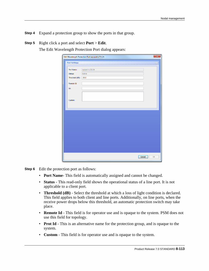
Step 4 Expand a protection group to show the ports in that group. Step 5 Right click a port and select Port > Edit.
The Edit Wavelength Protection Port dialog appears:
Step 6 Edit the protection port as follows:
• Port Name- This field is automatically assigned and cannot be changed.• Status - This read-only field shows the operational status of a line port. It is not
applicable to a client port.• Threshold (dB) - Select the threshold at which a loss of light condition is declared.
This field applies to both client and line ports. Additionally, on line ports, when thereceive power drops below this threshold, an automatic protection switch may takeplace.
• Remote Id - This field is for operator use and is opaque to the system. PSM does notuse this field for topology.
• Prot Id - This is an alternative name for the protection group, and is opaque to thesystem.
• Custom - This field is for operator use and is opaque to the system.
Product Release 7.0 STANDARD 8-113
Nodal management
Step 7 When you are finished, click OK.The PSM server sends the configuration request to the network element. You canmonitor the status of the request through the View > Server > Tasks window. The newprovisioning appears in the Network tree a short while after the task completessuccessfully.
8.3.6 Enabling or disabling a portUse this procedure to administratively enable or disable a port on a BTI7800 Series networkelement.
Step 1 Expand the network element in the Network tree to show the shelves in that NE. Step 2 Expand a shelf to show the slots in that shelf. Step 3 Expand a UFM to show the BICs on that UFM. Step 4 Expand a BIC to show the ports on that BIC. Step 5 Enable or disable a port as follows.
a) To enable a provisioned port, right click the port and select Admin State > Enable.b) To disable a provisioned port, right click the port and select Admin State > Disable.
8-114 proNX Service Manager User Guide – Document Version 01
Nodal management

8.4 Nodal management for BTI800 Series network elements
This section covers the following topics:• 8.4.1, “Enabling or disabling a port”
8.4.1 Enabling or disabling a portUse this procedure to administratively enable or disable a port on a BTI800 Series networkelement.
Step 1 Expand the network element in the Network tree to show the shelves in that NE. Step 2 Expand a shelf to show the slots in that shelf. Step 3 Expand a module to show the ports on that module. Step 4 Enable or disable a port as follows.
a) To enable a provisioned port, right click the port and select Admin State > Enable.b) To disable a provisioned port, right click the port and select Admin State > Disable.
Product Release 7.0 STANDARD 8-115
Nodal management

8-116 proNX Service Manager User Guide – Document Version 01
Nodal management
9.0 Configuring PSM client options
The proNX Service Manager (PSM) client options control the behavior of the PSM client inwhich the options are set.This chapter covers the following topics:• 9.1, “Configuring general options”• 9.2, “Configuring alerts options”• 9.3, “Configuring display options”• 9.4, “Configuring performance monitoring options”• 9.5, “Configuring utilities”
Note This chapter describes procedures to change PSM options on a Windows client.If you are running on OS X, the options wndow is accessed by psmclient > Preferences....
Product Release 7.0 STANDARD 9-1
C H A P T E R 9
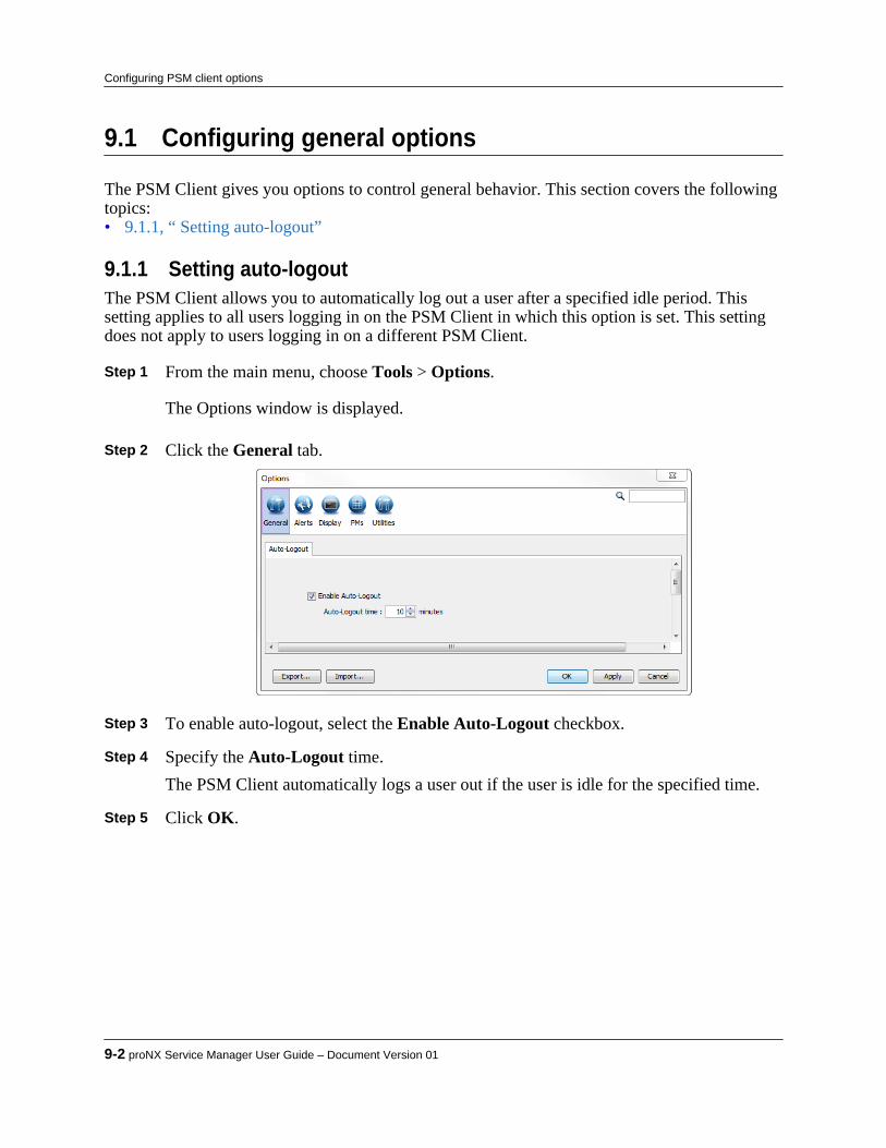
9.1 Configuring general options
The PSM Client gives you options to control general behavior. This section covers the followingtopics:• 9.1.1, “ Setting auto-logout”
9.1.1 Setting auto-logoutThe PSM Client allows you to automatically log out a user after a specified idle period. Thissetting applies to all users logging in on the PSM Client in which this option is set. This settingdoes not apply to users logging in on a different PSM Client.
Step 1 From the main menu, choose Tools > Options.
The Options window is displayed. Step 2 Click the General tab.
Step 3 To enable auto-logout, select the Enable Auto-Logout checkbox. Step 4 Specify the Auto-Logout time.
The PSM Client automatically logs a user out if the user is idle for the specified time. Step 5 Click OK.
9-2 proNX Service Manager User Guide – Document Version 01
Configuring PSM client options

9.2 Configuring alerts options
The PSM Client gives you options to control various audible alerts. This section covers thefollowing topics:• 9.2.1, “ Setting alarm alerts options”
9.2.1 Setting alarm alerts optionsThe PSM Client gives you options for the alerting of new alarms. To modify these options, usethe following procedure.
Step 1 From the main menu, choose Tools>Options.
The Options window is displayed. Step 2 Click the Alerts tab.
• To enable audible alerts, select Play alert on new alarm.• Browse to and select the audio file that contains the desired alert tone.• Select the Number of times to play the tone.
Step 3 Click OK.
Product Release 7.0 STANDARD 9-3
Configuring PSM client options
9.3 Configuring display options
The PSM Client allows you to control various display options. This section covers the followingtopics:• 9.3.1, “ Setting alarm display options”• 9.3.2, “ Setting auto-categorization options”• 9.3.3, “ Setting device display options”• 9.3.4, “ Setting overlay display options”• 9.3.5, “ Setting service display options”• 9.3.6, “ Setting topology display options”
9.3.1 Setting alarm display optionsThe PSM Client gives you options for the display of alarms. To modify these options, use thefollowing procedure.
Step 1 From the main menu, choose Tools>Options.
The Options window is displayed. Step 2 In the Options window, click Display. Step 3 Click the Alarms tab.
• To display acknowledged alarms in the alarms pane, check the DisplayAcknowledged Alarms check box.
• To filter the alarms in the alarms pane to only display alarms that relate to a selecteddevice when that device is selected in the Topology view or in the Tree view, checkthe Filter Alarms on Device Selection check box.
• To filter the alarms in the alarms pane to only display alarms that relate to a selectedservice when that service is selected in the Topology view or in the Tree view , checkthe Filter Alarms on Service Selection check box.
• To filter the alarms in the alarms pane to only display alarms that relate to aparticular group when that group is selected in the Topology view or in the Treeview, check the Filter Alarms on Group Selection check box.
• To automatically resume alarm notifications after alarm notifications have beensuspended, check the Expire Alarm Pausing check box and specify the AlarmPause Duration to wait for before resuming.
• To Show deltas for alarms in the alarms summary bar, select the alarm severities forwhich deltas are to be shown. Deltas are incremental alarm counters that provide anindication of how many new alarms have been raised since the counters were lastcleared.
9-4 proNX Service Manager User Guide – Document Version 01
Configuring PSM client options

• To specify how long to keep cleared alarms in the alarms pane, enter the Delaybefore removing cleared alarms in seconds. A setting of 0 causes the alarm to beremoved from the table immediately once it is cleared. Changes to this setting takeeffect for newly-raised alarms only. Existing alarms continue to use the previously-configured delay value.
Step 4 Click OK.
9.3.2 Setting auto-categorization optionsUse this procedure to set the auto-categorization options.When there are many services or customers, the Network tree can be difficult to navigate. Toreduce the visual clutter, PSM can automatically categorize and aggregate services andcustomers in the tree. You can let PSM choose default category names for you, or you cancustomize how PSM chooses the category names.
Step 1 From the main menu, choose Tools > Options.The Options window is displayed.
Step 2 Click the Auto-Categorization tab.
The auto-categorization options appear. There is a general Default section followed by asection for each branch of the tree that supports customized categorization.
Product Release 7.0 STANDARD 9-5
Configuring PSM client options

Step 3 To enable auto-categorization, select the Enable Auto-Categorization check box.
This enables auto-categorization for items in the Network tree. Step 4 Specify the Auto-Categorization Threshold.
When the number of items in a branch exceeds this threshold, PSM begins auto-categorization for that branch.
Step 5 To use the default PSM categories, click OK. Otherwise go to Step 6.
The Network tree is updated to show the new categorization. The default categories arebased on alphabetical categorization. For example:
Figure 9-1 Customers branch without auto-categorization
9-6 proNX Service Manager User Guide – Document Version 01
Configuring PSM client options
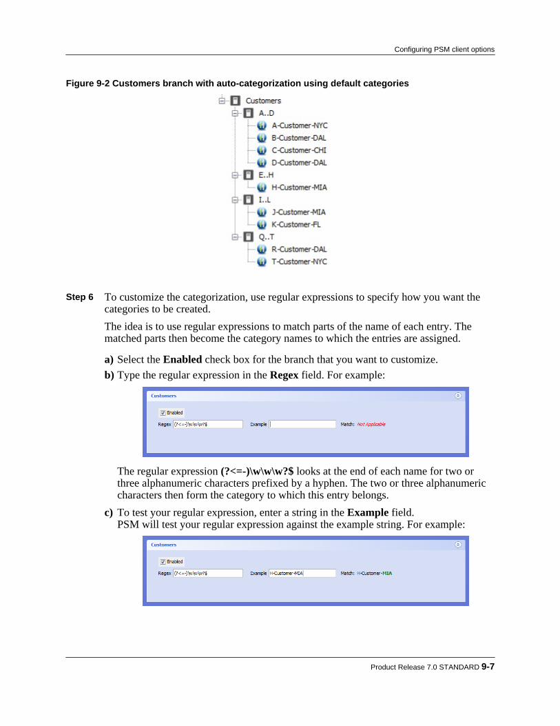
Figure 9-2 Customers branch with auto-categorization using default categories
Step 6 To customize the categorization, use regular expressions to specify how you want the
categories to be created.The idea is to use regular expressions to match parts of the name of each entry. Thematched parts then become the category names to which the entries are assigned.
a) Select the Enabled check box for the branch that you want to customize.b) Type the regular expression in the Regex field. For example:
The regular expression (?<=-)\w\w\w?$ looks at the end of each name for two orthree alphanumeric characters prefixed by a hyphen. The two or three alphanumericcharacters then form the category to which this entry belongs.
c) To test your regular expression, enter a string in the Example field.PSM will test your regular expression against the example string. For example:
Product Release 7.0 STANDARD 9-7
Configuring PSM client options
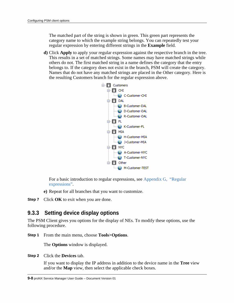
The matched part of the string is shown in green. This green part represents thecategory name to which the example string belongs. You can repeatedly test yourregular expression by entering different strings in the Example field.
d) Click Apply to apply your regular expression against the respective branch in the tree.This results in a set of matched strings. Some names may have matched strings whileothers do not. The first matched string in a name defines the category that the entrybelongs to. If the category does not exist in the branch, PSM will create the category.Names that do not have any matched strings are placed in the Other category. Here isthe resulting Customers branch for the regular expression above.
For a basic introduction to regular expressions, see Appendix G, “Regularexpressions”.
e) Repeat for all branches that you want to customize. Step 7 Click OK to exit when you are done.
9.3.3 Setting device display optionsThe PSM Client gives you options for the display of NEs. To modify these options, use thefollowing procedure.
Step 1 From the main menu, choose Tools>Options.
The Options window is displayed. Step 2 Click the Devices tab.
If you want to display the IP address in addition to the device name in the Tree viewand/or the Map view, then select the applicable check boxes.
9-8 proNX Service Manager User Guide – Document Version 01
Configuring PSM client options

Note If you select the Tree view, the IP address is also displayed in the NE column inthe Alarms window.
Step 3 Click OK.
9.3.4 Setting overlay display optionsUse this procedure to modify the appearance of how data widgets are overlaid on the backgroundwindow.This setting affects the appearance of the real-time PM data widgets and the link details widgets.
Step 1 From the main menu, choose Tools>Options.
The Options window is displayed. Step 2 In the Options window, click Display. Step 3 Click the Overlays tab.
Adjust the transparency of the data widgets. Choose any value from "0%" forcompletely transparent to "100%" for completely opaque.
Step 4 Click OK.
Product Release 7.0 STANDARD 9-9
Configuring PSM client options
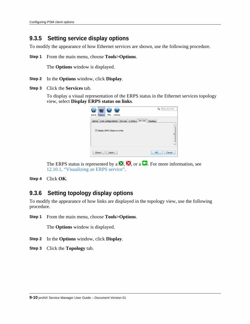
9.3.5 Setting service display optionsTo modify the appearance of how Ethernet services are shown, use the following procedure.
Step 1 From the main menu, choose Tools>Options.
The Options window is displayed. Step 2 In the Options window, click Display. Step 3 Click the Services tab.
To display a visual representation of the ERPS status in the Ethernet services topologyview, select Display ERPS status on links.
The ERPS status is represented by a , , or a . For more information, see12.10.1, “Visualizing an ERPS service”.
Step 4 Click OK.
9.3.6 Setting topology display optionsTo modify the appearance of how links are displayed in the topology view, use the followingprocedure.
Step 1 From the main menu, choose Tools>Options.
The Options window is displayed. Step 2 In the Options window, click Display. Step 3 Click the Topology tab.
9-10 proNX Service Manager User Guide – Document Version 01
Configuring PSM client options
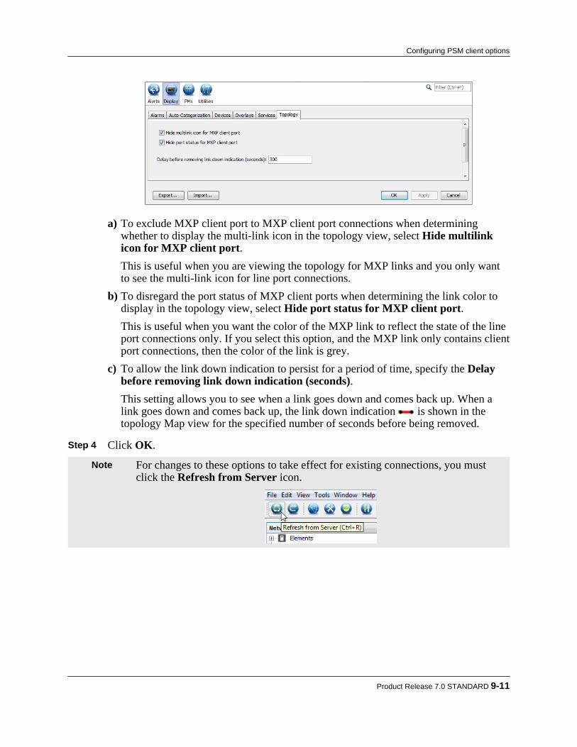
a) To exclude MXP client port to MXP client port connections when determiningwhether to display the multi-link icon in the topology view, select Hide multilinkicon for MXP client port.This is useful when you are viewing the topology for MXP links and you only wantto see the multi-link icon for line port connections.
b) To disregard the port status of MXP client ports when determining the link color todisplay in the topology view, select Hide port status for MXP client port.This is useful when you want the color of the MXP link to reflect the state of the lineport connections only. If you select this option, and the MXP link only contains clientport connections, then the color of the link is grey.
c) To allow the link down indication to persist for a period of time, specify the Delaybefore removing link down indication (seconds).This setting allows you to see when a link goes down and comes back up. When alink goes down and comes back up, the link down indication is shown in thetopology Map view for the specified number of seconds before being removed.
Step 4 Click OK.
Note For changes to these options to take effect for existing connections, you mustclick the Refresh from Server icon.
Product Release 7.0 STANDARD 9-11
Configuring PSM client options
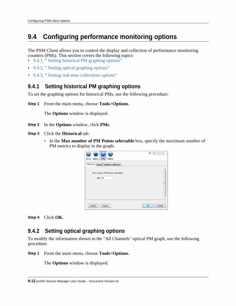
9.4 Configuring performance monitoring options
The PSM Client allows you to control the display and collection of performance monitoringcounters (PMs). This section covers the following topics:• 9.4.1, “ Setting historical PM graphing options”• 9.4.2, “ Setting optical graphing options”• 9.4.3, “ Setting real-time collections options”
9.4.1 Setting historical PM graphing optionsTo set the graphing options for historical PMs, use the following procedure:
Step 1 From the main menu, choose Tools>Options.
The Options window is displayed. Step 2 In the Options window, click PMs. Step 3 Click the Historical tab.
• In the Max number of PM Points selectable box, specify the maximum number ofPM metrics to display in the graph.
Step 4 Click OK.
9.4.2 Setting optical graphing optionsTo modify the information shown in the "All Channels" optical PM graph, use the followingprocedure:
Step 1 From the main menu, choose Tools>Options.
The Options window is displayed.
9-12 proNX Service Manager User Guide – Document Version 01
Configuring PSM client options

Step 2 In the Options window, click PMs. Step 3 Click the Optical tab.
• To display the channel number in the domain (horizontal) axis of the "All Channels"graph, select the Channel Number check box.
• To display the channel (32+8 Plan) number in the domain (horizontal) axis of the"All Channels" graph, select the Channel(32+8 Plan) check box.
• To display the wavelength in the domain (horizontal) axis of the "All Channels"graph, select the Wavelength check box.
• To display the frequency in the domain (horizontal) axis of the "All Channels" graph,select the Frequency check box.
Multiple check boxes can be selected.
Step 4 Click OK.
9.4.3 Setting real-time collections optionsTo modify how long real-time PM data is collected and how frequently the counts are updated,use the following procedure.
Step 1 From the main menu, choose Tools>Options.
The Options window is displayed. Step 2 In the Options window, click PMs. Step 3 Click the Realtime Collections tab.
• Select the Duration over which the real-time PM data is to be collected.• Select the Interval or frequency with which the real-time PM data is updated.
Product Release 7.0 STANDARD 9-13
Configuring PSM client options

Step 4 Click OK.
9-14 proNX Service Manager User Guide – Document Version 01
Configuring PSM client options
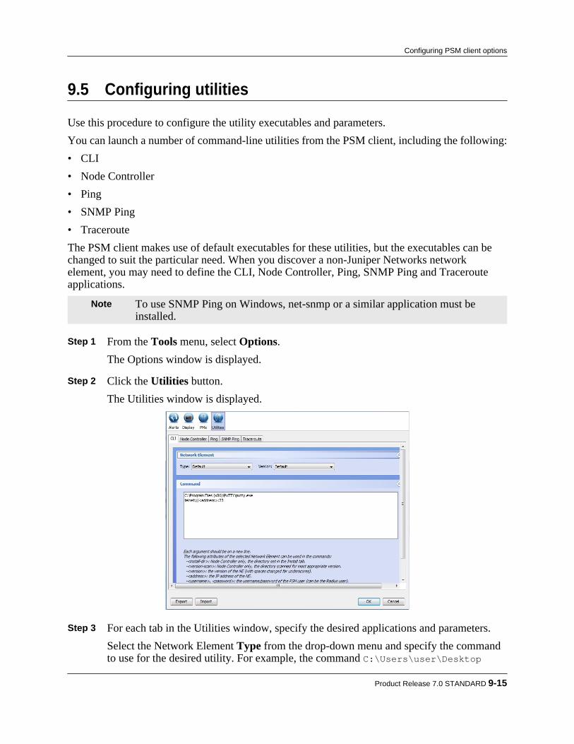
9.5 Configuring utilities
Use this procedure to configure the utility executables and parameters.You can launch a number of command-line utilities from the PSM client, including the following:• CLI• Node Controller• Ping• SNMP Ping• TracerouteThe PSM client makes use of default executables for these utilities, but the executables can bechanged to suit the particular need. When you discover a non-Juniper Networks networkelement, you may need to define the CLI, Node Controller, Ping, SNMP Ping and Tracerouteapplications.
Note To use SNMP Ping on Windows, net-snmp or a similar application must beinstalled.
Step 1 From the Tools menu, select Options.The Options window is displayed.
Step 2 Click the Utilities button.
The Utilities window is displayed.
Step 3 For each tab in the Utilities window, specify the desired applications and parameters.
Select the Network Element Type from the drop-down menu and specify the commandto use for the desired utility. For example, the command C:\Users\user\Desktop
Product Release 7.0 STANDARD 9-15
Configuring PSM client options

\putty.exe -ssh -P 22 user@<IP_address_of_selected_NE> is represented bythis configuration:
Note The <address> construct is a variable that represents the IP address of theselected NE.
Step 4 When you are done, click OK.
This procedure is complete.
Note To connect to the CLI, see 6.9, “ Connecting to the CLI on a network element”.To launch the Node Controller on the BTI7000, see 8.2.1, “Launching the proNX900 Node Controller ”. To launch the other utilities, see 19.3, “Performingdiagnostics”.
9.5.1 Configuring the proNX 900 Node ControllerUse this procedure to configure the proNX 900 Node Controller.
Note The proNX 900 Node Controller may not be supported on all PSM Clientplatforms. See the BTI7000 Series Common Equipment Installation Guide for alist of platforms that support the proNX 900 Node Controller.
Prerequisite:
• The proNX 900 Node Controller software that is compatible with the network elements inyour network must be installed on your local computer.
Step 1 From the main menu, choose Tools>Options.The Options window is displayed.
Step 2 Click the Utilities button and then click the Node Controller tab. Step 3 There are several methods by which you can specify the path to the proNX 900
application software on your local computer:• If all of your versions of proNX 900 are in one directory, you can browse to that
directory and select it. Afterwards, when you launch proNX 900, PSM chooses thecorrect version of the proNX 900 for the selected NE and launches it. If it cannot findan exact match, PSM chooses the best match and prompts you to confirm. Continueat Step 4.
9-16 proNX Service Manager User Guide – Document Version 01
Configuring PSM client options
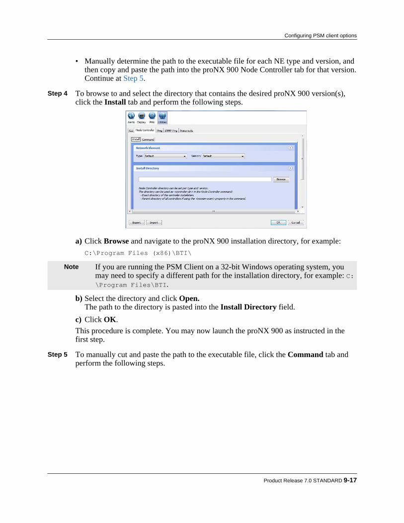
• Manually determine the path to the executable file for each NE type and version, andthen copy and paste the path into the proNX 900 Node Controller tab for that version.Continue at Step 5.
Step 4 To browse to and select the directory that contains the desired proNX 900 version(s),
click the Install tab and perform the following steps.
a) Click Browse and navigate to the proNX 900 installation directory, for example:C:\Program Files (x86)\BTI\
Note If you are running the PSM Client on a 32-bit Windows operating system, youmay need to specify a different path for the installation directory, for example: C:\Program Files\BTI.
b) Select the directory and click Open.The path to the directory is pasted into the Install Directory field.
c) Click OK.This procedure is complete. You may now launch the proNX 900 as instructed in thefirst step.
Step 5 To manually cut and paste the path to the executable file, click the Command tab and
perform the following steps.
Product Release 7.0 STANDARD 9-17
Configuring PSM client options
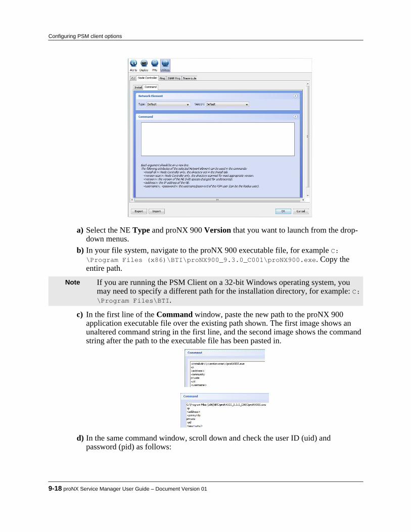
a) Select the NE Type and proNX 900 Version that you want to launch from the drop-down menus.
b) In your file system, navigate to the proNX 900 executable file, for example C:\Program Files (x86)\BTI\proNX900_9.3.0_C001\proNX900.exe. Copy theentire path.
Note If you are running the PSM Client on a 32-bit Windows operating system, youmay need to specify a different path for the installation directory, for example: C:\Program Files\BTI.
c) In the first line of the Command window, paste the new path to the proNX 900application executable file over the existing path shown. The first image shows anunaltered command string in the first line, and the second image shows the commandstring after the path to the executable file has been pasted in.
d) In the same command window, scroll down and check the user ID (uid) andpassword (pid) as follows:
9-18 proNX Service Manager User Guide – Document Version 01
Configuring PSM client options

• if you want to launch the proNX 900 without requiring the user to log in, ensurethat the user ID (uid) and password (pid) are the same as the NE user ID andpassword.
• alternatively, you can remove the user ID and password in the command window,forcing the user to log in when the proNX 900 launches.
e) As desired, repeat these steps for each NE Type and Version of proNX 900. Whenyou are finished click OK.
This procedure is complete.
Product Release 7.0 STANDARD 9-19
Configuring PSM client options

9-20 proNX Service Manager User Guide – Document Version 01
Configuring PSM client options

10.0 Bulk Configuration of NetworkElements
The proNX Service Manager Client allows you to perform configuration operations on multiplenetwork elements concurrently. This bulk configuration capability makes use of PSM Serverscripts to communicate with and configure the NEs.This section covers the following topics:• 10.1, “Creating new users on multiple network elements”• 10.2, “Configuring RADIUS server parameters on multiple network elements”• 10.3, “Configuring NTP server parameters on multiple network elements”
Product Release 7.0 STANDARD 10-1
C H A P T E R 1 0

10.1 Creating new users on multiple network elements
Use this procedure to add the same set of new users to multiple network elements.
Note The PSM server treats each network element separately, launching individualtasks to communicate with and configure each NE. A task failure for one NEdoes not affect tasks for the other NEs.
Note PSM connects to each NE using the login credentials that you supplied when youconnected to the PSM server. Therefore each NE must be configured with thesesame login credentials for this procedure to be successful.
Note PSM connects to each NE using the applicable protocol for that NE type. Whenconnecting to an NE over SSH (e.g. BTI7800), the SSH key provided by the NEmust match the expected key (if the key was previously stored). If the keysupplied by the NE does not match the expected key, the task times out and fails.Under normal situations, the supplied key matches the expected key. However, ifthe NE operating system has been re-installed, the keys may not match. In thissituation, you will need to remove the expected key from the PSM servermachine's ~/.ssh/known_hosts file. One method of doing this is to issue thefollowing Linux command from a Linux shell on the PSM server machine:# sed -i '/NE_IP_address/d' ~/.ssh/known_hostswhere NE_IP_address is the IP address of the NE.
This procedure is supported on BTI7000 Series, BTI7800 Series, BTI800 Series, and BTI700Series (excluding BTI718E) NEs.
Step 1 To create one or more new users, select one or more network elements from the maintopology window or from the tree view.
Step 2 Right-click and select Scripts>Network Elements>Create New Users.
The "Create New Users" dialog appears with the list of selected network elements at thetop:
10-2 proNX Service Manager User Guide – Document Version 01
Bulk Configuration of Network Elements

Note The "Selected Network Element(s)" box has limited space to display networkelements. In situations where the number of selected network elements is large,some network elements may not be displayed. This is normal behavior and doesnot affect script execution, which runs for all selected network elements,regardless of whether they appear in the list or not.
Step 3 Click Add to add a user.
A new row appears. Step 4 Click inside each field and add the necessary information. Select the "Role" from a pull-
down menu.
Product Release 7.0 STANDARD 10-3
Bulk Configuration of Network Elements
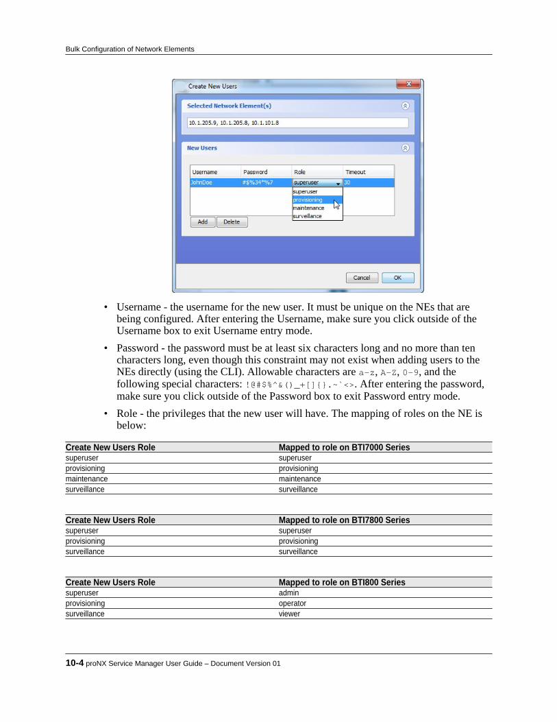
• Username - the username for the new user. It must be unique on the NEs that arebeing configured. After entering the Username, make sure you click outside of theUsername box to exit Username entry mode.
• Password - the password must be at least six characters long and no more than tencharacters long, even though this constraint may not exist when adding users to theNEs directly (using the CLI). Allowable characters are a-z, A-Z, 0-9, and thefollowing special characters: !@#$%^&()_+[]{}.~`<>. After entering the password,make sure you click outside of the Password box to exit Password entry mode.
• Role - the privileges that the new user will have. The mapping of roles on the NE isbelow:
Create New Users Role Mapped to role on BTI7000 Seriessuperuser superuserprovisioning provisioningmaintenance maintenancesurveillance surveillance
Create New Users Role Mapped to role on BTI7800 Seriessuperuser superuserprovisioning provisioningsurveillance surveillance
Create New Users Role Mapped to role on BTI800 Seriessuperuser adminprovisioning operatorsurveillance viewer
10-4 proNX Service Manager User Guide – Document Version 01
Bulk Configuration of Network Elements

Create New Users Role Mapped to role on BTI700 Seriessuperuser administratorsprovisioning operatorsmaintenance userssurveillance guests
• Timeout - the idle timeout before automatically logging the user out. This onlyapplies to the BTI7000 Series NEs, and has no effect on the other NE types.
Step 5 Add as many users as desired. You can delete a row by selecting it and clicking Delete. Step 6 When you are finished, click OK.
The PSM server launches a task for each NE being configured. Step 7 Look at the Tasks window to verify that each task has completed successfully. A
"Create New Users" task can fail for an NE if a user being added already exists on thatNE.In the following example, the "Create New Users" task was successful for 10.1.205.9but failed for 10.1.205.8.
Note A failure usually indicates that at least one username being added already existson the NE. The script does not add duplicate usernames, but continues to add allnon-duplicate usernames. It is good practice to log in to each failed NE (usingthe proNX 900) to verify which users have been added successfully and whichfailed.
This procedure is now complete.
Product Release 7.0 STANDARD 10-5
Bulk Configuration of Network Elements

10.2 Configuring RADIUS server parameters on multiplenetwork elements
Use this procedure to configure the same RADIUS server parameters across multiple networkelements.
Note The PSM server treats each network element separately, launching individualtasks to communicate with and configure each NE. A task failure for one NEdoes not affect tasks for the other NEs.
Note PSM connects to each NE using the login credentials that you supplied when youconnected to the PSM server. Therefore each NE must be configured with thesesame login credentials for this procedure to be successful.
Note PSM connects to each NE using the applicable protocol for that NE type. Whenconnecting to an NE over SSH (e.g. BTI7800), the SSH key provided by the NEmust match the expected key (if the key was previously stored). If the keysupplied by the NE does not match the expected key, the task times out and fails.Under normal situations, the supplied key matches the expected key. However, ifthe NE operating system has been re-installed, the keys may not match. In thissituation, you will need to remove the expected key from the PSM servermachine's ~/.ssh/known_hosts file. One method of doing this is to issue thefollowing Linux command from a Linux shell on the PSM server machine:# sed -i '/NE_IP_address/d' ~/.ssh/known_hostswhere NE_IP_address is the IP address of the NE.
This procedure is supported on BTI7000 Series, BTI7800 Series, BTI800 Series, and BTI700Series NEs.
Step 1 To configure RADIUS server parameters, select one or more network elements from themain topology window or from the tree view. Only compatible network elements can beselected together.
Step 2 Right-click and select Scripts>Network Elements>Configure Radius Server.The "Create Radius Server" dialog appears with the list of selected network elements at the top.Depending on the type of network element selected, you will see one of the following twodialogs:
10-6 proNX Service Manager User Guide – Document Version 01
Bulk Configuration of Network Elements
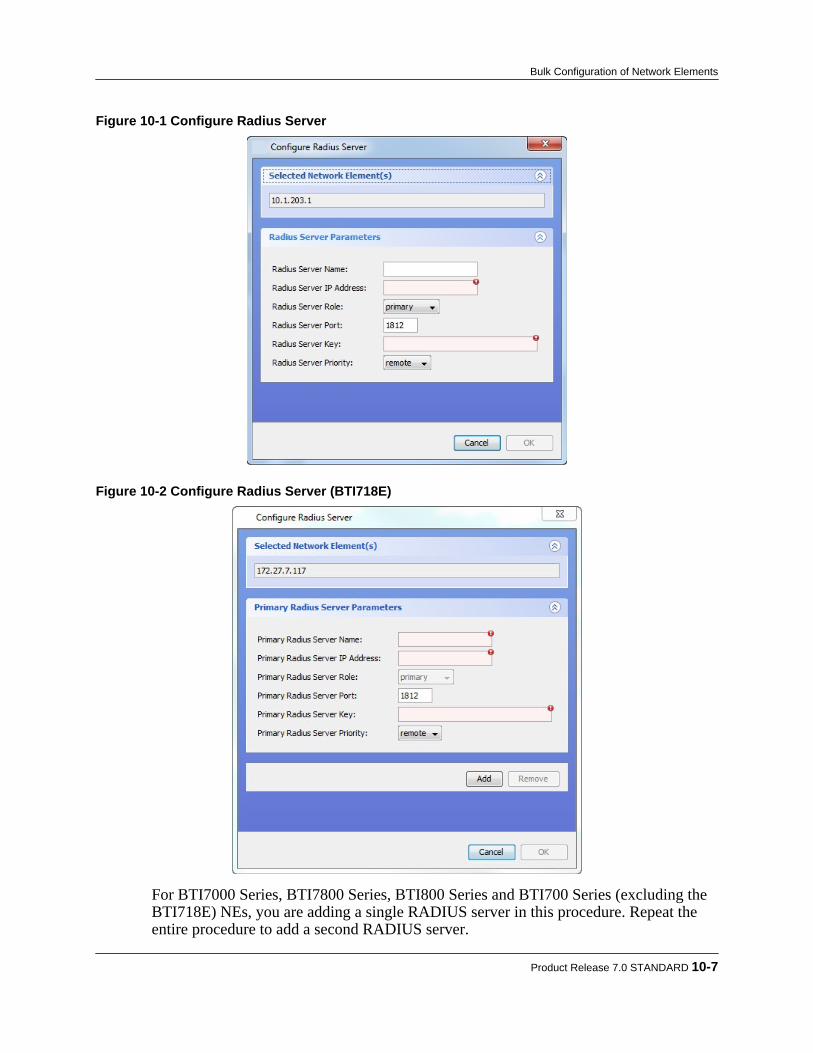
Figure 10-1 Configure Radius Server
Figure 10-2 Configure Radius Server (BTI718E)
For BTI7000 Series, BTI7800 Series, BTI800 Series and BTI700 Series (excluding theBTI718E) NEs, you are adding a single RADIUS server in this procedure. Repeat theentire procedure to add a second RADIUS server.
Product Release 7.0 STANDARD 10-7
Bulk Configuration of Network Elements

For the BTI718E, you are adding the primary and the secondary servers simultaneouslyin this procedure. Click the Add button to expand the dialog to specify up to amaximum of two secondary servers.
Note For both dialogs, the "Selected Network Element(s)" box has limited space todisplay network elements. In some situations where the number of selectednetwork elements is large, some network elements may not be displayed. This isnormal behavior and does not affect script execution, which runs for all selectednetwork elements, regardless of whether they appear in the list or not.
Step 3 Configure the RADIUS parameters:
Attribute BTI7000 SeriesRadius Server Name Not applicable.Radius Server IP Address Sets the IP address.Radius Server Role:
primary Sets the Role attribute to primary.secondary Sets the Role attribute to secondary.disabled Sets the Role attribute to disabled. The specified server is
configured but not used.Radius Server Port Sets the Port attribute to the specified value.Radius Server Key Sets the Key (shared secret) attribute to the specified value.Radius Server Priority
disabled Sets the Authentication Priority attribute to disabled. The NE useslocal database authentication only.
local Sets the Authentication Priority attribute to local. The NE uses localdatabase authentication first, then RADIUS server authentication.
remote Sets the Authentication Priority attribute to remote. The NE usesRADIUS server authentication first, then local databaseauthentication.
Attribute BTI7800 SeriesRadius Server Name Not applicable.Radius Server IP Address Sets the IP address.Radius Server Role Not applicable.Radius Server Port Sets the authentication port to the specified value.Radius Server Key Sets the shared secret to the specified value.Radius Server Priority Not applicable.
Attribute BTI800 SeriesRadius Server Name Not applicable.Radius Server IP Address Sets the IP address.Radius Server Role:
primary Specifies that this is the primary server for the BTI810. Notapplicable for the BTI805, BTI821, BTI822.
secondary Specifies that this is the secondary server for the BTI810. Notapplicable for the BTI805, BTI821, BTI822.
disabled Not applicable.Radius Server Port Sets the authentication port.Radius Server Key Sets the shared secret.Radius Server Priority
10-8 proNX Service Manager User Guide – Document Version 01
Bulk Configuration of Network Elements

Attribute BTI800 Seriesdisabled Not applicable.local Sets the auth-order attribute to local. The NE uses local database
authentication first, then RADIUS server authentication.remote Sets the auth-order attribute to radius. The NE uses RADIUS server
authentication first, then local database authentication.
Attribute BTI700 SeriesRadius Server Name Sets the NAME attribute to the specified value.Radius Server IP Address Sets the IP address.Radius Server Role:
primary Sets the mode attribute to main and the state to active.secondary Sets the mode attribute to backup, and the state to active.disabled Sets the state to suspend.
Radius Server Port Sets the auth-port attribute to the specified value.Radius Server Key Sets the SECRET attribute to the specified value.Radius Server Priority
disabled Sets line vty 1 2 login local. The NE uses localauthentication for the first two sessions.
local Sets line vty 1 2 login local. The NE uses localauthentication for the first two sessions.
remote Sets line vty 1 2 login radius. The NE uses RADIUSauthentication for the first two sessions.
Step 4 When you are finished, click OK.
The PSM server launches a task for each NE being configured. Step 5 Look at the Tasks window to verify that each task has completed successfully.
In this example, the "Configure Radius Server" task was successful for 10.1.205.8.
A task may fail under these conditions:• You are adding a RADIUS server to a BTI7000 Series NE that already has two
RADIUS servers defined. The task fails and no changes take effect.• You are adding a RADIUS server to a BTI7000 Series NE that has that particular
RADIUS server already defined (regardless of the role). The task fails and nochanges take effect.
Note Other failure conditions exist. Expand the task details of any failed task to seewhy the task has failed. Since a failed task may still lead to changes on the NE,you will also need to check the NE on task failure.
Product Release 7.0 STANDARD 10-9
Bulk Configuration of Network Elements

This procedure is now complete.
10-10 proNX Service Manager User Guide – Document Version 01
Bulk Configuration of Network Elements

10.3 Configuring NTP server parameters on multiplenetwork elements
Use this procedure to configure the same NTP server parameters on multiple network elements.It is highly recommended that PSM and all NEs in the network use NTP servers for obtaining thetime in order to avoid time discrepancies.
Note The PSM server treats each network element separately, launching individualtasks to communicate with and configure each NE. A task failure for one NEdoes not affect tasks for the other NEs.
Note PSM connects to each NE using the login credentials that you supplied when youconnected to the PSM server. Therefore each NE must be configured with thesesame login credentials for this procedure to be successful.
Note PSM connects to each NE using the applicable protocol for that NE type. Whenconnecting to an NE over SSH (e.g. BTI7800), the SSH key provided by the NEmust match the expected key (if the key was previously stored). If the keysupplied by the NE does not match the expected key, the task times out and fails.Under normal situations, the supplied key matches the expected key. However, ifthe NE operating system has been re-installed, the keys may not match. In thissituation, you will need to remove the expected key from the PSM servermachine's ~/.ssh/known_hosts file. One method of doing this is to issue thefollowing Linux command from a Linux shell on the PSM server machine:# sed -i '/NE_IP_address/d' ~/.ssh/known_hostswhere NE_IP_address is the IP address of the NE.
This procedure is supported for the BTI7000 Series, the BTI7800 Series, and the BTI800 SeriesNEs.
Step 1 To configure NTP server parameters, select one or more network elements from themain topology window or from the tree view.
Step 2 Right-click and select Scripts>Network Elements>Configure NTP.
The "Configure NTP" dialog appears with the list of selected network elements at thetop:
Product Release 7.0 STANDARD 10-11
Bulk Configuration of Network Elements
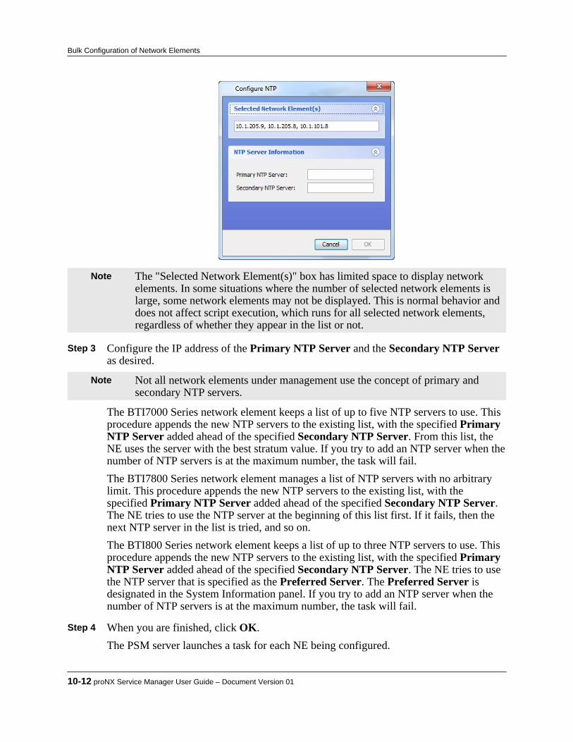
Note The "Selected Network Element(s)" box has limited space to display networkelements. In some situations where the number of selected network elements islarge, some network elements may not be displayed. This is normal behavior anddoes not affect script execution, which runs for all selected network elements,regardless of whether they appear in the list or not.
Step 3 Configure the IP address of the Primary NTP Server and the Secondary NTP Server
as desired.
Note Not all network elements under management use the concept of primary andsecondary NTP servers.
The BTI7000 Series network element keeps a list of up to five NTP servers to use. Thisprocedure appends the new NTP servers to the existing list, with the specified PrimaryNTP Server added ahead of the specified Secondary NTP Server. From this list, theNE uses the server with the best stratum value. If you try to add an NTP server when thenumber of NTP servers is at the maximum number, the task will fail.The BTI7800 Series network element manages a list of NTP servers with no arbitrarylimit. This procedure appends the new NTP servers to the existing list, with thespecified Primary NTP Server added ahead of the specified Secondary NTP Server.The NE tries to use the NTP server at the beginning of this list first. If it fails, then thenext NTP server in the list is tried, and so on.The BTI800 Series network element keeps a list of up to three NTP servers to use. Thisprocedure appends the new NTP servers to the existing list, with the specified PrimaryNTP Server added ahead of the specified Secondary NTP Server. The NE tries to usethe NTP server that is specified as the Preferred Server. The Preferred Server isdesignated in the System Information panel. If you try to add an NTP server when thenumber of NTP servers is at the maximum number, the task will fail.
Step 4 When you are finished, click OK.
The PSM server launches a task for each NE being configured.
10-12 proNX Service Manager User Guide – Document Version 01
Bulk Configuration of Network Elements
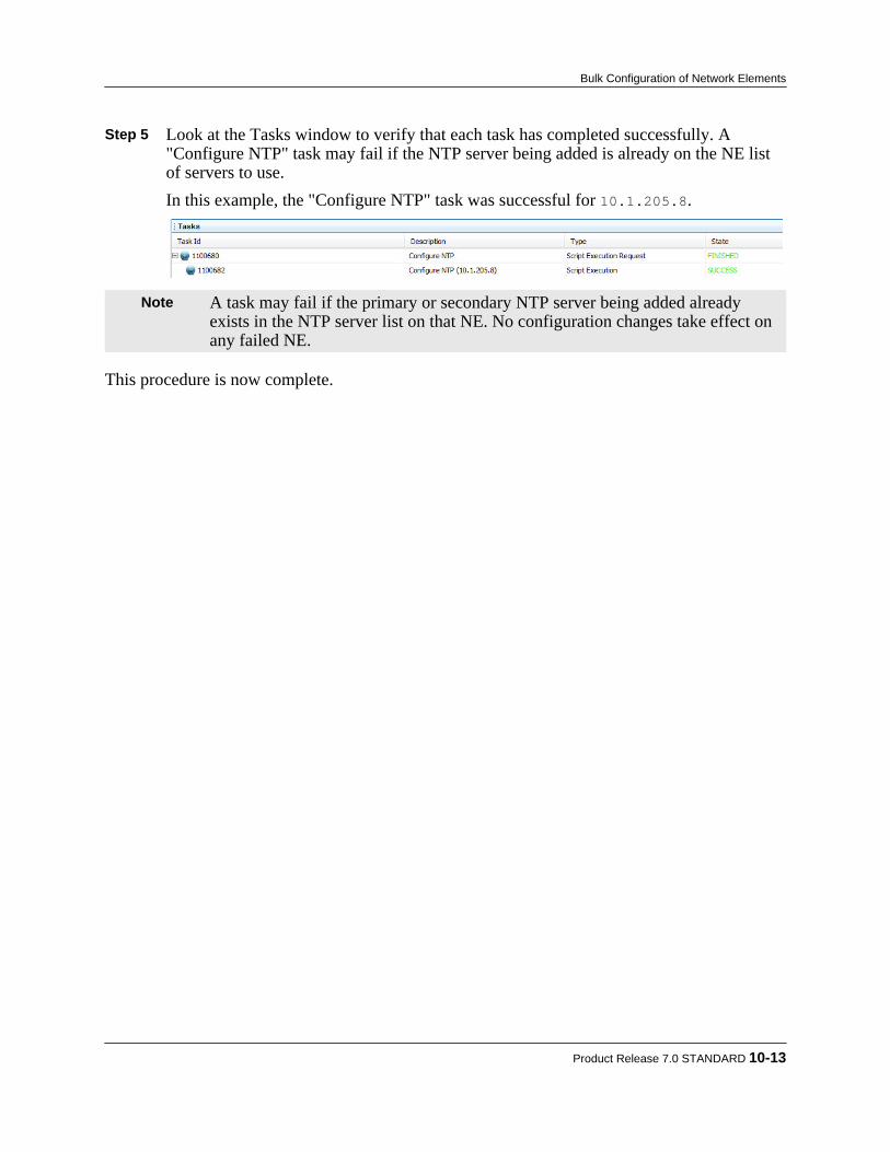
Step 5 Look at the Tasks window to verify that each task has completed successfully. A"Configure NTP" task may fail if the NTP server being added is already on the NE listof servers to use.In this example, the "Configure NTP" task was successful for 10.1.205.8.
Note A task may fail if the primary or secondary NTP server being added alreadyexists in the NTP server list on that NE. No configuration changes take effect onany failed NE.
This procedure is now complete.
Product Release 7.0 STANDARD 10-13
Bulk Configuration of Network Elements

10-14 proNX Service Manager User Guide – Document Version 01
Bulk Configuration of Network Elements

11.0 Managing optical and transportservices
PSM allows users to manage optical and transport services in the network for BTI7000 Seriesand BTI7800 Series network elements.This section covers the following topics:• 11.1, “Optical services”• 11.2, “Transport services”• 11.3, “Working with optical/transport services and topology tables”• 11.4, “Saving a service image”
Product Release 7.0 STANDARD 11-1
C H A P T E R 1 1

11.1 Optical services
PSM allows users to activate and manage optical services for BTI7000 Series and BTI7800Series network elements. Optical services add, drop, and switch wavelengths.• 11.1.1, “Visualizing an optical service”• 11.1.2, “Activating an optical service on a BTI7000 Series network”• 11.1.3, “Activating an optical service on a BTI7800 network”• 11.1.4, “Viewing the cross-connects in an optical service”• 11.1.5, “Updating an optical service”• 11.1.6, “Deleting an optical service”• 11.1.7, “Viewing the optical services table”• 11.1.8, “Viewing the optical services per span table”• 11.1.9, “Viewing the optical topology table”
11.1.1 Visualizing an optical serviceThe proNX Service Manager Client allows users several ways to visualize an optical service. Anoptical service can be visualized at the network, service, group, and module levels. Service pathscan be highlighted and detailed information can be displayed through tool tips or in table form.
Step 1 To see an optical service in its own panel, select it in the tree view under the Opticalbranch.
If the service includes a split ROADM node, the link connecting the two networkelements comprising the ROADM node is shown with a icon. For example, in thefollowing figure, 10.1.220.33 and 10.1.220.37 are both part of a single ROADM node,with each NE providing a degree:
11-2 proNX Service Manager User Guide – Document Version 01
Managing optical and transport services
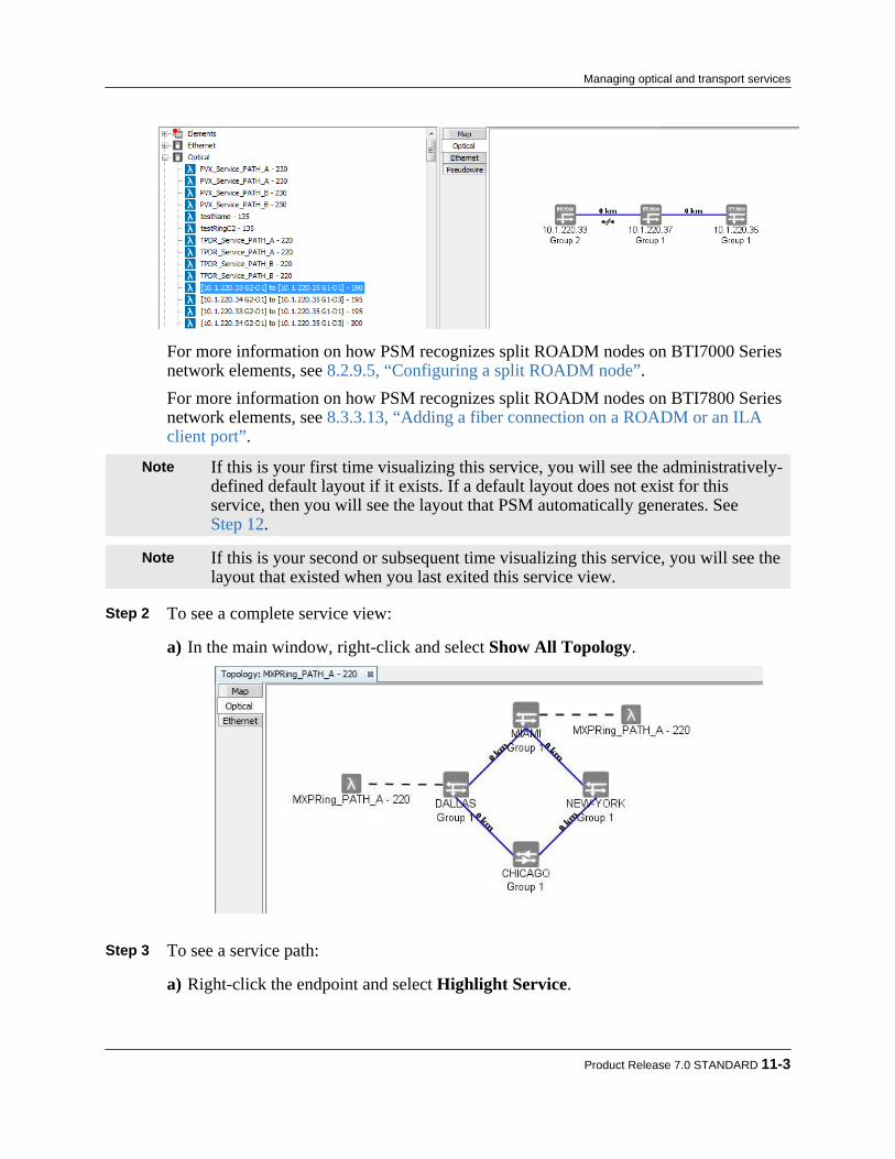
For more information on how PSM recognizes split ROADM nodes on BTI7000 Seriesnetwork elements, see 8.2.9.5, “Configuring a split ROADM node”.For more information on how PSM recognizes split ROADM nodes on BTI7800 Seriesnetwork elements, see 8.3.3.13, “Adding a fiber connection on a ROADM or an ILAclient port”.
Note If this is your first time visualizing this service, you will see the administratively-defined default layout if it exists. If a default layout does not exist for thisservice, then you will see the layout that PSM automatically generates. SeeStep 12.
Note If this is your second or subsequent time visualizing this service, you will see thelayout that existed when you last exited this service view.
Step 2 To see a complete service view:
a) In the main window, right-click and select Show All Topology.
Step 3 To see a service path:
a) Right-click the endpoint and select Highlight Service.
Product Release 7.0 STANDARD 11-3
Managing optical and transport services

Only groups that are part of the service are highlighted.b) Right-click on the background and select Clear Highlighting.
Step 4 To see the optical port or interface associated with the service endpoint, right-click the
endpoint and select Navigate > Optical Port or Navigate > Interface.The optical port or interface associated with the endpoint is highlighted in the Networktree.
Step 5 To see the physical equipment in a group, double-click the optical group icon:
The physical equipment and connections within the group are shown in a zoomed-inview.
Step 6 To change the size of the service view:
a) Right-click the background and select Zoom In to increase the view size
11-4 proNX Service Manager User Guide – Document Version 01
Managing optical and transport services
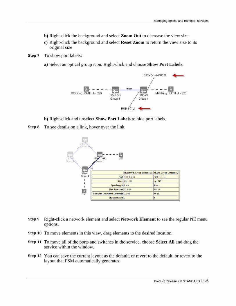
b) Right-click the background and select Zoom Out to decrease the view sizec) Right-click the background and select Reset Zoom to return the view size to its
original size Step 7 To show port labels:
a) Select an optical group icon. Right-click and choose Show Port Labels.
b) Right-click and unselect Show Port Labels to hide port labels. Step 8 To see details on a link, hover over the link.
Step 9 Right-click a network element and select Network Element to see the regular NE menu
options. Step 10 To move elements in this view, drag elements to the desired location. Step 11 To move all of the ports and switches in the service, choose Select All and drag the
service within the window. Step 12 You can save the current layout as the default, or revert to the default, or revert to the
layout that PSM automatically generates.
Product Release 7.0 STANDARD 11-5
Managing optical and transport services

a) To save the current layout as the default layout for this service, right-click thebackground and select Save Layout as Default.
Note You must have administrator privileges to execute this command.
Once the current layout is saved as the default, subsequent users who visualize thisservice will be able to see the current layout.
b) To reset the current layout to the default, right-click the background and select ResetLayout to Default.
c) To reset the current layout to the layout that PSM automatically generates, right-clickthe background and select Reset Layout.
Step 13 To save the service screen view as an image:
a) Select Save Service Image.The Save Service Image dialog appears.
b) Navigate to the desired folder and enter the filename.The default file format is png. To save the file in jpg format, enter .jpg at the end ofthe filename.
c) Click Save. You have successfully completed this procedure.
11.1.2 Activating an optical service on a BTI7000 Series networkUse this procedure to configure and activate an optical service on a BTI7000 Series network. TheBTI7000 Series optical network is called the BTI7000 Series Dynamic Optical Layer (DOL).
Step 1 Select Tools > Service Activation > Optical > DOL. Alternatively, click the ServiceActivation button on the toolbar, and select Optical > DOL.The Activate Optical Service dialog opens.
11-6 proNX Service Manager User Guide – Document Version 01
Managing optical and transport services

Step 2 In the Service tab, enter the required information as described in the following table.
Table 11-1 Fields on the Activate Optical Service dialog Field Description Required
field?ServiceName
User-defined name that uniquely identifies the service. Yes
Customer Select from the drop-down list. To add a customer to the list, select Edit>Add Customerfrom the main menu.
Optional
Site A Choose from a drop-down menu of existing sites. Yes
Site Z Choose from a drop-down menu of existing sites. Yes
Alien/C2 When selected, the service is not provisioned to Add/Drop on the Mux/Demux, but onthe C2 port of the ROB. When selected for both site A and site Z, four wavelengths areadded to the channels drop-down list. Note This option is not available for selection in a split ROADM node. In a split ROADM node,the Alien/C2 interface is used to connect the ROADM modules together, and cannot beconfigured for Add/Drop wavelengths.
Optional
Path Choose from a drop-down list of possible paths from Site A to Site Z. Each path has thefollowing format:
<Site A> to <Site Z> [via <Site N1>[; <Site N2>[;...]]]
where <Site Nx> represents a decision point for a ROADM with more than twodegrees. Each decision point specifies the incoming and outgoing degrees for the paththrough that NE. See 11.1.2.1, “Examples of path selection”.
Yes
Product Release 7.0 STANDARD 11-7
Managing optical and transport services

Table 11-1 Fields on the Activate Optical Service dialog (Continued) Field Description Required
field? Note By default, the maximum number of spans that a path can have is 10. If your pathrequires more than 10 spans, contact Juniper Networks Support to increase this limit.
Channel Choose from a drop-down list of existing channels. Yes
SecondPath
When selected, the Path and Channel for the protected path can be specified. Thisselection is greyed out if no alternative path exists.
Optional
Step 3 Click Activate.
Note You must wait for the activation tasks to complete before performing any otheroperation on the NEs affected by this activation.
You have successfully completed this procedure.
11.1.2.1 Examples of path selectionWhen you activate an optical service, you need to select the first (primary) path and channel, andoptionally the second (protected) path and channel between the service endpoints. All paths andchannels are selected from drop-down menus in the Activate Optical Service dialog. The drop-down menus list all the valid possibilities. A second path can only be selected if an alternativepath exists. Otherwise the Second Path check box is greyed out and cannot be selected.The path itself may contain decision points. A decision point refers to the decision that needs tobe made when traversing ROADM nodes with more than 2 degrees. When more than 2 degreesexist, there can be multiple outgoing degrees for each incoming degree. The decision pointqualifies the path by specifying the incoming and outgoing degrees through these nodes.
Selecting paths and channels
Figure 11-1 shows the selection of the first path and channel for a service between NEW-YORKand MIAMI. The topology is a ring with 2-degree ROADMs in NEW-YORK, MIAMI, andDALLAS, and a line amplifier node in CHICAGO. The first path is chosen to be the shortestpath around the ring.
11-8 proNX Service Manager User Guide – Document Version 01
Managing optical and transport services

Figure 11-1 Selecting the first path and channel
Figure 11-2 shows the selection of the second path and channel. In this topology, a second pathis possible via CHICAGO and DALLAS.Figure 11-2 Selecting the second path and channel
Product Release 7.0 STANDARD 11-9
Managing optical and transport services

Selecting a path with no decision points
Figure 11-3 shows the selection of a path with no decision points. The topology is a ring with 2-degree ROADMs in NEW-YORK, MIAMI, and DALLAS, and a line amplifier node inCHICAGO. The path merely specifies the start and end points.Figure 11-3 Selecting a path with no decision points
Selecting a path with one decision point
Figure 11-4 shows the selection of a path with one decision point. A 4-degree ROADM is at 10.1.207.9 while the other sites contain 2-degree ROADMs. The decision point is at 10.1.207.9going from degree 1 to degree 2, representing the most direct path between 10.1.207.1 and 10.1.207.2.
11-10 proNX Service Manager User Guide – Document Version 01
Managing optical and transport services
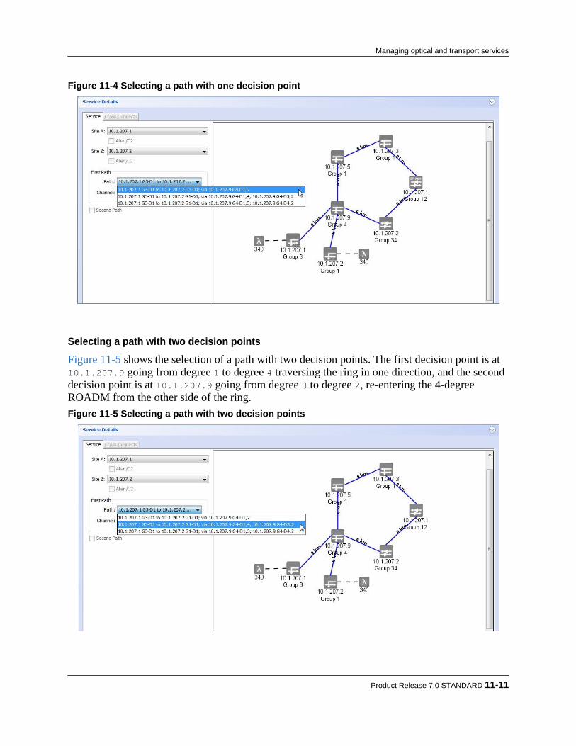
Figure 11-4 Selecting a path with one decision point
Selecting a path with two decision points
Figure 11-5 shows the selection of a path with two decision points. The first decision point is at 10.1.207.9 going from degree 1 to degree 4 traversing the ring in one direction, and the seconddecision point is at 10.1.207.9 going from degree 3 to degree 2, re-entering the 4-degreeROADM from the other side of the ring.Figure 11-5 Selecting a path with two decision points
Product Release 7.0 STANDARD 11-11
Managing optical and transport services
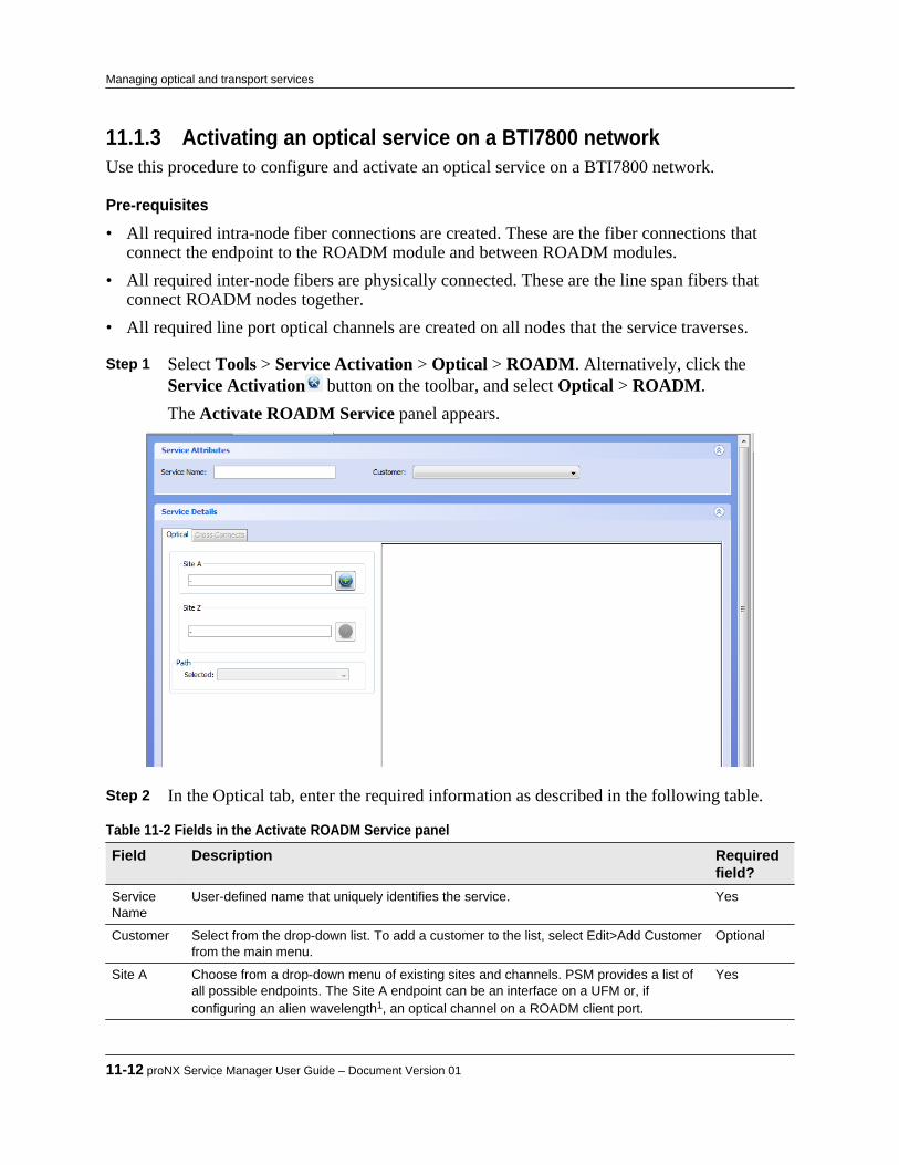
11.1.3 Activating an optical service on a BTI7800 networkUse this procedure to configure and activate an optical service on a BTI7800 network.
Pre-requisites
• All required intra-node fiber connections are created. These are the fiber connections thatconnect the endpoint to the ROADM module and between ROADM modules.
• All required inter-node fibers are physically connected. These are the line span fibers thatconnect ROADM nodes together.
• All required line port optical channels are created on all nodes that the service traverses.
Step 1 Select Tools > Service Activation > Optical > ROADM. Alternatively, click the Service Activation button on the toolbar, and select Optical > ROADM.The Activate ROADM Service panel appears.
Step 2 In the Optical tab, enter the required information as described in the following table.
Table 11-2 Fields in the Activate ROADM Service panel Field Description Required
field?ServiceName
User-defined name that uniquely identifies the service. Yes
Customer Select from the drop-down list. To add a customer to the list, select Edit>Add Customerfrom the main menu.
Optional
Site A Choose from a drop-down menu of existing sites and channels. PSM provides a list ofall possible endpoints. The Site A endpoint can be an interface on a UFM or, ifconfiguring an alien wavelength1, an optical channel on a ROADM client port.
Yes
11-12 proNX Service Manager User Guide – Document Version 01
Managing optical and transport services

Table 11-2 Fields in the Activate ROADM Service panel (Continued) Field Description Required
field?Site Z Choose from a drop-down menu of existing sites and channels. PSM provides a list of
all possible endpoints that can be reached from Site A. PSM creates this list based onthe fiber connections and the existence and availability of the optical channel from SiteA all along the path to Site Z.
The Site Z endpoint can be an interface on a UFM or, if the endpoint is external (alienwavelength), an optical channel on a ROADM client port.
Yes
Path Choose from a drop-down list of possible paths from Site A to Site Z. Note By default, the maximum number of spans that a path can have is 10. If your pathrequires more than 10 spans, contact Juniper Networks Support to increase this limit.
Yes
1An alien wavelength is a wavelength that is added/dropped to a local external endpoint. The external endpoint can be on a UFM on a differentBTI7800, or on other vendors' equipment. Since the endpoint is external and beyond the management of PSM, the endpoint you select for analien wavelength is an optical channel on the ROADM client port.
Step 3 Click Activate.
The PSM server sends the activation request to the network element. You can monitorthe status of the request through the View > Server > Tasks window. The new serviceappears in the Network tree a short while after the task completes successfully. As partof service activation, PSM creates all the necessary optical cross connects along the pathbetween the specified endpoints.
11.1.4 Viewing the cross-connects in an optical serviceUse this procedure to view the cross-connects in an activated optical service.
Step 1 In the Network tree, double-click the service you want to view. Alternatively, select theservice, right-click and choose View.The Service Attributes window opens.
Step 2 Click on the Cross Connects tab to see the cross-connects that make up the service on
all network elements .
11.1.5 Updating an optical serviceUse this procedure to change the service name and customer of an activated optical service.
Step 1 On the Network tree, double-click the service you want to update. Alternatively, selectthe service, right-click and choose View.The Service Attributes window opens.
Step 2 Modify the Customer or Service Name.
Product Release 7.0 STANDARD 11-13
Managing optical and transport services

Step 3 Click Apply.The optical service is updated.
11.1.6 Deleting an optical serviceUse this procedure to delete an optical service.When a service is deleted, the associated modules and ports remain in the UP state.
Step 1 In the Network tree view, right-click a service and choose Delete.An information window opens asking for confirmation.
Step 2 Click OK
The optical service is deleted from the network elements and the PSM server.
11.1.7 Viewing the optical services tableYou can view a list of the optical services with information such as Customer, Service Name,Channel, Site A, Site Z, End-To-End State, Intermediate Nodes, and more.
Step 1 To view the optical services table, from the main menu choose View > Optical > Services.The Optical Services tab is displayed.
Note To apply filters to this table, see 11.3, “Working with optical/transport servicesand topology tables”
Step 2 Use the scroll bar on the right side of the window to scroll through the list of services.
11.1.8 Viewing the optical services per span tableYou can view a list of the optical services per span with information such as Span Source, SpanFar-End, Channel, Service Name, Customer Name, Service Site A, Service Site Z, Source Port
11-14 proNX Service Manager User Guide – Document Version 01
Managing optical and transport services

State, Source Port Admin State, Far-End Port State, Far-End Port Admin State information, andmore.
Step 1 To view the optical services per span table, from the main menu choose View > Optical> Services per Span.The Optical Services per Span tab is displayed.
Note To apply filters to this table, see 11.3, “Working with optical/transport servicesand topology tables”
Step 2 Use the scroll bar on the right side of the window to scroll through the list of services
per span.
11.1.9 Viewing the optical topology tableYou can view a table of the optical topology with information such as Source Site, SourceDegree, Source Port, Far-End Site, Far-End Degree, Administrative Status, State, Span Length(km), Max. Span Loss (dB), Channel Count information, and more.The optical topology table has a row for each end of the link – that is, for each connection shownin the topology view there are two rows in the table. If only one end of the link is discovered,only one row is displayed. This table contains the same information shown in the tool tip, but canbe manipulated with the sorting and filtering functionality available for all tables.
Step 1 To view the optical topology table, from the main menu choose View > Optical > Topology.The Optical Topology tab displays.
Note To apply filters to this table, see 11.3, “Working with optical/transport servicesand topology tables”
Product Release 7.0 STANDARD 11-15
Managing optical and transport services

Step 2 Use the scroll bar on the right side of the window to scroll through the optical topologydetails.
11-16 proNX Service Manager User Guide – Document Version 01
Managing optical and transport services
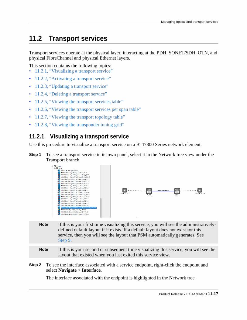
11.2 Transport services
Transport services operate at the physical layer, interacting at the PDH, SONET/SDH, OTN, andphysical FibreChannel and physical Ethernet layers.This section contains the following topics:• 11.2.1, “Visualizing a transport service”• 11.2.2, “Activating a transport service”• 11.2.3, “Updating a transport service”• 11.2.4, “Deleting a transport service”• 11.2.5, “Viewing the transport services table”• 11.2.6, “Viewing the transport services per span table”• 11.2.7, “Viewing the transport topology table”• 11.2.8, “Viewing the transponder tuning grid”
11.2.1 Visualizing a transport serviceUse this procedure to visualize a transport service on a BTI7800 Series network element.
Step 1 To see a transport service in its own panel, select it in the Network tree view under theTransport branch.
Note If this is your first time visualizing this service, you will see the administratively-defined default layout if it exists. If a default layout does not exist for thisservice, then you will see the layout that PSM automatically generates. SeeStep 9.
Note If this is your second or subsequent time visualizing this service, you will see thelayout that existed when you last exited this service view.
Step 2 To see the interface associated with a service endpoint, right-click the endpoint and
select Navigate > Interface.The interface associated with the endpoint is highlighted in the Network tree.
Product Release 7.0 STANDARD 11-17
Managing optical and transport services
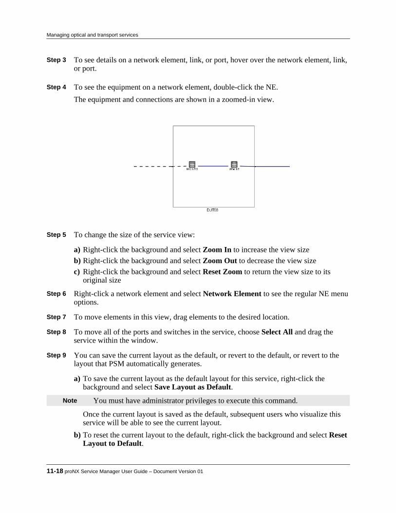
Step 3 To see details on a network element, link, or port, hover over the network element, link,or port.
Step 4 To see the equipment on a network element, double-click the NE.
The equipment and connections are shown in a zoomed-in view.
Step 5 To change the size of the service view:
a) Right-click the background and select Zoom In to increase the view sizeb) Right-click the background and select Zoom Out to decrease the view sizec) Right-click the background and select Reset Zoom to return the view size to its
original size Step 6 Right-click a network element and select Network Element to see the regular NE menu
options. Step 7 To move elements in this view, drag elements to the desired location. Step 8 To move all of the ports and switches in the service, choose Select All and drag the
service within the window. Step 9 You can save the current layout as the default, or revert to the default, or revert to the
layout that PSM automatically generates.
a) To save the current layout as the default layout for this service, right-click thebackground and select Save Layout as Default.
Note You must have administrator privileges to execute this command.
Once the current layout is saved as the default, subsequent users who visualize thisservice will be able to see the current layout.
b) To reset the current layout to the default, right-click the background and select ResetLayout to Default.
11-18 proNX Service Manager User Guide – Document Version 01
Managing optical and transport services

c) To reset the current layout to the layout that PSM automatically generates, right-clickthe background and select Reset Layout.
Step 10 To save the service screen view as an image:
a) Select Save Service Image.The Save Service Image dialog appears.
b) Navigate to the desired folder and enter the filename.The default file format is png. To save the file in jpg format, enter .jpg at the end ofthe filename.
c) Click Save. You have successfully completed this procedure.
11.2.2 Activating a transport serviceUse this procedure to configure and activate a transport service for a BTI7800 Series networkelement.
Step 1 Select Tools > Service Activation > Transport. Alternatively, click the ServiceActivation button on the toolbar, and select Transport, or right-click Transport inthe Network tree and select Service Activation.The Activate Transport Service dialog opens.
Step 2 Enter the required information as described in the following table.
Product Release 7.0 STANDARD 11-19
Managing optical and transport services

Table 11-3 Fields on the Activate Transport Service dialog Field Description Required
field?ServiceName
User-defined name that uniquely identifies the service. Yes
Customer Select from the drop-down list. To add a customer to the list, select Edit>Add Customerfrom the main menu.
Optional
Site A Click and choose from a drop-down menu of existing sites. Yes
Site Z Click and choose from a drop-down menu of existing sites. Yes
Path Choose from a drop-down list of possible paths from Site A to Site Z. Yes
Step 3 Click Activate.
Note You must wait for the activation tasks to complete before performing any otheroperation on the NEs affected by this activation.
The PSM server sends the configuration request to the network element. You canmonitor the status of the request through the View > Server > Tasks window. The newprovisioning appears in the Network tree view a short while after the task completessuccessfully.
You have successfully completed this procedure.
11.2.3 Updating a transport serviceUse this procedure to change the service name and customer of an activated transport service.
Step 1 In the Network tree, double-click the service you want to update. Alternatively, selectthe service, right-click, and choose View.The Service Attributes window opens.
Step 2 Modify the Customer or Service Name. Click Update.
The transport service is updated.
11.2.4 Deleting a transport serviceUse this procedure to delete a transport service.When a service is deleted, the state of the associated modules and ports remains unchanged.
Step 1 In the Network tree, right-click a service and choose Delete.A dialog opens asking for confirmation.
Step 2 Click OK.
The transport service is deleted from the network elements and the PSM server.
11-20 proNX Service Manager User Guide – Document Version 01
Managing optical and transport services

11.2.5 Viewing the transport services tableUse this procedure to view the transport services table for BTI7800 Series network elements.
Step 1 From the main menu choose View > Transport > Services.The Transport Services tab is displayed.
Note To apply filters to this table, see 11.3, “Working with optical/transport servicesand topology tables”
Step 2 Use the scroll bar on the right side of the window to scroll through the list of services.
11.2.6 Viewing the transport services per span tableUse this procedure to view the transport services per span table for BTI7800 Series networkelements.
Step 1 From the main menu choose View > Transport > Services per Span.The Transport Services per Span tab is displayed.
Note To apply filters to this table, see 11.3, “Working with optical/transport servicesand topology tables”
Step 2 Use the scroll bar on the right side of the window to scroll through the list of services
per span.
11.2.7 Viewing the transport topology tableUse this procedure to view the transport topology table for BTI7800 Series network elements.
Step 1 From the main menu choose View > Transport > Topology.The Transport Topology tab displays.
Product Release 7.0 STANDARD 11-21
Managing optical and transport services

Note To apply filters to this table, see 11.3, “Working with optical/transport servicesand topology tables”
Step 2 Use the scroll bar on the right side of the window to scroll through the optical topology
details.
11.2.8 Viewing the transponder tuning gridUse this procedure to view and optionally export the transponder tuning grid for BTI7000 Series,BTI7800 Series, and BTI800 Series network elements.The transponder tuning grid shows the wavelengths, real-time optical PM data, and otherinformation on transponder ports for the selected network element.
Step 1 In the Network tree or the Topology Map view, right-click a network element and select Node > Tuning Grid > View. Alternatively, right-click a shelf in the Network tree andselect Tuning Grid > View. This option is greyed out if the network element (or shelf)does not contain at least one transponder card with at least one provisioned portcontaining an XFP.The Tuning Grid window appears.
Step 2 To export the tuning grid in CSV format, select Export and enter the name of the file. Step 3 To refresh the real-time optical PM data, select Refresh.
11-22 proNX Service Manager User Guide – Document Version 01
Managing optical and transport services

11.3 Working with optical/transport services and topologytables
The PSM Client can display optical/transport services, optical/transport services per span, andoptical/transport topology information in table format. These tables can be manipulated to showinformation in different forms, depending on the need.
Sorting the tables
The tables can be sorted in the following ways:• To sort the tables by a column, click the column title.• To change the order (ascending or descending) of a column, click the column heading until the
arrow shows ascending or descending order as desired.• To show or hide columns, right-click the table title bar and check the column names you want
to show, and uncheck the column names you want to hide in the drop-down menu. Differenttables have different column selections. Figure 11-6 shows the column selections for the opticaltopology table.
Figure 11-6 Optical topology column selection
Filtering the tables
The optical information tables behave as follows:• If there is no filtering applied, the window title reflects the table being displayed, for example
"Optical Topology".• If a filter is applied, the title changes to indicate the presence of the filter, for example "Optical
Topology (Filtered)".• Each time a new entity or filter is chosen, the previous filtering is cleared and the tables display
the entries that pertain to the newly chosen criteria.To filter the tables to show only a particular set of entries, right-click a cell in the column of thetable that has the data you want to filter with, and choose the filter option Show only rowswhere to filter out (hide) all other entries from the table. In the following screen for the opticalservices per span table, the filter chosen is to show only entries using channel 230.
Product Release 7.0 STANDARD 11-23
Managing optical and transport services
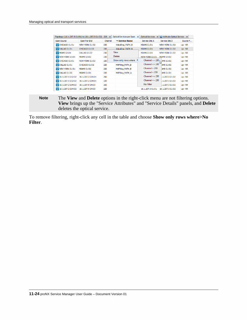
Note The View and Delete options in the right-click menu are not filtering options.View brings up the "Service Attributes" and "Service Details" panels, and Deletedeletes the optical service.
To remove filtering, right-click any cell in the table and choose Show only rows where>NoFilter.
11-24 proNX Service Manager User Guide – Document Version 01
Managing optical and transport services

11.4 Saving a service image
Use this procedure to save the service screen view to either a jpg or png image file. The defaultfile format is .png. To save the file in jpg format, enter .jpg at the end of the file name.
Step 1 In the main window, right-click and choose Save Service Image.
The windows file explorer window appears.
Step 2 Navigate to the desired folder, specify a file name, and click Save.
Your service view is saved as an image.
Product Release 7.0 STANDARD 11-25
Managing optical and transport services

11-26 proNX Service Manager User Guide – Document Version 01
Managing optical and transport services

12.0 Managing Ethernet services
PSM can be used to manage Ethernet services on the BTI7000 Series, the BTI700 Series, and theBTI800 Series network elements.This section covers the following topics:• 12.1, “Service visualization”• 12.2, “Understanding Ethernet service states”• 12.3, “Service activation”• 12.4, “Modifying a service”• 12.5, “Deleting a service”• 12.6, “Adding SLA/CFM to a service”• 12.7, “Running a Y.1731 link trace”• 12.8, “Running a Y.1731 loopback”• 12.9, “Running an RFC 2544 benchmarking test”• 12.10, “Ethernet Ring Protection Switching (ERPS)”• 12.11, “Routing considerations in mixed networks”• 12.12, “Managing profiles”
Product Release 7.0 STANDARD 12-1
C H A P T E R 1 2

12.1 Service visualization
PSM automatically discovers all Ethernet services in the network and displays them in agraphical view.
12.1.1 Visualizing an Ethernet serviceUse some or all of the techniques in this procedure to visualize an Ethernet service.
Step 1 In the Network tree, select the desired Ethernet service.The selected Ethernet service opens in the main Topology window. If the service isprotected by ERPS, the service is shown connected to an ERPS icon. The ERPS iconrepresents an ERPS ring. The green indicates that the ERPS ring is blocking its RPLlink, which is normal.
See 12.1.2, “Service visualization scheme” for details on this view, and see12.10, “Ethernet Ring Protection Switching (ERPS)” for details on ERPS.
Note If this is your first time visualizing this service, you will see the default layoutthat PSM automatically generates. The default layout can be changed. See Step 9.
Note If this is your second or subsequent time visualizing this service, you will see thelayout that existed when you last exited this service view.
Step 2 Double-click the ERPS icon to zoom in to see the network elements comprising the
ERPS ring. Double-click again to zoom back out.
Note Double-clicking to zoom works only on the default PSM layout or a smaller(more zoomed out) layout.
12-2 proNX Service Manager User Guide – Document Version 01
Managing Ethernet services

The green indicates the RPL link that is blocked.
Note The ERPS service itself can be visualized as well. For more information, see12.10.1, “Visualizing an ERPS service”.
Step 3 Alternatively, right-click the ERPS icon and choose Expand ERPS Ring.
Step 4 To change the size of the service view:
a) Right-click the background and select Zoom In to increase the view size.Alternatively, you can zoom in by scrolling the mouse scroll wheel away from you.
b) Right-click the background and select Zoom Out to decrease the view size.Alternatively, you can zoom out by scrolling the mouse scroll wheel towards you.
c) Right-click the background and select Reset Zoom to return the view size to itsoriginal size.
Step 5 Right-click a network element and select Network Element to see the regular NE menu
options.
Product Release 7.0 STANDARD 12-3
Managing Ethernet services
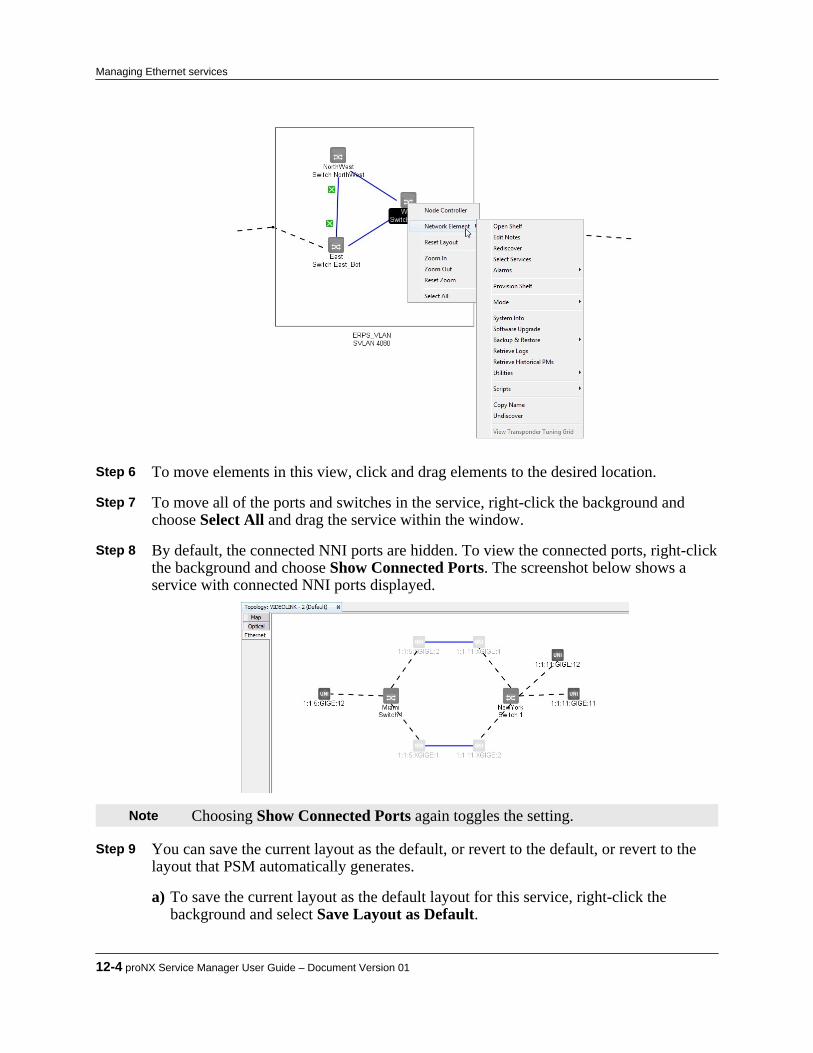
Step 6 To move elements in this view, click and drag elements to the desired location. Step 7 To move all of the ports and switches in the service, right-click the background and
choose Select All and drag the service within the window. Step 8 By default, the connected NNI ports are hidden. To view the connected ports, right-click
the background and choose Show Connected Ports. The screenshot below shows aservice with connected NNI ports displayed.
Note Choosing Show Connected Ports again toggles the setting. Step 9 You can save the current layout as the default, or revert to the default, or revert to the
layout that PSM automatically generates.
a) To save the current layout as the default layout for this service, right-click thebackground and select Save Layout as Default.
12-4 proNX Service Manager User Guide – Document Version 01
Managing Ethernet services
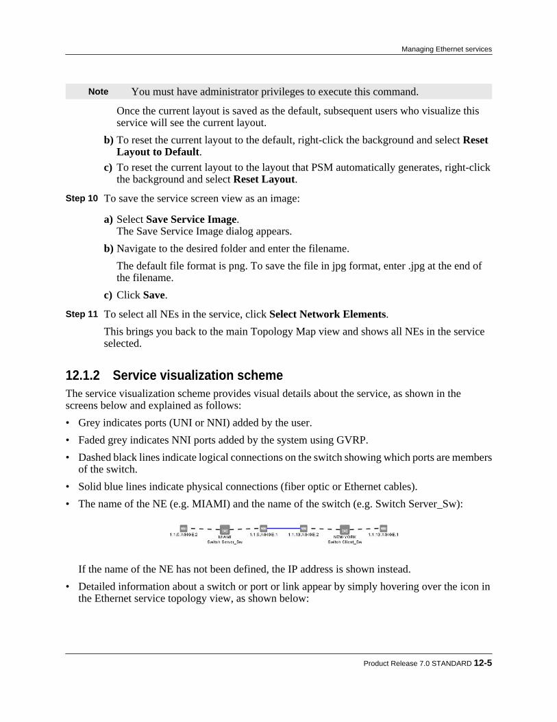
Note You must have administrator privileges to execute this command.
Once the current layout is saved as the default, subsequent users who visualize thisservice will see the current layout.
b) To reset the current layout to the default, right-click the background and select ResetLayout to Default.
c) To reset the current layout to the layout that PSM automatically generates, right-clickthe background and select Reset Layout.
Step 10 To save the service screen view as an image:
a) Select Save Service Image.The Save Service Image dialog appears.
b) Navigate to the desired folder and enter the filename.The default file format is png. To save the file in jpg format, enter .jpg at the end ofthe filename.
c) Click Save. Step 11 To select all NEs in the service, click Select Network Elements.
This brings you back to the main Topology Map view and shows all NEs in the serviceselected.
12.1.2 Service visualization schemeThe service visualization scheme provides visual details about the service, as shown in thescreens below and explained as follows:• Grey indicates ports (UNI or NNI) added by the user.• Faded grey indicates NNI ports added by the system using GVRP.• Dashed black lines indicate logical connections on the switch showing which ports are members
of the switch.• Solid blue lines indicate physical connections (fiber optic or Ethernet cables).• The name of the NE (e.g. MIAMI) and the name of the switch (e.g. Switch Server_Sw):
If the name of the NE has not been defined, the IP address is shown instead.• Detailed information about a switch or port or link appear by simply hovering over the icon in
the Ethernet service topology view, as shown below:
Product Release 7.0 STANDARD 12-5
Managing Ethernet services
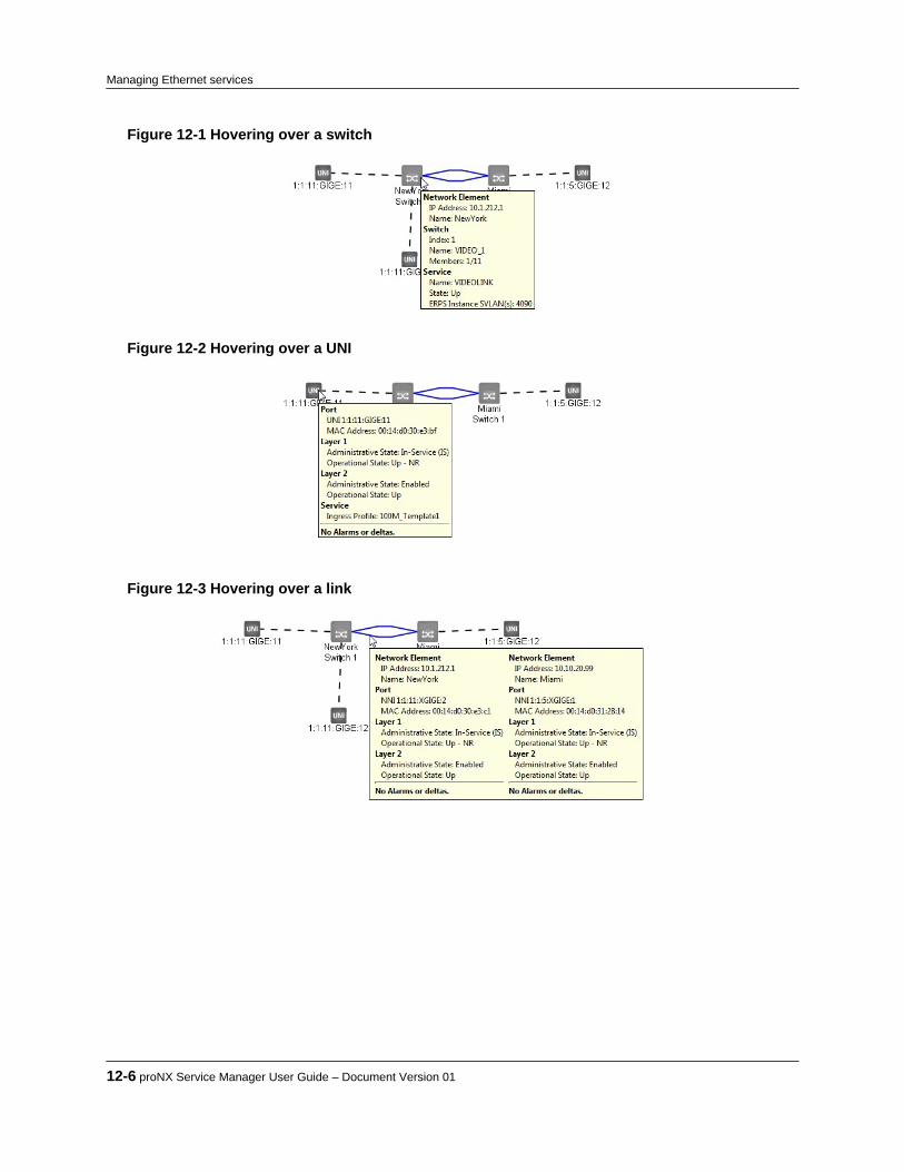
Figure 12-1 Hovering over a switch
Figure 12-2 Hovering over a UNI
Figure 12-3 Hovering over a link
12-6 proNX Service Manager User Guide – Document Version 01
Managing Ethernet services

12.2 Understanding Ethernet service states
PSM provides information on the state of an Ethernet service.Each switch maintains a state for every service configured on the switch. This state (one perservice) represents the state of the network connections to the remote MEPs, and does notinclude the state of the endpoint UNIs. This state behaves as follows:• Up - all remote MEPs are Up• Down - one or more remote MEPs are Down• Unknown - no remote MEPs existThis state is shown in PSM by hovering over an NE in the Ethernet service topology view.
Additionally, PSM maintains an End-to-End service state, which is an overall state that considersthe service states on all switches that have UNIs belonging to this service. The End-to-Endservice state behaves as follows:• Up - all service states for this service are Up• Down - all service states for this service are Down• Troubled - a mix of service states that are Up and Down• Unknown - all service states for this service are UnknownThe End-to-End service state is shown in PSM by hovering over an NE in the Ethernet servicetree view. It is also recorded in the Ethernet services report (17.2, “Generating Ethernet reports”).
Product Release 7.0 STANDARD 12-7
Managing Ethernet services
12.3 Service activation
PSM supports the Metro Ethernet Forum (MEF) paradigm for activating Layer 2 Ethernetservices in the network. As part of service activation, you define the service and you select theendpoints (and in some cases, the internal NNIs) that make up the service.
Note Unless otherwise specified, all references to UNI include UNI LAG, allreferences to NNI include NNI LAG, and all references to ENNI include ENNILAG.
An endpoint can be one of the following:• An Ethernet UNI, which is an Ethernet user-to-network interface.• An Ethernet ENNI, which is an external Ethernet network-to-network interface.• An Ethernet NNI, which can be an internal or external Ethernet network-to-network interface.
An external NNI is an endpoint, but an internal NNI is not. If PSM detects (via LLDPdiscovery) that the NNI is connected to Juniper Networks equipment, PSM considers that theNNI is internal. Otherwise, PSM considers the NNI is external, and treats it as an endpoint.An NNI that is determined to be external is similar to an ENNI. To avoid confusion, it is bestto use ENNIs for external NNIs where possible. For those network elements that do notsupport ENNI functionality, PSM continues to support the ability to treat the regular NNI asan external endpoint where applicable.
Note ENNI is supported on BTI7000 Series network elements starting in Release 13.2only. ENNI is not supported on any other network elements.
Before using PSM for service activation, you need to configure the packetVX cards on theappropriate network elements, and create the virtual switches that represent those cards. Youshould also create the necessary internal NNIs, but you do not need to create the endpoints asyou have the option of creating endpoints in PSM when you activate the service. You can createinternal NNIs in PSM as well, but if you create the internal NNIs beforehand, PSM will be ableto query the network and use the discovered LLDP topology to automatically select theappropriate internal NNIs as you add endpoints to the service. The ability to automatically selectthe internal NNIs is called the Auto-Provision NNIs feature.
Note For the Auto-Provision NNIs feature to work properly, you must create allinternal NNIs and bring up their links beforehand. In this situation, all NNIs thatyou create as part of service activation are external endpoint NNIs.
Creating a UNI, NNI, or ENNI refers to the initial configuration needed to transform anunprovisioned port to a UNI, NNI, or ENNI port.Selecting a UNI, NNI, or ENNI refers to choosing that UNI, NNI, or ENNI port to be part of theservice. When you select a UNI, NNI, or ENNI and you activate the service, PSM performs thenecessary configuration to include that port in the service.
Note In PSM, if you use the Provision As ... feature, you can create and select a UNI,NNI, or ENNI in a single step.
12-8 proNX Service Manager User Guide – Document Version 01
Managing Ethernet services

Not all internal NNIs need to be selected manually. If the network is running GVRP, then thenetwork can select the internal NNIs automatically after the service is activated. In othersituations, PSM can automatically select and configure the internal NNIs that are needed for theservice. This is shown in the following table:
Network Composition NNI SelectionThe domain contains only BTI7000 Series networkelements.
You do not need to manually select the internal NNIs.The BTI7000 Series network elements use GVRP toselect and configure the required internal NNIs. Formore information on GVRP, see 12.11.1, “GVRP -GARP VLAN Registration Protocol”.
The domain contains one or more BTI700 Seriesnetwork elements or one or more BTI800 Series networkelements.
If all network elements in the domain are running thefollowing minimum levels of software:• BTI7000 Series - Release 10.3 or later
• BTI700 Series - Release 1.5 or later
• BTI718E - Any release
• BTI800 Series - Release 1.1 or laterthen you can use the Auto-Provision NNIs feature toinstruct PSM to automatically select the required internalNNIs.1
Otherwise, you must manually select some or all of theinternal NNIs that make up the service. For moreinformation on which internal NNIs you need to select,see 12.11.2, “Mixed networks - BTI7000 Series withBTI700 Series or BTI800 Series elements”.
1PSM uses topology information gathered from LLDP to select the required NNIs. Only those NNIs that cannot be configured using GVRP areselected.
12.3.1 Service typesNote Unless otherwise specified, all references to UNI include UNI LAG, all
references to NNI include NNI LAG, and all references to ENNI include ENNILAG.
The service types supported are listed in the table below. The Service Type selected in the Service Attributes panel determines how UNIs can be used, and should be based on the UNIsyou have or expect to have in the service. The service type cannot be changed once the service isactivated. If the service does not and will not include any UNIs, then you can set the service typeto any value.
Table 12-1 Service Types Service type DescriptionEPLINE
(Ethernet Private Line)
Used to replace TDM private lines.
A port-based service with a point-to-point EVC (Ethernet VirtualConnection) between dedicated UNIs (that is, only a single EVC per UNI).
User can select a maximum of two endpoints.
EVPLINE Used to replace Frame Relay or ATM services.
Product Release 7.0 STANDARD 12-9
Managing Ethernet services

Table 12-1 Service Types (Continued) Service type Description(Ethernet Virtual Private Line) A multiplexed service with a point-to-point EVC between service-
multiplexed endpoints (that is, multiple EVCs per endpoint).
User can select a maximum of two endpoints.
Allows a single physical connection to the attached equipment withmultiple virtual connections.
EPLAN
(Ethernet Private LAN)
Used to support transparent LAN services and multipoint Layer 2 VPNs.
A port-based service with a multipoint-to-multipoint EVC across dedicatedendpoints (that is, only a single EVC per endpoint).
User can select more than two UNIs.
EVPLAN
(Ethernet Virtual Private LAN)
Used to support transparent LAN services and multipoint Layer 2 VPNs.
A multiplexed service with a multipoint-to-multipoint EVC across service-multiplexed endpoints (that is, multiple EVCs per endpoint).
User can select more than two endpoints.
EPTREE
(Ethernet Private TREE)
Used to support a multipoint service consisting of leaf endpoints and rootendpoints. Leaf endpoints and root endpoints can send and receivepackets from (other) root endpoints, but leaf endpoints cannot send andreceive packets from other leaf endpoints.
A port-based service with a rooted-multipoint EVC across dedicatedendpoints (that is, only a single EVC per endpoint).
User can select more than two endpoints.
This service type is only supported on BTI7000 Series network elements.
EVPTREE
(Ethernet Virtual Private TREE)
Used to support a multipoint service consisting of leaf endpoints and rootendpoints. Leaf endpoints and root endpoints can send and receivepackets from (other) root endpoints, but leaf endpoints cannot send andreceive packets from other leaf endpoints.
A port-based service at the leaf nodes and a multiplexed service at theroot node, using a rooted-multipoint EVC across endpoints (that is, only asingle EVC at the leaf endpoint, and multiple EVCs at the root endpoint).
User can select more than two endpoints.
This service type is only supported on BTI7000 Series network elements.
See the BTI7000 Series packetVX Solutions Guide for more details on Ethernet services andEthernet VCs.
12.3.2 Auto-provisioning NNIsNote Unless otherwise specified, all references to UNI include UNI LAG, all
references to NNI include NNI LAG, and all references to ENNI include ENNILAG.
PSM has the capability of selecting the necessary internal NNIs to add to the service. InternalNNIs are the NNIs that connect the service endpoints together.You should only choose this option if all network elements in the domain are running thefollowing minimum levels of software:
12-10 proNX Service Manager User Guide – Document Version 01
Managing Ethernet services

• BTI7000 Series - Release 10.3 or later• BTI700 Series - Release 1.5 or later• BTI718E - Any release• BTI800 Series - Release 1.1 or laterAdditionally, all the required internal NNIs must already exist and their links brought up, andLLDP enabled.When this option is selected, PSM uses topology information gathered from LLDP to select andconfigure those required internal NNIs that do not have GVRP enabled. If PSM determines thatGVRP is enabled on a particular NNI, it will let GVRP configure that NNI.PSM selects internal NNIs differently depending on whether the required NNI is part of an ERPSring or not. If the NNI is part of an ERPS ring, then PSM has sufficient information to determinewhether the NNI should be selected or not. If the NNI is not part of an ERPS ring, then PSMuses a more liberal set of selection criteria and may select more internal NNIs than is necessary.In such a case, you can manually delete the unnecessary NNIs from the service.As an alternative, you can force PSM to select a single path through non-ERPS nodes when Auto-Provision NNIs is enabled. See the proNX Service Manager Installation and AdministrationGuide for details.
12.3.3 Activating an Ethernet serviceUse this procedure to configure and activate an Ethernet service.
Pre-requisites:
• All the necessary packetVX cards and virtual switches have been configured.• ERPS rings (or MSTP) have been configured, as applicable. This prevents routing loops when
multiple paths exist through the network.
Note Unless otherwise specified, all references to UNI include UNI LAG, allreferences to NNI include NNI LAG, and all references to ENNI include ENNILAG.
Additionally:
If you want to ... Pre-requisite NotesSelect all UNIs, NNIs, and ENNIsmanually during service activation.
There is no additional pre-requisite. When you activate a service, youmanually select (and/or create) allthe UNIs, NNIs, and ENNIs thatmake up that service.1
Select endpoints manually and letthe network select internal NNIsusing GVRP.
Enable GVRP on BTI7000 Seriesnetwork elements where possible.
In a network that only containsBTI7000 Series network elements,GVRP can be used to propagateVLAN membership information to allthe NNIs, making it unnecessary toselect and configure each internalNNI individually from PSM. Just
Product Release 7.0 STANDARD 12-11
Managing Ethernet services

If you want to ... Pre-requisite Notesselect the endpoints and let GVRPconfigure the required internal NNIs(outside of PSM). PSM automaticallydiscovers and displays the internalNNIs as soon as you select theservice endpoints.
If the internal NNIs are down or notyet created, GVRP will not be able toconfigure the required internal NNIs.You can activate the service but theservice will be disconnected. Oncethe internal NNIs have been createdand/or their links brought up, thepath through the network will beestablished as VLAN membershipinformation propagates to all theinternal NNIs through GVRP.
In a mixed network that containsBTI7000 Series, BTI700 Series, and/or BTI800 Series network elements,you may need to manually selectinternal NNIs because not all ofthese devices support GVRP. See12.11.2.3, “Activating services overcombinations of BTI7000 SeriespacketVX and BTI700 Series orBTI800 Series networks”
Select endpoints manually and letthe network select internal NNIsusing GVRP, and let PSM selectinternal NNIs using the Auto-Provision NNIs option.
Ensure all network elements in thedomain are at the following minimumlevels of software:• BTI7000 Series - Release 10.3 or
later
• BTI700 Series - Release 1.5 orlater
• BTI718E - Any release
• BTI800 Series - Release 1.1 orlater
Enable LLDP on all networkelements in the domain.
Create all the required internal NNIports and bring their links up.
Enable GVRP on BTI7000 Seriesnetwork elements.
This lets GVRP configure therequired internal NNIs wherepossible. If GVRP is not enabled ornot supported, then PSM usestopological information gathered bythe NEs through LLDP, andautomatically selects the necessaryinternal NNIs. PSM only selectsthose internal NNIs that cannot beconfigured using GVRP.
1After you activate, GVRP, if enabled, may cause other NNIs to be selected as well, but this is performed outside of PSM.
The general service activation workflow is as follows:1 Create the Ethernet service and set the service-wide attributes.2 Select ports to be added to the service.
12-12 proNX Service Manager User Guide – Document Version 01
Managing Ethernet services

3 Set the port-based attributes (optional).4 Set the advanced switch-based and the advanced port-based attributes (optional).5 Activate the service.
Note ENNI is supported on BTI7000 Series network elements starting in Release 13.2only. ENNI is not supported on any other network elements.
Step 1 Create the Ethernet service and set the service-wide attributes.
a) Click the Service Activation button on the toolbar and choose Ethernet from thedrop-down menu.
If you have one domain only, the Activate Ethernet Service window appears, asshown. Proceed to Step 1-c.
If you have multiple domains, a Service Activation pop-up dialog box is displayed,as shown. Proceed to Step 1-b.
b) From the Select Domain drop-down menu, select a domain in which to create theservice. Each domain has its own S-VLAN ID namespace, allowing you to re-use S-VLAN IDs across domains. Click OK.
Product Release 7.0 STANDARD 12-13
Managing Ethernet services
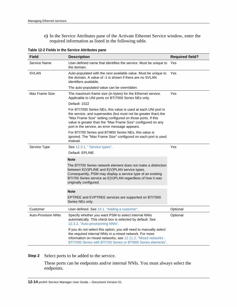
c) In the Service Attributes pane of the Activate Ethernet Service window, enter therequired information as listed in the following table.
Table 12-2 Fields in the Service Attributes pane Field Description Required field?Service Name User-defined name that identifies the service. Must be unique to
the domain.Yes
SVLAN Auto-populated with the next available value. Must be unique tothe domain. A value of -1 is shown if there are no SVLANidentifiers available.
The auto-populated value can be overridden.
Yes
Max Frame Size The maximum frame size (in bytes) for the Ethernet service.Applicable to UNI ports on BTI7000 Series NEs only.
Default: 1522
For BTI7000 Series NEs, this value is used at each UNI port inthe service, and supersedes (but must not be greater than) the"Max Frame Size" setting configured on those ports. If thisvalue is greater than the "Max Frame Size" configured on anyport in the service, an error message appears.
For BTI700 Series and BTI800 Series NEs, this value isignored. The "Max Frame Size" configured on each port is usedinstead.
Yes
Service Type See 12.3.1, “ Service types”.
Default: EPLINE Note The BTI700 Series network element does not make a distinctionbetween E(V)PLINE and E(V)PLAN service types.Consequently, PSM may display a service type of an existingBTI700 Series service as E(V)PLAN regardless of how it wasoriginally configured. Note EPTREE and EVPTREE services are supported on BTI7000Series NEs only.
Yes
Customer User-defined. See 14.1, “Adding a customer”. Optional
Auto-Provision NNIs Specify whether you want PSM to select internal NNIsautomatically. This check box is selected by default. See12.3.2, “Auto-provisioning NNIs”.
If you do not select this option, you will need to manually selectthe required internal NNIs in a mixed network. For moreinformation on mixed networks, see 12.11.2, “Mixed networks -BTI7000 Series with BTI700 Series or BTI800 Series elements”.
Optional
Step 2 Select ports to be added to the service.
These ports can be endpoints and/or internal NNIs. You must always select theendpoints.
12-14 proNX Service Manager User Guide – Document Version 01
Managing Ethernet services
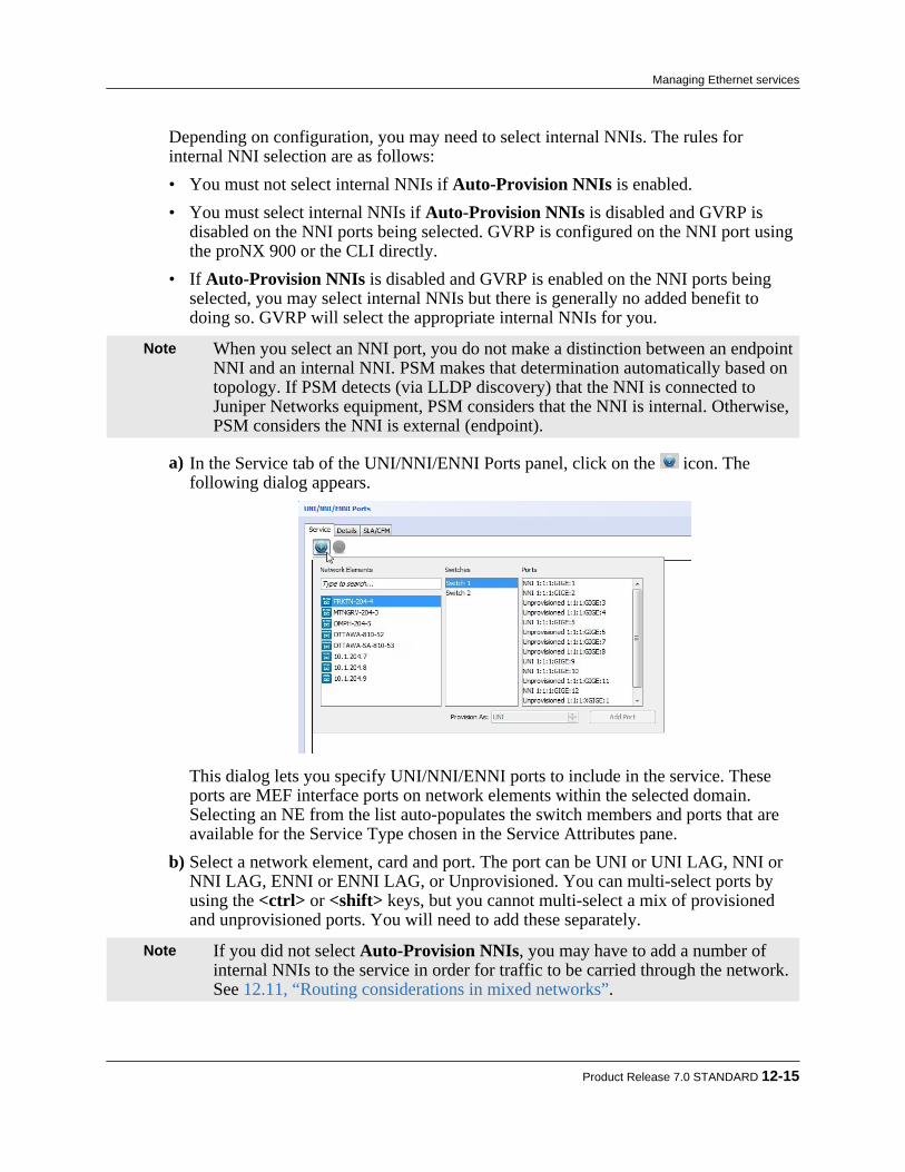
Depending on configuration, you may need to select internal NNIs. The rules forinternal NNI selection are as follows:• You must not select internal NNIs if Auto-Provision NNIs is enabled.• You must select internal NNIs if Auto-Provision NNIs is disabled and GVRP is
disabled on the NNI ports being selected. GVRP is configured on the NNI port usingthe proNX 900 or the CLI directly.
• If Auto-Provision NNIs is disabled and GVRP is enabled on the NNI ports beingselected, you may select internal NNIs but there is generally no added benefit todoing so. GVRP will select the appropriate internal NNIs for you.
Note When you select an NNI port, you do not make a distinction between an endpointNNI and an internal NNI. PSM makes that determination automatically based ontopology. If PSM detects (via LLDP discovery) that the NNI is connected toJuniper Networks equipment, PSM considers that the NNI is internal. Otherwise,PSM considers the NNI is external (endpoint).
a) In the Service tab of the UNI/NNI/ENNI Ports panel, click on the icon. Thefollowing dialog appears.
This dialog lets you specify UNI/NNI/ENNI ports to include in the service. Theseports are MEF interface ports on network elements within the selected domain.Selecting an NE from the list auto-populates the switch members and ports that areavailable for the Service Type chosen in the Service Attributes pane.
b) Select a network element, card and port. The port can be UNI or UNI LAG, NNI orNNI LAG, ENNI or ENNI LAG, or Unprovisioned. You can multi-select ports byusing the <ctrl> or <shift> keys, but you cannot multi-select a mix of provisionedand unprovisioned ports. You will need to add these separately.
Note If you did not select Auto-Provision NNIs, you may have to add a number ofinternal NNIs to the service in order for traffic to be carried through the network.See 12.11, “Routing considerations in mixed networks”.
Product Release 7.0 STANDARD 12-15
Managing Ethernet services

If you select an unprovisioned port in the Ports field, the Provision As field isactivated, allowing you to provision it as a UNI or UNI LAG, NNI or NNI LAG, ENNI or ENNI LAG.
If you use the Provision As option to create a UNI LAG, an NNI LAG, or an ENNILAG, then all ports you multi-select will be added to the LAG.
Note If you use the Provision As field to create a new NNI port on a BTI700 Seriesnetwork element, you cannot use the proNX 900 to reconfigure any of thesettings on that port. If you want to be able to use the proNX 900 to reconfigurethe settings on that port, you must create the NNI port using the proNX 900instead of using the Provision As option.
c) Click Add UNI or Add UNI LAG, Add NNI or Add NNI LAG, or Add ENNI or Add ENNI LAG depending on the type of port chosen.PSM adds the port and any auto-selected internal NNI ports required. Additionally, ifthe port that you are adding is a multi-chassis LAG member, PSM automatically addsall members of that multi-chassis LAG to the service. See 12.3.5, “Example:Activating an Ethernet service on a multi-chassis LAG” for a service activationexample involving a mutli-chassis LAG.
d) After you have finished adding ports, click on the Service tab to view the added ports.
12-16 proNX Service Manager User Guide – Document Version 01
Managing Ethernet services

Note PSM displays a warning message if it cannot find all the internal NNIs necessaryfor the service. This can occur if an internal NNI port is down, for example. Inthis situation, you can still activate the service but the service may not work.
e) To view the added ports, click on the Details tab.The Details window displays the added ports, showing the containing NE, switch,and LAG (if applicable). PSM displays the ports you manually specified, and theinternal NNI ports that PSM has selected through the Auto-Provision NNIs feature.
f) To filter your view, click the All, Endpoints, or NNI tabs to view all ports, viewonly UNI and ENNI ports, or view only NNI ports (both internal and endpoint)respectively.
g) To edit the list of ports, proceed as follows:
Product Release 7.0 STANDARD 12-17
Managing Ethernet services

• To remove a port from the service, right-click the port or LAG entry and select Remove Port, or select the port or LAG entry and click .• If you remove an auto-selected NNI port from the list, a Revert NNIs option
appears. This option allows you to add the NNI back to the list.
Note Reverting only adds back the auto-provisioned NNIs to this list. Any change youpreviously made to the NNI port, such as changing the service profiles, remain ineffect and are not reverted.
• If you remove a UNI or ENNI port, all internal NNI ports that have been auto-selected due to that UNI or ENNI port are also removed.
• To add members to a LAG, right-click the LAG entry and select Add LAGMember(s).
• To remove a member from a LAG, right-click the LAG member and select Remove LAG Member.
• To add more ports, repeat Step 2.
Note By adding or removing internal NNIs, you have full control over what NNIs(auto-selected or otherwise) are included in the service. In some situations, itmay be necessary for you to manually delete internal NNIs in this manner. Formore information, see 12.3.2, “Auto-provisioning NNIs”.
Note Any internal NNIs that will be added due to GVRP are not shown, as this isperformed outside of PSM.
Step 3 Set the port-based attributes (optional).
a) Click on the Details tab.b) Set the port-based attributes by clicking in the appropriate box.
Table 12-3 Port-based attributes Attribute Description Range DefaultVLAN Mappings For a UNI port, this specifies the customer VLAN ID(s)
that map to the service, and only applies to virtualservices:
• For the Virtual Single service type, specify a singleVLAN ID.
• For the Virtual Multiple service type, specify one ormore VLAN IDs as a comma-separated list (e.g.2000, 2200) or a range (e.g. 2000-2100) or both.
• For the Virtual Untagged service type, PSMpopulates this field with the C-PVID that has beenset for the port.
UNI: 1 to 4094
ENNI: 2 to 4094
None
12-18 proNX Service Manager User Guide – Document Version 01
Managing Ethernet services
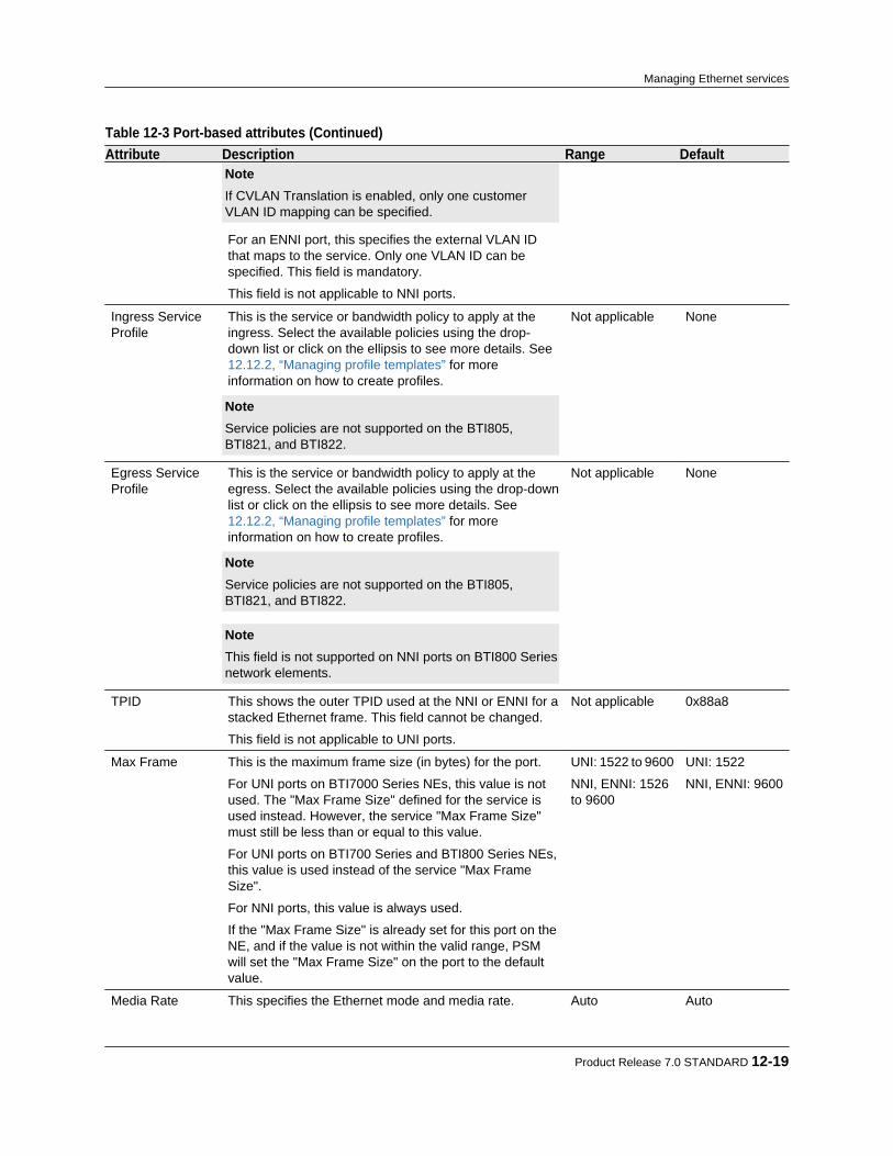
Table 12-3 Port-based attributes (Continued) Attribute Description Range Default
Note If CVLAN Translation is enabled, only one customerVLAN ID mapping can be specified. For an ENNI port, this specifies the external VLAN IDthat maps to the service. Only one VLAN ID can bespecified. This field is mandatory.
This field is not applicable to NNI ports.
Ingress ServiceProfile
This is the service or bandwidth policy to apply at theingress. Select the available policies using the drop-down list or click on the ellipsis to see more details. See12.12.2, “Managing profile templates” for moreinformation on how to create profiles. Note Service policies are not supported on the BTI805,BTI821, and BTI822.
Not applicable None
Egress ServiceProfile
This is the service or bandwidth policy to apply at theegress. Select the available policies using the drop-downlist or click on the ellipsis to see more details. See12.12.2, “Managing profile templates” for moreinformation on how to create profiles. Note Service policies are not supported on the BTI805,BTI821, and BTI822. Note This field is not supported on NNI ports on BTI800 Seriesnetwork elements.
Not applicable None
TPID This shows the outer TPID used at the NNI or ENNI for astacked Ethernet frame. This field cannot be changed.
This field is not applicable to UNI ports.
Not applicable 0x88a8
Max Frame This is the maximum frame size (in bytes) for the port.
For UNI ports on BTI7000 Series NEs, this value is notused. The "Max Frame Size" defined for the service isused instead. However, the service "Max Frame Size"must still be less than or equal to this value.
For UNI ports on BTI700 Series and BTI800 Series NEs,this value is used instead of the service "Max FrameSize".
For NNI ports, this value is always used.
If the "Max Frame Size" is already set for this port on theNE, and if the value is not within the valid range, PSMwill set the "Max Frame Size" on the port to the defaultvalue.
UNI: 1522 to 9600
NNI, ENNI: 1526to 9600
UNI: 1522
NNI, ENNI: 9600
Media Rate This specifies the Ethernet mode and media rate. Auto Auto
Product Release 7.0 STANDARD 12-19
Managing Ethernet services
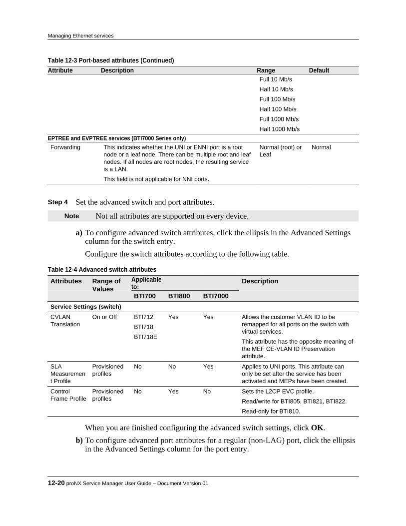
Table 12-3 Port-based attributes (Continued) Attribute Description Range Default
Full 10 Mb/s
Half 10 Mb/s
Full 100 Mb/s
Half 100 Mb/s
Full 1000 Mb/s
Half 1000 Mb/sEPTREE and EVPTREE services (BTI7000 Series only)Forwarding This indicates whether the UNI or ENNI port is a root
node or a leaf node. There can be multiple root and leafnodes. If all nodes are root nodes, the resulting serviceis a LAN.
This field is not applicable for NNI ports.
Normal (root) orLeaf
Normal
Step 4 Set the advanced switch and port attributes.
Note Not all attributes are supported on every device.
a) To configure advanced switch attributes, click the ellipsis in the Advanced Settingscolumn for the switch entry.Configure the switch attributes according to the following table.
Table 12-4 Advanced switch attributes Attributes Range of
ValuesApplicableto:
Description
BTI700 BTI800 BTI7000Service Settings (switch)CVLANTranslation
On or Off BTI712
BTI718
BTI718E
Yes Yes Allows the customer VLAN ID to beremapped for all ports on the switch withvirtual services.
This attribute has the opposite meaning ofthe MEF CE-VLAN ID Preservationattribute.
SLAMeasurement Profile
Provisionedprofiles
No No Yes Applies to UNI ports. This attribute canonly be set after the service has beenactivated and MEPs have been created.
ControlFrame Profile
Provisionedprofiles
No Yes No Sets the L2CP EVC profile.
Read/write for BTI805, BTI821, BTI822.
Read-only for BTI810.
When you are finished configuring the advanced switch settings, click OK.b) To configure advanced port attributes for a regular (non-LAG) port, click the ellipsis
in the Advanced Settings column for the port entry.
12-20 proNX Service Manager User Guide – Document Version 01
Managing Ethernet services
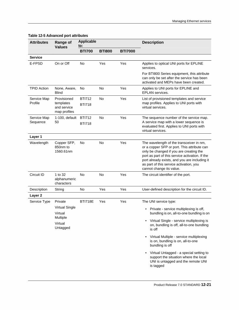
Table 12-5 Advanced port attributes Attributes Range of
ValuesApplicableto:
Description
BTI700 BTI800 BTI7000ServiceE-FPSD On or Off No Yes Yes Applies to optical UNI ports for EPLINE
services.
For BTI800 Series equipment, this attributecan only be set after the service has beenactivated and MEPs have been created.
TPID Action None, Aware,Blind
No No Yes Applies to UNI ports for EPLINE andEPLAN services.
Service MapProfile
Provisionedtemplatesand servicemap profiles
BTI712
BTI718
No Yes List of provisioned templates and servicemap profiles. Applies to UNI ports withvirtual services.
Service MapSequence
1-100, default50
BTI712
BTI718
No Yes The sequence number of the service map.A service map with a lower sequence isevaluated first. Applies to UNI ports withvirtual services.
Layer 1Wavelength Copper SFP,
850nm to1560.61nm
No No Yes The wavelength of the transceiver in nm,or a copper SFP or port. This attribute canonly be changed if you are creating theport as part of this service activation. If theport already exists, and you are including itas part of this service activation, youcannot change its value.
Circuit ID 1 to 32alphanumericcharacters
No No Yes The circuit identifier of the port.
Description String No Yes Yes User-defined description for the circuit ID.
Layer 2Service Type Private
Virtual Single
VirtualMultiple
VirtualUntagged
BTI718E Yes Yes The UNI service type:
• Private - service multiplexing is off,bundling is on, all-to-one bundling is on
• Virtual Single - service multiplexing ison, bundling is off, all-to-one bundlingis off
• Virtual Multiple - service multiplexingis on, bundling is on, all-to-onebundling is off
• Virtual Untagged - a special setting tosupport the situation where the localUNI is untagged and the remote UNIis tagged
Product Release 7.0 STANDARD 12-21
Managing Ethernet services

Table 12-5 Advanced port attributes (Continued) Attributes Range of
ValuesApplicableto:
Description
BTI700 BTI800 BTI7000 Note This is not the same attribute as theEthernet service type in 12.3.1, “ Servicetypes”.
C-PVID 1 to 4094,default isunselected
BTI718E Yes Yes Specifies the customer's default VLAN ID.This attribute is required on UNI portsrunning a virtual untagged service, but isoptional for other service types.
ControlFrame Profile
Provisionedprofiles
No Yes Yes Sets the L2CP UNI profile. See thedocumentation for the respective devicesfor details. Applies to UNI ports.
Read/write for BTI805, BTI821, BTI822,and BTI7000 equipment.
Read-only for BTI810.
MSTPEnabled
On or Off No No Yes Select to enable MSTP. Applies to UNIports.
CCM Enabled On or Off No No Yes Select to enable CCMs. Applies to UNIports.
SVLANTranslation
On or Off,default is Off.
If On, specifythe externalSVLAN IDfrom 2 to4094.
No No Yes Specify the external SVLAN ID. ThisSVLAN ID is mapped to the internalSVLAN ID from Table 12-2. Applies to NNIports only. Note To specify the external VLAN mapping forENNI ports, see Table 12-3 This attribute can only be configured whenyou first add the NNI to the service. Youcannot change the configuration after theNNI has been added to the service. Tochange the configuration after the NNI hasbeen added, you must first remove the NNIand then add it back to the service.
This mapping is 1:1. You cannot specify anexternal SVLAN ID that is mapped toanother service on this same port.
If SVLAN Translation is enabled, untaggedframes will be discarded on ingress.
SVLAN translation cannot co-exist withGVRP and MSTP. If SVLAN translation isenabled on an NNI that has GVRP and/orMSTP also enabled, PSM willautomatically disable GVRP and/or MSTP.When the last SVLAN translation isremoved from the NNI, PSM will
12-22 proNX Service Manager User Guide – Document Version 01
Managing Ethernet services

Table 12-5 Advanced port attributes Attributes Range of
ValuesApplicableto:
Description
BTI700 BTI800 BTI7000automatically enable GVRP and/or MSTPif either or both were originally enabled.
When you are finished configuring the advanced port settings, click OK.c) To configure port-based attributes for a LAG port, click the ellipsis in the Advanced
Settings column for the LAG port entry.
Table 12-6 Advanced LAG port attributes Attributes Range of
ValuesApplicableto:
Description
BTI700 BTI800 BTI7000ServiceSame asTable 12-5.
Layer 2Same as Table 12-5.
LAGDistributionMethod
Source MAC
DestinationMAC
Source andDestinationMAC
Source IP
Destination IP
Source andDestination IP
Source Port
DestinationPort
Yes Yes Yes The LAG distribution method.
LACP Mode BTI7000:
Active,Passive, On
BTI718E:
LACP, Static
BTI718E No Yes The LACP mode. This sets the LACP modefor all members of the LAG. A setting ofActive (LACP) means that the port willinitiate LACP negotiation. A setting ofPassive means that the port will not initiateLACP negotation but will respond to it. Asetting of On (Static) means that the portwill neither initiate nor respond to LACPnegotiation.
Max Links 1-8 Yes No Yes The maximum number of links permitted inthe LAG.
Min Links 1-8 BTI718E No No The minimum number of links that must beup before the LAG is considered up.
Product Release 7.0 STANDARD 12-23
Managing Ethernet services

When you are finished configuring the advanced LAG port settings, click OK.d) To configure port-based attributes for a LAG member, click the ellipsis in the
Advanced Settings column for the LAG member entry.
Table 12-7 Advanced LAG member attributes Attributes Range of
ValuesApplicableto:
Description
BTI700 BTI800 BTI7000Layer 1Same as Table 12-5.
LAG MemberLACP PortPriority
0-65535 Yes No Yes The LACP port priority.
LACP WaitTime
0-10 seconds No No Yes The LACP wait time.
LACP Mode Active,Passive, On
No No Yes The LACP mode. This sets the LACP modefor individual members of the LAG.
LACPTimeout
Long, Short No No Yes The LACP timeout period.
When you are finished configuring the advanced LAG member settings, click OK. Step 5 Click Activate. The service is activated.
For information about error messages, see Appendix A, “Service activation errormessages”.
Note You must wait for the activation tasks to complete before performing any otheroperation on the NEs affected by this activation.
12.3.4 Example: Activating an EVPLINE serviceThis is an example of how to use PSM to activate two different types of EVPLINE services. Thefirst service, between NEWYORK and MIAMI, requires CVLAN translation and no bundling. Thesecond service, between NEWYORK and DALLAS, requires connectivity between a tagged and anuntagged interface, also with no bundling. This is shown in Figure 12-4 along with the desiredservice policies.
12-24 proNX Service Manager User Guide – Document Version 01
Managing Ethernet services
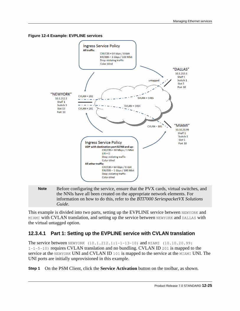
Figure 12-4 Example: EVPLINE services
Note Before configuring the service, ensure that the PVX cards, virtual switches, andthe NNIs have all been created on the appropriate network elements. Forinformation on how to do this, refer to the BTI7000 SeriespacketVX SolutionsGuide.
This example is divided into two parts, setting up the EVPLINE service between NEWYORK and MIAMI with CVLAN translation, and setting up the service between NEWYORK and DALLAS withthe virtual untagged option.
12.3.4.1 Part 1: Setting up the EVPLINE service with CVLAN translation
The service between NEWYORK (10.1.212.1:1-1-13-10) and MIAMI (10.10.20.99:1-1-5-10) requires CVLAN translation and no bundling. CVLAN ID 201 is mapped to theservice at the NEWYORK UNI and CVLAN ID 101 is mapped to the service at the MIAMI UNI. TheUNI ports are initially unprovisioned in this example.
Step 1 On the PSM Client, click the Service Activation button on the toolbar, as shown.
Product Release 7.0 STANDARD 12-25
Managing Ethernet services
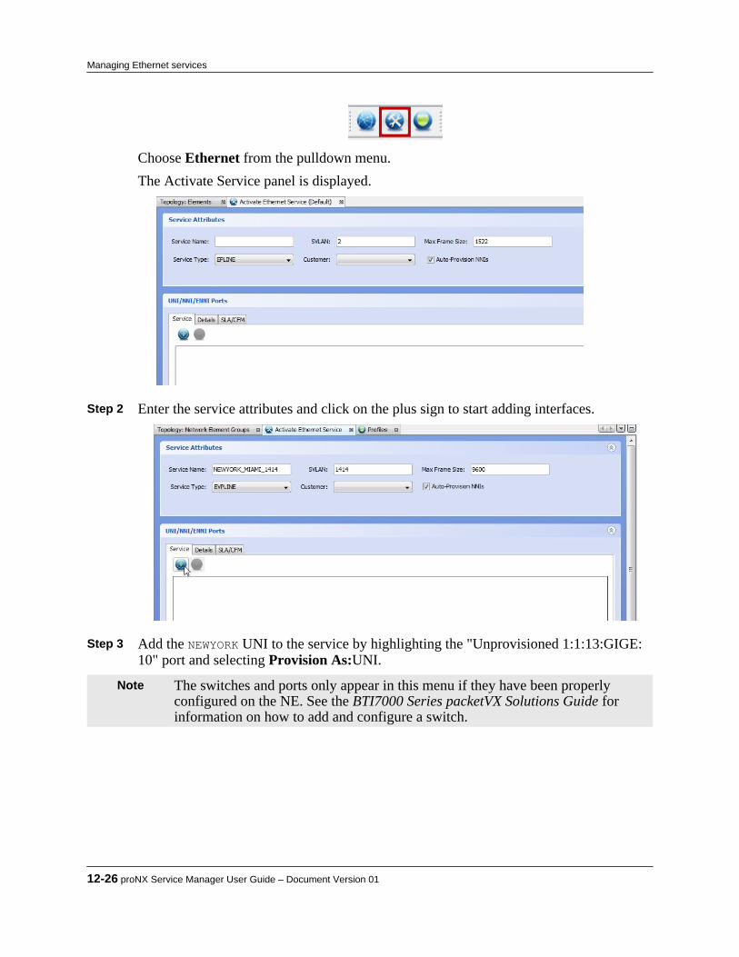
Choose Ethernet from the pulldown menu.The Activate Service panel is displayed.
Step 2 Enter the service attributes and click on the plus sign to start adding interfaces.
Step 3 Add the NEWYORK UNI to the service by highlighting the "Unprovisioned 1:1:13:GIGE:
10" port and selecting Provision As:UNI.
Note The switches and ports only appear in this menu if they have been properlyconfigured on the NE. See the BTI7000 Series packetVX Solutions Guide forinformation on how to add and configure a switch.
12-26 proNX Service Manager User Guide – Document Version 01
Managing Ethernet services
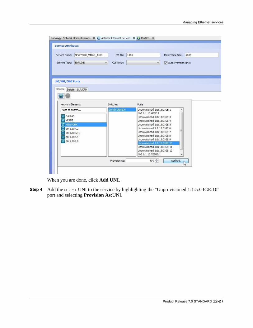
When you are done, click Add UNI. Step 4 Add the MIAMI UNI to the service by highlighting the "Unprovisioned 1:1:5:GIGE:10"
port and selecting Provision As:UNI.
Product Release 7.0 STANDARD 12-27
Managing Ethernet services
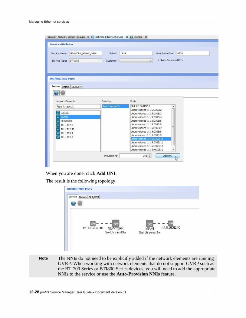
When you are done, click Add UNI.The result is the following topology.
Note The NNIs do not need to be explicitly added if the network elements are runningGVRP. When working with network elements that do not support GVRP such asthe BTI700 Series or BTI800 Series devices, you will need to add the appropriateNNIs to the service or use the Auto-Provision NNIs feature.
12-28 proNX Service Manager User Guide – Document Version 01
Managing Ethernet services
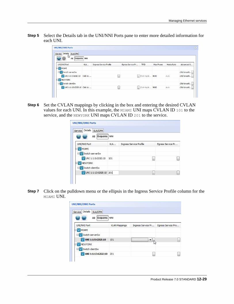
Step 5 Select the Details tab in the UNI/NNI Ports pane to enter more detailed information foreach UNI.
Step 6 Set the CVLAN mappings by clicking in the box and entering the desired CVLAN
values for each UNI. In this example, the MIAMI UNI maps CVLAN ID 101 to theservice, and the NEWYORK UNI maps CVLAN ID 201 to the service.
Step 7 Click on the pulldown menu or the ellipsis in the Ingress Service Profile column for the
MIAMI UNI.
Product Release 7.0 STANDARD 12-29
Managing Ethernet services

Step 8 Select the desired ingress service profile by highlighting it and clicking OK. When aprofile is highlighted, the profile details are displayed in the Selected Profile pane. Inthis example, the desired policy has already been defined.
Step 9 Repeat for the NEWYORK UNI.
12-30 proNX Service Manager User Guide – Document Version 01
Managing Ethernet services

Step 10 Open the Advanced Settings menu for the MIAMI UNI by clicking on the ellipsis.
Step 11 Select the service type from the pulldown menu and click OK.
In this example, the Service Type is Virtual Single, meaning that service multiplexingis on, bundling is off and all-to-1 bundling is off. Leave the C-PVID unchecked.
Step 12 Open the Advanced Settings menu for the MIAMI switch by clicking on the ellipsis.
Product Release 7.0 STANDARD 12-31
Managing Ethernet services
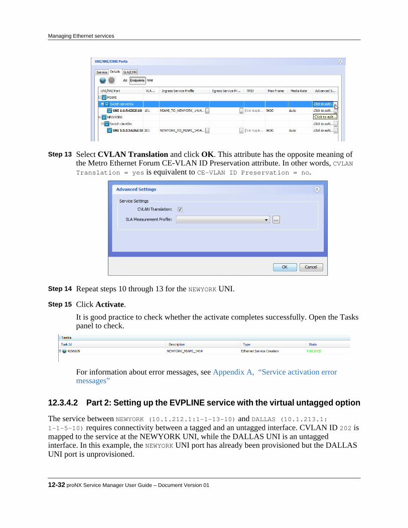
Step 13 Select CVLAN Translation and click OK. This attribute has the opposite meaning of
the Metro Ethernet Forum CE-VLAN ID Preservation attribute. In other words, CVLANTranslation = yes is equivalent to CE-VLAN ID Preservation = no.
Step 14 Repeat steps 10 through 13 for the NEWYORK UNI. Step 15 Click Activate.
It is good practice to check whether the activate completes successfully. Open the Taskspanel to check.
For information about error messages, see Appendix A, “Service activation errormessages”
12.3.4.2 Part 2: Setting up the EVPLINE service with the virtual untagged option
The service between NEWYORK (10.1.212.1:1-1-13-10) and DALLAS (10.1.213.1:1-1-5-10) requires connectivity between a tagged and an untagged interface. CVLAN ID 202 ismapped to the service at the NEWYORK UNI, while the DALLAS UNI is an untaggedinterface. In this example, the NEWYORK UNI port has already been provisioned but the DALLASUNI port is unprovisioned.
12-32 proNX Service Manager User Guide – Document Version 01
Managing Ethernet services

Step 1 On the PSM Client, click the Service Activation button on the toolbar, as shown.
Choose Ethernet from the pulldown menu.The Activate Service window is displayed.
Step 2 Enter the service attributes and click on the plus sign to start adding interfaces.
Step 3 Add the NEWYORK UNI to the service by highlighting the "UNI 1:1:13:GIGE:10" port.
Note The switches and ports only appear in this menu if they have been properlyconfigured on the NE. See the BTI7000 Series packetVX Solutions Guide forinformation on how to add and configure a switch.
Product Release 7.0 STANDARD 12-33
Managing Ethernet services
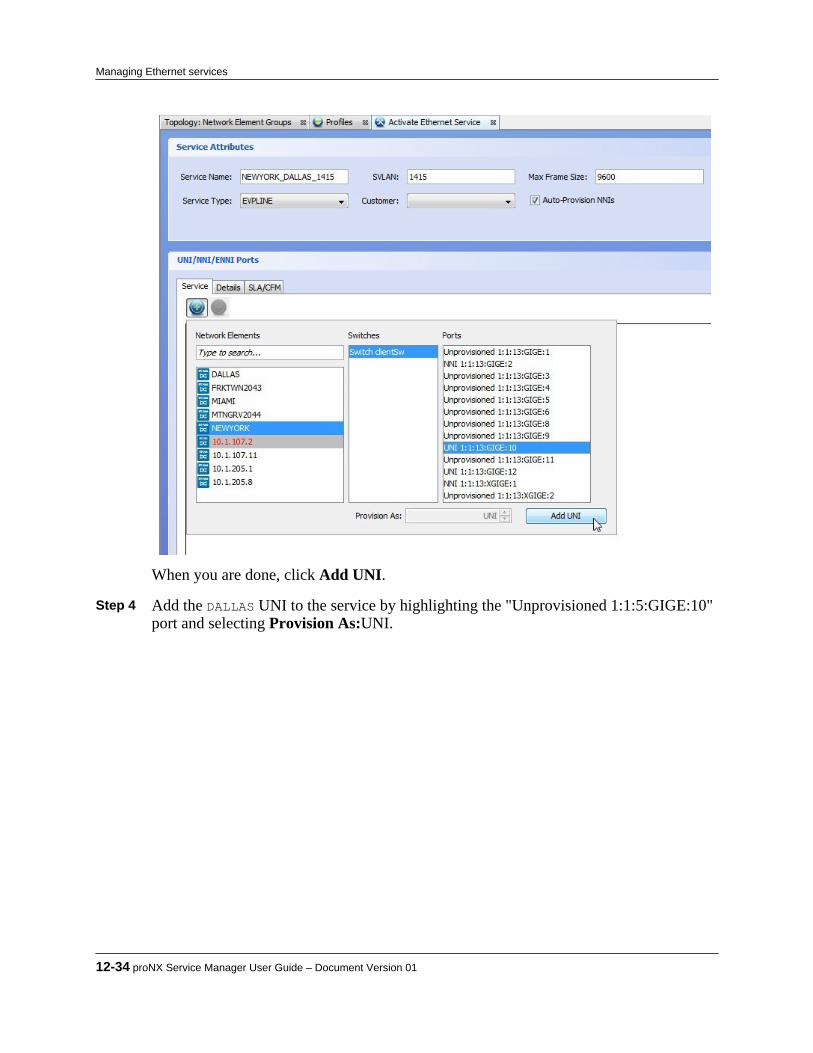
When you are done, click Add UNI. Step 4 Add the DALLAS UNI to the service by highlighting the "Unprovisioned 1:1:5:GIGE:10"
port and selecting Provision As:UNI.
12-34 proNX Service Manager User Guide – Document Version 01
Managing Ethernet services

When you are done, click Add UNI.The result is the following topology.
Note The NNIs do not need to be explicitly added if the network elements are runningGVRP. When working with network elements that do not support GVRP such asthe BTI700 Series or BTI800 Series devices, you will need to add the appropriateNNIs to the service or use the Auto-Provision NNIs feature.
Product Release 7.0 STANDARD 12-35
Managing Ethernet services
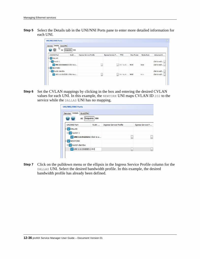
Step 5 Select the Details tab in the UNI/NNI Ports pane to enter more detailed information foreach UNI.
Step 6 Set the CVLAN mappings by clicking in the box and entering the desired CVLAN
values for each UNI. In this example, the NEWYORK UNI maps CVLAN ID 202 to theservice while the DALLAS UNI has no mapping.
Step 7 Click on the pulldown menu or the ellipsis in the Ingress Service Profile column for the
DALLAS UNI. Select the desired bandwidth profile. In this example, the desiredbandwidth profile has already been defined.
12-36 proNX Service Manager User Guide – Document Version 01
Managing Ethernet services

Step 8 Repeat for the NEWYORK UNI.
Step 9 Open the Advanced Settings menu for the DALLAS UNI by clicking on the ellipsis.
Product Release 7.0 STANDARD 12-37
Managing Ethernet services

Step 10 Select the service type from the pulldown menu and click OK.The Service Type should be Virtual Untagged, with C-PVID set to the value used atthe remote endpoint, in this case, 202. Ingress traffic at the DALLAS site will beautomatically tagged with this value, while egress traffic will automatically have this tagstripped.
Step 11 Open the Advanced Settings menu for the DALLAS switch by clicking on the ellipsis.
Step 12 Ensure CVLAN Translation is unchecked and click OK. This attribute has the opposite
meaning of the Metro Ethernet Forum CE-VLAN ID Preservation attribute. In thisexample, the DALLAS site only expects untagged traffic, so this parameter is notapplicable.
12-38 proNX Service Manager User Guide – Document Version 01
Managing Ethernet services

Step 13 Modify the Advanced Settings attributes for the NEWYORK UNI. Ensure the Service Type
is set to Virtual Single, C-PVID is unchecked, and CVLAN Translation is unchecked,meaning that CE-VLAN ID preservation is on, service multiplexing is on, bundling isoff, and all-to-1 bundling is off.
Step 14 Click Activate.
It is good practice to check whether the activate completes successfully. Open the Taskspanel to check.
For information about error messages, see Appendix A, “Service activation errormessages”
12.3.5 Example: Activating an Ethernet service on a multi-chassis LAGThis is an example of how to activate an Ethernet service on a multi-chassis LAG UNI. A multi-chassis LAG UNI has member links that terminate on two different network elements. If one linkor network element fails, the service continues to operate over the other link. Service activationfor a multi-chassis LAG UNI is very similar to service activation on a regular UNI.This example focuses on details that are specifc to multi-chassis LAG service activation.
Step 1 Select Tools > Service Activation > Ethernet.The Activate Ethernet Service panel is displayed.
Note If multiple domains exist, you will need to select the domain first.
Product Release 7.0 STANDARD 12-39
Managing Ethernet services
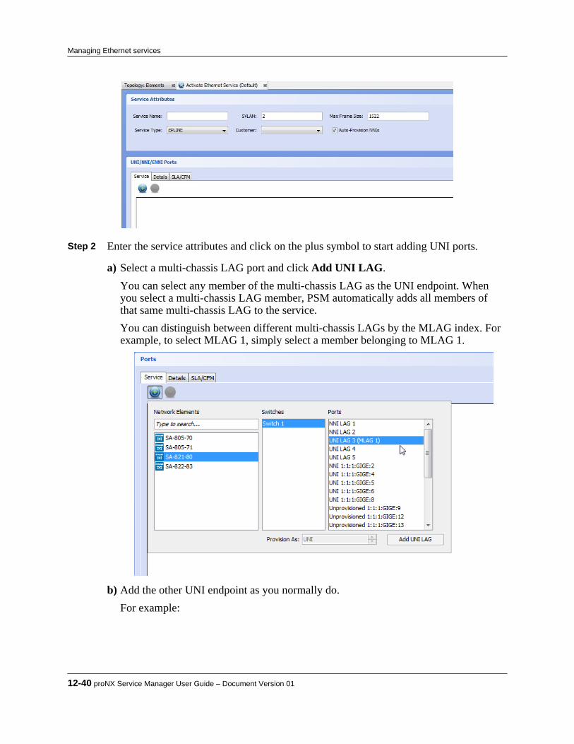
Step 2 Enter the service attributes and click on the plus symbol to start adding UNI ports.
a) Select a multi-chassis LAG port and click Add UNI LAG.You can select any member of the multi-chassis LAG as the UNI endpoint. Whenyou select a multi-chassis LAG member, PSM automatically adds all members ofthat same multi-chassis LAG to the service.You can distinguish between different multi-chassis LAGs by the MLAG index. Forexample, to select MLAG 1, simply select a member belonging to MLAG 1.
b) Add the other UNI endpoint as you normally do.For example:
12-40 proNX Service Manager User Guide – Document Version 01
Managing Ethernet services
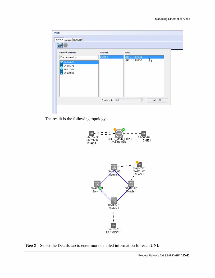
The result is the following topology.
Step 3 Select the Details tab to enter more detailed information for each UNI.
Product Release 7.0 STANDARD 12-41
Managing Ethernet services
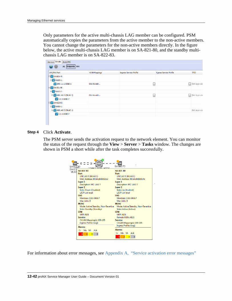
Only parameters for the active multi-chassis LAG member can be configured. PSMautomatically copies the parameters from the active member to the non-active members.You cannot change the parameters for the non-active members directly. In the figurebelow, the active multi-chassis LAG member is on SA-821-80, and the standby multi-chassis LAG member is on SA-822-83.
Step 4 Click Activate.
The PSM server sends the activation request to the network element. You can monitorthe status of the request through the View > Server > Tasks window. The changes areshown in PSM a short while after the task completes successfully.
For information about error messages, see Appendix A, “Service activation error messages”
12-42 proNX Service Manager User Guide – Document Version 01
Managing Ethernet services
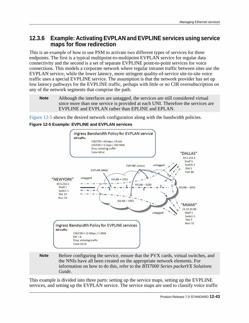
12.3.6 Example: Activating EVPLAN and EVPLINE services using servicemaps for flow redirection
This is an example of how to use PSM to activate two different types of services for threeendpoints. The first is a typical multipoint-to-multipoint EVPLAN service for regular dataconnectivity and the second is a set of separate EVPLINE point-to-point services for voiceconnections. This models a corporate network where regular intranet traffic between sites use theEVPLAN service, while the lower latency, more stringent quality-of-service site-to-site voicetraffic uses a special EVPLINE service. The assumption is that the network provider has set uplow latency pathways for the EVPLINE traffic, perhaps with little or no CIR oversubscription onany of the network segments that comprise the path.
Note Although the interfaces are untagged, the services are still considered virtualsince more than one service is provided at each UNI. Therefore the services areEVPLINE and EVPLAN rather than EPLINE and EPLAN.
Figure 12-5 shows the desired network configuration along with the bandwidth policies.Figure 12-5 Example: EVPLINE and EVPLAN services
Note Before configuring the service, ensure that the PVX cards, virtual switches, andthe NNIs have all been created on the appropriate network elements. Forinformation on how to do this, refer to the BTI7000 Series packetVX SolutionsGuide.
This example is divided into three parts: setting up the service maps, setting up the EVPLINEservices, and setting up the EVPLAN service. The service maps are used to classify voice traffic
Product Release 7.0 STANDARD 12-43
Managing Ethernet services
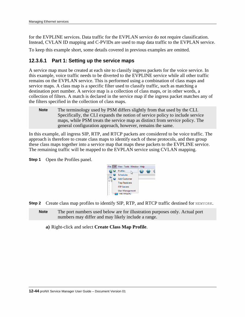
for the EVPLINE services. Data traffic for the EVPLAN service do not require classification.Instead, CVLAN ID mapping and C-PVIDs are used to map data traffic to the EVPLAN service.To keep this example short, some details covered in previous examples are omitted.
12.3.6.1 Part 1: Setting up the service maps
A service map must be created at each site to classify ingress packets for the voice service. Inthis example, voice traffic needs to be diverted to the EVPLINE service while all other trafficremains on the EVPLAN service. This is performed using a combination of class maps andservice maps. A class map is a specific filter used to classify traffic, such as matching adestination port number. A service map is a collection of class maps, or in other words, acollection of filters. A match is declared in the service map if the ingress packet matches any ofthe filters specified in the collection of class maps.
Note The terminology used by PSM differs slightly from that used by the CLI.Specifically, the CLI expands the notion of service policy to include servicemaps, while PSM treats the service map as distinct from service policy. Thegeneral configuration approach, however, remains the same.
In this example, all ingress SIP, RTP, and RTCP packets are considered to be voice traffic. Theapproach is therefore to create class maps to identify each of these protocols, and then groupthese class maps together into a service map that maps these packets to the EVPLINE service.The remaining traffic will be mapped to the EVPLAN service using CVLAN mapping.
Step 1 Open the Profiles panel.
Step 2 Create class map profiles to identify SIP, RTP, and RTCP traffic destined for NEWYORK.
Note The port numbers used below are for illustration purposes only. Actual portnumbers may differ and may likely include a range.
a) Right-click and select Create Class Map Profile.
12-44 proNX Service Manager User Guide – Document Version 01
Managing Ethernet services
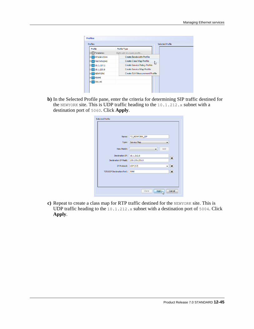
b) In the Selected Profile pane, enter the criteria for determining SIP traffic destined forthe NEWYORK site. This is UDP traffic heading to the 10.1.212.x subnet with adestination port of 5060. Click Apply.
c) Repeat to create a class map for RTP traffic destined for the NEWYORK site. This isUDP traffic heading to the 10.1.212.x subnet with a destination port of 5004. Click Apply.
Product Release 7.0 STANDARD 12-45
Managing Ethernet services

d) Repeat to create a class map for RTCP traffic destined for the NEWYORK site. This isUDP traffic heading to the 10.1.212.x subnet with a destination port of 5005. Click Apply.
This results in three class maps, classifying SIP, RTP, and RTCP traffic destined for NEWYORK.
Step 3 Repeat to create class maps for SIP, RTP, and RTCP traffic destined the MIAMI site.
12-46 proNX Service Manager User Guide – Document Version 01
Managing Ethernet services
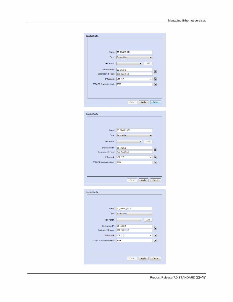
Product Release 7.0 STANDARD 12-47
Managing Ethernet services
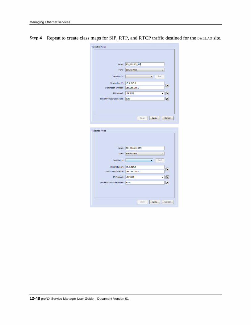
Step 4 Repeat to create class maps for SIP, RTP, and RTCP traffic destined for the DALLAS site.
12-48 proNX Service Manager User Guide – Document Version 01
Managing Ethernet services

Step 5 Group the class maps by creating a service map profile to identify voice traffic destined
for the NEWYORK site.
a) Right-click and select Create Service Map Profile.
b) In the Selected Profile pane, add the three TO_NEWYORK_xxx class maps created in theprevious step. Click Apply.
Product Release 7.0 STANDARD 12-49
Managing Ethernet services

The result is a service map that identifies voice traffic destined for NEWYORK. Step 6 Repeat to create the service map for voice traffic destined for the MIAMI site.
Step 7 Repeat to create the service map for voice traffic destined for the DALLAS site.
12-50 proNX Service Manager User Guide – Document Version 01
Managing Ethernet services
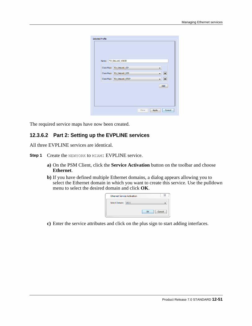
The required service maps have now been created.
12.3.6.2 Part 2: Setting up the EVPLINE services
All three EVPLINE services are identical.
Step 1 Create the NEWYORK to MIAMI EVPLINE service.
a) On the PSM Client, click the Service Activation button on the toolbar and choose Ethernet.
b) If you have defined multiple Ethernet domains, a dialog appears allowing you toselect the Ethernet domain in which you want to create this service. Use the pulldownmenu to select the desired domain and click OK.
c) Enter the service attributes and click on the plus sign to start adding interfaces.
Product Release 7.0 STANDARD 12-51
Managing Ethernet services

d) Add the NEWYORK UNI on "1:1:13:GIGE:10" and the MIAMI UNI on "1:1:5:GIGE:10".
Note The switches and ports only appear in the Add UNI menu if they have beenproperly configured on the NE. See the BTI7000 Series packetVX SolutionsGuide for information on how to add and configure a switch.
Note The NNIs do not need to be explicitly added if the network elements are runningGVRP. When working with network elements that do not support GVRP such asthe BTI700 Series or BTI800 Series devices, you will need to add the appropriateNNIs to the service or use the Auto-Provision NNIs feature.
e) Click the Details tab in the UNI/NNI Ports pane to enter more detailed informationfor each UNI.
There is no need to specify any CVLAN mappings since the interfaces are untagged.f) Select the ingress service profile for both sites by clicking on the pulldown menu or
the ellipsis.
12-52 proNX Service Manager User Guide – Document Version 01
Managing Ethernet services

g) Open the Advanced Settings menu for the MIAMI UNI by clicking on the ellipsis.
h) Select the service map from the pulldown menu and click OK.
Product Release 7.0 STANDARD 12-53
Managing Ethernet services

The Service Type is not applicable. Ensure the C-PVID is unchecked. The ServiceMap sequence is also not applicable.
i) Open the Advanced Settings menu for the MIAMI switch by clicking on the ellipsis.
j) Ensure CVLAN Translation is unchecked and click OK.
k) Repeat substeps f through i for the NEWYORK UNI but select the TO_MIAMI_VOICEservice map.
12-54 proNX Service Manager User Guide – Document Version 01
Managing Ethernet services
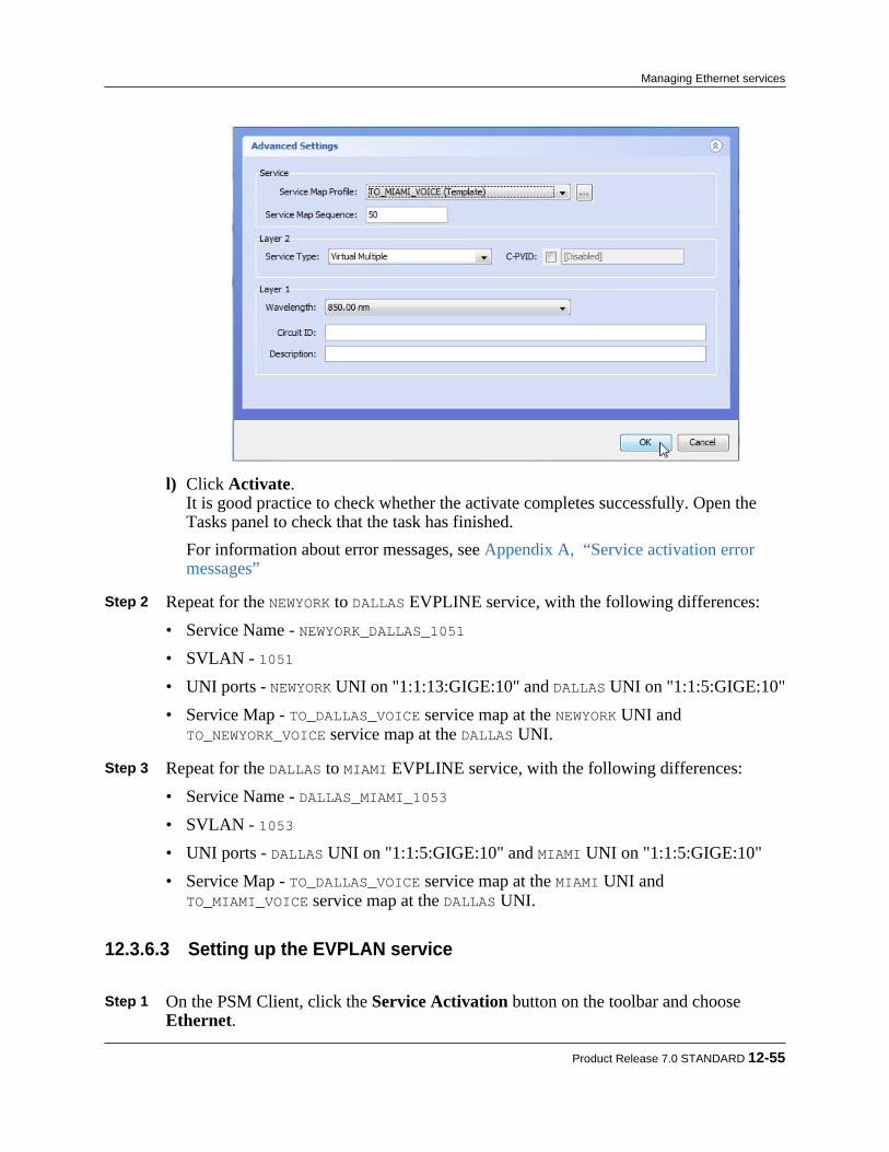
l) Click Activate.It is good practice to check whether the activate completes successfully. Open theTasks panel to check that the task has finished.For information about error messages, see Appendix A, “Service activation errormessages”
Step 2 Repeat for the NEWYORK to DALLAS EVPLINE service, with the following differences:
• Service Name - NEWYORK_DALLAS_1051• SVLAN - 1051• UNI ports - NEWYORK UNI on "1:1:13:GIGE:10" and DALLAS UNI on "1:1:5:GIGE:10"• Service Map - TO_DALLAS_VOICE service map at the NEWYORK UNI and
TO_NEWYORK_VOICE service map at the DALLAS UNI. Step 3 Repeat for the DALLAS to MIAMI EVPLINE service, with the following differences:
• Service Name - DALLAS_MIAMI_1053• SVLAN - 1053• UNI ports - DALLAS UNI on "1:1:5:GIGE:10" and MIAMI UNI on "1:1:5:GIGE:10"• Service Map - TO_DALLAS_VOICE service map at the MIAMI UNI and
TO_MIAMI_VOICE service map at the DALLAS UNI.
12.3.6.3 Setting up the EVPLAN service
Step 1 On the PSM Client, click the Service Activation button on the toolbar and choose Ethernet.
Product Release 7.0 STANDARD 12-55
Managing Ethernet services

Step 2 If you have defined multiple Ethernet domains, a dialog appears allowing you to select
the Ethernet domain in which you want to create this service. Use the pulldown menu toselect the desired domain and click OK.
Step 3 Enter the service attributes and click on the plus sign to start adding interfaces.
Step 4 Add the NEWYORK UNI on "1:1:13:GIGE:10", the MIAMI UNI on "1:1:5:GIGE:10", and
the DALLAS UNI on "1:1:5:GIGE:10".
Note The switches and ports only appear in the Add UNI menu if they have beenproperly configured on the NE. See the BTI7000 Series packetVX SolutionsGuide for information on how to add and configure a switch.
Note The NNIs do not need to be explicitly added if the network elements are runningGVRP. When working with network elements that do not support GVRP such asthe BTI700 Series or BTI800 Series devices, you will need to add the appropriateNNIs to the service or use the Auto-Provision NNIs feature.
Step 5 Click the Details tab in the UNI/NNI Ports pane to enter more detailed information for
each UNI.
12-56 proNX Service Manager User Guide – Document Version 01
Managing Ethernet services

Step 6 Configure the Advanced settings for each UNI.
a) Open the Advanced Settings menu for the each UNI by clicking on the ellipsis.
b) Set the C-PVID to an arbitrary value and click OK. For simplicity, set the C-PVID tothe same value for all three UNIs.
Product Release 7.0 STANDARD 12-57
Managing Ethernet services

By setting the C-PVID value, all untagged traffic arriving at the UNI will be treatedas if it contained a CVLAN ID equal to the C-PVID value. This value can then beused in the CVLAN mapping table. The Service Type is not applicable. The ServiceMap sequence is also not applicable.
Step 7 Configure the Advanced Settings attributes for each switch.
a) Open the Advanced Settings menu for each switch by clicking on the ellipsis.
b) Ensure CVLAN Translation is unchecked and click OK.
12-58 proNX Service Manager User Guide – Document Version 01
Managing Ethernet services

Step 8 Set the CVLAN mapping for each UNI, using the C-PVID value configured earlier.
Step 9 Select the ingress service profile by clicking on the pulldown menu or the ellipsis.
Step 10 Click Activate.
Product Release 7.0 STANDARD 12-59
Managing Ethernet services

It is good practice to check whether the activate completes successfully. Open the Taskspanel to check that the task has finished.For information about error messages, see Appendix A, “Service activation errormessages”
12-60 proNX Service Manager User Guide – Document Version 01
Managing Ethernet services

12.4 Modifying a service
The PSM Client allows users to modify existing Ethernet Services in the network by editing,adding and removing ports.
12.4.1 Modifying a port in a serviceCaution Modifying a port in a service may affect the service or the data traffic running on
the service.
Step 1 Double-click a service in the Network tree.The Ethernet Service Activation window for that service appears.
Step 2 Select the Details tab to display the port settings. Step 3 Click the port you want to modify, and then click the ellipsis in the Advanced settings
column. The text in the editable fields is black; fields that cannot be changed are grey.
Note For multi-chassis LAGs, you can only modify the active LAG member. PSMautomatically copies the modifications to the non-active LAG members.
Step 4 To implement the port modifications, click Apply. The port is changed.
12.4.2 Adding a port to a serviceStep 1 Double-click a service in the Network tree.
The Ethernet Service Activation window for that service appears.
Product Release 7.0 STANDARD 12-61
Managing Ethernet services

Step 2 In the Service tab of the UNI/NNI/ENNI Ports panel, click the icon. Step 3 Select the network element where the port is to be added, then select a switch from the
Switch Members list. This populates the ports panel with a list of ports that can beadded to the selected service, as shown below.
Step 4 Select the port or group of ports to be added to the service. Step 5 Click Add UNI or Add UNI LAG, Add NNI or Add NNI LAG, or Add ENNI or Add
ENNI LAG depending on the type of port chosen. Step 6 Click Apply. The port or group of ports is added as shown below.
12.4.3 Removing a port from a serviceCaution Removing a port from a service may affect the service or the data traffic running
on the service.
Step 1 Double-click a service in the Network tree.The Ethernet Service Activation window for that service appears.
Step 2 In the UNI/NNI/ENNI Ports section, remove a port using one of the following options:
12-62 proNX Service Manager User Guide – Document Version 01
Managing Ethernet services

a) In the Details tab, select the port from the list and click the subtract button to removethe port, or right-click the port and click Remove Port(s).
b) In the Service tab, select the port icon and click the subtract button to remove theport.
Note When you remove one member of a multi-chassis LAG from a service, PSMautomatically removes all other members of that multi-chassis LAG from theservice.
Step 3 To implement the port removal, click Apply. The port is removed.
Product Release 7.0 STANDARD 12-63
Managing Ethernet services

12.5 Deleting a service
Step 1 To delete a service, right-click on the service in the tree view and choose Delete.An information window opens asking for confirmation.
Step 2 Click OK.
The service is deleted from the network elements and the proNX Service Managerserver.The NE data stored in the proNX Service Manager server is automatically updated afterthe deletion completes when it re-discovers the affected nodes.
Note When a service is deleted (leaving a port unused), or when a port is removedfrom a service (leaving the port unused), the port remains in an administrativelyUP (and operationally UP) state and continues to pass control traffic.
12-64 proNX Service Manager User Guide – Document Version 01
Managing Ethernet services
12.6 Adding SLA/CFM to a service
Use this procedure to add SLA/CFM to UNI ports in an Ethernet service.
CFM provisioning
In an Ethernet network consisting only of BTI7000 Series network elements, Y.1731 setup isperformed automatically by the NEs. You do not need to use PSM to configure CFM.In a mixed Ethernet network consisting of BTI7000 Series, BTI700 Series, and/or BTI800 Seriesnetwork elements, or in an Ethernet network consisting of non-Juniper Networks networkelements, Y.1731 setup is partially performed by the NEs. You can use PSM to complete theCFM provisioning.In all cases, you cannot use PSM to change the settings for the Local MEG and MEP, but youcan use PSM to manually add and/or remove remote MEPs. Manually adding and/or removingremote MEPs is required when interworking with non-Juniper Networks network elements.Where applicable, PSM automatically sets the MEG name, MEG level, and MEP IDs for eachMEP provisioned on a UNI.There is a single MEP per switch in the BTI7000 Series and BTI700 Series equipment, and asingle MEP per port in the BTI800 Series equipment. The single MEP per switch limits you tohaving only one UNI on the switch belonging to an SLA pair. See Table 12-8.
Note There is a limit to the number of MEPs and MIPs supported on a BTI810network element. See the BTI800 Series Technical Product Guide for details. Asingle MIP counts as 2 towards that limit.
When a UNI is removed from a service, the corresponding MEP is automatically removed. Whenan NNI is removed from a service, the corresponding MIP is removed. When a service is deleted,the MEG is automatically removed.
SLA provisioning
SLA provisioning is performed by specifying SLA Initiator/Responder pairs in the SLA/CFMtab in the Ethernet Service Activation screen. Table 12-8 shows the constraints when configuringSLAs on different endpoints.
Table 12-8 SLA Provisioning Constraints NE Type NotesBTI7000 Series A UNI port can be configured as either an initiator or a
responder.
A UNI port can be the initiator for up to 4 responderports.
Only one UNI port per switch can be configured on anSLA pair.
A UNI port that is an initiator cannot be a responder forthe same remote port, but it can be a responder foranother remote port.
Product Release 7.0 STANDARD 12-65
Managing Ethernet services
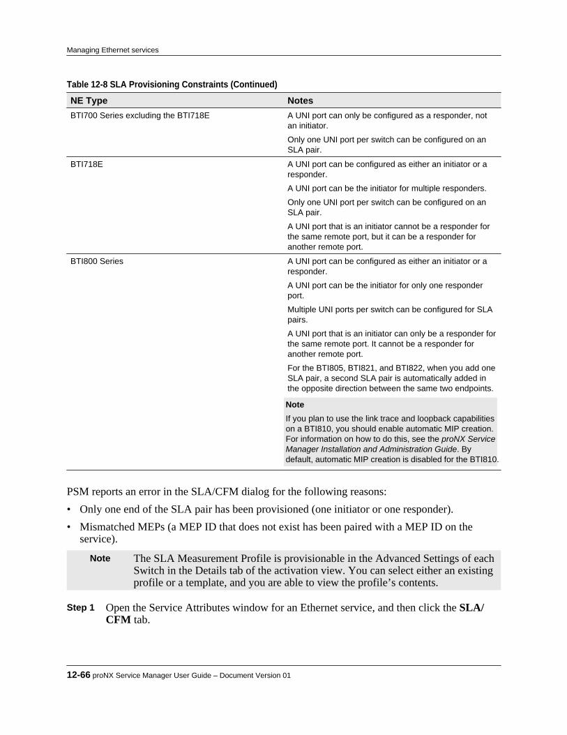
Table 12-8 SLA Provisioning Constraints (Continued) NE Type NotesBTI700 Series excluding the BTI718E A UNI port can only be configured as a responder, not
an initiator.
Only one UNI port per switch can be configured on anSLA pair.
BTI718E A UNI port can be configured as either an initiator or aresponder.
A UNI port can be the initiator for multiple responders.
Only one UNI port per switch can be configured on anSLA pair.
A UNI port that is an initiator cannot be a responder forthe same remote port, but it can be a responder foranother remote port.
BTI800 Series A UNI port can be configured as either an initiator or aresponder.
A UNI port can be the initiator for only one responderport.
Multiple UNI ports per switch can be configured for SLApairs.
A UNI port that is an initiator can only be a responder forthe same remote port. It cannot be a responder foranother remote port.
For the BTI805, BTI821, and BTI822, when you add oneSLA pair, a second SLA pair is automatically added inthe opposite direction between the same two endpoints. Note If you plan to use the link trace and loopback capabilitieson a BTI810, you should enable automatic MIP creation.For information on how to do this, see the proNX ServiceManager Installation and Administration Guide. Bydefault, automatic MIP creation is disabled for the BTI810.
PSM reports an error in the SLA/CFM dialog for the following reasons:• Only one end of the SLA pair has been provisioned (one initiator or one responder).• Mismatched MEPs (a MEP ID that does not exist has been paired with a MEP ID on the
service).
Note The SLA Measurement Profile is provisionable in the Advanced Settings of eachSwitch in the Details tab of the activation view. You can select either an existingprofile or a template, and you are able to view the profile’s contents.
Step 1 Open the Service Attributes window for an Ethernet service, and then click the SLA/CFM tab.
12-66 proNX Service Manager User Guide – Document Version 01
Managing Ethernet services
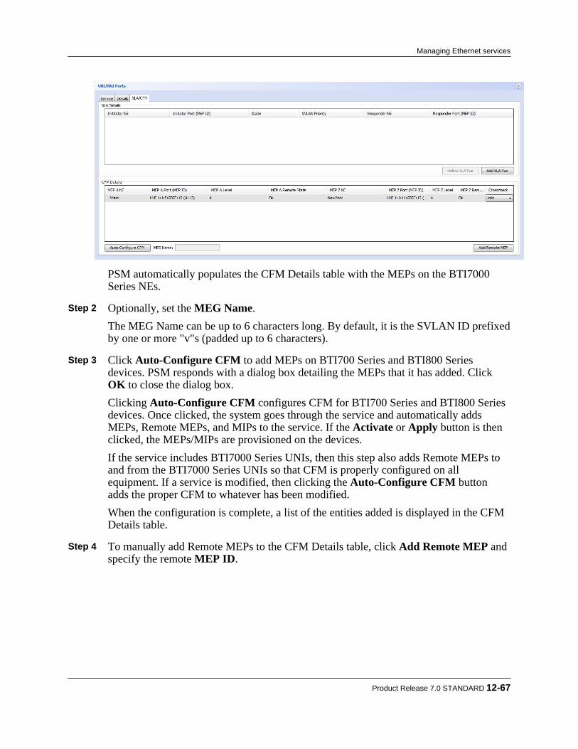
PSM automatically populates the CFM Details table with the MEPs on the BTI7000Series NEs.
Step 2 Optionally, set the MEG Name.
The MEG Name can be up to 6 characters long. By default, it is the SVLAN ID prefixedby one or more "v"s (padded up to 6 characters).
Step 3 Click Auto-Configure CFM to add MEPs on BTI700 Series and BTI800 Series
devices. PSM responds with a dialog box detailing the MEPs that it has added. Click OK to close the dialog box.Clicking Auto-Configure CFM configures CFM for BTI700 Series and BTI800 Seriesdevices. Once clicked, the system goes through the service and automatically addsMEPs, Remote MEPs, and MIPs to the service. If the Activate or Apply button is thenclicked, the MEPs/MIPs are provisioned on the devices.If the service includes BTI7000 Series UNIs, then this step also adds Remote MEPs toand from the BTI7000 Series UNIs so that CFM is properly configured on allequipment. If a service is modified, then clicking the Auto-Configure CFM buttonadds the proper CFM to whatever has been modified.When the configuration is complete, a list of the entities added is displayed in the CFMDetails table.
Step 4 To manually add Remote MEPs to the CFM Details table, click Add Remote MEP and
specify the remote MEP ID.
Product Release 7.0 STANDARD 12-67
Managing Ethernet services
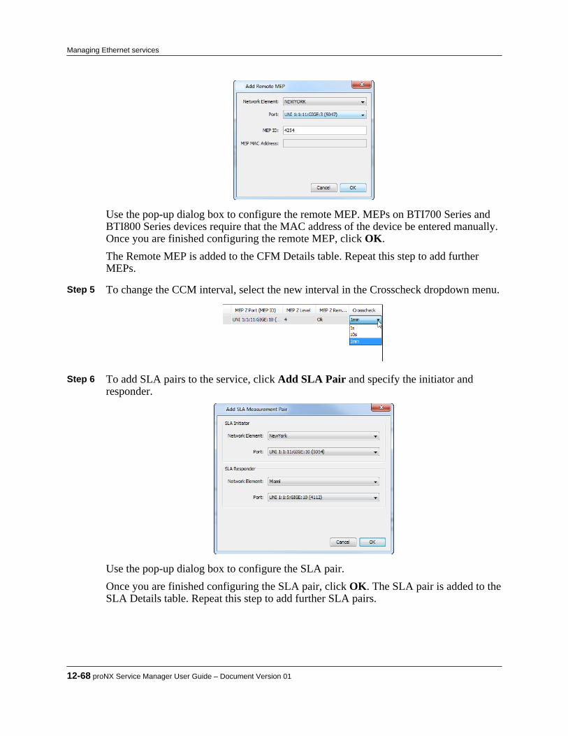
Use the pop-up dialog box to configure the remote MEP. MEPs on BTI700 Series andBTI800 Series devices require that the MAC address of the device be entered manually.Once you are finished configuring the remote MEP, click OK.The Remote MEP is added to the CFM Details table. Repeat this step to add furtherMEPs.
Step 5 To change the CCM interval, select the new interval in the Crosscheck dropdown menu.
Step 6 To add SLA pairs to the service, click Add SLA Pair and specify the initiator and
responder.
Use the pop-up dialog box to configure the SLA pair.Once you are finished configuring the SLA pair, click OK. The SLA pair is added to theSLA Details table. Repeat this step to add further SLA pairs.
12-68 proNX Service Manager User Guide – Document Version 01
Managing Ethernet services

Step 7 To change the SVLAN priority of the SLA pair, select the new priority from the
SVLAN Priority dropdown menu.
Step 8 To enable or disable the SLA pair, select the new state from the State dropdown menu.
Step 9 When you are done adding SLAs/CFMs to the service, click Activate to activate a new
service or Apply to apply changes to an existing service.
Note When you perform a CFM update on a pre-1.5 release BTI700 Series device, youmust manually rediscover the device in order for the update to be reflected inPSM.
This procedure is complete.
Product Release 7.0 STANDARD 12-69
Managing Ethernet services
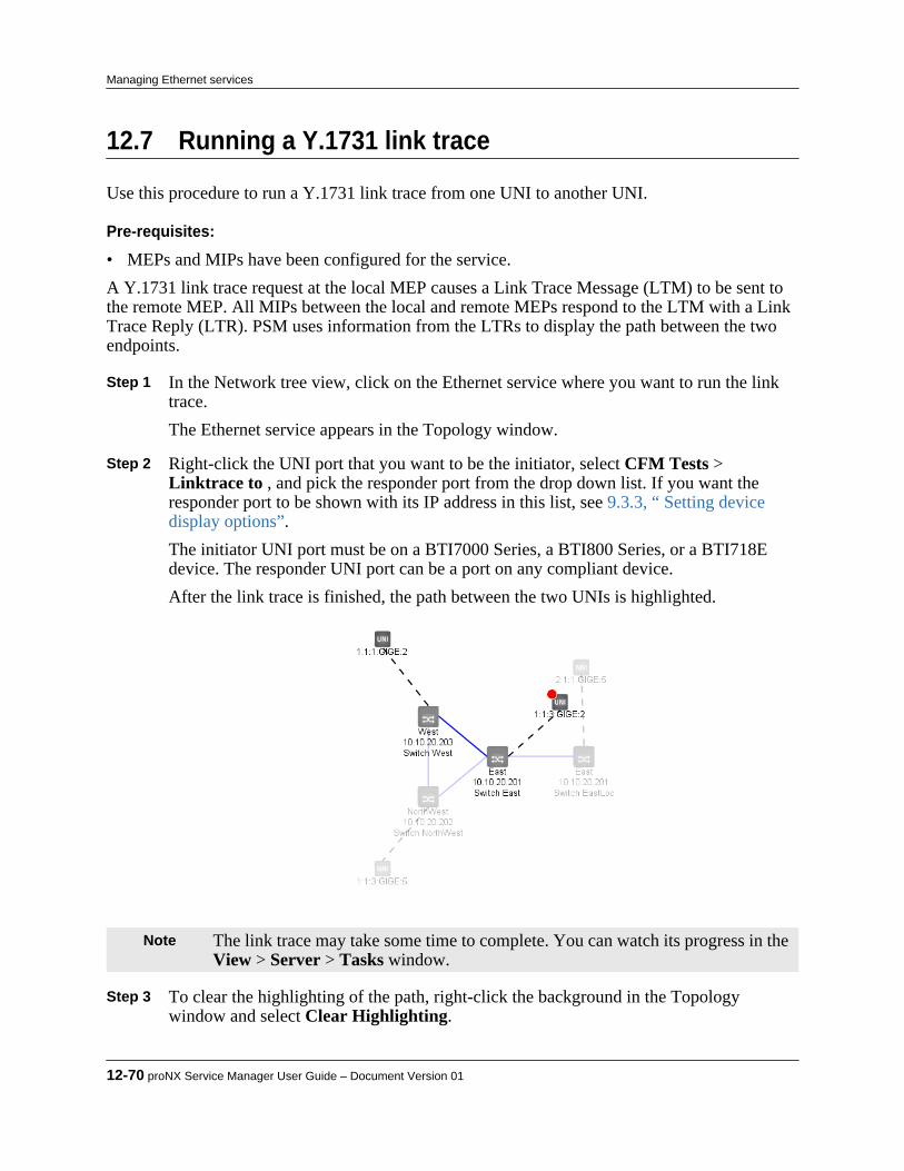
12.7 Running a Y.1731 link trace
Use this procedure to run a Y.1731 link trace from one UNI to another UNI.
Pre-requisites:
• MEPs and MIPs have been configured for the service.A Y.1731 link trace request at the local MEP causes a Link Trace Message (LTM) to be sent tothe remote MEP. All MIPs between the local and remote MEPs respond to the LTM with a LinkTrace Reply (LTR). PSM uses information from the LTRs to display the path between the twoendpoints.
Step 1 In the Network tree view, click on the Ethernet service where you want to run the linktrace.The Ethernet service appears in the Topology window.
Step 2 Right-click the UNI port that you want to be the initiator, select CFM Tests >
Linktrace to , and pick the responder port from the drop down list. If you want theresponder port to be shown with its IP address in this list, see 9.3.3, “ Setting devicedisplay options”.The initiator UNI port must be on a BTI7000 Series, a BTI800 Series, or a BTI718Edevice. The responder UNI port can be a port on any compliant device.After the link trace is finished, the path between the two UNIs is highlighted.
Note The link trace may take some time to complete. You can watch its progress in the View > Server > Tasks window.
Step 3 To clear the highlighting of the path, right-click the background in the Topology
window and select Clear Highlighting.
12-70 proNX Service Manager User Guide – Document Version 01
Managing Ethernet services
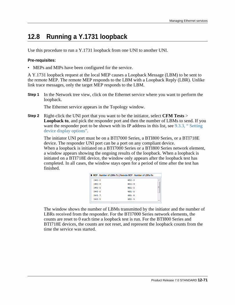
12.8 Running a Y.1731 loopback
Use this procedure to run a Y.1731 loopback from one UNI to another UNI.
Pre-requisites:
• MEPs and MIPs have been configured for the service.A Y.1731 loopback request at the local MEP causes a Loopback Message (LBM) to be sent tothe remote MEP. The remote MEP responds to the LBM with a Loopback Reply (LBR). Unlikelink trace messages, only the target MEP responds to the LBM.
Step 1 In the Network tree view, click on the Ethernet service where you want to perform theloopback.The Ethernet service appears in the Topology window.
Step 2 Right-click the UNI port that you want to be the initiator, select CFM Tests >
Loopback to, and pick the responder port and then the number of LBMs to send. If youwant the responder port to be shown with its IP address in this list, see 9.3.3, “ Settingdevice display options”.The initiator UNI port must be on a BTI7000 Series, a BTI800 Series, or a BTI718Edevice. The responder UNI port can be a port on any compliant device.When a loopback is initiated on a BTI7000 Series or a BTI800 Series network element,a window appears showing the ongoing results of the loopback. When a loopback isinitiated on a BTI718E device, the window only appears after the loopback test hascompleted. In all cases, the window stays open for a period of time after the test hasfinished.
The window shows the number of LBMs transmitted by the initiator and the number ofLBRs received from the responder. For the BTI7000 Series network elements, thecounts are reset to 0 each time a loopback test is run. For the BTI800 Series andBTI718E devices, the counts are not reset, and represent the loopback counts from thetime the service was started.
Product Release 7.0 STANDARD 12-71
Managing Ethernet services

12.9 Running an RFC 2544 benchmarking test
Use this procedure to run an RFC 2544 benchmarking test on the BTI805, BTI821, or BTI822devices.The tests specified in RFC 2544 are useful to determine whether an Ethernet service complieswith service level agreements. These tests apply to EPLINE and EVPLINE services only.
Step 1 Right-click a service in the Network tree and select RFC 2544 > Run Tests.The Rfc 2544 dialog appears.
Step 2 Select the test parameters as follows:
• Throughput - This is always selected. The other tests require the throughput test tobe enabled. The throughput test measures the maximum rate that can be processedwithin the specified Acceptable Loss constraint.
• Frame Loss Ratio - Select to run the frame loss ratio test. This test measures theframe loss ratios for different ingress traffic rates.
• Latency - Select to run the Latency test.• Endpoint - Select the endpoint of the circuit where the test is to be initiated.• Frame Size 1 through Frame Size 6 - Select the six different frame sizes to use for
the test(s).• Cos Type - Select the class of service type from the pulldown menu. Select EPU
(EVC per UNI) if you want to use the EVC class of service. Select MANUAL if youwant to manually specify the class of service.
12-72 proNX Service Manager User Guide – Document Version 01
Managing Ethernet services

• Cos Level - Select the class of service level if the Cos Type is set to MANUAL. Step 3 Select the Details tab to configure the detailed test settings.
Step 4 Select the throughput test parameters as follows:
• Oper-Way - Select DUAL_ENDED to generate test traffic from both ends, or LOOPBACK to loop back the test traffic at the remote end.
• Max. Trial Times - Specify the maximum number of trials to run. The minimumvalue for this parameter is 5.
• Acceptable Loss - Specify the percentage of frames that can be lost (and theoutcome still considered to be acceptable). If this is set to 0, the throughput testmeasures the maximum rate that can be processed with no loss of frames.
• Max. Rate - Specify the starting traffic rate (Mbps) for the test.• Duration - Specify the duration of the test in seconds.• S. Trial - Specify the number of successive trials that must be successful before the
test at the current frame size is stopped. A trial is successful if the number of lostframes is within the Acceptable Loss constraint.
Step 5 Select the frame loss ratio test parameters as follows:
• Oper-Way - Select DUAL_ENDED to generate test traffic from both ends, or SINGLE_ENDED to generate test traffic from one end, or LOOPBACK to loopback the test traffic at the remote end.
• Granularity - Specify the percentage of the maximum frame rate to step down foreach successive trial. The maximum frame rate is the frame rate that achieves 100%
Product Release 7.0 STANDARD 12-73
Managing Ethernet services

link utilization for the frame size being used. The rate is stepped down from themaximum frame rate successively if frame loss occurs.
• Duration - Specify the duration of the test in seconds.• S. Trial - Specify the number of successive trials that have no lost frames before the
test at the current frame size is stopped. Step 6 Select the latency test parameters as follows:
• Oper-Way - Select DUAL_ENDED to generate test traffic from both ends, or LOOPBACK to loop back the test traffic at the remote end.
• Duration - Specify the duration of the test in seconds. Step 7 Select Background Traffic to enable background traffic in the latency tests. Step 8 Click Run.
You can monitor the status of the test through the View > Server > Tasks window. Step 9 View the test results when the test is finished.
a) Right click the service in the Network tree and select RFC 2544 > Show Results.This command retrieves the most recent, completed RFC 2544 tests from the NE andlists them in the Rfc Test Result List.
12-74 proNX Service Manager User Guide – Document Version 01
Managing Ethernet services

Note Once PSM retrieves the test results, it stores them in its local database and makesthem available for display (even if the test results are subsequently deleted fromthe NE).
b) Select the test you want to view and click Open.A new tab opens showing the test that you have selected.
c) Click the chevron in the upper right corner to view the test results.The test results are organized as shown in the following figure:
d) To see the results of a specific test, click the associated chevron.For example, these are the results of the throughput test:
Step 10 To export the test data to an Excel file, click Export and save the file.
Product Release 7.0 STANDARD 12-75
Managing Ethernet services

12.10 Ethernet Ring Protection Switching (ERPS)
ERPS is a ring protection scheme for Ethernet networks, and is supported on BTI7000 Series,BTI800 Series, and BTI700 Series equipment.The network operator creates the ERPS service directly on the network element using either theproNX 900 or the CLI, and can use PSM to view the service graphically. PSM automaticallydiscovers and displays ERPS services in the network but does not currently support creatingERPS services.
12.10.1 Visualizing an ERPS serviceUse this procedure to view the ERPS service and its states.Under normal (non-failure) conditions, the ERPS service blocks the RPL link to prevent loopingof traffic for the Ethernet services it is protecting. On link failure, the ERPS service enables theblocked port to allow traffic from those Ethernet services to continue to flow.
Step 1 In the Network tree view, select the desired ERPS service.The ERPS service view opens in the main map window. If PSM is configured to showthe ERPS link icons (9.3.5, “ Setting service display options”), a green is displayedto indicate the RPL link being blocked.
Step 2 Right click the service view and select Show Connected Ports.
The ERPS service view is expanded to show the ports.
12-76 proNX Service Manager User Guide – Document Version 01
Managing Ethernet services
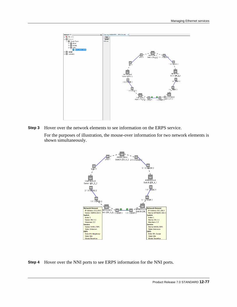
Step 3 Hover over the network elements to see information on the ERPS service.
For the purposes of illustration, the mouse-over information for two network elements isshown simultaneously.
Step 4 Hover over the NNI ports to see ERPS information for the NNI ports.
Product Release 7.0 STANDARD 12-77
Managing Ethernet services
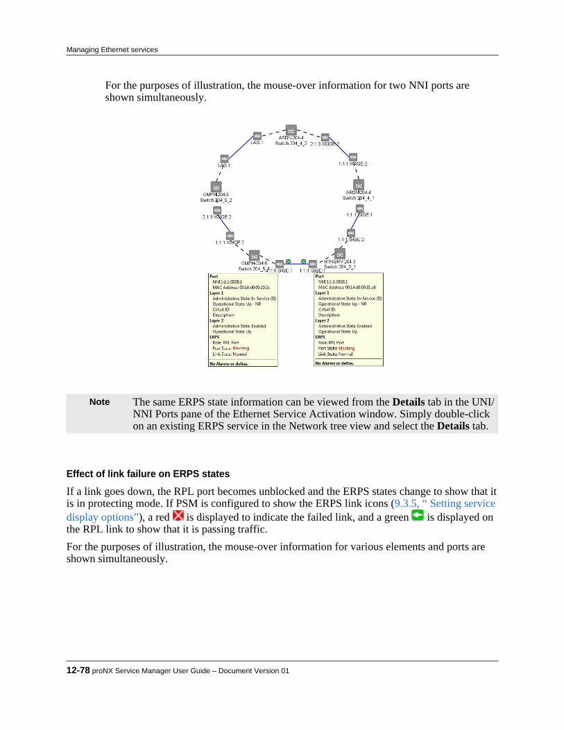
For the purposes of illustration, the mouse-over information for two NNI ports areshown simultaneously.
Note The same ERPS state information can be viewed from the Details tab in the UNI/NNI Ports pane of the Ethernet Service Activation window. Simply double-clickon an existing ERPS service in the Network tree view and select the Details tab.
Effect of link failure on ERPS states
If a link goes down, the RPL port becomes unblocked and the ERPS states change to show that itis in protecting mode. If PSM is configured to show the ERPS link icons (9.3.5, “ Setting servicedisplay options”), a red is displayed to indicate the failed link, and a green is displayed onthe RPL link to show that it is passing traffic.For the purposes of illustration, the mouse-over information for various elements and ports areshown simultaneously.
12-78 proNX Service Manager User Guide – Document Version 01
Managing Ethernet services

12.10.2 Viewing the ERPS services tableUse this procedure to view the ERPS services table.The ERPS services table displays information on all ERPS services running in the network.
Step 1 Select View > Ethernet > ERPS.The ERPS services table opens in the main Map window. The table shows the ERPSservices in the network along with their port states and other information.
Product Release 7.0 STANDARD 12-79
Managing Ethernet services
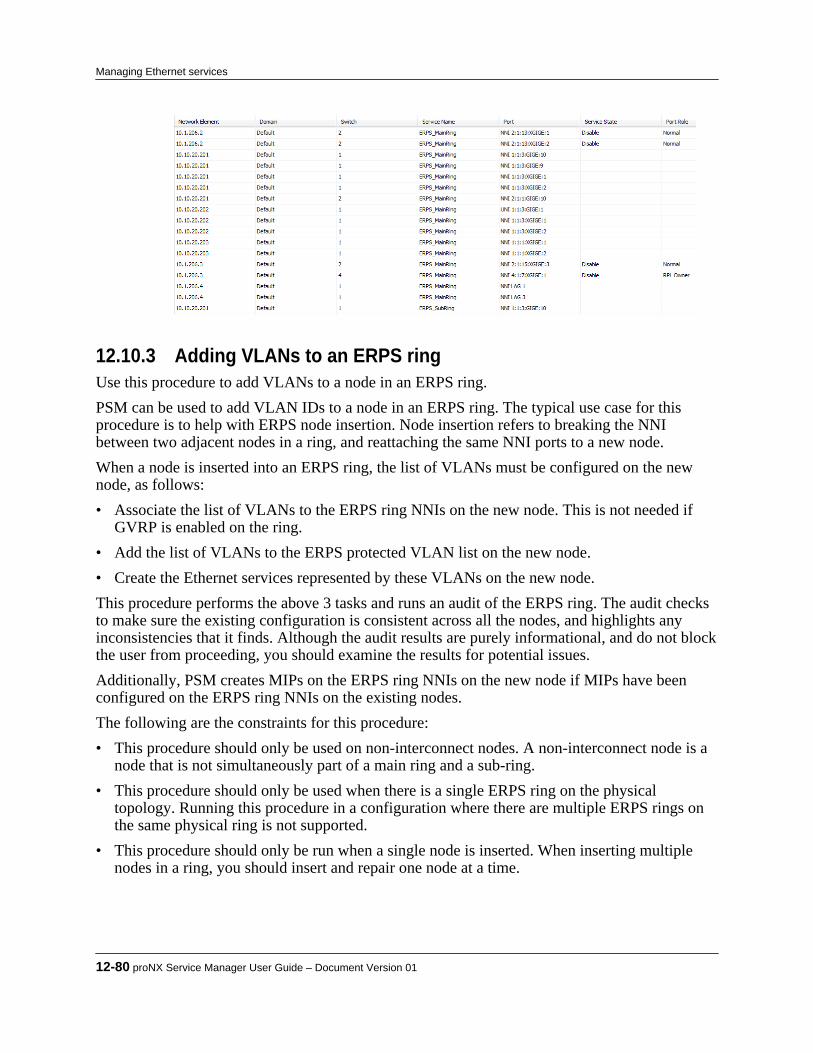
12.10.3 Adding VLANs to an ERPS ringUse this procedure to add VLANs to a node in an ERPS ring.PSM can be used to add VLAN IDs to a node in an ERPS ring. The typical use case for thisprocedure is to help with ERPS node insertion. Node insertion refers to breaking the NNIbetween two adjacent nodes in a ring, and reattaching the same NNI ports to a new node.When a node is inserted into an ERPS ring, the list of VLANs must be configured on the newnode, as follows:• Associate the list of VLANs to the ERPS ring NNIs on the new node. This is not needed if
GVRP is enabled on the ring.• Add the list of VLANs to the ERPS protected VLAN list on the new node.• Create the Ethernet services represented by these VLANs on the new node.This procedure performs the above 3 tasks and runs an audit of the ERPS ring. The audit checksto make sure the existing configuration is consistent across all the nodes, and highlights anyinconsistencies that it finds. Although the audit results are purely informational, and do not blockthe user from proceeding, you should examine the results for potential issues.Additionally, PSM creates MIPs on the ERPS ring NNIs on the new node if MIPs have beenconfigured on the ERPS ring NNIs on the existing nodes.The following are the constraints for this procedure:• This procedure should only be used on non-interconnect nodes. A non-interconnect node is a
node that is not simultaneously part of a main ring and a sub-ring.• This procedure should only be used when there is a single ERPS ring on the physical
topology. Running this procedure in a configuration where there are multiple ERPS rings onthe same physical ring is not supported.
• This procedure should only be run when a single node is inserted. When inserting multiplenodes in a ring, you should insert and repair one node at a time.
12-80 proNX Service Manager User Guide – Document Version 01
Managing Ethernet services

Note This procedure supplements the ERPS node insertion procedures on the networkelements. Refer to the ERPS node insertion procedures in the respectivedocumentation for the different network elements for more details.
Step 1 Select the desired ERPS service in the tree view. Step 2 In the Ethernet services topology window, identify the node that you want to add the
VLANs to.This is typically the newly inserted node.
Step 3 Right click that node and select Repair VLANs.PSM audits the ERPS service, treats the existing nodes as the baseline, and prepares to configurethe selected node to be consistent with the baseline. The audit results and the list of VLANs to beadded are presented. For example:
Here is an example of an audit that has uncovered underlying issues:
Tip You can use this procedure purely to audit the ERPS ring. Step 4 Add the VLANs to the selected node.
If the audit shows that the ERPS ring is healthy, select OK to add the VLANs to Repairlist to the selected node.
Product Release 7.0 STANDARD 12-81
Managing Ethernet services
If the audit shows issues with the existing ERPS ring configuration, select Cancel, fixthe issues, and repeat Step 3.
Note You are advised, but not required, to fix the audit issues before selecting OK toadd the VLANs.
Once you click OK, PSM associates the list of VLANs to the ERPS ring NNIs on theselected node, adds the list of VLANs to the protected VLAN list for the ERPS serviceon the selected node, creates the Ethernet services represented by these VLANs, andfinally, creates the MIPs as necessary.
12-82 proNX Service Manager User Guide – Document Version 01
Managing Ethernet services

12.11 Routing considerations in mixed networks
Depending on the topology of the Network, there are certain considerations to take into accountwhen activating services from the network perspective. This section attempts to highlight themain concerns and steps required to successfully activate services within different networkconfigurations.This section covers the following topics:• 12.11.1, “GVRP - GARP VLAN Registration Protocol”• 12.11.2, “Mixed networks - BTI7000 Series with BTI700 Series or BTI800 Series elements”
12.11.1 GVRP - GARP VLAN Registration ProtocolThe Generic Attributes Registration Protocol (GARP) is defined in 802.1D as a means forbridges to distribute information amongst themselves about membership in various groups. 802.1D defines GMRP (GARP Multicast Registration Protocol) to distribute multicast groupmembership. 802.1Q defines GVRP (GARP VLAN Registration Protocol) to distributeinformation about VLAN membership.GVRP addresses the problem of determining which inter-bridge links (NNIs) must be membersof which VLANs. In a VLAN-bridge, packets in VLAN x can only be transmitted on links thatare members of VLAN x. VLAN x subscriber interfaces (UNIs) are manually configured, but itcan be cumbersome to define a VLAN member for all VLANs across all NNIs. One fall-backwould be to simply define all VLANs on NNIs, but this means that all flooded packets will beflooded everywhere, which is a large waste of bandwidth.GVRP, in effect, advertises VLAN membership backwards through the network. If a node mustreceive packets in VLAN x, it sends a registration for VLAN x to all of its neighbors. Each ofthose neighbors adds the receiving link to VLAN x and then forwards a registration to all of itsneighbors.Using GVRP lets you dynamically route VLAN traffic through the network and create serviceswithout specifying the NNI ports needed for the service.
12.11.2 Mixed networks - BTI7000 Series with BTI700 Series or BTI800Series elements
When a network includes BTI7000 Series packetVX and BTI700 Series or BTI800 Seriesdevices, the topology of the network dictates the NNIs that must be explicitly added tosuccessfully activate a service, regardless of the type of Ethernet service selected. The rule ofthumb is that all NNIs on BTI700 Series devices must be added, and all NNIs on BTI7000 Seriesswitches that are facing BTI700 Series devices must be added in order for traffic to flow. Someexamples follow.
Note This section only applies if the Auto-Provision NNIs feature is not selected.
Product Release 7.0 STANDARD 12-83
Managing Ethernet services

12.11.2.1 Creating services in BTI7000 Series packetVX only networksFigure 12-6 Creating services in BTI7000 Series packetVX only networks
In this case, all network elements are BTI7000 Series packetVX nodes. Only the endpoint UNIsneed to be added to the service, as the NNIs will all be GVRP-enabled and the dynamic VLANcreation will automatically route the traffic.
Equipment Example IP Example PortNE 1 172.27.7.106 UNI 1: GIGE 12 on Switch 2
NE 4 172.27.7.110 UNI 1: GIGE 4 on Switch 1
Figure 12-7 Creating Services in BTI7000 Series packetVX-only Networks
12-84 proNX Service Manager User Guide – Document Version 01
Managing Ethernet services
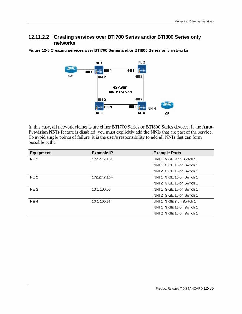
12.11.2.2 Creating services over BTI700 Series and/or BTI800 Series onlynetworks
Figure 12-8 Creating services over BTI700 Series and/or BTI800 Series only networks
In this case, all network elements are either BTI700 Series or BTI800 Series devices. If the Auto-Provision NNIs feature is disabled, you must explicitly add the NNIs that are part of the service.To avoid single points of failure, it is the user's responsibility to add all NNIs that can formpossible paths.
Equipment Example IP Example PortsNE 1 172.27.7.101 UNI 1: GIGE 3 on Switch 1
NNI 1: GIGE 15 on Switch 1
NNI 2: GIGE 16 on Switch 1
NE 2 172.27.7.104 NNI 1: GIGE 15 on Switch 1
NNI 2: GIGE 16 on Switch 1
NE 3 10.1.100.55 NNI 1: GIGE 15 on Switch 1
NNI 2: GIGE 16 on Switch 1
NE 4 10.1.100.56 UNI 1: GIGE 3 on Switch 1
NNI 1: GIGE 15 on Switch 1
NNI 2: GIGE 16 on Switch 1
Product Release 7.0 STANDARD 12-85
Managing Ethernet services

Figure 12-9 Creating services over BTI700 Series and/or BTI800 Series only networks
12.11.2.3 Activating services over combinations of BTI7000 Series packetVXand BTI700 Series or BTI800 Series networks
This is a combination of the two previous cases. If the Auto-Provision NNIs feature is disabled,you must add all the NNIs that do not face the GVRP ring (see the table below).
Figure 12-10 Activating services over a combination of BTI7000 Series packetVX, BTI700 Series, andBTI800 Series networks
In this example, NE 1 and NE 2 are BTI700 Series devices, NE 3 through NE 6 are BTI7000Series packetVX devices, and NE 7 and NE 8 are BTI800 Series devices.
Equipment Example IP Example PortsNE 1 172.27.7.101 NNI 1: GIGE 15 on Switch 1
NNI 2: GIGE 16 on Switch 1
12-86 proNX Service Manager User Guide – Document Version 01
Managing Ethernet services
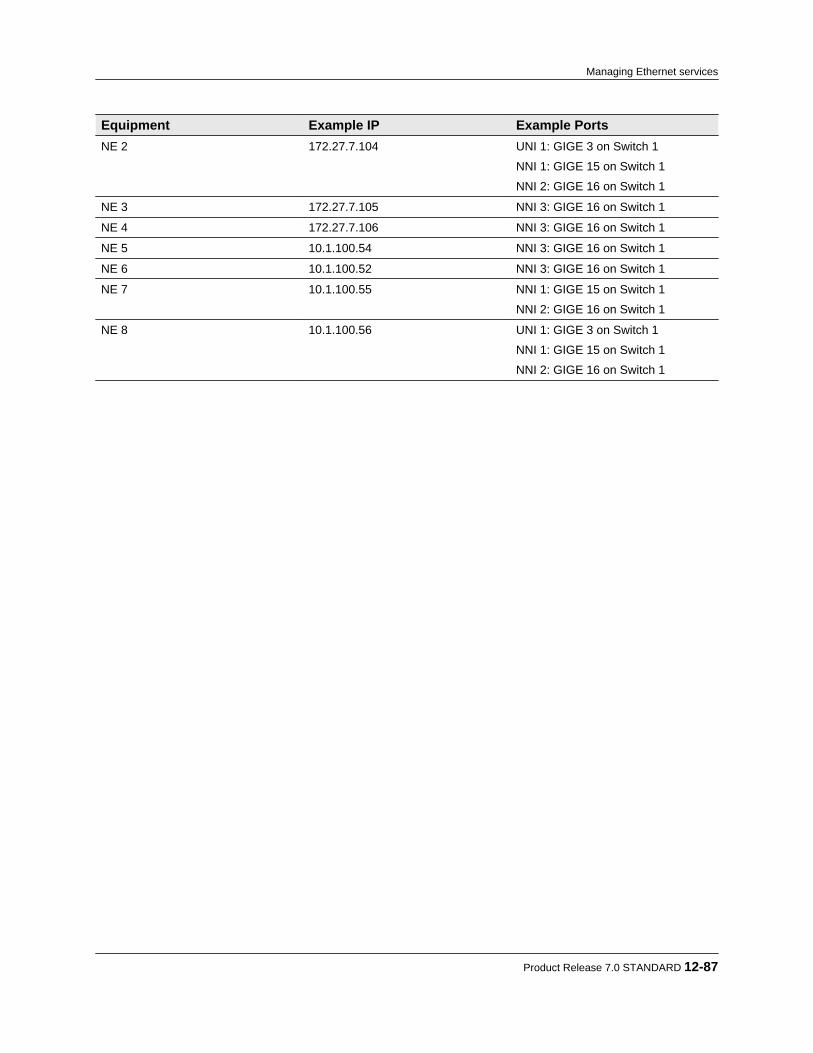
Equipment Example IP Example PortsNE 2 172.27.7.104 UNI 1: GIGE 3 on Switch 1
NNI 1: GIGE 15 on Switch 1
NNI 2: GIGE 16 on Switch 1
NE 3 172.27.7.105 NNI 3: GIGE 16 on Switch 1
NE 4 172.27.7.106 NNI 3: GIGE 16 on Switch 1
NE 5 10.1.100.54 NNI 3: GIGE 16 on Switch 1
NE 6 10.1.100.52 NNI 3: GIGE 16 on Switch 1
NE 7 10.1.100.55 NNI 1: GIGE 15 on Switch 1
NNI 2: GIGE 16 on Switch 1
NE 8 10.1.100.56 UNI 1: GIGE 3 on Switch 1
NNI 1: GIGE 15 on Switch 1
NNI 2: GIGE 16 on Switch 1
Product Release 7.0 STANDARD 12-87
Managing Ethernet services

12.12 Managing profiles
This section covers the following topics:• 12.12.1, “About profile manager”• 12.12.2, “Managing profile templates”• 12.12.3, “Bandwidth profile templates”• 12.12.4, “Class map profile templates”• 12.12.5, “Service policy profile templates”• 12.12.6, “Service map profile templates”• 12.12.7, “SLA measurement profile templates”
12.12.1 About profile managerPSM allows users to create or clone profiles that can be used to configure Ethernet services.The Profile Manager provides an easy way for you to create new profiles, as well as to managethe various profiles already associated with devices in the network. PSM automatically discoversexisting profiles in the network, and makes them visible in the Profile Manager, organized bynetwork element.A profile can exist in the following forms:• as a profile stored in PSM• as a profile stored on the network elementA profile that is stored in PSM is called a profile template. You can use the Profile Manager tocreate profile templates:• by specifying all parameters explicitly• by cloning from another profile template• by cloning from a profile associated with an actual device in the networkProfile templates are stored in PSM and are applied to the specified network elements during aservice activation operation. Applying a profile template to a network element causes that profileto be created and stored on the network element using the same name as the template. Afterservice activation, the profile exists both as a template in PSM and as an actual profile on thenetwork element.You can create, edit, or delete profile templates on PSM. You cannot use PSM to edit or deleteprofiles discovered on the network elements.
Note There is no synchronization between the profile templates defined in PSM andthe network. Changes to the templates are not reflected in the network, andchanges in the network are not automatically copied back to the respectiveprofile template. Changes in the network, however, are reflected in thediscovered profiles for the respective network elements.
12-88 proNX Service Manager User Guide – Document Version 01
Managing Ethernet services

Note Profile templates are part of the replicated data set when running with multipleservers. For more information on replicated data, see 1.3.2, “Running multipleservers with server replication”.
The Profile Manager screen is accessible via the Edit menu item Profiles, or via the toolbarbutton shown below.
The Profile Manager screen is shown below.
Selecting a profile during service activation
When you activate an Ethernet service, you have the ability to specify which profile to use on aport. The possible profiles include the list of profile templates in PSM, and the list of profilesdiscovered on the network element to which the port belongs. If you want to use a profile foundon another network element, you must first clone that profile into PSM so that it appears in thelist of profile templates.Note that it is normal for a profile template in PSM and a profile on a device to have the samename. The reason is that when you activate a service and you specify a profile template, PSMcreates a profile on the device with the same name as the template.During service activation, when confronted with a choice between a profile template on PSMand the equivalent profile on the device, you should always select the profile on the device. Ifyou select the profile template instead, you are in effect requesting PSM to create a new profileon the device with the same name as the profile template, which will result in an error becausethat profile already exists.For example, in the following profile selection dialog (during service activation), the profileGOLD appears as both a profile template and a profile:
Product Release 7.0 STANDARD 12-89
Managing Ethernet services

In such situations, you should always select the GOLD profile on the device (i.e. where theSource is DEVICE) rather than the GOLD profile template (i.e. where the Source isTEMPLATE). In fact, PSM will not allow you to select the GOLD profile template becausedoing so means that you are requesting PSM to create a new GOLD profile on the device, but theGOLD profile already exists on the device.
12.12.2 Managing profile templates
12.12.2.1 Creating a profile template
Step 1 From the main menu choose Edit>Profiles, or click the Profile Manager button in thetoolbar.The Profiles window displays.
Step 2 In the left panel, right-click on Templates and choose a profile type from the pop-up
menu, as shown below.
12-90 proNX Service Manager User Guide – Document Version 01
Managing Ethernet services

The parameters for the selected profile type display in the right panel. The screen belowshows the Bandwidth Profile parameters.
For information on setting parameters for the Bandwidth, Service Policy, Class Map, orService Map profiles, see:• 12.12.3, “Bandwidth profile templates”• 12.12.4, “Class map profile templates”• 12.12.5, “Service policy profile templates”• 12.12.6, “Service map profile templates”
Step 3 Enter a unique name for the profile in the Name field, and set the other parameters using
the drop-down menu. Step 4 Click Apply.
The newly-created profile appears under Templates in the left panel of the Profileswindow.
Product Release 7.0 STANDARD 12-91
Managing Ethernet services
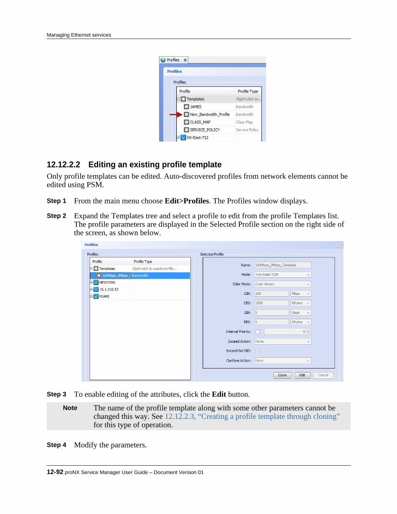
12.12.2.2 Editing an existing profile templateOnly profile templates can be edited. Auto-discovered profiles from network elements cannot beedited using PSM.
Step 1 From the main menu choose Edit>Profiles. The Profiles window displays. Step 2 Expand the Templates tree and select a profile to edit from the profile Templates list.
The profile parameters are displayed in the Selected Profile section on the right side ofthe screen, as shown below.
Step 3 To enable editing of the attributes, click the Edit button.
Note The name of the profile template along with some other parameters cannot bechanged this way. See 12.12.2.3, “Creating a profile template through cloning”for this type of operation.
Step 4 Modify the parameters.
12-92 proNX Service Manager User Guide – Document Version 01
Managing Ethernet services

Step 5 Click Apply to save the changes.
12.12.2.3 Creating a profile template through cloningYou can clone from an existing profile (discovered from a network element) or from a profiletemplate. Cloning creates a new template with all the same parameter values as the original.Cloned templates let users deploy proven profiles, thus reducing user input error.
Step 1 From the main menu choose Edit>Profiles. The Profiles window is displayed. Step 2 Expand the profile or profile template list so that the profile or profile template you
want to use as the source is displayed. Step 3 Right-click the profile or profile template that you want to be the source, and choose
Clone from the pop-up menu.The profile parameters are displayed in the Selected Profile section on the right panelwith the Name field blank.
Step 4 Enter a name, edit the parameters as required, and click the Apply button.
The cloned profile template is created and displayed in the expanded profile templatelist, and the original profile or profile template is left unmodified.
12.12.2.4 Deleting a profile templateOnly profile templates can be deleted. Auto-discovered profiles from network elements cannotbe deleted using PSM.
Step 1 From the main menu choose Edit>Profiles. The Profiles window displays. Step 2 In the Profiles area, right-click a profile Template from the expanded list, and choose
Delete from the pop-up menuA confirmation dialog displays.
Step 3 Select OK to delete profile template, or Cancel to keep the profile template.
12.12.3 Bandwidth profile templatesBandwidth Profiles are used for policing traffic to:• control the maximum rate of traffic sent or received on an interface.• partition a network into multiple priority levels or classes of service.A bandwidth profile is the starting point of any policing function and can be configured for useat the CoS queue, logical interface, or Layer 2 (MAC) level. The figure below shows theparameters for a bandwidth profile.
Product Release 7.0 STANDARD 12-93
Managing Ethernet services

Figure 12-11 Bandwidth Profile Template Parameters
There are three modes supported for Bandwidth Profile Templates:• Two-Rate TCM (TriColor Marker)• Single-Rate TCM• CARFor information about configuring CIR, CBS, EIR and EBS and Quality of Service / Class ofService , see the BTI7000 Series packetVX Solutions Guide.
Note Pre-10.3 BTI7000 Series network elements and all BTI700 Series networkelements use peak information rate and peak burst size instead of excessinformation rate and excess burst size. When managing those devices, PSMinternally converts the EIR and EBS to the peak information rate and peak burstsize. This conversion is performed transparently to the operator. The valuesshown on PSM continue to be the EIR and EBS, whereas the values shown onthe CLI on those devices are the peak information rate and peak burst size.
12.12.3.1 TCM bandwidth profilesThe Three Color (or Tricolor) Marking (TCM) scheme classifies packets as green, yellow or redbased on user-defined rates and burst size values.
Step 1 To create this type of Bandwidth Profile template, click the New button and selectBandwidth from the popup dialog.
Step 2 In the Selected Profile attributes pane on the right side, select Two-Rate TCM or
Single-Rate TCM from the Mode attribute.You must provide a name for the profile template a number of rate values along withColor Mode and Action attributes.
Step 3 Click Apply to accept the changes, or Discard to cancel.
12-94 proNX Service Manager User Guide – Document Version 01
Managing Ethernet services
12.12.3.2 Two-rate TCMTwo-Rate TCM classifies packets based on two rates and two burst sizes. Two-Rate TCM isuseful when the peak rate needs to be enforced.The two rate values are Committed Information Rate (CIR) and Excess Information Rate (EIR).The two burst size values are Committed Burst Size (CBS) and Excess Burst Size (EBS).Traffic is marked green, yellow or red based on whether the packets arriving are below the CIR(green), exceed the CIR but not the EIR (yellow), or exceed the EIR (red).
12.12.3.3 Single-rate TCMSingle-Rate TCM classifies packets based on a single rate and two burst sizes. Single-Rate TCMis useful when only the burst size matters.The rate value is Committed Information Rate (CIR).The two burst size values are Committed Burst Size (CBS) and Excess Burst Size (EBS).Traffic is marked green, yellow or red based on whether the packets arriving are below the CBS(green), exceed the CBS but not the EBS (yellow), or exceed the EBS (red).
12.12.3.4 CAR bandwidth profile templateCommitted Access Rate (CAR) allows you to configure a value above which any traffic isdiscarded.To create this type of Bandwidth Profile template, click the New button and select “CAR” fromthe Mode attribute. Enter a name for the profile template and a CAR value. Click Apply tocommit the changes or Discard to cancel.
Note This type of Bandwidth Profile can be used only on the BTI700 Series networkelements.
12.12.3.5 Color mode and actionsThe color mode for both Two-Rate and Single-Rate TCM is the same, either Color Aware orColor Blind. Color aware indicates that the existing color of the packet is taken intoconsideration when applying the bandwidth profile. Color blind indicates that the existingclassification is ignored. The color (green or yellow) of a packet can be determined from the DEIbit in the VLAN tag.Each color has an associated action that can be performed. The Conform Action applies topackets that are colored green and the Exceed Action applies to packets that are colored yellow.Incoming traffic that violates the profile is dropped. The options for assigning actions are asfollows:• None: no action is taken• Remark DSCP: Sets the IP DSCP (differentiated service code point) value. The value can be
in the range 0-63.In addition, the Conform Action has the following option:• Set ToS from Priority: Sets the IP type of service field
Product Release 7.0 STANDARD 12-95
Managing Ethernet services

12.12.3.6 Setting DEI on exceed trafficTraffic that is classified as yellow can have the DEI bit set in the frame.To select this option, choose Exceed Set DEI.
Note This is only applicable for the BTI7000 Series network elements.
12.12.3.7 Internal priority for bandwidth profile templatesThe internal priority is the primary determinant of the QoS for the flow. It is a value from 0 to 7(inclusive) and is used to select the appropriate transmit queue for the packet when a bandwidthprofile is used. If the bandwidth profile is assigned to a UNI, all frames received on the UNI willbe assigned the indicated internal priority.See the BTI7000 Series documentation for more details.
12.12.4 Class map profile templatesNote Class maps are not supported on the BTI805, BTI821, and BTI822.
Class Map Profiles specify the fields of a packet to be matched in order to determine the packetsto classify.
Figure 12-12 Class Map Profile Template
In Class Map profiles, at least one match criteria must be added. All criteria added to the profilemust match in order for a packet to be classified by a particular Class Map Profile.
1 From the main menu choose Edit>Profiles. The Profiles window is displayed.
12-96 proNX Service Manager User Guide – Document Version 01
Managing Ethernet services

2 Right-click beside Templates and choose Create Class Map Profile.
Class Map fields are added to the Selected Profile window on the right.3 Enter a name for the class map in the Name field.4 From the type drop-down menu, select a class map type:
• Ingress per Cos• Egress per CoS• Service Map
5 From the New Match drop-down list, select the criteria to match.6 Click Add.A new attribute is displayed based on the selection and a value will be required. An X will bedisplayed next to the attribute allowing the match criteria to be removed if desired.
Note The BTI700 Series devices only support the following subset of Match criteria:• C-VLAN• C-VLAN Priority• S-VLAN Priority• Source MAC• Destination MAC
Class Map profile templates work in conjunction with Service Policy Profile Templates. See12.3.6, “Example: Activating EVPLAN and EVPLINE services using service maps for flowredirection” for an example on how to configure class maps.
12.12.5 Service policy profile templatesNote Service policies are not supported on the BTI805, BTI821, and BTI822.
Service Policy Profile Templates are used to pair Bandwidth Profiles with Class Map Profiles.
Product Release 7.0 STANDARD 12-97
Managing Ethernet services
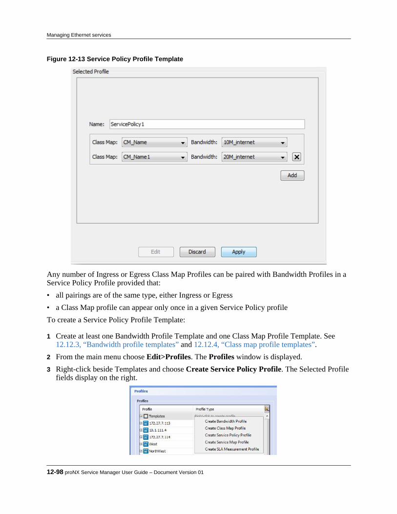
Figure 12-13 Service Policy Profile Template
Any number of Ingress or Egress Class Map Profiles can be paired with Bandwidth Profiles in aService Policy Profile provided that:• all pairings are of the same type, either Ingress or Egress• a Class Map profile can appear only once in a given Service Policy profileTo create a Service Policy Profile Template:
1 Create at least one Bandwidth Profile Template and one Class Map Profile Template. See12.12.3, “Bandwidth profile templates” and 12.12.4, “Class map profile templates”.
2 From the main menu choose Edit>Profiles. The Profiles window is displayed.3 Right-click beside Templates and choose Create Service Policy Profile. The Selected Profile
fields display on the right.
12-98 proNX Service Manager User Guide – Document Version 01
Managing Ethernet services
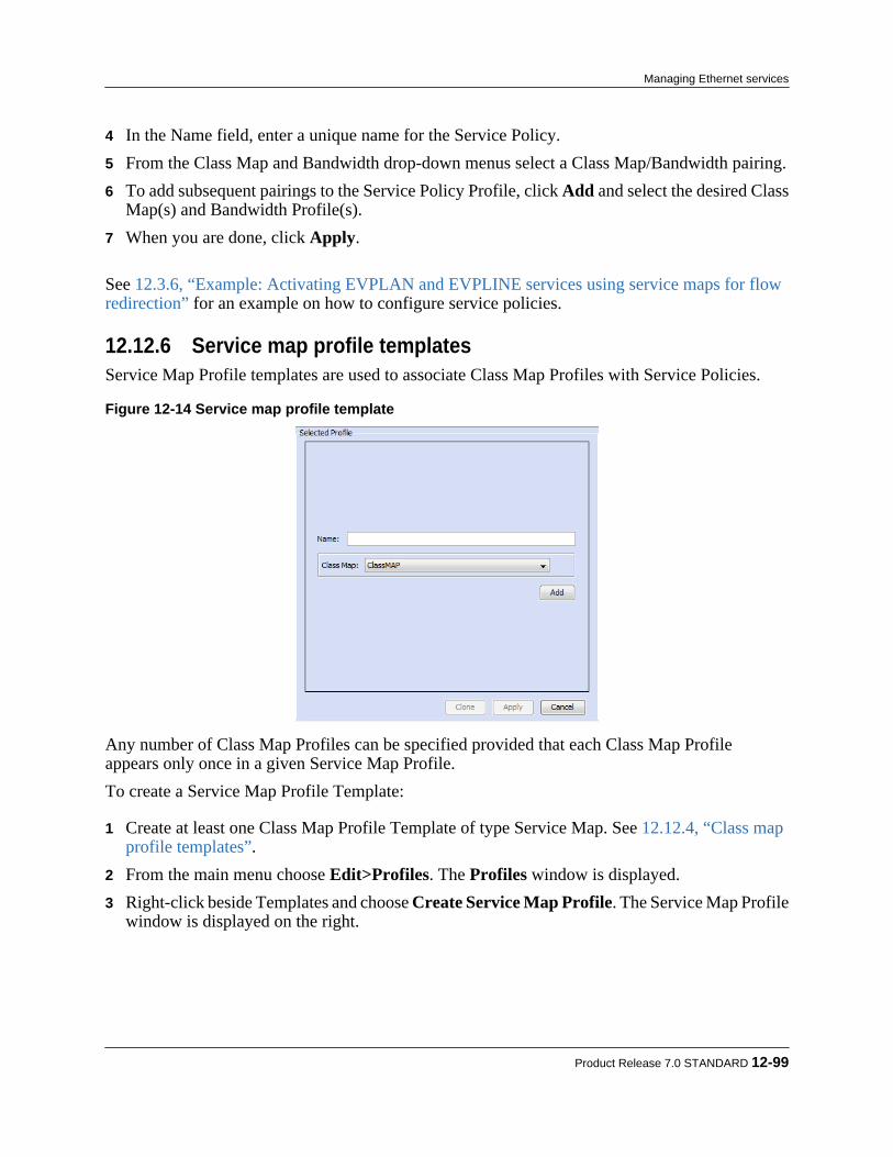
4 In the Name field, enter a unique name for the Service Policy.5 From the Class Map and Bandwidth drop-down menus select a Class Map/Bandwidth pairing.6 To add subsequent pairings to the Service Policy Profile, click Add and select the desired Class
Map(s) and Bandwidth Profile(s).7 When you are done, click Apply.
See 12.3.6, “Example: Activating EVPLAN and EVPLINE services using service maps for flowredirection” for an example on how to configure service policies.
12.12.6 Service map profile templatesService Map Profile templates are used to associate Class Map Profiles with Service Policies.
Figure 12-14 Service map profile template
Any number of Class Map Profiles can be specified provided that each Class Map Profileappears only once in a given Service Map Profile.To create a Service Map Profile Template:
1 Create at least one Class Map Profile Template of type Service Map. See 12.12.4, “Class mapprofile templates”.
2 From the main menu choose Edit>Profiles. The Profiles window is displayed.3 Right-click beside Templates and choose Create Service Map Profile. The Service Map Profile
window is displayed on the right.
Product Release 7.0 STANDARD 12-99
Managing Ethernet services
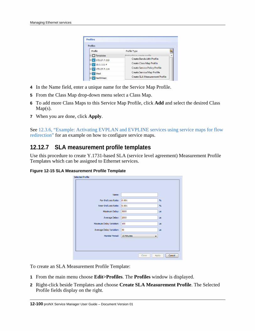
4 In the Name field, enter a unique name for the Service Map Profile.5 From the Class Map drop-down menu select a Class Map.6 To add more Class Maps to this Service Map Profile, click Add and select the desired Class
Map(s).7 When you are done, click Apply.
See 12.3.6, “Example: Activating EVPLAN and EVPLINE services using service maps for flowredirection” for an example on how to configure service maps.
12.12.7 SLA measurement profile templatesUse this procedure to create Y.1731-based SLA (service level agreement) Measurement ProfileTemplates which can be assigned to Ethernet services.
Figure 12-15 SLA Measurement Profile Template
To create an SLA Measurement Profile Template:
1 From the main menu choose Edit>Profiles. The Profiles window is displayed.2 Right-click beside Templates and choose Create SLA Measurement Profile. The Selected
Profile fields display on the right.
12-100 proNX Service Manager User Guide – Document Version 01
Managing Ethernet services
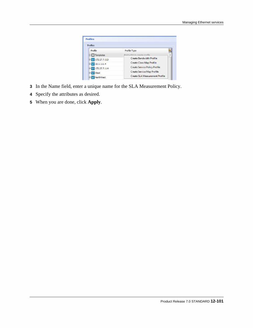
3 In the Name field, enter a unique name for the SLA Measurement Policy.4 Specify the attributes as desired.5 When you are done, click Apply.
Product Release 7.0 STANDARD 12-101
Managing Ethernet services

12-102 proNX Service Manager User Guide – Document Version 01
Managing Ethernet services
13.0 Managing pseudowire services
PSM can be used to manage pseudowire services on the BTI800 Series network elements.This section covers the following topics:• 13.1, “Visualizing a pseudowire service”• 13.2, “Service activation”• 13.3, “Modifying a pseudowire service”• 13.4, “Deleting a pseudowire service”
Product Release 7.0 STANDARD 13-1
C H A P T E R 1 3

13.1 Visualizing a pseudowire service
Use some or all of the techniques in this procedure to visualize a pseudowire service.
Step 1 In the Network tree view, select the desired pseudowire service.The selected pseudowire service topology view opens in the main map window.
Note If this is your first time visualizing this service, you will see the administratively-defined default layout if it exists. If a default layout does not exist for thisservice, then you will see the layout that PSM automatically generates. SeeStep 8.
Note If this is your second or subsequent time visualizing this service, you will see thelayout that existed when you last exited this service view.
Step 2 To see details on a network element, link, or port, hover over the network element, link,
or port. Step 3 To see the equipment on a network element, double-click the NE.
The equipment and connections are shown in a zoomed-in view. Step 4 To change the size of the service view:
a) Right-click the background and select Zoom In to increase the view sizeb) Right-click the background and select Zoom Out to decrease the view sizec) Right-click the background and select Reset Zoom to return the view size to its
original size Step 5 Right-click a network element and select Network Element to see the regular NE menu
options.
13-2 proNX Service Manager User Guide – Document Version 01
Managing pseudowire services

Step 6 To move elements in this view, drag elements to the desired location. Step 7 To move all of the ports and switches in the service, choose Select All and drag the
service within the window. Step 8 You can save the current layout as the default, or revert to the default, or revert to the
layout that PSM automatically generates.
a) To save the current layout as the default layout for this service, right-click thebackground and select Save Layout as Default.
Note You must have administrator privileges to execute this command.
Once the current layout is saved as the default, subsequent users who visualize thisservice will be able to see the current layout.
b) To reset the current layout to the default, right-click the background and select ResetLayout to Default.
c) To reset the current layout to the layout that PSM automatically generates, right-clickthe background and select Reset Layout.
Step 9 To save the service screen view as an image:
a) Select Save Service Image.The Save Service Image dialog appears.
b) Navigate to the desired folder and enter the filename.The default file format is png. To save the file in jpg format, enter .jpg at the end ofthe filename.
c) Click Save. Step 10 To select all NEs in the service, click Select Network Elements.
This brings you back to the main Topology Map view and shows all NEs in the serviceselected.
Product Release 7.0 STANDARD 13-3
Managing pseudowire services

13.2 Service activation
PSM supports the Metro Ethernet Forum (MEF) paradigm for activating T1/E1 TDM(pseudowire) services in a BTI800 Series network. Service activation is performed by firstcreating a regular Ethernet service and then creating a pseudowire service that uses that Ethernetservice.Figure 13-1 shows the component model for a BTI800 Series switch with a T1/E1 card residingin slot 1 and an OC3/STM1 card residing in slot 2.
Figure 13-1 BTI800 Series component model
Each card consists of a set of TDM and logical pseudowire interfaces. The pseudowire interfacesare logically connected to the UNI, and are distinguishable from each other through differentCVLANs. Each card is automatically associated with its own UNI, with the UNI in logical slot 2port 1 (2/1) associated with the card in physical slot 1, and the UNI in logical slot 3 port 1 (3/1)associated with the card in physical slot 2. These associations are hardcoded and cannot bechanged.The incoming bitstream on the TDM interface is processed on the card, encapsulated inside anEthernet frame (with a destination MAC address of the remote TDM card), and passed to thelocal UNI. From there, the TDM traffic is transported across the network as regular Ethernettraffic.
Note When configuring the underlying Ethernet service, you should take intoconsideration the delay variation requirements for a TDM circuit.
13-4 proNX Service Manager User Guide – Document Version 01
Managing pseudowire services
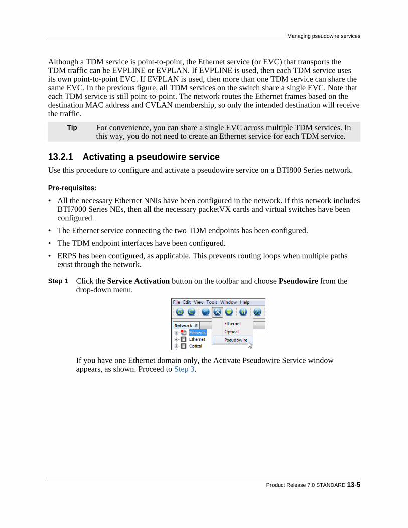
Although a TDM service is point-to-point, the Ethernet service (or EVC) that transports theTDM traffic can be EVPLINE or EVPLAN. If EVPLINE is used, then each TDM service usesits own point-to-point EVC. If EVPLAN is used, then more than one TDM service can share thesame EVC. In the previous figure, all TDM services on the switch share a single EVC. Note thateach TDM service is still point-to-point. The network routes the Ethernet frames based on thedestination MAC address and CVLAN membership, so only the intended destination will receivethe traffic.
Tip For convenience, you can share a single EVC across multiple TDM services. Inthis way, you do not need to create an Ethernet service for each TDM service.
13.2.1 Activating a pseudowire serviceUse this procedure to configure and activate a pseudowire service on a BTI800 Series network.
Pre-requisites:
• All the necessary Ethernet NNIs have been configured in the network. If this network includesBTI7000 Series NEs, then all the necessary packetVX cards and virtual switches have beenconfigured.
• The Ethernet service connecting the two TDM endpoints has been configured.• The TDM endpoint interfaces have been configured.• ERPS has been configured, as applicable. This prevents routing loops when multiple paths
exist through the network.
Step 1 Click the Service Activation button on the toolbar and choose Pseudowire from thedrop-down menu.
If you have one Ethernet domain only, the Activate Pseudowire Service windowappears, as shown. Proceed to Step 3.
Product Release 7.0 STANDARD 13-5
Managing pseudowire services
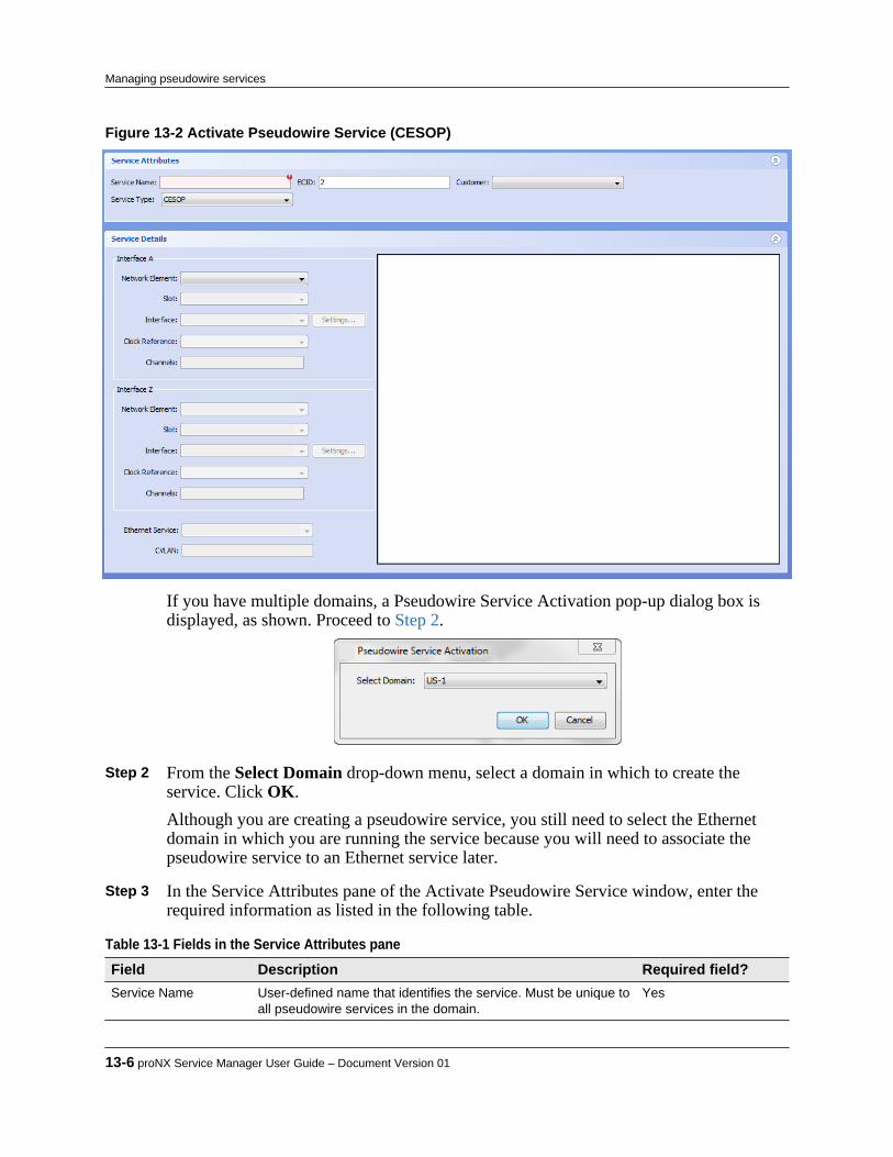
Figure 13-2 Activate Pseudowire Service (CESOP)
If you have multiple domains, a Pseudowire Service Activation pop-up dialog box isdisplayed, as shown. Proceed to Step 2.
Step 2 From the Select Domain drop-down menu, select a domain in which to create the
service. Click OK.Although you are creating a pseudowire service, you still need to select the Ethernetdomain in which you are running the service because you will need to associate thepseudowire service to an Ethernet service later.
Step 3 In the Service Attributes pane of the Activate Pseudowire Service window, enter the
required information as listed in the following table.
Table 13-1 Fields in the Service Attributes pane Field Description Required field?Service Name User-defined name that identifies the service. Must be unique to
all pseudowire services in the domain.Yes
13-6 proNX Service Manager User Guide – Document Version 01
Managing pseudowire services

Table 13-1 Fields in the Service Attributes pane (Continued) Field Description Required field?ECID Emulated circuit identifier. Must be unique to all pseudowire
services in the domain.
The auto-populated value can be overridden.
Yes
Customer User-defined. See 14.1, “Adding a customer”. Optional
Service Type The service type can be SATOP or CESOP. By default, theservice type is SATOP. When you select CESOP, additionalfields are available for configuration.
Yes
Step 4 Configure the Interface A endpoint.
a) In the Service Details pane, use the pulldown menu to select the Network Elementfor the Interface A endpoint.The pulldown menu is populated with all BTI800 Series nodes that have TDM cardsinserted.
b) Select the Slot and Interface from the pulldown menus.The pulldown menus are populated with all possible selections. Only the interfaces(or timeslots) not already in use can be selected. Interfaces or timeslots that are partof an existing service are greyed out.
Note Only ports that have been configured on the device as framed and enabled areselectable for a CESOP service.
Note Entries with an (M) designation can be configured as clock masters. Entrieswithout that designation can only be configured as slaves (or use internalclocking).
c) Select the Clock Reference.d) For CESOP, specify the Channels that make up the service.
You can specify a single channel (e.g. 5), a range of contiguous channels (e.g. 5-20),non-contiguous channels (e.g. 5,9), or a mix (e.g. 3,5-20). For T1, the availablechannels are 1 to 24. For E1, the available channels are 1 to 31. A channel cannotbelong to more than one service.
Note If the Clock Reference is set to Adaptive Master, then you must select one,two, four, or eight channels.
Note Channelized services can only be configured for T1/E1 cards.
e) Configure the TDM and physical interface settings (optional).Click on the Settings tab and set the TDM and physical interface (T1/E1 card only)attributes by clicking in the appropriate box.
Product Release 7.0 STANDARD 13-7
Managing pseudowire services

Table 13-2 TDM attributes Attribute Description Range DefaultCustomer VLANPriority
This specifies the priority to assign to the service. 0 to 7 6
PDV (Jitter Buffer) This specifies the size of the jitter buffer in microseconds. 2000 to 32000 5000
Payload Size This specifies the payload size of the packetizedbitstream in bytes. Both endpoints must have the samepayload size.
SATOP: 192,384, 576, 768,960
CESOP:Depends on thenumber ofchannels. SeeTable 13-4.
SATOP: 192
CESOP: None.
Table 13-3 Physical interface attributes (T1/E1 card only) Attribute Description Range DefaultLine Build Out This specifies the line build out (in feet) for the interface. 0 to 133, 134 to
266, 267 to 399,400 to 533, 534to 655 feet
0 to 133
Line Code This specifies the line coding for the interface. AMI or B8ZS(T1) or HDB3 (E1)
B8ZS (T1)
HDB3 (E1)
Table 13-4 CESOP payload sizes Number of channels Allowed payload sizes1 64
2 64,96,128,160,192,224,256
3 96,120,144,168,192,216
4 64,96,128,160,192,224,256
5 40,80,120,160,200,240,280,320
6 48,96,144,192,240,288,336
7 56,112,168,224,280,336
8 64,128,192,256,320
9 72,144,216,288
10 80,160,240,320
11 88,176,264,352
12 96,192,288
13 104,208,312
14 112,224,336
15 120,240
16 128,256
17 136,272
13-8 proNX Service Manager User Guide – Document Version 01
Managing pseudowire services
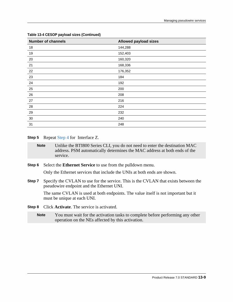
Table 13-4 CESOP payload sizes (Continued) Number of channels Allowed payload sizes18 144,288
19 152,403
20 160,320
21 168,336
22 176,352
23 184
24 192
25 200
26 208
27 216
28 224
29 232
30 240
31 248
Step 5 Repeat Step 4 for Interface Z.
Note Unlike the BTI800 Series CLI, you do not need to enter the destination MACaddress. PSM automatically determines the MAC address at both ends of theservice.
Step 6 Select the Ethernet Service to use from the pulldown menu.
Only the Ethernet services that include the UNIs at both ends are shown. Step 7 Specify the CVLAN to use for the service. This is the CVLAN that exists between the
pseudowire endpoint and the Ethernet UNI.The same CVLAN is used at both endpoints. The value itself is not important but itmust be unique at each UNI.
Step 8 Click Activate. The service is activated.
Note You must wait for the activation tasks to complete before performing any otheroperation on the NEs affected by this activation.
Product Release 7.0 STANDARD 13-9
Managing pseudowire services

13.3 Modifying a pseudowire service
Caution Modifying a service may affect the service or the data traffic running on theservice.
A stranded or semi-stranded service cannot be modified. A stranded or semi-stranded servicerefers to a service that has incomplete configuration that results in the absence of end-to-endconnectivity.
Step 1 In the Network tree view, expand the Pseudowire branch and double-click the serviceyou want to modify.The selected service appears in the main panel.
Step 2 To modify the customer associated with this service, select a different customer in the
Customer pulldown menu in the Service Attributes pane. Step 3 To modify the TDM or physical interface settings, select Settings... for Interface A or
Interface B as desired. Step 4 Make changes to the Customer VLAN Priority, the PDV (Jitter Buffer), the Payload
Size, and/or the physical interface attributes and click OK. Step 5 After making all your changes, click Apply.
13-10 proNX Service Manager User Guide – Document Version 01
Managing pseudowire services

13.4 Deleting a pseudowire service
Step 1 To delete a service, right-click on the service in the Network tree view and choose Delete.A dialog opens asking for confirmation.
Step 2 Click OK.
The service is deleted, and is subsequently removed from the Network tree view thenext time the node updates the proNX Service Manager.
Product Release 7.0 STANDARD 13-11
Managing pseudowire services

13-12 proNX Service Manager User Guide – Document Version 01
Managing pseudowire services

14.0 Managing customers
The proNX Service Manager allows you to add, modify and delete data about your customers.Customer data includes a company name, company reference, a list of employees specifying whois the primary and maintenance contact, and a notes section.Customers can be associated with services during service activation. When this association ismade, you will be able to see which services belong to which customers, and which alarms affectwhich customers.
Note Customer data and service association are part of the replicated data set whenrunning with multiple servers. For more information on replicated data, see1.3.2, “Running multiple servers with server replication”.
This section covers the following topics:• 14.1, “Adding a customer”• 14.2, “Modifying a customer”• 14.3, “Deleting a customer”
Product Release 7.0 STANDARD 14-1
C H A P T E R 1 4

14.1 Adding a customer
Step 1 To add a customer, click the Add Customer icon in the toolbar as shown below.
You can also right-click Customers in the Network tree and choose Add Customer asshown below.
The Customer screen displays.
Step 2 In the Company Name field (required), enter a unique name for the customer. Step 3 In the Company Reference field (optional), enter additional customer identification
information. Step 4 In the Employees table, click Add.
The Add Employee window displays. Enter a Name, Email and Telephone number, thenclick OK.
14-2 proNX Service Manager User Guide – Document Version 01
Managing customers

Note Entering data in the Employee Details fields is optional; however, it isrecommended that at least one field be completed.
Step 5 To edit employee details, select an employee from the Employees window and click
Edit. The Edit Employee window displays where you can change data. Step 6 To delete an employee record, select an employee from the Employees window and
click Delete. You are prompted to confirm the deletion. Step 7 You can also designate employees listed in the Employees window to be a Primary
Contact or a Maintenance Contact, and add text in the Notes fields:• In the Primary Contact field, choose an employee from the drop-down, or select
<none>• In the Maintenance Contact field, choose an employee from the drop-down, or select
<none>• In the Notes field, enter any additional text.
Step 8 Click Save.
Product Release 7.0 STANDARD 14-3
Managing customers
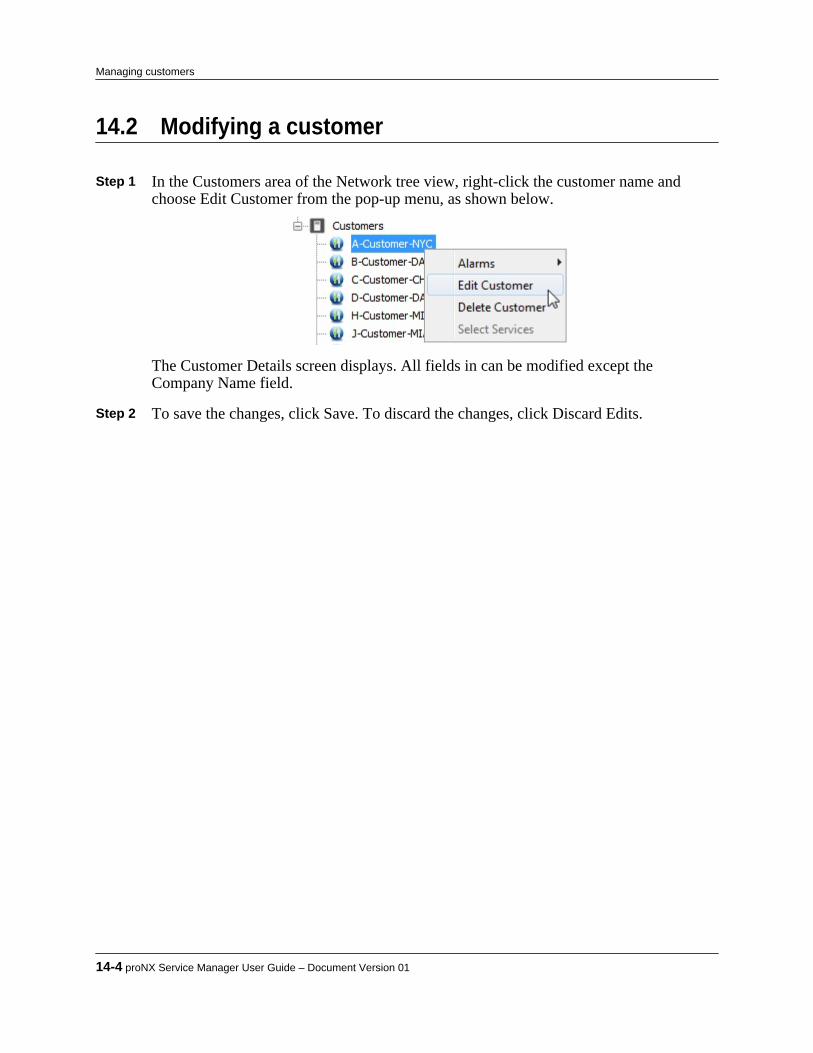
14.2 Modifying a customer
Step 1 In the Customers area of the Network tree view, right-click the customer name andchoose Edit Customer from the pop-up menu, as shown below.
The Customer Details screen displays. All fields in can be modified except theCompany Name field.
Step 2 To save the changes, click Save. To discard the changes, click Discard Edits.
14-4 proNX Service Manager User Guide – Document Version 01
Managing customers

14.3 Deleting a customer
Step 1 In the Customers area of the Network tree view, right-click the customer name andchoose Delete Customer.A confirmation dialog is displayed.
Step 2 Click OK to delete the customer or Cancel to cancel.
Product Release 7.0 STANDARD 14-5
Managing customers

14-6 proNX Service Manager User Guide – Document Version 01
Managing customers
15.0 Managing network element alarms
PSM supports the display and processing of alarms for the following:• BTI7800 Series network elements• BTI7000 Series network elements• BTI800 Series network elements• BTI700 Series network elementsThis section covers the following topics:• 15.1, “Alarm visualization”• 15.2, “Acknowledging, emailing, and clearing alarms”• 15.3, “Assigning an alarm to a user”• 15.4, “Viewing historical alarms”• 15.5, “Viewing alarms through an RSS feed”• 15.6, “Sending traps on the northbound interface”
Product Release 7.0 STANDARD 15-1
C H A P T E R 1 5

15.1 Alarm visualization
The PSM Client displays alarms reported by discovered network elements in the Alarms panel,and provides an alarms summary at the bottom of the window. Alarms are displayed in tableformat as shown in the figure below. When you hover the cursor over an alarm description, atool tip appears and provides more information on the alarm.
Figure 15-1 Alarm Table View
Note Alarm times from each NE are translated into the current PSM server time, sovariances in timezones are handled automatically when being displayed in thetable. It is highly recommended that PSM and all NEs in the network use NTPservers for obtaining the time in order to avoid time discrepancies.
Alarms in the alarms table and in the alarms summary are color-coded by severity:• Red - critical alarms• Amber - major alarms• Yellow - minor alarms• Grey - acknowledged alarms• Green - cleared alarmsAn alarm remains in the table until it is cleared, at which time the alarm is removed from thetable, either immediately or after a configurable delay. If no delay is configured, the alarm justdisappears from the table, with no indication that the alarm has been cleared, save for itsabsence. If a delay is configured, the alarm changes color to green to signify that it has beencleared, and remains in the table for the delay period. At the end of this period, the alarm isremoved from the table. For details on how to configure this option, see 9.3.1, “ Setting alarmdisplay options”. Regardless of which option is configured, when an alarm is cleared, the clearedalarms counters are incremented in the alarms summary bar at the bottom of the window. Forinformation on the alarms summary bar, see 15.1.4, “Understanding the alarms summary bar”Alarms are automatically retrieved from NEs and added to the alarms table upon initial nodediscovery and are kept synchronized using SNMP traps. When a device is discovered, the PSMserver registers itself as a trap listener with the network element, which enables the application toreceive notification of new or cleared alarms.
Note If BTI7000 Series network elements are running with software that pre-datesRelease 8.1.1, registration must be done manually using a different (TL1)interface. Refer to the BTI7000 Series documentation for details.
15-2 proNX Service Manager User Guide – Document Version 01
Managing network element alarms
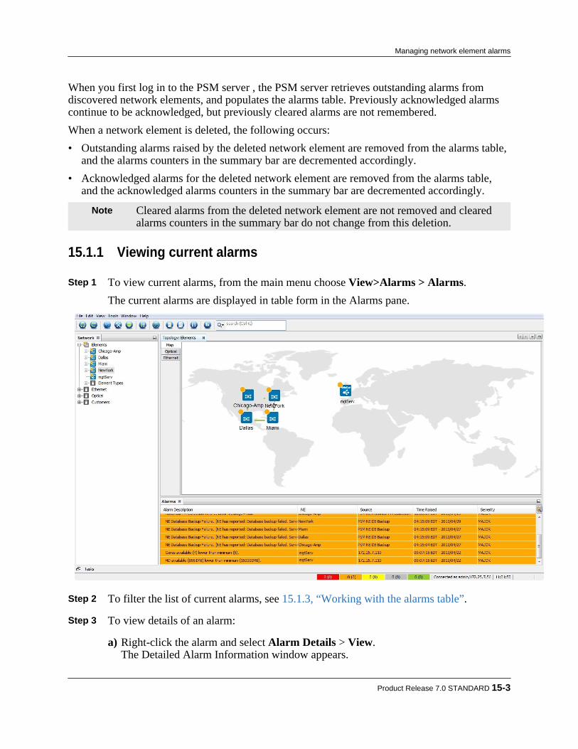
When you first log in to the PSM server , the PSM server retrieves outstanding alarms fromdiscovered network elements, and populates the alarms table. Previously acknowledged alarmscontinue to be acknowledged, but previously cleared alarms are not remembered.When a network element is deleted, the following occurs:• Outstanding alarms raised by the deleted network element are removed from the alarms table,
and the alarms counters in the summary bar are decremented accordingly.• Acknowledged alarms for the deleted network element are removed from the alarms table,
and the acknowledged alarms counters in the summary bar are decremented accordingly.
Note Cleared alarms from the deleted network element are not removed and clearedalarms counters in the summary bar do not change from this deletion.
15.1.1 Viewing current alarms
Step 1 To view current alarms, from the main menu choose View>Alarms > Alarms.The current alarms are displayed in table form in the Alarms pane.
Step 2 To filter the list of current alarms, see 15.1.3, “Working with the alarms table”. Step 3 To view details of an alarm:
a) Right-click the alarm and select Alarm Details > View.The Detailed Alarm Information window appears.
Product Release 7.0 STANDARD 15-3
Managing network element alarms
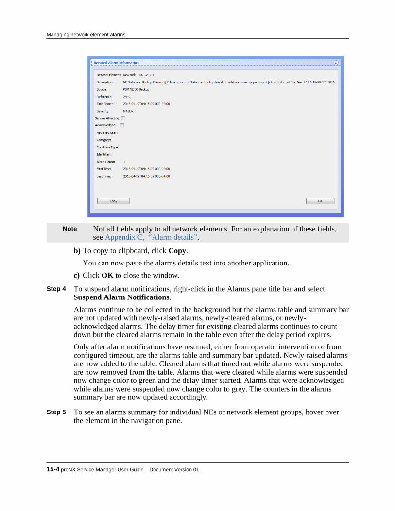
Note Not all fields apply to all network elements. For an explanation of these fields,see Appendix C, “Alarm details”.
b) To copy to clipboard, click Copy.You can now paste the alarms details text into another application.
c) Click OK to close the window. Step 4 To suspend alarm notifications, right-click in the Alarms pane title bar and select
Suspend Alarm Notifications.Alarms continue to be collected in the background but the alarms table and summary barare not updated with newly-raised alarms, newly-cleared alarms, or newly-acknowledged alarms. The delay timer for existing cleared alarms continues to countdown but the cleared alarms remain in the table even after the delay period expires.Only after alarm notifications have resumed, either from operator intervention or fromconfigured timeout, are the alarms table and summary bar updated. Newly-raised alarmsare now added to the table. Cleared alarms that timed out while alarms were suspendedare now removed from the table. Alarms that were cleared while alarms were suspendednow change color to green and the delay timer started. Alarms that were acknowledgedwhile alarms were suspended now change color to grey. The counters in the alarmssummary bar are now updated accordingly.
Step 5 To see an alarms summary for individual NEs or network element groups, hover over
the element in the navigation pane.
15-4 proNX Service Manager User Guide – Document Version 01
Managing network element alarms

15.1.2 Understanding alarm timestampsThe timestamp of an alarm may undergo multiple time zone adjustments by the time the PSMClient displays the alarm to the user. The network element that raises the alarm, the PSM Serverthat receives the alarm, and the PSM Client that displays the alarm can all be in different timezones. In order to be able to correlate alarms, it is important to understand how PSM performsalarm timestamping.
How the PSM Server timestamps the alarms
When an alarm condition occurs, the network element sends a trap to the PSM Server. The servertimestamps the alarm based on when the server receives the trap. This timestamp is relative tothe server's local time zone. Some network elements include a network element timestamp in thetrap. In this situation, the PSM Server uses the network element timestamp (converted to thelocal server time zone) instead of the time when the server receives the trap.
Note Some network elements may lose the original alarm timestamp when the networkelement is rebooted. In this situation, the alarm timestamp shown using thenetwork element's CLI may be different from the timestamp shown on the PSMServer. The PSM Server continues to use the original alarm timestamp.
How the PSM Server timestamps the clears
When an alarm condition is cleared, the network element sends a clear trap to the PSM Server.The server timestamps the clear based on when the server receives the clear trap. This timestampis relative to the server's local time zone. Network elements do not include a network elementtimestamp in the clear trap, so the PSM Server always uses the time when the clear trap isreceived.
How the PSM Client displays timestamps
The PSM Client converts the timestamp reported by the PSM Server to the client's local timezone. All timestamps displayed by the client are therefore local to the client's time zone.
Product Release 7.0 STANDARD 15-5
Managing network element alarms

15.1.3 Working with the alarms tableThe PSM client displays alarms in table format so you can sort alarms by column, and filteralarms by type.
Sorting the alarms table
The alarms table can be sorted in the following ways:• To sort the Alarms table by a column, click the column title.• To change the order (ascending or descending) of a column, click the column heading until the
arrow shows ascending or descending order as desired.• To hide a column, right-click any column title and uncheck the column name you want to hide
in the drop-down menu. The Network Element/Alarm column cannot be hidden.• To show or hide columns in the alarms table, right-click the Alarms Description column header
and from the drop-down menu select the columns that you want to show or hide.
Filtering the alarms table
The alarms table behaves as follows:• If there is no alarm filtering applied, the alarms window title is displayed as "Alarms".• If a filter is applied, the title changes to indicate the applied filter, for example "Alarms (Devices
- 10.1.103.6)".• If the filter description is too long to display completely, the title changes to "Alarms (filtered)".• By hovering over the alarms table title bar, a tool tip is displayed listing the applied filter
attributes.
• Each time a new entity or filter is chosen, the previous filtering is cleared and the alarms tabledisplays the alarms that pertain to the chosen criteria.
The alarms table can be filtered in the following ways:
15-6 proNX Service Manager User Guide – Document Version 01
Managing network element alarms

• From the main menu, choose Tool>Options. Click Display, and then click Alarms andconfigure the alarm display options as desired.
See 9.3.1, “ Setting alarm display options” for an explanation of these fields• To filter the table to show only a particular set of alarms, right-click a cell in the column of the
alarms table that has the data you want to filter with, and choose the filter option Show onlyrows where to filter out (hide) all other entries from the table. In the following screen, the filterchosen is to show only XFP failure alarms.
• To filter the table to show alarms that pertain only to a particular NE, service, or group, in thetree view right-click the entity and choose Alarms>Filter.
Product Release 7.0 STANDARD 15-7
Managing network element alarms
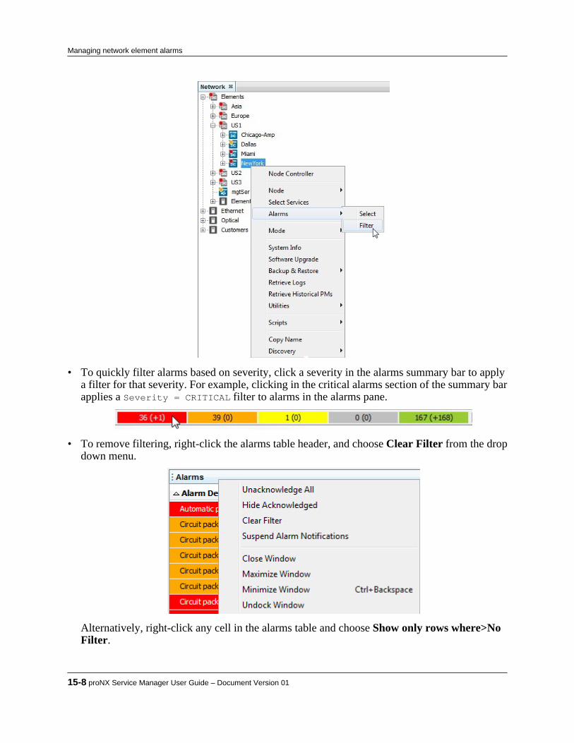
• To quickly filter alarms based on severity, click a severity in the alarms summary bar to applya filter for that severity. For example, clicking in the critical alarms section of the summary barapplies a Severity = CRITICAL filter to alarms in the alarms pane.
• To remove filtering, right-click the alarms table header, and choose Clear Filter from the dropdown menu.
Alternatively, right-click any cell in the alarms table and choose Show only rows where>NoFilter.
15-8 proNX Service Manager User Guide – Document Version 01
Managing network element alarms
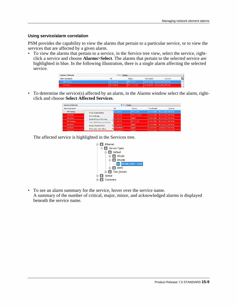
Using service/alarm correlation
PSM provides the capability to view the alarms that pertain to a particular service, or to view theservices that are affected by a given alarm.• To view the alarms that pertain to a service, in the Service tree view, select the service, right-
click a service and choose Alarms>Select. The alarms that pertain to the selected service arehighlighted in blue. In the following illustration, there is a single alarm affecting the selectedservice.
• To determine the service(s) affected by an alarm, in the Alarms window select the alarm, right-click and choose Select Affected Services.
The affected service is highlighted in the Services tree.
• To see an alarm summary for the service, hover over the service name.A summary of the number of critical, major, minor, and acknowledged alarms is displayedbeneath the service name.
Product Release 7.0 STANDARD 15-9
Managing network element alarms
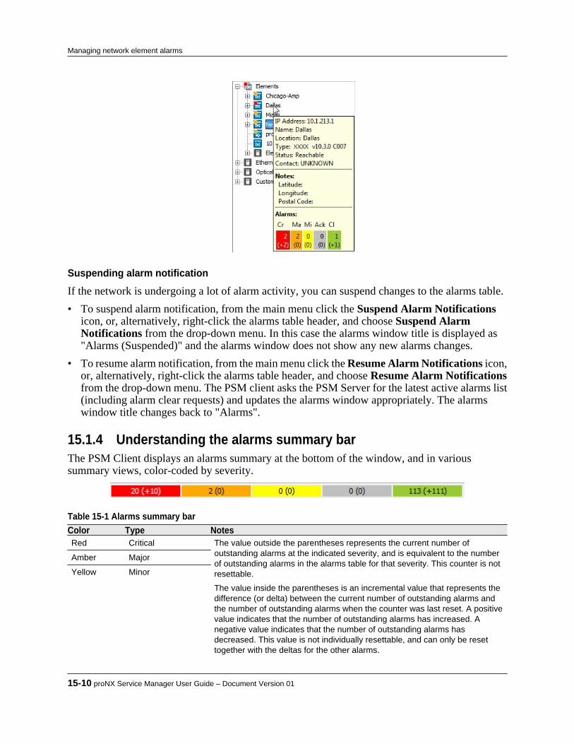
Suspending alarm notification
If the network is undergoing a lot of alarm activity, you can suspend changes to the alarms table.• To suspend alarm notification, from the main menu click the Suspend Alarm Notifications
icon, or, alternatively, right-click the alarms table header, and choose Suspend AlarmNotifications from the drop-down menu. In this case the alarms window title is displayed as"Alarms (Suspended)" and the alarms window does not show any new alarms changes.
• To resume alarm notification, from the main menu click the Resume Alarm Notifications icon,or, alternatively, right-click the alarms table header, and choose Resume Alarm Notificationsfrom the drop-down menu. The PSM client asks the PSM Server for the latest active alarms list(including alarm clear requests) and updates the alarms window appropriately. The alarmswindow title changes back to "Alarms".
15.1.4 Understanding the alarms summary barThe PSM Client displays an alarms summary at the bottom of the window, and in varioussummary views, color-coded by severity.
Table 15-1 Alarms summary bar Color Type NotesRed Critical The value outside the parentheses represents the current number of
outstanding alarms at the indicated severity, and is equivalent to the numberof outstanding alarms in the alarms table for that severity. This counter is notresettable.
The value inside the parentheses is an incremental value that represents thedifference (or delta) between the current number of outstanding alarms andthe number of outstanding alarms when the counter was last reset. A positivevalue indicates that the number of outstanding alarms has increased. Anegative value indicates that the number of outstanding alarms hasdecreased. This value is not individually resettable, and can only be resettogether with the deltas for the other alarms.
Amber Major
Yellow Minor
15-10 proNX Service Manager User Guide – Document Version 01
Managing network element alarms
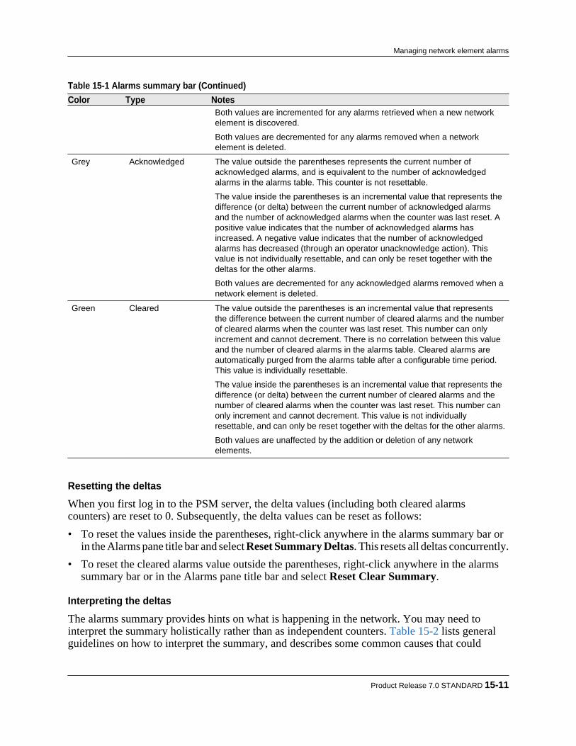
Table 15-1 Alarms summary bar (Continued) Color Type Notes
Both values are incremented for any alarms retrieved when a new networkelement is discovered.
Both values are decremented for any alarms removed when a networkelement is deleted.
Grey Acknowledged The value outside the parentheses represents the current number ofacknowledged alarms, and is equivalent to the number of acknowledgedalarms in the alarms table. This counter is not resettable.
The value inside the parentheses is an incremental value that represents thedifference (or delta) between the current number of acknowledged alarmsand the number of acknowledged alarms when the counter was last reset. Apositive value indicates that the number of acknowledged alarms hasincreased. A negative value indicates that the number of acknowledgedalarms has decreased (through an operator unacknowledge action). Thisvalue is not individually resettable, and can only be reset together with thedeltas for the other alarms.
Both values are decremented for any acknowledged alarms removed when anetwork element is deleted.
Green Cleared The value outside the parentheses is an incremental value that representsthe difference between the current number of cleared alarms and the numberof cleared alarms when the counter was last reset. This number can onlyincrement and cannot decrement. There is no correlation between this valueand the number of cleared alarms in the alarms table. Cleared alarms areautomatically purged from the alarms table after a configurable time period.This value is individually resettable.
The value inside the parentheses is an incremental value that represents thedifference (or delta) between the current number of cleared alarms and thenumber of cleared alarms when the counter was last reset. This number canonly increment and cannot decrement. This value is not individuallyresettable, and can only be reset together with the deltas for the other alarms.
Both values are unaffected by the addition or deletion of any networkelements.
Resetting the deltas
When you first log in to the PSM server, the delta values (including both cleared alarmscounters) are reset to 0. Subsequently, the delta values can be reset as follows:• To reset the values inside the parentheses, right-click anywhere in the alarms summary bar or
in the Alarms pane title bar and select Reset Summary Deltas. This resets all deltas concurrently.• To reset the cleared alarms value outside the parentheses, right-click anywhere in the alarms
summary bar or in the Alarms pane title bar and select Reset Clear Summary.
Interpreting the deltas
The alarms summary provides hints on what is happening in the network. You may need tointerpret the summary holistically rather than as independent counters. Table 15-2 lists generalguidelines on how to interpret the summary, and describes some common causes that could
Product Release 7.0 STANDARD 15-11
Managing network element alarms

precipitate the observed situations. Because other causes are possible, you should investigatefurther to confirm what is indeed transpiring.
Table 15-2 Interpreting the alarms summary Observed situation May indicate ...High critical/major/minor alarms delta, highcleared alarms delta
Flapping port or frequent intermittent failure and restoration, togetherwith a failure of a shared component, network element, or link.
High critical/major/minor alarms delta, lowcleared alarms delta
Failure of a shared component, network element, or link.
Low critical/major/minor alarms delta, highcleared alarms delta
Flapping port or frequent intermittent failure and restoration.
Low critical/major/minor alarms delta, lowcleared alarms delta
No change.
High (negative) critical/major/minor alarmsdelta, high cleared alarms delta
Restoration of a shared component, network element, or link, and apossible flapping port or frequent intermittent failure and restoration.
Filtering based on alarm severity
The alarms summary bar provides a quick way to filter alarms based on alarm severity. Simplyclick on a severity to apply a filter for that severity. For example, clicking in the critical alarmssection of the summary bar applies a Severity = CRITICAL filter to alarms in the alarms pane.
15-12 proNX Service Manager User Guide – Document Version 01
Managing network element alarms

15.2 Acknowledging, emailing, and clearing alarms
Step 1 To acknowledge an alarm, select the alarm from the table, right-click and selectAcknowledge.The alarm is set to "Acknowledged" and turns grey, or, if "Hide Acknowledged" hasbeen selected, is removed from the list.
Note Alarm acknowledgements are part of the replicated data set when running withmultiple servers. For more information on replicated data, see 1.3.2, “Runningmultiple servers with server replication”.
Step 2 To hide acknowledged alarms, right-click on the Alarms tab and choose Hide
Acknowledged. All alarms that are set to "Acknowledged" are removed from thealarms list. The alarms remain in the server and are available to other clients.
Step 3 To show acknowledged alarms, right-click on the Alarms tab and choose Show
Acknowledged. Acknowledged alarms are displayed and are grey in color. Step 4 To unacknowledge all alarms on the client, right-click the Alarms view heading and
select Unacknowledge All. Step 5 To email details about one or more alarms, select one or more alarms (by holding the
Shift or Ctrl key on the keyboard) from the list, right-click and select Alarm Details > Email. A new email is created in your local email application with the details of all theselected alarms populated in the body of the email.
Step 6 You cannot clear an NE-generated alarm. You can only clear alarms that have been
generated by the PSM. To manually clear a PSM-generated alarm, right-click on thealarm and choose Clear NMS Generated Alarm. Once cleared, you cannot restore analarm.
Product Release 7.0 STANDARD 15-13
Managing network element alarms

15.3 Assigning an alarm to a user
By assigning an alarm to a user, alarms can be filtered by user name.
Step 1 In the alarm window, right-click on an alarm and choose Assign Alarm to User andchoose the desired user from the list.
Note Alarm assignments are part of the replicated data set when running with multipleservers. For more information on replicated data, see 1.3.2, “Running multipleservers with server replication”.
Step 2 To filter the list of current alarms by assigned user, the "User Assigned" column must be
displayed. Do this by right-clicking beside one of the column headers to display thedrop-down menu and ensure that the "User Assigned:..." attribute is checked.
For more information on filtering options, see 15.1.3, “Working with the alarms table”.
15-14 proNX Service Manager User Guide – Document Version 01
Managing network element alarms

15.4 Viewing historical alarms
Use this procedure to view the historical alarms table.Historical Alarms provides you with a view of all resolved and unresolved alarms. To help youmanage this list, PSM allows you to apply filters to narrow down the view to the desired subset.PSM builds the historical alarms list from active alarms as they are raised (and when NEs arediscovered).Additionally, for the BTI7000 Series NEs, PSM reads the Alarm Logs table available on the NE,and supplements the historical alarms list with any alarms that are found in that table but missingfrom PSM's historical alarms list. The PSM server reads that table during NE discovery, andperiodically thereafter to ensure the lists are synchronized. The timestamps for the added alarmsare based on the timestamps retrieved from the network element, adjusted for the local PSMserver's time zone.For the other types of NEs (including the BTI7800 Series NEs), PSM builds the historical alarmslist based solely on alarms it sees. Consequently, for those NEs, historical alarms do not containalarms that were raised and cleared prior to PSM managing the device.
Note In some cases, you may see duplicate alarms in the historical alarms table. If youdelete and then rediscover a network element, PSM may insert the same alarminto the table as it reprocesses the outstanding alarms for the rediscovered NE.
To access Historical Alarms:
Step 1 From the main menu choose View>Alarms > Historical Alarms.
Step 2 To see the full alarm list, select Perform Query with no filters chosen.
Product Release 7.0 STANDARD 15-15
Managing network element alarms

Step 3 To filter historical alarms, select the desired filtering options from the Filter and Sorting
Options dialog. You can order results by a specific field and with a set number of alarmsdisplayed per page specified.
15-16 proNX Service Manager User Guide – Document Version 01
Managing network element alarms

15.5 Viewing alarms through an RSS feed
The proNX Service Manager Client allows the user to view active alarms on their web browserthrough an RSS feed. To activate this way of viewing alarms, type the following URL into yourweb browser:https:<IP address of PSM server host>:<port>/AlarmsFeedYou can also filter the alarms sent to your browser by adding an alarm severity to the URL, suchas:https:<IP address of PSM server host>:<port>/AlarmsFeed/majorThe port number is specified by the resources.address.port attribute in the common.properties file.The screen below shows a list of active alarms displayed in a web browser.
Product Release 7.0 STANDARD 15-17
Managing network element alarms
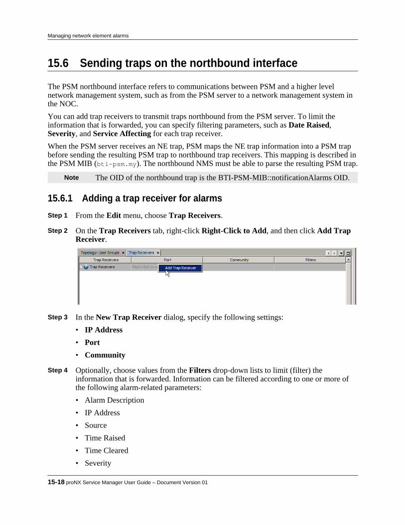
15.6 Sending traps on the northbound interface
The PSM northbound interface refers to communications between PSM and a higher levelnetwork management system, such as from the PSM server to a network management system inthe NOC.You can add trap receivers to transmit traps northbound from the PSM server. To limit theinformation that is forwarded, you can specify filtering parameters, such as Date Raised,Severity, and Service Affecting for each trap receiver.When the PSM server receives an NE trap, PSM maps the NE trap information into a PSM trapbefore sending the resulting PSM trap to northbound trap receivers. This mapping is described inthe PSM MIB (bti-psm.my). The northbound NMS must be able to parse the resulting PSM trap.
Note The OID of the northbound trap is the BTI-PSM-MIB::notificationAlarms OID.
15.6.1 Adding a trap receiver for alarmsStep 1 From the Edit menu, choose Trap Receivers. Step 2 On the Trap Receivers tab, right-click Right-Click to Add, and then click Add Trap
Receiver.
Step 3 In the New Trap Receiver dialog, specify the following settings:
• IP Address• Port• Community
Step 4 Optionally, choose values from the Filters drop-down lists to limit (filter) the
information that is forwarded. Information can be filtered according to one or more ofthe following alarm-related parameters:• Alarm Description• IP Address• Source• Time Raised• Time Cleared• Severity
15-18 proNX Service Manager User Guide – Document Version 01
Managing network element alarms
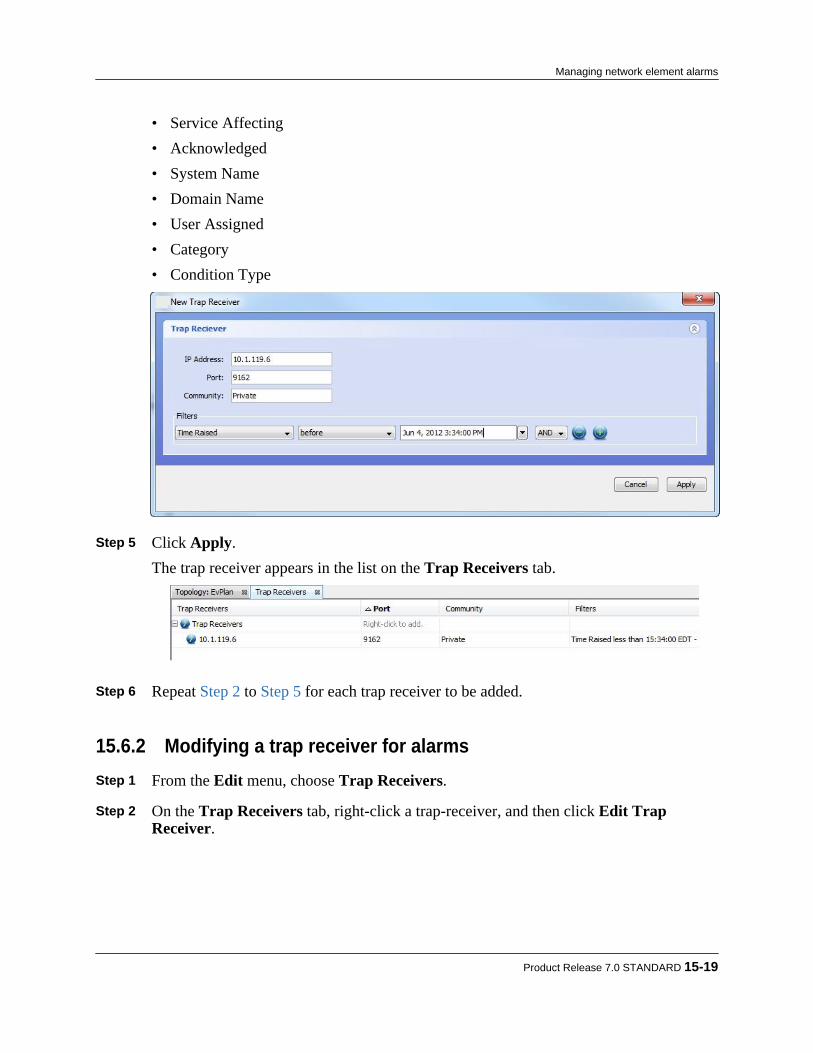
• Service Affecting• Acknowledged• System Name• Domain Name• User Assigned• Category• Condition Type
Step 5 Click Apply.
The trap receiver appears in the list on the Trap Receivers tab.
Step 6 Repeat Step 2 to Step 5 for each trap receiver to be added.
15.6.2 Modifying a trap receiver for alarmsStep 1 From the Edit menu, choose Trap Receivers. Step 2 On the Trap Receivers tab, right-click a trap-receiver, and then click Edit Trap
Receiver.
Product Release 7.0 STANDARD 15-19
Managing network element alarms
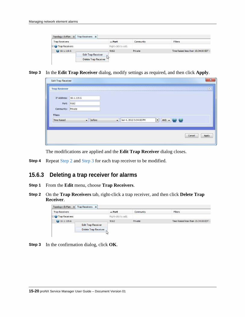
Step 3 In the Edit Trap Receiver dialog, modify settings as required, and then click Apply.
The modifications are applied and the Edit Trap Receiver dialog closes. Step 4 Repeat Step 2 and Step 3 for each trap receiver to be modified.
15.6.3 Deleting a trap receiver for alarmsStep 1 From the Edit menu, choose Trap Receivers. Step 2 On the Trap Receivers tab, right-click a trap receiver, and then click Delete Trap
Receiver.
Step 3 In the confirmation dialog, click OK.
15-20 proNX Service Manager User Guide – Document Version 01
Managing network element alarms
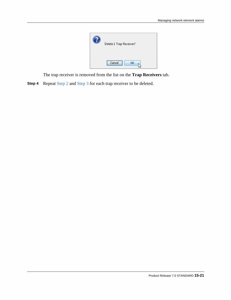
The trap receiver is removed from the list on the Trap Receivers tab. Step 4 Repeat Step 2 and Step 3 for each trap receiver to be deleted.
Product Release 7.0 STANDARD 15-21
Managing network element alarms

15-22 proNX Service Manager User Guide – Document Version 01
Managing network element alarms

16.0 Managing Network Element systemsoftware and FTP servers
proNX Service Manager provides features for managing operations relating to the systemsoftware of managed network elements, such as configuring (S)FTP servers, backing up andrestoring NE databases, and upgrading NE system software.This section covers the following topics:• 16.1, “Adding an FTP or SFTP server”• 16.2, “Modifying an FTP or SFTP server's configuration”• 16.3, “Deleting an FTP or SFTP server”• 16.4, “Manually backing up a network element configuration database”• 16.5, “Restoring a configuration database to a network element”• 16.6, “Upgrading system software for a network element”• 16.7, “Restoring a database to factory defaults on a BTI7800 network element”
Product Release 7.0 STANDARD 16-1
C H A P T E R 1 6
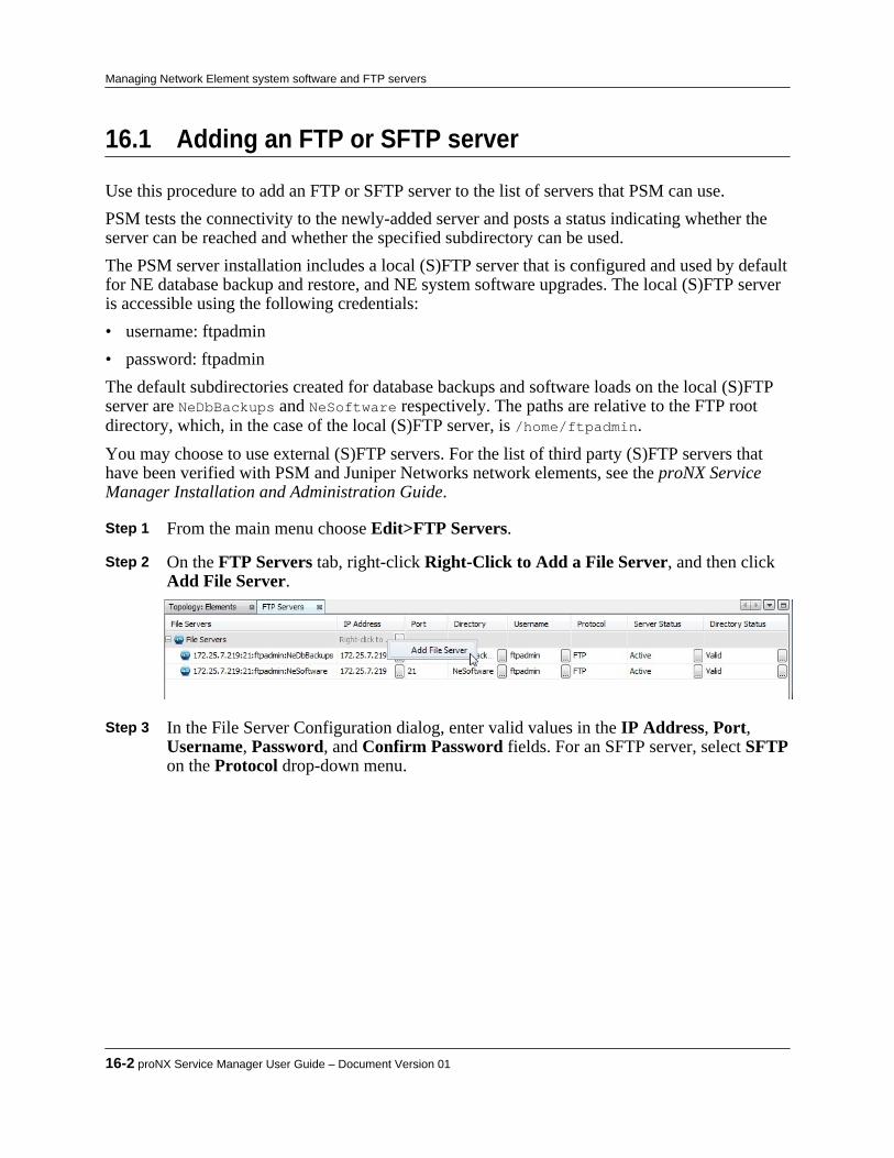
16.1 Adding an FTP or SFTP server
Use this procedure to add an FTP or SFTP server to the list of servers that PSM can use.PSM tests the connectivity to the newly-added server and posts a status indicating whether theserver can be reached and whether the specified subdirectory can be used.The PSM server installation includes a local (S)FTP server that is configured and used by defaultfor NE database backup and restore, and NE system software upgrades. The local (S)FTP serveris accessible using the following credentials:• username: ftpadmin• password: ftpadminThe default subdirectories created for database backups and software loads on the local (S)FTPserver are NeDbBackups and NeSoftware respectively. The paths are relative to the FTP rootdirectory, which, in the case of the local (S)FTP server, is /home/ftpadmin.You may choose to use external (S)FTP servers. For the list of third party (S)FTP servers thathave been verified with PSM and Juniper Networks network elements, see the proNX ServiceManager Installation and Administration Guide.
Step 1 From the main menu choose Edit>FTP Servers. Step 2 On the FTP Servers tab, right-click Right-Click to Add a File Server, and then click
Add File Server.
Step 3 In the File Server Configuration dialog, enter valid values in the IP Address, Port,
Username, Password, and Confirm Password fields. For an SFTP server, select SFTPon the Protocol drop-down menu.
16-2 proNX Service Manager User Guide – Document Version 01
Managing Network Element system software and FTP servers
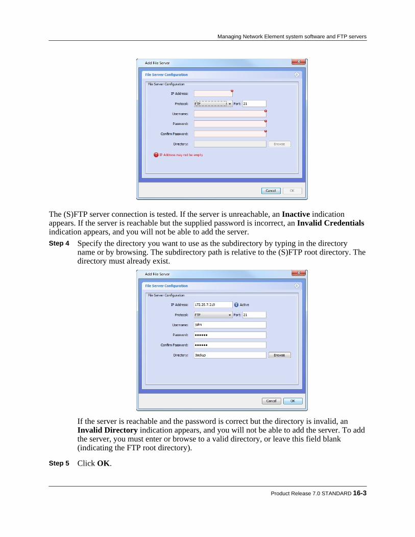
The (S)FTP server connection is tested. If the server is unreachable, an Inactive indicationappears. If the server is reachable but the supplied password is incorrect, an Invalid Credentialsindication appears, and you will not be able to add the server. Step 4 Specify the directory you want to use as the subdirectory by typing in the directory
name or by browsing. The subdirectory path is relative to the (S)FTP root directory. Thedirectory must already exist.
If the server is reachable and the password is correct but the directory is invalid, anInvalid Directory indication appears, and you will not be able to add the server. To addthe server, you must enter or browse to a valid directory, or leave this field blank(indicating the FTP root directory).
Step 5 Click OK.
Product Release 7.0 STANDARD 16-3
Managing Network Element system software and FTP servers

The (S)FTP server is added to the list on the FTP Servers tab. If there are no errorswhen configuring the server, the Server Status should be Active and the DirectoryStatus should be Valid.
Note You are allowed to add the server even if the server is unreachable. Step 6 Repeat Step 2 to Step 5 for each FTP server to be added.
16-4 proNX Service Manager User Guide – Document Version 01
Managing Network Element system software and FTP servers

16.2 Modifying an FTP or SFTP server's configuration
Step 1 From the main menu choose Edit>FTP Servers. Step 2 On the FTP Servers tab, right-click an FTP server, and then click Edit File Server.
Note The pre-installed server entries (<PSM server host>:ftpadmin:NeDbBackupsand <PSM server host>:ftpadmin:NeSoftware) cannot be edited. If you try toedit these entries, you will receive an error and the changes do not take effect.
Step 3 In the File Server Configuration dialog, modify settings as required, and then click
OK.
The modifications are applied and the File Server Configuration dialog closes. Step 4 Repeat Step 2 and Step 3 for each FTP server configuration to be modified.
Product Release 7.0 STANDARD 16-5
Managing Network Element system software and FTP servers

16.3 Deleting an FTP or SFTP server
Step 1 From the main menu choose Edit>FTP Servers. Step 2 On the FTP Servers tab, right-click an FTP server, and then click Delete File Server.
Note The pre-installed server entries (<PSM server host>:ftpadmin:NeDbBackupsand <PSM server host>:ftpadmin:NeSoftware) cannot be deleted. If you tryto delete these entries, you will receive an error and the deletion does not takeeffect.
Step 3 In the confirmation dialog, click OK.
The FTP server is removed from the list on the File Server Configuration tab. Step 4 Repeat Step 2 and Step 3 for each FTP server to be deleted.
16-6 proNX Service Manager User Guide – Document Version 01
Managing Network Element system software and FTP servers
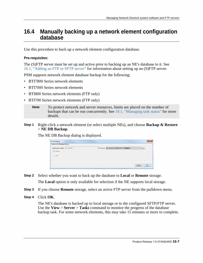
16.4 Manually backing up a network element configurationdatabase
Use this procedure to back up a network element configuration database.
Pre-requisites:
The (S)FTP server must be set up and active prior to backing up an NE's database to it. See16.1, “Adding an FTP or SFTP server” for information about setting up an (S)FTP server.PSM supports network element database backup for the following:• BTI7800 Series network elements• BTI7000 Series network elements• BTI800 Series network elements (FTP only)• BTI700 Series network elements (FTP only)
Note To protect network and server resources, limits are placed on the number ofbackups that can be run concurrently. See 19.1, “Managing task status” for moredetails.
Step 1 Right-click a network element (or select multiple NEs), and choose Backup & Restore> NE DB Backup.The NE DB Backup dialog is displayed.
Step 2 Select whether you want to back up the database to Local or Remote storage.
The Local option is only available for selection if the NE supports local storage. Step 3 If you choose Remote storage, select an active FTP server from the pulldown menu. Step 4 Click OK.
The NE's database is backed up to local storage or to the configured SFTP/FTP server.Use the View > Server > Tasks command to monitor the progress of the databasebackup task. For some network elements, this may take 15 minutes or more to complete.
Product Release 7.0 STANDARD 16-7
Managing Network Element system software and FTP servers

Note PSM-generated NE database backup related alarms are not automatically clearedonce the problem has been resolved. You must clear PSM-generated NE databasebackup alarms manually. To manually clear a PSM-generated alarm, right clickthe alarm and choose Clear NMS Generated Alarm. Once cleared, you cannotrestore an alarm.
16-8 proNX Service Manager User Guide – Document Version 01
Managing Network Element system software and FTP servers

16.5 Restoring a configuration database to a networkelement
Use this procedure to restore a configuration database to a network element.
Pre-requisites:
The (S)FTP server must be set up and active. See 16.1, “Adding an FTP or SFTP server” forinformation about setting up an (S)FTP server.PSM supports network element database restore for the following:• BTI7800 Series network elements• BTI7000 Series network elements• BTI800 Series network elements (FTP only)• BTI700 Series network elements (FTP only)
Note To protect network and server resources, limits are placed on the number ofrestores that can be run concurrently. See 19.1, “Managing task status” for moredetails.
Note For the BTI7000 Series network elements, PSM performs both the Load/Invokeand Commit phases. The NE cannot be viewed between the invoke and commitstages (to verify the data before committing the restore). To verify the databefore restoring, use the proNX 900 to perform each of the individual operations.
Step 1 Right-click a network element, and choose Backup & Restore > NE DB Restore.The NE DB Restore dialog is displayed.
Step 2 Select whether you want to restore the database from Local or Remote storage.
The Local option is only available for selection if the NE supports local storage. Step 3 If you choose Remote storage, select an active FTP server and subdirectory from the
pulldown menu and click Browse to navigate to and select the backup file from whichyou want to restore the database.
Product Release 7.0 STANDARD 16-9
Managing Network Element system software and FTP servers

Note You can only browse within the starting directory and its subdirectories. Thestarting directory is the directory you specified when adding the (S)FTP server.
The file you select appears in the Restore File field of the NE DB Restore dialog. Step 4 Click OK.
Use the View > Server > Tasks command to monitor the progress of the databaserestore task. For some network elements, this may take 15 minutes or more to complete.
Note PSM-generated NE database backup related alarms are not automatically clearedonce the problem has been resolved. You must clear PSM-generated NE databasebackup alarms manually. To manually clear a PSM-generated alarm, right clickthe alarm and choose Clear NMS Generated Alarm. Once cleared, you cannotrestore an alarm.
Note If you are using inband management communications for PSM through aBTI7000 Series NE, then you will not receive a response from the NE indicatingthe successful completion of the database restore.
16-10 proNX Service Manager User Guide – Document Version 01
Managing Network Element system software and FTP servers

16.6 Upgrading system software for a network element
Use this procedure to upgrade the system software for a network element.
Pre-requisites:
The (S)FTP server must be selected, set up, and active prior to downloading system software toan NE. See 16.1, “Adding an FTP or SFTP server” for information about setting up an (S)FTPserver.PSM supports network element software upgrade for the following:• BTI7800 Series network elements• BTI7000 Series network elements• BTI800 Series network elements (FTP only)• BTI700 Series network elements (FTP only)
Note A software upgrade to a previous software version is not supported.
Note To protect network and server resources, limits are placed on the number ofupgrades that can be run concurrently. See 19.1, “Managing task status” for moredetails.
Step 1 Right-click a network element in the Network tree view, and then click SoftwareUpgrade.The Software Upgrade dialog is displayed.
Alternatively, select multiple NEs, right-click and choose Software Upgrade. In thiscase the following dialog is displayed. If a combination of mixed NE types are selectedthen the Select Device pulldown contains the various NE types available for upgrade,and you must select a single NE type to upgrade.
Note Exercise caution when upgrading multiple NEs concurrently. This feature hasbeen provided for convenience and should only be used after you have performeda limited rollout of the new software and resolved any deployment issues.
Product Release 7.0 STANDARD 16-11
Managing Network Element system software and FTP servers
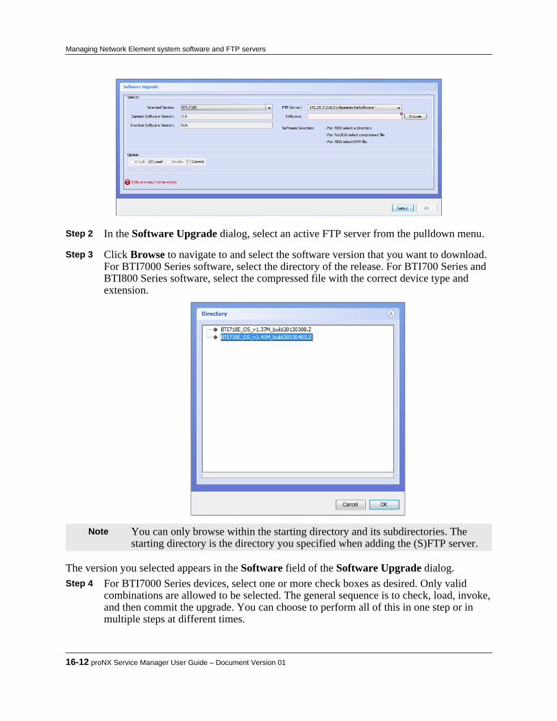
Step 2 In the Software Upgrade dialog, select an active FTP server from the pulldown menu. Step 3 Click Browse to navigate to and select the software version that you want to download.
For BTI7000 Series software, select the directory of the release. For BTI700 Series andBTI800 Series software, select the compressed file with the correct device type andextension.
Note You can only browse within the starting directory and its subdirectories. Thestarting directory is the directory you specified when adding the (S)FTP server.
The version you selected appears in the Software field of the Software Upgrade dialog. Step 4 For BTI7000 Series devices, select one or more check boxes as desired. Only valid
combinations are allowed to be selected. The general sequence is to check, load, invoke,and then commit the upgrade. You can choose to perform all of this in one step or inmultiple steps at different times.
16-12 proNX Service Manager User Guide – Document Version 01
Managing Network Element system software and FTP servers
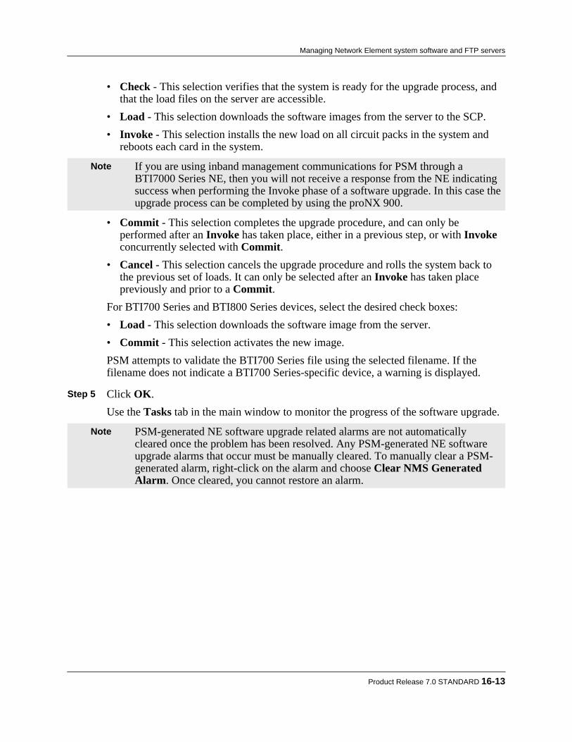
• Check - This selection verifies that the system is ready for the upgrade process, andthat the load files on the server are accessible.
• Load - This selection downloads the software images from the server to the SCP.• Invoke - This selection installs the new load on all circuit packs in the system and
reboots each card in the system.
Note If you are using inband management communications for PSM through aBTI7000 Series NE, then you will not receive a response from the NE indicatingsuccess when performing the Invoke phase of a software upgrade. In this case theupgrade process can be completed by using the proNX 900.
• Commit - This selection completes the upgrade procedure, and can only beperformed after an Invoke has taken place, either in a previous step, or with Invokeconcurrently selected with Commit.
• Cancel - This selection cancels the upgrade procedure and rolls the system back tothe previous set of loads. It can only be selected after an Invoke has taken placepreviously and prior to a Commit.
For BTI700 Series and BTI800 Series devices, select the desired check boxes:• Load - This selection downloads the software image from the server.• Commit - This selection activates the new image.PSM attempts to validate the BTI700 Series file using the selected filename. If thefilename does not indicate a BTI700 Series-specific device, a warning is displayed.
Step 5 Click OK.
Use the Tasks tab in the main window to monitor the progress of the software upgrade.
Note PSM-generated NE software upgrade related alarms are not automaticallycleared once the problem has been resolved. Any PSM-generated NE softwareupgrade alarms that occur must be manually cleared. To manually clear a PSM-generated alarm, right-click on the alarm and choose Clear NMS GeneratedAlarm. Once cleared, you cannot restore an alarm.
Product Release 7.0 STANDARD 16-13
Managing Network Element system software and FTP servers

16.7 Restoring a database to factory defaults on a BTI7800network element
Use this procedure to restore the configuration database back to factory defaults on a BTI7800network element.
Step 1 Right click a network element in the Network tree or in the Topology Map view andselect Node > Database > Factory Restore.
Step 2 Click OK in the confirmation dialog.
The factory database is restored on the selected network element.
16-14 proNX Service Manager User Guide – Document Version 01
Managing Network Element system software and FTP servers

17.0 Managing reports
This section covers the following topics:• 17.1, “Generating alarms reports”• 17.2, “Generating Ethernet reports”• 17.3, “Generating pseudowire reports”• 17.4, “Generating transport reports”• 17.5, “Generating NE logs reports”• 17.6, “Generating optical reports”• 17.7, “Generating inventory reports”• 17.8, “Generating task history reports”
Product Release 7.0 STANDARD 17-1
C H A P T E R 1 7

17.1 Generating alarms reports
PSM supports alarm report generation for the following:• BTI7800 Series network elements• BTI7000 Series network elements• BTI800 Series network elements• BTI700 Series network elements
17.1.1 Generating an active alarms reportUse this procedure to generate an active alarms report in spreadsheet format, and save it to thelocal drive.
Step 1 From the main menu, choose Tools > Reports > Alarms > Active. Step 2 Wait while the report generates. The bottom of the GUI shows "Requesting Report:"
followed by the selected report type. Step 3 When the report has been generated, the tool automatically launches your web browser
and points it to the location of the report (report URL) on the PSM Server. Log in usingyour PSM user name and password.
Note The report is stored indefinitely on the server at the location specified by thereport URL, and is accessible from any browser. To prevent unauthorized accessto this possibly sensitive data, the report location is password protected. If youhave generated reports previously, your web browser may have cached your username and password, and may log in automatically for you.
Note Your browser may require you to explicitly verify and accept the servercertificate before you can have access to the report. This is normal becausecommunication between the browser and the server is through HTTPS.
After logging in, a file download dialog box opens. Step 4 Open or save the report.
The following is an example of an Active Alarms report:
17-2 proNX Service Manager User Guide – Document Version 01
Managing reports

17.1.2 Generating a historical alarms reportUse this procedure to generate a historical alarms report in spreadsheet format, and save it to thelocal drive.
Step 1 From the main menu, choose Tools > Reports > Alarms > Historical.The Historical Alarms Report dialog appears:
Step 2 Specify the alarms you want to include in the report.
• Description Contains - Include alarms with the specified text string in the alarmdescription.
• Device Address Starts With - Include alarms raised by a node with the specified IPaddress prefix.
Product Release 7.0 STANDARD 17-3
Managing reports

• Source Contains - Include alarms with the specified text string in the sourcedescription.
• Raised Time After - Include alarms raised after the specified time.• (Raised Time) Before - Include alarms raised prior to the specfiied time.• Cleared Time After - Include alarms cleared after the specified time.• (Cleared Time) Before - Include alarms cleared prior to the specified time.• Severity - Include alarms at the indicated alarm severity. If no severity is selected,
alarms at all severities are included.• Service Affecting - Include alarms that are service affecting, non-service affecting,
or either.• Acknowledged - Include alarms that are acknowledged, unacknowledged, or either.• Assigned User Contains - Include alarms with the specified text string in the user
assignment.• System Name Contains - Include alarms with the specified text string in the system
name.• Domain Name Contains - Include alarms with the specified text string in the
domain name. Step 3 Click Run to generate the report based on the filters you specify. Step 4 Wait while the report generates. The bottom of the GUI shows "Requesting Report:"
followed by the selected report type. Step 5 When the report has been generated, the tool automatically launches your web browser
and points it to the location of the report (report URL) on the PSM Server. Log in usingyour PSM user name and password.
Note The report is stored indefinitely on the server at the location specified by thereport URL, and is accessible from any browser. To prevent unauthorized accessto this possibly sensitive data, the report location is password protected. If youhave generated reports previously, your web browser may have cached your username and password, and may log in automatically for you.
Note Your browser may require you to explicitly verify and accept the servercertificate before you can have access to the report. This is normal becausecommunication between the browser and the server is through HTTPS.
After logging in, a file download dialog box opens. Step 6 Open or save the report.
The following is an example of a Historical Alarms report:
17-4 proNX Service Manager User Guide – Document Version 01
Managing reports

Product Release 7.0 STANDARD 17-5
Managing reports
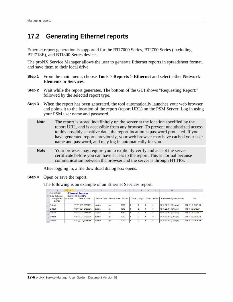
17.2 Generating Ethernet reports
Ethernet report generation is supported for the BTI7000 Series, BTI700 Series (excludingBTI718E), and BTI800 Series devices.The proNX Service Manager allows the user to generate Ethernet reports in spreadsheet format,and save them to their local drive.
Step 1 From the main menu, choose Tools > Reports > Ethernet and select either NetworkElements or Services.
Step 2 Wait while the report generates. The bottom of the GUI shows "Requesting Report:"
followed by the selected report type. Step 3 When the report has been generated, the tool automatically launches your web browser
and points it to the location of the report (report URL) on the PSM Server. Log in usingyour PSM user name and password.
Note The report is stored indefinitely on the server at the location specified by thereport URL, and is accessible from any browser. To prevent unauthorized accessto this possibly sensitive data, the report location is password protected. If youhave generated reports previously, your web browser may have cached your username and password, and may log in automatically for you.
Note Your browser may require you to explicitly verify and accept the servercertificate before you can have access to the report. This is normal becausecommunication between the browser and the server is through HTTPS.
After logging in, a file download dialog box opens. Step 4 Open or save the report.
The following is an example of an Ethernet Services report.
17-6 proNX Service Manager User Guide – Document Version 01
Managing reports
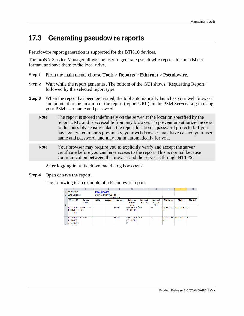
17.3 Generating pseudowire reports
Pseudowire report generation is supported for the BTI810 devices.The proNX Service Manager allows the user to generate pseudowire reports in spreadsheetformat, and save them to the local drive.
Step 1 From the main menu, choose Tools > Reports > Ethernet > Pseudowire. Step 2 Wait while the report generates. The bottom of the GUI shows "Requesting Report:"
followed by the selected report type. Step 3 When the report has been generated, the tool automatically launches your web browser
and points it to the location of the report (report URL) on the PSM Server. Log in usingyour PSM user name and password.
Note The report is stored indefinitely on the server at the location specified by thereport URL, and is accessible from any browser. To prevent unauthorized accessto this possibly sensitive data, the report location is password protected. If youhave generated reports previously, your web browser may have cached your username and password, and may log in automatically for you.
Note Your browser may require you to explicitly verify and accept the servercertificate before you can have access to the report. This is normal becausecommunication between the browser and the server is through HTTPS.
After logging in, a file download dialog box opens. Step 4 Open or save the report.
The following is an example of a Pseudowire report.
Product Release 7.0 STANDARD 17-7
Managing reports

17.4 Generating transport reports
Transport report generation is supported for the BTI7800 Series devices.The proNX Service Manager allows the user to generate transport reports in spreadsheet format,and save them to their local drive. There are four transport report types available: TransportServices, Transport Services per Span, Transport Topology, and Transport Cross-Connects.
Step 1 From the main menu, choose Tools > Reports > Transport and one of Services, Cross-Connects, Services per Span, Topology.
Step 2 Wait while the report generates. The bottom of the GUI shows "Requesting Report:"
followed by the selected report type. Step 3 When the report has been generated, the tool automatically launches your web browser
and points it to the location of the report (report URL) on the PSM Server. Log in usingyour PSM user name and password.
Note The report is stored indefinitely on the server at the location specified by thereport URL, and is accessible from any browser. To prevent unauthorized accessto this possibly sensitive data, the report location is password protected. If youhave generated reports previously, your web browser may have cached your username and password, and may log in automatically for you.
Note Your browser may require you to explicitly verify and accept the servercertificate before you can have access to the report. This is normal becausecommunication between the browser and the server is through HTTPS.
After logging in, a file download dialog box opens. Step 4 Open or save the report.
The following is an example of a Transport Services report.
17-8 proNX Service Manager User Guide – Document Version 01
Managing reports

17.5 Generating NE logs reports
The proNX Service Manager allows the user to generate NE logs reports in spreadsheet format,and save them to their local drive.PSM supports NE log report generation for the following:• BTI7800 Series network elements• BTI7000 Series network elements
Step 1 From the main menu, choose Tools>Reports>NE Logs.The Network Elements Logs Report window is displayed.
Step 2 Using the options in the Network Elements Logs Report window, specify the attributes
of the report. The bottom of the GUI shows "Requesting Report:" followed by theselected report type.
Step 3 Click Run.
Product Release 7.0 STANDARD 17-9
Managing reports

Step 4 Wait while the report generates. The bottom of the GUI shows "Requesting Report:"followed by the selected report type.
Step 5 When the report has been generated, the tool automatically launches your web browser
and points it to the location of the report (report URL) on the PSM Server. Log in usingyour PSM Client user name and password.
Note The report is stored indefinitely on the server at the location specified by thereport URL, and is accessible from any browser. To prevent unauthorized accessto this possibly sensitive data, the report location is password protected. If youhave generated reports previously, your web browser may have cached your username and password, and may log in automatically for you.
Note Your browser may require you to explicitly verify and accept the servercertificate before you can have access to the report. This is normal becausecommunication between the browser and the server is through HTTPS.
Step 6 A file download dialog box opens asking "Do you want to open or save this file?". Click
Save as. Step 7 Choose where to save the report on your local drive, then click Save to download the
file.The following image is an example of an NE Logs report file.
17-10 proNX Service Manager User Guide – Document Version 01
Managing reports

17.6 Generating optical reports
Optical report generation is supported for the BTI7000 Series and BTI7800 Series networkelements.The proNX Service Manager allows the user to generate optical reports in spreadsheet format,and save them to their local drive. There are four optical report types available: Optical Services,Optical Services per Span, Optical Topology, and Optical Cross-Connects.
Step 1 From the main menu, choose Tools > Reports > Optical and one of Services, Topology, Cross-Connects, Services per Span.
Step 2 Wait while the report generates. The bottom of the GUI shows "Requesting Report:"
followed by the selected report type. Step 3 When the report has been generated, the tool automatically launches your web browser
and points it to the location of the report (report URL) on the PSM Server. Log in usingyour PSM user name and password.
Note The report is stored indefinitely on the server at the location specified by thereport URL, and is accessible from any browser. To prevent unauthorized accessto this possibly sensitive data, the report location is password protected. If youhave generated reports previously, your web browser may have cached your username and password, and may log in automatically for you.
Note Your browser may require you to explicitly verify and accept the servercertificate before you can have access to the report. This is normal becausecommunication between the browser and the server is through HTTPS.
After logging in, a file download dialog box opens. Step 4 Open or save the report.
The following is an example of an Optical Topology report.
Product Release 7.0 STANDARD 17-11
Managing reports

17.7 Generating inventory reports
The proNX Service Manager allows the user to generate inventory reports in spreadsheet format,and save them to their local drive. The inventory report contains the same information as in thenetwork element inventory view (see 6.3, “Viewing network element inventory information”).PSM supports inventory report generation for the following:• BTI7800 Series network elements• BTI7000 Series network elements• BTI800 Series network elements• BTI700 Series network elements
Step 1 From the main menu, choose Tools>Reports>Inventory. Step 2 Wait while the report generates. The bottom of the GUI shows "Requesting Report:"
followed by the selected report type. Step 3 When the report has been generated, the tool automatically launches your web browser
and points it to the location of the report (report URL) on the PSM Server. Log in usingyour PSM user name and password.
Note The report is stored indefinitely on the server at the location specified by thereport URL, and is accessible from any browser. To prevent unauthorized accessto this possibly sensitive data, the report location is password protected. If youhave generated reports previously, your web browser may have cached your username and password, and may log in automatically for you.
Note Your browser may require you to explicitly verify and accept the servercertificate before you can have access to the report. This is normal becausecommunication between the browser and the server is through HTTPS.
After logging in, a file download dialog box opens. Step 4 Open or save the report.
The following is an example of an Inventory report.
17-12 proNX Service Manager User Guide – Document Version 01
Managing reports

17.8 Generating task history reports
The proNX Service Manager allows the user to generate task history reports in spreadsheetformat, and save them to their local drive. The task history shows a record of tasks performed byusers as well as scheduled tasks by the system.PSM supports task history report generation for the following:• BTI7800 Series network elements• BTI7000 Series network elements• BTI800 Series network elements• BTI700 Series network elements
Step 1 From the main menu, choose Tools > Reports > Task History.The Task History Report window is displayed.
Step 2 Select the task history filtering criteria as follows:
• Network Element: Specify the IP address or IP address prefix of the networkelement(s) that you want to be included in the task history report. The address is instandard dotted decimal notation. By specifying a prefix, you can include a set ofprefixes. For example, 10.1. returns all network elements within the address range 10.1.0.0 to 10.1.255.255. A 10.1.210.71 address returns the 10.1.210.71network element as well as network elements in the address range 10.1.210.710 to 10.1.210.719.
• Task Type: Specify the task type of the tasks you want to be included in the taskhistory report. When you type in the box, a drop-down menu appears that shows the
Product Release 7.0 STANDARD 17-13
Managing reports

task types that match what you have typed so far. The matches are based on a simpleunanchored pattern match of the typed string against the set of supported PSM tasktypes. In other words, all matching task types contain the typed string. You canchoose a specific task type from the drop-down menu, or keep typing to narrow downyour selections further, or simply keep the string that you have typed so far to includeall current task types in the drop-down menu.
• Username: Specify the user you want to be included in the task history report. Whenyou type in the box, a drop-down menu appears that shows the user names that matchwhat you have typed so far. The matches are based on a simple unanchored patternmatch of the typed string against the set of PSM users. In other words, all matchinguser names contain the typed string. You can choose a specific user from the drop-down menu, or keep typing to narrow down your selections further, or simply keepthe string that you have typed so far to include all current user names in the drop-down menu.
• Start Time: Specify the start time of the report period.• End Time: Specify the end time of the report period.
Note If you leave any box blank, then no filter is applied for the associated criterion. Step 3 Click Run. Step 4 Wait while the report generates. The bottom of the GUI shows "Requesting Report:"
followed by the selected report type. Step 5 When the report has been generated, the tool automatically launches your web browser
and points it to the location of the report (report URL) on the PSM Server. Log in usingyour PSM user name and password.
Note The report is stored indefinitely on the server at the location specified by thereport URL, and is accessible from any browser. To prevent unauthorized accessto this possibly sensitive data, the report location is password protected. If youhave generated reports previously, your web browser may have cached your username and password, and may log in automatically for you.
Note Your browser may require you to explicitly verify and accept the servercertificate before you can have access to the report. This is normal becausecommunication between the browser and the server is through HTTPS.
After logging in, a file download dialog box opens. Step 6 Open or save the report.
The following is an example of a Task History report.
17-14 proNX Service Manager User Guide – Document Version 01
Managing reports

Product Release 7.0 STANDARD 17-15
Managing reports

17-16 proNX Service Manager User Guide – Document Version 01
Managing reports

18.0 Performance monitoring
This chapter covers the following topics:• 18.1, “Viewing real-time optical service PMs”• 18.2, “Viewing real-time transport service PMs”• 18.3, “Viewing real-time Ethernet PMs and SLAs”• 18.4, “Viewing real-time pseudowire PMs”• 18.5, “ Collecting and viewing historical PMs”
Note You can also view port PMs using the nodal management procedures describedin Chapter 8, “Nodal management”.
Product Release 7.0 STANDARD 18-1
C H A P T E R 1 8
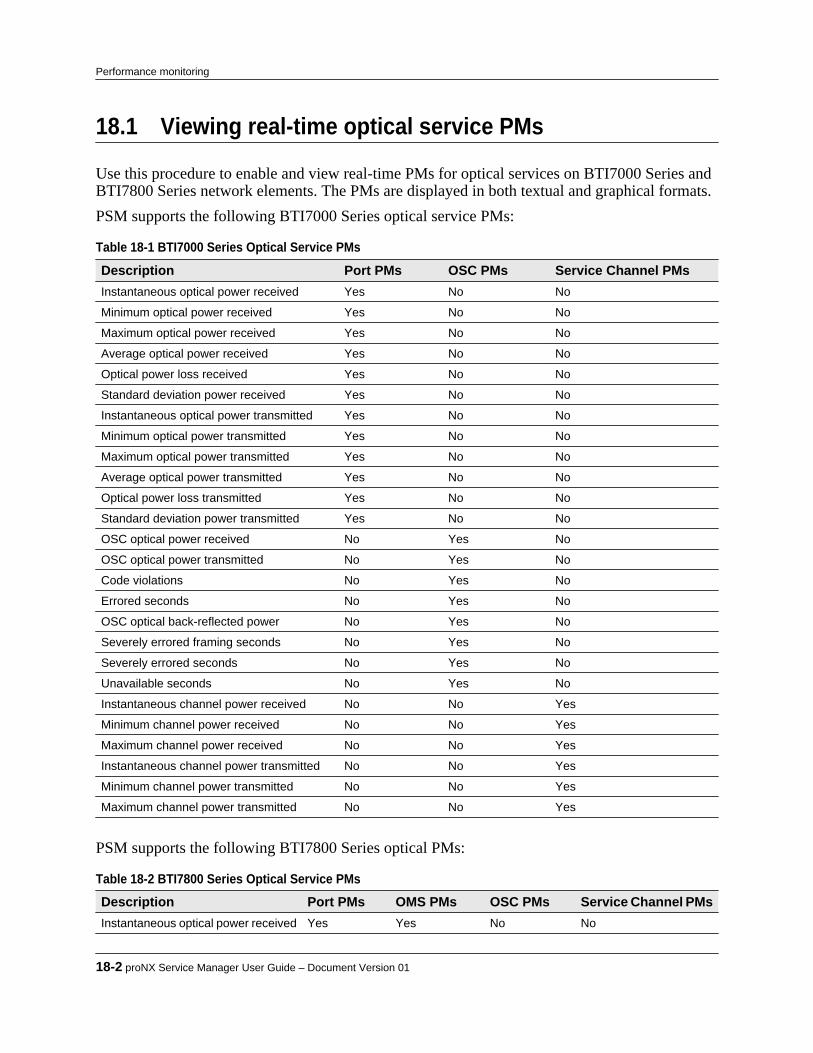
18.1 Viewing real-time optical service PMs
Use this procedure to enable and view real-time PMs for optical services on BTI7000 Series andBTI7800 Series network elements. The PMs are displayed in both textual and graphical formats.PSM supports the following BTI7000 Series optical service PMs:
Table 18-1 BTI7000 Series Optical Service PMs Description Port PMs OSC PMs Service Channel PMsInstantaneous optical power received Yes No No
Minimum optical power received Yes No No
Maximum optical power received Yes No No
Average optical power received Yes No No
Optical power loss received Yes No No
Standard deviation power received Yes No No
Instantaneous optical power transmitted Yes No No
Minimum optical power transmitted Yes No No
Maximum optical power transmitted Yes No No
Average optical power transmitted Yes No No
Optical power loss transmitted Yes No No
Standard deviation power transmitted Yes No No
OSC optical power received No Yes No
OSC optical power transmitted No Yes No
Code violations No Yes No
Errored seconds No Yes No
OSC optical back-reflected power No Yes No
Severely errored framing seconds No Yes No
Severely errored seconds No Yes No
Unavailable seconds No Yes No
Instantaneous channel power received No No Yes
Minimum channel power received No No Yes
Maximum channel power received No No Yes
Instantaneous channel power transmitted No No Yes
Minimum channel power transmitted No No Yes
Maximum channel power transmitted No No Yes
PSM supports the following BTI7800 Series optical PMs:
Table 18-2 BTI7800 Series Optical Service PMs Description Port PMs OMS PMs OSC PMs Service Channel PMsInstantaneous optical power received Yes Yes No No
18-2 proNX Service Manager User Guide – Document Version 01
Performance monitoring

Table 18-2 BTI7800 Series Optical Service PMs (Continued) Description Port PMs OMS PMs OSC PMs Service Channel PMsMinimum optical power received Yes Yes No No
Maximum optical power received Yes Yes No No
Average optical power received Yes Yes No No
Standard deviation power received Yes No No No
Instantaneous optical powertransmitted
Yes Yes No No
Minimum optical power transmitted Yes Yes No No
Maximum optical power transmitted Yes Yes No No
Average optical power transmitted Yes Yes No No
Standard deviation power transmitted Yes No No No
OSC optical power received No No Yes No
OSC optical power transmitted No No Yes No
Instantaneous channel powerreceived
No No No Yes
Minimum channel power received No No No Yes
Maximum channel power received No No No Yes
Instantaneous channel powertransmitted
No No No Yes
Minimum channel power transmitted No No No Yes
Maximum channel power transmitted No No No Yes
Step 1 To enable real-time PMs, right-click on an optical service in the tree view or in thebackground of an optical service topology view, and choose one of the following:• Enable Realtime PMs>Port• Enable Realtime PMs>OMS for BTI7800 Series• Enable Realtime PMs>OSC• Enable Realtime PMs>Service Channel• Enable Realtime PMs>All ChannelsReal-time PM collection for the optical service is started, and a PM data widget title baris displayed for each PM collection point. Additionally, a graphical view displaying theinstantaneous power along with the detected power range is provided at the bottom ofthe screen.
Note When you enable PMs on a stranded service11 , you may see PM data widgetsthat do not have lines connecting them to the network elements. This behavior isnormal.
Step 2 Click the PM data widget title bar to show or hide the PM data.11 A service is stranded if one or more segments in the path between the service endpoints has not been configured.
Product Release 7.0 STANDARD 18-3
Performance monitoring

Figure 18-1 Real-time PMs port view
Figure 18-2 Real-time PMs OSC view
18-4 proNX Service Manager User Guide – Document Version 01
Performance monitoring
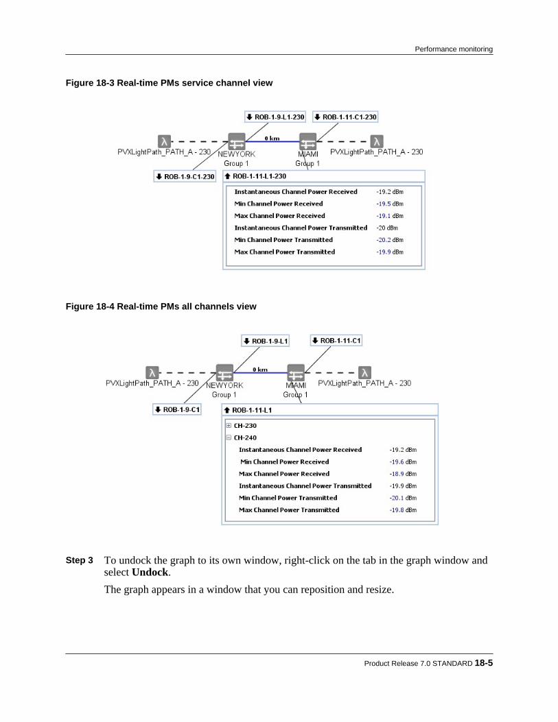
Figure 18-3 Real-time PMs service channel view
Figure 18-4 Real-time PMs all channels view
Step 3 To undock the graph to its own window, right-click on the tab in the graph window and
select Undock.The graph appears in a window that you can reposition and resize.
Product Release 7.0 STANDARD 18-5
Performance monitoring
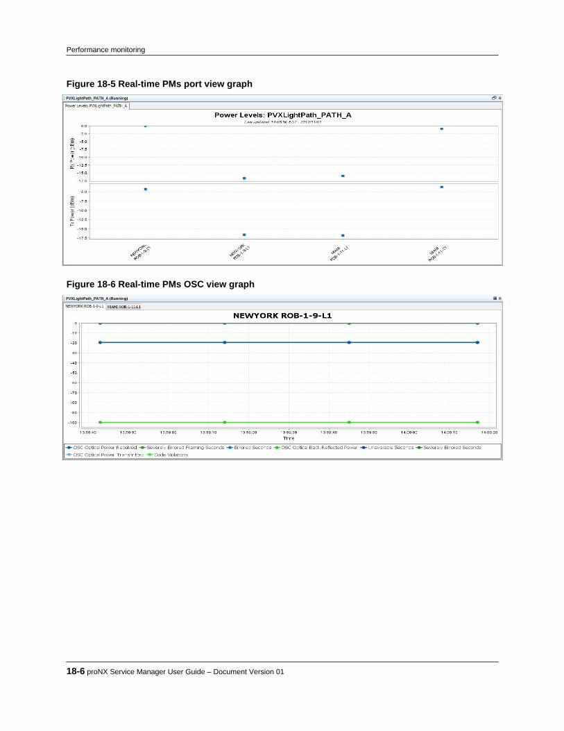
Figure 18-5 Real-time PMs port view graph
Figure 18-6 Real-time PMs OSC view graph
18-6 proNX Service Manager User Guide – Document Version 01
Performance monitoring

Figure 18-7 Real-time PMs service channel view graph
Figure 18-8 Real-time PMs all channels view graph
Note The information displayed on the domain (horizontal) axis of the real-time PMsall channels graph is selectable. See 9.4.2, “ Setting optical graphing options” fordetails on how to select what is shown.
Step 4 To change the range (vertical) scale of the graphs, highlight the desired area by left-
clicking and dragging the mouse to highlight the area of focus, and release.
Product Release 7.0 STANDARD 18-7
Performance monitoring
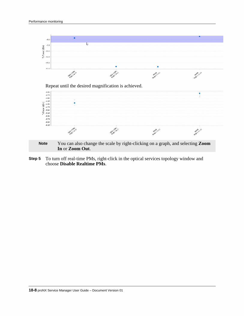
Repeat until the desired magnification is achieved.
Note You can also change the scale by right-clicking on a graph, and selecting ZoomIn or Zoom Out.
Step 5 To turn off real-time PMs, right-click in the optical services topology window and
choose Disable Realtime PMs.
18-8 proNX Service Manager User Guide – Document Version 01
Performance monitoring
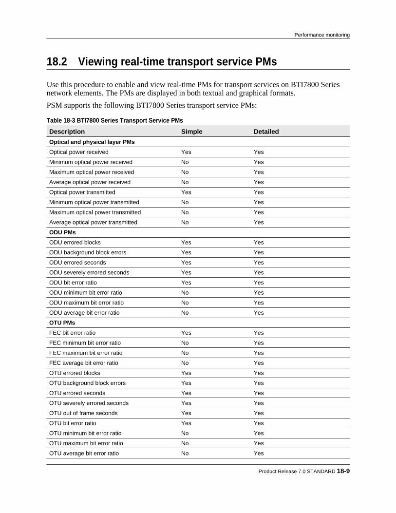
18.2 Viewing real-time transport service PMs
Use this procedure to enable and view real-time PMs for transport services on BTI7800 Seriesnetwork elements. The PMs are displayed in both textual and graphical formats.PSM supports the following BTI7800 Series transport service PMs:
Table 18-3 BTI7800 Series Transport Service PMs Description Simple DetailedOptical and physical layer PMsOptical power received Yes Yes
Minimum optical power received No Yes
Maximum optical power received No Yes
Average optical power received No Yes
Optical power transmitted Yes Yes
Minimum optical power transmitted No Yes
Maximum optical power transmitted No Yes
Average optical power transmitted No Yes
ODU PMsODU errored blocks Yes Yes
ODU background block errors Yes Yes
ODU errored seconds Yes Yes
ODU severely errored seconds Yes Yes
ODU bit error ratio Yes Yes
ODU minimum bit error ratio No Yes
ODU maximum bit error ratio No Yes
ODU average bit error ratio No Yes
OTU PMsFEC bit error ratio Yes Yes
FEC minimum bit error ratio No Yes
FEC maximum bit error ratio No Yes
FEC average bit error ratio No Yes
OTU errored blocks Yes Yes
OTU background block errors Yes Yes
OTU errored seconds Yes Yes
OTU severely errored seconds Yes Yes
OTU out of frame seconds Yes Yes
OTU bit error ratio Yes Yes
OTU minimum bit error ratio No Yes
OTU maximum bit error ratio No Yes
OTU average bit error ratio No Yes
Product Release 7.0 STANDARD 18-9
Performance monitoring

Table 18-3 BTI7800 Series Transport Service PMs (Continued) Description Simple DetailedEthernet PMsOctets received Yes Yes
Octets OK received No Yes
Octets OK transmitted No Yes
Packets received Yes Yes
Packets transmitted Yes Yes
Packets OK received No Yes
Packets OK transmitted No Yes
Broadcast packets received No Yes
Broadcast packets transmitted No Yes
Multicast packets received No Yes
Multicast packets transmitted No Yes
Step 1 To enable real-time PMs, right-click a transport service in the tree view or in thebackground of a transport service topology view, and choose one of the following:• Enable Realtime PMs > Simple• Enable Realtime PMs > DetailedReal-time PM collection for the transport service is started, and a PM data widget titlebar is displayed in the main window for each PM collection point. Additionally, agraphical view is displayed in the bottom window.
Note When you enable PMs on a stranded service12 , you may see PM data widgetsthat do not have lines connecting them to the network elements. This behavior isnormal.
Step 2 Click the PM data widget title bar to show or hide the PM data.
12 A service is stranded if one or more segments in the path between the service endpoints has not been configured.
18-10 proNX Service Manager User Guide – Document Version 01
Performance monitoring
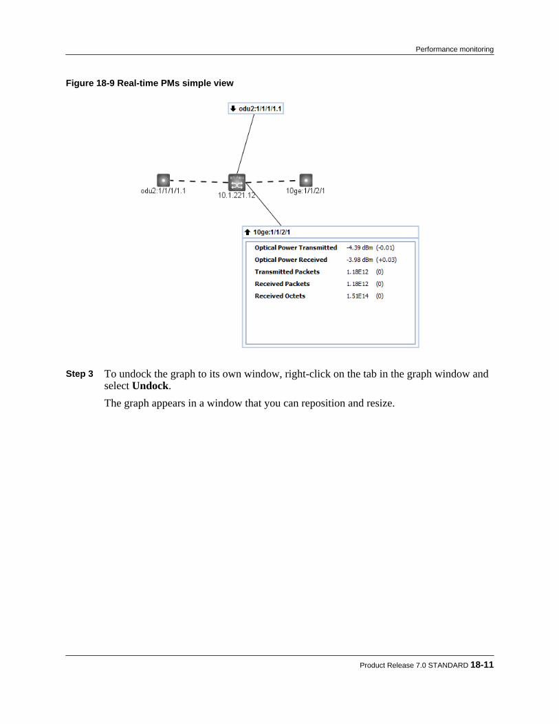
Figure 18-9 Real-time PMs simple view
Step 3 To undock the graph to its own window, right-click on the tab in the graph window and
select Undock.The graph appears in a window that you can reposition and resize.
Product Release 7.0 STANDARD 18-11
Performance monitoring
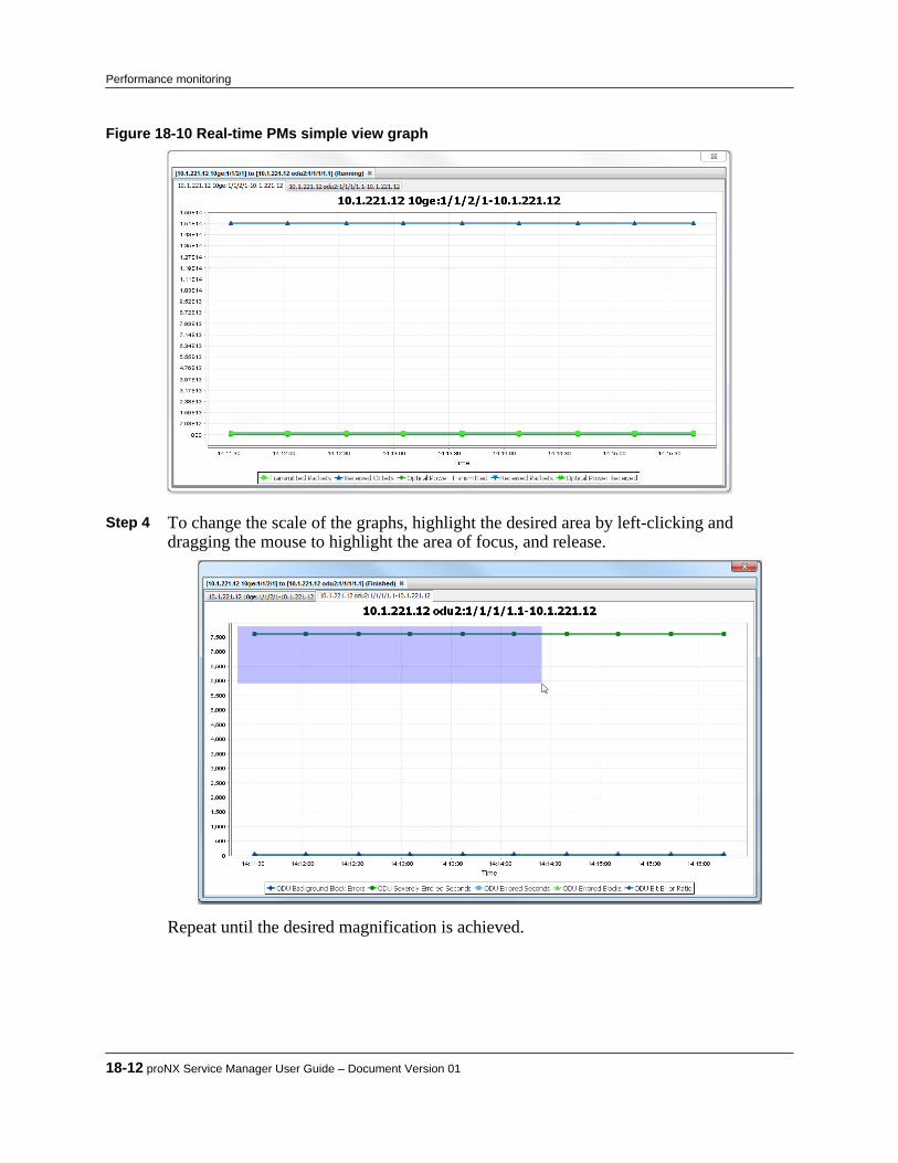
Figure 18-10 Real-time PMs simple view graph
Step 4 To change the scale of the graphs, highlight the desired area by left-clicking and
dragging the mouse to highlight the area of focus, and release.
Repeat until the desired magnification is achieved.
18-12 proNX Service Manager User Guide – Document Version 01
Performance monitoring
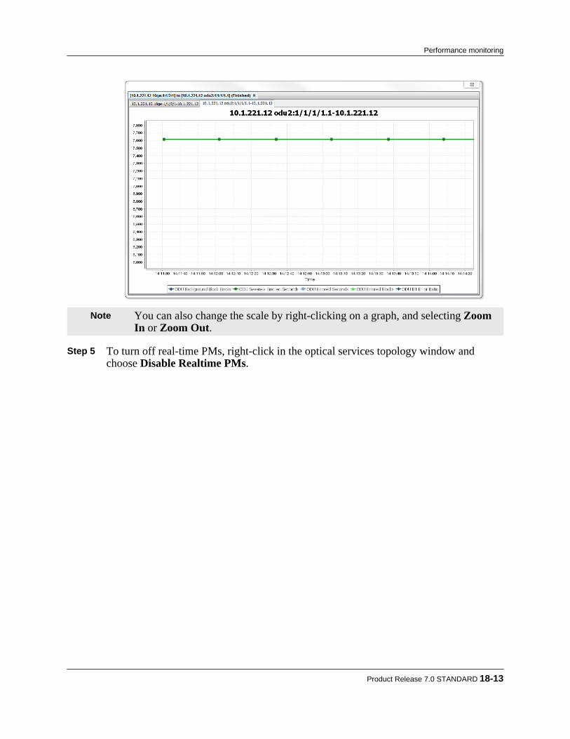
Note You can also change the scale by right-clicking on a graph, and selecting ZoomIn or Zoom Out.
Step 5 To turn off real-time PMs, right-click in the optical services topology window and
choose Disable Realtime PMs.
Product Release 7.0 STANDARD 18-13
Performance monitoring
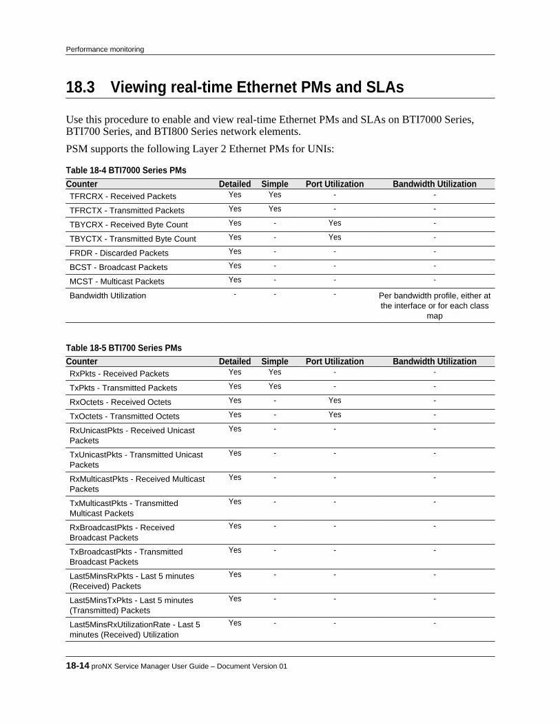
18.3 Viewing real-time Ethernet PMs and SLAs
Use this procedure to enable and view real-time Ethernet PMs and SLAs on BTI7000 Series,BTI700 Series, and BTI800 Series network elements.PSM supports the following Layer 2 Ethernet PMs for UNIs:
Table 18-4 BTI7000 Series PMs Counter Detailed Simple Port Utilization Bandwidth UtilizationTFRCRX - Received Packets Yes Yes - -
TFRCTX - Transmitted Packets Yes Yes - -
TBYCRX - Received Byte Count Yes - Yes -
TBYCTX - Transmitted Byte Count Yes - Yes -
FRDR - Discarded Packets Yes - - -
BCST - Broadcast Packets Yes - - -
MCST - Multicast Packets Yes - - -
Bandwidth Utilization - - - Per bandwidth profile, either atthe interface or for each class
map
Table 18-5 BTI700 Series PMs Counter Detailed Simple Port Utilization Bandwidth UtilizationRxPkts - Received Packets Yes Yes - -
TxPkts - Transmitted Packets Yes Yes - -
RxOctets - Received Octets Yes - Yes -
TxOctets - Transmitted Octets Yes - Yes -
RxUnicastPkts - Received UnicastPackets
Yes - - -
TxUnicastPkts - Transmitted UnicastPackets
Yes - - -
RxMulticastPkts - Received MulticastPackets
Yes - - -
TxMulticastPkts - TransmittedMulticast Packets
Yes - - -
RxBroadcastPkts - ReceivedBroadcast Packets
Yes - - -
TxBroadcastPkts - TransmittedBroadcast Packets
Yes - - -
Last5MinsRxPkts - Last 5 minutes(Received) Packets
Yes - - -
Last5MinsTxPkts - Last 5 minutes(Transmitted) Packets
Yes - - -
Last5MinsRxUtilizationRate - Last 5minutes (Received) Utilization
Yes - - -
18-14 proNX Service Manager User Guide – Document Version 01
Performance monitoring
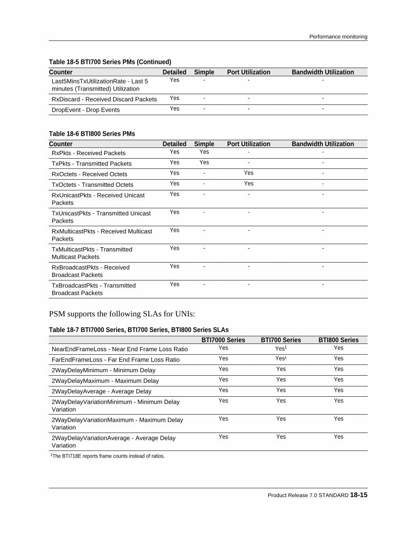
Table 18-5 BTI700 Series PMs (Continued) Counter Detailed Simple Port Utilization Bandwidth UtilizationLast5MinsTxUtilizationRate - Last 5minutes (Transmitted) Utilization
Yes - - -
RxDiscard - Received Discard Packets Yes - - -
DropEvent - Drop Events Yes - - -
Table 18-6 BTI800 Series PMs Counter Detailed Simple Port Utilization Bandwidth UtilizationRxPkts - Received Packets Yes Yes - -
TxPkts - Transmitted Packets Yes Yes - -
RxOctets - Received Octets Yes - Yes -
TxOctets - Transmitted Octets Yes - Yes -
RxUnicastPkts - Received UnicastPackets
Yes - - -
TxUnicastPkts - Transmitted UnicastPackets
Yes - - -
RxMulticastPkts - Received MulticastPackets
Yes - - -
TxMulticastPkts - TransmittedMulticast Packets
Yes - - -
RxBroadcastPkts - ReceivedBroadcast Packets
Yes - - -
TxBroadcastPkts - TransmittedBroadcast Packets
Yes - - -
PSM supports the following SLAs for UNIs:
Table 18-7 BTI7000 Series, BTI700 Series, BTI800 Series SLAs
BTI7000 Series BTI700 Series BTI800 SeriesNearEndFrameLoss - Near End Frame Loss Ratio Yes Yes1 Yes
FarEndFrameLoss - Far End Frame Loss Ratio Yes Yes¹ Yes
2WayDelayMinimum - Minimum Delay Yes Yes Yes
2WayDelayMaximum - Maximum Delay Yes Yes Yes
2WayDelayAverage - Average Delay Yes Yes Yes
2WayDelayVariationMinimum - Minimum DelayVariation
Yes Yes Yes
2WayDelayVariationMaximum - Maximum DelayVariation
Yes Yes Yes
2WayDelayVariationAverage - Average DelayVariation
Yes Yes Yes
1The BTI718E reports frame counts instead of ratios.
Product Release 7.0 STANDARD 18-15
Performance monitoring

Step 1 To enable real-time PMs or SLAs, right-click on an Ethernet service in the tree view orin an Ethernet topology view, and choose one of the following:• Enable realtime PMs>Detailed• Enable realtime PMs>Simple• Enable realtime PMs>SLA• Enable realtime PMs>Port Utilization• Enable realtime PMs>Bandwidth UtilizationReal-time PM/SLA collection for the Ethernet service is started, and for each PM/SLAcollection point in the service, a PM data widget is displayed with the current PMs/SLAs for that collection point (the statistics displayed for a given collection point arethe total statistics for that point, and not just the totals for the selected service).Additionally, a graphical view is provided at the bottom of the screen.
Note For SLA PMs, an SLA pair needs to have been created on the service view andapplied.
Step 2 Click the PM data widget title bar to show or hide the PM data.
PM/SLA absolute values (and their change from the previous collection) are shown.
Figure 18-11 Real-time PMs detailed view
18-16 proNX Service Manager User Guide – Document Version 01
Performance monitoring

Figure 18-12 Real-time PMs simple view
Figure 18-13 Real-time PMs SLA view
Product Release 7.0 STANDARD 18-17
Performance monitoring

Figure 18-14 Real-time PMs port utilization view
Figure 18-15 Real-time PMs bandwidth utilization view
Step 3 To expand the graphical view to full screen, right-click on the graph window title bar
and select Maximize Window.
Figure 18-16 Real-time PMs detailed view graph
18-18 proNX Service Manager User Guide – Document Version 01
Performance monitoring
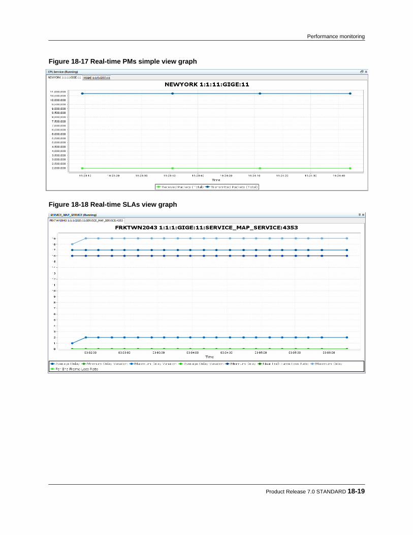
Figure 18-17 Real-time PMs simple view graph
Figure 18-18 Real-time SLAs view graph
Product Release 7.0 STANDARD 18-19
Performance monitoring

Figure 18-19 Real-time PMs port utilization view graph
Figure 18-20 Real-time PMs bandwidth utilization graph
Step 4 To change the scale of the graphs, highlight the desired area by left-clicking and
dragging the mouse to highlight the area of focus, and release. The scale for both thedomain (horizontal) axis and the range (vertical) axis can be changed.
18-20 proNX Service Manager User Guide – Document Version 01
Performance monitoring

Repeat until the desired magnification is achieved.
Note You can also change the scales by right-clicking on a graph, and selecting ZoomIn>Range Axis, Zoom Out>Range Axis, Zoom In>Domain Axis, and ZoomOut>Domain Axis. This changes the respective scales while keeping the centerof the range and/or domain as the area of focus.
Step 5 To turn off real-time PMs, right-click in the Ethernet topology window and choose
Disable Realtime PMs.
Product Release 7.0 STANDARD 18-21
Performance monitoring

18.4 Viewing real-time pseudowire PMs
Use this procedure to enable and view real-time PMs for pseudowire services on BTI800 Seriesnetwork elements. The PMs are displayed in both textual and graphical formats.PSM supports the following PMs for the pseudowire service:
T1 PMs E1 PMs SONET PMs SDH PMs SATOP PMsCodeViolations- Line
Errored Seconds Code Violations - Line Code Violations -Regenerator Section
SATOP TransmittedByte Count (Total)
ErroredSeconds -Line
Severely ErroredSeconds
Errored Seconds - Line Errored Seconds -Regenerator Section
SATOP Received ByteCount (Total)
SeverelyErroredSeconds -Line
Background Block Errorcount
Severely ErroredSeconds - Line
Severely ErroredSeconds - RegeneratorSection
SATOP Byte Loss(Total)
CodeViolations- Path
Unavailable Seconds Unavailable Seconds -Line
Unavailable Seconds -Regenerator Section
ErroredSeconds -Path
Errored Second Ratio Code Violations - Path Code Violations -Multiplex Section
SeverelyErroredSeconds -Path
Severely ErroredSecond Ratio
Errored Seconds - Path Errored Seconds -Multiplex Section
SeverelyErroredFrameSeconds -Path
Background Block ErrorRatio
Severely ErroredSeconds - Path
Severely ErroredSeconds - MultiplexSection
Unavailable Seconds- Path
Unavailable Seconds -Path
Unavailable Seconds -Multiplex Section
Code Violations -Section
Code Violations - VC4(AU4 mode only)
Errored Seconds -Section
Errored Seconds - VC4(AU4 mode only)
Severely ErroredSeconds - Section
Severely ErroredSeconds - VC4 (AU4mode only)
Severely ErroredFrame Seconds -Section
Unavailable Seconds -VC4 (AU4 mode only)
Code Violations - VT Code Violations - VC3(AU3 mode only)
18-22 proNX Service Manager User Guide – Document Version 01
Performance monitoring

T1 PMs E1 PMs SONET PMs SDH PMs SATOP PMsErrored Seconds - VT Errored Seconds - VC3
(AU3 mode only)
Severely ErroredSeconds - VT
Severely ErroredSeconds - VC3 (AU3mode only)
Unavailable Seconds -VT
Unavailable Seconds -VC3 (AU3 mode only)
Protection Switch Count Code Violations - Path
Errored Seconds - Path
Severely ErroredSeconds - Path
Unavailable Seconds -Path
Protection Switch Count
Step 1 To enable real-time PMs, right-click on a pseudowire service in the tree view or in thebackground of a pseudowire service topology view, and select Enable Realtime PMs > PseudowireReal-time PM collection for the pseudowire service is started, and a PM data widgettitle bar is displayed for each PM collection point. Additionally, a graphical viewdisplaying the PMs pops up on the screen.
Step 2 Click the PM data widget title bar to show or hide the PM data.
Product Release 7.0 STANDARD 18-23
Performance monitoring
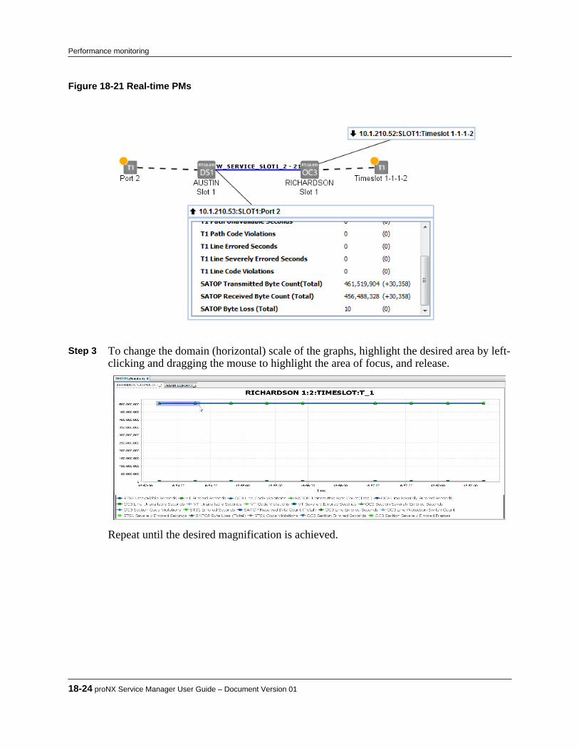
Figure 18-21 Real-time PMs
Step 3 To change the domain (horizontal) scale of the graphs, highlight the desired area by left-
clicking and dragging the mouse to highlight the area of focus, and release.
Repeat until the desired magnification is achieved.
18-24 proNX Service Manager User Guide – Document Version 01
Performance monitoring

Note You can also change the scale by right-clicking on a graph, and selecting ZoomIn>Domain Axis or Zoom Out>Domain Axis. This changes the horizontal scalewhile keeping the center of the range as the area of focus.
Step 4 To turn off real-time PMs, right-click the background in the pseudowire services
topology window and choose Disable Realtime PMs.
Product Release 7.0 STANDARD 18-25
Performance monitoring

18.5 Collecting and viewing historical PMs
Use this procedure to collect and view historical PMs for BTI7000 Series, BTI7800 Series,BTI800 Series, and BTI718E network elements.
Pre-requisites:
• For scheduled collections, ensure the scheduled historical PM retrieval capability is enabledand the retrieval schedule is set up. For information on how to do this, see the proNX ServiceManager Installation and Administration Guide. By default, scheduled historical PMcollection is disabled.
Note When using PSM to collect historical PMs from BTI800 Series networkelements, you must perform additional steps on the network element itself. SeeAppendix F, “Configuring historical PM collection on BTI800 Series networkelements” for information.
Historical PMs are PMs that are collected and binned (aggregated over a measurement interval,timestamped, and discretely stored) by the network element. PSM can be configured to retrievethese historical PMs on a regular, pre-defined schedule. When scheduled historical PM collectionis enabled, PSM retrieves historical PMs every 12 hours by default, which allows time to correctany retrieval failures for the 1-day bin while minimizing unnecessary processing.PSM stores these collected PMs in a database for 30 days and makes them available for viewing.PM data points older than 30 days are purged from the database.Both 15-minute and 1-day bins are collected. PM points in 15-minute bins are timestamped onthe hour and at every 15 minutes thereafter. PM points for the 1-day bin are timestamped atmidnight (local time of the PSM Client).
Note You can select which PMs you want to view but you cannot select whichhistorical PMs you want PSM to retrieve. PSM retrieves all historical PMs fromall discovered NEs.
For the list of historical PMs that PSM collects for BTI7000 Series, BTI800 Series, and BTI718Enetwork elements, see Appendix D, “Historical PM counters”. For information on BTI7800Series historical PMs, see the BTI7800 Series documentation.
Step 1 Retrieve historical PMs from the NE.This is performed automatically based on the collection schedule (default every 12hours). Optionally, you can direct PSM to retrieve historical PMs on demand by right-clicking a network element in the Network tree view or in the Topology Map view andselecting Retrieve Historical PMs. If you do this, you must wait for the retrieval task tocomplete before proceeding to the next step.
Note It is recommended that you always run scheduled collections. Depending solelyon on-demand PM retrieval will limit the collected data to what is stored on theNEs at the time of the on-demand retrievals.
18-26 proNX Service Manager User Guide – Document Version 01
Performance monitoring

Step 2 From the main menu, choose View > Historical PMs, or click on the Historical PMsicon .The Historical PMs window appears:
Step 3 Expand the Historical PMs tree view and select the PMs you want to display. You can
select PM points from more than one network element.
Discovered and reachable network elements are shown in black. Discovered andunreachable network elements are shown in red. Undiscovered network elements areshown in grey.
Note This list may contain network elements (in grey) that no longer appear in themain Topology view. This can occur if the network elements are removed fromthe Topology view, but still have historical PM data associated with them.
Product Release 7.0 STANDARD 18-27
Performance monitoring

Note When a port is reconfigured (e.g. with a different protocol), you will see PMpoints in the Historical PMs tree for both the old and the new protocol. This isnormal behavior. PSM stores historical PM data for 30 days, at which time thedata for the old protocol is purged.
Step 4 Select the time range you want to view by using the drop-down menus in the Date-Time
Selection pane.
Step 5 Click Plot to plot the graph.
The data is plotted and displayed in the Chart pane.
Note In the likely event that the From: and To: times do not fall on monitoring periodboundaries at the NE, the time of the first and last collections shown may notmatch exactly the start and end times requested.
Step 6 To zoom in on the graph, click and drag the portion you want to zoom, and then release.
18-28 proNX Service Manager User Guide – Document Version 01
Performance monitoring
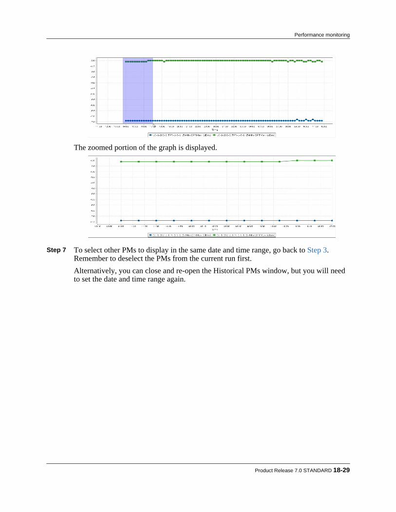
The zoomed portion of the graph is displayed.
Step 7 To select other PMs to display in the same date and time range, go back to Step 3.
Remember to deselect the PMs from the current run first.Alternatively, you can close and re-open the Historical PMs window, but you will needto set the date and time range again.
Product Release 7.0 STANDARD 18-29
Performance monitoring

18-30 proNX Service Manager User Guide – Document Version 01
Performance monitoring
19.0 Troubleshooting
This section covers the following topics:• 19.1, “Managing task status”• 19.2, “Exporting client and server logs”• 19.3, “Performing diagnostics”• 19.4, “Viewing the PSM Client log”• 19.5, “Testing network element connectivity”• 19.6, “Verifying PSM client-server connectivity”• 19.7, “Collecting and viewing NE logs”• 19.8, “ Saving network element configuration information”• 19.9, “Troubleshooting server replication”
Product Release 7.0 STANDARD 19-1
C H A P T E R 1 9

19.1 Managing task status
The proNX Service Manager provides a Tasks status screen that allows you to view the progressand status of running tasks. The Tasks status screen shows the list of tasks that this client hasrequested the server to execute. Tasks launched by other clients or scheduled tasks which are runby the server itself are not shown in this view.
Note When performing a task on a network element, you should wait until that taskcompletes before starting a new task on that network element.
Some tasks are displayed with a ‘parent’ or ‘top level’ task that can be expanded to show all thesubtasks that the server will execute to fulfill the user request.In the following example, Task13881 is made up of two subtasks.
The State column displays the current status of the tasks as RUNNING or FINISHED as reportedby the server. The possible subtask states are RUNNING, SUCCESS, or FAILURE. When allsubtasks are complete, the task State will transition to FINISHED. The Details column providesadditional details about a task or subtask.In an effort to protect network and server resources, the server may queue tasks that it is unableto service at the requested time. These queued tasks are not shown in the Tasks status window.• If the server is busy, new task requests are placed onto a queue. These new task requests are
dequeued for servicing as the server completes existing tasks. If a client requests a task that isidentical to a task already queued, PSM returns an error and does not queue the new task. Theerror can be for a subtask if the subtask is a duplicate, or a top level task if the top level task isa duplicate.
19-2 proNX Service Manager User Guide – Document Version 01
Troubleshooting

• Limits are placed on the number of tasks that can be started by the server. These limits applyfor each type of task and span across all clients. See /usr/local/ems9001/resources/serverConfigurations/workers.xml for the specific limits.
Note This file must not be changed or unintended consequences may occur.
Once a specific task limit is reached, any additional requests for that same type of task by anyclient are queued by the server. Once a running task of that type is completed, the serverdequeues the next task from that queue, and only then starts and places this new task in therespective client's Tasks status window.
19.1.1 Discovering task status
Step 1 To access the Tasks status screen, click the Tasks tab, or, from the main menu chooseView>Server>Tasks .
The Tasks screen is displayed in the lower right corner of the main client window.
19.1.2 Clearing completed tasks
Step 1 To clear the completed tasks from the Tasks status screen, right-click the title bar andselect Clear Completed Tasks.
Completed tasks are removed from the Tasks screen.
Product Release 7.0 STANDARD 19-3
Troubleshooting

19.2 Exporting client and server logs
Users can export client and server log files, and save them to a zip file on the local drive wherethe client resides. Client and server logs are useful in providing information to Juniper NetworksSupport for issue resolution.
Step 1 To export files, click on the Archive Logs button on the toolbar shown below.
Step 2 In the resulting pop-up dialog, enter the location of the directory in which you want to
store the archive and click OK.The filename format is psmLogs-<date-time>.zip. By default, the file is stored in thefollowing locations in the user's home directory.• Windows XP and Linux
Application Data\.psmclient\dev\Archivedlogs• Windows 7
AppData\Roaming\.psmclient\dev\ArchivedLogs• MAC OS X
Library/Application Support/psmclient/dev/ArchivedLogs
Note These paths are relative to the user's home directory, which varies depending onthe operating system. For Windows 7, the directory is C:\Users\<user_name>\AppData\Roaming\.psmclient\dev\ArchivedLogs.
19-4 proNX Service Manager User Guide – Document Version 01
Troubleshooting
19.3 Performing diagnostics
You can request the PSM client to perform the following diagnostic operations on demand totroubleshoot active issues:• Save Configuration - saves an xml file of the network element configuration details to your
local computer (for more information, see 19.8, “ Saving network element configurationinformation”).
• Ping - performs an ICMP ping on the network element.• Traceroute - performs a traceroute on the network element.• SNMP Ping - performs an on-demand SNMP Ping.
Step 1 In the Map view or Network tree, right-click a network element and chooseUtilities>Diagnostics and the type of diagnostic operation you want the PSM client toperform (Save Configuration, Ping, Traceroute, or SNMP Ping).
Product Release 7.0 STANDARD 19-5
Troubleshooting

19.4 Viewing the PSM Client log
Use this procedure to view the active PSM Client log when troubleshooting active issues.
Step 1 From the main menu choose View>Log.The active client log tab is displayed.
19-6 proNX Service Manager User Guide – Document Version 01
Troubleshooting

19.5 Testing network element connectivity
Use this procedure to check connectivity to a discovered network element. This procedure testsIP, SNMP, and NETCONF (where applicable) connectivity to the network element.
Step 1 Right-click the network element in the Network tree or in the Topology Map view andselect Node > Connectivity Test.PSM pings the NE, and checks SNMP and NETCONF connectivity where applicable.You can see the results of the test through the View > Server > Tasks window.
If the ping fails, PSM runs a traceroute command and displays the results. Thetraceroute task shows SUCCESS if the traceroute command can be run. A successfultraceroute task does not mean that the destination is reachable. To see the results of thetraceroute, click in the Details column of the task.
Note PSM also runs this test automatically when log collection or NE database backup/restore fails. In this case, the results are provided in the logs.
Product Release 7.0 STANDARD 19-7
Troubleshooting

19.6 Verifying PSM client-server connectivity
Use this procedure after installation or at any other time to verify that the PSM client is receivingasynchronous events from the PSM server.
Step 1 Click Tools > Network Element Discovery. Step 2 In the Device Discovery window, enter a non-existent IP address in the Discovery
Criteria box. Step 3 Click OK.
Look in the Tasks window and make sure you see the NE Discovery task for the non-existent IP address being launched and subsequently failing. If you do not see this taskfailing, check and fix your firewall settings and repeat this procedure.
19-8 proNX Service Manager User Guide – Document Version 01
Troubleshooting
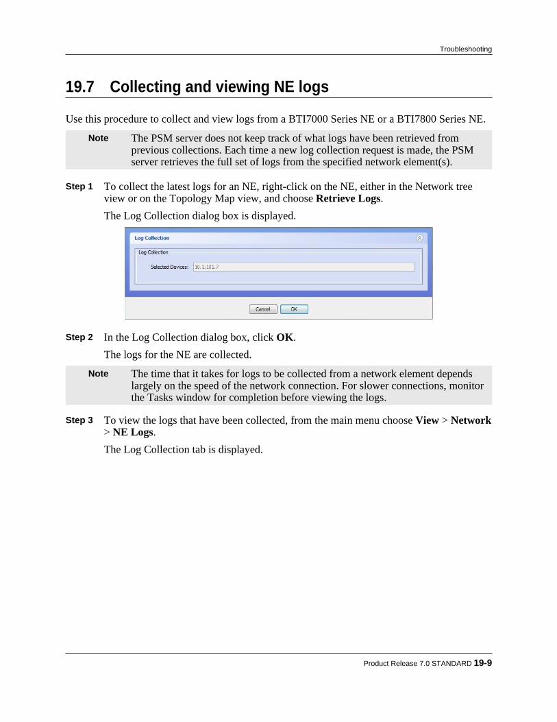
19.7 Collecting and viewing NE logs
Use this procedure to collect and view logs from a BTI7000 Series NE or a BTI7800 Series NE.
Note The PSM server does not keep track of what logs have been retrieved fromprevious collections. Each time a new log collection request is made, the PSMserver retrieves the full set of logs from the specified network element(s).
Step 1 To collect the latest logs for an NE, right-click on the NE, either in the Network treeview or on the Topology Map view, and choose Retrieve Logs.The Log Collection dialog box is displayed.
Step 2 In the Log Collection dialog box, click OK.
The logs for the NE are collected.
Note The time that it takes for logs to be collected from a network element dependslargely on the speed of the network connection. For slower connections, monitorthe Tasks window for completion before viewing the logs.
Step 3 To view the logs that have been collected, from the main menu choose View > Network
> NE Logs.The Log Collection tab is displayed.
Product Release 7.0 STANDARD 19-9
Troubleshooting
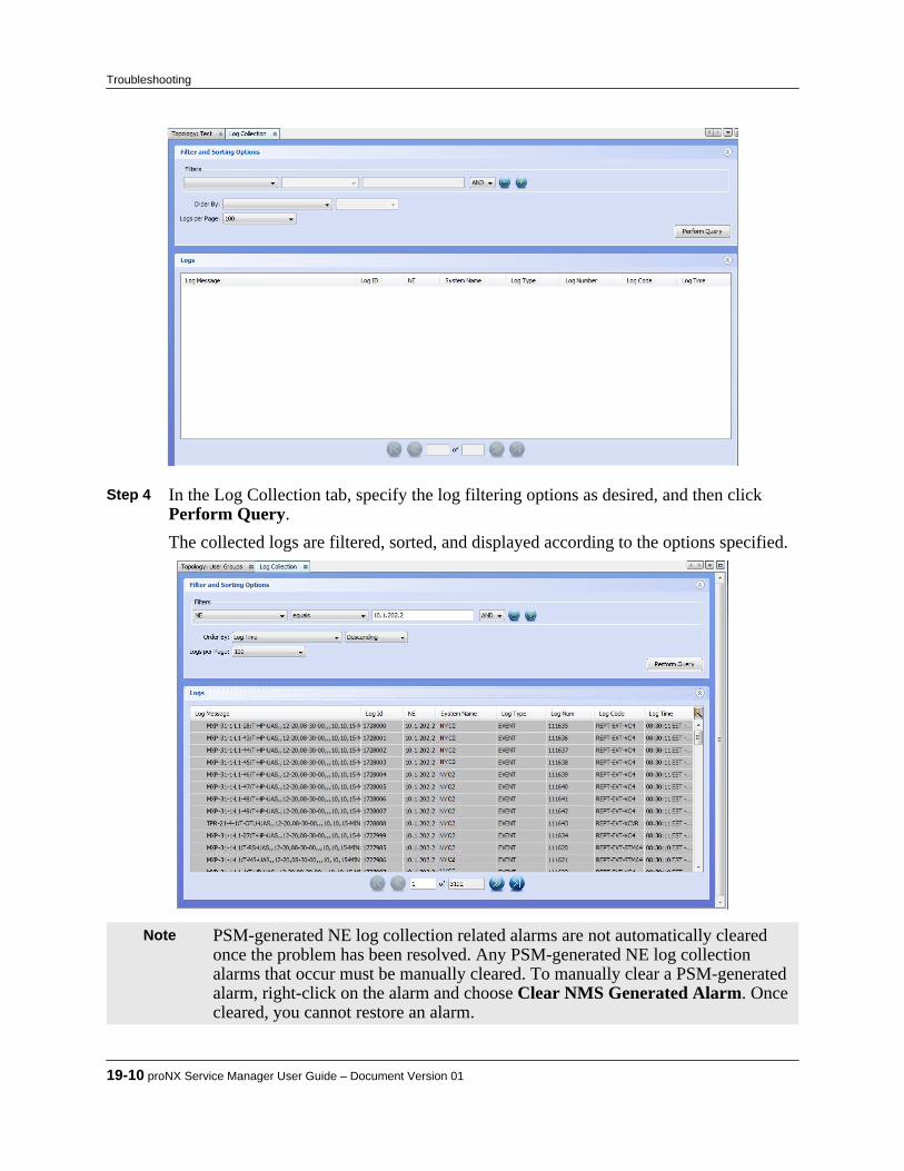
Step 4 In the Log Collection tab, specify the log filtering options as desired, and then click
Perform Query.The collected logs are filtered, sorted, and displayed according to the options specified.
Note PSM-generated NE log collection related alarms are not automatically clearedonce the problem has been resolved. Any PSM-generated NE log collectionalarms that occur must be manually cleared. To manually clear a PSM-generatedalarm, right-click on the alarm and choose Clear NMS Generated Alarm. Oncecleared, you cannot restore an alarm.
19-10 proNX Service Manager User Guide – Document Version 01
Troubleshooting
19.8 Saving network element configuration information
Use this procedure to save network element configuration data learned through SNMP to yourlocal computer.PSM lets you save an XML-formatted set of configuration data for a selected NE to your localcomputer. This configuration data is learned through SNMP. You can view the configurationdata to troubleshoot issues, or attach the XML document to an e-mail to send to your supportorganization.
Step 1 To save the configuration data for an NE, right-click the NE and select Utilities > Diagnostics > Save Configuration
Step 2 In the Save window, select a path in the Save in: field where you want to save the file.
The tool automatically assigns a .xml file extension to the file name.
Product Release 7.0 STANDARD 19-11
Troubleshooting

19.9 Troubleshooting server replication
This section describes how to troubleshoot server replication.
19.9.1 Loss of connectivity to the clusterWhen the PSM server loses connectivity with another member in the cluster, the server raises a'PSM cluster node connection lost' alarm, identifying the member with which connectivity hasbeen lost. Typically, the servers at both ends of the connection will raise the alarm, signifying aloss of connectivity with their counterpart.
When this occurs, it is best that you do not change any replicated data on the local server or onany server with which connectivity has been lost. If you do make changes, you may have tomanually reconcile these changes later. This becomes particularly complicated if there are morethan two servers in the cluster.
19.9.2 Loss of synchronization with a cluster memberWhen the PSM server loses synchronization with another member in the cluster, the server raisesa 'Synchronization failed against cluster node' alarm, identifying the member with whichsynchronization has been lost. Synchronization is declared lost when the remote member doesnot respond to a synchronization request. A server sends out synchronization requests on restartand on manual command.When this problem occurs, perform a manual synchronization (19.9.4, “Synchronizing replicateddata manually”).
19.9.3 Re-establishment of connectivity to the clusterWhen the PSM Server re-establishes connectivity with the other member(s), the server clears the'PSM cluster node connection lost' alarm(s).If you did not make any changes to the replicated data on the local server or on any of the serversfor which connectivity was lost, then you do not need to take any action. All servers have thecorrect replicated data and are synchronized.If you did make changes to the replicated data on the local server and/or on any of the otherservers for which connectivity was lost, then you will need to take the following action:• If there are only two members in the cluster, then follow the procedure in
19.9.4, “Synchronizing replicated data manually”.• If there are more than two members in the cluster, then follow the procedure in
19.9.5, “Restarting the cluster”.
19.9.4 Synchronizing replicated data manuallyUse this procedure to manually synchronize replicated data with other servers in a cluster.Before executing this command, ensure the following:
19-12 proNX Service Manager User Guide – Document Version 01
Troubleshooting
• When running with two servers in the cluster, ensure the other server has the correctreplicated data.
• When running with more than two servers in the cluster, ensure all other servers have thecorrect replicated data. If not all of the other servers have the correct replicated data, then donot run this command.
Perform manual synchronization of replicated data on the local server when you want the localserver to retrieve and adopt replicated data from the other servers. This is typically performedafter recovering from a loss of connectivity, but can be done at any time.Servers in a cluster do not automatically resynchronize with each other after recovering from aloss of connectivity because the servers have no way of knowing which server has the correctreplicated data. Instead, you have to decide which server has the correct replicated data, and thenmanually resynchronize all the other servers with that server.
Step 1 To force the local PSM server to manually synchronize with all servers in the cluster,select Tools > Synch Replication.
Note This option is not available for selection if server replication is disabled. See theproNX Service Manager Installation and Administration Guide for informationon how to enable server replication.
The local PSM server retrieves replicated data from all other servers in the cluster, andoverwrites its own replicated data with the retrieved data.
19.9.5 Restarting the clusterUse this procedure to restart the cluster with the correct replicated data.In order to execute this procedure, you must have access to the Linux operating system shell onthe PSM Server.
Step 1 Decide which server in the cluster has the correct replicated data. Leave this serverrunning.
Step 2 Stop the PSM server application on all the other servers. Step 3 Start the PSM server application on each server one by one.
Note Ensure each server is up and has the correct replicated data before bringing upthe next server.
Step 4 Proceed until all the servers are up and have the correct replicated data.
Note For information on how to stop and start the PSM Server, see the proNX ServiceManager Installation and Administration Guide.
Product Release 7.0 STANDARD 19-13
Troubleshooting

19-14 proNX Service Manager User Guide – Document Version 01
Troubleshooting
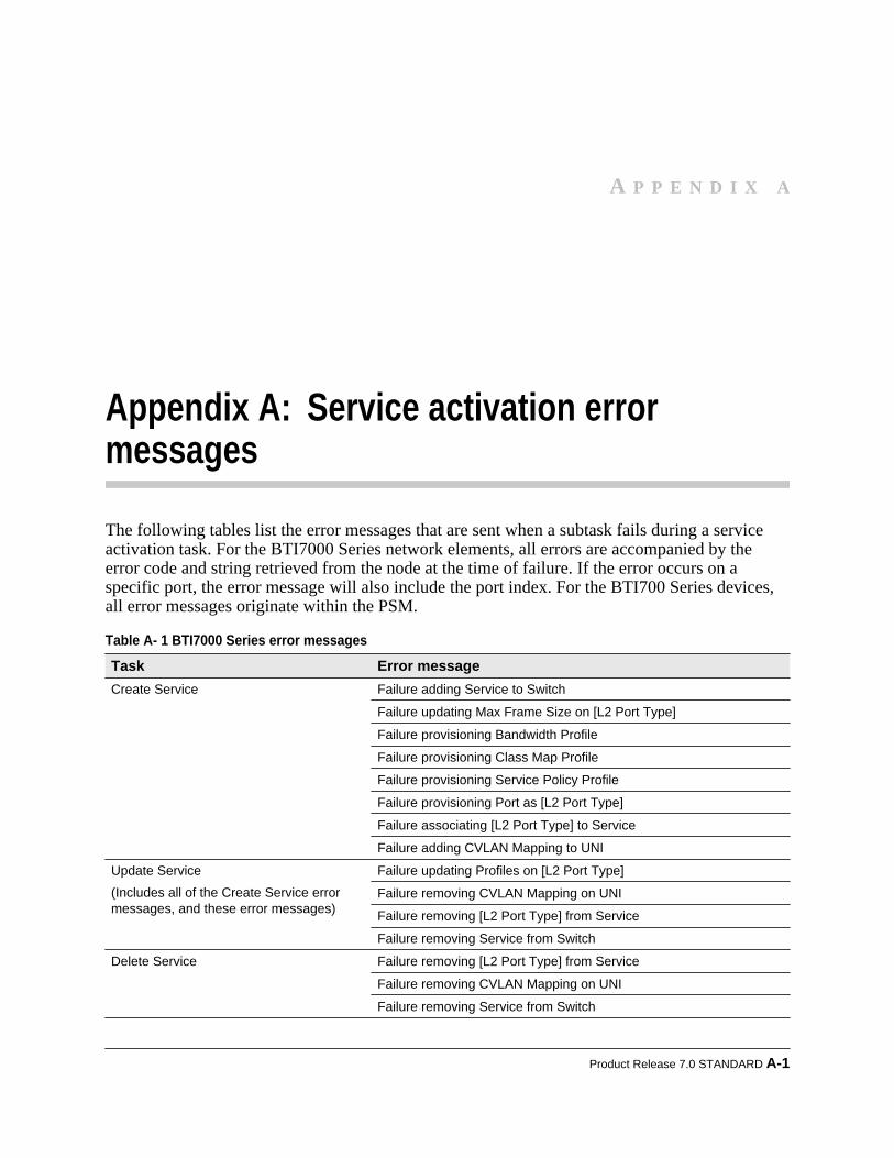
Appendix A: Service activation errormessages
The following tables list the error messages that are sent when a subtask fails during a serviceactivation task. For the BTI7000 Series network elements, all errors are accompanied by theerror code and string retrieved from the node at the time of failure. If the error occurs on aspecific port, the error message will also include the port index. For the BTI700 Series devices,all error messages originate within the PSM.
Table A- 1 BTI7000 Series error messages Task Error messageCreate Service Failure adding Service to Switch
Failure updating Max Frame Size on [L2 Port Type]
Failure provisioning Bandwidth Profile
Failure provisioning Class Map Profile
Failure provisioning Service Policy Profile
Failure provisioning Port as [L2 Port Type]
Failure associating [L2 Port Type] to Service
Failure adding CVLAN Mapping to UNI
Update Service
(Includes all of the Create Service errormessages, and these error messages)
Failure updating Profiles on [L2 Port Type]
Failure removing CVLAN Mapping on UNI
Failure removing [L2 Port Type] from Service
Failure removing Service from Switch
Delete Service Failure removing [L2 Port Type] from Service
Failure removing CVLAN Mapping on UNI
Failure removing Service from Switch
Product Release 7.0 STANDARD A-1
A P P E N D I X A

Table A- 2 BTI700 Series error messages Task Error messageCreate Service Failure adding Service to Switch
Failure adding Ports to Service
Failure provisioning [L2 Port Type]
Failure adding CVLAN Mappings to UNI
Failure adding VLAN 4094 for PVID on UNI
Failure setting PVID on UNI
Failure setting Profiles on [L2 Port Type]
Update Service
(Includes all of the Create Service errormessages, and these error messages)
Failure removing CVLAN Mappings from UNI
Failure removing [L2 Port Type] from Service
Delete Service Failure removing CVLAN Mappings from UNI
Failure removing Profiles from [L2 Port Type]
Failure removing Service from Switch
A-2 proNX Service Manager User Guide – Document Version 01
Appendix A: Service activation error messages
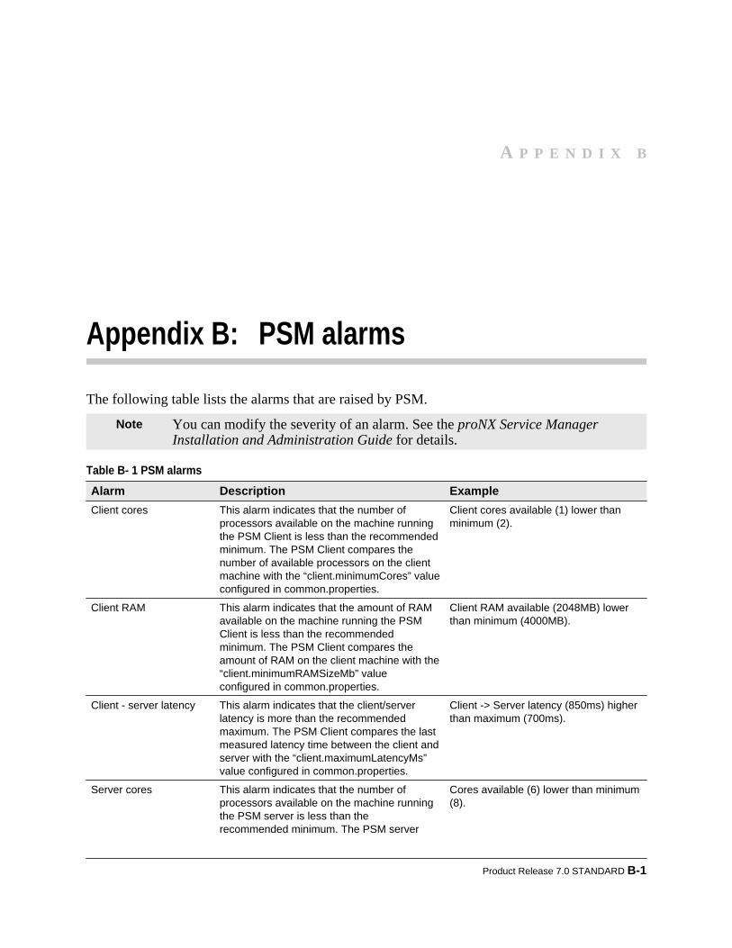
Appendix B: PSM alarms
The following table lists the alarms that are raised by PSM.
Note You can modify the severity of an alarm. See the proNX Service ManagerInstallation and Administration Guide for details.
Table B- 1 PSM alarms Alarm Description ExampleClient cores This alarm indicates that the number of
processors available on the machine runningthe PSM Client is less than the recommendedminimum. The PSM Client compares thenumber of available processors on the clientmachine with the “client.minimumCores” valueconfigured in common.properties.
Client cores available (1) lower thanminimum (2).
Client RAM This alarm indicates that the amount of RAMavailable on the machine running the PSMClient is less than the recommendedminimum. The PSM Client compares theamount of RAM on the client machine with the“client.minimumRAMSizeMb” valueconfigured in common.properties.
Client RAM available (2048MB) lowerthan minimum (4000MB).
Client - server latency This alarm indicates that the client/serverlatency is more than the recommendedmaximum. The PSM Client compares the lastmeasured latency time between the client andserver with the “client.maximumLatencyMs”value configured in common.properties.
Client -> Server latency (850ms) higherthan maximum (700ms).
Server cores This alarm indicates that the number ofprocessors available on the machine runningthe PSM server is less than therecommended minimum. The PSM server
Cores available (6) lower than minimum(8).
Product Release 7.0 STANDARD B-1
A P P E N D I X B

Table B- 1 PSM alarms (Continued) Alarm Description Example
compares the number of processors on theserver machine with the“widecastOS.minimumCores” valueconfigured in common.properties.
Server RAM This alarm indicates that the amount of RAMavailable on the machine running the PSMserver is less than the recommendedminimum. The PSM server compares theamount of RAM on the server machine withthe “widecastOS.minimumRAMSizeMb” valueconfigured in common.properties.
RAM available (3964MB) lower thanminimum (8000MB).
Server hard disk This alarm indicates that the amount of freeHard Disk space available on the machinerunning the PSM server is less than therecommended minimum. The PSM servercompares the amount of HDD space on theserver machine with the“widecastOS.minimiumDiskSizeMb” valueconfigured in common.properties.
HD available (24568MB) lower thanminimum (150000MB).
Unreachable networkelement
This alarm is raised when an attempt todiscover a device fails. The device will bepinged periodically to test whether it hasbecome reachable again. If the devicebecomes reachable then the alarm is cleared.
Network element 10.10.10.10 isunreachable.
Notifications stopped Connectivity to the indicated network elementfor receiving notifications has gone down andcannot be re-established. The NE is placedinto an AUTO out-of-service mode.
If this occurs, fix the underlying problem andrediscover the network element with thecorrect credentials.
Notifications stopped for 10.53.4.32 onstream StatusChange
Invalid FTP serverconfigured
This alarm is raised when the server fails toretrieve the FTP server configurationinformation based on the ID it is supplied fromthe request to perform an NE DB Backup task.
NE Database backup on PSM Serverhas invalid FTP server configured: 10.10.10.10:21:ftpuser
Invalid Remote ID This alarm is raised when the serverencounters an incorrectly-formatted RemoteID during topology discovery.
Invalid Remote ID format found[PVX-1-5-G2] PSM NE Invalid RemoteID
Remote ID mismatch This alarm is raised when the server detects aRemote ID mismatch where the two endpointsare not referring to each other. One alarm israised at each endpoint.
Remote ID mismatch found [PVX-1-5-G2] PSM NE Farend Mismatch
NE Link mismatch This alarm is raised when the server detects amismatch in topology between the LLDP dataand the Remote ID configuration. The serverignores the Remote ID and shows the LLDPtopology.
B-2 proNX Service Manager User Guide – Document Version 01
Appendix B: PSM alarms

Table B- 1 PSM alarms (Continued) Alarm Description ExampleNE DB backup failure This alarm is raised when an NE DB backup
process fails (either scheduled or startedmanually). The cause of the alarm can beattributed with any number of PSM server orNE issues, e.g. the NE DB backup processmay have exceeded the maximum timeallowed (300s), communication to the NE wasinterrupted, or the NE is unreachable. Thisalarm must be cleared manually.
NE DB Backup Failure. [Timed out after300000ms waiting for 7000’s trap.]. Lastfailure at Tue Aug 14 04:25:23 BST2012.
NE DB Backup Failure. NE isunreachable. Last failure at Tue Aug 1404:15:11 BST 2012.
NE DB restore failure This alarm is raised when an NE DB restoreprocess fails. The cause of the alarm can beattributed with any number of PSM server orNE issues, e.g. the NE DB restore processmay have exceeded the maximum timeallowed (300s), communication to the NE wasinterrupted, or the NE is unreachable. Thisalarm must be cleared manually.
NE DB Restore Failure. [Timed out after300000ms waiting for 7000’s trap.]. Lastfailure at Tue Aug 14 04:25:23 BST2012.
NE DB Restore Failure. NE isunreachable. Last failure at Tue Aug 1404:15:11 BST 2012.
NE log collection failure This alarm is raised when an NE LogCollection process fails. The cause of thealarm can be attributed with any number ofPSM server or NE issues, e.g. the NE LogCollection process may have exceeded themaximum time allowed (500s),communication to the NE was interrupted, orthe NE is unreachable. This alarm must becleared manually.
Log Collection Failure. NE isunreachable. Last failure at Fri Jul 1302:00:03 BST 2012.
NE software upgradefailure
This alarm is raised when an NE SoftwareUpgrade process fails. The cause of the alarmcan be attributed with any number of server orNE issues, e.g. the NE S/W Upgrade processtimes out, a failure of one of the upgradesteps on the NE or the NE is unreachable.This alarm must be cleared manually.
ERPS state change This alarm is raised when an ERPS ring goesinto protecting, pending, forced protecting, ormanual protecting state. Although this alarmis raised by PSM, this alarm is alsoassociated with the ERPS service. A changeto protecting state is a major alarm, while achange to other states is a minor alarm.
ERPS Ring SUB_ERPS (SVLAN 4089)is in Protection State
ERPS Ring MAIN_RING (SVLAN 200)is in Pending State in Domain Ottawa
ERPS dynamic port If GVRP has added ports dynamically to anyERPS rings in the network, these ports areremoved from view when the ring isvisualized. A minor alarm is raised indicatingtheir presence.
ERPS Ring MAIN_RING (SVLAN 200)has Dynamically Added Ports
ERPS Ring MAIN_RING (SVLAN 200)has Dynamically Added Ports inDomain Ottawa
PSM cluster nodeconnection lost
When running with server replication, thisalarm is raised if a connection to a member ofa server replication cluster is lost. The IPaddress of the remote member is identified inthe alarm. This alarm is cleared once
PSM cluster node 10.53.4.32connection lost
Product Release 7.0 STANDARD B-3
Appendix B: PSM alarms

Table B- 1 PSM alarms (Continued) Alarm Description Example
connection to the remote member is re-established.
Replication processingagainst cluster nodefailed
When running with server replication, thisalarm is raised if the server encountersproblems while processing the replicationmessage from another server in the cluster.The IP address of the remote member isidentified in the alarm. This alarm can only becleared manually.
Replication processing against clusternode 10.53.4.32 failed for GROUPS
Synchronization failedagainst cluster node
When running with server replication, thisalarm is raised if the server fails tosynchronize with another server in the cluster.The IP address of the remote member isidentified in the alarm. This alarm is clearedwhen a successful synchronization with theremote member occurs. This alarm can alsobe cleared manually.
Synchronization failed against clusternode 10.53.4.32
B-4 proNX Service Manager User Guide – Document Version 01
Appendix B: PSM alarms
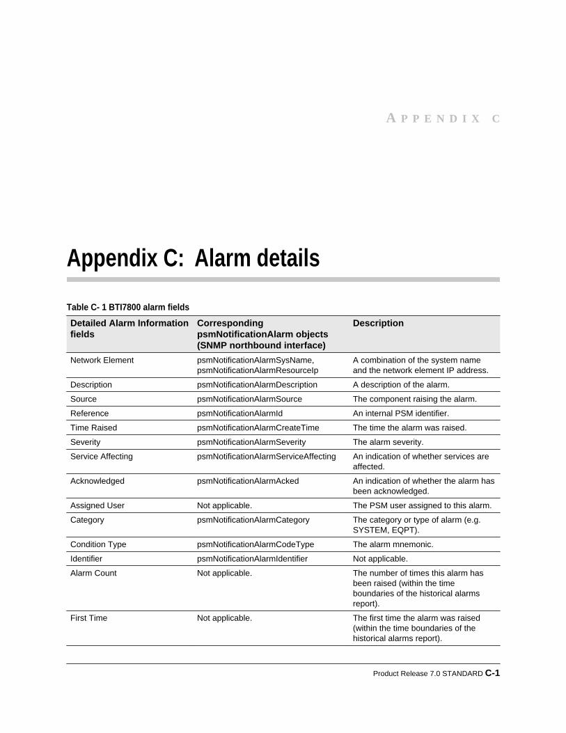
Appendix C: Alarm details
Table C- 1 BTI7800 alarm fields Detailed Alarm Informationfields
CorrespondingpsmNotificationAlarm objects(SNMP northbound interface)
Description
Network Element psmNotificationAlarmSysName,psmNotificationAlarmResourceIp
A combination of the system nameand the network element IP address.
Description psmNotificationAlarmDescription A description of the alarm.
Source psmNotificationAlarmSource The component raising the alarm.
Reference psmNotificationAlarmId An internal PSM identifier.
Time Raised psmNotificationAlarmCreateTime The time the alarm was raised.
Severity psmNotificationAlarmSeverity The alarm severity.
Service Affecting psmNotificationAlarmServiceAffecting An indication of whether services areaffected.
Acknowledged psmNotificationAlarmAcked An indication of whether the alarm hasbeen acknowledged.
Assigned User Not applicable. The PSM user assigned to this alarm.
Category psmNotificationAlarmCategory The category or type of alarm (e.g.SYSTEM, EQPT).
Condition Type psmNotificationAlarmCodeType The alarm mnemonic.
Identifier psmNotificationAlarmIdentifier Not applicable.
Alarm Count Not applicable. The number of times this alarm hasbeen raised (within the timeboundaries of the historical alarmsreport).
First Time Not applicable. The first time the alarm was raised(within the time boundaries of thehistorical alarms report).
Product Release 7.0 STANDARD C-1
A P P E N D I X C
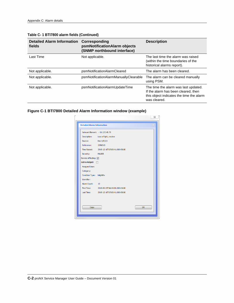
Table C- 1 BTI7800 alarm fields (Continued) Detailed Alarm Informationfields
CorrespondingpsmNotificationAlarm objects(SNMP northbound interface)
Description
Last Time Not applicable. The last time the alarm was raised(within the time boundaries of thehistorical alarms report).
Not applicable. psmNotificationAlarmCleared The alarm has been cleared.
Not applicable. psmNotificationAlarmManuallyClearable The alarm can be cleared manuallyusing PSM.
Not applicable. psmNotificationAlarmUpdateTime The time the alarm was last updated.If the alarm has been cleared, thenthis object indicates the time the alarmwas cleared.
Figure C-1 BTI7800 Detailed Alarm Information window (example)
C-2 proNX Service Manager User Guide – Document Version 01
Appendix C: Alarm details

Appendix D: Historical PM counters
This section contains a short description of the historical PM counters that PSM retrieves anddisplays.
Product Release 7.0 STANDARD D-1
A P P E N D I X D
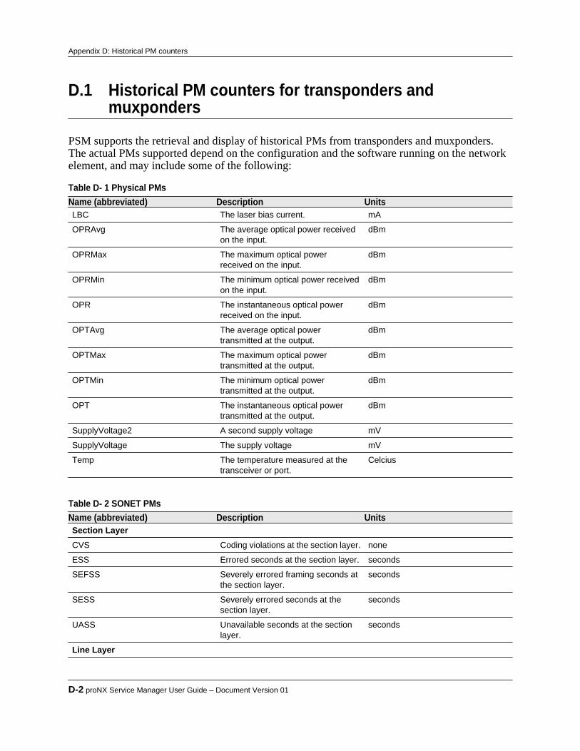
D.1 Historical PM counters for transponders andmuxponders
PSM supports the retrieval and display of historical PMs from transponders and muxponders.The actual PMs supported depend on the configuration and the software running on the networkelement, and may include some of the following:
Table D- 1 Physical PMs Name (abbreviated) Description UnitsLBC The laser bias current. mA
OPRAvg The average optical power receivedon the input.
dBm
OPRMax The maximum optical powerreceived on the input.
dBm
OPRMin The minimum optical power receivedon the input.
dBm
OPR The instantaneous optical powerreceived on the input.
dBm
OPTAvg The average optical powertransmitted at the output.
dBm
OPTMax The maximum optical powertransmitted at the output.
dBm
OPTMin The minimum optical powertransmitted at the output.
dBm
OPT The instantaneous optical powertransmitted at the output.
dBm
SupplyVoltage2 A second supply voltage mV
SupplyVoltage The supply voltage mV
Temp The temperature measured at thetransceiver or port.
Celcius
Table D- 2 SONET PMs Name (abbreviated) Description UnitsSection LayerCVS Coding violations at the section layer. none
ESS Errored seconds at the section layer. seconds
SEFSS Severely errored framing seconds atthe section layer.
seconds
SESS Severely errored seconds at thesection layer.
seconds
UASS Unavailable seconds at the sectionlayer.
seconds
Line Layer
D-2 proNX Service Manager User Guide – Document Version 01
Appendix D: Historical PM counters
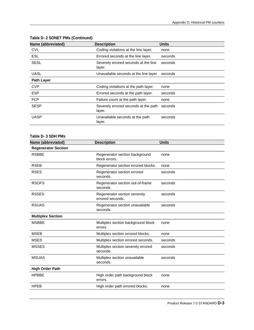
Table D- 2 SONET PMs (Continued) Name (abbreviated) Description UnitsCVL Coding violations at the line layer. none
ESL Errored seconds at the line layer. seconds
SESL Severely errored seconds at the linelayer.
seconds
UASL Unavailable seconds at the line layer. seconds
Path LayerCVP Coding violations at the path layer. none
ESP Errored seconds at the path layer. seconds
FCP Failure count at the path layer. none
SESP Severely errored seconds at the pathlayer.
seconds
UASP Unavailable seconds at the pathlayer.
seconds
Table D- 3 SDH PMs Name (abbreviated) Description UnitsRegenerator SectionRSBBE Regenerator section background
block errors.none
RSEB Regenerator section errored blocks. none
RSES Regenerator section erroredseconds.
seconds
RSOFS Regenerator section out-of-frameseconds.
seconds
RSSES Regenerator section severelyerrored seconds.
seconds
RSUAS Regenerator section unavailableseconds.
seconds
Multiplex SectionMSBBE Multiplex section background block
errors.none
MSEB Multiplex section errored blocks. none
MSES Multiplex section errored seconds. seconds
MSSES Multiplex section severely erroredseconds.
seconds
MSUAS Multiplex section unavailableseconds.
seconds
High Order PathHPBBE High order path background block
errors.none
HPEB High order path errored blocks. none
Product Release 7.0 STANDARD D-3
Appendix D: Historical PM counters
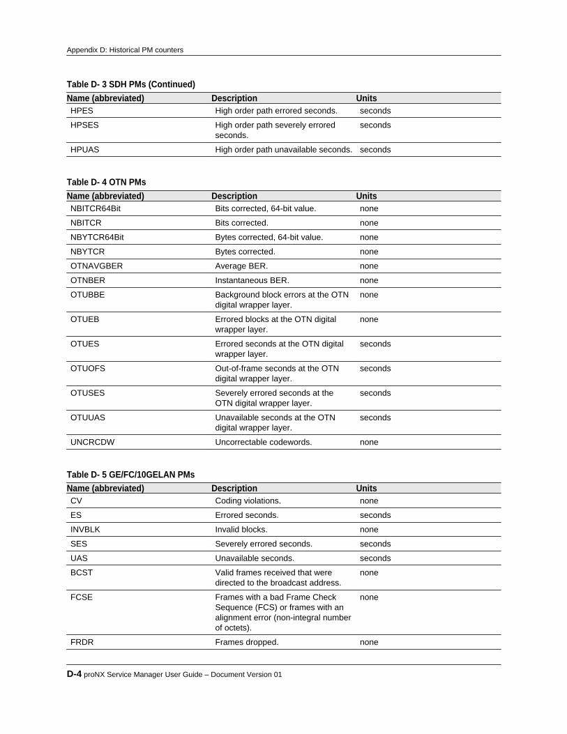
Table D- 3 SDH PMs (Continued) Name (abbreviated) Description UnitsHPES High order path errored seconds. seconds
HPSES High order path severely erroredseconds.
seconds
HPUAS High order path unavailable seconds. seconds
Table D- 4 OTN PMs Name (abbreviated) Description UnitsNBITCR64Bit Bits corrected, 64-bit value. none
NBITCR Bits corrected. none
NBYTCR64Bit Bytes corrected, 64-bit value. none
NBYTCR Bytes corrected. none
OTNAVGBER Average BER. none
OTNBER Instantaneous BER. none
OTUBBE Background block errors at the OTNdigital wrapper layer.
none
OTUEB Errored blocks at the OTN digitalwrapper layer.
none
OTUES Errored seconds at the OTN digitalwrapper layer.
seconds
OTUOFS Out-of-frame seconds at the OTNdigital wrapper layer.
seconds
OTUSES Severely errored seconds at theOTN digital wrapper layer.
seconds
OTUUAS Unavailable seconds at the OTNdigital wrapper layer.
seconds
UNCRCDW Uncorrectable codewords. none
Table D- 5 GE/FC/10GELAN PMs Name (abbreviated) Description UnitsCV Coding violations. none
ES Errored seconds. seconds
INVBLK Invalid blocks. none
SES Severely errored seconds. seconds
UAS Unavailable seconds. seconds
BCST Valid frames received that weredirected to the broadcast address.
none
FCSE Frames with a bad Frame CheckSequence (FCS) or frames with analignment error (non-integral numberof octets).
none
FRDR Frames dropped. none
D-4 proNX Service Manager User Guide – Document Version 01
Appendix D: Historical PM counters

Table D- 5 GE/FC/10GELAN PMs (Continued) Name (abbreviated) Description UnitsFRGT Frames received that were less than
64 octets in length and that had anFCS error or an alignment error.
none
JABR Frames received longer than themaximum MTU size, includingframes with FCS errors or alignmenterrors.
none
MCST Valid frames received that weredirected to a multicast address.
none
OSIZE Frames received that were greaterthan 9600 octets in length, but wereotherwise valid.
none
SIZE64 Frames received with the specifiedlength or range (excluding framingbits but including FCS).
none
SIZE65To127 Frames received with the specifiedlength or range (excluding framingbits but including FCS).
none
SIZE128To255 Frames received with the specifiedlength or range (excluding framingbits but including FCS).
none
SIZE256To511 Frames received with the specifiedlength or range (excluding framingbits but including FCS).
none
SIZE512To1023 Frames received with the specifiedlength or range (excluding framingbits but including FCS).
none
SIZE1024To1518 Frames received with the specifiedlength or range (excluding framingbits but including FCS).
none
SIZEOver1518 Frames received with the specifiedlength or range (excluding framingbits but including FCS).
none
TBYCRX Total bytes of data received fromvalid and invalid frames.
none
TBYCTX Total bytes of data transmitted. none
TFRCRX Total frames received including validand invalid frames, broadcastframes, and multicast frames.
none
TFRCTX Total frames transmitted. none
TPFCRX Total PAUSE frames received. none
TPFCTX Total PAUSE frames transmitted. none
USIZE Frames received that were less than64 octets in length, but wereotherwise valid.
none
Product Release 7.0 STANDARD D-5
Appendix D: Historical PM counters

For information on what ports and protocols support these PMs, see the BTI7000 SeriesTransponder Solutions Guide and the BTI7000 Series Muxponder Solutions Guide.
D-6 proNX Service Manager User Guide – Document Version 01
Appendix D: Historical PM counters
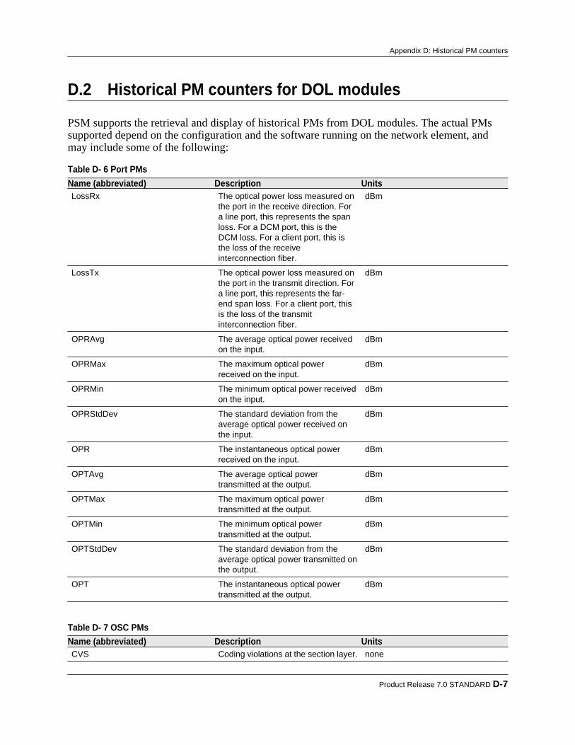
D.2 Historical PM counters for DOL modules
PSM supports the retrieval and display of historical PMs from DOL modules. The actual PMssupported depend on the configuration and the software running on the network element, andmay include some of the following:
Table D- 6 Port PMs Name (abbreviated) Description UnitsLossRx The optical power loss measured on
the port in the receive direction. Fora line port, this represents the spanloss. For a DCM port, this is theDCM loss. For a client port, this isthe loss of the receiveinterconnection fiber.
dBm
LossTx The optical power loss measured onthe port in the transmit direction. Fora line port, this represents the far-end span loss. For a client port, thisis the loss of the transmitinterconnection fiber.
dBm
OPRAvg The average optical power receivedon the input.
dBm
OPRMax The maximum optical powerreceived on the input.
dBm
OPRMin The minimum optical power receivedon the input.
dBm
OPRStdDev The standard deviation from theaverage optical power received onthe input.
dBm
OPR The instantaneous optical powerreceived on the input.
dBm
OPTAvg The average optical powertransmitted at the output.
dBm
OPTMax The maximum optical powertransmitted at the output.
dBm
OPTMin The minimum optical powertransmitted at the output.
dBm
OPTStdDev The standard deviation from theaverage optical power transmitted onthe output.
dBm
OPT The instantaneous optical powertransmitted at the output.
dBm
Table D- 7 OSC PMs Name (abbreviated) Description UnitsCVS Coding violations at the section layer. none
Product Release 7.0 STANDARD D-7
Appendix D: Historical PM counters

Table D- 7 OSC PMs (Continued) Name (abbreviated) Description UnitsESS Errored seconds at the section layer. seconds
OBR The optical back-reflected power. dBm
OPR The instantaneous optical powerreceived on the input.
dBm
OPT The instantaneous optical powertransmitted at the output.
dBm
SEFSS Severely errored framing seconds atthe section layer.
seconds
SESS Severely errored seconds at thesection layer.
seconds
UASS Unavailable seconds at the sectionlayer.
seconds
Table D- 8 Wavelength Channel PMs Name (abbreviated) Description UnitsOPRMax The maximum optical power
received on the input.dBm
OPRMin The minimum optical power receivedon the input.
dBm
OPR The instantaneous optical powerreceived on the input.
dBm
OPTMax The maximum optical powertransmitted at the output.
dBm
OPTMin The minimum optical powertransmitted at the output.
dBm
OPT The instantaneous optical powertransmitted at the output.
dBm
For information on what ports and protocols support these PMs, see the BTI7000 Series DynamicOptical Layer Engineering Guideline.
D-8 proNX Service Manager User Guide – Document Version 01
Appendix D: Historical PM counters

D.3 Historical PM counters for packetVX modules
PSM supports the retrieval and display of historical PMs from PVX modules. The actual PMssupported depend on the configuration and the software running on the network element, andmay include some of the following:
Table D- 9 Physical PMs Name (abbreviated) Description UnitsLBC The laser bias current. mA
OPRAvg The average optical power receivedon the input.
dBm
OPRMax The maximum optical powerreceived on the input.
dBm
OPRMin The minimum optical power receivedon the input.
dBm
OPR The instantaneous optical powerreceived on the input.
dBm
OPTAvg The average optical powertransmitted at the output.
dBm
OPTMax The maximum optical powertransmitted at the output.
dBm
OPTMin The minimum optical powertransmitted at the output.
dBm
OPT The instantaneous optical powertransmitted at the output.
dBm
SupplyVoltage2 A second supply voltage mV
SupplyVoltage The supply voltage mV
Temp The temperature measured at thetransceiver or port.
Celcius
Table D- 10 OTN PMs Name (abbreviated) Description UnitsNBITCR64Bit Bits corrected, 64-bit value. none
NBITCR Bits corrected. none
NBYTCR64Bit Bytes corrected, 64-bit value. none
NBYTCR Bytes corrected. none
OTNAVGBER Average BER. none
OTNBER Instantaneous BER. none
OTUBBE Background block errors at the OTNdigital wrapper layer.
none
OTUEB Errored blocks at the OTN digitalwrapper layer.
none
OTUES Errored seconds at the OTN digitalwrapper layer.
seconds
Product Release 7.0 STANDARD D-9
Appendix D: Historical PM counters

Table D- 10 OTN PMs (Continued) Name (abbreviated) Description UnitsOTUOFS Out-of-frame seconds at the OTN
digital wrapper layer.seconds
OTUSES Severely errored seconds at theOTN digital wrapper layer.
seconds
OTUUAS Unavailable seconds at the OTNdigital wrapper layer.
seconds
UNCRCDW Uncorrectable codewords. none
Table D- 11 GE/10GE PMs Name (abbreviated) Description UnitsCV 8B/10B coding violations for GE
ports.none
ES Errored seconds. seconds
INVBLK Invalid blocks on 10GE ports. dBm
SES Severely errored seconds. seconds
UASS Unavailable seconds for GE ports. seconds
Table D- 12 Ethernet L2 PMs Name (abbreviated) Description UnitsBCST Valid frames received that were
directed to the broadcast address.none
FCSE Frames with a bad Frame CheckSequence (FCS) or frames with analignment error (non-integral numberof octets).
none
FRDR Frames dropped. none
FRGT Frames received that were less than64 octets in length and that had anFCS error or an alignment error.
none
MCST Valid frames received that weredirected to a multicast address.
none
OSIZE Frames received that were greaterthan 9600 octets in length, but wereotherwise valid.
none
SIZE64 Frames received with the specifiedlength or range (excluding framingbits but including FCS).
none
SIZE65To127 Frames received with the specifiedlength or range (excluding framingbits but including FCS).
none
SIZE128To255 Frames received with the specifiedlength or range (excluding framingbits but including FCS).
none
D-10 proNX Service Manager User Guide – Document Version 01
Appendix D: Historical PM counters

Table D- 12 Ethernet L2 PMs (Continued) Name (abbreviated) Description UnitsSIZE256To511 Frames received with the specified
length or range (excluding framingbits but including FCS).
none
SIZE512To1023 Frames received with the specifiedlength or range (excluding framingbits but including FCS).
none
SIZE1024To1518 Frames received with the specifiedlength or range (excluding framingbits but including FCS).
none
SIZEOver1518 Frames received with the specifiedlength or range (excluding framingbits but including FCS).
none
TBYCRX Total bytes of data received fromvalid and invalid frames.
none
TBYCTX Total bytes of data transmitted. none
TFRCRX Total frames received including validand invalid frames, broadcastframes, and multicast frames.
none
TFRCTX Total frames transmitted. none
TPFCRX Total PAUSE frames received. none
TPFCTX Total PAUSE frames transmitted. none
USIZE Frames received that were less than64 octets in length, but wereotherwise valid.
none
Table D- 13 LAG PMs Name (abbreviated) Description UnitsINVLACFRRX The count of invalid Link Access
Control frames received on the LAGport.
none
LACPDURX The total Link Access Control PDUsreceived on the LAG port.
none
LACPDUTX The total Link Access Control PDUstransmitted on the LAG port.
none
MRKPDURX The count of Marker PDUs receivedon the LAG port.
none
MRKPDUTX The count of Marker PDUstransmitted on the LAG port.
none
MRKRSPPDURX The count of Marker ResponsePDUs received on the LAG port.
none
MRKRSPPDUTX The count of Marker ResponsePDUs transmitted on the LAG port.
none
Product Release 7.0 STANDARD D-11
Appendix D: Historical PM counters
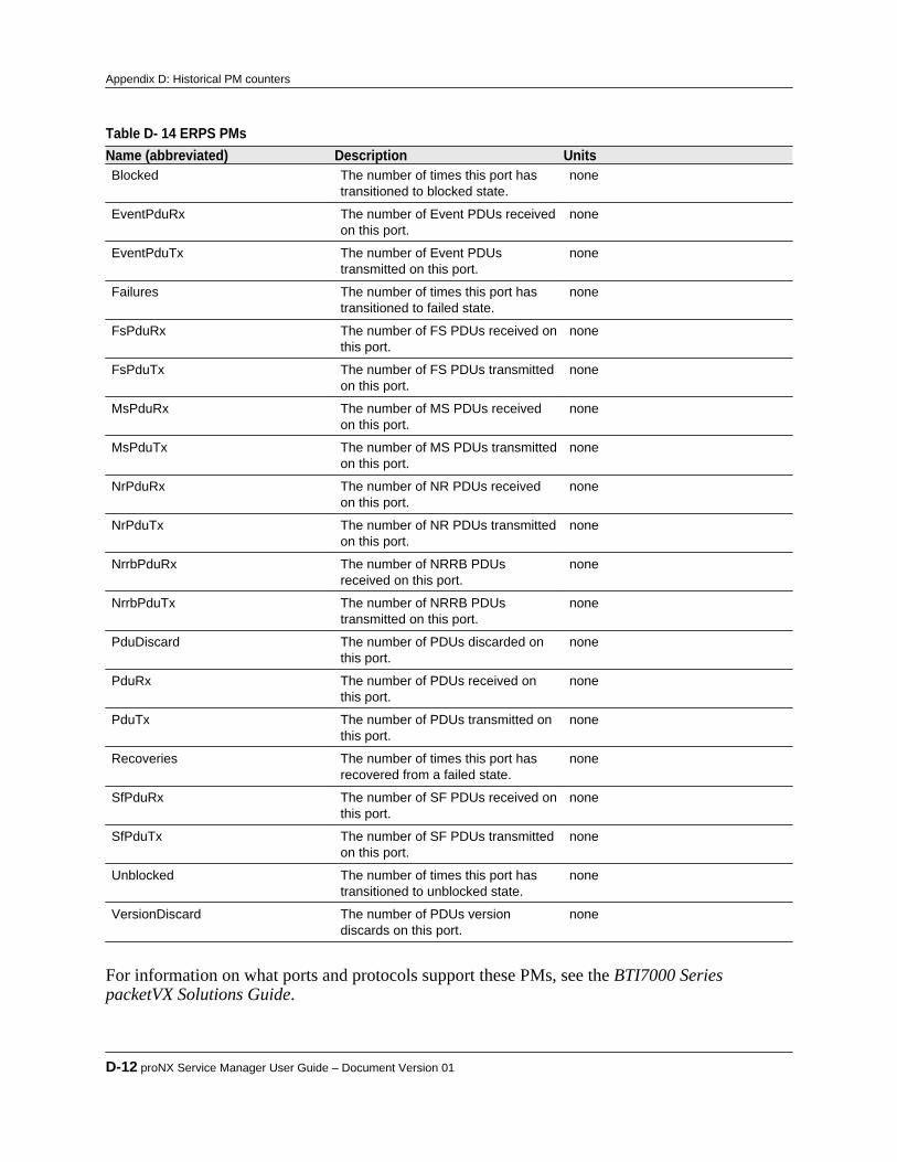
Table D- 14 ERPS PMs Name (abbreviated) Description UnitsBlocked The number of times this port has
transitioned to blocked state.none
EventPduRx The number of Event PDUs receivedon this port.
none
EventPduTx The number of Event PDUstransmitted on this port.
none
Failures The number of times this port hastransitioned to failed state.
none
FsPduRx The number of FS PDUs received onthis port.
none
FsPduTx The number of FS PDUs transmittedon this port.
none
MsPduRx The number of MS PDUs receivedon this port.
none
MsPduTx The number of MS PDUs transmittedon this port.
none
NrPduRx The number of NR PDUs receivedon this port.
none
NrPduTx The number of NR PDUs transmittedon this port.
none
NrrbPduRx The number of NRRB PDUsreceived on this port.
none
NrrbPduTx The number of NRRB PDUstransmitted on this port.
none
PduDiscard The number of PDUs discarded onthis port.
none
PduRx The number of PDUs received onthis port.
none
PduTx The number of PDUs transmitted onthis port.
none
Recoveries The number of times this port hasrecovered from a failed state.
none
SfPduRx The number of SF PDUs received onthis port.
none
SfPduTx The number of SF PDUs transmittedon this port.
none
Unblocked The number of times this port hastransitioned to unblocked state.
none
VersionDiscard The number of PDUs versiondiscards on this port.
none
For information on what ports and protocols support these PMs, see the BTI7000 SeriespacketVX Solutions Guide.
D-12 proNX Service Manager User Guide – Document Version 01
Appendix D: Historical PM counters
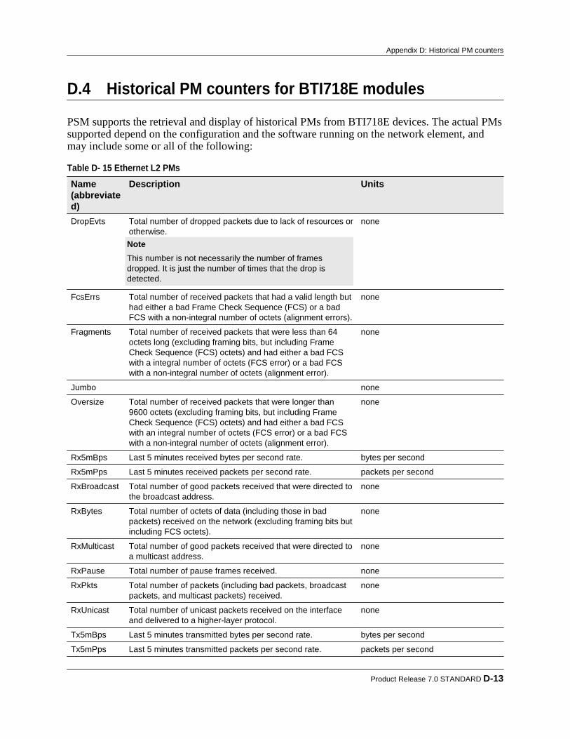
D.4 Historical PM counters for BTI718E modules
PSM supports the retrieval and display of historical PMs from BTI718E devices. The actual PMssupported depend on the configuration and the software running on the network element, andmay include some or all of the following:
Table D- 15 Ethernet L2 PMs Name(abbreviated)
Description Units
DropEvts Total number of dropped packets due to lack of resources orotherwise. Note This number is not necessarily the number of framesdropped. It is just the number of times that the drop isdetected.
none
FcsErrs Total number of received packets that had a valid length buthad either a bad Frame Check Sequence (FCS) or a badFCS with a non-integral number of octets (alignment errors).
none
Fragments Total number of received packets that were less than 64octets long (excluding framing bits, but including FrameCheck Sequence (FCS) octets) and had either a bad FCSwith a integral number of octets (FCS error) or a bad FCSwith a non-integral number of octets (alignment error).
none
Jumbo none
Oversize Total number of received packets that were longer than9600 octets (excluding framing bits, but including FrameCheck Sequence (FCS) octets) and had either a bad FCSwith an integral number of octets (FCS error) or a bad FCSwith a non-integral number of octets (alignment error).
none
Rx5mBps Last 5 minutes received bytes per second rate. bytes per second
Rx5mPps Last 5 minutes received packets per second rate. packets per second
RxBroadcast Total number of good packets received that were directed tothe broadcast address.
none
RxBytes Total number of octets of data (including those in badpackets) received on the network (excluding framing bits butincluding FCS octets).
none
RxMulticast Total number of good packets received that were directed toa multicast address.
none
RxPause Total number of pause frames received. none
RxPkts Total number of packets (including bad packets, broadcastpackets, and multicast packets) received.
none
RxUnicast Total number of unicast packets received on the interfaceand delivered to a higher-layer protocol.
none
Tx5mBps Last 5 minutes transmitted bytes per second rate. bytes per second
Tx5mPps Last 5 minutes transmitted packets per second rate. packets per second
Product Release 7.0 STANDARD D-13
Appendix D: Historical PM counters

Table D- 15 Ethernet L2 PMs (Continued) Name(abbreviated)
Description Units
TxBroadcast Total number of packets transmitted that were directed tothe broadcast address.
none
TxBytes Total number of octets of data transmitted on the network(excluding framing bits but including FCS octets).
none
TxMulticast Total number of packets transmitted that were directed to amulticast address.
none
TxPause Total number of pause frames transmitted. none
TxPkts Total number of packets (including broadcast packets andmulticast packets) transmitted.
none
TxUnicast Total number of packets that higher-layer protocolsrequested to be transmitted to a unicast address, includingthose that were discarded or not sent.
none
Undersize Total number of packets received that were less than 64octets long (excluding framing bits, but including FrameCheck Sequence (FCS) octets) and were otherwise wellformed.
none
For information on these PMs, see the BTI718E Ethernet Access Device Technical ProductGuide.
D-14 proNX Service Manager User Guide – Document Version 01
Appendix D: Historical PM counters
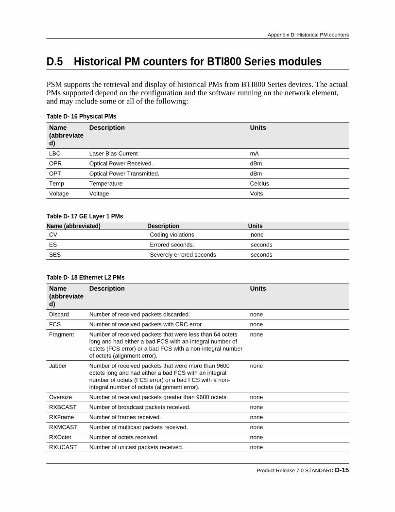
D.5 Historical PM counters for BTI800 Series modules
PSM supports the retrieval and display of historical PMs from BTI800 Series devices. The actualPMs supported depend on the configuration and the software running on the network element,and may include some or all of the following:
Table D- 16 Physical PMs Name(abbreviated)
Description Units
LBC Laser Bias Current mA
OPR Optical Power Received. dBm
OPT Optical Power Transmitted. dBm
Temp Temperature Celcius
Voltage Voltage Volts
Table D- 17 GE Layer 1 PMs Name (abbreviated) Description UnitsCV Coding violations none
ES Errored seconds. seconds
SES Severely errored seconds. seconds
Table D- 18 Ethernet L2 PMs Name(abbreviated)
Description Units
Discard Number of received packets discarded. none
FCS Number of received packets with CRC error. none
Fragment Number of received packets that were less than 64 octetslong and had either a bad FCS with an integral number ofoctets (FCS error) or a bad FCS with a non-integral numberof octets (alignment error).
none
Jabber Number of received packets that were more than 9600octets long and had either a bad FCS with an integralnumber of octets (FCS error) or a bad FCS with a non-integral number of octets (alignment error).
none
Oversize Number of received packets greater than 9600 octets. none
RXBCAST Number of broadcast packets received. none
RXFrame Number of frames received. none
RXMCAST Number of multicast packets received. none
RXOctet Number of octets received. none
RXUCAST Number of unicast packets received. none
Product Release 7.0 STANDARD D-15
Appendix D: Historical PM counters

Table D- 18 Ethernet L2 PMs (Continued) Name(abbreviated)
Description Units
TXBCAST Number of broadcast packets transmitted. none
TXFrame Number of frames transmitted. none
TXMCAST Number of multicast packets transmitted. none
TXOctet Number of octets transmitted. none
TXUCAST Number of unicast packets transmitted. none
Undersize Number of received packets less than 64 octets. none
For information on these PMs, see the BTI800 Series Technical Product Guide.
D-16 proNX Service Manager User Guide – Document Version 01
Appendix D: Historical PM counters

Appendix E: Installing Net-SNMP
Use this procedure to install Net-SNMP.The Simple Network Management Protocol (SNMP) is a messaging protocol used by the switchto communicate configuration and status information with a network management system.SNMP messages are exchanged within a SNMP community, which consists of one or moreswitches and one or more management workstations. Membership in a community is controlledby community strings, which function as passwords for the community. The community stringsare embedded in every SNMP packet exchanged between the members of the community toauthenticate access to the Management Information Base (MIB) on the switch.Net-SNMP is a suite of applications used to implement SNMP using IPv4 or IPv6. proNXService Manager uses Net-SNMP to deliver functionality offered in the CLI utilities. See9.5, “Configuring utilities” for examples.For detailed information and Net-SNMP download executables, go to www.net-snmp.org.
Step 1 Navigate to and download the latest version of Net-SNMP at www.net-snmp.org/download.html.
Step 2 Install Net-SNMP following the installation instructions. Use the suggested default
settings. Step 3 To confirm that Net-SNMP is installed, use proNX Service Manager to execute an
SNMP ping against a network element.
a) Right-click a network element and select Utilities>Diagnostics>SNMP Ping.A command window should pop up with the output of the SNMP ping command:
Product Release 7.0 STANDARD E-1
A P P E N D I X E
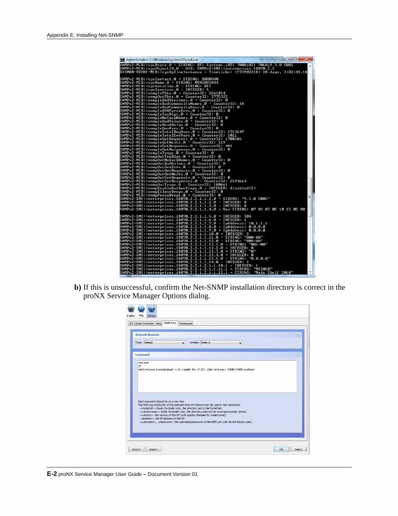
b) If this is unsuccessful, confirm the Net-SNMP installation directory is correct in theproNX Service Manager Options dialog.
E-2 proNX Service Manager User Guide – Document Version 01
Appendix E: Installing Net-SNMP

Appendix F: Configuring historical PMcollection on BTI800 Series network elements
In order for PSM to retrieve historical PMs from BTI800 Series network elements, you mustconfigure the BTI800 Series network elements to transfer the historical PM counts to the PSMserver. Unlike historical PM collection for the other NE types, BTI800 Series network elementsstore historical PM counts in CSV files that must be transferred to the PSM server.This procedure is required regardless of whether you are running scheduled or on-demandhistorical PMs.
Note The generated CSV files are named using the NE name. Therefore each BTI800Series network element must be configured with a unique name to ensure theCSV files that it generates have unique names when placed on the PSM server.
Note Ensure the BTI800 Series network element is not also reporting statistics to theSLA Portal. You cannot use both PSM and the SLA Portal to retrieve countsfrom BTI800 Series network elements at the same time.
The following steps are performed using the CLI on the BTI800 Series network element:
Step 1 Configure the NTP server if one is not already configured.The following specifies the NTP server to use, and sets the time zone to EST.configure ntp del-server 1configure ntp add-server <ntp_server_ip>configure ntp enableconfigure timezone est
Step 2 Disable any existing PM collection and file transfer.
configure pm file-transfer disableconfigure pm sys disable
Product Release 7.0 STANDARD F-1
A P P E N D I X F

configure pm eth disableconfigure pm oam disableconfigure pm eservice disableconfigure pm eservice last5m disableconfigure interface average-rate disable
Step 3 Enable Ethernet PM collection.
configure pm eth enable Step 4 Configure PM file transfer.
The following configures the BTI800 Series switch to transfer 15-minute and 1-dayEthernet PMs to the PSM server every hour, which is the highest recommended uploadfrequency. To change/decrease the frequency of the file transfer, change the setting ofthe upload-mode parameter.configure pm file-transfer mode sftpconfigure pm file-transfer target <server_ip> <username> <password> <dest_dir> <sftp_port>configure pm file-transfer upload-bin group del allconfigure pm file-transfer upload-bin group add 15mconfigure pm file-transfer upload-bin group add 24hconfigure pm file-transfer upload-mode frequency 0 0 60configure pm file-transfer upload-group add ethconfigure pm file-transfer enablewhere• <server_ip> is the IP address of the PSM server.• <username> and <password> are the login credentials used to log in to the PSM
server.• <dest_dir> is the destination directory where the historical PM CSV files are to be
placed, and consequently where PSM retrieves the historical PM CSV files. Thisdirectory is specified relative to the FTP user's home directory, and should be set to HistoricalPMs/ne800.
• <sftp_port> is the port number (typically 22) to use.With these settings, the BTI800 Series network element transfers a historical PM CSVfile to the PSM server once every hour. The file name includes the name of the NE (orIP address), and the GMT time and date.
Note If you are running on-demand historical PMs, be aware of the file transferfrequency. The on-demand historical PM data reflects the counts from the lastupdate.
F-2 proNX Service Manager User Guide – Document Version 01
Appendix F: Configuring historical PM collection on BTI800 Series network elements
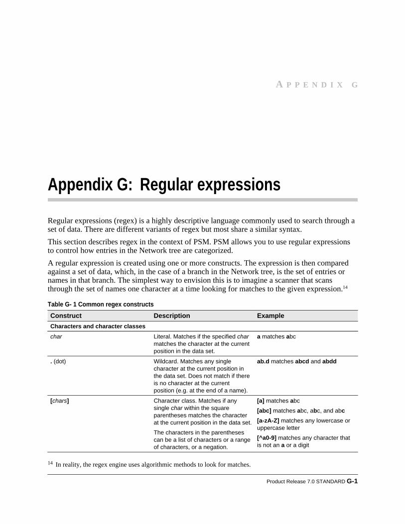
Appendix G: Regular expressions
Regular expressions (regex) is a highly descriptive language commonly used to search through aset of data. There are different variants of regex but most share a similar syntax.This section describes regex in the context of PSM. PSM allows you to use regular expressionsto control how entries in the Network tree are categorized.A regular expression is created using one or more constructs. The expression is then comparedagainst a set of data, which, in the case of a branch in the Network tree, is the set of entries ornames in that branch. The simplest way to envision this is to imagine a scanner that scansthrough the set of names one character at a time looking for matches to the given expression.14
Table G- 1 Common regex constructs Construct Description ExampleCharacters and character classeschar Literal. Matches if the specified char
matches the character at the currentposition in the data set.
a matches abc
. (dot) Wildcard. Matches any singlecharacter at the current position inthe data set. Does not match if thereis no character at the currentposition (e.g. at the end of a name).
ab.d matches abcd and abdd
[chars] Character class. Matches if anysingle char within the squareparentheses matches the characterat the current position in the data set.
The characters in the parenthesescan be a list of characters or a rangeof characters, or a negation.
[a] matches abc
[abc] matches abc, abc, and abc[a-zA-Z] matches any lowercase oruppercase letter
[^a0-9] matches any character thatis not an a or a digit
14 In reality, the regex engine uses algorithmic methods to look for matches.
Product Release 7.0 STANDARD G-1
A P P E N D I X G
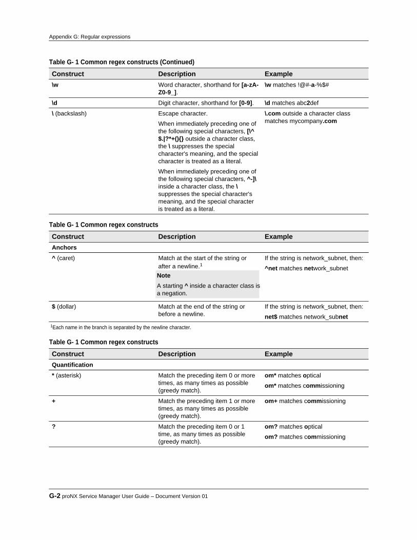
Table G- 1 Common regex constructs (Continued) Construct Description Example\w Word character, shorthand for [a-zA-
Z0-9_].\w matches !@#-a-%$#
\d Digit character, shorthand for [0-9]. \d matches abc2def
\ (backslash) Escape character.
When immediately preceding one ofthe following special characters, [\^$.|?*+(){} outside a character class,the \ suppresses the specialcharacter's meaning, and the specialcharacter is treated as a literal.
When immediately preceding one ofthe following special characters, ^-]\inside a character class, the \suppresses the special character'smeaning, and the special characteris treated as a literal.
\.com outside a character classmatches mycompany.com
Table G- 1 Common regex constructs Construct Description ExampleAnchors^ (caret) Match at the start of the string or
after a newline.1 Note A starting ^ inside a character class isa negation.
If the string is network_subnet, then:
^net matches network_subnet
$ (dollar) Match at the end of the string orbefore a newline.
If the string is network_subnet, then:
net$ matches network_subnet1Each name in the branch is separated by the newline character.
Table G- 1 Common regex constructs Construct Description ExampleQuantification* (asterisk) Match the preceding item 0 or more
times, as many times as possible(greedy match).
om* matches optical
om* matches commissioning
+ Match the preceding item 1 or moretimes, as many times as possible(greedy match).
om+ matches commissioning
? Match the preceding item 0 or 1time, as many times as possible(greedy match).
om? matches optical
om? matches commissioning
G-2 proNX Service Manager User Guide – Document Version 01
Appendix G: Regular expressions

Table G- 1 Common regex constructs Construct Description ExampleGroupings(expression1|expression2|...) Alternation. Matches if any of the
expressions matches.(aaa|bbb) matches aaa or bbb
(?<=lb_expression)expression Lookbehind. Matches if the mainexpression and the precedinglookbehind expression match. Thepart of the match due tolb_expression is not included in thematched result. The matched resultconsists of the match resulting fromexpression only.
This is useful when you want tosearch for a string and you want toexclude the first part of that stringfrom the matched result itself.
(?<=www.)\w*\.com matcheswww.mycompany.comThe resulting matched string ismycompany.com.
expression(?=la_expression) Lookahead. Matches if the mainexpression and the followinglookahead expression match. Thepart of the match due tola_expression is not included in thematched result. The matched resultconsists of the match resulting fromexpression only.
This is useful when you want tosearch for a string and you want toexclude the latter part of that stringfrom the matched result itself.
\w*(?=@) [email protected]
The resulting matched string is john.
Product Release 7.0 STANDARD G-3
Appendix G: Regular expressions


Juniper Networks, Inc. 1133 Innovation Way Sunnyvale, CA 94089 USA
tel: 408-745-2000
www.juniper.net
Part Number:Document Version:Published:Type:
BP2A64PA 01 June 2016 STANDARD
product release 7.0