Chemical compounds from Phoenician juniper berries (Juniperus phoenicea
Upload
khangminh22Category
view
1download
0
Juniper Security Director Cloud
User Guide
Published
2022-07-07

Juniper Networks, Inc.1133 Innovation WaySunnyvale, California 94089USA408-745-2000www.juniper.net
Juniper Networks, the Juniper Networks logo, Juniper, and Junos are registered trademarks of Juniper Networks, Inc.in the United States and other countries. All other trademarks, service marks, registered marks, or registered servicemarks are the property of their respective owners.
Juniper Networks assumes no responsibility for any inaccuracies in this document. Juniper Networks reserves the rightto change, modify, transfer, or otherwise revise this publication without notice.
Juniper Security Director Cloud User GuideCopyright © 2022 Juniper Networks, Inc. All rights reserved.
The information in this document is current as of the date on the title page.
YEAR 2000 NOTICE
Juniper Networks hardware and software products are Year 2000 compliant. Junos OS has no known time-relatedlimitations through the year 2038. However, the NTP application is known to have some difficulty in the year 2036.
END USER LICENSE AGREEMENT
The Juniper Networks product that is the subject of this technical documentation consists of (or is intended for usewith) Juniper Networks software. Use of such software is subject to the terms and conditions of the End User LicenseAgreement ("EULA") posted at https://support.juniper.net/support/eula/. By downloading, installing or using suchsoftware, you agree to the terms and conditions of that EULA.
ii

Table of Contents
About This Guide | xxiv
1 Introduction
Juniper Security Director Cloud Overview | 2
Juniper Secure Edge Overview | 14
2 Dashboard
About the Dashboard | 24
Tasks You Can Perform | 24
Field Descriptions | 25
3 Monitor
Alerts | 32
Alerts Overview | 32
Search Alerts | 33
Delete an Alert | 34
Using Generated Alerts | 34
Alert Definitions Main Page Fields | 34
Create Alert Definitions | 35
Edit Alert Definitions | 37
Clone Alert Definition | 38
Delete Alert Definitions | 38
Search Alert Definitions | 38
Logs | 39
About the Session Page | 39
About the Threats Page | 44
About the Web Filtering Events Page | 49
iii

About the IPsec VPNs Events Page | 55
About the All Security Events Page | 60
Monitor End User Authentication Logs | 66
Maps and Charts | 69
Threat Map Overview | 69
About the Application Visibility Page | 72
About the User Visibility Page | 77
Tunnel Status | 83
Tunnel Status Overview | 83
About the Tunnel Status Page | 84
Use the Advanced Filter to Monitor Specific Tunnels | 85
About the Site Tunnel Status Page | 86
Service Locations | 89
About the Service Locations Monitor Page | 89
Advanced Threat Prevention | 91
Hosts Overview | 91
Host Details | 94
Threat Sources Overview | 96
Threat Source Details | 98
HTTP File Download Overview | 101
HTTP File Download Details | 103
Signature Details | 107
Manual Scanning Overview | 108
SMB File Download Overview | 109
SMB File Download Details | 111
Email Attachments Scanning Overview | 115
iv

Email Attachments Scanning Details | 117
DNS DGA Detection Overview | 119
DNS Tunnel Detection Overview | 120
DNS DGA and Tunneling Detection Details | 122
Encrypted Traffic Insights Overview | 126
Encrypted Traffic Insights Details | 128
SMTP Quarantine Overview | 132
IMAP Block Overview | 133
Telemetry Overview | 135
Reports | 138
Reports Overview | 138
Managing Reports | 138
Report Definitions | 142
Report Definitions Main Page Fields | 142
Create Threat Analysis Report Definitions | 143
Create Application User Usage Report Definitions | 145
Using Report Definitions | 147
Editing Report Definitions | 148
Deleting Report Definitions | 149
Generated Reports | 150
Using Reports | 150
ATP Report Definitions | 152
About the ATP Report Definition Page | 152
Create ATP Report Definition | 154
Edit and Delete ATP Report Definition | 156
Edit an ATP Report Definition | 156
Delete an ATP Report Definition | 157
v

Send ATP Report | 157
ATP Generated Reports | 159
About the ATP Generated Reports Page | 159
4 SRX
Device Management-Devices | 167
About the Devices Page | 167
Add Devices to Juniper Security Director Cloud | 183
Add Devices or Device Clusters Using Commands | 184
Add Devices Using Zero Touch Provisioning | 185
Manage Subscriptions for Your Device | 186
Device Subscription Overview | 186
Associate Your Device with a Device Subscription | 187
Delete a Device From Juniper Security Director Cloud | 187
Add a License to a Device | 188
Add a Physical Interface on the Device | 190
Configure a Security Zone For the Device | 194
Configure a Routing Instance for the Device | 197
Configure a Static Route for the Devices | 200
Import a Device Certificate | 205
Resynchronize a Device with Juniper Security Director Cloud | 207
Manage Configuration Versions | 208
View Configuration Versions | 209
Edit Configuration Version Description | 210
Pin a Configuration Version | 210
Rollback to a Configuration Version | 211
Compare Configuration Versions | 211
Reboot a Device | 213
Upgrade a Device | 214
vi

Enable Security Logs | 215
Device Management-Configuration Templates | 217
Configuration Templates Overview | 217
Configuration Templates Workflow | 219
About the Configuration Templates Page | 219
Add a Configuration Template | 222
Preview and Render a Configuration Template | 228
Deploy a Configuration Template on to a Device | 229
Edit, Clone, and Delete a Configuration Template | 230
Edit a Configuration Template | 230
Clone a Configuration Template | 231
Delete a Configuration Template | 231
Device Management-Images | 233
About the Images Page | 233
Image Upgrade Workflow | 235
Add an Image | 236
Stage an Image | 238
Deploy an Image | 239
Delete Images | 240
Device Management-Security Packages | 241
About the Security Packages Page | 241
Install Security Package | 243
SRX Policy | 244
Security Policy Overview | 244
About the SRX Policy Page | 246
About the Security Policy Rules Page | 248
Add a Security Policy | 251
vii

Edit and Delete a Security Policy | 252
Edit a Security Policy | 252
Delete a Security Policy | 253
Import Security Policies Overview | 253
Import Security Policies | 256
Add a Security Policy Rule | 257
Edit, Clone, and Delete a Security Policy Rule | 261
Edit a Security Policy Rule | 262
Clone a Security Policy Rule | 262
Delete a Security Policy Rule | 262
Configure Global Options | 263
Configure Default Rule Option | 265
Select a Security Policy Rule Source | 265
Select a Security Policy Rule Destination | 266
Select Applications and Services | 268
Add Applications and Services to Security Policy Rule | 268
Common Operations on a Security Policy Rule | 269
Deploy Security Policies | 272
SRX Policy-Device View | 273
Devices with Security Policies Main Page Fields | 273
Security Subscriptions-IPS | 275
About the IPS Profiles Page | 275
Create an IPS Profile | 277
Edit, Clone, and Delete an IPS Profile | 278
Edit an IPS Profile | 278
Clone an IPS Profile | 279
Delete IPS Profiles | 279
About the <IPS-Profile-Name> Page | 280
viii

Create an IPS or an Exempt Rule | 281
Create an IPS Rule | 282
Create an Exempt Rule | 289
Edit, Clone, and Delete an IPS Rule or an Exempt Rule | 290
Edit an IPS Rule or an Exempt Rule | 290
Clone an IPS Rule or an Exempt Rule | 291
Delete IPS Rules or Exempt Rules | 291
About the IPS Signatures Page | 292
Create an IPS Signature | 299
Create an IPS Signature Static Group | 311
Create an IPS Signature Dynamic Group | 313
Edit, Clone, and Delete an IPS Signature | 321
Edit an IPS Signature | 321
Clone an IPS Signature | 322
Delete IPS Signatures | 322
Edit, Clone, and Delete an IPS Signature Static Group | 323
Edit an IPS Signature Static Group | 323
Clone an IPS Signature Static Group | 324
Delete IPS Signature Static Groups | 324
Edit, Clone, and Delete an IPS Signature Dynamic Group | 325
Edit an IPS Signature Dynamic Group | 325
Clone IPS Signature Dynamic Groups | 326
Delete IPS Signature Dynamic Groups | 326
Security Subscriptions-Content Security | 327
Content Security Overview | 327
Configure the Content Security Settings | 330
About the Content Security Profiles Page | 332
Create a Content Security Profile | 335
Edit, Clone, and Delete a Content Security Profile | 340
Edit a Content Security Profile | 340
ix

Clone a Content Security Profile | 340
Delete a Content Security Profile | 341
About the Web Filtering Profiles Page | 341
Create a Web Filtering Profile | 344
Edit, Clone, and Delete a Web Filtering Profile | 352
Edit a Web Filtering Profile | 352
Clone a Web Filtering Profile | 353
Delete a Web Filtering Profile | 353
About the Antivirus Profiles Page | 354
Create an Antivirus Profile | 356
Edit, Clone, and Delete an Antivirus Profile | 359
Edit an Antivirus Profile | 359
Clone an Antivirus Profile | 360
Delete an Antivirus Profile | 360
About the Antispam Profiles Page | 361
Create an Antispam Profile | 363
Edit, Clone, and Delete an Antispam Profile | 365
Edit an Antispam Profile | 365
Clone an Antispam Profile | 365
Delete an Antispam Profile | 366
About the Content Filtering Profiles Page | 366
Create a Content Filtering Profile | 369
Edit, Clone, and Delete a Content Filtering Profile | 373
Edit a Content Filtering Profile | 373
Clone a Content Filtering Profile | 373
Delete a Content Filtering Profile | 374
Security Subscriptions-Decrypt Profiles | 375
Decrypt Profiles Overview | 375
About the Decrypt Profiles Page | 382
x

Create a Decrypt Profile | 385
Edit, Clone, and Delete a Decrypt Profile | 392
Edit a Decrypt Profile | 393
Clone an Decrypt Profile | 393
Delete a Decrypt Profile | 393
IPsec VPN | 394
IPsec VPN Overview | 394
Understanding IPsec VPN Modes | 397
Understanding IPsec VPN Routing | 397
Understanding IKE Authentication | 398
IPsec VPN Main Page Fields | 398
IPsec VPN Global Settings | 400
Create a Site-to-Site VPN | 401
Create a Hub-and-Spoke (Establishment All Peers) VPN | 414
Create a Hub-and-Spoke (Establishment by Spokes) VPN | 426
Create a Hub-and-Spoke Auto Discovery VPN | 436
Create a Remote Access VPN—Juniper Secure Connect | 447
Importing IPsec VPNs | 459
Deploying IPSec VPN | 460
Modify IPsec VPN Settings | 461
Modify Device Selection | 461
Deleting IPSec VPN | 461
IPsec VPN-VPN Profiles | 463
VPN Profiles Overview | 463
VPN Profiles Main Page Fields | 464
Creating VPN Profiles | 464
Edit and Clone IPsec VPN profiles | 472
Edit a VPN Profile | 472
xi

Clone IPsec VPN Profile | 473
Assigning Policies and Profiles to Domains | 473
IPsec VPN-Extranet Devices | 475
Creating Extranet Devices | 475
Extranet Devices Main Page Fields | 476
Find Usage for Extranet Devices | 477
NAT-NAT Policies | 478
NAT Policies Overview | 478
About the NAT Policies Page | 482
Create a NAT Policy | 483
Edit and Delete a NAT Policy | 484
Edit a NAT Policy | 485
Delete a NAT Policy | 485
About the NAT Policy Rules Page | 485
Create a NAT Policy Rule | 487
Edit, Clone, and Delete a NAT Policy Rule | 495
Edit a NAT Policy Rule | 495
Clone a NAT Policy Rule | 496
Delete a NAT Policy Rule | 496
Common Operations on a NAT Policy Rule | 496
Deploy a NAT Policy | 498
NAT-NAT Pools | 499
NAT Pools Overview | 499
About the NAT Pools Page | 499
Create a NAT Pool | 500
Edit, Clone, and Delete a NAT Pool | 504
Edit a NAT Pool | 504
Clone a NAT Pool | 505
xii

Delete a NAT Pool | 505
Identity-JIMS | 506
Juniper Identity Management Service Overview | 506
About the Identity Management Profile Page | 508
Create Identity Management Profiles | 509
Edit, Clone, and Delete Identity Management Profiles | 512
Edit Identity Management Profiles | 513
Clone Identity Management Profiles | 513
Delete Identity Management Profiles | 514
Deploy the Identity Management Profile to SRX Series Devices | 514
Identity-Active Directory | 515
About the Active Directory Profile Page | 515
Create an Active Directory Profile | 516
Deploy an Active Directory Profile to SRX Series Devices | 521
Edit, Clone, and Delete an Active Directory Profile | 522
Edit an Active Directory Profile | 522
Clone an Active Directory Profile | 522
Delete an Active Directory Profile | 523
Identity-Access profile | 524
LDAP Functionality in Integrated User Firewall Overview | 524
About the Access Profile Page | 526
Create Access Profiles | 527
Deploy the Access Profile to SRX Series Devices | 532
Edit, Clone, and Delete Access Profiles | 533
Edit Access Profiles | 533
Clone Access Profiles | 533
Delete Access Profiles | 534
Identity-Address Pools | 535
About the Address Pool Page | 535
xiii

Create Address Pool | 536
Edit and Delete Address Pool | 537
Edit an Address Pool | 538
Delete an Address Pool | 538
5 Secure Edge
Service Management | 540
About the Service Locations Page | 540
Create a Service Location | 542
Edit and Delete Service Locations | 543
Edit a Service Location | 543
Delete a Service Location | 544
About the Sites Page | 544
Create a Site | 546
Edit and Delete Sites | 549
Edit a Site | 550
Delete a Site | 550
About the IPsec Profiles Page | 550
Create an IPsec Profile | 552
Edit or Delete an IPsec Profile | 555
Edit an IPsec Profile | 555
Delete an IPsec Profile | 555
Security Policy | 556
About the Secure Edge Policy Page | 556
Add a Secure Edge Policy Rule | 559
Edit, Clone, and Delete a Secure Edge Policy Rule | 563
Edit a Secure Edge Policy Rule | 564
Clone a Secure Edge Policy Rule | 564
Delete a Secure Edge Policy Rule | 564
Select a Secure Edge Policy Source | 565
xiv

Select a Secure Edge Policy Destination | 566
Select Applications and Services | 567
Add Applications and Services to Security Policy | 567
Common Operations on a Secure Edge Policy | 568
Deploy Secure Edge Policies | 569
Security Subscriptions | 570
IPS Policies Overview | 571
About IPS Policies | 571
Create IPS Rule | 572
Edit, Clone, and Delete IPS Rules | 576
Edit an IPS Rule | 576
Clone an IPS Rule | 577
Delete IPS Rules | 577
Create Exempt Rule | 577
Edit, Clone, and Delete Exempt Rule | 579
Edit an Exempt Rule | 579
Clone an Exempt Rule | 580
Delete Exempt Rules | 580
Web Filtering Profiles Overview | 581
About the Web Filtering Profiles Page | 581
Create a Web Filtering Profile | 583
Edit, Clone, and Delete a Web Filtering Profile | 585
Edit a Web Filtering Profile | 585
Clone a Web Filtering Profile | 586
Delete a Web Filtering Profile | 586
Content Filtering Policies Overview | 586
About the Content Filtering Policies Page | 587
Create a Content Filtering Policy | 588
xv

Add Rules in a Content Filtering Policy | 589
Edit and Delete a Content Filtering Policy | 590
Edit a Content Filtering Policy | 591
Delete a Content Filtering Policy | 591
Edit, Clone, and Delete a Content Filtering Policy Rule | 591
Edit a Content Filtering Policy Rule | 592
Clone a Secure Edge Policy Rule | 592
Delete a Secure Edge Policy Rule | 592
SecIntel Profiles Overview | 592
About SecIntel Profiles | 593
Create Command and Control Profile | 594
Create DNS Profile | 596
Create Infected Hosts Profile | 598
Edit, Clone, and Delete SecIntel Profile | 600
Edit a SecIntel Profile | 600
Clone a SecIntel Profile | 601
Delete a SecIntel Profile | 601
About SecIntel Profile Groups | 601
Create SecIntel Profile Group | 603
Edit, Clone, and Delete SecIntel Profile Group | 604
Edit a SecIntel Profile Group | 604
Clone a SecIntel Profile Group | 605
Delete a SecIntel Profile Group | 605
Anti-malware Profiles Overview | 605
About Anti-malware Profiles | 606
Create Anti-malware Profile | 607
Edit, Clone, and Delete Anti-malware Profile | 610
Edit an Anti-malware Profile | 610
Clone an Anti-malware Profile | 610
xvi

Delete an Anti-malware Profile | 611
Create a DNS Security Profile | 611
Create an Encrypted Traffic Insights Profile | 613
Service Administration | 614
Certificate Management Overview | 614
About the Certificate Management Page | 615
Generate a Certificate | 617
Upload and Download a Certificate | 619
Upload a Certificate | 619
Download a Certificate | 619
Regenerate and Delete a Certificate | 620
Regenerate a Certificate | 620
Delete a Certificate | 620
Proxy Auto Configuration Files Overview | 621
About the PAC Page | 621
Manually Add a PAC File to a Web Browser | 623
Add a PAC File to Google Chrome in Microsoft Windows | 623
Add a PAC File to Mozilla Firefox in Microsoft Windows | 624
Edit, Clone, and Delete a Proxy Auto Configuration File | 625
Edit a Proxy Auto Configuration File | 626
Clone a Proxy Auto Configuration File | 626
Delete Proxy Auto Configuration Files | 626
Configure an Explicit Proxy Profile | 626
Create a URL Category | 627
Create a URL Pattern | 628
About the Addresses Page | 630
Create Addresses or Address Groups | 632
Edit, Clone, and Delete Addresses and Address Groups | 635
xvii

Edit Addresses and Address Groups | 636
Clone Addresses and Address Groups | 636
Delete Addresses and Address Groups | 636
Decrypt Profiles Overview | 637
About the Decrypt Profiles Page | 641
Create a Decrypt Profile | 643
Edit, Clone, and Delete a Decrypt Profile | 645
Edit a Decrypt Profile | 645
Clone a Decrypt Profile | 645
Delete a Decrypt Profile | 645
Identity | 647
End User Authentication Overview | 647
About the End User Authentication Page | 648
Add an End User Profile | 659
Edit and Delete an End User Profile | 661
Edit an End User Profile | 661
Delete an End User Profile | 662
Add a Group | 662
Edit and Delete a Group | 664
Edit a Group | 664
Delete a Group | 665
Juniper Identity Management Service Overview | 665
Onboard JIMS Collector | 666
Create JIMS Collector Service Accounts | 668
Configuring Limited Permission User Accounts | 668
Configuring Properties for Limited Permission User Accounts | 669
Adding Limited Permission User Accounts to Active Directory Groups | 669
Defining Group Policies for Limited Permission User Accounts | 669
Install and Configure JIMS Collector | 669
xviii

Configure JIMS Collector to Probe Unknown IP Addresses | 674
View the JIMS Collector Status | 674
6 Shared Services
Firewall Profiles-Rule Options | 677
About Rule Options Page | 677
Create Rule Options | 678
Edit, Clone, and Delete Rule Options | 682
Edit Rule Options | 682
Clone Rule Options | 682
Delete Rule Options | 683
Firewall Profiles-Redirect Profiles | 684
About the Redirect Profiles Page | 684
Create a Redirect Profile | 685
Edit, Clone, and Delete a Redirect Profile | 686
Edit a Redirect Profile | 686
Clone a Redirect Profile | 687
Delete a Redirect Profile | 687
Objects-Addresses | 688
About the Addresses Page | 688
Variable Address Overview | 690
Create Addresses or Address Groups | 691
Edit, Clone, and Delete Addresses and Address Groups | 696
Edit Addresses and Address Groups | 697
Clone Addresses and Address Groups | 697
Delete Addresses and Address Groups | 698
Objects-GeoIP | 699
About the GeoIP Page | 699
Create a GeoIP Feed | 700
Edit, Clone, and Delete GeoIP Feeds | 702
xix

Edit a GeoIP Feed | 702
Clone a GeoIP Feed | 703
Delete a GeoIP Feed | 703
Objects-Services | 705
About the Services Page | 705
Create Services and Service Groups | 707
Edit, Clone, and Delete Services and Service Groups | 710
Edit Services and Service Groups | 710
Clone Services or Service Groups | 711
Delete Services and Service Groups | 711
Create Protocols | 711
Edit and Delete Protocols | 715
Edit Protocols | 715
Delete Protocols | 715
Objects-Applications | 717
About the Application Signatures Page | 717
Add Application Signatures | 720
Edit, Clone, and Delete Application Signatures | 727
Edit Custom Application Signatures | 728
Clone Application Signatures | 728
Delete Application Signatures | 729
Add Custom Application Signature Groups | 729
Edit, Clone, and Delete Application Signature Groups | 730
Edit Custom Application Signature Groups | 731
Clone Application Signature Groups | 731
Delete Custom Application Signature Groups | 731
Objects-Schedules | 733
Schedules Overview | 733
About the Schedules Page | 734
Create a Schedule | 735
xx

Edit, Clone, and Delete a Schedule | 737
Edit a Schedule | 737
Clone a Schedule | 738
Delete a Schedule | 738
Objects-URL Patterns | 739
About the URL Patterns Page | 739
Create a URL Pattern | 740
Edit, Clone, and Delete a URL Pattern | 742
Edit a URL Pattern | 743
Clone a URL Pattern | 743
Delete a URL Pattern | 744
Objects-URL Categories | 745
About the URL Categories Page | 745
Create a URL Category | 746
Edit, Clone, and Delete a URL Category | 748
Edit a URL Category | 748
Clone a URL Category | 748
Delete a URL Category | 749
Advanced Threat Prevention | 750
File Inspection Profiles Overview | 750
Create File Inspection Profiles | 752
Email Management Overview | 754
Configure SMTP Email Management | 755
Configure IMAP Email Management | 759
Allowlist and Blocklist Overview | 762
Create Allowlists and Blocklists | 763
SecIntel Feeds Overview | 769
Juniper Threat Feeds Overview | 774
Global Configuration for Infected Hosts | 775
xxi

Enable Logging | 778
Configure Threat Intelligence Sharing | 778
Configure Trusted Proxy Servers | 780
7 Administration
Subscriptions | 783
Subscriptions | 783
Overview | 783
Add Subscriptions | 785
Delete a Subscription | 786
Users & Roles | 788
Users Overview | 788
About the Users Page | 789
Add a User | 790
Edit and Delete a User | 792
Edit a User | 792
Delete a User | 794
Roles Overview | 794
About the Roles Page | 795
Add a Role | 796
Edit, Clone, and Delete a Role | 798
Edit a Role | 799
Clone a Role | 799
Delete a Role | 799
Audit Logs | 801
Audit Logs Overview | 801
About the Audit Logs Page | 802
Export Audit Logs | 804
Jobs | 805
Jobs Management in Juniper Security Director Cloud | 805
xxii

Jobs Main Page Fields | 806
Using Jobs in Juniper Security Director Cloud | 808
Viewing the Details of a Job in Juniper Security Director Cloud | 808
Canceling Scheduled Jobs in Juniper Security Director Cloud | 810
Data Management | 811
About the Data Management Page | 811
Export Device Logs | 813
Delete Device Logs | 813
Organization | 814
About the Organization Page | 814
Create a New Organization | 817
Edit and Delete an Organization | 817
Edit an Organization | 817
Delete an Organization | 818
ATP Mapping | 819
About the ATP Mapping Page | 819
Map an Auto-generated Realm | 820
Map an Existing ATP Realm | 820
ATP Audit Logs | 822
About the ATP Audit Logs Page | 822
Export Audit Logs | 823
xxiii

About This Guide
Use this guide to understand Juniper® Security Director Cloud which is a cloud-based portal thatmanages on-premises security, cloud-based security, and cloud-delivered security.
xxiv

1PART
Introduction
Juniper Security Director Cloud Overview | 2
Juniper Secure Edge Overview | 14

Juniper Security Director Cloud Overview
IN THIS SECTION
Benefits of Juniper Security Director Cloud | 11
Access Juniper Security Director Cloud | 11
Using Navigational Elements | 13
Juniper Security Director Cloud is your portal to Secure Access Service Edge (SASE), bridging yourcurrent security deployments with your future SASE rollout. Juniper Security Director Cloud helpsorganizations migrate securely to SASE architecture. Using Juniper Security Director Cloud,organizations can create unified policies once and deploy the policies wherever their users are using theapplications. Unified policy management ensures seamless security across all users, applications, ordevices wherever they are.
Juniper Security Director Cloud empowers both traditional security roles and network roles byautomating tier I and tier II security tasks and by supplementing network visibility with security insights.Additionally, Juniper Security Director Cloud provides value for enterprise and service providers byshifting from monolithic centralized data center architectures to SASE-based, decentralized architecturesthat bring services closer to end users.
Juniper Security Director Cloud provides a user-friendly and security-focused GUI interface that allowsan administrator to perform specific tasks. Table 1 on page 3.
When you log in to application, the main menu (left sidebar) that is displayed and the actions that youcan perform depend on your access privileges. Table 1 on page 3 lists the main menu that is availablein the Juniper Security Director Cloud, a brief description of each menu item, and a link to the relevanttopic in the Juniper Security Director Cloud User Guide.
2

Table 1: GUI Menu and Description
Menu Description
Dashboard The dashboard displays information such as topevents, top denials, top applications, top source anddestination IP addresses, top traffic, and top infectedhosts. Graphical security widgets that can be added,removed, and rearranged per user. These widgets offereach user a customized view of network security. See"About the Dashboard" on page 24.
Monitor You can view following information from Monitormenu:
• Alerts—Alerts are used to notify about significantevents within the system. You can define alertcriteria based on a set of predefined filters. See"Alerts Overview" on page 32
• Logs—You can view details of the traffic logs thatare generated by managed devices. You can viewinformation about security events based on IPSpolicies, Web filtering policies, and IPSec VPNpolicies. You can also view an overall, high-levelview of your network environment. You can viewabnormal events, attacks, viruses, or worms whenlog data is correlated and analyzed. See "About theSession Page" on page 39
• Maps and Charts—The threat map provides avisualization of the geographic regions for incomingand outgoing traffic. You can view blocked andallowed threat events based on feeds from IPS,antivirus, and antispam engines. See "Threat MapOverview" on page 69
• Reports—Reports are generated based on asummary of network activity and overall networkstatus. These generated reports can help you toperform a trend analysis of your network'sactivities to study changes in traffic patterns. Youcan use the predefined reports, or you can buildcustom reports that meet specific needs. See"Reports Overview" on page 138
3

Table 1: GUI Menu and Description (Continued)
Menu Description
SRX>Device Management • Devices—Discover and manage devices. See "Aboutthe Devices Page" on page 167.
• Configuration Templates—Provision configurations,both during onboarding and throughout the devicelife cycle, for Juniper Networks and other third-party devices. By using configuration templates,you can deploy customized configurations ondevices. See "Configuration Templates Overview"on page 217.
• Software Images—A software image is a softwareinstallation package used to upgrade or downgradethe operating system running on a network device.Juniper Security Director Cloud helps you tomanage (add, stage, deploy, and delete) the entirelifecycle of software images of all managednetwork devices. See "About the Images Page" onpage 233.
• Security Packages—Security package consists ofIPS Signatures, Application Signatures, and URLCategories. Use the Security Packages page. Youcan view the list of latest security packagesavailable on Juniper Security Director Cloud, viewthe list of currently installed security packages onthe device, and install the latest security packageson the device. See "About the Security PackagesPage" on page 241.
4

Table 1: GUI Menu and Description (Continued)
Menu Description
SRX>Security Policy • SRX Policy— Provides security functionality byenforcing rules on traffic that passes through adevice. Traffic is permitted or denied based on theaction defined in the security policy rules. You cancreate, modify, and delete security policy andassociate the devices with a security policy. See"Security Policy Overview" on page 244.
• Device View—Provides an overall, high-level viewof your security policy device settings. You can alsouse this page to view detailed information on thenumber of rules and policies assigned per device.See "Devices with Security Policies Main PageFields" on page 273.
SRX>Security Subscriptions Advanced Security management related to:
• IPS— The intrusion prevention system (IPS) profileis deployed on a device by associating the profilewith a security policy rule, which is deployed onthe device. You can associate IPS rules and exemptrules with an IPS profile. See "About the IPSProfiles Page" on page 275.
• Content Security—content security is a term usedto describe the consolidation of several securityfeatures to protect against multiple threat types.You can enable antispam, antivirus, contentfiltering, and web filtering. See "About the ContentSecurity Profiles Page" on page 332.
• Decrypt Profiles—You can view and manage SSLproxy profiles. See "About the Decrypt ProfilesPage" on page 382.
• VPN—You can view and manage the IPsec VPNprofiles that provide a means to securelycommunicate with remote computers across apublic WAN, such as the Internet. See "IPsec VPNOverview" on page 394.
5

Table 1: GUI Menu and Description (Continued)
Menu Description
SRX>IPsec VPN IPsec VPN—You can view and manage the IPsec VPNprofiles that provide a means to securely communicatewith remote computers across a public WAN, such asthe Internet. See "IPsec VPN Overview" on page 394.
SRX>NAT • NAT Policies— Create, modify, clone, and deleteNAT policies and policy rules. You can filter andsort this information to get a better understandingof what you want to configure. See "About theNAT Policies Page" on page 482.
• NAT Pools—A NAT pool is a set of IP addressesthat you can define and use for address translation.NAT policies perform address translation bytranslating internal IP addresses to the addresses inthese pools. See "About the NAT Pools Page" onpage 499.
6

Table 1: GUI Menu and Description (Continued)
Menu Description
SRX>Identity • JIMS—Use the Identity Management Profile pageto obtain advanced user identity from differentauthentication sources for SRX Series devices. Youcan create, edit, clone, delete and deploy identitymanagement profiles. See "About the IdentityManagement Profile Page" on page 508.
• Active Directory—Active Directory configuration isused by the SRX series devices to contact theActive Directory server. You can view, create,modify, clone, and delete Active Directory profile.See "About the Active Directory Profile Page" onpage 515.
• Access Profiles—Access profiles enable accessconfiguration on the network—this consists ofauthentication configuration. Juniper SecurityDirector Cloud supports RADIUS, LightweightDirectory Access Protocol (LDAP), and localauthentication as authentication methods. See"About the Access Profile Page" on page 526.
• Address Pools—An address pool is a set of InternetProtocol (IP) addresses available for allocation tousers, such as in host configurations with theDHCP. You can create centralized IPv4 addresspools independent of the client applications thatuse the pools. See "About the Address Pool Page"on page 535.
7

Table 1: GUI Menu and Description (Continued)
Menu Description
Shared Services>Firewall Profiles Perform security-related management tasks related to:
• Rule Options—You can create an object to specifyredirect options, authentication, TCP-options, andaction for destination-address translated oruntranslated packets. When a rule options iscreated, the Juniper Security Director Cloudcreates an object in the database to represent therule options. See "About Rule Options Page" onpage 677.
• Redirect Profiles—You can create a redirect profileand provide a reason for the policy action or toredirect the user request to an informativewebpage. See "About the Redirect Profiles Page" onpage 684.
8

Table 1: GUI Menu and Description (Continued)
Menu Description
Shared Services>Objects Mange the following objects:
• Addresses—Create, edit, and delete addresses andaddress groups. Addresses and address groups areused in security and NAT services. See "About theAddresses Page" on page 688.
• GeoIP—Create, modify, or delete the IP-basedgeolocation (GeoIP) feeds. You can use the GeoIPfeeds in security policy to deny or allow trafficbased on source or destination IP address. See"About the GeoIP Page" on page 699.
• Services—Manage applications across devices. Aservice refers to an application on a device, such asDomain Name Service (DNS). See "About theServices Page" on page 705.
• Applications—Create, modify, clone, and deleteapplication signature groups. You can also view thedetails of predefined application signatures that arealready downloaded. See "About the ApplicationSignatures Page" on page 717.
• Schedules—A schedule allows a policy to be activefor a specified duration. If you want a policy to beactive during a scheduled time, you must firstcreate a schedule for that policy or link the policyto an existing schedule. See "Schedules Overview"on page 733.
• URL Patterns—View, create, edit, clone, and deleteURL patterns. A URL pattern contains a list ofURLs. See "About the URL Patterns Page" on page739
• URL Categories—View, create, edit, clone, anddelete URL categories. A URL category is a list ofURL patterns grouped under a single title. See"About the URL Categories Page" on page 745.
9

Table 1: GUI Menu and Description (Continued)
Menu Description
Administration Perform administrative tasks including:
• Subscriptions—Add and manage your JuniperSecurity Director Cloud subscriptions.See"Subscriptions" on page 783
• Users and Roles—Juniper Security Director Cloudsupports authentication and role-based accesscontrol (RBAC) to its resources and services. See"About the Users Page" on page 789
• Jobs—The Jobs page lets you monitor the status ofjobs that have run or are scheduled to run inJuniper Security Director Cloud. Jobs can bescheduled to run immediately or in the future. See"Jobs Management in Juniper Security DirectorCloud" on page 805
• Audit logs—An audit log is a record of a sequenceof activities that have affected a specific operationor procedure. Audit logs are useful for tracingevents and for maintaining historical data. See"About the Audit Logs Page" on page 802
• Data Management—The Data Management pagedisplays device logs related to security and datatraffic. You can export or delete these logs. See"About the Data Management Page" on page 811
• Organization—An organization account helps youto add devices, subscribe your devices, and startmanaging the devices. An administrator, operator,or user with read-only access of organization cancreate multiple organization accounts in JuniperSecurity Director Cloud. See "About theOrganization Page" on page 814
When you log in to Portal, the main menu (left sidebar) that is displayed and the actions that you canperform depend on your access privileges. Table 1 on page 3 displays the main menu available in theJuniper Security Director Cloud Portal, a brief description of each menu item, and a link to the relevanttopic in the Juniper Security Director Cloud User Guide.
10

Benefits of Juniper Security Director Cloud
• Manages all security deployments—physical, virtual, and containerized SRX for traditionaldeployments— and helps the smooth transition to a SASE architecture.
• Offers fully integrated security with unified policies at every point of connection. With unified policymanagement, you can create a policy once and apply it anywhere. You don't need to copy over orrecreate rule sets.
• Provides a single centralized management interface that enables administrators to manage all phasesof the security policy life cycle by using customizable dashboards and reports.
• Offers protection from attacks against the client and from the server-side exploits, malware, and C2traffic, regardless of where the users and applications are located.
• Enables easy deployment and configuration for new sites using zero-touch provisioning (ZTP), auto-rule placement, and policy-based routing.
• Enables security for on-premise and cloud-based environments simultaneously and at scale, withvalidated efficacy against data center threats.
Access Juniper Security Director Cloud
To access Juniper Security Director Cloud portal:
1. If you are logging in to Juniper Security Director Cloud for the first time, click Create an organizationaccount link. If you already created an organization account, skip to Step "5" on page 13.
2. Set your login credentials, contact details, and the organization account details according to theguidelines provided in table Table 2 on page 11.Table 2: Fields to Create an Organization Account
Field Description
Login Credentials
Email Enter a valid e-mail ID.
11

Table 2: Fields to Create an Organization Account (Continued)
Field Description
Password Enter a password that contains at least one number,one uppercase letter and one special character. Thepassword length should be between 8 to 20characters.
Contact Details
Contact Details Enter the following contact details:
• Name—Enter you name. Only alphabets withspaces are allowed. The maximum length is 32characters.
• Company name—Enter your company name. Onlyalphanumeric characters, spaces, `-` (hyphen) and`_` (underscore) are allowed. The maximumlength is 64 characters.
• Country—Select the country from the dropdownlist.
• Phone number—Enter a valid phone number thatcan contain numbers and +, -, or () symbols. Thetotal length of phone number must be 7(including hyphen) through 18 characters.Example phone formats:
• +91-9590951194
• +918087677876
• 408-111-1111
• 1(234)56789011234
• (+351)282435050
• 90191919908
• 555-89097896
12

Table 2: Fields to Create an Organization Account (Continued)
Field Description
Organization account details Enter a name for organization account for which youwould be managing the security devices and services.
3. Click Create Organization Account. You will receive an email to verify your e-mail address and tosend a request to the Juniper Security Director Cloud team to activate your organization account.
4. Log in to your e-mail account, open the e-mail, and click the Activate Organization Account button tosend a request to activate your organization account.
NOTE:
• You must verify your e-mail address and send the account activation request by clickingthe Activate Organization Account button within 24 hours after receiving the e-mail.Otherwise, your account details will be deleted from Juniper Security Director Cloud, andyou'll have to re-create your account and send the activation request.
• You will receive an e-mail about your organization account activation status within 7working days.
If your account activation request is approved, you will receive an e-mail with login page information.
5. Click Go to Login Page and enter your e-mail address and password to log in and start using theJuniper Security Director Cloud portal.
NOTE: We recommend that you use Google Chrome (Version 85 or later) or Firefox (Version85 or later) to access the Juniper Security Director Cloud GUI.
6. Click Go to Dashboard. You can access different tasks easily using the menu bar on the left of eachpage. The top-level menu items are listed in Table 1 on page 3.
Using Navigational Elements
For a more personal and customizable user experience, Juniper Networks provides some navigationalaids within the GUI. Table 3 on page 14 shows the sample of navigation, customization, and help icons.
13

Table 3: Navigational Elements
Element Icon Location
Breadcrumbs—Trace your locationin the UI. The breadcrumbs providea path back to one of the sevenstarting tabs: Dashboard, Monitor,Device Management, NAT &Objects, Firewall, AdvancedSecurity, and Administration.
The upper left part of the mainscreen below the Monitor tab. Notvisible on the Dashboard.
Info Tips—Position your mouseover any available question markicon for quick pop-up guidance.
Various places around the GUI.
Show and Hide Left-Nav—Click thehamburger icon to show or hide theleft-navigation section.
Left side of the tab bar.
Show/Hide Columns—In tabulardisplays, you can choose whichcolumns are visible by clicking theicon, and then selecting the checkboxes in the menu.
Upper-right corner of some tabulardisplay windows such as theMonitor tab and the DeviceManagement tab.
Table Search—
In large tabular views, you cansearch for specific text within anyof the visible fields in the display.
Upper-right corner of tabular views.Next to the Show Hide Columnsicon.
Juniper Secure Edge Overview
IN THIS SECTION
Benefits of Juniper Secure Edge | 19
Create Your Juniper Secure Edge Organization | 20
14

Juniper Secure Edge provides full-stack Secure Services Edge (SSE) capabilities to protect web, SaaS, andon-premises applications and provide users with consistent and secure access that follows themwherever they go. When combined with Juniper’s AI-Driven SD-WAN, Juniper Secure Edge provides abest-in-suite SASE solution that helps you deliver seamless and secure end-user experiences thatleverage existing architectures and grow with them as they expand their SASE footprint.
Juniper Secure Edge provides a user-friendly and security-focused GUI interface that allows anadministrator to perform specific tasks. When you log in to Juniper Secure Edge, the main menu on theleft that is displayed and the actions that you can perform depend on your access privileges. Table 4 onpage 15 lists the main menu that is available in Juniper Secure Edge, a brief description of each menuitem, and a link to the relevant topic in the Juniper Secure Edge User Guide.
Table 4: GUI Menu and Description
Menu Description
Dashboard You can view information such as top events, topdenials, top applications, top source and destination IPaddresses, top traffic, and top infected hosts ingraphical security widgets.
These security widgets offer users a customized viewof network security and can be added, removed, andrearranged as per each user's preference. See No LinkTitle.
15

Table 4: GUI Menu and Description (Continued)
Menu Description
Monitor You can view following information from the Monitormenu:
• Site Tunnel Status—View the status of theconfigured tunnels between sites and servicelocations. See "About the Site Tunnel Status Page"on page 86.
• Service Locations—View the status of all theservice locations, the users in a location, thebandwidth consumed by the users, and theavailable storage. See "About the Service LocationsPage" on page 540.
• ATP—Juniper Advanced Threat Prevention Cloud(ATP Cloud) is a cloud-based service that providescomplete advanced anti-malware and anti-ransomware protection against “zero-day” andunknown threats. Monitor the status ofcompromised hosts, malicious threat sources,suspicious file downloads, Domain Name System(DNS) Domain Generation Algorithm (DGA)detections, tunnel detections, encrypted trafficinsights, quarantined e-mails, blocked e-mails, andtelemetry of blocked web and email files in ATPCloud. See "Hosts Overview" on page 91.
• ATP Report Definitions—Build custom threatassessment reports which meet your needs forviewing incidents during specific time-frames. See"About the ATP Report Definition Page" on page152.
16

Table 4: GUI Menu and Description (Continued)
Menu Description
Secure Edge You can manage the following services from the SecureEdge menu:
• Service Management
• Service Locations—Manage service locations forJuniper Secure Edge instances. Servicelocations are the connection (access) point forboth onpremises and roaming users. See "Aboutthe Service Locations Page" on page 540.
• Sites—Manage sites that are usually alignedwith physical locations of customers, such as abranch or office. See "About the Sites Page" onpage 544.
• IPsec Profiles—Create IPsec profiles to definethe parameters with which an IPsec tunnel isestablished when the Customer PremisesEquipment (CPE) devices start communicatingwith your Juniper Secure Edge instance. See"About the IPsec Profiles Page" on page 550.
• Security Policy—Manage the rules of JuniperSecure Edge policies which specify the actions totake for specific sets of traffic. You can filter andsort this information to get a better understandingof what to configure. See "About the Secure EdgePolicy Page" on page 556.
• Security Subscriptions
• IPS—Manage IPS rules and exempt rules in IPSprofiles that are deployed on a device. See "IPSPolicies Overview" on page 571.
• Web Filtering—Manage web filtering profileswhich enable you to manage Internet usage bypreventing access to inappropriate Webcontent over HTTP. See "Web Filtering ProfilesOverview" on page 581.
17

Table 4: GUI Menu and Description (Continued)
Menu Description
• Content Filtering—Manage content filteringpolicies that determine the file type based onthe file content and not based on the fileextensions. See "Content Filtering PoliciesOverview" on page 586.
• SecIntel—Configure a SecIntel profile group toadd SecIntel profiles, such as C&C, DNS, andinfected hosts. Once created, you can assignthis group to the security policy. See "SecIntelProfiles Overview" on page 592.
• Anti-malware—Configure anti-malware profileand associate the profile with security policies.Anti-malware profiles define the content toscan for any malware and the action to be takenwhen malware is detected. See "Anti-malwareProfiles Overview" on page 605.
• DNS Security—Create a DNS security profile forDomain Generation Algorithm (DGA) detectionand tunnel detection. See "Create a DNSSecurity Profile" on page 611.
• ETI—Create an ETI profile that detectsmalicious threats hidden in encrypted trafficwithout intercepting and decrypting the traffic.See "Create an Encrypted Traffic InsightsProfile" on page 613.
• Service Administration
• Certificate Management—Manage the devicecertificates to establish TLS or SSL sessions.See "Certificate Management Overview" onpage 614.
• PAC Files—Manage proxy auto configurationfiles which tell a web browser where to directthe traffic for a URL. See "Proxy AutoConfiguration Files Overview" on page 621.
18

Table 4: GUI Menu and Description (Continued)
Menu Description
• Explicit Proxy Profiles—Create an explicit proxyprofile which tells Juniper Secure Edge theports to listen to for the client-side traffic andthe traffic to decrypt or bypass. See "Configurean Explicit Proxy Profile" on page 626.
• Decrypt Profiles—Manage decrypt profileswhich allow you to define the types of trafficthat should be exempted from decryption. See"Decrypt Profiles Overview" on page 637.
• Identity
• User Authentication—Configure authenticationprofiles to authenticate the end users. See "EndUser Authentication Overview" on page 647.
• JIMS—Onboard JIMS Collector which collectsand maintains a large database of user, device,and group information from Active Directorydomains or system log services. See "JuniperIdentity Management Service Overview" onpage 665.
Shared Services ATP—Configure various settings to protect againstcompromised hosts, malicious threat sources,suspicious file downloads, Domain Name System (DNS)Domain Generation Algorithm (DGA) detections,tunnel detections, encrypted traffic insights,quarantined e-mails, blocked e-mails, and telemetry ofblocked web and email files in Juniper AdvancedThreat Prevention Cloud (ATP Cloud). See "FileInspection Profiles Overview" on page 750.
Benefits of Juniper Secure Edge
• Secure the Remote Workforce—Support the WFA workforce wherever users are located. Securitypolicies follow the user wherever they go, whether they’re on or off the network.
19

• Single-Policy Framework: Use the same policy framework as with the SRX Series Firewalls and applysecurity policies to remote users and branch sites. Create policies once and apply everywhere withunified policy management, including user- and application-based access, IPS, anti-malware andsecure web access within a single policy framework.
• Leverage Existing Investments—Moving to a cloud-based security architecture shouldn’t meanabandoning existing IT investments. Organizations can transition at their own pace without forcingadministrators to toggle between separate management platforms for on-premises and cloud-delivered security. Juniper customers can use the physical, virtual, containerized SRX firewalls, andnow cloud-delivered Secure Edge services, completely managed by Security Director Cloud with asingle-policy framework, allowing for full visibility and consistent security across both the edge andthe data center from one UI.
• Dynamic User Segmentation Based on Zero Trust Principles—Maintain the security of data aroundidentity- and risk-driven policies. Juniper Secure Edge delivers a consistent security policy frameworkwith policies that automatically adapt based on new risk and attack vectors and follow the userwherever they go, providing secure access to employees and third-party contractors through granularpolicy control, to further protect data by adhering to Zero Trust principles.
• Security Assurance—Whether it’s a rule for a traditional firewall policy or policy delivered as aservice, it’s important that rules are placed in the proper order to be effective when needed. WithJuniper Secure Edge organizations can utilize Security Director Cloud’s automation, and duplicateand shadowed rules are flagged before committed. Rule hit counts are highlighted so administratorscan quickly make changes, ensuring that policies are effective for the intended users at the intendedtime, and makes cleaning up deprecated rules easy for the organization when they know these rulesare no longer in use. This takes a big chunk of the stress out of day-to-day operations.
• Integrate with Any Identity Provider—Juniper Secure Edge is flexible and easily integrates with anyidentity service to define user-based policies and application usage based on individual users or usergroups via direct integration with Azure AD and Okta, and SAML 2.0 support to integrate with allother identity services.
• Proven Security Effectiveness—Validated protection from attacks that is more than 99% effectiveagainst client- and server-side exploits, malware and C2 traffic, regardless of where the users andapplications are located, ensuring consistent security enforcement.
Create Your Juniper Secure Edge Organization
1. Open the URL to the Juniper Security Director Cloud portal.
2. In the portal, click Create an Organization Account.
The Login Credentials page opens. Use this page to set the login credentials for your account.
20

3. Enter the following details and click Next.
• E-mail address—your preferred e-mail address.
• Password—a password of your choice.
The Contact Details page opens.
4. Enter your full name, company name, country, the phone number for your organization and clickNext.
The Organization Account Details page opens.
5. Type the name of your organization or the organization that will be using Juniper Security DirectorCloud to manage devices.
6. Read the terms and conditions of use, and if you agree, click Create Organization Account.
You will receive an e-mail to verify your e-mail address and to send a request to the Juniper SecurityDirector Cloud team to activate your organization account.
7. Log in to your e-mail account, open the e-mail, and click Activate Organization Account to send arequest to activate your organization account.
NOTE:
• You must verify your e-mail address and click the Activate Organization Account buttonwithin 24 hours after receiving the e-mail. Otherwise, your account details will be deletedfrom Juniper Security Director Cloud, and you will have to re-create your account andsend the activation request.
• After verifying your e-mail and sending the account activation request, you will receive ane-mail about your organization account activation status within 7 working days.
21

If your account activation request is approved, you will receive an e-mail with log in pageinformation.
8. Click Go to Login Page and enter your e-mail address and password to log in and start using theJuniper Security Director Cloud portal.
Figure 1: Login Page
22

2PART
Dashboard
About the Dashboard | 24

About the Dashboard
IN THIS SECTION
Tasks You Can Perform | 24
Field Descriptions | 25
To access the dashboard, select Dashboard from the menu.
Juniper Security Director Cloud provides a user-configurable dashboard that offers you a customizedview of network services through widgets. You can drag these widgets from the top of the dashboard toyour workspace where you can add, remove, and rearrange the widgets.
The dashboard automatically adjusts the placement of the widgets to dynamically fit on your webbrowser window without changing the order of the widgets. You can manually reorder the widgets byusing the drag and drop option. You can also press and hold the top portion of the widget to move it to anew location.
Tasks You Can Perform
You can perform the following tasks from this page:
• Customize the dashboard by adding, removing, and rearranging the widgets.
• Update the dashboard or an individual widget by clicking the refresh icon.
• Show or hide widget thumbnails in the carousel by selecting the category of widgets to view fromthe list at the top left of the carousel. The default setting is All Widgets.
• Add a widget to the dashboard by dragging the widget from the palette or thumbnail container intothe dashboard.
• Delete a widget from the dashboard page by clicking the delete icon in the title bar of the widget andconfirming the delete operation.
• Add a dashboard tab by clicking the plus icon, optionally entering a name, and pressing Enter.
You can then add widgets to the dashboard.
24

• Rename a dashboard by double-clicking the title bar of the dashboard, entering a name, and pressingEnter.
• Delete a dashboard by clicking the delete icon in the title bar of the dashboard and confirming thedelete operation.
Field Descriptions
You can view important data by using the widgets at the top of your dashboard.
Table 5 on page 25 describes the dashboard widgets.
NOTE: All the following widgets are populated from the syslog data.
Table 5: Widgets on the Dashboard
Widget Description
C&C Server and Malware Source Locations Displays a world map showing the number of threatevent count across countries.
You can sort the information based on the time periodranging from 5 minutes to 30 days.
Top Infected File Categories Displays a graph of the top infected file categories.
You can sort the information based on the time periodranging from 5 minutes to 30 days.
Top Scanned File Categories Displays a graph of the top file types scanned formalware.
You can sort the information based on the time periodranging from 5 minutes to 30 days.
25

Table 5: Widgets on the Dashboard (Continued)
Widget Description
Top Malware Identified Displays the top malware found based on the numberof times the malware is detected over a period of time.
You can sort the information based on the time periodranging from 5 minutes to 30 days.
Top Compromised Hosts Displays the top compromised hosts based on theirassociated threat level and blocked status.
You can sort the information based on the time periodranging from 5 minutes to 30 days.
VPN Tunnel Status Displays the status of the VPN tunnels.
Devices Connection Status Displays the connection status of devices.
You can filter the widget by the connection status.
Devices by OS Versions Displays devices based on the software versions.
You can filter the widget by the software version.
Devices by Platforms Displays devices based on the device platform.
You can filter the widget by the platform.
Device Subscriptions Status Displays the subscription status of devices.
You can filter the widget by the subscription status.
Device Management Entitlements Displays the subscriptions based on devices associatedwith the subscriptions.
You can filter the widget by used or unusedsubscriptions.
Overall Storage Displays the storage used by the organization of theuser.
26

Table 5: Widgets on the Dashboard (Continued)
Widget Description
Threat Map: IPS Displays a world map showing total IPS event countacross countries.
You can sort the information based on the source, thedestination, and the time period ranging from 5minutes to 7 days.
Threat Map: Virus Displays a world map showing the total virus eventcount across countries.
You can sort the information based on the source, thedestination, and the time period ranging from 5minutes to 7 days.
Firewall: Top Events Displays a bar chart of the top firewall events of thenetwork traffic sorted by count.
You can sort the information based on the time periodranging from 5 minutes to 7 days.
Firewall: Top Denials Displays a column chart of the top requests denied bythe firewall based on the source IP addresses sorted bycount.
You can sort the information based on the time periodranging from 5 minutes to 7 days.
IP: Top Sources Displays the top IP source addresses of the networktraffic sorted by count.
You can sort the information based on the time periodranging from 5 minutes to 7 days.
IP: Top Destinations Displays the top IP destination addresses of thenetwork traffic sorted by count.
You can sort the information based on the time periodranging from 5 minutes to 7 days.
27

Table 5: Widgets on the Dashboard (Continued)
Widget Description
NAT: Top Source Translations Displays the top source IP addresses that aretranslated sorted by count.
You can sort the information based on the time periodranging from 5 minutes to 7 days.
NAT: Top Destination Translations Displays the top destination IP addresses that aretranslated sorted by count.
You can sort the information based on the time periodranging from 5 minutes to 7 days.
Top Source IPs by Volume Displays the top source IP addresses based on thevolume of traffic sorted by count.
You can sort the information based on time periodranging from 15 minutes to 7 days.
Virus: Top Blocked Displays viruses with the maximum number of blockssorted by count.
You can sort the information based on the time periodranging from 5 minutes to 7 days.
Web Filtering: Top Blocked Displays a bar chart of websites with the maximumnumber of blocks sorted by count.
You can sort the information based on the time periodranging from 5 minutes to 7 days.
Applications: Most Sessions Displays a bar chart of the top applications with amaximum number of sessions sorted by count.
You can sort the information based on the time periodranging from 5 minutes to 7 days.
28

Table 5: Widgets on the Dashboard (Continued)
Widget Description
Top Applications by Volume Displays the applications based on volume of trafficsorted by count.
You can sort the information based on the time periodranging from 5 minutes to 7 days and view theinformation in a bar chart or a bubble chart.
Top Spams by Source Displays the number of spams detected by the sourceIP addresses.
You can sort the information based on the time periodranging from 5 minutes to 7 days.
IPS: Top Attacks Displays the top IPS events of the network trafficsorted by count.
You can sort the information based on the time periodranging from 5 minutes to 7 days.
Top 5 Users by Bandwidth Displays the top 5 users by bandwidth usage.
You can sort the information based on the time periodranging from 5 minutes to 30 days.
Top 5 Service Locations by Users Displays the top 5 service locations by number ofusers.
You can sort the information based on the time periodranging from 5 minutes to 30 days.
Top 3 Sites by Bandwidth Displays the top 3 users by bandwidth usage.
You can sort the information based on the time periodranging from 5 minutes to 30 days.
29

Table 5: Widgets on the Dashboard (Continued)
Widget Description
Top 3 Service Locations by Bandwidth Displays the top 3 service locations by number ofusers.
You can sort the information based on the time periodranging from 5 minutes to 30 days.
Top 5 Sites by Users Displays the top 5 sites by number of users.
You can sort the information based on the time periodranging from 5 minutes to 30 days.
Overview Displays the average bandwidth usage and percentageof users.
You can sort the information based on the time periodranging from 5 minutes to 30 days.
Monitored Tunnels Up/Down Displays all the tunnels with their current status.
Total Service Locations Displays all the service locations with their currentstatus.
30

3PART
Monitor
Alerts | 32
Logs | 39
Maps and Charts | 69
Tunnel Status | 83
Service Locations | 89
Advanced Threat Prevention | 91
Reports | 138
Report Definitions | 142
Generated Reports | 150
ATP Report Definitions | 152
ATP Generated Reports | 159

CHAPTER 1
Alerts
IN THIS CHAPTER
Alerts Overview | 32
Search Alerts | 33
Delete an Alert | 34
Using Generated Alerts | 34
Alert Definitions Main Page Fields | 34
Create Alert Definitions | 35
Edit Alert Definitions | 37
Clone Alert Definition | 38
Delete Alert Definitions | 38
Search Alert Definitions | 38
Alerts Overview
IN THIS SECTION
Understanding Role-Based Access Control for the Alerts and Alert Definitions | 33
Alerts and notifications are used to notify administrators about significant events within the system.Notifications can also be sent through e-mail. You will be notified when predefined network trafficcondition is met. Alert trigger threshold is number of network traffic events crossing a pre-definedthreshold within a period of time.
Alerts and notifications provide options for:
32

• Defining alert criteria based on a set of predefined filters. You can use the filters defined in the FilterManagement window on the Event Viewer page to generate alerts.
• Generating an alert message and notifying you when an alert criteria are met.
• Searching for specific alerts on the Generated Alerts page based on alert ID, description, alertdefinition, alert type, or recipient e-mail address.
• Supporting event-based alerts.
For example, If you are an administrator, you can define a condition such that if the number of firewall-deny events crosses a predefined threshold in a given time range for a specific device, you receive an e-mail alert.
NOTE: If a threshold is crossed and remains so for a long duration, new alerts are not generated.Alerts are generated again when the number of logs matching the alert criteria drops below thethreshold and crosses the threshold again.
Understanding Role-Based Access Control for the Alerts and Alert Definitions
NOTE: You must have Security Analyst or Security Architect role or have permissions equivalentto that role to access the alerts and alert definitions.
You must have the following privileges under Administration > Users & Roles > Roles:
• Create Alert Definition to create an alert definition.
• Update Alert Definition to modify alerts.
• Delete Alert Definition to delete alerts.
• User account under Role Based Access Control to search for user accounts in alert definitions.
Search Alerts
To quickly locate an alert use the search option on the upper right side of the Alerts page:
1. Enter the alert ID, description, or alert name in the search box.
2. Click the search icon.
33

Delete an Alert
To delete an alert or multiple alerts:
1. Select Monitor > Alerts > Alerts.
2. Select an alert or multiple alerts for deletion.
3. On the upper left side of the Alerts page, click the delete icon (X).
The delete alert notification is displayed.
4. Click OK.
The alert is deleted.
Using Generated Alerts
Before You Begin
• Read the "Alerts Overview" on page 32 topic.
• Review the Generated Alerts main page for an understanding of existing generated alerts. See "AlertDefinitions Main Page Fields" on page 34 for field descriptions.
Use the Generated Alerts page to view the system event-based alerts in response to a configured alertdefinition. The generated alerts help you to identify problems that appear in your monitored networkenvironment. You can view statistics such as the number of critical and non-critical alerts.
To use the Generated Alerts page:
1. Select Monitor > Alerts > Alerts. The Alerts page appears.
2. Select the generated alert and then right-click or click More > Detail View to view the detailedinformation about the generated alert.
Alert Definitions Main Page Fields
Use this page to understand the alert definitions. Table 6 on page 35 describes the fields on this page.
34

Table 6: Alert Definition Main Page Field
Field Description
Select Provides the option to select the available alerts.
Alert Name Specifies the name of the alert.
Alert Description Specifies the description of the alert.
Filter Specifies the filter generating the alerts.
Recipients Specifies the recipients of the alerts generated from the alert definitions.
Status Specifies the status of the alert as active or inactive.
Severity Specifies the severity level of the alert: Info, minor, major, critical.
Alert Type Specifies the type of alert such as system based.
Create Alert Definitions
Before You Begin
• Read the "Alerts Overview" on page 32 topic.
• Review the Alert Definitions main page for an understanding of your current data set. See "AlertDefinitions Main Page Fields" on page 34 for field descriptions.
Use the Alert Definitions page to generate alerts that warn you of problems in your monitoredenvironment. An alert definition consists of data criteria for triggering an alert. An alert is triggered whenthe event threshold exceeds the data criteria that is defined.
You can create an alert definition to monitor your data in real time. You can identify issues and attacksbefore they impact your network.
35

For example, if you are an administrator, you can define a condition such that if the number of firewalldeny events crosses a predefined threshold in a given time frame for a specific device, you receive anemail alert.
To create an alert definition:
1. Select Monitor > Alert > Alert Definitions.
2. Click the + icon.
3. Complete the configuration according to the guidelines provided in Table 7 on page 36.
4. Click Ok.
A new alert definition with the configured alert triggering condition is created. You can view thegenerated alerts from the alert definition to troubleshoot the issues with your system.
Table 7: Alert Definitions Settings
Setting Guideline
General
Alert Name Enter a unique string of alphanumeric characters, colons, periods, dashes, and underscores.No spaces are allowed and the maximum length is 63 characters.
Alert Description Enter a description for the alerts. The maximum length is 1024 characters.
Alert Type Displays the type of alert that is system based.
Status Click the toggle button to view only the active alerts.
Severity Select the severity level of the alert: Info, minor, major, critical.
Trigger Displays the data criteria from the list of default and user-created filters that are saved fromthe Event Viewer.
36

Table 7: Alert Definitions Settings (Continued)
Setting Guideline
Data Criteria Specifies the data criteria from the list of default and user-created filters that are saved fromthe Event Viewer.
To add saved filters:
• Click the Use data criteria from filters link. The Add Saved Filters page appears.
• Select the filters to be added.
• Click OK.
Time Span Specify the time period for triggering an alert.
Number of Events Enter the event threshold (number of logs for each category). An alert triggers if the numberexceeds the specified threshold. Range: between 1-1,000,000,000.
Recipient(s)
E-mail address(es) Specify the e-mail addresses for the recipients of the alert notification.
Custom Message Enter a custom string for identifying the type of alert in the alert notification e-mail.
Edit Alert Definitions
To edit an alert definition:
1. Select Alerts > Alert Definitions.
2. Select the alert.
3. On the upper right side of the Alert Definitions page, click the pencil icon.
The edit alert definitions page is displayed showing the same options as when creating a new alertdefinitions.
4. Click OK.
37

RELATED DOCUMENTATION
Create Alert Definitions | 35
Clone Alert Definition
You can clone an existing alert definition.
To clone an alert definition:
1. Select Monitor > Alerts > Alert Definitions.
2. Right-click an alert, or select Clone from the More link.
The Clone window appears with editable fields.
3. Click OK to save your changes.
Delete Alert Definitions
To delete an alert definition or multiple alert definitions:
1. Select Monitor > Alerts > Alert Definitions.
2. Select an alert definition or multiple alert definitions for deletion.
3. On the upper left side of the Alert Definitions page, click the delete icon.
The delete alert definition notification is displayed.
4. Click OK.
The alert definition is deleted.
Search Alert Definitions
To quickly locate an alert definition, use the search option on the upper right side of the Monitor >Alerts> Alert Definitions page:
1. Enter the alert definition name, description, or recipient name in the search box.
2. Click the search icon.
38

CHAPTER 2
Logs
IN THIS CHAPTER
About the Session Page | 39
About the Threats Page | 44
About the Web Filtering Events Page | 49
About the IPsec VPNs Events Page | 55
About the All Security Events Page | 60
Monitor End User Authentication Logs | 66
About the Session Page
IN THIS SECTION
Tasks You Can Perform | 40
To access this page, click Monitor > Logs > Session.
You can use the Session page to view the details of the traffic logs that are generated by manageddevices. You can view the traffic logs that are generated in the past 24 hours. These traffic logs are usedto debug certain events such as creationg of sessions, deletion of sessions, and update sessions. You canalso view the traffic logs for firewall and other security deployments.
NOTE: You must enable policy logging to view the traffic log data, and application tracking at thezone level if you need APPTRACK logs.
39

Tasks You Can Perform
You can perform the following tasks from this page:
• View a graphical representation of traffic logs for a specified time range in the Time Range widget.
The x-axis represents the defined time and the y-axis represents number of traffic logs.
Use the slider to decrease or increase the time range within which you want to view the traffic logs.You can also select from predefined time ranges such as 5m, 10m, 20m, 30m, 1h, 2h, 4h, 8h, 16h,24h, or Custom.
If you select Custom, you must specify the dates and time range in MM/DD/YYYY and HH:MM:SS24-hour or AM/PM formats to display the traffic logs for a specific period.
• View information related to traffic logs. See Table 8 on page 40.
• View similar traffic logs. Select a traffic log, and click Show exact match to view similar logs.
• Group the traffic logs based on the options available in the Group by field. For example, you cangroup the traffic logs based on destination country and destination IP address.
• Show or hide the columns displayed on the page—Click the Show Hide Columns icon at the top rightcorner of the page and select the columns that you want displayed in the grid.
• View the traffic logs in non tabular format or raw text by clicking the More > Show raw log option.
• Export a traffic log to a comma-separated values (CSV) file by clicking the More > Export to CSVoption.
Table 8 on page 40 provides information related to traffic logs.
Table 8: Columns on the Session Page
Fields Description
Time View the time when the traffic log was generated.
Generated by The user who generates the log.
Event Name View the event name of the traffic log.
User Name View the user name.
40

Table 8: Columns on the Session Page (Continued)
Fields Description
Source Country View the source country name from where the eventoriginated.
Source IP View the source IP address from where the eventoccurred (IPv4 or IPv6).
Destination Country View the destination country name from where theevent occurred.
Destination IP View the destination IP address of the event (IPv4 orIPv6).
URL View the accessed URL name that triggered the trafficlog.
Category View the event category of the traffic log (For examplefirewall or apptrack).
Application Name of the application associated with the traffic thattriggered the event.
Nested Application View the name of the Layer 7 application.
Received Time View the time when the traffic log was received byJuniper Security Director Cloud.
Policy Name View the policy name in the log.
Source Port View the source port of the event.
Destination Port View the destination port of the event.
41

Table 8: Columns on the Session Page (Continued)
Fields Description
Description View the description of the log.
Threat Severity View the threat severity of the event.
Name View the name of the event.
Client Hostname Host name of the client associated with the traffic thattriggered the event. For example, if a specific computeris infected, the name of that computer is displayed.
Event Category View the event category of the traffic log (For examplefirewall or apptrack).
Argument View the type of traffic. For example, FTP and HTTP.
Service Name View the name of the Layer 4 service used for thetraffic that triggered the event. For example, FTP,HTTP, SSH, and so on.
Source Zone View the source zone of the site.
Destination zone View the destination zone of the site.
Protocol ID Protocol ID of the traffic that triggered the event.
Roles View the role names associated with the event.
Reason View the reason for the log generation. For example,unrestricted access.
NAT Source Port View the source port of traffic after NAT.
42

Table 8: Columns on the Session Page (Continued)
Fields Description
NAT Destination Port View the destination port of traffic after NAT.
NAT Source Rule Name View the source NAT rule name.
NAT Destination Rule Name View the destination NAT rule name.
NAT Source IP View the source IP address after the IP addresstranslation.
NAT Destination IP View the destination IP address after the IP addresstranslation.
Traffic Session ID View the Session ID mapped by site to an event.
Path Name View the path name of the log.
Logical System Name View the logical system name.
Rule Name View the rule name.
Profile Name View the name of the event profile that triggered thelog.
Malware Info Information about the malware causing the event.
Source VRF Group Name View the source VRF group name that generated theevent.
Destination VRF Group Name View the destination VRF group name that generatedthe event.
43

About the Threats Page
IN THIS SECTION
Tasks You Can Perform | 44
Summary View | 44
Detail View | 46
To access this page, click Monitor > Logs > Threats.
Use the Threats page to view information about security events based on IPS policies. Analyzing IPS andcontent security logs yields useful security management information such as abnormal events, attacks,viruses, or worms.
Using the time-range slider, you can quickly focus on the area of activity that you are most interested in.Once the time range is selected, all of the data presented in your view is refreshed automatically. Youcan also use the custom button to set a custom time range.
There are two ways to view your data. You can select either the Summary View tab or the Detail Viewtab.
NOTE: This information is sourced from IPS and content security features.
Tasks You Can Perform
You can perform the following tasks from this page:
• View a brief summary of all the all the IPS events in your network. See "Summary View" on page 44.
• View the comprehensive details of events in a tabular format that includes sortable columns. See"Detail View" on page 46.
Summary View
The data presented in the area graph is refreshed automatically based on the selected time range. Youcan use widgets to view critical information such as IPS severities, top sources, top destinations, topreporting devices, top IPS attacks, top source countries, and top destination countries.
44

Table 9 on page 45 provides guidelines on using the widgets on the Detail View page.
Table 9: Widgets on the Summary Page
Field Description
IPS Severities View the top IPS severities of the events based on theseverity level: critical, high, medium.
Top Sources View the top source IP addresses of the networktraffic; sorted by the number of event occurrences.
Top Destinations View the top destination IP addresses of the networktraffic; sorted by the number of event occurrences.
Top Reporting/Attacked Devices View the top devices that are attacked by IPS events;sorted by the number of times users are active on thenetwork.
Top IPS Attacks View the top IPS attacks in the network traffic; sortedby the times devices are attacked.
Top Source Countries View the top source countries from where the eventsource originated; sorted by the number of IPaddresses.
Top Destination Countries View the top destination countries from where theevent source originated; sorted by the number of IPaddresses.
Top Viruses View viruses with the maximum number of blockssorted by count.
Top Spam by Source View the number of spams detected by the source IPaddresses.
45

Detail View
You can sort the events using the Group By option. For example, you can sort the events based onthreat severity. The table includes information such as the rule that caused the event, severity for theevent, event ID, traffic information, and how and when the event was detected.
Table 10 on page 46 provides guidelines on using the fields on the Detail View page.
Table 10: Fields on the Detail View Page
Fields Description
Time View the time when the traffic log was generated.
Generated by The user who generates the log.
Event Name View the event name of the traffic log.
Attack Name View the attack name of the log: Trojan, worm, virus,and so on.
Threat Severity View the threat severity of the event.
User Name View the user name.
URL View the accessed URL name that triggered the trafficlog.
Nested Application View the name of the Layer 7 application.
Action View the action taken for the event: warning, allow,and block.
Source IP View the source IP address from where the eventoccurred (IPv4 or IPv6).
Destination IP View the destination IP address of the event (IPv4 orIPv6).
46

Table 10: Fields on the Detail View Page (Continued)
Fields Description
Destination Port View the destination port of the event.
Received Time View the time when the traffic log was received byJuniper Security Director Cloud.
Policy Name View the policy name in the log.
Source Country View the source country name from where the eventoriginated.
Destination Country View the destination country name from where theevent occurred.
Source Port View the source port of the event.
Description View the description of the log.
Name View the name of the event.
Category View the event category of the threat. Category can beAnti-spam, Anti-virus, Web-filtering, and IPS.
Client Hostname Host name of the client associated with the traffic thattriggered the event. For example, if a specific computeris infected, the name of that computer is displayed.
Event Category View the event category of the traffic log (For examplefirewall or apptrack).
Argument View the type of traffic. For example, FTP and HTTP.
47

Table 10: Fields on the Detail View Page (Continued)
Fields Description
Application Name of the application associated with the traffic thattriggered the event.
Host Name Host name of the device where the log was generated
Service Name View the name of the Layer 4 service used for thetraffic that triggered the event. For example, FTP,HTTP, SSH, and so on.
Source Zone View the source zone of the site.
Destination zone View the destination zone of the site.
Protocol ID Protocol ID of the traffic that triggered the event.
Roles View the role names associated with the event.
Reason View the reason for the log generation. For example,unrestricted access.
NAT Source Port View the source port of traffic after NAT.
NAT Destination Port View the destination port of traffic after NAT.
NAT Source Rule Name View the source NAT rule name.
NAT Destination Rule Name View the destination NAT rule name.
NAT Source IP View the source IP address after the IP addresstranslation.
48

Table 10: Fields on the Detail View Page (Continued)
Fields Description
NAT Destination IP View the destination IP address after the IP addresstranslation.
Traffic Session ID View the Session ID mapped by site to an event.
Path Name View the path name of the log.
Logical System Name View the logical system name.
Rule Name View the rule name.
Profile Name View the name of the Web filtering profile thattriggered the log.
Malware Info Information about the malware causing the event.
Source VRF Group Name View the source VRF group name that generated theevent.
Destination VRF Group Name View the destination VRF group name that generatedthe event.
About the Web Filtering Events Page
IN THIS SECTION
Tasks You Can Perform | 50
Summary View | 50
Detail View | 51
49

To access this page, click Monitor > Logs > Web Filtering.
Use the Web Filtering page to view information about security events based on Web filtering policies.Web filtering allows you to permit or block access to specific websites by URL or by URL category usingcloud-based lookups, a local database, or an external Websense server.
Analyzing Web filtering logs yields useful security management information such as users detectedaccessing restricted URLs and actions taken by the system. Using the time-range slider, you can quicklyfocus on the area of activity that you are most interested in. Once the time range is selected, all of thedata presented in your view is refreshed automatically. You can also use the Custom button to set acustom time range.
NOTE: This information is sourced from Web filtering in content security.
There are two ways to view your data. You can select either the Summary View tab or the Detail Viewtab.
Tasks You Can Perform
You can perform the following tasks from this page:
• View a brief summary of all the Web filtering events in your network. See "Summary View" on page50.
• View the comprehensive details of events in a tabular format that includes sortable columns. See"Detail View" on page 51.
Summary View
The top of the page has a area graph of all the Web filtering events against the blocked events. Belowthe area graph are widgets displaying critical information such as top sources, top destinations, topusers, and top reporting devices.
You can use the widgets at the bottom of the page to view critical information such as top URLsblocked, top matched profiles, top sources, and top destinations.
Table 11 on page 51 describes the widgets on the Summary View page.
50

Table 11: Widgets on the Summary View Page
Widget Description
Top URLs Blocked View the URL names that are blocked; sorted by eventcount.
Top Reporting Devices View the top devices reporting Web filtering events;sorted by event count.
Top Sources View the top source IP addresses of the networktraffic; sorted by event count.
Top Destinations View the top destination IP addresses of the networktraffic; sorted by event count.
Detail View
You can aggregate the events using the Group By option. For example, you can group the events basedon source country. The table includes information such as the event name, source IP address, sourcecountry, and so on.
Table 12 on page 51 provides guidelines on using the fields on the Detail View page.
Table 12: Fields on the Detail View Page
Fields Description
Time View the time when the traffic log was generated.
Generated by The user who generates the log.
Event Name View the event name of the traffic log.
User Name View the user name.
51

Table 12: Fields on the Detail View Page (Continued)
Fields Description
Source Country View the source country name from where the eventoriginated.
Source IP View the source IP address from where the eventoccurred (IPv4 or IPv6).
Destination Country View the destination country name from where theevent occurred.
Destination IP View the destination IP address of the event (IPv4 orIPv6).
URL View the accessed URL name that triggered the trafficlog.
Category View the event category of the traffic log (For examplefirewall or apptrack).
Application Name of the application associated with the traffic thattriggered the event.
Nested Application View the name of the Layer 7 application.
Received Time View the time when the traffic log was received byJuniper Security Director Cloud.
Policy Name View the policy name in the log.
Source Port View the source port of the event.
Destination Port View the destination port of the event.
52

Table 12: Fields on the Detail View Page (Continued)
Fields Description
Description View the description of the log.
Attack Name View the attack name of the log: Trojan, worm, virus,and so on.
Threat Severity View the threat severity of the event.
Name View the name of the event.
Client Hostname Host name of the client associated with the traffic thattriggered the event. For example, if a specific computeris infected, the name of that computer is displayed.
Event Category View the event category of the traffic log (For examplefirewall or apptrack).
Argument View the type of traffic. For example, FTP and HTTP.
Action View the action taken for the event: warning, allow,and block.
Host Name Host name of the device where the log was generated
Service Name View the name of the Layer 4 service used for thetraffic that triggered the event. For example, FTP,HTTP, SSH, and so on.
Source Zone View the source zone of the site.
Destination zone View the destination zone of the site.
Protocol ID Protocol ID of the traffic that triggered the event.
53

Table 12: Fields on the Detail View Page (Continued)
Fields Description
Roles View the role names associated with the event.
Reason View the reason for the log generation. For example,unrestricted access.
NAT Source Port View the source port of traffic after NAT.
NAT Destination Port View the destination port of traffic after NAT.
NAT Source Rule Name View the source NAT rule name.
NAT Destination Rule Name View the destination NAT rule name.
NAT Source IP View the source IP address after the IP addresstranslation.
NAT Destination IP View the destination IP address after the IP addresstranslation.
Traffic Session ID View the Session ID mapped by site to an event.
Path Name View the path name of the log.
Logical System Name View the logical system name.
Rule Name View the rule name.
Profile Name View the name of the Web filtering profile thattriggered the log.
Malware Info Information about the malware causing the event.
54

Table 12: Fields on the Detail View Page (Continued)
Fields Description
Source VRF Group Name View the source VRF group name that generated theevent.
Destination VRF Group Name View the destination VRF group name that generatedthe event.
About the IPsec VPNs Events Page
IN THIS SECTION
Tasks You Can Perform | 56
Summary View | 56
Detail View | 56
To access this page, click Monitor > Logs > IPsec VPNs.
Use this page to view information about security events based on IPSec VPN policies. The event viewerprovides a view of all IPsec VPN events.
Using the time-range slider, you can quickly focus on the area of activity that you are most interested in.Once the time range is selected, all of the data presented in your view is refreshed automatically. Youcan also use the custom button to set a custom time range.
NOTE: This information is sourced from system syslog.
There are two ways to view your data. You can select either the Summary View tab or the Detail Viewtab.
55

Tasks You Can Perform
You can perform the following tasks from this page:
• View a brief summary of all the IPsec VPN events in your network. See "Summary View" on page56.
• View the comprehensive details of events in a tabular format that includes sortable columns. See"Detail View" on page 56.
Summary View
The top of the page has an area graph of all the VPN events. You can use the widgets at the bottom ofthe page to view critical information such as top sources, top destinations, and top reporting devices.
Table 13 on page 56 describes the widgets on the Summary View page.
Table 13: Widgets on the Summary View Page
Widget Description
Top Sources View the top source IP addresses of the networktraffic; sorted by event count.
Top Destinations View the top destination IP addresses of the networktraffic; sorted by event count.
Top Reporting Devices View the top reporting device IP addresses; sorted byevent count.
Detail View
You can aggregate the events using the Group By option. For example, you can group the events basedon source country. The table includes information such as the event name, log source, host name, sourcecountry, and so on.
Table 14 on page 57 provides guidelines on using the fields on the Detail View page.
56

Table 14: Fields on the Detail View Page
Fields Description
Log Generated Time View the time when the traffic log was generated.
Log Received Time View the time when the traffic log was received byJuniper Security Director Cloud.
Policy Name View the policy name in the log.
Event Name View the event name of the traffic log.
Source Country View the source country name from where the eventoriginated.
Source IP View the source IP address from where the eventoccurred (IPv4 or IPv6).
Destination Country View the destination country name from where theevent occurred.
Destination IP View the destination IP address of the event (IPv4 orIPv6).
Source Port View the source port of the event.
Destination Port View the destination port of the event.
Description View the description of the log.
Attack Name View the attack name of the log: Trojan, worm, virus,and so on.
Threat Severity View the threat severity of the event.
57

Table 14: Fields on the Detail View Page (Continued)
Fields Description
Name View the name of the event.
Category View the event category of the traffic log (For examplefirewall or apptrack).
URL View the accessed URL name that triggered the trafficlog.
Event Category View the event category of the traffic log (For examplefirewall or apptrack).
User Name View the user name.
Argument View the type of traffic. For example, FTP and HTTP.
Action View the action taken for the event: warning, allow,and block.
Application Name of the application associated with the traffic thattriggered the event.
Host Name Host name of the device where the log was generated
Service Name View the name of the Layer 4 service used for thetraffic that triggered the event. For example, FTP,HTTP, SSH, and so on.
Nested Application View the name of the Layer 7 application.
Source Zone View the source zone of the site.
Destination zone View the destination zone of the site.
58

Table 14: Fields on the Detail View Page (Continued)
Fields Description
Protocol ID Protocol ID of the traffic that triggered the event.
Roles View the role names associated with the event.
Reason View the reason for the log generation. For example,unrestricted access.
NAT Source Port View the source port of traffic after NAT.
NAT Destination Port View the destination port of traffic after NAT.
NAT Source Rule Name View the source NAT rule name.
NAT Destination Rule Name View the destination NAT rule name.
NAT Source IP View the source IP address after the IP addresstranslation.
NAT Destination IP View the destination IP address after the IP addresstranslation.
Traffic Session ID View the Session ID mapped by site to an event.
Path Name View the path name of the log.
Logical System Name View the logical system name.
Rule Name View the rule name.
Profile Name View the name of the IPSec VPN profile that triggeredthe log.
59

Table 14: Fields on the Detail View Page (Continued)
Fields Description
Client Hostname Host name of the client associated with the traffic thattriggered the event. For example, if a specific computeris infected, the name of that computer is displayed.
Malware Info Information about the malware causing the event.
Source VRF Group Name View the source VRF group name that generated theevent.
Destination VRF Group Name View the destination VRF group name that generatedthe event.
About the All Security Events Page
IN THIS SECTION
Tasks You Can Perform | 61
Summary View | 61
Detail View | 62
To access this page, click Monitor > Logs > All Security Events.
Use this page to get an overall, high-level view of your network environment. You can view abnormalevents, attacks, viruses, or worms when log data is correlated and analyzed.
This page provides administrators with an advanced filtering mechanism and provides visibility intoactual events collected by the Log Collector. Using the time-range slider, you can instantly focus onareas of unusual activity by dragging the time slider to the area of interest to you. The slider and theCustom button under Time Range remain at the top of each tab. Users select the time range, and thenthey can decide how to view the data, using the summary view or detail view tabs.
60

NOTE: This information is sourced from system syslog for the VPN events, and IPS, contentsecurity, firewall deny logs (when logging is enabled on policies) for all other events.
Tasks You Can Perform
You can perform the following tasks from this page:
• View a brief summary of all events in your network. See "Summary View" on page 61.
• View the comprehensive details of events in a tabular format that includes sortable columns. See"Detail View" on page 62.
Summary View
You can view a brief summary of all the events in your network. At the center of the page is criticalinformation, including total number of events, viruses found, total number of interfaces that are down,number of attacks, CPU spikes, system reboots, and sessions. This data is refreshed automatically basedon the selected time range.
At the bottom of the page is an area view of different events that are happening at a specific time. Theevents include firewall, Web filtering, VPN, content filtering, antispam, antivirus, application tracking,screen, IPS, and IPSec VPN. Each event is color-coded, with darker shades representing a higher level ofactivity. Each tab provides deep information like type, and number of events occurring at that specifictime.
Table 15 on page 61 describes the widgets on the All Events Summary View page.
Table 15: Widgets on the All Security Events Summary View Page
Field Description
Total Events View the total number of events that includes firewall,web filtering, IPS, IPSec VPNs, content filtering,antispam, antivirus, and screen.
Firewall View the total number of events blocked by thefirewall.
Web Filtering View the total number of URLs permitted and blocked.
61

Table 15: Widgets on the All Security Events Summary View Page (Continued)
Field Description
Screen View the total number of blocked screen events.
IPS View the the data seen by the IDP engine andcategorized as Critical, High, Medium.
Content Filtering View the details of the blocked traffic.
Antispam View the details of the blocked traffic.
Antivirus View the details of the blocked traffic.
Detail View
Click Detail View for comprehensive details of events in a tabular format that includes sortable columns.You can sort the events using the Group By option. For example, you can sort the events based onthreat severity. The table includes information such as the rule that caused the event, severity for theevent, event ID, traffic information, and how and when the event was detected.
Table 16 on page 62 describes the fields on the All Events Detail View Page.
Table 16: Fields on the All Events Detail View Page
Fields Description
Time View the time when the traffic log was generated.
Generated By
Traffic Session ID View the Session ID mapped by site to an event.
User Name View the user name.
62

Table 16: Fields on the All Events Detail View Page (Continued)
Fields Description
Source IP View the source IP address from where the eventoccurred (IPv4 or IPv6).
Destination IP View the destination IP address of the event (IPv4 orIPv6).
Application Name of the application associated with the traffic thattriggered the event.
Nested Application View the name of the Layer 7 application.
Threat Severity View the threat severity of the event.
URL View the accessed URL name that triggered the trafficlog.
Name View the name of the event.
Received Time View the time when the traffic log was received byJuniper Security Director Cloud.
Policy Name View the policy name in the log.
Event Name View the event name of the traffic log.
Source Country View the source country name from where the eventoriginated.
Destination Country View the destination country name from where theevent occurred.
Source Port View the source port of the event.
63

Table 16: Fields on the All Events Detail View Page (Continued)
Fields Description
Destination Port View the destination port of the event.
Description View the description of the log.
Attack Name View the attack name of the log: Trojan, worm, virus,and so on.
Category View the event category of the traffic log (For examplefirewall or apptrack).
Client Hostname Host name of the client associated with the traffic thattriggered the event. For example, if a specific computeris infected, the name of that computer is displayed.
Event Category View the event category of the traffic log (For examplefirewall or apptrack).
Argument View the type of traffic. For example, FTP and HTTP.
Action View the action taken for the event: warning, allow,and block.
Service Name View the name of the Layer 4 service used for thetraffic that triggered the event. For example, FTP,HTTP, SSH, and so on.
Source Zone View the source zone of the site.
Destination zone View the destination zone of the site.
Protocol ID Protocol ID of the traffic that triggered the event.
64

Table 16: Fields on the All Events Detail View Page (Continued)
Fields Description
Roles View the role names associated with the event.
Reason View the reason for the log generation. For example,unrestricted access.
NAT Source Port View the source port of traffic after NAT.
NAT Destination Port View the destination port of traffic after NAT.
NAT Source Rule Name View the source NAT rule name.
NAT Destination Rule Name View the destination NAT rule name.
NAT Source IP View the source IP address after the IP addresstranslation.
NAT Destination IP View the destination IP address after the IP addresstranslation.
Path Name View the path name of the log.
Logical System Name View the logical system name.
Rule Name View the rule name.
Profile Name View the name of the event profile that triggered thelog.
Malware Info Information about the malware causing the event.
Source VRF Group Name View the source VRF group name that generated theevent.
65

Table 16: Fields on the All Events Detail View Page (Continued)
Fields Description
Destination VRF Group Name View the destination VRF group name that generatedthe event.
Monitor End User Authentication Logs
IN THIS SECTION
Tasks You Can Perform | 67
Summary View | 67
Detail View | 67
To access this page, click Monitor > Logs > End User Authentication.
Use this page to get an overall, high-level view of end user authentication status.
Using the time-range slider, you can instantly focus on areas of unusual activity by dragging the timeslider to the area of interest to you. The slider and the Custom button under Time Range remain at thetop of each tab. Users select the time range, and then they can decide how to view the data, using thesummary view or detail view tabs.
Figure 2: Monitor End User Authentication Logs
66

Tasks You Can Perform
You can perform the following tasks from this page:
• View a brief summary of all end user authentications. See Table 17 on page 67.
• View the comprehensive details of end user authentication in a tabular format that includes sortablecolumns. See Table 18 on page 67 .
Summary View
You can view a brief summary of all the authentications and the top five authentication failures.
Table 17 on page 67 describes the widgets on the All Events Summary View page.
Table 17: Widgets on the End User Authentication Summary View Page
Field Description
Authentication Count The total number of authentications.
Top 5 Failed Authentications The details of top five failed authentication.
Detail View
Click Detail View for comprehensive details of end user authentication events in a tabular format thatincludes sortable columns. The table includes information such as the rule that caused the event,severity for the event, event ID, traffic information, and how and when the event was detected.
Table 18 on page 67 describes the fields on the All Events Detail View Page.
Table 18: Fields on the End User Authentication Detail View Page
Fields Description
Time The time when the end user authentication log wasgenerated.
User Name The name of the user who was authenticated.
67

Table 18: Fields on the End User Authentication Detail View Page (Continued)
Fields Description
Generated By The administrator who generated the authenticationlog.
Source IP The source IP address from where the log occurred(IPv4 or IPv6).
Authentication Status The status (success or failure) of end userauthentication.
Authentication Method The authentication method used by the user.
Message The description for the authentication.
Received Time The time when the authentication log was received byJuniper Secure Edge.
Event Name The event name of the authentication log.
Source Country View the source country name from where theauthentication log originated.
Event Category The event category of the authentication log.
68

CHAPTER 3
Maps and Charts
IN THIS CHAPTER
Threat Map Overview | 69
About the Application Visibility Page | 72
About the User Visibility Page | 77
Threat Map Overview
The threat map provides a visualization of the geographic regions for incoming and outgoing traffic. Youcan view blocked and allowed threat events based on feeds from IPS, antivirus, antispam engines, andscreen attempts.
Clicking a specific geographical location displays an event count for each attack object. This event countview is useful for viewing unusual activity that could indicate a possible attack.
You can view the color-coded threats at the top of the page. You can also get a quick view of:
• The total number of threats blocked and allowed
• The individual count of threats blocked and allowed for each event
• The top targeted devices
• The top destination countries
• The top source countries
Clicking a threat displays the Threats page. The data on the Threats page is filtered based on the threatyou clicked. For example, if you click the threat count of the IPS threats, the filtered results display onlythe IPS threat logs.
You can click any individual source or destination point on the threat map to review information aboutthe threat events. The information includes the number of threat events, the type of threats, the time ofevents, the source IP address, and the destination IP address. You can also perform further analysis ofthe attack by clicking the attack type and viewing the filtered list of events from the Event Viewer.
69

You can click a country on the threat map to display the respective country page. You can view the totalthreat events since midnight, followed by inbound and outbound threat events. The threat map displaysthe highest top five inbound and outbound IP addresses, but you can also view all IP addresses.
Click View Details to see more details for the country on the right panel. In addition, you can view thetotal number of inbound and outbound threats for each event.
NOTE: Threats with unknown geographical IP addresses are displayed as undefined.
Table 19 on page 70 describes different types of threats blocked and allowed.
Table 19: Types of Threats
Attack Description
IPS Threats Intrusion detection and prevention (IDP) attacksdetected by the IDP module.
The information reported about the attack includes:
• The source of the attack
• The destination of the attack
• The type of attack
• The session information
• The severity
• The policy information that permitted the traffic
• The action taken: traffic permitted or dropped
70

Table 19: Types of Threats (Continued)
Attack Description
Virus Virus attacks detected by the antivirus engine.
The information reported about the attack includes:
• The source of the infected file
• The destination
• The file name
• The URL used for accessing the file
Spam The e-mail spam that is detected based on the blocklistof spam e-mails.
The information reported about the attack includes:
• The source
• The action taken: The e-mail is rejected or allowed
• The reason for identifying the e-mail as spam
Screen A type of threat detected by the SRX Series devices.
The information reported about the attack includes:
• The attack name
• The action taken
• The source of the attack
• The destination of the attack
71

About the Application Visibility Page
IN THIS SECTION
Prerequisites | 72
Tasks You Can Perform | 73
Card View | 73
Grid View | 75
To access this page, select Monitor > Maps & Charts > Applications.
Juniper Security Director Cloud supports application visibility, a feature that enables you to protect yournetwork against application-level threats.
The feature provides security management information such as the type, bandwidth consumption, andbehavior of applications running on your network. You can use this information to identify application-level threats to your network. For example, you can identify threats posed by applications that consumeexcess bandwidth and cause data loss due to network bandwidth congestion. You can also control theapplications at a granular level by managing the type of traffic allowed to enter or exit the network.
There are two ways in which you can view your application visibility data-Card View or Grid View. Bydefault, the data is displayed in Card View.
Prerequisites
You need to do the following to view application visibility data:
• Ensure that an application signature package is installed on the SRX Series device. For example:
show services application-identification versionApplication package version: 3387
• Ensure that a dynamic application is applied on the firewall rule. For example:
set security policies from-zone trust to-zone untrust policy from185-1 match dynamic-application any
72

You can also match the firewall rule to a specific dynamic application or group. For example:
set security policies from-zone trust to-zone untrust policy from185-2 match dynamic-application junos:ICMP-ECHOset security policies from-zone trust to-zone untrust policy from185-2 match dynamic-application junos:ICMP-ECHO-REPLY
• Enable Session initiate logs and Session close logs on the firewall rule.
Tasks You Can Perform
You can perform the following tasks from this page:
• View application visibility data in Card View. See "Card View" on page 73.
• View application visibility data in Grid View. See "Grid View" on page 75.
Card View
Click the Card View link for a brief summary of the top 50 applications consuming the maximumbandwidth in your network. The data can be presented graphically as a bubble graph, heat map, or azoomable bubble graph. The data is refreshed automatically based on the selected time range. You canalso use the Custom option in the Time Span field to set a custom time range.
You can hover over your applications to view critical information such as total number of sessions, totalnumber of blocks, category, bandwidth consumed, risk levels, and characteristics. You can also view thetop five users accessing your application.
Table 20 on page 74 provides guidelines on using the fields on the Card View of the ApplicationVisibility page.
73

Table 20: Fields on the Card View
Field Description
Time Span Select the required time range to view a user's data.
Use the custom option to choose the time range if youwant to view data for more than one day.
For Displays the sites for which application visibility data isdisplayed. By default, All Sites is selected. To viewapplication visibility data for a specific site group:
1. Click Edit to open the Add Site Group page.
2. Select the Selective option.
3. Select the site(s) you want to the site group fromthe available sites and click > to add the site(s) tothe site group.
4. Click OK.
Show By Select from the following options to view a user's data:
• Bandwidth—Shows data based on the amount ofbandwidth the application has consumed for aparticular time range.
• Number of Sessions—Shows data based on thenumber of sessions consumed by the application.
Select Graph Select from the following graphical representations toview an application's data:
• Bubble Graph
• Heat Map
• Zoomable Bubble Graph
By default, data is shown in the Bubble Graph format.
74

Table 20: Fields on the Card View (Continued)
Field Description
Group By Select from the following options to view theapplication's data:
• Risk-Grouped by critical, high, unsafe, and so on.
• Category-Grouped by categories such as web,infrastructure, and so on.
Grid View
Click the Grid View link to obtain comprehensive details about applications. You can view top users byvolume, top applications by volume, top category by volume, top characteristics by volume, and sessionsby risk. You can also view the data in a tabular format that includes sortable columns. You can sort theapplications in ascending or descending order based on application name, risk level, and so on. Table 21on page 75 describes the widgets in this view. Use these widgets to get an overall, high-level view ofyour applications, users, and the content traversing your network.
Table 21 on page 75 provides guidelines on using the fields on the Grid View of the ApplicationVisibility page.
Table 21: Widgets on the Grid View
Field Description
Top Users By Volume Top users of the application; sorted by bandwidthconsumption.
Top Apps By Volume Top applications using the network traffic, such asAmazon, Facebook, and so on, sorted by bandwidthconsumption.
Top Category By Volume The top category of the application, such as Web,infrastructure, and so on; sorted by bandwidthconsumption.
75

Table 21: Widgets on the Grid View (Continued)
Field Description
Top Characteristics By Volume Top behavioral characteristics of the application, suchas whether it is highly prone to misuse, the topbandwidth consumer, and so on.
Sessions By Risk Number of events or sessions received; grouped byrisk.
Table 22 on page 76 describes the fields in the table below the widgets. Users are displayed byusernames or IP addresses. When you click a link, the User Visibility page appears in a grid view, withthe correct filter applied. Sessions are also displayed as links and when you click a link, the All Eventspage appears with all security events.
Table 22: Detailed View of Applications
Field Description
Application Name Name of the application, such as Amazon, Facebook,and so on.
Risk Level Risk associated with the application: critical, high,unsafe, moderate, low, and unknown.
Users Total number of users accessing the application.
Volume Bandwidth used by the application.
Total Sessions Total number of application sessions.
No of Rejects Total number of sessions blocked.
Category Category of the application, such as Web,infrastructure, and so on.
76

Table 22: Detailed View of Applications (Continued)
Field Description
Sub Category Subcategory of the application. For example, socialnetworking, news, and advertisements.
Characteristics Characteristics of the application. For example, proneto misuse, bandwidth consumer, capable of tunneling.
About the User Visibility Page
IN THIS SECTION
Prerequisites | 77
Tasks You Can Perform | 78
Card View | 79
Grid View | 81
To access this page, select Monitor > Maps & Charts > Users.
Use the User Visibility page to view information about users or source IP addresses (such as top 50users or IP addresses accessing high bandwidth consuming applications or establishing higher number ofsessions) on your network. Based on this information, network administrators can choose to rate-limit adevice that is accessing applications which consume large bandwidth or create maximum traffic.
Prerequisites
You need to do the following to view user visibility data:
77

• Ensure that an application signature package is installed on the SRX Series device. For example:
show services application-identification versionApplication package version: 3387
• Ensure that a dynamic application is applied on the firewall rule. For example:
set security policies from-zone trust to-zone untrust policy from185-1 match dynamic-application any
You can also match the firewall rule to a specific dynamic application or group. For example:
set security policies from-zone trust to-zone untrust policy from185-2 match dynamic-application junos:ICMP-ECHOset security policies from-zone trust to-zone untrust policy from185-2 match dynamic-application junos:ICMP-ECHO-REPLY
• Enable Session initiate logs and Session close logs on the firewall rule.
• Configure source identity on the firewall rule. Otherwise, the source IP address of the end host isdisplayed instead of the user name. See User Role Firewall Security Policies.
Tasks You Can Perform
You can perform the following tasks from this page:
• View user visibility data in Card View. See "Card View" on page 79.
• View user visibility data in Grid View. See "Grid View" on page 81.
78

Card View
Click the Card View tab to view the data graphically as a bubble graph, heat map, or a zoomable bubblegraph. The data is refreshed automatically based on the selected time span.
You can hover over the chart to view critical information such as the total number of sessionsestablished and bandwidth consumed about each user.
Users are represented by the IP address or usernames of their devices on the network.
You can also view the top five applications of each user, based on either their bandwidth consumptionor number of sessions established.
Table 23 on page 79 provides guidelines on using the fields on the Card View tab of the User Visibilitypage.
Table 23: Fields on the Card View
Field Description
Time Span Select the duration (last 15 minutes, last 30 minutes,last 45 minutes, last 1 hour, last 4 hours, last 8 hours,last 12 hours, last 1 day, or custom) for which you wantto view the user visibility data.
Select Custom to view data for more than one day.
The Custom Time page appears.
Specify the From date and To date (in MM/DD/YYYYformat).The time span is from 00:00 through 23:59.
For Displays the sites for which application visibility data isdisplayed. By default, All Sites is selected. To viewapplication visibility data for a specific site group:
1. Click Edit to open the Add Site Group page.
2. Select the Selective option.
3. Select the site(s) you want to the site group fromthe available sites and click > to add the site(s) tothe site group.
4. Click OK.
79

Table 23: Fields on the Card View (Continued)
Field Description
Show By Select the criterion to display information regardingthe bandwidth consumed and number of sessionsestablished by applications in the selected time span:
• Bandwidth—Displays users based on theirbandwidth consumption. Users runningapplications that consume larger bandwidth arerepresented by larger bubbles or matrices.
• Number of Session—Displays users based on thenumber of sessions established. Users runningapplications that have higher number of sessionsestablished are represented by larger bubbles ormatrices.
Select Graph Select one of the following options to view datagraphically:
• Bubble Graph (default)
• Heat Map
• Zoomable Bubble Graph
Group By Select from the following options to view theapplication's data:
• Risk-Grouped by critical, high, unsafe, and so on.
• Category-Grouped by categories such as web,infrastructure, and so on.
Table 24 on page 81 describes the parameters that are displayed when you hover your cursor over thechart.
80

Table 24: Parameters on the Chart
Parameter Description
User Name Name of the user or source IP address accessing theapplication.
Bandwidth Total Bandwidth consumed by the user (device).
Number of Sessions Total number of application sessions established by theuser (device).
Grid View
Click the Grid View tab to view high-level details of the users on your network. You can view widgetsthat provide information about top users by volume and top applications that create network traffic byvolume. The data is also displayed in a tabular format with sortable columns.
Table 25 on page 81 describes the widgets on the Grid View of the User Visibility page.
Table 25: Widgets on the Grid View
Field Description
Top Users by Volume Top users of applications, based on bandwidthconsumption, for the selected time span.
Top Apps by Volume Top applications accessed by users on the network,based on bandwidth consumption, for the selectedtime span.
For example: Amazon
Table 26 on page 82 describes the fields in the table below the widgets.
The table includes sortable columns, with the users (devices) represented by usernames or IP addresses.
Click the Search icon to enter the search text that can include a specific application or user name, or IPaddress of a device on the network.
81

Table 26: Detailed View of Users
Field Description
User Name IP address or username of the user (device) accessingthe applications.
Volume Bandwidth consumed by a user (who is represented bya user name or IP address).
Total Sessions Total number of application sessions established by aspecific user (device).
Applications Name of the application accessed by a specific user(device).
For example: Google
NOTE: By default, this column lists only oneapplication per user. If a user accesses more than oneapplication, a +<integer>icon (for example: +2) appearsto the right of the application name. The integerindicates the number of additional applicationsaccessed by the user. Click the integer to view allapplications accessed by a user.
82

CHAPTER 4
Tunnel Status
IN THIS CHAPTER
Tunnel Status Overview | 83
About the Tunnel Status Page | 84
Use the Advanced Filter to Monitor Specific Tunnels | 85
About the Site Tunnel Status Page | 86
Tunnel Status Overview
Juniper Security Director Cloud displays the status of IPsec VPN tunnels in a dashboard and tabularformat. The number of tunnels for each VPN depends on the type of VPN, such as site-to-site, hub-and-spoke, or remote access VPN. Juniper Security Director Cloud supports a route-based tunnel mode. Youcan view the tunnel status of IPsec VPNs configured on devices that are managed by Juniper SecurityDirector Cloud. The tunnel status micro-service runs at specified intervals and updates the status of theIPsec VPN tunnels as up or down every 10 minutes.
Figure 3 on page 84 shows the VPN Tunnels dashboard for the VPNs, the VPN tunnels, and the VPNtunnel downtime count.
The VPN Tunnels dashboard contains widgets that display the total number of IPsec VPN tunnels, thenumber of VPN tunnels that are up, the number of tunnels that are down, and the number of tunnelswhose status is unavailable. You can click the widgets to filter the VPN list and display all the tunnels,only tunnels that are up, or only tunnels that are down. You can also filter the VPN list based on theVPN topology—site-to-site and hub-and-spoke. You can also use the filter to specify custom searchparameters and display the VPN list based on the VPN name and endpoints connected with the VPNtunnels.
The Top Unstable Tunnels dashboard displays the top five unstable VPN tunnels that were down for aspecific period along with the downtime count. You can select a time span from 10 minutes to 30 days.
83

The list of tunnels varies depending on the selected time span. Based on the selected duration, a timerange and graph are displayed with the tunnel status data.
Figure 3: Tunnel Status Page
About the Tunnel Status Page
IN THIS SECTION
Tasks You Can Perform | 84
Field Descriptions | 85
To access this page, select Monitor > Tunnel Status > Device Tunnel Status.
Use the Tunnel Status page to view the total number of monitored IPsec VPNs, VPN tunnels, their statusas either up or down, and the tunnel downtime count.
Tasks You Can Perform
You can perform the following tasks from this page:
84

• View the current VPN tunnel details in the VPN Tunnels dashboard.
• Use the advanced filter to display the VPN list filtered by the VPN name or endpoints. See "Use theAdvanced Filter to Monitor Specific Tunnels" on page 85.
• View the tunnel downtime count ranging from 10 minutes to 30 days in the Top Unstable Tunnelsdashboard.
Field Descriptions
Table 27 on page 85 provides guidelines on using the fields on the IPsec VPN Monitoring page.
Table 27: Fields on the Tunnel Status Page
Fields Description
VPN Name Specifies the name of the IPsec VPN. Click the name to navigate to the Tunnel Status page.
Device 1 Specifies the IPv4 address of the source device.
Device 2 Specifies the IPv4 address of the destination device.
Tunnel Status Specifies the status of the tunnel: Tunnels Up, Tunnels Down, or Tunnels Status Unavailable.
If the tunnel is down, also displays the reason for the failure.
End Point 1 Specifies the name of endpoint 1.
End Point 2 Specifies the name of endpoint 2.
Use the Advanced Filter to Monitor Specific Tunnels
You can use the advanced filter to filter the list of VPNs that the Tunnel Status page displays based onthe VPN name and endpoints.
1. Select Monitor > Tunnel Status > Device Tunnel Status.
2. Click the filter icon, then Add filter.
The Add Criteria page opens.
85

3. Complete the configuration of the license according to the guidelines provided
Table 28: Fields on the Add Criteria Page
Field Description
Field Decide whether to filter the VPN tunnel list based onVPN name or endpoints, then select one of thefollowing options:
• VPN Name
• Endpoint 1
• Endpoint 2
Condition Select the condition of the search parameter.
You can choose for the query to match the fieldvalue or enter a value to search for results containingthe value.
Value Enter the VPN or endpoint name as the searchparameter value.
4. Click Add.
About the Site Tunnel Status Page
IN THIS SECTION
Tasks You Can Perform | 87
Field Descriptions | 87
To access this page, select Monitor > Tunnel Status > Site Tunnel Status.
Use the Site Tunnel Status page to view the status of the configured tunnels between sites and servicelocations.
86

Tasks You Can Perform
You can perform the following tasks from this page:
• View the current tunnel status of the sites. See Table 29 on page 87.
• Use the advanced filter to display the site list filtered by the site name, service locations, tunnel type,or endpoints. See Table 30 on page 88.
Field Descriptions
Table 29 on page 87 provides guidelines on using the fields on the Site Tunnel Status Monitoring page.
Table 29: Fields on the Site Tunnel Status Page
Fields Description
Sites Name of the site.
Service Locations Name of the service location of the site.
Tunnel Status The current status of the tunnel: Tunnels Up, TunnelsDown, or Tunnels Unmonitored.
Tunnel Type Type of the tunnel: GRE or IPsec
Endpoint 1 Name of endpoint 1.
Endpoint 2 Name of endpoint 2.
You can use the advanced filter to filter tunnel status based on the site, service location, tunnel type,endpoint 1, or endpoint 2. Click the filter icon to add the criteria.
Table 30 on page 88 provides the guidelines on using the fields on the Add Criteria page.
87

Table 30: Fields on the Add Criteria Page
Field Description
Field Filter the site tunnel list based on one of the followingoptions:
• Sites
• Service Locations
• Tunnel Type
• Endpoint 1
• Endpoint 2
Condition Select the condition of the search parameter.
Value Enter the name of a site, service location, tunnel type,endpoint 1, or endpoint 2 as the search parametervalue.
88

CHAPTER 5
Service Locations
IN THIS CHAPTER
About the Service Locations Monitor Page | 89
About the Service Locations Monitor Page
IN THIS SECTION
Map View | 89
Grid View | 90
To access this page, select Monitor > Service Locations.
Use the Service Locations page to view the status of each service location, the number of provisionedusers per location, the outbound data transfer per service location, and the available storage.
You can view your data using the Map View or Grid View. By default, the data set is displayed in theMap view for the specified time span. In the Time Span field, you can specify the time range to view theservice location's data. Hover over the Time Span field to select the time range.
Map View
Click Map View to view all the service locations pinned in a map. You can hover over each pin to viewcritical information of that particular service location such as:
• Current status of the service location
• Region
• Location
89

• Number of users
• Bandwidth used by the users
Grid View
Click Grid View to obtain comprehensive details about service locations in a tabular format.
Table 31 on page 90 provides guidelines on using the fields on the Grid View.
Table 31: Widgets on the Grid View
Field Description
Service Location Name The name of the service location.
Status The current status of the service location.
Users The number of active users in the service location
Bandwidth The total bandwidth used by all the active users.
90

CHAPTER 6
Advanced Threat Prevention
IN THIS CHAPTER
Hosts Overview | 91
Host Details | 94
Threat Sources Overview | 96
Threat Source Details | 98
HTTP File Download Overview | 101
HTTP File Download Details | 103
Signature Details | 107
Manual Scanning Overview | 108
SMB File Download Overview | 109
SMB File Download Details | 111
Email Attachments Scanning Overview | 115
Email Attachments Scanning Details | 117
DNS DGA Detection Overview | 119
DNS Tunnel Detection Overview | 120
DNS DGA and Tunneling Detection Details | 122
Encrypted Traffic Insights Overview | 126
Encrypted Traffic Insights Details | 128
SMTP Quarantine Overview | 132
IMAP Block Overview | 133
Telemetry Overview | 135
Hosts Overview
Access this page from the Monitor > ATP > Hosts menu.
91

The hosts page lists compromised hosts and their associated threat levels. From here, you can monitorand mitigate malware detections on a per host basis.
Compromised hosts are systems for which there is a high degree of confidence that attackers havegained unauthorized access. When a host is compromised, the attacker can do several things, such as:
• Send junk or spam e-mail to attack other systems or distribute illegal software.
• Collect personal information, such as passwords and account numbers.
Compromised hosts are listed as security threat intelligence data feeds (also called information sources.)The data feed lists the IP address of the host along with a threat level; for example, 10.130.132.133 andthreat level. 5. Once threats are identified, you can create threat prevention policies to take enforcementactions on the inbound and outbound traffic on these infected hosts. See "Global Configuration forInfected Hosts" on page 775 for more information.
For the Hosts listed on this page, you can perform the following actions on one or multiple hosts atonce:
Table 32: Operations for Multiple Infected Hosts
Action Definition
Export Data Click the Export button to download compromised host data to a CSV file.You are prompted to narrow the data download to a selected time-frame.
Set Policy Override Select the check box beside one or multiple hosts and choose one of thefollowing options:
• Never include host(s) in infected hosts feed
• Always include host(s) in infected hosts feed
• Use configured policy (not included in infected hosts feed)
Set Investigation Status Select the check box beside one or multiple hosts and choose one of thefollowing options: In progress, Resolved - false positive, Resolved - fixed,and Resolved - ignored.
NOTE: When you select a Policy Override option for hosts, other dependent status fields, such as Infected HostFeed, will also change accordingly. In some cases, you may have to refresh the page to see the updatedinformation.
The following information is available in the Host table.
92

Table 33: Compromised Host Information
Field Description
Host Identifier The Juniper ATP Cloud-assigned name for the host. This name is createdby Juniper ATP Cloud using known host information such as IP address,MAC address, user name, and host name. The assigned name will be inthe following format: username@server. If the username is not known andMAC address or IP address are used, the name may appear as any of thefollowing formats:
user01@2001:db8:cc:dd:ee:ff, [email protected] or 10.1.1.1
NOTE: You can edit this name. If you edit the Juniper ATP Cloud-assigned name, Juniper ATP Cloud will recognize the new name and notoverride it.
Host IP The IP address of the compromised host.
Threat Level A number between 0 and 10 indicating the severity of the detectedthreat, with 10 being the highest.
NOTE: Click the three vertical dots at the top of the column to filter theinformation on the page by threat level.
Infected Host Feed Displays the current host feed settings:
• Included: This is the default policy. The host is included in theinfected host feed if its threat level meets the set infected hostthreshold.
• Excluded: The host is allowlisted and will be excluded from theinfected host feed even if its threat level meets the threshold.
• Excluded Manually: The host is allowlisted manually and will beexcluded from the infected host feed even if its threat level meetsthe threshold.
Example: If you do not enable Add to Infected Hosts setting whilecreating a new adaptive threat profiling feed, the feed informationwill not be sent to the infected host feed.
• Included Manually: The host is blocklisted and will be included ininfected host feed even if its threat level does not meet thethreshold.
93

Table 33: Compromised Host Information (Continued)
Field Description
First Host Activity Displays the date and time of the first activity of the threat.
Last Host Activity Displays the date and time of the most recent activity of the threat.
C&C Hits The number of times a command and control (C&C) servercommunication threat with this host was detected.
NOTE: Click the three vertical dots at the top of the column to filter theinformation on the page by C&C hits.
Malware The number of times malware was downloaded by this host.
NOTE: Click the three vertical dots at the top of the column to filter theinformation on the page by malware detections.
Policy Displays the current policy settings.
• Use configured policy
• Always include host in the Infected Hosts feed
• Never include host in the Infected Hosts feed
State of Investigation Displays either Open, In progress, Resolved-False positive, Resolved-Fixed, Resolved-Ignored
Source Displays the source of the threat. For example, API, Detection, Adaptivethreat profiling feed, and so on.
Host Details
Access this page by clicking the Host Identifier from the Monitor > ATP > Hosts page. Double click onthe host to view summary details and malicious files that have been downloaded.
94

Use the host details page to view in-depth information about current threats to a specific host by timeframe.
For C&C threat sources, you can change the host identifier, the investigation status, and the blockedstatus of the host
The information provided on the host details page is as follows:
Table 34: Threat Level Recommendations
Threat Level Definition
0 Clean; no action is required.
1–3 Low threat level. Recommendation: Disable this host.
4–6 Medium threat level. Recommendation: Disable this host.
7–10 High threat level. Host has been automatically blocked.
• Host Identifier—Displays the Juniper ATP Cloud-assigned name of the host. You can edit this nameby entering a new name in this field and clicking Save. To return to the default assigned name, clickReset.
• Host IP Address—Displays the IP address of the selected host.
• MAC Address—This information is only available when Juniper ATP Cloud is used with PolicyEnforcer.
• Host Status—Displays the current threat level of the host and recommended actions.
• Investigation Status—The following states of investigation are available: Open, In progress, Resolved -false positive, Resolved - fixed, and Resolved - ignored.
• Policy override for this host—The following options are available: Use configured policy (not includedin infected hosts feed), Always include host in infected hosts feed, Never include host in infectedhosts feed.
NOTE: The blocked status changes in relation to the investigation state. For example, when ahost changes from an open status (Open or In Progress) to one of the resolved statuses, theblocked status is changed to allowed and the threat level is brought down to 0. Also, when
95

the investigation status is changed to resolved, an event is added to the log at the bottom ofthe page.
• Host threat level graph—This is a color-coded graphical representation of threats to this hostdisplayed by time frame. You can change the time frame, and you can slide the graph backward orforward to zoom in or out on certain times. When you zoom in, you can view individual days within amonth.
• Expand timeframe to separate events—Use this check box to stretch a period of time and see theevents spread out individually.
• Past threats—The date and status of past threats to this host are listed here. The time frame setpreviously also applies to this list. The description for each event provides details about the threatand the action taken at the time.
Threat Sources Overview
Access this page from the Monitor > ATP > Threat Sources menu.
The Threat Sources page lists information of servers that have attempted to contact and compromisehosts on your network. A threat source is a centralized computer that issues commands to botnets(compromised networks of computers) and receives reports back from them.
Benefits
• Using C&C feeds adds another layer of protection to your network, preventing the creation ofbotnets from within your network. Botnets gather sensitive information, such as account numbers orcredit card information, and participate in distributed denial-of-service (DDoS) attacks.
• Using C&C feeds also prevents botnets from communicating with hosts within your network togather information or launch an attack.
You can allowlist threat sources from the details page. See "Threat Source Details" on page 98.
NOTE:
• At this time, C&C URL feeds are not supported with SSL forward proxy.
The following information is available on this page.
96

Table 35: Threat Source Data Fields
Field Definition
External Server The IP address or host name of the suspected threat source.
Blocked Via Displays the custom feed name.
Highest Threat Level The threat level of the threat source as determined by an analysis of actions andbehaviors.
Count The number of times hosts on the network have attempted to contact the threat server.
Country The country where the threat source is located.
Last Seen The date and time of the most recent threat source hit.
Protocol The protocol of the threat source.
Action The action taken on the communication (permitted, sinkhole, or blocked).
Category Displays the DNS feed category. The available options are custom, global, and whitelist.
DNS Record Type Displays the query type of the DNS request. The supported DNS query types are A,AAAA, MX, CNAME, SRV, SRV NoErr, TXT, ANY, and so on.
Report False Positive Displays the status of report false positives.
RELATED DOCUMENTATION
Threat Source Details | 98
97

Threat Source Details
Access this page by clicking on an External Server link from the Threat Sources page.
Use Threat Source Details page to view analysis information and a threat summary for the threat source.The following information is displayed for each threat source.
• Threat Summary (Location, Category, Host Name, and Time Seen)
• Total Hits
• Protocols and Ports (TCP and UDP)
For threat sources of type C&C, you can add the threat source to the allowlist or report it as a falsepositive to Juniper Networks from the Threat Source Details page.
For threat source of type DNS , you can only report the threat source as false positive to JuniperNetworks.
Table 36: Options on the Threat Source Details Page (Upper Right Side of Page)
Button/Link Purpose
Select Option > Add toWhitelist
Choose this option to add the threat source to the allowlist.
WARNING: Adding a threat source to the allowlist automatically triggers aremediation process to update any affected hosts (in that realm) that havecontacted the newly allowlisted threat source.
All C&C events related to this allowlisted server will be removed from theaffected hosts’ events, and a host threat level recalculation will occur.
If the host score changes during this recalculation, a new host event appearsdescribing why it was rescored. (For example, “Host threat level updated afterthreat source 1.2.3.4 was cleared.”) Additionally, the threat source will nolonger appear in the list of threat source because it has been cleared.
NOTE: You can also allowlist threat source from the Configuration > Allowlistspage. See "Create Allowlists and Blocklists" on page 763 for details.
Select Option > Report asFalse Positive
Choose this option to launch a new screen which lets you send a report to JuniperNetworks, informing Juniper of a false position or a false negative. Juniper willinvestigate the report; however, this does not change the verdict.
Under Time Range is a graph displaying the frequency of events over time. An event occurs when a hostcommunicates to the threat source IP address (either sending or receiving data). You can filter this
98

information by clicking on the time-frame links: 1 day, 1 week, 1 month, Custom (select your own time-frame).
Hosts is a list of hosts that have contacted the server. The information provided in this section is asfollows:
Table 37: Threat Source Contacted Host Data
Field Definition
Client Host The name of the host in contact with the threat source.
Client IP Address The IP address of the host in contact with the threat source. (Clickthrough to the Host Details page for this host IP.)
Threat Level at Time The threat level of the threat source as determined by an analysis ofactions and behaviors at the time of the event.
Status The action taken by the device on the communication (whether it waspermitted, sinkhole, or blocked).
Protocol The protocol (TCP or UDP) the threat source used to attemptcommunication.
Source Port The port the threat source used to attempt communication.
Device Name The name of the device in contact with the threat source.
Date/Time Seen The date and time of the most recent threat source hit.
Username The name of the host user in contact with the threat source.
Domains is a list of domains that the IP address previously used at the time of suspicious events. If athreat source IP address is seen changing its DNS/domain name to evade detection, a list of the variousnames used will be listed along with the dates in which they were seen.
99

Table 38: Threat Source Associated Domains Data
Field Definition
C & C Host This is a list of domains to which the destination IP addresses in thethreat source events resolved.
Last Seen The date and time of the most recent threat source server hit.
Signatures are a list of the threat indicators associated with the IP address. A threat source blocked bythe Juniper “Global Threat Feed” will show domains and/or signatures. (The “Blocked Via” column, underthe threat source listing, shows whether a threat source IP address was found in the Juniper “GlobalThreat Feed” or in a different configured custom feed.)
Table 39: Threat Source Signature Data
Field Definition
Name The name or type of detected malware.
Category Description of the malware and way in which it may have compromiseda resource or resources.
Date The date the malware was seen.
Certificates is a list of certificates associated with the threat source.
Table 40: Threat Source Certificate Data
Field Definition
Certificate Hash Displays the certificate hash of the threat source.
Date/Time Seen The date and time when the certificate hash file was last updated.
100

RELATED DOCUMENTATION
Threat Sources Overview | 96
HTTP File Download Overview
Access the HTTP File Download page from the Monitor > ATP > File Scanning > HTTP File Downloadsmenu.
The following tabs are available:
• Full File—Displays a record of all file metadata sent to the cloud for inspection. These are the filesthat are sent to cloud for inspection but are not blocked based on the signature match detectionsand policy configurations on Juniper Secure Edge. From the Full File tab, click the file hash link toview more information, such as file details, what other malware scanners say about this file, and acomplete list of hosts that downloaded this file.
• Partial File—Partial file analysis leverages the Positive Hit Advanced Strike Engine (PHASE) torecognize signatures and determines if there is a potential malware to be blocked before the entirefile is downloaded. The Partial File tab displays a record for all malware hit events for all blockedsignature match detections. From the Partial File tab, click the file signature to view moreinformation, such as file details, host that downloaded the file, and so on.
Benefits of viewing HTTP File Downloads
• Allows you to view a compiled list of suspicious downloaded files all in one place, including thesignature, threat level, URL, and malware type.
• Allows you to filter the list of downloaded files by individual categories.
Export Data—Click the Export button to download file scanning data to a CSV file. You are prompted tonarrow the data download to a selected timeframe.
The following information is available on this page.
Table 41: HTTP Scanning Data Fields
Field Definition Applicable To
File Hash A unique identifier located at the beginning of a file that provides informationon the contents of the file. The file hash can also contain information thatensures the original data stored in the file remains intact and has not beenmodified.
Full File
101

Table 41: HTTP Scanning Data Fields (Continued)
Field Definition Applicable To
Phase Sig ID A unique identifier for each signature that is generated by Juniper ATP Cloud. Partial File
Threat Level The threat score.
NOTE: Click the three vertical dots at the top of the column to filter theinformation on the page by threat level.
Full File
Partial File
Filename The name of the file, including the extension.
NOTE: Enter text in the space at the top of the column to filter the data.
Full File
Partial File
Last Submitted The time and date of the most recent scan of this file. Full File
Partial File
URL The URL from which the file originated.
NOTE: Enter text in the space at the top of the column to filter the data.
Full File
Partial File
Malware Name The name of file and the type of threat if the verdict is positive for malware.Examples: Trojan, Application, Adware. If the file is not malware, the verdict is"clean."
NOTE: Enter text in the space at the top of the column to filter the data.
Full File
Partial File
Category The type of file. Examples: PDF, executable, document.
NOTE: Enter text in the space at the top of the column to filter the data.
Full File
Partial File
102

HTTP File Download Details
IN THIS SECTION
File Summary | 105
Behavior Analysis | 106
HTTP Downloads | 106
Sample STIX Report | 107
To access this page, navigate to Monitor > ATP > File Scanning > HTTP File Downloads. Click on the FileHash link in the Full File tab to go to the File Download Details page.
Use this page to view analysis information and malware behavior summaries for the downloaded file.This page is divided into several sections:
Table 42: Links on the HTTP File Download Details Page
Button/Link Purpose
Report False Positive Click this button to launch a new screen which lets you send a report toJuniper Networks, informing Juniper of a false position or a false negative.Juniper will investigate the report; however, this does not change theverdict. If you want to make a correction (mark system as clean) you must doit manually.
103

Table 42: Links on the HTTP File Download Details Page (Continued)
Button/Link Purpose
Download STIX Report When there is a STIX report available, a download link appears on this page.Click the link to view gathered, open-source threat information, such asblocklisted files, addresses and URLs.
STIX (Structured Threat Information eXpression) is a language used forreporting and sharing threat information using TAXII (Trusted AutomatedeXchange of Indicator Information). TAXII is the protocol for communicationover HTTPS of threat information between parties.
STIX and TAXII are an open community-driven effort of specifications thatassist with the automated exchange of threat information. This allows threatinformation to be represented in a standardized format for sharing andconsuming. Juniper ATP Cloud uses this information as well as othersources. This occurs automatically. There is no administrator configurationrequired for STIX.
STIX reports will vary. View a sample report at the bottom of this page.
NOTE: Juniper ATP Cloud can also share threat intelligence. You can controlwhat threat information is shared from the Threat Sharing page. See"Configure Threat Intelligence Sharing" on page 778.
Download Zipped Files (When available) Click this link to download the quarantined malware foranalysis. The link allows you to download a password-protected zipped filecontaining the malware. The password for the zip file is the SHA256 hash ofthe malware exe file (64 characters long, alpha numeric string) shown in theGeneral tab for the file in question.
Download PDF Report Click this link to download a detailed report on the file in question. Thereport includes file threat level, protocol seen, file category and size, client IPaddress and username, and much more information, if available. This data isprovided in a formatted PDF with a TOC.
The top of the page provides a quick view of the following information (scroll to the right in the UI tosee more boxes):
• Threat Level—This is the threat level assigned (0-10), This box also provides the file name, and threatcategory.
• Top Indicators—In this box, you will find the malware name, the signature it matches, antivirus state,and the IP address/URL from which the file originated.
104

• Prevalence—This box provides information on how often this malware has been seen, how manyindividual hosts on the network downloaded the file, and the protocol used.
File Summary
Table 43: General Summary Fields
Field Definition
Threat Level This is the assigned threat level 0-10. 10 is the most malicious.
Global Prevalence How often this file has been seen across different customers.
Last Scanned The time and date of the last scan to detect the suspicious file.
File Name The name of the suspicious file. Examples: unzipper-setup.exe, 20160223158005.exe,,wordmui.msi.
Category The type of file. Examples: PDF, executable, document.
Size The size of the downloaded file.
Platform The target operating system of the file. Example. Win32
Malware Name If possible, Juniper ATP Cloud determines the name of the malware.
Type If possible, Juniper ATP Cloud determines the type of threat. Example: Trojan, Application,Adware.
Strain If possible, Juniper ATP Cloud determines the strain of malware detected. Example:Outbrowse.1198, Visicom.E, Flystudio.
sha256 and md5 One way to determine whether a file is malware is to calculate a checksum for the file andthen query to see if the file has previously been identified as malware.
105

Behavior Analysis
Juniper ATP Cloud provides network behavioral analysis and machine learning to determine if anSSL/TLS connection is benign or malicious.
Behavior analysis tab displays the signature information in a radar chart with malware categories orbehaviors on each axis. This data helps us better identify the category of a malware and map thatcategory to a severity.
The malware priority is classified into low, medium, and high.
Table 44: Behavior Analysis Fields
Behavior Category Sample Behavior Definition
Targeting Checks volume information.
Fine-grained Behavior Contains code to communicate with device drivers.
Contains code to delete services.
Memory allocated in system DLL range.
Obfuscation Utilizes known code obfuscation techniques.
Evasion Contains code to detect VMs.
Contains large amount of unused code (likelyobfuscated code).
Contains code to determine API calls at runtime.
Persistence Modifies registry keys to run application duringstartup.
Networking Memory or binary contains internet addresses.
HTTP Downloads
This section displays the list of hosts that have downloaded the suspicious file. Click the IP address to betaken to the Host Details page for this host. Click the Device Serial number to be taken to the Devicespage. From there you can view device versions and version numbers for the Juniper ATP Cloud
106

configuration, including profile, allowlist, and blocklist versions. You can also view the malware detectionconnection type for the device: telemetry, submission, or C&C event.
In the Network Activity section, you can view information in the following tabs:
• Contacted Domains—If available, lists any domains that were contacted while executing the file inthe Juniper ATP Cloud sandbox.
• Contacted IPs—If available, lists all IPs that were contacted while executing the file, along with thedestination IP’s country, ASN, and reputation. The reputation field is based on Juniper IP intelligencedata destination.
• DNS Activity— This tab lists DNS activity while executing the file, including reverse lookup to findthe domain name of externally contacted servers. This tab also provides the known reputation of thedestination servers.
Sample STIX Report
Figure 4: Sample STIX Report
Signature Details
To access the malware signature details page, go to.
• Monitor > ATP > File Scanning > HTTP File Download
107

• Monitor > ATP > File Scanning > Email Attachments
• Monitor > ATP > File Scanning > SMB File Download
Click Partial File tab and Phase Sig ID link to go to the Signature Details page.
Use the Signature Details page to view the malware signature details. The malware signatures areprovided by Juniper ATP Cloud to the Juniper Secure Edge as well as SRX Series devices. When JuniperSecure Edge detects a malware file, it can block the file immediately based on these malware signaturesand the anti-malware profile. The malware signatures are shared with Juniper Secure Edge wheneverthere is an update in Juniper ATP Cloud. For each malware signature hit, Juniper Secure Edge providesthe malware signature hit report to Juniper ATP Cloud.
This page is divided into several sections:
• Report False Positive—Click this button to launch a new screen to send a report to Juniper Networks,informing if the report is a false positive or a false negative. Juniper will investigate the report;however, this does not change the verdict. If you want to make a correction (mark system as clean)you must do it manually.
• Threat Level—This is the threat level assigned (0-10). This box also provides the signature file name,threat category and the action taken.
• Prevalence—Provides information on how often this malware has been seen, how many individualhosts on the network downloaded the file, and the protocol used.
• Downloads—List of hosts that have downloaded the suspicious file. You can view the IP address ofthe host. You can also view the client IP address, file name of the signature, date/time when thesignature was submitted, device serial number, URL, destination IP address and username of thehost.
Manual Scanning Overview
Access this page from the Monitor > ATP > File Scanning > Manual Uploads menu.
If you suspect a file is suspicious, you can manually upload it to the cloud for scanning and evaluation.Click the Upload button to browse to the file you want to upload. The file can be up to 32 MB.
Benefits of Manually Scanning Files
• Allows you to investigate files that were not filtered by existing blocklists.
• Provides all file analysis data that accompanies known suspicious files, such as behavior analysis andnetwork activity.
108

There is a limit to the number of files administrators can upload for manual scanning. File uploads arelimited by realm (across all users in a realm) in a 24-hour period.
Table 45: File Scanning Data Fields
Field Definition
File Signature A unique identifier located at the beginning of a file that provides information on the contentsof the file. The file signature can also contain information that ensures the original data storedin the file remains intact and has not been modified.
Threat Level The threat score.
Filename The name of the file, including the extension.
Last Submitted The time and date of the most recent scan of this file.
URL The URL from which the file originated.
Verdict The name of file and the type of threat if the verdict is positive for malware. Examples: Trojan,Application, Adware. If the file is not malware, the verdict is "clean."
Category The type of file. Examples: PDF, executable, document.
SMB File Download Overview
Access the SMB File Download page from the Monitor > ATP > File Scanning > SMB File Downloadsmenu.
The Server Message Block (SMB) protocol enables applications or users to access files and otherresources on a remote server.
NOTE: SMB protocol is supported only for Security Director Cloud use cases.
The following tabs are available:
109

• Full File—Displays a record of all file metadata sent to the cloud for inspection. These are the filesthat are sent to cloud for inspection but are not blocked based on the signature match detectionsand policy configurations on Juniper Secure Edge. From the Full File tab, click the file hash link toview more information, such as file details, what other malware scanners say about this file, and acomplete list of hosts that downloaded this file.
• Partial File—Partial file analysis leverages the Positive Hit Advanced Strike Engine (PHASE) torecognize signatures and determines if there is a potential malware to be blocked before the entirefile is downloaded. The Partial File tab displays a record for all malware hit event for all blockedsignature match detections. From the Partial File tab, click the file signature to view moreinformation, such as file details, host that downloaded the file, and so on.
Benefits of viewing SMB File Downloads
• Allows you to view a compiled list of suspicious downloaded files all in one place, including thesignature, threat level, URL, and malware type.
• Allows you to filter the list of downloaded files by individual categories.
Export Data—Click the Export button to download file scanning data to a CSV file. You are prompted tonarrow the data download to a selected time-frame.
The following information is available on this page.
Table 46: SMB Scanning Data Fields
Field Definition Applicable To
File Hash A unique identifier located at the beginning of a file that provides informationon the contents of the file. The file hash can also contain information thatensures the original data stored in the file remains intact and has not beenmodified.
NOTE: Enter text in the space at the top of the column to filter the data.
Full File
Phase Sig ID A unique identifier for each signature that is generated by Juniper ATP Cloud. Partial File
Threat Level The threat score.
NOTE: Click the three vertical dots at the top of the column to filter theinformation on the page by threat level.
Full File
Partial File
110

Table 46: SMB Scanning Data Fields (Continued)
Field Definition Applicable To
Filename The name of the file, including the extension.
NOTE: Enter text in the space at the top of the column to filter the data.
Full File
Partial File
Last Submitted The time and date of the most recent scan of this file. Full File
Partial File
URL The URL from which the file originated.
NOTE: Enter text in the space at the top of the column to filter the data.
Full File
Partial File
Malware The name of file and the type of threat if the verdict is positive for malware.Examples: Trojan, Application, Adware. If the file is not malware, the verdict is"clean."
NOTE: Enter text in the space at the top of the column to filter the data.
Full File
Partial File
Category The type of file. Examples: PDF, executable, document.
NOTE: Enter text in the space at the top of the column to filter the data.
Full File
Partial File
RELATED DOCUMENTATION
SMB File Download Details | 111
SMB File Download Details
IN THIS SECTION
File Summary | 113
SMB Downloads | 114
111

To access this page, navigate to Monitor > ATP > File Scanning > SMB File Download. Click on the FileHash link in Full File tab to go to the SMB File Download Details page.
NOTE: SMB protocol is supported only for Security Director Cloud use cases.
Use this page to view analysis information and malware behavior summaries for the downloaded file.This page is divided into several sections:
Table 47: Links on the SMB File Download Details Page
Button/Link Purpose
Report False Positive Click this button to launch a new screen which lets you send a report toJuniper Networks, informing Juniper of a false position or a false negative.Juniper will investigate the report; however, this does not change theverdict.
Download STIX Report When there is a STIX report available, a download link appears on this page.Click the link to view gathered, open-source threat information, such asblocklisted files, addresses and URLs.
STIX (Structured Threat Information eXpression) is a language used forreporting and sharing threat information using TAXII (Trusted AutomatedeXchange of Indicator Information). TAXII is the protocol for communicationover HTTPS of threat information between parties.
STIX and TAXII are an open community-driven effort of specifications thatassist with the automated exchange of threat information. This allows threatinformation to be represented in a standardized format for sharing andconsuming. Juniper ATP Cloud uses this information as well as othersources. This occurs automatically. There is no administrator configurationrequired for STIX.
STIX reports will vary. View a sample report at the bottom of this page.
NOTE: Juniper ATP Cloud can also share threat intelligence. You can controlwhat threat information is shared from the Threat Sharing page. See"Configure Threat Intelligence Sharing" on page 778.
112

Table 47: Links on the SMB File Download Details Page (Continued)
Button/Link Purpose
Download Zipped File (When available) Click this link to download the quarantined malware foranalysis. The link allows you to download a password-protected zipped filecontaining the malware. The password for the zip file is the SHA256 hash ofthe malware exe file (64 characters long, alpha numeric string) shown in theGeneral tab for the file in question.
Download PDF Report Click this link to download a detailed report on the file in question. Thereport includes file threat level, protocol seen, file category and size, client IPaddress and username, and much more information, if available. This data isprovided in a formatted PDF with a TOC.
The top of the page provides a quick view of the following information (scroll to the right in the UI tosee more boxes):
• Threat Level—This is the threat level assigned (0-10), This box also provides the file name and threatcategory.
• Top Indicators—In this box, you will find the signature match for the file name, and the antivirusdetails.
• Prevalence—This box provides information on how often this malware has been seen, how manyindividual hosts on the network downloaded the file, and the protocol used.
File Summary
Table 48: General Summary Fields
Field Definition
General
Threat Level This is the assigned threat level 0-10. 10 is the most malicious.
Global Prevalence How often this file has been seen across different customers.
Last Scanned The time and date of the last scan to detect the suspicious file.
113

Table 48: General Summary Fields (Continued)
Field Definition
File Information
File Name The name of the suspicious file. Examples: unzipper-setup.exe, 20160223158005.exe,,wordmui.msi.
Category The type of file. Examples: PDF, executable, document.
Size The size of the downloaded file.
Platform The target operating system of the file. Example. Win32
Malware Name If possible, Juniper ATP Cloud determines the name of the malware.
Type If possible, Juniper ATP Cloud determines the type of threat. Example: Trojan, Application,Adware.
Strain If possible, Juniper ATP Cloud determines the strain of malware detected. Example:Outbrowse.1198, Visicom.E, Flystudio.
Other Details
sha256 and md5 One way to determine whether a file is malware is to calculate a checksum for the file andthen query to see if the file has previously been identified as malware.
SMB Downloads
This is a list of hosts that have downloaded the suspicious file. Click the Host Identifier link to be takento the Host Details page for this host.
RELATED DOCUMENTATION
SMB File Download Overview | 109
114

Email Attachments Scanning Overview
Access the Email Attachments page from the Monitor > ATP > File Scanning > Email Attachments menu.
The following tabs are available:
• Full File—Displays a record of all file metadata sent to the cloud for inspection. These are the filesthat are sent to cloud for inspection but are not blocked based on the signature match detectionsand policy configurations on Juniper Secure Edge. From the Full File tab, click the file hash link toview more information, such as file details, what other malware scanners say about this file, and acomplete list of hosts that downloaded this file.
• Partial File—Partial file analysis leverages the Positive Hit Advanced Strike Engine (PHASE) torecognize signatures and determines if there is a potential malware to be blocked before the entirefile is downloaded. The Partial File tab displays a record for all malware hit event for all blockedsignature match detections. From the Partial File tab, click the file signature to view moreinformation, such as file details, host that downloaded the file, and so on.
Benefits of Viewing Scanned Email Attachments
• Allows you to view a compiled list of suspicious email attachments all in one place, including the filehash, threat level, file name, and malware type.
• Allows you to filter the list of email attachments by individual categories.
Export Data—Click the Export button to download file scanning data to a CSV file. You are prompted tonarrow the data download to a selected time-frame.
The following information is available on this page.
Table 49: Email Attachments Scanning Data Fields
Field Definition Applicable To
File Hash A unique identifier located at the beginning of a file that provides informationon the contents of the file. The file hash can also contain information thatensures the original data stored in the file remains intact and has not beenmodified.
Full File
Phase Sig ID A unique identifier for each signature that is generated by Juniper ATP Cloud. Partial File
115

Table 49: Email Attachments Scanning Data Fields (Continued)
Field Definition Applicable To
Threat Level The threat score. Full File
Partial File
Date Scanned The date and time the file was scanned. Full File
Partial File
Filename The name of the file, including the extension. Full File
Partial File
Recipient The email address of the intended recipient. Full File
Partial File
Sender The email address of the sender. Full File
Partial File
Malware Name The type of malware found. Full File
Partial File
Status Indicates whether the file was blocked or permitted. Full File
Partial File
Category The type of file. Examples: PDF, executable, document. Full File
Partial File
116

Email Attachments Scanning Details
IN THIS SECTION
File Summary | 118
To access this page, navigate to Monitor > ATP > File Scanning > Email Attachments. Click on the FileHash link in Full File tab to go to the File Scanning Details page.
Use this page to view analysis information and malware behavior summaries for the downloaded file.This page is divided into several sections:
Report False Positives—Click the Report False Positive button to launch a new screen which lets yousend a report to Juniper Networks, informing Juniper of a false position or a false negative. Juniper willinvestigate the report, however, this does not change the verdict. If you want to make a correction (marksystem as clean) you must do it manually.
Download STIX Report—
When there is a STIX report available, a download link appears on this page. Click the link to viewgathered, open-source threat information, such as blocklisted files, addresses and URLs. STIX(Structured Threat Information eXpression) is a language used for reporting and sharing threatinformation using TAXII (Trusted Automated eXchange of Indicator Information). TAXII is the protocolfor communication over HTTPS of threat information between parties.
STIX and TAXII are an open community-driven effort of specifications that assist with the automatedexchange of threat information. This allows threat information to be represented in a standardizedformat for sharing and consuming. Juniper ATP Cloud uses this information as well as other sources.This occurs automatically. There is no administrator configuration required for STIX.
NOTE: Juniper ATP Cloud can also share threat intelligence. You can control what threatinformation is shared from the Threat Sharing page. See "Configure Threat Intelligence Sharing"on page 778.
Download Zipped Files—(When available) Click this link to download the quarantined malware foranalysis. The link allows you to download a password-protected zipped file containing the malware. Thepassword for the zip file is the SHA256 hash of the malware exe file (64 characters long, alpha numericstring) shown in the General tab for the file in question.
117

The top of the page provides a quick view of the following information (scroll to the right in the UI tosee more boxes):
• Threat Level—This is the threat level assigned (0-10), This box also provides the threat category andthe action taken.
• Top Indicators—In this box, you will find the malware name, the signature it matches, and the IPaddress/URL from which the file originated.
• Prevalence—This box provides information on how often this malware has been seen, how manyindividual hosts on the network downloaded the file, and the protocol used.
File Summary
Table 50: General Summary Fields
Field Definition
Threat Level This is the assigned threat level 0-10. 10 is the most malicious.
Action Taken The action taken based on the threat level and host settings: block or permit.
Global Prevalence How often this file has been seen across different customers.
Last Scanned The time and date of the last scan to detect the suspicious file.
File Name The name of the suspicious file. Examples: unzipper-setup.exe, 20160223158005.exe,wordmui.msi.
Category The type of file. Examples: PDF, executable, document.
File Size The size of the downloaded file.
Platform The target operating system of the file. Example. Win32
Malware Name If possible, Juniper ATP Cloud determines the name of the malware.
118

Table 50: General Summary Fields (Continued)
Field Definition
Type If possible, Juniper ATP Cloud determines the type of threat. Example: Trojan, Application,Adware.
Strain If possible, Juniper ATP Cloud determines the strain of malware detected. Example:Outbrowse.1198, Visicom.E, Flystudio.
Other Details
sha256 and md5 One way to determine whether a file is malware is to calculate a checksum for the file andthen query to see if the file has previously been identified as malware.
In the Network Activity section, you can view information in the following tabs:
NOTE: This section will appear blank if there has been no network activity.
• Contacted Domains—If available, lists any domains that were contacted while executing the file inthe Juniper ATP Cloud sandbox.
• Contacted IPs—If available, lists all IPs that were contacted while executing the file, along with thedestination IP’s country, ASN, and reputation. The reputation field is based on Juniper IP intelligencedata destination.
• DNS Activity— This tab lists DNS activity while executing the file, including reverse lookup to findthe domain name of externally contacted servers. This tab also provides the known reputation of thedestination servers.
In the Behavior Details section, you can view the behavior of the file on the system. This includes anyprocesses that were started, files that were dropped, and network activity seen during the execution ofthe file. Dropped files are any additional files that were downloaded and installed by the original file.
DNS DGA Detection Overview
Domain Name System (DNS) Domain Generation Algorithm (DGA) generates seemingly random domainnames that are used as rendezvous points with potential C&C servers. DNS DGA detection uses
119

machine learning models as well as known pre-computed DGA domain names and provides domainverdicts, which helps in-line blocking and sinkholing of DNS queries on Juniper Secure Edge.
Juniper ATP Cloud provides a machine learning-based DGA detection model. Juniper Secure Edge actsas a collector of security metadata and streams the metadata to Juniper ATP Cloud for DGA analysis.We use both ATP Cloud service and security-metadata-streaming framework to conduct DGAInspection in the cloud.
DNS DGA detection is available only with a Secure Edge Advanced or higher license.
To view DNS DGA detections, navigate to Monitor > ATP > DNS. The DGA detections are displayed asshown in Figure 5 on page 120.
Figure 5: DNS DGA Page
RELATED DOCUMENTATION
security-metadata-streaming
DNS Tunnel Detection Overview
IN THIS SECTION
DNS Tunneling Procedure | 121
120

DNS Tunneling is a cyber-attack method that encodes the data of other programs or protocols in DNSqueries and responses. It indicates that DNS traffic is likely to be subverted to transmit data of anotherprotocol or malware beaconing.
When a DNS packet is detected as tunneled, Juniper Secure Edge can take permit, deny or sinkholeaction.
DNS Tunneling detection is available only with a Secure Edge Advanced or higher license.
Juniper Secure Edge exports the tunneling metadata to Juniper ATP Cloud. To view the DNS tunnelingdetections, navigate to Monitor > ATP > DNS. Click on the Tunnel tab to view the DNS tunneldetections as shown in Figure 6 on page 121. You can click on a domain name to view more details ofthe hosts that have contacted the domain.
Figure 6: DNS Tunnel Page
DNS Tunneling Procedure
Here is how DNS tunneling works:
1. A cyber attacker registers a malicious domain, for example, “badsite.com”.
2. The domain’s name server points to the attacker’s server, where DNS Tunneling malware program isrunning.
3. DNS Tunnel client program running on the infected host generates DNS requests to the maliciousdomain.
121

4. DNS resolver routes the query to the attacker’s command-and-control server.
5. Connection is established between victim and attacker through DNS resolver.
6. This tunnel can be used to exfiltrate data or for other malicious purposes.
DNS DGA and Tunneling Detection Details
IN THIS SECTION
DGA | 122
Tunnel | 124
To access this page, click Monitor > ATP > DNS.
You can view details about DNS DGA and tunnel detections.
DGA
You can perform the following action in the DGA tab:
• View details about the DGA-based detections. See Table 51 on page 123 .
• View the threat sources if there is a C&C hit for a domain. Click on domain name with DGA verdict toview the threat sources.
• Report false positives. Choose this option to send a report to Juniper Networks, informing a falsepositive. Juniper will investigate the report; however, this does not change the verdict.
• Export DGA detections as a CSV file to view and analyze the exported DGA detections as needed.You can either export all detections at once or for a specific timespan.
• Select the time span to view the DGA detections for a specific period.
122

Table 51: Fields on the DGA Tab
Field Description
Domain Displays the domain name where DGA hit occurs.
DNS Record Type Displays the DNS record type.
Example: A (Host address), CNAME (Canonical namefor an alias), SRV (location of service), and so on.
• A— DNS record is used to point a domain orsubdomain to an IP address.
• CNAME—DNS record is used to point a domain orsubdomain to another hostname.
• SRV—DNS record is used to point a domain orsubdomain to a service location.
Last Hit Session ID Displays the ID of the most recent domain hit.
Last Hit Source IP Displays the source IP address of the most recentdomain hit.
Last Hit Destination IP Displays the destination IP address of the most recentdomain hit.
Total Hits Displays the total number of hits on the domain.
Verdict Displays the confirmed DGA verdict provided by ATPCloud.
• Clean
• DGA
Last Hit Time Displays the date and time of the most recent domainhit.
123

Tunnel
Use the Tunnel tab to monitor the DNS tunneling metadata provided by Juniper Secure Edge. Table 52on page 124 displays the DNS tunneling metadata.
You can perform the following action in the Tunnel tab:
• View details about the DNS tunneling metadata provided by Juniper Secure Edge. Table 52 on page124 displays the DNS tunneling metadata.
• Export DNS Tunnel detections as a CSV file to view and analyze the exported DNS tunnelingdetections as needed. You can either export all detections at once or for a specific timespan.
• Select the time span to view the DNS tunneling detections for a specific period.
• View detailed information about a DNS tunnel. Click on a domain name. See Table 53 on page 125
• Download PCAP from the DNS Tunnel page. Select a client and click Download PCAP to downloadthe packet capture details and view more information about the network.
Table 52: Fields on the Tunnel Tab
Field Description
Domain Displays the domain name
DNS Record Type Displays the DNS record type.
Example: A (Host address), CNAME (Canonical namefor an alias), SRV (location of service), and so on.
• A— DNS record used to point a domain orsubdomain to an IP address.
• CNAME—DNS record used to point a domain orsubdomain to another hostname.
• SRV—DNS record used to point a domain orsubdomain to a service location.
Last Hit Session ID Displays the session ID of the most recent domain hit.
Tunnel Data Displays the tunnel information shared by JuniperSecure Edge.
124

Table 52: Fields on the Tunnel Tab (Continued)
Field Description
Last Hit Source IP Displays the source IP address of the most recentdomain hit.
Last Hit Destination IP Displays the destination IP address of the most recentdomain hit.
Total Hits Displays the total number of sessions that were hit.
Last Hit Time Displays the date and time of the most recent domainhit.
Table 53: Fields on the DNS Tunnel page
Field Description
Client IP Address Displays the IP address of the host that has contactedthe DNS domain.
Device Name Displays the name of the Juniper Secure Edge device incontact with the DNS domain.
Incoming Bytes Displays the number of incoming bytes to the DNStunnel.
Outgoing Bytes Displays the number of outgoing bytes from the DNStunnel.
Last Seen The date and time of the most recent DNS tunnel hit.
125

Encrypted Traffic Insights Overview
IN THIS SECTION
Encrypted Traffic Insights and Detection | 127
Workflow | 128
Access this page from the Monitor > ATP > Encrypted Traffic menu.
Encrypted Traffic Insights helps you to detect malicious threats that are hidden in encrypted trafficwithout intercepting and decrypting the traffic.
Benefits of encrypted traffic insights
• Monitors network traffic for threats without breaking the encryption of the traffic, thereby adheringto data privacy laws.
• Erases the need for additional hardware or network changes to set up and manage the network:
• Juniper Secure Edge provides the required metadata (such as known malicious certificates andconnection details) and connection patterns to ATP Cloud.
• The ATP Cloud provides behavior analysis and machine learning capabilities.
• Provides greater visibility and policy enforcement over encrypted traffic without requiring resource-intensive SSL decryption:
• Based on the network behaviors analyzed by ATP Cloud, the network connections are classifiedas malicious or benign.
• Adds an additional layer of protection beyond traditional information security solutions to helporganizations reduce and manage risk.
• Ensures no latency as we do not decrypt the traffic.
Table 54 on page 127 lists the information that is available on the Encrypted Traffic Insights page.
126

Table 54: Encrypted Traffic Insights
Field Guideline
External Server IP The IP address of the external server.
External Server Hostname The host name of the external server.
Highest Threat Level The threat level on the external server based on encrypted traffic insights.
Count The number of times hosts on the network have attempted to contact this server.
Country The country where the external server is located.
Last Seen The date and time of the most recent external server hit.
Category Additional category information known about this server, for example, botnets,malware, etc.
Encrypted Traffic Insights and Detection
The encrypted traffic insights combines rapid response and network analysis (both static and dynamic)to detect and remediate malicious activity hidden in encrypted sessions.
A staged approach of encrypted traffic insights for a new TCP session is as follows:
1. Known Malicious Activity—Juniper ATP Cloud provides information regarding certificates known tobe associated with malware, which Juniper Secure Edge uses to immediately identify malicioustraffic.
2. Unknow Malicious Activity—Metadata and network connection details are collected and analyzed byJuniper ATP Cloud.
3. Automated detection and Remediation—ATP events are correlated with user and device informationand added to Infected Host feed.
4. Host is blocked
127

Workflow
This section provides the workflow to perform encrypted traffic insights.
Step Description
1 A client host requests a file to be downloaded from the Internet.
2 Juniper Secure Edge receives the response from the Internet. Juniper Secure Edge extracts theserver certificate from the session and compares its signature with the blocklist certificatesignatures. If a match occurs, then connection is blocked.
NOTE: The Juniper Networks ATP Cloud feed keeps Juniper Secure Edge up to date with a feed ofcertificates associated with known malware sites.
3 Juniper Secure Edge collects the metadata and connection statistics and sends it to the ATP Cloudfor analysis.
4 The ATP Cloud performs behavioral analysis to classify the traffic as benign or malicious.
5 If a malicious connection is detected, the threat score of the host is recalculated. If the new scoreis above the threshold, then the client host is added to infected host list, The client host might beblocked based on policy configurations on Juniper Secure Edge devices.
RELATED DOCUMENTATION
Encrypted Traffic Insights Details | 128
Encrypted Traffic Insights Details
To access this page, navigate to Monitor > ATP > Encrypted Traffic. Click on the any of the ExternalServer IP address link.
Use Encrypted Traffic Insights Details page to view analysis information and a threat summary for theexternal server. The following information is displayed for each server:
• Total Hits
128

• Threat Summary (Location, Category, Time last seen)
• Ports and protocols used
The encrypted traffic insights details page is divided into several sections:
Table 55 on page 129 lists the actions that you can perform on this page. You can perform these actionsusing the options that are available on the upper right corner of page.
Table 55: Options on the Encrypted Traffic Insights Details Page
Button/Link Purpose
Select Option > Add toAllowlist
Choose this option to allowlist the server from encrypted traffic insights baseddetections.
NOTE: You can also allowlist the servers from the Configure > Allowlist > ETApage.
Select Option > Report FalsePositive
Choose this option to send a report to Juniper Networks, informing Juniper of afalse positive. Juniper will investigate the report; however, this does not changethe verdict.
Under Time Range is a graph displaying the frequency of events over time. An event occurs when a hostcommunicates to the external server IP address (either sending or receiving data). You can filter thisinformation by clicking on the timeframe links: 1 day, 1 week, 1 month, Custom (select your own time-frame).
Hosts is a list of hosts that have contacted the external server. Table 56 on page 129 lists theinformation provided in this section.
Table 56: External Server Contacted Host Data
Field Definition
Client Host The name of the host in contact with the external server.
Client IP Address The IP address of the host in contact with the external server. (Clickthrough to the Host Details page for this host IP address.)
Threat Level at Time The threat level of the external server as determined by an analysis ofactions and behaviors at the time of the event.
129

Table 56: External Server Contacted Host Data (Continued)
Field Definition
Status The action taken by the device on the communication (whether it waspermitted or blocked).
NOTE: At this point of time, encrypted traffic insights only detectsmalicious threats but does not block it. Actions such as blocking ishandled by features such as infected hosts based on the host threatscore and customer policies.
Protocol The protocol (https) the external server used to attempt communication.
Source Port The port the external server used to attempt communication.
Uploaded Number of bytes uploaded to the server.
Downloaded Number of bytes downloaded from the server.
Device Name The name of the Juniper Secure Edge device in contact with the externalserver.
Date/Time Seen The date and time of the most recent external server hit.
Username The name of the host user in contact with the external server.
Select a client host and click Download packet to download the packet capture details and view moreinformation about the network/SSL traffic.
Domains is a list of domains that the IP address has previously used at the time of suspicious events. Ifan external IP address is seen changing its DNS/domain name to evade detection, a list of the variousnames used will be listed along with the dates in which they were seen.
130

Table 57: External Server Associated Domains Data
Field Definition
C&C Host This is a list of domains the destination IP addresses in the externalserver events resolved to.
Last Seen The date and time of the most recent external server hit.
Signatures is a list of the threat indicators associated with the IP address.
Table 58: ETA Server Signature Data
Field Definition
Name The name or type of detected malware.
Category Description of the malware and way in which it may have compromiseda resource or resources.
Date The date the malware was seen.
Certificates is a list of certificates associated with the external server. Click View Certificate andDownload Certificate
Table 59: ETA Server Certificate Data
Field Definition
Subject Specifies the IP address of the external server.
Issuer Specifies the authority that issued the certificate.
SHA1 SHA1 hash of the server certificate.
Date/Time Seen The date and time when the SHA1 file was last updated.
131

RELATED DOCUMENTATION
Encrypted Traffic Insights Overview | 126
SMTP Quarantine Overview
Access this page from the Monitor > ATP > Blocked Email menu.
The SMTP quarantine monitor page lists quarantined emails with their threat score and other detailsincluding sender and recipient. You can also act on quarantined emails here, including releasing themand adding them to the blocklist.
NOTE: SMTP is supported only for Security Director Cloud use cases.
The following information is available from the Summary View:
Table 60: Blocked Email Summary View
Field Description
Time Range Use the slider to narrow or increase the timeframe within the selectedthe time parameter in the top right: 12 hrs, 24 hrs, 7 days or custom.
Total Email Scanned This lists the total number of emails scanned during the chosentimeframe and then categorizes them into blocked, quarantined,released, and permitted emails.
Malicious Email Count This is a graphical representation of emails, organized by time, with linesfor blocked emails, quarantined and not released emails, and quarantinedand released emails.
Emails Scanned This is a graphical representation of emails, organized by time, with linesfor total emails, and emails with one or more attachments.
Email Classification This is another graphical view of classified emails, organized bypercentage of blocked emails, quarantined and not released emails, andquarantined and released emails.
The following information is available from the Details View:
132

Table 61: Blocked Email Details View
Field Description
Recipient The email address of the recipient.
Sender The email address of the sender.
Subject Click the Read This link and preview the email.
Date The date the email was received.
Malicious Attachment Click on the attachment name to go to the Juniper ATP Cloud filescanning page where you can view details about the attachment.
Size The size of the attachment in kilobytes.
Threat Score The threat score of the attachment, 0-10, with 10 being the mostmalicious.
Threat Name The type of threat found in the attachment, for example, worm or trojan.
Action The action taken, including the date and the person (recipient oradministrator) who took the action.
Using the available buttons on the Details page, you can take the following actions on blocked emails:
• Add domain to blocklist
• Add sender to blocklist
• Release
IMAP Block Overview
Access this page from the Monitor > ATP > Blocked Email menu.
133

The IMAP Block monitor page lists blocked emails with their threat score and other details includingsender and recipient. You can also act on blocked emails here, including releasing them and adding themto the blocklist.
NOTE: IMAP is supported only for Security Director Cloud use cases.
The following information is available from the Summary View:
Table 62: Blocked Email Summary View
Field Description
Time Range Use the slider to narrow or increase the timeframe within the selectedthe time parameter in the top right: 12 hrs, 24 hrs, 7 days or custom.
Malicious Email Count This lists the total number of malicious emails scanned during the chosentimeframe and then categorizes them into blocked, blocked and notallowed, quarantined and allowed.
Emails Scanned This is a graphical representation of all scanned emails, organized bydate.
The following information is available from the Detail View:
Table 63: Blocked Email Detail View
Field Description
Recipient The email address of the recipient.
Sender The email address of the sender.
Subject Click the Read This link and preview the email.
Date The date the email was received.
134

Table 63: Blocked Email Detail View (Continued)
Field Description
Malicious Attachment Click on the attachment name to go to the Juniper ATP Cloud filescanning page where you can view details about the attachment.
Size The size of the attachment in kilobytes.
Threat Score The threat score of the attachment, 0-10, with 10 being the mostmalicious.
Threat Name The type of threat found in the attachment, for example, worm or trojan.
Action The action taken, including the date and the person (recipient oradministrator) who took the action.
Using the available buttons on the Details page, you can take the following actions on blocked emails:
• Unblock Attachment for Selected User(s)
• Unblock Attachment for All Users
Telemetry Overview
Access this page from the Monitor > ATP > Telemetry > Web Protocols or Email Protocols menu.
The telemetry page provides comprehensive monitoring information of devices for a variety of activities,including the number of web and e-mail files scanned or blocked per protocol. It also offers a counterreset capability.
Benefits of Telemetry
• Exposes monitoring data in the web portal.
• Centralizes valuable monitoring data in one place, facilitating the ability to put events in contextagainst other events for a more comprehensive view of the network.
Reset button—When you select the check box for a device and click Reset, it clears the counter to zerofor that device and protocol. This reset applies only to the information displayed on the web portal.
135

NOTE: In a chassis cluster environment (both active/passive, active/active ), each node sharesthe telemetry data separately. Both the node details are displayed separately in the web portal.
For the Devices listed on this page, you can view the following information for Web Protocols byselecting the HTTP tab and the HTTPS tab.
Table 64: Telemetry Data for Web Protocols
Web Protocols Available Data
HTTP and HTTPS Host Name
Total Scanned
Blocked
Permitted
Quarantined
Tag and deliver
Ignored
Blocklist hits
Allowlist hits
Last Reset (This is the time when the device counter was last reset to zero.Note that the reset applies only to the information that is displayed on the webportal.)
For the Devices listed on this page, you can view the following information for Email Protocol byselecting the tabs that correspond to SMTP, SMTPS, IMAP, and IMAPS.
136

Table 65: Telemetry Data for Email Protocols
Email Protocols Available Data
SMTP and SMTPS
IMAP and IMAPS
Host Name
Total Scanned
Blocked
Permitted
Quarantined
Tag and Deliver
Ignored
Blocklist hits
Allowlist hits
Last Reset (This is the time when the device counter was last reset to zero.Note that the reset applies only to the information that is displayed on the webportal.)
137

CHAPTER 7
Reports
IN THIS CHAPTER
Reports Overview | 138
Managing Reports | 138
Reports Overview
Reports are generated based on a summary of network activity and overall network status. Thesegenerated reports can help you perform a trend analysis of your network's activities and study changesin traffic patterns.
Using reports, you can:
• Schedule reports based on the defined filters.
• Schedule reports based on the available default reports.
A Juniper Networks branded cover page is the default cover sheet of the reports. It contains the reporttitle, name, and date of report creation. The generated report includes Table of Contents (TOC) withlinks to each section of the report. When the system generates a report, you and other designatedrecipients receive the report in PDF format through e-mail.
Managing Reports
You can perform various actions using reports, such as run a report immediately, edit a schedule, edit e-mail recipients, preview a report in the PDF format, send reports, clone reports, and view reportdefinition details.
1. Select Monitor > Reports > Report Definitions.
2. Select the report definition, and click one of the following options:
138

Table 66: More Menu Settings
Setting Guidelines
Run Now Select this option to run the report immediately andview the report in the PDF format.
a. Configure according to the guidelines provided inthe Table 67 on page 141.
b. Click OK. The report is generated and a link isdisplayed to download the report in the PDFformat.
You can also view the archived reports by clicking theGenerated Reports link on the left navigation pane.
Detail Select this option to view the report name,description, report content type, report definitiontype, and its contents in the Report Definition Detailspage.
You can also click the icon next to Name in theReport Definitions page to view the ReportDefinitions Details page.
Preview as PDF Select this option to preview the generated report inthe PDF format.
You can also generate the report as needed.
139

Table 66: More Menu Settings (Continued)
Setting Guidelines
Send Report Select this option to send the report through e-mailto the recipient.
a. Configure according to the guidelines provided inthe Table 67 on page 141.
b. Click OK.
The Edit Recipients page is displayed.
c. Modify or add the recipients, subject line, or anycomments for the e-mail notifications.
d. Click OK to send the report to the recipients.
A success message is displayed.
The user receives a notification once the report issent. The user can also use the job ID to see moredetails of the job. You can generate the report asneeded.
Edit Recipients Select this option to edit or add the recipients, e-mailaddress, subject, and comments.
a. Modify or add recipients, subject, and commentsin the e-mail.
b. Click OK.
Edit Schedule Select this option to edit the schedule such as thestart date, end date, and time.
Click one of the following:
• Run Now—To schedule the job immediately.
• Schedule at a later time—Select a date and timeto schedule the job at a later period of time.
140

Table 66: More Menu Settings (Continued)
Setting Guidelines
Clone Select this option to clone an existing reportdefinition.
a. Edit the details of the report.
b. Click OK.
Table 67: Run Now Settings
Fields Description
Types Choose an option from the following types:
• Run Now—To generate the report immediately, for the default time duration.
• Custom Time Range Selection—To generate the report immediately for a selected timerange.
If you select the type as Custom Time Range Selection, then Show Top and Time Span(Last) fields are displayed.
Show Top Select the number of top records to be displayed in the generated report.
The valid range is 1 to 20.
Time Span(Last)
Select a period in minutes, hours, days, or months, or select Custom to choose the timerange to generate reports.
Devices Select all devices or specific device. By default, data is displayed for all the devices in thenetwork.
Choose the Selective option to select specific devices.
Select devices from the Available column and click the right arrow to move these devices tothe Selected column.
141

CHAPTER 8
Report Definitions
IN THIS CHAPTER
Report Definitions Main Page Fields | 142
Create Threat Analysis Report Definitions | 143
Create Application User Usage Report Definitions | 145
Using Report Definitions | 147
Editing Report Definitions | 148
Deleting Report Definitions | 149
Report Definitions Main Page Fields
Use this page to get an overall, high-level view of your report definition settings. You can filter and sortthis information to get a better understanding of what you want to configure. Table 68 on page 142describes the fields on the Report Definitions page and Table 68 on page 142 describes the predefinedreport definitions.
Table 68: Report Definition Main Page Fields
Field Description
ID The unique identifier of the report.
Name The name of the report, which can be user-created or predefined.
Description The description of the report definition.
Type The type of report definition used, such as log reports, bandwidthreport, or policy analysis reports.
142

Table 68: Report Definition Main Page Fields (Continued)
Field Description
Definition Type The predefined report.
Schedule The report generation schedule.
Recipients The recipients of the generated reports.
Last Generated The time when the last report was generated, along with the status.
Job ID The unique job ID of the report.
Create Threat Analysis Report Definitions
The threat analysis report provides an assessment of threats that target applications by bypassingtraditional network-layer protections. The report also analyzes insider threats from users by allowingthem unlimited access to these applications.
Before You Begin
• Read the "Reports Overview" on page 138 topic.
• Review the Reports main page for an understanding of your current data set. See "Report DefinitionsMain Page Fields" on page 142 for field descriptions.
1. Select Monitor > Reports > Report Definitions.
2. Click Create, and select Threat Assessment Report.
3. Complete the configuration according to the guidelines provided in the Table 69 on page 143.
Table 69: Threat Analysis Report Definition Settings
Settings Guidelines
General Information
143

Table 69: Threat Analysis Report Definition Settings (Continued)
Settings Guidelines
Report Name Enter a unique string for the report name containing maximum 64 alphanumericcharacters.
The name can contain dashes.
Description Enter a description containing maximum 900 characters for the report.
Content
Time Span Specify the duration for which the report is generated.
You can select a time span of the last 3 to 24 hours or a custom time span. When youselect the custom option, you must specify the From and To date in the MM/DD/YYYYand HH:MM:SS format.
Number of TopLogs
Enter the number of top events to be displayed.
The valid range is 1 to 20, and the default value is 10.
Schedule
Report Schedule Click Add Schedule.
Select the type of report schedule to use:
• Run now—Select this option to schedule and publish the configuration at thecurrent time.
• Schedule at a later time–Select this option to schedule and publish theconfiguration at a later time.
Email Section
144

Table 69: Threat Analysis Report Definition Settings (Continued)
Settings Guidelines
Email Recipients Enable this option to send the report to specific recipients in an email.
• Recipients—Enter or select the e-mail addresses of the recipients. By default, youcan search by first name and select registered users. You can also type in externalemail addresses.
• Subject—Enter a subject line containing maximum 2048 characters for the e-mail.
• Comments—Enter the text containing maximum 2048 to include in the body of thee-mail.
NOTE: The reports are not sent if a specified recipient does not have permission for adevice or domain included in the report configuration when the report is generated.
4. Click OK to save the report definition.
A new threat analysis report definition with the defined configurations is created.
Create Application User Usage Report Definitions
The application user usage report provides an overview of the business risks in relation to applicationsand user behavior, such as abnormalities that can lead to data loss, bandwidth hogging, time-consumingapplications, and personal applications that can increase business risks.
Before You Begin
• Read the "Reports Overview" on page 138 topic.
• Review the Reports main page for an understanding of your current data set. See "Report DefinitionsMain Page Fields" on page 142 for field descriptions.
1. Select Monitor > Reports > Report Definitions.
2. Click Create, and select Application User Usage Report.
3. Complete the configuration according to the guidelines provided in the Table 70 on page 146.
145

Table 70: Application User Usage Report Definition Settings
Settings Guidelines
General Information
Report Name Enter a unique string for the report name containing maximum 64 alphanumericcharacters.
The name can contain dashes.
Description Enter a description containing maximum 900 characters for the report.
Content
Time Span Specify the duration for which the report is generated.
You can select a time span of the last 3 to 24 hours or a custom time span. When youselect the custom option, you must specify the From and To date in the MM/DD/YYYYand HH:MM:SS format.
Number of TopLogs
Enter the number of top events to be displayed.
The valid range is 1 to 20, and the default value is 10.
Schedule
Report Schedule Click Add Schedule.
Select the type of report schedule to use:
• Run now—Select this option to schedule and publish the configuration at thecurrent time.
• Schedule at a later time–Select this option to schedule and publish theconfiguration at a later time.
Email Section
146

Table 70: Application User Usage Report Definition Settings (Continued)
Settings Guidelines
Email Recipients Enable this option to send the report to specific recipients in an email.
• Recipients—Enter or select the e-mail addresses of the recipients. By default, youcan search by first name and select registered users. You can also type in externalemail addresses.
• Subject—Enter the subject for the e-mail notification.
• Comments—Enter the comments for the e-mail notification.
NOTE: The reports are not sent if a specified recipient does not have permission for adevice or domain included in the report configuration when the report is generated.
4. Click OK to save the report definition.
A new threat analysis report definition with the defined configurations is created.
Using Report Definitions
You can use the Report Definitions page to view a summary of network activity and overall networkstatus.
1. Select Monitor > Reports > Report Definitions.
The Report Definitions page opens.
2. Click a column header.
The available options are:
• Sort Ascending—Sorts reports in ascending order, such as from A to Z or 1 to 10.
• Sort Descending—Sorts reports in descending order, such as from Z to A or 10 to 1.
• Show or Hide Columns—Provides a list of columns with check boxes to add or remove columnsfrom the report definitions table. Table 71 on page 148 lists the columns that you can add to thetable or remove from the table.
• Check boxes—Each row has a check box. Select the check box to perform operations like, runnow, preview as PDF, send report, edit recipients, edit schedule, clone, edit the report definitions,and delete the report definitions.
147

By default, some predefined reports are available.
Table 71: Report Definitions Columns
Field Description
ID The unique identifier of the report.
Name The name of the report, which can be user-created or predefined.
Description The description of the report definition.
Type The type of report definition used, such as log reports, bandwidthreport, or policy analysis reports.
Schedule The report generation schedule.
Recipients The recipients of the generated reports.
Last Generated The time when the last report was generated, along with the status.
Job ID The unique job ID of the report.
• Search for reports by using keywords—Click the search icon, enter the search term in the text box,and press Enter. The search results are displayed on the same page.
Editing Report Definitions
1. Select Monitor > Reports > Report Definitions.
The Report Definitions page opens.
2. Select a report definition by clicking the appropriate check box.
3. On the upper right side of the Report Definitions page, click Edit.
The edit report definition page opens. The options available on the create report definition page areavailable for editing.
4. Click OK to save your changes.
148

Deleting Report Definitions
You can clear all unwanted report definitions that are not used anywhere in your network.
NOTE: An error message appears if the report definition is used by any object.
1. Select Monitor > Reports > Report Definitions.
The report definitions page opens.
2. Select the report definition to delete, and then select the minus sign.
An alert message asking for confirmation to delete your selection is displayed.
3. Click Yes to delete your selection.
The delete report notification is displayed.
4. Click OK.
149

CHAPTER 9
Generated Reports
IN THIS CHAPTER
Using Reports | 150
Using Reports
IN THIS SECTION
Logging | 151
Reports are generated based on a summary of network activity and overall network status. Thesegenerated reports can help you to perform a trend analysis of your network's activities to study changesin traffic patterns.
Using reports, you can:
• Schedule reports based on the defined filters.
• Schedule reports based on the available default reports.
A Juniper Networks branded cover page is the default cover sheet reports. It contains the report title,name, and date of report creation. You can provide your company logo on the cover page along with theJuniper Networks logo. You can also provide the text for the footer and the logo for the header. If youdo not provide the header and footer, the Juniper Networks branded header and footer are used. Thegenerated report includes Table of Contents (TOC) with links to each section of the report. When thesystem generates a report, you and other designated recipients receive the report in PDF formatthrough e-mail.
150

Logging
Logs, also called event logs, provide vital information for managing network security incidentinvestigation and response. Logging provides the following features:
• Receives events from SRX Series devices and application logs.
• Stores events for a defined period of time or a set volume of data.
• Parses and indexes logs to help speed up searching.
• Provides queries and helps in data analysis and historical events investigation.
151

CHAPTER 10
ATP Report Definitions
IN THIS CHAPTER
About the ATP Report Definition Page | 152
Create ATP Report Definition | 154
Edit and Delete ATP Report Definition | 156
Send ATP Report | 157
About the ATP Report Definition Page
IN THIS SECTION
Tasks You Can Perform | 152
To access this page, select Monitor > Reports > ATP Report Definitions.
You can build custom threat assessment reports which meet your needs for viewing incidents duringspecific time-frames. Using the available fields, build a report that runs at set intervals and sends data toemail addresses you select. You can also use the included, pre-defined, read-only, on-demand reports(Threat Assessment Last Day, Threat Assessment Last Week, and Threat Assessment Last Month). Oncea report is run, it is listed in the Generated Reports page for downloading and viewing anytime.
Tasks You Can Perform
You can perform the following tasks from this page:
• Create a report—See "Create ATP Report Definition" on page 154.
• Edit or delete a report—See "Edit and Delete ATP Report Definition" on page 156.
152
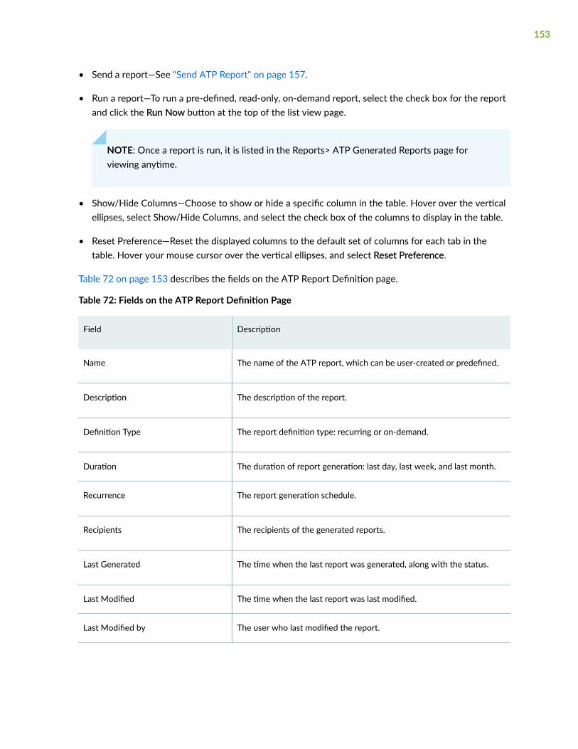
• Send a report—See "Send ATP Report" on page 157.
• Run a report—To run a pre-defined, read-only, on-demand report, select the check box for the reportand click the Run Now button at the top of the list view page.
NOTE: Once a report is run, it is listed in the Reports> ATP Generated Reports page forviewing anytime.
• Show/Hide Columns—Choose to show or hide a specific column in the table. Hover over the verticalellipses, select Show/Hide Columns, and select the check box of the columns to display in the table.
• Reset Preference—Reset the displayed columns to the default set of columns for each tab in thetable. Hover your mouse cursor over the vertical ellipses, and select Reset Preference.
Table 72 on page 153 describes the fields on the ATP Report Definition page.
Table 72: Fields on the ATP Report Definition Page
Field Description
Name The name of the ATP report, which can be user-created or predefined.
Description The description of the report.
Definition Type The report definition type: recurring or on-demand.
Duration The duration of report generation: last day, last week, and last month.
Recurrence The report generation schedule.
Recipients The recipients of the generated reports.
Last Generated The time when the last report was generated, along with the status.
Last Modified The time when the last report was last modified.
Last Modified by The user who last modified the report.
153

Table 72: Fields on the ATP Report Definition Page (Continued)
Field Description
Report Definition ID The unique identifier of the report.
Create ATP Report Definition
Use the available fields to build a report that runs at set intervals and automatically sends the PDFreport to the email addresses you specify.
In addition to creating your own report definition, you can use the included, pre-defined, read-only, ondemand reports. The included reports are named as follows:
• Threat Assessment Last Day
• Threat Assessment Last Week
• Threat Assessment Last Month
To create a custom ATP report definition:
1. Navigate to Monitor > Reports>ATP Report Definitions.
The ATP Report Definition Page appears.
2. Click the + (Create) icon on the top right of the page.
The Create Report page appears.
3. Complete the configuration according to the guidelines provided in the
4. Click OK to save the report definition.
A new ATP report definition with the defined configurations is created. The new report is listed as adownloadable PDF file in the Reports>Generated Reports page for viewing anytime.
154

Table 73: ATP Report Definition Settings
Settings Guidelines
Report Name Enter a name for the report.
The name must begin with an alphanumericcharacter and can include dashes, spaces, andunderscores; 63-character maximum.
Description Give the report a detailed description that alladministrators can recognize.
Date Range Options Configure a recurring schedule for running a report.The options are: Last Day (daily), Last Week (onceweekly), and Last Month (once monthly).
Based on your selection, you will configure a specifictime period in the next field.
Generate report every Use the downward arrow in the entry field for addingmultiple days.
If you selected Last Day in the previous field, choosemultiple days of the week for running a report. Forexample, every day (add all days manually Sundaythrough Saturday) or only add Monday, Wednesday,and Friday for an every other day report.
If you selected Last Week, choose one day of theweek for running a weekly report.
If you selected Last Month, choose whether to run areport on the first day of the month or the last day ofthe month.
155

Table 73: ATP Report Definition Settings (Continued)
Settings Guidelines
Email Recipients Once a report is generated, you can have it sent toone or more email addresses. The email addressesavailable for receiving reports come from theAdministrator > Users list.
Note that once the report is created, you can alwayssend it to an email address on-demand by selectingthe check box for the report in the list view andclicking the Send button at the top of the page. Anew window appears, and you can select an emailaddress there. Again, the available addresses comefrom the Administrator > Users list.
Edit and Delete ATP Report Definition
IN THIS SECTION
Edit an ATP Report Definition | 156
Delete an ATP Report Definition | 157
You can edit and delete ATP report definitions from the ATP Report Definitions page. This topic has thefollowing sections:
Edit an ATP Report Definition
1. Select Monitor > Reports > ATP Report Definitions.
The ATP Report Definitions page appears.
2. Select a report definition by clicking the appropriate check box.
3. On the upper right side of the ATP Report Definitions page, click Edit (pencil) icon.
The edit report definition page opens. The options available on the create report definition page areavailable for editing.
4. Modify the parameters according to the guidelines provided in Table 73 on page 155.
156

5. Click OK to save your changes.
Delete an ATP Report Definition
You can clear all unwanted report definitions that are not used anywhere in your network.
NOTE: An error message appears if the report definition is used by any object.
1. Select Monitor > Reports > ATP Report Definitions.
The ATP Report Definitions page appears.
2. Select the report definition you want to delete, and then click the delete icon (trash can).
An alert message asking for confirmation to delete your selection is displayed.
3. Click Yes to delete your selection.
The delete report notification is displayed.
4. Click OK.
Send ATP Report
You can send the ATP report through e-mail to the recipients.
To send a report:
1. Select Monitor > Reports > ATP Report Definitions.
The ATP Report Definitions page appears.
2. Select a report and click Send Report.
The Send Report page appears.
3. Configure according to the guidelines provided in Table 74 on page 157.
4. Click OK.
A message is displayed indicating the status of the operation. If the operation is successful, the userreceives a notification once the report is sent.Table 74: Send Report Settings
Setting Guidelines
Subject Enter the subject name of the report.
Comments Enter the description for the report.
157
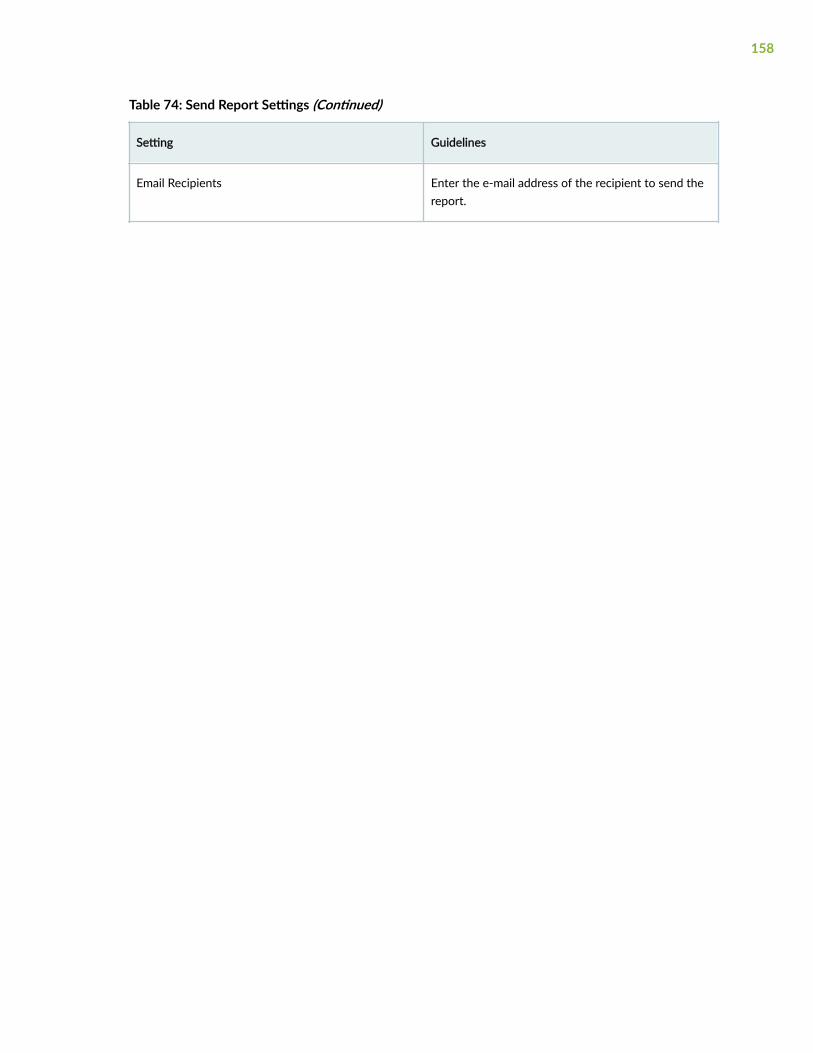
Table 74: Send Report Settings (Continued)
Setting Guidelines
Email Recipients Enter the e-mail address of the recipient to send thereport.
158

CHAPTER 11
ATP Generated Reports
IN THIS CHAPTER
About the ATP Generated Reports Page | 159
About the ATP Generated Reports Page
IN THIS SECTION
Tasks You Can Perform | 159
To access this page, select Monitor > Reports > ATP Generated Reports.
You can configure ATP threat assessment reports to be run on-demand or on scheduled intervals. Whileyou cannot determine the information included in the report, you can narrow information to a selectedtimeframe. When the system generates a report, you and other designated recipients receive the reportin PDF format through e-mail.
Tasks You Can Perform
You can perform the following tasks from this page:
• Download the report—Click on a report PDF name to download the report. The content of thegenerated report is shown in Table 76 on page 161.
• Delete the report—Select a report and click the delete icon (trash can). An alert message asking forconfirmation to delete your selection is displayed. Click Yes to delete the report.
Table 75 on page 160 displays the fields on ATP Generated Reports page.
159

Table 75: ATP Generated Reports
Field Description
Report PDF Name Name of the generated ATP report. Click on the reportname to download the report. The details of the reportis described in Table 76 on page 161.
Generated Time Date and time of report creation.
Description Description of the generated report.
Definition Definition of the generated report.
Generated By User who generated the report.
Recipients User with whom the report is shared.
160

Table 76: ATP Threat Assessment Report Contents
Report Category Definition
Executive Summary An overview report data separated into following categories:
• Malware—Lists newly discovered malware and knownmalware.
• C&C Server Destinations—Lists C&C server destination.
NOTE: The criteria to display the C&C server destination inthe reports is that the threat level must be equal to orgreater than 7.
• Hosts with Malicious Activities—Lists the following:
• Infected hosts—Lists the number of potentially infectedhosts whose threat level is less than the thresholdthreat level that is set by the customer.
• Blocked hosts—Lists the number of infected hosts thathave met the threshold threat level and is blocked bypolicies configured on Juniper Secure Edge.
• Domains and URLs—Lists the domains and URLs that aresuspicious or known to be risky.
• High-risk User Data—Lists the following:
• Users’ computers infected with malware.
• High-risk web sites accessed by users.
Malware The malware section contains the following information:
• Top Malware Identified—Lists the names of the topmalware by count.
• Top Infected File MIME Types—Lists the top infected multi-purpose Internet mail extensions (MIME) by count.
• Top Scanned File Categories—Lists the top file categoriesthat are scanned.
161

Table 76: ATP Threat Assessment Report Contents (Continued)
Report Category Definition
C&C Server and Malware Locations This section contains the following information:
• Top C&C Server Location by Count—Lists the top countriesfor command and control (C&C) servers by number ofcommunication attempts (C&C hits).
• Top Malware Threat Locations by Count—Lists the topcountries with malware threats.
Hosts This section contains the following information:.
• Top Compromised Hosts—Lists the top hosts that may havebeen compromised based on their associated threat level.
Risky Files This section contains the following information:
• Top Risky File Categories by Count—Lists the top risky filecategories by count for known and newly discoveredmalicious files.
• Top Risky Files Detected by Count—Lists the top risky filesdetected by count.
• Top IPs Detected Attempting to Access Risky Files byCount—Lists the top IP addresses attempting to accessrisky files.
• Top Risky Files Detected by IPs—Lists the top risky filesdetected per top IP address attempting to access the files.
162

Table 76: ATP Threat Assessment Report Contents (Continued)
Report Category Definition
Risky Domains, URLS, AND IPs This section contains the following information: top riskydomains, URLs, and IP addresses detected by the number oftimes access was attempted. It also includes the top users whohave attempted to access these risky domains, URLs, and IPaddresses.
• Top Detected Risky Domains, URLs, and IPs by Count—Liststhe top risky domains, URLs, and IP addresses detected bythe number of times access was attempted.
• Most Active Users for Risky Domains, URLs, and IPs byCount—Lists the top users who are most active inattempting to access the risky domains, URLs, and IPaddresses by count.
• Top Detected Risky Domains, URLs, and IPs by Threat Level—Lists the top risky domains, URLs, and IP addressesdetected by the threat level.
163

Table 76: ATP Threat Assessment Report Contents (Continued)
Report Category Definition
Email This section contains the list of actions taken on scannedemails. It also includes email attachments determined to bemalware and users who are risky email senders.
• Actions Taken—Lists the action taken for scanned e-mail.
• High-Risk Email Data—Lists the count of e-mailattachments with malware and risky senders.
• Malicious SMTP Email by Count—The report breaksscanned e-mail down by protocol and lists SMTP e-mailsfound to be malicious.
• Malicious IMAP Email by Count—The report breaks scannede-mail down by protocol and lists IMAP e-mails found to bemalicious.
• Top Risky File Categories Detected for Email Attachments—Lists the top risky file categories that were detected fromfiles received as e-mail attachments.
• Top Risky Email Attachments Detected by Count—Lists thetop risky files that are detected from email attachments.
• Top Users Receiving Risky Email Attachments—Lists the topusers who are receiving risky file attachments through e-mail.
• Top Risky Email Attachments Detected per Top Users—Liststhe top users and their most risky file attachments.
• Top Risky Email Sender Domains by Count—Lists the toprisky sender domains based on the threat level of fileattachments sent in email.
• Top Sender Domains of Risky File Attachments by Count—Lists the top sender domains with risky file attachmentsand the count of how many times the risky file attachmentsthat were detected.
• Actions on SMTP Malicious Email by Count—Lists actionstaken for malicious SMTP e-mails.
164

Table 76: ATP Threat Assessment Report Contents (Continued)
Report Category Definition
• Actions on IMAP Malicious Email by Count—Lists actionstaken for malicious IMAP e-mails.
Devices This section contains the following information:
• Zero submissions—List of devices that have not submittedfiles in the past 30 days.
• Expiring Devices—List of devices that are going to expire innext 60 days.
165

4PART
SRX
Device Management-Devices | 167
Device Management-Configuration Templates | 217
Device Management-Images | 233
Device Management-Security Packages | 241
SRX Policy | 244
SRX Policy-Device View | 273
Security Subscriptions-IPS | 275
Security Subscriptions-Content Security | 327
Security Subscriptions-Decrypt Profiles | 375
IPsec VPN | 394
IPsec VPN-VPN Profiles | 463
IPsec VPN-Extranet Devices | 475
NAT-NAT Policies | 478
NAT-NAT Pools | 499
Identity-JIMS | 506
Identity-Active Directory | 515
Identity-Access profile | 524
Identity-Address Pools | 535

CHAPTER 12
Device Management-Devices
IN THIS CHAPTER
About the Devices Page | 167
Add Devices to Juniper Security Director Cloud | 183
Manage Subscriptions for Your Device | 186
Delete a Device From Juniper Security Director Cloud | 187
Add a License to a Device | 188
Add a Physical Interface on the Device | 190
Configure a Security Zone For the Device | 194
Configure a Routing Instance for the Device | 197
Configure a Static Route for the Devices | 200
Import a Device Certificate | 205
Resynchronize a Device with Juniper Security Director Cloud | 207
Manage Configuration Versions | 208
Reboot a Device | 213
Upgrade a Device | 214
Enable Security Logs | 215
About the Devices Page
IN THIS SECTION
Tasks You Can Perform | 168
Field Descriptions | 169
167

To access this page, click SRX > Device Management > Devices.
The Devices page displays a list of devices managed by Juniper Security Director Cloud. You can viewinformation about the device, such as the software release version, the platform, and various statusindicators. You can also view the device inventory details, rollback to a configuration version,resynchronize or reboot a device, and upgrade a device.
To manage devices using Juniper Security Director Cloud, you must first add the devices to JuniperSecurity Director Cloud. After you add your devices, you can manage the devices using the Devicespage.
Tasks You Can Perform
You can perform the following tasks from this page:
• Add devices to Juniper Security Director Cloud. See "Add Devices to Juniper Security Director Cloud"on page 183.
• Subscribe your devices to multiple subscriptions. See "Manage Subscriptions for Your Device" onpage 186.
• Delete a device from Juniper Security Director Cloud. See "Delete a Device From Juniper SecurityDirector Cloud" on page 187.
• View the details of a device. Select a device, and click More > Detail. The details of the device isdisplayed in a panel on the right side of the page. See Table 78 on page 172.
• View the device inventory information. Select a device, and click More > View Inventory. The deviceinventory page opens displaying the device discovery. See Table 79 on page 174.
• Add a physical interface on the device. See "Add a Physical Interface on the Device" on page 190
• Configure a security zone for the device. See "Configure a Security Zone For the Device" on page194
• Configure a routing instance for the device. See "Configure a Routing Instance for the Device" onpage 197
• Configure a static route for the device. See "Configure a Static Route for the Devices" on page 200
• Add feature licenses for a device. See "Add a License to a Device" on page 188
• Import local certificates and CA certificates into your devices. See "Import a Device Certificate" onpage 205
• Resynchronize a device with Juniper Security Director Cloud. See "Resynchronize a Device withJuniper Security Director Cloud" on page 207
168

• View the active configuration of a device. Select a device, and click More > View ActiveConfiguration. The Active Configuration page opens displaying the active configuration of the device.
• View configuration versions of a device. See "Manage Configuration Versions" on page 208.
• Reboot a device. See "Reboot a Device" on page 213.
• Upgrade a device. See "Upgrade a Device" on page 214.
• Export device information as a CSV file that can be opened and edited using an application such asMicrosoft Excel. Click More > Export as CSV.
• Export the device inventory information as a zipped file. Click More > Export Inventory.
• Enable security logging for a device or device cluster. See "Enable Security Logs" on page 215.
• Show or hide columns about a device. Click the Show/Hide columns icon in the top-right corner ofthe page and select the columns to view on the page.
• Filter information based on select criteria. You can add filters, save the filters, and set any of thefilters as default. To add a filter:
1. Click the filter icon on the top-right corner of the page, and select Add Filter to open the AddCriteria page.
2. Set the filter conditions, and click Add.
The filter is saved and the filter is applied on the data. You can save the filter. You can also mark onefilter as the default filter.
To remove the filter, click the filter icon, and select Hide Filter.
Field Descriptions
Table 77 on page 169 describes the fields on the Devices page.
Table 77: Fields on the Devices Page
Fields Description
Host Name Displays the name of the device.
169

Table 77: Fields on the Devices Page (Continued)
Fields Description
Management Status Displays the following connection statuses of devicesin Juniper Security Director Cloud:
• Up—The device is connected to Juniper SecurityDirector Cloud.
• Down—The device is not connected to JuniperSecurity Director Cloud.
• Discovery Not Initiated—The device is added to thedevice list on the Devices page, but is not addedcompletely. To complete adding the device, clickAdopt Device, and follow the instructions in "AddDevices or Device Clusters Using Commands" onpage 184.
• Discovery Failed—There was an error during thedevice discovery process or while adding thedevice to Juniper Security Director Cloud. You canview the reason for the failure when you hoveryour mouse cursor over the Discovery Failedstatus.
Configuration Status Displays the current state of the device configuration:
• Unknown—The device status is unknown to JuniperSecurity Director Cloud. The device is either notconnected to Juniper Security Director Cloud or isdown.
• In Sync—The device is connected to JuniperSecurity Director Cloud.
• Out of Sync—The device is not connected toJuniper Security Director Cloud.
• Sync in Progress—The device is being synchronizedto Juniper Security Director Cloud after the deviceis added or upgraded.
170

Table 77: Fields on the Devices Page (Continued)
Fields Description
Device Health Status Displays the resources used by the device, such asCPU processing power, memory, and storage.
The health status is displayed only for devices withsubscriptions. The status of the device is color-coded.
• Green indicates a healthy device with resourceusage below 50%.
• Orange indicates warnings with resource usagereaching 50% to 80%.
• Red indicates errors and heavy resource usageabove 80%.
Subscriptions Displays the subscriptions to which the device issubscribed.
• Displays Trial Subscription if you have subscribedthe device to the trial subscription.
• Displays No Subscription if you have not yetsubscribed the device to any subscriptions.
OS Version Displays the operating system firmware versionrunning on the device
This field displays Unknown for devices that are notmanaged using Juniper Security Director Cloud.
Platform Displays the model number of the device.
For devices that are not managed using JuniperSecurity Director Cloud, the platform details arediscovered through SNMP. If the platform detailscannot be discovered, the field displays Unknown.
Table 78 on page 172 describes the fields on the Device Details pane.
171

Table 78: Fields on the Device Details Pane
Fields Description
Basic Information
Host Name Displays the name of the device.
OS Version Displays the operating system firmware versionrunning on the device.
This field displays Unknown for devices that are notmanaged using Juniper Security Director Cloud.
Family Displays the device family of the selected device.
For devices that are not managed using JuniperSecurity Director Cloud, the family is the same as theprovided vendor name. The field displays Unknown ifthe vendor name is not available and if SNMP is notused or has failed.
Platform Displays the model number of the device.
For devices that are not managed using JuniperSecurity Director Cloud, the platform details arediscovered through SNMP. If the platform detailscannot be discovered, the field displays Unknown.
Serial Number The serial number of the device chassis.
This field displays Unknown for devices that are notmanaged using Juniper Security Director Cloud.
Status Information
172

Table 78: Fields on the Device Details Pane (Continued)
Fields Description
Management Status Displays the connection status of the device in JuniperSecurity Director Cloud.
• Up—The device is connected to Juniper SecurityDirector Cloud.
• Down—The device is not connected to JuniperSecurity Director Cloud.
• Discovery Failed—There was an error during devicediscovery or adding to Juniper Security DirectorCloud. You can see the reason for the failure whenyou hover your mouse cursor over the DiscoveryFailed status.
Configuration Status Displays the current state of the device configuration.
• Unknown—The device status is unknown to JuniperSecurity Director Cloud. The device is either notconnected to Juniper Security Director Cloud or isdown.
• In Sync—The device is connected to JuniperSecurity Director Cloud.
• Out of Sync—The device is not connected toJuniper Security Director Cloud.
• Sync in Progress—The device is beingresynchronized to Juniper Security Director Cloudafter the device is added or upgraded.
Additional Details
ZTP Displays the status of the device added using zero-touch provisioning (ZTP).
Table 79 on page 174 describes the fields on the Device Inventory page.
173

Table 79: Fields on the Device Inventory Page
Fields Description
Overview
Chassis Displays the port usage and health status of hardwaredevices.
Port Count by Status Displays the operational status of the interface port ofthe devices currently being managed by JuniperSecurity Director Cloud.
Device Details Displays device details.
See Table 78 on page 172.
Additional Details Displays the status of devices added using ZTP.
Resource Utiliziation Displays the storage resources used by each device.
Inventory - Chassis
Module Displays the module of the device.
Type Displays the type of the device.
Model Displays the model of the device.
Version Displays the version of the device software.
Part Number Displays the part number of the device.
Serial Number Displays the serial number of the device.
174

Table 79: Fields on the Device Inventory Page (Continued)
Fields Description
Physical Interfaces Displays standard information about physicalinterfaces connected to the device in thetype-/fpc/pic/port format where type is the mediatype that identifies the network device. For example,ge-0/0/6.
Click View to go to the Interfaces tab.
Description Displays an optional description for this interfaceconfigured on the device.
The description can be a text string that contains up to512 characters. Longer strings are truncated to 512characters. If there is no information, the column isempty.
Inventory - Interfaces
Include All Displays the list of devices.
By default, only devices that are in Up and In Syncstates are listed. Select Include All to list all thedevices.
Interface Name Displays the interface that the device uses to connectto Juniper Security Director Cloud.
MAC Address Displays the MAC address of the physical interface.
Admin Status Displays the administrative status of the interface,which can be Up or Down.
Operational Status Displays the operational status of the interface, whichcan be Up or Down.
MTU Displays the maximum transmission unit (MTU) size onthe physical interface.
175

Table 79: Fields on the Device Inventory Page (Continued)
Fields Description
Speed Displays the speed (mbps) at which the interface isrunning.
Link Type Displays the link level type of the physical interface.
Logical Interfaces Displays the link to the table of logical interfaces of thedevice.
Inventory - Licenses
License Name Displays the name of the license associated with thedevice.
Version Displays the version of the license.
State Displays the status of the license, which can be Valid,Invalid, or Expired.
Only valid licenses are included in the license countcalculation.
Validity Type Displays the validity type of the license, which can beTrial, Count-down, or Data-based.
Start Date Displays the start date of the licensed feature.
End Date Displays the end date of the licensed feature.
Features Displays the number of features associated with thelicense.
Click the link to view the licensed features.
176

Table 79: Fields on the Device Inventory Page (Continued)
Fields Description
Add License The option to add licenses to the device.
See "Add a License to a Device" on page 188.
Inventory - Features
Feature Name Displays the name of the licensed SKU or feature.
You can use Feature Name to look up the license withJuniper Networks.
NOTE: Not all devices support Feature Name.
Description Displays the description of the feature.
Used Count Displays the number of times the feature is used.
For some types of licenses, the license count stays 1even when the license might be used multiple times.For capacity-based license items, if infringement issupported, the license count might exceed the givencount, which has a corresponding effect on the needcount.
Installed Count Displays the name of the devices with which thefeature is associated.
Need Count Displays the number of times the feature is usedwithout a license.
Not all devices can provide this information.
Validity Type Displays the validity type of the feature, which can beTrial, Count-down, or Data-based.
177

Table 79: Fields on the Device Inventory Page (Continued)
Fields Description
Licenses Displays the number of times an item has beenlicensed.
The total number might include the license usage frommore than one licensed SKU or feature. For sometypes of licenses, the license count might stay 1 eventhough the license might be used multiple times.
Inventory - Certificates
Certificate ID Displays the unique identification of the certificate.
Issuer Organization Displays the details of the organization that issued thecertificate.
Status Displays the expiration status of the certificate:
• If you set the certificate to be renewedautomatically, the status displayed depends on therenewal period selected from the Edit CertificateSettings page.
For example, if you select the renewal period as 1month, the Status field displays Less than 1 monthbefore expiry
• If you set the certificate to be manually renewed,the status displayed depends on the expirationnotification time for the certificate. For example,Less than 2 weeks before expiry
• If the expiration date of the certificate does notmeet the expiration notification time yet, theStatus field displays –
• If the certificate has expired, the Status fielddisplays Expired
178

Table 79: Fields on the Device Inventory Page (Continued)
Fields Description
Expiry Date Displays the date and time when the certificateexpires.
Encryption Type Displays the type of the certificate:
• Root certificate
• Trusted certificate
Import The option to import certificates into the device.
See "Import a Device Certificate" on page 205.
Inventory - Software
Software Name Displays the name of the installed software package.
State Type Displays the type of the software package.
Software Description Displays the description of the software package.
Version Displays the version number of the installed softwarepackage.
Inventory - Security Packages
Name Displays the name of the currently installed securitypackage.
Version Displays the currently installed security packageversion.
179

Table 79: Fields on the Device Inventory Page (Continued)
Fields Description
License Displays the number of licenses associated with thesecurity package.
Click the link to see the details of the licenses.
Configuration Template
Name Displays the name of the configuration template.
Deployment Status Displays the deployment status of the configurationtemplate, which can be No configuration, Ready todeploy, or Deployed.
Deployment Date Displays the date on which the configuration templatewas deployed.
Description Displays the description of the configuration template.
Validation Displays the status of the configuration templatesvalidation job, which can be Success, Failed, or In-progress.
This field is temporarily populated when you clickValidate on the Configuration Template page.
Configuration
Physical Interfaces
Interface Name Displays the interface that the device uses to connectto Juniper Security Director Cloud.
MTU Displays the maximum transmission unit (MTU) size onthe physical interface.
180
Table 79: Fields on the Device Inventory Page (Continued)
Fields Description
Description Displays the description of the physical interface.
Logical Interfaces Displays the link to the table of logical interfaces of thedevice.
Config State Displays the status of the device.
Config Version Displays the configuration version of the device.
Zones
Name Displays the source zone of the device.
Interfaces Displays the link to the table of logical interfaces of thedevice.
Config State Displays the status of the device.
Description Displays the configuration version of the device.
Routing Instance
Name Displays the name of the routing instance. Eachrouting instance has a unique name and acorresponding IP unicast table.
Routing Protocols View or configure static routes for the routing instanceby clicking the link in the Routing Protocols column.
Instance Type Displays the type of routing instance. Juniper SecurityDirector Cloud supports Virtual router as the defaultrouting instance.
181

Table 79: Fields on the Device Inventory Page (Continued)
Fields Description
Assigned Interface Displays the interface associated with the routinginstance.
Description Displays the description for the routing instance.
Status Displays the deployment status of the routing instance.
Static Routes
IP Address Displays the IPv4 or IPv6 address depending on thetype of IP address specified.
Next Hop Displays the next hop IP address.
Qualified Next Hop Displays the qualified next hops that allow you toassociate one or more properties with a particularnext-hop address.
Next Table Displays the name of the next routing table to thedestination.
RELATED DOCUMENTATION
Add Devices to Juniper Security Director Cloud | 183
Manage Subscriptions for Your Device | 186
Subscriptions | 783
Delete a Device From Juniper Security Director Cloud | 187
Manage Configuration Versions | 208
Reboot a Device | 213
Resynchronize a Device with Juniper Security Director Cloud | 207
Upgrade a Device | 214
182

Add Devices to Juniper Security Director Cloud
IN THIS SECTION
Add Devices or Device Clusters Using Commands | 184
Add Devices Using Zero Touch Provisioning | 185
Add devices to Juniper Security Director Cloud, after which you can manage your network securityusing these devices. There are multiple ways to add devices to Juniper Security Director Cloud. Choosethe method that's right for you:
• Add Devices Using Commands. Juniper Security Director Cloud generates commands for adding adevice or device cluster. You can copy the commands and paste them into the device console. Whenyou commit the commands to the device, Juniper Security Director Cloud discovers and adds thedevice or device cluster to the cloud. See "Add Devices or Device Clusters Using Commands" onpage 184 for details.
• Add Devices With Zero Touch Provisioning. With Zero Touch Provisioning (ZTP) you can configureand provision devices automatically. You can use ZTP to add devices for Junos OS Release 18.4R3 onSRX300, SRX320, SRX340, SRX345, SRX550 HM SRX Series devices, Junos OS Release 20.2R1 onthe SRX1500 SRX device, and Junos OS Release 20.1R1 on SRX380 devices. See "Add Devices UsingZero Touch Provisioning" on page 185 for details.
• Add Devices Using J-Web. This feature is supported from J-Web Release 21.3R1 and later. See Addan SRX Series Device to Juniper Security Director Cloud in the J-Web User Guide for SRX SeriesDevices for details.
• Add Devices from Security Director. This feature is supported from Security Director Release 21.3R1and later. See Add Devices to Security Director Cloud in the Security Director User Guide for details.
NOTE: Ensure that your network firewall is configured in the following manner:
• Allows access to the srx.sdcloud.juniperclouds.net FQDN.
• Port 7804 opened.
• Port 6514 opened for monitoring and sending security logs to Juniper Security DirectorCloud.
183

Add Devices or Device Clusters Using Commands
Juniper Security Director Cloud generates commands for adding a device or a device cluster. You cancopy the commands and paste them into the device console. When you commit the commands to thedevice, Juniper Security Director Cloud discovers and adds the device or the device cluster to the cloud.
1. Select SRX > Device Management > Devices.
The Device page opens.
2. Click Add Devices.
The Add Devices page opens.
3. Click Adopt SRX Devices.
4. Select one of the following options:
• Devices to add individual devices.
• Clusters to add device clusters.
5. Enter the number of devices or device clusters to add to Juniper Security Director Cloud in theNumber of SRX devices to be adopted field, and click OK.
You can add a maximum of 50 devices or device clusters at one time.
A message confirming that the new device or device cluster is added is displayed. The Devices pageopens with the newly added device or device cluster listed in the table.
NOTE: At this point, Juniper Security Director Cloud has not yet completely added the deviceor device cluster, so the Connection Status displays Discovery Not Initiated.
6. On the Devices page, in the Connection Status column for the new device, click one of the followingoptions:
• Adopt Device to add a device.
• Adopt Cluster to add a device cluster.
The Adopt Devices page opens with the commands that you need to commit to the device.
7. Copy the commands and paste it to your device edit prompt, and press Enter to run the commands.
If you are adding a device cluster, paste these commands to the CLI of the primary device of thecluster.
8. Type Commit, and press Enter to commit the changes to the device.
You can view the status of the process, by going to the Administration > Jobs page.
When you commit the commands to the device, the device discovery process starts in JuniperSecurity Director Cloud. You can refresh the Devices page and see the status Discovery in progress inthe Connection Status column.
184
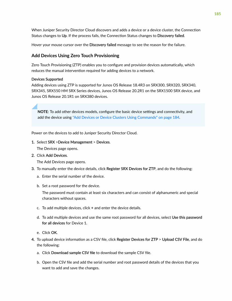
When Juniper Security Director Cloud discovers and adds a device or a device cluster, the ConnectionStatus changes to Up. If the process fails, the Connection Status changes to Discovery failed.
Hover your mouse cursor over the Discovery failed message to see the reason for the failure.
Add Devices Using Zero Touch Provisioning
Zero Touch Provisioning (ZTP) enables you to configure and provision devices automatically, whichreduces the manual intervention required for adding devices to a network.
Devices SupportedAdding devices using ZTP is supported for Junos OS Release 18.4R3 on SRX300, SRX320, SRX340,SRX345, SRX550 HM SRX Series devices, Junos OS Release 20.2R1 on the SRX1500 SRX device, andJunos OS Release 20.1R1 on SRX380 devices.
NOTE: To add other devices models, configure the basic device settings and connectivity, andadd the device using "Add Devices or Device Clusters Using Commands" on page 184.
Power on the devices to add to Juniper Security Director Cloud.
1. Select SRX >Device Management > Devices.
The Devices page opens.
2. Click Add Devices.
The Add Devices page opens.
3. To manually enter the device details, click Register SRX Devices for ZTP, and do the following:
a. Enter the serial number of the device.
b. Set a root password for the device.
The password must contain at least six characters and can consist of alphanumeric and specialcharacters without spaces.
c. To add multiple devices, click + and enter the device details.
d. To add multiple devices and use the same root password for all devices, select Use this passwordfor all devices for Device 1.
e. Click OK.
4. To upload device information as a CSV file, click Register Devices for ZTP > Upload CSV File, and dothe following:
a. Click Download sample CSV file to download the sample CSV file.
b. Open the CSV file and add the serial number and root password details of the devices that youwant to add and save the changes.
185

c. Browse for the CSV file and click OK.
The CSV file must be in a specific format for the devices to be added. You use the sample CSV file toenter the device details in the correct format and upload the file.
The devices are added to Juniper Security Director Cloud. You can view the devices at DeviceManagement > Devices.
SEE ALSO
About the Devices Page | 167
Manage Subscriptions for Your Device | 186
Subscriptions | 783
Delete a Device From Juniper Security Director Cloud | 187
Manage Configuration Versions | 208
Reboot a Device | 213
Resynchronize a Device with Juniper Security Director Cloud | 207
Upgrade a Device | 214
Manage Subscriptions for Your Device
IN THIS SECTION
Device Subscription Overview | 186
Associate Your Device with a Device Subscription | 187
Device Subscription Overview
Device subscriptions are used to manage devices within Juniper Security Director Cloud portal. Tomanage devices using Juniper Security Director Cloud portal, you must purchase the device subscriptionfor the required number of devices, add the subscription in Juniper Security Director Cloud, and thenassociate your devices to the device subscriptions.
For more details about the subscription, see Datasheet. To purchase the device subscriptions, reach outto your sales representative or account manager.
186

To see details about adding subscription to Juniper Security Director Cloud, see "Add Subscriptions" onpage 785.
Associate Your Device with a Device Subscription
Before associating your device with a device subscription, ensure that:
• You have a valid device subscription. Reach out to your sales representative or account manager topurchase the device subscriptions.
• You have added the details of your purchased device subscription in the Juniper Security DirectorCloud. See "Add Subscriptions" on page 785 for details.
To associate your device with the device subscription:
1. Select SRX > Device Management > Devices.
For devices that are not associated with a device subscription, the Subscriptions column displays Nosubscription.
The Devices page opens
2. Select the device, and click Manage Subscriptions.The Manage Subscriptions page opens.
3. Choose the device subscription to associate with the device.
For example, to associate your device with the trial subscription, select Trial from the list.
After associating your device with a device subscription, you cannot remove the device subscription.However, you will be able to transfer the device subscription to another device. The devicesubscription is freed up if you delete the device from the Devices page.
4. Click OK.
The device is associated with the device subscription. You can view the details of the devicesubscription on the SRX > Device Management > Devices page.
RELATED DOCUMENTATION
Subscriptions | 783
Delete a Device From Juniper Security Director Cloud
If you do not want Juniper Security Director Cloud to manage a device anymore, you must remove ordelete the device from Juniper Security Director Cloud.
1. Select SRX > Device Management > Devices.
187

The Devices page opens
2. Select the device to remove, and click the delete icon on the top-right corner of the page.
If provisioning services, such as firewall policies or configuration templates, are associated with thedevice that you want to delete, select the Force delete option. If the device you want to delete isprovisioned, and you do not select the Force delete option, the device will not be deleted.
The Delete Device page opens asking for confirmation of the delete operation.
3. Click Yes to delete the device.
The device is deleted from Juniper Security Director Cloud.
As part of this process, the initial configuration on the device to enabled the device and Juniper SecurityDirector Cloud to communicate with each other is deleted.
Add a License to a Device
Add a license for a software feature to a device or a device cluster. Each license is associated with afeature, such as IPS, content security, and is valid for only one device. You can add a license to a deviceeither by uploading a license file or by copying and pasting the license key.
1. Select SRX > Device Management > Devices.
The Devices page opens.
2. Select the device or the device cluster, and click More >View Inventory to view the inventory.
3. Click INVENTORY > LICENSES.
4. Click Add License.
The Add License page opens.
5. Complete the configuration of the license according to the guidelines provided in Table 80 on page189.
188

Table 80: Fields on Add License Page
Field Description
Options • Select Copy and paste license to copy the licensekey from the license file and paste it in theLicense text box.
NOTE: You must not edit the key.
• Select Upload license to browse and upload alicense file in the .txt format.
License If you selected Copy and paste license, copy thelicense information and paste into this text box.
You will have received the license information in ane-mail when you purchased the license.
For a device cluster, you will see options to copy andto paste license information for each device in thecluster. You can provide different licenses fordifferent devices in a device cluster.
License file If you selected Upload license, browse and uploadthe license file.
For a device cluster, you will see options to browsefor license files for each device in the cluster. You canupload different license files for different devices in adevice cluster.
6. Click OK.
The feature license is added to the device or the device cluster.
RELATED DOCUMENTATION
About the Devices Page | 167
189

Add a Physical Interface on the Device
Configure a physical interface on the device. You can also configure the logical interfaces associatedwith the physical interface.
1. Select SRX > Device Management > Devices.
The Devices page opens.
2. Select the device and click More > View inventory.
The device inventory details page opens.
3. Click the CONFIGURATION tab, and click Physical Interfaces.
4. Perform the required action provided in Table 1.
Table 81: Physical Interface Actions
Field Description
Add a physical interface a. Click the + icon to create a physical interface. TheAdd Physical Interface page appears.
b. Complete the configuration according to theguidelines provided in Table 82 on page 192.
c. Click OK.
The physical interface is added and you arereturned to the Configuration page.
Modify a physical interface a. Select a physical interface and click the pencilicon.
The Edit Physical Interface page appears, showingthe same fields when you add a physical interface.
b. Modify the required fields on this page. See Table82 on page 192 for an explanation of the fields.
c. Click OK.
The changes are saved and you are returned tothe Configuration page.
190

Table 81: Physical Interface Actions (Continued)
Field Description
Delete physical interfaces a. Select one or more physical interfaces and clickthe delete icon to delete the routes. The Warningpage appears.
b. Click Yes to confirm the deletion. The selectedphysical interfaces are deleted.
Preview physical interface configuration Lists the preview configuration for a given physicalinterface.
Deploy the physical interface a. Select one or more physical interfaces and clickthe Deploy button. The Deploy Config Resourcespage appears.
b. Do one of the following:
• Click Run Now to deploy the configuration onthe selected devices immediately.
• Click Schedule at a later time to deploy theconfiguration later.
c. Click OK.
The settings are saved and you are returned tothe Configuration page that shows thedeployment status in the Config State column. Aconfirmation message appears indicating that ajob is created. For each device, a separate task istriggered in the job to deploy the configuration.You can also view the status from theAdministration > Jobs page.
191

Table 82: Fields on the Add Physical Interfaces Page
Field Description
Interface Name Enter a name containing up to 63 characters withoutspaces.
The name must begin with an alphanumericcharacter and can include colons, periods, dashes,and underscores.
Description Enter a description of the physical interface.
Ensure that the description contains usefulinformation that is helpful to administrators.
MTU Enter the Maximum Transmission Unit (MTU) size.
MTU is the largest packet or frame size specified inbytes or octets that can be sent in a packet-based orframe-based network. TCP uses MTU to determinethe maximum size of each packet in any transmission.The valid range is between 256 and 9192.
Enabled Enable this option to activate VLAN tagging for thephysical interface.
VLAN Tagging Type Select whether you want the interface to receive andforward dingle tag frames, flexible dual-tag frames, ora mixture of untagged single-tag and dual-tag frames.
If you change the VLAN tagging type, you mustupdate the logical units of this interface.
Native-VLAN ID Enter the VLAN identifier to associate with theuntagged packets received on the physical interfaceof a trunk mode interface.
MAC address Enter the MAC address of the physical interface.
192

Table 82: Fields on the Add Physical Interfaces Page (Continued)
Field Description
Storm Control Profile Name Enter a storm control profile on a switch or router.
Storm control is used to prevent network outagesthat are caused by broadcast traffic storms.
Aggregate ID Enter the aggregated Ethernet interface ID.
Port Speed Enter the port speed for the interface.
Port speed is the maximum amount of data that theline card transmits through a port in one second.
Flow Control Enable this option to regulate the flow of packetsfrom the device to the remote side of theconnection.
VLAN Interface Mode Determine whether the interface accepts or discardspackets based on VLAN tags.
Select one of the following options:
• None to accept both untagged and taggedpackets.
• TRUNK for only tagged packets.
• ACCESS for only untagged packets
Access VLAN Enter the VLAN ID to which the interface thataccepts untagged packets belongs.
Trunk VLANs Enter the VLAN ID to which the interface thataccepts tagged packets belongs.
Gratuitous-ARP Reply Enable this option to process ARP updates receivedthrough gratuitous ARP reply messages.
193

Table 82: Fields on the Add Physical Interfaces Page (Continued)
Field Description
Gratuitous-ARP No reply Enable this option to prevent the interface fromresponding to gratuitous ARP requests.
Hold Time Up Select the hold time to use when an interfacetransitions from down to up.
Hold Time Down Select the hold time to use when an interfacetransitions from up to down.
Configure a Security Zone For the Device
A security zone is a collection of one or more network segments requiring the regulation of inbound andoutbound traffic through policies. Security zones are logical entities to which one or more interfaces arebound. You can define multiple security zones, the exact number of which you can determine based onyour network needs.
1. Select SRX > Device Management > Devices.
The Devices page opens.
2. Select the device and click More > View inventory.The device inventory details page opens.
3. Click the CONFIGURATION tab, and click Zones.
4. Perform the required action provided in Table 1.
194

Table 83: Security Zone Actions
Field Description
Create a security zone a. Click the + icon to create a security zone. The AddSecurity Zone page appears.
b. Complete the configuration according to theguidelines provided in Table 84 on page 196.
c. Click OK.
The security zone is created and you are returnedto the Zones section on the Configuration page.
Modify a security zone a. Select a security zone and click the pencil icon.
The Edit Security Zone page appears, showing thesame fields that are presented when you create asecurity zone.
b. Modify the required fields on this page. See Table84 on page 196 for an explanation of the fields.After you have modified the security zone.
c. Click OK.
The changes are saved and you are returned tothe Zones section on the Configuration page.
Delete security zones a. Select one or more security zones and click thedelete icon to delete the zones. The Warning pageappears.
b. Click Yes to confirm the deletion. The selectedsecurity zones are deleted.
Preview security zone configuration Preview security zone configuration by clicking thePreview button on the page.
195

Table 83: Security Zone Actions (Continued)
Field Description
Deploy the security zone a. Select one or more security zones and click theDeploy button. The Deploy Config Resourcespage appears.
b. Do one of the following:
• Click Run Now to deploy the configuration onthe selected devices immediately.
• Click Schedule at a later time to deploy theconfiguration later.
c. Click OK.
The settings are saved and you are returned tothe Configuration page that shows thedeployment status in the Config State column. Aconfirmation message appears indicating that ajob is created. For each device, a separate task istriggered in the job to deploy the configuration.You can also view the status from theAdministration > Jobs page.
Table 84: Fields on the Add Zone Page
Field Description
Name Enter a name containing up to 63 characters withoutspaces.
The name must begin with an alphanumericcharacter and can include colons, periods, dashes,and underscores.
Description Enter a description of the zone containing up to 900characters.
Ensure that the description contains usefulinformation that is helpful to administrators.
196

Table 84: Fields on the Add Zone Page (Continued)
Field Description
Application Tracking Enable this option to maintain the application usagestatistics on the device.
Interfaces Select the interfaces to include in the zone from theleft column and add the interfaces to the rightcolumn.
System Services Select the system services to include in the zonefrom the left column and add the services to the rightcolumn.
Protocols Select the protocols to include in the zone from theleft column and add the protocols to the rightcolumn.
TCP Reset Enable this option to activate sending TCP packetswith the RST (reset) flag set to 1 in response to TCPpackets that have a flag set to any flag other thanSYN and that do not belong to an existing session.
Interface Services and Protocols View the summary of interface, services andprotocols for your device.
RELATED DOCUMENTATION
https://www.juniper.net/documentation/us/en/software/junos/security-policies/topics/topic-map/security-zone-configuration.html
Configure a Routing Instance for the Device
A routing instance is a collection of routing tables, interfaces, and routing protocol parameters. The setof interfaces belongs to the routing tables, and the routing protocol parameters control the informationin the routing tables.
197

You can use the Routing Instances section on the Configuration page to view, create, edit, or deleterouting instances on the device and configure static routes.
To configure the routing instance:
1. Select SRX > Device Management > Devices.
The Devices page opens.
2. Select the device and click More > View inventory.
The device inventory details page opens.
3. Click the CONFIGURATION tab, and click Routing Instance link in the left-navigation menu.The Routing Instances section is displayed. The existing routing instances are displayed in a table.
4. Perform the required action provided in Table 1 on page 198.
Table 85: Routing Instances Actions
Field Description
Create a routing instance a. Click the + icon to create a routing instance. TheCreate Routing Instance page appears.
b. Complete the configuration according to theguidelines provided in Table 2 on page 200.
c. Click OK.
The routing instance is created and you arereturned to the Routing Instances section on theConfiguration page.
Modify a routing instance a. Select a routing instance and click the pencil icon.
The Edit Routing Instance page appears, showingthe same fields that are presented when youcreate a routing instance.
b. Modify the required fields on this page. See Table2 on page 200 for an explanation of the fields.After you have modified the routing instance
c. Click OK.
The changes are saved and you are returned tothe Routing Instances section on theConfiguration page.
198

Table 85: Routing Instances Actions (Continued)
Field Description
Delete routing instances a. Select one or more routing instances and click thedelete icon to delete the routes. The Warningpage appears.
b. Click Yes to confirm the deletion. The selectedrouting instances are deleted.
View or configure static routes for an existing routinginstance
View or configure static routes for the routinginstance by clicking the Configure Protocols link inthe Routing Protocols column.
Deploy the routing instance a. Select one or more routing instances and click theDeploy button. The Deploy Config Resourcespage appears.
b. Do one of the following:
• Click Run Now to deploy the configuration onthe selected devices immediately.
• Click Schedule at a later time to deploy theconfiguration later.
c. Click OK.
The settings are saved and you are returned tothe Configuration page that shows thedeployment status in the Config State column. Aconfirmation message appears indicating that ajob is created. For each device, a separate task istriggered in the job to deploy the configuration.You can also view the status from theAdministration > Jobs page.
Preview routing instance configuration Preview routing instance configuration by clickingthe Preview button on the page.
199

Table 86: Fields on the Routing Instance Page
Field Description
Name Enter a name for the routing instance; no specialcharacters are allowed and the keyword defaultcannot be used. The routing instance name must beunique and must contain a corresponding IP unicasttable.
Description Enter a description for the routing instance. Werecommend that you enter a maximum of 255characters.
Interfaces From the interfaces displayed in the Availablecolumn, select one or more interfaces to associatewith the routing instance.
RELATED DOCUMENTATION
https://www.juniper.net/documentation/us/en/software/junos/routing-overview/topics/concept/routing-instances-overview.html
Configure a Static Route for the Devices
Static route is often used when the complexity of a dynamic routing protocol is not desired. A route thatdoes not frequently change, and for which there is only one (or very few) paths to the destination, is agood candidate for static routing.
You can use the Static Routes section on the Configuration tab of the device inventory details page toview, create, edit, or delete static routes on the device.
1. Select SRX > Device Management > Devices.
The Devices page opens.
2. Select the device and click More > View inventory.
The device inventory details page opens.
3. Click the CONFIGURATION tab, and click Static Routes in the left-navigation menu.The Static Routes section is displayed.
200

4. Perform the required action provided in Table 1.
Table 87: Static Route Actions
Field Description
Create a static route a. Click the + icon to create a static route. TheCreate Static Route page appears.
b. Complete the configuration according to theguidelines provided in Table 88 on page 202.
c. Click OK.
The static route is created and you are returnedto the Static Routes section on the Configurationpage.
Modify a static route a. Select a static route and click the pencil icon.
The Edit Static Routes page appears, showing thesame fields that are presented when you create astatic route.
b. Modify the required fields on this page. See Table88 on page 202 for an explanation of the fields.After you have modified the static route.
c. Click OK.
The changes are saved and you are returned tothe Static Routes section on the Configurationpage.
Delete static routes a. Select one or more static routes and click thedelete icon to delete the static routes. TheWarning page appears.
b. Click Yes to confirm the deletion. The selectedstatic routes are deleted.
Preview static route configuration Preview static route configuration by clicking thePreview button on the page.
201

Table 87: Static Route Actions (Continued)
Field Description
Deploy the static route a. Select one or more static routes and click theDeploy button. The Deploy Config Resourcespage appears.
b. Do one of the following:
• Click Run Now to deploy the configuration onthe selected devices immediately.
• Click Schedule at a later time to deploy theconfiguration later.
c. Click OK.
The settings are saved and you are returned tothe Configuration page that shows thedeployment status in the Config State column. Aconfirmation message appears indicating that ajob is created. For each device, a separate task istriggered in the job to deploy the configuration.You can also view the status from theAdministration > Jobs page.
Table 88: Fields on the Create Static Routing Page
Field Description
Address type Select the type of IP address.
• IPv4
• IPv6
IP address Enter the IPv4 or IPv6 address depending on theselected type of IP address.
Prefix Enter the prefix for the IP address.
202

Table 88: Fields on the Create Static Routing Page (Continued)
Field Description
Next hop Select the IP addresses for the next hop of the staticroute.
You can also add IP addresses for the next hop byclicking + and configuring the fields as described in"Next Hop" on page 203.
Advanced Configure a static route on the device as described in"Advanced" on page 203.
You must configure either the next hop or the nexttable for each static route.
Next Hop
IP address Enter the IPv4 or IPv6 address depending on thetype of IP address specified.
Metric Enter a metric value that signifies the cost for anaccess route for the next hop.
The valid range is from 0 to 2147483647.
Advanced
Qualified next hop Configure the qualified next hop for the static route.You can specify a preference and a metric for thequalified next hop.
You can also add IP addresses for the next hop byclicking + and configuring the fields as described in"Qualified Next Hop" on page 204.
Next table Select the name of the next routing table to thedestination.
203

Table 88: Fields on the Create Static Routing Page (Continued)
Field Description
Metric Enter a metric value that signifies the cost for anaccess route for the next hop.
The valid range is from 0 to 2147483647.
Discard Specify whether the packets addressed to thedestination are dropped and ICMP unreachablemessages are not sent to the originator of the packet.
Resolve Specify whether indirectly connected next hopsshould be resolved.
Select None if no action is required.
Retain Specify whether to retain or delete the route in theforwarding table.
Select None if no action is required. If you selectRetain route in forwarding table, the route is saved inthe forwarding table when the routing protocolprocess shuts down normally.
Install Specify whether to install the route in the forwardingtable.
Select None if no action is required.
Re-advertise Specify whether the route should be re-advertised byrouting protocols.
Select None if no action is required.
Qualified Next Hop
Next Hop Type Select whether to specify an IP address or aninterface as the next hop of the static route.
204

Table 88: Fields on the Create Static Routing Page (Continued)
Field Description
IP address Enter the IP address for the next hop of the staticroute.
Interface Select the interface name for the next hop of thestatic route.
Preference Enter a preference for the next hop.
The lower the number the higher the routepreference. The valid range is from 0 to2147483647.
Metric Enter a metric value that signifies the cost for anaccess route for the next hop.
The valid range is from 0 to 2147483647.
RELATED DOCUMENTATION
https://www.juniper.net/documentation/us/en/software/junos/static-routing/topics/topic-map/config_static-routes.html
Import a Device Certificate
Import local certificates and CA certificates from your computer into the managed device toauthenticate SSL.
SSL uses public-private key technology that requires a paired private key and an authenticationcertificate for providing the SSL service. SSL encrypts communication between your device and the webbrowser with a session key negotiated by the SSL server certificate.
1. Select SRX > Device Management > Devices.
The Devices page opens.
2. Select the device or the device cluster, and click More >View Inventory.
3. Click INVENTORY > CERTIFICATES.
205

4. Click one of the following:
• Import in the Local Certificates section to open the Import Certificate page.
• Import in the CA Certificates section to open the Import CA Certificate page.
Click Generate Default Trusted CAs if you need to generate default trusted CA profiles.
5. Complete the configuration of the certificate according to the guidelines provided in Table 89 onpage 206.
Table 89: Fields on Import Certificate Page
Field Description
Certificate ID Enter a unique value for the certificate ID for anexternally generated certificate.
The certificate ID is used to create a key pair alongwith the algorithm to associate with the key.
Upload Certificate The option to navigate to and upload the certificate.
Click Browse to navigate to the location of thecertificate. Juniper Security Director Cloud supportsonly the PEM format for local certificates.
Upload Private Key The option to navigate to and upload the private key.
Click Browse to navigate to the location of theprivate key. Juniper Security Director Cloud supportsonly the PEM format for private keys.
Passphrase Enter the passphrase used to protect the private keyor key pair of the certificate file.
206

Table 90: Fields on the Import CA Certificate Page
Field Description
CA Profile ID Enter a unique value for the CA profile ID for anexternally generated certificate.
The CA profile ID is used to create a key pair alongwith the algorithm to associate with the key.
Upload certificate The option to navigate to and upload the certificate.
Click Browse to navigate to the location of thecertificate. Juniper Security Director Cloud supportsonly the CER format for CA certificates.
6. Click OK.
If the certificate content is validated successfully, the certificate is imported.
After importing a certificate, you can use the certificate when you create an SSL proxy profile and forIPsec VPN peers authentication.
RELATED DOCUMENTATION
About the Devices Page | 167
Resynchronize a Device with Juniper Security Director Cloud
When you resynchronize a managed device, the configuration changes made on the device and theinventory resources, such as certificates and licenses, are synchronized with the Juniper SecurityDirector Cloud database.
For example, when a managed device is updated by a device administrator using the CLI or the GUI ofthe device and you trigger a manual resynchronization, the device configuration on the physical device issynchronized with the Juniper Security Director Cloud database.
1. Select SRX > Device Management > Devices.
The Devices page opens.
2. Select the device to resynchronize, and click More > Resynchronize with Network.
207

A job is created for the resynchronization process and the details are displayed on the top of thepage. Click Administration > Jobs to view the job.
When the job completes successfully, the device resynchronization is complete.
RELATED DOCUMENTATION
About the Devices Page | 167
Add Devices to Juniper Security Director Cloud | 183
Manage Subscriptions for Your Device | 186
Subscriptions | 783
Delete a Device From Juniper Security Director Cloud | 187
Manage Configuration Versions | 208
Reboot a Device | 213
Upgrade a Device | 214
Manage Configuration Versions
IN THIS SECTION
View Configuration Versions | 209
Edit Configuration Version Description | 210
Pin a Configuration Version | 210
Rollback to a Configuration Version | 211
Compare Configuration Versions | 211
Configuration files in Juniper Security Director Cloud are created when the device configuration datafrom managed devices are backed up to the Juniper Security Director Cloud database for the first time.
A separate configuration file is created in the database for each managed device. Each time theconfiguration of a device changes, a new version of the configuration file is created on the device, whichcan then be backed up to the Juniper Security Director Cloud database or to a remote server at a fixedtime or at a set recurrence interval periodically.
208

Centralized configuration file management enables you to maintain multiple versions of your deviceconfiguration files in Juniper Security Director Cloud. This helps you recover device configuration files incase of a system failure and maintain consistent configuration across multiple devices.
NOTE: When you change the configuration of a device using Juniper Security Director Cloud, theportal processes this configuration change in a similar manner to a scenario where you wouldchange the configuration without using Juniper Security Director Cloud.
In both such scenarios, the device becomes out of sync with Juniper Security Director Cloud'ssecurity policies. Juniper Security Director Cloud overwrites such device configurations with theoriginal configuration when it deploys the security policies again. Use the configuration previewoption to view the configuration changes.
You must resynchronize out-of-sync devices with Juniper Security Director Cloud. See"Resynchronize a Device with Juniper Security Director Cloud" on page 207.
The following sections describe how you can pin important configuration versions, edit a configurationversion description, roll back to a particular configuration version, or compare two configurationversions.
View Configuration Versions
You can view information about all configuration versions of a device that are backed up in the JuniperSecurity Director Cloud database.
1. Select SRX > Device Management > Devices.
The Devices page opens.
2. Select the device or device cluster to view the configuration versions, and click More >ConfigurationVersions.
The Configuration Versions page opens displaying the previous ten configuration versions for theselected device or device cluster in the Version History pane. The page displays the followinginformation:
• Version Number—The version number of the configuration file. The files listed in order of themost recent to the oldest versions.
• Name—The name of the configuration versions. This is the device serial number with the .conf fileextension.
• Creation Date—The date and time the different versions of the configuration are created in theJuniper Security Director Cloud database. Version 1 corresponds to the time when you back up adevice configuration for the first time from the device.
By default, Juniper Security Director Cloud stores the previous ten configuration versions.
209

3. Select any configuration file to see a preview of the file in the Preview pane on the right side of thepage.
Edit Configuration Version Description
You can edit the description of each configuration version to make them intuitive to understand whenyou want to pin or rollback to a particular configuration version.
1. Select SRX > Device Management > Devices.
The Devices page opens.
2. Select the device or the device cluster to view the configuration files, and click More >ConfigurationVersions.
The Configuration Versions page opens displaying the previous ten versions of the configuration filesfor the selected device or the device cluster in the Version History pane.
3. Select the configuration version to edit the description, and click ✎ on the top right of the page.The Add Description page opens.
4. Update the description as required, and click OK.
The updated description of the configuration version is displayed in the Configuration Versions.
Pin a Configuration Version
By default, Juniper Security Director Cloud, stores the previous ten configuration versions of a device ora device cluster. If the number of backed up configuration versions exceeds ten, the oldest configurationversion is deleted and the latest version is stored.
Juniper Security Director Cloud allows you to pin certain configuration versions as important. Theseversions can be either golden versions without errors or configurations for specific requirements. Pinnedconfiguration versions are never deleted even when new configuration versions are created. You can pina maximum of three configuration versions as important.
If you have already pinned three configuration versions and pin a fourth configuration version, the firstpinned configuration version is deleted. For example, if you pinned Version 1, Version 2, and Version 3 insuccession, and if you pin Version 4, the pinned Version 1 is deleted.
1. Select SRX > Device Management > Devices.
The Devices page opens.
2. Select the device or device cluster to view the configuration files, and click More >ConfigurationVersions.
The Configuration Versions page opens displaying the previous ten versions of the configuration filesfor the selected device or the device cluster in the Version History pane.
3. Select the configuration version to pin, and click the pin icon on the top right of the page.
The pin symbol is displayed against the configuration version indicating that the version is pinned.
210

Rollback to a Configuration Version
The Rollback option enables you to deploy any version of the saved configurations to the device.
Restoring a configuration version involves overriding the device’s running configuration file with theselected version of the configuration backup file from Juniper Security Director Cloud.
NOTE: When you rollback the configuration version of a device using Juniper Security DirectorCloud, the portal processes this configuration change in a similar manner to a scenario where youwould rollback the configuration without using Juniper Security Director Cloud.
In both such scenarios, the device becomes out of sync with Juniper Security Director Cloud'ssecurity policies. Juniper Security Director Cloud overwrites such device configurations with theoriginal configuration when it deploys the security policies again. Use the configuration previewoption to view the configuration changes.
You must resynchronize out-of-sync devices with Juniper Security Director Cloud. See"Resynchronize a Device with Juniper Security Director Cloud" on page 207.
1. Select SRX > Device Management > Devices.
The Devices page opens.
2. Select the device or device cluster to rollback the configuration files, and click More >ConfigurationVersions.
The Configuration Versions page opens displaying the previous ten versions of the configuration filesfor the selected device or the device cluster in the Version History pane.
3. Select the configuration version to rollback to, and click Rollback.The Rollback Operation pop-up opens asking you for confirmation to continue the rollbackoperation.
4. Click Yes.A job is created for the rollback operation and the details are displayed on the top of the page. ClickAdministration > Jobs to view the job.
Once the job completes the device configuration rollback is complete. The configuration resources ofthe device are resynchronized and the device is ready for use.
Compare Configuration Versions
Juniper Security Director Cloud enables you to compare two device configuration versions by using theCompare option.
You can view the device configuration versions side by side to compare and see the total number ofdifferences, the date and time of the last commit operation, and the number of changes made.
211

NOTE: When you compare versions, each configuration parameter in one version is set side byside with the same parameter in the other version. Therefore, you might see multiple pages ofconfiguration for a single parameter in one version, whereas the same parameter in the otherversion might be only a few lines long.
1. Select SRX > Device Management > Devices.
The Devices page opens.
2. Select the device or device cluster to compare configuration versions, and click More >ConfigurationVersions.
The Configuration Versions page opens displaying the previous ten versions of the configuration filesfor the selected device or the device cluster in the Version History pane.
3. Select the configuration versions to compare to, and click Compare.
The Comparison page opens displaying the delta between the two versions. Table 91 on page 212describes what the color-coded text indicates.
Table 91: Comparison Page Legend
Text Color Description
Black text Indicates content that is common to both files
Green text Indicates content in the source file on the left that isnot contained in the target file on the right
Blue text Indicates content in the target file on the right that isnot contained in the source file on the left
Pink text Indicates content that is changed.
The status bar shows the current page number and the total number of pages, along with navigationcontrols to move from page to page and to refresh the display.
4. To locate differences in configuration, click ⬆ to view the previous difference or ⬆ to view the nextdifference.
212

SEE ALSO
About the Devices Page | 167
Add Devices to Juniper Security Director Cloud | 183
Manage Subscriptions for Your Device | 186
Subscriptions | 783
Delete a Device From Juniper Security Director Cloud | 187
Resynchronize a Device with Juniper Security Director Cloud | 207
Reboot a Device | 213
Upgrade a Device | 214
Reboot a Device
The Reboot option is useful in scenarios where you need to reboot a device during a software upgrade.
• You can only reboot devices for which the connection status is up.
• In a device cluster, you can reboot the primary and secondary devices independently.
1. Select SRX > Device Management > Devices.
The Devices page opens.
2. Select the device or device cluster to reboot, and click More > Reboot Device.A job is created for the reboot process and the details are displayed on the top of the page. ClickAdministration > Jobs to view the job.
When the job completes successfully, the device reboot is complete.
If some of the devices fail to reboot, you can use the Retry on Failed Devices action to retry rebootingthe devices that failed to reboot.
RELATED DOCUMENTATION
Add Devices to Juniper Security Director Cloud | 183
Manage Subscriptions for Your Device | 186
Subscriptions | 783
Delete a Device From Juniper Security Director Cloud | 187
Manage Configuration Versions | 208
Reboot a Device | 213
213

Resynchronize a Device with Juniper Security Director Cloud | 207
Upgrade a Device | 214
Upgrade a Device
A device image is a software installation package that enables you to upgrade to or downgrade from onesoftware release to another.
Juniper Security Director Cloud facilitates the management of device images by enabling you to uploaddevice images from your local file system and deploy the image on a device or multiple devices of thesame device family simultaneously.
You can download device images from https://www.juniper.net/customers/support/.
1. Select SRX > Device Management > Devices.
The Devices page opens.
2. Select the device or device cluster to upgrade, and click More > Upgrade Devices.The Upgrade Devices page opens displaying the platform and current software version deployed onthe device or device cluster.
3. Select the device or device cluster to upgrade, and click ✎ on the top-right corner of the Selectdevices table.
To upgrade multiple devices of same device model or a different device model that supports commonimage, select the devices to upgrade, and click Bulk Select Image.
4. Select the image to upgrade the device or device cluster to in the Selected Image column.
5. Click ✔ to proceed with the upgrade.
6. Click one of the following options:
• Run Now to immediately trigger the upgrade on the device or device cluster.
• Schedule Later to upgrade the device later and specify a date and time to for the upgrade.
7. Click OK.
A job is created for the upgrade process and the details are displayed on the top of the page. ClickAdministration > Jobs to view the progress of the job.
While the device is being upgraded, the device goes into maintenance mode and you cannot performany operations on the device. After the device is upgraded and connects back to Juniper SecurityDirector Cloud, the device is rebooted, the device inventory is resynchronized, and the device isavailable for all operations.
214

RELATED DOCUMENTATION
About the Devices Page | 167
Add Devices to Juniper Security Director Cloud | 183
Manage Subscriptions for Your Device | 186
Subscriptions | 783
Delete a Device From Juniper Security Director Cloud | 187
Manage Configuration Versions | 208
Reboot a Device | 213
Resynchronize a Device with Juniper Security Director Cloud | 207
Enable Security Logs
Configure security logging for devices. When you configure security logging for a device, it streamssecurity logs containing monitoring and reporting data to Juniper Security Director Cloud.
1. Select SRX > Device Management > Devices.
The Devices page opens.
2. Click Enable Security Logs.The Enable Security Logs page opens displaying all the devices.
3. Select the device or device cluster to enable security logging, and click ✎ on the top right of thepage.
4. Enable Security Log Status for the device or device cluster.
5. Select the source interface from the drop down list, and click ✔.If you have not configured security logging for all the devices or device clusters, a message askingyou whether to configure security logging for the rest of the devices is displayed.
6. Click one of the following options:
• Yes to go ahead with the process.
• No to stop the process and configure security logging for other devices or device clusters of yourchoice.
If you click Yes, the job is created to push the syslog configuration to the device or device cluster.
When the job completes, security logging is configured for the device or device cluster.
215

RELATED DOCUMENTATION
About the Devices Page | 167
216

CHAPTER 13
Device Management-Configuration Templates
IN THIS CHAPTER
Configuration Templates Overview | 217
Configuration Templates Workflow | 219
About the Configuration Templates Page | 219
Add a Configuration Template | 222
Preview and Render a Configuration Template | 228
Deploy a Configuration Template on to a Device | 229
Edit, Clone, and Delete a Configuration Template | 230
Configuration Templates Overview
IN THIS SECTION
Benefits | 219
Juniper Security Director Cloud provides configuration templates to provision configurations, bothduring onboarding and throughout the device life cycle, for Juniper Networks and other third-partydevices. By using configuration templates, you can deploy customized configurations on devices.
You can use a configuration template in following ways:
• Globally—You can define the configuration (for example, SNMP Configuration) to be applied to all thedevices managed by Juniper Security Director Cloud.
• Device-specific—You can define a configuration that is specific to a device; for example, BGPconfiguration.
217

By default, Juniper Security Director Cloud provides some predefined configuration templates. See Table92 on page 218 for the list of the predefined configuration templates. You can also create your owntemplates by cloning an existing template and modifying its settings. Templates can be added byadministrators or users with privilege to add configuration templates.
Table 92 on page 218 lists the predefined configuration templates.
Table 92: Predefined Configuration Templates
Name Description
AE_DEVICE_COUNT Configure the aggregated Ethernet interfaces on a device.
BANNER Configure the banner that appears when you log in to a device.
DNS Configure Domain Name System (DNS) server settings on a device.
DOMAIN_NAME Configure the domain name on a device.
HOSTNAME Configure the host name on a device.
LLDP Enable and configure Link Layer Discovery Protocol (LLDP) on all interfaces of a device.
LOCAL_USER Configure a local user on a device.
NETCONF Configure NETCONF on a device.
NTP Configure Network Time Protocol (NTP) settings on a device.
SNMP Configure basic SNMP version 2 (SNMPv2) parameters on a device.
SSH Configure SSH parameters on a device.
SYSLOG Configure system log settings on a device.
You can deploy the configuration template directly on a device. See "Deploy a Configuration Templateon to a Device" on page 229.
218

Benefits
Configuration templates provide a mechanism to create customized configurations and push theconfigurations to one or more devices. This helps you to deploy configurations beyond the standardconfiguration templates provided in Juniper Security Director Cloud.
Configuration Templates Workflow
The high-level workflow for configuration templates is as follows:
1. Use a pre-existing template (skip to step 2) or create a template using one of the following methods:
• Clone an existing configuration template and modify the cloned template. See"Edit, Clone, andDelete a Configuration Template" on page 230.
• Add a configuration template by specifying the template configuration and logic. See "Add aConfiguration Template" on page 222.
2. (Optional) Preview and validate the configuration template before deploying the configurationtemplate directly on a device. See "Preview and Render a Configuration Template" on page 228.
3. Deploy a configuration template directly on one or more devices that were previously activated,which enables you to deploy templates that were added after a device was activated or to deployadditional configuration to devices. You can deploy configuration templates to devices from theConfiguration Templates See "Deploy a Configuration Template on to a Device" on page 229.
About the Configuration Templates Page
IN THIS SECTION
Tasks You Can Perform | 220
Field Descriptions | 221
To access this page, click SRX > Device Management > Configuration Templates in the left navigationmenu.
219

Tasks You Can Perform
You can perform the following tasks from this page:
• View details of a configuration template. Select a configuration template and click More > Detail orhover over the configuration template and click the detailed view icon. The details of <Template-Name> pane appears on the right side of the page displaying the configuration template details.
• Add a configuration template. See "Add a Configuration Template" on page 222
• Preview a configuration template. See "Preview and Render a Configuration Template" on page 228
• Deploy a configuration template on one or more devices. See "Deploy a Configuration Template onto a Device" on page 229
• Clone, edit, or delete a configuration template. See "Edit, Clone, and Delete a ConfigurationTemplate" on page 230
• Filter Entries—Filter the table entries by adding new filtering criteria.
Hover over the Filter (funnel) icon and select Add Filter. On the Add Criteria page, select the filteringcriteria from the Field and Condition list, and enter the text to be compared in the Value field. ClickAdd.
The filtered table entries are listed and the filter criteria name is displayed above the table columnnames.
You can click the cross (X) icon (next to the filter name) to remove the filtering criteria.
NOTE:
• You can add multiple filtering criteria. Once you add the multiple filtering criteria, you canselect the And condition to display the entries matching all the filtering criteria or selectthe Or condition to display the entries matching any one of the filtering criteria.
• Quick filter: Save the filtering criteria as quick filters. Once you have added all the filteringcriteria, you can save a particular criteria or multiple criteria for future use by clicking Save.
On the Save Filter window, enter a name for the filter, optionally toggle the Set as Defaultbutton if you want to use this filtering criteria by default, and click OK.
The saved filters are displayed under Quick Filters when you hover over the Filter (funnel)icon. You can then apply these saved filters to the table entries.
• Show/Hide Columns—Choose to show or hide a specific column in the table.
220

Hover over the More Options (vertical ellipsis) > Show/Hide Columns and select the Column-Namecheck box of the columns you want to display in the table.
• Reset Preference—Reset the displayed columns to the default set of columns for each tab in thetable.
Hover over the More Options (vertical ellipsis) and select Reset Preference.
• Sort Entries—Click the column name to highlight the up and down arrows next to the column name.Sort the table entries in ascending or descending order of that column by clicking the up or downarrow respectively.
Field Descriptions
Table 93 on page 221 displays the fields on the Configuration Templates page.
Table 93: Fields on the Configuration Templates Page
Field Description
Name The name of the configuration template.
Format The format in which the configuration template is defined—CLI or XML.
Family The device family for which the configuration template is applicable:
• Juniper-SRX
Description A description of the configuration template.
Last Updated The date and time when the configuration template was last updated, in the MonthDD, YYYY HH:MM:SS format.
Created by The user who created the configuration template. System indicates that thetemplate is a predefined template.
221

Add a Configuration Template
To add a configuration template, you should either be a user with administrative privileges or have theprivilege to add configuration templates.
NOTE:
• Before you add the configuration template, ensure that you have the device configurationready.
• We recommend that you use a working device configuration to add the configurationtemplate.
To add a configuration template:
1. Select SRX > Device Management > Configuration Templates on the left navigation menu.
The Configuration Templates page appears.
2. Click the Add icon (+).
The Add Configuration Template page (wizard) appears.
NOTE: Fields marked with an asterisk (*) are mandatory.
3. Configure the fields on the Basic Information tab according to the guidelines provided inTable 94 onpage 223.
4. Click Next to go to the Template Configuration tab.
5. Add the configuration on the Template Configuration tab.
You can view a sample configuration by clicking the Sample Configuration link.
You can do the following in the editor provided for entering the configuration:
• Copy the required configuration stanza from a device and create a template from parameters inthe configuration.
• Refer to the sample configuration file for adding the configuration.
• Parameterize variables by using double curly braces {{}}.
6. Click Next to go to the Generated UI tab, where you can view the UI for the parameters that youentered.
7. Perform one or more actions on the Generated UI tab, as explained inTable 95 on page 223.
8. Click Save.
222

The configuration template is added and you are returned to the Configuration Templates page,where a confirmation message appears.
Table 94 on page 223 lists fields to be entered on the Basic Information tab of the Add ConfigurationTemplates page.
Table 94: Fields on the Basic Information Tab of the Add Configuration Templates Page
Field Description
Template Name Enter a unique name for the configuration template. The name can only containalphanumeric characters and hyphens; 64-characters maximum.
Description Enter a description for the configuration template; 255-characters maximum..
ConfigurationFormat
Select the output format for the configuration template:
• CLI (default)
• XML
Device Family Juniper-SRX
Table 95 on page 223 lists the actions that you can perform on the Generated UI tab of the AddConfiguration Templates page.
Table 95: Generated UI Actions
Action Description
Reorder the UI Drag and drop individual fields, grids, or sections to change the order in which theparameters appear on the UI.
223

Table 95: Generated UI Actions (Continued)
Action Description
Modify the settingsfor a field, section,or grid
To modify the settings for a field, section, or grid:
1. Click the Settings (gear) icon next to the field, section, or grid.
The Form Settings pane appears on the right side of the page, displaying the BasicSettings and Advanced Settings tabs.
2. Modify the fields on these tabs, as needed. See Table 96 on page 225 for anexplanation of the fields on these tabs.
3. Click Save Settings for each field to save your changes.
The modifications that you made are displayed on the UI.
Reset thegenerated UI
Click Undo all Edits to discard the changes that you made and undo the changes made onthe UI.
Previewconfiguration
Preview the configuration defined in the configuration template.
To preview a configuration template:
1. Click Preview Configuration.
The Preview Configuration page appears, displaying the configuration that wasrendered based on the values that you entered.
2. Check if the configuration is rendered correctly.
• If the configuration is not rendered correctly, click the close (X) icon to go back andmake modifications as needed.
• If the configuration is rendered correctly, click OK.
You are returned to the Generated UI page.
Table 96 on page 225 lists the fields on the Form Settings pane.
224

Table 96: Form Settings
Setting Guideline
Basic Settings Tab Fields populated in this tab are based on the input type that you select.
Input Type Select the input type for the parameter in the configuration template:
• Text (default): If the input value for the parameter is a string of characters.
• Number: If the input value for the parameter is a number.
• Email: If the input value for the parameter is an e-mail address.
• IPv4: If the input value for the parameter is an IPv4 address.
• IPv4 Prefix: If the input value for the parameter is an IPv4 prefix.
• IPv6: If the input value for the parameter is an IPv6 address.
• IPv6 Prefix: If the input value for the parameter is an IPv6 prefix.
• Toggle Button (Boolean): If the input value for the parameter is a boolean value (trueor false).
• Dropdown: If the input value for the parameter is selected from a list.
• Password: If the input value for the parameter is a password.
The value that you enter is masked (default).
(Optional) Click the Show Password (eye) icon to unmask the password.
• Confirm Password: If the input value for the parameter is to confirm the password.
If you select this option, a Confirm Password field appears on the UI. The value thatyou enter is masked (default).
(Optional) Click the Show Password (eye) icon to unmask the password.
Label Enter the label that you want displayed (on the UI) for the parameter.
Default Value Specify a default value for the parameter.
225

Table 96: Form Settings (Continued)
Setting Guideline
Validate For Text input type, select one or more validation criteria against which the input valuewill be checked:
• No Space
• Alpha and Numeric
• Alpha, Numeric, and Dash
• Alpha, Numeric, and Underscore
If the value that you entered for the parameter on the UI does not meet the selectedvalidation criteria, an error message appears.
NOTE: For greater control of input values, you can use the regular expression option inthe Advanced Settings tab.
Description Enter an explanation for the parameter, which will appear when you hover over the Help(?) icon for the parameter; the maximum length allowed is 256 characters.
Global Scope Click the toggle button to make the parameter common across all devices to which theconfiguration template is being deployed. If you disable the toggle button, which isdefault, the parameter must be specified for each device.
Hidden Click the toggle button to hide the parameter on the UI when you preview and deploythe template.
Typically, this option is used to hide a parameter and display it in the template onlywhen an event is triggered. By default, the toggle button is disabled, which means thatthe parameter is displayed.
Required Click the toggle button to make the parameter mandatory; parameters that aremandatory are marked with an asterisk (*) on the UI.
Maximum Value For parameters that are numbers, enter the maximum value (up to 16 digits) for theinput.
226

Table 96: Form Settings (Continued)
Setting Guideline
Minimum Value For parameters that are numbers, enter the minimum value (up to 16 digits) for theinput.
Visibility for Disabled For Boolean parameters, select one or more parameters that must appear on the UIwhen the toggle button is disabled (boolean value is FALSE).
Visibility for Enabled For Boolean parameters, select one or more parameters that must appear on the UIwhen the toggle button is enabled (boolean value is TRUE).
Resource Type For Dropdown input type, select the type of resource from which you want to retrievedata:
• Static Resource—Resources in the list on the UI are mapped to the values that youspecify.
• To add a static resource:
1. Click the Add (+) icon.
Cells appear in the List Values table.
2. Click inside the cells to specify values for the Label (name for the option inthe list), Value (value for the option in the list), and Visibility (conditionalvisibility based on the option selected from the list) fields.
3. Click √ (check mark) to save your changes.
The values that you specified are displayed in the List Values table.
• To edit a static resource, select the resource and click the Edit (pencil) icon.
• To delete a static resource, select the resource and click the Delete (X) icon.
Table 96: Form Settings (Continued)
Advanced Settings Tab
227

Regexp Enter a regular expression (regex pattern) to validate the input value.
A regular expression defines a search pattern that is used to match characters in a string.
For example, the regular expression [A-Z] matches the input with the characters Athrough Z.
If the input consists of characters other than A through Z, an error message (as specifiedin the Invalid Message field) appears.
Invalid Message Enter an error message that you want displayed on the UI when the input value doesnot match the specified regular expression.
Event List
Event Name Select an event from the list based on which the parameter is conditionally displayed.
Event Handler Enter a JavaScript function that specifies the actions that the event handler takes inresponse to an event.
Preview and Render a Configuration Template
You must be an administrator or a user with the preview privilege to preview configuration templates.
You can use the Preview workflow to validate a configuration template by entering values for theconfiguration template and then render the template to view the configuration.
We recommend that you use this workflow to validate a configuration template before deploying it on adevice.
To preview and render a configuration template:
1. Select SRX > Device Management > Configuration Templates.
The Configuration Templates page appears.
2. Select the configuration template that you want to preview and click Preview.
The Template Preview for Template-Name page appears.
3. In the CONFIGURE tab, specify values for the parameters as needed.
228

NOTE: Fields marked with an asterisk (*) are mandatory.
4. After you have entered the necessary parameters, click PREVIEW.
The PREVIEW tab renders the configuration based on the values that you specified.
5. Check if the configuration was rendered correctly.
If the configuration was not rendered correctly, you can modify the configuration template asneeded. See .
6. Click Close.
You are returned to the Configuration Templates page. You can deploy the configuration on a device.
Deploy a Configuration Template on to a Device
You can deploy a configuration template directly on one or more devices that were previously activated.This enables you to add configurations to devices after a device was activated or to deploy additionalconfiguration to the device.
To deploy a configuration template on a device, you must either be an administrator or a user with theprivilege to deploy configuration on devices.
To deploy a configuration template to one or more devices:
1. Select SRX > Device Management > Configuration Templates.
The Configuration Templates page appears.
2. Select the configuration template to deploy and click Deploy to Devices.
The list of devices to which the configuration template can be deployed appear in the ConfigurationTemplates page.
3. Do one of the following:
• If you have not set values for the parameters in the configuration template, click Set Parameters.
The Template Parameters page appears.
a. In the Configure tab, set values for the parameters.
b. Click Preview to view and to render the configuration.
If the configuration is fine, click OK or change the configuration in the Preview tab if you wantto change the configuration.
On clicking OK, a message indicating that the configuration is successful appears and youreturn to the Devices list.
229

c. (Optional) Click Validate to validate the configuration on the device.
A message indicating that a job is created for the validation appears. You can view the statusof the validation from the Administration > Jobs page.
4. Click Deploy.
The Deploy page appears.
5. Do one of the following:
• Click Run Now to deploy the configuration on the selected devices immediately.
• Click Schedule Later to deploy the configuration later.
If you choose to deploy the configuration later, you must enter the date (in MM/DD/YYYYformat) and time (in HH:MM:SS 24-hour or AM/PM format) that you want the deployment tooccur.
6. Click OK.
The settings are saved and you are returned to the Configuration Templates page. A confirmationmessage appears indicating that a job is created. For each device, a separate task is triggered in thejob to deploy the configuration. You can view the status of the validation from the Administration >Jobs page.
Edit, Clone, and Delete a Configuration Template
IN THIS SECTION
Edit a Configuration Template | 230
Clone a Configuration Template | 231
Delete a Configuration Template | 231
You must be an administrator or a user with edit, clone, and delete privileges for the configurationtemplates.
Edit a Configuration Template
NOTE: You cannot edit predefined configuration templates.
230

To edit a Configuration Template:
1. Select SRX > Device Management > Configuration Templates.
The Configuration Templates page appears.
2. Select the configuration template that you want to modify and click the Edit (pencil) icon.
The Edit Configuration Template page appears. The fields on this page are similar to the fields in theAdd Configuration Template workflow.
3. Modify the fields.
See "Add a Configuration Template" on page 222 for an explanation of the fields.
NOTE: Fields marked with an asterisk (*) are mandatory.
4. Click OK.
The modifications are saved and a confirmation message is displayed. If the configuration templatewas previously deployed on a device, then you must redeploy the configuration template for thechanges to take effect.
Clone a Configuration Template
To clone a configuration template:
1. Select SRX > Device Management > Configuration Templates.
The Configuration Templates page appears.
2. Select the configuration template that you want to clone and click Clone.
The Clone Configuration Template page appears.
3. In the Template Name field, enter a unique template name. The name can only contain alphanumericcharacters and hyphens up to a maximum of 64 characters.
4. Click OK.
In the Configuration Templates page, a confirmation message appears at the top of the pageindicating the status of the clone operation.
After a template is cloned successfully, you can modify the template if needed. See the precedingsection for details.
Delete a Configuration Template
NOTE:
231

• You cannot delete predefined configuration templates.
• You can delete a configuration template only if the following conditions hold good:
• You added (created) the template.
• The template is not deployed on a device.
1. Select SRX > Device Management > Configuration Templates.
The Configuration Templates page appears.
2. Select the configuration template and click the delete icon.
Delete confirmation dialog box opens.
3. Click Yes.
A popup appears indicating whether the deletion was successful or not.
232

CHAPTER 14
Device Management-Images
IN THIS CHAPTER
About the Images Page | 233
Image Upgrade Workflow | 235
Add an Image | 236
Stage an Image | 238
Deploy an Image | 239
Delete Images | 240
About the Images Page
IN THIS SECTION
Tasks You Can Perform | 233
Field Descriptions | 234
To access this page, click SRX > Device Management > Software images.
A device image is a software installation package used to upgrade or downgrade the operating systemrunning on a network device. Juniper Security Director Cloud helps you to manage (add, stage, deploy,and delete) the entire lifecycle of images of all managed network devices.
Juniper Security Director Cloud can manage the software images running on SRX Series (bothstandalone and chassis clusters) and vSRX.
Tasks You Can Perform
You can perform the following tasks from this page:
233

• Add an image. See "Add an Image" on page 236
• Stage an image. See "Stage an Image" on page 238.
• Deploy an image. See "Deploy an Image" on page 239.
• Delete images. See "Delete Images" on page 240.
• Show or hide columns about a device. Click the Show/Hide columns icon in the top-right corner ofthe page and select the columns to view on the page.
• Filter information based on select criteria. You can add filters, save the filters, and set any of thefilters as default. To add a filter:
1. Click the filter icon on the top-right corner of the page, and select Add Filter to open the AddCriteria page.
2. Set the filter conditions, and click Add.
The filter is saved and the filter is applied on the data. You can save the filter. You can also mark onefilter as the default filter.
To remove the filter, click the filter icon, and select Hide Filter.
• Sort Entries: Click on a column name to highlight the up and down arrows next to the column name.Sort the table entries in ascending or descending order of the column by clicking the up or downarrow respectively.
Field Descriptions
Table 97 on page 234 displays the fields on the Images page.
Table 97: Fields on the Images Page
Field Description
Image Name The name of the software image file.
Version The version number of the software image.
For example, 20.4R1.12
234

Table 97: Fields on the Images Page (Continued)
Field Description
Vendor The vendor of the software image.
For example, Juniper Networks.
Family The device family to which the software imagebelongs.
For example, Juniper-SRX
Supported Platform The device models on which the software image canbe deployed.
Only one device model, such as SRX, is listed in thiscolumn. A +<Integer> where the integer indicates thenumber of additional device models supported isdisplayed next to the device model, such as +2. Clickthe +<Integer> to view the list of all the other devicemodels on which the image can be deployed.
Size The size of the software image file in MB or GB.
Uploaded By The user who uploaded the software image file.
Image Upgrade Workflow
The following is the software image upgrade workflow in Juniper Security Director Cloud:
1. Add a software image in Juniper Security Director Cloud. See "Add an Image" on page 236.
2. Stage the software image on the device. See "Stage an Image" on page 238.
Juniper Security Director Cloud validates whether the complete software is copied onto the deviceby using the checksum of the image. The checksum of the image in Juniper Security Director Cloud isverified with the checksum of the image in the device. If the checksum of the image copied onto thedevice does not match with the checksum of the device in Juniper Security Director Cloud, the image
235

copied onto the device is deleted and the image is copied again. If the checksum does not matchagain, the stage task fails.
3. Deploy the software image. See "Deploy an Image" on page 239.
During the deployment, the following tasks are performed on the device:
• Validation of the image copied onto the device—Juniper Security Director Cloud validates if thecomplete software is copied onto the device by using the checksum of the image. The checksumof the image in Juniper Security Director Cloud is verified with the checksum of the image in thedevice. If the checksum of the image copied onto the device does not match with the checksumof the device in Juniper Security Director Cloud, the image copied onto the device is deleted andthe image is copied again. If the checksum does not match again, the deploy job fails.
• Upgrade of the image on the device—Juniper Security Director Cloud upgrades devices in thefollowing manner:
• Single Chassis/Standalone devices—Normal upgrade where the device stops forwarding trafficduring the upgrade process.
• Chassis Clusters (SRX Series devices)—The upgrade or downgrade is possible by using In-BandCluster Upgrade (ICU) or In-Service Software Upgrade (ISSU). See Upgrading Devices in aChassis Cluster Using ICU for details about ICU and Understanding In-Service SoftwareUpgrade (ISSU) for details about ISSU.
• vSRX Cluster: For vSRX clusters, Juniper Security Director Cloud decides whether it has to useISSU or manually upgrade the cluster nodes.
• Reboot the device—The devices are automatically rebooted after the image is upgraded.
Juniper Security Director Cloud synchronizes with the device after the device connects back.
Add an Image
You can add software images of devices to Juniper Security Director Cloud so that you can manage thelifecycle of the image on the devices. When you need to upgrade or downgrade the image running on adevice, you can stage and deploy the required image on the device by using Juniper Security DirectorCloud.
236

NOTE: When you add a software image, only details such as the URL, the checksum details, andthe properties are stored on Juniper Security Director Cloud The actual image is uploaded onlywhen you stage the image. See "Stage an Image" on page 238
Before you begin, ensure that the device can access the location of the image.
1. Click SRX > Device Management > Software images.
The Images page opens.
2. Click the + icon.
The Add Image page opens.
3. Complete the configuration described in Fields on the Add Image Page on page 237.
4. Click OK.
The image is listed on the Images page.
Fields on the Add Image Page on page 237 lists the fields on the Add Image page.
Table 98: Field on the Add Image Page
Field Description
Image URL Enter the URL where the image is located.
You can generate the URL on the product-specificSupport page of the Juniper Networks website.
NOTE: The URL that is generated on the JuniperNetworks website is valid for only 15 minutes.
SHA Checksum Select a valid calculated SHA-1 file checksum fromthe drop-down list.
You can get the relevant checksum from the product-specific Support page of the Juniper Networkswebsite.
Display Name Enter a name for the images.
The name can contain alphanumeric characters andspecial characters such as underscores and periods.
237

Table 98: Field on the Add Image Page (Continued)
Field Description
Supported Platform Select the supported platforms from the drop-downlist.
Version Enter the version of the software image.
For example, 15.1R7.9.
Stage an Image
The stage option is useful if you are using a low-bandwidth connection. On low bandwidth connections,manually staging a software image before deploying the image helps prevent the image deploymentfrom timing out because of a slow connection. On high-bandwidth connections, you can choose to stagethe image along with the image deployment.
When you stage a software image, the checksum of the image in Juniper Security Director Cloud isverified with the checksum of the image in the device. If the checksum of the image on the device doesnot match with the checksum in Juniper Security Director Cloud, the image copied on to the device isdeleted and the image is copied again.
An administrator or a user with the privileges to add, stage, and deploy software images can stage animage.
NOTE: You must stage or copy a software image onto a device before upgrading the softwarerunning on the device.
1. Click SRX > Device Management > Software images.
The Images page opens.
2. Select the image, and click Stage.
The Stage Image page opens.
You can stage an image onto multiple devices simultaneously.
3. Under Select Devices, select one or more devices to stage the image.
4. In the Stage Image field, click:
• Run Now to stage the image immediately.
238

• Schedule Later to stage the image later, and specify the date and time when to stage the image.
5. Click OK.
• If you select Run Now, a job is initiated immediately to stage the image.
• If you select Schedule Later, a job is initiated at the scheduled date and time to stage the image.
Click Administration > Jobs to view the job.
Deploy an Image
An administrator or a user with the privileges to add, stage, and deploy software images can deployimages on devices. You can deploy an image on multiple devices simultaneously.
NOTE:
• When you deploy a software image on a device, the device goes into the maintenance state.In the maintenance state:
• Other actions that impact the device, such as rebooting the device or deployingconfiguration templates, cannot be performed.
• Traffic flowing through an SRX Chassis Cluster is not disrupted.
• Traffic flowing through a standalone device is disrupted.
You can also upgrade images from the Devices page. See "Upgrade a Device" on page 214.
1. Click SRX > Device Management > Software images.
The Images page opens.
2. Select the device image, and click Deploy.
The Deploy Images page opens.
In the Deploy Images page, you can view whether the image is staged on a device. If the image is notstaged, the image is copied onto the device and deployed, which increases the deployment time.
3. Under Select Devices, select one or more devices to deploy the device image.
4. In the Deploy Image field, select a time to run the deployment:
• Click Run Now to deploy the image immediately.
• Click Schedule Later to deploy the image later, and specify the date and time to deploy the image.
5. Click OK.
239

• If you select Run Now, a job is initiated immediately to deploy the image.
• If you select Schedule Later, a job is initiated at the scheduled date and time to deploy the image
Click Administration > Jobs to view the job.
Delete Images
You can delete one or more software images from the Images page when you no longer need to managethe images.
An administrator or a user with the privileges to add, stage, and deploy software images can delete animage. If you delete an image while the image is being staged or deployed, the job initiated to stage ordeploy the image fails.
1. Click SRX > Device Management > Software images.
The Images page opens.
2. Select one or more images, and click delete icon.
A confirmation message is displayed.
3. Click Yes to delete the images.
The selected images are deleted, and the images are no longer listed on the Images page.
240

CHAPTER 15
Device Management-Security Packages
IN THIS CHAPTER
About the Security Packages Page | 241
Install Security Package | 243
About the Security Packages Page
IN THIS SECTION
Tasks You Can Perform | 241
Field Descriptions | 242
To access this page, click SRX > Device Management > Security Packages.
Security package consists of IPS Signatures, Application Signatures, and URL Categories. Use theSecurity Packages page to:
• View the list of latest security packages available on Juniper Security Director Cloud.
• Install the latest Security Package on the device.
• View the currently installed security package on the device.
Tasks You Can Perform
You can perform the following tasks from this page:
• Probe devices to get the latest license details on the devices.
When you add the device for the first time, the device is listed under Devices and Security packageDetails without the license information. To get the license information, you must probe the device.
241

Click Probe Devices and click the refresh icon to view the latest license details and the installedsecurity package version on the device.
• Install the latest Security Package from on the device. See "Install Security Package" on page 243 fordetails.
Field Descriptions
The following table describes the fields for the latest security packages available on Juniper SecurityDirector Cloud.
Table 99: Fields on the Security Packages Page- Latest Security Packages
Fields Description
Name Displays the name of the security packages availableon the Security Director Cloud.
Version Displays version for the latest security packageavailable on the Juniper Security Director Cloud.
Published Date Displays the date when the security package wasreleased.
Detectors Displays information of the currently installed securitypackage detector version.
The following table describes the fields about the Security Packages currently installed on the devices.
Table 100: Fields on the Security Packages Page-Devices and Security Package Details
Fields Description
Device Name Displays the name of the device.
Platform Displays the model number of the device.
IPS Signature Displays the IPS signature license details and theinstalled package version in the device.
242

Table 100: Fields on the Security Packages Page-Devices and Security Package Details (Continued)
Fields Description
Application Signature Displays the Application Signature license details andthe installed package version in the device.
URL Category Displays the URL Category license details and theinstalled package version in the device.
Install Security Package
Use the Install Security package to install the latest IPS signature, application signature, or URL categoryon the devices from Juniper Security Director Cloud.
To install the latest security package on the device:
1. Select SRX > Device Management > Security Packages.
The Security Packages page appears.
2. Click Probe Devices to get the information about latest license details and security package versioninstalled on the device. Refresh the display information by clicking the refresh icon.
3. From Latest Security Packages, select one or more packages listed under and click Install SecurityPackage.
The Install security packages page appears.
4. Select the devices to install the packages.
NOTE: IPS Signatures and URL Category packages requires license for installation. Onlydevices with valid license are listed in the table.
5. From the Schedule Installation options, select Run Now to install the security package immediately.Select Schedule at a later time and specify the date and time at which the security package should beinstalled.
6. Click OK. A job is created. Click the job ID to go to the Jobs page and view the status of the installoperation.
243

CHAPTER 16
SRX Policy
IN THIS CHAPTER
Security Policy Overview | 244
About the SRX Policy Page | 246
About the Security Policy Rules Page | 248
Add a Security Policy | 251
Edit and Delete a Security Policy | 252
Import Security Policies Overview | 253
Import Security Policies | 256
Add a Security Policy Rule | 257
Edit, Clone, and Delete a Security Policy Rule | 261
Configure Global Options | 263
Configure Default Rule Option | 265
Select a Security Policy Rule Source | 265
Select a Security Policy Rule Destination | 266
Select Applications and Services | 268
Common Operations on a Security Policy Rule | 269
Deploy Security Policies | 272
Security Policy Overview
Juniper Security Director Cloud provides the ability to create, modify, and delete security policy andassociate the devices with a security policy. Security policies provide security functionality by enforcingrules on traffic that passes through a device. Traffic is permitted or denied based on the action defined inthe security policy rules. A security policy rule controls transit traffic within a context that is derived outof the end-points defined in the rule. Rule-based security policies can incorporate both transport layer(Layer 4) and application layer (Layer 7) security constructs in a single rule. The choice of sequence and
244

the assignment happens implicitly based on the endpoints in the rule definition. Security rules consist ofsource and destination endpoints, IP addresses, user identity, URL categories, services, and applications.
NOTE: If a device (CPE or next-generation security) is running Junos OS Release 18.2R1 or later,a security policy acts as a unified security policy. In a unified security policy, dynamic applicationcan be used as a match condition along with the existing match conditions. Therefore, a separateapplication security is not configured on the device to allow or block traffic to an application.
A security policy provides the following features:
• Permit, reject, deny or redirect the traffic based on the application in use.
• Identifies not only HTTP but also any application running on top of it, enabling you to properlyenforce policies. For example, an application security rule could block HTTP traffic from Facebookbut allow Web access to HTTP traffic from Microsoft Outlook.
• Advanced security protection by specifying one or more of the following:
• Intrusion prevention system (IPS) profile
• Content security profile
• SSL proxy profile
Rules are categorized as zone-based rules and global rules.
• Zone-based-rules are the rules with zones as source and destination endpoints. The parameters thatyou can define for zone-based rules are listed in Table 101 on page 245.
• Global rules gives the flexibility to perform action on the traffic without any zone restrictions. Table101 on page 245 lists the parameters for global rules.Table 101: Parameters for Zone-based and Global rules
Sources Destinations Applications/Services
Action AdvancedSecurityOptions
SupportedOptions
Zone
Addresses
Identity
Zone
Addresses
URL Categories
Applications
Services
Permit
Deny
Reject
Redirect
IPS Profile
ContentSecurity Profile
SSL ProxyProfile
Schedules
Logging
Rule Options
245

About the SRX Policy Page
IN THIS SECTION
Tasks You Can Perform | 246
Field Descriptions | 246
To access this page, select SRX > Security Policy > SRX Policy.Use the SRX Policy page to view and manage security policies associated with SRX devices.
Tasks You Can Perform
You can perform the following tasks from this page:
• Add a security policy. See "Add a Security Policy" on page 251.
• Edit or delete a security policy. See "Edit and Delete a Security Policy" on page 252.
• Add a rule to security policy. See "Add a Security Policy Rule" on page 257.
• Import a security policy. See "Import Security Policies" on page 256.
• Deploy a security policy. See "Deploy Security Policies" on page 272.
• Search for a security policy. Click the Search icon in the top right corner of the page to search for asecurity policy.
You can enter partial text or full text of the keyword in the text box and press Enter.
The search results are displayed on the same page.
Field Descriptions
Table 102 on page 247 provides guidelines on using the fields on the Policy List page.
246

Table 102: Fields on the Policy List Page
Field Description
Seq. Order number for the policy.
Name Name of the security policy.
Rules Number of rules associated with the policy. If no rule isassociated with the policy Add Rule link is displayed.For more information, see "Add a Security Policy Rule"on page 257
Devices Number of devices associated with the policy.
Status Displays the deployment status of the security policy.
• Deploy Successful
• Deploy Pending
• Deploy Failed
• Deploy scheduled
• Deploy in progress
• Redeploy required
Modified By The user who modified the policy.
Last Modified The date and time when the policy was modified.
Description Description of the security policy.
247

About the Security Policy Rules Page
IN THIS SECTION
Tasks You Can Perform | 248
Field Descriptions | 248
To access this page, click SRX > Security Policies > Security Policies and click on security policy rule link.Use Security Policy Rules page to view and manage policy rules associated with the devices. You canfilter and sort this information to get a better understanding of what you want to configure.
Tasks You Can Perform
You can perform the following tasks from this page:
• Create a security policy rule. See "Add a Security Policy Rule" on page 257.
• Modify, clone, or delete security policy rules. See "Edit, Clone, and Delete a Security Policy Rule" onpage 261.
• Deploy a security policy. See "Deploy Security Policies" on page 272.
• Search for a security policy rule. Click the search icon in the top right corner of the page to search fora security policy rule. You can enter partial text or full text of the keyword in the text box and pressEnter. The search results are displayed on the same page.
• Show or hide columns. Click the Show Hide Columns icon at the top right corner of the page.
Field Descriptions
Table 103 on page 248 provides guidelines on using the fields on the Security Policy Rule page.
Table 103: Fields on the Security Policy Rules Page
Field Description
Seq Order number for the policy. Policy lookup isperformed in the order that the policies are configured.The first policy that matches the traffic is used.
248

Table 103: Fields on the Security Policy Rules Page (Continued)
Field Description
Hit Count Displays how often a particular policy is used based ontraffic flow. The hit count is the number of hits sincethe last reset.
Example: The hit count is especially useful when youare using a large policy set and you want to verifywhich rules are highly utilized and which ones arerarely used. Specifically, if you see that some of therules are not being used, you can verify that the rulesare not being shadowed by another policy.
This helps you manage the device without having togenerate traffic manually.
Name Name of the security policy rule.
Sources Source endpoint to which a security policy rule applies.A source endpoint consists of zones, addresses, andidentities.
Destinations Destination endpoint to which a security policy ruleapplies. A destination endpoint can be zones,addresses, and URL categories.
Applications/Services Applications and services associated with the securitypolicy.
249

Table 103: Fields on the Security Policy Rules Page (Continued)
Field Description
Action Action applies to all traffic that matches the specifiedcriteria.
• Permit—Device permits traffic using the type ofsecurity authentication applied to the policy.
• Deny—Device silently drops all packets for thesession and does not send any active controlmessages such as TCP Resets or ICMPunreachable.
• Reject—Device sends a TCP reset if the protocol isTCP, and device sends an ICMP reset if theprotocols are UDP, ICMP, or any other IP protocol.This option is useful when dealing with trustedresources so that applications do not waste timewaiting for timeouts and instead get the activemessage.
• Redirect—
The redirect URL or a custom message to be shownwhen HTTP requests are blocked.
Advanced Security Advanced security options:
• IPS—IPS profile to monitor and prevent intrusions.
• Content Security— Content security profile forprotection against multiple threat types includingspam and malware, and control access tounapproved websites and content.
• SSL— SSL proxy profile.
Total Rules Number of rules associated with the security policy.
Options Displays scheduling, logging, and rule optioninformation applicable to the security policy rule.
Deploy Status Displays the deployment status.
250

Add a Security Policy
A security policy enforces rules for transit traffic, in terms of what traffic can pass through the security,and the actions that need to take place on traffic as it passes through the security.
Use this page to add a security policy and assign it to one or more devices.
NOTE: A single policy can have both zone based rules and global rules for the devices.
To add a security policy:
1. Select SRX > Security Policies > Security Policies.
The Security Policy page appears.
2. Click the plus icon (+).
The Add Security Policy page appears.
3. Complete the configuration settings according to the guidelines provided in Table 104 on page 251.
NOTE: Fields marked with an asterisk (*) are mandatory.
4. Click OK.
The new security policy is created and a confirmation message is displayed.Table 104: Fields on the Add Security Policy Page
Field Description
Name Enter a unique string of alphanumeric characters thatcan include spaces and some special characters.
The maximum length is 255 characters.
Description Enter a description for the policy; the maximumlength is 255 characters.
All devices Select the toggle button to apply the security policyto all devices.
251

Table 104: Fields on the Add Security Policy Page (Continued)
Field Description
Select Devices Select the devices from the Available column andclick the right-arrow to move the devices to theSelected column.
Sequence No. Select this option to specify the policy sequencenumber. This number identifies the location of yourpolicy in relation to the entire sequence.
Change Sequence Number Click the link and use the Select Policy Sequencepage to move and place the policy to your preferredsequence in the list. This helps you to organize yourpolicy in the required sequence.
Edit and Delete a Security Policy
IN THIS SECTION
Edit a Security Policy | 252
Delete a Security Policy | 253
You can edit and delete security policies from the SRX > Security Policies > Security Policies page.
Edit a Security Policy
To modify the parameters configured for a security policy:
1. Select SRX > Security Policies > Security Policies.The Security Policy page appears, displaying the list of security policies.
2. Select the security policy that you want to edit, and then click the pencil icon.The Edit Security Policy page appears displaying the same options that you entered while creatingthe security policy.
3. Modify the parameters following the guidelines provided in "Add a Security Policy" on page 251
252

4. Click OK to save the changes.
The modified policy appears on the Security Policy page.
Delete a Security Policy
To delete a security policy:
1. Select SRX > Security Policies > Security Policies.The Security Policy page appears, displaying the list of security policies.
2. Select the security policy that you want to delete and then click the delete icon.A message requesting confirmation for the deletion appears.
3. Click Yes to delete the selected security policy.
The associated device configuration is removed from the selected policy and the policy is deleted.
Import Security Policies Overview
Juniper Security Director Cloud supports importing policy configurations from next-generation securitydevices. You can discover existing policy configuration while onboarding next-generation security device(non-ZTP).
Juniper Security Director Cloud uses object name as the unique identifier for an object (such asaddresses, services, schedulers, SSL profiles, content security, IPS, and Layer 7 applications). Duringpolicy import, all objects supported by Juniper Security Director Cloud are imported and all objectsnames are compared between what is in Juniper Security Director Cloud and what is on the next-generation security device. A conflict occurs when the name of the object to be imported matches anexisting object, but the value of the object does not match. The object conflict resolution (OCR)operation is triggered to resolve the object name conflicts.
• If the object name does not exist in Juniper Security Director Cloud, the object is added to JuniperSecurity Director Cloud.
• If the object name exists in Juniper Security Director Cloud with the same content, the existingobject in Juniper Security Director Cloud is used.
• If the object name exists in Juniper Security Director Cloud with different content, the object conflictresolution operation is triggered. The following conflict resolution options are available.
• Rename object
• This is the default option.
• By default, the suffix "_1" is added to the object name. Alternatively you can specify a newunique name.
253

• Deploying the policy will delete the original object and add the object with the new name.
• There is no functional change to the security policy (labels only).
• Overwrite with imported value
• The object in Juniper Security Director Cloud is replaced with the object from the importoperation.
• The change will be reflected for all other devices that use this object after the policydeployment.
• There is no functional change to the security policy.
• There might be possible traffic impact to all other devices that use this object the next timethe other device is updated from Juniper Security Director Cloud.
• Keep existing object
• The object name in Juniper Security Director Cloud is used instead of what is on the nextgeneration security device.
• Policy deployment for the imported security policy will show the modification.
• There might be possible traffic impact to this security because the content is different in someway.
The following section provides an example for importing policies. Here we use Address as an object typeand see how to resolve the object name conflicts.
The existing objects in Juniper Security Director Cloud are listed in Table 105 on page 254.
Table 105: Existing address in Juniper Security Director Cloud
Object Name Existing Value
Address 1 198.51.100.10
Address 2 198.51.100.20
Address 3 198.51.100.30
The existing objects in the next generation security device are listed in Table 106 on page 255.
254

Table 106: Existing address in next-generation security device
Object name Existing Value
Address 1 203.0.113.10/32
Address 2 203.0.113.20/32
Address 3 203.0.113.30/32
During policy import, OCR is triggered and the object conflicts between next generation security deviceand Juniper Security Director Cloud. The resolution that we have chosen is listed in Table 107 on page255.
Table 107: OCR while importing policies to Juniper Security Director Cloud
Object Name inJuniper SecurityDirector Cloud
Object Type inJuniper SecurityDirector Cloud
Existing Value inJuniper SecurityDirector Cloud
Imported Valueto JuniperSecurityDirector Cloud
ConflictResolution
New ObjectName in JuniperSecurityDirector Cloud
Address 1 Address 198.51.100.10 203.0.113.10 Keep ExistingObject
Address1_1
Address 2 Address 198.51.100.2 203.0.113.20 Overwrite withImported value
Address2_1
Address 3 Address 198.51.100.30 203.0.113.30 Rename Object Address3_1
The object values and the result after resolving conflicts are listed in Table 108 on page 255.
Table 108: After importing policies to Juniper Security Director Cloud
Discovered Object Name in JuniperSecurity Director Cloud
Discovered Value in JuniperSecurity Director Cloud
Result
Address 1 198.51.100.10 No change
Address 2 203.0.113.20 Content changed
255

Table 108: After importing policies to Juniper Security Director Cloud (Continued)
Discovered Object Name in JuniperSecurity Director Cloud
Discovered Value in JuniperSecurity Director Cloud
Result
Address 3 198.51.100.30 No change
Address3_1 203.0.113.30 Address3_1 create
Import Security Policies
Use this page to manually import a security policy from the discovered or onboarded devices.
To import a security policy:1. Select SRX > Security Policies > Security Policies.
The Security Policy page appears.
2. Click Import.
The Import Security Policies page appears displaying a list of discovered devices (next generationsecurity devices).
3. Select the device from which you want to import the security policies and click Next.The Discovered Services tab appears.
4. Select the Security Policy and NAT policy services that you want to import and click Next.The Resolve Conflicts tab appears.
5. For any conflicts with the imported objects, object conflict resolution (OCR) operation is triggered.The Conflicts window displays all the conflicts between Juniper Security Director Cloud and thenext-generation security device. Select an object from the Conflicts window and click on any of thebelow option to resolve the object conflict.
The resolution options are:
• Rename Object— Rename the imported object. By default, the suffix "_1" is added to the objectname, or you can specify a new name.
• Overwrite with imported value— The object in Juniper Security Director Cloud is replaced withthe object from the import operation.
• Keep existing object— The object name in Juniper Security Director Cloud is used instead of whatis on the next-generation security device.
6. Click Finish.
A summary of the discovered services is listed.
256

7. Review the summary and click OK to import the security policies.
The security policies are imported from next-generation security device to Juniper Security DirectorCloud. You can view the imported policy from the Security Policy page.
RELATED DOCUMENTATION
Edit and Delete a Security Policy | 252
Edit, Clone, and Delete a Security Policy Rule | 261
Add a Security Policy Rule
Use this page to add a security policy rule that controls transit traffic within a context. The traffic isclassified by matching its source and destination zones, the source and destination addresses, and theapplication that the traffic carries in its protocol headers with the policy database.
You can also enable advanced security protection by specifying one or more of the following:
• Content security profile
• SSL proxy profile
• Intrusion prevention system (IPS) profile
To configure a security policy rule:
1. Select SRX > Security Policies > Security Policies.The Security Policy page appears.
2. Click the security policy to which you want to add the rule.The Security-Policy-Name page appears.
3. Click the add icon (+).
The option to create security policy rule appears inline on the The Security-Policy-Name page.
4. Complete the configuration according to the guidelines provided in Table 109 on page 257.
Table 109: Fields on the Security Policy Name Page
Field Description
General Information
257

Table 109: Fields on the Security Policy Name Page (Continued)
Field Description
Name Enter a unique string beginning with a number orletter and consisting of letters, numbers, dashes andunderscores. No spaces are allowed and themaximum length is 63 characters. If you do not entera name, the rule is saved with a default nameassigned by Juniper Security Director Cloud.
Description Enter a description for the policy rule; maximumlength is 900 characters. The description must be astring excluding '&', '<', '>' and '\n' characters.
Sources Click the add icon (+) to select the source end pointson which the security policy rule applies, from thedisplayed list of zone, addresses, and users. You canalso select a source end point using the methodsdescribed in "Select a Security Policy Rule Source" onpage 265
Destinations Click the add icon (+) to select the destination endpoints on which the security policy rule applies, fromthe displayed list of zone, addresses, and URLcategories. You can also select a destination endpoint using the methods described in "Select aSecurity Policy Rule Destination" on page 266.
Applications/Services Click the add icon (+) to select the applications andservices.
258

Table 109: Fields on the Security Policy Name Page (Continued)
Field Description
Action From the drop-down menu, select the action for thetraffic between the source and destination.
• Permit—Device permits the traffic.
• Deny—Device silently drops all packets for thesession and does not send any active controlmessages such as TCP Resets or ICMPunreachable.
• Reject—Device drops the packet and sends thefollowing message based on traffic type:
• TCP traffic: Device sends the TCP resetmessage to the source host
• UDP traffic: Device sends the ICMP message“destination unreachable, port unreachable”.
• For all other traffic: Device drops the packetwithout notifying the source host.
• Redirect—
When a policy blocks HTTP or HTTPS traffic witha reject action, you can define a response in theunified policy to notify the connected client.Redirect Options:
• Message—
Select the message from the drop-down listor click Create redirect message and enter themessage (in the Block Message field).
• URL—
Select the redirect URL from the drop-downlist or click Add redirect URL and enter theredirect URL.
259

Table 109: Fields on the Security Policy Name Page (Continued)
Field Description
Advance Security NOTE: This field is enabled only if you either selectPermit for the action.
• IPS— When you set the action to Permit, you canspecify an IPS profile by selecting a profile fromthe list (under IPS Profiles ).
You specify an IPS profile to monitor and preventintrusions.
• Content Security— When you set the action toPermit, you can specify a content security profileby selecting a profile from the list (under ContentSecurity Profiles).
You specify a content security profile forprotection against multiple threat types includingspam and malware, and control access tounapproved websites and content.
You can add a new content security profile byclicking + in the End Points pane and selectingContent Security Profiles. See "Create a ContentSecurity Profile" on page 335.
• SSL—
You can configure SSL proxy when the action isPermit or Reject or Redirect.
SSL proxy performs SSL encryption anddecryption between the client and the server toobtain granular application information andenable you to apply advanced securitysubscriptions protection and detect threats. See"Create a Decrypt Profile" on page 385.
Options
260

Table 109: Fields on the Security Policy Name Page (Continued)
Field Description
Schedule Policy schedules enable you to define when a policyis active, and thus are an implicit match criterion. Youcan define the day of the week and the time of theday when the policy is active. For instance, you candefine a security policy that opens or closes accessbased on business hours. Select a pre-saved scheduleand the schedule options are populated with theselected schedule data. See "Create a Schedule" onpage 735.
Session initiate logs Select this option to enable logging of events whensessions are created.
Session close logs Select this option to enable logging of events whensessions are closed.
When logging is enabled, the system logs at sessionclose time by default.
Rule options Use this page to create an object to specify redirectoptions, Authentication, TCP-options, and action fordestination-address translated or untranslatedpackets. See "Create Rule Options" on page 678.
5. Click the check mark icon ✓ to save the changes.
A new security policy rule with the provided configuration is saved and a confirmation message isdisplayed. Based on the source and destination end points, the rules are categorized as zone-basedrules and global rules.
Edit, Clone, and Delete a Security Policy Rule
IN THIS SECTION
Edit a Security Policy Rule | 262
261

Clone a Security Policy Rule | 262
Delete a Security Policy Rule | 262
You can edit, clone, and delete security policy rules from the SRX > Security Policies > Security Policiespage.
Edit a Security Policy Rule
To modify the parameters configured for a security policy rule:1. Select SRX > Security Policies > Security Policies.
The Security Policy page appears, displaying the list of security policies.
2. Click the security policy for which you want to edit the security policy rules.The security policy rules are displayed in the Security Policy page.
3. Click the pencil icon that appears on the right side of the rule.
The Security Policy page displays the same options as those that appear when you create a newsecurity policy rule.
4. Modify the parameters following the guidelines provided in "Add a Security Policy Rule" on page 257.
5. Click ✓ to save the changes.
The modified rule appears on the Security Policy page.
Clone a Security Policy Rule
To clone a security policy rule:1. Select SRX > Security Policies > Security Policies.
The Security Policy page appears, displaying the rules associated with the policy.
2. Click the security policy for which you want to clone the security policy rules.The security policy rules are displayed in the Security Policy page.
3. Right-click and select Clone. Alternatively, click More drop-down menu and select Clone.
The Security Policy page displays the same options as those that appear when you create a newsecurity policy rule. Update the cloned rule as required.
4. Click Save to save the changes. If you want to discard your changes, click Cancel instead.
5. Click ✓ to save the changes.
The modified rule appears on the Security Policy page.
Delete a Security Policy Rule
To delete a security policy rule:1. Select SRX > Security Policies > Security Policies.
262

The Security Policy page appears, displaying the rules associated with the policy.
2. Click the security policy for which you want to delet the security policy rules.The security policy rules are displayed in the Security Policy page.
3. Select the security policy rule you want to delete, and then click the delete icon that appears on theright side of the rule. Click Delete.
An alert message appears, verifying that you want to delete the selected rule.
4. Click Yes to delete the selected rule.
The selected rule is deleted from the policy.
Configure Global Options
You can configure the global options by setting the default security settings and default advancedsecurity. The global options are tenant-level configurations and are applicable for all the devices underthe tenant.
• Default security settings—The security policy takes some time to detect the L7 application in a trafficand act upon it. The default profiles help in providing security during that time. Configure the defaultadvanced security profiles.
• Default advanced security—You can set the default profiles to apply to a firewall rule. You cancustomize these settings at rule level. The default profiles are applied to a security policy rule, only ifthe profiles are enabled for that rule.
To configure the global options for a security policy:1. Select SRX > Security Policies > Security Policies.
The Security Policy page appears.
2. Click Global options.
The Global Options page appears displaying a list of default settings.
3. Complete the configuration according to the guidelines provided in Table 110 on page 263.
Table 110: Fields on the Global Options Page
Field Description
Default security settings
IPS profile An IPS profile that will be set as default IPS policy.
Content Security profile A content security profile that will be set as default-configuration for content security.
263

Table 110: Fields on the Global Options Page (Continued)
Field Description
SSL profile An SSL profile that will be set as a default SSL proxyprofile.
Default advanced security
Default IPS profile Select an IPS profile to assign to policy rules. Theselected IPS profile is applied as a default IPS profilewhen you enable theIPS toggle button is at rule level.See "Add a Security Policy Rule" on page 257.
NOTE: You can customize an IPS profile at the rulelevel. The rule-level IPS profile takes precedence overthe default IPS profile that you select using the globaloption.
Default content security profile Select a content security profile to assign to policyrules. The selected content security profile is appliedas a default content security profile when you enablethe Content Security toggle button is at rule level.See "Add a Security Policy Rule" on page 257.
NOTE: You can customize an content security profileat the rule level. The rule-level content securityprofile takes precedence over the default contentsecurity profile that you select using the globaloption.
Default SSL profile Select an SSL proxy profile to assign to policy rules.The selected SSL proxy profile is applied as a defaultSSL proxy profile when you enable theSSL togglebutton at rule level. See "Add a Security Policy Rule"on page 257.
NOTE: You can customize an SSL proxy profile at therule level. The rule-level SSL proxy profile takesprecedence over the default SSL proxy profile thatyou select using the global option.
4. Click OK.
A confirmation message is displayed.
264

Configure Default Rule Option
You can set the default rule options to apply to a security policy rule. The default rule options areapplied when you enable the Rule options toggle at the rule level. However, you can customize the ruleoptions at rule level. The rule-level customization takes precedence over the default rule option.
To configure the default rule option:1. Select SRX > Security Policies > Security Policies.
The Security Policy page appears.
2. Select the security policy rule and click Set Default Rule Option.
The Set Default Rule Options page appears displaying a list of default settings.
3. Select the default rule options from the available list alternatively you can create the new rule optionby clicking on Create New. See "Create Rule Options" on page 678.
4. Click OK.
The default rule option is added.
Select a Security Policy Rule Source
You can view and select the source end point from the complete list of zone, addresses, including theidentity of such source end point.
1. Click the Sources field. A list of relevant endpoints are displayed.
2. Complete the configuration according to the guidelines provided in Table 111 on page 265
Table 111: Source Fields on the Security Policy Rule Page
Field Description
Zone For SRX Series devices, specify a source zone (from-zone) to define the context for the policy. Zonepolicies are applied on traffic entering one securityzone (source zone) to another security zone(destination zone).
265

Table 111: Source Fields on the Security Policy Rule Page (Continued)
Field Description
Addresses Enter one or more address names or address setnames.
• Any—Add any address to the security policy rule.
• Specific—Select the check box beside eachaddress you want to include in the address group.Click the greater-than icon (>) to move theselected address or addresses from the Availablecolumn to the Selected column. Note that youcan use the fields at the top of each column tosearch for addresses. See "Create Addresses orAddress Groups" on page 691.
Identitity Specify the source identity to be used as matchcriteria for the policy. You can have different policyrules based on user roles and user groups. Click thegreater-than icon (>) to move the selected useridentity from the Available column to the Selectedcolumn. You can select a source identity from theavailable list or you can create a new identify byclicking add icon (+).
3. Click OK to select the end point as a source.
Select a Security Policy Rule Destination
You can view and select the destination end point from the complete list of zones and addresses.
1. Click on Destinations. A list of relevant end points are displayed.
2. Complete the configuration according to the guidelines provided in Table 112 on page 267
266

Table 112: Destination Fields on the Security Policy Rule Page
Field Description
Zone For SRX Series devices, specify a destination zone(to-zone) to define the context for the policy. Zonepolicies are applied on traffic entering one securityzone (source zone) to another security zone(destination zone).
Addresses Enter one or more address names or address setnames.
• Any—Add any address to the security policy rule.
• Specific—Select the check box beside eachaddress you want to include in the address group.Click the greater-than icon (>) to move theselected address or addresses from the Availablecolumn to the Selected column. Note that youcan use the fields at the top of each column tosearch for addresses. See "Create Addresses orAddress Groups" on page 691.
URL Categories Select the URL category:
• None
• Any—Add any URL to the security policy rule.
• Specific—Select the check box beside each URLyou want to include. Click the greater-than icon(>) to move the selected URLs from the Availablecolumn to the Selected column.
3. Click OK to select the end point as a destination.
267

Select Applications and Services
IN THIS SECTION
Add Applications and Services to Security Policy Rule | 268
The following procedures provides various methods using which you can add applications and servicesto the security policy rule.
Add Applications and Services to Security Policy Rule
You can add the applications and services to the existing security policy rule name.
1. Click on Applications/Services. Applications & Services page is displayed.
2. Complete the configuration according to the guidelines provided in Table 113 on page 268
Table 113: Applications and Services Fields on the Security Policy Rule Page
Field Description
Applications Select one of the following options for theapplications:
• Not Configured
• None
• Specific—Click the + icon to add the applicationand select the check boxes next to theapplication to be added.
NOTE: You can search for a specific applicationby entering the search criteria in the search field.You can search the applications by their name.
268

Table 113: Applications and Services Fields on the Security Policy Rule Page (Continued)
Field Description
Services Select one of the following options for the services:.
• Default—Junos-default services.
• Any—Add any service to the security policy rule.
• Specific—Select the check box beside eachservice you want to include. Click the greater-than icon (>) to move the selected service orservices from the Available column to theSelected column. Note that you can use the fieldsat the top of each column to search for services.
3. Click OK to add the selected applications and services to the security policy rule.
Common Operations on a Security Policy Rule
You can perform common operations on a security policy rule from the Security Policy page.
To perform common operations on a security policy rule:
1. Select SRX > Security Policies > Security Policies.
The Security Policy page appears.
2. Click the security policy rule and click More.
The dropdown menu shows common operations for a security policy rule.
3. Complete the configuration according to the guidelines provided in the following table.
Table 114: Common Operations on Security Policy Rules Page
Field Description
Add Rule Before Add a rule before an existing rule.
Add Rule After Add a rule after an existing rule.
269

Table 114: Common Operations on Security Policy Rules Page (Continued)
Field Description
Copy Copy an existing rule to paste at different order.
Cut Cut an existing rule to paste at different order.
Paste Before—Paste the rule before an existing rule.
After—Paste the rule after and existing rule.
Clone Create a copy of an existing rule.
Enable Enable the rule.
Disable Disable the rule.
Move Move the rule by selecting one of the followingoptions:
• Move Top
• Move Up
• Move Down
• Move Bottom
Clear All Selections Clear the sections for the rules.
Rule Group
270

Table 114: Common Operations on Security Policy Rules Page (Continued)
Field Description
Create Rule Group Rule Group are useful to group the specific type offirewall policy rules or arrange the rules for betterview.
To create a rule group:
a. Select any security policy rule and create a RuleGroup by selecting More> Rule Group > CreateRule Group.
b. Enter the name and description for the rule group.
c. Click OK to save the changes.
Move to Rule Group Move any security policy rule to an existing rulegroup.
Modify Rule Group To modify a rule group:
a. Select the rule group.
b. Right click the rule group select Rule Group >Modify Rule Group.
c. In the modify rule group page, enter the rulegroup name and description.
d. Click OK to save the changes.
Ungroup Rule Move out specific security policy rule from the rulegroup.
Ungroup Rule Group Ungroup rule group is equivalent to deleting a rulegroup. To remove a rule group from UI, select therule group and click More> Rule Group > UngroupRule Group.
271

Deploy Security Policies
After adding the rules to the security policies, you can deploy the security policy by clicking the Deployoption. You can also deploy one or more policies from the Security Policy page.
To deploy security policies:
1. Select SRX > Security Policies > Security Policies.
The Security Policy page appears.
2. Select one or more policies and click Deploy.
The Deploy page appears.
3. In Deployment Time options, select Run Now to deploy the policy immediately. Select Schedule at alater time and specify the date and time at which the policy should be deployed.
4. Click Deploy. A job is created. Click the job ID to go to the Jobs page and view the status of thedeploy operation.
NOTE: During deployment, Juniper Security Director Cloud ensures the order of the zone-based rules and global rules within and across the policies.
272

CHAPTER 17
SRX Policy-Device View
IN THIS CHAPTER
Devices with Security Policies Main Page Fields | 273
Devices with Security Policies Main Page Fields
To access the page, click SRX > Security Policies > Device View.Use this to view detailed information on the number of rules and policies assigned per device. Detailshelp you keep track of the number and order of rules per policy and of all the policies that are assignedto a specific device. You can filter and sort this information to get a better understanding of what youwant to view. The following table describes the fields on this page.
Table 115: Devices with Security Policies Main Page Fields
Field Description
Device Name Name of the device.
273

Table 115: Devices with Security Policies Main Page Fields (Continued)
Field Description
Rules Total number of rules of all the policies assigned to thedevice. Click the link to view the rules order that aredeployed on the device.
After clicking the rule number, the page with devicename opens. This page displays all the security policiesand all the rules associated with each security policyfor the device.
See Table 103 on page 248 for details about the fields.
Use Expand All or Collapse All options to viewexpanded or collapsed view for all the security policies.
You can also search for a specific policy. Click theSearch icon in the top right corner of the page tosearch for a security policy.
You can also filter the information based on selectedcriteria. You can add filters, save the filters, and set anyof the filters as default.
Platform Displays the supported platform. For example:SRX4100 or vSRX.
Assigned Policies List of all assigned security policies. When a device isassigned to any security policy, the policy name isshown in this column.
Installed Policies List of the security policy names that are deployed tothe device.
RELATED DOCUMENTATION
About the Security Policy Rules Page | 248
274

CHAPTER 18
Security Subscriptions-IPS
IN THIS CHAPTER
About the IPS Profiles Page | 275
Create an IPS Profile | 277
Edit, Clone, and Delete an IPS Profile | 278
About the <IPS-Profile-Name> Page | 280
Create an IPS or an Exempt Rule | 281
Edit, Clone, and Delete an IPS Rule or an Exempt Rule | 290
About the IPS Signatures Page | 292
Create an IPS Signature | 299
Create an IPS Signature Static Group | 311
Create an IPS Signature Dynamic Group | 313
Edit, Clone, and Delete an IPS Signature | 321
Edit, Clone, and Delete an IPS Signature Static Group | 323
Edit, Clone, and Delete an IPS Signature Dynamic Group | 325
About the IPS Profiles Page
IN THIS SECTION
Tasks You Can Perform | 276
Field Descriptions | 276
To access this page, select SRX > Security Subscriptions > IPS > IPS Profiles.
275

The intrusion prevention system (IPS) profile is deployed on a device by associating the profile with afirewall policy rule, which is deployed on the device. You can associate IPS rules and exempt rules withan IPS profile.
Use the IPS Profiles page to manage IPS profiles.
Tasks You Can Perform
• Create an IPS profile—See "Create an IPS Profile" on page 277.
• Edit, clone, or delete an IPS profile—See "Edit, Clone, and Delete an IPS Profile" on page 278.
• Manage the IPS rules associated with an IPS profile—Click the IPS-Profile-Name to manage the IPSrules associated with the IPS profile. See "About the <IPS-Profile-Name> Page" on page 280.
• Search for IPS profiles by using keywords—Click the search icon, enter the search term in the textbox, and press Enter. The search results are displayed on the same page.
• Sort IPS profiles—Click a column name to sort the data in the grid (table) based on the column name.
NOTE: Sorting is applicable only to some fields.
Field Descriptions
Table 116 on page 276 describes the field on the IPS Profiles page.
Table 116: Fields on the IPS Profiles Page
Field Description
Policy Name The name of the IPS profile.
Click the IPS-Profile-Name to manage the IPS rulesassociated with the IPS profile. The IPS-Profile-Namepage opens.
See "About the <IPS-Profile-Name> Page" on page280.
276

Table 116: Fields on the IPS Profiles Page (Continued)
Field Description
Rules Indicates the count of rules created in the IPS profile.
Click the rule count to manage the IPS rules associatedwith the IPS profile. The IPS-Profile-Name page opens.
See "About the <IPS-Profile-Name> Page" on page280.
Predefined / Custom Indicates whether the IPS profile was system-generated (Predefined) or created by a user (Custom).
Description The description of the IPS profile.
Create an IPS Profile
Juniper Security Director Cloud contains predefined intrusion prevention system (IPS) profiles. You cancreate customized IPS profiles from the Create IPS Profile page.
To create a customized IPS profile:
1. Select SRX > Security Subscriptions > IPS > IPS Profiles.
The IPS Profiles page opens.
2. Click the add (+) icon.
The Create IPS Profile page opens.
3. Complete the configuration according to the guidelines in Table 117 on page 278.
NOTE: Fields marked with an asterisk (*) are mandatory.
4. Click OK.
The IPS Profiles page opens with a confirmation message indicating that the IPS profile is created.
After you create an IPS profile, you can add one or more IPS or exempt rules to the profile, and usethe IPS profile in a firewall policy intent.
277

Table 117: Create IPS Profile Settings
Setting Guideline
Name Enter a unique name for the IPS profile that is astring of maximum 127 characters without spaces.
The string can contain alphanumeric characters andspecial characters, such as colons, hyphens, periods,and underscores.
Description Enter a description of maximum 255 characters forthe IPS profile.
Edit, Clone, and Delete an IPS Profile
IN THIS SECTION
Edit an IPS Profile | 278
Clone an IPS Profile | 279
Delete IPS Profiles | 279
Edit an IPS Profile
You can edit only customized IPS profiles, and not predefined (system-generated) profiles.
To edit a customized IPS profile:
1. Select SRX > Security Subscriptions > IPS > IPS Profiles.
The IPS Profiles page opens.
2. Select a customized IPS profile, and click the edit (pencil) icon.
The Edit IPS Profile page opens.
3. Modify the IPS profile fields. See "Create an IPS Profile" on page 277.
278

NOTE: You cannot modify the IPS profile name.
4. Click OK to save your changes.
The IPS Profiles page opens with a message that the IPS profile was successfully updated.
If the IPS profile is referenced in a firewall policy intent, then the firewall policy is marked fordeployment. You must deploy the firewall policy for the changes to take effect on the device.
Clone an IPS Profile
Cloning enables you to easily create a new IPS profile based on an existing one. You can clonepredefined or customized IPS profiles and modify the parameters.
To clone an IPS profile:
1. Select SRX > Security Subscriptions > IPS > IPS Profiles.
The IPS Profiles page opens.
2. Select an IPS profile and select More > Clone.
The Clone IPS Profile page opens.
3. Modify the IPS profile fields. See "Create an IPS Profile" on page 277.
4. Click OK to save your changes.
The IPS Profiles page opens with a message that the IPS profile was successfully created.
Delete IPS Profiles
NOTE: You can delete only customized IPS profiles that are not referenced in a firewall policyintent. You cannot delete predefined (system-generated) IPS profiles.
To delete the customized IPS profiles:
1. Select SRX > Security Subscriptions > IPS > IPS Profiles.
The IPS Profiles page opens.
2. Select one or more customized IPS profiles, and click the delete (trash can) icon.
A warning message asking you to confirm the deletion is displayed.
3. Click Yes to proceed with the deletion.
The IPS Profiles page opens with a message indicating the status of the delete operation.
279

About the <IPS-Profile-Name> Page
IN THIS SECTION
Tasks You Can Perform | 280
Field Descriptions | 280
To access this page, select SRX > Security Subscriptions > IPS > IPS Profiles > IPS-Profile-Name.
The intrusion prevention system (IPS) profile is deployed on a device by associating the profile with afirewall policy intent, which is deployed on the device. You can associate IPS rules or exempt rules withan IPS profile.
Use this page to view, add, modify, clone, or delete the IPS rules and exempt rules in the IPS profiles.
Tasks You Can Perform
• Create an IPS rule—See "Create an IPS or an Exempt Rule" on page 281.
• Create an exempt rule—See "Create an IPS or an Exempt Rule" on page 281.
• Edit, clone, or delete an IPS rule or an exempt rule—See "Edit, Clone, and Delete an IPS Rule or anExempt Rule" on page 290.
• Search for rules by using keywords—Click the search icon, enter the search term in the text box, andpress Enter. The search results are displayed on the same page.
• Filter rules—Click the filter icon (funnel), and specify one or more filtering criteria. The filtered resultsare displayed on the same page.
NOTE: Filtering is applicable only to some fields.
Field Descriptions
Fields on the <IPS-Profile-Name> Page on page 281 describes the fields on the IPS-Profile-Name page.
280

Table 118: Fields on the <IPS-Profile-Name> Page
Field Description
Name The name of the IPS rule or exempt rule.
IPS Signatures Displays the IPS signatures associated with the IPS ruleor exempt rule.
If multiple signatures are associated with the rule, thenumber of additional signatures is displayed. Hoverover the number to view the full list of signatures.
Action Displays the action to be taken when the IPS rule ismatched.
Options Displays the following options for IPS rules:
• The logging options configured if advance settings(to be taken when the rule is matched) areconfigured. Hover over the arrow icon to view thelogging options configured.
• The advance settings configured if advance settings(to be taken when the rule is matched) areconfigured. Hover over the gear icon to view theadvance settings configured.
Create an IPS or an Exempt Rule
IN THIS SECTION
Create an IPS Rule | 282
Create an Exempt Rule | 289
You can create intrusion prevention system (IPS) rules or exempt rules only for customized IPS profiles.
281

Create an IPS Rule
To create an IPS rule:
1. Select SRX>Security Subscriptions>IPS>IPS Profiles.
The IPS Profiles page opens.
2. Click IPS-Profile-Name.
The IPS-Profile-Name page opens.
3. Click the add (+) icon on the IPS Rules tab.
The parameters for an IPS rule are displayed inline at the top of the page.
4. Complete the configuration according to the guidelines in Table 119 on page 282.
NOTE: Fields marked with an asterisk (*) are mandatory.
5. Click the check mark (✓) to save your changes.
The changes are saved and a confirmation message is displayed at the top of the page.
You can use the IPS profile in a firewall policy intent. When you deploy the firewall policy on thedevice, the IPS and exempt rules associated with the profile are also deployed.
Table 119: Create IPS Rule Settings
Setting Guideline
Name Juniper Security Director Cloud generates a uniquerule name by default. You can modify the name.
The name must begin with an alphanumericcharacter and can contain maximum 63 characters,which includes alphanumeric characters and somespecial characters, such as colons, hyphens, forwardslashes, periods, and underscores.
Description Enter a description containing maximum 1024characters for the rule.
282

Table 119: Create IPS Rule Settings (Continued)
Setting Guideline
IPS Signatures Add one or more IPS signatures and IPS signaturestatic and dynamic groups to be associated with therule:
a. Click inside the text box with the + icon.
A list of IPS signatures and IPS signature staticand dynamic groups opens.
b. (Optional) Click the add (+) icon to add signatures.The Add IPS Signatures popup window opens.
c. (Optional) Enter a search term and press Enter tofilter the list of items displayed.
d. Click a list item to add it to the IPS signatures andIPS signature static or dynamic groups associatedwith the rule.
e. (Optional) Repeat the preceding step to add moresignatures, static groups, and dynamic groups.
283

Table 119: Create IPS Rule Settings (Continued)
Setting Guideline
Action Select the action to be taken when the monitoredtraffic matches the attack objects specified in therules:
• Recommended (default)—Uses the action thatJuniper Networks recommends when an attack isdetected. All predefined attack objects have adefault action associated with the objects.
• No action—No action is taken. Use this action toonly generate logs for some traffic.
• Drop Connection—Drops all packets associatedwith the connection and prevents traffic for theconnection from reaching its destination. Use thisaction to drop connections for traffic that is notprone to spoofing.
• Drop Packet—Drops a matching packet before itcan reach its destination but does not close theconnection. Use this action to drop packets forattacks in traffic that is prone to spoofing, such asUDP traffic. Dropping a connection for suchtraffic could result in a denial of service thatprevents traffic from a legitimate source IPaddress.
• Close Client—Closes the connection and sends anRST packet to the client, but not to the server.
• Close Server—Closes the connection and sendsan RST packet to the server, but not to the client.
• Close Client and Server—Closes the connectionand sends a TCP reset (RST) packet to both theclient and the server.
• Ignore Connection—Stops scanning traffic for therest of the connection if an attack match is found.IPS disables the rulebase for the specificconnection.
284

Table 119: Create IPS Rule Settings (Continued)
Setting Guideline
• Mark DiffServ—Assigns the specified DSCP valueto the packet in an attack and pass the packet onnormally.
When you select Mark DiffServ, the Code pointpopup is displayed.
a. In the Code Point field, enter a DSCP valuefrom 0 to 63.
b. Click OK.
The previous page opens displaying theentered DSCP value.
Options Enable one or both the following options to create alog:
• Log attacks—Enable this option to log attacks.You can enable the Alert flag option in theAdvanced settings to add an alert flag to anattack log.
• Log packets—Enable this option to log packetcapture when a rule matches for further offlineanalysis of attacker behavior. You can configurethe number of pre-attack and post-attack packetsto be captured for this attack and limit theduration of the post-attack packet capture byspecifying a timeout value.
You must configure at least one of the PacketsBefore, Packets After, or Post Window Timeoutfields in the Advanced settings.
Table 120: Advanced
Setting Guideline
Threat Profiling
285

Table 120: Advanced (Continued)
Setting Guideline
Add attacker to feed Add the IP addresses of the attackers to the feed toconfigure threat profiles in the IPS rule.
Add target to feed Add the IP addresses of the attack targets to thefeedto configure threat profiles in the IPS rule.
Alert Flag Enable this option to set the alert flag in the attacklog.
Packets Before Enter the number of received packets that must becaptured before an attack for further analysis of theattack behavior.
The range is from 1 to 255.
This field is available only if you enable the Logpackets option.
Packets After Enter the number of received packets after an attackthat must be captured for further analysis of attackerbehavior.
The range is 1 to 255.
This field is available only if you enable the Logpackets option.
Post Window Timeout Enter a time limit in seconds for capturing packetsreceived after an attack. No packets are capturedafter the specified timeout has elapsed.
The range is from 1 to 1800 seconds.
This field is available only if you enable the Logpackets option.
IP Actions
286

Table 120: Advanced (Continued)
Setting Guideline
Action Select the action to be taken on future connectionsthat use the same IP address:
NOTE: If an IP action matches with multiple rules,then the most severe IP action of all the matchedrules is applied. In decreasing order of severity, theactions are block, close, and notify.
• None (default)—Do not take any action. This issimilar to not configuring the IP action.
• IP Notify—Do not take any action on futuretraffic but log the event.
• IP Close—Close future connections of newsessions that match the IP address by sendingRST packets to the client and server.
• IP Block—Block future connections of any sessionthat matches the IP address.
287

Table 120: Advanced (Continued)
Setting Guideline
IP Target Select how the traffic must be matched for theconfigured IP actions:
• None—Do not match any traffic.
• Destination Address—Matches traffic based onthe destination IP address of the attack traffic.
• Service—For TCP and UDP, matches traffic basedon the source IP address, source port, destinationIP address, and destination port of the attacktraffic.
• Source Address—Matches traffic based on thesource IP address of the attack traffic.
• Source Zone—Matches traffic based on thesource zone of the attack traffic.
• Source Zone Address—Matches traffic based onthe source zone and source IP address of theattack traffic.
• Zone Service—Matches traffic based on thesource zone, destination IP address, destinationport, and protocol of the attack traffic.
Refresh Timeout Enable this option to refresh the IP action timeout(entered in the Timeout Value field) if future trafficmatches the IP actions configured.
Timeout Value Configure the number of seconds for the IP action toremain in effect.
For example, if you configure a timeout of 3600seconds (1 hour) and the traffic matches the IPactions configured, the IP action remains in effect for1 hour.
The range is from 0 to 64800 seconds.
288

Table 120: Advanced (Continued)
Setting Guideline
Log IP-Action hits Enable this option to log the information about the IPaction against the traffic that matches a rule.
Log IP-Action rule creation Enable this option to generate an event when the IPaction filter is triggered.
Rule Modifiers
Severity override Select a severity level to override the inherited attackseverity in the rules.
The most dangerous level is Critical which attemptsto crash your server or gain control of your network,while the least dangerous level is Informational whichyou can use to discover vulnerabilities in yoursecurity systems.
Terminal matching Enable this option to mark the IPS rule as terminal.
When a terminal rule is matched, the device stopsmatching for the rest of the rules in that IPS profile.
Create an Exempt Rule
To create an exempt rule:
1. Select SRX>Security Subscriptions>IPS>IPS Profiles.
The IPS Profiles page opens.
2. Click IPS-Profile-Name.
The IPS-Profile-Name page opens.
3. Click the add (+) icon on the IPS Rules tab.
The parameters for an exempt rule are displayed inline at the top of the page.
4. You can configure only the following fields:
• Rule Name
• Description
289

• IPS Signatures
See Table 119 on page 282 for an explanation of these fields.
5. Click Save to save your changes.
The changes are saved and a confirmation message is displayed at the top of the page.
You can use the IPS profile in a firewall policy intent. When you deploy the firewall policy on thedevice, the IPS and exempt rules associated with the profile are also deployed.
Edit, Clone, and Delete an IPS Rule or an Exempt Rule
IN THIS SECTION
Edit an IPS Rule or an Exempt Rule | 290
Clone an IPS Rule or an Exempt Rule | 291
Delete IPS Rules or Exempt Rules | 291
Edit an IPS Rule or an Exempt Rule
You can edit IPS rules and exempt rules associated only with customized IPS profiles, and not the rulesassociated with predefined (system-generated) profiles.
To edit an IPS or an exempt rule:
1. Select SRX > Security Subscriptions > IPS > IPS Profiles.
The IPS Profiles page opens.
2. Click IPS-Profile-Name.
The IPS-Profile-Name page opens.
3. Click either the IPS RULES or the EXEMPT RULES tab, then select the IPS rule.
4. Click edit (pencil) icon.
The rule selected for editing is displayed inline at the top of the page.
5. Modify the rule. See "Create an IPS or an Exempt Rule" on page 281.
NOTE: You cannot modify the IPS rule or the exempt rule name.
6. Click the check mark (✓) to save your changes.
290

The changes are saved and a confirmation message is displayed at the top of the page.
If the IPS or exempt rule belongs to an IPS profile that is referenced in a firewall policy intent, thenthe firewall policy is marked for deployment. You must deploy the firewall policy for the changes totake effect on the device.
Clone an IPS Rule or an Exempt Rule
Cloning enables you to easily create an IPS or exempt rule based on an existing one. You can clone IPSand exempt rules associated only with customized IPS profiles, and not rules associated with predefined(system-generated) profiles.
To clone an IPS or an exempt rule:
1. Select SRX > Security Subscriptions > IPS > IPS Profiles.
The IPS Profiles page opens.
2. Click IPS-Profile-Name.
The IPS-Profile-Name page opens.
3. Select a rule, and select More > Clone.
The rule selected for cloning is displayed inline at the top of the page.
4. Modify the rule. See "Create an IPS or an Exempt Rule" on page 281.
5. Click the check mark (✓) to save your changes.
The new rule is created and a confirmation message is displayed at the top of the page.
Delete IPS Rules or Exempt Rules
You can delete IPS rules and exempt rules associated only with customized IPS profiles, and not therules associated with predefined (system-generated) profiles.
To delete IPS rules or exempt rules:
1. Select SRX > Security Subscriptions > IPS > IPS Profiles.
The IPS Profiles page opens.
2. Click IPS-Profile-Name.
The IPS-Profile-Name page opens.
3. Select one or more rules, and click the delete (trash can) icon.
A warning message asking you to confirm the deletion is displayed.
4. Click Yes.
A message indicating the status of the delete operation is displayed at the top of the page.
If the deleted IPS rule or exempt rule belongs to an IPS profile that is referenced in a firewall policyintent, then the firewall policy is marked for deployment. You must deploy the firewall policy for thechanges to take effect on the device.
291

About the IPS Signatures Page
IN THIS SECTION
Tasks You Can Perform | 292
Field Descriptions | 293
To access this page, select SRX > Security Subscriptions > IPS > IPS Signature.IPS compares traffic against signatures of known threats and blocks traffic when a threat is detected.
Use the IPS Signatures page to monitor and prevent intrusions using the signatures. You can view,create, modify, clone, and delete IPS signatures, IPS signature static groups, and IPS signature dynamicgroups. You can delete only the customized IPS signatures, static groups, and dynamic groups that arenot used in the IPS or exempt rules.
Tasks You Can Perform
• View the details of an IPS signature—Select an IPS signature and click More > Detail, or mouse overthe IPS signature, and click the Detailed View icon. The IPS Signature Details View page opens. SeeTable 122 on page 295 for an explanation of fields on this page.
• View the details of an IPS signature static group—Select an IPS signature static group and click More> Detail, or mouse over the IPS signature static group, and click the Detailed View icon. The IPSStatic Group Details page opens. See Table 123 on page 297 for an explanation of fields on this page.
• View the details of an IPS signature dynamic group—Select an IPS signature dynamic group and clickMore > Detail, or mouse over the IPS signature dynamic group, and click the Detailed View icon. TheIPS Signature Dynamic Details View page opens. See Table 124 on page 298 for an explanation offields on this page.
• Create an IPS signature—See "Create an IPS Signature" on page 299.
• Create an IPS signature static group—See "Create an IPS Signature Static Group" on page 311.
• Create an IPS signature dynamic group—See "Create an IPS Signature Dynamic Group" on page 313.
• Edit, clone, or delete an IPS signature—See "Edit, Clone, and Delete an IPS Signature" on page 321.
• Edit, clone, or delete an IPS signature static group—See "Edit, Clone, and Delete an IPS SignatureStatic Group" on page 323.
292

• Edit, clone, or delete an IPS signature dynamic group—See "Edit, Clone, and Delete an IPS SignatureDynamic Group" on page 325.
• Search for IPS signatures, static groups, or dynamic groups by using keywords—Click the search icon,enter the search term in the text box, and press Enter. The search results are displayed on the samepage.
• Filter IPS signatures, static groups, or dynamic groups—Click the filter icon (funnel) and select one ormore filtering criteria. The filtered results are displayed on the same page.
• Sort IPS signatures, static groups, or dynamic groups—Click a column name to sort the data in thegrid (table) based on the column name.
NOTE: Sorting is applicable only to some fields.
• Show or hide columns—Click Show Hide Columns.
Field Descriptions
Table 121 on page 293 describes the field on the IPS Signatures page.
Table 121: Fields on the IPS Signatures Page
Field Description
Name The name of the IPS signature, IPS signature staticgroup, or IPS signature dynamic group.
Severity The severity level of the attack that the signaturereports.
Category The category of the attack object.
CVE Displays the Common Vulnerabilities and Exposures(CVE) identifier or name associated with the threat.
CVSS Score The Common Vulnerability Scoring System (CVSS)score used as a filter for the dynamic group.
293

Table 121: Fields on the IPS Signatures Page (Continued)
Field Description
Activation Date The date when the IPS signature was activated.
Type The type of IPS signature, which include:
• Static Group
• Dynamic Group
• Signature
• Protocol Anomaly
• Compound Attack
Recommended Indicates whether the attack objects are recommendedby Juniper Networks (True) or not (False).
Action The action taken when the monitored traffic matchesthe attack objects added in the IPS rules.
Predefined/Custom Indicates whether the IPS signature, static group, ordynamic group was system-generated (Predefined) orcreated by a user (Custom).
CERT Displays the computer emergency response team(CERT) advisory number associated with the threat.
BUG Displays the list of bugs that are related to thesignature attack.
False Positives Displays the frequency with which the attack producesa false positive on your network.
Service The protocol or service that the attack uses to enteryour network.
294
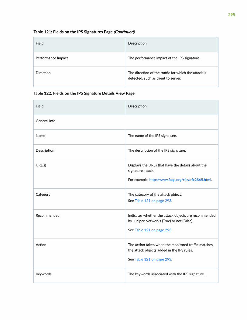
Table 121: Fields on the IPS Signatures Page (Continued)
Field Description
Performance Impact The performance impact of the IPS signature.
Direction The direction of the traffic for which the attack isdetected, such as client to server.
Table 122: Fields on the IPS Signature Details View Page
Field Description
General Info
Name The name of the IPS signature.
Description The description of the IPS signature.
URL(s) Displays the URLs that have the details about thesignature attack.
For example, http://www.faqs.org/rfcs/rfc2865.html.
Category The category of the attack object.
See Table 121 on page 293.
Recommended Indicates whether the attack objects are recommendedby Juniper Networks (True) or not (False).
See Table 121 on page 293.
Action The action taken when the monitored traffic matchesthe attack objects added in the IPS rules.
See Table 121 on page 293.
Keywords The keywords associated with the IPS signature.
295

Table 122: Fields on the IPS Signature Details View Page (Continued)
Field Description
Severity The severity level of the attack that the signaturereports.
See Table 121 on page 293.
BUGS Displays the list of bugs that are related to thesignature attack.
See Table 121 on page 293.
CERT Displays the computer emergency response team(CERT) advisory number associated with the threat.
See Table 121 on page 293.
CVE Displays the Common Vulnerabilities and Exposures(CVE) identifier or name associated with the threat.
See Table 121 on page 293.
Signature Details
Binding The protocol or service that the attack uses to enteryour network.
Service For service binding, displays the service the attack usesto enter your network.
Time Count The number of times that IPS detects the attack in aspecified time scope.
Match Assurance The positives filter to track attack objects based on thefrequency that the attack produces a false positive onyour network.
296

Table 122: Fields on the IPS Signature Details View Page (Continued)
Field Description
Performance Impact The performance impact filter used for the IPSsignature.
Signature Displays (in a table) the signature attack objectsconfigured as part of the IPS signature. For each row,the following fields are displayed:
• No—A unique identifier for the signature attackobject.
• Context—The attack context, which defines thelocation of the signature where IPS must look forthe attack.
• Direction—The connection direction of the attack.
• Pattern—The signature pattern (in JuniperNetwork's proprietary regular expression syntax) ofthe attack to be detected.
• Regex—The regular expression to match maliciousor unwanted behavior over the network.
• Negated—Indicates whether the pattern must beexcluded from being matched (true) or not (false).
Table 123: Fields on the IPS Static Group Details Page
Field Description
Name The name of the IPS signature static group.
Description The description of the IPS signature static group.
297

Table 123: Fields on the IPS Static Group Details Page (Continued)
Field Description
Group Members Displays the IPS signatures or IPS signature dynamicgroups that are part of the IPS static group.
See Table 121 on page 293 for an explanation of thefields in the table.
To view the details, select a row, click More > Detail, ormouse over a row, and click the Detailed View icon.Depending on the object type, the IPS SignatureDetails View page or IPS Signature Dynamic DetailsView page opens.
See Table 122 on page 295 and Table 124 on page 298for an explanation of the fields on these pages.
Table 124: Fields on the IPS Signature Dynamic Details View Page
Field Description
Name The name of the IPS signature dynamic group.
Severity The severity filters used for the dynamic group.
Service The service filters used for the dynamic group.
Category The category filters used for the dynamic group.
Recommended Indicates whether predefined attack objectsrecommended by Juniper Networks are added to thedynamic group (true) or not (false).
Excluded Indicates whether predefined attack objectsrecommended by Juniper Networks are excluded fromthe dynamic group (true) or not (false).
Direction The traffic direction filters used for the dynamic group.
298

Table 124: Fields on the IPS Signature Dynamic Details View Page (Continued)
Field Description
Performance Impact The performance impact filter used for the dynamicgroup.
False Positive The false positive filter used for the dynamic group.
Age of Attack The age of the attack in years used as a filter for thedynamic group.
CVSS Score The Common Vulnerability Scoring System (CVSS)score used as a filter for the dynamic group.
File Type The file type of the attack used as a filter for thedynamic group.
Vulnerability Type The vulnerability type of the attack used as a filter forthe dynamic group.
Object Type The type of the object (anomaly or signature) used as afilter for the dynamic group.
Vendor Description The vendor or product that the attack belongs to.
Create an IPS Signature
The signature database in Juniper Security Director Cloud contains predefined intrusion preventionsystem (IPS) signatures.
You can create customized IPS signatures to block newer attacks or unknown attacks from the CreateIPS Signature page. You must have the tenant administrator role or a customized role assigned with theappropriate IPS tasks to create customized IPS signatures.
• When you add multiple members in the Signature and Anomaly fields, a chain-type signature iscreated.
299

• When you add anomaly details in the Anomaly field, an anomaly-type signature is created.
To create a customized IPS signature:
1. Select SRX > Security Subscriptions > IPS > IPS Signatures.
The IPS Signatures page opens.
2. Select Create > IPS Signature.
The Create IPS Signature page opens.
3. Complete the configuration according to the guidelines in Table 125 on page 300.
NOTE: Fields marked with an asterisk (*) are mandatory.
4. Click OK.
The IPS Signatures page opens with a message indicating that the signature is created.
You can use the new IPS signature in an IPS rule or an exempt rule. You can then reference the IPSprofile containing the rule in a firewall policy, which you can deploy on a device.
Table 125: Create IPS Signature Settings
Setting Guideline
Name Enter a unique name for the IPS signature that is astring of maximum 60 characters without spaces.
The string can contain alphanumeric characters andspecial characters, such as colons, hyphens, periods,and underscores.
Description Enter a description of maximum 1024 characters forthe IPS signature.
Category Enter a predefined category or a new category ofmaximum 63 characters without spaces.
The category must begin with an alphanumericcharacter and can contain special characters, such ashyphens and underscores.
You can use categories to group attack objects.Within each category, you can assign severity levelsto the groups of attack objects.
300

Table 125: Create IPS Signature Settings (Continued)
Setting Guideline
Action Select the action to take when the monitored trafficmatches the attack objects specified in the IPS rule:
• None—No action is taken. Use this action to onlygenerate logs for some traffic.
• Close Client & Server—Closes the connection andsends a TCP reset (RST) packet to both the clientand the server.
• Close Client—Closes the connection and sends anRST packet to the client, but not to the server.
• Close Server—Closes the connection and sendsan RST packet to the server, but not to the client.
• Ignore—Stops scanning traffic for the rest of theconnection if an attack match is found. IPSdisables the rulebase for the specific connection.
• Drop—Drops all packets associated with theconnection, preventing traffic for the connectionfrom reaching its destination. Use this action todrop connections for traffic that is not prone tospoofing.
• Drop Packet—Drops a matching packet before itcan reach its destination but does not close theconnection. Use this action to drop packets forattacks in traffic that is prone to spoofing, such asUDP traffic. Dropping a connection for suchtraffic could result in a denial of service thatprevents traffic from a legitimate source IPaddress.
Keyword Enter unique identifiers that can be used to searchand to sort signatures.
The keywords must relate to the attack and theattack object. For example, Amanda AmindexdRemote Overflow.
301
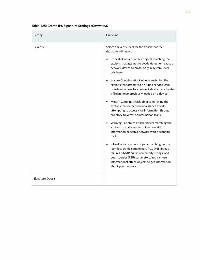
Table 125: Create IPS Signature Settings (Continued)
Setting Guideline
Severity Select a severity level for the attack that thesignature will report:
• Critical—Contains attack objects matching theexploits that attempt to evade detection, cause anetwork device to crash, or gain system-levelprivileges.
• Major—Contains attack objects matching theexploits that attempt to disrupt a service, gainuser-level access to a network device, or activatea Trojan horse previously loaded on a device.
• Minor—Contains attack objects matching theexploits that detect reconnaissance effortsattempting to access vital information throughdirectory traversal or information leaks.
• Warning—Contains attack objects matching theexploits that attempt to obtain noncriticalinformation or scan a network with a scanningtool.
• Info—Contains attack objects matching normal,harmless traffic containing URLs, DNS lookupfailures, SNMP public community strings, andpeer-to-peer (P2P) parameters. You can useinformational attack objects to get informationabout your network.
Signature Details
302

Table 125: Create IPS Signature Settings (Continued)
Setting Guideline
Binding Select the protocol or service that the attack uses toenter your network:
• IP—Matches the attack for a specified protocoltype number, which you must enter in theProtocol field.
• IPv6—Matches the attack for a specified protocoltype number for the header following the IPv6header, which you must enter in the Next Headerfield.
• TCP—Matches the attack for the specified TCPports or port ranges, which you must enter in thePort Range(s) field.
• UDP—Matches the attack for the specified UDPports or port ranges.
• ICMP—Matches the attack for ICMP packets.
• ICMPv6—Matches the attack for ICMPv6packets.
• RPC—Matches the attack for a specified remoteprocedure call (RPC) program number, which youmust enter in the Program Number field.
• Service—Matches the attack for a specifiedservice, which you must select from the Servicefield.
Protocol For IP binding, enter the transport layer protocolnumber to match with the attack.
The range is from 1 to 139 excluding 1, 6, and 17.
Next Header For IPv6 binding, enter the transport layer protocolnumber for the next header following the IPv6header with which to match the attack.
The range is from 1 to 139 excluding 6, 17, and 58.
303

Table 125: Create IPS Signature Settings (Continued)
Setting Guideline
Port Range(s) For the TCP or UDP binding, enter a port number ora port range to match with the attack.
Enter the port range in the min port no.-max port no.format.
Program Number For RPC binding, enter the RPC program number (ID)to match with the attack.
Service For service binding, select the service to match withthe attack.
Time Count Enter the number of times an IPS detects the attackwithin the specified time scope before triggering anevent.
Time Scope Enter the scope within which the counting of theattack occurs:
• Source IP—Detects attacks from the source IPaddress for the specified time count regardless ofthe destination IP address.
• Dest IP—Detects attacks from the destination IPaddress for the specified time count regardless ofthe source IP address.
• Peer—Detects attacks between the source andthe destination IP addresses of the sessions forthe specified time count.
304

Table 125: Create IPS Signature Settings (Continued)
Setting Guideline
Match Assurance Select a false positives filter to track attack objectsbased on the frequency that the attack produces afalse positive on your network:
• None—No false positive filter is applied.
• High—Provides information on the frequently-tracked false positive occurrences.
• Medium—Provides information on theoccasionally-tracked false positive occurrences.
• Low—Provides information on the rarely-trackedfalse positive occurrences.
Performance Impact Select appropriate attacks based on performanceimpact. For example, to filter out slow-performingattack objects:
• None—No filter is applied.
• Low—Add low-performance impact attack objectsthat are vulnerable to an attack. The performanceimpact of signatures is Low1 to Low3 where theapplication identification is faster.
• Medium—Add medium-performance impactattack objects that are vulnerable to an attack.The performance impact of signatures isMedium4 to Medium6 where the applicationidentification is normal.
• High—Add high-performance impact attackobjects that are vulnerable to an attack. Theperformance impact of signatures is High7 toHigh9 where the application identification isslow.
305

Table 125: Create IPS Signature Settings (Continued)
Setting Guideline
Add Signature You can add one or more signature attack objectsthat use a stateful attack signature (a pattern thatalways exists within a specific section of the attack)to detect known attacks.
NOTE: For a customized IPS signature, you must addat least one signature attack object or anomaly.
• To add a signature attack object:
a. Click the add (+) icon.
The Add Signature page opens.
b. Complete the configuration according to theguidelines in Table 126 on page 309.
c. Click OK.
The previous page opens and the signatureattack object is displayed in the table.
• To modify a signature attack object:
a. Select an attack object and click the edit(pencil) icon.
The Edit Signature page opens.
b. Modify the fields. See Table 126 on page 309.
c. Click OK.
Your modifications are saved and the previouspage opens.
• To delete a signature attack object:
a. Select an attack object and click the delete(trash can) icon.
A popup appears asking you to confirm thedelete operation.
306

Table 125: Create IPS Signature Settings (Continued)
Setting Guideline
b. Click Yes.
The signature attack object is deleted and theprevious page opens.
307

Table 125: Create IPS Signature Settings (Continued)
Setting Guideline
Add Anomaly Select an option to detect abnormal or ambiguousmessages within a connection according to the set ofrules for the particular protocol being used.
NOTE:
• The Add Anomaly field is displayed only if youselect Service in the Binding field.
• For a customized IPS signature, you must add atleast one signature attack object or anomaly.
You can add, modify, or delete anomaly attackobjects:
• To add an anomaly:
a. Click the add (+) icon.
The Add Anomaly page opens.
b. Complete the configuration according to theguidelines in Table 127 on page 310.
c. Click OK.
The previous page opens and the anomaly isdisplayed in the table.
• To modify an anomaly:
a. Select an anomaly, and click the edit (pencil)icon.
The Edit Anomaly page opens.
b. Modify the fields as needed. See Table 127 onpage 310.
c. Click OK.
Your modifications are saved and the previouspage opens.
• To delete an anomaly:
308

Table 125: Create IPS Signature Settings (Continued)
Setting Guideline
a. Select an anomaly and click the delete (trashcan) icon.
A popup opens asking you to confirm thedelete operation.
b. Click Yes.
The signature anomaly is deleted and theprevious page opens.
Table 126: Add Signature Settings
Setting Guideline
Signature No. Displays the system-generated signature number.
You cannot modify this field.
Context Select the attack context, which defines the locationof the signature where IPS must look for the attack ina specific Application Layer protocol.
Direction Select the connection direction of the attack:
• Any—Detects the attack for traffic in eitherdirection.
• Client to Server—Detects the attack only in theclient to server traffic.
• Server to Client—Detects the attack only in theserver to client traffic.
309
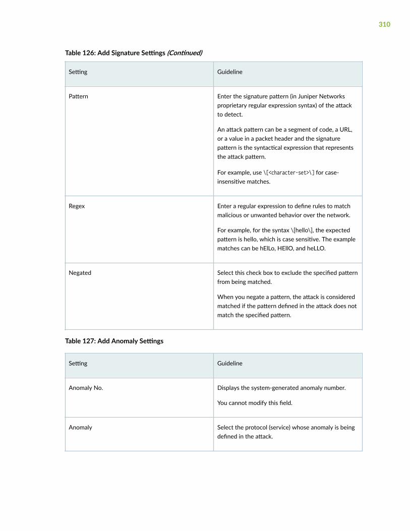
Table 126: Add Signature Settings (Continued)
Setting Guideline
Pattern Enter the signature pattern (in Juniper Networksproprietary regular expression syntax) of the attackto detect.
An attack pattern can be a segment of code, a URL,or a value in a packet header and the signaturepattern is the syntactical expression that representsthe attack pattern.
For example, use \[<character-set>\] for case-insensitive matches.
Regex Enter a regular expression to define rules to matchmalicious or unwanted behavior over the network.
For example, for the syntax \[hello\], the expectedpattern is hello, which is case sensitive. The examplematches can be hElLo, HEllO, and heLLO.
Negated Select this check box to exclude the specified patternfrom being matched.
When you negate a pattern, the attack is consideredmatched if the pattern defined in the attack does notmatch the specified pattern.
Table 127: Add Anomaly Settings
Setting Guideline
Anomaly No. Displays the system-generated anomaly number.
You cannot modify this field.
Anomaly Select the protocol (service) whose anomaly is beingdefined in the attack.
310

Table 127: Add Anomaly Settings (Continued)
Setting Guideline
Direction Select the connection direction of the attack:
• Any—Detects the attack for traffic in eitherdirection.
• Client to Server—Detects the attack only in theclient to server traffic.
• Server to Client—Detects the attack only inserver to client traffic.
Create an IPS Signature Static Group
The signature database in Juniper Security Director Cloud contains predefined intrusion preventionsystem (IPS) signature static groups.
You can create customized IPS signature static groups from the Create IPS Signature Static Group page.You must have the tenant administrator role or a custom role assigned with the appropriate IPS tasks tocreate customized IPS signature static groups.
Static groups enable better manageability because you can group different types of signatures into oneentity.
To create a customized IPS signature static group:
1. Select SRX > Security Subscriptions > IPS > IPS Signatures.
The IPS Signatures page opens.
2. Select Create > Static Group.
The Create IPS Signature Static Group page opens.
3. Complete the configuration according to the guidelines in Table 128 on page 312.
NOTE: Fields marked with an asterisk (*) are mandatory.
4. Click OK.
The IPS Signatures page opens with a message that the static group was successfully created.
311
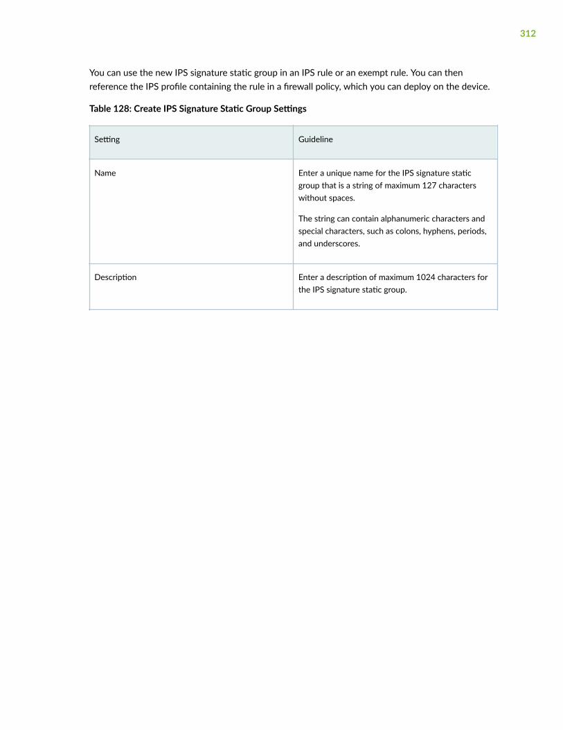
You can use the new IPS signature static group in an IPS rule or an exempt rule. You can thenreference the IPS profile containing the rule in a firewall policy, which you can deploy on the device.
Table 128: Create IPS Signature Static Group Settings
Setting Guideline
Name Enter a unique name for the IPS signature staticgroup that is a string of maximum 127 characterswithout spaces.
The string can contain alphanumeric characters andspecial characters, such as colons, hyphens, periods,and underscores.
Description Enter a description of maximum 1024 characters forthe IPS signature static group.
312

Table 128: Create IPS Signature Static Group Settings (Continued)
Setting Guideline
Group Members Add one or more IPS signatures, static groups, ordynamic groups as members of the new static group.
NOTE: You must add at least one IPS signature, staticgroup, or dynamic group to proceed.
• To add group members:
a. Click the add (+) icon.
The Add IPS Signatures page opens displayingthe existing predefined and customized IPSsignatures, static groups, and dynamic groupsin a table.
b. Select one or more group members by clickingthe check boxes corresponding to the rows.
c. Click OK.
The previous page opens and the selectedgroup members are displayed in the table.
• To delete group members:
a. Select the group members to delete, and clickthe delete (trash can) icon.
A warning message asking you to confirm thedeletion is displayed.
b. Click Yes.
The group members are deleted.
Create an IPS Signature Dynamic Group
The signature database in Juniper Security Director Cloud contains predefined intrusion preventionsystem (IPS) signature dynamic groups.
313

You can create customized IPS signature dynamic groups based on a specific filter criteria from theCreate IPS Signature Dynamic Group page. You must have the tenant administrator role or a custom rolewith the appropriate IPS tasks to create customized IPS signature dynamic groups.
The specified filter criteria are matched only to predefined or customized IPS signatures, and not to IPSstatic groups and dynamic groups. When a new signature database is used, the dynamic groupmembership is automatically updated based on the filter criteria for the group.
To create a customized IPS signature dynamic group:
1. Select SRX > Security Subscriptions > IPS > IPS Signatures.
The IPS Signatures page opens.
2. Select Create > Dynamic Group.
The Create IPS Signature Dynamic Group page opens.
3. Complete the configuration according to the guidelines in Table 129 on page 314.
4. (Optional) Click Preview Filtered Signatures to check whether the signatures that match the dynamicgroup are consistent with the specified filter criteria.
The IPS Signatures page opens displaying the list of IPS signatures matching the filters.
If the signatures do not match, you can tweak the filter criteria. Click Close to go back to the previouspage.
5. Click OK.
The IPS Signatures page opens with a message indicating that the dynamic group was successfullycreated.
You can use the new IPS signature dynamic group in an IPS rule or an exempt rule. You can thenreference the IPS profile containing the rule in a firewall policy, which you can deploy on the device.
Table 129: Create IPS Signature Dynamic Group Settings
Setting Guideline
Name Enter a unique name for the IPS signature dynamicgroup that is a string of maximum 255 characterswithout spaces.
The string can contain alphanumeric characters andspecial characters, such as colons, hyphens, periods,and underscores.
314

Table 129: Create IPS Signature Dynamic Group Settings (Continued)
Setting Guideline
Filter Criteria Select one or more filters to define the attributes ofIPS signatures that will be added to the new IPSsignature dynamic group.
Filters apply to existing signatures (alreadydownloaded in the application) and to new signatureswhen the signatures are downloaded.
IPS signatures that match any of the configuredfilters are included as part of the signature group.
Severity
Info Enable this option to include IPS signatures with theInfo severity level.
Warning Enable this option to include IPS signatures with theWarning severity level.
Minor Enable this option to include IPS signatures with theMinor severity level.
Major Enable this option to include IPS signatures with theMajor severity level.
Critical Enable this option to include IPS signatures with theCritical severity level.
Service
315

Table 129: Create IPS Signature Dynamic Group Settings (Continued)
Setting Guideline
Service Select the services to filter IPS signatures that mustbe included as part of the dynamic group.
Select one or more services listed in the Availablecolumn, and click the forward arrow to confirm yourselection. The selected services are displayed in theSelected column.
Category
Category Select the categories to filter IPS signatures thatmust be included as part of the dynamic group.
Select one or more categories listed in the Availablecolumn, and click the forward arrow to confirm yourselection. The selected categories are displayed inthe Selected column.
Recommended
Recommended This filter is based on attack objects that arerecommended by Juniper Networks. Select one ofthe following:
• None—Do not use this filter.
• Yes—Add predefined attacks recommended byJuniper Networks to the dynamic group.
• No—Add predefined attacks that are notrecommended by Juniper Networks to thedynamic group.
Direction Add IPS signatures to the dynamic group based onthe traffic direction of the attacks.
If you select more than one traffic direction (Any,Client-to-Server, and Server-to-Client), you mustselect a value in the Expression field.
316

Table 129: Create IPS Signature Dynamic Group Settings (Continued)
Setting Guideline
Any Select one of the following:
• None (default): Do not use this filter.
• Yes: Include IPS signatures that track traffic fromclient to server or server to client.
• No: Do not include IPS signatures that tracktraffic from client to server or server to client.
Client-to-Server Select one of the following:
• None (default): Do not use this filter.
• Yes: Include IPS signatures that track traffic fromclient to server.
• No: Do not include IPS signatures that tracktraffic from client to server.
Server-to-Client Select one of the following:.
• None (default): Do not use this filter.
• Yes: Include IPS signatures that track traffic fromserver to client.
• No: Do not include IPS signatures that tracktraffic from server to client.
Expression If you select more than one traffic directional filter,you must select how the signatures must bematched:
• None (default): Do not use this filter.
• OR—Include signatures that match any of thespecified traffic directions.
• AND—Include signatures that match all of thespecified traffic directions.
317

Table 129: Create IPS Signature Dynamic Group Settings (Continued)
Setting Guideline
Performance Impact
Unknown Enable this option to include the IPS signatures withthe Unknown performance impact.
Slow Enable this option to include the IPS signatures withthe Slow performance impact.
Normal Enable this option to include the IPS signatures withthe Normal performance impact.
Fast Enable this option to include the IPS signatures withthe Fast performance impact.
False Positives
Unknown Enable this option to include the IPS signatures withthe Unknown match assurance.
Low Enable this option to include the IPS signatures withthe Low match assurance.
Medium Enable this option to include the IPS signatures withthe Medium match assurance.
High Enable this option to include the IPS signatures withthe High match assurance.
Age of Attack The age of the attack in years to be used as a filtercriteria to include IPS signatures as part of thedynamic group.
318

Table 129: Create IPS Signature Dynamic Group Settings (Continued)
Setting Guideline
Greater Than Enter the age of attack in years to include the IPSsignatures with the age of attack greater than thespecified value as part of the dynamic group.
The range is from 1 to 100 years.
Less Than Enter the age of attack in years to include the IPSsignatures with the age of attack less than thespecified value as part of the dynamic group.
The range is from 1 to 100 years.
CVSS Score The Common Vulnerability Scoring System (CVSS) tobe used as a filter criteria to include IPS signatures aspart of the dynamic group.
Greater Than Enter the CVSS score to include the IPS signatureswith the score greater than the specified value aspart of the dynamic group.
The range is a decimal number between 0 and 10.
Less Than Enter the CVSS score to include the IPS signatureswith the score less than the specified value as part ofthe dynamic group.
The range is a decimal number between 0 and 10.
Other Filters
319

Table 129: Create IPS Signature Dynamic Group Settings (Continued)
Setting Guideline
Excluded Select one of the following:.
• None (default): Do not use this filter.
• Yes: Include excluded attack objects as part of thedynamic group.
• No: Do not include excluded attack objects aspart of the dynamic group.
File Type Select the file type of the attack to be used as a filtercriteria.
For example, flash.
Vulnerability Type Select the vulnerability type of the attack to be usedas a filter criteria.
For example, overflow.
Type Use this filter to group attack objects by type(anomaly or signature).
Signature Enable this option to add signatures based onstateful signature attack objects specified in thesignature.
A stateful attack signature is a pattern that alwaysexists within a specific section of the attack. Statefulsignature attack objects also include the protocol orservice used to perpetrate the attack and the contextin which the attack occurs.
Protocol Anomaly Enable this option to add signatures of attacks thatviolate protocol specifications (RFCs and commonRFC extensions).
Vendor Description
320

Table 129: Create IPS Signature Dynamic Group Settings (Continued)
Setting Guideline
Product Type Select this filter to include signatures belonging tothe selected product type.
Vendor Name Select this filter to include signatures belonging tothe selected vendor.
Title Select this filter to include signatures belonging tothe selected product name.
The product names are populated only when youselect a product type and a vendor.
Edit, Clone, and Delete an IPS Signature
IN THIS SECTION
Edit an IPS Signature | 321
Clone an IPS Signature | 322
Delete IPS Signatures | 322
You must have the tenant administrator role or a customized role assigned with the appropriate IPStasks to modify customized IPS signatures.
Edit an IPS Signature
You can edit only customized IPS signatures and not predefined (system-generated) signatures.
To edit a customized IPS signature:
1. Select SRX > Security Subscriptions > IPS > IPS Signatures.
The IPS Signatures page opens.
2. Select a customized IPS signature, and click the edit (pencil) icon.
321

The Edit IPS Signature page opens.
3. Modify the IPS signature fields. See "Create an IPS Signature" on page 299.
NOTE: You cannot modify the name of the IPS signature.
4. Click OK to save your changes.
The IPS Signatures page opens with a message that the IPS signature was successfully updated.
If the IPS signature was used in an IPS rule or exempt rule that is deployed on the device through thefirewall policy, then the firewall policy is marked for deployment. You must deploy the firewall policyfor the changes to take effect on the device.
Clone an IPS Signature
Cloning enables you to easily create an IPS signature based on an existing one. You can clone predefinedor customized IPS signatures and modify the parameters.
To clone an IPS signature:
1. Select SRX > Security Subscriptions > IPS > IPS Signatures.
The IPS Signatures page opens.
2. Select an IPS signature, and select More > Clone.
The Clone IPS Signature page opens.
3. Modify the IPS signature fields. See "Create an IPS Signature" on page 299.
4. Click OK to save your changes.
The IPS Signatures page opens with a message that the IPS signature was successfully created.
You can use the cloned IPS signature in an IPS rule or an exempt rule. You can then reference the IPSprofile containing the rule in a firewall policy, which you can deploy on the device.
Delete IPS Signatures
NOTE: You can delete only customized (user-created) IPS signatures that are not used in an IPSor exempt rule. You cannot delete predefined (system-generated) IPS signatures.
To delete the customized IPS signatures:
1. Select SRX > Security Subscriptions > IPS > IPS Signatures.
The IPS Signatures page opens.
2. Select one or more customized IPS signatures, and click the delete (trash can) icon.
A warning message asking you to confirm the deletion is displayed.
322

3. Click Yes.
The IPS Signatures page opens with a message indicating the status of the delete operation.
Edit, Clone, and Delete an IPS Signature Static Group
IN THIS SECTION
Edit an IPS Signature Static Group | 323
Clone an IPS Signature Static Group | 324
Delete IPS Signature Static Groups | 324
You must have the tenant administrator role or a customized role assigned with the appropriate IPStasks to modify customized IPS signature static groups.
Edit an IPS Signature Static Group
You can edit only customized IPS signature static groups, and not predefined (system-generated) staticgroups.
To edit a customized IPS signature static group:
1. Select SRX > Security Subscriptions > IPS > IPS Signatures.
The IPS Signatures page opens.
2. Select a customized IPS signature static group, and click the edit (pencil) icon.
The Edit IPS Signature Static Group page opens.
3. Modify the IPS signature static group fields. See "Create an IPS Signature Static Group" on page 311.
NOTE: You cannot modify the IPS signature static group name.
4. Click OK to save your changes.
The IPS Signatures page opens with a message that the IPS signature static group was successfullyupdated.
If the IPS signature static group was used in an IPS rule or exempt rule that is deployed on the devicethrough the firewall policy, then the firewall policy is marked for deployment. You must deploy thefirewall policy for the changes to take effect on the device.
323

Clone an IPS Signature Static Group
Cloning enables you to easily create an IPS signature static group based on an existing one. You canclone predefined or customized IPS signature static groups and modify the parameters.
To clone an IPS signature static group:
1. Select SRX > Security Subscriptions > IPS > IPS Signatures.
The IPS Signatures page opens.
2. Select an IPS signature static group, and select More > Clone.
The Clone IPS Signature Static Group page opens.
3. Modify the IPS signature static group fields. See "Create an IPS Signature Static Group" on page 311.
4. Click OK to save your changes.
The IPS Signatures page opens with a message that the IPS signature static group was successfullycreated.
You can use the cloned IPS signature static group in an IPS rule or an exempt rule. You can thenreference the IPS profile containing the rule in a firewall policy, which you can deploy on the device.
Delete IPS Signature Static Groups
NOTE: You can delete only customized (user-created) IPS signature static groups that are notused in an IPS or exempt rule. You cannot delete predefined (system-generated) IPS signaturestatic groups.
To delete the customized IPS signature static groups:
1. Select SRX > Security Subscriptions > IPS > IPS Signatures.
The IPS Signatures page opens.
2. Select one or more customized IPS signature static groups, and click the delete (trash can) icon.
A warning message asking you to confirm the deletion is displayed.
3. Click Yes.
The IPS Signatures page opens with a message indicating the status of the delete operation.
324

Edit, Clone, and Delete an IPS Signature Dynamic Group
IN THIS SECTION
Edit an IPS Signature Dynamic Group | 325
Clone IPS Signature Dynamic Groups | 326
Delete IPS Signature Dynamic Groups | 326
You must have the tenant administrator role or a customized role assigned with the appropriate IPStasks to modify customized IPS signature dynamic groups.
Edit an IPS Signature Dynamic Group
You can edit only customized IPS signature dynamic groups, and not predefined (system-generated)dynamic groups.
To edit a customized IPS signature dynamic group:
1. Select SRX > Security Subscriptions > IPS > IPS Signatures.
The IPS Signatures page opens.
2. Select a customized IPS signature dynamic group, and click the edit (pencil) icon.
The Edit IPS Signature Dynamic Group page opens.
3. Modify the IPS signature dynamic group fields. See "Create an IPS Signature Dynamic Group" onpage 313.
NOTE: You cannot modify the IPS signature dynamic group name.
4. (Optional) Click Preview Filtered Signatures to check if the signatures that match the dynamic groupare consistent with the specified filter criteria.
The IPS Signatures page opens displaying the list of IPS signatures matching the filters. If thesignatures do not match, you can tweak the filter criteria. Click Close to go back to the previous page.
5. Click OK to save your changes.
The IPS Signatures page opens with a message indicating that the IPS signature dynamic group wassuccessfully updated.
If the IPS signature dynamic group was used in an IPS rule or exempt rule that is deployed on thedevice through the firewall policy, then the firewall policy is marked for deployment. You must deploythe firewall policy for the changes to take effect on the device.
325

Clone IPS Signature Dynamic Groups
Cloning enables you to easily create an IPS signature dynamic group based on an existing one. You canclone predefined or customized IPS signature dynamic groups and modify the parameters.
To clone an IPS signature dynamic group:
1. Select SRX > Security Subscriptions > IPS > IPS Signatures.
The IPS Signatures page opens.
2. Select an IPS signature dynamic group, and select More > Clone.
The Clone IPS Signature Dynamic Group page opens.
3. Modify the IPS signature dynamic group fields. See "Create an IPS Signature Dynamic Group" onpage 313.
4. (Optional) Click Preview Filtered Signatures to check if the signatures that match the dynamic groupare consistent with the specified filter criteria.
The IPS Signatures page opens displaying the list of IPS signatures matching the filters. If thesignatures do not match, you can tweak the filter criteria. Click Close to go back to the previous page.
5. Click OK to save your changes.
The IPS Signatures page opens with a message that the IPS signature dynamic group was successfullycreated.
You can use the cloned IPS signature dynamic group in an IPS rule or an exempt rule. You can thenreference the IPS profile containing the rule in a firewall policy, which you can deploy on the device.
Delete IPS Signature Dynamic Groups
NOTE: You can delete only customized (user-created) IPS signature dynamic groups that are notused in an IPS or exempt rule. You cannot delete predefined (system-generated) IPS signaturedynamic groups.
To delete the customized IPS signature dynamic groups:
1. Select SRX > Security Subscriptions > IPS > IPS Signatures.
The IPS Signatures page opens.
2. Select one or more customized IPS signature dynamic groups, and click the delete (trash can) icon.
A warning message asking you to confirm the deletion is displayed.
3. Click Yes.
The IPS Signatures page opens with a message indicating the status of the delete operation.
326

CHAPTER 19
Security Subscriptions-Content Security
IN THIS CHAPTER
Content Security Overview | 327
Configure the Content Security Settings | 330
About the Content Security Profiles Page | 332
Create a Content Security Profile | 335
Edit, Clone, and Delete a Content Security Profile | 340
About the Web Filtering Profiles Page | 341
Create a Web Filtering Profile | 344
Edit, Clone, and Delete a Web Filtering Profile | 352
About the Antivirus Profiles Page | 354
Create an Antivirus Profile | 356
Edit, Clone, and Delete an Antivirus Profile | 359
About the Antispam Profiles Page | 361
Create an Antispam Profile | 363
Edit, Clone, and Delete an Antispam Profile | 365
About the Content Filtering Profiles Page | 366
Create a Content Filtering Profile | 369
Edit, Clone, and Delete a Content Filtering Profile | 373
Content Security Overview
IN THIS SECTION
Content Security Licensing | 329
Content Security Components | 329
327

Content security is a term used to describe the consolidation of several security features to protectagainst multiple threat types. The advantage of content security is a streamlined installation andmanagement of multiple security capabilities.
NOTE: In Junos CLI commands, we continue to use the legacy term UTM for content security.
The following security features are provided as part of the content security solution:
• Antispam—This feature examines transmitted messages to identify e-mail spam. E-mail spam consistsof unwanted messages usually sent by commercial, malicious, or fraudulent entities. When the devicedetects an e-mail message deemed to be spam, it either drops the message or tags the messageheader or subject field with a preprogrammed string. The antispam feature uses a constantly updatedSpamhaus Block List (SBL). Sophos updates and maintains the IP-based SBL.
• Full file-based antivirus—A virus is an executable code that infects or attaches itself to otherexecutable code to reproduce itself. Some malicious viruses erase files or lock up systems. Otherviruses merely infect files and overwhelm the target host or network with bogus data. The full file-based antivirus feature provides file-based scanning on specific application layer traffic, checking forviruses against a virus signature database. The antivirus feature collects the received data packetsuntil it has reconstructed the original application content, such as an e-mail file attachment, and thenscans this content.
• Express antivirus—Express antivirus scanning is offered as a less CPU-intensive alternative to the fullfile-based antivirus feature. The express antivirus feature is similar to the antivirus feature in that itscans specific application layer traffic for viruses against a virus signature database. However, unlikefull antivirus, express antivirus does not reconstruct the original application content. Rather, it justsends (streams) the received data packets, as is, to the scan engine. With express antivirus, the virusscanning is executed by a hardware pattern-matching engine. This improves performance whilescanning is occurring, but the level of security provided is lessened. Juniper Networks provides thescan engine.
• Content filtering—Content filtering blocks or permits certain types of traffic based on the MIME type,file extension, protocol command, and embedded object type.
• Web filtering—Web filtering enables you to manage Internet usage by preventing access toinappropriate Web content. The following types of Web filtering solutions are available:
• Integrated Web filtering—Blocks or permits Web access after the device identifies the categoryfor a URL either from user-defined categories or from a category server (Websense provides theSurfControl Content Portal Authority (CPA) server).
• Redirect Web filtering—Intercepts HTTP requests and forwards the server URL to an external URLfiltering server to determine whether to block or permit the requested Web access. Websenseprovides the URL filtering server.
328

Content Security Licensing
All content security components require licenses with the exception of content filtering, which uses theparameters defined in the content filtering profile. This is because Juniper Networks leverages third-party technology that is constantly updated to provide the most up-to-date inspection capabilities.
Content Security Components
Content security components include custom objects, feature profiles, and content security profiles thatcan be configured on SRX Series devices. From a high level, feature profiles specify how a feature isconfigured and then applied to content security profiles, which in turn is applied to firewall policies, asshown in Figure 7 on page 329.
Figure 7: Content Security Components
Content security profiles do not have their own seven-tuple rulebase; in a sense they inherit the rulesfrom the firewall rule. The strength of the content security feature comes from URL filtering, where youcan have a separate configuration for different users or user groups.
• Custom objects—Although SRX Series devices support predefined feature profiles that can handlemost typical use cases, there are some cases where you might need to define your own objects,specifically for URL filtering, antivirus filtering, and content filtering.
• Feature profiles—Feature profiles specify how components of each profile should function. You canconfigure multiple feature profiles that can be applied through different content security profiles tofirewall rules.
• Content security profiles—content security profiles function as a logical container for individualfeature profiles. Content security profiles are then applied to specific traffic flows based on theclassification of rules in the firewall policy, thereby enabling you to define separate content securityprofiles per firewall rule to differentiate the enforcement per firewall rule. Essentially, the firewallrulebase acts as the match criteria, and the content security profile is the action to be applied.
• Security policy—You can choose predefined content security policies which consist of predefinedfeature profiles that can be applied to the firewall policy rules. The predefined content securitypolicies are :
• default-utm-policy
329

• sopohos-av-policy
• je-wf-policy
• sopohos-je-av-wf-policy
Configure the Content Security Settings
Use the Edit Content Security Settings page to configure content security antispam, antivirus, and Webfiltering settings for a tenant.
These settings are applicable to all the devices. The settings are pushed to all those devices where afirewall policy rule with content security enabled is applicable.
To configure content security settings:1. Select SRX > Security Subscriptions > Content Security > Content Security Settings.
The Edit Content Security Settings page appears.
2. Complete the configuration according to the guidelines provided in Table 130 on page 330.
3. Do one of the following:
• Click Reset to reset the settings to the previously saved configured.
• Click OK to save the settings.
The settings are saved and a confirmation message is displayed.
Table 130: Content Security Settings
Setting Guideline
Antispam Settings
Address Allowlist Select the URL pattern to be used as the antispamallowlist.
Alternatively, click Create New URL Pattern to create anew URL pattern to use as a allowlist.
The Create URL Patterns page appears.
For more information, see "Create a URL Pattern" onpage 740 for an explanation of the fields on this page.
330

Table 130: Content Security Settings (Continued)
Setting Guideline
Address Blocklist Select the URL pattern to be used as the antispamblocklist.
Alternatively, click Create New URL Pattern to create anew URL pattern to use as a blocklist.
Antivirus Settings
MIME Allowlist Enter one or more MIME types (separated by commas)to exclude from antivirus scanning.
Exception MIME Allowlist Enter one or more MIME types (separated by commas)that are to be excluded from the list of MIME typesspecified as part of the MIME allowlist. This list is asubset of the MIME types that you specified in theMIME allowlist. For example, if you specify video/ inthe allowlist and video/x-shockwave-flash in theexception allowlist, all objects of MIME type video/except MIME type video/x-shockwave-flash areexcluded from antivirus scanning.
URL Allowlist Select the list of URLs the antivirus settings can allow.
Web Filtering Settings
URL Allowlist Select the list of URLs the Web filtering settings canallow; these URLs are excluded from Web filtering.
URL Blocklist Select the list of URLs the Web filtering settings canblock; these URLs are blocked from Web access.
331

Table 130: Content Security Settings (Continued)
Setting Guideline
Site Reputation Level Site reputation level is a rating system to define thefollwing default security levels for a URL:
• Harmful
• Suspicious
• Fairly-safe
• Moderately-safe
• Very-safe
Drag the slider to change the default site reputationvalues. For example, to change the site reputationvalue for harmful URL (1-59), you can drag the slider toleft or right to increase or decrease the default sitereputation value.
About the Content Security Profiles Page
IN THIS SECTION
Tasks You Can Perform | 333
Field Descriptions | 333
To access this page, select SRX > Security Subscriptions > Content Security > Content Security Profiles.
You can view and manage content security profiles using the Content Security Profiles page. Contentsecurity profiles enable you to consolidate several security features into one system to protect againstmultiple threat types.
332

Tasks You Can Perform
You can perform the following tasks from this page:
• Create a content security profile—See "Create a Content Security Profile" on page 335.
• Edit, clone, or delete a content security profile—See "Edit, Clone, and Delete a Content SecurityProfile" on page 340.
• View the details of a content security profile—Select the content security profile for which you wantto view the details and from the More or right-click menu, select Detailed View. The ContentSecurity Profile Details page appears. Table 132 on page 334 describes the fields on this page.
• Clear the selected content security profiles—Click Clear All Selections to clear any content securityprofiles that you might have selected.
• Search for content security profiles using keywords—Click the search icon and enter the search termin the text box and press Enter. The search results are displayed on the same page.
Field Descriptions
Table 131 on page 333 describes the fields on the Content Security Profiles page.
Table 131: Content Security Profiles Page Fields
Field Description
Name Name of the content security profile.
Antispam Information about the antispam profile associated withthe content security profile.
Antivirus Information about the antivirus profiles associatedwith the content security profile.
Content Filtering Information about the content filtering profilesassociated with the content security profile.
Web Filtering Information about the Web filtering profile associatedwith the content security profile.
Description Description of the content security profile.
333
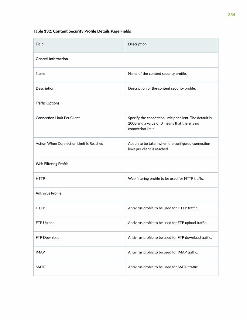
Table 132: Content Security Profile Details Page Fields
Field Description
General Information
Name Name of the content security profile.
Description Description of the content security profile.
Traffic Options
Connection Limit Per Client Specify the connection limit per client. The default is2000 and a value of 0 means that there is noconnection limit.
Action When Connection Limit Is Reached Action to be taken when the configured connectionlimit per client is reached.
Web Filtering Profile
HTTP Web filtering profile to be used for HTTP traffic.
Antivirus Profile
HTTP Antivirus profile to be used for HTTP traffic.
FTP Upload Antivirus profile to be used for FTP upload traffic.
FTP Download Antivirus profile to be used for FTP download traffic.
IMAP Antivirus profile to be used for IMAP traffic.
SMTP Antivirus profile to be used for SMTP traffic.
334

Table 132: Content Security Profile Details Page Fields (Continued)
Field Description
POP3 Antivirus profile to be used for POP3 traffic.
Antispam Profile
SMTP Antispam profile to be used for SMTP traffic.
Content Filtering Profile
HTTP Content filtering profile to be used for HTTP traffic.
FTP Upload Content filtering profile to be used for FTP uploadtraffic.
FTP Download Content filtering profile to be used for FTP downloadtraffic.
IMAP Content filtering profile to be used for IMAP traffic.
SMTP Content filtering profile to be used for SMTP traffic.
POP3 Content filtering profile to be used for POP3 traffic.
Create a Content Security Profile
Use the Create Content Security Profiles page to configure content security profiles. Content securityconsolidates several security features to protect against multiple threat types. The Create ContentSecurity Profiles wizard provides step-by-step procedures to create a content security profile. You canconfigure antispam, antivirus, Web filtering, and content filtering profiles by launching the respectivewizards from the wizard.
To create a content security profile:
335

1. Select SRX > Security Subscriptions > Content Security > Content Security.
The Content Security Profiles page appears.
2. Click the add icon (+) to create a new content security profile.
The Create Content Security Profiles wizard appears, displaying brief instructions about creating acontent security profile.
3. Complete the configuration according to the guidelines provided in Table 133 on page 336.
NOTE: Fields marked with * are mandatory.
4. Click Finish.
A content security profile is created. You are returned to the content security Profiles page where aconfirmation message is displayed. After you create a content security profile, you can assign it to afirewall policy rule on the Security Policy page.
Table 133: Content Security Profile Settings
Setting Guideline
General Information
Name Enter a unique name for the content security profile.The maximum length is 29 characters.
Description Enter a description for the content security profile. Themaximum length is 255 characters.
Traffic Options
NOTE: In an attempt to consume all available resources, a malicious user might generate a large amount of trafficall at once. To prevent such activity from succeeding, you can impose traffic options.
Connection Limit per Client Specify the connection limit per client for clientconnections on the device. The default is 2000 and avalue of 0 means that there is no connection limit.
336

Table 133: Content Security Profile Settings (Continued)
Setting Guideline
Action when connection limit is reached Specify the action that must be taken when theconnection limit is reached. The available actions areNo action (default), Log and permit, and Block.
Click Next to continue.
Web Filtering Profiles by Traffic Protocol
HTTP Select the Web filtering profile to be applied for HTTPtraffic.
Alternatively, click Create Another Profile to create aWeb filtering profile. The Create Web Filtering Profileswizard appears. See "Create a Web Filtering Profile" onpage 344 for an explanation of the fields on thiswizard.
Click Back to go the preceding step or click Next to goto the next step.
Antivirus Profiles by Traffic Protocol
Apply to all protocols Click the toggle button to enable a single antivirusprofile to all traffic protocols and then specify theprofile in the Default Profile field.
If you disable the toggle button, which is the default,you can specify antivirus profiles for each traffic type .
Default Profile Select the antivirus profile to be applied to all trafficprotocols.
Click Back to go the preceding step or click Next to goto the next step.
NOTE: Click Create Another Profile to create an antivirus profile that you can then assign. The Create AntivirusProfiles wizard appears. See "Create an Antivirus Profile" on page 356 for an explanation of the fields on thiswizard.
337

Table 133: Content Security Profile Settings (Continued)
Setting Guideline
HTTP Select the antivirus profile to be applied to HTTPtraffic.
FTP Upload Select the antivirus profile to be applied to FTP uploadtraffic.
FTP Download Select the antivirus profile to be applied to FTPdownload traffic.
IMAP Select the antivirus profile to be applied to IMAPtraffic.
SMTP Select the antivirus profile to be applied to SMTPtraffic.
POP3 Select the antivirus profile to be applied to POP3traffic.
Click Back to go the preceding step or click Next to goto the next step.
Antispam Profiles by Traffic Protocol
SMTP Select the antispam profile to be applied for SMTPtraffic.
Alternatively, click Create Another Profile to create anantispam profile. The Create Antispam Profiles wizardappears. See "Create an Antispam Profile" on page 363for an explanation of the fields on this wizard.
Click Back to go the preceding step or click Next to goto the next step.
Content Filtering Profiles by Traffic Protocol
338

Table 133: Content Security Profile Settings (Continued)
Setting Guideline
Apply to all protocols Click the toggle button to apply a single contentfiltering profile to all traffic protocols and then specifythe profile in the Default Profile field.
If you disable this toggle button, which is the default,you can specify antivirus profiles for each traffic type.
Default Profile Select the content filtering profile to be applied to alltraffic protocols.
Click Back to go the preceding step or click Next to goto the next step.
NOTE: Click Create Another Profile to create a content filtering profile that you can then assign. The CreateContent Filtering Profiles wizard appears. See "Create a Content Filtering Profile" on page 369 for an explanationof the fields on this wizard.
HTTP Select the content filtering profile to be applied toHTTP traffic.
FTP Upload Select the content filtering profile to be applied to FTPupload traffic.
FTP Download Select the content filtering profile to be applied to FTPdownload traffic.
IMAP Select the content filtering profile to be applied toIMAP traffic.
SMTP Select the content filtering profile to be applied toSMTP traffic.
POP3 Select the content filtering profile to be applied toPOP3 traffic.
Click Back to go the preceding step.
339

Edit, Clone, and Delete a Content Security Profile
IN THIS SECTION
Edit a Content Security Profile | 340
Clone a Content Security Profile | 340
Delete a Content Security Profile | 341
You can edit, clone, and delete content security profiles from the Content Security Profiles page. Thistopic has the following sections:
Edit a Content Security Profile
To modify the parameters configured for a content security profile:
NOTE: You cannot modify the default profiles already present in the system.
1. Select SRX > Security Subscriptions > Content Security > Content Security Profiles.
The Content Security Profiles page appears, displaying the existing content security profiles.
2. Select the custom content security profile that you want to edit and click the pencil icon.
The Edit Content Security Profiles page appears, displaying the same fields that are presented whenyou create a content security profile.
3. Modify the content security profile fields as needed.
4. Click OK to save your changes.
You are taken to the Content Security Profiles page. A confirmation message appears indicating thestatus of the edit operation.
Clone a Content Security Profile
Cloning enables you to easily create a new content security profile based on an existing one.
To clone a content security profile:
1. Select SRX > Security Subscriptions > Content Security > Content Security Profiles.
The Content Security Profiles page appears, displaying the existing content security profiles.
2. Select the custom content security profile that you want to clone and then select More > Clone.
340

The Clone Content Security Profiles page appears, displaying the same fields that are presentedwhen you create a content security profile.
3. Modify the content security profile fields as needed.
4. Click OK to save your changes.
You are taken to the Content Security Profiles page. A confirmation message appears, indicating thestatus of the clone operation.
Delete a Content Security Profile
NOTE: Before deleting a content security profile, ensure that the profile is not used in a firewallpolicy rule. If you try to delete a profile that is used in a firewall policy rule, an error message isdisplayed.
To delete one or more content security profiles:
1. Select SRX > Security Subscriptions > Content Security > Content Security Profiles.
The Content Security Profiles page appears, displaying the existing content security profiles.
2. Select one or more custom content security profiles that you want to delete and click the delete icon.
An alert message appears, asking you to confirm the delete operation.
3. Click Yes to delete the selected content security profiles.
A confirmation message appears, indicating the status of the delete operation.
About the Web Filtering Profiles Page
IN THIS SECTION
Tasks You Can Perform | 342
Field Descriptions | 343
To access this page, select SRX > Security Subscriptions > Content Security > Web Filtering Profiles inCustomer Portal.
Use the Web Filtering Profiles page to view and manage Web filtering profiles. Web filtering profilesenable you to manage Internet usage by preventing access to inappropriate Web content over HTTP.Table 134 on page 342 lists the Web filtering solutions that are supported and the license requirements.
341

Table 134: Web Filtering Solutions Supported
Type Description License Requirement
Integrated Web Filtering Blocks or permits Web access afterthe device identifies the categoryfor a URL, either from user-definedcategories or from a categoryserver (SurfControl Content PortalAuthority provided by Websense).
A separately licensed subscriptionservice.
Redirect Web Filtering Intercepts HTTP requests andforwards the server URL to anexternal URL filtering server todetermine whether to block orpermit the requested Web access.Websense provides the URLfiltering server.
Does not require a license.
Juniper Local Web Filtering Intercepts every HTTP request in aTCP connection. In this case, thedecision making is done on thedevice after it looks up a URL todetermine whether it is in theallowlist or blocklist based on itsuser-defined category.
Does not require a license or aremote category server.
Tasks You Can Perform
You can perform the following tasks from this page:
• Create a Web filtering profile—See "Create a Web Filtering Profile" on page 344.
• Edit, clone, or delete a Web filtering profile—See "Edit, Clone, and Delete a Web Filtering Profile" onpage 352.
• View the details of a Web filtering profile—Select the Web filtering profile for which you want toview the details and from the More, select Detailed View. The Web Filtering Profile Details pageappears. Table 136 on page 343 describes the fields on this page.
• Clear the selected Web filtering profiles—Click Clear All Selections to clear any Web filtering profilesthat you might have selected.
342

• Search for Web filtering profiles using keywords—Click the search icon and enter the search term inthe text box and press Enter. The search results are displayed on the same page.
Field Descriptions
Table 135 on page 343 describes the fields on the Web Filtering Profiles page.
Table 135: Web Filtering Profiles Page Fields
Field Description
Name Name of the Web filtering profile.
Profile Type Type of engine used for the profile: Juniper-enhancedor Websense redirect.
Default Action Default action taken when the specified connectionlimit per client is reached.
Timeout Timeout value to wait for a response from theWebsense server.
Description Description of the Web filtering profile.
Table 136: Web Filtering Profile Details Page Fields
Field Description
General Information
Name Name of the Web filtering profile.
Description Description of the Web filtering profile.
Engine Type Type of engine used for the profile: Juniper-enhancedor Websense redirect or Local.
343

Table 136: Web Filtering Profile Details Page Fields (Continued)
Field Description
Timeout Timeout value to wait for a response from theWebsense server.
Custom Block Message/ URL Redirect URL address or a custom message whenHTTP requests are blocked.
Custom Quarantine Message Custom message to indicate if the access is allowed ordenied to the URL.
Fallback Options
Default Action Action taken for URL categories with no assignedaction and for uncategorized URLs. This action is takenonly if no reputation action is assigned.
Global Reputation Actions Actions taken for the following site reputations:
• Very Safe
• Moderately Safe
• Fairly Safe
• Suspicious
• Harmful
URL Categories URL categories associated with the Web filteringprofile.
Create a Web Filtering Profile
Web filtering profiles enable you to manage Internet usage by preventing access to inappropriate Webcontent over HTTP.
344

To create a Web filtering profile:
1. Select SRX > Security Subscriptions > Content Security > Web Filtering Profiles.
The Web Filtering Profiles page appears.
2. Click the add icon (+) to create a new Web filtering profile.
The Create Web Filtering Profiles wizard appears, displaying brief instructions about creating a Webfiltering profile.
3. Click Next to navigate to the next page.
4. Complete the configuration according to the guidelines provided in Table 137 on page 345.
NOTE: Fields marked with * are mandatory.
5. Click Finish.
A Web filtering profile is created, which you can associate with a content security profile. You arereturned to the Web Filtering Profiles page where a confirmation message is displayed.
Table 137: Creating Web Filtering Profiles Settings
Setting Guideline
General Information
Name Enter a unique name for the Web filtering profile.The maximum length is 29 characters.
Description Enter a description for the Web filtering profile. Themaximum length is 255 characters.
Timeout Enter a timeout (in seconds) to wait for a responsefrom the Websense server. The default is 15 secondsand the maximum is 1800 seconds.
345

Table 137: Creating Web Filtering Profiles Settings (Continued)
Setting Guideline
Engine Type Select an engine type for Web filtering:
• (Default) Juniper Enhanced—UTM-enhancedWeb filtering.
• Websense Redirect—Redirect Web filteringprofile.
• Local—Allows you to define custom URLcategories, which can be included in blocklistsand allowlists that are evaluated on the device.
Safe Search Click the toggle button to enable (default) or disablethe safe search. Safe search ensures that embeddedobjects, such as images on the URLs received fromthe search engines, are safe and that undesirablecontent is not returned to the client.
NOTE: This option is available only for the JuniperEnhanced engine type. Save search redirect supportsonly HTTP and you cannot extract the URL forHTTPS. Therefore, it is not possible to generate aredirect response for HTTPS search URLs.
Custom Block Message/URL Specify the redirect URL or a custom message to besent when HTTP requests are blocked. The maximumlength is 1024 characters.
NOTE: If a message begins with http: or https:, themessage is considered a block URL. Messages thatbegin with values other than http: or https: areconsidered custom block messages.
Click Back to go the preceding step or click Next togo to the next step.
346

Table 137: Creating Web Filtering Profiles Settings (Continued)
Setting Guideline
Custom Quarantine Message Define a custom message to allow or deny access toa blocked site based on a user's response to themessage. The maximum length is 512 characters.
The quarantine message contains the followinginformation:
• URL name
• Quarantine name
• Category (if available)
• Site reputation (if available)
For example, if you set the action forEnhanced_Search_Engines_and_Portals to quarantine,and you try to access www.search.yahoo.com, thequarantine message is as follows: ***The requestedwebpage is blocked by your organization’saccess policy***.
Click Back to go the preceding step or click Next togo to the next step.
Account Specify the user account associated with theWebsense Web filtering profile.
Server Specify the hostname or an IP address for theWebsense server.
Port Specify the port number to use to communicate withthe Websense server. The default port value is15968.
Click Back to go the preceding step or click Next togo to the next step.
347

Table 137: Creating Web Filtering Profiles Settings (Continued)
Setting Guideline
Sockets Enter the number of sockets used for communicationbetween the client and the server. The default valueis 8.
URL Categories
Deny Action List Click the Add URL Categories button to specify a listof URL categories that must be denied access.
The Select URL Categories page appears. Completethe configuration according to the guidelinesprovided in Table 138 on page 351.
The list of URL categories selected is displayed in atext box.
Log & Permit Action List Specify a list of URL categories that are logged andthen permitted.
The Select URL Categories page appears. Completethe configuration according to the guidelinesprovided in Table 138 on page 351.
The list of URL categories selected is displayed in atext box.
Permit Action List Specify a list of URL categories that should bepermitted access.
The Select URL Categories page appears. Completethe configuration according to the guidelinesprovided in Table 138 on page 351.
The list of URL categories selected is displayed in atext box.
348

Table 137: Creating Web Filtering Profiles Settings (Continued)
Setting Guideline
Quarantine Action List Specify a list of URL categories that should bequarantined.
The Select URL Categories page appears. Completethe configuration according to the guidelinesprovided in Table 138 on page 351.
The list of URL categories selected is displayed in atext box.
Click Back to go the preceding step or click Next togo to the next step.
Fallback Options
349

Table 137: Creating Web Filtering Profiles Settings (Continued)
Setting Guideline
Global Reputation Actions Enhanced Web filtering intercepts HTTP and HTTPSrequests and sends the HTTP URL or the HTTPSsource IP to the Websense ThreatSeeker Cloud(TSC). The TSC categorizes the URL into one of thepredefined categories and provides the sitereputation information to the device. The devicedetermines if it can permit or block the requestbased on the information provided by the TSC.
By default, the URLs are processed using theirreputation score if there is no category available.Click the toggle button to disable global reputationactions or select the action that you want to take forthe uncategorized URLs based on their reputationscore:
• Very Safe—Permit, log and permit, block, orquarantine a request if a site reputation value is90 through 100. By default, Permit is selected.
• Moderately Safe—Permit, log and permit, block,or quarantine a request if a site reputation of 80through 89 is returned. By default, Log andPermit is selected.
• Fairly Safe—Permit, log and permit, block orquarantine a request if a site-reputation of 70through 79 is returned. By default, Log andPermit is selected.
• Suspicious—Permit, log and permit, block, orquarantine a request if a site reputation of 60through 69 is returned. By default, Quarantine isselected.
• Harmful—Permit, log and permit, block, orquarantine a request if a site reputation of zerothrough 59 is returned. By default, Block isselected.
NOTE: The site reputation score for each level canbe modified as per user requirements under ContentSecurity Settings menu. For more information, see
350

Table 137: Creating Web Filtering Profiles Settings (Continued)
Setting Guideline
"Configure the Content Security Settings" on page330.
Default Action Choose the actions for URL categories with noassigned action and for uncategorized URLs. This isused only if no reputation action is assigned.
Fallback Action Select the fallback action, which is used when:
• The ThreatSeeker Websense Cloud servers areunreachable.
• A timeout occurs for requests to ThreatSeekerCloud.
• Too many requests to be handled by the device.
Table 138: Select URL Categories Settings
Setting Guideline
Show Choose which URL categories for selection: Allcategories, Custom URL categories, or WebsenseURL categories.
The Available column of the URL Categories fielddisplays URL categories based on your selection.
351

Table 138: Select URL Categories Settings (Continued)
Setting Guideline
URL Categories Select one or more URL categories in the Availablecolumn and click the forward arrow to confirm yourselection. The selected URL categories are displayedin the Selected column.
Alternatively, click Create New URL Category tocreate a URL category and assign it to the URLcategory. The Create URL Categories page appears;for more information, see "Create a URL Category"on page 746.
Click OK to confirm your selection. You are returnedto the Create Web Filtering Profiles page.
Edit, Clone, and Delete a Web Filtering Profile
IN THIS SECTION
Edit a Web Filtering Profile | 352
Clone a Web Filtering Profile | 353
Delete a Web Filtering Profile | 353
You can edit, clone, and delete Web filtering profiles from the Web Filtering Profiles page. This topic hasthe following sections:
Edit a Web Filtering Profile
To modify the parameters configured for a Web filtering profile:
NOTE: You cannot modify the default profiles already present in the system.
1. Select SRX > Security Subscriptions > Content Security > Web Filtering Profiles.
352

The Web Filtering Profiles page appears, displaying the existing Web filtering profiles.
2. Select the custom Web filtering profile that you want to edit and click the pencil icon.
The Edit Web Filtering Profiles page appears, displaying the same fields that are presented when youcreate a Web filtering profile.
3. Modify the Web filtering profile fields as needed.
4. Click OK to save your changes.
You are taken to the Web Filtering Profiles page. A confirmation message appears, indicating thestatus of the edit operation.
Clone a Web Filtering Profile
Cloning enables you to easily create a new Web filtering profile based on an existing one.
To clone a Web filtering profile:
1. Select SRX > Security Subscriptions > Content Security > Web Filtering Profiles.
The Web Filtering Profiles page appears, displaying the existing Web filtering profiles.
2. Select the Web filtering profile that you want to clone and then select More > Clone.
The Clone Web Filtering Profiles page appears, displaying the same fields that are presented whenyou create a Web filtering profile.
3. Modify the Web filtering profile fields as needed.
4. Click OK to save your changes.
You are taken to the Web Filtering Profiles page. A confirmation message appears, indicating thestatus of the clone operation.
Delete a Web Filtering Profile
Before deleting a Web filtering profile, ensure that the profile is not used in a content security profilethat is, in turn, used in a firewall policy rule. If you try to delete a Web filtering profile that is used in afirewall policy rule, an error message is displayed.
To delete one or more Web filtering profiles:
1. Select SRX > Security Subscriptions > Content Security > Web Filtering Profiles.
The Web Filtering Profiles page appears, displaying the existing Web filtering profiles.
2. Select one or more custom Web filtering profiles that you want to delete and click the delete icon.
An alert message appears, asking you to confirm the delete operation.
3. Click Yes to delete the selected Web filtering profiles.
A confirmation message appears, indicating the status of the delete operation.
353

About the Antivirus Profiles Page
IN THIS SECTION
Tasks You Can Perform | 354
Field Descriptions | 354
To access this page, select SRX > Security Subscriptions > Content Security > Antivirus Profiles.
Use the Antivirus Profiles page to view and manage antivirus profiles. Antivirus profiles enable you toinspect files transmitted over several protocols (HTTP, FTP upload and download, IMAP, SMTP, andPOP3) to determine whether the files exchanged are known malicious files, similar to how desktopantivirus software scans files for the same purpose.
Tasks You Can Perform
You can perform the following tasks from this page:
• Create an antivirus profile—See "Create an Antivirus Profile" on page 356.
• Edit, clone, or delete an antivirus profile—See "Edit, Clone, and Delete an Antivirus Profile" on page359.
• View the details of an antivirus profile—Select the antivirus profile for which you want to view thedetails and from the More or right-click menu, select Detailed View. The Antivirus Profile Detailspage appears. Table 140 on page 355 describes the fields on this page.
• Clear the selected antivirus profiles—Click Clear All Selections to clear any antivirus profiles that youmight have selected.
• Search for antivirus profiles by using keywords—Click the search icon and enter the search term inthe text box and press Enter. The search results are displayed on the same page.
Field Descriptions
Table 139 on page 355 describes the fields on the Antivirus Profiles page.
354

Table 139: Antivirus Profiles Page Fields
Field Description
Name Name of the antivirus profile.
Profile Type Type of engine used for the profile.
Content Size Limit Content size limit, in kilobytes, refers to accumulatedTCP payload size.
Trickling Timeout Number of seconds to wait for a response from theserver.
Description Description of the antivirus profile.
Table 140: Antivirus Profiles Details Page Fields
Field Description
General Information
Name Name of the antivirus profile.
Description Description of the antivirus profile.
Engine Type Type of engine used for the profile.
Scan Options
Content Size Limit Content size limit, in kilobytes, refers to accumulatedTCP payload size.
Fallback Options
355

Table 140: Antivirus Profiles Details Page Fields (Continued)
Field Description
Default Action Displays the default fallback action taken when theantivirus system encounters errors.
Content Size Displays the actions taken if the content size exceeds aset limit.
Engine Error Displays the action taken when an engine error occurs.
Create an Antivirus Profile
Use the Create Antivirus Profiles page to configure antivirus profiles. The antivirus profile defines thecontent to scan for any malware and the action to be taken when malware is detected. After you createa profile, you can assign it to content security profiles.
To create an antivirus profile:
1. Select SRX > Security Subscriptions > Content Security > Antivirus Profiles.
The Antivirus Profiles page appears.
2. Click the add icon (+) to create a new antivirus profile.
The Create Antivirus Profiles wizard appears, displaying brief instructions about creating an antivirusprofile.
3. Click Next to navigate to the next page.
4. Complete the configuration according to the guidelines provided in Table 141 on page 357.
NOTE: Fields marked with * are mandatory.
5. Click Finish.
A summary page is displayed. Review the settings, and if you need to make any modifications, clickthe Edit link or the Back button.
6. Click OK to save the settings and create the profile.
A message indicating the status of the create operation is displayed.
7. Click Close.
356

You are returned to the Antivirus Profiles page.
Table 141: Antivirus Profile Settings
Setting Guideline
General Information
Name Enter a unique name for the antivirus profile. Themaximum length is 29 characters.
Description Enter a description for the antivirus profile. Themaximum length is 255 characters.
Engine Type Displays the engine type used for scanning.Currently, Sophos is the only antivirus enginesupported.
Sophos antivirus is an in-the-cloud antivirus solution.The virus and malware database is located onexternal servers maintained by Sophos (SophosExtensible List) servers, thus there is no need todownload and maintain large pattern databases onthe Juniper Networks device.
Fallback Options
357

Table 141: Antivirus Profile Settings (Continued)
Setting Guideline
Fallback options are used when the antivirus systemexperiences errors and must fall back to one of thepreviously configured actions to either deny (block)or permit the object.
Specify the fallback options to use when there is afailure, or select the default action if no specificoptions are to be configured:
• Content Size—Select an option to specifywhether the content should be blocked (default)or logged and permitted if the content sizeexceeds the previously defined limit.
• Content Size Limit—Enter the content size limit inkilobytes (KB) based on which action is taken.The range is 20 through 40,000 KB. The contentsize limit check occurs before the scan request issent. The content size refers to accumulated TCPpayload size.
• Engine Error—Select the action to take (Block[default] or Log and Permit) when an engine erroroccurs.
The term engine error refers all engine errors,including engine not ready, timeout, too manyrequests, password protected, corrupt file,decompress layer, and out of resources.
• Default Action—Select the default action (Block[default] or Log and Permit) to take when an erroroccurs.
Notification Options
358

Table 141: Antivirus Profile Settings (Continued)
Setting Guideline
Use the notification options to configure a method ofnotifying the user when a fallback occurs or a virus isdetected:
• Fallback Deny—Select this option to notify mailsenders that their messages were blocked.
• Fallback Non-Deny—Select this option to warnmail recipients that they received unblockedmessages despite problems.
• Virus Detected—Select this option to notify mailrecipients that their messages were blocked.
Edit, Clone, and Delete an Antivirus Profile
IN THIS SECTION
Edit an Antivirus Profile | 359
Clone an Antivirus Profile | 360
Delete an Antivirus Profile | 360
You can edit, clone, and delete antivirus profiles from the Antivirus Profiles page. This topic has thefollowing sections:
Edit an Antivirus Profile
To modify the parameters configured for an antivirus profile:
NOTE: You cannot modify the default profiles already present in the system.
1. Select Security Subscriptions > Content Security > Antivirus Profiles.
359

The Antivirus Profiles page appears, displaying the existing antivirus profiles.
2. Select the custom antivirus profile that you want to edit and then select the pencil icon.
The Edit Antivirus Profiles page appears, displaying the same fields that are presented when youcreate an antivirus profile.
3. Modify the antivirus profile fields as needed.
4. Click OK to save your changes.
You are taken to the Antivirus Profiles page. A confirmation message appears, indicating the status ofthe edit operation.
Clone an Antivirus Profile
Cloning enables you to easily create a new antivirus profile based on an existing one.
To clone an antivirus profile:
1. Select Security Subscriptions > Content Security > Antivirus Profiles.
The Antivirus Profiles page appears, displaying the existing antivirus profiles.
2. Select the antivirus profile that you want to clone and then select More > Clone.
The Clone Antivirus Profiles page appears, displaying the same fields that are presented when youcreate an antivirus profile.
3. Modify the antivirus profile fields as needed.
4. Click OK to save your changes.
You are taken to the Antivirus Profiles page. A confirmation message appears, indicating the status ofthe clone operation.
Delete an Antivirus Profile
Before deleting an antivirus profile, ensure that the profile is not used in a content security profile thatis, in turn, used in a firewall policy rule. If you try to delete an antivirus profile that is used in a firewallpolicy rule, an error message is displayed.
To delete one or more antivirus profiles:
1. Select SRX > Security Subscriptions > Content Security > Antivirus Profiles in Customer Portal.
The Antivirus Profiles page appears, displaying the existing antivirus profiles.
2. Select one or more custom antivirus profiles that you want to delete and then select the delete icon.
An alert message appears, asking you to confirm the delete operation.
3. Click Yes to delete the selected antivirus profiles.
A confirmation message appears, indicating the status of the delete operation.
360

About the Antispam Profiles Page
IN THIS SECTION
Tasks You Can Perform | 361
Field Descriptions | 361
To access this page, select Security Subscriptions > Content Security > Antispam Profiles in CustomerPortal.Use the Antispam Profiles page to view and manage antispam profiles, An antispam profile is used toexamine transmitted e-mail messages to identify e-mail spam by using a constantly updated spam blocklist.
Tasks You Can Perform
You can perform the following tasks from this page:
• Create an antispam profile—See "Create an Antispam Profile" on page 363.
• Edit, clone, or delete an antispam profile—See "Edit, Clone, and Delete an Antispam Profile" on page365.
• View the details of an antispam profile—Select the antispam profile for which you want to view thedetails and from the More or right-click menu, select Detailed View. The Antispam Profile Detailspage appears. Table 143 on page 362 describes the fields on this page.
• Clear the selected antispam profiles—Click Clear All Selections to clear any antispam profiles that youmight have selected.
• Search for antispam profiles using keywords—Click the search icon and enter the search term in thetext box and press Enter. The search results are displayed on the same page.
Field Descriptions
Table 142 on page 362 describes the fields on the Antispam Profiles page.
361

Table 142: Antispam Profiles Page Fields
Field Description
Name Name of the antispam profile.
Blacklist Indicates whether server-based spam filtering or localspam filtering is used.
Action Action to be taken when spam is detected.
Custom Tag Custom-defined tag that identifies an e-mail messageas spam.
Description Description of the antispam profile.
Table 143: Antispam Profile Details Page Fields
Field Description
Name Name of the antispam profile.
Description Description of the antispam profile.
Sophos Blacklist Indicates whether Sophos Blocklist is enabled (server-based filtering) or disabled (local filtering).
Default Action Action to be taken when spam is detected.
Custom Tag Custom-defined tag that identifies an e-mail messageas spam.
362

Create an Antispam Profile
Use the Create Antispam Profiles page to configure antispam profiles.
E-mail spam consists of unwanted e-mail messages usually sent by commercial, malicious, or fraudulententities. When the device detects an e-mail message deemed to be spam, it either blocks the messageor tags the message header or subject field with a preprogrammed string. Antispam filtering allows youto use a third-party server-based spam block list (SBL) and to optionally create your own local allowlists(benign) and blocklists (malicious) for filtering against e-mail messages.
NOTE: Sophos updates and maintains the IP-based SBL. Antispam is a separately licensedsubscription service.
After you create an antispam profile, you can assign it to content security profiles.
To create an antispam profile:
1. Select SRX > Security Subscriptions > Content Security > Antispam Profiles.
The Antispam Profiles page appears.
2. Click the add icon (+) to create a new antispam profile.
The Create Antispam Profiles page appears, displaying brief instructions about creating an antispamprofile.
3. Complete the configuration according to the guidelines provided in Table 144 on page 363.
Fields marked with * are mandatory.
4. Click OK save the settings and create the profile.
A message indicating the status of the create operation is displayed. You are returned to theAntispam Profiles page.
Table 144: Antispam Profile Settings
Setting Guideline
General Information
Name Enter a unique name for the antispam profile. Themaximum length is 29 characters.
363

Table 144: Antispam Profile Settings (Continued)
Setting Guideline
Description Enter a description for the antispam profile. Themaximum length is 255 characters.
Sophos Blacklist Use this toggle button to enable server-based spamfiltering. If the toggle button is disabled, which is thedefault, local spam filtering is used.
Server-based antispam filtering requires Internetconnectivity with the spam block list (SBL) server.Domain Name Service (DNS) is required to accessthe SBL server. The firewall performs SBL lookupsthrough the DNS protocol.
NOTE: Server-based spam filtering supports only IP-based spam block list blocklist lookup. Sophosupdates and maintains the IP-based spam block list.Server-based antispam filtering is a separatelylicensed subscription service.
Action
Default Action Select the action to be taken when spam is detected:
• Tag Email Subject Line
• Tag SMTP Header
• Block Email
• None
Custom Tag Enter a custom string for identifying a message asspam. The maximum length is 512 characters and thedefault is ***SPAM***.
364

Edit, Clone, and Delete an Antispam Profile
IN THIS SECTION
Edit an Antispam Profile | 365
Clone an Antispam Profile | 365
Delete an Antispam Profile | 366
You can edit, clone, and delete antispam profiles from the Antispam Profiles page. This topic has thefollowing sections:
Edit an Antispam Profile
To modify the parameters configured for an antispam profile:
NOTE: You cannot modify the default profiles already present in the system.
1. Select SRX > Security Subscriptions > Content Security > Antispam Profiles.
The Antispam Profiles page appears, displaying the existing antispam profiles.
2. Select the custom antispam profile that you want to edit and click the pencil icon.
The Edit Antispam Profiles page appears, displaying the same fields that are presented when youcreate an antispam profile.
3. Modify the antispam profile fields as needed.
4. Click OK to save your changes.
You are taken to the Antispam Profiles page. A confirmation message appears, indicating the statusof the edit operation.
Clone an Antispam Profile
Cloning enables you to easily create a new antispam profile based on an existing one.
To clone an antispam profile:
1. Select SRX > Security Subscriptions > Content Security > Antispam Profiles.
The Antispam Profiles page appears displaying the existing antispam profiles.
2. Select the custom antispam profile that you want to clone and then select More > Clone.
365

The Clone Antispam Profiles page appears, displaying the same fields that are presented when youcreate an antispam profile.
3. Modify the antispam profile fields as needed.
4. Click OK
You are taken to the Antispam Profiles page. A confirmation message appears, indicating the statusof the clone operation.
Delete an Antispam Profile
Before deleting an antispam profile, ensure that the profile is not used in a content security profile thatis, in turn, used in a firewall policy rule. If you try to delete an antispam profile that is used in a firewallpolicy rule, an error message is displayed.
To delete one or more antispam profiles:
1. Select SRX > Security Subscriptions > Content Security > Antispam Profiles.
The Antispam Profiles page appears, displaying the existing antispam profiles.
2. Select one or more custom antispam profiles that you want to delete and click the delete icon.
An alert message appears, asking you to confirm the delete operation.
3. Click Yes to delete the selected antispam profiles.
A confirmation message appears, indicating the status of the delete operation.
About the Content Filtering Profiles Page
IN THIS SECTION
Tasks You Can Perform | 367
Field Descriptions | 367
To access this page, select SRX > Security Subscriptions > Content Security > Content Filtering Profilesin Customer Portal.Use the Content Filtering Profiles page to view and manage content filtering profiles. Content filteringprofiles enable you to block or permit certain types of traffic over several protocols (HTTP, FTP uploadand download, IMAP, SMTP, and POP3) based on the MIME type, file extension, protocol command, andembedded object type.
366

Tasks You Can Perform
You can perform the following tasks from this page:
• Create a content filtering profile—See "Create a Content Filtering Profile" on page 369.
• Edit, clone, or delete a content filtering profile—See "Edit, Clone, and Delete a Content FilteringProfile" on page 373.
• View the details of a content filtering profile—Select the content filtering profile for which you wantto view the details and from the More or right-click menu, select Detailed View. The ContentFiltering Profile Details page appears. Table 146 on page 368 describes the fields on this page.
• Clear the selected content filtering profiles—Click Clear All Selections to clear any content filteringprofiles that you might have selected.
• Search for content filtering profiles by using keywords—Click the search icon, enter the search termin the text box, and press Enter. The search results are displayed on the same page.
Field Descriptions
Table 145 on page 367 describes the fields on the Content Filtering Profiles page.
Table 145: Content Filtering Profiles Page Fields
Field Description
Name Name of the content filtering profile.
Permit Command List List of protocol commands permitted by the contentfiltering profile.
Block Command List List of protocol commands blocked by the contentfiltering profile.
Notification Type Type of notification that is sent when content isblocked.
Description Description of the content filtering profile.
367

Table 146: Content Filtering Profiles Details Page Fields
Field Description
General Information
Name Name of the content filtering profile.
Description Description of the content filtering profile.
Notification Options
Notify Mail Sender Specifies whether the option to notify the e-mailsender is enabled or disabled.
Notification Type Type of notification that is sent when content isblocked.
Protocol Commands
Command Block List List of protocol commands permitted by the contentfiltering profile.
Command Permit List List of protocol commands blocked by the contentfiltering profile.
Content Types
Block Content Types List of harmful content types to be blocked.
File Extensions
Extension Block List File extensions to be blocked.
MIME
368

Table 146: Content Filtering Profiles Details Page Fields (Continued)
Field Description
MIME Block List List of MIME types to be blocked.
MIME Permit List List of MIME types to be permitted.
Create a Content Filtering Profile
Use the Create Content Filtering Profiles page to configure content filtering profiles. Content filteringblocks or permits certain types of traffic based on the MIME type, file extension, and protocol command.The content filter controls file transfers across the device by checking traffic against configured filterlists. Table 147 on page 369 displays the types of content filters that you can configure as part of acontent filtering profile.
NOTE: The content filtering profile evaluates traffic before all other content security profiles.Therefore, if traffic meets criteria configured in the content filter, the content filter acts first uponthis traffic.
Table 147: Supported Content Filter Types
Type Description
Protocol Command Block and Permit Lists Different protocols use different commands tocommunicate between servers and clients. By blockingor allowing certain commands, traffic can be controlledon the protocol command level. The block or permitcommand lists are intended to be used in combination,with the permit list acting as an exception list to theblock list.
NOTE: If a protocol command appears on both thepermit list and the block list, the command ispermitted.
369

Table 147: Supported Content Filter Types (Continued)
Type Description
Extension Block List It is recommended to use file extensions to block orallow file transfers, because the name of a file isavailable during the transfers. All protocols support theuse of the extension block list.
MIME pattern filter MIME patterns are used to identify the type of trafficin HTTP and MAIL protocols. There are two lists ofMIME patterns that are used by the content filter todetermine the action to be taken. The MIME Block Listcontains a list of MIME type traffic that is to beblocked. The MIME Permit List contains MIMEpatterns that permitted by the content filter and aregenerally subsets of items on the block list.
NOTE: The MIME permit list has a higher priority thanthe block list.
To create a content filtering profile:
1. Select SRX > Security Subscriptions > Content Security > Content Filtering Profiles.
The Content Filtering Profiles page appears.
2. Click the add icon (+) to create a new content filtering profile.
The Create Content Filtering Profiles wizard appears, displaying brief instructions about creating acontent filtering profile.
3. Click Next to navigate to the next page.
4. Complete the configuration according to the guidelines provided in Table 148 on page 371.
Fields marked with * are mandatory.
5. Click Finish.
A summary page is displayed. Review the settings and if you need to make any modifications click theEdit link or the Back button.
6. Click OK save the settings and create the profile.
A message indicating the status of the create operation is displayed.
7. Click Close.
You are returned to the Content Filtering Profiles page.
370

Table 148: Content Filtering Profile Settings
Setting Guideline
General Information
Name Enter a unique name for the content filtering profile.The maximum length is 29 characters.
Description Enter a description for the content filtering profile.The maximum length is 255 characters.
Notification Options
Notify Mail Sender Click this toggle button to enable notification when acontent filter is matched. Notifications are disabledby default.
Notification Type Select the type of notification to send:
• None—Do not send notifications.
• Protocol—Send a protocol-specific notification.With these notifications, a protocol-specific errorcode might be sent.
• Message—Send a generic notification.
Custom Notification Message Enter a custom notification message. The maximumlength is 512 characters.
Protocol Commands
Command Block List Enter the protocol commands to be blocked for theHTTP, FTP, SMTP, IMAP, and POP3 protocols. Usecommas to separate each command.
Protocol commands allow you to control traffic at theprotocol-command level.
371

Table 148: Content Filtering Profile Settings (Continued)
Setting Guideline
Command Permit List Enter specific commands to be permitted for theHTTP, FTP, SMTP, IMAP, and POP3 protocols. Usecommas to separate each command.
Block Content Type Use the content filter to block other types of harmfulfiles that the MIME type or the file extension cannotcontrol. Select from the following types of contentblocking (supported only for HTTP):
• Active X
• Windows executables (.exe)
• HTTP cookie
• Java applet
• ZIP files
Extension Block List Use a file extension list to define a set of fileextensions to block over HTTP, FTP, SMTP, IMAP,and POP3.
Enter file extensions to block separated by commas.For example, exe, pdf, js, and so on.
MIME Block List Enter the MIME types you want to block over HTTP,FTP, SMTP, IMAP, and POP3 connections. Usecommas to separate each MIME type.
MIME Permit List Enter the MIME types you want to permit overHTTP, FTP, SMTP, IMAP, and POP3 connections. Usecommas to separate each MIME type.
372

Edit, Clone, and Delete a Content Filtering Profile
IN THIS SECTION
Edit a Content Filtering Profile | 373
Clone a Content Filtering Profile | 373
Delete a Content Filtering Profile | 374
You can edit, clone, and delete content filtering profiles from the Content Filtering Profiles page. Thistopic has the following sections:
Edit a Content Filtering Profile
To modify the parameters configured for a content filtering profile:
NOTE: You cannot modify the default profiles already present in the system.
1. Select SRX > Security Subscriptions > Content Security > Content Filtering Profiles.
The Content Filtering Profiles page appears, displaying the existing content filtering profiles.
2. Select the custom content filtering profile that you want to edit and click the pencil icon.
The Edit Content Filtering Profiles page appears, displaying the same fields that are presented whenyou create a content filtering profile.
3. Modify the content filtering profile fields as needed.
4. Click OK to save your changes.
You are taken to the Content Filtering Profiles page. A confirmation message appears, indicating thestatus of the edit operation.
Clone a Content Filtering Profile
Cloning enables you to easily create a new content filtering profile based on an existing one.
To clone a content filtering profile:
1. Select SRX > Security Subscriptions > Content Security > Content Filtering Profiles.
The Content Filtering Profiles page appears, displaying the existing content filtering profiles.
2. Select the content filtering profile that you want to clone and then select More > Clone.
373

The Clone Content Filtering Profiles page appears, displaying the same fields that are presentedwhen you create a content filtering profile.
3. Modify the content filtering profile fields as needed.
4. Click OK to save your changes.
You are taken to the Content Filtering Profiles page. A confirmation message appears, indicating thestatus of the clone operation.
Delete a Content Filtering Profile
Before deleting a content filtering profile, ensure that the profile is not used in a content security profilethat is, in turn, used in a firewall policy rule. If you try to delete a content filtering profile that is used in afirewall policy rule, an error message is displayed.
To delete one or more content filtering profiles:
1. Select SRX > Security Subscriptions > Content Security > Content Filtering Profiles.
The Content Filtering Profiles page appears, displaying the existing content filtering profiles.
2. Select one or more custom content filtering profiles that you want to delete and click the delete icon.
An alert message appears, asking you to confirm the delete operation.
3. Click Yes to delete the selected content filtering profiles.
A confirmation message appears, indicating the status of the delete operation.
374

CHAPTER 20
Security Subscriptions-Decrypt Profiles
IN THIS CHAPTER
Decrypt Profiles Overview | 375
About the Decrypt Profiles Page | 382
Create a Decrypt Profile | 385
Edit, Clone, and Delete a Decrypt Profile | 392
Decrypt Profiles Overview
IN THIS SECTION
Supported Ciphers in Proxy Mode | 377
Server Authentication | 379
Root CA | 380
Trusted CA List | 380
Session Resumption | 380
SSL Proxy Logs | 381
Secure Sockets Layer (SSL) is an application-level protocol that provides encryption technology for theInternet. SSL, also called Transport Layer Security (TLS), ensures the secure transmission of databetween a client and a server through a combination of privacy, authentication, confidentiality, and dataintegrity. SSL relies on certificates and private–public key exchange pairs for this level of security.
Server authentication guards against fraudulent transmissions by enabling a Web browser to validatethe identity of a Web server. Confidentiality mechanisms ensure that communications are private. SSLenforces confidentiality by encrypting data to prevent unauthorized users from eavesdropping on
375

electronic communications. Finally, message integrity ensures that the contents of a communicationhave not been tampered with.
SSL proxy performs SSL encryption and decryption between the client and the server, but neither theserver nor the client can detect its presence. SSL proxy ensures that it has the keys to encrypt anddecrypt the payload:
• For the server, SSL proxy acts as a client—SSL proxy generates the shared pre-master key, itdetermines the keys to encrypt and decrypt.
• For the client, SSL proxy acts as a server—SSL proxy first authenticates the original server andreplaces the public key in the original server certificate with a key that is known to it. It thengenerates a new certificate by replacing the original issuer of the certificate with its own identity andsigns this new certificate with its own public key (provided as a part of the proxy profileconfiguration). When the client accepts such a certificate, it sends a shared pre-master key encryptedwith the public key on the certificate. Because SSL proxy replaced the original key with its own key, itis able to receive the shared pre-master key. Decryption and encryption take place in each direction(client and server), and the keys are different for both encryption and decryption.
Figure 8 on page 377 shows how SSL proxy works on an encrypted payload. SSL proxy uses thefollowing services:
• SSL-T-SSL terminator on the client side.
376

• SSL-I-SSL initiator on the server side.
Figure 8: SSL Proxy on an Encrypted Payload
This topic has the following sections:
Supported Ciphers in Proxy Mode
An SSL cipher comprises encryption ciphers, authentication method, and compression. Table 149 onpage 378 displays a list of supported ciphers. NULL ciphers are excluded.
The following SSL protocols are supported:
• SSLv3
• TLS1
377

Table 149: Supported Ciphers in Proxy Mode
SSL Cipher Key Exchange Algorithm Data Encryption Message Integrity
RSA_WITH_RC4_128_MD5
RSA key exchange 128-bit RC4 MD5 hash
RSA_WITH_RC4_128_SHA
RSA key exchange 128-bit RC4 Secure Hash Algorithm(SHA) hash
RSA_WITH_DES_CBC_SHA
RSA key exchange DES CBC SHA hash
RSA_WITH_3DES_EDE_CBC_SHA
RSA key exchange 3DES EDE/CBC SHA hash
RSA_WITH_AES_128_CBC_SHA
RSA key exchange 128-bit AES/CBC SHA hash
RSA_WITH_AES_256_CBC_SHA
RSA key exchange 256-bit AES/CBC SHA hash
RSA_EXPORT_WITH_RC4_40_MD5
RSA-export 40-bit RC4 MD5 hash
RSA_EXPORT_WITH_DES40_CBC_SHA
RSA-export 40-bit DES/CBC SHA hash
RSA_EXPORT1024_WITH_DES_CBC_SHA
RSA 1024 bit export DES/CBC SHA hash
RSA_EXPORT1024_WITH_RC4_56_MD5
RSA 1024 bit export 56-bit RC4 MD5 hash
RSA_EXPORT1024_WITH_RC4_56_SHA
RSA 1024 bit export 56-bit RC4 SHA hash
378

Table 149: Supported Ciphers in Proxy Mode (Continued)
SSL Cipher Key Exchange Algorithm Data Encryption Message Integrity
RSA-WITH-AES-256-GCM-SHA384
RSA key exchange 256-bit AES/GCM SHA384 hash
RSA-WITH-AES-256-CBC-SHA256
RSA key exchange 256-bit AES/CBC SHA256 hash
RSA-WITH-AES-128-GCM-SHA256
RSA key exchange 128-bit AES/GCM SHA256 hash
RSA-WITH-AES-128-CBC-SHA256
RSA key exchange 128-bit AES/CBC SHA256 hash
Server Authentication
Implicit trust between the client and the device (because the client accepts the certificate generated bythe device) is an important aspect of SSL proxy. It is extremely important that server authentication isnot compromised; however, in reality, self-signed certificates and certificates with anomalies are inabundance. Anomalies can include expired certificates, instances of common name not matching adomain name, and so forth.
You can specify that the SSL proxy should ignore server authentication completely. In this case, SSLproxy ignores errors encountered during the server certificate verification process (such as CA signatureverification failure, self-signed certificates, and certificate expiry).
You can specify whether the SSL proxy should ignore server authentication errors or not during thecreation of an SSL proxy profile.
• If you specify that server authentication errors should not be ignored, the following scenarios occur:
• If authentication succeeds, a new certificate is generated by replacing the keys and changing theissuer name to the issuer name that is configured in the root CA certificate in the proxy profile.
• If authentication fails, the connection is dropped.
• If you specify that server authentication errors should be ignored, the following scenarios occur:
379

NOTE: We do not recommend that you configure this option for authentication becauseconfiguring it results in websites not being authenticated at all. However, you can use thisoption to effectively identify the root cause for dropped SSL sessions.
• If the certificate is self-signed, a new certificate is generated by replacing the keys only. The issuername is not changed. This ensures that the client browser displays a warning that the certificate isnot valid.
• If the certificate has expired or if the common name does not match the domain name, a newcertificate is generated by replacing the keys and changing the issuer name to SSL-PROXY:DUMMY_CERT:GENERATED DUE TO SRVR AUTH FAILURE. This ensures that the clientbrowser displays a warning that the certificate is not valid.
Root CA
In a public key infrastructure (PKI) hierarchy, the root CA is at the top of the trust path. The root CAidentifies the server certificate as a trusted certificate.
Trusted CA List
SSL proxy ensures secure transmission of data between a client and a server. Before establishing asecure connection, SSL proxy checks certificate authority (CA) certificates to verify signatures on servercertificates. For this reason, a reasonable list of trusted CA certificates is required to effectivelyauthenticate servers.
Session Resumption
An SSL session refers to the set of parameters and encryption keys that are created when a fullhandshake is performed. A connection is the conversation or active data transfer that occurs within thesession. The computational overhead of a complete SSL handshake and generation of primary keys isconsiderable. In short-lived sessions, the time taken for the SSL handshake can be more than the timefor data transfer. To improve throughput and still maintain an appropriate level of security, SSL sessionresumption provides a mechanism for caching sessions. This way, session information, such as the pre-master secret key and agreed-upon ciphers, can be cached for both the client and the server. A sessionID identifies the cached information. In subsequent connections, both parties agree to use the sessionID to retrieve the information rather than create pre-master secret key. Session resumption shortens thehandshake process and accelerates SSL transactions.
380

SSL Proxy Logs
When logging is enabled in an decrypt profile, the SSL proxy can generate the messages shown in Table150 on page 381.
Table 150: SSL Proxy Logs
Log Type Description
All All logs are generated.
Warning Logs used for reporting warnings.
Info Logs used for reporting general information.
Error Logs used for reporting errors.
Session Whitelisted Logs generated when a session is allowed.
Session Allowed Logs generated when a session is processed by SSLproxy even after encountering some minor errors.
Session Dropped Logs generated when a session is dropped by SSLproxy.
All logs contain similar information; the message field contains the reason for the log generation. One ofthree prefixes shown in Table 151 on page 381 identifies the source of the message. Other fields aredescriptively labeled.
Table 151: SSL Proxy Log Prefixes
Prefix Description
system Logs generated because of errors related to the deviceor an action taken as part of the decrypt profile. Mostlogs fall into this category.
381

Table 151: SSL Proxy Log Prefixes (Continued)
Prefix Description
openssl error Logs generated during the handshake process if anerror is detected by the openssl library.
certificate error Logs generated during the handshake process if anerror is detected in the certificate (X.509 relatederrors).
About the Decrypt Profiles Page
IN THIS SECTION
Tasks You Can Perform | 382
Widget Descriptions | 383
To access this page, click Security Subscriptions > Decrypt > Decrypt Profiles.Use the Decrypt Profiles page to view and to manage decrypt profiles.
Tasks You Can Perform
You can perform the following tasks from this page:
• Create an decrypt profile—See "Create a Decrypt Profile" on page 385.
• Edit, clone, or delete an decrypt profile—See "Edit, Clone, and Delete a Decrypt Profile" on page 392.
• View the details of an decrypt profile—Select the decrypt profile for which you want to view thedetails and from the More or right-click menu, select Detailed View. The View decrypt profile Detailspage appears. Table 153 on page 383 describes the fields on this page.
• Search for decrypt profiles using keywords—Click the search icon and enter the search term in thetext box and press Enter. The search results appear on the same page.
382

Widget Descriptions
Table 152 on page 383 describes the fields on the decrypt Profiles page.
Table 152: Fields on the Decrypt Profiles Page
Field Description
Name Name of the decrypt profile.
Preferred Cipher Preferred cipher associated with the profile.
Custom Ciphers The set of ciphers, if the preferred cipher is Custom,which the SSH server uses to perform the encryptionand the decryption functions.
Exempted Address Addresses that are exempted from decrypt processing.
Description Description of the decrypt profile.
Root Certificate Root certificate associated with the decrypt profile.
Table 153: View Decrypt Profile Details Page Fields
Field Description
General Information
Name Name of the decrypt profile.
Description Description of the decrypt profile.
Preferred Cipher Preferred cipher associated with the proxy profile.
383

Table 153: View Decrypt Profile Details Page Fields (Continued)
Field Description
Custom Ciphers The set of ciphers, if the preferred cipher is Custom,which the SSH server uses to perform the encryptionand the decryption functions.
Flow Trace Enabled Indicates whether flow tracing is enabled or disabled.
Certificates Displays the root certificate and the trusted certificateauthorities associated with the root certificate.
Exempted Address Addresses that are exempted from decrypt processing.
Exempted URL Categories URL categories that are exempted from decryptprocessing.
Actions
Ignore Indicates whether server authentication failure isignored (Enabled) or not (Disabled).
Session Resumption Indicates whether session information is cached toenable session resumption (Enabled) or not (Disabled).
Logging If logging is enabled, indicates the type of events thatare logged.
Renegotiation Indicates the type of renegotiation required for achange in SSL parameters after creating a session andestablishing the SSL tunnel transport.
384

Create a Decrypt Profile
Use this page to configure decrypt profiles. decrypt profile is enabled as an application service within asecurity policy.
To create an decrypt profile:
NOTE: Ensure that you have a root certificate imported for the tenant before you create andecrypt profile. You can import SSL certificates (root and trusted) from the Certificates page(Administration > Certificates) and associate the certificates with decrypt profiles.
1. Select Security Subscriptions > Decrypt.
The decrypt profiles page appears.
2. Click the add icon (+) to create an decrypt profile.
The Create Decrypt Profiles page appears.
3. Complete the configuration according to the guidelines provided in Table 154 on page 385.
Fields marked with an asterisk (*) are mandatory.
4. Click OK.
An decrypt profile is created. You are returned to the decrypt Profiles page where a confirmationmessage is displayed.
Table 154: decrypt profile Setting
Setting Guideline
General Information
Name Enter a unique name for the profile, which is string ofalphanumeric characters and some special characters(- _). No spaces are allowed and the maximum lengthis 63 characters.
Description Enter a description for the profile. The maximumlength is 255 characters.
385

Table 154: decrypt profile Setting (Continued)
Setting Guideline
Preferred Cipher Select a preferred cipher. Preferred ciphers enableyou to define an SSL cipher that can be used withacceptable key strength. You can select from thefollowing categories:
• None (Default)—Do not specify a preferredcipher.
• Medium—Use ciphers with key strength of 128bits or greater.
• Strong—Use ciphers with key strength of 168 bitsor greater.
• Weak—Use ciphers with key strength of 40 bitsor greater.
• Custom—Configure a custom cipher suite.
386

Table 154: decrypt profile Setting (Continued)
Setting Guideline
Custom Ciphers If you specified Custom as the preferred cipher, youcan define a custom cipher list by selecting ciphers.
Select the set of ciphers that the SSH server can useto perform encryption and decryption functions.
The available custom ciphers are:
• rsa-with-RC4-128-md5—RSA, 128- bit RC4, MD5hash
• rsa-with-RC4-128-sha—RSA, 128-bit RC4, SHAhash
• rsa-with-des-cbc-sha—RSA, DES/CBC, SHA hash
• rsa-with-3DES-ede-cbc-sha—RSA, 3DES EDE/CBC, SHA hash
• rsa-with-aes-128-cbc-sha—RSA, 128-bit AES/CBC, SHA hash
• rsa-with-aes-256-cbc-sha—RSA, 256 bit AES/CBC, SHA hash
• rsa-export-with-rc4-40-md5—RSA-export, 40 bitRC4, MD5 hash
• rsa-export-with-des40-cbc-sha—RSA-export, 40bit DES/CBC, SHA hash
• rsa-export1024-with-des-cbc-sha—RSA 1024 bitexport, DES/CBC, SHA hash
• rsa-export1024-with-rc4-56-md5—RSA 1024 bitexport, 56 bit RC4, MD5 hash
• rsa-export1024-with-rc4-56-sha—RSA 1024 bitexport, 56 bit RC4, SHA hash
• rsa-with-aes-256-gcm-sha384—RSA, 256 bitAES/GCM, SHA384 hash
387

Table 154: decrypt profile Setting (Continued)
Setting Guideline
• rsa-with-aes-256-cbc-sha256—RSA, 256 bit AES/CBC, SHA256 hash
• rsa-with-aes-128-gcm-sha256—RSA, 128 bitAES/GCM, SHA256 hash
• rsa-with-aes-128-cbc-sha256—RSA, 256 bit AES/CBC, SHA256 hash
• ecdhe-rsa-with-aes-256-gcm-sha384—ECDHE,RSA, 256 bit AES/GCM, SHA384 hash
• ecdhe-rsa-with-aes-256-cbc-sha384—ECDHE,RSA, 256 bit AES/CBC, SHA384 hash
• ecdhe-rsa-with-aes-256-cbc-sha—ECDHE, RSA,256 bit AES/CBC, SHA hash
• ecdhe-rsa-with-aes-3des-ede-cbc-sha—ECDHE,RSA, 3DES, EDE/CBC, SHA hash
• ecdhe-rsa-with-aes-128-gcm-sha256—ECDHE,RSA, 128 bit AES/GCM, SHA256 hash
• ecdhe-rsa-with-aes-128-cbc-sha256—ECDHE,RSA, 128 bit AES/CBC, SHA256 hash
• ecdhe-rsa-with-aes-128-cbc-sha—ECDHE, RSA,128 bit AES/CBC, SHA hash
Flow Trace Move this toggle button to enable flow tracing fortroubleshooting the policy-related issues.
Root Certificate Select or add a root certificate. In a public keyinfrastructure (PKI) hierarchy, the root certificateauthority (CA) is at the top of the trust path.
NOTE: To select the root certificate from the device,you must ensure that at least one trusted certificateis installed on the device.
388

Table 154: decrypt profile Setting (Continued)
Setting Guideline
Trusted Certificate Authorities Choose whether you want to add all trustedcertificates present on the device (All) or selectspecific trusted certificates. Before establishing asecure connection, the decrypt checks CAcertificates to verify signatures on server certificates.
NOTE:
• Specifying that all trusted certificates should beused means that all trusted certificates on aparticular device (site) are used during SSL policydeployment.
• If you specify that all trusted certificates shouldbe used in an decrypt profile, you must ensurethat at least one trusted certificate is installed onthe device.
389

Table 154: decrypt profile Setting (Continued)
Setting Guideline
Exempted Addresses Exempted addresses include addresses that you wantto exempt from undergoing decrypt processing.
To specify exempted addressees, select one or moreaddresses in the Available column and click theforward arrow to confirm your selection. Theselected addresses are then displayed in the Selectedcolumn. These addresses are used to create allowliststhat bypass decrypt processing.
Because SSL encryption and decryption arecomplicated and expensive procedures, networkadministrators can selectively bypass decryptprocessing for some sessions.
Such sessions typically include connections andtransactions with trusted servers or domains withwhich network administrators are very familiar. Thereare also legal requirements to exempt financial andbanking sites. Such exemptions are achieved byconfiguring the IP addresses or domain names of theservers under allowlists.
NOTE: You can also add addresses by clicking AddAddress. The Create Addresses page appears. See"Create Addresses or Address Groups" on page 691.
Exempted URL Categories Select the previously defined URL categories tocreate allowlists that bypass decrypt processing. Theselected URL categories are exempted during SSLinspection.
Actions
390

Table 154: decrypt profile Setting (Continued)
Setting Guideline
Server Auth Failure Select this check box to ignore errors encounteredduring the server certificate verification process(such as CA signature verification failure, self-signedcertificates, and certificate expiry). This check box iscleared by default.
We do not recommend this option forauthentication, because configuring it results inwebsites not being authenticated at all. However,you can use this option to effectively identify theroot cause for dropped SSL sessions.
Session Resumption Select this check box to disable session resumption.This check box is cleared by default.
To improve throughput and still maintain anappropriate level of security, SSL session resumptionprovides a session-caching mechanism so thatsession information, such as the pre-master secretkey and agreed-upon ciphers, can be cached for boththe client and server.
Logging Select one or more events to be logged. You canchoose to log all events, warnings, generalinformation, errors, or different sessions (allowed,dropped, or ignored). Logging is disabled by default.
391

Table 154: decrypt profile Setting (Continued)
Setting Guideline
Renegotiation Select one of the following options if a change in SSLparameters requires renegotiation:
• None (default)—Indicates that renegotiation is notrequired.
• Allow—Allow secure and nonsecurerenegotiation.
• Allow Secure—Allow secure negotiation only.
• Drop—Drop session on renegotiation request.
After a session is created and SSL tunnel transporthas been established, a change in SSL parametersrequires renegotiation. decrypt supports both secure(RFC 5746) and nonsecure (TLS v1.0 and SSL v3)renegotiation.
When session resumption is enabled, sessionrenegotiation is useful in the following situations:
• Cipher keys need to be refreshed after aprolonged SSL session.
• Stronger ciphers need to be applied for a moresecure connection.
Edit, Clone, and Delete a Decrypt Profile
IN THIS SECTION
Edit a Decrypt Profile | 393
Clone an Decrypt Profile | 393
Delete a Decrypt Profile | 393
392

You can edit, clone, and delete decrypt profiles from the decrypt Profiles page.
Edit a Decrypt Profile
To modify the parameters configured for an decrypt profile:
1. Select Security Subscriptions > Decrypt.
The Decrypt Profiles page appears, displaying the existing decrypt profiles.
2. Select the decrypt profile that you want to edit and then click the edit icon (pencil).
The Edit decrypt profile page appears showing the same fields that are presented when you create andecrypt profile.
3. Modify the decrypt profile fields as needed.
4. Click OK to save your changes.
The modified decrypt Profiles page appears.
Clone an Decrypt Profile
Cloning enables you to easily decrypt profile based on an existing one.
To clone an decrypt profile:
1. Select Security Subscriptions > Decrypt.
The decrypt Profiles page appears displaying the existing decrypt profiles.
2. Select the decrypt profile that you want to clone and then select More > Clone. Alternatively, right-click a profile and select Clone.
The Clone decrypt profile page appears, showing the same fields when you create an decrypt profile.
3. Modify the decrypt profile fields as needed.
4. Click OK to save your changes.
Decrypt Profiles page appears. A confirmation message appears, indicating the status of the cloneoperation.
Delete a Decrypt Profile
1. Select Security Subscriptions > Decrypt.
The decrypt Profiles page appears, displaying the existing decrypt profiles.
2. Select one or more decrypt profiles that you want to delete and then click the delete icon.
An alert message appears asking you to confirm the delete operation.
3. Click Yes to delete the selected decrypt profiles.
A confirmation message appears indicating the status of the delete operation.
393

CHAPTER 21
IPsec VPN
IN THIS CHAPTER
IPsec VPN Overview | 394
IPsec VPN Main Page Fields | 398
IPsec VPN Global Settings | 400
Create a Site-to-Site VPN | 401
Create a Hub-and-Spoke (Establishment All Peers) VPN | 414
Create a Hub-and-Spoke (Establishment by Spokes) VPN | 426
Create a Hub-and-Spoke Auto Discovery VPN | 436
Create a Remote Access VPN—Juniper Secure Connect | 447
Importing IPsec VPNs | 459
Deploying IPSec VPN | 460
Modify IPsec VPN Settings | 461
Deleting IPSec VPN | 461
IPsec VPN Overview
IN THIS SECTION
Understanding IPsec VPN Modes | 397
Understanding IPsec VPN Routing | 397
Understanding IKE Authentication | 398
IPsec VPN provides a means to securely communicate with remote computers across a public WANsuch as the Internet. A VPN connection can link two LANs using a site-to-site VPN or a remote dial-upuser and a LAN. The traffic that flows between these two points passes through shared resources such
394

as routers, switches, and other network equipment that comprise the public WAN. To secure VPNcommunication that passes through the WAN, you need to create an IPsec tunnel.
Juniper Security Director Cloud simplifies the management and deployment of IPsec VPNs. In general,VPN configurations are tedious and repetitive when deploying over a large number of SRX Seriesdevices. With Juniper Security Director Cloud, you can use VPN profiles to group common settings andapply the profiles to multiple VPN tunnel configurations across multiple SRX Series devices. You candeploy site-to-site and hub-and-spoke VPNs. Juniper Security Director Cloud determines the necessarydeployment scenarios and publishes the required configuration for all SRX Series devices.
Juniper Security Director Cloud supports route-based IPsec VPNs on SRX Series devices. If you havetwo or more SRX Series devices, then route-based VPNs offer more flexibility and scalability. To allowdata to be securely transferred between a branch office and the corporate office, configure a route-based IPsec VPN. For an enterprise-class deployment, configure a hub-and-spoke IPsec VPN.
Use route-based tunnel mode if:
• Participating gateways are Juniper Networks products.
• Either source or destination NAT must occur when traffic traverses the VPN.
• Dynamic routing protocols must be used for VPN routing.
• Primary and backup VPNs are required in the setup.
When you create a route-based IPsec VPN, a topology is displayed for a representation. You need toclick the icons to configure the remote gateway.
NOTE:
• Juniper Security Director Cloud views each logical system as any other security device andtakes ownership of the security configuration of the logical system. In Juniper SecurityDirector Cloud, each logical system is managed as a unique security device.
• Juniper Security Director Cloud ensures that the tunnel interfaces are exclusively assigned tothe individual logical systems of a device. No tunnel interface is assigned to more than onelogical system of the same device.
• Juniper Security Director Cloud does not support VPN over Point-to-Point Protocol overEthernet (PPPoE).
IPsec VPN Topologies
The following IPsec VPNs are supported:
395

• Site-to-Site VPNs—Connects two sites in an organization together and allows securecommunications between the sites.
• Hub-and-Spoke (establishment all peers)—Connects branch offices to the corporate office in anenterprise network. You can also use this topology to connect spokes together by sending trafficthrough the hub.
• Hub-and-Spoke (establishment by spokes)—Auto-VPN supports an IPsec VPN aggregator called ahub that serves as a single termination point for multiple tunnels to remote sites called spokes. Auto-VPN allows network administrators to configure a hub for current and future spokes. Noconfiguration changes are required on the hub when spoke devices are added or deleted, whichallows administrators flexibility in managing large-scale network deployments.
• Hub-and-Spoke (Auto Discovery VPN)—Auto Discovery VPN (ADVPN) is a technology that allowsthe central hub to dynamically inform spokes about a better path for traffic between two spokes.When both spokes acknowledge the information from the hub, the spokes establish a shortcuttunnel and change the routing topology for the host to reach the other side without sending trafficthrough the hub.
396

• Remote Access VPN (Juniper Secure Connect)—Juniper Secure Connect provides secure remoteaccess for the users to connect to the corporate networks and resources remotely using the Internet.Juniper Secure Connect downloads the configuration from SRX Services devices and chooses themost effective transport protocols during connection establishment.
Understanding IPsec VPN Modes
The following two modes determine how traffic is exchanged in the VPN:
• Tunnel Mode—This mode encapsulates the original IP packet within another packet in the VPNtunnel. This is most commonly used when hosts within separate private networks want tocommunicate over a public network. Both VPN gateways establish the VPN tunnel to each other, andall traffic between the two gateways appears to be from the two gateways, with the original packetembedded within the exterior IPsec packet.
• Transport Mode—This mode does not encapsulate the original packet in a new packet like the tunnelmode. The transport mode sends the packet directly between the two hosts that have establishedthe IPsec tunnel.
The Tunnel mode is the most common VPN mode on the Internet because it easily allows entirenetworks, particularly those with private address space, to communicate over public IP networks. TheTransport mode is primarily used when encrypting traffic between two hosts to secure communicationwhere IP address overlap is not an issue, such as between a host and a server on a private network.
Understanding IPsec VPN Routing
SRX Series devices must know how to reach destination networks. This can be configured through theuse of static routing or dynamic routing.
In Juniper Security Director Cloud, route-based VPNs support OSPF, RIP, and eBGP routing along withstatic routing. Static routing requires that administrators specify the list of host or network addresses ateach site as part of the VPN.
397

For example, in a retail scenario, where thousands of spokes can be part of a VPN, the static routingapproach generates a huge configuration at each device. Static routing requires administrators tomanually configure each route, and problems might occur when the infrastructure changes or when theadministrators do not have access to the addresses for the protected network. Keeping routes up-to-date manually also creates a tremendous overhead.
Understanding IKE Authentication
Internet Key Exchange negotiations only provide the ability to establish a secure channel over whichtwo parties can communicate. You still need to define how they authenticate each other. This is whereIKE authentication is used to ensure that the other party is authorized to establish the VPN.
The following IKE authentications are available:
• Preshared key authentication—The most common way to establish a VPN connection is to usepreshared keys, which is essentially a password that is the same for both parties. This password mustbe exchanged in advance in an out-of-band mechanism, such as over the phone, through a verbalexchange, or through less secure mechanisms, even e-mail. The parties then authenticate each otherby encrypting the preshared key with the peer’s public key, which is obtained in the Diffie-Hellmanexchange.
Preshared keys are commonly deployed for site-to-site IPsec VPNs, either within a singleorganization or between different organizations. To ensure that preshared keys are used in the mostsecure fashion, a preshared key must consist of at least 8 characters with 12 or more charactersrecommended comprising a combination of letters, numbers, and non-alphanumeric characters, alongwith different cases for the letters. Preshared keys should not use a dictionary word.
• Certificate authentication—Certificate-based authentication is considered more secure thanpreshared key authentication because the certificate key cannot be compromised easily. Certificatesare also more ideal in larger scale environments with numerous peer sites that should not all share apreshared key. Certificates are composed of a public and private key and can be signed by a primarycertificate known as a certificate authority (CA). In this way, certificates can be checked to see if theyare signed with a trusted CA.
IPsec VPN Main Page Fields
Use IPsec VPNs to secure your network traffic with encryption and authentication. The VPN tunnels arecentral components of networks which secure the data between different sites and remote users.
398

Table 155: IPsec VPN Main Page Fields
Field Description
Name The name of the IPsec VPN.
Description The description of the IPsec VPN.
VPN Topology The types of deployment topologies for IPsec VPN, such as site-to-site, hub-and-spoke,and remote access VPNs.
Profile Type The type of VPN profile, such as Inline Profile or Shared Profile.
Profile Name The name of the VPN profile.
The security parameters are defined in this profile to establish the VPN connectionbetween two sites.
Tunnel Mode The tunnel mode, such as Route Based.
Configuration State The configuration state of the IPsec VPN.
Status Displays the publish state of the VPN configuration.
You can verify your VPN configurations before updating the configuration to the device.
• Deploy pending—The VPN is created but not deployed.
• Deploy scheduled—The deployment of the VPN is scheduled.
• Deploy in-progress— The deployment of the VPN is in progress.
• Deploy successful—The configuration is deployed to all the devices involved in theVPN.
• Redeploy required—Modifications are made to the VPN configuration after it isdeployed.
• Deploy failed—The deployment of the VPN failed.
Created by The email address of the user who created the IPsec VPN.
399

IPsec VPN Global Settings
The Global Settings page displays the default settings that apply to the devices in your remote accessVPN topology. You can view or modify the VPN global configuration details.
1. Select SRX > IPsec VPN > IPsec VPNs.
The IPsec VPNs page opens.
2. Click Global Settings.
The Global Settings page opens.
3. Click the pencil icon to modify the global settings.
The Modify Global Settings page opens.
Table 156: Global Settings
Field Description
Default ProfileName
Select a default profile name from the list.
NOTE: This option is available when at least one Juniper Secure Connect VPN is created.
Remote Access VPN
Default RAVPN Select a remote IPsec VPN profile.
This option is available when at least one Juniper Secure Connect VPN is created.
SSL VPN Tunneltracking
Enable this option to track Encapsulated Security Payload (ESP) tunnels.
400

Table 156: Global Settings (Continued)
Field Description
SSL VPN Profiles Lists the SSL VPN profiles.
NOTE: This option displays associated IPsec VPNs when at least one remote access VPN iscreated.
To create a new SSL VPN profile:
1. Click Add.
The Add SSL VPN Profile page opens.
2. Enter the name for an SSL VPN profile.
3. Enable Logging option to log SSL VPN events.
4. Enter an SSL termination profile name.
5. Select a server certificate from the list.
6. Click OK.
To edit an SSL VPN profile, select the profile to edit, and click the pencil icon.
To delete an SSL VPN profile, select the profile to delete, and click the delete icon.
Create a Site-to-Site VPN
A site-to-site VPN connects two sites in an organization and allows secure communications between thesites.
Before You Begin
• Read the "IPsec VPN Overview" on page 394 topic.
• Review the IPsec VPN main page for an understanding of your current data set. See "IPsec VPN MainPage Fields" on page 398 for the field descriptions.
• Create addresses and address sets. See "Create Addresses or Address Groups" on page 691.
• Create VPN profiles. See "Creating VPN Profiles" on page 464.
• Define extranet devices. See "Creating Extranet Devices" on page 475.
401
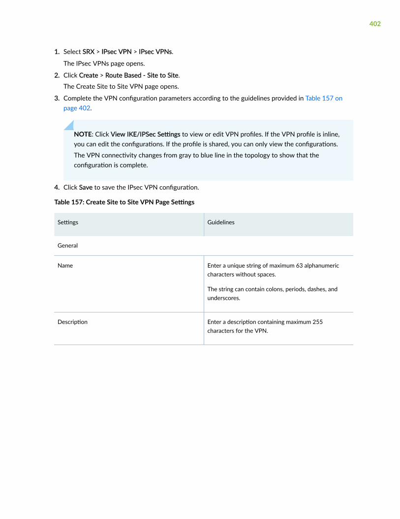
1. Select SRX > IPsec VPN > IPsec VPNs.
The IPsec VPNs page opens.
2. Click Create > Route Based - Site to Site.
The Create Site to Site VPN page opens.
3. Complete the VPN configuration parameters according to the guidelines provided in Table 157 onpage 402.
NOTE: Click View IKE/IPSec Settings to view or edit VPN profiles. If the VPN profile is inline,you can edit the configurations. If the profile is shared, you can only view the configurations.
The VPN connectivity changes from gray to blue line in the topology to show that theconfiguration is complete.
4. Click Save to save the IPsec VPN configuration.
Table 157: Create Site to Site VPN Page Settings
Settings Guidelines
General
Name Enter a unique string of maximum 63 alphanumericcharacters without spaces.
The string can contain colons, periods, dashes, andunderscores.
Description Enter a description containing maximum 255characters for the VPN.
402

Table 157: Create Site to Site VPN Page Settings (Continued)
Settings Guidelines
Routing topology Select one of the following options:
• Traffic selector (Auto route insertion)—A trafficselector is an agreement between IKE peers topermit traffic through a tunnel if the traffic matchesa specified pair of local and remote addresses.
• Static routing—Generates static routing based onthe protected networks or zones per device.
• OSPF-dynamic routing—Generates OSPFconfiguration.
• RIP-dynamic routing—Generates RIP configuration.
• eBGP-dynamic routing—Generates eBGPconfiguration.
The Routing topology is applicable only to route-basedVPNs.
VPN Profile Select a VPN profile from the drop-down list based onthe deployment scenario.
• The Inline profile is applicable only to a particularIPsec VPN. You can view and edit the details byclicking View IKE/IPsec settings on the Create VPNpage.
• The Shared profile can be used by one or moreIPsec VPNs. You can only view the details of theshared profiles by clicking View IKE/IPsec settings.
403

Table 157: Create Site to Site VPN Page Settings (Continued)
Settings Guidelines
Authentication Method Select an authentication method from the list that thedevice uses to authenticate the source of IKEmessages.
• Pre-shared based—Specifies that a pre-shared key,which is a secret key shared between the twopeers, is used during authentication to identify thepeers to each other. The same key must beconfigured for each peer.
• RSA-Signatures—Specifies that a public keyalgorithm, which supports encryption and digitalsignatures, is used.
• DSA-Signatures—Specifies that the DigitalSignature Algorithm (DSA) is used.
• ECDSA-Signatures-256—Specifies that the EllipticCurve DSA (ECDSA) using the 256-bit elliptic curvesecp256r1, as specified in the Federal InformationProcessing Standard (FIPS) Digital SignatureStandard (DSS) 186-3, is used.
• ECDSA-Signatures-384—Specifies that the ECDSAusing the 384-bit elliptic curve secp384r1, asspecified in the FIPS DSS 186-3, is used.
Network IP Enter the IP address of the numbered tunnel interface.
This is the subnet address from where the IP address isautomatically assigned for tunnel interfaces.
Max Transmission Unit Select the maximum transmission unit (MTU) in bytes.
MTU defines the maximum size of an IP packet,including the IPsec overhead. You can specify the MTUvalue for the tunnel endpoint. The valid range is 68 to9192 bytes, and the default value is 1500 bytes.
404

Table 157: Create Site to Site VPN Page Settings (Continued)
Settings Guidelines
Pre-shared Key Establish a VPN connection using pre-shared keys,which is essentially a password that is same for bothparties. Pre-shared keys are commonly deployed forsite-to-site IPsec VPNs, either within a singleorganization or between different organizations.
Select the type of pre-shared key to use:
• Autogenerate—Select if you want to automaticallygenerate a unique key per tunnel.
• Manual—Select to enter the key manually. Bydefault, the manual key is masked.
Pre-shared keys are applicable only if theauthentication method is pre-shared based.
Devices Add devices as endpoints in the VPN. You can addmaximum two devices.
To add devices in route-based VPNs:
1. Click Add, and click one of the following: Device orExtranet Device.
The Add Device page opens.
2. Configure the device parameters as described inTable 158 on page 405
3. Click OK.
Table 158: Add Device page settings
Settings Guidelines
Device Select a device.
External Interface Select the outgoing interface for IKE security associations (SAs).
405

Table 158: Add Device page settings (Continued)
Settings Guidelines
Tunnel Zone Select the tunnel zone.
Tunnel zones are logical areas of address spaces that can support dynamic IP (DIP) addresspools for NAT applications to pre and post-encapsulated IPsec traffic. Tunnel zones alsoprovide flexibility in combining tunnel interfaces with VPN tunnels.
Tunnel zones are applicable only for route-based site-to-site VPN.
Routing instance Select the required routing instance.
Routing instances are applicable only for route-based site-to-site VPNs.
Initiator/Recipient Select one of the following options:
• Initiator
• Recipient
This option is applicable when the VPN profile is Aggressive Mode profile.
Certificate Select a certificate to authenticate the VPN initiator and recipient.
Authentication certificates are applicable in one of the following scenarios:
• The VPN profile is RSA profile or ADVPN profile.
• The authentication method is RSA-Signatures, DSA-Signatures, ECDSA-Signatures-256,or ECDSA-Signatures-384.
Trusted CA/Group Select the CA profile from the list to associate it with the local certificate.
CA profiles are applicable in one of the following scenarios:
• The VPN profile is RSA profile, ADVPN profile, or default profile with any signaturetype.
• The authentication method is RSA-Signatures, DSA-Signatures, ECDSA-Signatures-256,or ECDSA-Signatures-384.
406

Table 158: Add Device page settings (Continued)
Settings Guidelines
Export Select the type of routes to export.
• Select the Static Routes check box to export static routes.
Juniper Security Director Cloud simplifies VPN address management by enablingadministrators to export static routes to a remote site over a tunnel, allowing the staticroute networks to participate in the VPN.
For eBGP Dynamic Routing, the Static Routes check box is selected by default.
• Select the RIP Routes check box to export RIP routes.
You can export RIP routes only when Routing Topology is OSPF Dynamic Routing.
• Select the OSPF Routes check box to export OSPF routes.
You can export OSPF routes only when Routing Topology is RIP-Dynamic Routing.
If you select OSPF or RIP export, the OSPF or RIP routes outside the VPN network isimported into a VPN network through OSPF or RIP Dynamic routing protocols.
OSPF Area Select an OSPF area ID within the range of 0 to 4,294,967,295 where the tunnel interfacesof this VPN must be configured.
The OSPF area ID is applicable when the routing topology is OSPF-Dynamic Routing inroute-based site-to-site VPNs.
MaxRetransmissionTime
Select the retransmission timer to limit the number of times the RIP demand circuit re-sends update messages to an unresponsive peer.
If the configured retransmission threshold is reached, routes from the next-hop router aremarked as unreachable and the hold-down timer starts. You must configure a pair of RIPdemand circuits for this timer to take effect. The retransmission range is from 5 to 180seconds, and the default value is 50 seconds.
This option is applicable only when the routing topology is RIP-Dynamic Routing in route-based site-to-site VPN.
407

Table 158: Add Device page settings (Continued)
Settings Guidelines
AS Number Select a unique number to assign to the autonomous system (AS).
The AS number identifies an autonomous system and enables the system to exchangeexterior routing information with other neighboring autonomous systems. The valid rangeis from 0 to 4294967294.
The AS number is applicable only when the routing topology is e-BGP Dynamic Routing inroute-based site-to-site VPN.
ProtectedNetworks
Configure the addresses or the interface type for the selected device to protect one area ofthe network from the other.
When a dynamic routing protocol is selected, the interface option is displayed. You can alsocreate addresses by clicking the + sign.
This option is applicable only for route-based site-to-site VPNs.
Table 159: IKE and IPSec Settings
Settings Guidelines
IKE Settings
408

Table 159: IKE and IPSec Settings (Continued)
Settings Guidelines
AuthenticationMethod
Select an authentication method from the list that the device uses to authenticate thesource of IKE messages.
• Pre-shared based—Specifies that a pre-shared key, which is a secret key sharedbetween the two peers, is used during authentication to identify the peers to eachother. The same key must be configured for each peer.
• RSA-Signatures—Specifies that a public key algorithm, which supports encryption anddigital signatures, is used.
• DSA-Signatures—Specifies that the Digital Signature Algorithm (DSA) is used.
• ECDSA-Signatures-256—Specifies that the Elliptic Curve DSA (ECDSA) using the256-bit elliptic curve secp256r1, as specified in the Federal Information ProcessingStandard (FIPS) Digital Signature Standard (DSS) 186-3, is used.
• ECDSA-Signatures-384—Specifies that the ECDSA using the 384-bit elliptic curvesecp384r1, as specified in the FIPS DSS 186-3, is used.
IKE Version Select the required IKE version, either V1 or V2, that is used to negotiate dynamicsecurity associations (SAs) for IPsec.
By default, IKE V2 is used.
Mode Select an IKE policy mode.
• Main—Uses six messages in three peer-to-peer exchanges to establish the IKE SA.These three steps include the IKE SA negotiation, a Diffie-Hellman exchange, andauthentication of the peer. This mode provides identity protection.
• Aggressive—Takes half the number of messages of main mode, has less negotiationpower, and does not provide identity protection.
Mode is applicable when the IKE Version is V1.
Encryption Algorithm Select the appropriate encryption mechanism.
AuthenticationAlgorithm
Select an algorithm.
The device uses this algorithm to verify the authenticity and integrity of a packet.
409

Table 159: IKE and IPSec Settings (Continued)
Settings Guidelines
Deffie HellmanGroup
Select a group.
Diffie-Hellman (DH) groups determine the strength of the key used in the key exchangeprocess.
Lifetime Seconds Select a lifetime of an IKE security association (SA).
The valid range is from 180 to 86400 seconds.
Dead Peer Detection Enable this option to permit the two gateways to determine if the peer gateway is up andresponding to the Dead Peer Detection (DPD) messages that are negotiated during IPsecestablishment.
DPD Mode Select a DPD Mode.
• Optimized: R-U-THERE messages are triggered if there is no incoming IKE or IPsectraffic within a configured interval after the device sends outgoing packets to thepeer. This is the default mode.
• Probe Idle Tunnel: R-U-THERE messages are triggered if there is no incoming oroutgoing IKE or IPsec traffic within a configured interval. R-U-THERE messages aresent periodically to the peer until there is traffic activity.
• Always-send: R-U-THERE messages are sent at configured intervals regardless oftraffic activity between the peers.
DPD Interval Select an interval in seconds to send dead peer detection messages.
The default interval is 10 seconds with a valid range of 2 to 60 seconds.
DPD Threshold Select the failure DPD threshold value.
This specifies the maximum number of times the DPD messages must be sent whenthere is no response from the peer. The default number of transmissions is 5 times with avalid range of 1 to 5.
Advance Settings
410

Table 159: IKE and IPSec Settings (Continued)
Settings Guidelines
General IKE ID Enable this option to accept peer IKE ID.
This option is disabled by default. If General IKE ID is enabled, the IKE ID option isdisabled automatically.
IKEv2 ReAuthentication
Select a reauthentication frequency.
Reauthentication can be disabled by setting the reauthentication frequency to 0. Thevalid range is 0 to 100.
IKEv2 ReFragmentationSupport
Enable this option to split a large IKEv2 message into a set of smaller ones so that thereis no fragmentation at the IP level.
IKEv2 Re-fragmentSize
Select the size of the packet at which messages are fragmented.
By default, the size is 576 bytes for IPv4, and the valid range is 570 to 1320.
IKE ID Select one of the following options:
• None
• Distinguished name
• Hostname
• IPv4 address
• E-mail Address
IKE ID is applicable only when General IKE ID is disabled.
NAT-T Enable Network Address Translation-Traversal (NAT-T) if the dynamic endpoint is behinda NAT device.
Keep Alive Select a period in seconds to keep the connection alive.
NAT Keepalives are required to maintain the NAT translation during the connectionbetween the VPN peers. The valid range is from 1 to 300 seconds.
411

Table 159: IKE and IPSec Settings (Continued)
Settings Guidelines
IPSec Settings
Protocol Select the required protocol to establish the VPN.
• ESP—The Encapsulating Security Payload (ESP) protocol provides both encryptionand authentication.
• AH—The Authentication Header (AH) protocol provides data integrity and dataauthentication.
Encryption Algorithm Select the encryption method.
This option is applicable if the Protocol is ESP.
AuthenticationAlgorithm
Select an algorithm.
The device uses these algorithms to verify the authenticity and integrity of a packet.
Perfect ForwardSecrecy
Select Perfect Forward Secrecy (PFS) as the method that the device uses to generate theencryption key.
The PFS generates each new encryption key independently from the previous key. Thehigher numbered groups provide more security but require more processing time.
Establish Tunnel Select an option to specify when IKE is activated.
• Immediately—IKE is activated immediately after VPN configuration changes arecommitted.
• On-traffic—IKE is activated only when data traffic flows and must be negotiated withthe peer gateway. This is the default behavior.
Advance Settings
VPN Monitor Enable this option to send Internet Control Message Protocol (ICMP) to determine if theVPN is up.
412

Table 159: IKE and IPSec Settings (Continued)
Settings Guidelines
Optimized Enable this option to optimize VPN monitoring and configure SRX Series devices to sendICMP echo requests, also called pings, only when there is outgoing traffic and noincoming traffic from the configured peer through the VPN tunnel.
If there is incoming traffic through the VPN tunnel, the SRX Series devices considers thetunnel to be active and do not send pings to the peer.
Anti Replay Enable this option for the IPsec mechanism to protect against a VPN attack that uses asequence of numbers that are built into the IPsec packet.
IPsec does not accept a packet for which it has already seen the same sequence number.It checks the sequence numbers and enforces the check rather than just ignoring thesequence numbers.
Disable this option if there is an error with the IPsec mechanism that results in out-of-order packets, preventing proper functionality.
By default, Anti-Replay detection is enabled.
Install interval Select the maximum number of seconds to allow for the installation of a re-keyedoutbound security association (SA) on the device.
Idle Time Select the appropriate idle time interval.
The sessions and their corresponding translations typically time out after a certain periodif no traffic is received.
DF Bit Select an option to process the Don’t Fragment (DF) bit in IP messages.
• Clear—Disable the DF bit from the IP messages. This is the default option.
• Copy—Copy the DF bit to the IP messages.
• Set—Enable the DF bit in the IP messages.
413

Table 159: IKE and IPSec Settings (Continued)
Settings Guidelines
Copy Outer DSCP Enable this option to allow copying of the Differentiated Services Code Point (DSCP)field from the outer IP header encrypted packet to the inner IP header plain text messageon the decryption path.
The benefit in enabling this option is that after IPsec decryption, clear text packets canfollow the inner class-of-service (CoS) rules.
Lifetime Seconds Select a lifetime of an IKE security association (SA).
The valid range is from 180 to 86,400 seconds.
Lifetime Kilobytes Select the lifetime in kilobytes of an IPsec security association (SA).
The range is from 64 through 4294967294 kilobytes.
Create a Hub-and-Spoke (Establishment All Peers) VPN
The hub-and-spoke (establishment all peers) VPN connects spokes together by sending traffic throughthe hub.
Before You Begin
• Read the "IPsec VPN Overview" on page 394 topic.
• Review the IPsec VPN main page for an understanding of your current data set. See "IPsec VPN MainPage Fields" on page 398 for the field descriptions.
• Create addresses and address sets. See "Create Addresses or Address Groups" on page 691.
• Create VPN profiles. See "Creating VPN Profiles" on page 464
• Define extranet devices. See "Creating Extranet Devices" on page 475.
1. Select SRX > IPsec VPN > IPsec VPNs.
The IPsec VPNs page opens.
2. Click Create > Route Based - Hub and Spoke (Establishment All Peers).
The Create Hub-and-Spoke (Establishment All Peers) VPN page opens.
414

3. Complete the VPN configuration parameters according to the guidelines provided in Table 160 onpage 415.
NOTE: Click View IKE/IPSec Settings to view or edit VPN profiles. If the VPN profile isdefault, you can edit the configurations. If the profile is shared, you can only view theconfigurations.
The VPN connectivity will change from gray to blue line in the topology to show that theconfiguration is complete. The topology displayed for hub-and-spoke is only a representation.You can configure maximum one hub.
4. Click Save to save the IPsec VPN configuration.
Table 160: Create Hub-and-Spoke (Establishment All Peers) VPN Page Settings
Settings Guidelines
Name Enter a unique string of maximum 63 alphanumericcharacters without spaces.
The string can contain colons, periods, dashes, andunderscores.
Description Enter a description containing maximum 255characters for the VPN.
415

Table 160: Create Hub-and-Spoke (Establishment All Peers) VPN Page Settings (Continued)
Settings Guidelines
Routing Topology Select one of the following options:
• Traffic selector (Auto route insertion)—A trafficselector is an agreement between IKE peers topermit traffic through a tunnel if the trafficmatches a specified pair of local and remoteaddresses.
• Static routing—Generates static routing based onthe protected networks or zones per device.
• OSPF-dynamic routing—Generates OSPFconfiguration.
• RIP-dynamic routing—Generates RIPconfiguration.
• eBGP-dynamic routing—Generates eBGPconfiguration.
VPN Profile Select a VPN profile from the drop-down list basedon the deployment scenario.
• The Inline profile is applicable only to a particularIPsec VPN. You can view and edit the details byclicking View IKE/IPsec settings on the CreateVPN page.
• The Shared profile can be used by one or moreIPsec VPNs. You can only view the details of theshared profiles by clicking View IKE/IPsecsettings.
416

Table 160: Create Hub-and-Spoke (Establishment All Peers) VPN Page Settings (Continued)
Settings Guidelines
Authentication Method Select an authentication method from the list thatthe device uses to authenticate the source of IKEmessages.
• Pre-shared based—Specifies that a pre-sharedkey, which is a secret key shared between thetwo peers, is used during authentication toidentify the peers to each other. The same keymust be configured for each peer.
• RSA-Signatures—Specifies that a public keyalgorithm, which supports encryption and digitalsignatures is used.
• DSA-Signatures—Specifies that the DigitalSignature Algorithm (DSA) is used.
• ECDSA-Signatures-256—Specifies that the EllipticCurve DSA (ECDSA) using the 256-bit ellipticcurve secp256r1, as specified in the FederalInformation Processing Standard (FIPS) DigitalSignature Standard (DSS) 186-3, is used.
• ECDSA-Signatures-384—Specifies that theECDSA using the 384-bit elliptic curvesecp384r1, as specified in the FIPS DSS 186-3, isused.
Max Transmission Unit Select the maximum transmission unit (MTU) inbytes.
MTU defines the maximum size of an IP packet,including the IPsec overhead. You can specify theMTU value for the tunnel endpoint. The valid range is68 to 9192 bytes, and the default value is 1500bytes.
417

Table 160: Create Hub-and-Spoke (Establishment All Peers) VPN Page Settings (Continued)
Settings Guidelines
Pre-shared Key Establish a VPN connection using pre-shared keys,which is essentially a password that is same for bothparties.
Select the type of pre-shared key to use:
• Autogenerate—Select if you want toautomatically generate a unique key per tunnel.When selected, the Generate Unique key pertunnel option is automatically enabled. If youdisable Generate Unique key per tunnel option,Juniper Security Director Cloud generates a singlekey for all tunnels.
• Manual—Select to enter the key manually. Bydefault, the manual key is masked.
Pre-shared keys are applicable only if theauthentication method is pre-shared based.
Network IP Enter the IP address of the numbered tunnelinterface.
This is the subnet address from where the IP addressis automatically assigned for tunnel interfaces.
Number of Spoke Devices Per Tunnel Interface Select All or specify the number of spoke devices toshare one tunnel interface on hub.
Devices Add devices as endpoints in the VPN.
To add devices in route-based VPNs:
a. Click Add, and click one of the following: HubDevice, Spoke Device, or Extranet Spoke Device.
The Add Device page opens.
b. Configure the device parameters as described inTable 161 on page 419.
c. Click OK.
418

Table 161: Add Device Page Settings
Settings Guidelines
Device Select a device.
External Interface Select the outgoing interface for IKE security associations (SAs).
This interface is associated with a zone that acts as its carrier, providing firewallsecurity for it.
Tunnel Zone Select the tunnel zone.
Tunnle zones are logical areas of address space that can support dynamic IP (DIP)address pools for NAT applications to pre- and post-encapsulated IPsec traffic. Tunnelzones also provide flexibility in combining tunnel interfaces with VPN tunnels.
Metric Specify the cost for an access route for the next hop.
Routing instance Select the required routing instance.
Certificate Select a certificate to authenticate the virtual private network (VPN) initiator andrecipient.
This is applicable in one of the following scenarios:
• The VPN profile is RSA profile or ADVPN profile.
• The authentication method is RSA-Signatures, DSA-Signatures, ECDSA-Signatures-256, or ECDSA-Signatures-384.
Trusted CA/Group Select the CA profile from the list to associate it with the local certificate.
This is applicable in one of the following scenarios:
• The VPN profile is RSA profile or ADVPN profile.
• The authentication method is RSA-Signatures, DSA-Signatures, ECDSA-Signatures-256, or ECDSA-Signatures-384.
419

Table 161: Add Device Page Settings (Continued)
Settings Guidelines
Export Select the type of routes to export.
• Select the Static Routes check box to export static routes.
Juniper Security Director Cloud simplifies VPN address management by enablingthe administrator to export static routes to a remote site over a tunnel, allowing thestatic route networks to participate in the VPN. However, only devices on the hubside can export static default routes to the device side. Devices at the spoke sidecannot export static default routes over a tunnel.
For eBGP Dynamic Routing, the Static Routes check box is selected by default.
• Select the RIP Routes check box to export RIP routes.
You can export RIP routes only when Routing Topology is OSPF Dynamic Routing.
• Select the OSPF Routes check box to export OSPF routes.
You can export OSPF routes only when Routing Topology is RIP-Dynamic Routing.
If you select OSPF or RIP export, the OSPF or RIP routes outside the VPN network isimported into a VPN network through OSPF or RIP Dynamic routing protocols.
OSPF Area Select an OSPF area ID within the range of 0 to 4,294,967,295 where the tunnelinterfaces of this VPN must be configured.
The OSPF area ID is applicable when the Routing Topology is OSPF-Dynamic Routing.
MaxRetransmissionTime
Select the retransmission timer to limit the number of times the RIP demand circuit re-sends update messages to an unresponsive peer.
If the configured retransmission threshold is reached, routes from the next-hop routerare marked as unreachable and the hold-down timer starts. You must configure a pairof RIP demand circuits for this timer to take effect.
The retransmission range is from 5 to 180 seconds and the default value is 50 seconds.
This option is applicable only when Routing Topology is RIP-Dynamic Routing.
420

Table 161: Add Device Page Settings (Continued)
Settings Guidelines
AS Number Select a unique number to assign to the autonomous system (AS).
The AS number identifies an autonomous system and enables the system to exchangeexterior routing information with other neighboring autonomous systems. The validrange is from 0 to 4294967295.
The AS number is applicable only when Routing Topology is e-BGP Dynamic Routing.
ProtectedNetworks
Configure the addresses or interface type for the selected device to protect one area ofthe network from the other.
When a dynamic routing protocol is selected, the interface option is displayed.
You can also create addresses by clicking Add New Address.
Table 162: View IKE/IPsec Settings
Settings Guidelines
IKE Settings
IKE Version Select the required IKE version, either V1 or V2, that is used to negotiate dynamicsecurity associations (SAs) for IPsec.
By default, IKE V2 is used.
Mode Select an IKE policy mode.
• Main—Uses six messages in three peer-to-peer exchanges to establish the IKE SA.These three steps include the IKE SA negotiation, a Diffie-Hellman exchange, andauthentication of the peer. This mode also provides identity protection.
• Aggressive—Takes half the number of messages of main mode, has lessnegotiation power, and does not provide identity protection.
Mode is applicable when the IKE Version is V1.
Encryption Algorithm Select the appropriate encryption mechanism.
421

Table 162: View IKE/IPsec Settings (Continued)
Settings Guidelines
AuthenticationAlgorithm
Select an algorithm.
The device uses this algorithm to verify the authenticity and integrity of a packet.
Deffie Hellman group Select a group.
Diffie-Hellman (DH) groups determine the strength of the key used in the keyexchange process.
Lifetime Seconds Select a lifetime of an IKE security association (SA).
The valid range is from 180 to 86400 seconds.
Dead Peer Detection Enable this option to permit the two gateways to determine if the peer gateway is upand responding to the Dead Peer Detection (DPD) messages that are negotiatedduring IPsec establishment.
DPD Mode Select a DPD Mode.
• Optimized: R-U-THERE messages are triggered if there is no incoming IKE orIPsec traffic within a configured interval after the device sends outgoing packetsto the peer. This is the default mode.
• Probe Idle Tunnel: R-U-THERE messages are triggered if there is no incoming oroutgoing IKE or IPsec traffic within a configured interval. R-U-THERE messagesare sent periodically to the peer until there is traffic activity.
• Always-send: R-U-THERE messages are sent at configured intervals regardless oftraffic activity between the peers.
DPD Interval Select an interval in seconds to send dead peer detection messages.
The default interval is 10 seconds with a valid range of 2 to 60 seconds.
DPD Threshold Select the failure DPD threshold value.
This specifies the maximum number of times the DPD messages must be sent whenthere is no response from the peer. The default number of transmissions is 5 timeswith a valid range of 1 to 5.
422

Table 162: View IKE/IPsec Settings (Continued)
Settings Guidelines
Advance Settings
General IKE ID Enable this option to accept peer IKE ID.
This option is disabled by default. If General IKE ID is enabled, the IKE ID option isdisabled automatically.
IKEv2 ReAuthentication
Select a reauthentication frequency. Reauthentication can be disabled by setting thereauthentication frequency to 0.
The valid range is from 0 to 100.
IKEv2 ReFragmentationSupport
Enable this option to split a large IKEv2 message into a set of smaller ones so thatthere is no fragmentation at the IP level.
IKEv2 Re-fragmentSize
Select the size of the packet at which messages are fragmented.
By default, the size is 576 bytes for IPv4, and the valid range is from 570 to 1320.
IKE ID Select one of the following options:
• None
• Distinguished name
• Hostname
• IPv4 address
• E-mail Address
IKE ID is applicable only when General IKE ID is disabled.
NAT-T Enable Network Address Translation-Traversal (NAT-T) if the dynamic endpoint isbehind a NAT device.
423

Table 162: View IKE/IPsec Settings (Continued)
Settings Guidelines
Keep Alive Select a period in seconds to keep the connection alive.
NAT Keepalives are required to maintain the NAT translation during the connectionbetween the VPN peers.
The valid range is from 1 to 300 seconds.
IPSec Settings
Protocol Select the required protocol to establish the VPN.
• ESP—The Encapsulating Security Payload (ESP) protocol provides both encryptionand authentication.
• AH—The Authentication Header (AH) protocol provides data integrity and dataauthentication.
Encryption Algorithm Select the encryption method.
This option is applicable if the Protocol is ESP.
AuthenticationAlgorithm
Select an algorithm.
The device uses these algorithms to verify the authenticity and integrity of a packet.
Perfect ForwardSecrecy
Select Perfect Forward Secrecy (PFS) as the method that the device uses to generatethe encryption key.
The PFS generates each new encryption key independently from the previous key.The higher numbered groups provide more security but require more processing time.
Establish Tunnel Select an option to specify when IKE is activated.
• Immediately—IKE is activated immediately after VPN configuration changes arecommitted.
• On-traffic—IKE is activated only when data traffic flows and must be negotiatedwith the peer gateway. This is the default behavior.
424

Table 162: View IKE/IPsec Settings (Continued)
Settings Guidelines
Advance Settings
VPN Monitor Enable this option to send Internet Control Message Protocol (ICMP) to determine ifthe VPN is up.
Optimized Enable this option to optimize VPN monitoring and configure SRX Series devices tosend ICMP echo requests, also called pings, only when there is outgoing traffic andno incoming traffic from the configured peer through the VPN tunnel.
If there is incoming traffic through the VPN tunnel, the SRX Series devices considersthe tunnel to be active and do not send pings to the peer.
Anti Replay Enable this option for the IPsec mechanism to protect against a VPN attack that usesa sequence of numbers that are built into the IPsec packet.
IPsec does not accept a packet for which it has already seen the same sequencenumber. It checks the sequence numbers and enforces the check rather than justignoring the sequence numbers.
Disable this option if there is an error with the IPsec mechanism that results in out-of-order packets, preventing proper functionality.
By default, Anti-Replay detection is enabled.
Install interval Select the maximum number of seconds to allow for the installation of a re-keyedoutbound security association (SA) on the device.
Idle Time Select the appropriate idle time interval.
The sessions and their corresponding translations typically time out after a certainperiod if no traffic is received.
DF Bit Select an option to process the Don’t Fragment (DF) bit in IP messages.
• Clear—Disable the DF bit from the IP messages. This is the default option.
• Copy—Copy the DF bit to the IP messages.
• Set—Enable the DF bit in the IP messages.
425

Table 162: View IKE/IPsec Settings (Continued)
Settings Guidelines
Copy Outer DSCP Enable this option to allow copying of the Differentiated Services Code Point (DSCP)field from the outer IP header encrypted packet to the inner IP header plain textmessage on the decryption path.
The benefit in enabling this feature is that after IPsec decryption, clear text packetscan follow the inner class-of-service (CoS) rules.
Lifetime Seconds Select a lifetime of an IKE security association (SA).
The valid range is from 180 to 86400 seconds.
Lifetime kilobytes Select the lifetime in kilobytes of an IPsec security association (SA).
The valid range is from 64 to 4294967294 kilobytes.
Create a Hub-and-Spoke (Establishment by Spokes) VPN
Auto-VPN allows you to configure a hub for current and future spokes. No configuration changes arerequired on the hub when spoke devices are added or deleted, which allows administrators flexibility inmanaging large-scale network deployments.
Before You Begin
• Read the "IPsec VPN Overview" on page 394 topic.
• Review the IPsec VPN main page for an understanding of your current data set. See "IPsec VPN MainPage Fields" on page 398 for the field descriptions.
• Create addresses and address sets. See "Create Addresses or Address Groups" on page 691.
• Create VPN profiles. See "Creating VPN Profiles" on page 464.
1. Select SRX > IPsec VPN > IPsec VPNs.
The IPsec VPNs page opens.
2. Click Create > Route Based - Hub and Spoke (Establishment by Spokes).
The Create Hub-and-Spoke (Establishment by Spokes) VPN page opens.
426

3. Complete the VPN configuration parameters according to the guidelines provided in Table 163 onpage 427.
NOTE: Click View IKE/IPSec Settings to view or edit VPN profiles. If the VPN profile isdefault, you can edit the configurations. If the profile is shared, you can only view theconfigurations.
The VPN connectivity will change from gray to blue line in the topology to show that theconfiguration is complete. The topology displayed for hub-and-spoke is only a representation.You can configure maximum one hub.
4. Click Save to save the IPsec VPN configuration.
Table 163: Create Hub-and-Spoke (Establishment By Spokes) VPN Page Settings
Settings Guidelines
Name Enter a unique string of maximum 63 alphanumericcharacters without spaces.
The string can contain colons, periods, dashes, andunderscores.
Description Enter a description containing maximum 255characters for the VPN.
Routing Topology Select OSPF-dynamic routing to generate the OSPFconfiguration.
VPN Profile Select a VPN profile from the drop-down list based onthe deployment scenario.
• The Inline profile is applicable only to a particularIPsec VPN. You can view and edit the details byclicking View IKE/IPsec settings on the Create VPNpage.
• The Shared profile can be used by one or moreIPsec VPNs. You can only view the details of theshared profiles by clicking View IKE/IPsec settings.
427

Table 163: Create Hub-and-Spoke (Establishment By Spokes) VPN Page Settings (Continued)
Settings Guidelines
Authentication Method Select an authentication method from the list that thedevice uses to authenticate the source of IKEmessages.
• RSA-Signatures—Specifies that a public keyalgorithm, which supports encryption and digitalsignatures is used.
• DSA-Signatures—Specifies that the DigitalSignature Algorithm (DSA) is used.
• ECDSA-Signatures-256—Specifies that the EllipticCurve DSA (ECDSA) using the 256-bit elliptic curvesecp256r1, as specified in the Federal InformationProcessing Standard (FIPS) Digital SignatureStandard (DSS) 186-3, is used.
• ECDSA-Signatures-384—Specifies that the ECDSAusing the 384-bit elliptic curve secp384r1, asspecified in the FIPS DSS 186-3, is used.
Max Transmission Unit Select the maximum transmission unit (MTU) in bytes.
MTU defines the maximum size of an IP packet,including the IPsec overhead. You can specify the MTUvalue for the tunnel endpoint. The valid range is 68 to9192 bytes, and the default value is 1500 bytes.
Network IP Enter the IP address of the numbered tunnel interface.
This is the subnet address from where the IP address isautomatically assigned for tunnel interfaces.
428

Table 163: Create Hub-and-Spoke (Establishment By Spokes) VPN Page Settings (Continued)
Settings Guidelines
Devices Add devices as endpoints in the VPN.
To add devices in route-based VPNs:
1. Click Add, and click one of the following: HubDevice, Spoke Device, or Extranet Spoke Device.
The Add Device page opens.
2. Configure the device parameters as described inTable 164 on page 429.
3. Click OK.
Table 164: Add Device Page Settings
Settings Guidelines
Device Select a device.
ExternalInterface
Select the outgoing interface for IKE security associations (SAs). \
This interface is associated with a zone that acts as its carrier, providing firewall security for it.
Tunnel Zone Select the tunnel zone.
Tunnel zones are logical areas of address space that can support dynamic IP (DIP) addresspools for NAT applications to pre- and post-encapsulated IPsec traffic. Tunnel zones alsoprovide flexibility in combining tunnel interfaces with VPN tunnels.
Metric Specify the cost for an access route for the next hop.
Routinginstance
Select the required routing instance.
429

Table 164: Add Device Page Settings (Continued)
Settings Guidelines
Certificate Select a certificate to authenticate the virtual private network (VPN) initiator and recipient.
This is applicable in one of the following scenarios:
• The VPN profile is RSA profile or ADVPN profile.
• The authentication method is RSA-Signatures, DSA-Signatures, ECDSA-Signatures-256, orECDSA-Signatures-384.
Trusted CA/Group
Select the CA profile from the list to associate it with the local certificate.
This is applicable in one of the following scenarios:
• The VPN profile is RSA profile or ADVPN profile.
• The authentication method is RSA-Signatures, DSA-Signatures, ECDSA-Signatures-256, orECDSA-Signatures-384.
Export Select the type of routes to export.
• Select the Static Routes check box to export static routes.
Juniper Security Director Cloud simplifies VPN address management by enabling theadministrator to export static routes to a remote site over a tunnel, allowing the staticroute networks to participate in the VPN. However, only devices on the hub side canexport static default routes to the device side. Devices at the spoke side cannot exportstatic default routes over a tunnel.
For eBGP Dynamic Routing, the Static Routes check box is selected by default.
• Select the RIP Routes check box to export RIP routes.
You can export RIP routes only when Routing Topology is OSPF Dynamic Routing.
• Select the OSPF Routes check box to export OSPF routes.
You can export OSPF routes only when Routing Topology is RIP-Dynamic Routing.
If you select OSPF or RIP export, the OSPF or RIP routes outside the VPN network isimported into a VPN network through OSPF or RIP Dynamic routing protocols.
430

Table 164: Add Device Page Settings (Continued)
Settings Guidelines
OSPF Area Select an OSPF area ID within the range of 0 to 4,294,967,295 where the tunnel interfaces ofthis VPN must be configured.
The OSPF area ID is applicable when the Routing Topology is OSPF-Dynamic Routing.
ProtectedNetworks
Configure the addresses or interface type for the selected device to protect one area of thenetwork from the other.
When a dynamic routing protocol is selected, the interface option is displayed.
You can also create addresses by clicking Add New Address.
Table 165: View IKE/IPsec Settings
Settings Guidelines
IKE Settings
IKE Version Select the required IKE version, either V1 or V2, that is used to negotiate dynamicsecurity associations (SAs) for IPsec.
By default, IKE V2 is used.
Mode Select an IKE policy mode.
• Main—Uses six messages in three peer-to-peer exchanges to establish the IKE SA.These three steps include the IKE SA negotiation, a Diffie-Hellman exchange, andauthentication of the peer. This mode also provides identity protection.
• Aggressive—Takes half the number of messages of main mode, has less negotiationpower, and does not provide identity protection.
Mode is applicable when the IKE Version is V1.
Encryption Algorithm Select the appropriate encryption mechanism.
AuthenticationAlgorithm
Select an algorithm.
The device uses this algorithm to verify the authenticity and integrity of a packet.
431

Table 165: View IKE/IPsec Settings (Continued)
Settings Guidelines
Deffie Hellman group Select a group.
Diffie-Hellman (DH) groups determine the strength of the key used in the key exchangeprocess.
Lifetime Seconds Select a lifetime of an IKE security association (SA).
The valid range is from 180 to 86400 seconds.
Dead Peer Detection Enable this option to permit the two gateways to determine if the peer gateway is upand responding to the Dead Peer Detection (DPD) messages that are negotiated duringIPsec establishment.
DPD Mode Select a DPD Mode.
• Optimized: R-U-THERE messages are triggered if there is no incoming IKE or IPsectraffic within a configured interval after the device sends outgoing packets to thepeer. This is the default mode.
• Probe Idle Tunnel: R-U-THERE messages are triggered if there is no incoming oroutgoing IKE or IPsec traffic within a configured interval. R-U-THERE messages aresent periodically to the peer until there is traffic activity.
• Always-send: R-U-THERE messages are sent at configured intervals regardless oftraffic activity between the peers.
DPD Interval Select an interval in seconds to send dead peer detection messages.
The default interval is 10 seconds with a valid range of 2 to 60 seconds.
DPD Threshold Select the failure DPD threshold value.
This specifies the maximum number of times the DPD messages must be sent whenthere is no response from the peer. The default number of transmissions is 5 times witha valid range of 1 to 5.
Advance Settings
432

Table 165: View IKE/IPsec Settings (Continued)
Settings Guidelines
General IKE ID Enable this option to accept peer IKE ID
This option is disabled by default. If General IKE ID is enabled, the IKE ID option isdisabled automatically.
IKEv2 ReAuthentication
Select a reauthentication frequency. Reauthentication can be disabled by setting thereauthentication frequency to 0.
The valid range is 0 to 100.
IKEv2 ReFragmentationSupport
Enable this option to split a large IKEv2 message into a set of smaller ones so that thereis no fragmentation at the IP level.
IKEv2 Re-fragmentSize
Select the size of the packet at which messages are fragmented.
By default, the size is 576 bytes for IPv4, and the valid range is 570 to 1320.
IKE ID Select one of the following options:
• None
• Distinguished name
• Hostname
• IPv4 address
• E-mail Address
IKE ID is applicable only when General IKE ID is disabled.
NAT-T Enable Network Address Translation-Traversal (NAT-T) if the dynamic endpoint is behinda NAT device.
433

Table 165: View IKE/IPsec Settings (Continued)
Settings Guidelines
Keep Alive Select a period in seconds to keep the connection alive.
NAT Keepalives are required to maintain the NAT translation during the connectionbetween the VPN peers.
The valid range is from 1 to 300 seconds.
IPSec Settings
Protocol Select the required protocol to establish the VPN.
• ESP—The Encapsulating Security Payload (ESP) protocol provides both encryptionand authentication.
• AH—The Authentication Header (AH) protocol provides data integrity and dataauthentication.
Encryption Algorithm Select the encryption method.
This is applicable if the Protocol is ESP.
AuthenticationAlgorithm
Select an algorithm.
The device uses these algorithms to verify the authenticity and integrity of a packet.
Perfect ForwardSecrecy
Select Perfect Forward Secrecy (PFS) as the method that the device uses to generate theencryption key.
The PFS generates each new encryption key independently from the previous key. Thehigher numbered groups provide more security but require more processing time.
Establish Tunnel Select an option to specify when IKE is activated.
• Immediately—IKE is activated immediately after VPN configuration changes arecommitted.
• On-traffic—IKE is activated only when data traffic flows and must be negotiated withthe peer gateway. This is the default behavior.
434

Table 165: View IKE/IPsec Settings (Continued)
Settings Guidelines
Advance Settings
VPN Monitor Enable this option to send Internet Control Message Protocol (ICMP) to determine if theVPN is up.
Optimized Enable this option to optimize VPN monitoring and configure SRX Series devices to sendICMP echo requests, also called pings, only when there is outgoing traffic and noincoming traffic from the configured peer through the VPN tunnel.
If there is incoming traffic through the VPN tunnel, the SRX Series devices considers thetunnel to be active and do not send pings to the peer.
Anti Replay Enable this option for the IPsec mechanism to protect against a VPN attack that uses asequence of numbers that are built into the IPsec packet.
IPsec does not accept a packet for which it has already seen the same sequence number.It checks the sequence numbers and enforces the check rather than just ignoring thesequence numbers.
Disable this option if there is an error with the IPsec mechanism that results in out-of-order packets, preventing proper functionality.
By default, Anti-Replay detection is enabled.
Install interval Select the maximum number of seconds to allow for the installation of a re-keyedoutbound security association (SA) on the device.
Idle Time Select the appropriate idle time interval.
The sessions and their corresponding translations typically time out after a certainperiod if no traffic is received.
DF Bit Select an option to process the Don’t Fragment (DF) bit in IP messages.
• Clear—Disable the DF bit from the IP messages. This is the default option.
• Copy—Copy the DF bit to the IP messages.
• Set—Enable the DF bit in the IP messages.
435

Table 165: View IKE/IPsec Settings (Continued)
Settings Guidelines
Copy Outer DSCP Enable this option to allow copying of the Differentiated Services Code Point (DSCP)field from the outer IP header encrypted packet to the inner IP header plain textmessage on the decryption path.
The benefit in enabling this feature is that after IPsec decryption, clear text packets canfollow the inner class-of-service (CoS) rules.
Lifetime Seconds Select a lifetime of an IKE security association (SA).
The valid range is from 180 to 86400 seconds.
Lifetime Kilobytes Select the lifetime in kilobytes of an IPsec security association (SA).
The valid range is from 64 to 4294967294 kilobytes.
Create a Hub-and-Spoke Auto Discovery VPN
The Auto-Discovery VPN (ADVPN) dynamically establishes VPN tunnels between spokes to avoidrouting traffic through the hub.
Before You Begin
• Read the "IPsec VPN Overview" on page 394 topic.
• Review the IPsec VPN main page for an understanding of your current data set. See "IPsec VPN MainPage Fields" on page 398 for the field descriptions.
• Create addresses and address sets. See "Create Addresses or Address Groups" on page 691
• Create VPN profiles. See "Creating VPN Profiles" on page 464.
1. Select SRX > IPsec VPN > IPsec VPNs.
The IPsec VPNs page opens.
2. Click Create > Route Based - Hub and Spoke (ADVPN - Auto Discovery VPN).
The Create Hub-and-Spoke (ADVPN - Auto Discovery VPN) page opens.
3. Complete the VPN configuration parameters according to the guidelines provided in Table 163 onpage 427.
436

NOTE: Click View IKE/IPSec Settings to view or edit VPN profiles. If the VPN profile isdefault, you can edit the configurations. If the profile is shared, you can only view theconfigurations.
The VPN connectivity will change from gray to blue line in the topology to show that theconfiguration is complete. The topology displayed for hub-and-spoke is only a representation.You can configure any number of hubs and spokes.
4. Click Save to save the IPsec VPN configuration.
Table 166: Create Hub-and-Spoke (ADVPN - Auto Discovery VPN) Page Settings
Settings Guidelines
Name Enter a unique string of maximum 63 alphanumericcharacters without spaces.
The string can contain colons, periods, dashes, andunderscores.
Description Enter a description containing maximum 255characters for the VPN.
Routing Topology Select OSPF-dynamic routing to generate the OSPFconfiguration.
VPN Profile Select a VPN profile from the drop-down list based onthe deployment scenario.
• The Inline profile is applicable only to a particularIPsec VPN. You can view and edit the details byclicking View IKE/IPsec settings on the Create VPNpage.
• The Shared profile can be used by one or moreIPsec VPNs. You can only view the details of theshared profiles by clicking View IKE/IPsec settings.
437

Table 166: Create Hub-and-Spoke (ADVPN - Auto Discovery VPN) Page Settings (Continued)
Settings Guidelines
Authentication Method Select an authentication method from the list that thedevice uses to authenticate the source of IKEmessages.
• RSA-Signatures—Specifies that a public keyalgorithm, which supports encryption and digitalsignatures is used.
• DSA-Signatures—Specifies that the DigitalSignature Algorithm (DSA) is used.
• ECDSA-Signatures-256—Specifies that the EllipticCurve DSA (ECDSA) using the 256-bit elliptic curvesecp256r1, as specified in the Federal InformationProcessing Standard (FIPS) Digital SignatureStandard (DSS) 186-3, is used.
• ECDSA-Signatures-384—Specifies that the ECDSAusing the 384-bit elliptic curve secp384r1, asspecified in the FIPS DSS 186-3, is used.
Max Transmission Unit Select the maximum transmission unit (MTU) in bytes.
MTU defines the maximum size of an IP packet,including the IPsec overhead. You can specify the MTUvalue for the tunnel endpoint. The valid range is 68 to9192 bytes, and the default value is 1500 bytes.
438

Table 166: Create Hub-and-Spoke (ADVPN - Auto Discovery VPN) Page Settings (Continued)
Settings Guidelines
Pre-shared Key Establish a VPN connection using pre-shared keys,which is essentially a password that is same for bothparties.
Select the type of pre-shared key to use:
• Autogenerate—Select if you want to automaticallygenerate a unique key per tunnel. When selected,the Generate Unique key per tunnel option isautomatically enabled. If you disable GenerateUnique key per tunnel option, Security Directorgenerates a single key for all tunnels.
• Manual—Select to enter the key manually. Bydefault, the manual key is masked.
Pre-shared keys are applicable only if theauthentication method is Preshared-based.
Network IP Enter the IP address of the numbered tunnel interface.
This is the subnet address from where the IP address isautomatically assigned for tunnel interfaces.
Number of Spoke Devices Per Tunnel Interface Select All or specify the number of spoke devices toshare one tunnel interface on hub.
Devices Add devices as endpoints in the VPN. You can addmaximum two devices.
To add devices in route-based VPNs:
1. Click Add, and click one of the following: HubDevice, Spoke Device, or Extranet Spoke Device.
The Add Device page opens.
2. Configure the device parameters as described inTable 164 on page 429.
3. Click OK.
439

Table 167: Add Device Page Settings
Settings Guidelines
Device Select a device.
ExternalInterface
Select the outgoing interface for IKE security associations (SAs).
This interface is associated with a zone that acts as its carrier, providing firewall security for it.
Tunnel Zone Select the tunnel zone.
Tunnel zones are logical areas of address space that can support dynamic IP (DIP) addresspools for NAT applications to pre- and post-encapsulated IPsec traffic. Tunnel zones alsoprovide flexibility in combining tunnel interfaces with VPN tunnels.
Metric Specify the cost for an access route for the next hop.
Routinginstance
Select the required routing instance.
Certificate Select a certificate to authenticate the VPN initiator and recipient.
This is applicable in one of the following scenarios:
• The VPN profile is RSA profile or ADVPN profile.
• The authentication method is RSA-Signatures, DSA-Signatures, ECDSA-Signatures-256, orECDSA-Signatures-384.
Trusted CA/Group
Select the CA profile from the list to associate it with the local certificate.
This is applicable in one of the following scenarios:
• The VPN profile is RSA profile or ADVPN profile.
• The authentication method is RSA-Signatures, DSA-Signatures, ECDSA-Signatures-256, orECDSA-Signatures-384.
440

Table 167: Add Device Page Settings (Continued)
Settings Guidelines
Container The hub authenticates the spoke’s IKE ID if the subject fields of the spoke’s certificate exactlymatch the values configured on the hub.
You can specify multiple entries for each subject field. The order of values in the fields mustmatch.
Wildcard The hub authenticates the spoke’s IKE ID if the subject fields of the spoke’s certificate matchthe values configured on the hub.
The wildcard match supports only one value per field. The order of the fields is inconsequential
Export Select the type of routes to export.
• Select the Static Routes check box to export static routes.
Juniper Security Director Cloud simplifies VPN address management by enabling theadministrator to export static routes to a remote site over a tunnel, allowing the staticroute networks to participate in the VPN. However, only devices on the hub side canexport static default routes to the device side. Devices at the spoke side cannot exportstatic default routes over a tunnel.
For eBGP Dynamic Routing, the Static Routes check box is selected by default.
• Select the RIP Routes check box to export RIP routes.
You can export RIP routes only when Routing Topology is OSPF Dynamic Routing.
• Select the OSPF Routes check box to export OSPF routes.
You can export OSPF routes only when Routing Topology is RIP-Dynamic Routing.
If you select OSPF or RIP export, the OSPF or RIP routes outside the VPN network is importedinto a VPN network through OSPF or RIP Dynamic routing protocols.
OSPF Area Select an OSPF area ID within the range of 0 to 4,294,967,295 where the tunnel interfaces ofthis VPN need to be configured.
The OSPF area ID is applicable when the Routing Topology is OSPF-Dynamic Routing.
441

Table 167: Add Device Page Settings (Continued)
Settings Guidelines
ProtectedNetworks
Configure the addresses or interface type for the selected device to protect one area of thenetwork from the other.
When a dynamic routing protocol is selected, the interface option is displayed.
You can also create addresses by clicking Add New Address.
Table 168: View IKE/IPsec Settings
Settings Guidelines
IKE Settings
IKE Version Select the required IKE version, either V1 or V2, that is used to negotiate dynamicsecurity associations (SAs) for IPsec.
By default, IKE V2 is used.
Mode Select an IKE policy mode.
• Main—Uses six messages in three peer-to-peer exchanges to establish the IKE SA.These three steps include the IKE SA negotiation, a Diffie-Hellman exchange, andauthentication of the peer. This mode also provides identity protection.
• Aggressive—Takes half the number of messages of main mode, has less negotiationpower, and does not provide identity protection.
Mode is applicable when the IKE Version is V1.
Encryption Algorithm Select the appropriate encryption mechanism.
AuthenticationAlgorithm
Select an algorithm.
The device uses this algorithm to verify the authenticity and integrity of a packet.
Deffie Hellman group Select a group.
Diffie-Hellman (DH) groups determine the strength of the key used in the key exchangeprocess.
442

Table 168: View IKE/IPsec Settings (Continued)
Settings Guidelines
Lifetime Seconds Select a lifetime of an IKE security association (SA).
The valid range is from 180 to 86400 seconds.
Dead Peer Detection Enable this option to permit the two gateways to determine if the peer gateway is upand responding to the Dead Peer Detection (DPD) messages that are negotiated duringIPsec establishment.
DPD Mode Select a DPD Mode.
• Optimized: R-U-THERE messages are triggered if there is no incoming IKE or IPsectraffic within a configured interval after the device sends outgoing packets to thepeer. This is the default mode.
• Probe Idle Tunnel: R-U-THERE messages are triggered if there is no incoming oroutgoing IKE or IPsec traffic within a configured interval. R-U-THERE messages aresent periodically to the peer until there is traffic activity.
• Always-send: R-U-THERE messages are sent at configured intervals regardless oftraffic activity between the peers.
DPD Interval Select an interval in seconds to send dead peer detection messages.
The default interval is 10 seconds with a valid range of 2 to 60 seconds.
DPD Threshold Select the failure DPD threshold value.
This specifies the maximum number of times the DPD messages must be sent whenthere is no response from the peer. The default number of transmissions is 5 times witha valid range of 1 to 5.
Advance Settings
General IKE ID Enable this option to accept peer IKE ID
This option is disabled by default. If General IKE ID is enabled, the IKE ID option isdisabled automatically.
443

Table 168: View IKE/IPsec Settings (Continued)
Settings Guidelines
IKEv2 ReAuthentication
Select a reauthentication frequency. Reauthentication can be disabled by setting thereauthentication frequency to 0.
The valid range is 0 to 100.
IKEv2 ReFragmentationSupport
Enable this option to split a large IKEv2 message into a set of smaller ones so that thereis no fragmentation at the IP level.
IKEv2 Re-fragmentSize
Select the size of the packet at which messages are fragmented.
By default, the size is 576 bytes for IPv4, and the valid range is 570 to 1320.
IKE ID Select one of the following options:
• None
• Distinguished name
• Hostname
• IPv4 address
• E-mail Address
IKE ID is applicable only when General IKE ID is disabled.
NAT-T Enable Network Address Translation-Traversal (NAT-T) if the dynamic endpoint is behinda NAT device.
Keep Alive Select a period in seconds to keep the connection alive.
NAT Keepalives are required to maintain the NAT translation during the connectionbetween the VPN peers.
The valid range is from 1 to 300 seconds.
IPSec Settings
444

Table 168: View IKE/IPsec Settings (Continued)
Settings Guidelines
Protocol Select the required protocol to establish the VPN.
• ESP—The Encapsulating Security Payload (ESP) protocol provides both encryptionand authentication.
• AH—The Authentication Header (AH) protocol provides data integrity and dataauthentication.
Encryption Algorithm Select the encryption method.
This is applicable if the Protocol is ESP.
AuthenticationAlgorithm
Select an algorithm.
The device uses these algorithms to verify the authenticity and integrity of a packet.
Perfect ForwardSecrecy
Select Perfect Forward Secrecy (PFS) as the method that the device uses to generate theencryption key.
The PFS generates each new encryption key independently from the previous key. Thehigher numbered groups provide more security but require more processing time.
Establish Tunnel Select an option to specify when IKE is activated.
• Immediately—IKE is activated immediately after VPN configuration changes arecommitted.
• On-traffic—IKE is activated only when data traffic flows and must be negotiated withthe peer gateway. This is the default behavior.
Advance Settings
VPN Monitor Enable this option to send Internet Control Message Protocol (ICMP) to determine if theVPN is up.
445

Table 168: View IKE/IPsec Settings (Continued)
Settings Guidelines
Optimized Enable this option to optimize VPN monitoring and configure SRX Series devices to sendICMP echo requests, also called pings, only when there is outgoing traffic and noincoming traffic from the configured peer through the VPN tunnel.
If there is incoming traffic through the VPN tunnel, the SRX Series devices considers thetunnel to be active and do not send pings to the peer.
Anti Replay Enable this option for the IPsec mechanism to protect against a VPN attack that uses asequence of numbers that are built into the IPsec packet.
IPsec does not accept a packet for which it has already seen the same sequence number.It checks the sequence numbers and enforces the check rather than just ignoring thesequence numbers.
Disable this option if there is an error with the IPsec mechanism that results in out-of-order packets, preventing proper functionality.
By default, Anti-Replay detection is enabled.
Install interval Select the maximum number of seconds to allow for the installation of a re-keyedoutbound security association (SA) on the device.
Idle Time Select the appropriate idle time interval.
The sessions and their corresponding translations typically time out after a certainperiod if no traffic is received.
DF Bit Select an option to process the Don’t Fragment (DF) bit in IP messages.
• Clear—Disable the DF bit from the IP messages. This is the default option.
• Copy—Copy the DF bit to the IP messages.
• Set—Enable the DF bit in the IP messages.
446

Table 168: View IKE/IPsec Settings (Continued)
Settings Guidelines
Copy Outer DSCP Enable this option to allow copying of the Differentiated Services Code Point (DSCP)field from the outer IP header encrypted packet to the inner IP header plain textmessage on the decryption path.
The benefit in enabling this feature is that after IPsec decryption, clear text packets canfollow the inner class-of-service (CoS) rules.
Lifetime Seconds Select a lifetime of an IKE security association (SA).
The valid range is from 180 to 86400 seconds.
Lifetime Kilobytes Select the lifetime in kilobytes of an IPsec security association (SA).
The valid range is from 64 to 4294967294 kilobytes.
Create a Remote Access VPN—Juniper Secure Connect
Juniper Secure Connect is Juniper Networks’s client-based SSL-VPN solution that offers secure remoteaccess for your network resources. Juniper Secure Connect downloads the configuration from SRXServices devices and chooses the most effective transport protocols during connection establishment.
Before You Begin
• Read the "IPsec VPN Overview" on page 394 topic.
• Review the IPsec VPN main page for an understanding of your current data set. See "IPsec VPN MainPage Fields" on page 398 for the field descriptions.
• Create addresses and address sets. See "Create Addresses or Address Groups" on page 691.
• Create VPN profiles. See "Creating VPN Profiles" on page 464.
• Define extranet devices. See "Creating Extranet Devices" on page 475.
1. Select SRX > IPsec VPN > IPsec VPNs.
The IPsec VPNs page opens.
2. Click Create > Remote Access Juniper Secure Connect.
The Create Remote Access VPN page opens.
447

3. Complete the IPsec VPN configuration parameters according to the guidelines provided in Table 169on page 448.
NOTE: Click View IKE/IPSec Settings to view or edit VPN profiles. If the VPN profile isdefault, you can edit the configurations. If the profile is shared, you can only view theconfigurations.
The VPN connectivity will change from gray to blue line in the topology to show that theconfiguration is complete. The topology displayed is only for representation.
4. Click Save to save the IPsec configuration.
Table 169: Create Remote Access VPN Page Settings
Settings Guidelines
Name Enter a unique string of maximum 63 alphanumericcharacters without spaces.
The string can contain colons, periods, dashes, andunderscores.
Description Enter a description containing maximum 255characters for the VPN.
Routing Topology Select Traffic Selector (Auto Route Insertion).
A traffic selector is an agreement between IKE peers topermit traffic through a tunnel if the traffic matches aspecified pair of local and remote addresses.
VPN Profile Select a VPN profile from the drop-down list based onthe deployment scenario.
• The Inline profile is applicable to a particular IPsecVPN only. You can view and edit the details byclicking View IKE/IPsec settings on the CreateIPsec VPN page.
• The Shared profile can be used by one or moreIPsec VPNs. You can only view the details of theshared profiles by clicking View IKE/IPsec settingson the Create IPsec VPN page.
448

Table 169: Create Remote Access VPN Page Settings (Continued)
Settings Guidelines
Authentication Method Select an authentication method from the list that thedevice uses to authenticate the source of Internet KeyExchange (IKE) messages.
• Pre-shared based—Specifies that a pre-shared key,which is a secret key shared between the twopeers, is used during authentication to identify thepeers to each other. The same key must beconfigured for each peer.
• RSA Signatures—Specifies that a public keyalgorithm, which supports encryption and digitalsignatures is used.
Max Transmission Unit Select the maximum transmission unit (MTU) in bytes.
MTU defines the maximum size of an IP packet,including the IPsec overhead. You can specify the MTUvalue for the tunnel endpoint. The valid range is 68 to9192 bytes, and the default value is 1500 bytes.
Pre-shared Key Establish a VPN connection using pre-shared keys,which is essentially a password that is same for bothparties.
Select the type of pre-shared key you want to use:
• Autogenerate—Select if you want to automaticallygenerate a unique key per tunnel. When selected,the Generate Unique key per tunnel option isautomatically enabled. If you disable the GenerateUnique key per tunnel option, Juniper SecurityDirector Cloud generates a single key for alltunnels.
• Manual—Select to enter the key manually. Bydefault, the manual key is masked.
Pre-shared keys are applicable only if theauthentication method is pre-shared-based.
449
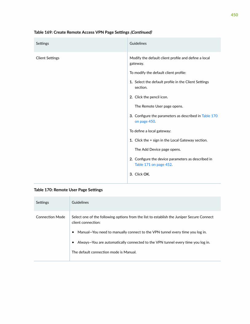
Table 169: Create Remote Access VPN Page Settings (Continued)
Settings Guidelines
Client Settings Modify the default client profile and define a localgateway.
To modify the default client profile:
1. Select the default profile in the Client Settingssection.
2. Click the pencil icon.
The Remote User page opens.
3. Configure the parameters as described in Table 170on page 450.
To define a local gateway:
1. Click the + sign in the Local Gateway section.
The Add Device page opens.
2. Configure the device parameters as described inTable 171 on page 452.
3. Click OK.
Table 170: Remote User Page Settings
Settings Guidelines
Connection Mode Select one of the following options from the list to establish the Juniper Secure Connectclient connection:
• Manual—You need to manually connect to the VPN tunnel every time you log in.
• Always—You are automatically connected to the VPN tunnel every time you log in.
The default connection mode is Manual.
450

Table 170: Remote User Page Settings (Continued)
Settings Guidelines
SSL VPN Enable this option to establish SSL VPN connection from the Juniper Secure ConnectClient to the SRX Series device.
This is a fallback option when IPsec ports are not reachable. By default,this option isenabled.
BiometricAuthentication
Enable this option to authenticate the client system using unique configured methods.
An authentication prompt is displayed when you connect in the client system. The VPNconnection will only be initiated after successful authentication through the methodconfigured for Windows Hello (fingerprint recognition, face recognition, PIN entry, and soon).
Windows Hello must be preconfigured on the client system if the Biometric authenticationoption is enabled.
Dead PeerDetection
Enable this option to allow the Juniper Secure Connect client to detect if the SRX Seriesdevice is reachable.
Disable this option to allow the Juniper Secure Connect client to detect till the SRX Seriesdevice connection reachability is restored.
This option is enabled by default.
DPD Mode Select a DPD Mode.
• Optimized: R-U-THERE messages are triggered if there is no incoming IKE or IPsectraffic within a configured interval after the device sends outgoing packets to the peer.This is the default mode.
• Probe Idle Tunnel: R-U-THERE messages are triggered if there is no incoming oroutgoing IKE or IPsec traffic within a configured interval. R-U-THERE messages are sentperiodically to the peer until there is traffic activity.
• Always-send: R-U-THERE messages are sent at configured intervals regardless of trafficactivity between the peers.
DPD Interval Select an interval in seconds to send dead peer detection messages.
The default interval is 10 seconds with a valid range of 2 to 60 seconds.
451

Table 170: Remote User Page Settings (Continued)
Settings Guidelines
DPD Threshold Select the failure DPD threshold value.
This specifies the maximum number of times the DPD messages must be sent when thereis no response from the peer. The default number of transmissions is 5 times with a validrange of 1 to 5.
Certificates The option to configure the security certificates.
• Expiry Warning—When enabled, you receive certificate expiration warning when thecertificate is about to expire. This option is enabled by default.
• Warning Interval—Enter the interval in days when you want the warning to bedisplayed.
• Pin Req Per Connection—When enabled, you must enter the certificate PIN for everyconnection. This option is enabled by default.
EAP-TLS The option to use the EAP-TLS authentication method to validate the security certificates.
This option is enabled by default.
Window logon Enable this option to provide users to securely log on to the Windows domain beforelogging on to the Windows system.
The client supports domain login using a credential service provider after establishing aVPN connection to the company network.
Table 171: Add Device Page Settings
Settings Guidelines
External Interface Select the outgoing interface for IKE security associations (SAs).
This interface is associated with a zone that acts as its carrier, providing firewall securityfor it.
452

Table 171: Add Device Page Settings (Continued)
Settings Guidelines
Tunnel Zone Select the tunnel zone.
Tunnel zones are logical areas of address space that can support dynamic IP (DIP) addresspools for NAT applications to pre- and post-encapsulated IPsec traffic. Tunnel zones alsoprovide flexibility in combining tunnel interfaces with VPN tunnels.
User Authentication Select the authentication profile from the list that will be used to authenticate a useraccessing the remote access VPN.
Click Add to create a new access profile.
NOTE: LDAP authentication is not supported in a remote VPN.
SSL VPN Profile Select an SSL VPN profile from the list to terminate the remote access connection.
To create a new SSL VPN profile:
1. Click Add.
The Add SSL VPN Profile page opens.
2. Enter the SSL VPN profile name.
3. Enable Logging option to log SSL VPN events.
4. Enter a SSL termination profile name.
5. Select a server certificate.
6. Click OK.
Certificate Select a certificate to authenticate the virtual private network (VPN) initiator andrecipient.
Trusted CA/Group Select the CA profile from the list to associate it with the local certificate.
This is applicable when authentication method is RSA-Signatures.
453

Table 171: Add Device Page Settings (Continued)
Settings Guidelines
Protected Networks Configure the addresses type for the selected device to protect one area of the networkfrom the other.
You can also create addresses by clicking Add New Address.
Table 172: View IKE/IPsec Settings
Settings Guidelines
IKE Settings
IKE Version Select the required IKE version, either V1 or V2, that is used to negotiate dynamicsecurity associations (SAs) for IPsec.
By default, IKE V2 is used.
Mode Select an IKE policy mode.
• Main—Uses six messages in three peer-to-peer exchanges to establish the IKE SA.These three steps include the IKE SA negotiation, a Diffie-Hellman exchange, andauthentication of the peer. This mode also provides identity protection.
• Aggressive—Takes half the number of messages of main mode, has less negotiationpower, and does not provide identity protection.
Mode is applicable when the IKE Version is V1.
Encryption Algorithm Select the appropriate encryption mechanism.
AuthenticationAlgorithm
Select an algorithm.
The device uses this algorithm to verify the authenticity and integrity of a packet.
Deffie Hellman group Select a group.
Diffie-Hellman (DH) groups determine the strength of the key used in the key exchangeprocess.
454

Table 172: View IKE/IPsec Settings (Continued)
Settings Guidelines
Lifetime Seconds Select a lifetime of an IKE security association (SA).
The valid range is from 180 to 86400 seconds.
Dead Peer Detection Enable this option to permit the two gateways to determine if the peer gateway is upand responding to the Dead Peer Detection (DPD) messages that are negotiated duringIPsec establishment.
DPD Mode Select a DPD Mode.
• Optimized: R-U-THERE messages are triggered if there is no incoming IKE or IPsectraffic within a configured interval after the device sends outgoing packets to thepeer. This is the default mode.
• Probe Idle Tunnel: R-U-THERE messages are triggered if there is no incoming oroutgoing IKE or IPsec traffic within a configured interval. R-U-THERE messages aresent periodically to the peer until there is traffic activity.
• Always-send: R-U-THERE messages are sent at configured intervals regardless oftraffic activity between the peers.
DPD Interval Select an interval in seconds to send dead peer detection messages.
The default interval is 10 seconds with a valid range of 2 to 60 seconds.
DPD Threshold Select the failure DPD threshold value.
This specifies the maximum number of times the DPD messages must be sent whenthere is no response from the peer. The default number of transmissions is 5 times witha valid range of 1 to 5.
Advance Settings
General IKE ID Enable this option to accept peer IKE ID
This option is disabled by default. If General IKE ID is enabled, the IKE ID option isdisabled automatically.
455

Table 172: View IKE/IPsec Settings (Continued)
Settings Guidelines
IKEv2 ReAuthentication
Select a reauthentication frequency. Reauthentication can be disabled by setting thereauthentication frequency to 0.
The valid range is 0 to 100.
IKEv2 ReFragmentationSupport
Enable this option to split a large IKEv2 message into a set of smaller ones so that thereis no fragmentation at the IP level.
IKEv2 Re-fragmentSize
Select the size of the packet at which messages are fragmented. By default, the size is576 bytes for IPv4.
The valid range is 570 to 1320.
IKE ID Select one of the following options:
• None
• Distinguished name
• Hostname
• IPv4 address
• E-mail Address
IKE ID is applicable only when General IKE ID is disabled.
NAT-T Enable Network Address Translation-Traversal (NAT-T) if the dynamic endpoint is behinda NAT device.
Keep Alive Select a period in seconds to keep the connection alive.
NAT Keepalives are required to maintain the NAT translation during the connectionbetween the VPN peers.
The valid range is from 1 to 300 seconds.
IPSec Settings
456

Table 172: View IKE/IPsec Settings (Continued)
Settings Guidelines
Protocol Select the required protocol to establish the VPN.
• ESP—The Encapsulating Security Payload (ESP) protocol provides both encryptionand authentication.
• AH—The Authentication Header (AH) protocol provides data integrity and dataauthentication.
Encryption Algorithm Select the encryption method.
This is applicable if the Protocol is ESP.
AuthenticationAlgorithm
Select an algorithm.
The device uses these algorithms to verify the authenticity and integrity of a packet.
Perfect ForwardSecrecy
Select Perfect Forward Secrecy (PFS) as the method that the device uses to generate theencryption key.
The PFS generates each new encryption key independently from the previous key. Thehigher numbered groups provide more security but require more processing time.
Establish Tunnel Select an option to specify when IKE is activated.
• Immediately—IKE is activated immediately after VPN configuration changes arecommitted.
• On-traffic—IKE is activated only when data traffic flows and must be negotiated withthe peer gateway. This is the default behavior.
Advance Settings
VPN Monitor Enable this option to send Internet Control Message Protocol (ICMP) to determine if theVPN is up.
457

Table 172: View IKE/IPsec Settings (Continued)
Settings Guidelines
Optimized Enable this option to optimize VPN monitoring and configure SRX Series devices to sendICMP echo requests, also called pings, only when there is outgoing traffic and noincoming traffic from the configured peer through the VPN tunnel.
If there is incoming traffic through the VPN tunnel, the SRX Series devices considers thetunnel to be active and do not send pings to the peer.
Anti Replay Enable this option for the IPsec mechanism to protect against a VPN attack that uses asequence of numbers that are built into the IPsec packet.
IPsec does not accept a packet for which it has already seen the same sequence number.It checks the sequence numbers and enforces the check rather than just ignoring thesequence numbers.
Disable this option if there is an error with the IPsec mechanism that results in out-of-order packets, preventing proper functionality.
By default, Anti-Replay detection is enabled.
Install interval Select the maximum number of seconds to allow for the installation of a re-keyedoutbound security association (SA) on the device.
Idle Time Select the appropriate idle time interval.
The sessions and their corresponding translations typically time out after a certainperiod if no traffic is received.
DF Bit Select an option to process the Don’t Fragment (DF) bit in IP messages.
• Clear—Disable the DF bit from the IP messages. This is the default option.
• Copy—Copy the DF bit to the IP messages.
• Set—Enable the DF bit in the IP messages.
458

Table 172: View IKE/IPsec Settings (Continued)
Settings Guidelines
Copy Outer DSCP Enable this option to allow copying of the Differentiated Services Code Point (DSCP)field from the outer IP header encrypted packet to the inner IP header plain textmessage on the decryption path.
The benefit in enabling this feature is that after IPsec decryption, clear text packets canfollow the inner class-of-service (CoS) rules.
Lifetime Seconds Select a lifetime of an IKE security association (SA).
The valid range is from 180 to 86400 seconds.
Lifetime Kilobytes Select the lifetime in kilobytes of an IPsec security association (SA).
The valid range is from 64 to 4294967294 kilobytes.
Importing IPsec VPNs
Juniper Security Director Cloud lets you import your existing large and complex VPN configurations intothe portal. You do not have to recreate the same VPN environment to allow Juniper Security DirectorCloud to manage it. During the VPN import operation, all VPN-related objects are also imported alongwith the VPN.
When you import a VPN, Juniper Security Director Cloud adds a new VPN to the VPN list with thename as ImportVPN_<number>.
At any point of the import workflow, you can choose to exit. All your settings and progress arediscarded.
1. Select SRX > IPsec VPN > IPsec VPNs.
The IPsec VPNs page opens.
2. Click Import.
The Import VPNs page opens.
3. Select the devices to import the VPNs.
You can select one or more devices from which the VPN configuration must be imported. The filteroption enables you to perform a free-text search on the device name.
459

Ensure that you select all the devices, otherwise the network topology discovery might vary and theimport of the VPN configuration might treat other devices as extranet devices.
NOTE: Hover your mouse cursor over Supported/unsupported items. The displayed list givesyou an idea about the VPN types and settings that Juniper Security Director Cloud supports,along with the settings that are not supported. Juniper Security Director Cloud displays theother settings that it does not support, but you can modify the features only using CLI.
4. Click Next.
The list of VPNs to be imported is displayed.
5. Click Finish.
A Job Status page opens displaying the details of the Import VPN job, such as the number of VPNs,the number of devices in each VPN, and the time stamp.
6. Click OK.
The imported VPNs are displayed on the IPsec VPN page and the corresponding VPN profiles are listedon the VPN Profiles page.
Deploying IPSec VPN
1. Select SRX > IPsec VPN > IPsec VPNs.
The IPsec VPNs page opens.
2. Select the VPN policy, and click Deploy.
The Deploy VPN page opens.
3. Select one of the following:
• Schedule at a later time to schedule and to publish the configuration later.
• Run now to apply the configuration immediately.
4. Click Update.
The Affected Devices page displays the devices where the policies will be published.
460

Modify IPsec VPN Settings
IN THIS SECTION
Modify Device Selection | 461
1. Select SRX > IPsec VPN > IPsec VPNs.
The IPsec VPNs page is displayed.
2. Select the IPsec VPN, and click the pencil icon.
Based on the VPN topology, the corresponding edit IPsec VPN page opens.
3. Edit the required fields, and click OK.
Follow the applicable configuration guidelines used while creating the IPsec VPN. You can also editthe tunnel settings on the device configuration page by clicking View/Edit Tunnels.
Modify Device Selection
1. Select SRX > IPsec VPN > IPsec VPNs.
The IPsec VPNs page opens.
2. Select an IPsec VPN, and click the pencil icon.
The Modify IPsec VPN page opens.
3. Click View/Select Devices.
4. Edit the device selection.
5. Click OK.
Deleting IPSec VPN
1. Select SRX > IPsec VPN > IPsec VPNs.
The IPsec VPNs page opens.
2. Select an IPSec VPN.
3. Click X to delete the IPSec VPN.
Juniper Security Directory Cloud displays a message to confirm the delete operation.
4. Click Yes to delete the selected IPSec VPN.
461

The IPSec VPN is deleted from the IPSec VPNs page.
A warning is displayed for confirmation on deleting the IPSec VPN from the device.
462

CHAPTER 22
IPsec VPN-VPN Profiles
IN THIS CHAPTER
VPN Profiles Overview | 463
VPN Profiles Main Page Fields | 464
Creating VPN Profiles | 464
Edit and Clone IPsec VPN profiles | 472
Assigning Policies and Profiles to Domains | 473
VPN Profiles Overview
You can use a VPN Profile Wizard to create an object that specifies the VPN proposals, mode of theVPN, and other parameters used in a route-based IPsec VPN. You can also configure the Phase 1 andPhase 2 settings in a VPN profile.
When a VPN profile is created, Juniper Security Director Cloud creates an object in the database torepresent the VPN profile. You can use this object to create route-based IPsec VPN.
NOTE: You cannot modify or delete Juniper Networks defined VPN profiles. You can only clonethe profiles and create new profiles.
SRX Series devices support preshared key and PKI certificate-based authentication methods in IKEnegotiation for IPsec VPNs. The RSA certificate and DSA certificate-based authentication are supportedfor IKE negotiation. The predefined VPN profile is available with both RSA and DSA certificates-basedauthentication. The PKI certificate list from the device is automatically retrieved during the devicediscovery and update-based syslog notifications.
463

VPN Profiles Main Page Fields
Use the VPN profiles main page to get an overall, high-level view of your VPN settings. You can filterand sort this information to get a better understanding of what you want to configure. Table 173 onpage 464 describes the fields on this page.
Table 173: VPN Profiles Main Page Fields
Field Description
Name The name of the VPN profile.
Description The description of the VPN profile.
Type A VPN profile type can be predefined or custom.
Juniper Security Director Cloud comes with predefined proposal sets for both Phase 1 andPhase 2 IKE negotiations. You can use these predefined sets or create your own.
Mode The Phase1 IKE negotiation mode (main or aggressive) is used to determine the type andnumber of message exchanges that occur in a phase.
Only one mode is used for negotiation, and the same mode must be configured on both sides ofthe tunnel.
VPN Topology The types of deployment topologies for IPsec VPN, such as site-to-site, hub-and-spoke, andremote access VPNs.
IPsec VPNs The IPsec VPNs involved in the VPN profile.
Created By The user who created the VPN profile.
Creating VPN Profiles
Configure VPN profiles that define security parameters when establishing a VPN connection. You canreuse the same profile to create more VPN tunnels. The VPN profile includes VPN proposals, VPNmode, authentication, and other parameters used in IPsec VPN. When a VPN profile is created, Juniper
464

Security Director Cloud creates an object in the database to represent the VPN profile. You can use thisobject to create route-based IPsec VPNs.
NOTE: You cannot modify or delete Juniper Networks-defined VPN profiles. You can only clonethe profiles and create new profiles.
You can also configure the IKE negotiation phases known as Phase 1 and Phase 2 settings in a VPNprofile. SRX Series devices support the following authentication methods in IKE negotiations for IPsecVPN:
• Preshared key
• ECDSA certificate
• RSA certificate
• DSA certificate
The predefined VPN profile is available for RSA certificates-based authentication. The PKI certificate listfrom the device is automatically retrieved during the device discovery.
Before You Begin
• Review the VPN profiles main page for an understanding of your current data set. See "VPN ProfilesMain Page Fields" on page 464 for the field descriptions.
• Read the "VPN Profiles Overview" on page 463 topic.
1. Select SRX > IPsec VPNs > VPN Profiles.
The VPN Profiles page opens.
2. Click Create to create a new VPN profile, and select one of the following options:
• Site to Site
• Hub and Spoke (Establishment All Peers)
• Hub and Spoke (Establishment by Spokes)
• Hub and Spoke (ADVPN - Auto Discovery VPN)
• Remote Access
3. Complete the configuration according to the guidelines provided in Table 174 on page 466 .
A new VPN profile with the predefined VPN configuration is created. You can use this object to createIPsec VPNs.
465

Table 174: VPN Profiles Settings
Setting Guideline
Name Enter a unique string of maximum 255 alphanumeric characters without spaces.
The string can contain colons, periods, dashes, and underscores.
Description Enter a description containing maximum 1024 character for the VPN profile.
Authentication Type Select the required authentication type:
• Pre-shared based
• RSA-Signatures
• DSA-Signatures
• ECDSA-Signatures-256
• ECDSA-Signatures-384
IKE Version Select the required IKE version, either V1 or V2, that is used to negotiate dynamicsecurity associations (SAs) for IPsec. By default, IKEv1 is used.
In Juniper Security Director Cloud, IKEv2 message fragmentation allows IKEv2 to operatein environments where IP fragments might be blocked and peers would not be able toestablish an IPsec security association (SA). IKEv2 fragmentation splits a large IKEv2message into a set of smaller ones so that there is no fragmentation at the IP level.
Mode Select a VPN mode:
• Main—The most common and secure way to establish a VPN when building site-to-site VPNs. The IKE identities are encrypted and cannot be determined byeavesdroppers.
• Aggressive—This is an alternative to main mode IPsec negotiation. This is the mostcommon mode when building VPNs from client workstations to VPN gateways, wherethe IP address of the client is neither known in advance nor fixed.
EncryptionAlgorithm
Select the appropriate encryption mechanism.
466

Table 174: VPN Profiles Settings (Continued)
Setting Guideline
AuthenticationAlgorithm
Select an algorithm. The device uses this algorithm to verify the authenticity and integrityof a packet.
Deffie HellmanGroup
Select a group.
Diffie-Hellman (DH) groups determine the strength of the key used in the key exchangeprocess.
Lifetime Seconds Select a lifetime of an IKE security association (SA).
The valid range is from 180 through 86400 seconds.
Dead PeerDetection
Enable this option to permit the two gateways to determine if the peer gateway is up andresponding to the Dead Peer Detection (DPD) messages that are negotiated during IPsecestablishment.
DPD Mode Select a DPD Mode.
• Optimized: R-U-THERE messages are triggered if there is no incoming IKE or IPsectraffic within a configured interval after the device sends outgoing packets to the peer.This is the default mode.
• Probe Idle Tunnel: R-U-THERE messages are triggered if there is no incoming oroutgoing IKE or IPsec traffic within a configured interval. R-U-THERE messages aresent periodically to the peer until there is traffic activity.
• Always-send: R-U-THERE messages are sent at configured intervals regardless oftraffic activity between the peers.
DPD Interval Select an interval in seconds to send dead peer detection messages.
The default interval is 10 seconds with a valid range of 2 to 60 seconds.
DPD Threshold Select the failure DPD threshold value.
This specifies the maximum number of times the DPD messages must be sent when thereis no response from the peer. The default number of transmissions is 5 times with a validrange of 1 to 5.
467

Table 174: VPN Profiles Settings (Continued)
Setting Guideline
Advance Settings
General-IkeID Enable this option to accept peer IKE ID in general.
This option is disabled by default. If General IKE ID is enabled, the IKE ID option isdisabled automatically.
• This option is not available in Aggressive VPN mode.
• You cannot use a VPN profile with the General IKE ID option enabled for the AutoVPN and ADVPN.
IKEv2 ReAuthentication
Select a reauthentication frequency. Reauthentication can be disabled by setting thereauthentication frequency to 0.
The valid range is 0 to 100.
IKEv2 ReFragmentationSupport
Enable this option to split a large IKEv2 message into a set of smaller ones so that there isno fragmentation at the IP level.
IKEv2 Re-fragmentSize
Select the size of the packet at which messages are fragmented.
By default, the size is 576 bytes for IPv4, and the valid range is 570 to 1320.
468

Table 174: VPN Profiles Settings (Continued)
Setting Guideline
IKE Id Configure the following IKE identifiers:
• Hostname—The hostname or FQDN is a string that identifies the end system.
• User@hostname—A simple string that follows the same format as an e-mail address.
User—Enter the e-mail address of the user. We recommend that you use a valid e-mailaddress of the user for ease of management.
• IPAddress—This is the most common form of IKE identity for site-to-site VPNs.
This can be either an IPv4 or IPv6 address. This option is available only if the VPNmode is Aggressive and the authentication type is Preshared Key.
• DN—The distinguished name used in certificates to identify a unique user in acertificate.
This option is available only for RSA, DSA, and ECDSA signature authentication types.
NOTE:
• For the Preshared Key authentication type:
• If you have enabled the General IKE ID option, the IKE ID option is automaticallyset to None and you cannot edit this option.
• When modifying an IPsec VPN, you cannot edit the IKE ID column in the View/Edit Tunnel page, if you have chosen a VPN profile with the General IKE ID optionenabled.
• For the certificate-based authentication type:
• You can edit the IKE ID option even if you have enabled the General IKE ID optionbecause, the local-identity CLI is used for certificate authentication.
• When modifying an IPsec VPN, you can edit the IKE ID column in the View/EditTunnel page, if you have chosen a VPN profile with the General IKE ID optionenabled.
NAT-T Enable Network Address Translation-Traversal (NAT-T) if the dynamic endpoint is behinda NAT device.
469

Table 174: VPN Profiles Settings (Continued)
Setting Guideline
Keep Alive Select a period in seconds to keep the connection alive.
NAT Keepalives are required to maintain the NAT translation during the connectionbetween the VPN peers. The valid range is from 1 to 300 seconds.
IPSec Settings
Protocol Select the required protocol to establish the VPN.
• ESP—The Encapsulating Security Payload (ESP) protocol provides both encryption andauthentication.
• AH—The Authentication Header (AH) protocol provides data integrity and dataauthentication.
EncryptionAlgorithm
Select the necessary encryption method.
This is applicable if the Protocol is ESP.
AuthenticationAlgorithm
Select an algorithm.
The device uses these algorithms to verify the authenticity and integrity of a packet.
Perfect ForwardSecrecy
Select Perfect Forward Secrecy (PFS) as the method that the device uses to generate theencryption key.
The PFS generates each new encryption key independently from the previous key. Thehigher numbered groups provide more security but require more processing time.
Establish Tunnel Select an option to specify when IKE is activated.
• Immediately—IKE is activated immediately after VPN configuration changes arecommitted.
• On-traffic—IKE is activated only when data traffic flows and must be negotiated withthe peer gateway. This is the default behavior.
Advance Settings
470

Table 174: VPN Profiles Settings (Continued)
Setting Guideline
VPN Monitor Enable this option to send Internet Control Message Protocol (ICMP) to determine if theVPN is up.
Optimized Enable this option to optimize VPN monitoring and configure SRX Series devices to sendICMP echo requests, also called pings, only when there is outgoing traffic and noincoming traffic from the configured peer through the VPN tunnel.
If there is incoming traffic through the VPN tunnel, the SRX Series devices considers thetunnel to be active and do not send pings to the peer.
Anti Replay Enable this option for the IPsec mechanism to protect against a VPN attack that uses asequence of numbers that are built into the IPsec packet.
IPsec does not accept a packet for which it has already seen the same sequence number.It checks the sequence numbers and enforces the check rather than just ignoring thesequence numbers.
Disable this option if there is an error with the IPsec mechanism that results in out-of-order packets, preventing proper functionality.
By default, Anti-Replay detection is enabled.
Install interval Select the maximum number of seconds to allow for the installation of a re-keyedoutbound security association (SA) on the device.
Idle Time Select the appropriate idle time interval.
The sessions and their corresponding translations typically time out after a certain periodif no traffic is received.
DF Bit Select an option to process the Don’t Fragment (DF) bit in IP messages.
• Clear—Disable the DF bit from the IP messages. This is the default option.
• Copy—Copy the DF bit to the IP messages.
• Set—Enable the DF bit in the IP messages.
471

Table 174: VPN Profiles Settings (Continued)
Setting Guideline
Copy Outer DSCP Enable this option to allow copying of the Differentiated Services Code Point (DSCP) fieldfrom the outer IP header encrypted packet to the inner IP header plain text message onthe decryption path.
The benefit in enabling this feature is that after IPsec decryption, clear text packets canfollow the inner class-of-service (CoS) rules.
Lifetime Seconds Select a lifetime of an IKE security association (SA).
The valid range is from 180 through 86400 seconds.
Lifetime Kilobytes Select the lifetime in kilobytes of an IPsec security association (SA).
The valid range is from 64 through 4294967294 kilobytes.
Edit and Clone IPsec VPN profiles
IN THIS SECTION
Edit a VPN Profile | 472
Clone IPsec VPN Profile | 473
You can edit or clone a custom IPsec VPN profile. When you edit or clone a VPN profile migrated froman earlier release, you need to select a VPN topology for the VPN profile.
NOTE: You cannot modify or delete Juniper Networks Predefined VPN profiles. You can onlyclone the profiles and create new profiles.
Edit a VPN Profile
1. Select SRX > IPsec VPNs > VPN Profiles.
472

The VPN Profiles page opens.
2. Select the IPsec VPN to edit, and click the pencil icon.
NOTE: Select a VPN topology while creating an IPsec VPN. When you edit a VPN profilemigrated from an earlier release, you’ll need to select a VPN topology for the VPN profile.
The edit window opens showing the same options as when creating a new VPN profile.
3. Click Save to save your changes.
Clone IPsec VPN Profile
1. Select SRX > IPsec VPNs > VPN Profiles.
The VPN Profiles page opens.
2. Right-click the VPN Profile to clone, and select Clone.
You can also select Clone from the More list.
The Clone window opens with editable fields.
3. Click OK to save your changes.
Assigning Policies and Profiles to Domains
You can assign or reassign policies or profiles to different domains when it is first configured andwhenever you want to implement a change.
You can assign only one policy or profile at a time. Before assigning a policy or profile to another domain,Juniper Security Director Cloud checks for the validity of the move. If the move is not acceptable, awarning message appears.
1. Select the landing page for the type of policy or profile to assign to a domain.
2. From the landing page, click More.
A list of actions opens.
3. Select Assign <Policy or Profile> to Domain.
The Assign <Policy or Profile> to Domain page opens.
NOTE: <Policy or Profile> is the name of the policy or profile that you are assigning to adomain.
4. Select the required items to assign to a domain.
473

5. Enable this option to ignore warning messages.
6. Click Assign.
A policy or profile is assigned to a domain.
474

CHAPTER 23
IPsec VPN-Extranet Devices
IN THIS CHAPTER
Creating Extranet Devices | 475
Extranet Devices Main Page Fields | 476
Find Usage for Extranet Devices | 477
Creating Extranet Devices
Use the Extranet devices page to manage the third-party devices that Juniper Security Director Clouddoes not directly control or manage.
Extranet devices can be ScreenOS devices or other vendor VPN-capable firewall devices that cannot bemanaged by Juniper Security Director Cloud. Extranet devices in the Juniper Security Director Cloudhelp users design and manage VPNs residing between SRX Series devices and third-party deviceswithout actually being connected to them.
To configure extranet devices:
Before You Begin
Review the Extranet Devices main page for an understanding of your current data set. See "ExtranetDevices Main Page Fields" on page 476 for the field descriptions
1. Select Security Subscriptions > VPNs > Extranet Devices.
The Exranet Devices page opens.
2. Click the plus sign to create a new extranet device.
Complete the configuration according to the guidelines provided in Table 175 on page 476.
475

Table 175: Create Extranet Device Page Settings
Setting Guideline
Name Enter a name containing maximum 63 characters that begins with an alphanumeric character
The name can include colons, periods, slashes, and underscores.
Description Enter a description containing maximum 1024 characters.
IP Address Enter the IPv4 address for the extranet device.
Hostname Enter a DNS resolvable name containing maximum 64 characters.
The hostname can include alphanumeric characters, dashes, and underscores.
This hostname is used to generate an IKE ID.
Created Displays the name of the user who created the extranet device.
3. Click OK to save.
Your changes are saved, a new extranet device is added to Juniper Security Director Cloud.
Extranet Devices Main Page Fields
Use extranet device objects to reference third-party devices that you do not have login or other devicecontrols over. Extranet devices are firewalls that Juniper Security Director Cloud does not directlycontrol and manage.
Table 176: Extranet Devices Main Page Fields
Field Description
Name The name of the extranet device.
Description The description of the extranet device.
476

Table 176: Extranet Devices Main Page Fields (Continued)
Field Description
Hostname The DNS resolvable name of the extranet device.
This hostname is used to generate IKE ID.
IP Address The IPv4 address of the device.
Created By The user who created the extranet device.
Domain Name The user domain for mapping objects and managing sections of a network.
Find Usage for Extranet Devices
In Juniper Security Director Cloud, you can find the usage of extranet devices in IPsec VPNs.
1. Select Security Subscriptions > VPNs > Extranet Devices.
The Exranet Devices page opens.
2. Right-click an extranet device, and select Find Usage.
The Search Results page opens with the IPsec VPN names where the extranet device is used.
If the extranet device is not used by any VPN, the search result will not display any IPsec VPNs.
477

CHAPTER 24
NAT-NAT Policies
IN THIS CHAPTER
NAT Policies Overview | 478
About the NAT Policies Page | 482
Create a NAT Policy | 483
Edit and Delete a NAT Policy | 484
About the NAT Policy Rules Page | 485
Create a NAT Policy Rule | 487
Edit, Clone, and Delete a NAT Policy Rule | 495
Common Operations on a NAT Policy Rule | 496
Deploy a NAT Policy | 498
NAT Policies Overview
Network Address Translation (NAT) is a form of network masquerading where you can hide devices orsites between zones or interfaces. A trusted zone is a segment of a network on which security measuresare applied. It is usually assigned to the internal LAN. An example of an untrusted zone is the internet.NAT modifies the IP addresses of the packets moving between the trusted and untrusted zones.
Whenever a packet exits a NAT device (when traversing from the internal LAN to the external WAN),the device performs a translation on the packet's IP address. The packet's IP address rewritten with an IPaddress that was specified for external use. After translation, the packet appears to have originated fromthe gateway rather than from the original device within the network. This process hides your internal IPaddresses from the other networks and keeps your network secure.
Using NAT also enables you to use more internal IP addresses. As these IP addresses are hidden, there isno risk of conflict with an IP address from a different network. This helps you conserve IP addresses.
Juniper Security Director Cloud supports configuring three types of NAT on the SRX devices:
• Source NAT—Translates the source IP address of a packet leaving a trust zone (outbound traffic). Ittranslates the traffic originating from the device in the trust zone. The source IP address of the traffic
478

(which is a private IP address), is translated to a public IP address that can be accessed by thedestination device specified in the NAT rule. The destination IP address is not translated.
The following uses cases show the support for source NAT translation between IPv6 and IPv4address domains:
• Translation from one IPv6 subnet to another IPv6 subnet without Network Address PortTranslation (NAPT), also known as Port Address Translation (PAT).
• Translation from IPv4 addresses to IPv6 prefixes along with IPv4 address translation.
• Translation from IPv6 hosts to IPv6 hosts with or without NAPT.
• Translation from IPv6 hosts to IPv4 hosts with or without NAPT.
• Translation from IPv4 hosts to IPv6 hosts with or without NAPT.
• Destination NAT—Translates the destination IP address of a packet. Using destination NAT, anexternal device can send packets to a hidden internal device. As an example, consider the case of awebserver behind a NAT device. Traffic to the WAN-facing public IP address (the destination IPaddress) is translated to the internal webserver private IP address.
The following uses cases show the support for destination NAT translation between IPv6 and IPv4address domains:
• Mapping of one IPv6 subnet to another IPv6 subnet
• Mapping between one IPv6 host and another IPv6 host
• Mapping of one IPv6 host (and optional port number) to another special IPv6 host (and optionalport number)
• Mapping of one IPv6 host (and optional port number) to another special IPv4 host (and optionalport number)
• Mapping of one IPv4 host (and optional port number) to another special IPv6 host (and optionalport number)
• Static NAT—Always translates a private IP address to the same public IP address. It translates trafficfrom both sides of the network (both source and destination). For example, a web-server with aprivate IP address can access the Internet using a static, one-to-one address translation. In this case,outgoing traffic from the web-server undergoes source NAT translation, and incoming traffic to theweb-server undergoes destination NAT translation.
The following uses cases show the support for static NAT translation between IPv6 and IPv4 addressdomains:
• Mapping of one IPv6 subnet to another IPv6 subnet.
479

• Mapping between one IPv6 host and another IPv6 host.
• Mapping between IPv4 address a.b.c.d and IPv6 address Prefix::a.b.c.d.
• Mapping between IPv4 hosts and IPv6 hosts.
• Mapping between IPv6 hosts and IPv4 hosts.
Juniper Security Director Cloud also supports configuring persistent NAT where address translations aremaintained in the database for a configurable amount of time after a session ends.
Table 177 on page 480 shows the persistent NAT support for different source NAT and destination NATaddresses.
Table 177: Persistent NAT Support
Source NAT Address Translated Address Destination NAT
Address
Persistent NAT Support
IPv4 IPv6 IPv4 No
IPv4 IPv6 IPv6 No
IPv6 IPv4 IPv4 Yes
IPv6 IPv6 IPv6 No
Table 178 on page 480 and Table 179 on page 481 show the translated address pool selection forsource NAT, destination NAT, and static NAT addresses.
Table 178: Translated Address Pool Selection for Source NAT
Source NAT Address Destination Address Pool Address
IPv4 IPv4 IPv4
IPv4 IPv6 - Subnet must be greater than96
IPv6
480

Table 178: Translated Address Pool Selection for Source NAT (Continued)
Source NAT Address Destination Address Pool Address
IPv6 IPv4 IPv4
IPv6 IPv6 IPv6
Table 179: Translated Address Pool Selection for Destination NAT and Static NAT
Source NAT Address Destination Address Pool Address
IPv4 IPv4 IPv4 or IPv6
IPv4 IPv6 - Subnet must be greater than96
IPv4 or IPv6
IPv6 IPv4 IPv4
IPv6 IPv6 IPv4 or IPv6
NOTE:
• For source NAT, the proxy Neighbor Discovery Protocol (NDP) is available for NAT pooladdresses. For the destination NAT and the static NAT, the proxy NDP is available fordestination NAT addresses.
• A NAT pool can have a single IPv6 subnet or multiple IPv6 hosts.
• You cannot configure the overflow pool if the address type is IPv6.
• NAT pools permit the address entries of only one version type: IPv4 or IPv6.
481

About the NAT Policies Page
IN THIS SECTION
Tasks You Can Perform | 482
Field Descriptions | 482
To access this page, select SRX > NAT > NAT Policies.
Use the NAT Policies page to create, modify, clone, and delete NAT policies and policy rules. You canfilter and sort this information to get a better understanding of what you want to configure.
Tasks You Can Perform
You can perform the following tasks from this page:
• Create a NAT policy. See "Create a NAT Policy" on page 483.
• Modify or delete a NAT policy. See "Edit and Delete a NAT Policy" on page 484.
• Create, modify, and delete NAT policy rules. See "About the NAT Policy Rules Page" on page 485.
• Search for a specific NAT policy. Click the Search icon in the top right corner of the page to searchfor a NAT policy.
You can enter partial text or full text of the keyword in the text box and press Enter.
The search results are displayed on the same page.
• Show or hide columns. Click the Show Hide Columns icon in the top right corner of the page.
Field Descriptions
Table 180 on page 483 provides guidelines on using the fields on the NAT Policies page.
482

Table 180: Fields on the NAT Policies Page
Field Description
Seq. Order number for the NAT policy.
Name Displays the name of the NAT policy.
Rules Number of rules assigned to the NAT policy.
Devices Device on which the NAT policy will be deployed.
Status Deployment status for the NAT policy.
Modified By The user who modified the policy.
Last Modified The date and time when the policy was modified.
Description Description of the NAT policy.
Create a NAT Policy
Use the Create NAT Policy page to create NAT policies.
To create a NAT policy:
1. Select SRX > NAT > NAT Policies.
The NAT Policies page appears.
2. Click the add icon (+).
The Create NAT Policy page displays fields required for creating and configuring a NAT policy.
3. Complete the configuration according to the guidelines provided in Table 181 on page 484.
4. Click OK to save the changes.
A NAT policy with the configuration you provided is created.
483

Table 181: Fields on the Create NAT Policy Page
Field Description
Name Enter a unique string of alphanumeric characters,colons, periods, dashes, and underscores. No spacesare allowed and the maximum length is 255characters.
Description Enter a description for the policy; the maximumlength is 255 characters.
Manage Auto-Proxy ARP Click the toggle button to respond to incomingAddress Resolution Protocol (ARP) requests. ARPtranslates IPv4 addresses to MAC addresses.
Select Devices Select the device on which you want to apply thepolicy in the Available column and move them to theSelected column by clicking the greater-than icon (>).
NOTE: The Available column lists only those devicesthat do not have a NAT policy associated with them.
Sequence No. Click Change Sequence Number. The Select PolicySequence page appears, displaying all NAT policies.Select the policy you want to reorder and selectMove Policy Up or Move Policy Down to reorderyour NAT policy among the existing policies.
Edit and Delete a NAT Policy
IN THIS SECTION
Edit a NAT Policy | 485
Delete a NAT Policy | 485
484

You can edit or delete a NAT policy from the NAT Policies page.
Edit a NAT Policy
To modify the parameters configured for a NAT Policy:
1. Select SRX > NAT > NAT Policies.
The NAT Policies page appears.
2. Select the NAT policy you want to edit, and then click on the edit icon (pencil symbol).
The Edit NAT Policy page appears, showing the same fields as those seen when you create a newNAT policy.
3. Modify the parameters according to the guidelines provided in "Create a NAT Policy" on page 483.
4. Click OK to save the changes.
The modified NAT policy is displayed in the NAT Policies page.
Delete a NAT Policy
To delete a NAT policy:
1. Select SRX > NAT > NAT Policies.
The NAT Policies page appears.
2. Select the NAT policy you want to delete and then click the delete icon.
An alert message appears, verifying that you want to delete your selection.
3. Click Yes to delete the selection.
The NAT policy is deleted.
NOTE: When the NAT policy is deleted, the NAT rules associated with the policy are deletedfrom device.
About the NAT Policy Rules Page
IN THIS SECTION
Tasks You Can Perform | 486
Field Descriptions | 486
485

To access this page, select SRX > NAT > NAT Policies. The NAT Policies page appears displaying allexisting NAT policies. Click on a NAT policy to view the rules associated with it.
The NAT policy rules page displays the NAT rules associated with the NAT policy and keep track of thenumber and order of rules for each policy. You can also create a new NAT rule, modify the configuredparameters of existing NAT rules, clone, and delete NAT rules, using this page.
Tasks You Can Perform
You can perform the following tasks from this page:
• Create a NAT rule. See "Create a NAT Policy Rule" on page 487.
• Update the sequence of the NAT rules using the up and down arrows that appear when you hoverover the NAT rule.
• Modify, clone, and delete NAT rules. See "Edit, Clone, and Delete a NAT Policy Rule" on page 495.
• Search for a specific NAT rule. Click the Search icon in the top right corner of the page to search for aNAT rule.
• Show or hide columns. Click the Show Hide Columns icon in the top right corner of the page.
Field Descriptions
Table 182 on page 486 provides information on the fields in the NAT rules contained within this NATpolicy.
Table 182: Fields on the NAT Policy Rules Page
Field Description
Seq. Order number for the NAT policy.
Rule Name NAT policy rule name.
Type Type of the NAT rule such as source, destination, orstatic.
Sources Displays the source endpoints on which the NATpolicy applies. A source endpoint can be zone,interface, routing instance, zone, addresses or ports.
486

Table 182: Fields on the NAT Policy Rules Page (Continued)
Field Description
Destinations Displays the destination endpoints on which the NATpolicy applies. A destination endpoint can be zone,interface, routing instance, zone, addresses or ports.
Services/Protocols Services and protocols to permit or deny for the sourceand destination type NAT rules.
Translation Displays the translation type applied on the incomingor outgoing traffic.
The Total Rules field on the top right corner of the page displays the total number of rules associatedwith the NAT policy. The Deploy pending field displays the deploy status of the rules associated withthe NAT policy.
Create a NAT Policy Rule
NAT processing centers on the evaluation of NAT rule sets and rules. A rule set determines the overalldirection of the traffic to be processed. After a rule set matches the traffic, each rule in the rule set isevaluated for a match. NAT rules can match on the following packet information:
• Source and destination address
• Source port (for source and static NAT only)
• Destination port
The first rule in the rule set that matches the traffic is used. If a packet matches a rule in a rule set duringsession establishment, traffic is processed according to the action specified by that rule.
To create NAT rule, click the NAT policy name. The NAT policy rules page appears, providing your withoptions to configure NAT rules. Alternately, you can click on the rule number listed under Rules againstthe policy, to create a rule. You can configure the following types of NAT rules:
• Static—To add a static NAT rule, click Create on the top right corner and select Static.
• Source—To add a source NAT rule, click Create on the top right corner and select Source.
487

• Destination—To add a destination NAT rule, click Create on the top right corner and selectDestination.
Depending on the type of rule you have chosen, some fields in the rule will not be applicable. In additionto defining rules between zones and interfaces, you can define NAT rules with virtual routers defined onthe device.
To create a NAT policy rule:
1. Select SRX > NAT > NAT Policies.
The NAT Policies page appears that shows the existing NAT policies.
2. Click the name of the NAT policy for which you want to create rules. Alternately, you can click AddRule link against a NAT policy.
The NAT policy rules page appears.
3. Click Create and select either Source, Static, or Destination. The page displays fields for creating aNAT rule.
4. Complete the configuration according to the guidelines provided in Table 183 on page 488.
5. Click OK to save the changes.
A NAT rule with the configuration you provided is created.
Table 183 on page 488 provides guidelines on using the fields on the NAT Policies page.
Table 183: Fields on the NAT Policies Page for Creating NAT Rules
Field Description
Rule Name Enter a unique string beginning with a number orletter and consisting of letters, numbers, dashes andunderscores. The maximum length is 31 characters.
Description Enter a description for the policy rule that must be astring excluding '&', '<', '>' and '\n'. The maximumlength is 900 characters.
Sources Click the add icon (+) to select the source endpointson which the NAT policy rule applies, from thedisplayed list of Source Ingress Type, Source zones,Source addresses, Soure port/port range.
488

Table 183: Fields on the NAT Policies Page for Creating NAT Rules (Continued)
Field Description
Source Ingress Type a. Select an ingress type: Zone, Interface, or RoutingInstance.
b. From the appropriate selector, select the zones,interfaces, or routing instance that you want toassociate the rule to, from the Available column.
NOTE: For the Routing Instance option, you canselect one or more of the available virtual routerson the device. For the group NAT policy, you willsee a consolidated list of all virtual routers on alldevices that the policy is assigned to.
c. Click OK.
Source Addresses Enter one or more address names or address setnames.
• Any—Add any address to the NAT rule.
• Specific—Select the check box beside eachaddress you want to include in the address group.Click the greater-than icon (>) to move theselected address or addresses from the Availablecolumn to the Selected column. Note that youcan use the fields at the top of each column tosearch for addresses. .
Source Ports/Port Range Enter a maximum of eight ports and port rangesseparated by commas.
489

Table 183: Fields on the NAT Policies Page for Creating NAT Rules (Continued)
Field Description
Destinations Click the add icon (+) to select the destinationendpoints on which the NAT policy rule applies, fromthe displayed list of Destination Ingress Type,Destination zones, Destination addresses,Destination ports/port range.
NOTE: When you create a destination NAT rule fortraffic arriving on an interface that terminates a VPNlink, the translation process might break the VPNlink. This will happen if the destination address in adestination NAT rule is specified only as the WAN-facing IP address of that interface. For example, inthe following NAT rule, any traffic destined to WANIP will get translated to the destination pool and willbreak functionality of the VPN link packetsterminating on this interface.
[Any.Address] --> [Wan.IP] :: [Dest-Pool-1]
Therefore, the recommendation in such cases is touse a destination NAT rule with destination field as[Address + Port]. For example:
[Any.Address] --> [Wan.IP + Port] :: [Dest-Pool-1]
Destination Addresses Enter one or more address names or address setnames.
• Any—Add any address to the NAT rule.
• Specific—Select the check box beside eachaddress you want to include in the address group.Click the greater-than icon (>) to move theselected address or addresses from the Availablecolumn to the Selected column. Note that youcan use the fields at the top of each column tosearch for addresses. .
Destination Ports/Port Range Enter a maximum of eight ports and port rangesseparated by commas.
490

Table 183: Fields on the NAT Policies Page for Creating NAT Rules (Continued)
Field Description
Service/Protocols Choose one among the following for a NAT rule:
• None—Select this option if you do not want toset any service or protocols in source ordestination NAT.
• Services—Select one or more services from theAvailable list to permit or deny traffic.
• Protocols—Select the protocols from theAvailable list to permit or deny traffic.
491

Table 183: Fields on the NAT Policies Page for Creating NAT Rules (Continued)
Field Description
Translation Specify the translation type for the incoming traffic.The translation options vary based on whether youare creating a source, static, or destination NAT rule.
Chose one among the following translation types fora source NAT rule:
• None—No translation is required for the incomingtraffic.
• Interface—Performs interface-based translationson the source or the destination packet.
• Pool—Performs pool-based translations on thesource or the destination packet. Click on the addicon (+) in the Select Pool field to choose thetranslation pool.
You can also create a new pool by clicking Addnew pool. See "Create a NAT Pool" on page 500.
Chose one among the following translation types fora static NAT rule:
• Address—Performs address-based translations onthe source or the destination packet. Click on theadd icon (+) in the Select Address field to choosethe translation address.
• Corresponding IPv4—Uses the correspondingIPv4 address to perform translations on thesource or the destination packet.
Chose one among the following translation types fora destination NAT rule:
• None—Translation is not required for theincoming traffic.
• Pool—Performs pool-based translations on thesource or the destination packet. Click on the add
492

Table 183: Fields on the NAT Policies Page for Creating NAT Rules (Continued)
Field Description
icon (+) in the Select Pool field to choose thetranslation pool.
You can also create a new pool by clicking Addnew pool. See "Create a NAT Pool" on page 500.
Table 184 on page 493 provides guidelines on using the fields on the Advanced Settings page for asource NAT rule.
Table 184: Fields on the Advanced Settings Page for Source NAT Rule
Field Description
Persistent Click the toggle button to ensure that all requestsfrom the same internal transport address are mappedto the same reflexive transport address.
NOTE: For persistence to be applicable for the NATpolicy, ensure that port overloading is turned off forthe device to which the NAT policy is applicable. Usethe following command to turn off port overloadingfor a device:
[Edit mode]set security nat source interface port-overloading off
493

Table 184: Fields on the Advanced Settings Page for Source NAT Rule (Continued)
Field Description
Persistent NAT Type Configure persistent NAT mappings.
• Permit any remote host— Any external host cansend a packet to the internal host by sending thepacket to the reflexive transport address.
• Permit target host—An external host can send apacket to an internal host by sending the packetto the reflexive transport address. The internalhost must have previously sent a packet to theexternal host's IP address.
• Permit target host port—An external host cansend a packet to an internal host by sending thepacket to the reflexive transport address. Theinternal host must have previously sent a packetto the external host's IP address and port.
Inactivity Timeout The amount of time, in seconds, that the persistentNAT binding remains in the site's memory when allthe sessions of the binding entry have ended. Whenthe configured timeout occurs, the binding isremoved from memory. The value of the inactivitytimeout can range from 60 through 7200 seconds.The default value of the inactivity timeout is 60seconds.
Maximum Session Number Maximum session number—The maximum number ofsessions with which a persistent NAT binding can beassociated. For example, if the maximum sessionnumber of the persistent NAT rule is 65,536, then a65,537th session cannot be established if thatsession uses the persistent NAT binding created fromthe persistent NAT rule.
The range is 8 through 65,536. The default is 30sessions.
Address Mapping Click the toggle button to enable or disable theaddress mapping.
494

Table 185 on page 495 provides guidelines on using the fields on the Advanced Settings page for astatic NAT rule.
Table 185: Fields on the Advanced Settings Page for Static NAT Rule
Field Description
Mapped Port Type Specify the type of port mapping:
• Port—Enter a value for Port, ranging from 0through 65,535.
• Range—Enter the port range values in the Startand End fields, ranging from 0 through 65,535.
Routing Instance Select the routing instance for the static NAT rule.
Edit, Clone, and Delete a NAT Policy Rule
IN THIS SECTION
Edit a NAT Policy Rule | 495
Clone a NAT Policy Rule | 496
Delete a NAT Policy Rule | 496
You can edit, clone, or delete a NAT policy rule from the NAT Policy page.
Edit a NAT Policy Rule
To modify the parameters configured for an NAT policy rule:
1. Select SRX > NAT > NAT Policies.
The NAT Policies page appears, displaying the NAT policies.
2. Click the NAT policy for which you want to edit the NAT policy rules.
The selected NAT Policy appears, displaying the rules associated with the NAT policy.
495

3. Click the pencil icon that appears on the right side of the rule.
The NAT Policy page displays the same options as those that appear when you create a new NATpolicy rule.
4. Modify the parameters following the guidelines provided in "Create a NAT Policy Rule" on page 487.
5. Click OK to save the changes.
The modified NAT policy rule appears on the NAT Policy page.
Clone a NAT Policy Rule
To clone a NAT policy rule:
1. Select SRX > NAT > NAT Policies.
The NAT Policies page appears, displaying the NAT policies.
2. Click the NAT policy for which you want to clone the NAT policy rules.
The selected NAT Policy appears, displaying the rules associated with the NAT policy.
3. Right-click and select Clone.
The NAT Policy page displays the same options as those that appear when you create a new NATpolicy rule. Update the cloned rule as required.
4. Click Save to save the changes.
The modified rule appears on the NAT Policy page
Delete a NAT Policy Rule
To delete a NAT policy rule:
1. Select SRX > NAT > NAT Policies.
The NAT Policies page appears, displaying the NAT policies.
2. Select the NAT policy whose rule you want to delete.
The selected NAT Policy appears, displaying the rules associated with the NAT policy.
3. Hover over the NAT policy rule you want to delete and then click the delete icon (X) .
An alert message appears, verifying that you want to delete your selection.
4. Click Yes to delete the selection.
The selected NAT policy rule is deleted.
Common Operations on a NAT Policy Rule
You can perform common operations on a NAT policy rule from the NAT Policy page.
To perform common operations on a NAT policy rule:
496

1. Select SRX > NAT > NAT Policies.
The NAT Policies page appears, displaying the NAT policies.
2. Click the NAT policy rule and click More.
The dropdown menu shows common operations for a NAT rule.
3. Complete the configuration according to the guidelines provided in the following table.
Table 186: Common Operatons on NAT Policy Rules Page
Field Description
Add Rule Before Add a rule before an existing rule.
Add Rule After Add a rule after an existing rule.
Copy Copy an existing rule to paste at different order.
Cut Cut an existing rule to paste at different order.
Paste Before—Paste the rule before an existing rule.
After—Paste the rule after and existing rule.
Clone Create a copy of an existing rule.
Enable Enable the rule.
Disable Disable the rule.
Move Move the rule by selecting one of the followingoptions:
• Move Top
• Move Up
• Move Down
• Move Bottom
497

Table 186: Common Operatons on NAT Policy Rules Page (Continued)
Field Description
Clear All Selections Clear the sections for the rules.
Deploy a NAT Policy
After adding the rules to the NAT policies, you can deploy the NAT policy by clicking the Deploy optionthat is above the End Points panel. You can also deploy one or more policies from the NAT Policies page.
To deploy NAT policies:
1. Select SRX > NAT > NAT Pools.
The NAT Policies page appears.
2. Select one or more policies and click Deploy.
The Deploy page appears.
3. In Deployment Time options, select Run Now to deploy the policy immediately. Select Schedule at alater time and specify the date and time at which the policy should be deployed.
4. Click OK.
A job is created. Click the job ID to go to the Jobs page and view the status of the deploy operation.
498

CHAPTER 25
NAT-NAT Pools
IN THIS CHAPTER
NAT Pools Overview | 499
About the NAT Pools Page | 499
Create a NAT Pool | 500
Edit, Clone, and Delete a NAT Pool | 504
NAT Pools Overview
A NAT pool is a set of IP addresses that you can define and use for address translation. NAT policiesperform address translation by translating internal IP addresses to the addresses in these pools. Unlikestatic NAT, where there is a one-to-one mapping that includes destination IP address translation in onedirection and source IP address translation in the reverse direction, with source NAT, you translate theoriginal source IP address to an IP address in the address pool. With destination NAT, you translate theoriginal destination address to an IP address in the address pool.
About the NAT Pools Page
IN THIS SECTION
Tasks You Can Perform | 500
To access this page, select SRX > NAT > NAT Pools.Use the NAT Pools page to create, modify, clone, and delete NAT pools. You can filter and sort thisinformation to get a better understanding of what you want to configure.
499

Tasks You Can Perform
You can perform the following tasks from this page:
• Create a NAT pool. See "Create a NAT Pool" on page 500.
• Modify, clone, or delete a NAT pool. See "Edit, Clone, and Delete a NAT Pool" on page 504.
• View the details of a NAT pool by selecting More > Detailed View, or by right-clicking a NAT pooland select Detailed View.
• Search for a specific NAT pool. Click the Search icon in the top right corner of the page to search fora NAT pool. You can enter partial text or full text of the keyword in the text box and press Enter.
The search results are displayed on the same page.
• Show or hide columns. Click the Show Hide Columns icon at the top right corner of the page.
Table 187 on page 500 provides description of the fields on the NAT Pools page.
Table 187: Fields on the NAT Pools Page
Field Description
Name Displays the name of the NAT pool.
Pool Type Displays the NAT pool type. A NAT pool can be oftype Source or Destination.
Pool Address Displays the IP address of the NAT pool.
Description Displays the description provided about the NAT poolwhen it was created.
Create a NAT Pool
Use the Create NAT Pool page to create NAT pools.
To create a NAT pool:
1. Select SRX > NAT > NAT Pools.
500

The NAT Pools page appears.
2. Click the add icon (+).
The Create NAT Pool
3. Complete the configuration according to the guidelines provided in Table 188 on page 501.
4. Click OK to save the changes. A NAT pool is available with the configuration you provided.
Table 188 on page 501 provides guidelines on using the fields on the Create NAT Pool page.
Table 188: Fields on the Create NAT Pool Page
Field Description
General Information
Name Enter a unique string of alphanumeric characters,dashes, spaces, and underscores. Colons and periodsare not allowed. The maximum length is 31characters.
Description Enter a description string excluding '&', '<', '>' and '\n'characters. The maximum length is 900 characters.
Pool Type Select a NAT pool type to configure:
• Source
• Destination
Pool Address Select a NAT pool address or click Add new addressto create a NAT pool address.
Routing Instance
Devices Select the devices to which the NAT pool isapplicable.
Routing Instance Select the required routing instance from the list ofavailable routing instances for the selected device.
501

Table 188: Fields on the Create NAT Pool Page (Continued)
Field Description
Port Enter the destination port number that is used forport forwarding. The value of the port can be anyvalue between 1024 to 65535.
Advanced
Pool Translation Select the translation type for the incoming traffic:
• No Translation—No translation required for theincoming traffic.
• Port/Range—Set the global default single portrange for source NAT pools with port translation.
• Overload—Multiple source addresses aretranslated to pool addresses. If you set Overloadas the translation type, the value of the PoolAddress field cannot be an IP range or subnet,but it will be a single address.
Host Address Base Enter the base address of the original source IPaddress range. The Host Address Base is used for IPaddress shifting.
Address Pooling Select a NAT address pooling behavior:
• Paired—Use this option for applications thatrequire all sessions associated with one internalIP address to be translated to the same externalIP address for multiple sessions.
• Non-Paired—Use this option for applications thatcan be assigned IP addresses in a round-robinfashion.
502

Table 188: Fields on the Create NAT Pool Page (Continued)
Field Description
Port overloading factor Enter the port overloading capacity in source NAT.The value can be any value between 2 to 32. If theport-overloading-factor is set to x, each translated IPaddress will have x number of ports available.
Address Sharing Enable address sharing so that multiple internal IPaddresses can be mapped to the same external IPaddress. Select this option only when the sourceNAT pool is configured with no port translation.When a source NAT pool has only one or a fewexternal IP addresses available, the address sharingoption with a many-to-one address mappingincreases NAT resources and improves traffic.
Port Enter the port number for the NAT pools. The valueof the port can be any value between 1024 to65535.
Start Enter the start port value for the source NAT pools.The value of the port range can be any valuebetween 1024 to 65535.
End Enter the end port value for the source NAT pools.The value of the port range can be any valuebetween 1024 to 65535.
503

Table 188: Fields on the Create NAT Pool Page (Continued)
Field Description
Overflow Pool Type Select a source pool to use when the current addresspool is exhausted.
• Interface—Allow the egress interface IP addressto support overflow.
• Pool—Name of the source address pool.
• Overflow Pool—When addresses from theoriginal source NAT pool are exhausted, IPaddresses and port numbers are allocated fromthe overflow pool. A user-defined source NATpool or an egress interface can be used as theoverflow pool. When the overflow pool is used,the pool ID is returned with the address.
Edit, Clone, and Delete a NAT Pool
IN THIS SECTION
Edit a NAT Pool | 504
Clone a NAT Pool | 505
Delete a NAT Pool | 505
Edit a NAT Pool
To modify the parameters configured for a NAT pool:
1. Select SRX > NAT > NAT Pools.
The NAT Pools page appears.
2. Select the NAT pool that you want to edit, and click the edit icon (pencil symbol).
The Edit NAT Pool page appears, displaying the same options that are displayed when creating a newNAT pool.
504

3. Modify the parameters according to the guidelines provided in "Create a NAT Pool" on page 500.
4. Click OK to save the changes.
Clone a NAT Pool
To clone a NAT pool:
1. Select SRX > NAT > NAT Pools.
The NAT Pools page appears.
2. Right-click the NAT pool that you want to clone and then click Clone, or select More > Clone.
The Clone NAT Pool page appears with editable fields. Modify the parameters of the cloned NATpool as per your requirements.
3. Click OK to save the changes.
The cloned NAT pool appears at the end of the NAT pools list in the NAT Pools page.
Delete a NAT Pool
To delete a NAT pool:
1. Select SRX > NAT > NAT Pools.
The NAT Pools page appears.
2. Select the NAT pool you want to delete and then click the delete icon.
An alert message appears, verifying that you want to delete the NAT pool.
3. Click Yes to delete the NAT pool.
505

CHAPTER 26
Identity-JIMS
IN THIS CHAPTER
Juniper Identity Management Service Overview | 506
About the Identity Management Profile Page | 508
Create Identity Management Profiles | 509
Edit, Clone, and Delete Identity Management Profiles | 512
Deploy the Identity Management Profile to SRX Series Devices | 514
Juniper Identity Management Service Overview
Juniper Identity Management Service (JIMS) is a standalone Windows service application that collectsand maintains a large database of user, device, and group information from Active Directory domains.JIMS collects advanced user identities from different authentication sources for SRX Series devices.JIMS enables the device to rapidly identify thousands of users in a large, distributed enterprise.
Juniper Security Director Cloud is used to push the JIMS configuration to SRX Series devices. You cancreate an identity management profile in Juniper Security Director Cloud and deploy the identity
506

management profile to SRX series devices. Based on the deployed identity management profile, the SRXSeries devices query the JIMS server to obtain required information.
Figure 9: Juniper Security Director Cloud, SRX, and JIMS Connectivity
SRX Series devices communicate with JIMS through HTTP or HTTPS connection. Use HTTP connectionfor debugging and HTTPS for deployments. SRX Series devices consist of primary and secondary JIMSconfigurations. These devices must always query the primary JIMS. The secondary JIMS is available as afall back option with limited resources. You must use the secondary JIMS when the HTTP GET query ornumber of queries to the primary JIMS fails. SRX Series devices constantly scrutinize the failed primaryJIMS and revert to the primary JIMS, once it is up and running.
NOTE:
• Juniper Security Director Cloud does not directly communicate with JIMS server. SRX seriesdevices query the JIMS server to obtain the user identity information. For more informationabout different query modes, see Understanding Advanced Query Feature for Obtaining UserIdentity Information from JIMS and Configuring Advanced Query Feature for Obtaining UserIdentity Information from JIMS.
• SRX firewall authentication can also push the authentication entries to JIMS.
• IP and user mapping information might be inaccurate, if the user identities in JIMS arecleared, delayed, or missing.
507

About the Identity Management Profile Page
IN THIS SECTION
Tasks You Can Perform | 508
Field Descriptions | 508
To access this page, click SRX > Identity > JIMS.Use the Identity Management Profile page to obtain advanced user identity from differentauthentication sources for SRX Series devices.
Tasks You Can Perform
You can perform the following tasks from this page:
• Create the identity management profile. See "Create Identity Management Profiles" on page 509.
• Edit, clone, and delete an existing identity management profile. See "Edit, Clone, and Delete IdentityManagement Profiles" on page 512.
• Deploy the identity management profile. See "Deploy the Identity Management Profile to SRX SeriesDevices" on page 514.
Field Descriptions
Table 189 on page 508 provides guidelines on using the fields on the Identity Management Profilepage.
Table 189: Fields on the Identity Management Profile Page
Field Description
Name Specifies the name of the identity management profile.
Description Specifies the description for the identity management profile.
Primary JIMS Server Specifies the IP address of the primary Juniper Identity Management System (JIMS) server.
508

Table 189: Fields on the Identity Management Profile Page (Continued)
Field Description
Devices Specifies the name of a SRX Series device.
Create Identity Management Profiles
Use the Create Identity Management Profile page to create a JIMS profile and to obtain user identities.
To create an identity management profile:
1. Select SRX > Identity > JIMS.
The Identity Management Profile page appears.
2. Click the + sign.
The Create Identity Management Profile page appears.
3. Complete the configuration by using the guidelines in Table 190 on page 509.
4. Click OK.
Table 190: Fields on the Create Identity Management Profile Page
Field Description
General
Name Enter a unique string that begins with alphanumeric characters. You can use colons,periods, dashes, and underscores. The maximum length is 62 characters.
Description Enter a description for the identity management profile. The maximum length is 255characters.
Primary JIMSserver
Enter a valid IPv4 address of the primary JIMS server.
SRX Series devices always query the primary JIMS to obtain the user identities.
509

Table 190: Fields on the Create Identity Management Profile Page (Continued)
Field Description
Primary CAcertificate path
Enter the certificate path of the primary JIMS server. The SRX Series device uses thiscertificate to verify the certificate of the JIMS server for the SSL connection that is usedfor the user query function. For example: ’/var/tmp/RADIUSServerCertificate.crt’
When SRX Series device does not receive the information from JIMS through the Web APIPOST requests, user query enables the SRX Series device to query JIMS for authenticationand identity information for an individual user.
Secondary Identity Enable this option to use the secondary JIMS server as a fallback when the primary JIMSserver fails. By default, this option is disabled.
Secondary JIMSserver
Enter a valid IPv4 address of the secondary JIMS server.
The secondary JIMS is available as a fall back option with limited resources. Use thesecondary JIMS when the HTTP GET or number of queries to the primary JIMS fails.
Secondary JIMScertificate path
Enter the certificate path of the secondary JIMS server. The SRX Series device uses thiscertificate to verify the JIMS server certificate for the SSL connection, used for the userquery function.
Assign Devices—Add Devices
Device Name Select the SRX Series device from the list for JIMS to send the report on user identities.
Client ID Enter the client ID that the SRX Series device requires to obtain an access token for theJIMS user query function. The client ID must be consistent with the API client configuredon JIMS.
Secret Key Enter the client secret used with the client ID that the SRX Series device requires to obtainan access token. The client secret must be consistent with the API client configured onJIMS.
NOTE: If you delete the assigned device, the JIMS profile configuration is removed from the device. If you addany new device the JIMS profile configuration is assigned to the new device.
Connection Settings
510

Table 190: Fields on the Create Identity Management Profile Page (Continued)
Field Description
Connection Type Select the application protocol from the list to connect the SRX Series device to JIMS foruser query request. You identify the connection protocol along with the configuration thatidentifies JIMS. The user query function allows the SRX Series device to request userauthentication and identity information for an individual user from JIMS.
• HTTP—Protocol that JIMS uses to connect to the SRX Series device.
• HTTPS—Secure version of the protocol that JIMS uses to connect to the SRX Seriesdevice.
If you do not select the connection type, HTTPS is used by default.
Port Select the connection port of the JIMS server, from the list. Default port number is 443.The range is 1 to 65535.
Token API Enter the token API used to generate the URL to acquire an access token. The token API iscombined with the connection method and the IP address of JIMS to produce the completeURL used to acquire an access token.
For example, if the token API is oauth, the connection method is HTTPS, and the IPaddress of JIMS is 192.0.2.199, the complete URL to acquire an access token would behttps://192.0.2.199/api/oauth.
The default token API is oauth_token/oauth.
Query API Enter the query API to specify the path of the URL that the SRX Series device uses toquery JIMS for an individual user. For the SRX Series device to be able to make a request,you must have configured the query API to obtain an access token.
The SRX Series device generates the complete URL for the user query request bycombining the query API string with the connection method (HTTP/HTTPS) and the JIMSIP address.
The default token API is user_query/v2.
Advanced
Maximum itemsper batch
Enter the value for maximum number of reports to include in the JIMS response.
Range: 100 through 1000.
511

Table 190: Fields on the Create Identity Management Profile Page (Continued)
Field Description
Query interval Enter the time interval, in seconds, for SRX Series devices to periodically query JIMS forthe newly generated user identities.
Range: 1 through 60 seconds.
Query delay time Enter the time in seconds for the SRX Series device to delay before sending the individualIP queries to JIMS for authentication and identity information for individual users.
After the delay timeout expires, the SRX Series device performs the following actions:
• Sends the query to JIMS.
• Creates a pending entry for the user in the Routing Engine authentication table.
Range: 1 through 60 seconds
Invalid timeout Enter the timeout interval (in minutes) after which, the idle entries in the JIMSauthentication table expire. The timeout interval begins from when the user authenticationentry is added to the authentication table. This value can be between 10 and 1440minutes, where a value of 0 means no timeout.
IP query Click the toggle button to disable the IP address query function that is enabled by default.
Filter for domain The SRX Series device sends a query to JIMS for the user identity information within thespecified domains. Enter a comma-separated list of up to 25 domain names. A domainname can be an alphanumeric string of up to 64 characters that can also contain dashes,underscores, and dots.
Example: example.net
Edit, Clone, and Delete Identity Management Profiles
IN THIS SECTION
Edit Identity Management Profiles | 513
512

Clone Identity Management Profiles | 513
Delete Identity Management Profiles | 514
You can edit, clone, and delete the identity management profiles from the Identity Management Profilespage. You can clone an identity management profile to easily create an identity management profile. Youcan delete the unused identity management profiles.
Edit Identity Management Profiles
To edit an identity management profile:
1. Select SRX > Identity > JIMS.
The Identity Management Profile page appears.
2. Select the identity management profile that you want to edit, and click the pencil icon.
The Edit Identity Management Profile page appears, showing the same fields that are displayed whenyou create an identity management profile.
3. Edit the identity management profile fields as needed.
The changes are saved and you are returned to the Identity Management Profile page.
Clone Identity Management Profiles
To clone an identity management profile:
1. Select SRX > Identity > JIMS.
The Identity Management Profile page appears.
2. Select the identity management profile that you want to clone, and select Clone from the More list orright-click menu.
The Clone Identity Management Profile page appears, showing the same fields for creating anidentity management profile.
3. Modify the identity management profile fields as needed.
4. Click OK to save the changes.
The cloned identity management profile is created and you are returned to the Identity ManagementProfile page.
513

Delete Identity Management Profiles
NOTE: If you delete an identity management profile, it is deleted from the assigned devices aswell.
To delete one or more identity management profiles:
1. Select SRX > Identity > JIMS.
The Identity Management Profile page appears.
2. Select the identity management profile that you want to delete, and click the Delete.
A warning dialog box appears asking you to confirm the deletion.
3. Click Yes to delete the selected identity management profiles.
The identity management profiles are deleted and you are returned to the Identity ManagementProfile page.
Deploy the Identity Management Profile to SRX Series Devices
To deploy the identity management profiles to SRX Series devices:
1. Select SRX > Identity > JIMS.
The Identity Management Profile page appears.
2. Select the identity management profile that you want to deploy, and click Deploy.
The deploy status message page appears showing the link for job IDs.
3. Click the job ID to see the deploy status.
4. (Optional) Select Administration>Jobs and click the job name link to see the deploy status.
RELATED DOCUMENTATION
About the Identity Management Profile Page | 508
Create Identity Management Profiles | 509
Edit, Clone, and Delete Identity Management Profiles | 512
514

CHAPTER 27
Identity-Active Directory
IN THIS CHAPTER
About the Active Directory Profile Page | 515
Create an Active Directory Profile | 516
Deploy an Active Directory Profile to SRX Series Devices | 521
Edit, Clone, and Delete an Active Directory Profile | 522
About the Active Directory Profile Page
IN THIS SECTION
Tasks You can Perform | 515
Field Descriptions | 516
Active Directory configuration is used by the SRX series devices to contact the Active Directory server.Active Directory enables you to configure the IP address-to-user mapping information and the user-to-group mapping information to access the LDAP server. You can view, create, modify, clone, and deleteActive Directory profile. You can deploy Active Directory profiles on one or more SRX series devices.
To access this page, click SRX > Identity > Active Directory.
Tasks You can Perform
You can perform the following tasks from this page:
• Create an Active Directory profile. See "Create an Active Directory Profile" on page 516.
• Modify or delete an existing Active Directory profile. See "Edit, Clone, and Delete an ActiveDirectory Profile" on page 522.
515

• Deploy the Active Directory profile to SRX Series devices. See "Deploy an Active Directory Profile toSRX Series Devices" on page 521.
Field Descriptions
Table 191 on page 516 provides guidelines on using the fields on the Active Directory page.
Table 191: Fields on the Active Directory Profile Page
Field Description
Name Specifies the name of the Active Directory.
Active Directory Domains Specifies the domain for which the status is displayed.
Example: Global
Devices Lists the assigned devices for a directory.
Example: SRX
Description Describes the Active Directory.
RELATED DOCUMENTATION
https://www.juniper.net/documentation/us/en/software/junos/authentication-firewall/topics/topic-map/security-user-auth-intergrated-user-firewall-overview.html
Create an Active Directory Profile
Use the Create Active Directory Profile page to configure the IP address-to-user mapping informationand the user-to-group mapping information to access the LDAP server.
To create an Active Directory profile:
1. Select SRX > Identity > Active Directory.
The Active Directory Profile page appears.
2. Click the + icon.
516

3. Complete the configuration by using the guidelines in Table 192 on page 517.
4. Click OK.
A Summary page providing a preview of the complete configuration appears.
Table 192: Fields on the Create Active Directory Profile Page
Field Description
General Information
Name Enter a unique string of alphanumeric charactersincluding:
• Colons
• Periods
• Dashes
• Underscores
The maximum length is 62 characters.
Description Enter a description for the Active Directory profile. Themaximum length is 255 characters.
Add Domain Settings
General
Domain Name Enter the name of the domain. The maximum length is64 characters. The SRX Series device can have theintegrated user firewall configured in a maximum oftwo domains.
Example: example.net
Description Enter a description for the LDAP server domain. Themaximum length is 255 characters.
Domain Controller
517

Table 192: Fields on the Create Active Directory Profile Page (Continued)
Field Description
Username Enter the Active Directory account name. The range is1 through 64 characters.
Example: administrator
Password Enter the password of the Active Directory account.The range is 1 through 128 characters.
Example: $ABC123
Domain Controller Click the plus sign to create new domain controllers.
• Domain Controller Name— Enter the name that canrange from 1 through 64 characters. You canconfigure a maximum of 10 domain controllers.
• Address—IP address of the domain controller.
User Group Mapping (LDAP)
Credential Options Select one of the following options.
• Use Domain Controllers username/password
• Specify username/password
Address Specify the IP address of the LDAP server. If noaddress is specified, the system uses one of theconfigured Active Directory domain controllers.
Example: 192.0.2.15
Port Specify the port number of the LDAP server. If no portnumber is specified, the system uses port 389 for plaintext or port 636 for encrypted text.
518

Table 192: Fields on the Create Active Directory Profile Page (Continued)
Field Description
Base DN Enter the LDAP base distinguished name (DN).
Example: DC=example,DC=net
Username Enter the username of the LDAP account. If nousername is specified, the system will use theconfigured domain controller’s username.
Example: administrator
Password Enter the password for the account. If no password isspecified, the system uses the configured domaincontroller’s password.
Advanced
SSL Click the toggle button to enable Secure Sockets Layer(SSL) to ensure secure transmission with the LDAPserver. This field is disabled by default and thepassword is sent in plain text.
Authentication Algorithm Click the toggle button to specify the algorithm usedwhile the SRX Series device communicates with theLDAP server. By default, simple is selected to configuresimple (plain text) authentication mode.
IP-User Mapping
Event log scanning interval Enter the scanning interval at which the SRX Seriesdevice scans the event log on the domain controller.The range is 5 through 60 seconds.
519

Table 192: Fields on the Create Active Directory Profile Page (Continued)
Field Description
Event log span Enter the time of the earliest event log on the domaincontroller that the SRX Series device will initially scan.This scan applies to the initial deployment only. AfterWMIC and the user identification start working, theSRX Series device scans only the latest event log.
The range is 1 through 168 seconds.
Assign Device
Device Select these devices from the Available column andmove to the Selected column.
You can also search for the devices in the search fieldin both the Available and Selected columns. You cansearch these devices by entering the device name,device IP address, or device tag.
Timeout
Authentication Entry Timeout Set the timeout to 0 to avoid having the user's entrybeing removed from the authentication table after thetimeout.
Note that when a user is no longer active, a timerstarts for that user’s entry in the Active Directoryauthentication table. When the time is up, the user’sentry is removed from the table. Entries in the tableremain active as long as there are sessions associatedwith the entry.
The default authentication entry timeout is thirtyminutes. To disable timeout, set the interval to zero.The range is 10 through 1440 minutes.
520

Table 192: Fields on the Create Active Directory Profile Page (Continued)
Field Description
WMI Timeout Configure the number of seconds that the domain PChas to respond to the SRX Series device’s querythrough Windows Management Instrumentation(WMI) or Distributed Component Object Module(DCOM).
If there is no response from the domain PC within thewmi-timeoutinterval, the probe fails and the systemeither creates an invalid authentication entry orupdates the existing authentication entry as invalid. Ifan authentication table entry exists for the probed IPaddress, and no response is received from the domainPC within the wmi-timeout interval, the probe fails andthat entry is deleted from the table.
The range is 3 through 120 seconds.
Filter
Filter Set the range of IP addresses that must be monitoredor not monitored.
• Include—Specify to include IP addresses from theAvailable column.
• Exclude—Specify to exclude IP addresses from theAvailable column.
Click Add New Address to create an IP address andadd it as either include or exclude from monitoring.
Deploy an Active Directory Profile to SRX Series Devices
To deploy an Active Directory profile to SRX Series devices:
1. Select SRX > Identity > Active Directory.
The Active Directory Profile page appears.
2. Select the required SRX Series device to deploy the Active Directory profile, and click Deploy.
521

A new job is created.
3. Select Administration>Jobs and click the job name link to see the deploy status.
The Job status page appears showing the state of the deployed job.
Edit, Clone, and Delete an Active Directory Profile
IN THIS SECTION
Edit an Active Directory Profile | 522
Clone an Active Directory Profile | 522
Delete an Active Directory Profile | 523
You can edit and delete Active Directory profiles. This topic contains the following sections:
Edit an Active Directory Profile
To edit an Active Directory profile:
1. Select SRX > Identity > Active Directory.
The Active Directory Profile page appears listing the existing Active Directory profiles.
2. Select the Active Directory profile that you want to edit and click the pencil icon.
The Edit Active Directory Profile page appears, showing the same options as when creating a newActive Directory profile.
3. Click OK after completing editing.
Clone an Active Directory Profile
To clone an Active Directory profile:
1. Select SRX > Identity > Active Directory.
The Active Directory Profile page appears listing the existing Active Directory profiles.
2. Select the Active Directory profile that you want to clone and click More > Clone.
The Clone Active Directory Profile page appears, showing the same options as when creating a newActive Directory profile.
3. Click OK to save the changes.
522

Delete an Active Directory Profile
To delete an Active Directory profile from all devices:
1. Select SRX > Identity > Active Directory.
The Active Directory Profile page appears listing the existing Active Directory profiles.
2. Select the active directory profile that you want to delete and then click the delete icon.
The the selected active directory profile is deleted from all the SRX Series devices. An alert messageappears verifying that you want to delete your selection.
3. Click Yes to delete your selection.
523

CHAPTER 28
Identity-Access profile
IN THIS CHAPTER
LDAP Functionality in Integrated User Firewall Overview | 524
About the Access Profile Page | 526
Create Access Profiles | 527
Deploy the Access Profile to SRX Series Devices | 532
Edit, Clone, and Delete Access Profiles | 533
LDAP Functionality in Integrated User Firewall Overview
IN THIS SECTION
Understanding the Role of LDAP in an Integrated User Firewall | 524
Understanding the LDAP Server Configuration and Base Distinguished Name | 525
LDAP Authentication Method | 525
LDAP Server Username, Password, and Server Address | 525
The topics in this section use the term Lightweight Directory Access Protocol (LDAP) to applyspecifically to LDAP functionality within the integrated user firewall feature.
This topic includes the following sections:
Understanding the Role of LDAP in an Integrated User Firewall
SRX Series devices use the Lightweight Directory Access Protocol (LDAP) to get user and groupinformation necessary to implement the integrated user firewall feature. The SRX Series device acts asan LDAP client communicating with an LDAP server. In a common implementation scenario, the domain
524

controller acts as the LDAP server. The LDAP module in the SRX Series device, by default, queries theActive Directory in the domain controller.
The SRX Series device downloads user and group lists from the LDAP server. The device also queries theLDAP server for user and group updates. The SRX Series device downloads a first-level, user-to-groupmapping relationship and then calculates a full user-to-group mapping.
Understanding the LDAP Server Configuration and Base Distinguished Name
Most of the LDAP server configuration is optional, because the common implementation uses thedomain controller as the LDAP server. The SRX Series device periodically (every two minutes) queriesthe LDAP server to get the user and group information changed since the last query.
The only required LDAP server configuration is the LDAP base distinguished name (DN), which is at thetop level of the LDAP directory tree. Microsoft Active Directory follows the convention of deriving thebase DN from a company’s Domain Name System (DNS) domain components. An example of a base DNis dc=juniper, dc=net.
LDAP Authentication Method
By default, the LDAP authentication method uses simple authentication. The client’s username andpassword are sent to the LDAP server in plaintext. Keep in mind that the password is clear and can beread from the network.
To avoid exposing the password, you can use simple authentication within an encrypted channel, namelySecure Sockets layer (SSL), as long as the LDAP server supports LDAP over SSL. After enabling SSL, thedata sent from the LDAP server to the SRX Series device is encrypted.
LDAP Server Username, Password, and Server Address
The LDAP server’s username, password, IP address, and port are all optional, but they can be configured.
• If the username and password are not configured, the system uses the configured domain controller’susername and password.
• If the LDAP server’s IP address is not configured, the system uses the address of one of theconfigured Active Directory domain controllers.
• If the port is not configured, the system uses port 389 for plaintext or port 636 for encrypted text.
525

About the Access Profile Page
IN THIS SECTION
Tasks You Can Perform | 526
Field Descriptions | 526
To access this page, click SRX > Identity> Access Profile.
Access profiles enable access configuration on the network—this consists of authenticationconfiguration. Juniper Security Director Cloud supports RADIUS, Lightweight Directory Access Protocol(LDAP), and local authentication as authentication methods. You can use the Access Profile page toconfigure the Lightweight Directory Access Protocol (LDAP) for SRX Series devices that use theintegrated user firewall feature. The SRX Series device acts as an LDAP client communicating with anLDAP server.
Tasks You Can Perform
You can perform the following tasks from this page:
• Create an access profile. See "Create Access Profiles" on page 527.
• Modify, clone, or delete an existing access profile. See "Deploy the Access Profile to SRX SeriesDevices" on page 532.
• Deploy the access profile to SRX Series devices. See "Deploy the Access Profile to SRX SeriesDevices" on page 532.
Field Descriptions
Table 193 on page 526 provides guidelines on using the fields on the Access Profile page.
Table 193: Access Profile Main Page Fields
Field Description
Name Name of the access profile.
526

Table 193: Access Profile Main Page Fields (Continued)
Field Description
Order1 Shows the order in which Junos OS tries different authentication methods whenverifying that a client can access the devices.
Order2 Shows the next authentication method if the authentication method included in theauthentication order option is not available, or if the authentication is available butreturns a reject response.
Description Describes the access profile.
Local Users Users with local authentication.
LDAP Server (Address) Specifies the IP address of the LDAP authentication server.
RADIUS Server (Address) Specifies the IP address of the RADIUS authentication server.
Create Access Profiles
Use the Access Profile page to configure LADP server.
To configure LDAP server:
1. Select SRX > Identity> Access Profile.
2. Click the + icon.
3. Complete the configuration by using the guidelines in Table 194 on page 528.
4. Click OK.
A summary page display a preview of the complete configuration.
527

Table 194: LDAP Server Configuration Parameters
Field Description
General Setting
Access ProfileName
Enter a unique string of alphanumeric characters, colons, periods, dashes, and underscores.The maximum length is 255 characters.
Description Enter a description for the access profile. The maximum length is 255 characters.
Assign Device
Device Select these devices from the Available column and move to the Selected column.
You can also search for the devices in the search field in both the Available and Selectedcolumns. You can search these devices by entering the device name, device IP address, ordevice tag.
Authentication Select the authentication method the device should use to authenticate users;
• Local
• RADIUS
• LDAP
Local Provide the following details:
• Address Assignment—Select the address pool or create an address pool.
• User Name—Enter the user name.
• Secret—Enter the password for the server.
• XAUTH IP Address—Enter the IPv4 address of the external authentication server.
• Groups—Enter the group name to store several user accounts together on the externalauthentication servers.
528

Table 194: LDAP Server Configuration Parameters (Continued)
Field Description
RADIUS Select the toggle button to specify the details of RADIUS servers.
To configure RADIUS Servers:
1. Click the + icon.
2. Enter the following details:
• IP Address—Enter the 32–bit IP address of the server.
• Secret—Enter the password for the server.
• Port-Enter the port number on which to contact the RADIUS server. The range is 1through 65,535.
• Retry-Enter the number of retries that a device can attempt to contact RADIUSserver. The range is 1 through 10.
• Routing Instance-Enter the routing instance used to send RADIUS packets to theRADIUS server. A routing instance is a collection of routing tables, the interfacescontained in the routing tables, and the routing protocol parameters that control theinformation in the routing tables.
• Source Address-Enter a source IP address configured on one of the device(s)interfaces.
• Timeout-Enter the amount of time that the local device waits to receive a responsefrom an RADIUS authentication server. The range is 3 to 90 seconds.
3. Click OK.
529

Table 194: LDAP Server Configuration Parameters (Continued)
Field Description
LDAP Select the toggle button to specify the details of LDAP server.
To configure LDAP Servers:
1. Click the + icon.
2. Enter the following details:
• IP Address—Enter the IPv4 address of the LDAP server.
• Port-Enter the port number on which to contact the LDAP server. The range is 1through 65,535.
• Retry-Enter the number of retries that a device can attempt to contact an LDAPserver. The range is 1 through 10.
• Routing Instance-Enter the routing instance used to send LDAP packets to theLDAP server. A routing instance is a collection of routing tables, the interfacescontained in the routing tables, and the routing protocol parameters that control theinformation in the routing tables.
• Source Address-Enter a source address for each configured LDAP server. EachLDAP request sent to an LDAP server uses the specified source address.
• Timeout-Enter the amount of time that the local device waits to receive a responsefrom an LDAP server. The range is 3 to 90 seconds.
3. Click OK.
LDAP Options
Revert Interval Specify the amount of time that elapses before the primary server is contacted if a backupserver is being used. The range is 60 through 4,294,967,295 seconds.
530

Table 194: LDAP Server Configuration Parameters (Continued)
Field Description
Base distinguishedname
Specify the base distinguished name, that is used in one of the following ways:
• If you use the Assemble option to assemble the user's distinguished name and the basedistinguished name is appended to a username to generate the user's distinguishedname. The resulting distinguished name is used in the LDAP bind call.
• If you are using the search filter to search for the user's distinguished name. The searchis restricted to the subtree of the base distinguished name.
The base distinguished name is a series of basic properties that define the user. Forexample, in the base distinguished name, o=juniper, c=us, where o for organization, and cstands for country.
LDAP Option Type
Assemble Specify that a user’s LDAP distinguished name is assembled through the use of a commonname identifier, the username, and base distinguished name.
Common name Enter a common name identifier used as a prefix for the username during the assembly ofthe user's distinguished name. For example, uid specifies “ user id,” and cn specifies“common name.”
Search Filter Enter the name of the filter to find the user's LDAP distinguished name. For example, afilter cn specifies that the search matches a user whose common name is the username.
Admin Search Perform an LDAP administrator search. By default, the search is an anonymous search. Toperform an administrator search, you must specify administrator credentials, which areused in the bind as part of performing the search.
DistinguishedName
Enter the distinguished name of an administrative user. The distinguished name is used inthe bind for performing the LDAP search.
For example, cn=admin, ou=eng, o=juniper, dc=net.
Password Configure the plain-text password for the administrative user. This password is used in thebind for performing the LDAP search.
531

Table 194: LDAP Server Configuration Parameters (Continued)
Field Description
Order 1 Configure the order in which the different user authentication methods are tried when auser attempts to log in. For each login attempt, the method for authentication starts withthe first one, until the password matches.
The method can be one or more of the following:
• NONE—No authentication for the specified user.
• LDAP—Use LDP. The SRX Series device uses this protocol to get user and groupinformation necessary to implement the integrated user firewall feature.
• Local—Use a locally configured password in the access profile.
You can set the password to none or configure for the following authentication orders:
• LDAP
• Radius servers
• Local
• Radius—Use RADIUS authentication services.
If RADIUS servers fail to respond or return a reject response, try passwordauthentication, because it is explicitly configured in the authentication order.
Order 2 Configure the next authentication method if the authentication method included in theauthentication order option is not available, or if the authentication is available but returnsa reject response.
Deploy the Access Profile to SRX Series Devices
To deploy the access profile to SRX Series devices:
1. Select SRX > Identity> Access Profile.
The Access Profile page appears.
2. Select the access profile that you want to deploy, and click Deploy.
The Update Access Profile page appears.
532

A new job is created.
3. Click the job ID to see the update status.
The Job Status page appears showing the state of the updated job.
Edit, Clone, and Delete Access Profiles
IN THIS SECTION
Edit Access Profiles | 533
Clone Access Profiles | 533
Delete Access Profiles | 534
You can edit, clone, and delete access profiles. This topic contains the following sections:
Edit Access Profiles
To edit an access profile:
1. Select SRX > Identity> Access Profile.
The Access Profile page appears listing the existing access profiles.
2. Select the access profile that you want to edit and click the edit icon.
The Edit Access Profile page appears, showing the same options as when creating a new accessprofile.
3. Click OK after completing editing.
Clone Access Profiles
To edit an access profile:
1. Select SRX > Identity> Access Profile.
The Access Profile page appears listing the existing access profiles.
2. Select the access profile that you want to clone, right-click and select Clone or select More>Clone .
The Clone Access Profile page appears, showing the same options as when creating a new accessprofile.
3. Click OK after filling the details.
533

Delete Access Profiles
To delete an access profile from Juniper Security Director Cloud:
1. Select SRX > Identity> Access Profile.
The Access Profile page appears listing the existing access profiles.
2. Select the access profile and click the Delete.
The delte access profile page opens.
3. Select Delete From Security Director Inventory.
This deletes the selected access profile from Juniper Security Director Cloud portal.
To delete an access profile from devices and Juniper Security Director Cloud portal:
1. Select SRX > Identity> Access Profile.
The Access Profile page appears listing the existing access profiles.
2. Select the access profile and click the Delete.
The delte access profile page opens.
3. Select Delete From Device and Security Director Inventory
This deletes the selected access profile from the SRX Series devices and the Juniper Security DirectorCloud portal.
534

CHAPTER 29
Identity-Address Pools
IN THIS CHAPTER
About the Address Pool Page | 535
Create Address Pool | 536
Edit and Delete Address Pool | 537
About the Address Pool Page
IN THIS SECTION
Tasks You Can Perform | 535
Field Descriptions | 536
To access this page, click SRX > Identity > Address Pools.
An address pool is a set of Internet Protocol (IP) addresses available for allocation to users, such as inhost configurations with the DHCP. An address-assignment pool supports IPv4 address. You can createcentralized IPv4 address pools independent of the client applications that use the pools.
Tasks You Can Perform
You can perform the following tasks from this page:
• Create an address pool. See "Create Address Pool" on page 536.
• Edit and delete an address pool. See "Edit and Delete Address Pool" on page 537.
535

Field Descriptions
Table 195 on page 536 provides guidelines on using the fields on the Address Pool page.
Table 195: Fields on the Address Pool Page
Field Description
Name Specifies the address pool name.
Network Address Specifies the network address.
Primary DNS Specifies the primary DNS IP address.
Secondary DNS Specifies the secondary DNS IP address.
Primary WINS Specifies the primary Windows IP address.
Secondary WINS Specifies the secondary Windows IP address.
Address Ranges Specifies the address range name.
Create Address Pool
You can create centralized IPv4 address pools independent of the client applications that use the pools.
To create an address pool:
1. Select SRX > Identity > Address Pools.
2. Click the + icon.
The Create Address Pool page is displayed.
3. Configure according to the guidelines in Table 196 on page 537.
4. Click the + icon to configure a named range of IPv4 addresses, used within an address-assignmentpool.
5. Enter the lower and upper limit of an address range.
6. Click OK.
536

Table 196: Address Pool Configuration Parameters
Field Description
General
Pool Name Enter the name of the address pool that begins with an alphanumeric character.Colons, periods, slashes, dashes, and underscores are allowed. The maximum length is63 characters.
Network Address Enter the network address (valid IPv4 prefix) used by the address pool.
XAUTH Attributes
Primary DNS Server Enter the primary DNS IPv4 address.
Secondary DNS Server Enter the secondary DNS IPv4 address.
Primary WINS Server Enter the primary Windows IPv4 address.
Secondary WINS Server Enter the secondary Windows IPv4 address.
RELATED DOCUMENTATION
About the Address Pool Page | 535
Edit and Delete Address Pool | 537
Edit and Delete Address Pool
IN THIS SECTION
Edit an Address Pool | 538
Delete an Address Pool | 538
537

You can edit and delete an address pool.
Edit an Address Pool
To edit an address pool:
1. Select SRX > Identity > Address Pools.
The Address Pool page is displayed.
2. Select an address pool and click the pencil icon to edit address pool.
The Edit Address Pool page is displayed.
3. Edit the required fields.
4. Click OK.
Delete an Address Pool
To delete an address pool:
1. Select SRX > Identity > Address Pools.
The Address Pool page is displayed.
2. Select an address pool and click the delete icon.
A pop-up is displayed with a confirmation message.
3. Click Yes to delete the address object.
RELATED DOCUMENTATION
About the Address Pool Page | 535
Create Address Pool | 536
538

5PART
Secure Edge
Service Management | 540
Security Policy | 556
Security Subscriptions | 570
Service Administration | 614
Identity | 647

CHAPTER 30
Service Management
IN THIS CHAPTER
About the Service Locations Page | 540
Create a Service Location | 542
Edit and Delete Service Locations | 543
About the Sites Page | 544
Create a Site | 546
Edit and Delete Sites | 549
About the IPsec Profiles Page | 550
Create an IPsec Profile | 552
Edit or Delete an IPsec Profile | 555
About the Service Locations Page
IN THIS SECTION
Tasks You Can Perform | 541
Field Descriptions | 541
To access this page, select Secure Edge > Service Management > Service Locations.
A Service Location also known as a cloud data center (DC) or POP (point of presence), represents aJuniper Secure Edge in a location. The service location is the connection (access) point for both on-premises and roaming users. You can use this page to add a POP location for a Juniper Service Edgeinstance. You can also use this page to edit and to delete the existing POPs.
540

Tasks You Can Perform
You can perform the following tasks from this page:
• Create a service location—See "Create a Service Location" on page 542.
• Edit or delete a service location—See "Edit and Delete Service Locations" on page 543.
• View the status of existing service locations.
Field Descriptions
Table 197 on page 541 describes the fields on the Service Locations page.
Table 197: Fields on the Service Locations Page
Field Description
Name Name of the Service Location.
Region Geographic region in which Secure Edge is located.
Edge Location Location of Secure Edge in the Region
Number of Users The number of users that could use Secure Edge at thisService Location.
Data Transfer Out The amount of outbound data transfer volume at theService Location for the last 30 days.
541

Table 197: Fields on the Service Locations Page (Continued)
Field Description
Status Possible statuses include:
• In progress: Service Edge is being created at theService Location.
NOTE: It may take from 5 to 10 minutes for ServiceEdge to become active.
• Active: Service Edge is active at the ServiceLocation.
• Failed: Service Edge instantiation at the ServiceLocation has failed.
• Down: Service Edge is currently inactive at theService Location.
Create a Service Location
Use the Create Service Location page to create a POP (point of presence) for Juniper Secure Edge.Service Location is the set of service instances running in a POP location for a user. The number of usersspecified for a Service Location tells Secure Edge the capacity that it needs to provision for.
To create a Service Location:
1. Select Secure Edge > Service Management > Service Locations.
The Service Locations page appears.
2. Click the add icon (+).
The Create Service Location wizard appears.
3. Complete the configuration according to the guidelines provided in Table 198 on page 543.
NOTE: Fields marked with * are mandatory.
4. Click OK.
A Service Location is created. You are returned to the Service Locations page where a confirmationmessage is displayed. After you have created two or more Service Locations, you can assign the
542

primary service location and secondary service location on the Traffic Forwarding wizard of Sitescreation page.
Table 198: Service Location Settings
Setting Guideline
Region Choose the geographic region where you want tocreate a Juniper Service Edge instance.
Edge Location Select the location for the service edge in the region.
Number of users Enter the total possible number of users this ServiceLocation may need to serve (including during timesof failover).
Edit and Delete Service Locations
IN THIS SECTION
Edit a Service Location | 543
Delete a Service Location | 544
You can edit and delete the Service Locations from the Service Locations Page.
Edit a Service Location
You cannot modify the Region and Edge Location that are defined while creating a Service Location. Youcan only update the number of users who can use the service.
WARNING: Downgrade of number of users is not supported.
To update the number of users of a Service Location:
1. Select Secure Edge > Service Management > Service Locations.
543

The Service Locations page appears, displaying the existing Service Locations.
2. Select the custom Service Location that you want to update and click the pencil icon.
The Update Service Location page appears, displaying the same fields that are presented when youcreate a Service Location.
3. Modify the number of users field as needed.
4. Click OK to save your changes.
You are taken to the Service Locations page. A confirmation message appears indicating the status ofthe edit operation.
Delete a Service Location
NOTE: Before deleting a Service Location, ensure that the POP location is not assigned to Sites.If you try to delete a service location that is used in Sites, an error message is displayed.
To delete one or more Service Locations:
1. Select Secure Edge > Service Management > Service Locations.
The Service Locations page appears, displaying the existing Service Locations.
2. Select one or more custom Service Locations that you want to delete and click the delete icon.
An alert message appears, asking you to confirm the delete operation.
3. Click Yes to delete the selected Service Locations.
A confirmation message appears, indicating the status of the delete operation.
About the Sites Page
IN THIS SECTION
Tasks You Can Perform | 545
Field Descriptions | 545
To access this page, select Secure Edge > Service Management > Sites.
A site is a customer location such as a branch or office. Some or all of Internet bound traffic fromcustomer sites may be forwarded to the Juniper Secure Edge cloud through GRE or IPsec tunnels from
544

CPE devices at the site. You can view and manage the existing sites configuration using Sites page. Youcan also use this page to create, edit, and delete sites.
Tasks You Can Perform
You can perform the following tasks from this page:
• Create a site—See "Create a Site" on page 546.
• Edit or delete a site—See "Edit and Delete Sites" on page 549.
• View the status of existing sites.
• View and configure the tunnels.
• Sort the sites. Click the Name column to sort the sites based on the site name.
Field Descriptions
Table 199 on page 545 describes the fields on the Sites page.
Table 199: Fields on the Sites Page
Field Description
Name The name of the site.
Protected Networks List of IP address ranges at the site that are protectedby Secure Edge.
Tunnel Type The type of tunnel selected to forward the traffic.
Primary Service Location The primary Service Location to which the traffic fromthe site will be forwarded to.
Secondary Service Location The secondary Service Location to which the trafficfrom the site will be forwarded to.
Tunnel Configurations Tunnel configurations for customer premisesequipment (CPE) – Juniper and non-Juniper devices.
545

Table 199: Fields on the Sites Page (Continued)
Field Description
Description The description for the site.
Create a Site
Use the Create Site page to create a site. You can forward the Internet bound traffic from CPE devices atthis site to Juniper Secure Edge through GRE or IPsec tunnels. You can create the following types oftunnels:
• GRE
• IPsec Static
• IPsec Dynamic
To create a Site:
1. Select Secure Edge > Service Management > Sites.
The Sites page appears.
2. Click the add icon (+).
The Create Site page opens.
3. Configure the fields on the Site Details tab according to the guidelines in Table 200 on page 546.
NOTE: Fields marked with * are mandatory.
Table 200: Site Details Settings
Setting Guideline
Name Enter a unique string for the site name containingmaximum 63 alphanumeric characters.
The name can contain dashes and underscores.
546

Table 200: Site Details Settings (Continued)
Setting Guideline
Description Enter a description containing maximum 255characters for the site.
Country Select the country where the site is located.
Postal code Enter the postal code of the site.
Site address Enter the location address of the site.
Number of Users Enter the number of users at the site.
Protected networks Click the add icon (+) to enter the IP address rangesat the site that should have access to Secure Edge.
4. Click Next.
The Traffic Forwarding page appears.
5. Configure the fields on the Traffic Forwarding page according to the guidelines in Table 201 on page547.
Table 201: Traffic Forwarding Settings
Setting Guideline
Tunnel type Select the type of tunnel as either IPsec or GRE toforward the traffic.
IP address type Select the type of IP address as either Dynamic orStatic. This option is enabled only when you selectthe type of tunnel as IPsec.
IPsec profile Select the IPsec profile from the list. To create a newIPsec profile, see "Create an IPsec Profile" on page552.
547

Table 201: Traffic Forwarding Settings (Continued)
Setting Guideline
Pre-shared key Enter the Pre-shared key to authenticate the remoteaccess user. The key should be minimum 6characters long with at least one lower case, oneupper case, one number and one special character.
IKE ID Enter the Internet Key Exchange (IKE) ID for thesite. This option is enabled only when you select thetype of IP address as Dynamic.
Site IP address Enter the device IP address. This option is enabledonly when you select the IP address type as static.
Site IP address Enter the device IP address. This option is enabledonly when you select the type of tunnel as GRE.
Primary service location Select a service location from the list that you wishto establish a tunnel as an active tunnel.
Secondary service location Select a service location from the list that you wishto establish a tunnel as a passive tunnel.
6. Click Next.
The Site Configuration page appears.
7. Configure the fields on the Site Configuration page according to the guidelines in Table 202 on page548.
Table 202: Site Configuration Settings
Setting Guideline
External interface Enter the external interface name. The default valueis ge-0/0/0.0.
This option is enabled only when you select thetype of tunnel as IPsec in Traffic Forwarding page.
Tunnel seed number Enter the tunnel seed number between 1 and 1000.The default value is 1.
548

Table 202: Site Configuration Settings (Continued)
Setting Guideline
Tunnel security zone Enter the type of zone for tunnel security as eithertrust or untrust. The default zone is trust.
External interface zone Enter the type of zone for external interface aseither trust or untrust. The default zone is untrust.
8. Click Next.
The summary tab with the details entered in Site Details tab, Traffic Forwarding tab and SiteConfiguration opens.
9. Review the summary and click Finish to complete Site creation.
The Sites page opens with a message that the Operation was successful.
You will see a warning message as Tunnels Not Configured in the Primary Service Location andSecondary Service Location columns.
10. Click View/Configure Tunnels in the Tunnel Configurations column.
The Tunnel Configurations page appears showing the tunnel configuration for a Juniper device andfor non-Juniper device.
11. Click Copy to Clipboard and copy the commands from either For Juniper Device tab or For Non-Juniper Device tab accordingly and paste it to the device to configure tunnels.
After configuring the tunnels successfully, you will see a message as Up in the Primary ServiceLocation and Secondary Service Location columns.
The new site is added to the device.
Edit and Delete Sites
IN THIS SECTION
Edit a Site | 550
Delete a Site | 550
You can edit and delete the Sites from the Sites Page. This topic has the following sections:
549

Edit a Site
To modify the parameters configured for a site:
1. Select Secure Edge > Service Management > Sites.
The Sites page appears.
2. Select the site that you want to edit. Click the edit icon (pencil symbol) on the right top corner of thepage.
NOTE: You cannot modify the site Name.
The Edit Site page appears, displaying the same options that are displayed when creating a new site.
3. Modify the parameters according to the guidelines provided in "Create a Site" on page 546.
4. Click Finish to save your changes. If you want to discard your changes, click Cancel.
If you click Finish, you will see the modified site in the Sites page.
Delete a Site
To delete a site:
1. Select Secure Edge > Service Management > Sites.
The Sites page appears.
2. Select the site you want to delete and then click the delete icon (trash can).
An alert message appears, verifying that you want to delete the site.
3. Click Yes to delete the site. If you do not want to delete, click Cancel instead.
If you click Yes, the selected site is deleted.
About the IPsec Profiles Page
IN THIS SECTION
Tasks You Can Perform | 551
Field Descriptions | 551
To access this page, select Secure Edge > Service Management > IPsec Profiles.
550

IPsec profiles define the parameters with which an IPsec tunnel is established when the CustomerPremises Equipment (CPE) devices start communicating with your Secure Edge solution in cloud.
Use this page to view, create, edit and delete IPsec profiles.
Tasks You Can Perform
You can perform the following tasks from this page:
• Create an IPsec profile—See "Create an IPsec Profile" on page 552.
• Edit or delete an IPsec profile—See "Edit or Delete an IPsec Profile" on page 555.
• View the details of an IPsec profile—Select an IPsec profile and click More > Detail, or mouse overthe IPsec profile, and click the Detailed View icon. The Site Details tab appears on the right side ofthe IPsec profiles page.
Field Descriptions
Table 203 on page 551 describes the fields on the IPsec Profiles page.
Table 203: Fields on the IPsec Profiles Page
Field Description
Profile Name The name of the IPsec profile.
Description The description of the IPsec profile.
IKE Auth Method The selected authentication method for an InternetKey Exchange (IKE) proposal.
IKE Encryption Algorithm The selected encryption algorithm for an Internet KeyExchange (IKE) proposal.
IPsec Encryption Algorithm The selected IPsec encryption algorithm to allow datacommunication securely.
551

Create an IPsec Profile
Use the Create IPsec Profile page to configure IPsec profiles. IPsec profiles define the parameters withwhich you can establish IPsec tunnels.
To create an IPsec profile:
1. Select Secure Edge > Service Management > IPsec Profiles.
The IPsec Profiles page opens.
2. Click the add icon (+).
The Create IPsec Profile page appears.
3. Complete the configuration according to the guidelines in Table 204 on page 552.
NOTE: Fields marked with an asterisk (*) are mandatory.
Table 204: Create IPsec Profile Settings
Setting Guideline
Name Enter a unique IPsec profile name that is a string ofmaximum 18 characters without spaces.
The string can contain alphanumeric characters andspecial characters such as colons, hyphens, periods,and underscores.
Description Enter the description for the IPsec profile.
IKE Settings
552

Table 204: Create IPsec Profile Settings (Continued)
Setting Guideline
IKE Auth Method Select an authentication method from the list thatthe device uses to authenticate the source of IKEmessages.
• PSK—Specifies that a pre-shared key, which is asecret key shared between the two peers, is usedduring authentication to identify the peers toeach other. The same key must be configured foreach peer.
• ECDSA_256—Specifies that the Elliptic CurveDigital Signature Algorithm (ECDSA) using the256-bit elliptic curve secp256r1, as specified inthe Federal Information Processing Standard(FIPS) Digital Signature Standard (DSS) 186-3, isused.
• ECDSA_384—Specifies that the ECDSA using the384-bit elliptic curve secp384r1, as specified inthe FIPS DSS 186-3, is used.
• ECDSA_521—Specifies that the ECDSA using the521-bit elliptic curve secp521r1, as specified inthe FIPS DSS 186-3, is used.
• RSA—Specifies that a public key algorithm, whichsupports encryption and digital signatures, isused.
Diffie-Hellman group Select a group from the list.
Diffie-Hellman (DH) groups determine the strengthof the key used in the key exchange process.
Encryption algorithm Select the appropriate encryption mechanism for anInternet Key Exchange (IKE) proposal.
Authentication algorithm Select an algorithm from the list.
The device uses this algorithm to verify theauthenticity and integrity of a packet.
553

Table 204: Create IPsec Profile Settings (Continued)
Setting Guideline
Lifetime seconds Select a lifetime of an IKE security association (SA).
The valid range is from 180 to 86400 seconds. Thecommon default value for IKE lifetime is 86400seconds (1 day).
NOTE: IKE lifetime value must be greater than theIPsec lifetime value.
IPsec Settings
Encryption algorithm Select the IPsec encryption method that allows datato communicate securely.
Authentication algorithm Select an algorithm from the list.
The device uses these algorithms to verify theauthenticity and integrity of a packet.
Lifetime seconds Select a value for the IPsec lifetime.
The common default value for IPsec lifetime is 3600seconds (1 hour).
Perfect forward secrecy group Select Perfect Forward Secrecy (PFS) group as themethod that the device uses to generate theencryption key.
The PFS generates each new encryption keyindependently from the previous key. The highernumbered groups provide more security but requiremore processing time.
4. Click OK.
The IPsec Profiles page opens with a message indicating that the IPsec profile is created successfully.
After you create an IPsec profile, you can assign it on the Traffic Forwarding tab of the Sites creationpage, if you select the Tunnel Type as IPsec.
554

Edit or Delete an IPsec Profile
IN THIS SECTION
Edit an IPsec Profile | 555
Delete an IPsec Profile | 555
You can edit and delete the IPsec profiles from the IPsec Profiles page.
Edit an IPsec Profile
To edit an IPsec profile:
1. Select Secure Edge > Service Management > IPsec Profiles.
The IPsec Profiles page appears.
2. Select the IPsec profile that you want to edit. Click the edit icon (pencil symbol).
NOTE: You cannot modify the IPsec profile Name.
The Modify IPsec Profile page appears, displaying the same options that are displayed when creatinga new IPsec profile.
3. Modify the IPsec profile fields. See "Create an IPsec Profile" on page 552.
4. Click OK to save your changes.
The IPsec profiles page opens with a message that the IPsec profile was successfully updated.
Delete an IPsec Profile
To delete an IPsec profile:
1. Select Secure Edge > Service Management > IPsec Profiles.
The IPsec Profiles page appears.
2. Select one or more IPsec profiles, and click the delete (trash can) icon.
A warning message asking you to confirm the deletion is displayed.
3. Click Yes to proceed with the deletion.
The IPsec Profiles page opens with a message indicating the status of the delete operation.
555

CHAPTER 31
Security Policy
IN THIS CHAPTER
About the Secure Edge Policy Page | 556
Add a Secure Edge Policy Rule | 559
Edit, Clone, and Delete a Secure Edge Policy Rule | 563
Select a Secure Edge Policy Source | 565
Select a Secure Edge Policy Destination | 566
Select Applications and Services | 567
Common Operations on a Secure Edge Policy | 568
Deploy Secure Edge Policies | 569
About the Secure Edge Policy Page
IN THIS SECTION
Tasks You Can Perform | 556
Field Description | 557
To access this page, click Secure Edge > Security Policy.
Secure Edge policy specifies what actions to take for specific sets of traffic. Use the Secure Edge Policypage to view and manage policy rules. You can filter and sort this information to get a betterunderstanding of what you want to configure.
Tasks You Can Perform
You can perform the following tasks from this page:
556

• Create a Secure Edge policy. See "Add a Secure Edge Policy Rule" on page 559
• Modify, clone, or delete a Secure Edge policy. See "Edit, Clone, and Delete a Secure Edge Policy Rule"on page 563
• Deploy a Secure Edge policy. See "Deploy Secure Edge Policies" on page 569
• Search for a Secure Edge policy. Click the search icon in the top-right corner of the page. You canenter partial text or full text of the keyword in the text box, and press Enter. The search results aredisplayed on the same page.
• Show or hide columns. Click the Show Hide Columns icon at the top right corner of the page.
Field Description
Table 205 on page 557 provides guidelines on using the fields on the Secure Edge Policy page.
Table 205: Fields on the Secure Edge Policy Page
Field Description
Seq The order number for the policy. The policy lookup isperformed in the order that the policies are configured.The first policy that matches the traffic is used.
Below the sequence number, you can also see the hitcount. It displays how often a particular policy is usedbased on traffic flow. The hit count is the number ofhits since the last reset.
Rule Name The name of the Secure Edge policy.
Sources The source endpoint to which a Secure Edge policyapplies. A source endpoint consists of sites, addresses,and user groups.
Destinations The destination endpoint to which a Secure Edgepolicy applies. A destination endpoint can be addressesand URL categories.
Applications/Services The applications and services associated with thesecurity policy.
557

Table 205: Fields on the Secure Edge Policy Page (Continued)
Field Description
Action The action applies to all traffic that matches thespecified criteria.
• Permit—Device permits traffic using the type ofsecurity authentication applied to the policy.
• Deny—Device silently drops all packets for thesession and does not send any active controlmessages such as TCP Resets or ICMPunreachable.
• Reject—Device sends a TCP reset if the protocol isTCP, and device sends an ICMP Unreachable if theprotocols are UDP, ICMP, or any other IP protocol.This option is useful when dealing with trustedresources, so that applications do not waste timewaiting for timeouts and instead get the activemessage.
• Redirect—The redirect URL or a custom message tobe shown when HTTP requests are blocked.
Advanced Security The advanced security options are:
• IPS—IPS profile to monitor and prevent intrusions.
• Decrypt Profile—Decrypt profile to decrypt the SSLencryption.
• Web filtering—Web filtering to prevent access toinappropriate Web content over HTTP.
• Content filtering—Content filtering filters thecontent based on the file type, application, anddirection.
• SecIntel group—SecIntel profiles that are groupedtogether.
• Anti-malware—Anti-malware profile to scan thecontent for any malware and take actions whenmalware is detected.
558
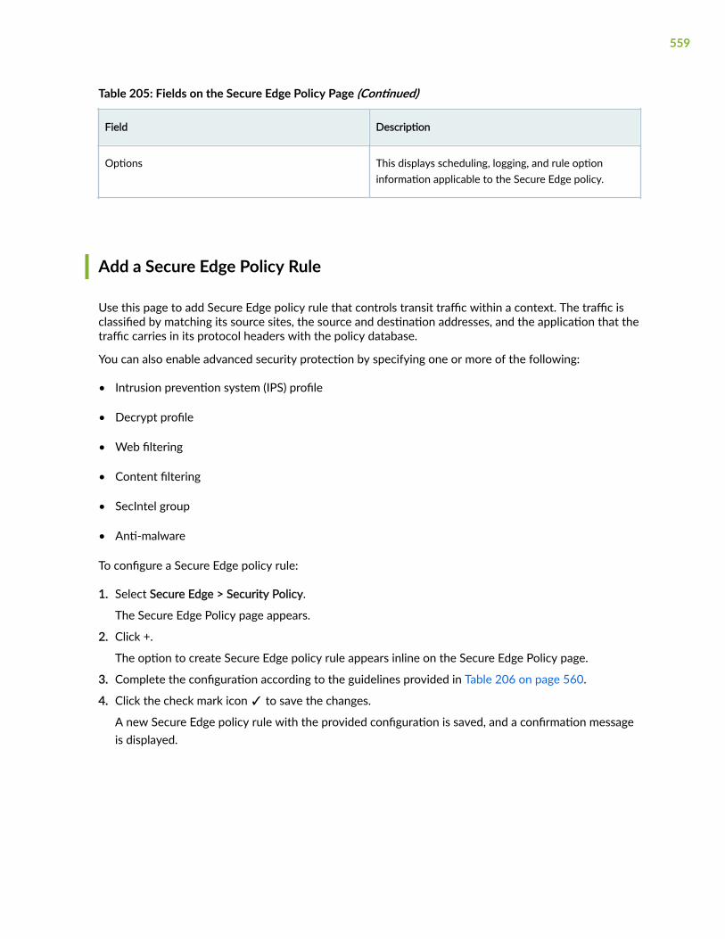
Table 205: Fields on the Secure Edge Policy Page (Continued)
Field Description
Options This displays scheduling, logging, and rule optioninformation applicable to the Secure Edge policy.
Add a Secure Edge Policy Rule
Use this page to add Secure Edge policy rule that controls transit traffic within a context. The traffic isclassified by matching its source sites, the source and destination addresses, and the application that thetraffic carries in its protocol headers with the policy database.
You can also enable advanced security protection by specifying one or more of the following:
• Intrusion prevention system (IPS) profile
• Decrypt profile
• Web filtering
• Content filtering
• SecIntel group
• Anti-malware
To configure a Secure Edge policy rule:
1. Select Secure Edge > Security Policy.
The Secure Edge Policy page appears.
2. Click +.
The option to create Secure Edge policy rule appears inline on the Secure Edge Policy page.
3. Complete the configuration according to the guidelines provided in Table 206 on page 560.
4. Click the check mark icon ✓ to save the changes.
A new Secure Edge policy rule with the provided configuration is saved, and a confirmation messageis displayed.
559

Table 206: Fields on the Secure Edge Policy Add Page
Field Description
Rule Name Enter a unique string beginning with a number orletter and consisting of letters, numbers, dashes andunderscores. No spaces are allowed and themaximum length is 63 characters. If you do not entera name, the rule is saved with a default nameassigned by Juniper Secure Edge.
Description Enter a description for the policy rule; maximumlength is 900 characters. The description must be astring excluding '&', '<', '>' and '\n' characters.
Sources Click the add icon (+) to select the source end pointson which the Secure Edge policy rule applies, fromthe displayed list of sites, addresses, and user groups.
Destinations Click the add icon (+) to select the destination endpoints on which the Secure Edge policy rule applies,from the displayed list of addresses and URLcategories.
Application/Services Click the add icon (+) to select the applications andservices.
560

Table 206: Fields on the Secure Edge Policy Add Page (Continued)
Field Description
Action From the drop-down menu, select the action for thetraffic between the source and destination.
• Permit—Device permits the traffic.
• Deny—Device silently drops all packets for thesession and does not send any active controlmessages such as TCP Resets or ICMPunreachable.
• Reject—Device drops the packet and sends thefollowing message based on traffic type:
• TCP traffic: Device sends the TCP resetmessage to the source host.
• UDP traffic: Device sends the ICMP message“destination unreachable, port unreachable”.
• For all other traffic: Device drops the packetwithout notifying the source host.
• Redirect—When a policy blocks HTTP or HTTPStraffic with a reject action, you can define aresponse in the unified policy to notify theconnected client. Redirect options:
• Message—Select the message from the drop-down list or click Create redirect message andenter the message (in the Block Messagefield).
• URL—Select the redirect URL from the drop-down list, or click Add redirect URL and enterthe redirect URL.
561

Table 206: Fields on the Secure Edge Policy Add Page (Continued)
Field Description
Advanced Security NOTE: You can configure all the advanced securityoptions only if you select Permit for the action.
• IPS— When you set the action to Permit, you canenable an IPS profile.
Enable an IPS profile to monitor and preventintrusions.
• Decrypt profile—When you set the action toPermit or Reject, you can specify a decrypt profileby selecting a profile from the list.
You can use the Decrypt profile to specify thetraffic that may be decrypted or bypassed fordecryption by Secure Edge.
Click Create New, if you want to add a newDecrypt profile.
• Web filtering—When you set the action toPermit, you can specify a Web filtering profile byselecting a profile from the list.
You can use the Web filtering profile to manageinternet usage by preventing access toinappropriate Web content over HTTP.
Click Create New, if you want to add a new Webfiltering profile.
• Content filtering—When you set the action toPermit, you can specify a Content filtering profileby selecting a profile from the list.
You can use the Content filtering profile to filterthe content based on the file type, application,and direction. The content filtering policyevaluates traffic before all other content securitypolicies. Therefore, if traffic meets criteriaconfigured in the content filter, the content filteracts first upon this traffic.
Click Create New, if you want to add a newContent filtering profile.
562

Table 206: Fields on the Secure Edge Policy Add Page (Continued)
Field Description
• SecIntel group—When you set the action toPermit, you can specify a SecIntel profile group byselecting a profile from the list.
You use the SecIntel profile group to assign agroup of different SecIntel profiles.
Click Create New, if you want to add a newSecIntel group.
• Anti-malware—When you set the action toPermit, you can specify a antimalware profile byselecting a profile from the list.
You can use the antimalware profile to define thecontent to scan for any malware and the action tobe taken when a malware is detected.
Click Create New if you want to add a newantimalware profile.
Options Select a pre-saved schedule from the list.
Policy schedules enable you to define when a policyis active, and thus are an implicit match criterion.Click Create Schedule to define a new schedule. Youcan define the day of the week and the time of theday when the policy is active. For instance, you candefine a security policy that opens or closes accessbased on business hours.
Enable the Logging option to log events whensessions are created.
Edit, Clone, and Delete a Secure Edge Policy Rule
IN THIS SECTION
Edit a Secure Edge Policy Rule | 564
563

Clone a Secure Edge Policy Rule | 564
Delete a Secure Edge Policy Rule | 564
You can edit, clone, and delete Secure Edge policy rules from the Secure Edge > Security Policy page.
Edit a Secure Edge Policy Rule
To modify the parameters configured for a Secure Edge policy rule:1. Select Secure Edge > Security Policy.
The Secure Edge Policy page appears, displaying the list of Secure Edge policies.
2. Select the Secure Edge policy rule that you want to edit, and click the pencil icon.
3. Modify the parameters and click ✓ to save the changes.
The modified rule appears on the Secure Edge Policy page.
Clone a Secure Edge Policy Rule
To clone a Secure Edge policy rule:1. Select Secure Edge > Security Policy.
The Secure Edge Policy page appears.
2. Right-click the Secure Edge policy rule to clone, and select Clone. Alternatively, click More drop-down menu, and select Clone.
Update the cloned policy rule as required.
3. Click ✓ to save the changes.
The modified policy rule appears on the Secure Edge Policy page.
Delete a Secure Edge Policy Rule
To delete a Secure Edge policy rule:1. Select Secure Edge > Security Policy.
The Secure Edge Policy page appears.
2. Select the Secure Edge policy rule you want to delete, and then click the delete icon.
An alert message appears, verifying that you want to delete the selected policy.
3. Click Yes to delete the selected policy rule.
564

Select a Secure Edge Policy Source
You can view and select the source end point from the complete list of sites, addresses, and user groups.
1. Click the Sources field.A list of relevant endpoints is displayed.
2. Complete the configuration according to the guidelines provided in Table 207 on page 565
Table 207: Source Fields on the Secure Edge Policy Page
Field Description
Sites Select the sites that are required as sources for theSecure Edge policy.
Addresses Select one of the following address options:
• Any—Add any address to the security policy.
• Specific—Select the check box beside eachaddress you want to include in the address group.Click the greater-than icon (>) to move theselected address or addresses from the Availablecolumn to the Selected column. Note that youcan use the fields at the top of each column tosearch for addresses.
User groups Select one of the following users or groups options:
• Any—Add any user or a group to the securitypolicy.
• Specific—Select the check box beside each useryou want to include in the user group. Click thegreater-than icon (>) to move the selectedaddress or addresses from the Available columnto the Selected column. Note that you can usethe fields at the top of each column to search foraddresses.
3. Click OK to select the end point as a source.
565

Select a Secure Edge Policy Destination
You can view and select the destination end point from the complete list of addresses.
1. Click on Destinations. A list of relevant end points is displayed.
2. Complete the configuration according to the guidelines provided in Table 208 on page 566.
Table 208: Destination Fields on the Secure Edge Policy Page
Field Description
Addresses Enter one or more address names or address setnames.
• Any—Add any address to the security policy rule.
• Specific—Select the check box beside eachaddress you want to include in the address group.Click the greater-than icon (>) to move theselected address or addresses from the Availablecolumn to the Selected column. Note that youcan use the fields at the top of each column tosearch for addresses.
URL Categories Enable the toggle button to configure the URLcategory:
• None
• Any—Add any URL to the security policy.
• Specific—Select the check box beside each URLyou want to include. Click the greater-than icon(>) to move the selected URLs from the Availablecolumn to the Selected column.
3. Click OK to select the end point as a destination.
566

Select Applications and Services
IN THIS SECTION
Add Applications and Services to Security Policy | 567
The following procedure provides instructions to add applications and services to the Secure Edgepolicy.
Add Applications and Services to Security Policy
You can add the applications and services to the existing security policy.
1. Click on Applications/Services. Applications & Services page is displayed.
2. Complete the configuration according to the guidelines provided in Table 209 on page 567
Table 209: Applications and Services Fields on the Security Policy Rule Page
Field Description
Applications Select one of the following options for theapplications:
• None
• Any—Add any application to the security policy.
• Specific—Click the + icon to add the applicationsignatures and select the check boxes next to theapplication to be added.
NOTE: You can search for a specific applicationby entering the search criteria in the search field.You can search the applications by their name.
567

Table 209: Applications and Services Fields on the Security Policy Rule Page (Continued)
Field Description
Services Select one of the following options for the services:
• Default—Junos-default services.
• Any—Add any service to the security policy.
• Specific—Select the check box beside eachservice you want to include. Click the greater-than icon (>) to move the selected service orservices from the Available column to theSelected column. Note that you can use the fieldsat the top of each column to search for services.
3. Click OK to add the selected applications and services to the security policy rule.
Common Operations on a Secure Edge Policy
You can perform common operations on a Secure Edge policy rule from the Secure Edge Policy page.
To perform common operations on a security policy:
1. Select Secure Edge > Security Policy.
The Secure Edge Policy page appears.
2. Click the security policy and click More.
The following common operations are available for a security policy.
• Add a rule before an existing rule.
• Add a rule after an existing rule.
• Create a copy of an existing rule.
• Enable the rule.
• Disable the rule.
• Probe latest hits to get the latest policy rule hit count. The hit count is incremented by 1 eachtime an entry is matched.
• Reset the hit count for a rule. Resetting sets the current hit count to zero.
568

• Move the rule by selecting one of the following options:
• Move Top
• Move Up
• Move Down
• Move Bottom
• Clear the sections for the rules.
Deploy Secure Edge Policies
After configuring the rules to the Secure Edge policies, you can deploy the Secure Edge policies byclicking the Deploy option. You can also deploy one or more policies from the Secure Edge Policy page.
To deploy Secure Edge policies:
1. Select Secure Edge > Security Policy.
The Security Policy page appears.
2. Select one or more policies and click Deploy.
The Deploy page appears.
3. Complete the configuration as per the guidelines provided in Table 210 on page 569
Table 210: Fields on the Deploy page
Field Description
Deployment Time Choose one of the following options
• Run Now—Select this option to deploy the policyimmediately.
• Schedule at a later time—Select this option tospecify the date and time at which the policyshould be deployed.
Service Locations Review the list of service locations to which theSecure Edge policy will be deployed.
4. Click OK.A job is created. Click the job ID to go to the Jobs page and view the status of the deploy operation.
569

CHAPTER 32
Security Subscriptions
IN THIS CHAPTER
IPS Policies Overview | 571
About IPS Policies | 571
Create IPS Rule | 572
Edit, Clone, and Delete IPS Rules | 576
Create Exempt Rule | 577
Edit, Clone, and Delete Exempt Rule | 579
Web Filtering Profiles Overview | 581
About the Web Filtering Profiles Page | 581
Create a Web Filtering Profile | 583
Edit, Clone, and Delete a Web Filtering Profile | 585
Content Filtering Policies Overview | 586
About the Content Filtering Policies Page | 587
Create a Content Filtering Policy | 588
Add Rules in a Content Filtering Policy | 589
Edit and Delete a Content Filtering Policy | 590
Edit, Clone, and Delete a Content Filtering Policy Rule | 591
SecIntel Profiles Overview | 592
About SecIntel Profiles | 593
Create Command and Control Profile | 594
Create DNS Profile | 596
Create Infected Hosts Profile | 598
Edit, Clone, and Delete SecIntel Profile | 600
About SecIntel Profile Groups | 601
Create SecIntel Profile Group | 603
Edit, Clone, and Delete SecIntel Profile Group | 604
Anti-malware Profiles Overview | 605
570

About Anti-malware Profiles | 606
Create Anti-malware Profile | 607
Edit, Clone, and Delete Anti-malware Profile | 610
Create a DNS Security Profile | 611
Create an Encrypted Traffic Insights Profile | 613
IPS Policies Overview
An intrusion prevention system (IPS) policy defines how your device handles the network traffic. Itallows you to enforce various attack detection and prevention techniques on traffic traversing yournetwork. You can define policy rules to match a section of traffic based on a zone, network, andapplication, and then take active or passive preventive actions on that traffic.
About IPS Policies
IN THIS SECTION
Tasks You Can Perform | 571
To access this page, select Secure Edge > Security Subscriptions > IPS.
The intrusion prevention system (IPS) profile is deployed on a device by associating the profile with afirewall policy intent, which is deployed on the device. You can associate IPS rules or exempt rules withan IPS profile.
Use this page to view, add, modify, clone, or delete the IPS rules and exempt rules in the IPS profiles.
Tasks You Can Perform
• Create an IPS rule —See "Create IPS Rule" on page 572.
• Create an exempt rule—See "Create Exempt Rule" on page 577.
571

• Edit, clone, or delete an IPS rule—See "Edit, Clone, and Delete IPS Rules" on page 576.
• Edit, clone, or delete an Exempt rule—See "Edit, Clone, and Delete Exempt Rule" on page 579.
• Search for rules by using keywords—Click the search icon, enter the search term in the text box, andpress Enter. The search results are displayed on the same page.
• Filter rules—Click the filter icon (funnel), and specify one or more filtering criteria. The filtered resultsare displayed on the same page.
NOTE: Filtering is applicable only to some fields.
• Table 211: Fields on the IPS Policy Page
Field Description
Name The name of the IPS rule.
IPS Signatures Displays the IPS signatures associated with the IPSrule.
If multiple signatures are associated with the rule,the number of additional signatures is displayed.Hover over the number to view the full list ofsignatures.
Action Displays the action to be taken when the IPS rule ismatched.
Options Displays the configuration options for IPS rules.
Hover over the arrow icon to view the loggingoptions configured.
Create IPS Rule
You can create intrusion prevention system (IPS) rules only for customized IPS profiles.
To create an IPS rule:
572

1. Select Secure Edge > Security Subscriptions > IPS.
The IPS Policy page appears.
2. Click the add (+) icon on the IPS Rules tab.
The parameters for an IPS rule are displayed inline at the top of the page.
3. Complete the configuration according to the guidelines in Table 212 on page 573.
4. Click the check mark (✓) to save your changes.
The changes are saved and a confirmation message is displayed at the top of the page.
You can use the IPS profile in a firewall policy intent. When you deploy the firewall policy on thedevice, the IPS and exempt rules associated with the profile are also deployed.
Table 212: Create IPS Rule Settings
Setting Guideline
Name Juniper Security Edge generates a unique rule nameby default. You can modify the name.
The name must begin with an alphanumericcharacter and can contain maximum 63 characters,which includes alphanumeric characters and somespecial characters, such as colons, hyphens, forwardslashes, periods, and underscores.
Description Enter a description containing maximum 1024characters for the rule.
573

Table 212: Create IPS Rule Settings (Continued)
Setting Guideline
IPS Signatures Add one or more IPS signatures and IPS signaturestatic and dynamic groups to be associated with therule:
a. Click the + icon inside the text box.
A list of IPS signatures and IPS signature staticand dynamic groups opens.
b. (Optional) Click the add (+) icon to add signatures.The Add IPS Signatures popup window opens.
c. (Optional) Enter a search term and press Enter tofilter the list of items displayed.
d. Click a list item to add it to the IPS signatures andIPS signature static or dynamic groups associatedwith the rule.
e. (Optional) Repeat the preceding step to add moresignatures, static groups, and dynamic groups.
574

Table 212: Create IPS Rule Settings (Continued)
Setting Guideline
Action Select the action to be taken when the monitoredtraffic matches the attack objects specified in therules:
• Recommended (default)—Uses the action thatJuniper Networks recommends when an attack isdetected. All predefined attack objects have adefault action associated with the objects.
• No action—No action is taken. Use this action toonly generate logs for some traffic.
• Drop Connection—Drops all packets associatedwith the connection and prevents traffic for theconnection from reaching its destination. Use thisaction to drop connections for traffic that is notprone to spoofing.
• Drop Packet—Drops a matching packet before itcan reach its destination but does not close theconnection. Use this action to drop packets forattacks in traffic that is prone to spoofing, such asUDP traffic. Dropping a connection for suchtraffic could result in a denial of service thatprevents traffic from a legitimate source IPaddress.
• Close Client—Closes the connection and sends anRST packet to the client, but not to the server.
• Close Server—Closes the connection and sendsan RST packet to the server, but not to the client.
• Close Client and Server—Closes the connectionand sends a TCP reset (RST) packet to both theclient and the server.
• Ignore Connection—Stops scanning traffic for therest of the connection if an attack match is found.IPS disables the rulebase for the specificconnection.
575

Table 212: Create IPS Rule Settings (Continued)
Setting Guideline
Options Enable Log attacks option to create a log.
Edit, Clone, and Delete IPS Rules
IN THIS SECTION
Edit an IPS Rule | 576
Clone an IPS Rule | 577
Delete IPS Rules | 577
Edit an IPS Rule
You can edit IPS rules associated only with customized IPS profiles, and not the rules associated withpredefined (system-generated) profiles.
To edit an IPS rule:
1. Select Secure Edge > Security Subscriptions > IPS.
The IPS Policy page opens.
2. Click the IPS RULES tab and select the IPS rule.
3. Click edit (pencil) icon.
The rule selected for editing is displayed inline at the top of the page.
4. Modify the rule. See "Create IPS Rule" on page 572.
5. Click the check mark (✓) to save your changes.
The changes are saved and a confirmation message is displayed at the top of the page.
If the IPS belongs to an IPS profile that is referenced in a firewall policy intent, then the firewall policyis marked for deployment. You must deploy the firewall policy for the changes to take effect on thedevice.
576

Clone an IPS Rule
Cloning enables you to easily create an IPS rule based on an existing one. You can clone IPS rulesassociated only with customized IPS profiles, and not rules associated with predefined (system-generated) profiles.
To clone an IPS rule:
1. Select Secure Edge > Security Subscriptions > IPS.
The IPS Policy page opens.
2. Click the IPS RULES tab and select the IPS rule.
3. Select a rule, and select More > Clone.
The rule selected for cloning is displayed inline at the top of the page.
4. Modify the rule. See "Create IPS Rule" on page 572.
5. Click the check mark (✓) to save your changes.
The new rule is created and a confirmation message is displayed at the top of the page.
Delete IPS Rules
You can delete IPS rules associated only with customized IPS profiles, and not the rules associated withpredefined (system-generated) profiles.
To delete IPS rules:
1. Select Secure Edge > Security Subscriptions > IPS.
The IPS Policy page opens.
2. Click the IPS RULES tab and select the IPS rule.
3. Select one or more rules, and click the delete (trash can) icon.
A warning message asking you to confirm the deletion is displayed.
4. Click Yes.
A message indicating the status of the delete operation is displayed at the top of the page.
If the deleted IPS rule belongs to an IPS profile that is referenced in a firewall policy intent, then thefirewall policy is marked for deployment. You must deploy the firewall policy for the changes to takeeffect on the device.
Create Exempt Rule
You can create intrusion prevention system (IPS) exempt rules only for customized IPS profiles.
To create an exempt rule:
577

1. Select Secure Edge > Security Subscriptions > IPS.
The IPS Policy page opens.
2. Click the Exempt Rules tab.
3. Click the add (+) icon.
The parameters for an exempt rule are displayed inline at the top of the page.
4. Complete the configuration according to the guidelines in Table 213 on page 578.
5. Click the check mark (✓) to save your changes.
The changes are saved and a confirmation message is displayed at the top of the page.
You can use the IPS profile in a firewall policy intent. When you deploy the firewall policy on thedevice, the IPS and exempt rules associated with the profile are also deployed.
Table 213: Create Exempt Rule Settings
Setting Guideline
Name Juniper Secure Edge generates a unique rule name bydefault. You can modify the name.
The name must begin with an alphanumericcharacter and can contain maximum 63 characters,which includes alphanumeric characters and somespecial characters, such as colons, hyphens, forwardslashes, periods, and underscores.
Description Enter a description containing maximum 1024characters for the rule.
578

Table 213: Create Exempt Rule Settings (Continued)
Setting Guideline
IPS Signatures Add one or more IPS signatures and IPS signaturestatic and dynamic groups to be associated with therule:
a. Click inside the text box with the + icon.
A list of IPS signatures and IPS signature staticand dynamic groups opens.
b. (Optional) Click the add (+) icon to add signatures.The Add IPS Signatures popup window opens.
c. (Optional) Enter a search term and press Enter tofilter the list of items displayed.
d. Click a list item to add it to the IPS signatures andIPS signature static or dynamic groups associatedwith the rule.
e. (Optional) Repeat the preceding step to add moresignatures, static groups, and dynamic groups.
Edit, Clone, and Delete Exempt Rule
IN THIS SECTION
Edit an Exempt Rule | 579
Clone an Exempt Rule | 580
Delete Exempt Rules | 580
Edit an Exempt Rule
You can edit exempt rules associated only with customized IPS profiles, and not the rules associatedwith predefined (system-generated) profiles.
579

To edit an exempt rule:
1. Select Secure Edge > Security Subscriptions > IPS.
The IPS Policy page appears.
2. Click the EXEMPT RULES tab, then select the rule.
3. Click edit (pencil) icon.
The rule selected for editing is displayed inline at the top of the page.
4. Modify the rule. See "Create Exempt Rule" on page 577.
5. Click the check mark (✓) to save your changes.
The changes are saved and a confirmation message is displayed at the top of the page.
If the exempt rule belongs to an IPS profile that is referenced in a firewall policy intent, then thefirewall policy is marked for deployment. You must deploy the firewall policy for the changes to takeeffect on the device.
Clone an Exempt Rule
Cloning enables you to easily create an exempt rule based on an existing one. You can clone exemptrules associated only with customized IPS profiles, and not rules associated with predefined (system-generated) profiles.
To clone an exempt rule:
1. Select Secure Edge > Security Subscriptions > IPS.
The IPS Policy page appears.
2. Click the EXEMPT RULES tab.
3. Select a rule, and select More > Clone.
The rule selected for cloning is displayed inline at the top of the page.
4. Modify the rule. See "Create Exempt Rule" on page 577.
5. Click the check mark (✓) to save your changes.
The new rule is created and a confirmation message is displayed at the top of the page.
Delete Exempt Rules
You can delete exempt rules associated only with customized IPS profiles, and not the rules associatedwith predefined (system-generated) profiles.
To delete exempt rules:
1. Select Secure Edge > Security Subscriptions > IPS.
The IPS Policy page opens.
2. Click the EXEMPT RULES tab.
3. Select one or more rules, and click the delete (trash can) icon.
580

A warning message asking you to confirm the deletion is displayed.
4. Click Yes.
A message indicating the status of the delete operation is displayed at the top of the page.
If the deleted exempt rule belongs to an IPS profile that is referenced in a firewall policy intent, thenthe firewall policy is marked for deployment. You must deploy the firewall policy for the changes totake effect on the device.
Web Filtering Profiles Overview
Juniper Secure Edge blocks or permits Web access based on built-in web categories or user-defined webcategories.
Web filtering profiles enable you to manage Internet usage by preventing access to inappropriate Webcontent over HTTP. Juniper Networks provides a list of 178 categories which you can use to create Webfiltering profiles and manage Web access in your enterprise network.
About the Web Filtering Profiles Page
IN THIS SECTION
Tasks You Can Perform | 581
Field Descriptions | 582
To access this page, select Secure Edge > Security Subscriptions > Web Filtering Profiles.
Use the Web Filtering Profiles page to view and manage Web filtering profiles.
Tasks You Can Perform
You can perform the following tasks from this page:
• Create a Web filtering profile—See "Create a Web Filtering Profile" on page 583.
• Edit, clone, or delete a Web filtering profile—See "Edit, Clone, and Delete a Web Filtering Profile" onpage 585.
581

• View the details of a Web filtering profile—Select the Web filtering profile to view the details andfrom the More menu, select Detailed View. The Web Filtering Profile Details page appears. Table 215on page 583 describes the fields on this page.
• Clear the selected Web filtering profiles—Click Clear All Selections to clear any Web filtering profilesthat you might have selected.
• Search for Web filtering profiles using keywords—Click the search icon and enter the search term inthe text box and press Enter. The search results are displayed on the same page.
Field Descriptions
Table 214 on page 582 describes the fields on the Web Filtering Profiles page.
Table 214: Web Filtering Profiles Page Fields
Field Description
Name The name of the Web filtering profile.
Permitted Categories The Juniper Networks pre-defined categories andcustom categories of Web content that is permitted inthe enterprise network.
Permitted & Logged Categories The Juniper Networks pre-defined categories andcustom categories of Web content that is permittedand logged in the enterprise network.
Denied Categories The Juniper Networks pre-defined categories andcustom categories of Web content that is denied in theenterprise network.
Quarantined Categories The Juniper Networks pre-defined categories andcustom categories of Web content that is quarantinedin the enterprise network when detected.
Description The description of the Web filtering profile.
582

Table 215: Web Filtering Profile Details Page Fields
Field Description
General Information
Name The name of the Web filtering profile.
Permitted Categories The Juniper Networks pre-defined categories andcustom categories of Web content that is permitted inthe enterprise network.
Permitted & Logged Categories The Juniper Networks pre-defined categories andcustom categories of Web content that is permittedand logged in the enterprise network.
Denied Categories The Juniper Networks pre-defined categories andcustom categories of Web content that is denied in theenterprise network.
Quarantined Categories The Juniper Networks pre-defined categories andcustom categories of Web content that is quarantinedin the enterprise network when detected.
Redirect Message The redirect URL address or a custom message whenHTTP requests are blocked.
Description The description of the Web filtering profile.
Create a Web Filtering Profile
Web filtering profiles enable you to manage Internet usage by preventing access to inappropriate Webcontent over HTTP.
1. Select Secure Edge > Security Subscriptions > Web Filtering Profiles.
The Web Filtering Profiles page opens.
583

2. Click the + to create a new Web filtering profile.
The Create Web Filtering Profiles wizard opens, displaying brief instructions about creating a Webfiltering profile.
3. Click Next to navigate to the next page.
4. Complete the configuration according to the guidelines provided in Table 216 on page 584.
NOTE: Fields marked with * are mandatory.
5. Click Finish.
Table 216: Fields on the Create Web Filtering Profile Page
Setting Guideline
Name Enter a unique name containing maximum 29characters for the Web filtering profile.
Description Enter a description containing maximum 255characters for the Web filtering profile.
Force safe search The option to filter explicit results and to preventthem from appearing in your search results.
Safe search ensures that embedded objects, such asimages on the URLs received from the searchengines, are safe and that undesirable content is notreturned to the client.
Categories The Juniper Networks pre-defined categories andcustom categories list and the followingcorresponding actions for each category:
• Permit
• Permit and Log
• Deny
• Quarantine
584

Table 216: Fields on the Create Web Filtering Profile Page (Continued)
Setting Guideline
Block options The option to block either a URL address or a custommessage when HTTP Web contents are blocked.
Redirect message Specify the redirect URL or a custom message to besent when HTTP requests are blocked. The maximumlength is 1024 characters.
NOTE: If a message begins with http: or https:, themessage is considered a block URL. Messages thatbegin with values other than http: or https: areconsidered custom block messages.
A Web filtering profile is created, and the Web Filtering Profiles page opens with a confirmationmessage.
Edit, Clone, and Delete a Web Filtering Profile
IN THIS SECTION
Edit a Web Filtering Profile | 585
Clone a Web Filtering Profile | 586
Delete a Web Filtering Profile | 586
You can edit, clone, and delete Web filtering profiles from the Web Filtering Profiles page. This topic hasthe following sections:
Edit a Web Filtering Profile
You cannot modify the default profiles present in the system.
1. Select Secure Edge > Security Subscriptions > Web Filtering Profiles.
The Web Filtering Profiles page opens, displaying the existing Web filtering profiles.
585

2. Select the custom Web filtering profile to edit, and click the pencil icon.
The Edit Web Filtering Profiles page opens.
3. Edit the Web filtering profile fields.
4. Click OK to save your changes.
The Web Filtering Profiles page opens with a confirmation message indicating the status of the editoperation.
Clone a Web Filtering Profile
Cloning enables you to easily create a new Web filtering profile based on an existing one.
1. Select Secure Edge > Security Subscriptions > Web Filtering Profiles.
The Web Filtering Profiles page opens, displaying the existing Web filtering profiles.
2. Select the Web filtering profile to clone, and select More > Clone.
The Clone Web Filtering Profiles page opens.
3. Edit the Web filtering profile fields.
4. Click OK to save your changes.
The Web Filtering Profiles page opens with a confirmation message indicating the status of the cloneoperation.
Delete a Web Filtering Profile
Before deleting a Web filtering profile, ensure that the profile is not used in a content security profile. Ifyou try to delete a Web filtering profile that is used in a content security profile, an error message isdisplayed.
1. Select Secure Edge > Security Subscriptions > Web Filtering Profiles.
The Web Filtering Profiles page opens, displaying the existing Web filtering profiles.
2. Select the custom Web filtering profiles to delete, and click the delete icon.
A message asking you to confirm the delete operation is displayed.
3. Click Yes to delete the selected Web filtering profiles.
A confirmation message indicating the status of the delete operation is displayed.
Content Filtering Policies Overview
Content filtering policies determine the file type based on the file content and not based on the fileextensions. The content filtering policies analyze the file content to accurately determine the file type.Juniper Secure Edge filters the content based on the file type, application, and direction.
586

NOTE: The content filtering policy evaluates traffic before all other content security policies.Therefore, if traffic meets criteria configured in the content filter, the content filter acts first uponthis traffic.
About the Content Filtering Policies Page
IN THIS SECTION
Tasks You Can Perform | 587
Field Descriptions | 588
To access this page, select Secure Edge >Security Subscriptions > Content Filtering.Use the Content Filtering Policies page to view and manage content filtering policies.
Tasks You Can Perform
You can perform the following tasks from this page:
• Create a content filtering policy—See "Create a Content Filtering Policy" on page 588.
• Edit and delete a content filtering policy—See "Edit and Delete a Content Filtering Policy" on page590.
• Edit, clone, or delete a content filtering policy rule—See "Edit, Clone, and Delete a Content FilteringPolicy Rule" on page 591.
• Search for content filtering policies by using keywords and policy name—Click the search icon, enterthe search term in the text box, and press Enter. The search results are displayed on the same page.
• Filter rules—Click the filter icon (funnel), and specify one or more filtering criteria. The filtered resultsare displayed on the same page.
• Filter information based on select criteria. You can add filters, save the filters, and set any of the
filters as default. To add a filter:
587

1. Click the filter icon on the top-right corner of the page, and select Add Filter to open the AddCriteria page.
2. Set the filter conditions, and click Add.
The filter is saved and the filter is applied on the data. You can save the filter. You can also mark onefilter as the default filter.
To remove the filter, click the filter icon, and select Hide Filter.
Field Descriptions
Table 217 on page 588 describes the fields on the Content Filtering Policies page.
Table 217: Fields on the Content Filtering Policies Page
Field Description
Name The name of the content filtering policy.
Rules The number of rules associated with the contentfiltering policy.
Description The description of the content filtering policy.
Create a Content Filtering Policy
Use the Create Content Filtering Policies page to configure content filtering policies.
1. Select Secure Edge > Security Subscriptions > Content Filtering.
The Content Filtering Policies page opens.
2. Click + to create a new content filtering policy.
The Create Content Filtering Policy page opens.
3. Complete the configuration according to the guidelines provided in Table 218 on page 589.
4. Click OK.
588

Table 218: Fields on the Content Filtering Policies Page
Setting Guideline
Name Enter a unique name containing maximum 29characters for the content filtering policy.
Description Enter a description containing maximum 255characters for the content filtering policy.
The Content Filtering Policies page opens displaying the new content filtering policy.
Next, add rules to the content filtering policy.
Add Rules in a Content Filtering Policy
1. Select Secure Edge > Security Subscriptions > Content Filtering.
The Content Filtering Policies page opens.
2. Click Add Rules for the content filtering policy.The content filtering policy page opens.
3. Click +, and complete the configuration according to the guidelines provided in Table 219 on page589.
4. Click ✓.
Table 219: Fields on the Content Filtering Policy Rule Page
Setting Guideline
Name Enter a unique name containing maximum 29characters for the content filtering rule.
Direction Select the direction of the content traffic to filter.
• Any
• Download
• Upload
589

Table 219: Fields on the Content Filtering Policy Rule Page (Continued)
Setting Guideline
File Types Click + to open the Files Types page, and select thetypes of files to filter.
Action Select the action to be taken on the selected types offiles in the content filtering rule.
• No Action
• Block
• Close Client
• Close Server
• Close Client and Server
Options Do the following:
• Click the Event logs toggle button to enablelogging for the content filter.
• Click the End user notification toggle button toenable notifications to users, and enter a customnotification message containing maximum 512characters.
Edit and Delete a Content Filtering Policy
IN THIS SECTION
Edit a Content Filtering Policy | 591
Delete a Content Filtering Policy | 591
590

Edit a Content Filtering Policy
You cannot modify the default policies.
1. Select Secure Edge > Security Subscriptions > Content Filtering.
The Content Filtering Policies page opens displaying the existing content filtering policies.
2. Select the custom content filtering profile to edit, and click the pencil icon.
The Edit Content Filtering Policies page opens.
3. Edit the content filtering profile fields.
4. Click OK to save your changes.
The Content Filtering Policies page opens with a confirmation message indicating the status of the editoperation.
Delete a Content Filtering Policy
Before deleting a content filtering profile, ensure that the profile is not used in a UTM profile which is, inturn, used in a firewall policy rule. If you try to delete a content filtering profile that is used in a firewallpolicy rule, an error message is displayed.
1. Select Secure Edge > Security Subscriptions > Content Filtering.
The Content Filtering Policies page opens displaying the existing content filtering policies.
2. Select the custom content filtering policies to delete, and click the delete icon.
A message asking you to confirm the delete operation is displayed.
3. Click Yes to delete the selected content filtering policies.
A confirmation message indicating the status of the delete operation is displayed.
Edit, Clone, and Delete a Content Filtering Policy Rule
IN THIS SECTION
Edit a Content Filtering Policy Rule | 592
Clone a Secure Edge Policy Rule | 592
Delete a Secure Edge Policy Rule | 592
591

You can edit, clone, and delete content filtering policy rules from the Secure Edge > SecuritySubscriptions > Content Filtering page.
Edit a Content Filtering Policy Rule
1. Select Secure Edge > Security Subscriptions > Content Filtering.
The Content Filtering Policies page opens displaying the list of content filtering policies.
2. Click the content filtering policy name.
The content fIltering policy page opens displaying the list of rules included in the policy.
3. Select the content filtering policy rule, and click the pencil icon.
4. Modify the parameters, and click ✓ to save the changes.
The content fIltering policy page displays the modified rule.
Clone a Secure Edge Policy Rule
1. Select Secure Edge > Security Subscriptions > Content Filtering.
The Content Filtering Policies page opens displaying the list of content filtering policies.
2. Click the content filtering policy name.
The content fIltering policy page opens displaying the list of rules included in the policy.
3. Select the content filtering policy rule, and click More > Clone.The content filtering policy page displays the cloned rule.
4. Update the cloned content filtering policy rule as required.
5. Click ✓ to save the changes.
The content filtering policy page displays the modified rule.
Delete a Secure Edge Policy Rule
1. Select Secure Edge > Security Subscriptions > Content Filtering.
The Content Filtering Policies page opens displaying the list of content filtering policies.
2. Click the content filtering policy name.
The content fIltering policy page opens displaying the list of rules included in the policy.
3. Select the content filtering policy rule, and click the delete icon.
An alert message asking you to confirm the delete operation is displayed.
4. Click Yes to delete the selected policy rule.
SecIntel Profiles Overview
Juniper Networks Security Intelligence (SecIntel) provides carefully curated and verified threatintelligence from industry-leading threat feeds to Juniper Secure Edge. This enables blocking malicious
592

and unwanted traffic such as Command and Control (C&C) communications, GeoIP, Attacker IPs, andmore with minimum latency. SecIntel delivers real-time threat intelligence by enabling automatic andresponsive traffic filtering.
Configure SecIntel profiles to work with security intelligence feeds, such as C&C, DNS, and infectedhosts. The Security Intelligence process is responsible for downloading the security intelligence feedsand parsing from the feed connector or ATP Cloud feed server. Anything that matches these scores isconsidered malware or an infected host.
About SecIntel Profiles
IN THIS SECTION
Tasks You Can Perform | 593
Field Description | 594
To access this page, select Secure Edge > Security Subscriptions > SecIntel > Profiles.
Use the SecIntel Profiles page to manage Command & Control (C&C), DNS, and Infected Hosts profile.
Tasks You Can Perform
You can perform the following tasks from this page:
• View the list of C&C, DNS, and infected hosts profiles. To do this, click View by list and selectCommand & Control, DNS, or Infected Hosts profile.
• Create a command and control profile—See "Create Command and Control Profile" on page 594.
• Create a DNS profile—See "Create DNS Profile" on page 596.
• Create an infected hosts profile—See "Create Infected Hosts Profile" on page 598.
• Edit, clone, or delete SecIntel profile—See "Edit, Clone, and Delete SecIntel Profile" on page 600.
• Show or hide columns in the SecIntel table. To do this, use the Show Hide Columns icon in the topright corner of the page and select the options you want to show or deselect to hide options on thepage.
593

• Reset Preference—Reset the displayed columns to the default set of columns for each tab in thetable.
Hover over the More Options (vertical ellipsis) and select Reset Preference.
Field Description
Table 220 on page 594 describes the fields on the SecIntel Profiles page.Table 220: Fields on the SecIntel Profiles Page
Field Description
Name Displays the SecIntel profile name.
Type Displays if the SecIntel profile is a C&C, a DNS, or aninfected hosts profile.
Block action Displays the notification action taken with the blockaction. For example, Close session, Drop packet, andSinkhole.
Description Displays the description of the SecIntel profile.
Create Command and Control Profile
Create a Command and Control (C&C) profile to provide information on C&C servers that haveattempted to contact and compromise hosts on your network. A C&C server is a centralized computerthat issues commands to botnets of compromised networks of computers and receives reports backfrom them.
To create a C&C profile:
1. Click Secure Edge > Security Subscriptions > SecIntel > Profiles.The SecIntel Profiles page opens.
2. Select Create > Command & Control.The Create Command & Control Profile page appears.
3. Complete the configuration according to the guidelines provided in Table 221 on page 595.
4. Click OK to save the changes. To discard your changes, click Cancel.
Once you create the C&C profile, you can associate it with the SecIntel profile groups.
594

Table 221: Fields on the Create Command & Control Profile page
Field Action
Name Enter a name for the C&C profile.
The name must be a unique string of alphanumericand special characters; 63-character maximum.Special characters < and > are not allowed.
Description Enter a description for the C&C profile.
Default action for all feeds Drag the slider to change the action to be taken forall the feed types. Actions are Permit (1 - 4), Log(5-6), and Block (7 - 10).
Log will have the permit action and also logs theevent.
Specific action for feeds Do the following:
a. Click + to define feeds and threat score for theC&C profile.
The Add Feeds window appears.
b. Enter the following details:
i. Feeds—Select one or more feeds that areknown command and control for botnetsfrom the Available column and move it to theSelected column.
ii. Threat score—Drag the slider to change theaction to be taken based on the threat score.
c. Click OK.
595

Table 221: Fields on the Create Command & Control Profile page (Continued)
Field Action
Block action Select one of the following block actions from thelist:
• Drop Packets—Device silently drops the session’spacket and the session eventually times out.
• Close session options—Device sends a TCP RSTpacket to the client and server and the session isdropped immediately.
Close session options Select one of the following options from the list:None, Redirect URL, or Redirect message.
Redirect URL Enter a remote file URL to redirect users whenconnections are closed.
Redirect message Enter a custom message to send to the users whenconnections are closed.
Create DNS Profile
Create a DNS profile to configure feeds and threat score to list the domains that are known to beconnected to malicious activity.
To create a DNS profile:
1. Click Secure Edge > Security Subscriptions > SecIntel > Profiles.The SecIntel Profiles page appears.
2. Select Create > DNS.The Create DNS Profile page appears.
3. Complete the configuration according to the guidelines provided in Table 222 on page 597.
4. Click OK to save the changes. To discard your changes, click Cancel.
Once you create the DNS profile, you can associate it with the SecIntel profile groups.
596

Table 222: Fields on the Create DNS Profile Page
Field Action
Name Enter a name for the DNS profile.
The name must be a unique string of alphanumericand special characters; 63-character maximum.Special characters such as < and > are not allowed.
Description Enter a description for the DNS profile.
Default action for all feeds Drag the slider to change the action to be taken forall the feed types. Actions are Permit (1 - 4), Log(5-6), and Block (7 - 10).
Log will have the permit action and also logs theevent.
Specific action for feeds Do the following:
a. Click + to define feeds and threat score to theDNS profile.
The Add Feeds window appears.
b. Enter the following details:
i. Feeds—Select one or more feeds from theAvailable column and move it to the Selectedcolumn to associate with the DNS profile.
ii. Threat score—Drag the slider to change theaction to be taken based on the threat score.
c. Click OK.
597

Table 222: Fields on the Create DNS Profile Page (Continued)
Field Action
Block action Select one of the following block actions from thelist:
• Drop Packets—Device silently drops the session’spacket and the session eventually times out.
• Sinkhole—DNS sinkhole action for malicious DNSqueries.
Create Infected Hosts Profile
Create an Infected Hosts profile to configure feeds and threat score to list the IP address or IP subnet ofthe compromised host. Infected hosts indicate local devices that are potentially compromised becausethey appear to be part of a C&C network or exhibit other symptoms.
To create an Infected Hosts profile:
1. Click Secure Edge > Security Subscriptions > SecIntel > Profiles.The SecIntel Profiles page appears.
2. Select Create > Infected Hosts.The Create Infected Hosts Profile page appears.
3. Complete the configuration according to the guidelines provided in Table 223 on page 598.
4. Click OK to save the changes. To discard your changes, click Cancel.
Once you create the Infected Hosts profile, you can associate it with the SecIntel profile groups.
Table 223: Fields on the Create Infected Hosts Profile Page
Field Action
Name Enter a name for the Infected Hosts profile.
The name must be a unique string of alphanumericand special characters; 63-character maximum.Special characters such as < and > are not allowed.
598

Table 223: Fields on the Create Infected Hosts Profile Page (Continued)
Field Action
Description Enter a description for the Infected Hosts profile.
Default action for all feeds Drag the slider to change the action to be taken forall the feed types. Actions are Permit (1 - 4), Log(5-6), and Block (7 - 10).
Log will have the permit action and also logs theevent.
Specific action for feeds Do the following:
a. Click + to define feeds and threat score to theInfected Hosts profile.
The Add Feeds window appears.
b. Enter the following details:
i. Feeds—Select one or more feeds from theAvailable column and move it to the Selectedcolumn to associate with the Infected Hostsprofile.
ii. Threat score—Drag the slider to change theaction to be taken based on the threat score.
c. Click OK.
Block action Select one of the following block actions from thelist:
• Drop Packets—Device silently drops the session’spacket and the session eventually times out.
• Close session options—Device sends a TCP RSTpacket to the client and server and the session isdropped immediately.
Close session options Select one of the following options from the list:None, Redirect URL, or Redirect message.
599

Table 223: Fields on the Create Infected Hosts Profile Page (Continued)
Field Action
Redirect URL Enter a remote file URL to redirect users whenconnections are closed.
Redirect message Enter a custom message to send to the users whenconnections are closed.
Edit, Clone, and Delete SecIntel Profile
IN THIS SECTION
Edit a SecIntel Profile | 600
Clone a SecIntel Profile | 601
Delete a SecIntel Profile | 601
Edit a SecIntel Profile
To edit a SecIntel profile:
1. Select Secure Edge > Security Subscriptions > SecIntel > Profiles.
The SecIntel Profiles page appears.
2. Select a profile, and click the edit (pencil) icon.
The Edit Profile page appears.
3. Modify the profile fields. See "Create Command and Control Profile" on page 594, "Create DNSProfile" on page 596, or "Create Infected Hosts Profile" on page 598.
4. Click OK to save your changes.
The SecIntel Profiles page opens with a message that the profile was successfully updated.
If the SecIntel profile is referenced in a firewall policy intent, then the firewall policy is marked fordeployment. You must deploy the firewall policy for the changes to take effect on the device.
600

Clone a SecIntel Profile
Cloning enables you to easily create a new SecIntel profile based on an existing one. You can clone aSecIntel profile and modify the parameters.
To clone a SecIntel profile:
1. Select Secure Edge > Security Subscriptions > SecIntel > Profiles.
The SecIntel Profiles page appears.
2. Select a profile and select More > Clone.
The Clone Profile page appears.
3. Modify the profile fields. See "Create Command and Control Profile" on page 594, "Create DNSProfile" on page 596, or "Create Infected Hosts Profile" on page 598.
4. Click OK to save your changes.
The SecIntel Profiles page opens with a message that the IPS profile was successfully created.
Delete a SecIntel Profile
To delete a SecIntel profile:
1. Select Secure Edge > Security Subscriptions > SecIntel > Profiles.
The SecIntel Profiles page appears.
2. Select one or more SecIntel profiles, and click the delete (trash can) icon.
A warning message asking you to confirm the deletion is displayed.
3. Click Yes to proceed with the deletion.
The SecIntel Profiles page opens with a message indicating the status of the delete operation.
About SecIntel Profile Groups
IN THIS SECTION
Tasks You Can Perform | 602
Field Description | 602
To access this page, select Secure Edge > Security Subscriptions > SecIntel > Profile Groups.
601

Configure a SecIntel profile group to add SecIntel profiles, such as C&C, DNS, and infected hosts. Oncecreated, you can assign this group to the security policy.
Use the SecIntel Profiles page to manage SecIntel profile groups.
Tasks You Can Perform
You can perform the following tasks from this page:
• Create a SecIntel profile group—See "Create SecIntel Profile Group" on page 603.
• Edit, clone, or delete SecIntel profile group—See "Edit, Clone, and Delete SecIntel Profile Group" onpage 604.
• Show or hide columns in the SecIntel table. To do this, use the Show Hide Columns icon in the topright corner of the page and select the options you want to show or deselect to hide options on thepage.
• Reset Preference—Reset the displayed columns to the default set of columns for each tab in thetable.
Hover over the More Options (vertical ellipsis) and select Reset Preference.
Field Description
Table 224 on page 602 describes the fields on the SecIntel Profiles page.Table 224: Fields on the SecIntel Profile Groups Page
Field Description
Name Displays the SecIntel profile group name.
Command & Control Displays the C&C profile that you have associated withthe SecIntel profile group.
DNS Displays the DNS profile that you have associated withthe SecIntel profile group.
Infected Hosts Displays the infected hosts profile that you haveassociated with the SecIntel profile group.
Description Displays the description of the SecIntel profile group.
602

Create SecIntel Profile Group
Create a SecIntel profile group with SecIntel profiles, such as C&C, DNS, and infected hosts. Oncecreated, you can assign this group to the security policy.
To create a SecIntel profile group:
1. Click Secure Edge > Security Subscriptions > SecIntel > Profile Groups.The SecIntel Profile Groups page appears.
2. Click + on the upper-right corner of the SecIntel Profile Groups page.
The Create SecIntel Profile Groups page appears.
3. Complete the configuration according to the guidelines provided in Table 225 on page 603.
4. Click OK to save the changes. To discard your changes, click Cancel.
Once you create the SecIntel profile group, you can associate it with the security policies.
Table 225: Fields on the Create SecIntel Profile Groups Page
Field Action
Name Enter a name for the SecIntel profile group.
The name must be a unique string of alphanumeric,special characters and 64-character maximum.Special characters such as & ( ) ] ? " # < > are notallowed.
Description Enter description for the SecIntel profile group.
Command & Control Select a C&C profile from the list to associate withthe SecIntel profile group.
Click Create New to create a new C&C profile inline.For more information on a new C&C profile, see"Create Command and Control Profile" on page 594.
DNS Select a DNS profile from the list to associate withthe SecIntel profile group.
Click Create New to create a new DNS profile inline.For more information on a new DNS profile, see"Create DNS Profile" on page 596.
603

Table 225: Fields on the Create SecIntel Profile Groups Page (Continued)
Field Action
Infected Hosts Select a infected hosts profile from the list toassociate with the SecIntel profile group.
Click Create New to create a new infected hostsprofile inline. For more information on a new infectedhosts profile, see "Create Infected Hosts Profile" onpage 598.
Edit, Clone, and Delete SecIntel Profile Group
IN THIS SECTION
Edit a SecIntel Profile Group | 604
Clone a SecIntel Profile Group | 605
Delete a SecIntel Profile Group | 605
Edit a SecIntel Profile Group
To edit a SecIntel profile group:
1. Select Secure Edge > Security Subscriptions > SecIntel > Profile Groups.
The SecIntel Profile Groups page appears.
2. Select a profile group, and click the edit (pencil) icon.
The Edit SecIntel Profile Group page appears.
3. Modify the profile fields. See "Create SecIntel Profile Group" on page 603.
4. Click OK to save your changes.
The SecIntel Profile Groups page opens with a message that the profile was successfully updated.
If the SecIntel profile group is referenced in a firewall policy intent, then the firewall policy is markedfor deployment. You must deploy the firewall policy for the changes to take effect on the device.
604

Clone a SecIntel Profile Group
Cloning enables you to easily create a new SecIntel profile group based on an existing one. You canclone a SecIntel profile group and modify the parameters.
To clone a SecIntel profile group:
1. Select Secure Edge > Security Subscriptions > SecIntel > Profile Groups.
The SecIntel Profile Groups page appears.
2. Select a SecIntel profile group and select More > Clone.
The Create SecIntel Profile Group page appears.
3. Modify the profile fields. See "Create SecIntel Profile Group" on page 603.
4. Click OK to save your changes.
The SecIntel Profile Groups page opens with a message that the IPS profile was successfully created.
Delete a SecIntel Profile Group
To delete a SecIntel profile group:
1. Select Secure Edge > Security Subscriptions > SecIntel > Profile Groups.
The SecIntel Profile Groups page appears.
2. Select one or more SecIntel profile groups, and click the delete (trash can) icon.
A warning message asking you to confirm the deletion is displayed.
3. Click Yes to proceed with the deletion.
The SecIntel Profile Groups page opens with a message indicating the status of the delete operation.
Anti-malware Profiles Overview
Juniper Secure Edge uses intelligence provided by Juniper Advanced Threat Prevention Cloud (JuniperATP Cloud) to remediate malicious content using security policies. If configured, security policies blockthe content before it is delivered to the destination address.
The anti-malware profile defines the content to scan for any malware and the action to be taken whenmalware is detected. Juniper ATP Cloud uses a pipeline approach to analyzing and detecting malware. Ifan analysis reveals that the file is malware, it is not necessary to continue the pipeline to further examinethe malware.
605

About Anti-malware Profiles
IN THIS SECTION
Tasks You Can Perform | 606
Field Descriptions | 606
To access this page, select Secure Edge > Security Subscriptions > SecIntel > Antimalware.
Configure antimalware profile and associate the profile with security policies.
Tasks You Can Perform
You can perform the following tasks from this page:
• Create an anti-malware profile. See "Create Anti-malware Profile" on page 607.
• Edit, clone or delete an anti-malware profile. See "Edit, Clone, and Delete Anti-malware Profile" onpage 610.
• View the configured parameters of an anti-malware profile. Click the details icon that appears whenyou hover over the name of an address or address group or select More > Detailed View.
• Clear the selected anti-malware profile—Click More > Clear All Selections to clear any anti-malwareprofile that you might have selected.
• Show or hide columns in the Anti-malware table. To do this, use the Show Hide Columns icon in theupper-right corner of the page, and select the options to show or deselect to hide options on thepage.
• Reset Preference—Reset the displayed columns to the default set of columns for each tab in thetable.
Hover over the More Options (vertical ellipsis) and select Reset Preference.
Field Descriptions
Table 226 on page 607 describes the fields on the Anti-malware page.
606

Table 226: Fields on the Anti-malware Page
Field Description
Name Displays the anti-malware profile name.
Verdict threshold Displays the threshold value to determine when a fileis considered malware.
HTTP Displays whether the HTTP protocol is enabled or not.
Logs Displays whether the additional logs configured arefiles under verdict threshold, Allowlist, and/or Blocklist.
Create Anti-malware Profile
Configure the anti-malware profiles for Juniper Secure Edge. The profile lets you define which files tosend to the ATP cloud for inspection and the action to be taken when malware is detected.
To create an anti-malware profile:
1. Select Secure Edge > Security Subscriptions > Anti-malware.The Anti-malware page appears.
2. Click + on the upper-right corner of the Anti-malware page.
The Create Anti-malware Profile page appears.
3. Complete the configuration according to the guidelines provided in Table 227 on page 608.
4. Click OK to save the changes. To discard your changes, click Cancel.
Once you create the anti-malware profile, you can associate it with the security policies.
607

Table 227: Fields on the Create Anti-malware Profile Page
Field Action
Name Enter a name for the anti-malware profile.
The name must be a unique string of alphanumeric,special characters and 64 characters maximum. Specialcharacters such as & ( ) ] ? " # are not allowed.
Verdict threshold Select a threshold value from the list.
The threshold value determines when a file isconsidered malware. If the cloud service returns a fileverdict equal to or higher than the configuredthreshold, then that file is considered as malware.
Protocols
HTTP Enable this option to inspect advanced anti-malware(AAMW) files downloaded by hosts through HTTPprotocol. The AAMW files are then submitted toJuniper ATP Cloud for malware screening.
Inspection profile Select a Juniper Advanced Threat Prevention (ATP)Cloud profile name form the list. The ATP Cloud profiledefines the types of files to scan.
To view the default and other inspection profiles onJuniper Secure Edge, your device must be enrolledwith Juniper ATP Cloud.
Action Select Permit or Block action from the list based on theknown verdict of the detected malware.
Action (unknown verdict) Select Permit or Block action from the list based on thedetected malware having a verdict of “unknown.”
608

Table 227: Fields on the Create Anti-malware Profile Page (Continued)
Field Action
Client Notification Select one of the following options to permit or blockactions based on detected malware:
• None
• Redirect URL—Enter HTTP URL redirection for acustomized client notification based on detectedmalware with the block action.
• Redirect message—Enter the message for acustomized client notification based on detectedmalware with the block action.
Range: 1 through 1023
Log files that meet verdict threshold Click the toggle button to create a log entry whenattempting to download a file that meets the verdictthreshold.
Additional Logging
Files below verdict threshold Enable this option to create a log entry whenattempting to download a file that is below the verdictthreshold.
Blocklist hits Enable this option to create a log entry whenattempting to download a file from a site listed in theblocklist file.
Allowlist hits Enable this option to create a log entry whenattempting to download a file from a site listed in theallowlist file.
609

Edit, Clone, and Delete Anti-malware Profile
IN THIS SECTION
Edit an Anti-malware Profile | 610
Clone an Anti-malware Profile | 610
Delete an Anti-malware Profile | 611
Edit an Anti-malware Profile
To edit an anti-malware profile:
1. Select Secure Edge > Security Subscriptions > Anti-malware.
The Anti-malware page appears.
2. Select an anti-malware profile, and click the edit (pencil) icon.
The Edit Anti-malware Profile page appears.
3. Modify the profile fields. See "Create Anti-malware Profile" on page 607.
4. Click OK to save your changes.
The Anti-malware Profile page opens with a message that the profile was successfully updated.
If the anti-malware profile is referenced in a firewall policy intent, then the firewall policy is markedfor deployment. You must deploy the firewall policy for the changes to take effect on the device.
Clone an Anti-malware Profile
Cloning enables you to easily create a new anti-malware profile based on an existing one. You can clonean anti-malware profile and modify the parameters.
To clone an anti-malware profile:
1. Select Secure Edge > Security Subscriptions > Anti-malware.
The Anti-malware page appears.
2. Select an anti-malware profile and select More > Clone.
The Create Anti-malware profile page appears.
3. Modify the profile fields. See "Create Anti-malware Profile" on page 607.
4. Click OK to save your changes.
The Anti-malware profile page opens with a message that the anti-malware profile was successfullycreated.
610

Delete an Anti-malware Profile
To delete an Anti-malware profile:
1. Select Secure Edge > Security Subscriptions > Anti-malware.
The Anti-malware page appears.
2. Select one or more anti-malware profile, and click the delete (trash can) icon.
A warning message asking you to confirm the deletion is displayed.
3. Click Yes to proceed with the deletion.
The Anti-malware Profile page opens with a message indicating the status of the delete operation.
Create a DNS Security Profile
Create a DNS security profile for Domain Generation Algorithm (DGA) detection and tunnel detection.1. Select Secure Edge > Security Subscriptions > DNS Security.
The DNS Security Profile page opens.
2. Complete the configuration according to the guidelines provided in Table 228 on page 611.
3. Click Save.
Table 228: Fields on the DNS Security Profile Page
Setting Guideline
DGA detection Enable this option for DNS DGA to generate randomdomain names that are used as rendezvous pointswith potential command.
Action Specify the action that Juniper Secure Edge mustperform when malicious traffic is detected.
• Permit: Permits the tunnel session.
• Deny: Drops the tunnel session.
• Sinkhole: Drops the tunnel sessions and sinkholesthe domain.
611
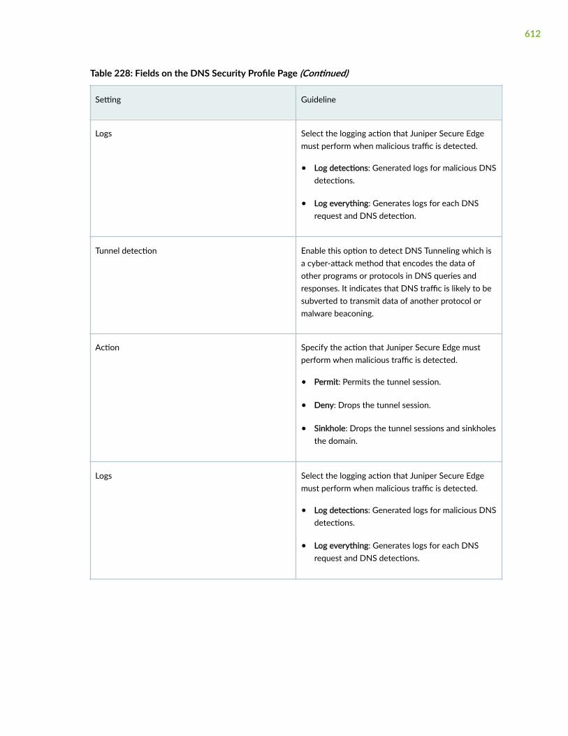
Table 228: Fields on the DNS Security Profile Page (Continued)
Setting Guideline
Logs Select the logging action that Juniper Secure Edgemust perform when malicious traffic is detected.
• Log detections: Generated logs for malicious DNSdetections.
• Log everything: Generates logs for each DNSrequest and DNS detection.
Tunnel detection Enable this option to detect DNS Tunneling which isa cyber-attack method that encodes the data ofother programs or protocols in DNS queries andresponses. It indicates that DNS traffic is likely to besubverted to transmit data of another protocol ormalware beaconing.
Action Specify the action that Juniper Secure Edge mustperform when malicious traffic is detected.
• Permit: Permits the tunnel session.
• Deny: Drops the tunnel session.
• Sinkhole: Drops the tunnel sessions and sinkholesthe domain.
Logs Select the logging action that Juniper Secure Edgemust perform when malicious traffic is detected.
• Log detections: Generated logs for malicious DNSdetections.
• Log everything: Generates logs for each DNSrequest and DNS detections.
612

Create an Encrypted Traffic Insights Profile
Encrypted traffic insights (ETI) detects malicious threats hidden in encrypted traffic without interceptingand decrypting the traffic.1. Select Secure Edge > Security Subscriptions > ETI.
The ETI Profile page opens.
2. Complete the configuration according to the guidelines provided in Table 229 on page 613.
3. Click Save.
Table 229: Fields on the ETI Profile Page
Setting Guideline
Encrypted Traffic Insights (ETI) Enable this option to detect malicious threats hiddenin an encrypted traffic without intercepting anddecrypting the traffic.
Logs Select the action that Juniper Secure Edge must takewhen malicious traffic is detected.
• Log detections: Generated logs for malicioustraffic detections.
• Log everything: Generates logs for eachencrypted traffic session and malicious trafficdetections.
613

CHAPTER 33
Service Administration
IN THIS CHAPTER
Certificate Management Overview | 614
About the Certificate Management Page | 615
Generate a Certificate | 617
Upload and Download a Certificate | 619
Regenerate and Delete a Certificate | 620
Proxy Auto Configuration Files Overview | 621
About the PAC Page | 621
Manually Add a PAC File to a Web Browser | 623
Edit, Clone, and Delete a Proxy Auto Configuration File | 625
Configure an Explicit Proxy Profile | 626
Create a URL Category | 627
Create a URL Pattern | 628
About the Addresses Page | 630
Create Addresses or Address Groups | 632
Edit, Clone, and Delete Addresses and Address Groups | 635
Decrypt Profiles Overview | 637
About the Decrypt Profiles Page | 641
Create a Decrypt Profile | 643
Edit, Clone, and Delete a Decrypt Profile | 645
Certificate Management Overview
Typically, users gain access to resources from an application or system on the basis of their usernameand password. You can also use certificates to authenticate and authorize sessions among variousservers and users. Certificate-based authentication over a Secure Sockets Layer (SSL) connection is the
614

most secure type of authentication. The certificates can be stored on a smart card, a USB token, or acomputer’s hard drive.
Certificate Management manages the device certificates to authenticate Secure Socket Layer (SSL). SSLuses public-private key technology that requires a paired private key and an authentication certificatefor providing the SSL service. SSL encrypts communication between your device and the Web browserwith a session key negotiated by the SSL server certificate.
SSL proxy acts as an intermediary, performing SSL encryption and decryption between the client and theserver. Better visibility into application usage can be made available when SSL forward proxy is enabled.SSL proxy relies on certificates and private-public key exchange pairs to provide the securecommunication. Transport Layer Security (TLS) evolved from SSL, hence the terms TLS and SSL aresometimes used interchangeably in the document.
About the Certificate Management Page
IN THIS SECTION
Tasks You Can Perform | 615
To access this page, select Secure Edge > Service Administration > Certificate Management.
You must manage the device certificates to establish Transport Layer Security (TLS) or Secure SocketLayer (SSL) sessions. TLS or SSL uses public-private key technology that requires a paired private keyand an authentication certificate. SSL encrypts communication between the web browser and webserver with a session key negotiated by the SSL server certificate. Device certificates are required forboth on-premises users and roaming users. The certificate generation is a one-time activity and youmust do it before deploying the security policies.
Use this page to manage TLS/SSL certificate that is used to establish secure communications betweenSecure Edge and user endpoints. The certificates may be signed by your own Certificate Authority (CA)or by Juniper's CA. You may create a new certificate signing requests (CSR) that can be used to generatea new certificate by your own CA or you can have Juniper Networks create a new certificate.
Tasks You Can Perform
You can perform the following tasks from this page:
• Generate a CSR or a Juniper Networks issued certificate. See "Generate a Certificate" on page 617.
615

• Upload a certificate. See "Upload and Download a Certificate" on page 619.
• Download a certificate. See "Upload and Download a Certificate" on page 619.
• Regenerate a certificate. See "Regenerate and Delete a Certificate" on page 620.
• Delete a certificate. See "Regenerate and Delete a Certificate" on page 620.
• View details of a certificate. To do this, select an existing certificate and click More > Detail. Thedetails of the certificate appears on the right-hand side of the page. Also, when you hover over thecertificate name, a Detailed View icon appears before the certificate name. You can also use this iconto view the certificate details.
• Search for a text in a certificate. To do this, click the search icon in the top right corner of a page tosearch for text containing letters and special characters on that page. To search for text: Enter partialtext or full text of the keyword in the search bar and click the search icon. The search results aredisplayed. Click X next to a search keyword or click Clear All to clear the search results.
• Show or hide columns in the Certificate Management table. To do this, use the Show Hide Columnsicon in the top right corner of the page and select the options you want to show or deselect to hideoptions on the page.
Table 230 on page 616 provides the details of the fields of the Certificate Management page.
Table 230: Fields on the Certificate Management Page
Field Description
Name Displays the name of the certificate.
Certificate name is unique across the device. This willbe used to create a key pair along with the algorithm toassociate with the key.
Type Displays the certificate type:
• Custom—new certificate signing request (CSR)
• Juniper issued certificate
Expiry Date Displays certificate expiration date.
Encryption Type Displays whether the algorithm of the certificate isRSA, DSA, or ECDSA encryption.
616

Generate a Certificate
You can create a new Certificate Signing Request (CSR) or Juniper Networks issued certificate from theCertificate Management page.
• CSR—Choose CSR if your company maintains a Private Key Infrastructure (PKI) and certificateauthority (CA), and can generate its own certificates. By issuing a CSR on Security Director Cloud,you will not need to upload the private key of the certificate to Juniper Security Director Cloud. Afterthe CSR is generated by Juniper Secure Edge, download the CSR and submit it to your CA togenerate a new certificate. Once generated, click Upload to upload the certificate on the CertificateManagement page.
• Juniper issued certificate—Choose Juniper Networks Issued Certificate if your company does nothave its own CA. Juniper Networks will generate and keep the certificate on the system. Once thecertificate has been generated, click Download to download the certificates. The CA certificate willbe downloaded. Distribute the certificates to your managed devices.
To generate a certificate:
1. Select Secure Edge > Service Administration > Certificate Management.
The Certificate Management page appears.
2. Select Generate > Certificate signing request or Juniper issued certificate..
The Generate Certificate Signing Request or Generate Juniper Issued Certificate page appears.
3. Complete the configuration according to the guidelines in Table 231 on page 617.
NOTE: Fields marked with an asterisk (*) are mandatory.
Table 231: Generate Certificate Settings
Setting Guideline
Name Displays the name of the certificate.
For example, jsec-ssl-proxy-root-cert. For a CSR, thecertificate name is jsec-ssl-proxy-root-cert(CSRRequest).
Common name Enter a common name for the certificate.
617

Table 231: Generate Certificate Settings (Continued)
Setting Guideline
Organization name Enter the organization name that you want toassociate with the certificate.
Organization unit name Enter the organization unit or department that youwant to associate with the certificate.
Email address Enter the e-mail address of the certificate holder.
Country Select the country from where you are creating thiscertificate.
State or province Select the state or region from where you arecreating this certificate.
Locality Select the locality from where you are creating thiscertificate.
Cryptographic Settings
Algorithm Displays the algorithm or encryption type used tosign the certificate.
No. of bits Displays the bit length size for the algorithm.
Digest Displays the digests available for the certificate.
Expiration Displays the validity period of the certificate.
4. Click OK.
The Certificate Management page opens with a message indicating that the certificate is createdsuccessfully.
618

Upload and Download a Certificate
IN THIS SECTION
Upload a Certificate | 619
Download a Certificate | 619
You can upload and download a certificate from the Certificate Management page. This topic has thefollowing sections:
Upload a Certificate
Manually upload the selected CSR signed certificate or an externally generated certificate to the device.Only certificate with .pem format and RSA algorithm are supported. Before you proceed, make sure thatthe signed certificate is available on your local system.To upload a signed certificate:
1. Select Secure Edge > Service Administration > Certificate Management.
The Certificate Management page appears.
2. Select a CSR certificate or an externally generated certificate and click Upload.
The Upload Certificate page appears.
3. Click Browse and navigate to the location of the signed certificate file on your local system.
NOTE: Ensure that the uploaded .pem file exactly matches with the selected certificate. Ifthere is a mismatch, then the traffic processing will fail at Juniper Secure Edge.
4. Select the signed certificate and click Open.
5. Click OK.
You are taken to the Certificate Management page. If the certificate content that you imported isvalidated successfully, a confirmation message is displayed; if not, an error message is displayed.
After uploading a signed certificate, you can use it when you create an SSL proxy profile.
Download a Certificate
To download a certificate:
1. Select Secure Edge > Service Administration > Certificate Management.
The Certificate Management page appears.
619

2. Select a CSR certificate or an externally generated certificate and click Download.
The certificate is downloaded to your system.
Regenerate and Delete a Certificate
IN THIS SECTION
Regenerate a Certificate | 620
Delete a Certificate | 620
You can regenerate or delete an existing certificate from the Certificate Management page. This topichas the following sections:
Regenerate a Certificate
You can regenerate a certificate a few days in advance if the certificate is about to expire.You can either regenerate a Juniper issued certificate or a CSR for customer issued certificate.
To regenerate a certificate:
1. Select Secure Edge > Service Administration > Certificate Management.
The Certificate Management page appears.
2. Select a CSR certificate or an externally generated certificate and click Regenerate.
A message indicating the status of the regenerate certificate operation is displayed.
Delete a Certificate
You delete a certificate when you do not want to trust a certificate authority in Juniper Secure Edge.
To delete a certificate:
1. Select Secure Edge > Service Administration > Certificate Management.
The Certificate Management page appears.
2. Select the certificate that you want to delete.
3. On the upper right side of the Certificate Management page, click the delete icon (trash can).
A confirmation window appears.
4. Click Yes to delete.
620

NOTE: You must delete a certificate before you delete a tenant.
Proxy Auto Configuration Files Overview
A proxy auto configuration (PAC) file tells a browser where to direct the traffic for a URL. Depending onthe proxy auto configuration file configuration, the traffic destination can be a proxy server or a realcontent server.
A proxy auto configuration file contains several mappings between the source, destination and the nexthop, such as:
• Source IP subnets and their proxy servers.
• Destination domains and URLs and their proxy servers.
• Source IP subnets that are not to be proxied.
• Destination domains and URLs that are not to be proxied.
When you create a new organization, a recommended proxy auto configuration file is automaticallygenerated. You can download the configuration file or clone and edit the file. You cannot edit theoriginal proxy auto configuration file.
About the PAC Page
IN THIS SECTION
Tasks You Can Perform | 622
Field Descriptions | 622
To access the PAC page, click Secure Edge > Service Administration > PAC Files.
Use the PAC page to download the proxy auto configuration files, clone the configuration files and editthe cloned files.
621

Tasks You Can Perform
You can perform the following tasks from this page:
• Edit, clone, or delete a proxy auto configuration file—See "Edit, Clone, and Delete a Proxy AutoConfiguration File" on page 625.
• View the details of a proxy auto configuration file—Select the configuration file to view the details,and from the More or right-click menu, select Detail. The Details page opens. Table 232 on page622 describes the fields on this page.
• Search for proxy auto configuration files using keywords—Click the search icon and enter the searchterm in the text box, and press Enter. The search results open on the same page.
Field Descriptions
Table 232 on page 622 describes the fields on the PAC page.
Table 232: Fields on the PAC Page
Field Description
Name The name of the proxy auto configuration file.
Predefined/Custom Indicates whether the proxy auto configuration file isautomatically generated or edited.
URL The URL of the proxy auto configuration file.
Description The description of the proxy auto configuration file.
Created Time The time when the proxy auto configuration file iscreated.
Table 233: Details Page Fields
Field Description
General Information
622

Table 233: Details Page Fields (Continued)
Field Description
Name The name of the proxy auto configuration file.
Description The description of the proxy auto configuration file.
URL The URL of the proxy auto configuration file.
XML Code The XML-based code in the proxy auto configurationfile.
Manually Add a PAC File to a Web Browser
IN THIS SECTION
Add a PAC File to Google Chrome in Microsoft Windows | 623
Add a PAC File to Mozilla Firefox in Microsoft Windows | 624
The following procedures explain steps to manually add a PAC file to the Google Chrome and MozillaFirefox web browsers in Microsoft Windows.
To know more about proxy settings for Mac, see here.
Add a PAC File to Google Chrome in Microsoft Windows
1. Open Google Chrome.
2. Go to the Settings page.
3. In the Search field, search for the "proxy" string.
4. In the search result, click Open your computer's proxy settings.The Proxy page opens.
623

5. Enable Use setup script.
Figure 10: Manually Add a PAC File to Google Chrome in Microsoft Windows
6. Click Save.
Add a PAC File to Mozilla Firefox in Microsoft Windows
1. Open Mozilla Firefox.
2. Go to the Settings page.
3. In the Search field, search for the "proxy" string.
4. In the search results, click Network Settings.
The Connection Settings page opens.
5. Select the Automatic proxy configuration URL option.
624

6. Copy the PAC URL in the Automatic proxy configuration URL field.
Figure 11: Manually Add a PAC File to Mozilla Firefox in Microsoft Windows
7. Click OK.
Edit, Clone, and Delete a Proxy Auto Configuration File
IN THIS SECTION
Edit a Proxy Auto Configuration File | 626
Clone a Proxy Auto Configuration File | 626
Delete Proxy Auto Configuration Files | 626
You can edit, clone, and delete proxy auto configuration files from the PAC page.
625

Edit a Proxy Auto Configuration File
You cannot edit the default Proxy Auto Configuration file. You must first clone the default file, and editthe cloned file.
1. Click Secure Edge > Service Administration > PAC Files.
2. Select a PAC file, and click the pencil icon.
The Edit PAC <PAC file name> page opens.
3. Edit the parameters.
You cannot edit the name and URL of a PAC file.
4. Click OK.
The changes are saved, and the PAC page opens.
Clone a Proxy Auto Configuration File
1. Click Secure Edge > Service Administration > PAC Files.
The Clone PAC <PAC file name> page opens.
2. Select a PAC file, and click More > Clone.
3. Edit the parameters.
You cannot edit the name and URL of a PAC file.
4. Click OK.
The changes are saved, and the PAC page opens with a confirmation message indicating the status ofthe clone operation.
Delete Proxy Auto Configuration Files
1. Click Secure Edge > Service Administration > PAC Files.
2. Select the proxy auto configuration files to delete, and click the delete icon.
A message asking you to confirm the delete operation is displayed
3. Click Yes to delete the selected files.
A confirmation message is displayed indicating the status of the delete operation.
Configure an Explicit Proxy Profile
The explicit proxy profile tells Secure Edge which port to listen to for the client-side traffic and whichtraffic to decrypt or bypass.
626
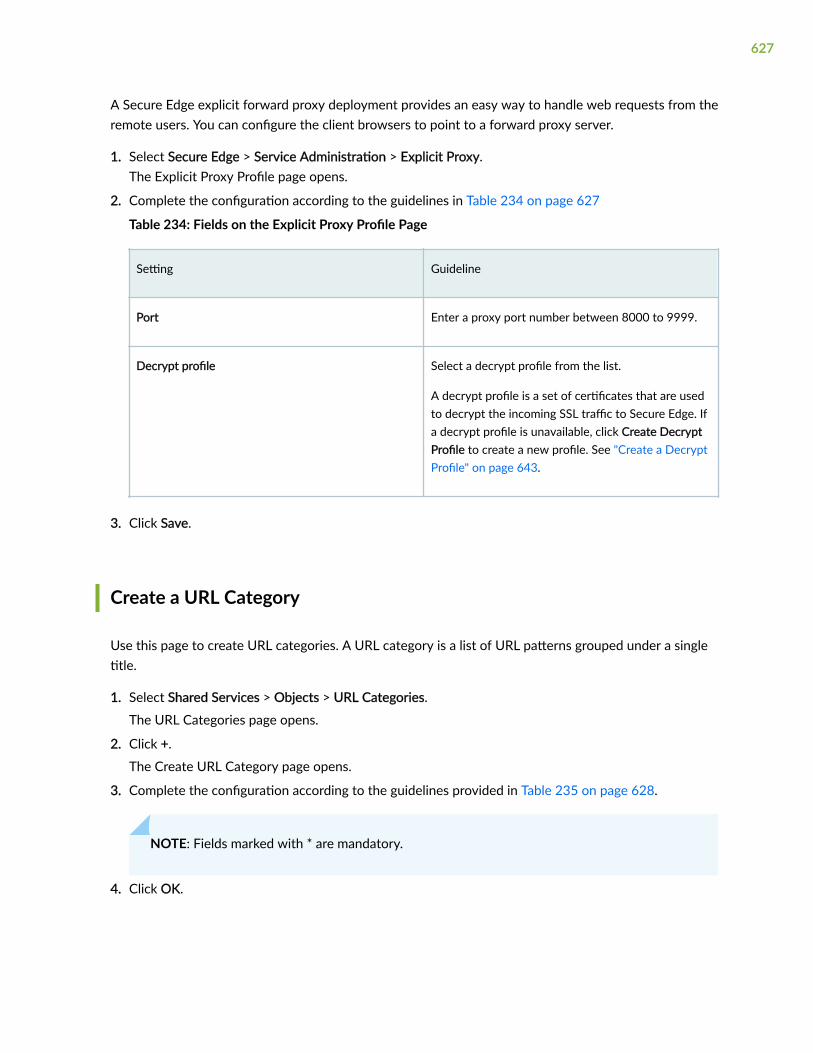
A Secure Edge explicit forward proxy deployment provides an easy way to handle web requests from theremote users. You can configure the client browsers to point to a forward proxy server.
1. Select Secure Edge > Service Administration > Explicit Proxy.The Explicit Proxy Profile page opens.
2. Complete the configuration according to the guidelines in Table 234 on page 627
Table 234: Fields on the Explicit Proxy Profile Page
Setting Guideline
Port Enter a proxy port number between 8000 to 9999.
Decrypt profile Select a decrypt profile from the list.
A decrypt profile is a set of certificates that are usedto decrypt the incoming SSL traffic to Secure Edge. Ifa decrypt profile is unavailable, click Create DecryptProfile to create a new profile. See "Create a DecryptProfile" on page 643.
3. Click Save.
Create a URL Category
Use this page to create URL categories. A URL category is a list of URL patterns grouped under a singletitle.
1. Select Shared Services > Objects > URL Categories.
The URL Categories page opens.
2. Click +.
The Create URL Category page opens.
3. Complete the configuration according to the guidelines provided in Table 235 on page 628.
NOTE: Fields marked with * are mandatory.
4. Click OK.
627

Table 235: Fields on the Create URL Categories Page
Settings Guidelines
Name Enter a unique name containing maximum 59characters.
The name must begin with a letter or an underscoreand can contain alphanumeric characters and specialcharacters such as dashes and underscores
Description Enter a description containing maximum 255characters.
URL Patterns Select minimum one URL pattern to add in your URLcategory.
NOTE: You can also add URL patterns by clicking + toopen the Create URL Pattern page. See "Create aURL Pattern" on page 628.
A new URL category is created and the URL Categories page opens.
Create a URL Pattern
Use this page to create URL patterns. You can also assign URL patterns to a URL category.
1. Select Shared Services > Objects > URL Patterns.
The URL Patterns page opens.
2. Click +.
The Create URL Pattern page opens.
3. Complete the configuration according to the guidelines provided in Table 236 on page 629.
NOTE: Fields marked with * are mandatory.
4. Click OK.
628

Table 236: Fields on the Create URL Patterns Page
Settings Guidelines
Name Enter a unique name containing maximum 27characters.
The name must begin with a letter or an underscoreand can contain alphanumeric characters and specialcharacters such as dashes and underscores.
Description Enter a description containing maximum 255characters.
Add URLs Click +, and enter URLs in the text box.
• The following wildcard characters are supportedin the text box:
• asterisk (*)—Can only be used at thebeginning of a URL and must be followed by aperiod (.).
• period (.)
• square brackets ([])
• question mark (?)—Can only be used at theend of a URL.
• All URL patterns containing wildcard charactersmust begin with http://.
• The following types of wildcard syntaxes aresupported: http://*.example.net, http://www.example.ne?, and http://www.example.n??.
• The following types of wildcard syntaxes are notsupported: *.example.???, http://*example.net,http://?, and www.example.ne?.
The URLs are displayed in the URL list.
A new URL pattern is created and the URL Patterns page opens.
629

About the Addresses Page
IN THIS SECTION
Tasks You Can Perform | 630
Field Descriptions | 631
To access this page, select Shared Services > Objects > Addresses.
An address specifies an IP address or a host name. You can create addresses that can be used across allpolicies. Addresses are used in firewall and NAT services and apply to the corresponding policies. If youknow only the host name, you enter it into the Hostname field and use the address resolution option toresolve it to an IP address. You can also resolve an IP address to the corresponding host name.
Juniper Secure Edge manages its address book at the global level, assigning objects to devices that arerequired to create policies. An address book is a collection of addresses and address groups that areavailable in a security zone. If the device is capable of using a global address book, Juniper Secure Edgepushes address objects used in the policies to the global address book of the device.
Use this page to create, edit, clone, and delete addresses and address groups. Addresses and addressgroups are used in firewall and NAT services. After you create an address, you can combine it with otheraddresses to form an address group. Address groups are useful when you want to apply the same policyto multiple services.
Tasks You Can Perform
You can perform the following tasks from this page:
• Create an address or address group. See "Create Addresses or Address Groups" on page 632.
• Modify, clone, or delete an address or address group. See "Edit, Clone, and Delete Addresses andAddress Groups" on page 635.
• View the configured parameters of an address or address group. Click the details icon that appearswhen you hover over the name of an address or address group or select More > Detailed View.
• Show or hide columns about the address or address group. Click the Show Hide columns icon in thetop right corner of the page and select columns that you want to view on the page.
• Filter information based on select criteria. You can add filters, save the filters, and set any of thefilters as default. To add a filter:
630

1. Click on the filter icon on the top-right corner of the page and select Add Filter to open the AddCriteria page.
2. Set the filter conditions and click Add.
The filter is saved and the filter is applied on the data on the page. Filter can be saved and can markany one filter as default.
To remove the filter, click on the filter icon and select Hide Filter.
• Search for an address or address group. Click the Search icon in the top right corner of the page tosearch for an address or address group.
You can enter partial text or full text of the keyword in the text box and press Enter.
The search results are displayed on the same page.
Field Descriptions
Table 237 on page 631 provides guidelines on using the fields on the Addresses page.
Table 237: Fields on the Addresses Page
Field Description
Name The name of the address or address group.
Type The type of the address object.
Hostname The host name of the address.
IP Address The IP address associated with the address.
Description The description of the address or address group.
631

Create Addresses or Address Groups
Use this page to create addresses and address groups. After you create an address, you can combine itwith other addresses to form an address group. Address groups are useful when you want to apply thesame policy to multiple services.
1. Select Shared Services > Objects > Addresses.
The Addresses page opens.
2. Click +.
The Create Address page opens.
3. Complete the configuration according to the guidelines provided in Table 238 on page 632 andTable 239 on page 634.
4. Click OK.
Table 238: Fields on the Create Addresses Page
Field Description
Name Enter a unique name containing maximum 63characters.
The name must begin with an alphanumericcharacter and can contain alphanumeric charactersand special characters such as colons, hyphens,slashes, periods, and underscores.
Description Enter a description containing maximum 900characters.
The description can contain alphanumeric charactersand special characters except ampersand, angularbrackets, or a new line.
You should make this description as useful aspossible for all administrators.
Object Type Select Address or Address Group.
If you select Address Group, the screen changes foryou to select the addresses to include in youraddress group. Table 239 on page 634 describesaddress group configuration parameters.
632

Table 238: Fields on the Create Addresses Page (Continued)
Field Description
Type Select one of the following address types andconfigure the corresponding fields:
• Host
• Host IP—Enter the IPv4 host IP address. Forexample, 192.0.2.0. If you don't know the IPaddress, you can enter the host name, andclick Look up hostname.
• Hostname—Enter a host name containingmaximum 63 characters. The host name mustbegin with an alphanumeric character and cancontain special characters such as dashes andunderscores. For example,www.company.com. If you don't know thehost name, you can enter the IP address, andclick Look up IP address. The host namelookup is supported for IPv4 addresses.
• Range
• Start Address—Enter a starting IPv4 addressalong with the classless inter-domain routing(CIDR) for the address range. Forexample,192.0.2.0/24.
• End Address—Enter an ending IPv4 addressfor the address range.
The address range is validated after you enter theaddresses.
NOTE: An address range is configured on amanaged device as an address set with one ormore network address objects covering thespecified address range.
• Network
633

Table 238: Fields on the Create Addresses Page (Continued)
Field Description
• Network—Enter the network IP address. Forexample,192.0.2.0 for an IPv4 or2001:db8:4136:e378:8000:63bf:3fff:fdd2 foran IPv6 address.
• Subnet Mask—Enter the subnet mask for thenetwork range. For example, 192.0.2.0/24 foran IPv4 netmask or 2001:db8::/32 for an IPv6prefix. The subnet mask is validated as youenter it. You must enter the correct subnetmask based on the network value.
• DNS Host
DNS Name—Enter the DNS name containingmaximum 63 characters. The DNS name mustend with an alphanumeric character and cancontain alphanumeric characters and specialcharacters such as dashes and periods.
Table 239: Fields on the Address Group Page
Field Description
Name Enter a unique name containing maximum 63characters.
The name must begin with an alphanumericcharacter and can contain alphanumeric charactersand special characters such as colons, hyphens,slashes, periods, and underscores.
634

Table 239: Fields on the Address Group Page (Continued)
Field Description
Description Enter a description containing maximum 900characters.
The description can contain alphanumeric charactersand special characters except ampersand, angularbrackets, or a new line.
You should make this description as useful aspossible for all administrators.
Object Type Select Address Group.
The screen changes for you to select the addressesto include in your address group.
Addresses Select the addresses to include in your addressgroup.
You can use the fields at the top of each column tosearch for addresses.
A new address or address group with your configurations is created.
Edit, Clone, and Delete Addresses and Address Groups
IN THIS SECTION
Edit Addresses and Address Groups | 636
Clone Addresses and Address Groups | 636
Delete Addresses and Address Groups | 636
You can edit, clone, and delete addresses and address groups from the Addresses page.
635

NOTE: You cannot edit or delete predefined addresses.
Edit Addresses and Address Groups
If you edit an address that is a deployed as part of a policy, you must redeploy the policy for the changesto take effect.
1. Select Shared Services > Objects > Addresses.
The Addresses page opens.
2. Select the address or address group to edit, and click the pencil icon.
The Edit Address page opens.
3. Edit the parameters according to the guidelines provided in "Create Addresses or Address Groups" onpage 632.
NOTE: You cannot edit Address Name and Object Type.
4. Click OK.
The changes are saved, and the modified address or address group is displayed on the Addresses page.
Clone Addresses and Address Groups
1. Select Shared Services > Objects > Addresses.
The Addresses page opens.
2. Select the address or address group, and click More > Clone.
The Clone Address page opens.
3. Edit the parameters according to the guidelines provided in "Create Addresses or Address Groups" onpage 632.
4. Click OK.
The changes are saved, and the cloned address or address group is displayed on the Addresses page.
Delete Addresses and Address Groups
You can delete only addresses or address groups that are not referenced in any policy.
1. Select Shared Services > Objects > Addresses.
The Addresses page opens.
2. Select the addresses or address groups to delete, and click the delete icon.
A message asking you to confirm the delete operation is displayed
636

3. Click Yes to delete the addresses or address groups.
A confirmation message is displayed indicating the status of the delete operation. If the addresses oraddress groups are referenced in a policy, an error message is displayed.
Decrypt Profiles Overview
IN THIS SECTION
Server Authentication | 638
Root CA | 639
Trusted CA List | 639
Session Resumption | 639
SSL Proxy Logs | 639
Juniper Secure Edge attempts to decrypt all SSL/TLS traffic by default. Decrypt profiles allow you todefine the types of traffic that should be exempted from decryption.
SSL is an application-level protocol that provides encryption technology for the Internet. SSL, also calledTLS, ensures the secure transmission of data between a client and a server through a combination ofprivacy, authentication, confidentiality, and data integrity. SSL relies on certificates and private–publickey exchange pairs for this level of security.
Server authentication guards against fraudulent transmissions by enabling a Web browser to validatethe identity of a Web server. Confidentiality mechanisms ensure that communications are private. SSLenforces confidentiality by encrypting data to prevent unauthorized users from eavesdropping onelectronic communications. Finally, message integrity ensures that the contents of a communicationhave not been tampered with.
SSL proxy performs SSL encryption and decryption between the client and the server, but neither theserver nor the client can detect its presence. SSL proxy ensures that it has the keys to encrypt anddecrypt the payload:
• For the server, SSL proxy acts as a client—SSL proxy generates the shared pre-master key, itdetermines the keys to encrypt and decrypt.
• For the client, SSL proxy acts as a server—SSL proxy first authenticates the original server andreplaces the public key in the original server certificate with a key that is known to it. It then
637

generates a new certificate by replacing the original issuer of the certificate with its own identity andsigns this new certificate with its own public key (provided as a part of the proxy profileconfiguration). When the client accepts such a certificate, it sends a shared pre-master key encryptedwith the public key on the certificate. Because SSL proxy replaced the original key with its own key, itis able to receive the shared pre-master key. Decryption and encryption take place in each direction(client and server), and the keys are different for both encryption and decryption.
SSL proxy uses the following services:
• SSL-T-SSL terminator on the client side.
• SSL-I-SSL initiator on the server side.
This topic has the following sections:
Server Authentication
Implicit trust between the client and the device (because the client accepts the certificate generated bythe device) is an important aspect of SSL proxy. It is extremely important that server authentication isnot compromised; however, in reality, self-signed certificates and certificates with anomalies are inabundance. Anomalies can include expired certificates, instances of common name not matching adomain name, and so forth.
You can specify that the SSL proxy should ignore server authentication completely. In this case, SSLproxy ignores errors encountered during the server certificate verification process (such as CA signatureverification failure, self-signed certificates, and certificate expiry).
You can specify whether the SSL proxy should ignore server authentication errors or not during thecreation of an SSL proxy profile.
• If you specify that server authentication errors should not be ignored, the following scenarios occur:
• If authentication succeeds, a new certificate is generated by replacing the keys and changing theissuer name to the issuer name that is configured in the root CA certificate in the proxy profile.
• If authentication fails, the connection is dropped.
• If you specify that server authentication errors should be ignored, the following scenarios occur:
NOTE: We do not recommend that you configure this option for authentication becauseconfiguring it results in websites not being authenticated at all. However, you can use thisoption to effectively identify the root cause for dropped SSL sessions.
638

• If the certificate is self-signed, a new certificate is generated by replacing the keys only. The issuername is not changed. This ensures that the client browser displays a warning that the certificate isnot valid.
• If the certificate has expired or if the common name does not match the domain name, a newcertificate is generated by replacing the keys and changing the issuer name to SSL-PROXY:DUMMY_CERT:GENERATED DUE TO SRVR AUTH FAILURE. This ensures that the clientbrowser displays a warning that the certificate is not valid.
Root CA
In a public key infrastructure (PKI) hierarchy, the root CA is at the top of the trust path. The root CAidentifies the server certificate as a trusted certificate.
Trusted CA List
SSL proxy ensures secure transmission of data between a client and a server. Before establishing asecure connection, SSL proxy checks certificate authority (CA) certificates to verify signatures on servercertificates. For this reason, a reasonable list of trusted CA certificates is required to effectivelyauthenticate servers.
Session Resumption
An SSL session refers to the set of parameters and encryption keys that are created when a fullhandshake is performed. A connection is the conversation or active data transfer that occurs within thesession. The computational overhead of a complete SSL handshake and generation of primary keys isconsiderable. In short-lived sessions, the time taken for the SSL handshake can be more than the timefor data transfer. To improve throughput and still maintain an appropriate level of security, SSL sessionresumption provides a mechanism for caching sessions. This way, session information, such as the pre-master secret key and agreed-upon ciphers, can be cached for both the client and the server. A sessionID identifies the cached information. In subsequent connections, both parties agree to use the sessionID to retrieve the information rather than create pre-master secret key. Session resumption shortens thehandshake process and accelerates SSL transactions.
SSL Proxy Logs
When logging is enabled in a decrypt profile, the SSL proxy can generate the messages shown in Table240 on page 640.
639

Table 240: SSL Proxy Logs
Log Type Description
All All logs are generated.
Warning Logs used for reporting warnings.
Info Logs used for reporting general information.
Error Logs used for reporting errors.
Session Whitelisted Logs generated when a session is allowed.
Session Allowed Logs generated when a session is processed by SSLproxy even after encountering some minor errors.
Session Dropped Logs generated when a session is dropped by SSLproxy.
All logs contain similar information; the message field contains the reason for the log generation. One ofthree prefixes shown in Table 241 on page 640 identifies the source of the message. Other fields aredescriptively labeled.
Table 241: SSL Proxy Log Prefixes
Prefix Description
system Logs generated because of errors related to the deviceor an action taken as part of the decrypt profile. Mostlogs fall into this category.
openssl error Logs generated during the handshake process if anerror is detected by the openssl library.
640

Table 241: SSL Proxy Log Prefixes (Continued)
Prefix Description
certificate error Logs generated during the handshake process if anerror is detected in the certificate (X.509 relatederrors).
About the Decrypt Profiles Page
IN THIS SECTION
Tasks You Can Perform | 641
Field Descriptions | 641
To access this page, click Secure Edge > Service Administration > Decrypt Profiles.Use the Decrypt Profiles page to view and to manage decrypt profiles.
Tasks You Can Perform
You can perform the following tasks from this page:
• Create a decrypt profile—See "Create a Decrypt Profile" on page 643
• Edit, clone, or delete a decrypt profile—See "Edit, Clone, and Delete a Decrypt Profile" on page 645.
• View the details of a decrypt profile—Select the decrypt profile to view the details, and from theMore or right-click menu, select Detailed View. The View decrypt profile Details page opens. Table242 on page 642 describes the fields on this page.
• Search for decrypt profiles using keywords—Click the search icon and enter the search term in thetext box, and press Enter. The search results open on the same page.
Field Descriptions
Table 242 on page 642 describes the fields on the Decrypt Profiles page.
641

Table 242: Fields on the Decrypt Profiles Page
Field Description
Name The name of the decrypt profile.
Exempted Address The addresses that are exempted from decryptprocessing.
Description The description of the decrypt profile.
Root Certificate The root certificate associated with the decrypt profile.
Table 243: View Decrypt Profile Details Page Fields
Field Description
General Information
Name The name of the decrypt profile.
Description The description of the decrypt profile.
Root certificate Displays the root certificate authorities associated withthe root certificate.
Exempted address The addresses that are exempted from decryptprocessing.
Exempted URL categories The URL categories that are exempted from decryptprocessing.
642

Create a Decrypt Profile
Use this page to configure decrypt profiles. The decrypt profile is enabled as an application servicewithin a security policy.
NOTE: Ensure that you have a root certificate imported for the organization before you create adecrypt profile. You can import SSL certificates (root and trusted) from the CertificateManagement page (Secure Edge > Service Management > Certificate Management) and associatethe certificates with decrypt profiles.
1. Select Secure Edge > Service Administration > Decrypt.
The Decrypt Profiles page opens.
2. Click +.
The Create Decrypt Profile page opens.
3. Complete the configuration according to the guidelines provided in Table 244 on page 643.
Fields marked with an asterisk (*) are mandatory.
4. Click OK.
Table 244: Fields on the Decrypt Profile Page
Setting Guideline
General Information
Name Enter a unique name without spaces containingmaximum 63 characters.
The name can contain alphanumeric characters andspecial characters such as hyphens and underscores.
Description Enter a description containing maximum 255characters.
643

Table 244: Fields on the Decrypt Profile Page (Continued)
Setting Guideline
Root certificate Select or add a root certificate. In a public keyinfrastructure (PKI) hierarchy, the root certificateauthority (CA) is at the top of the trust path.
NOTE: To select the root certificate from the device,you must ensure that at least one trusted certificateis installed on the device.
Exempted URL categories Select the previously defined URL categories tocreate allowlists that bypass decrypt processing. Theselected URL categories are exempted during SSLinspection.
NOTE: You can also add URL categories by clicking +to open the Create URL Category page. See "Createa URL Category" on page 627.
Exempted addresses Select the previously defined addresses to createallowlists that bypass decrypt processing. Theselected addresses are exempted during SSLinspection.
Because SSL encryption and decryption arecomplicated and expensive procedures, networkadministrators can selectively bypass decryptprocessing for some sessions.
Such sessions typically include connections andtransactions with trusted servers or domains withwhich network administrators are very familiar. Thereare also legal requirements to exempt financial andbanking sites. Such exemptions are achieved byconfiguring the IP addresses or domain names of theservers under allowlists.
NOTE: You can also add addresses by clicking + toopen the Create Addresses page. See "CreateAddresses or Address Groups" on page 632.
An decrypt profile is created, and the Decrypt Profiles page opens displaying a confirmation message.
644

Edit, Clone, and Delete a Decrypt Profile
IN THIS SECTION
Edit a Decrypt Profile | 645
Clone a Decrypt Profile | 645
Delete a Decrypt Profile | 645
You can edit, clone, and delete decrypt profiles from the Decrypt Profiles page.
Edit a Decrypt Profile
1. Select Secure Edge > Service Administration > Decrypt Profiles.
The Decrypt Profiles page opens displaying the existing decrypt profiles.
2. Select the decrypt profile, and click the pencil icon.
The Edit Decrypt Profile page opens.
3. Edit the parameters according to the guidelines provided in "Create a Decrypt Profile" on page 643.
4. Click OK.
The changes are saved, and the Decrypt Profiles page opens.
Clone a Decrypt Profile
Cloning enables you to easily create a decrypt profile based on an existing one.
1. Select Secure Edge > Service Administration > Decrypt Profiles.
The Decrypt Profiles page opens displaying the existing decrypt profiles.
2. Select the decrypt profile, and select More > Clone.
The Clone decrypt profile page opens.
3. Edit the parameters according to the guidelines provided in "Create a Decrypt Profile" on page 643.
4. Click OK.
The changes are saved, and the Decrypt Profiles page opens with a confirmation message indicating thestatus of the clone operation.
Delete a Decrypt Profile
1. Select Secure Edge > Service Administration > Decrypt Profiles.
The Decrypt Profiles page opens displaying the existing decrypt profiles.
645

2. Select the decrypt profiles to delete, and click the delete icon.
A message asking you to confirm the delete operation is displayed
3. Click Yes to delete the selected decrypt profiles.
A confirmation message is displayed indicating the status of the delete operation.
646

CHAPTER 34
Identity
IN THIS CHAPTER
End User Authentication Overview | 647
About the End User Authentication Page | 648
Add an End User Profile | 659
Edit and Delete an End User Profile | 661
Add a Group | 662
Edit and Delete a Group | 664
Juniper Identity Management Service Overview | 665
Onboard JIMS Collector | 666
Create JIMS Collector Service Accounts | 668
Install and Configure JIMS Collector | 669
Configure JIMS Collector to Probe Unknown IP Addresses | 674
View the JIMS Collector Status | 674
End User Authentication Overview
Juniper Secure Edge provides end user authentication service that is tenant-aware and internet-facing.The authentication service is responsible for authenticating users using the preferred authenticationmethods configured by the administrator.
Administrators must authenticate the remote (roaming) users using any one of the following supportedauthentication methods:
• Hosted Database—Use a database hosted on Juniper Secure Edge for authentication andauthorization.
• SAML— Connect to an identity provider (IdP) of your choice over the Internet for authentication. Youuse the Security Assertion Markup Language (SAML) 2.0 framework for authentication using an IdP.
• LDAP—Connect to your organization’s Active Directory service over the Internet for authentication.
647

For user-based firewall policies using group membership, You must first install a Juniper IdentityManagement Service (JIMS) Collector on your network: See "Juniper Identity Management ServiceOverview" on page 665.
Based on the authentication methods configured by the tenant administrator, the user will be re-directed to the login page with those configured authentication methods.
Figure 12: Login Page for End User Authentication
When all three authentication methods are configured, the user can authenticate using the method oftheir choice. For SAML authentication, click Single Sign-On (SSO) and for Hosted DB and LDAPauthentication, click E-mail/Password button. In case both Hosted DB and LDAP are configured, and theuser enters the username and password, then order of authentication is: (1) Hosted DB, (2) LDAP.
About the End User Authentication Page
IN THIS SECTION
Tasks You Can Perform | 649
Create a SAML Profile | 649
Create an LDAP Profile | 653
Manage the Hosted Database | 658
648

To access this page, select Secure Edge > Identity > User Authentication.
Configure authentication profiles to authenticate the end users.
Tasks You Can Perform
You can perform the following tasks from this page:
• Create SAML profile. See "Create a SAML Profile" on page 649.
• Create LDAP Profile. See "Create an LDAP Profile" on page 653
• Manage the Hosted Database. You can view, add, modify, and delete the end user and group profiles.
Create a SAML Profile
To create a SAML profile:
1. Select Secure Edge > Identity > User Authentication .
The End User Authentication page appears with the SAML Profile tab.
2. Complete the configurations according to the guidelines in Table 245 on page 652
649

NOTE: Fields marked with an asterisk (*) are mandatory.
Figure 13: SAML Profile
650

Figure 14: IdP Attributes
Figure 15: IdP Metadata URL
3. Click OK.
651

Table 245: Fields on the SAML Profile tab
Field Description
Name Enter a unique profile name. The name can containalphanumeric characters, underscore, period, andspace.
Domain name Enter the domain name which the end-user belongs to.
Service Provider (SP)
Entity ID Displays the unique identifier for the SAML Profile.
Username attribute Enter the username attribute for SAML.
Username attribute is mandatory and must be in e-mailaddress format. The username attribute is mapped tothe user data, which is provided by IdP in the SAMLassertion response.
Sign auth requests Enable the toggle button to sign the SAMLauthentication requests sent from Juniper Secure Edgeto IdP. If you enable sign authentication requests, youmust provide both private key and public keycertificate.
Private key Enter the private key that you have generated locally.In Juniper Secure Edge, the private key is used to signSAML authentication request. The private key is notshared with IdP.
Public key Enter the public key that you have generated locally.The public key certificate is generated locally by theuser. You must upload the same public key certificatein the IdP portal. In IdP, the public key certificate isused to validate the SAML authentication request sentby Juniper Secure Edge.
652

Table 245: Fields on the SAML Profile tab (Continued)
Field Description
Group attribute Enter the group attribute which the end-user belongsto which is then filtered and sent to IDP.
First name attribute Enter the first name attribute of the SAML user.
The first name attribute is used to create an userprofile.
Last name attribute Enter the last name attribute of the SAML user.
The last name attribute is used to create an userprofile.
Identity Provider (IdP)
Metadata URL Enter the IdP metadata URL. The SP uses the metadataURL to validate that the SAML assertions are issuedfrom the correct IdP.
NOTE: For SAML, the retries and the locking period is configurable in SAML server.
Create an LDAP Profile
LDAP profile configuration supports high availability (HA). You must configure both primary andsecondary LDAP servers. If you enable SSL encryption, the default SSL LDAP port number is 636. If youare not using SSL, the default port number is 389.
To create an LDAP profile:
1. Select Secure Edge > Identity > User Authentication .
The End User Authentication page appears.
2. Click LDAP Profile tab.
3. Complete the configurations according to the guidelines in Table 246 on page 656
653

NOTE: Fields marked with an asterisk (*) are mandatory.
654

Figure 16: LDAP Profile
655

4. Click OK.
Table 246: Fields on the LDAP Profile tab
Field Description
LDAP Server
Primary Server
Server address Enter the IP address of LDAP authentication server.The server address is a unique IPv4 or IPv6 addressthat is assigned to a particular LDAP server and usedto route information to the server.
SSL Click to enable SSL encryption. If you enable SSLencryption, you must provide both SSL certificate andport number.
SSL certificate The client certificate for LDAP client to establish anLDAP over SSL connection. If you plan to use SSLencryption with your LDAP server, you must importthe SSL certificate from the LDAP server. Click Browse,select the SSL certificate and click Open.
Port number Specify a port on the LDAP server to which the LDAPclient can connect to. Click Test LDAP ServersConnection to check if the connection is established.
Secondary Server (Optional) Click the toggle button to enable the secondary server.
Server address Enter the IP address of secondary LDAP authenticationserver. The server address is a unique IPv4 or IPv6address that is assigned to a particular LDAP serverand used to route information to the server.
SSL Click to enable SSL encryption. If you enable SSLencryption, you must provide both SSL certificate andport number.
656

Table 246: Fields on the LDAP Profile tab (Continued)
Field Description
SSL certificate* The client certificate for LDAP client to establish anLDAP over SSL connection. If you plan to use SSLencryption with your secondary LDAP server, youmust import the SSL certificate from the LDAP server.Click Browse, select the SSL certificate and click Open.
Port number Specify a port on the secondary LDAP server to whichthe LDAP client can connect to. Click Test LDAPServers Connection to check if the connection isestablished.
LDAP Authentication
Base domain name Enter the distinguished name (DN) of the search base.Configure the distinguished name of the search base(LDAP base) that specifies the base of user directory.Every entry in the directory has a distinguished name(DN). The DN is the name that uniquely identifies anentry in the directory.
Bind domain name Enter the distinguished name of the proxy account ofthe LDAP client to bind to the server with. Configurethe distinguished name to bind the LDAP client withthe LDAP server.
Bind password Enter the credentials of the LDAP client to bind withthe LDAP server. Configure the public key password.Click Test Authentication to check if the credentialsare bound for authentication.
User Options
User attribute Enter the username attribute that is used forcomparing user entries. The username attribute haspermissions to access the LDAP server.
657

Table 246: Fields on the LDAP Profile tab (Continued)
Field Description
User filter Enter a value to use for the search parameter filter inLDAP.
Manage the Hosted Database
End users can be authenticated against a hosted database consisting of user's username (email address)and passwords. Administrators can use the Juniper Secure Edge portal to configure and activate theusers in hosted database. Once the users are configured in the Juniper Secure Edge portal, the user willreceive an e-mail consisting of their credentials (username and password). Once the user has thisinformation, they can use their email address and password as credentials to authenticate.
Use the Hosted Database tab to add, modify, and delete an end user profile or groups.
You can perform the following tasks from this page:
• Add an end user profile. See "Add an End User Profile" on page 659.
• Edit or delete end user profile. See "Edit and Delete an End User Profile" on page 661.
• Add a group.
• Edit or delete groups.
• View details about end user profiles. See Table 247 on page 658.
NOTE: Hosted database supports maximum five retry attempts after which the user is locked.The number of retries is not configurable. Once a user is locked, they can only be unlocked bythe administrator.
Table 247: Fields on the Hosted Database tab
Field Description
End users
658

Table 247: Fields on the Hosted Database tab (Continued)
Field Description
Name Displays the name of the user who is a part of thetenant.
Email Displays the email address of the user. E-mail is theusername, which will be used by the user forauthentication.
Groups Displays the groups to which the user belongs to.Group name is displayed in domain:groupname format.
Groups
Name Displays the name of the group.
Username Click on Show users to view the list of users in thegroup. Username for a user is the email address of theuser.
Domain Displays the domain to which the group belongs to.
Description Displays the description of the group.
Add an End User Profile
You can add up to 50 users per group. You cannot create a user without tagging them to a group.
NOTE: You must create at least one group to create a user.
To add an end user profile:
1. Select Secure Edge > Identity > User Authentication.
659

The End User Authentication page appears.
2. Click the Hosted Database tab.
The End Users tab appears.
3. Click the add icon (+).
The Create End User Profile page appears.
Figure 17: Create End User Profile
4. Configure the parameters according to the guidelines provided in Table 248 on page 660.
NOTE: Fields marked with * are mandatory.
Table 248: End User Profile Settings
Setting Guideline
Name Enter the name of the user. The name can containalphanumeric characters, underscore, period, andspace.
Email Enter the email address of the user.
660

Table 248: End User Profile Settings (Continued)
Setting Guideline
Groups Select the groups to which you want to assign theuser and click >.
5. Click OK to save your changes. If you want to discard your changes, click Cancel.
Once you click OK, the new password will be sent to the email address of the user. You will see thenew profile in the Hosted Database > End users tab.
Edit and Delete an End User Profile
IN THIS SECTION
Edit an End User Profile | 661
Delete an End User Profile | 662
You can edit and delete end user profiles from the Hosted Database tab. This topic has the followingsections:
Edit an End User Profile
To modify the parameters configured for an end user:
1. Select Secure Edge > Identity > User Authentication.
The End User Authentication page appears.
2. Click the Hosted Database tab and select the end user profile you want to edit. Click the edit icon(pencil symbol) on the right top corner of the page.
3. The Edit End User Profile page appears, displaying the same options that are displayed when creatinga new End User Profile.
NOTE: You can only edit the name of a user and the groups to which the user belongs to. Youcannot edit the e-mail address of the user.
4. Modify the parameters according to the guidelines provided in Table 248 on page 660.
661

5. Click OK to save your changes. If you want to discard your changes, click Cancel.
If you click OK, you will see the modified profiles in the Hosted Database tab.
6. To reset the password for the end user, select the end user profile and click Reset Password. An alertmessage appears, verifying that you want to reset the password. Once you click Yes, the newpassword will be sent to the email address of the user. Only administrators can reset the password.
Delete an End User Profile
To delete an user profile:
1. Select Secure Edge > Identity > User Authentication.
The End User Authentication page appears.
2. Click the Hosted Database tab and select the end user profile you want to delete and then click thedelete icon (trash can).
An alert message appears, verifying that you want to delete the user profile.
3. Click Yes to delete the user profile. If you do not want to delete, click Cancel instead.
If you click Yes, the selected user profile is deleted.
Add a Group
You can add up to 50 groups for a single tenant. Each group can contain up to 50 users. A user can onlybe present in groups having the same domain name.
To add a group profile:
1. Select Secure Edge > Identity > User Authentication.
The End User Authentication page appears.
2. Click the Hosted Database tab.
3. Click the Groups tab.
4. Click the add icon (+).
662

The Create Group page appears.
Figure 18: Create Group
5. Configure the parameters according to the guidelines provided in Table 249 on page 663.
NOTE: Fields marked with * are mandatory.
Table 249: Group Settings
Setting Guideline
Name Enter the name of the group. The name can containalphanumeric characters, underscore, period, andspace.
Description Enter the description for the group.
Domain Enter the domain to which the group belongs to.
663

Table 249: Group Settings (Continued)
Setting Guideline
End users Select the users whom you want to assign to thegroup and click >.
6. Click OK to save your changes. If you want to discard your changes, click Cancel.
If you click OK, you will see the new group in the Hosted Database > Groups tab.
Edit and Delete a Group
IN THIS SECTION
Edit a Group | 664
Delete a Group | 665
You can edit and delete groups from the Hosted Database tab. This topic has the following sections:
Edit a Group
To modify the parameters configured for a group:
1. Select Secure Edge > Identity > User Authentication.
The End User Authentication page appears.
2. Click the Hosted Database > Groups tab and select the group you want to edit.
3. Click the edit icon (pencil symbol) on the right top corner of the page.
The Edit Group page appears, displaying the same options that are displayed when creating a newgroup.
NOTE:
4. Modify the parameters according to the guidelines provided in Table 249 on page 663.
5. Click OK to save your changes. If you want to discard your changes, click Cancel.
If you click OK, you will see the modified parameters in the Hosted Database > Groups tab.
664

Delete a Group
To delete a group:
1. Select Secure Edge > Identity > User Authentication.
The End User Authentication page appears.
2. Click the Hosted Database > Groups tab and select the group you want to delete and then click thedelete icon (trash can).
An alert message appears, verifying that you want to delete the group.
3. Click Yes to delete the group. If you do not want to delete, click Cancel instead.
If you click Yes, the selected group is deleted.
Juniper Identity Management Service Overview
Juniper Identity Management Service (JIMS) is a standalone service application that runs on MicrosoftWindows. JIMS Collector collects and maintains a large database of user, device, and group informationfrom Active Directory domains or system log services.
JIMS Collector monitors and collect data from Active Directory every 30 seconds. After collecting thedata, JIMS Collector automatically pushes this data to Juniper Secure Edge.
Table 250 on page 665 lists the ports JIMS Collector uses to connection to various servers.
Table 250: JIMS Collector Communication Ports
Connection Port
JIMS Collector connects to directory services, such asMicrosoft Active Directory, using LDAP or LDAPS.
• LDAP: TCP port 389
• LDAPS: TCP port 636
JIMS Collector connects to identity Producers, such asMicrosoft Domain Controllers or Exchange Server,using MSRPC.
TCP port 135
JIMS Collector connects to the SYSLOG server identityproducer using internal communications. The SYSLOGserver listens to TCP and UDP port for incoming syslogmessages.
TCP and UDP port 514
665

Table 250: JIMS Collector Communication Ports (Continued)
Connection Port
JIMS Collector connects to the PC Probe identityproducers using internal communications. PC Probesends outbound Windows ManagementInstrumentation (WMI) requests to computers usingTCP ports.
TCP ports range 49152 to 65535
JIMS Collector pushes data to JIMS servers using TLSover a TCP port.
TCP port 443
Onboarding JIMS Collector involves the following tasks:
1. Downloading JIMS Collector.
2. Generating the JIMS Collector base configuration.
3. Creating service accounts for JIMS Collector.
4. Installing and configuring JIMS Collector
5. Verifying the JIMS Collector connectivity.
Onboard JIMS Collector
Juniper Secure Edge supports JIMS Collector Release 1.5 or later.1. Log in to Juniper Secure Edge.
2. Select Secure Edge > Identity > JIMS > Collector Onboarding.
666

The JIMS page opens.
Figure 19: JIMS Collector Onboarding Page
3. Click Download.
The JIMS Collector setup file can now be saved to your computer.
4. Click Generate - JIMS Collector, and save the generated XML configuration file to your computer.
You can also change the description of JIMS Collector before generate the JIMS Collectorconfiguration file. The description is displayed in the list of JIMS Collectors on the Collector Statuspage.
Downloading the XML configuration file also automatically generates a secret key to decrypt theconfiguration in the file in JIMS Collector. A new secret key is generated every time you generate theXML configuration file.
5. Copy the secret key generated after the XML configuration file is downloaded.
You will need to load the secret key into JIMS Collector after installing the application.
667

Create JIMS Collector Service Accounts
IN THIS SECTION
Configuring Limited Permission User Accounts | 668
Configuring Properties for Limited Permission User Accounts | 669
Adding Limited Permission User Accounts to Active Directory Groups | 669
Defining Group Policies for Limited Permission User Accounts | 669
Create the following service accounts with limited privileges to ensure these service accounts only havepermission to execute their tasks.
• JIMS-EventSource; Used to pull Microsoft event logs.
• JIMS-DirectoryService: Used to pull username, devices and groups from the directory service.
• JIMS-PCProbe: Used to probe a Microsoft Windows computer in your Active Directory domain.
Creating service accounts involves the following tasks:
1. Configuring user accounts with limited permission.
2. Configuring the properties of the user accounts.
3. Adding the user accounts to Active Directory groups.
4. Defining group policies for the user accounts.
Configuring Limited Permission User Accounts
For each new user account:
1. From the Start menu, select Active Directory Users and Computers.
2. Navigate to the forest’s Users container.
3. Right-click Users and select New Users.
4. Specify a descriptive first and middle name and any username or pre-Windows 2000 username.
5. Specify a password according to your organization’s password policy.
6. Clear the User must change password at next login check box.
7. Select the User cannot change password check box.
8. Select the Password never expires check box.
668

Configuring Properties for Limited Permission User Accounts
To set properties for each new user account:
1. Right-click a user and then select Properties.
2. Select the Remote Control tab.
3. Clear the Enable Remote Control check box.
4. Select Remote Desktop Services Profile.
5. Select the Deny this user’s permissions to log onto remote desktop session host server check box.
6. Select the Dial-in tab and select the Deny Access check box.
Adding Limited Permission User Accounts to Active Directory Groups
To add each new user account to an Active Directory group:
1. Select Built-in under the forest.
2. Select the Event Log Readers group and add the JIMS-EventLogRemoteAccess account.
3. Select the Distributed COM Users group and add the JIMS-PC-Probe account.
4. Select the Remote Management Users group and add the JIMS-PC-Probe account.
5. Select the Domain Admins group and add the JIMS-PC-Probe account.
Defining Group Policies for Limited Permission User Accounts
To define group policies for each new user account:
1. From the Start menu, select Group Policy Management.
2. In the Group Policy Manager, select the forest, select Default Domain Policy, and right-click Edit.
3. Select Computer Configuration > Policies > Windows Settings > Security Settings > Local Policies >User Rights Assignment.
4. Select Deny Logon locally, select Define these policy settings, and add each new user account.
5. Select Deny Logon through Remote Desktop Services, select Define these policy settings, and addeach new user account.
6. Select Deny Logon through Terminal Services, select Define these policy settings, and add each newuser account.
7. Select Deny logon as a batch job, select Define these policy settings, and add each new user account.
8. Select Deny Logon as a service, select Define these policy settings, and add each new user account.
Install and Configure JIMS Collector
1. Install JIMS Collector on a Microsoft Windows computer
669

Ensure that the computer can connect to Juniper Security Director Cloud and your enterprise'sActive Directory.
2. Select Juniper Networks > JIMS Administrative Interface from the Start menu of the computer.
3. Onboard JIMS Collector to Juniper Secure Edge.
a. Click File > Juniper Secure Edge Connect.The Juniper Secure Edge Connect page opens.
Figure 20: Juniper Secure Edge Connect Page
b. Select the downloaded XML configuration file.
c. Insert the secret key generated after downloading the XML configuration file.
d. Click OK.
4. Check whether JIMS Collector has established a connection with Juniper Secure Edge.
a. Click Monitor on the left pane, and click the JIMS Servers tab.
b. Verify that the Connection State column displays Connected.
Juniper Secure Edge displays the onboarded JIMS Collector on the Collector Status page after theapplication is successfully installed and a connection with Juniper Secure Edge is established.
5. Configure the Active Directory server on JIMS Collector.
JIMS Collector uses this configuration to fetch the user and group mapping information from ActiveDirectory.
a. Click Directory Services on the left pane, and click Add.
670

The Add Active Directory Configuration page opens.
Figure 21: Add Active Directory Configuration Window
b. Complete the configuration according to the guidelines provided in
Table 251: Fields on the Add Active Directory Configuration Page
Field Description
Description Enter a description for the active directory.
The description must be useful for alladministrators.
Server Hostname or IP Address Enter an IP address or FQDN of your ActiveDirectory server.
We recommend that you enter an FQDN becausethe IP address might change.
Login ID Enter the username of the service account.
Password Enter the password of the service account.
671

Table 251: Fields on the Add Active Directory Configuration Page (Continued)
Field Description
TLS Connection Select whether the connection must use TLS as thedefault encryption protocol.
The default setting is No.
c. Click OK.
6. Configure identity producers.
JIMS Collector uses this data to map user and group mapping information from Active Directory withIP addresses.
a. Click Identity Producers on the left pane, and click the Event Sources tab.
b. Click AddThe Add EventSource Configuration page opens.
Figure 22: Add EventSource Configuration Page
c. Complete the configuration according to the guidelines provided in
672

Table 252: Fields on the Add EventSource Configuration Page
Field Description
Select a Source Select one of the following sources to monitor themapping between the user and IP address:
• Domain Controller
• Exchange Server
Description Enter a description for the active directory.
The description must be useful for alladministrators.
Server Hostname or IP Address Enter the FQDN of your Active Directory server.
You can also enter the IP address, but FQDN isbetter because the IP address might change.
Login ID Enter the username of the service account.
Password Enter the password of the service account.
Startup Event History Catchup Time Enter a time period in hours that the JIMS Collectorgoes back after a restart and begins collectingevent log information from the sources.
The valid range is between 1 and 10 hours. Thedefault value is 1 hour.
d. Click OK.
JIMS Collector takes a short period to gather data and display the monitored data at Monitor >Summary.
673
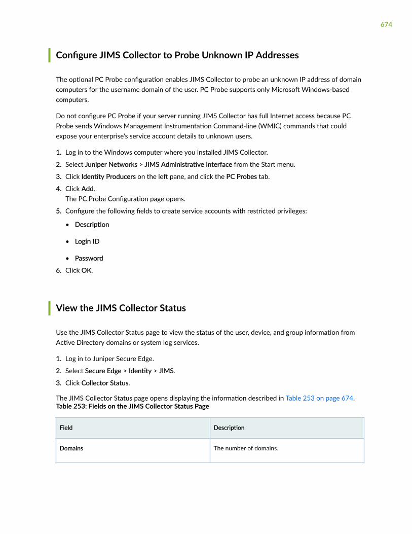
Configure JIMS Collector to Probe Unknown IP Addresses
The optional PC Probe configuration enables JIMS Collector to probe an unknown IP address of domaincomputers for the username domain of the user. PC Probe supports only Microsoft Windows-basedcomputers.
Do not configure PC Probe if your server running JIMS Collector has full Internet access because PCProbe sends Windows Management Instrumentation Command-line (WMIC) commands that couldexpose your enterprise's service account details to unknown users.
1. Log in to the Windows computer where you installed JIMS Collector.
2. Select Juniper Networks > JIMS Administrative Interface from the Start menu.
3. Click Identity Producers on the left pane, and click the PC Probes tab.
4. Click Add.The PC Probe Configuration page opens.
5. Configure the following fields to create service accounts with restricted privileges:
• Description
• Login ID
• Password
6. Click OK.
View the JIMS Collector Status
Use the JIMS Collector Status page to view the status of the user, device, and group information fromActive Directory domains or system log services.
1. Log in to Juniper Secure Edge.
2. Select Secure Edge > Identity > JIMS.
3. Click Collector Status.
The JIMS Collector Status page opens displaying the information described in Table 253 on page 674.Table 253: Fields on the JIMS Collector Status Page
Field Description
Domains The number of domains.
674

Table 253: Fields on the JIMS Collector Status Page (Continued)
Field Description
Users The number of active users.
Devices The number of active devices.
Groups The number of groups.
Sessions The number of active sessions.
Current State The current state of JIMS Collector
JIMS Collector ID The name of the Microsoft Windows server whereJIMS Collector is installed.
Version The version of JIMS Collector that is installed on theMicrosoft Windows server.
Description The user description that the JIMS Collector UIdisplays.
Last Update The timestamp when JIMS Collector last connected tothe JIMS server for an update.
675

6PART
Shared Services
Firewall Profiles-Rule Options | 677
Firewall Profiles-Redirect Profiles | 684
Objects-Addresses | 688
Objects-GeoIP | 699
Objects-Services | 705
Objects-Applications | 717
Objects-Schedules | 733
Objects-URL Patterns | 739
Objects-URL Categories | 745
Advanced Threat Prevention | 750

CHAPTER 35
Firewall Profiles-Rule Options
IN THIS CHAPTER
About Rule Options Page | 677
Create Rule Options | 678
Edit, Clone, and Delete Rule Options | 682
About Rule Options Page
IN THIS SECTION
Tasks You Can Perform | 677
Use the Rule Options page to create an object to specify redirect options, authentication, TCP-options,and action for destination-address translated or untranslated packets. When a rule options is created,the Juniper Security Director Cloud creates an object in the database to represent the rule options. Youcan use this object to create security policies.
Tasks You Can Perform
You can perform the following tasks from this page:
• Create rule options. See "Create Rule Options" on page 678.
• Edit or delete rule options. See "Edit, Clone, and Delete Rule Options" on page 682.
• Search for a rule option. Click the Search icon in the top right corner of the page to search for afirewall policy.
You can enter partial text or full text of the keyword in the text box and press Enter.
677

The search results are displayed on the same page.
Table 254: Fields on the Rule Options Page
Field Description
Name Name of the rule option.
Description Description of the Rule Option
Definition Type Number of devices associated with the policy.
Last Updated By The user who modified the rule option.
Last Updated Time The date and time when the rule option was modified.
Create Rule Options
When a rule options is created, Juniper Security Director Cloud creates an object in the database torepresent the rule options. You can use this object to create security policies.
Use the Rule Options page to create an object that specifies the basic settings of a security policy.
To create rule option:
1. Select Shared Services > Firewall Profiles > Rule Options.
The Rule Options page appears.
2. Click the plus icon (+).
The Create Rule Options page appears.
3. Complete the configuration settings according to the guidelines provided in "About Rule OptionsPage" on page 677.
NOTE: Fields marked with an asterisk (*) are mandatory.
4. Click OK.
The new rule option is created and a confirmation message is displayed.
678

Table 255: Fields on the Create Rule Options Page
Field Description
Name Enter a unique string of alphanumeric characters thatcan include spaces and some special characters.
The maximum length is 255 characters.
Description Enter a description for the policy; the maximumlength is 255 characters.
General
Hardware Acceleration Enable this option to process fast-path packets in thenetwork processor instead of in the ServicesProcessing Unit (SPU). When performing the policycheck, the SPU verifies if the traffic is qualified forservices offloading.
Redirect Options Select an option:
• None
• Redirect Wx- Select this option if you want toenable WX redirection for packets that arrivefrom the LAN.
• Reverse Redirect Wx-Select this option if youwant to enable WX redirection for the reverseflow of packets that arrive from the WAN.
Authentication
NOTE: Authentication is supported only when the permit action is enabled.
Push Auth Entry to JIMS Enable Push to JIMS.
679

Table 255: Fields on the Create Rule Options Page (Continued)
Field Description
Authentication Type Select an option to restrict or permit usersindividually or in groups. Select None if you do notwant to use any authentication to restrict or permitclients.
• Pass Through-Pass-through user authentication isa form of active authentication. The user isprompted to enter a username and passwordwhen pass-through authentication is invoked.
• Web-Web authentication is an alternative topass-through user authentication. Instead ofpointing to the resource that you want toconnect to from your client browser, you pointthe browser to an IP address on the device that isenabled for Web authentication. This initiates anHTTP session to the IP address hosting the Webauthentication feature on the device. The devicethen prompts you for your username andpassword and caches the result in the device.Later, when traffic encounters a Webauthentication policy, you are allowed or deniedaccess based on the prior Web authenticationresults.
• User Firewall-Firewall authentication policies thatrestrict and permit access of firewall users toprotected resources behind a firewall.
• Infranet-Select this option to configure the SRXSeries device to act as a Junos OS Enforcer in aUnified Access Control (UAC) deployment..
TCP Option
Syn-check Enable this option for the device to reject TCPsegments with non-SYN flags set unless they belongto an established session.
680

Table 255: Fields on the Create Rule Options Page (Continued)
Field Description
Sequence Check Enable this option to monitor the TCP byte sequencecounter and to validate the trusted acknowledgmentnumber against the untrusted sequence number.
Window Scale Enable this option to increase the networktransmission speed
Initial TCP MSS Select the TCP maximum segment size (MSS) forpackets arriving at the ingress interface (initialdirection). If the value in the packet is higher than theone you select, the configured value overrides theTCP MSS value in the incoming packet. The range is64 through 65535.
Reverse TCP MSS Select the TCP maximum segment size (MSS) forpackets that match a specific policy and travel in thereverse direction of a session. If the value in thepacket is higher than the one you select, theconfigured value replaces the TCP MSS value. Therange is 64 through 65535.
Advanced Settings
Destination NAT Control Select an option
• None
• Drop Untranslated-Drop packets with translateddestination IP addresses. Traffic permitted by thesecurity policy is limited to packets where thedestination IP address has not been translated.
• Drop Translated-Drop packets without translateddestination IP addresses. Traffic permitted by thesecurity policy is limited to packets where thedestination IP address has been translated bymeans of a destination NAT rule.
681

RELATED DOCUMENTATION
About Rule Options Page | 677
Edit, Clone, and Delete Rule Options | 682
Edit, Clone, and Delete Rule Options
SUMMARY IN THIS SECTION
Edit Rule Options | 682
Clone Rule Options | 682
Delete Rule Options | 683
You can edit, clone, and delete rule options from the Rule Options page. This topic has the followingsections:
Edit Rule Options
To modify the parameters configured for a rule option:1. Select Shared Services > Firewall Profiles > Rule Options.
The Rule Options page appears, displaying the existing rule options.
2. Select the rule option that you want to edit and then select the pencil icon.
The Edit Rule Options page appears, displaying the same fields that are presented when you create arule option.
3. Modify the rule option fields.
4. Click OK to save your changes.
A confirmation message appears, indicating the status of the edit operation.
Clone Rule Options
Cloning enables you to easily create rule option based on an existing one.
To clone a rule option:
1. Select Shared Services > Firewall Profiles > Rule Options.
The Rule Options page appears, displaying the existing rule options.
682

2. Select the rule option that you want to clone and then select More > Clone. Alternatively, right-clicka profile and select Clone.
The Clone Rule Options page appears, displaying the same fields that are presented when you createa rule option.
3. Modify the rule option fields.
4. Click OK to save your changes.
A confirmation message appears, indicating the status of the clone operation.
Delete Rule Options
To delete one or more rule options:
1. Select Shared Services > Firewall Profiles > Rule Options.
The Rule Options page appears, displaying the existing rule options.
2. Select one or more rule options that you want to delete and then select the delete icon.
An alert message appears, asking you to confirm the delete operation.
3. Click Yes to delete the selected rule options.
A confirmation message appears, indicating the status of the delete operation.
RELATED DOCUMENTATION
About Rule Options Page | 677
683

CHAPTER 36
Firewall Profiles-Redirect Profiles
IN THIS CHAPTER
About the Redirect Profiles Page | 684
Create a Redirect Profile | 685
Edit, Clone, and Delete a Redirect Profile | 686
About the Redirect Profiles Page
IN THIS SECTION
Tasks You Can Perform | 684
Field Descriptions | 685
To access this page, select Shared Services > Firewall Profiles > Redirect Profiles.Use the Redirect Profiles page to create a redirect profile and provide a reason for the policy action or toredirect the user request to an informative webpage. After you configure the redirect profiles for apolicy, when a policy blocks HTTP or HTTPS traffic with reject action, a message or redirect URL is sentto the user. You can customize the redirect action by adding the text message or specify the URL towhich the user is redirected.
Tasks You Can Perform
You can perform the following tasks from this page:
• Add a redirect profile. See "Create a Redirect Profile" on page 685.
• Edit, Clone, and Delete a redirect profile. See "Edit, Clone, and Delete a Redirect Profile" on page686.
684

Field Descriptions
Table 256 on page 685 provides guidelines on using the fields on the Redirect Profile page.
Table 256: Fields on the Redirect Profile Page
Field Description
Block Message Type The message type, that is, Text or Redirect URL.
Block Message/Redirect URL The custom text or the URL of the webpage to whichthe user is redirected. If custom-text is specified, boththe default block message and the custom-definedblock message are displayed. Custom text is insertedbelow the default message, which includes username,Application Firewall has blocked your request toapplication application name at dest-ip:dest-portaccessed from src-ip:src-port.
Create a Redirect Profile
Use this page to create a redirect profile and configure a custom block message or redirect URL.
To create a redirect profile:
1. Select Shared Services > Firewall Profiles > Redirect Profiles.The Redirect Profiles page appears.
2. Click the add icon (+).
The Create Redirect Profile page appears.
3. Complete the configuration according to the guidelines provided in Table 257 on page 686.
685

Table 257: Fields on the Redirect Profile Page
Field Description
Block Message Type Select the block message type:
• Text—If custom text is specified, both the defaultblock message and the custom-defined blockmessage are displayed. The maximum length ofcustom text is 512 characters.
• Redirect URL—The URL of the webpage to whichthe client is redirected. The URL must start withhttp or https. For example,http://www.juniper.net.The URL must not exceed 1024 characters.
Redirect URL Enter the block message or redirect URL.
4. Click OK.
A profile is created and displayed on the redirect profiles page.
Edit, Clone, and Delete a Redirect Profile
IN THIS SECTION
Edit a Redirect Profile | 686
Clone a Redirect Profile | 687
Delete a Redirect Profile | 687
You can edit, clone, and delete redirect profiles from the Redirect Profiles page.
Edit a Redirect Profile
To modify the parameters configured for a Redirect profile:
1. Select Shared Services > Firewall Profiles > Redirect Profiles.
686

The Redirect Profiles page appears.
2. Select the redirect profile that you want to edit and click the edit icon (pencil).
The Edit Redirect Profile page appears showing the same fields that are presented when you create aRedirect profile.
3. Modify the redirect profile fields as needed.
4. Click OK to save your changes.
You are taken to the Redirect Profiles page with the modified redirect profile information.
Clone a Redirect Profile
Cloning enables you to easily create a new redirect profile based on an existing one.
To clone a Redirect profile:
1. Select Shared Services > Firewall Profiles > Redirect Profiles.
The Redirect Profiles page appears.
2. Select the redirect profile that you want to clone and select More > Clone. Alternatively, right-click aprofile and select Clone.
The Clone Redirect Profile page appears, showing the same fields that are presented when youcreate a Redirect profile.
3. Modify the redirect profile fields as needed.
4. Click OK to save your changes.
You are taken to the Redirect Profiles page. A confirmation message appears, indicating the status ofthe clone operation.
Delete a Redirect Profile
1. Select Shared Services > Firewall Profiles > Redirect Profiles.
The Redirect Profiles page appears.
2. Select one or more redirect profiles that you want to delete and click the delete icon.
An alert message appears asking you to confirm the delete operation.
3. Click Yes to delete the selected redirect profiles.
A confirmation message appears indicating the status of the delete operation.
687

CHAPTER 37
Objects-Addresses
IN THIS CHAPTER
About the Addresses Page | 688
Variable Address Overview | 690
Create Addresses or Address Groups | 691
Edit, Clone, and Delete Addresses and Address Groups | 696
About the Addresses Page
IN THIS SECTION
Tasks You Can Perform | 689
Field Descriptions | 689
To access this page, select Shared Services > Objects > Addresses.
An address specifies an IP address or a hostname. You can create addresses that can be used across allpolicies. Addresses are used in firewall and NAT services and apply to the corresponding policies. If youknow only the hostname, you enter it into the Hostname field and use the address resolution option toresolve it to an IP address. You can also resolve an IP address to the corresponding hostname.
Juniper Security Director Cloud manages its address book at the global level, assigning objects todevices that are required to create policies. An address book is a collection of addresses and addressgroups that are available in a security zone. If the device is capable of using a global address book,Juniper Security Director Cloud pushes address objects used in the policies to the global address bookof the device.
Use this page to create, edit, clone, and delete addresses and address groups. Addresses and addressgroups are used in firewall and NAT services. After you create an address, you can combine it with other
688

addresses to form an address group. Address groups are useful when you want to apply the same policyto multiple services.
Tasks You Can Perform
You can perform the following tasks from this page:
• Create an address or address group. See "Create Addresses or Address Groups" on page 691.
• Modify, clone, or delete an address or address group. See "Edit, Clone, and Delete Addresses andAddress Groups" on page 696.
• View the configured parameters of an address or address group. Click the details icon that appearswhen you hover over the name of an address or address group or select More > Detailed View.
• Show or hide columns about the address or address group. Click the Show Hide columns icon in thetop right corner of the page and select columns that you want to view on the page.
• Filter information based on select criteria. You can add filters, save the filters, and set any of thefilters as default. To add a filter:
1. Click on the filter icon on the top-right corner of the page and select Add Filter to open the AddCriteria page.
2. Set the filter conditions and click Add.
The filter is saved and the filter is applied on the data on the page. Filter can be saved and can markany one filter as default.
To remove the filter, click on the filter icon and select Hide Filter.
• Search for an address or address group. Click the Search icon in the top right corner of the page tosearch for an address or address group.
You can enter partial text or full text of the keyword in the text box and press Enter.
The search results are displayed on the same page.
Field Descriptions
Table 258 on page 690 provides guidelines on using the fields on the Addresses page.
689

Table 258: Fields on the Addresses Page
Field Description
Name View the name of the address or address group.
Type View the type of the address object.
Hostname View the hostname of the address.
IP Address View the IP address associated with the address.
Description View the description provided about the address oraddress group when it was created.
RELATED DOCUMENTATION
Create Addresses or Address Groups | 691
Edit, Clone, and Delete Addresses and Address Groups | 696
Variable Address Overview
A variable is useful when you want to apply similar rules across devices where only the address mightdiffer. Instead of using static values, you can use variables to create fewer rules and use them morewidely. You can achieve this by creating and configuring a variable address for all devices to which youare applying a group policy.
For example:
• Group firewall policy FW-G1 has two devices, Dev-1 and Dev-2. Each device has its own uniqueaddress. Dev-1 has address A1. Dev-2 has address A2.
• You want to apply the same rule to both devices, but you do not want to configure two rules with allthe same criteria except for the address. It is more efficient to configure one rule with a variabledefault address and apply it to both devices.
690

• You can achieve this by creating an address variable with a default address A3, and making A3common to Dev-1 and Dev-2 in your rule. When you configure default address A3, you map it to thereal address of each device, A1 for Dev-1 and A2 for Dev-2.
• When group firewall policy FW-G1 is applied, these mappings are used to replace the default addresswith the real address for each device.
•NOTE: Variable addresses are used in group policies only. Variable addresses are notapplicable to device policies.
Figure 23: Variable Address Usage
Create Addresses or Address Groups
Use the Addresses page to create addresses and address groups. Addresses and address groups are usedin firewall and NAT services. After you create an address, you can combine it with other addresses toform an address group. Address groups are useful when you want to apply the same policy to multipleservices.
To create an address or address group:
691

1. Select Shared Services > Objects > Addresses.
The Addresses page appears.
2. Click the add icon (+).
The Create Addresses page appears.
3. Complete the configuration according to the guidelines provided in Table 259 on page 692 andTable 260 on page 695.
4. Click OK to save the changes. If you want to discard your changes, click Cancel instead.
A new address or address group with your configurations is created. You can use this object infirewall or NAT policies.
Table 259: Fields on the Create Addresses Page
Field Description
Name Enter a unique name for the address. The name mustbegin with an alphanumeric character and cancontain alphanumeric characters and some specialcharacters (colons, hyphens, forward slashes, periods,and underscores). The maximum length is63characters.
Description Enter a description for your address. The descriptioncan contain alphanumeric characters and specialcharacters (excluding ampersand, lesser than (<) andgreater than (>), and newline (\n)). The maximumlength is 900 characters.
You should make this description as useful aspossible for all administrators.
Object Type Select Address or Address Group. If you selectAddress Group, then the screen changes so you canselect the addresses you want to include in youraddress group. Table 260 on page 695 describesaddress group configuration parameters.
692

Table 259: Fields on the Create Addresses Page (Continued)
Field Description
Type Select a type of address and fill in the correspondingfields. Available types are:
• Host
• Host IP—Enter the IPv4 host IP address. Forexample: 192.0.2.0. If you do not know the IPaddress, you can enter the hostname and clickLook up hostname.
• Hostname—Enter the hostname. It must beginwith an alphanumeric character and cannotexceed 63 characters. Dashes andunderscores are allowed. If you do not knowthe host name, you can enter the IP addressand click Look up IP address. For example,enter www.company.com and click Look up IPaddress. Hostname lookup is supported forIPv4 addresses.
• Range
• Start Address—Enter a starting IPv4 addressalong with the classless inter-domain routing(CIDR) for the address range. For example:192.0.2.0/24.
• End Address—Enter an ending IPv4 addressfor the address range. The range is validatedafter you enter the address.
NOTE: An address range is configured on amanaged device as an address set with one ormore network address objects covering thespecified address range.
• Network
• Network—Enter the network IP address. Forexample: 192.0.2.0. IPv6 is also supported.
693

Table 259: Fields on the Create Addresses Page (Continued)
Field Description
For example:2001:db8:4136:e378:8000:63bf:3fff:fdd2.
• Subnet Mask—Enter the subnet mask for thenetwork range. For example, IPv4 netmask:192.0.2.0/24. IPv6 prefix: 2001:db8::/32 Thesubnet mask is validated as you enter it. Youmust enter the correct subnet mask inaccordance with the network value.
• DNS Host
• DNS Name—Enter the DNS name. Forexample: company.com. Only alphanumericcharacters, dashes, and periods are accepted.This name cannot exceed 63 characters inlength, and must end with an alphanumericcharacter.
• DNS Type—Select the DNS type as IPv4-onlyor IPv6-only.
• Variable
• Default address—This default address isreplaced with the mapped device-specificaddress when applied to the group firewallpolicy.
• Variable address—Steps to add the variableaddress:
a. Click the add icon (+). Create variable pageappears.
b. Select the check box beside each device towhich you want to map this variableaddress. Click the arrow to move theselected device or devices from theAvailable column to the Selected column.
694

Table 259: Fields on the Create Addresses Page (Continued)
Field Description
Only devices from the current and childdomain are listed. You can use the fields atthe top of each column to search for listeddevices.
c. Select a predefined address by clickinganywhere within this field and choosing anaddress from the Select Address window.The default address is replaced by thisdevice-specific address when applied to apolicy that includes the selected device ordevice
d. Click OK. A new variable with yourconfigurations is created. You can use thisvariable address in policies. See "Select aSecurity Policy Rule Source" on page 265and "Select a Security Policy RuleDestination" on page 266
NOTE: Variables addresses are used ingroup policies only. Variable addresses arenot applicable to device policies.
Table 260: Address Group Settings
Field Description
Name Enter a unique name for the address group that mustbegin with an alphanumeric character. The name cancontain alphanumeric characters and some specialcharacters (colons, hyphens, forward slashes, periods,and underscores). The maximum length is 63-character.
695

Table 260: Address Group Settings (Continued)
Field Description
Description Enter a description for your address. The descriptioncan contain alphanumeric characters and specialcharacters (excluding ampersand, lesser than (<) andgreater than (>), and newline (\n)). The maximumlength is 900 characters.
You should make this description as useful aspossible for all administrators.
Object Type Select Address or Address Group. If you selectAddress Group, then the screen changes so you canselect the addresses you want to include in youraddress group.
Addresses Select the check box beside each address you wantto include in the address group. Click the greater-than icon (>) to move the selected address oraddresses from the Available column to the Selectedcolumn. Note that you can use the fields at the top ofeach column to search for addresses.
RELATED DOCUMENTATION
About the Addresses Page | 688
Edit, Clone, and Delete Addresses and Address Groups | 696
Variable Address Overview | 690
Edit, Clone, and Delete Addresses and Address Groups
IN THIS SECTION
Edit Addresses and Address Groups | 697
696

Clone Addresses and Address Groups | 697
Delete Addresses and Address Groups | 698
You can edit, clone, and delete addresses and address groups from the Addresses page.
NOTE:
• You cannot edit or delete predefined addresses.
• You cannot edit or delete the GeoIP feeds from the Addresses page. You can edit or deletethe GeoIP feeds from the Shared Services > Objects > GeoIP page.
Edit Addresses and Address Groups
To modify the parameters configured for an address or address group:
1. Select Shared Services > Objects > Addresses.
The Addresses page appears.
2. Select the address or address group that you want to edit and click the edit icon (pencil symbol) atthe right top corner of the table.
The Edit Address page appears, showing the same options as displayed when you create a newaddress or address group.
3. Modify the parameters according to the guidelines provided in "Create Addresses or AddressGroups" on page 691.
NOTE: Address Name and Object Type can not be modified.
4. Click OK to save the changes. If you want to discard your changes, click Cancel instead.
When you click OK, the modified address or address group is displayed on the Addresses page.
NOTE: When you edit an address that is a deployed as part of a policy, you will need toredeploy that policy in order for the changes to take effect.
Clone Addresses and Address Groups
To clone an address or address group:
697

1. Select Shared Services > Objects > Addresses.
The Addresses page appears.
2. Right-click the address or address group that you want to clone and then click Clone, or select More> Clone.
The Clone Address page appears with editable fields.
3. Modify the parameters according to the guidelines provided in "Create Addresses or AddressGroups" on page 691.
4. Click OK to save the changes. If you want to discard your changes, click Cancel instead.
If you select OK, the cloned address or address group is saved.
Delete Addresses and Address Groups
NOTE: Only addresses or address groups that have not been referenced in any policy can bedeleted. If you try to delete such an address or address group, an error message will be displayed.
To delete an address or address group:
1. Select Shared Objects > Objects > Addresses.
The Addresses page appears.
2. Select the address or address group you want to delete and then click the delete icon (trash can).
An alert message appears verifying that you want to delete your selection.
3. Click Yes to delete the address or address group. If you do not want to delete, click Cancel instead.
If you select Yes, the selected address or address group is deleted, unless it is referenced in a policy.
SEE ALSO
About the Addresses Page | 688
Create Addresses or Address Groups | 691
698

CHAPTER 38
Objects-GeoIP
IN THIS CHAPTER
About the GeoIP Page | 699
Create a GeoIP Feed | 700
Edit, Clone, and Delete GeoIP Feeds | 702
About the GeoIP Page
IN THIS SECTION
Tasks You Can Perform | 699
Field Descriptions | 700
To access this page, select Shared Services > Objects > GeoIP
IP-based geolocation (GeoIP) is the method of locating a computer terminal's geographic location byidentifying that terminal's IP address. A GeoIP feed is an up-to-date mapping of IP addresses togeographical regions. By mapping an IP address to the sources of attack traffic, geographic regions oforigin can be determined, giving you the ability to filter traffic to and from specific locations in the world.
Using Juniper Security Director Cloud, you can create, modify, or delete the GeoIP feeds. You can usethe GeoIP feeds in security policy to deny or allow traffic based on source or destination IP address.
Tasks You Can Perform
You can perform the following tasks from this page:
• Create a GeoIP feed. See "Create a GeoIP Feed" on page 700.
• Modify, clone, or delete a GeoIP feed. See "Edit, Clone, and Delete GeoIP Feeds" on page 702.
699

• View the configured parameters of GeoIP feed. Click the details icon that appears when you hoverover the name of a GeoIP feed or select More > Detailed View.
• Show or hide columns about the GeoIP feed. Click the Show Hide columns icon in the top rightcorner of the page and select columns that you want to view on the page.
• Filter information based on select criteria. You can add filters, save the filters, and set any of thefilters as default. To add a filter:
1. Click on the filter icon on the top-right corner of the page and select Add Filter to open the AddCriteria page.
2. Set the filter conditions and click Add.
The filter is saved and applied on the page. You can save the filter and can mark any one filter asdefault.
To remove the filter, click the filter icon and select Hide Filter.
• Search for a GeoIP feed. Click the Search icon in the top right corner of the page to search for aGeoIP feed. Type partial or full text of the keyword in the text box and press Enter.
You can view the search results on the same page.
Field Descriptions
Table 261 on page 700 provides guidelines on using the fields on the GeoIP page.
Table 261: Fields on the GeoIP Page
Field Description
Name View the name of the GeoIP feed.
Description View the description about the GeoIP feed.
Countries View the countries included in the GeoIP feed.
Create a GeoIP Feed
You can create GeoIP feeds from the GeoIP page.
700

Before You Begin
• You must have Juniper ATP Cloud account. Make sure you configure the necessary steps for JuniperATP Cloud before creating a GeoIP feed. See Juniper Advanced Threat Prevention Cloud InstallationOverview for more details.
• GeoIP filtering is a useful tool when you are experiencing certain types of attacks, such as DDoS fromspecific geographical locations.
• If you are using Juniper ATP Cloud, you must select your GeoIP feed as the source or destination of asecurity policy rule to apply it.
To create a GeoIP feed:
1. Select Shared Services > Objects > GeoIP.
The GeoIP page appears.
2. Click the add icon (+).
The Create GeoIP page appears.
3. Complete the configuration according to the guidelines provided in and "Create a GeoIP Feed" onpage 700.
4. Click OK to save the changes. If you want to discard your changes, click Cancel instead.
A new GeoIP feed is created and listed as a dynamic address group entry on the Shared Services >Objects > Addresses page. You can use this GeoIP feed as address group to specify the source ordestination address while creating security policy rules.
Table 262: Fields on the Create GeoIP Page
Field Description
Name Enter a unique name containing maximum 63characters without spaces. The name must beginwith an alphanumeric character and can containspecial characters such as colons, periods, dashes,and underscores.
Description Enter a description that contains alphanumericcharacters and special characters (excludingampersand, lesser than (<) and greater than (>), andnewline ()). The maximum length is 900 characters.
701

Table 262: Fields on the Create GeoIP Page (Continued)
Field Description
Countries Select the check box beside the countries in theAvailable list and click the >icon to move to theSelected list. The countries in the Selected list areincluded in the feed to take action according to theirthreat level. You can use the search at the top ofeach column to search for the listed countries.
RELATED DOCUMENTATION
Edit, Clone, and Delete Addresses and Address Groups | 696
About the Addresses Page | 688
Edit, Clone, and Delete GeoIP Feeds
IN THIS SECTION
Edit a GeoIP Feed | 702
Clone a GeoIP Feed | 703
Delete a GeoIP Feed | 703
You can edit, clone, and delete GeoIP feeds from the GeoIP page.
Edit a GeoIP Feed
To modify the parameters configured for a GeoIP feed:
1. Select Shared Services > Objects > GeoIP.
The GeoIP page appears.
2. Select the GeoIP feed to edit and click the edit icon (pencil symbol) at the right top corner of thetable.
702

The Edit GeoIP page appears, showing the same options as displayed when you create a GeoIP feed.
3. Modify the parameters according to the guidelines provided in "Create a GeoIP Feed" on page 700.
4. Click OK to save the changes. If you want to discard your changes, click Cancel instead.
When you click OK, the modified GeoIP feed is displayed on the GeoIP page.
NOTE: When you edit a GeoIP feed that is a deployed as part of a security policy, you mustredeploy that policy for the changes to take effect.
Clone a GeoIP Feed
To clone a GeoIP feed:
1. Select Shared Services > Objects > GeoIP.
The GeoIP page appears.
2. Right-click the GeoIP feed that you want to clone and then click Clone, or select More > Clone.
The Clone GeoIP page appears with editable fields.
3. Modify the parameters according to the guidelines provided in "Create a GeoIP Feed" on page 700.
4. Click OK to save the changes. If you want to discard your changes, click Cancel instead.
If you select OK, the cloned GeoIP feed is saved.
Delete a GeoIP Feed
NOTE: You can delete only those GeoIP feeds that are not referenced in any policy.
To delete a GeoIP feed:
1. Select Shared Services > Objects > GeoIP.
The GeoIP page appears.
2. Select the GeoIP feed you want to delete and then click the delete icon (trash can).
An alert message appears verifying that you want to delete your selection.
3. Click Yes to delete the GeoIP feed. If you do not want to delete, click Cancel instead.
If you select Yes, the selected GeoIP feed is deleted, unless it is referenced in a policy.
SEE ALSO
About the GeoIP Page | 699
Create a GeoIP Feed | 700
703

About the Addresses Page | 688
Create Addresses or Address Groups | 691
704

CHAPTER 39
Objects-Services
IN THIS CHAPTER
About the Services Page | 705
Create Services and Service Groups | 707
Edit, Clone, and Delete Services and Service Groups | 710
Create Protocols | 711
Edit and Delete Protocols | 715
About the Services Page
IN THIS SECTION
Tasks You Can Perform | 705
Field Descriptions | 706
To access this page, select Shared Services > Objects > Services.Use the Services page to create, modify, clone and delete service or service groups. You can also createand manage protocols, that you use to create services.
A service refers to an application on a device, such as Domain Name Service (DNS). Services are basedon protocols and ports used by an application. When added to a policy, a configured service can beapplied across all devices associated to it. The protocols available to create a service include: TCP, UDP,SUN-RPC, MS-RPC, ICMP, ICMPv6, and Other.
Tasks You Can Perform
You can perform the following tasks from this page:
705

• Create a service or service group. See "Create Services and Service Groups" on page 707.
• Modify, clone or delete a service or service group. See "Edit, Clone, and Delete Services and ServiceGroups" on page 710.
• View the configured parameters of a service or service group. Click the details icon that appearswhen you hover over the name of a service or service group, or click More > Detailed View.
• Show or hide columns about the services or service groups. Click the Show Hide columns icon in thetop right corner of the page and select columns that you want to view on the page.
• Filter information based on select criteria. You can add filters, save the filters, and set any of thefilters as default. To add a filter:
1. Click on the filter icon on the top-right corner of the page and select Add Filter to open the AddCriteria page.
2. Set the filter conditions and click Add.
The filter is saved and the filter is applied on the data on the page. Filter can be saved and can markany one filter as default.
To remove the filter, click on the filter icon and select Hide Filter.
• Search a specific service or service group. Click the Search icon in the top right corner of the page tosearch for a service or service group.
You can enter partial text or full text of the keyword in the text box and press Enter.
The search results are displayed on the same page.
Field Descriptions
Table 263 on page 706 provides guidelines on using the fields on the Services page.
Table 263: Fields on the Service Page
Field Description
Name Name of the service or service group.
Type Specifies whether the object is a service or servicegroup.
706

Table 263: Fields on the Service Page (Continued)
Field Description
Description Description about the service or service group.
Predefined/Custom Indicates whether a service or service group ispredefined or custom.
RELATED DOCUMENTATION
Create Services and Service Groups | 707
Edit, Clone, and Delete Services and Service Groups | 710
Create Protocols | 711
Edit and Delete Protocols | 715
Create Services and Service Groups
Use the Create Service page to create a service. You can create services based on protocols and portsused by an application. You can use protocols such as TCP, UDP, MS-RPC, SUN-RPC, ICMP, ICMPv6,and so on, to create services. Once you create a service, you can combine it with other services to forma service group. Service groups are useful when you want to apply the same policy to multiple services.
You can also create or modify service-based protocols from the Services page.
To configure a service or service group:
1. Select Shared Services > Objects > Services.
The Services page appears.
2. Click the add icon (+) to create service or service group.
The Create Service page appears.
3. Complete the configuration of a service according to the guidelines provided in Table 264 on page708.
If you want to configure a service group, see Table 265 on page 709.
4. Click OK to save the changes. If you want to discard your changes, click Cancel instead.
707

A new service or service group with the configuration you provided is created. You can use thisservice or service group as an endpoint in firewall policies.
Table 264 on page 708 provides guidelines on using the fields to create a service.
Table 264: Create Service Settings
Field Description
Name Enter a unique name for the service. The name mustbegin with an alphanumeric character and cancontain alphanumeric characters and some specialcharacters (colons, hyphens, forward slashes, periods,and underscores); 63-character maximum.
Description Enter a description for your service. The descriptioncan contain alphanumeric characters and specialcharacters (excluding ampersand, lesser than (<) andgreater than (>), and newline (\n)); 900-charactermaximum.
You should make this description as useful aspossible for all administrators.
Type Select Service or Service Group. If you select ServiceGroup, then the page changes so you can select theservices you want to include in your service group.See Table 264 on page 708.
Protocols Select the protocol you want to associate with theservice. You can also create a new protocol, or editexisting protocols:
• To create a new protocol, click on the add icon(+). See "Create Protocols" on page 711.
• To edit an existing protocol, click on the edit icon(pencil symbol). See "Edit and Delete Protocols"on page 715.
Table 265 on page 709 provides guidelines on using the fields to create a service group.
708

Table 265: Service Group Settings
Field Description
Name Enter a unique name for the service group. The namemust begin with an alphanumeric character and cancontain alphanumeric characters and some specialcharacters (colons, hyphens, forward slashes, periods,and underscores); 63-character maximum.
Description Enter a description for your service group. Thedescription can contain alphanumeric characters andspecial characters (excluding ampersand, lesser than(<) and greater than (>), and newline (\n)); 900-character maximum.
You should make this description as useful aspossible for all administrators.
Type Select Service or Service Group. If you select ServiceGroup, then the screen changes so you can select theservices you want to include in your service group.
Services Select the service you want to include in the servicegroup and click the greater-than icon (>) to move theselected service or services from the Availablecolumn to the Selected column. You can use thesearch field at the top of each column to search forlisted services.
RELATED DOCUMENTATION
About the Services Page | 705
Edit, Clone, and Delete Services and Service Groups | 710
Create Protocols | 711
Edit and Delete Protocols | 715
709

Edit, Clone, and Delete Services and Service Groups
IN THIS SECTION
Edit Services and Service Groups | 710
Clone Services or Service Groups | 711
Delete Services and Service Groups | 711
You can edit, clone, and delete services and service groups from the Services page.
NOTE:
• You cannot edit or delete predefined services, however, you can clone predefined services.
• You cannot delete services or service groups that are in use.
Edit Services and Service Groups
To modify the parameters configured for a service or service group:
1. Select Shared Services > Objects > Services.
The Services page appears.
2. Select the service or service group that you want to edit, and click on the edit icon (pencil symbol) onthe right top corner of the table.
NOTE: You cannot modify the service or service group Name or the Object Type.
The Edit Service page appears, displaying the same options that are displayed when creating a newservice or service group.
3. Modify the parameters according to the guidelines provided in "Create Services and Service Groups"on page 707.
4. Click OK to save the changes. If you want to discard your changes, click Cancel instead.
If you click OK, you will see the modified service or service group in the Services page.
710

Clone Services or Service Groups
To clone a service or service group:
1. Select Shared Services > Objects > Services.
The Services page appears.
2. Right-click on the service or service group that you want to clone and then click Clone, or selectMore > Clone.
The Clone Service page appears with editable fields. Modify the parameters as required according tothe guidelines provided in "Create Services and Service Groups" on page 707.
3. Click OK to save the changes. If you want to discard your changes, click Cancel instead.
If you click OK, the cloned service or service group will appear beneath the selected service orservice group.
Delete Services and Service Groups
To delete a service or service group:
1. Select Shared Services > Objects > Services.
The Services page appears.
2. Select the service or service group you want to delete and then click the delete icon (trash can).
An alert message appears, verifying that you want to delete the service or service group.
3. Click Yes to delete the service or service group. If you do not want to delete, click Cancel instead.
If you click Yes, the selected service or service group is deleted.
SEE ALSO
About the Services Page | 705
Create Services and Service Groups | 707
Create Protocols | 711
Edit and Delete Protocols | 715
Create Protocols
Use the Create Protocol page to create TCP, UDP, MS-RPC, SUN-RPC, ICMP, ICMPv6, and otherprotocols, that can be used in services. A service refers to an application on a device. Services are basedon protocols and ports used by an application.
To create a protocol:
711

1. Select Shared Services > Objects > Services.
The Services page appears.
2. Click the add icon (+) to create service or service group.
The Create Services page appears.
3. Click the add icon (+) that appears above the Protocols table.
The Create Protocol page appears.
4. Complete the configuration of the protocol according to the guidelines provided in Table 266 on page712 and Table 267 on page 713.
5. Click OK to save the changes. If you want to discard your changes, click Cancel instead.
A new protocol with the configuration you provided is created within the service.
Table 266 on page 712 provides guidelines on using the fields to create a protocol.
Table 266: Fields on Create Protocol Page Settings
Field Description
General Information
Name Enter a unique name for the protocol. The namemust begin with an alphanumeric character and cancontain alphanumeric characters and some specialcharacters (colons, hyphens, forward slashes, periods,and underscores); 63-character maximum.
Description Enter a description for your protocol. The descriptioncan contain alphanumeric characters and specialcharacters (excluding ampersand, lesser than (<) andgreater than (>), and newline (\n)); 900-charactermaximum.
You should make this description as useful aspossible for all administrators.
Type Select the type of the protocol you want to createand fill in the corresponding fields. The availabletypes of protocols are: TCP, UDP, ICMP, SUN-RPC,MS-RPC, ICMPv6, and so on. If you select TCP orUDP, continue with this table. See Table 267 on page713 for the other protocol types.
712

Table 266: Fields on Create Protocol Page Settings (Continued)
Field Description
Destination Port Enter a destination port number for TCP. The range isfrom 0 to 65, 535.
Advanced Settings
Inactivity Timeout Enable this option to specify the amount of time theprotocol can be inactive before it times out.
Timeout Duration Enter a timeout value for this protocol. The valuerange is 4 to 86400 seconds.
ALG Select an ALG (Application Layer Gateway) serviceoption if applicable.
Source Ports and Port Ranges Enter the source port or port range for the protocol.
Table 267 on page 713 includes the settings and guidelines for the various protocol types.
Table 267: Create Protocol Type Settings
Field Description
ICMP
ICMP Type Enter a value from 0 through 225 for the ICMPmessage type. For example, enter 1 for hostunreachable. You can find these values in RFC 792.
ICMP Code Enter a value from 0 through 225 for the ICMP code.For example, enter 0 for echo reply. You can findthese values in RFC 792.
SUN-RPC
713

Table 267: Create Protocol Type Settings (Continued)
Field Description
RPC Program Number Enter a value or value range for the RPC (remoteprocedure call) service. For example, enter 100,017for remote execution. You can find these values inRFC 5531.
Protocol Type Select TCP or UDP for the protocol type.
MS-RPC
UUID Enter the corresponding UUID value for the MS-RPCservice. For predefined values, refer to MS-RPCUUID Mappings.
Protocol Type Select TCP or UDP for the protocol type.
ICMPv6
ICMP Type Enter a value from 0 through 225 for the ICMPv6message type. You can find these values in RFC4443.
ICMP Code Enter a value from 0 through 225 for the ICMPv6code. You can find these values in RFC 4443.
SCTP, RSVP, PIM, OSPF, IPIP, IGMP, GRE, ESP, EGP, AH, and Other
Protocol Number Enter a protocol number for the protocol type. Thisnumber identifies the service in the next higher levelin the protocol stack to which data is passed.
RELATED DOCUMENTATION
About the Services Page | 705
714

Create Services and Service Groups | 707
Edit, Clone, and Delete Services and Service Groups | 710
Edit and Delete Protocols | 715
Edit and Delete Protocols
IN THIS SECTION
Edit Protocols | 715
Delete Protocols | 715
You can edit and delete protocols through the Services page.
Edit Protocols
To modify the parameters configured for a protocol:
1. Select Shared Services > Objects > Services.
The Services page appears.
2. Select the service to which the protocol you want to edit is associated, and click on the edit icon(pencil symbol) on the right top corner of the table.
The Edit Service page appears, listing the protocols associated with the service in Protocols table.
3. Select the protocol that you want to edit, and then click on the edit icon (pencil symbol) on the righttop corner of the Protocols table.
The Edit Protocol page appears, showing the same fields as those seen when you create a newprotocol.
4. Modify the parameters of the protocol according to the guidelines provided in "Create Protocols" onpage 711.
5. Click OK to save the changes. If you want to discard your changes, click Cancel instead.
If you click OK, the modified protocol appears in the Protocols table.
Delete Protocols
To delete a protocol:
1. Select Shared Services > Objects > Services.
715

The Services page appears.
2. Select the service to which the protocol you want to delete is associated, and click on the edit icon(pencil symbol) on the right top corner of the table.
The Edit Service page appears, listing the protocols associated with the service in Protocols table.
3. Select the protocol you want to delete and then click the delete icon (trash can).
An alert message appears, verifying that you want to delete the protocol.
4. Click Yes to delete the protocol. If you do not want to delete, click Cancel instead.
If you click Yes, the selected protocol is deleted.
SEE ALSO
About the Services Page | 705
Create Services and Service Groups | 707
Edit, Clone, and Delete Services and Service Groups | 710
Create Protocols | 711
716

CHAPTER 40
Objects-Applications
IN THIS CHAPTER
About the Application Signatures Page | 717
Add Application Signatures | 720
Edit, Clone, and Delete Application Signatures | 727
Add Custom Application Signature Groups | 729
Edit, Clone, and Delete Application Signature Groups | 730
About the Application Signatures Page
IN THIS SECTION
Tasks You Can Perform | 717
Field Descriptions | 718
To access this page, select Shared Services > Objects > Applications.
Use the Application Signatures page to view application signatures that are already downloaded and tocreate, modify, clone, and delete application signatures and signature groups. The Application Signaturespage displays the name, object type, category and subcategory, risk associated with, and characteristicsof the signature. You can create custom application and application group with a set of similar signaturesfor consistent reuse when defining policies.
Tasks You Can Perform
You can perform the following tasks from this page:
• Add an application signature. See "Add Application Signatures" on page 720.
717

• Modify, clone, or delete an application signature. See "Edit, Clone, and Delete Application Signatures"on page 727.
• Add an application signature group. See "Add Custom Application Signature Groups" on page 729.
• Modify, clone, or delete an application signature group. See "Edit, Clone, and Delete ApplicationSignature Groups" on page 730.
NOTE: You cannot modify the name of an application signature group.
• View the configured parameters of an application signature or application signature group. Click thedetails icon that appears when you hover over the name of an image or click More > Details.
• Show or hide columns in the Application Signatures. Click the Show Hide columns icon in the topright corner of the page and select columns that you want to view on the page.
• Search for a specific application signature or application signature group. Click the Search icon in thetop right corner of the page to search for an application signature or application signature group.
• Filter the application signature information based on select criteria. You can add filters, save thefilters, and set any of the filters as default. To add a filter:
1. Click on the filter icon on the top-right corner of the page and select Add Filter to open the AddCriteria page.
2. Set the filter conditions and click Add.
The filter is saved and the filter is applied on the data on the page. Filter can be saved and can markany one filter as default.
To remove the filter, click on the filter icon and select Hide Filter.
Field Descriptions
Table 268 on page 719 provides guidelines on using the fields on the Application Signatures page.
718

Table 268: Fields on the Application Signatures Page
Field Description
Name Enter a unique name for the application signature orapplication signature group. The name must begin withan alphanumeric character and can containalphanumeric characters and some special characters(colons, hyphens, forward slashes, periods, andunderscores); 63-character maximum.
Type Signature application or group —either applicationsignature or application signature group.
Category Category of the application signature. For example, thevalue of Category can be Messaging, Web,Infrastructure, Remote-Access, Multimedia, and so on
Sub Category Subcategory of the application signature. For example,the value of Subcategory can be Wiki, File-Sharing,Multimedia, Social-Networking, News, and so on.
Risk Level of risk associated with the application signature.For example, the value of Risk can be Low, Moderate,Unsafe, High, and Critical.
Characteristics One or more characteristics of the applicationsignature.
Predefined/Custom Indicates whether an application signature or signaturegroups is predefined or custom.
Cacheable If an application is created with the Cacheable option,the column displays True, otherwise displays --.
Created Version Version of the application signature.
Order Order of the application signature.
719

RELATED DOCUMENTATION
Add Application Signatures | 720
Edit, Clone, and Delete Application Signatures | 727
Add Custom Application Signature Groups | 729
Edit, Clone, and Delete Application Signature Groups | 730
Add Application Signatures
You can add custom application signatures for applications that are not included in Juniper Networkspredefined application database. When you add custom application signatures, make sure that yourapplication signatures are unique, by providing a unique and relevant name.
To create a custom application signature:
1. Select Shared Services > Objects > Applications.
2. Click Create > Signature.The Create Application Signature page appears.
3. Complete the configuration according to the guidelines provided in Table 269 on page 720.
4. Click OK to save the changes. If you want to discard your changes, click Cancel instead.
A new application signature with your configurations is created.
Table 269 on page 720 provides guidelines on using the fields on the Create Application Signaturepage.
Table 269: Fields on the Create Application Signature Page
Field Description
Name Enter a unique name that is a string of alphanumericcharacters, colons, periods, dashes, and underscores.No spaces are allowed and the maximum length is 63characters.
Description Enter a description for the application signature;maximum length is 255 characters.
Signature Order and Priority
720

Table 269: Fields on the Create Application Signature Page (Continued)
Field Description
Order Enter the order for the custom application signaturein the range between 1 and 50000. A lower ordervalue has higher priority. This option is used whenmultiple custom application signatures of the sametype match the same traffic. However, you cannotuse this option to prioritize among different type ofapplications such as TCP stream-based applicationsagainst TCP port-based applications or IP address-based applications against port-based applications.
NOTE: Application order must be unique for eachapplication.
Priority Specify the application signature priority (high orlow) over other application signatures.
Signature Classification
Category Enter the category of the application signature. Forexample, Messaging, Web, Infrastructure, Remote-Access, Multimedia, and so on.
Sub Category Enter the subcategory of the application signature.For example, Wiki, File-Sharing, Multimedia, Social-Networking, News, and so on.
Risk Select the level of risk associated with theapplication signature. For example, Low, Moderate,High, Critical, and Unsafe.
Characteristics Enter one or more characteristics of the applicationsignature. For example, supports file transfer, loss ofproductivity, and so on.
721

Table 269: Fields on the Create Application Signature Page (Continued)
Field Description
Application Criteria Enable one or more application matching criteria:
• ICMP Mapping
• IP Protocol Mapping
• Address Mapping
• L7 Signature
ICMP Mapping Click the toggle button to specify the InternetControl Message Protocol (ICMP) value for anapplication while configuring custom applicationsignatures for application identification.
The ICMP mapping technique maps standard ICMPmessage types and optional codes to a uniqueapplication name. The ICMP code and type provideadditional specification, for packet matching in anapplication definition.
ICMP Type Enter an ICMP value for the application. The ICMPmapping technique maps standard ICMP messagetypes and optional codes to a unique applicationname.
Range is 0-254.
ICMP Code Enter an ICMP code for the application. The fieldprovides further information (such as RFCs) aboutthe ICMP type field.
Range is 0-254.
IP Protocol Mapping Click the toggle button to specify the IP protocolvalue for an application. This parameter is used toidentify an application based on it's IP protocol valueand is intended only for IP traffic. To ensure adequatesecurity, use IP protocol mapping only in your privatenetwork for trusted servers.
722

Table 269: Fields on the Create Application Signature Page (Continued)
Field Description
IP Protocol Enter an IP Protocol number for the application.Standard IP protocol numbers map an application toIP traffic. To ensure adequate security, use IPprotocol mapping only in your private network fortrusted servers.
Range is 0-254.
You can find a complete list of industry standardprotocol numbers at the IANA website.
NOTE: You cannot use IP protocol numbers 1(ICMP),6(TCP ) and 17(UDP) for custom applicationsignature creation. Instead, we recommend you touse L7 signature policies for these protocols.
Address Mapping Click the toggle button to specify address mappinginformation. Layer 3 and Layer 4 address mappingdefines an application by matching the destination IPaddress or port range (optional) of the traffic. Use theaddress mapping option to configure customapplications signatures when the configuration ofyour private network predicts application traffic to orfrom trusted servers.
Address mapping provides efficiency and accuracywhile handling traffic from a known application. Formore information, see Table 270 on page 724.
NOTE:
• You must specify either IP address or TCP/UDPport range for address mapping.
• If both IP address and TCP/UDP ports areconfigured, both should match destination tuples(IP address and port range) of the packet.
723

Table 269: Fields on the Create Application Signature Page (Continued)
Field Description
L7 Signature Click the toggle button to specify the Layer 7-basedcustom application signatures that are required toidentify the multiple applications running on thesame L7 protocols. For example, applications such asFacebook and Yahoo Messenger can both run overHTTP, but there is a need to identify them as twodifferent applications running on the same Layer 7protocol. For more information, see Table 271 onpage 725.
Cacheable Click the toggle button to enable caching ofapplication identification results on the device.
Enable this option to True only when L7 signaturesare configured alone in a custom signature. Thisoption is not supported for address-based, IPprotocol-based, and ICMP-based custom applicationsignatures.
Table 270: Fields on the Add IP Address Mapping Page
Field Description
Name Enter a unique string of alphanumeric characters,colons, periods, dashes, and underscores. No spacesare allowed; maximum length is 63 characters.
IP Address Enter the destination IPv4 or IPv6 address of theapplication.
CIDR Enter a CIDR value for the IP Address that you assignto the application.
Range for IPv4 address is 1-32.
Range for IPv6 address is 1-128.
724

Table 270: Fields on the Add IP Address Mapping Page (Continued)
Field Description
TCP Port range (Optional) Enter space-separated list of ports or portranges to match a TCP destination port for Layer 3and Layer 4 address-based custom applications.
The range is 0-65535.
Example: 80-82 443.
UDP port range (Optional) Enter space-separated list of ports or portranges ranges to match an UDP destination port forLayer 3 and Layer 4 address-based customapplications. The range is 0-65535.
Example: 160-162 260.
Table 271: Fields on the Add Signature Page
Field Description
Over Protocol Displays the signature to match the applicationprotocol.
Example: HTTP.
Signature Name Enter a unique name that is a string of alphanumericcharacters, colons, periods, dashes, and underscores.No spaces are allowed and the maximum length is 63characters.
Port Range Enter the port range for the application.
Range is 0-65535
Example: 80-82 443
Add Members Click the plus icon (+) to add the member details.
725

Table 271: Fields on the Add Signature Page (Continued)
Field Description
Member No. Displays the member name for a custom applicationsignature. Custom signatures can contain multiplemembers that define attributes for an application.(The supported member name range is m01—m15.)
Context Select the service-specific context.
• For L7 Signatures over HTTP, select any of thefollowing context:
• http-get-url-parsed-param-parsed
• http-header-content-type
• http-header-cookie
• http-header-host
• http-header-user-agent
• http-post-url-parsed-param-parsed
• http-post-variable-parsed
• http-url-parsed
• http-url-parsed-param-parsed
• For L7 Signatures over SSL, select the service-specific context as ssl-server-name.
• For L7 Signatures over TCP, select the service-specific context as stream.
• For L7 Signatures over UDP, select the service-specific context as stream.
For possible combinations of context and directionfor L7 application creation, refer context (ApplicationIdentification).
726

Table 271: Fields on the Add Signature Page (Continued)
Field Description
Direction Select the direction of the packet flow to which thesignature must be matched.
• any—The direction of packet flow can either befrom client-side to server-side or from server-sideto client-side.
• client-to-server—The direction of packet flow isfrom client-side to server-side.
• server-to-client—The direction of packet flow isfrom server-side to client-side.
Pattern Enter the deterministic finite automaton (DFA)pattern matched on the context. The DFA patternspecifies the pattern to be matched for the signature.Maximum length is 128.
RELATED DOCUMENTATION
About the Application Signatures Page | 717
Edit, Clone, and Delete Application Signatures | 727
Add Custom Application Signature Groups | 729
Edit, Clone, and Delete Application Signature Groups | 730
Edit, Clone, and Delete Application Signatures
IN THIS SECTION
Edit Custom Application Signatures | 728
Clone Application Signatures | 728
Delete Application Signatures | 729
727

You can edit, clone, and delete custom application signatures from the Application Signatures page.
NOTE:
• You cannot edit or delete predefined application signatures, however, you can clonepredefined application signatures.
• You cannot delete application signatures that are in use.
Edit Custom Application Signatures
To modify the parameters configured for a user-created (custom) application signature:
1. Select Shared Services > Objects > Applications.
The Application Signatures page appears.
2. Select the custom application signature that you want to edit, and then click on the edit icon (pencil),on the top right corner of the table.
The Edit Application Signature page appears, showing the same options as those displayed when youcreate a new application signature.
3. Modify the parameters according to the guidelines provided in "Add Application Signatures" on page720.
4. Click Save to save the changes. If you want to discard your changes, click Cancel instead.
The modified application signature appears on the Application Signatures page.
Clone Application Signatures
You can clone a application signature when you want to reuse an existing application signature, but witha few minor changes. This way, you can save time recreating the application signature from scratch.
To clone an application signature:
1. Select Shared Services > Objects > Applications.
The Application Signatures page appears.
2. Select the application signature that you want to clone, and then select More > Clone, or right-clickthe application signature and then select Clone.
The Clone page appears with editable fields.
3. Modify the fields as required. Refer to the guidelines provided in "Add Application Signatures" onpage 720.
4. Click OK to save the changes. If you want to discard your changes, click Cancel instead.
The cloned application signature is displayed on the Application Signatures page.
728

Delete Application Signatures
To delete a cloned user-created (custom) application signature:
1. Select Shared Services > Objects > Applications.
The Application Signatures page appears.
2. Select the application signature you want to delete and then click the delete icon.
An alert message appears to verify that you want to delete the selected application signature.
3. Click Yes to delete the selected application signature. If you do not want to delete, click Cancelinstead.
The deleted application signature is removed from the Application Signatures page.
SEE ALSO
About the Application Signatures Page | 717
Add Application Signatures | 720
Add Custom Application Signature Groups | 729
Edit, Clone, and Delete Application Signature Groups | 730
Add Custom Application Signature Groups
Application identification supports custom application signatures to detect applications as they passthrough the device. When you add custom signature groups, make sure that your signature groups areunique, by providing a unique and relevant name.
To add an application signature group:
1. Select Shared Services > Objects > Applications.
2. Click Create > Signature Group.
3. Complete the configuration according to the guidelines provided in Table 272 on page 730.
4. Click OK to save the changes. If you want to discard your changes, click Cancel instead.
A new application signature group with your configurations is created.
Table 272 on page 730 provides guidelines on using the fields on the Create Application SignatureGroup page.
729

Table 272: Fields on the Create Application Signature Group Page
Field Description
Name Enter a unique name that is a string of alphanumericcharacters, colons, periods, dashes, and underscores.No spaces are allowed and the maximum length is 63characters.
Description Enter a description for the application signature;maximum length is 255 characters.
Group Members Click the add icon (+) to add signatures to yourapplication group. On the Add Application Signaturespage, select the check boxes next to the signaturesyou want to add to the group.
RELATED DOCUMENTATION
About the Application Signatures Page | 717
Add Application Signatures | 720
Edit, Clone, and Delete Application Signatures | 727
Edit, Clone, and Delete Application Signature Groups | 730
Edit, Clone, and Delete Application Signature Groups
IN THIS SECTION
Edit Custom Application Signature Groups | 731
Clone Application Signature Groups | 731
Delete Custom Application Signature Groups | 731
730

You can edit, clone, and delete application signature groups from the Application Signatures page.
Edit Custom Application Signature Groups
To modify the parameters configured for an application signature group:
1. Select Shared Services > Objects > Applications.
The Application Signatures page appears.
2. Select the application signature group that you want to edit, and click on the edit icon (pencilsymbol), on the top right corner of the table.
The Edit page appears, showing the same options as those displayed when you create a newapplication signature group.
3. Modify the parameters according to the guidelines provided in "Add Custom Application SignatureGroups" on page 729.
4. Click Save to save the changes. If you want to discard your changes, click Cancel instead.
The modified application signature group appears in the Application Signatures page.
Clone Application Signature Groups
You can clone an application signature group when you want to reuse an existing application signaturegroup, but with a few minor changes. This way, you can save time recreating the application signaturegroup from the start.
To clone an application signature group:
1. Select Shared Services > Objects > Applications.
The Application Signatures page appears.
2. Right-click the application signature group that you want to clone and then select Clone, or selectMore > Clone.
The Clone page appears with editable fields.
3. Click OK to save the changes. If you want to discard your changes, click Cancel instead.
The cloned application signature group is displayed on the Application Signatures page.
Delete Custom Application Signature Groups
To delete a custom application signature group:
1. Select Shared Services > Objects > Applications.
The Application Signatures page appears.
2. Select the custom application signature group you want to delete and then click the delete icon (trashcan).
An alert message appears, verifying that you want to delete the selected item.
731

3. Click Yes to delete the selected application signature group. If you do not want to delete, click Cancelinstead.
SEE ALSO
About the Application Signatures Page | 717
Add Application Signatures | 720
Edit, Clone, and Delete Application Signatures | 727
Add Custom Application Signature Groups | 729
732

CHAPTER 41
Objects-Schedules
IN THIS CHAPTER
Schedules Overview | 733
About the Schedules Page | 734
Create a Schedule | 735
Edit, Clone, and Delete a Schedule | 737
Schedules Overview
A schedule allows a policy to be active for a specified duration. If you want a policy to be active during ascheduled time, you must first create a schedule for that policy or link the policy to an existing schedule.When a schedule timeout expires, the associated policy is deactivated and all sessions associated withthe policy are also timed out.
If a policy contains a reference to a schedule, that schedule determines when the policy is active. Whena policy is active, it can be used as a possible match for traffic. A schedule lets you restrict access to, orremove a restriction from a resource, for a period of time.
A schedule uses the following guidelines:
• A schedule can have multiple policies associated with it; however, a policy cannot be associated withmultiple schedules.
• A policy remains active as long as the schedule it refers to is also active.
A schedule can be active during a single time slot, as specified by a start date and time, and a stopdate and time.
• A schedule can be active forever (recurrent), but only as specified by the daily schedule. The scheduleon a specific day (time slot) takes priority over the daily schedule.
• A scheduler can be active during a time slot, as specified by the weekday schedule.
• A scheduler be active within two different time slots (daily or for a specified duration).
733

About the Schedules Page
IN THIS SECTION
Tasks You Can Perform | 734
Field Descriptions | 734
To access this page, click Shared Services > Objects> Schedules.
The Schedules page enables you to create, modify, clone, and delete schedules for the security policy. Aschedule allows you to restrict access to a resource, or remove a restriction to a resource, for a specifiedperiod of time.
Tasks You Can Perform
You can perform the following tasks from this page:
• Create a firewall policy schedule group. See "Create a Schedule" on page 735
• Modify, clone or delete a firewall policy schedule. See "Edit, Clone, and Delete a Schedule" on page737
• View the configured parameters of a security policy schedule. Click the details icon that appearswhen you hover over the name of an image or click More> Detail.
• Show or hide columns about the security policy schedule. Click the Show Hide columns icon in thetop right corner of the page and select columns that you want to view on the page.
• Search for a specific security policy schedule. Click the Search icon in the top right corner of the pageto search for a firewall policy schedule.
You can enter partial text or full text of the keyword in the text box and press Enter.
The search results are displayed on the same page.
Field Descriptions
Provides guidelines on using the fields on the Schedules page.
734

Field Description
Name Name of the schedule; maximum length is 63characters.
Description Description for the schedule; maximum length is 900characters.
Start Date The date and time from when the schedule comes intoeffect.
End Date The date and time from when the schedule ends.
Second Start Date The second date and time from when the schedulecomes into effect.
Second End Date The second date and time from when the scheduleends.
Schedules Displays if the schedule is active daily or for anyspecific days including specifc times of the day.
Create a Schedule
Use the Create Schedules page to create schedules. A schedule allows you to restrict access to aresource, or remove a restriction to a resource, for a specified period of time.
To configure a schedule:
1. Select Shared Services > Objects > Schedules.
The Schedules page appears.
2. Click the add icon (+).The Create Schedules page appears.
3. Complete the configuration of the schedule according to the guidelines provided in Table 273 onpage 736.
4. Click OK to save the changes. If you want to discard your changes, click Cancel instead.
735

A new schedule is created. You can use this schedule to activate security policies for the times and datesconfigured in your schedules.
Table 273 on page 736 provides guidelines on using the fields to create a schedule.
Table 273: Fields on the Create Schedules Page
Field Description
General Information
Name Required. Enter a unique name for the service. It mustbegin with an alphanumeric character and cannotexceed 63 characters. Dashes and underscores areallowed.
Description Enter a description for your service. You should makethis description as useful as possible for alladministrators.
Dates
Date Range Select Ongoing if you want your schedules to alwaysbe active.
Select Custom to configure two sets of start and enddates for a single schedule. For the first set, enterdates in the Start Date and End Date fields. You mustenter the days in MM/DD/YYYY format.
For the second set of the schedule, enter the start datein the Second Start Date field and enter the end datein the Second End Date field.
Times
Time Range Create a schedule to be active daily or for any specifictimes of the day.
736

Table 273: Fields on the Create Schedules Page (Continued)
Field Description
Daily Options Select Daily to make the schedule applicable daily.
Select Custom to enter specific days and times. Clickon a specific day to specify time options for an entireday, to exclude a specific day, or to enter time rangesfor the selected day. You must enter the time inHH:MM:SS format.
For example, if you click on Monday, you get a dialogbox that allows you to specify whether you want theschedule to be active all day Monday, exclude Mondayfrom the schedule, or have the schedule be active atspecific times.
Edit, Clone, and Delete a Schedule
IN THIS SECTION
Edit a Schedule | 737
Clone a Schedule | 738
Delete a Schedule | 738
You can edit, clone, and delete schedules from the Schedules page.
Edit a Schedule
To modify the parameters configured for a schedule:1. Select Shared Services > Objects > Schedules.
The Schedules page appears.
2. Select the schedule that you want to edit, and then click on the edit icon (pencil) on the right topcorner of the table.The Edit Schedules page appears, showing the same options as when creating a new schedule.
3. Modify the parameters according to the guidelines provided in "Create a Schedule" on page 735.
737

4. Click OK to save the changes.
The modified schedule appears on the Schedules page.
Clone a Schedule
To clone a schedule:1. Select Shared Services > Objects > Schedules.
The Schedules page appears.
2. Right-click on the schedule that you want to clone and then click Clone, or select More> Clone.The Clone Schedule page appears displaying the same fields that are available when you create aschedule.
3. Modify the schedule fields as needed.
4. Click OK to save your changes.
The modified schedule appears on the Schedules page.
Delete a Schedule
To delete a schedule:1. Select Shared Services > Objects > Schedules.
The Schedules page appears.
2. Select the schedule you want to delete and then click the delete icon.
An alert message appears, asking you to confirm the delete operation.
3. Click Yes to delete the selection.
A confirmation message appears, indicating the status of the delete operation.
738

CHAPTER 42
Objects-URL Patterns
IN THIS CHAPTER
About the URL Patterns Page | 739
Create a URL Pattern | 740
Edit, Clone, and Delete a URL Pattern | 742
About the URL Patterns Page
IN THIS SECTION
Tasks You Can Perform | 739
Field Descriptions | 740
To access this page, select Shared Services > Objects > URL Patterns.Use this page to view, create, edit, clone, and delete URL patterns. A URL pattern contains a list of URLs.
Tasks You Can Perform
You can perform the following tasks from this page:
• Create a URL pattern—See "Create a URL Pattern" on page 740.
• Edit, clone, or delete a URL pattern—See "Edit, Clone, and Delete a URL Pattern" on page 742.
• View the details of a URL pattern—Select the URL pattern for which you want to view the details andfrom the More or right-click menu, select Detailed View. The URL Pattern Details page appearsdisplaying the fields shown in Table 274 on page 740.
739

• Clear the selected URL patterns—Click Clear All Selections to clear any URL patterns that you mighthave selected.
• Search for URL patterns using keywords—Click the search icon and enter the search term in the textbox and press Enter. The search results are displayed on the same page.
Field Descriptions
Table 274 on page 740 describes the fields on the URL Patterns page.
Table 274: URL Patterns Page Fields
Field Description
Name Name of the URL pattern.
URLs List of URLs in the URL pattern.
Description Description of the URL pattern.
Create a URL Pattern
Use this page to create URL patterns. You can also assign URL patterns to a URL category.
1. Select Shared Services > Objects > URL Patterns.
The URL Patterns page appears.
2. Click the add icon (+) to create a URL pattern.
The Create URL Patterns page is displayed.
3. Complete the configuration according to the guidelines provided in Table 275 on page 741.
NOTE: Fields marked with * are mandatory.
4. Click OK.
A new URL pattern is created and you are returned to the URL Patterns page.
740

Table 275: Create URL Patterns Settings
Settings Guidelines
Name Enter a unique name for the URL pattern.
The name must begin with a letter or an underscore(_) and can contain alphanumeric characters andsome special characters (_ -). The maximum length is29 characters.
Description Enter a description for the URL pattern. Themaximum length is 255 characters.
URL Category Select the URL category to which you want to assignthe URL pattern. Alternatively, click Create New URLCategory to create a URL category, enter the URLcategory name in the text box, and click Save toassign the URL pattern to the new category.
741

Table 275: Create URL Patterns Settings (Continued)
Settings Guidelines
Add URLs Enter one or more URLs (separated by commas) inthe text box, and click Add. The URLs are displayedin the URL List table.
NOTE:
• The following wildcard characters are supported:
• asterisk (*)
• period (.)
• square brackets ([])
• question mark (?)
• Precede all wildcard characters with http://.
• The asterisk (*) can only be used at the beginningof a URL and must be followed by a period (.).
• The question mark (?) can only be used at the endof a URL.
• The following are examples of wildcard syntaxesthat are supported: http://*.example.net, http://www.example.ne?, and http://www.example.n??.
• The following are examples of wildcard syntaxesthat are not supported: *.example.???, http://*example.net, http://?, and www.example.ne?.
Edit, Clone, and Delete a URL Pattern
IN THIS SECTION
Edit a URL Pattern | 743
742

Clone a URL Pattern | 743
Delete a URL Pattern | 744
You can edit, clone, and delete URL patterns from the URL Patterns page. This topic has the followingsections:
Edit a URL Pattern
To modify the parameters configured for a URL pattern:
1. Select Shared Services > Objects > URL Patterns.
The URL Patterns page appears, displaying the existing URL patterns.
2. Select the URL pattern that you want to edit and click the pencil icon.
The Edit URL Patterns page appears, displaying the same fields that are presented when you create aURL pattern.
3. Modify the URL pattern fields as needed.
4. Click OK.
You are taken to the URL Patterns page. A confirmation message appears, indicating the status of theedit operation.
Clone a URL Pattern
Cloning enables you to easily create a new URL pattern based on an existing one.
To clone a URL pattern:
1. Select Shared Services > Objects > URL Patterns.
The URL Patterns page appears, displaying the existing URL patterns.
2. Select the URL pattern that you want to clone and then select More > Clone.
The Clone URL Patterns page appears, displaying the same fields that are presented when you createa URL pattern.
3. Modify the URL pattern fields as needed.
4. Click OK to save your changes.
You are taken to the URL Patterns page. A confirmation message appears, indicating the status of theclone operation.
743

Delete a URL Pattern
Before deleting a URL pattern, ensure that the URL pattern is not referenced in any content securityprofiles that are, in turn, used in firewall policy rules or in URL categories referenced in the contentsecurity settings. If you try to delete such a URL pattern, an error message is displayed.
To delete one or more URL patterns:
1. Select Shared Services > Objects > URL Patterns.
The URL Patterns page appears, displaying the existing URL patterns.
2. Select one or more URL patterns that you want to delete and click the delete icon.
An alert message appears, asking you to confirm the delete operation.
3. Click Yes to delete the selected URL patterns.
A confirmation message appears, indicating the status of the delete operation.
744

CHAPTER 43
Objects-URL Categories
IN THIS CHAPTER
About the URL Categories Page | 745
Create a URL Category | 746
Edit, Clone, and Delete a URL Category | 748
About the URL Categories Page
IN THIS SECTION
Tasks You Can Perform | 745
Field Descriptions | 746
To access this page, select Shared Services > Objects > URL Categories.Use this page to view, create, edit, clone, and delete URL categories. A URL category is a list of URLpatterns grouped under a single title.
Tasks You Can Perform
You can perform the following tasks from this page:
• Create a URL category—See "Create a URL Category" on page 746.
• Edit, clone, or delete a URL category—See "Edit, Clone, and Delete a URL Category" on page 748.
• View the details of a URL category—Select the URL category for which you want to view the detailsand from the More or right-click menu, select Detailed View. The URL Category Details pageappears, displaying the details of the selected URL category; see Table 276 on page 746 for anexplanation of the fields.
745
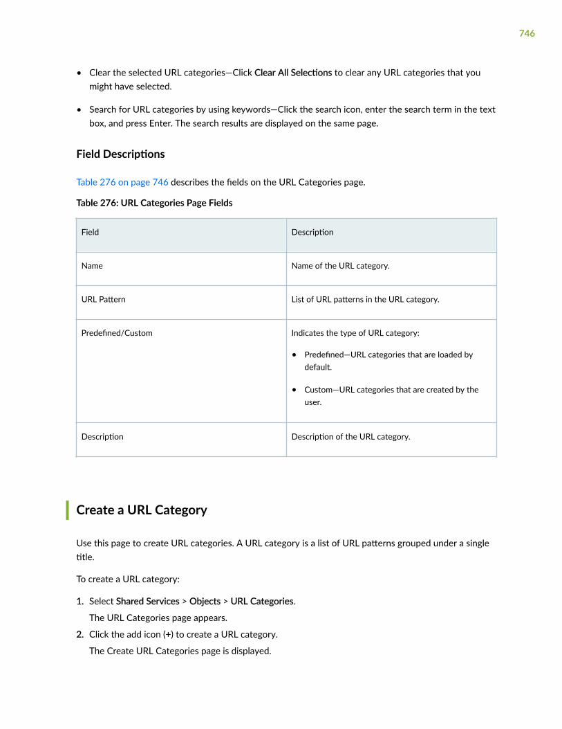
• Clear the selected URL categories—Click Clear All Selections to clear any URL categories that youmight have selected.
• Search for URL categories by using keywords—Click the search icon, enter the search term in the textbox, and press Enter. The search results are displayed on the same page.
Field Descriptions
Table 276 on page 746 describes the fields on the URL Categories page.
Table 276: URL Categories Page Fields
Field Description
Name Name of the URL category.
URL Pattern List of URL patterns in the URL category.
Predefined/Custom Indicates the type of URL category:
• Predefined—URL categories that are loaded bydefault.
• Custom—URL categories that are created by theuser.
Description Description of the URL category.
Create a URL Category
Use this page to create URL categories. A URL category is a list of URL patterns grouped under a singletitle.
To create a URL category:
1. Select Shared Services > Objects > URL Categories.
The URL Categories page appears.
2. Click the add icon (+) to create a URL category.
The Create URL Categories page is displayed.
746

3. Complete the configuration according to the guidelines provided in Table 277 on page 747.
NOTE: Fields marked with * are mandatory.
4. Click OK.
A new URL category is created and you are returned to the URL Categories page.
Table 277: Create URL Categories Settings
Settings Guidelines
Name Enter a unique name for the URL category.
The name must begin with a letter or an underscore(_) and can contain alphanumeric characters andsome special characters (_ -). The maximum length is59 characters.
Description Enter a description for the URL pattern. Themaximum length is 255 characters.
URL Patterns Select one or more URL patterns in the Availablecolumn and click the forward arrow to confirm yourselection. The selected URL patterns are displayed inthe Selected column.
Alternatively, click Create a New Pattern to create aURL pattern and assign it to the URL category. TheCreate URL Patterns page appears. For moreinformation, see "Create a URL Pattern" on page 740.
NOTE: You must select at least one URL pattern.
747

Edit, Clone, and Delete a URL Category
IN THIS SECTION
Edit a URL Category | 748
Clone a URL Category | 748
Delete a URL Category | 749
You can edit, clone, and delete URL categories from the URL Categories page. This topic has thefollowing sections:
Edit a URL Category
To modify the parameters configured for a URL category:
1. Select Shared Services > Objects > URL Categories.
The URL Categories page appears, displaying the existing URL categories.
2. Select the custom URL category that you want to edit and click the pencil icon.
The Edit URL Categories page appears, displaying the same fields that are presented when you createa URL category.
3. Modify the URL category fields as needed.
4. Click OK to save your changes.
You are taken to the URL Categories page. A confirmation message appears, indicating the status ofthe edit operation.
Clone a URL Category
Cloning enables you to easily create a new URL category based on an existing one.
To clone a URL category:
1. Select Shared Services > Objects > URL Categories.
The URL Categories page appears, displaying the existing URL categories.
2. Select the URL category that you want to clone and then select More > Clone.
The Clone URL Categories page appears, displaying the same fields that are presented when youcreate a URL category.
3. Modify the URL category fields as needed.
4. Click OK to save your changes.
748

You are taken to the URL Categories page. A confirmation message appears, indicating the status ofthe clone operation.
Delete a URL Category
Before deleting a URL category, ensure that the URL category is not referenced in any content securityprofiles that are, in turn, used in firewall policy rules or in the content security settings. If you try todelete such a URL category, an error message is displayed.
To delete one or more URL categories:
1. Select Shared Services > Objects > URL Categories.
The URL Categories page appears, displaying the existing URL categories.
2. Select one or more custom URL categories that you want to delete and click the delete icon.
An alert message appears, asking you to confirm the delete operation.
3. Click Yes to delete the selected URL categories.
A confirmation message appears, indicating the status of the delete operation.
749

CHAPTER 44
Advanced Threat Prevention
IN THIS CHAPTER
File Inspection Profiles Overview | 750
Create File Inspection Profiles | 752
Email Management Overview | 754
Configure SMTP Email Management | 755
Configure IMAP Email Management | 759
Allowlist and Blocklist Overview | 762
Create Allowlists and Blocklists | 763
SecIntel Feeds Overview | 769
Juniper Threat Feeds Overview | 774
Global Configuration for Infected Hosts | 775
Enable Logging | 778
Configure Threat Intelligence Sharing | 778
Configure Trusted Proxy Servers | 780
File Inspection Profiles Overview
Access this page from Shared Services > ATP > File Inspection Profiles.
Juniper ATP Cloud profiles let you define which files to send to the cloud for inspection. You can grouptypes of files to be scanned together (such as .tar, .exe, and .java) under a common name and createmultiple profiles based on the content you want scanned. Then enter the profile names on eligibleJuniper Secure Edge devices to apply them.
Benefits of File Inspection Profiles
• Allows you to create file categories to send to the cloud for scanning rather than having to list everysingle type of file you want scanned.
750

• Allows you to configure multiple scanning categories based on file type, adding and removing filetypes when necessary, increasing or decreasing granularity.
Table 278: File Category Contents
Category Description
Archive Archive files
Configuration Configuration files
Document All document types except PDFs
Executable Executable binaries
ELF Executable and Linkable Format (ELF) is a standard file format for executable files, object code,and libraries.
Java Java applications, archives, and libraries
Library Dynamic and static libraries and kernel modules
Mobile Mobile formats
OS package OS-specific update applications
PDF PDF, e-mail, and MBOX files
Rich Application Installable Internet Applications such as Adobe Flash, JavaFX, Microsoft Silverlight
Script Scripting files
You can also define the maximum file size requirement per each category to send to the cloud. If a filefalls outside of the maximum file size limit the file is automatically downloaded to the client system.
751

NOTE: If you are using the free or basic model of Juniper ATP Cloud, you are limited to only theexecutable file category.
NOTE: The ELF file types support both static analysis and dynamic analysis.
Juniper ATP Cloud periodically polls for new and updated content and automatically downloads it toJuniper Secure Edge. There is no need to manually push your profile.
Create File Inspection Profiles
Use this page to group files under a common, unique name for scanning. By grouping files together intoa profile, you can choose file categories to send to the cloud rather than having to list every single typeof file you want to scan, such as .tar, .exe, and .java. Once you create your profile name, select one ormore check boxes to add file types to be scanned to the profile. Optionally, enter a value limit for the filetype in megabytes.
• Review the "File Inspection Profiles Overview" on page 750 topic.
• Note that a default profile, default_profile, is created as part of the initial configuration step. You canmodify this default profile, but you cannot delete it.
• If you are using the free or basic model of Juniper Advanced Threat Prevention Cloud, you are limitedto only the executable file category.
To create a device profile:
1. Select Shared Services > ATP > File Inspection Profiles.
2. Click the plus sign (+). Complete the configuration according to the guidelines provided in the tablebelow.
3. Click OK.
752

Table 279: Profile Settings
Setting Guideline
Name Enter a unique name for the profile. This must be a unique string thatbegins with an alphanumeric character and can include letters,numbers, and underscores; no spaces are allowed; 63-charactermaximum.
File Categories You can create several profiles and each profile can contain differentoptions for how each file type is scanned. From the pulldown list foreach file type, you can select:
Do not scan – This file type is not processed for scanning and is alwaysallowed through.
Hash lookup only – Instead of the file, a sha256 hash of the file is sentfor matching against known malware. This may provide a faster resultbecause only a matching of the hash is done and all the file data doesnot have to be sent. The danger here is that the hash will only matchknown malware. If the file is a new type of malware that is not known,it will not be recognized as malicious using this method.
Scan files up to max size – The full content of the file is sent to thecloud for scanning as long as it falls within the set file size limits. If afile exceeds this limit, it is not sent to the cloud for inspection and istransferred to the client. If you do not set the maximum file size, adefault of 32 MB is used.
NOTE: You can create up to 32 profiles.
NOTE: Juniper ATP Cloud periodically polls for new and updated content and automaticallydownloads it to Juniper Secure Edge. There is no need to manually push your profile.
753

Email Management Overview
With Email Management, Juniper Secure Edge transparently submit potentially malicious emailattachments to the cloud for inspection. Once an attachment is evaluated, Juniper ATP Cloud assignsthe file a threat score between 0-10 with 10 being the most malicious.
NOTE: If an email contains no attachments, it is allowed to pass without any analysis.
Benefits of Email Management
• Allows attachments to be checked against allowlists and blocklists.
• Prevents users from opening potential malware received as an email attachment.
Configure Juniper ATP Cloud to take one of the following actions when an email attachment isdetermined to be malicious:
For SMTP
• Quarantine Malicious Messages—If you select to quarantine emails with attachments found to bemalicious, those emails are stored in the cloud in an encrypted form and a replacement email is sentto the intended recipient. That replacement email informs the recipient of the quarantined messageand provides a link to the quarantine portal where the email can be previewed. The recipient canthen choose to release the email by clicking a Release button (or request that the administratorrelease it) or Delete the email.
• Deliver malicious messages with warning headers added—When you select this option, headers areadded to emails that most mail servers recognize and filter into Spam or Junk folders.
• Permit—You can select to permit the email and the recipient receives it intact. Optionally, you canchoose to send a notification to the end user about the permitted message.
For IMAP
• Block Malicious Messages—Block emails with attachments that are found to be malicious.
• Permit—You can select to permit the email and the recipient receives it intact.
Quarantine Release
If the recipient selects to release a quarantined email, it is allowed to pass through Juniper Secure Edgewith a header message that prevents it from being quarantined again, but the attachments are placed ina password-protected ZIP file. The password required to open the ZIP file is also included as a separateattachment. The administrator is notified when the recipient takes an action on the email (either torelease or delete it).
754

If you configure Juniper ATP Cloud to have the recipient send a request to the administrator to releasethe email, the recipient previews the email in the quarantine portal and can select to Delete the email orRequest to Release. The recipient receives a message when the administrator takes action (either torelease or delete the email.)
Blocklist and Allowlist
Emails are checked against administrator-configured blocklists and allowlists using information such asEnvelope From (MAIL FROM), Envelope To (RCPT TO), Body Sender, Body Receiver. If an email matchesthe allowlist, that email is allowed through without any scanning. If an email matches the blocklist, it isconsidered to be malicious and is handled the same way as an email with a malicious attachment.
Configure SMTP Email Management
Access this page from Shared Services > ATP > Email Management > SMTP.
NOTE: SMTP is supported only for Security Director Cloud use cases.
• Read the "Email Management Overview" on page 754 topic.
• Decide how malicious emails are handled: quarantined, delivered with headers, or permitted.
1. Select Configure > Email Management > SMTP.
The SMTP page appears.
2. Based on your selections, configuration options will vary. See the tables below.
Table 280: Configure Quarantine Malicious Messages
Setting Guideline
Action to take Quarantine malicious messages—When you select to quarantinemalicious email messages, in place of the original email, intendedrecipients receive a custom email you configure with information onthe quarantining. Both the original email and the attachment are storedin the cloud in an encrypted format.
755

Table 280: Configure Quarantine Malicious Messages (Continued)
Setting Guideline
Release option • Recipients can release email—This option provides recipients with alink to the quarantine portal where they can preview the email.From the portal, recipients can select to Release the email orDelete it. Either action causes a message to be sent to theadministrator.
NOTE: If a quarantined email has multiple recipients, any individualrecipient can release the email from the portal and all recipients willreceive it. Similarly, if one recipient deletes the email from theportal, it is deleted for all recipients.
• Recipients can request administrator to release email—This optionalso provides recipients with a link to the quarantine portal wherethey can preview the email. From the portal, recipients can selectto Request to Release the email or Delete it. Either choice causes amessage to be sent to the administrator. When the administratortakes action on the email, a message is sent to the recipient.
NOTE: When a quarantined email is released, it is allowed to passthrough the Juniper Secure Edge with a header message that preventsit from being quarantined again, but the attachment is placed inside apassword-protected zip file with a text file containing the passwordthat the recipient must use to open the file.
Email Notifications for End Users
Learn More Link URL If you have a corporate web site with further information for users,enter that URL here. If you leave this field blank, this option will notappear to the end user.
Subject When an email is quarantined, the recipient receives a custommessage informing them of their quarantined email. For this custommessage, enter a subject indicating a suspicious email sent to them hasbeen quarantined, such as "Malware Detected."
Custom Message Enter information to help email recipients understand what theyshould do next.
756

Table 280: Configure Quarantine Malicious Messages (Continued)
Setting Guideline
Custom Link Text Enter custom text for the quarantine portal link where recipients canpreview quarantined emails and take action on them.
Buttons • Click Preview to view the custom message that will be sent to arecipient when an email is quarantined. Then click Save.
• Click Reset to clear all fields without saving.
• Click Save if you are satisfied with the configuration.
Table 281: Configure Deliver with Warning Headers
Setting Guideline
Action to take Deliver with warning headers—When you select to deliver a suspiciousemail with warning headers, you can add headers to emails that mostmail servers will recognize and filter into spam or junk folders.
SMTP Headers • X-Distribution (Bulk, Spam)—Use this header for messages that aresent to a large distribution list and are most likely spam. You canalso select “Do not add this header.”
• X-Spam-Flag—This is a common header added to incoming emailsthat are possibly spam and should be redirected into spam or junkfolders. You can also select “Do not add this header.”
• Subject Prefix—You can prepend headers with information for therecipient, such as "Possible Spam."
Buttons • Click Reset to clear all fields without saving.
• Click OK if you are satisfied with the configuration.
757

Table 282: Permit
Setting Guideline
Action to take Permit—You can select to permit the message. Optionally, you canchoose to send a notification to the end user about the permittedmessage containing an unknown malware.
Notify end users Enable this option to configure the protected domain and send customnotifications to the protected domain users and administrators. If thisfield is disabled, then the notification is sent only to the administrators.
Protected Domains (Optional) Enter comma-separated list of domain names. By default,malware notification is sent to configured administrators and end usersof all domains. When you specify the protected domains, the malwarenotification will only be sent to the users in the specified domains.
Subject When an email is permitted and Notify end user is enabled, therecipient receives a custom message informing them of their permittedemail containing an unknown malware. For this custom message, entera subject indicating a suspicious email sent to them has beenpermitted, such as "Malware Notification."
Custom Message (Optional). Enter information to help email recipients understand whatthey should do next. Default predefined message will be sent if leftblank.
Email Notifications for Administrators
Subject When an email is permitted, the administrator receives a custommessage informing them of the permitted email. For this custommessage, enter a subject indicating a suspicious email sent to them hasbeen permitted, such as "Malware Notification."
Custom Message Enter information to help email recipients understand what theyshould do next.
758

Table 282: Permit (Continued)
Setting Guideline
Buttons • Click Preview to view the custom message that will be sent to arecipient when an email is permitted. Then click Save.
• Click Reset to clear all fields without saving.
• Click Save if you are satisfied with the configuration.
Administrators Who Receive Notifications
To send notifications to administrators when emails are quarantined or released from quarantine:
1. Click the + sign to add an administrator.
2. Enter the administrator's email address.
3. Select the Quarantine Notification check box to receive those notifications.
4. Select the Release Notifications check box to receive those notifications.
5. Click OK.
Configure IMAP Email Management
To access this page, navigate to Shared Services > ATP > Email Management > IMAP.
NOTE: IMAP is supported only for Security Director Cloud use cases.
• Read the "Email Management Overview" on page 754 topic.
• Decide how malicious emails are handled. For IMAP, the available options are to block or permitemail. Unlike SMTP, there is no quarantine option for IMAP and no method for previewing a blockedemail.
1. Select Shared Services > ATP > Email Management > IMAP.
The IMAP page appears.
2. Based on your selections, configuration options will vary. See the tables below.
759

Table 283: Configure Block Malicious Messages
Setting Guideline
Action to take • Permit download of attachments—Allow email attachments, eitherfrom all IMAP servers or specific IMAP servers, through to theirdestination.
NOTE: In Permit mode, black and allowlists are not checked. Emailsfrom blocklisted addresses are not sent to the cloud for scanning.They are allowed through to the client.
• Block download of attachments—Block email attachments, eitherfrom all IMAP servers or specific IMAP servers, from reaching theirdestination.
NOTE: In Block mode, black and allowlists are checked. Emails fromblocklisted addresses are blocked. Emails from allowlistedaddresses are allowed through to the client.
Recipients can send a request to an administrator to release theemail. Enter the email address to which recipients should send arelease request.
NOTE: If a blocked email has multiple recipients, any individualrecipient can request to release the email and all recipients willreceive it.
When you select to block email attachments, in place of the originalemail, intended recipients receive a custom email you configure withinformation on the block action. Both the original email and theattachment are stored in the cloud in an encrypted format.
IMAP Server • All IMAP Servers—The permitting or blocking of email attachmentsapplies to all IMAP servers.
• Specific IMAP Server—The permitting or blocking of emailattachments applies only to IMAP servers with hostnames that youadd to a list. A configuration section to add the IMAP server nameappears when you select this option.
When you add IMAP servers to the list, it is sent to Juniper SecureEdge to filter emails sent to Juniper ATP Cloud for scanning. For emailsthat are sent for scanning, if the returned score is above the set policythreshold on Juniper Secure Edge, then the email is blocked.
760

Table 283: Configure Block Malicious Messages (Continued)
Setting Guideline
IMAP Servers Select the Specific IMAP Server option above and click the + sign toadd IMAP server hostnames to the list.
NOTE: You must use the IMAP server hostname and not the IPaddress.
Email Notifications for End Users
Learn More Link URL If you have a corporate web site with further information for users,enter that URL here. If you leave this field blank, this option will notappear to the end user.
Subject When an email is blocked, the recipient receives a custom messageinforming them of their blocked email. For this custom message, entera subject indicating a suspicious email sent to them has been blocked,such as "Malware Detected."
Custom Message Enter information to help email recipients understand what theyshould do next.
Custom Link Text Enter custom text for the quarantine portal link where recipients canpreview blocked emails and take action on them.
Buttons • Click Preview to view the custom message that will be sent to arecipient when an email is blocked. Then click Save.
• Click Reset to clear all fields without saving.
• Click Save if you are satisfied with the configuration.
Administrators Who Receive Notifications
To send notifications to administrators when emails are blocked or released from quarantine:
1. Click the + sign to add an administrator.
2. Enter the administrator's email address and click OK.
761

3. Once the administrator is created, you can uncheck or check which notification types theadministrator will receive.
• Block Notifications—When this check box is selected, a notification is sent when an email isblocked.
• Unblock Notifications—When this check box is selected, a notification is sent when a userreleases a blocked email.
Allowlist and Blocklist Overview
An allowlist contains known trusted IP addresses, Hashes, Email addresses, and URLs. Contentdownloaded from locations on the allowlist does not have to be inspected for malware. A blocklistcontains known untrusted IP addresses and URLs. Access to locations on the blocklist is blocked, andtherefore no content can be downloaded from those sites.
Benefits of Allowlists and Blocklists
• Allowlist allows users to download files from sources that are known to be safe. Allowlist can beadded to in order to decrease false positives.
• Blocklists prevent users from downloading files from sources that are known to be harmful orsuspicious.
The Custom allowlists or custom blocklists allow you to add items manually. Both are configured on theJuniper ATP Cloud server. The priority order is as follows:
1. Custom allowlist
2. Custom blocklist
If a location is in multiple lists, the first match wins.
Allowlists support the following types:
• Anti-malware—IP address, URL, file hash, and e-mail sender
• SecIntel—C&C, ETI, and DNS
Blocklists support the following types:
• Anti-malware—IP address, URL, file hash, and e-mail sender
• SecIntel—C&C
762

NOTE:
• For IP and URL, The Web UI performs basic syntax checks to ensure your entries are valid.
• A hash is a unique signature for a file generated by an algorithm. You can add custom allowlistand blocklist hashes for filtering, but they must be listed in a text file with each entry on asingle line. You can only have one running file containing up to 15,000 file hashes. For uploaddetails see "Create Allowlists and Blocklists" on page 763. Note that Hash lists are slightlydifferent than other list types in that they operate on the cloud side rather than the JuniperSecure Edge side. This means the web portal is able to display hits on hash items.
Juniper Secure Edge makes requests approximately every two hours for new and updated feed content.If there is nothing new, no new updates are downloaded.
Create Allowlists and Blocklists
Access these pages from Shared Services > ATP > Allowlists or Blocklists.
Use these pages to configure custom trusted and untrusted lists. You can also upload hash files.
Content downloaded from locations on the allowlist is trusted and does not have to be inspected formalware. Hosts cannot download content from locations on the blocklist, because those locations areuntrusted.
• Read the "Allowlist and Blocklist Overview" on page 762 topic.
• Decide on the type of item you intend to define: URL, IP, Hash, E-mail sender, C&C, ETI, or DNS,
• Review current list entries to ensure the item you are adding does not already exist.
• If you are uploading hash files, the files must be in a text file with each hash on its own single line.
To create Juniper ATP Cloud allowlists or blocklists:
1. Select Shared Services > ATP > Allowlists or Blocklists.
2. For either Allowlist or Blocklist, select one of the following tabs: Anti-Malware or SecIntel. Enter therequired information. See the tables below.
Allowlists support the following types:
• Anti-malware—IP address, URL, file hash, and e-mail sender
• SecIntel—C&C, ETI, and DNS
763

Blocklists support the following types:
• Anti-malware—IP address, URL, file hash, and e-mail sender
• SecIntel—C&C
3. Click OK.
Refer to the following tables for the data required by each tab.
IP
When you create a new IP list item, you must select the Type of list as IP. You must enter the requiredinformation. See the following table.
Table 284: IP Configuration
Setting Guideline
IP Enter the IPv4 or IPv6 IP address. For example: 1.2.3.4 or0:0:0:0:0:FFFF:0102:0304. CIDR notation and IP address ranges are alsoaccepted.
Any of the following IPv4 formats are valid: 1.2.3.4, 1.2.3.4/30, or1.2.3.4-1.2.3.6.
Any of the following IPv6 formats are valid: 1111::1, 1111::1-1111::9, or1111:1::0/64.
NOTE: Address ranges: No more than a block of /16 IPv4 addressesand /48 IPv6 addresses are accepted. For example, 10.0.0.0-10.0.255.255 isvalid, but 10.0.0.0-10.1.0.0 is not.
Bitmasks: The maximum amount of IP addresses covered by bitmask in asubnet record for IPv4 is 16 and for IPv6 is 48. For example, 10.0.0.0/15and 1234::/47 are not valid.
NOTE: To edit an existing allowlist or blocklist IP entry, select the check box next to the entry you want to edit,click the pencil icon and click OK.
URL
When you create a new URL list item, you must choose the Type of list: URL. Enter the requiredinformation. See the following table.
764

Table 285: URL Configuration
Setting Guideline
URL Enter the URL using the following format: juniper.net. Wildcards andprotocols are not valid entries. The system automatically adds a wildcard tothe beginning and end of URLs. Therefore juniper.net also matchesa.juniper.net, a.b.juniper.net, and a.juniper.net/abc. If you explicitly entera.juniper.net, it matches b.a.juniper.net, but not c.juniper.net. You can entera specific path. If you enter juniper.net/abc, it matches x.juniper.net/abc, butnot x.juniper.net/123.
NOTE: To edit an existing allowlist or blocklist URL entry, select the check box next to the entry you want to edit,click the pencil icon and click OK.
Hash File
When you upload a hash file, it must be in a text file with each hash on its own single line. You can onlyhave one running hash file. To add to it or edit it, see the instructions in the following table.
Table 286: Hash File Upload and Edit Configuration
Field Guideline
You can add custom allowlist and blocklist hashes for filtering, but they must be listed in a text file with eachentry on a single line. You can only have one running hash file containing up to 15,000 file hashes. This is the“current” list, but you can add to it, edit it, and delete it at any time.
765

Table 286: Hash File Upload and Edit Configuration (Continued)
Field Guideline
SHA-256 Hash Item To add to hash entries, you can upload several text files and they willautomatically combine into one file. See all, merge, delete and replaceoptions below.
Download—Click this button to download the text file if you want to viewor edit it.
You can select any of the following options from the Select Hash File ItemsUpload Option drop-down list:
• Replace current list—Use this option when you want to change theexisting list, but do not want to delete it entirely. Download the existingfile, edit it, and then upload it again.
• Merge with current list—Use this option when you upload a new text fileand want it to combine with the existing text file. The hashes in bothfiles combine to form one text file containing all hashes.
• Delete from current list—Use this option when you want to delete only aportion of the current list. In this case, you would create a text filecontaining only the hashes you want to remove from the current list.Upload the file using this option and only the hashes in the uploaded fileare deleted from the current active list.
Delete All or Delete Selected—Sometimes it’s more efficient to delete thecurrent list rather than downloading it and editing it. Click this button todelete the current selected list or all lists that have been added andaccumulated here.
Source This says either Allowlist or Blocklist.
Date Added The month, date, year, and time when the hash file was last uploaded oredited.
Email Sender
Add email addresses to be allowlist or blocklist if found in either the sender or recipient of an emailcommunication. Add addresses one at a time using the + icon.
766

Table 287: Email Sender Configuration
Field Guideline
Email address Enter an email address in the format [email protected]. Wildcards andpartial matches are not supported, but if you want to include an entiredomain, you could enter only the domain as follows: domain.com
If an email matches the blocklist, it is considered to be malicious and is handled the same way as an email with amalicious attachment. The email is blocked and a replacement email is sent. If an email matches the allowlist, thatemail is allowed through without any scanning. See "SMTP Quarantine Overview" on page 132.
It is worth noting that attackers can easily fake the “From” email address of an email, making blocklists a lesseffective way to stop malicious emails.
C&C Server
When you allowlist a C&C server, the IP or hostname is sent to Juniper Secure Edge to be excluded fromany security intelligence blocklists or C&C feeds (both Juniper’s global threat feed and third party feeds).The server will also now be listed under the C&C allowlist management page.
You can enter C&C server data manually or upload a list of servers. That list must be a text file with eachIP or Domain on its own single line. The text file must include all IPs or all Domains, each in their ownfile. You can upload multiple files, one at a time.
NOTE: You can also manage allowlist and blocklist entries using the Threat Intelligence API.When adding entries to the allowlist/blocklist data, these will be available in the ThreatIntelligence API under the following feed names: “whitelist_domain” or “whitelist_ip”, and“blacklist_domain” or “blacklist_ip.” See the Juniper ATP Cloud Threat Intelligence Open APISetup Guide for details on using the API to manage any custom feeds.
Table 288: C&C Configuration
Field Guideline
Type Select IP to enter the IP address of a C&C server that you want to add tothe allowlist. Select Domain to allowlist an entire domain on the C&C serverlist.
767

Table 288: C&C Configuration (Continued)
Field Guideline
IP or Domain For IP, enter an IPv4 or IPv6 address. An IP can be IP address, IP range or IPsubnet. For domain, use the following syntax: juniper.net. Wildcards are notsupported.
Description Enter a description that indicates why an item has been added to the list.
You can also allowlist C&C servers directly from the C&C Monitoring page details view. See Command andControl Server Details.
WARNING: Adding a C&C server to the allowlist automatically triggers a remediation process to update anyaffected hosts (in that realm) that have contacted the whitelisted C&C server. All C&C events related to thisallowlisted server will be removed from the affected hosts’ events, and a host threat level recalculation willoccur.
If the host score changes during this recalculation, a new host event appears describing why it was rescored.(For example, “Host threat level updated after C&C server 1.2.3.4 was cleared.”) Additionally, the server willno longer appear in the list of C&C servers because it has been cleared.
Encrypted Traffic Insights (ETI)
You can specify the IP address or domain names that you want to allowlist from encrypted trafficanalysis. Use this tab to add, modify, or delete the allowlists for encrypted traffic analysis.
Table 289: Encrypted Traffic Configuration
Field Guideline
Type Select whether you want to specify the IP address or domain name for the allowlist.
IP or Domain Enter the IP address or domain name for the allowlist.
Domain Name System (DNS)
You can specify the domains that you want to allowlist from DNS filtering. Use this tab to add, modify,or delete the allowlists for DNS filtering.
768

Table 290: Domains Configuration
Field Guideline
URL Enter the URL for domain that you want to allowlist.
Comments Enter a description that indicates why the domain has been added to the list.
NOTE: Juniper ATP Cloud periodically polls for new and updated content and automaticallydownloads it to Juniper Secure Edge. There is no need to manually push your allowlist orblocklist files.
SecIntel Feeds Overview
SecIntel provides carefully curated and verified threat intelligence from Juniper Networks’ AdvancedThreat Prevention (ATP) Cloud, Juniper Threat Labs, Dynamic Address Group (DAG), and industry-leading threat feeds to Juniper Secure Edge, MX Series routers, SRX Series Services Gateways, and NFXSeries Network Services Platform to block Command and Control (C&C) communications at line rate.SecIntel delivers real-time threat intelligence by enabling automatic and responsive traffic filtering.
SecIntel integrates with EX Series and QFX Series switches and enables these switches to subscribe toSecIntel’s infected host feed. This enables you to block compromised hosts at the switch port. You cannow extend SecIntel throughout your entire network and increase the number of security enforcementpoints.
Benefits of SecIntel Feeds
You can view all the default feeds that are available with your current license.
Using this page, you can enable the following feeds for integration with Juniper ATP Cloud.
• Juniper threat feeds
• Third party threat feeds—IP threat feeds and URL threat feeds.
• Dynamic address group feeds—Juniper DAG feeds and Third-party DAG feeds.
769

NOTE: The total number of CC feeds are 32, out of which four feeds are reserved for cc_ip,cc_url, cc_ipv6, and cc_cert_sha1. So, you can enable up to 28 feeds to the CC category, whichincludes CC custom feeds and CC third-party feeds. This limit is applicable if you are injectingadditional feeds using the available open API.
Information to know if you are enabling external feeds:
• If a hit is detected on an enabled external feed, this event appears under Monitor > ATP with a threatlevel of 10.
• On Juniper Secure Edge, you can configure policies with the permit or block action for each feed.Note that C&C and Infected Host feeds require an enabled Security Intelligence policy on JuniperSecure Edge in order to work.
• External feeds are updated once every 24 hours.
WARNING: Understand that these are open source feeds managed by third parties anddetermining the accuracy of the feed is left up to the Juniper ATP Cloud administrator.Juniper will not investigate false positives generated by these feeds.
WARNING: Juniper Secure Edge policies will block malicious IP addresses based onenabled third party feeds, but these events do not affect host threat scores. Only eventsfrom Juniper ATP Cloud feeds affect host threat scores.
To enable the available feeds, do the following:
1. Navigate to Configure > SecIntel Feeds.
2. For each feed, select the toggle button to enable the feed. Refer to the guidelines in Table 291 onpage 771.
NOTE: The Infected Host feed is enabled for all license tiers. All other Juniper SecIntel feedsare enabled only with Secure Edge Advanced or higher license.
Click the Go to feed site link to view feed information, including the contents of the feed.
770

Table 291: SecIntel Feeds
Field Guidelines
Juniper Threat Feeds
Command and Control Displays whether the C&C feed is enabled or not.
Malicious Domains Displays whether the DNS feed is enabled or not.
Infected Host Feed Displays whether the infected host feed is enabled or not.
Third Party Threat Feeds
IP Threat Feeds
Block List Click the toggle button to enable block list feeds as third party feeds.
Threatfox IP Click the toggle button to enable Threatfox feeds as third party feeds.
Feodo Tracker Click the toggle button to enable Feodo feeds as third party feeds.
DShield Click the toggle button to enable DShield feeds as third party feeds.
Tor Click the toggle button to enable tor feeds as third party feeds.
URL Threat Feeds
Threatfox URL Click the toggle button to enable Threatfox feed as third party feeds.ThreatFox is a free platform from abuse.ch with the goal of sharing indicatorsof compromise (IOCs) associated with malware with the infosec community,AV vendors and threat intelligence providers. The IOC can be an IP address,domain name, or URL.
771

Table 291: SecIntel Feeds (Continued)
Field Guidelines
URLhaus URL Threat Feed Click the toggle button to enable URLhaus feed as third party feeds.URLhaus is a threat intelligence feed that shares malicious URLs that areused for malware distribution.
Open Phish Click the toggle button to enable OpenPhish feed as third party feeds.OpenPhish is a fully automated self-contained platform for phishingintelligence. It identifies phishing sites and performs intelligence analysis inreal time without human intervention and without using any externalresources, such as blocklists. For malware inspection, SecIntel will analyzetraffic using URLs in this feed.
Domain Threat Feeds
Threatfox Domains Click the toggle button to enable Threatfox feed as third party feeds.
Dynamic Address Group Feeds
Juniper DAG Feeds
GeoIP Feed Displays whether the GeoIP feed is enabled or not. GeoIP feed is an up-to-date mapping of IP addresses to geographical regions. This gives you theability to filter traffic to and from specific geographies in the world.
Third Party DAG Feeds
office365 Click the toggle button to enable office365 IP filter feed as a third party feed.The office365 IP filter feed is an up-to-date list of published IP addresses forOffice 365 service endpoints which you can use in security policies. This feedworks differently from others on this page and requires certain configurationparameters, including a pre-defined cloud feed name of “ipfilter_office365”.
Pre-defined cloud feed name— ipfilter_office365
facebook Click the toggle button to enable feeds from Facebook.
Pre-defined cloud feed name— ipfilter_facebook
772

Table 291: SecIntel Feeds (Continued)
Field Guidelines
google Click the toggle button to enable feeds from Google.
Pre-defined cloud feed name— ipfilter_google
atlassian Click the toggle button to enable feeds from Atlassian.
Pre-defined cloud feed name— ipfilter_atlassian
zscaler Click the toggle button to enable feeds from Zscaler.
Pre-defined cloud feed name— ipfilter_zscaler
oracleoci Click the toggle button to enable feeds from Oracle oci.
Pre-defined cloud feed name— ipfilter_oracleoci
cloudflare Click the toggle button to enable feeds from Cloudflare.
Pre-defined cloud feed name— ipfilter_cloudflare
zoom Click the toggle button to enable feeds from Zoom.
Pre-defined cloud feed name— ipfilter_zoom
microsoftazure Click the toggle button to enable feeds from Microsoft Azure.
Pre-defined cloud feed name— ipfilter_microsoftazure
amazonaws Click the toggle button to enable feeds from Amazon AWS.
Pre-defined cloud feed name— ipfilter_amazonaws
okta Click the toggle button to enable feeds from Okta.
Pre-defined cloud feed name— ipfilter_okta
773

Table 291: SecIntel Feeds (Continued)
Field Guidelines
paypal Click the toggle button to enable feeds from Paypal.
Pre-defined cloud feed name— ipfilter_paypal
NOTE:
• Since Ransomware Tracker and Malware Domain list are deprecated, ransomware trackerand malware domain list IP feeds are not supported on Juniper ATP Cloud. If you hadenabled this feed earlier, you might stop receiving these feeds.
• The update interval for a third party Internet service feed is one day.
Using the office365 Feed
Enable the Using the office365 Feed check box in Juniper ATP Cloud to push Microsoft Office 365services endpoint information (IP addresses) to Juniper Secure Edge. The office365 feed worksdifferently from other feeds on this page and requires certain configuration parameters, including a pre-defined name of “ipfilter_office365”.
After you enable the check box, you must create a dynamic address object on Juniper Secure Edge thatrefers to the ipfilter_office365 feed.
Juniper Threat Feeds Overview
SecIntel feeds include threat feeds provided by Juniper Networks, 3rd party threat feeds, or DynamicAddress Group (DAG) feeds. The SecIntel threat feeds provided by Juniper Networks is shown in Table292 on page 775.
NOTE: The Infected Host feed is enabled by default for all license tiers. All other Juniper Threatfeeds are enabled by default with Secure Edge Advanced or higher license.
774

Table 292: Juniper Threat Feeds
Field Guidelines
Command and ControlFeed
C&C feeds are essentially a list of servers that are known command and control forbotnets. The list also includes servers that are known sources for malware downloads.
Malicious Domains(DNS)
List of domains that are known to be connected to malicious activity.
Infected Host Feed Infected hosts indicate local devices that are potentially compromised because theyappear to be part of a C&C network or exhibit other symptoms.
Global Configuration for Infected Hosts
Threat Level Threshold
Set the global threat level to block infected hosts. When a host is found to be compromised, it isassigned a threat level. Based on the global threat level you set here, 1-10 with 10 being the highestthreat, compromised hosts with the set threat level and above are added to the infected hosts lists andcan subsequently be blocked by policies configured on Juniper Secure Edge. See "Hosts Overview" onpage 91 for more information.
You can configure Juniper ATP Cloud to send e-mails when certain threat levels are reached for infectedhosts. For example, you can send e-mails to an IT department when thresholds of 5 are met and send e-mails to an escalation department when thresholds of 9 are met.
You can send e-mails to any account; you are not restricted to administrator e-mails defined in the Userswindow. The Web UI does not verify if an e-mail account is valid.
Configure Threat Level Threshold and Email Alerts
Benefits of the Global Infected Hosts Alerts
• Email alerts for infected hosts call immediate attention to administrators when a possible networksecurity issue arises.
• Email alerts can be configured for only specific administrators and not all users of the web portal,targeting alerts more narrowly.
1. Select Shared Services > ATP > Misc Configuration > Infected Hosts.
775

2. (Premium licenses only) Set the default threat level threshold.
3. Click the plus sign to create e-mail alerts, or click the pencil icon to edit existing ones. Configure thefields described in the table below.
4. Click OK.
Table 293: Email alerts for infected hosts fields
Setting Guideline
Threat Level Select a threat level between 1 and 10. When this level is reached, an e-mailis sent to the address you provided.
E-mail Enter an e-mail address.
Automatically Expire Blocked Hosts
When a host is marked as infected and added to the infected hosts feed, it is blocked from the networkby policies configured on Juniper Secure Edge. There are options for unblocking individual hosts on theInfected Hosts page in the Portal. See "Hosts Overview" on page 91 for information. If you want tounblock multiple host IP addresses based on time period and threat level, you will use the AutomaticallyExpire Blocked Hosts feature on the Misc Configuration > Infected Hosts page in the Web Portal.
From the Infected Hosts page, you can set infected hosts to expire after a configured time based on aminimum and maximum threat level. Once the time period is reached, blocked IP addresses are nolonger marked as infected and therefore no longer blocked.
One example of when you might use this feature is if you are using DHCP addressing and reallocatingaddresses on a set schedule. In that case, you may want to set an expiration time for infected hosts(based on IP address lease times), after which addresses are no longer marked as infected.
Configure Automatic Expiration of Infected Hosts
1. Select Shared Services > ATP > Misc Configuration > Infected Hosts.
2. (System Administrators and Operators only) Enable Automatically Expire Blocked Hosts and selectone of the following:
• Unblock all hosts
• Unblock a range of hosts—Enter a range of IPv4 or IPv6 addresses.
Any of the following IPv4 formats are valid: 10.2.3.4/30, or 10.2.3.4-1.2.3.6
Any of the following IPv6 formats are valid: 1111::1-1111::9, or 1111:1::0/64
776

NOTE: No more than a block of /16 IPv4 addresses and /48 IPv6 addresses are accepted.For example, 10.0.0.0-10.0.255.255 is valid, but 10.0.0.0-10.1.0.0 is not.
Bitmasks: The maximum amount of IP addresses covered by bitmask in a subnet record forIPv4 is 16 and for IPv6 is 48. For example, 10.0.0.0/15 and 1234::/47 are not valid. CIDRnotation is also accepted.
3. For both Unblock all hosts or Unblock a range of hosts, you must also set expiration intervals andthreat levels. Click the plus + sign to create a new entry and set the following in the UnblockedExpiration Intervals table.
Table 294: Unblock expiration interval fields
Setting Guideline
Set the Minimum Threat Level Click the table entry under Minimum Threat Level to access a pulldownmenu. Select a minimum threat level (1-10). The level you select is includedin the minimum setting.
Set the Maximum Threat Level Click the table entry under Maximum Threat Level to access a pulldownmenu. Select a maximum threat level (1-10). The level you select is includedin the maximum setting.
Set the Hours to Unblock Click the table entry under Hours to Unblock. You can select Never, 6, 12,18, or 24 hours. After the set amount of hours, the infected label expiresand the hosts are no longer blocked.
For example, if you set the minimum at 6 and the maximum at 8 with hours to unblock as 24, the followingwould occur. All infected hosts with a threat level of 6 and above and 8 and below would expire after 24hours.
NOTE: You can create multiple entries in this table, setting different expiration times for different threatlevels.
Once unblock settings are entered in the table, you can use the table to change existing settings or to deletesettings.
4. You must click Save or your settings are lost.
777

Enable Logging
You can select the event types that you want to log for the devices in your realm. The Juniper ATPCloud logs yields information such as malware name, action taken, infected host, source of an attack,and destination of an attack. The devices in your realm use the event logs to generate system logs(syslogs).
To enable logging, do the following:
1. Select Shared Services > ATP > Misc Configuration > Logging.
2. Click the Malware toggle button to log malware in your realm.
3. Click the Host Status toggle button to log the host status in your realm.
NOTE: You can log the Malware or the Host Status event or both the event types.
Configure Threat Intelligence Sharing
Using the TAXII service, Juniper ATP Cloud can contribute to STIX reports by sharing the threatintelligence it gathers from file scanning. Juniper ATP Cloud also uses threat information from STIXreports as well as other sources for threat prevention. See "HTTP File Download Details" on page 103for more information on STIX reports.
• STIX (Structured Threat Information eXpression) is a language used for reporting and sharing threatinformation using TAXII (Trusted Automated eXchange of Indicator Information). TAXII is the protocolfor communication over HTTPS of threat information between parties.
• STIX and TAXII are an open community-driven effort of specifications that assist with the automatedexchange of threat information. This allows threat information to be represented in a standardizedformat for sharing.
• If you enable TAXII (it is disabled by default), you can limit who has access to your shared threatinformation by creating an application token.
To enable and configure threat intelligence sharing, do the following:
1. Select Shared Services > ATP > Misc Configuration > Threat Intelligence Sharing.
2. Move the knob to the right to Enable TAXII.
3. Move the slide bar to designate a file sharing threshold. Only files that meet or exceed the setthreshold will be used in STIX reports. The default is threat level 6 or higher.
778

NOTE: You can limit who has access to your information by creating an application token.
TAXII URLs and Services Description
Discovery URL Used by the TAXII client to discover available TAXII Services. Thecommand to initiate a TAXII request is: taxii-discovery
NOTE: Refer to the TAXII documentation for information on additionalcommands. http://taxiiproject.github.io/documentation/
Juniper ATP Cloud Discovery URLs are:
US Region: https://taxii.sky.junipersecurity.net/services/discovery
EU Region: https://taxii-eu.sky.junipersecurity.net/services/discovery
APAC Region: https://taxii-apac.sky.junipersecurity.net/services/discovery
Canada: https://taxii-canada.sky.junipersecurity.net/services/discovery
At this time, there are two services supported by Juniper ATP Cloud on the TAXII server.
Collection Management Used by the TAXII client to request information about available datacollections.
Juniper ATP Cloud Collection Management URLs are:
US Region: https://taxii.sky.junipersecurity.net/services/collection-management
EU Region: https://taxii-eu.sky.junipersecurity.net/services/collection-management
APAC Region: https://taxii-apac.sky.junipersecurity.net/services/collection-management
Canada: https://taxii-canada.sky.junipersecurity.net/services/collection-management
779

(Continued)
TAXII URLs and Services Description
Poll URL Used by the TAXII client to poll for STIX files - looking for malware that hasbeen identified on the network.
Juniper ATP Cloud Polling URLs are:
US Region: https://taxii.sky.junipersecurity.net/services/poll
EU Region: https://taxii-eu.sky.junipersecurity.net/services/poll
APAC Region: https://taxii-apac.sky.junipersecurity.net/services/poll
Canada: https://taxii-canada.sky.junipersecurity.net/services/poll
Configure Trusted Proxy Servers
Use this page to add trusted proxy server IP addresses to Juniper ATP Cloud. This feature is optional
Access this page from Shared Services > ATP > Misc Configuration > Proxy Servers.
When there is a proxy server between users on the network and a firewall, the firewall might see theproxy server IP address as the source of an HTTP or HTTPS request instead of the actual address of theuser making the request.
With this in mind, X-Forwarded-For (XFF) is a standard header added to packets by a proxy server thatincludes the real IP address of the client making the request. Therefore, if you add trusted proxy serversIP addresses to the list in Juniper ATP Cloud, by matching this list with the IP addresses in the HTTPheader (X-Forwarded-For field) for requests sent from Juniper Secure Edge, Juniper ATP Cloud candetermine the originating IP address.
NOTE: X-Forwarded-For (XFF) only applies to HTTP or HTTPS traffic, and only if the proxyserver supports the XFF header.
To add trusted proxy servers to the list, do the following:
1. Navigate to Shared Services > ATP > Misc Configuration > Proxy Servers.
2. Click the + sign.
780

3. Enter the IP address of the proxy server in the available field.
4. Click OK.
781

7PART
Administration
Subscriptions | 783
Users & Roles | 788
Audit Logs | 801
Jobs | 805
Data Management | 811
Organization | 814
ATP Mapping | 819
ATP Audit Logs | 822

CHAPTER 45
Subscriptions
IN THIS CHAPTER
Subscriptions | 783
Subscriptions
IN THIS SECTION
Overview | 783
Add Subscriptions | 785
Delete a Subscription | 786
Overview
IN THIS SECTION
Juniper Security Director Cloud Subscriptions | 784
Juniper Secure Edge Subscriptions | 784
Tasks You Can Perform | 784
Field Descriptions | 785
To access the Juniper Security Director Cloud subscriptions page, click Administration > Subscriptions.
Use the Subscriptions page to add and manage your Juniper Security Director Cloud and Juniper SecureEdge subscriptions.
783

Juniper Security Director Cloud Subscriptions
Juniper Security Director Cloud has the following two types of subscriptions:
• Device subscription to manage the devices within Juniper Security Director Cloud portal. After youpurchase a device subscription and add it in Juniper Security Director Cloud, you must associate thedevice with the device subscription. See "Device Subscription Overview" on page 186 for details
• Log subscription provides additional Juniper Security Director Cloud storage space for longerretention of data gathered from devices. After you purchase the log subscription and add it in JuniperSecurity Director Cloud, the log subscriptions are associated with the organization.
NOTE: Log subscriptions are non-transferable.
Juniper Secure Edge Subscriptions
Juniper Secure Edge has the following types of subscriptions:
• Juniper Secure Edge subscription that enables the service for all licensed users. The subscription alsoentitles you to deploy the service in two cloud service locations.
• Extra Service Location subscription that provides additional service locations for the licensed users ofthe base license.
• Storage subscription provides additional Juniper Secure Edge storage space for longer retention ofdata gathered from devices. After you purchase the storage subscription and add it in Juniper SecureEdge, the storage subscriptions are associated with the organization.
NOTE: Storage subscriptions are non-transferable.
For more details about these subscriptions, see Datasheet. To purchase these subscriptions, reach out toyour sales representative or account manager.
Tasks You Can Perform
You can perform the following tasks from this page:
• Add a subscription. See "Add Subscriptions" on page 785.
• Delete a subscription. See "Delete a Subscription" on page 786.
• Show or hide columns. Click the Show Hide Columns icon at the top right corner of the page.
784

Field Descriptions
Table 295 on page 785 describes the fields on the License Management page.
Table 295: Fields on the Subscriptions Page
Field Description
Name Displays the name of the subscription.
Entitlement Displays the device and the log subscriptioninformation. Device subscriptions are displayed asnumber of devices that you can subscribe to, alongwith the number of years this subscription is valid. Logsubscriptions are displayed as the amount of storagespace entitled, along with the number of years thissubscription is valid.
Actual Usage Displays the number of devices associated with thedevice subscription. Hover over the number to viewthe names of the devices that are subscribed to thissubscription.
Status Displays whether the subscription is active or expired.
Expiry Date Displays the expiry date on the subscription.
Plan Displays the name of the plan associated with thedevice subscription and the log subscription.
SSRN Displays the software support reference number(SSRN) which is the serial number of the subscription.
Add Subscriptions
After you purchase your Juniper Security Director Cloud subscription, you must add it to your account.
To add your purchased subscriptions to your account:
1. Log in to the Juniper Security Director Cloud portal with your user credentials.
2. Go to the Administration > Subscriptions page.
785

The Subscriptions page appears. If you have not added any subscriptions to your account, you willsee a message to this effect along with an option to add your subscriptions.
3. Click Add Subscriptions to open the Add New Subscriptions page.
4. Enter the following information and click OK.
• Name—A descriptive name for the subscription.
• SSRN—The software support reference number of the subscription that you received in youremail.
If you have purchased multiple subscriptions, click + and enter the details of the subscription(s).
5. Click OK.
Juniper Security Director Cloud verifies the SSRN and activates the subscription(s). The Subscriptionpage opens displaying the newly added subscriptions.
6. Review your subscription details to be sure everything is correct (activation state, expiration date,number of devices that you can subscribe to this subscription, and so on).
Important Information About Subscriptions
• You will receive a subscription renewal e-mail notification 90 days before a subscription expires.After that, you’ll receive a renewal e-mail notification once every week until 30 days before theexpiry date.
• You will receive a subscription renewal e-mail notification every day starting 30 days before thesubscription expires.
• You will receive a subscription renewal e-mail notification every day during grace period (30 daysafter the subscription expires).
• For a trial account, if the device subscription is not renewed within the grace period (within 30 daysafter trial period is over), then all the data for that organization will be deleted.
• When all the purchased subscriptions are expired and grace-period is also over, then storage logs willbe deleted.
Delete a Subscription
To delete one or more subscriptions from your Juniper Security Director Cloud account:
1. Log in to the Juniper Security Director Cloud portal with your user credentials.
2. Go to the Administration > Subscriptions page.
3. Select the subscription(s) you want to delete and click the delete icon on the top-right corner of thepage.
The selected subscription(s) are deleted from your Juniper Security Director Cloud account.
786

NOTE:
• Active subscriptions cannot be deleted.
• You can delete the subscriptions with unsuccessful SSRN activation or paid subscriptions thatare expired. If you delete the subscriptions, you will not receive email notifications aboutsubscription renewal.
• When a device subscription is deleted, the devices that were associated to that subscriptionwill lose the entitlements provided by the subscription.
SEE ALSO
About the Devices Page | 167
Manage Subscriptions for Your Device | 186
787

CHAPTER 46
Users & Roles
IN THIS CHAPTER
Users Overview | 788
About the Users Page | 789
Add a User | 790
Edit and Delete a User | 792
Roles Overview | 794
About the Roles Page | 795
Add a Role | 796
Edit, Clone, and Delete a Role | 798
Users Overview
Juniper Security Director Cloud supports authentication and role-based access control (RBAC) to itsresources and services. You can access only the resources and actions that are defined in the rolesassigned to you. For example, if you are assigned the operator role, you can only view the details ofobjects, such as devices and configuration templates. You do not have the permission to create, add,modify, or delete objects.
The use of access controls allows the assignment of different access privileges to different users.
Juniper Security Director Cloud provides the following default users and permissions:
• administrator—Users with the administrator role have full access to the Juniper Security DirectorCloud GUI and API capabilities. They can add users, create custom roles, and user groups.
• operator—Users with the operator role have read-only access to the Juniper Security Director CloudGUI.
788

About the Users Page
IN THIS SECTION
Tasks You Can Perform | 789
Field Descriptions | 789
To access this page, click Administration > Users & Roles > Users.
Tasks You Can Perform
You can perform the following tasks from this page:
• View the details of a user.
To view the details of a specific user, select the user, and click More > Detail. Alternatively, hoverover the user name, and click the Details icon.
The user details are displayed in a pane on the right side of the page. The details contain basicinformation, such as the roles assigned to the user, the provider type of the user, and the status ofthe user.
• Add a User. See "Add a User" on page 790.
• Edit and delete a user. See "Edit and Delete a User" on page 792.
• Show/Hide Columns—Choose to show or hide a specific column in the table.
Hover over the vertical ellipses, select Show/Hide Columns, and select the check box of the columnsto display in the table.
• Reset Preference—Reset the displayed columns to the default set of columns for each tab in thetable.
Hover your mouse cursor over the vertical ellipses, and select Reset Preference.
Field Descriptions
Table 296 on page 790 displays the fields on the Users page.
789

Table 296: Fields on the Users Page
Field Description
E-mail The e-mail of the user.
Full Name The name of the user.
Roles The roles assigned to the user.
By default, this column lists only one role assigned tothe user. When a user is assigned more than one role, a+(integer), such as +2, is displayed to the right side ofthe role. The integer indicates the number of additionalroles assigned to the user. Click the integer to viewadditional roles.
Status Indicates a user's account status.
A user can log in to Juniper Security Director Cloudonly if their account is active.
Last Logged in The date and time stamp when the user last logged into their account.
Add a User
An administrator or a user with the privileges to add, edit, and delete users can add the following typesof users to Juniper Security Director Cloud:
• Local users where the user is authenticated and authorized by Juniper Security Director Cloud.
• LDAP users where the user is authenticated by the LDAP server and authorized by Juniper SecurityDirector Cloud.
1. Click Administration > Users & Roles > Users.
The Users page opens.
2. Click the + icon.
The Create User page opens.
790

3. Complete the configuration as described in Table 297 on page 791.
4. Click OK to save the changes.
A confirmation message indicating that the user account is created is displayed and the user accountis listed on the Users page.
After the user is created, if SMTP is configured on the device, the user receives an activation e-mailfrom Juniper Security Director Cloud. The e-mail contains the link to activate the new user account.By default, the activation link expires within 24 hours. If the user does not click the activation linkand set a password, the account is not activated. To activate the account, you must resend theactivation link by clicking More > Resend activation mail.
Table 297 on page 791 lists the fields on the Create User page.
Table 297: Fields on the Create User Page
Field Description
Full Name Enter the full name of the user containing maximum32 alphanumeric characters.
The name can contain special characters, such asunderscores and hyphens.
Email Enter a valid e-mail address in the user@domainformat.
Action Click the toggle button to enable or disable the user.
By default, this option is enabled. A user can log in toJuniper Security Director Cloud only when youenable the user.
Role Assign one or more roles to the user.
To assign roles, select the roles in the left column,and click >. The selected roles are moved to the rightcolumn.
791

Edit and Delete a User
IN THIS SECTION
Edit a User | 792
Delete a User | 794
Edit a User
An administrator or a user with the privileges to add, edit, and delete users can edit a user.
1. Click Administration > Users & Roles > Users.
The Users page opens.
2. Select the user, and click the pencil icon.
The Edit User page opens.
3. Modify the parameters by following the guidelines provided in Table 298 on page 792.
Table 298: Fields on the Edit User Page
Field Description
Full Name Enter the full name of the user containing maximum32 alphanumeric characters.
The name can contain special characters, such asunderscores and hyphens.
Email Enter a valid e-mail address in the user@domainformat.
You cannot change the email address of a useraccount after creating the account.
792

Table 298: Fields on the Edit User Page (Continued)
Field Description
Company name Enter the company name for the user havingmaximum 64 alphanumeric characters.
The company name can contain spaces, underscores,and hyphens.
You can change the company name only for yourown user account.
Country Select the country for the user.
You can change the country only for your own useraccount.
Phone number Enter a valid phone number containing between 7 to18 characters.
The phone number can contain numbers, plus sign,hyphens, and parentheses.
You can change the phone number only for your ownuser account.
Action Click the toggle button to enable or disable the user.
By default, this option is enabled. A user can log in toJuniper Security Director Cloud only when youenable the user.
Role Assign one or more roles to the user.
To assign roles, select the roles in the left column,and click >. The selected roles are moved to the rightcolumn.
4. Click OK to save the changes.
A confirmation message indicating that the user account is modified is displayed and the updatedinformation about the user is displayed on the Users page.
793

Delete a User
1. Click Administration > Users & Roles > Users.
The Users page opens.
2. Select the user, and click the trash can icon.
A message asking you to confirm the delete operation is displayed.
3. Click Yes to delete the users.
A confirmation message indicating that the selected user account is deleted from Juniper SecurityDirector Cloud is displayed, and the user account is removed from the Users page.
Roles Overview
IN THIS SECTION
Types of Roles | 794
Access Privileges | 795
A role is a function assigned to a user that defines the tasks that the user can perform in JuniperSecurity Director Cloud. Each user can be assigned one or more roles depending on the tasks that theuser is expected to perform.
User roles enable you to classify users based on the privileges assigned to them to perform tasks.
Types of Roles
Juniper Security Director Cloud provides the following types of roles:
• Pre-canned roles—System-defined roles with a set of predefined access privileges. Predefined rolesare created while installing Juniper Security Director Cloud.
• Custom roles—User-defined roles with a set of access privileges. Customized roles can be created bythe administrator or a user with the privilege to create users.
794

Access Privileges
User roles define the access privileges and actions to access objects, such as the dashboard, devicetemplates, and devices in Juniper Security Director Cloud. For example, a user role can containpermissions to read device configurations and delete alert objects.
Juniper Security Director Cloud provides the following privileges:
• Read
• Create
• Update
• Delete
• Other actions, such as stage and deploy for the device software images
About the Roles Page
IN THIS SECTION
Tasks You Can Perform | 795
Field Descriptions | 796
To access this page, click Administration > Users & Roles > Roles.
Tasks You Can Perform
You can perform the following tasks from this page:
• View the details of a role.
To view the details of a specific role, select the role, and click More > Detail. Alternatively, hover overthe role name, and click the Details icon.
The details of the role is displayed in a pane on the right side of the page. The details contain basicinformation, such as the roles scope and a link to the Preview Roles page. The Preview Roles pagelists the access privileges assigned to the role.
795

• Create a customized role. See "Add a Role" on page 796.
• Edit, clone, or delete a role. See "Edit, Clone, and Delete a Role" on page 798.
• Show/Hide Columns—Choose to show or hide a specific column in the table.
Hover your mouse cursor over the vertical ellipses, select Show/Hide Columns, and select the checkbox of the columns to display in the table.
• Reset Preference—Reset the displayed columns to the default set of columns for each tab in thetable.
Hover your mouse cursor over the vertical ellipses, and select Reset Preference.
• Sort Entries—Click on a column name to highlight the up and down arrows next to the column name.Sort the table entries in ascending or descending order of that column by clicking the up or downarrow respectively.
Field Descriptions
Table 299 on page 796 describes the fields on the Roles page.
Table 299: Fields on the Roles Page
Field Description
Role Name The name of the role.
Role Scope The scope of the role is Organization.
This is a read-only field.
Role Type The type of role, which can be pre-canned and custom.
Created By The user who created the role.
The system indicates that the roles are pre-canned.
Add a Role
An administrator or a user with the privileges to add, edit, clone, and delete roles can add a role.
796

1. Select Administration > Users & Roles > Roles.
The Roles page opens.
2. Click the + icon to add a new role.
The Create Role page opens.
3. Complete the configuration according to the guidelines provided in Table 300 on page 797.
4. Click OK.
A confirmation message indicating that the role is created is displayed, and the role is listed on theRoles page.
Table 300: Fields on the Add Roles Page
Field Description
Role Name Enter a unique name containing maximumalphanumeric 32 characters for the role.
The name can contain special characters such asunderscores, periods, and spaces.
Description Enter a description containing maximum 255characters for the role.
Role Scope The scope of the role is Organization.
This is a read-only field.
797

Table 300: Fields on the Add Roles Page (Continued)
Field Description
Access Privileges Displays the objects in Juniper Security DirectorCloud.
You must select the check box against each objectand select the privileges to assign to the user for theselected object. You can select multiple accessprivileges to assign to the user role.
NOTE: You must assign at least one access privilegeto a role.
If you select the first-level objects, the submenuitems that belong to the main object and thecorresponding access privileges are also selected.
The following access privileges can be assigned to auser role:
• Read— Enables the user to read existing objects.
• Create—Enables the user to add new objects.
• Update—Enables the user to edit or modify theexisting objects.
• Delete—Enables the user to delete objects.
• Other Actions—Includes actions such as deploy,stage, upload, and simulate.
Edit, Clone, and Delete a Role
IN THIS SECTION
Edit a Role | 799
Clone a Role | 799
Delete a Role | 799
798

An administrator or a user with the privileges can edit, clone, and delete roles.
Edit a Role
You cannot edit pre-canned roles.
1. Select Administration > Users & Roles > Roles.
The Roles page opens displaying the details of the available roles.
2. Select the role, and click the pencil icon to modify the attributes.
The Edit Role page opens. The fields on the Edit Role page are available for editing.
3. Modify the role description and privileges.
You cannot modify the role name and the role scope.
4. Click OK to save the changes.
A message indicating that the role is successfully edited opens, and the updated role information isdisplayed in the Roles table.
Clone a Role
You can clone a customized or pre-canned role when you want to quickly create a copy of an existingrole and modify its access privileges.
1. Select Administration > Users & Roles > Roles.
The Roles page opens displaying the details of the available roles.
2. Select the role, and click the Clone button at the top-right corner of the page.
The Clone Role Role-Name page opens.
3. Specify an appropriate name for the cloned role.
The name must contain maximum 32 alphanumeric characters and can contain special characterssuch as underscores, periods, and spaces.
4. Click OK to save your changes.
A clone of the role is created and listed on the Roles page.
5. Select the new cloned role, and click the pencil icon to modify the parameters.
The Edit Role page opens.
6. Select the objects, and modify the access privileges of the role.
You cannot modify the role name and the role scope.
7. Click OK to save your changes.
A confirmation message indicating the status of the edit operation is displayed.
Delete a Role
You cannot delete a pre-canned role or a role that is assigned to a user.
799

1. Select Administration > Users & Roles > Roles.
The Roles page displaying the details of the available roles opens.
2. Select a role, and click the trash can icon.
A message asking you to confirm the delete operation is displayed.
3. Click Yes to delete the selected role.
A confirmation message indicating that the selected role is deleted is displayed, and the role is no longerlisted on the Roles page.
800

CHAPTER 47
Audit Logs
IN THIS CHAPTER
Audit Logs Overview | 801
About the Audit Logs Page | 802
Export Audit Logs | 804
Audit Logs Overview
An audit log is a record of a sequence of activities that have affected a specific operation or procedure.Audit logs are useful for tracing events and for maintaining historical data.
Audit logs contain information about tasks initiated by using the Juniper Security Director Cloud GUI orAPIs. In addition to providing information about the resources that were accessed, audit log entriesusually include details about user-initiated operations, such as the name, role, and IP address of the userwho initiated an operation, the status of the operation, and date and time of execution.
NOTE:
• Juniper Security Director Cloud retains the audit log for 6 months.
• Device-driven tasks (that is, tasks not initiated by the user) are not recorded in audit logs.
Administrators can use audit logs to review events. For example, administrators can identify the useraccounts associated with an event, determine the chronological sequence of events. For audit logentries that have an associated job, you can click the hyperlinked job ID to go to the Jobs page, whereyou can view the details of the job.
801

About the Audit Logs Page
IN THIS SECTION
Tasks You Can Perform | 802
To access this page, select Administration > Audit Logs.Use the Audit Logs page to view the tasks that you have initiated either by using the Juniper SecurityDirector Cloud GUI or APIs. You can also export audit logs as a comma-separated values (CSV) file or aportable data format (PDF) file.
Tasks You Can Perform
You can perform the following tasks from this page:
• View the details of various user-initiated tasks by selecting More > Details. You can also mouse overthe audit log and click on the Detailed View icon.
• Export audit logs as a CSV file or a PDF file—See "Export Audit Logs" on page 804.
• Sort and filter audit logs:
• Click a column name to sort the audit logs based on the column name.
• Click the filter icon and select whether you want to show or hide column filters or apply a quickfilter. For example, you can use audit log filtering to track user accounts that were added on aspecific date, track configuration changes across a particular type of device, view services thatwere provisioned on specific devices.
• Show or hide columns—Click the Show Hide Columns icon at the top right corner of the page andselect the columns that you want to display on the Audit Logs page.
Table 301 on page 803 provides description of the fields on the Audit Logs page.
802

Table 301: Fields on the Audit Logs Page
Field Description
Username Displays the username of the user who initiated thetask.
Object Name Displays the name of the object on which the task wasinitiated. An object can be a tenant, site, device, deviceimage, template, and so on.
Source IP Displays the IP address of the client from which theuser initiated the task. For tasks that do not have anassociated user IP address, this field is blank.
Operation Displays the name of the task that triggered the auditlog. For example, create address, delete address, createNAT policy, and so on.
Description Displays details about the task.
Status Displays the status of the task that triggered the auditlog:
• Success—Job or task was completed successfully.
• Failure—Job or task failed and was terminated.
• Job Scheduled—Job is scheduled but has not yetstarted.
• Recurring Job Scheduled—Recurring job isscheduled.
Logged Time Displays the date and time at which the execution ofthe task was completed. This timestamp is stored inUTC time in the database, but is mapped to the localtime zone of the client computer.
803

Table 301: Fields on the Audit Logs Page (Continued)
Field Description
Job ID For tasks that have associated jobs, displays the ID ofthe job associated with the task.
You can click the job ID to go to the Jobs page, whereyou can view the status of the job.
Export Audit Logs
You can export audit logs as comma-separated values (CSV) file or portable document format (PDF). Youcan view and analyze the exported audit logs, as needed.
To export the audit logs:
1. Select Administration > Audit Logs.
The Audit Logs page appears displaying the audit logs.
2. Click Export Logs and select the format (CSV or PDF) for the exported logs.
You can export audit logs for a maximum of 180 days prior to the current date and time. For example,if the current date is July 1, 2021, you can export the audit logs starting from January 1, 2021.
3. Click OK to export the audit logs.
Depending on the settings of the browser that you are using and the format you selected, you candownload the audit logs directly or save the file.
You are returned to the Audit Logs page.
After the file is downloaded, you can open the CSV or PDF file and analyze the logs as required.
804

CHAPTER 48
Jobs
IN THIS CHAPTER
Jobs Management in Juniper Security Director Cloud | 805
Jobs Main Page Fields | 806
Using Jobs in Juniper Security Director Cloud | 808
Viewing the Details of a Job in Juniper Security Director Cloud | 808
Canceling Scheduled Jobs in Juniper Security Director Cloud | 810
Jobs Management in Juniper Security Director Cloud
A job is an action that is performed on any object that is managed by Juniper Security Director Cloud,such as a device, service, or user. On the Jobs page, you can monitor the status of jobs that have run orare scheduled to run in Juniper Security Director Cloud. Jobs can be scheduled to run immediately or inthe future.
Depending on the settings in your user account or remote profile, you can view only your own jobs or alljobs.
NOTE: A user with the Super Administrator or Job Administrator role assigned can view all jobstriggered by all users.
Juniper Security Director Cloud maintains a history of job status for all jobs. When a job is initiated,Juniper Security Director Cloud assigns a unique ID to that job, which serves to identify the job, alongwith the job type on the Jobs page. The following is a list of some of the job types supported in JuniperSecurity Director Cloud:
• Device management—Device onboarding, license installation, security package installation, securitycertificate importation and installation, software image upgradation, and device deletion.
• Firewall—Automatic importation, manual importation, preview, deployment, and deletion.
805

• NAT—Automatic importation, manual importation, preview, deployment, and deletion,
• IPSec VPN—Importation, preview, deployment, and deletion.
• Active Directory—Preview and deployment.
• JIMS profiles—Preview and deployment.
• Access profiles—Preview and deployment.
• User role—Creation.
• Subscriptions—Addition and deletion.
• Policy hits.
Jobs Main Page Fields
Use this page to view jobs and cancel scheduled jobs. You can retry jobs that failed. You can filter andsort the jobs displayed, and view details of each job. Table 302 on page 806 describes the fields on thispage.
Table 302: Jobs Main Page Fields
Field Description
All
Job Name The name of the job.
For most jobs, the job type is assigned as the name.
Status The state of the job execution:
• Success—The job completed successfully.
• Failure—The job failed and was terminated.
• In Progress—The job is in progress.
Owner The email address of the owner who initiated the job.
806

Table 302: Jobs Main Page Fields (Continued)
Field Description
Start Time The time when the job is started.
End Time The time when the job was completed or terminated if the job execution failed.
Job ID The unique identifier of the job.
Scheduled
Name The name of the job.
For most jobs, the job type is assigned as the name.
Owner The email address of the owner who initiated the job.
Status The state of the job execution:
• Scheduled—The job is scheduled to run in the future.
• Success—The job completed successfully.
• Failed—The job failed and was terminated.
• In Progress—The job is in progress.
• Cancelled—The job was canceled by a user.
Next Run Time The date and time when the job is scheduled to start.
NOTE: The time is stored as UTC time in the database but mapped to the local time zone of theclient from which the UI is accessed.
UUID The unique identifier of a job.
You can use the UUID to fetch a relevant job from Juniper Security Director Cloud.
807

Using Jobs in Juniper Security Director Cloud
Use the Jobs page to view all that jobs that have been scheduled to run or have run from JuniperSecurity Director Cloud. By default, jobs are sorted by the Scheduled Start Time column. Depending onyour user account settings, you can view all jobs or only your jobs.
Before You Begin
• Read the "Jobs Management in Juniper Security Director Cloud" on page 805 topic.
• Review the Jobs main page for an understanding of the existing jobs See "Jobs Main Page Fields" onpage 806 for the field descriptions.
1. Click Administration > Jobs.
The Jobs page opens.
2. Use the guidelines provided in Table 303 on page 808 to learn about the page.
Table 303: Jobs Page Actions
Action Guideline
View the details of a job View the details of a job, such as the tasks involved in each job.
See "Viewing the Details of a Job in Juniper Security Director Cloud" on page 808.
Retry Job Try to complete failed jobs again.
From the More menu, click Retry Job.
Cancel jobs Select one or more scheduled or in-progress jobs on the Scheduled tab.
See "Canceling Scheduled Jobs in Juniper Security Director Cloud" on page 810.
Viewing the Details of a Job in Juniper Security Director Cloud
You can view the details of a job, which allows you to view information about the job at a quick glanceon one page, from the Jobs page.
1. Click Administration > Jobs.
The Jobs page opens.
808

2. Select the job, and from the More menu, select View Job Details.
The Job Status page opens. The fields displayed vary depending on the job.
Table 304 on page 809 describes some of the fields on the Job Status page.
3. Click OK.
The Jobs page opens.
Table 304: Job Status Fields
Field Description
Details
Name The name of the job.
For most jobs, the job type is assigned as the name.
Status The state of the job execution:
• Tasks Succeeded—The tasks related to the job that successfully completed.
• Tasks Failed—The tasks related to the job that failed.
You can expand each task to view the subtask details.
Start Time The time when the job is started.
NOTE: The time is stored as UTC time in the database but mapped to the local time zone ofthe client from which the UI is accessed.
End Time The time when the job was completed or terminated if the job execution failed.
Owner The owner of the job can be the system or the user who started the job.
Job ID The unique identifier of the job.
Tasks
Tasks Succeeded The status of the individual tasks that are executed for the job.
809

Table 304: Job Status Fields (Continued)
Field Description
Tasks Failed The status of the individual tasks that failed to execute for the job.
Canceling Scheduled Jobs in Juniper Security Director Cloud
You can cancel the jobs that are scheduled for execution. You can cancel jobs only before theirscheduled start time, not the jobs that are already in progress.
If you are an administrator, you can cancel jobs scheduled by any user. If you are assigned a role thatdoes not allow you to cancel any job, you cannot cancel any jobs.
1. Click Administration > Jobs.
The Jobs page opens.
2. Click the SCHEDULED tab.
3. Select the job, and click Cancel.
A confirmation message is displayed.
4. Click Yes to confirm that you want to cancel the selected jobs.
The Jobs page opens, and the status of the jobs that were canceled changes to Canceled.
810

CHAPTER 49
Data Management
IN THIS CHAPTER
About the Data Management Page | 811
Export Device Logs | 813
Delete Device Logs | 813
About the Data Management Page
IN THIS SECTION
Tasks You can Perform | 812
Field Descriptions | 812
To access this page, click Administration > Data Management.
The Data Management page displays device logs related to security and data traffic. You can exportthese logs generated up to the past one week or one month, while you can delete the logs that are olderthan one week, one month, or one year. Juniper Security Director Cloud exports log data in the CSVformat.
NOTE: After 60% of your licensed storage capacity is consumed, Juniper Security Director Cloudnotifies you in the following manner to purchase additional storage or free up storage:
• Displays notifications when you log in to the portal.
• Sends e-mail notifications every two hours.
811

If you do not purchase additional storage or free up the existing storage after your storage usagereaches 90% of the capacity, Juniper Security Director Cloud automatically deletes data based onfirst-in-first-out basis to reduce the storage usage to 70%.
Tasks You can Perform
You can perform the following tasks from this page:
• Export the device logs related to security and data traffic from Juniper Security Director Cloud. See"Export Device Logs" on page 813.
• Delete the device logs to free up storage. See "Delete Device Logs" on page 813.
Field Descriptions
Table 305: Fields on the Data Management Page
Field Description
Action The type of action selected.
Time Range Selected The period of logs selected to either export or delete.
Status The status of the export or delete job.
Click View Job to view the job status details.
Activity Completed On The time when the export or delete job completes.
Action Taken By The user who starts the export or delete job.
Download The option to download the logs in the CSV format.
Click Download Data in export-related jobs todownload the logs.
812

Export Device Logs
You can export device logs as CSV files to view and analyze the logs. You can export logs from the pastone week or one month.
If you are using a Juniper Security Director Cloud trial subscription, you can export the device logs onlyfor the past one week.
1. Select Administration > Data Management.
The Data Management page opens.
2. Select Export log data as the action.
3. Select the period of the logs to export from the Time range.
4. Click Export log data.
Juniper Security Director Cloud creates a job in the Data Management Activity section. You can clickView Job to view the details of the export job.
After the job is complete, you can click Download Data to download the CSV file of the logs.
Delete Device Logs
You can delete the device logs older than one week, one month, or one year.
If you are using a Juniper Security Director Cloud trial subscription, you cannot delete device logs.
1. Select Administration > Data Management.
The Data Management page opens.
2. Select Delete log data as the action.
3. Select the period of the logs to delete from the Time range.
4. Click Delete log data.
Juniper Security Director Cloud creates a job in the Data Management Activity section. You can clickView Job to view the details of the delete job.
813

CHAPTER 50
Organization
IN THIS CHAPTER
About the Organization Page | 814
Create a New Organization | 817
Edit and Delete an Organization | 817
About the Organization Page
IN THIS SECTION
Tasks You Can Perform | 814
Field Descriptions | 815
To access this page, click Administration > Organizations.
An organization account helps you to add devices, subscribe your devices, and start managing thedevices. An administrator, operator, or user with read-only access of organization can create multipleorganization accounts in Juniper Security Director Cloud. Having multiple organization accounts canhelp you to segregate large groups into smaller, more manageable groups and control administrativeaccess. For example, you can have different organization accounts based on location or business units.When an organization is not functional or no longer required due to business situation, you can deletean organization account. Deleting an organization account will remove the entire organization includingits devices, user accounts, reports, and logs.
Tasks You Can Perform
• Create new organization. See "Create a New Organization" on page 817.
• Edit and delete an organization. See "Edit and Delete an Organization" on page 817.
814

Field Descriptions
Table 306 on page 815 displays the fields on the Organization page.
Table 306: Fields on the Organization Page
Field Description
Details
Organization account name The name of the organization.
Organization ID Auto-generated universally unique identifier (UUID) foran organization. This unique ID is used to identifyorganizations that have identical name.
Settings
Auto-import device after device discovery Enable to automatically import firewall and NATpolicies when the device discovery process completessuccessfully.
This setting is enabled by default.
Update disabled rules to device Enable to automatically delete rules on the devicewhen the rules are disabled in Juniper SecurityDirectory Cloud.
This setting is disabled by default.
Delete unused address and address groups Enable to automatically delete addresses and addressgroups on the devices when they are deleted inJuniper Security Director Cloud.
This setting is enabled by default.
Delete unused services and service groups Enable to automatically delete services and servicegroups on the devices when they are deleted inJuniper Security Director Cloud.
This setting is enabled by default.
815

Table 306: Fields on the Organization Page (Continued)
Field Description
Hit count Enable to track the number of times a policy is usedbased on traffic flow. The hit count is the number ofhits since the last reset.
The hit count is especially useful when you are using alarge policy set and you want to verify which rules arehighly utilized and which ones are rarely used.Specifically, if you see that some of the rules are notbeing used, you can verify that the rules are not beingshadowed by another policy. This helps you managethe device without having to generate traffic manually.
This setting is enabled by default.
Hit count start time Set the time from when the policy use must betracked.
The hit count collects the policy use statistics every 24hours and updates the count to all the policies. Thedefault start time is 0200 hours.
Unnumbered tunnels Enable to import unnumbered, matching tunnels asSite-to-Site topology. If this setting is disabled, thetunnels are imported as Hub-and-Spoke topology.
This setting is disabled by default.
Snapshots per policy Set the number of configuration snapshots that mustbe stored for each device. You can use the snapshotsto revert to a previous configuration of a device.
Juniper Security Director Cloud stores the upto latest10 snapshots.
RELATED DOCUMENTATION
Users Overview | 788
816

Create a New Organization
You must have a subscription (or multiple subscriptions as required) to create an organization. For moredetails see "Subscriptions" on page 783
To create an organization:
1. From any of the pages, click the drop-down next to the organization name on the top right corner.
The create new organization page opens.
2. Click the Create New Organization link.
The Create New Organization page opens.
3. Enter the organization account name.
The organization account name must not be more than 32 characters. The string can containalphanumeric characters hyphen(-) and underscore(_).
4. Click OK to save the changes.
An account creation confirmation message is displayed. You will be navigated to dashboard page ofthe new organization.
5. Customize your organization by following the guidelines provided in Table 306 on page 815.
6. Click Save.
Edit and Delete an Organization
IN THIS SECTION
Edit an Organization | 817
Delete an Organization | 818
Edit an Organization
An administrator or user with required privileges can edit the organization's settings.
To edit an organization's settings:
1. Click Administration > Organization.
The Organization page opens.
2. Modify the organization account name.
817

The organization account name must not be more than 32 characters. The string can containalphanumeric characters hyphen(-) and underscore(_).
3. Click Save to save the changes.
A confirmation message is displayed.
4. Modify your organization's settings by following the guidelines provided in Table 306 on page 815.
5. Click Save.
Delete an Organization
An administrator or user with required privileges can delete an organization.
NOTE: If you delete an organization, entire organization including its devices, user accounts,reports and logs will be removed. This action will be permanent and the data will not berecoverable.
To delete an organization account from Juniper Security Director Cloud:
1. Click Administration > Organization.
The organization page opens.
2. Click the Delete Organization button.
A message asking you to confirm the delete operation is displayed.
3. Click Delete Organization to delete the organization account.
A confirmation message is displayed.
818

CHAPTER 51
ATP Mapping
IN THIS CHAPTER
About the ATP Mapping Page | 819
Map an Auto-generated Realm | 820
Map an Existing ATP Realm | 820
About the ATP Mapping Page
IN THIS SECTION
Tasks You Can Perform | 819
A security realm is a group identifier for an organization that is used to restrict access to Webapplications. You must create at least one security realm to log in into ATP Cloud. Once you create arealm, you can enroll Juniper Secure Edge service into the realm.
Tasks You Can Perform
You can perform the following tasks from this page:
• Create a new ATP realm—See "Map an Auto-generated Realm" on page 820.
• Map an existing ATP realm—See "Map an Existing ATP Realm" on page 820.
• Delete an existing realm—To remove an existing realm, click Delete ATP.
819

Map an Auto-generated Realm
If you do not have an ATP realm configured, you can map an auto-generated realm.
To map an auto-generated realm:
1. Select Administration > ATP Mapping.
The Advanced Threat Prevention (ATP) page appears displaying a message that no ATP is available.
Figure 24: ATP Mapping
2. Click Map Auto generated Realm.
The Map Auto-generated Realm page appears.
The ATP realm will be mapped to Secure Edge automatically.
Map an Existing ATP Realm
If you have already created a realm in ATP Cloud, you can map it to Secure Edge from the AdvancedThreat Prevention (ATP) page. You can access ATP related screens in the portal only when you map anATP realm to Secure Edge.
To map an existing ATP realm to Secure Edge:
1. Select Administration > ATP Mapping.
The Advanced Threat Prevention (ATP) page appears displaying a message that no ATP is created ormapped.
2. Click Map an Existing ATP Realm.
The Map an Existing ATP Realm page appears.
3. Complete the configuration according to the guidelines in Table 307 on page 821.
820

NOTE: Fields marked with an asterisk (*) are mandatory.
Table 307: Map Existing ATP Realm Settings
Setting Guideline
Realm Enter a name for the security realm. This should be aname that is meaningful to your organization. Arealm name can only contain alphanumericcharacters and the dash symbol. Once created, thisname cannot be changed.
Email ID Enter the e-mail address for the realm. The emailaddress will be used as the user name to log in to therealm.
Password Enter the password for the realm. The passwordmust be a unique string with at least 8 characterslong. Include both uppercase and lowercase letters,at least one number, and at least one specialcharacter (~!@#$%^&*()_-+={}[]|:;<>,./?); no spacesare allowed, and you cannot use the same sequenceof characters that are in your user name.
4. Click OK.
A message is displayed indicating whether the ATP mapping is done successfully or not. If ATPmapping is successful, then the ATP page displays the region and realm details. You can access allATP related screen in Secure Edge.
821

CHAPTER 52
ATP Audit Logs
IN THIS CHAPTER
About the ATP Audit Logs Page | 822
Export Audit Logs | 823
About the ATP Audit Logs Page
IN THIS SECTION
Tasks You Can Perform | 822
To access this page, select Administration > ATP Audit Logs.
Use the ATP Audit Logs page to view the information about the login activity and specific tasks thatwere completed successfully using the ATP Cloud Web Portal. Audit log entries include details aboutuser-initiated tasks, such as the username, task name, task details, and date and time of execution of thetask.
Tasks You Can Perform
You can perform the following tasks from this page:
• Export audit logs as a CSV file —See "Export Audit Logs" on page 823.
• Sort and filter audit logs:
• Click a column name to sort the audit logs based on the column name.
• Click the filter icon and select whether you want to show or hide column filters or apply a quickfilter.
822

• Click Timespan and select the range to filter the audit logs.
• Search for audit logs by using keywords—Click the search icon. Enter partial text or full text of thekeyword in the search bar and click the search button or press Enter. The search results aredisplayed.
• Show or hide columns—Click the Show Hide Columns icon at the top right corner of the page andselect the columns that you want to display on the ATP Audit Logs page.
Table 308 on page 823 provides description of the fields on the ATP Audit Logs page.
Table 308: Fields on the ATP Audit Logs Page
Setting Guideline
Timestamp Timestamp for the audit log file that is stored in UTCtime in the database but mapped to the local time zoneof the client computer.
User Name Username of the user that initiated the task.
Action Name of the task that triggered the audit log.
Details Detailed information about the task performed.
Click the details link to view more details about thetask.
Export Audit Logs
You can export audit logs as comma-separated values (CSV) file. You can view and analyze the exportedaudit logs, as needed.
To export the audit logs:
1. Select Administration > ATP Audit Logs.
The Audit Logs page appears displaying the audit logs.
2. Click Export.
The Set Date Range for Export page appears.
3. Specify the export type and the time period for which you want to export the audit logs according tothe guidelines provided in Table 309 on page 824.
823

4. Click OK to export the audit logs.
Depending on the settings of the browser that you are using, the CSV file containing the audit logsfor the specified time period is either downloaded directly, or you are asked to open or save the file.
You are returned to the ATP Audit Logs page.
After the file is downloaded, you can open the CSV file in any application and view and analyze thelogs as required.
Table 309: Fields on the Set Date Range for Export Page
Field Description
Export Type • Export All—Select to export all audit logs.
• Export for a specified period—Select to exportaudit logs for a specific time range. If you selectthis option, you must specify the start date andend date.
Start Date Specify the date (in MM/DD/YYYY format) fromwhen the audit logs should be exported.
End Date Specify the date (in MM/DD/YYYY format) up towhen the audit logs should be exported.
824
Copyright © 2022 FDOKUMEN