Line Current Differential Protection over MPLS - Juniper ...
Upload
khangminh22Category
view
0download
0
QFX5100 Switch Hardware Guide
Published
2022-06-16

Juniper Networks, Inc.1133 Innovation WaySunnyvale, California 94089USA408-745-2000www.juniper.net
Juniper Networks, the Juniper Networks logo, Juniper, and Junos are registered trademarks of Juniper Networks, Inc.in the United States and other countries. All other trademarks, service marks, registered marks, or registered servicemarks are the property of their respective owners.
Juniper Networks assumes no responsibility for any inaccuracies in this document. Juniper Networks reserves the rightto change, modify, transfer, or otherwise revise this publication without notice.
QFX5100 Switch Hardware GuideCopyright © 2022 Juniper Networks, Inc. All rights reserved.
The information in this document is current as of the date on the title page.
YEAR 2000 NOTICE
Juniper Networks hardware and software products are Year 2000 compliant. Junos OS has no known time-relatedlimitations through the year 2038. However, the NTP application is known to have some difficulty in the year 2036.
END USER LICENSE AGREEMENT
The Juniper Networks product that is the subject of this technical documentation consists of (or is intended for usewith) Juniper Networks software. Use of such software is subject to the terms and conditions of the End User LicenseAgreement ("EULA") posted at https://support.juniper.net/support/eula/. By downloading, installing or using suchsoftware, you agree to the terms and conditions of that EULA.
ii
Table of Contents
About This Guide | ix
1 Overview
QFX5100 System Overview | 2
QFX5100 Device Hardware Overview | 2
QFX5100 Device Models | 13
Understanding Hardware Redundancy of QFX5100 Device Components and Functionality | 17
Field-Replaceable Units in a QFX5100 Device | 18
QFX5100 Chassis Description and Port Panels | 19
Chassis Physical Specifications for a QFX5100 Device | 19
Port Panel of a QFX5100-24Q Device | 20
Port Panel of a QFX5100-24Q-AA Device | 25
Port Panel of QFX5100-48S and QFX5100-48SH Devices | 26
Port Panel of QFX5100-48T and QFX5100-48TH Devices | 28
Port Panel of a QFX5100-96S Device | 30
Expansion Modules for QFX5100 Devices | 33
EX4600-EM-8F | 34
QFX-EM-4Q | 36
QFX-PFA-4Q | 37
Access Port and Uplink Port LEDs on a QFX5100 Device | 39
QFX5100 Management Panel | 43
Management Panel of a QFX5100 Device | 43
Management Port LEDs on a QFX5100 Device | 48
Chassis Status LEDs on a QFX5100 Device | 51
QFX5100 Power System | 54
AC Power Supply for a QFX5100 Device | 55
iii
AC Power Specifications for a QFX5100 Device | 58
AC Power Cord Specifications for a QFX5100 Device | 59
AC Power Supply LEDs on a QFX5100 Device | 60
DC Power Supply in a QFX5100 Device | 61
DC Power Specifications for a QFX5100 Device | 65
DC Power Supply LEDs on a QFX5100 Device | 66
QFX5100 Cooling System | 67
Cooling System and Airflow in a QFX5100 Device | 68
Fan Module LED on a QFX5100 Device | 76
Clearance Requirements for Airflow and Hardware Maintenance for a QFX5100 Device | 77
2 Site Planning, Preparation, and Specifications
Site Preparation Checklist for a QFX5100 Device | 80
QFX5100 Site Guidelines and Requirements | 82
Environmental Requirements and Specifications for a QFX5100 Device | 82
General Site Guidelines | 84
Site Electrical Wiring Guidelines | 84
Grounding Cable and Lug Specifications for a QFX5100 Device | 85
Rack Requirements for a QFX5100 Device | 86
Cabinet Requirements for a QFX5100 Device | 89
Plan a Virtual Chassis Fabric Deployment | 90
QFX5100 Network Cable and Transceiver Planning | 94
Determining Interface Support for the QFX5100 Device | 94
Cable Specifications for QSFP+ and QSFP28 Transceivers | 97
Understanding QFX Series Fiber-Optic Cable Signal Loss, Attenuation, and Dispersion | 99
Calculating Power Budget and Power Margin for Fiber-Optic Cables | 101
How to Calculate Power Budget for Fiber-Optic Cables | 101
How to Calculate Power Margin for Fiber-Optic Cables | 102
iv

QFX5100 Cable and Pinout Specifications | 104
Cable Specifications for Console and Management Connections for the QFX Series | 104
RJ-45 Management Port Connector Pinout Information | 105
Console Port Connector Pinouts for the QFX Series | 106
Copper Cable Specifications for QFX5100-48T and QFX5100-48TH Switches | 106
USB Port Specifications for the QFX Series | 108
3 Initial Installation and Configuration
QFX5100 Installation Overview | 111
QFX5100 Standalone Installation Overview | 111
Virtual Chassis Fabric Installation Overview | 112
QFX5100 Installation Safety Guidelines | 113
Unpack and Mount the QFX5100 Switch | 114
Unpack a QFX5100 Device | 114
Register Products—Mandatory to Validate SLAs | 116
Mount a QFX5100 Device in a Rack or Cabinet | 116
Before You Begin Rack Installation | 116
Four-Post Procedure | 118
Connect the QFX5100 to External Devices | 121
Connect a Device to a Network for Out-of-Band Management | 122
Connect a Device to a Management Console Using an RJ-45 Connector | 122
Connect the QFX5100 in a Virtual Chassis or Virtual Chassis Fabric | 124
Connecting QFX Series and EX Series Switches in a QFX Virtual Chassis | 125
Before You Start | 125
Valid Configurations | 126
Cabling QFX3500 Switches in a QFX5100 Virtual Chassis | 128
Cabling QFX3600 Switches in a QFX Virtual Chassis | 130
Cabling a Mixed QFX Virtual Chassis | 130
Connecting a QFX5100 Device in a Virtual Chassis Fabric | 134
v
Connect the QFX5100 to Power | 137
Connecting Earth Ground to a QFX5100 Device | 137
Connecting AC Power to a QFX5100 Device | 140
Connecting DC Power to a QFX5100 Device | 143
Configure a QFX5100 Device | 148
Configuring a QFX5100 for Junos OS | 148
Configuring QFX10000 Switches for QFX5100-SH and QFX5100-TH as Satellite Devices | 151
4 Maintaining Components
Install and Remove QFX5100 Fan Modules | 154
Installing a Fan Module in a QFX5100 Device | 154
Removing a Fan Module from a QFX5100 Device | 156
Install and Remove QFX5100 Power Supplies | 158
Installing a Power Supply in a QFX5100 Device | 158
Removing a Power Supply from a QFX5100 Device | 160
Install and Remove Expansion Modules in a QFX5100-Device | 163
Installing an Expansion Module in a QFX5100 Device | 163
Removing an Expansion Module from a QFX5100 Device | 167
Install and Remove Transceivers and Fiber Optic Cables on QFX5100 Devices | 170
Install a Transceiver | 171
Remove a Transceiver | 173
Connect a Fiber-Optic Cable | 176
Disconnect a Fiber-Optic Cable | 177
How to Handle Fiber-Optic Cables | 178
Power Off a QFX5100 Device | 179
Remove a QFX5100 Device | 181
Installing and Removing QFX5100 Device Hardware Components | 182
Powering Off an Existing QFabric Node Device | 183
vi
Removing a QFX5100 Device from a Rack or Cabinet | 185
5 Troubleshooting Hardware
Troubleshoot the QFX5100 Device | 188
Alarm Types and Severity Levels | 188
Interface Alarm Messages | 190
Chassis Alarm Messages | 190
Creating an Emergency Boot Device for QFX Series Switches | 195
Recovering the Installation Using an Emergency Boot Device | 196
6 Contacting Customer Support and Returning the Chassis or Components
Contact Customer Support to Obtain Return Material Authorization | 200
Return the QFX5100 Chassis or Components | 201
Locating the Serial Number on a QFX5100 Device or Component | 201
Listing the Chassis and Component Details Using the CLI | 202
Locating the Chassis Serial Number ID Label on a QFX5100 Switch | 202
Locating the Serial Number ID Labels on FRU Components | 204
How to Return a Hardware Component to Juniper Networks, Inc. | 205
Guidelines for Packing Hardware Components for Shipment | 206
7 Safety and Compliance Information
General Safety Guidelines and Warnings | 209
Definitions of Safety Warning Levels | 210
Qualified Personnel Warning | 212
Warning Statement for Norway and Sweden | 212
Fire Safety Requirements | 213
Installation Instructions Warning | 214
Chassis and Component Lifting Guidelines | 215
Restricted Access Warning | 215
Ramp Warning | 217
vii
Rack-Mounting and Cabinet-Mounting Warnings | 217
Grounded Equipment Warning | 221
Laser and LED Safety Guidelines and Warnings | 222
Radiation from Open Port Apertures Warning | 225
Maintenance and Operational Safety Guidelines and Warnings | 226
General Electrical Safety Guidelines and Warnings | 232
Action to Take After an Electrical Accident | 233
Prevention of Electrostatic Discharge Damage | 234
AC Power Electrical Safety Guidelines | 235
AC Power Disconnection Warning | 236
DC Power Electrical Safety Guidelines | 237
DC Power Copper Conductors Warning | 238
DC Power Disconnection Warning | 239
DC Power Grounding Requirements and Warning | 240
DC Power Wiring Sequence Warning | 241
DC Power Wiring Terminations Warning | 242
Multiple Power Supplies Disconnection Warning | 244
Agency Approvals for the QFX Series | 245
Compliance Statements for EMC Requirements for the QFX Series | 246
Statements of Volatility for Juniper Network Devices | 251
TN Power Warning | 254
viii
About This Guide
Use this guide to plan, install, perform initial software configuration, perform routine maintenance, andto troubleshoot QFX5100 switches.
After completing the installation and basic configuration procedures covered in this guide, refer to theJunos OS documentation for further software configuration.
ix

1CHAPTER
Overview
QFX5100 System Overview | 2
QFX5100 Chassis Description and Port Panels | 19
QFX5100 Management Panel | 43
QFX5100 Power System | 54
QFX5100 Cooling System | 67
QFX5100 System Overview
IN THIS SECTION
QFX5100 Device Hardware Overview | 2
QFX5100 Device Models | 13
Understanding Hardware Redundancy of QFX5100 Device Components and Functionality | 17
Field-Replaceable Units in a QFX5100 Device | 18
QFX5100 Device Hardware Overview
IN THIS SECTION
QFX5100 Hardware | 2
System Software | 13
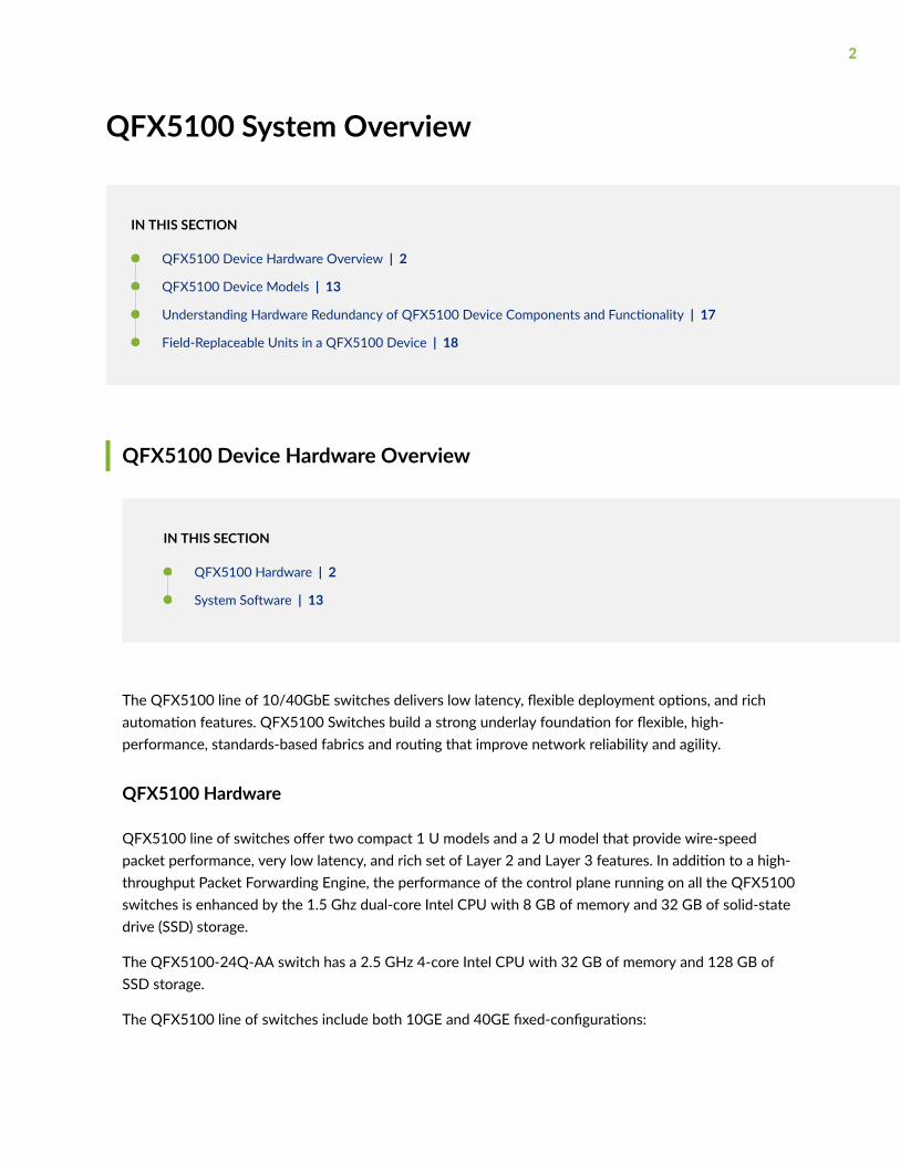
The QFX5100 line of 10/40GbE switches delivers low latency, flexible deployment options, and richautomation features. QFX5100 Switches build a strong underlay foundation for flexible, high-performance, standards-based fabrics and routing that improve network reliability and agility.
QFX5100 Hardware
QFX5100 line of switches offer two compact 1 U models and a 2 U model that provide wire-speedpacket performance, very low latency, and rich set of Layer 2 and Layer 3 features. In addition to a high-throughput Packet Forwarding Engine, the performance of the control plane running on all the QFX5100switches is enhanced by the 1.5 Ghz dual-core Intel CPU with 8 GB of memory and 32 GB of solid-statedrive (SSD) storage.
The QFX5100-24Q-AA switch has a 2.5 GHz 4-core Intel CPU with 32 GB of memory and 128 GB ofSSD storage.
The QFX5100 line of switches include both 10GE and 40GE fixed-configurations:
2
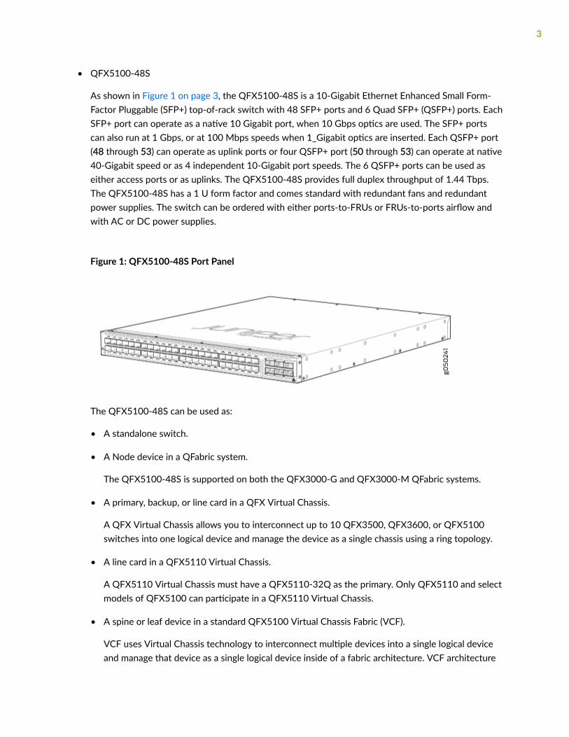
• QFX5100-48S
As shown in Figure 1 on page 3, the QFX5100-48S is a 10-Gigabit Ethernet Enhanced Small Form-Factor Pluggable (SFP+) top-of-rack switch with 48 SFP+ ports and 6 Quad SFP+ (QSFP+) ports. EachSFP+ port can operate as a native 10 Gigabit port, when 10 Gbps optics are used. The SFP+ portscan also run at 1 Gbps, or at 100 Mbps speeds when 1_Gigabit optics are inserted. Each QSFP+ port(48 through 53) can operate as uplink ports or four QSFP+ port (50 through 53) can operate at native40-Gigabit speed or as 4 independent 10-Gigabit port speeds. The 6 QSFP+ ports can be used aseither access ports or as uplinks. The QFX5100-48S provides full duplex throughput of 1.44 Tbps.The QFX5100-48S has a 1 U form factor and comes standard with redundant fans and redundantpower supplies. The switch can be ordered with either ports-to-FRUs or FRUs-to-ports airflow andwith AC or DC power supplies.
Figure 1: QFX5100-48S Port Panel
The QFX5100-48S can be used as:
• A standalone switch.
• A Node device in a QFabric system.
The QFX5100-48S is supported on both the QFX3000-G and QFX3000-M QFabric systems.
• A primary, backup, or line card in a QFX Virtual Chassis.
A QFX Virtual Chassis allows you to interconnect up to 10 QFX3500, QFX3600, or QFX5100switches into one logical device and manage the device as a single chassis using a ring topology.
• A line card in a QFX5110 Virtual Chassis.
A QFX5110 Virtual Chassis must have a QFX5110-32Q as the primary. Only QFX5110 and selectmodels of QFX5100 can participate in a QFX5110 Virtual Chassis.
• A spine or leaf device in a standard QFX5100 Virtual Chassis Fabric (VCF).
VCF uses Virtual Chassis technology to interconnect multiple devices into a single logical deviceand manage that device as a single logical device inside of a fabric architecture. VCF architecture
3
supports up to 20 total devices in a spine and leaf topology. Out of the 20 total devices, you canconfigure a maximum of 4 spine devices.
A QFX5100 VCF uses QFX5100 devices as spines or leaf devices. You can also use QFX3500,QFX3600, and EX4300 models as leaf devices in a QFX5100 VCF.
Whenever possible, configure the QFX5100-24Q as the spine device in a QFX5100 VCF. You canuse the QFX5100-48S as the spine in an all QFX5100-48S VCF or when EX4300 devices areused as leaf devices.
• A leaf device in a QFX5110 VCF.
A QFX5110 VCF must have a minimum of two QFX5110-32Q as spine devices. Junos OS Release17.3R1 or later is required for QFX5110 VCF.
• A satellite device in a Junos Fusion system.
Junos OS Release 14.2.3 or later is required for Junos Fusion.
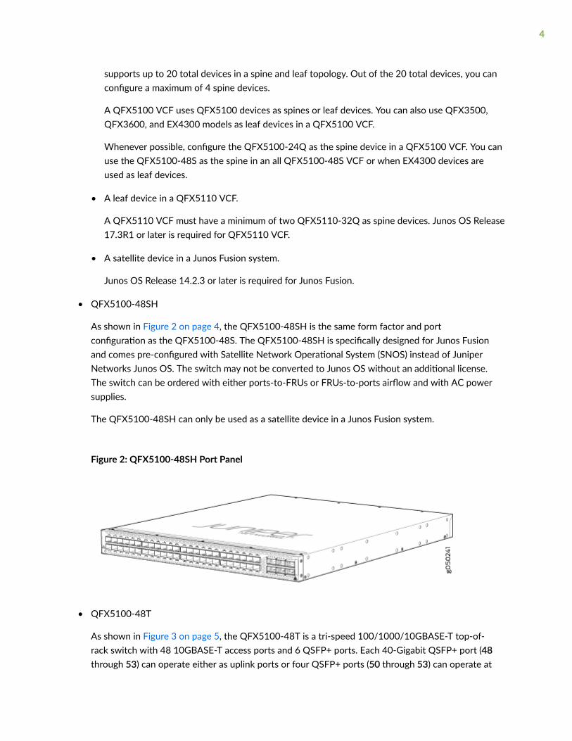
• QFX5100-48SH
As shown in Figure 2 on page 4, the QFX5100-48SH is the same form factor and portconfiguration as the QFX5100-48S. The QFX5100-48SH is specifically designed for Junos Fusionand comes pre-configured with Satellite Network Operational System (SNOS) instead of JuniperNetworks Junos OS. The switch may not be converted to Junos OS without an additional license.The switch can be ordered with either ports-to-FRUs or FRUs-to-ports airflow and with AC powersupplies.
The QFX5100-48SH can only be used as a satellite device in a Junos Fusion system.
Figure 2: QFX5100-48SH Port Panel
• QFX5100-48T
As shown in Figure 3 on page 5, the QFX5100-48T is a tri-speed 100/1000/10GBASE-T top-of-rack switch with 48 10GBASE-T access ports and 6 QSFP+ ports. Each 40-Gigabit QSFP+ port (48through 53) can operate either as uplink ports or four QSFP+ ports (50 through 53) can operate at
4
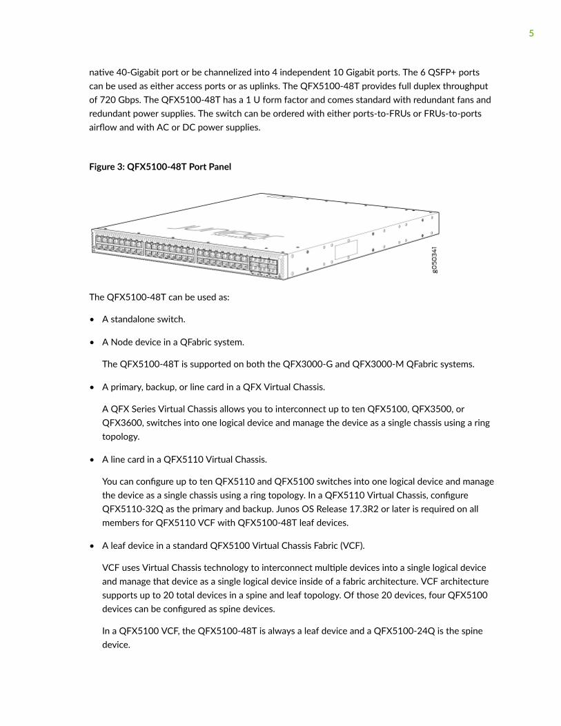
native 40-Gigabit port or be channelized into 4 independent 10 Gigabit ports. The 6 QSFP+ portscan be used as either access ports or as uplinks. The QFX5100-48T provides full duplex throughputof 720 Gbps. The QFX5100-48T has a 1 U form factor and comes standard with redundant fans andredundant power supplies. The switch can be ordered with either ports-to-FRUs or FRUs-to-portsairflow and with AC or DC power supplies.
Figure 3: QFX5100-48T Port Panel
The QFX5100-48T can be used as:
• A standalone switch.
• A Node device in a QFabric system.
The QFX5100-48T is supported on both the QFX3000-G and QFX3000-M QFabric systems.
• A primary, backup, or line card in a QFX Virtual Chassis.
A QFX Series Virtual Chassis allows you to interconnect up to ten QFX5100, QFX3500, orQFX3600, switches into one logical device and manage the device as a single chassis using a ringtopology.
• A line card in a QFX5110 Virtual Chassis.
You can configure up to ten QFX5110 and QFX5100 switches into one logical device and managethe device as a single chassis using a ring topology. In a QFX5110 Virtual Chassis, configureQFX5110-32Q as the primary and backup. Junos OS Release 17.3R2 or later is required on allmembers for QFX5110 VCF with QFX5100-48T leaf devices.
• A leaf device in a standard QFX5100 Virtual Chassis Fabric (VCF).
VCF uses Virtual Chassis technology to interconnect multiple devices into a single logical deviceand manage that device as a single logical device inside of a fabric architecture. VCF architecturesupports up to 20 total devices in a spine and leaf topology. Of those 20 devices, four QFX5100devices can be configured as spine devices.
In a QFX5100 VCF, the QFX5100-48T is always a leaf device and a QFX5100-24Q is the spinedevice.
5
• A leaf device in a QFX5110 VCF.
A QFX5110 VCF must have a minimum of two QFX5110-32Q as spine devices. Junos OS Release17.3R2 or later is required on all VCF devices for QFX5100-48T leaf devices to operate in aQFX5110 VCF.
• A satellite device in a Junos Fusion system.
Junos OS Release 14.2.3 or later is required for Junos Fusion.
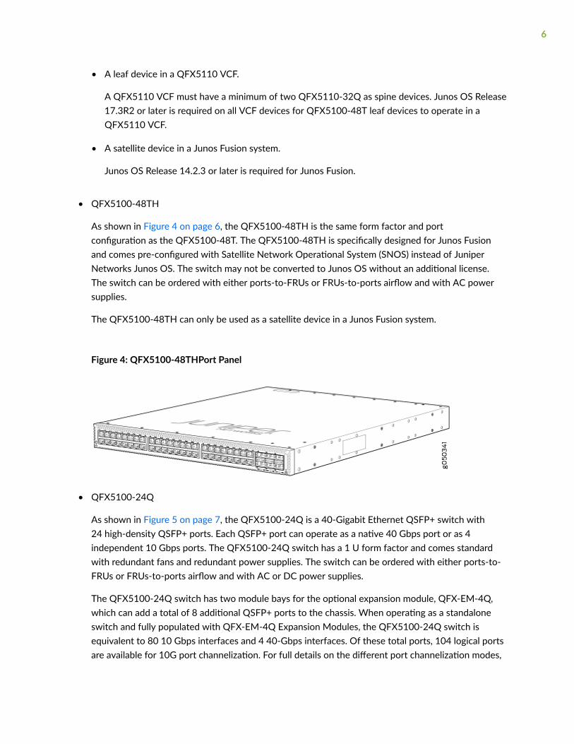
• QFX5100-48TH
As shown in Figure 4 on page 6, the QFX5100-48TH is the same form factor and portconfiguration as the QFX5100-48T. The QFX5100-48TH is specifically designed for Junos Fusionand comes pre-configured with Satellite Network Operational System (SNOS) instead of JuniperNetworks Junos OS. The switch may not be converted to Junos OS without an additional license.The switch can be ordered with either ports-to-FRUs or FRUs-to-ports airflow and with AC powersupplies.
The QFX5100-48TH can only be used as a satellite device in a Junos Fusion system.
Figure 4: QFX5100-48THPort Panel
• QFX5100-24Q
As shown in Figure 5 on page 7, the QFX5100-24Q is a 40-Gigabit Ethernet QSFP+ switch with24 high-density QSFP+ ports. Each QSFP+ port can operate as a native 40 Gbps port or as 4independent 10 Gbps ports. The QFX5100-24Q switch has a 1 U form factor and comes standardwith redundant fans and redundant power supplies. The switch can be ordered with either ports-to-FRUs or FRUs-to-ports airflow and with AC or DC power supplies.
The QFX5100-24Q switch has two module bays for the optional expansion module, QFX-EM-4Q,which can add a total of 8 additional QSFP+ ports to the chassis. When operating as a standaloneswitch and fully populated with QFX-EM-4Q Expansion Modules, the QFX5100-24Q switch isequivalent to 80 10 Gbps interfaces and 4 40-Gbps interfaces. Of these total ports, 104 logical portsare available for 10G port channelization. For full details on the different port channelization modes,
6
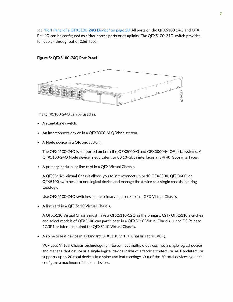
see "Port Panel of a QFX5100-24Q Device" on page 20. All ports on the QFX5100-24Q and QFX-EM-4Q can be configured as either access ports or as uplinks. The QFX5100-24Q switch providesfull duplex throughput of 2.56 Tbps.
Figure 5: QFX5100-24Q Port Panel
The QFX5100-24Q can be used as:
• A standalone switch.
• An interconnect device in a QFX3000-M QFabric system.
• A Node device in a QFabric system.
The QFX5100-24Q is supported on both the QFX3000-G and QFX3000-M QFabric systems. AQFX5100-24Q Node device is equivalent to 80 10-Gbps interfaces and 4 40-Gbps interfaces.
• A primary, backup, or line card in a QFX Virtual Chassis.
A QFX Series Virtual Chassis allows you to interconnect up to 10 QFX3500, QFX3600, orQFX5100 switches into one logical device and manage the device as a single chassis in a ringtopology.
Use QFX5100-24Q switches as the primary and backup in a QFX Virtual Chassis.
• A line card in a QFX5110 Virtual Chassis.
A QFX5110 Virtual Chassis must have a QFX5110-32Q as the primary. Only QFX5110 switchesand select models of QFX5100 can participate in a QFX5110 Virtual Chassis. Junos OS Release17.3R1 or later is required for QFX5110 Virtual Chassis.
• A spine or leaf device in a standard QFX5100 Virtual Chassis Fabric (VCF).
VCF uses Virtual Chassis technology to interconnect multiple devices into a single logical deviceand manage that device as a single logical device inside of a fabric architecture. VCF architecturesupports up to 20 total devices in a spine and leaf topology. Out of the 20 total devices, you canconfigure a maximum of 4 spine devices.
7
A QFX5100 VCF uses QFX5100 devices as spines or leaf devices. You can also use QFX3500,QFX3600, and EX4300 models as leaf devices in a QFX5100 VCF.
Whenever possible, configure the QFX5100-24Q as the spine device in a QFX5100 VCF.
• A leaf device in a QFX5110 VCF.
A QFX5110 VCF must have a minimum of two QFX5110-32Q as spine devices. Junos OS Release17.3R1 or later is required for QFX5110 VCF.
• A satellite device in a Junos Fusion system.
Junos OS Release 14.2.3 or later is required for Junos Fusion.
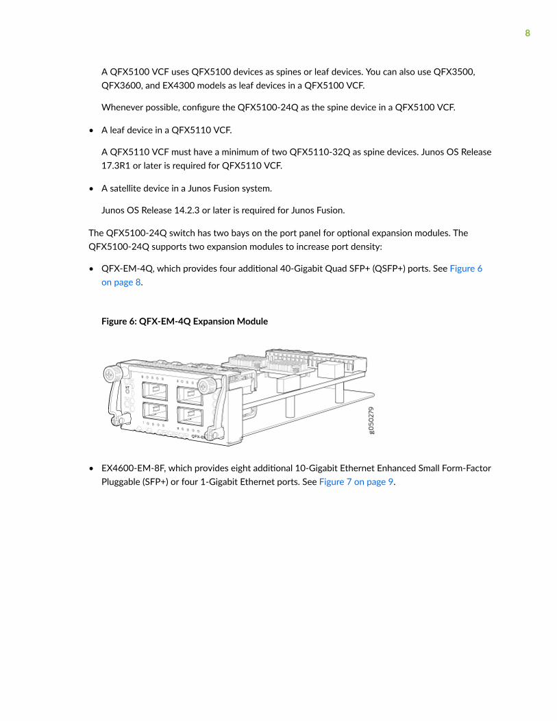
The QFX5100-24Q switch has two bays on the port panel for optional expansion modules. TheQFX5100-24Q supports two expansion modules to increase port density:
• QFX-EM-4Q, which provides four additional 40-Gigabit Quad SFP+ (QSFP+) ports. See Figure 6on page 8.
Figure 6: QFX-EM-4Q Expansion Module
• EX4600-EM-8F, which provides eight additional 10-Gigabit Ethernet Enhanced Small Form-FactorPluggable (SFP+) or four 1-Gigabit Ethernet ports. See Figure 7 on page 9.
8
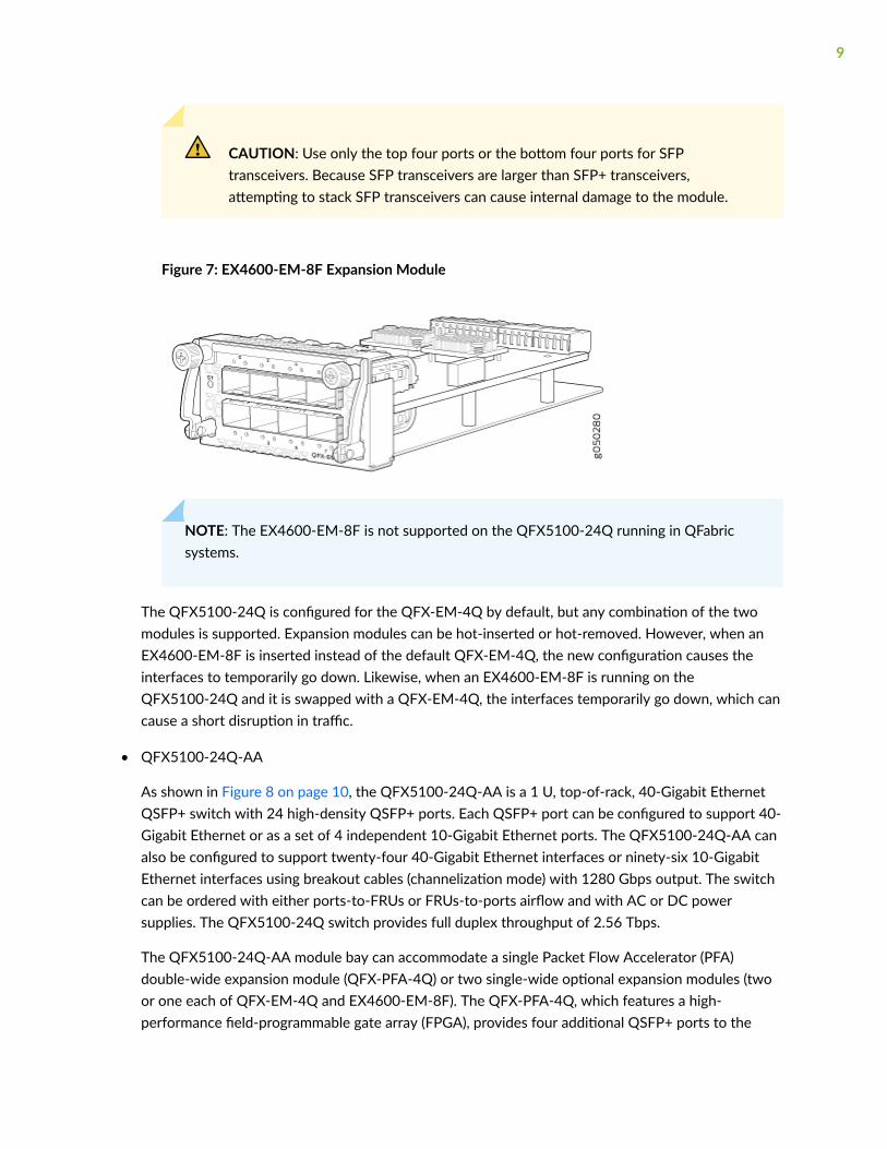
CAUTION: Use only the top four ports or the bottom four ports for SFPtransceivers. Because SFP transceivers are larger than SFP+ transceivers,attempting to stack SFP transceivers can cause internal damage to the module.
Figure 7: EX4600-EM-8F Expansion Module
NOTE: The EX4600-EM-8F is not supported on the QFX5100-24Q running in QFabricsystems.
The QFX5100-24Q is configured for the QFX-EM-4Q by default, but any combination of the twomodules is supported. Expansion modules can be hot-inserted or hot-removed. However, when anEX4600-EM-8F is inserted instead of the default QFX-EM-4Q, the new configuration causes theinterfaces to temporarily go down. Likewise, when an EX4600-EM-8F is running on theQFX5100-24Q and it is swapped with a QFX-EM-4Q, the interfaces temporarily go down, which cancause a short disruption in traffic.
• QFX5100-24Q-AA
As shown in Figure 8 on page 10, the QFX5100-24Q-AA is a 1 U, top-of-rack, 40-Gigabit EthernetQSFP+ switch with 24 high-density QSFP+ ports. Each QSFP+ port can be configured to support 40-Gigabit Ethernet or as a set of 4 independent 10-Gigabit Ethernet ports. The QFX5100-24Q-AA canalso be configured to support twenty-four 40-Gigabit Ethernet interfaces or ninety-six 10-GigabitEthernet interfaces using breakout cables (channelization mode) with 1280 Gbps output. The switchcan be ordered with either ports-to-FRUs or FRUs-to-ports airflow and with AC or DC powersupplies. The QFX5100-24Q switch provides full duplex throughput of 2.56 Tbps.
The QFX5100-24Q-AA module bay can accommodate a single Packet Flow Accelerator (PFA)double-wide expansion module (QFX-PFA-4Q) or two single-wide optional expansion modules (twoor one each of QFX-EM-4Q and EX4600-EM-8F). The QFX-PFA-4Q, which features a high-performance field-programmable gate array (FPGA), provides four additional QSFP+ ports to the
9

chassis. Each QFX-EM-4Q adds four QSFP+ ports to the chassis and each EX4600-EM-8F adds eight10-Gigabit SFP+ ports to the chassis. The QFX-EM-4Q ports can also be configured as either accessports or uplink ports, but only ports 0 and 2 can be channelized using port mode. For full details onthe different port channelization modes, see "Port Panel of a QFX5100-24Q Device" on page 20.All ports on the QFX5100-24Q and QFX-EM-4Q can be configured as either access ports or uplinkports.
This switch provides the hardware support to enable PTP boundary clocks by using the QFX-PFA-4Qmodule. The QFX5100-24Q-AA also supports GPS in and out signals when QFX-PFA-4Q is installed.
The CPU subsystem of this switch includes a 2-port 10-Gigabit Ethernet network interface card (NIC)to provide a high bandwidth path or to alternate traffic path to guest VMs directly from the PacketForwarding Engine.
Figure 8: QFX5100-24Q-AA Port Panel with QFX-PFA-4Q
The QFX5100-24Q-AA can be used as a standalone switch that supports high frequency statisticscollection. Working with Juniper Networks Cloud Analytics Engine, this switch monitors and reportsthe workload and application behavior across the physical and virtual infrastructure.
The QFX5100-24Q-AA supports the following expansion modules to increase port density:
10

• QFX-PFA-4Q (double-wide), which provides four additional QSFP+ ports. See Figure 9 on page11.
Figure 9: QFX-PFA-4Q Expansion Module
• QFX-EM-4Q (single-wide), which provides 4 additional 40-Gigabit Ethernet QSFP+ ports. SeeFigure 6 on page 8.
• EX4600-EM-8F (single-wide), which provides 8 additional 10-Gigabit Ethernet SFP+ ports. SeeFigure 7 on page 9.
The QFX5100-24Q switch supports the QFX-PFA-4Q and you must take the switch offline beforereplacing the expansion module. Any combination of EX4600-EM-8F and QFX-EM-4Q is alsosupported. These two expansion modules can be hot-inserted or hot-removed. However, when anEX4600-EM-8F is inserted instead of a QFX-EM-4Q, the new configuration causes the interfaces totemporarily go down. Likewise, when an EX4600-EM-8F is running on the QFX5100-24Q and isswapped with a QFX-EM-4Q, the interfaces temporarily go down, which can cause a short disruptionin traffic.
• QFX5100-96S
As shown in Figure 10 on page 12, the QFX5100-96S switch is a is a 10-Gigabit Ethernet EnhancedSmall Form-Factor Pluggable (SFP+) top-of-rack switch with 96 SFP+ ports and 8 Quad SFP+ (QSFP+) ports. Each SFP+ port can operate as a native 10 Gigabit port, when 10 Gbps optics are used. TheSFP+ ports can also run at 1 Gbps, or at 100 Mbps speeds when 1_Gigabit optics are inserted. QSFP+ ports 96 and 100 can operate at native 40 Gbps speed or can be channelized to 4 independent 10Gbps port speeds. The 8 QSFP+ ports can be used as either access ports or as uplinks. TheQFX5100-96S switch has a 2 U form factor and comes standard with redundant fans and redundant
11
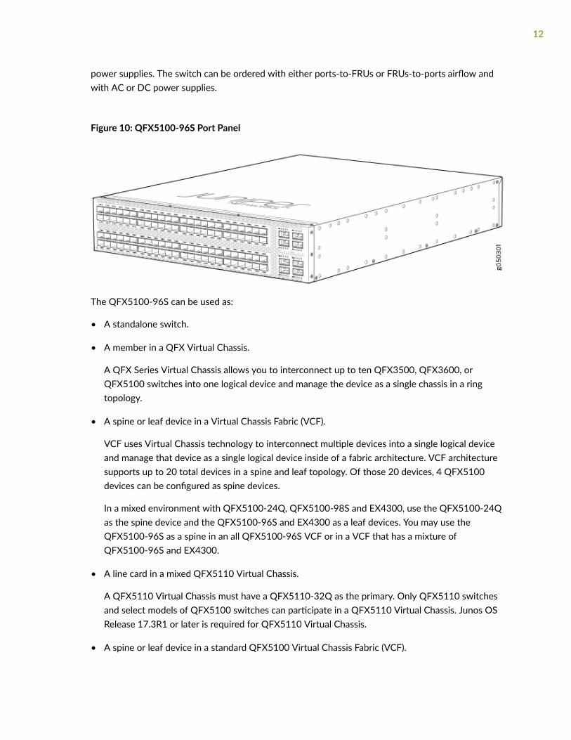
power supplies. The switch can be ordered with either ports-to-FRUs or FRUs-to-ports airflow andwith AC or DC power supplies.
Figure 10: QFX5100-96S Port Panel
The QFX5100-96S can be used as:
• A standalone switch.
• A member in a QFX Virtual Chassis.
A QFX Series Virtual Chassis allows you to interconnect up to ten QFX3500, QFX3600, orQFX5100 switches into one logical device and manage the device as a single chassis in a ringtopology.
• A spine or leaf device in a Virtual Chassis Fabric (VCF).
VCF uses Virtual Chassis technology to interconnect multiple devices into a single logical deviceand manage that device as a single logical device inside of a fabric architecture. VCF architecturesupports up to 20 total devices in a spine and leaf topology. Of those 20 devices, 4 QFX5100devices can be configured as spine devices.
In a mixed environment with QFX5100-24Q, QFX5100-98S and EX4300, use the QFX5100-24Qas the spine device and the QFX5100-96S and EX4300 as a leaf devices. You may use theQFX5100-96S as a spine in an all QFX5100-96S VCF or in a VCF that has a mixture ofQFX5100-96S and EX4300.
• A line card in a mixed QFX5110 Virtual Chassis.
A QFX5110 Virtual Chassis must have a QFX5110-32Q as the primary. Only QFX5110 switchesand select models of QFX5100 switches can participate in a QFX5110 Virtual Chassis. Junos OSRelease 17.3R1 or later is required for QFX5110 Virtual Chassis.
• A spine or leaf device in a standard QFX5100 Virtual Chassis Fabric (VCF).
12
VCF uses Virtual Chassis technology to interconnect multiple devices into a single logical deviceand manage that device as a single logical device inside of a fabric architecture. VCF architecturesupports up to 20 total devices in a spine and leaf topology. Out of the 20 total devices, you canconfigure a maximum of 4 spine devices.
A QFX5100 VCF uses QFX5100 devices as spines or leaf devices. You can also use QFX3500,QFX3600, and EX4300 models as leaf devices in a QFX5100 VCF.
Whenever possible, configure the QFX5100-24Q as the spine device in a QFX5100 VCF.
• A leaf device in a QFX5110 VCF.
A QFX5110 VCF must have a minimum of two QFX5110-32Q as spine devices. Junos OS Release17.3R1 or later is required for QFX5110 VCF.
• A satellite device in a Junos Fusion system.
Junos OS Release 14.2.3 or later is required for Junos Fusion.
System Software
QFX Series devices use the Junos operating system (OS), which provides Layer 2 and Layer 3 switching,routing, and security services. Junos OS is installed on a QFX5100 switch’s 32-gigabyte (GB) internalsolid state flash drive. The same Junos OS code base that runs on QFX5100 switches also runs on allJuniper Networks EX Series switches, M Series, MX Series, and T Series routers.
Participation in a QFX5110 Virtual Chassis or a QFX5110 VCF requires the same Junos OS image on alldevices in the Virtual Chassis or VCF. Junos OS 17.3R1 or later is the minimum software release forQFX5110 Virtual Chassis or QFX5110 VCF.
For more information about which features are supported on QFX Series devices, see Feature Explorer.
You manage the switch using the Junos OS command-line interface (CLI), accessible through the consoleand out-of-band management ports on the device.
SEE ALSO
Plan a Virtual Chassis Fabric Deployment | 90
QFX5100 Device Models
The QFX5100 switches have 24, 48, or 96 port configurations. The 24 port switches can be expandedto a maximum of 32 QSFP+ ports using expansion modules. All switches are available with either AC or
13
DC power supply and with either airflow-in or airflow-out cooling. In legacy switches, or switches withan LCD, this air flow is called front-to-back and back-to-front.
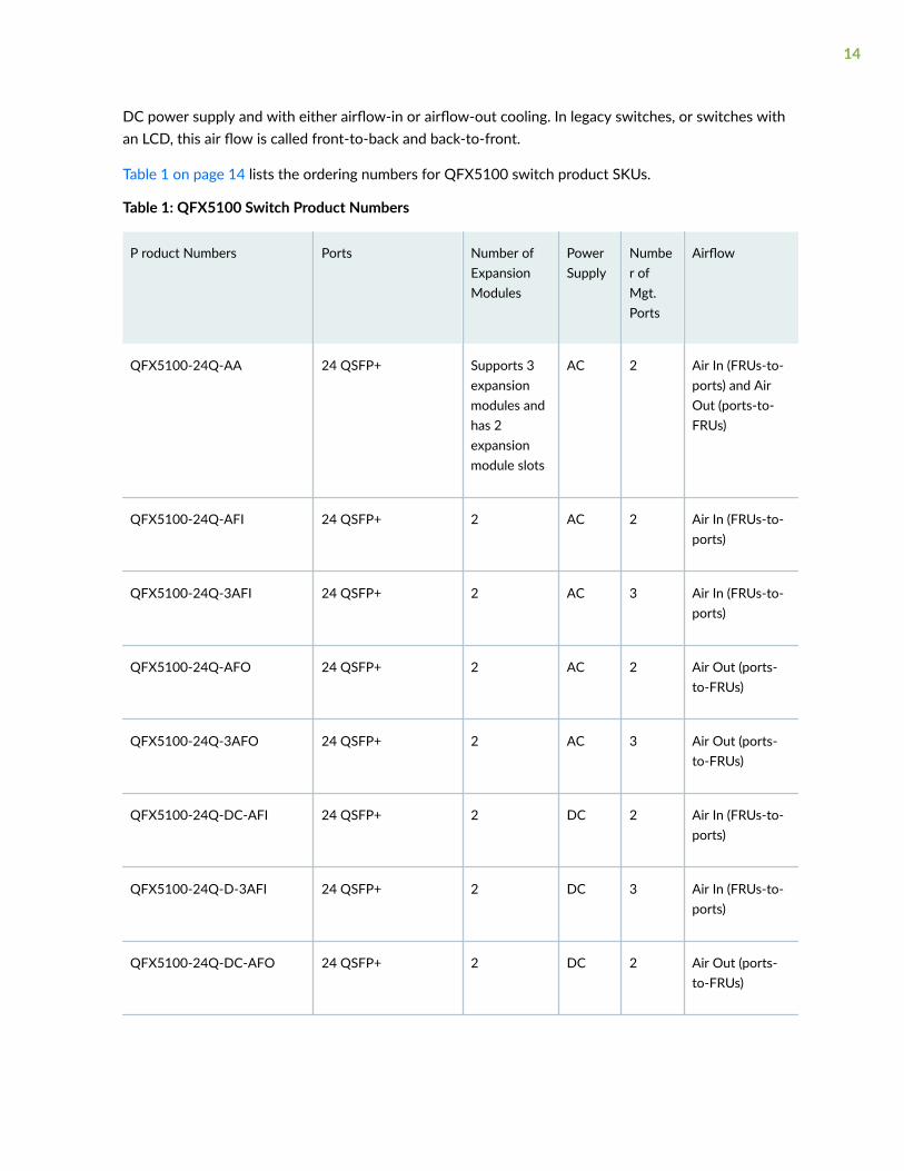
Table 1 on page 14 lists the ordering numbers for QFX5100 switch product SKUs.
Table 1: QFX5100 Switch Product Numbers
P roduct Numbers Ports Number ofExpansionModules
PowerSupply
Number ofMgt.Ports
Airflow
QFX5100-24Q-AA 24 QSFP+ Supports 3expansionmodules andhas 2expansionmodule slots
AC 2 Air In (FRUs-to-ports) and AirOut (ports-to-FRUs)
QFX5100-24Q-AFI 24 QSFP+ 2 AC 2 Air In (FRUs-to-ports)
QFX5100-24Q-3AFI 24 QSFP+ 2 AC 3 Air In (FRUs-to-ports)
QFX5100-24Q-AFO 24 QSFP+ 2 AC 2 Air Out (ports-to-FRUs)
QFX5100-24Q-3AFO 24 QSFP+ 2 AC 3 Air Out (ports-to-FRUs)
QFX5100-24Q-DC-AFI 24 QSFP+ 2 DC 2 Air In (FRUs-to-ports)
QFX5100-24Q-D-3AFI 24 QSFP+ 2 DC 3 Air In (FRUs-to-ports)
QFX5100-24Q-DC-AFO 24 QSFP+ 2 DC 2 Air Out (ports-to-FRUs)
14
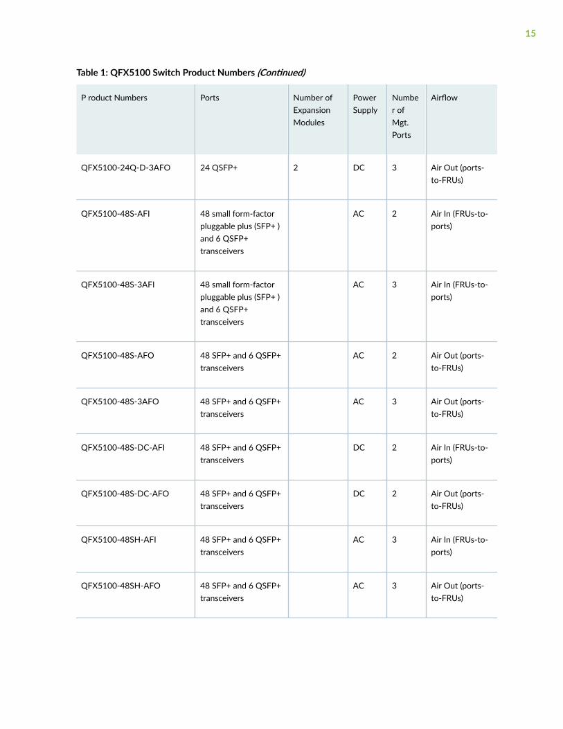
Table 1: QFX5100 Switch Product Numbers (Continued)
P roduct Numbers Ports Number ofExpansionModules
PowerSupply
Number ofMgt.Ports
Airflow
QFX5100-24Q-D-3AFO 24 QSFP+ 2 DC 3 Air Out (ports-to-FRUs)
QFX5100-48S-AFI 48 small form-factorpluggable plus (SFP+ )and 6 QSFP+transceivers
AC 2 Air In (FRUs-to-ports)
QFX5100-48S-3AFI 48 small form-factorpluggable plus (SFP+ )and 6 QSFP+transceivers
AC 3 Air In (FRUs-to-ports)
QFX5100-48S-AFO 48 SFP+ and 6 QSFP+transceivers
AC 2 Air Out (ports-to-FRUs)
QFX5100-48S-3AFO 48 SFP+ and 6 QSFP+transceivers
AC 3 Air Out (ports-to-FRUs)
QFX5100-48S-DC-AFI 48 SFP+ and 6 QSFP+transceivers
DC 2 Air In (FRUs-to-ports)
QFX5100-48S-DC-AFO 48 SFP+ and 6 QSFP+transceivers
DC 2 Air Out (ports-to-FRUs)
QFX5100-48SH-AFI 48 SFP+ and 6 QSFP+transceivers
AC 3 Air In (FRUs-to-ports)
QFX5100-48SH-AFO 48 SFP+ and 6 QSFP+transceivers
AC 3 Air Out (ports-to-FRUs)
15
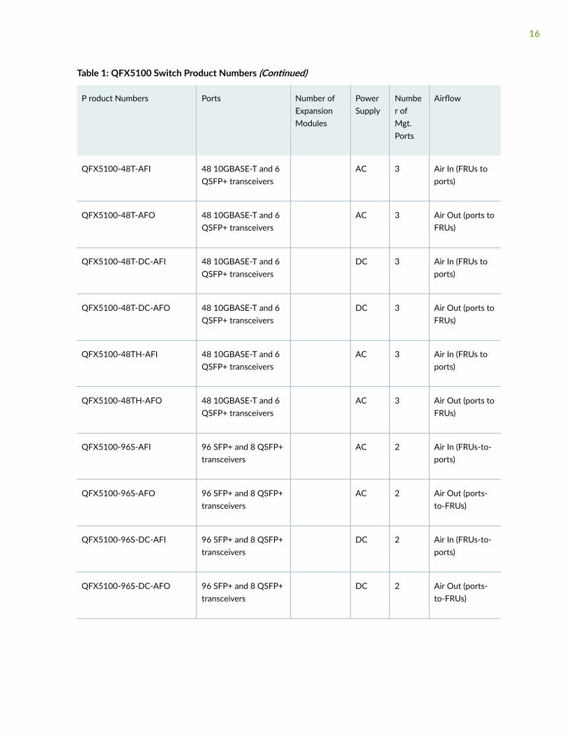
Table 1: QFX5100 Switch Product Numbers (Continued)
P roduct Numbers Ports Number ofExpansionModules
PowerSupply
Number ofMgt.Ports
Airflow
QFX5100-48T-AFI 48 10GBASE-T and 6QSFP+ transceivers
AC 3 Air In (FRUs toports)
QFX5100-48T-AFO 48 10GBASE-T and 6QSFP+ transceivers
AC 3 Air Out (ports toFRUs)
QFX5100-48T-DC-AFI 48 10GBASE-T and 6QSFP+ transceivers
DC 3 Air In (FRUs toports)
QFX5100-48T-DC-AFO 48 10GBASE-T and 6QSFP+ transceivers
DC 3 Air Out (ports toFRUs)
QFX5100-48TH-AFI 48 10GBASE-T and 6QSFP+ transceivers
AC 3 Air In (FRUs toports)
QFX5100-48TH-AFO 48 10GBASE-T and 6QSFP+ transceivers
AC 3 Air Out (ports toFRUs)
QFX5100-96S-AFI 96 SFP+ and 8 QSFP+transceivers
AC 2 Air In (FRUs-to-ports)
QFX5100-96S-AFO 96 SFP+ and 8 QSFP+transceivers
AC 2 Air Out (ports-to-FRUs)
QFX5100-96S-DC-AFI 96 SFP+ and 8 QSFP+transceivers
DC 2 Air In (FRUs-to-ports)
QFX5100-96S-DC-AFO 96 SFP+ and 8 QSFP+transceivers
DC 2 Air Out (ports-to-FRUs)
16
CAUTION: Mixing different types (AC and DC) of power supplies in the same chassis isnot supported. Mixing different airflow modules in the same chassis is not supported.
SEE ALSO
QFX5100 Management Panel | 43
Understanding Hardware Redundancy of QFX5100 Device Componentsand Functionality
The following hardware components provide redundancy on a QFX5100 switch:
• Power supplies—The QFX5100 switch has one or two power supplies. Each power supply providespower to all components in the switch. If two power supplies are installed, the two power suppliesprovide full power redundancy to the device. If one power supply fails or is removed, the secondpower supply balances the electrical load without interruption.
To provide power redundancy to the system both power supplies must be installed. Connect powersource feed A to one power supply and power source feed B to the second power supply.
CAUTION: Do not connect feed A and feed B to the same power supply inputterminal.
• Cooling system—The 1 U models of QFX5100 line of switches have five fan modules; the 2 UQFX5100-96S has three fan modules. If a fan module fails and is unable to keep the QFX5100switch within the desired temperature thresholds, chassis alarms occur and the QFX5100 switch canshut down.
SEE ALSO
QFX5100 Power System | 54
QFX5100 Cooling System | 67
17
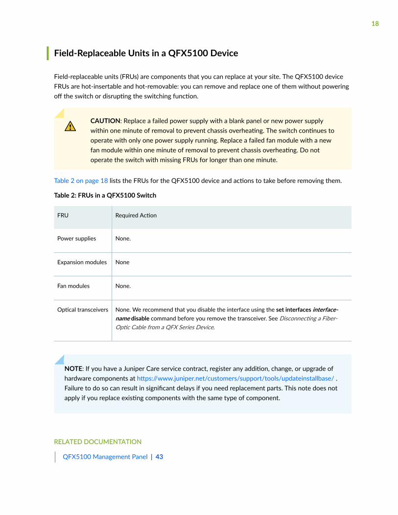
Field-Replaceable Units in a QFX5100 Device
Field-replaceable units (FRUs) are components that you can replace at your site. The QFX5100 deviceFRUs are hot-insertable and hot-removable: you can remove and replace one of them without poweringoff the switch or disrupting the switching function.
CAUTION: Replace a failed power supply with a blank panel or new power supplywithin one minute of removal to prevent chassis overheating. The switch continues tooperate with only one power supply running. Replace a failed fan module with a newfan module within one minute of removal to prevent chassis overheating. Do notoperate the switch with missing FRUs for longer than one minute.
Table 2 on page 18 lists the FRUs for the QFX5100 device and actions to take before removing them.
Table 2: FRUs in a QFX5100 Switch
FRU Required Action
Power supplies None.
Expansion modules None
Fan modules None.
Optical transceivers None. We recommend that you disable the interface using the set interfaces interface-name disable command before you remove the transceiver. See Disconnecting a Fiber-Optic Cable from a QFX Series Device.
NOTE: If you have a Juniper Care service contract, register any addition, change, or upgrade ofhardware components at https://www.juniper.net/customers/support/tools/updateinstallbase/ .Failure to do so can result in significant delays if you need replacement parts. This note does notapply if you replace existing components with the same type of component.
RELATED DOCUMENTATION
QFX5100 Management Panel | 43
18

QFX5100 Chassis Description and Port Panels
IN THIS SECTION
Chassis Physical Specifications for a QFX5100 Device | 19
Port Panel of a QFX5100-24Q Device | 20
Port Panel of a QFX5100-24Q-AA Device | 25
Port Panel of QFX5100-48S and QFX5100-48SH Devices | 26
Port Panel of QFX5100-48T and QFX5100-48TH Devices | 28
Port Panel of a QFX5100-96S Device | 30
Expansion Modules for QFX5100 Devices | 33
Access Port and Uplink Port LEDs on a QFX5100 Device | 39
Chassis Physical Specifications for a QFX5100 Device
The QFX5100 switch chassis is a rigid sheet-metal structure that houses the hardware components.Table 3 on page 19 summarizes the physical specifications of the QFX5100 chassis.
Table 3: Physical Specifications for the QFX5100 Switch Chassis
Product SKU Height Width Depth Weight
QFX5100-24Q 1.72 in.(4.3 cm)
17.36 in.(44.1 cm)
20.48 in. (52 cm) With FRUs installed: 22lbs ( 9.97 kg)
QFX5100-24Q-AA 1.72 in.(4.3 cm)
17.36 in.(44.1 cm)
20.48 in. (52 cm) With FRUs installed: 25lbs ( 11.4 kg)
QFX5100-48S andQFX5100-48SH
1.72 in.(4.3 cm)
17.36 in.(44.1 cm)
20.48 in. (52 cm) With FRUs installed: 21.8lbs (9.8 kg)
19
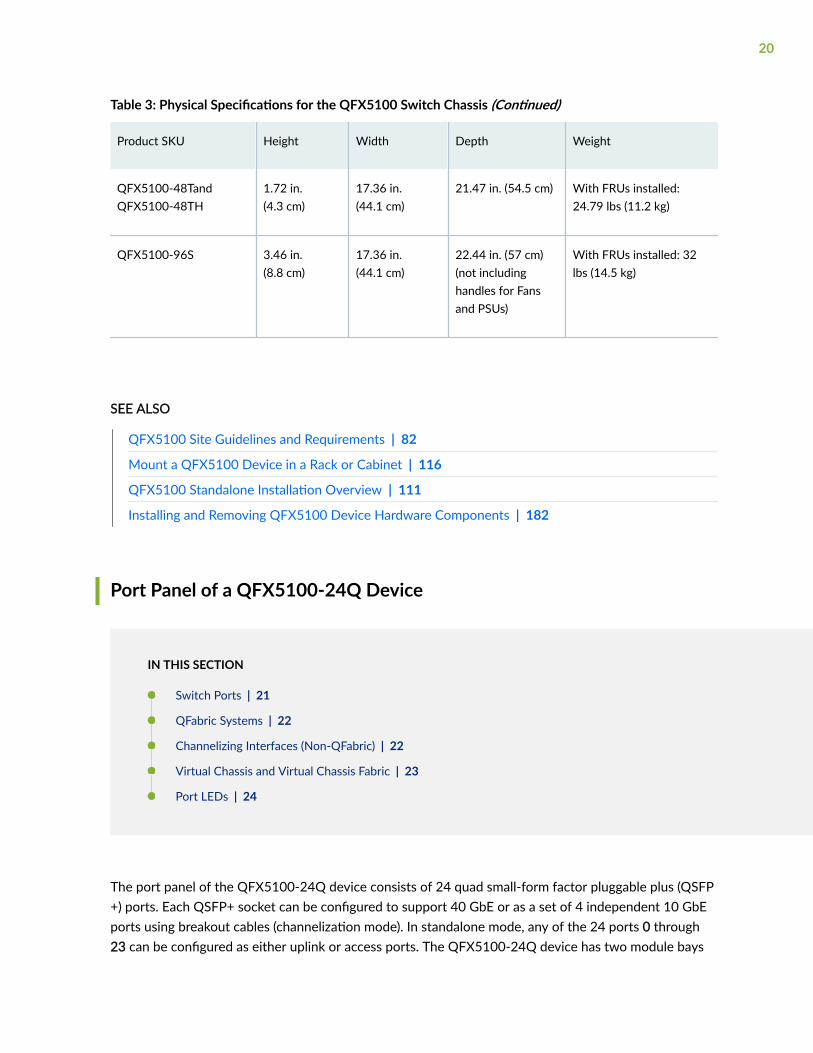
Table 3: Physical Specifications for the QFX5100 Switch Chassis (Continued)
Product SKU Height Width Depth Weight
QFX5100-48TandQFX5100-48TH
1.72 in.(4.3 cm)
17.36 in.(44.1 cm)
21.47 in. (54.5 cm) With FRUs installed:24.79 lbs (11.2 kg)
QFX5100-96S 3.46 in.(8.8 cm)
17.36 in.(44.1 cm)
22.44 in. (57 cm)(not includinghandles for Fansand PSUs)
With FRUs installed: 32lbs (14.5 kg)
SEE ALSO
QFX5100 Site Guidelines and Requirements | 82
Mount a QFX5100 Device in a Rack or Cabinet | 116
QFX5100 Standalone Installation Overview | 111
Installing and Removing QFX5100 Device Hardware Components | 182
Port Panel of a QFX5100-24Q Device
IN THIS SECTION
Switch Ports | 21
QFabric Systems | 22
Channelizing Interfaces (Non-QFabric) | 22
Virtual Chassis and Virtual Chassis Fabric | 23
Port LEDs | 24
The port panel of the QFX5100-24Q device consists of 24 quad small-form factor pluggable plus (QSFP+) ports. Each QSFP+ socket can be configured to support 40 GbE or as a set of 4 independent 10 GbEports using breakout cables (channelization mode). In standalone mode, any of the 24 ports 0 through23 can be configured as either uplink or access ports. The QFX5100-24Q device has two module bays
20
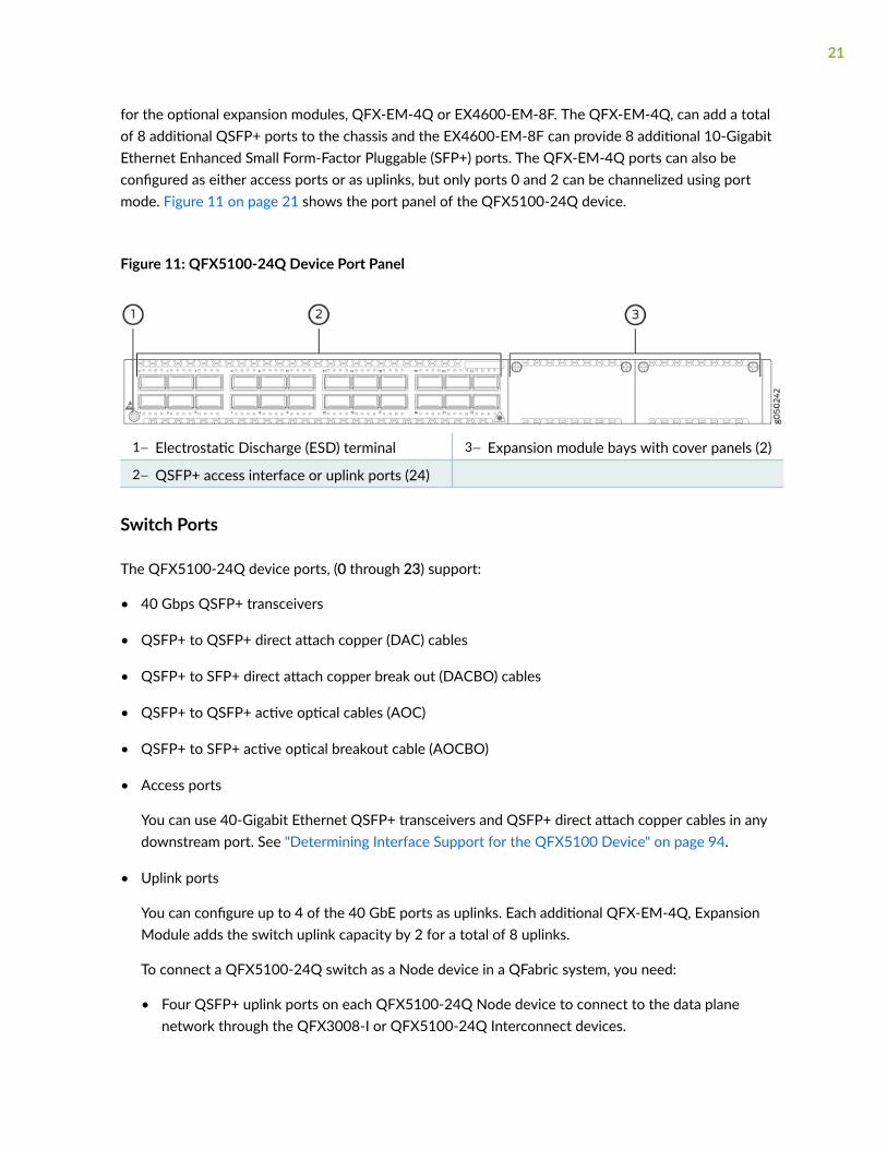
for the optional expansion modules, QFX-EM-4Q or EX4600-EM-8F. The QFX-EM-4Q, can add a totalof 8 additional QSFP+ ports to the chassis and the EX4600-EM-8F can provide 8 additional 10-GigabitEthernet Enhanced Small Form-Factor Pluggable (SFP+) ports. The QFX-EM-4Q ports can also beconfigured as either access ports or as uplinks, but only ports 0 and 2 can be channelized using portmode. Figure 11 on page 21 shows the port panel of the QFX5100-24Q device.
Figure 11: QFX5100-24Q Device Port Panel
1— Electrostatic Discharge (ESD) terminal 3— Expansion module bays with cover panels (2)
2— QSFP+ access interface or uplink ports (24)
Switch Ports
The QFX5100-24Q device ports, (0 through 23) support:
• 40 Gbps QSFP+ transceivers
• QSFP+ to QSFP+ direct attach copper (DAC) cables
• QSFP+ to SFP+ direct attach copper break out (DACBO) cables
• QSFP+ to QSFP+ active optical cables (AOC)
• QSFP+ to SFP+ active optical breakout cable (AOCBO)
• Access ports
You can use 40-Gigabit Ethernet QSFP+ transceivers and QSFP+ direct attach copper cables in anydownstream port. See "Determining Interface Support for the QFX5100 Device" on page 94.
• Uplink ports
You can configure up to 4 of the 40 GbE ports as uplinks. Each additional QFX-EM-4Q, ExpansionModule adds the switch uplink capacity by 2 for a total of 8 uplinks.
To connect a QFX5100-24Q switch as a Node device in a QFabric system, you need:
• Four QSFP+ uplink ports on each QFX5100-24Q Node device to connect to the data planenetwork through the QFX3008-I or QFX5100-24Q Interconnect devices.
21
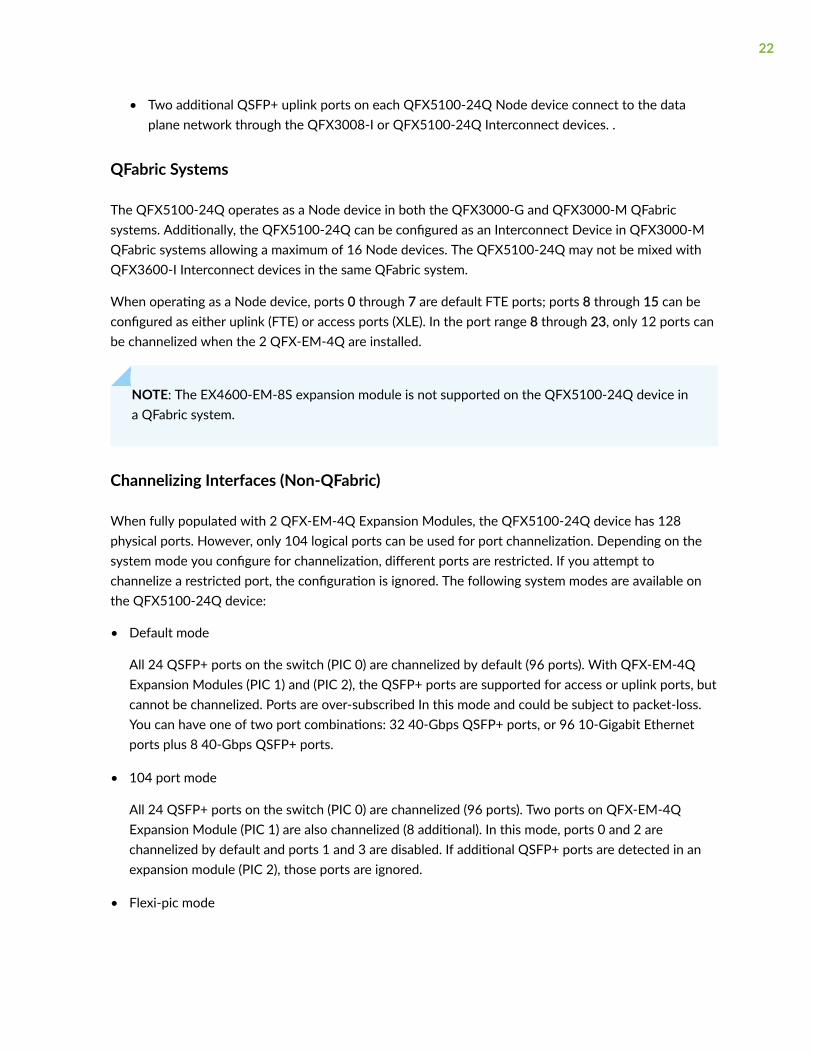
• Two additional QSFP+ uplink ports on each QFX5100-24Q Node device connect to the dataplane network through the QFX3008-I or QFX5100-24Q Interconnect devices. .
QFabric Systems
The QFX5100-24Q operates as a Node device in both the QFX3000-G and QFX3000-M QFabricsystems. Additionally, the QFX5100-24Q can be configured as an Interconnect Device in QFX3000-MQFabric systems allowing a maximum of 16 Node devices. The QFX5100-24Q may not be mixed withQFX3600-I Interconnect devices in the same QFabric system.
When operating as a Node device, ports 0 through 7 are default FTE ports; ports 8 through 15 can beconfigured as either uplink (FTE) or access ports (XLE). In the port range 8 through 23, only 12 ports canbe channelized when the 2 QFX-EM-4Q are installed.
NOTE: The EX4600-EM-8S expansion module is not supported on the QFX5100-24Q device ina QFabric system.
Channelizing Interfaces (Non-QFabric)
When fully populated with 2 QFX-EM-4Q Expansion Modules, the QFX5100-24Q device has 128physical ports. However, only 104 logical ports can be used for port channelization. Depending on thesystem mode you configure for channelization, different ports are restricted. If you attempt tochannelize a restricted port, the configuration is ignored. The following system modes are available onthe QFX5100-24Q device:
• Default mode
All 24 QSFP+ ports on the switch (PIC 0) are channelized by default (96 ports). With QFX-EM-4QExpansion Modules (PIC 1) and (PIC 2), the QSFP+ ports are supported for access or uplink ports, butcannot be channelized. Ports are over-subscribed In this mode and could be subject to packet-loss.You can have one of two port combinations: 32 40-Gbps QSFP+ ports, or 96 10-Gigabit Ethernetports plus 8 40-Gbps QSFP+ ports.
• 104 port mode
All 24 QSFP+ ports on the switch (PIC 0) are channelized (96 ports). Two ports on QFX-EM-4QExpansion Module (PIC 1) are also channelized (8 additional). In this mode, ports 0 and 2 arechannelized by default and ports 1 and 3 are disabled. If additional QSFP+ ports are detected in anexpansion module (PIC 2), those ports are ignored.
• Flexi-pic mode
22
Ports 0 through 3 of the switch cannot be channelized; ports 4 through 24 are channelized by default(80 ports). With QFX-EM-4Q Expansion Modules (PIC 1) and (PIC 2), the QSFP+ ports are supportedfor access or uplink ports, but cannot be channelized. With EX4600-EM-8F Expansion Modulesinstalled (PIC 1) and (PIC 2), the 16 SFP+ ports of SFP are recognized for a total of 96 logical ports.
• Non-oversubscribed mode
All 24 QSFP+ ports on the switch (PIC 0) are channelized (96 ports). Expansion modules on PIC 1 andPIC 2 are not supported and cannot be channelized. There is no packet loss for packets of any size inthis mode.
Virtual Chassis and Virtual Chassis Fabric
The QFX5100-24Q device operates as a standalone switch, a member of a QFX Virtual Chassis, or as aspine or leaf device in a QFX5100 Virtual Chassis Fabric (VCF). QFX Virtual Chassis support up to 10members. QFX5100 VCF supports 20 QFX5100 and EX4300 devices, of which 4 QFX5100 devices canbe configured as spines.
To connect a QFX5100-24Q device as a member in a QFX Virtual Chassis, you need to cable a pair ofports to link each member in the Virtual Chassis into a ring topology. Each member in the ring has atleast one direct Virtual Chassis port (VCP) connection to each directly connected member.QFX5100-24Q devices are recommended in the primary, backup, or line card role. When mixed withQFX3500 or QFX3600 devices, configure the QFX5100-24Q device in the primary and backup roles.See Connecting QFX Series and EX Series Switches in a QFX Virtual Chassis for cabling diagrams. TheVirtual Chassis feature is not applicable to QFX devices in a QFabric.
To connect a QFX5100-24Q device as a spine or leaf device in a QFX5100 VCF, you need to cable a setof ports as VCP connections that link each spine device and leaf device. All spine devices have at leastone direct VCP connection to each leaf device in the VCF. Non-channelized DAC cables can beconfigured as VCP connections. See "Connecting a QFX5100 Device in a Virtual Chassis Fabric" on page134 for a cabling diagram.
BEST PRACTICE: Whenever possible use the QFX5100-24Q device as a spine device. By usingthe QFX5100-24Q device in a maximum configuration of 20 total devices, four QFX5100-24Qdevices may be used as spine devices. All members can be connected to the spine using QSFP+ports.
As of Junos OS release 17.3R1, you can also connect a QFX5100-24Q as a leaf device in a QFX5110VCF or as a member in a QFX5110 Virtual Chassis.
23
Port LEDs
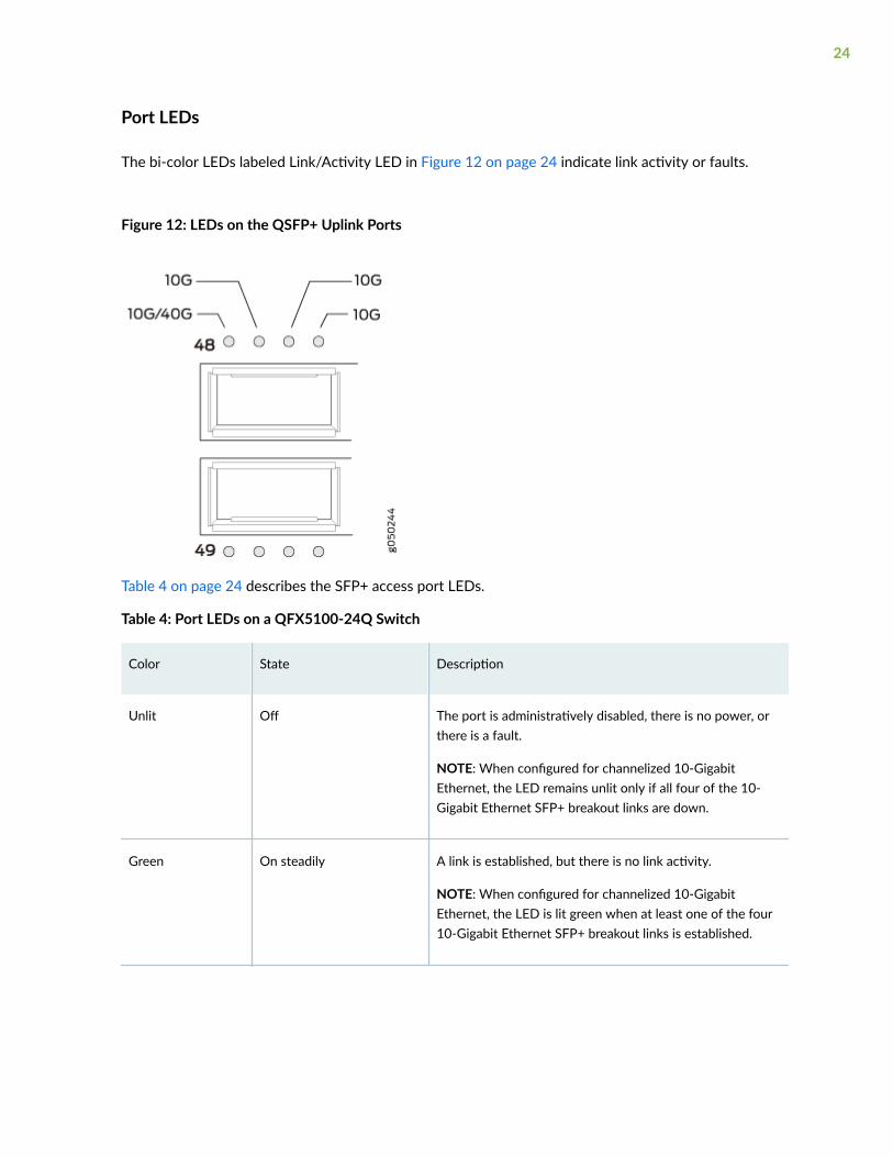
The bi-color LEDs labeled Link/Activity LED in Figure 12 on page 24 indicate link activity or faults.
Figure 12: LEDs on the QSFP+ Uplink Ports
Table 4 on page 24 describes the SFP+ access port LEDs.
Table 4: Port LEDs on a QFX5100-24Q Switch
Color State Description
Unlit Off The port is administratively disabled, there is no power, orthere is a fault.
NOTE: When configured for channelized 10-GigabitEthernet, the LED remains unlit only if all four of the 10-Gigabit Ethernet SFP+ breakout links are down.
Green On steadily A link is established, but there is no link activity.
NOTE: When configured for channelized 10-GigabitEthernet, the LED is lit green when at least one of the four10-Gigabit Ethernet SFP+ breakout links is established.
24

Table 4: Port LEDs on a QFX5100-24Q Switch (Continued)
Color State Description
Blinking A link is established, and there is link activity.
NOTE: When configured for channelized 10-GigabitEthernet, the LED is lit green when at least one of the four10-Gigabit Ethernet SFP+ breakout links is established.
Amber Blinking All four LEDs blink to indicate the beacon function wasenabled on the port.
Port Panel of a QFX5100-24Q-AA Device
The port panel of the QFX5100-24Q-AA switch consists of 24 quad small-form factor pluggable plus(QSFP+) 40-Gigabit Ethernet ports. Each QSFP+ socket can be configured to support 40-GigabitEthernet or as a set of four independent 10-Gigabit Ethernet ports using breakout cables (channelizationmode). The QFX5100-24Q-AA can also be configured to support 96 10-Gigabit Ethernet ports usingbreakout cables (channelization mode) with 1280 Gbps output. Any of the 24 ports can be configured aseither an uplink port or an access port.
The expansion module bay of the QFX5100-24Q switch is located on the port panel. In the expansionmodule bay, you can install a single double-wide expansion module (QFX-PFA-4Q) or two single-wideoptional expansion modules (QFX-EM-4Q and EX4600-EM-8F, in any combination). When you installtwo single-wide expansion modules, the slot on your left hand side is slot 1 (QIC0), and the slot on yourright hand side is slot 2 (QIC1).
The QFX-PFA-4Q module adds four QSFP+ ports to the chassis. The QFX-EM-4Q module adds fourQSFP+ ports to the chassis and the EX4600-EM-8F module adds eight 10-Gigabit SFP+ ports to thechassis. The QFX-EM-4Q ports can be configured as either access ports or as uplinks ports, but onlyports 0 and 2 can be channelized by using port mode. The QFX-EM-4Q ports can also be configured as
25

either access ports or uplink ports, but only ports 0 and 2 can be channelized by using port mode. Figure13 on page 26 shows the port panel of the QFX5100-24Q-AA device.
Figure 13: Port Panel of a QFX5100-24Q-AA Switch
1— Electrostatic discharge (ESD) terminal 3— Expansion module bay (with a QFX-PFA-4Qexpansion module installed)
2— QSFP+ ports (24)
For details on port LEDs, see "Port Panel of a QFX5100-24Q Device" on page 20.
Port Panel of QFX5100-48S and QFX5100-48SH Devices
The port panel of the QFX5100-48S and QFX5100-48SH switches supports up to a maximum of 72logical 10 GbE ports when operating as a standalone switch. Forty-eight physical ports(0 through 47)support 10 Gigabit Ethernet small form-factor pluggable plus (SFP+) transceivers. These ports can alsosupport 1 Gigabit SFP transceivers and can be configured at either 1 Gbps or 1 Gbps speeds using theset interface speed command. All 48 of these ports can be used for SFP+ transceivers or SFP+ directattach copper (DAC) cables. You can use 1-Gigabit Ethernet SFP+, 10-Gigabit Ethernet SFP+transceivers and SFP+ DAC cables in any access port.
The remaining 24 logical ports are the six 40 GbE physical ports (48 through 53) that support up to 6quad small-form factor pluggable plus (QSFP+) transceivers . Each QSFP+ socket can operate either as asingle 40 Gbps port or as a set of 4 independent 10 Gbps ports using QSFP+ breakout cables. The 40GbE ports can be configured as either access ports or as uplinks.
CAUTION: When you use the latest OEM part number FCLF8521P2BTL (printed onthe transceiver label), you can install 1GbE transceivers (such as QFX-SFP-1GE-T) in anyport with no restrictions. The same applies for devices that support 10GbE coppertransceivers. However, if you are using the older OEM part number SP7041-M1-JN (notshipped in last 3+ years) instead, do not install 1GbE copper transceivers (such as QFX-SFP-1GE-T) directly above or below another 1GbE copper transceiver. Use only the top
26

row or bottom row to avoid damage to the device caused when the transceivers areinstalled above or below each other.
To connect a QFX5100-48S switch as a node device in a QFabric system, you need:
• Four QSFP+ uplink ports on each QFX5100-48S Node device to connect to the data plane networkthrough the QFX3008-I or QFX5100-24Q Interconnect devices.
• The two remaining QSFP+ uplink ports on each QFX5100-48S Node device connect to the dataplane network through the QFX3008-I or QFX5100-24Q Interconnect devices. See "DeterminingInterface Support for the QFX5100 Device" on page 94.
To connect a QFX5100-48S switch as a member in a QFX Virtual Chassis, you need a pair of dedicatedports and cables that link each member in the Virtual Chassis into a ring topology. Each member in thering has at least one direct Virtual Chassis port (VCP) connection to a upstream and downstreammember. QFX5100-48S switches are recommended in the primary, backup, or line card role. Whenmixed with QFX3500 or QFX3600 devices, configure the QFX5100-48S in the primary and backuproles. See Connecting QFX Series and EX Series Switches in a QFX Virtual Chassis for cabling diagrams.
To connect a QFX5100-48S switch as a spine or leaf device in a QFX5100 Virtual Chassis Fabric (VCF),you need a pair of dedicated ports and cables that link each spine device and leaf device in the VCF. Allspine devices have at least one direct VCP connection to each leaf device in the VCF. See "Connecting aQFX5100 Device in a Virtual Chassis Fabric" on page 134 for a cabling diagram.
BEST PRACTICE: In a mixed QFX5100 VCF environment with multiple models of QFX5100 andthe EX4300, use QFX5100-24Q as spine devices. In the maximum configuration of 20 totaldevices, up to four QFX5100-24Q devices may be used as spine devices. All members can beconnected to the spine using QSFP+ ports. You can configure the QFX5100-96S as a spine in anall QFX5100-96S VCF or in a mixed VCF comprised of EX4300 and QFX5100-96S.
As of Junos OS release 17.3R1, you can also connect a QFX5100-48S as a leaf device in a QFX5110VCF or as a member in a QFX5110 Virtual Chassis.
27
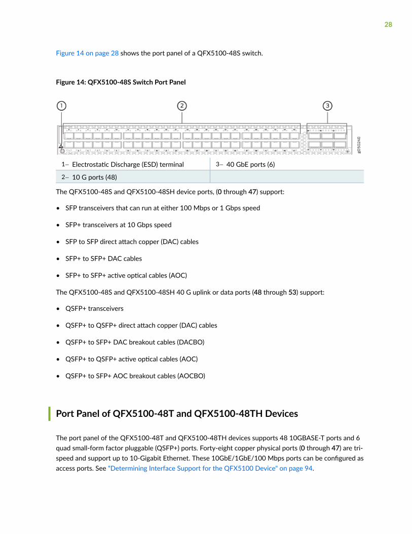
Figure 14 on page 28 shows the port panel of a QFX5100-48S switch.
Figure 14: QFX5100-48S Switch Port Panel
1— Electrostatic Discharge (ESD) terminal 3— 40 GbE ports (6)
2— 10 G ports (48)
The QFX5100-48S and QFX5100-48SH device ports, (0 through 47) support:
• SFP transceivers that can run at either 100 Mbps or 1 Gbps speed
• SFP+ transceivers at 10 Gbps speed
• SFP to SFP direct attach copper (DAC) cables
• SFP+ to SFP+ DAC cables
• SFP+ to SFP+ active optical cables (AOC)
The QFX5100-48S and QFX5100-48SH 40 G uplink or data ports (48 through 53) support:
• QSFP+ transceivers
• QSFP+ to QSFP+ direct attach copper (DAC) cables
• QSFP+ to SFP+ DAC breakout cables (DACBO)
• QSFP+ to QSFP+ active optical cables (AOC)
• QSFP+ to SFP+ AOC breakout cables (AOCBO)
Port Panel of QFX5100-48T and QFX5100-48TH Devices
The port panel of the QFX5100-48T and QFX5100-48TH devices supports 48 10GBASE-T ports and 6quad small-form factor pluggable (QSFP+) ports. Forty-eight copper physical ports (0 through 47) are tri-speed and support up to 10-Gigabit Ethernet. These 10GbE/1GbE/100 Mbps ports can be configured asaccess ports. See "Determining Interface Support for the QFX5100 Device" on page 94.
28
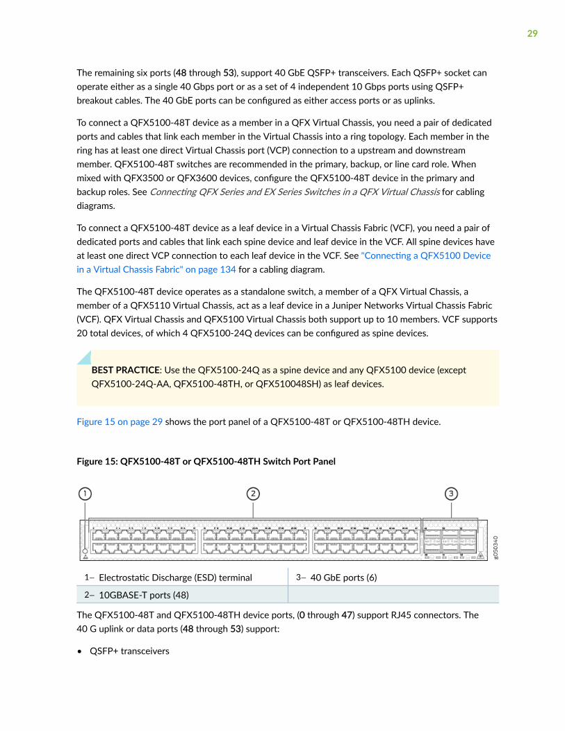
The remaining six ports (48 through 53), support 40 GbE QSFP+ transceivers. Each QSFP+ socket canoperate either as a single 40 Gbps port or as a set of 4 independent 10 Gbps ports using QSFP+breakout cables. The 40 GbE ports can be configured as either access ports or as uplinks.
To connect a QFX5100-48T device as a member in a QFX Virtual Chassis, you need a pair of dedicatedports and cables that link each member in the Virtual Chassis into a ring topology. Each member in thering has at least one direct Virtual Chassis port (VCP) connection to a upstream and downstreammember. QFX5100-48T switches are recommended in the primary, backup, or line card role. Whenmixed with QFX3500 or QFX3600 devices, configure the QFX5100-48T device in the primary andbackup roles. See Connecting QFX Series and EX Series Switches in a QFX Virtual Chassis for cablingdiagrams.
To connect a QFX5100-48T device as a leaf device in a Virtual Chassis Fabric (VCF), you need a pair ofdedicated ports and cables that link each spine device and leaf device in the VCF. All spine devices haveat least one direct VCP connection to each leaf device in the VCF. See "Connecting a QFX5100 Devicein a Virtual Chassis Fabric" on page 134 for a cabling diagram.
The QFX5100-48T device operates as a standalone switch, a member of a QFX Virtual Chassis, amember of a QFX5110 Virtual Chassis, act as a leaf device in a Juniper Networks Virtual Chassis Fabric(VCF). QFX Virtual Chassis and QFX5100 Virtual Chassis both support up to 10 members. VCF supports20 total devices, of which 4 QFX5100-24Q devices can be configured as spine devices.
BEST PRACTICE: Use the QFX5100-24Q as a spine device and any QFX5100 device (exceptQFX5100-24Q-AA, QFX5100-48TH, or QFX510048SH) as leaf devices.
Figure 15 on page 29 shows the port panel of a QFX5100-48T or QFX5100-48TH device.
Figure 15: QFX5100-48T or QFX5100-48TH Switch Port Panel
1— Electrostatic Discharge (ESD) terminal 3— 40 GbE ports (6)
2— 10GBASE-T ports (48)
The QFX5100-48T and QFX5100-48TH device ports, (0 through 47) support RJ45 connectors. The40 G uplink or data ports (48 through 53) support:
• QSFP+ transceivers
29

• QSFP+ to QSFP+ direct attach copper (DAC) cables
• QSFP+ to SFP+ DAC breakout cables (DACBO)
• QSFP+ to QSFP+ active optical cables (AOC)
• QSFP+ to SFP+ AOC breakout cables (AOCBO)
To connect a QFX5100-48T switch as a Node device in a QFabric system, you need:
• Four QSFP+ uplink ports on each QFX5100-48T Node device to connect to the data plane networkthrough the QFX3008-I or QFX5100-24Q Interconnect devices.
• The two remaining QSFP+ uplink ports on each QFX5100-48T Node device connect to the dataplane network through the QFX3008-I or QFX5100-24Q Interconnect devices.
Access port pinouts for the QFX5100-48T switch are the same as the management port connectorpinouts for the QFX Series. For more information, see "RJ-45 Management Port Connector PinoutInformation" on page 105.
SEE ALSO
Connect the QFX5100 in a Virtual Chassis or Virtual Chassis Fabric | 124
Port Panel of a QFX5100-96S Device
IN THIS SECTION
Switch Ports | 31
Channelizing Interfaces | 32
Virtual Chassis and Virtual Chassis Fabric Support | 32
The port panel of the QFX5100-96S switch consists of 96 small form-factor pluggable plus (SFP+) and 8quad small-form factor pluggable plus (QSFP+) ports that are normally configured as access ports.Physical ports(0 through 95) support 10 Gbps SFP+ transceivers and 1 Gbps transceivers. The eight 40-Gigabit ports (96 through 104) support QSFP+ transceivers and are normally configured as uplinks orVirtual Chassis ports (VCPs). Although the 104 physical ports of the QFX5100-96S would map to 128logical ports using channelization, only 104 logical ports are supported.
30
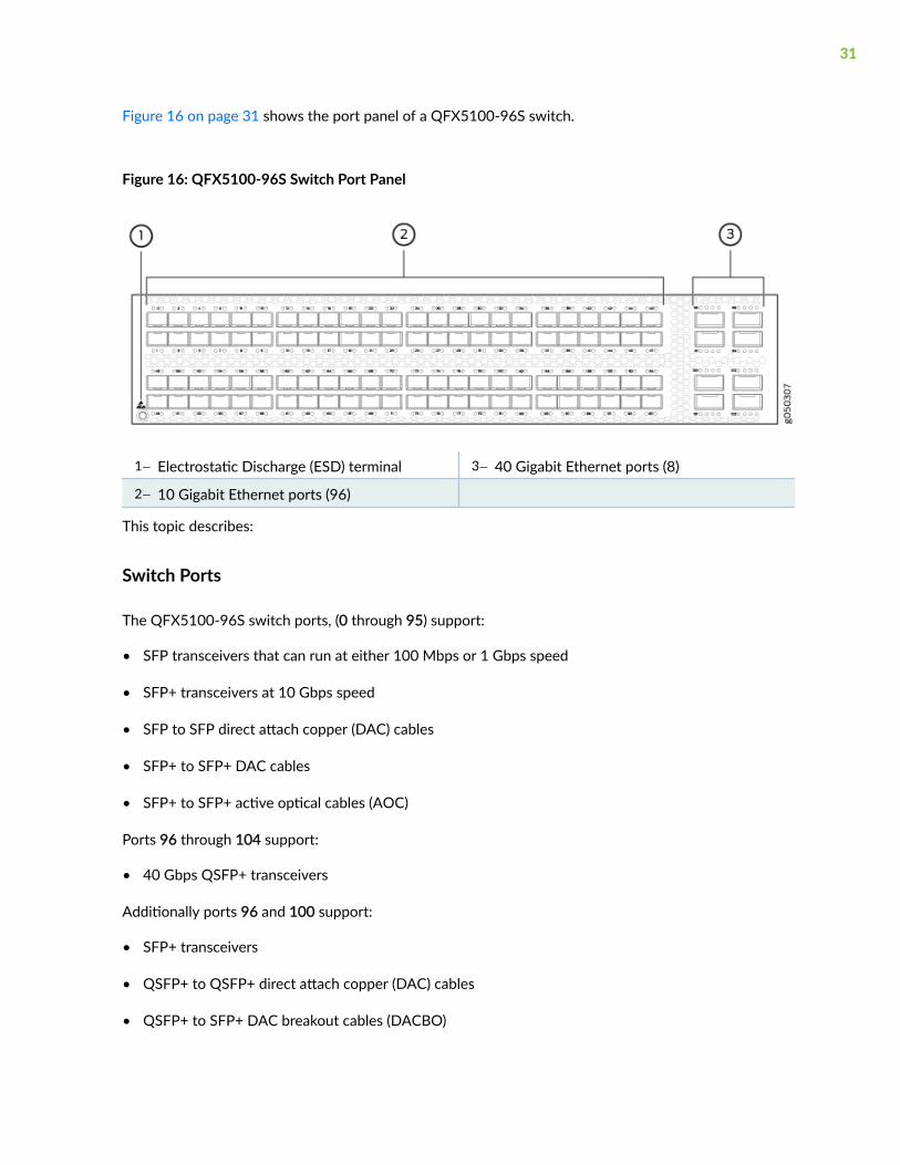
Figure 16 on page 31 shows the port panel of a QFX5100-96S switch.
Figure 16: QFX5100-96S Switch Port Panel
1— Electrostatic Discharge (ESD) terminal 3— 40 Gigabit Ethernet ports (8)
2— 10 Gigabit Ethernet ports (96)
This topic describes:
Switch Ports
The QFX5100-96S switch ports, (0 through 95) support:
• SFP transceivers that can run at either 100 Mbps or 1 Gbps speed
• SFP+ transceivers at 10 Gbps speed
• SFP to SFP direct attach copper (DAC) cables
• SFP+ to SFP+ DAC cables
• SFP+ to SFP+ active optical cables (AOC)
Ports 96 through 104 support:
• 40 Gbps QSFP+ transceivers
Additionally ports 96 and 100 support:
• SFP+ transceivers
• QSFP+ to QSFP+ direct attach copper (DAC) cables
• QSFP+ to SFP+ DAC breakout cables (DACBO)
31

• QSFP+ to QSFP+ active optical cables (AOC)
• QSFP+ to SFP+ AOC breakout cables (AOCBO)
CAUTION: When you use the latest OEM part number FCLF8521P2BTL (printed onthe transceiver label), you can install 1GbE transceivers (such as QFX-SFP-1GE-T) in anyport with no restrictions. The same applies for devices that support 10GbE coppertransceivers. However, if you are using the older OEM part number SP7041-M1-JN (notshipped in last 3+ years) instead, do not install 1GbE copper transceivers (such as QFX-SFP-1GE-T) directly above or below another 1GbE copper transceiver. Use only the toprow or bottom row to avoid damage to the device caused when the transceivers areinstalled above or below each other.
Channelizing Interfaces
The port panel of the QFX5100-96S switch supports up to a maximum of 104 logical 10 GbE ports thatcan be distributed over 96 small form-factor pluggable plus (SFP+) and 8 quad small-form factorpluggable plus (QSFP+) transceivers . Because of an 104 port restriction, only two of the eight QSFP+can be channelized. Depending on how you set the system mode for channelization, the behavior ofchannelization for the QSFP+ changes. The following system modes are available for the QFX5100-96Sswitch:
• Non-oversubscribed
All 96 SFP+ ports on the switch (PIC 0) are supported. In this mode, the eight QSFP+ ports are notsupported and cannot be channelized. There is no packet loss for packets of any size in this mode.
• Default mode
All 96 SFP+ ports on the switch (PIC 0) are supported. QSFP+ ports 96 and 100 can be channelized.If ports 96 and 100 are channelized, the interfaces on ports 97, 98, 99, 101, 102, and 103 aredisabled.
Virtual Chassis and Virtual Chassis Fabric Support
The QFX5100-96S switch operates as a standalone switch, as a member in a QFX Virtual Chassis, as amember in a QFX5110 Virtual Chassis, as a spine or leaf device in a QFX5100 Virtual Chassis Fabric(VCF), or as a leaf device in a QFX5110 VCF. QFX Virtual Chassis support up to 10 members; QFX5100VCF supports a total of 20 devices, of which 4 QFX5100 devices can be configured as spines. A QFXVirtual Chassis is cabled in a ring topology, where a VCF is cabled in a spine and leaf topology.
Virtual Chassis
32

In a QFX Virtual Chassis, you can connect up to 10 standalone QFX5100-96S switches into a QFXSeries Virtual Chassis and manage the interconnected switches as a single chassis. The advantages ofconnecting multiple switches into a Virtual Chassis include better-managed bandwidth at a networklayer, simplified configuration and maintenance because multiple devices can be managed as a singledevice, increased fault tolerance and high availability (HA) because a Virtual Chassis can remain activeand network traffic can be redirected to other member switches when a single member switch fails, anda flatter, simplified Layer 2 network topology that minimizes or eliminates the need for loop preventionprotocols such as Spanning Tree Protocol (STP).
As of Junos OS release 17.3R1, you can also connect a QFX5100-96S as a member in a QFX5110Virtual Chassis.
Virtual Chassis Fabric
The VCF provides a low-latency, high-performance fabric architecture that can be managed as a singledevice. VCF is an evolution of the Virtual Chassis feature, which allows you to interconnect multipledevices into a single logical device, inside of a fabric architecture. The VCF architecture is optimized tosupport small and medium-sized data centers that contain a mix of 1-Gpbs, 10-Gpbs, and 40-GbpsEthernet interfaces.
A VCF is constructed using a spine-and-leaf architecture and topology. In the spine-and-leafarchitecture, each spine device is interconnected to each leaf device. A VCF supports up to 20 devices,of which 4 QFX5100 devices can be configured into spine devices. In a mixed environment withQFX5100-24Q, QFX5100-98S and EX4300, use the QFX5100-24Q as the spine device and theQFX5100-96S and EX4300 as a leaf devices. You may use the QFX5100-96S as a spine in an allQFX5100-96S VCF or in a VCF that has a mixture of QFX5100-96S and EX4300.
As of Junos OS release 17.3R1, you can also connect a QFX5100-24Q as a leaf device in a QFX5110VCF.
Expansion Modules for QFX5100 Devices
IN THIS SECTION
EX4600-EM-8F | 34
QFX-EM-4Q | 36
QFX-PFA-4Q | 37
33
The QFX5100-24Q and QFX5100-24Q-AA devices have two bays on the port panel for optionalexpansion modules. These expansion modules can be hot-inserted or hot-removed. Expansion modulesand transceivers are not shipped with the switch and must be ordered separately.
The QFX5100-24Q and QFX5100-24Q-AA support these expansion modules up to the 104-portlimitation:
• Two EX4600-EM-8F, which provides a total of 16 additional 10-Gigabit Ethernet Enhanced SmallForm-Factor Pluggable (SFP+) ports or 8 additional 1-Gigabit SFP ports. When both bays (PIC 1 andPIC 2) are populated with EX4600-EM-8F modules, you must configure the system mode as Flexi-pic. In this mode, port 0 to 3 of PIC 0 are disabled, which allows the devices to operate within the104-port limitation.
• Two QFX-EM-4Q, which provides a total of 8 additional 40-Gigabit Quad SFP+ (QSFP+) ports.
• One EX4600-EM-8F and one QFX-EM-4Q, which provides 8 additional 10-Gigabit Ethernet SFP+ (or8 additional 1-Gigabit SFP ports) and 4 additional 40-Gigabit (QSFP+) ports. This combinationrequires the system mode to be configured as Flexi-pic. See Configuring the System Mode.
Additionally, the QFX5100-24Q-AA supports the QFX-PFA-4Q expansion module, which provides 4additional QSFP+ ports.
NOTE: In order to run the orchestration diagnostics, Precision Time Protocol (PTP) andsynchronization diagnostics, and utilities contained in the Packet Flow Accelerator Diagnosticssoftware, you must have Junos OS Release 14.1X53-D27 or later software with enhancedautomation installed on your QFX5100-24Q-AA.
EX4600-EM-8F
The EX4600-EM-8F is a MACsec-capable expansion module that inserts into one of the device bays of aQFX5100-24Q, QFX5100-24Q-AA, or an EX4600 switch. It provides 8 additional 10-Gigabit EthernetSFP+ ports or 8 additional 1-Gigabit SFP ports to each bay. Figure 7 shows the ports and LEDs on theexpansion module.
CAUTION: Copper SFP transceivers (1000BASE-T) are restricted to the top four portsor the bottom four ports; fiber SFP transceivers (1000BASE-X) can be used in any of the
34
eight ports. Attempting to stack copper SFP transceivers causes internal damage to themodule.
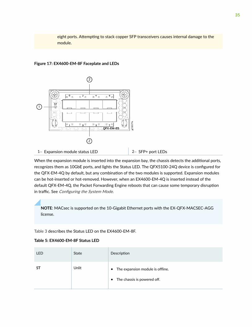
Figure 17: EX4600-EM-8F Faceplate and LEDs
1— Expansion module status LED 2— SFP+ port LEDs
When the expansion module is inserted into the expansion bay, the chassis detects the additional ports,recognizes them as 10GbE ports, and lights the Status LED. The QFX5100-24Q device is configured forthe QFX-EM-4Q by default, but any combination of the two modules is supported. Expansion modulescan be hot-inserted or hot-removed. However, when an EX4600-EM-4Q is inserted instead of thedefault QFX-EM-4Q, the Packet Forwarding Engine reboots that can cause some temporary disruptionin traffic. See Configuring the System Mode.
NOTE: MACsec is supported on the 10-Gigabit Ethernet ports with the EX-QFX-MACSEC-AGGlicense.
Table 3 describes the Status LED on the EX4600-EM-8F.
Table 5: EX4600-EM-8F Status LED
LED State Description
ST Unlit • The expansion module is offline.
• The chassis is powered off.
35
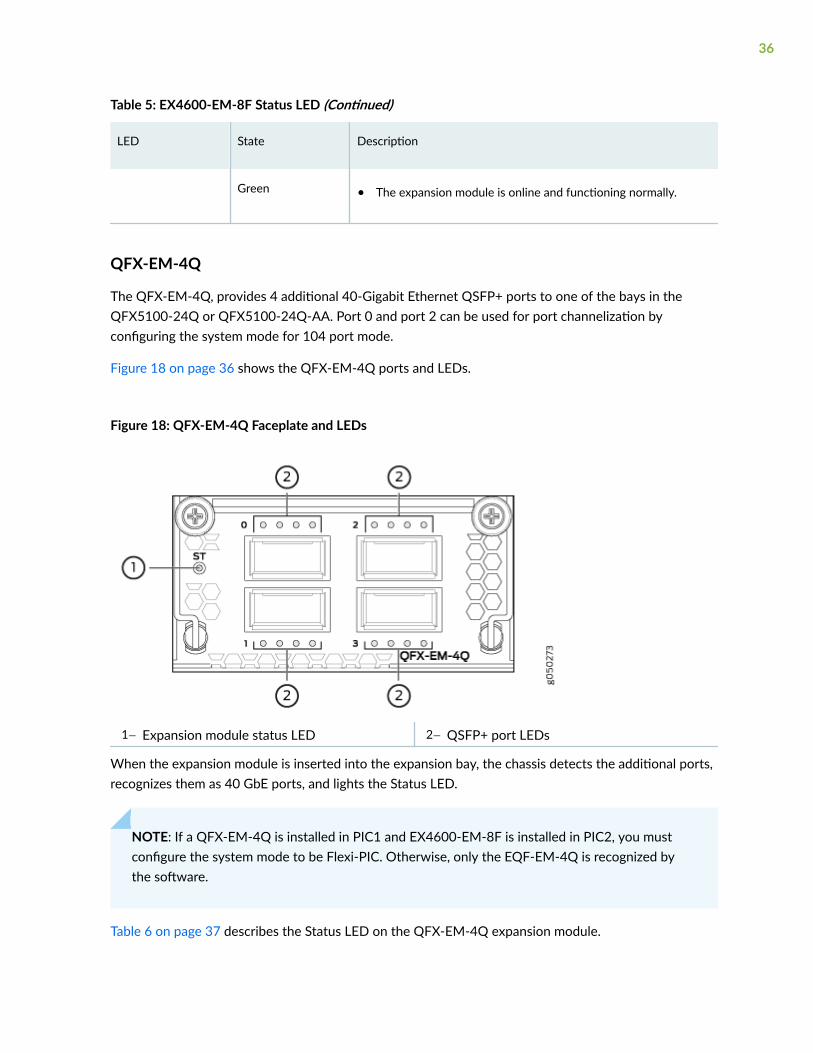
Table 5: EX4600-EM-8F Status LED (Continued)
LED State Description
Green • The expansion module is online and functioning normally.
QFX-EM-4Q
The QFX-EM-4Q, provides 4 additional 40-Gigabit Ethernet QSFP+ ports to one of the bays in theQFX5100-24Q or QFX5100-24Q-AA. Port 0 and port 2 can be used for port channelization byconfiguring the system mode for 104 port mode.
Figure 18 on page 36 shows the QFX-EM-4Q ports and LEDs.
Figure 18: QFX-EM-4Q Faceplate and LEDs
1— Expansion module status LED 2— QSFP+ port LEDs
When the expansion module is inserted into the expansion bay, the chassis detects the additional ports,recognizes them as 40 GbE ports, and lights the Status LED.
NOTE: If a QFX-EM-4Q is installed in PIC1 and EX4600-EM-8F is installed in PIC2, you mustconfigure the system mode to be Flexi-PIC. Otherwise, only the EQF-EM-4Q is recognized bythe software.
Table 6 on page 37 describes the Status LED on the QFX-EM-4Q expansion module.
36

Table 6: Expansion Module Status LED
LED State Description
ST Unlit • The expansion module is offline.
• The chassis is powered off.
Green • The expansion module is online and functioning normally.
QFX-PFA-4Q
The QFX-PFA-4Q, which features a high-performance field-programmable gate array (FPGA), providesfour additional QSFP+ ports to the QFX5100-24Q-AA switch. The QFX-PFA-4Q is a double-wideexpansion module. Figure 19 on page 37 shows the ports and LEDs on the expansion module.
Figure 19: QFX-PFA-4Q Faceplate and LEDs
1— Expansion module status LED 4— 1-PPS and 10-MHz GPS input and output
2— QSFP+ ports and LEDs 5— RJ-45 Ethernet port
3— FPGA LEDs 6— Time-of-day (TOD) RS-232 port
Table 7 on page 38 describes the status and FPGA LEDs on the QFX-PFA-4Q.
37
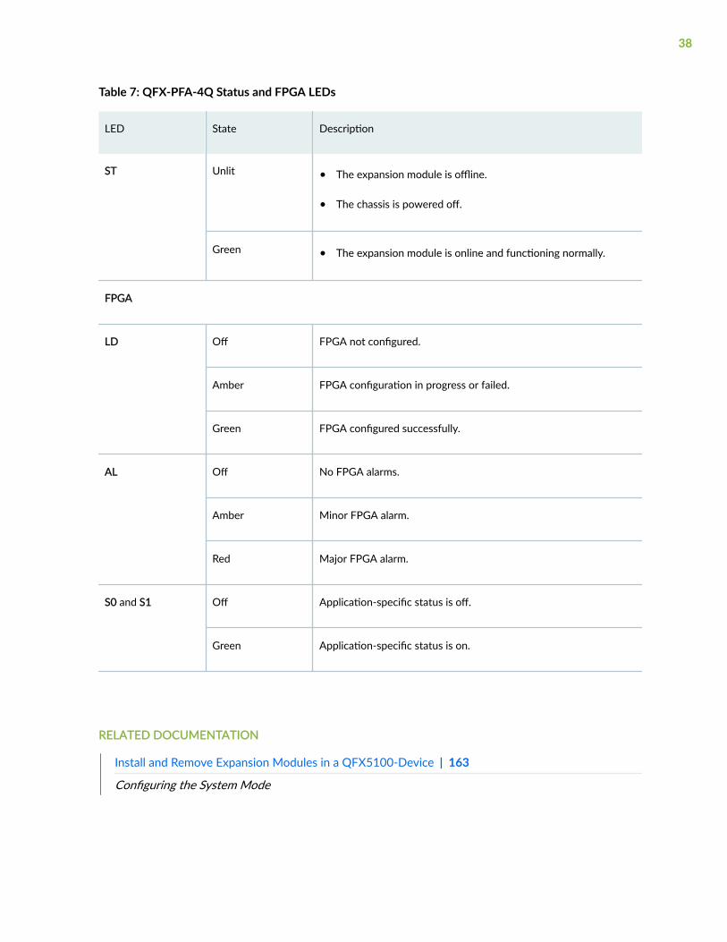
Table 7: QFX-PFA-4Q Status and FPGA LEDs
LED State Description
ST Unlit • The expansion module is offline.
• The chassis is powered off.
Green • The expansion module is online and functioning normally.
FPGA
LD Off FPGA not configured.
Amber FPGA configuration in progress or failed.
Green FPGA configured successfully.
AL Off No FPGA alarms.
Amber Minor FPGA alarm.
Red Major FPGA alarm.
S0 and S1 Off Application-specific status is off.
Green Application-specific status is on.
RELATED DOCUMENTATION
Install and Remove Expansion Modules in a QFX5100-Device | 163
Configuring the System Mode
38
Access Port and Uplink Port LEDs on a QFX5100 Device
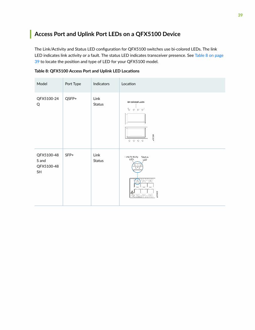
The Link/Activity and Status LED configuration for QFX5100 switches use bi-colored LEDs. The linkLED indicates link activity or a fault. The status LED indicates transceiver presence. See Table 8 on page39 to locate the position and type of LED for your QFX5100 model.
Table 8: QFX5100 Access Port and Uplink LED Locations
Model Port Type Indicators Location
QFX5100-24Q
QSFP+ LinkStatus
QFX5100-48S andQFX5100-48SH
SFP+ LinkStatus
39
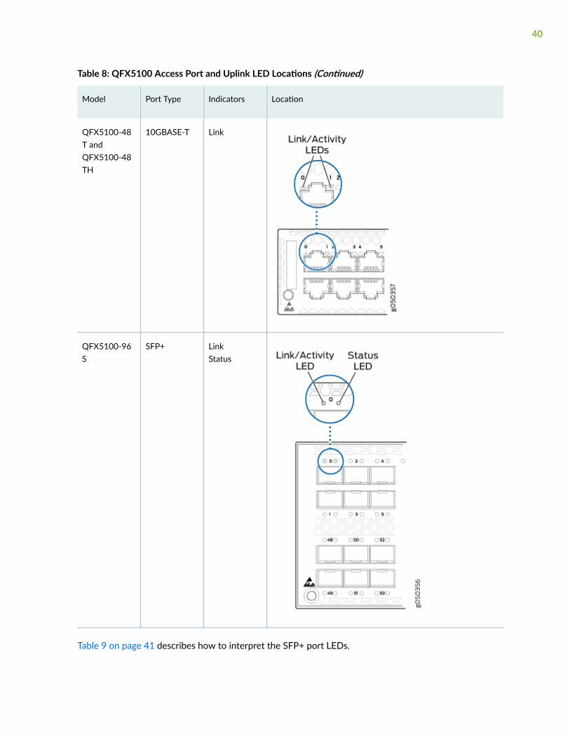
Table 8: QFX5100 Access Port and Uplink LED Locations (Continued)
Model Port Type Indicators Location
QFX5100-48T andQFX5100-48TH
10GBASE-T Link
QFX5100-96S
SFP+ LinkStatus
Table 9 on page 41 describes how to interpret the SFP+ port LEDs.
40
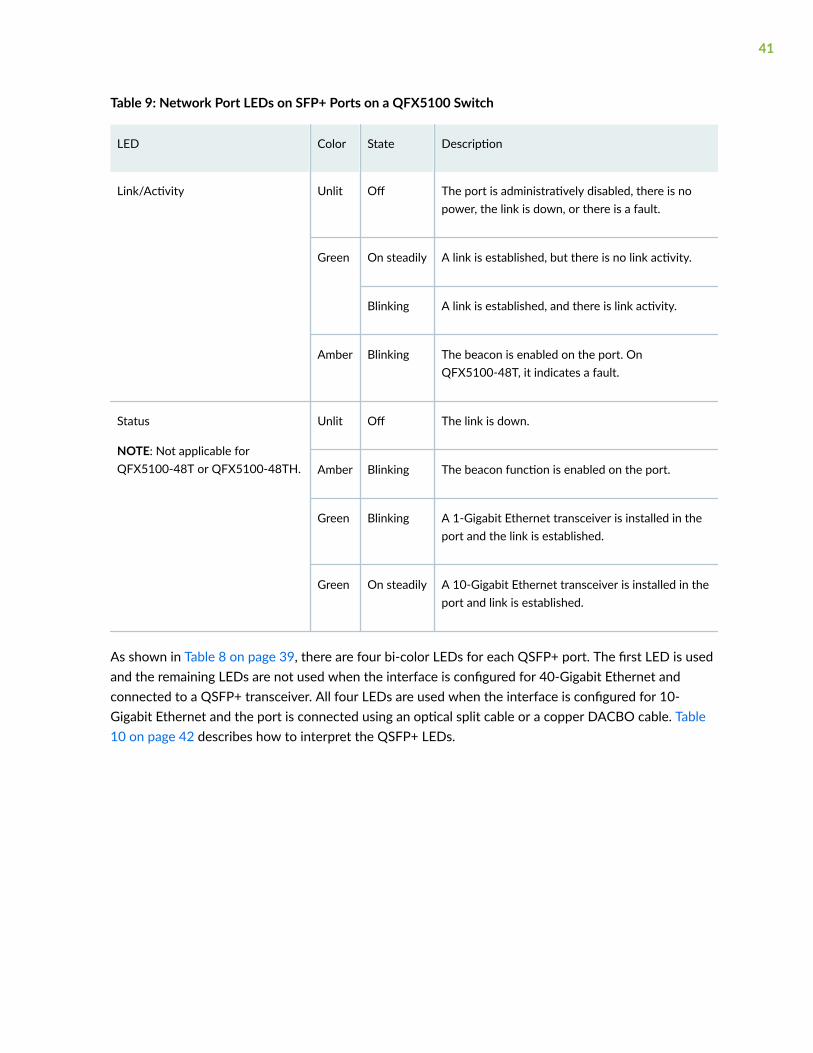
Table 9: Network Port LEDs on SFP+ Ports on a QFX5100 Switch
LED Color State Description
Link/Activity Unlit Off The port is administratively disabled, there is nopower, the link is down, or there is a fault.
Green On steadily A link is established, but there is no link activity.
Blinking A link is established, and there is link activity.
Amber Blinking The beacon is enabled on the port. OnQFX5100-48T, it indicates a fault.
Status
NOTE: Not applicable forQFX5100-48T or QFX5100-48TH.
Unlit Off The link is down.
Amber Blinking The beacon function is enabled on the port.
Green Blinking A 1-Gigabit Ethernet transceiver is installed in theport and the link is established.
Green On steadily A 10-Gigabit Ethernet transceiver is installed in theport and link is established.
As shown in Table 8 on page 39, there are four bi-color LEDs for each QSFP+ port. The first LED is usedand the remaining LEDs are not used when the interface is configured for 40-Gigabit Ethernet andconnected to a QSFP+ transceiver. All four LEDs are used when the interface is configured for 10-Gigabit Ethernet and the port is connected using an optical split cable or a copper DACBO cable. Table10 on page 42 describes how to interpret the QSFP+ LEDs.
41
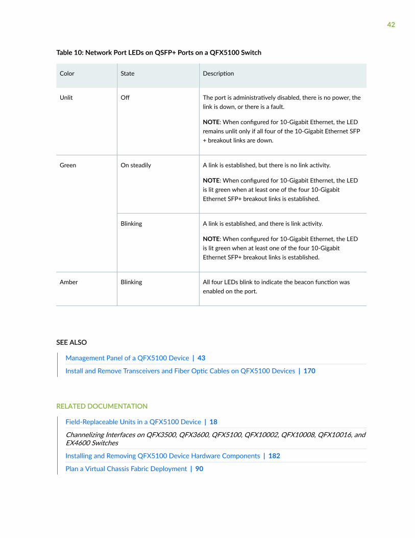
Table 10: Network Port LEDs on QSFP+ Ports on a QFX5100 Switch
Color State Description
Unlit Off The port is administratively disabled, there is no power, thelink is down, or there is a fault.
NOTE: When configured for 10-Gigabit Ethernet, the LEDremains unlit only if all four of the 10-Gigabit Ethernet SFP+ breakout links are down.
Green On steadily A link is established, but there is no link activity.
NOTE: When configured for 10-Gigabit Ethernet, the LEDis lit green when at least one of the four 10-GigabitEthernet SFP+ breakout links is established.
Blinking A link is established, and there is link activity.
NOTE: When configured for 10-Gigabit Ethernet, the LEDis lit green when at least one of the four 10-GigabitEthernet SFP+ breakout links is established.
Amber Blinking All four LEDs blink to indicate the beacon function wasenabled on the port.
SEE ALSO
Management Panel of a QFX5100 Device | 43
Install and Remove Transceivers and Fiber Optic Cables on QFX5100 Devices | 170
RELATED DOCUMENTATION
Field-Replaceable Units in a QFX5100 Device | 18
Channelizing Interfaces on QFX3500, QFX3600, QFX5100, QFX10002, QFX10008, QFX10016, andEX4600 Switches
Installing and Removing QFX5100 Device Hardware Components | 182
Plan a Virtual Chassis Fabric Deployment | 90
42

QFX5100 Management Panel
IN THIS SECTION
Management Panel of a QFX5100 Device | 43
Management Port LEDs on a QFX5100 Device | 48
Chassis Status LEDs on a QFX5100 Device | 51
Management Panel of a QFX5100 Device
The management panel of the QFX5100 switch is found on the Field Replaceable Unit (FRU) end of theswitch as shown in Figure 20 on page 43 for 1 U switches and Figure 21 on page 44 for the 2 U ,QFX5100-96S switch. See Figure 22 on page 44 and Figure 23 on page 45 for FRUs and managementpanel detail.
Figure 20: QFX5100 Switch, FRU End 1 U Product SKUs
1— Management panel 3— Power supply units
43

2— Fan modules
Figure 21: QFX5100-96S, FRU End
Figure 22: Management Panel Components on 1 U QFX5100
1— Status LEDs 4— em0–RJ-45 (1000 Base-T) managementEthernet port (C0)Some SKUs have an additional SFPmanagement Ethernet port (second C0)
2— em1–SFP management Ethernet port (C1)Cage (socket for either 1 GbE copper SFP orfiber SFP)
5— RJ-45 console port (CON) )
3— Reset button, see caution statement below 6— USB port
44

CAUTION: Do not use the Reset button to restart the power sequence unless under thedirection of Juniper Networks Technical Assistance Center (JTAC).
Figure 23: Management Panel Components on the QFX5100-96S
1— Status LEDs 4— em0–RJ-45 (1000 Base-T) managementEthernet port (C0)
2— em1–SFP management Ethernet port (C1)Cage (socket for either 1 GbE copper SFP orfiber SFP)
5— RJ-45 console port (C0N) )
3— Reset button, see caution statement above 6— USB port
The management panel consists of the following components:
• Status LEDs
• ALM–Alarm
• Unlit indicates the switch is halted or that there is no alarm.
45
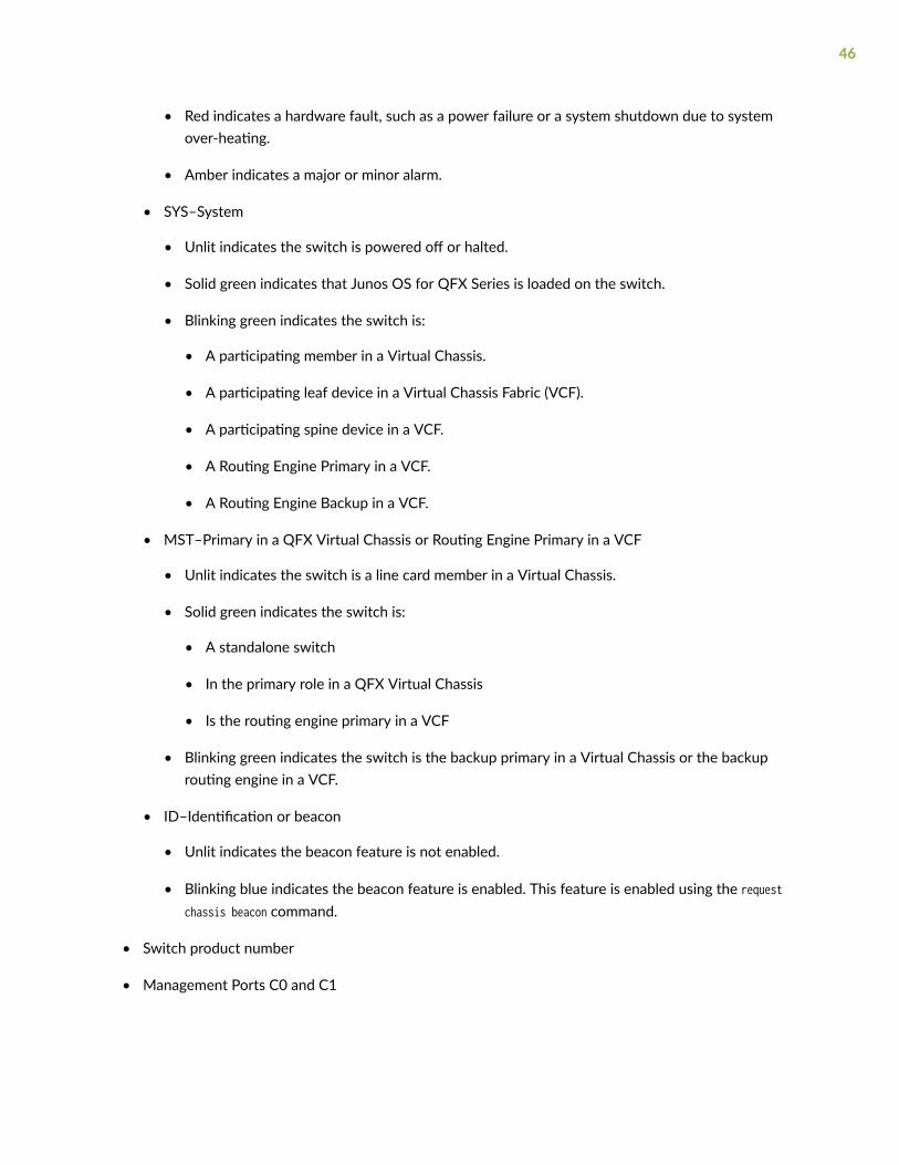
• Red indicates a hardware fault, such as a power failure or a system shutdown due to systemover-heating.
• Amber indicates a major or minor alarm.
• SYS–System
• Unlit indicates the switch is powered off or halted.
• Solid green indicates that Junos OS for QFX Series is loaded on the switch.
• Blinking green indicates the switch is:
• A participating member in a Virtual Chassis.
• A participating leaf device in a Virtual Chassis Fabric (VCF).
• A participating spine device in a VCF.
• A Routing Engine Primary in a VCF.
• A Routing Engine Backup in a VCF.
• MST–Primary in a QFX Virtual Chassis or Routing Engine Primary in a VCF
• Unlit indicates the switch is a line card member in a Virtual Chassis.
• Solid green indicates the switch is:
• A standalone switch
• In the primary role in a QFX Virtual Chassis
• Is the routing engine primary in a VCF
• Blinking green indicates the switch is the backup primary in a Virtual Chassis or the backuprouting engine in a VCF.
• ID–Identification or beacon
• Unlit indicates the beacon feature is not enabled.
• Blinking blue indicates the beacon feature is enabled. This feature is enabled using the requestchassis beacon command.
• Switch product number
• Management Ports C0 and C1
46

• C0–Use the RJ-45 connectors for 10/100/1000 BaseT or to cable a virtual management Ethernet(VME) interface for spine members in a VCF. See "Connect a Device to a Network for Out-of-Band Management" on page 122.
NOTE: For product SKUs with C0 available in both copper and fiber, the copper C0 haspriority over fiber C0.
• C1–Use the SFP connector for 1000 BaseX.
• USB port for image updates.
• Console port (RJ-45) to support RS-232 serial ports. The LEDs above the port indicate status andlink.
47

Management Port LEDs on a QFX5100 Device
The management ports (labeled C0 for 10/100/1000 Base-T and C1 for 10/100/1000 Base-T and SFP1000 Base-X connections) on a QFX5100 switch have two LEDs that indicate link status and linkactivity (see Figure 24 on page 49). The left LED indicates status; the right LED indicates link/activity.
48
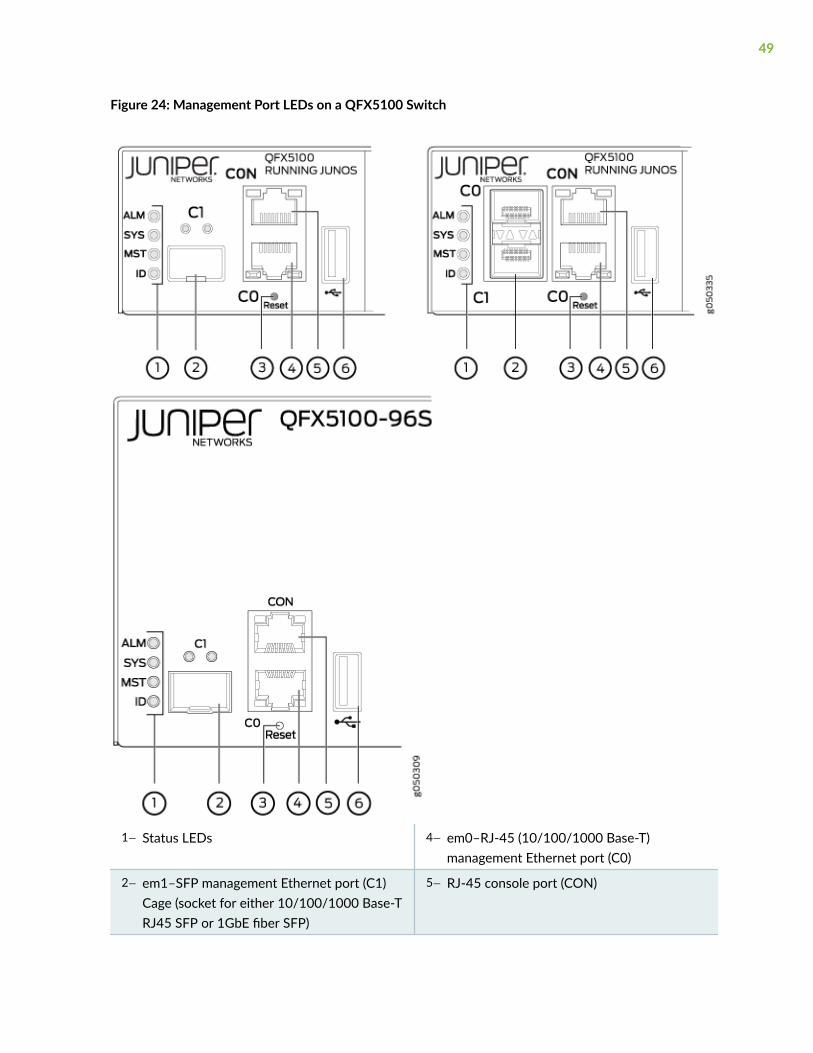
Figure 24: Management Port LEDs on a QFX5100 Switch
1— Status LEDs 4— em0–RJ-45 (10/100/1000 Base-T)management Ethernet port (C0)
2— em1–SFP management Ethernet port (C1)Cage (socket for either 10/100/1000 Base-TRJ45 SFP or 1GbE fiber SFP)
5— RJ-45 console port (CON)
49
3— Reset button, see caution statement below 6— USB port
CAUTION: Do not use the Reset button to restart the power sequence unless under thedirection of Juniper Networks Technical Assistance Center (JTAC).
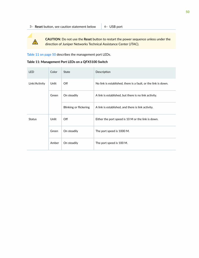
Table 11 on page 50 describes the management port LEDs.
Table 11: Management Port LEDs on a QFX5100 Switch
LED Color State Description
Link/Activity Unlit Off No link is established, there is a fault, or the link is down.
Green On steadily A link is established, but there is no link activity.
Blinking or flickering A link is established, and there is link activity.
Status Unlit Off Either the port speed is 10 M or the link is down.
Green On steadily The port speed is 1000 M.
Amber On steadily The port speed is 100 M.
50
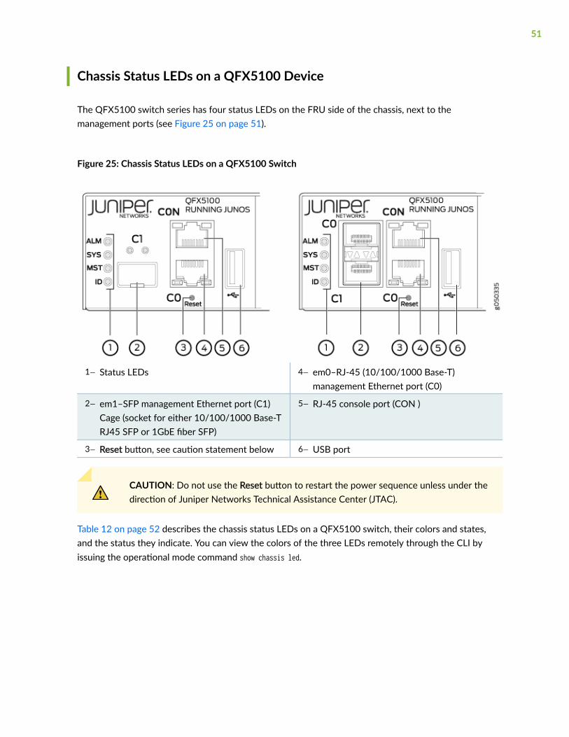
Chassis Status LEDs on a QFX5100 Device
The QFX5100 switch series has four status LEDs on the FRU side of the chassis, next to themanagement ports (see Figure 25 on page 51).
Figure 25: Chassis Status LEDs on a QFX5100 Switch
1— Status LEDs 4— em0–RJ-45 (10/100/1000 Base-T)management Ethernet port (C0)
2— em1–SFP management Ethernet port (C1)Cage (socket for either 10/100/1000 Base-TRJ45 SFP or 1GbE fiber SFP)
5— RJ-45 console port (CON )
3— Reset button, see caution statement below 6— USB port
CAUTION: Do not use the Reset button to restart the power sequence unless under thedirection of Juniper Networks Technical Assistance Center (JTAC).
Table 12 on page 52 describes the chassis status LEDs on a QFX5100 switch, their colors and states,and the status they indicate. You can view the colors of the three LEDs remotely through the CLI byissuing the operational mode command show chassis led.
51
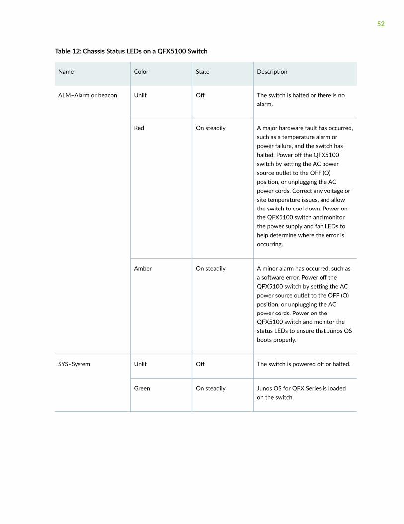
Table 12: Chassis Status LEDs on a QFX5100 Switch
Name Color State Description
ALM–Alarm or beacon Unlit Off The switch is halted or there is noalarm.
Red On steadily A major hardware fault has occurred,such as a temperature alarm orpower failure, and the switch hashalted. Power off the QFX5100switch by setting the AC powersource outlet to the OFF (O)position, or unplugging the ACpower cords. Correct any voltage orsite temperature issues, and allowthe switch to cool down. Power onthe QFX5100 switch and monitorthe power supply and fan LEDs tohelp determine where the error isoccurring.
Amber On steadily A minor alarm has occurred, such asa software error. Power off theQFX5100 switch by setting the ACpower source outlet to the OFF (O)position, or unplugging the ACpower cords. Power on theQFX5100 switch and monitor thestatus LEDs to ensure that Junos OSboots properly.
SYS–System Unlit Off The switch is powered off or halted.
Green On steadily Junos OS for QFX Series is loadedon the switch.
52
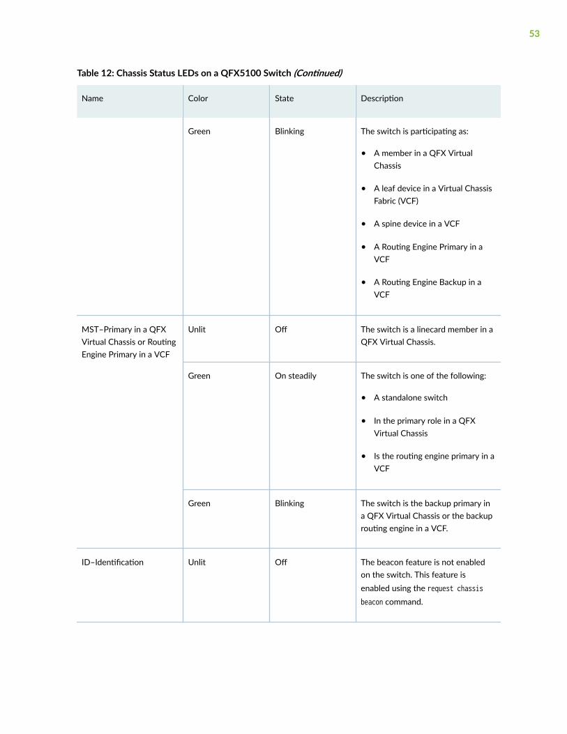
Table 12: Chassis Status LEDs on a QFX5100 Switch (Continued)
Name Color State Description
Green Blinking The switch is participating as:
• A member in a QFX VirtualChassis
• A leaf device in a Virtual ChassisFabric (VCF)
• A spine device in a VCF
• A Routing Engine Primary in aVCF
• A Routing Engine Backup in aVCF
MST–Primary in a QFXVirtual Chassis or RoutingEngine Primary in a VCF
Unlit Off The switch is a linecard member in aQFX Virtual Chassis.
Green On steadily The switch is one of the following:
• A standalone switch
• In the primary role in a QFXVirtual Chassis
• Is the routing engine primary in aVCF
Green Blinking The switch is the backup primary ina QFX Virtual Chassis or the backuprouting engine in a VCF.
ID–Identification Unlit Off The beacon feature is not enabledon the switch. This feature isenabled using the request chassisbeacon command.
53

Table 12: Chassis Status LEDs on a QFX5100 Switch (Continued)
Name Color State Description
Blue Blinking The beacon feature is enabled onthe switch. This feature is enabledusing the request chassis beaconcommand.
SEE ALSO
show chassis alarms
request chassis beacon
RELATED DOCUMENTATION
QFX5100 Cable and Pinout Specifications | 104
Installing and Removing QFX5100 Device Hardware Components | 182
Connect a Device to a Network for Out-of-Band Management | 122
QFX5100 Power System
IN THIS SECTION
AC Power Supply for a QFX5100 Device | 55
AC Power Specifications for a QFX5100 Device | 58
AC Power Cord Specifications for a QFX5100 Device | 59
AC Power Supply LEDs on a QFX5100 Device | 60
DC Power Supply in a QFX5100 Device | 61
DC Power Specifications for a QFX5100 Device | 65
DC Power Supply LEDs on a QFX5100 Device | 66
54

AC Power Supply for a QFX5100 Device
The two power supplies in QFX5100 switches are hot-removable and hot-insertable field-replaceableunits (FRUs). The power supplies are installed in the switch at the factory. You can install replacementpower supplies from the management panel without powering off the switch or disrupting the switchingfunction.
The AC power supply in 1 U QFX5100 switches is 650 W; the AC power supply in the 2 U,QFX5100-96S switch, is 850 W. Both power supplies look identical. Be sure to use the correct powersupply for your chassis product SKU (see Table 13 on page 57).
CAUTION: Do not mix power supplies with different airflow or different wattage. Thesystem raises an alarm when a power supply having a different airflow or wattage isinserted into the chassis.
See Figure 26 on page 55 for an example of the 1 U design and Figure 27 on page 56 for an exampleof the 2 U power supply.
Figure 26: 1 U AC Power Supply in QFX5100 Switches
1— Handle 3— AC appliance inlet
55
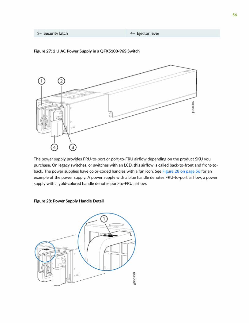
2— Security latch 4— Ejector lever
Figure 27: 2 U AC Power Supply in a QFX5100-96S Switch
The power supply provides FRU-to-port or port-to-FRU airflow depending on the product SKU youpurchase. On legacy switches, or switches with an LCD, this airflow is called back-to-front and front-to-back. The power supplies have color-coded handles with a fan icon. See Figure 28 on page 56 for anexample of the power supply. A power supply with a blue handle denotes FRU-to-port airflow; a powersupply with a gold-colored handle denotes port-to-FRU airflow.
Figure 28: Power Supply Handle Detail
56

1— Fan icon on handle
CAUTION: Verify that the airflow direction on the power supply handle matches thedirection of airflow in the chassis. Ensure that each power supply you install in thechassis has the same airflow direction. If you install power supplies with two differentairflow directions, Junos OS raises an alarm. If you need to convert the airflow patternon a chassis, you must change out all the fans and power supplies at one time to usethe new direction.
Table 13 on page 57 shows the different power supplies and their direction of airflow.
Table 13: Airflow Direction in QFX5100 AC Power Supplies
QFX5100Product SKUs
Wattage Product Number Direction ofAirflow
Color of PowerSupply Handle
QFX5100-24Q
QFX5100-48S
QFX5100-48SH
QFX5100-48T
QFX5100-48TH
650 W JPSU-650W-AC-AFI
QFXC01-PWRACI-650A(older version)
FRU-to-port Juniper AzureBlue
QFX5100-96S 850 W JPSU-850W-AC-AFI
QFX5100-24Q
QFX5100-48S
QFX5100-48SH
QFX5100-48T
QFX5100-48TH
650 W JPSU-650W-AC-AFO
QFXC01-PWRACO-650A(older version)
Port-to-FRU Juniper Gold
QFX5100-96S 850 W JPSU-850W-AC-AFO
To avoid electrical injury, carefully follow instructions in "Connecting AC Power to a QFX5100 Device"on page 140.
57
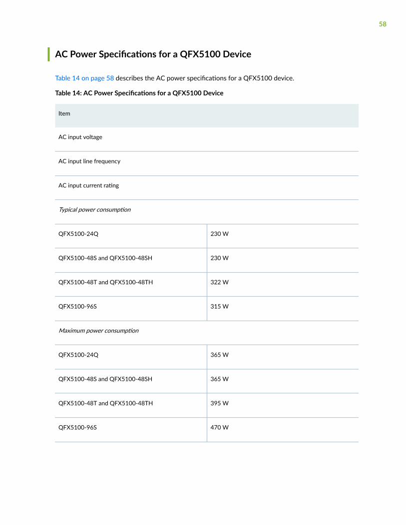
AC Power Specifications for a QFX5100 Device
Table 14 on page 58 describes the AC power specifications for a QFX5100 device.
Table 14: AC Power Specifications for a QFX5100 Device
Item
AC input voltage
AC input line frequency
AC input current rating
Typical power consumption
QFX5100-24Q 230 W
QFX5100-48S and QFX5100-48SH 230 W
QFX5100-48T and QFX5100-48TH 322 W
QFX5100-96S 315 W
Maximum power consumption
QFX5100-24Q 365 W
QFX5100-48S and QFX5100-48SH 365 W
QFX5100-48T and QFX5100-48TH 395 W
QFX5100-96S 470 W
58

AC Power Cord Specifications for a QFX5100 Device
Detachable AC power cords are shipped with the chassis, if you include them as part of your order. Thecoupler is type C13 as described by International Electrotechnical Commission (IEC) standard 60320.The plug end of the power cord fits into the power source outlet that is standard for your geographicallocation.
CAUTION: The AC power cord for the device is intended for use with that chassis onlyand not for any other use.
NOTE: In North America, AC power cords must not exceed 4.5 meters (approximately 14.75 feet)in length, to comply with National Electrical Code (NEC) Sections 400-8 (NFPA 75, 5-2.2) and210-52 and Canadian Electrical Code (CEC) Section 4-010(3). The cords that can be ordered forthe QFX5100 devices are in compliance.
Table 15 on page 59 lists AC power cord specifications provided for each country or region.
Table 15: AC Power Cord Specifications
Country/Region Electrical Specifications Plug Standards
Australia 250 VAC, 10 A, 50 Hz AS/NZ 3112-1993
China 250 VAC, 10 A, 50 Hz GB2099.1 1996 and GB1002 1996(CH1-10P)
Europe (except Italy, Switzerland,and United Kingdom)
250 VAC, 10 A, 50 Hz CEE (7) VII
Italy 250 VAC, 10 A, 50 Hz CEI 23-16/VII
Japan 125 VAC, 12 A, 50 Hz or 60 Hz JIS 8303
North America 125 VAC, 13 A, 60 Hz NEMA 5-15
South Korea 250 VAC, 10 A, 60 Hz KSC 8305
59

Table 15: AC Power Cord Specifications (Continued)
Country/Region Electrical Specifications Plug Standards
Switzerland 250 VAC, 10 A, 50 Hz SEV 1011 SEV 6534/2
United Kingdom 250 VAC, 10 A, 50 Hz BS 1363A
Figure 29 on page 60 illustrates the plug on the power cord for some of the countries or regions listedin Table 15 on page 59.
Figure 29: AC Plug Types
AC Power Supply LEDs on a QFX5100 Device
Figure 30 on page 60 shows the location of the LEDs on the power supply.
Figure 30: AC Power Supply LEDs on a QFX5100 Switch
Table 16 on page 61 describes the LEDs on the AC power supplies.
60

Table 16: AC Power Supply LEDs on a QFX5100 Switch
LED Color State Description
AC OK Unlit Off The power supply is disconnected from power, or power is not coming into thepower supply.
Green On steadily Power is coming into the power supply.
DC OK Unlit Off The power supply is disconnected from power, or the power supply is notsending out power correctly.
Green On steadily The power supply is sending out power correctly.
Fault Amber On steadily An error has been detected in the power supply. Replace the power supply assoon as possible. To maintain proper airflow through the chassis, leave thepower supply installed in the chassis until you are ready to replace it.
NOTE: If the AC OK LED and the DC OK LED are unlit, either the AC power cord is not installedproperly or the power supply fuse has failed. If the AC OK LED is lit and the DC OK LED is unlit,the AC power supply is installed properly, but the power supply has an internal failure.
DC Power Supply in a QFX5100 Device
The power supplies in QFX5100 devices (see Figure 31 on page 62) are hot-removable and hot-insertable field-replaceable units (FRUs) that you can install in 1 U DC product SKUs of QFX5100devices without powering off the device or disrupting the switching function.
The DC power supply in 1 U product SKUs of QFX5100 is 650 W with dual feeds for power resiliency.The DC power supply in the 2 U product SKU, QFX5100-96S, is 850 W with dual feeds for power
61
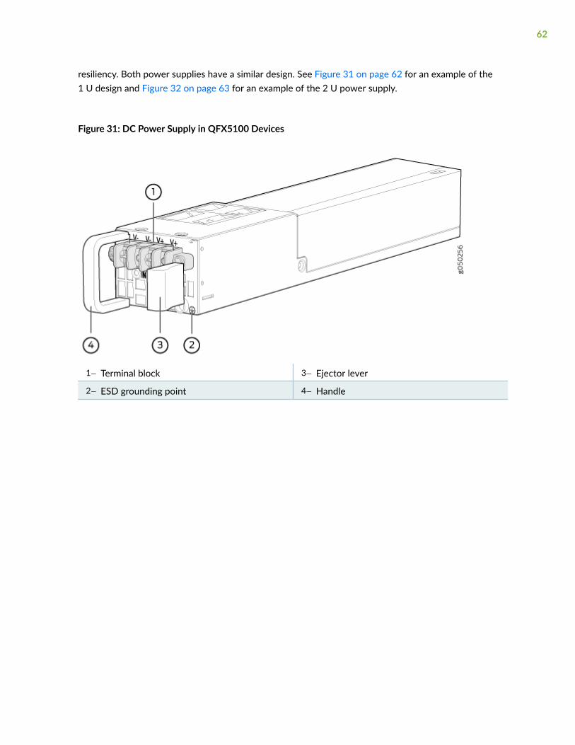
resiliency. Both power supplies have a similar design. See Figure 31 on page 62 for an example of the1 U design and Figure 32 on page 63 for an example of the 2 U power supply.
Figure 31: DC Power Supply in QFX5100 Devices
1— Terminal block 3— Ejector lever
2— ESD grounding point 4— Handle
62
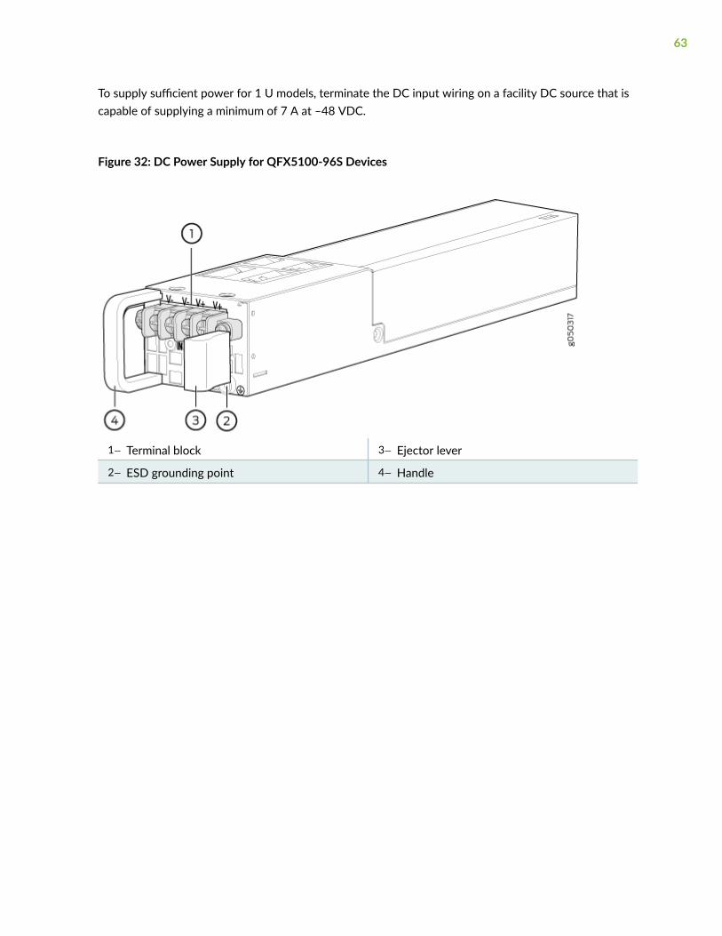
To supply sufficient power for 1 U models, terminate the DC input wiring on a facility DC source that iscapable of supplying a minimum of 7 A at –48 VDC.
Figure 32: DC Power Supply for QFX5100-96S Devices
1— Terminal block 3— Ejector lever
2— ESD grounding point 4— Handle
63
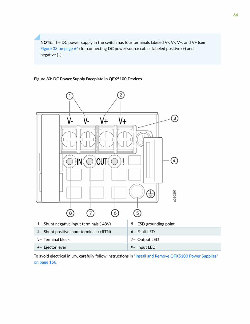
NOTE: The DC power supply in the switch has four terminals labeled V-, V-, V+, and V+ (seeFigure 33 on page 64) for connecting DC power source cables labeled positive (+) andnegative (–).
Figure 33: DC Power Supply Faceplate in QFX5100 Devices
1— Shunt negative input terminals (-48V) 5— ESD grounding point
2— Shunt positive input terminals (+RTN) 6— Fault LED
3— Terminal block 7— Output LED
4— Ejector lever 8— Input LED
To avoid electrical injury, carefully follow instructions in "Install and Remove QFX5100 Power Supplies"on page 158.
64
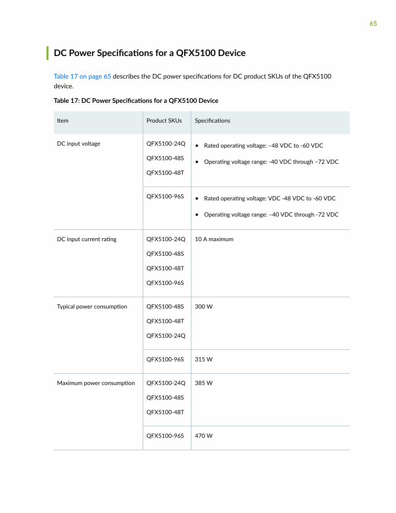
DC Power Specifications for a QFX5100 Device
Table 17 on page 65 describes the DC power specifications for DC product SKUs of the QFX5100device.
Table 17: DC Power Specifications for a QFX5100 Device
Item Product SKUs Specifications
DC input voltage QFX5100-24Q
QFX5100-48S
QFX5100-48T
• Rated operating voltage: –48 VDC to -60 VDC
• Operating voltage range: -40 VDC through –72 VDC
QFX5100-96S • Rated operating voltage: VDC -48 VDC to -60 VDC
• Operating voltage range: –40 VDC through -72 VDC
DC input current rating QFX5100-24Q
QFX5100-48S
QFX5100-48T
QFX5100-96S
10 A maximum
Typical power consumption QFX5100-48S
QFX5100-48T
QFX5100-24Q
300 W
QFX5100-96S 315 W
Maximum power consumption QFX5100-24Q
QFX5100-48S
QFX5100-48T
385 W
QFX5100-96S 470 W
65
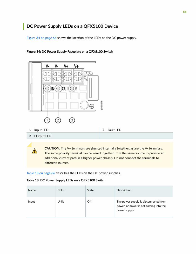
DC Power Supply LEDs on a QFX5100 Device
Figure 34 on page 66 shows the location of the LEDs on the DC power supply.
Figure 34: DC Power Supply Faceplate on a QFX5100 Switch
1— Input LED 3— Fault LED
2— Output LED
CAUTION: The V+ terminals are shunted internally together, as are the V- terminals.The same polarity terminal can be wired together from the same source to provide anadditional current path in a higher power chassis. Do not connect the terminals todifferent sources.
Table 18 on page 66 describes the LEDs on the DC power supplies.
Table 18: DC Power Supply LEDs on a QFX5100 Switch
Name Color State Description
Input Unlit Off The power supply is disconnected frompower, or power is not coming into thepower supply.
66
Table 18: DC Power Supply LEDs on a QFX5100 Switch (Continued)
Name Color State Description
Green On steadily Power is coming into the power supply.
Output Unlit Off The power supply is disconnected frompower, or the power supply is not sendingout power correctly.
Green On steadily The power supply is sending out powercorrectly.
Fault Amber On steadily An error has been detected in the powersupply. Replace the power supply as soonas possible. To maintain proper airflowthrough the chassis, leave the powersupply installed in the chassis until you areready to replace it.
RELATED DOCUMENTATION
Connect the QFX5100 to Power | 137
Prevention of Electrostatic Discharge Damage | 234
QFX5100 Cooling System
IN THIS SECTION
Cooling System and Airflow in a QFX5100 Device | 68
Fan Module LED on a QFX5100 Device | 76
Clearance Requirements for Airflow and Hardware Maintenance for a QFX5100 Device | 77
67

Cooling System and Airflow in a QFX5100 Device
IN THIS SECTION
Fan Modules | 68
Do Not Install Components with Different Airflow or Wattage in the Switch | 74
Fan Module Status | 75
The cooling system in an QFX5100 device consists of fan modules and a single fan in each powersupply. The number of fan modules vary depending whether the size of the switch is 1 U or 2 U high. Allswitches can be set up to work in one of two airflow directions:
• Airflow In–Air comes into the switch through the vents in the field-replaceable units (FRUs)
• Airflow Out–Air comes into the switch through the vents in the port panel.
CAUTION: Airflow In and Airflow Out fans and power supplies cannot be mixed in thesame chassis.
Fan Modules
The fan modules in QFX5100 devices are hot-insertable and hot-removable field-replaceable units(FRUs). These fan modules are designed for one of the two available airflow directions (Airflow In orAirflow Out). Some fan modules are also color-coded for the airflow direction as well. The fan modulesare installed in the fan module slots on the management panel of the switch next to the power supplies.
Both the 1 U and 2 U versions of QFX5100 fan modules have a similar design with different dimensions.The 1 U QFX5100 devices have 5 fan modules numbered 0 through 4 from left to right, where the 2 U,QFX5100-96S device, has 3 fan modules numbered 0 through 2. On all QFX5100 devices, each fanmodule slot has a fan icon next to it.
68
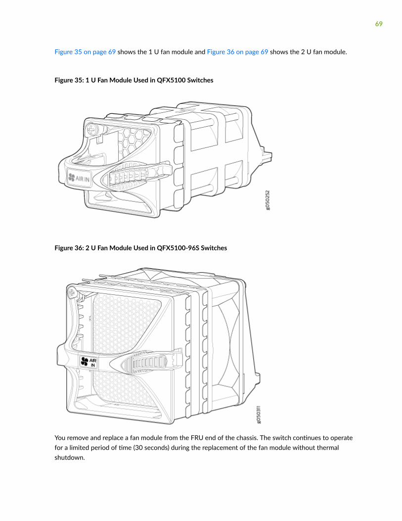
Figure 35 on page 69 shows the 1 U fan module and Figure 36 on page 69 shows the 2 U fan module.
Figure 35: 1 U Fan Module Used in QFX5100 Switches
Figure 36: 2 U Fan Module Used in QFX5100-96S Switches
You remove and replace a fan module from the FRU end of the chassis. The switch continues to operatefor a limited period of time (30 seconds) during the replacement of the fan module without thermalshutdown.
69
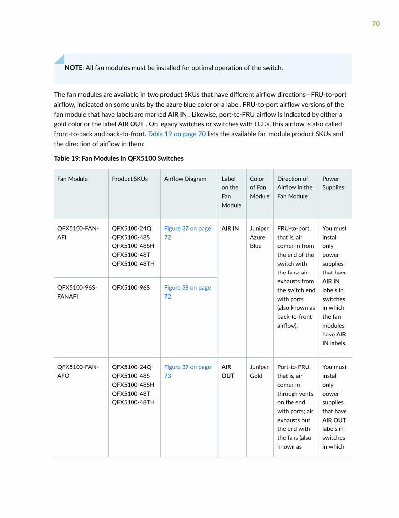
NOTE: All fan modules must be installed for optimal operation of the switch.
The fan modules are available in two product SKUs that have different airflow directions—FRU-to-portairflow, indicated on some units by the azure blue color or a label. FRU-to-port airflow versions of thefan module that have labels are marked AIR IN . Likewise, port-to-FRU airflow is indicated by either agold color or the label AIR OUT . On legacy switches or switches with LCDs, this airflow is also calledfront-to-back and back-to-front. Table 19 on page 70 lists the available fan module product SKUs andthe direction of airflow in them:
Table 19: Fan Modules in QFX5100 Switches
Fan Module Product SKUs Airflow Diagram Labelon theFanModule
Colorof FanModule
Direction ofAirflow in theFan Module
PowerSupplies
QFX5100-FAN-AFI
QFX5100-24QQFX5100-48SQFX5100-48SHQFX5100-48TQFX5100-48TH
Figure 37 on page72
AIR IN JuniperAzureBlue
FRU-to-port,that is, aircomes in fromthe end of theswitch withthe fans; airexhausts fromthe switch endwith ports(also known asback-to-frontairflow).
You mustinstallonlypowersuppliesthat haveAIR INlabels inswitchesin whichthe fanmoduleshave AIRIN labels.
QFX5100-96S-FANAFI
QFX5100-96S Figure 38 on page72
QFX5100-FAN-AFO
QFX5100-24QQFX5100-48SQFX5100-48SHQFX5100-48TQFX5100-48TH
Figure 39 on page73
AIROUT
JuniperGold
Port-to-FRU,that is, aircomes inthrough ventson the endwith ports; airexhausts outthe end withthe fans (alsoknown as
You mustinstallonlypowersuppliesthat haveAIR OUTlabels inswitchesin which
70
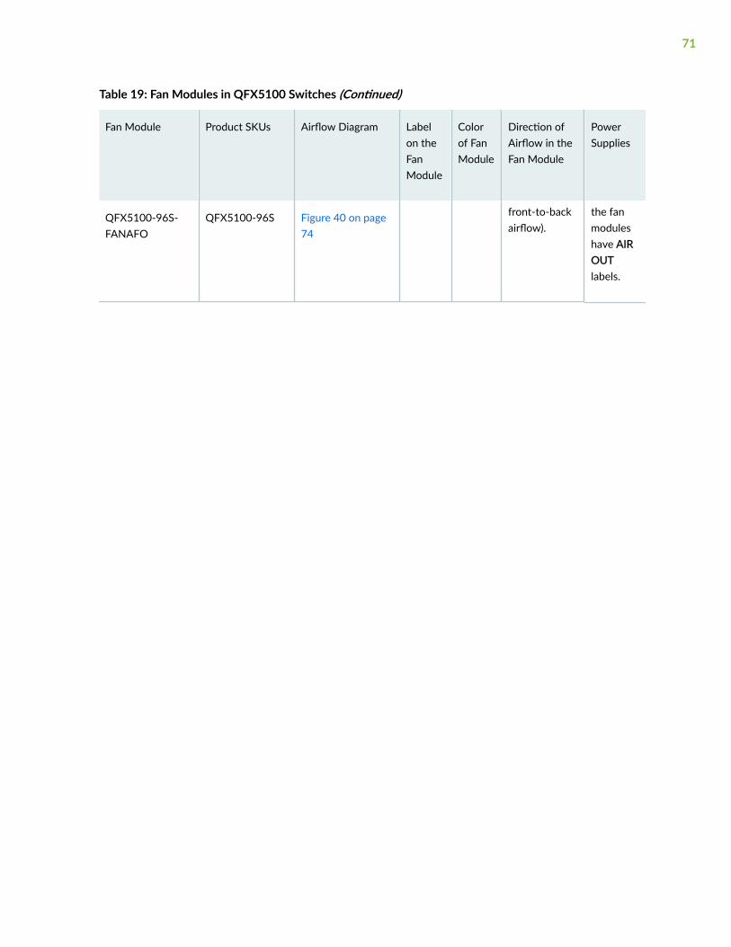
Table 19: Fan Modules in QFX5100 Switches (Continued)
Fan Module Product SKUs Airflow Diagram Labelon theFanModule
Colorof FanModule
Direction ofAirflow in theFan Module
PowerSupplies
QFX5100-96S-FANAFO
QFX5100-96S Figure 40 on page74
front-to-backairflow).
the fanmoduleshave AIROUTlabels.
71
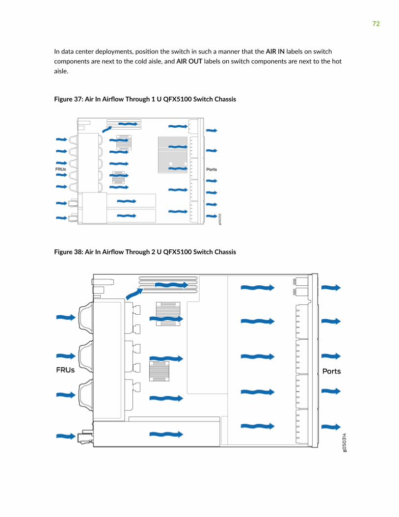
In data center deployments, position the switch in such a manner that the AIR IN labels on switchcomponents are next to the cold aisle, and AIR OUT labels on switch components are next to the hotaisle.
Figure 37: Air In Airflow Through 1 U QFX5100 Switch Chassis
Figure 38: Air In Airflow Through 2 U QFX5100 Switch Chassis
72
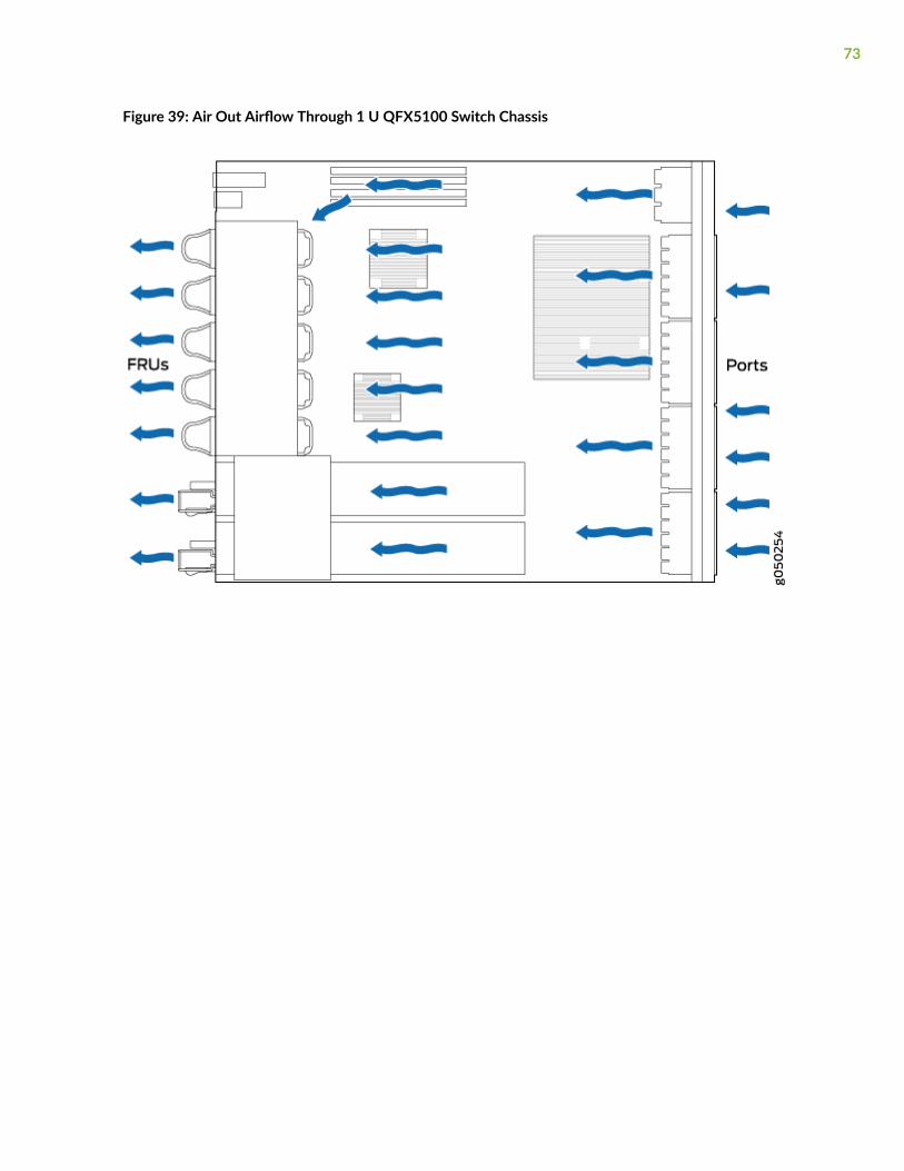
Figure 39: Air Out Airflow Through 1 U QFX5100 Switch Chassis
73
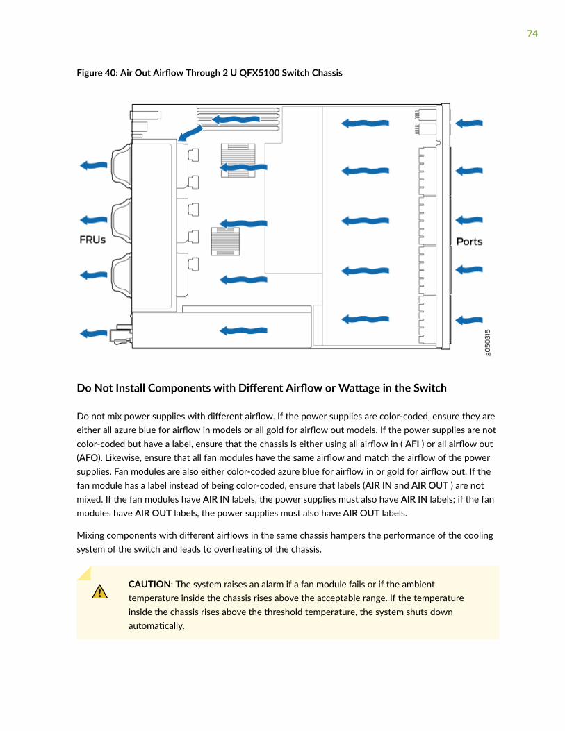
Figure 40: Air Out Airflow Through 2 U QFX5100 Switch Chassis
Do Not Install Components with Different Airflow or Wattage in the Switch
Do not mix power supplies with different airflow. If the power supplies are color-coded, ensure they areeither all azure blue for airflow in models or all gold for airflow out models. If the power supplies are notcolor-coded but have a label, ensure that the chassis is either using all airflow in ( AFI ) or all airflow out(AFO). Likewise, ensure that all fan modules have the same airflow and match the airflow of the powersupplies. Fan modules are also either color-coded azure blue for airflow in or gold for airflow out. If thefan module has a label instead of being color-coded, ensure that labels (AIR IN and AIR OUT ) are notmixed. If the fan modules have AIR IN labels, the power supplies must also have AIR IN labels; if the fanmodules have AIR OUT labels, the power supplies must also have AIR OUT labels.
Mixing components with different airflows in the same chassis hampers the performance of the coolingsystem of the switch and leads to overheating of the chassis.
CAUTION: The system raises an alarm if a fan module fails or if the ambienttemperature inside the chassis rises above the acceptable range. If the temperatureinside the chassis rises above the threshold temperature, the system shuts downautomatically.
74
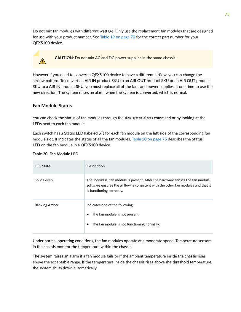
Do not mix fan modules with different wattage. Only use the replacement fan modules that are designedfor use with your product number. See Table 19 on page 70 for the correct part number for yourQFX5100 device.
CAUTION: Do not mix AC and DC power supplies in the same chassis.
However if you need to convert a QFX5100 device to have a different airflow, you can change theairflow pattern. To convert an AIR IN product SKU to an AIR OUT product SKU or an AIR OUT productSKU to a AIR IN product SKU, you must replace all of the fans and power supplies at one time to use thenew direction. The system raises an alarm when the system is converted, which is normal.
Fan Module Status
You can check the status of fan modules through the show system alarms command or by looking at theLEDs next to each fan module.
Each switch has a Status LED (labeled ST) for each fan module on the left side of the corresponding fanmodule slot. It indicates the status of all the fan modules. Table 20 on page 75 describes the StatusLED on the fan module in a QFX5100 device.
Table 20: Fan Module LED
LED State Description
Solid Green The individual fan module is present. After the hardware senses the fan module,software ensures the airflow is consistent with the other fan modules and that itis functioning correctly.
Blinking Amber Indicates one of the following:
• The fan module is not present.
• The fan module is not functioning normally.
Under normal operating conditions, the fan modules operate at a moderate speed. Temperature sensorsin the chassis monitor the temperature within the chassis.
The system raises an alarm if a fan module fails or if the ambient temperature inside the chassis risesabove the acceptable range. If the temperature inside the chassis rises above the threshold temperature,the system shuts down automatically.
75
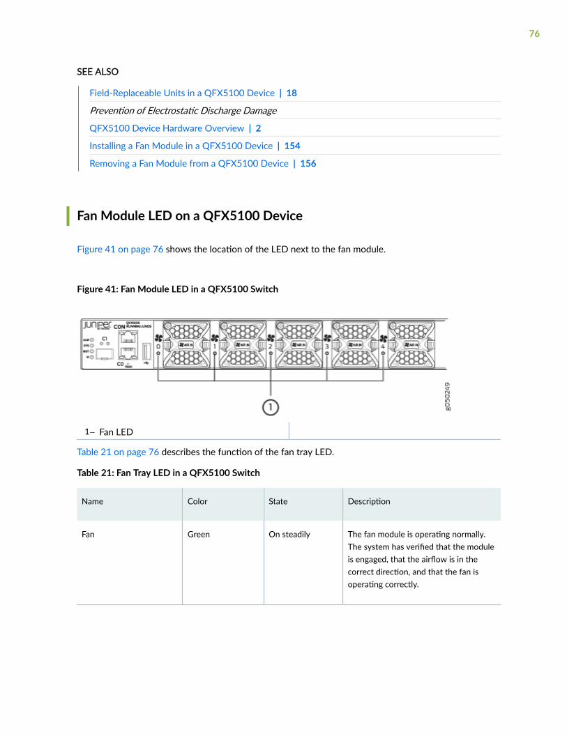
SEE ALSO
Field-Replaceable Units in a QFX5100 Device | 18
Prevention of Electrostatic Discharge Damage
QFX5100 Device Hardware Overview | 2
Installing a Fan Module in a QFX5100 Device | 154
Removing a Fan Module from a QFX5100 Device | 156
Fan Module LED on a QFX5100 Device
Figure 41 on page 76 shows the location of the LED next to the fan module.
Figure 41: Fan Module LED in a QFX5100 Switch
1— Fan LED
Table 21 on page 76 describes the function of the fan tray LED.
Table 21: Fan Tray LED in a QFX5100 Switch
Name Color State Description
Fan Green On steadily The fan module is operating normally.The system has verified that the moduleis engaged, that the airflow is in thecorrect direction, and that the fan isoperating correctly.
76

Table 21: Fan Tray LED in a QFX5100 Switch (Continued)
Name Color State Description
Amber Blinking An error has been detected in the fanmodule. Replace the fan module as soonas possible. Either the fan has failed or itis seated incorrectly. To maintain properairflow through the chassis, leave thefan module installed in the chassis untilyou are ready to replace it.
Clearance Requirements for Airflow and Hardware Maintenance for aQFX5100 Device
When planning the site for installing a QFX5100 device, you must allow sufficient clearance around theinstalled chassis (see Figure 42 on page 77).
Figure 42: Clearance Requirements for Airflow and Hardware Maintenance for a QFX5100 Device
77

• For the cooling system to function properly, the airflow around the chassis must be unrestricted. See"Cooling System and Airflow in a QFX5100 Device" on page 68 for more information about theairflow through the chassis.
• If you are mounting a QFX5100 device in a rack or cabinet with other equipment, ensure that theexhaust from other equipment does not blow into the intake vents of the chassis.
• Leave at least 24 in. (61 cm) both in front of and behind the QFX5100 device. For service personnelto remove and install hardware components, you must leave adequate space at the front and back ofthe switch. NEBS GR-63 recommends that you allow at least 30 in. (76.2 cm) in front of the rack orcabinet and 24 in. (61 cm) behind the rack or cabinet.
RELATED DOCUMENTATION
Install and Remove QFX5100 Fan Modules | 154
General Site Guidelines | 84
Rack-Mounting and Cabinet-Mounting Warnings | 217
78

2CHAPTER
Site Planning, Preparation, andSpecifications
Site Preparation Checklist for a QFX5100 Device | 80
QFX5100 Site Guidelines and Requirements | 82
Plan a Virtual Chassis Fabric Deployment | 90
QFX5100 Network Cable and Transceiver Planning | 94
QFX5100 Cable and Pinout Specifications | 104

Site Preparation Checklist for a QFX5100 Device
The checklist in Table 22 on page 80 summarizes the tasks you need to perform when preparing a sitefor QFX5100 deviceinstallation.
Table 22: Site Preparation Checklist
Item or Task For More Information Performed By Date
Architecture
Determine whether the QFX5100device will operate:
• standalone
• as a member in a Virtual Chassis
• as a spine or leaf in a VirtualChassis Fabric (VCF)
• as a node in a QFabric
• "Plan a Virtual Chassis FabricDeployment" on page 90
• Planning a QFX3000-G QFabricSystem Deployment
• Planning a QFX3000-M QFabricSystem Deployment
Environment
Verify that environmental factorssuch as temperature and humiditydo not exceed switch tolerances.
"Environmental Requirements andSpecifications for a QFX5100 Device"on page 82
Power
Measure the distance betweenexternal power sources and switchinstallation site.
Calculate the power consumptionand requirements.
"AC Power Specifications for aQFX5100 Device" on page 58
Rack or Cabinet
80
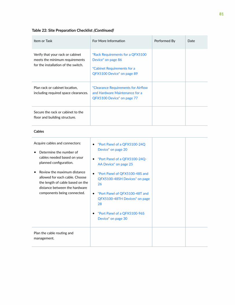
Table 22: Site Preparation Checklist (Continued)
Item or Task For More Information Performed By Date
Verify that your rack or cabinetmeets the minimum requirementsfor the installation of the switch.
"Rack Requirements for a QFX5100Device" on page 86
"Cabinet Requirements for aQFX5100 Device" on page 89
Plan rack or cabinet location,including required space clearances.
"Clearance Requirements for Airflowand Hardware Maintenance for aQFX5100 Device" on page 77
Secure the rack or cabinet to thefloor and building structure.
Cables
Acquire cables and connectors:
• Determine the number ofcables needed based on yourplanned configuration.
• Review the maximum distanceallowed for each cable. Choosethe length of cable based on thedistance between the hardwarecomponents being connected.
• "Port Panel of a QFX5100-24QDevice" on page 20
• "Port Panel of a QFX5100-24Q-AA Device" on page 25
• "Port Panel of QFX5100-48S andQFX5100-48SH Devices" on page26
• "Port Panel of QFX5100-48T andQFX5100-48TH Devices" on page28
• "Port Panel of a QFX5100-96SDevice" on page 30
Plan the cable routing andmanagement.
81

RELATED DOCUMENTATION
General Safety Guidelines and Warnings
QFX5100 Standalone Installation Overview | 111
QFX5100 Site Guidelines and Requirements
IN THIS SECTION
Environmental Requirements and Specifications for a QFX5100 Device | 82
General Site Guidelines | 84
Site Electrical Wiring Guidelines | 84
Grounding Cable and Lug Specifications for a QFX5100 Device | 85
Rack Requirements for a QFX5100 Device | 86
Cabinet Requirements for a QFX5100 Device | 89
Environmental Requirements and Specifications for a QFX5100 Device
The switch must be installed in a rack or cabinet. It must be housed in a dry, clean, well-ventilated, andtemperature-controlled environment.
Follow these environmental guidelines:
• The site must be as dust-free as possible, because dust can clog air intake vents and filters, reducingthe efficiency of the switch cooling system.
• Maintain ambient airflow for normal switch operation. If the airflow is blocked or restricted, or if theintake air is too warm, the switch might overheat, leading to the switch temperature monitor shuttingdown the device to protect the hardware components.
Table 23 on page 83 provides the required environmental conditions for normal switch operation.
82
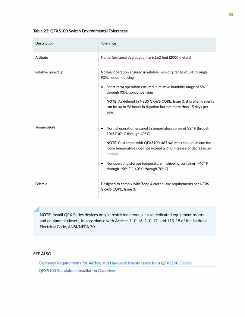
Table 23: QFX5100 Switch Environmental Tolerances
Description Tolerance
Altitude No performance degradation to 6,562 feet (2000 meters)
Relative humidity Normal operation ensured in relative humidity range of 5% through90%, noncondensing
• Short-term operation ensured in relative humidity range of 5%through 93%, noncondensing
NOTE: As defined in NEBS GR-63-CORE, Issue 3, short-term eventscan be up to 96 hours in duration but not more than 15 days peryear.
Temperature • Normal operation ensured in temperature range of 32° F through104° F (0° C through 40° C)
NOTE: Customers with QFX5100-48T switches should ensure theroom temperature does not exceed a 2° C increase or decrease perminute.
• Nonoperating storage temperature in shipping container: –40° Fthrough 158° F (–40° C through 70° C)
Seismic Designed to comply with Zone 4 earthquake requirements per NEBSGR-63-CORE, Issue 3.
NOTE: Install QFX Series devices only in restricted areas, such as dedicated equipment roomsand equipment closets, in accordance with Articles 110-16, 110-17, and 110-18 of the NationalElectrical Code, ANSI/NFPA 70.
SEE ALSO
Clearance Requirements for Airflow and Hardware Maintenance for a QFX5100 Device
QFX5100 Standalone Installation Overview
83

General Site Guidelines
Efficient device operation requires proper site planning and maintenance and proper layout of theequipment, rack or cabinet, and wiring closet.
To plan and create an acceptable operating environment for your device and prevent environmentallycaused equipment failures:
• Keep the area around the chassis free from dust and conductive material, such as metal flakes.
• Follow prescribed airflow guidelines to ensure that the cooling system functions properly and thatexhaust from other equipment does not blow into the intake vents of the device.
• Follow the prescribed electrostatic discharge (ESD) prevention procedures to prevent damaging theequipment. Static discharge can cause components to fail completely or intermittently over time.
• Install the device in a secure area, so that only authorized personnel can access the device.
Site Electrical Wiring Guidelines
Table 24 on page 85 describes the factors you must consider while planning the electrical wiring atyour site.
WARNING: You must provide a properly grounded and shielded environment and useelectrical surge-suppression devices.
Avertissement Vous devez établir un environnement protégé et convenablement mis àla terre et utiliser des dispositifs de parasurtension.
84

Table 24: Site Electrical Wiring Guidelines
Site WiringFactor
Guidelines
Signalinglimitations
If your site experiences any of the following problems, consult experts in electrical surgesuppression and shielding:
• Improperly installed wires cause radio frequency interference (RFI).
• Damage from lightning strikes occurs when wires exceed recommended distances or passbetween buildings.
• Electromagnetic pulses (EMPs) caused by lightning damage unshielded conductors andelectronic devices.
Radiofrequencyinterference
To reduce or eliminate RFI from your site wiring, do the following:
• Use a twisted-pair cable with a good distribution of grounding conductors.
• If you must exceed the recommended distances, use a high-quality twisted-pair cable withone ground conductor for each data signal, when applicable.
Electromagneticcompatibility
If your site is susceptible to problems with electromagnetic compatibility (EMC), particularlyfrom lightning or radio transmitters, seek expert advice.
Some of the problems caused by strong sources of electromagnetic interference (EMI) are:
• Destruction of the signal drivers and receivers in the device
• Electrical hazards as a result of power surges conducted over the lines into the equipment
Grounding Cable and Lug Specifications for a QFX5100 Device
For installations that require a separate grounding conductor to the chassis, the switch must beadequately grounded before power is connected to ensure proper operation and to meet safety andelectromagnetic interference (EMI) requirements. To ground a QFX5100 device, connect a groundingcable to earth ground and then attach it to the chassis grounding points.
85

WARNING: The switch is pluggable type A equipment installed in a restricted-accesslocation. It has a separate protective earthing terminal provided on the chassis inaddition to the grounding pin of the power supply cord. This separate protectiveearthing terminal must be permanently connected to earth ground for installations thatrequire a separate grounding conductor to the chassis.
WARNING: To comply with GR-1089 requirements, all intra-building copper cablingused for SFP+ and QSFP+ ports must be shielded and grounded at both ends.
CAUTION: Before switch installation begins, a licensed electrician must attach a cablelug to the grounding cables that you supply. See "Connecting Earth Ground to aQFX5100 Device" on page 137. A cable with an incorrectly attached lug can damagethe switch.
Before connecting the switch to earth ground, review the following information:
• A protective earthing terminal bracket is provided in the accessory kit for connecting the switch toearth ground. This L-shaped bracket attaches to the side of the QFX5100 chassis through themounting bracket, providing a protective earthing terminal for the switch.
• The grounding lug required is a Panduit LCD10-10A-L or equivalent (not provided).. The groundinglug should accommodates 14–10 AWG (2–5.3 mm²) stranded wire.
• The grounding cable that you provide for a QFX5100 device must be 14 AWG (2 mm²), minimum 60°C wire, or as permitted by the local code.
• Ensure you have two SAE 10-32 washers and screws to attach the cable and bracket (not provided).
SEE ALSO
QFX5100 Power System | 54
Connect the QFX5100 to Power | 137
Rack Requirements for a QFX5100 Device
All QFX5100 devices are designed to be installed on four-post racks. The QFX5100-96S device can alsobe installed on two-post racks.
86
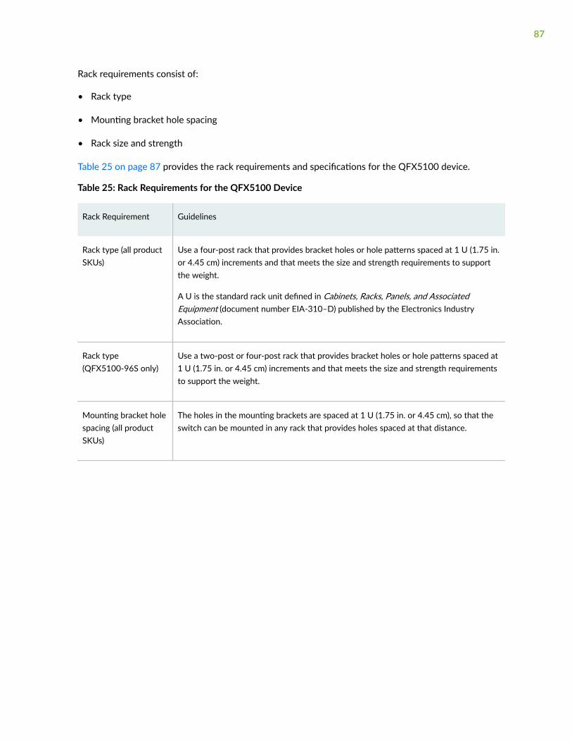
Rack requirements consist of:
• Rack type
• Mounting bracket hole spacing
• Rack size and strength
Table 25 on page 87 provides the rack requirements and specifications for the QFX5100 device.
Table 25: Rack Requirements for the QFX5100 Device
Rack Requirement Guidelines
Rack type (all productSKUs)
Use a four-post rack that provides bracket holes or hole patterns spaced at 1 U (1.75 in.or 4.45 cm) increments and that meets the size and strength requirements to supportthe weight.
A U is the standard rack unit defined in Cabinets, Racks, Panels, and AssociatedEquipment (document number EIA-310–D) published by the Electronics IndustryAssociation.
Rack type(QFX5100-96S only)
Use a two-post or four-post rack that provides bracket holes or hole patterns spaced at1 U (1.75 in. or 4.45 cm) increments and that meets the size and strength requirementsto support the weight.
Mounting bracket holespacing (all productSKUs)
The holes in the mounting brackets are spaced at 1 U (1.75 in. or 4.45 cm), so that theswitch can be mounted in any rack that provides holes spaced at that distance.
87
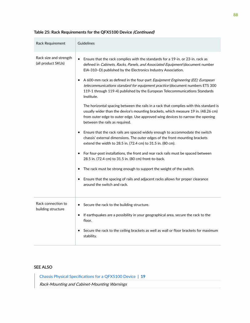
Table 25: Rack Requirements for the QFX5100 Device (Continued)
Rack Requirement Guidelines
Rack size and strength(all product SKUs)
• Ensure that the rack complies with the standards for a 19-in. or 23-in. rack asdefined in Cabinets, Racks, Panels, and Associated Equipment (document numberEIA-310–D) published by the Electronics Industry Association.
• A 600-mm rack as defined in the four-part Equipment Engineering (EE); Europeantelecommunications standard for equipment practice (document numbers ETS 300119-1 through 119-4) published by the European Telecommunications StandardsInstitute.
The horizontal spacing between the rails in a rack that complies with this standard isusually wider than the device's mounting brackets, which measure 19 in. (48.26 cm)from outer edge to outer edge. Use approved wing devices to narrow the openingbetween the rails as required.
• Ensure that the rack rails are spaced widely enough to accommodate the switchchassis’ external dimensions. The outer edges of the front-mounting bracketsextend the width to 28.5 in. (72.4 cm) to 31.5 in. (80 cm).
• For four-post installations, the front and rear rack rails must be spaced between28.5 in. (72.4 cm) to 31.5 in. (80 cm) front-to-back.
• The rack must be strong enough to support the weight of the switch.
• Ensure that the spacing of rails and adjacent racks allows for proper clearancearound the switch and rack.
Rack connection tobuilding structure
• Secure the rack to the building structure.
• If earthquakes are a possibility in your geographical area, secure the rack to thefloor.
• Secure the rack to the ceiling brackets as well as wall or floor brackets for maximumstability.
SEE ALSO
Chassis Physical Specifications for a QFX5100 Device | 19
Rack-Mounting and Cabinet-Mounting Warnings
88

Clearance Requirements for Airflow and Hardware Maintenance for a QFX5100 Device | 77
Mount a QFX5100 Device in a Rack or Cabinet | 116
Cabinet Requirements for a QFX5100 Device
You can mount the QFX5100 device in an enclosure or cabinet that contains a four-post 19-in. openrack as defined in Cabinets, Racks, Panels, and Associated Equipment (document number EIA-310-D)published by the Electronics Industry Association.
Cabinet requirements consist of:
• Cabinet size and clearance
• Cabinet airflow requirements
Table 26 on page 89 provides the cabinet requirements and specifications for the QFX5100 device.
Table 26: Cabinet Requirements for the QFX5100 Device
Cabinet Requirement Guidelines
Cabinet size and clearance The minimum cabinet size for accommodating a QFX5100 device is 36 in.(91.4 cm) deep. Large cabinets improve airflow and reduce the chance ofoverheating.
89
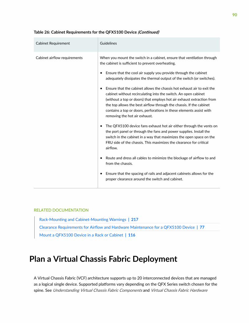
Table 26: Cabinet Requirements for the QFX5100 Device (Continued)
Cabinet Requirement Guidelines
Cabinet airflow requirements When you mount the switch in a cabinet, ensure that ventilation throughthe cabinet is sufficient to prevent overheating.
• Ensure that the cool air supply you provide through the cabinetadequately dissipates the thermal output of the switch (or switches).
• Ensure that the cabinet allows the chassis hot exhaust air to exit thecabinet without recirculating into the switch. An open cabinet(without a top or doors) that employs hot air exhaust extraction fromthe top allows the best airflow through the chassis. If the cabinetcontains a top or doors, perforations in these elements assist withremoving the hot air exhaust.
• The QFX5100 device fans exhaust hot air either through the vents onthe port panel or through the fans and power supplies. Install theswitch in the cabinet in a way that maximizes the open space on theFRU side of the chassis. This maximizes the clearance for criticalairflow.
• Route and dress all cables to minimize the blockage of airflow to andfrom the chassis.
• Ensure that the spacing of rails and adjacent cabinets allows for theproper clearance around the switch and cabinet.
RELATED DOCUMENTATION
Rack-Mounting and Cabinet-Mounting Warnings | 217
Clearance Requirements for Airflow and Hardware Maintenance for a QFX5100 Device | 77
Mount a QFX5100 Device in a Rack or Cabinet | 116
Plan a Virtual Chassis Fabric Deployment
A Virtual Chassis Fabric (VCF) architecture supports up to 20 interconnected devices that are managedas a logical single device. Supported platforms vary depending on the QFX Series switch chosen for thespine. See Understanding Virtual Chassis Fabric Components and Virtual Chassis Fabric Hardware
90
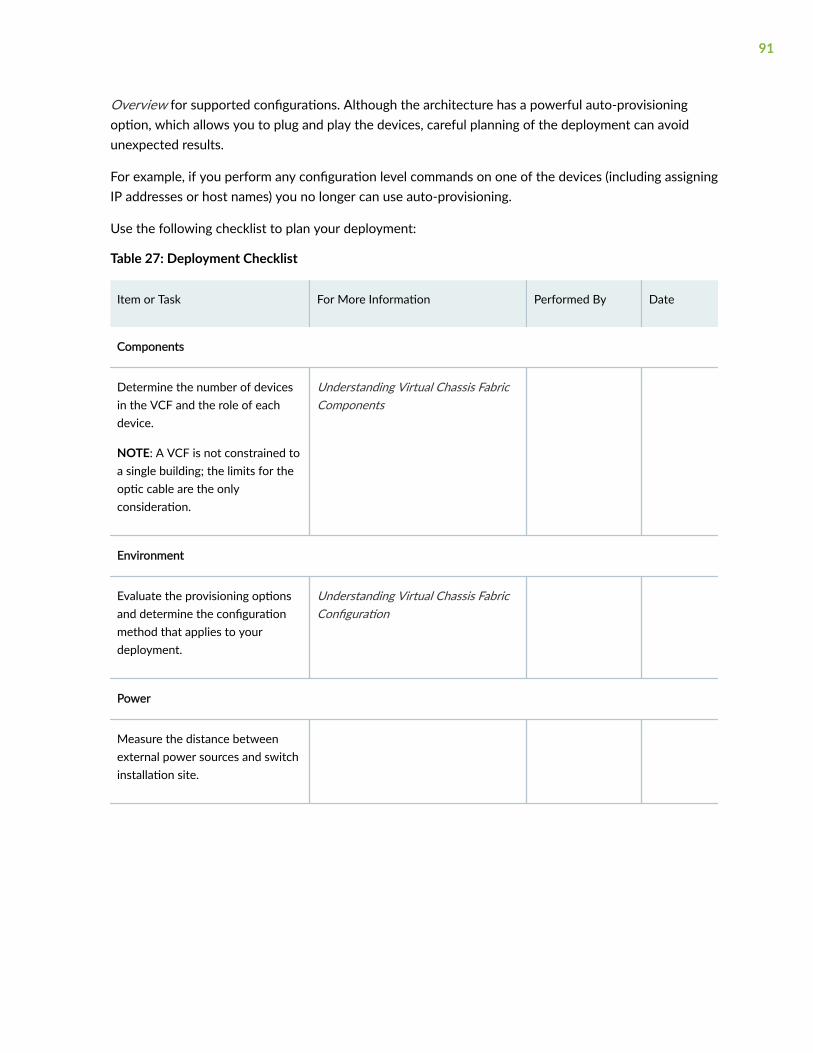
Overview for supported configurations. Although the architecture has a powerful auto-provisioningoption, which allows you to plug and play the devices, careful planning of the deployment can avoidunexpected results.
For example, if you perform any configuration level commands on one of the devices (including assigningIP addresses or host names) you no longer can use auto-provisioning.
Use the following checklist to plan your deployment:
Table 27: Deployment Checklist
Item or Task For More Information Performed By Date
Components
Determine the number of devicesin the VCF and the role of eachdevice.
NOTE: A VCF is not constrained toa single building; the limits for theoptic cable are the onlyconsideration.
Understanding Virtual Chassis FabricComponents
Environment
Evaluate the provisioning optionsand determine the configurationmethod that applies to yourdeployment.
Understanding Virtual Chassis FabricConfiguration
Power
Measure the distance betweenexternal power sources and switchinstallation site.
91
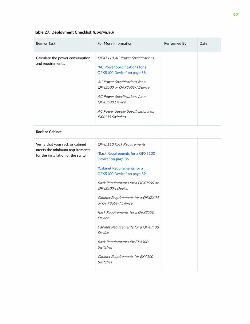
Table 27: Deployment Checklist (Continued)
Item or Task For More Information Performed By Date
Calculate the power consumptionand requirements.
QFX5110 AC Power Specifications
"AC Power Specifications for aQFX5100 Device" on page 58
AC Power Specifications for aQFX3600 or QFX3600-I Device
AC Power Specifications for aQFX3500 Device
AC Power Supply Specifications forEX4300 Switches
Rack or Cabinet
Verify that your rack or cabinetmeets the minimum requirementsfor the installation of the switch.
QFX5110 Rack Requirements
"Rack Requirements for a QFX5100Device" on page 86
"Cabinet Requirements for aQFX5100 Device" on page 89
Rack Requirements for a QFX3600 orQFX3600-I Device
Cabinet Requirements for a QFX3600or QFX3600-I Device
Rack Requirements for a QFX3500Device
Cabinet Requirements for a QFX3500Device
Rack Requirements for EX4300Switches
Cabinet Requirements for EX4300Switches
92
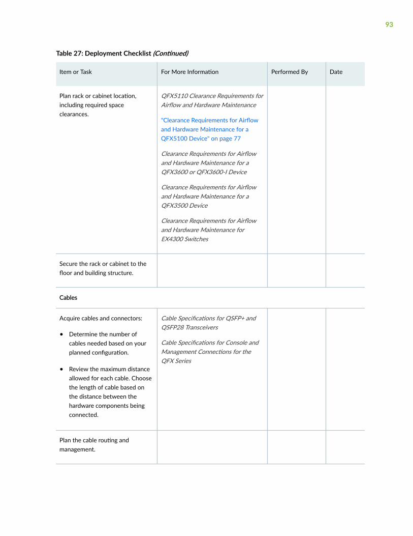
Table 27: Deployment Checklist (Continued)
Item or Task For More Information Performed By Date
Plan rack or cabinet location,including required spaceclearances.
QFX5110 Clearance Requirements forAirflow and Hardware Maintenance
"Clearance Requirements for Airflowand Hardware Maintenance for aQFX5100 Device" on page 77
Clearance Requirements for Airflowand Hardware Maintenance for aQFX3600 or QFX3600-I Device
Clearance Requirements for Airflowand Hardware Maintenance for aQFX3500 Device
Clearance Requirements for Airflowand Hardware Maintenance forEX4300 Switches
Secure the rack or cabinet to thefloor and building structure.
Cables
Acquire cables and connectors:
• Determine the number ofcables needed based on yourplanned configuration.
• Review the maximum distanceallowed for each cable. Choosethe length of cable based onthe distance between thehardware components beingconnected.
Cable Specifications for QSFP+ andQSFP28 Transceivers
Cable Specifications for Console andManagement Connections for theQFX Series
Plan the cable routing andmanagement.
93
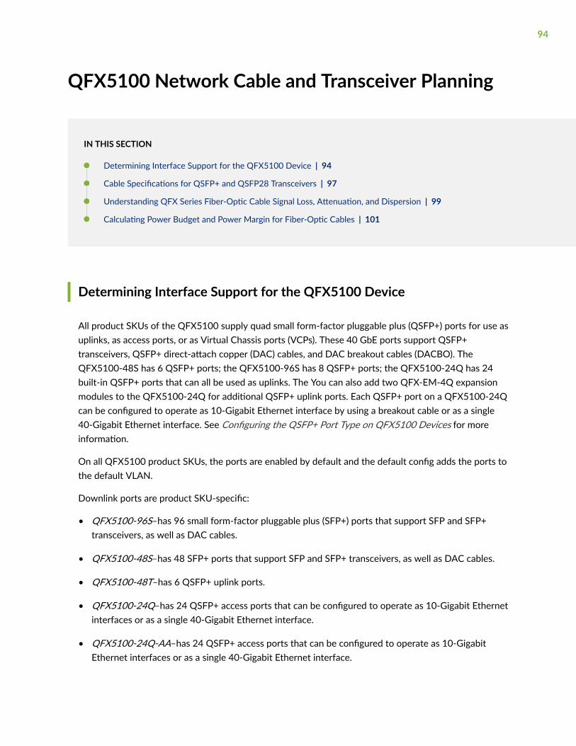
QFX5100 Network Cable and Transceiver Planning
IN THIS SECTION
Determining Interface Support for the QFX5100 Device | 94
Cable Specifications for QSFP+ and QSFP28 Transceivers | 97
Understanding QFX Series Fiber-Optic Cable Signal Loss, Attenuation, and Dispersion | 99
Calculating Power Budget and Power Margin for Fiber-Optic Cables | 101
Determining Interface Support for the QFX5100 Device
All product SKUs of the QFX5100 supply quad small form-factor pluggable plus (QSFP+) ports for use asuplinks, as access ports, or as Virtual Chassis ports (VCPs). These 40 GbE ports support QSFP+transceivers, QSFP+ direct-attach copper (DAC) cables, and DAC breakout cables (DACBO). TheQFX5100-48S has 6 QSFP+ ports; the QFX5100-96S has 8 QSFP+ ports; the QFX5100-24Q has 24built-in QSFP+ ports that can all be used as uplinks. The You can also add two QFX-EM-4Q expansionmodules to the QFX5100-24Q for additional QSFP+ uplink ports. Each QSFP+ port on a QFX5100-24Qcan be configured to operate as 10-Gigabit Ethernet interface by using a breakout cable or as a single40-Gigabit Ethernet interface. See Configuring the QSFP+ Port Type on QFX5100 Devices for moreinformation.
On all QFX5100 product SKUs, the ports are enabled by default and the default config adds the ports tothe default VLAN.
Downlink ports are product SKU-specific:
• QFX5100-96S–has 96 small form-factor pluggable plus (SFP+) ports that support SFP and SFP+transceivers, as well as DAC cables.
• QFX5100-48S–has 48 SFP+ ports that support SFP and SFP+ transceivers, as well as DAC cables.
• QFX5100-48T–has 6 QSFP+ uplink ports.
• QFX5100-24Q–has 24 QSFP+ access ports that can be configured to operate as 10-Gigabit Ethernetinterfaces or as a single 40-Gigabit Ethernet interface.
• QFX5100-24Q-AA–has 24 QSFP+ access ports that can be configured to operate as 10-GigabitEthernet interfaces or as a single 40-Gigabit Ethernet interface.
94
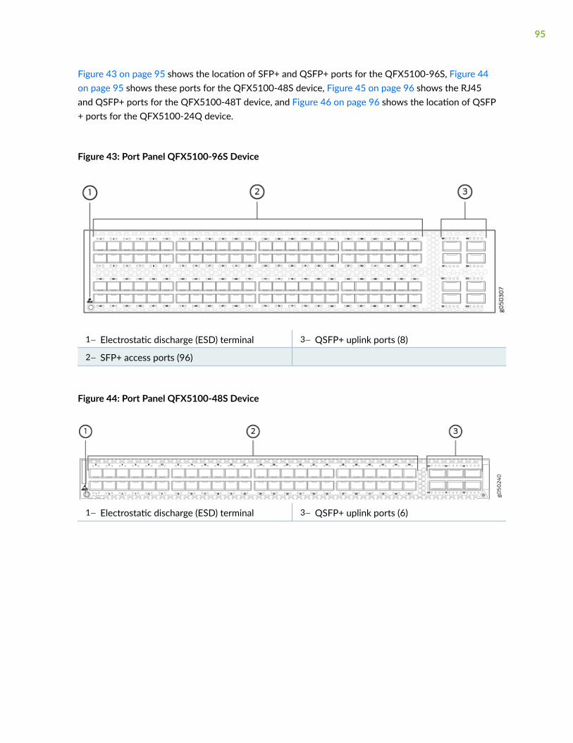
Figure 43 on page 95 shows the location of SFP+ and QSFP+ ports for the QFX5100-96S, Figure 44on page 95 shows these ports for the QFX5100-48S device, Figure 45 on page 96 shows the RJ45and QSFP+ ports for the QFX5100-48T device, and Figure 46 on page 96 shows the location of QSFP+ ports for the QFX5100-24Q device.
Figure 43: Port Panel QFX5100-96S Device
1— Electrostatic discharge (ESD) terminal 3— QSFP+ uplink ports (8)
2— SFP+ access ports (96)
Figure 44: Port Panel QFX5100-48S Device
1— Electrostatic discharge (ESD) terminal 3— QSFP+ uplink ports (6)
95
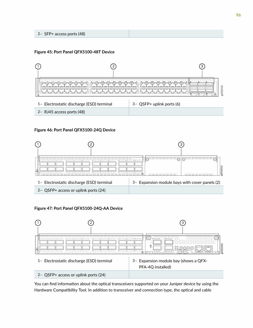
2— SFP+ access ports (48)
Figure 45: Port Panel QFX5100-48T Device
1— Electrostatic discharge (ESD) terminal 3— QSFP+ uplink ports (6)
2— RJ45 access ports (48)
Figure 46: Port Panel QFX5100-24Q Device
1— Electrostatic discharge (ESD) terminal 3— Expansion module bays with cover panels (2)
2— QSFP+ access or uplink ports (24)
Figure 47: Port Panel QFX5100-24Q-AA Device
1— Electrostatic discharge (ESD) terminal 3— Expansion module bay (shows a QFX-PFA-4Q installed)
2— QSFP+ access or uplink ports (24)
You can find information about the optical transceivers supported on your Juniper device by using theHardware Compatibility Tool. In addition to transceiver and connection type, the optical and cable
96
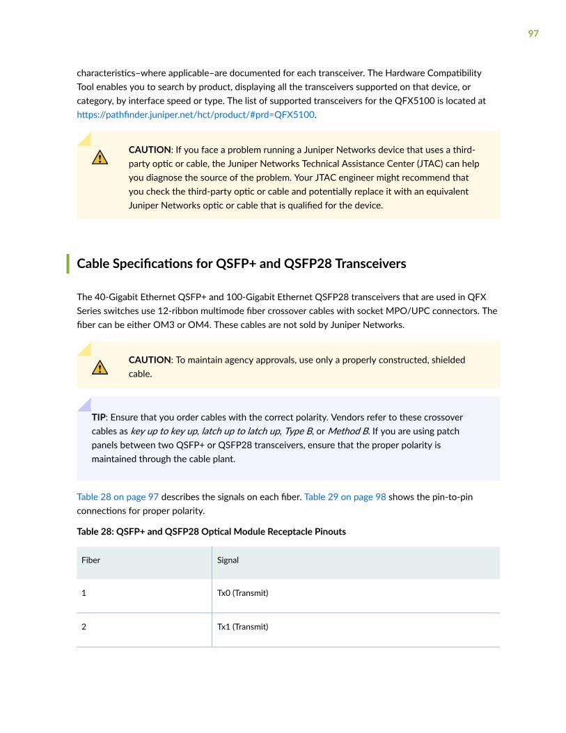
characteristics–where applicable–are documented for each transceiver. The Hardware CompatibilityTool enables you to search by product, displaying all the transceivers supported on that device, orcategory, by interface speed or type. The list of supported transceivers for the QFX5100 is located athttps://pathfinder.juniper.net/hct/product/#prd=QFX5100.
CAUTION: If you face a problem running a Juniper Networks device that uses a third-party optic or cable, the Juniper Networks Technical Assistance Center (JTAC) can helpyou diagnose the source of the problem. Your JTAC engineer might recommend thatyou check the third-party optic or cable and potentially replace it with an equivalentJuniper Networks optic or cable that is qualified for the device.
Cable Specifications for QSFP+ and QSFP28 Transceivers
The 40-Gigabit Ethernet QSFP+ and 100-Gigabit Ethernet QSFP28 transceivers that are used in QFXSeries switches use 12-ribbon multimode fiber crossover cables with socket MPO/UPC connectors. Thefiber can be either OM3 or OM4. These cables are not sold by Juniper Networks.
CAUTION: To maintain agency approvals, use only a properly constructed, shieldedcable.
TIP: Ensure that you order cables with the correct polarity. Vendors refer to these crossovercables as key up to key up, latch up to latch up, Type B, or Method B. If you are using patchpanels between two QSFP+ or QSFP28 transceivers, ensure that the proper polarity ismaintained through the cable plant.
Table 28 on page 97 describes the signals on each fiber. Table 29 on page 98 shows the pin-to-pinconnections for proper polarity.
Table 28: QSFP+ and QSFP28 Optical Module Receptacle Pinouts
Fiber Signal
1 Tx0 (Transmit)
2 Tx1 (Transmit)
97
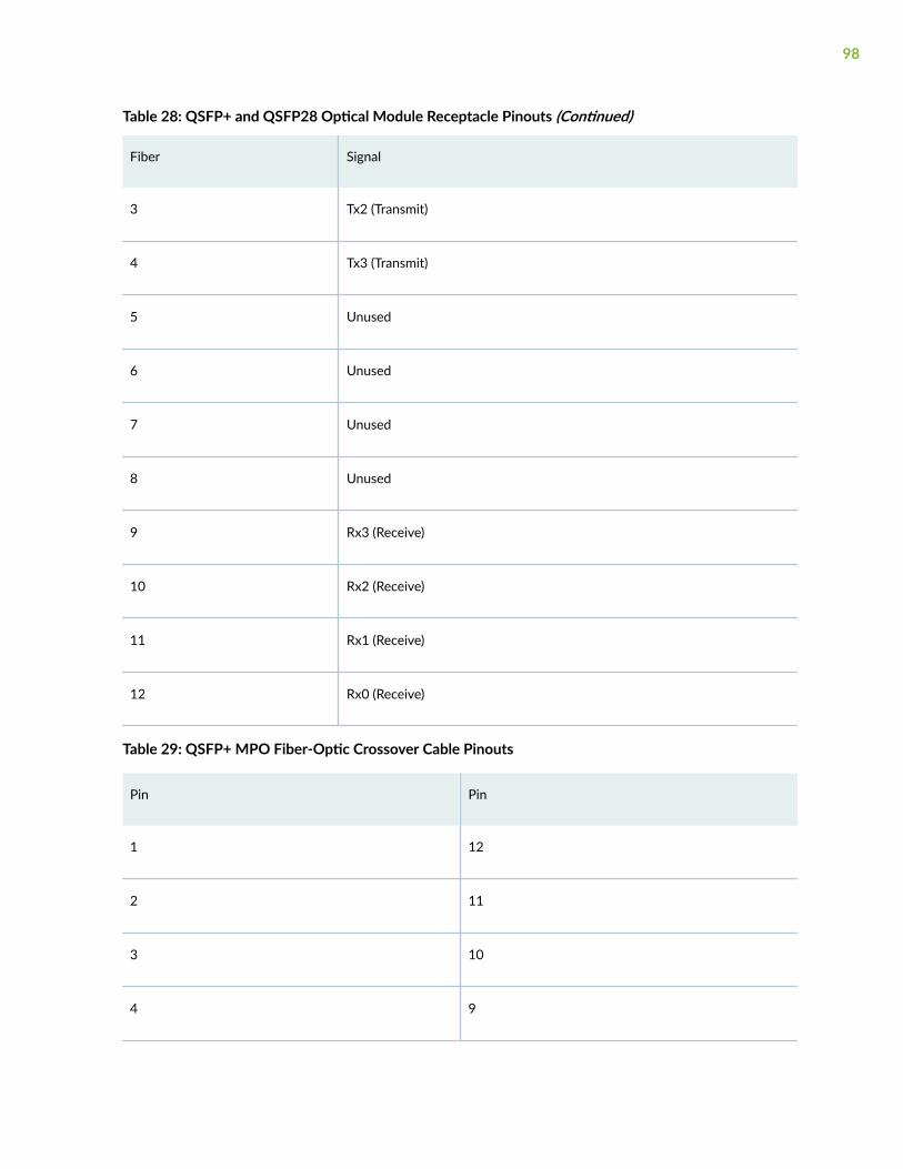
Table 28: QSFP+ and QSFP28 Optical Module Receptacle Pinouts (Continued)
Fiber Signal
3 Tx2 (Transmit)
4 Tx3 (Transmit)
5 Unused
6 Unused
7 Unused
8 Unused
9 Rx3 (Receive)
10 Rx2 (Receive)
11 Rx1 (Receive)
12 Rx0 (Receive)
Table 29: QSFP+ MPO Fiber-Optic Crossover Cable Pinouts
Pin Pin
1 12
2 11
3 10
4 9
98
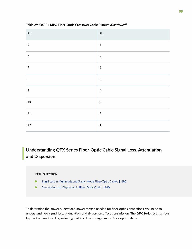
Table 29: QSFP+ MPO Fiber-Optic Crossover Cable Pinouts (Continued)
Pin Pin
5 8
6 7
7 6
8 5
9 4
10 3
11 2
12 1
Understanding QFX Series Fiber-Optic Cable Signal Loss, Attenuation,and Dispersion
IN THIS SECTION
Signal Loss in Multimode and Single-Mode Fiber-Optic Cables | 100
Attenuation and Dispersion in Fiber-Optic Cable | 100
To determine the power budget and power margin needed for fiber-optic connections, you need tounderstand how signal loss, attenuation, and dispersion affect transmission. The QFX Series uses varioustypes of network cables, including multimode and single-mode fiber-optic cables.
99
Signal Loss in Multimode and Single-Mode Fiber-Optic Cables
Multimode fiber is large enough in diameter to allow rays of light to reflect internally (bounce off thewalls of the fiber). Interfaces with multimode optics typically use LEDs as light sources. However, LEDsare not coherent light sources. They spray varying wavelengths of light into the multimode fiber, whichreflect the light at different angles. Light rays travel in jagged lines through a multimode fiber, causingsignal dispersion. When light traveling in the fiber core radiates into the fiber cladding (layers of lowerrefractive index material in close contact with a core material of higher refractive index), higher-ordermode loss occurs. Together, these factors reduce the transmission distance of multimode fiber comparedto that of single-mode fiber.
Single-mode fiber is so small in diameter that rays of light reflect internally through one layer only.Interfaces with single-mode optics use lasers as light sources. Lasers generate a single wavelength oflight, which travels in a straight line through the single-mode fiber. Compared to multimode fiber, single-mode fiber has a higher bandwidth and can carry signals for longer distances. It is consequently moreexpensive.
For information about the maximum transmission distance and supported wavelength range for thetypes of single-mode and multimode fiber-optic cables that are connected to the QFX Series, see theHardware Compatibility Tool. Exceeding the maximum transmission distances can result in significantsignal loss, which causes unreliable transmission.
Attenuation and Dispersion in Fiber-Optic Cable
An optical data link functions correctly provided that modulated light reaching the receiver has enoughpower to be demodulated correctly. Attenuation is the reduction in strength of the light signal duringtransmission. Passive media components such as cables, cable splices, and connectors causeattenuation. Although attenuation is significantly lower for optical fiber than for other media, it stilloccurs in both multimode and single-mode transmission. An efficient optical data link must transmitenough light to overcome attenuation.
Dispersion is the spreading of the signal over time. The following two types of dispersion can affectsignal transmission through an optical data link:
• Chromatic dispersion, which is the spreading of the signal over time caused by the different speedsof light rays.
• Modal dispersion, which is the spreading of the signal over time caused by the different propagationmodes in the fiber.
For multimode transmission, modal dispersion, rather than chromatic dispersion or attenuation, usuallylimits the maximum bit rate and link length. For single-mode transmission, modal dispersion is not afactor. However, at higher bit rates and over longer distances, chromatic dispersion limits the maximumlink length.
100

An efficient optical data link must have enough light to exceed the minimum power that the receiverrequires to operate within its specifications. In addition, the total dispersion must be within the limitsspecified for the type of link in the Telcordia Technologies document GR-253-CORE (Section 4.3) andInternational Telecommunications Union (ITU) document G.957.
When chromatic dispersion is at the maximum allowed, its effect can be considered as a power penaltyin the power budget. The optical power budget must allow for the sum of component attenuation,power penalties (including those from dispersion), and a safety margin for unexpected losses.
Calculating Power Budget and Power Margin for Fiber-Optic Cables
IN THIS SECTION
How to Calculate Power Budget for Fiber-Optic Cables | 101
How to Calculate Power Margin for Fiber-Optic Cables | 102
Use the information in this topic and the specifications for your optical interface to calculate the powerbudget and power margin for fiber-optic cables.
TIP: You can use the Hardware Compatibility Tool to find information about the pluggabletransceivers supported on your Juniper Networks device.
To calculate the power budget and power margin, perform the following tasks:
How to Calculate Power Budget for Fiber-Optic Cables
To ensure that fiber-optic connections have sufficient power for correct operation, you need to calculatethe link's power budget, which is the maximum amount of power it can transmit. When you calculatethe power budget, you use a worst-case analysis to provide a margin of error, even though all the partsof an actual system do not operate at the worst-case levels. To calculate the worst-case estimate ofpower budget (PB), you assume minimum transmitter power (PT) and minimum receiver sensitivity (PR):
PB = PT – PR
The following hypothetical power budget equation uses values measured in decibels (dB) and decibelsreferred to one milliwatt (dBm):
101
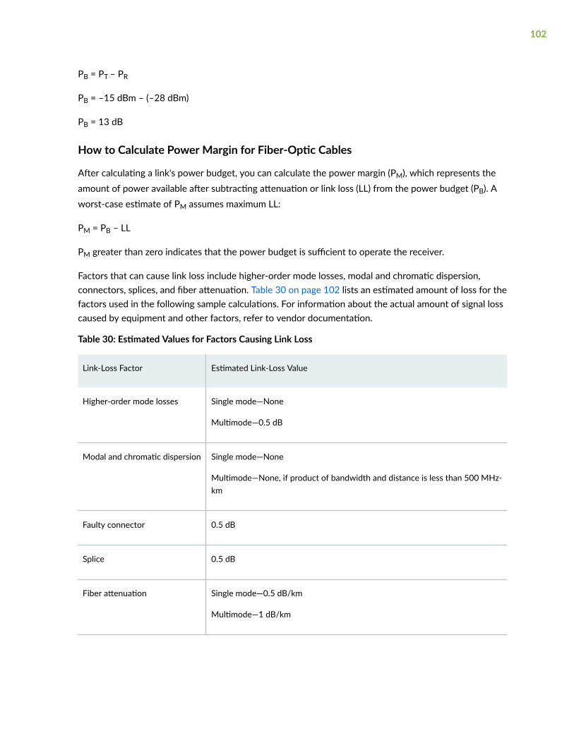
PB = PT – PR
PB = –15 dBm – (–28 dBm)
PB = 13 dB
How to Calculate Power Margin for Fiber-Optic Cables
After calculating a link's power budget, you can calculate the power margin (PM), which represents theamount of power available after subtracting attenuation or link loss (LL) from the power budget (PB). Aworst-case estimate of PM assumes maximum LL:
PM = PB – LL
PM greater than zero indicates that the power budget is sufficient to operate the receiver.
Factors that can cause link loss include higher-order mode losses, modal and chromatic dispersion,connectors, splices, and fiber attenuation. Table 30 on page 102 lists an estimated amount of loss for thefactors used in the following sample calculations. For information about the actual amount of signal losscaused by equipment and other factors, refer to vendor documentation.
Table 30: Estimated Values for Factors Causing Link Loss
Link-Loss Factor Estimated Link-Loss Value
Higher-order mode losses Single mode—None
Multimode—0.5 dB
Modal and chromatic dispersion Single mode—None
Multimode—None, if product of bandwidth and distance is less than 500 MHz-km
Faulty connector 0.5 dB
Splice 0.5 dB
Fiber attenuation Single mode—0.5 dB/km
Multimode—1 dB/km
102

The following sample calculation for a 2-km-long multimode link with a power budget (PB) of 13 dB usesthe estimated values from Table 30 on page 102. This example calculates link loss (LL) as the sum offiber attenuation (2 km @ 1 dB/km, or 2 dB) and loss for five connectors (0.5 dB per connector, or2.5 dB) and two splices (0.5 dB per splice, or 1 dB) as well as higher-order mode losses (0.5 dB). Thepower margin (PM) is calculated as follows:
PM = PB – LL
PM = 13 dB – 2 km (1 dB/km) – 5 (0.5 dB) – 2 (0.5 dB) – 0.5 dB
PM = 13 dB – 2 dB – 2.5 dB – 1 dB – 0.5 dB
PM = 7 dB
The following sample calculation for an 8-km-long single-mode link with a power budget (PB) of 13 dBuses the estimated values from Table 30 on page 102. This example calculates link loss (LL) as the sumof fiber attenuation (8 km @ 0.5 dB/km, or 4 dB) and loss for seven connectors (0.5 dB per connector, or3.5 dB). The power margin (PM) is calculated as follows:
PM = PB – LL
PM = 13 dB – 8 km (0.5 dB/km) – 7(0.5 dB)
PM = 13 dB – 4 dB – 3.5 dB
PM = 5.5 dB
In both examples, the calculated power margin is greater than zero, indicating that the link has sufficientpower for transmission and does not exceed the maximum receiver input power.
RELATED DOCUMENTATION
QFX5100 Chassis Description and Port Panels | 19
QFX5100 Power System | 54
103
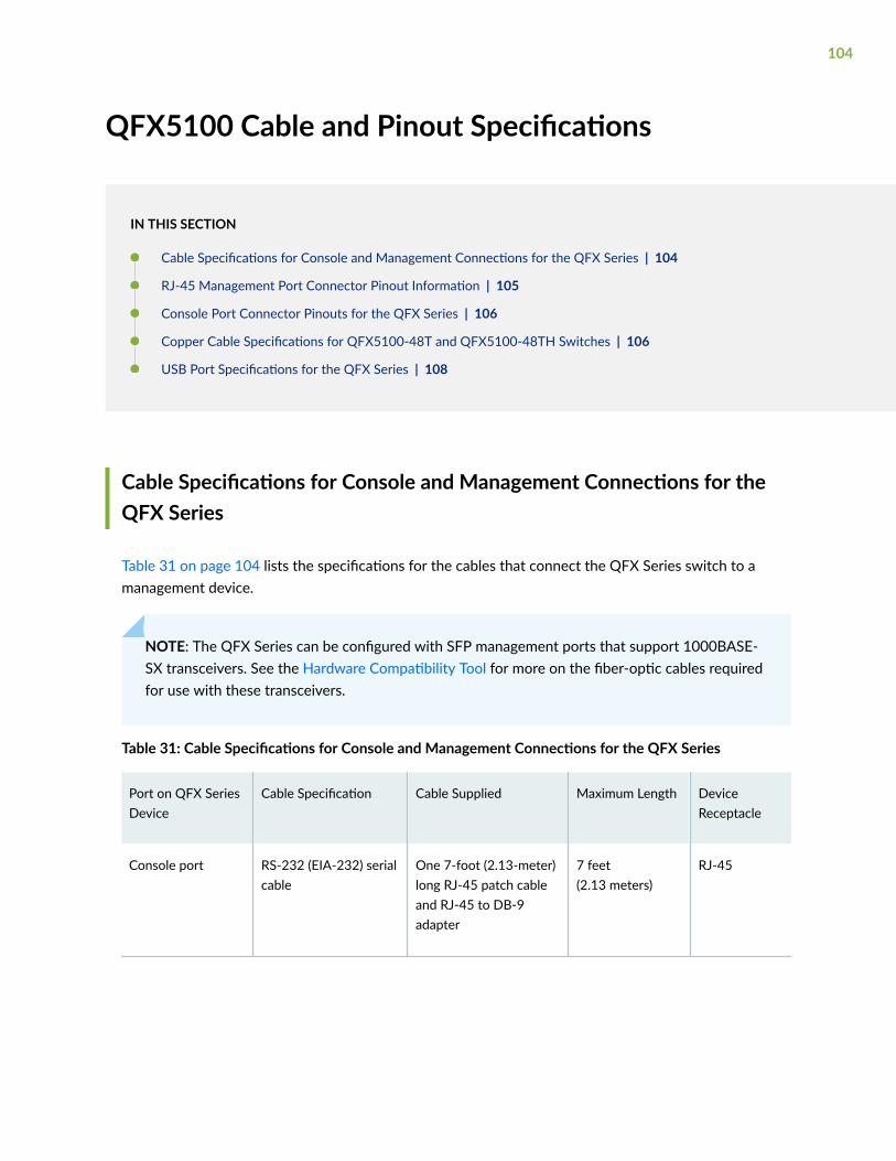
QFX5100 Cable and Pinout Specifications
IN THIS SECTION
Cable Specifications for Console and Management Connections for the QFX Series | 104
RJ-45 Management Port Connector Pinout Information | 105
Console Port Connector Pinouts for the QFX Series | 106
Copper Cable Specifications for QFX5100-48T and QFX5100-48TH Switches | 106
USB Port Specifications for the QFX Series | 108
Cable Specifications for Console and Management Connections for theQFX Series
Table 31 on page 104 lists the specifications for the cables that connect the QFX Series switch to amanagement device.
NOTE: The QFX Series can be configured with SFP management ports that support 1000BASE-SX transceivers. See the Hardware Compatibility Tool for more on the fiber-optic cables requiredfor use with these transceivers.
Table 31: Cable Specifications for Console and Management Connections for the QFX Series
Port on QFX SeriesDevice
Cable Specification Cable Supplied Maximum Length DeviceReceptacle
Console port RS-232 (EIA-232) serialcable
One 7-foot (2.13-meter)long RJ-45 patch cableand RJ-45 to DB-9adapter
7 feet(2.13 meters)
RJ-45
104
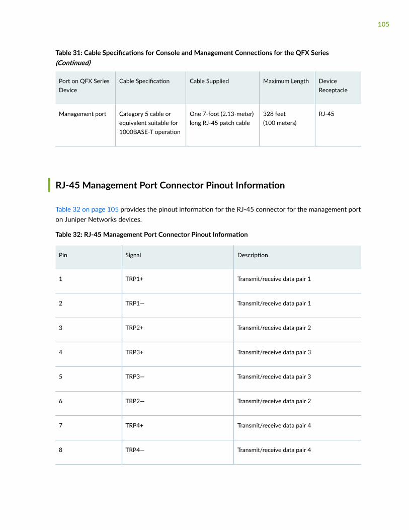
Table 31: Cable Specifications for Console and Management Connections for the QFX Series(Continued)
Port on QFX SeriesDevice
Cable Specification Cable Supplied Maximum Length DeviceReceptacle
Management port Category 5 cable orequivalent suitable for1000BASE-T operation
One 7-foot (2.13-meter)long RJ-45 patch cable
328 feet(100 meters)
RJ-45
RJ-45 Management Port Connector Pinout Information
Table 32 on page 105 provides the pinout information for the RJ-45 connector for the management porton Juniper Networks devices.
Table 32: RJ-45 Management Port Connector Pinout Information
Pin Signal Description
1 TRP1+ Transmit/receive data pair 1
2 TRP1— Transmit/receive data pair 1
3 TRP2+ Transmit/receive data pair 2
4 TRP3+ Transmit/receive data pair 3
5 TRP3— Transmit/receive data pair 3
6 TRP2— Transmit/receive data pair 2
7 TRP4+ Transmit/receive data pair 4
8 TRP4— Transmit/receive data pair 4
105

Console Port Connector Pinouts for the QFX Series
The console port (labeled CON, or CONSOLE) is an RS-232 serial interface that uses an RJ-45 connectorto connect to a console management device. The default baud rate for the console port is 9600 baud.
Table 33 on page 106 provides the pinout information for the RJ-45 console connector. An RJ-45 cableand RJ-45 to DB-9 adapter are supplied with the QFX Series device.
NOTE: If your laptop or PC does not have a DB-9 plug connector pin and you want to connectyour laptop or PC directly to a QFX Series device, use a combination of the RJ-45 cable andRJ-45 to DB-9 adapter supplied with the device and a USB to DB-9 plug adapter. You mustprovide the USB to DB-9 plug adapter.
Table 33: Console Port Connector Pinouts for the QFX Series
Pin Signal Description
3 TxD Output Transmit data
4 Signal Ground Signal ground
5 Signal Ground Signal ground
6 RxD Input Receive data
Copper Cable Specifications for QFX5100-48T and QFX5100-48THSwitches
The QFX5100-48T and QFX5100-48TH switches have 10GBASE-T interfaces that use various types ofcopper network cables. To achieve optimal performance, you must use cables that conform to IEEE802.3-2012 specifications for connections for 10GBASE-T network ports. Table 34 on page 107 lists thecable specifications for 10GBASE-T port on QFX5100-48T and QFX5100-48TH switches.
106

Table 34: Cable Specification for 10GBASE-T Network Ports
Ports onSwitches
IEEE CableStandard
Shield orUnshieldedTwisted Pair(STP/UTP)
Cable StandardSpecification
MaximumReach
Frequency(MHz)
AdditionalInformation
10GBASE-T
Class F/CAT 7
STP ISO/IEC11801:2002
328 ft(100 m)
1–600
Class EA/CAT 6A
STP/UTP ANSI/TIA/EIA-568-B2-10
328 ft(100 m)
1–500
Class E/CAT 6
UTP ANSI/TIA/EIA568-B.2-1
98 ft(30 m)
1–250 CAT 6 cables aredefined toperform atfrequencies up to250 MHz and aresensitive to aliencrosstalk. To usesuch cables toconnect to10GBASE-T ports,you must ensurethat the cableinstallation istested and iscertified for500 MHz as perTIA TSB-155standard.
Class E/CAT 6
STP ANSI/TIA/EIA568-B.2-1
98 ft(30 m)
1–250
1000BASE-T
CAT 5eCAT 6CAT 6A(STP/UTP)
STP/UTP ANSI/TIA/EIA-568-AANSI/TIA/EIA-568-B.2-1ANSI/TIA/EIA-568-B2-10
328 ft(100 m)
1-1001-2501-500
107
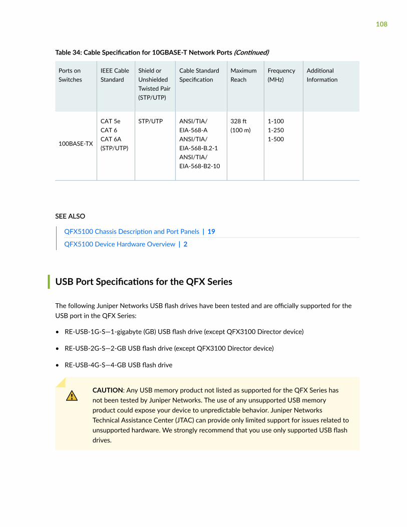
Table 34: Cable Specification for 10GBASE-T Network Ports (Continued)
Ports onSwitches
IEEE CableStandard
Shield orUnshieldedTwisted Pair(STP/UTP)
Cable StandardSpecification
MaximumReach
Frequency(MHz)
AdditionalInformation
100BASE-TX
CAT 5eCAT 6CAT 6A(STP/UTP)
STP/UTP ANSI/TIA/EIA-568-AANSI/TIA/EIA-568-B.2-1ANSI/TIA/EIA-568-B2-10
328 ft(100 m)
1-1001-2501-500
SEE ALSO
QFX5100 Chassis Description and Port Panels | 19
QFX5100 Device Hardware Overview | 2
USB Port Specifications for the QFX Series
The following Juniper Networks USB flash drives have been tested and are officially supported for theUSB port in the QFX Series:
• RE-USB-1G-S—1-gigabyte (GB) USB flash drive (except QFX3100 Director device)
• RE-USB-2G-S—2-GB USB flash drive (except QFX3100 Director device)
• RE-USB-4G-S—4-GB USB flash drive
CAUTION: Any USB memory product not listed as supported for the QFX Series hasnot been tested by Juniper Networks. The use of any unsupported USB memoryproduct could expose your device to unpredictable behavior. Juniper NetworksTechnical Assistance Center (JTAC) can provide only limited support for issues related tounsupported hardware. We strongly recommend that you use only supported USB flashdrives.
108
CAUTION: Remove the USB flash drive before upgrading Junos OS or rebooting a QFXSeries device. Failure to do so could expose your device to unpredictable behavior.
NOTE: Executing the request system snapshot CLI command on a QFX3500 device requires anexternal USB flash drive with at least 4 GB of free space. We recommend using the RE-USB-4G-S flash drive.
NOTE: USB flash drives used with the QFX Series device must support USB 2.0 or later.
109
3CHAPTER
Initial Installation and Configuration
QFX5100 Installation Overview | 111
Unpack and Mount the QFX5100 Switch | 114
Connect the QFX5100 to External Devices | 121
Connect the QFX5100 in a Virtual Chassis or Virtual Chassis Fabric | 124
Connect the QFX5100 to Power | 137
Configure a QFX5100 Device | 148
QFX5100 Installation Overview
IN THIS SECTION
QFX5100 Standalone Installation Overview | 111
Virtual Chassis Fabric Installation Overview | 112
QFX5100 Installation Safety Guidelines | 113
QFX5100 Standalone Installation Overview
You can mount a QFX5100 device:
• Flush with the front of a 19-in. four-post rack. Use the standard mounting brackets provided with theswitch for this configuration.
• Recessed 2 in. (5 cm) from the front of a 19-in. four-post rack. Use the extension bracket provided inthe standard mounting kit for this configuration. Recessed mounting is primarily used in enclosedcabinets.
To install and connect a QFX5100 device:
1. Follow the instructions in Unpack a QFX5100 Device.
2. Determine how the device is to be mounted.
Flush or recessed mounted in a rack or cabinet, see Mount a QFX5100 Device in a Rack or Cabinet.
3. Follow the instructions in:
a. Connecting Earth Ground to a QFX5100 Device
b. Connecting AC Power to a QFX5100 Device or Connecting DC Power to a QFX5100 Device
c. Register Products—Mandatory to Validate SLAs
4. Depending on how you plan to use the QFX5100 device, do one of the following:
• If you are using the QFX5100 device as a standalone switch, follow the instructions in Configure aQFX5100 Device.
• If you are using the QFX5100 device as a Node device in a QFX3000-G QFabric system, seeQFX3000-G QFabric System Installation Overview for information about the steps to install andconfigure your QFX3000-G QFabric system.
111
• If you are using the QFX5100 device as a Node device in a QFX3000-M QFabric system, seeQFX3000-M QFabric System Installation Overview for information about the steps to install andconfigure your QFX3000-M QFabric system.
• If you are using a QFX5100-24Q as an Interconnect device in a QFX3000-M QFabric system, seeConnecting a QFX5100 Node Device to a QFX5100-24Q Interconnect Device.
• If you are using the QFX5100 device in a Virtual Chassis Fabric, see Connecting a QFX5100Device in a Virtual Chassis Fabric.
Virtual Chassis Fabric Installation Overview
For best results, ensure you review and understand the Virtual Chassis Fabric (VCF) configurationoptions. These configuration options are explained in Virtual Chassis Fabric Hardware Overview andUnderstanding Virtual Chassis Fabric Configuration. Do not interconnect the switches with cables untildirected in the procedure.
1. Install the individual switches in a rack or cabinet following the guidelines in "Plan a Virtual ChassisFabric Deployment" on page 90.
BEST PRACTICE: Install spine devices at the top of the rack or cabinet in order of primaryrouting engine (RE), backup RE, and then other leaf devices.
2. Make a list of all of the serial numbers of the devices.
3. Log into each device and configure into fabric mode and mixed mode, if needed. Mixed mode is onlynecessary for QFX5100 VCF when QFX5100-96S, QFX5100-48T, QFX3500, QFX3600, or EX4300devices are present as leaf devices in the configuration. If a spine device is not properly configured infabric and mixed mode for QFX5100 mixed VCF, the VCF devices reboot to commit the mixed modeor fabric settings. When fabric and mixed mode are not set, you might need to manually correct anyissues that are related to the VCF not forming correctly because the device did not immediately jointhe VCF.
WARNING: Only configure operational-level commands. If you commit anyconfiguration-level commands (including assigning IP address), the Virtual ChassisFabric cannot form and the switch must be zeroed.
4. Configure the VCF into mixed mode if it is a QFX5100 VCF and the switch models span differentlines of switches.
112
5. Configure each device for one of the provisioning modes: autoprovision, preprovision, ornonprovision. See:
• Autoprovisioning a Virtual Chassis Fabric
• Preprovisioning a Virtual Chassis Fabric
• Configuring a Nonprovisioned Virtual Chassis Fabric
6. Connect and configure one of the management ports (C0) or (C1) to a management switch as theVirtual Management Ethernet interface. Using this interface, you can configure and manage thedevices in the VCF. See Connect a Device to a Network for Out-of-Band Management.
7. Commit your changes.
8. Cable the ports that you will use as VCPs. For cabling examples, see Connecting QFX5110 in aQFX5110 Virtual Chassis Fabric, "Connecting a QFX5100 Device in a Virtual Chassis Fabric" on page134, Connecting a QFX3500 or QFX3600 Switch in a QFX5100 Virtual Chassis Fabric, andConnecting EX Series Switches in a QFX5100 Virtual Chassis Fabric.
If you configured your devices as either autoprovisioned or preprovisioned, the Virtual Chassis ports(VCP) are automatically configured. If you configure the devices as nonprovisioned, you mustmanually configure the VCPs.
QFX5100 Installation Safety Guidelines
The weight of a 1 U fully loaded QFX5100 switch chassis is approximately 30.8 lb (14 kg); the 2 Uproduct SKU is approximately 32 lbs (14.5 kg). Observe the following guidelines for lifting and moving aQFX5100 switch:
CAUTION: If you are installing the QFX5100 switch above 60 in. (152.4 cm) from thefloor, either remove the power supplies, fan modules, and any expansion modulesbefore attempting to install the switch, or ask someone to assist you during theinstallation.
• Before installing a QFX5100 switch, read the guidelines in Site Preparation Checklist for a QFX5100Device to verify that the intended site meets the specified power, environmental, and clearancerequirements.
• Before lifting or moving the QFX5100 switch, disconnect all external cables.
• As when lifting any heavy object, lift most of the weight with your legs rather than your back. Keepyour knees bent and your back relatively straight and avoid twisting your body as you lift. Balancethe load evenly and be sure that your footing is solid.
113
SEE ALSO
General Safety Guidelines and Warnings
Installation Instructions Warning
RELATED DOCUMENTATION
QFX5100 Site Guidelines and Requirements | 82
Clearance Requirements for Airflow and Hardware Maintenance for a QFX5100 Device | 77
Unpack and Mount the QFX5100 Switch
IN THIS SECTION
Unpack a QFX5100 Device | 114
Register Products—Mandatory to Validate SLAs | 116
Mount a QFX5100 Device in a Rack or Cabinet | 116
Unpack a QFX5100 Device
The QFX5100 switch chassis is a rigid sheet-metal structure that houses the hardware components. AQFX5100 device is shipped in a cardboard carton, secured with foam packing material. The carton alsocontains an accessory box and quick start instructions.
CAUTION: QFX5100 devices are maximally protected inside the shipping carton. Donot unpack the switch until you are ready to begin installation.
To unpack a QFX5100 device:
1. Move the shipping carton to a staging area as close to the installation site as possible, but where youhave enough room to remove the system components.
2. Position the carton so that the arrows are pointing up.
3. Open the top flaps on the shipping carton.
114
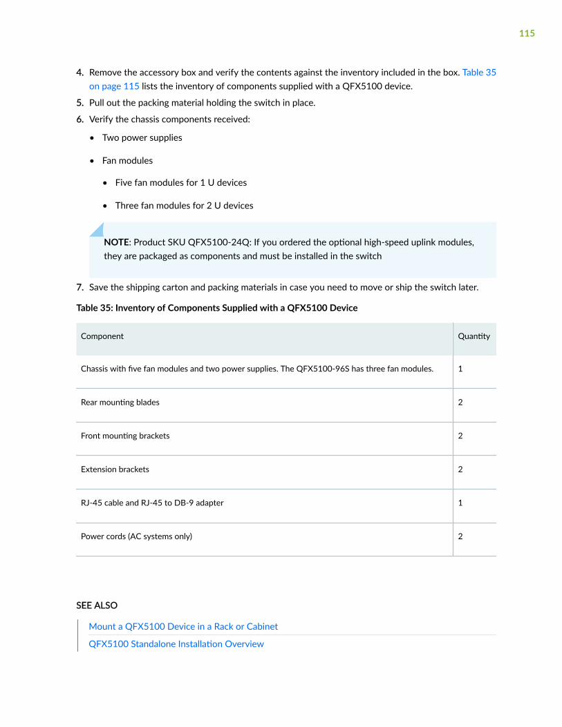
4. Remove the accessory box and verify the contents against the inventory included in the box. Table 35on page 115 lists the inventory of components supplied with a QFX5100 device.
5. Pull out the packing material holding the switch in place.
6. Verify the chassis components received:
• Two power supplies
• Fan modules
• Five fan modules for 1 U devices
• Three fan modules for 2 U devices
NOTE: Product SKU QFX5100-24Q: If you ordered the optional high-speed uplink modules,they are packaged as components and must be installed in the switch
7. Save the shipping carton and packing materials in case you need to move or ship the switch later.
Table 35: Inventory of Components Supplied with a QFX5100 Device
Component Quantity
Chassis with five fan modules and two power supplies. The QFX5100-96S has three fan modules. 1
Rear mounting blades 2
Front mounting brackets 2
Extension brackets 2
RJ-45 cable and RJ-45 to DB-9 adapter 1
Power cords (AC systems only) 2
SEE ALSO
Mount a QFX5100 Device in a Rack or Cabinet
QFX5100 Standalone Installation Overview
115
Register Products—Mandatory to Validate SLAs
Register all new Juniper Networks hardware products and changes to an existing installed product usingthe Juniper Networks website to activate your hardware replacement service-level agreements (SLAs).
CAUTION: Register product serial numbers on the Juniper Networks website andupdate the installation base data if there is any addition or change to the installationbase or if the installation base is moved. Juniper Networks will not be held accountablefor not meeting the hardware replacement service-level agreement for products that donot have registered serial numbers or accurate installation base data.
Register your product(s) at https://tools.juniper.net/svcreg/SRegSerialNum.jsp.Update your installation base at https://www.juniper.net/customers/csc/management/updateinstallbase.jsp.
Mount a QFX5100 Device in a Rack or Cabinet
IN THIS SECTION
Before You Begin Rack Installation | 116
Four-Post Procedure | 118
You can mount all QFX5100 switches on a four post 19-in. rack or cabinet using the mounting kitprovided with the device.
For four post rack or cabinet installations, the mounting kit contains two front mounting rails with twomatching rear mounting blades. This configuration allows either end of the switch to be mounted flushwith the rack and still be adjustable for racks with different depths.
(The remainder of this topic uses “rack” to mean “rack or cabinet.”) The front and rear rack rails must bespaced between 28.5 in. (72.4 cm) to 31.5 in. (80 cm) front to back.
Before You Begin Rack Installation
Before you begin mounting a QFX5100 switch in the rack or cabinet:
1. Ensure that you understand how to prevent electrostatic discharge (ESD) damage. See Prevention ofElectrostatic Discharge Damage.
116
2. Verify that the site meets the requirements described in Site Preparation Checklist for a QFX5100Device.
3. Place the rack in its permanent location, allowing adequate clearance for airflow and maintenance,and secure it to the building structure.
4. Read General Site Guidelines, with particular attention to QFX5100 Installation Safety Guidelines.
5. Remove the switch from the shipping carton (see Unpack a QFX5100 Device).
6. Ensure that you have the following parts and tools available to mount the switch in a rack:
• ESD grounding strap (not provided).
• Blades, rails, or brackets (provided).
• For four-post installations:
• One pair of rear mounting blades. These mounting blades support the rear of the chassisand must be installed (provided).
• One pair of front mounting rails. The mounting blades slide into the mounting rails tosupport the switch (provided).
• Screws to secure the mounting rails to the chassis (provided).
• Twelve screws for 1 U chassis
• Twenty-four screws for QFX5100-96S
• Eight screws to secure the chassis and rear installation blades to the rack (not provided).
• Appropriate screwdriver for the mounting screws (not provided).
• Two power cords with plugs appropriate to your geographical location (provided).
• RJ-45 cable and RJ-45 to DB-9 serial port adapter (provided).
• Management host, such as a PC laptop, with a serial port (not provided).
Optional equipment: Grounding cable kit with bracket, lug, and three nuts with integrated washers.
WARNING: The 1 U versions of QFX5100 switches must be supported at all fourcorners. Mounting the chassis using only the front brackets will damage the chassis andcan result in serious bodily injury.
CAUTION: All QFX5100 switches require two people for installation, one person to liftthe switch into place and another person to attach the switch to the rack. If you are
117
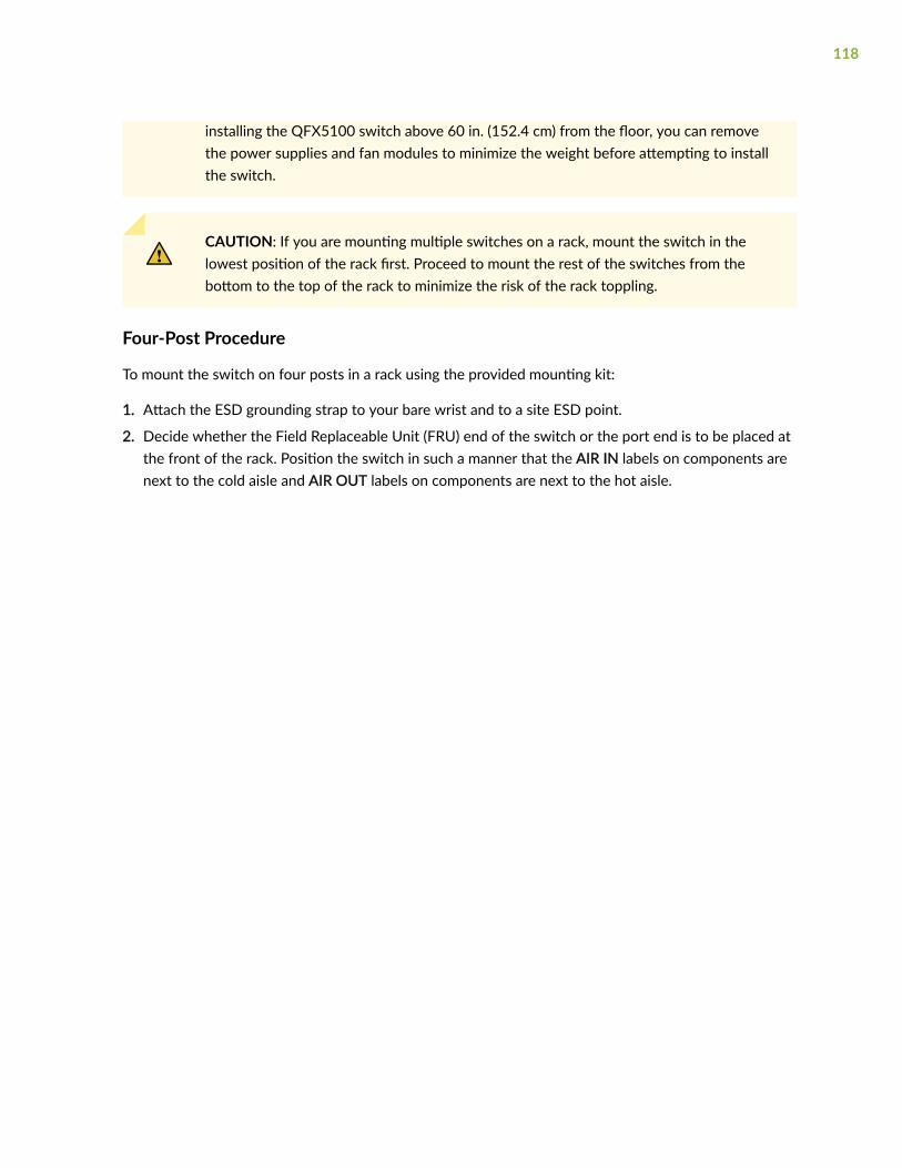
installing the QFX5100 switch above 60 in. (152.4 cm) from the floor, you can removethe power supplies and fan modules to minimize the weight before attempting to installthe switch.
CAUTION: If you are mounting multiple switches on a rack, mount the switch in thelowest position of the rack first. Proceed to mount the rest of the switches from thebottom to the top of the rack to minimize the risk of the rack toppling.
Four-Post Procedure
To mount the switch on four posts in a rack using the provided mounting kit:
1. Attach the ESD grounding strap to your bare wrist and to a site ESD point.
2. Decide whether the Field Replaceable Unit (FRU) end of the switch or the port end is to be placed atthe front of the rack. Position the switch in such a manner that the AIR IN labels on components arenext to the cold aisle and AIR OUT labels on components are next to the hot aisle.
118

3. Align the holes in the mounting rail with the holes on the side of the chassis. See Figure 48 on page119 through Figure 50 on page 119 for examples the proper alignment of 1 U and 2 U chassissystems.
Figure 48: Attaching Mounting Rails to the QFX5100-24Q
Figure 49: Attaching Mounting Rails to the QFX5100-48S
Figure 50: Attaching Mounting Rails to the QFX5100-96S
4. Attach the mounting rail to the switch using the mounting screws (and cage nuts and washers if yourrack requires them). Tighten the screws.
5. Repeats steps 4 and 5 on the opposite side of the switch.
119
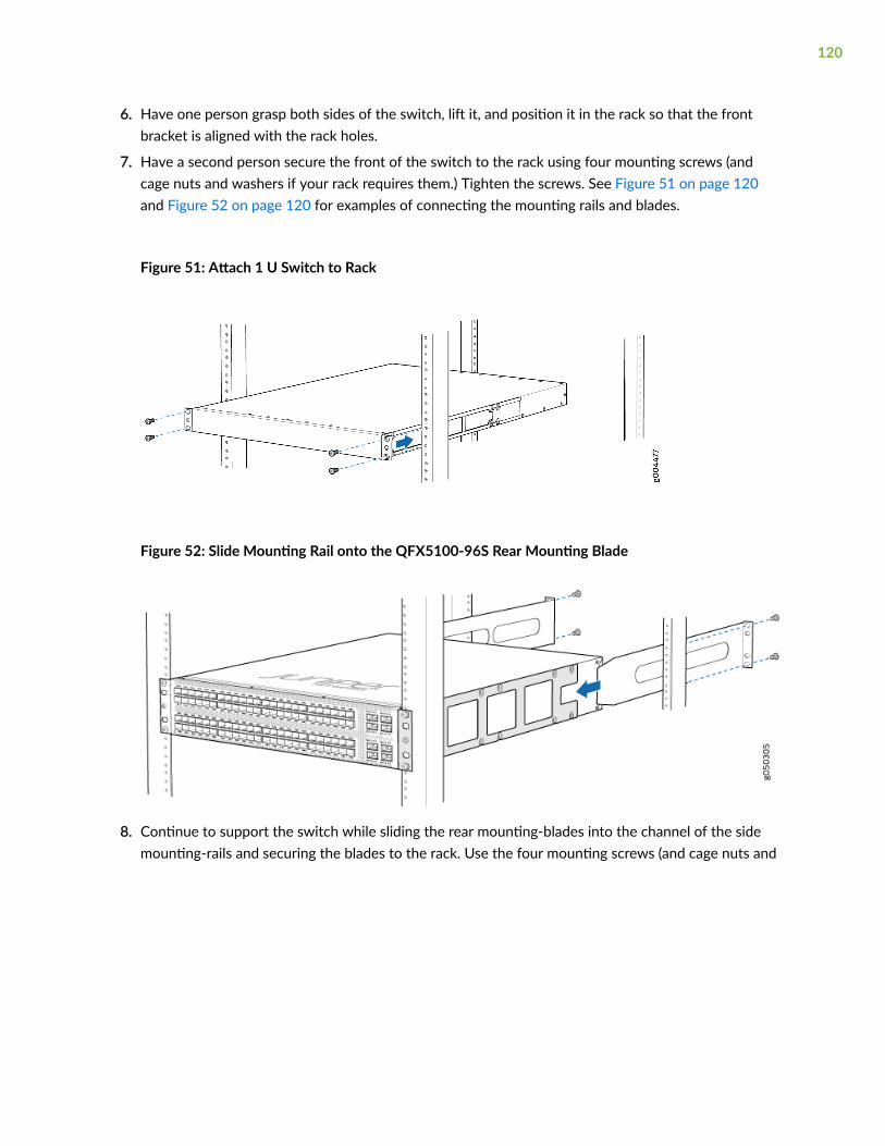
6. Have one person grasp both sides of the switch, lift it, and position it in the rack so that the frontbracket is aligned with the rack holes.
7. Have a second person secure the front of the switch to the rack using four mounting screws (andcage nuts and washers if your rack requires them.) Tighten the screws. See Figure 51 on page 120and Figure 52 on page 120 for examples of connecting the mounting rails and blades.
Figure 51: Attach 1 U Switch to Rack
Figure 52: Slide Mounting Rail onto the QFX5100-96S Rear Mounting Blade
8. Continue to support the switch while sliding the rear mounting-blades into the channel of the sidemounting-rails and securing the blades to the rack. Use the four mounting screws (and cage nuts and
120
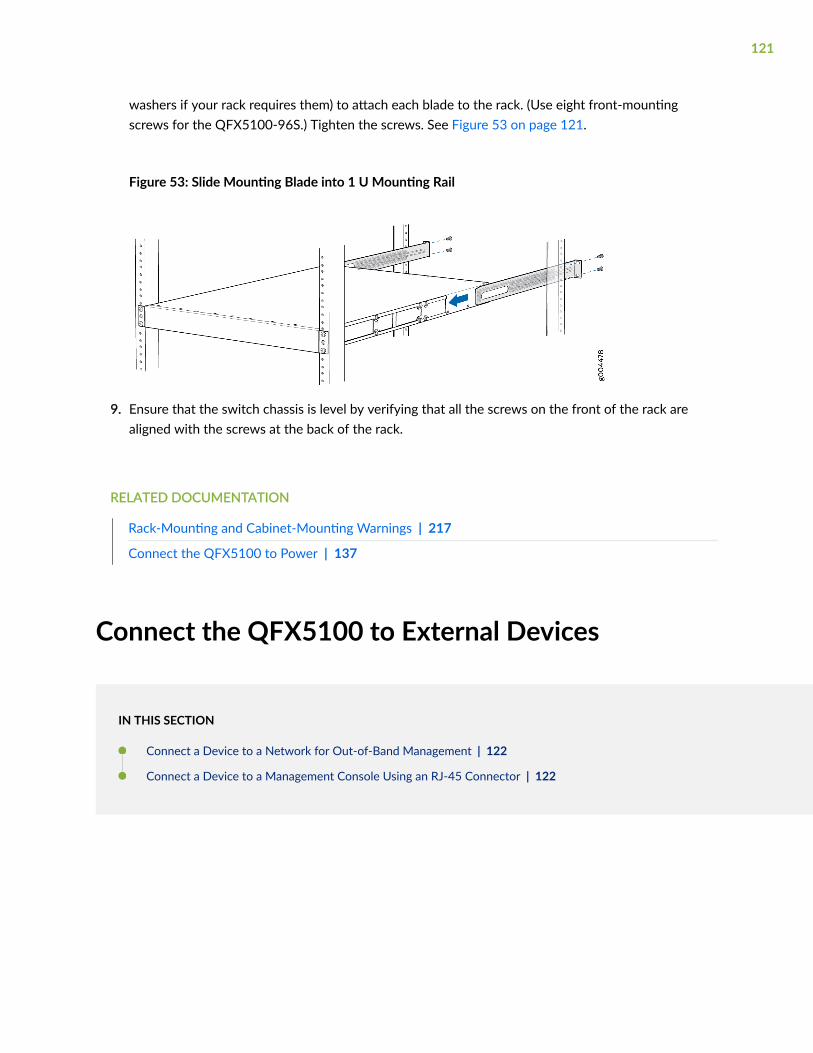
washers if your rack requires them) to attach each blade to the rack. (Use eight front-mountingscrews for the QFX5100-96S.) Tighten the screws. See Figure 53 on page 121.
Figure 53: Slide Mounting Blade into 1 U Mounting Rail
9. Ensure that the switch chassis is level by verifying that all the screws on the front of the rack arealigned with the screws at the back of the rack.
RELATED DOCUMENTATION
Rack-Mounting and Cabinet-Mounting Warnings | 217
Connect the QFX5100 to Power | 137
Connect the QFX5100 to External Devices
IN THIS SECTION
Connect a Device to a Network for Out-of-Band Management | 122
Connect a Device to a Management Console Using an RJ-45 Connector | 122
121
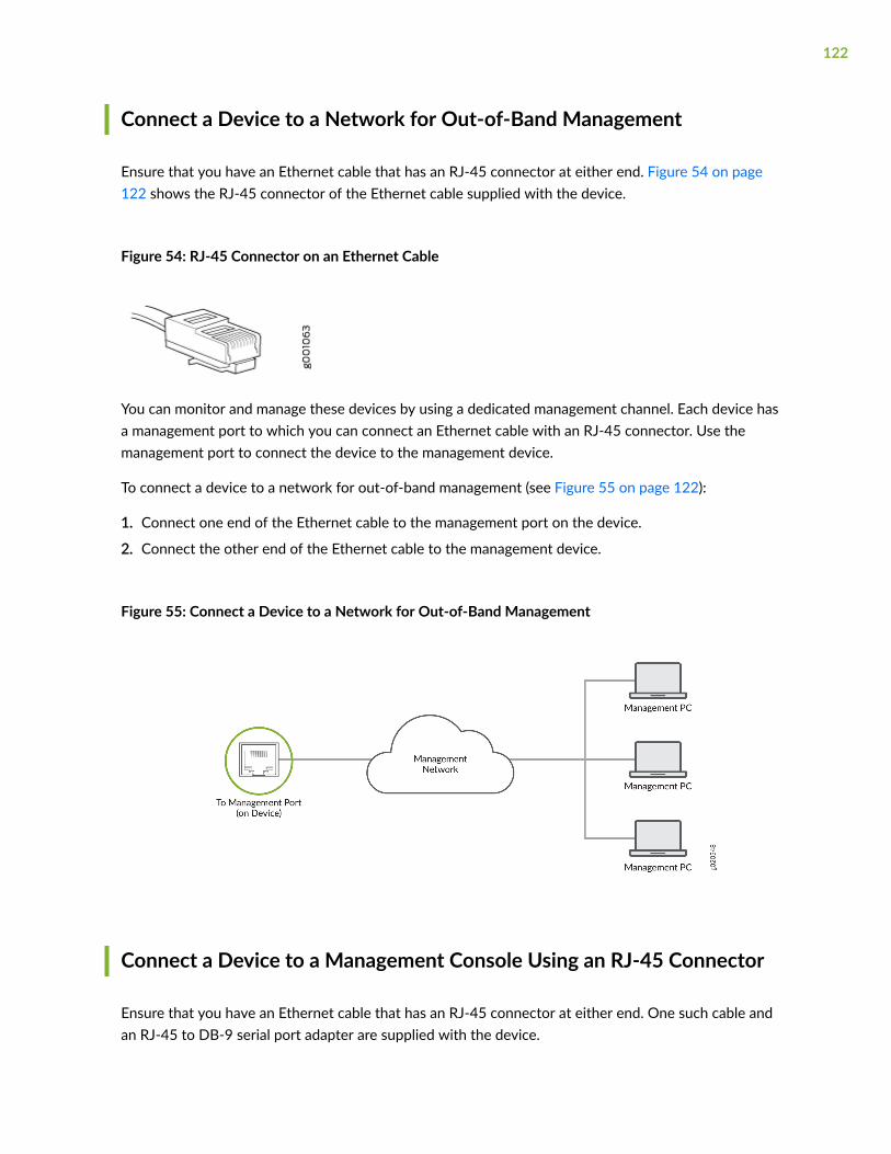
Connect a Device to a Network for Out-of-Band Management
Ensure that you have an Ethernet cable that has an RJ-45 connector at either end. Figure 54 on page122 shows the RJ-45 connector of the Ethernet cable supplied with the device.
Figure 54: RJ-45 Connector on an Ethernet Cable
You can monitor and manage these devices by using a dedicated management channel. Each device hasa management port to which you can connect an Ethernet cable with an RJ-45 connector. Use themanagement port to connect the device to the management device.
To connect a device to a network for out-of-band management (see Figure 55 on page 122):
1. Connect one end of the Ethernet cable to the management port on the device.
2. Connect the other end of the Ethernet cable to the management device.
Figure 55: Connect a Device to a Network for Out-of-Band Management
Connect a Device to a Management Console Using an RJ-45 Connector
Ensure that you have an Ethernet cable that has an RJ-45 connector at either end. One such cable andan RJ-45 to DB-9 serial port adapter are supplied with the device.
122

Figure 56 on page 123 shows the RJ-45 connector of the Ethernet cable.
Figure 56: RJ-45 Connector on an Ethernet Cable
NOTE: If your laptop or desktop PC does not have a DB-9 plug connector pin and you want toconnect your laptop or desktop PC directly to the device, use a combination of the RJ-45 toDB-9 socket adapter supplied with the device and a USB to DB-9 plug adapter. You must providethe USB to DB-9 plug adapter.
You can configure and manage devices using a dedicated management channel. Each device has aconsole port which you can connect to using an Ethernet cable with an RJ-45 connector. Use theconsole port to connect the device to the console server or management console. The console portaccepts a cable that has an RJ-45 connector.
To connect the device to a management console (see Figure 57 on page 124 and Figure 58 on page124):
1. Connect one end of the Ethernet cable to the console port (labeled CON, CONSOLE, or CON1) onthe device.
123
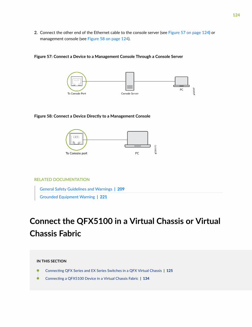
2. Connect the other end of the Ethernet cable to the console server (see Figure 57 on page 124) ormanagement console (see Figure 58 on page 124).
Figure 57: Connect a Device to a Management Console Through a Console Server
Figure 58: Connect a Device Directly to a Management Console
RELATED DOCUMENTATION
General Safety Guidelines and Warnings | 209
Grounded Equipment Warning | 221
Connect the QFX5100 in a Virtual Chassis or VirtualChassis Fabric
IN THIS SECTION
Connecting QFX Series and EX Series Switches in a QFX Virtual Chassis | 125
Connecting a QFX5100 Device in a Virtual Chassis Fabric | 134
124
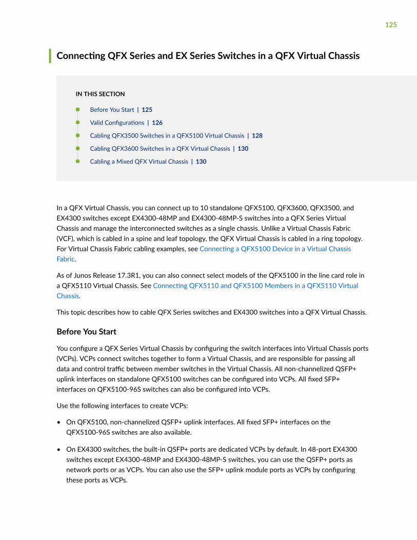
Connecting QFX Series and EX Series Switches in a QFX Virtual Chassis
IN THIS SECTION
Before You Start | 125
Valid Configurations | 126
Cabling QFX3500 Switches in a QFX5100 Virtual Chassis | 128
Cabling QFX3600 Switches in a QFX Virtual Chassis | 130
Cabling a Mixed QFX Virtual Chassis | 130
In a QFX Virtual Chassis, you can connect up to 10 standalone QFX5100, QFX3600, QFX3500, andEX4300 switches except EX4300-48MP and EX4300-48MP-S switches into a QFX Series VirtualChassis and manage the interconnected switches as a single chassis. Unlike a Virtual Chassis Fabric(VCF), which is cabled in a spine and leaf topology, the QFX Virtual Chassis is cabled in a ring topology.For Virtual Chassis Fabric cabling examples, see Connecting a QFX5100 Device in a Virtual ChassisFabric.
As of Junos Release 17.3R1, you can also connect select models of the QFX5100 in the line card role ina QFX5110 Virtual Chassis. See Connecting QFX5110 and QFX5100 Members in a QFX5110 VirtualChassis.
This topic describes how to cable QFX Series switches and EX4300 switches into a QFX Virtual Chassis.
Before You Start
You configure a QFX Series Virtual Chassis by configuring the switch interfaces into Virtual Chassis ports(VCPs). VCPs connect switches together to form a Virtual Chassis, and are responsible for passing alldata and control traffic between member switches in the Virtual Chassis. All non-channelized QSFP+uplink interfaces on standalone QFX5100 switches can be configured into VCPs. All fixed SFP+interfaces on QFX5100-96S switches can also be configured into VCPs.
Use the following interfaces to create VCPs:
• On QFX5100, non-channelized QSFP+ uplink interfaces. All fixed SFP+ interfaces on theQFX5100-96S switches are also available.
• On EX4300 switches, the built-in QSFP+ ports are dedicated VCPs by default. In 48-port EX4300switches except EX4300-48MP and EX4300-48MP-S switches, you can use the QSFP+ ports asnetwork ports or as VCPs. You can also use the SFP+ uplink module ports as VCPs by configuringthese ports as VCPs.
125
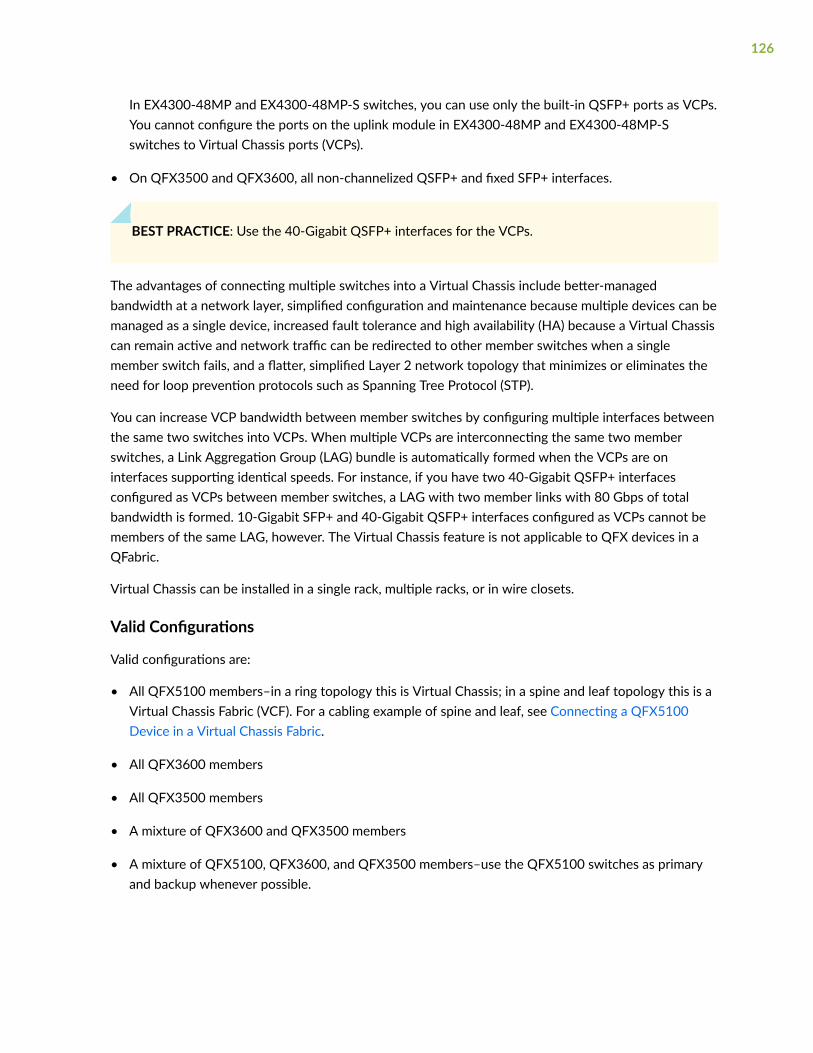
In EX4300-48MP and EX4300-48MP-S switches, you can use only the built-in QSFP+ ports as VCPs.You cannot configure the ports on the uplink module in EX4300-48MP and EX4300-48MP-Sswitches to Virtual Chassis ports (VCPs).
• On QFX3500 and QFX3600, all non-channelized QSFP+ and fixed SFP+ interfaces.
BEST PRACTICE: Use the 40-Gigabit QSFP+ interfaces for the VCPs.
The advantages of connecting multiple switches into a Virtual Chassis include better-managedbandwidth at a network layer, simplified configuration and maintenance because multiple devices can bemanaged as a single device, increased fault tolerance and high availability (HA) because a Virtual Chassiscan remain active and network traffic can be redirected to other member switches when a singlemember switch fails, and a flatter, simplified Layer 2 network topology that minimizes or eliminates theneed for loop prevention protocols such as Spanning Tree Protocol (STP).
You can increase VCP bandwidth between member switches by configuring multiple interfaces betweenthe same two switches into VCPs. When multiple VCPs are interconnecting the same two memberswitches, a Link Aggregation Group (LAG) bundle is automatically formed when the VCPs are oninterfaces supporting identical speeds. For instance, if you have two 40-Gigabit QSFP+ interfacesconfigured as VCPs between member switches, a LAG with two member links with 80 Gbps of totalbandwidth is formed. 10-Gigabit SFP+ and 40-Gigabit QSFP+ interfaces configured as VCPs cannot bemembers of the same LAG, however. The Virtual Chassis feature is not applicable to QFX devices in aQFabric.
Virtual Chassis can be installed in a single rack, multiple racks, or in wire closets.
Valid Configurations
Valid configurations are:
• All QFX5100 members–in a ring topology this is Virtual Chassis; in a spine and leaf topology this is aVirtual Chassis Fabric (VCF). For a cabling example of spine and leaf, see Connecting a QFX5100Device in a Virtual Chassis Fabric.
• All QFX3600 members
• All QFX3500 members
• A mixture of QFX3600 and QFX3500 members
• A mixture of QFX5100, QFX3600, and QFX3500 members–use the QFX5100 switches as primaryand backup whenever possible.
126

• A mixture of QFX5100, QFX3600, QFX3500, and EX4300 members except EX4300-48MP andEX4300-48MP-S switches. EX4300 switches as the primary or backup is not supported; useQFX5100 switches in these roles whenever possible.
An all EX4300 member is simply considered an EX4300 Virtual Chassis (see Understanding EX SeriesVirtual Chassis).
If the QSFP+ interfaces are not available for VCP, 10-Gigbit interfaces can be used.
All members of the Virtual Chassis are required to run the same Junos OS Release. You can check theversion and release by issuing the show chassis version CLI command.
127

Cabling QFX3500 Switches in a QFX5100 Virtual Chassis
Figure 59 on page 128 is the preferred cabling method using the 40-Gigabit QSFP ports. See Figure 60on page 129 for an alternative method using the 10-Gigabit SFP+ ports.
Figure 59: QFX3500 Using the 40G Ports as the VCPs
128
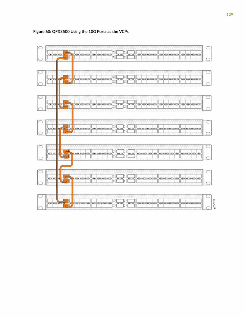
Figure 60: QFX3500 Using the 10G Ports as the VCPs
129
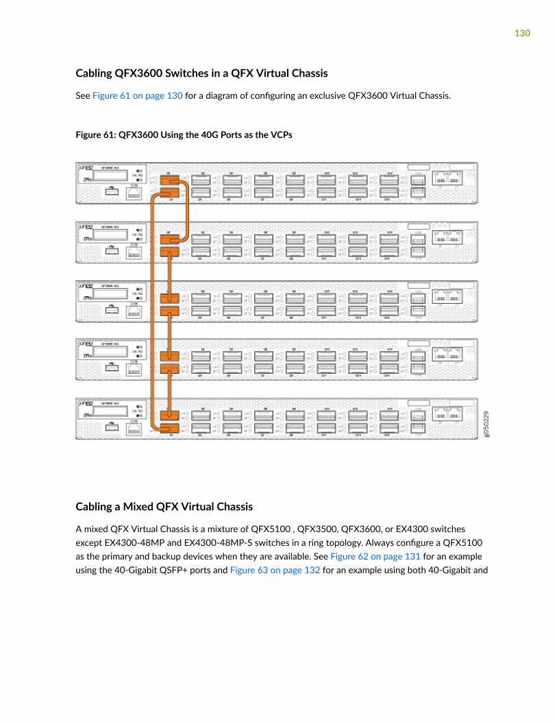
Cabling QFX3600 Switches in a QFX Virtual Chassis
See Figure 61 on page 130 for a diagram of configuring an exclusive QFX3600 Virtual Chassis.
Figure 61: QFX3600 Using the 40G Ports as the VCPs
Cabling a Mixed QFX Virtual Chassis
A mixed QFX Virtual Chassis is a mixture of QFX5100 , QFX3500, QFX3600, or EX4300 switchesexcept EX4300-48MP and EX4300-48MP-S switches in a ring topology. Always configure a QFX5100as the primary and backup devices when they are available. See Figure 62 on page 131 for an exampleusing the 40-Gigabit QSFP+ ports and Figure 63 on page 132 for an example using both 40-Gigabit and
130
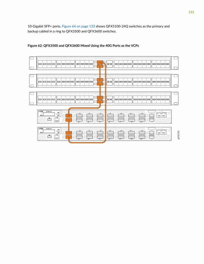
10-Gigabit SFP+ ports. Figure 64 on page 133 shows QFX5100-24Q switches as the primary andbackup cabled in a ring to QFX3500 and QFX3600 switches.
Figure 62: QFX3500 and QFX3600 Mixed Using the 40G Ports as the VCPs
131
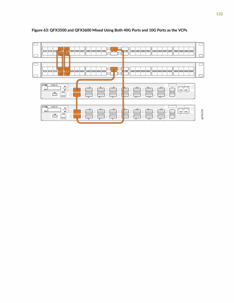
Figure 63: QFX3500 and QFX3600 Mixed Using Both 40G Ports and 10G Ports as the VCPs
132
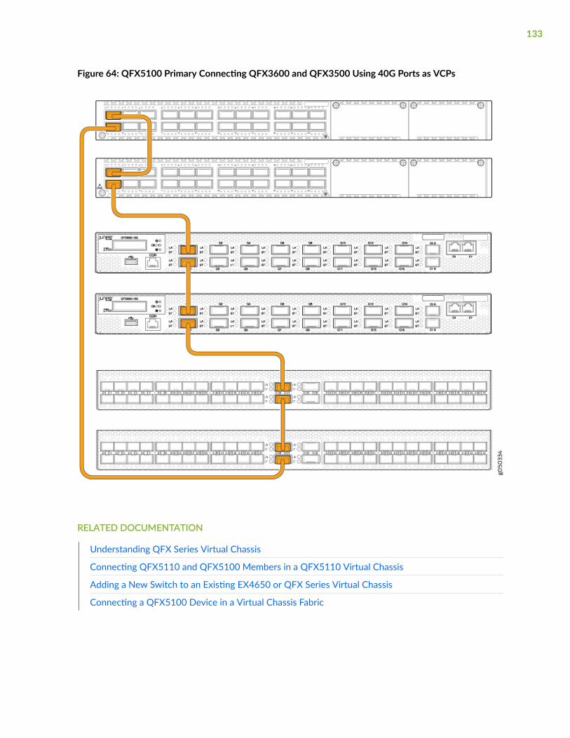
Figure 64: QFX5100 Primary Connecting QFX3600 and QFX3500 Using 40G Ports as VCPs
RELATED DOCUMENTATION
Understanding QFX Series Virtual Chassis
Connecting QFX5110 and QFX5100 Members in a QFX5110 Virtual Chassis
Adding a New Switch to an Existing EX4650 or QFX Series Virtual Chassis
Connecting a QFX5100 Device in a Virtual Chassis Fabric
133

Connecting a QFX5100 Device in a Virtual Chassis Fabric
The role of a QFX5100 device in a VCF is dependant on the other switch models used in the VCFconfiguration. To understand the different hardware configurations supported, see Virtual Chassis FabricHardware Overview.
You can install a VCF in a single rack, multiple racks, or in wire closets. You construct a QFX5100 VCF bycabling and then configuring SFP+ or QSFP+ interfaces into Virtual Chassis ports (VCPs). All non-channelized QSFP+ uplink interfaces on QFX5100 switches can be configured into VCPs. All fixed SFP+interfaces on QFX5100-96S switches can also be configured into VCPs.
BEST PRACTICE: Use 40-Gigabit QSFP+ ports as VCPs.
134
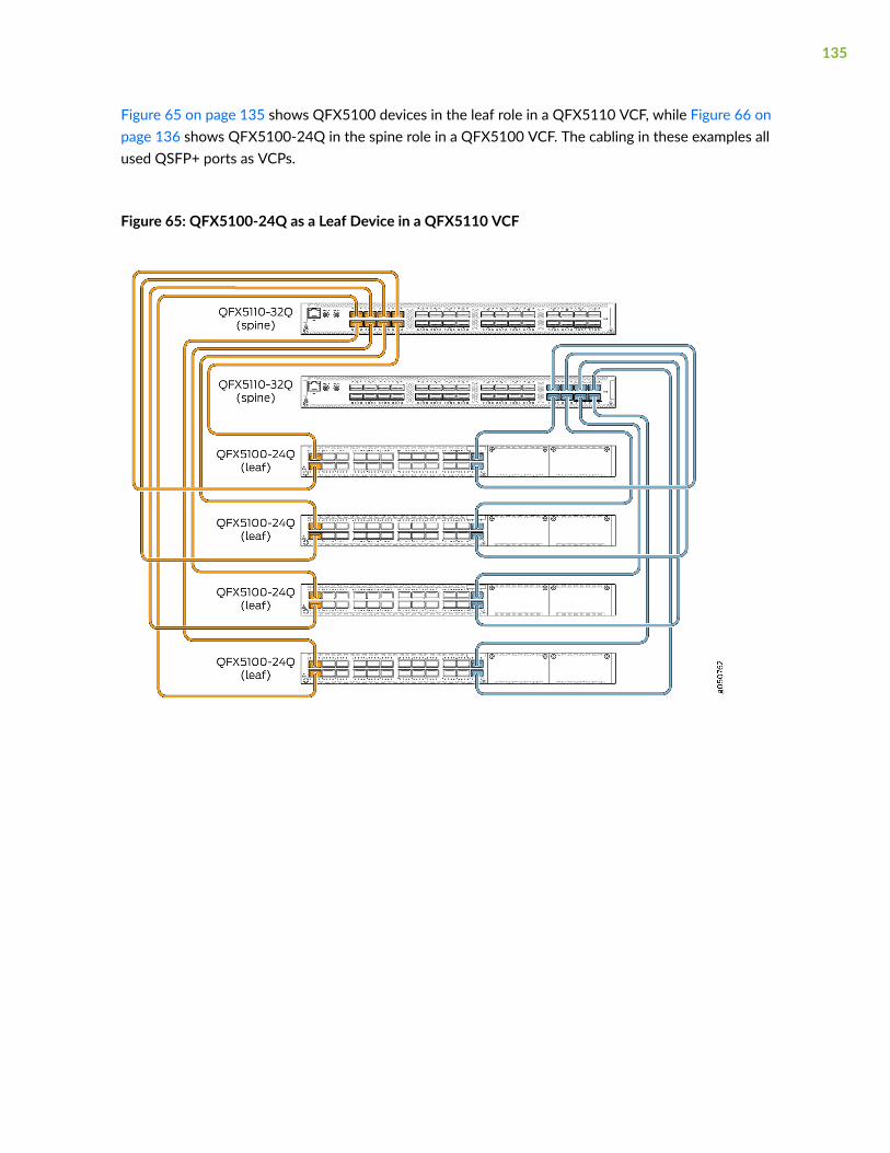
Figure 65 on page 135 shows QFX5100 devices in the leaf role in a QFX5110 VCF, while Figure 66 onpage 136 shows QFX5100-24Q in the spine role in a QFX5100 VCF. The cabling in these examples allused QSFP+ ports as VCPs.
Figure 65: QFX5100-24Q as a Leaf Device in a QFX5110 VCF
135
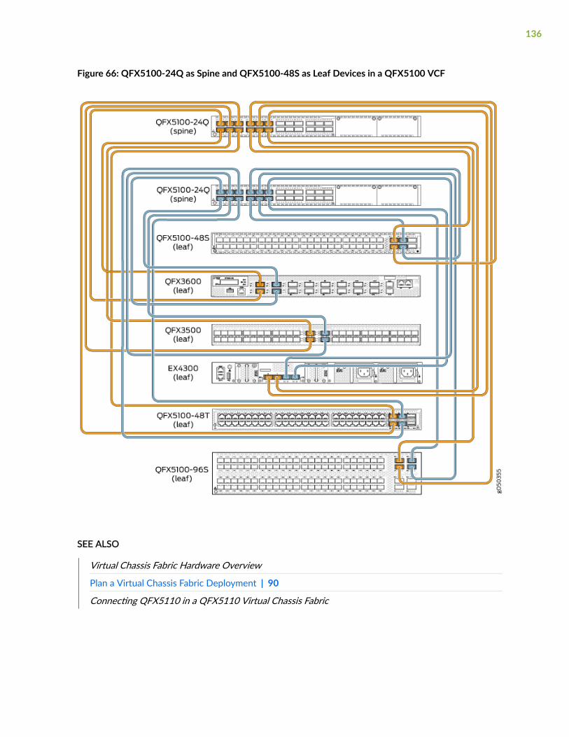
Figure 66: QFX5100-24Q as Spine and QFX5100-48S as Leaf Devices in a QFX5100 VCF
SEE ALSO
Virtual Chassis Fabric Hardware Overview
Plan a Virtual Chassis Fabric Deployment | 90
Connecting QFX5110 in a QFX5110 Virtual Chassis Fabric
136

Connect the QFX5100 to Power
IN THIS SECTION
Connecting Earth Ground to a QFX5100 Device | 137
Connecting AC Power to a QFX5100 Device | 140
Connecting DC Power to a QFX5100 Device | 143
Connecting Earth Ground to a QFX5100 Device
To meet safety and electromagnetic interference (EMI) requirements and to ensure proper operation,you must connect the QFX5100 device to earth ground before you connect it to power.
You must install the QFX5100 in a restricted-access location and ensure that the chassis is alwaysproperly grounded. The QFX5100 has a two-hole protective grounding terminal provided on the chassis.See Figure 67 on page 139. We recommend that you use this protective grounding terminal as thepreferred method for grounding the chassis regardless of the power supply configuration. However, ifadditional grounding methods are available, you can also use those methods. For example, you can usethe grounding wire in the AC power cord or use the grounding terminal or lug on a DC power supply.This tested system meets or exceeds all applicable EMC regulatory requirements with the two-holeprotective grounding terminal.
Before you connect earth ground to the protective earthing terminal of a QFX5100 device, ensure that alicensed electrician has attached an appropriate grounding lug to the grounding cable.
CAUTION: Using a grounding cable with an incorrectly attached lug can damage theswitch.
NOTE: Mount your switch in the rack or cabinet before attaching the grounding lug to theswitch. See Mount a QFX5100 Device in a Rack or Cabinet.
Ensure that you have the following parts and tools available:
• Protective earthing terminal bracket—This bracket attaches to the QFX5100 switch chassis throughthe left front mounting bracket, providing a protective earthing terminal for the switch.
137

• Grounding cable for your QFX5100 device—The grounding cable must be 14 AWG (2 mm²),minimum 90° C wire, or as permitted by the local code.
• Grounding lug for your grounding cable—The grounding lug required is a Panduit LCD10-10A-L orequivalent.
• Two SAE 10-32 washers and screws—To attach the grounding lug to the protective earthing terminal.
• Screwdriver to attach the screws.
An AC-powered QFX5100 switch chassis gains additional grounding when you plug the power supply inthe switch into a grounded AC power outlet by using an AC power cord appropriate for yourgeographical location. See AC Power Cord Specifications for a QFX Series Device.
To connect earth ground to a QFX5100 device:
1. Attach one end of the grounding cable to an appropriate earth ground site, such as the mountingrack.
2. Position the grounding lug over the protective earthing terminal on the side of the chassis, which isvisible through the mounting bracket.
138
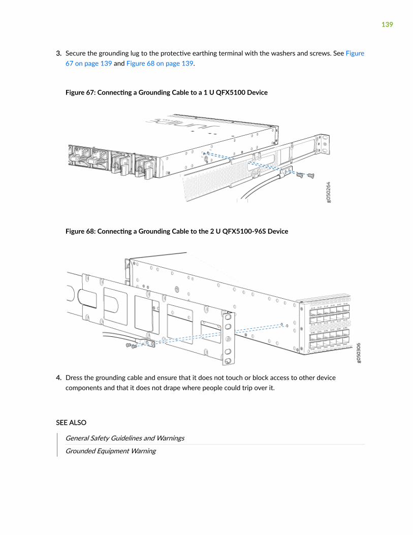
3. Secure the grounding lug to the protective earthing terminal with the washers and screws. See Figure67 on page 139 and Figure 68 on page 139.
Figure 67: Connecting a Grounding Cable to a 1 U QFX5100 Device
Figure 68: Connecting a Grounding Cable to the 2 U QFX5100-96S Device
4. Dress the grounding cable and ensure that it does not touch or block access to other devicecomponents and that it does not drape where people could trip over it.
SEE ALSO
General Safety Guidelines and Warnings
Grounded Equipment Warning
139
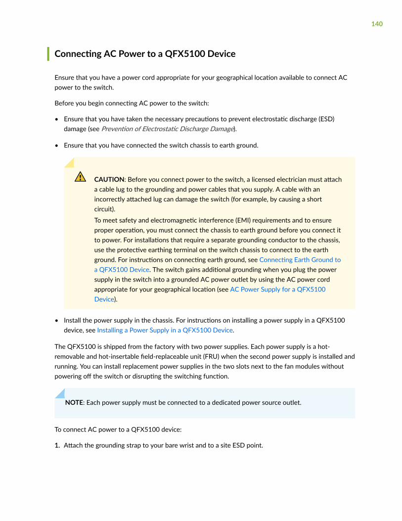
Connecting AC Power to a QFX5100 Device
Ensure that you have a power cord appropriate for your geographical location available to connect ACpower to the switch.
Before you begin connecting AC power to the switch:
• Ensure that you have taken the necessary precautions to prevent electrostatic discharge (ESD)damage (see Prevention of Electrostatic Discharge Damage).
• Ensure that you have connected the switch chassis to earth ground.
CAUTION: Before you connect power to the switch, a licensed electrician must attacha cable lug to the grounding and power cables that you supply. A cable with anincorrectly attached lug can damage the switch (for example, by causing a shortcircuit).
To meet safety and electromagnetic interference (EMI) requirements and to ensureproper operation, you must connect the chassis to earth ground before you connect itto power. For installations that require a separate grounding conductor to the chassis,use the protective earthing terminal on the switch chassis to connect to the earthground. For instructions on connecting earth ground, see Connecting Earth Ground toa QFX5100 Device. The switch gains additional grounding when you plug the powersupply in the switch into a grounded AC power outlet by using the AC power cordappropriate for your geographical location (see AC Power Supply for a QFX5100Device).
• Install the power supply in the chassis. For instructions on installing a power supply in a QFX5100device, see Installing a Power Supply in a QFX5100 Device.
The QFX5100 is shipped from the factory with two power supplies. Each power supply is a hot-removable and hot-insertable field-replaceable unit (FRU) when the second power supply is installed andrunning. You can install replacement power supplies in the two slots next to the fan modules withoutpowering off the switch or disrupting the switching function.
NOTE: Each power supply must be connected to a dedicated power source outlet.
To connect AC power to a QFX5100 device:
1. Attach the grounding strap to your bare wrist and to a site ESD point.
140
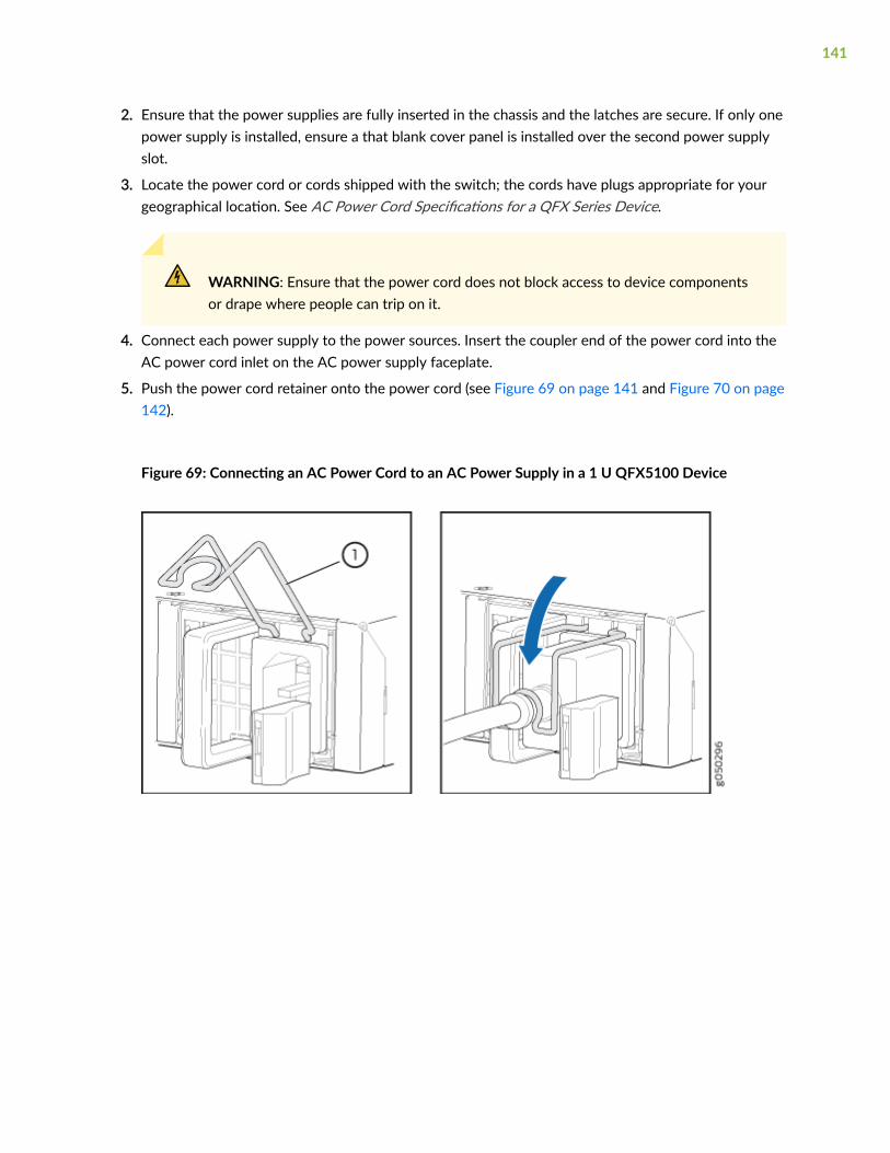
2. Ensure that the power supplies are fully inserted in the chassis and the latches are secure. If only onepower supply is installed, ensure a that blank cover panel is installed over the second power supplyslot.
3. Locate the power cord or cords shipped with the switch; the cords have plugs appropriate for yourgeographical location. See AC Power Cord Specifications for a QFX Series Device.
WARNING: Ensure that the power cord does not block access to device componentsor drape where people can trip on it.
4. Connect each power supply to the power sources. Insert the coupler end of the power cord into theAC power cord inlet on the AC power supply faceplate.
5. Push the power cord retainer onto the power cord (see Figure 69 on page 141 and Figure 70 on page142).
Figure 69: Connecting an AC Power Cord to an AC Power Supply in a 1 U QFX5100 Device
141
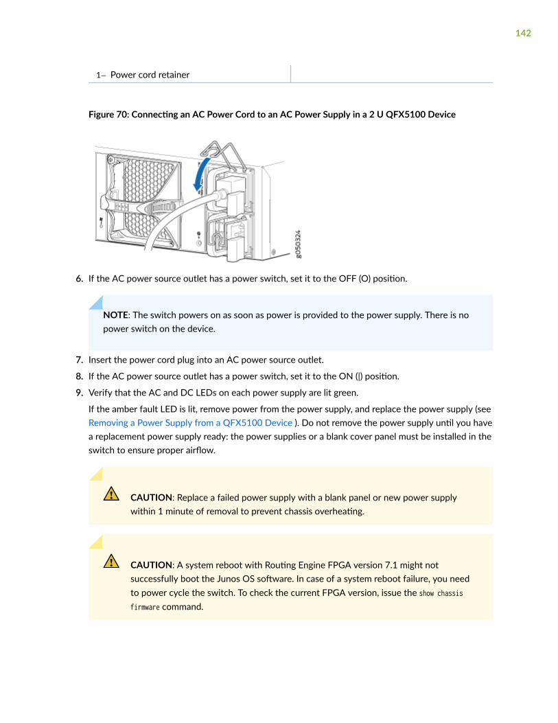
1— Power cord retainer
Figure 70: Connecting an AC Power Cord to an AC Power Supply in a 2 U QFX5100 Device
6. If the AC power source outlet has a power switch, set it to the OFF (O) position.
NOTE: The switch powers on as soon as power is provided to the power supply. There is nopower switch on the device.
7. Insert the power cord plug into an AC power source outlet.
8. If the AC power source outlet has a power switch, set it to the ON (|) position.
9. Verify that the AC and DC LEDs on each power supply are lit green.
If the amber fault LED is lit, remove power from the power supply, and replace the power supply (seeRemoving a Power Supply from a QFX5100 Device ). Do not remove the power supply until you havea replacement power supply ready: the power supplies or a blank cover panel must be installed in theswitch to ensure proper airflow.
CAUTION: Replace a failed power supply with a blank panel or new power supplywithin 1 minute of removal to prevent chassis overheating.
CAUTION: A system reboot with Routing Engine FPGA version 7.1 might notsuccessfully boot the Junos OS software. In case of a system reboot failure, you needto power cycle the switch. To check the current FPGA version, issue the show chassisfirmware command.
142
Connecting DC Power to a QFX5100 Device
Before you begin connecting DC power to the switch:
• Ensure that you have taken the necessary precautions to prevent electrostatic discharge (ESD)damage (see Prevention of Electrostatic Discharge Damage).
• Ensure that you have connected the switch chassis to earth ground.
CAUTION: Before you connect power to the switch, a licensed electrician must attacha cable lug to the grounding and power cables that you supply. A cable with anincorrectly attached lug can damage the switch (for example, by causing a shortcircuit).
To meet safety and electromagnetic interference (EMI) requirements and to ensureproper operation, you must connect the chassis to earth ground before you connect itto power. For installations that require a separate grounding conductor to the chassis,use the protective earthing terminal on the switch chassis to connect to the earthground. For instructions on connecting earth ground, see Connecting Earth Ground toa QFX5100 Device.
• Install the power supply in the chassis. For instructions on installing a power supply in a QFX5100device, see Installing a Power Supply in a QFX5100 Device.
Ensure that you have the following parts and tools available:
• DC power source cables (14–16 AWG) with ring lug (Molex 190700069 or equivalent) (not provided)
• Phillips (+) screwdriver, number 2 (not provided)
• Multimeter (not provided)
The QFX5100 is shipped from the factory with two power supplies. Each power supply is a hot-removable and hot-insertable field-replaceable unit (FRU) when the second power supply is installed andrunning. You can install replacement power supplies in the two slots next to the fan modules withoutpowering off the switch or disrupting the switching function.
WARNING: DC-powered QFX5100 devices are intended for installation only in arestricted access location.
143

NOTE: The battery returns of the DC power supply must be connected as an isolated DC return(DC-I).
To connect DC power to a QFX5100 device:
1. Attach the grounding strap to your bare wrist and to a site ESD point.
2. Verify that the DC power cables are correctly labeled before making connections to the powersupply. In a typical power distribution scheme where the return is connected to chassis ground atthe battery plant, you can use a multimeter to verify the resistance of the –48V and RTN DC cablesto chassis ground:
• The cable with very low resistance (indicating a closed circuit) to chassis ground is positive (+)and will be installed on the V+ (return) DC power input terminal.
• The cable with very high resistance (indicating an open circuit) to chassis ground is negative (–)and will be installed on the V– (input) DC power input terminal.
CAUTION: You must ensure that power connections maintain the proper polarity.The power source cables might be labeled (+) and (–) to indicate their polarity.There is no standard color coding for DC power cables. The color coding used bythe external DC power source at your site determines the color coding for the leadson the power cables that attach to the DC power input terminals on each powersupply.
3. Ensure that the input circuit breaker is open so that the voltage across the DC power source cableleads is 0 V and that the cable leads do not become active while you are connecting DC power.
NOTE: The V+ terminals are referred to as +RTN, and V– terminals are referred to as –48 Vin DC Power Wiring Sequence Warning and DC Power Electrical Safety Guidelines.
4. Ensure that the power supplies are fully inserted in the chassis.
5. Remove the terminal block cover. The terminal block cover is a piece of clear plastic that snaps intoplace over the terminal block (see Figure 71 on page 146).
6. Remove the screws on the terminals using the screwdriver. Save the screws.
WARNING: Ensure that the power cables do not block access to devicecomponents or drape where people can trip on them.
144
7. Connect each power supply to the power sources. Secure power source cables to the powersupplies by screwing the ring lugs attached to the cables to the appropriate terminals by using thescrew from the terminals (see Figure 71 on page 146 and Figure 72 on page 147 ).
The QFX5100 is designed to operate with a DC power supply that has a single, non-redundant,feed input. For source redundancy, two DC power supplies must be installed in QFX5100; connectsource (A) to one power supply and connect source (B) to the second power supply. Thisconfiguration provides the commonly deployed A/B feed redundancy for the system.
The terminal block of the power supply has four terminals labeled V+, V+, V–, and V– forconnecting DC power source cables labeled positive (+) and negative (–). The V+ terminals areshunted internally together, as are the V- terminals.
CAUTION: The connection between each power source and power supply mustinclude a circuit breaker.
Do not connect two sources to a single power supply because doing so canpotentially cause circulating current in feed wires whenever there is any differencein the voltage of the two sources.
NOTE: For QFX5100-96S installations using battery backup, a single 15 A circuit breaker isrecommended.
a. Secure the ring lug of the positive (+) DC power source cable to the V+ terminal on the DCpower supply.
b. Secure the ring lug of the negative (–) DC power source cable to the V– terminal on the DCpower supply.
145
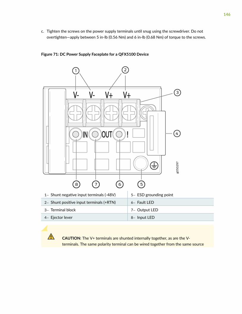
c. Tighten the screws on the power supply terminals until snug using the screwdriver. Do notovertighten—apply between 5 in-lb (0.56 Nm) and 6 in-lb (0.68 Nm) of torque to the screws.
Figure 71: DC Power Supply Faceplate for a QFX5100 Device
1— Shunt negative input terminals (-48V) 5— ESD grounding point
2— Shunt positive input terminals (+RTN) 6— Fault LED
3— Terminal block 7— Output LED
4— Ejector lever 8— Input LED
CAUTION: The V+ terminals are shunted internally together, as are the V-terminals. The same polarity terminal can be wired together from the same source
146
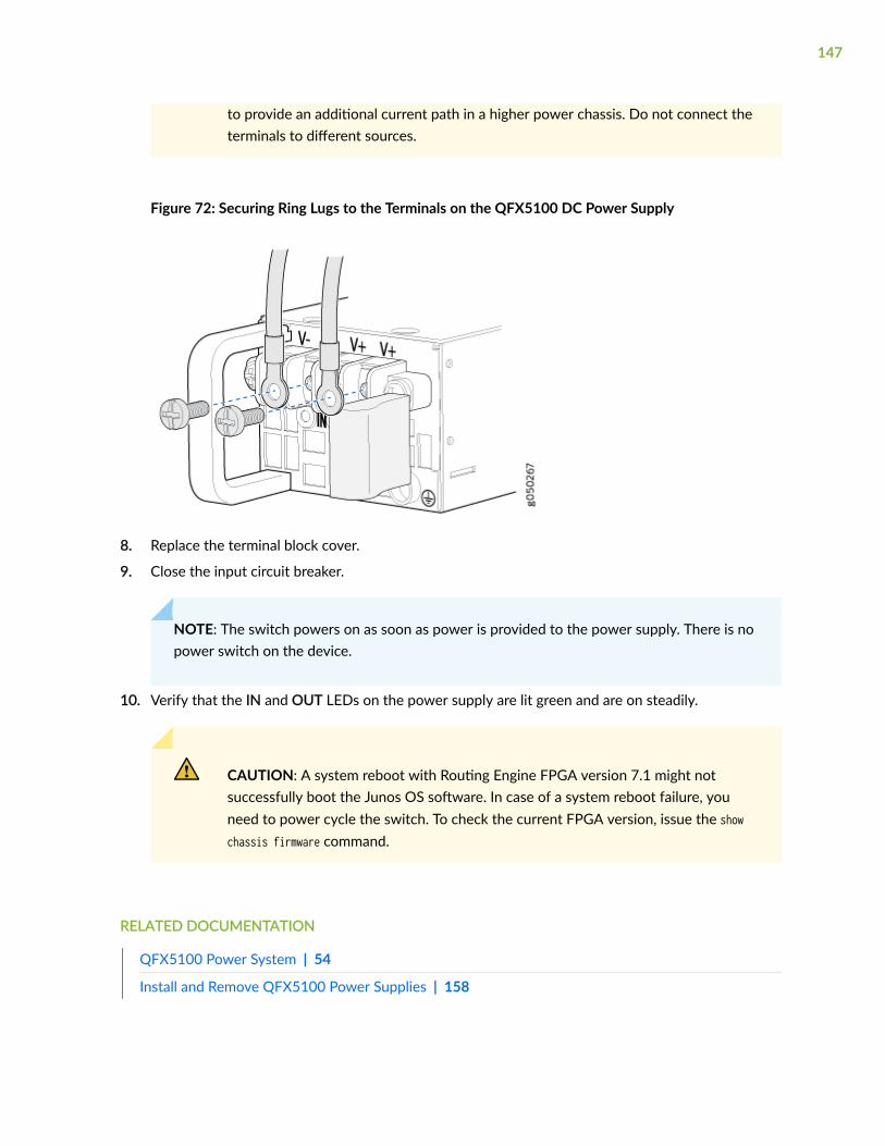
to provide an additional current path in a higher power chassis. Do not connect theterminals to different sources.
Figure 72: Securing Ring Lugs to the Terminals on the QFX5100 DC Power Supply
8. Replace the terminal block cover.
9. Close the input circuit breaker.
NOTE: The switch powers on as soon as power is provided to the power supply. There is nopower switch on the device.
10. Verify that the IN and OUT LEDs on the power supply are lit green and are on steadily.
CAUTION: A system reboot with Routing Engine FPGA version 7.1 might notsuccessfully boot the Junos OS software. In case of a system reboot failure, youneed to power cycle the switch. To check the current FPGA version, issue the showchassis firmware command.
RELATED DOCUMENTATION
QFX5100 Power System | 54
Install and Remove QFX5100 Power Supplies | 158
147
Configure a QFX5100 Device
IN THIS SECTION
Configuring a QFX5100 for Junos OS | 148
Configuring QFX10000 Switches for QFX5100-SH and QFX5100-TH as Satellite Devices | 151
The initial configuration of QFX5100 switches running Juniper Networks Junos OS are configuredthrough the console port using the command-line interface (CLI). QFX5100-48SH and QFX5100-48THare preconfigured Satellite Network Operational System (SNOS) software. SNOS systems are configuredat the aggregation device (AD). This topic covers:
Configuring a QFX5100 for Junos OS
Before you begin connecting and configuring a QFX5100 switch, set the following parameter values onthe console server or PC:
• Baud Rate—9600
• Flow Control—None
• Data—8
• Parity—None
• Stop Bits—1
• DCD State—Disregard
To connect and configure the switch from the console:
1. Connect the console port to a laptop or PC using the supplied RJ-45 cable and RJ-45 to DB-9adapter. The console (CON) port is located on the management panel of the switch.
148
2. Log in as root. There is no password. If the software booted before you connected to the consoleport, you might need to press the Enter key for the prompt to appear.
login: root
3. Start the CLI.
root@% cli
4. Enter configuration mode.
root> configure
5. Add a password to the root administration user account.
[edit]root@# set system root-authentication plain-text-passwordNew password: passwordRetype new password: password
6. (Optional) Configure the name of the switch. If the name includes spaces, enclose the name inquotation marks (“ ”).
[edit]root@# set system host-name host-name
7. Configure the default gateway.
[edit]root@# set routing-options static route default next-hop address
8. Configure the IP address and prefix length for the switch management interface.
[edit]root@# set interfaces em0 unit 0 family inet address address/prefix-length
149
CAUTION: Although the CLI permits you to configure two management Ethernetinterfaces within the same subnet, only one interface is usable and supported.
NOTE: The management ports, em0 (C0) and em1 (C1) are found on the FRU end of theQFX5100 switch.
9. (Optional) Configure the static routes to remote prefixes with access to the management port.
[edit]root@# set routing-options static route remote-prefix next-hop destination-ip retain no-readvertise
10. Enable telnet service.
[edit]root@# set system services telnet
NOTE: When Telnet is enabled, you cannot log in to a QFX5100 switch through Telnet usingroot credentials. Root login is allowed only for SSH access.
11. Enable SSH service for root login.
[edit]root@# set system services SSH
12. Commit the configuration to activate it on the switch.
[edit] root@# commit
150

Configuring QFX10000 Switches for QFX5100-SH and QFX5100-TH asSatellite Devices
Satellite software is pre-installed on the device. All configuration for the QFX5100-48SH andQFX5100-48TH is performed at the QFX10000 aggregation device (AD).
To add the QFX5100-48SH or QFX5100-48TH to a Junos Fusion as a satellite device:
1. Log in to the Junos Fusion aggregation device (the QFX10000 switch).
NOTE: The aggregation device must be configured with a Junos Fusion software license.
2. Configure the interface on the aggregation device that will connect to the satellite device as acascade port. For a list of QFX10000 line cards that support having interfaces configured intocascade ports, and for the related OS Junos releases that support cascade ports, see the JunosFusion documentation at https://www.juniper.net/documentation/.
For example, to configure interface xe-0/0/1 as a cascade port interface:
[edit]user@aggregation-device# set interfaces xe-0/0/1 cascade-port
3. Associate a line card slot ID (also known as a FPC slot ID) with the QFX5100-48SH orQFX5100-48TH.
There are many ways to associate a line card with a satellite device. See the Junos OS for the QFXSeries documentation at https://www.juniper.net/documentation/. The following are some examples.
To map FPC slot ID 100 with the satellite device by using the interface xe-0/0/1, which is configuredas the cascade port:
[edit]user@aggregation device# set chassis satellite-management fpc 100 cascade-ports xe-0/0/1
To map FPC slot ID 101 with the satellite device by using the serial number ABCDEFGHIJKL of thesatellite device:
[edit]user@aggregation-device# set chassis satellite-management fpc101 serial-number ABCDEFGHIJKL
151
To map FPC slot ID 102 with the satellite device by using the MAC address 12:34:56:AB:CD:EF ofthe satellite device:
[edit]user@aggregation-device# set chassis satellite-management fpc102 system-id 12:34:56:AB:CD:EF
4. Commit the configuration on the Routing Engines of the QFX10000.
[edit]user@aggregation-device# commit synchronize
5. (Optional but recommended) Add the satellite device to a satellite software upgrade group that usesthe same version of the satellite software that is installed on the QFX5100-48SH orQFX5100-48TH.
user@aggregation-device# set chassis satellite-managementupgrade-groups group1 satellite all
6. Connect the cascade port interface configured on the QFX10000 in step 2 to the QFX5100-48SH orQFX5100-48TH.
RELATED DOCUMENTATION
QFX5100 Standalone Installation Overview | 111
152
4CHAPTER
Maintaining Components
Install and Remove QFX5100 Fan Modules | 154
Install and Remove QFX5100 Power Supplies | 158
Install and Remove Expansion Modules in a QFX5100-Device | 163
Install and Remove Transceivers and Fiber Optic Cables on QFX5100 Devices | 170
Power Off a QFX5100 Device | 179
Remove a QFX5100 Device | 181

Install and Remove QFX5100 Fan Modules
IN THIS SECTION
Installing a Fan Module in a QFX5100 Device | 154
Removing a Fan Module from a QFX5100 Device | 156
Installing a Fan Module in a QFX5100 Device
Before you install a fan module in a QFX5100 device, ensure that you have taken the necessaryprecautions to prevent electrostatic discharge (ESD) damage (see Prevention of Electrostatic DischargeDamage).
The fan modules in a QFX5100 device are hot-removable and hot-insertable field-replaceable units(FRUs): you can remove and replace them without powering off the switch or disrupting switchfunctions.
CAUTION: Replace a failed fan module with a new fan module within 1 minute ofremoval to prevent chassis overheating. Before removing the fan module, ensure youhave a replacement fan module at hand.
NOTE: The fan module provides FRU-to-port or port-to-FRU airflow depending on the switchproduct SKU you purchase. In legacy switches, or switches with an LCD, this airflow is calledfront to back and back to front.
To install a fan module in a QFX5100 device (see Figure 73 on page 155 and Figure 74 on page 155):
1. Attach the ESD grounding strap to your bare wrist, and connect the strap to the ESD point on thechassis.
2. Taking care not to touch the connectors, remove the fan module from its bag.
3. Align the module with the open slot on the management panel of the chassis and slide it in until it isfully seated.
154
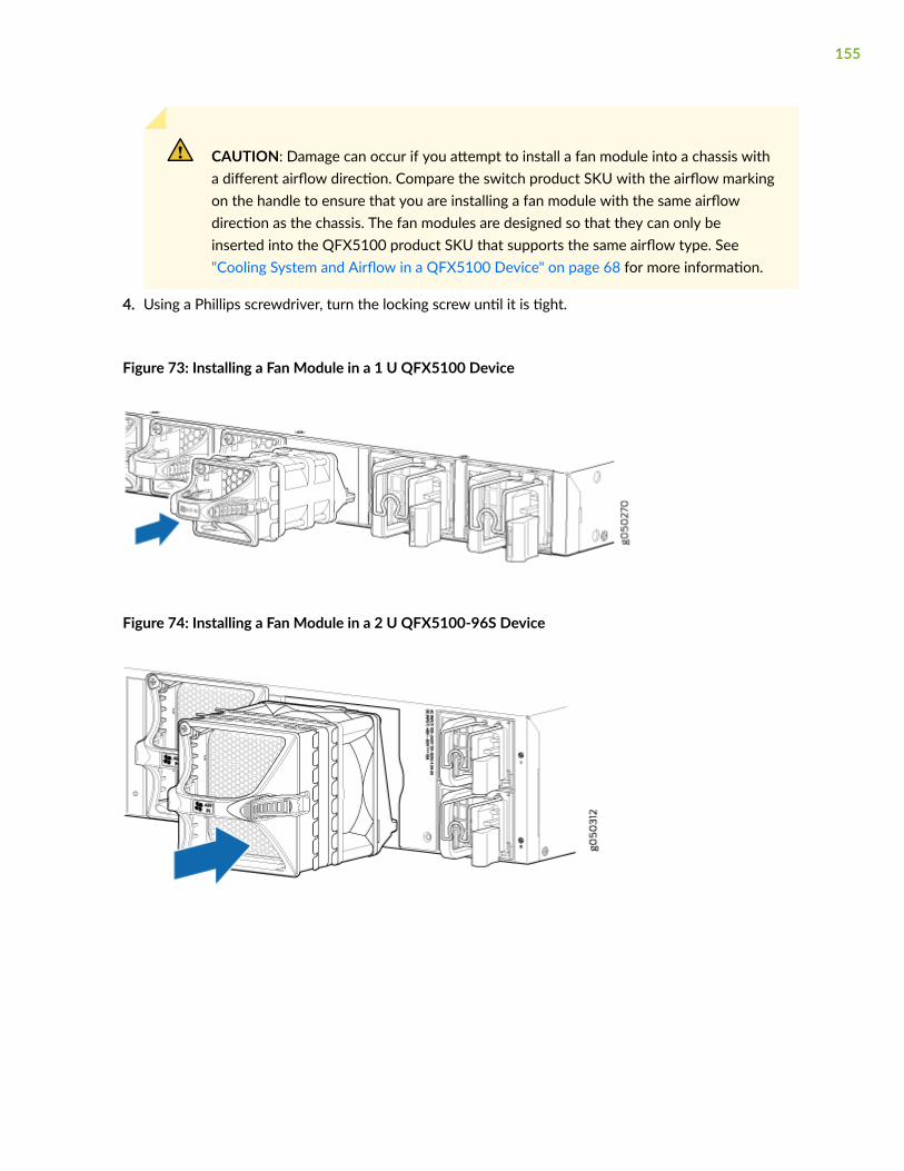
CAUTION: Damage can occur if you attempt to install a fan module into a chassis witha different airflow direction. Compare the switch product SKU with the airflow markingon the handle to ensure that you are installing a fan module with the same airflowdirection as the chassis. The fan modules are designed so that they can only beinserted into the QFX5100 product SKU that supports the same airflow type. See"Cooling System and Airflow in a QFX5100 Device" on page 68 for more information.
4. Using a Phillips screwdriver, turn the locking screw until it is tight.
Figure 73: Installing a Fan Module in a 1 U QFX5100 Device
Figure 74: Installing a Fan Module in a 2 U QFX5100-96S Device
155
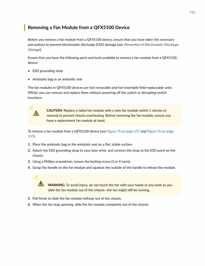
Removing a Fan Module from a QFX5100 Device
Before you remove a fan module from a QFX5100 device, ensure that you have taken the necessaryprecautions to prevent electrostatic discharge (ESD) damage (see Prevention of Electrostatic DischargeDamage).
Ensure that you have the following parts and tools available to remove a fan module from a QFX5100device:
• ESD grounding strap
• Antistatic bag or an antistatic mat
The fan modules in QFX5100 devices are hot-removable and hot-insertable field-replaceable units(FRUs): you can remove and replace them without powering off the switch or disrupting switchfunctions.
CAUTION: Replace a failed fan module with a new fan module within 1 minute ofremoval to prevent chassis overheating. Before removing the fan module, ensure youhave a replacement fan module at hand.
To remove a fan module from a QFX5100 device (see Figure 75 on page 157 and Figure 76 on page157):
1. Place the antistatic bag or the antistatic mat on a flat, stable surface.
2. Attach the ESD grounding strap to your bare wrist, and connect the strap to the ESD point on thechassis.
3. Using a Phillips screwdriver, loosen the locking screw (3 or 4 turns).
4. Grasp the handle on the fan module and squeeze the outside of the handle to release the module.
WARNING: To avoid injury, do not touch the fan with your hands or any tools as youslide the fan module out of the chassis—the fan might still be running.
5. Pull firmly to slide the fan module halfway out of the chassis.
6. When the fan stop spinning, slide the fan module completely out of the chassis.
156
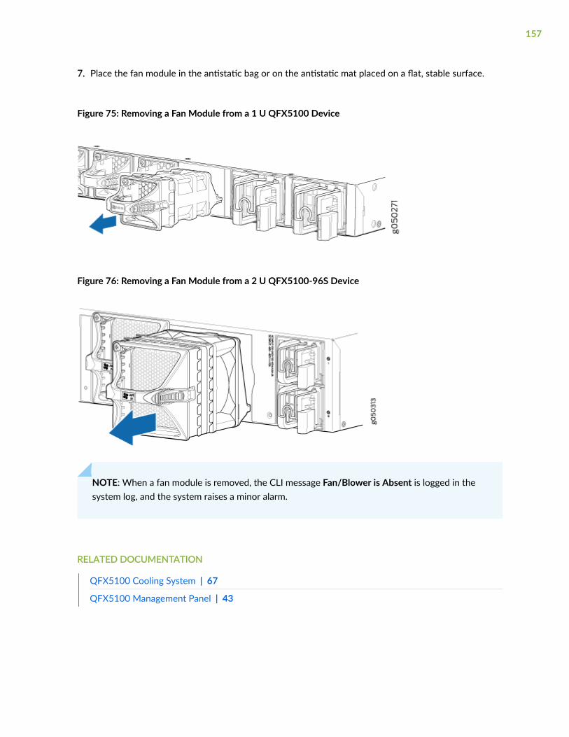
7. Place the fan module in the antistatic bag or on the antistatic mat placed on a flat, stable surface.
Figure 75: Removing a Fan Module from a 1 U QFX5100 Device
Figure 76: Removing a Fan Module from a 2 U QFX5100-96S Device
NOTE: When a fan module is removed, the CLI message Fan/Blower is Absent is logged in thesystem log, and the system raises a minor alarm.
RELATED DOCUMENTATION
QFX5100 Cooling System | 67
QFX5100 Management Panel | 43
157

Install and Remove QFX5100 Power Supplies
IN THIS SECTION
Installing a Power Supply in a QFX5100 Device | 158
Removing a Power Supply from a QFX5100 Device | 160
Installing a Power Supply in a QFX5100 Device
• Before you install a power supply in a QFX5100 device, ensure that you have taken the necessaryprecautions to prevent electrostatic discharge (ESD) damage (see Prevention of ElectrostaticDischarge Damage).
• Ensure that the airflow direction of the power supply is the same as the chassis. Labels on the powersupply handle indicate the direction of airflow. See "Cooling System and Airflow in a QFX5100Device" on page 68 for more information.
The QFX5100 is shipped from the factory with two power supplies. Each power supply is a hot-removable and hot-insertable field-replaceable unit (FRU) when the second power supply is installed andrunning. You can install replacement power supplies in the two slots next to the fan modules withoutpowering off the switch or disrupting the switching function.
To install a power supply in a QFX5100 device (see Figure 77 on page 159 and Figure 78 on page 159):
1. Attach the ESD grounding strap to your bare wrist, and connect the strap to the ESD point on thechassis.
2. Taking care not to touch power supply components, pins, leads, or solder connections, remove thepower supply from its bag.
CAUTION: Verify that the direction of the arrow on the power supply handle matchesthe direction of airflow in the chassis. Ensure that each power supply you install in thechassis has the same airflow direction. If you install power supplies with two differentairflow directions, Junos OS raises an alarm, and the status (ALM) LED blinks amber.
158
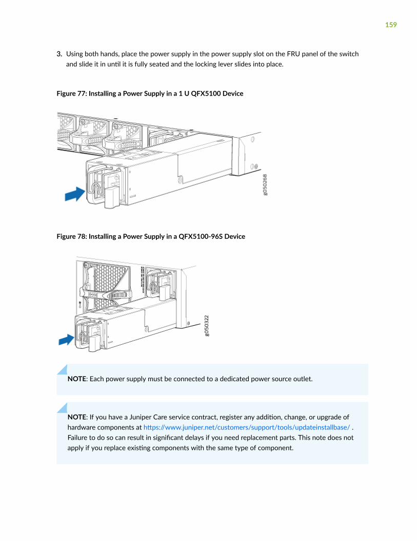
3. Using both hands, place the power supply in the power supply slot on the FRU panel of the switchand slide it in until it is fully seated and the locking lever slides into place.
Figure 77: Installing a Power Supply in a 1 U QFX5100 Device
Figure 78: Installing a Power Supply in a QFX5100-96S Device
NOTE: Each power supply must be connected to a dedicated power source outlet.
NOTE: If you have a Juniper Care service contract, register any addition, change, or upgrade ofhardware components at https://www.juniper.net/customers/support/tools/updateinstallbase/ .Failure to do so can result in significant delays if you need replacement parts. This note does notapply if you replace existing components with the same type of component.
159
Removing a Power Supply from a QFX5100 Device
Before you remove a power supply from a QFX5100 device, ensure that you have taken the necessaryprecautions to prevent electrostatic discharge (ESD) damage (see Prevention of Electrostatic DischargeDamage).
Ensure that you have the following parts and tools available to remove a power supply from a QFX5100device:
• ESD grounding strap
• Antistatic bag or an antistatic mat
• Phillips (+) screwdriver, number 2 (DC power supply)
The QFX5100 is shipped from the factory with two power supplies. Each power supply is a hot-removable and hot-insertable field-replaceable unit (FRU) when the second power supply is installed andrunning. You can install replacement power supplies in the two slots next to the fan modules withoutpowering off the switch or disrupting the switching function.
CAUTION: Replace the power supply with a new power supply within 1 minute ofremoval to prevent chassis overheating.
To remove a power supply from a QFX5100 device (see Figure 79 on page 162 and Figure 80 on page162):
1. Place the antistatic bag or the antistatic mat on a flat, stable surface.
2. Attach the ESD grounding strap to your bare wrist, and connect the strap to the ESD point on thechassis.
NOTE: If only one power supply is installed in your QFX5100 device, you need to power offthe switch before removing the power supply. See "Power Off a QFX5100 Device" on page179.
3. Disconnect power to the switch:
• AC power supply—If the AC power source outlet has a power switch, set it to the OFF (O)position. If the AC power source outlet does not have a power switch, gently pull out the plug endof the power cord connected to the power source outlet.
• DC power supply—Switch the circuit breaker on the panel board that services the DC circuit tothe OFF position.
4. Remove the power source cable from the power supply faceplate:
160

• AC power supply—Remove the power cord from the power supply faceplate by detaching thepower cord retainer and gently pulling out the socket end of the power cord connected to thepower supply faceplate.
• DC power supply—Remove the screws securing the ring lugs attached to the power source cablesto the power supply using the screwdriver, and remove the power source cables from the powersupply. Replace the screws on the terminals and tighten them.
5. Slide the locking lever toward the handle until it stops.
6. Grasp the power supply handle and pull firmly to slide the power supply halfway out of the chassis.
7. Place one hand under the power supply to support it and slide it completely out of the chassis. Takecare not to touch power supply components, pins, leads, or solder connections.
161
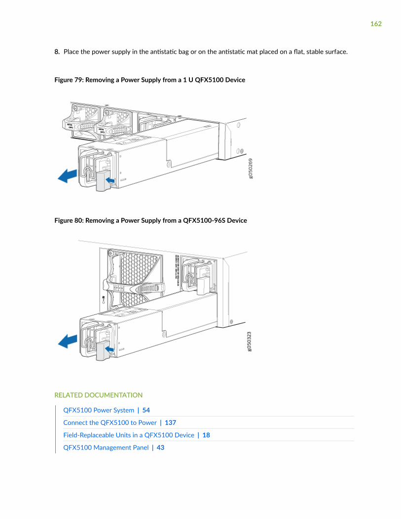
8. Place the power supply in the antistatic bag or on the antistatic mat placed on a flat, stable surface.
Figure 79: Removing a Power Supply from a 1 U QFX5100 Device
Figure 80: Removing a Power Supply from a QFX5100-96S Device
RELATED DOCUMENTATION
QFX5100 Power System | 54
Connect the QFX5100 to Power | 137
Field-Replaceable Units in a QFX5100 Device | 18
QFX5100 Management Panel | 43
162

Install and Remove Expansion Modules in aQFX5100-Device
IN THIS SECTION
Installing an Expansion Module in a QFX5100 Device | 163
Removing an Expansion Module from a QFX5100 Device | 167
Installing an Expansion Module in a QFX5100 Device
Before you begin installing an expansion module in the switch, ensure that you have taken the necessaryprecautions to prevent electrostatic discharge (ESD) damage (see Prevention of Electrostatic DischargeDamage).
Ensure that you have the following parts and tools available:
• ESD grounding strap. If a grounding strap is not available, follow the alternative grounding methoddescribed in Step 1 of the following procedure.
• Phillips (+) screwdriver, number 2
The QFX5100-24Q device allows up to two expansion modules to be added to the port panel toincrease port density. The QFX5100-24Q device holds two bays of expansion modules that can bemixed and matched as desired. The supported modules are:
163
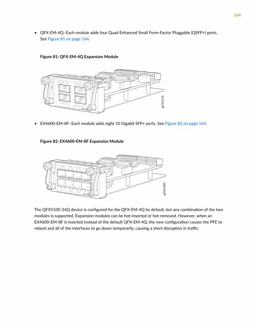
• QFX-EM-4Q–Each module adds four Quad Enhanced Small Form-Factor Pluggable (QSFP+) ports.See Figure 81 on page 164.
Figure 81: QFX-EM-4Q Expansion Module
• EX4600-EM-8F–Each module adds eight 10 Gigabit SFP+ ports. See Figure 82 on page 164.
Figure 82: EX4600-EM-8F Expansion Module
The QFX5100-24Q device is configured for the QFX-EM-4Q by default, but any combination of the twomodules is supported. Expansion modules can be hot-inserted or hot-removed. However, when anEX4600-EM-8F is inserted instead of the default QFX-EM-4Q, the new configuration causes the PFE toreboot and all of the interfaces to go down temporarily, causing a short disruption in traffic.
164
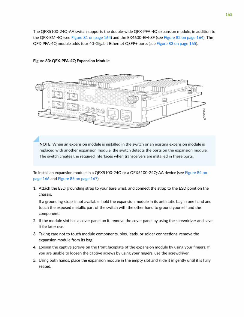
The QFX5100-24Q-AA switch supports the double-wide QFX-PFA-4Q expansion module, in addition tothe QFX-EM-4Q (see Figure 81 on page 164) and the EX4600-EM-8F (see Figure 82 on page 164). TheQFX-PFA-4Q module adds four 40-Gigabit Ethernet QSFP+ ports (see Figure 83 on page 165).
Figure 83: QFX-PFA-4Q Expansion Module
NOTE: When an expansion module is installed in the switch or an existing expansion module isreplaced with another expansion module, the switch detects the ports on the expansion module.The switch creates the required interfaces when transceivers are installed in these ports.
To install an expansion module in a QFX5100-24Q or a QFX5100-24Q-AA device (see Figure 84 onpage 166 and Figure 85 on page 167):
1. Attach the ESD grounding strap to your bare wrist, and connect the strap to the ESD point on thechassis.
If a grounding strap is not available, hold the expansion module in its antistatic bag in one hand andtouch the exposed metallic part of the switch with the other hand to ground yourself and thecomponent.
2. If the module slot has a cover panel on it, remove the cover panel by using the screwdriver and saveit for later use.
3. Taking care not to touch module components, pins, leads, or solder connections, remove theexpansion module from its bag.
4. Loosen the captive screws on the front faceplate of the expansion module by using your fingers. Ifyou are unable to loosen the captive screws by using your fingers, use the screwdriver.
5. Using both hands, place the expansion module in the empty slot and slide it in gently until it is fullyseated.
165
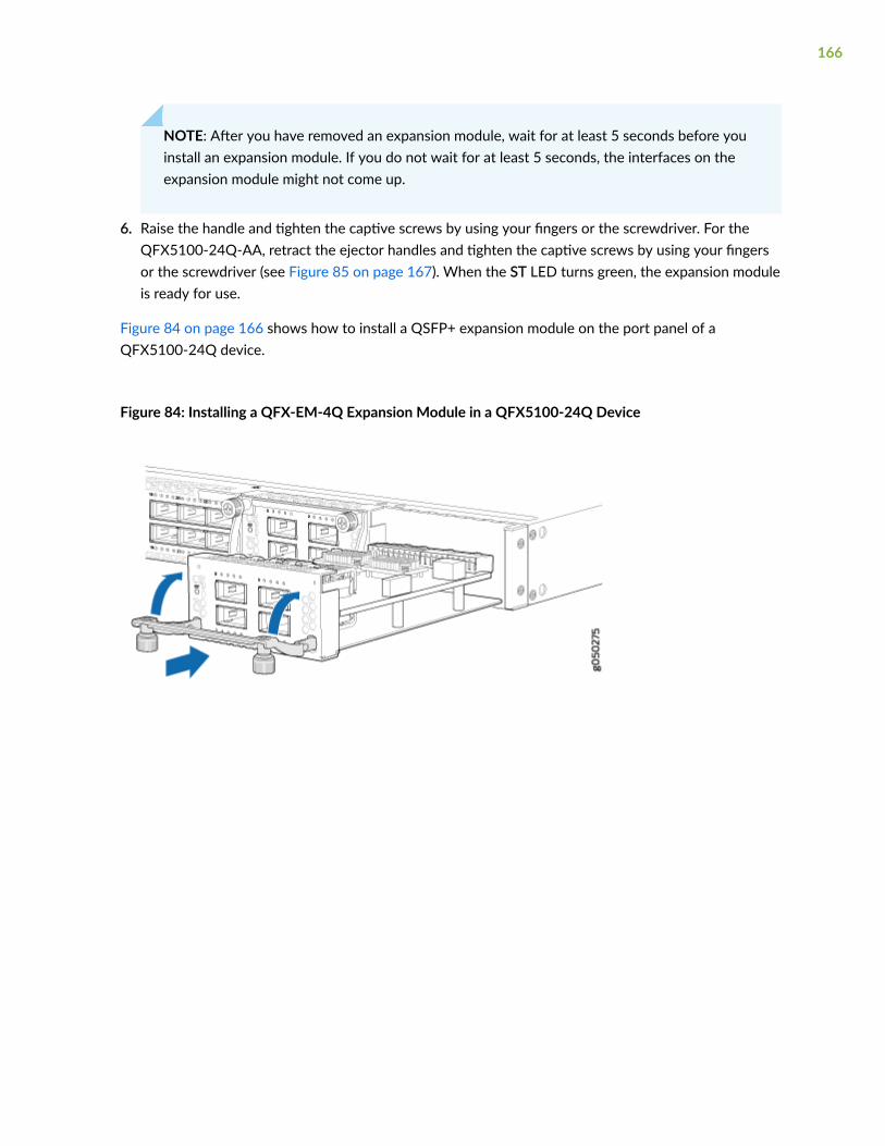
NOTE: After you have removed an expansion module, wait for at least 5 seconds before youinstall an expansion module. If you do not wait for at least 5 seconds, the interfaces on theexpansion module might not come up.
6. Raise the handle and tighten the captive screws by using your fingers or the screwdriver. For theQFX5100-24Q-AA, retract the ejector handles and tighten the captive screws by using your fingersor the screwdriver (see Figure 85 on page 167). When the ST LED turns green, the expansion moduleis ready for use.
Figure 84 on page 166 shows how to install a QSFP+ expansion module on the port panel of aQFX5100-24Q device.
Figure 84: Installing a QFX-EM-4Q Expansion Module in a QFX5100-24Q Device
166
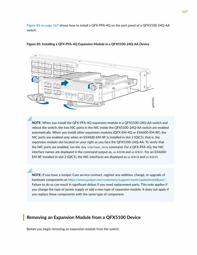
Figure 85 on page 167 shows how to install a QFX-PFA-4Q on the port panel of a QFX5100-24Q-AAswitch.
Figure 85: Installing a QFX-PFA-4Q Expansion Module in a QFX5100-24Q-AA Device
NOTE: When you install the QFX-PFA-4Q expansion module in a QFX5100-24Q-AA switch andreboot the switch, the two NIC ports in the NIC inside the QFX5100-24Q-AA switch are enabledautomatically. When you install other expansion modules (QFX-EM-4Q or EX4600-EM-8F), theNIC ports are enabled only when an EX4600-EM-8F is installed in slot 2 (QIC1), that is, theexpansion module slot located on your right as you face the QFX5100-24Q-AA. To verify thatthe NIC ports are enabled, run the show interfaces terse command. For a QFX-PFA-4Q, the NICinterface names are displayed in the command output as, xe-0/0/40 and xe-0/0/41. For an EX4600-EM-8F installed in slot 2 (QIC1), the NIC interfaces are displayed as xe-0/0/24 and xe-0/0/25.
NOTE: If you have a Juniper Care service contract, register any addition, change, or upgrade ofhardware components at https://www.juniper.net/customers/support/tools/updateinstallbase/ .Failure to do so can result in significant delays if you need replacement parts. This note applies ifyou change the type of power supply or add a new type of expansion module. It does not apply ifyou replace these components with the same type of component.
Removing an Expansion Module from a QFX5100 Device
Before you begin removing an expansion module from the switch:
167
• Ensure that you have taken the necessary precautions to prevent electrostatic discharge (ESD)damage (see Prevention of Electrostatic Discharge Damage).
• If there are any transceivers installed in the expansion module, remove them before you remove theexpansion module. For instructions on removing transceivers, see Removing a Transceiver from aQFX Series Device.
Ensure that you have the following parts and tools available:
• ESD grounding strap
• Phillips screwdriver, number 2
• A replacement optional module or cover panel
• An antistatic bag or antistatic mat
The expansion modules used in QFX5100-24Q and QFX5100-24Q-AA devices are hot-removable andhot-insertable field-replaceable units (FRUs): You can remove and replace them without powering off theswitch or disrupting switch functions.
NOTE: You must take the QFX5100-24Q-AA switch offline, before replacing the QFX-PFA-4Qexpansion module.
CAUTION: We recommend that you install either a replacement optional module or acover panel in the empty module slot to avoid chassis overheating and dustaccumulation.
To remove an expansion module from the switch (see Figure 86 on page 169 and Figure 87 on page170):
1. Attach the ESD grounding strap to your bare wrist, and connect the strap to the ESD point on thechassis.
2. Unscrew both captive screws on the faceplate of the expansion module by using your fingers. If youare unable to unscrew the captive screws by using your fingers, use the screwdriver.
3. Hold the handle and gently pull the expansion module toward you and out of the module slot. For aQFX5100-24Q-AA switch, unscrew the captive screws of the ejector handles and pull the expansionmodule toward you and out of the module slot (see Figure 87 on page 170).
4. Place the expansion module in an antistatic bag or on an antistatic mat placed on a flat, stablesurface.
5. If you are not replacing the expansion module with an optional module, install the cover panel overthe slot.
168

NOTE: After you have removed an expansion module, wait for at least 5 seconds before youinstall an expansion module. If you do not wait for at least 5 seconds, the interfaces on theexpansion module might not come up.
Figure 86 on page 169 shows removing a QFX-EM-4Q expansion module from the port panel of aQFX5100-24Q device.
Figure 86: Removing a QFX-EM-4Q Expansion Module from a QFX5100-24Q Device
Figure 87 on page 170 shows removing a QFX-PFA-4Q expansion module from the port panel of aQFX5100-24Q-AA switch.
169
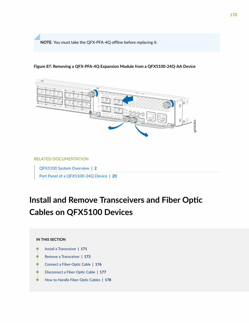
NOTE: You must take the QFX-PFA-4Q offline before replacing it.
Figure 87: Removing a QFX-PFA-4Q Expansion Module from a QFX5100-24Q-AA Device
RELATED DOCUMENTATION
QFX5100 System Overview | 2
Port Panel of a QFX5100-24Q Device | 20
Install and Remove Transceivers and Fiber OpticCables on QFX5100 Devices
IN THIS SECTION
Install a Transceiver | 171
Remove a Transceiver | 173
Connect a Fiber-Optic Cable | 176
Disconnect a Fiber-Optic Cable | 177
How to Handle Fiber-Optic Cables | 178
170
Install a Transceiver
Before you install a transceiver in a device, ensure that you have taken the necessary precautions forsafe handling of lasers (see Laser and LED Safety Guidelines and Warnings).
Ensure that you have a rubber safety cap available to cover the transceiver.
The transceivers for Juniper Networks devices are hot-removable and hot-insertable field-replaceableunits (FRUs): You can remove and replace them without powering off the device or disrupting the devicefunctions.
NOTE: After you insert a transceiver or after you change the media-type configuration, wait for6 seconds for the interface to display operational commands.
NOTE: We recommend that you use only optical transceivers and optical connectors purchasedfrom Juniper Networks with your Juniper Networks device.
CAUTION: The Juniper Networks Technical Assistance Center (JTAC) providescomplete support for Juniper-supplied optical modules and cables. However, JTAC doesnot provide support for third-party optical modules and cables that are not qualified orsupplied by Juniper Networks. If you face a problem running a Juniper device that usesthird-party optical modules or cables, JTAC may help you diagnose host-related issues ifthe observed issue is not, in the opinion of JTAC, related to the use of the third-partyoptical modules or cables. Your JTAC engineer will likely request that you check thethird-party optical module or cable and, if required, replace it with an equivalentJuniper-qualified component.
Use of third-party optical modules with high-power consumption (for example,coherent ZR or ZR+) can potentially cause thermal damage to or reduce the lifespan ofthe host equipment. Any damage to the host equipment due to the use of third-partyoptical modules or cables is the users’ responsibility. Juniper Networks will accept noliability for any damage caused due to such use.
Figure 88 on page 173 shows how to install a QSFP+ transceiver. The procedure is the same for all typesof transceivers except the QSFP28 and CFP transceivers.
To install a transceiver:
171
CAUTION: To prevent electrostatic discharge (ESD) damage to the transceiver, do nottouch the connector pins at the end of the transceiver.
1. Wrap and fasten one end of the ESD wrist strap around your bare wrist, and connect the other endof the strap to the ESD point on the switch.
2. Remove the transceiver from its bag.
3. Check to see whether the transceiver is covered with a rubber safety cap. If it is not, cover thetransceiver with a rubber safety cap.
LASER WARNING: Do not leave a fiber-optic transceiver uncovered except when insertingor removing a cable. The rubber safety cap keeps the port clean and prevents accidentalexposure to laser light.
4. If the port in which you want to install the transceiver is covered with a dust cover, remove the dustcover and save it in case you need to cover the port later. If you are hot-swapping a transceiver, waitfor at least 10 seconds after removing the transceiver from the port before installing a newtransceiver.
5. Using both hands, carefully place the transceiver in the empty port. The connectors must face thechassis.
CAUTION: Before you slide the transceiver into the port, ensure that the transceiver isaligned correctly. Misalignment might cause the pins to bend, making the transceiverunusable.
6. Slide the transceiver in gently until it is fully seated. If you are installing a CFP transceiver, tighten thecaptive screws on the transceiver by using your fingers.
7. Remove the rubber safety cap from the transceiver and the end of the cable, and insert the cable intothe transceiver.
LASER WARNING: Do not look directly into a fiber-optic transceiver or into the ends offiber-optic cables. Fiber-optic transceivers and fiber-optic cable connected to a transceiveremit laser light that can damage your eyes.
172
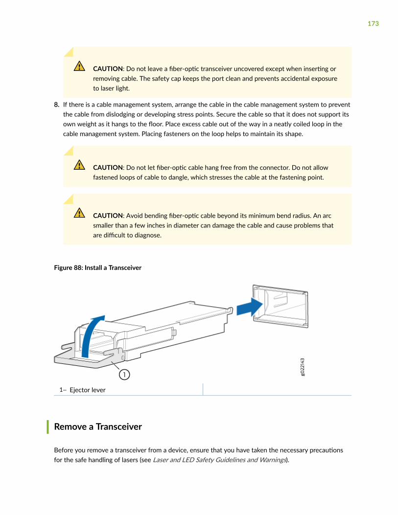
CAUTION: Do not leave a fiber-optic transceiver uncovered except when inserting orremoving cable. The safety cap keeps the port clean and prevents accidental exposureto laser light.
8. If there is a cable management system, arrange the cable in the cable management system to preventthe cable from dislodging or developing stress points. Secure the cable so that it does not support itsown weight as it hangs to the floor. Place excess cable out of the way in a neatly coiled loop in thecable management system. Placing fasteners on the loop helps to maintain its shape.
CAUTION: Do not let fiber-optic cable hang free from the connector. Do not allowfastened loops of cable to dangle, which stresses the cable at the fastening point.
CAUTION: Avoid bending fiber-optic cable beyond its minimum bend radius. An arcsmaller than a few inches in diameter can damage the cable and cause problems thatare difficult to diagnose.
Figure 88: Install a Transceiver
1— Ejector lever
Remove a Transceiver
Before you remove a transceiver from a device, ensure that you have taken the necessary precautionsfor the safe handling of lasers (see Laser and LED Safety Guidelines and Warnings).
173
Ensure that you have the following parts and tools available:
• An antistatic bag or an antistatic mat
• Rubber safety caps to cover the transceiver and fiber-optic cable connector
• A dust cover to cover the port or a replacement transceiver
The transceivers for Juniper Networks devices are hot-removable and hot-insertable field-replaceableunits (FRUs): You can remove and replace them without powering off the device or disrupting devicefunctions.
NOTE: After you remove a transceiver or when you change the media-type configuration, waitfor 6 seconds for the interface to display the operational commands.
Figure 89 on page 175 shows how to remove a QSFP+ transceiver. The procedure is the same for alltypes of transceivers except the QSFP28 and CFP transceivers.
To remove a transceiver from a device:
1. Place the antistatic bag or antistatic mat on a flat, stable surface.
2. Wrap and fasten one end of the ESD wrist strap around your bare wrist, and connect the other endof the strap to the ESD point on the switch.
3. Label the cable connected to the transceiver so that you can reconnect it correctly.
LASER WARNING: Do not look directly into a fiber-optic transceiver or into the ends offiber-optic cables. Fiber-optic transceivers and fiber-optic cables connected to transceiversemit laser light that can damage your eyes.
LASER WARNING: Do not leave a fiber-optic transceiver uncovered except when insertingor removing a cable. The rubber safety cap keeps the port clean and prevents accidentalexposure to laser light.
CAUTION: Do not bend fiber-optic cables beyond their minimum bend radius. An arcsmaller than a few inches in diameter can damage the cables and cause problems thatare difficult to diagnose.
174
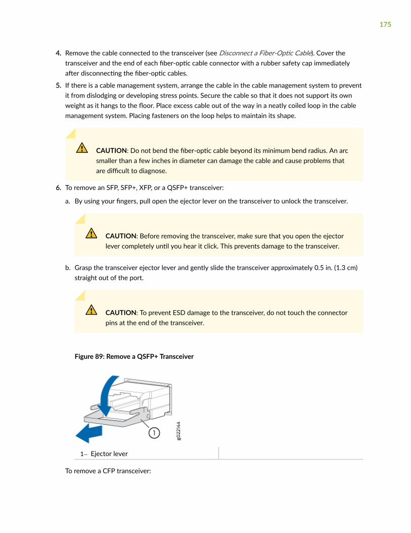
4. Remove the cable connected to the transceiver (see Disconnect a Fiber-Optic Cable). Cover thetransceiver and the end of each fiber-optic cable connector with a rubber safety cap immediatelyafter disconnecting the fiber-optic cables.
5. If there is a cable management system, arrange the cable in the cable management system to preventit from dislodging or developing stress points. Secure the cable so that it does not support its ownweight as it hangs to the floor. Place excess cable out of the way in a neatly coiled loop in the cablemanagement system. Placing fasteners on the loop helps to maintain its shape.
CAUTION: Do not bend the fiber-optic cable beyond its minimum bend radius. An arcsmaller than a few inches in diameter can damage the cable and cause problems thatare difficult to diagnose.
6. To remove an SFP, SFP+, XFP, or a QSFP+ transceiver:
a. By using your fingers, pull open the ejector lever on the transceiver to unlock the transceiver.
CAUTION: Before removing the transceiver, make sure that you open the ejectorlever completely until you hear it click. This prevents damage to the transceiver.
b. Grasp the transceiver ejector lever and gently slide the transceiver approximately 0.5 in. (1.3 cm)straight out of the port.
CAUTION: To prevent ESD damage to the transceiver, do not touch the connectorpins at the end of the transceiver.
Figure 89: Remove a QSFP+ Transceiver
1— Ejector lever
To remove a CFP transceiver:
175
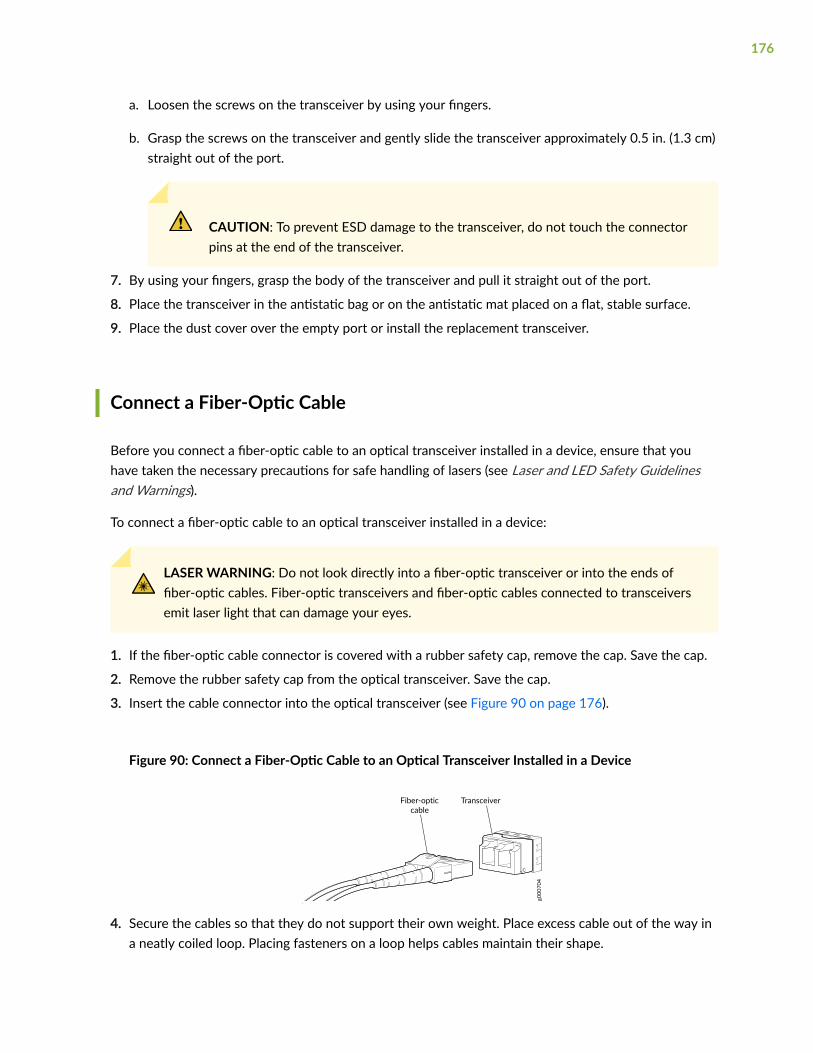
a. Loosen the screws on the transceiver by using your fingers.
b. Grasp the screws on the transceiver and gently slide the transceiver approximately 0.5 in. (1.3 cm)straight out of the port.
CAUTION: To prevent ESD damage to the transceiver, do not touch the connectorpins at the end of the transceiver.
7. By using your fingers, grasp the body of the transceiver and pull it straight out of the port.
8. Place the transceiver in the antistatic bag or on the antistatic mat placed on a flat, stable surface.
9. Place the dust cover over the empty port or install the replacement transceiver.
Connect a Fiber-Optic Cable
Before you connect a fiber-optic cable to an optical transceiver installed in a device, ensure that youhave taken the necessary precautions for safe handling of lasers (see Laser and LED Safety Guidelinesand Warnings).
To connect a fiber-optic cable to an optical transceiver installed in a device:
LASER WARNING: Do not look directly into a fiber-optic transceiver or into the ends offiber-optic cables. Fiber-optic transceivers and fiber-optic cables connected to transceiversemit laser light that can damage your eyes.
1. If the fiber-optic cable connector is covered with a rubber safety cap, remove the cap. Save the cap.
2. Remove the rubber safety cap from the optical transceiver. Save the cap.
3. Insert the cable connector into the optical transceiver (see Figure 90 on page 176).
Figure 90: Connect a Fiber-Optic Cable to an Optical Transceiver Installed in a Device
g000
704
TransceiverFiber-opticcable
4. Secure the cables so that they do not support their own weight. Place excess cable out of the way ina neatly coiled loop. Placing fasteners on a loop helps cables maintain their shape.
176

CAUTION: Do not bend fiber-optic cables beyond their minimum bend radius. An arcsmaller than a few inches in diameter can damage the cables and cause problems thatare difficult to diagnose.
Do not let fiber-optic cables hang free from the connector. Do not allow fastenedloops of cables to dangle, which stresses the cables at the fastening point.
Disconnect a Fiber-Optic Cable
Before you disconnect a fiber-optic cable from an optical transceiver, ensure that you have taken thenecessary precautions for safe handling of lasers. See Laser and LED Safety Guidelines and Warnings.
Ensure that you have the following parts and tools available:
• A rubber safety cap to cover the transceiver
• A rubber safety cap to cover the fiber-optic cable connector
Juniper Networks devices have optical transceivers to which you can connect fiber-optic cables.
To disconnect a fiber-optic cable from an optical transceiver installed in the device:
1. Disable the port in which the transceiver is installed by issuing the following command:
[edit interfaces]user@device# set interface-name disable
LASER WARNING: Do not look directly into a fiber-optic transceiver or into the ends offiber-optic cables. Fiber-optic transceivers and fiber-optic cables connected to transceiversemit laser light that can damage your eyes.
2. Carefully unplug the fiber-optic cable connector from the transceiver.
3. Cover the transceiver with a rubber safety cap.
LASER WARNING: Do not leave a fiber-optic transceiver uncovered except when insertingor removing a cable. The rubber safety cap keeps the port clean and prevents accidentalexposure to laser light.
177

4. Cover the fiber-optic cable connector with the rubber safety cap.
How to Handle Fiber-Optic Cables
Fiber-optic cables connect to optical transceivers that are installed in Juniper Networks devices.
To maintain fiber-optic cables:
• When you unplug a fiber-optic cable from a transceiver, place rubber safety caps over the transceiverand on the end of the cable.
• Anchor fiber-optic cables to prevent stress on the connectors. When attaching a fiber-optic cable toa transceiver, be sure to secure the fiber-optic cable so that it does not support its own weight as ithangs to the floor. Never let a fiber-optic cable hang free from the connector.
• Avoid bending fiber-optic cables beyond their minimum bend radius. Bending fiber-optic cables intoarcs smaller than a few inches in diameter can damage the cables and cause problems that aredifficult to diagnose.
• Frequent plugging and unplugging of fiber-optic cables in and out of optical instruments can damagethe instruments, which are expensive to repair. Attach a short fiber extension to the opticalequipment. Any wear and tear due to frequent plugging and unplugging is then absorbed by theshort fiber extension, which is easier and less expensive to replace than the instruments.
• Keep fiber-optic cable connections clean. Microdeposits of oil and dust in the canal of the transceiveror cable connector can cause loss of light, reduction in signal power, and possibly intermittentproblems with the optical connection.
• To clean the transceiver canal, use an appropriate fiber-cleaning device such as RIFOCS FiberOptic Adaptor Cleaning Wands (part number 946). Follow the instructions in the cleaning kit youuse.
• After cleaning the transceiver, make sure that the connector tip of the fiber-optic cable is clean.Use only an approved alcohol-free fiber-optic cable cleaning kit such as the Opptex Cletop-S®Fiber Cleaner. Follow the instructions in the cleaning kit you use.
RELATED DOCUMENTATION
QFX5100 Chassis Description and Port Panels | 19
178

Power Off a QFX5100 Device
Before you power off a QFX5100 switch:
• Ensure that you have taken the necessary precautions to prevent electrostatic discharge (ESD)damage. See Prevention of Electrostatic Discharge Damage.
• Ensure that you do not need to forward traffic through the switch.
NOTE: Use the following procedure to turn off power on a QFX5100 device that is in standalonemode, a member in a QFX Virtual Chassis, or either a spine device or a leaf device in a VirtualChassis Fabric. QFX5100 devices that are configured either as Node devices or as anInterconnect device in a QFabric system running OS Junos release 14.1 or later, must use adifferent procedure and CLI to ensure there is no traffic loss. See Adding or Replacing a NodeDevice in a QFabric Node Group .
Ensure that you have the following parts and tools available to power off the switch:
• An ESD grounding strap
• An external management device such as a PC
• An RJ-45 to DB-9 rollover cable to connect the external management device to the console port
To power off a QFX5100 switch:
1. Connect to the switch using one of the following methods:
• Connect a management device to the console (CON) port on a QFX5100 switch. For instructionsabout connecting a management device to the console (CON) port, see "Connect a Device to aManagement Console Using an RJ-45 Connector" on page 122.
• You can shut down the QFX5100 switch from a management device on your out-of-bandmanagement network. For instructions about connecting a management device to themanagement (CO or C1) port, see "Connect a Device to a Network for Out-of-Band Management"on page 122.
2. Shut down Junos OS from the external management device by issuing the request system haltoperational mode CLI command. This command shuts down the switch gracefully and preservessystem state information. A message appears on the console, confirming that the operating systemhas halted.
179
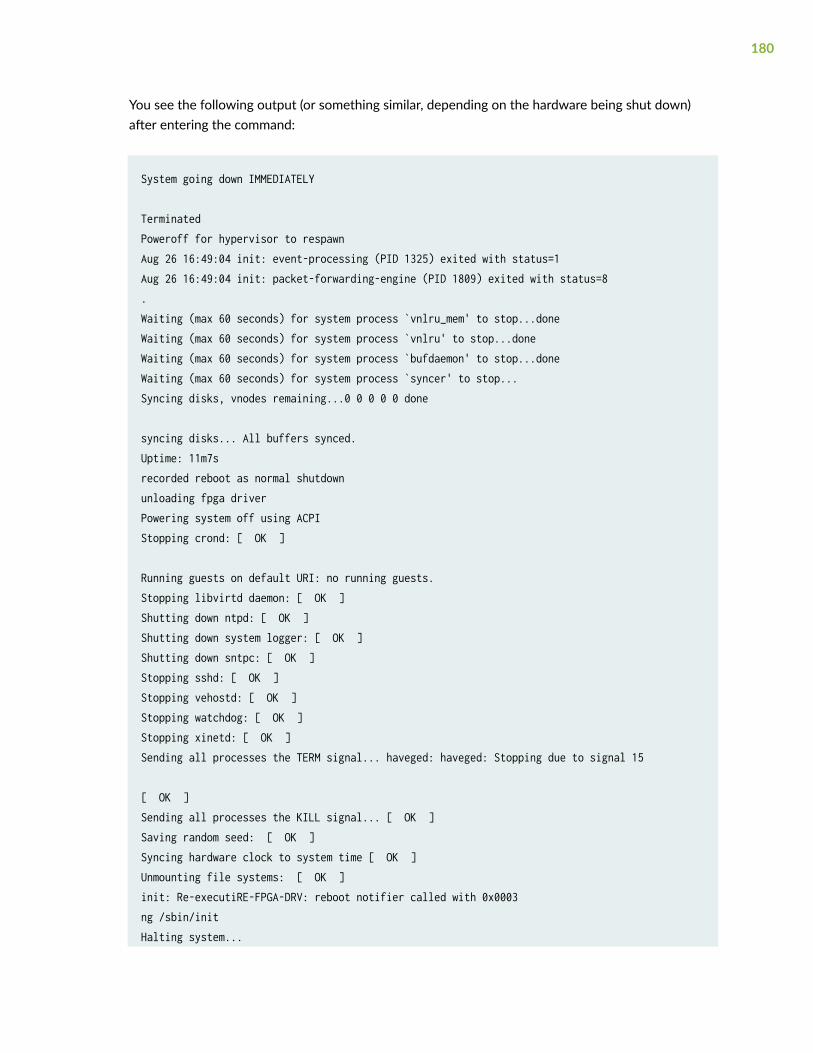
You see the following output (or something similar, depending on the hardware being shut down)after entering the command:
System going down IMMEDIATELY
TerminatedPoweroff for hypervisor to respawnAug 26 16:49:04 init: event-processing (PID 1325) exited with status=1Aug 26 16:49:04 init: packet-forwarding-engine (PID 1809) exited with status=8.Waiting (max 60 seconds) for system process `vnlru_mem' to stop...doneWaiting (max 60 seconds) for system process `vnlru' to stop...doneWaiting (max 60 seconds) for system process `bufdaemon' to stop...doneWaiting (max 60 seconds) for system process `syncer' to stop...Syncing disks, vnodes remaining...0 0 0 0 0 done
syncing disks... All buffers synced.Uptime: 11m7srecorded reboot as normal shutdownunloading fpga driverPowering system off using ACPIStopping crond: [ OK ]
Running guests on default URI: no running guests.Stopping libvirtd daemon: [ OK ]Shutting down ntpd: [ OK ]Shutting down system logger: [ OK ]Shutting down sntpc: [ OK ]Stopping sshd: [ OK ]Stopping vehostd: [ OK ]Stopping watchdog: [ OK ]Stopping xinetd: [ OK ]Sending all processes the TERM signal... haveged: haveged: Stopping due to signal 15
[ OK ]Sending all processes the KILL signal... [ OK ]Saving random seed: [ OK ]Syncing hardware clock to system time [ OK ]Unmounting file systems: [ OK ]init: Re-executiRE-FPGA-DRV: reboot notifier called with 0x0003ng /sbin/initHalting system...
180
tmc-fpga: TMC FPGA driver shutdown called.Power down.
CAUTION: The final output of any version of the request system halt command is“Power down.” Wait at least 60 seconds after first seeing this message before followingthe instructions in Step 4 and Step 5 to power off the switch.
3. Attach the grounding strap to your bare wrist and to a site ESD point.
4. Disconnect power to the switch by performing one of the following tasks:
• AC power supply—If the AC power source outlet has a power switch, set it to the OFF (O)position. If the AC power source outlet does not have a power switch, gently pull out the plug endof the power cord connected to the power source outlet.
• DC power supply—Switch the circuit breaker on the panel board that services the DC circuit tothe OFF position.
5. Remove the power source cable from the power supply faceplate:
• AC power supply—Remove the power cord from the power supply faceplate by detaching thepower cord retainer and gently pulling out the socket end of the power cord connected to thepower supply faceplate.
• DC power supply—Remove the screws securing the ring lugs attached to the power source cablesto the power supply using the screwdriver, and remove the power source cables from the powersupply. Replace the screws on the terminals and tighten them.
6. Uncable the switch before removing it from the rack or cabinet.
RELATED DOCUMENTATION
Connect the QFX5100 to Power | 137
Remove a QFX5100 Device
IN THIS SECTION
Installing and Removing QFX5100 Device Hardware Components | 182
181
Powering Off an Existing QFabric Node Device | 183
Removing a QFX5100 Device from a Rack or Cabinet | 185
Installing and Removing QFX5100 Device Hardware Components
The QFX5100 switch chassis is a rigid sheet-metal structure that houses the hardware components. Thefield-replaceable units (FRUs) in QFX5100 devices are:
• Power supply
• Fan module
• Expansion module (QFX5100-24Q and QFX5100-24Q-AA only)
• SFP+ transceiver
• QSFP+ transceiver
All of the QFX5100 device FRUs are hot-insertable and hot-removable: you can remove and replacethem without powering off the switch or disrupting switch functions.
CAUTION: Replace a failed power supply with a new power supply within 1 minute ofremoval to prevent chassis overheating. Replace a failed fan module with a new fanwithin 1 minute of removal to prevent chassis overheating.
To install a power supply in a QFX5100 device, follow the instructions in "Installing a Power Supply in aQFX5100 Device" on page 158. To remove a power supply from a QFX5100 device, follow theinstructions in "Removing a Power Supply from a QFX5100 Device" on page 160.
To install a fan module in a QFX5100 device, follow the instructions in "Installing a Fan Module in aQFX5100 Device" on page 154. To remove a fan module from a QFX5100 device, follow theinstructions in "Removing a Fan Module from a QFX5100 Device" on page 156.
To install an SFP+ or QSFP+ transceiver in a QFX5100 device, follow the instructions in Installing aTransceiver in a QFX Series Device. To remove an SFP+ or QSFP+ transceiver from a QFX5100 device,follow the instructions in Removing a Transceiver from a QFX Series Device.
To connect a fiber-optic cable to an SFP+ or QSFP+ transceiver in a QFX5100 device, follow theinstructions in Connecting a Fiber-Optic Cable to a QFX Series Device. To disconnect a fiber-optic cablefrom an SFP+ or QSFP+ transceiver from a QFX5100 device, follow the instructions in Disconnecting aFiber-Optic Cable from a QFX Series Device.
182
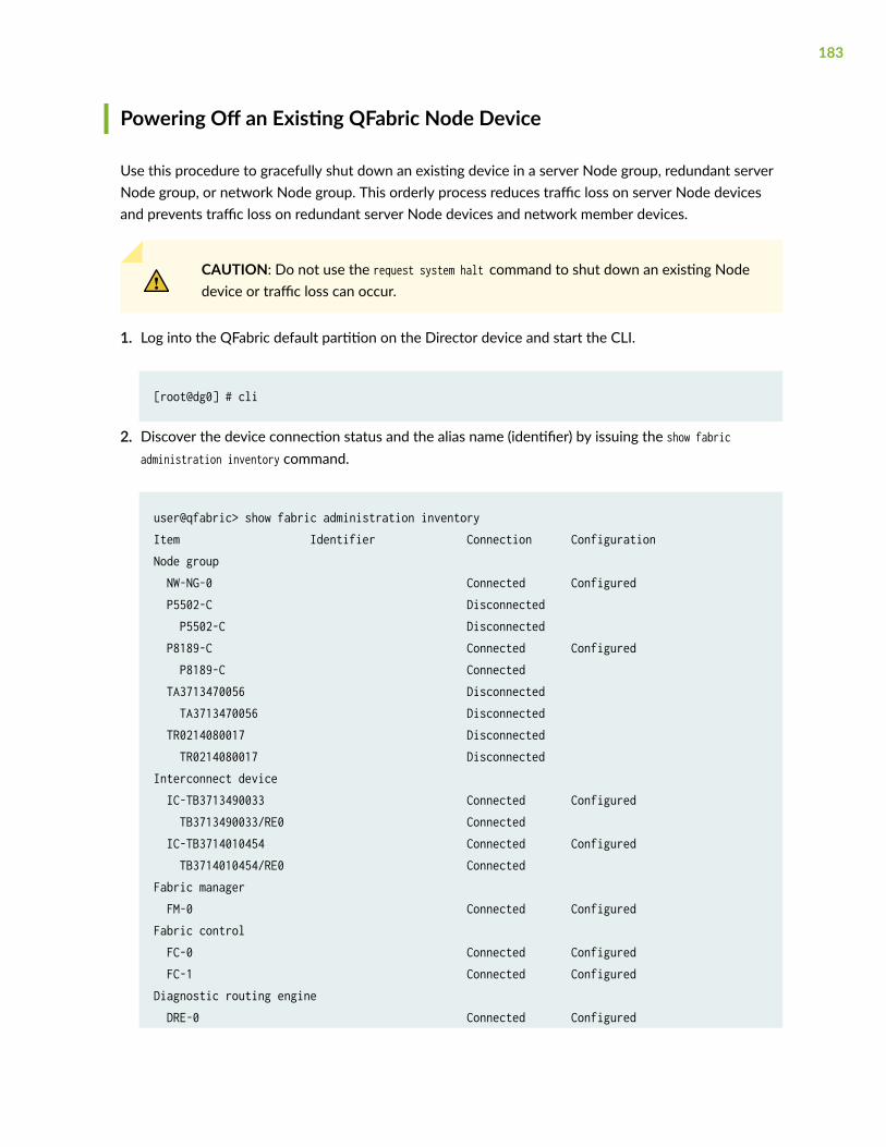
Powering Off an Existing QFabric Node Device
Use this procedure to gracefully shut down an existing device in a server Node group, redundant serverNode group, or network Node group. This orderly process reduces traffic loss on server Node devicesand prevents traffic loss on redundant server Node devices and network member devices.
CAUTION: Do not use the request system halt command to shut down an existing Nodedevice or traffic loss can occur.
1. Log into the QFabric default partition on the Director device and start the CLI.
[root@dg0] # cli
2. Discover the device connection status and the alias name (identifier) by issuing the show fabricadministration inventory command.
user@qfabric> show fabric administration inventoryItem Identifier Connection ConfigurationNode group NW-NG-0 Connected Configured P5502-C Disconnected P5502-C Disconnected P8189-C Connected Configured P8189-C Connected TA3713470056 Disconnected TA3713470056 Disconnected TR0214080017 Disconnected TR0214080017 DisconnectedInterconnect device IC-TB3713490033 Connected Configured TB3713490033/RE0 Connected IC-TB3714010454 Connected Configured TB3714010454/RE0 ConnectedFabric manager FM-0 Connected ConfiguredFabric control FC-0 Connected Configured FC-1 Connected ConfiguredDiagnostic routing engine DRE-0 Connected Configured
183
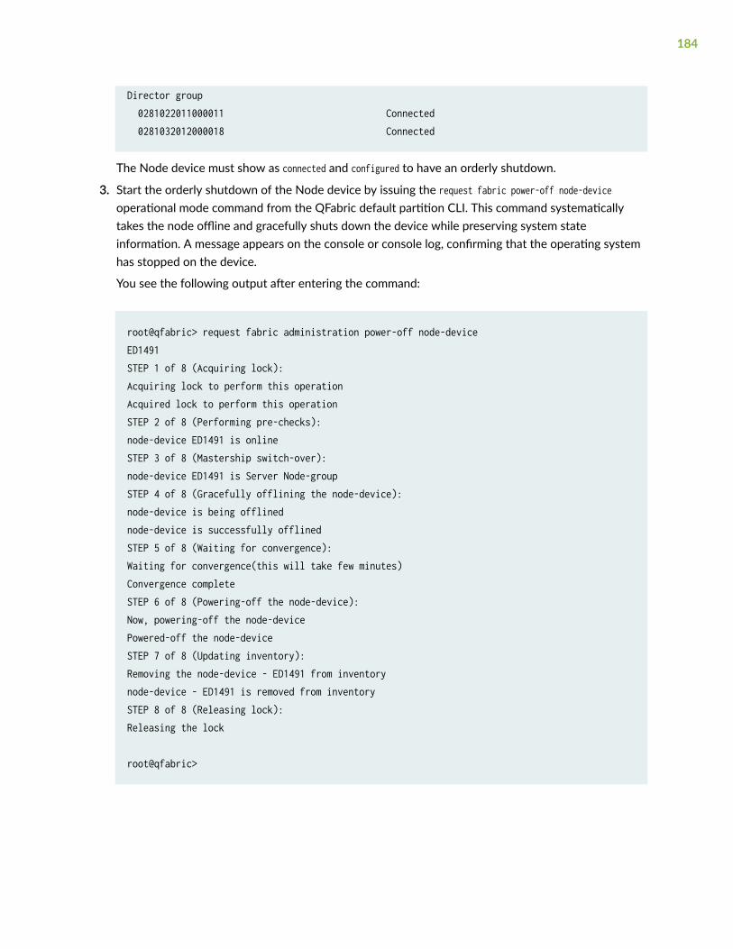
Director group 0281022011000011 Connected 0281032012000018 Connected
The Node device must show as connected and configured to have an orderly shutdown.
3. Start the orderly shutdown of the Node device by issuing the request fabric power-off node-deviceoperational mode command from the QFabric default partition CLI. This command systematicallytakes the node offline and gracefully shuts down the device while preserving system stateinformation. A message appears on the console or console log, confirming that the operating systemhas stopped on the device.
You see the following output after entering the command:
root@qfabric> request fabric administration power-off node-device ED1491 STEP 1 of 8 (Acquiring lock):Acquiring lock to perform this operationAcquired lock to perform this operationSTEP 2 of 8 (Performing pre-checks):node-device ED1491 is onlineSTEP 3 of 8 (Mastership switch-over):node-device ED1491 is Server Node-groupSTEP 4 of 8 (Gracefully offlining the node-device):node-device is being offlinednode-device is successfully offlinedSTEP 5 of 8 (Waiting for convergence):Waiting for convergence(this will take few minutes)Convergence completeSTEP 6 of 8 (Powering-off the node-device):Now, powering-off the node-devicePowered-off the node-deviceSTEP 7 of 8 (Updating inventory):Removing the node-device - ED1491 from inventorynode-device - ED1491 is removed from inventorySTEP 8 of 8 (Releasing lock):Releasing the lock
root@qfabric>
184

CAUTION: The final output of the request fabric power-off node-device command is thefollowing message: The device is shutting down and can be removed when the LCDs are off.Wait at least 3 to 4 minutes after first seeing this message before following theinstructions in Step 5 and Step 6 to disconnect the switch.
4. Attach the grounding strap to your bare wrist and to a site ESD point.
5. Disconnect power to the switch by performing one of the following tasks:
• AC power supply—If the AC power source outlet has a power switch, set it to the OFF (O)position. If the AC power source outlet does not have a power switch, gently pull out the plug endof the power cord connected to the power source outlet.
• DC power supply—Switch the circuit breaker on the panel board that services the DC circuit tothe OFF position.
6. Remove the power source cable from the power supply faceplate:
• AC power supply—Remove the power cord from the power supply faceplate by detaching thepower cord retainer and gently pulling out the socket end of the power cord connected to thepower supply faceplate.
• DC power supply—Remove the screws securing the ring lugs attached to the power source cablesto the power supply using the screwdriver, and remove the power source cables from the powersupply. Replace the screws on the terminals and tighten them.
Removing a QFX5100 Device from a Rack or Cabinet
Before removing a QFX5100 device from a rack:
Ensure that you have the following parts and tools available:
• A Phillips (+) screwdriver, number 2 or number 3, depending on the size of your rack mountingscrews, for mounting the QFX5100 device on the rack.
If you need to relocate an installed QFX5100 device, use the procedure described in this topic. (Theremainder of this topic uses “rack” to mean “rack or cabinet.” )
NOTE: When you remove multiple devices from a rack, remove the device in the top of the rackfirst and proceed to remove the rest of the devices from top to bottom.
• Ensure that the rack is stable and secured to the building.
185

• Ensure that there is enough space to place the removed QFX5100 device in its new location andalong the path to the new location.
• Read General Safety Guidelines and Warnings.
• Use the appropriate power off sequence for your configuration to safely powered off the device.
• If the QFX5100 device is being used as a standalone switch, a member in a QFX Virtual Chassis,or either a spine device or a leaf device in a Virtual Chassis Fabric (VCF), see "Power Off aQFX5100 Device" on page 179.
• If the QFX5100 device is configured as either a Node device or as a Interconnect device in aQFabric system, see Adding or Replacing a Node Device in a QFabric Node Group .
• Disconnect the power cords.
• Ensure that you have disconnected any cables or wires attached to the QFX5100 switch ports.
To remove a QFX5100 device from a rack or cabinet:
1. Have one person support the weight of the switch while another person uses the screwdriver toremove the front mounting screws that attach the chassis mounting brackets to the rack or cabinet.
2. Remove the QFX5100 device from the rack or cabinet.
3. Use the screwdriver to remove the mounting screws that attach the mounting blades attached to therear of the rack or cabinet.
4. Place the removed screws and mounting blades in a labeled bag. You will need them when youreinstall the chassis.
5. Transport the QFX5100 device to your desired new location.
RELATED DOCUMENTATION
Mount a QFX5100 Device in a Rack or Cabinet | 116
Connect the QFX5100 to Power | 137
QFX5100 Cooling System | 67
186
5CHAPTER
Troubleshooting Hardware
Troubleshoot the QFX5100 Device | 188

Troubleshoot the QFX5100 Device
IN THIS SECTION
Alarm Types and Severity Levels | 188
Interface Alarm Messages | 190
Chassis Alarm Messages | 190
Creating an Emergency Boot Device for QFX Series Switches | 195
Recovering the Installation Using an Emergency Boot Device | 196
Alarm Types and Severity Levels
The QFX Series switches support different alarm types and severity levels. Table 36 on page 188provides a list of alarm terms and definitions that may help you in monitoring the device.
Table 36: Alarm Terms and Definitions
Term Definition
Alarm Signal that alerts you to conditions that might prevent normal operation.On the device, alarm indicators might include an LCD panel and LEDs onthe device. The LCD panel (if present on the device) displays the chassisalarm message count. Blinking amber or yellow LEDs indicate yellowalarm conditions for chassis components.
Alarm condition Failure event that triggers an alarm.
188
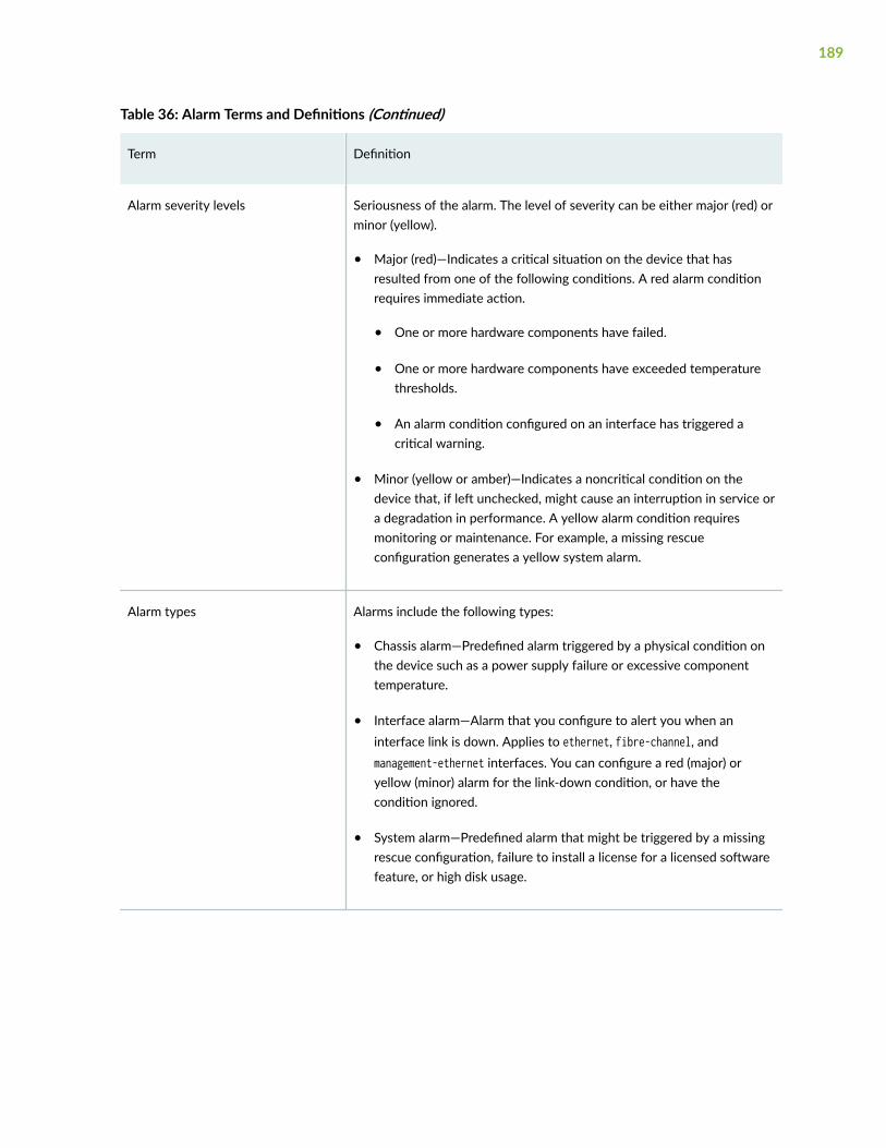
Table 36: Alarm Terms and Definitions (Continued)
Term Definition
Alarm severity levels Seriousness of the alarm. The level of severity can be either major (red) orminor (yellow).
• Major (red)—Indicates a critical situation on the device that hasresulted from one of the following conditions. A red alarm conditionrequires immediate action.
• One or more hardware components have failed.
• One or more hardware components have exceeded temperaturethresholds.
• An alarm condition configured on an interface has triggered acritical warning.
• Minor (yellow or amber)—Indicates a noncritical condition on thedevice that, if left unchecked, might cause an interruption in service ora degradation in performance. A yellow alarm condition requiresmonitoring or maintenance. For example, a missing rescueconfiguration generates a yellow system alarm.
Alarm types Alarms include the following types:
• Chassis alarm—Predefined alarm triggered by a physical condition onthe device such as a power supply failure or excessive componenttemperature.
• Interface alarm—Alarm that you configure to alert you when aninterface link is down. Applies to ethernet, fibre-channel, andmanagement-ethernet interfaces. You can configure a red (major) oryellow (minor) alarm for the link-down condition, or have thecondition ignored.
• System alarm—Predefined alarm that might be triggered by a missingrescue configuration, failure to install a license for a licensed softwarefeature, or high disk usage.
189

Interface Alarm Messages
Interface alarms are alarms that you configure to alert you when an interface is down.
To configure an interface link-down condition to trigger a red or yellow alarm, or to configure the link-down condition to be ignored, use the alarm statement at the [edit chassis] hierarchy level. You canspecify the ethernet, fibre-channel, or management-ethernet interface type.
NOTE: Fibre Channel alarms are valid only on QFX3500 devices.
NOTE: When red alarms or major alarms are issued on QFX5100 or EX4600 switches, the alarmLED glows amber instead of red.
By default, major alarms are configured for interface link-down conditions on the control plane andmanagement network interfaces in a QFabric system. The link-down alarms indicate that connectivity tothe control plane network is down. You can configure these alarms to be ignored using the alarmstatement at the [edit chassis] hierarchy level.
NOTE: If you configure a yellow alarm on the QFX3008-I Interconnect device, it is handled as ared alarm.
Chassis Alarm Messages
Chassis alarms indicate a failure on the device or one of its components. Chassis alarms are preset andcannot be modified.
Chassis alarms on QFX5100, QFX5110, QFX5210, and QFX5120 devices have two severity levels:
• Major (red)—Indicates a critical situation on the device that has resulted from one of the conditionsdescribed in Table 37 on page 191. A red alarm condition requires immediate action.
• Minor (yellow)—Indicates a noncritical condition on the device that, if left unchecked, might cause aninterruption in service or degradation in performance. A yellow alarm condition requires monitoringor maintenance.
Table 37 on page 191 describes the chassis alarm messages on QFX5100, QFX5110, QFX5200,QFX5210, and QFX5120 devices.
190
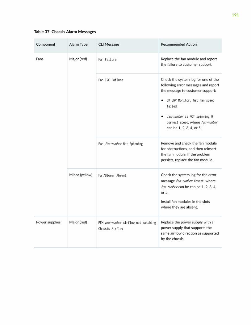
Table 37: Chassis Alarm Messages
Component Alarm Type CLI Message Recommended Action
Fans Major (red) Fan Failure Replace the fan module and reportthe failure to customer support.
Fan I2C Failure Check the system log for one of thefollowing error messages and reportthe message to customer support:
• CM ENV Monitor: Get fan speedfailed.
• fan-number is NOT spinning @correct speed, where fan-numbercan be 1, 2, 3, 4, or 5.
Fan fan-number Not Spinning Remove and check the fan modulefor obstructions, and then reinsertthe fan module. If the problempersists, replace the fan module.
Minor (yellow) Fan/Blower Absent Check the system log for the errormessage fan-number Absent, wherefan-number can be can be 1, 2, 3, 4,or 5.
Install fan modules in the slotswhere they are absent.
Power supplies Major (red) PEM pem-number Airflow not matchingChassis Airflow
Replace the power supply with apower supply that supports thesame airflow direction as supportedby the chassis.
191
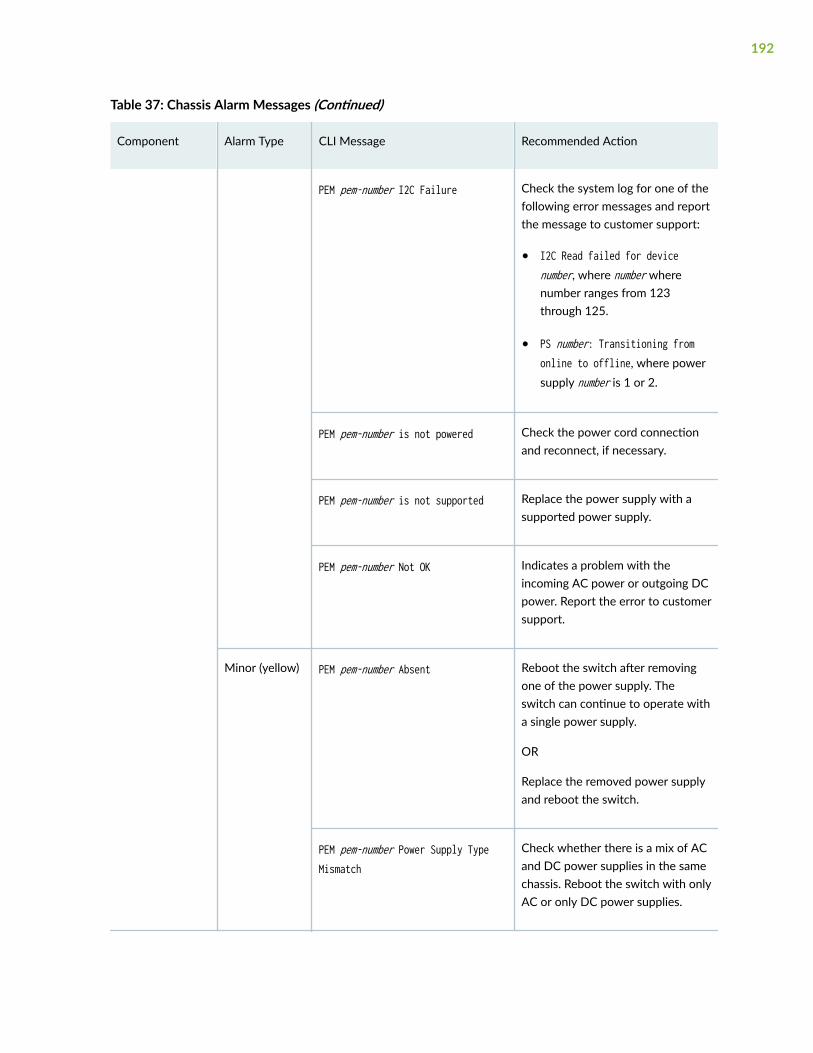
Table 37: Chassis Alarm Messages (Continued)
Component Alarm Type CLI Message Recommended Action
PEM pem-number I2C Failure Check the system log for one of thefollowing error messages and reportthe message to customer support:
• I2C Read failed for devicenumber, where number wherenumber ranges from 123through 125.
• PS number: Transitioning fromonline to offline, where powersupply number is 1 or 2.
PEM pem-number is not powered Check the power cord connectionand reconnect, if necessary.
PEM pem-number is not supported Replace the power supply with asupported power supply.
PEM pem-number Not OK Indicates a problem with theincoming AC power or outgoing DCpower. Report the error to customersupport.
Minor (yellow) PEM pem-number Absent Reboot the switch after removingone of the power supply. Theswitch can continue to operate witha single power supply.
OR
Replace the removed power supplyand reboot the switch.
PEM pem-number Power Supply TypeMismatch
Check whether there is a mix of ACand DC power supplies in the samechassis. Reboot the switch with onlyAC or only DC power supplies.
192
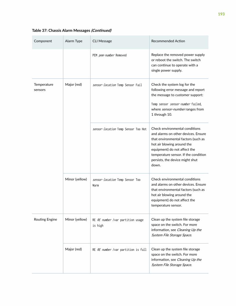
Table 37: Chassis Alarm Messages (Continued)
Component Alarm Type CLI Message Recommended Action
PEM pem-number Removed Replace the removed power supplyor reboot the switch. The switchcan continue to operate with asingle power supply.
Temperaturesensors
Major (red) sensor-location Temp Sensor Fail Check the system log for thefollowing error message and reportthe message to customer support:
Temp sensor sensor-number failed,where sensor-number ranges from1 through 10.
sensor-location Temp Sensor Too Hot Check environmental conditionsand alarms on other devices. Ensurethat environmental factors (such ashot air blowing around theequipment) do not affect thetemperature sensor. If the conditionpersists, the device might shutdown.
Minor (yellow) sensor-location Temp Sensor TooWarm
Check environmental conditionsand alarms on other devices. Ensurethat environmental factors (such ashot air blowing around theequipment) do not affect thetemperature sensor.
Routing Engine Minor (yellow) RE RE number /var partition usageis high
Clean up the system file storagespace on the switch. For moreinformation, see Cleaning Up theSystem File Storage Space.
Major (red) RE RE number /var partition is full Clean up the system file storagespace on the switch. For moreinformation, see Cleaning Up theSystem File Storage Space.
193
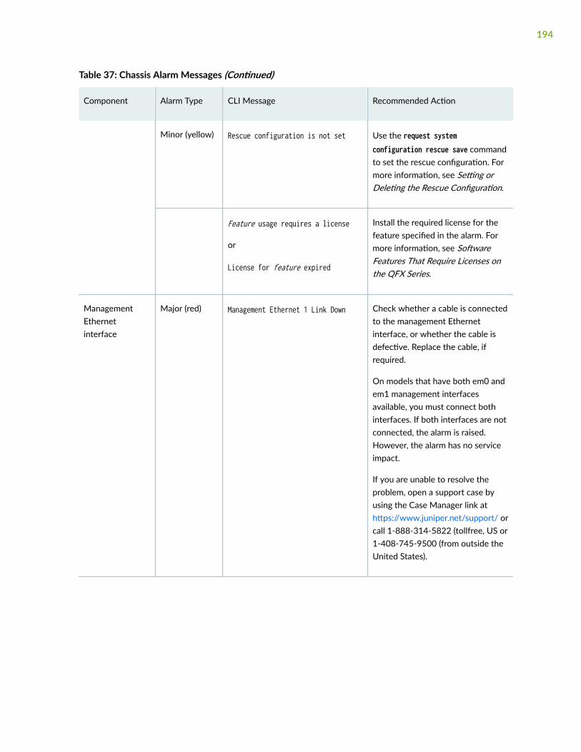
Table 37: Chassis Alarm Messages (Continued)
Component Alarm Type CLI Message Recommended Action
Minor (yellow) Rescue configuration is not set Use the request systemconfiguration rescue save commandto set the rescue configuration. Formore information, see Setting orDeleting the Rescue Configuration.
Feature usage requires a license
or
License for feature expired
Install the required license for thefeature specified in the alarm. Formore information, see SoftwareFeatures That Require Licenses onthe QFX Series.
ManagementEthernetinterface
Major (red) Management Ethernet 1 Link Down Check whether a cable is connectedto the management Ethernetinterface, or whether the cable isdefective. Replace the cable, ifrequired.
On models that have both em0 andem1 management interfacesavailable, you must connect bothinterfaces. If both interfaces are notconnected, the alarm is raised.However, the alarm has no serviceimpact.
If you are unable to resolve theproblem, open a support case byusing the Case Manager link athttps://www.juniper.net/support/ orcall 1-888-314-5822 (tollfree, US or1-408-745-9500 (from outside theUnited States).
194

Creating an Emergency Boot Device for QFX Series Switches
Before you begin, you need to download the installation media image for your device and Junos OSrelease from https://www.juniper.net/customers/support/ .
If Junos OS on the device is damaged in some way that prevents the software from loading properly, youcan use an emergency boot device to repartition the primary disk and load a fresh installation ofJunos OS. Use the following procedure to create an emergency boot device.
NOTE: You can create the emergency boot device on another Juniper Networks switch or router,or any laptop or desktop PC that supports Linux. The steps you take to create the emergencyboot device vary, depending on the device.
To create an emergency boot device:
1. Use FTP to copy the installation media image into the /var/tmp directory on the device.
2. Insert a USB storage device into the USB port.
3. From the Junos OS command-line interface (CLI), start the shell:
user@device> start shell%
4. Use the gunzip command to unzip the image file.
5. Switch to the root account using the su command:
% suPassword: password
NOTE: The password is the root password for the device. If you logged in to the device as theroot user, you do not need to perform this step.
6. Enter the following command on the device:
root@device% dd if=/var/tmp/filename of=/dev/da1 bs=1m
195
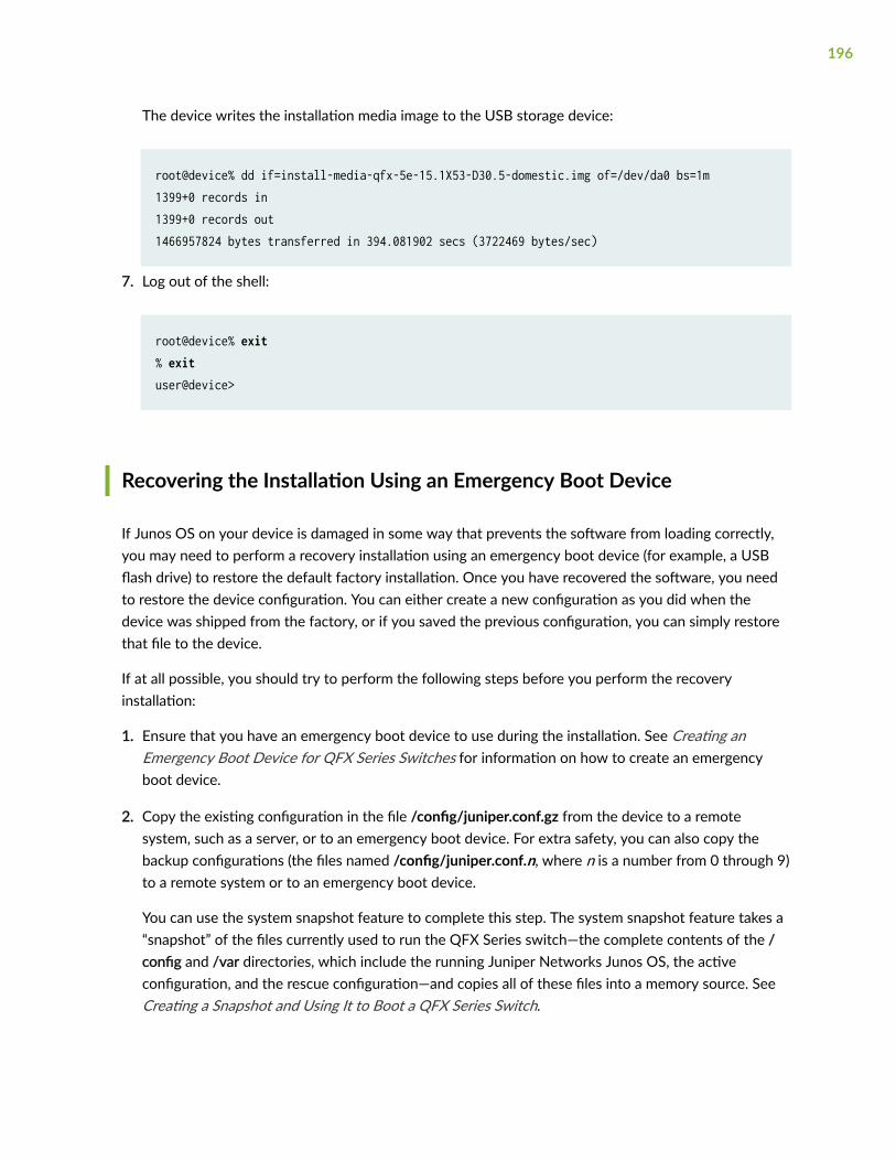
The device writes the installation media image to the USB storage device:
root@device% dd if=install-media-qfx-5e-15.1X53-D30.5-domestic.img of=/dev/da0 bs=1m1399+0 records in1399+0 records out1466957824 bytes transferred in 394.081902 secs (3722469 bytes/sec)
7. Log out of the shell:
root@device% exit% exituser@device>
Recovering the Installation Using an Emergency Boot Device
If Junos OS on your device is damaged in some way that prevents the software from loading correctly,you may need to perform a recovery installation using an emergency boot device (for example, a USBflash drive) to restore the default factory installation. Once you have recovered the software, you needto restore the device configuration. You can either create a new configuration as you did when thedevice was shipped from the factory, or if you saved the previous configuration, you can simply restorethat file to the device.
If at all possible, you should try to perform the following steps before you perform the recoveryinstallation:
1. Ensure that you have an emergency boot device to use during the installation. See Creating anEmergency Boot Device for QFX Series Switches for information on how to create an emergencyboot device.
2. Copy the existing configuration in the file /config/juniper.conf.gz from the device to a remotesystem, such as a server, or to an emergency boot device. For extra safety, you can also copy thebackup configurations (the files named /config/juniper.conf.n, where n is a number from 0 through 9)to a remote system or to an emergency boot device.
You can use the system snapshot feature to complete this step. The system snapshot feature takes a“snapshot” of the files currently used to run the QFX Series switch—the complete contents of the /config and /var directories, which include the running Juniper Networks Junos OS, the activeconfiguration, and the rescue configuration—and copies all of these files into a memory source. SeeCreating a Snapshot and Using It to Boot a QFX Series Switch.
196
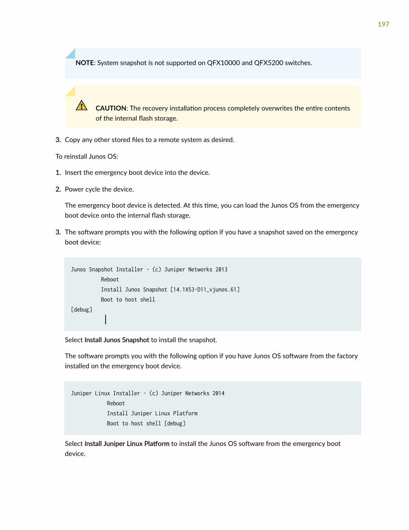
NOTE: System snapshot is not supported on QFX10000 and QFX5200 switches.
CAUTION: The recovery installation process completely overwrites the entire contentsof the internal flash storage.
3. Copy any other stored files to a remote system as desired.
To reinstall Junos OS:
1. Insert the emergency boot device into the device.
2. Power cycle the device.
The emergency boot device is detected. At this time, you can load the Junos OS from the emergencyboot device onto the internal flash storage.
3. The software prompts you with the following option if you have a snapshot saved on the emergencyboot device:
Junos Snapshot Installer - (c) Juniper Networks 2013 Reboot Install Junos Snapshot [14.1X53-D11_vjunos.61] Boot to host shell [debug] │
Select Install Junos Snapshot to install the snapshot.
The software prompts you with the following option if you have Junos OS software from the factoryinstalled on the emergency boot device.
Juniper Linux Installer - (c) Juniper Networks 2014 Reboot Install Juniper Linux Platform Boot to host shell [debug]
Select Install Juniper Linux Platform to install the Junos OS software from the emergency bootdevice.
197
4. The device copies the software from the emergency boot device, occasionally displaying statusmessages. Copying the software can take up to 12 minutes.
When the software is finished being copied from the emergency device to the device, the devicereboots from the internal flash storage on which the software was just installed. When the reboot iscomplete, the device displays the Junos OS login prompt:
root@switch#
5. Create a new configuration as you did when the device was shipped from the factory, or restore thepreviously saved configuration file to the device.
6. Remove the emergency boot device.
RELATED DOCUMENTATION
Configure a QFX5100 Device | 148
QFX5100 Chassis Description and Port Panels | 19
198

6CHAPTER
Contacting Customer Support andReturning the Chassis or Components
Contact Customer Support to Obtain Return Material Authorization | 200
Return the QFX5100 Chassis or Components | 201
Contact Customer Support to Obtain ReturnMaterial Authorization
If you are returning a device or hardware component to Juniper Networks for repair or replacement,obtain a Return Material Authorization (RMA) number from Juniper Networks Technical AssistanceCenter (JTAC).
After locating the serial number of the device or hardware component you want to return, open aservice request with Juniper Networks Technical Assistance Center (JTAC) on the Web or by telephone.
Before you request an RMA number from JTAC, be prepared to provide the following information:
• Your existing service request number, if you have one
• Serial number of the component
• Your name, organization name, telephone number, fax number, and shipping address
• Details of the failure or problem
• Type of activity being performed on the device when the problem occurred
• Configuration data displayed by one or more show commands
You can contact JTAC 24 hours a day, seven days a week on the Web or by telephone:
• Service Request Manager: https://support.juniper.net/support
• Telephone: +1-888-314-JTAC (+1-888-314-5822), toll free in U.S., Canada, and Mexico
NOTE: For international or direct-dial options in countries without toll free numbers, see https://support.juniper.net/support
If you are contacting JTAC by telephone, enter your 12-digit service request number followed by thepound (#) key for an existing case, or press the star (*) key to be routed to the next available supportengineer.
The support representative validates your request and issues an RMA number for return of thecomponent.
200

Return the QFX5100 Chassis or Components
IN THIS SECTION
Locating the Serial Number on a QFX5100 Device or Component | 201
How to Return a Hardware Component to Juniper Networks, Inc. | 205
Guidelines for Packing Hardware Components for Shipment | 206
Locating the Serial Number on a QFX5100 Device or Component
IN THIS SECTION
Listing the Chassis and Component Details Using the CLI | 202
Locating the Chassis Serial Number ID Label on a QFX5100 Switch | 202
Locating the Serial Number ID Labels on FRU Components | 204
If you are returning a switch or component to Juniper Networks for repair or replacement, you mustlocate the serial number of the switch or component. You must provide the serial number to the JuniperNetworks Technical Assistance Center (JTAC) when you contact them to obtain a Return MaterialsAuthorization (RMA). See Contacting Customer Support to Obtain a Return Materials Authorization fora QFX Series Device or Component.
If the switch is operational and you can access the command-line interface (CLI), you can list serialnumbers for the switch and for some components with a CLI command. If you do not have access to theCLI or if the serial number for the component does not appear in the command output, you can locatethe serial number ID label on the switch or component.
NOTE: If you want to find the serial number ID label on a component, you need to remove thecomponent from the switch chassis, for which you must have the required parts and toolsavailable.
201

Listing the Chassis and Component Details Using the CLI
To list the QFX5100 switch and components and their serial numbers, use the show chassis hardware CLIoperational mode command. If you are using the QFX5100 switch as a Node device in a QFabric system,you must first log in to the switch using the request component login CLI operational mode command.
user@device> show chassis hardware
Hardware inventory:Item Version Part number Serial number DescriptionChassis EL9270 QFX5100-24Q-2PPseudo CB 0Routing Engine 0 BUILTIN BUILTIN QFX Routing EngineFPC 0 REV 17 750-036931 P5331-C QFX5100-24Q-2P CPU BUILTIN BUILTIN FPC CPU PIC 0 BUILTIN BUILTIN 24x 40G-QSFPPower Supply 0 Rev 04 740-032091 VB02420 QFX3500-48S4QPower Supply 1Fan Tray 1 QFX5100 Fan Tray 1, Back to Front Airflow - AFIFan Tray 2 QFX5100 Fan Tray 2, Back to Front Airflow - AFIFan Tray 3 QFX5100 Fan Tray 3, Back to Front Airflow - AFIFan Tray 4 QFX5100 Fan Tray 4, Back to Front Airflow - AFIFan Tray 5 QFX5100 Fan Tray 5, Back to Front Airflow - AFI
NOTE: You must remove the fan module to read the fan serial number from the serial number IDlabel. The fan module serial number cannot be viewed through the CLI. Fan Tray 2 refers to thethird module from the left, counting from 0.
Locating the Chassis Serial Number ID Label on a QFX5100 Switch
The location for the chassis serial number ID label is product SKU-dependent. On the QFX5100-96S,QFX5100-48S, QFX5100-48SH, QFX5100-48T, and QFX5100-48TH product SKUs, the serial numberID label is located on the left side of the port panel. On legacy switches, or switches with an LCD, theport panel is referred to as the front panel. See Figure 91 on page 203 through Figure 93 on page 204
202
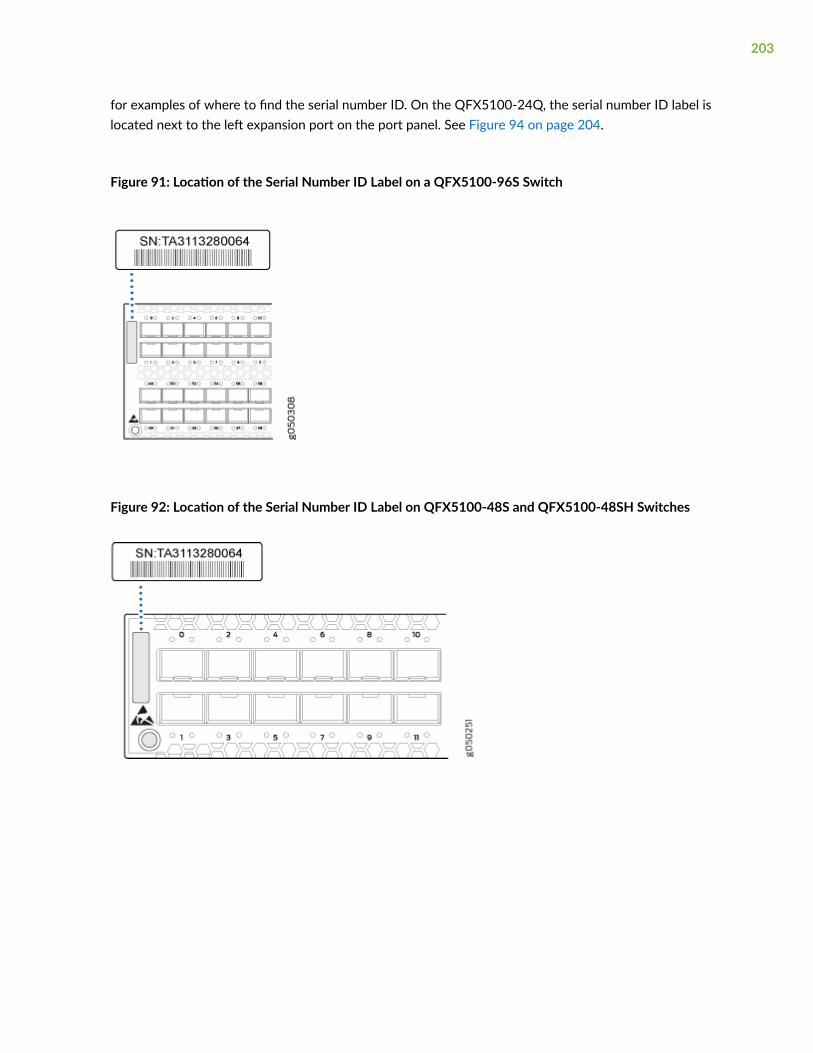
for examples of where to find the serial number ID. On the QFX5100-24Q, the serial number ID label islocated next to the left expansion port on the port panel. See Figure 94 on page 204.
Figure 91: Location of the Serial Number ID Label on a QFX5100-96S Switch
Figure 92: Location of the Serial Number ID Label on QFX5100-48S and QFX5100-48SH Switches
203
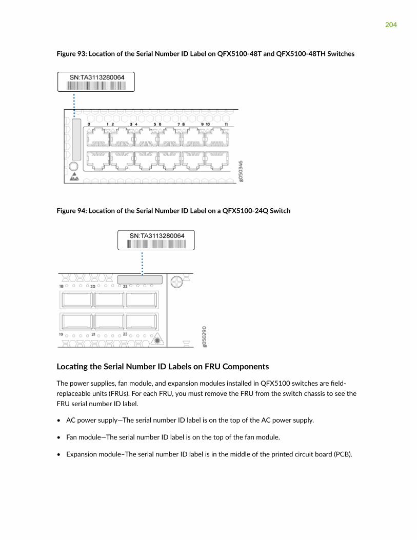
Figure 93: Location of the Serial Number ID Label on QFX5100-48T and QFX5100-48TH Switches
Figure 94: Location of the Serial Number ID Label on a QFX5100-24Q Switch
Locating the Serial Number ID Labels on FRU Components
The power supplies, fan module, and expansion modules installed in QFX5100 switches are field-replaceable units (FRUs). For each FRU, you must remove the FRU from the switch chassis to see theFRU serial number ID label.
• AC power supply—The serial number ID label is on the top of the AC power supply.
• Fan module—The serial number ID label is on the top of the fan module.
• Expansion module–The serial number ID label is in the middle of the printed circuit board (PCB).
204
RELATED DOCUMENTATION
Returning a QFX5100 Device or Component for Repair or Replacement
How to Return a Hardware Component to Juniper Networks, Inc.
If a hardware component fails, please contact Juniper Networks, Inc. to obtain a Return MaterialAuthorization (RMA) number. This number is used to track the returned material at the factory and toreturn repaired or new components to the customer as needed.
NOTE: Do not return any component to Juniper Networks, Inc. unless you have first obtained anRMA number. Juniper Networks, Inc. reserves the right to refuse shipments that do not have anRMA. Refused shipments are returned to the customer by collect freight.
For more information about return and repair policies, see the customer support webpage at https://support.juniper.net/support/.
For product problems or technical support issues, contact the Juniper Networks Technical AssistanceCenter (JTAC) by using the Service Request Manager link at https://support.juniper.net/support/ or at1-888-314-JTAC (within the United States) or 1-408-745-9500 (from outside the United States).
To return a defective hardware component:
1. Determine the part number and serial number of the defective component.
2. Obtain an RMA number from the Juniper Networks Technical Assistance Center (JTAC). You can sende-mail or telephone as described above.
3. Provide the following information in your e-mail message or during the telephone call:
• Part number and serial number of component
• Your name, organization name, telephone number, and fax number
• Description of the failure
4. The support representative validates your request and issues an RMA number for return of thecomponent.
5. Pack the component for shipment.
205
Guidelines for Packing Hardware Components for Shipment
To pack and ship individual components:
• When you return components, make sure that they are adequately protected with packing materialsand packed so that the pieces are prevented from moving around inside the carton.
• Use the original shipping materials if they are available.
• Place individual components in antistatic bags.
• Write the RMA number on the exterior of the box to ensure proper tracking.
CAUTION: Do not stack any of the hardware components.
RELATED DOCUMENTATION
Remove a QFX5100 Device | 181
206

7CHAPTER
Safety and Compliance Information
General Safety Guidelines and Warnings | 209
Definitions of Safety Warning Levels | 210
Qualified Personnel Warning | 212
Warning Statement for Norway and Sweden | 212
Fire Safety Requirements | 213
Installation Instructions Warning | 214
Chassis and Component Lifting Guidelines | 215
Restricted Access Warning | 215
Ramp Warning | 217
Rack-Mounting and Cabinet-Mounting Warnings | 217
Grounded Equipment Warning | 221
Laser and LED Safety Guidelines and Warnings | 222
Radiation from Open Port Apertures Warning | 225
Maintenance and Operational Safety Guidelines and Warnings | 226
General Electrical Safety Guidelines and Warnings | 232
Action to Take After an Electrical Accident | 233
Prevention of Electrostatic Discharge Damage | 234
AC Power Electrical Safety Guidelines | 235
AC Power Disconnection Warning | 236
DC Power Electrical Safety Guidelines | 237

DC Power Copper Conductors Warning | 238
DC Power Disconnection Warning | 239
DC Power Grounding Requirements and Warning | 240
DC Power Wiring Sequence Warning | 241
DC Power Wiring Terminations Warning | 242
Multiple Power Supplies Disconnection Warning | 244
Agency Approvals for the QFX Series | 245
Compliance Statements for EMC Requirements for the QFX Series | 246
Statements of Volatility for Juniper Network Devices | 251
TN Power Warning | 254
General Safety Guidelines and Warnings
The following guidelines help ensure your safety and protect the device from damage. The list ofguidelines might not address all potentially hazardous situations in your working environment, so bealert and exercise good judgment at all times.
• Perform only the procedures explicitly described in the hardware documentation for this device.Make sure that only authorized service personnel perform other system services.
• Keep the area around the device clear and free from dust before, during, and after installation.
• Keep tools away from areas where people could trip over them while walking.
• Do not wear loose clothing or jewelry, such as rings, bracelets, or chains, which could become caughtin the device.
• Wear safety glasses if you are working under any conditions that could be hazardous to your eyes.
• Do not perform any actions that create a potential hazard to people or make the equipment unsafe.
• Never attempt to lift an object that is too heavy for one person to handle.
• Never install or manipulate wiring during electrical storms.
• Never install electrical jacks in wet locations unless the jacks are specifically designed for wetenvironments.
• Operate the device only when it is properly grounded.
• Follow the instructions in this guide to properly ground the device to earth.
• Replace fuses only with fuses of the same type and rating.
• Do not open or remove chassis covers or sheet-metal parts unless instructions are provided in thehardware documentation for this device. Such an action could cause severe electrical shock.
• Do not push or force any objects through any opening in the chassis frame. Such an action couldresult in electrical shock or fire.
• Avoid spilling liquid onto the chassis or onto any device component. Such an action could causeelectrical shock or damage the device.
• Avoid touching uninsulated electrical wires or terminals that have not been disconnected from theirpower source. Such an action could cause electrical shock.
209
• Some parts of the chassis, including AC and DC power supply surfaces, power supply unit handles,SFB card handles, and fan tray handles might become hot. The following label provides the warningof the hot surfaces on the chassis:
• Always ensure that all modules, power supplies, and cover panels are fully inserted and that theinstallation screws are fully tightened.
Definitions of Safety Warning Levels
The documentation uses the following levels of safety warnings (there are two Warning formats):
NOTE: You might find this information helpful in a particular situation, or you might overlook thisimportant information if it was not highlighted in a Note.
CAUTION: You need to observe the specified guidelines to prevent minor injury ordiscomfort to you or severe damage to the device.
Attention Veillez à respecter les consignes indiquées pour éviter toute incommodité oublessure légère, voire des dégâts graves pour l’appareil.
LASER WARNING: This symbol alerts you to the risk of personal injury from a laser.
Avertissement Ce symbole signale un risque de blessure provoquée par rayon laser.
WARNING: This symbol means danger. You are in a situation that could cause bodilyinjury. Before you work on any equipment, be aware of the hazards involved withelectrical circuitry and be familiar with standard practices for preventing accidents.
Waarschuwing Dit waarschuwingssymbool betekent gevaar. U verkeert in een situatiedie lichamelijk letsel kan veroorzaken. Voordat u aan enige apparatuur gaat werken,
210

dient u zich bewust te zijn van de bij elektrische schakelingen betrokken risico's en dientu op de hoogte te zijn van standaard maatregelen om ongelukken te voorkomen.
Varoitus Tämä varoitusmerkki merkitsee vaaraa. Olet tilanteessa, joka voi johtaaruumiinvammaan. Ennen kuin työskentelet minkään laitteiston parissa, ota selvääsähkökytkentöihin liittyvistä vaaroista ja tavanomaisista onnettomuuksienehkäisykeinoista.
Avertissement Ce symbole d'avertissement indique un danger. Vous vous trouvez dansune situation pouvant causer des blessures ou des dommages corporels. Avant detravailler sur un équipement, soyez conscient des dangers posés par les circuitsélectriques et familiarisez-vous avec les procédures couramment utilisées pour éviterles accidents.
Warnung Dieses Warnsymbol bedeutet Gefahr. Sie befinden sich in einer Situation, diezu einer Körperverletzung führen könnte. Bevor Sie mit der Arbeit an irgendeinemGerät beginnen, seien Sie sich der mit elektrischen Stromkreisen verbundenen Gefahrenund der Standardpraktiken zur Vermeidung von Unfällen bewußt.
Avvertenza Questo simbolo di avvertenza indica un pericolo. La situazione potrebbecausare infortuni alle persone. Prima di lavorare su qualsiasi apparecchiatura, occorreconoscere i pericoli relativi ai circuiti elettrici ed essere al corrente delle pratichestandard per la prevenzione di incidenti.
Advarsel Dette varselsymbolet betyr fare. Du befinner deg i en situasjon som kan føretil personskade. Før du utfører arbeid på utstyr, må du vare oppmerksom på defaremomentene som elektriske kretser innebærer, samt gjøre deg kjent med vanligpraksis når det gjelder å unngå ulykker.
Aviso Este símbolo de aviso indica perigo. Encontra-se numa situação que lhe poderácausar danos físicos. Antes de começar a trabalhar com qualquer equipamento,familiarize-se com os perigos relacionados com circuitos eléctricos, e com quaisquerpráticas comuns que possam prevenir possíveis acidentes.
¡Atención! Este símbolo de aviso significa peligro. Existe riesgo para su integridad física.Antes de manipular cualquier equipo, considerar los riesgos que entraña la corrienteeléctrica y familiarizarse con los procedimientos estándar de prevención de accidentes.
Varning! Denna varningssymbol signalerar fara. Du befinner dig i en situation som kanleda till personskada. Innan du utför arbete på någon utrustning måste du varamedveten om farorna med elkretsar och känna till vanligt förfarande för att förebyggaskador.
211

Qualified Personnel Warning
WARNING: Only trained and qualified personnel should install or replace the device.
Waarschuwing Installatie en reparaties mogen uitsluitend door getraind en bevoegdpersoneel uitgevoerd worden.
Varoitus Ainoastaan koulutettu ja pätevä henkilökunta saa asentaa tai vaihtaa tämänlaitteen.
Avertissement Tout installation ou remplacement de l'appareil doit être réalisé par dupersonnel qualifié et compétent.
Warnung Gerät nur von geschultem, qualifiziertem Personal installieren oderauswechseln lassen.
Avvertenza Solo personale addestrato e qualificato deve essere autorizzato ad installareo sostituire questo apparecchio.
Advarsel Kun kvalifisert personell med riktig opplæring bør montere eller bytte ut detteutstyret.
Aviso Este equipamento deverá ser instalado ou substituído apenas por pessoaldevidamente treinado e qualificado.
¡Atención! Estos equipos deben ser instalados y reemplazados exclusivamente porpersonal técnico adecuadamente preparado y capacitado.
Varning! Denna utrustning ska endast installeras och bytas ut av utbildad ochkvalificerad personal.
Warning Statement for Norway and Sweden
WARNING: The equipment must be connected to an earthed mains socket-outlet.
Advarsel Apparatet skal kobles til en jordet stikkontakt.
Varning! Apparaten skall anslutas till jordat nätuttag.
212

Fire Safety Requirements
IN THIS SECTION
Fire Suppression | 213
Fire Suppression Equipment | 213
In the event of a fire emergency, the safety of people is the primary concern. You should establishprocedures for protecting people in the event of a fire emergency, provide safety training, and properlyprovision fire-control equipment and fire extinguishers.
In addition, you should establish procedures to protect your equipment in the event of a fire emergency.Juniper Networks products should be installed in an environment suitable for electronic equipment. Werecommend that fire suppression equipment be available in the event of a fire in the vicinity of theequipment and that all local fire, safety, and electrical codes and ordinances be observed when youinstall and operate your equipment.
Fire Suppression
In the event of an electrical hazard or an electrical fire, you should first turn power off to the equipmentat the source. Then use a Type C fire extinguisher, which uses noncorrosive fire retardants, to extinguishthe fire.
Fire Suppression Equipment
Type C fire extinguishers, which use noncorrosive fire retardants such as carbon dioxide and Halotron™,are most effective for suppressing electrical fires. Type C fire extinguishers displace oxygen from thepoint of combustion to eliminate the fire. For extinguishing fire on or around equipment that draws airfrom the environment for cooling, you should use this type of inert oxygen displacement extinguisherinstead of an extinguisher that leaves residues on equipment.
Do not use multipurpose Type ABC chemical fire extinguishers (dry chemical fire extinguishers). Theprimary ingredient in these fire extinguishers is monoammonium phosphate, which is very sticky and
213
difficult to clean. In addition, in the presence of minute amounts of moisture, monoammoniumphosphate can become highly corrosive and corrodes most metals.
Any equipment in a room in which a chemical fire extinguisher has been discharged is subject topremature failure and unreliable operation. The equipment is considered to be irreparably damaged.
NOTE: To keep warranties effective, do not use a dry chemical fire extinguisher to control a fireat or near a Juniper Networks device. If a dry chemical fire extinguisher is used, the unit is nolonger eligible for coverage under a service agreement.
We recommend that you dispose of any irreparably damaged equipment in an environmentallyresponsible manner.
Installation Instructions Warning
WARNING: Read the installation instructions before you connect the device to a powersource.
Waarschuwing Raadpleeg de installatie-aanwijzingen voordat u het systeem met devoeding verbindt.
Varoitus Lue asennusohjeet ennen järjestelmän yhdistämistä virtalähteeseen.
Avertissement Avant de brancher le système sur la source d'alimentation, consulter lesdirectives d'installation.
Warnung Lesen Sie die Installationsanweisungen, bevor Sie das System an dieStromquelle anschließen.
Avvertenza Consultare le istruzioni di installazione prima di collegare il sistemaall'alimentatore.
Advarsel Les installasjonsinstruksjonene før systemet kobles til strømkilden.
Aviso Leia as instruções de instalação antes de ligar o sistema à sua fonte de energia.
¡Atención! Ver las instrucciones de instalación antes de conectar el sistema a la red dealimentación.
Varning! Läs installationsanvisningarna innan du kopplar systemet till dessströmförsörjningsenhet.
214

Chassis and Component Lifting Guidelines
• Before moving the device to a site, ensure that the site meets the power, environmental, andclearance requirements.
• Before lifting or moving the device, disconnect all external cables and wires.
• As when lifting any heavy object, ensure that most of the weight is borne by your legs rather thanyour back. Keep your knees bent and your back relatively straight. Do not twist your body as you lift.Balance the load evenly and be sure that your footing is firm.
• Use the following lifting guidelines to lift devices and components:
• Up to 39.7 lb (18 kg): One person.
• 39.7 lb (18 kg) to 70.5 lb (32 kg): Two or more people.
• 70.5 lb (32 kg) to 121.2 lb (55 kg): Three or more people.
• Above 121.2 lb (55 kg): Material handling systems (such as levers, slings, lifts and so on) must beused. When this is not practical, specially trained persons or systems must be used (riggers ormovers).
Restricted Access Warning
WARNING: This unit is intended for installation in restricted access areas. A restrictedaccess area is an area to which access can be gained only by service personnel throughthe use of a special tool, lock and key, or other means of security, and which iscontrolled by the authority responsible for the location.
Waarschuwing Dit toestel is bedoeld voor installatie op plaatsen met beperkte toegang.Een plaats met beperkte toegang is een plaats waar toegang slechts doorservicepersoneel verkregen kan worden door middel van een speciaal instrument, eenslot en sleutel, of een ander veiligheidsmiddel, en welke beheerd wordt door deoverheidsinstantie die verantwoordelijk is voor de locatie.
Varoitus Tämä laite on tarkoitettu asennettavaksi paikkaan, johon pääsy on rajoitettua.Paikka, johon pääsy on rajoitettua, tarkoittaa paikkaa, johon vain huoltohenkilöstö
215
pääsee jonkin erikoistyökalun, lukkoon sopivan avaimen tai jonkin muun turvalaitteenavulla ja joka on paikasta vastuussa olevien toimivaltaisten henkilöiden valvoma.
Avertissement Cet appareil est à installer dans des zones d'accès réservé. Ces dernièressont des zones auxquelles seul le personnel de service peut accéder en utilisant un outilspécial, un mécanisme de verrouillage et une clé, ou tout autre moyen de sécurité.L'accès aux zones de sécurité est sous le contrôle de l'autorité responsable del'emplacement.
Warnung Diese Einheit ist zur Installation in Bereichen mit beschränktem Zutrittvorgesehen. Ein Bereich mit beschränktem Zutritt ist ein Bereich, zu dem nurWartungspersonal mit einem Spezialwerkzeugs, Schloß und Schlüssel oder andererSicherheitsvorkehrungen Zugang hat, und der von dem für die Anlage zuständigenGremium kontrolliert wird.
Avvertenza Questa unità deve essere installata in un'area ad accesso limitato. Un'areaad accesso limitato è un'area accessibile solo a personale di assistenza tramiteun'attrezzo speciale, lucchetto, o altri dispositivi di sicurezza, ed è controllatadall'autorità responsabile della zona.
Advarsel Denne enheten er laget for installasjon i områder med begrenset adgang. Etområde med begrenset adgang gir kun adgang til servicepersonale som bruker etspesielt verktøy, lås og nøkkel, eller en annen sikkerhetsanordning, og det kontrolleresav den autoriteten som er ansvarlig for området.
Aviso Esta unidade foi concebida para instalação em áreas de acesso restrito. Uma áreade acesso restrito é uma área à qual apenas tem acesso o pessoal de serviço autorizado,que possua uma ferramenta, chave e fechadura especial, ou qualquer outra forma desegurança. Esta área é controlada pela autoridade responsável pelo local.
¡Atención! Esta unidad ha sido diseñada para instalarse en áreas de acceso restringido.Área de acceso restringido significa un área a la que solamente tiene acceso el personalde servicio mediante la utilización de una herramienta especial, cerradura con llave, oalgún otro medio de seguridad, y que está bajo el control de la autoridad responsabledel local.
Varning! Denna enhet är avsedd för installation i områden med begränsat tillträde. Ettområde med begränsat tillträde får endast tillträdas av servicepersonal med ett specielltverktyg, lås och nyckel, eller annan säkerhetsanordning, och kontrolleras av denauktoritet som ansvarar för området.
216

Ramp Warning
WARNING: When installing the device, do not use a ramp inclined at more than 10degrees.
Waarschuwing Gebruik een oprijplaat niet onder een hoek van meer dan 10 graden.
Varoitus Älä käytä sellaista kaltevaa pintaa, jonka kaltevuus ylittää 10 astetta.
Avertissement Ne pas utiliser une rampe dont l'inclinaison est supérieure à 10 degrés.
Warnung Keine Rampen mit einer Neigung von mehr als 10 Grad verwenden.
Avvertenza Non usare una rampa con pendenza superiore a 10 gradi.
Advarsel Bruk aldri en rampe som heller mer enn 10 grader.
Aviso Não utilize uma rampa com uma inclinação superior a 10 graus.
¡Atención! No usar una rampa inclinada más de 10 grados.
Varning! Använd inte ramp med en lutning på mer än 10 grader.
Rack-Mounting and Cabinet-Mounting Warnings
Ensure that the rack or cabinet in which the device is installed is evenly and securely supported. Unevenmechanical loading could lead to a hazardous condition.
WARNING: To prevent bodily injury when mounting or servicing the device in a rack,take the following precautions to ensure that the system remains stable. The followingdirectives help maintain your safety:
• The device must be installed in a rack that is secured to the building structure.
• The device should be mounted at the bottom of the rack if it is the only unit in therack.
• When mounting the device on a partially filled rack, load the rack from the bottomto the top with the heaviest component at the bottom of the rack.
217

• If the rack is provided with stabilizing equipment, install the stabilizers beforemounting or servicing the device in the rack.
Waarschuwing Om lichamelijk letsel te voorkomen wanneer u dit toestel in een rekmonteert of het daar een servicebeurt geeft, moet u speciale voorzorgsmaatregelennemen om ervoor te zorgen dat het toestel stabiel blijft. De onderstaande richtlijnenworden verstrekt om uw veiligheid te verzekeren:
• De Juniper Networks switch moet in een stellage worden geïnstalleerd die aan eenbouwsel is verankerd.
• Dit toestel dient onderaan in het rek gemonteerd te worden als het toestel het enigein het rek is.
• Wanneer u dit toestel in een gedeeltelijk gevuld rek monteert, dient u het rek vanonderen naar boven te laden met het zwaarste onderdeel onderaan in het rek.
• Als het rek voorzien is van stabiliseringshulpmiddelen, dient u de stabilisatoren temonteren voordat u het toestel in het rek monteert of het daar een servicebeurtgeeft.
Varoitus Kun laite asetetaan telineeseen tai huolletaan sen ollessa telineessä, onnoudatettava erityisiä varotoimia järjestelmän vakavuuden säilyttämiseksi, jottavältytään loukkaantumiselta. Noudata seuraavia turvallisuusohjeita:
• Juniper Networks switch on asennettava telineeseen, joka on kiinnitettyrakennukseen.
• Jos telineessä ei ole muita laitteita, aseta laite telineen alaosaan.
• Jos laite asetetaan osaksi täytettyyn telineeseen, aloita kuormittaminen senalaosasta kaikkein raskaimmalla esineellä ja siirry sitten sen yläosaan.
• Jos telinettä varten on vakaimet, asenna ne ennen laitteen asettamista telineeseentai sen huoltamista siinä.
Avertissement Pour éviter toute blessure corporelle pendant les opérations de montageou de réparation de cette unité en casier, il convient de prendre des précautionsspéciales afin de maintenir la stabilité du système. Les directives ci-dessous sontdestinées à assurer la protection du personnel:
• Le rack sur lequel est monté le Juniper Networks switch doit être fixé à la structuredu bâtiment.
218

• Si cette unité constitue la seule unité montée en casier, elle doit être placée dans lebas.
• Si cette unité est montée dans un casier partiellement rempli, charger le casier debas en haut en plaçant l'élément le plus lourd dans le bas.
• Si le casier est équipé de dispositifs stabilisateurs, installer les stabilisateurs avant demonter ou de réparer l'unité en casier.
Warnung Zur Vermeidung von Körperverletzung beim Anbringen oder Warten dieserEinheit in einem Gestell müssen Sie besondere Vorkehrungen treffen, umsicherzustellen, daß das System stabil bleibt. Die folgenden Richtlinien sollen zurGewährleistung Ihrer Sicherheit dienen:
• Der Juniper Networks switch muß in einem Gestell installiert werden, das in derGebäudestruktur verankert ist.
• Wenn diese Einheit die einzige im Gestell ist, sollte sie unten im Gestell angebrachtwerden.
• Bei Anbringung dieser Einheit in einem zum Teil gefüllten Gestell ist das Gestell vonunten nach oben zu laden, wobei das schwerste Bauteil unten im Gestellanzubringen ist.
• Wird das Gestell mit Stabilisierungszubehör geliefert, sind zuerst die Stabilisatorenzu installieren, bevor Sie die Einheit im Gestell anbringen oder sie warten.
Avvertenza Per evitare infortuni fisici durante il montaggio o la manutenzione di questaunità in un supporto, occorre osservare speciali precauzioni per garantire che il sistemarimanga stabile. Le seguenti direttive vengono fornite per garantire la sicurezzapersonale:
• Il Juniper Networks switch deve essere installato in un telaio, il quale deve esserefissato alla struttura dell'edificio.
• Questa unità deve venire montata sul fondo del supporto, se si tratta dell'unica unitàda montare nel supporto.
• Quando questa unità viene montata in un supporto parzialmente pieno, caricare ilsupporto dal basso all'alto, con il componente più pesante sistemato sul fondo delsupporto.
• Se il supporto è dotato di dispositivi stabilizzanti, installare tali dispositivi prima dimontare o di procedere alla manutenzione dell'unità nel supporto.
219
Advarsel Unngå fysiske skader under montering eller reparasjonsarbeid på denneenheten når den befinner seg i et kabinett. Vær nøye med at systemet er stabilt.Følgende retningslinjer er gitt for å verne om sikkerheten:
• Juniper Networks switch må installeres i et stativ som er forankret tilbygningsstrukturen.
• Denne enheten bør monteres nederst i kabinettet hvis dette er den eneste enheten ikabinettet.
• Ved montering av denne enheten i et kabinett som er delvis fylt, skal kabinettetlastes fra bunnen og opp med den tyngste komponenten nederst i kabinettet.
• Hvis kabinettet er utstyrt med stabiliseringsutstyr, skal stabilisatorene installeres førmontering eller utføring av reparasjonsarbeid på enheten i kabinettet.
Aviso Para se prevenir contra danos corporais ao montar ou reparar esta unidade numaestante, deverá tomar precauções especiais para se certificar de que o sistema possuium suporte estável. As seguintes directrizes ajudá-lo-ão a efectuar o seu trabalho comsegurança:
• O Juniper Networks switch deverá ser instalado numa prateleira fixa à estrutura doedificio.
• Esta unidade deverá ser montada na parte inferior da estante, caso seja esta a únicaunidade a ser montada.
• Ao montar esta unidade numa estante parcialmente ocupada, coloque os itens maispesados na parte inferior da estante, arrumando-os de baixo para cima.
• Se a estante possuir um dispositivo de estabilização, instale-o antes de montar oureparar a unidade.
¡Atención! Para evitar lesiones durante el montaje de este equipo sobre un bastidor,oeriormente durante su mantenimiento, se debe poner mucho cuidado en que elsistema quede bien estable. Para garantizar su seguridad, proceda según las siguientesinstrucciones:
• El Juniper Networks switch debe instalarse en un bastidor fijado a la estructura deledificio.
• Colocar el equipo en la parte inferior del bastidor, cuando sea la única unidad en elmismo.
220
• Cuando este equipo se vaya a instalar en un bastidor parcialmente ocupado,comenzar la instalación desde la parte inferior hacia la superior colocando el equipomás pesado en la parte inferior.
• Si el bastidor dispone de dispositivos estabilizadores, instalar éstos antes de montaro proceder al mantenimiento del equipo instalado en el bastidor.
Varning! För att undvika kroppsskada när du installerar eller utför underhållsarbete pådenna enhet på en ställning måste du vidta särskilda försiktighetsåtgärder för attförsäkra dig om att systemet står stadigt. Följande riktlinjer ges för att trygga dinsäkerhet:
• Juniper Networks switch måste installeras i en ställning som är förankrad ibyggnadens struktur.
• Om denna enhet är den enda enheten på ställningen skall den installeras längst nedpå ställningen.
• Om denna enhet installeras på en delvis fylld ställning skall ställningen fyllas nedifrånoch upp, med de tyngsta enheterna längst ned på ställningen.
• Om ställningen är försedd med stabiliseringsdon skall dessa monteras fast innanenheten installeras eller underhålls på ställningen.
Grounded Equipment Warning
WARNING: This device must be properly grounded at all times. Follow the instructionsin this guide to properly ground the device to earth.
Waarschuwing Dit apparaat moet altijd goed geaard zijn. Volg de instructies in dezegids om het apparaat goed te aarden.
Varoitus Laitteen on oltava pysyvästi maadoitettu. Maadoita laite asianmukaisestinoudattamalla tämän oppaan ohjeita.
Avertissement L’appareil doit être correctement mis à la terre à tout moment. Suivez lesinstructions de ce guide pour correctement mettre l’appareil à la terre.
Warnung Das Gerät muss immer ordnungsgemäß geerdet sein. Befolgen Sie dieAnweisungen in dieser Anleitung, um das Gerät ordnungsgemäß zu erden.
221
Avvertenza Questo dispositivo deve sempre disporre di una connessione a massa.Seguire le istruzioni indicate in questa guida per connettere correttamente il dispositivoa massa.
Advarsel Denne enheten på jordes skikkelig hele tiden. Følg instruksjonene i denneveiledningen for å jorde enheten.
Aviso Este equipamento deverá estar ligado à terra. Siga las instrucciones en esta guíapara conectar correctamente este dispositivo a tierra.
¡Atención! Este dispositivo debe estar correctamente conectado a tierra en todomomento. Siga las instrucciones en esta guía para conectar correctamente estedispositivo a tierra.
Varning! Den här enheten måste vara ordentligt jordad. Följ instruktionerna i den härguiden för att jorda enheten ordentligt.
Laser and LED Safety Guidelines and Warnings
IN THIS SECTION
General Laser Safety Guidelines | 223
Class 1 Laser Product Warning | 223
Class 1 LED Product Warning | 224
Laser Beam Warning | 224
Juniper Networks devices are equipped with laser transmitters, which are considered a Class 1 LaserProduct by the U.S. Food and Drug Administration and are evaluated as a Class 1 Laser Product per EN60825-1 requirements.
Observe the following guidelines and warnings:
222
General Laser Safety Guidelines
When working around ports that support optical transceivers, observe the following safety guidelines toprevent eye injury:
• Do not look into unterminated ports or at fibers that connect to unknown sources.
• Do not examine unterminated optical ports with optical instruments.
• Avoid direct exposure to the beam.
LASER WARNING: Unterminated optical connectors can emit invisible laser radiation. Thelens in the human eye focuses all the laser power on the retina, so focusing the eyedirectly on a laser source—even a low-power laser—could permanently damage the eye.
Avertissement Les connecteurs à fibre optique sans terminaison peuvent émettre unrayonnement laser invisible. Le cristallin de l’œil humain faisant converger toute lapuissance du laser sur la rétine, toute focalisation directe de l’œil sur une source laser, —même de faible puissance—, peut entraîner des lésions oculaires irréversibles.
Class 1 Laser Product Warning
LASER WARNING: Class 1 laser product.
Waarschuwing Klasse-1 laser produkt.
Varoitus Luokan 1 lasertuote.
Avertissement Produit laser de classe I.
Warnung Laserprodukt der Klasse 1.
Avvertenza Prodotto laser di Classe 1.
Advarsel Laserprodukt av klasse 1.
Aviso Produto laser de classe 1.
¡Atención! Producto láser Clase I.
Varning! Laserprodukt av klass 1.
223
Class 1 LED Product Warning
LASER WARNING: Class 1 LED product.
Waarschuwing Klasse 1 LED-product.
Varoitus Luokan 1 valodiodituote.
Avertissement Alarme de produit LED Class I.
Warnung Class 1 LED-Produktwarnung.
Avvertenza Avvertenza prodotto LED di Classe 1.
Advarsel LED-produkt i klasse 1.
Aviso Produto de classe 1 com LED.
¡Atención! Aviso sobre producto LED de Clase 1.
Varning! Lysdiodprodukt av klass 1.
Laser Beam Warning
LASER WARNING: Do not stare into the laser beam or view it directly with opticalinstruments.
Waarschuwing Niet in de straal staren of hem rechtstreeks bekijken met optischeinstrumenten.
Varoitus Älä katso säteeseen äläkä tarkastele sitä suoraan optisen laitteen avulla.
Avertissement Ne pas fixer le faisceau des yeux, ni l'observer directement à l'aided'instruments optiques.
Warnung Nicht direkt in den Strahl blicken und ihn nicht direkt mit optischen Gerätenprüfen.
Avvertenza Non fissare il raggio con gli occhi né usare strumenti ottici per osservarlodirettamente.
Advarsel Stirr eller se ikke direkte p strlen med optiske instrumenter.
224
Aviso Não olhe fixamente para o raio, nem olhe para ele directamente com instrumentosópticos.
¡Atención! No mirar fijamente el haz ni observarlo directamente con instrumentos ópticos.
Varning! Rikta inte blicken in mot strålen och titta inte direkt på den genom optiskainstrument.
Radiation from Open Port Apertures Warning
LASER WARNING: Because invisible radiation might be emitted from the aperture of theport when no fiber cable is connected, avoid exposure to radiation and do not stare intoopen apertures.
Waarschuwing Aangezien onzichtbare straling vanuit de opening van de poort kan komenals er geen fiberkabel aangesloten is, dient blootstelling aan straling en het kijken in openopeningen vermeden te worden.
Varoitus Koska portin aukosta voi emittoitua näkymätöntä säteilyä, kun kuitukaapelia ei olekytkettynä, vältä säteilylle altistumista äläkä katso avoimiin aukkoihin.
Avertissement Des radiations invisibles à l'il nu pouvant traverser l'ouverture du portlorsqu'aucun câble en fibre optique n'y est connecté, il est recommandé de ne pas regarderfixement l'intérieur de ces ouvertures.
Warnung Aus der Port-Öffnung können unsichtbare Strahlen emittieren, wenn keinGlasfaserkabel angeschlossen ist. Vermeiden Sie es, sich den Strahlungen auszusetzen, undstarren Sie nicht in die Öffnungen!
Avvertenza Quando i cavi in fibra non sono inseriti, radiazioni invisibili possono essereemesse attraverso l'apertura della porta. Evitate di esporvi alle radiazioni e non guardatedirettamente nelle aperture.
Advarsel Unngå utsettelse for stråling, og stirr ikke inn i åpninger som er åpne, fordi usynligstråling kan emiteres fra portens åpning når det ikke er tilkoblet en fiberkabel.
Aviso Dada a possibilidade de emissão de radiação invisível através do orifício da via deacesso, quando esta não tiver nenhum cabo de fibra conectado, deverá evitar an EXposiçãoà radiação e não deverá olhar fixamente para orifícios que se encontrarem a descoberto.
225
¡Atención! Debido a que la apertura del puerto puede emitir radiación invisible cuando noexiste un cable de fibra conectado, evite mirar directamente a las aperturas para noexponerse a la radiación.
Varning! Osynlig strålning kan avges från en portöppning utan ansluten fiberkabel och dubör därför undvika att bli utsatt för strålning genom att inte stirra in i oskyddade öppningar.
Maintenance and Operational Safety Guidelines andWarnings
IN THIS SECTION
Battery Handling Warning | 226
Jewelry Removal Warning | 227
Lightning Activity Warning | 229
Operating Temperature Warning | 230
Product Disposal Warning | 231
While performing the maintenance activities for devices, observe the following guidelines and warnings:
Battery Handling Warning
WARNING: Replacing a battery incorrectly might result in an explosion. Replace abattery only with the same or equivalent type recommended by the manufacturer.Dispose of used batteries according to the manufacturer's instructions.
Waarschuwing Er is ontploffingsgevaar als de batterij verkeerd vervangen wordt.Vervang de batterij slechts met hetzelfde of een equivalent type dat door de fabrikantaanbevolen is. Gebruikte batterijen dienen overeenkomstig fabrieksvoorschriftenweggeworpen te worden.
226
Varoitus Räjähdyksen vaara, jos akku on vaihdettu väärään akkuun. Käytä vaihtamiseenainoastaan saman- tai vastaavantyyppistä akkua, joka on valmistajan suosittelema.Hävitä käytetyt akut valmistajan ohjeiden mukaan.
Avertissement Danger d'explosion si la pile n'est pas remplacée correctement. Ne laremplacer que par une pile de type semblable ou équivalent, recommandée par lefabricant. Jeter les piles usagées conformément aux instructions du fabricant.
Warnung Bei Einsetzen einer falschen Batterie besteht Explosionsgefahr. Ersetzen Siedie Batterie nur durch den gleichen oder vom Hersteller empfohlenen Batterietyp.Entsorgen Sie die benutzten Batterien nach den Anweisungen des Herstellers.
Advarsel Det kan være fare for eksplosjon hvis batteriet skiftes på feil måte. Skift kunmed samme eller tilsvarende type som er anbefalt av produsenten. Kasser bruktebatterier i henhold til produsentens instruksjoner.
Avvertenza Pericolo di esplosione se la batteria non è installata correttamente.Sostituire solo con una di tipo uguale o equivalente, consigliata dal produttore. Eliminarele batterie usate secondo le istruzioni del produttore.
Aviso Existe perigo de explosão se a bateria for substituída incorrectamente. Substituaa bateria por uma bateria igual ou de um tipo equivalente recomendado pelo fabricante.Destrua as baterias usadas conforme as instruções do fabricante.
¡Atención! Existe peligro de explosión si la batería se reemplaza de manera incorrecta.Reemplazar la baterían EXclusivamente con el mismo tipo o el equivalenterecomendado por el fabricante. Desechar las baterías gastadas según las instruccionesdel fabricante.
Varning! Explosionsfara vid felaktigt batteribyte. Ersätt endast batteriet med sammabatterityp som rekommenderas av tillverkaren eller motsvarande. Följ tillverkarensanvisningar vid kassering av använda batterier.
Jewelry Removal Warning
WARNING: Before working on equipment that is connected to power lines, removejewelry, including rings, necklaces, and watches. Metal objects heat up when connectedto power and ground and can cause serious burns or can be welded to the terminals.
227

Waarschuwing Alvorens aan apparatuur te werken die met elektrische leidingen isverbonden, sieraden (inclusief ringen, kettingen en horloges) verwijderen. Metalenvoorwerpen worden warm wanneer ze met stroom en aarde zijn verbonden, en kunnenernstige brandwonden veroorzaken of het metalen voorwerp aan de aansluitklemmenlassen.
Varoitus Ennen kuin työskentelet voimavirtajohtoihin kytkettyjen laitteiden parissa, otapois kaikki korut (sormukset, kaulakorut ja kellot mukaan lukien). Metalliesineetkuumenevat, kun ne ovat yhteydessä sähkövirran ja maan kanssa, ja ne voivat aiheuttaavakavia palovammoja tai hitsata metalliesineet kiinni liitäntänapoihin.
Avertissement Avant d'accéder à cet équipement connecté aux lignes électriques, ôtertout bijou (anneaux, colliers et montres compris). Lorsqu'ils sont branchés àl'alimentation et reliés à la terre, les objets métalliques chauffent, ce qui peut provoquerdes blessures graves ou souder l'objet métallique aux bornes.
Warnung Vor der Arbeit an Geräten, die an das Netz angeschlossen sind, jeglichenSchmuck (einschließlich Ringe, Ketten und Uhren) abnehmen. Metallgegenständeerhitzen sich, wenn sie an das Netz und die Erde angeschlossen werden, und könnenschwere Verbrennungen verursachen oder an die Anschlußklemmen angeschweißtwerden.
Avvertenza Prima di intervenire su apparecchiature collegate alle linee di alimentazione,togliersi qualsiasi monile (inclusi anelli, collane, braccialetti ed orologi). Gli oggettimetallici si riscaldano quando sono collegati tra punti di alimentazione e massa: possonocausare ustioni gravi oppure il metallo può saldarsi ai terminali.
Advarsel Fjern alle smykker (inkludert ringer, halskjeder og klokker) før du skal arbeidepå utstyr som er koblet til kraftledninger. Metallgjenstander som er koblet tilkraftledninger og jord blir svært varme og kan forårsake alvorlige brannskader ellersmelte fast til polene.
Aviso Antes de trabalhar em equipamento que esteja ligado a linhas de corrente, retiretodas as jóias que estiver a usar (incluindo anéis, fios e relógios). Os objectos metálicosaquecerão em contacto com a corrente e em contacto com a ligação à terra, podendocausar queimaduras graves ou ficarem soldados aos terminais.
¡Atención! Antes de operar sobre equipos conectados a líneas de alimentación, quitarselas joyas (incluidos anillos, collares y relojes). Los objetos de metal se calientan cuandose conectan a la alimentación y a tierra, lo que puede ocasionar quemaduras graves oque los objetos metálicos queden soldados a los bornes.
228

Varning! Tag av alla smycken (inklusive ringar, halsband och armbandsur) innan duarbetar på utrustning som är kopplad till kraftledningar. Metallobjekt hettas upp när dekopplas ihop med ström och jord och kan förorsaka allvarliga brännskador; metallobjektkan också sammansvetsas med kontakterna.
Lightning Activity Warning
WARNING: Do not work on the system or connect or disconnect cables during periodsof lightning activity.
Waarschuwing Tijdens onweer dat gepaard gaat met bliksem, dient u niet aan hetsysteem te werken of kabels aan te sluiten of te ontkoppelen.
Varoitus Älä työskentele järjestelmän parissa äläkä yhdistä tai irrota kaapeleitaukkosilmalla.
Avertissement Ne pas travailler sur le système ni brancher ou débrancher les câblespendant un orage.
Warnung Arbeiten Sie nicht am System und schließen Sie keine Kabel an bzw. trennenSie keine ab, wenn es gewittert.
Avvertenza Non lavorare sul sistema o collegare oppure scollegare i cavi durante untemporale con fulmini.
Advarsel Utfør aldri arbeid på systemet, eller koble kabler til eller fra systemet når dettordner eller lyner.
Aviso Não trabalhe no sistema ou ligue e desligue cabos durante períodos de mautempo (trovoada).
¡Atención! No operar el sistema ni conectar o desconectar cables durante el transcursode descargas eléctricas en la atmósfera.
Varning! Vid åska skall du aldrig utföra arbete på systemet eller ansluta eller koppla losskablar.
229
Operating Temperature Warning
WARNING: To prevent the device from overheating, do not operate it in an area thatexceeds the maximum recommended ambient temperature. To prevent airflowrestriction, allow at least 6 in. (15.2 cm) of clearance around the ventilation openings.
Waarschuwing Om te voorkomen dat welke switch van de Juniper Networks router danook oververhit raakt, dient u deze niet te bedienen op een plaats waar de maximaleaanbevolen omgevingstemperatuur van 40° C wordt overschreden. Om te voorkomendat de luchtstroom wordt beperkt, dient er minstens 15,2 cm speling rond de ventilatie-openingen te zijn.
Varoitus Ettei Juniper Networks switch-sarjan reititin ylikuumentuisi, sitä ei saa käyttäätilassa, jonka lämpötila ylittää korkeimman suositellun ympäristölämpötilan 40° C. Etteiilmanvaihto estyisi, tuuletusaukkojen ympärille on jätettävä ainakin 15,2 cm tilaa.
Avertissement Pour éviter toute surchauffe des routeurs de la gamme JuniperNetworks switch, ne l'utilisez pas dans une zone où la température ambiante estsupérieure à 40° C. Pour permettre un flot d'air constant, dégagez un espace d'au moins15,2 cm autour des ouvertures de ventilations.
Warnung Um einen Router der switch vor Überhitzung zu schützen, darf dieser nicht ineiner Gegend betrieben werden, in der die Umgebungstemperatur das empfohleneMaximum von 40° C überschreitet. Um Lüftungsverschluß zu verhindern, achten Siedarauf, daß mindestens 15,2 cm lichter Raum um die Lüftungsöffnungen herum freibleibt.
Avvertenza Per evitare il surriscaldamento dei switch, non adoperateli in un locale cheecceda la temperatura ambientale massima di 40° C. Per evitare che la circolazionedell'aria sia impedita, lasciate uno spazio di almeno 15.2 cm di fronte alle aperture delleventole.
Advarsel Unngå overoppheting av eventuelle rutere i Juniper Networks switch Disseskal ikke brukes på steder der den anbefalte maksimale omgivelsestemperaturenoverstiger 40° C (104° F). Sørg for at klaringen rundt lufteåpningene er minst 15,2 cm(6 tommer) for å forhindre nedsatt luftsirkulasjon.
Aviso Para evitar o sobreaquecimento do encaminhador Juniper Networks switch, nãoutilize este equipamento numa área que exceda a temperatura máxima recomendada de40° C. Para evitar a restrição à circulação de ar, deixe pelo menos um espaço de 15,2 cmà volta das aberturas de ventilação.
230
¡Atención! Para impedir que un encaminador de la serie Juniper Networks switch serecaliente, no lo haga funcionar en un área en la que se supere la temperatura ambientemáxima recomendada de 40° C. Para impedir la restricción de la entrada de aire, deje unespacio mínimo de 15,2 cm alrededor de las aperturas para ventilación.
Varning! Förhindra att en Juniper Networks switch överhettas genom att inte användaden i ett område där den maximalt rekommenderade omgivningstemperaturen på 40° Cöverskrids. Förhindra att luftcirkulationen inskränks genom att se till att det finns frittutrymme på minst 15,2 cm omkring ventilationsöppningarna.
Product Disposal Warning
WARNING: Disposal of this device must be handled according to all national laws andregulations.
Waarschuwing Dit produkt dient volgens alle landelijke wetten en voorschriften teworden afgedankt.
Varoitus Tämän tuotteen lopullisesta hävittämisestä tulee huolehtia kaikkiavaltakunnallisia lakeja ja säännöksiä noudattaen.
Avertissement La mise au rebut définitive de ce produit doit être effectuéeconformément à toutes les lois et réglementations en vigueur.
Warnung Dieses Produkt muß den geltenden Gesetzen und Vorschriften entsprechendentsorgt werden.
Avvertenza L'eliminazione finale di questo prodotto deve essere eseguita osservando lenormative italiane vigenti in materia
Advarsel Endelig disponering av dette produktet må skje i henhold til nasjonale lover ogforskrifter.
Aviso A descartagem final deste produto deverá ser efectuada de acordo com osregulamentos e a legislação nacional.
¡Atención! El desecho final de este producto debe realizarse según todas las leyes yregulaciones nacionales
Varning! Slutlig kassering av denna produkt bör skötas i enlighet med landets alla lagaroch föreskrifter.
231

General Electrical Safety Guidelines and Warnings
WARNING: Certain ports on the device are designed for use as intrabuilding (within-the-building) interfaces only (Type 2 or Type 4 ports as described in GR-1089-CORE)and require isolation from the exposed outside plant (OSP) cabling. To comply withNEBS requirements and protect against lightning surges and commercial powerdisturbances, the intrabuilding ports must not be metallically connected to interfacesthat connect to the OSP or its wiring. The intrabuilding ports on the device are suitablefor connection to intrabuilding or unexposed wiring or cabling only. The addition ofprimary protectors is not sufficient protection for connecting these interfacesmetallically to OSP wiring.
Avertissement Certains ports de l’appareil sont destinés à un usage en intérieuruniquement (ports Type 2 ou Type 4 tels que décrits dans le document GR-1089-CORE)et doivent être isolés du câblage de l’installation extérieure exposée. Pour respecter lesexigences NEBS et assurer une protection contre la foudre et les perturbations detension secteur, les ports pour intérieur ne doivent pas être raccordés physiquementaux interfaces prévues pour la connexion à l’installation extérieure ou à son câblage. Lesports pour intérieur de l’appareil sont réservés au raccordement de câbles pour intérieurou non exposés uniquement. L’ajout de protections ne constitue pas une précautionsuffisante pour raccorder physiquement ces interfaces au câblage de l’installationextérieure.
CAUTION: Before removing or installing components of a device, connect anelectrostatic discharge (ESD) grounding strap to an ESD point and wrap and fasten theother end of the strap around your bare wrist. Failure to use an ESD grounding strapcould result in damage to the device.
Attention Avant de retirer ou d’installer des composants d’un appareil, raccordez unbracelet antistatique à un point de décharge électrostatique et fixez le bracelet à votrepoignet nu. L’absence de port d’un bracelet antistatique pourrait provoquer des dégâtssur l’appareil.
• Install the device in compliance with the following local, national, and international electrical codes:
• United States—National Fire Protection Association (NFPA 70), United States National ElectricalCode.
• Other countries—International Electromechanical Commission (IEC) 60364, Part 1 through Part 7.
• Evaluated to the TN power system.
232

• Canada—Canadian Electrical Code, Part 1, CSA C22.1.
• Suitable for installation in Information Technology Rooms in accordance with Article 645 of theNational Electrical Code and NFPA 75.
Peut être installé dans des salles de matériel de traitement de l’information conformément àl’article 645 du National Electrical Code et à la NFPA 75.
• Locate the emergency power-off switch for the room in which you are working so that if an electricalaccident occurs, you can quickly turn off the power.
• Make sure that grounding surfaces are cleaned and brought to a bright finish before groundingconnections are made.
• Do not work alone if potentially hazardous conditions exist anywhere in your workspace.
• Never assume that power is disconnected from a circuit. Always check the circuit before starting towork.
• Carefully look for possible hazards in your work area, such as moist floors, ungrounded powerextension cords, and missing safety grounds.
• Operate the device within marked electrical ratings and product usage instructions.
• To ensure that the device and peripheral equipment function safely and correctly, use the cables andconnectors specified for the attached peripheral equipment, and make certain they are in goodcondition.
You can remove and replace many device components without powering off or disconnecting power tothe device, as detailed elsewhere in the hardware documentation for this device. Never installequipment that appears to be damaged.
Action to Take After an Electrical Accident
If an electrical accident results in an injury, take the following actions in this order:
1. Use caution. Be aware of potentially hazardous conditions that could cause further injury.
2. Disconnect power from the device.
3. If possible, send another person to get medical aid. Otherwise, assess the condition of the victim,then call for help.
233

Prevention of Electrostatic Discharge Damage
Device components that are shipped in antistatic bags are sensitive to damage from static electricity.Some components can be impaired by voltages as low as 30 V. You can easily generate potentiallydamaging static voltages whenever you handle plastic or foam packing material or if you movecomponents across plastic or carpets. Observe the following guidelines to minimize the potential forelectrostatic discharge (ESD) damage, which can cause intermittent or complete component failures:
• Always use an ESD wrist strap when you are handling components that are subject to ESD damage,and make sure that it is in direct contact with your skin.
If a grounding strap is not available, hold the component in its antistatic bag (see Figure 95 on page235) in one hand and touch the exposed, bare metal of the device with the other hand immediatelybefore inserting the component into the device.
WARNING: For safety, periodically check the resistance value of the ESD groundingstrap. The measurement must be in the range 1 through 10 Mohms.
Avertissement Par mesure de sécurité, vérifiez régulièrement la résistance du braceletantistatique. Cette valeur doit être comprise entre 1 et 10 mégohms (Mohms).
• When handling any component that is subject to ESD damage and that is removed from the device,make sure the equipment end of your ESD wrist strap is attached to the ESD point on the chassis.
If no grounding strap is available, touch the exposed, bare metal of the device to ground yourselfbefore handling the component.
• Avoid contact between the component that is subject to ESD damage and your clothing. ESDvoltages emitted from clothing can damage components.
234

• When removing or installing a component that is subject to ESD damage, always place it component-side up on an antistatic surface, in an antistatic card rack, or in an antistatic bag (see Figure 95 onpage 235). If you are returning a component, place it in an antistatic bag before packing it.
Figure 95: Placing a Component into an Antistatic Bag
CAUTION: ANSI/TIA/EIA-568 cables such as Category 5e and Category 6 can getelectrostatically charged. To dissipate this charge, always ground the cables to a suitableand safe earth ground before connecting them to the system.
Attention Les câbles ANSI/TIA/EIA-568, par exemple Cat 5e et Cat 6, peuventemmagasiner des charges électrostatiques. Pour évacuer ces charges, reliez toujours lescâbles à une prise de terre adaptée avant de les raccorder au système.
AC Power Electrical Safety Guidelines
The following electrical safety guidelines apply to AC-powered devices:
• Note the following warnings printed on the device:
“CAUTION: THIS UNIT HAS MORE THAN ONE POWER SUPPLY CORD. DISCONNECT ALLPOWER SUPPLY CORDS BEFORE SERVICING TO AVOID ELECTRIC SHOCK.”
235
“ATTENTION: CET APPAREIL COMPORTE PLUS D'UN CORDON D'ALIMENTATION. AFIN DEPRÉVENIR LES CHOCS ÉLECTRIQUES, DÉBRANCHER TOUT CORDON D'ALIMENTATION AVANTDE FAIRE LE DÉPANNAGE.”
• AC-powered devices are shipped with a three-wire electrical cord with a grounding-type plug thatfits only a grounding-type power outlet. Do not circumvent this safety feature. Equipment groundingmust comply with local and national electrical codes.
• You must provide an external certified circuit breaker (2-pole circuit breaker or 4-pole circuit breakerbased on your device) rated minimum 20 A in the building installation.
• The power cord serves as the main disconnecting device for the AC-powered device. The socketoutlet must be near the AC-powered device and be easily accessible.
• For devices that have more than one power supply connection, you must ensure that all powerconnections are fully disconnected so that power to the device is completely removed to preventelectric shock. To disconnect power, unplug all power cords (one for each power supply).
Power Cable Warning (Japanese)
WARNING: The attached power cable is only for this product. Do not use the cable for another product.
AC Power Disconnection Warning
WARNING: Before working on the device or near power supplies, unplug all the powercords from an AC-powered device.
Waarschuwing Voordat u aan een frame of in de nabijheid van voedingen werkt, dient ubij wisselstroom toestellen de stekker van het netsnoer uit het stopcontact te halen.
Varoitus Kytke irti vaihtovirtalaitteiden virtajohto, ennen kuin teet mitäänasennuspohjalle tai työskentelet virtalähteiden läheisyydessä.
236

Avertissement Avant de travailler sur un châssis ou à proximité d'une alimentationélectrique, débrancher le cordon d'alimentation des unités en courant alternatif.
Warnung Bevor Sie an einem Chassis oder in der Nähe von Netzgeräten arbeiten,ziehen Sie bei Wechselstromeinheiten das Netzkabel ab bzw.
Avvertenza Prima di lavorare su un telaio o intorno ad alimentatori, scollegare il cavo dialimentazione sulle unità CA.
Advarsel Før det utføres arbeid på kabinettet eller det arbeides i nærheten avstrømforsyningsenheter, skal strømledningen trekkes ut på vekselstrømsenheter.
Aviso Antes de trabalhar num chassis, ou antes de trabalhar perto de unidades defornecimento de energia, desligue o cabo de alimentação nas unidades de correntealternada.
¡Atención! Antes de manipular el chasis de un equipo o trabajar cerca de una fuente dealimentación, desenchufar el cable de alimentación en los equipos de corriente alterna(CA).
Varning! Innan du arbetar med ett chassi eller nära strömförsörjningsenheter skall du förväxelströmsenheter dra ur nätsladden.
DC Power Electrical Safety Guidelines
• A DC-powered device is equipped with a DC terminal block that is rated for the power requirementsof a maximally configured device.
• For permanently connected equipment, a readily accessible disconnect device shall be incorporatedexternal to the equipment.
• For pluggable equipment, the socket-outlet shall be installed near the equipment and shall be easilyaccessible.
• Be sure to connect the ground wire or conduit to a solid central office earth ground.
• A closed loop ring is recommended for terminating the ground conductor at the ground stud.
• Run two wires from the circuit breaker box to a source of 48 VDC.
• A DC-powered device that is equipped with a DC terminal block is intended only for installation in arestricted-access location. In the United States, a restricted-access area is one in accordance withArticles 110-16, 110-17, and 110-18 of the National Electrical Code ANSI/NFPA 70.
237

NOTE: Primary overcurrent protection is provided by the building circuit breaker. This breakermust protect against excess currents, short circuits, and earth grounding faults in accordancewith NEC ANSI/NFPA 70.
• Ensure that the polarity of the DC input wiring is correct. Under certain conditions, connections withreversed polarity might trip the primary circuit breaker or damage the equipment.
• The marked input voltage of –48 VDC for a DC-powered device is the nominal voltage associatedwith the battery circuit, and any higher voltages are only to be associated with float voltages for thecharging function.
• Because the device is a positive ground system, you must connect the positive lead to the terminallabeled RTN, the negative lead to the terminal labeled –48 VDC, and the earth ground to the devicegrounding points.
DC Power Copper Conductors Warning
WARNING: Use copper conductors only.
Waarschuwing Gebruik alleen koperen geleiders.
Varoitus Käytä vain kuparijohtimia.
Attention Utilisez uniquement des conducteurs en cuivre.
Warnung Verwenden Sie ausschließlich Kupferleiter.
Avvertenza Usate unicamente dei conduttori di rame.
Advarsel Bruk bare kobberledninger.
Aviso Utilize apenas fios condutores de cobre.
¡Atención! Emplee sólo conductores de cobre.
Varning! Använd endast ledare av koppar.
238

DC Power Disconnection Warning
WARNING: Before performing any of the DC power procedures, ensure that power isremoved from the DC circuit. To ensure that all power is off, locate the circuit breakeron the panel board that services the DC circuit, switch the circuit breaker to the OFFposition, and tape the device handle of the circuit breaker in the OFF position.
Waarschuwing Voordat u een van de onderstaande procedures uitvoert, dient u tecontroleren of de stroom naar het gelijkstroom circuit uitgeschakeld is. Om u ervan teverzekeren dat alle stroom UIT is geschakeld, kiest u op het schakelbord destroomverbreker die het gelijkstroom circuit bedient, draait de stroomverbreker naar deUIT positie en plakt de schakelaarhendel van de stroomverbreker met plakband in deUIT positie vast.
Varoitus Varmista, että tasavirtapiirissä ei ole virtaa ennen seuraavien toimenpiteidensuorittamista. Varmistaaksesi, että virta on KATKAISTU täysin, paikanna tasavirrastahuolehtivassa kojetaulussa sijaitseva suojakytkin, käännä suojakytkin KATKAISTU-asentoon ja teippaa suojakytkimen varsi niin, että se pysyy KATKAISTU-asennossa.
Avertissement Avant de pratiquer l'une quelconque des procédures ci-dessous, vérifierque le circuit en courant continu n'est plus sous tension. Pour en être sûr, localiser ledisjoncteur situé sur le panneau de service du circuit en courant continu, placer ledisjoncteur en position fermée (OFF) et, à l'aide d'un ruban adhésif, bloquer la poignéedu disjoncteur en position OFF.
Warnung Vor Ausführung der folgenden Vorgänge ist sicherzustellen, daß dieGleichstromschaltung keinen Strom erhält. Um sicherzustellen, daß sämtlicher Stromabgestellt ist, machen Sie auf der Schalttafel den Unterbrecher für dieGleichstromschaltung ausfindig, stellen Sie den Unterbrecher auf AUS, und kleben Sieden Schaltergriff des Unterbrechers mit Klebeband in der AUS-Stellung fest.
Avvertenza Prima di svolgere una qualsiasi delle procedure seguenti, verificare che ilcircuito CC non sia alimentato. Per verificare che tutta l'alimentazione sia scollegata(OFF), individuare l'interruttore automatico sul quadro strumenti che alimenta il circuitoCC, mettere l'interruttore in posizione OFF e fissarlo con nastro adesivo in taleposizione.
Advarsel Før noen av disse prosedyrene utføres, kontroller at strømmen er frakobletlikestrømkretsen. Sørg for at all strøm er slått AV. Dette gjøres ved å lokaliserestrømbryteren på brytertavlen som betjener likestrømkretsen, slå strømbryteren AV ogteipe bryterhåndtaket på strømbryteren i AV-stilling.
239
Aviso Antes de executar um dos seguintes procedimentos, certifique-se que desligou afonte de alimentação de energia do circuito de corrente contínua. Para se assegurar quetoda a corrente foi DESLIGADA, localize o disjuntor no painel que serve o circuito decorrente contínua e coloque-o na posição OFF (Desligado), segurando nessa posição amanivela do interruptor do disjuntor com fita isoladora.
¡Atención! Antes de proceder con los siguientes pasos, comprobar que la alimentacióndel circuito de corriente continua (CC) esté cortada (OFF). Para asegurarse de que todala alimentación esté cortada (OFF), localizar el interruptor automático en el panel quealimenta al circuito de corriente continua, cambiar el interruptor automático a laposición de Apagado (OFF), y sujetar con cinta la palanca del interruptor automático enposición de Apagado (OFF).
Varning! Innan du utför någon av följande procedurer måste du kontrollera attströmförsörjningen till likströmskretsen är bruten. Kontrollera att all strömförsörjning ärBRUTEN genom att slå AV det överspänningsskydd som skyddar likströmskretsen ochtejpa fast överspänningsskyddets omkopplare i FRÅN-läget.
DC Power Grounding Requirements and Warning
An insulated grounding conductor that is identical in size to the grounded and ungrounded branchcircuit supply conductors but is identifiable by green and yellow stripes is installed as part of the branchcircuit that supplies the device. The grounding conductor is a separately derived system at the supplytransformer or motor generator set.
WARNING: When you install the device, the ground connection must always be madefirst and disconnected last.
Waarschuwing Bij de installatie van het toestel moet de aardverbinding altijd het eersteworden gemaakt en het laatste worden losgemaakt.
Varoitus Laitetta asennettaessa on maahan yhdistäminen aina tehtävä ensiksi jamaadoituksen irti kytkeminen viimeiseksi.
Avertissement Lors de l'installation de l'appareil, la mise à la terre doit toujours êtreconnectée en premier et déconnectée en dernier.
Warnung Der Erdanschluß muß bei der Installation der Einheit immer zuerst hergestelltund zuletzt abgetrennt werden.
240
Avvertenza In fase di installazione dell'unità, eseguire sempre per primo il collegamentoa massa e disconnetterlo per ultimo.
Advarsel Når enheten installeres, må jordledningen alltid tilkobles først og frakobles sist.
Aviso Ao instalar a unidade, a ligação à terra deverá ser sempre a primeira a ser ligada, ea última a ser desligada.
¡Atención! Al instalar el equipo, conectar la tierra la primera y desconectarla la última.
Varning! Vid installation av enheten måste jordledningen alltid anslutas först ochkopplas bort sist.
DC Power Wiring Sequence Warning
WARNING: Wire the DC power supply using the appropriate lugs. When connectingpower, the proper wiring sequence is ground to ground, +RTN to +RTN, then –48 V to –48 V. When disconnecting power, the proper wiring sequence is –48 V to –48 V, +RTNto +RTN, then ground to ground. Note that the ground wire must always be connectedfirst and disconnected last.
Waarschuwing De juiste bedradingsvolgorde verbonden is aarde naar aarde, +RTN naar+RTN, en –48 V naar – 48 V. De juiste bedradingsvolgorde losgemaakt is en –48 naar –48 V, +RTN naar +RTN, aarde naar aarde.
Varoitus Oikea yhdistettava kytkentajarjestys on maajohto maajohtoon, +RTN varten+RTN, –48 V varten – 48 V. Oikea irrotettava kytkentajarjestys on –48 V varten – 48 V,+RTN varten +RTN, maajohto maajohtoon.
Avertissement Câblez l'approvisionnement d'alimentation CC En utilisant les crochetsappropriés à l'extrémité de câblage. En reliant la puissance, l'ordre approprié de câblageest rectifié pour rectifier, +RTN à +RTN, puis –48 V à –48 V. En débranchant lapuissance, l'ordre approprié de câblage est –48 V à –48 V, +RTN à +RTN, a alors rectifiépour rectifier. Notez que le fil de masse devrait toujours être relié d'abord et débranchépour la dernière fois. Notez que le fil de masse devrait toujours être relié d'abord etdébranché pour la dernière fois.
Warnung Die Stromzufuhr ist nur mit geeigneten Ringösen an das DC Netzteilanzuschliessen. Die richtige Anschlusssequenz ist: Erdanschluss zu Erdanschluss, +RTNzu +RTN und dann -48V zu -48V. Die richtige Sequenz zum Abtrennen der
241
Stromversorgung ist -48V zu -48V, +RTN zu +RTN und dann Erdanschluss zuErdanschluss. Es ist zu beachten dass der Erdanschluss immer zuerst angeschlossen undals letztes abgetrennt wird.
Avvertenza Mostra la morsettiera dell alimentatore CC. Cablare l'alimentatore CCusando i connettori adatti all'estremità del cablaggio, come illustrato. La correttasequenza di cablaggio è da massa a massa, da positivo a positivo (da linea ad L) e danegativo a negativo (da neutro a N). Tenere presente che il filo di massa deve semprevenire collegato per primo e scollegato per ultimo.
Advarsel Riktig tilkoples tilkoplingssekvens er jord til jord, +RTN til +RTN, –48 V til –48 V. Riktig frakoples tilkoplingssekvens er –48 V til – 48 V, +RTN til +RTN, jord til jord.
Aviso Ate con alambre la fuente de potencia cc Usando los terminales apropiados en elextremo del cableado. Al conectar potencia, la secuencia apropiada del cableado semuele para moler, +RTN a +RTN, entonces –48 V a –48 V. Al desconectar potencia, lasecuencia apropiada del cableado es –48 V a –48 V, +RTN a +RTN, entonces molió paramoler. Observe que el alambre de tierra se debe conectar siempre primero ydesconectar por último. Observe que el alambre de tierra se debe conectar siempreprimero y desconectar por último.
¡Atención! Wire a fonte de alimentação de DC Usando os talões apropriados nanEXtremidade da fiação. Ao conectar a potência, a seqüência apropriada da fiação émoída para moer, +RTN a +RTN, então –48 V a –48 V. Ao desconectar a potência, aseqüência apropriada da fiação é –48 V a –48 V, +RTN a +RTN, moeu então para moer.Anote que o fio à terra deve sempre ser conectado primeiramente e desconectado porúltimo. Anote que o fio à terra deve sempre ser conectado primeiramente edesconectado por último.
Varning! Korrekt kopplingssekvens ar jord till jord, +RTN till +RTN, –48 V till –48 V.Korrekt kopplas kopplingssekvens ar –48 V till –48 V, +RTN till +RTN, jord till jord.
DC Power Wiring Terminations Warning
WARNING: When stranded wiring is required, use approved wiring terminations, suchas closed-loop or spade-type with upturned lugs. These terminations must be theappropriate size for the wires and must clamp both the insulation and conductor.
242

Waarschuwing Wanneer geslagen bedrading vereist is, dient u bedrading te gebruikendie voorzien is van goedgekeurde aansluitingspunten, zoals het gesloten-lus type of hetgrijperschop type waarbij de aansluitpunten omhoog wijzen. Deze aansluitpuntendienen de juiste maat voor de draden te hebben en dienen zowel de isolatie als degeleider vast te klemmen.
Varoitus Jos säikeellinen johdin on tarpeen, käytä hyväksyttyä johdinliitäntää,esimerkiksi suljettua silmukkaa tai kourumaista liitäntää, jossa on ylöspäin käännetytkiinnityskorvat. Tällaisten liitäntöjen tulee olla kooltaan johtimiin sopivia ja niiden tuleepuristaa yhteen sekä eristeen että johdinosan.
Avertissement Quand des fils torsadés sont nécessaires, utiliser des douilles terminaleshomologuées telles que celles à circuit fermé ou du type à plage ouverte avec cossesrebroussées. Ces douilles terminales doivent être de la taille qui convient aux fils etdoivent être refermées sur la gaine isolante et sur le conducteur.
Warnung Wenn Litzenverdrahtung erforderlich ist, sind zugelasseneVerdrahtungsabschlüsse, z.B. für einen geschlossenen Regelkreis oder gabelförmig, mitnach oben gerichteten Kabelschuhen zu verwenden. Diese Abschlüsse sollten dieangemessene Größe für die Drähte haben und sowohl die Isolierung als auch den Leiterfestklemmen.
Avvertenza Quando occorre usare trecce, usare connettori omologati, come quelli aocchiello o a forcella con linguette rivolte verso l'alto. I connettori devono avere lamisura adatta per il cablaggio e devono serrare sia l'isolante che il conduttore.
Advarsel Hvis det er nødvendig med flertrådede ledninger, brukes godkjenteledningsavslutninger, som for eksempel lukket sløyfe eller spadetype medoppoverbøyde kabelsko. Disse avslutningene skal ha riktig størrelse i forhold tilledningene, og skal klemme sammen både isolasjonen og lederen.
Aviso Quando forem requeridas montagens de instalação eléctrica de cabo torcido, useterminações de cabo aprovadas, tais como, terminações de cabo em circuito fechado eplanas com terminais de orelha voltados para cima. Estas terminações de cabo deverãoser do tamanho apropriado para os respectivos cabos, e deverão prendersimultaneamente o isolamento e o fio condutor.
¡Atención! Cuando se necesite hilo trenzado, utilizar terminales para cableshomologados, tales como las de tipo "bucle cerrado" o "espada", con las lengüetas deconexión vueltas hacia arriba. Estos terminales deberán ser del tamaño apropiado paralos cables que se utilicen, y tendrán que sujetar tanto el aislante como el conductor.
243
Varning! När flertrådiga ledningar krävs måste godkända ledningskontakter användas,t.ex. kabelsko av sluten eller öppen typ med uppåtvänd tapp. Storleken på dessakontakter måste vara avpassad till ledningarna och måste kunna hålla både isoleringenoch ledaren fastklämda.
Multiple Power Supplies Disconnection Warning
WARNING: The network device has more than one power supply connection. Allconnections must be removed completely to remove power from the unit completely.
Waarschuwing Deze eenheid heeft meer dan één stroomtoevoerverbinding; alleverbindingen moeten volledig worden verwijderd om de stroom van deze eenheidvolledig te verwijderen.
Varoitus Tässä laitteessa on useampia virtalähdekytkentöjä. Kaikki kytkennät onirrotettava kokonaan, jotta virta poistettaisiin täysin laitteesta.
Avertissement Cette unité est équipée de plusieurs raccordements d'alimentation. Poursupprimer tout courant électrique de l'unité, tous les cordons d'alimentation doiventêtre débranchés.
Warnung Diese Einheit verfügt über mehr als einen Stromanschluß; um Strom gänzlichvon der Einheit fernzuhalten, müssen alle Stromzufuhren abgetrennt sein.
Avvertenza Questa unità ha più di una connessione per alimentatore elettrico; tutte leconnessioni devono essere completamente rimosse per togliere l'elettricità dall'unità.
Advarsel Denne enheten har mer enn én strømtilkobling. Alle tilkoblinger må kobles heltfra for å eliminere strøm fra enheten.
Aviso Este dispositivo possui mais do que uma conexão de fonte de alimentação deenergia; para poder remover a fonte de alimentação de energia, deverão serdesconectadas todas as conexões existentes.
¡Atención! Esta unidad tiene más de una conexión de suministros de alimentación; paraeliminar la alimentación por completo, deben desconectarse completamente todas lasconexiones.
Varning! Denna enhet har mer än en strömförsörjningsanslutning; alla anslutningarmåste vara helt avlägsnade innan strömtillförseln till enheten är fullständigt bruten.
244

Agency Approvals for the QFX Series
IN THIS SECTION
Compliance Statement for Argentina | 246
The QFX Series complies with the following standards:
• Safety
• CAN/CSA-C22.2 No. 60950-1 Safety of Information Technology Equipment
• UL 62368-1 Audio/Video, Information and Communication Technology Equipment- Safety
• IEC 62368-1: 2014 Audio/Video, Information and Communication Technology Equipment–Safety
• IEC 60950-1: 2005/A2:2013 Information Technology Equipment -Safety (All country deviations):CB Scheme
• EN 60825-1 Safety of Laser Products - Part 1: Equipment Classification, Requirements and User’sGuide
• Electromagnetic Compatibility (EMC)
• EN 300 386 V1.6.1 (2012) Telecom Network Equipment–EMC requirements
• EN 55024: 1998/A1:2001/A2:2003 Information Technology Equipment Immunity Characteristics
• TEC/SD/DD/EMC-221—India EMC standard
• EN 301 489-1 V1.92 (2011-09)–EMC and Radio spectrum Matters
• EN 55024
• CISPR 24
• BSMI, Class A
• CNS 13438
• Electromagnetic Interference (EMI)
• FCC 47 CFR Part 15, Class A (2009) USA Radiated Emissions
245

• EN 55022 Class A (2010) European Radiated Emissions
• VCCI Class A:(2010) Japanese Emissions
• BSMI CNS 13438 and NCC C6357 Class A Taiwan Radiated Emissions
• AS/NZS CISPR 22:2009: Class A, Australian/New Zealand Radiated Emissions
• Immunity
• EN 55024: 1998/A1:2001/A2:2003 Information Technology Equipment Immunity Characteristics
• EN-61000-3-2 (2006) Power Line Harmonics
• EN-61000-3-3 (2013) Power Line Voltage Fluctuations
• EN-61000-4-2 (2009) Electrostatic Discharge
• EN-61000-4-3 (2007) Radiated Immunity
• EN-61000-4-4 (2012) Electrical Fast Transients
• EN-61000-4-5 (2006) Surge
• EN-61000-4-6 (2009) Immunity to Conducted Disturbances
• EN-61000-4-11 (2004) Voltage Dips and Sags
Compliance Statement for Argentina
EQUIPO DE USO IDÓNEO.
Compliance Statements for EMC Requirements forthe QFX Series
IN THIS SECTION
Canada | 247
246

European Community | 248
Israel | 248
Japan | 248
Korea | 249
Taiwan | 249
United States | 249
Nonregulatory Environmental Standards | 250
This topic describes the EMC requirements for the QFX Series.
Canada
This Class A digital apparatus complies with Canadian ICES-003.
Cet appareil numérique de la classe A est conforme à la norme NMB-003 du Canada.
The Industry Canada label identifies certified equipment. This certification means that the equipmentmeets certain telecommunications network protective, operational, and safety requirements. IndustryCanada does not guarantee the equipment will operate to the users’ satisfaction.
Before installing this equipment, users should ensure that it is permissible to connect the equipment tothe facilities of the local telecommunications company. The equipment must also be installed using anacceptable method of connection. In some cases, the inside wiring associated with a single lineindividual service may be extended by means of a certified connector assembly. The customer should beaware that compliance with the above conditions may not prevent degradation of service in somesituations.
Repairs to certified equipment should be made by an authorized Canadian maintenance facilitydesignated by the supplier. Any repairs or alterations made by the user to this equipment, or equipmentmalfunctions, may give the telecommunications company cause to request the user to disconnect theequipment.
CAUTION: Users should not attempt to make electrical ground connections bythemselves, but should contact the appropriate inspection authority or an electrician, asappropriate.
247

Users should ensure for their own protection that the electrical ground connections of the power utility,telephone lines, and internal metallic water pipe system, if present, are connected together. Thisprecaution may be particularly important in rural areas.
European Community
This is a Class A product. In a domestic environment this product may cause radio interference in whichcase the user may be required to take adequate measures.
Israel
Translation from Hebrew–Warning: This product is Class A. In residential environments, the product maycause radio interference, and in such a situation, the user may be required to take adequate measures.
Japan
The preceding translates as follows:
This is a Class A product. In a domestic environment this product may cause radio interference in whichcase the user may be required to take adequate measures.
VCCI-A
248
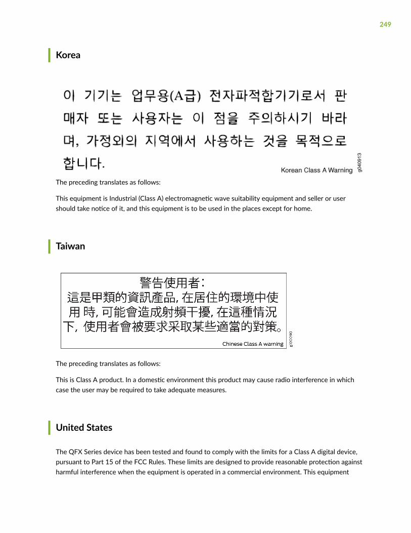
Korea
The preceding translates as follows:
This equipment is Industrial (Class A) electromagnetic wave suitability equipment and seller or usershould take notice of it, and this equipment is to be used in the places except for home.
Taiwan
The preceding translates as follows:
This is Class A product. In a domestic environment this product may cause radio interference in whichcase the user may be required to take adequate measures.
United States
The QFX Series device has been tested and found to comply with the limits for a Class A digital device,pursuant to Part 15 of the FCC Rules. These limits are designed to provide reasonable protection againstharmful interference when the equipment is operated in a commercial environment. This equipment
249

generates, uses, and can radiate radio frequency energy and, if not installed and used in accordance withthe instruction manual, may cause harmful interference to radio communications. Operation of thisequipment in a residential area is likely to cause harmful interference in which case the user will berequired to correct the interference at his own expense.
Nonregulatory Environmental Standards
These QFX Series product SKUs are Network Equipment Building System (NEBS) compliant:
• QFX3008-I
• QFX3600-I
• QFX3600
• QFX3500
• QFX5100
• QFX5110
• QFX5200-32C
• QFX10002-36Q and QFX10002-72Q
• QFX10008
• QFX10016
Those device product SKUs meet the following NEBS compliance standards:
• SR-3580 NEBS Criteria Levels (Level 3 Compliance)
• GR-1089-CORE, Issue 6: EMC and Electrical Safety—Generic Criteria for NetworkTelecommunications Equipment
• The equipment is suitable for installation in locations where the National Electrical Code (NEC)applies.
• The battery return connection is to be treated as an Isolated DC return (DC-I), as defined inGR-1089-CORE.
• GR-63-CORE: NEBS, Physical Protection
• The equipment is suitable for installation as part of the Common Bonding Network (CBN).
• The equipment is suitable for installation in a central office (CO).
250
RELATED DOCUMENTATION
Agency Approvals for the QFX Series
Statements of Volatility for Juniper NetworkDevices
A statement of volatility (SoV)—sometimes known as letter of volatility (LoV)—identifies the volatile andnon-volatile storage components in Juniper Networks devices, and describes how to remove non-volatile storage components from the device.
NOTE: Individual FRUs do not have separate SoV or LoV documents. They are covered in the SoVor LoV of the Juniper Networks device in which they are installed.
NOTE: Statements of volatility are not available for all Juniper Networks devices.
CTP Series:
• CTP150
• CTP2000
EX Series:
• EX2200 and EX2200-C
• EX2300-24P, EX2300-24T, and EX2300-24T-DC
• EX2300-48P and EX2300-48T
• EX2300-C
• EX3300
• EX3400-24P, EX3400-24T, EX3400-24T-DC
• EX3400-48P, EX3400-48T, EX3400-48T-AFI
• EX4200
251
• EX4300
• EX4300-48MP
• EX4400
1. EX4400-24T
2. EX4400-24P
3. EX4400-24MP
4. EX4400-48T
5. EX4400-48P
6. EX4400-48MP
7. EX4400-48F
• EX4500
• EX4550
• EX4600
• EX8200
• EX9251
• EX9253
• XRE200 External Routing Engine
LN Series:
• LN1000–CC
MX Series:
• M7i
• M7i Compact Forwarding Engine Board (CFEB)
• M40e and M10i
• M320
• MX5, MX10, MX40, and MX80
• MX104
252
• MX204
• MX240, MX480, and MX960
• MX10003
• RE-A-2000 Route Engine
• RE-S-X6-64G Routing Engine
NFX Series:
• NFX250
QFX Series:
• QFX3008-I
• QFX3100
• QFX3500
• QFX3600
• QFX5100-24Q
• QFX5100-48S
• QFX5100-48T
• QFX5110-32Q
• QFX5110-48S
• QFX5200
• QFX5200-32C
• QFX10008 and QFX10016
SRX Series:
• SRX100
• SRX110
• SRX210B
• SRX210H-POE
• SRX210H-P-MGW
253
• SRX220
• SRX240H
• SRX240H-POE
• SRX300
• SRX320
• SRX340 and SRX345
• SRX380
• SRX550
• SRX650
• SRX1400
• SRX1500
• SRX3400 and SRX3600
• SRX4200
• SRX4600
• SRX5400, SRX5600, and SRX5800
• SRX-MP-1SERIAL
• SSG-520M
T Series:
• RE-A-2000 Route Engine
TN Power Warning
WARNING: The device is designed to work with a TN power system.
Waarschuwing Het apparaat is ontworpen om te functioneren met TNenergiesystemen.
254

Varoitus Koje on suunniteltu toimimaan TN-sähkövoimajärjestelmien yhteydessä.
Avertissement Ce dispositif a été conçu pour fonctionner avec des systèmesd'alimentation TN.
Warnung Das Gerät ist für die Verwendung mit TN-Stromsystemen ausgelegt.
Avvertenza Il dispositivo è stato progettato per l'uso con sistemi di alimentazione TN.
Advarsel Utstyret er utfomet til bruk med TN-strømsystemer.
Aviso O dispositivo foi criado para operar com sistemas de corrente TN.
¡Atención! El equipo está diseñado para trabajar con sistemas de alimentación tipo TN.
Varning! Enheten är konstruerad för användning tillsammans med elkraftssystem av TN-typ.
255
Copyright © 2022 FDOKUMEN