SIP Server HA Deployment Guide - Genesys Documentation
132
This PDF is generated from authoritative online content, and is provided for convenience only. This PDF cannot be used for legal purposes. For authoritative understanding of what is and is not supported, always use the online content. To copy code samples, always use the online content. SIP Server 8.1.0 SIP Server HA Deployment Guide 1/14/2022
-
Upload
khangminh22 -
Category
Documents
-
view
0 -
download
0
Transcript of SIP Server HA Deployment Guide - Genesys Documentation

This PDF is generated from authoritative online content, andis provided for convenience only. This PDF cannot be usedfor legal purposes. For authoritative understanding of whatis and is not supported, always use the online content. Tocopy code samples, always use the online content.
SIP Server 8.1.0
SIP Server HA Deployment Guide
1/14/2022
www.princexml.com
Prince - Non-commercial License
This document was created with Prince, a great way of getting web content onto paper.

Table of ContentsSIP Server High-Availability Deployment Guide 3Overview 4SIP Server HA Architecture 5
HA Redundancy Types 7IP Address Takeover 9Windows NLB Cluster 13Network Device-Based HA 15Other SIP Server HA Enhancements 17
SIP Server HA Workflows 20IP Address Takeover HA Workflows 21Windows NLB Cluster HA Workflows 25
SIP Server HA Deployment 31IP Address Takeover 32
Deploying HA on Windows Server 2008 R2 33Deploying HA on AIX 50Deploying HA on Solaris 64Deploying HA on Linux 78
Deploying HA in Windows NLB Cluster 92Business Continuity 108
SIP Business Continuity Architecture 109Call Delivery 112Disaster Recovery 117Graceful Migration 122
Deploying SIP Business Continuity 123Basic Deployment 124DR Peer and Remote Site Deployment 127Configuration Options 129
Using IP Phones 130Using Siemens OSV 131
Log Events 132

SIP Server High-Availability DeploymentGuideThis guide introduces you to the concepts, terminology, and procedures that are relevant to SIPServer high-availability (HA) deployment.
Find the information you need from the topics below.
About the HA MethodsFind descriptions of the different waysyou can set up HA SIP Server instances.
IP Address TakeoverWindows NLBNetwork Device-Based HA
Deploying on WindowsFind procedures for the different ways todeploy SIP Server HA on Windowsservers.
IP Address Takeover on WindowsWindows NLB
Business ContinuityFind information about setting upBusiness Continuity in your environment.
ArchitectureDeployment
Deploying on UNIXFind procedures for the different ways todeploy SIP Server HA on UNIX-basedservers.
Deploying on AIXDeploying on SolarisDeploying on Linux
SIP Server High-Availability Deployment Guide
SIP Server HA Deployment Guide 3

OverviewWelcome to the Framework 8.1 SIP Server High-Availability Deployment Guide. These topicsintroduce you to the concepts, terminology, and procedures that are relevant to SIP Server high-availability (HA) deployment.
The information includes, but is not limited to, an overview of SIP Server HA architecture, HAworkflows, and SIP Server HA-deployment procedures for Windows and UNIX operating systems.
This document can be used together with the Framework 8.1 SIP Server Deployment Guide duringyour deployment planning.
About SIP Server
SIP Server is the Genesys software component that provides an interface between your telephonyhardware and the rest of the Genesys software components in your enterprise. It translates andkeeps track of events and requests that come from, and are sent to, the telephony device. SIP Serveris an IP"based server that can also act as a messaging interface between SIP Server clients. It is thecritical point in allowing your Genesys solution to facilitate and track the contacts that flow throughyour enterprise.
Intended Audience
These topics primarily intended for system architects or administrators who are responsible forensuring that systems, including SIP Server, are highly available. It has been written with theassumption that you have a basic understanding of:
• High-availability architecture• Network design and operation• Genesys Framework architecture and functions• Your own network architecture and configurations
Reading PrerequisitesYou must read the Framework 8.1 SIP Server Deployment Guide before you use these topics. Thosetopics contain information about the SIP Server deployment in general.
Overview
SIP Server HA Deployment Guide 4

SIP Server HA ArchitectureA high-availability (HA) architecture implies the existence of redundant applications: a primary and abackup. These applications are configured so that if one fails, the other can take over its operationswithout significant loss of data or impact to business operations.
SIP Server supports several high-availability deployment options:
• IP Address Takeover• Windows NLB Cluster• Network device-based HA
IP Address Takeover and Windows NLB Cluster HA options utilize the concept of a Virtual IP address.In a Virtual IP interface"based architecture, primary and backup SIP Servers are located on the samesubnet, and SIP endpoints and gateways are configured to send SIP messages to SIP Server by usingthis single Virtual IP address. The Virtual IP address is preserved during switchover occurrences, andmessages that are sent to the Virtual IP address are delivered to the SIP Server that is currentlyrunning in primary mode.
When the Management Layer detects failure of a primary SIP Server, it executes a set of correctiveactions, which allows SIP messages that are destined for the failed primary SIP Server to be deliveredto the backup SIP Server that has just started running in primary mode.
While SIP endpoints and gateways use a single Virtual IP address to communicate with SIP Server,Management Layer and Configuration Layer components, and T-Library clients must use a unique IPaddress for communication with the SIP Server and Local Control Agent (LCA) that is installed at eachSIP Server host.
On Windows and UNIX, an IP Address Takeover configuration is implemented by using Virtual IPaddress control scripts to enable and disable Virtual IP addresses. The Windows NLB configurationuses Cluster control scripts to enable and disable Virtual IP ports.
A network device-based HA is an alternative to software-based HA configurations. The SIP Server andF5 Networks BIG-IP Local Traffic Manager (LTM) integration solution supports this type of HAconfiguration.
Each of these configurations is described in more detail in the following sections.
The following table summarizes SIP Server HA options, their benefits and limitations, and supportedoperating systems (Windows, Linux, Solaris, or AIX).
Comparing High-Availability OptionsHA Option Benefits Limitations
IP Address Takeover• Supported on all operating
systems• Supports multiple NICs
• Supports a single subnet• Operations on both servers,
backup and primary, mustsucceed
SIP Server HA Architecture
SIP Server HA Deployment Guide 5

HA Option Benefits Limitations
• 100% Genesys components• HA option of choice for
reliability ratings and tests
• Subnet equipment to acceptgratuitous ARP
Windows NLB Cluster• Widely deployed• Thoroughly documented• Supports multiple NICs
• Supports a single subnet• Complexity/Prerequisites• Dedicated switch/VLAN
F5 Networks BIG-IP LTM
• Reliability• Flexibility (HA and Load
balancing)• Supports multiple NICs
• Additional equipment cost• Additional network element
SIP Server also supports HA configurations in which both primary and backup SIP Server instancesreside on a single host server. In this case, IP interface virtualization is not required.
SIP Server HA Architecture
SIP Server HA Deployment Guide 6

HA Redundancy TypesWhen you deploy a SIP Server HA configuration, you can choose a hot-standby or warm-standbyredundancy type, both are supported for the Virtual IP interface–based HA configuration.
The redundancy-type selection is made in the Configuration Layer or Genesys Administrator whenyou configure the primary SIP Server.
When you deploy a hot-standby configuration, there are additional steps for enabling datasynchronization between the primary and backup SIP Servers. Configuration steps for both hot- andwarm-standby redundancy types are included in the deployment procedures that are provided in SIPServer HA Deployment.
Hot-Standby Redundancy TypeGenesys uses the expression hot standby to describe the high-availability configuration in which abackup-server application remains initialized, clients connect to both the primary and backup serversat startup, and the backup-server data is synchronized from the primary server.
Data synchronization and existing client connections to the backup server guarantee a higher degreeof availability. Data synchronization includes information about calls, device states, monitoringsubscriptions, and agent states.
SIP Server supports Hot Standby mode for established calls, calls that are in the ringing state, andcalls that are parked on a Routing Point. All telephony functions can be performed on synchronizedcalls after a switchover.
While the hot-standby redundancy type provides a higher degree of availability than the warm-standby redundancy type, hot standby has limitations that include the following:
• Client requests that are sent during the time in which a failure occurs until switchover completes mightbe lost.
• IP requests that are sent by SIP endpoints during the failure and switchover might be lost.• SIP Server does not synchronize interactions that begin before it starts.• Some T-Library events might be duplicated or lost.• The Client request Reference ID might be lost for client requests that are received just before a failure
occurs and processed after the switchover completes.
When you deploy an HA configuration of the hot-standby redundancy type, Genesys recommendsthat Advanced Disconnect Detection Protocol (ADDP) be configured on the connection between theprimary and backup SIP Servers. The primary SIP Server uses this connection to deliversynchronization updates.
Warm-Standby Redundancy TypeGenesys uses the expression warm standby to describe the high-availability configuration in which abackup-server application remains initialized and ready to take over the operations of the primary
SIP Server HA Architecture HA Redundancy Types
SIP Server HA Deployment Guide 7

server.
Unlike the hot-standby redundancy type, there is no propagation or synchronization of informationfrom the primary SIP Server to the backup SIP Server about calls, devices, monitoring subscriptions,and agent states.
SIP Server HA Architecture HA Redundancy Types
SIP Server HA Deployment Guide 8
IP Address TakeoverWindows and UNIX PlatformsHigh availability of the service for SIP communications requires that the IP address of SIP Server isalways accessible by other SIP components, is operational on the SIP Server currently running inprimary mode, and is transferred to the other server in case of failover or switchover.
There are two approaches for the IP Address Takeover HA configuration:
• Linux and Solaris platforms use the Virtual IP address as the IP address configured on a logical sub-interface on the network interface card (NIC).• Logical sub-interface with the Virtual IP address is enabled on the server that is running in primary
mode.• Logical sub-interface with the Virtual IP address is disabled on the server that is running in backup
mode.
• Windows and AIX platforms use the Virtual IP address as an additional (or alias) IP address configuredon the NIC.• Virtual IP address is added to the NIC configuration on the server that is running in primary mode.• Virtual IP address is deleted from the NIC configuration on the server that is running in backup
mode.
The HA Configuration with One NIC figure shows an IP Address Takeover configuration on theLinux or Solaris platform using one NIC.
SIP Server HA Architecture IP Address Takeover
SIP Server HA Deployment Guide 9

HA Configuration with One NIC
There are two SIP Server hosts on the same subnet, each of them has two logical IP interfaces set upon the NIC connected to the subnet. Each host has a unique IP address that is configured on the mainlogical IP interface. The second IP interface (a sub-interface) is configured with the IP address that isshared by the hosts and called the Virtual IP address. The second IP interface is enabled only on onehost at a time.
The IP interface with the unique IP address is always active. Management Layer and ConfigurationLayer components, and T-Library clients use the unique IP address for communication with the SIPServer and LCA.
SIP endpoints and gateways use the Virtual IP address to send SIP messages to SIP Server. The IPinterface with the Virtual IP address is only enabled on the host on which SIP Server is running inprimary mode. The IP interface with the Virtual IP address is disabled on the host on which SIP Serveris running in backup mode.
In the IP Address Takeover configuration, the IP interface with the Virtual IP address is enabled anddisabled by using the Virtual IP address control scripts.
The IP Address Takeover HA can be configured using either one network interface card (NIC), ormultiple NICs.
The HA Configuration with Two NICs figure shows an IP Address Takeover configuration using twoNICs on the Windows platform.
SIP Server HA Architecture IP Address Takeover
SIP Server HA Deployment Guide 10

HA Configuration with Two NICs
In a deployment with two NICs, one NIC (NIC 2 in the above figure) is used for the SIP communication,while the second NIC (NIC 1 in the above figure) is used for other kinds of communication withvarious components"for example, Management Layer and Configuration Layer components, as wellas any T-Library clients. Solution Control Server (SCS) manages and monitors the SIP Serverapplication through NIC 1 (dedicated to other non-SIP communication).
Although, the unique IP address of NIC 2 is not used, the Virtual IP address is configured on NIC 2 orits sub-interface. Monitoring of the connectivity through NIC 2 can be done by means of the SIP trafficmonitoring feature. (See SIP Traffic Monitoring.)
See the IP Address Takeover HA Workflows for step-by-step descriptions of manual switchover,primary SIP Server failure, and primary SIP Server disconnect workflows. For deployment procedures,see:
• Deploying HA on Windows• Deploying HA on AIX• Deploying HA on Solaris• Deployng HA on Linux
SIP Server HA Architecture IP Address Takeover
SIP Server HA Deployment Guide 11

IP Address Takeover HA Notes
• In an IP Address Takeover configuration, the Virtual IP address control scripts are used to add and deletethe Virtual IP address to achieve a switchover. On Windows platform, the scripts use a Netsh command.Improper execution of this command may impact the SIP Server switchover time, as follows:• If the Netsh command fails to execute on either SIP Server host, the switchover will fail. For
example, the Netsh command fails if any NIC properties are opened.• The Netsh command may take up to five seconds to execute. The execution time depends on the
hardware and software characteristics of the host.With some network adapters the execution timecan be significantly longer.
• Some hosts on the subnet may not be able to connect to the primary SIP Server after a switchover.Disabling the Virtual IP address at one host and enabling it at another changes the relationshipbetween the MAC address and Virtual IP address. If an Address Resolution Protocol (ARP)announcement fails, the ARP table on some hosts on the subnet is not updated.
See the Prerequisites section for information about basic requirements and recommendations fordeploying an IP Address Takeover HA configuration in a particular operating system.
SIP Server HA Architecture IP Address Takeover
SIP Server HA Deployment Guide 12

Windows NLB ClusterA SIP Server HA configuration using Windows Network Load Balancing (NLB) configuration is analternative to a Windows IP Address Takeover configuration.
Microsoft's NLB cluster technology allows you to configure cluster hosts to receive requests at asingle Virtual IP address. SIP endpoints and gateways are configured to send all requests to SIPServer by using this single Virtual IP address. The Windows NLB cluster technology delivers therequests to the SIP Server that is running in primary mode and reroutes traffic to the backup SIPServer when a failure is detected.
The HA Windows NLB Cluster Configuration figure shows a SIP Server HA configuration that usesWindows NLB. SIP endpoints and gateways are configured to communicate with SIP Server by using asingle Virtual IP address, and the SIP Server port is enabled only at the SIP Server that is running inprimary mode. When a switchover to the backup SIP Server occurs, the port at the backup SIP Serverhost is enabled, and traffic is directed to the active SIP Server.
HA Windows NLB Cluster Configuration
The Management Layer uses a Windows NLB utility (wlbs.exe or nlb.exe) to enable and disableports that are occupied by SIP Server. The NLB utility is initiated by Cluster control scripts that aretriggered by SIP Server Alarm Conditions that are configured for SIP Server log events that occur
SIP Server HA Architecture Windows NLB Cluster
SIP Server HA Deployment Guide 13

when a SIP Server changes its mode from primary to backup or from backup to primary.
Windows NLB can be configured to distribute incoming requests by using either the Unicast or theMulticast method. When you deploy a SIP Server HA configuration, you must define the method thatyou want to use.
Unicast and Multicast methods are described in the following sections.
See Windows NLB Cluster HA Workflows for step-by-step descriptions of manual switchover, primarySIP Server failure, and primary SIP Server disconnect workflows. For deployment procedures, seeWindows NLB Cluster HA Deployment.
Unicast MethodIn the Unicast method, all NLB cluster hosts share an identical unicast MAC address. NLB overwritesthe original MAC address of the cluster adapter by using the unicast MAC address that is assigned toall of the cluster hosts. Unicast NLB nodes cannot communicate over an NLB-enabled networkadapter. Considerations for the Unicast distribution method include the following:
• If you are using Windows Server 2003, you might require a second network adapter to provide peer-to-peer communication between cluster hosts. This limitation applies only to Windows Server 2003.Note: You can avoid the requirement for a second network adapter on Windows 2003 by applying aWindows Server 2003 Service Pack and performing a registry update. For instructions, see the followingMicrosoft Support article: [1].
• In the Unicast method, all switch ports are flooded with NLB traffic, including ports to which non-NLBservers are attached. A workaround for this issue is to place cluster hosts on separate VLANs.
Multicast MethodIn a Multicast configuration, each NLB cluster host retains the original MAC address of the networkadapter. In addition to the original MAC address of the adapter, the adapter is assigned a multicastMAC address that is shared by all cluster hosts. Client requests are sent to all cluster hosts at themulticast MAC address. Considerations for implementation of the Multicast distribution methodinclude the following:
• Upstream routers might require a static Address Resolution Protocol (ARP) entry. Without an ARP entry,routers might not accept an ARP response that resolves unicast IP addresses to multicast MACaddresses.
• Without Internet Group Management Protocol (IGMP), switches might require additional configuration todefine which ports the switch should use for multicast traffic.
• Upstream routers might not support mapping of a unicast IP address (the cluster IP address) to amulticast MAC address. In this case, you might be required to update or replace your router in order touse the Multicast method.
SIP Server HA Architecture Windows NLB Cluster
SIP Server HA Deployment Guide 14

Network Device-Based HAAn alternative to software-based Virtual IP interface configurations is a hardware-based Virtual IPconfiguration that uses an external network device.
Benefits of using a network hardware device include the following:
• Less complex configuration: Alarm Reactions and Alarm Conditions are not required.• There is no switch flooding, as there might be with a Windows NLB Unicast configuration.• A single network device can support multiple SIP Server HA pairs.
Disadvantages might include the cost of a network device and the configuration that is required forSecure Network Address Translation (SNAT).
A network device works by presenting a shared Virtual IP address. SIP endpoints and gateways areconfigured to communicate with this single Virtual IP address. When the network device receives arequest at the Virtual IP address, it routes the request to the SIP Server that is running in primarymode.
The SIP Server and the F5 Networks BIG-IP Local Traffic Manager (LTM) integration solution supportsthis type of HA configuration as shown in the HA Configuration Using F5 Networks BIG-IP LTMfigure. F5's BIG-IP LTM monitors the primary SIP Server by sending an OPTIONS request to the SIPServer at configured intervals and listening for a response.
SIP Server HA Architecture Network Device-Based HA
SIP Server HA Deployment Guide 15

HA Configuration Using F5 Networks BIG-IP LTM
For more information about a SIP Server HA configuration that uses the F5 Networks BIG-IP LTM, referto the Framework 8.1 SIP Server Integration Reference Manual. This guide describes configurationsteps that are required to implement a hot-standby SIP Server HA configuration that runs behind anF5 Networks BIG-IP LTM.
SIP Server HA Architecture Network Device-Based HA
SIP Server HA Deployment Guide 16

Other SIP Server HA EnhancementsSIP Server supports several additional capabilities related to high-availability deployments.
• Single Host HA Deployment• Synchronization of Contact Between SIP Server HA Pair• SIP Traffic Monitoring• Monitoring Critical Conditions
Single Host HA Deployment
Starting with version 8.0, SIP Server supports deploying both primary and backup SIP Serverapplications, as well as the Stream Manager or Media Server application, on the same physical host.Benefits of using the single host HA configuration include the following:
• Efficient use of the hardware equipment.• Less complex configuration: Virtual IP address control scripts, Alarm Reactions, and Alarm Conditions
are not required.
However, this type of HA configuration is supported only for small-size deployments--100 seats orless.
Synchronization of Contact Between SIP Server HA Pair
SIP Server 8.x synchronizes the SIP registration Contact header for a particular device across bothprimary and backup instances of SIP Server. The primary SIP Server sends the contact information tothe backup SIP Server using the HA link, as well as through the Configuration Server.
SIP Traffic Monitoring
SIP Server 8.x supports SIP traffic monitoring for enhanced reliability. When configured, SIP Servermonitors incoming SIP traffic and can initiate a switchover after a configurable length of time duringwhich no SIP messages are received.
In deployments where two NICs are used, one NIC is dedicated to SIP communication, while thesecond NIC is used for other kinds of communication with various components. Solution ControlServer (SCS) manages and monitors the SIP Server application through the second NIC.
The SIP traffic monitoring feature allows the primary SIP Server to monitor the network connectivitythrough the NIC that is responsible for SIP communication, to recognize connectivity issues that
SIP Server HA Architecture Other SIP Server HA Enhancements
SIP Server HA Deployment Guide 17

impact the SIP service, and to initiate reactions that result in recovery of the service.
An Application-level configuration option, sip-pass-check, must be configured to enable thisfunctionality. In addition, at least one service device must be configured for Active Out-Of-ServiceDetection by using oos-check and oos-force configuration options. See the Framework 8.1 SIPServer Deployment Guide for information about the Active Out-Of-Service Detection featuredescription.
When it is set to true, the sip-pass-check option enables tracking of SIP messages that reach theprimary SIP Server, including responses from SIP devices (DNs) that are monitored by SIP Server byusing the oos-check and oos-force options.
The primary SIP Server summarizes results of the checks on DNs for out-of-service status andmonitors the time that has passed since the last received SIP message. If the primary SIP Server doesnot receive SIP messages for a certain period of time, SIP Server reports the SERVICE_UNAVAILABLEstatus to LCA/SCS. The period of time is chosen as the maximum of sums (among the sums of theoos-check and oos-force option values, configured for service DNs). When SIP Server reports theSERVICE_UNAVAILABLE status to LCA/SCS, SCS switches the primary SIP Server to the backup modeand this SIP Server reports the SERVICE_RUNNING status to LCA/SCS. The former backup SIP Serverbecomes the primary server and starts to monitor SIP traffic.
If both the primary and backup servers receive no SIP traffic, a switchover would occur each time thatthe effective out-of-service timeout expires. To prevent frequent switchovers in this case, SIP Serverdetects the "double switchover" condition and doubles the effective out-of-service timeout each timethat the double switchover happens"up to four times greater than the initially calculated timeout, oruntil one of the two servers detects SIP traffic. As soon as SIP traffic is detected, the server thatdetected the traffic remains the primary SIP Server and continues normal operation.
Monitoring Critical Conditions
You can use Genesys Administrator to check the current running status of SIP Server. Starting inrelease 8.1.0, SIP Server displays its state as Running in Genesys Administrator in cases where it isunable to open a listening port, and it is configured as one instance in a High Availability (HA) pair.Prior to release 8.1.0, (release 8.0.4 and earlier), in this same scenario SIP Server displayed its statusas UNAVAILABLE.
To monitor problems with binding a listener (SIP Server is running but unable to open a listeningport), Genesys recommends that, for each SIP Server instance, you configure an Alarm Condition forthe log event 00-04200. For more information, consult the Solution Control Interface (SCI) help topic,"Using Log Events for Alarm Detection".
To ensure that administrators do not miss the alarm, Genesys recommends that you configureautomatic clearing of the activated alarm in accordance with business processes and the schedule ofthe customer administrator.
The recommended configuration of an Alarm Condition for 00-04200 enables monitoring of a widerange of events that are critical for both SIP Server functionality and for service availability. Thisincludes problems that might occur when binding a listener, unexpected terminations, orunauthorized terminations of the SIP Server process.
In Genesys Administrator, alarms that are detected and activated can be observed through adedicated view, providing a central location for observing all alarms that occurred in the entire
SIP Server HA Architecture Other SIP Server HA Enhancements
SIP Server HA Deployment Guide 18

environment.
If required, an alarm reaction can be configured to notify administrators automatically when a criticalcondition occurs.
After the administrator investigates and resolves the problem, they must manually clear the alarmcondition.
If the problem occurred due to a temporary outage (for example, a network switch reboot), SIP Serverremains in the Running state, ensuring availability of the HA pair once the network switch isrecovered; in release 8.0.4, SIP Serer required a manual restart to return to the Running state.
In release 8.0.4, if both SIP Server instances encountered a problem when binding a listener, bothinstances in the HA pair remained in UNAVAILABLE status, requiring a manual operation to resume theservice. In release 8.1.0, SIP Server instead switches the primary role between the two HA instancesand resumes the service as soon as one of the instances is able to open a listening port.
SIP Server HA Architecture Other SIP Server HA Enhancements
SIP Server HA Deployment Guide 19

SIP Server HA WorkflowsThese topics describes workflows for SIP Server HA Architectures:
• IP Address Takeover HA Workflows• Windows NLB Cluster HA Workflows
The workflows provide a step-by-step account of events that occur during a manual switchover,during a primary SIP Server failure, and during a primary SIP Server disconnection.
For configuration and deployment information about the log events, Alarm Conditions, Alarm Reactionscripts, and Application objects that are referred to in the SIP Server HA workflows, see SIP Server HADeployment.
SIP Server HA Workflows Other SIP Server HA Enhancements
SIP Server HA Deployment Guide 20

IP Address Takeover HA WorkflowsThe HA Configuration with One NIC figure shows an IP Address Takeover configuration prior to aswitchover:
Manual-Switchover Workflow
The following steps describe a primary to backup-switchover workflow for a IP Address Takeoverconfiguration (the HA Configuration After a Switchover figure represents the end state of theworkflow):
State Prior to Switchover
• SIP Server 1 is in primary mode.• SIP Server 2 is in backup mode.• The Virtual IP address at the primary
SIP Server (SIP Server 1) is enabled.• The Virtual IP address at the backup
SIP Server (SIP Server 2) is disabled.
State After a SwitchoverTo see what happens in different scenarios, seethe following:
• Manual-Switchover Workflow• Primary Server-Failure Workflow• Primary Server-Disconnected
Workflow
HA Configuration with One NIC
SIP Server HA Workflows IP Address Takeover HA Workflows
SIP Server HA Deployment Guide 21

Primary Server-Failure Workflow
The following steps describe a primary server-failure workflow for an IP Address Takeoverconfiguration (the HA Configuration After Primary Server Failure figure represents the end stateof the workflow):
1. The switchover is initiated manually from theSolution Control Interface (SCI).
2. Through LCA, the SCS instructs the primarySIP Server (SIP Server 1) to go into backupmode.
3. Through LCA, the SCS instructs the backupSIP Server (SIP Server 2) to go into primarymode.
4. The SCS generates a log message with EventID 00-5150 to indicate that SIP Server 2 haschanged to primary mode and a logmessages with Event ID 00-5151 to indicatethat SIP Server 1 has changed to backupmode.
5. The SCS activates the Alarm Conditions,which execute the associated Alarm Reactionscripts.
6. The Alarm Reaction scripts trigger the VirtualIP address control scripts that are configuredas applications.
7. The SCS instructs LCA to launch the Virtual IPaddress control scripts on the SIP Serverhosts.
8. The Virtual IP address control scripts disablethe Virtual IP address on the SIP Server 1 host(Host 1) and enable the Virtual IP address onthe SIP Server 2 host (Host 2).
HA Configuration After a Switchover
SIP Server HA Workflows IP Address Takeover HA Workflows
SIP Server HA Deployment Guide 22

Primary Server-Disconnected Workflow
The following steps describe a primary server-disconnected workflow for an IP Address Takeoverconfiguration (the HA Configuration After a Primary Server is Disconnected figure representsthe end state of the workflow):
1. The primary SIP Server (SIP Server 1)fails.
2. LCA detects the primary SIP Serverfailure and reports it to the SCS.
3. Through LCA, the SCS instructs thebackup SIP Server (SIP Server 2) to gointo primary mode.
4. The SCS generates a log message withEvent ID 00-5150, to indicate that SIPServer 2 has changed to primary mode.
5. The SCS activates the Alarm Condition,which executes the associated AlarmReaction scripts.
6. The Alarm Reaction scripts trigger theVirtual IP address control scripts that areconfigured as applications.
7. The SCS instructs LCA to launch theVirtual IP address control scripts on theSIP Server hosts.
8. The Virtual IP address control scriptsdisable the Virtual IP address on the SIPServer 1 host (Host 1) and enable theVirtual IP address on the SIP Server 2host (Host 2).
HA Configuration After Primary Server Failure
SIP Server HA Workflows IP Address Takeover HA Workflows
SIP Server HA Deployment Guide 23

Because SIP Server 1 is disconnected, the script that disables the Virtual IP address on Host 1 cannotbe run. When the connection to SIP Server 1 has been restored, the following workflow will occur (notrepresented in the HA Configuration After a Primary Server is Disconnected figure above):
1. The SCS detects that the connection to the SIP Server 1 host has been restored.2. The SCS discovers that both SIP Servers are running in primary mode.3. Through LCA, the SCS instructs SIP Server 1, whose connection was just restored, to go into backup
mode.4. The SCS generates a log message with Event ID 00-5151, to indicate that SIP Server 1 has changed to
backup mode.5. The SCS activates an Alarm Condition, which executes the associated Alarm Reaction script.6. The Alarm Reaction script triggers a Virtual IP address control script that is configured as an application.7. The SCS instructs LCA to launch the Virtual IP address control script on the SIP Server 1 host.8. The Virtual IP address control script runs on the SIP Server 1 host and disables the Virtual IP address.
1. The SCS detects that the connection tothe primary SIP Server host (Host 1) hasbeen lost.
2. Through LCA, the SCS instructs thebackup SIP Server (SIP Server 2) to gointo primary mode.
3. The SCS generates a log message withEvent ID 00-5150, to indicate that SIPServer 2 has changed to primary mode.
4. The SCS activates the Alarm Condition,which executes the associated AlarmReaction scripts.
5. The Alarm Reaction scripts trigger theVirtual IP address control scripts that areconfigured as applications.
6. The SCS instructs LCA to launch theVirtual IP address control scripts on theSIP Server hosts.
HA Configuration After a Primary Server is Disconnected
SIP Server HA Workflows IP Address Takeover HA Workflows
SIP Server HA Deployment Guide 24

Windows NLB Cluster HA WorkflowsThe HA Windows NLB Cluster Configuration figure shows a Windows NLB Cluster configurationprior to a switchover.
Manual-Switchover Workflow
The following steps describe a switchover workflow for a Windows NLB Cluster configuration (the HAWindows NLB Cluster Configuration After a Switchover figure represents the end state of theworkflow):
State Prior to Switchover
• SIP Server 1 is in primary mode.• SIP Server 2 is in backup mode.• The SIP port is enabled at the
primary SIP Server (SIP Server 1).• The SIP port is disabled at the
backup SIP Server (SIP Server 2).
State After a SwitchoverTo see what happens in different scenarios, seethe following:
• Manual-Switchover Workflow• Primary Server-Failure Workflow• Primary Server-Disconnected
Workflow 1• Primary Server-Disconnected
Workflow 2
HA Windows NLB Cluster Configuration
SIP Server HA Workflows Windows NLB Cluster HA Workflows
SIP Server HA Deployment Guide 25

Primary Server-Failure Workflow
The following steps describe a primary server-failure workflow for a Windows NLB Clusterconfiguration (the HA Windows NLB Cluster Configuration After Primary Server Failure figurerepresents the end state of the workflow):
1. The switchover is initiated manually from theSolution Control Interface (SCI).
2. Through Local Control Agent (LCA), theSolution Control Server (SCS) instructs theprimary SIP Server (SIP Server 1) to go intobackup mode.
3. Through LCA, the SCS instructs the backupSIP Server (SIP Server 2) to go into primarymode.
4. The SCS generates a log message with EventID 00-5150 to indicate that SIP Server 2 haschanged to primary mode and a logmessages with Event ID 00-5151 to indicatethat SIP Server 1 has changed to backupmode.
5. The SCS activates the Alarm Conditions,which execute the associated Alarm Reactionscripts.
6. The Alarm Reaction scripts trigger the Clustercontrol scripts that are configured asapplications.
7. The SCS instructs LCA to launch the Clustercontrol scripts on the SIP Server hosts.
8. The Cluster control scripts run NLB utilitiesthat disable the Virtual IP port on SIP Server 1and enable the Virtual IP port on SIP Server 2.
HA Windows NLB Cluster Configuration After a Switchover
SIP Server HA Workflows Windows NLB Cluster HA Workflows
SIP Server HA Deployment Guide 26

Primary Server-Disconnected Workflow 1
The following steps describe a primary server-disconnected workflow for a Windows NLB Clusterconfiguration (the HA Windows NLB Cluster Configuration After a Primary Server isDisconnected figure represents the end state of the workflow):
1. The primary SIP Server (SIP Server 1)fails.
2. LCA detects the primary SIP Serverapplication failure and reports it to theSCS.
3. Through LCA, the SCS instructs thebackup SIP Server (SIP Server 2) to gointo primary mode.
4. The SCS generates a log message withEvent ID 00-5150, to indicate that SIPServer 2 has changed to primary mode.
5. The SCS activates the Alarm Condition,which executes the associated AlarmReaction scripts.
6. The Alarm Reaction scripts trigger theCluster control scripts that areconfigured as applications.
7. The SCS instructs LCA to launch theCluster control scripts on the SIP Serverhosts.
8. The Cluster control scripts run WindowsNLB utilities that disable the Virtual IPport on SIP Server 1 and enable theVirtual IP port on SIP Server 2.
HA Windows NLB Cluster Configuration After Primary Server Failure
SIP Server HA Workflows Windows NLB Cluster HA Workflows
SIP Server HA Deployment Guide 27

When the connection to SIP Server 1 has been restored, the following workflow occurs (not depictedin the HA Windows NLB Cluster Configuration After a Primary Server is Disconnected figure,above):
1. The SCS detects that the connection to SIP Server 1 host has been restored.2. The SCS discovers that both SIP Servers are running in primary mode.3. Through LCA, the SCS instructs SIP Server 1, whose connection was just restored, to go into backup
mode.4. The SCS generates a log message with Event ID 00-5151, to indicate that SIP Server 1 has changed to
backup mode.5. The SCS activates an Alarm Condition, which executes an associated Alarm Reaction script.6. The Alarm Reaction script triggers the Cluster control script that is configured as application.7. The SCS instructs LCA to launch the Cluster control script on SIP Server 1.
1. The SCS detects that the connection tothe primary SIP Server host (SIP Server1) has been lost.
2. Through LCA, the SCS instructs thebackup SIP Server (SIP Server 2) to gointo primary mode.
3. The SCS generates a log message withEvent ID 00-5150, to indicate that SIPServer 2 has changed to primary mode.
4. The SCS activates the Alarm Condition,which executes the associated AlarmReaction scripts.
5. The Alarm Reaction scripts trigger theCluster control scripts that areconfigured as applications.
6. The SCS instructs LCA to launch theCluster control scripts on the SIP Serverhosts.
7. Because SIP Server 1 is disconnected,the Cluster control script that is used todisable the Virtual IP port on SIP Server 1cannot be executed, and the portremains enabled. The Cluster controlscript is able to run on SIP Server 2 andthe Virtual IP port is enabled.
HA Windows NLB Cluster Configuration After a Primary Server is Disconnected
SIP Server HA Workflows Windows NLB Cluster HA Workflows
SIP Server HA Deployment Guide 28

8. The Cluster control script runs on SIP Server 1, and the Virtual IP port is disabled.
Primary Server-Disconnected Workflow 2
The following steps describe a primary server-disconnected workflow for a Windows NLB Clusterconfiguration in the scenario where both SIP Servers use two NICs—one NIC is used for SIPcommunication (NIC 2), while the second NIC (NIC 1) is used for other kinds of communication withother components on the network. The SIP traffic monitoring feature is enabled (the HA WindowsNLB Cluster Configuration with Two NICs After a Primary Server is Disconnected figurerepresents the end state of the workflow):
1. The Ethernet cord is unplugged from NIC2 on the SIP Server 1 host.
2. The primary SIP Server (SIP Server 1)detects that it does not receive SIPmessages for a certain period of time.SIP Server 1 reports theSERVICE_UNAVAILABLE status to LCA/SCS.
3. Through LCA, the SCS instructs theprimary SIP Server (SIP Server 1) to gointo backup mode and it instructs thebackup SIP Server (SIP Server 2) to gointo primary mode.
4. The SCS generates a log message withEvent ID 00-5150 to indicate that SIPServer 2 has changed to primary modeand a log messages with Event ID00-5151 to indicate that SIP Server 1 haschanged to backup mode.
5. The SCS activates the Alarm Conditions,which execute the associated AlarmReaction scripts.
6. The Alarm Reaction scripts trigger theCluster control scripts that areconfigured as applications.
7. The SCS instructs LCA to launch theCluster control scripts on the SIP Serverhosts.
HA Windows NLB Cluster Configuration with Two NICs After a Primary Server is Disconnected
SIP Server HA Workflows Windows NLB Cluster HA Workflows
SIP Server HA Deployment Guide 29

When the connection to SIP Server 1 has been restored, the following workflow occurs (not depictedin the HA Windows NLB Cluster Configuration with Two NICs After a Primary Server isDisconnected figure):
1. Because the NLB port on SIP Server 1 remained enabled, after network connectivity is restored at NIC 2on the SIP Server 1 host, the NLB cluster on both hosts is now incorrectly configured"SIP messages aredelivered to the NLB cluster node where SIP Server is running in backup mode (SIP Server 1).
2. The primary SIP Server (SIP Server 2) detects that it had not received any SIP messages for a certainperiod of time. SIP Server 2 reports the SERVICE_UNAVAILABLE status to LCA/SCS.
3. Through LCA, the SCS instructs the primary SIP Server (SIP Server 2) to go into backup mode andinstructs the backup SIP Server (SIP Server 1) to go into primary mode.
4. The SCS generates a log message with Event ID 00-5150 to indicate that SIP Server 2 has changed toprimary mode and a log messages with Event ID 00-5151 to indicate that SIP Server 1 has changed tobackup mode.
5. The SCS activates the Alarm Conditions, which execute associated Alarm Reaction scripts.6. The Alarm Reaction scripts trigger the Cluster control scripts that are configured as applications.7. The SCS instructs LCA to launch the Cluster control scripts on SIP Server hosts.8. The Cluster control scripts run NLB utilities that disable the Virtual IP port on SIP Server 2 and enable
the Virtual IP port on SIP Server 1.
8. Because NIC 2 on SIP Server 1 isdisconnected, the NLB does not react toreconfiguration commands from theCluster control script that is used todisable the Virtual IP port on SIP Server1, and so the port remains enabled. TheCluster control script is successfullyexecuted on SIP Server 2 and the VirtualIP port is enabled.
SIP Server HA Workflows Windows NLB Cluster HA Workflows
SIP Server HA Deployment Guide 30

SIP Server HA DeploymentThese topics describe how to deploy the SIP Server high-availability (HA) configurations that aredescribed in SIP Server High-Availability Architecture:
• IP Address Takeover HA Deployment on Windows• IP Address Takeover HA Deployment on AIX• IP Address Takeover HA Deployment on Solaris• IP Address Takeover HA Deployment on Linux• Windows NLB Cluster HA Deployment• SIP Server HA Configuration Testing
SIP Server HA Deployment Windows NLB Cluster HA Workflows
SIP Server HA Deployment Guide 31

IP Address TakeoverThis section describe how to deploy IP Address Takeover configurations on the following operatingsystems:
• IP Address Takeover HA Deployment on Windows• IP Address Takeover HA Deployment on AIX• IP Address Takeover HA Deployment on Solaris• IP Address Takeover HA Deployment on Linux
SIP Server HA Deployment IP Address Takeover
SIP Server HA Deployment Guide 32

Deploying HA on Windows Server 2008 R2Complete these steps to set up SIP Server HA on Windows Server 2008 R2, using the IP AddressTakeover method.
IP Address Takeover HA Deployment on Windows
1. Check prerequisites.
Prerequisites
There are basic requirements and recommendations for deploying an IP Address Takeover HAconfiguration of SIP Server in your environment.
• Two separate physical host computers: one for the primary SIP Server and one for the backup SIPServer.Note: Genesys recommends that you install primary and backup instances of SIP Server on differenthost computers. However, SIP Server does support HA configurations in which both primary and backupSIP Server instances reside on a single host server.
• Software requirements:• For the Windows OS to send a gratuitous ARP packet when a new IP address is assigned on the
computer, you must install the Microsoft Hotfix 2811463 for Windows 2008 R2. Seehttp://support.microsoft.com/kb/2811463/en-us.
• SIP Server must be installed and configured on both host computers.• LCA must be installed and configured on both host computers.• In deployments where SIP Server uses two NICs, one NIC is used for SIP communication, while the
second NIC is used for other kinds of communication with various components. Solution ControlServer (SCS) manages and monitors the SIP Server application through the second NIC. When youcreate a Host object, make sure you specify the hostname or IP address of the second NIC(dedicated to other non-SIP communication).
• Networking requirements:• Static IP addresses are required for all network interfaces on both host computers.• It is highly recommended that you have primary and backup SIP Server hosts on a dedicated subnet.
A dedicated subnet ensures that Virtual IP Address Takeover affects only the Address ResolutionProtocol (ARP) table on the subnet router. Without a dedicated subnet, hosts that communicate withSIP Server might fail to update the ARP table during Virtual IP Address Takeover.
• In deployments where SIP Server uses two NICs, one NIC is used for SIP communication, while thesecond NIC is used for other kinds of communication with various components. Each host has oneNIC connected to a subnet dedicated to SIP communication. The Virtual IP address should be withinthe range of the network to which the NIC dedicated to SIP communication is connected. The
SIP Server HA Deployment IP Address Takeover
SIP Server HA Deployment Guide 33

second NIC on both hosts should be connected to a separate network.
2. Configure the primary SIP Server.
Configuring the primary SIP Server
PurposeTo configure the primary SIP Server Application object for high availability.
Start
1. Stop the SIP Server applications on the primary and backup hosts. Genesys SIP Server applications canbe stopped by using the Genesys Solution Control Interface.
2. Open the Configuration Manager.3. Select the Applications folder, and right-click the SIP Server Application object that you want to
configure as the primary SIP Server. Select Properties.4. Click the Options tab.
a. Select the TServer section.i. Set the sip-port option to the port number that will be used by both the primary and backup
SIP Server applications.ii. Set the sip-address option to the Virtual IP address. (For Windows NLB cluster configurations,
set the value to the Windows NLB cluster IP address).iii. Click Apply to save the configuration changes.
b. If you are deploying a hot-standby configuration, it is recommended that you enable ADDP forcommunication between the primary and backup SIP Servers. To enable ADDP:i. Select the backup-sync section, and configure the following options:
• sync-reconnect-tout
• protocol
• addp-timeout
• addp-remote-timeout
SIP Server HA Deployment IP Address Takeover
SIP Server HA Deployment Guide 34

Configuring the backup-sync Options: Sample Configuration
In the preceding example, the guideline that is used to configure ADDP settings is to set the addp-timeout and addp-remote-timeout options to at least two times the established network-latency time, and to set the sync-reconnect-toutoption to at least two times the timeout value plus the established network latency.Note: For more information about ADDP configuration parameters, see the "Backup-Synchronization Section" section in theFramework 8.1 SIP Server Deployment Guide.
5. Click Apply to save the configuration changes.
• Click the Switches tab.
a. Ensure that the correct Switch object is specified. If necessary, select the correct Switch object by usingthe Add button.
b. Click Apply to save the configuration changes.
• Click the Server Info tab.
a. Select the Redundancy Type. You can select either Hot Standby or Warm Standby.b. Complete this step if you are deploying a hot-standby configuration. If you are deploying a warm-standby
configuration, proceed to Step c.i. In the Ports section, select the port to which the backup SIP Server will connect for HA data
synchronization, and click Edit Port.
ii. In the Port Properties dialog box, on the Port Info tab, select the HA sync check box.iii. Click OK.
Note: If the HA sync check box is not selected, the backup SIP Server will connect to the default port of the primary SIP Server.
• For the Backup Server option, select the SIP Server Application object that you want to use as the backupSIP Server. If necessary, browse to locate the backup SIP Server Application object.
• Click Apply to save the configuration changes.• Click the Start Info tab.
a. Select Auto-Restart.b. Click Apply to save the configuration changes.
• Click Apply and then OK to save the configuration changes.
End
SIP Server HA Deployment IP Address Takeover
SIP Server HA Deployment Guide 35

3. Configure the backup SIP Server.
Configuring the backup SIP ServerPurposeTo configure the backup SIP Server Application object for high availability.
Start
1. Stop the SIP Server applications on the primary and backup hosts. Genesys SIP Server applications canbe stopped by using the Genesys Solution Control Interface.
2. Open the Configuration Manager.3. Select the Applications folder, and right-click the SIP Server Application object that you want to
configure as the backup SIP Server. Select Properties.4. Click the Switches tab.
a. Click Add, and select the Switch object that you associated with the primary SIP Server Applicationobject.
b. Click Apply to save the configuration changes.
5. Click the Start Info tab.a. Select Auto-Restart.b. Click Apply to save the configuration changes.
6. Click the Options tab.a. Select the TServer section.
i. Set the sip-port option to the same port number that you specified for the primary SIP Server.ii. Set the sip-address option to the Virtual IP address. (For Windows NLB cluster configurations,
set the value to the Windows NLB cluster IP address)
b. Click Apply to save the configuration changes.
7. If you are deploying a hot-standby configuration and have configured ADDP communication on theprimary SIP Server, you must configure ADDP also on the backup SIP Server. To enable ADDP:i. Select the backup-sync section, and configure the following options:
• sync-reconnect-tout
• protocol
• addp-timeout
• addp-remote-timeout
SIP Server HA Deployment IP Address Takeover
SIP Server HA Deployment Guide 36

Configuring the backup-sync Options: Sample Configuration
In the preceding example, the guideline that is used to configure ADDP settings is to set the addp-timeout and addp-remote-timeout options to at least two times the established network-latency time,and to set the sync-reconnect-tout option to at least two times the timeout value plus theestablished network latency.
8. Click Apply to save the configuration changes.
• Click Apply and then OK to save the configuration changes.
End
4. Create Virtual IP address control scripts.
Creating Virtual IP address control scripts for Windows 2008 R2and laterPurposeTo create scripts for the primary and backup SIP Servers that the Management Layer runs to routetraffic to the SIP Server that is running in primary mode.
• HA_IP_ON.bat—To enable the Virtual IP address• HA_IP_OFF.bat—To disable the Virtual IP address
Start
1. On the primary SIP Server host computer, create a batch file that is named HA_IP_ON.bat, and enterthe following commands into the file:[+] Commands for '''HA_IP_ON.bat'''
SIP Server HA Deployment IP Address Takeover
SIP Server HA Deployment Guide 37

@set VirtualIP=10.10.11.103@set vipMask=255.255.255.0@set VirtualInterface="Local Area Connection"@echo ********************* HA_IP_ON ********************** >> Takeover.log@echo %time% >> Takeover.log@rem check if Virtual IP released on Backup [email protected] ping.vbs %VirtualIP% //Nologo >> Takeover.log@if not errorlevel 1 goto [email protected] ping.vbs %VirtualIP% //Nologo >> Takeover.log@if not errorlevel 1 goto [email protected] ping.vbs %VirtualIP% //Nologo >> Takeover.log:ready@rem Add VirtualIP@netsh interface ip delete arpcachenetsh interface ip add address name=%VirtualInterface% addr=%VirtualIP% mask=%vipMask%store=active >> Takeover.log@rem check if VirtualIP added succesefully if not do it [email protected] check_ip.vbs localhost %VirtualIP% //Nologo >> Takeover.log@if errorlevel 1 goto donenetsh interface ip delete address name=%VirtualInterface% addr=%VirtualIP% >>Takeover.lognetsh interface ip add address name=%VirtualInterface% addr=%VirtualIP% mask=%vipMask%store=active >> Takeover.log@if errorlevel 1 (@echo %VirtualIP% not added to %VirtualInterface% >> Takeover.log@goto done):done@echo %time% >> Takeover.log
Note: The store=active parameter of netsh interface ip add address is only available when you deploy the IP AddressTakeover method on Windows Server 2008 R2.
2. In the first line of the HA_IP_ON.bat script, replace the VirtualIP value of 10.10.11.103 with yourVirtual IP address.
3. In the second line of the HA_IP_ON.bat script, replace the vipMask value of 255.255.255.0 with yourVirtual IP mask.
4. In the third line of the HA_IP_ON.bat script, ensure that the VirtualInterface value is set to the NICconnection name that is defined in the Windows Network Connections dialog box.
5. On the primary SIP Server host computer, create a batch file that is named HA_IP_OFF.bat, and enterthe following commands into the file:[+] Commands for '''HA_IP_OFF.bat'''
@set VirtualIP=10.10.11.103@set VirtualInterface="Local Area Connection"@echo ********************* HA_IP_OFF ********************** >>Takeover.log@echo %time% >> Takeover.lognetsh interface ip delete address name=%VirtualInterface%addr=%VirtualIP% >> Takeover.log@netsh interface ip delete [email protected] ping.vbs %VirtualIP% //Nologo >> Takeover.log@echo %time% >> Takeover.log
6. In the first line of the HA_IP_OFF.bat script, replace the VirtualIP value of 10.10.11.103 with yourVirtual IP address.
7. In the second line of the HA_IP_OFF.bat script, ensure that the VirtualInterface value is set to theNIC connection name that is defined in the Windows Network Connections dialog box.
8. Follow the steps in this procedure to create the same two scripts on the backup SIP Server host.
SIP Server HA Deployment IP Address Takeover
SIP Server HA Deployment Guide 38

9. On the primary SIP Server host computer, create an accessory script that is named Ping.vbs, and enterthe following commands into the script:[+] Commands for Ping.vbs
rem ping host and return 1 if ping successful 0 if notOn Error Resume Nextif WScript.Arguments.Count > 0 thenstrTarget = WScript.Arguments(0)Set objShell = CreateObject("WScript.Shell")Set objExec = objShell.Exec("ping -n 2 -w 1000 " & strTarget)strPingResults = LCase(objExec.StdOut.ReadAll)If InStr(strPingResults, "reply from") And Not InStr(strPingResults, "unreachable") ThenWScript.Echo strTarget & " responded to ping."wscript.Quit 1ElseWScript.Echo strTarget & " did not respond to ping."wscript.Quit 0End IfElseWScript.Echo "target is not specified."wscript.Quit -1End If
10. On the primary SIP Server host computer, create an accessory script that is named Check_ip.vbs, andenter the following commands into the script:[+] Commands for Check_ip.vbs
rem check if IP address (arg0 ) can be found on host (arg1 )On Error Resume Nextif WScript.Arguments.Count > 0 thenstrComputer = WScript.Arguments(0)targetIPAddress = WScript.Arguments(1)Set objWMIService = GetObject("winmgmts:" _& "{impersonationLevel=impersonate}!\\" & strComputer &"\root\cimv2")Set colNicConfigs = objWMIService.ExecQuery _("SELECT * FROM Win32_NetworkAdapterConfiguration WHEREIPEnabled = True")WScript.Echo "Computer Name: " & strComputer & " ip " &targetIPAddressFor Each objNicConfig In colNicConfigsFor Each strIPAddress In objNicConfig.IPAddressIf InStr(strIPAddress, targetIPAddress) ThenWScript.Echo targetIPAddress & " is found on " &objNicConfig.Descriptionwscript.Quit 1End IfNextNextWScript.Echo targetIPAddress & " not found."wscript.Quit 0ElseWScript.Echo "target not specified."wscript.Quit -1End If
11. Place accessory scripts Ping.vbs and Check_ip.vbs in the same directory as the HA_IP_ON.bat andHA_IP_OFF.bat files on both the primary and backup SIP Server hosts.
End
SIP Server HA Deployment IP Address Takeover
SIP Server HA Deployment Guide 39

5. Configure primary and backup hosts.
Configuring primary and backup hostsPurposeTo prepare the primary and backup hosts for a Virtual IP Address Takeover.
Start
• Install the Microsoft Hotfix 2582281 (http://support.microsoft.com/kb/2582281).
End
6. Test Virtual IP address control scripts.
Testing Virtual IP address control scriptsPurposeTo verify that the Virtual IP address control scripts that you created in Step 4 work as expected.
Start
1. Run the HA_IP_OFF.bat script on the backup SIP Server host.2. Run the HA_IP_ON.bat script on the primary SIP Server host.3. Verify that the Virtual IP interface is running on the primary host by using the ipconfig command—for
example:[+] Example ipconfig command
C:\GCTI\SWITCHOVER\1NIC>ipconfigWindows IP Configuration
Ethernet adapter Local Area Connection:Connection-specific DNS Suffix . :IP Address. . . . . . . . . . . . : 10.10.11.103Subnet Mask . . . . . . . . . . . : 255.255.255.0IP Address. . . . . . . . . . . . : 10.10.11.101Subnet Mask . . . . . . . . . . . : 255.255.255.0Default Gateway . . . . . . . . . : 10.10.11.104
4. Verify that the Virtual IP interface is not running on the backup SIP Server host—for example:[+] Example ipconfig command
SIP Server HA Deployment IP Address Takeover
SIP Server HA Deployment Guide 40

C:\GCTI\SWITCHOVER\1NIC>ipconfigWindows IP Configuration
Ethernet adapter Local Area Connection:Connection-specific DNS Suffix . :IP Address. . . . . . . . . . . . : 10.10.11.102Subnet Mask . . . . . . . . . . . : 255.255.255.0Default Gateway . . . . . . . . . : 10.10.11.104
5. Run the HA_IP_OFF.bat script on the primary SIP Server host.6. Run the HA_IP_ON.bat script on the backup SIP Server host.7. Verify that the Virtual IP interface is running on the backup SIP Server host by using the ipconfig
command. Output should appear similar to the following:[+] Example ipconfig command
Ethernet adapter Local Area Connection:Connection-specific DNS Suffix . :IP Address. . . . . . . . . . . . : 10.10.11.103Subnet Mask . . . . . . . . . . . : 255.255.255.0IP Address. . . . . . . . . . . . : 10.10.11.102Subnet Mask . . . . . . . . . . . : 255.255.255.0Default Gateway . . . . . . . . . : 10.10.11.104
8. Verify that the Virtual IP interface is not running on the primary SIP Server host by using the ipconfigcommand. Output should appear similar to the following:[+] Example ipconfig command
Ethernet adapter Local Area Connection:Connection-specific DNS Suffix . :IP Address. . . . . . . . . . . . : 10.10.11.101Subnet Mask . . . . . . . . . . . : 255.255.255.0Default Gateway . . . . . . . . . : 10.10.11.104
End
7. Create Application objects for Virtual IP address controlscripts.
Creating Application objects for Virtual IP address control scriptsPurposeTo create four Application objects of type Third Party Server: one for each of the scripts that youcreated in Step 4. For example:
• SIP_SERVER_PRIMARY_VIP_UP—For a script that enables the Virtual IP address (to be run on the primarySIP Server host)
SIP Server HA Deployment IP Address Takeover
SIP Server HA Deployment Guide 41

• SIP_SERVER_PRIMARY_VIP_DOWN—For a script that disables the Virtual IP address (to be run on theprimary SIP Server host)
• SIP_SERVER_BACKUP_VIP_UP—For a script that enables the Virtual IP address (to be run on the backupSIP Server host)
• SIP_SERVER_BACKUP_VIP_DOWN—For a script that disables the Virtual IP address (to be run on thebackup SIP Server host)
Creating Application objects for the Virtual IP address control scripts allows the scripts to be run asapplications within the Genesys Framework.
Start
1. In the Configuration Manager, select Environment > Applications.2. Right-click and select New > Application.3. Select the Third Party Server template from the Application Templates folder, and click OK.4. On the General tab, enter a name for the Application object—for example,
SIP_SERVER_PRIMARY_VIP_UP.
Configuring the Application Object for the Script, General Tab: Sample Configuration
Note: You can use the suggested Application object names, or you can specify your own.
5. Select the Server Info tab.a. Select the host name of the SIP Server on which the corresponding Virtual IP address control script is
located.b. If necessary, specify a valid communication-port number by using the Edit Port option.
SIP Server HA Deployment IP Address Takeover
SIP Server HA Deployment Guide 42

Configuring the Application Object for the Script, Server Info Tab: SampleConfiguration
6. Select the Start Info tab.a. Set the Working Directory to the location of the Virtual IP address control script, and enter the
name of the script in the Command Line field. For example, for the SIP_SERVER_PRIMARY_VIP_UPApplication object, enter the script name that enables the Virtual IP address (HA_IP_ON.bat). Forthe SIP_SERVER_PRIMARY_VIP_DOWN Application object, enter the script name that disables theVirtual IP address (HA_IP_OFF.bat).
Configuring the Application Object for the Script, Start Info Tab: Sample Configuration
b. If you are configuring an Application object that disables the Virtual IP address(SIP_SERVER_PRIMARY_VIP_DOWN and SIP_SERVER_BACKUP_VIP_DOWN), set the Timeout Startupvalue to 8.
3. Repeat the steps in this procedure to create an Application object for each of the four Virtual IP addresscontrol scripts.
End
8. Create Alarm Reaction scripts
SIP Server HA Deployment IP Address Takeover
SIP Server HA Deployment Guide 43

Creating Alarm Reaction scriptsPurposeTo create Alarm Reaction scripts for HA-related Alarm Conditions. When an HA-related AlarmCondition occurs, the associated Alarm Reaction script is run. Alarm Reaction scripts are configured tocall the Application objects that you created in Step 6.
Start
1. Open the Configuration Manager.2. Select Resources > Scripts.3. Right-click and select New > Script.4. Create four scripts: one for each of the Application objects that you created previously. For example:
• AR_SCRIPT_PRIMARY_VIP_UP—To trigger a script that enables the Virtual IP address (to be run on theprimary SIP Server host)
• AR_SCRIPT_PRIMARY_VIP_DOWN—To trigger a script that disables the Virtual IP address (to be run onthe primary SIP Server host)
• AR_SCRIPT_BACKUP_VIP_UP—To trigger a script that enables the Virtual IP address (to be run on thebackup SIP Server host)
• AR_SCRIPT_BACKUP_VIP_DOWN—To trigger a script that disables the Virtual IP address (to be run onthe backup SIP Server host)
Configuring the Alarm Reaction Script: Sample Configuration
5. For each of the Alarm Reaction scripts, select Alarm Reaction as the Script Type.6. For each of the Alarm Reaction scripts, use the Alarm Reaction Wizard to configure the Alarm Reaction
Type.a. Select an Alarm Reaction script, and right-click to open the Alarm Reaction Wizard (select Wizard >
Configure).b. In the Alarm Reaction Wizard, click Next.c. In the Alarm Reaction Type dialog box, select Start a specified application, and click Next.
SIP Server HA Deployment IP Address Takeover
SIP Server HA Deployment Guide 44

Alarm Reaction: Selecting the Alarm Reaction Type
d. Browse to select the corresponding Application object. For example, for theAR_SCRIPT_PRIMARY_VIP_UP Alarm Reaction script, select the SIP_SERVER_PRIMARY_VIP_UPApplication object of type Third Party Server.
Alarm Reaction: Selecting the Application to Start
e. Repeat the previous steps to configure each of the Alarm Reaction scripts that you created in Step 4.
End
9. Create Alarm Conditions.
Creating Alarm ConditionsPurposeAlarm Conditions are required to handle log events that occur when a SIP Server changes its modefrom primary to backup or from backup to primary. When you create the Alarm Conditions, you willconfigure them to trigger the Alarm Reaction scripts that you created in Step 7.
Four Alarm Conditions are required for your HA configuration: two for the primary SIP Serverapplication and two for the backup. The following table outlines the Alarm Conditions for both hot-standby and warm-standby configurations.
SIP Server HA Deployment IP Address Takeover
SIP Server HA Deployment Guide 45

Alarm Conditions: Sample Configuration
Log Event ID SIP ServerApplication Alarm Condition
Alarm ReactionScripts
00-05151 SIP_SERVER_PRIMARY ALRM_PRIMARY_51_HABackupAR_SCRIPT_PRIMARY_VIP_DOWN
00-05150 SIP_SERVER_PRIMARY ALRM_PRIMARY_50_HAPrimaryAR_SCRIPT_BACKUP_VIP_DOWNAR_SCRIPT_PRIMARY_VIP_UP
00-05151 SIP_SERVER_BACKUP ALRM_BACKUP_51_HABackupAR_SCRIPT_BACKUP_VIP_DOWN
00-05150 SIP_SERVER_BACKUP ALRM_BACKUP_50_HAPrimaryAR_SCRIPT_BACKUP_VIP_UPAR_SCRIPT_PRIMARY_VIP_DOWN
For information about the log events for which you are creating Alarm Conditions, refer to Log eventsgenerated by SCS.
Start
1. Open the Configuration Manager.2. Navigate to the Environment > Alarm Conditions folder.3. Right-click and select New > Alarm Condition to open the New Alarm Condition Properties dialog
box.4. On the General tab:
• Enter the Name for the Alarm Condition—for example, ALRM_PRIMARY_51_HABackup.• Optionally, enter a description.• For the Category value, select Critical.• Set Cancel Timeout to 1.
SIP Server HA Deployment IP Address Takeover
SIP Server HA Deployment Guide 46

Configuring the Alarm Condition, General Tab: Sample Configuration
5. On the Detect Event tab:• Set the Log Event ID as defined in the table above.• Set the Selection Mode to Select By Application.• For the Application Name field, click the folder icon to browse for the SIP Server Application object.
If you are creating an Alarm Condition for the primary SIP Server, select the primary SIP ServerApplication object. If you are creating an Alarm Condition for the backup SIP Server, select thebackup SIP Server Application object.
Configuring the Alarm Condition, Detect Event Tab: Sample Configuration
6. Click OK.
SIP Server HA Deployment IP Address Takeover
SIP Server HA Deployment Guide 47

7. On the Reaction Scripts tab, add the Alarm Reaction script as defined in the previous table.8. Repeat the steps in this procedure to create each of the four Alarm Conditions for your configuration.
End
10. Test Alarm Conditions.
Testing Alarm ConditionsPurposeTo verify that the Alarm Conditions work as expected.
Start
1. Use Telnet to access the SIP Server Virtual IP interface.2. Open the Solution Control Interface (SCI).3. Under Alarm Conditions, select the Alarm Condition that you created in the previous procedure—for
example, ALRM_PRIMARY_51_HABackup—right-click it, and then click Test. TheALRM_PRIMARY_51_HABackup Alarm Condition indicates that the primary SIP Server is in backup mode,which triggers the Alarm Reaction scripts that disable the Virtual IP address at the primary SIP Serverand disable the Virtual IP address at the backup SIP Server.
4. Use the ipconfig command to verify that the Virtual IP interface is active on the backup SIP Server andthat the Virtual IP interface is inactive on the primary SIP Server.
End
11. Verify the HA configuration.
Testing your SIP Server HA configurationPurposeTo validate your HA configuration, you can perform the following tests.
Prerequisites
SIP Server HA Deployment IP Address Takeover
SIP Server HA Deployment Guide 48

• Ensure that the Management Layer is up and running.• Start the primary SIP Server, and ensure that it is in primary mode.• Start the backup SIP Server, and ensure that it is in backup mode.
Start
1. Test 1: Manual switchovera. Establish a call between two SIP endpoints.b. Perform a manual switchover by using the SCI. In the SCI, verify that the SIP Server roles have
changed.c. Verify that hold, retrieve, and transfer functions can be performed on the call that was established
before the switchover.d. Release the call.
5. Test 2: Manual switchbacka. Establish a call between two SIP endpoints.b. Perform a manual switchover again by using the SCI. In the SCI, verify that the SIP Server roles
have changed.c. Verify that hold, retrieve, and transfer functions can be performed on the call that was established
before the switchover.d. Release the call.
5. Test 3: Stop primary SIP Servera. Establish a call between two SIP endpoints.b. Stop the primary SIP Server. Use the SCI to verify that the backup SIP Server goes into primary
mode.c. Verify that hold, retrieve, and transfer functions can be performed on the call that was established
before the switchover.d. Release the call.
End
SIP Server HA Deployment IP Address Takeover
SIP Server HA Deployment Guide 49
Deploying HA on AIXComplete these steps to set up SIP Server HA on AIX, using the IP Address Takeover method.
IP Address Takeover HA Deployment on AIX
1. Check prerequisites.
Prerequisites
There are basic requirements and recommendations for deploying an IP Address Takeover HAconfiguration of SIP Server in your environment.
• Two separate physical host computers: one for the primary SIP Server and one for the backup SIPServer.Note: Genesys recommends that you install primary and backup instances of SIP Server on differenthost computers. However, SIP Server does support HA configurations in which both primary and backupSIP Server instances reside on a single host server.
• Software requirements:• For the Windows OS to send a gratuitous ARP packet when a new IP address is assigned on the
computer, you must install the Microsoft Hotfix 2811463 for Windows 2008 R2. Seehttp://support.microsoft.com/kb/2811463/en-us.
• SIP Server must be installed and configured on both host computers.• LCA must be installed and configured on both host computers.• In deployments where SIP Server uses two NICs, one NIC is used for SIP communication, while the
second NIC is used for other kinds of communication with various components. Solution ControlServer (SCS) manages and monitors the SIP Server application through the second NIC. When youcreate a Host object, make sure you specify the hostname or IP address of the second NIC(dedicated to other non-SIP communication).
• Networking requirements:• Static IP addresses are required for all network interfaces on both host computers.• It is highly recommended that you have primary and backup SIP Server hosts on a dedicated subnet.
A dedicated subnet ensures that Virtual IP Address Takeover affects only the Address ResolutionProtocol (ARP) table on the subnet router. Without a dedicated subnet, hosts that communicate withSIP Server might fail to update the ARP table during Virtual IP Address Takeover.
• In deployments where SIP Server uses two NICs, one NIC is used for SIP communication, while thesecond NIC is used for other kinds of communication with various components. Each host has oneNIC connected to a subnet dedicated to SIP communication. The Virtual IP address should be withinthe range of the network to which the NIC dedicated to SIP communication is connected. Thesecond NIC on both hosts should be connected to a separate network.
SIP Server HA Deployment IP Address Takeover
SIP Server HA Deployment Guide 50

2. Configure the primary SIP Server.
Configuring the primary SIP Server
PurposeTo configure the primary SIP Server Application object for high availability.
Start
1. Stop the SIP Server service on the primary and backup hosts. Genesys SIP Server services can bestopped by using the Windows Services dialog box.
2. Open the Configuration Manager.3. Select the Applications folder, and right-click the SIP Server Application object that you want to
configure as the primary SIP Server. Select Properties.4. Click the Options tab.
a. Select the TServer section.i. Set the sip-port option to the port number that will be used by both the primary and backup
SIP Server applications.ii. Set the sip-address option to the Virtual IP address.iii. Click Apply to save the configuration changes.
b. If you are deploying a hot-standby configuration, it is recommended that you enable ADDP forcommunication between the primary and backup SIP Servers. To enable ADDP:i. Select the backup-sync section, and configure the following options:
• sync-reconnect-tout
• protocol
• addp-timeout
• addp-remote-timeout
SIP Server HA Deployment IP Address Takeover
SIP Server HA Deployment Guide 51

Configuring the backup-sync Options: Sample Configuration
In the preceding example, the guideline that is used to configure ADDP settings is to set the addp-timeout and addp-remote-timeout options to at least two times the established network-latency time, and to set the sync-reconnect-toutoption to at least two times the timeout value plus the established network latency.Note: For more information about ADDP configuration parameters, see the "Backup-Synchronization Section" section in theFramework 8.1 SIP Server Deployment Guide.
5. Click Apply to save the configuration changes.
• Click the Switches tab.
a. Ensure that the correct Switch object is specified. If necessary, select the correct Switch object by usingthe Add button.
b. Click Apply to save the configuration changes.
• Click the Server Info tab.
a. Select the Redundancy Type. You can select either Hot Standby or Warm Standby.b. Complete this step if you are deploying a hot-standby configuration. If you are deploying a warm-standby
configuration, proceed to Step c.i. In the Ports section, select the port to which the backup SIP Server will connect for HA data
synchronization, and click Edit Port.
ii. In the Port Properties dialog box, on the Port Info tab, select the HA sync check box.iii. Click OK.
Note: If the HA sync check box is not selected, the backup SIP Server will connect to the default port of the primary SIP Server.
• For the Backup Server option, select the SIP Server Application object that you want to use as the backupSIP Server. If necessary, browse to locate the backup SIP Server Application object.
• Click Apply to save the configuration changes.• Click the Start Info tab.
a. Select Auto-Restart.b. Click Apply to save the configuration changes.
• Click Apply and then OK to save the configuration changes.
End
3. Configure the backup SIP Server.
Configuring the backup SIP ServerPurpose
SIP Server HA Deployment IP Address Takeover
SIP Server HA Deployment Guide 52

To configure the backup SIP Server Application object for high availability.
Start
1. Stop both primary and backup SIP Servers, if they are running. You can stop the SIP Server service byusing the Windows Services dialog box.
2. Open the Configuration Manager.3. Select the Applications folder, and right-click the SIP Server Application object that you want to
configure as the backup SIP Server. Select Properties.4. Click the Switches tab.
a. Click Add, and select the Switch object that you associated with the primary SIP Server Applicationobject.
b. Click Apply to save the configuration changes.
5. Click the Start Info tab.a. Select Auto-Restart.b. Click Apply to save the configuration changes.
6. Click the Options tab.a. Select the TServer section.
i. Set the sip-port option to the same port number that you specified for the primary SIP Server.ii. Set the sip-address option to the Virtual IP address.
b. Click Apply to save the configuration changes.
7. If you are deploying a hot-standby configuration and have configured ADDP communication on theprimary SIP Server, you must configure ADDP also on the backup SIP Server. To enable ADDP:i. Select the backup-sync section, and configure the following options:
• sync-reconnect-tout
• protocol
• addp-timeout
• addp-remote-timeout
SIP Server HA Deployment IP Address Takeover
SIP Server HA Deployment Guide 53

Configuring the backup-sync Options: Sample Configuration
In the preceding example, the guideline that is used to configure ADDP settings is to set the addp-timeout and addp-remote-timeout options to at least two times the established network-latency time,and to set the sync-reconnect-tout option to at least two times the timeout value plus theestablished network latency.
8. Click Apply to save the configuration changes.
• Click Apply and then OK to save the configuration changes.
End
4. Update the /etc/hosts file.
Updating the /etc/hosts filePurposeTo update the /etc/hosts file on the primary and backup SIP Server host computers to make theaddress and host name of the Virtual IP interface known to the DNS server.
Start
1. On the primary SIP Server host computer, open the /etc/hosts file in a text editor.2. Add an entry for the Virtual IP interface by using the following format:
<IP_address> <host_name>For example:IPAddress Hostname127.0.0.1 sip_host_1
3. Perform the same steps on the backup SIP Server host computer.
SIP Server HA Deployment IP Address Takeover
SIP Server HA Deployment Guide 54

End
5. Create Virtual IP address control scripts.
Creating Virtual IP address control scriptsPurposeTo create Virtual IP address control scripts and wrap them in shell files. The Virtual IP address isenabled and disabled by using the ifconfig administrative command.
Start
1. On both SIP Server host computers, create two shell files: one to enable the Virtual IP address andanother to disable it—for example:• set_ip_up.sh—To enable the Virtual IP address• set_ip_down.sh—To disable the Virtual IP address
2. In the set_ip_up.sh file, enter the following command line:ifconfig <name_of_ethernet_interface> <vip_address> netmask <vip_netmask> aliaswhere:• <name_of_ethernet_interface> is the name of the Virtual IP interface• <vip_address> is the Virtual IP–interface IP address• <vip_netmask> is the Virtual IP netmask
3. In the set_ip_down.sh file, enter the following command line:ifconfig <name_of_ethernet_interface> <vip_address> deletewhere:• <name_of_ethernet_interface> is the name of the Virtual IP interface• <vip_address> is the Virtual IP–interface IP address
End
6. Create Application objects for Virtual IP address control script.
SIP Server HA Deployment IP Address Takeover
SIP Server HA Deployment Guide 55

Creating Application objects for the Virtual IP address controlscriptsPurposeTo create four Application objects of type Third Party Server: one for each of the shell files thatyou created previously. For example:
• SIP_SERVER_PRIMARY_VIP_UP—For a script that enables the Virtual IP address (to be run on the primarySIP Server host)
• SIP_SERVER_PRIMARY_VIP_DOWN—For a script that disables the Virtual IP address (to be run on theprimary SIP Server host)
• SIP_SERVER_BACKUP_VIP_UP—For a script that enables the Virtual IP address (to be run on the backupSIP Server host)
• SIP_SERVER_BACKUP_VIP_DOWN—For a script that disables the Virtual IP address (to be run on thebackup SIP Server host)
Creating Application objects for the shell files allows the shell files to be run as applications within theGenesys Framework.
Start
1. In the Configuration Manager, select Environment > Applications.2. Right-click and select New > Application.3. Select the Third Party Server template from the Application Templates folder, and click OK.4. On the General tab, enter a name for the Application object—for example,
SIP_SERVER_PRIMARY_VIP_UP.
Configuring the Application Object for the Script, General Tab: Sample Configuration
Note: You can use the previously listed Application object names, or you can specify your own.
5. Select the Server Info tab.a. Select the host name of the SIP Server on which the corresponding Virtual IP address control script is
SIP Server HA Deployment IP Address Takeover
SIP Server HA Deployment Guide 56

located.b. If necessary, specify a valid communication-port number by using the Edit Port option.
Configuring the Application Object for the Script, Server Info Tab: SampleConfiguration
6. Select the Start Info tab.a. Set the Working Directory to the location of the script, and enter the name of the script in the
Command Line field. For example, for the SIP_SERVER_PRIMARY_VIP_UP Application object, enterthe script name that enables the Virtual IP address (set_ip_up.sh). For theSIP_SERVER_PRIMARY_VIP_DOWN Application object, enter the script name that disables the VirtualIP address (set_ip_down.sh).
b. If you are configuring an Application object that disables the Virtual IP interface(SIP_SERVER_PRIMARY_VIP_DOWN and SIP_SERVER_BACKUP_VIP_DOWN), set the Timeout Startupvalue to 8.
3. Repeat the steps in this procedure to create an Application object for each of the four scripts.
End
7. Create Alarm Reaction scripts.
Creating Alarm Reaction scriptsPurposeTo create Alarm Reaction scripts for HA-related Alarm Conditions. When an HA-related AlarmCondition occurs, the associated Alarm Reaction script is run. Alarm Reaction scripts are configured tocall the Application objects that you created in Step 6.
Start
1. Open the Configuration Manager.
SIP Server HA Deployment IP Address Takeover
SIP Server HA Deployment Guide 57

2. Select Resources > Scripts.3. Right-click and select New > Script.4. Create four scripts: one for each of the Application objects that you created previously. For example:
• AR_SCRIPT_PRIMARY_VIP_UP—To trigger a script that enables the Virtual IP address (to be run on theprimary SIP Server host)
• AR_SCRIPT_PRIMARY_VIP_DOWN—To trigger a script that disables the Virtual IP address (to be run onthe primary SIP Server host)
• AR_SCRIPT_BACKUP_VIP_UP—To trigger a script that enables the Virtual IP address (to be run on thebackup SIP Server host)
• AR_SCRIPT_BACKUP_VIP_DOWN—To trigger a script that disables the Virtual IP address (to be run onthe backup SIP Server host)
Configuring the Alarm Reaction Script: Sample Configuration
5. For each of the Alarm Reaction scripts, select Alarm Reaction as the Script Type.6. For each of the Alarm Reaction scripts, use the Alarm Reaction Wizard to configure the Alarm Reaction
Type.a. Select an Alarm Reaction script, and right-click to open the Alarm Reaction Wizard (select Wizard >
Configure).b. In the Alarm Reaction Wizard, click Next.c. In the Alarm Reaction Type dialog box, select Start a specified application, and click Next.
Alarm Reaction: Selecting the Alarm Reaction Type
d. Browse to select the corresponding Application object. For example, for theAR_SCRIPT_PRIMARY_VIP_UP Alarm Reaction script, select the SIP_SERVER_PRIMARY_VIP_UPApplication object of type Third Party Server.
SIP Server HA Deployment IP Address Takeover
SIP Server HA Deployment Guide 58

Alarm Reaction: Selecting the Application to Start
e. Repeat the previous steps to configure each of the Alarm Reaction scripts that you created in Step 4.
End
8. Create Alarm Conditions.
Creating Alarm ConditionsPurposeAlarm Conditions are required to handle log events that occur when a SIP Server changes its modefrom primary to backup or from backup to primary. When you create the Alarm Conditions, you willconfigure them to trigger the Alarm Reaction scripts that you created in Step 7.
Four Alarm Conditions are required for your HA configuration: two for the primary SIP Serverapplication and two for the backup. The following table outlines the Alarm Conditions for both hot-standby and warm-standby configurations.
Alarm Conditions: Sample Configuration
Log Event ID SIP ServerApplication Alarm Condition
Alarm ReactionScripts
00-05151 SIP_SERVER_PRIMARY ALRM_PRIMARY_51_HABackupAR_SCRIPT_PRIMARY_VIP_DOWN
00-05150 SIP_SERVER_PRIMARY ALRM_PRIMARY_50_HAPrimaryAR_SCRIPT_BACKUP_VIP_DOWNAR_SCRIPT_PRIMARY_VIP_UP
00-05151 SIP_SERVER_BACKUP ALRM_BACKUP_51_HABackupAR_SCRIPT_BACKUP_VIP_DOWN
00-05150 SIP_SERVER_BACKUP ALRM_BACKUP_50_HAPrimaryAR_SCRIPT_BACKUP_VIP_UPAR_SCRIPT_PRIMARY_VIP_DOWN
SIP Server HA Deployment IP Address Takeover
SIP Server HA Deployment Guide 59

For information about the log events for which you are creating Alarm Conditions, refer to Log eventsgenerated by SCS.
Start
1. Open the Configuration Manager.2. Navigate to the Environment > Alarm Conditions folder.3. Right-click and select New > Alarm Condition to open the New Alarm Condition Properties dialog
box.4. On the General tab:
• Enter the Name for the Alarm Condition—for example, ALRM_PRIMARY_51_HABackup.• Optionally, enter a description.• For the Category value, select Critical.• Set Cancel Timeout to 1.
Configuring the Alarm Condition, General Tab: Sample Configuration
5. On the Detect Event tab:• Set the Log Event ID as defined in the table above.• Set the Selection Mode to Select By Application.• For the Application Name field, click the folder icon to browse for the SIP Server Application object.
If you are creating an Alarm Condition for the primary SIP Server, select the primary SIP ServerApplication object. If you are creating an Alarm Condition for the backup SIP Server, select thebackup SIP Server Application object.
SIP Server HA Deployment IP Address Takeover
SIP Server HA Deployment Guide 60

Configuring the Alarm Condition, Detect Event Tab: Sample Configuration
6. Click OK.7. On the Reaction Scripts tab, add the Alarm Reaction script as defined in the previous table.8. Repeat the steps in this procedure to create each of the four Alarm Conditions for your configuration.
End
9. Test Alarm Conditions.
Testing Alarm ConditionsPurposeTo verify that the Alarm Conditions work as expected.
Start
1. Use Telnet to access the SIP Server Virtual IP interface.2. Open the Solution Control Interface (SCI).3. Under Alarm Conditions, select the Alarm Condition that you created in the previous procedure—for
example, ALRM_PRIMARY_51_HABackup—right-click it, and then click Test. TheALRM_PRIMARY_51_HABackup Alarm Condition indicates that the primary SIP Server is in backup mode,which triggers the Alarm Reaction scripts that disable the Virtual IP address at the primary SIP Serverand disable the Virtual IP address at the backup SIP Server.
SIP Server HA Deployment IP Address Takeover
SIP Server HA Deployment Guide 61

4. Use the ipconfig command to verify that the Virtual IP interface is active on the backup SIP Server andthat the Virtual IP interface is inactive on the primary SIP Server.
End
10. Verify the HA configuration.
Testing your SIP Server HA configurationPurposeTo validate your HA configuration, you can perform the following tests.
Prerequisites
• Ensure that the Management Layer is up and running.• Start the primary SIP Server, and ensure that it is in primary mode.• Start the backup SIP Server, and ensure that it is in backup mode.
Start
1. Test 1: Manual switchovera. Establish a call between two SIP endpoints.b. Perform a manual switchover by using the SCI. In the SCI, verify that the SIP Server roles have
changed.c. Verify that hold, retrieve, and transfer functions can be performed on the call that was established
before the switchover.d. Release the call.
5. Test 2: Manual switchbacka. Establish a call between two SIP endpoints.b. Perform a manual switchover again by using the SCI. In the SCI, verify that the SIP Server roles
have changed.c. Verify that hold, retrieve, and transfer functions can be performed on the call that was established
before the switchover.d. Release the call.
5. Test 3: Stop primary SIP Servera. Establish a call between two SIP endpoints.
SIP Server HA Deployment IP Address Takeover
SIP Server HA Deployment Guide 62

b. Stop the primary SIP Server. Use the SCI to verify that the backup SIP Server goes into primarymode.
c. Verify that hold, retrieve, and transfer functions can be performed on the call that was establishedbefore the switchover.
d. Release the call.
End
SIP Server HA Deployment IP Address Takeover
SIP Server HA Deployment Guide 63

Deploying HA on SolarisComplete these steps to set up SIP Server HA on Solaris, using the IP Address Takeover method.
IP Address Takeover HA Deployment on Solaris
1. Check prerequisites.
Prerequisites
There are basic requirements and recommendations for deploying an IP Address Takeover HAconfiguration of SIP Server in your environment.
• Two separate physical host computers: one for the primary SIP Server and one for the backup SIPServer.Note: Genesys recommends that you install primary and backup instances of SIP Server on differenthost computers. However, SIP Server does support HA configurations in which both primary and backupSIP Server instances reside on a single host server.
• Software requirements:• For the Windows OS to send a gratuitous ARP packet when a new IP address is assigned on the
computer, you must install the Microsoft Hotfix 2811463 for Windows 2008 R2. Seehttp://support.microsoft.com/kb/2811463/en-us.
• SIP Server must be installed and configured on both host computers.• LCA must be installed and configured on both host computers.• In deployments where SIP Server uses two NICs, one NIC is used for SIP communication, while the
second NIC is used for other kinds of communication with various components. Solution ControlServer (SCS) manages and monitors the SIP Server application through the second NIC. When youcreate a Host object, make sure you specify the hostname or IP address of the second NIC(dedicated to other non-SIP communication).
• Networking requirements:• Static IP addresses are required for all network interfaces on both host computers.• It is highly recommended that you have primary and backup SIP Server hosts on a dedicated subnet.
A dedicated subnet ensures that Virtual IP Address Takeover affects only the Address ResolutionProtocol (ARP) table on the subnet router. Without a dedicated subnet, hosts that communicate withSIP Server might fail to update the ARP table during Virtual IP Address Takeover.
• In deployments where SIP Server uses two NICs, one NIC is used for SIP communication, while thesecond NIC is used for other kinds of communication with various components. Each host has oneNIC connected to a subnet dedicated to SIP communication. The Virtual IP address should be withinthe range of the network to which the NIC dedicated to SIP communication is connected. Thesecond NIC on both hosts should be connected to a separate network.
SIP Server HA Deployment IP Address Takeover
SIP Server HA Deployment Guide 64

2. Configure the primary SIP Server.
Configuring the primary SIP Server
PurposeTo configure the primary SIP Server Application object for high availability.
Start
1. Stop the SIP Server service on the primary and backup hosts. Genesys SIP Server services can bestopped by using the Windows Services dialog box.
2. Open the Configuration Manager.3. Select the Applications folder, and right-click the SIP Server Application object that you want to
configure as the primary SIP Server. Select Properties.4. Click the Options tab.
a. Select the TServer section.i. Set the sip-port option to the port number that will be used by both the primary and backup
SIP Server applications.ii. Set the sip-address option to the Virtual IP address.iii. Click Apply to save the configuration changes.
b. If you are deploying a hot-standby configuration, it is recommended that you enable ADDP forcommunication between the primary and backup SIP Servers. To enable ADDP:i. Select the backup-sync section, and configure the following options:
• sync-reconnect-tout
• protocol
• addp-timeout
• addp-remote-timeout
SIP Server HA Deployment IP Address Takeover
SIP Server HA Deployment Guide 65

Configuring the backup-sync Options: Sample Configuration
In the preceding example, the guideline that is used to configure ADDP settings is to set the addp-timeout and addp-remote-timeout options to at least two times the established network-latency time, and to set the sync-reconnect-toutoption to at least two times the timeout value plus the established network latency.Note: For more information about ADDP configuration parameters, see the "Backup-Synchronization Section" section in theFramework 8.1 SIP Server Deployment Guide.
5. Click Apply to save the configuration changes.
• Click the Switches tab.
a. Ensure that the correct Switch object is specified. If necessary, select the correct Switch object by usingthe Add button.
b. Click Apply to save the configuration changes.
• Click the Server Info tab.
a. Select the Redundancy Type. You can select either Hot Standby or Warm Standby.b. Complete this step if you are deploying a hot-standby configuration. If you are deploying a warm-standby
configuration, proceed to Step c.i. In the Ports section, select the port to which the backup SIP Server will connect for HA data
synchronization, and click Edit Port.
ii. In the Port Properties dialog box, on the Port Info tab, select the HA sync check box.iii. Click OK.
Note: If the HA sync check box is not selected, the backup SIP Server will connect to the default port of the primary SIP Server.
• For the Backup Server option, select the SIP Server Application object that you want to use as the backupSIP Server. If necessary, browse to locate the backup SIP Server Application object.
• Click Apply to save the configuration changes.• Click the Start Info tab.
a. Select Auto-Restart.b. Click Apply to save the configuration changes.
• Click Apply and then OK to save the configuration changes.
End
3. Configure the backup SIP Server.
Configuring the backup SIP ServerPurpose
SIP Server HA Deployment IP Address Takeover
SIP Server HA Deployment Guide 66

To configure the backup SIP Server Application object for high availability.
Start
1. Stop both primary and backup SIP Servers, if they are running. You can stop the SIP Server service byusing the Windows Services dialog box.
2. Open the Configuration Manager.3. Select the Applications folder, and right-click the SIP Server Application object that you want to
configure as the backup SIP Server. Select Properties.4. Click the Switches tab.
a. Click Add, and select the Switch object that you associated with the primary SIP Server Applicationobject.
b. Click Apply to save the configuration changes.
5. Click the Start Info tab.a. Select Auto-Restart.b. Click Apply to save the configuration changes.
6. Click the Options tab.a. Select the TServer section.
i. Set the sip-port option to the same port number that you specified for the primary SIP Server.ii. Set the sip-address option to the Virtual IP address.
b. Click Apply to save the configuration changes.
7. If you are deploying a hot-standby configuration and have configured ADDP communication on theprimary SIP Server, you must configure ADDP also on the backup SIP Server. To enable ADDP:i. Select the backup-sync section, and configure the following options:
• sync-reconnect-tout
• protocol
• addp-timeout
• addp-remote-timeout
SIP Server HA Deployment IP Address Takeover
SIP Server HA Deployment Guide 67

Configuring the backup-sync Options: Sample Configuration
In the preceding example, the guideline that is used to configure ADDP settings is to set the addp-timeout and addp-remote-timeout options to at least two times the established network-latency time,and to set the sync-reconnect-tout option to at least two times the timeout value plus theestablished network latency.
8. Click Apply to save the configuration changes.
• Click Apply and then OK to save the configuration changes.
End
4. Update the /etc/hosts file.
Updating the /etc/hosts filePurposeTo update the /etc/hosts file on the primary and backup SIP Server host computers to make theaddress and host name of the Virtual IP interface known to the DNS server.
Start
1. On the primary SIP Server host computer, inside the /etc directory, create the file:/etc/hostname.<interface_name>:<n>where interface_name is the actual name of the Virtual IP interface on that computer—for example:/etc/hostname.dmfe0:1This file must contain the hostname of the Virtual IP interface as it is known to the DNS server and isrecorded inside the /etc/hosts file.
2. Perform the same steps on the backup SIP Server host computer.
End
SIP Server HA Deployment IP Address Takeover
SIP Server HA Deployment Guide 68

5. Create Virtual IP address control scripts.
Creating Virtual IP address control scriptsPurposeTo create Virtual IP interface/address control scripts and wrap them in shell files. The Virtual IPinterface is enabled and disabled by using the ifconfig administrative command.
Start
1. On both SIP Server host computers, create two shell files: one to enable the Virtual IP interface andanother to disable it--for example:• set_ip_up.sh—To enable the Virtual IP interface• set_ip_down.sh—To disable the Virtual IP interface
2. In the set_ip_up.sh file, enter the following command line:ifconfig hostname.<interface_name>:<n> upwhere interface_name is the name of the Virtual IP interface—for example:ifconfig /etc/hostname.dmfe0:1 up
3. In the set_ip_down.sh file, enter the following command line:ifconfig hostname.<interface_name>:<n> downwhere interface_name is the name of the Virtual IP interface—for example:ifconfig /etc/hostname.dmfe0:1 down
End
6. Create Application objects for Virtual IP address controlscripts.
Creating Application objects for the Virtual IP address controlscriptsPurposeTo create four Application objects of type Third Party Server: one for each of the shell files thatyou created previously. For example:
• SIP_SERVER_PRIMARY_VIP_UP—For a script that enables the Virtual IP address (to be run on the primary
SIP Server HA Deployment IP Address Takeover
SIP Server HA Deployment Guide 69

SIP Server host)• SIP_SERVER_PRIMARY_VIP_DOWN—For a script that disables the Virtual IP address (to be run on the
primary SIP Server host)• SIP_SERVER_BACKUP_VIP_UP—For a script that enables the Virtual IP address (to be run on the backup
SIP Server host)• SIP_SERVER_BACKUP_VIP_DOWN—For a script that disables the Virtual IP address (to be run on the
backup SIP Server host)
Creating Application objects for the shell files allows the shell files to be run as applications within theGenesys Framework.
Start
1. In the Configuration Manager, select Environment > Applications.2. Right-click and select New > Application.3. Select the Third Party Server template from the Application Templates folder, and click OK.4. On the General tab, enter a name for the Application object—for example,
SIP_SERVER_PRIMARY_VIP_UP.
Configuring the Application Object for the Script, General Tab: Sample Configuration
Note: You can use the previously listed Application object names, or you can specify your own.
5. Select the Server Info tab.a. Select the host name of the SIP Server on which the corresponding Virtual IP address control script is
located.b. If necessary, specify a valid communication-port number by using the Edit Port option.
SIP Server HA Deployment IP Address Takeover
SIP Server HA Deployment Guide 70

Configuring the Application Object for the Script, Server Info Tab: SampleConfiguration
6. Select the Start Info tab.a. Set the Working Directory to the location of the script, and enter the name of the script in the
Command Line field. For example, for the SIP_SERVER_PRIMARY_VIP_UP Application object, enterthe script name that enables the Virtual IP address (set_ip_up.sh). For theSIP_SERVER_PRIMARY_VIP_DOWN Application object, enter the script name that disables the VirtualIP address (set_ip_down.sh).
b. If you are configuring an Application object that disables the Virtual IP interface(SIP_SERVER_PRIMARY_VIP_DOWN and SIP_SERVER_BACKUP_VIP_DOWN), set the Timeout Startupvalue to 8.
3. Repeat the steps in this procedure to create an Application object for each of the four scripts.
End
7. Create Alarm Reaction scripts.
Creating Alarm Reaction scriptsPurposeTo create Alarm Reaction scripts for HA-related Alarm Conditions. When an HA-related AlarmCondition occurs, the associated Alarm Reaction script is run. Alarm Reaction scripts are configured tocall the Application objects that you created in Step 6.
Start
1. Open the Configuration Manager.2. Select Resources > Scripts.3. Right-click and select New > Script.
SIP Server HA Deployment IP Address Takeover
SIP Server HA Deployment Guide 71

4. Create four scripts: one for each of the Application objects that you created previously. For example:• AR_SCRIPT_PRIMARY_VIP_UP—To trigger a script that enables the Virtual IP address (to be run on the
primary SIP Server host)• AR_SCRIPT_PRIMARY_VIP_DOWN—To trigger a script that disables the Virtual IP address (to be run on
the primary SIP Server host)• AR_SCRIPT_BACKUP_VIP_UP—To trigger a script that enables the Virtual IP address (to be run on the
backup SIP Server host)• AR_SCRIPT_BACKUP_VIP_DOWN—To trigger a script that disables the Virtual IP address (to be run on
the backup SIP Server host)
Configuring the Alarm Reaction Script: Sample Configuration
5. For each of the Alarm Reaction scripts, select Alarm Reaction as the Script Type.6. For each of the Alarm Reaction scripts, use the Alarm Reaction Wizard to configure the Alarm Reaction
Type.a. Select an Alarm Reaction script, and right-click to open the Alarm Reaction Wizard (select Wizard >
Configure).b. In the Alarm Reaction Wizard, click Next.c. In the Alarm Reaction Type dialog box, select Start a specified application, and click Next.
Alarm Reaction: Selecting the Alarm Reaction Type
d. Browse to select the corresponding Application object. For example, for theAR_SCRIPT_PRIMARY_VIP_UP Alarm Reaction script, select the SIP_SERVER_PRIMARY_VIP_UPApplication object of type Third Party Server.
SIP Server HA Deployment IP Address Takeover
SIP Server HA Deployment Guide 72

Alarm Reaction: Selecting the Application to Start
e. Repeat the previous steps to configure each of the Alarm Reaction scripts that you created in Step 4.
End
8. Create Alarm Conditions.
Creating Alarm ConditionsPurposeAlarm Conditions are required to handle log events that occur when a SIP Server changes its modefrom primary to backup or from backup to primary. When you create the Alarm Conditions, you willconfigure them to trigger the Alarm Reaction scripts that you created in Step 7.
Four Alarm Conditions are required for your HA configuration: two for the primary SIP Serverapplication and two for the backup. The following table outlines the Alarm Conditions for both hot-standby and warm-standby configurations.
Alarm Conditions: Sample Configuration
Log Event ID SIP ServerApplication Alarm Condition
Alarm ReactionScripts
00-05151 SIP_SERVER_PRIMARY ALRM_PRIMARY_51_HABackupAR_SCRIPT_PRIMARY_VIP_DOWN
00-05150 SIP_SERVER_PRIMARY ALRM_PRIMARY_50_HAPrimaryAR_SCRIPT_BACKUP_VIP_DOWNAR_SCRIPT_PRIMARY_VIP_UP
00-05151 SIP_SERVER_BACKUP ALRM_BACKUP_51_HABackupAR_SCRIPT_BACKUP_VIP_DOWN
00-05150 SIP_SERVER_BACKUP ALRM_BACKUP_50_HAPrimaryAR_SCRIPT_BACKUP_VIP_UPAR_SCRIPT_PRIMARY_VIP_DOWN
SIP Server HA Deployment IP Address Takeover
SIP Server HA Deployment Guide 73

For information about the log events for which you are creating Alarm Conditions, refer to Log eventsgenerated by SCS.
Start
1. Open the Configuration Manager.2. Navigate to the Environment > Alarm Conditions folder.3. Right-click and select New > Alarm Condition to open the New Alarm Condition Properties dialog
box.4. On the General tab:
• Enter the Name for the Alarm Condition—for example, ALRM_PRIMARY_51_HABackup.• Optionally, enter a description.• For the Category value, select Critical.• Set Cancel Timeout to 1.
Configuring the Alarm Condition, General Tab: Sample Configuration
5. On the Detect Event tab:• Set the Log Event ID as defined in the table above.• Set the Selection Mode to Select By Application.• For the Application Name field, click the folder icon to browse for the SIP Server Application object.
If you are creating an Alarm Condition for the primary SIP Server, select the primary SIP ServerApplication object. If you are creating an Alarm Condition for the backup SIP Server, select thebackup SIP Server Application object.
SIP Server HA Deployment IP Address Takeover
SIP Server HA Deployment Guide 74

Configuring the Alarm Condition, Detect Event Tab: Sample Configuration
6. Click OK.7. On the Reaction Scripts tab, add the Alarm Reaction script as defined in the previous table.8. Repeat the steps in this procedure to create each of the four Alarm Conditions for your configuration.
End
9. Test Alarm Conditions.
Testing Alarm ConditionsPurposeTo verify that the Alarm Conditions work as expected.
Start
1. Use Telnet to access the SIP Server Virtual IP interface.2. Open the Solution Control Interface (SCI).3. Under Alarm Conditions, select the Alarm Condition that you created in the previous procedure—for
example, ALRM_PRIMARY_51_HABackup—right-click it, and then click Test. TheALRM_PRIMARY_51_HABackup Alarm Condition indicates that the primary SIP Server is in backup mode,which triggers the Alarm Reaction scripts that disable the Virtual IP address at the primary SIP Serverand disable the Virtual IP address at the backup SIP Server.
SIP Server HA Deployment IP Address Takeover
SIP Server HA Deployment Guide 75
4. Use the ipconfig command to verify that the Virtual IP interface is active on the backup SIP Server andthat the Virtual IP interface is inactive on the primary SIP Server.
End
10. Verify the HA configuration.
Testing your SIP Server HA configurationPurposeTo validate your HA configuration, you can perform the following tests.
Prerequisites
• Ensure that the Management Layer is up and running.• Start the primary SIP Server, and ensure that it is in primary mode.• Start the backup SIP Server, and ensure that it is in backup mode.
Start
1. Test 1: Manual switchovera. Establish a call between two SIP endpoints.b. Perform a manual switchover by using the SCI. In the SCI, verify that the SIP Server roles have
changed.c. Verify that hold, retrieve, and transfer functions can be performed on the call that was established
before the switchover.d. Release the call.
5. Test 2: Manual switchbacka. Establish a call between two SIP endpoints.b. Perform a manual switchover again by using the SCI. In the SCI, verify that the SIP Server roles
have changed.c. Verify that hold, retrieve, and transfer functions can be performed on the call that was established
before the switchover.d. Release the call.
5. Test 3: Stop primary SIP Servera. Establish a call between two SIP endpoints.
SIP Server HA Deployment IP Address Takeover
SIP Server HA Deployment Guide 76

b. Stop the primary SIP Server. Use the SCI to verify that the backup SIP Server goes into primarymode.
c. Verify that hold, retrieve, and transfer functions can be performed on the call that was establishedbefore the switchover.
d. Release the call.
End
SIP Server HA Deployment IP Address Takeover
SIP Server HA Deployment Guide 77

Deploying HA on LinuxComplete these steps to set up SIP Server HA on Linux, using the IP Address Takeover method.
IP Address Takeover HA Deployment on Linux
1. Ensure that your system meets the deployment prerequisites.
Prerequisites
There are basic requirements and recommendations for deploying an IP Address Takeover HAconfiguration of SIP Server in your environment.
• Two separate physical host computers: one for the primary SIP Server and one for the backup SIPServer.Note: Genesys recommends that you install primary and backup instances of SIP Server on differenthost computers. However, SIP Server does support HA configurations in which both primary and backupSIP Server instances reside on a single host server.
• Software requirements:• For the Windows OS to send a gratuitous ARP packet when a new IP address is assigned on the
computer, you must install the Microsoft Hotfix 2811463 for Windows 2008 R2. Seehttp://support.microsoft.com/kb/2811463/en-us.
• SIP Server must be installed and configured on both host computers.• LCA must be installed and configured on both host computers.• In deployments where SIP Server uses two NICs, one NIC is used for SIP communication, while the
second NIC is used for other kinds of communication with various components. Solution ControlServer (SCS) manages and monitors the SIP Server application through the second NIC. When youcreate a Host object, make sure you specify the hostname or IP address of the second NIC(dedicated to other non-SIP communication).
• Networking requirements:• Static IP addresses are required for all network interfaces on both host computers.• It is highly recommended that you have primary and backup SIP Server hosts on a dedicated subnet.
A dedicated subnet ensures that Virtual IP Address Takeover affects only the Address ResolutionProtocol (ARP) table on the subnet router. Without a dedicated subnet, hosts that communicate withSIP Server might fail to update the ARP table during Virtual IP Address Takeover.
• In deployments where SIP Server uses two NICs, one NIC is used for SIP communication, while thesecond NIC is used for other kinds of communication with various components. Each host has oneNIC connected to a subnet dedicated to SIP communication. The Virtual IP address should be withinthe range of the network to which the NIC dedicated to SIP communication is connected. Thesecond NIC on both hosts should be connected to a separate network.
SIP Server HA Deployment IP Address Takeover
SIP Server HA Deployment Guide 78

2. Configure the primary SIP Server.
Configuring the primary SIP Server
PurposeTo configure the primary SIP Server Application object for high availability.
Start
1. Stop the SIP Server service on the primary and backup hosts. Genesys SIP Server services can bestopped by using the Windows Services dialog box.
2. Open the Configuration Manager.3. Select the Applications folder, and right-click the SIP Server Application object that you want to
configure as the primary SIP Server. Select Properties.4. Click the Options tab.
a. Select the TServer section.i. Set the sip-port option to the port number that will be used by both the primary and backup
SIP Server applications.ii. Set the sip-address option to the Virtual IP address.iii. Click Apply to save the configuration changes.
b. If you are deploying a hot-standby configuration, it is recommended that you enable ADDP forcommunication between the primary and backup SIP Servers. To enable ADDP:i. Select the backup-sync section, and configure the following options:
• sync-reconnect-tout
• protocol
• addp-timeout
• addp-remote-timeout
SIP Server HA Deployment IP Address Takeover
SIP Server HA Deployment Guide 79

Configuring the backup-sync Options: Sample Configuration
In the preceding example, the guideline that is used to configure ADDP settings is to set the addp-timeout and addp-remote-timeout options to at least two times the established network-latency time, and to set the sync-reconnect-toutoption to at least two times the timeout value plus the established network latency.Note: For more information about ADDP configuration parameters, see the "Backup-Synchronization Section" section in theFramework 8.1 SIP Server Deployment Guide.
5. Click Apply to save the configuration changes.
• Click the Switches tab.
a. Ensure that the correct Switch object is specified. If necessary, select the correct Switch object by usingthe Add button.
b. Click Apply to save the configuration changes.
• Click the Server Info tab.
a. Select the Redundancy Type. You can select either Hot Standby or Warm Standby.b. Complete this step if you are deploying a hot-standby configuration. If you are deploying a warm-standby
configuration, proceed to Step c.i. In the Ports section, select the port to which the backup SIP Server will connect for HA data
synchronization, and click Edit Port.
ii. In the Port Properties dialog box, on the Port Info tab, select the HA sync check box.iii. Click OK.
Note: If the HA sync check box is not selected, the backup SIP Server will connect to the default port of the primary SIP Server.
• For the Backup Server option, select the SIP Server Application object that you want to use as the backupSIP Server. If necessary, browse to locate the backup SIP Server Application object.
• Click Apply to save the configuration changes.• Click the Start Info tab.
a. Select Auto-Restart.b. Click Apply to save the configuration changes.
• Click Apply and then OK to save the configuration changes.
End
3. Configure the backup SIP Server.
Configuring the backup SIP ServerPurpose
SIP Server HA Deployment IP Address Takeover
SIP Server HA Deployment Guide 80

To configure the backup SIP Server Application object for high availability.
Start
1. Stop both primary and backup SIP Servers, if they are running. You can stop the SIP Server service byusing the Windows Services dialog box.
2. Open the Configuration Manager.3. Select the Applications folder, and right-click the SIP Server Application object that you want to
configure as the backup SIP Server. Select Properties.4. Click the Switches tab.
a. Click Add, and select the Switch object that you associated with the primary SIP Server Applicationobject.
b. Click Apply to save the configuration changes.
5. Click the Start Info tab.a. Select Auto-Restart.b. Click Apply to save the configuration changes.
6. Click the Options tab.a. Select the TServer section.
i. Set the sip-port option to the same port number that you specified for the primary SIP Server.ii. Set the sip-address option to the Virtual IP address.
b. Click Apply to save the configuration changes.
7. If you are deploying a hot-standby configuration and have configured ADDP communication on theprimary SIP Server, you must configure ADDP also on the backup SIP Server. To enable ADDP:i. Select the backup-sync section, and configure the following options:
• sync-reconnect-tout
• protocol
• addp-timeout
• addp-remote-timeout
SIP Server HA Deployment IP Address Takeover
SIP Server HA Deployment Guide 81
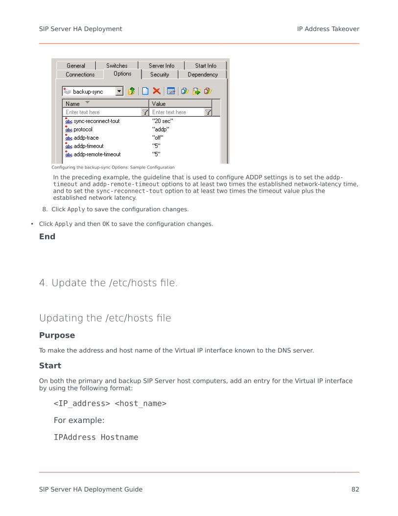
Configuring the backup-sync Options: Sample Configuration
In the preceding example, the guideline that is used to configure ADDP settings is to set the addp-timeout and addp-remote-timeout options to at least two times the established network-latency time,and to set the sync-reconnect-tout option to at least two times the timeout value plus theestablished network latency.
8. Click Apply to save the configuration changes.
• Click Apply and then OK to save the configuration changes.
End
4. Update the /etc/hosts file.
Updating the /etc/hosts filePurposeTo make the address and host name of the Virtual IP interface known to the DNS server.
StartOn both the primary and backup SIP Server host computers, add an entry for the Virtual IP interfaceby using the following format:
<IP_address> <host_name>
For example:
IPAddress Hostname
SIP Server HA Deployment IP Address Takeover
SIP Server HA Deployment Guide 82

127.0.0.1 sipdev1
End
5. Create a configuration file for the Virtual IP interface.
Creating a configuration file for the Virtual IP interfacePurposeTo create a configuration file for the Virtual IP interface. This procedure must be performed on bothSIP Server host computers.
Start
1. On each of the SIP Server host computers, locate the /etc/sysconfig/network-scripts/ifcfg-eth0file.
2. Create a copy that is named /etc/sysconfig/network-scripts/ifcfg-eth0:1.3. Define IPADDR, NETMASK, and NETWORK parameters values for the Virtual IP interface. When you are
finished, the content of the file should appear similar to the following example:DEVICE=eth0:1BOOTPROTO=staticUSERCTL=yesTYPE=EthernetIPADDR=192.51.14.208NETMASK=255.255.255.0NETWORK=192.51.14.0BROADCAST=192.51.14.255ONPARENT=no
End
6. Create Virtual IP address control scripts.
Creating Virtual IP address control scriptsPurposeThe Virtual IP interface/address is enabled and disabled by using the ifconfig administrative
SIP Server HA Deployment IP Address Takeover
SIP Server HA Deployment Guide 83

command. To facilitate the enabling and disabling of the Virtual IP interface, you can wrap ifconfigcommands in shell files.
Start
1. On both SIP Server host computers, create two shell files: one to enable the Virtual IP interface andanother to disable it—for example:• set_ip_up.sh—To enable the Virtual IP interface• set_ip_down.sh—To disable the Virtual IP interface
2. In the set_ip_up.sh file, enter the following command line:ifconfig <name_of_ethernet_interface>:1 xxx.xxx.xxx.xxx upwhere name_of_ethernet_interface is the name of the Virtual IP interface and xxx.xxx.xxx.xxx isthe Virtual IP--interface IP address.
3. In the set_ip_down.sh file, enter the following command line:ifconfig <name_of_ethernet_interface>:1 downwhere name_of_ethernet_interface is the name of the Virtual IP interface.
End
7. Create Application objects for Virtual IP address controlscripts.
Creating Application objects for the Virtual IP address controlscriptsPurposeTo create four Application objects of type Third Party Server: one for each of the shell files thatyou created previously. For example:
• SIP_SERVER_PRIMARY_VIP_UP—For a script that enables the Virtual IP address (to be run on the primarySIP Server host)
• SIP_SERVER_PRIMARY_VIP_DOWN—For a script that disables the Virtual IP address (to be run on theprimary SIP Server host)
• SIP_SERVER_BACKUP_VIP_UP—For a script that enables the Virtual IP address (to be run on the backupSIP Server host)
• SIP_SERVER_BACKUP_VIP_DOWN—For a script that disables the Virtual IP address (to be run on thebackup SIP Server host)
Creating Application objects for the shell files allows the shell files to be run as applications within the
SIP Server HA Deployment IP Address Takeover
SIP Server HA Deployment Guide 84

Genesys Framework.
Start
1. In the Configuration Manager, select Environment > Applications.2. Right-click and select New > Application.3. Select the Third Party Server template from the Application Templates folder, and click OK.4. On the General tab, enter a name for the Application object—for example,
SIP_SERVER_PRIMARY_VIP_UP.
Configuring the Application Object for the Script, General Tab: Sample Configuration
Note: You can use the previously listed Application object names, or you can specify your own.
5. Select the Server Info tab.a. Select the host name of the SIP Server on which the corresponding Virtual IP address control script is
located.b. If necessary, specify a valid communication-port number by using the Edit Port option.
Configuring the Application Object for the Script, Server Info Tab: SampleConfiguration
6. Select the Start Info tab.a. Set the Working Directory to the location of the script, and enter the name of the script in the
Command Line field. For example, for the SIP_SERVER_PRIMARY_VIP_UP Application object, enter
SIP Server HA Deployment IP Address Takeover
SIP Server HA Deployment Guide 85

the script name that enables the Virtual IP address (set_ip_up.sh). For theSIP_SERVER_PRIMARY_VIP_DOWN Application object, enter the script name that disables the VirtualIP address (set_ip_down.sh).
b. If you are configuring an Application object that disables the Virtual IP interface(SIP_SERVER_PRIMARY_VIP_DOWN and SIP_SERVER_BACKUP_VIP_DOWN), set the Timeout Startupvalue to 8.
3. Repeat the steps in this procedure to create an Application object for each of the four scripts.
End
8. Create Alarm Reaction scripts.
Creating Alarm Reaction scriptsPurposeTo create Alarm Reaction scripts for HA-related Alarm Conditions. When an HA-related AlarmCondition occurs, the associated Alarm Reaction script is run. Alarm Reaction scripts are configured tocall the Application objects that you created in Step 7.
Start
1. Open the Configuration Manager.2. Select Resources > Scripts.3. Right-click and select New > Script.4. Create four scripts: one for each of the Application objects that you created previously. For example:
• AR_SCRIPT_PRIMARY_VIP_UP—To trigger a script that enables the Virtual IP address (to be run on theprimary SIP Server host)
• AR_SCRIPT_PRIMARY_VIP_DOWN—To trigger a script that disables the Virtual IP address (to be run onthe primary SIP Server host)
• AR_SCRIPT_BACKUP_VIP_UP—To trigger a script that enables the Virtual IP address (to be run on thebackup SIP Server host)
• AR_SCRIPT_BACKUP_VIP_DOWN—To trigger a script that disables the Virtual IP address (to be run onthe backup SIP Server host)
SIP Server HA Deployment IP Address Takeover
SIP Server HA Deployment Guide 86
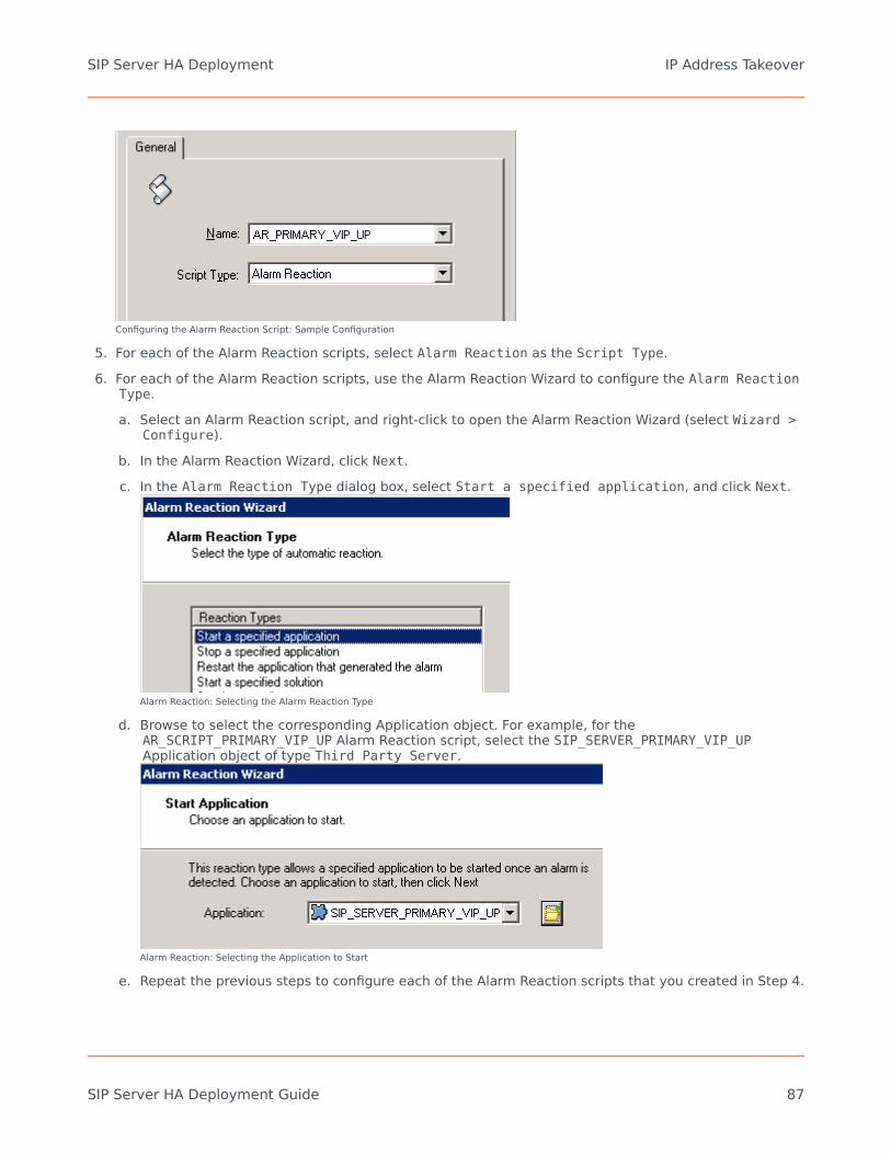
Configuring the Alarm Reaction Script: Sample Configuration
5. For each of the Alarm Reaction scripts, select Alarm Reaction as the Script Type.6. For each of the Alarm Reaction scripts, use the Alarm Reaction Wizard to configure the Alarm Reaction
Type.a. Select an Alarm Reaction script, and right-click to open the Alarm Reaction Wizard (select Wizard >
Configure).b. In the Alarm Reaction Wizard, click Next.c. In the Alarm Reaction Type dialog box, select Start a specified application, and click Next.
Alarm Reaction: Selecting the Alarm Reaction Type
d. Browse to select the corresponding Application object. For example, for theAR_SCRIPT_PRIMARY_VIP_UP Alarm Reaction script, select the SIP_SERVER_PRIMARY_VIP_UPApplication object of type Third Party Server.
Alarm Reaction: Selecting the Application to Start
e. Repeat the previous steps to configure each of the Alarm Reaction scripts that you created in Step 4.
SIP Server HA Deployment IP Address Takeover
SIP Server HA Deployment Guide 87

End
9. Create Alarm Conditions.
Creating Alarm ConditionsPurposeAlarm Conditions are required to handle log events that occur when a SIP Server changes its modefrom primary to backup or from backup to primary. When you create the Alarm Conditions, you willconfigure them to trigger the Alarm Reaction scripts that you created in Step 8.
Four Alarm Conditions are required for your HA configuration: two for the primary SIP Serverapplication and two for the backup. The following table outlines the Alarm Conditions for both hot-standby and warm-standby configurations.
Alarm Conditions: Sample Configuration
Log Event ID SIP ServerApplication Alarm Condition
Alarm ReactionScripts
00-05151 SIP_SERVER_PRIMARY ALRM_PRIMARY_51_HABackupAR_SCRIPT_PRIMARY_VIP_DOWN
00-05150 SIP_SERVER_PRIMARY ALRM_PRIMARY_50_HAPrimaryAR_SCRIPT_BACKUP_VIP_DOWNAR_SCRIPT_PRIMARY_VIP_UP
00-05151 SIP_SERVER_BACKUP ALRM_BACKUP_51_HABackupAR_SCRIPT_BACKUP_VIP_DOWN
00-05150 SIP_SERVER_BACKUP ALRM_BACKUP_50_HAPrimaryAR_SCRIPT_BACKUP_VIP_UPAR_SCRIPT_PRIMARY_VIP_DOWN
For information about the log events for which you are creating Alarm Conditions, refer to Log eventsgenerated by SCS.
Start
1. Open the Configuration Manager.2. Navigate to the Environment > Alarm Conditions folder.3. Right-click and select New > Alarm Condition to open the New Alarm Condition Properties dialog
box.4. On the General tab:
• Enter the Name for the Alarm Condition—for example, ALRM_PRIMARY_51_HABackup.• Optionally, enter a description.
SIP Server HA Deployment IP Address Takeover
SIP Server HA Deployment Guide 88

• For the Category value, select Critical.• Set Cancel Timeout to 1.
Configuring the Alarm Condition, General Tab: Sample Configuration
5. On the Detect Event tab:• Set the Log Event ID as defined in the table above.• Set the Selection Mode to Select By Application.• For the Application Name field, click the folder icon to browse for the SIP Server Application object.
If you are creating an Alarm Condition for the primary SIP Server, select the primary SIP ServerApplication object. If you are creating an Alarm Condition for the backup SIP Server, select thebackup SIP Server Application object.
SIP Server HA Deployment IP Address Takeover
SIP Server HA Deployment Guide 89

Configuring the Alarm Condition, Detect Event Tab: Sample Configuration
6. Click OK.7. On the Reaction Scripts tab, add the Alarm Reaction script as defined in the previous table.8. Repeat the steps in this procedure to create each of the four Alarm Conditions for your configuration.
End
10. Test Alarm Conditions.
Testing Alarm ConditionsPurposeTo verify that the Alarm Conditions work as expected.
Start
1. Use Telnet to access the SIP Server Virtual IP interface.2. Open the Solution Control Interface (SCI).3. Under Alarm Conditions, select the Alarm Condition that you created in the previous procedure—for
example, ALRM_PRIMARY_51_HABackup—right-click it, and then click Test. TheALRM_PRIMARY_51_HABackup Alarm Condition indicates that the primary SIP Server is in backup mode,which triggers the Alarm Reaction scripts that disable the Virtual IP address at the primary SIP Serverand disable the Virtual IP address at the backup SIP Server.
4. Use the ipconfig command to verify that the Virtual IP interface is active on the backup SIP Server andthat the Virtual IP interface is inactive on the primary SIP Server.
End
11. Verify the HA configuration.
Testing your SIP Server HA configurationPurpose
SIP Server HA Deployment IP Address Takeover
SIP Server HA Deployment Guide 90

To validate your HA configuration, you can perform the following tests.
Prerequisites
• Ensure that the Management Layer is up and running.• Start the primary SIP Server, and ensure that it is in primary mode.• Start the backup SIP Server, and ensure that it is in backup mode.
Start
1. Test 1: Manual switchovera. Establish a call between two SIP endpoints.b. Perform a manual switchover by using the SCI. In the SCI, verify that the SIP Server roles have
changed.c. Verify that hold, retrieve, and transfer functions can be performed on the call that was established
before the switchover.d. Release the call.
5. Test 2: Manual switchbacka. Establish a call between two SIP endpoints.b. Perform a manual switchover again by using the SCI. In the SCI, verify that the SIP Server roles
have changed.c. Verify that hold, retrieve, and transfer functions can be performed on the call that was established
before the switchover.d. Release the call.
5. Test 3: Stop primary SIP Servera. Establish a call between two SIP endpoints.b. Stop the primary SIP Server. Use the SCI to verify that the backup SIP Server goes into primary
mode.c. Verify that hold, retrieve, and transfer functions can be performed on the call that was established
before the switchover.d. Release the call.
End
SIP Server HA Deployment IP Address Takeover
SIP Server HA Deployment Guide 91

Deploying HA in Windows NLB ClusterComplete these steps to set up SIP Server HA on Windows, using Windows Network Load Balancing(NLB) Cluster functionality.
Windows NLB Cluster HA Deployment
1. Check prerequisites.
Prerequisites
The following are the basic requirements and recommendations that must be complete before youcan deploy a SIP Server HA configuration in a Windows NLB Cluster environment.
• Two separate physical host computers: one for the primary SIP Server and one for the backup SIPServer.
Note: Genesys recommends that you install primary and backup instances of SIP Server on differenthost computers. However, SIP Server does support HA configurations in which both primary andbackup SIP Server instances reside on a single host server.
• Operating-system requirement:• Windows Server 2003 or Windows Server 2008 with Microsoft Windows Network Load Balancing
(NLB).
• Software requirements:• SIP Server must be installed and configured on both host computers.• Local Control Agent (LCA) must be installed and configured on both host computers.
• Networking requirements:• A name-resolution method such as Domain Name System (DNS), DNS dynamic-update protocol, or
Windows Internet Name Service (WINS) is required.• Both host computers must be members of the same domain.• A domain-level account that is a member of the local Administrators group is required on each host
computer. A dedicated account is recommended.• Each host computer must have a unique NetBIOS name.• A static IP address is required for each of the network interfaces on both host computers. Note:
Server clustering does not support IP addresses that are assigned through Dynamic HostConfiguration Protocol (DHCP) servers.
SIP Server HA Deployment Deploying HA in Windows NLB Cluster
SIP Server HA Deployment Guide 92

• A dedicated network switch or separate virtual local-area network (VLAN) for cluster adapters isrecommended to reduce switch flooding that might be caused by Windows NLB.
• Access to a domain controller is required. If the cluster service is unable to authenticate the useraccount that is used to start the service, the cluster might fail. It is recommended that the domaincontroller be on the same local-area network (LAN) as the cluster, to ensure availability.
• Each node must have at least two network adapters: one for the connection to the public networkand another for the connection to the private node-to-node cluster network.
• A dedicated private-network adapter is required for HCL certification.• All nodes must have two physically independent LANs or VLANs for public and private
communication.• If you are using fault-tolerant network cards or network-adapter teaming, verify that firmware and
drivers are up to date, and check with your network-adapter manufacturer for Windows NLB clustercompatibility.
• In deployments where SIP Server uses two NICs, one NIC is used for SIP communication, while thesecond NIC is used for other kinds of communication with various components. Each host has oneNIC connected to a subnet dedicated to SIP communication. The Virtual IP address should be withinthe range of the network to which the NIC dedicated to SIP communication is connected. Thesecond NIC on both hosts should be connected to a separate network.
2. Configure Windows NLB parameters.
Configuring Windows NLB cluster parametersPurposeTo configure Windows NLB cluster parameters that are required for this type of SIP Server HAdeployment. Use the Microsoft Network Load Balancing (NLB) Manager to configure load-balancingparameters, as described in the following procedure.
Start
1. Open the Microsoft Network Load Balancing Manager tool.2. Select a cluster host, and open the Cluster Properties window.3. On the Cluster Parameters tab, select the Cluster operation mode. You can choose either Unicast
(default) or Multicast mode. For information about Windows NLB Unicast and Multicast modes, refer toyour Microsoft Windows Server documentation.
4. Click the Port Rules tab.a. Specify a Port range that includes the port that you will assign as the sip-port. See "Configuring
the primary SIP Server".b. In the Protocols section, select Both (both UDP and TCP).
SIP Server HA Deployment Deploying HA in Windows NLB Cluster
SIP Server HA Deployment Guide 93

c. In the Filtering mode section, select Multiple host, and set Affinity to either None or Single.d. Set Load weight to Equal.
5. Click the Host Parameters tab. In the Initial host state section, set the Default state toStopped.
For more information about Windows NLB cluster parameters, refer to your Microsoft Windows Serverdocumentation.
End
3. Configure the primary SIP Server.
Configuring the primary SIP Server
PurposeTo configure the primary SIP Server Application object for high availability.
Start
1. Stop the SIP Server applications on the primary and backup hosts. Genesys SIP Server applications canbe stopped by using the Genesys Solution Control Interface.
2. Open the Configuration Manager.3. Select the Applications folder, and right-click the SIP Server Application object that you want to
configure as the primary SIP Server. Select Properties.4. Click the Options tab.
a. Select the TServer section.i. Set the sip-port option to the port number that will be used by both the primary and backup
SIP Server applications.ii. Set the sip-address option to the Virtual IP address. (For Windows NLB cluster configurations,
set the value to the Windows NLB cluster IP address).iii. Click Apply to save the configuration changes.
b. If you are deploying a hot-standby configuration, it is recommended that you enable ADDP forcommunication between the primary and backup SIP Servers. To enable ADDP:i. Select the backup-sync section, and configure the following options:
• sync-reconnect-tout
• protocol
• addp-timeout
SIP Server HA Deployment Deploying HA in Windows NLB Cluster
SIP Server HA Deployment Guide 94

• addp-remote-timeout
Configuring the backup-sync Options: Sample Configuration
In the preceding example, the guideline that is used to configure ADDP settings is to set the addp-timeout and addp-remote-timeout options to at least two times the established network-latency time, and to set the sync-reconnect-toutoption to at least two times the timeout value plus the established network latency.Note: For more information about ADDP configuration parameters, see the "Backup-Synchronization Section" section in theFramework 8.1 SIP Server Deployment Guide.
5. Click Apply to save the configuration changes.
• Click the Switches tab.
a. Ensure that the correct Switch object is specified. If necessary, select the correct Switch object by usingthe Add button.
b. Click Apply to save the configuration changes.
• Click the Server Info tab.
a. Select the Redundancy Type. You can select either Hot Standby or Warm Standby.b. Complete this step if you are deploying a hot-standby configuration. If you are deploying a warm-standby
configuration, proceed to Step c.i. In the Ports section, select the port to which the backup SIP Server will connect for HA data
synchronization, and click Edit Port.
ii. In the Port Properties dialog box, on the Port Info tab, select the HA sync check box.iii. Click OK.
Note: If the HA sync check box is not selected, the backup SIP Server will connect to the default port of the primary SIP Server.
• For the Backup Server option, select the SIP Server Application object that you want to use as the backupSIP Server. If necessary, browse to locate the backup SIP Server Application object.
• Click Apply to save the configuration changes.• Click the Start Info tab.
a. Select Auto-Restart.b. Click Apply to save the configuration changes.
• Click Apply and then OK to save the configuration changes.
SIP Server HA Deployment Deploying HA in Windows NLB Cluster
SIP Server HA Deployment Guide 95

End
4. Configure the backup SIP Server.
Configuring the backup SIP ServerPurposeTo configure the backup SIP Server Application object for high availability.
Start
1. Stop the SIP Server applications on the primary and backup hosts. Genesys SIP Server applications canbe stopped by using the Genesys Solution Control Interface.
2. Open the Configuration Manager.3. Select the Applications folder, and right-click the SIP Server Application object that you want to
configure as the backup SIP Server. Select Properties.4. Click the Switches tab.
a. Click Add, and select the Switch object that you associated with the primary SIP Server Applicationobject.
b. Click Apply to save the configuration changes.
5. Click the Start Info tab.a. Select Auto-Restart.b. Click Apply to save the configuration changes.
6. Click the Options tab.a. Select the TServer section.
i. Set the sip-port option to the same port number that you specified for the primary SIP Server.ii. Set the sip-address option to the Virtual IP address. (For Windows NLB cluster configurations,
set the value to the Windows NLB cluster IP address)
b. Click Apply to save the configuration changes.
7. If you are deploying a hot-standby configuration and have configured ADDP communication on theprimary SIP Server, you must configure ADDP also on the backup SIP Server. To enable ADDP:i. Select the backup-sync section, and configure the following options:
• sync-reconnect-tout
• protocol
SIP Server HA Deployment Deploying HA in Windows NLB Cluster
SIP Server HA Deployment Guide 96

• addp-timeout
• addp-remote-timeout
Configuring the backup-sync Options: Sample Configuration
In the preceding example, the guideline that is used to configure ADDP settings is to set the addp-timeout and addp-remote-timeout options to at least two times the established network-latency time,and to set the sync-reconnect-tout option to at least two times the timeout value plus theestablished network latency.
8. Click Apply to save the configuration changes.
• Click Apply and then OK to save the configuration changes.
End
5. Create Cluster control scripts.
Creating Cluster control scriptsPurposeTo create Cluster control scripts for each of the SIP Servers. The scripts are used to enable the VirtualIP port on the host on which the SIP Server is in primary mode and disable the Virtual IP port on thehost on which the SIP Server is in backup mode.
In this procedure, you will create the following four Cluster control scripts:
• sip_server_primary_vip_up.bat—Enables the Virtual IP port on the primary SIP Server host• sip_server_primary_vip_down.bat—Disables the Virtual IP port on the primary SIP Server host• sip_server_backup_vip_up.bat—Enables the Virtual IP port on the backup SIP Server host• sip_server_backup_vip_down.bat—Disables the Virtual IP port on the backup SIP Server host
SIP Server HA Deployment Deploying HA in Windows NLB Cluster
SIP Server HA Deployment Guide 97

Note: You can use the previously listed script names, or you can specify your own.
Start
1. On the primary SIP Server host computer, create a batch file that is namedsip_server_primary_vip_up.bat and enter the following commands:[+] Commands for sip_server_primary_vip_up.bat
@title Enable Cluster Control Script@echo ************** Primary Virtual IP Enabled ************** >>vip1.log@echo %time% >> vip1.logwlbs.exe start sipcluster:host1_ip >> vip1.logwlbs.exe enable 5060 sipcluster:host1_ip >> vip1.logwlbs.exe drainstop sipcluster:host2_ip >> vip1.logexit
where:
• host1_ip is the dedicated cluster IP address of the primary host• host2_ip is the dedicated cluster IP address of the backup host
2. On the primary SIP Server host computer, create a batch file that is namedsip_server_primary_vip_down.bat and enter the following commands:[+] Commands for sip_server_primary_vip_down.bat
@title Disable Cluster Control Script@echo *************** Primary Virtual IP Disabled ************ >>vip1.log@echo %time% >> vip1.logwlbs.exe drainstop sipcluster:host1_ip >> vip1.logping -n 2 127.0.0.1exit
3. On the backup SIP Server host computer, create a batch file that is namedsip_server_backup_vip_up.bat and enter the following commands:[+] Commands for sip_server_backup_vip_up.bat
@title Enable Cluster Control Script@echo ************** Backup Virtual IP Enabled *************** >>vip2.log@echo %time% >> vip2.logwlbs.exe start sipcluster:host2_ip >> vip2.logwlbs.exe enable 5060 sipcluster:host2_ip >> vip2.logwlbs.exe drainstop sipcluster:host1_ip >> vip2.logexit
4. On the backup SIP Server host computer, create a batch file that is namedsip_server_backup_vip_down.bat and enter the following commands:[+] Commands for sip_server_backup_vip_down.bat
@title Disable Cluster Control Script@echo ***************** Backup Virtual IP Disabled *********** >>vip2.log@echo %time% >> vip2.logwlbs.exe drainstop sipcluster:host2_ip >> vip2.logping -n 2 127.0.0.1exit
Note: The preceding scripts include commands for logging script execution. The logs are created
SIP Server HA Deployment Deploying HA in Windows NLB Cluster
SIP Server HA Deployment Guide 98

in the directory in which the script is located.
End
6. Creating Application objects for Cluster control scripts.
Creating Application objects for Cluster control scriptsPurposeTo create four Application objects of type Third Party Server: one for each of the Cluster controlscripts that you created in Step 5. For example:
• SIP_SERVER_PRIMARY_VIP_UP—For a script that enables the Virtual IP port on the primary SIP Serverhost
• SIP_SERVER_PRIMARY_VIP_DOWN—For a script that disables the Virtual IP port on the primary SIP Serverhost
• SIP_SERVER_BACKUP_VIP_UP—For a script that enables the Virtual IP port on the backup SIP Server host• SIP_SERVER_BACKUP_VIP_DOWN—For a script that disables the Virtual IP port on the backup SIP Server
host
Creating Application objects for the Cluster control scripts allows the scripts to be run as applicationswithin the Genesys Framework.
Start
1. In the Configuration Manager, select Environment > Applications.2. Right-click and select New > Application.3. Select the Third Party Server template from the Application Templates folder, and click OK.4. On the General tab, enter the name for the Application object—for example,
SIP_SERVER_PRIMARY_VIP_UP.
SIP Server HA Deployment Deploying HA in Windows NLB Cluster
SIP Server HA Deployment Guide 99

Configuring the Application Object for the Script, General Tab: Sample Configuration
Note: You can use the suggested Application object names, or you can specify your own.
5. Select the Server Info tab.a. Select the host name of the SIP Server on which the corresponding Cluster control script is located.b. If necessary, specify a valid communication-port number by using the Edit Port option.
Configuring the Application Object for the Script, Server Info Tab: SampleConfiguration
6. Select the Start Info tab.a. Set the Working Directory to the location of the control script, and enter the name of the script in
the Command Line field. For example, for the SIP_SERVER_PRIMARY_VIP_UP Application object,enter the script name that enables the Virtual IP port (sip_server_primary_up.bat). For theSIP_SERVER_PRIMARY_VIP_DOWN Application object, enter the script name that disables the VirtualIP port (sip_server_primary_down.bat).
SIP Server HA Deployment Deploying HA in Windows NLB Cluster
SIP Server HA Deployment Guide 100

Configuring the Application Object for the Script, Start Info Tab: Sample Configuration
b. If you are configuring an Application object that disables a Virtual IP port(SIP_SERVER_PRIMARY_VIP_DOWN and SIP_SERVER_BACKUP_VIP_DOWN), set the Timeout Startupvalue to 8.
3. Repeat the steps in this procedure to create an Application object for each of the four Cluster controlscripts.
End
7. Create Alarm Reaction scripts.
Creating Alarm Reaction scriptsPurposeTo create Alarm Reaction scripts for HA-related Alarm Conditions. When an HA-related AlarmCondition occurs, the associated Alarm Reaction script is run. Alarm Reaction scripts are configured tocall the Application objects that you created in Step 6.
Start
1. Open the Configuration Manager.2. Select Resources > Scripts.3. Right-click and select New > Script.4. Create four scripts: one for each of the Application objects that you created previously. For example:
• AR_SCRIPT_PRIMARY_VIP_UP—To trigger a script that enables the Virtual IP address (to be run on theprimary SIP Server host)
• AR_SCRIPT_PRIMARY_VIP_DOWN—To trigger a script that disables the Virtual IP address (to be run onthe primary SIP Server host)
• AR_SCRIPT_BACKUP_VIP_UP—To trigger a script that enables the Virtual IP address (to be run on the
SIP Server HA Deployment Deploying HA in Windows NLB Cluster
SIP Server HA Deployment Guide 101

backup SIP Server host)• AR_SCRIPT_BACKUP_VIP_DOWN—To trigger a script that disables the Virtual IP address (to be run on
the backup SIP Server host)
Configuring the Alarm Reaction Script: Sample Configuration
5. For each of the Alarm Reaction scripts, select Alarm Reaction as the Script Type.6. For each of the Alarm Reaction scripts, use the Alarm Reaction Wizard to configure the Alarm Reaction
Type.a. Select an Alarm Reaction script, and right-click to open the Alarm Reaction Wizard (select Wizard >
Configure).b. In the Alarm Reaction Wizard, click Next.c. In the Alarm Reaction Type dialog box, select Start a specified application, and click Next.
Alarm Reaction: Selecting the Alarm Reaction Type
d. Browse to select the corresponding Application object. For example, for theAR_SCRIPT_PRIMARY_VIP_UP Alarm Reaction script, select the SIP_SERVER_PRIMARY_VIP_UPApplication object of type Third Party Server.
SIP Server HA Deployment Deploying HA in Windows NLB Cluster
SIP Server HA Deployment Guide 102

Alarm Reaction: Selecting the Application to Start
e. Repeat the previous steps to configure each of the Alarm Reaction scripts that you created in Step 4.
End
8. Create Alarm Conditions.
Creating Alarm ConditionsPurposeAlarm Conditions are required to handle log events that occur when a SIP Server changes its modefrom primary to backup or from backup to primary. When you create the Alarm Conditions, you willconfigure them to trigger the Alarm Reaction scripts that you created in Step 7.
Four Alarm Conditions are required for your HA configuration: two for the primary SIP Serverapplication and two for the backup. The following table outlines the Alarm Conditions for both hot-standby and warm-standby configurations.
Alarm Conditions: Sample Configuration
Log Event ID SIP ServerApplication Alarm Condition
Alarm ReactionScripts
00-05151 SIP_SERVER_PRIMARY ALRM_PRIMARY_51_HABackupAR_SCRIPT_PRIMARY_VIP_DOWN
00-05150 SIP_SERVER_PRIMARY ALRM_PRIMARY_50_HAPrimaryAR_SCRIPT_BACKUP_VIP_DOWNAR_SCRIPT_PRIMARY_VIP_UP
00-05151 SIP_SERVER_BACKUP ALRM_BACKUP_51_HABackupAR_SCRIPT_BACKUP_VIP_DOWN
00-05150 SIP_SERVER_BACKUP ALRM_BACKUP_50_HAPrimaryAR_SCRIPT_BACKUP_VIP_UPAR_SCRIPT_PRIMARY_VIP_DOWN
For information about the log events for which you are creating Alarm Conditions, refer to Log eventsgenerated by SCS.
Start
1. Open the Configuration Manager.2. Navigate to the Environment > Alarm Conditions folder.3. Right-click and select New > Alarm Condition to open the New Alarm Condition Properties dialog
box.
SIP Server HA Deployment Deploying HA in Windows NLB Cluster
SIP Server HA Deployment Guide 103

4. On the General tab:• Enter the Name for the Alarm Condition—for example, ALRM_PRIMARY_51_HABackup.• Optionally, enter a description.• For the Category value, select Critical.• Set Cancel Timeout to 1.
Configuring the Alarm Condition, General Tab: Sample Configuration
5. On the Detect Event tab:• Set the Log Event ID as defined in the table above.• Set the Selection Mode to Select By Application.• For the Application Name field, click the folder icon to browse for the SIP Server Application object.
If you are creating an Alarm Condition for the primary SIP Server, select the primary SIP ServerApplication object. If you are creating an Alarm Condition for the backup SIP Server, select thebackup SIP Server Application object.
SIP Server HA Deployment Deploying HA in Windows NLB Cluster
SIP Server HA Deployment Guide 104

Configuring the Alarm Condition, Detect Event Tab: Sample Configuration
6. Click OK.7. On the Reaction Scripts tab, add the Alarm Reaction script as defined in the previous table.8. Repeat the steps in this procedure to create each of the four Alarm Conditions for your configuration.
End
9. Test Alarm Conditions.
Testing Alarm ConditionsPurposeTo verify that the Alarm Conditions work as expected.
Start
1. Open the Solution Control Interface (SCI).2. Under Alarm Conditions, select the Alarm Condition that you created in the previous procedure—for
example, ALRM_PRIMARY_51_HABackup—right-click it, and then click Test. TheALRM_PRIMARY_51_HABackup Alarm Condition indicates that the primary SIP Server is in backup mode,which triggers the Alarm Reaction scripts that disable the Virtual IP portat the primary SIP Server anddisable the Virtual IP port at the backup SIP Server.
3. Use an wlbs queryport command to verify that the Virtual IP port is disabled on the primary SIP Server
SIP Server HA Deployment Deploying HA in Windows NLB Cluster
SIP Server HA Deployment Guide 105

and that the Virtual IP port is enabled on the backup SIP Server.
End
10. Verify the HA configuration.
Testing your SIP Server HA configurationPurposeTo validate your HA configuration, you can perform the following tests.
Prerequisites
• Ensure that the Management Layer is up and running.• Start the primary SIP Server, and ensure that it is in primary mode.• Start the backup SIP Server, and ensure that it is in backup mode.
Start
1. Test 1: Manual switchovera. Establish a call between two SIP endpoints.b. Perform a manual switchover by using the SCI. In the SCI, verify that the SIP Server roles have
changed.c. Verify that hold, retrieve, and transfer functions can be performed on the call that was established
before the switchover.d. Release the call.
5. Test 2: Manual switchbacka. Establish a call between two SIP endpoints.b. Perform a manual switchover again by using the SCI. In the SCI, verify that the SIP Server roles
have changed.c. Verify that hold, retrieve, and transfer functions can be performed on the call that was established
before the switchover.d. Release the call.
5. Test 3: Stop primary SIP Servera. Establish a call between two SIP endpoints.b. Stop the primary SIP Server. Use the SCI to verify that the backup SIP Server goes into primary
SIP Server HA Deployment Deploying HA in Windows NLB Cluster
SIP Server HA Deployment Guide 106

mode.c. Verify that hold, retrieve, and transfer functions can be performed on the call that was established
before the switchover.d. Release the call.
End
SIP Server HA Deployment Deploying HA in Windows NLB Cluster
SIP Server HA Deployment Guide 107

Business ContinuityThis section contains information about SIP Business Continuity, which provides the ability for a groupof agents to continue offering critical business functions to customers in the event of a loss of allGenesys components running at a particular site.
Business Continuity Deploying HA in Windows NLB Cluster
SIP Server HA Deployment Guide 108

SIP Business Continuity Architecture
SIP Business Continuity provides the ability for a group of agents to continue offering critical businessfunctions to customers in the event of a loss of all Genesys components running at a particular site.The SIP Business Continuity architecture uses a synchronized, two-site deployment, where Genesysswitch and server components are mirrored at each site in an active-active configuration, so that anyagent can log in to either switch, at any time.
The Business Continuity Overview figure shows the basic connections between SIP Serverinstances and endpoints across the redundant sites.
Business Continuity Overview
What Does It Do?
SIP Business Continuity includes (though not limited to) the following functions:
• Work area redundancy• Disaster Recovery• Graceful Migration
For regular call processing, agent activity can be load-balanced across the two sites, or you canconfigure agents to use one preferred site over the other. In the event of a failure at one site (a SIPServer HA pair or all Genesys components go down), agents connected to the failed site are re-logged in automatically to the surviving site. Although any active calls on the failed site areterminated at the moment of failure (including calls on the surviving site that include the failed SIPServer in the signaling path), the surviving site is able to process all new calls, with minimal impact toqueue wait times.
Business Continuity SIP Business Continuity Architecture
SIP Server HA Deployment Guide 109

Note: Business Continuity does not provide recovery for the local failure of particular agentendpoints or workstations. It is intended to provide redundancy for Genesys components only.
Note: Alcatel-Lucent 4000-series IP Phones do not support dual registration. Instead, an active-backup registration scheme is used to handle disaster recovery scenarios. Special configuration forthese phones is required. For more information, see Using IP Phones with SIP Server in BusinessContinuity Mode.
SIP Server Peers
A pair of primary and backup SIP Server instances are deployed at each site, providing local highavailability (HA). For Business Continuity, these dual HA pairs are known as SIP Server Peers. The SIPServer Peers rely on synchronized configuration for all agent-related objects: Extension DNs, Places,Agent Logins (and the references to their related User or Person object). Each agent desktop isconfigured with a "Preferred Site", indicating to which site it should connect if possible.
Synchronizing Configuration ObjectsUsing Genesys Administrator, you can synchronize all agent-related configuration object (DNs ofcertain types, Places, Agent Logins and the reference to their associated User or Person) between theSIP Server Peers.
Synchronization applies to the following configuration objects:
• ACD Position DN• ACD Queue DN• Call Processing Port DN• Extension DN• Agent Login
After you run the synchronization once, Genesys Administrator will automatically synchronize anyfurther configuration changes of Places and Users between the SIP Peers--as long as the changes aremade using Genesys Administrator.
SIP Phones
Business Continuity only supports SIP endpoints that are able to maintain dual registrations--oneregistration for each site (Alcatel 4000-series phones are the exception). For outbound 1pcc calls, oneof the sites is considered "preferred" based on either 3rd-party configuration on the phone itself, orbased on DNS SRV record priority.
For Alcatel 4000-series phones, an active-backup registration scheme is used--where the phoneregisters to the SIP Server on the backup site only if the primary is unavailable.
For details, see Using IP Phones with SIP Server in Business Continuity Mode.
Business Continuity SIP Business Continuity Architecture
SIP Server HA Deployment Guide 110

Agent Desktop
The agent desktop maintains a login to a single site at one time. Typically, the agent desktop logsinto the "Preferred Site" specified in the desktop configuration, but it will log in to the other peer ifboth the preferred site is unavailable and the SIP endpoint switches registration to the backup site.The agent desktop maintains a basic connection (no login) to the backup peer site.
For more information, see the Interaction Workspace 8.1 Deployment Guide.
Business Continuity SIP Business Continuity Architecture
SIP Server HA Deployment Guide 111

Call DeliveryDuring regular call processing, external media gateways distribute incoming traffic between the SIPServer Peers. Or optionally, an additional SIP Server or Network SIP Server can be deployed at thenetwork level to provide intelligent pre-routing, or for scaling SIP Server Peers.
Each SIP Server Peer delivers routed calls, internal calls, direct inbound calls, and external calls to aparticular agent through the SIP Server instance to which the agent is currently logged on. The agentinitiates calls through the SIP Server where they are logged in.
• About the Call Forwarding Procedure• Call Delivery - SIP Server Peer• Call Delivery - Network SIP Server• Call Delivery - Multi-Site
About the Call Forwarding Procedure
In case of a direct call to an agent phone number, Business Continuity takes special measures tomake sure that the call is delivered to the DN where the agent's SIP phone is actually registered.Since agents can be registered on either SIP Server Peer site, the party that makes the call does notknow the agent's current location, meaning the call can arrive at either SIP Server in the peer group.This SIP Server instance uses an internal call forwarding procedure to determine the location of thecall destination (the agent phone number) and deliver the call there. This procedure ensures that thecall is delivered to the site where T-Library messaging is linked to the logged in agent (identified asthe User or Person), so that proper reporting takes place. The option dr-forward controls the rulesfor this call forwarding procedure.
The call forwarding procedure typically takes place as follows:
1. An inbound direct call arrives on SIP Server 1.2. SIP Server 1 detects that the agent's phone is registered and accessible, but the agent is not logged in.3. SIP Server 1 initiates an Out-of-Signaling-Path (OOSP) transfer--it sends a 302 Moved Temporarily
response back to the caller with the address of the DN on its SIP Server Peer.4. The media gateway sends the secondary INVITE to SIP Server 2, targeting the same DN number.5. SIP Server 2 processes the INVITE and tries to establish the call with the target. To prevent a forwarding
loop, because the call has already been processed on SIP Server 1, SIP Server 2 will not forward the callback to that site, even if it turns out that the agent is not logged in on the SIP Server 2 site either.
Call Delivery - SIP Server Peers
The Call Delivery, Direct to SIP Server Peer figure shows a typical call flow for inbound call
Business Continuity SIP Business Continuity Architecture
SIP Server HA Deployment Guide 112

delivery to an agent, where the call arrives directly at the SIP Server Peer (no network-level SIPServer in the flow).
Call Delivery, Direct to SIP Server Peer
The following steps describe the call flow from media gateway to selected agent:
1. Media gateways distribute incoming traffic across both sites.2. A call arrives at SIP Server on Site 1. SIP Server requests routing instructions from the Universal Routing
Server (URS).3. Each Stat Server monitors both SIP Server Peers. As such, the Stat Server on Site 1 is able to determine
agent availability on both SIP Server Peers--agents can be logged in on either SIP Server Peer.4. URS selects the appropriate agent to handle the call. In this example, the selected agent is logged in on
the other SIP Server Peer site. URS sends a TRouteRequest to SIP Server, instructing it to route the callto the targeted agent.
Business Continuity SIP Business Continuity Architecture
SIP Server HA Deployment Guide 113

Note: To route calls across sites (using Inter Server Call Control (ISCC)), Agent Reservation must beenabled. For more information, see the "Agent Reservation" section in the "T-Server Fundamentals"chapter of the SIP Server Deployment Guide. Also, see the Universal Routing 8.1 Deployment Guide.
1. As part of its internal Business Continuity Forwarding procedure, SIP Server first determines that theselected agent is not logged in locally. Based on this logic (and related option values that control theprocedure), SIP Server then forwards the call to Site 2 through the specially configured inter-site TrunkDN, using ISCC routing.
2. The SIP Server Peer on Site 2 delivers the call to the agent.
Call Delivery - Network SIP Server
The Call Delivery, Network SIP Server figure shows a typical call flow for inbound call delivery toan agent, where the call first passes through a Network SIP Server.
Business Continuity SIP Business Continuity Architecture
SIP Server HA Deployment Guide 114

Call Delivery, Network SIP Server
Note: The Network SIP Server in this architecture could be replaced with a Premise SIP Serverinstance, installed at the network level. In either case, Genesys recommends configuring defaultrouting.
The following steps describe the call flow from media gateway to selected agent:
1. The media gateways distribute incoming traffic between Network SIP Server instances at the two sites.Network SIP Server, in conjunction with URS, can provide additional intelligence when deciding to whichsite to route the call. For example, routing can be configured to send a greater share of calls towhichever site currently has more logged in agents. Network SIP Server can also distribute calls acrossmultiple SIP Server Peer groups, for scaled deployments.
2. The call arrives at the Network SIP Server on Site 1. URS at Site 1 determines that the call should go toSite 2, which currently has more agents logged in.
Business Continuity SIP Business Continuity Architecture
SIP Server HA Deployment Guide 115

3. Network SIP Server sends a 302 Moved Temporarily message to the media gateway. The mediagateway sends a new INVITE to the SIP Server at Site 2.
4. URS at Site 2 selects the best agent to handle the call. In this example, the selected agent is logged into Site 2.
5. URS sends a TRouteRequest to SIP Server, instructing it to route the call to the targeted agent. SIPServer establishes the call with the agent.
Call Delivery - Multi-Site
In cases where the deployment includes an external Genesys location in addition to the SIP ServerPeers, the call is delivered to one of the SIP Server Peers, based on how the targeted Trunk isresolved. For example, if the INVITE through Trunk1 arrives at SIP Server on Site 1, but the targetedagent DN is not found at this site, Business Continuity Forwarding is applied, and the call is forwardedto the other SIP Server Peer at Site 2.
For configuration details, see Deploying SIP Business Continuity With a Remote Site.
Business Continuity SIP Business Continuity Architecture
SIP Server HA Deployment Guide 116

Disaster RecoveryIn the event of the catastrophic failure of a particular site--in which all Genesys components becomeunavailable, including locally paired HA servers--peer site redundancy is used to provide ongoingsupport for all logged in agents. For those agents logged in to the surviving SIP Server Peer, theirlogin remains unaffected and they can continue handling calls. For those agents that were logged into the failed site, there is a temporary increase in queue wait times as these agents are logged in tothe surviving site. Some loss of calls may occur at the failed site.
• Site Failure• Networking Failure Between Sites
Site Failure
The Site Failure figure illustrates what typically happens when one site in a SIP Server Peer groupsuffers a catastrophic failure.
Business Continuity SIP Business Continuity Architecture
SIP Server HA Deployment Guide 117

Site Failure
The following steps describe how Business Continuity recovers from a catastrophic failure of aparticular SIP Server Peer site:
1. Site 1 suffers a catastrophic failure. All Genesys components, including paired HA servers, are
Business Continuity SIP Business Continuity Architecture
SIP Server HA Deployment Guide 118

unavailable.2. The media gateways detect a response timeout from Site 1. In response, the media gateways begin
sending all new calls to Site 2.If the media gateway itself is affected by the disaster outage, the PSTN should detect this; load-balancing at the gateway level should redirect calls to the surviving media gateways.
3. Agents that are currently logged in to Site 2 continue to handle calls. Queue wait times increasetemporarily.
4. The agent's SIP phone responds in either of the following ways:• If the phone is configured to register on one site only, it re-registers now on the Site 2 SIP Server.• If the phone is configured for dual-registration, the phone automatically switches call handling from
the local site to the backup site (Site 2).
Agent desktops detect Site 1 failure, and re-login automatically to the SIP Server on Site 2. In addition,the desktop establishes connections to the Stat Server and Configuration Server Proxy on Site 2.
5. The standby Configuration Server and Configuration Server Database as Site 2 are brought into service.6. When the surviving SIP Server detects that its peer is failed, it continues operation in single-site mode,
stopping Business Continuity functions as follows:• It no longer applies the call forwarding procedure to new calls.• It allows agents to log in independently of the status of their endpoint.• It does not employ the forced logout procedure
Networking Failure Between Sites
The Networking Failure figure illustrates what typically happens when a networking failure occursbetween SIP Server Peer sites.
Business Continuity SIP Business Continuity Architecture
SIP Server HA Deployment Guide 119

Networking Failure
The following steps describe how Business Continuity recovers from a networking failure between theSIP Server Peer sites:
1. In this example, network connectivity between the two data center sites is lost. SIP Server detects this
Business Continuity SIP Business Continuity Architecture
SIP Server HA Deployment Guide 120

failure through Active Out of Service detection (options oos-check and oos-force) of the inter-siteTrunk DN. Connectivity between the media gateways and contact centers at each site are stillavailable.
2. The SIP Server instances at each site revert to their normal non-peered operation.3. Incoming calls at each site are routed only to agents logged in at that site--Business Continuity
Forwarding does not apply.4. In this case, the Business Continuity solution avoids any "split-brain" problems because there are no
longer any inter-dependencies between the sites.5. For short-term outages, the Configuration Server Proxy on Site 2 provides configuration data to local
Site 2 applications. For longer outages, Site 2 Configuration Server and Configuration Server Databasecan be brought into service.
6. When the surviving SIP Server detects that its peer is failed, it continues operation in single-site mode,stopping Business Continuity functions as follows:• It no longer applies the call forwarding procedure to new calls.• It allows agents to log in independently of the status of their endpoint.• It does not employ the forced logout procedure
Business Continuity SIP Business Continuity Architecture
SIP Server HA Deployment Guide 121

Graceful MigrationBusiness Continuity supports the graceful migration of operations from two active SIP Server Peersites to a single site, in cases where one full site needs to be taken offline or powered off--forexample, to perform maintenance on an entire data center. The goal of graceful migration is togradually move all business activity to the second site with no lost calls. Agents must migrate to thesecond site.
To start a graceful migration, you first configure your environment to stop sending calls to the SIPServer Peer site that you intend to shutdown. Using Genesys Administrator, you then initiate agraceful shutdown of the SIP Server itself, in which SIP Server stops accepting new calls, while stillallowing any ongoing calls to finish, ensuring that no calls are dropped when this SIP Server instanceis finally stopped.
Assuming that Site 2 is going to be taken offline, the overall procedure for graceful migration isfollows:
1. Configure the media gateways to stop sending new calls to Site 2.2. Configure the routing strategy to stop sending new calls to Site 2.3. Initiate the graceful shutdown procedure for SIP Server. You can initiate this in one of two ways:
• Using Genesys Administrator, initiate the graceful shutdown procedure from the SIP ServerApplication object.
• Sending a TPrivateRequest with serviceid=3019 from a T-Library client.
Either of these actions starts the SIP Server graceful shutdown process.4. All agents are forcedly moved into the NotReady state. New calls can no longer be distributed to these
agents.5. All new INVITE requests are rejected with a configurable error response (the option shutdown-sip-
reject-code). All new calls initiated by T-Library requests are rejected.6. Agents on this SIP Server instance are forcedly logged out as they end their calls with an appropriate
reason code. Once there are no more calls on this SIP Server, it shuts down.7. If the agents use Genesys Interaction Workspace, then they are logged in automatically at Site 1. SIP
Server at Site 1 now handles all calls.
Business Continuity SIP Business Continuity Architecture
SIP Server HA Deployment Guide 122

Deploying SIP Business ContinuityThis pages describes how to deploy SIP Business Continuity in different scenarios, environments, andmodes:
Basic DeploymentUse these procedures to set up basic SIPBusiness Continuity.
Deploying Basic SIP Continuity
Setup a Remote SiteUse these additional procedures toinclude a remote site in the continuitysetup.
Deplying SIP Continuity With a RemoteSite
Business Continuity Deploying SIP Business Continuity
SIP Server HA Deployment Guide 123
Basic DeploymentThe following tasks are required to deploy basic SIP Business Continuity in your environment. Unlessotherwise stated, refer to the Framework 8.1 SIP Server Deployment Guide for information about theconfiguration options.
Deploying Basic SIP Business Continuity
1. Create the peer switch.
For each DR pair required, use the Sync Switch Wizard in Genesys Administrator to create a new peerswitch or use an existing switch as the peer. Each switch in the DR pair must be located at a separatesite. The Wizard sets up the switches as peers, synchronizes switch-related elements between them,and then keeps them synchronized.
For remote agents, before using the Sync Switch Wizard in Genesys Administrator to create a newpeer switch:
1. Configure the contact option with the value equal the FQDN of the media gateway for all remote agentDNs or a softswitch.
2. Configure local DNS servers for each peer to resolve this FQDN to respective gateway addresses.
ImportantThe switches are not synchronized automatically for changes madeoutside of Genesys Administrator. However, you can re-synchronizethese switches at any time by using the Sync Switch Wizard. Formore information about the Sync Switch Wizard, refer to GenesysAdministrator 8.1 Help.
2. Interconnect the DR peers.
On each DR peer:
1. Configure a Trunk DN pointing to the other peer.2. Assign to each DN a unique prefix that does not match a possible dialed number to avoid the DN being
mistaken for use by an outbound call. The options oos-check and oos-force must be configured toenable Active Out Of Service Detection.
Note: Use the names of these DNs when configuring the Application option dr-peer-trunk.
Business Continuity Deploying SIP Business Continuity
SIP Server HA Deployment Guide 124

3. Set the dr-peer-location option to the name of the Switch object of the other SIP Server in the DRpair.
4. Do not configure the auto-redirect-enabled option.
3. Configure ISCC COF between the DR peer switches.
Refer to the Framework 8.1 SIP Server Deployment Guide for instructions.Set the following options inthe extrouter section on each SIP Server:
• cof-feature=true
• default-network-call-id-matching=sip
4. Set up default routing.
Do one or both of the following, as appropriate:
• If you are using premise SIP Servers at the network level, use the configuration options router-timeoutand default-dn.
• If you are using Network SIP Servers, use the configuration option default-route-destination.
5. Configure routing from premise to peer.
On each premise SIP Server, use the configuration option dr-peer-trunk to identify that the SIPServer is a part of a DR pair, and to identify the Trunk DN that points to the other SIP Server in thepair. Genesys also recommends the following:
• Add the addresses of both DR peers to the list of addresses in the option enforce-external-domains,to ensure that the call parties are properly recognized based on the Host element of the contacts.
• Use the option dr-forward at the Application or DN level to define the mode of forwarding inbound andinternal calls when SIP Server is operating in Business Continuity mode. Set this option to one of thefollowing values, as appropriate:• no-agent—for call center deployments or for an agent's DNs• oos—for Alcatel-Lucent and Bria IP phones that do not support simultaneous registrations on two
sites• off—for office (that is, non-agent) deployments of endpoints
6. (Optional) Configure the preferred site for agents.
Interaction Workspace (IW) supports preferred-site connections for agents. Other agent desktops
Business Continuity Deploying SIP Business Continuity
SIP Server HA Deployment Guide 125

must use the same mechanism as used by IW for configuring preferred-site connections. Forconfiguration details, see the Interaction Workspace 8.1 Deployment Guide.
Business Continuity Deploying SIP Business Continuity
SIP Server HA Deployment Guide 126

DR Peer and Remote Site DeploymentThe following tasks describe the steps necessary to deploy SIP Business Continuity in the followingscenario:
• Two sites, S1 and S2, are configured as a DR peer. You want to call the agents in the DR peer from athird site S3.
Unless otherwise stated, refer to the Framework 8.1 SIP Server Deployment Guide for informationabout the configuration options.
Deploying SIP Business Continuity With a Remote Site
1. Configure sites S1 and S2 as DR peers.
See Basic Deployment.
2. Configure two trunks on the third switch, one each to theother switches in the DR pair.
1. On the third switch, configure two Trunk DNs, and configure the contact option on each DN as follows:• First DN: contact=<FQDN of DR peer>• Second DN: contact=<FQDN of DR peer>
2. On both DNs, do no configure the auto-redirect-enabled option.
All other options can remain the same. However, if you want, you can use theoptions priority and capacity to indicate the preference of one trunk over theother.
3. Configure ISCC COF between DR peer switches.
Configure ISCC COF access between the following sites:
• The remote site and the first DR pair site.• The remote site and the second DR pair site.
Business Continuity Deploying SIP Business Continuity
SIP Server HA Deployment Guide 127

Refer to the Framework 8.1 SIP Server Deployment Guide for instructions. Set thefollowing options in the extrouter section on each SIP Server:
• cof-feature=true
• default-network-call-id-matching=sip
Business Continuity Deploying SIP Business Continuity
SIP Server HA Deployment Guide 128

Configuration OptionsThis section describes configuration options that are used in the deployment of SIP BusinessContinuity. All options are in the TServer section, and unless otherwise specified, are set at theApplication level.
dr-forwardDefault Value: offValid Values:
• off -- DR peer forwarding is turned off. SIP Server works in the traditional single mode and always triesto deliver the call to the requested destination on the local switch.
• no-agent -- SIP Server tries to determine if the call should be forwarded to its DR peer when there is noagent logged into the DN.Note: Use this setting for only ALU 4000-series IP Phones. Contact Genesys Technical Support if youwant to utilize it for other SIP endpoints.
• oos -- SIP Server forwards the call to the second SIP Server peer if an endpoint is in an Out-Of-Service(OOS) state.
Changes Take Effect: Immediately
Defines a system-wide mode of forwarding inbound and internal calls when SIP Server is operating inBusiness Continuity mode. This option can also be set at the DN level, in which case the settingoverrides that set at the Application level.
dr-peer-trunkDefault Value: NULLValid Values: A valid name of a Trunk DN that points to the DR peer site.Changes Take Effect: Immediately
Specifies that this SIP Server is a part of a DR pair, and identifies the Trunk DN that points to theother SIP Server in the DR pair. If set to NULL (the default), SIP Server operates in the traditionalsingle mode.
shutdown-sip-reject-codeDefault Value: 603Valid Values: 300–603Changes Take Effect: Immediately
Specifies the error response used for rejecting new INVITE messages received by the system that is inshutdown mode. If set to 300, 301, or 302, SIP Server first checks to see if dr-peer-trunk isconfigured, and if so, sends the contact of that Trunk DN in the 302 response.
Business Continuity Deploying SIP Business Continuity
SIP Server HA Deployment Guide 129

Using IP PhonesThis section describes how SIP endpoints, such as IP Phones, work with SIP Server in BusinessContinuity mode.
Supported IP PhonesThe following is a list of IP Phones that can be configured to support SIP Business Continuity, with theactual model that was tested in parentheses:
• CounterPath Bria 3.x IP Phones (Bria 3.0)• Polycom SoundPoint IP Phones using firmware version 3.2 or later (Polycom SoundPoint IP330 with
firmware version 3.2)• Alcatel-Lucent (ALU) 4000-series IP Phones with SIP version 2.10.80 or later (ALU 4008/4018 with SIP
version 2.10.80)
Note: Advanced IP Phone features, such as Presence and MWI, are not available in SIP BusinessContinuity Mode.
Refer to device-specific documentation for detailed information and instructions for configuring thephone.
Registration RequirementsIn a stand-alone SIP Server configuration with Business Continuity mode activated, agents' phonesmust be able to register on two sites in one of the following ways:
• Simultaneously--Register on both peer Sip Servers at the same time.• Sequentially--Register on the main peer SIP Server first; if that peer SIP Server is down, then register on
the secondary peer SIP Server.
There are also specific Configuration Server configuration requirements for SIP endpoints. In thefollowing situations, the dr-forward must be set to oos:
• When SIP endpoints are configured to register sequentially.• When Bria or ALU IP Phones are configured.
Business Continuity Using IP Phones
SIP Server HA Deployment Guide 130

Using Siemens OSVSIP Server integrated with Siemens OpenScape Voice version 5 can be configured in BusinessContinuity mode. You must configure the option dr-forward=no-agent on the Application or DN(Voice over IP Service DN with service type=softswitch) when you configure SIP Server.
See the Framework 8.1 SIP Server Integration Reference Manual for information and instructionsabout configuring the Siemens OpenScape Voice PBX.
Business Continuity Using Siemens OSV
SIP Server HA Deployment Guide 131

Log EventsTo launch the Virtual IP address control scripts or Cluster control scripts on SIP Server host, configurethe Alarm Conditions to execute Alarm Reaction scripts, which instructs the Management Layer byusing the Application objects.
This configuration aligns the IP configuration of the host computer with the run mode of therespective SIP Server application, enabling the switchover process to be completed successfully.
The following log events, which are relevant to SIP Server HA hot- and warm-standby configurations,respectively, are fully described in the Framework 8.1 Combined Log Events Help.
Log Events Generated by SCS
SCS generates the following log events when an application changes run modes (from backup toprimary or from primary to backup):
00-05150Level: StandardText: The run mode of the Application is changed to PrimaryAttributes: NoneDescription: Solution Control Server (SCS) generates this log event on behalf of any application whenthe application starts to run in Primary mode.
00-05151Level: StandardText: The run mode of the Application is changed to BackupAttributes: NoneDescription: Solution Control Server (SCS) generates this log event on behalf of any application whenthe application starts to run in Backup mode.
Log Events Using Siemens OSV
SIP Server HA Deployment Guide 132