IDU-450 8.0K Fixed Wing Pilot Guide - Genesys Aerosystems
456
IDU-450 EFIS Software Version 8.0K (Fixed Wing) IDU-450 8.0K Fixed Wing Pilot Guide PRECISE PERFORMANCE. PROVEN EXPERIENCE. PERSONALIZED ATTENTION.
-
Upload
khangminh22 -
Category
Documents
-
view
0 -
download
0
Transcript of IDU-450 8.0K Fixed Wing Pilot Guide - Genesys Aerosystems

IDU-450 EFIS Software Version 8.0K (Fixed Wing)
IDU-450 8.0K Fixed Wing Pilot Guide
PRECISE PERFORMANCE. PROVEN EXPER IENCE.
PERSONALIZED ATTENTION.

1st Ed Dec 2019 IDU-450 EFIS Software Version 8.0K (Fixed Wing) i
Pilot Operating Guide and
Reference (Fixed Wing)
EFIS Software Version 8.0K
Document 64-000103-080K
This pilot guide must be carried in the aircraft and made available to the pilot at all times. It can only be used in conjunction with the Federal Aviation Administration (FAA) approved Aircraft Flight Manual (AFM). Refer to the applicable AFM for aircraft specific information, such as unique ground tests, limitations, and emergency procedures.
© 2019 Genesys Aerosystems All Rights Reserved
No part of this document may be reproduced in any form, or by any means, without prior written consent of Genesys Aerosystems.
FlightLogic and Virtual VFR are trademarks of Genesys Aerosystems. All other brand names and trademarks are the property of their respective holders.
For service or repairs, contact an authorized Genesys Aerosystems dealer. For product support or inquiries regarding this pilot guide, contact Genesys Aerosystems.
One S-TEC Way, Municipal Airport, Mineral Wells TX 76067 Phone: (800) 872-7832 Fax: (940) 325-3904
www.genesys-aerosystems.com

1st Ed Dec 2019 IDU-450 EFIS Software Version 8.0K (Fixed Wing) ii
Revision Record
Rev Notes/Pages changed, added, or deleted by current revision
Date Author
Retain this record in front of pilot guide. Upon receipt of a revision, insert changes and complete table below. Revision or Edition Revision Date Insertion Date/Initials

IDU-450 EFIS Software Version 8.0K
1st Ed Dec 2019 IDU-450 EFIS Software Version 8.0K (Fixed Wing) TOC-1
Table of Contents
Section 1 Introduction ......................................................................... 1-1
1.1. Introduction ............................................................................. 1-1
1.2. EFIS/FMS Description ............................................................ 1-1
1.3. About This Guide .................................................................... 1-2
Section 2 System Overview ................................................................ 2-1
2.1. Abbreviations and Acronyms .................................................. 2-1
2.2. System Overview .................................................................. 2-11
2.2.1. Functional Integration and Display Redundancy ...... 2-15
2.2.2. IDU Initialization ........................................................ 2-16
2.3. General Arrangement ........................................................... 2-22
2.3.1. Data Source Monitors ............................................... 2-22
2.3.2. IDU Intra-System Communications ........................... 2-22
2.4. Color Conventions................................................................. 2-23
2.5. Warning/Caution/Advisory System ....................................... 2-25
2.5.1. Time-Critical Warning and Caution Alerts ................. 2-25
2.5.2. Warning Alerts ........................................................... 2-28
2.5.3. Caution Alerts ............................................................ 2-30
2.5.4. Side-Specific Caution Alerts ..................................... 2-38
2.5.5. Advisory Alerts .......................................................... 2-38
2.5.6. Side-Specific Advisory Alerts .................................... 2-40
2.5.7. Audio-Only Caution and Advisory Alerts ................... 2-42
2.5.8. Voice Alerts and Muting ............................................ 2-44
2.5.9. Visual Alert Prioritization and Declutter ..................... 2-44
2.6. Database and Software Updates .......................................... 2-45
2.6.1. Navigation and Obstruction Database ...................... 2-45
2.6.2. Update Requirements ............................................... 2-47
2.6.3. Software and Terrain Database Update ................... 2-48
2.7. Run Demonstrator/Training Program .................................... 2-48
2.8. EFIS Training Tool ................................................................ 2-49
2.9. Application Software Air Mode and Ground Mode ................ 2-49

IDU-450 EFIS Software Version 8.0K
TOC-2 IDU-450 EFIS Software Version 8.0K (Fixed Wing) 1st Ed Dec 2019
Section 3 Display Symbology ............................................................. 3-1
3.1. Introduction ............................................................................. 3-1
3.1.1. IDU-450 PFD Display (Basic Mode) ........................... 3-1
3.1.2. IDU-450 MFD Display ................................................. 3-2
3.2. PFD Symbology ...................................................................... 3-2
3.2.1. Altitude Display ........................................................... 3-3
3.2.1.1. Altitude Display (Metric Units) ..................................... 3-3
3.2.2. Altimeter Setting .......................................................... 3-3
3.2.3. Selected Altitude Sub-Mode (Target Altitude) ............ 3-4
3.2.4. Altitude Display (VNAV Tile) ....................................... 3-5
3.2.5. VNAV Sub-Mode......................................................... 3-6
3.2.6. Minimum Altitude ........................................................ 3-6
3.2.7. Vertical Speed Indicator .............................................. 3-7
3.2.8. Normal AGL Indication ................................................ 3-8
3.2.9. Analog AGL Indication ................................................ 3-9
3.2.10. Decision Height ......................................................... 3-10
3.2.11. Airspeed Display ....................................................... 3-11
3.2.12. Airspeed Display (with EFIS-Coupled) ..................... 3-15
3.2.13. Heading Display ........................................................ 3-16
3.2.14. Pitch Scale ................................................................ 3-17
3.2.15. Pitch Limit Indicator .................................................. 3-18
3.2.16. Turn Rate Indicator ................................................... 3-19
3.2.17. G-Force and Fast/Slow Indicator .............................. 3-20
3.2.18. Landing Gear Indication ............................................ 3-20
3.2.19. Unusual Attitude Mode ............................................. 3-21
3.2.20. PFD Background....................................................... 3-22
3.2.21. Flight Path Marker (Velocity Vector) ......................... 3-25
3.2.22. Bank Angle Scale ..................................................... 3-28
3.2.23. Timer Indication ........................................................ 3-28
3.2.24. Marker Beacon Symbology ....................................... 3-28
3.2.25. Flight Director Symbology ......................................... 3-29
3.2.26. OBS Setting of CDI ................................................... 3-32

IDU-450 EFIS Software Version 8.0K
1st Ed Dec 2019 IDU-450 EFIS Software Version 8.0K (Fixed Wing) TOC-3
3.2.27. Heading/Roll-Steering Sub-Mode ............................. 3-33
3.2.28. No Autopilot or Fully-Integrated Autopilot CDI .......... 3-33
3.2.29. Vertical Deviation Indicator (VDI) .............................. 3-33
3.2.30. Vertical Deviation Indicator (EFIS Coupled) ............. 3-35
3.2.31. Highway in the Sky/Skyway ...................................... 3-36
3.2.32. Active Waypoint and Waypoint Identifier .................. 3-36
3.2.33. Mini Map .................................................................... 3-38
3.2.34. Runways ................................................................... 3-38
3.2.35. Genesys/S-TEC DFCS Autopilot Annunciations ...... 3-40
3.3. MFD Symbology .................................................................... 3-40
3.3.1. Ownship Symbology ................................................. 3-40
3.3.2. Moving Map ............................................................... 3-41
3.3.3. Compass Rose/ND Boundary Circle Symbol ........... 3-43
3.3.4. Clock/Options ............................................................ 3-43
3.3.5. Air Data and Groundspeed ....................................... 3-44
3.3.6. Fuel Totalizer/Waypoint Distance Functions ............ 3-45
3.3.7. Navigation Data ......................................................... 3-46
3.3.8. Analog Navigation Symbology .................................. 3-48
3.3.9. Borders ...................................................................... 3-49
3.3.10. Terrain/Obstructions .................................................. 3-50
3.3.11. Pan Mode .................................................................. 3-51
3.3.12. Start Point ................................................................. 3-52
3.3.13. Direct Point ................................................................ 3-52
3.3.14. Altitude Capture Predictor/Top-of-Descent ............... 3-53
3.3.15. Projected Path ........................................................... 3-54
3.3.16. Active Flight Plan Path/Manual Course/Runways .... 3-54
3.3.16.1. Parallel Track ............................................................ 3-54
3.3.16.2. Manual Course .......................................................... 3-55
3.3.16.3. Active Flight Plan Path .............................................. 3-55
3.3.17. Field of View Indication ............................................. 3-56
3.3.18. Range ........................................................................ 3-56
3.4. HSI Page ............................................................................... 3-57
IDU-450 EFIS Software Version 8.0K
TOC-4 IDU-450 EFIS Software Version 8.0K (Fixed Wing) 1st Ed Dec 2019
3.4.1. Compass Rose Symbols .......................................... 3-57
3.4.2. Conventional HSI/PTR Format ................................. 3-58
3.4.3. HSI CDI and VDI Scale ............................................. 3-58
3.4.4. Analog Navigation Symbology .................................. 3-59
3.4.5. Air Data and Groundspeed ....................................... 3-61
3.4.6. Clock/Options ............................................................ 3-61
3.4.7. Fuel Totalizer/Waypoint Distance Functions ............ 3-62
3.5. Navigation Log ...................................................................... 3-62
3.5.1. Clock and Groundspeed ........................................... 3-62
3.5.2. Fuel Remaining and Fuel Flow Data ........................ 3-62
3.5.3. Waypoint Identifier Column ....................................... 3-63
3.5.4. VNAV and VNAV Offset Column .............................. 3-63
3.5.5. Path Column ............................................................. 3-64
3.5.6. Distance Column....................................................... 3-64
3.5.7. Estimated Time Enroute Column .............................. 3-64
3.5.8. Estimated Time of Arrival Column ............................ 3-65
3.5.9. Fuel Remaining Column ........................................... 3-65
Section 4 Reversionary Modes ........................................................... 4-1
4.1. Reversionary Modes ............................................................... 4-1
4.1.1. Oat Sensor Failure Mode ............................................ 4-5
4.1.2. Heading Failure Mode ................................................ 4-5
4.1.3. PFD Screen Auto Reversion ....................................... 4-5
4.1.4. GPS Failure ................................................................ 4-6
4.2. PFD and MFD Failure Mode Examples .................................. 4-8
4.2.1. PFD Failure Mode 0 .................................................... 4-9
4.2.2. MFD Failure Mode 0 ................................................... 4-9
4.2.3. PFD Failure Mode 1 .................................................. 4-10
4.2.4. MFD Failure Mode 1 ................................................. 4-10
4.2.5. PFD Failure Mode 2 .................................................. 4-11
4.2.6. MFD Failure Mode 2 ................................................. 4-11
4.2.7. PFD Failure Mode 3 .................................................. 4-12
4.2.8. MFD Failure Mode 3 ................................................. 4-12

IDU-450 EFIS Software Version 8.0K
1st Ed Dec 2019 IDU-450 EFIS Software Version 8.0K (Fixed Wing) TOC-5
4.2.9. PFD Failure Mode 4 .................................................. 4-13
4.2.10. MFD Failure Mode 4 ................................................. 4-13
4.2.11. PFD Failure Mode 5 .................................................. 4-14
4.2.12. MFD Failure Mode 5 ................................................. 4-14
4.2.13. PFD Failure Mode 6 .................................................. 4-15
4.2.14. MFD Failure Mode 6 ................................................. 4-15
4.2.15. PFD Failure Mode 7 .................................................. 4-16
4.2.16. MFD Failure Mode 7 ................................................. 4-16
Section 5 Menu Functions and Step-By-Step Procedures ................. 5-1
5.1. Menu Functions ....................................................................... 5-1
5.1.1. Menu Philosophy ......................................................... 5-1
5.1.2. Avoidance of Autonomous Behavior ........................... 5-2
5.2. Menu Synchronization ............................................................ 5-3
5.3. Normal Top-Level Menu ......................................................... 5-6
5.3.1. Top-Level Menu Option Descriptions .......................... 5-6
5.3.2. Top-Level Menu Automatic Pop-up Function Descriptions .................................................................................... 5-7
5.4. First Page (PFD) ..................................................................... 5-9
5.4.1. PFD Page First-Level Option Descriptions ................. 5-9
5.5. First-Level (MFD) .................................................................. 5-11
5.5.1. MFD Page First-Level Option Descriptions .............. 5-11
5.6. Lower-Level Menus (Below First-Level) ............................... 5-12
5.7. Flight Plan (FPL) Menu ......................................................... 5-12
5.7.1. Flight Planner Page ................................................... 5-12
5.7.2. Flight Planner Page ................................................... 5-13
5.7.3. PFD Page Shown ...................................................... 5-13
5.7.4. MFD Page Shown on IDU ......................................... 5-14
5.7.5. To Create an Overfly User Waypoint (Step-By-Step) 5-14
5.7.6. Flight Plan (FPL) Menu Selecting (PFD or MFD) (Step-By-Step) .................................................................................. 5-14
5.7.7. Flight Plan (FPL) Menu Create-Edit (MFD only) (Step-By-Step) .................................................................................. 5-15
5.7.8. Activate Flight Plan (PFD or MFD) (Step-By-Step) ... 5-16

IDU-450 EFIS Software Version 8.0K
TOC-6 IDU-450 EFIS Software Version 8.0K (Fixed Wing) 1st Ed Dec 2019
5.7.9. Edit Flight Plan (MFD only) (Step-By-Step) .............. 5-16
5.7.10. Reverse Flight Plan (MFD only) (Step-By-Step) ....... 5-18
5.7.11. Delete Flight Plan (MFD only) (Step-By-Step) .......... 5-18
5.7.12. Create User Waypoint (MFD only) (LAT-LON) (Step-By-Step) .................................................................................. 5-19
5.7.13. Create User Waypoint (RAD-DST) (MFD only) (Step-By-Step) .................................................................................. 5-20
5.7.14. Edit User Waypoint (MFD only) (Step-By-Step) ....... 5-21
5.7.15. Delete User Waypoint (MFD only) (Step-By-Step) ... 5-22
5.7.16. RAIM Prediction (MFD only) (Step-By-Step) ............ 5-23
5.8. Active Flight Plan (ACTV) Menu ........................................... 5-26
5.8.1. Active Flight Plan (ACTV) Menu Options ................. 5-27
5.8.2. Active Flight Plan (ACTV) Menu Options (PFD or MFD) (Step-By-Step) ............................................................................... 5-31
5.8.3. Active Flight Plan (ACTV) Menu (PFD or MFD) (Step-By-Step) .................................................................................. 5-32
5.8.4. Active Flight Plan (ACTV) Options NRST Menu Option (PFD or MFD) (Step-By-Step) ....................................................... 5-33
5.9. Information (INFO) Menu ...................................................... 5-33
5.9.1. Information (INFO) Menu (Step-By-Step) ................. 5-36
5.10. Omnibearing Selector (OBS) Menu ...................................... 5-37
5.10.1. Omnibearing Selector (OBS) Menu (Step-By-Step) . 5-39
5.11. Heading Bug (HDG) Menu .................................................... 5-40
5.11.1. Heading Bug (HDG) Menu (PFD only) (Step-By-Step) .................................................................................. 5-40
5.12. Nearest (NRST) Menu .......................................................... 5-41
5.12.1. Nearest (NRST) Menu PFD or MFD) (Step-By-Step) .................................................................................. 5-42
5.12.2. Nearest (NRST) Menu ILS (Step-By-Step) ............... 5-43
5.13. Direct Menu ........................................................................... 5-44
5.13.1. Direct Menu (Step-By-Step) ...................................... 5-45
5.14. Time (TIME) Menu ................................................................ 5-46
5.14.1. Time (TIME) Menu (PFD or MFD) (Step-By-Step) ... 5-47
5.15. PFD Source (SOURCE) Menu ............................................. 5-49

IDU-450 EFIS Software Version 8.0K
1st Ed Dec 2019 IDU-450 EFIS Software Version 8.0K (Fixed Wing) TOC-7
5.15.1. PFD Page First-Level Source Selection (Step-By-Step) .................................................................................. 5-50
5.16. PFD Bug (BUGS) Menu ........................................................ 5-50
5.16.1. PFD Bug (BUGS) Menu (Step-By-Step) ................... 5-52
5.17. PFD Declutter (DCLTR) Menu .............................................. 5-55
5.17.1. PFD Declutter (DCLTR) Menu (Step-By-Step) ......... 5-56
5.18. Altimeter Menu ...................................................................... 5-57
5.18.1. PFD Altimeter Menu (Step-By-Step) ......................... 5-58
5.19. MFD Fault Display (FAULTS) Menu ..................................... 5-59
5.19.1. MFD Fault Display (FAULTS) Menu (Step-By-Step) 5-61
5.20. MFD Fuel Totalizer Quantity Setting (SET FUEL) Menu ...... 5-62
5.21. MFD Page (PAGE) Menu ..................................................... 5-63
5.21.1. MFD Page (PAGE) Menu (Step-By-Step) ................. 5-64
5.21.2. MFD NAV LOG Page (Step-By-Step) ....................... 5-64
5.21.3. MFD HSI Page (Step-By-Step) ................................. 5-65
5.22. MFD HSI Declutter (DCLTR) Menu ...................................... 5-66
5.22.1. MFD HSI Declutter (DCLTR) Menu (Step-By-Step) . 5-66
5.23. MFD ND Page Format Menu ................................................ 5-67
5.23.1. MFD Page Format (Step-By-Step) ............................ 5-69
5.23.1.1. Changing MFD ND Orientation ................................. 5-69
5.23.1.2. Adding LAT/LON to MFD ND Page .......................... 5-70
Section 6 Quick Start Tutorial ............................................................. 6-1
Section 7 IFR Procedures ................................................................... 7-1
7.1. Active Flight Plan .................................................................... 7-1
7.2. IFR Procedures ....................................................................... 7-4
7.3. Overview of Procedures and Instrument Approaches ............ 7-4
7.3.1. Highway in the Sky (Skyway) ...................................... 7-6
7.3.2. Waypoint Sequencing ............................................... 7-11
7.3.3. Fly-Over Waypoints ................................................... 7-12
7.3.4. Fly-By Waypoints ...................................................... 7-13
7.3.5. Direct-To ................................................................... 7-16
7.3.5.1. Direct-To Unnamed Waypoints Inside Procedures ... 7-17

IDU-450 EFIS Software Version 8.0K
TOC-8 IDU-450 EFIS Software Version 8.0K (Fixed Wing) 1st Ed Dec 2019
7.4. Discontinuities ....................................................................... 7-17
7.4.1. Manual Termination Legs ......................................... 7-18
7.5. Magnetic Course ................................................................... 7-18
7.5.1. AHRS Modes for Heading Source ............................ 7-19
7.5.2. GPS Altitude ............................................................. 7-19
7.5.3. Dead Reckoning ....................................................... 7-19
7.5.4. Geodesic Path Computation Accuracy ..................... 7-19
7.5.5. Parallel Offsets .......................................................... 7-20
7.6. Default GPS/SBAS Navigation Modes ................................. 7-22
7.7. Required Navigation Performance ....................................... 7-25
7.7.1. Manually Entered RNP Value ................................... 7-26
7.7.2. When in an Approach Region of Operation .............. 7-26
7.7.3. When outside the Approach Region of Operation .... 7-26
7.8. GPS/SBAS CDI Scale and FSD Transitions ........................ 7-27
7.9. Approach Type Selection ...................................................... 7-29
7.9.1. Approach Path Definition as VTF IFR Approach ...... 7-30
7.9.2. VTF IFR Approach .................................................... 7-31
7.9.3. VTF VFR Approach .................................................. 7-31
7.10. Missed Approach and Departure Path Definition ................. 7-31
7.11. Loss of Navigation Monitoring .............................................. 7-32
7.11.1. Automatic RNP Mode ............................................... 7-32
7.11.2. Enroute Mode ........................................................... 7-33
7.11.3. LNAV Approach Mode .............................................. 7-33
7.11.4. LNAV/VNAV Approach Mode ................................... 7-33
7.11.5. LP/LPV Approach Mode ........................................... 7-33
7.12. Loss of Integrity Caution Monitoring ..................................... 7-33
7.13. Selection of an Instrument Procedure .................................. 7-34
7.13.1. Standard Terminal Arrival Route (STAR) (Step-By-Step) .................................................................................. 7-35
7.13.2. ILS Instrument Approach (Step-By-Step) ................. 7-38
7.13.3. ILS Approach with Manual Termination Leg in MAP (Step-By-Step) ............................................................................... 7-42

IDU-450 EFIS Software Version 8.0K
1st Ed Dec 2019 IDU-450 EFIS Software Version 8.0K (Fixed Wing) TOC-9
7.13.4. LOC Back Course Instrument Approach (Step-By-Step) .................................................................................. 7-46
7.13.5. RNAV (GPS) Instrument Approach to LPV Minima (Step-By-Step) .................................................................................. 7-50
7.13.6. NRST ILS Instrument Approach (Step-By-Step) ...... 7-55
7.13.7. VOR/DME Instrument Approach (Step-By-Step) ...... 7-60
7.13.8. ILS or LOC RWY 1 Instrument Approach with Missed Approach Flown to Alternate fix (Step-By-Step) ............................ 7-64
Section 8 Terrain Awareness Warning System .................................. 8-1
8.1. TAWS Functions ..................................................................... 8-1
8.2. Terrain Display ........................................................................ 8-2
8.3. Forward Looking Terrain Alert Function ................................. 8-3
8.3.1. FLTA Modes ................................................................ 8-3
8.3.2. GPS/SBAS Navigation Mode Slaving ......................... 8-3
8.3.3. Default FLTA Mode ..................................................... 8-4
8.3.4. FLTA Search Envelope ............................................... 8-5
8.3.5. FLTA Alerts and Automatic Popup .............................. 8-8
8.4. Premature Descent Alert (PDA) Function ............................... 8-9
8.5. Excessive Rate of Descent (GPWS Mode 1) ....................... 8-10
8.6. Excessive Closure Rate to Terrain (GPWS Mode 2) ............ 8-10
8.7. Sink Rate after Takeoff or Missed Approach (GPWS Mode 3) ... .............................................................................................. 8-12
8.8. Flight into Terrain when not in Landing Configuration (GPWS Mode 4) ............................................................................................. 8-13
8.9. Excessive Downward Deviation from an ILS Glideslope (GPWS Mode 5) ............................................................................................. 8-14
8.10. 500-Foot Wake-Up Call ........................................................ 8-15
8.11. External Sensors and Switches ............................................ 8-16
8.12. TAWS Basic Parameter Determination ................................ 8-17
8.13. TAWS Automatic Inhibit Functions (Normal Operation) ....... 8-19
8.13.1. TAWS Automatic Inhibit Functions (Abnormal Operation) .................................................................................. 8-20
8.13.2. TAWS Manual Inhibit Functions ................................ 8-22
8.14. TAWS Selections on PFD ..................................................... 8-22

IDU-450 EFIS Software Version 8.0K
TOC-10 IDU-450 EFIS Software Version 8.0K (Fixed Wing) 1st Ed Dec 2019
Section 9 Appendix ............................................................................. 9-1
9.1. Appendix ................................................................................. 9-1
9.2. Operating Tips ........................................................................ 9-1
9.3. Domestic or International Flight Planning ............................... 9-1
9.4. Descent Planning .................................................................... 9-1
9.5. Terrain Clearance ................................................................... 9-1
9.6. Departure Airport Information ................................................. 9-2
9.7. Unique Names for Flight Plans ............................................... 9-2
9.8. Altimeter Settings .................................................................... 9-2
9.9. Warnings, Cautions, and Advisories ....................................... 9-2
9.10. Magnetic vs. True North Modes of Operation ......................... 9-2
9.11. Altitude Miscompare Threshold .............................................. 9-4
9.12. Airspeed Miscompare Threshold ............................................ 9-5
9.13. Jeppesen Sanderson NavData® Chart Compatibility ............. 9-6
9.14. ARINC 424 Path-Terminator Leg Types ................................. 9-6
9.15. Data Logging and Retrieval .................................................... 9-6
9.15.1. Delete Log Files .......................................................... 9-7
9.15.2. Logged Flags and Custom CAS Messages ................ 9-7
9.16. Routes and Waypoints ............................................................ 9-8
9.16.1. VFR Flight Planning .................................................... 9-8
9.16.2. Download Routes and User Waypoints ...................... 9-8
9.16.3. Upload Routes and User Waypoints........................... 9-8
9.16.4. Delete Routes and User Waypoints............................ 9-9
9.16.5. EFIS Training Tool (ETT) ............................................ 9-9
9.17. USB Flash Drive Memory Limitations ................................... 9-10
9.18. Certification Basis ................................................................. 9-10
9.19. Environmental Requirements ............................................... 9-11
T 1. Traffic Symbology ................................................................... T-1
T 1.1. Traffic Display Definitions ........................................... T-1
T 1.2. Traffic Rendering Rules .............................................. T-2
T 1.3. Traffic Thumbnail ........................................................ T-3
T 2. TCAS-II Traffic RA indicator ................................................... T-3

IDU-450 EFIS Software Version 8.0K
1st Ed Dec 2019 IDU-450 EFIS Software Version 8.0K (Fixed Wing) TOC-11
T 3. Dedicated Traffic Page ........................................................... T-4
T 3.1. MFD Page (PAGE) Menu ........................................... T-4
T 3.2. Traffic Display Format ................................................. T-4
T 3.3. Traffic Page Screen Range ......................................... T-4
T 3.4. Compass Rose Symbols ............................................. T-4
T 3.5. Clock and Options ....................................................... T-5
T 3.6. Fuel Totalizer/Waypoint Distance Functions .............. T-6
T 3.7. Active Flight Plan Path/Manual Course/Runways ...... T-6
T 4. OASIS Traffic Page Overlays ................................................. T-7
T 5. MFD Fault Display (FAULTS) (L1) Menu ................................ T-7
T 6. MFD Traffic Format (FORMAT..) (R4) Menu .......................... T-7
T 7. PFD Declutter (DCLTR) (R4) Menu ........................................ T-8
T 8. Menu Synchronization ............................................................ T-8
RBP 1. Remote BUGs Panel ...................................................... RBP-1
S 1. WX-500 Data ........................................................................... S-1
S 2. Dedicated Strikes Page .......................................................... S-2
S 2.1. MFD Page (PAGE) Menu ........................................... S-2
S 2.1.1. MFD STRIKES Page (Step-By-Step) .......................... S-2
S 2.2. Page Screen Range .................................................... S-2
S 2.3. Air Data and Groundspeed ......................................... S-2
S 2.4. Clock and Options ....................................................... S-3
S 2.5. Active Flight Plan Path/Manual Course/Runways ...... S-4
S 2.6. Fuel Totalizer/Waypoint Distance Functions .............. S-4
S 3. MFD Faults Display (FAULTS) Menu ..................................... S-4
S 4. MFD Page First-Level Option Descriptions ............................ S-4
S 5. MFD Strikes Format (FORMAT) Menu ................................... S-5
S 6. OASIS Strikes Screen Overlays ............................................. S-5
S 7. Menu Synchronization ............................................................ S-5
D 1. Datalink Symbology ............................................................... D-1
D 2. Dedicated Datalink Page ....................................................... D-4
D 2.1. MFD Page (PAGE) Menu ........................................... D-4
D 2.2. Ownship Symbol ......................................................... D-5

IDU-450 EFIS Software Version 8.0K
TOC-12 IDU-450 EFIS Software Version 8.0K (Fixed Wing) 1st Ed Dec 2019
D 2.3. Datalink Page Legend ................................................ D-5
D 2.4. Air Data and Groundspeed ......................................... D-5
D 2.5. Clock and Options ...................................................... D-5
D 2.6. Datalink Page Screen Orientation .............................. D-7
D 2.7. Boundary Circle Symbols ........................................... D-8
D 2.8. Active Flight Plan Path/Manual Course/Runways ...... D-8
D 2.9. Borders ....................................................................... D-9
D 2.10. Pan Mode .................................................................... D-9
D 3. Top-Level Menu Automatic Pop-Up Function Descriptions .... D-9
D 4. MFD Page First-Level Option Descriptions .......................... D-10
D 5. MFD Datalink Format Menu .................................................. D-10
D 5.1. MFD DATALINK Page (Step-By-Step) ..................... D-11
D 6. Active Flight Plan (ACTV) Menu Options ............................. D-12
D 7. Information (INFO) Menu ...................................................... D-12
D 8. MFD Fault Display Menu ...................................................... D-12
D 9. Menu Synchronization .......................................................... D-13
WX 1. Weather Radar ............................................................... WX-1
WX 2. Top-Level Menu Option Descriptions ............................. WX-3
WX 3. PFD Weather Radar Page Format (FORMAT) Menu ..... WX-3
WX 3.1. Ownship Symbol ...................................................... WX-3
WX 3.2. Weather Radar Page Format ................................... WX-6
WX 3.3. Weather Radar Page Screen Range ....................... WX-8
WX 3.4. Track Line ................................................................ WX-8
WX 3.5. Active Flight Plan Path/ Manual Course/ Runways . WX-9
WX 3.6. Weather Radar Return Data .................................. WX-10
WX 3.7. Air Data and Groundspeed .................................... WX-12
WX 3.8. Clock/Options ......................................................... WX-12
WX 3.9. Fuel Totalizer/Waypoint Distance Functions ......... WX-14
WX 4. MFD Fault Display (FAULTS) Menu ............................. WX-14
WX 5. Top-Level Menu Automatic Pop-Up Function Descriptions ...... ...................................................................................... WX-15
WX 6. Menu Synchronization .................................................. WX-15

IDU-450 EFIS Software Version 8.0K
1st Ed Dec 2019 IDU-450 EFIS Software Version 8.0K (Fixed Wing) TOC-13
RD 1. PFD Primary Flight Instrumentation ................................. RD-1
RD 1.1. Pitch Scale ............................................................... RD-1
RD 1.2. Flight Director Symbology ........................................ RD-1
RD 1.3. Marker Beacon Indicators ........................................ RD-2
RD 1.4. Unusual Attitude Mode ............................................. RD-2
RD 1.5. Bank Angle Scale ..................................................... RD-3
RD 1.6. Pitch Limit Indicator .................................................. RD-3
RD 1.7. AGL Indication .......................................................... RD-4
RD 1.8. Landing Gear Indication ........................................... RD-5
RD 1.9. Airspeed Display ...................................................... RD-5
RD 1.9.1 Airspeed Readout .................................................... RD-7
RD 1.9.2 Takeoff and Landing Speed Bugs ............................ RD-8
RD 1.10. Altimeter ................................................................... RD-9
RD 1.11. Altitude Display ...................................................... RD-10
RD 1.11.1 Loss of ADC Sensor Indication .......................... RD-11
RD 1.11.2 Altitude Sub-Mode ............................................. RD-11
RD 1.11.3 Metric Altitude .................................................... RD-12
RD 1.12. Vertical Speed Indicator ......................................... RD-12
RD 1.13. Heading Display ..................................................... RD-14
RD 1.14. Heading Failure Mode ............................................ RD-14
RD 1.15. G-Force Indicator ................................................... RD-15
RD 1.16. Turn Rate Indicator ................................................ RD-16
RD 1.17. Timer Indication ...................................................... RD-16
RD 1.18. Vertical Deviation Indicator (VDI) ........................... RD-17
RD 1.19. Course Deviation Indicator ..................................... RD-19
RD 1.20. Vertical Deviation Indicator (EFIS Coupled) .......... RD-22
RD 1.21. Active Waypoint and Waypoint Identifier ............... RD-22
RD 2. GPS Failure .................................................................... RD-23
RD 3. PFD Failure Mode 0 ....................................................... RD-24
RD 3.1. PFD Failure Mode 1 ............................................... RD-25
RD 3.2. PFD Failure Mode 2 ............................................... RD-25
SAR 1. Search and Rescue (SAR) Patterns .............................. SAR-1

IDU-450 EFIS Software Version 8.0K
TOC-14 IDU-450 EFIS Software Version 8.0K (Fixed Wing) 1st Ed Dec 2019
SAR 1.1. SAR Pattern Step-by-Step Procedures ................. SAR-1
SAR 2. Expanding Square Pattern ............................................. SAR-4
SAR 3. Rising Ladder Pattern .................................................... SAR-6
SAR 4. Orbit Pattern................................................................... SAR-7
SAR 5. Race Track Pattern ........................................................ SAR-8
SAR 6. Sector Search Pattern ................................................. SAR-10
INDEX
GLOSSARY

IDU-450 EFIS Software Version 8.0K
1st Ed Dec 2019 IDU-450 EFIS Software Version 8.0K (Fixed Wing) LOFT-1
List of Figures and Tables
FIGURE 1-1: IDU-680 INPUT IDENTIFICATION .................................................... 1-1 TABLE 2-1: PERTINENT EFIS LIMITS SETTINGS ............................................... 2-12 FIGURE 2-1: IDU-450 PRIMARY FLIGHT DISPLAY (PFD) .................................. 2-14 FIGURE 2-2: IDU-450 MULTIFUNCTION FLIGHT DISPLAY (MFD) ....................... 2-15 FIGURE 2-3: SYSTEM DIAGRAM ...................................................................... 2-15 FIGURE 2-4: IDU-450 INITIALIZATION SCREEN ................................................ 2-16 TABLE 2-2: IDU SOFTWARE VERSION AND PART NUMBER ............................... 2-16 TABLE 2-3: IDU NUMBER DESIGNATION ......................................................... 2-17 FIGURE 2-5: LOGO SCREEN WITH “TESTING” ................................................ 2-19 FIGURE 2-6: CRC SCREEN............................................................................ 2-20 FIGURE 2-7: TWO-MINUTE COUNTDOWN SCREEN ........................................... 2-20 FIGURE 2-8: QUICK START SCREEN ........................................................... 2-21 TABLE 2-4: COLOR CONVENTIONS ................................................................. 2-23 TABLE 2-5: TIME-CRITICAL WARNING AND CAUTION ALERTS IN PRIMARY FIELD OF
VIEW ................................................................................................... 2-25 FIGURE 2-9: TIME-CRITICAL WARNING ALERT ................................................. 2-26 FIGURE 2-10: TIME-CRITICAL CAUTION ALERT ................................................ 2-26 TABLE 2-6: TIME-CRITICAL WARNING AND CAUTION ALERTS ............................ 2-26 FIGURE 2-11: WARNING ALERTS .................................................................... 2-28 TABLE 2-7: WARNING ALERT ELEMENTS ......................................................... 2-29 TABLE 2-8: WARNING ALERTS ....................................................................... 2-29 FIGURE 2-12: CAUTION ALERTS ..................................................................... 2-30 TABLE 2-9: CAUTION ALERT ELEMENTS .......................................................... 2-30 TABLE 2-10: CAUTION ALERTS....................................................................... 2-30 TABLE 2-11: SIDE-SPECIFIC CAUTION ALERTS ................................................ 2-38 FIGURE 2-13: ADVISORY ALERTS ................................................................... 2-38 TABLE 2-12: ADVISORY ALERT ELEMENTS ...................................................... 2-38 TABLE 2-13: ADVISORY ALERTS ..................................................................... 2-39 TABLE 2-14: SIDE-SPECIFIC ADVISORY ALERTS .............................................. 2-40 TABLE 2-15: AUDIO-ONLY CAUTION AND ADVISORY ALERTS ............................ 2-43 FIGURE 2-14: GROUND MAINTENANCE PAGE .................................................. 2-48 FIGURE 3-1: PFD ........................................................................................... 3-1 FIGURE 3-2: PFD IN BASIC MODE .................................................................... 3-1 FIGURE 3-3: MFD ........................................................................................... 3-2 FIGURE 3-4: PFD SYMBOLOGY ........................................................................ 3-2 FIGURE 3-5: SELECTING ALTIMETER SETTING ................................................... 3-3 FIGURE 3-6: ALTITUDE DISPLAY (METRIC UNITS) .............................................. 3-3 FIGURE 3-7: ALTIMETER SETTING .................................................................... 3-4 FIGURE 3-8: QFE ALTIMETER SETTING ............................................................ 3-4 FIGURE 3-9: TARGET ALTITUDE ....................................................................... 3-5 FIGURE 3-10: TARGET ALTITUDE BUG .............................................................. 3-5 FIGURE 3-11: TARGET ALTITUDE BUG (WITHOUT AUTOPILOT) ........................... 3-5 FIGURE 3-12: ALTITUDE DISPLAY (VNAV TILE) ................................................. 3-5 FIGURE 3-13: VNAV SUB-MODE (NOT VERTICALLY INTEGRATED) ..................... 3-6 FIGURE 3-14: VNAV SUB-MODE WITH GENESYS/S-TEC DFCS ........................ 3-6 FIGURE 3-15: MINIMUM ALTITUDE .................................................................... 3-7

IDU-450 EFIS Software Version 8.0K
LOFT-2 IDU-450 EFIS Software Version 8.0K (Fixed Wing) 1st Ed Dec 2019
FIGURE 3-16: VSI ........................................................................................... 3-7 FIGURE 3-17: VSI BUG ................................................................................... 3-7 TABLE 3-1: SCALE GRADUATIONS AND DISPLAY ................................................ 3-8 FIGURE 3-18: VSI BUG WITHOUT GENESYS/S-TEC DFCS ................................ 3-8 FIGURE 3-19: VSI BUG WITH GENESYS/S-TEC DFCS ...................................... 3-8 FIGURE 3-20: NORMAL AGL INDICATION ........................................................... 3-9 TABLE 3-2: AGL INDICATION ............................................................................ 3-9 FIGURE 3-21: ANALOG AGL INDICATION ........................................................... 3-9 TABLE 3-3: ANALOG AGL INDICATOR................................................................ 3-9 TABLE 3-4: ANALOG AGL INDICATOR MARKINGS ............................................. 3-10 FIGURE 3-22: DECISION HEIGHT .................................................................... 3-10 FIGURE 3-23: AIRSPEED DISPLAY................................................................... 3-11 FIGURE 3-24: AIRSPEED TREND ..................................................................... 3-12 FIGURE 3-25: AIRSPEED BUG OFF SCALE ....................................................... 3-12 TABLE 3-5: AIRSPEED BUG LIMITS .................................................................. 3-12 TABLE 3-6: AIRSPEED BUG SETTING ANNUNCIATION AND BUG COLORS ............ 3-12 FIGURE 3-26: AIRSPEED SCALE FAR PART 23 ................................................ 3-13 FIGURE 3-27: AIRSPEED SCALE FAR PART 25 ................................................ 3-14 FIGURE 3-28: AIRSPEED DISPLAY (WITH EFIS-COUPLED) ................................ 3-15 FIGURE 3-29: HEADING DISPLAY .................................................................... 3-16 FIGURE 3-30: DAMPENED INTEGRAL SLIP INDICATOR ....................................... 3-16 TABLE 3-7: HEADING DISPLAY ........................................................................ 3-16 FIGURE 3-31: DG INDICATED WHEN AHRS IN DG MODE ................................. 3-17 FIGURE 3-32: GPS LOSS OF NAVIGATION (LON) ............................................ 3-17 FIGURE 3-33: PITCH SCALE ........................................................................... 3-17 FIGURE 3-34: PITCH SCALE ZENITH AND NADIR SYMBOL ................................. 3-18 FIGURE 3-35: PITCH LIMIT INDICATOR (5 KNOTS ABOVE STALL) ........................ 3-18 FIGURE 3-36: PITCH LIMIT INDICATOR (20 KNOTS ABOVE STALL) ...................... 3-19 FIGURE 3-37: TURN INDICATION (SELECTED FROM DECLUTTER MENU) ............. 3-19 FIGURE 3-38: G-FORCE INDICATOR ................................................................ 3-20 FIGURE 3-39: G-FORCE INDICATOR TELLTALE INDICATIONS ............................. 3-20 FIGURE 3-40: ANALOG G-FORCE INDICATOR ................................................... 3-20 FIGURE 3-41: RESET G ............................................................................... 3-20 FIGURE 3-42: LANDING GEAR INDICATION ....................................................... 3-21 FIGURE 3-43: UNUSUAL ATTITUDE MODE ....................................................... 3-21 FIGURE 3-44: PFD TERRAIN AND OBSTRUCTIONS ........................................... 3-23 TABLE 3-8: LAT-LON RESOLUTION BOUNDARIES ........................................... 3-23 TABLE 3-9: TERRAIN AND OBSTRUCTION RENDERING LEVELS .......................... 3-24 FIGURE 3-45: TERRAIN DESELECTED ON PFD AND RETAINED ON MFD MAP ..... 3-24 FIGURE 3-46: PFD WITH OBSTRUCTIONS ........................................................ 3-25 FIGURE 3-47: FLIGHT PATH MARKER .............................................................. 3-26 FIGURE 3-48: FLIGHT PATH MARKER VIEWS ................................................... 3-26 TABLE 3-10: FLIGHT PATH MARKER BEHAVIOR ............................................... 3-27 FIGURE 3-49: FLIGHT PATH MARKER GHOST .................................................. 3-27 FIGURE 3-50: FLIGHT PATH MARKER ABSENCE ............................................... 3-27 FIGURE 3-51: BANK ANGLE ............................................................................ 3-28 FIGURE 3-52: TIMER ..................................................................................... 3-28 FIGURE 3-53: MARKER BEACONS ................................................................... 3-28

IDU-450 EFIS Software Version 8.0K
1st Ed Dec 2019 IDU-450 EFIS Software Version 8.0K (Fixed Wing) LOFT-3
FIGURE 3-54: FLIGHT DIRECTOR FD1 SINGLE CUE ......................................... 3-29 FIGURE 3-55: FLIGHT DIRECTOR FD1 ............................................................ 3-29 FIGURE 3-56: FLIGHT DIRECTOR FD2 (NORMAL MODE) .................................. 3-30 FIGURE 3-57: FLIGHT DIRECTOR FD2 COURSE DEVIATION INDICATOR ............. 3-30 FIGURE 3-58: COURSE DEVIATION INDICATOR ................................................ 3-30 TABLE 3-11: CDI BEHAVIOR AND COLOR ........................................................ 3-31 FIGURE 3-59: CDI NO AUTOPILOT OR FULLY-INTEGRATED AUTOPILOT ............. 3-33 FIGURE 3-60: VERTICAL DEVIATION INDICATOR ............................................... 3-33 FIGURE 3-61: VDI COLOR DURING GPS/SBAS LON OR VLON ...................... 3-34 TABLE 3-12: VERTICAL DEVIATION INDICATOR BEHAVIOR ................................. 3-34 FIGURE 3-62: EFIS COUPLED VERTICALLY WITH GLIDESLOPE MODE ............... 3-35 FIGURE 3-63: HIGHWAY IN THE SKY ............................................................... 3-36 FIGURE 3-64: ACTIVE WAYPOINT ................................................................... 3-36 FIGURE 3-65: MINI MAP ................................................................................ 3-38 TABLE 3-13: MINI-MAP BEHAVIOR (WHEN NOT DECLUTTERED) ....................... 3-38 FIGURE 3-66: RUNWAYS ............................................................................... 3-39 TABLE 3-14: RUNWAY DRAWING CRITERIA ..................................................... 3-39 FIGURE 3-67: OWNSHIP SYMBOLS ................................................................. 3-40 FIGURE 3-68: BASIC MOVING MAP ................................................................. 3-41 FIGURE 3-69: MOVING MAP WITH INSTRUMENT APPROACH WITH HSI ENABLED 3-41 FIGURE 3-70: NORTH-UP ARC MODE WITH HSI ENABLED AND VOR1 SELECTED ......
........................................................................................................... 3-42 FIGURE 3-71: NORTH-UP CENTERED MODE WITH HSI ENABLED AND VLOC1
SELECTED ............................................................................................ 3-42 FIGURE 3-72: HEADING-UP CENTERED MODE ................................................ 3-43 FIGURE 3-73: COMPASS ROSE/ND BOUNDARY CIRCLE SYMBOL ...................... 3-43 FIGURE 3-74: CLOCK OPTIONS ...................................................................... 3-43 TABLE 3-15: CLOCK/OPTIONS ....................................................................... 3-43 FIGURE 3-75: AIR DATA AND GROUNDSPEED .................................................. 3-44 FIGURE 3-76: FUEL TOTALIZER/ WAYPOINT DISTANCE FUNCTIONS ................... 3-45 TABLE 3-16: FUEL TOTALIZER/WAYPOINT DISTANCE FUNCTIONS ..................... 3-45 FIGURE 3-77: NAVIGATION DATA AND AIRSPACE DEPICTION ............................ 3-46 TABLE 3-17: NAVIGATION SYMBOLOGY ........................................................... 3-47 TABLE 3-18: AIRSPACE DEPICTION ................................................................ 3-47 FIGURE 3-78: ANALOG NAVIGATION SYMBOLOGY, IN ARC MODE WITH HSI ENABLED
........................................................................................................... 3-48 FIGURE 3-79: ANALOG NAVIGATION SYMBOLOGY, HSI IN CENTERED MODE ..... 3-49 FIGURE 3-80: WITH INTERNATIONAL AND STATE BORDERS .............................. 3-49 FIGURE 3-81: WITHOUT INTERNATIONAL AND STATE BORDERS ........................ 3-50 FIGURE 3-82: TERRAIN AND OBSTRUCTIONS ................................................... 3-50 TABLE 3-19: TERRAIN COLOR ........................................................................ 3-51 TABLE 3-20: OBSTRUCTIONS ......................................................................... 3-51 FIGURE 3-83: PAN MODE .............................................................................. 3-52 FIGURE 3-84: START POINT ........................................................................... 3-52 FIGURE 3-85: DIRECT POINT ......................................................................... 3-53 FIGURE 3-86: TOP-OF-DESCENT OR TOP-OF-CLIMB ........................................ 3-53 FIGURE 3-87: TOP-OF-DESCENT AND BOTTOM-OF-DESCENT ........................... 3-54 FIGURE 3-88: PROJECTED PATH .................................................................... 3-54

IDU-450 EFIS Software Version 8.0K
LOFT-4 IDU-450 EFIS Software Version 8.0K (Fixed Wing) 1st Ed Dec 2019
FIGURE 3-89: PARALLEL TRACK ..................................................................... 3-55 FIGURE 3-90: GPS/SBAS OBS MANUAL ....................................................... 3-55 FIGURE 3-91: FIELD OF VIEW ......................................................................... 3-56 FIGURE 3-92: RANGE .................................................................................... 3-56 FIGURE 3-93: HSI SCREEN ............................................................................ 3-57 FIGURE 3-94: COMPASS ROSE ....................................................................... 3-57 FIGURE 3-95: HSI POINTER COLOR ............................................................... 3-58 FIGURE 3-96: CDI SCALE WITH VDI ............................................................... 3-59 FIGURE 3-97: ANALOG NAVIGATION DISPLAY VOR1 AND VOR2 ...................... 3-59 FIGURE 3-98: ANALOG NAVIGATION DISPLAY FMS AND ADF2 ......................... 3-60 FIGURE 3-99: HSI BEARING DISTANCE READOUT WITH DME IN HOLD ............ 3-60 FIGURE 3-100: PFD AND MFD HSI WITH MARKER BEACON DISPLAYED ........... 3-61 FIGURE 3-101: HSI DISPLAY AIR DATA AND GROUNDSPEED ............................ 3-61 FIGURE 3-102: HSI CLOCK ............................................................................ 3-61 FIGURE 3-103: HSI FUEL TOTALIZER/WAYPOINT DISTANCE ............................. 3-62 FIGURE 3-104: NAVIGATION LOG ................................................................... 3-62 TABLE 4-1: PFD FUNCTIONS ........................................................................... 4-2 TABLE 4-2: ND FUNCTIONS ............................................................................. 4-3 TABLE 4-3: OUTPUT FUNCTIONS ...................................................................... 4-3 FIGURE 4-1: GPS TRK ................................................................................... 4-5 FIGURE 4-2: LOSS OF INTEGRITY (LOI) ............................................................. 4-6 FIGURE 4-3: FAULTS MENU ON MFD ............................................................. 4-7 FIGURE 4-4: LOSS OF VERTICAL NAVIGATION (VLON) ....................................... 4-8 FIGURE 4-5: PFD FAILURE MODE 0 GPS, ADC AND AHRS NORMAL ................. 4-9 FIGURE 4-6: MFD FAILURE MODE 0 GPS, ADC AND AHRS NORMAL ............... 4-9 FIGURE 4-7: PFD FAILURE MODE 1 GPS/SBAS FAILED, ADC AND AHRS NORMAL
........................................................................................................... 4-10 FIGURE 4-8: MFD FAILURE MODE 1 GPS/SBAS FAILED, ADC AND AHRS NORMAL
........................................................................................................... 4-10 FIGURE 4-9: PFD MODE 2 ADC FAILED, GPS/SBAS AND AHRS NORMAL ..... 4-11 FIGURE 4-10: MFD FAILURE MODE 2, (NORMAL MODE) ADC FAILED, GPS/SBAS
AND AHRS NORMAL ............................................................................. 4-11 FIGURE 4-11: PFD FAILURE MODE 3 AHRS FAILED, GPS/SBAS AND ADC NORMAL
........................................................................................................... 4-12 FIGURE 4-12: MFD FAILURE MODE 3 AHRS FAILED, GPS/SBAS AND ADC NORMAL
........................................................................................................... 4-12 FIGURE 4-13: PFD FAILURE MODE 4 GPS/SBAS AND ADC FAILED, AHRS NORMAL
........................................................................................................... 4-13 FIGURE 4-14: MFD FAILURE MODE 4 GPS/SBAS AND ADC FAILED, AHRS NORMAL
........................................................................................................... 4-13 FIGURE 4-15: PFD FAILURE MODE 5 GPS/SBAS AND AHRS FAILED, ADC NORMAL
........................................................................................................... 4-14 FIGURE 4-16: MFD FAILURE MODE 5 GPS/SBAS AND AHRS FAILED, ADC NORMAL
........................................................................................................... 4-14 FIGURE 4-17: PFD FAILURE MODE 6 ADC AND AHRS FAILED, GPS/SBAS NORMAL
........................................................................................................... 4-15 FIGURE 4-18: MFD FAILURE MODE 6 (NORMAL MODE) ADC AND AHRS FAILED,
GPS/SBAS NORMAL ............................................................................ 4-15
IDU-450 EFIS Software Version 8.0K
1st Ed Dec 2019 IDU-450 EFIS Software Version 8.0K (Fixed Wing) LOFT-5
FIGURE 4-19: PFD FAILURE MODE 7 GPS/SBAS, ADC AND AHRS FAILED ... 4-16 FIGURE 4-20: MFD FAILURE MODE 7 GPS/SBAS, ADC AND AHRS FAILURE . 4-16 FIGURE 5-1: IDU-450 INPUT CONTROLS .......................................................... 5-1 FIGURE 5-2: IDU-450 MENU MESSAGES .......................................................... 5-2 TABLE 5-1: MENU SYNCHRONIZATION .............................................................. 5-3 FIGURE 5-3: PFD TOP-LEVEL MENU ................................................................ 5-6 TABLE 5-2: TOP-LEVEL MENU AUTOMATIC FUNCTION DESCRIPTIONS, TILE LEGEND,
AND ACTION IN ORDER OF PRECEDENCE .................................................. 5-7 FIGURE 5-4: FIRST PAGE PFD ......................................................................... 5-9 TABLE 5-3: CROSSFILL INHIBIT/ARM/SYNC FUNCTION ........................................ 5-9 FIGURE 5-5: FIRST-LEVEL MFD ..................................................................... 5-11 FIGURE 5-6: FLIGHT PLAN MENU ................................................................... 5-12 FIGURE 5-7: ACTIVE FLIGHT PLAN MAIN MENU ............................................... 5-26 FIGURE 5-8: ACTIVE FLIGHT PLAN MENU OPTIONS .......................................... 5-27 TABLE 5-4: ACTIVE FLIGHT PLAN MENU OPTIONS ........................................... 5-28 FIGURE 5-9: INFORMATION MENU ................................................................... 5-34 TABLE 5-5: INFO MENU INFORMATION ........................................................... 5-35 FIGURE 5-10: REMOTE TUNING COM RADIOS ................................................ 5-35 FIGURE 5-11: REMOTE TUNING NAV RADIOS ................................................. 5-36 FIGURE 5-12: CRS SYNC ............................................................................ 5-36 FIGURE 5-13: OMNIBEARING SELECTOR (OBS) MENU .................................... 5-37 TABLE 5-6: OMNIBEARING SELECTOR (OBS) MENU OPTIONS .......................... 5-38 FIGURE 5-14: HEADING BUG (HDG) MENU ..................................................... 5-40 FIGURE 5-15: NEAREST (NRST) MENU .......................................................... 5-41 FIGURE 5-16: DIRECT MENU .......................................................................... 5-44 FIGURE 5-17: TIME MENU ............................................................................. 5-46 FIGURE 5-18: PFD SOURCE MENU ................................................................ 5-49 FIGURE 5-19: AHRS SLAVE/AHRS SLEW .................................................. 5-49 FIGURE 5-20: PFD BUG (BUGS) MENU ......................................................... 5-51 FIGURE 5-21: PFD BUG (BUGS) MENU (CONTINUED) ................................... 5-52 FIGURE 5-22: PFD DECLUTTER (DCLTR) MENU ............................................ 5-55 TABLE 5-7: PFD DECLUTTER OPTIONS .......................................................... 5-55 FIGURE 5-23: ALTIMETER MENU .................................................................... 5-58 FIGURE 5-24: MFD FAULT DISPLAY MENU ..................................................... 5-59 FIGURE 5-25: MFD SET FUEL ..................................................................... 5-62 FIGURE 5-26: MFD FUEL TOTALIZER QUANTITY MENU .................................... 5-62 FIGURE 5-27: FUEL TOTALIZER QUANTITY SETTING (SET FUEL) MENU........... 5-63 FIGURE 5-28: MFD PAGE (PAGE) ................................................................ 5-63 FIGURE 5-29: MFD HSI DCLTR (DCLTR) MENU .......................................... 5-66 FIGURE 5-30: MFD ND PAGE FORMAT MENU ................................................ 5-67 FIGURE 5-31: MFD SYMBOL DECLUTTER ....................................................... 5-68 FIGURE 7-1: VERTICAL DEVIATION INDICATOR LINEAR DEVIATION ....................... 7-6 TABLE 7-1: HIGHWAY IN THE SKY CONFIGURATION ............................................ 7-7 FIGURE 7-2: HIGHWAY IN THE SKY (AIRCRAFT REFERENCED) ............................ 7-8 FIGURE 7-3: HIGHWAY IN THE SKY (GEO-REFERENCED BACKWARD) .................. 7-9 FIGURE 7-4: HIGHWAY IN THE SKY (GEO-REFERENCED FORWARD) .................... 7-9 TABLE 7-2: FINAL SEGMENT OF IFR APPROACH, DESCENT ANGLE AND VNAV
WAYPOINT ............................................................................................. 7-9
IDU-450 EFIS Software Version 8.0K
LOFT-6 IDU-450 EFIS Software Version 8.0K (Fixed Wing) 1st Ed Dec 2019
FIGURE 7-5: HIGHWAY IN THE SKY FINAL APPROACH SEGMENTS ...................... 7-10 FIGURE 7-6: FLY-OVER WAYPOINTS ............................................................... 7-12 TABLE 7-3: RNAV PATH TERMINATOR LEG TYPE ............................................ 7-13 FIGURE 7-7: FLY-BY WAYPOINTS ................................................................... 7-13 TABLE 7-4: LEG SEGMENTS FOR PATHS CONSTRUCTED BY EFIS ..................... 7-14 FIGURE 7-8: UNNAMED WAYPOINTS ............................................................... 7-17 FIGURE 7-9: PARALLEL OFFSET PTK-/PTK ENDING ..................................... 7-21 TABLE 7-5: PARALLEL OFFSETS SYMBOLS AND DESCRIPTION ........................... 7-21 TABLE 7-6: DEFAULT GPS/SBAS NAVIGATION MODES ................................... 7-23 TABLE 7-7: DEFAULT NAVIGATION MODES BASED UPON REGION OF OPERATION .....
........................................................................................................... 7-23 TABLE 7-8: DEFAULT NAVIGATION MODES BASED UPON REGION OF OPERATION .....
........................................................................................................... 7-26 TABLE 7-9: SUMMARY OF CHANGES IN CROSS-TRACK FSD ............................. 7-27 FIGURE 7-10: GPS MODE (LNAV APPR) ...................................................... 7-29 FIGURE 7-11: VTF VFR APPROACH ............................................................... 7-31 FIGURE 7-12: MISSED APPROACH AND DEPARTURE PATH CREATED................. 7-32 TABLE 7-10: LOSS OF INTEGRITY CAUTION MONITORING .................................. 7-34 FIGURE 7-13: STANDARD TERMINAL ARRIVAL ROUTE (STAR) ......................... 7-36 FIGURE 7-14: ILS INSTRUMENT APPROACH (EDJA) ........................................ 7-38 FIGURE 7-15: ILS APPROACH (EGYD) ........................................................... 7-42 FIGURE 7-16: LOC BACK COURSE APPROACH ................................................ 7-46 FIGURE 7-17: RNAV (GPS) INSTRUMENT APPROACH TO LPV MINIMA ............. 7-50 FIGURE 7-18: NRST ILS INSTRUMENT APPROACH .......................................... 7-55 FIGURE 7-19: STANDARD INSTRUMENT DEPARTURE PROCEDURE ..................... 7-56 FIGURE 7-20: KEMPTON THREE ALPHA (KPT 3A) SID ..................................... 7-56 FIGURE 7-21: VOR/DME INSTRUMENT APPROACH ......................................... 7-60 FIGURE 7-22: ILS OR LOC RWY 1 INSTRUMENT APPROACH WITH MISSED APPROACH
FLOWN TO ALTERNATE FIX (STEP-BY-STEP) ........................................... 7-64 TABLE 8-1: TAWS FUNCTIONS PROVIDED BY THE EFIS .................................... 8-1 FIGURE 8-1: PFD TERRAIN DISPLAY ................................................................ 8-2 FIGURE 8-2: MFD TERRAIN DISPLAY ................................................................ 8-2 FIGURE 8-3: FLTA INHBT .............................................................................. 8-3 FIGURE 8-4: DEFAULT FLTA INHBT ................................................................ 8-4 FIGURE 8-5: FLTA INHBT MODE AREAS ......................................................... 8-5 TABLE 8-2: FLTA SEARCH ENVELOPE .............................................................. 8-5 FIGURE 8-6: FLTA SEARCH VOLUME ............................................................... 8-7 FIGURE 8-7: ND IN POPUP MODE ..................................................................... 8-8 FIGURE 8-8: PDA ALERT THRESHOLD .............................................................. 8-9 TABLE 8-3: GPWS MODE 1 ENVELOPE .......................................................... 8-10 FIGURE 8-9: FIXED WING GPWS MODE 1 ...................................................... 8-10 TABLE 8-4: GPWS MODE 2 ENVELOPES ........................................................ 8-11 TABLE 8-5: GPWS MODE 2A ENVELOPES (NOT IN LANDING CONFIGURATION) 8-11 TABLE 8-6: GPWS MODE 2B ENVELOPES (LANDING CONFIGURATION) ............ 8-11 FIGURE 8-10: FIXED WING GPWS MODE 2 .................................................... 8-12 FIGURE 8-11: GPWS MODE 3 CAUTION (SINK RATE AFTER TAKEOFF OR MISSED
APPROACH) .......................................................................................... 8-12 FIGURE 8-12: FIXED WING GPWS MODE 3 .................................................... 8-13

IDU-450 EFIS Software Version 8.0K
1st Ed Dec 2019 IDU-450 EFIS Software Version 8.0K (Fixed Wing) LOFT-7
TABLE 8-7: MODE 4 ENVELOPES .................................................................... 8-13 TABLE 8-8: GPWS MODE 4 ALERTING CRITERIA ............................................ 8-14 TABLE 8-9: GPWS MODE 4 PARAMETERS ...................................................... 8-14 FIGURE 8-13: FIXED WING GPWS MODE 4 .................................................... 8-14 TABLE 8-10: GPWS MODE 5 ENVELOPES ...................................................... 8-15 FIGURE 8-14: FIXED WING GPWS MODE 5 .................................................... 8-15 TABLE 8-11: TAWS EXTERNAL SENSORS AND SWITCHES ............................... 8-16 TABLE 8-12: AIRPLANE TAWS BASIC PARAMETERS DETERMINATION ............... 8-17 TABLE 8-13: TAWS AUTOMATIC INHIBIT FUNCTIONS ....................................... 8-20 FIGURE 8-15: PFD SVS BASIC OPTION ....................................................... 8-23 FIGURE 8-16: PFD SVS TAWS OPTION ........................................................ 8-23 FIGURE 8-17: PFD SVS TAWS OPTION AND OBSTRUCTIONS ......................... 8-24 FIGURE 8-18: PFD OBSTRUCTION CAUTION ................................................... 8-24 FIGURE 8-19: PFD OBSTRUCTION WARNING .................................................. 8-25 FIGURE 9-1: US/UK WORLD MAGNETIC MODEL ............................................... 9-3 TABLE 9-1: ALLOWABLE INSTRUMENT ERROR ................................................... 9-4 TABLE 9-2: REGULATORY REFERENCE ............................................................. 9-4 TABLE 9-3: AIRSPEED ERROR .......................................................................... 9-5 TABLE 9-4: AIRSPEED REGULATORY REFERENCE .............................................. 9-6 TABLE 9-5: LOG FILE VALUES .......................................................................... 9-8 FIGURE 9-2: VFR WAYPOINT ........................................................................... 9-8 FIGURE T-1: TRAFFIC SYMBOLOGY .................................................................. T-1 TABLE T-1: TRAFFIC RENDERING RULES .......................................................... T-2 TABLE T-2: TRAFFIC SYMBOLOGY .................................................................... T-2 TABLE T-3: PILOT SELECTED OT AND PA TRAFFIC ALTITUDE-FILTER ................. T-2 FIGURE T-2: TRAFFIC THUMBNAIL .................................................................... T-3 FIGURE T-3: TCAS-II RA INDICATION .............................................................. T-3 FIGURE T-4: TRAFFIC DISPLAY FORMAT ........................................................... T-4 FIGURE T-5: TRAFFIC PAGE COMPASS ROSE SYMBOLS ..................................... T-5 FIGURE T-6: CLOCK AND OPTIONS ................................................................... T-5 TABLE T-4: CLOCK AND OPTIONS ..................................................................... T-5 FIGURE T-7: FUEL TOTALIZER/WAYPOINT DISTANCE FUNCTIONS ....................... T-6 TABLE T-5: ADS-B AND TIS-B TRAFFIC SYMBOLS ............................................ T-7 FIGURE T-8: MFD TRAFFIC FORMAT (FORMAT) MENU .................................... T-7 TABLE T-6: PFD DECLUTTER OPTIONS AND FEATURES ..................................... T-8 TABLE T-7: MENU SYNCHRONIZATION .............................................................. T-8 FIGURE RBP-1: REMOTE BUGS PANEL ....................................................... RBP-1 TABLE RBP-1: REMOTE BUGS PANEL (RBP) ............................................... RBP-2 TABLE S-1: LIGHTNING STRIKES ...................................................................... S-1 FIGURE S-1: LIGHTNING SYMBOLS ................................................................... S-1 FIGURE S-2: AIR DATA AND GROUNDSPEED IN UPPER LEFT CORNER ................. S-2 FIGURE S-3: CLOCK AND OPTIONS ................................................................... S-3 TABLE S-2: WX-500 STATUS .......................................................................... S-3 FIGURE S-4: ACTIVE FLIGHT PLAN PATH/MANUAL COURSE/RUNWAYS ............... S-4 FIGURE S-5: FUEL TOTALIZER/WAYPOINT DISTANCE FUNCTIONS ....................... S-4 FIGURE S-6: MFD STRIKES FORMAT (FORMAT) MENU ................................... S-5 TABLE S-3: MENU SYNCHRONIZATION .............................................................. S-5 FIGURE D-1: DATALINK SYMBOLOGY WITH G METAR ON ................................. D-1

IDU-450 EFIS Software Version 8.0K
LOFT-8 IDU-450 EFIS Software Version 8.0K (Fixed Wing) 1st Ed Dec 2019
FIGURE D-2: DATALINK SYMBOLOGY WITH NEXRAD ON .................................. D-1 TABLE D-1: ADS-B DATA ............................................................................... D-2 TABLE D-2: DATALINK NEXRAD DATA ............................................................ D-2 TABLE D-3: GRAPHICAL METAR SYMBOLS ..................................................... D-2 TABLE D-4: GRAPHICAL METARS (G METARS) SCREEN RANGE .................... D-3 FIGURE D-3: NRST AIRPORT INFO ................................................................ D-3 TABLE D-5: DATALINK GRAPHICAL METAR PRECIPITATION .............................. D-3 FIGURE D-4: METAR AND TAF REPORT FOR KPHX ........................................ D-4 FIGURE D-5: DATALINK SYMBOLOGY OWNSHIP SYMBOL ................................... D-5 FIGURE D-6: ADS-B DATALINK LEGEND .......................................................... D-5 FIGURE D-7: CLOCK/OPTIONS ........................................................................ D-5 TABLE D-6: DATALINK NEXRAD STATUS ........................................................ D-6 FIGURE D-8: DATALINK PAGE SCREEN RANGE ................................................. D-7 TABLE D-7: DATALINK PAGE SCREEN RANGES ................................................. D-8 FIGURE D-9: BOUNDARY CIRCLE SYMBOL ........................................................ D-8 TABLE D-8: TILE LEGEND AND ACTION IN ORDER OF PRECEDENCE .................... D-9 FIGURE D-10: MFD DATALINK FORMAT MENU ............................................... D-10 FIGURE D-11: FAULTS MENU WITH ADS-B STATUS ..................................... D-12 TABLE D-9: MENU SYNCHRONIZATION ........................................................... D-13 FIGURE WX-1: WEATHER RADAR IMAGE ON MAP .......................................... WX-2 FIGURE WX-2: MFD WEATHER RADAR PAGE ............................................... WX-2 TABLE WX-1: WEATHER RADAR INHIBITED CONDITIONS ................................ WX-2 FIGURE WX-3: OWNSHIP SYMBOL ................................................................ WX-4 FIGURE WX-4: PFD WX RDR FORMAT (FORMAT) MENU ........................... WX-4 FIGURE WX-5: WX RDR DECLUTTER (DCLTR) MENU ................................. WX-6 FIGURE WX-6: RADAR IMAGE IN ARC FORMAT .............................................. WX-6 FIGURE WX-7: RADAR IMAGE IN ARC FORMAT (STAB LIMIT) ........................ WX-7 FIGURE WX-8: RADAR IMAGE IN PROFILE DEPICTION .................................... WX-7 FIGURE WX-9: RADAR IMAGE IN PROFILE DEPICTION (STAB LIMIT) .............. WX-8 FIGURE WX-10: RADAR TRACK LINE ............................................................ WX-9 FIGURE WX-11: RADAR TRACK LINE WITH MENUS ........................................ WX-9 FIGURE WX-12: RADAR ACTIVE FLIGHT PLAN ............................................. WX-10 FIGURE WX-13: RADAR ACTIVE FLIGHT PLAN ............................................. WX-10 FIGURE WX-14: RADAR RETURN DATA ...................................................... WX-11 TABLE WX-2: WEATHER RADAR RETURN DATA .......................................... WX-11 FIGURE WX-15: RADAR CLOCK/OPTIONS ................................................... WX-12 TABLE WX-3: RDR 2100 APPLICABILITY .................................................... WX-12 TABLE WX-4: RDR 2100 MODE ANNUNCIATION ......................................... WX-13 TABLE WX-5: TOP-LEVEL AUTO POP-UP FUNCTION DESCRIPTIONS ............. WX-15 TABLE WX-6: MENU SYNCHRONIZATION ..................................................... WX-15 FIGURE RD-1: PITCH SCALE ......................................................................... RD-1 FIGURE RD-2: FLIGHT DIRECTOR .................................................................. RD-2 FIGURE RD-3: MARKER BEACON INDICATORS ................................................ RD-2 FIGURE RD-4: UNUSUAL ATTITUDE MODE ..................................................... RD-3 FIGURE RD-5: BANK ANGLE SCALE TYPES .................................................... RD-3 FIGURE RD-6: PITCH LIMIT INDICATOR .......................................................... RD-4 FIGURE RD-7: AGL INDICATOR ..................................................................... RD-4 TABLE RD-1: AGL ALTITUDE VALUES............................................................ RD-5

IDU-450 EFIS Software Version 8.0K
1st Ed Dec 2019 IDU-450 EFIS Software Version 8.0K (Fixed Wing) LOFT-9
FIGURE RD-8: LANDING GEAR INDICATION .................................................... RD-5 FIGURE RD-9: AIRSPEED DISPLAY ................................................................ RD-6 FIGURE RD-10: AIRSPEED DISPLAY LIMITS AND BUGS .................................. RD-6 TABLE RD-2: AIRSPEED BUGS ..................................................................... RD-6 FIGURE RD-11: AIRSPEED READOUT WITH MACH NUMBER ............................. RD-7 FIGURE RD-12: TAKEOFF AND LANDING SPEED BUGS .................................... RD-9 FIGURE RD-13: ALTIMETER SETTING ............................................................ RD-9 FIGURE RD-14: ALTIMETER QNH ................................................................. RD-9 FIGURE RD-15: ALTIMETER QFE ................................................................ RD-10 FIGURE RD-16: ALTITUDE DISPLAY ............................................................. RD-10 FIGURE RD-17: ALTITUDE DISPLAY (WHEN BELOW SEA LEVEL) ................... RD-10 FIGURE RD-18: AIRSPEED AND ALTITUDE WITH LOSS OF ADC ...................... RD-11 FIGURE RD-19: TARGET ALTITUDE BUG ...................................................... RD-11 FIGURE RD-20: VNAV SUB-MODE ............................................................. RD-12 FIGURE RD-21: METRIC ALTITUDE .............................................................. RD-12 FIGURE RD-22: VERTICAL SPEED INDICATOR .............................................. RD-13 FIGURE RD-23: VERTICAL SPEED INDICATOR RA DISPLAY ........................... RD-13 TABLE RD-3: SCALE GRADUATIONS AND DISPLAY ........................................ RD-13 FIGURE RD-24: VSI BUGS ......................................................................... RD-14 FIGURE RD-25: HEADING DISPLAY ............................................................. RD-14 FIGURE RD-26: HEADING INDICATOR WHEN AHRS IN DG MODE .................. RD-14 FIGURE RD-27: GPS TRK ......................................................................... RD-15 FIGURE RD-28: HEADING INDICATOR WITH HEADING FAILURE AND GOOD GPS ........
........................................................................................................ RD-15 FIGURE RD-29: HEADING INDICATOR WITH HEADING FAILURE WITH GPS FAILURE
........................................................................................................ RD-15 FIGURE RD-30: G-FORCE INDICATOR ......................................................... RD-15 FIGURE RD-31: G-FORCE TELLTALE INDICATION ......................................... RD-16 FIGURE RD-32: TURN RATE INDICATOR ...................................................... RD-16 FIGURE RD-33: TIMER INDICATION.............................................................. RD-16 FIGURE RD-34: VERTICAL DEVIATION INDICATOR (VDI) ............................... RD-17 TABLE RD-4: VERTICAL DEVIATION INDICATOR BEHAVIOR ............................ RD-17 FIGURE RD-35: VDI COLOR DURING GPS/SBAS LON OR VLON ................ RD-18 FIGURE RD-36: COURSE DEVIATION INDICATOR .......................................... RD-19 TABLE RD-5: CDI BEHAVIOR AND COLOR .................................................... RD-19 TABLE RD-6: CDI LATERAL MODE INDICATION ............................................. RD-21 FIGURE RD-37: EFIS COUPLED VERTICALLY WITH GLIDESLOPE MODE ......... RD-22 FIGURE RD-38: ACTIVE WAYPOINT ............................................................. RD-22 FIGURE RD-39: LOSS OF INTEGRITY (LOI) .................................................. RD-23 FIGURE RD-40: LOSS OF VERTICAL NAVIGATION (VLON) ............................ RD-24 FIGURE RD-41: PFD FAILURE MODE 0 GPS, ADC AND AHRS NORMAL ...... RD-24 FIGURE RD-42: PFD FAILURE MODE 1 GPS/SBAS FAILED, ADC AND AHRS
NORMAL ........................................................................................... RD-25 FIGURE RD-43: PFD FAILURE MODE 2 ADC FAILED, GPS/SBAS AND AHRS
NORMAL ........................................................................................... RD-25 FIGURE SAR-1: EXPANDING SQUARE PATTERN ........................................... SAR-4 FIGURE SAR-2: EXPANDING SQUARE PATTERN PARAMETERS ...................... SAR-4 TABLE SAR-1: EXPANDING SQUARE PATTERN PARAMETERS ........................ SAR-5
IDU-450 EFIS Software Version 8.0K
LOFT-10 IDU-450 EFIS Software Version 8.0K (Fixed Wing) 1st Ed Dec 2019
FIGURE SAR-3: EXPANDING SQUARE PATTERN-TURN AND LEG .................... SAR-5 FIGURE SAR-4: EXPANDING SQUARE PATTERN-INDIVIDUAL LEG SELECTED ... SAR-5 FIGURE SAR-5: RISING LADDER PATTERN ................................................... SAR-6 FIGURE SAR-6: RISING LADDER PATTERN PARAMETERS .............................. SAR-6 TABLE SAR-2: RISING LADDER PATTERN PARAMETERS ................................ SAR-6 FIGURE SAR-7: RISING LADDER PATTERN-TURN, LEG, AND TRACK ............... SAR-6 FIGURE SAR-8: RISING LADDER PATTERN-INDIVIDUAL LEG SELECTED .......... SAR-7 FIGURE SAR-9: ORBIT PATTERN ................................................................ SAR-7 FIGURE SAR-10: ORBIT PATTERN PARAMETERS .......................................... SAR-7 TABLE SAR-3: ORBIT PATTERN PARAMETERS ............................................. SAR-7 FIGURE SAR-11: ORBIT PATTERN-TURN AND RADIUS .................................. SAR-8 FIGURE SAR-12: RACE TRACK PATTERN .................................................... SAR-8 FIGURE SAR-13: RACE TRACK PATTERN CONT (L2) .................................. SAR-9 FIGURE SAR-14: RACE TRACK PATTERN PARAMETERS ................................ SAR-9 TABLE SAR-4: RACE TACK PATTERN PARAMETERS ..................................... SAR-9 FIGURE SAR-15: RACE TRACK PATTERN-TURN, LEG, AND TRACK ................ SAR-9 FIGURE SAR-16: SECTOR SEARCH PATTERN ............................................ SAR-10 FIGURE SAR-17: SECTOR SEARCH PATTERN PARAMETERS ....................... SAR-10 TABLE SAR-5: SECTOR SEARCH PATTERN PARAMETERS ........................... SAR-10 FIGURE SAR-18: RACE TRACK PATTERN-TURN AND TRACK ....................... SAR-11 FIGURE SAR-19: SECTOR SEARCH PATTERN-INDIVIDUAL LEG SELECTED .... SAR-11

Section 1 Introduction
1st Ed Dec 2019 IDU-450 EFIS Software Version 8.0K (Fixed Wing) 1-1
Section 1 Introduction
1.1. Introduction
The Genesys Aerosystems Electronic Flight Instrument System (EFIS) is a “pilot-centered” system. While still highly automated, it presents the pilot with information necessary to make decisions and take appropriate actions. For example, the Highway-in-the-Sky (HITS) allows for highly automated approaches, but its predictive nature provides the pilot awareness of upcoming maneuvers. Instead of overloading the pilot with information and options, the Genesys Aerosystems EFIS presents only necessary information to reduce workload, decrease task complexity, and minimize confusion, which results in safer flying with less stress and fatigue.
1.2. EFIS/FMS Description
L1 R1
L2 R2
L3 R3
L4 R4
Figure 1-1: IDU-680 Input Identification
The integrated display unit (IDU) has 8 buttons along the vertical sides referenced as L1 through L4 starting at the top left corner of the display moving down and R1 through R4 from the top right corner moving down the display from a pilot’s perspective.
There are two encoders along the bottom. The left encoder () only controls the backlighting intensity. References throughout this guide refer to the right-hand encoder () and when to push and/or rotate for desired outcomes.

Section 1 Introduction
1-2 IDU-450 EFIS Software Version 8.0K (Fixed Wing) 1st Ed Dec 2019
On the bezel between the two center encoders, a slip indicator or blank housing acts as the USB memory door. When lifted prior to power-up, the ground maintenance mode is initiated after power-up. If a limits change, software, or database update is planned, the USB drive must be inserted prior to power-up.
A sensor on the face of the IDU bezel measures ambient light levels. Use to control the brightness of the panel or display lighting. To adjust panel lighting (illumination of legends, encoders, inclinometer, and buttons) push and rotate clockwise to increase or counter clockwise to decrease. To adjust display lighting (illumination of the LCD display) without pushing rotate as described with panel lighting. Lighting may be controlled locally or remotely with a default state being with the local control.
NOTE:
If entering ground maintenance mode with bright light shining or reflecting directly into the display, shield the light sensor to avoid the
IDU from going directly into the flight mode.
1.3. About This Guide
Operation of the Genesys Aerosystems EFIS is described in detail and divided into sections as follows:
TABLE OF CONTENTS: Locate areas by topic
INTRODUCTION (Section 1): Basic explanation of the pilot guide.
SYSTEM OVERVIEW (Section 2): Description of system and hardware; IDU behavior during initialization, warning alerts, time-critical warning alerts, master visual and aural alerts caution alerts, and advisory alerts with conditions; coloring conventions; abbreviations and acronyms; and database update procedures.
DISPLAY SYMBOLOGY (Section 3): Identification of each element of the PFD and MFD, and explanation of symbology.
REVERSIONARY MODES (Section 4): Views of displays with various sensor failed conditions and resulting symbology, as well as, examples of various configurations and display formats used with specific tables showing affected functions. Explanation of what to expect when a particular sensor fails and what changes on the display immediately or after a specified amount of time.

Section 1 Introduction
1st Ed Dec 2019 IDU-450 EFIS Software Version 8.0K (Fixed Wing) 1-3
MENU FUNCTIONS AND STEP-BY-STEP PROCEDURES (Section 5): Menu structure of each feature and step-by-step procedures for operation of each task. Basic description of all encoder and button functions with menu tile definitions.
QUICK START TUTORIAL (Section 6): Basics necessary for flying a flight with this system. Includes simple steps to manage displays for existing flight conditions to quickly gain familiarity with where to locate controls to manipulate the system for each operation.
IFR PROCEDURES (Section 7): Detailed information and instruction about selecting and flying instrument procedures with examples of the most popular published procedures with views of referenced published procedures. Includes descriptions of selection of departure, published instrument approach, standard terminal arrival procedures, as well as, how the active flight plan quickly reflects changes to ATC clearances.
TERRAIN AWARENESS WARNING SYSTEM (Section 8): Description of the TAWS (all classes) functionality for this fixed wing aircraft with all configurations. Defines the various parameters, which automatically apply to each mode of flight.
APPENDIX (Section 9): Contains support material and other useful information about system operation, guidance from Jeppesen, and supplemental information such as flight planning; magnetic vs. true north modes; airspeed/altitude miscompare thresholds; EFIS Training Tool; and downloading routes and user waypoints.
APPENDICES: Traffic, Remote Bugs Panel, WX-500 Lightning Strikes, Datalink, Weather Radar, Round Dials, and Search and Rescue Patterns. Sections on equipment and features not installed in every aircraft and may be removed at the discretion of the end-user.
INDEX: Alphabetical listing of terms or keywords with corresponding page numbers.
GLOSSARY: Alphabetical listing of definitions for terms.

Section 2 System Overview
1st Ed Dec 2019 IDU-450 EFIS Software Version 8.0K (Fixed Wing) 2-1
Section 2 System Overview
2.1. Abbreviations and Acronyms
0R No Radius
3D Three-Dimensional
AC Advisory Circular
ACTV Active
ADAHRS Air Data Attitude Heading Reference System
ADC Air Data Computer
ADF Automatic Direction Finder
ADS-B Automatic Dependent Surveillance-Broadcast
AFCS Automatic Flight Control System
AFM Aircraft Flight Manual
AFMS Aircraft Flight Manual Supplement
AGL Above Ground Level
AHRS Attitude Heading Reference System
AIRAC Aeronautical Information Regulation and Control
AIRMET Airmen’s Meteorological Information
ALT Pressure Altitude
ALT SEL Altitude Selection
AMLCD Active Matrix Liquid Crystal Display
ANP Actual Navigation Performance
ANT Antenna
AOA Angle of Attack
AP Autopilot
APP Waypoint is part of an Instrument Approach Procedure
APPR Approach
APT Airport
APV Approach with Vertical Guidance
ARINC Aeronautical Radio, Inc.
ARL Auto Range Limiting (RDR-2100)
ARTCC Air Route Traffic Control Center
AS SAE Aerospace Standard
ASEL Aircraft Selected Altitude

Section 2 System Overview
2-2 IDU-450 EFIS Software Version 8.0K (Fixed Wing) 1st Ed Dec 2019
ATC Air Traffic Control
ATT Attitude
Baro Barometric setting
Baro-VNAV Barometric Vertical Navigation
BC Backcourse navigation
BIT Built-in-test
BRT Brightness
BTM Bottom
C Celsius
CA Course to Altitude (ARINC-424 Leg)
CALC as in RAIM (R2)
CAS Crew Alerting System
CD Course to DME Distance (ARINC-424 Leg)
CCW Counter Clockwise
CDA Continuous Descent Approach
CDI Course Deviation Indicator
CF Course to Fix (ARINC-424 Leg)
CI Course to Intercept (ARINC-424 Leg)
CLR Clear
CNX Cancel
COM Communication
CONT Continue
CPLT Co-Pilot CPM Computer Processor Module
CPU Central Processing Unit
CR Course to Radial Termination (ARINC-424 Leg)
CRC Cyclic Redundancy Check
CRS Course
CSA Conflict Situation Awareness (ADS-B)
CTRST Contrast
CW Clockwise
dBZ Decibel relative to radar reflectivity (Z)
DCLTR Declutter
DCND Descend

Section 2 System Overview
1st Ed Dec 2019 IDU-450 EFIS Software Version 8.0K (Fixed Wing) 2-3
DEC HT Decision Height Bug
DEL Delete
DESIG Designate
DF Direct to Fix (ARINC-424 Leg)
DFCS Digital Flight Control System
DFLT Default
DG Directional Gyro
DH Decision Height
DLNK Datalink
DME Distance Measuring Equipment
DO RTCA Document
DOD Department of Defense
DP Departure Procedure
DR Dead Reckoning
EFIS Electronic Flight Instrument System
EGM Earth Gravity Model
EGNOS European Geostationary Navigation Overlay Service
EGPWS Enhanced Ground Proximity Warning System
EQPMNT Equipment
ETA Estimated Time of Arrival
ETE Estimated Time Enroute
ETT EFIS Training Tool
EXCD Exceedance
EXPND Expand (used with Datalink)
F Fahrenheit
FA Course from a Fix to Altitude (ARINC-424 Leg)
FAA Federal Aviation Administration
FAF Final Approach Fix
FAR Federal Aviation Regulation
FAWP Final Approach Waypoint (same as FAF)
FC Course Fix to along Track Distance (ARINC-424 Leg)
FD Course from a Fix to DME Distance (ARINC-424 Leg); Flight Director
FDE Fault Detection and Exclusion

Section 2 System Overview
2-4 IDU-450 EFIS Software Version 8.0K (Fixed Wing) 1st Ed Dec 2019
FG Fixed Gear
FG + F Fixed Gear with Defined Landing Flaps Position
FIS Flight Information Service
FIS-B Flight Information Service-Broadcast
FL Flight Level
FLTA Forward Looking Terrain Awareness
FM Course from Fix to Manual termination (ARINC-424 Leg)
FMS Flight Management System
FOV Field of View
FPL Flight Plan
fpm Feet per minute
FPM Flight Path Marker
FPNM Feet Per Nautical Mile
FRT Fixed-Radius Transition
FSD Full Scale Deflection
FT Feet
FTE Flight Technical Error
FTP Fictitious Threshold Point
FNCT Function
GAGAN India’s GPS and GEO-Augmented Navigation System
GARP GNSS Azimuth Reference Point
GBAS Australia’s Ground Based Augmentation System
GLS GNSS Landing System
GMAP Ground Map mode (RDR-2100)
GMETAR Graphical METAR (also GMTR)
GMF Ground Maintenance Function
GN Gain
GND Ground
GNSS Global Navigation Satellite System
GPI Glidepath Intercept
GPIP Glide Path Intercept Point
GPS Global Positioning System
GPSV Global Positioning System Vertical Navigation
GPWS Ground Proximity Warning System

Section 2 System Overview
1st Ed Dec 2019 IDU-450 EFIS Software Version 8.0K (Fixed Wing) 2-5
GS Glideslope
H Hold
HA Terminates at an altitude (ARINC-424 Leg)
HF Holding, Pattern to Fix (ARINC-424 Leg)
HM Altitude or Manual Termination (ARINC-424 Leg)
HAL Horizontal Alert Limit
HAT Height Above Threshold
HDG Heading
HFOM Horizontal Figure of Merit
hh:mm:ss Hours: Minutes: Seconds
HITS Highway in the Sky
HLTH Health
HORIZ Horizontal
HOTAS Hands on Throttle and Stick
hPa Hectopascal
HPL Horizontal Protection Level
HSI Horizontal Situation Indicator
HUD Head Up Display
IAP Instrument Approach Procedure; Initial Approach Point
IAS Indicated Airspeed
IAWP Initial Approach Waypoint (same as IAP)
ICAO International Civil Aviation Organization
ID Identity or Identification
IDU Integrated Display Unit
IF Initial Fix
IFR Instrument Flight Rules
ILS Instrument Landing System
IM Inner Marker
INFO Information
INHBT Inhibit
inHg Inches of Mercury
INIT Initialize
IO Input/Output
IP Initial Point

Section 2 System Overview
2-6 IDU-450 EFIS Software Version 8.0K (Fixed Wing) 1st Ed Dec 2019
IPV Instrument Procedure with Vertical Guidance
ISA International Standard Atmosphere
IVSI Instantaneous Vertical Speed Indicator
IWP Intermediate Approach Waypoint
K Kilo=1000
KB Kilobyte
kHz Kilohertz
KIAS Knots Indicated Airspeed
KT Knot - Nautical Miles per Hour
KTAS Knots True Airspeed
LAT Latitude
lbs Pounds
LCD Liquid Crystal Display
LCL Local
LDA Localizer-type Directional Aid
LED Light Emitting Diode
LGND Legend
LIFR Low IFR conditions (Ceiling < 100’ or visibility < 1 mile)
LNAV Lateral Navigation
LOC Localizer
LOI Loss of Integrity
LON Loss of Navigation; Longitude
LP Localizer Performance
LPV Localizer Performance with Vertical Guidance
LTP Landing Threshold Point
LVL Level
MA Waypoint is part of the missed approach segment of an Instrument Approach Procedure
MAGVAR Magnetic Declination (Variation)
MAHP Missed Approach Holding Point
MAHWP Missed Approach Holding Waypoint (same as MAHP)
MAN Manual
MAP Missed Approach Point; Missed Approach Procedure
MASPS Minimum Aviation System Performance Standard
Section 2 System Overview
1st Ed Dec 2019 IDU-450 EFIS Software Version 8.0K (Fixed Wing) 2-7
MAWP Missed Approach Waypoint (also MAWPT)
mbar Millibars
MDA Minimum Descent Altitude
MESO Mesocyclonic
METAR Routine hourly weather report
MFD Multifunction Display
MIN Minimum
MM Middle Marker
MMO Maximum Operating Mach Number
MNO Maximum Structural Cruising Mach Number
MOA Military Operations Area
MOT Mark On Target
MSAS Japan’s MTSAT-based Satellite Augmentation System
MSG Message
MSL Mean Sea Level
MVFR Marginal Visual Flight Rules
NAS U.S. National Airspace System
NAV Navigation
NAVAID Device or system providing navigational assistance
ND Navigation Display
NDB Nondirectional Beacon
NEXRAD (Next-Generation Radar) network of weather radars operated by the National Weather Service (NWS) (also NXRD)
NIMA National Imagery and Mapping Agency
NM Nautical Mile
NRST Nearest
nT Nanoteslas (ref. World magnetic Model)
NWS National Weather Service
OAT Outside Air Temperature
OBS Omnibearing Selector
ODP Obstacle Departure Procedure
OF Over-fly
OM Outer Marker
OT Other Traffic (Traffic Function)

Section 2 System Overview
2-8 IDU-450 EFIS Software Version 8.0K (Fixed Wing) 1st Ed Dec 2019
PA Proximate Advisory (Traffic Function)
PDA Premature Descent Alert
PFD Primary Flight Display (also refers to the primary IDU with software that only shows primary flight instrumentation)
PFI Primary Flight Information
PI Procedure Turn (ARINC-424 Leg)
PLI Pitch Limit Indicator
PLT Pilot PM Personality Module
PN Pan
PROC Procedure
PRN Pseudo-Random-Noise (Satellite communications)
PRS Press
PRV Previous
PSH Push
PTK Parallel offset (Parallel Track)
PTRS Pointers
PWR Power
QFE Altimeter setting provides height above reference point
QNE Altimeter setting provides pressure altitude readout
QNH Altimeter setting provides MSL altitude at a reporting point
RA Resolution Advisory (Traffic Function)
RADALT Radar Altimeter (also RALT)
RAD-DST Radial and Distance
RAIM Receiver Autonomous Integrity Monitoring
RBP Remote Bug Panel
RCP Radar Control Panel
RDR Radar
RF Precision Arc to Fix (ARINC-424 Leg)
RG Retractable Gear
RG + F Retractable Gear with Defined Landing Flaps Position
RHT Radar Height

Section 2 System Overview
1st Ed Dec 2019 IDU-450 EFIS Software Version 8.0K (Fixed Wing) 2-9
RMI Radio Magnetic Indicator
RNAV Area Navigation
RNP Required Navigation Performance
RTC Real Time Computing
RTCA Radio Technical Commission for Aeronautics
RTD Resistive Thermal Detector
RW Runway
SAE Society of Automotive Engineers
SAR Search and Rescue
SAT Saturation
SATLT Satellite
SBAS Satellite-Based Augmentation System
SCC System Configuration Card (personality module)
SECAM Analog color television system used in France
SIC Side-in-Command
SID Standard Instrument Departure
SIGMET Significant Meteorological Advisory
SSM Sign Status Matrix
STAB Stability
STAR Standard Terminal Arrival Routes
STBY Stand-by
STD Standard
STRKS Strikes (Lightning detection)
SVS Synthetic Vision System
SYMB Symbol
SYNC Synchronize
SYRD System Requirements Document
TA Traffic Advisory (Traffic Function)
TACAN Ultra-High Frequency Tactical Air Navigational Aid
TAFs Terminal Aerodrome Forecasts
TAS Traffic Advisory System; True Airspeed
TAWS Terrain Awareness and Warning System
TCA Terminal Control Areas
TCAD Traffic Collision Alert Device

Section 2 System Overview
2-10 IDU-450 EFIS Software Version 8.0K (Fixed Wing) 1st Ed Dec 2019
TCAS Traffic Collision Alert System
TD Terrain Data
T/D Top of Descent
TERPS Terminal Instrument Procedures
TF Track to a Fix; Track from Fix to New Fix (ARINC-424 Leg)
TFR Temporary Flight Restriction
TGT Target
TIS Traffic Information Service
TIS-B Traffic information Service-Broadcast
TLT Tilt
TRANS Transition
TRK Track
TRNDO Tornadic
TSO Technical Standard Order
TTA Time to Alert
TURB Turbulence
USB Universal Serial Bus flash drive
USR User Waypoint
UTC Universal Time Coordinated
VA Heading to Altitude (ARINC-424 Leg)
VA Speed above which it is unwise to make full application of any single flight control
VAL Vertical Alert Limit
VAPP Target approach airspeed
VD Heading to DME Distance (ARINC-424 Leg)
VDI Vertical Deviation Indicator
VERT Vertical
VFE Maximum flap extended speed
VFOM Vertical Figure of Merit
VFR Visual Flight Rules
VHF Very High Frequency
VI Heading to Intercept (ARINC-424 Leg)
VLOC VOR/Localizer
VLON Vertical Loss of Navigation

Section 2 System Overview
1st Ed Dec 2019 IDU-450 EFIS Software Version 8.0K (Fixed Wing) 2-11
VM Heading to Manual Termination (ARINC-424 Leg)
VMO Maximum operating limit speed
VNAV Vertical Navigation (also VNV)
VNE Never exceed speed
VNO Maximum structural cruising speed or maximum speed for normal operations
VOR VHF Omnidirectional Radio
VORTAC Collocated VOR and TACAN
VP VFR waypoints (five digits beginning with “VP”)
VPL Vertical Protection Level
VPROC Procedure Speed
VR Rotation speed
VR Heading to Radial Termination (ARINC-424 Leg)
VREF Landing reference speed or threshold crossing speed
VS Vertical Speed
VSI Vertical Speed Indicator
VTF Vectors to Final
VYSE Best rate of climb speed with a single operating engine a light twin-engine aircraft
WAAS Wide Area Augmentation System
WGS84 World Geodetic System 1984
WOG Weight on Ground
WOW Weight on Wheels
WPT Waypoint
WX Weather
WXA Weather-alert (RDR-2100)
XFILL Crossfill
2.2. System Overview
The IDU-450 EFIS is a complete flight and navigation instrumentation system intuitively providing information via computer-generated displays. The displays include 3D, enhanced situational awareness primary flight display (PFD) and multi-function display (MFD), which may be configured to show a moving map, HSI, terrain, traffic, datalink, strikes, or weather radar.

Section 2 System Overview
2-12 IDU-450 EFIS Software Version 8.0K (Fixed Wing) 1st Ed Dec 2019
At any given time, each system only has one IDU transmit enabled to send RS-232 and RS-422 system transmissions. By default, the PFD is transmit enabled and, if it subsequently fails, the respective MFD becomes transmit enabled.
Table 2-1 describes the EFIS limits set for all screen captured views for this pilot guide development except where different settings are noted.
Table 2-1: Pertinent EFIS Limits Settings
Category Setting Screen Position Settings: Screen Number Aircraft Type
#1 or #2 as specified Generic
Speed Settings: Airspeed Scale Type Airspeed Units Pilot-side analog configuration Digital configuration
FAR 23.1545 with VMO/MMO Knots Tapes Pure Digital (or Rolling where depicted)
Optional Sensor Settings: Datalink Receiver TAWS Type Traffic Sensor WX-500 (STRIKES) SAR Patterns
ADS-B Class A (RG + Flaps) TCAD/TAS (RS-232) Installed Enabled
Airframe Settings: Landing Gear Configuration Temperature Units Mach Display enable Map Encoder Rotation Maximum AGL Display Minimum Obstacle Height PLI Display Roll Indicator Type Slip-Skid Display Minimum Runway length Positive G-Limit Negative G-Limit Show Full MFD Status Show MFD Density Alt Show MFD IS Tem Deviation Show MFD True Airspeed
Retractable °C Enabled CW increase Range (MAP/WX RDR) 2500’ 0’ Enabled Sky Pointer Enabled 3000’ 3.5 -1.5 Enabled Enabled Enabled Enabled

Section 2 System Overview
1st Ed Dec 2019 IDU-450 EFIS Software Version 8.0K (Fixed Wing) 2-13
Table 2-1: Pertinent EFIS Limits Settings
Category Setting Autopilot Settings: Autopilot Type Flight Director Flight Director on Side-in-Command
Analog Enabled Disabled
Basic Sensor Settings: Remote Tuning ADF System ADC System Baro Autosetting on Startup Synch pilot/Copilot Baro AHRS System Analog interface unit DME System EFIS System Cockpit Arrangement Pilot Position GPS System Radar Altimeter Dual DH Baro Agl VOR System
Cobham CD/Honeywell… Dual Dual Enabled Enabled Dual Installed Dual RC DME4000 Dual (Pilot-Side defaults to #1 Sensors) Side-by-Side Left Dual Dual Disabled Enabled Dual
Weather Radar Settings: WX RDR Enable Screen #1 WX RDR Enable Screen#2 WX RDR Enable Screen#3 WX RDR Enable Screen #4 WX RDR Type External Radar Control Panel Radar Scan Width
Disable Enabled Disabled Disabled Honeywell RDR-2100 Not Installed 100° (± 50°)
Discrete Input Settings: GPI# 1 GPI# 2 GPI# 3 GPI# 4 GPI# 5 GPI#6
All Landing Gear Down TAWS Landing Flaps TAWS Glideslope Inhibit TAWS Inhibit No Function Weight On Ground/Wheels
Aircraft Fuel Settings: Fuel Totalizer Fuel Tank Count Fuel Flow Count Unmonitored Fuel
Enabled 2 2 FALSE
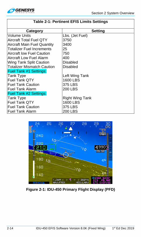
Section 2 System Overview
2-14 IDU-450 EFIS Software Version 8.0K (Fixed Wing) 1st Ed Dec 2019
Table 2-1: Pertinent EFIS Limits Settings
Category Setting Volume Units Aircraft Total Fuel QTY Aircraft Main Fuel Quantity Totalizer Fuel Increments Aircraft low Fuel Caution Aircraft Low Fuel Alarm Wing Tank Split Caution Totalizer Mismatch Caution Fuel Tank #1 Settings: Tank Type Fuel Tank QTY Fuel Tank Caution Fuel Tank Alarm Fuel Tank #2 Settings: Tank Type Fuel Tank QTY Fuel Tank Caution Fuel Tank Alarm
Lbs. (Jet Fuel) 3750 3400 25 750 400 Disabled Disabled Left Wing Tank 1600 LBS 375 LBS 200 LBS Right Wing Tank 1600 LBS 375 LBS 200 LBS
Figure 2-1: IDU-450 Primary Flight Display (PFD)

Section 2 System Overview
1st Ed Dec 2019 IDU-450 EFIS Software Version 8.0K (Fixed Wing) 2-15
Figure 2-2: IDU-450 Multifunction Flight Display (MFD)
2.2.1. Functional Integration and Display Redundancy
IDUs incorporate a high-brightness AMLCD screen; bezel buttons; encoders and enter switches; central processing unit; numerous RS-232, RS-422, and ARINC 429 receive and transmit ports; and discrete IO ports. Hardware and software are identical for all IDUs, and functionality is determined by configuration settings setup during installation. The IDUs are independently connected to all external sensors and independently perform all integrated functions (e.g., TAWS, FMS, ADS-B In, weather radar, traffic, or strikes). This provides an exceptional level of redundancy as compared to traditional display architectures where most of these functions were performed by external line replaceable units.
Pilot Co-Pilot
IDU #1
*IDU #2
*IDU #3
*IDU #4
GPS #1
*GPS #2
ADC #1
*ADC #2
AHRS #1
*AHRS #2
*WX-500
IDU #1
*IDU #2
*IDU #3
*IDU #4
*Analog Interface
*Traffic Sensor
*Remote Tune Radios
*Remote Bugs Panel
*Digital Autopilot
*Weather Radar
*Fuel Flow/Quantity
Note: * = Optional
Sync Sync
Crosslink
*Datalink/ADS-B
Figure 2-3: System Diagram

Section 2 System Overview
2-16 IDU-450 EFIS Software Version 8.0K (Fixed Wing) 1st Ed Dec 2019
Figure 2-3 depicts a typical architecture used by IDUs. The IDUs depend upon intra-system (between IDUs on a side – depicted as “Sync”) and inter-system (between IDUs on opposite sides – depicted as “Crosslink”) to achieve synchronization of the integrated functions. The IDUs also depend upon intra-system communications to determine which IDU on a side takes over “talker” responsibilities. The “talker” IDU is the IDU providing data to external sensors and generating aural alerts.
2.2.2. IDU Initialization
Upon power-up, the hardware, including file system, IO, and graphics, is initialized. Immediately after graphics initialization, a logo screen with “INITIALIZING” is displayed with the Genesys Aerosystems logo, software version number, and part number. The software version number delineates: (1) major revision number (i.e., “8.0”), and (2) minor revision letter (i.e., “K”).
Figure 2-4: IDU-450 Initialization Screen
Table 2-2: IDU Software Version and Part Number
Version Number Part Number Rev 8.0K 25-EFIS80K-SW-0002
Aircraft configurations are initially read from flash drive storage to provide IDUs with a default configuration setup in the event of personality module failure. The personality module contains the CPU/IDU number (Table 2-3) and system designation (pilot or co-pilot). The IDU number is identified below the part number on the CRC screen (Figure 2-6).

Section 2 System Overview
1st Ed Dec 2019 IDU-450 EFIS Software Version 8.0K (Fixed Wing) 2-17
Table 2-3: IDU Number Designation
CPU Number/IDU# Definition “0” Single-screen installation “1” IDU only shows PFD “2” First MFD in multi-screen installation “3” Second MFD in a multi-screen installation “4” Third MFD in a multi-screen installation
Aircraft parameters (latitude, longitude, altitude), as they existed prior to the last system shutdown, are read for a good system initialization, even if system sensors are failed or not yet initialized. For future updates (i.e., updating software version 8.0K to 8.0L), all aircraft settings re-initialize to default values. Otherwise, aircraft settings, as they existed prior to the last system shutdown, are used to initialize the system except for the following default values:
1) Selected sensors are initialized to default values.
2) Active flight plan structure and associated values are cleared.
3) ADAHRS set to slaved mode, and slewing value is initialized to zero.
4) Timers are turned off.
5) Datalink and map panning modes are set to off.
6) Fuel caution and alarm thresholds are set to default values.
7) Heading bug is set to 360° (analog autopilot [AP] or Genesys/S-TEC DFCS enabled) or turned off.
8) Heading mode is turned off.
9) HSI navigation source is set to FMS.
10) Minimum altitude setting is turned off.
11) FMS OBS setting is set to automatic.
12) VOR/LOC 1 OBS setting is set to 360°.
13) VOR/LOC 2 OBS setting is set to 360°.
14) Parallel offset is set to 0 NM.
15) PFD zoom mode is set to off.
16) Manual RNP is set to off.
17) If in round dial mode, analog AGL is set to off.

Section 2 System Overview
2-18 IDU-450 EFIS Software Version 8.0K (Fixed Wing) 1st Ed Dec 2019
18) If in round dial mode, analog G indicator is set to off.
19) PFD skyway is set to on.
20) Airspeed bug is turned off.
21) Target and preselected altitude bugs are turned off
22) True north mode is turned off.
23) V-speeds are cleared.
24) Vertical speed bug is turned off.
25) Weather radar scale is initialized to 80NM.
26) If Telephonics RDR-1600 is installed, weather radar anti-clutter is set to off, automatic range limit is set to off, auto tilt is set to off, sector scan is set to off and track angle is set to off. These weather radar parameters are not used by Telephonics RDR-1600.
27) Crosslink is initialized to on.
28) If Genesys/S-TEC DFCS is enabled, flight directors are initialized to single-cue.
29) Map modes are set to allowed values.
30) G telltales are automatically reset so long as the associated G limit has not been exceeded
The magnetic variation coefficients database is read from the flash drive storage and CRC-32 checked.
The IDU decides whether it is booting on the ground or in flight based on the air/ground mode parameter value from the last system shutdown. If booting on the ground, the following actions happen:
1) A logo screen with “TESTING” is displayed.

Section 2 System Overview
1st Ed Dec 2019 IDU-450 EFIS Software Version 8.0K (Fixed Wing) 2-19
Figure 2-5: Logo Screen with “TESTING”
2) CRC-32 values for application executable, limitations files, NavData files, obstruction files, sounds database, and terrain header files are checked.
During this action, “PRESS ANY BUTTON TO QUICK START” is displayed below “TESTING.” Press any button to stop the ground booting and execute the flight booting.
3) If the BIT (built-in-test) check fails, the program exits with an error message and creates a BIT result file indicating failure.
4) If the BIT check passes, the program continues to initialize and creates a BIT result file indicating passage.
5) If “Baro Auto-Setting in EFIS limits is enabled, the system auto-sets the altimeter based on the terrain elevation at the startup point (only applicable at surveyed airports.) In case of QFE mode operation, the application will autoset the altimeter to read zero altitude.
6) CRC screen displays:
a) Software CRC-32;
b) Aircraft type;
c) Sounds database name and CRC-32;
d) Magnetic variation coefficients version and CRC-32; and
e) Database versions and validity dates are displayed along with “PRESS ANY BUTTON TO CONTINUE.”

Section 2 System Overview
2-20 IDU-450 EFIS Software Version 8.0K (Fixed Wing) 1st Ed Dec 2019
Figure 2-6: CRC Screen
7) If all critical sensors (GPS, ADC, and AHRS) are in normal condition, the display screens are shown immediately.
8) If any critical sensor is not in normal condition, a logo screen with a two-minute countdown timer is displayed along with “PRESS ANY BUTTON TO SKIP.”
Figure 2-7: Two-Minute Countdown Screen
9) The display screens initialize at the earliest of:
a) when 2 minutes has elapsed;
b) when the pilot presses any button to escape the startup countdown; or
c) when all critical sensors are in normal condition.
10) Display screens initialize as follows:
a) IDU #1: PFD screen

Section 2 System Overview
1st Ed Dec 2019 IDU-450 EFIS Software Version 8.0K (Fixed Wing) 2-21
b) Other IDUs (IDU #0, #2, #3, or #4): Initializes to MFD screen.
c) Other IDUs (IDU #0, #2, #3, or #4) with fuel totalizer functions enabled: Fuel set menu is activated to remind the pilot to set the fuel totalizer quantity.
11) All active alerts are automatically acknowledged for 5 seconds to reduce nuisance alerting.
If booting in the air, the following actions happen:
1) A logo screen with “QUICK START” is displayed.
Figure 2-8: QUICK START Screen
2) BIT result file created during the last ground boot is checked.
a) Failure = indicates a failure, program exits with an error message.
b) Passage = program continues.
3) The display screens initialize immediately as follows:
a) IDU #1: PFD screen
b) Other IDUs (IDU #0, #2, #3, or #4): Initializes to MFD screen.
c) Other IDUs (IDU #0, #2, #3, or #4) with fuel totalizer functions enabled: Fuel set menu is activated to remind the pilot to set the fuel totalizer quantity.
4) All active alerts are automatically acknowledged for 5 seconds to reduce nuisance alerting.

Section 2 System Overview
2-22 IDU-450 EFIS Software Version 8.0K (Fixed Wing) 1st Ed Dec 2019
NOTE:
Intra-system and inter-system synchronization messages are paused when any IDU menu is active. After IDU initialization, if any menu is
active, press EXIT (R1) on each display and wait at least 20 seconds to allow PFDs to sync with MFDs and pilot and co-pilot sides to sync.
2.3. General Arrangement
The IDU-450 is 6.375” W x 5.65” H x 4.75” D and weighs less than 7.5 lbs. The IDU-450 has the capacity to accommodate integrated peripherals mechanically attached to the IDU but have electrical isolation and redundancy. These modules may include:
1) Integrated ADAHRS sensor module
2) Integrated GPS/SBAS sensor module
3) Serial protocol converters
4) Weather radar module
Data storage is sufficiently sized to hold world terrain, navigation, and obstruction databases. Because the receive ports are connected to the digital sensor modules in parallel, each IDU is independent from all others.
2.3.1. Data Source Monitors
In installations with redundant sensors, IDUs continuously monitor the following sensors to detect disagreements:
1) Airspeed
2) Altitude
3) Attitude
4) Barometric setting (pilot vs. co-pilot sides)
5) GPS position, track, and groundspeed
6) Heading
7) Localizer and glideslope deviations
8) Radar altitude
2.3.2. IDU Intra-System Communications
Communication between IDUs installed on the same side is referred to as intra-system communications. In a two-sided system (pilot and co-pilot) configuration, the crosslink side-to-side communications is referred to as inter-system communications. IDUs on the same side (pilot side and co-
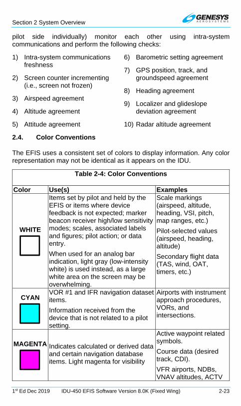
Section 2 System Overview
1st Ed Dec 2019 IDU-450 EFIS Software Version 8.0K (Fixed Wing) 2-23
pilot side individually) monitor each other using intra-system communications and perform the following checks:
1) Intra-system communications freshness
2) Screen counter incrementing (i.e., screen not frozen)
3) Airspeed agreement
4) Altitude agreement
5) Attitude agreement
6) Barometric setting agreement
7) GPS position, track, and groundspeed agreement
8) Heading agreement
9) Localizer and glideslope deviation agreement
10) Radar altitude agreement
2.4. Color Conventions
The EFIS uses a consistent set of colors to display information. Any color representation may not be identical as it appears on the IDU.
Table 2-4: Color Conventions
Color Use(s) Examples
WHITE
Items set by pilot and held by the EFIS or items where device feedback is not expected; marker beacon receiver high/low sensitivity modes; scales, associated labels and figures; pilot action; or data entry.
When used for an analog bar indication, light gray (low-intensity white) is used instead, as a large white area on the screen may be overwhelming.
Scale markings (airspeed, altitude, heading, VSI, pitch, map ranges, etc.)
Pilot-selected values (airspeed, heading, altitude)
Secondary flight data (TAS, wind, OAT, timers, etc.)
CYAN
VOR #1 and IFR navigation dataset items.
Information received from the device that is not related to a pilot setting.
Airports with instrument approach procedures, VORs, and intersections.
MAGENTA
Indicates calculated or derived data and certain navigation database items. Light magenta for visibility
Active waypoint related symbols.
Course data (desired track, CDI).
VFR airports, NDBs, VNAV altitudes, ACTV

Section 2 System Overview
2-24 IDU-450 EFIS Software Version 8.0K (Fixed Wing) 1st Ed Dec 2019
Table 2-4: Color Conventions
Color Use(s) Examples freq/codes, operating modes, and transmit enable indications.
GRAY
Background for airspeed and altitude readout and for conformal runway depiction
Light gray for usable portion of active runway, dark gray for other runway surfaces
GREEN
VOR #2 and to indicate normal or valid operation (airspeed, altitude tape coloring, status indication, etc.) Light green for visibility.
Aircraft ground track, skyway symbology, and airspeeds in green arc.
DARK GREEN
Terrain indication on moving map (slope between adjacent terrain determines the shade used).
AMBER (YELLOW)
Identifies conditions requiring immediate pilot awareness and possible subsequent action. Used for DME hold indications.
OLIVE
In various shades shows terrain within 2000’ and below aircraft altitude.
BROWN
In a variety of shades indicates earth/terrain portion of PFD or when above 100 feet less than aircraft altitude on MFD.
BLUE
In a variety of shades indicates sky portion of PFD, bodies of water on moving map, and advisory text on black background.
RED
Indicates aircraft limitations or conditions, which require immediate pilot action, or a device failure (red “X”).
BLACK
Field of view angle lines on moving map, figures on a gray background, and outlining borders and certain figures/elements on backgrounds with minimal contrast, e.g., airspeed, altitude, and menu tiles on the PFD/MFD.

Section 2 System Overview
1st Ed Dec 2019 IDU-450 EFIS Software Version 8.0K (Fixed Wing) 2-25
2.5. Warning/Caution/Advisory System
The IDU has an integrated audio/visual warning system, which monitors a wide variety of parameters and provides alerts for conditions that demand pilot action or awareness. The following alerts are provided and described below:
1) Warning Alerts
2) Time-Critical Warning Alerts
3) Master Visual and Audible/Voice Alerts
4) Caution Alerts
5) Advisory Alerts
All warnings, including time-critical warnings, activate the warning (red) light and master caution light. All cautions, including time-critical cautions, activate the caution (yellow) light and master caution light. Once acknowledged, the flashing behavior stops, the audible alert is interrupted, and the discrete outputs are deactivated.
2.5.1. Time-Critical Warning and Caution Alerts
Time-critical warning and caution alerts trigger the following elements (Table 2-6) and display in the pilot’s primary field of view with a shaded background (Figure 2-9 and Figure 2-10). EFIS limits may have enabled the option for time-critical alerts to illuminate a master warning/master caution push button annunciator when equipped.
NOTE:
In the following tables, examples show shaded backgrounds on sky and terrain backgrounds for readability.
Table 2-5: Time-Critical Warning and Caution Alerts in Primary Field of View
Alert Type Text Color Flash Rate Audio Alert at Full Volume
Red 2 Hz
Repeated until acknowledged
Amber (Yellow)
1 Hz Plays only once

Section 2 System Overview
2-26 IDU-450 EFIS Software Version 8.0K (Fixed Wing) 1st Ed Dec 2019
Figure 2-9: Time-Critical Warning Alert
Figure 2-10: Time-Critical Caution Alert
Table 2-6: Time-Critical Warning and Caution Alerts
Visual Alert Voice Alert Condition ** No time delay
“Overspeed, Overspeed”
IAS exceeds redline (VNE/VMO/MMO) plus instrument error. **
“Stall, Stall”
Activated above 100’ AGL if indicated airspeed is below the higher of VS1 or VS1 corrected for G-load + 5 kts. Deactivated if stall-warning EFIS limits is set to 0. **

Section 2 System Overview
1st Ed Dec 2019 IDU-450 EFIS Software Version 8.0K (Fixed Wing) 2-27
Table 2-6: Time-Critical Warning and Caution Alerts
Visual Alert Voice Alert Condition ** No time delay
“Terrain, Terrain,
Pull Up, Pull Up”
Terrain cell within TAWS FLTA warning envelope. Half-second time delay. Within GPWS 2 warning envelope. Half-second time delay.
“Pull Up, Pull Up”
Within GPWS Mode 1 warning envelope. Half-second time delay.
“Glideslope, Glideslope”
Within GPWS Mode 5 warning envelope. Half-second time delay.
“Warning Obstruction,
Warning Obstruction”
Obstruction within TAWS FLTA warning envelope. Half-second time delay.
“Traffic, Traffic”
Resolution advisory. Not given if own aircraft at or below 400’ AGL. Not given if target is at or below 200’ AGL (ground target). Audio not generated with TCAS-II system. **
“Check Gear, Check Gear”
Activates if aircraft is below 500’ AGL, is descending, and is below VFE; and any landing gear is not down. 2-second time delay.
“Caution Obstruction,
Caution Obstruction”
Obstruction within TAWS FLTA caution envelope. Half-second time delay.
“Caution Terrain,
Caution Terrain”
Terrain cell within TAWS FLTA caution envelope. Half-second time delay. Within GPWS Mode 2 caution envelope. Half-second time delay.
“Sink Rate, Sink Rate”
Within GPWS Mode 1 caution envelope. Half-second time delay.
“Glideslope, Glideslope”
Within GPWS Mode 5 caution envelope. Half-second time delay.
“Too Low Terrain, Too Low Terrain”
Within GPWS Mode 3 envelope. Half-second time delay. Within GPWS Mode 4-1 “Too Low Terrain” envelope. Half-second time delay. Within TAWS PDA envelope. Half-second time delay.
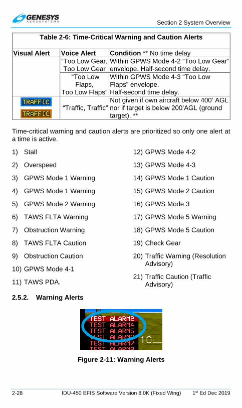
Section 2 System Overview
2-28 IDU-450 EFIS Software Version 8.0K (Fixed Wing) 1st Ed Dec 2019
Table 2-6: Time-Critical Warning and Caution Alerts
Visual Alert Voice Alert Condition ** No time delay “Too Low Gear, Too Low Gear
Within GPWS Mode 4-2 “Too Low Gear” envelope. Half-second time delay.
“Too Low Flaps,
Too Low Flaps”
Within GPWS Mode 4-3 “Too Low Flaps” envelope. Half-second time delay.
“Traffic, Traffic”
Not given if own aircraft below 400’ AGL nor if target is below 200’AGL (ground target). **
Time-critical warning and caution alerts are prioritized so only one alert at a time is active.
1) Stall
2) Overspeed
3) GPWS Mode 1 Warning
4) GPWS Mode 1 Warning
5) GPWS Mode 2 Warning
6) TAWS FLTA Warning
7) Obstruction Warning
8) TAWS FLTA Caution
9) Obstruction Caution
10) GPWS Mode 4-1
11) TAWS PDA.
12) GPWS Mode 4-2
13) GPWS Mode 4-3
14) GPWS Mode 1 Caution
15) GPWS Mode 2 Caution
16) GPWS Mode 3
17) GPWS Mode 5 Warning
18) GPWS Mode 5 Caution
19) Check Gear
20) Traffic Warning (Resolution Advisory)
21) Traffic Caution (Traffic Advisory)
2.5.2. Warning Alerts
Figure 2-11: Warning Alerts

Section 2 System Overview
1st Ed Dec 2019 IDU-450 EFIS Software Version 8.0K (Fixed Wing) 2-29
Table 2-7: Warning Alert Elements
Type Alert Location Flash Rate Audio Alert
PFD lower left corner of transmit enabled IDU
2 Hz Until acknowledged
Table 2-8: Warning Alerts
Visual Alert Voice Alert Condition ** No time delay
“Fuel Low, Fuel Low”
One of the following conditions is true:
1) A low fuel warning discrete input is active
2) A sensed fuel tank quantity is below its low fuel warning threshold
3) Total aircraft fuel is below the pilot-set emergency fuel threshold.
1-minute time delay. Duplicate Time-Critical Warning Alerts (IDU#0):
“Overspeed, Overspeed”
Indicated airspeed exceeds redline (VNE/VMO/MMO as appropriate) plus instrument error. **
“Stall, Stall”
Activated above 100’ AGL if IAS is below the higher of VS1 or VS1 corrected for G-load + 5 kts. Deactivated if stall-warning not enabled in EFIS limits. **
“Warning Obstruction,
Warning Obstruction”
Obstruction within TAWS FLTA warning envelope. Half-second time delay.
“Terrain, Terrain, Pull Up, Pull Up”
Terrain cell within TAWS FLTA warning envelope. Half-second time delay. Within GPWS Mode 2 warning envelope. Half-second time delay.
“Pull Up, Pull Up”
Within GPWS Mode 1 warning envelope. Half-second time delay.
“Glideslope, Glideslope”
Within GPWS Mode 5 warning envelope. Half-second time delay.
“Traffic, Traffic”
Resolution advisory. Not given if own aircraft at or below 400’ AGL. Not given if target is at or below 200’ AGL (ground target). Audio not generated with TCAS-II system. **

Section 2 System Overview
2-30 IDU-450 EFIS Software Version 8.0K (Fixed Wing) 1st Ed Dec 2019
2.5.3. Caution Alerts
Figure 2-12: Caution Alerts
Table 2-9: Caution Alert Elements
Type Alert Location Flash Rate
Audio Alert
PFD lower left corner of transmit enabled IDU
1 Hz Plays only once at full volume.
Table 2-10: Caution Alerts
Visual Alert Voice Alert/ Alert Tone
Condition
** No time delay
[1] Only active in dual-sensor installation with neither sensor in failure condition [2] Only active in dual-system (pilot and co-pilot) [3] Only active when single-pilot mode discrete not asserted
Alert Tone
Indicates no valid IAS, pressure altitude, nor VSI received from numbered ADC(s) for more than 1 second. ** [1]
Alert Tone
Enabled by ADS-B out fail warning limits setting. Mode-S transponder indicates bad ADS-B out status. Also, set by audio/radio interface with NGT-9000R transponder. 2-second time delay.
Alert Tone
Indicates no valid bank, pitch, nor heading received from enumerated AHRS(s) for more than 1 second. Inhibited during and for 10 seconds after unusual attitude mode.** [1] [2]
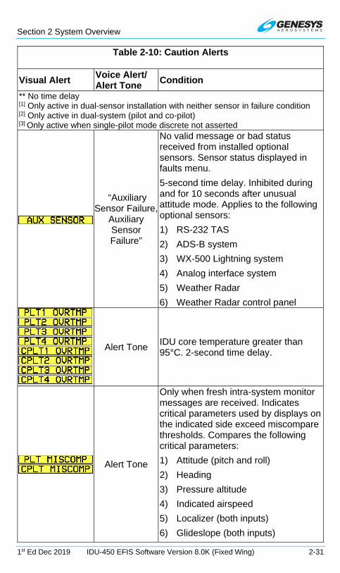
Section 2 System Overview
1st Ed Dec 2019 IDU-450 EFIS Software Version 8.0K (Fixed Wing) 2-31
Table 2-10: Caution Alerts
Visual Alert Voice Alert/ Alert Tone
Condition
** No time delay
[1] Only active in dual-sensor installation with neither sensor in failure condition [2] Only active in dual-system (pilot and co-pilot) [3] Only active when single-pilot mode discrete not asserted
“Auxiliary Sensor Failure,
Auxiliary Sensor Failure”
No valid message or bad status received from installed optional sensors. Sensor status displayed in faults menu.
5-second time delay. Inhibited during and for 10 seconds after unusual attitude mode. Applies to the following optional sensors:
1) RS-232 TAS
2) ADS-B system
3) WX-500 Lightning system
4) Analog interface system
5) Weather Radar
6) Weather Radar control panel
Alert Tone IDU core temperature greater than 95°C. 2-second time delay.
Alert Tone
Only when fresh intra-system monitor messages are received. Indicates critical parameters used by displays on the indicated side exceed miscompare thresholds. Compares the following critical parameters:
1) Attitude (pitch and roll)
2) Heading
3) Pressure altitude
4) Indicated airspeed
5) Localizer (both inputs)
6) Glideslope (both inputs)

Section 2 System Overview
2-32 IDU-450 EFIS Software Version 8.0K (Fixed Wing) 1st Ed Dec 2019
Table 2-10: Caution Alerts
Visual Alert Voice Alert/ Alert Tone
Condition
** No time delay
[1] Only active in dual-sensor installation with neither sensor in failure condition [2] Only active in dual-system (pilot and co-pilot) [3] Only active when single-pilot mode discrete not asserted
7) Radar altitude
8) Latitude
9) Longitude
10) Track
11) Groundspeed
1-second time delay. Inhibited during and for 10 seconds after unusual attitude mode. [2]
Alert Tone
Indicates pressure altitude difference between ADCs is beyond limits. 10-second time delay. Inhibit for 5 minutes after startup.[1]
Alert Tone
Indicates pitch or roll difference between AHRS is beyond limits (6°). 10-second time delay. Inhibit for 5 minutes after startup.[1]
“Check Pitch Trim”
Pitch mistrimmed for more than 3 continuous seconds (trim not responding). Trim is needed in indicated direction.
“Check Range, Check
Range”
Based on flight plan in use on the indicated side, less than 30 minutes buffer (at current groundspeed) between calculated range and distance to:
1) last waypoint if it is active; or
2) airport if on a missed approach; or
3) along-route distance to destination.
Not activated in climbing flight nor if below 60 kts groundspeed.
5-minute time delay.

Section 2 System Overview
1st Ed Dec 2019 IDU-450 EFIS Software Version 8.0K (Fixed Wing) 2-33
Table 2-10: Caution Alerts
Visual Alert Voice Alert/ Alert Tone
Condition
** No time delay
[1] Only active in dual-sensor installation with neither sensor in failure condition [2] Only active in dual-system (pilot and co-pilot) [3] Only active when single-pilot mode discrete not asserted
Alert Tone
Indicates personality module for designated IDU (side and IDU #) could not be read upon power-up. Internal limits are in use by the system. Only active on the ground.
Alert Tone
Indicates on the designated IDU (side and IDU #), aircraft is currently beyond extent of terrain database or a failure condition is preventing TAWS FLTA function from operating. Half-second time delay. Inhibited during and for 10 seconds after unusual attitude mode.
Alert Tone
Triggered when external cooling fan is commanded on by discrete output, but cooling fan status discrete input indicates cooling fan is not rotating. 1-minute time delay.
Alert Tone
Compares the volume of fuel designated left wing tank fuel vs. volume of fuel designated right wing tank fuel to the fuel split caution threshold. Issued if the difference exceeds the fuel split caution threshold. Only performed if the fuel split caution threshold is non-zero and both left and right wing tank fuel is monitored and valid. 1-minute time delay.
“Fuel Low, Fuel Low”
A low fuel warning is not active and one of the following conditions is true:
1) One of the low fuel caution discrete inputs is active

Section 2 System Overview
2-34 IDU-450 EFIS Software Version 8.0K (Fixed Wing) 1st Ed Dec 2019
Table 2-10: Caution Alerts
Visual Alert Voice Alert/ Alert Tone
Condition
** No time delay
[1] Only active in dual-sensor installation with neither sensor in failure condition [2] Only active in dual-system (pilot and co-pilot) [3] Only active when single-pilot mode discrete not asserted
2) One of the sensed fuel tank quantities is below its low fuel caution threshold
3) Total aircraft fuel is below the pilot-set minimum fuel threshold.
1-minute time delay.
Alert Tone
Indicates position, track, or groundspeed difference between GPS/SBAS units is beyond the following limits:
Position: Enroute Mode 4NM
Terminal Mode 2NM
Departure Mode .6NM
IFR Approach Mode .6NM
VFR Approach Mode .6NM
Track: If groundspeed is greater than 30 kts, miscompare if difference is more than 4°.
Groundspeed: If difference between GPS#1 and GPS#2 miscompare is more than 10 kts.
10-second time delay. Inhibited during and for 10 seconds after unusual attitude mode. [1]
Alert Tone
Indicates at least one glideslope is receiving a signal within 1 dot of center and difference between glideslope signals is beyond limits (0.25 dots). 10-second time delay. [1]

Section 2 System Overview
1st Ed Dec 2019 IDU-450 EFIS Software Version 8.0K (Fixed Wing) 2-35
Table 2-10: Caution Alerts
Visual Alert Voice Alert/ Alert Tone
Condition
** No time delay
[1] Only active in dual-sensor installation with neither sensor in failure condition [2] Only active in dual-system (pilot and co-pilot) [3] Only active when single-pilot mode discrete not asserted
Alert Tone
“HDG FAIL” Applicable to single AHRS installation. “HDG# FAIL” applicable to dual AHRS installation. Indicates that Heading is invalid but other AHRS data parameters are normal. Half second time delay. [1]
Alert Tone
With neither AHRS failed nor in DG mode. Indicates heading difference between AHRS is beyond the heading miscompare threshold limit. 60-second delay. Inhibited during and for 10 seconds after unusual attitude mode. Inhibit for 5 minutes after startup. [1]
Alert Tone
Indicates IAS difference between ADCs is beyond limits. 10-second time delay. Inhibit for 5 minutes after startup. [1]
Alert Tone
Indicates at least one localizer is receiving a signal within 1 dot of center and difference between localizer signals is beyond limits (0.25 dots). 10-second time delay. [1]
Alert Tone
Indicates that radar altitude difference between radar altimeters is beyond limits. 10 second time delay. Limits are as follows:
>= 500’AGL Δ14%
100 – 500’AGL Δ10%
< 100’AGL Δ10’ [1]
Alert Tone
OAT FAIL applicable to single ADC installation. OAT# FAIL indicates OAT indication is invalid but other air data parameters are normal (i.e., air data not red-X’d) [1]. Half-second time delay.
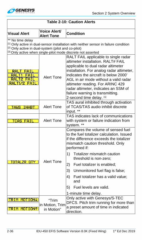
Section 2 System Overview
2-36 IDU-450 EFIS Software Version 8.0K (Fixed Wing) 1st Ed Dec 2019
Table 2-10: Caution Alerts
Visual Alert Voice Alert/ Alert Tone
Condition
** No time delay
[1] Only active in dual-sensor installation with neither sensor in failure condition [2] Only active in dual-system (pilot and co-pilot) [3] Only active when single-pilot mode discrete not asserted
Alert Tone
RALT FAIL applicable to single radar altimeter installation. RALT# FAIL applicable to dual radar altimeter installation. For analog radar altimeter, indicates the aircraft is below 2000’ AGL in air mode without a valid radar altimeter reading. For ARINC 429 radar altimeter, indicates an SSM of failure warning is transmitting. 2-second time delay. [1]
Alert Tone TAS aural inhibited through activation of TCAS/TAS audio inhibit discrete input. **
Alert Tone TAS indicates lack of communications with system or failure indication from system. **
Alert Tone
Compares the volume of sensed fuel to the fuel totalizer calculation. Issued if the difference exceeds the totalizer mismatch caution threshold. Only performed if:
1) Totalizer mismatch caution threshold is non-zero;
2) Fuel totalizer is enabled;
3) Unmonitored fuel flag is false;
4) Fuel totalizer has a valid value; and
5) Fuel levels are valid.
1-minute time delay.
“Trim in Motion, Trim
in Motion”
Only active with Genesys/S-TEC DFCS. Pitch trim running for more than a preset amount of time in indicated direction.

Section 2 System Overview
1st Ed Dec 2019 IDU-450 EFIS Software Version 8.0K (Fixed Wing) 2-37
Table 2-10: Caution Alerts
Visual Alert Voice Alert/ Alert Tone
Condition
** No time delay
[1] Only active in dual-sensor installation with neither sensor in failure condition [2] Only active in dual-system (pilot and co-pilot) [3] Only active when single-pilot mode discrete not asserted
Alert Tone
Indicates lack of inter-system communications. 2-second time delay. Inhibit for 30 seconds after startup. [2] [3]
Alert Tone
Indicates no valid message received from numbered GPS/SBAS for more than 5 seconds. ** Inhibited during and for 10 seconds after unusual attitude mode. [1]
Duplicate Time-Critical Caution Alerts (IDU#0):
“Check Gear, Check Gear”
Activates if aircraft is below 500’ AGL, is descending, and is below VFE; and any landing gear is not down. 2-second time delay.
“Caution Terrain, Caution Terrain”
Terrain cell within TAWS FLTA caution envelope. Half-second time delay. Within GPWS Mode 2 caution envelope. Half-second time delay.
“Sink Rate, Sink Rate”
Within GPWS Mode 1 caution envelope. Half-second time delay.
“Glideslope, Glideslope”
Within GPWS Mode 5 caution envelope. Half-second time delay.
“Too Low Terrain, Too Low Terrain”
Within GPWS Mode 3 envelope. Half-second time delay. Within GPWS Mode 4-1 “Too Low Terrain” envelope. Half-second time delay. Within TAWS PDA envelope. Half-second time delay.
“Too Low Gear,
Too Low Gear
Within GPWS Mode 4-2 “Too Low Gear” envelope. Half-second time delay.
“Too Low Flaps,
Too Low Flaps”
Within GPWS Mode 4-3 “Too Low Flaps” envelope. Half-second time delay.

Section 2 System Overview
2-38 IDU-450 EFIS Software Version 8.0K (Fixed Wing) 1st Ed Dec 2019
Table 2-10: Caution Alerts
Visual Alert Voice Alert/ Alert Tone
Condition
** No time delay
[1] Only active in dual-sensor installation with neither sensor in failure condition [2] Only active in dual-system (pilot and co-pilot) [3] Only active when single-pilot mode discrete not asserted
“Caution Obstruction,
Caution Obstruction”
Obstruction within TAWS FLTA caution envelope. Half-second time delay.
“Traffic, Traffic” Not given if own aircraft below 400’ AGL nor if target is below 200’AGL (ground target). **
2.5.4. Side-Specific Caution Alerts
Side-specific caution alerts are displayed on all IDUs on a side that detect a failure on an IDU on that side. These types of alerts are used for safety-critical monitoring functions that can’t take credit for the presence of other system IDUs.
Table 2-11: Side-Specific Caution Alerts
Visual Alert Alert Tone Condition ** No time delay
Alert Tone
IDU status has not been received from another same-side IDU in the last second ± 0.1 seconds. # indicates which IDU is failing the check. **
2.5.5. Advisory Alerts
Figure 2-13: Advisory Alerts
Table 2-12: Advisory Alert Elements
Type Alert Location Appearance Audio Alert PFD lower left corner of transmit enabled IDU
While condition persists
Single advisory chime played at 80% volume

Section 2 System Overview
1st Ed Dec 2019 IDU-450 EFIS Software Version 8.0K (Fixed Wing) 2-39
Table 2-13: Advisory Alerts
Visual Alert Alert Tone Condition ** No time delay
[1] Only active in dual-sensor installation with neither sensor in failure condition [2] Only active in dual-system (pilot and co-pilot) [3] Only active when single-pilot mode discrete not asserted
Chime Indicates ADC# not at full accuracy during warm-up. ** [1]
Chime
Indicates numbered AHRS in DG mode. ** [1]
Chime
Indicates a dual redundant power supply within the designated IDU (side and IDU #) is not functioning correctly. Only active on the ground. 1-minute time delay. [2]
Chime Flight path marker inhibit function activated through use of momentary discrete input. **
Chime Indicates mismatch of altimeter settings or altimeter modes between systems. 10-second time delay. [2] [3]
Chime Indicates both sides are operating from same ADC source. ** [1]
Chime Indicates both sides are operating from same AHRS source. ** [1]
Chime Indicates both sides are operating from same DME source ** [1] [3]
Chime Indicates both sides are operating from same GPS/SBAS source.**[1][2][3]
Chime Indicates both sides are operating from same navigation source.**[1] [2] [3]
Chime Indicates both sides are operating from same radar altimeter source. ** [1] [2] [3]
Chime
TAS aural inhibited through activation of TCAS/TAS Audio Inhibit discrete input. **

Section 2 System Overview
2-40 IDU-450 EFIS Software Version 8.0K (Fixed Wing) 1st Ed Dec 2019
Table 2-13: Advisory Alerts
Visual Alert Alert Tone Condition ** No time delay
[1] Only active in dual-sensor installation with neither sensor in failure condition [2] Only active in dual-system (pilot and co-pilot) [3] Only active when single-pilot mode discrete not asserted
Chime (Class A TAWS) TAWS glideslope cancel (GPWS Mode 5) activated through discrete input. **
Chime Only active with TCAS-II. Indicates system is either in standby or executing functional test in flight.**
Chime Only active with TCAS-II. Indicates system is unable to display resolution advisories. **
Chime Only active with TCAS-II. Indicates system is in functional test on ground.**
Chime
Only active with good inter-system communications and crossfill not inhibited. Indicates systems are not synchronized and synchronized function is available. ** [2] [3]
Chime Only with good inter-system communications, indicates crossfill is inhibited through discrete input.** [2] [3]
2.5.6. Side-Specific Advisory Alerts
Side-specific advisory alerts have the same characteristics as advisory alerts except, they always appear in the lower-left corner of the transmit enabled IDU screen.
These type of alerts are used where the pilot and co-pilot sides can generate different alerts, such as when the pilot and co-pilot sides are not crossfilled and are operating on different FMS flight plans.
Table 2-14: Side-Specific Advisory Alerts
Visual Alert Alert Tone Condition ** No time delay
Chime Ascending through transition level: Altimeter not set to 29.92 inHg or 1013 mbar.

Section 2 System Overview
1st Ed Dec 2019 IDU-450 EFIS Software Version 8.0K (Fixed Wing) 2-41
Table 2-14: Side-Specific Advisory Alerts
Visual Alert Alert Tone Condition ** No time delay Descending through transition level: Altimeter set to 29.92 inHg or 1013 mbar. Descent warning times out in 10 seconds.
Disabled during QFE operation.
2-second time delay.
Chime
GPS/SBAS actual navigation performance in nautical miles based upon current GPS/SBAS HPL. Value ranges from 0.01 to 15.0 NM.
Chime
GPS/SBAS automatic required navigation performance in nautical miles as acquired from navigation database. Value ranges from 0.01 to 15.0 NM.
Chime
GPS/SBAS manual required navigation performance in nautical miles as set by pilot. Value ranges from 0.10 to 15.0 NM.
Chime
GPS/SBAS in dead reckoning mode with valid ADC and AHRS data. Timer shows time since loss of position (mm:ss) to indicate quality of DR solution.** Inhibited during and for 10 seconds after unusual attitude mode. Valid range is from 00:00 to 59:59.
Chime GPS/SBAS in LNAV approach mode. **
Chime GPS/SBAS in LNAV/VNAV approach mode. **
Chime GPS/SBAS in LP approach mode. **
Chime GPS/SBAS in LPV approach mode. **
Chime
Automatic waypoint sequencing is suspended under any of the following conditions: **
1) Pilot has selected a manual GPS/SBAS OBS.
2) Active waypoint is the missed approach waypoint, and missed approach procedure has not been armed (ARM) nor initiated (MISS).
3) Aircraft is in a published or manually created holding pattern, and pilot has

Section 2 System Overview
2-42 IDU-450 EFIS Software Version 8.0K (Fixed Wing) 1st Ed Dec 2019
Table 2-14: Side-Specific Advisory Alerts
Visual Alert Alert Tone Condition ** No time delay not chosen to continue (CONT) out of the holding pattern.
4) Leg following active waypoint is a manual termination leg, and the pilot has not chosen to resume (RESUME) to the waypoint following the manual termination.
5) Aircraft is in a repeating SAR pattern (see SAR appendix), and the pilot has not chosen to continue out of the SAR pattern.**
Chime GPS/SBAS in terminal mode. **
Chime GPS/SBAS in VFR approach mode.**
Chime GPS/SBAS in vectors to final approach mode prior to sequencing FAWP. **
Chime
GPS/SBAS parallel offset path advisory. ## is nautical miles left (L) or right (R) of main path. PTK ENDING if within the parallel offset distance from a parallel offset exit waypoint. **
Chime
Shown when FLTA function is automatically inhibited during normal operation. TAWS INHBT advisory has priority.**
Chime System operating in true north mode.**
Chime
Only active with Genesys/S-TEC DFCS. Indicates VNAV guidance is available but not currently in use by the AP. Press “VNV” button on mode control panel to engage VNAV mode.
2.5.7. Audio-Only Caution and Advisory Alerts
Audio-only caution alerts trigger a single audio message that played at the full volume, whereas audio-only advisory alerts are played at 80% of the full volume.

Section 2 System Overview
1st Ed Dec 2019 IDU-450 EFIS Software Version 8.0K (Fixed Wing) 2-43
Table 2-15: Audio-Only Caution and Advisory Alerts
Caution or Advisory Alert
Voice Alert/ Alert Tone
Condition ** No time delay
Minimum Altitude Caution Alert
“Minimums, Minimums”
Deviation from above to below minimum altitude bug. Minimum altitude readout turns amber (yellow) and flashes. **
Selected Altitude Deviation
Caution Alert
“Altitude, Altitude”
Deviation greater than 150’ from se-lected altitude after capture (within 100’ of altitude). 2-second time delay.
VNAV Altitude Deviation
Caution Alert
“Altitude, Altitude”
If not on a descending VNAV profile, deviation greater than 150’ from alti-tude of the current or prior VNAV way-point after capture (within 100’ of altitude). 2-second time delay.
Decision Height Caution Alert
“Decision Height”
Deviation from above to below decision height bug. Decision height readout turns amber (yellow) and flashes. **
GBS/SBAS Failure
Caution Alert Alert Tone
No valid position data available from selected GPS/SBAS for more than 5 seconds and dead reckoning not available. Inhibited during and for 10 seconds after unusual attitude mode. Loss of position data is obvious from symbology changes associated with reversionary modes. **
GPS/SBAS Loss of Integrity
Caution Alert Alert Tone
GPS/SBAS loss of integrity caution. Inhibited during and for 10 seconds after unusual attitude mode. LOI indication is integrated with lateral deviation indicator. **
GPS/SBAS Loss of Navigation Caution Alert
Alert Tone
GPS/SBAS loss of navigation caution. Inhibited during and for 10 seconds after unusual attitude mode. LON indication is integrated with lateral deviation indicator.**
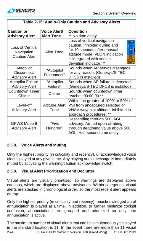
Section 2 System Overview
2-44 IDU-450 EFIS Software Version 8.0K (Fixed Wing) 1st Ed Dec 2019
Table 2-15: Audio-Only Caution and Advisory Alerts
Caution or Advisory Alert
Voice Alert/ Alert Tone
Condition ** No time delay
Loss of Vertical Navigation
Caution Alert Alert Tone
Loss of vertical navigation caution. Inhibited during and for 10 seconds after unusual attitude mode. VLON indication is integrated with vertical deviation indicator. **
Autopilot Disconnect
Advisory Alert
“Autopilot Disconnect”
Sounds when AP servos disengage for any reason. (Genesys/S-TEC DFCS is installed)
Autopilot Failure Advisory Alert
“Autopilot Failure”
Sounds when AP failure is detected. (Genesys/S-TEC DFCS is installed)
Countdown Timer Chime
Chime Sounds when countdown timer reaches 00:00:00.**
Level-off Advisory Alert
Altitude Alert Tone
Within the greater of 1000’ or 50% of VSI from uncaptured selected or VNAV waypoint altitude. Inhibited in approach procedures. **
GPWS Mode 6 Advisory Alert
“Five Hundred”
Descending through 500’ AGL advisory. Armed upon climbing through deadband value above 500’ AGL. Half-second time delay.
2.5.8. Voice Alerts and Muting
Only the highest priority (in criticality and recency), unacknowledged voice alert is played at any given time. Any playing audio message is immediately muted by activating the warning/caution acknowledge switch.
2.5.9. Visual Alert Prioritization and Declutter
Visual alerts are visually prioritized, so warnings are displayed above cautions, which are displayed above advisories. Within categories, visual alerts are stacked in chronological order, so the most recent alert appears on top.
Only the highest priority (in criticality and recency), unacknowledged aural annunciation is played at a time. In addition, to further minimize cockpit confusion, annunciations are grouped and prioritized so only one annunciation is active.
The maximum number of visual alerts that can be simultaneously displayed in the standard location is 11. In the event there are more than 11 visual

Section 2 System Overview
1st Ed Dec 2019 IDU-450 EFIS Software Version 8.0K (Fixed Wing) 2-45
alerts, appears for guidance in accessing the EXPAND CAS menu.
In addition, flags are decluttered from all IDUs, which are not “transmit enabled.” Flags only appear on these IDUs if they are IDU-specific (i.e., CHECK IDU #).
2.6. Database and Software Updates
2.6.1. Navigation and Obstruction Database
The EFIS uses Jeppesen Sanderson NavData® for the navigation database and Jeppesen Sanderson obstacle data for the obstruction database.
Visit www.jeppesen.com to place the order for the correct database.
NOTE:
When ordering, review the EFIS Equipment-Database Compatibility Matrix (Document 01-000062) on the Genesys Aerosystems website. This document specifies the compatibility of Genesys Aerosystems
EFIS equipment and software versions to navigation database versions.
Three available coverage areas of navigation databases may be used on this EFIS:
Americas - Major airports and navigation for Alaska, Canada, Continental U.S., Hawaii, Puerto Rico, Bahamas, Bermuda, Mexico, Central, and South America.
International - All available coverage except North and South America.
World - Major airports and navigation with the Americas.
The updateable navigation database contains at least the following location and path information, referenced to WGS-84, with a resolution of 0.01 minute (latitude/longitude) and 0.1° (for course information) or better at all of the following for the area(s) in which IFR operations are intended:
1) Airports.
2) VORs, DMEs (including DMEs collocated with localizers), collocated VOR/DMEs, VORTACs, and NDBs (including NDBs used as locator outer marker).

Section 2 System Overview
2-46 IDU-450 EFIS Software Version 8.0K (Fixed Wing) 1st Ed Dec 2019
3) All named waypoints and intersections shown on enroute and terminal area charts.
4) All airways shown on enroute charts, including all waypoints, intersections, and associated RNP values (if applicable). Airways are retrievable as a group of waypoints (select the airway by name to load the appropriate waypoints and legs between desired entry and exit points into the flight plan).
5) RNAV DPs and STARs, including all waypoints, intersections, and associated RNP values (if applicable). DPs and STARs are retrievable as a procedure (select the procedure by name to load the appropriate waypoints and legs into the flight plan).
6) LNAV approach procedures in the area(s) in which IFR operation is intended consist of:
a) Runway number and label (required for approach identification);
b) Initial approach waypoint (IAWP);
c) Intermediate approach waypoint(s) (IWP), when applicable;
d) Final approach waypoint (FAWP);
e) Missed approach waypoint (MAWP);
f) Additional missed approach waypoints, when applicable; and
g) Missed approach holding waypoint (MAHWP).
The complete sequence of waypoints and associated RNP values (if applicable), in the correct order for each approach, is retrievable as a procedure (select the procedure by name to load the appropriate waypoints and legs into the flight plan). Waypoints utilized as a final approach waypoint (FAWP) or missed approach waypoint (MAWP) in an LNAV approach procedure are uniquely identified as such (when appropriate) to provide proper approach mode operation.
7) LNAV/VNAV procedures in the area(s) where IFR operation is intended. LPV, LP, and/or LNAV/VNAV published procedures are available. Select a procedure by name to load the appropriate waypoints and legs into the active flight plan. Waypoints used as a final approach waypoint (FAWP) and LTP/FTP/MAWP in an LNAV/VNAV procedure are uniquely identified as such to provide proper approach mode operation.
The obstruction database is distributed by a government agency in each country. Not all countries have obstruction databases available.

Section 2 System Overview
1st Ed Dec 2019 IDU-450 EFIS Software Version 8.0K (Fixed Wing) 2-47
2.6.2. Update Requirements
Scheduled updates for databases are as follows:
1) Navigation Database - Every 28 days
2) Obstruction Database - Every 28 days
3) MAGVAR Database - Every 5 years (updated as described in a Genesys Aerosystems service bulletin)
CAUTION:
Failure to update the EFIS with the correct NavData® causes the IDU to remain in continual reboot mode and does not allow any
display page to appear.
The EFIS is updated through the ground maintenance function (GMF). To gain access to the GMF, prior to applying power, slide the slip indicator or non-slip blank door cover at the bottom-center of the IDU bezel upward to the first detent position to expose the USB port.
When an update is performed, the following procedures must be performed separately on every IDU installed in the aircraft.
To update the databases:
1) Load the navigation database (navdata.exe) and obstruction database (obst.exe) on USB flash drive.
2) With the power off, insert the USB flash drive into USB port.
CAUTION:
Always install a valid USB flash drive in the IDU prior to activating any ground maintenance function. Operation of the GMF without a
valid USB flash drive installed may cause erroneous failure indications or corruption of the IDU.
3) Turn on power to gain access to the GMF page.
4) Rotate to Update Databases and push to enter.

Section 2 System Overview
2-48 IDU-450 EFIS Software Version 8.0K (Fixed Wing) 1st Ed Dec 2019
Figure 2-14: Ground Maintenance Page
5) Once each database is loaded, press any button to continue to complete the process.
6) Once both databases have been uploaded, power down the IDU, remove the USB flash drive, and lower the USB door.
7) Once each IDU has been updated, power up the entire EFIS in normal flight mode and verify each IDU successfully updated with the latest database by noting the new navigation database and obstruction database cycle expiration dates before acknowledging the initialization screen (Figure 2-4). Because the obstruction database is advisory in nature, there technically is no expiration date. The listed date is the effective date of the next available obstruction database.
8) A cyclic redundancy check (CRC) self-test verifies the data at every step of the process, thereby ensuring the data installed into the system has not been corrupted at any point during the process.
2.6.3. Software and Terrain Database Update
Updates and terrain database updates are provided on an as-needed basis and performed as per a service bulletin.
2.7. Run Demonstrator/Training Program
The EFIS has a built-in demonstration application to fly anywhere in the world while performing any procedure (except takeoff and landing) based on the current Jeppesen navigation database. Use this feature on the ground in ground mode as follows:
1) With power off, lift the USB flash drive door and insert a USB flash drive.
2) Power on system. Rotate to RUN DEMONSTRATOR/TRAINING PROGRAM and push to enter.
Use the demonstrator to gain familiarity of the EFIS menu structure and location of button tiles for each operation. Load an instrument procedure prior to take off to view the expected sequence of events.

Section 2 System Overview
1st Ed Dec 2019 IDU-450 EFIS Software Version 8.0K (Fixed Wing) 2-49
The demonstrator begins flying over Reno, Nevada, USA at an altitude of approximately 8000’ MSL. Altitude may be changed with altitude bug, VNAV profiles or navigation database procedures. Airspeed remains relatively constant but may be controlled with the airspeed IAS bug in the BUGS menu. The simulated aircraft may be positioned anywhere in the world, by activating a flight plan stored in the memory.
All appropriate navigation signals are simulated, allowing for precision and non-precision instrument approaches found within the current navigation database. All obstructions in the latest obstruction database and all warning, caution, and advisory aural and flag annunciations are presented as appropriate during simulated flights.
NOTE:
When the IDU is operating in demonstrator mode, the IDU is isolated from all sensors and other IDUs. The creation of a flight plan results in that flight plan being stored on that IDU alone. To have that new flight plan available on all other IDUs, the following action must be taken.
1) While in flight mode, activate the flight plan created in demonstrator mode.
2) With crossfill enabled (in two-sided systems), view active flight plan on any other IDU and press SAVE (L1) to save this flight plan on all displays.
2.8. EFIS Training Tool
In addition to the demonstrator program, the EFIS Training Tool (ETT) is available to load on a personal computer. The ETT is compatible with 32- or 64-bit versions of Microsoft Windows. It serves as a multi-purpose tool for training pilots and provides features to record and capture images. See user guide distributed with the ETT installer for further details.
2.9. Application Software Air Mode and Ground Mode
Numerous symbology elements change behavior depending upon whether the aircraft is on the ground (ground mode) or in flight (air mode). The mode is determined separately from the system initialization modes. This parameter is continuously calculated as follows:
1) If a Weight on Wheels/Weight on Ground discrete input is configured, the air or ground modes are determined solely from the discrete input position.
Section 2 System Overview
2-50 IDU-450 EFIS Software Version 8.0K (Fixed Wing) 1st Ed Dec 2019
2) Otherwise, mode is determined as follows:
a) If airspeed is valid and AGL altitude is valid, ground mode is set when indicated airspeed is less than 30 knots, and AGL altitude is less than 75 feet.
b) If airspeed is invalid but AGL altitude is valid, ground mode is set when AGL altitude is less than 75 feet.
c) Under any other circumstance, air mode is set by default.

Section 3 Display Symbology
1st Ed Dec 2019 IDU-450 EFIS Software Version 8.0K (Fixed Wing) 3-1
Section 3 Display Symbology
3.1. Introduction
This section details the symbology used on the PFD and MFD IDU-450 in normal and essential modes. Not all combinations of possible views are represented.
Figure 3-1: PFD
3.1.1. IDU-450 PFD Display (Basic Mode)
Figure 3-2: PFD in Basic Mode
When selected, basic mode is a traditional attitude display with airspeed, altitude, and heading scales appearing in blacked-out areas in a “Basic-T” arrangement but is disabled in unusual attitude mode. The following are no longer present in basic mode:
Rolling digital
Rolling digital

Section 3 Display Symbology
3-2 IDU-450 EFIS Software Version 8.0K (Fixed Wing) 1st Ed Dec 2019
1) Atmospheric perspective
2) Airspeed Trend
3) Terrain rendering
4) Obstruction rendering
5) Flight Path Marker
6) Airport runways
7) Highway in the Sky
8) Bank Scale Declutter
3.1.2. IDU-450 MFD Display
Figure 3-3: MFD
3.2. PFD Symbology
Figure 3-4: PFD Symbology

Section 3 Display Symbology
1st Ed Dec 2019 IDU-450 EFIS Software Version 8.0K (Fixed Wing) 3-3
The PFD combines pitot-static information, heading, attitude, 3D navigation data, and more overlaid on a virtual background of the outside world. Other objects in the background, including terrain, obstructions, traffic, and runways, are presented conformally as if seen directly in front of the aircraft while looking outside.
3.2.1. Altitude Display
Pure Digital Rolling ADC Failure
Figure 3-5: Selecting Altimeter Setting
The PFD altitude box with altitude scale on the right side of the display. The altitude box digitally displays barometric altitude as adjusted by an altimeter setting. The digital display of altitude is either purely digital (to nearest 10 feet) or rolling digits (to nearest 20 feet) as defined in aircraft limits. The altitude box has a pointer that interacts with the altitude scale, which has graduations every 100 feet and labels every 500 feet. The altitude scale background has a gray region and a brown region where the junction between the gray and brown regions indicates ground level.
3.2.1.1. Altitude Display (Metric Units)
Altitude values (altitude display and pilot-selectable target and VNAV altitudes) may be displayed in metric units with a resolution of 1 meter.
Figure 3-6: Altitude Display (Metric Units)
3.2.2. Altimeter Setting
Press BARO (R2) to enter altimeter setting mode and view the altimeter setting in inches of mercury (inHg) or millibars (mbar) value in the lower right corner. Rotate CW to increase or CCW to decrease the altimeter setting. Push to enter the new value. Digital display of altitude is either purely digital (nearest 10 ft.) or incorporates rolling digits (nearest 20 ft.) as determined by EFIS limits.
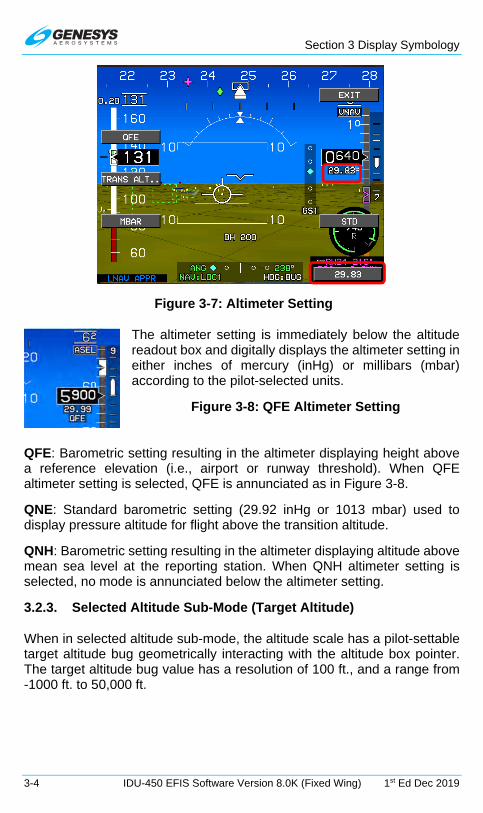
Section 3 Display Symbology
3-4 IDU-450 EFIS Software Version 8.0K (Fixed Wing) 1st Ed Dec 2019
Figure 3-7: Altimeter Setting
The altimeter setting is immediately below the altitude readout box and digitally displays the altimeter setting in either inches of mercury (inHg) or millibars (mbar) according to the pilot-selected units.
Figure 3-8: QFE Altimeter Setting
QFE: Barometric setting resulting in the altimeter displaying height above a reference elevation (i.e., airport or runway threshold). When QFE altimeter setting is selected, QFE is annunciated as in Figure 3-8.
QNE: Standard barometric setting (29.92 inHg or 1013 mbar) used to display pressure altitude for flight above the transition altitude.
QNH: Barometric setting resulting in the altimeter displaying altitude above mean sea level at the reporting station. When QNH altimeter setting is selected, no mode is annunciated below the altimeter setting.
3.2.3. Selected Altitude Sub-Mode (Target Altitude)
When in selected altitude sub-mode, the altitude scale has a pilot-settable target altitude bug geometrically interacting with the altitude box pointer. The target altitude bug value has a resolution of 100 ft., and a range from -1000 ft. to 50,000 ft.
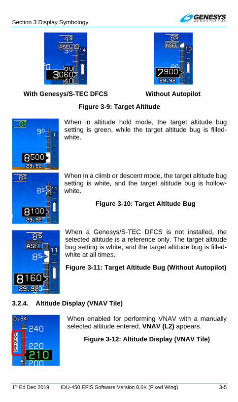
Section 3 Display Symbology
1st Ed Dec 2019 IDU-450 EFIS Software Version 8.0K (Fixed Wing) 3-5
With Genesys/S-TEC DFCS Without Autopilot
Figure 3-9: Target Altitude
When in altitude hold mode, the target altitude bug setting is green, while the target altitude bug is filled-white.
When in a climb or descent mode, the target altitude bug setting is white, and the target altitude bug is hollow-white.
Figure 3-10: Target Altitude Bug
When a Genesys/S-TEC DFCS is not installed, the selected altitude is a reference only. The target altitude bug setting is white, and the target altitude bug is filled-white at all times.
Figure 3-11: Target Altitude Bug (Without Autopilot)
3.2.4. Altitude Display (VNAV Tile)
When enabled for performing VNAV with a manually selected altitude entered, VNAV (L2) appears.
Figure 3-12: Altitude Display (VNAV Tile)

Section 3 Display Symbology
3-6 IDU-450 EFIS Software Version 8.0K (Fixed Wing) 1st Ed Dec 2019
3.2.5. VNAV Sub-Mode
When in VNAV sub-mode, the altitude scale shows the active waypoint VNAV altitude (if it exists) with a bug symbol geometrically interacting with the altitude box pointer. The VNAV altitude bug setting is annunciated above the altitude scale with a resolution of 100 feet.
When not vertically integrated with a fully integrated digital AP, the VNAV altitude bug setting includes “VNAV” indicating VNAV altitude sub-mode.
Figure 3-13: VNAV Sub-Mode (Not Vertically Integrated)
The VNAV altitude bug is a visual reference or, when vertically integrated with an autopilot either fully or partially integrated through the vertical mode discrete input, as a control parameter for climbs or descents.
When a Genesys/S-TEC DFCS is installed, the VNAV altitude provides control inputs to the DFCS and has the following behavior:
When in altitude hold mode, the VNAV altitude bug value is green, and the VNAV altitude bug is a filled-magenta. During altitude hold capture, the VNAV altitude bug-setting flashes.
When in climb or descent mode, the VNAV altitude bug value is white, and the VNAV altitude bug is hollow-magenta.
Figure 3-14: VNAV Sub-Mode with Genesys/S-TEC DFCS
When the VNAV altitude or target altitude differs from aircraft altitude to the extent the associated bug is off-scale, the associated bug appears to be “parked” in the direction of the difference with half of the associated bug visible as seen in Figure 3-14.
3.2.6. Minimum Altitude
A user-settable minimum altitude bug consists of a bold yellow line on the altitude scale and a yellow region on the altitude scale from the minimum altitude down to ground level. The minimum altitude bug value is displayed

Section 3 Display Symbology
1st Ed Dec 2019 IDU-450 EFIS Software Version 8.0K (Fixed Wing) 3-7
above the altitude scale with a resolution of 10 ft. The minimum altitude bug can be used in conjunction with a selected altitude or VNAV bug. When a minimum altitude is set, descending from above to below causes an audible alert of “Minimums, Minimums” and the minimum altitude to turn amber (yellow) and flash.
Figure 3-15: Minimum Altitude
3.2.7. Vertical Speed Indicator
The vertical speed indicator (VSI) is depicted in a "worm" format providing analog and digital representation of VSI in feet per minute (fpm).
Figure 3-16: VSI
The pilot-selectable VSI bug setting (100 fpm resolution) in this example is set to 1000 fpm. The vertical speed bug is used either as a visual reference or, when vertically integrated with an AP (either fully integrated or partially integrated through use of the vertical mode discrete input), as a control parameter for climbs or descents. It is mutually exclusive with the airspeed bug.
Figure 3-17: VSI Bug
Minimum Altitude: 760’

Section 3 Display Symbology
3-8 IDU-450 EFIS Software Version 8.0K (Fixed Wing) 1st Ed Dec 2019
Table 3-1: Scale Graduations and Display
Traffic Installed
Scale Limit
Scale Graduations and Display
With TCAS-II ±6,000 fpm
±500, ±1,000, ±2,000, ±4,000, and ±6,000 fpm
Background of the VSI functions as an RA display with green and red regions to provide RA maneuver guidance.
Without TCAS-II
±3,000 fpm
±500, ±1,000, ±2,000, and ±3,000 fpm
The VSI indication can have a pilot-settable vertical speed bug with a 100 fpm resolution and a range from -3000 to +3000 fpm. It is mutually exclusive with the airspeed bug.
When a Genesys/S-TEC DFCS is not installed, the VSI bug is for reference only. The VSI bug value is white and appears above the VSI indicator. The VSI bug is filled white at all times.
Figure 3-18: VSI Bug without Genesys/S-TEC DFCS
When vertically integrated with a Genesys/S-TEC DFCS, the VSI bug value is green with the speed bug filled-white when in VSI climb or descent mode. Otherwise, the VSI bug value is white and VSI bug is hollow-white.
Figure 3-19: VSI Bug with Genesys/S-TEC DFCS
3.2.8. Normal AGL Indication
AGL altitude is displayed above the course deviation indicator. The source for the indication is the source used by TAWS and displayed next to the AGL altitude as follows.

Section 3 Display Symbology
1st Ed Dec 2019 IDU-450 EFIS Software Version 8.0K (Fixed Wing) 3-9
R = Radar altitude
G = GPS/SBAS geodetic height less database ground elevation
B = Barometric altitude less database ground elevation
Figure 3-20: Normal AGL Indication
AGL altitude is not displayed when it is greater than the radar altimeter maximum valid altitude (2500’ AGL or as set in EFIS limits) nor, when it is invalid or when an analog indication is selected by the pilot. Additionally, AGL indication includes the set decision height (see § 3.2.10).
Table 3-2: AGL Indication
Altitude ≥300 Feet
≥100 Feet < 300 Feet
<100 Feet
AGL Indication resolution 10 Feet 5 Feet 1 Foot
3.2.9. Analog AGL Indication
Pilot-selected analog AGL indication is displayed in the lower right corner of the PFD above the active waypoint identifier with a green circular tape and digital readout in the center. The circular tape has a green radial line at its end that disappears above 1000’ AGL.
Figure 3-21: Analog AGL Indication
The analog AGL indicator disappears in unusual attitude mode and is mutually exclusive with the mini-map, analog G meter, and traffic thumbnail. Analog AGL altitude is not displayed when it is greater than the radar altitude maximum valid value (2,500 ft. or as set in EFIS limits), when it is invalid, or when the pilot deselects analog AGL.
Table 3-3: Analog AGL Indicator
Markings 0-1000 Feet AGL Scaling
(clock position)
0-100 Feet 100 Feet-1000 Feet 0’ AGL 6:00 Linear Logarithmic 50’ AGL 9:00 100’ AGL 12:00 200’ AGL 1:30 500’ AGL 3:00

Section 3 Display Symbology
3-10 IDU-450 EFIS Software Version 8.0K (Fixed Wing) 1st Ed Dec 2019
Table 3-4: Analog AGL Indicator Markings
Major Tick Marks Minor Tick Marks 0’
10’ 20’ 30’ 40’ 50’
60’ 70’ 80’ 90’ 100’
200’ 300’ 400’ 500’
1000’
3.2.10. Decision Height
Pilot-settable decision height is displayed above the CDI with the abbreviation DH and by a yellow radial on the analog indicator.
When the aircraft descends below decision height, DH ### turns amber (yellow) and flashes, and the circular tape and readout turn amber (yellow). This is accompanied by “Decision Height” audible alert.
Figure 3-22: Decision Height
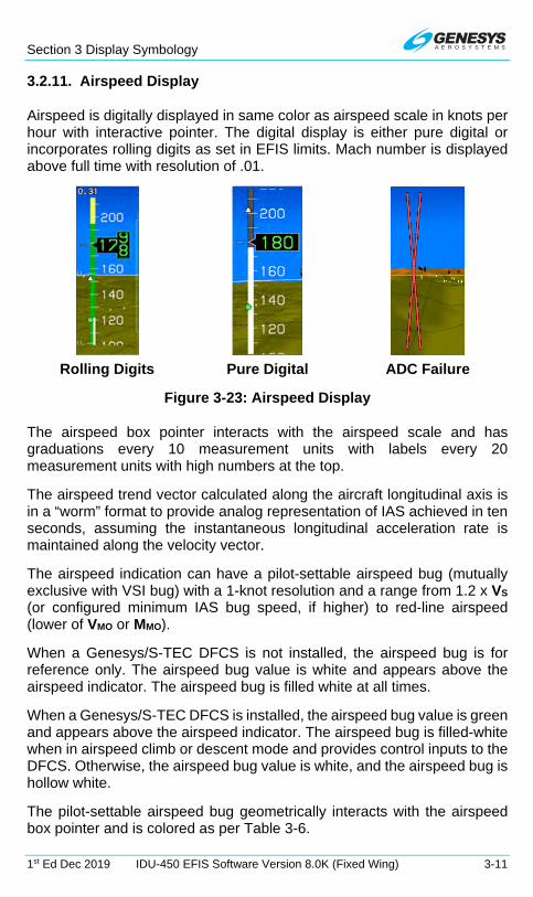
Section 3 Display Symbology
1st Ed Dec 2019 IDU-450 EFIS Software Version 8.0K (Fixed Wing) 3-11
3.2.11. Airspeed Display
Airspeed is digitally displayed in same color as airspeed scale in knots per hour with interactive pointer. The digital display is either pure digital or incorporates rolling digits as set in EFIS limits. Mach number is displayed above full time with resolution of .01.
Rolling Digits Pure Digital ADC Failure
Figure 3-23: Airspeed Display
The airspeed box pointer interacts with the airspeed scale and has graduations every 10 measurement units with labels every 20 measurement units with high numbers at the top.
The airspeed trend vector calculated along the aircraft longitudinal axis is in a “worm” format to provide analog representation of IAS achieved in ten seconds, assuming the instantaneous longitudinal acceleration rate is maintained along the velocity vector.
The airspeed indication can have a pilot-settable airspeed bug (mutually exclusive with VSI bug) with a 1-knot resolution and a range from 1.2 x VS (or configured minimum IAS bug speed, if higher) to red-line airspeed (lower of VMO or MMO).
When a Genesys/S-TEC DFCS is not installed, the airspeed bug is for reference only. The airspeed bug value is white and appears above the airspeed indicator. The airspeed bug is filled white at all times.
When a Genesys/S-TEC DFCS is installed, the airspeed bug value is green and appears above the airspeed indicator. The airspeed bug is filled-white when in airspeed climb or descent mode and provides control inputs to the DFCS. Otherwise, the airspeed bug value is white, and the airspeed bug is hollow white.
The pilot-settable airspeed bug geometrically interacts with the airspeed box pointer and is colored as per Table 3-6.
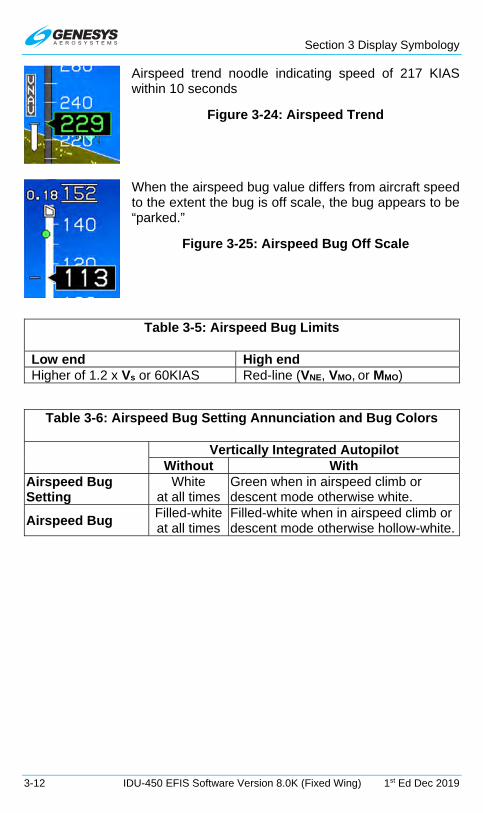
Section 3 Display Symbology
3-12 IDU-450 EFIS Software Version 8.0K (Fixed Wing) 1st Ed Dec 2019
Airspeed trend noodle indicating speed of 217 KIAS within 10 seconds
Figure 3-24: Airspeed Trend
When the airspeed bug value differs from aircraft speed to the extent the bug is off scale, the bug appears to be “parked.”
Figure 3-25: Airspeed Bug Off Scale
Table 3-5: Airspeed Bug Limits
Low end High end Higher of 1.2 x Vs or 60KIAS Red-line (VNE, VMO, or MMO)
Table 3-6: Airspeed Bug Setting Annunciation and Bug Colors
Vertically Integrated Autopilot Without With
Airspeed Bug Setting
White at all times
Green when in airspeed climb or descent mode otherwise white.
Airspeed Bug Filled-white at all times
Filled-white when in airspeed climb or descent mode otherwise hollow-white.

Section 3 Display Symbology
1st Ed Dec 2019 IDU-450 EFIS Software Version 8.0K (Fixed Wing) 3-13
The airspeed scale background and readout for Part 23 airplanes has coloration as follows:
Figure 3-26: Airspeed Scale FAR Part 23
1) If in air mode, a red low-speed awareness area from the bottom of the scale to VS0. The airspeed readout is red in this area.
2) If in ground mode, a gray area from the bottom of the scale to VS0. The airspeed readout is gray at 0 (indicating “dead” airspeed) but otherwise white in this area.
3) If a valid VFE exists, a white flap-operating area from VS0 to VFE. The airspeed readout is white in this area.
4) For aircraft without a VMO/MMO:
a) A green safe-operating area from VS1 to VNO. The airspeed readout is green in this area.
b) An amber (yellow) caution area from VNO to VNE. The airspeed readout is amber (yellow) in this area.
c) A red high-speed awareness area from VNE to the top of the scale. The airspeed readout is red in this area.
5) For aircraft with a VMO/MMO:
a) A gray safe-operating area from VFE (if it exists) or VS0 to VMO/MMO. The airspeed readout is green in this area.
VNE Aircraft
VMO/MMO Aircraft
VNE VMO/MMO
VNO
VFE
VS0
VS1

Section 3 Display Symbology
3-14 IDU-450 EFIS Software Version 8.0K (Fixed Wing) 1st Ed Dec 2019
b) A red high-speed awareness area from the lower of VMO or MMO to the top of the scale. The airspeed readout is red in this area.
The airspeed scale background for Part 25 airplanes (Part 25 “Airspeed Scale Type”) has colored regions and readout coloration as follows:
Figure 3-27: Airspeed Scale FAR Part 25
1) If in air mode with a pilot-input VREF value:
a) A red low-speed awareness area from the bottom of the scale to G-compensated 1.1 x VS0. VS0 is calculated by dividing the pilot-input VREF by 1.23. The airspeed readout is red in this area.
b) An amber (yellow) low-speed awareness area from G-compensated 1.1 x VS0 to G-compensated 1.2 x VS0. The airspeed readout is amber (yellow) in this area.
c) If a valid VFE exists, a white flap-operating area from G-compensated 1.2 x VS0 to VFE and a gray normal-operating area from VFE to the lower of VMO or MMO. The airspeed readout is white in the flap-operating area and green in the normal-operating area.
d) If a valid VFE does not exist, a gray normal-operating area from G-compensated 1.2 x VS0 to the lower of VMO or MMO. The airspeed readout is green in this area.
2) If in Ground Mode or without a pilot-input VREF value:
On Ground or No VREF
In Flight with VREF
VFE
1.1 x VS0
1.2 x VS0
VMO/MMO

Section 3 Display Symbology
1st Ed Dec 2019 IDU-450 EFIS Software Version 8.0K (Fixed Wing) 3-15
a) If a valid VFE exists, a white flap-operating area from the bottom of the scale to VFE and a gray normal-operating area from VFE to the lower of VMO or MMO. The airspeed readout is gray at 0 (indicating “dead” airspeed) otherwise white in the flap-operating area and green in the normal-operating area.
b) If a valid VFE does not exist, a gray normal-operating area from the bottom of the scale to the lower of VMO or MMO. The airspeed readout is gray at 0 (indicating “dead” airspeed) otherwise white below 60 and green at or above 60 in this area.
3) A red high-speed awareness area from the lower of VMO or MMO to the top of the scale. The airspeed readout is red in this area.
The airspeed scale for Part 25 airplanes have additional specific airspeed markings as follows:
1) If pilot-input VREF is valid, a white VS marking at the aircraft’s 1-G VS0 or an amber (yellow) VS marking at VS0 corrected for G-loading, whichever is higher. VS0 is calculated by dividing the pilot-input VREF by 1.23
2) If enabled (VGL not 0), a “green dot” best glide speed marker at VGL.
3) If enabled (VX not 0), a VX marking at VX.
4) If enabled (VY not 0), a VY marking at VY.
5) If enabled (VA not 0), a VA marking at VA.
6) If enabled (VMFE not 0), a “white triangle” maximum flap extension speed marker at VMFE.
3.2.12. Airspeed Display (with EFIS-Coupled)
Airspeed descent to 7,500’ with green color and filled airspeed
Figure 3-28: Airspeed Display (with EFIS-Coupled)
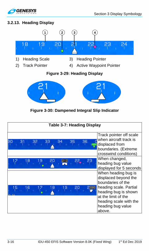
Section 3 Display Symbology
3-16 IDU-450 EFIS Software Version 8.0K (Fixed Wing) 1st Ed Dec 2019
3.2.13. Heading Display
1) Heading Scale 2) Track Pointer
3) Heading Pointer
4) Active Waypoint Pointer
Figure 3-29: Heading Display
Figure 3-30: Dampened Integral Slip Indicator
Table 3-7: Heading Display
Track pointer off scale when aircraft track is displaced from boundaries. (Extreme crosswind conditions)
When changed, heading bug value displayed for 5 seconds
When heading bug is displaced beyond the boundaries of the heading scale. Partial heading bug is shown at the limit of the heading scale with the heading bug value above.
1 2 3 4

Section 3 Display Symbology
1st Ed Dec 2019 IDU-450 EFIS Software Version 8.0K (Fixed Wing) 3-17
NOTE:
The track pointer is not displayed when indicated airspeed is in the noise range (indicated airspeed or groundspeed is less than 30 knots).
When AHRS is in the DG mode, DG appears.
Figure 3-31: DG Indicated when AHRS in DG Mode
Figure 3-32: GPS Loss of Navigation (LON)
3.2.14. Pitch Scale
Figure 3-33: Pitch Scale
The PFD has large aircraft symbol reference marks fixed in the center of the display. Rotation of the background, pitch scale, and background oriented display elements occur relative to the location of the large aircraft symbol reference marks.
Pitch scale has increments every 5° with major increments and pitch scale labels every 10°. Increments are equally spaced to conform approximately to the 3D PFD background. Pointer bars at the ends of each major increment indicate direction to the horizon and automatically declutter to present the fewest possible increments needed to unambiguously display pitch attitude. The pitch scale terminates with a zenith symbol (small white circle) at +90° and a nadir symbol (small white circle with “+”) at -90°.
5° UP

Section 3 Display Symbology
3-18 IDU-450 EFIS Software Version 8.0K (Fixed Wing) 1st Ed Dec 2019
Figure 3-34: Pitch Scale Zenith and Nadir Symbol
3.2.15. Pitch Limit Indicator
The pitch limit indicator first appears above the applicable reference symbol (either the FPM or the large aircraft symbol reference marks) and converges upon the applicable reference symbol as indicated airspeed decreases.
Pitch Limit Indicator Appearance Limits: 1-G VS1 or VS1 corrected for G-loading.
Figure 3-35: Pitch Limit Indicator (5 Knots above Stall)
Zenith symbol
Nadir symbol
5 knots above stall

Section 3 Display Symbology
1st Ed Dec 2019 IDU-450 EFIS Software Version 8.0K (Fixed Wing) 3-19
Figure 3-36: Pitch Limit Indicator (20 Knots above Stall)
3.2.16. Turn Rate Indicator
Rate of turn is available as an option in the PFD declutter menu to show a worm in the direction of turn with full-scale deflection indicating a standard rate of turn (and slightly beyond) and half-standard rate indicated at the mid-scale marking.
Figure 3-37: Turn Indication (Selected from Declutter Menu)
20 knots above stall
Full standard rate
Half standard rate

Section 3 Display Symbology
3-20 IDU-450 EFIS Software Version 8.0K (Fixed Wing) 1st Ed Dec 2019
3.2.17. G-Force and Fast/Slow Indicator
G-Force indicator appears in normal mode as depicted or next to the large aircraft symbol reference marks (basic or unusual attitude mode) when difference between G-force and 1-G is greater than 0.3 Gs.
Figure 3-38: G-Force Indicator
Positive telltales appear whenever G-force exceeds 2.5G. Negative telltales appear whenever negative G-force is less than -0.5G. Telltales appear full-time within G-indication area.
Figure 3-39: G-Force Indicator Telltale Indications
When selected from declutter menu, analog G-force indication is displayed to nearest tenth G.
Figure 3-40: Analog G-Force Indicator
Press RESET G (L2) to reset telltales to zero, unless the aircraft G-limits have been exceeded. If G-limits have been exceeded, reset exceedance in GMF.
Figure 3-41: RESET G
3.2.18. Landing Gear Indication
If configured, PFD displays landing gear position as small “tires” below FPM or large aircraft symbol reference marks.
Red radial G-force limits
Positive telltale of 4.2G

Section 3 Display Symbology
1st Ed Dec 2019 IDU-450 EFIS Software Version 8.0K (Fixed Wing) 3-21
Basic Mode Normal Mode
Figure 3-42: Landing Gear Indication
3.2.19. Unusual Attitude Mode
Unusual attitude mode is enabled when pitch attitude exceeds +30° or -30° or bank angle exceeds 65°. Once enabled, the waterline symbol is replaced by large aircraft symbol and the unusual attitude mode remains engaged until pitch attitude returns to within 5° of the horizon and bank attitude returns to within 10° of the horizon. Recovery chevrons tied to the 30° and higher pitch scale indications (both positive and negative) aid in unusual attitude recovery and are a normal part of the pitch scale and are not necessarily tied to unusual attitude mode.
Figure 3-43: Unusual Attitude Mode
NOTE:
The recovery chevrons are a normal part of the pitch scale but are not necessarily tied to unusual attitude mode.

Section 3 Display Symbology
3-22 IDU-450 EFIS Software Version 8.0K (Fixed Wing) 1st Ed Dec 2019
The following features are disabled in unusual attitude mode:
1) Terrain and obstruction rendering
2) CDI
3) VDI
4) Flight path marker
5) Highway in the Sky boxes
6) Atmospheric perspective
7) Analog and digital AGL indication
8) Active waypoint symbology
9) Mini map
10) Traffic thumbnail
11) If in basic mode, PFD reverts to Normal Mode
12) If in zoom mode FOV, PFD reverts to normal FOV
13) Runways
3.2.20. PFD Background
The PFD has a 3D background generated from terrain elevation and obstruction elevation data stored in electronic memory. The “actual horizon” displayed on the PFD is based upon the higher of terrain within 90NM or a horizon calculated using a visible horizon equation. Thus, the relative elevation of terrain and obstructions with respect to aircraft altitude and performance is observed by reference to the primary flight information pitch ladder and FPM.
The background has two pilot-selectable field-of-view (FOV) modes, wide FOV mode (approximately 70°) and narrow FOV mode (approximately 35°). In unusual attitude mode, wide FOV mode is automatically selected in the PFI area only.
A blended-tone sky is displayed in conjunction with terrain. The sky fades from light blue at the horizon to dark blue at the top of the display to simulate atmospheric perspective and enhance the 3D presentation. Additionally, the blended sky increases contrast of the directional scale, emphasizes the horizon, and provides a compelling visual cue to a nose-high attitude.
Terrain and obstruction rendering uses hidden surface removal techniques while terrain/sky rendering uses atmospheric perspective techniques. Terrain with obstruction rendering is collectively pilot-selectable to declutter the display (independent declutter of obstructions is not possible). Terrain and obstruction rendering is disabled in the basic mode, unusual attitude mode, and during any reversionary mode. In unusual attitude mode, the blue-brown boundary line of the background decouples from the pitch scale at high pitch angles so a sliver of the blue-brown boundary line always remains visible to give guidance to the horizon.

Section 3 Display Symbology
1st Ed Dec 2019 IDU-450 EFIS Software Version 8.0K (Fixed Wing) 3-23
Figure 3-44: PFD Terrain and Obstructions
Terrain ahead of the aircraft is shown conformally with the artificial horizon in the correct scale and perspective for the aircraft’s current position and altitude. Worldwide terrain coverage is provided in each IDU and is shown with a resolution as in Table 3-8. Terrain is displayed ahead of the aircraft using a grid and simulates atmospheric perspective (terrain lines fade into the background ground color as they recede into the distance).
NOTE:
There is a one-degree dead band to prevent grid flicker while flying along one of the boundary latitudes. The grid space switching changes
at one degree less latitude when flying towards the Equator than it does when flying toward the Poles.
At latitudes greater than 75°, no grid lines are shown. To keep the grid spacing relatively consistent, at latitudes between 45° and 75°, the longitude spacing is increased according as in Table 3-8.
Table 3-8: LAT-LON Resolution Boundaries
Latitude Range Longitude Grid Spacing
Heading Boundary Pole Equator
0° to 46° 24 arc-seconds 46° to 62° 48 arc-seconds 46° 45° 62° to 70° 72 arc-seconds 62° 61° 70° to 74° 96 arc-seconds 70° 69° 74° to 75° 120 arc-seconds 74° 73°

Section 3 Display Symbology
3-24 IDU-450 EFIS Software Version 8.0K (Fixed Wing) 1st Ed Dec 2019
Table 3-9: Terrain and Obstruction Rendering Levels
Feature Terrain Coloring Obstructions Notes
SVS BASIC
Shades of brown for non-water terrain
Within the following ranges, depicted on PFI in SVS Basic or SVS TAWS mode:
Narrow FOV: 17NM
Wide FOV: 12NM
Amber and red colors not used for normal display of terrain.
Deep blue for areas of water has precedence over shades of brown.
SVS TAWS
Shades of olive when at or below 100 ft. aircraft altitude
Shades of brown when above 100 ft. aircraft altitude
TAWS coloring of FLTA alert or warning cells
Amber and red colors used for normal display of terrain and terrain areas causing FLTA alerts.
Deep blue for areas of water has precedence over other colors.
None No terrain nor obstructions are shown. Neither, SVS BASIC or SVS TAWS is selected.
When terrain and obstruction rendering is deselected or disabled, the PFD screen background is a conventional blue over brown attitude display presentation without atmospheric perspective. Additionally, terrain may be deselected on the PFD and retained on the ND MAP display.
Figure 3-45: Terrain Deselected on PFD and Retained on MFD Map
NOTE:
The obstruction data is provided by Jeppesen and must be updated every 28 days to maintain current database information.

Section 3 Display Symbology
1st Ed Dec 2019 IDU-450 EFIS Software Version 8.0K (Fixed Wing) 3-25
WARNING:
DO NOT USE THIS EFIS FOR TERRAIN-FOLLOWING FLIGHT. DO NOT ATTEMPT TO NAVIGATE USING TERRAIN DEPICTION.
ALWAYS ADHERE TO PUBLISHED NAVIGATIONAL INSTRUMENT PROCEDURES AND NAVIGATIONAL CHARTS IN ALL FLIGHT
CONDITIONS.
Obstructions such as towers, antennas, buildings, and other manmade structures are shown on the PFD display as vertical amber (yellow) lines. Obstructions are conformal in both location and size and are only shown in conjunction with terrain regardless of altitude. Obstructions representing a collision hazard are annunciated audibly and visually with a time-critical warning or caution alert. All vertical amber (yellow) lines in Figure 3-46 are obstructions near the airport. See Section 2 System Overview for description of alerts when obstructions represent a collision hazard.
WARNING:
MANY TOWERS, ANTENNAS, STRUCTURES, AND OBSTRUCTIONS ARE NOT IN THE DATABASE.
Obstructions without hazardous condition
Obstructions creating an OBSTRUCTION caution
Figure 3-46: PFD with Obstructions
3.2.21. Flight Path Marker (Velocity Vector)
The FPM appears on the background to coincide with the aircraft’s actual flight path as projected on the outside world. The FPM is laterally displaced parallel to the horizon with respect to the center of the display to account for the difference between aircraft track and heading, and is vertically

Section 3 Display Symbology
3-26 IDU-450 EFIS Software Version 8.0K (Fixed Wing) 1st Ed Dec 2019
displaced perpendicular to the horizon to account for aircraft climb or descent angle.
The FPM is not shown in basic mode. In unusual attitude mode, it disappears to allow the pilot to concentrate on the large aircraft symbol reference marks for unusual attitude recovery. FPM at low speed (airspeed < 45 KIAS) behavior further depends upon whether or not the aircraft is in flight or on the ground and whether or not a WOW/WOG discrete input is enabled.
Figure 3-47: Flight Path Marker
Because the FPM is used in conjunction with a 3D background, the FPM utility normally associated with a HUD is achieved. When the FPM is displaced to the extent it interferes with heading, altitude, or airspeed indications, it is removed from the display.
FPM nearing airspeed tape due to strong
crosswind.
FPM caged in center due to excessive crosswinds from the right. Ghost FPM
appears in proper lateral location.
Figure 3-48: Flight Path Marker Views
When the location of the ghost is displaced to the extent it interferes with heading, altitude, or airspeed indications, the ghost is removed from the display.

Section 3 Display Symbology
1st Ed Dec 2019 IDU-450 EFIS Software Version 8.0K (Fixed Wing) 3-27
Table 3-10: Flight Path Marker Behavior
Crab Angle Cage (Become laterally centered on the display)
When exceeding 15° (wide FOV) or 7.5° (narrow FOV mode)
Uncage (Resume lateral floating)
When returning below 13° (wide FOV mode) or 6.5° (narrow FOV mode)
FPM movement is dampened by reference to aircraft pitch and heading so as not to deviate from pitch or heading at a rate greater than 1°/sec.
Figure 3-49: Flight Path Marker Ghost
Figure 3-50: Flight Path Marker Absence
FPM Ghost
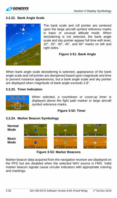
Section 3 Display Symbology
3-28 IDU-450 EFIS Software Version 8.0K (Fixed Wing) 1st Ed Dec 2019
3.2.22. Bank Angle Scale
The bank scale and roll pointer are centered upon the large aircraft symbol reference marks in basic or unusual attitude mode. When decluttering is not selected, the bank angle scale and sky pointer appear full time with level, 10°, 20°, 30°, 45°, and 60° marks on left and right sides.
Figure 3-51: Bank Angle
When bank angle scale decluttering is selected, appearance of the bank angle scale and roll pointer are dampened based upon magnitude and time to prevent nuisance appearances, but a bank angle scale and sky pointer are displayed when magnitude of bank angle exceeds 2.8°.
3.2.23. Timer Indication
When selected, a countdown or count-up timer is displayed above the fight path marker or large aircraft symbol reference marks.
Figure 3-52: Timer
3.2.24. Marker Beacon Symbology
Normal Mode
Basic Mode
Figure 3-53: Marker Beacons
Marker beacon data acquired from the navigation receiver are displayed on the PFD but are disabled when the selected NAV source is FMS. Valid marker beacon signals cause circular indicators with appropriate coloring and markings.

Section 3 Display Symbology
1st Ed Dec 2019 IDU-450 EFIS Software Version 8.0K (Fixed Wing) 3-29
3.2.25. Flight Director Symbology
Flight director (FD) symbology is controlled on the IDU or integrated autopilot/FD. When selected, FD symbology and valid steering commands are received from the FD with one of the following symbols shown in normal mode. The PFD has a waterline symbol fixed in the center of the display. Rotation of the background, pitch scale, and background oriented display elements occurs relative to the location of the waterline symbol or large aircraft reference marks.
Figure 3-54: Flight Director FD1 Single Cue
Figure 3-55: Flight Director FD1

Section 3 Display Symbology
3-30 IDU-450 EFIS Software Version 8.0K (Fixed Wing) 1st Ed Dec 2019
Figure 3-56: Flight Director FD2 (Normal Mode)
Figure 3-57: Flight Director FD2 Course Deviation Indicator
Figure 3-58: Course Deviation Indicator
The order of precedence of type accuracy used by the system from highest to lowest is as follows:
1) Manual RNP: The pilot may override the automatic accuracy types by setting a manual RNP value.

Section 3 Display Symbology
1st Ed Dec 2019 IDU-450 EFIS Software Version 8.0K (Fixed Wing) 3-31
2) Automatic RNP: These are based upon RNP values, which are coded in the navigation database. The EFIS looks at the leg coding on all legs other than those on the final approach segment. On the final approach segment, the EFIS looks at the “Level of Service” record for those approaches, which have RNP transition legs, and then goes to LP or LPV minima for the final approach.
3) Default TSO-C146C operation: As specified as per Table 3-11 for enroute, terminal, and various approach modes according to the “Level of Service” record.
Table 3-11: CDI Behavior and Color
CDI Pointer and Condition Color or Behavior Full Scale Deflection Flash Slaved to GPS/SBAS Scale is appropriate FSD value for
mode of flight:
Enroute: ±2NM
From Enroute to Terminal: Change from ±2 NM FSD to ±1 NM FSD over distance of 1 NM; start transition when entering terminal mode.
From Terminal to Enroute: Change from ±1 NM FSD to ±2 NM FSD over distance of 1 NM; start transition when entering enroute mode.
From Terminal to Approach: If VTF, switch immediately.
Otherwise, change from ±1 NM FSD to approach FSD over distance of 2 NM; start transition at 2 NM from FAWP.
From Approach to Terminal: Change to 1 NM.
From Departure to Terminal: If initial leg is aligned with runway, change from ±0.3 NM FSD to ±1 NM FSD at the turn initiation point of the first fix in the departure procedure.
Slaved to GPS/SBAS (with GPS LON)
Amber (Yellow)
Normal conditions Magenta In sources other than FMS Angular scale annunciation
With Analog Autopilot Configured

Section 3 Display Symbology
3-32 IDU-450 EFIS Software Version 8.0K (Fixed Wing) 1st Ed Dec 2019
Table 3-11: CDI Behavior and Color
CDI Pointer and Condition Color or Behavior
Reverse sensing (Course error exceeds 105°)
Red “X” displayed over CDI
Selected nav source FMS1
Selected nav source VLOC1
Selected nav source VOR1 with “TO” indication.
Selected nav source VOR2 With “FROM” indication.
With Genesys/S-TEC DFCS Integrated Autopilot or Without Autopilot Configured
Reverse sensing (Course error exceeds 105°)
Red “X” displayed over CDI
Selected nav source FMS1
Selected nav source VLOC1
Selected nav source VOR1 with “TO” indication.
Selected nav source VOR2 With “FROM” indication.
3.2.26. OBS Setting of CDI
In automatic mode, the system controls the scale and OBS setting according to the requirements of GPS/SBAS (TSO-C-146C). The selected navigation source is annunciated below the CDI as follows:
1) NAV: FMS1/FMS2
2) NAV: VOR1/LOC1
3) NAV: BC1/BC2 (annunciated instead of LOC1/2 when course error exceeds 105°)
4) NAV: VOR2/LOC2

Section 3 Display Symbology
1st Ed Dec 2019 IDU-450 EFIS Software Version 8.0K (Fixed Wing) 3-33
3.2.27. Heading/Roll-Steering Sub-Mode
Heading/roll-steering sub-mode annunciation appears immediately right of the selected navigation source annunciation and displays:
1) HDG: LVL (Wing-Leveling Sub-Mode Guidance)
2) HDG: LNAV (LNAV Sub-Mode Guidance)
3) HDG: BUG (Heading Bug Sub-Mode Guidance)
4) HDG: --- (Failure Sub-Mode)
3.2.28. No Autopilot or Fully-Integrated Autopilot CDI
Without Autopilot With Autopilot
Figure 3-59: CDI No Autopilot or Fully-Integrated Autopilot
In an installation without an AP or with a fully-integrated AP, the heading/roll-steering sub-mode indication is decluttered from the CDI. Therefore, the shaded background of the CDI only falls behind the CDI scale. An abbreviated navigation source indication (without “NAV:”) appears above the top left corner of the CDI scale. The heading/roll-steering sub-mode indication does not appear, as it is not required with AP mode indications nor when no AP is installed.
3.2.29. Vertical Deviation Indicator (VDI)
The vertical deviation indicator (VDI) on the right side displays vertical deviation for the selected vertical navigation source for displaying descent profile but disappears in unusual attitude mode.
Figure 3-60: Vertical Deviation Indicator
1) LPV Mode and LPV1 or LPV2: When descending on final approach segment in LPV mode. GPS altitude used to generate VDI; pilot may follow guidance to LPV minima regardless of temperature.

Section 3 Display Symbology
3-34 IDU-450 EFIS Software Version 8.0K (Fixed Wing) 1st Ed Dec 2019
2) LNAV Mode and VNV1-G or VNV2-G: When descending on final approach segment in LP, LNAV/VNAV, and LNAV or RNP modes when using GPS VNAV. GPS altitude used to generate VDI; pilot may follow guidance to LNAV minima regardless of temperature.
3) LNAV Mode and VNV1-B or VNV2-B: Default FMS barometric VNAV mode. Using barometric altitude to generate the VDI, pilot may follow guidance to LNAV minima as long as the specified temperature is within limits.
4) GS1 or GS2: Glideslope receiver #1 or #2 as indicated. Pilot follows guidance to published barometric DH.
Figure 3-61: VDI Color during GPS/SBAS LON or VLON
Table 3-12: Vertical Deviation Indicator Behavior
Source (Below VDI)
Behavior/Condition Pointer Color
FMS Conforms to the VDI display Magenta
Glideslope Source must be valid when a valid glideslope is received.
Magenta
LPV or VNAV mode
Source is valid if:
On VNAV descent segments when approaching Top of Descent point to provide descent anticipation as long as the following are true:
1) On VNAV descent segments; or
2) If the vertical deviations on VNAV level segments option is enabled, on VNAV level segments; or
Magenta

Section 3 Display Symbology
1st Ed Dec 2019 IDU-450 EFIS Software Version 8.0K (Fixed Wing) 3-35
Table 3-12: Vertical Deviation Indicator Behavior
Source (Below VDI)
Behavior/Condition Pointer Color
3) If the vertical deviations on VNAV level segments option is disabled, when approaching the Top of Descent point to provide descent anticipation;
Providing:
1) Aircraft is within 2NM or twice the full scale deflection for the mode of flight (whichever is greater) of the lateral navigation route; and
2) Aircraft is in TO operation relative to the active VNAV waypoint (i.e., taking into account VNAV offsets); and
3) If on the final approach segment, aircraft is within a 35° lateral wedge of the azimuth reference point (either GARP or MAWPT + 10,000 ft.).
LPV,VNV-G During GPS LON or GPS VLON
Pointer and Text Color
Amber (Yellow)
3.2.30. Vertical Deviation Indicator (EFIS Coupled)
Figure 3-62: EFIS Coupled Vertically with Glideslope Mode

Section 3 Display Symbology
3-36 IDU-450 EFIS Software Version 8.0K (Fixed Wing) 1st Ed Dec 2019
When vertically integrated with Genesys S/TEC DFCS enabled through glideslope mode discrete input with glideslope mode engaged, the selected vertical navigation source is green indicating the AP is vertically coupled. Otherwise, the source is white.
3.2.31. Highway in the Sky/Skyway
Coupled to Skyway Uncoupled to Skyway
Figure 3-63: Highway in the Sky
When not decluttered, the PFD displays the active navigation route or manual OBS course in 3D with a series of skyway boxes, which overly the flight plan route at a desired altitude and provide lateral and vertical guidance. See Section 7 IFR Procedures for details.
3.2.32. Active Waypoint and Waypoint Identifier
Figure 3-64: Active Waypoint
The PFD displays the active waypoint symbol as a magenta “tethered balloon” consisting of:

Section 3 Display Symbology
1st Ed Dec 2019 IDU-450 EFIS Software Version 8.0K (Fixed Wing) 3-37
1) an “X” depicted at the ground location of the active waypoint;
2) a hoop or “tethered balloon” (for fly-over waypoints) or “tethered diamond” (for fly-by waypoints) depicted at the VNAV altitude or at aircraft altitude (if there is no VNAV altitude), and
3) a line connecting the “X” and the hoop.
The “X” and connecting line are not shown if no ground elevation information is encoded with the NavData® waypoint information (e.g., terminal and enroute fixes). The active waypoint symbol is drawn using the hidden surface removal techniques of terrain and obstruction rendering, so an active waypoint behind terrain appears to be so. The active waypoint symbol disappears in unusual attitude mode but turns amber (yellow) in the event of GPS LON caution.
The identifier of the waypoint along with the bearing and distance to the waypoint are displayed in the lower right corner of the PFD in magenta. If a target altitude is not set and the active waypoint has a VNAV altitude associated as in Figure 3-64, the identifier includes a display of the VNAV altitude.
NOTE:
Only the active waypoint is shown on the PFD. Subsequent waypoints in a route are displayed sequentially as the current active waypoint is passed. With terrain turned off, the active waypoint is always visible
regardless of distance.
If the active waypoint is beyond the lateral limits of the screen, the magenta waypoint direction pointer (i.e., magenta triangle) on the
directional scale indicates shortest direction of turn to the waypoint.
If the waypoint is only a hoop hanging in space, it is a fix and not directly associated with a NAVAID on the ground (e.g. VOR, NDB, user
waypoint, or airport).
If the waypoint X disappears behind terrain on the PFD, there is terrain between the aircraft present position and the waypoint.

Section 3 Display Symbology
3-38 IDU-450 EFIS Software Version 8.0K (Fixed Wing) 1st Ed Dec 2019
3.2.33. Mini Map
Figure 3-65: Mini Map
Table 3-13: Mini-Map Behavior (When Not Decluttered)
VOR Pointer, Active Leg, Ownship Symbol
Color Condition
VOR 1
Cyan
When Valid
VOR 2
Green
When Valid
Active Leg Magenta GPS/SBAS normal Amber (Yellow) GPS/SBAS LON
Ownship Symbol (Figure 3-67) White Mutually exclusive with the analog AGL, traffic thumbnail, and analog G Force indicator. Mini-Map disappears in Unusual Attitude Mode
3.2.34. Runways
The PFD displays airport runways in a 3D manner. Upon activation of a DP, VFR approach, IFR approach, or STAR procedure, runways for the airport associated with the procedure, as well as, runways associated with the three nearest airports (computed by TAWS algorithms) are displayed. Runways are displayed with hidden surface removal techniques of the terrain and obstruction rendering, so runways behind terrain appear to be so. Runways are based on characteristics in the navigation database, including elevation, position, orientation, length, and width, and are displayed as defined in Table 3-14.
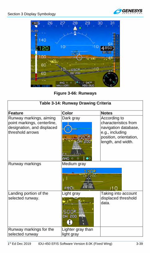
Section 3 Display Symbology
1st Ed Dec 2019 IDU-450 EFIS Software Version 8.0K (Fixed Wing) 3-39
Figure 3-66: Runways
Table 3-14: Runway Drawing Criteria
Feature Color Notes Runway markings, aiming point markings, centerline, designation, and displaced threshold arrows
Dark gray
According to characteristics from navigation database, e.g., including position, orientation, length, and width.
Runway markings Medium gray
Landing portion of the selected runway.
Light gray
Taking into account displaced threshold data.
Runway markings for the selected runway
Lighter gray than light gray
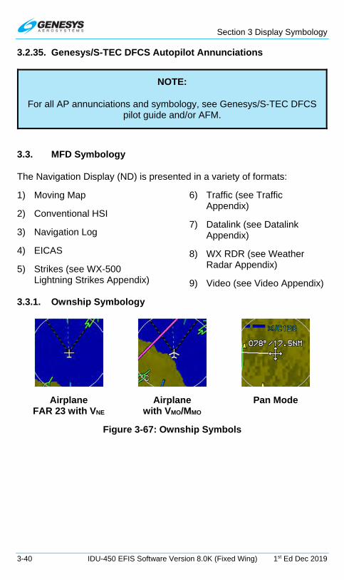
Section 3 Display Symbology
3-40 IDU-450 EFIS Software Version 8.0K (Fixed Wing) 1st Ed Dec 2019
3.2.35. Genesys/S-TEC DFCS Autopilot Annunciations
NOTE:
For all AP annunciations and symbology, see Genesys/S-TEC DFCS pilot guide and/or AFM.
3.3. MFD Symbology
The Navigation Display (ND) is presented in a variety of formats:
1) Moving Map
2) Conventional HSI
3) Navigation Log
4) EICAS
5) Strikes (see WX-500 Lightning Strikes Appendix)
6) Traffic (see Traffic Appendix)
7) Datalink (see Datalink Appendix)
8) WX RDR (see Weather Radar Appendix)
9) Video (see Video Appendix)
3.3.1. Ownship Symbology
Airplane FAR 23 with VNE
Airplane with VMO/MMO
Pan Mode
Figure 3-67: Ownship Symbols

Section 3 Display Symbology
1st Ed Dec 2019 IDU-450 EFIS Software Version 8.0K (Fixed Wing) 3-41
3.3.2. Moving Map
Figure 3-68: Basic Moving Map
Figure 3-69: Moving Map with Instrument Approach with HSI Enabled
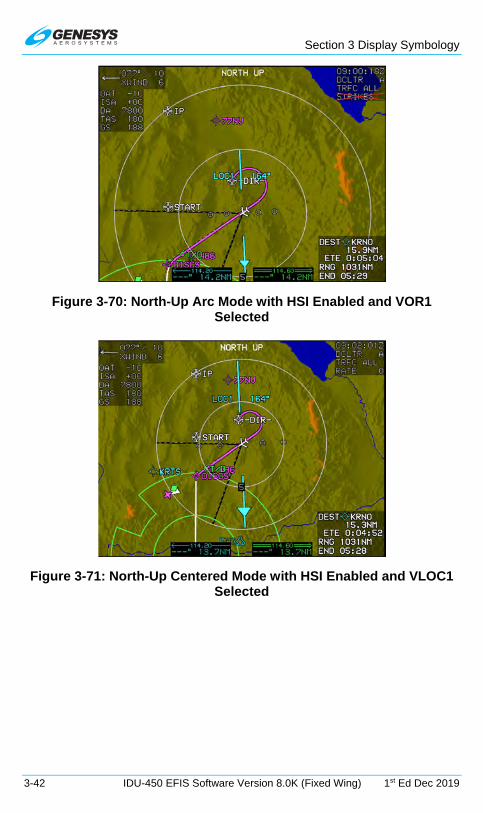
Section 3 Display Symbology
3-42 IDU-450 EFIS Software Version 8.0K (Fixed Wing) 1st Ed Dec 2019
Figure 3-70: North-Up Arc Mode with HSI Enabled and VOR1 Selected
Figure 3-71: North-Up Centered Mode with HSI Enabled and VLOC1 Selected

Section 3 Display Symbology
1st Ed Dec 2019 IDU-450 EFIS Software Version 8.0K (Fixed Wing) 3-43
Figure 3-72: Heading-Up Centered Mode
In heading up mode, the magnetic digital heading readout and pointer are aligned with the longitudinal axis of the ownship symbol.
3.3.3. Compass Rose/ND Boundary Circle Symbol
Figure 3-73: Compass Rose/ND Boundary Circle Symbol
3.3.4. Clock/Options
The following are displayed in the upper right corner of the ND.
Zulu Time Local Offset Time
Figure 3-74: Clock Options
Table 3-15: Clock/Options
Feature Options Notes Zulu Time or Local Offset
hh:mm:ssZ hh:mm:ssL
Synchronized with GPS/SBAS constellation.

Section 3 Display Symbology
3-44 IDU-450 EFIS Software Version 8.0K (Fixed Wing) 1st Ed Dec 2019
Table 3-15: Clock/Options
Feature Options Notes Declutter Mode
DCLTR A DCLTR M
= Automatic declutter mode = Manual declutter mode
Terrain Status Enabled or Disabled
Indicated by the absence or presence of terrain.
3.3.5. Air Data and Groundspeed
True North Mode Normal Mode
Figure 3-75: Air Data and Groundspeed
The following are displayed in the upper left corner of the ND:
1) Wind: Information consists of the following readouts:
a) Direction in degrees;
b) Speed in knots;
c) Crosswind component in knots; and
d) Graphical wind vector arrow oriented to correspond to the ND orientation.
NOTE:
Wind information is not shown when indicated airspeed is in the noise range of less than 30 knots, when the aircraft is in the ground mode, or
when the AHRS is in DG mode.
2) Outside Air Temperature: Digitally in Degrees C or F (as configured).
3) International Standard Atmosphere (ISA): Difference between ISA temperature and current outside air temperature is displayed digitally in °C or °F (Negative values = less than Standard OAT). Decluttered if the “Show ISA Temperature Flag” is disabled in EFIS limits.

Section 3 Display Symbology
1st Ed Dec 2019 IDU-450 EFIS Software Version 8.0K (Fixed Wing) 3-45
4) Density Altitude: Digitally in feet. Decluttered if the “Show Density altitude Flag” is disabled in EFIS limits.
5) True Airspeed: Digitally in knots. Decluttered if the “True Airspeed Flag” is disabled in EFIS limits.
6) Groundspeed: Digitally in knots.
3.3.6. Fuel Totalizer/Waypoint Distance Functions
Not the current active waypoint Current active waypoint
Figure 3-76: Fuel Totalizer/ Waypoint Distance Functions
Table 3-16: Fuel Totalizer/Waypoint Distance Functions
Function Conditions Type/Symbols TO Waypoint
If there is an active flight plan, waypoint type, identifier, range, bearing, and ETE/ETA for the active waypoint (“TO” waypoint) are shown.
Waypoint information is magenta but turns amber (yellow) with GPS LON caution.
ETA or ETE
Degree (°) or True North (T) symbol
DEST Waypoint
If there is an active flight plan, waypoint type, identifier, range, and ETE/ETA for the last waypoint (“DEST” waypoint) are shown.
If the active waypoint is not the last waypoint, range and time to destination waypoint are based on the flight plan route. Otherwise, range and time are based on a direct geodetic path.
Waypoint information is white but turns amber (yellow) with GPS LON caution.
ETA or ETE
Degree (°) or True North (T) symbol
Range Based on instantaneous fuel flow, fuel remaining and groundspeed are shown immediately below “DEST” waypoint information for easy comparison.
Endurance Based on instantaneous fuel flow and fuel remaining is shown.

Section 3 Display Symbology
3-46 IDU-450 EFIS Software Version 8.0K (Fixed Wing) 1st Ed Dec 2019
3.3.7. Navigation Data
Figure 3-77: Navigation Data and Airspace Depiction
The ND displays navigation symbology in its correct relationship to the ownship symbol and includes the symbols in Table 3-17. The ND has manual and automatic decluttering of navigation data. There are six levels of automatic declutter based upon the number of potential navigation data symbols drawn in the current ND format and range. Decluttering is as follows:
1) Airports: Manually or automatically decluttered. In automatic declutter mode, large airports (IFR procedure and longest runway and automatically adjusted threshold needed to achieve desired symbol count) are always shown; IFR airports that are not large airports are shown in levels 1, 2, 3, and 4; and VFR airports are shown in levels 1, 2, and 3.
1) VORs: Manually or automatically decluttered. In automatic declutter mode, VORs are shown in levels 1, 2, 3, 4, and 5.
2) NDBs: Manually or automatically decluttered. In automatic declutter mode, NDBs are shown in levels 1 and 2. Both enroute and terminal NDBs are shown.
3) Fixes (including User Waypoints): Manually or automatically decluttered. In automatic declutter mode, enroute fixes are shown in level 1. Terminal fixes are manually selected and not shown in automatic declutter mode. Enroute fixes, terminal fixes, and user waypoints may be manually decluttered separately from each other.
4) High Altitude Airways: Manually selected.

Section 3 Display Symbology
1st Ed Dec 2019 IDU-450 EFIS Software Version 8.0K (Fixed Wing) 3-47
5) Low Altitude Airways: Manually selected.
The ND displays navigation symbology in its correct relationship to the ownship symbol and includes the following symbols.
Table 3-17: Navigation Symbology
High Altitude Airway
Low Altitude Airway
IFR Airport
NDB
VFR Airport
Fix
VORTAC
DME only or TACAN
VOR
User Waypoint
User Waypoint in Pan Mode
HSI CDI scale
Table 3-18: Airspace Depiction
Type of ARINC 424 Airspace Vertical Limits
Dashed lines More than ±500’
Solid lines Within 500’
Thick solid lines Within airspace
vertical limits Airspace Color
Class C, Control Area, TRSAs, Class D Green
Class B, TCAs (Where applicable) Blue

Section 3 Display Symbology
3-48 IDU-450 EFIS Software Version 8.0K (Fixed Wing) 1st Ed Dec 2019
Table 3-18: Airspace Depiction
Type of ARINC 424 Airspace Vertical Limits Caution areas, danger areas, MOAs, training areas, warning areas, unknown areas
Amber (Yellow)
Prohibited areas, restricted areas, TFR areas (when equipped with Datalink)
Red
3.3.8. Analog Navigation Symbology
Figure 3-78: Analog Navigation Symbology, in ARC Mode with HSI Enabled
When selected, the ND displays analog (VOR1 and VOR2) navigation symbology when valid. When VOR1 and/or VOR2 pointers are selected for display, bearing and distance for the selected VOR pointers appear at the bottom of the ND view (cyan for VOR1, green for VOR2). Both VOR 1 and 2 distance readouts match the color of the respective pointer. If the DME channel is in hold mode, “H” is shown above the distance readout. If a bearing or distance are not valid, the respective field is filled with dashes.
VOR1 RMI
VOR2 RMI

Section 3 Display Symbology
1st Ed Dec 2019 IDU-450 EFIS Software Version 8.0K (Fixed Wing) 3-49
Figure 3-79: Analog Navigation Symbology, HSI in Centered Mode
3.3.9. Borders
National and United States state borders are drawn if selected at all map scales. They are white if the ND background includes terrain.
Figure 3-80: With International and State Borders
VOR2 RMI
VOR1 RMI

Section 3 Display Symbology
3-50 IDU-450 EFIS Software Version 8.0K (Fixed Wing) 1st Ed Dec 2019
Figure 3-81: Without International and State Borders
3.3.10. Terrain/Obstructions
Figure 3-82: Terrain and Obstructions
Terrain and obstruction rendering is pilot-selectable to declutter the display by deselecting terrain (independent declutter of obstructions is not possible). Furthermore, terrain and obstruction rendering is disabled when:
1) The GPS/SBAS sensor is failed; OR
2) When the ADC is failed; OR
3) When the horizontal figure of merit exceeds the greater of 0.3NM or the horizontal alarm limit for the mode of flight.

Section 3 Display Symbology
1st Ed Dec 2019 IDU-450 EFIS Software Version 8.0K (Fixed Wing) 3-51
Terrain is displayed on the ND in correct relationship to the ownship symbol using color to show relationship to aircraft altitude.
Table 3-19: Terrain Color
Based on Aircraft Altitude Color Notes Terrain at or below 100 ft. less than aircraft altitude
Olive shades Terrain slope determines shade Terrain above 100 ft. less
than aircraft altitude Brown shades
FLTA alerts Amber and Red See Section 8 TAWS
Water at all altitudes Deep Blue Takes precedence over other colors
Table 3-20: Obstructions
Lateral Distance Away
17 NM or less PFD in Narrow FOV 12 NM or less PFD in Wide FOV 8.5 NM or greater Not depicted on ND 8.5 NM or less As described below
Vertical Criteria
More than 2000’ below aircraft Not depicted on ND Within 2000’ but more than 500’ below aircraft
Depicted in amber
Within 500’ but below aircraft Depicted in light red At or above aircraft altitude Depicted in deep red
NOTE:
See Section 8 Terrain Awareness Warning System for obstructions causing TAWS alarms and depiction of separate symbology.
3.3.11. Pan Mode
The map has a pan mode to view details along the route of flight and at the intended or alternate destination while in flight or on the ground. When pan mode is active, use labeled buttons to move the pan mode location north, south, east, and west in a north-up, centered orientation. Upon entering the pan mode, the heading pointer, track pointer, lubber line, waypoint pointer, analog navigation symbology, and field of view lines are removed.
Figure 3-83 shows the line with bearing and distance from the map center to the aircraft’s current position in white when the aircraft is more than 0.5

Section 3 Display Symbology
3-52 IDU-450 EFIS Software Version 8.0K (Fixed Wing) 1st Ed Dec 2019
NM away. When panning, the nearest displayed airport, VOR, NDB, or fix within the inner range ring is highlighted with a flashing circle. Buttons are labeled to allow for viewing or hiding waypoint information. When exiting the pan mode, all previous settings are restored as before pan mode was enabled.
Figure 3-83: Pan Mode
3.3.12. Start Point
Figure 3-84: Start Point
Activation of NRST or Direct-To functions creates and activates a flight plan from the present position to the selected waypoint. A waypoint named “START” is placed at the current aircraft location when the flight plan is created.
3.3.13. Direct Point
Unnamed waypoints appear depending upon the procedure loaded when a direct-to command is entered. See Section 7 IFR Procedures for more information.

Section 3 Display Symbology
1st Ed Dec 2019 IDU-450 EFIS Software Version 8.0K (Fixed Wing) 3-53
1) -ALT- for altitude terminations
2) -DIR- for waypoints that begin a direct-to leg
3) -DME- for distance or DME terminations
4) -INT- for intercept terminations
5) -RAD- for radial terminations
Figure 3-85: Direct Point
3.3.14. Altitude Capture Predictor/Top-of-Descent
Top of Descent Top of Climb
Figure 3-86: Top-of-Descent or Top-of-Climb
When a selected altitude or VNAV altitude is specified on the PFD, T/D marks correct point on the flight plan path at which descent must commence and contains location on the flight plan path with indication of the glidepath angle used to calculate position. After passing top of descent along the lubber line, altitude is captured and shown as a green arc located ahead of the aircraft. The arc marks the bottom-of-descent or top-of-climb point.

Section 3 Display Symbology
3-54 IDU-450 EFIS Software Version 8.0K (Fixed Wing) 1st Ed Dec 2019
Figure 3-87: Top-of-Descent and Bottom-of-Descent
3.3.15. Projected Path
When the aircraft is in a bank angle, a projected path emanates from the ownship symbol. This curving path is based on aircraft bank angle and groundspeed as projected one minute into the future up to a maximum of 180° of turn. The projected path or “noodle” assists in course interception and making small adjustments to bank angle for proper roll out.
Figure 3-88: Projected Path
3.3.16. Active Flight Plan Path/Manual Course/Runways
3.3.16.1. Parallel Track
When there is an active flight plan and GPS/SBAS OBS setting is automatic, the flight plan path is shown on the ND in correct relationship to the ownship symbol. See Section 5 Menu Functions and Procedures for details on creating a parallel track.
Top-of-Descent
Bottom-of-Descent

Section 3 Display Symbology
1st Ed Dec 2019 IDU-450 EFIS Software Version 8.0K (Fixed Wing) 3-55
Figure 3-89: Parallel Track
3.3.16.2. Manual Course
Manual course through the waypoint shown centered on the waypoint, which matches lateral guidance on PFD (GPS/SBAS CDI in manual mode, skyway boxes, and mini-map.
3.3.16.3. Active Flight Plan Path
The active flight plan path’s active leg/manual course and active waypoint are magenta but turn amber (yellow) in the event of a GPS LON caution.
Figure 3-90: GPS/SBAS OBS Manual
Original flight plan path

Section 3 Display Symbology
3-56 IDU-450 EFIS Software Version 8.0K (Fixed Wing) 1st Ed Dec 2019
3.3.17. Field of View Indication
The ND background indicates the ND FOV with a set of segmented gray lines leading out from the ownship symbol in either 35° or 70° angles depending on the zoom mode setting on the PFD.
Normal FOV (Zoom Off) Narrow FOV (Zoom On)
Figure 3-91: Field of View
3.3.18. Range
The white range ring is centered on the aircraft’s position to quickly estimate distances. Distance (in NM) from the aircraft to the ring is a white number overlaying the 6 o’clock position of the ring. The range ring is half the distance to the directional scale. Consequently, when the range ring shows a distance of 5NM, the directional scale is 10NM. Rotate to set the overall map scale ranges to .5, 1, 2.5, 5, 10, 25, 50, 100, and 200NM as appropriate.
Figure 3-92: Range

Section 3 Display Symbology
1st Ed Dec 2019 IDU-450 EFIS Software Version 8.0K (Fixed Wing) 3-57
3.4. HSI Page
When selected, VOR1, VOR2, and ADF navigation are displayed with a magenta single line FMS1 (), a cyan single line VOR1 needle (), and a green double line VOR2 needle (), and ADF () tuned to an NDB. When the signal is invalid, the associated pointer is not shown.
Figure 3-93: HSI Screen
3.4.1. Compass Rose Symbols
Normal Mode True North Mode
Figure 3-94: Compass Rose
When selected, a digital heading readout and pointer aligned with the longitudinal axis of the ownship symbol appears on the compass rose boundary circle. If referenced to magnetic north, the heading readout uses the degree (°) symbol. Otherwise, a stylized true north.
See Section 7 IFR Procedures for description of the following heading modes with the AHRS and EFIS:
1) ADAHRS Slaved—EFIS Magnetic North
2) ADAHRS Slaved—EFIS True North
3) ADAHRS Free/”DG”—EFIS Magnetic North
4) ADAHRS Free/”DG”—EFIS True North
1
2
3
4
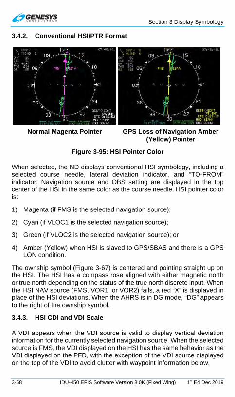
Section 3 Display Symbology
3-58 IDU-450 EFIS Software Version 8.0K (Fixed Wing) 1st Ed Dec 2019
3.4.2. Conventional HSI/PTR Format
Normal Magenta Pointer GPS Loss of Navigation Amber
(Yellow) Pointer
Figure 3-95: HSI Pointer Color
When selected, the ND displays conventional HSI symbology, including a selected course needle, lateral deviation indicator, and “TO-FROM” indicator. Navigation source and OBS setting are displayed in the top center of the HSI in the same color as the course needle. HSI pointer color is:
1) Magenta (if FMS is the selected navigation source);
2) Cyan (if VLOC1 is the selected navigation source);
3) Green (if VLOC2 is the selected navigation source); or
4) Amber (Yellow) when HSI is slaved to GPS/SBAS and there is a GPS LON condition.
The ownship symbol (Figure 3-67) is centered and pointing straight up on the HSI. The HSI has a compass rose aligned with either magnetic north or true north depending on the status of the true north discrete input. When the HSI NAV source (FMS, VOR1, or VOR2) fails, a red “X” is displayed in place of the HSI deviations. When the AHRS is in DG mode, “DG” appears to the right of the ownship symbol.
3.4.3. HSI CDI and VDI Scale
A VDI appears when the VDI source is valid to display vertical deviation information for the currently selected navigation source. When the selected source is FMS, the VDI displayed on the HSI has the same behavior as the VDI displayed on the PFD, with the exception of the VDI source displayed on the top of the VDI to avoid clutter with waypoint information below.

Section 3 Display Symbology
1st Ed Dec 2019 IDU-450 EFIS Software Version 8.0K (Fixed Wing) 3-59
1) VNV1-B: Default FMS barometric VNAV mode
2) VNV2-B: Default FMS barometric VNAV mode
3) GS1: Glideslope #1
4) GS2: Glideslope #2
Figure 3-96: CDI Scale with VDI
3.4.4. Analog Navigation Symbology
Figure 3-97: Analog Navigation Display VOR1 and VOR2
When selected, the HSI displays analog (VOR1 [cyan] and VOR2 [green]) navigation symbology with an RMI pointer format overlaid upon the HSI. When the signal is invalid, the associated pointer is not shown. When the signal is valid for VOR1 and VOR2, a bearing and distance display for the selected VOR pointers appears at the bottom of the display in the same
CDI Scale VDI Scale

Section 3 Display Symbology
3-60 IDU-450 EFIS Software Version 8.0K (Fixed Wing) 1st Ed Dec 2019
color of the respective pointer. When an ADF2 is enabled, the ADF2 double needle is as shown in Figure 3-98.
Figure 3-98: Analog Navigation Display FMS and ADF2
If a DME channel is in hold mode, the associated distance readout is displayed in amber (yellow) rather than blue or green, and “H” is above the distance readout.
Figure 3-99: HSI Bearing Distance Readout with DME in HOLD
Valid marker beacon discretes are displayed on the PFD and ND HSI with appropriate coloring markings. Only during a built-in-test, more than one marker beacon may be active. Marker beacons are disabled when NAV source is FMS.

Section 3 Display Symbology
1st Ed Dec 2019 IDU-450 EFIS Software Version 8.0K (Fixed Wing) 3-61
1) Cyan OBS CDI for VOR1 2) Green ground track pointer 3) VOR1 OBS setting 4) Valid marker beacon
Figure 3-100: PFD and MFD HSI with Marker Beacon Displayed
3.4.5. Air Data and Groundspeed
Air data and groundspeed are displayed as shown as specified in § 3.3.5.
Figure 3-101: HSI Display Air Data and Groundspeed
3.4.6. Clock/Options
Figure 3-102: HSI Clock
1
2
2
3
4

Section 3 Display Symbology
3-62 IDU-450 EFIS Software Version 8.0K (Fixed Wing) 1st Ed Dec 2019
The following are displayed in the upper right corner of the HSI:
1) Zulu Time or LCL Time: As specified in § 3.3.4.
2) Traffic: If configured as specified in Traffic Appendix.
3) Datalink: If configured as specified in Datalink Appendix.
4) Weather Radar: If configured Weather Radar Appendix.
3.4.7. Fuel Totalizer/Waypoint Distance Functions
Fuel totalizer and waypoint distance are displayed in lower right corner of the HSI as specified in § 3.3.6.
Figure 3-103: HSI Fuel Totalizer/Waypoint Distance
3.5. Navigation Log
With Fuel Enabled Without Fuel Enabled
Figure 3-104: Navigation Log
3.5.1. Clock and Groundspeed
The following are displayed in the upper left corner of the nav log:
1) Zulu Time or LCL Time: As specified in §3.3.4.
2) Groundspeed: Displayed digitally in knots.
3.5.2. Fuel Remaining and Fuel Flow Data
The following are displayed in the upper right corner of the nav log:
1) Fuel Remaining: If fuel level or fuel flow is available, current fuel remaining is displayed digitally in fuel units.

Section 3 Display Symbology
1st Ed Dec 2019 IDU-450 EFIS Software Version 8.0K (Fixed Wing) 3-63
2) Fuel Flow: If fuel flow is available, current total fuel flow is displayed digitally in fuel units.
3.5.3. Waypoint Identifier Column
The identifier for each waypoint of the active flight plan is displayed in the left-most column of the nav log. The active waypoint, indicated with an asterisk, is magenta but turns amber (yellow) in the event of a GPS LON caution. Brackets indicate suppressed waypoints. Navigation data symbols are shown with the waypoint identifier to easily distinguish the waypoint type.
When a waypoint is part of a procedure or parallel offset, the following legends are drawn on top of the navigation data symbols:
1) SAR = Waypoint is part of SAR pattern
2) HOLD = Waypoint is part of an enroute Holding pattern
3) Airway Designation = Waypoint is part of the designated Airway
4) FAF = Waypoint is a final approach fix
5) MAP = Waypoint is a missed approach point
6) MA = Waypoint is part of the missed approach segment of an instrument approach procedure
7) APP = Waypoint is part of an instrument approach procedure but not a final approach fix, missed approach point, nor part of the missed approach segment
8) VFR = Waypoint is part of a VFR approach
9) STAR = Waypoint is part of a standard terminal arrival procedure
10) DP = Waypoint is part of a departure procedure
11) PTK = Parallel Offset. In the case of a STAR or DP waypoint subject to a parallel offset, both STAR/DP and PTK are shown
3.5.4. VNAV and VNAV Offset Column
VNAV altitude and associated VNAV offset (in NM) are displayed immediately to the right of the waypoint identifier column. In the case of an approach with a final approach segment data block, VNAV offset readout associated with the missed approach point is “GPI” to designate distance to the glidepath intercept point. VNAV altitudes and offsets from the navigation database or manually entered are white; those computed automatically are gray. VNAV and VNAV offset column elements align with

Section 3 Display Symbology
3-64 IDU-450 EFIS Software Version 8.0K (Fixed Wing) 1st Ed Dec 2019
waypoint identifier column elements to indicate the VNAV information applies to the associated waypoint.
3.5.5. Path Column
LNAV path between waypoints is displayed immediately to the right of the VNAV and VNAV offset column. The following are displayed:
1) Geodetic path between waypoints is displayed with (R4), followed by the initial geodetic course for the leg.
2) Discontinuities (i.e., a leg where FMS is unable to compute a valid path) are shown with the legend -DISCONT-
3) Procedure turns are shown with a pictorial representation of a procedure turn (either left or right turns) as well as the entry and exit course for the procedure turn.
4) Holding patterns are shown with a pictorial representation of a holding pattern (either left or right turns) as well as the inbound course for the holding pattern.
5) Arcs are shown with a pictorial representation of an arc (either left or right turns) as well as the entry and exit radials for the arc.
6) An altitude termination leg is shown by the initial geodetic course for the leg followed by the altitude at which the leg terminates.
Path column elements are offset from waypoint identifier column elements to indicate the path information applies to the leg between waypoints.
3.5.6. Distance Column
Distance between waypoints is displayed immediately to the right of the path column and is calculated taking into account the associated path as well as parallel offsets. In the case of a discontinuity, distance between waypoints is the direct geodetic distance between the two waypoints. Distance column elements are offset from waypoint identifier column elements to indicate distance information applies to the leg between waypoints.
3.5.7. Estimated Time Enroute Column
ETE between waypoints is displayed immediately to the right of the distance column and is calculated taking into account the associated distance between waypoints and current groundspeed. ETE column elements are offset from waypoint identifier column elements to indicate ETE information applies to the leg between waypoints.

Section 3 Display Symbology
1st Ed Dec 2019 IDU-450 EFIS Software Version 8.0K (Fixed Wing) 3-65
3.5.8. Estimated Time of Arrival Column
ETA at the active waypoint and all subsequent waypoints are displayed immediately to the right of the ETE column. ETA at the active waypoint is calculated taking into account the associated time remaining on the active leg and current time. ETA at subsequent waypoints is calculated taking into account the cumulative ETEs and current time. ETA column elements align with waypoint identifier column elements to indicate the ETA information applies to the associated waypoint.
3.5.9. Fuel Remaining Column
Fuel remaining at the active waypoint and all subsequent waypoints is displayed immediately to the right of the ETA column. Fuel remaining at the active waypoint is calculated taking into account the associated time remaining on the active leg, current fuel flow, and current fuel quantity. Fuel remaining at subsequent waypoints is calculated taking into account the cumulative ETEs, current fuel flow, and current fuel quantity. Fuel remaining column elements are aligned with waypoint identifier column elements to indicate the fuel remaining information applies to the associated waypoint.
NOTE:
Since a suppressed waypoint is not part of the active flight plan, dashes appear in the absence of the following VNAV data associated
with a suppressed waypoint:
1) Path data
2) Distance data
3) ETE data
4) ETA data
5) Fuel remaining data

Section 4 Reversionary Modes
1st Ed Dec 2019 IDU-450 EFIS Software Version 8.0K (Fixed Wing) 4-1
Section 4 Reversionary Modes
4.1. Reversionary Modes
The equipment has eight reversionary modes as follows:
Mode 0: GPS/SBAS, ADC, and AHRS normal.
Mode 1: GPS/SBAS failed; ADC and AHRS normal.
Mode 2: ADC failed; GPS/SBAS and AHRS normal.
Mode 3: AHRS failed; GPS/SBAS and ADC normal.
Mode 4: GPS/SBAS and ADC failed; and AHRS normal.
Mode 5: GPS/SBAS and AHRS failed; and ADC normal.
Mode 6: ADC and AHRS failed; and GPS/SBAS normal.
Mode 7: GPS, ADC, and AHRS failed.
To use this section, review the following table and notes to determine what feature or function is affected by one or more of the three sensors failed conditions. Examples follow with the IDU-450 displays in various configurations with a table breaking down the affected functions.
Not all possible IDU-450 display configurations and format combinations are represented here. All eight modes of system operation are represented for description purposes.

Section 4 Reversionary Modes
4-2 IDU-450 EFIS Software Version 8.0K (Fixed Wing) 1st Ed Dec 2019
Table 4-1: PFD Functions
PFD Function Mode
0 1 2 3 4 5 6 7 Airspeed OK OK 19 OK 19 OK 19 19 Altimeter OK OK 19 OK 19 OK 19 19 Altimeter Set Display OK OK - OK - OK - - Bank Scale OK OK OK - OK - - -
CDI OK 1 + 20
OK OK 20 20 OK 20
Runway OK 1 25 - - - - - Waypoint Pointer 7 1 7 7 - - 7 - Heading Scale 7 7 7 7 7 - 7 - AGL Ind. OK 2 4 OK 11 11 4 -
Flight Path Marker OK 1 + 14
- - - - - -
G-meter OK OK OK - OK - - - Ground Track 7 1 7 7 - - 7 - Heading Indicator 7 7 7 - 7 - - - Horizon OK OK OK - OK - - - Mini-Map 7 1 7 7 - - 7 - Pitch Limit Indicator OK OK - 8 - 8 - - Pitch Scale OK OK OK - OK - - -
Highway in the Sky OK 1 + 15
- - - - - -
Terrain/Obstructions OK - 25 - - - - - Clock Functions OK OK OK OK OK OK OK OK VSI OK OK - OK - OK - - Waterline Symbol 22 22 5 13 5 13 13 13 Waypoint Symbol OK 1 - - - - - - Waypoint Brg/Dist OK 1 OK OK - - OK - Traffic OK OK OK - - - - - Traffic Thumbnail OK OK OK OK OK OK OK OK Speed Trend OK OK - - - - - - Dynamic Stall Speed OK OK - 8 - 8 - -

Section 4 Reversionary Modes
1st Ed Dec 2019 IDU-450 EFIS Software Version 8.0K (Fixed Wing) 4-3
Table 4-2: ND Functions
ND Functions Mode
0 1 2 3 4 5 6 7 Aircraft Position OK 1 OK OK - - OK -
Special Use Airspace 9 1 6 9 - - 6 + 9
-
Waypoint Pointer 9 1 9 9 - - 9 - Active Flight Plan Path 9 1 9 9 - - 9 - Glide Range 9 1 - 10 - - - - Groundspeed OK 1 OK OK - - OK - Ground Track 9 1 9 9 - - 9 - Heading Indicator 9 9 9 - 9 - - - Navigation Symbols 9 1 9 9 - - 9 - Outside Air Temp. OK OK - OK - OK - - Projected Path OK 1 OK - - - - - Traffic OK OK OK OK OK OK OK OK
Terrain/Obstructions OK - 25 OK - - 25+
9 -
Clock Functions OK OK OK OK OK OK OK OK Waypoint Brg./Dist. OK 1 OK OK - - OK - Wind 21 3 - - - - - - WX-500 Data OK OK OK OK OK OK OK OK Compass Rose 9 9 9 9 9 - 9 - Fuel Totalizer Functions 23 24 23 23 12 12 12 12 True Airspeed OK OK - OK - OK - - Density Altitude OK OK - OK - OK - - OAT/ISA Display OK OK - OK - OK - -
Table 4-3: Output Functions
Output Functions Mode
0 1 2 3 4 5 6 7 Air/Ground Output 16 16 17 16 17 16 17 17 Autopilot EFIS Valid 16 16 16 - - - - - TAWS Alarm Output 16 16 16 16 16 16 16 16 Transmit Enabled 16 16 16 16 16 16 16 16 Warning Light Output 16 16 16 16 16 16 16 16 Caution Light Output 16 16 16 16 16 16 16 16 Mstr. Caut. Light Output 16 16 16 16 16 16 16 16 MDA/DH Output 16 16 18 16 18 16 18 18 Altitude Capture Output 16 16 - 16 - 16 - - IAS Switch Output 16 16 - 16 - 16 - -

Section 4 Reversionary Modes
4-4 IDU-450 EFIS Software Version 8.0K (Fixed Wing) 1st Ed Dec 2019
Note 1: Presented using inertial dead-reckoning based on last known wind information. If unable to dead-reckon (e.g., heading is failed or true airspeed cannot be calculated), function is disabled.
Note 2: Only radar altitude presented when available.
Note 3: Last known wind is saved during GPS/SBAS failure.
Note 4: Either radar altitude or geodetic altitude less database elevation.
Note 5: Waterline symbol expanded to large attitude bars.
Note 6: Special use airspace boundaries are drawn with bold lines due to lack of aircraft altitude data.
Note 7: In heading-only failure mode or AHRS failure mode, heading scale aligned with aircraft track and heading indication is removed. In heading-only failure mode or AHRS failure mode combined with GPS failure, heading scale is replaced with a red-X.
Note 8: Based upon 1G stall speed.
Note 9: In heading-only failure mode or AHRS failure mode, compass rose aligned with aircraft track and heading indication is removed when in heading up mode. In heading-only failure mode or AHRS failure mode combined with GPS failure, compass rose is removed.
Note 10: Presenting using last-known wind information and aligned with aircraft track in heading up mode.
Note 11: Only radar altitude presented when available.
Note 12: Assuming valid fuel flow information, endurance is presented.
Note 13: Large attitude bars presented and X’d out.
Note 14: Flight path marker grayed after one minute to indicate degraded operation.
Note 15: Highway in the Sky removed after one minute.
Note 16: See IDU SCC card and limits requirements for activation requirements.
Note 17: Defaults to AIR unless Weight on Wheel/Weight on Ground discrete input is active.

Section 4 Reversionary Modes
1st Ed Dec 2019 IDU-450 EFIS Software Version 8.0K (Fixed Wing) 4-5
Note 18: Only DH function (with valid AGL altitude) in this mode.
Note 19: Red X in place of scale.
Note 20: VLOC CDI always available if optional VOR symbology enabled.
Note 21: Function removed during heading-only failure mode.
Note 23: Assuming valid fuel flow information, both range and endurance are presented.
Note 24: Assuming valid fuel flow information, both range and endurance are presented using inertial dead-reckoning based on last known wind information. If the pilot is unable to dead-reckon due to loss of heading or true airspeed cannot be calculated, endurance only information is presented.
Note 25: Inhibited in accordance with the conditions specified in TAWS automatic inhibit function (abnormal operation).
4.1.1. Oat Sensor Failure Mode
In addition, the equipment has an OAT sensor failure mode. With the OAT sensor failed, the display of wind, OAT, density altitude, and true airspeed on the ND are disabled.
4.1.2. Heading Failure Mode
In addition, the equipment has a heading failure mode. With heading failed, the PFD heading scale and MFD compass rose align with track (if available) or are removed and replaced with a red-X.
In this failure mode, the PFD heading scale includes “GPS TRK” around the track marker to clearly delineate the failure mode.
Figure 4-1: GPS TRK
4.1.3. PFD Screen Auto Reversion
For IFR approval in aircraft, flight instrument information essential to safety of flight remains available to the pilot without additional action after a failure. To accommodate this, MFDs must have the ability to sense when the PFD has failed and take over the PFD function automatically. The manner in which this occurs is as follows:
When an MFD (IDU #2) becomes the transmit-enabled IDU, the MFD automatically switches to a PFD.

Section 4 Reversionary Modes
4-6 IDU-450 EFIS Software Version 8.0K (Fixed Wing) 1st Ed Dec 2019
4.1.4. GPS Failure
GPS degrades or fails as a result of loss of satellite information or GPS equipment failure. When SBAS provides the integrity, the IDU provides a loss of integrity (LOI) caution within two seconds if the current horizontal protection level (HPL) exceeds the horizontal alert level (HAL). LOI caution appears when there is no integrity monitoring and disappears when it is restored.
Figure 4-2: Loss of Integrity (LOI)
Further GPS degradation causes the EFIS to lose GPS updating of aircraft position, groundspeed, and ground track, and the ability to calculate the wind information.
1) (Loss of Integrity) displayed with no time delay.
2) HPL > HAL for the phase of flight currently in. Position is still presented based upon a GPS navigation solution.
3) (Loss of Navigation) displayed with no time delay of the onset of the following:
a) The absence of power;
b) Equipment malfunction or failure;
c) The presence of a condition lasting five seconds or more where there are an inadequate number of satellites to compute position solution;
d) Fault detects a position failure that cannot be excluded within time-to-alert when integrity is provided by FDE;
e) HPL > HAL on the final approach segment. Genesys Aerosystems EFIS does not transition to DR navigation at this stage. A GPS navigation solution is still presented; and
f) Where HPL > HAL on the final approach segment, this position may still be satisfactory for GPS navigation. For example, an HPL of 0.31NM exists, which means as soon as a transition to terminal mode occurs, all alerts disappear. This is significantly important during a wind change if the system had been in a DR mode.

Section 4 Reversionary Modes
1st Ed Dec 2019 IDU-450 EFIS Software Version 8.0K (Fixed Wing) 4-7
NOTE:
At any time, view HFOM on the faults page to see the system-reported accuracy.
Figure 4-3: FAULTS Menu on MFD
4) DR (Dead Reckoning)
If a GPS position cannot be calculated, a dead reckoning solution is provided with a timer . This solution is calculated from heading and TAS derived from the AHRS and ADC.
5) Loss of Vertical Navigation
If the navigation equipment is no longer adequate to conduct or continue the LNAV/VNAV approach, “VLON” appears within one second of the onset of any of the following conditions:
a) The absence of power;
b) Equipment malfunction or failure;
c) The presence of a condition where fault detection detects a position failure that cannot be excluded;
d) There are an insufficient number of SBAS HEALTHY satellites;
e) The horizontal protection level exceeds the alert limit as follows for LNAV/VNAV approaches:

Section 4 Reversionary Modes
4-8 IDU-450 EFIS Software Version 8.0K (Fixed Wing) 1st Ed Dec 2019
i) Prior to sequencing, the FAWP- HAL should be 0.3 NM with no limit on VAL.
ii) After sequencing the FAWP- HAL 556m (0.3NM) and VAL 50m.
Figure 4-4: Loss of Vertical Navigation (VLON)
When in LNAV mode, the fault detection function detects positioning failures within 10 seconds after the onset of the positioning failure.
4.2. PFD and MFD Failure Mode Examples
GPS failure results in the EFIS operating in dead reckoning mode. The EFIS continues to provide navigational position, groundspeed, and ground track information, based upon the last known wind, current air data, and heading. The PFD and MFD are affected as follows.
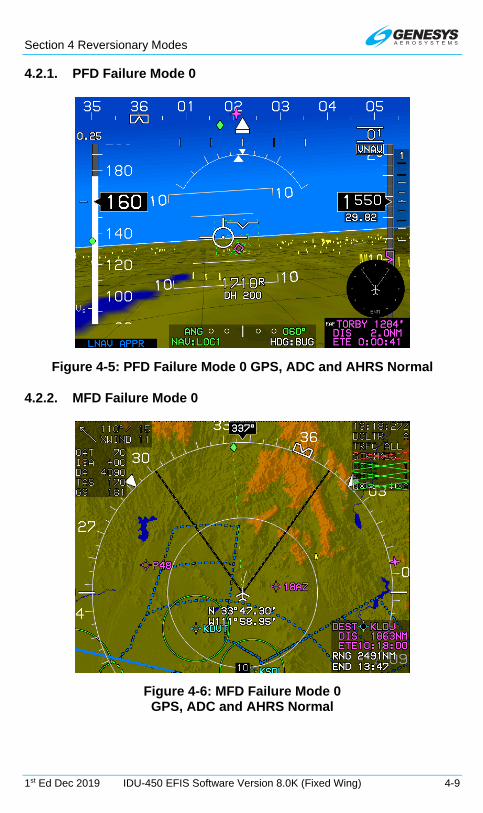
Section 4 Reversionary Modes
1st Ed Dec 2019 IDU-450 EFIS Software Version 8.0K (Fixed Wing) 4-9
4.2.1. PFD Failure Mode 0
Figure 4-5: PFD Failure Mode 0 GPS, ADC and AHRS Normal
4.2.2. MFD Failure Mode 0
Figure 4-6: MFD Failure Mode 0 GPS, ADC and AHRS Normal

Section 4 Reversionary Modes
4-10 IDU-450 EFIS Software Version 8.0K (Fixed Wing) 1st Ed Dec 2019
4.2.3. PFD Failure Mode 1
Figure 4-7: PFD Failure Mode 1 GPS/SBAS Failed, ADC and AHRS Normal
4.2.4. MFD Failure Mode 1
Figure 4-8: MFD Failure Mode 1 GPS/SBAS Failed, ADC and AHRS Normal

Section 4 Reversionary Modes
1st Ed Dec 2019 IDU-450 EFIS Software Version 8.0K (Fixed Wing) 4-11
4.2.5. PFD Failure Mode 2
Figure 4-9: PFD Mode 2 ADC Failed, GPS/SBAS and AHRS Normal
4.2.6. MFD Failure Mode 2
Figure 4-10: MFD Failure Mode 2, (Normal Mode) ADC Failed, GPS/SBAS and AHRS Normal

Section 4 Reversionary Modes
4-12 IDU-450 EFIS Software Version 8.0K (Fixed Wing) 1st Ed Dec 2019
4.2.7. PFD Failure Mode 3
Figure 4-11: PFD Failure Mode 3 AHRS Failed, GPS/SBAS and ADC Normal
4.2.8. MFD Failure Mode 3
Figure 4-12: MFD Failure Mode 3 AHRS Failed, GPS/SBAS and ADC Normal

Section 4 Reversionary Modes
1st Ed Dec 2019 IDU-450 EFIS Software Version 8.0K (Fixed Wing) 4-13
4.2.9. PFD Failure Mode 4
Figure 4-13: PFD Failure Mode 4 GPS/SBAS and ADC Failed, AHRS Normal
4.2.10. MFD Failure Mode 4
Figure 4-14: MFD Failure Mode 4 GPS/SBAS and ADC Failed, AHRS Normal

Section 4 Reversionary Modes
4-14 IDU-450 EFIS Software Version 8.0K (Fixed Wing) 1st Ed Dec 2019
4.2.11. PFD Failure Mode 5
Figure 4-15: PFD Failure Mode 5 GPS/SBAS and AHRS Failed, ADC Normal
4.2.12. MFD Failure Mode 5
Figure 4-16: MFD Failure Mode 5 GPS/SBAS and AHRS Failed, ADC Normal

Section 4 Reversionary Modes
1st Ed Dec 2019 IDU-450 EFIS Software Version 8.0K (Fixed Wing) 4-15
4.2.13. PFD Failure Mode 6
Figure 4-17: PFD Failure Mode 6 ADC and AHRS Failed, GPS/SBAS Normal
4.2.14. MFD Failure Mode 6
Figure 4-18: MFD Failure Mode 6 (Normal Mode) ADC and AHRS Failed, GPS/SBAS Normal

Section 4 Reversionary Modes
4-16 IDU-450 EFIS Software Version 8.0K (Fixed Wing) 1st Ed Dec 2019
4.2.15. PFD Failure Mode 7
Figure 4-19: PFD Failure Mode 7 GPS/SBAS, ADC and AHRS Failed
4.2.16. MFD Failure Mode 7
Figure 4-20: MFD Failure Mode 7 GPS/SBAS, ADC and AHRS Failure

Section 5 Menu Functions and Procedures
1st Ed Dec 2019 IDU-450 EFIS Software Version 8.0K (Fixed Wing) 5-1
Section 5 Menu Functions and Step-By-Step Procedures
5.1. Menu Functions
L1 R1
L2 R2
L3 R3
L4 R4
Figure 5-1: IDU-450 Input Controls
The top-level menu level corresponds to the permanent labeling of the IDU pushbuttons and is active any time no soft menu options appear on the screen. Soft menu function tiles appear next to the appropriate IDU button and the right encoder () when appropriate.
On the PFD, rotate to activate the heading menu. On MFD pages with an adjustable display (e.g., ND, Strikes, Traffic, Datalink, Weather Radar, rotate to change the display scale (CW = increase scale, CCW = decrease scale, or as set in EFIS limits).
With the exception of IDU #1, push to swap between the PFD and MFD, unless the IDU is in MFD-only mode. IDU #1 is always configured to the PFD page.
5.1.1. Menu Philosophy
The menu system and buttons with an action are clearly labeled. The following rules are in the design of the menu system.

Section 5 Menu Functions and Procedures
5-2 IDU-450 EFIS Software Version 8.0K (Fixed Wing) 1st Ed Dec 2019
EXIT (R1): Whenever menu system is beyond the top level, provides a one-touch escape to the top-level.
BACK (L1): Whenever soft menu level is deeper than the first level, regresses through the menu system by one level.
Soft menu tiles: Used (even at the top-level) and are annunciated in a dedicated, blacked-out area in the screen margins adjacent to the appropriate IDU button or encoder when appropriate.
Selection list: Menus adjacent to are frequently a selection list. Lists too long to be presented in the space available provide an indication of location within the list.
Indication of further menu levels: A filled triangle next to a menu legend means the button press leads to a further menu level. An empty triangle next to a menu legend means the button press is a final action.
Within lists or on a soft menu tile, a two-dot trailer indicates further menu levels.
Menu messages are displayed for ten seconds but are cleared if no IDU button is pressed or encoder pushed or rotated.
Figure 5-2: IDU-450 Menu Messages
5.1.2. Avoidance of Autonomous Behavior
The displays are designed to be under the control of the pilot to ensure critical functions are placed at the top level. Autonomous changes in function are avoided to the most extent possible. The following autonomous behaviors incorporated into the IDUs, all of which are required by regulation or guidance.
Automatic popup of flight instruments: For IFR approval in aircraft, flight instrument information essential to flight safety must remain available to the

Section 5 Menu Functions and Procedures
1st Ed Dec 2019 IDU-450 EFIS Software Version 8.0K (Fixed Wing) 5-3
pilot without additional crewmember action after a failure. This guidance is specific to flight instruments, navigation instruments. This requirement is met by assigning an order of precedence of the IDUs based upon the IDU number. IDU #1 always shows the essential flight instruments, because the PFI page is always shown on the PFD. Lower priority IDUs monitor the higher priority IDU via intra-system communications and automatically switch to the PFD upon determining the higher priority IDU has failed.
TAWS popups: When an FLTA alert is generated, a popup function enables PFI SVS (returns PFI to screen showing synthetic vision display) and activates terrain at an appropriate scale and format on the moving map MFD (one of the multi-function pages). This is a required function of TSO-C151 (Class A, B and C TAWS are described in Section 8 Terrain Awareness Warning System.)
Traffic popups: See Traffic Appendix.
5.2. Menu Synchronization
System settings changed by the menu system are synchronized between multiple IDUs according to Table 5-1. All parameters for fixed wing aircraft are included. Each appendix for Datalink, Strikes, RBP, Traffic, and Weather Radar contains specific limitations for menu synchronization for that feature.
Table 5-1: Menu Synchronization
Menu Parameter Notes The following menu parameters are synchronized across all displays at all times. These are bugs and fundamental aircraft values that should never have independence.
AHRS 1 and 2 mode and slewing values
Fuel Totalizer Quantity VNAV Climb Angle Countdown Timer Start Time Countdown Timer Default Value Remote Tune Frequencies

Section 5 Menu Functions and Procedures
5-4 IDU-450 EFIS Software Version 8.0K (Fixed Wing) 1st Ed Dec 2019
Table 5-1: Menu Synchronization
Menu Parameter Notes VNAV Descent Angle G-Force Limit Parameters
Decision Height Setting Used when “Dual Decision Height” option is not selected in EFIS Limits.
Emergency and Minimum Fuel Settings
Heading Bug and Heading Sub-Mode
Minimum Altitude Bug Value VLOC OBS Settings Roll Trim parameter Airspeed Bug Setting TCAS-II control parameters Target Altitude Bug Setting Timer Starting Signal True North Mode UTC Offset VSI Bug Setting Crosslink Synchronization Status The following menu parameters are synchronized across all displays when crosslink is enabled. Otherwise, they are only synchronized onside. These parameters are FMS parameters and allow the pilot and co-pilot FMSs to be operated independently when crosslink is inhibited.
Active Flight Plan Parameters Runway Display Parameters The following menu parameters are only synchronized onside. These parameters are usually sensor selections or PFD options used to keep the appearance of any pilot's PFD consistent in the case of PFD reversion. The onside characteristic means that individual pilots can still adjust their PFD settings to their preference.

Section 5 Menu Functions and Procedures
1st Ed Dec 2019 IDU-450 EFIS Software Version 8.0K (Fixed Wing) 5-5
Table 5-1: Menu Synchronization
Menu Parameter Notes
Sensor Selections Transition Altitude
Decision Height Setting Used when “Dual Decision Height” is selected in EFIS Limits.
Barometric Setting Parameters Navigation Source PFD Basic Mode PFD Zoom Mode PFD Analog AGL PFD Analog G-Force Indicator PFD Full-time Bank PFD Flight Director PFD Mini-map PFD Altitude (meters) PFD Skyway PFD Traffic Thumbnail PFD Terrain Rate of turn indication The following menu parameters are independent between displays. These are used to support non-PFD display options to give the pilot maximum MFD operating flexibility.
CPU Type To support mixed CPU type installations
MFD Map and HSI Page Pointer Settings

Section 5 Menu Functions and Procedures
5-6 IDU-450 EFIS Software Version 8.0K (Fixed Wing) 1st Ed Dec 2019
Table 5-1: Menu Synchronization
Menu Parameter Notes MFD Map NavData® Symbol Declutter Settings
MFD Map Function Declutter Settings
MFD Selected Page MFD OASIS Overlay MFD Map Page Settings MFD Show ETA IDU-450 Screen Display status
5.3. Normal Top-Level Menu
There are two types of menu functions on the IDU-450, top-level menu functions corresponding to the labeled pushbutton, and soft menu functions indicated by menu tiles, which appear on screen. Soft menu function tiles appear next to the appropriate IDU button or in the lower right corner when use of the encoder is appropriate. Soft menu functions take precedence over IDU button functions.
5.3.1. Top-Level Menu Option Descriptions
PFD Page: Push – Switch to MFD (N/A to CPU #1) Rotate – Activate Heading Bug Menu
MFD Page Push – switch to PFD Rotate (MFD Page with adjustable range) --
Change range
MENU
BARO
NRST
FPL
ACTV
INFO
OBS
D
Flight Plan Menu
Active Flight Plan Menu
Information Menu
Omnibearing Selector Menu
First Soft Menu Level
Altimeter Menu
Nearest Menu
Direct Menu
1
Figure 5-3: PFD Top-Level Menu
1) FPL (L1): Flight plan menu
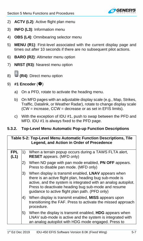
Section 5 Menu Functions and Procedures
1st Ed Dec 2019 IDU-450 EFIS Software Version 8.0K (Fixed Wing) 5-7
2) ACTV (L2): Active flight plan menu
3) INFO (L3): Information menu
4) OBS (L4): Omnibearing selector menu
5) MENU (R1): First-level associated with the current display page and times out after 10 seconds if there are no subsequent pilot actions.
6) BARO (R2): Altimeter menu option
7) NRST (R3): Nearest menu option
8) (R4): Direct menu option
9) #1 Encoder ()
a) On a PFD, rotate to activate the heading menu.
b) On MFD pages with an adjustable display scale (e.g., Map, Strikes, Traffic, Datalink, or Weather Radar), rotate to change display scale (CW = increase, CCW = decrease or as set in EFIS limits).
c) With the exception of IDU #1, push to swap between the PFD and MFD. IDU #1 is always fixed to the PFD page.
5.3.2. Top-Level Menu Automatic Pop-up Function Descriptions
Table 5-2: Top-Level Menu Automatic Function Descriptions, Tile Legend, and Action in Order of Precedence
FPL (L1)
1) When a terrain popup occurs during a TAWS FLTA alert, RESET appears. (MFD only)
2) When ND page with pan mode enabled, PN OFF appears. Press to disable pan mode. (MFD only)
3) When display is transmit enabled, LNAV appears when there is an active flight plan, heading bug sub-mode is active, and the system is integrated with an analog autopilot. Press to deactivate heading bug sub-mode and resume guidance to active flight plan path. (PFD only)
4) When display is transmit enabled, MISS appears upon transitioning the FAF. Press to activate the missed approach procedure.
5) When the display is transmit enabled, HDG appears when LNAV sub-mode is active and the system is integrated with an analog autopilot with HDG mode engaged. Press to

Section 5 Menu Functions and Procedures
5-8 IDU-450 EFIS Software Version 8.0K (Fixed Wing) 1st Ed Dec 2019
Table 5-2: Top-Level Menu Automatic Function Descriptions, Tile Legend, and Action in Order of Precedence
deactivate LNAV sub-mode and resume guidance to the heading bug. (PFD only)
ACTV (L2)
1) When showing ND Page with: (a) pan mode enabled; (b) information for the nearest highlighted waypoint is shown; and (c) airport weather information present in the information block.
2) When the display is transmit enabled, CONT appears when in a holding pattern with further active flight plan legs after the holding pattern. Press to re-enable automatic waypoint sequencing to allow normal sequencing to the leg after the holding pattern. (PFD only)
3) When the display is transmit enabled, RESUME appears when the following leg is a manual leg and the FMS is in FROM operation. Press to activate a Direct-To the waypoint after the manual leg. (PFD only)
4) When the display is transmit enabled, VNAV appears when VNAV guidance is valid, the selected altitude sub-mode is active, and the system is integrated with an analog autopilot. Press to deactivate selected altitude sub-mode and resume guidance to VNAV path. (PFD only)
5) When the display is transmit enabled, ARM appears when on the final approach segment (between FAF and MAP). Press to arm missed approach procedure to automatically activate upon sequencing MAP. (PFD only)
INFO (L3)
When ND page with pan mode enabled, NORTH appears. Press to shift the center of the page in the specified direction.
OBS (L4)
When ND page with pan mode enabled, SOUTH appears. Press to shift the center of the page in the specified direction.
BARO (R2)
When ND page with pan mode enabled, INFO or HIDE appears. Press to toggle the display of information for the nearest highlighted waypoint.
NRST (R3)
When ND page with pan mode enabled, EAST appears. Press to shift the center of the page in the specified direction.
(R4)
When ND page with pan mode enabled, WEST appears. Press to shift the center of the page in the specified direction.

Section 5 Menu Functions and Procedures
1st Ed Dec 2019 IDU-450 EFIS Software Version 8.0K (Fixed Wing) 5-9
5.4. First Page (PFD)
The IDU #1 is fixed to the PFD page, and other IDUs may show the PFD page as a backup function. The PFD page first-level options are as follows.
FPL
ACTV
INFO
OBS
D
MENU
BARO
NRST
ZOOM ON
ZOOM OFF
DCLTR..
BUGS..
EXIT
TIME..
DESIG
XFILL SYNC
Synchronizepilot and co-pilotsystems in dual-
system installationswhen cross-linkis re-enabled
PFD Bugs Menu
Narrow FOV
Time Menu
Exit to Top-Level
Wide FOV
PFD Declutter Menu
Create userwaypoint at
current location
MENU
1
SOURCE.. PFD Source Menu
EXPAND CAS..Expand CAS menu.
Only shown if message count exceeds 11
Figure 5-4: First Page PFD
5.4.1. PFD Page First-Level Option Descriptions
XFILL SYNC (FPL) (L1): Appears in dual-system installations where the pilot and co-pilot systems are not synchronized, but crosslink is enabled. Press to synchronize the pilot and co-pilot active flight plan parameters to the system where the button press occurred.
Table 5-3: Crossfill Inhibit/Arm/Sync Function
Crossfill (1) Flight Plan
Indication (Pilot and Co-pilot)
Action to Synchronize Flight
Plans Result
Pilot Co-pilot
Enabled
(Cond.1) Synchro-
nized None None None
No action required. Pilot and co-pilot sides already synchronized.
Enabled
(Cond.2)
Not Synchro-nized (2)
MENU (R1)
XFILL SYNC (L1)
None
Pilot’s flight plan is sent to co-pilot side and both sides are synchronized going forward.
is removed from both sides.
None MENU (R1)
XFILL SYNC( L1)
Co-pilot’s flight plan is sent to pilot side and both sides are synchronized going

Section 5 Menu Functions and Procedures
5-10 IDU-450 EFIS Software Version 8.0K (Fixed Wing) 1st Ed Dec 2019
Table 5-3: Crossfill Inhibit/Arm/Sync Function
Crossfill (1) Flight Plan
Indication (Pilot and Co-pilot)
Action to Synchronize Flight
Plans Result
Pilot Co-pilot forward.
is removed from both sides.
Inhibited
(Cond.3)
Not Synchro-
nized
Enable crossfill (1) (proceed to Cond. 2)
removed.
displayed on both sides.
(1) Crossfill is inhibited with the use of a latching (ON) crossfill inhibit switch. Crossfill is enabled by releasing (OFF) this switch. The location and number of crossfill inhibit switches in a cockpit varies by installation. Usually a single crossfill switch can be centrally located in a side-by-side cockpit within reach of both pilots. If a single switch cannot be installed within reach of both pilots (tandem cockpits or very wide cockpits), two switches can be installed to function in parallel (either switch inhibits or enables crossfill on both the pilot and co-pilot sides).
(2) Pilot and co-pilot flight plans can become unsynchronized under the following conditions: 1) Crossfill is inhibited, and pilot and co-pilot flight plans are separately
changed before crossfill is re-enabled. 2) Either the pilot or co-pilot side is restarted with an active flight plan on the
other side and crossfill enabled. 3) If condition exists and any changes are made to either side
flight plans.
SOURCE (L2): Activates PFD source selection menu.
DESIG (L3): Creates a user waypoint at current aircraft location. In addition, if pressed with an ND page in pan mode, creates a user waypoint at the panning location. User waypoint at current location is automatically named “OF###” where “###” is the next available over-fly user waypoint number. User waypoint at panning location is automatically named “PN###” where “###” is the next available panning user waypoint number. When DESIG (L3) is pressed but there are more than 998 user waypoints, the EFIS displays USER WPTS FULL message.
TIME (L4): Activates timer menu
BUGS (R2): Activates the PFD bug set menu
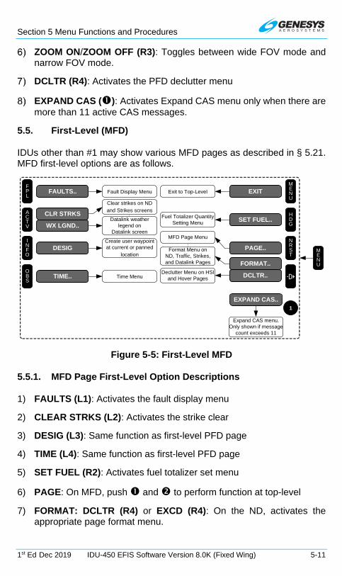
Section 5 Menu Functions and Procedures
1st Ed Dec 2019 IDU-450 EFIS Software Version 8.0K (Fixed Wing) 5-11
ZOOM ON/ZOOM OFF (R3): Toggles between wide FOV mode and narrow FOV mode.
DCLTR (R4): Activates the PFD declutter menu
EXPAND CAS (): Activates Expand CAS menu only when there are more than 11 active CAS messages.
5.5. First-Level (MFD)
IDUs other than #1 may show various MFD pages as described in § 5.21. MFD first-level options are as follows.
Create user waypoint at current or panned
location
Datalink weatherlegend on
Datalink screen
Declutter Menu on HSI and Hover Pages D
MENU
HDG
NRST
FPL
ACTV
INFO
OBS
CLR STRKS
WX LGND..
Clear strikes on ND and Strikes screens
FAULTS..
DESIG
TIME..
EXIT
SET FUEL..
PAGE..
FORMAT..
DCLTR..
Format Menu onND, Traffic, Strikes, and Datalink Pages
Fault Display Menu
Fuel Totalizer Quantity Setting Menu
MFD Page Menu
Time Menu
MENU
1
EXPAND CAS..
Expand CAS menu. Only shown if message
count exceeds 11
Exit to Top-Level
Figure 5-5: First-Level MFD
5.5.1. MFD Page First-Level Option Descriptions
1) FAULTS (L1): Activates the fault display menu
2) CLEAR STRKS (L2): Activates the strike clear
3) DESIG (L3): Same function as first-level PFD page
4) TIME (L4): Same function as first-level PFD page
5) SET FUEL (R2): Activates fuel totalizer set menu
6) PAGE: On MFD, push and to perform function at top-level
7) FORMAT: DCLTR (R4) or EXCD (R4): On the ND, activates the appropriate page format menu.

Section 5 Menu Functions and Procedures
5-12 IDU-450 EFIS Software Version 8.0K (Fixed Wing) 1st Ed Dec 2019
a) FORMAT: On the Map, Traffic, Strikes, Datalink, and Weather Radar pages, activates the appropriate page format menu option.
b) DCLTR: On HSI page with VOR or ADF symbology enabled, activates HSI declutter menu option.
8) EXPAND CAS (): Activates the expand CAS menu option only when there are more than 11 active CAS messages.
5.6. Lower-Level Menus (Below First-Level)
The buttons and encoders, which control the top-level and first-level menus, called lower-level menus, are described in the following diagrams with button and encoder numbers as defined in Figure 5-1.
5.7. Flight Plan (FPL) Menu
PFD Page shown?
No
Storedflight plans
exist?
Yes
No
Storedflight plans
exist? Yes
SELECT..
CREATE-EDIT..
NO SAVED FPLS
Flight Plan List.........
YesActivate
flight planand second
waypoint
Planning functionfor creating and
editing flight plans and user waypoints
No
CREATE-EDIT..
FPL
1
1
1
Figure 5-6: Flight Plan Menu
5.7.1. Flight Planner Page
Upon activation of the flight plan menu, the system checks for saved flight plans. If there are no saved flight plans, CREATE-EDIT.. encoder message
Section 5 Menu Functions and Procedures
1st Ed Dec 2019 IDU-450 EFIS Software Version 8.0K (Fixed Wing) 5-13
is issued (MFD only). Otherwise, a list of saved flight plans is presented. Upon selection of a saved flight plan, the second waypoint in the flight plan is activated.
Because the flight planner takes over the IDU’s controls, limitations are placed upon access and display of the flight planner. The flight planner is not available when a PFD page is being displayed on the IDU. (MFD in reversion mode).
When the flight planner is accessed, it only appears on the MFD to preserve access to crucial PFD page controls such as altimeter settings.
Flight Plan Limits: Flight plans are stored routes (100 maximum) for repeated use without having to re-enter the waypoints each time. A flight plan consists of at least two waypoints (a start and an end) and may have up to 40 waypoints. Flights requiring more than 40 waypoints are divided into two or more flight plans.
5.7.2. Flight Planner Page
Perform following types of functions through the flight planner page.
1) Manage stored flight plans (activating, creating, editing, deleting, and reversing);
2) Manage user waypoints (creating, editing, and deleting); and
3) Perform RAIM predictions.
These operations demand pilot attention and are not a normal operating condition for the IDU. When the flight planner page is in use, it takes over the IDUs controls and disables the menu operations described (other than automatic EICAS page reversions). Normal menu operation and IDU control function are restored upon:
Exiting the flight planner page; or
Automatic reversion of the IDU to PFD automatic reversion exits the flight planner page and wipes out any changes being performed.
Because the flight planner page takes over the IDUs controls, limitations are placed upon access and display of the flight planner page. When the flight planner page is accessed, it only appears on the MFD.
5.7.3. PFD Page Shown
Upon activation of the flight plan menu, the system checks for existing saved flight plans. If there are no saved flight plans, NO SAVED FPLS appears. Otherwise, a selection list of saved flight plans is presented. Upon

Section 5 Menu Functions and Procedures
5-14 IDU-450 EFIS Software Version 8.0K (Fixed Wing) 1st Ed Dec 2019
selection of a saved flight plan, the second waypoint in the flight plan is activated.
5.7.4. MFD Page Shown on IDU
Upon activation of the flight plan menu, the system checks for existing saved flight plans. If there are no saved flight plans, the flight planner is activated. Otherwise, an option list is presented for the pilot to either select a saved flight plan or enter the flight planner. Selecting the saved flight plan option leads to a list of saved flight plans. Upon selection of a saved flight plan, the second waypoint in the flight plan is activated.
5.7.5. To Create an Overfly User Waypoint (Step-By-Step)
1) When flying over intended waypoint, press MENU (R1) then DESIG (L3) on the PFD or MFD. (PFD shown)
2) A user waypoint is created at the present position and automatically named “OF###,” where ### is the next available sequence overfly user waypoint number. (MFD shown)
NOTE:
A maximum of 998 user waypoints may be created and stored.
If a discrete input has been enabled as “Remote User Waypoint Designate,” it may be used to easily create a user waypoint.
5.7.6. Flight Plan (FPL) Menu Selecting (PFD or MFD) (Step-By-Step)
1) Press FPL (L1). (PFD shown)
2) Rotate to desired flight plan and push to enter.

Section 5 Menu Functions and Procedures
1st Ed Dec 2019 IDU-450 EFIS Software Version 8.0K (Fixed Wing) 5-15
5.7.7. Flight Plan (FPL) Menu Create-Edit (MFD only) (Step-By-Step)
1) Press FPL (L1).
2) Rotate to CREATE-EDIT.. and push to enter.
3) Rotate to CREATE FLIGHT PLAN and push to enter.
4) Press ADD (R2) to begin creating first waypoint.
5) Press NRST APT (L2), NRST VOR (L3), NRST NDB (L4), NRST FIX (R2), NRST USR (R3), or AIRWAY (R4) to view applicable list, rotate to desired selection. Push to insert into flight plan as first waypoint.
6) Each flight plan is required to have a minimum of two waypoints. Press ADD (R2) and continue process as stated above to build flight plan.
7) When all desired waypoints have been added (no more than 40), press SAVE (R4) to save flight plan and store as one of the 100 possible stored flight plans.
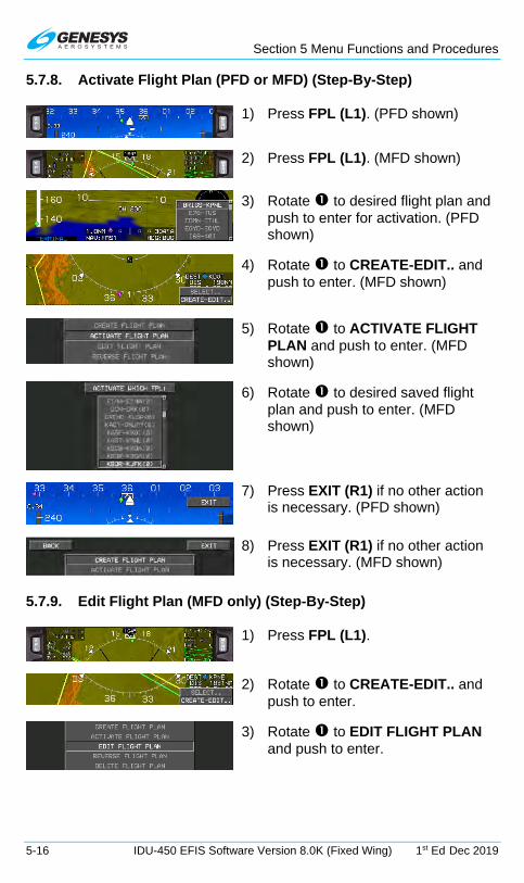
Section 5 Menu Functions and Procedures
5-16 IDU-450 EFIS Software Version 8.0K (Fixed Wing) 1st Ed Dec 2019
5.7.8. Activate Flight Plan (PFD or MFD) (Step-By-Step)
1) Press FPL (L1). (PFD shown)
2) Press FPL (L1). (MFD shown)
3) Rotate to desired flight plan and push to enter for activation. (PFD shown)
4) Rotate to CREATE-EDIT.. and push to enter. (MFD shown)
5) Rotate to ACTIVATE FLIGHT PLAN and push to enter. (MFD shown)
6) Rotate to desired saved flight plan and push to enter. (MFD shown)
7) Press EXIT (R1) if no other action is necessary. (PFD shown)
8) Press EXIT (R1) if no other action is necessary. (MFD shown)
5.7.9. Edit Flight Plan (MFD only) (Step-By-Step)
1) Press FPL (L1).
2) Rotate to CREATE-EDIT.. and push to enter.
3) Rotate to EDIT FLIGHT PLAN and push to enter.
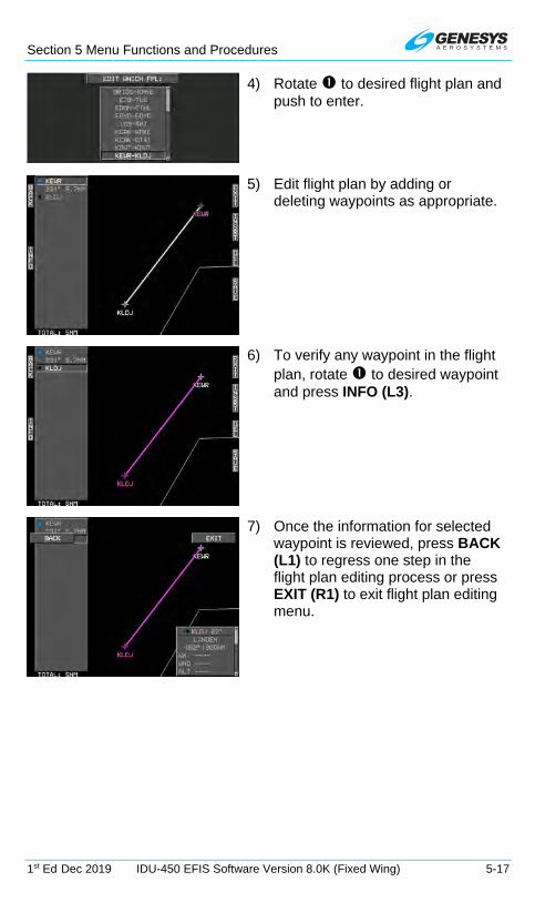
Section 5 Menu Functions and Procedures
1st Ed Dec 2019 IDU-450 EFIS Software Version 8.0K (Fixed Wing) 5-17
4) Rotate to desired flight plan and push to enter.
5) Edit flight plan by adding or deleting waypoints as appropriate.
6) To verify any waypoint in the flight plan, rotate to desired waypoint and press INFO (L3).
7) Once the information for selected waypoint is reviewed, press BACK (L1) to regress one step in the flight plan editing process or press EXIT (R1) to exit flight plan editing menu.

Section 5 Menu Functions and Procedures
5-18 IDU-450 EFIS Software Version 8.0K (Fixed Wing) 1st Ed Dec 2019
8) If changes were made to flight plan as in this case where KMMU was inserted above KLDJ, press SAVE (R4) to save changes and return to EDIT WHICH FPL: menu.
9) If there are no other flight plans to edit press EXIT (R1), to exit EDIT FLIGHT PLAN menu.
5.7.10. Reverse Flight Plan (MFD only) (Step-By-Step)
1) Press FPL (L1).
2) Rotate to CREATE-EDIT.. and push to enter.
3) Rotate to REVERSE FLIGHT PLAN and push to enter.
4) Rotate to desired flight plan and push to enter. This action reverses the selected flight plan and alphabetizes the flight plan list in the new order.
5) If no other flight plan to reverse, press EXIT (R1).
5.7.11. Delete Flight Plan (MFD only) (Step-By-Step)
1) Press FPL (L1).
2) Rotate to CREATE-EDIT.. and push to enter.

Section 5 Menu Functions and Procedures
1st Ed Dec 2019 IDU-450 EFIS Software Version 8.0K (Fixed Wing) 5-19
3) Rotate to DELETE FLIGHT PLAN and push to enter.
4) Rotate to flight plan to delete. Push to enter.
5) Push to CONFIRM DELETE FPL.
6) The next flight plan is highlighted.
7) If no further deletions, press EXIT (R1).
5.7.12. Create User Waypoint (MFD only) (LAT-LON) (Step-By-Step)
User waypoints may be created with three methods:
1) Latitude and Longitude
2) Radial and Distance
3) Overfly (Designate)
To create a user waypoint using latitude and longitude, use the following step-by-step procedure.
1) Press FPL (L1).
2) Rotate to CREATE-EDIT.. and push to enter.
3) Rotate to CREATE USER WPT (LAT-LON) and push to enter.
4) To name a new user waypoint, rotate and push to enter all five character spaces.

Section 5 Menu Functions and Procedures
5-20 IDU-450 EFIS Software Version 8.0K (Fixed Wing) 1st Ed Dec 2019
5) With new user waypoint name created, push to proceed through all fields as necessary.
Approach bearing preloading depends on mode of flight as follows:
On Ground: Preloaded with current heading
In Flight: Preloaded with “OFF” value.
If desired, specify the approach bearing to user waypoint in degrees 1°- 360°. “OFF” disables VFR approaches to the user waypoint.
6) Once all fields are entered, press SAVE (R3) to save user waypoint and return to editing screen or
press (R4) to activate/save ROTOR as the active waypoint and begin navigation guidance.
5.7.13. Create User Waypoint (RAD-DST) (MFD only) (Step-By-Step)
1) Press FPL (L1).
2) Rotate to CREATE-EDIT.. and push to enter.
3) Rotate to CREATE USER WPT (RAD-DST). Push to enter.

Section 5 Menu Functions and Procedures
1st Ed Dec 2019 IDU-450 EFIS Software Version 8.0K (Fixed Wing) 5-21
4) Identifier is automatically named RD### where ### is the next available radial distance waypoint number.
5) Rotate to enter identifier for reference waypoint. If a single search result, menu advances to radial entry box. If multiple search results appear, a list appears. INFO (R3) appears to verify each waypoint information.
6) If OF004 is desired, push to enter as the waypoint to be used.
7) Rotate to enter the radial entry and distance as the 060° at 14.7 NM from OF004.
8) Press SAVE (R3) to save new
waypoint or press (R4) to activate/save RD004 as the active waypoint and begin navigation guidance.
5.7.14. Edit User Waypoint (MFD only) (Step-By-Step)
1) Press FPL (L1).
2) Rotate to CREATE-EDIT.. and push to enter.

Section 5 Menu Functions and Procedures
5-22 IDU-450 EFIS Software Version 8.0K (Fixed Wing) 1st Ed Dec 2019
3) Rotate to EDIT USER WPT and push to enter.
4) Rotate to waypoint to be edited. Push to enter.
5) Use to enter alphanumeric characters; follow prompts to edit information. Push to step through all character spaces. To back up, press BACK (L1) and continue to the end of all character spaces.
6) OF004 was renamed RUFUS and APP BRG was set to 015°. Press SAVE (R3) to save new waypoint
name or press (R4) to activate/save RUFUS as active waypoint and begin navigational guidance.
7) Press BACK (L1) to regress inside procedure for making changes or press EXIT (R1) to exit EDIT USER WPT menu.
5.7.15. Delete User Waypoint (MFD only) (Step-By-Step)
1) Press FPL (L1).
2) Rotate to CREATE-EDIT.. and push to enter.
3) Rotate to DELETE USER WPT and push to enter.
4) Rotate to desired waypoint to be deleted and push to enter.

Section 5 Menu Functions and Procedures
1st Ed Dec 2019 IDU-450 EFIS Software Version 8.0K (Fixed Wing) 5-23
5) Push to confirm DEL USER WPT.
6) If no more waypoints to delete, press EXIT (R1).
When changes are made to a user waypoint, and those changes are desired in existing flight plans, which use the waypoint, it must be deleted and replaced in the flight plans with the following steps:
Edit the user waypoint as described above
Open a flight plan which uses the user waypoint
Delete the existing waypoint from the flight plan
Save and exit
Reload the flight plan if it was in use.
NOTE:
Alterations of user waypoint parameters while in flight are not automatically updated to an active flight plan.
5.7.16. RAIM Prediction (MFD only) (Step-By-Step)
When selected, the RAIM prediction screen is only shown if the GPS/SBAS receiver is capable of performing a RAIM prediction (not suitable for enroute predictions). This requires there be no faults along with a current almanac in memory. Check the FAULTS menu to determine if the GPS/SBAS receiver is capable of performing a RAIM prediction.
1) Press FPL (L1).
2) Rotate to CREATE-EDIT.. and push to enter.
3) Rotate to RAIM PREDICTION and push to enter.

Section 5 Menu Functions and Procedures
5-24 IDU-450 EFIS Software Version 8.0K (Fixed Wing) 1st Ed Dec 2019
SEE NOTE BELOW.
4) If another RAIM prediction is necessary, press START OVER (R2) or press EXIT (R1).

Section 5 Menu Functions and Procedures
1st Ed Dec 2019 IDU-450 EFIS Software Version 8.0K (Fixed Wing) 5-25
NOTE:
The pilot may perform RAIM prediction at a designated waypoint. The screen has various data entry boxes as follows:
1) Designated Waypoint: Prompted to enter an identifier for the designated waypoint. If there is a single result, advanced to UTC time entry box. If there is no result, re-prompted to enter an identifier. If there are multiple results, a selection list with matching identifiers is presented and, upon selection, is advanced to UTC time entry box. INFO (R2) aids in selection and gives access to information for the highlighted results.
2) UTC Time Entry: Allows entry of the 24-Hour UTC estimated time of arrival at the designated waypoint.
3) UTC Date Entry: Allows entry of the UTC estimated date of arrival at the designated waypoint.
4) PRN Mask Entry: Allows specification the PRN number of satellites expected to be unavailable at the destination.
5) EXIT: Exit of the RAIM prediction screen at any time.
6) Once a designated waypoint and UTC estimated time of arrival are entered, CALC (R2) appears to initiate the RAIM Prediction. Press CALC (R2) to check the UTC estimated time of arrival and ensure it is within the current almanac (i.e., <3.5 days from current date and time). If it is, a Predictive FDE Request message requesting “Detection Availability” with a required HAL of 0.3NM is sent to the GPS/SBAS receiver. In response, the GPS/SBAS receiver replies with a sequence of Predictive FDE Response messages. These messages are parsed and used to fill in the RAIM Prediction result area at the bottom of the screen. The RAIM Prediction result area shows the RAIM Prediction results as “OK” or “XX” for ETA ± in 5-minute increments. Once a prediction is complete, press START OVER (R2) to perform another prediction without exiting the RAIM Prediction screen.

Section 5 Menu Functions and Procedures
5-26 IDU-450 EFIS Software Version 8.0K (Fixed Wing) 1st Ed Dec 2019
5.8. Active Flight Plan (ACTV) Menu
See Section 7 IFR Procedures for active flight plan description.
Figure 5-7: Active Flight Plan Main Menu
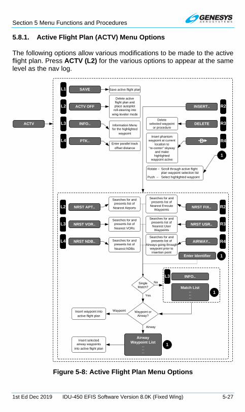
Section 5 Menu Functions and Procedures
1st Ed Dec 2019 IDU-450 EFIS Software Version 8.0K (Fixed Wing) 5-27
5.8.1. Active Flight Plan (ACTV) Menu Options
The following options allow various modifications to be made to the active flight plan. Press ACTV (L2) for the various options to appear at the same level as the nav log.
L2
L3
L4 R4
R2
R3DELETE
D
INSERT..
PTK..
INFO..Delete
selected waypointor procedure
Enter parallel track offset distance
Insert phantomwaypoint at current
location to“re-center” skyway
and makehighlighted
waypoint active
Information Menufor the highlighted
waypoint
1
ACTV OFF
Delete activeflight plan andplace autopilot
roll-steering intowing-leveler mode
Rotate – Scroll through active flightplan waypoint selection list
Push – Select highlighted waypoint
1Enter Identifier
SingleMatch?
L3 INFO..
Match List.........
1
No
Waypoint orAirway?
Yes
Insert waypoint into active flight plan
Airway
AirwayWaypoint List
...
...
...
1
Waypoint
Insert selectedairway waypoints
into active flight plan
ACTV
L1 SAVE Save active flight plan
L2
L3
L4 R4
R2
R3NRST USR..
AIRWAY..
NRST FIX..
NRST NDB..
NRST VOR..
Searches for and presents list of Nearest User
Waypoints
Searches for and presents list of Nearest NDBs
Searches for and presents list of
Airways going through waypoint prior to
insertion point
Searches for and presents list of Nearest VORs
NRST APT..
Searches for and presents list of
Nearest Airports
Searches for and presents list of
Nearest Enroute Waypoints
Figure 5-8: Active Flight Plan Menu Options

Section 5 Menu Functions and Procedures
5-28 IDU-450 EFIS Software Version 8.0K (Fixed Wing) 1st Ed Dec 2019
Table 5-4: Active Flight Plan Menu Options
Menu Options Action for Active Flight Plan
Search Limits Limitations
SAVE (L1) Saves and is part of 100 stored flight plans
N/A
Saves without procedures or phantom waypoints. Named by first and last waypoints.
ACTV OFF (L2) Deletes Prompted to confirm deletion.
INFO.. (L3)
Activates information menu for the highlighted waypoint.
With no active flight plan, activates information for nearest airport.
PTK.. (L4)
If active leg is eligible for offset, allows pilot to specify parallel offset distance for non-procedure segments.
20NM left or right in 1NM increments.
INSERT../ADD.. (R2)
Insert or add a waypoint or airway.
ADD: At the end of active flight plan.
INSERT: Above the highlighted waypoint.
SEARCH: Requires minimum of 2 characters.
INFO: After adding waypoint, appears to aid in selection.
AIRWAY: Search for all airways going through highlighted waypoint. Offers option to select exit waypoint.

Section 5 Menu Functions and Procedures
1st Ed Dec 2019 IDU-450 EFIS Software Version 8.0K (Fixed Wing) 5-29
Table 5-4: Active Flight Plan Menu Options
Menu Options Action for Active Flight Plan
Search Limits Limitations
NRST APT.. (L2)
Search for airports of runway length criteria set in EFIS limits.
Search for 20 items within 240 NM nearest to the waypoint prior to the insertion point.
NO RESULTS: No eligible airports within search area or selection list includes bearing, distance to each result.
INFO: After adding waypoint, appears to aid in selection.
NRST FIX.. (R2) Search for fixes
NO RESULTS: No fixes within search area or selection list includes identifier, bearing and distance to each result.
INFO: Provides information and aids in selection.
NRST NDB.. (L4)
Search for NDBs
NO RESULTS: No NDBs within search area or selection list including identifier, bearing, and distance to each result.
INFO: Provides information and aids in selection.
NRST USR.. (R3)
Search for nearest user waypoints
NO RESULTS: No user waypoints within search area or selection list including identifier, bearing, and distance to each result.

Section 5 Menu Functions and Procedures
5-30 IDU-450 EFIS Software Version 8.0K (Fixed Wing) 1st Ed Dec 2019
Table 5-4: Active Flight Plan Menu Options
Menu Options Action for Active Flight Plan
Search Limits Limitations
INFO: Provides information and aids in selection.
NRST VOR.. (L3)
Search for nearest VORs
NO RESULTS: No VORs within search area or selection list including identifier, bearing, and distance to each result. (Geodetic results only)
INFO: Provides information and aids in selection.
Identifier Entry Box
Area to enter identifier where encoder message would normally appear.
N/A
Entry of at least 2 characters and then SEARCH (R4) appears for immediate search to begin. Selection list may appear for addition to add to flight plan.
INFO: Provides information and aids in selection.
DELETE (R3)
If highlighted waypoint is a non-procedure waypoint, deletes the waypoint after confirmation.
If highlighted waypoint is part of a procedure, deletes entire procedure after confirmation. Does not appear if highlighted waypoint is a non-procedure and there are fewer than three non-procedure

Section 5 Menu Functions and Procedures
1st Ed Dec 2019 IDU-450 EFIS Software Version 8.0K (Fixed Wing) 5-31
Table 5-4: Active Flight Plan Menu Options
Menu Options Action for Active Flight Plan
Search Limits Limitations
waypoints in active flight plan.
Does not appear if highlighted waypoint is suppressed or one position beyond the end.
DIRECT (R4)
Inserts phantom waypoint at the current aircraft position and makes the highlighted waypoint active.
Phantom waypoint is a fly-over defined entry waypoint, and leg prior to the phantom waypoint is designated a discontinuity. Assures the skyway is re-centered for guidance. Does not appear when the highlighted waypoint is suppressed or one position beyond the end.
5.8.2. Active Flight Plan (ACTV) Menu Options (PFD or MFD) (Step-By-Step)
1) Press ACTV (L2) to view active flight plan.

Section 5 Menu Functions and Procedures
5-32 IDU-450 EFIS Software Version 8.0K (Fixed Wing) 1st Ed Dec 2019
2) Rotate to desired waypoint. Push to enter.
3) Rotate to desired option (for example OFLY/AUTO..) and push to enter.
4) Rotate to OVERFLY and push to enter.
5) KJRB is now overflown as a “Fly-Over” waypoint.
5.8.3. Active Flight Plan (ACTV) Menu (PFD or MFD) (Step-By-Step)
1) With desired flight plan selected and activated, press ACTV (L2) to view active flight plan.
2) Rotate to desired waypoint and push to enter.
3) As one option, rotate to VNAV.. and push to enter a VNAV setting.
4) Rotate to ALTITUDE: and push to enter. Rotate to select 3000’ and push to enter. Rotate to OFFSET: and push to enter. Rotate CCW to -1NM and push to enter.
5) View active flight plan with waypoint crossing altitude offset of 1 NM before at 3000’.

Section 5 Menu Functions and Procedures
1st Ed Dec 2019 IDU-450 EFIS Software Version 8.0K (Fixed Wing) 5-33
5.8.4. Active Flight Plan (ACTV) Options NRST Menu Option (PFD or MFD) (Step-By-Step)
1) With active flight plan displayed, press INSERT (R2) below where new waypoint is to be inserted.
2) Press NRST APT.. (L2), NRST VOR.. (L3), NRST NDB.. (L4), NRST FIX.. (R2), or NRST USR.. (R3), to view applicable list. Rotate to desired selection and push to insert into active flight plan.
3) Press SAVE (L1) to save this active flight plan as one of the 100 saved flight plans on all IDUs.
5.9. Information (INFO) Menu
If INFO is activated from within the ACTV, NRST, or Direct menus, information on the highlighted waypoint is shown. Otherwise, the function checks for an active waypoint. If there is an active waypoint, it becomes the default entry. If there is no active waypoint, then the nearest airport becomes the default entry. If the default entry is accepted, then information for the default entry is shown. If the user rejects the default entry by entering identifier characters, then a search for matching characters is performed.

Section 5 Menu Functions and Procedures
5-34 IDU-450 EFIS Software Version 8.0K (Fixed Wing) 1st Ed Dec 2019
Only two identifier characters are needed prior to searching, therefore after entering two identifier characters, SEARCH (R4) appears which allows an immediate search to begin if desired. If there is a single result from the search, information for that result is shown. If there is no result from the search, the user is re-prompted to enter an identifier. If there are multiple results from the search, a selection list with matching identifiers is presented to allow the user to select the desired identifier.
1
SingleMatch?
Match List.........
1No
L3 INFO..
1Scroll through active flight plan
waypoint selection list
L3 INFO..
1
Nearest List.........
1
R2INSERT..
1Enter Identifier
NotSingleMatch
1Scroll through match list
L3 INFO..
1Enter Identifier
NotSingleMatch
1Scroll through match list
R2
R3
Enter Identifier
TO COM * (a)
TO NAV * (a)
Display Selection
Information.........
1
TO COM1 * (b)
TO NAV1 * (b)
Remote tune NAV or COMradio with highlighted frequency:
(a) Garmin SL-30/40
(b) ARM/HoneywellKX155A/165A orWulfsberg Flightline
* Shown if applicable
TO COM2 * (b)
TO NAV2 * (b)
L2
L3
WX LGND.. *
EXPND WX.. *
L4 CRS SYNC *
Display graphicalMETAR legend
for airport
Display textualMETAR and TAF
data for airport
SynchronizeVLOC1 and VLOC2
OBS to localizer course
Yes
Selection List.........
INFO
ACTV
NRST
Direct-To
R2
Figure 5-9: Information Menu
The amount and type of information presented depends upon the type of waypoint as in Table 5-5.
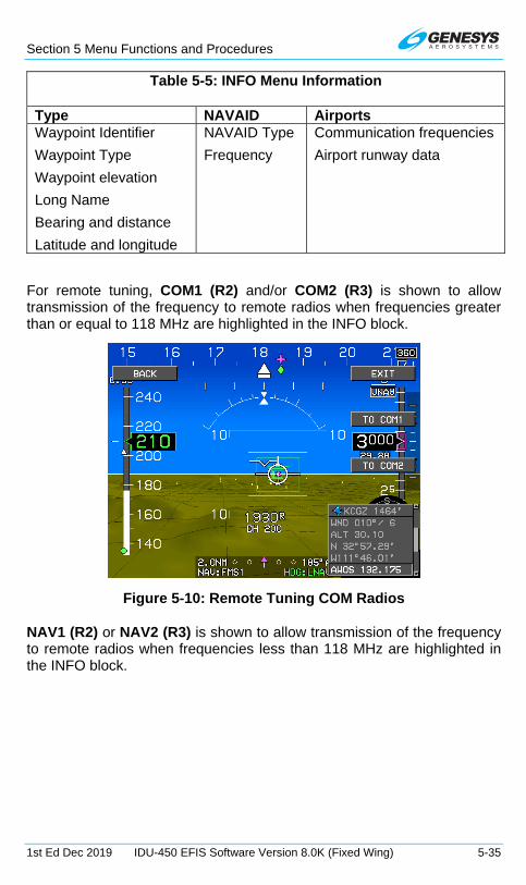
Section 5 Menu Functions and Procedures
1st Ed Dec 2019 IDU-450 EFIS Software Version 8.0K (Fixed Wing) 5-35
Table 5-5: INFO Menu Information
Type NAVAID Airports Waypoint Identifier
Waypoint Type
Waypoint elevation
Long Name
Bearing and distance
Latitude and longitude
NAVAID Type
Frequency
Communication frequencies
Airport runway data
For remote tuning, COM1 (R2) and/or COM2 (R3) is shown to allow transmission of the frequency to remote radios when frequencies greater than or equal to 118 MHz are highlighted in the INFO block.
Figure 5-10: Remote Tuning COM Radios
NAV1 (R2) or NAV2 (R3) is shown to allow transmission of the frequency to remote radios when frequencies less than 118 MHz are highlighted in the INFO block.

Section 5 Menu Functions and Procedures
5-36 IDU-450 EFIS Software Version 8.0K (Fixed Wing) 1st Ed Dec 2019
Figure 5-11: Remote Tuning NAV Radios
When information presented is for an ILS or localizer waypoint and the VLOC1 or VLOC2 omnibearing selectors are not synchronized with the localizer course, CRS SYNC (L4) synchronizes VLOC1 and VLOC2 omnibearing selectors to the localizer course.
Figure 5-12: CRS SYNC
5.9.1. Information (INFO) Menu (Step-By-Step)
1) Rotate to desired waypoint and press INFO.. (L3) to view active waypoint information.
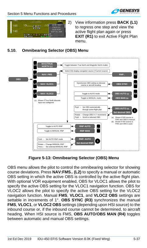
Section 5 Menu Functions and Procedures
1st Ed Dec 2019 IDU-450 EFIS Software Version 8.0K (Fixed Wing) 5-37
2) View information press BACK (L1) to regress one step and view the active flight plan again or press EXIT (R1) to exit Active Flight Plan menu.
5.10. Omnibearing Selector (OBS) Menu
R3
Set desired OBS1
OBS SYNC
OBS:AUTO (a)
L2
L3
NAV: FMS
NAV: VLOC1
L4 NAV: VLOC2
Select HSI display navigation source (*Current source)
Rotate – Change OBS in 1° incrementsPush – Scroll to selected OBS
Push – Set OBS automaticallythrough active flight plan
R4OBS AUTO (a)
Synchronize OBS setting to inbound course or aircraft heading
Toggle to AUTO mode
(a) Shown if HSI source isFMS and OBS is manual
(b) Shown if HSI source is FMS and OBS is auto
OBS MAN (b)Toggle to MANUAL mode
R2RNP..
Set desired RNP1
RNP: AUTO
R4RNP AUTO
RNP MAN
Toggle to AUTO RNP
Toggle to MANUAL RNP
Rotate – Change MANUAL RNPPress – Set selected MANUAL RNP
Push – Set AUTO RNP mode
OBS
L1 MAG/TRUE NORTH (c)
Toggle between True North and Magnetic North modes
(c) Shown if True North discrete input not configured
Figure 5-13: Omnibearing Selector (OBS) Menu
OBS menu allows the pilot to control the omnibearing selector for showing course deviations. Press NAV:FMS.. (L2) to specify a manual or automatic OBS setting in which the active OBS is controlled by the active flight plan. With optional VOR equipment enabled, OBS for VLOC1 allows the pilot to specify the active OBS setting for the VLOC1 navigation function. OBS for VLOC2 allows the pilot to specify the active OBS setting for the VLOC2 navigation function. Manual FMS, VLOC1, and VLOC2 OBS settings are settable in increments of 1°. OBS SYNC (R3) synchronizes the manual FMS, VLOC1, or VLOC2 OBS settings (depending upon HSI source) to the inbound course or, if the inbound course cannot be determined, to aircraft heading. When HSI source is FMS, OBS AUTO/OBS MAN (R4) toggles between automatic and manual OBS settings.

Section 5 Menu Functions and Procedures
5-38 IDU-450 EFIS Software Version 8.0K (Fixed Wing) 1st Ed Dec 2019
NOTE:
If true north mode discrete input is not configured, the OBS menu allows the pilot to toggle between TRUE NORTH and MAG NORTH modes.
Table 5-6: Omnibearing Selector (OBS) Menu Options
OBS (L4) *Nav Source in use
OBS SYNC (R3) OBS MANUAL (R4) Nav Source and CDI Indication
NAV:FMS (L2)
Only available with active waypoint. Synchronizes FMS to inbound course.
Only available with active waypoint. Set in increments of 1° with .
GPS navigation source
or
NAV:
VLOC1 (L3)
Synchronizes VLOC1 or VOR1 to the inbound course or if the inbound course cannot be determined, to aircraft heading. Set in increments of
1° with .
NAV: VLOC2 (L4)
Synchronizes VLOC2 or VOR2 to the inbound course or if the inbound course cannot be determined, to aircraft heading.
RNP (R2)
RNP MANUAL (R4)
When selected, allows for RNP(R4)
or
Rotate to set desired manual RNP value.
Manual RNP is selectable between 0.15NM and 15NM.
0.01 increments RNP 0.10-0.3
0.1NM increments RNP0.3-2.0
1NM increments RNP 2.0-15

Section 5 Menu Functions and Procedures
1st Ed Dec 2019 IDU-450 EFIS Software Version 8.0K (Fixed Wing) 5-39
Table 5-6: Omnibearing Selector (OBS) Menu Options
OBS (L4) *Nav Source in use
OBS SYNC (R3) OBS MANUAL (R4) Nav Source and CDI Indication
TRUE NORTH (L1)
OBS Menu allows the pilot to toggle between
(L1) and (L1)
The OBS function also permits the pilot to select either FMS, VLOC1, or VLOC2 as the HSI source. The HSI source selects the navigation source used to generate HSI guidance symbology. The OBS function also permits the pilot to select between manual and automatic RNP settings.
5.10.1. Omnibearing Selector (OBS) Menu (Step-By-Step)
1) Before pressing OBS (L4) to make any OBS changes, view the current setting to see FMS1 is selected.
2) Press OBS (L4) then make HSI source selection or change to OBS MANUAL (R4). (There must be an active waypoint selected to use manual OBS.)
3) When the OBS is set to FMS, press OBS MANUAL (R4) and rotate to select new OBS course and push to enter.
4) To select manual RNP press OBS (L4) then RNP (R2).

Section 5 Menu Functions and Procedures
5-40 IDU-450 EFIS Software Version 8.0K (Fixed Wing) 1st Ed Dec 2019
5) Press RNP MANUAL (R4).
6) Rotate to desired RNP FSD setting and push to enter to view estimate of position uncertainty required in RNP airspace.
5.11. Heading Bug (HDG) Menu
Rotate to activate the heading bug menu to set the heading bug in increments of 1°, and to synchronize to current heading.
(a) Not available if integrated autopilot installed
R3
Set heading bug
SYNC
Rotate – Change heading bugin 1° increments
Push – Set selected heading
R4OFF (a)
Synchronize heading bugto current aircraft heading
Turn heading bug off
1
Figure 5-14: Heading Bug (HDG) Menu
5.11.1. Heading Bug (HDG) Menu (PFD only) (Step-By-Step)
1) Rotate to change heading bug in 1° increments.
2) Press SYNC (R3) to synchronize heading to current heading.
3) When heading bug is a heading far from current heading, it is often easier to press SYNC (R3) and then make small adjustments by rotating to desired heading and pushing to enter or press EXIT (R1) to exit menu and save HDG bug setting.

Section 5 Menu Functions and Procedures
1st Ed Dec 2019 IDU-450 EFIS Software Version 8.0K (Fixed Wing) 5-41
5.12. Nearest (NRST) Menu
1
APT..
VOR..
ILS..
NDB..
FIX..
USER.. *
ARTCC..
FSS..
WX.. *
EmptyList?
No
Yes
NO RESULTS
R2
R3
TO COM * (a)
TO NAV * (a)
Nearest List.........
1
TO COM1 * (b)
TO NAV1 * (b)
Remote tune NAV or COMradio with highlighted frequency:
(a) Garmin SL-30/40
(b) ARM/HoneywellKX155A/165A orWulfsberg Flightline
* Shown if Applicable
TO COM2 * (b)
TO NAV2 * (b)
L3 INFO
L4 CRS SYNC *
Information Menu
SynchronizeVLOC1 and VLOC2
OBS to localizer course
Create and activate new flight plan from present position to
selected waypoint
ILSor
APT, VOR, NDB,FIX, USER?
APT, VOR, NDB,FIX, USER
ILS
CONFIRM ACTIVATE ILS 1
Create new flight plan from present position to airport
associated with selected ILSand activate VTF ILS approach
NRST
Figure 5-15: Nearest (NRST) Menu
Upon selecting a category from the option list, a list of up to 20 items within 240NM matching the category appears. If the list is empty (i.e., no items within 240NM), NO RESULTS is displayed. The selection list includes identifier, bearing, and distance to the item. The list of airports contains only airports with runway length greater than or equal to the minimum runway length setting as configured during installation.
The list for airports, VORs, ILSs, NDBs, ARTCCs, and FSSs includes an associated frequency (CTAF for airports). Tiles allow transmission of the

Section 5 Menu Functions and Procedures
5-42 IDU-450 EFIS Software Version 8.0K (Fixed Wing) 1st Ed Dec 2019
associated frequency to remote NAV or COM radios. If the frequency is greater than or equal to 118 MHz, tiles read to either COM1 (R2) or COM2 (R3). If the frequency is less than 118 MHz, tiles read NAV1 (R2) or NAV2 (R3).
When the results for the nearest category of airports, VORs, ILSs, NDBs, fixes, user waypoints, ARTCC, and FSS, are displayed, INSERT (R2) inserts a waypoint into the active flight plan at the active waypoint position. This feature facilitates rapid clearance changes from air traffic control. To prevent corruption of IFR approaches, STARs, and DPs, INSERT (R2) does not appear if the active waypoint is within a procedure.
When the results for airports, VORs, ILSs, NDBs, fixes, and user waypoints are displayed, INFO (L3) provides further information on the highlighted item.
In the case of NRST ILS where the current VLOC1 or VLOC2 OBS does not match the localizer course, CRS SYNC (L4) synchronizes VLOC1 and VLOC2 OBS to the localizer course.
Upon selecting airport, VOR, NDB, fix, or user waypoint, a new active flight plan is created from present aircraft position to the selected waypoint. Upon selecting ILS, CONFIRM ACTIVATE ILS is displayed. When the ILS is confirmed, the following actions occur:
A direct flight plan to the airport associated with the ILS is created;
A vectors-to-final ILS approach to the ILS is activated;
If the heading bug is turned off, it is activated to current heading to act as a starting point for receiving vectors (AP enabled systems only);
VLOC1 and VLOC2 OBS settings are set to the associated localizer course;
HSI source is switched as follows:
a) Default sensor for the selecting side controls which source is used. Source for the other side does not change.
Connected NAV radios are remote tuned to ILS frequency.
5.12.1. Nearest (NRST) Menu PFD or MFD) (Step-By-Step)
1) Press NRST (R3) to enter nearest menu.

Section 5 Menu Functions and Procedures
1st Ed Dec 2019 IDU-450 EFIS Software Version 8.0K (Fixed Wing) 5-43
2) Rotate to select APT.. and push to enter.
3) Rotate to desired airport and select TO COM1 (R2), COM2 (R3), INFO.. (L3), or push to change active waypoint to desired airport.
4) Or, if a nav frequency is selected, press NAV1 (R2) or NAV2 (R3) to send frequency, or push to change active waypoint to selected VOR.
5.12.2. Nearest (NRST) Menu ILS (Step-By-Step)
1) Press NRST (R3) to enter nearest menu.
2) Rotate to ILS.. and push to enter.
3) If selection is a LOC, no action is taken. Selection must be an ILS.

Section 5 Menu Functions and Procedures
5-44 IDU-450 EFIS Software Version 8.0K (Fixed Wing) 1st Ed Dec 2019
4) Rotate to desired (eligible)
airport and ILS approach. Push to select and enter.
5) Push to confirm and activate ILS.
5.13. Direct Menu
Upon activating the direct menu from the top-level menu, if an active waypoint is found, it is the default entry. If there is no active waypoint, the nearest airport is the default entry.
1
SingleMatch?
No
Enter Identifier
Active Waypoint *
Enter – Insert phantom waypointat current location to
“re-center” skyway
*Or nearest airport ifno active waypointL3 INFO..
Match List.........
1
Create and activate new flight plan from present position to
selected waypoint
Yes
Direct-To
Figure 5-16: Direct Menu
If the default entry is the active waypoint and accepted by the pilot, a phantom waypoint is inserted at the current aircraft location. The phantom waypoint is a fly-over defined entry waypoint, and the leg prior to the phantom waypoint is designated a discontinuity. This assures the skyway is re-centered to provide guidance to the new active waypoint. The rest of the active flight plan remains unchanged.
If the default entry is not the active waypoint and accepted by the pilot, the resulting action depends upon whether the aircraft is in the air or on the ground. If in the air, a new active flight plan is created from present aircraft position to the selected waypoint. If on the ground, a search is conducted

Section 5 Menu Functions and Procedures
1st Ed Dec 2019 IDU-450 EFIS Software Version 8.0K (Fixed Wing) 5-45
for a database airport within 6NM. If an airport is found, a new active flight plan is created from the found airport to the selected waypoint. Otherwise, a new active flight plan is created from present aircraft position to the selected waypoint.
If the pilot rejects the default entry by entering identifier characters, a search for matching identifiers is performed. If there is a single result, the resulting action depends upon whether the aircraft is in the air or on the ground. If in the air, a new active flight plan is created from present aircraft position to the selected waypoint. If on the ground, a search is conducted for a database airport within 6NM. If an airport is found, a new active flight plan is created from the found airport to the selected waypoint. Otherwise, a new active flight plan is created from present aircraft position to the selected waypoint.
If there is no result, pilot is re-prompted to enter an identifier. If there are multiple results, a selection list with matching identifiers is presented. Upon selection, the resulting action depends upon whether the aircraft is in the air or on the ground. If in the air, a new active flight plan is created from present aircraft position to the selected waypoint. If on the ground, a search is conducted for a database airport within 6NM. If an airport is found, a new active flight plan is created from the found airport to the selected waypoint. Otherwise, a new active flight plan is created from present aircraft position to the selected waypoint. INFO.. (L3) gives information for the highlighted result.
5.13.1. Direct Menu (Step-By-Step)
1) Press (R4) to enter direct menu.
2) Active or nearest airport waypoint appears. In this case KMKE was the active waypoint.
3) If new waypoint is to be created, push to begin entering new waypoint identifier and rotate to complete all 5 spaces and push to enter new identifier.
4) ABQ_ _ was entered bringing up a list of two options from which to select.

Section 5 Menu Functions and Procedures
5-46 IDU-450 EFIS Software Version 8.0K (Fixed Wing) 1st Ed Dec 2019
5) Rotate to the desired destination waypoint and push to enter. This created a new active flight plan from the present aircraft position.
5.14. Time (TIME) Menu
Upon selecting the time menu, a list appears to choose the count up timer, countdown timer, or flight time display. OFF (R4) turns off any active timer functions.
If the pilot selects the count up timer, the count up timer is activated. If the countdown timer is selected, the pilot is prompted to enter a start time from which the countdown begins. Shortcut buttons to quickly add or decrement by five-minute increments. After entering a start time, start the countdown timer or press STORE (R4) or push to store the start time for later use.
1COUNT DN..
COUNT UP
Turn off anyactive timerfunctions
TIME..
FLT TIME
R4OFF
Start count up timer
Displayelapsed
flight time
R3
Set start time 1
-5 MIN
Rotate – Change start time in1 second increments
Push – Start timer
R4STORE
Decrement start timeby 5 minutes
Store start time for later use
R2+5 MINIncrement start timeby 5 minutes
MENU
UTC OFFSET..
OFFSET = ±HH:MM 1
Rotate – Change offset in 15 minute increments between-12:00 and +14:00.Push – Use new offset
R4ZULUUse Zulu Time (Offset = 0)
Figure 5-17: Time Menu
If UTC offset is selected, the pilot is prompted to enter a UTC offset between -12:00 and +14:00 in 15-minute increments.
If the pilot selects the flight time display option, the elapsed time since the aircraft transitioned from ground to air mode is displayed for 10 seconds or
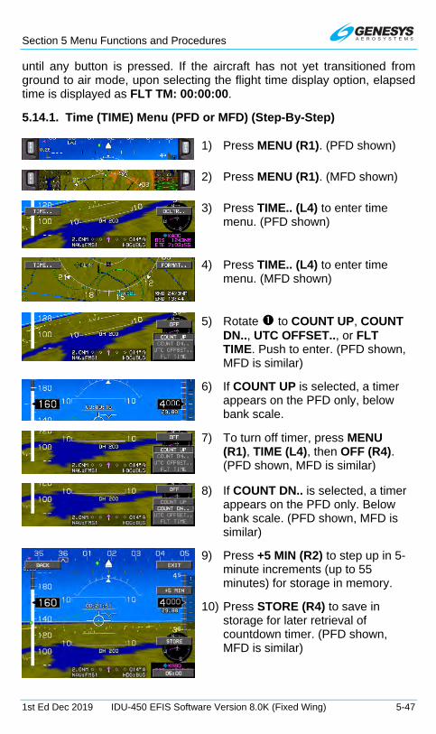
Section 5 Menu Functions and Procedures
1st Ed Dec 2019 IDU-450 EFIS Software Version 8.0K (Fixed Wing) 5-47
until any button is pressed. If the aircraft has not yet transitioned from ground to air mode, upon selecting the flight time display option, elapsed time is displayed as FLT TM: 00:00:00.
5.14.1. Time (TIME) Menu (PFD or MFD) (Step-By-Step)
1) Press MENU (R1). (PFD shown)
2) Press MENU (R1). (MFD shown)
3) Press TIME.. (L4) to enter time menu. (PFD shown)
4) Press TIME.. (L4) to enter time menu. (MFD shown)
5) Rotate to COUNT UP, COUNT DN.., UTC OFFSET.., or FLT TIME. Push to enter. (PFD shown, MFD is similar)
6) If COUNT UP is selected, a timer appears on the PFD only, below bank scale.
7) To turn off timer, press MENU (R1), TIME (L4), then OFF (R4). (PFD shown, MFD is similar)
8) If COUNT DN.. is selected, a timer appears on the PFD only. Below bank scale. (PFD shown, MFD is similar)
9) Press +5 MIN (R2) to step up in 5-minute increments (up to 55 minutes) for storage in memory.
10) Press STORE (R4) to save in storage for later retrieval of countdown timer. (PFD shown, MFD is similar)

Section 5 Menu Functions and Procedures
5-48 IDU-450 EFIS Software Version 8.0K (Fixed Wing) 1st Ed Dec 2019
11) To adjust time set in countdown timer storage, press -5 MIN (R3) to step down in 5-minute increments. (PFD shown, MFD is similar)
12) To set offset for local time, rotate to UTC OFFSET... Push to enter. (PFD shown, MFD is similar)
13) Rotate to desired offset value. Push to enter. (PFD shown, MFD is similar)
14) Local time now appears where Zulu time was previously displayed on the MFD only.
15) Press ZULU (R4) to quickly reset local time back to ZULU time.
16) Rotate to FLT TIME and push to enter to view current elapsed time since the aircraft transitioned from ground to air mode.
17) Current elapsed time aircraft transitioned from ground to air mode is displayed for 10 seconds or until any key is pressed. If not yet transitioned to air mode
appears for 10 seconds. (MFD shown, PFD is similar)

Section 5 Menu Functions and Procedures
1st Ed Dec 2019 IDU-450 EFIS Software Version 8.0K (Fixed Wing) 5-49
5.15. PFD Source (SOURCE) Menu
SOURCE..
1
ADC2 (a)
AHRS1 (b)
AHRS2 (b)
EICAS1 (c)
EICAS2 (c)
GPS1 (d)
GPS2 (d)
RADALT1 (e)
RADALT2 (e)
Selects ADC2 and Deselects ADC1
Selects AHRS1 and Deselects AHRS2
Selects AHRS2 andDeselects AHRS1
Selects #1 EICAS Sensors and Deselects #2 EICAS Sensors
Selects #2 EICAS Sensors and Deselects #1 EICAS Sensors
Selects GPS1 and Deselects GPS2
Selects GPS2 and Deselects GPS1
Selects Radar Altimeter 1 and Deselects Radar Altimeter 2
Selects Radar Altimeter 2 and Deselects Radar Altimeter 1 DONE
Accept changes
ADC1 (a)
Selects ADC1 and Deselects ADC2
MENU
(a) Only available if dual ADC’s are installed and an ADC offside select discrete input is not configured.
(b) Only available if dual AHRS’s are installed and an AHRS offside select discrete input is not configured.
(c) Only available if an EICAS offside select discrete input is not configured.
(d) Only available if dual GPS’s are installed and a GPS offside select discrete input is not configured.
(e) Only available if dual Radar Altimeters are installed and a Radar Altimeter offside select discrete input is not configured.
(f) Only available if selected AHRS is a CFS/Genesys ADAHRS and an AHRS DG mode discrete input for the selected AHRS is not configured.
(g) Only available if selected AHRS is a CFS/Genesys ADAHRS that is in DG mode and AHRS slew discrete inputs for the selected AHRS are not configured.
R2AHRS SLAVE/DG (f)Toggle between Slaved and DG mode
R3AHRS SLEW (g)1 AHRS SLEW
Figure 5-18: PFD Source Menu
Upon activating the PFD source menu, an option list of sensor sources appears to select/deselect the following items if external switches are not configured through discrete input configuration:
ADC1
ADC2
AHRS1
AHRS2
GPS1
GPS2
Radar Altimeter 1
Radar Altimeter 2
AHRS SLAVE/AHRS DG (R2) toggles between the two AHRS modes. AHRS SLEW (R3) enters a submenu to adjust the DG mode slewing value (if a DG/Slave discrete input is not configured for that AHRS.)
Figure 5-19: AHRS SLAVE/AHRS SLEW

Section 5 Menu Functions and Procedures
5-50 IDU-450 EFIS Software Version 8.0K (Fixed Wing) 1st Ed Dec 2019
5.15.1. PFD Page First-Level Source Selection (Step-By-Step)
1) Press MENU (R1).
2) Press SOURCE.. (L2).
3) Rotate to check desired source, push to check, rotate to DONE, and push to enter or press EXIT (R1).
5.16. PFD Bug (BUGS) Menu
Upon selecting the PFD bugs menu, choose from the following:
MINS.. (R3): Push to select DEC HT.. then 200 FT (R3) or OFF (R4), or set DH in increments of 10’ or;
Rotate to select MIN ALT.. press SYNC (R3) to synchronize minimums to current altitude or rotate to desired minimum altitude in increments of 10’;
IAS.. (L2): Set airspeed bug to synchronize with current airspeed, turn off, or set the bug in increments of 1 knot IAS). (No bug setting less than 1.2 VS or 60KIAS, whichever is lower. No higher than VMO/MMO);
VNAV CDA.. (R4): Set VNAV climb or descent angle (setting either in increments of 0.1° with corresponding feet per nautical mile, or selecting a shortcut for 3° (R4));
V-SPDS.. (L3): Set V-speeds options for either takeoff V-speed (V1, VR, V2, and VENR) or approach V-speeds (VREF and VAPP) or;
VSI.. (L4): Set vertical speed by synchronizing the VSI bug to the current VSI, turning off the VSI bug, or setting the VSI bug in increments of 100 feet per minute.
NOTE:
With the exception of when integrated with a Genesys/s-TEC DFCS, the airspeed bug and VSI bug are mutually exclusive and therefore
selecting one turns off the other.

Section 5 Menu Functions and Procedures
1st Ed Dec 2019 IDU-450 EFIS Software Version 8.0K (Fixed Wing) 5-51
BUGS..
R3MINS..
R4VNAV CDA..
R2ALT SEL..
R3
Enter altitude
SYNC
Rotate – Change altitude 100 ft increments
Push – Set selected altitude
R4OFF
Synchronize target altitude to current altitude
Turn targetaltitude off
DEC HT..
MIN ALT..1
R3
Enter height 1
200 FT
Rotate – Change height in10 ft increments
Push – Set selected height
R4OFF
Set decisionheight to 200 ft
Turn decisionheight off
R3
Enter altitude 1
SYNC
Rotate – Change altitude 10 ft increments
Push – Set selected altitude
R4OFF
Synchronize minimum altitude to current
altitude
Turn minimumaltitude off
DCND ANG..
CLMB ANG..
1
Enter angle 1
Rotate – Change descent angle in 0.1° increments
Push – Set selected angle
R43°
Set 3° descent angle
Enter angle 1
Rotate – Change climb anglein 0.1° increments
Push – Set selected angle
R43°
Set 3° climb angle
MENU
1
Figure 5-20: PFD Bug (BUGS) Menu

Section 5 Menu Functions and Procedures
5-52 IDU-450 EFIS Software Version 8.0K (Fixed Wing) 1st Ed Dec 2019
L2
L3
IAS..
V-SPDS..
L4 VSI..
R3
Enter airspeed 1
SYNC
Rotate – Change airspeedin 1 kt increments
Push – Set selected airspeed
R4OFF
Synchronize airspeed bug to current airspeed
Turn airspeed bug off
BUGS..
TAKEOFF..
APPROACH..1
Set V1 1
R4OFF
Turn off selectedV-speed
Set VR 1
Set V2 1
Set VENR 1
Set VREF 1
R4OFF
Turn off selectedV-speed
Set VAPP 1
R3
Enter VSI 1
SYNC
Rotate – Change VSI in100 fpm increments
Push – Set selected VSI
R4OFF
Synchronize VSIbug to current VSI
Turn VSI bug off
MENU
Figure 5-21: PFD BUG (BUGS) Menu (Continued)
5.16.1. PFD Bug (BUGS) Menu (Step-By-Step)
1) Press MENU (R1) and then BUGS.. (R2) to enter the bugs menu.

Section 5 Menu Functions and Procedures
1st Ed Dec 2019 IDU-450 EFIS Software Version 8.0K (Fixed Wing) 5-53
2) Press IAS.. (L2), V-SPDS.. (L3), VSI.. (L4), MINS.. (R3), or VNAV.. CDA (R4).
3) If IAS was pressed, press SYNC (R3) to accept or OFF (R4) to turn off IAS bug. (When integrated with Genesys/S-TEC DFCS in IAS mode, it is not possible to turn off the airspeed bug.)
4) Press VSI (L4) for adjustment of VSI BUG. Rotate to set in increments of 100 fpm and push to select. (When integrated with Genesys/S-TEC DFCS in VS mode, it is not possible to turn off the VSI bug.)
5) For a different IAS bug, rotate to select airspeed. Push to enter new value. Value is displayed in PFI area above airspeed tape.
6) If MINS (R3) is pressed, rotate to select DEC HT.. or MIN ALT.. and push to enter.
7) If DEC HT.. is pushed, rotate to create new decision height and push to enter.
8) New DH displays on the PFI area below the FPM.
9) If VNAV CDA (R4) is pressed, rotate to select DCND.. or CLIMB... Push to enter.

Section 5 Menu Functions and Procedures
5-54 IDU-450 EFIS Software Version 8.0K (Fixed Wing) 1st Ed Dec 2019
10) If DCND.. is pressed, rotate to create new descent angle.
11) For example, select -4.5° (-499 FPNM). Push or press EXIT (R1) to enter.
12) For V-speeds, press V-SPDS.. (L3). Rotate to TAKEOFF.. and push to enter.
13) Rotate to desired V1 speed and push to enter.
14) Rotate to desired VR speed and push to enter.
15) Rotate to desired V2 speed and push to enter.
16) Rotate to desired VENR speed and push to enter. Normally, takeoff speeds are set in sequence on the ground prior to takeoff.
17) To set approach bugs, press V-SPDS.. (L3) and rotate to APPROACH.. and push to enter.
18) Rotate to desired VREF speed and push to enter.
19) Rotate to desired VAPP speed and push to enter. Press OFF (R4) to turn off VREF sped bug.
NOTE:
When integrated with the Genesys/S-TEC DFCS, it is only possible to toggle between single cue and dual cue flight director options. This is due to the flight directors when integrated with the Genesys/S-TEC
DFCS is controlled through the mode control panel.

Section 5 Menu Functions and Procedures
1st Ed Dec 2019 IDU-450 EFIS Software Version 8.0K (Fixed Wing) 5-55
5.17. PFD Declutter (DCLTR) Menu
DCLTR..
Basicor Normal
Mode?
Basic
1
BANK SCL
BASIC
MINI MAP
MINI TRFC (a)
SKYWAY
SVS TAWS (d)
TRAFFIC (a)
FD1 (b)
FD2 (b)
Full-time or auto-decluttered bank scale
Switch PFD to Basic Mode
PFD mini-map
PFD traffic thumbnail
Skyway guidance symbology
TAWS terrain andobstacle depiction
Perspective traffic depiction
Single cue flightdirector symbology
Dual cue flightdirector symbology
DONE
Accept changes
(a) Shown if optional traffic sensor installed.
(b) Shown if FD option enabled. Dual and single cue FD are mutually exclusive.
(d) Only one may be selected. Turning both off disables terrain. Note that “SVS TAWS” is labeled “SVS ADVNCD” when TAWS is not enabled.
BASIC
MINI MAP
MINI TRFC (a)
FD2 (b)
Switch PFD to Normal Mode
PFD mini-map
PFD traffic thumbnail
Single cue flight director symbology
Dual cue flight director symbology
DONEAccept changes
FD1 (b)
1
METERSEnable Metric display
METERS
Enable Metric display
Normal
ANLG AGL
PFD Analog AGL Indicator
ANLG AGLPFD Analog AGL Indicator
MENU
TURN INDTurn Indicator
Turn Indicator TURN IND
Non-TAWS terrain and obstacle depiction SVS BASIC (d)
Round Dials or Tapes?
RoundDials
FD2 (b)
DONE
FD1 (b)
1
METERSTapes
ANLG G (e)PFD Analog G-Meter
ANLG G
PFD Analog G-Meter
Single cue flightdirector symbology
Dual cue flightdirector symbology
Accept changes
Enable Metric display
Figure 5-22: PFD Declutter (DCLTR) Menu
Upon activation of the PFD declutter menu, an option list of declutter items are shown.
Table 5-7: PFD Declutter Options
Option Configuration
Notes SVN Basic
ANLG AGL
Mutually exclusive ANLG G MINI MAP MINI TRFC BANK SCL Always in view while in basic mode BASIC SKYWAY SVS TAWS SVS TAWS is labeled “SVS ADVNCD”
when TAWS is not enabled SVS BASIC TRAFFIC TURN IND
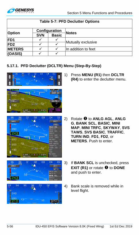
Section 5 Menu Functions and Procedures
5-56 IDU-450 EFIS Software Version 8.0K (Fixed Wing) 1st Ed Dec 2019
Table 5-7: PFD Declutter Options
Option Configuration
Notes SVN Basic
FD1 Mutually exclusive
FD2 METERS (OS) In addition to feet (OASIS) )
5.17.1. PFD Declutter (DCLTR) Menu (Step-By-Step)
1) Press MENU (R1) then DCLTR (R4) to enter the declutter menu.
2) Rotate to ANLG AGL, ANLG G, BANK SCL, BASIC, MINI MAP, MINI TRFC, SKYWAY, SVS TAWS, SVS BASIC, TRAFFIC, TURN IND, FD1, FD2, or METERS. Push to enter.
3) If BANK SCL is unchecked, press EXIT (R1) or rotate to DONE and push to enter.
4) Bank scale is removed while in level flight.
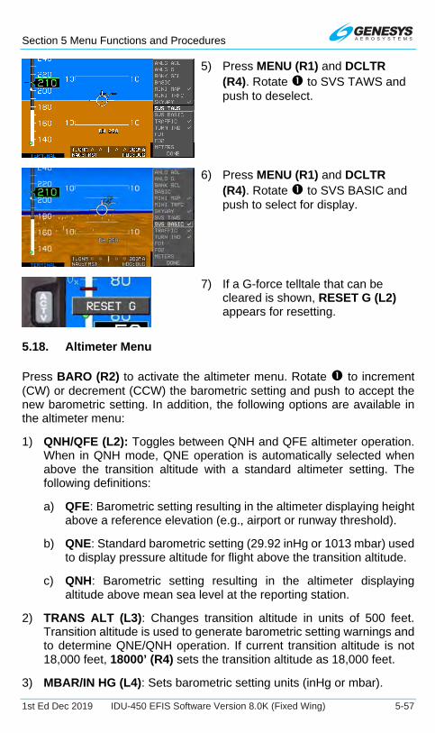
Section 5 Menu Functions and Procedures
1st Ed Dec 2019 IDU-450 EFIS Software Version 8.0K (Fixed Wing) 5-57
5) Press MENU (R1) and DCLTR (R4). Rotate to SVS TAWS and push to deselect.
6) Press MENU (R1) and DCLTR (R4). Rotate to SVS BASIC and push to select for display.
7) If a G-force telltale that can be cleared is shown, RESET G (L2) appears for resetting.
5.18. Altimeter Menu
Press BARO (R2) to activate the altimeter menu. Rotate to increment (CW) or decrement (CCW) the barometric setting and push to accept the new barometric setting. In addition, the following options are available in the altimeter menu:
1) QNH/QFE (L2): Toggles between QNH and QFE altimeter operation. When in QNH mode, QNE operation is automatically selected when above the transition altitude with a standard altimeter setting. The following definitions:
a) QFE: Barometric setting resulting in the altimeter displaying height above a reference elevation (e.g., airport or runway threshold).
b) QNE: Standard barometric setting (29.92 inHg or 1013 mbar) used to display pressure altitude for flight above the transition altitude.
c) QNH: Barometric setting resulting in the altimeter displaying altitude above mean sea level at the reporting station.
2) TRANS ALT (L3): Changes transition altitude in units of 500 feet. Transition altitude is used to generate barometric setting warnings and to determine QNE/QNH operation. If current transition altitude is not 18,000 feet, 18000’ (R4) sets the transition altitude as 18,000 feet.
3) MBAR/IN HG (L4): Sets barometric setting units (inHg or mbar).

Section 5 Menu Functions and Procedures
5-58 IDU-450 EFIS Software Version 8.0K (Fixed Wing) 1st Ed Dec 2019
4) STD (R4): Sets barometric setting to standard (29.92 inHg or 1013 mbar).
L3 TRANS ALT
R4STD
Enterbarometric
setting
1
Rotate – Change barometric setting in0.01 inHg or 1 mbar increments
Push – Accept barometric setting
Change barometric setting to standard(29.92 inHg or 1013 mbar)
L2QFE
QNH
Switch to QFEaltimeter operation
Switch to QNHaltimeter operation
Enter altitude 1
Rotate – Change altitude in1000 ft increments
Push – Set selected altitude
L4MBAR
Select MBarbarometric setting units
Select in Hgbarometric setting units
IN HG
R418000' *Change altitude to 18,000 ft* Displayed if current
transition altitude isnot 18,000 ft
BARO R2
Figure 5-23: Altimeter Menu
5.18.1. PFD Altimeter Menu (Step-By-Step)
1) Press BARO (R2) to enter altimeter menu.
2) Rotate to set proper QNH and push to enter.
3) Crosscheck proper QNH under altitude indication.
4) Press BARO (R2) again and STD (R4) to reset QNH to 1020. Push to enter.

Section 5 Menu Functions and Procedures
1st Ed Dec 2019 IDU-450 EFIS Software Version 8.0K (Fixed Wing) 5-59
5.19. MFD Fault Display (FAULTS) Menu
Upon selecting the MFD faults menu, status of the following system parameters are displayed.
FAULTS..
GPS PWR OKGPS EQPMNT OKGPS SATLT OKGPS FDE OKGPS LOI OKGPS HPL 0.1NM
SBAS MSG OKSBAS HLTH OKWX-500 OK(a)TRFC OK(b)AIU OK(c)ADSB POSN OK(d)*ADSB MAINT OK(d)*ADSB CSA OK(d)*
GPS/SBAS loss of navigation:absence of power
GPS/SBAS loss of navigation:probable equipment failure
GPS/SBAS loss of navigation:inadequate satellites
GPS/SBAS loss of navigation:Unable to exclude position failure
GPS/SBAS loss of integrity GPS/SBAS horizontal protection level in nautical miles
GPS/SBAS loss of navigation:no valid SBAS message GPS/SBAS loss of navigation:
insufficient healthy satellitesWX-500: loss of communication
Traffic sensor: loss of communicationAnalog interface:
loss of communicationADS-B datalink: position validity
ADS-B datalink: receiver maintenance required ADS-B datalink: Conflict
Situational Awareness working
(a) Shown if optional WX-500 installed(b) Shown if optional traffic sensor installed(c) Shown if optional AIU installed(d) Shown if optional ADS-B datalink installedf) Shown if optional weather radar installed(g) Shown if optional weather radar installed
and weather radar type is RDR-2000 or RDR-2100
WXR RCP OK(g)WXR FAULT OK(f)WXR PWR OK(f)
Weather Radar:Loss of communication Weather Radar:
Radar reports fault conditionRadar Control Panel:Loss of communication or fault
GPS VPL 25MGPS HFOM 0.0NMGPS VFOM 19MGPS ALMANAC OK
GPS/SBAS vertical protection level in meters
GPS/SBAS vertical figure of merit (95% accuracy) in meters
GPS/SBAS horizontal figure of merit (95% accuracy) in nautical miles
GPS/SBAS almanac validity
MENU
Figure 5-24: MFD Fault Display Menu
1) GPS/SBAS loss of navigation due to absence of power (GPS PWR).
2) GPS/SBAS loss of navigation due to probable equipment failure (GPS EQPMNT).
3) GPS/SBAS loss of navigation due to inadequate satellites to compute a position solution (GPS SATLT).
4) GPS/SBAS loss of navigation due to a position failure that cannot be excluded within the time to alert (GPS FDE).
5) GPS/SBAS loss of integrity and loss of navigation due to loss of integrity (GPS LOI).

Section 5 Menu Functions and Procedures
5-60 IDU-450 EFIS Software Version 8.0K (Fixed Wing) 1st Ed Dec 2019
6) Readout of the current GPS/SBAS horizontal protection level (GPS HPL) in nautical miles. This value may be used as the estimate of position uncertainty required in RNP airspace.
7) Readout of the current GPS/SBAS vertical protection level (GPS VPL) in meters.
8) Readout of the current GPS/SBAS horizontal figure of merit (GPS HFOM) in nautical miles. This value is an indication of the 95% confidence horizontal position accuracy.
9) Readout of the current GPS/SBAS vertical figure of merit (GPS VFOM) in meters. This value is an indication of the 95% confidence vertical position accuracy. (For Example, the MSL altitude used in the TAWS algorithms use geodetic height converted to MSL with the current EGM (Earth Gravity Model) database. For this to be considered valid for use as MSL altitude, the VFOM must be less than or equal to 106 feet.) Additionally, the tertiary source for vertical speed is GPS/SBAS vertical speed providing the VFOM is less than or equal to 106 feet. When AGL altitude is based on BARO, it is because the RADALT was in a failed state (if so equipped) and the VFOM exceeded 106 feet rendering the vertical component of GPS altitude invalid in the MSL altitude calculation.
10) An indication of whether the GPS/SBAS receiver has a valid almanac in memory (GPS ALMANAC).
11) GPS/SBAS loss of navigation due to no valid SBAS message received for 4 seconds or more (SBAS MSG).
12) GPS/SBAS loss of navigation due to insufficient number of SBAS HEALTHY satellites (SBAS HLTH).
a) An Attitude or Range Fault Condition exists.
b) A Control Fault Condition exists.
c) A T/R Fault Condition exists.
13) If the WX-500 option is enabled, loss of communications with the WX-500 (WX-500).
14) If the traffic option is enabled, loss of communications with the traffic sensor (TRFC).
15) If the analog interface option is enabled, loss of communications with the analog interface (AIU).
16) If ADS-B datalink is enabled, an indication of ADS-B position validity (ADSB POSN), an indication of whether maintenance of the ADS-B

Section 5 Menu Functions and Procedures
1st Ed Dec 2019 IDU-450 EFIS Software Version 8.0K (Fixed Wing) 5-61
receiver is required (ADSB MAINT) and an indication of whether the conflict situational awareness algorithm is working (ADSB CSA).
17) If weather radar is enabled, an indication of weather radar power/communication status (“WXR PWR X” or “WXR PWR OK”). Weather radar power/communication status failed (WXR PWR X) reflects that any one of the following conditions are true:
a) Loss of weather radar communication (ARINC 453 label 055 or 171 not available or not accepted for more than 2 seconds).
b) Weather radar mode is OFF.
18) If weather radar is enabled, an indication of weather radar fault status (“WXR FAULT -,” “WXR FAULT X,” or “WXR FAULT OK”). When weather radar power/communication status is failed, weather radar fault status indicates determination of weather radar faults is not possible (WXR FAULT –). Weather radar fault status failed (WXR FAULT X) reflects that any one of the following conditions are true:
a) A cooling fault condition exists
b) For weather radar types ARINC 708-6 or Collins 800/840, a display or control bus fault condition exists.
c) For weather radar types ARINC 708-6, Collins 800/840 or Honeywell PRIMUS, a calibration or air data fault condition exists.
d) An attitude or range fault condition exists.
e) A control fault condition exists.
f) A T/R Fault Condition exists.
19) If weather radar is enabled, the weather radar type is RDR-2000 or RDR-2100 and an external radar control panel is installed, an indication of radar control panel status (“WXR RCP X” or “WXR RCP OK”). External radar control panel status failed (WXR RCP X) indicates either loss of communication or a failure status.
5.19.1. MFD Fault Display (FAULTS) Menu (Step-By-Step)
1) Press MENU (R1) and then within 10 seconds FAULTS (L1) to view the faults menu.

Section 5 Menu Functions and Procedures
5-62 IDU-450 EFIS Software Version 8.0K (Fixed Wing) 1st Ed Dec 2019
2) View status of GPS and equipment parameters.
5.20. MFD Fuel Totalizer Quantity Setting (SET FUEL) Menu
Figure 5-25: MFD SET FUEL
SET FUEL..
1Set Fuel Totalizer
Set fuel totalizerquantity to “fuel tabs”
fuel capacity
R4
MAINS R3
FULLSet fuel totalizer
quantity to total aircraftfuel capacity
Rotate – Change quantityPush – Set selected quantity
MENU
Set aircraft emergency fuel value
L4
EMG FUEL..L3
MIN FUEL..Set aircraft minimum fuel
value
Figure 5-26: MFD Fuel Totalizer Quantity Menu
SET FUEL menu allows the pilot to:
1) Set the fuel totalizer quantity in increments of volume units.
If either a fuel totalizer or fuel level sensing (with no unmonitored fuel) is configured in the aircraft limits, set emergency and minimum fuel bugs in increments of volume units.

Section 5 Menu Functions and Procedures
1st Ed Dec 2019 IDU-450 EFIS Software Version 8.0K (Fixed Wing) 5-63
2) Press MAINS (R3) to set the quantity to the “fuel tabs” fuel capacity. Press FULL (R4) to set the quantity to the total aircraft fuel capacity. Units of measure and fuel flow are shown in the quantity window when available. If fuel flow is available, current fuel flow is shown on the Nav Log top area.
3) If an aircraft fuel caution or aircraft fuel warning is configured in the limits, set EMG FUEL.. (L3) and MIN FUEL.. (L4) fuel bugs in increments of volume units.
Figure 5-27: Fuel Totalizer Quantity Setting (SET FUEL) Menu
5.21. MFD Page (PAGE) Menu
PAGE..
MAP
HSI
NAV LOG
STRIKES (a)
DATALINK (c)
TRAFFIC (b)
ND page
HSI page
FMS page
Strikes page
Traffic page
Datalink page
(a) Shown if optionalWX-500 installed.
(b) Shown if optionaltraffic sensor installed.
(c) Shown if optionalADS-B installed.
(d) Shown if optional weather radar
installed.
WX-RDR (d)WX-RDR page 1
Figure 5-28: MFD Page (PAGE)

Section 5 Menu Functions and Procedures
5-64 IDU-450 EFIS Software Version 8.0K (Fixed Wing) 1st Ed Dec 2019
PAGE menu allows the pilot to select which MFD page to display:
1) MAP: ND page
2) HSI: HSI page
3) NAV LOG: FMS page
4) STRIKES: WX-500 Lightning Strikes page (See Strikes Appendix)
5) TRAFFIC: Traffic page (See Traffic Appendix)
6) DATALINK: Datalink page (See Datalink Appendix)
7) WX-RDR: Weather Radar page (See Weather Radar Appendix)
5.21.1. MFD Page (PAGE) Menu (Step-By-Step)
1) Press MENU (R1) to open MFD menus.
2) Press PAGE.. (R3) rotate to MAP, HSI, NAV LOG, STRIKES, TRAFFIC, DATALINK, or WX-RDR. Push to enter.
5.21.2. MFD NAV LOG Page (Step-By-Step)
1) Press PAGE.. (R3) rotate to NAV LOG and push to enter.

Section 5 Menu Functions and Procedures
1st Ed Dec 2019 IDU-450 EFIS Software Version 8.0K (Fixed Wing) 5-65
2) Example of NAV LOG shown with full page. Rotate CW to view additional NAV log legs.
3) View of remainder of NAV LOG with (KPHX) suppressed waypoint at the end.
5.21.3. MFD HSI Page (Step-By-Step)
Press MENU (R1), PAGE (R3), rotate to HSI, and push to enter.

Section 5 Menu Functions and Procedures
5-66 IDU-450 EFIS Software Version 8.0K (Fixed Wing) 1st Ed Dec 2019
5.22. MFD HSI Declutter (DCLTR) Menu
DCLTR..
PTR ADF1 (a)
PTR NAV1 (a)
PTR NAV2 (a)
DONE 1
(a)Shown if optional VOR or ADF navigation installed.
ADF1 pointer
VOR1 pointer
VOR2 pointer
Accept changes
PTR ADF2 (a)ADF2 pointer
MENU
Figure 5-29: MFD HSI DCLTR (DCLTR) Menu
Upon selecting the HSI declutter menu in the HSI page, a list appears to individually display:
ADF1 pointer (if ADF symbology if enabled);
ADF2 pointer (if dual ADF symbology if enabled);
VOR1 pointer (if VOR symbology if enabled); and
VOR2 pointer (if dual VOR symbology if enabled).
5.22.1. MFD HSI Declutter (DCLTR) Menu (Step-By-Step)
1) Press MENU (R1) then DCLTR.. (R4) to enter Declutter menu.
2) It is not possible to declutter the FMS HSI needle.
3) Rotate to PTR ADF1, PTR ADF2, NAV1, or PTR NAV2 and push to place check mark, then press EXIT (R1) or rotate to DONE and push to enter.

Section 5 Menu Functions and Procedures
1st Ed Dec 2019 IDU-450 EFIS Software Version 8.0K (Fixed Wing) 5-67
5.23. MFD ND Page Format Menu
FORMAT..
CENTER
ARC
HDG UP
SYMB DCLTR..
Switch to centered display format(shown if arced is current display format and not panning)
Switch to arced display format(shown if centered is current display format and not panning)
FNCT DCLTR..
N UP
1
Switch to heading up display format(shown if true north up is current display format and not panning)
Switch to true north up display format(shown if heading up is current display format and not panning)
1
AIRSPACE
BORDERS
1
Airspace
DATALINK
ETA
GLIDE
H AIRWAY
L AIRWAY
LAT/LON
PTR ADF1
PTR NAV1
PTR NAV2
STRIKES
TERRAIN
TRAFFIC
DONE
Borders
Datalink NEXRAD,graphical METARS.
Automatic navigation
symbol declutterAUTO
MANUAL..
LRG APT
IFR APT
VFR APT
VORS
NDBS
FIXES
TRM FIXES
USER WPTS
1DONE
Estimatedtime of arrival
Glide range
High-altitude airways
Low-altitude airways
Current latitudeand longitude
ADF1 pointer
VOR1 pointer
VOR2 pointer
Strikes
Terrain
Traffic
Accept changes
Large airports
IFR airports
VFR airports
VORs
NDBs
Fixes
Terminal fixes
User waypoints
Accept changes
PAN ON
PAN OFFTurn pan mode off(shown if pan mode is on)
Turn pan mode on (shown if pan mode is off)
R4
EAST
R3
WEST
NORTH
SOUTH
L3
L4
Pan east
Pan west
Pan north
Pan south
1Right Rotate – Increase rangeLeft Rotate – Decrease rangeDepending on EFIS Limits setting
INFO
R2
Show/ Hidehighlighted
point information
PN
OFF
L1Pan Off
HIDE
MENU
HSIHSI Overlay
Figure 5-30: MFD ND Page Format Menu
Upon selecting the MFD format menu when in the ND page, a list appears with the following options:

Section 5 Menu Functions and Procedures
5-68 IDU-450 EFIS Software Version 8.0K (Fixed Wing) 1st Ed Dec 2019
CENTER/ARC: Toggles between centered and arced ND display format (if not panning).
HDG UP/N UP: Toggles between heading up and north-up ND display format (if not panning).
PAN ON/PAN OFF: Toggles ND page pan mode.
SYMB DCLTR: Activates a list to choose automatic or manual navigation symbol declutter. If the pilot chooses manual navigation symbol declutter, a list appears to individually select:
a) large airports;
b) IFR airports;
c) VFR airports;
d) VORs;
e) NDBs;
f) fixes;
g) terminal fixes; and
h) user waypoints
Figure 5-31: MFD Symbol Declutter
Turning on VFR airports also turns on large and IFR airports. Turning on IFR airports also turns on large airports. Turning off large airports also turns off IFR and VFR airports. Turning off IFR airports turns off VFR airports.
FNCT DCLTR: Activates a list to individually toggle display of:
a) airspace;
b) borders;
c) ETA;
d) glide range;
e) high-altitude airways;
f) low-altitude airways;
g) current latitude and longitude display
h) ADF #1 pointer;
i) ADF #2 pointer;
j) VOR1 pointer;
k) VOR2 pointer;
l) strikes;
m) terrain; or
n) traffic.

Section 5 Menu Functions and Procedures
1st Ed Dec 2019 IDU-450 EFIS Software Version 8.0K (Fixed Wing) 5-69
5.23.1. MFD Page Format (Step-By-Step)
5.23.1.1. Changing MFD ND Orientation
1) Press MENU (R1).
2) Press FORMAT.. (R4).
3) If in arc mode, rotate to CENTER and push to enter to center display.
4) If in center mode, rotate to ARC and push to enter to change to arc mode.
5) If in HDG UP mode, rotate to N UP and push to enter to change display to north-up orientation.
6) To enter pan mode, press MENU (R1) and then FORMAT.. (R4). Rotate to PAN ON and push to enter.
7) To turn off pan mode, either press PN OFF (L1) or MENU (R1) and then FORMAT.. (R4). Rotate to PAN OFF and press to enter.

Section 5 Menu Functions and Procedures
5-70 IDU-450 EFIS Software Version 8.0K (Fixed Wing) 1st Ed Dec 2019
5.23.1.2. Adding LAT/LON to MFD ND Page
1) Press MENU (R1).
2) Press FORMAT.. (R4).
3) Rotate to FNCT DCLTR.. Push to enter.
4) Rotate to LAT/LON and push then either press EXIT (R1) or rotate to DONE and push to enter.
Latitude/longitude display is removed when a traffic alert is present.
1) To turn off terrain, press MENU (R1) and FORMAT (R4). Rotate to TERRAIN and push to uncheck.
2) To exit menu, press EXIT (R1) or rotate to DONE and push to enter. When the IDU is powered down and reinitialized, terrain remains off until restored.

Section 6 Quick Start Tutorial
1st Ed Dec 2019 IDU-450 EFIS Software Version 8.0K (Fixed Wing) 6-1
Section 6 Quick Start Tutorial
Quick Reference Guide (DOC 64-000101-080K)
Begin by reading the EFIS Aircraft Flight Manual (AFM) or Aircraft Flight Manual Supplement (AFMS).
Power up the EFIS. The system performs a built-in test routine. If all tests pass, the system displays a screen identifying the database coverage. Press any button or push/ rotate encoder to acknowledge. The system begins a two-minute count down while awaiting sensor initialization. For the purpose of flight planning, etc., press any button or push/rotate encoder to override this countdown.
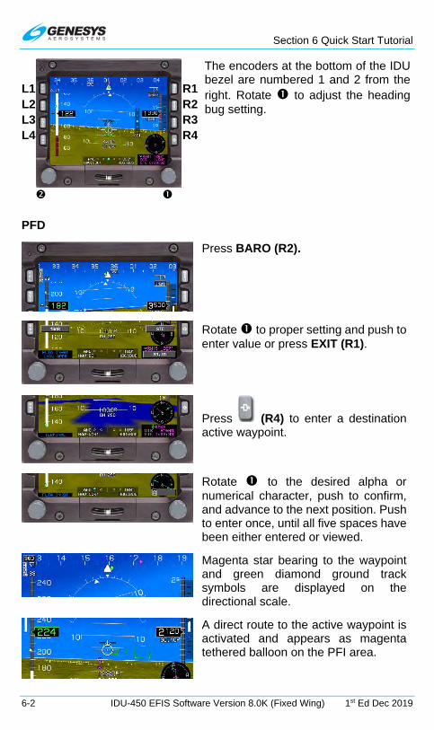
Section 6 Quick Start Tutorial
6-2 IDU-450 EFIS Software Version 8.0K (Fixed Wing) 1st Ed Dec 2019
L1 R1
The encoders at the bottom of the IDU bezel are numbered 1 and 2 from the right. Rotate to adjust the heading bug setting.
L2 R2L3 R3L4 R4
PFD
Press BARO (R2).
Rotate to proper setting and push to enter value or press EXIT (R1).
Press (R4) to enter a destination active waypoint.
Rotate to the desired alpha or numerical character, push to confirm, and advance to the next position. Push to enter once, until all five spaces have been either entered or viewed.
Magenta star bearing to the waypoint and green diamond ground track symbols are displayed on the directional scale.
A direct route to the active waypoint is activated and appears as magenta tethered balloon on the PFI area.

Section 6 Quick Start Tutorial
1st Ed Dec 2019 IDU-450 EFIS Software Version 8.0K (Fixed Wing) 6-3
Active waypoint information, including waypoint type and identifier; elevation or crossing altitude; and bearing and distance are displayed below the analog AGL indicator or mini map as configured.
Indicated airspeed is on the left, altitude is on the right, and heading is across the top. FMS/VLOC CDI is located on the bottom. VSI appears on the right side of the altitude tape. Time-critical caution is displayed in the primary field of view.
MFD
Analog navigation symbology on MFD HIS.
Manual Leg
A manual leg has been created within a procedure and waypoint sequencing is suspended.
To resume normal waypoint sequencing press RESUME (L2).

Section 6 Quick Start Tutorial
6-4 IDU-450 EFIS Software Version 8.0K (Fixed Wing) 1st Ed Dec 2019
Now RESUME (L2) is no longer present and the system is no longer in
mode.
Flight Plans (Stored Routes)
Activate Flight Plan on PFD or MFD
1) Press FPL (L1).
2) Rotate to SELECT.. and push to enter.
3) Rotate to select desired flight plan and push to activate.
Create Flight Plan on MFD
1) Press FPL (L1).
2) Rotate to CREATE-EDIT.. and push to enter.
3) Select CREATE FLIGHT PLAN and push to enter.
4) Press ADD (R2) to create first waypoint using to enter waypoints from beginning to end; or press NRST APT (L2), NRST VOR (L3), NRST NDB (L4), NRST FIX (R2), NRST USR (R3) or AIRWAY (R4) to select next waypoint, and push to enter.
5) Press SAVE (R4) to save flight plan.
6) Press EXIT (R1) to exit flight planner.
Waypoints
Create a User Waypoint on PFD or MFD
1) Press MENU (R1).
2) Press DESIG (L3).

Section 6 Quick Start Tutorial
1st Ed Dec 2019 IDU-450 EFIS Software Version 8.0K (Fixed Wing) 6-5
Edit a User Waypoint MFD
1) Press FPL (L1).
2) Rotate to CREATE-EDIT.. and push to enter.
3) Rotate to EDIT USER WPT and push to enter.
4) Rotate to highlight waypoint to edit and push to enter.
5) Edit waypoint. Press SAVE (R4) or press EXIT (R1) to exit flight planner.
Add Waypoint to an Active Route on PFD or MFD
1) Press ACTV (L2).
2) Rotate to location on waypoint list where added waypoint is to be inserted above.
3) Press INSERT (R2).
4) Press NRST APT (L2), NRST VOR (L3), NRST NDB (L4), NRST FIX (R2), or NRST USR (R3), or AIRWAY (R4) and then
a) Rotate to make selection and push to enter, or
b) Use to enter waypoint identifier and push to enter.
5) Press SAVE (L1) to save new active flight plan as another stored flight plan.
Delete Waypoint from an Active Route on PFD or MFD
1) Press ACTV (L2).
2) Rotate to waypoint to delete and press DELETE (R3) to prompt CONFIRM DEL WPT. If part of a published procedure, press DELETE (R3) to prompt CONFIRM DEL PROC.
3) Push to CONFIRM DEL WPT or CONFIRM DEL.
Omnibearing Selector Function
Automatic OBS (FMS OBS Only) on PFD or MFD
1) Press OBS (L4).
2) Push OBS:AUTO to enter.

Section 6 Quick Start Tutorial
6-6 IDU-450 EFIS Software Version 8.0K (Fixed Wing) 1st Ed Dec 2019
Manual OBS on PFD or MFD
1) Press OBS (L4).
2) To select desired HSI source, press NAV VLOC1 (L3) or NAV VLOC2 (L4).
3) If HSI source is NAV FMS, press OBS MANUAL (R4) then rotate to desired OBS value and push to enter, or press OBS SYNC (R3) and push to enter.
4) If HSI source is NAV VLOC1 or NAV VLOC2, rotate to desired course (OBS:XXX° (XXX°)) and push to enter.
Approaches/Track
Select a VFR Approach on PFD or MFD
(The active flight plan must contain an eligible airport for runway selection and VFR approach creation.)
1) Press ACTV (L2).
2) Rotate to desired airport or user waypoint and push to enter.
3) Rotate to VFR APPR.. and push to enter.
4) Rotate to desired runway and push to enter.
Change Runway during VFR Approach on PFD or MFD
1) Press ACTV (L2).
2) Rotate to highlight the following and push to enter:
a) Destination airport
b) VFR APPR..
c) Desired runway
(This deletes the previous VFR approach and creates a new VFR approach to the selected runway.)
Select an IFR Approach on PFD or MFD
1) Press ACTV (L2).
2) Rotate to desired eligible airport and push to enter.
3) Rotate to IFR APPR.. and push to enter.

Section 6 Quick Start Tutorial
1st Ed Dec 2019 IDU-450 EFIS Software Version 8.0K (Fixed Wing) 6-7
4) Rotate to desired approach and push to enter.
5) Rotate to desired transition and push to enter.
6) Rotate to desired runway and push to enter.
Change Runway on IFR Approach on PFD or MFD
1) Press ACTV (L2).
2) Rotate to destination airport and push to enter.
3) Select APPR: Rotate to desired approach. Push to enter.
4) Select TRANS: Rotate to desired transition. Push to enter.
5) Select RW: Rotate to desired runway. Push to enter.
(This deletes the previous IFR approach and creates a new IFR approach to the selected runway.)
XFILL SYNC Operation
XFILL Sync Operation on PFD
(Crossfill is the normal default mode of operation.)
1) During crossfill inhibited operation, appears on the PFD in
the lower left corner.
2) After the XFILL switch is pressed again, the pilot and co-pilot sides are not synchronized; appears in lower left corner of both PFDs.
3) When the pilot and co-pilot sides are not synchronized, press MENU (R1) then XFILL SYNC (L1) to synchronize the pilot and co-pilot active flight plan parameters from the side where the button press occurred.

Section 7 IFR Procedures
1st Ed Dec 2019 IDU-450 EFIS Software Version 8.0K (Fixed Wing) 7-1
Section 7 IFR Procedures
7.1. Active Flight Plan
Upon activation of the active flight plan menu, the application checks for an active waypoint. If there is no active waypoint, NO ACTIVE WPT is issued. Otherwise, a nav log of waypoints in the active flight plan is presented with the following:
1) Waypoint identifier and characterization (default, overfly [OF], or no radius [0R])
2) Symbol designating waypoint type and what type of procedure (if any) the waypoint is associated
3) VNAV altitudes and offsets associated with each waypoint
4) Information related to flight plan path between each waypoint
In the case of an approach with a final approach segment data block, the VNAV offset readout associated with the missed approach point is “GPI” to designate distance to the glidepath intercept point. When courses are presented as part of the path information, they are displayed referenced to magnetic north with the degree (°) symbol.
VNAV altitudes and offsets from the navigation database or have been manually entered are white, and those computed automatically are gray. The active waypoint is designated by an asterisk and is magenta but turns amber (yellow) in the event of a GPS LON caution.
A suppressed waypoint (designated by brackets) is an airport associated with an IFR or VFR approach procedure. After an approach procedure is activated, the associated airport is no longer part of the active flight plan for guidance purposes. However, the associated airport is still shown in the nav log for it to be highlighted for information or to activate other procedures to the airport. Since only one approach may be active at any given time, only one waypoint may be suppressed at any given time.
A skipped waypoint is a waypoint associated with a dynamic termination leg with a zero length. These are either:
1) An altitude termination leg when current aircraft altitude is above the termination altitude; or
2) System-created (i.e., not NavData® specified) intercept to a “Course to a Fix” leg where there is insufficient distance to calculate an intercept heading.
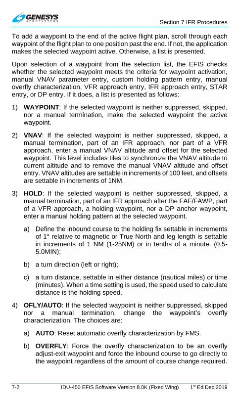
Section 7 IFR Procedures
7-2 IDU-450 EFIS Software Version 8.0K (Fixed Wing) 1st Ed Dec 2019
To add a waypoint to the end of the active flight plan, scroll through each waypoint of the flight plan to one position past the end. If not, the application makes the selected waypoint active. Otherwise, a list is presented.
Upon selection of a waypoint from the selection list, the EFIS checks whether the selected waypoint meets the criteria for waypoint activation, manual VNAV parameter entry, custom holding pattern entry, manual overfly characterization, VFR approach entry, IFR approach entry, STAR entry, or DP entry. If it does, a list is presented as follows:
1) WAYPOINT: If the selected waypoint is neither suppressed, skipped, nor a manual termination, make the selected waypoint the active waypoint.
2) VNAV: If the selected waypoint is neither suppressed, skipped, a manual termination, part of an IFR approach, nor part of a VFR approach, enter a manual VNAV altitude and offset for the selected waypoint. This level includes tiles to synchronize the VNAV altitude to current altitude and to remove the manual VNAV altitude and offset entry. VNAV altitudes are settable in increments of 100 feet, and offsets are settable in increments of 1NM.
3) HOLD: If the selected waypoint is neither suppressed, skipped, a manual termination, part of an IFR approach after the FAF/FAWP, part of a VFR approach, a holding waypoint, nor a DP anchor waypoint, enter a manual holding pattern at the selected waypoint.
a) Define the inbound course to the holding fix settable in increments of 1° relative to magnetic or True North and leg length is settable in increments of 1 NM (1-25NM) or in tenths of a minute. (0.5-5.0MIN);
b) a turn direction (left or right);
c) a turn distance, settable in either distance (nautical miles) or time (minutes). When a time setting is used, the speed used to calculate distance is the holding speed.
4) OFLY/AUTO: If the selected waypoint is neither suppressed, skipped nor a manual termination, change the waypoint’s overfly characterization. The choices are:
a) AUTO: Reset automatic overfly characterization by FMS.
b) OVERFLY: Force the overfly characterization to be an overfly adjust-exit waypoint and force the inbound course to go directly to the waypoint regardless of the amount of course change required.

Section 7 IFR Procedures
1st Ed Dec 2019 IDU-450 EFIS Software Version 8.0K (Fixed Wing) 7-3
c) NO RADIUS: Force the turn radius at the waypoint to be zero. This forces the inbound course and outbound course to go directly to and from the waypoint regardless of the amount of course change required.
NOTE:
It is not possible to track a “NO RADIUS” path perfectly, but the FMS path guidance quickly recaptures the outbound course after resuming
automatic waypoint sequencing. Designating a waypoint as a “NO RADIUS” waypoint affects the turn radius used to calculate procedure
turn and holding pattern leg paths.
5) VFR APP: If selected waypoint is a user waypoint with an approach bearing, a VFR approach to the user waypoint based upon the approach bearing is created, and the user waypoint is suppressed. If the selected waypoint is a VFR airport or an IFR airport with surveyed runways, the pilot is presented with a list of runways. After selecting a runway, a VFR approach to the runway is created, and the airport waypoint is suppressed. Activating a VFR approach deletes any pre-existing IFR or VFR approaches. If a heading bug is not active; activating a VFR approach activates the heading bug on current aircraft heading and is used to define the course intercept angle.
6) IFR APP: If selected waypoint is an airport with an IFR approach, the pilot is presented with a list of available approaches (including, if applicable, the five-digit channel number, followed by a list of available transitions, if there are more than one) and a list of runways (if there are surveyed runways at the airport). After selection, the appropriate IFR approach is created, and the airport waypoint is suppressed. Activating an IFR approach deletes any pre-existing IFR or VFR approaches. If there is a pre-existing STAR to the airport, the IFR approach waypoints are inserted after the STAR waypoints. If a heading bug is not active and the activated transition is “Vectors to Final,” activating an IFR approach activates the heading bug on current aircraft heading for purposes of defining the course intercept angle.
7) STAR: If selected waypoint is an airport with a STAR, the pilot is presented with a list of available STARs, followed by a list of available transitions (if there are more than one) and a list of runways (if there are surveyed runways at the airport). After selection, the appropriate STAR is created. Activating a STAR automatically deletes any pre-existing STAR. If there is a pre-existing approach (IFR or VFR) to the airport, STAR waypoints are inserted prior to the approach waypoints.

Section 7 IFR Procedures
7-4 IDU-450 EFIS Software Version 8.0K (Fixed Wing) 1st Ed Dec 2019
8) DP: If selected waypoint is an airport with a DP, the pilot is presented with a list of DPs, followed by a list of available transitions (if there are more than one) and a list of runways (if there are surveyed runways and more than one runway authorized for the DP). After selection, the appropriate DP is created, and upon activation, deletes any pre-existing DPs.
7.2. IFR Procedures
Pilots operating in a radar environment are expected to associate departure headings or an RNAV departure advisory with vectors or the flight path to the planned route or flight. The EFIS employs two types of departure procedures, obstacle departure procedures (ODPs), which are printed either textually or graphically, and standard instrument departure procedures (SIDs), which are always printed graphically. All DPs, either textual or graphic may be designed using either conventional or RNAV criteria. RNAV procedures have RNAV printed in the title.
ODPs are not found in the navigation database, and therefore the climb angle found in the PFD BUGS menu should be set to comply with the steeper than normal climb gradient during the departure until established on the enroute structure. ODPs are recommended for obstruction clearance and may be flown without ATC clearance, unless an alternate departure procedure (SID or radar vector) has been specifically assigned by ATC.
Approach minima are never coded in NavData®. On some approaches, the altitude coded at the MAP for a non-precision approach coincides with an MDA (normally where the final approach course does not align with the runway), but more often the coded altitude is some height above the threshold.
7.3. Overview of Procedures and Instrument Approaches
This Genesys Aerosystems EFIS provides 3-D GPS precision and non-precision instrument approach guidance using a system integral TSO C146c BETA 3 GPS receiver with GPS and augmented GPS with SBAS (Satellite Based Augmentation System) commonly referred to as WAAS (Wide Area Augmentation System). In order to support full integration of RNAV procedures into the National Airspace System (NAS), a charting format for instrument approach procedures (IAPs) is designed to avoid confusion and duplication of instrument approach charts.
Use of this GPS receiver provides a level of certified service supporting RNAV (GPS) approaches to LNAV, LP, LNAV/VNAV, and LPV lines of minima within system coverage. Some locations close to the edge of the coverage may have lower availability of vertical guidance.

Section 7 IFR Procedures
1st Ed Dec 2019 IDU-450 EFIS Software Version 8.0K (Fixed Wing) 7-5
Approach with vertical guidance (APV) procedures are defined in ICAO Annex 6 and include approaches such as the LNAV/VNAV procedures presently being flown with barometric vertical navigation (BARO-VNAV). These approaches provide vertical guidance but do not meet the more stringent standards of a precision approach. With the WAAS BETA 3 GPS receiver and updatable navigation database in this system, these approaches may be flown using an electronic glidepath, which eliminates errors introduced by using barometric altimetry.
In addition to LNAV/VNAV procedures, APV takes advantage of the high accuracy guidance and increased integrity provided by GBS/SBAS. This SBAS (TEROS/ICAO) generated angular guidance allows use of the same TERPS approach criteria for ILS approaches. The resulting approach procedure minima, localizer performance with vertical guidance (LPV), have a decision altitude as low as 200 feet height above touchdown (EASA OPS LPV 250 ft.) with visibility minimums as low as ½ mile (providing the terrain and airport infrastructure and regulations support the lowest minima criteria).
Another non-precision GPS/SBAS approach, certified as an localizer performance (LP) approach where terrain or obstructions prohibit the certification of the LPV vertically guided approach, takes advantage of the angular lateral guidance and smaller position errors (provided by GPS/SBAS) to provide a lateral only procedure similar to an ILS localizer. LP procedures may provide lower minima than a LNAV procedure due to the narrower obstacle clearance surface. In the LP approach, vertical guidance is for information only and is based on SBAS or BARO information.
The Genesys Aerosystems EFIS guides the pilot through every step of the approach procedure with Highway in the Sky 3-D symbology. The system defines a desired flight path based upon the active flight plan. The current position of the aircraft is determined relative to the desired path in order to determine lateral deviation for display on the GPS/SBAS CDI and VDI. The IDU auto-sequences from one waypoint to the next in accordance with the flight plan along the flight path with the following exceptions:
1) Pilot has selected a manual GPS/SBAS OBS ( shown).
2) Active waypoint is the missed approach waypoint, and missed approach procedure has not been armed (ARM) nor initiated (MISS) ( shown).
3) Aircraft is in a published or manually created holding pattern, and pilot has not chosen to continue (CONT) out of the holding pattern ( shown).

Section 7 IFR Procedures
7-6 IDU-450 EFIS Software Version 8.0K (Fixed Wing) 1st Ed Dec 2019
4) Active waypoint is the last waypoint of the active flight plan (no flag shown).
5) Leg following active waypoint is a manual termination leg, and the pilot has not chosen to resume (RESUME) to the waypoint following the manual termination ( shown).
6) The aircraft is in a repeating SAR pattern (race track, sector search, or orbit) and the pilot has not chosen to continue out of the SAR pattern ( shown).
Where automatic waypoint sequencing is suspended due to reasons 1, 2, or 4 above, the EFIS automatically switches from TO operation to FROM operation when appropriate. If not suspended, automatic waypoint sequencing occurs upon the following conditions:
1) Bearing to the transition point (turn bisector for the fly-by waypoint, active waypoint for fly-over waypoint) is more than 90° from the current course (transition from “TO” to “From” operation);
2) Aircraft location is within one turn diameter (based upon current true Airspeed and 15° angle of bank) of the transition point; and
3) Aircraft heading is within 90° of the current course (generally pointed in the correct direction).
The linear vertical scale limits of the VDI for LNAV/VNAV and LPV approaches are shown in Figure 7-1.
Figure 7-1: Vertical Deviation Indicator Linear Deviation
7.3.1. Highway in the Sky (Skyway)
When not decluttered, the PFD displays the active navigation route or manual OBS course 3-D manner with a series of skyway boxes, which overlay the flight plan route at a desired altitude and provide lateral and vertical guidance. Skyway boxes conform to the VNAV requirements of GPS/SBAS receiver requirements (TSO-C-146C). The top and bottom of
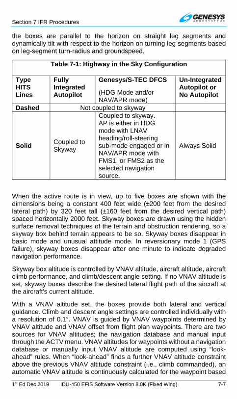
Section 7 IFR Procedures
1st Ed Dec 2019 IDU-450 EFIS Software Version 8.0K (Fixed Wing) 7-7
the boxes are parallel to the horizon on straight leg segments and dynamically tilt with respect to the horizon on turning leg segments based on leg-segment turn-radius and groundspeed.
Table 7-1: Highway in the Sky Configuration
Type HITS Lines
Fully Integrated Autopilot
Genesys/S-TEC DFCS
(HDG Mode and/or NAV/APR mode)
Un-Integrated Autopilot or No Autopilot
Dashed Not coupled to skyway
Solid Coupled to Skyway
Coupled to skyway. AP is either in HDG mode with LNAV heading/roll-steering sub-mode engaged or in NAV/APR mode with FMS1, or FMS2 as the selected navigation source.
Always Solid
When the active route is in view, up to five boxes are shown with the dimensions being a constant 400 feet wide (±200 feet from the desired lateral path) by 320 feet tall (±160 feet from the desired vertical path) spaced horizontally 2000 feet. Skyway boxes are drawn using the hidden surface removal techniques of the terrain and obstruction rendering, so a skyway box behind terrain appears to be so. Skyway boxes disappear in basic mode and unusual attitude mode. In reversionary mode 1 (GPS failure), skyway boxes disappear after one minute to indicate degraded navigation performance.
Skyway box altitude is controlled by VNAV altitude, aircraft altitude, aircraft climb performance, and climb/descent angle setting. If no VNAV altitude is set, skyway boxes describe the desired lateral flight path of the aircraft at the aircraft's current altitude.
With a VNAV altitude set, the boxes provide both lateral and vertical guidance. Climb and descent angle settings are controlled individually with a resolution of 0.1°. VNAV is guided by VNAV waypoints determined by VNAV altitude and VNAV offset from flight plan waypoints. There are two sources for VNAV altitudes; the navigation database and manual input through the ACTV menu. VNAV altitudes for waypoints without a navigation database or manually input VNAV altitude are computed using “look-ahead” rules. When “look-ahead” finds a further VNAV altitude constraint above the previous VNAV altitude constraint (i.e., climb commanded), an automatic VNAV altitude is continuously calculated for the waypoint based

Section 7 IFR Procedures
7-8 IDU-450 EFIS Software Version 8.0K (Fixed Wing) 1st Ed Dec 2019
upon an immediate climb to the altitude constraint at the higher of actual climb angle or the climb angle setting (dynamic climb angle). When “look-ahead” finds a further VNAV altitude constraint below the previous VNAV altitude constraint (i.e., descent commanded), an automatic VNAV altitude is calculated for the waypoint based upon a descent to reach the VNAV altitude constraint at the associated waypoint using the descent angle setting. If no further VNAV altitude constraints are found, the automatic VNAV altitude is set to the last valid VNAV altitude constraint.
When a VNAV climb is desired, the boxes are drawn at a vertical position the higher of: (a) the dynamic climb angle emanating from the aircraft's present position (aircraft-referenced); (b) the dynamic climb angle emanating from the next waypoint VNAV altitude (geo-referenced forward); or (c) the climb angle setting emanating from the previous waypoint VNAV altitude (geo-referenced backward). The geo-referenced backward calculation is only considered when the current leg is part of a procedure and is designed to provide pilot awareness, if a specified climb gradient is not being met. Once the boxes intercept the VNAV altitude, further boxes are drawn with a zero angle to show a level off followed by a level flight segment. Because five boxes are shown, the level-off depiction is an anticipatory cue for the pilot. Climb guidance is depicted in Figure 7-2, Figure 7-3, and Figure 7-4.
Figure 7-2: Highway in the Sky (Aircraft Referenced)
VNAV Altitude
Level-Off Point
Depicted Flight Path
Dynamic Climb Angle
Active Waypoint

Section 7 IFR Procedures
1st Ed Dec 2019 IDU-450 EFIS Software Version 8.0K (Fixed Wing) 7-9
Figure 7-3: Highway in the Sky (Geo-Referenced Backward)
Figure 7-4: Highway in the Sky (Geo-Referenced Forward)
When a VNAV descent is desired, boxes are drawn with a zero angle until reaching a descent point. Further boxes are drawn downward at an angle corresponding to the descent angle setting. The descent point is defined by the intercept of a line emanating upward from the subsequent VNAV waypoint at the descent angle setting and a line representing level flight at the previous VNAV altitude. On the final approach segment of an IFR approach, descent angle and VNAV waypoint are defined in Table 7-2.
Table 7-2: Final Segment of IFR Approach, Descent Angle and VNAV Waypoint
Condition VNAV Waypoint Descent Angle IFR approach with valid final approach segment data block
Glidepath intercept point (GPIP) as defined in final approach segment data block
Descent angle as defined in final approach segment data block
VNAV Altitude
Level-Off Point
Depicted Flight Path
Climb Angle Setting
Previous Waypoint
VNAV Altitude
Level-Off Point
Depicted Flight Path
Dynamic Climb Angle
Active Waypoint

Section 7 IFR Procedures
7-10 IDU-450 EFIS Software Version 8.0K (Fixed Wing) 1st Ed Dec 2019
Table 7-2: Final Segment of IFR Approach, Descent Angle and VNAV Waypoint
Condition VNAV Waypoint Descent Angle No or invalid final approach segment data block
No intermediate waypoints exist between FAF and MAP
Missed approach point location
Straight line from FAF to MAP location and altitudes.
No or invalid final approach segment data block
Intermediate waypoints exist between FAF and MAP
Missed approach point location
Steepest descent angle based upon straight lines from FAF and sub-sequent inter-mediate waypoints to MAP location and altitudes
On the final approach segment of a VFR approach procedure, the higher of the descent angle setting or 3° is used.
Because five boxes are shown, the descent point depiction is an anticipatory cue. Figure 7-5 depicts descent guidance and creates an easily understood, yet safe, VNAV paradigm to meet the VNAV requirements current guidance.
Figure 7-5: Highway in the Sky Final Approach Segments
Further, the paradigm is biased towards keeping the aircraft at the highest altitude possible for the longest period of time. The climb paradigm compensates for an aircraft's ability to climb more steeply than specified

Section 7 IFR Procedures
1st Ed Dec 2019 IDU-450 EFIS Software Version 8.0K (Fixed Wing) 7-11
and warns of being below a desired climb gradient when the aircraft is unable to meet the specified climb angle. The descent paradigm encourages flying stabilized approaches.
7.3.2. Waypoint Sequencing
When automatic waypoint sequencing is suspended due to reasons 4 or 5 in § 7.3, the EFIS switches from “TO” to “FROM” operation when appropriate. If not suspended, automatic waypoint sequencing occurs in following conditions:
1) Bearing to the transition point (turn bisector for fly-by waypoint, active waypoint for fly-over waypoint) is more than 90° from the current course (i.e., transition from “TO” to “FROM” operation);
2) Aircraft location is within two turn diameters (based upon current true airspeed and 15° angle of bank) of the active waypoint location; and
3) Aircraft is within 90° of the current course (i.e., generally pointed in the correct direction).
The desired flight path is created from a sequence of straight, left turning, and right turning leg segments designed to provide smooth skyway, GPS/SBAS CDI, and lateral autopilot guidance. Each leg between waypoints is composed of up to nine segments. Otherwise radii for turning segments (other than DME arc or radius to a fix segments) are calculated with the parameter speed determined as follows:
1) If the waypoint is part of a DP and within 30NM of the departure runway, speed is the preprogrammed procedure speed.
2) If the waypoint is part of a STAR and within 30NM of the arrival runway, speed is the preprogrammed procedure speed.
3) If the waypoint is part of an IFR or VFR approach procedure, speed is the preprogrammed procedure speed.
4) If the waypoint is part of a holding pattern, speed is the preprogrammed procedure speed.
5) Within a SAR pattern, speed is the lower of holding speed or procedure speed.
6) Where a Fixed-Radius Transition (FRT) is defined by the navigation database for a waypoint, that turn radius is used for the turning segment. FRT is used in enroute flight in order to save the number of waypoints and to provide a smoother transition. The RF leg can only be used in a SID or in a STAR. It is the flight plan leg stored in the

Section 7 IFR Procedures
7-12 IDU-450 EFIS Software Version 8.0K (Fixed Wing) 1st Ed Dec 2019
navigation database, which is defined by constant radius turns around a given fix.
7) Otherwise, speed is the current true airspeed or procedure speed, whichever is higher.
In all cases, if NavData® derived speed limit is associated with the waypoint, speed is the lower of the NavData® derived speed limit or the speed determined above.
7.3.3. Fly-Over Waypoints
Figure 7-6: Fly-Over Waypoints
To create the desired flight path, each waypoint is designated as a fly-by or a fly-over waypoint. Waypoints are further subdivided into waypoints with a defined entry heading and waypoints with a defined exit heading. Waypoint auto-sequencing for fly-by waypoints occurs at the bisector of the turn. Waypoint auto-sequencing for fly-over waypoints occurs over the waypoint.
These waypoints are type fly-over with defined entry heading:
1) Exit from holding pattern;
2) Exit from procedure turn;
3) Entry into holding pattern;
4) Missed approach point;
5) Phantom waypoint (created by inserting a waypoint into the active flight plan or performing Direct-To function within the active flight plan -- avoids S-turns);
6) Last waypoint;
7) Start waypoint (created by creating a new active flight plan with the Direct-To function – avoids S-turns);
8) Reference (takeoff runway end) waypoint of a DP;
Auto-Sequence Auto-
Sequence Defined Exit Defined Entry
MFD PFD

Section 7 IFR Procedures
1st Ed Dec 2019 IDU-450 EFIS Software Version 8.0K (Fixed Wing) 7-13
9) Waypoint leading into discontinuity; and
10) Altitude, DME, or radial termination legs (ARINC-424 path types CA, FA, VA, CR, VR, CD, FD, and VD; see Table 7-3).
11) Waypoints marked as overfly in the navigation database.
Table 7-3: RNAV Path Terminator Leg Type
Path Designator Terminator Constant DME arc A A Altitude Course to C C Distance Direct Track D D DME Distance Course from a Fix to F F Fix Holding Pattern H I Next Leg Initial I M Manual Termination Constant Radius R R Radial Termination Track Between T Heading To V Examples: CF= Course to Fix, and FM= Course from a Fix to a Manual Termination, etc.
7.3.4. Fly-By Waypoints
MFD PFD
Normal Large Turn
Defined Exit Large Turn
Defined Entry
Figure 7-7: Fly-By Waypoints
These waypoints are type fly-over with defined exit heading:
Auto-Sequence
Bisector
Auto-Sequence
Bisector
Auto-Sequence
Bisector

Section 7 IFR Procedures
7-14 IDU-450 EFIS Software Version 8.0K (Fixed Wing) 1st Ed Dec 2019
1) Entry into procedure turn; and
2) Waypoint exiting a discontinuity with the exception of phantom waypoints or DP reference waypoints;
3) First waypoint with the exception of start waypoints or DP reference waypoints
4) Course to a fix legs that are not to the FAF/FAWP are Fly-By with defined entry heading. All other waypoints are fly-by with defined exit heading.
NOTE:
Entry adjustments should be expected anytime a turn exceeds 120⁰. Turns greater than 120⁰ should not be used in conjunction with RNP
routes. (RNP standards specifically exclude such turns from RNP requirements.)
Leg segments for paths are constructed by the EFIS as follows.
Table 7-4: Leg Segments for Paths Constructed by EFIS
Path Type
Waypoint # of Segments and Description
Entry Exit
Straight Leg, DME Arc or Radius to a Fix
Fly-By Fly-By
2nd half of fly-by turn at entry waypoint.
WGS-84 geodesic or arc path from entry to exit turns.
1st half of fly-by turn at exit waypoint.
Fly-By
Fly-Over Defined Exit Heading
2nd half of fly-by turn at entry waypoint.
WGS-84 geodesic or arc path from entry to exit turns.
Turn to exit heading prior to exit waypoint.
Fly-By
Fly-Over Defined Entry Heading
2nd half of fly-by turn at entry waypoint.
WGS-84 geodesic or arc path from entry turn to exit waypoint.
Fly-Over Defined Exit Heading
Fly-By WGS-84 geodesic or arc path from entry waypoint to exit turn.
1st half of fly-by turn at exit waypoint.

Section 7 IFR Procedures
1st Ed Dec 2019 IDU-450 EFIS Software Version 8.0K (Fixed Wing) 7-15
Table 7-4: Leg Segments for Paths Constructed by EFIS
Path Type
Waypoint # of Segments and Description
Entry Exit Fly-Over Defined Exit Heading
Fly-Over Defined Exit Heading
WGS-84 geodesic or arc path from entry waypoint to exit turn.
Turn to exit heading prior to exit waypoint.
Fly-Over Defined Exit Heading
Fly-Over Defined Entry Heading
WGS-84 geodesic or arc path from entry waypoint to exit waypoint.
Fly-Over Defined Entry Heading
Fly-By
Turn from entry heading after entry waypoint.
WGS-84 geodesic or arc path from entry to exit turns.
1st half of fly-by turn at exit waypoint.
Fly-Over Defined Entry Heading
Fly-Over Defined Exit Heading
Turn from entry heading after entry waypoint.
WGS-84 geodesic or arc path from entry to exit turns.
Turn to exit heading prior to exit waypoint.
Fly-Over Defined Entry Heading
Fly-Over Defined Entry Heading
Turn from entry heading after entry waypoint.
WGS-84 geodesic or arc path from entry turn to exit waypoint.
Procedure Turn
Fly-Over Defined Exit Heading
Fly-Over Defined Entry Heading
WGS-84 geodesic path from entry waypoint on outbound heading for 30 seconds.
Turn to procedure turn heading (45°).
Outbound on procedure turn heading for 72 seconds.
Turn to inbound heading (135°).
WGS-84 geodesic path to exit waypoint. Entry waypoint and exit waypoint are same point.
Holding Pattern
Fly-Over Defined Entry Heading
Fly-Over Defined Entry Heading
Turn to proper entry procedure heading. This heading varies. For a parallel entry, it is 180° from the holding course. For direct and teardrop
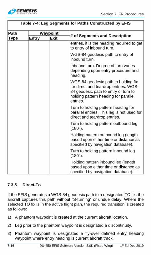
Section 7 IFR Procedures
7-16 IDU-450 EFIS Software Version 8.0K (Fixed Wing) 1st Ed Dec 2019
Table 7-4: Leg Segments for Paths Constructed by EFIS
Path Type
Waypoint # of Segments and Description
Entry Exit entries, it is the heading required to get to entry of inbound turn.
WGS-84 geodesic path to entry of inbound turn.
Inbound turn. Degree of turn varies depending upon entry procedure and heading.
WGS-84 geodesic path to holding fix for direct and teardrop entries. WGS-84 geodesic path to entry of turn to holding pattern heading for parallel entries.
Turn to holding pattern heading for parallel entries. This leg is not used for direct and teardrop entries.
Turn to holding pattern outbound leg (180°).
Holding pattern outbound leg (length based upon either time or distance as specified by navigation database).
Turn to holding pattern inbound leg (180°).
Holding pattern inbound leg (length based upon either time or distance as specified by navigation database).
7.3.5. Direct-To
If the EFIS generates a WGS-84 geodesic path to a designated TO fix, the aircraft captures this path without “S-turning” or undue delay. Where the selected TO fix is in the active flight plan, the required transition is created as follows:
1) A phantom waypoint is created at the current aircraft location.
2) Leg prior to the phantom waypoint is designated a discontinuity.
3) Phantom waypoint is designated a fly-over defined entry heading waypoint where entry heading is current aircraft track.

Section 7 IFR Procedures
1st Ed Dec 2019 IDU-450 EFIS Software Version 8.0K (Fixed Wing) 7-17
Where the selected TO fix is not in the active flight plan, the required transition is created as follows:
1) A new active flight plan is created from “Start” (current aircraft location) to the TO fix.
2) “Start” waypoint is designated a fly-over defined entry heading waypoint where entry heading is current aircraft track.
7.3.5.1. Direct-To Unnamed Waypoints Inside Procedures
The following identifiers are implemented for unnamed waypoints inside a published procedure and are found on the ND or inside the active flight plan.
1) -ALT- altitude terminations
2) -DIR- waypoints that begin a Direct-To leg
3) -DME- distance or DME terminations
4) -INT- intercept terminations
5) -RAD- radial terminations
6) -MAN- manual terminations
Active Flight Plan MFD Navigation
Display PFD Active Waypoint
Information
Figure 7-8: Unnamed Waypoints
7.4. Discontinuities
When the EFIS is unable to construct a smooth flight path, as described above due to active flight plan waypoint spacing (i.e., spacing too close for turn radius), a discontinuity is placed between the waypoints. When a discontinuity exists, no path nor skyway is drawn between the waypoints. The pilot cannot activate the waypoint exiting the discontinuity, as it is not possible to provide path guidance to this waypoint. Attempts to activate the waypoint exiting the discontinuity activates the next waypoint or, if there is no next waypoint (i.e., end of active flight plan), activation of the waypoint leading into the discontinuity.

Section 7 IFR Procedures
7-18 IDU-450 EFIS Software Version 8.0K (Fixed Wing) 1st Ed Dec 2019
7.4.1. Manual Termination Legs
Manual termination legs (ARINC 424 path types FM and VM) are a special case and are handled as follows:
1) The manual termination leg is a discontinuity; The manual termination leg is rendered as a path on the database course/heading for 10NM beyond either: (a) the previous waypoint (manual leg not active); or (b) the nearest on-path point (manual leg active);
2) Rendering of the manual termination leg will not terminate with a waypoint symbol;
3) The manual termination leg will be followed by a discontinuity;
4) Waypoint sequencing is suspended on the manual termination leg;
5) Once the CDI transitions to FROM operation, RESUME (L2) appears;
6) When ready to end manual navigation and resume a path to the waypoint following the manual termination leg, press RESUME (L2) to create and activate a Direct-To path to the waypoint.
NOTE:
If the manual termination leg is not followed by another waypoint (other than a suppressed waypoint), RESUME (L2) does not appear,
because there would be no waypoint-to-waypoint sequencing to resume.
7.5. Magnetic Course
The source of magnetic variation used for paths defined using magnetic course is in accordance with the following:
1) If the leg is part of a database terminal area procedure and the magnetic variation is specified by the State for that procedure, the magnetic variation to be used is the value specified.
2) If the leg is not part of a procedure and the active fix is a VOR, the magnetic variation to be used is the published station declination for the VOR.
3) If the leg is not part of a procedure and the terminating fix is not a VOR, the magnetic variation to be used is defined by the system using an internal model.

Section 7 IFR Procedures
1st Ed Dec 2019 IDU-450 EFIS Software Version 8.0K (Fixed Wing) 7-19
The EFIS has the capability of computing magnetic variation at any location within the region where flight operations may be conducted using magnetic north reference. The assigned magnetic variation is calculated with the NIMA GEOMAG algorithm and World Magnetic Model appropriate to the five-year cycle.
7.5.1. AHRS Modes for Heading Source
AHRS Slaved—EFIS Magnetic North: Standard mode of operation. Everything displayed relative to magnetic north drift free.
AHRS Slaved—EFIS True North: Everything displayed relative to true north with drift free heading. The preferred way to operate in areas where navigation is done relative to true north. (See Section 9 Appendix for limitations on Earth’s magnetic flux horizontal field.)
AHRS Free/“DG”—EFIS Magnetic North: Use when operating around significant magnetic disturbances in areas where navigation is done relative to magnetic north. Ensure the compass rose is slewed to a magnetic north value.
AHRS Free/“DG”—EFIS True North: Method of operation in high-latitude areas where navigation is accomplished relative to true north. Heading is not drift free and requires periodic correction. This mode may also be used when operating around significant magnetic disturbances in areas where navigation is done relative to true north. Ensure the compass rose is slewed to a true north value.
7.5.2. GPS Altitude
WGS-84 ellipsoid altitude received from the GPS/SBAS is converted to geodetic (MSL) altitude using the EGM 2008 geoidal database, which is revised on a twelve-year cycle.
7.5.3. Dead Reckoning
The EFIS has dead reckoning capability and is active whenever the GPS/SBAS sensor is not sending a valid position. The EFIS projects the last known GPS/SBAS position forward using TAS and heading, corrected for last known wind as it continues to navigate using this position and the active flight plan. The system provides the capability to determine bearing to an airport, based upon the dead reckoning position.
7.5.4. Geodesic Path Computation Accuracy
The cross-track path deviation error between the computed path used to determine cross-track deviations and the true WGS-84 geodesic is less

Section 7 IFR Procedures
7-20 IDU-450 EFIS Software Version 8.0K (Fixed Wing) 1st Ed Dec 2019
than 10% of the horizontal alert limit of the navigation mode applicable to the leg containing the path.
7.5.5. Parallel Offsets
The parallel offset is a route parallel to, but offset from, the original active route. The basis of the offset path is the original flight plan leg(s) and one or more offset reference points as computed by the EFIS. The computed offset reference points are located so they lie on the intersection of lines drawn parallel to the host route at the desired offset distance and the line that bisects the track change angle, except where the parallel offset ends. In this case, the offset reference point is located abeam of the original flight plan waypoint at the offset distance.
The parallel offset function does not propagate through route discontinuities, unreasonable path geometries as follows:
1) Legs that are parts of approach procedures (IFR and VFR); or
2) Legs with complex geometries or that begin or end with dynamically terminations. (ARINC 424 path types other than CF, DF, or TF or any leg where the starting waypoint is not a fixed position); or
3) Legs that begin at an aircraft starting position (reference waypoint in a DP or Start/Phantom waypoints created by the Direct-To function.
Parallel offset function does not propagate through the following:
1) Any waypoint at the beginning or end of a route discontinuity; or
2) Any waypoint at the beginning or end of a prohibited leg type; or
3) A waypoint with an unreasonable path geometry (defined as a turn greater than 120°.
When the parallel offset function begins or ends within a flight plan due to the above constraints, parallel offset entry or exit waypoints are inserted into the flight plan. Discontinuities precede parallel offset entry waypoints and follow parallel offset exit waypoints. This allows the pilot to navigate to and from the parallel offset as required.
The EFIS provides guidance to parallel tracks at a selected offset distance. When executing a parallel offset, the navigation mode and all performance requirements of the original route in the active flight plan are applicable to the offset route. The EFIS provides for entry of offset distance in increments of 1 NM, left or right of course, and is capable of offsets of at least 20 NM. Offset mode is indicated with an advisory flag, e.g., . When in offset mode, the EFIS provides reference parameters (e.g., cross-track

Section 7 IFR Procedures
1st Ed Dec 2019 IDU-450 EFIS Software Version 8.0K (Fixed Wing) 7-21
deviation, distance-to-go, time-to-go) relative to the offset path and offset reference points.
Once a parallel offset is activated, the offset remains active for all flight plan route segments until removed automatically (transitioning through a parallel track exit waypoint), until the flight crew enters a “Direct-To” routing or activates a new flight plan route, or until (manual) cancellation.
Figure 7-9: Parallel Offset PTK-/PTK ENDING
NOTE:
If a parallel offset is entered in the active flight plan and then cancelled, that active flight plan is no longer eligible for configuring another
parallel offset without deleting and reopening due to the creation of a discontinuity.
Table 7-5: Parallel Offsets Symbols and Description
Symbol Description
Parallel offset has been created and has a designated ending waypoint.
Designated ending waypoint of parallel offset

Section 7 IFR Procedures
7-22 IDU-450 EFIS Software Version 8.0K (Fixed Wing) 1st Ed Dec 2019
Table 7-5: Parallel Offsets Symbols and Description
Symbol Description Parallel track advisory indicating offset track 3 NM to the right of host route.
PTK.. (L4) appears when active route is eligible for a parallel offset.
Approaching end of parallel offset waypoint
VNAV altitude is possible with offset of distance before or after waypoint.
VNAV altitude input is possible but not an offset of a distance before or after waypoint.
The absence of PTK (L4) indicates a parallel offset is not allowed for reasons stated above.
Indicates each waypoint is a part of the parallel offset.
7.6. Default GPS/SBAS Navigation Modes
In the default GPS/SBAS mode, the EFIS has enroute, terminal, LNAV approach, LNAV/VNAV approach, LP approach, LPV approach, VFR approach, and departure navigation modes. Mode annunciation, alert limits (horizontal and vertical), and CDI FSD (horizontal and vertical) are determined by navigation mode.

Section 7 IFR Procedures
1st Ed Dec 2019 IDU-450 EFIS Software Version 8.0K (Fixed Wing) 7-23
Table 7-6: Default GPS/SBAS Navigation Modes
Navigation Mode Annunciation Enroute None
Terminal LNAV Approach LNAV/VNAV Approach LP Approach LPV Approach VFR Approach Departure
The system switches to default navigation modes based upon region of operation as in Table 7-7.
Table 7-7: Default Navigation Modes Based Upon Region of Operation
Default Nav Mode
Definition of Region/Default GPS/SBAS Navigation Modes
Departure
Selected when active waypoint is first waypoint of a departure or missed approach procedure and active leg heading is aligned (±3°) with active runway heading. Also, set when active waypoint is MAWP but a missed approach has been manually activated.
HAL 0.3NM
FSD (Horizontal) 0.3 NM
VTF approach (LNAV, LNAV/VNAV, LP, or LPV)
VTF IFR approach has been selected; and
within 30NM of the active runway; and
FAWP is active waypoint; and
bearing to FAWP is within 45° of final approach segment track (treated as a mode entry criteria); and
desired track to FAWP is within 45° of final approach segment track (treated as mode entry criteria).
HAL 0.3NM prior to FAWP, 556m (0.3NM after FAWP
FSD (Horizontal) Angular/Linear
VAL N/A prior to FAWP, 50m or reversion to barometric VNAV after FAWP
LNAV approach
MAWP or FAWP is active waypoint; and
if FAWP is active waypoint:
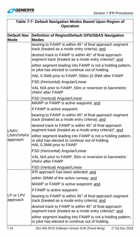
Section 7 IFR Procedures
7-24 IDU-450 EFIS Software Version 8.0K (Fixed Wing) 1st Ed Dec 2019
Table 7-7: Default Navigation Modes Based Upon Region of Operation
Default Nav Mode
Definition of Region/Default GPS/SBAS Navigation Modes bearing to FAWP is within 45° of final approach segment track (treated as a mode entry criteria); and
desired track to FAWP is within 45° of final approach segment track (treated as a mode entry criteria)*; and
either segment leading into FAWP is not a holding pattern, or pilot has elected to continue out of holding.
HAL 0.3NM prior to FAWP, 556m (0.3NM after FAWP
FSD (Horizontal) Angular/Linear
VAL N/A prior to FAWP, 50m or reversion to barometric VNAV after FAWP
FSD (Vertical) Angular/Linear
LNAV, LNAV/VNAV approach
MAWP or FAWP is active waypoint; and
if FAWP is active waypoint:
bearing to FAWP is within 45° of final approach segment track (treated as a mode entry criteria); and
desired track to FAWP is within 45° of final approach segment track (treated as a mode entry criteria)*; and
either segment leading into FAWP is not a holding pattern, or pilot has elected to continue out of holding. HAL 0.3NM prior to FAWP
FSD (Horizontal) Angular/Linear
VAL N/A prior to FAWP, 50m or reversion to barometric VNAV after FAWP
FSD (Vertical) Angular/Linear
LP or LPV approach
IFR approach has been selected; and
within 30NM of the active runway; and
MAWP or FAWP is active waypoint; and
if FAWP is active waypoint:
bearing to FAWP is within 45° of final approach segment track (treated as a mode entry criteria); and
desired track to FAWP is within 45° of final approach segment track (treated as a mode entry criteria)*; and
either segment leading into FAWP is not a holding pattern, or pilot has elected to continue out of holding.

Section 7 IFR Procedures
1st Ed Dec 2019 IDU-450 EFIS Software Version 8.0K (Fixed Wing) 7-25
Table 7-7: Default Navigation Modes Based Upon Region of Operation
Default Nav Mode
Definition of Region/Default GPS/SBAS Navigation Modes HAL 0.3NM 0.3 prior to FAWP
FSD (Horizontal) Angular/Linear
LPV VAL N/A prior to FAWP FSD (Vertical) Angular/Linear
VFR Approach
VFR Approach has been selected; and
within 30NM of the active runway; and
active runway is the active waypoint.
HAL 0.3NM
FSD (Horizontal) Angular/Linear
FSD (Vertical) Angular/Linear
Terminal
Not in departure mode; and
not in approach mode; and
active waypoint is part of a departure or active waypoint and previous waypoint are parts of an arrival or approach or within 30NM of the departure airport, arrival airport, or runway.
HAL 2NM
FSD (Horizontal) 2NM
FSD (Vertical) 150m
Enroute
Not in departure, approach, nor terminal modes. HAL 2NM
FSD (Horizontal) 1NM
FSD (Vertical) 150m
7.7. Required Navigation Performance
The EFIS supports required navigation performance as follows:
1) Manually entering RNP values; or
2) RNP values automatically retrieved from the navigation database that are associated airways or procedures (DPs, STARs or IAPs).

Section 7 IFR Procedures
7-26 IDU-450 EFIS Software Version 8.0K (Fixed Wing) 1st Ed Dec 2019
7.7.1. Manually Entered RNP Value
If a manually entered RNP value exists, it is annunciated along with the ANP. The navigation mode is RNP and the manually entered RNP value is used to determine CDI FSD, LON, and LOI alerting. Manual RNP overrides all other modes.
7.7.2. When in an Approach Region of Operation
When inside an approach region of operation, system operation conforms to the mode in the associated “Level of Service” navigation database record. The “Level of Service” record tracks the minima lines in the IAP published approach plate.
7.7.3. When outside the Approach Region of Operation
When outside the approach region of operation and neither a manually entered nor automatic RNP value exists, the EFIS defaults to GPS/SBAS operation.
Table 7-8: Default Navigation Modes Based Upon Region of Operation
Navigation Mode
Annunciation HAL1 FSD(H) VAL FSD(V)
Manual RNP (manually set between 0.1NM and 15NM)
0.1 to ≥ 4.0NM
= HAL N/A2 500 ft.
Manual RNP on final approach segment
0.1 to ≥ 4.0NM
= HAL
N/A prior to FAWP, RNP-dependent or reversion to barometric VNAV after FAWP2
150 ft.
Automatic RNP (retrieved from navigation database)
0.1 to ≥ 4.0NM
= HAL N/A2 500 ft.

Section 7 IFR Procedures
1st Ed Dec 2019 IDU-450 EFIS Software Version 8.0K (Fixed Wing) 7-27
Table 7-8: Default Navigation Modes Based Upon Region of Operation
Navigation Mode
Annunciation HAL1 FSD(H) VAL FSD(V)
Automatic RNP on final approach segment
0.1 to ≥ 4.0NM
= HAL
N/A prior to FAWP, RNP-dependent or reversion to barometric VNAV after FAWP2
150 ft.
1 HAL is the manually set or automatically retrieved RNP value.
2 EFIS provides advisory vertical guidance. On all route segments other than the final approach segment, barometric altitude driven by an ADC (if applicable) is used as the control parameter. On the final approach segment, GPS-derived altitude is the preferred control parameter and is selected so long as the VPL is less than the VAL of 35m (RNP < 0.23NM) or 50m (RNP ≥ 0.23NM). In the event that VPL is greater than these values, the system selects barometric VNAV. Once GPS-derived altitude is selected for the final approach segment, there is no reversion to barometric VNAV.
7.8. GPS/SBAS CDI Scale and FSD Transitions
Table 7-9: Summary of Changes In Cross-Track FSD
To Enroute To Terminal To Approach
From Enroute
Change from ±2 NM FSD to ±1 NM FSD over distance of 1 NM; start transition when entering terminal mode.
When outside the approach region of operation, If a manually entered RNP value does not exist but an automatic RNP value retrieved from the navigation database does exist, then the automatically retrieved RNP value

Section 7 IFR Procedures
7-28 IDU-450 EFIS Software Version 8.0K (Fixed Wing) 1st Ed Dec 2019
Table 7-9: Summary of Changes In Cross-Track FSD
To Enroute To Terminal To Approach is annunciated along with the actual ANP is displayed. Navigation mode is RNP and automatically retrieved RNP value is used to determine CDI FSD LON and LOI alerting.
From Terminal
Change from ±1 NM FSD to ±2 NM FSD over distance of 1 NM; start transition when entering enroute mode.
If VTF, switch immediately. Otherwise, change from ±1 NM FSD to approach FSD over distance of 2 NM; start transition at 2 NM from FAWP.
From Approach
Change to 1 NM.
From Departure
If initial leg is aligned with runway, change from ±0.3 NM FSD to ±1 NM FSD at turn initiation point of first fix in departure procedure.

Section 7 IFR Procedures
1st Ed Dec 2019 IDU-450 EFIS Software Version 8.0K (Fixed Wing) 7-29
7.9. Approach Type Selection
Figure 7-10: GPS Mode (LNAV APPR)
The EFIS selects the approach type (LNAV, LNAV/VNAV, LP, or LPV) when entering approach mode with the following order of precedence and prerequisites:
1) LPV:
a) LPV Enable is enabled;
b) ARINC-424 “Level of Service” indicates LPV minimums are published;
c) Valid long-term, fast, and ionospheric SBAS corrections are available and being applied to at least 4 GPS satellites;
d) Final approach segment data block exists and passes the Built-in-Test; and
e) Horizontal and vertical alert limits from final approach segment data block are predicted to be supported.
2) LP: (Same precedence and prerequisites as LPV)
3) LNAV/VNAV:
a) ARINC-424 “Level of Service” indicates LNAV/VNAV minimums are published;
b) If a final approach segment data block exists, LPV Enable is enabled;
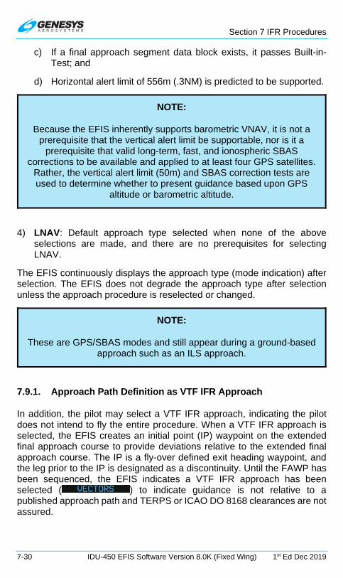
Section 7 IFR Procedures
7-30 IDU-450 EFIS Software Version 8.0K (Fixed Wing) 1st Ed Dec 2019
c) If a final approach segment data block exists, it passes Built-in-Test; and
d) Horizontal alert limit of 556m (.3NM) is predicted to be supported.
NOTE:
Because the EFIS inherently supports barometric VNAV, it is not a prerequisite that the vertical alert limit be supportable, nor is it a
prerequisite that valid long-term, fast, and ionospheric SBAS corrections to be available and applied to at least four GPS satellites.
Rather, the vertical alert limit (50m) and SBAS correction tests are used to determine whether to present guidance based upon GPS
altitude or barometric altitude.
4) LNAV: Default approach type selected when none of the above selections are made, and there are no prerequisites for selecting LNAV.
The EFIS continuously displays the approach type (mode indication) after selection. The EFIS does not degrade the approach type after selection unless the approach procedure is reselected or changed.
NOTE:
These are GPS/SBAS modes and still appear during a ground-based approach such as an ILS approach.
7.9.1. Approach Path Definition as VTF IFR Approach
In addition, the pilot may select a VTF IFR approach, indicating the pilot does not intend to fly the entire procedure. When a VTF IFR approach is selected, the EFIS creates an initial point (IP) waypoint on the extended final approach course to provide deviations relative to the extended final approach course. The IP is a fly-over defined exit heading waypoint, and the leg prior to the IP is designated as a discontinuity. Until the FAWP has been sequenced, the EFIS indicates a VTF IFR approach has been selected ( ) to indicate guidance is not relative to a published approach path and TERPS or ICAO DO 8168 clearances are not assured.

Section 7 IFR Procedures
1st Ed Dec 2019 IDU-450 EFIS Software Version 8.0K (Fixed Wing) 7-31
7.9.2. VTF IFR Approach
In addition, the pilot may select a VTF IFR approach, indicating the pilot does not intend to fly the entire procedure. When a VTF IFR approach is selected, the EFIS creates an initial point (IP) waypoint on the extended final approach course to provide deviations relative to the extended final approach course. The IP is a fly-over defined exit heading waypoint, and the leg prior to the IP is designated a discontinuity. Until the FAWP is sequenced, the EFIS indicates a VTF IFR approach has been selected (
) to indicate guidance is not relative to a published approach path, and TERPS clearances are not assured.
7.9.3. VTF VFR Approach
The pilot may select a VFR approach to a runway or user waypoint with a defined approach bearing. When a VFR approach is selected, the EFIS creates an “IP” waypoint approximately 12 NM on the extended final approach course to provide deviations relative to the extended final approach course. The IP is designated a fly-over defined exit heading waypoint, and the leg prior to the IP is designated a discontinuity.
Figure 7-11: VTF VFR Approach
As depicted in Figure 7-11, during the VTF VFR approach, the aircraft proceeds towards the IP. Since the IP is designated as a discontinuity, proceeding direct is not possible. When attempting to proceed direct to the IP, only the active leg between the IP and RW07 is activated.
7.10. Missed Approach and Departure Path Definition
Once on the final approach segment, the pilot may initiate an immediate missed approach or arm the system to execute the missed approach at the MAWP. If armed before crossing the MAWP, the equipment arms the missed approach for automatic initiation at the MAWP. If a missed approach is not initiated prior to crossing the MAWP, the EFIS switches to FROM mode at the MAWP and continues on the same course.
If the pilot initiates the missed approach, the EFIS provides guidance relative to the procedure. If a missed approach is armed prior to crossing the MAWP, the desired path to and after the MAWP is defined by the procedure. If the first leg in the missed approach procedure is not a straight path aligned within 3° of the final approach course, the FSD changes to terminal mode FSD (±1 NM) when the missed approach is initiated.

Section 7 IFR Procedures
7-32 IDU-450 EFIS Software Version 8.0K (Fixed Wing) 1st Ed Dec 2019
Otherwise, the FSD changes to ±0.3 NM when the missed approach is initiated (departure mode) and changes to terminal mode FSD (±1 NM) at the turn initiation point of the first waypoint in the missed approach procedure.
Figure 7-12: Missed Approach and Departure Path Created
The pilot may select DP guidance and, if the first leg in the DP is not a straight path aligned within 3° of the runway heading, terminal mode FSD (±1NM) is used. Otherwise, the FSD is ±0.3 NM (departure mode) and changes to terminal mode FSD (±1 NM) at the turn initiation point of the first waypoint in the DP.
7.11. Loss of Navigation Monitoring
The EFIS continuously monitors for loss of navigation capability. In manual or automatic RNP mode prior to sequencing the FAWP, the LON caution is displayed with a 10-second time to alert the RNP value is less than 2NM and a 30-second time to alert otherwise. RNP is also a statement of navigation performance necessary for operation within a defined airspace. Use the faults menu to distinguish the cause of the LON caution. The caution returns to its normal state upon termination of the responsible condition.
7.11.1. Automatic RNP Mode
In automatic RNP mode after sequencing the FAWP, the EFIS provides an indication when the navigation system is no longer adequate to conduct or
continue through use of and loss of terrain. The
Missed Approach

Section 7 IFR Procedures
1st Ed Dec 2019 IDU-450 EFIS Software Version 8.0K (Fixed Wing) 7-33
FAULTS menu allows the pilot to distinguish the cause of the loss of navigation caution. Once this LON condition exists, it is latched until the equipment is no longer in an approach mode.
7.11.2. Enroute Mode
While in enroute and terminal modes, the LON caution is also displayed until there is a termination of the responsible condition.
7.11.3. LNAV Approach Mode
In LNAV approach mode, the EFIS LON condition exists when the system is no longer adequate to conduct or continue the approach. Prior to sequencing the FAWP, the LON condition returns to its normal state immediately upon termination of the responsible condition. After sequencing the FAWP, the LON condition is latched until the EFIS is no longer in the approach mode. Prior to sequencing the FAWP, the LON condition returns to its normal state immediately upon termination of the responsible condition.
7.11.4. LNAV/VNAV Approach Mode
In LNAV/VNAV approach mode, the EFIS LON or VERT LON conditions are an indication that the EFIS is no longer able to continue the approach. The flags are displayed with the exception that when the LNAV/VNAV approach mode is predicated upon barometric VNAV.
The FAULTS menu enables the pilot to distinguish the cause of the loss of navigation caution. Prior to sequencing the FAWP, the flags return to their normal state immediately upon termination of the responsible condition. After sequencing the FAWP, the flags are latched until the equipment is no longer in an approach mode.
7.11.5. LP/LPV Approach Mode
In LP or LPV approach mode, the EFIS LON or VERT LON conditions are an indication that the EFIS is no longer able to continue the approach.
The FAULTS menu enables the pilot to distinguish the cause of the loss of navigation caution. Prior to sequencing the FAWP, the flags return to their normal state immediately upon termination of the responsible condition. After sequencing the FAWP, the flags are latched until the equipment is no longer in an approach mode.
7.12. Loss of Integrity Caution Monitoring
The EFIS provides a caution, independent of any pilot action when the EFIS experiences a loss of integrity monitoring. Loss of integrity monitoring

Section 7 IFR Procedures
7-34 IDU-450 EFIS Software Version 8.0K (Fixed Wing) 1st Ed Dec 2019
occurs when HPLFD exceeds the applicable HAL for longer than the applicable time to alert and HPLSBAS exceeds the HAL for the current navigation mode for longer than two seconds.
Table 7-10: Loss of Integrity Caution Monitoring
Phase of Flight HAL Time to Alert
RNP As manually set or automatically retrieved
10 seconds (RNP < 2NM)
30 seconds (otherwise)
Enroute 2NM 30 seconds Terminal 1NM 10 seconds LNAV Approach* 0.3NM 10 seconds LNAV/VNAV Approach* 0.3NM 10 seconds LP or LPV Approach* 0.3NM 10 seconds Departure 0.3NM 10 seconds * Requirements only apply prior to sequencing FAWP. Meeting LOI criteria after sequencing the FAWP is defined as a LON.
NOTE:
This aircraft is equipped for the following individual levels of RNP but may not be capable due to limited satellite coverage. Manual RNP is
selectable between 0.10NM and 15NM as follows:
1) 0.01NM increments between RNP 0.10 and RNP 0.3
2) 0.1NM increments between RNP 0.3 and RNP 2
3) 1NM increments between RNP 2 and RNP 15
7.13. Selection of an Instrument Procedure
When an instrument procedure is selected and active, the receiver notifies the pilot of the most accurate level of service supported by the combination of the GPS/SBAS signal, receiver, and selected approach using naming conventions on the minima lines of the selected approach procedure. Once the level of service has been given, the EFIS operates in this mode for the duration of the procedure, unless the level of service is unavailable. The EFIS cannot change back to a more accurate level of service until the next time an approach is activated.
The following are samples of step-by-step procedures:
Section 7 IFR Procedures
1st Ed Dec 2019 IDU-450 EFIS Software Version 8.0K (Fixed Wing) 7-35
1) Standard Terminal Arrival Route (STAR)
2) ILS Instrument Approach
3) ILS Instrument Approach with Manual Termination leg
4) LOC Back Course Instrument Approach
5) RNAV (GPS) Instrument Approach to LPV Minima
6) NRST ILS Instrument Approach with Standard Instrument Departure (SID)
7) VOR/DME Instrument Approach
8) Instrument approach with primary and alternate missed approach procedures.
7.13.1. Standard Terminal Arrival Route (STAR) (Step-By-Step)
If the selected waypoint is an airport with a published STAR, this option is available from a selection list of available STARs, transitions, and runways. After selection, the appropriate STAR is created and displayed on the MAP page. Activating a STAR deletes any pre-existing STAR, and it is inserted prior to any approach waypoints if previously entered.
STARS normally terminate at a fix near the airport, so a radar vector or feeder route is used for transition to the approach phase of the arrival. If an Instrument approach is activated during the STAR, the approach waypoints are inserted after the STAR.
The following example includes the execution of a Standard Terminal Arrival Route procedure into Friedrichshafen Germany (EDNY) followed by an ILS RWY 24.
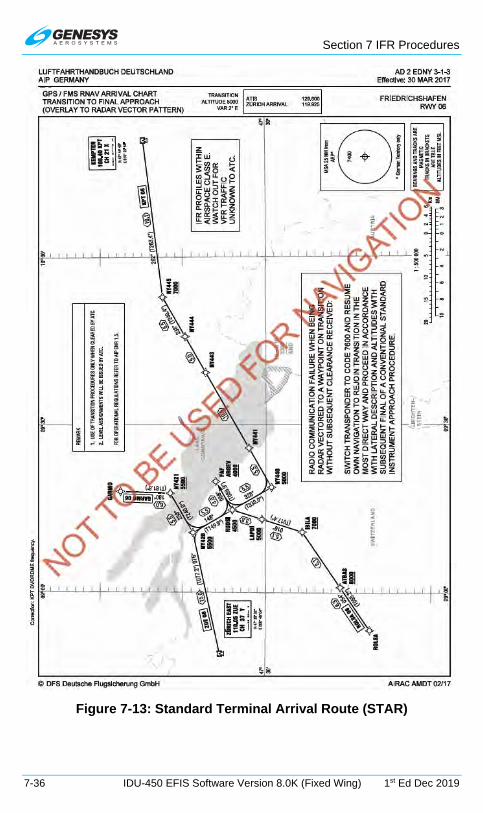
Section 7 IFR Procedures
7-36 IDU-450 EFIS Software Version 8.0K (Fixed Wing) 1st Ed Dec 2019
Figure 7-13: Standard Terminal Arrival Route (STAR)

Section 7 IFR Procedures
1st Ed Dec 2019 IDU-450 EFIS Software Version 8.0K (Fixed Wing) 7-37
1) Press ACTV (L2) arrival airport must be entered as a waypoint.
2) Push with desired airport (EDNY) highlighted.
3) Rotate to STAR.. and push to enter.
4) Rotate to desired STAR (KPT6P). Push to enter.
5) If no transition is offered, rotate to desired runway (RW24). Push to enter.
6) ATC clears direct MOKOP and ILS RWY 24. Press ACTV (L2) rotate to MOKOP and push to enter. (See § 7.13.2 for loading an ILS)
7) Push and rotate to NAV LOG and push to enter to view first portion and then rotate to view remainder of NAV LOG.

Section 7 IFR Procedures
7-38 IDU-450 EFIS Software Version 8.0K (Fixed Wing) 1st Ed Dec 2019
7.13.2. ILS Instrument Approach (Step-By-Step)
All approach operations begin with the same basic steps. This example selects ILS or LOC RWY 24 at Memmingen Germany (EDJA).
Figure 7-14: ILS Instrument Approach (EDJA)

Section 7 IFR Procedures
1st Ed Dec 2019 IDU-450 EFIS Software Version 8.0K (Fixed Wing) 7-39
1) With destination airport entered as the waypoint, press ACTV (L2). Rotate to desired airport and push to enter.
2) Rotate and select IFR APPR... Push to enter.
3) Rotate and select desired approach and push to enter.
4) Rotate and desired transition and push to enter.
5) Rotate and select desired runway and push to enter.
6) If instructed to hold at OGROB as published, rotate to OGROB and push to enter. Rotate to HOLD.. and push to enter and enter holding direction and leg length or time. Push to enter.
7) The holding pattern is created and is the next leg to be sequenced. ATC issues clearance for the ILS 24 Memmingen and to maintain 4000’.
8) Rotate to create holding entry and direction/leg length and push to enter.

Section 7 IFR Procedures
7-40 IDU-450 EFIS Software Version 8.0K (Fixed Wing) 1st Ed Dec 2019
9) Established in the HOLD as directed at 4000’. When ATC issues clearance for the approach, press CONT (L2) to continue waypoint sequencing to the FAF. (PFD shown)
10) Established in holding at OGROB (MFD shown)
11) Passing the FAF, press ARM (L2) to arm the missed approach procedure and continue waypoint sequencing.
12) ON the MFD press MENU (R1) and PAGE.. (R3) and push to enter. Rotate to HSI and push to enter.

Section 7 IFR Procedures
1st Ed Dec 2019 IDU-450 EFIS Software Version 8.0K (Fixed Wing) 7-41
13) Over the middle marker and with zoom mode active, press MENU (R1) then ZOOM (R3) to emulate the outside view in the PFI area. High on the glideslope with landing gear extended.
14) During the missed approach, press MENU (R1) then ZOOM OFF (R3) to restore normal wide field of view in the PFI area.
15) Missed approach segment appears as magenta and white dashed lines. The next leg (-ALT-) has an altitude termination leg of 3000’ which has already been achieved, therefore this leg is now –SKIPPED-.

Section 7 IFR Procedures
7-42 IDU-450 EFIS Software Version 8.0K (Fixed Wing) 1st Ed Dec 2019
7.13.3. ILS Approach with Manual Termination Leg in MAP (Step-By-Step)
This example selects RAF Cranwell United Kingdom (EGYD) with -ALT- termination leg followed by an immediate manual termination leg requiring pilot action to resume automatic waypoint sequencing.
Figure 7-15: ILS Approach (EGYD)

Section 7 IFR Procedures
1st Ed Dec 2019 IDU-450 EFIS Software Version 8.0K (Fixed Wing) 7-43
1) Press ACTV (L2). Rotate to the destination airport and push to enter.
2) Rotate to IFR APPR.. and push to enter.
3) Rotate to desired approach and push to enter.
4) Rotate to desired Transition and push to enter. (* = most logical from present position.)
5) Rotate to desired runway (colors the active runway light gray).
6) Press OBS (L4), NAV:VLOC1.. (L3) and rotate to FAC 264° and push to enter.
7) Passing the FAF, press ARM (L2) to arm the missed approach procedure and resume automatic waypoint sequencing.
8) Localizer minimums set as MDA 520’ and landing gear down.

Section 7 IFR Procedures
7-44 IDU-450 EFIS Software Version 8.0K (Fixed Wing) 1st Ed Dec 2019
9) Over the middle marker on glideslope and on the localizer. “Minimum, minimums” aural alert is sounding and Minimums (520) is flashing.
10) Past the MAWP, auto nav source switches to FMS-1 and auto waypoint sequencing is suspended due to -ALT- leg climbing to 2680’ with green altitude predictor arc indicating climb performance will achieve leg requirement.
11) Past the –ALT– termination leg and ready for pilot action to press RESUME (L2) to resume normal automatic waypoint sequencing.

Section 7 IFR Procedures
1st Ed Dec 2019 IDU-450 EFIS Software Version 8.0K (Fixed Wing) 7-45
12) After RESUME (L2) is pressed, normal waypoint sequencing resumes, course to next active waypoint appears as a magenta line, and active waypoint information is updated.

Section 7 IFR Procedures
7-46 IDU-450 EFIS Software Version 8.0K (Fixed Wing) 1st Ed Dec 2019
7.13.4. LOC Back Course Instrument Approach (Step-By-Step)
This example includes a LOC/DME Back Course approach at Santa Maria CA USA (KSMX) with attention drawn to OBS settings and includes blue numbers to associate places of reference on the chart and the EFIS.
Figure 7-16: LOC Back Course Approach
❶
❷
❸
❹
❺

Section 7 IFR Procedures
1st Ed Dec 2019 IDU-450 EFIS Software Version 8.0K (Fixed Wing) 7-47
1) Press ACTV (L2). Rotate to airport active waypoint. Push to enter.
2) Rotate to IFR APPR.. and push to enter.
3) Rotate to LBCA and push to enter.
4) Rotate to transition (*indicates most logical from current position). Push to enter.
5) Rotate to desired runway. Push to enter.
6) Follow ATC clearance and determine where to proceed. To view NAV LOG, press MENU (R1), press PAGE.. (R3), rotate to NAV LOG, and push to enter.
7) ❷ Assume ATC issued clearance to fly heading 184° for radar vectors to KOAKS, ACTV (L2) and
(R4) were pressed when KOAKS was highlighted.
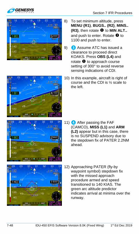
Section 7 IFR Procedures
7-48 IDU-450 EFIS Software Version 8.0K (Fixed Wing) 1st Ed Dec 2019
8) To set minimum altitude, press MENU (R1), BUGS.. (R2), MINS.. (R3), then rotate to MIN ALT.. and push to enter. Rotate to 1100 and push to enter.
9) ❸ Assume ATC has issued a clearance to proceed direct KOAKS. Press OBS (L4) and rotate to approach course setting of 300° to avoid reverse sensing indications of CDI.
10) In this example, aircraft is right of course and the CDI is ½ scale to the left.
11) ❹ After passing the FAF (CAMCO), MISS (L1) and ARM (L2) appear but in this case, there is no SUSPEND advisory due to the stepdown fix of PATER 2.2NM ahead.
12) Approaching PATER (fly-by waypoint symbol) stepdown fix with the missed approach procedure armed and speed transitioned to 140 KIAS. The green arc altitude predictor indicates arrival at minima over the runway.

Section 7 IFR Procedures
1st Ed Dec 2019 IDU-450 EFIS Software Version 8.0K (Fixed Wing) 7-49
13) Passing the MAWP, nav source automatically switches to the FMS and CDI changes cyan to magenta.
14) ❺ Entering HOLD at GLG and navigating on FMS1
15) CONT (L2) appears as a reminder to press when ready to leave the HOLD and continue to the destination KMIT.

Section 7 IFR Procedures
7-50 IDU-450 EFIS Software Version 8.0K (Fixed Wing) 1st Ed Dec 2019
7.13.5. RNAV (GPS) Instrument Approach to LPV Minima (Step-By-Step)
This example includes an RNAV (GPS) RWY 32 approach to Wichita, Kansas, USA (KICT) and includes blue numbers to associate places of reference on the chart and the EFIS.
Figure 7-17: RNAV (GPS) Instrument Approach to LPV Minima
❸
❹
❺

Section 7 IFR Procedures
1st Ed Dec 2019 IDU-450 EFIS Software Version 8.0K (Fixed Wing) 7-51
1) To select airport from active flight plan, press ACTV (L2) and then
rotate to desired airport and push to enter.
2) Rotate to IFR APPR.. and push to enter.
3) Rotate to desired approach and
verify WAAS channel number matches instrument approach chart and push to enter.
4) Rotate to the desired transition and push to enter. (* = transition following likely avenue of actual arrival direction.)
5) Rotate to assigned landing runway. (Active runway colored light gray for identification purposes.)
6) Rotate to scale map to desired value and observe T/D within instrument approach procedure.
7) Active leg is magenta line, and next leg is white.

Section 7 IFR Procedures
7-52 IDU-450 EFIS Software Version 8.0K (Fixed Wing) 1st Ed Dec 2019
8) During this leg enroute to BADAC, the TOD was passed and descent begun based upon VNAV-B as shown below VDI.
9) ❸ On final approach course and approaching the FAF, appears along with the VDI.
10) ❹ Upon passing HOLUS, press ARM (L2) to continue auto waypoint sequencing. (This is the latest point on the approach to press ARM)
11) VDI displays vertical guidance for the LPV vertical profile based on GPS/SBAS.

Section 7 IFR Procedures
1st Ed Dec 2019 IDU-450 EFIS Software Version 8.0K (Fixed Wing) 7-53
12) Obstructions appear on PFI and ND areas.
13) Press MENU (R1) then ZOOM (R3) for wide- angle view of PFI area.
14) FPM lined up on the active runway on glidepath approaching minimums with CDI centered and on glidepath approaching minimums of 1580’ MSL.
15) Below minimums with FPM aligned with touchdown zone on runway. Minimums are amber (yellow) and flashing as the audible alert, “Minimums, Minimums,” sounds.
16) Past the MAWP, NAV source remains FMS1 and scale automatically changes to 0.3NM FSD.

Section 7 IFR Procedures
7-54 IDU-450 EFIS Software Version 8.0K (Fixed Wing) 1st Ed Dec 2019
17) ❺ Established in hold at CEPGA. Press CONT (L2) to continue waypoint sequencing to next leg in active flight plan.

Section 7 IFR Procedures
1st Ed Dec 2019 IDU-450 EFIS Software Version 8.0K (Fixed Wing) 7-55
7.13.6. NRST ILS Instrument Approach (Step-By-Step)
This method does not require the airport to be in the active flight plan. This example selects ILS RWY 24 at Memmingen Germany (EDJA) with the NRST ILS method of creation followed by the Kempton Three Alpha (KPT 3A) SID.
Figure 7-18: NRST ILS Instrument Approach

Section 7 IFR Procedures
7-56 IDU-450 EFIS Software Version 8.0K (Fixed Wing) 1st Ed Dec 2019
Figure 7-19: Standard Instrument Departure Procedure
Figure 7-20: Kempton Three Alpha (KPT 3A) SID

Section 7 IFR Procedures
1st Ed Dec 2019 IDU-450 EFIS Software Version 8.0K (Fixed Wing) 7-57
1) Press NRST (R3) then rotate to ILS... Push to enter.
2) Once confirmed, push to activate the ILS.
Following actions occur:
a) Direct flight plan to the ILS airport is created.
b) A vectors-to-final ILS approach is activated.
c) Heading bug is activated to the current heading.
d) VLOC 1 and VLOC 2 OBS are set to the associated localizer course.
e) ILS frequency is automatically transmitted to NAV#1 in standby position.
f) EFIS changes to LOC1, and VDI indicates source of glideslope GS1.
3) Passing the FAF (OGROB), MISS (L1) and ARM (L2) appear. Press ARM (L2) to arm the missed approach procedure and continue automatic waypoint sequencing.
4) HITS indicates guidance to follow GPS overlay of the localizer and glideslope. However, the localizer source for CDI and glideslope receiver VDI are the primary sources for navigation guidance on this ILS approach.

Section 7 IFR Procedures
7-58 IDU-450 EFIS Software Version 8.0K (Fixed Wing) 1st Ed Dec 2019
5) Inside 2.0 NM final with
indicating no TAWS alerts are triggered and the default GPS mode of LNAV APPR is active.
6) To view the HSI page, press MENU (R1), PAGE.. (R3) and then rotate to HSI and push to enter.
7) Above DH over the middle marker and stabilized at 135 KIAS on the localizer centerline.
8) Glideslope is full scale deflection above glide path and go-around decisision has been made.
9) During the missed approach, the navigation source automatically switches to FMS1 with 0.3NM FSD. FLTA is still inhibited and terminal mode is active while within the terminal area.

Section 7 IFR Procedures
1st Ed Dec 2019 IDU-450 EFIS Software Version 8.0K (Fixed Wing) 7-59
10) Kempton Three Alpha SID was loaded to the (EDJA) suppressed waypoint, and JA242 and JA244 displayed on the white track line. This requires management of the active flight plan to follow the SID in lieu of the missed approach path.
11) Press ACTV (L2) and then rotate
to JA242, press (R4), and push to enter.
12) Now JA244 is the active waypoint with a magenta line going direct to active waypoint. With route of flight as follows:
On track 237° ALG to 5.3 DME ALD. LT, on track 166° to intercept R299 KPT to KPT climb to FL 70.

Section 7 IFR Procedures
7-60 IDU-450 EFIS Software Version 8.0K (Fixed Wing) 1st Ed Dec 2019
7.13.7. VOR/DME Instrument Approach (Step-By-Step)
This example loads the Lamar Muni Co. USA VOR/DME RWY 36 approach and is flown via the east arc followed by a missed approach. Blue numbers associate locations on chart and EFIS.
Figure 7-21: VOR/DME Instrument Approach
❶
❷
❸
❹
❺
❻
❼

Section 7 IFR Procedures
1st Ed Dec 2019 IDU-450 EFIS Software Version 8.0K (Fixed Wing) 7-61
1) With destination airport highlighted as the waypoint, press ACTV (L2). Rotate to IFR APPR... Push to enter.
2) ❶ Rotate to select desired approach (example, VORDME36) and push to enter.
3) Rotate to desired transition of DO48T (* = most likely transition from this avenue of arrival). Push to enter.
4) Rotate to desired runway. Push to enter.
5) Rotate to proper MAP range to view procedure and select fix for compliance with ATC clearance
❷ (DO48T). Press (R4) and push to enter.
6) A magenta line leads from the -DIR- current position to ❸ D048T, which is now the active waypoint. 6000’ is the VNAV altitude, and aircraft is descending to the HITS boxes with green arc altitude predictor showing where this altitude will be reached along the route.

Section 7 IFR Procedures
7-62 IDU-450 EFIS Software Version 8.0K (Fixed Wing) 1st Ed Dec 2019
7) Established on the 20 DME ARC ❹ with NAV1 and NAV2 set on 116.9 MHz for LAA VOR and inbound FAC set at 350° on both VORs with DME indicating on both nav sources.
8) Altitude predictor green arc indicates no pilot action is necessary for vertical planning. CF36 will be crossed at the published altitude.
9) Established inbound on the final approach course to the FAF (FF36) ❺ crossing top of descent symbol ahead indicating when descent can be commenced to cross the FAF at 5700’. NAV Source is VOR1 and HITS source is GPS. The primary lateral source is the VOR and DME for this Instrument approach.
10) After passing the FAF MISS (L1) and ARM (L2) appears to allow for executing the missed approach procedure immediately by pressing MISS (L1) or arming the Missed approach procedure upon crossing the MAWPT by pressing ARM (L2).

Section 7 IFR Procedures
1st Ed Dec 2019 IDU-450 EFIS Software Version 8.0K (Fixed Wing) 7-63
11) Approaching the ❻ stepdown fix 11VOR lower than 4498’ as shown in the waypoint information box.
12) Press MENU (R1) then ZOOM ON (R3). Established at 130 KIAS on short final with the runway in sight .6 NM ahead at the same angle as shown on the instrument approach chart.
13) After passing the MAWPT and the missed approach procedure was automatically sequenced, aircraft begins following the dashed magenta missed approach course lines on the MAP. NAV source automatically switched to FMS1 and 0.3NM FSD.
references to still being in the terminal area and TAWS terrain alerts are still inhibited.
❼

Section 7 IFR Procedures
7-64 IDU-450 EFIS Software Version 8.0K (Fixed Wing) 1st Ed Dec 2019
7.13.8. ILS or LOC RWY 1 Instrument Approach with Missed Approach Flown to Alternate fix (Step-By-Step)
This example loads the Akron-Canton ILS or LOC RWY 1 approach with the missed approach flown to the alternate missed approach fix (KEATN)
Figure 7-22: ILS or LOC RWY 1 Instrument Approach with Missed Approach Flown to Alternate fix (Step-By-Step)
During the instrument approach clearance, ATC advised that in the event of a missed approach, plan on flying the alternate missed approach instructions to ❶ KEATN intersection and hold as published. The ILS RWY 1 instrument approach is loaded and the active flight plan is opened and is scrolled to one position past (KCAK) and INSERT (R2) is pressed and entered KEATN with and pushed to enter.
1) ❶ Create KEATN waypoint in active flight plan and push to enter.
2) Rotate to HOLD.. and push to enter.
3) Create published holding pattern at KEATN and rotate/push through the process then push to enter. Observe KEATN is in
❶ ❷

Section 7 IFR Procedures
1st Ed Dec 2019 IDU-450 EFIS Software Version 8.0K (Fixed Wing) 7-65
correct position in active flight plan after (KCAK.)
4) ❷ Upon executing the missed approach, press ACTV (L2) and
rotate to KEATN then press (R4) and push to enter a direct routing to KEATN.
5) Verify the active flight plan has the holding pattern entered as published and is depicted on the MFD correctly.
6) Established in the holding pattern at KEATN. When cleared to continue to next waypoint on active flight plan, press CONT (L2) to resume waypoint sequencing.
7) If an instrument approach is necessary at the destination KMKE, the approach can be loaded without losing the holding pattern at KEATN since it was not part of the KCAK ILS 01 Instrument approach procedure.

Section 7 IFR Procedures
7-66 IDU-450 EFIS Software Version 8.0K (Fixed Wing) 1st Ed Dec 2019
8) When ATC provides a clearance for an instrument approach to KMKE, it can be added without losing the holding pattern at KEATN but the preceding ILS procedure is deleted automatically.
NOTE:
Navigation databases should be current for the duration of the flight. If the Aeronautical Information Regulation and Control (AIRAC) cycle is due to change during the flight, operators and pilots should establish
procedures to ensure the accuracy of navigation data including suitability of navigation facilities used to define the routes and
procedures for flight. Once acceptable means to compare aeronautical charts (new and old) to verify navigation fixes prior to departure,
electronic data have traditionally been verified against paper products. If an amended chart is published for the procedure, do not use the
database to conduct the operation.
There may be a slight difference between the navigation information portrayed on the chart and the primary navigation display heading.
Differences of three degrees or less may result from equipment manufacturer’s application of magnetic variation and are operationally
acceptable.
GPS receivers do not “fail down” to lower levels of service once the approach has been activated.
If only appears, use the LNAV minima if the rules under which the flight is operating allow changing the type of approach being flown after commencing the procedure. If the lateral integrity limit is exceeded on
an LP approach, a missed approach is necessary, since the lateral alarm limit may not be reset while the approach is active.

Section 8 Terrain Awareness Warning System
1st Ed Dec 2019 IDU-450 EFIS Software Version 8.0K (Fixed Wing) 8-1
Section 8 Terrain Awareness Warning System
8.1. TAWS Functions
The IDU provides TSO-C151b TAWS functionality. The following description is for a TAWS Class A, B, and C depending on aircraft configuration and external sensors/switches. Warning functions provided by TAWS are as follows. See Section 2 System Overview for additional information on system warning, caution, and advisory alerts.
Table 8-1: TAWS Functions Provided by the EFIS
Aircraft Type Airplane
Airplane RG + F RG FG + F FG
TAWS Class A A A A B or C Terrain Display FLTA PDA GPWS Mode 1 GPWS Mode 2
GPWS Mode 3 GPWS Mode 4
GPWS Mode 5
500’ Call
1) Terrain Display: Terrain and obstacles on PFD and ND.
2) Forward Looking Terrain Awareness (FLTA): Alerts to hazardous terrain or obstructions in front of the aircraft.
3) Premature Descent Alert (PDA): Alerts when descending well below a normal approach glidepath on the final approach segment of an instrument approach procedure.
4) Excessive Rate of Descent (GPWS Mode 1): Alerts when high rate of descent above terrain (i.e., descending into terrain).
5) Excessive Closure Rate to Terrain (GPWS Mode 2): Alerts when hazardously high rate of change over rising terrain.
6) Sink Rate after Takeoff or Missed Approach (GPWS Mode 3): Alerts when loss of altitude is detected immediately after takeoff or initiation of a missed approach.

Section 8 Terrain Awareness Warning System
8-2 IDU-450 EFIS Software Version 8.0K (Fixed Wing) 1st Ed Dec 2019
7) Flight into Terrain when not in Landing Configuration (GPWS Mode 4): Alerts when descending into terrain without properly configuring the aircraft for landing.
8) Excessive Downward Deviation from an ILS Glideslope (GPWS Mode 5): Alerts when deviating below glideslope on the ILS final approach segment.
9) 500 foot Wake-up Call: Single audible callout when descending through 500 feet AGL.
8.2. Terrain Display
Figure 8-1: PFD Terrain Display
Figure 8-2: MFD Terrain Display

Section 8 Terrain Awareness Warning System
1st Ed Dec 2019 IDU-450 EFIS Software Version 8.0K (Fixed Wing) 8-3
Display of terrain on the PFD and ND are described in Sections 3 Display Symbology and 5 Menu Functions and Step-By-Step Procedures where applicable.
8.3. Forward Looking Terrain Alert Function
Figure 8-3: FLTA INHBT
FLTA function uses the following to alert to hazardous terrain or obstructions within a search envelope in front of the aircraft:
1) Terrain database
2) Obstruction database
3) Airport and runway database
4) Aircraft position
5) Aircraft track
6) Aircraft groundspeed
7) Aircraft bank angle
8) Aircraft altitude
9) Aircraft vertical speed
8.3.1. FLTA Modes
FLTA mode is either slaved to the GPS/SBAS navigation mode or set automatically based upon default mode logic.
8.3.2. GPS/SBAS Navigation Mode Slaving
The EFIS performs TSO-C146c GPS/SBAS functions in addition to the TAWS functions. As a result, GPS/SBAS navigation mode is available as an input to the TAWS. The pilot may select an IFR procedure (approach, DP, or STAR), which automatically changes the GPS/SBAS navigation mode to enroute, terminal, departure, or IFR approach as appropriate. In addition, the pilot may select a VFR approach to any runway or user waypoint with a defined approach path. Selection of a VFR approach causes automatic GPS/SBAS navigation mode changes to enroute, terminal, or VFR approach as appropriate.
When slaved, the GPS/SBAS active runway threshold or user waypoint is the reference point for automatic FLTA inhibiting. The advantage is the

Section 8 Terrain Awareness Warning System
8-4 IDU-450 EFIS Software Version 8.0K (Fixed Wing) 1st Ed Dec 2019
GPS/SBAS navigation modes are a direct indication to the FLTA function of pilot intent.
8.3.3. Default FLTA Mode
If the default FLTA navigation mode is higher in precedence than the GPS/SBAS navigation mode, FLTA mode is slaved to the default FLTA navigation mode. These modes and order of precedence are:
1) Departure Mode: Enabled when in ground mode. Reference point for automatic FLTA inhibiting and mode envelope definition is the last point at which the ground definition was satisfied (near the liftoff point). Departure mode ends upon climbing through 1500 feet above or traveling more than 6NM from the reference point.
Figure 8-4: Default FLTA INHBT
2) Other Modes: For other default FLTA modes, reference point for automatic FLTA inhibiting and mode envelope is the nearest runway threshold or user waypoint with a defined approach bearing. TAWS continuously searches all runway thresholds at the nearest three airports to determine the nearest runway threshold. TAWS performs a search for the nearest three airports and nearest user waypoints with a defined approach bearing every 3NM of distance traveled. Modes are as follows:
a) Approach Mode: When within 1900 feet and 5NM of the reference point.
b) Terminal Mode: From 5NM to 15NM from the reference point when below an altitude that varies from 1900 feet (at 5NM) to 3500 feet (at 15NM) above the reference point.
c) Enroute Mode: When not in any other mode.
FLTA Inhibit
Departure Mode
Reference Point
Departure Mode
6NM 6NM
1500’
2NM 2NM
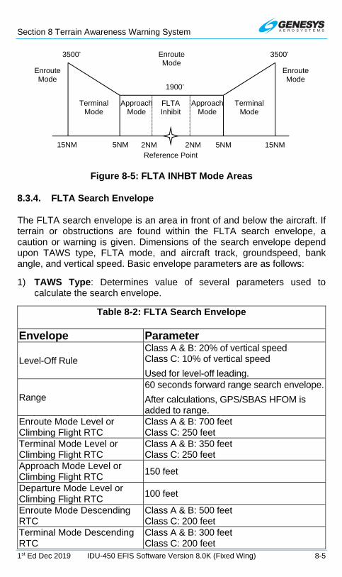
Section 8 Terrain Awareness Warning System
1st Ed Dec 2019 IDU-450 EFIS Software Version 8.0K (Fixed Wing) 8-5
Figure 8-5: FLTA INHBT Mode Areas
8.3.4. FLTA Search Envelope
The FLTA search envelope is an area in front of and below the aircraft. If terrain or obstructions are found within the FLTA search envelope, a caution or warning is given. Dimensions of the search envelope depend upon TAWS type, FLTA mode, and aircraft track, groundspeed, bank angle, and vertical speed. Basic envelope parameters are as follows:
1) TAWS Type: Determines value of several parameters used to calculate the search envelope.
Table 8-2: FLTA Search Envelope
Envelope Parameter
Level-Off Rule Class A & B: 20% of vertical speed Class C: 10% of vertical speed
Used for level-off leading.
Range 60 seconds forward range search envelope.
After calculations, GPS/SBAS HFOM is added to range.
Enroute Mode Level or Climbing Flight RTC
Class A & B: 700 feet Class C: 250 feet
Terminal Mode Level or Climbing Flight RTC
Class A & B: 350 feet Class C: 250 feet
Approach Mode Level or Climbing Flight RTC
150 feet
Departure Mode Level or Climbing Flight RTC
100 feet
Enroute Mode Descending RTC
Class A & B: 500 feet Class C: 200 feet
Terminal Mode Descending RTC
Class A & B: 300 feet Class C: 200 feet
Enroute Mode
Enroute Mode
Terminal Mode
Terminal Mode
15NM 15NM
3500’ 3500’
FLTA Inhibit
Approach Mode
Approach Mode
5NM 5NM
1900’
2NM 2NM
Enroute Mode
Reference Point

Section 8 Terrain Awareness Warning System
8-6 IDU-450 EFIS Software Version 8.0K (Fixed Wing) 1st Ed Dec 2019
Table 8-2: FLTA Search Envelope
Envelope Parameter Approach Mode Descending RTC
100 feet
Departure Mode Descending RTC
100 feet
2) Aircraft Track: Terrain search envelope is aligned with aircraft track.
3) Aircraft Groundspeed: Used in conjunction with range parameter to determine the look-ahead distance and used with FLTA mode to determine search volume width as follows:
a) Enroute Mode: Based on a 30 change in track followed by 30 seconds of flight at aircraft groundspeed. Maximum width is 0.5NM either side of track.
b) Terminal Mode: Based on a 15 change in track followed by 30 seconds of flight at aircraft groundspeed. Maximum width is 0.5NM either side of track.
c) Approach Mode: Based on a 10 change in track followed by 30 seconds of flight at aircraft groundspeed. Maximum width is 0.3NM either side of track.
d) Departure Mode: Based on a 10 change in track followed by 30 seconds of flight at aircraft groundspeed. Maximum width is 0.3NM either side of track.
After calculating search volume width as described above, the GPS/SBAS HFOM is added to search volume width.

Section 8 Terrain Awareness Warning System
1st Ed Dec 2019 IDU-450 EFIS Software Version 8.0K (Fixed Wing) 8-7
Figure 8-6: FLTA Search Volume
4) Aircraft Bank Angle: Used to expand the search volume in the direction of a turn and requires at least 10 of bank. In addition, search volume expansion is delayed, so at 10 of bank, the bank angle must be continuously held for 3.25 seconds. The amount of delay is reduced linearly with increased bank angle so at 30 of bank there is no delay time. Delaying is intended to reduce nuisance-search volume expansions when experiencing bank angle excursions due to turbulence.
5) Aircraft Vertical Speed: Used to determine which RTC values should be used. At vertical speeds above -500 fpm, level and climbing flight RTC values are used. At vertical speeds less than or equal to -500 fpm, descending flight RTC values are used. In addition, vertical speed is used to increase the descending flight RTC value used by the system. The increase in descending flight RTC is based upon a three-second pilot reaction time is used and applied to the level-off rule parameters.
Width
⅔
⅔
⅔
Track
RTC
Caution Warn
Expanded
Search Volume
Caution Warn
Range

Section 8 Terrain Awareness Warning System
8-8 IDU-450 EFIS Software Version 8.0K (Fixed Wing) 1st Ed Dec 2019
8.3.5. FLTA Alerts and Automatic Popup
When terrain or obstructions fall within the FLTA search envelope, an FLTA warning is generated. Terrain rendering is enabled when an FLTA warning is initiated or upgraded as follows:
1) On MFD, if TAWS Inhibit is not enabled.
Figure 8-7: ND in Popup Mode
In addition, when an FLTA warning is initiated or upgraded, an automatic popup mode is engaged and:
1) Switches to navigation display.
2) Switches to aircraft centered and heading up.
3) Panning disabled.
4) Scale set to:
a) 10 NM (groundspeed > 200 knots);
b) 5 NM (groundspeed <= 200 knots and groundspeed > 100 knots); or
c) 2 NM (groundspeed <= 100 knots).
After the popup mode is engaged, the pilot may change any setting automatically changed by the popup mode. In addition, RESET (L1) appears for 20 seconds to reset the previous screen configuration with one button press. Popups only occur on IDU #2 with all TAWS classes configured and does not occur: TAWS inhibit is enabled.

Section 8 Terrain Awareness Warning System
1st Ed Dec 2019 IDU-450 EFIS Software Version 8.0K (Fixed Wing) 8-9
8.4. Premature Descent Alert (PDA) Function
PDA function alerts when descending well below a normal approach glidepath on the final approach segment of an instrument approach procedure. PDA function uses the following:
1) GPS/SBAS navigation database
2) GPS/SBAS navigation mode
3) Aircraft position
4) Aircraft altitude
PDA function is armed when on the final approach segment of an IFR approach procedure and below the FAF crossing altitude. The alerting threshold for the PDA function is 0.5º less than the lower of:
1) a straight line from the FAF to approach runway threshold; or
2) 3º
When the aircraft descends below the threshold, a PDA warning is generated (Figure 8-8).
Figure 8-8: PDA Alert Threshold
3º
High FAF
2NM PDA Inhibit
Approach Runway Threshold
Too Low
Low FAF
2NM PDA Inhibit
Approach Runway Threshold
Too Low

Section 8 Terrain Awareness Warning System
8-10 IDU-450 EFIS Software Version 8.0K (Fixed Wing) 1st Ed Dec 2019
8.5. Excessive Rate of Descent (GPWS Mode 1)
GPWS Mode 1 function uses aircraft vertical speed information and AGL altitude to alert when high rate of descent above terrain. GPWS Mode 1 has a caution and a warning threshold. When below the thresholds, a GPWS Mode 1 caution or warning is generated.
Table 8-3: GPWS Mode 1 Envelope
Sink Rate (fpm)
AGL Altitude (ft.) Caution Threshold Warning Threshold
2360 125% Sink Rate 1416
66% CautionThreshold
2360 to
4900
Lesser of: 2450, or, 50% Sink Rate
Figure 8-9: Fixed Wing GPWS Mode 1
8.6. Excessive Closure Rate to Terrain (GPWS Mode 2)
GPWS Mode 2 function is present in Class A TAWS and uses filtered AGL rate and AGL altitude to alert when hazardously high rate of change over rising terrain. AGL rate filtering is based upon a 10-second sampling time.
There are two Mode 2 envelopes: Mode 2A which is active when not in landing configuration, and Mode 2B which is active when in landing configuration. Envelope selection is determined as follows.
0
500
1000
1500
2000
2500
3000
0 2000 4000 6000 8000
Hei
ght A
bove
Ter
rain
(F
T)
Barometric Altitude Sink Rate (FPM)
Fixed Wing Mode 1
"Sink Rate" "Pull Up"

Section 8 Terrain Awareness Warning System
1st Ed Dec 2019 IDU-450 EFIS Software Version 8.0K (Fixed Wing) 8-11
Table 8-4: GPWS Mode 2 Envelopes
Configuration Mode 2A Mode 2B Retractable gear with defined landing flaps position
Flaps NOT in landing configuration
Flaps in landing configuration
Retractable gear Landing gear UP Landing gear DOWN Fixed gear with defined landing flaps position
Flaps NOT in landing configuration
Flaps in landing configuration
Fixed gear AGL Altitude 500 ft
or Airspeed VFE
AGL Altitude 500 ft or
Airspeed VFE
When GPWS Mode 2 envelope is pierced, a GPWS Mode 2 caution or warning is generated.
Table 8-5: GPWS Mode 2A Envelopes (NOT in Landing Configuration)
AGL Rate (fpm)
AGL Altitude (ft.) Caution Threshold Warning Threshold
3900 80% AGL Rate 2000
66% Caution
Threshold 3900
1520 + 15% of the lesser of:
Airspeed (KIAS)
AGL Rate (fpm)
220 6000 220 to
300 6000
50 Airspeed 220 300 10,000
Or AGL Rate
Table 8-6: GPWS Mode 2B Envelopes (Landing Configuration)
AGL Altitude (ft.) Caution Threshold Warning Threshold
Lesser of:
800 or 80% AGL Rate 2000
66% Caution Threshold

Section 8 Terrain Awareness Warning System
8-12 IDU-450 EFIS Software Version 8.0K (Fixed Wing) 1st Ed Dec 2019
Figure 8-10: Fixed Wing GPWS Mode 2
8.7. Sink Rate after Takeoff or Missed Approach (GPWS Mode 3)
GPWS Mode 3 function uses aircraft vertical speed information and AGL altitude to alert when sink rate is detected immediately after takeoff or initiation of a missed approach. GPWS Mode 3 is armed by either being in ground mode or on the first leg of a missed approach procedure (as determined by the GPS/SBAS) with distance to the active runway threshold increasing. GPWS Mode 3 is disarmed upon climbing through 700 feet AGL traveling more than 6 NM from the last point at which the ground definition was satisfied (this is near the liftoff point), or transitioning to the second leg of a missed approach procedure. GPWS Mode 3 has a caution threshold based upon height above terrain and vertical speed. When below the caution threshold (AGL threshold = 1.4 x sink rate), a GPWS Mode 3 caution is generated.
Figure 8-11: GPWS Mode 3 Caution (Sink Rate after Takeoff or Missed Approach)
0
500
1000
1500
2000
2500
0 3000 6000 9000 12000
Hei
ght A
bove
Ter
rain
(F
T)
Terrain Closure Rate (FPM)
Fixed Wing Mode 2
2A Envelope 2A Speed Expansion 2B Envelope

Section 8 Terrain Awareness Warning System
1st Ed Dec 2019 IDU-450 EFIS Software Version 8.0K (Fixed Wing) 8-13
Figure 8-12: Fixed Wing GPWS Mode 3
8.8. Flight into Terrain when not in Landing Configuration (GPWS Mode 4)
GPWS Mode 4 function is present in Class A TAWS and uses aircraft speed information and AGL altitude to alert when descending into terrain without properly configuring the aircraft for landing. There are two Mode 4 envelopes: Mode 4A which gives cautions when landing gear is in other than landing configuration, and Mode 4B which gives cautions when landing gear or flaps are in other than landing configuration. Applicability of Mode 4 envelopes to aircraft types are as follows.
Table 8-7: Mode 4 Envelopes
Configuration Mode 4A Mode 4B Retractable gear with defined landing flaps position
Landing gear up Landing gear up or flaps not in landing configuration
Retractable gear Landing gear up Landing gear up Fixed gear with defined landing flaps position
Not Applicable Flaps not in landing configuration
Fixed gear Not Applicable Not Applicable Mode 4 alerting criteria requires the Mode 4 envelope be entered from above, so changing aircraft configuration while within a Mode 4 envelope does not generate an alert. Mode 4 envelopes consists of low-speed and high-speed regions.
0
200
400
600
800
0 1000 2000 3000 4000
Hei
ght A
bove
Ter
rain
(F
T)
Barometric Altitude Sink Rate (FPM)
Fixed Wing Mode 3

Section 8 Terrain Awareness Warning System
8-14 IDU-450 EFIS Software Version 8.0K (Fixed Wing) 1st Ed Dec 2019
Table 8-8: GPWS Mode 4 Alerting Criteria
Mode Region Caution Flag Single Audible Alert
4A Low-Speed
“Too Low Gear” High-Speed “Too Low Terrain”
4B Low-Speed
Landing gear up: “Too Low Gear”
Landing gear down: “Too Low Flaps” High-Speed “Too Low Terrain”
Table 8-9: GPWS Mode 4 Parameters
Mode Region Speed (KIAS) AGL Altitude (ft.)
4A
Low-Speed 182.5 500
High-Speed 182.5 Lesser of:
800 or 8 KIAS 120
4B
Low-Speed 138.75 150
High-Speed 138.75 Lesser of:
800 or 8 KIAS 120
Figure 8-13: Fixed Wing GPWS Mode 4
8.9. Excessive Downward Deviation from an ILS Glideslope (GPWS Mode 5)
GPWS Mode 5 function uses ILS glideslope deviation information and AGL altitude to alert when excessive downward glideslope deviation is detected on the final approach segment of an ILS approach. GPWS Mode 5 is armed
0
200
400
600
800
1000
0 100 200 300
Hei
ght A
bove
Ter
rain
(F
T)
Airspeed (Knots)
Fixed Wing Mode 4
4B 4A

Section 8 Terrain Awareness Warning System
1st Ed Dec 2019 IDU-450 EFIS Software Version 8.0K (Fixed Wing) 8-15
when a valid glideslope signal is being received, AND the aircraft is below 1000’ AGL.
GPWS Mode 5 has a caution and a warning threshold. When below a threshold, a GPWS Mode 5 warning is generated. The curve compares glideslope deviation to AGL altitude as follows. (Reference: RTCA/DO-161A Mode 5 for TAWS)
Table 8-10: GPWS Mode 5 Envelopes
Caution Threshold Warning Threshold Greater of:
1.3 1.4%150 AGL Altitude Dots
or 1.3 Dots
Greater of: 2 1%
150 AGL Altitude Dots
or 2 Dots
Figure 8-14: Fixed Wing GPWS Mode 5
8.10. 500-Foot Wake-Up Call
This function is present in all TAWS classes. The 500-foot function includes an arming deadband of 500 feet to prevent nuisance warnings during low altitude operations. Thus, the aircraft must climb above 1000 feet AGL to arm the 500-foot function and generate a 500-foot annunciation.
0
200
400
600
800
1000
1200
0 1 2 3 4Hei
ght A
bove
Ter
rain
(F
T)
Below Glide Slope Deviation (Dots)
Fixed Wing Mode 5
Caution Warning
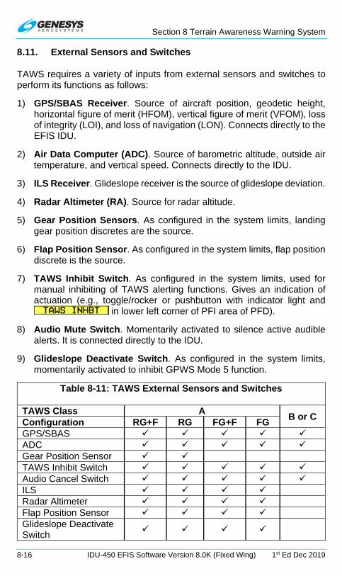
Section 8 Terrain Awareness Warning System
8-16 IDU-450 EFIS Software Version 8.0K (Fixed Wing) 1st Ed Dec 2019
8.11. External Sensors and Switches
TAWS requires a variety of inputs from external sensors and switches to perform its functions as follows:
1) GPS/SBAS Receiver. Source of aircraft position, geodetic height, horizontal figure of merit (HFOM), vertical figure of merit (VFOM), loss of integrity (LOI), and loss of navigation (LON). Connects directly to the EFIS IDU.
2) Air Data Computer (ADC). Source of barometric altitude, outside air temperature, and vertical speed. Connects directly to the IDU.
3) ILS Receiver. Glideslope receiver is the source of glideslope deviation.
4) Radar Altimeter (RA). Source for radar altitude.
5) Gear Position Sensors. As configured in the system limits, landing gear position discretes are the source.
6) Flap Position Sensor. As configured in the system limits, flap position discrete is the source.
7) TAWS Inhibit Switch. As configured in the system limits, used for manual inhibiting of TAWS alerting functions. Gives an indication of actuation (e.g., toggle/rocker or pushbutton with indicator light and
in lower left corner of PFI area of PFD).
8) Audio Mute Switch. Momentarily activated to silence active audible alerts. It is connected directly to the IDU.
9) Glideslope Deactivate Switch. As configured in the system limits, momentarily activated to inhibit GPWS Mode 5 function.
Table 8-11: TAWS External Sensors and Switches
TAWS Class A B or C
Configuration RG+F RG FG+F FG GPS/SBAS ADC Gear Position Sensor
TAWS Inhibit Switch Audio Cancel Switch ILS Radar Altimeter Flap Position Sensor Glideslope Deactivate Switch

Section 8 Terrain Awareness Warning System
1st Ed Dec 2019 IDU-450 EFIS Software Version 8.0K (Fixed Wing) 8-17
8.12. TAWS Basic Parameter Determination
Fundamental parameters used for TAWS functions are as follows.
Table 8-12: Airplane TAWS Basic Parameters Determination
Parameter Source Notes Aircraft position, groundspeed, and track
GPS/SBAS HFOM must be less than or equal to the greater of 0.3 NM or the Horizontal alert limit (HAL) for the mode of flight.
MSL Altitude GPS/SBAS Geodetic Height converted to MSL with the current EGM database. To be considered valid for use as MSL altitude, VFOM must be less than or equal to 106 feet.
Secondary source of MSL altitude is barometric altitude from an air data computer. Barometric altitude is based upon a barometric setting in the following order of preference:
1) If either the pilot or co-pilot system is operating in QNH mode, the QNH barometric setting is used (on-side barometric setting preferred); or
2) If GPS/SBAS geodetic height has been valid within the last 30 minutes, a barometric setting derived from the GPS/SBAS geodetic height is used.
If neither of the above conditions are met, MSL altitude is marked as invalid.
When a reporting station elevation is determined and outside air temperature is valid, a temperature correction is applied.
TAWS uses the lower of the barometric altitude or the temperature-corrected altitude. In the case of QNH-mode barometric

Section 8 Terrain Awareness Warning System
8-18 IDU-450 EFIS Software Version 8.0K (Fixed Wing) 1st Ed Dec 2019
Table 8-12: Airplane TAWS Basic Parameters Determination
Parameter Source Notes setting, reporting station elevation is derived from waypoint or active runway elevations in the active flight plan using the following logic:
1) If the aircraft is in TERMINAL, DEPARTURE, IFR APPROACH, or VFR APPROACH mode and an active runway exists, reporting station elevation is the elevation of the active runway threshold.
2) Otherwise, if the aircraft is in TERMINAL mode, reporting station elevation is the elevation of the airport causing TERMINAL mode.
3) In ENROUTE mode, no reporting station elevation is determined.
In the case of GPS/SBAS geodetic height-based barometric setting, reporting station elevation is the GPS MSL altitude reported at the time the barometric setting was determined (see Section 3 Display Symbology).
Terrain Data Terrain Database To be considered valid, the following must apply:
1) Aircraft position is valid;
2) Aircraft position is within the boundaries of the terrain database; and
3) Terrain database is not corrupt as determined by built-in test at system initialization and during runtime.
Obstacle Data Obstacle Database To be considered valid, the following must apply:

Section 8 Terrain Awareness Warning System
1st Ed Dec 2019 IDU-450 EFIS Software Version 8.0K (Fixed Wing) 8-19
Table 8-12: Airplane TAWS Basic Parameters Determination
Parameter Source Notes 1) Aircraft position is valid;
2) Aircraft position is within the boundaries of the obstacle database; and
3) Obstacle database is not corrupt as determined by built-in test at system initialization.
AGL Altitude Radar Altitude Secondary source is MSL altitude less terrain altitude.
Vertical Speed Instantaneous vertical speed
IVSI values come from barometric vertical speed from an ADC “quickened” with vertical acceleration from an AHRS. Secondary source for vertical speed is barometric vertical speed from an ADC. The tertiary source for vertical speed is GPS/SBAS vertical speed providing the VFOM is less than or equal to 106 feet.
Terrain Closure Rate
Smoothed first derivative of AGL Altitude
Due to multiple sources for altitude, there are multiple sources for terrain closure rate.
Runway/ Reference point location
EFIS navigation database
To be considered valid, the following must apply:
1) Aircraft position is valid;
2) Aircraft position is within the boundaries of the navigation database; and
3) Navigation database is not determined corrupt by built-in test at system initialization.
8.13. TAWS Automatic Inhibit Functions (Normal Operation)
The following automatic inhibit functions occur during normal TAWS operation to prevent nuisance warnings:
1) FLTA function is automatically inhibited when in terminal, departure, IFR approach, or VFR approach modes and within 2NM and 1900’ of the reference point.

Section 8 Terrain Awareness Warning System
8-20 IDU-450 EFIS Software Version 8.0K (Fixed Wing) 1st Ed Dec 2019
2) PDA function is automatically inhibited when within 2NM and 1900’ of the approach runway threshold.
3) GPWS Modes 1 through 4 are automatically inhibited when below 50 feet AGL (radar altimeter AGL altitude) or below 100 feet AGL (terrain database AGL altitude).
4) GPWS Mode 5 is inhibited below 200’ AGL. This form of automatic inhibit remains active until the aircraft climbs above 1000’ AGL and prevents nuisance alarms on missed approach when the glideslope receiver detects glideslope sidelobes.
8.13.1. TAWS Automatic Inhibit Functions (Abnormal Operation)
The following automatic inhibit functions occur during the specified abnormal operations. System sensor failures, non-installation of optional sensors, database failures, and combinations thereof affect TAWS as follows.
Table 8-13: TAWS Automatic Inhibit Functions
Sen
sor
Par
amet
ers
Lo
st
Ter
rain
D
isp
lace
d
FL
TA
PD
A
GPWS Mode
500’
Wak
e-U
p
1 2 3 4 5
GP
S/S
BA
S
(H)
AC
P
ositi
on
Inhi
bit
Inhi
bit
Inhi
bit
TD
Ter
rain
E
lev.
Inhi
bit
Inhi
bit
ILS
Glid
e-sl
ope
Dev
.
Inhi
bit
MS
L
MS
L A
ltitu
de
Inhi
bit
Inhi
bit
Inhi
bit

Section 8 Terrain Awareness Warning System
1st Ed Dec 2019 IDU-450 EFIS Software Version 8.0K (Fixed Wing) 8-21
Table 8-13: TAWS Automatic Inhibit Functions
Sen
sor
Par
amet
ers
Lo
st
Ter
rain
D
isp
lace
d
FL
TA
PD
A
GPWS Mode
500’
Wak
e-U
p
1 2 3 4 5
GP
S/S
BA
S
(H)
+ R
AD
LT
AC
Pos
ition
, A
GL
Alti
tude
Inhi
bit
Inhi
bit
Inhi
bit
Inhi
bit
Inhi
bit
Inhi
bit
Inhi
bit
Inhi
bit
Inhi
bit
GP
S/S
BA
S
(V)
+ A
DC
MS
L A
ltitu
de,
VS
I
Inhi
bit
Inhi
bit
Inhi
bit
Inhi
bit
Inhi
bit
TD
+
RA
DLT
Ter
rain
Ele
v.
AG
L A
ltitu
de
Inhi
bit
Inhi
bit
Inhi
bit
Inhi
bit
Inhi
bit
Inhi
bit
Inhi
bit
Inhi
bit
MS
L +
R
AD
LT
MS
L A
ltitu
de,
AG
L A
ltitu
de
Inhi
bit
Inhi
bit
Inhi
bit
Inhi
bit
Inhi
bit
Inhi
bit
Inhi
bit
Inhi
bit
Inhi
bit
GP
S/S
BA
S
(V)
+ A
DC
+
RA
DLT
MS
L A
ltitu
de,
VS
I, A
GL
ALT
In
hibi
t
Inhi
bit
Inhi
bit
Inhi
bit
Inhi
bit
Inhi
bit
Inhi
bit
Inhi
bit
Inhi
bit
Notes:
1) Combinations listed give the minimum combinations with the worst consequences. Many other combinations are possible, but their effects are subsumed within the combinations listed.
2) GPS/SBAS (H) = HFOM > max (0.3NM, HAL). Indication is loss of terrain display on PFD and ND.
3) GPS/SBAS (V) = VFOM > 106’.
4) GPS/SBAS = GPS/SBAS (H) + GPS/SBAS (V). Indication is loss of terrain display on PFD and ND.
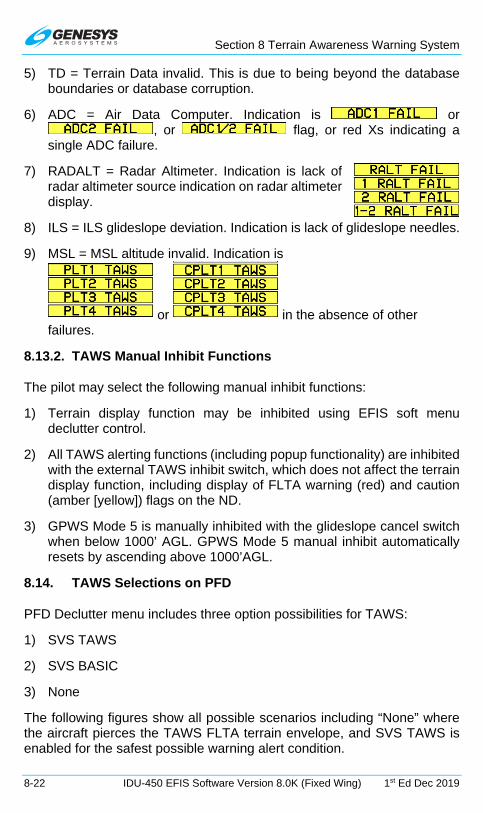
Section 8 Terrain Awareness Warning System
8-22 IDU-450 EFIS Software Version 8.0K (Fixed Wing) 1st Ed Dec 2019
5) TD = Terrain Data invalid. This is due to being beyond the database boundaries or database corruption.
6) ADC = Air Data Computer. Indication is or , or flag, or red Xs indicating a
single ADC failure.
7) RADALT = Radar Altimeter. Indication is lack of radar altimeter source indication on radar altimeter display.
8) ILS = ILS glideslope deviation. Indication is lack of glideslope needles.
9) MSL = MSL altitude invalid. Indication is
or in the absence of other failures.
8.13.2. TAWS Manual Inhibit Functions
The pilot may select the following manual inhibit functions:
1) Terrain display function may be inhibited using EFIS soft menu declutter control.
2) All TAWS alerting functions (including popup functionality) are inhibited with the external TAWS inhibit switch, which does not affect the terrain display function, including display of FLTA warning (red) and caution (amber [yellow]) flags on the ND.
3) GPWS Mode 5 is manually inhibited with the glideslope cancel switch when below 1000’ AGL. GPWS Mode 5 manual inhibit automatically resets by ascending above 1000’AGL.
8.14. TAWS Selections on PFD
PFD Declutter menu includes three option possibilities for TAWS:
1) SVS TAWS
2) SVS BASIC
3) None
The following figures show all possible scenarios including “None” where the aircraft pierces the TAWS FLTA terrain envelope, and SVS TAWS is enabled for the safest possible warning alert condition.

Section 8 Terrain Awareness Warning System
1st Ed Dec 2019 IDU-450 EFIS Software Version 8.0K (Fixed Wing) 8-23
Figure 8-15: PFD SVS BASIC Option
TAWS FLTA Caution Terrain: Amber (Yellow) TAWS FLTA Caution Warning: Red
Figure 8-16: PFD SVS TAWS Option

Section 8 Terrain Awareness Warning System
8-24 IDU-450 EFIS Software Version 8.0K (Fixed Wing) 1st Ed Dec 2019
Figure 8-17: PFD SVS TAWS Option and Obstructions
Obstruction within TAWS FLTA Caution envelope with voice alert “Caution Obstruction, Caution Obstruction.” Obstruction symbols flash.
Figure 8-18: PFD Obstruction Caution
Obstruction above aircraft
Obstruction below aircraft

Section 8 Terrain Awareness Warning System
1st Ed Dec 2019 IDU-450 EFIS Software Version 8.0K (Fixed Wing) 8-25
Obstruction within TAWS FLTA warning envelope with voice alert “Warning Obstruction, Warning Obstruction.” Obstruction symbols flash.
Figure 8-19: PFD Obstruction Warning

Section 9 Appendix
1st Ed Dec 2019 IDU-450 EFIS Software Version 8.0K (Fixed Wing) 9-1
Section 9 Appendix
9.1. Appendix
This section contains a variety of useful information not found elsewhere in the document and includes operating tips, system specifications, feedback forms, and environmental requirements.
9.2. Operating Tips
With the Genesys Aerosystems EFIS installed and certified in all categories of certified aircraft, numerous tips and suggestions are available for obtaining the maximum performance and benefit from this system. Additional operating tips are available with future releases of this publication.
9.3. Domestic or International Flight Planning
Due to the differences in every aircraft avionics suite installation, the pilot to determine what equipment code is applicable for domestic or international flight plans. The aircraft operator must determine which certifications pertain to them. Visit the FAA website, www.faa.gov, for flight plan guidance for both domestic and international filers, as well as, information and documentation regarding FAA, ICAO, and Flight Services agreements and procedures.
9.4. Descent Planning
Instead of performing conventional time/speed/distance/descent-rate calculations, use the waypoint symbol for descent planning. Simply maintain the cruise altitude until the “X” at the bottom of the waypoint symbol is 2-3 degrees below the horizon (as indicated by the pitch scale) then begin a 2-3 degree descent. Maintain the correct descent angle by keeping the flight path marker positioned on the waypoint “X” symbol. Following the skyway boxes assures the VNAV descent angle is maintained.
9.5. Terrain Clearance
Use the flight path marker to evaluate climb performance for terrain clearance. If climbing at the best climb speed to clear terrain and the flight path marker is overlaying the terrain, the climb rate is insufficient. Either the course or climb rate must be altered to adequately clear the terrain. If the flight path marker is well clear of the terrain (overlaying blue sky), the climb is sufficient for the present time, and no further action is necessary until level off.

Section 9 Appendix
9-2 IDU-450 EFIS Software Version 8.0K (Fixed Wing) 1st Ed Dec 2019
9.6. Departure Airport Information
On startup, all information for the departure airport is readily available. The altimeter is automatically set to the nearest IFR runway touchdown zone elevation (if Baro Autosetting on Startup is enabled in EFIS limits). Press NRST (R3) to reveal the nearest airports when highlighted where all important data such as elevation, frequencies, and runway lengths are displayed.
9.7. Unique Names for Flight Plans
Multiple routes between the same airport pairs are numbered automatically (KCEW-KDHN) [0], (KCEW-KDHN) [1], etc.). The work-around is to apply this easily remembered differentiation. If a route is routinely flown from one airport to another but different routing is necessary due to weather, hot MOA areas, etc., up to 10 different flight plans may be created for the same destination.
As an example for departing Sikes on a northern routing (KCEWN) or a southern routing (KCEWS), create two different user waypoints at the departure airport named KCEWN and KCEWS followed by different routing to clear whatever creates the necessity for specific routing, e.g. a MOA.
9.8. Altimeter Settings
Use caution when setting the altimeter and inadvertently changing the transition level. If this is reset to a lower than normal altitude,
may appear due to the altimeter setting not on 29.92 inHg or 1013 mbar.
9.9. Warnings, Cautions, and Advisories
Review Section 2 System Overview for the conditions precisely defining scenarios for various time-critical warning alerts, warning alerts, master visual and audio alerts, time-critical caution alerts and advisory alerts, as they appear including the conditions and time delay when applicable.
9.10. Magnetic vs. True North Modes of Operation
There are two modes for the AHRS:
1) Slaved mode (i.e., compass rose stabilized by Earth’s magnetic flux horizontal field) is the normal mode. It works well over most of the surface of the earth (i.e., areas with a horizontal field of 5000nT or above, which includes about 2/3rds of Canadian NDA). ADAHRS senses magnetic flux with a 3D magnetometer. Performance in small

Section 9 Appendix
1st Ed Dec 2019 IDU-450 EFIS Software Version 8.0K (Fixed Wing) 9-3
horizontal fields is installation dependent as variable magnetic disturbances from the aircraft may begin to predominate.
2) Free or “DG” mode (i.e., compass rose not stabilized by the Earth’s magnetic flux horizontal field and subject to drift) is used in areas of magnetic disturbances (oilrigs, MRI machines, etc.) or in areas where the horizontal field is too weak. In Free/”DG” mode, heading no longer corrects towards Earth’s magnetic flux horizontal field, and the pilot may “slew” the heading solution.
Figure 9-1: US/UK World Magnetic Model
There are two modes for the EFIS:
1) Magnetic North mode: Heading from AHRS (whether slaved or Free/”DG”) is used as-is and is expected to reflect magnetic north. GPS track is converted from true north-referenced to magnetic north-referenced with a magnetic variation database. PFD scenes and compass rose symbols are aligned with magnetic north. Wind is displayed referenced to magnetic north.
2) True North mode: GPS track is used as-is and reflects true north. When AHRS is in slaved mode, heading from AHRS is converted from magnetic north-referenced to true north-referenced using a magnetic variation database. When AHRS is in Free/”DG” mode, heading from the AHRS is used as-is and is expected to reflect true north. PFD scenes and compass rose symbols are aligned with true north. Wind is displayed referenced to true north.

Section 9 Appendix
9-4 IDU-450 EFIS Software Version 8.0K (Fixed Wing) 1st Ed Dec 2019
NOTE:
Designating magnetic north vs. true north mode is critical since it determines how the inputs are used, i.e., the relationship between GPS track and ADAHRS heading. Mixing things up in Free/”DG” mode (i.e., slewing the compass rose to match magnetic north when in true north mode and vice-versa) may result in large errors in wind calculations
and GPS track/flight path marker displays.
9.11. Altitude Miscompare Threshold
The altitude miscompare threshold is based upon allowable altitude error. There are two components to allowable altitude error, instrument error and installed system error. Allowable instrument error is based upon the values of SAE AS8002A Table 1 as follows.
Table 9-1: Allowable Instrument Error
Altitude Allowed Error Sea Level 25’
1,000’ 25’ 2,000’ 25’ 3,000’ 25’ 4,000’ 25’ 5,000’ 25’ 8,000’ 30’
11,000’ 35’ 14,000’ 40’ 17,000’ 45’ 20,000’ 50’ 30,000’ 75’ 40,000’ 100’ 50,000’ 125’
Allowable installed system error is added on top of instrument error and these values are derived from the regulations as follows.
Table 9-2: Regulatory Reference
Regulation Allowed Error
14 CFR § 23.1325 At sea level, the greater of 30’ or 30% of the calibrated airspeed in knots. This increases proportionally to SAE AS8002A Table 1 at higher altitudes.
14 CFR § 25.1325

Section 9 Appendix
1st Ed Dec 2019 IDU-450 EFIS Software Version 8.0K (Fixed Wing) 9-5
An allowable altitude error is computed for each compared value and added together to create the altitude miscompare threshold. This accommodates for the values deviating in different directions.
Worked example for a calibrated airspeed of 100 knots and comparing a first altitude of 3,490’ with a second altitude of 3,510’:
1) Calculate allowable instrument error based upon altitudes: Allowable Instrument Error #1 = 50’ Allowable Instrument Error #2 = 50’
2) Calculate allowable installed system error based upon altitudes and calibrated airspeed: Allowable Installed System Error #1 = 30’ Allowable Installed System Error #2 = 30’
3) Calculate altitude miscompare threshold based upon sum of above allowable errors: Altitude Miscompare Threshold = 160’
9.12. Airspeed Miscompare Threshold
Airspeed miscompare threshold is based upon allowable airspeed error. There are two components to allowable airspeed error, instrument error and installed system error. Allowable instrument error is based upon the values of SAE AS8002A Table 3 as follows.
Table 9-3: Airspeed Error
Calibrated Airspeed Allowed Error 50 knots 5 knots 80 knots 3 knots
100 knots 2 knots 120 knots 2 knots 150 knots 2 knots 200 knots 2 knots 250 knots 2.4 knots 300 knots 2.8 knots 350 knots 3.2 knots 400 knots 3.6 knots 450 knots 4 knots
Allowable installed system error is added on top of instrument. Error and these values are derived from the regulations as follows.

Section 9 Appendix
9-6 IDU-450 EFIS Software Version 8.0K (Fixed Wing) 1st Ed Dec 2019
Table 9-4: Airspeed Regulatory Reference
Regulation Allowed Error
14 CFR § 23.1323
Starting from (1.3 x VS1): Greater of 5 knots or 3%.
Do not perform a comparison if either value is below (1.3 x VS1).
14 CFR § 25.1323
Starting from (1.23 x VSR1): Greater of 5 knots or 3%.
Do not perform a comparison if either value is below (1.23 x VSR1).
System uses VS1 as a substitute for VSR1. An allowable airspeed error is computed for each compared value and added together to create the airspeed miscompare threshold and accommodates for the values deviating in different directions.
9.13. Jeppesen Sanderson NavData® Chart Compatibility
As GPS navigation, flight management systems, computer flight maps, and computer flight planning systems have gained acceptance, avionics companies and software developers have added more features. Even with the many systems available today, paper enroute, departure, arrival, and approach charts are still required and necessary for flight. Avionics systems, flight planning, computer mapping systems, and associated databases do not provide all of the navigation information needed to conduct a legal and safe flight. They are not a substitute for current aeronautical charts.
See www.Jeppesen.com for the latest information on coding instrument procedures, naming conventions, altitudes within the database, and aeronautical information compatibility.
9.14. ARINC 424 Path-Terminator Leg Types
For information, definitions, and examples, visit the FAA website, www.faa.gov, to view the Instrument Procedures Handbook (FAA-H-8083-16A).
9.15. Data Logging and Retrieval
The EFIS logs all data associated with a flight, including all flight instrument and navigation data, which may be downloaded for review after flight. Data from the last 5 flights or 20 hours are logged at a one-second interval.
Data logging files contain recordings of flight and engine parameters of up to five hours each from the previous five system operations. During system operation, flight and engine parameters are recorded every one second.

Section 9 Appendix
1st Ed Dec 2019 IDU-450 EFIS Software Version 8.0K (Fixed Wing) 9-7
Each time the parameters are recorded, a Zulu time stamp followed by three lines of comma delimited ASCII text data are written where the first line contains flight parameters and, the second line contains engine parameters.
With IDU powered off, open USB door, and insert USB flash drive. Power up and select to create a “\log” directory on the USB flash drive and copy the data logging files into the directory.
CAUTION:
Always install a valid USB flash drive in the IDU prior to activating any ground maintenance function to avoid erroneous failure
indications or corruption of the IDU.
9.15.1. Delete Log Files
1) If there are problems updating a navigation database or application software due to an excessively large log file, select “Delete Log Files” to delete all log files in the log directory.
Files named “LOG00.dat” thru “LOG04.DAT” and “MSGLOG.DAT” are deleted. This does not affect operations of the EFIS, as the EFIS generates new “LOG00.DAT” and “MSGLOG.DAT” files once a flight has started.
2) Press any button on the IDU or push to return to the ground maintenance menu.
9.15.2. Logged Flags and Custom CAS Messages
Flags and custom CAS messages are logged in memory to a file named “caslog00.csv” (*.csv files may be opened in Microsoft Excel or similar spreadsheet software). In addition, data from the previous four flights are saved in files “caslog01.csv” through “caslog04.csv.” Upon system start, the existing “caslog00.csv” through “caslog03.csv” files are renamed “caslog01.csv” through “caslog04.csv,” and “caslog00.csv” is opened for active logging.
The first line of the log files contains column headings related to the flag’s text (for standard warning functions) or the “CAS Log File Text” parameter (for custom CAS messages). All standard warning functions are logged. Only custom CAS messages with valid “CAS Log File Text” parameters (i.e., not an empty string) are logged. Within the data fields of the log file, values are written as follows.
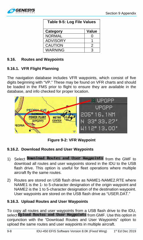
Section 9 Appendix
9-8 IDU-450 EFIS Software Version 8.0K (Fixed Wing) 1st Ed Dec 2019
Table 9-5: Log File Values
Category Value NORMAL 0 ADVISORY 1 CAUTION 2 WARNING 3
9.16. Routes and Waypoints
9.16.1. VFR Flight Planning
The navigation database includes VFR waypoints, which consist of five digits beginning with “VP.” These may be found on VFR charts and should be loaded in the FMS prior to flight to ensure they are available in the database, and info checked for proper location.
Figure 9-2: VFR Waypoint
9.16.2. Download Routes and User Waypoints
1) Select from the GMF to download all routes and user waypoints stored in the IDU to the USB flash drive. This option is useful for fleet operations where multiple aircraft fly the same routes.
2) Routes are stored on USB flash drive as NAME1-NAME2.RTE where NAME1 is the 1- to 5-character designation of the origin waypoint and NAME2 is the 1 to 5-character designation of the destination waypoint. User waypoints are stored on the USB flash drive as “USER.DAT.”
9.16.3. Upload Routes and User Waypoints
To copy all routes and user waypoints from a USB flash drive to the IDU, select from GMF. Use this option in conjunction with the “Download Routes and User Waypoints” option to upload the same routes and user waypoints in multiple aircraft.

Section 9 Appendix
1st Ed Dec 2019 IDU-450 EFIS Software Version 8.0K (Fixed Wing) 9-9
9.16.4. Delete Routes and User Waypoints
When corrupted routes cause the IDU to continually reboot, select “Delete Routes” on the Ground Maintenance page to remove all routes and the user waypoint file (USER.DAT) from the IDU.
9.16.5. EFIS Training Tool (ETT)
See the Installation and User Guide distributed with the ETT install files for directions to install and use the EFIS Training Tool.
Use the ETT to create routes and user waypoints to save and upload into the aircraft mounted IDUs. When uploading a saved flight plan (route) into an aircraft mounted IDU, the following rules apply:
3) Either upload flight plan (route) into each IDU to ensure flight plan (route) is saved in the route directory (all other displays); Or
4) Upload flight plan (route) into one display while in the ground mode. When in flight mode, activate that flight plan, and on any other display, view active flight plan and press SAVE (L1) to save flight plan in the route directory. This action will save the new uploaded flight plan (route) in all other displays.
NOTE:
In a two-sided system, crossfill must be enabled to save flight plan to all other displays on each side of the system.
The ETT has a bezel with simulated buttons and encoders responsive to mouse and keyboard messages. Bezel graphics are derived from actual bezel design data, and the ETT presents an active display with 1:1 pixel correspondence to an actual IDU display. The audio output capability for the ETT matches the audio functionality in the actual IDU. This training tool simulates the functionalities of the IDU, which begins flight in Reno, Nevada at approximately 8000’ MSL. If different ETT startup conditions are required, they may be edited.
Flight plans may be created (on the PFD or MFD), stored, and activated in the same manner as on the EFIS displays installed in the aircraft. This allows for moving the start point to anywhere in the world where loaded NavData® is present for practicing published procedures. As with the demonstrator program, the aircraft begins flying at approximately 8000’ MSL (unless the simulate.ini program is loaded) intercepting the first leg at a 45° angle.
Section 9 Appendix
9-10 IDU-450 EFIS Software Version 8.0K (Fixed Wing) 1st Ed Dec 2019
9.17. USB Flash Drive Memory Limitations
When powering up the IDU with a USB flash drive inserted and “Error: No updater files found on USB drive” displays, the USB flash drive is likely not acceptable for loading or transferring data.
1) Ensure the USB flash drive with required files is properly connected.
2) Try again after reboot.
3) Press any button to continue.
4) Try a different USB flash drive.
NOTE:
USB flash drive must be formatted as FAT16 or FAT32.
If the flash drive is not recognized, try another source.
9.18. Certification Basis
The following TSOs are considered applicable to the IDU-680 (depending upon the features of the installed software).
Document Number Document Title ARINC 429-16 Mark 33 Digital Information Transfer System (DITS) ARINC 735A-1 Traffic Alert and Collision Avoidance System
EIA-232D Interface between Data Terminal Equipment and Data
EIA-422A Electrical Characteristics of Balanced Voltage Digital Interface Circuits
FAA AC 23.1311-1B Installation of Electronic Display in Part 23 Airplanes
RTCA/DO-155 Minimum Performance Standards - Airborne Low-Range Radio Altimeters
RTCA/DO-229D Minimum Operational Performance Standards for Global Positioning System/Wide Area Augmentation System Airborne Equipment
RTCA/DO-283A Minimum Operational Performance Standards for Required Navigation Performance for Area Navigation
SAE AS396B Bank and Pitch Instruments (Indicating Stabilized Type)

Section 9 Appendix
1st Ed Dec 2019 IDU-450 EFIS Software Version 8.0K (Fixed Wing) 9-11
Document Number Document Title
SAE AS8002A Air Data Computer - Minimum Performance Standard
TSO-C4c Bank and Pitch Instruments TSO-C87 Airborne Low-Range Radio Altimeter TSO-C106 Air Data Computer TSO-C151b Terrain Awareness and Warning System
TSO-C113 Airborne Multipurpose Electronic Displays
SAE AS8034
TSO-C52b Flight Director Equipment SAE AS8008
TSO-C146a Stand-Alone airborne navigation equipment using the Global Positioning System (GPS) Augmented by the Wide Area Augmentation System (WAAS)
N/A Airplane Aerodynamics and Performance, Lan and Roskam, 1981.
9.19. Environmental Requirements
While the IDU-680 meets the following RTCA/DO-160F requirements, Genesys Aerosystems claims the following:
1) The coldest storage temperature is -55°C.
2) Coldest condition in which the units can be powered up is -40°C. It will take at least 4 minutes to warm up with the internal heater circuit operating.
Sec. Condition Cat. Test Category Description Notes 4.0 Temperature and
Altitude F2 Equipment intended for
installation in non-pressurized and non-controlled temperature location in an aircraft that is operated at altitudes up to 55,000 ft. (16,800 m) MSL. Operating Low Temp: -55 deg C Operating High temp: +70 deg C Ground Survival Low Temp: -55 deg C Ground Survival High Temp: +85 deg C Altitude: +55,000 feet
+75°C for Short-Time Operating High Temp. Cat. V (30 minutes) for loss of cooling.
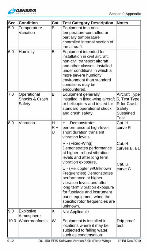
Section 9 Appendix
9-12 IDU-450 EFIS Software Version 8.0K (Fixed Wing) 1st Ed Dec 2019
Sec. Condition Cat. Test Category Description Notes 5.0 Temperature
Variation B Equipment in a non-
temperature-controlled or partially temperature controlled internal section of the aircraft.
6.0 Humidity B Equipment intended for installation in civil aircraft, non-civil transport aircraft and other classes, installed under conditions in which a more severe humidity environment than standard conditions may be encountered.
7.0 Operational Shocks & Crash Safety
B Equipment generally installed in fixed-wing aircraft or helicopters and tested for standard operational shock and crash safety.
Aircraft Type 5, Test Type R for Crash Safety Sustained Test
8.0 Vibration H + R + U
H – Demonstrates performance at high-level, short duration transient vibration levels
R - (Fixed-Wing) Demonstrates performance at higher, robust vibration levels and after long term vibration exposure.
U - (Helicopter w/Unknown Frequencies) Demonstrates performance at higher vibration levels and after long term vibration exposure for fuselage and instrument panel equipment when the specific rotor frequencies are unknown.
Cat. H, curve R
Cat. R, curves B, B1
Cat. U, curve G
9.0 Explosive Atmosphere
X Not Applicable
10.0 Waterproofness W Equipment is installed in locations where it may be subjected to falling water, such as condensation
Drip proof test

Section 9 Appendix
1st Ed Dec 2019 IDU-450 EFIS Software Version 8.0K (Fixed Wing) 9-13
Sec. Condition Cat. Test Category Description Notes 11.0 Fluids
Susceptibility X Not Applicable
12.0 Sand and Dust S Equipment is installed in locations subject to blowing sand and dust.
13.0 Fungus Resistance
F Demonstrate whether equipment material is adversely affected by fungi growth.
By Analysis
14.0 Salt Fog S Equipment is subjected to a corrosive atmosphere
15.0 Magnetic Effect Z Magnetic deflection distance less than 0.3m.
16.0 Power Input Z Equipment intended for use on aircraft DC electrical systems where the DC supply has a battery whose capacity is small compared with the capacity of the DC generators.
200 ms power interruption capacity
17.0 Voltage Spike A Equipment intended primarily for installation where a high degree of protection against damage by voltage spikes is required.
18.0 Audio Frequency Conducted Susceptibility-Power Inputs
Z Equipment intended for use on aircraft DC electrical systems where the DC supply may not have a battery of significant capacity floating on the dc bus at all times.
19.0 Induced Signal Susceptibility
ZC Equipment intended primarily for operation in systems where interference-free operation is required on aircraft whose primary power is constant frequency or DC.
20.0 Radio Frequency Susceptibility (Radiated and Conducted)
Y Equipment and interconnecting wiring installed in severe electromagnetic environments and to show
Radiated: K Minimum level at all frequencies to be 100V/m

Section 9 Appendix
9-14 IDU-450 EFIS Software Version 8.0K (Fixed Wing) 1st Ed Dec 2019
Sec. Condition Cat. Test Category Description Notes compliance with the interim HIRF rules.
21.0 Emission of Radio Frequency Energy
M Equipment in areas where apertures are EM significant but not in direct view of aircraft antennas, such as passenger cabin or cockpit
22.0 Lightning Induced Transient Susceptibility
A3J33
Equipment interconnected with wiring installed within any airframe or airframe section when structural resistance is also a significant source of induced transients, (i.e., carbon fiber composite structures). Level 3 designates equipment and interconnecting wiring installed in a moderately exposed environment.
Level 4 for MSU and OAT Probe pins.
23.0 Lightning Direct Effects
X Not Applicable
24.0 Icing X Not Applicable
25.0 Electrostatic Discharge (ESD)
A Electronic equipment that is installed, repaired, or operated in an aerospace environment.
26.0 Fire, Flammability
C Non-metallic equipment, component parts, sub-assemblies installed in pressurized or non-pressurized zones and non-fire zones with largest dimension greater than 50 mm.
By Analysis

Traffic
1st Ed Dec 2019 IDU-450 EFIS Software Version 8.0K (Fixed Wing) T-1
Traffic
T 1. Traffic Symbology
PFD
MFD
Figure T-1: Traffic Symbology
T 1.1. Traffic Display Definitions
1) Resolution Advisory (RA): Traffic with a dangerous closest point of approach and generates climb or descent commands as defined by internal TCAS-II sensor logic.

Traffic
T-2 IDU-450 EFIS Software Version 8.0K (Fixed Wing) 1st Ed Dec 2019
2) Traffic Advisory (TA): Traffic with a dangerous closest point of approach as defined by internal traffic sensor logic.
3) Proximate Advisory (PA): Traffic within 6 NM and ±1200 feet from ownship that is not a RA or TA.
4) Other Traffic (OT): Traffic beyond 6 NM or ±1200 feet from ownship that is not a RA or TA.
T 1.2. Traffic Rendering Rules
Table T-1: Traffic Rendering Rules
Type Traffic Distance Results OT and PA Traffic Beyond 6 NM
Not displayed TCAS-I, TCAS-II, TAS or TIS-A Sensor
Within 200’ of ground
Table T-3: Pilot Selected OT and PA Traffic Altitude-Filter
Mode Parameter
AUTO
If aircraft VSI is less than -500 fpm, traffic within +2,700 and -9,900 feet of aircraft altitude displayed.
If aircraft VSI is more than +500 fpm, traffic within -2,700 and +9,900 feet of aircraft altitude displayed.
Otherwise, traffic within -2,700 and +2,700 feet of aircraft altitude displayed.
ABOVE Traffic within -2,700 and +9,900 feet of aircraft altitude displayed.
BELOW Traffic within +2,700 and -9,900 feet of aircraft altitude displayed.
Table T-2: Traffic Symbology
Type Traffic Symbology TCAS-I, TCAS-II, and TIS-A
Other Traffic
Proximate Advisory
Traffic Advisory
(Flashing)
Resolution Advisory
(Flashing) Ownship Symbol
Airplane w/o MMO Airplane with MMO

Traffic
1st Ed Dec 2019 IDU-450 EFIS Software Version 8.0K (Fixed Wing) T-3
Table T-3: Pilot Selected OT and PA Traffic Altitude-Filter
Mode Parameter
NORMAL Traffic within -2,700 and +2,700 feet of aircraft altitude displayed.
ALL All received traffic displayed, no altitude filtering.
T 1.3. Traffic Thumbnail
When selected from declutter options, the traffic thumbnail is displayed in the lower right corner of the PFI area of the PFD above the active waypoint identifier and has clock face markings fixed at the 6 NM scale.
Figure T-2: Traffic Thumbnail
The traffic thumbnail is automatically enabled while there is an active traffic warning (TA or RA) and the aircraft is above 500’ AGL. During a traffic warning, the traffic thumbnail scale automatically adjusts in multiple multiples of 2 NM (2 NM, 4NM, or 6NM) to optimally display the traffic. While the traffic thumbnail is mutually exclusive with the MINI MAP, ANLG AGL, and ANLG G so it too disappears in the unusual attitude mode.
T 2. TCAS-II Traffic RA indicator
Figure T-3: TCAS-II RA Indication
When TCAS-II is enabled, the background of the VSI functions as an RA display with green and red colored regions for resolution advisory guidance.

Traffic
T-4 IDU-450 EFIS Software Version 8.0K (Fixed Wing) 1st Ed Dec 2019
T 3. Dedicated Traffic Page
When selected, a traffic page is available based roughly on the appearance of a TCAS display and has the following elements.
T 3.1. MFD Page (PAGE) Menu
TRAFFIC: Shows the Traffic page.
T 3.2. Traffic Display Format
The traffic display uses a centered display format with the ownship symbol (Table T-2) centered in the traffic page with data displayed out to an equal distance in all directions. When the AHRS is in DG Mode, “DG” appears to the right of the ownship symbol.
Figure T-4: Traffic Display Format
T 3.3. Traffic Page Screen Range
Screen ranges are available (all distances represent the distance from the ownship symbol to the compass rose): 5NM, 10NM, and 20NM. A TCAS range ring is centered upon the ownship symbol to help judge range to displayed symbols with a 3NM radius in 5NM and 10NM ranges, has a radius of half the range in 20NM, 50NM, and 100NM ranges, and is presented on the TCAS range ring (e.g., 3NM, 10NM, 25NM, or 50NM).
T 3.4. Compass Rose Symbols
The compass rose is aligned with either magnetic north or true north depending upon the status of the true north discrete input. A digital heading readout and pointer aligned with the longitudinal axis of the ownship symbol

Traffic
1st Ed Dec 2019 IDU-450 EFIS Software Version 8.0K (Fixed Wing) T-5
appears on the compass rose boundary circle. Compass rose symbols are as specified in Section 3 Display Symbology. A green dashed lubber line connects the center of the aircraft symbol and the track pointer.
Normal Mode True North Mode
Figure T-5: Traffic Page Compass Rose Symbols
If a target altitude is set and not captured, an altitude capture predictor arc is displayed on the lubber line at a point corresponding with predicted climb or descent distance (based upon current VSI). A top of descent symbol is shown at the point where a VNAV descent is predicted to commence. The track pointer, lubber line, altitude capture predictor arc, and top of descent symbol are not displayed when groundspeed is less than 30 knots. A pilot-settable heading bug geometrically interacting with the heading pointer appears on the compass rose. A magenta, star-shaped waypoint pointer is displayed on the heading scale at a point corresponding with the active waypoint and turns amber (yellow) in the event of GPS LON caution.
T 3.5. Clock and Options
The following are displayed in the upper right corner of traffic page.
Zulu Time Local Offset Time
Figure T-6: Clock and Options
Table T-4: Clock and Options
Feature Options Notes Zulu Time or Local Offset
hh:mm:ssZ hh:mm:ssL
Synchronized with GPS/SBAS constellation
Traffic Status Enabled or Disabled
If traffic is disabled, overlying red “X”. When enabled, traffic altitude filtering is as follows (see Table T-3).
AUTO = TRFC AUTO ABOVE = TRFC ABV BELOW = TRFC BLW NORMAL = TRFC NORM ALL = TRFC ALL

Traffic
T-6 IDU-450 EFIS Software Version 8.0K (Fixed Wing) 1st Ed Dec 2019
Table T-4: Clock and Options
Feature Options Notes ADS-B Traffic Vector Length
Length of traffic vector annunciated as VECT## (traffic vector length in minutes)
T 3.6. Fuel Totalizer/Waypoint Distance Functions
As defined in Section 3 Display Symbology.
Figure T-7: Fuel Totalizer/Waypoint Distance Functions
T 3.7. Active Flight Plan Path/Manual Course/Runways
When there is an active flight plan and automatic GPS/ SBAS OBS setting, the flight plan path, when selected, is shown in correct relationship to the ownship symbol. The active flight plan path depiction meets all GPS/SBAS path definition requirements and matches the lateral navigation guidance on the PFD (GPS/SBAS CDI in automatic OBS mode, skyway boxes, and mini-map). Active flight plan path fly-over waypoints symbols are distinct from fly-by waypoints and consist of the waypoint symbol within a circle. When there is a parallel offset, the active flight plan path depicts the parallel offset path, and the original flight plan path is shown with haloed gray dashed lines.
When there is an active waypoint and manual GPS/SBAS OBS setting, the course through the waypoint is shown as a pointer centered on the waypoint and matches the lateral navigation guidance on the PFD (GPS/SBAS CDI in manual OBS mode, skyway boxes, and mini-map).
The active flight plan path’s active leg/manual course and active waypoint are magenta and turn amber (yellow) in the event of a GPS LON caution. The traffic page displays airport runways in correct relationship and scale to the ownship symbol.
When traffic source is ADS-B, traffic vectors and aircraft identification data are shown. The traffic vector is a line connecting the traffic’s current position with the predicted position based on its current track and groundspeed. The prediction time, in minutes, is pilot-selectable. Aircraft identification (e.g. aircraft registration number or scheduled airline flight number) is text located near the traffic symbol in the same color as the traffic symbol.

Traffic
1st Ed Dec 2019 IDU-450 EFIS Software Version 8.0K (Fixed Wing) T-7
Table T-5: ADS-B and TIS-B Traffic Symbols
Other Traffic
Proximate Advisory
Traffic Advisory (Flashing)
High-Integrity Traffic with Track Information
High-Integrity Traffic without Track Information
Degraded Position Traffic with Track Information
Degraded Position Traffic without Track Information
T 4. OASIS Traffic Page Overlays
Up to eight symbology OASIS traffic overlays are possible to appear on top of all other traffic symbology but below CAS warnings.
T 5. MFD Fault Display (FAULTS) (L1) Menu
If traffic enabled, loss of communications with traffic sensor (TRFC) is annunciated with TRAFFIC with an overlying red “X.”
T 6. MFD Traffic Format (FORMAT..) (R4) Menu
FORMAT..
ROUTE ON
ROUTE OFF
ALT FILTER
IDENT OFF (a)
TCAD TEST (b)
IDENT ON (a)
1
(a) Shown if optionalTIS-B installed
(b) Shown if optionalRyan/Avidyne TCADinstalled
TREND VECTOR (a)
Display active flight plan route(shown if route is not currently displayed)
Do not display active flight plan route(shown if route is currently displayed)
Display traffic identifier/squawk information (shown if information is not
currently displayed)
Do not display traffic identifier/squawk information (shown if information is
currently displayed)
Activate TCAD pilot initiated test function
ABOVE
BELOW
AUTO
1
NORMAL
ALL
Rotate – Scroll through trafficaltitude filter options
Push – Set selectedtraffic altitude filter1
Set TrendVector Length
R4OFFTurn traffic trend vector off
Rotate – Change trend vectorlength in 1 minincrements not toexceed 15 min
Push – Set selected trendvector length
MENU
Figure T-8: MFD Traffic Format (FORMAT) Menu

Traffic
T-8 IDU-450 EFIS Software Version 8.0K (Fixed Wing) 1st Ed Dec 2019
Upon selecting the MFD format menu, FORMAT (R8), a list appears with the following options:
1) ROUTE ON/ROUTE OFF: Toggles active flight plan route.
2) IDENT OFF/IDENT ON: When EFIS is configured for TIS-B, toggles traffic identifier/squawk information.
3) ALT FILTER: Sets traffic altitude filter to AUTO, ABOVE, BELOW, NORMAL, or ALL.
4) TCAD TEST: Activates test function when Ryan/Avidyne TCAD.
5) TREND VECTOR: When TCAS flag is TIS-B, sets traffic trend vector length in minutes. OFF (R4) turns off traffic trend vector.
T 7. PFD Declutter (DCLTR) (R4) Menu
Upon activating the PFD declutter menu, an option list of declutter items is shown.
Table T-6: PFD Declutter Options and Features
Declutter Options Configuration
Tapes Basic PFD Traffic Thumbnail Perspective Traffic Depiction
T 8. Menu Synchronization
Section 5 Menu Functions and Step-by-Step Procedures for additional information.
Table T-7: Menu Synchronization
Menu Parameter Notes The following menu parameters are synchronized across all displays at all times. These are bugs and fundamental aircraft values that should never have independence. Traffic Filter Setting The following menu parameters are only synchronized onside. These parameters are usually sensor selections or PFD options used to keep the appearance of any pilot's PFD consistent in the case of PFD reversion. The onside characteristic means that individual pilots can still adjust their PFD settings to their preference. PFD Traffic Thumbnail Show Flag PFD Traffic Show Flag
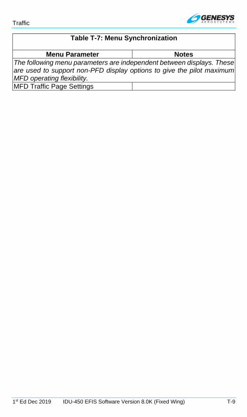
Traffic
1st Ed Dec 2019 IDU-450 EFIS Software Version 8.0K (Fixed Wing) T-9
Table T-7: Menu Synchronization
Menu Parameter Notes The following menu parameters are independent between displays. These are used to support non-PFD display options to give the pilot maximum MFD operating flexibility. MFD Traffic Page Settings
T.

Remote Bugs Panel (RBP)
1st Ed Dec 2019 IDU-450 EFIS Software Version 8.0K (Fixed Wing) RBP-1
Remote Bugs Panel (RBP)
RBP 1. Remote BUGs Panel
1) Increase/decrease HDG bug – Push to synchronize to current heading
2) Increase/decrease target altitude – Push to synchronize to current altitude
3) Moves through "Set" options – press both arrows simultaneously to place into brightness dimming mode
4) Main display – Indicates course, bug, angle, height, and minimums to be set with multifunction encoder
5) Moves through "Set" options – Press both arrows simultaneously to place into brightness dimming mode
6) Multifunction encoder – Increase/decrease value indicated in main display
7) LNAV – Switches autopilot roll steering between LNAV and HDG sub-modes
8) VNAV – Switches autopilot pitch steering between VNAV and target altitude sub-modes
9) Option display – Toggles function value in main display
10) Option button – Toggles function displayed in option display (also exits brightness dimming mode)
Figure RBP-1: Remote Bugs Panel
The Remote Bugs Panel (RBP) promotes ease of operation while minimizing pilot workload complexity by providing dedicated controls for frequently used bugs and controls for setting IDU parameters as defined in Table RBP-1.
1 2 3 4 5 6
7 8 9 10

Remote Bugs Panel (RBP)
RBP-2 IDU-450 EFIS Software Version 8.0K (Fixed Wing) 1st Ed Dec 2019
The heading (HDG) and altitude (ALT) encoders behave similarly as the encoders on the IDU. (See Section 5 Menu Functions and Step-By-Step Procedures for HDG and ALT encoder description)
During initialization, the RBP begins with “GENESYS RBP” on the main and option display screens. To access the internal light sensor control for brightness, press the two arrow buttons simultaneously and rotate the multifunction encoder to make adjustments. Press the Option button to exit the brightness control program and return the RBP to normal operation.
Table RBP-1: Remote Bugs Panel (RBP)
Button/Encoder Function Rotate Push
HDG Encoder Heading Bug
Increase or decrease
Synchronize to current heading
ALT Encoder Altitude Bug
Increase or decrease target altitude
Synchronize to current altitude
Multifunction Encoder
GPS Course
Increase or decrease
Synchronize to current bearing to active waypoint
Multifunction Encoder
VOR 1 Course Increase or
decrease
Synchronize to current bearing to the station Multifunction
Encoder VOR 2 Course
Multifunction Encoder
Airspeed Bug
Increase or decrease
Synchronize to current airspeed
Multifunction Encoder
Vertical Speed Bug
Increase or decrease
Synchronize to current VSI
Multifunction Encoder
Climb Angle Set Increase or
decrease Set to 3°
Multifunction Encoder
Descent Angle Set
Multifunction Encoder
Decision Height Bug
Increase or decrease
Set to 200’ AGL
Multifunction Encoder
Minimum Altitude Bug
Increase or decrease
Synchronize to current altitude
Option “---“ Button GPS Course
N/A Change OBS mode (manual or automatic)
Option “---“ Button VOR 1 Course
N/A No function
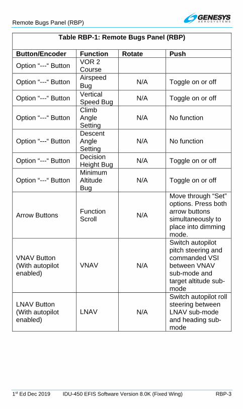
Remote Bugs Panel (RBP)
1st Ed Dec 2019 IDU-450 EFIS Software Version 8.0K (Fixed Wing) RBP-3
Table RBP-1: Remote Bugs Panel (RBP)
Button/Encoder Function Rotate Push
Option “---“ Button VOR 2 Course
Option “---“ Button Airspeed Bug
N/A Toggle on or off
Option “---“ Button Vertical Speed Bug
N/A Toggle on or off
Option “---“ Button Climb Angle Setting
N/A No function
Option “---“ Button Descent Angle Setting
N/A No function
Option “---“ Button Decision Height Bug
N/A Toggle on or off
Option “---“ Button Minimum Altitude Bug
N/A Toggle on or off
Arrow Buttons Function Scroll
N/A
Move through “Set” options. Press both arrow buttons simultaneously to place into dimming mode.
VNAV Button (With autopilot enabled)
VNAV N/A
Switch autopilot pitch steering and commanded VSI between VNAV sub-mode and target altitude sub-mode
LNAV Button (With autopilot enabled)
LNAV N/A
Switch autopilot roll steering between LNAV sub-mode and heading sub-mode
RBP

WX-500 Lightning Strikes
1st Ed Dec 2019 IDU-450 EFIS Software Version 8.0K (Fixed Wing) S-1
WX-500 Lightning Strikes
S 1. WX-500 Data
When selected, the ND displays cell mode or strike mode lightning strikes in correct relationship to the ownship symbol with the following limits.
Table S-1: Lightning Strikes
Time or Distance Limit View Display scale less than 25 NM
Strikes not shown More than 3 minutes old Strikes less than 20 seconds old Lightning symbol Strikes between 20 seconds and 2 minutes old Large cross symbol Strikes between 2 and 3 minutes old Small cross symbol
ND Lightning Display Strikes Page Display
Figure S-1: Lightning Symbols
The pilot may select either an arced or centered display format.
Arced: Ownship displaced toward the bottom of the screen. Strike data are displayed in a larger scale while displaying all data within range ahead of the aircraft.
Centered: Ownship symbol is in the center of the ND with navigation data is displayed out to an equal distance in all directions.
The strikes page has Strikefinder markings aligned with either magnetic north or true north depending upon the status of the true north discrete input. When the AHRS is in DG mode, “DG” appears to the right of the ownship symbol.

WX-500 Lightning Strikes
S-2 IDU-450 EFIS Software Version 8.0K (Fixed Wing) 1st Ed Dec 2019
S 2. Dedicated Strikes Page
S 2.1. MFD Page (PAGE) Menu
STRIKES: Shows the strikes page.
S 2.1.1. MFD STRIKES Page (Step-By-Step)
1) Push or and scroll to STRIKES and push to enter.
2) Example shows MFD with STRIKES in bottom area.
S 2.2. Page Screen Range
The following screen ranges may be selected with all distances representing the distance from the ownship symbol to the Strikefinder markings: 12.5 NM, 25 NM, 50 NM, 100 NM, and 200 NM. The range ring is centered upon the ownship symbol to help judge range to displayed symbols. It has half the radius of the Strikefinder markings displayed indicating the range corresponding to the radius of the range ring such as (1.5 NM, 25 NM, 50 NM, and 10 NM.) The range ring is completely visible in arced display format for the pilot to ascertain the current strikes page setting.
S 2.3. Air Data and Groundspeed
Figure S-2: Air Data and Groundspeed in Upper Left Corner
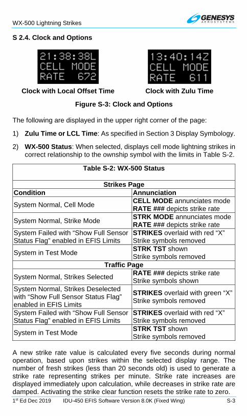
WX-500 Lightning Strikes
1st Ed Dec 2019 IDU-450 EFIS Software Version 8.0K (Fixed Wing) S-3
S 2.4. Clock and Options
Clock with Local Offset Time Clock with Zulu Time
Figure S-3: Clock and Options
The following are displayed in the upper right corner of the page:
1) Zulu Time or LCL Time: As specified in Section 3 Display Symbology.
2) WX-500 Status: When selected, displays cell mode lightning strikes in correct relationship to the ownship symbol with the limits in Table S-2.
Table S-2: WX-500 Status
Strikes Page Condition Annunciation
System Normal, Cell Mode CELL MODE annunciates mode RATE ### depicts strike rate
System Normal, Strike Mode STRK MODE annunciates mode RATE ### depicts strike rate
System Failed with “Show Full Sensor Status Flag” enabled in EFIS Limits
STRIKES overlaid with red “X” Strike symbols removed
System in Test Mode STRK TST shown Strike symbols removed
Traffic Page
System Normal, Strikes Selected RATE ### depicts strike rate Strike symbols shown
System Normal, Strikes Deselected with “Show Full Sensor Status Flag” enabled in EFIS Limits
STRIKES overlaid with green “X” Strike symbols removed
System Failed with “Show Full Sensor Status Flag” enabled in EFIS Limits
STRIKES overlaid with red “X” Strike symbols removed
System in Test Mode STRK TST shown Strike symbols removed
A new strike rate value is calculated every five seconds during normal operation, based upon strikes within the selected display range. The number of fresh strikes (less than 20 seconds old) is used to generate a strike rate representing strikes per minute. Strike rate increases are displayed immediately upon calculation, while decreases in strike rate are damped. Activating the strike clear function resets the strike rate to zero.

WX-500 Lightning Strikes
S-4 IDU-450 EFIS Software Version 8.0K (Fixed Wing) 1st Ed Dec 2019
S 2.5. Active Flight Plan Path/Manual Course/Runways
When there is an active flight plan and the GPS/SBAS OBS setting is automatic, the flight plan path is shown on the strikes page in correct relationship to the ownship symbol.
When there is an active waypoint and the GPS/SBAS OBS setting is manual, the course through the waypoint is shown as a pointer centered on the waypoint. The pointer matches the lateral navigation guidance on the PFD (GPS/SBAS CDI in manual OBS mode, skyway boxes, and mini-map).
Figure S-4: Active Flight Plan Path/Manual Course/Runways
The active flight plan path’s active leg/manual course and active waypoint are magenta but turn amber (yellow) in the event of a GPS LON caution. The strikes page displays airport runways in correct relationship and scale to the ownship symbol.
S 2.6. Fuel Totalizer/Waypoint Distance Functions
As defined in Section 3 Display Symbology.
Figure S-5: Fuel Totalizer/Waypoint Distance Functions
S 3. MFD Faults Display (FAULTS) Menu
If WX-500 is enabled, loss of communications with the WX-500 is indicated with an “X” in place of “OK.”
S 4. MFD Page First-Level Option Descriptions
CLR STRKS (L2) or WX LGND (L2): On ND or strikes page with WX-500 enabled, CLR STRKS activates the strike clear option.

WX-500 Lightning Strikes
1st Ed Dec 2019 IDU-450 EFIS Software Version 8.0K (Fixed Wing) S-5
S 5. MFD Strikes Format (FORMAT) Menu
FORMAT..
CENTER
ARC
ROUTE ON
STRK MODE
CELL MODE
ROUTE OFF
1STRK TEST
Switch to centered display format(shown if arced is current display format)
Switch to arced display format(shown if centered is current display format)
Display active flight plan route(shown if route is not displayed)
Do not display active flight plan route(shown if route is currently displayed)
Switch to strike mode(shown if cell is current mode)
Switch to cell mode(shown if strike is current mode)
Activate WX-500 pilot initiated test function
MENU
Figure S-6: MFD Strikes Format (FORMAT) Menu
Upon selecting the MFD format menu, FORMAT (R4) when in the strikes page, the following option list appears:
1) CENTER/ARC: Toggles centered and arced display format.
2) ROUTE ON/ROUTE OFF: Toggles the active flight plan route.
3) STRK MODE/CELL MODE: Toggles strike and cell mode.
4) STRK TEST: Activates the WX-500 test function.
S 6. OASIS Strikes Screen Overlays
Up to eight symbology OASIS Strikes overlays are possible to appear on top of all other strikes symbology but below CAS warnings.
S 7. Menu Synchronization
Section 5 Menu Functions and Step-by-Step Procedures for additional information.
Table S-3: Menu Synchronization
Menu Parameter Notes The following menu parameters are only synchronized onside. These parameters are usually sensor selections or PFD options used to keep the appearance of any pilot's PFD consistent in the case of PFD

WX-500 Lightning Strikes
S-6 IDU-450 EFIS Software Version 8.0K (Fixed Wing) 1st Ed Dec 2019
Table S-3: Menu Synchronization
Menu Parameter Notes reversion. The onside characteristic means that individual pilots can still adjust their PFD settings to their preference. MFD Strike (WX-500) Page Settings
S

Datalink
1st Ed Dec 2019 IDU-450 EFIS Software Version 8.0K (Fixed Wing) D-1
Datalink
D 1. Datalink Symbology
Figure D-1: Datalink Symbology with G METAR On
Figure D-2: Datalink Symbology with NEXRAD On
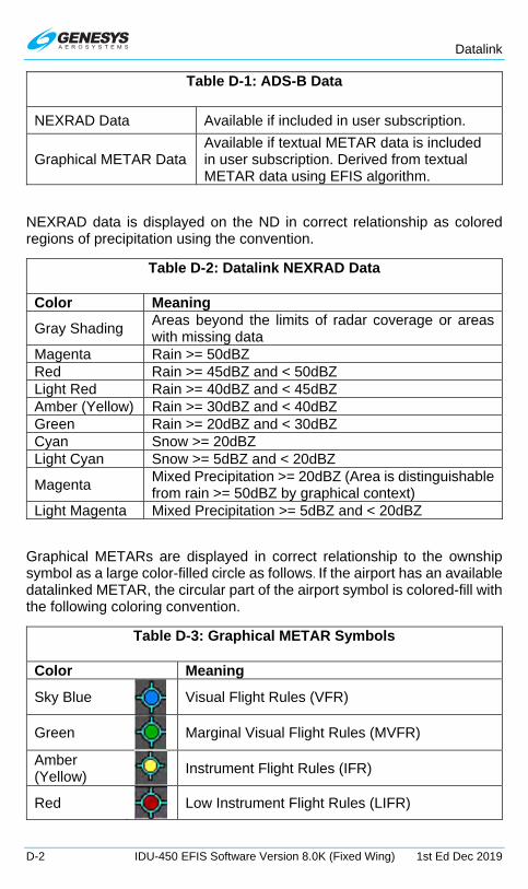
Datalink
D-2 IDU-450 EFIS Software Version 8.0K (Fixed Wing) 1st Ed Dec 2019
Table D-1: ADS-B Data
NEXRAD Data Available if included in user subscription.
Graphical METAR Data Available if textual METAR data is included in user subscription. Derived from textual METAR data using EFIS algorithm.
NEXRAD data is displayed on the ND in correct relationship as colored regions of precipitation using the convention.
Table D-2: Datalink NEXRAD Data
Color Meaning
Gray Shading Areas beyond the limits of radar coverage or areas with missing data
Magenta Rain >= 50dBZ Red Rain >= 45dBZ and < 50dBZ Light Red Rain >= 40dBZ and < 45dBZ Amber (Yellow) Rain >= 30dBZ and < 40dBZ Green Rain >= 20dBZ and < 30dBZ Cyan Snow >= 20dBZ Light Cyan Snow >= 5dBZ and < 20dBZ
Magenta Mixed Precipitation >= 20dBZ (Area is distinguishable from rain >= 50dBZ by graphical context)
Light Magenta Mixed Precipitation >= 5dBZ and < 20dBZ
Graphical METARs are displayed in correct relationship to the ownship symbol as a large color-filled circle as follows. If the airport has an available datalinked METAR, the circular part of the airport symbol is colored-fill with the following coloring convention.
Table D-3: Graphical METAR Symbols
Color Meaning
Sky Blue
Visual Flight Rules (VFR)
Green
Marginal Visual Flight Rules (MVFR)
Amber (Yellow)
Instrument Flight Rules (IFR)
Red
Low Instrument Flight Rules (LIFR)

Datalink
1st Ed Dec 2019 IDU-450 EFIS Software Version 8.0K (Fixed Wing) D-3
Table D-3: Graphical METAR Symbols
Color Meaning
Magenta
Less than Category 1 Approach Minimums
Black
No Data
Table D-4: Graphical METARS (G METARS) Screen Range
Screen Range Display 50 NM All G METARS with Airport Symbol and ID 100 NM All G METARS with Airport Symbol only 200 NM All G METARS 400 NM VFR G METARS are decluttered 800NM and 1,600 NM VFR and MVFR G METARS are decluttered
Graphical METARs are also displayed in the menu system “nearest airport,” “nearest weather,” and “info” functions.
Figure D-3: NRST Airport INFO
Graphical weather conditions data are displayed in the menu system “info” function as large colored squares per the following convention.
Table D-5: Datalink Graphical METAR Precipitation
Color Meaning Sky blue No significant precipitation Green Rain White Snow Red Hazardous weather Right half gray Obscuration to visibility Small black square centered in large square High wind Black No data

Datalink
D-4 IDU-450 EFIS Software Version 8.0K (Fixed Wing) 1st Ed Dec 2019
The following may be displayed on the datalink page:
1) Convective SIGMET: Magenta line segments showing the area boundary in correct relationship to the ownship symbol. Pilot may view the text of individual convective SIGMETs. When viewing text, the associated symbol flashes.
2) Icing AIRMET and SIGMET: Cyan line segments showing the area boundary in correct relationship to the ownship symbol. Pilot may view the text of individual icing AIRMETs and SIGMETs. When viewing text, the associated symbol flashes.
3) IFR AIRMET and SIGMET: Red line segments showing the area boundary in correct relationship to the ownship symbol. Pilot may view the text of individual IFR AIRMETs and SIGMETs. When viewing text, the associated symbol flashes.
4) Turbulence AIRMET and SIGMET: Amber (yellow) line segments showing the area boundary in correct relationship to the ownship symbol. Pilot may view the text of individual turbulence AIRMETs and SIGMETs. When viewing text, the associated turbulence AIRMET or SIGMET symbol flashes.
Textual METAR and TAF data are displayed when appropriate in the menu system “info” function. Time of observation and forecast are contained within the text.
Figure D-4: METAR and TAF Report for KPHX
D 2. Dedicated Datalink Page
D 2.1. MFD Page (PAGE) Menu
DATALINK: Shows the Datalink page.
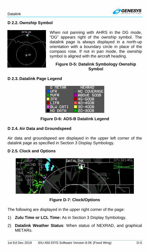
Datalink
1st Ed Dec 2019 IDU-450 EFIS Software Version 8.0K (Fixed Wing) D-5
D 2.2. Ownship Symbol
When not panning with AHRS in the DG mode, “DG” appears right of the ownship symbol. The datalink page is always displayed in a north-up orientation with a boundary circle in place of the compass rose. If not in pan mode, the ownship symbol is aligned with the aircraft heading.
Figure D-5: Datalink Symbology Ownship Symbol
D 2.3. Datalink Page Legend
Figure D-6: ADS-B Datalink Legend
D 2.4. Air Data and Groundspeed
Air data and groundspeed are displayed in the upper left corner of the datalink page as specified in Section 3 Display Symbology.
D 2.5. Clock and Options
Figure D-7: Clock/Options
The following are displayed in the upper right corner of the page:
1) Zulu Time or LCL Time: As in Section 3 Display Symbology.
2) Datalink Weather Status: When status of NEXRAD, and graphical METARs.

Datalink
D-6 IDU-450 EFIS Software Version 8.0K (Fixed Wing) 1st Ed Dec 2019
Table D-6: Datalink NEXRAD Status
Condition Status Annunciation *NEXRAD Graphical METAR Never completely downlinked
No Annunciation
Downlinked within last 5 minutes and selected for display (*if installed, weather radar deselected from display). “Show Full Sensor Status Flag” enabled.
“NXRD ##” in green. ## is age in minutes.
NEXRAD shown.
“GMTR ##” in green. ## is age in minutes.
G METARS shown.
Downlinked within last 5 minutes and deselected from display (*if installed, weather radar selected for display). “Show Full Sensor Status Flag” enabled.
“NXRD ##” in green. ## is age in minutes.
“NXRD ##” overlaid with green “X”
NEXRAD not shown.
“GMTR ##” in green. ## is age in minutes.
“GMTR ##” overlaid with green “X”
G METARS not shown.
Not downlinked within last 5 minutes but downlinked within last 10 minutes and selected for display (*if installed, weather radar deselected from display). “Show Full Sensor Status Flag” enabled.
“NXRD ##” in amber (yellow). ## is age in minutes.
NEXRAD shown.
“GMTR ##” in amber (yellow). ## is age in minutes.
G METARS shown.
Not downlinked within last 5 minutes but downlinked within last 10 minutes and deselected from display (*if installed, weather radar selected for display). “Show Full Sensor Status Flag” enabled.
“NXRD ##” in amber (yellow). ## is age in minutes.
“NXRD ##” overlaid with green “X”
NEXRAD not shown.
“GMTR ##” in amber (yellow). ## is age in minutes.
“GMTR ##” overlaid with green “X”
G METARS not shown.
Not downlinked within last 10 minutes but downlinked within last 75 minutes and selected for display (*if installed, weather radar deselected from display).
“NXRD ##” in red. ## is age in minutes.
NEXRAD shown.
“GMTR ##” in red. ## is age in minutes.
G METARS shown.
Not downlinked within last 10 minutes but downlinked within last 75 minutes and deselected from display (*if
“NXRD ##” in red. ## is age in minutes.
“GMTR ##” in red. ## is age in minutes.

Datalink
1st Ed Dec 2019 IDU-450 EFIS Software Version 8.0K (Fixed Wing) D-7
Table D-6: Datalink NEXRAD Status
Condition Status Annunciation *NEXRAD Graphical METAR installed, weather radar selected for display). “Show Full Sensor Status Flag” enabled.
“NXRD ##” overlaid with green “X”
NEXRAD not shown.
“GMTR ##” overlaid with green “X”
G METARS not shown.
Not downlinked within last 75 minutes (timed-out). “Show Full Sensor Status Flag” enabled.
“NXRD XX” in red
“NXRD XX” overlaid with red “X”
NEXRAD not shown.
“GMTR XX” in red
“GMTR XX” overlaid with red “X”
G METARS not shown.
D 2.6. Datalink Page Screen Orientation
Figure D-8: Datalink Page Screen Range
When selected, the following screen ranges (all distances represent distance from the ownship symbol to the boundary circle) are available. Radius of the range ring is presented on the inner range ring with the outer ring representing double the value of the inner ring.

Datalink
D-8 IDU-450 EFIS Software Version 8.0K (Fixed Wing) 1st Ed Dec 2019
D 2.7. Boundary Circle Symbols
Figure D-9: Boundary Circle Symbol
A white triangular heading pointer aligned with the longitudinal axis of the ownship symbol appears on the boundary circle with a green diamond-shaped track pointer aligned with the aircraft’s track across the earth. A green dashed lubber line connects the center of the aircraft symbol and the track pointer.
If a target or VNAV altitude is set and not captured, an altitude capture predictor arc is displayed on the lubber line at a point corresponding with predicted climb or descent distance (based upon current VSI). The track pointer, lubber line, and altitude capture predictor arc are not displayed when groundspeed is less than 60 knots. A pilot-settable heading bug geometrically interacting with the heading pointer appears on the boundary circle. A magenta, star-shaped waypoint pointer displayed on the boundary circle at a point corresponds with the active waypoint. The waypoint pointer turns amber (yellow) in the event of GPS LON caution. Boundary circle symbols are not drawn when in pan mode.
D 2.8. Active Flight Plan Path/Manual Course/Runways
When there is an active flight plan and automatic GPS/SBAS OBS setting, the flight plan path, when selected, is shown in correct relationship to the ownship symbol. The active flight plan path depiction meets all GPS/SBAS path definition requirements and matches the lateral navigation guidance on the PFD (GPS/SBAS CDI in automatic OBS mode, skyway boxes, and mini-map). Active flight plan path fly-over waypoints symbols are distinct from fly-by waypoints and consist of the waypoint symbol within a circle.
Table D-7: Datalink Page Screen Ranges
Ownship to Boundary Circle Radius Range Values 50 NM 25 NM
100 NM 50 NM 200 NM 100 NM 400 NM 200 NM 800 NM 400 NM 1600 NM 800 NM
Boundary Circles
Datalink
1st Ed Dec 2019 IDU-450 EFIS Software Version 8.0K (Fixed Wing) D-9
When there is a parallel offset, the active flight plan path depicts the parallel offset path, and the original flight plan path is shown with haloed gray dashed lines.
When there is an active waypoint and manual GPS/SBAS OBS setting, the course through the waypoint is shown as a pointer centered on the waypoint and matches the lateral navigation guidance on the PFD (GPS/SBAS CDI in manual OBS mode, skyway boxes, and mini-map).
The active flight plan path’s active leg/manual course and active waypoint are magenta but turn amber (yellow) in the event of a GPS LON caution. The datalink page displays airport runways in correct relationship and scale to the ownship symbol.
D 2.9. Borders
National and United States state borders are drawn in white in correct relationship to the ownship symbol.
D 2.10. Pan Mode
Use the pan mode to change the location of the center of the page away from current location and view weather conditions along the route of flight and at the intended destination or alternate destination. When pan mode is active, rotate to pan north, south, east, and west. When pan mode is active, a line is drawn from the map center to the aircraft's current position, and bearing and distance to the map center is always displayed above the ownship symbol when the aircraft is more than 0.5 NM away. If referenced to magnetic north, (as specified in Section 3 Display Symbology) when panning, the nearest displayed graphical METAR symbol within the inner range ring is highlighted with a flashing circle. When such a point is highlighted, dedicated buttons are present to allow the pilot to view and hide the waypoint information (including datalink weather information) associated with that point.
D 3. Top-Level Menu Automatic Pop-Up Function Descriptions
See Section 5 Menu Functions and Step-by-Step Procedures for top-level menu option descriptions. Soft menu tiles appear adjacent to buttons under the specified conditions.
Table D-8: Tile Legend and Action in Order of Precedence
L1 When Datalink page with pan mode enabled, PN OFF appears. Press to disable pan mode.

Datalink
D-10 IDU-450 EFIS Software Version 8.0K (Fixed Wing) 1st Ed Dec 2019
Table D-8: Tile Legend and Action in Order of Precedence
L2 When Datalink page with: (a) pan mode enabled; (b) information for the nearest highlighted waypoint is shown; and (c) airport weather information is present in the information block; WX appears. Press to display textual METAR and TAF data for the airport.
L3 When Datalink page with pan mode enabled, NORTH appears. Press to shift center of page in the specified direction.
L4 When Datalink page with pan mode enabled. SOUTH appears. Press to shift the center of the page in the specified direction.
R2 When ND page or Datalink page with pan mode enabled, INFO or HIDE appears. Press to toggle information for nearest highlighted waypoint.
R3 When Datalink page with pan mode enabled, EAST appears. Press to shift the center of the page in the specified direction.
R4 When Datalink page with pan mode enabled, WEST appears. Press to shift the center of the page in the specified direction.
D 4. MFD Page First-Level Option Descriptions
WX LGND (ACTV) (L2): Activates datalink weather legend.
D 5. MFD Datalink Format (FORMAT) Menu
FORMAT..
PAN ON
DCLTR..
PAN OFF
1
Turn pan mode off(shown if pan mode is on)
G METAR
NEXRAD
1DONE
Graphical METAR
NEXRAD radar
Turn pan mode on(shown if pan mode is off)
R4
EAST
R3
WEST
NORTH
SOUTH
L3
L4
Pan east
Pan west
Pan north
Pan south
1Push – Switch to PFDRotate – Change range as set in EFIS limits
PN
OFF
L1
Pan Off
MENU
ROUTEDisplay active flight plan route
Accept Changes
Figure D-10: MFD Datalink Format (FORMAT) Menu

Datalink
1st Ed Dec 2019 IDU-450 EFIS Software Version 8.0K (Fixed Wing) D-11
Upon selecting the MFD format menu FORMAT.. (R4) on Datalink page, a list appears with the following options:
1) ROUTE ON/ROUTE OFF: Toggles active flight plan route.
2) PAN ON/PAN OFF: Toggles pan mode.
3) DCLTR: Only available when Datalink weather products are available for display. Allows the pilot to select individual Datalink weather products for display.
D 5.1. MFD DATALINK Page (Step-By-Step)
1) Press MENU (R1), press PAGE (R3) and rotate to DATALINK and push to enter.
2) Example shows MFD with DATALINK.
3) Press MENU (R1) and then FORMAT.. (R4) to format Datalink page.
4) Rotate to PAN ON or DCLTR.. Push to enter.

Datalink
D-12 IDU-450 EFIS Software Version 8.0K (Fixed Wing) 1st Ed Dec 2019
5) In pan mode, press NORTH (L3), SOUTH (L4), EAST (R3), or WEST (R4) to move aircraft in desired direction.
D 6. Active Flight Plan (ACTV) Menu Options
NRST APT (L2): WX LGND and EXPND WX are available to show a weather symbol legend and highlighted result METAR and TAF text respectively.
Identifier Entry Box: Highlighted result information may include datalinked weather information when available.
D 7. Information (INFO) Menu
When airport weather information is presented in the information block, WX LGND (L2) displays an airport graphical METAR legend, and EXPND WX (L3) displays textual METAR and TAF data for the airport.
D 8. MFD Fault Display Menu
Figure D-11: FAULTS Menu with ADS-B Status
Upon selecting the MFD faults menu with ADS-B datalink enabled, an indication of ADS-B position validity (ADSB POSN), indication of whether ADS-B receiver maintenance is required (ADSB MAINT), and indication the conflict situational awareness algorithm is working (ADSB CSA) appear.

Datalink
1st Ed Dec 2019 IDU-450 EFIS Software Version 8.0K (Fixed Wing) D-13
D 9. Menu Synchronization
Section 5 Menu Functions and Step-by-Step Procedures for additional information.
Table D-9: Menu Synchronization
Menu Parameter Notes The following menu parameters are independent between displays. These are used to support non-PFD display options to give the pilot maximum MFD operating flexibility. MFD Datalink Page Settings
D

Weather Radar
1st Ed Dec 2019 IDU-450 EFIS Software Version 8.0K (Fixed Wing) WX-1
Weather Radar
WX 1. Weather Radar
This Weather Radar appendix is primarily for the Honeywell RDR-2100 installed with no external control panel. The EFIS controls the WX RDR from the EFIS PFD bottom display or MFD with WX RDR displayed in the top area or bottom area. Since there is only one RDR-2100 installed in the aircraft, only one display area at a time can show the WX RDR menu.
WARNING:
CAUTION:
Maintain prescribed safe distance when standing in front of operating antenna. (Reference FAA Advisory Circular #20-68)
Never expose eyes or any part of the body to an unterminated wave guide.

Weather Radar
WX-2 IDU-450 EFIS Software Version 8.0K (Fixed Wing) 1st Ed Dec 2019
Figure WX-1: Weather Radar Image on Map
Figure WX-2: MFD Weather Radar Page
Weather radar automatically declutters when weather radar returns are selected for display on the ND map page in correct relationship to the ownship symbol unless inhibited during active FLTA alerts. When weather radar is selected, Datalink NEXRAD is automatically deselected. Table WX-1 defines all inhibited factors with display.
Table WX-1: Weather Radar Inhibited Conditions
During Active FLTA alerts ND Moving Map Pan Mode When North Up orientation is selected When RDR-2100 is in vertical profile mode

Weather Radar
1st Ed Dec 2019 IDU-450 EFIS Software Version 8.0K (Fixed Wing) WX-3
Table WX-1: Weather Radar Inhibited Conditions
When screen range is too small to effectively show the weather returns (defined as when the length of the weather radar scan line is longer than 512 pixels given current weather radar scale setting, screen range, and screen mode)
WX 2. Top-Level Menu Option Descriptions
WX RDR.. (L2): If a Weather Radar page is displayed on the MFD, activates the Weather Radar menu for controlling Honeywell RDR-2000/2100.
Encoder: On an MFD (IDU #2, #3 or #4) showing the Weather Radar page, rotate to change the display RNG (direction of rotation is dependent upon EFIS limits settings.)
DCLTR.. (R4): DCLTR activates Weather Radar Declutter menu option.
WX 3. PFD Weather Radar Page Format (FORMAT) Menu
Upon selecting WX RDR menu in the WX RDR page when weather radar type is RDR-2100 without external RCP installed, the following list appears.
1) WX RDR (L2): Opens CTRL (L2) menu.
2) Off (R2): Turns Weather Radar off.
3) Standby (R3): Toggles WX RDR to STBY mode, press ON WXA (L4) to turn on WX RDR.
4) Test (R4): Toggles radar into TEST mode, press ON WX (L4) to return to normal operation.
5) ON WX (L4): Toggles WX ON, WXA, or GMAP.
6) Vertical Profile (L3): Toggles vertical profile ON/OFF. (When VP is OFF, horizontal profile is ON.)
WX 3.1. Ownship Symbol
The ownship symbol appears in horizontal and profile depictions on the weather radar page.

Weather Radar
WX-4 IDU-450 EFIS Software Version 8.0K (Fixed Wing) 1st Ed Dec 2019
Horizontal Depiction Profile Depiction
Airplane with MMO Airplane without MMO
Figure WX-3: Ownship Symbol
R4
STAB ONR3
L4 ROLL TRIM.. GAIN..Set desiredROLL TRIM1
Rotate – Change Roll Trim in 0.125°increments
Push – Set selected Roll Trim
TILT: +/-XX° TRACK: +/-XX°
Set desired TILT
TILT:AUTO*
Rotate – Change TILT in 0.25° incrementsPush – Set selected TILT
Press – Set TILT automatically
R3AUTO*Toggle to AUTO Mode
MAN*Toggle to MANUAL mode
Set desired TRACK
Rotate – Change Track in 1° incrementsPush – Set selected Gain
SCTR ON*L2
STAB OFFSCTR OFF*
Set desired GAIN 1
Rotate – Change Gain in 1dB incrementsPush – Set selected Gain
WX RDR.. (R7)
MENU (R1)
R1
R2
R4
STBY
TEST
OFF
ON WX
ON WXA
ON GMAP
L2
L3VP ON
L4
Enable standby mode. Not shown when in standby mode
Cycles through WX/WXA/GMAP sub modes.Not available when in OFF mode.
Vertical Profile ON/OFF. Not available when in OFF or STBY mode.VP OFF
CTRL..
ARL ON*R1
ARL OFF*
ACLTR ONL1
ACLTR OFF
Enable TEST mode. Not shown when in test mode
Enable OFF mode. Not shown when in off mode
Control Menu. Not available when in OFF or STBY mode.
R2ASTEP ON*
Toggle Auto Step Scan ON/OFFASTEP OFF*
*Applicable only to Honeywell RDR-2100
1RNGIncrease/decrease radar range
1
RNG
Increase/decrease radar range
1 1
1
1
Figure WX-4: PFD WX RDR Format (FORMAT) Menu
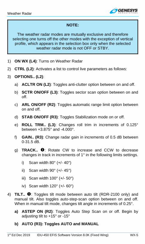
Weather Radar
1st Ed Dec 2019 IDU-450 EFIS Software Version 8.0K (Fixed Wing) WX-5
NOTE:
The weather radar modes are mutually exclusive and therefore selecting one turns off the other modes with the exception of vertical profile, which appears in the selection box only when the selected
weather radar mode is not OFF or STBY.
1) ON WX (L4): Turns on Weather Radar
2) CTRL (L2): Activates a list to control live parameters as follows:
3) OPTIONS.. (L2):
a) ACLTR ON (L2): Toggles anti-clutter option between on and off.
b) SCTR ON/OFF (L3): Toggles sector scan option between on and off.
c) ARL ON/OFF (R2): Toggles automatic range limit option between on and off.
d) STAB ON/OFF (R3): Toggles Stabilization mode on or off.
e) ROLL TRM.. (L3): Changes roll trim in increments of 0.125° between +3.875° and -4.000°.
f) GAIN.. (R3): Change radar gain in increments of 0.5 dB between 0-31.5 dB.
g) TRACK.. : Rotate CW to increase and CCW to decrease changes in track in increments of 1° in the following limits settings.
i) Scan width 80° (+/- 40°)
ii) Scan width 90° (+/- 45°)
iii) Scan width 100° (+/- 50°)
iv) Scan width 120° (+/- 60°)
4) TILT.. : Toggles tilt mode between auto tilt (RDR-2100 only) and manual tilt. Also toggles auto-step-scan option between on and off. When in manual tilt mode, changes tilt angle in increments of 0.25°.
a) ASTEP ON (R2): Toggles Auto Step Scan on or off. Begin by adjusting tilt to +15° or -15°
b) AUTO (R3): Toggles AUTO and MANUAL

Weather Radar
WX-6 IDU-450 EFIS Software Version 8.0K (Fixed Wing) 1st Ed Dec 2019
5) RNG : See § WX 2.
6) DCLTR: ROUTE toggles active flight plan route.
DCLTR..
MENU
ROUTE
1
Display Active Flight Plan Route (Horizontal
Profile Only)
DONEAccept Changes
Figure WX-5: WX RDR Declutter (DCLTR) Menu
WX 3.2. Weather Radar Page Format
In a horizontal depiction, the weather radar page uses an arced format with the ownship symbol centered in the bottom of the display with the weather area depicted as an arc ahead of the ownship symbol.
Figure WX-6: Radar Image in Arc Format
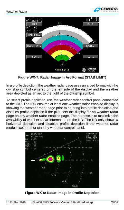
Weather Radar
1st Ed Dec 2019 IDU-450 EFIS Software Version 8.0K (Fixed Wing) WX-7
Figure WX-7: Radar Image in Arc Format (STAB LIMIT)
In a profile depiction, the weather radar page uses an arced format with the ownship symbol centered on the left side of the display and the weather area depicted as an arc to the right of the ownship symbol.
To select profile depiction, use the weather radar control panel connected to the IDU. The IDU ensures at least one weather radar-enabled display is showing the weather radar page prior to entering into profile depiction and disables profile depiction if the pilot sets the display for no weather radar page on any weather radar-enabled page. The purpose is to maximize the availability of weather radar information on the ND. The ND only shows a horizontal depiction and disables profile depiction if the weather radar mode is set to off or standby via radar control panel.
Figure WX-8: Radar Image in Profile Depiction

Weather Radar
WX-8 IDU-450 EFIS Software Version 8.0K (Fixed Wing) 1st Ed Dec 2019
Figure WX-9: Radar Image in Profile Depiction (STAB LIMIT)
WX 3.3. Weather Radar Page Screen Range
Weather radar page screen range is pilot-selectable with either (RDR-2000 and RDR-2100 weather radar types) or a control panel directly attached to the weather radar receiver-transmitter. Weather radar page screen range is displayed as a series of equidistant dashed arcs centered upon the ownship symbol to help judge range to the displayed weather radar returns. All distances represent the distance from the ownship symbol to the outer dashed arc: 5NM, 10NM, 20NM, 40NM, 80NM, 160NM, 240NM, and 320NM.
For most screen ranges, there are four equidistant dashed arcs. Each arc is labeled with distance in nautical miles at its right-most point (horizontal depiction) or bottom-most point (profile depiction). In profile depiction, there are also three horizontal altitude lines drawn relative to the aircraft’s altitude to help judge the vertical distance to the displayed weather radar returns. The center line is level with the ownship symbol to represent the aircraft’s altitude. The other two lines are equally spaced above and below the center line to represent altitude differences above and below the aircraft. The number of feet above and below the aircraft varies with the selected range to compensate for the radar scan width at the different ranges.
WX 3.4. Track Line
When the weather radar type is RDR-2000 or RDR-2100 and the horizontal depiction is shown, a dashed track line emanates from the ownship symbol to the outer dashed arc. The value of the track line in whole degrees left or right of aircraft heading is displayed adjacent to the outer end of the track line.

Weather Radar
1st Ed Dec 2019 IDU-450 EFIS Software Version 8.0K (Fixed Wing) WX-9
Figure WX-10: Radar Track Line
Figure WX-11: Radar Track Line with Menus
WX 3.5. Active Flight Plan Path/ Manual Course/ Runways
The active flight plan path (when selected), waypoints, and manual course appear, when the weather radar page is showing horizontal depiction. The weather radar page displays airport runways, when the weather radar page is showing horizontal depiction.
In horizontal depiction, the active flight plan path (when selected), waypoints, manual course appear and airport runways appear.
Track Line
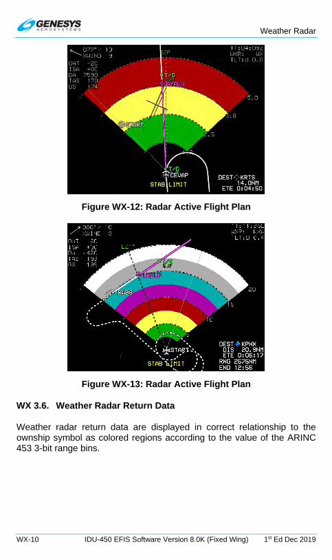
Weather Radar
WX-10 IDU-450 EFIS Software Version 8.0K (Fixed Wing) 1st Ed Dec 2019
Figure WX-12: Radar Active Flight Plan
Figure WX-13: Radar Active Flight Plan
WX 3.6. Weather Radar Return Data
Weather radar return data are displayed in correct relationship to the ownship symbol as colored regions according to the value of the ARINC 453 3-bit range bins.

Weather Radar
1st Ed Dec 2019 IDU-450 EFIS Software Version 8.0K (Fixed Wing) WX-11
Figure WX-14: Radar Return Data
Table WX-2: Weather Radar Return Data
ARINC 453 3-Bit Range Bin
Color Meaning
000b BLACK No returns
001b GREEN Low-level weather or low-level ground returns
010b YELLOW Mid-level weather or mid-level ground returns
011b RED Third-level weather returns. Color is black when in MAP mode.
100b MAGENTA
Fourth-level weather or third-level ground returns. With RDR-2000 or RDR-2100 weather radar type, color alternates between magenta and black at 1Hz when internal sub-mode is WXA.
101b CYAN Automatic range limit returns. Indicates areas of unreliable returns due to radar power absorption.
110b LIGHT GRAY Moderate turbulence returns 111b WHITE Severe turbulence returns
The following weather radar-specific warnings appear in a conspicuous area adjacent to weather radar return data so they do not conflict with the weather radar return data. Only one warning appears at any given time, with the following order of precedence:

Weather Radar
WX-12 IDU-450 EFIS Software Version 8.0K (Fixed Wing) 1st Ed Dec 2019
1) WX ALRT: Weather alert condition is active.
2) TURB ALRT: Turbulence alert condition is active.
3) STAB LIMIT: Aircraft attitude has moved to a point where the weather radar antenna can no longer be effectively stabilized.
4) ANT FAULT: Weather radar antenna is temporarily dislodged by turbulence.
WX 3.7. Air Data and Groundspeed
Air data and groundspeed are displayed in upper left corner of the weather radar page as specified in Section 3 Display Symbology.
WX 3.8. Clock/Options
Figure WX-15: Radar Clock/Options
The following are displayed in the upper right corner:
1) Zulu Time or LCL Time: As in Section 3 Display Symbology;
2) Weather Radar Mode Annunciation: As in Table WX-3 and Table WX-4.
Table WX-3: RDR 2100 Applicability
Mode Annunciation Off WXR:OFF Standby WXR:STBY Weather only WXR:WX Weather alert WXR:WXA Ground map WXR:GMAP Test WXR:TEST Not defined WXR:----

Weather Radar
1st Ed Dec 2019 IDU-450 EFIS Software Version 8.0K (Fixed Wing) WX-13
Table WX-4: RDR 2100 Mode Annunciation
Annunciation Conditions Overlaid with Red X
Weather radar mode is off or not defined.
Cooling fault condition exists.
Attitude or range fault condition exists.
T/R fault condition exists. STAB OFF (Stabilization)
Mode annunciation not overlaid with a red “X”;
Mode not standby or forced standby; and
Weather radar indicates stabilization is off. TGT ALERT (Target Alert)
Mode annunciation not overlaid with a red “X”;
Mode not standby or forced standby;
Weather radar presenting horizontal depiction. “TLT:UXX.X” or “TLT:AUTO” (TILT)
U = Up or Down (either U or D, but not both, may appear – use “U” for 0°);
XX.X represents absolute value of the tilt angle in degrees truncated to the nearest tenth;
“TLT:AUTO” used where weather radar reports a value of -16°, representing automatic tilt.
Weather radar tilt annunciation only appears when all following conditions are true:
1) Mode annunciation not overlaid with a red “X”;
2) Mode not standby or forced standby; and
3) Radar not in vertical profile depiction. TRK:LXX (TRACK)
L = Left or Right (either L or R, but not both, may appear – use “R” for 0°); and
XX represents absolute value of the track angle in degrees.
Weather radar track annunciation only appears when all following conditions are true:
1) Mode annunciation not overlaid with a red “X”;
2) Mode not standby or forced standby; and
3) Radar in vertical profile depiction. “GN:SXXDB,” “GN:CAL,” or “GN:MAX” (GAIN)
S = Sign (either “+” or “-,” but not both, may appear – use “+” for 0°); and
XXDB represents the manual gain setting in decibels.
“GN:CAL” represents the calibrated condition
“GN:MAX” represents maximum manual gain

Weather Radar
WX-14 IDU-450 EFIS Software Version 8.0K (Fixed Wing) 1st Ed Dec 2019
Table WX-4: RDR 2100 Mode Annunciation
Annunciation Conditions Weather radar manual gain annunciation only appears when all following weather radar mode conditions are true:
1) Mode annunciation not overlaid with a red “X”;
2) Mode not standby or forced standby; and
3) Mode is ground map.
WX 3.9. Fuel Totalizer/Waypoint Distance Functions
Displayed as specified in Section 3 Display Symbology.
NOTE:
When using EFIS menu system for RDR-2XXX control, the weather radar mode received from the offside system is used to update onside weather radar mode as follows. This is to ensure weather radar power
on/off is synchronized between both sides.
When offside mode is commanded to STBY, TEST, or ON and if onside mode is OFF, then the onside mode is set to STBY.
When offside mode is commanded to OFF, then the onside mode is also set to OFF.
WX 4. MFD Fault Display (FAULTS) Menu
Upon selecting the MFD faults menu, the status of the following system parameters are displayed if weather radar is enabled:
1) If WX-500 enabled, loss of communications with WX-500.
2) Indicates weather radar power/communication status (WXR PWR X or WXR PWR OK). Status failed (WXR PWR X) reflects any one of the following conditions is true:
a) Loss of weather radar communication.
b) Weather radar mode is OFF.
3) Indicates weather radar fault status (WXR FAULT –, WXR FAULT X, or WXR FAULT OK). Status failed (WXR FAULT –) indicates it is not

Weather Radar
1st Ed Dec 2019 IDU-450 EFIS Software Version 8.0K (Fixed Wing) WX-15
possible to determine weather radar faults. Status failed (WXR FAULT X) reflects any of the following conditions is true:
a) A cooling fault condition exists.
b) For weather radar types ARINC 708-6 or Collins 800/840, a display or control bus fault condition exists.
c) For weather radar types ARINC 708-6, Collins 800/840, or Honeywell PRIMUS, a calibration or air data fault condition exists.
d) An attitude or range fault condition exists.
e) A control fault condition exists.
f) A T/R fault condition exists.
4) If weather radar type is RDR-2000 or RDR-2100, indicates radar control panel status (WXR RCP X or WXR RCP OK). Status failed (WXR RCP X) indicates loss of communication or a failure status using same test as invalid data SSM for output labels 270, 271, 273, or 275.
WX 5. Top-Level Menu Automatic Pop-Up Function Descriptions
Soft menu tiles appear adjacent to buttons under specified conditions.
Table WX-5: Top-Level Auto Pop-Up Function Descriptions
Note 1 Tile Legend and Action
L2
When ND Page with: (a) pan mode enabled; (b) information for nearest highlighted waypoint shown; and (c) airport weather information present in the information block; WX displays textual METAR and TAF data for the airport.
WX 6. Menu Synchronization
Section 5 Menu Functions and Step-by-Step Procedures for additional information.
Table WX-6: Menu Synchronization
Menu Parameter Notes The following menu parameters are synchronized across all displays at all times. These are bugs and fundamental aircraft values that should never have independence.
WX RDR Control Menu parameters Used to synchronize certain RDR-2XXX modes. See note below.

Weather Radar
WX-16 IDU-450 EFIS Software Version 8.0K (Fixed Wing) 1st Ed Dec 2019
Table WX-6: Menu Synchronization
Menu Parameter Notes The following menu parameters are only synchronized onside. These parameters are usually sensor selections or PFD options used to keep the appearance of any pilot's PFD consistent in the case of PFD reversion. The onside characteristic means that individual pilots can still adjust their PFD settings to their preference.
WX RDR Control Menu parameters Synchronized onside when Honeywell RDR-2XXX is installed.
Rate of Turn Indication flag Onside due to range being controlled by the weather radar.
Weather Radar Scale Onside because range is controlled by the weather radar.
The following menu parameters are independent between displays. These are used to support non-PFD display options to give the pilot maximum MFD operating flexibility. MFD Selected Page This parameter is transmitted to all
other IDUs to support weather radar vertical profile mode selection.
MFD Map Page Settings Map scale is transmitted onside to support weather radar range selection.
WX 7. Managing RDR-2100 Weather Radar Menus (PFD) (Step-By-Step)
1) On MFD, press MENU (R1), PAGE (R1).
2) Rotate to WX-RDR and push to enter.
3) Press MENU (R1).

Weather Radar
1st Ed Dec 2019 IDU-450 EFIS Software Version 8.0K (Fixed Wing) WX-17
4) Press WX RDR.. (L2).
5) Press OFF (R2) to enable OFF mode. (This option is not shown when in OFF mode.)
6) Press STBY (R3) to enable standby mode. (This option not shown when in standby mode.)
7) Press TEST (R4) to enable test mode. (This option not shown when in test mode.)
8) While in STBY mode, press ON WX (L4) to return Radar to ON mode.
9) Current mode status is displayed in upper right corner of radar display.
10) Press MENU (R1), WX RDR.. (L2), and then VP ON (L3) to toggle between horizontal and vertical modes.
11) Press VP OFF (L3) to toggle back to horizontal profile.

Weather Radar
WX-18 IDU-450 EFIS Software Version 8.0K (Fixed Wing) 1st Ed Dec 2019
12) Press ON WXA (L4) to enable Weather-Alert sub-mode.
13) Weather-Alert sub-mode annunciated in upper right corner.
14) Press MENU (R1), WX RDR.. (L2), ON GMAP (L4) to enable Ground Map sub-mode.
15) Ground Map sub-mode annunciated in upper right corner.
16) Press MENU (R1), WX RDR.. (L2), and then ON WX (L4) to resume normal weather radar mode of operation.
17) Radar mode of operation annunciated in upper right corner.
18) Rotate to alter range of weather radar from 5.00 NM to 320.00 NM. Rotation direction dependent upon EFIS limits setting.

Weather Radar
1st Ed Dec 2019 IDU-450 EFIS Software Version 8.0K (Fixed Wing) WX-19
19) Range rings are located on the right side of the arc.
20) Press MENU (R1), WX RDR.. (L2), and then CTRL.. (L2) to enter radar control menu. (Not shown when in OFF or STBY mode.)
21) Press OPTIONS.. (L2) and then ACLTR ON (L2) to toggle anti-clutter option ON and OFF.
22) Press SCTR ON (L3) to toggle Sector Scan option ON and OFF.
23) Press MENU (R1), WX RDR.. (L2), CTRL.. (L2), ROLL TRIM (L3) and then rotate to desired roll trim angle (increments of 0.125°) and push to enter.
24) Press MENU (R1), WX RDR.. (L2), CTRL.. (L2), and then TILT.. (R4)
25) Rotate to set tilt angle between ±15°. Set angle is annunciated above and in upper right corner.
26) When in TILT AUTO mode, annunciation is above .

Weather Radar
WX-20 IDU-450 EFIS Software Version 8.0K (Fixed Wing) 1st Ed Dec 2019
27) Press ASTEP ON (R2) or ASTEP OFF (R2) to toggle antenna tilt to sequentially step in 4° increments. (Auto step scan is entered initially by adjusting the tilt to +15° or -15°.)
28) Press BACK (L1) or Exit (R1) to exit out of TILT sub-mode.
29) Press MENU (R1), WX RDR.. (L2), CTRL.. (L2), and then TRACK.. (L4).
30) Rotate and rotate or begin by rotating to set new TRACK angle in 1° increments between limits set in EFIS limits. Read new TRACK in two places.
31) Press MENU (R1), WX RDR.. (L2), CTRL.. (L2), and then GAIN (R3) to open GAIN menu.
32) Rotate to change gain in 1 dB increments. Push to set selected gain value.
WX

Round Dials
1st Ed Dec 2019 IDU-450 EFIS Software Version 8.0K (Fixed Wing) RD-1
Round Dials
RD 1. PFD Primary Flight Instrumentation
This following details round dial display symbology used on the IDU-450 PFD and MFD (in reversionary PFD mode). The round dials option is only available with pure digital ADC configured. Not all combinations of possible views are represented. See Section 3 Display Symbology for further information on the following display symbology.
RD 1.1. Pitch Scale
Figure RD-1: Pitch Scale
The white pitch scale and horizon rotates about the large aircraft symbol reference marks according to the aircraft’s roll angle. The pitch scale has 5° with major increments and pitch scale labels every 10°. Pointer bars at the ends of each major increment indicate the direction to the horizon. Pitch scale increments automatically declutter to present the fewest possible increments needed.
RD 1.2. Flight Director Symbology
A pilot-selectable flight director is available through the menu system or integrated autopilot/flight director avionics. When selected, one of the above symbology examples appear when valid steering commands are received.

Round Dials
RD-2 IDU-450 EFIS Software Version 8.0K (Fixed Wing) 1st Ed Dec 2019
FD-1 Single Cue FD-2 Dual Cue
Figure RD-2: Flight Director
RD 1.3. Marker Beacon Indicators
When enabled and valid marker beacon indicators with appropriate coloring and markings are displayed in the lower central portion of the PFD. During a built-in-test, more than one marker beacon can be active. Marker beacons acquired from NAV VLOC1 or VLOC2. Marker beacons are disabled when the NAV source is FMS.
Outer Marker Middle Marker
Figure RD-3: Marker Beacon Indicators
RD 1.4. Unusual Attitude Mode
Unusual attitude mode is enabled when the pitch attitude exceeds +30° or -30° or bank angle exceeds 65° left or right. Once enabled, unusual attitude mode remains engaged until pitch attitude returns to within 5° of the horizon and bank attitude returns to within 10° of the horizon.

Round Dials
1st Ed Dec 2019 IDU-450 EFIS Software Version 8.0K (Fixed Wing) RD-3
Pitch up 21° Recovery Chevrons
Only Pitch up 31° Unusual Attitude
Mode
Figure RD-4: Unusual Attitude Mode
RD 1.5. Bank Angle Scale
The bank angle scale and roll pointer are centered upon the waterline. Either a roll pointer or sky pointer can be selected during EFIS limits configuration.
Roll Pointer Sky Pointer
Figure RD-5: Bank Angle Scale Types
RD 1.6. Pitch Limit Indicator
When enabled in either category of airplane, a yellow pitch limit indicator appears at 20 KIAS above stall speed. Stall speed is defined as the following:
1) Part 23 airplanes, the higher of the aircraft’s 1-G VS1 or VS1 corrected for G-loading; or

Round Dials
RD-4 IDU-450 EFIS Software Version 8.0K (Fixed Wing) 1st Ed Dec 2019
2) Part 25 airplanes, if pilot-input VREF is valid, the higher of the aircraft’s 1-G VSO or VSO corrected for G-loading where VSO is calculated by dividing the pilot-input VREF by 1.23.
5 Knots before Stall Stall Speed
Figure RD-6: Pitch Limit Indicator
The pitch limit indicator merges with the large aircraft reference symbol at stall speed and continues moving downward as indicated airspeed further decreases.
RD 1.7. AGL Indication
Figure RD-7: AGL Indicator
AGL altitude is displayed as in Figure RD-7 at the bottom of the display or above the CDI. The source for AGL indication is the source being used for the TAWS, which is designated as follows:
R = Radar Altitude

Round Dials
1st Ed Dec 2019 IDU-450 EFIS Software Version 8.0K (Fixed Wing) RD-5
G = GPS/SBAS geodetic height less database found elevation.
B = Barometric altitude less database ground elevation.
AGL altitude is not displayed when it is greater than the radar altimeter maximum valid altitude as set in the EFIS limits and is not displayed when it is invalid. This area also includes a decision height set with the PFD bugs menu.
Table RD-1: AGL Altitude Values
Value Resolution Color <300’ 10’
White <100’ >300’ 5’ >100’ 1’
Decision Height
10’
White but turns amber (yellow) and flashes at and below DH.
RD 1.8. Landing Gear Indication
Figure RD-8: Landing Gear Indication
When configured as retractable gear in the EFIS limits, the landing gear is shown as three small “tires” below the large aircraft reference marks. This symbology is driven by discrete inputs.
RD 1.9. Airspeed Display
The airspeed display digitally displays indicated airspeed in knots, miles per hour, or kilometers per hour as set in the EFIS limits. The display is scaled to show the entire operating range of the aircraft. CW movement

Round Dials
RD-6 IDU-450 EFIS Software Version 8.0K (Fixed Wing) 1st Ed Dec 2019
corresponds to increasing speed. When an ADC sensor fails, the display appears as shown in Figure RD-18.
Figure RD-9: Airspeed Display
Without Airspeed Bugs
IAS Bug Set to 170 and Indicating 170 KIAS
IAS Bug Set to 170 and Indicating 150 KIAS
Figure RD-10: Airspeed Display Limits and BUGs
Table RD-2: Airspeed BUGs
Airspeed Bug Limits Notes
The higher of 1.2 x Vs or 60KIAS at the low end, and red-line airspeed (VNE, VMO, or MMO)
** Can be used as a visual reference.
Mutually exclusive with VSI bug.
** When integrated with Genesys/S-TEC DFCS or partially integrated through use of the vertical mode discrete input as a control parameter for climbs and descents. When vertically integrated with an autopilot, the airspeed bug is filled-white when in airspeed climb or descent mode. Otherwise, the airspeed bug is hollow-white. When not vertically integrated, the airspeed bug is filled-white at all times.

Round Dials
1st Ed Dec 2019 IDU-450 EFIS Software Version 8.0K (Fixed Wing) RD-7
RD 1.9.1 Airspeed Readout
When enabled the Mach indicator is displayed above the airspeed readout with a resolution of .01 Mach.
Figure RD-11: Airspeed Readout with Mach Number
If in air mode, a red low-speed awareness area from the bottom of the dial to VSO.
If in ground mode, a gray area from the bottom of the dial to VSO. The airspeed readout is gray but otherwise white in this area.
If a valid VFE exists, a white flap-operating area from VSO to VFE. The airspeed is white in this area.
A gray safe-operating area from VFE to VMO/MMO and the airspeed readout is green in this area.
For aircraft with VNE:
1) A green safe-operating area from VS1 to VNO/MNO. The airspeed readout is green in this area.
2) A yellow caution area from VNO/MNO to VNE/MMO. The airspeed is yellow in this area.
3) A red radial line at VNE/MMO. The airspeed readout is red at or above the radial line.
For aircraft with VMO:
1) A grey safe-operating area from VFE (if existing) to VSO to VMO/ MMO. The airspeed is green in this area.
2) A red radial line at VMO/MMO. The airspeed readout is red at or above this radial line.
The airspeed dial for Part 23 airplanes have additional airspeed markings as follows:
1) For reciprocating multiengine-powered aircraft 6,000 pounds or less, a red radial line at VMC.

Round Dials
RD-8 IDU-450 EFIS Software Version 8.0K (Fixed Wing) 1st Ed Dec 2019
2) For reciprocating multiengine-powered aircraft 6,000 pounds or less, a blue radial line at VYSE.
The airspeed dial for part 25 airplanes have additional airspeed markings as follows:
1) If in air mode with a pilot-input VREF value:
a) A red low-speed awareness area from the bottom of the dial to G-compensated 1.1 X VSO. The airspeed is readout is red in this area.
b) A yellow low-speed awareness area from G-compensated 1.1 X VSO to G-compensated 1.2 X VSO. The airspeed is yellow in this area.
c) If a valid VFE exists, a white flap-operating area from G-compensated 1.2 X VSO to VFE and a gray normal-operating area from VFE to the lower of VMO or MMO. The airspeed is white in the flap-operating area and green in the normal-operating area.
d) If a valid VFE does not exist, a gray normal-operating area from G-compensated 1.2 X VSO to the lower of VMO or MMO. The airspeed readout is green in this area.
2) If in ground mode or without a pilot-input VREF value.
a) If a valid VFE exists, a white flap-operating area from the bottom of the dial to VFE and a gray normal-operating area from VFE to the lower of VMO or MMO. The airspeed readout is gray at 0 but otherwise white in the flap-operating area and green in the normal-operating area.
b) If a valid VFE does not exist, a gray normal-operating area from the bottom of the dial to the lower of VMO or MMO. The airspeed readout is gray at 0 otherwise white below 60 and green at or above 60 in this area.
3) A red radial line at the lower of VMO or MMO. The airspeed readout is red at or above the red radial line.
RD 1.9.2 Takeoff and Landing Speed Bugs
In airplanes Part 23 or 25 airspeed scale, V1, VR, V2, VENR, VREF, and VAPP can also be shown on the airspeed dial when set. The V1, VR, and V2 symbols automatically declutter when above 2000 feet AGL.
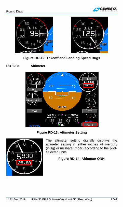
Round Dials
1st Ed Dec 2019 IDU-450 EFIS Software Version 8.0K (Fixed Wing) RD-9
Figure RD-12: Takeoff and Landing Speed Bugs
RD 1.10. Altimeter
Figure RD-13: Altimeter Setting
The altimeter setting digitally displays the altimeter setting in either inches of mercury (inHg) or millibars (mbar) according to the pilot-selected units.
Figure RD-14: Altimeter QNH
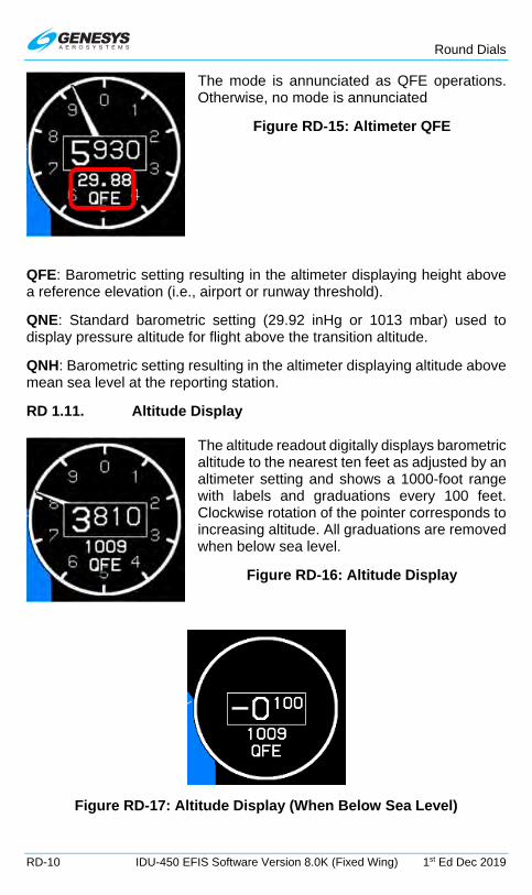
Round Dials
RD-10 IDU-450 EFIS Software Version 8.0K (Fixed Wing) 1st Ed Dec 2019
The mode is annunciated as QFE operations. Otherwise, no mode is annunciated
Figure RD-15: Altimeter QFE
QFE: Barometric setting resulting in the altimeter displaying height above a reference elevation (i.e., airport or runway threshold).
QNE: Standard barometric setting (29.92 inHg or 1013 mbar) used to display pressure altitude for flight above the transition altitude.
QNH: Barometric setting resulting in the altimeter displaying altitude above mean sea level at the reporting station.
RD 1.11. Altitude Display
The altitude readout digitally displays barometric altitude to the nearest ten feet as adjusted by an altimeter setting and shows a 1000-foot range with labels and graduations every 100 feet. Clockwise rotation of the pointer corresponds to increasing altitude. All graduations are removed when below sea level.
Figure RD-16: Altitude Display
Figure RD-17: Altitude Display (When Below Sea Level)

Round Dials
1st Ed Dec 2019 IDU-450 EFIS Software Version 8.0K (Fixed Wing) RD-11
RD 1.11.1 Loss of ADC Sensor Indication
Figure RD-18: Airspeed and Altitude with Loss of ADC
RD 1.11.2 Altitude Sub-Mode
Altitude sub-mode user-selectable triangular target altitude bug shown here at 4,400’. The bug is limited to -1,000’ up to 50,000’ and is removed when more than 500’ away from current altitude.
Figure RD-19: Target Altitude Bug
The target altitude bug can be used as a visual reference or when vertically integrated with the Genesys/S-Tec DFCS or partially integrated through use of the vertical mode discrete input, as a climb control parameter for climbs or descents, the bug characteristics indicate the following modes:
1) Filled-white when in altitude hold mode.
2) Hollow-white when in a climb or descent mode.
3) Filled-white during altitude hold capture.
When not vertically integrated with the Genesys/S-Tec DFCS, the target altitude bug is filled-white at all times.

Round Dials
RD-12 IDU-450 EFIS Software Version 8.0K (Fixed Wing) 1st Ed Dec 2019
When in VNAV sub-mode, the VNAV altitude bug appears when within 500’ from the current altitude. In this example, the VNAV altitude is 5,100’.
Figure RD-20: VNAV Sub-Mode
The VNAV bug can be used as a visual reference or when vertically integrated with the Genesys/S-Tec DFCS or partially integrated through use of the vertical mode discrete input as a control parameter for climbs or descents. The following bug characteristics indicate the following modes:
1) Filled-magenta when in altitude hold mode.
2) Hollow-magenta when in a climb or descent mode.
3) Filled-magenta during altitude hold capture.
When not vertically integrated with the Genesys/S-Tec DFCS, the VNAV bug is filled-white at all times.
RD 1.11.3 Metric Altitude
Metric altitude values may be selected from within the declutter menu with a resolution of 1 meter.
Figure RD-21: Metric Altitude
RD 1.12. Vertical Speed Indicator
The VSI located below the altitude display with a readout and dial pointer and scale of ±6,000 feet per minute. The integral scale graduations are ±500, ±1,000, ±3,000 and ±6,000 feet per minute for airplanes with VMO or airspeed scale type FAR part 25, or in applications where TCAS-II is enabled. Otherwise, the scale is ±3,000 with graduations of ±500, ±1,000, ±3,000. CW (upward) rotation of the pointer corresponds to increasing vertical speed while CCW corresponds to decreasing speed digitally displaying vertical speed rounded to the nearest 100 feet per minute.

Round Dials
1st Ed Dec 2019 IDU-450 EFIS Software Version 8.0K (Fixed Wing) RD-13
Figure RD-22: Vertical Speed Indicator
When TCAS-II is enabled, the background of the VSI functions as an RA display with green and red colored regions to provide RA maneuver guidance.
Figure RD-23: Vertical Speed Indicator RA Display
Table RD-3: Scale Graduations and Display
Type Traffic Installed
Scale Limit
Scale Graduations and Display
With TCAS-II ±6,000 fpm
±500, ±1,000, ±2,000, ±4,000, and ±6,000 fpm
Background of the VSI functions as an RA display with green and red regions to provide RA maneuver guidance.
Without TCAS-II ±3,000 fpm ±500, ±1,000, ±2,000, and ±3,000 fpm
The vertical speed bug is mutually exclusive with the IAS bug and can be used either as a visual reference or when vertically integrated with the Genesys S-TEC DFCS or partially integrated through use of the vertical mode discrete input as a control parameter for climbs or descents. When vertically integrated, the vertical speed bug is filled-white when in VSI climb or descent mode. Otherwise, the vertical speed bug is hollow-white as shown above on the left. When not vertically integrated with an autopilot, the vertical bug is filled-white at all times.

Round Dials
RD-14 IDU-450 EFIS Software Version 8.0K (Fixed Wing) 1st Ed Dec 2019
VSI bug set to +1,000 fpm with Genesys/S-TEC DFCS enabled
VSI bug set to +1,000 fpm without Genesys/S-TEC DFCS enabled
Figure RD-24: VSI Bugs
RD 1.13. Heading Display
Figure RD-25: Heading Display
The heading display appears in a blacked-out area on the bottom to emulate a “Basic-T”. The heading display automatically declutters when a compass rose is shown in the bottom area.
When AHRS is in DG mode, heading indicator appears.
Figure RD-26: Heading Indicator when AHRS in DG Mode
RD 1.14. Heading Failure Mode
In addition, the equipment has a heading failure mode. With heading failed, the PFD heading scale and MFD compass rose align with track (if available) or are removed and replaced with a red-X.

Round Dials
1st Ed Dec 2019 IDU-450 EFIS Software Version 8.0K (Fixed Wing) RD-15
In this failure mode, the PFD heading scale includes “GPS TRK” around the track marker to clearly delineate the failure mode.
Figure RD-27: GPS TRK
Figure RD-28: Heading Indicator with Heading Failure and Good GPS
Figure RD-29: Heading Indicator with Heading Failure with GPS Failure
RD 1.15. G-Force Indicator
The G-Force indicator located below the VSI has a readout dial and pointer. The scale accommodates any G-Force limits with a minimum of +6/-4G. The dial is centered on 1G including labeled indices at even values and displays G-Force to the nearest tenth G. Clockwise (upward) rotation of the pointer corresponds to increasing G-Force while counter clockwise rotation corresponds to decreasing G-Force.
Figure RD-30: G-Force Indicator
The G-Force indicator includes positive and negative G telltales. The positive G telltale appears whenever positive G-Force exceeds 2.5G. The negative G telltale appears whenever negative G-force is less than 0G. Either G telltale is resettable by the pilot so long as the associated G limit has not been exceeded. If a G limit has been exceeded, the associated telltale can only be cleared by maintenance action. The G telltales automatically reset upon software initialization as long as the associated G limit has not been exceeded.
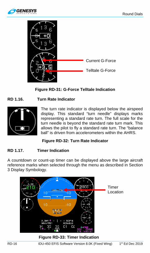
Round Dials
RD-16 IDU-450 EFIS Software Version 8.0K (Fixed Wing) 1st Ed Dec 2019
Figure RD-31: G-Force Telltale Indication
RD 1.16. Turn Rate Indicator
The turn rate indicator is displayed below the airspeed display. This standard “turn needle” displays marks representing a standard rate turn. The full scale for the turn needle is beyond the standard rate turn mark. This allows the pilot to fly a standard rate turn. The “balance ball” is driven from accelerometers within the AHRS.
Figure RD-32: Turn Rate Indicator
RD 1.17. Timer Indication
A countdown or count-up timer can be displayed above the large aircraft reference marks when selected through the menu as described in Section 3 Display Symbology.
Figure RD-33: Timer Indication
Current G-Force
Telltale G-Force
Timer Location
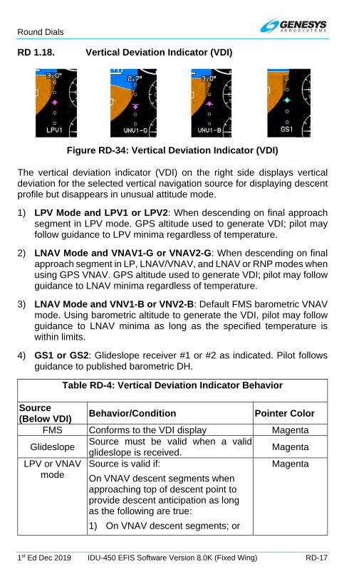
Round Dials
1st Ed Dec 2019 IDU-450 EFIS Software Version 8.0K (Fixed Wing) RD-17
RD 1.18. Vertical Deviation Indicator (VDI)
Figure RD-34: Vertical Deviation Indicator (VDI)
The vertical deviation indicator (VDI) on the right side displays vertical deviation for the selected vertical navigation source for displaying descent profile but disappears in unusual attitude mode.
1) LPV Mode and LPV1 or LPV2: When descending on final approach segment in LPV mode. GPS altitude used to generate VDI; pilot may follow guidance to LPV minima regardless of temperature.
2) LNAV Mode and VNAV1-G or VNAV2-G: When descending on final approach segment in LP, LNAV/VNAV, and LNAV or RNP modes when using GPS VNAV. GPS altitude used to generate VDI; pilot may follow guidance to LNAV minima regardless of temperature.
3) LNAV Mode and VNV1-B or VNV2-B: Default FMS barometric VNAV mode. Using barometric altitude to generate the VDI, pilot may follow guidance to LNAV minima as long as the specified temperature is within limits.
4) GS1 or GS2: Glideslope receiver #1 or #2 as indicated. Pilot follows guidance to published barometric DH.
Table RD-4: Vertical Deviation Indicator Behavior
Source (Below VDI)
Behavior/Condition Pointer Color
FMS Conforms to the VDI display Magenta
Glideslope Source must be valid when a valid glideslope is received.
Magenta
LPV or VNAV mode
Source is valid if:
On VNAV descent segments when approaching top of descent point to provide descent anticipation as long as the following are true:
1) On VNAV descent segments; or
Magenta

Round Dials
RD-18 IDU-450 EFIS Software Version 8.0K (Fixed Wing) 1st Ed Dec 2019
Table RD-4: Vertical Deviation Indicator Behavior
Source (Below VDI)
Behavior/Condition Pointer Color
2) If the vertical deviations on VNAV level segments option is enabled, on VNAV level segments; or
3) If the vertical deviations on VNAV level segments option is disabled, when approaching the Top of Descent point to provide descent anticipation;
Providing:
1) Aircraft is within 2NM or twice the full scale deflection for the mode of flight (whichever is greater) of the lateral navigation route; and
2) Aircraft is in TO operation relative to the active VNAV waypoint (i.e., taking into account VNAV offsets); and
3) If on the final approach segment, aircraft is within a 35° lateral wedge of the azimuth reference point (either GARP or MAWPT + 10,000 ft.).
LPV,VNV-G During GPS LON or GPS VLON Pointer and Text
Color Amber (Yellow)
Figure RD-35: VDI Color during GPS/SBAS LON or VLON

Round Dials
1st Ed Dec 2019 IDU-450 EFIS Software Version 8.0K (Fixed Wing) RD-19
RD 1.19. Course Deviation Indicator
NAV Source VLOC1
NAV Source FMS1 with LON
Figure RD-36: Course Deviation Indicator
The order of precedence of type accuracy used by the system from highest to lowest is as follows:
1) Manual RNP: The pilot may override the automatic accuracy types by setting a manual RNP value.
2) Automatic RNP: These are based upon RNP values, which are coded in the navigation database. The EFIS looks at the leg coding on all legs other than those on the final approach segment. On the final approach segment, the EFIS looks at the “Level of Service” record for those approaches, which have RNP transition legs, and then goes to LP or LPV minima for the final approach.
3) Default TSO-C146C operation: As specified as per Table RD-5 for enroute, terminal, and various approach modes according to the Level of Service record.
Table RD-5: CDI Behavior and Color
CDI Pointer and Condition Color or Behavior Full Scale Deflection Flash Slaved to GPS/SBAS Scale is appropriate FSD value for
mode of flight:
Enroute: ±2NM
From Enroute to Terminal: Change from ±2 NM FSD to ±1 NM FSD over distance of 1 NM; start transition when entering terminal mode.
From Terminal to Enroute: Change from ±1 NM FSD to ±2 NM FSD over

Round Dials
RD-20 IDU-450 EFIS Software Version 8.0K (Fixed Wing) 1st Ed Dec 2019
Table RD-5: CDI Behavior and Color
CDI Pointer and Condition Color or Behavior distance of 1 NM; start transition when entering enroute mode.
From Terminal to Approach: If VTF, switch immediately.
Otherwise, change from ±1 NM FSD to approach FSD over distance of 2 NM; start transition at 2 NM from FAWP.
From Approach to Terminal: Change to 1 NM.
From Departure to Terminal: If initial leg is aligned with runway, change from ±0.3 NM FSD to ±1 NM FSD at the turn initiation point of the first fix in the departure procedure.
CDI images below represent installations with Genesys/S-TEC DFCS integrated autopilot or without an autopilot
enabled.
Nav source FMS1 GPS/SBAS (with GPS LON) amber (yellow) OBS manual mode with a “FROM” indication.
Nav source FMS1 GPS/SBAS (with GPS LON) amber (yellow) OBS automatic mode with a “TO” indication.
Normal conditions Magenta In sources other than FMS Angular scale annunciation
Nav source is localizer (course error exceeds 105°). Reverse sensing with distance to approach threshold
Lateral deviations in failed state Red “X” displayed over CDI
Nav source FMS1 in auto waypoint sequencing mode
Nav source FMS1 in manual OBS mode with a “TO’ indication. Waypoint sequencing is suspended.
Nav source Fms1 in manual OBS mode with a “FROM” indication. Waypoint sequencing is suspended.

Round Dials
1st Ed Dec 2019 IDU-450 EFIS Software Version 8.0K (Fixed Wing) RD-21
Table RD-5: CDI Behavior and Color
CDI Pointer and Condition Color or Behavior
Nav source FMS1 in automatic OBS mode with true north mode. Only applicable for CDI in this GPS/SBAS navigation source.
Nav source VLOC1
Nav source VLOC2
Nav source VOR1 with “TO” indication. Currently on a bearing 289°/14.6NM to the VOR
Nav source VOR1 with a “FROM” indication on a bearing of 344° to the VOR
Nav source VOR2 with “TO” indication on a bearing of 145°/46.3NM to the VOR
When laterally integrated with an autopilot, either fully integrated Genesys/S-TEC DFCS or partially integrated through use of the NAV/APR mode discrete input with either the NAV, LOC, APPR or BC modes engaged, the selected navigation source is annunciated green to indicate that the autopilot is laterally coupled to he selected navigation source. Otherwise, the selected navigation source is annunciated white.
Table RD-6: CDI Lateral Mode Indication
CDI Pointer and Condition* Color or Behavior
Heading bug sub-mode guidance
LNAV sub-mode guidance
Failure Sub-Mode
* Installations with an analog autopilot enabled.

Round Dials
RD-22 IDU-450 EFIS Software Version 8.0K (Fixed Wing) 1st Ed Dec 2019
RD 1.20. Vertical Deviation Indicator (EFIS Coupled)
When vertically integrated with Genesys S/TEC DFCS enabled through glideslope mode discrete input with glideslope mode engaged, the selected vertical navigation source is green indicating the AP is vertically coupled. Otherwise, the source is white.
Figure RD-37: EFIS Coupled Vertically with Glideslope Mode
When not decluttered, the PFD displays the active navigation route or manual OBS course and VDI path in conventional analog navigation symbology. See Section 7 IFR Procedures for details.
RD 1.21. Active Waypoint and Waypoint Identifier
Figure RD-38: Active Waypoint

Round Dials
1st Ed Dec 2019 IDU-450 EFIS Software Version 8.0K (Fixed Wing) RD-23
See Section 3 Display Symbology for more information.
RD 2. GPS Failure
GPS degrades or fails because of loss of satellite information or GPS equipment failure. When SBAS provides the integrity, the IDU provides a loss of integrity (LOI) caution within two seconds if the current horizontal protection level (HPL) exceeds the horizontal alert level (HAL).
LOI caution appears when there is no integrity monitoring and disappears when it is restored.
Figure RD-39: Loss of Integrity (LOI)
Further GPS degradation causes the EFIS to lose GPS updating of aircraft position, groundspeed, and ground track, and the ability to calculate the wind information.
1) (Loss of Integrity) displayed with no time delay.
2) HPL > HAL for the phase of flight currently in. Position is still presented based upon a GPS navigation solution.
3) (Loss of Navigation) displayed with no time delay of the onset of the following:
a) The absence of power;
b) Equipment malfunction or failure;
c) The presence of a condition lasting five seconds or more where there are an inadequate number of satellites to compute position solution;
d) Fault detects a position failure that cannot be excluded within time-to-alert when integrity is provided by FDE;
e) HPL > HAL on the final approach segment. Genesys Aerosystems EFIS does not transition to DR navigation at this stage. A GPS navigation solution is still presented; and
f) Where HPL > HAL on the final approach segment, this position may still be satisfactory for GPS navigation. For example, an HPL of 0.31NM exists, which means as soon as a transition to terminal mode occurs, all alerts disappear. This is significantly important during a wind change if the system had been in a DR mode.

Round Dials
RD-24 IDU-450 EFIS Software Version 8.0K (Fixed Wing) 1st Ed Dec 2019
NOTE:
At any time, view HFOM on the FAULTS page to see the system-reported accuracy.
4) Loss of Vertical Navigation
Figure RD-40: Loss of Vertical Navigation (VLON)
RD 3. PFD Failure Mode 0
Figure RD-41: PFD Failure Mode 0 GPS, ADC and AHRS Normal
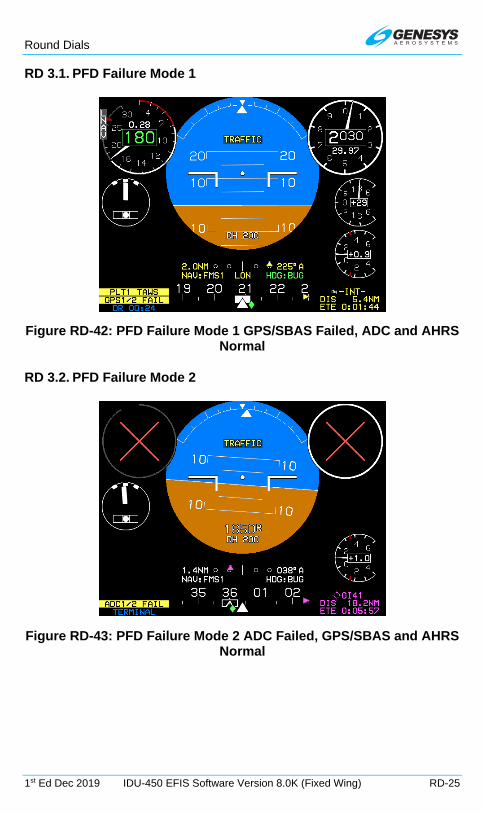
Round Dials
1st Ed Dec 2019 IDU-450 EFIS Software Version 8.0K (Fixed Wing) RD-25
RD 3.1. PFD Failure Mode 1
Figure RD-42: PFD Failure Mode 1 GPS/SBAS Failed, ADC and AHRS Normal
RD 3.2. PFD Failure Mode 2
Figure RD-43: PFD Failure Mode 2 ADC Failed, GPS/SBAS and AHRS Normal
RD

Search and Rescue (SAR) Patterns
1st Ed Dec 2019 IDU-450 EFIS Software Version 8.0K (Fixed Wing) SAR-1
Search and Rescue (SAR) Patterns
SAR 1. Search and Rescue (SAR) Patterns
When enabled by EFIS system limits, the pilot can create one SAR pattern at an eligible flight plan waypoint and only one waypoint within the active flight plan. The current position of the aircraft is determined relative to that desired path for lateral deviation for display on the GPS/SBAS CDI. In most cases, the IDU auto-sequences from one waypoint to the next similar to all other flight plan sequencing along the flight path.
The SAR option is available for any waypoint except the following:
1) Suppressed waypoint
2) Skipped waypoint
3) Manual termination waypoint
4) Waypoint that is part of an IFR or VFR approach
5) Holding pattern waypoint
6) SAR pattern exit waypoint
7) Waypoint that begins a departure procedure
8) Parallel offset entry or exit waypoint
9) Dynamic termination waypoint (altitude termination, DME termination, radial termination or intercept termination)
SAR patterns can be created in the RUN DEMONSTRATOR/TRAINING PROGRAM Ground Maintenance Page or the EFIS Training Tool. After the SAR pattern is created and saved, that flight plan can be uploaded to any IDU or all IDUs in an aircraft for later use.
The desired flight path is created from a sequence of straight, left, and right turning leg segments to provide smooth skyway, GPS/SBS CDI, and lateral autopilot guidance. SAR patterns are drawn at the lowest of holding or procedure speed.
SAR 1.1. SAR Pattern Step-by-Step Procedures
To select a SAR pattern, follow these step-by-step procedures. Refer to subsequent sections for additional details and examples for the individual patterns.

Search and Rescue (SAR) Patterns
SAR-2 IDU-450 EFIS Software Version 8.0K (Fixed Wing) 1st Ed Dec 2019
1) Press ACTV (L2) and rotate to desired eligible waypoint to begin SAR pattern creation process and push to enter.
2) Press ACTV (L2) and then rotate to SAR PTRN.. and push to enter.
3) Rotate to one of the five SAR pattern options and push to enter. *Pattern includes the option to select individual legs within the SAR pattern for navigation guidance.
a) Expanding Square*
b) Rising Ladder*
c) Orbit
d) Race Track
e) Sector Search*
4) Rotate through each step, create the desired parameters (e.g., direction, track, leg length, leg spacing, and number of legs), and push to enter.
See following sub-sections for more details for parameters of each pattern.

Search and Rescue (SAR) Patterns
1st Ed Dec 2019 IDU-450 EFIS Software Version 8.0K (Fixed Wing) SAR-3
5) After SAR pattern is created, it appears on the MAP, MINI MAP, and active flight plan.
6) To select a SAR pattern individual legs rotate to SAR pattern EXIT WPT as it appears in magenta and push to enter.
7) Rotate to SAR SGMNT.. and push to enter.
8) Rotate to desired leg for navigation guidance.
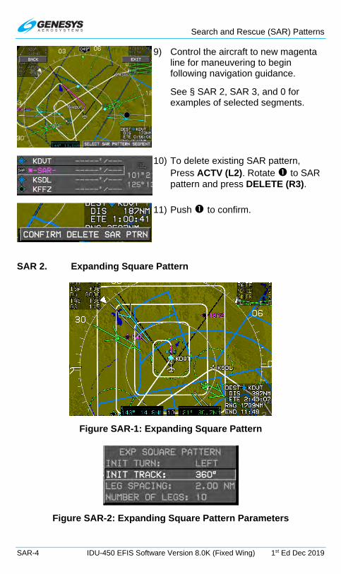
Search and Rescue (SAR) Patterns
SAR-4 IDU-450 EFIS Software Version 8.0K (Fixed Wing) 1st Ed Dec 2019
9) Control the aircraft to new magenta line for maneuvering to begin following navigation guidance.
See § SAR 2, SAR 3, and 0 for examples of selected segments.
10) To delete existing SAR pattern, Press ACTV (L2). Rotate to SAR pattern and press DELETE (R3).
11) Push to confirm.
SAR 2. Expanding Square Pattern
Figure SAR-1: Expanding Square Pattern
Figure SAR-2: Expanding Square Pattern Parameters
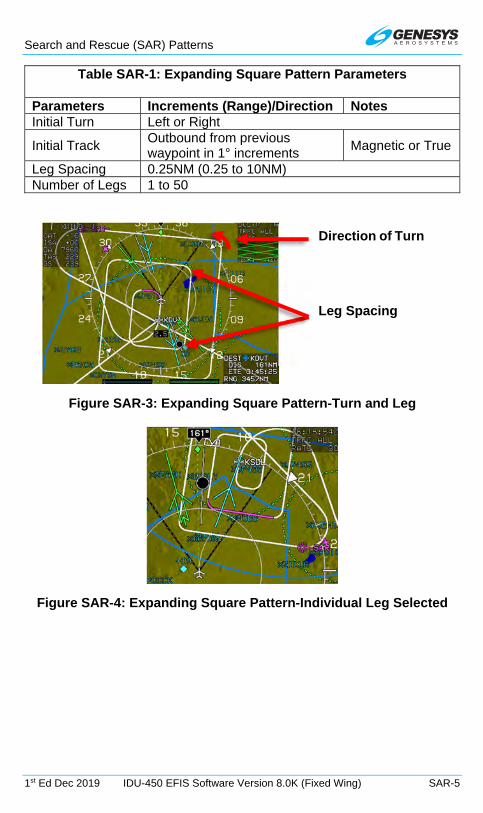
Search and Rescue (SAR) Patterns
1st Ed Dec 2019 IDU-450 EFIS Software Version 8.0K (Fixed Wing) SAR-5
Table SAR-1: Expanding Square Pattern Parameters
Parameters Increments (Range)/Direction Notes Initial Turn Left or Right
Initial Track Outbound from previous waypoint in 1° increments
Magnetic or True
Leg Spacing 0.25NM (0.25 to 10NM) Number of Legs 1 to 50
Figure SAR-3: Expanding Square Pattern-Turn and Leg
Figure SAR-4: Expanding Square Pattern-Individual Leg Selected
Leg Spacing
Direction of Turn

Search and Rescue (SAR) Patterns
SAR-6 IDU-450 EFIS Software Version 8.0K (Fixed Wing) 1st Ed Dec 2019
SAR 3. Rising Ladder Pattern
Figure SAR-5: Rising Ladder Pattern
Figure SAR-6: Rising Ladder Pattern Parameters
Table SAR-2: Rising Ladder Pattern Parameters
Parameters Increments (Range)/Direction Notes Initial Turn Left or Right
Initial Track Outbound from previous waypoint in 1° increments
Magnetic or True
Leg Length 0.5 NM (1NM to 100NM) Leg Spacing 0.25NM (0.25 to 25NM) Number of Legs 1 to 50
Figure SAR-7: Rising Ladder Pattern-Turn, Leg, and Track
INIT TURN: LEFT
LEG LENGTH: 15.NM
INIT TRACK: 360°
LEG SPACING: 3.00NM

Search and Rescue (SAR) Patterns
1st Ed Dec 2019 IDU-450 EFIS Software Version 8.0K (Fixed Wing) SAR-7
Figure SAR-8: Rising Ladder Pattern-Individual Leg Selected
SAR 4. Orbit Pattern
The SAR exit waypoint is a duplicate of the previous waypoint. This SAR pattern is unique in that the navigation path never goes through the waypoint. The path is a circle around the waypoint intercepted along tangents. With no other menus displayed on the PFD, CONT (L2) appears to allow for continuing out of the orbit and normal sequencing in the active flight plan.
Figure SAR-9: Orbit Pattern
Figure SAR-10: Orbit Pattern Parameters
Table SAR-3: Orbit Pattern Parameters
Parameters Increments (Range)/Direction Turn Direction Left or Right Radius 0.25NM (0.25NM to 10NM)

Search and Rescue (SAR) Patterns
SAR-8 IDU-450 EFIS Software Version 8.0K (Fixed Wing) 1st Ed Dec 2019
Figure SAR-11: Orbit Pattern-Turn and Radius
SAR 5. Race Track Pattern
Figure SAR-12: Race Track Pattern
TURN DIR: LEFT
RADIUS: 5.0NM
Mini Map Orientation
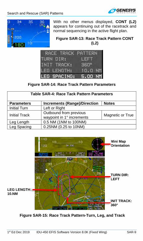
Search and Rescue (SAR) Patterns
1st Ed Dec 2019 IDU-450 EFIS Software Version 8.0K (Fixed Wing) SAR-9
With no other menus displayed, CONT (L2) appears for continuing out of the racetrack and normal sequencing in the active flight plan.
Figure SAR-13: Race Track Pattern CONT (L2)
Figure SAR-14: Race Track Pattern Parameters
Table SAR-4: Race Tack Pattern Parameters
Parameters Increments (Range)/Direction Notes Initial Turn Left or Right
Initial Track Outbound from previous waypoint in 1° increments
Magnetic or True
Leg Length 0.5 NM (1NM to 100NM) Leg Spacing 0.25NM (0.25 to 10NM)
Figure SAR-15: Race Track Pattern-Turn, Leg, and Track
INIT TRACK: 360°
LEG LENGTH: 10.NM
TURN DIR: LEFT
Mini Map Orientation

Search and Rescue (SAR) Patterns
SAR-10 IDU-450 EFIS Software Version 8.0K (Fixed Wing) 1st Ed Dec 2019
SAR 6. Sector Search Pattern
Figure SAR-16: Sector Search Pattern
Figure SAR-17: Sector Search Pattern Parameters
Table SAR-5: Sector Search Pattern Parameters
Parameters Increments (Range)/Direction Notes Initial Turn Left or Right
Initial Track Outbound from previous waypoint in 1° increments
Magnetic or True
Leg Length 0.5 NM (1NM to 100NM)

Search and Rescue (SAR) Patterns
1st Ed Dec 2019 IDU-450 EFIS Software Version 8.0K (Fixed Wing) SAR-11
Figure SAR-18: Race Track Pattern-Turn and Track
Figure SAR-19: Sector Search Pattern-Individual Leg Selected
SAR DON’T DELETE THIS LINE
Mini Map Orientation
INIT TURN: LEFT
INIT TRACK: 348°

IDU-450 EFIS Software Version 8.0K
1st Ed Dec 2019 IDU-450 EFIS Software Version 8.0K (Fixed Wing) Index-1
INDEX
500-Foot Wake-Up Call ......................................... 3-3, 5-57, 8-2, 8-5, 8-15
ADAHRS ..................................................................... 2-1, 2-17, 2-22, 3-57
ADF ........................................................... 2-1, 2-13, 3-57, 5-12, 5-66 to 68
ADS-B (ADSB) ........... 2-1, 2-2, 2-12, 2-15, 2-30 to 31, 5-60, T-6 to 7, D-2, ................................................................................................... D-5, D-12
AGL Indication ....................................................................... 3-8 to 9, RD-4
Air Data ........... 2-1, 2-35, 3-44, 3-61, 4-8, 5-61, 8-16 to 17, 8-22, S-2, D-5, .......................................................................................... WX-12, WX-15
Aircraft
In the Air ............................................ 2-21, 2-47, 5-44 to 45, 5-62, WX-1
On the Ground ................. 2-18, 2-33, 2-39, 2-48 to 49, 3-26, 3-37, 3-51, ..................................................................................... 5-44 to 45, 5-54
Referenced .......................................................................................... 7-8
Airport ........... 2-32, 3-4, 3-25, 3-37 to 38, 3-52, 5-8, 5-28, 5-33, 5-42 to 45, ............. 5-57, 6-6 to 7, 7-1 to 5, 7-19, 7-25, 7-35 to 39, 7-43, 7-47, 7-51, ....... 7-55 to 57, 7-61, 8-18, T-6, S-4, D-2 to 3, D-9 to 12, WX-9, WX-15, ........................................................................................................ RD-10
Airspace .................................................... 3-47, 4-4, 5-40, 5-60, 5-68, 7-32
Depiction .................................................................................. 3-46 to 47
Airspeed
Bug ..................... 3-7 to 8, 3-11 to 12, 5-4, 5-50, 5-53, RBP-2 to 3, RD-6
Display ........................................................ 3-11, 3-15, RD-5 to 6, RD-16
True ........................................... 2-6, 2-9, 2-12, 3-45, 4-3 to 5, 7-11 to 12
Airway(s) ........................................ 2-46, 3-46 to 47, 3-63, 5-28, 5-68, 7-25
AIU ........................................................................................................ 5-60
Altimeter
Menu .................................................................................. 5-7, 5-57 to 58
Setting ........................................... 2-39, 3-3 to 4, 5-13, 5-57, RD-9 to 10
Altitude
Bug Menu (ASEL) ............................................................................... 2-1
Capture Predictor ............................................................... 3-53, T-5, D-8
Display ...................................................... 3-3 to 5, T-2 to 3, RD-10 to 12
Minimum ................................ 2-43, 3-6 to 7, 5-4, 5-50, 7-48, RBP-2 to 3
Miscompare Threshold ........................................................................ 1-3

IDU-450 EFIS Software Version 8.0K
Index-2 IDU-450 EFIS Software Version 8.0K (Fixed Wing) 1st Ed Dec 2019
Sub-Mode .................................................................. 3-4 to 6, 5-8, RD-11
Target ................................... 2-1, 3-4 to 6, 3-37, T-5, RBP-1 to 3, RD-11
Amber (Yellow) ............. 2-24 to 25, 2-43, 3-7, 3-10, 3-13 to 15, 3-25, 3-31, . 3-35 to 38, 3-45, 3-48, 3-55, 3-58 to 60, 3-63, 7-1, 7-53, 8-23, T-5 to 6, ..................................................... S-4, D-2, D-6 to 9, RD-5, RD-18 to 20
Analog AGL Indicator (ANLG AGL) .............. 3-9 to 10, 5-55 to 56, 6-3, T-3
Analog Navigation Symbology ........................ 3-48 to 51, 3-59, 6-3, RD-22
Approach .. 2-1 to 7, 2-34, 3-31, 3-41, 5-20, 6-6 to 7, 7-4 to 10, 7-23 to 35, 7-38, 7-42, 7-46, 7-50, 7-55, 7-60, 7-64, 8-1, 8-4 to 6, 8-12, D-3, RD-20
APPR ............................................................ 2-1, 6-7, 7-29, 7-58, RD-21
APV .............................................................................................. 2-1, 7-5
ARM ................................ 2-41, 5-8, 7-5, 7-40, 7-43, 7-48, 7-52, 7-57, 7-62
Atmospheric Perspective ...................................................... 3-2, 3-22 to 24
BACK ............................................................. 5-2, 5-17, 5-22, 5-37, WX-20
Bank Scale (BANK SCL) ........................................... 3-28, 5-47, 5-55 to 56
BARO ............................. 2-2, 2-13, 2-19, 3-3, 5-7 to 8, 5-57 to 60, 6-2, 7-5
BARO-VNAV ........................................................................................... 7-5
Basic Mode ................................. 3-1, 3-21 to 22, 3-26 to 28, 5-5, 5-55, 7-7
Blue .... 2-24, 3-22 to 24, 3-47, 3-51, 3-60, 7-46, 7-50, 7-60, D-2 to 3, RD-8
Borders .............................................................. 2-24, 3-49 to 50, 5-68, D-9
Boundary Circle ..................................................... 3-43, 3-57, T-5, D-5 to 8
Brown ................................................................. 2-24, 3-3, 3-22 to 24, 3-51
BUGS ........................................................ 2-49, 5-10, 5-50 to 52, 7-4, 7-48
Button/Menu/Encoder Functions ........ 1-3, 3-54, 5-1, 5-6, 8-3, T-8, RBP-2, ............................................................................. S-5, D-9, D-13, WX-15
CENTER/ARC ............................................................................... 5-68, S-5
Compass Rose . 3-43, 3-57 to 58, 4-3 to 5, 7-19, 9-3, T-4 to 5, D-5, RD-14
CONFIRM DEL .............................................................................. 5-19, 6-5
CONT ...................... 2-2, 2-42, 5-8, 7-5, 7-40, 7-49, 7-54, 7-65, SAR-7 to 9
Course Deviation Indicator (CDI) ...... 2-2, 2-23, 3-8 to 10, 3-22, 3-30 to 33, ............ 3-47, 3-55, 3-58 to 61, 4-2, 4-5, 5-38, 6-3, 7-5, 7-11, 7-18, 7-22, ................... 7-26 to 28, 7-48 to 49, 7-53, 7-57, T-6, S-4, D-8 to 9, RD-4, ................................................................................. RD-19 to 21, SAR-1
Scale ........................................................................................ 3-59, 7-27
CRS SYNC .................................................................................. 5-36, 5-42
Cyan ............................ 2-23, 3-38, 3-48, 3-57 to 61, 7-49, D-2 to 4, WX-11

IDU-450 EFIS Software Version 8.0K
1st Ed Dec 2019 IDU-450 EFIS Software Version 8.0K (Fixed Wing) Index-3
Database
Jeppesen ................................................................. 1-3, 2-45, 2-48, 3-24
NavData® .......................................... 2-45 to 47, 3-37, 5-6, 7-1, 7-4, 7-12
Navigation ................ 2-23, 2-41, 2-45 to 49, 3-31, 3-38 to 39, 3-63, 7-1, ....................... 7-4 to 7, 7-11 to 13, 7-16, 7-25 to 27, 8-9, 8-19, RD-19
Obstruction ...................................................................... 2-22, 2-45 to 49
Terrain ................................................................... 2-33, 2-48, 8-18 to 20
Update ........................................................................................ 1-2, 2-48
Datalink .... 1-3, 2-3, 2-12, 2-17, 3-40, 3-48, 3-62, 5-1 to 3, 5-7, 5-12, 5-64, ........................................................................................ D-1 to 13, WX-2
Page (DATALINK) ........................................................... 5-64, D-4, D-11
DCLTR ................. 2-2, 3-44, 5-11 to 12, 5-55 to 57, 5-66 to 70, T-8, D-11, .............................................................................................. WX-3, WX-6
DCND .................................................................................... 2-2, 5-53 to 54
Dead Reckoning (DR) ................................... 2-3, 2-41 to 43, 4-7 to 8, 7-19
Decision Height (DEC HT) ........... 2-3, 2-43, 3-9 to 10, 5-4 to 5, 5-50, 5-53, ...................................................................................... RBP-2 to 3, RD-5
DELETE ........................................... 5-19, 5-22, 5-30, 6-5, SAR-4, SAR-11
Demonstrator ............................................................................... 2-48 to 49
Density Altitude ....................................................................... 3-45, 4-3 to 5
Departure ........... 1-3, 2-3, 2-7 to 9, 2-34, 3-31, 3-63, 7-4, 7-11, 7-22 to 25, ..................... 7-28, 7-31 to 35, 7-56, 7-66, 8-3 to 6, 8-19, RD-20, SAR-1
DESIG .................................................................. 2-3, 5-10 to 11, 5-14, 6-4
DG Mode ........................................................................... 3-17, T-4, RD-14
Direct ..... 2-3, 3-52 to 53, 5-7 to 8, 5-33, 5-44 to 45, 7-12 to 13, 7-16 to 21, ........................................................................................................... 7-57
Direct-To ............................................................ 3-52, 5-8, 7-12, 7-16 to 21
Discontinuity ................................... 3-64, 5-31, 5-44, 7-13 to 21, 7-30 to 31
DME .... 2-2 to 3, 2-10, 2-13, 2-24, 2-39, 3-47 to 48, 3-53, 3-60, 7-11 to 14, ......................................................... 7-17, 7-35, 7-46, 7-59 to 62, SAR-1
DONE ........................................................................ 5-50, 5-56, 5-66, 5-70
Download ................................................................................................ 9-8
DP .............................. 2-3, 3-38, 3-63, 7-2 to 4, 7-11 to 14, 7-20, 7-32, 8-3
EFIS Training Tool (ETT) ........................................... 1-3, 2-3, 2-49, SAR-1
EICAS .......................................................................................... 3-40, 5-13

IDU-450 EFIS Software Version 8.0K
Index-4 IDU-450 EFIS Software Version 8.0K (Fixed Wing) 1st Ed Dec 2019
Enroute ................. 2-3, 2-34, 2-46, 3-31, 3-37, 3-46, 3-63, 5-23, 7-4, 7-11, ........................................... 7-22 to 28, 7-33 to 34, 7-52, 8-3 to 6, RD-19
Enter Identifier ............................................................................. 5-21, 5-30
Estimated Time Enroute (ETE) .................................... 2-3, 3-45, 3-64 to 65
Estimated Time of Arrival (ETA) ................. 2-3, 3-45, 3-65, 5-6, 5-25, 5-68
EXIT ........... 2-22, 5-2, 5-16 to 19, 5-22 to 25, 5-37, 5-40, 5-50, 5-54 to 56, ...................................................................... 5-66, 5-70, 6-2 to 5, SAR-3
EXPAND CAS ..................................................................... 2-45, 5-11 to 12
FAF ......... 2-3, 3-63, 5-7 to 8, 7-2, 7-10, 7-14, 7-40, 7-43, 7-48, 7-52, 7-57, ................................................................................................... 7-62, 8-9
FAULTS .. 4-7, 5-11, 5-23, 5-59 to 61, 7-33, T-7, S-4, D-12, WX-14, RD-24
FAWP .................... 2-3, 2-42, 2-46, 3-31, 4-8, 7-2, 7-14, 7-23 to 34, RD-20
Field of View (FOV) ............... 2-4, 2-25, 3-22, 3-24, 3-27, 3-51, 3-56, 5-11
Zoom ................................................... 2-17, 3-22, 3-56, 5-11, 7-41, 7-63
Fixes ....................................................... 3-37, 3-46, 5-29, 5-42, 5-68, 7-66
Flight Path Marker (FPM) .......... 2-4, 3-2, 3-18 to 22, 3-25 to 27, 4-2, 5-53, ............................................................................................ 7-53, 9-1, 9-4
Flight Plan .... 1-3, 2-4, 2-17, 2-32, 2-40, 2-46, 2-49, 3-36, 3-45, 3-52 to 55, ... 3-63 to 65, 5-7 to 19, 5-23, 5-26 to 33, 5-37, 5-42 to 46, 6-1, 6-4 to 7, ... 7-1 to 2, 7-5 to 7, 7-11 to 12, 7-16 to 21, 7-51, 7-54 to 59, 7-64 to 65, ........ 8-18, 9-1 to 2, 9-6 to 9, T-6 to 8, S-4 to 5, D-8 to 11, WX-6, WX-9, ............................................................................ SAR-1 to 3, SAR-7 to 9
Activate ...................................................................................... 5-16, 6-4
Active (ACTV) .......... 2-1, 2-23, 3-54 to 55, 4-3, 5-4, 5-7 to 8, 5-26 to 28, ......... 5-31 to 33, 5-37, 6-5 to 7, 7-1, 7-7, 7-17, 7-37 to 39, 7-43, 7-47, .... 7-51, 7-59 to 61, 7-65, T-6, S-4, D-8 to 12, WX-9 to 10, SAR-2 to 4
CREATE-EDIT .................................................. 5-12, 5-15 to 23, 6-4 to 5
Delete ................................................................................................ 5-18
FPL ....................................................... 2-4, 5-6 to 9, 5-12 to 23, 6-4 to 5
Limits ................................................................................................. 5-13
Path ................................... 3-53 to 55, 5-7, 7-1, T-6, S-4, D-8 to 9, WX-9
Reverse ............................................................................................. 5-18
FLTA ..... 2-4, 2-27 to 29, 2-33, 2-37 to 38, 2-42, 3-24, 3-51, 5-3, 5-7, 7-58, ........................................................................ 8-1 to 8, 8-19 to 25, WX-2
FMS ...... 1-1, 2-4, 2-15 to 17, 2-40, 3-28, 3-31, 3-34, 3-58 to 60, 3-64, 5-4, . 5-8, 5-37 to 39, 5-64 to 66, 6-3 to 6, 7-2 to 3, 7-44, 7-49, RD-2, RD-17, ....................................................................................................... RD-20
FORMAT ......... 5-11 to 12, 5-67 to 70, T-7 to 8, S-5, D-10 to 11, WX-3 to 4

IDU-450 EFIS Software Version 8.0K
1st Ed Dec 2019 IDU-450 EFIS Software Version 8.0K (Fixed Wing) Index-5
Fuel Remaining ...................................................................3-45, 3-62, 3-65
Geodesic Path .................................................................... 7-15 to 16, 7-19
Geo-Referenced ..................................................................................... 7-9
Glideslope .. 2-5, 2-13, 2-22 to 23, 2-27 to 31, 2-34, 2-37, 2-40, 3-34 to 36, . 3-59, 7-41, 7-44, 7-57 to 58, 8-2, 8-14 to 16, 8-20 to 22, RD-17, RD-22
GPS .............. 2-4, 2-13, 2-20 to 23, 2-34, 2-37 to 43, 3-9, 3-17, 3-31 to 38, 3-43 to 45, 3-50, 3-54 to 55, 3-58, 3-63, 4-1, 4-4 to 16, 5-23 to 25, 5-38, .. 5-59 to 62, 7-1, 7-4 to 7, 7-11, 7-19, 7-22 to 23, 7-26 to 30, 7-34 to 35, ........... 7-50 to 52, 7-57 to 58, 7-62, 7-66, 8-3 to 6, 8-9, 8-12, 8-16 to 21, ...................... T-5 to 6, RBP-2, S-4, D-8 to 9, RD-5, RD-15 to 25, SAR-1
ALMANAC ......................................................................................... 5-60
Altitude............................................................................................... 7-19
EQPMNT ........................................................................................... 5-59
FDE ................................................................................................... 5-59
HFOM ................................................................................................ 5-60
HPL .................................................................................................... 5-60
LOI ..................................................................................................... 5-59
LON ............. 3-31, 3-35 to 37, 3-45, 3-55, 3-58, 3-63, 7-1, T-5 to 6, S-4, ............................................................................ D-8 to 9, RD-18 to 20
PWR .................................................................................................. 5-59
SATLT ............................................................................................... 5-59
TRK ......................................................................................... 4-5, RD-15
VFOM ................................................................................................ 5-60
VPL .................................................................................................... 5-60
GPS/SBAS .......... 2-22, 2-34, 2-37 to 43, 3-9, 3-31 to 34, 3-38, 3-43, 3-50, .... 3-54 to 55, 3-58, 4-1, 4-4, 4-10 to 16, 5-23 to 25, 5-59 to 60, 7-5 to 6, . 7-11, 7-19, 7-22 to 23, 7-26 to 27, 7-30, 7-34, 7-52, 8-3 to 6, 8-9, 8-12, .... 8-16 to 21, T-5 to 6, S-4, D-8 to 9, RD-5, RD-18 to 21, RD-25, SAR-1
Navigation Mode ............................................................... 7-22 to 23, 8-3
GPWS Modes ........ 2-27 to 29, 2-37, 2-40, 8-1 to 2, 8-10 to 16, 8-20 to 22
Gray ..... 2-23 to 24, 3-3, 3-13 to 15, 3-39, 3-56, 3-63, 7-1, 7-43, 7-51, T-6, ............................................................... D-2 to 3, D-9, WX-11, RD-7 to 8
Green .. 2-24, 3-5 to 15, 3-36 to 38, 3-47 to 48, 3-53, 3-57 to 61, 6-2, 7-44, ..... 7-48, 7-61 to 62, T-3 to 5, S-3, D-2 to 3, D-6 to 8, WX-11, RD-7 to 8, .................................................................................. RD-13, RD-21 to 22
Groundspeed .... 2-22 to 23, 2-32 to 34, 3-17, 3-44 to 45, 3-54, 3-61 to 64, . 4-3, 4-6 to 8, 7-7, 8-3 to 8, 8-17, T-5 to 6, S-2, D-5, D-8, WX-12, RD-23
IDU-450 EFIS Software Version 8.0K
Index-6 IDU-450 EFIS Software Version 8.0K (Fixed Wing) 1st Ed Dec 2019
Heading
Display .................................................................................. 3-16, RD-14
Heading Up (HDG UP) ..................................... 3-43, 4-4, 5-68 to 69, 8-8
North Up (N UP) ............................................................ 5-68 to 69, WX-2
Pointer ....................................................................... 3-16, 3-51, T-5, D-8
Heading Bug .....3-16, 3-33, 5-4, 5-7 to 8, 5-40 to 42, 6-2, 7-3, T-5, RBP-2, ............................................................................................................ D-8
Sub-Mode ................................................................................ 5-7, RD-21
Hidden Surface Removal Techniques ......................... 3-22, 3-37 to 38, 7-7
Highway in the Sky (HITS)...... 1-1, 2-5, 3-2, 3-22, 3-36, 4-2 to 4, 7-5 to 10, ........................................................................................ 7-57, 7-61 to 62
Skyway (SKYWAY) .. 2-18, 2-24, 3-36, 3-55, 5-5, 5-31, 5-44, 5-55 to 56, .............................. 7-6 to 7, 7-11, 7-17, 9-1, T-6, S-4, D-8 to 9, SAR-1
HOLD ............................................... 3-60, 3-63, 7-2, 7-39 to 40, 7-49, 7-64
Holding Pattern ................. 2-41, 3-64, 5-8, 7-2 to 5, 7-11 to 16, 7-24, 7-39, ................................................................................................. 7-64 to 66
IAP ................................................................................................. 2-5, 7-26
IAS .. 2-5, 2-26, 2-29 to 30, 2-35, 2-49, 3-11, 4-3, 5-50, 5-53, RD-6, RD-13
IFR
APPR ........................................... 6-6, 7-39, 7-43, 7-47, 7-51, 7-61, 8-18
Procedures .................................. 3-36, 3-52, 3-57, 5-26, 7-1, 7-4, RD-22
ILS ................ 2-5, 5-36, 5-42 to 44, 7-5, 7-30, 7-35 to 39, 7-42, 7-55 to 57, ..................................................... 7-64 to 66, 8-2, 8-14 to 16, 8-20 to 22
CONFIRM ACTIVATE ....................................................................... 5-42
NRST ILS ........................................................................ 5-42, 7-35, 7-55
INFO ..... 2-5, 5-7 to 8, 5-17, 5-21, 5-25, 5-28 to 30, 5-33 to 36, 5-42 to 45, ......................................................................................... D-3, D-10 to 12
inHg/mbar .................. 2-5 to 7, 2-40 to 41, 3-3 to 4, 5-57 to 58, RD-9 to 10
Initialization ........ 1-2, 2-16 to 17, 2-22, 2-48 to 49, 6-1, 8-18 to 19, RBP-2, ....................................................................................................... RD-15
International Standard Atmosphere (ISA) ............................... 2-6, 3-44, 4-3
Latitude/Longitude ....... 2-6, 2-17, 2-32, 2-45, 3-23, 5-19, 5-35, 5-68 to 70, .......................................................................................................... 7-19
LNAV .. 2-6, 2-41, 2-46, 3-33 to 34, 3-64, 4-7 to 8, 5-7, 7-4 to 7, 7-22 to 24, ................ 7-29 to 30, 7-33 to 34, 7-58, 7-66, RBP-1 to 3, RD-17, RD-21
Approach ............................................. 2-41, 2-46, 7-22 to 23, 7-33 to 34

IDU-450 EFIS Software Version 8.0K
1st Ed Dec 2019 IDU-450 EFIS Software Version 8.0K (Fixed Wing) Index-7
Sub-Mode ................................................................... 5-7, RBP-3, RD-21
LNAV/VNAV ... 2-41, 2-46, 3-34, 4-7, 7-4 to 6, 7-22 to 24, 7-29, 7-33 to 34, ........................................................................................................ RD-17
Approach ............................................... 2-41, 4-7, 7-22 to 24, 7-33 to 34
Log Files .................................................................................................. 9-7
Loss of Integrity (LOI) ........... 2-6, 2-43, 4-6, 5-59, 7-33 to 34, 8-16, RD-23
Loss of Navigation (LON) ........ 2-6, 2-10, 2-43, 3-17, 3-58, 4-6, 5-59 to 60, ............................................................................ 7-32 to 33, 8-16, RD-23
LP .......... 2-6, 2-41, 2-46, 3-31 to 34, 7-4 to 5, 7-22 to 24, 7-29, 7-33 to 34, ......................................................................................7-66, RD-17 to 19
LPV ....... 2-6, 2-41, 2-46, 3-31 to 35, 7-4 to 6, 7-22 to 25, 7-29, 7-33 to 35, ............................................................................ 7-50 to 52, RD-17 to 19
Lubber Line ................................................................... 3-51 to 53, T-5, D-8
Magenta ......... 2-23, 3-6, 3-31, 3-34 to 38, 3-45, 3-55 to 58, 3-63, 6-2, 7-1, ........ 7-41, 7-45, 7-49 to 51, 7-59 to 63, T-5 to 6, S-4, D-2 to 4, D-8 to 9, .............................................. WX-11, RD-12, RD-17, RD-20, SAR-3 to 4
Map
Mini .............................................. 3-9, 3-38, 3-55, 4-2, T-6, S-4, D-8 to 9
Moving ........................................................................... 3-40 to 41, WX-2
Page (MAP) ..................................................................................... WX-2
Marker Beacon(s) ........................................... 2-23, 3-28, 3-60 to 61, RD-2
MENU .... 1-3, 5-7 to 9, 5-14, 5-47, 5-50 to 52, 5-56 to 57, 5-61, 5-64 to 66, ........ 5-69 to 70, 6-4, 6-7, 7-40 to 41, 7-47 to 48, 7-53, 7-58, 7-63, D-11, .............................................................................................. WX-16 to 20
Metric (METERS) .............................................................. 3-3, 5-56, RD-12
MFD ........ 1-2, 2-7, 2-11 to 12, 2-15 to 17, 2-21, 2-24, 3-1 to 2, 3-24, 3-40, ........... 3-61, 4-5 to 16, 5-1 to 7, 5-11 to 23, 5-31 to 33, 5-42, 5-47 to 70, ..... 6-3 to 7, 7-13, 7-17, 7-40, 7-65, 8-2, T-1, T-4, T-7 to 9, S-2 to 6, D-4, .................................. D-10 to 13, WX-1 to 3, WX-14 to 16, RD-1, RD-14
Fault Display ............................................... 5-59 to 61, T-7, D-12, WX-14
HSI Pointer ........................................................................................ 3-58
Page (PAGE) ............ 5-11, 5-14, 5-63 to 65, 5-69, 7-40, 7-47, 7-58, T-4, .......................................................... S-2 to 4, D-4, D-10 to 11, WX-16
Page Format ...................................................................................... 5-69
Minima .......................................................................................... 7-35, 7-50
Minimums (MINS) .................... 2-43, 3-7, 5-50, 5-53, 7-44, 7-48, 7-53, D-3
MISS ........................................................... 2-41, 5-7, 7-5, 7-48, 7-57, 7-62

IDU-450 EFIS Software Version 8.0K
Index-8 IDU-450 EFIS Software Version 8.0K (Fixed Wing) 1st Ed Dec 2019
NAV VLOC ............................................................................................ 7-43
Navigation Display (ND) ... 2-7, 3-24, 3-40, 3-43 to 51, 3-54 to 60, 4-3 to 5, .............. 5-1, 5-7 to 11, 5-64, 5-67 to 70, 7-17, 7-53, 7-66, 8-1 to 3, 8-8, ............................. 8-21 to 22, S-1, S-4, D-2, D-10, WX-2, WX-7, WX-15
Navigation Log (NAV LOG) ... 3-40, 3-62 to 63, 5-27, 5-64 to 65, 7-1, 7-37, .......................................................................................................... 7-47
Columns ................................................................................... 3-63 to 65
NDB ................ 2-7, 3-37, 3-47, 3-52, 3-57, 5-15, 5-29, 5-33, 5-42, 6-4 to 5
Nearest (NRST) Menu ............... 2-7, 3-52, 5-7 to 8, 5-15, 5-29 to 30, 5-33, ...................................... 5-41 to 43, 6-4 to 5, 7-35, 7-55 to 57, D-3, D-12
NO RESULTS ..................................................................... 5-29 to 30, 5-41
OASIS ............................................................................. 5-6, 5-56, T-7, S-5
Obstruction(s) ......2-19, 2-22, 2-27 to 29, 2-38, 2-45 to 49, 3-2, 3-22 to 24, ......................................................................... 3-50, 7-4, 8-3, 8-24 to 25
ODP ........................................................................................................ 2-7
OFF ... 5-7, 5-10 to 11, 5-20, 5-28, 5-46 to 47, 5-50, 5-53 to 54, 5-61, 5-69, ..................... T-8, S-5, D-9 to 11, WX-3 to 5, WX-12 to 14, WX-17 to 20
Olive .................................................................................... 2-24, 3-24, 3-51
Omnibearing Selector (OBS) .......... 2-7, 2-17, 2-41, 3-32, 3-36, 3-54 to 55, ......... 3-58, 3-61, 5-4, 5-7 to 8, 5-37 to 39, 5-42, 6-5 to 6, 7-5 to 6, 7-43, ........................ 7-46 to 48, 7-57, T-6, RBP-2, S-4, D-8 to 9, RD-20 to 22
AUTO ................................................................................................ 5-37
Manual ....................................................................................... 3-55, 6-6
Menu ........................................................................................ 5-37 to 39
SYNC ................................................................................ 5-37 to 38, 6-6
Operation
FROM .................................................................................. 5-8, 7-6, 7-18
TO .................................................................................. 3-35, 7-6, RD-18
Outside Air Temperature (OAT) ................... 2-7, 2-23, 2-35, 3-44, 4-3 to 5
Ownship Symbol ......................................... 3-38 to 40, T-2, D-5, WX-3 to 4
Pan Mode ............ 3-51 to 52, 5-7 to 10, 5-68 to 69, D-5, D-8 to 12, WX-15
PAN ON/PAN OFF .................................................................. 5-68, D-11
Parallel Offsets ................................................................... 3-64, 7-20 to 21
Parallel Track ...................................................... 2-8, 3-54 to 55, 7-20 to 21
PFD ......... 1-2, 2-8, 2-11 to 14, 2-17 to 21, 2-24, 2-29 to 30, 2-38, 3-1 to 3, ... 3-9, 3-17 to 25, 3-28 to 29, 3-36 to 38, 3-51 to 61, 4-2, 4-5, 4-8 to 16, ........... 5-1 to 16, 5-31 to 33, 5-40 to 42, 5-47 to 52, 5-55 to 58, 6-2 to 7,

IDU-450 EFIS Software Version 8.0K
1st Ed Dec 2019 IDU-450 EFIS Software Version 8.0K (Fixed Wing) Index-9
.......... 7-4 to 6, 7-13, 7-17, 7-40, 8-1 to 3, 8-8, 8-16, 8-21 to 25, T-1 to 3, ............ T-6 to 9, S-4, S-5, D-8 to 9, D-13, WX-1 to 4, WX-16, RD-1 to 5, ............................................................. RD-14 to 15, RD-22 to 25, SAR-7
Background ....................................................................................... 3-22
Declutter .................................................................. 5-55 to 56, 8-22, T-8
Symbology ........................................................................................... 3-2
Pitch Scale ...................................... 3-17 to 18, 3-21 to 22, 3-29, 4-2, RD-1
Nadir Symbol/Zenith Symbol ............................................................. 3-17
Pop-Up ..................................................................... 5-2 to 3, 5-7, 8-8, 8-22
Primary Flight Information (PFI) .......... 2-8, 3-22 to 24, 5-3, 5-53, 6-2, 7-41, .......................................................................................... 7-53, 8-16, T-3
Procedure Turn .................................................... 2-8, 3-64, 7-3, 7-12 to 15
Projected Path ............................................................................... 3-54, 4-3
PTK ........................................................... 2-8, 2-42, 3-63, 5-28, 7-21 to 22
PTR .............................................................................................. 3-58, 5-66
QFE ..........................................................2-8, 2-19, 2-41, 3-4, 5-57, RD-10
QNE ........................................................................... 2-8, 3-4, 5-57, RD-10
QNH .............................................. 2-8, 3-4, 5-57 to 58, 8-17, RD-9, RD-10
RAIM .................................................................... 2-2, 2-8, 5-13, 5-23 to 25
Range ........ 2-1, 2-12, 2-32, 3-23, 3-45, 3-56, 4-3, 5-60, 8-5, T-4, S-2, D-3, .......................................... D-7 to 8, WX-8, WX-11, WX-19, SAR-5 to 10
Re-Centered................................................................................. 5-31, 5-44
Red ............. 2-24 to 25, 2-35, 3-8, 3-11 to 15, 3-24, 3-32, 3-48, 3-51, 3-58, ...... 4-4 to 5, 8-22 to 23, T-3 to 7, S-3, D-2 to 7, WX-11 to 14, RD-6 to 8, .................................................................................. RD-13 to 14, RD-20
Red-X’d ................................................................................................. 2-35
Remote Bugs Panel (RBP) ................................... 1-3, 2-8, 5-3, RBP-1 to 2
Required Navigation Performance (RNP) ......... 2-9, 2-46, 3-30 to 31, 3-34, ..................... 5-38 to 40, 5-60, 7-14, 7-25 to 27, 7-32 to 34, RD-17 to 19
Automatic (AUTO) ..................................... 3-31, 7-26 to 27, 7-32, RD-19
Manual (MAN) ........................ 2-17, 3-30, 5-38 to 40, 7-26, 7-34, RD-19
Reversionary Modes (Failure Modes) ................ 4-1, 4-5, 4-8 to 16, RD-14, ............................................................................................... RD-24 to 25
RNAV .......................................................... 2-9, 2-46, 7-4, 7-13, 7-35, 7-50
Runway .. 2-9, 2-24, 3-4, 3-31, 3-39, 3-46, 5-29, 5-35, 5-41, 5-57, 6-6 to 7, ......... 7-3 to 4, 7-11 to 12, 7-23 to 25, 7-28, 7-31 to 32, 7-35 to 39, 7-43,

IDU-450 EFIS Software Version 8.0K
Index-10 IDU-450 EFIS Software Version 8.0K (Fixed Wing) 1st Ed Dec 2019
......... 7-47 to 55, 7-60 to 64, 8-3 to 4, 8-9, 8-12, 8-18 to 20, 9-2, RD-10, ....................................................................................................... RD-20
SAVE ........................................ 2-49, 5-15, 5-18 to 22, 5-28, 5-33, 6-4 to 5
SBAS .................. 2-9, 2-41 to 43, 4-6 to 7, 5-23 to 25, 5-60, 7-4 to 5, 7-19, ...................... 7-29 to 30, 8-3 to 4, 8-17, 8-21, T-6, S-4, D-8 to 9, RD-23
HLTH ................................................................................................. 5-60
MSG .................................................................................................. 5-60
Search and Rescue Pattern (SAR) ............ 2-9, 2-12, 2-42, 3-63, 7-6, 7-11, .............................................................................................. SAR-1 to 11
Search Envelope ............................................................................. 8-3 to 8
SID ..................................................... 2-9, 7-4, 7-11, 7-35, 7-55 to 56, 7-59
Slip Indicator ......................................................................... 1-2, 2-47, 3-16
STAR ................................... 2-9, 3-38, 3-63, 7-2 to 3, 7-11, 7-35 to 37, 8-3
START OVER .............................................................................. 5-24 to 25
STD ................................................................................................ 2-9, 5-58
SUSPEND ............................................................................................ 7-48
SYMB DCLTR ....................................................................................... 5-68
SYNC ...........................................................................2-9, 5-40, 5-50, 5-53
Terminal .......... 2-9 to 10, 2-34, 3-31, 3-46, 7-23 to 28, 7-34 to 36, 8-4 to 6, .............................................................................................. RD-19 to 20
Terrain.............. 2-4, 2-9 to 11, 2-19, 2-22 to 29, 2-33, 2-37, 2-48, 3-2 to 3, ... 3-22 to 25, 3-37 to 38, 3-44, 3-49 to 51, 4-2 to 3, 5-3 to 7, 5-68 to 70, ................................................ 7-5 to 7, 7-32, 7-63, 8-1 to 14, 8-18 to 23
Terrain and Obstruction Rendering ... 3-22 to 24, 3-37 to 38, 3-50, 7-7, 8-8
Time
Clock/Timer ......... 2-20, 2-41, 2-44, 3-28, 4-7, 5-3 to 4, 5-10, 5-46 to 48, .................................................................................................... RD-16
COUNT DN ....................................................................................... 5-47
COUNT UP ....................................................................................... 5-47
FLT TIME ................................................................................. 5-47 to 48
Local Offset ........................................................................ 3-43, T-5, S-3
Menu ...................................................................... 5-10 to 11, 5-46 to 47
STORE ..................................................................................... 5-46 to 47
Zulu ..................................... 3-43, 3-62, 5-48, 9-7, T-5, S-3, D-5, WX-12
TO COM ............................................................................................... 5-43
Top of Climb ......................................................................................... 3-53

IDU-450 EFIS Software Version 8.0K
1st Ed Dec 2019 IDU-450 EFIS Software Version 8.0K (Fixed Wing) Index-11
Top of Descent .................... 2-10, 3-34 to 35, 3-53, 7-62, T-5, RD-17 to 18
Top-Level Menu ............................................... 5-6 to 7, D-9, WX-3, WX-15
Automatic Pop-Up ................................................................. D-9, WX-15
Track Pointer .............................................. 3-16 to 17, 3-51, 3-61, T-5, D-8
Traffic ........ 1-3, 2-1 to 2, 2-7 to 12, 2-27 to 29, 2-38, 3-8, 3-22, 3-40, 3-62, ................................... 4-2 to 3, 5-1 to 7, 5-12, 5-64, T-1 to 9, S-3, RD-13
Page (TRAFFIC) .............................................. 5-55 to 56, 5-64, T-4, T-7
TRFC ................................................................ 5-55 to 56, 5-60, T-5, T-7
TRANS ALT .......................................................................................... 5-57
Transmit Enabled ............... 2-12, 2-29 to 30, 2-38 to 40, 2-45, 4-3, 5-7 to 8
TSO .................................... 2-10, 3-31 to 32, 5-3, 7-4 to 6, 8-1 to 3, RD-19
Unusual Attitude Mode ............. 2-30 to 37, 2-41 to 44, 3-1, 3-9, 3-20 to 22, .......................... 3-26 to 28, 3-33, 3-37 to 38, 7-7, T-3, RD-2 to 3, RD-17
USB .................................................................... 1-2, 2-10, 2-47 to 48, 9-10
Vertical Deviation Indicator (VDI) ........... 2-10, 3-22, 3-33 to 35, 3-58 to 59, ................................................. 7-5 to 6, 7-52, 7-57, RD-17 to 18, RD-22
Vertical Speed Indicator (VSI) ... 2-6, 2-11, 2-23, 2-30, 2-44, 3-7 to 8, 3-11, ............. 4-2, 5-4, 5-50, 5-53, 6-3, 8-21, T-2 to 5, RBP-2 to 3, D-8, RD-6, ............................................................................................... RD-12 to 15
VFR ... 2-10 to 11, 2-23, 2-34, 2-42, 3-38, 3-46 to 47, 3-63, 5-20, 5-68, 6-6, ... 7-1 to 3, 7-10 to 11, 7-20 to 25, 7-31, 8-3, 8-18 to 19, D-2 to 3, SAR-1
APPR .......................................................................................... 6-6, 8-18
Video ..................................................................................................... 3-40
VNAV .... 2-2, 2-11, 2-23, 2-42 to 46, 2-49, 3-3 to 7, 3-34 to 37, 3-53, 3-59, ................. 3-63 to 65, 5-3 to 4, 5-8, 5-32, 5-50, 5-53, 7-1 to 2, 7-6 to 10, ............ 7-22 to 27, 7-30, 7-33, 7-52, 7-61, T-5, RBP-1 to 3, D-8, RD-12, ............................................................................................... RD-17 to 18
CDA .......................................................................................... 5-50, 5-53
Sub-Mode ................................................................................ 3-6, RD-12
VOR ......... 2-10 to 13, 2-17, 2-23 to 24, 2-45, 3-37 to 38, 3-47 to 48, 3-52, . 3-59, 4-5, 5-12, 5-15, 5-30, 5-33, 5-37, 5-42 to 43, 5-66, 6-4 to 5, 7-18, .........................................................7-35, 7-60 to 62, RBP-2 to 3, RD-21
VOR1/VOR2 ........... 3-32, 3-42, 3-48, 3-57 to 61, 5-38, 5-66 to 68, 7-62, .................................................................................................... RD-21
VTF ...................................................... 2-11, 3-31, 7-23, 7-28 to 31, RD-20
Warnings, Cautions, and Advisories
ADC FAIL Caution ............................................................................. 2-30

IDU-450 EFIS Software Version 8.0K
Index-12 IDU-450 EFIS Software Version 8.0K (Fixed Wing) 1st Ed Dec 2019
ADC INIT Advisory ............................................................................ 2-39
ADS-B FAIL Caution ......................................................................... 2-30
AHRS DG Advisory ........................................................................... 2-39
AHRS FAIL Caution .......................................................................... 2-30
ALT MISCOMP Caution .................................................................... 2-32
ANP Advisory .................................................................................... 2-41
ATT MISCOMP Caution .................................................................... 2-32
AUX SENSOR Caution ..................................................................... 2-31
BARO MISCOMP Advisory ............................................................... 2-39
CHECK GEAR Caution Time-Critical Alert ....................................... 2-27
CHECK IDU Caution ......................................................................... 2-38
CHECK TRIM Down Caution ............................................................ 2-32
CHECK TRIM Up Caution ................................................................. 2-32
CHK BARO Advisory......................................................................... 2-40
COOLING FAN Caution .................................................................... 2-33
CPLT MISCOMP Caution ................................................................. 2-31
CPLT OVRTMP Caution ................................................................... 2-31
CPLT PWR Advisory ......................................................................... 2-39
CPLT RANGE Caution ...................................................................... 2-32
CPLT SCC Caution ........................................................................... 2-33
CPLT TAWS Caution ........................................................................ 2-33
DR Advisory ...................................................................................... 2-41
FLTA INHBT Advisory ....................................................................... 2-42
FPM INHBT Advisory ........................................................................ 2-39
FUEL SPLIT Caution......................................................................... 2-33
GLIDESLOPE Caution Time-Critical Alert ........................................ 2-27
GLIDESLOPE Warning Time-Critical Alert ....................................... 2-27
GPS FAIL Caution ............................................................................. 2-37
GPS MISCOMP Caution ................................................................... 2-34
GS MISCOMP Caution ..................................................................... 2-34
HDG FAIL Caution ............................................................................ 2-35
HDG MISCOMP Caution .................................................................. 2-35
IAS MISCOMP Caution ..................................................................... 2-35
LNAV APPR Advisory ....................................................................... 2-41

IDU-450 EFIS Software Version 8.0K
1st Ed Dec 2019 IDU-450 EFIS Software Version 8.0K (Fixed Wing) Index-13
LNV/VNV APPR Advisory ................................................................. 2-41
LOC MISCOMP Caution ................................................................... 2-35
LOW FUEL Caution ........................................................................... 2-33
LOW FUEL Warning .......................................................................... 2-29
LP APPR Advisory ............................................................................ 2-41
LPV APPR Advisory .......................................................................... 2-41
OAT FAIL Caution ............................................................................. 2-35
OBSTRUCTION Caution Time-Critical Alert ..................................... 2-27
OBSTRUCTION Warning Time-Critical Alert .................................... 2-27
OVERSPEED Warning Time-Critical Alert ........................................ 2-26
PLT MISCOMP Caution .................................................................... 2-31
PLT OVRTMP Caution ...................................................................... 2-31
PLT PWR Advisory ............................................................................ 2-39
PLT RANGE Caution ......................................................................... 2-32
PLT SCC Caution .............................................................................. 2-33
PLT TAWS Caution ........................................................................... 2-33
PTK Advisory ..................................................................................... 2-42
PULL UP Warning Time-Critical Alert ............................................... 2-27
RALT FAIL Caution ........................................................................... 2-36
RALT MISCOMP Caution.................................................................. 2-35
RNP Advisory .................................................................................... 2-41
SAME ADC Advisory ......................................................................... 2-39
SAME AHRS Advisory ...................................................................... 2-39
SAME DME Advisory ........................................................................ 2-39
SAME GPS Advisory ......................................................................... 2-39
SAME NAV Advisory ......................................................................... 2-39
SAME RALT Advisory ....................................................................... 2-39
SINK RATE Caution Time-Critical Alert ............................................ 2-27
STALL Warning Time-Critical Alert ................................................... 2-26
SUSPEND Advisory .......................................................................... 2-41
TA ONLY Advisory ............................................................................ 2-40
TAS INHBT Advisory ......................................................................... 2-39
TAWS GS CNX Advisory .................................................................. 2-40
TAWS INHBT Caution ....................................................................... 2-36

IDU-450 EFIS Software Version 8.0K
Index-14 IDU-450 EFIS Software Version 8.0K (Fixed Wing) 1st Ed Dec 2019
TCAS FAIL Caution ........................................................................... 2-36
TCAS STBY Advisory ....................................................................... 2-40
TCAS TEST Advisory........................................................................ 2-40
TERMINAL Advisory ......................................................................... 2-42
TERRAIN Caution Time-Critical Alert ............................................... 2-27
TOO LOW Caution Time-Critical Alert .............................................. 2-27
TOTALZR QTY Caution .................................................................... 2-36
TRAFFIC Caution Time-Critical Alert ................................................ 2-28
TRAFFIC Warning Time-Critical Alert ............................................... 2-27
TRIM MOTION Down Caution .......................................................... 2-36
TRIM MOTION Up Caution ............................................................... 2-36
TRUE NORTH Advisory .................................................................... 2-42
VECTORS Advisory .......................................................................... 2-42
VFR APPR Advisory ......................................................................... 2-42
VNAV AVAIL Advisory ...................................................................... 2-42
XFILL ARM Advisory ......................................................................... 2-40
XFILL FAIL Caution........................................................................... 2-37
XFILL INHBT Advisory ...................................................................... 2-40
Water .................................................................................. 2-24, 3-24, 3-51
Waypoint ...... 2-1 to 7, 2-10 to 11, 2-23, 2-32, 2-41 to 46, 3-22, 3-35 to 37, .......... 3-45 to 47, 3-51 to 52, 3-55, 3-58, 3-62 to 65, 4-2 to 3, 5-8 to 10, ........... 5-13 to 25, 5-28 to 36, 5-42 to 46, 6-2 to 6, 7-1 to 25, 7-30 to 32, ..... 7-35 to 45, 7-48, 7-52 to 54, 7-57 to 65, 8-3 to 4, 8-18, 9-1, 9-8 to 9, ............ T-5 to 6, S-4, D-8 to 10, WX-14 to 15, RD-18 to 22, SAR-1 to 2, .............................................................................................. SAR-5 to 10
Active ................ 2-42, 3-6, 3-9, 3-16, 3-36 to 37, 3-45, 3-55, 3-63 to 65, ......... 5-20 to 22, 5-33, 5-36 to 39, 5-42 to 45, 6-2, 7-1 to 2, 7-6, 7-11, ............ 7-17, 7-23 to 25, 7-45 to 47, 7-59 to 61, T-3 to 6, RBP-2, S-4, ..................................................................................... D-8 to 9, RD-22
ADD ................................................................................... 5-15, 5-28, 6-4
APP ............................................................................ 2-1, 3-63, 5-22, 7-3
Create User .............................................................................. 5-19 to 20
Create User (RAD-DST) ................................................................... 5-20
Delete User ....................................................................................... 5-22
Edit User ........................................................................................... 5-21
Fly-By .............................................. 3-37, 7-6, 7-11 to 15, 7-48, T-6, D-8

IDU-450 EFIS Software Version 8.0K
1st Ed Dec 2019 IDU-450 EFIS Software Version 8.0K (Fixed Wing) Index-15
Fly-Over ...... 3-37, 5-31 to 32, 5-44, 7-6, 7-11 to 17, 7-30 to 31, T-6, D-8
INSERT .......................................................... 5-28, 5-33, 5-42, 6-5, 7-64
MAHWP ...................................................................................... 2-6, 2-46
MAWP ................................ 2-7, 2-46, 7-23 to 24, 7-31, 7-44, 7-49, 7-53
NO RADIUS ........................................................................................ 7-3
OFLY/AUTO ............................................................................... 5-32, 7-2
OVERFLY ................................................................................... 5-32, 7-2
Overfly User ...................................................................................... 5-14
Phantom ....................................................... 5-28, 5-31, 5-44, 7-14, 7-16
Pointer ................................................................................ 3-51, T-5, D-8
Routes and User ................................................................................. 1-3
Sequencing .................... 2-41, 5-8, 6-3, 7-3, 7-6, 7-11, 7-18, 7-40 to 45, ............................................................... 7-52 to 54, 7-57, 7-65, RD-20
Skipped................................................................................................ 7-1
Suppressed ........................................... 3-63 to 65, 5-65, 7-1, 7-18, 7-59
USER WPT ............................................................. 5-10, 5-19 to 23, 6-5
USER WPTS FULL ........................................................................... 5-10
WGS-84 .................................................................... 2-45, 7-14 to 16, 7-19
White ... 2-23, 3-5 to 8, 3-11 to 17, 3-36 to 38, 3-45, 3-49 to 51, 3-56, 3-63, ................ 7-1, 7-41, 7-51, 7-59, D-3, D-8 to 9, WX-11, RD-1, RD-5 to 8, ......................................................................... RD-11 to 13, RD-21 to 22
Wind ............................................................................................... 3-44, 4-3
WX-500 Lightning Strikes .... 1-3, 2-9 to 12, 2-15, 2-31, 3-40, 4-3, 5-1 to 3, ............................................ 5-7, 5-12, 5-60, 5-64, 5-68, S-1 to 6, WX-14
Page (STRIKES) ....................................................... 2-12, 5-64, S-2 to 3
WX-RDR .................................................................................. 5-64, WX-16
XFILL SYNC..................................................................................... 5-9, 6-7
IDU-450 EFIS Software Version 8.0K
1st Ed Dec 2019 IDU-450 EFIS Software Version 8.0K (Fixed Wing) G-1
Glossary
AGL Indication (Rad Alt, GPS Alt, Baro Alt) – Display of altitude above the ground, with designation of the altitude source as R (radio altitude), G (GPS WAAS geodetic altitude less local ground elevation), or B (barometric altitude less local ground elevation).
Air Data and Groundspeed – Display of density altitude, outside air temperature, ISA temperature deviation, true airspeed, and groundspeed.
Airspeed Information – Display of airspeed is the indicated airspeed tape and airspeed readout with associated data. The airspeed function includes color-coded caution bands for minimum and maximum speeds based on V-speeds set in the EFIS limits.
Altitude Information – Display of altitude information is the altitude tape and altitude readout.
Approach Mode Signal Output – Conventional autopilot approach mode signals are course error output, the left/right deviation signal (localizer output) and the up/down deviation signal (glideslope output). Signals are based on the selected ILS source.
Attitude Information – Display of attitude information includes pitch and roll. The bank angle scale may be set to auto-declutter by the pilot when the bank angle is less than 2.8°. The pitch ladder is limited to ±10° from the flight path marker or aircraft waterline, whichever is greater. The unusual attitude display appears when the aircraft pitch exceeds ± 30° or bank angle exceeds 65°.
Autoset – Automatically selects features or settings.
Azimuth – Angle between the north vector and the perpendicular projection of the star down onto the horizon. Usually measured in degrees (°).
Barometric Altimetry – Measurement of altitude based on the atmosphere (pressure and temperature).
Barometric Correction – Display and altitude correction for local barometric pressure.
Bezel – Faceplate of the IDU comprised of pushbuttons along the pushbuttons along the sides and rotary encoders along the bottom.
Conformally – Angle-preserving. Example: Traffic appears conformally on the PFD.
IDU-450 EFIS Software Version 8.0K
G-2 IDU-450 EFIS Software Version 8.0K (Fixed Wing) 1st Ed Dec 2019
Course Deviation Indicator – Display of course deviation from selected course, including a To-From indicator.
Critical Flight Phase – Phase(s) of flight where the failure mode would result in a hazard condition using flight phases. For example, failure of ILS would only be a hazard condition during approach and landing.
Crossfill – Transfer of data and information between IDUs with two PFDs configured.
Cross-linked – Synchronized across both EFIS sides.
Datalinked – Display of received data such as weather or traffic from peripheral systems such as ADS-B.
dBZ – Decibel relative to radar reflectivity (Z). Composite reflectivity shows the highest dBZ (strongest reflected energy) at all elevations. Unlike base reflectivity, which only shows reflected energy at a single elevation scan of the radar, composite reflectivity displays the highest reflectivity of ALL elevations scans. If there is heavier precipitation in the atmosphere over an area of lighter precipitation (i.e. rain has yet to reach the ground), the composite reflectivity displays the stronger dBZ level.
Deadband – Neutral zone where no action or changes are made.
Directional Scale (Compass Rose or Arc) and Ownship Symbol – Display of general directional information. All MFD pages include a form of the compass rose with current heading pointer and aircraft “ownship” symbol.
Discrete – A logic input or output that identifies a condition or status of or for an ancillary system. Discretes are defined by the operating software or settings programmed specifically for the aircraft.
Display of ADF – Display of single ADF bearing information in the form of an RMI needle.
Display of Glideslope – Display of Glideslope 1 or Glideslope 2 in the form of vertical deviation dots and deviation on PFD or MFD HSI page.
Display of Lightning Cell Information – Display of lightning information from a WX-500 system and shown in the form of lightning cells. The pilot may show individual lightning strike data by selecting the dedicated WX-500 page.
Display of Localizer – Display of Localizer 1 or Localizer 2 in the form of horizontal deviation dots and deviation.

IDU-450 EFIS Software Version 8.0K
1st Ed Dec 2019 IDU-450 EFIS Software Version 8.0K (Fixed Wing) G-3
Display of Marker Beacon – Display of outer, middle, and inner marker beacons in the form of a color-coded circle with the corresponding letter (O, M, I).
Display of Traffic Information – When integrated with an appropriate traffic system, the PFD and MFD display traffic information in two formats. One format is via traffic symbols as shown on the PFD and MFD Map page and Traffic page. The second format is with the traffic pop-up thumbnail display showing traffic position in a full 360° format on the PFD.
Display of VOR RMI – Display of VOR1 and VOR2 bearing in the form of RMI needles.
Dot – (CDI scale referenced) represents an additional 2° for VOR and 1.25° for Localizer.
EFIS-Coupled – The EFIS is coupled to an autopilot and controls the lateral and vertical modes of the autopilot.
Failure Condition Hazard Description – A description of the failure mode to be analyzed.
Flight Director (Selectable Function) – Display of flight director in a single or dual cue format when selected for display on the PFD.
Flight Path Marker (Velocity Vector) – Display of aircraft’s actual flight path, showing where the aircraft is going as opposed to where the aircraft is pointed.
Flight Plan and Navigation Display – Display of the active GPS WAAS/SBAS-based flight plan, including course line, waypoints, ground track, glide range, projected path, altitude capture predictor, approach procedure, missed approach procedure, and the aircraft present position on the active leg.
Geodetic – Set of reference points used to locate places on the earth.
Geodesic – A generalization of the notion of a straight line to curved spaces. The shortest route between two points on the Earth’s surface.
Geoid – Global mean sea level.
G-Force and Fast/Slow Indicator – Indications to show the G-force on the aircraft or, for aircraft equipped with a compatible angle of attack computer, the deviation from the reference speed while in the landing configuration.
Glideslope Sidelobes – False glideslope signals.

IDU-450 EFIS Software Version 8.0K
G-4 IDU-450 EFIS Software Version 8.0K (Fixed Wing) 1st Ed Dec 2019
GPS WAAS Course Deviation Indicator (CDI) – Display of CDI relative to selected course, either automatic based on active flight plan or manual based on pilot-selected OBS.
GPS WAAS Functions – The EFIS meets the GPS WAAS navigation and flight planning/management requirements of TSO-C146a (RTCA/DO-229D) for Class Gamma 3 equipment. These functions include navigation, flight planning (function select, flight plan generation and editing, selected waypoints, user waypoints, etc.), path definition including approach and departure paths, GPS altitude, dead reckoning, navigation modes with automatic mode switching, loss of navigation monitoring, loss of integrity monitoring, etc. The database used with the GPS WAAS functions meets the integrity requirements of RTCA/DO-200A.
Heading Bug – Display and control of selected heading using a bug. May be used to drive heading bug output to autopilot for HSI-based heading mode.
Heading Display – Display of heading with directional scale is provided at the top of the PFD. This is the same heading information provided on the MFD.
Heading Mode Signal Output – Conventional autopilot heading mode signal is a heading error output based on the difference between the EFIS desired heading and the actual aircraft heading. The EFIS desired heading is either the pilot-selected heading bug or a heading designed to achieve and maintain the active GPS-based flight plan.
Hectopascal (hPa) – International System of Units (SI) unit measure of pressure, equals one millibar (mbar).
HeliSAS – Genesys Aerosystems’ helicopter autopilot and stability augmentation system.
Horizontal Situation Indicator (Selectable Function) – Display of VOR or localizer and glideslope deviation when selected for display on the MFD.
HOTAS – Hands On Throttle And Stick
Inches of Mercury (inHg) – Unit of atmospheric pressure used in the United States. Named for the use of mercurial barometers, which equate height of a column of mercury with air pressure.
Inhibit – Prevention of activity or occurrence. Examples are:
and .
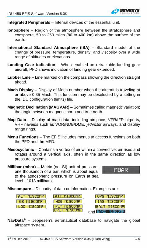
IDU-450 EFIS Software Version 8.0K
1st Ed Dec 2019 IDU-450 EFIS Software Version 8.0K (Fixed Wing) G-5
Integrated Peripherals – Internal devices of the essential unit.
Ionosphere – Region of the atmosphere between the stratosphere and exosphere, 50 to 250 miles (80 to 400 km) above the surface of the earth.
International Standard Atmosphere (ISA) – Standard model of the change of pressure, temperature, density, and viscosity over a wide range of altitudes or elevations.
Landing Gear Indication – When enabled on retractable landing gear aircraft, PFD shows indication of landing gear extended.
Lubber Line – Line marked on the compass showing the direction straight ahead.
Mach Display – Display of Mach number when the aircraft is traveling at or above 0.35 Mach. This function may be deselected by a setting in the IDU configuration (limits) file.
Magnetic Declination (MAGVAR) – Sometimes called magnetic variation; the angle between magnetic north and true north.
Map Data – Display of map data, including airspace, VFR/IFR airports, VHF navaids such as VOR/NDB/DME, jet/victor airways, and display range rings.
Menu Functions – The EFIS includes menus to access functions on both the PFD and the MFD.
Mesocyclonic – Contains a vortex of air within a convective; air rises and rotates around a vertical axis, often in the same direction as low pressure systems.
Millibar (mbar) – Metric (not SI) unit of pressure, one thousandth of a bar, which is about equal to the atmospheric pressure on Earth at sea level - 1013 millibars.
Miscompare – Disparity of data or information. Examples are:
, , , , , , ,
, ,
and . NavData® – Jeppesen's aeronautical database to navigate the global
airspace system.

IDU-450 EFIS Software Version 8.0K
G-6 IDU-450 EFIS Software Version 8.0K (Fixed Wing) 1st Ed Dec 2019
Navigation Data Display – Display of active waypoint, bearing to waypoint, and ground track based on active flight plan. The pilot may also select flight plan information as a mini-map (thumbnail map). These functions are analyzed as part of the GPS WAAS functions not the PFD functions.
Navigation Log – Display of navigation information based on active flight plan, including next waypoint, destination, estimated time remaining, and fuel totalizer-based range and endurance. This function may be deselected by a setting in the IDU configuration (limits) file. These functions are analyzed as part of the GPS WAAS functions not the MFD functions.
Navigation Mode Signal Output – Conventional autopilot Navigation mode signals are the course error output and the left-right deviation signals. Course error output is based on the difference between the EFIS selected course (OBS) and the actual aircraft heading. These signals are based on the selected navigation signal (VOR, GPS).
Nondirectional – Functions in all directions.
Noodle – Navigation Display (ND) projected path; curving path based upon the aircraft bank angle and groundspeed used effectively to assist in course interception and making small adjustments to bank angle for proper roll out.
Nanoteslas (nT) – A unit of measurement of the strength of the magnetic field. Earth's strongest magnetic field is located at the poles, and the weakest field is near the equator.
Obstructions Display – Display of obstructions identified in the embedded obstruction database, which are within 8.5 NM of the aircraft present position. Non-threatening obstructions are displayed by color to identify altitude relative to the aircraft’s current altitude (amber [yellow] < 2000’ below, light red < 500’ below, bright red = at or above aircraft). Threatening obstructions, defined as those that pierce the TAWS envelope, are identified by highlight when producing a caution and identified by flashing highlight when producing a warning. The database used with the obstruction functions meets the integrity requirements of RTCA/DO-200A.
Omnibearing – Magnetic bearing of an omni-range station.
Offset – When referring to parallel track of an active flight plan, “offset” implies the distance paralleling the original track. When referring to VNAV altitudes, “offset” refers to the distance before or after the waypoint the VNAV altitude must be reached.

IDU-450 EFIS Software Version 8.0K
1st Ed Dec 2019 IDU-450 EFIS Software Version 8.0K (Fixed Wing) G-7
Ownship – Principal eye-point; referring to icon of aircraft represented on display.
Pitch Limit Indicator – Appears when the aircraft is within 10 knots of stall speed, based on the VSI setting in the EFIS limits. The intent is to notify the pilot of a possible stall condition so corrective action is taken before the stall occurs. This function may be deselected by a setting in the IDU configuration (limits) file.
Q-Routes – Published RNAV routes, including Q-Routes and T-Routes, can be flight planned for use by the Genesys EFIS, subject to any limitations or requirements noted on enroute charts, in applicable advisory circulars, or by NOTAM. RNAV routes are depicted in blue on aeronautical charts and are identified by the letter “Q” or “T” followed by the airway number, e.g., Q35, T-205. Published RNAV routes are RNAV-2 except when specifically charted as RNAV-1.
QFE – Barometric setting that results in the altimeter displaying height above a reference elevation (e.g., airport or runway threshold).
QNE – Standard barometric setting (29.92 inHg or 1013 mbar) used to display pressure attitude for flight above the transition attitude.
QNH – Barometric setting that results in the altimeter displaying altitude above mean sea level at the reporting station.
Recency – State of occurrence, appearance, or origin.
Selection and Display of Selected Course – Omni-Bearing Select (OBS) function for the pilot to select the course for navigation. Selected course is displayed for reference.
Settable V-Speeds, Targets – The pilot may set certain V-speeds for reference during flight. In addition, the pilot may set certain information at any time for reference during flight, including target airspeed (with corresponding bug) and target altitude (with corresponding bug).
Side in Command – Side of aircraft control responsible for its operation.
Skipped Waypoint – A skipped waypoint is a waypoint associated with a dynamic termination leg with a zero length. These are either:
1) An altitude termination leg when current aircraft altitude is above the termination altitude; or
2) System-created (i.e., not NavData® specified) intercept to a “Course to a Fix” leg where there is insufficient distance to calculate an intercept heading.

IDU-450 EFIS Software Version 8.0K
G-8 IDU-450 EFIS Software Version 8.0K (Fixed Wing) 1st Ed Dec 2019
Skyway VNAV/LNAV Guidance (Synthetic Vision) – Display of GPS-based active navigation route, flight plan, procedure, or OBS course in a three-dimensional series of skyway boxes. Also known as Highway in the Sky (HITS).
Slip Indicator – Display of aircraft lateral accelerations via an integral slip/skid indicator function. The slip indicator is a rectangle just below the heading pointer that moves left and right to indicate the lateral acceleration sensed by the AHRS in the same manner as the ball in a mechanical slip indicator.
Strikefinder – Lightning detector system (WX-500) connected to EFIS and enabled through factory program settings.
Suppressed Waypoint – A suppressed waypoint (designated by brackets) is an airport associated with an IFR or VFR approach procedure.
Symbology – Use of symbols.
T-Routes – T-Routes are available for use by GPS or GPS/SBAS equipped aircraft from 1,200 feet above the surface (or in some instances higher) up to but not including 18.000 feet MSL. T-Routes are depicted on enroute low altitude charts and considered to include the same attributes of Low altitude airways in the Genesys Aerosystems EFIS declutter menus.
Talker – IDU providing data to external sensors and generating aural alerts. IDUs depend upon intra-system communications to determine which IDU on a side takes over “talker” responsibilities. Only one talker (transmit enabled) per side, two talkers in a two sided system, and a master talker PFD when considering aircraft limits. Any IDU may become a talker through auto reversionary means in the event of the PFD failing.
Terrain Display (PFD Artificial Horizon) – Conformal display of surrounding terrain presented with the artificial horizon, shown in the correct scale and perspective for the aircraft’s current position and altitude. Includes conformal display of known runway locations, direction, scale, and perspective based on aircraft’s current position and altitude.
Terrain Display and TAWS/HTAWS – Display of terrain, including identification and annunciation of threatening terrain in accordance with Terrain Awareness Warning System (TAWS) requirements. Coloring scheme for SVS-TAWS PFD and MAP has been simplified as follows:
Non-alerting Terrain below aircraft – Olive Shades

IDU-450 EFIS Software Version 8.0K
1st Ed Dec 2019 IDU-450 EFIS Software Version 8.0K (Fixed Wing) G-9
Non-alerting terrain above aircraft – Brown Shades
TAWS FLTA Caution Terrain – Amber (Yellow)
TAWS FLTA Warning Terrain – Red
Obstacles Below aircraft – Amber (Yellow)
Obstacles above aircraft – Red
When over water – Deep Blue
Threatening terrain is determined by the requirements of TAWS TSO-C151b (fixed wing). Threatening terrain is shaded amber (yellow) for caution situations or shaded red for warning situations per TSO-C151b. TAWS cautions and warnings are accompanied by an amber (yellow) or red flag and an aural annunciation. TAWS Class A, TAWS Class B, TAWS Class C, The database used with the TAWS functions meets the integrity requirements of RTCA/DO-200A.
Timer Indication – Pilot-selected function for a count-up or countdown timer.
Traffic Display – When integrated with an appropriate traffic system, traffic is shown using standard TCAS symbology showing relative position, altitude, climb/decent, and color. The pilot may also show traffic information by selecting the dedicated traffic display page.
Vertical Speed Display – Display of altitude rate of change (vertical speed or climb rate).
VPROC (Procedure Speed) – The aircraft’s normal speed (in airspeed units and configured in EFIS limits) for flying instrument approaches (DPs, IAPs, STARs). This value is used for calculating the turn radius used for instrument procedure legs. This speed is not seen on the airspeed tape and only found in the aircraft speed settings inside the limits.
Warning, Caution, and Advisory Flags – Display of, warning, caution, and advisory indications accompanied by aural indications. The flags are stacked in the lower left corner of the PFD. Warnings are always shown at the top of the flag stack, followed by cautions and then advisories. These flags remain in view for as long as the situation exists.
Waterline – Indication of the aircraft’s longitudinal axis or waterline (attitude).
Wide Area Augmentation System (WAAS) – Developed by Federal Aviation Administration to provide accurate positioning part of the Satellite Based Augmentation System (SBAS). Other countries have

IDU-450 EFIS Software Version 8.0K
G-10 IDU-450 EFIS Software Version 8.0K (Fixed Wing) 1st Ed Dec 2019
similar systems: Europe: European Geostationary Overlay System (EGNOS); Japan: MTSAT Satellite-based Augmentation System (MSAS); India: GPS Aided GEO Augmented Navigation system (GAGAN).
Wind Information – Display of wind direction, wind speed, and cross wind component.
Zulu – Display of Zulu time (based on GPS data).

IDU-450 EFIS Software Version 8.0K (Fixed Wing)
genesys-aerosystems.com 1-817-215-7600
One S-TEC Way, Mineral Wells, TX 76067 USA Copyright © 2019 Genesys Aerosystems. All rights reserved.
64-000103-080K