3LD 450 3LD 510 3LD 450/S 3LD 510/S 4LD 640 4LD 705 ...
33
WORKSHOP MANUAL 3/4 LD, CODE1-5302-556 ENGINE SERIES SERVICE 3LD 450 3LD 510 3LD 450/S 3LD 510/S 4LD 640 4LD 705 4LD 820 3 rd edition DATE 30.11.2001 TECO/ATL AUTHOR BOOK CODE 1-5302-556 MODEL No. 50839 DATE OF ISSUE 01-94 REVIEW 02 APPROVAL 1
-
Upload
khangminh22 -
Category
Documents
-
view
5 -
download
0
Transcript of 3LD 450 3LD 510 3LD 450/S 3LD 510/S 4LD 640 4LD 705 ...

WORKSHOPMANUAL
3/4 LD, CODE1-5302-556 ENGINE SERIES
SERVICE
3LD 4503LD 510
3LD 450/S3LD 510/S4LD 6404LD 7054LD 820
3rd edition
DATE
30.11.2001
TECO/ATL AUTHOR BOOK CODE
1-5302-556
MODEL No.
50839
DATE OF ISSUE
01-94REVIEW 02
APPROVAL
1

BOOK CODE
1-5302-556
MODEL No.
50839
DATE OF ISSUE
01-94REVIEW 02 DATE
30-11-2001
APPROVAL TECO/ATL AUTHOR
2
INDEX OF CHAPTERS
I MODEL AND IDENTIFICATION
II CHARACTERISTIC CURVES
III MAINTENANCERECOMMENDED OIL, CAPACITIES
VI TROUBLE SHOOTING
V DISASSEMBLING AND REASSEMBLING
VI LUBRICATION CIRCUIT
VII FUEL/INJECTION CIRCUIT
VIII ELECTRIC CIRCUIT
IX ELECTRIC EQUIPMENT
X ADJUSTMENTS
XI UPKEEPING
XII TECHNICAL DATA
XIII MAIN DRIVING TORQUES
XIV USE OF SEALANT
XV CLAMPING TORQUES
This handbook provides the main information concerning the repair of the following LOMBARDINI Dieselengines 3LD 450, 3LD 510, 3LD 451/S, 3LD 510/S, 4LD 640, 4LD 705, 4LD 820, which are air-cooled,provided with direct injection and revised on the 30-11-2001.
Page 3
" 4
" 5
" 6
" 7
" 18
" 20
" 22
" 23
" 25
" 27
" 28
" 29
" 30
" 31
INTRODUCTION

DATE
30-11-2001
TECO/ATL AUTHOR BOOK CODE
1-5302-556
MODEL No.
50839
DATE OF ISSUE
01-94REVIEW 02
APPROVAL
3
REGISTRATION CODE AND IDENTIFICATION
Approval code
Engine serial number
Customer's code
Approval code
DIESELLOMBARDINI
Engine grup number
Displacement CC
Displacement CC
DIESEL
Customer's code
Engine serial number
LOMBARDINI
Engine group number
I

BOOK CODE
1-5302-556
MODEL No.
50839
DATE OF ISSUE
01-94REVIEW 02 DATE
30-11-2001
APPROVAL TECO/ATL AUTHOR
4
N (80/1269/EU - ISO 1585) AUTOMOTIVES POWER : Discontinuous services at variable rpm and load.NB (ISO 3046 - 1 IFN) NON-OVERLOADABLE POWER:Continuous light services at constant rpm and variable load.NA (ISO 3046 - 1 ICXN) CONTINUOUS OVERLOADABLE POWER: Continuous heavy-duty services at constant rpm and load.
The above mentioned power levels refer to the engine equipped with air filter, standard silencer, suction fan - which previously underwent abreaking-in period - at 20°C ambient conditions, at 1 bar.The maximum power is guaranteed with a 5% tolerance.These powers are reduced of abt. 1% every 100 m height and of 2% for every 5°C exceeding 25°C.
C (NB): Specific fuel consumption at NB powerM T : Torque at N powera : Continuous service field of use. For any purpose out of this field of use, please contact company LOMBARDINI.
CHARACTERISTIC CURVES CONCERNING POWER, TORQUES AND SPECIFICCONSUMPTION
Il CHARACTERISTIC CURVES

DATE
30-11-2001
TECO/ATL AUTHOR BOOK CODE
1-5302-556
MODEL No.
50839
DATE OF ISSUE
01-94REVIEW 02
APPROVAL
5
SAE 5W/30
SAE 10W/40
SAE 15W/40
SAE 15W/30
-20 -10 +10 +20 +300
-13 -4 5 14 23 32 41 8650 59 68 77
SAE 40
°C°F
SAE 30
SAE 20W/20
RATING
SAE 10W
CAPACITIES IN LITERS
Standard fuel tank3LD450, 3LD510, 3LD451/S, 3LD510/S = 5.34LD 640, 4LD705, 4 LD 820 = 7.2
Standard oil sump:3LD450, 3LD510, 3LD451/S, 3LD510/S =1.754LD640, 4LD705, 4LD 820 = 2.60
Air filter oil bowl = 0.3For special filters, tanks and oil sumps, pleasefollow LOMBARDINI instructions.
INTERVALS (HOURS) OPERATION DETAIL
10 50 125 250 500 1000 2500 5000AIR FILTER (OIL-BATH) (*)
CLEANING HEAD AND CYLINDER FINS (*)FUEL TANKINJECTORS
AIR FILTER OIL CHECK LEVEL SUMP OIL
BATTERY LIQUID FUEL HOSE COUPLING FASTENING VALVE AND ROCKER ARM CLEARANCE INJECTOR SETTING
AIR FILTER(**) (***) CHANGE SUMP (***)
OIL FILTER CARTRIDGEFUEL FILTER CARTRIDGE
OVERHAUL PARTIAL (****)GENERAL
First replacement. (*) In particular running conditions even every day. (**) In particularly dusty environments every 4-5 hours. (***) See prescribed oil. (****) It includes the check of cylinders, segments, guides, valve seat springs and grindings, head and cylinderdescaling, injection pump and injector checks.
RECOMMENDED OILAGIP DIESEL SIGMA S SAE 30-40 MIL-L-2104 CESSOLUBE D3 specification, MIL-L-2104 D andUNIFARM specification MIL-L-2104 C. ForCountries in which AGIP and ESSO productsare not available, the prescribed oil is APISERVICE CD for diesel engines or oil whichshould be in conformity with the MIL -L-2104 Cand MIL -L-2104D military specifications.
MAINTENANCE -PRESCRIBED OIL - REFUELLINGS III

BOOK CODE
1-5302-556
MODEL No.
50839
DATE OF ISSUE
01-94REVIEW 02 DATE
30-11-2001
APPROVAL TECO/ATL AUTHOR
6
PROBABLE CAUSES
ELEC
TRIC
ALEQ
UIPM
ENT
SE
TTIN
GS
AN
D R
EP
AIR
ING
SL
UB
RIC
AT
ION
FUE
L C
IRC
UIT
Exc
essi
ve
oil
con
sum
ptio
n
Low
oi
lp
ress
ure
Oil
leve
lin
cre
ase
Inco
nsis
tent
rpm
It do
es n
ot a
c-ce
lera
te
It st
arts
but
doe
sno
t st
op
It do
es n
otst
art
This table shows some possible causes concerning malfunctions that could arise during the machine running. Always,systematically carry out simpler checks before any disassembly or replacement.
Oil
and
fuel
leak
age
from
the
exha
ust
TROUBLE
Bl
ac
ksm
oke
Whi
te s
mok
e
Cylinder head gasket
MAI
NTEN
ANCE
Clogged pipingsClogged fuel filterPresence of air in the fuel circuitClogged tank breatherFaulty fuel pumpBlocked injector
Blocked injection pump valveWrong injector settingPlunger excessive leakage
Stuck injection pump delivery controlWrong injection pump delivery settingHigh oil levelBlocked pressure relief valveWorn oil pumpPresence of air inside the oil intake pipeFaulty pressure gauge or switchClogged oil intake ductDischarged batteryInefficient or wrong cable connectionFaulty starting switch
Faulty starting motorClogged air filterExcessive idle operationIncomplete running-inOverloaded engineAdvanced injectionDelayed injectionIncorrect governor tinkage adjustmentBroken or loose govener springLow idling settingWorn or stuck piston ringsWorn or scored cylindersWorn valve guidesSticking valvesWorn crankshaft-connecting rod bearingsNon-sliding speed governor leverageCrank shaft not turning freely
TROUBLE SHOOTINGIV

DATE
30-11-2001
TECO/ATL AUTHOR BOOK CODE
1-5302-556
MODEL No.
50839
DATE OF ISSUE
01-94REVIEW 02
APPROVAL
7
3
DISASSEMBLY AND REASSEMBLY
Apart from disassembly and reassembly operations, this chapteralso includes checks, setting up, dimensions, repairs and runninginstructions.It is necessary to use LOMBARDINI original spare parts for a correctrepair.
Oil-bath air filter (standard)Oil-bath type with double filtering mass.The lower mass is made of metal, while the upper is made ofpolyurethan.Check the gasket conditions and replace them in case they aredamaged.Make sure that the weldings are not damaged.Carefully clean the lower body and the filtering masses usingsome gas oil, blow the lower mass with compressed air and drythe upper mass by means of a cloth. Fill with engine oil filter to theindicated level.While reassembling, tighten the nuts at 25 Nm (3LD450, 3LD510,3LD451/S, 3LD 510/S), at 30 Nm (4LD 640, 4LD 705, 4LD 820)Details:1 Upper body 4External sealing ring2 Filtering mass made of polyurethan 5 Filterning mass3 Internal sealing ring 6 Bowl
Silencer (standard)Make sure that it is free from any carbon and oily residues, ifcontaminated, replace it. While reassembling it, replace the gasketsand tighten the brass nuts at 25 Nm.
FlywheelClockwise unscrew nut 1 and remove the flywheel using the puller2 Part. no. 7271-3595-050 for 3LD 450, 3LD 451/S, 3LD510, 3LD510/S,while for 4LD 640, 4 LD 705, 4LD 820 use puller with Part. no. 7271-3595-048.Check that the starter ring gear, when it is present, and the conicsurface of the driving shaft coupling hole are intact.While reassembling, tighten the screws 1 at 170 Nm for 3LD 450,3LD 451/S, 3LD510, 3LD 510/s and at 350 Nm for 4LD 640, 4LD705, 4LD 820.
Note: The flywheels of the left-hand engines (3LD 451/S, 3LD 510/S) have a blading turned in the opposite direction and the nut1 shall be anticlockwise unscrewed.
2
1
DISASSEMBLY/REASSEMBLY V
BOOK CODE
1-5302-556
MODEL No.
50839
DATE OF ISSUE
01-94REVIEW 02 DATE
30-11-2001
APPROVAL TECO/ATL AUTHOR
8
9
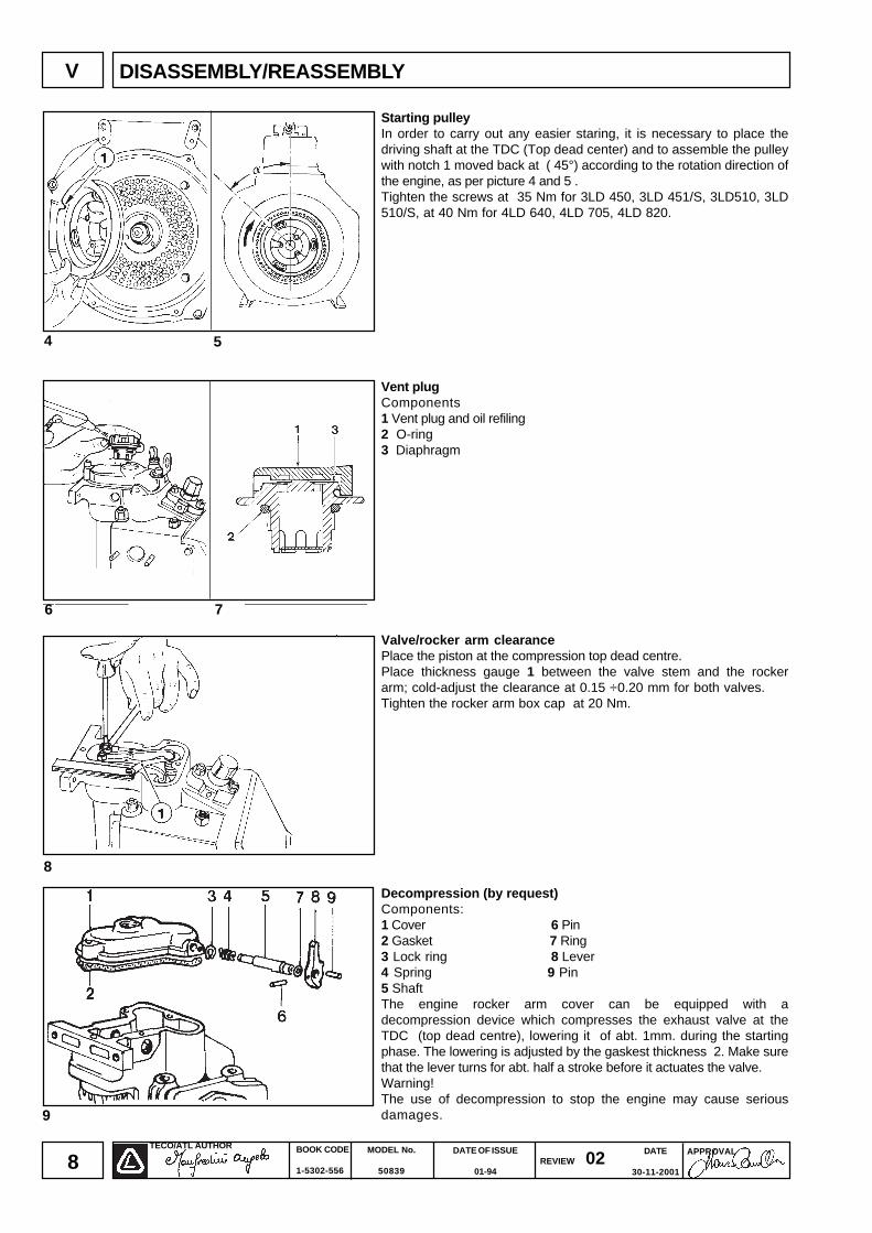
Starting pulleyIn order to carry out any easier staring, it is necessary to place thedriving shaft at the TDC (Top dead center) and to assemble the pulleywith notch 1 moved back at ( 45°) according to the rotation direction ofthe engine, as per picture 4 and 5 .Tighten the screws at 35 Nm for 3LD 450, 3LD 451/S, 3LD510, 3LD510/S, at 40 Nm for 4LD 640, 4LD 705, 4LD 820.
Vent plugComponents1 Vent plug and oil refiling2 O-ring3 Diaphragm
Valve/rocker arm clearancePlace the piston at the compression top dead centre.Place thickness gauge 1 between the valve stem and the rockerarm; cold-adjust the clearance at 0.15 ÷0.20 mm for both valves.Tighten the rocker arm box cap at 20 Nm.
Decompression (by request)Components:1 Cover 6 Pin2 Gasket 7 Ring3 Lock ring 8 Lever4 Spring 9 Pin5 ShaftThe engine rocker arm cover can be equipped with adecompression device which compresses the exhaust valve at theTDC (top dead centre), lowering it of abt. 1mm. during the startingphase. The lowering is adjusted by the gaskest thickness 2. Make surethat the lever turns for abt. half a stroke before it actuates the valve.Warning!The use of decompression to stop the engine may cause seriousdamages.
4
6
8
5
7
V DISASSEMBLY/REASSEMBLY
DATE
30-11-2001
TECO/ATL AUTHOR BOOK CODE
1-5302-556
MODEL No.
50839
DATE OF ISSUE
01-94REVIEW 02
APPROVAL
9
15
12
14
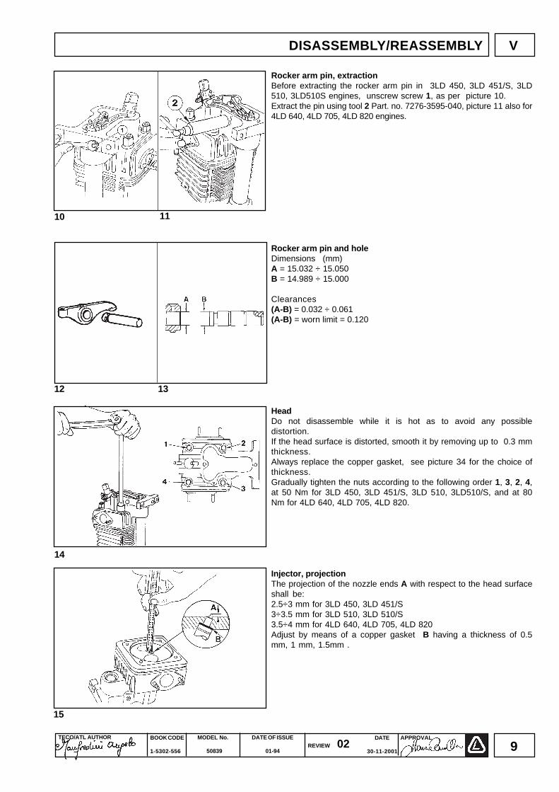
Rocker arm pin, extractionBefore extracting the rocker arm pin in 3LD 450, 3LD 451/S, 3LD510, 3LD510S engines, unscrew screw 1, as per picture 10.Extract the pin using tool 2 Part. no. 7276-3595-040, picture 11 also for4LD 640, 4LD 705, 4LD 820 engines.
Rocker arm pin and holeDimensions (mm)A = 15.032 ÷ 15.050B = 14.989 ÷ 15.000
Clearances(A-B) = 0.032 ÷ 0.061(A-B) = worn limit = 0.120
HeadDo not disassemble while it is hot as to avoid any possibledistortion.If the head surface is distorted, smooth it by removing up to 0.3 mmthickness.Always replace the copper gasket, see picture 34 for the choice ofthickness.Gradually tighten the nuts according to the following order 1, 3, 2, 4,at 50 Nm for 3LD 450, 3LD 451/S, 3LD 510, 3LD510/S, and at 80Nm for 4LD 640, 4LD 705, 4LD 820.
Injector, projectionThe projection of the nozzle ends A with respect to the head surfaceshall be:2.5÷3 mm for 3LD 450, 3LD 451/S3÷3.5 mm for 3LD 510, 3LD 510/S3.5÷4 mm for 4LD 640, 4LD 705, 4LD 820Adjust by means of a copper gasket B having a thickness of 0.5mm, 1 mm, 1.5mm .
10 11
13
VDISASSEMBLY/REASSEMBLY
BOOK CODE
1-5302-556
MODEL No.
50839
DATE OF ISSUE
01-94REVIEW 02 DATE
30-11-2001
APPROVAL TECO/ATL AUTHOR
10
19
20
16
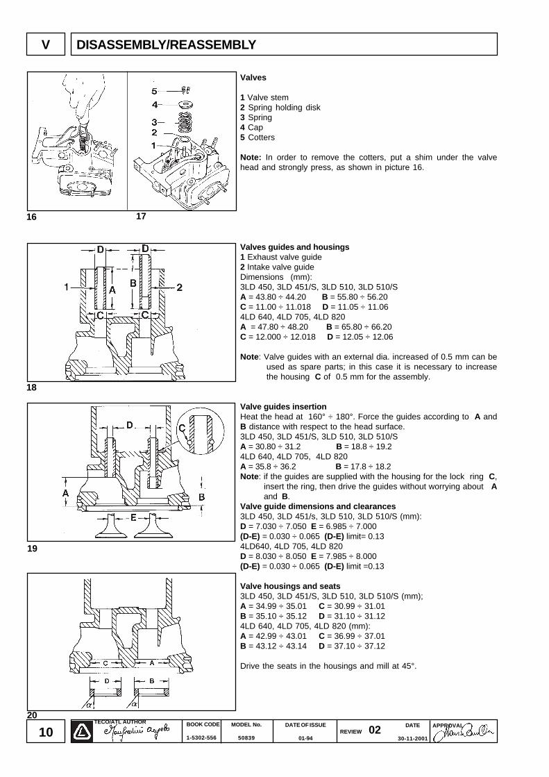
Valves
1 Valve stem2 Spring holding disk3 Spring4 Cap5 Cotters
Note: In order to remove the cotters, put a shim under the valvehead and strongly press, as shown in picture 16.
Valves guides and housings1 Exhaust valve guide2 Intake valve guideDimensions (mm):3LD 450, 3LD 451/S, 3LD 510, 3LD 510/SA = 43.80 ÷ 44.20 B = 55.80 ÷ 56.20C = 11.00 ÷ 11.018 D = 11.05 ÷ 11.064LD 640, 4LD 705, 4LD 820A = 47.80 ÷ 48.20 B = 65.80 ÷ 66.20C = 12.000 ÷ 12.018 D = 12.05 ÷ 12.06
Note: Valve guides with an external dia. increased of 0.5 mm can beused as spare parts; in this case it is necessary to increasethe housing C of 0.5 mm for the assembly.
Valve guides insertionHeat the head at 160° ÷ 180°. Force the guides according to A andB distance with respect to the head surface.3LD 450, 3LD 451/S, 3LD 510, 3LD 510/SA = 30.80 ÷ 31.2 B = 18.8 ÷ 19.24LD 640, 4LD 705, 4LD 820A = 35.8 ÷ 36.2 B = 17.8 ÷ 18.2Note: if the guides are supplied with the housing for the lock ring C,
insert the ring, then drive the guides without worrying about Aand B.
Valve guide dimensions and clearances3LD 450, 3LD 451/s, 3LD 510, 3LD 510/S (mm):D = 7.030 ÷ 7.050 E = 6.985 ÷ 7.000(D-E) = 0.030 ÷ 0.065 (D-E) limit= 0.134LD640, 4LD 705, 4LD 820D = 8.030 ÷ 8.050 E = 7.985 ÷ 8.000(D-E) = 0.030 ÷ 0.065 (D-E) limit =0.13
Valve housings and seats3LD 450, 3LD 451/S, 3LD 510, 3LD 510/S (mm);A = 34.99 ÷ 35.01 C = 30.99 ÷ 31.01B = 35.10 ÷ 35.12 D = 31.10 ÷ 31.124LD 640, 4LD 705, 4LD 820 (mm):A = 42.99 ÷ 43.01 C = 36.99 ÷ 37.01B = 43.12 ÷ 43.14 D = 37.10 ÷ 37.12
Drive the seats in the housings and mill at 45°.
18
17
DISASSEMBLY/REASSEMBLYV

DATE
30-11-2001
TECO/ATL AUTHOR BOOK CODE
1-5302-556
MODEL No.
50839
DATE OF ISSUE
01-94REVIEW 02
APPROVAL
11
27
21
23
2625
22
24
VDISASSEMBLY/REASSEMBLY
Valve seat grindingAfter milling, grind with fine emery paste in engine oil bath.The S sealing surface shall not exceed 2 mm.Embed valves D after grinding for 3LD 450, 3LD 451/S, 3LD 510,3LD 510/S = 0.55 ÷ 1.05 mm; for 4LD 640, 4LD 705, 4LD 820 =0.45 ÷ 0.95 mm.
Cylinder and pistonSet a bore gauge to zero with a calibrated ring. Check the dia. Ø atpoints A and B at three different heights, see pictures 23 and 24.In case of wear exceeding 0.06 mm to the maximum value prescribed,grind the cylinder at the subsequent increased value.The increases suggested are 0.50 and 1.00 mm.Measure the piston Q dia. (picture 26) at A height from the skirtbase:A = 17 mm (3LD 450, 3LD 451/S, 4LD 820)A = 12 mm (3LD 510, 3LD 510/S)A = 22 mm (4LD 640, 4LD 705)Remove the stop rings and extract the piston pin, picture 25.Remove the piston rings and clean the slots.Replace the piston as well as the segments in case the dia. wearexceeds 0.05 mm as regards to the minimum value prescribed.
Dimensions (mm)
ENGINES Ø Q (Ø-Q)
3LD 450, 3LD 451/S3LD 510, 3LD 510/S
4LD 640 95.00 ÷ 95.02 94.88 ÷ 94.90 0.10 ÷ 0.144LD 705 100.00 ÷ 100.02 99.83 ÷ 99.85 0.15 ÷ 0.194LD 820 102.00 ÷ 102.02 101.85 ÷ 101.89 0.11 ÷ 0.17
Note: Even if 3LD 450, 3LD 451/S and 3LD510, 3LD510/S pistonshave the same bore, they differ in other dimensions, thusthey are not interchangeable.
Distance among segment ends (mm)Insert the piston ring in the lower part of the cylinder, then measure thedistance among the points.3LD 450, 3LD 451/S, 3LD510, 3LD 510/S1st piston ring (chromium plated) A = 0.30 ÷ 0.502nd piston ring (torsional) A = 0.30 ÷ 0.503rd piston ring (scraper ring) A = 0.25 ÷ 0.504LD 640, 4LD 705, 4LD 8201st piston ring (chromium plated) A = 0.40 ÷ 0.652nd piston ring (torsional) A = 0.40 ÷ 0.653rd piston ring (torsional) A = 0.40 ÷ 0.654th piston ring (oil scraper ring) A = 0.30 ÷ 0.60
0.05 ÷ 0.0984.925 ÷ 84.94585.00 ÷ 85.02

BOOK CODE
1-5302-556
MODEL No.
50839
DATE OF ISSUE
01-94REVIEW 02 DATE
30-11-2001
APPROVAL TECO/ATL AUTHOR
12
Piston ring - Clearances among slots (mm)
3LD 450, 3LD 451/S, 3LD 510, 3LD 510S, picture28A = 0.08 ÷ 0.09B = 0.06 ÷ 0.07C = 0.05 ÷ 0.06
4LD 640, 4LD 705, 4LD 820, picture 29A = 0.12 ÷ 0.14B = 0.07 ÷ 0.09C = 0.07 ÷ 0.09D = 0.06 ÷ 0.08
Piston ring assembly order3LD 450, 3LD 451/S, 3LD 510, 3LD 510/S, picture 30A = slot for first piston ring (chromium plated)B = slot for piston ring segment (torsional)C = slot for third piston ring (oil scraper ring)
4LD 640, 4LD 705, 4LD 820, picture 31A = slot for first piston ring (chromium plated)B = slot for second piston ring (torsional)C = slot for third piston ring(torsional)D = slot for fourth piston ring(oil scrarper ring)
Note: before inserting the piston in the cylinder, oil the piston ringwithengine oil and turn them, thus the cuts are misaligned.
Piston reassemblyCouple the piston with the connecting rod, thus the combustionchamber centre B is perpendicularly under end A of the nozzlehoused inside the head.Lubricate the piston pin and insert it in the piston, lightly pressingwith your thumb.Make sure that the two stop rings are well housed inside theirseats.
28
30
32 33
31
29
V DISASSEMBLY/REASSEMBLY

DATE
30-11-2001
TECO/ATL AUTHOR BOOK CODE
1-5302-556
MODEL No.
50839
DATE OF ISSUE
01-94REVIEW 02
APPROVAL
13
Clearance volumeA = Clearance volumeB = Head gasket
The thickness B head gasket determines the clearance volume Awhich shall be 0.75 ÷ 0.90 mm for 3LD 450, 3LD 451/S, 3LD 510,3LD 510/S and 0.80 ÷ 1.00 mm for 4LD 640, 4LD 705, 4LD 820.Measure the piston crown position as to the cylinder surface andchose a gasket having a suitable thickness.Always consider that the piston at the top dead centre could be at thesame level, either under or over the cylinder.
Connecting rod equipped with bearings and piston pinFor 3LD 450, 3LD 451/S, 3LD 510, 3LD 510/SDimensions (mm)A = 144.05 ÷ 145.05B = 23.02 ÷ 23.03 (with driven and machined bearing)C = 42.028 ÷ 42.052 (with bearing tightening at 3 Nm)D = 27.995 ÷ 23.000For 4LD 640, 4LD 705, 4LD 820Dimensions (mm)A = 162.95 ÷ 163.05B = 28.02 ÷ 28.03C = 55.40 ÷ 55.43D = 27.995 ÷ 28.000The connecting rod big end bearings are supplied either at nominalvalue and diminished to 0.25 and 0.50 mm.
Connecting rod, big end bearingsWhile reassembling, the A and B centering marks should not be on thesame side.Tighten the screws at 30 Nm for 3LD 450, 3LD 451/S, 3LD 510,3LD 510/S and at 45 Nm for 4LD 640, 4LD 705, 4LD 820.
Main bearing on flywheel sideExtract the bearing using three screws, as per picture 38.While reassembling, replace gasket 1. Check that the oil seal ringis intact. Tighten the screws at 25 Nm.
Drive shaft axial clearanceAfter having screwed the main bearing on the flywheel, check driveshaft axial clearance. Its value is 0.10 ÷ 0.40 mm for 3LD 450, 3LD451/S, 3LD 510, 3LD 510/S and 0.10 ÷ 0.30 mm for 4LD 640, 4LD705, 4Ld 820.The adjustment is carried out by changing the gasket 1 thickness.
38
34
35
39
3736
DISASSEMBLY/REASSEMBLY V

BOOK CODE
1-5302-556
MODEL No.
50839
DATE OF ISSUE
01-94REVIEW 02 DATE
30-11-2001
APPROVAL TECO/ATL AUTHOR
14
Side distributor portIt can be found in engines equipped with industrial type drive shaft.The gaskets 3 and 5, thanks to their thickness, assure the oil sealand affect the camshaft axial clearance, as well. For the check, seeinformation hereunder.
ComponentsFor 3LD 450, 3LD 510 picture 401 Port 2 Bush 3 GasketFix the door at its base at 25 Nm.
For 4LD 640, 4LD 705, 4LD 820 picture 414 Port 5 Gasket 6 Ball bearingFix the port at its base at 40 Nm.
Camshaft axial clearanceCarry out this check before assembling the head. Fix the sidedistributor port or bell 1 at 25 Nm. Remove the intake and exhausttappets and with an implement operate on the camshaft forwardand backward in an axial direction.The axial clearance A shall be:A = 0.20 ÷ 0.60 mm 3LD 450, 3LD 451/S, 3LD 510, 3LD 510/S.A = 0.15 ÷ 0.65 mm for 4LD 640, 4LD 705, 4LD 820.Adjust the clearance by changing the gasket thickness between thedistributor port (if it is assembled) or bell 1 and the base; it isforbidden to assemble more than one gasket.
Drive shaftThere are two types of standard drive shafts:A Automotive type (agricultural machines)B industrial type (motor pumps generating set, etc.)
Note:For left-handed engines, i.e 3LD 510/S, the drive shaft turnsanticlockwise (seen from the flywheel position) and theirthread is clockwise on the power takeoff side as well as onthe flywheel side.
Drive shaft lubrication ductsRemove the caps, clean the ducts A and B with a point and blowthem with compressed air.Replace the caps by caulking them on their seat, then check theirseal.
Drive shaft connecting radiusR = 3 mmR1 = 3.5 mm
Note: When the main journal and the crank are ground, it isessential to reset R and R1 values in order to avoid any possiblebreaking of the drive shaft.
44
40
42
43
41
DISASSEMBLY/REASSEMBLYV
DATE
30-11-2001
TECO/ATL AUTHOR BOOK CODE
1-5302-556
MODEL No.
50839
DATE OF ISSUE
01-94REVIEW 02
APPROVAL
15
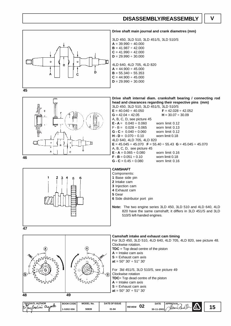
Drive shaft main journal and crank diametres (mm)
3LD 450, 3LD 510, 3LD 451/S, 3LD 510/SA = 39.990 ÷ 40.000B = 41.987 ÷ 42.000C = 41.990 ÷ 42.000D = 29.990 ÷ 30.000
4LD 640, 4LD 705, 4LD 820A = 44.900 ÷ 45.000B = 55.340 ÷ 55.353C = 44.900 ÷ 45.000D = 29.990 ÷ 30.000
Drive shaft internal diam. crankshaft bearing / connecting rodhead and clearances regarding their respective pins (mm)3LD 450, 3LD 510, 3LD 451/S, 3LD 510/SE = 40.040 ÷ 40.050 F = 42.028 ÷ 42.052G = 42.04 ÷ 42.05 H = 30.07 ÷ 30.09A, B, C, D, see picture 45E - A = 0.040 ÷ 0.060 worn limit 0.12F - B = 0.028 ÷ 0.065 worn limit 0.13G - C = 0.040 ÷ 0.060 worn limit 0.12H - D = 0.070 ÷ 0.10 worn limit 0.184LD 640, 4LD 705, 4LD 820E = 45.045 ÷ 45.070 F = 55.40 ÷ 55.43 G = 45.045 ÷ 45.070A, B, C, D, see picture 45E - A = 0.065 ÷ 0.080 worn limit 0.16F - B = 0.051 ÷ 0.10 worn limit 0.18G - C = 0.45 ÷ 0.080 worn limit 0.16
CAMSHAFTComponents:1 Base side pin2 Intake cam3 Injection cam4 Exhaust cam5 Gear6 Side distributor port pin
Note: The two engine series 3LD 450, 3LD 510 and 4LD 640, 4LD820 have the same camshaft; it differs in 3LD 451/S and 3LD510/S left-handed engines.
Camshaft intake and exhaust cam timingFor 3LD 450, 3LD 510, 4LD 640, 4LD 705, 4LD 820, see picture 48.Clockwise rotation.TDC = Top dead centre of the pistonA = Intake cam axisS = Exhaust cam axisat = 50° 30' ÷ 51° 30'
For 3ld 451/S, 3LD 510/S, see picture 49Clockwise rotationTDC= Top dead centre of the pistonA = Intake cam axisS = Exhaust cam axisat = 50° 30' ÷ 51° 30'
48
45
46
47
49
DISASSEMBLY/REASSEMBLY V
BOOK CODE
1-5302-556
MODEL No.
50839
DATE OF ISSUE
01-94REVIEW 02 DATE
30-11-2001
APPROVAL TECO/ATL AUTHOR
16
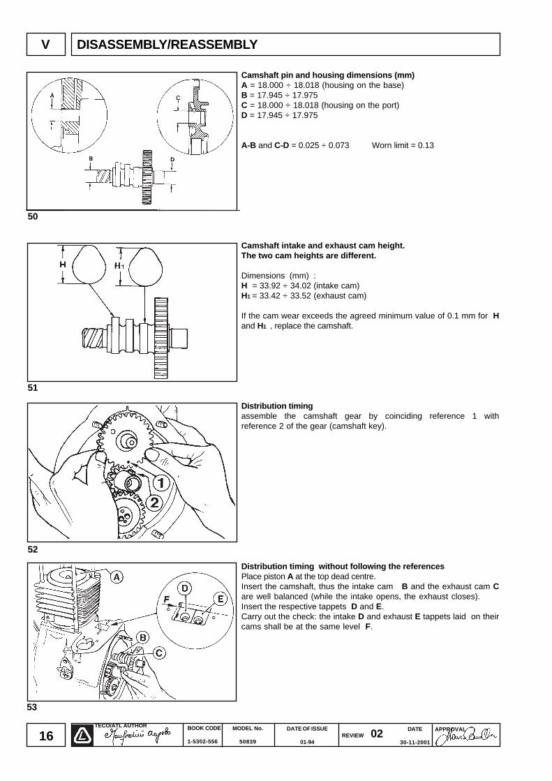
Camshaft pin and housing dimensions (mm)A = 18.000 ÷ 18.018 (housing on the base)B = 17.945 ÷ 17.975C = 18.000 ÷ 18.018 (housing on the port)D = 17.945 ÷ 17.975
A-B and C-D = 0.025 ÷ 0.073 Worn limit = 0.13
Camshaft intake and exhaust cam height.The two cam heights are different.
Dimensions (mm) :H = 33.92 ÷ 34.02 (intake cam)H1 = 33.42 ÷ 33.52 (exhaust cam)
If the cam wear exceeds the agreed minimum value of 0.1 mm for Hand H1 , replace the camshaft.
Distribution timingassemble the camshaft gear by coinciding reference 1 withreference 2 of the gear (camshaft key).
Distribution timing without following the referencesPlace piston A at the top dead centre.Insert the camshaft, thus the intake cam B and the exhaust cam Care well balanced (while the intake opens, the exhaust closes).Insert the respective tappets D and E.Carry out the check: the intake D and exhaust E tappets laid on theircams shall be at the same level F.
53
50
51
52
V DISASSEMBLY/REASSEMBLY

DATE
30-11-2001
TECO/ATL AUTHOR BOOK CODE
1-5302-556
MODEL No.
50839
DATE OF ISSUE
01-94REVIEW 02
APPROVAL
17
Speed governorIt has a centrifugal system with 6 balls housed in the gear, which isdirectly operated by the drive shaft.The balls, moved at the gear periphery by a centrifugal force, axiallyshift the bell 3, which actuates the fork 2 connected to lever 1 inorder to determine the injection pump rack rod position. A springwith two plates 4, energized by the accelerator control 5, opposesthe action of the governor cetrifugal force. The balance between thetwo forces keeps the rpm rate constant with the change of load.
Timing of the speed governorAdjust the injection pump control lever 1 thus, when the governor isclosed, it is placed at distance A as to the external surface of thebase.- Loosen the screw 2.- Close the governor (move the mobile bell 3 towards the operator,picture 55).- Place lever 1 at A distance, picture 56 (22 mm for 3LD 450, 3LD510, 3LD 451/S, 3LD 510/S and 28 mm for 4LD 640, 4LD 705, 4LD820).- Tighten the screw 2.
54
55 56
DISASSEMBLY/REASSEMBLY V

BOOK CODE
1-5302-556
MODEL No.
50839
DATE OF ISSUE
01-94REVIEW 02 DATE
30-11-2001
APPROVAL TECO/ATL AUTHOR
18
Lubrication circuitDetails:1 Intake pipe2 Oil pump3 Oil filter4 Pressure switch5 Crankshaft bearing6 Pressure adjusting valve7 Tappet rod protection pipe8 Vent and oil filler plug.
Oil pumpMake sure that the gear teeth are intact and check that theclearance between the gear periphery and the pump case does notexceed 0.15 mm and that the drive shaft can easily turn with an axialclearance not exceeding 0.15 mm.Check that the gear lubrication holes 1 and 2 are not clogged.Tighten the pump case at 30 Nm.Tighten the pump control gear at 20 Nm.The oil pumps for 3LD 451/S and 3LD 510/S engines, which turnanticlockwise (from flywheel position), are different, see informationbelow.
57
58
VI LUBRICATION CIRCUIT
59
DATE
30-11-2001
TECO/ATL AUTHOR BOOK CODE
1-5302-556
MODEL No.
50839
DATE OF ISSUE
01-94REVIEW 02
APPROVAL
19
65
60
62
61
63 64
LUBRICATION CIRCUIT VI
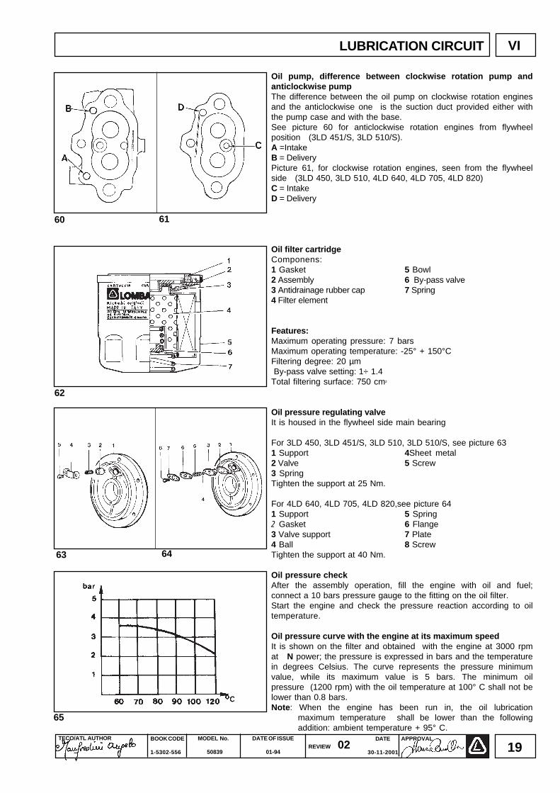
Oil pump, difference between clockwise rotation pump andanticlockwise pumpThe difference between the oil pump on clockwise rotation enginesand the anticlockwise one is the suction duct provided either withthe pump case and with the base.See picture 60 for anticlockwise rotation engines from flywheelposition (3LD 451/S, 3LD 510/S).A =IntakeB = DeliveryPicture 61, for clockwise rotation engines, seen from the flywheelside (3LD 450, 3LD 510, 4LD 640, 4LD 705, 4LD 820)C = IntakeD = Delivery
Oil filter cartridgeComponens:1 Gasket 5 Bowl2 Assembly 6 By-pass valve3 Antidrainage rubber cap 7 Spring4 Filter element
Features:Maximum operating pressure: 7 barsMaximum operating temperature: -25° + 150°CFiltering degree: 20 µm By-pass valve setting: 1÷ 1.4Total filtering surface: 750 cm2
Oil pressure regulating valveIt is housed in the flywheel side main bearing
For 3LD 450, 3LD 451/S, 3LD 510, 3LD 510/S, see picture 631 Support 4Sheet metal2 Valve 5 Screw3 SpringTighten the support at 25 Nm.
For 4LD 640, 4LD 705, 4LD 820,see picture 641 Support 5 Spring2 Gasket 6 Flange3 Valve support 7 Plate4 Ball 8 ScrewTighten the support at 40 Nm.
Oil pressure checkAfter the assembly operation, fill the engine with oil and fuel;connect a 10 bars pressure gauge to the fitting on the oil filter.Start the engine and check the pressure reaction according to oiltemperature.
Oil pressure curve with the engine at its maximum speedIt is shown on the filter and obtained with the engine at 3000 rpmat N power; the pressure is expressed in bars and the temperaturein degrees Celsius. The curve represents the pressure minimumvalue, while its maximum value is 5 bars. The minimum oilpressure (1200 rpm) with the oil temperature at 100° C shall not belower than 0.8 bars.Note: When the engine has been run in, the oil lubrication
maximum temperature shall be lower than the followingaddition: ambient temperature + 95° C.

BOOK CODE
1-5302-556
MODEL No.
50839
DATE OF ISSUE
01-94REVIEW 02 DATE
30-11-2001
APPROVAL TECO/ATL AUTHOR
20
69
66
67
68
70
VII FUEL/INJECTION CIRCUIT
Standard feeding/injection circuitComponents:1 Tank2 Filter3 Pump4 Pipe5 Injector6 Injector waste pipe
Fuel filter inside the tank (standard)Details:
1 Spring 6 Gasket2 Disk 7 Cover3 Ring 8 Ring4 Cartridge 9 Bolt5 Gasket
Cartridge features:Filtering degree = 7 µmFiltering surface = 390 cm2
Feeding pump (by request)Features: at 1500 rpm of the control eccentric, the minimum deliveryis 60 l/h, while the automatic adjustment pressure is 4 ÷ 5 mcolumn of water.
Feeding pump rod projectionDetails:1 Feeding pump 3 Rod2 Base 4 Oil pump drive shaft eccentricThe check shall be carried out with the eccentric 4 at rest.The projection A of rod 3 is 0.8 ÷ 1.2 mm; it shall be adjusted withthe following supplied gaskets having a thickness of 0.50; 0.80 and1.0 mm.Rod length = 65.4 mm for 3LD 450, 3LD 451/S, 3LD 510, 3LD 510/Sand 75.2 mm for 4LD 640, 4LD 705, 4LD 820.
Injection pumpComponents:
1 Delivery fitting 11 Spring2 O-ring 12 Pumping piston3 Spring 13 Tappet case4 Delivery valve 14 External roller5 Gasket 15 Internal roller6 Barrel 16 Pin7 Pump case 17 Lock ring8 Eccentric 18 Rack rod9 Sector gear 19 Lock pin10 Spring bearing cap 20 Collar
Tighten the pump at its base at 30 Nm.

DATE
30-11-2001
TECO/ATL AUTHOR BOOK CODE
1-5302-556
MODEL No.
50839
DATE OF ISSUE
01-94REVIEW 02
APPROVAL
21
Injection pump assemblyInsert the cylinder 6 in the pump case 7, engaging the slot A in theeccentric 8.Insert the delivery valve 4, copper gasket 5, spring 3 O ring 2, thentighten the fitting at 3.5 ÷ 40 Nm.Assemble the rack rod 18 and sector gear 9 coinciding points B.Insert the upper collar 10, spring 11 and piston 12 with reference Con the same side of the slot A (if it is assembled on the oppositeside, the engine revs out).Assemble the collar 20, the tappet 13 with rollers 14, 15 and pin16. While pressing on the tappet, insert the pin 19 and the ring 17.
Advanced injection (static)Disconnect the diesel oil thrust pipe fitting, being careful not to loosenalso the pump delivery fitting 1, then screw the tester for the advancedinjection check 2. Fill the tank, checking that the fuel level is at least 10cm above the tester. Place the accelerator lever halfway. Turn theflywheel towards the engine rotation direction and make sure that thefuel arrives at the tester assembled on the injection pump deliveryfitting. Repeat this operation; during the compression phase, operateslowly and immediately stop when the fuel moves into the tester hole;move the flywheel 3 mm back; this is the static advanced injection. If Cdoes not coincide with B but comes before, add some shims underthe pump, otherwise, remove the shims if C is beyond B.Note: By removing or adding a 0.1 mm shim under the pump, it is
possible to delay or advance C, which is after B.
Advanced Injection references on the conveyor and flywheelprotection diskA Piston reference at top dead centreB Injection advance reference as to AA ÷ B Distance in mmC Reference of piston in injection advance positiona Reference in degreesD Flywheel protection disk diameter
ENGINES (A-B)mm amm D (3LD)mm D (4LD)mm3LD 450, 3LD 451/S 58 ÷ 633LD 510, 3LD 510/S 24 ÷ 26 276 3104LD 640, 4LD 705, 4LD 820 65 ÷ 704LD 820 at 2600 rpm 60 ÷ 65 22° ÷ 24°Note: 1° stands for 2.7 mm on dia. D= 310 mm; on dia. D = 276 mm,
1° stands for 2.4 mm.
InjectorComponents:1 Ring nut - 2 Nozzle 3 Needle 4 Fitting 5 Nozzle bearing 6 Pressurerod 7 Spring 8 Spring seat 9 Union 10 Ring nutSettingConnect the injector to a manual pump and check that the settingpressure is 190 ÷ 200 bars. If necessary adjust, actuating theunion 9.While replacing the spring, the setting shall be carried outat a pressure higher than 10 bars (200 ÷210 bars) in order tocounterbalance the running adjustments. Check the needle valveseal by slowly activating the manual pump up to abt. 170 bars. Incase of dripping, replace the nozzle. Tighten the injector to the headat 15 Nm for 3LD 450, 3LD 451/S, 3 LD 510, 3 LD 510/S and at 20Nm for 4LD 640, 4LD705, 4LD 820.Note: A new injector is currently assembled, its components are
different, though the setting remains the same.
71
74
75
72 73
VIIFUEL/INJECTION CIRCUIT

BOOK CODE
1-5302-556
MODEL No.
50839
DATE OF ISSUE
01-94REVIEW 02 DATE
30-11-2001
APPROVAL TECO/ATL AUTHOR
22
76
77
VIII ELECTRIC CIRCUIT
12 V 14 A electrical ignition, diagram with voltage regulator ,battery recharge lamp and manostat
Components:1 Alternator2 Starting motor3 Voltage regulator4 Battery5 Oil pressure switch6 Oil pressure lamp7 Ignition switch8 Battery recharge lamp
Note: The batteries, which are not supplied by Lombardini, shallhave a 12 V voltage and the following capacity:
3LD 450, 3lD 451/S, 3LD 510, 3LD 510/S = 45 Ah 4LD 640 = 55 Ah 4LD 705 = 66 Ah 4LD 820 = 70 Ah
12.5 V 14 A alternatorIt is equipped with a fixed rotor assembled on the main journal,while the pivoting rotor is housed inside the flywheel.
Dimensions (mm):A = 159B = 44.5C = 4D = 28.5
Note: The clearance between inductor and rotor (air gap) shall be0.5 ÷ 0.6 mm.
12,5 V, 14 A alternator battery recharge curveIt is carried out at + 25° C ambient temperature, 12.5 V batteryvoltage.
78

DATE
30-11-2001
TECO/ATL AUTHOR BOOK CODE
1-5302-556
MODEL No.
50839
DATE OF ISSUE
01-94REVIEW 02
APPROVAL
23
82
79
Voltage regulatorThere are two different types of regulators: one with makeSAPRISA, ALTECNA, NICSA and the other with make DUCATI.
ALTECNA Cable Tab dimensionsSAPRISA colours DUCATI Width Thickness NICSA ~ yellow G 6.25 0.8 R red R 9.50 1.2 + red B 9.50 1.2 LE green L 4.75 0.8 brown C 6.25 0.8
Voltage regulator, running checkMake sure that the connections are in compliance with thediagram.Remove the respective clamp from the battery positive pole.Insert a voltmeter with direct current between the two poles of thebattery.
Connect a 20A ammeter at direct current between the positive poleand cable 1 respective clamp.Start a few times until the battery voltage goes down to 13 V.When the battery voltage reaches 14.5 V, the ammeter current willdrop to a value near zero.If the voltage is lower than 14 V and the recharge current is zero,replace the regulator.
Note: The voltage regulator does not work when not earthed andthe battery is completely discharged.
Warning: when the engine runs, do not remove the battery cablesand do not take the key off the control board.Do not place the regulator near heat sources, a temperatureexceeding 75° C could cause damages.Avoid any electric welding either on the engine and on theequipment.
Bosch DW (L) 12 V 1, 1 KW type, starting motorFor 3LD 450, 3LD 510Anticlockwise rotation direction (seen from the flywheel side)A = 29.5 ÷ 31.5 mm (rim surface and motor flange distance)
Note: For any possible repairs, please contact bosch servicecentres.
81
80
ELECTRIC EQUIPMENT IX

BOOK CODE
1-5302-556
MODEL No.
50839
DATE OF ISSUE
01-94REVIEW 02 DATE
30-11-2001
APPROVAL TECO/ATL AUTHOR
24
Characteristic curves for Bosch DW(L) 12V 1.1 kW type,starting motor
Bosch JF(L) 12V 2.5 kW type, starting motorFor 4LD 640, 4LD 705, 4LD 820Anticlockwise rotation (seen from the pinion side)A = 23 ÷ 25 mm
Characteristic curves for Bosch JF(L) 12V 2,5 kW type startingmotor
84
85
83
ELECTRIC EQUIPMENTIX
DATE
30-11-2001
TECO/ATL AUTHOR BOOK CODE
1-5302-556
MODEL No.
50839
DATE OF ISSUE
01-94REVIEW 02
APPROVAL
25
87
88
86
ADJUSTMENTS
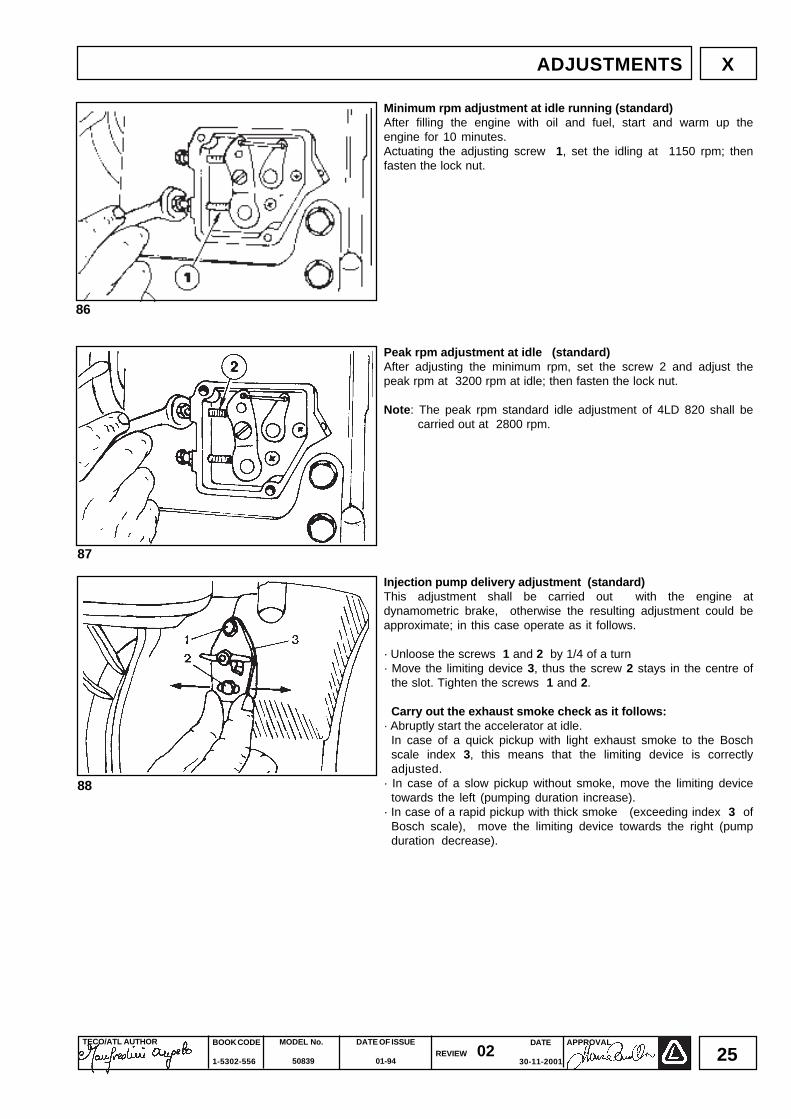
Minimum rpm adjustment at idle running (standard)After filling the engine with oil and fuel, start and warm up theengine for 10 minutes.Actuating the adjusting screw 1, set the idling at 1150 rpm; thenfasten the lock nut.
Peak rpm adjustment at idle (standard)After adjusting the minimum rpm, set the screw 2 and adjust thepeak rpm at 3200 rpm at idle; then fasten the lock nut.
Note: The peak rpm standard idle adjustment of 4LD 820 shall becarried out at 2800 rpm.
Injection pump delivery adjustment (standard)This adjustment shall be carried out with the engine atdynamometric brake, otherwise the resulting adjustment could beapproximate; in this case operate as it follows.
· Unloose the screws 1 and 2 by 1/4 of a turn· Move the limiting device 3, thus the screw 2 stays in the centre of
the slot. Tighten the screws 1 and 2.
Carry out the exhaust smoke check as it follows:· Abruptly start the accelerator at idle.
In case of a quick pickup with light exhaust smoke to the Boschscale index 3, this means that the limiting device is correctlyadjusted.
· In case of a slow pickup without smoke, move the limiting devicetowards the left (pumping duration increase).
· In case of a rapid pickup with thick smoke (exceeding index 3 ofBosch scale), move the limiting device towards the right (pumpduration decrease).
X

BOOK CODE
1-5302-556
MODEL No.
50839
DATE OF ISSUE
01-94REVIEW 02 DATE
30-11-2001
APPROVAL TECO/ATL AUTHOR
26
89
Time secsfor 100 cc.
r/kW.hKw
power
90
140-146
143-149
117-122
96-100
96-100
108-113
87-92
272-283
285-299
272-283
284-295
276-287
263-277
258-273
3000
3600
3000
3000
3000
2600
2600
N 7,5
NB 7
N 9
N 10,5
N 10,8
N 10
N 12,1
3LD 450
3LD 450
3LD 510
4LD 640
4LD 705
4LD 705
4LD 820
Engine
Specific fuel consumption *
Rpm
* The specific consumption values indicated are valid after abt. 100 working hours.
X ADJUSTMENTS
Limiting device for injection pump delivery and torque gearingdeviceIt is housed in the pump control lever A and it is constituted of aspring on cam B, limiting the stroke of the same lever A.At the torque rate, the spring flexure, subject to the acceleratorcontrol action, allows a further stroke of lever A, thus an increaseddelivery of the injection pump.
Adjustment of injection pump delivery with braked engine1) Bring the engine to its idling point .2) Move the delivery limiting device 3 towards the left, see picture 883) Operate the engine until it reaches the power and rpm requiredby the manufacturer of the equipment.4) Make sure that the consumption is in compliance with the valuesspecified in the table of the adjustments (see information below). If the consumption is in compliance with the fixed values, it isessential to change the balance conditions measured on the brake,operating either on the load and on the regulator. When the engine is steady, carry out the consumption check again.5) Move the limiting device 3 towards the right, as per picture 88,until the engine rpm number descreases. Lock the limiting deviceby means of the two screws.6) Completely release the brake and check the rpm at which theengine settles. The speed governor performances shall be incompliance with the class required by the manufacturer of theequipment.7) Stop the engine.8) When the engine is cold, check the valve clearance again.
Required adjustments (the most demanded)

DATE
30-11-2001
TECO/ATL AUTHOR BOOK CODE
1-5302-556
MODEL No.
50839
DATE OF ISSUE
01-94REVIEW 02
APPROVAL
27
UPKEEPING
The engines to be stored for more than 30 days shall be preparedas follows:
Temporary protection (1÷ 6 months).· Start the engine at idle and at a minimum rpm for at least 15
minutes.· Fill the sump with protection oil MIL -1-644-P9 and operate for
5 ÷ 10 minutes at 3/4 of maximum speed.· When the engine is heated, empty the sump and refill with new
normal oil (picture 91).· Remove the fuel filter cover and empty the tank (picture 92).· Desassemble the fuel filter, replace the cartridge and, if it is not dirty,
reassemble it.· Carefully clean fins, cylinder and head (picture 93).· Seal with adhesive tape all the openings.· Remove the injector, (pictureaw) pour abt. a spoon of oil SAE 30 into
the cylinder and manually turn in order to spread the oil.Reassemble the injector.
· Spray SAE 10W oil in the exhaust and intake duct, rocker arms,valves, tappets, etc. and protect with some grease the partswhich are not painted.
· Wrap the engine in plastic cloth.· Keep it in a dry place, possibly not in direct contact with the
ground and away from high voltage electric lines.
Permanent protection (over 6 months)Apart from the previous instructions, we advise you to:· Treat the lubrication and injection system, together with the mobile
parts, with rust preventing oil having MIL-L-21260 P 10 2nddegree features , SAE 30 (i.e.ESSO RUST - Ban 623 - AGIP,RUSTIA C. SAE 30). Run the engine equipped with rust preventingoil and let the exceeding oil off.
· Coat the external non-painted surfaces with rust preventing oil,having the MIL - C - 16173D features - 3rd degree (For exampleESSO RUST BAN 398 - AGIP, RUSTIA 100/F).
Preparation for the setting at work· Clean the external part of the engine.· Remove all protections and coverings.· Remove the rust preventer from the external part by means of a
suitable solvent or degreasing product.· Desassemble the injector, fill it with normal oil, pivot the drive
shaft of some turns, then desassemble the sump and let the oilcontaining the protective element off.
· Check the injector, valve clearance, head tightening, oil and airfilter setting. If the engine has been stored for quite a long period(over 6 months), check a bearing in order to find any possible traceof corrosion.
94
91
92
93
UPKEEPING XI

BOOK CODE
1-5302-556
MODEL No.
50839
DATE OF ISSUE
01-94REVIEW 02 DATE
30-11-2001
APPROVAL TECO/ATL AUTHOR
28
Cyl
inde
rsB
ore
Str
oke
Dis
plac
emen
tC
ompr
essi
on r
atio
rpm
N D
IN 7
0020
- 8
0/12
69/C
EE
- is
o 15
85 K
W P
ower
N
B
DIN
627
1 -
ISO
304
6 -
1 IF
NN
A
DIN
627
1 -
ISO
304
6 -
1 IC
XN
Pea
k to
rque
*F
uel s
peci
fic c
onsu
mpt
ion
Oil
cons
umpt
ion
Dry
wei
ght
Com
bust
ion
air
volu
me
at 3
000
rpm
Coo
ling
air
volu
me
at 3
000
rpm
Max
. axi
al lo
ad p
erm
issi
ble
for
driv
e sh
aft i
n tw
o di
rect
ions
inst
anta
neou
s M
ax.i
nclin
atio
n
ex
tend
ed to
1 h
.pe
rman
ent
3L
D45
0
3
LD
510
4L
D64
0
4LD
705
4L
D82
0
N.
mm
mm
Cm
³
Nm
RP
M l/hK
g/h
Kg.
l./1'
l./1'
Kg. a α α
3L
D45
0, 3
LD
510,
4L
D64
0, 4
LD
705,
4L
D82
0 F
EA
TU
RE
S
EN
GIN
E T
YP
E
1 102
100
817
17,0
:130
00 13
11,4
D10
,3 D
48
@ 1
600
3,0*
**0,
035*
**10
589
0 D
1040
0 D
300
35°
25°
****
* I
t sta
nds
for
pow
er**
It s
tand
s fo
r N
B p
ower
***
It st
ands
to N
B p
ower
at
260
0 rp
m**
** A
ccor
ding
to th
e ap
plic
atio
nD
a
t 260
0 rp
mN
ote
: F
or L
DA
450
, LD
A 5
10,
LDA
96,
LD
A 9
7, L
DA
820
out
-of-
prod
uctio
n en
gine
s, t
he r
epai
r sp
ecifi
catio
ns
are
equa
l to
tho
se o
f th
een
gine
s sp
ecifi
ed i
n th
e ta
ble.
3
LD 4
51/S
, 3L
D 5
10/S
eng
ines
, w
hich
are
cur
rent
ly p
rodu
ced,
not
spe
cifie
d i
n th
e ta
ble,
tur
nan
ticlo
ckw
ise
( se
en fr
om th
e fly
whe
el s
ide)
, and
are
pro
vide
d w
ith th
e sa
me
feat
ure
as 3
LD45
0 an
d 3
LD51
0eng
ines
.
1 85
80
454
17,5
:130
007,
56,
66,
028
,5@
170
01,
70.
007
57 560
9000
250
35°
30°
****
XII TECHNICAL DATA
1 85
90
510
17,5
:130
009,
07,
36,
632
,8@
180
01,
90.
008
60 630
9000
250
35°
30°
****
1 95
90
638
17,0
:130
0010
,58,
87,
938
,7@
170
02,
40.
024
100
780
1200
030
035
°25
°**
**
1 100
90
707
17,0
:130
0012
,09,
9 D
8,8
D43
,1@
200
02,
6***
0,03
0***
100
770
D10
400
D30
035
°25
°**
**

DATE
30-11-2001
TECO/ATL AUTHOR BOOK CODE
1-5302-556
MODEL No.
50839
DATE OF ISSUE
01-94REVIEW 02
APPROVAL
29
POSITIONTorque( Nm )
4045
280250280402025405025202030404030403540407080
350
Dia. / Pitch( mm )
Reference( picture no.)
18x1.510x1.514x1.514x1.514x1.510x1.58x1.258x1.258x1.2510x1.58x1.258x1.258x1.258x1.2510x1.510x1.58x1.2510x1.512x1.510x1.510x1.514x1.512x1.520x1.5
7136----8-
581-
5875---
6941-4
64-
143
Injection pump unitConnecting rod 4LD 820 clutch bearing bell bolt 4LD 640, 4LD clutch bearing bell boltBolt for hubFlanging bellRocker arm box capOil sumpOil pump caseAir filterOil filterOil pump gearInjetor towards the headRocker arm pin for injection pump controlGear pin for speed governorEngine footInjection pumpDistributor side portOil pressure switchStarting pulleyMain bearing on flywheel sideSump oil drain boltCylinder headFlywheel
3LD 450 - 3LD 510 - 3LD 451/S - 3LD 510/S MAIN DRIVING TORQUES
MAIN DRIVING TORQUES 4LD 640 - 4LD 705 - 4LD 820
4030
25025802010302525201560404025253535253550
170
POSITIONTorque( Nm )
Dia. /Pitch( mm )
REFERENCE( Picture NO. )
18x1.58x1.2514x1.58x1.2516x1.58x1.25
6x18x1.258x1.258x1.258x1.258x1.2514x1.510x1.58x1.258x1.258x1.2512x1.58x1.258x1.2510x1.510x1.520x1.5
7136---8-
581-
5875---
6940-4
63-
143
Injection pump unionConnecting rodClutch bearing bell boltFlanging bellClutch bell (industrial engine)Rocker arm box capOil sumpOil pump caseAir filterOil filterOil pump gearInjector towards the headRocker arm fulcrum pin for injection pumpGear pin for speed governorEngine footInjection pumpDistributor side portOil pressure switchStarting pulleyMain bearing on flywheel sideSump oil drain boltCylinderFlywheel
MAIN DRIVING TORQUES XIII

BOOK CODE
1-5302-556
MODEL No.
50839
DATE OF ISSUE
01-94REVIEW 02 DATE
30-11-2001
APPROVAL TECO/ATL AUTHOR
30
TYPE OF SEALANT
LOCTITE 270LOCTITE 270LOCTITE 270LOCTITE 270LOCTITE 270LOCTITE 270LOCTITE 270LOCTITE 270LOCTITE 270LOCTITE 270LOCTITE 270LOCTITE 270LOCTITE 270
Clutch bearing bell and embedded hexagonal-head screwsControl pin threadingCoupling nipple for oil filter cartridgeStud bolt for clamping on engine headStud bolt for clamping on main bearing flywheel sideStud bolt for clamping on distributor port sideStud bolt on engine bellClamping screw for pin regulatorClamping screw for baffle on air conveyorStud bolt for clamping on engine flange bellRocker arm fulcrum pin for injection pump controlBracket clamping screw on side platesStud bolt for clamping at feeding pump
POSITION
USE OF DOPE FOR 3LD 450 - 3LD 510 - 3LD 451/S - 3LD 510/S
POSITION
Bearing on port or bellRegulating pin threadingStud bolt for clamping on engine headStud bolt for clamping on main bearing on flywheel sideStud bolt for clamping on distribution sideLock screw for rocker arm pinClamping screw for regulating pinIndustrial portStud bolt for clamping on feeding pump
USE OF DOPE FOR 4LD 640 - 4LD705 - 4LD 820
LOCTITE 270LOCTITE 270LOCTITE 270LOCTITE 270LOCTITE 270LOCTITE 270LOCTITE 270
DOW CORNING Q3 - 7091SILICONELOCTITE 270
TYPE OF SEALANT
USE OF SEALANTXIV
DATE
30-11-2001
TECO/ATL AUTHOR BOOK CODE
1-5302-556
MODEL No.
50839
DATE OF ISSUE
01-94REVIEW 02
APPROVAL
31
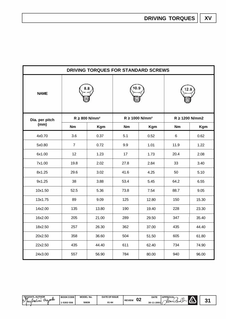
DRIVING TORQUES FOR STANDARD SCREWS
NAME
Dia. per pitch(mm)
R ≥≥≥≥≥ 800 N/mm² R ≥≥≥≥≥ 1000 N/mm² R ≥≥≥≥≥ 1200 N/mm2
Nm Kgm Nm Kgm Nm Kgm
4x0.70
5x0.80
6x1.00
7x1.00
8x1.25
9x1.25
10x1.50
13x1.75
14x2.00
16x2.00
18x2.50
20x2.50
22x2.50
24x3.00
0.62
1.22
2.08
3.40
5.10
6.55
9.05
15.30
23.30
35.40
44.40
61.80
74.90
96.00
0.52
1.01
1.73
2.84
4.25
5.45
7.54
12.80
19.40
29.50
37.00
51.50
62.40
80.00
3.6
7
12
19.8
29.6
38
52.5
89
135
205
257
358
435
557
5.1
9.9
17
27.8
41.6
53.4
73.8
125
190
289
362
504
611
784
6
11.9
20.4
33
50
64.2
88.7
150
228
347
435
605
734
940
0.37
0.72
1.23
2.02
3.02
3.88
5.36
9.09
13.80
21.00
26.30
36.60
44.40
56.90
XVDRIVING TORQUES

BOOK CODE
1-5302-556
MODEL No.
50839
DATE OF ISSUE
01-94REVIEW 02 DATE
30-11-2001
APPROVAL TECO/ATL AUTHOR
32
GENERAL ALPHABETICAL INDEX
Adjustments
Advanced injection
Advanced injection reference on conveyor and
Air filter
Alternator
Battery characteristic curve
Bosch DW(L) starting motor
Bosch JF(L) starting motor
Camshaft
Camshaft axial clearance
Camshaft intake and exhaust cam timing
Camshaft, intake and exhaust cam height
Characteristic curves
Characteristic curves of Bosch JF(L) starting motor
Characteristic curves of Bosch DW(L) starting motor
Clearance volume
Connecting rod equipped with bearings and piston pin
Cylinder and piston
Decompression
Disassembly/reassembly
Distributor side port
Sealant use
Drive shaft
Drive shaft axial clearance
Drive shaft crankshaft bearing/connection rod head
Drive shaft fitting radii
Drive shaft lubrication ducts
Drive shaft main journal and crank dia.
Driving torques
Electric circuit
Electric equipment
Electric starting diagram
Fuel/injection circuit
Flywheel
flywheel protection disk
Fuel filter
Fuel pump
Fuel pump rod projection
Head
Big end bearing connecting rod
Idling adjustment
Injection pump
Injection pump assembly
Injection pump delivery adjustment
Injection pump delivery adjustment with braked engine
Injection pump delivery limiting device
Injector
Injector projection
Lubrication circuit
Main bearing on flywheel side
Main driving torque
Maintenance
Maintenance, prescribed oil, refuellings
Oil filter cartridge
Oil pressure check
Oil pressure curve with engine at its peak rpm
Oil pressure regulating valve
Oil pump
Oil pump, difference between clockwise and anticlockwise rotation
Peak rpm adjustment
Permanent protection
Pin and housing dimensions for camshaft
Preparation for the setting at work
Prescribed oil
Reassembly of piston
Capacities
Registration code and identification
Repairing
Rocker arm pin extraction
Rocker arm Pin/Hole
Rocker arm valve clearance
Piston rings assembly order
Piston rings, distance among ends
Setting
Silencer
Speed governor
Speed governor, timing
Starting pulley
Temporary protection
Timing system
Timing system without considering any reference
Upkeeping
Valve clearance housings
Valve guide clearance dimensions
Valve guide insertion
Valve seat grinding
Valve seat housings
Valves
Vent plug
Voltage regulator
Voltage regulator running check

DATE
30-11-2001
TECO/ATL AUTHOR BOOK CODE
1-5302-556
MODEL No.
50839
DATE OF ISSUE
01-94REVIEW 02
APPROVAL
33
La Lombardini si riserva il diritto di modificare in qualunque momento i dati contenuti in questa pubblicazione.Lombardini se réserve le droit de modifier, à n'importe quel moment, les données reportées dans cettepublication.Data reported in this issue can be modified at any time by Lombardini.Lombardini behält sich alle Rechte vor, die hierin enthaltenen Angaben jederzeit zu ändern.La Lombardini se reserva el derecho de modificar sin previo aviso los datos de esta publicación.
42100 Reggio Emilia, ItalyVia Cav. del Lavoro Adelmo Lombardini,2Casella Postale 1074Tel. (0522) 3891 - Telex: 530003 Motlom ITelegr: Lombarmotor - Telefax (0522) 389465