PUBL-7644 System 450 Modular Electronic Controls Catalog
116
System 450 ™ Modular Electronic Controls Catalog
-
Upload
khangminh22 -
Category
Documents
-
view
3 -
download
0
Transcript of PUBL-7644 System 450 Modular Electronic Controls Catalog

System 450™ Modular Electronic
Controls Catalog

for the latest product updates, visit us online at johnsoncontrols.com
> Building Efficiency
> johnsoncontrols.com
>
> Commercial Refrigeration
> Modular Control Systems

III III
System 450™ Series Modular ControlsSystem 450 is a family of modular, digital electronic controls that is easily assembled and set up to provide reliable temperature, pressure, and humidity control for a wide variety of HVACR applications, commercial process applications, and industrial process applications.
The System 450 control system is designed to replace System 350™ and System 27 control systems, and to provide many additional features and benefits with fewer than twenty model variations.
System 450 control modules provide a field-configurable, out-of-the-box solution. Most System 450 control modules can control temperature, pressure, and humidity systems simultaneously.
A single C450 control module can be set up as a stand-alone control or connected to expansion modules to control up to ten on/off relay and proportional analog outputs, based on any of the three available inputs.
System 450 Control Modules with Communications enable you to connect System 450 control systems to Modbus® or Ethernet networks for remote monitoring and setup. The Modbus communications control module is an RS485, RTU-compliant slave device. The Ethernet communications control module has an integral web server that can deliver web pages through a direct connection, on your LAN, or across the Internet.
System 450 Reset Control Modules provide many of the features of the standard models for temperature and humidity control. In addition, these modules provide setpoint reset, real-time setback scheduling, and runtime balancing (equal runtime) capability.
The System 450 Control Module with Hybrid Analog Output has a single self-selecting analog output to optimize and extend the controlled speed range of variable speed electronically commutated (EC) motors.
System 450 Control System with Control, Power and Expansion Modules

IV
Features and Benefits
Features Benefits
Durable, Compact, Interchangeable Modular Components with Plug-Together Connectors and DIN Rail or Direct Wall-Mount Capability
Eliminate field wiring between modules and allows you to quickly and easily design, assemble, install, and upgrade your control systems.
Versatile, Multipurpose, Field-Configurable Control Modules and Expansion Modules Designed for Global Use
Allow you to create a wide variety of application-specific control systems capable of controlling temperature, pressure, or humidity, or all three conditions simultaneously, with only a smaller suite of module models.
Ethernet Communication Capability through a Built-in Web Server (Ethernet Control Modules Only)
Allows you to monitor your control system status and set up or change the parameters through a direct Ethernet cable connection, through a LAN connection, or over the Internet. The built in web server delivers user-friendly web pages to client browsers on a desktop, laptop, tablet, or smart device.
RS485, RTU Compliant Modbus Network Communication Capability (Modbus Control Modules Only)
Enables a head-end RS485 Modbus master controller to read and write control system status and setup parameters to the System 450 Modbus communication control module.
Up to Three Hard-Wired Input Sensors and Up to Ten Relay or Analog Outputs (In Any Combination) per Control System
Allow you to build complex custom control systems while reducing your control system cost to only the cost of the required components.
Control Modules with Bright Backlit LCDs and Four-Button Touchpad User Interface
Provide quick, clear, visual status of your System 450 control system inputs and outputs with the touch of a button and enable you to quickly and easily set up and adjust your control system.
Multipurpose, All-In-One Control Modules Enable simple, stand-alone, single-module control systems that are temperature, pressure, and humidity capable out of the box and easy to set up in the field to replace a wide variety of OEM HVACR and process controls.
An Extensive Suite of Compatible Temperature and Humidity Sensors, and Pressure Transducers
Allows you to monitor and control a wide range of HVACR and process conditions in a variety of standard and global units of measurement.
High Input Signal Selection Enables your control system to monitor a temperature, pressure, or humidity condition with two or three sensors (of the same type) and control your system outputs based on the highest condition value sensed by the referenced sensors.
Differential Control Enables your control system to monitor and maintain a temperature, pressure, or humidity differential between two sensor points within a system, process, or space.
Web Page Server on Ethernet Communication Modules
Provides a simple, intuitive web interface for easy remote monitoring, setup and adjustment of your control systems across Ethernet networks.
Password Protection for Local Access (Ethernet and Modbus Control Modules Only) and Password Protection for Remote Access (Ethernet Control Module Only)
Deter unauthorized changes to the control system settings, but allow local and remote monitoring of your control system status.
Analog Output Signal Limiting Features (Communication Control Modules Only)
Allow you to select the rate and condition range at which the control updates the analog output signal, potentially reducing wear on the controlled equipment.
Binary Input with Time Delay (Communication Control Modules Only)
Allows you to use an external set of dry contacts and selectable time delays to control relay outputs.
Adjustable Minimum and Maximum Setpoint Temperatures (Reset Control Modules Only)
Enable compliance with the manufacturer’s specifications for your controlled HVACR and process equipment.
Selectable Shutdown-High and Shutdown-Low Temperature Settings (Reset Control Modules Only)
Save you energy by shutting down controlled equipment when the ambient temperature rises or drops to a point where heating or cooling is no longer required.
Real Time Clock and Adjustable Setback Temperature (Reset Control Modules Only)
Save you energy by setting back heating, cooling, or humidity setpoints during scheduled unoccupied periods (24-hour day, 7-day week schedule).
User-Defined Reset Control Capability (Reset Control Modules Only)
Saves you energy in a wide variety of temperature and humidity reset control applications by adjusting the temperature or humidity control loop, based on changes in ambient outdoor temperature or other uncontrolled conditions.

V
OverviewThe System 450 Series is a family of compact digital electronic control, expansion, and power modules that are easily assembled and set up to provide reliable on/off and proportional control of temperature, pressure, and humidity conditions in a wide variety of HVACR applications, commercial process applications, and industrial process applications.
A System 450 Series control system includes:• A single System 450 Control module with LCD and four-button touchpad
• One to three inputs
• One to ten relay and/or analog outputs (provided by the control module and expansion modules)
• An optional power module
Compact Modular Plug-Together DesignAll System 450 modules feature a compact, durable, gray Lexan® housing with DIN rail clips and slotted mounting holes molded into the back of the housing for easy installation.
System 450 modules also feature 6-pin connectors on the sides of the housing, enabling easy assembly and upgrade of your control systems and eliminating the need for field wiring between modules.
A System 450 control system provides compact, clean, and consistent control system assemblies that are simple to build, install, and maintain.
Multipurpose and Field-Configurable DesignSystem 450 control, expansion, and power modules are multipurpose devices that can be easily configured in the field to control temperature, pressure, and humidity, simultaneously.
Global DesignA System 450 control system is the next generation of System 350 and System 27 modular control system, with fewer than twenty model variations, provides far more features and flexibility than either the System 350 modular control system (54 models) or the System 27 modular control system (40 models).
System 450 modules are designed, tested, and certified for global application and are Underwriters® Laboratories, Inc. (UL) Listed and CE Compliant.
System 450 control system can be set up in standard units of measurement used worldwide: Fahrenheit, Celsius, psi, bar, inches water column (in W.C.), and relative humidity (RH).
Control CapabilitiesA System 450 control system offers a variety of control capabilities, depending on the model selected.
Note: See the table on page IX for more information about System 450 control modules with specific features.
Network CommunicationsNetwork communications control modules provide network connectivity and communications. Depending on the System 450 communications control module, it can connect to and communicate over Ethernet networks or Modbus networks. See the table on page IX for more information about the System 450 control modules with this feature.
Ethernet CommunicationsSystem 450 Control Modules with Ethernet Communications have an integral web server that delivers web pages to client browsers on desktop and laptop computers, as well as smart phones, devices, and tablets. The System 450 web UI allows you to monitor your control system status and set up or change the configuration in simple, user-friendly web pages delivered to your computer via a direct connection, connection through a LAN, or over the internet.
System 450 System Overview Page Example
You can monitor control system status and configure the control system parameters in both the local UI (LCD and four-button touch pad) and the web UI.

VI
Overview
System 450 Control modules with Ethernet Communications allow you to:• Directly connect your computer to the System 450 control module with an Ethernet cable, then set up, monitor, and modify your control system.
• Connect your control system to an existing network and establish a static IP address or use a DHCP server to provide a dynamic address.
• Set up a Dynamic DNS and allow you to browse to your System 450 control system on a local network or across the Internet using a text-based URL (host name) instead of a numeric IP address and port number.
The System 450 web UI offers easy remote access to your System 450 controls system across your LAN or across the Internet. The web UI allows you to log in (directly, locally, or remotely) and view the web UI system status, system setup parameters, and parameter values in the UI.
The remote access lock feature, when activated in the web UI, allows users to view the control system status, but not make system changes. The system configuration capability allows you to set up or change all the parameters of your system outputs.
RS485 Modbus CommunicationsThe System 450 Control Module with Modbus® Communications is an RS485, RTU compliant Modbus slave device. It allows you to connect your System 450 control system to Modbus networks and communicate over them.
The System 450 Modbus communication control module also allows your entire control system to respond to data requests and commands from a Modbus master device on the Modbus network.
On/Off Relay Control
Relay outputs provide low-voltage and line-voltage on/off control for devices and equipment in your controlled systems. Each relay output is a single-pole, double-throw (SPDT) set of dry contacts.
Note: System 450 output relays are SPDT dry contact relays only and do not provide any power source for your controlled environment.
See Technical Specifications for output relay electrical rating information. See the table on page IX for more information about the System 450 control modules with this feature.
Analog Proportional ControlAnalog outputs provide proportional analog signals for devices and equipment in your controlled systems. Each analog output can generate either a 4 to 20 mA or 0 to 10 VDC signal. The output signal type is self-selecting; after you connect the analog output to the controlled equipment, it generates the appropriate analog signal for the connected input.
You can set up an analog output to generate a direct acting or reverse acting proportional output signal. You can also set up the output signal strength to increase or decrease in either the direct acting or reverse acting mode. See the example on page V.
An analog output’s control action is automatically determined by the setup values you select for the Setpoint, End Point, % Output at Setpoint, and % Output at Endpoint values when you set up the output in the UI.
An indicator (control ramp) appears on the output status screen for each analog output to represent the analog outputs control action.
Proportional Analog Output Operation for Room Heating (Reverse Acting) Application
See the table on page IX for more information about System 450 control modules with this feature.

VII
Proportional Plus Integral ControlIn addition to standard proportional (only) control analog signals, a System 450 control system provides integral control capability and six-time-integral selections that enable you to set up analog outputs to generate a proportional plus integral signal.
Proportional plus integral (PI) control incorporates a time-integral control action with proportional control action. Therefore, if properly set up, a PI control loop can effectively eliminate offset error and enable a controlled system to drive much closer to the desired setpoint, even under large constant loads. On a properly sized system with predictable loads, PI control can maintain the controlled system very close to setpoint.
The integration constant that you select establishes the rate at which the control readjusts the analog output signal. The faster the integration constant, the faster the control readjusts the output signal, and the faster the recovery rate of a properly sized and setup control loop. See the table on page IX for more information about the System 450 control modules with this feature.
Multi-Stage On/Off and Proportional ControlYou can set up multiple outputs to create a variety of equipment staging control systems. Depending on the control module and expansion modules, a System 450 multi-stage application may use on/off control (relay outputs) or proportional control (analog outputs). See the table on page IX for more information about the System 450 control modules with this feature.
High Input Signal SelectThe High Input Signal Selection feature enables a System 450 control system to monitor a condition (temperature, pressure, or humidity) with two or three sensors (of the same type) and control relay and analog outputs based on the highest condition value sensed. See the table on page IX for more information about the System 450 control modules with this feature.
Differential ControlThe Differential Control feature enables a System 450 control system to monitor and maintain a temperature, pressure, or humidity differential between two sensors of the same type. This feature also enables the control system to control relay outputs, analog outputs, or a combination of relay and analog outputs, based on the sensed differential value relative to user-selected differential values. An example is the water pressure drop across an in-line water filter. See the table on page IX for more information about System 450 control modules with this feature.
Reset ControlSystem 450 Reset Control Modules automatically adjust the setpoint for a supply control loop, based on input from the master (outdoor/ambient) sensor and the user-selected reset setpoint settings. This saves energy by using only the required capacity of the supply to heat, cool, dehumidify, or humidify the desired space or environment.
See the example below of Setpoint Reset Control for both a chilled water temperature reset application and a boiler water temperature reset application. See the table on page IX for more information about the System 450 control modules with this feature.
Reset Setpoint Application for Boiler Water Supply and Chiller Water Supply Showing Relationships between the Reset Setpoint Setup Parameters
Setback SchedulingThe reset control module’s real-time clock allows you to schedule outputs by day of week and time of day. You can also set up setback temperatures (and humidity) to create an occupied/unoccupied setback schedule for the outputs in your control system. You can select a negative setback value for heating or humidification, or a positive setback value for cooling or dehumidification control. See the table on page IX for more information about the System 450 control modules with this feature.

VIII
Overview
Run-Time BalancingThe reset control module’s run-time balancing feature enables your control system to even out the runtimes of staged equipment by automatically selecting the stage with the least runtime when responding to increases in the system load. Run-time balancing allows control of up to four staged outputs. See the table on page IX for more information about the System 450 control modules with this feature.
Analog Output Signal LimitingThe Output Signal Update Rate and Output Deadband features on the control modules with communications are used to reduce the rate at which an analog output updates its output signal strength in response to input signal changes. When controlling a device such as a modulating acutator, these features can reduce the actuator position update frequency, which can lengthen actuator life. See the table on page IX for more information about the System 450 control modules with this feature.
Output Signal Update RateAllows you to select the rate (in seconds) at which an analog output updates the output signal to the controlled equipment.
Output Signal DeadbandAllows you to create a deadband for the analog output signal within which the output signal strength remains constant.
Binary Input Control for Relay OutputsYou can connect a binary input (a user-supplied pair of dry contacts) to any of the three control module input terminals and control the output relays in your control system based on the binary inputs state (open or closed). Examples of dry contacts include door switches, timers, occupancy sensors, and many more switching devices.
A sensor set up as a binary input can be referenced only by a relay output. Analog outputs cannot reference sensors set up as binary inputs.
On/Off Duration Time Control Four time control parameters on the control modules with communications allow you to set up the relay outputs with on or off time delays and minimum on or off times.
Hybrid Analog Output ControlHybrid Analog Output Control, on C450CPW-100* control modules, enables an analog VDC output to transition to a pulse output at low signal levels, providing more efficient low-speed control of variable speed electronically commutated (EC) motors in condenser fan applications.
* NOTE: This model was designed for (but is not limited to) controlling an EC motor. By using temperature, humidity, or pressure sensor inputs, this control can also be used for a wide range of additional applications.

IX
System 450 Control Module Capabilities System 450 Control Modules
Control By:
Standard Communications Reset Hybrid
C450CPN-3 C450CQN-3 C450CBN-3 C450CCN-3
C450CEN- 1 C450CRN- 1
C450RBN- 3 C450RCN- 3 C450CPW- 100
Controlled Condition
Temperature X X X X
Pressure X X - X
Humidity X X X X
Combination of Conditions X X X X
Control Capabilities
On/Off Relay Control X X X X
Analog Proportional Control (Direct and Reverse Action) X X X X
Analog Proportional Plus Integral Control (Direct and Reverse Action) X X X X
Combination of On/Off Relay and Analog Output Control X X X X
Stand-Alone Control X - X X
Multi-Stage Control (Relay or Analog) X X X X
Network Communications - X - -
High Input Signal Selection X X - X
Differential Control X X - X
Output Signal LimitingOutput Signal Update Rate Output Signal Deadband
- X - -
Binary Input Control for Relay Outputs - X - -
On/Off Duration Time Control - X - -
Temperature and Humidity Reset Control - - X -
Scheduling and Temperature Setback Control - - X -
Reset Setpoint Control - - X -
Setback Scheduling - - X -
Run-Time Balancing - - X -
Hybrid Analog Output Control - - - X1
1. Only on output OUTA1

X
System 450 Control Modules
The System 450 control module is the supervisor of your control system and the interface for the systems inputs, supply power, and outputs. The photo below shows an example of an available System 450 control module.
C450CBNStandard Control Module
All System 450 control systems require a control module for setting up the control system’s inputs and outputs, monitoring the control system’s status, and controlling the system’s outputs.
System 450 control modules are capable of monitoring up to three inputs and controlling up to ten outputs that can be any combination of relay and analog outputs (provided by expansion modules).
User-Friendly LCD and Touchpad UISystem 450 control modules feature a backlit LCD screen, which during normal operation displays the real-time status of the sensors that are set up in your control system. The four-button touchpad enables you to quickly scroll through and view the output status screens and access the system setup screens to set up or adjust the sensors and outputs in your control system.
After you assemble and power your control system, and select the Sensor Types in the UI, the control module automatically determines the output numbers and output types. The control module then generates the menu-based setup screens and supplies all of the default setup valves required to set up your custom control system.
System 450 Standard Control ModulesSystem 450 Standard Control Modules can be easily configured out of the box as stand-alone controls, which can provide SPDT control or proportional analog signal control (depending on the model) for a wide range of
HVACR applications, as well as commercial process and industrial process applications. The following modules are available:
• C450CBN-3 control module has one SPDT relay output.
• C450CCN-3 control modules have two SPDT relay outputs.
• C450CPN-3 control modules have one analog output (each 0-10 VDC or 4-20 mA).
• C450CQN-3 control modules have two analog outputs (each 0-10 VDC or 4-20 mA).
With a standard control module and the available sensors and transducers, almost any temperature, pressure, or humidity control you may encounter in the field can be quickly replaced with a System 450 control system. Standard Control Modules provide the capabilities shown in the table on page IX.
System 450 Control Modules with CommunicationsA System 450 control module with communications provides the same types of control as the standard control modules. See System 450 Standard Control Modules. System 450 Control Modules with Communications provide the capabilities shown in the table on page IX.
C450CEN-1 control modules feature and RJ45 Ethernet network port that enables you to connect your control system to an Ethernet network and communicate across it.
C450CRN-1 control modules feature an RS485 terminal block that enables you to connect your control system to an RS485 Modbus network and communicate on it.
Note: System 450 communications control modules do not provide onboard outputs and require expansion modules to provide outputs.
System 450 Reset Control ModulesC450RBN-3 (one SPDT relay output) and C450RCN-3 (two SPDT relay outputs) Reset Control Modules provide many of the features of the standard control modules for temperature and humidity control. In addition, these modules provide temperature and humidity reset, real-time setback, and run-time balancing capability.
Note: Reset Control Modules control temperature and humidity, but not pressure.

XI
System 450 Hybrid Analog Output Control ModulesA System 450 Hybrid Analog Output Control Module can provide the same types of control as the standard controls, while providing a hybrid analog output control option for your application equipment.
The hybrid C450CPW-100 analog output control feature enables an analog VDC output to transition to a pulse output at low signal levels. This provides more efficient low-speed control of electronically commutated (EC) variable speed motors. These EC variable speed motors are typically used in condenser fan applications on a wide variety of refrigeration and HVAC condensing units.
The onboard analog output can also be configured for High Input Signal Selection, which enables precise and efficient EC motor speed control on multi-circuit condensing units.System 450 Hybrid Analog Output Control Modules provide the capabilities shown in the table on page IX.
Other System 450 ComponentsYou can connect up to three inputs (temperature, pressure and humidity) to your System 450 control system, and control up to ten outputs (relay, analog, or a combination of both). This allows you to create a multipurpose control system capable of controlling temperature, pressure, and humidity devices simultaneously.
The System 450 suite of components enables you to build a wide variety of cost-effective, custom control systems that meet your specific application requirements. You do not need to purchase additional and unnecessary features and components associated with packaged control systems, which reduces your control system costs to just the inputs, outputs, and features required by your application.
In addition, a System 450 control system includes:
• One to ten outputs provided by the control module and expansion modules, each output providing either on/off control or a proportional analog signal (0 to 10 VDC or 4 to 20 mA) to the equipment in your controlled system.
• One to three sensors or transducers, which are hard-wired directly to the control module and provide input signals for monitoring and controlling your system equipment.
• An optional power module to provide power to the connected control module and expansion modules.
Expansion Modules
C450SCN Relay Expansion Module
System 450 expansion modules allow you to increase the number of outputs in your control system to meet your application requirements. The following models are available:
• C450SBN-3: Relay Expansion Module with one SPDT relay output
• C450SCN-3: Relay Expansion Module with two SPDT relay outputs
• C450SPN-1: Analog Expansion Module with one analog output
• C450SQN-1: Analog Expansion Module with two analog outputs
System 450 modules require 24 VAC - Class 2 power. In applications where 24 VAC power is not available, the C450YNN-1 Power Module provides a convenient means of transforming 120/240 VAC to 24 VAC to power System 450 modules.
Power Module
C450YNN Power Module

XII
System 450 Compatible Sensors and Transducers
System 450 control modules are designed to operate with a variety of compatible sensors and transducers. The System 450 compatible sensors and transducers cover a wide range of temperature, pressure, and humidity conditions.
System 450 compatible sensors and transducers come in a variety of styles and configurations, allowing you to select the sensor or transducer that best fits your control system requirements.
For ease of installation and setup, the sensor or transducer type selected in the UI automatically determines the sensed condition, unit of measurement, minimum differential, setup value ranges, and the default setup values for each control system output that references the sensor or transducer.
For additional information about these sensors, see the technical documents in QuickLIT at cgproducts.johnsoncontrols.com
Sensor Options
P499 Ratiometric Transducer
HE-67S3 Humidity Sensor
TE-6800 Temperature Sensors
A99 Temperature Sensor
TE-6300 Temperature Sensors
DPT2650 Low Pressure Differential Transducer
TE-6000-1 Temperature Sensing Element

XIII
System 450 Compatible Sensors and Transducers System 450 Modular Electronic Controls Family
Single Relay Control Module
C450CBN-3
Dual Relay Control Module
C450CCN-3
Analog Output Module
C450CPN-3
Dual Analog Output Module
C450CQN-3
Single Relay Expansion Module
C450SBN-3
Dual Relay Expansion Module
C450SCN-3
Analog Output Expansion Module
C450SPN-1
Dual Analog Expansion Module
C450SQN-1
Single Relay Reset Module
C450RBN-3
Dual Relay Reset Module
C450RCN-3
Hybrid Analog Output and High Input Signal Select
C450CPW-100
Ethernet Communications Module
C450CEN-1
RS485 Modbus RTU Communications Module
C450CRN-1
Power Module
C450YNN-1


BUILDING EFFICIENCY
System 450 Catalog
System 450 Control Series . . . . . . . . . . . . . . . . . . . . . . . . . . . . . . . . . . . . . . . . SYS-7
Boiler Application Notes . . . . . . . . . . . . . . . . . . . . . . . . . . . . . . . . . . . . . . . . . SYS-38
Chiller Application Notes . . . . . . . . . . . . . . . . . . . . . . . . . . . . . . . . . . . . . . . . SYS-43
Condenser Rack Application Notes . . . . . . . . . . . . . . . . . . . . . . . . . . . . . . . . SYS-48
Cooling Tower Application Notes . . . . . . . . . . . . . . . . . . . . . . . . . . . . . . . . . . SYS-61
Differential Pressure Application Notes . . . . . . . . . . . . . . . . . . . . . . . . . . . . . SYS-66
Equal Runtime Application Notes . . . . . . . . . . . . . . . . . . . . . . . . . . . . . . . . . . SYS-68
Greenhouse/Humidor/Wine Cellar Application Notes . . . . . . . . . . . . . . . . . . . SYS-70
Refrigeration Application Notes . . . . . . . . . . . . . . . . . . . . . . . . . . . . . . . . . . . SYS-85
Solar Collector Application Notes . . . . . . . . . . . . . . . . . . . . . . . . . . . . . . . . . . SYS-89
Additional Application Notes . . . . . . . . . . . . . . . . . . . . . . . . . . . . . . . . . . . . . . SYS-91
SYS-1

SYS-2

Table of Contents: Catalog Pages
System 450 Control Series . . . . . . . . . . . . . . . . . . . . . . . . . . . . . . . . . . . . . . . SYS-7
System 450™ Series Modular Controls . . . . . . . . . . . . . . . . . . . . . . . . . . . . . . . . . . . . . . . . . . SYS-7
System 450™ Series Control Module with Network Communications . . . . . . . . . . . . . . . . . . SYS-18
System 450™ Reset Control Modules with Real-Time Clock and Relay Output . . . . . . . . . . SYS-21
System 450™ Control Modules with Analog Output . . . . . . . . . . . . . . . . . . . . . . . . . . . . . . . . SYS-23
System 450™ Control Modules with Relay Output . . . . . . . . . . . . . . . . . . . . . . . . . . . . . . . . . SYS-25
System 450™ Control Module with Hybrid Analog Output . . . . . . . . . . . . . . . . . . . . . . . . . . . SYS-27
System 450™ Expansion Modules with Analog Output . . . . . . . . . . . . . . . . . . . . . . . . . . . . . SYS-29
System 450™ Expansion Modules with Relay Output . . . . . . . . . . . . . . . . . . . . . . . . . . . . . . SYS-31
System 450™ Power Module . . . . . . . . . . . . . . . . . . . . . . . . . . . . . . . . . . . . . . . . . . . . . . . . . SYS-33
System 450™ Compatible Sensors, Transducers, and Accessories . . . . . . . . . . . . . . . . . . . SYS-34
SYS-3

Table of Contents: Application Notes
Boiler Application Notes . . . . . . . . . . . . . . . . . . . . . . . . . . . . . . . . . . . . . . . .SYS-38
Hot Water Supply Loop Reset . . . . . . . . . . . . . . . . . . . . . . . . . . . . . . . . . . . . . . . . . . . . . . . . SYS-38
Chiller Application Notes. . . . . . . . . . . . . . . . . . . . . . . . . . . . . . . . . . . . . . . .SYS-43
Chilled Water Supply Loop Reset Using an Actuated Mixing Valve . . . . . . . . . . . . . . . . . . . . SYS-43
Condenser Rack Application Notes . . . . . . . . . . . . . . . . . . . . . . . . . . . . . . .SYS-48
Controlling Head Pressure on a Two-Circuit Condenser with High Input Signal Select . . . . . SYS-48
Small Refrigeration Rack Controller with Communications . . . . . . . . . . . . . . . . . . . . . . . . . . SYS-51
Ten-Stage Rack Controller with Ethernet Communications . . . . . . . . . . . . . . . . . . . . . . . . . . SYS-54
Small Refrigeration Rack Controller with Ethernet Communication . . . . . . . . . . . . . . . . . . . . SYS-58
Cooling Tower Application Notes . . . . . . . . . . . . . . . . . . . . . . . . . . . . . . . . .SYS-61
Cooling Tower Control with Two-Speed Fan/Low Temperature Lockout . . . . . . . . . . . . . . . . SYS-61
Two-Speed Fan Motor Control Using Any Compatible Pressure, Humidity, or Temperature Sensor . . . . . . . . . . . . . . . . . . . . . . . . . . . . . . . . . . . . . . . . . . . . . . . . . . SYS-64
Differential Pressure Application Notes. . . . . . . . . . . . . . . . . . . . . . . . . . . .SYS-66
Differential Control to Replace a Standard Differential Pressure Transmitter . . . . . . . . . . . . . SYS-66
Equal Runtime Application Notes. . . . . . . . . . . . . . . . . . . . . . . . . . . . . . . . .SYS-68
Attaining Equal Runtimes on Redundant Mechanical Systems . . . . . . . . . . . . . . . . . . . . . . . SYS-68
Greenhouse/Humidor/Wine Cellar Application Notes. . . . . . . . . . . . . . . . .SYS-70
A99 and TE-6000 Temperature Sensor Averaging . . . . . . . . . . . . . . . . . . . . . . . . . . . . . . . . . SYS-70
Proportional Temperature Control of M9200 Series Actuators with Remote Minimum Positioning . . . . . . . . . . . . . . . . . . . . . . . . . . . . . . . . . . . . . . . . . . SYS-72
Room Temperature, Humidity, and Static Pressure Control System with Communications . . SYS-74
Heating and Cooling Control with System Status Indication . . . . . . . . . . . . . . . . . . . . . . . . . . SYS-78
Proportional Temperature, Pressure, or Humidity Control of an M9100-GGA or M9100-GGC Actuator . . . . . . . . . . . . . . . . . . . . . . . . . . . . . . . . . . . . . . . . . . . . . . . . . . SYS-80
Proportional Control of a Barber-Colman® MMR-400 Actuator . . . . . . . . . . . . . . . . . . . . . . . SYS-83
Refrigeration Application Notes . . . . . . . . . . . . . . . . . . . . . . . . . . . . . . . . . .SYS-85
Two-Stage Cooling Application with Remote Communications Featuring On Delay Time and Analog Output Limiter Control . . . . . . . . . . . . . . . . . . . . . . . . . . . . . . . . . . . . . . . . . . SYS-85
Solar Collector Application Notes . . . . . . . . . . . . . . . . . . . . . . . . . . . . . . . .SYS-89
Solar Heating Control Applications with Differential Temperature Control . . . . . . . . . . . . . . . SYS-89
Additional Application Notes . . . . . . . . . . . . . . . . . . . . . . . . . . . . . . . . . . . .SYS-91
Floating Control System Powered by an External Transformer to Control an Actuator . . . . . SYS-91
Head Pressure Control - Water Source Heat Pump with Analog Output Limiter Control . . . . SYS-93
Extending A99 Sensor Cables . . . . . . . . . . . . . . . . . . . . . . . . . . . . . . . . . . . . . . . . . . . . . . . . SYS-97
SYS-4

Code Number Index
A
A99BA-200C . . . . . . . . . . . . . .SYS-10, SYS-35A99BB-200C . . . . . . . . . . . . . .SYS-10, SYS-35A99BB-25C . . . . . . . . . . . . . . .SYS-10, SYS-35A99BB-300C . . . . . . . . . . . . . .SYS-10, SYS-35A99BB-500C . . . . . . . . . . . . . .SYS-10, SYS-35A99BB-600C . . . . . . . . . . . . . .SYS-10, SYS-35A99BC-1500C . . . . . . . . . . . . .SYS-10, SYS-35A99BC-25C . . . . . . . . . . . . . . .SYS-10, SYS-35A99BC-300C . . . . . . . . . . . . . .SYS-10, SYS-35A99-CLP-1 . . . . . . . . . . . . . . .SYS-11, SYS-35ADP11A-600R . . . . . . . . . . . .SYS-11, SYS-35
B
BKT287-1R . . . . . . . SYS-10, SYS-19, SYS-22, . . . . . . . . . . . . . . . SYS-23, SYS-25, SYS-28, . . . . . . . . . . . . . . .SYS-29, SYS-31, SYS-33
BKT287-2R . . . . . . . SYS-10, SYS-19, SYS-22, . . . . . . . . . . . . . . SYS-23, SYS-25, SYS-28, . . . . . . . . . . . . . . .SYS-29, SYS-31, SYS-33
BKT287-3R . . . . . . . SYS-10, SYS-19, SYS-22, . . . . . . . . . . . . . . SYS-23, SYS-25, SYS-28, . . . . . . . . . . . . . . .SYS-29, SYS-31, SYS-33
BKT287-4R . . . . . . . SYS-10, SYS-19, SYS-22, . . . . . . . . . . . . . . SYS-23, SYS-25, SYS-28, . . . . . . . . . . . . . . .SYS-29, SYS-31, SYS-33
BOX10A-600R . . . . . . . . . . . .SYS-10, SYS-35
C
C450CBN-3C . . . . . . . . . . . . .SYS-10, SYS-25C450CCN-3C . . . . . . . . . . . . .SYS-10, SYS-25C450CEN-1C . . . . . . . . . . . . .SYS-10, SYS-19C450CPN-3C . . . . . . . . . . . . .SYS-10, SYS-23C450CPW-100C . . . . . . . . . . .SYS-10, SYS-28C450CQN-3C . . . . . . . . . . . . .SYS-10, SYS-23C450CRN-1C . . . . . . . . . . . . .SYS-10, SYS-19C450RBN-3C . . . . . . . . . . . . .SYS-10, SYS-22C450RCN-3C . . . . . . . . . . . . .SYS-10, SYS-22C450SBN-3C . . . . . . . . . . . . .SYS-10, SYS-31C450SCN-3C . . . . . . . . . . . . .SYS-10, SYS-31C450SPN-1C . . . . . . . . . . . . .SYS-10, SYS-29C450SQN-1C . . . . . . . . . . . . .SYS-10, SYS-29C450YNN-1C . . . . . . . . . . . . .SYS-10, SYS-33
D
DPT2650-005D-AB . . . . . . . . SYS-11, SYS-36DPT2650-0R5D-AB . . . . . . . . SYS-11, SYS-36DPT2650-10D-AB . . . . . . . . . SYS-11, SYS-36DPT2650-2R5D-AB . . . . . . . . SYS-11, SYS-36DPT2650-R25B-AB . . . . . . . . SYS-11, SYS-36
H
HE-67S3-0N00P . . . . . . . . . . . SYS-11, SYS-36HE-67S3-0N0BT . . . . . . . . . . SYS-11, SYS-36HE-68N2-0N00WS . . . . . . . . . SYS-11, SYS-36HE-68N3-0N00WS . . . . . . . . . SYS-11, SYS-36
P
P499RAP-101C . . . . . . . . . . . SYS-12, SYS-37P499RAP-101K . . . . . . . . . . . SYS-12, SYS-37P499RAP-102C . . . . . . . . . . . SYS-12, SYS-37P499RAP-105C . . . . . . . . . . . SYS-12, SYS-37P499RAP-105K . . . . . . . . . . . SYS-12, SYS-37P499RAP-107C . . . . . . . . . . . SYS-12, SYS-37P499RAP-107K . . . . . . . . . . . SYS-12, SYS-37P499RAPS100C . . . . . . . . . . . SYS-12, SYS-37P499RAPS100K . . . . . . . . . . . SYS-12, SYS-37P499RAPS102C . . . . . . . . . . . SYS-12, SYS-37P499RAPS102K . . . . . . . . . . . SYS-12, SYS-37P499RCP-101C . . . . . . . . . . . SYS-12, SYS-36P499RCP-101K . . . . . . . . . . . SYS-12, SYS-36P499RCP-105C . . . . . . . . . . . SYS-12, SYS-36P499RCP-105K . . . . . . . . . . . SYS-12, SYS-36P499RCP-107C . . . . . . . . . . . SYS-12, SYS-36P499RCP-107K . . . . . . . . . . . SYS-12, SYS-36P499RCP-401C . . . . . . . . . . . SYS-12, SYS-36P499RCP-402C . . . . . . . . . . . SYS-12, SYS-36P499RCP-404C . . . . . . . . . . . SYS-12, SYS-36P499RCP-405C . . . . . . . . . . . SYS-12, SYS-36P499RCPS100C . . . . . . . . . . SYS-12, SYS-36P499RCPS100K . . . . . . . . . . . SYS-12, SYS-36P499RCPS102C . . . . . . . . . . SYS-12, SYS-36P499RCPS102K . . . . . . . . . . . SYS-12, SYS-36PLT344-1R . . . . . . . SYS-10, SYS-19, SYS-22,
. . . . . . . . . . . . . . SYS-23, SYS-25, SYS-28, . . . . . . . . . . . . . . . SYS-29, SYS-31, SYS-33
Note: Page numbers in italics denote pages where the product code number appears, but not as the main part.
SYS-5

Code Number Index
S
SHL10A-603R . . . . . . . . . . . . .SYS-11, SYS-35
T
TE-6000-x . . . . . . . . . . . . . . . .SYS-11, SYS-35TE-6001-1 . . . . . . . . . . . . . . . .SYS-11, SYS-35TE-6001-11 . . . . . . . . . . . . . . .SYS-11, SYS-35TE-631xx-x . . . . . . . . . . . . . . .SYS-11, SYS-35TE-68NT-0N00S . . . . . . . . . . .SYS-11, SYS-36
W
WEL11A-601R . . . . . . . . . . . . SYS-11, SYS-35WHA-C450-100C . . SYS-10, SYS-19, SYS-22,
. . . . . . . . . . . . . . SYS-23, SYS-25, SYS-28, . . . . . . . . . . . . . . . SYS-29, SYS-31, SYS-33
WHA-PKD3-200C . . . . . . . . . . SYS-12, SYS-37WHA-PKD3-400C . . . . . . . . . . SYS-12, SYS-37WHA-PKD3-600C . . . . . . . . . . SYS-12, SYS-37
Note: Page numbers in italics denote pages where the product code number appears, but not as the main part.
SYS-6

ode No. LIT-1900549
System 450 Control System with a Control, Power, and Expansion Module
DescriptionSystem 450™ is a family of modular, digital electronic controls that is easily assembled and set up to provide reliable temperature, pressure, and humidity control for a wide variety of HVACR applications, commercial process applications, and industrial process applications.
The System 450 control system is designed to replace System 350™ and System 27 control systems, and to provide many additional features and benefits with fewer than twenty model variations.
System 450 control modules provide a field-configurable out-of-the-box solution. Most System 450 control modules can control temperature, pressure, and humidity systems simultaneously.
System 450 Control Modules with Communications enable you to connect System 450 control systems to Modbus® or Ethernet networks for remote monitoring and setup. The Modbus communications control module is an RS485, RTU-compliant slave device. The Ethernet communications control module has an integral web server that can deliver web pages by means of a direct connection, on your LAN, or across the Internet.
System 450 Reset Control Modules provide many of the features of the standard models for temperature and humidity control. In addition, these modules provide setpoint reset, real-time setback scheduling, and run-time balancing (equal run time) capability.
The System 450 Control Module with Hybrid Analog Output has a single self-selecting analog output to optimize and extend the controlled speed range of variable speed electronically commutated (EC) motors.
Refer to the following documents for important product application information.
• System 450™ Series Modular Controls Product Bulletin (LIT-12011458)
• System 450™ Series Modular Control Systems with Standard Control Modules Technical Bulletin (LIT-12011459)
• System 450™ Series Modular Control Systems with Reset Control Modules Technical Bulletin (LIT-12011842)
• System 450™ Series Modular Control Systems with Communications Control Modules Technical Bulletin (LIT-12011826)
Features• Durable, compact, interchangeable modular components with
plug-together connectors and DIN rail or direct wall mount capability eliminate field wiring between modules and allow you to quickly and easily design, assemble, install, and upgrade your control systems.
• Versatile, multipurpose, field-configurable control modules and expansion modules designed for global use allow you to create a wide variety of application-specific control systems capable of controlling temperature, pressure, or humidity, or all three conditions simultaneously, with only a small suite of module models.
• Up to three hard-wired input sensors and up to ten relay or analog outputs (in any combination) per control system allow you to build complex custom control systems while reducing your control system cost to only the cost of the required components.
• Control Modules with bright backlit LCDs and four-button touch pad user interfaces provide quick, clear, visual status of your System 450 control system inputs and outputs with the touch of a button and enable you to quickly and easily set up and adjust your control system.
•
•
•
•
T
•
•
•
•
The performance specifications are nominal and conform to acceptable industry standards. ForJohnson Controls, Inc. shall not be liable for damages resulting from misapplication or misuse
SYS
Multipurpose, all-in-one control modules enable simple stand-alone, single-module control systems that are temperature, pressure, and humidity capable out of the box and easy to set up in the field to replace a wide variety of OEM HVACR and process controls.An extensive suite of compatible temperature and humidity sensors, and pressure transducers allows you to monitor and control a wide range of HVACR and process conditions in a variety of standard and global units of measurement.High input signal selection enables your control system to monitor a temperature, pressure, or humidity condition with two or three sensors (of the same type) and control your system outputs based on the highest condition value sensed by the referenced sensors.Differential control enables your control system to monitor and maintain a temperature, pressure, or humidity differential between two sensor points within a system, process, or space.
he Reset Control modules have additional features:
Adjustable minimum and maximum setpoint temperatures (reset control modules only) enable compliance with the manufacturer’s specifications for your controlled HVACR and process equipment.Selectable shutdown-high and shutdown-low temperature settings (reset control modules only) saves you energy by shutting down controlled equipment when the ambient temperature either rises or drops to a point where heating or cooling is no longer required.Real time clock and adjustable setback temperature (reset control modules only) save you energy by setting back heating, cooling, or humidity setpoints during scheduled unoccupied periods (24-hour day, 7-day week schedule).User-defined reset control capability (reset control modules only) saves you energy in a wide variety of temperature and humidity reset control applications by adjusting the temperature or humidity control loop, based on changes in ambient outdoor temperature or other uncontrolled condition.
CSystem 450 Control Series
System 450™ Series Modular Controls
applications at conditions beyond these specifications, consult the local Johnson Controls office.of its products. © 2015 Johnson Controls, Inc. www.johnsoncontrols.com
–7

System 450™ Series Modular Controls (Continued)
System 450 Control Series
The Control Modules with Communications have additional features:
• Ethernet communication capability through a built-in web server (Ethernet Control Modules only) allows you to monitor your control system status and set up or change the parameters by means of a direct Ethernet cable connection, through a LAN connection, or over the Internet. The built in web server delivers user-friendly web pages to client browsers on a desktop, laptop, tablet, or smart device.
• The Web page server on Ethernet communication modules provides a simple, intuitive web interface for easy remote monitoring, setup, adjustment and remote monitoring of your control systems across Ethernet networks.
• RS485, RTU-compliant Modbus® network communication capability (Modbus control modules only) enables a head-end RS485 Modbus master controller to read and write control system status and setup parameters to the System 450 Modbus communication control module.
• Password protection for local access (Ethernet and Modbus control modules only) and password protection for remote access (Ethernet control module only) deters unauthorized changes to the control system settings, but allows local and remote monitoring of your control system status.
• Analog output signal limiting features (communication control modules only) allow you to select the rate and condition range at which the control updates the analog output signal, potentially reducing wear on the controlled equipment.
• Binary input with time delay (communication control modules only) allows you to use an external set of dry contacts and selectable time delays to control relay outputs.
ApplicationsYou can create a wide variety of custom, application-specific control systems with System 450 modules. The following are some common control application examples:
• Temperature control• Pressure control• Humidity control• Multipurpose control• Reset and setback control• High input-signal selection• Differential control
Temperature Control• Temperature monitoring and alarming• On/Off staged control of boilers and chillers• Proportional stage control of boilers and chillers• Boiler and chiller pump control• Heating and cooling control with deadband• Floating temperature control of damper and valve actuators• Cooling tower fan speed/stage control based on water
temperature• Supply, make-up, and mixed air temperature control• Temperature actuated valve control• Supply and make-up air damper and fan control• Condenser fan staging or speed control based on condenser
temperature
Refrigerant Pressure Control• Condenser fan cycling and stage control• Multispeed condenser fan control• Floating pressure control of damper and valve actuators
The performance specifications are nominal and conform to acceptable industry standards. For Johnson Controls, Inc. shall not be liable for damages resulting from misapplication or misuse o
SYS–
• Condenser fan speed and damper control• High and low pressure cutout control• Staged compressor control • Cooling tower fan speed control based on high-side pressure• Direct speed control of electronically commutated (EC) condenser
fan motors (C450CPW-100 model)
Other Pressure Control• Relief damper and fan control for building pressurization• Constant static pressure control
Humidity Control• On/Off humidification and dehumidification control• Proportional humidification and dehumidification control• Multistage humidification and dehumidification control• Humidity monitoring and alarming
Multipurpose Control• Temperature and pressure based refrigeration rack control• Temperature and humidity control of wine cellars and greenhouses• Temperature, humidity, and static pressure control of clean rooms
and greenhouses• Dehumidification with reheat control
Reset Control• Boiler supply water temperature reset control based on outside air
temperature• Chiller supply water temperature reset control based on outside air
temperature• VAV zone temperature control based on outside air temperature• Humidity reset based on outside air temperature• Staged applications with runtime balancing• Real-time Occupied/Unoccupied Setback
High Input Signal Selection• Pressure-based fan speed or fan cycling control on multi-circuit
condensers• Temperature-based fan speed or fan cycling control on
multi-circuit condensers
Differential Control• Air and fluid pump-flow monitoring and alarming• Air and fluid filter status monitoring and alarming• Chiller barrel flow monitoring, control, and alarming• Solar air and water heating applications
Note: Communications modules add network communication to any application of your choosing, except those requiring reset, setback, or EC motor control.
Repair InformationIf a System 450 module fails to operate within its specifications, replace the module. For a replacement module, contact your Johnson Controls® representative.
applications at conditions beyond these specifications, consult the local Johnson Controls office.f its products. © 2015 Johnson Controls, Inc. www.johnsoncontrols.com
8

System 450™ Series Modular Controls (Continued)
System 450 Control Series
System 450 Control Module CapabilitiesControl by ________ System 450 Control Modules
Standard Communications Reset Hybrid
C450CPN-3CC450CQN-3CC450CBN-3CC450CCN-3C
C450CEN-1CC450CRN-1C
C450RBN-3CC450RCN-3C
C450CPW-100C
Controlled Condition
Temperature X X X X
Pressure X X - X
Humidity X X X X
Combination of Conditions X X X X
Control Capabilities
On/Off Relay Control X X X X
Analog Proportional Control(Direct and Reverse Action)
X X X X
Analog Proportional Plus Integral Control (Direct and Reverse Action)
X X X X
Combination of On/Off Relay and Analog Output Control
X X X X
Stand-Alone Control X - X X
Multi-Stage Control (Relay or Analog)
X X X X
Network Communications - X - -
High Input Signal Selection X X - X
Differential Control X X - X
Output Signal Limiting Output Signal Update Rate Output Signal Deadband
- X - -
Binary Input Control for Relay Outputs
- X - -
On/Off Duration Time Control - X - -
Temperature and Humidity Reset Control - - X -
Scheduling and Temperature Setback Control - - X -
Reset Setpoint Control - - X -
Setback Scheduling - - X -
Run-Time Balancing - - X -
Hybrid Analog Output Control - - - X1
1. Only on output OUTA1.
The performance specifications are nominal and conform to acceptable industry standards. For applications at conditions beyond these specifications, consult the local Johnson Controls office.Johnson Controls, Inc. shall not be liable for damages resulting from misapplication or misuse of its products. © 2015 Johnson Controls, Inc. www.johnsoncontrols.com
SYS–9

System 450™ Series Modular Controls (Continued)
System 450 Control Series
Selection Charts System 450 Modules and Accessories Ordering InformationProduct Code Number
Product Description
C450CBN-3C Standard Control Module with LCD, Four-Button Touchpad UI, and Relay Output; provides one relay output (SPDT line-voltage relay) for SPDT control.
C450CCN-3C Standard Control Module with LCD, Four-Button Touchpad UI, and Relay Output; provides two relay outputs (SPDT line-voltage relays) for SPDT control.
C450CEN-1C Control Module with Ethernet Communications, LCD, and Four-Button Touchpad UI. (No onboard outputs available on control modules with network communications capabilities.)
C450CPN-3C Standard Control Module with LCD, Four-Button Touchpad UI, and Analog Output; provides one analog output (0–10 VDC or 4–20 mA self-selecting signal) for proportional control.
C450CPW-100C Hybrid Analog Output Control Module with LCD, Four-Button Touchpad UI, Hybrid Analog Output and Optional High Input Signal Select; provides one hybrid analog output and optional high input signal select primarily used for variable-speed EC motor speed control.Only Analog Output 1 (OUTA1) can be configured as a hybrid analog output and/or use the High Input Signal Selection feature. These features are not available for any of the other outputs in a System 450 control system that uses the C450CPW-100C as the control module.
C450CQN-3C Standard Control Module with LCD and Four-Button Touchpad UI, and Analog Output; provides two analog outputs (0–10 VDC or 4–20 mA self-selecting signals) for proportional control.
C450CRN-1C Control Module with RS485 Modbus Communications, LCD, and Four-Button Touchpad UI. (No onboard outputs available on control modules with network communications capabilities.)
C450RBN-3C Reset Control Module with LCD, Four-Button Touchpad UI, and SPDT relay output; provides one SPDT output relay. One A99BC-25C temperature sensor with 0.25 m (9-1/4 in.) silicon leads and one A99BC-300C temperature sensor with 3 m (9 ft 10 in.) silicon leads are included in the box with the Reset Control Module.
C450RCN-3C Reset Control Module with LCD, Four-Button Touchpad UI, and SPDT relay output; provides two SPDT output relays. One A99BC-25C temperature sensor with 0.25 m (9-1/4 in.) silicon leads and one A99BC-300C temperature sensor with 3 m (9 ft 10 in.) silicon leads are included in the box with the Reset Control Module.
C450SBN-3C Relay Output Expansion Module; provides one SPDT line-voltage relay output.
C450SCN-3C Relay Output Expansion Module; provides two SPDT line-voltage relay outputs.
C450SPN-1C Analog Output Expansion Module; provides one analog output (0–10 VDC or 4–20 mA self-selecting signal) for proportional control.
C450SQN-1C Analog Output Expansion Module; provides two analog outputs (0–10 VDC or 4–20 mA self-selecting signals) for proportional control.
C450YNN-1C Power Module; provides 24 V to System 450 Module Assembly; 120 VAC or 240 VAC supply power input terminals.
BKT287-1R DIN Rail; 0.30 m (12 in.) long
BKT287-2R DIN Rail; 1 m (39-1/3 in.) long
BKT287-3R DIN Rail; 0.61 m (24 in.) long
BKT287-4R DIN Rail; 0.36 m (14 in.) long
PLT344-1R DIN Rail End Clamps (2 clamps)
WHA-C450-100C System 450 module connection extension cable, 100 cm (3.3 ft) long
System 450 Compatible A99B Temperature Sensors and Accessories Ordering Information1 (Part 1 of 2)Product Code Number
Product Description
A99BA-200C PTC Silicon Sensor with Shielded Cable; Cable Length 2 m (6-1/2 ft); Sensor Temperature Range: -40 to 120°C (-40 to 250°F)Cable Jacket Temperature Range: -40 to 100°C (-40 to 212°F)
A99BB-25C PTC Silicon Sensor with PVC Cable; Cable Length 0.25 m (9-3/4 in.); Sensor Temperature Range: -40 to 120°C (-40 to 250°F)Cable Jacket Temperature Range: -40 to 100°C (-40 to 212°F)
A99BB-200C PTC Silicon Sensor with PVC Cable; Cable Length 2 m (6-1/2 ft); Sensor Temperature Range: -40 to 120°C (-40 to 250°F)Cable Jacket Temperature Range: -40 to 100°C (-40 to 212°F)
A99BB-300C PTC Silicon Sensor with PVC Cable; Cable Length 3 m (9-3/4 ft); Sensor Temperature Range: -40 to 120°C (-40 to 250°F)Cable Jacket Temperature Range: -40 to 100°C (-40 to 212°F)
A99BB-500C PTC Silicon Sensor with PVC Cable; Cable Length 5 m (16-3/8 ft); Sensor Temperature Range: -40 to 120°C (-40 to 250°F)Cable Jacket Temperature Range: -40 to 100°C (-40 to 212°F)
A99BB-600C PTC Silicon Sensor with PVC Cable; Cable Length 6 m (19-1/2 ft); Sensor Temperature Range: -40 to 120°C (-40 to 250°F)Cable Jacket Temperature Range: -40 to 100°C (-40 to 212°F)
A99BC-25C PTC Silicon Sensor with High Temperature Silicon Cable; Cable Length 0.25 m (9-3/4 in.); Sensor Temperature Range: -40 to 120°C (-40 to 250°F) Cable Jacket Rated for Full Sensor Temperature Range.
A99BC-300C PTC Silicon Sensor with High Temperature Silicon Cable; Cable Length 3 m (9-3/4 ft)Sensor Temperature Range: -40 to 120°C (-40 to 250°F)Cable Jacket Rated for Full Sensor Temperature Range.
A99BC-1500C PTC Silicon Sensor with High Temperature Silicon Cable; Cable Length 15 m (49 ft)Sensor Temperature Range: -40 to 120°C (-40 to 250°F)Cable Jacket Rated for Full Sensor Temperature Range.
BOX10A-600R PVC Enclosure for A99 Sensor; Includes Wire Nuts and Conduit Connector (for Outdoor Sensor)
The performance specifications are nominal and conform to acceptable industry standards. For applications at conditions beyond these specifications, consult the local Johnson Controls office.Johnson Controls, Inc. shall not be liable for damages resulting from misapplication or misuse of its products. © 2015 Johnson Controls, Inc. www.johnsoncontrols.com
SYS–10

System 450™ Series Modular Controls (Continued)
System 450 Control Series
WEL11A-601R Immersion Well for A99 Sensor Liquid Sensing Applications
A99-CLP-1 Mounting Clip for A99 Temperature Sensor
ADP11A-600R Conduit Adaptor, 1/2 in. Snap-Fit EMT Conduit Adaptor (box of 10)
TE-6001-1 Duct Mounting Hardware with Handy Box for A99 Sensor
TE-6001-11 Duct Mounting Hardware without Handy Box for A99 Sensor
SHL10A-603R Sun Shield (for Use with Outside A99 Sensors in Sunny Locations)
1. Refer to the A99B Series Temperature Sensors Product/Technical Bulletin (LIT-125186) on the Johnson Controls® Product Literature website for more information.
System 450 Compatible TE-6000 Series 1,000 Ohm Nickel Temperature Sensors and Accessories Ordering InformationProduct Code Number
Product Description
TE-6000-x TE6000 Series 1,000 ohm at 70F nickel temperature sensors (only). Only the TE-6000-6 sensor can be used for the entire HIC and HIF temperature range. Different sensing element packages are available for various applications. For a complete list of compatible 1,000 ohm nickel sensors, including sensor descriptions, technical specifications, and mounting accessories, refer to the TE-6000 Series Temperature Sensing Elements Product Bulletin (LIT-216288). (System 450 Sensor Types HIC and HIF)
System 450 Compatible TE-6300 Series 1,000 Ohm Nickel Temperature Sensors and Accessories Ordering InformationProduct Code Number
Product Description
TE-631xx-x TE6300 Series 1,000 ohm at 70F nickel averaging and 1,000 ohm thin-film nickel temperature sensors (only). For a complete list of compatible 1,000 ohm nickel averaging and thin-film nickel sensors, including sensor descriptions, technical specifications, and mounting accessories, refer to the TE-6300 Series Temperature Sensors Product Bulletin (LIT-216320). (System 450 Sensor Types HIC and HIF)
System 450 Compatible TE-68NT-0N00S 1,000 Ohm Nickel Temperature Sensor Ordering InformationProduct Code Number
Product Description
TE-68NT-0N00S TE6800 Series 1,000 ohm nickel temperature sensor for wall-mount applications. For more information, including sensor description, technical specifications, and mounting accessories, refer to the TE-6800 Series Temperature Sensors Product Bulletin (LIT-12011542). (System 450 Sensor Types HIC and HIF)
System 450 Compatible HE67S3 Type Humidity Sensors with Integral A99B Temperature Sensor Ordering Information1
Product Code Number
Product Description
HE-67S3-0N0BT Wall Mount Humidity Sensor with A99B Type Temperature Sensor: 10 to 90% RH; 0 to 60C (32 to 140F)
HE-67S3-0N00P Duct Mount Humidity Sensor with A99B Type Temperature Sensor: 10 to 90% RH; 0 to 60C (32 to 140F)
1. The HE-67S3 sensors require 24 VAC input and must use the 0–5 VDC output. Refer to the TrueRH Series HE-67xx Humidity Element with Temperature Sensors Product Bulletin (LIT-216245) on the Johnson Controls Product Literature website for more information, including technical specifications and mounting accessories.
System 450 Compatible HE6800 Series Humidity Transmitters with Temperature Sensor Ordering Information1
Product Code Number
Product Description
HE-68N2-0N00WS Wall Mount Humidity Transmitter with Nickel Temperature Sensor: 10 to 90 ±2% RH; 0 to 55C (32 to 131F)
HE-68N3-0N00WS Wall Mount Humidity Transmitter with Nickel Temperature Sensor: 10 to 90 ±3% RH; 0 to 55C (32 to 131F)
1. The HE-6800 transmitters require 24 VAC input and must use the 0–5 VDC output. Refer to the HE-6800 Series Humidity Transmitters with Temperature Sensor Product Bulletin (LIT-12011625) on the Johnson Controls Product Literature website for more information, including technical specifications and mounting accessories.
System 450 Compatible Low Pressure Differential Transducer Ordering Information1 2
Product Code Number
Product Description
DPT2650-R25B-AB Low Pressure Differential Transducer: -0.25 to 0.25 in. W.C. (System 450 Sensor Type: P 0.25)3
DPT2650-0R5D-AB Low Pressure Differential Transducer: 0 to 0.5 in. W.C. (System 450 Sensor Type: P 0.5)
DPT2650-2R5D-AB Low Pressure Differential Transducer: 0 to 2.5 in. W.C. (System 450 Sensor Type: P 2.5)
DPT2650-005D-AB Low Pressure Differential Transducer: 0 to 5.0 in. W.C. (System 450 Sensor Type: P 5)
DPT2650-10D-AB Low Pressure Differential Transducer: 0 to 10 in. W.C. (System 450 Sensor Type: P 10)
1. Refer to the Setra Systems Model DPT265 Very Low Differential Pressure Transducer Catalog Page on the Johnson Controls Product Literature website for more information.
2. The DPT265 sensors require 24 VAC input and must use the 0–5 VDC output. Refer to the Setra Systems Model DPT265 Very Low Differential Pressure Transducer Catalog Page on the Johnson Controls Product Literature website for more information.
3. Used only with Communications Control Modules.
System 450 Compatible A99B Temperature Sensors and Accessories Ordering Information1 (Part 2 of 2)Product Code Number
Product Description
The performance specifications are nominal and conform to acceptable industry standards. For applications at conditions beyond these specifications, consult the local Johnson Controls office.Johnson Controls, Inc. shall not be liable for damages resulting from misapplication or misuse of its products. © 2015 Johnson Controls, Inc. www.johnsoncontrols.com
SYS–11

System 450™ Series Modular Controls (Continued)
System 450 Control Series
Technical Specifications
System 450 Compatible P499 Series Transducers with 1/4 in. SAE 45 Flare Internal Thread with Depressor (Style 47) Ordering Information1 Product Code Number
Product Description
P499RCP-401C -1 to 8 bar; order WHA-PKD3 type wire harness separately
P499RCP-402C -1 to 15 bar; order WH A-PKD3 type wire harness separately
P499RCP-404C 0 to 30 bar; order WHA-PKD3 type wire harness separately
P499RCP-405C 0 to 50 bar; order WHA-PKD3 type wire harness separately
P499RCPS100C -10 to 100 psis (sealed for wet and freeze/thaw applications); order WHA-PKD3 type wire harness separately
P499RCPS100K -10 to 100 psis (sealed for wet and freeze/thaw applications); WHA-PKD3-200C wire harness included
P499RCPS102C 0 to 200 psis (sealed for wet and freeze/thaw applications); order WHA-PKD3 type wire harness separately
P499RCPS102K 0 to 200 psis (sealed for wet and freeze/thaw applications); WHA-PKD3-200C wire harness included
P499RCP-101C 0 to 100 psig; order WHA-PKD3 type wire harness separately
P499RCP-101K 0 to 100 psig; WHA-PKD3-200C wire harness included
P499RCP-105C 0 to 500 psig; order WHA-PKD3 type wire harness separately
P499RCP-105K 0 to 500 psig; WHA-PKD3-200C wire harness included
P499RCP-107C 0 to 750 psig; order WHA-PKD3 type wire harness separately
P499RCP-107K 0 to 750 psig; WHA-PKD3-200C wire harness included
1. The P499 sensors must be powered with the +5 VDC and C terminals and the output is 0.5 to 4.5 VDC. Refer to the P499 Series Electronic Pressure Transducers Product/Technical Bulletin (LIT-12011190) on the Johnson Controls Product Literature website for more information.
System 450 Compatible P499 Series Transducers with 1/8 in. 27 NPT External Thread (Style 49) Ordering Information1 Product Code Number
Product Description
P499RAPS100C -10 to 100 psis (sealed for wet and freeze/thaw applications); order WHA-PKD3 type wire harness separately
P499RAPS100K -10 to 100 psis (sealed for wet and freeze/thaw applications); WHA-PKD3-200C wire harness included
P499RAPS102C 0 to 200 psis (sealed for wet and freeze/thaw applications); order WHA-PKD3 type wire harness separately
P499RAPS102K 0 to 200 psis (sealed for wet and freeze/thaw applications); WHA-PKD3-200C wire harness included
P499RAP-101C 0 to 100 psig; order WHA-PKD3 type wire harness separately
P499RAP-101K 0 to 100 psig; WHA-PKD3-200C wire harness included
P499RAP-102C 0 to 200 psig; order WHA-PKD3 type wire harness separately
P499RAP-105C 0 to 500 psig; order WHA-PKD3 type wire harness separately
P499RAP-105K 0 to 500 psig; WHA-PKD3-200C wire harness included
P499RAP-107C 0 to 750 psig; order WHA-PKD3 type wire harness separately
P499RAP-107K 0 to 750 psig; WHA-PKD3-200C wire harness included
1. The P499 sensors must be powered with the +5 VDC and C terminals and the output is 0.5 to 4.5 VDC. Refer to the P499 Series Electronic Pressure Transducers Product/Technical Bulletin (LIT-12011190) on the Johnson Controls Product Literature website for more information.
WHA-PKD3 Wire Harnesses Ordering Information1
Product Code Number
Product Description
WHA-PKD3-200C Plug and 3-Wire Harness for P499 Electronic Pressure Transducers: 2.0 m (6-1/2 ft) cable
WHA-PKD3-400C Plug and 3-Wire Harness for P499 Electronic Pressure Transducers: 4.0 m (13 ft) cable
WHA-PKD3-600C Plug and 3-Wire Harness for P499 Electronic Pressure Transducers: 6.0 m (19-5/8 ft) cable
1. Refer to the P499 Series Electronic Pressure Transducers Product/Technical Bulletin (LIT-12011190) on the Johnson Controls Product Literature website for more information.
C450CPN-3C and C450CQN-3C Control Modules with Analog Output (Part 1 of 2)Product C450CPN-3C and C450CQN-3C: System 450 Control Module models are sensing controls and operating controls with
LCD, four-button touchpad, and SPDT analog outputC450CPN-3C: Control Module with one analog output C450CQN-3C: Control Module with two analog outputs
Power Consumption C450CPN-3C: 1.3 VA maximum using 0–10 V out; 1.5 VA maximum using 4–20 mA outC450CQN-3C: 2.0 VA maximum using 0–10 V out; 2.4 VA maximum using 4–20 mA out
Supply Power Internal Supply Power: C450YNN-1C Power Supply ModuleExternal Supply Power: 24 VAC (20–30 VAC) Safety Extra-Low Voltage (SELV) (Europe), Class 2 (North America), 50/60 Hz, 10 VA minimumNote: A System 450 control module or module assembly can use an internal or an external supply power source, but must not be connected to both simultaneously.
The performance specifications are nominal and conform to acceptable industry standards. For applications at conditions beyond these specifications, consult the local Johnson Controls office.Johnson Controls, Inc. shall not be liable for damages resulting from misapplication or misuse of its products. © 2015 Johnson Controls, Inc. www.johnsoncontrols.com
SYS–12

System 450™ Series Modular Controls (Continued)
System 450 Control Series
Ambient Operating Conditions Temperature: -40 to 66C (-40 to 150F) when using 0–10 VDC outputs; -40 to 40C (-40 to 104F) when using 4–20 mA outputsHumidity: Up to 95% RH noncondensing; maximum dew point 29C (85F)
Ambient Shipping and Storage Conditions
Temperature: -40 to 80C (-40 to 176F)Humidity: Up to 95% RH noncondensing; maximum dew point 29C (85F)
Input Signal 0–5 VDC for humidity sensors and static pressure transducers0.5–4.5 VDC for ratiometric pressure transducers1,035 ohms at 25C (77F) for A99 PTC temperature sensors1,000 ohms at 21.1C (70F) for TE-6xxx Nickel temperature sensors
Analog Output Voltage Mode (0–10 VDC):10 VDC maximum output voltage10 mA maximum output currentRequires an external load of 1,000 ohms or moreThe AO operates in Voltage Mode when connected to devices with impedance greater than 1,000 ohms. Devices that fall below 1,000 ohms may not operate as intended with Voltage Mode applications.
Current Mode (4–20 mA):Requires an external load between 0–300 ohmsThe AO operates in Current Mode when connected to devices with impedance less than 300 ohms. Devices that rise above 300 ohms may not operate as intended with Current Mode applications.
Analog Input Accuracy Resolution: 14 bits
Control Construction Independently mounted control, surface mounted with Lexan® 950 enclosure suitable for DIN rail mounting or direct mounting to a hard, even surface.
Dimensions (H x W x D) 127 x 61 x 61 mm (5 x 2-3/8 x 2-3/8 in.)
Weight C450CPN-3C: 195 g (0.43 lb)C450CQN-3C: 195 g (0.43 lb)
Compliance North America: cULus Listed; UL 60730, File E27734; FCC Compliant to CFR47, Part 15, Subpart B, Class BIndustry Canada (IC) Compliant to Canadian ICES-003, Class B limits
Europe: CE Mark – Johnson Controls, Inc. declares that this product is in compliance with the essential requirements and other relevant provisions of the EMC Directive and the Low Voltage Directive.
Australia: Mark: C-Tick Compliant (N1813)
C450CEN-1C Control Module with Ethernet CommunicationsProduct C450CEN: System 450 control modules are sensing controls and operating controls with LCD and four-button
touchpad UI, Ethernet communications capability, and no outputs.C450CEN-1C: Control module with Ethernet communications capability
Supply Power Internal Supply Power: C450YNN-1C Power Supply ModuleExternal Supply Power: 24 VAC (20–30 VAC) Safety Extra-Low Voltage (SELV) (Europe), Class 2 (North America), 50/60 Hz, 10 VA minimumNote: A System 450 control module or module assembly can use an internal or an external supply power source, but must not be connected to both simultaneously.
Ambient Operating Conditions Temperature: -40 to 66C (-40 to 150F)Humidity: Up to 95% RH noncondensing; maximum dew point 29C (85F)
Ambient Shipping and Storage Conditions
Temperature: -40 to 80C (-40 to 176F)Humidity: Up to 95% RH noncondensing; maximum dew point 29C (85F)
Input Signal 0–5 VDC; 1,035 ohms at 25C (77F) for an A99 PTC Temperature Sensor
Analog Input Accuracy Resolution: 16 bits
Control Construction Independently mounted control, surface mounted with Lexan® 950 enclosure suitable for DIN rail mounting or direct mounting to a hard, even surface.
Dimensions (H x W x D) 127 x 63 x 63 mm (5 x 2-3/8 x 2-3/8 in.)
Weight C450CEN-1C: 207 g (0.46 lb)
Compliance North America: cULus Listed; UL 60730, File E27734; FCC Compliant to CFR47, Part 15, Subpart B, Class BIndustry Canada (IC) Compliant to Canadian ICES-003, Class B limits
Europe: CE Mark – Johnson Controls, Inc. declares that this product is in compliance with the essential requirements and other relevant provisions of the EMC Directive; Low Voltage Directive; CISPR22, class B.
Australia: Mark: C-Tick Compliant (N1813)
C450CPN-3C and C450CQN-3C Control Modules with Analog Output (Part 2 of 2)
The performance specifications are nominal and conform to acceptable industry standards. For applications at conditions beyond these specifications, consult the local Johnson Controls office.Johnson Controls, Inc. shall not be liable for damages resulting from misapplication or misuse of its products. © 2015 Johnson Controls, Inc. www.johnsoncontrols.com
SYS–13

System 450™ Series Modular Controls (Continued)
System 450 Control Series
C450CRN-1C Control Module with RS485 Modbus CommunicationsProduct C450CRN-1C: System 450 control modules are sensing controls and operating controls with LCD and four-button
touchpad UI and no outputs. This control module is an RS485, RTU compliant Modbus slave device.
Supply Power Internal Supply Power: C450YNN-1C Power Supply ModuleExternal Supply Power: 24 VAC (20–30 VAC) Safety Extra-Low Voltage (SELV) (Europe), Class 2 (North America), 50/60 Hz, 10 VA minimumNote: A System 450 control module or module assembly can use an internal or an external supply power source, but must not be connected to both simultaneously.
Ambient Operating Conditions Temperature: -40 to 66C (-40 to 150F)Humidity: Up to 95% RH noncondensing; maximum dew point 29C (85F)
Ambient Shipping and Storage Conditions
Temperature: -40 to 80C (-40 to 176F)Humidity: Up to 95% RH noncondensing; maximum dew point 29C (85F)
Input Signal 0–5 VDC; 1,035 ohms at 25C (77F) for an A99 PTC Temperature Sensor
Analog Input Accuracy Resolution: 16 bits
Control Construction Independently mounted control, surface mounted with Lexan® 950 enclosure suitable for DIN rail mounting or direct mounting to a hard, even surface.
Dimensions (H x W x D) 127 x 63 x 63 mm (5 x 2-3/8 x 2-3/8 in.)
Weight C450CRN-1C: 207 g (0.46 lb)
Compliance North America: cULus Listed; UL 60730, File E27734: FCC Compliant to CFR47, Part 15, Subpart B, Class BIndustry Canada (IC) Compliant to Canadian ICES-003, Class B limits
Europe: CE Mark – Johnson Controls, Inc. declares that this product is in compliance with the essential requirements and other relevant provisions of the EMC Directive; Low Voltage Directive; CISPR22, class B
Australia: Mark: C-Tick Compliant (N1813)
C450CPW-100C Control Module with Hybrid Analog OutputProduct C450CPW-100C System 450 control module is a sensing control and operating control with LCD, four-button
touchpad, and analog output with pulse-width modulation capability.
Power Consumption C450CPW-100C: 1.3 VA maximum using 0–10 V out; 1.5 VA maximum using 4–20 mA out
Supply Power Internal Supply Power: C450YNN-1C Power Supply ModuleExternal Supply Power: 24 VAC (20–30 VAC) Safety Extra-Low Voltage (SELV) (Europe), Class 2 (North America), 50/60 Hz, 10 VA minimumNote: A System 450 control module or module assembly can use an internal or an external supply power source, but must not be connected to both simultaneously.
Ambient Operating Conditions Temperature: -40 to 66C (-40 to 150F) when using 0–10 VDC outputs; -40 to 40C (-40 to 104F) when using 4–20 mA outputsHumidity: Up to 95% RH noncondensing; maximum dew point 29C (85F)
Ambient Shipping and Storage Conditions
Temperature: -40 to 80C (-40 to 176F)Humidity: Up to 95% RH noncondensing; maximum dew point 29C (85F)
Input Signal 0–5 VDC for humidity sensors and static pressure transducers0.5–4.5 VDC for ratiometric pressure transducers1,035 ohms at 25C (77F) for A99 PTC temperature sensors1,000 ohms at 21.1C (70F) for TE-6xxx Nickel temperature sensors
Analog Output Voltage Mode (0–10 VDC):10 VDC maximum output voltage10 mA maximum output currentRequires an external load of 1,000 ohms or moreThe AO operates in Voltage Mode when connected to devices with impedance greater than 1,000 ohms. Devices that fall below 1,000 ohms may not operate as intended with Voltage Mode applications.
Current Mode (4–20 mA):Requires an external load between 0–300 ohmsThe AO operates in Current Mode when connected to devices with impedance less than 300 ohms. Devices that rise above 300 ohms may not operate as intended with Current Mode applications.
Analog Input Accuracy Resolution: 14 bits
Control Construction Independently mounted control, surface mounted with Lexan® 950 enclosure suitable for DIN rail mounting or direct mounting to a hard, even surface.
Dimensions (H x W x D) 127 x 61 x 61 mm (5 x 2-3/8 x 2-3/8 in.)
Weight C450CPW-100C: 195 g (0.43 lb)
Compliance North America: cULus Listed; UL 60730, File E27734; FCC Compliant to CFR47, Part 15, Subpart B, Class BIndustry Canada (IC) Compliant to Canadian ICES-003, Class B limits
Europe: CE Mark – Johnson Controls, Inc. declares that this product is in compliance with the essential requirements and other relevant provisions of the EMC Directive and the Low Voltage Directive.
Australia: Mark: C-Tick Compliant (N1813)
The performance specifications are nominal and conform to acceptable industry standards. For applications at conditions beyond these specifications, consult the local Johnson Controls office.Johnson Controls, Inc. shall not be liable for damages resulting from misapplication or misuse of its products. © 2015 Johnson Controls, Inc. www.johnsoncontrols.com
SYS–14

System 450™ Series Modular Controls (Continued)
System 450 Control Series
C450CBN-3C and C450CCN-3C Control Modules with Relay OutputProduct C450CBN-3C and C450CCN-3C: System 450 Control Module models are sensing controls and operating controls with
LCD, four-button touchpad, and SPDT relay outputC450CBN-3C: Control Module with one SPDT output relayC450CCN-3C: Control Module with two SPDT output relays
Power Consumption C450CBN-3C: 0.9 VA maximumC450CCN-3C: 1.3 VA maximum
Supply Power Internal Supply Power: C450YNN-1C Power Supply ModuleExternal Supply Power: 24 VAC (20–30 VAC) Safety Extra-Low Voltage (SELV) (Europe), Class 2 (North America), 50/60 Hz, 10 VA minimumNote: A System 450 control module or module assembly can use an internal or an external supply power source, but must not be connected to both simultaneously.
Ambient Operating Conditions Temperature: -40 to 66C (-40 to 150F)Humidity: Up to 95% RH noncondensing; maximum dew point 29C (85F)
Ambient Shipping and Storage Conditions
Temperature: -40 to 80C (-40 to 176F)Humidity: Up to 95% RH noncondensing; maximum dew point 29C (85F)
Input Signal 0–5 VDC for humidity sensors and static pressure transducers0.5–4.5 VDC for ratiometric pressure transducers1,035 ohms at 25C (77F) for A99 PTC temperature sensors1,000 ohms at 21.1C (70F) for TE-6xxx Nickel temperature sensors
Output Relay Contacts General: 1/2 HP at 120/240 VAC, SPDT
Specific: AC Motor Ratings 120 VAC 208/240 VAC AC Full-load Amperes: 9.8 A 4.9 A Locked-Rotor Amperes: 58.8 A 29.4 A _____________________________________ 10 Amperes AC Non-inductive at 24/240 VAC Pilot Duty: 125 VA at 24/240 VAC
Analog Input Accuracy Resolution: 14 bits
Control Construction Independently mounted control, surface mounted with Lexan® 950 enclosure suitable for DIN rail mounting or direct mounting to a hard, even surface.
Dimensions (H x W x D) 127 x 61 x 61 mm (5 x 2-3/8 x 2-3/8 in.)
Weight C450CBN-3C: 209 g (0.46 lb)C450CCN-3C: 222 g (0.49 lb)
Compliance North America: cULus Listed; UL 60730, File E27734; FCC Compliant to CFR47, Part 15, Subpart B, Class B; Industry Canada (IC) Compliant to Canadian ICES-003, Class B limits
Europe: CE Mark – Johnson Controls, Inc. declares that this product is in compliance with the essential requirements and other relevant provisions of the EMC Directive and the Low Voltage Directive.
Australia: Mark: C-Tick Compliant (N1813)
C450RBN-3C and C450RCN-3C Reset Control Modules with Real-Time Clock and Relay Output (Part 1 of 2)Product C450RBN-3C and C450RCN-3C: System 450 Reset Control Module models are sensing controls and operating
controls with LCD, four-button touchpad, and SPDT relay outputC450RBN-3C: Control Module with one SPDT output relayC450RCN-3C: Control Module with two SPDT output relays
Power Consumption C450RBN-3C: 0.9 VA maximumC450RCN-3C: 1.3 VA maximum
Supply Power Internal Supply Power: C450YNN-1C Power Supply ModuleExternal Supply Power: 24 VAC (20–30 VAC) Safety Extra-Low Voltage (SELV) (Europe), Class 2 (North America), 50/60 Hz, 10 VA minimumNote: A System 450 control module or module assembly can use an internal or an external supply power source, but must not be connected to both simultaneously.
Ambient Operating Conditions Temperature: -40 to 66C (-40 to 150F)Humidity: Up to 95% RH noncondensing; maximum dew point 29C (85F)
Ambient Shipping and Storage Conditions
Temperature: -40 to 80C (-40 to 176F)Humidity: Up to 95% RH noncondensing; maximum dew point 29C (85F)
Input Signal 0–5 VDC for humidity sensors1,035 ohms at 25C (77F) for A99 PTC temperature sensors
The performance specifications are nominal and conform to acceptable industry standards. For applications at conditions beyond these specifications, consult the local Johnson Controls office.Johnson Controls, Inc. shall not be liable for damages resulting from misapplication or misuse of its products. © 2015 Johnson Controls, Inc. www.johnsoncontrols.com
SYS–15

System 450™ Series Modular Controls (Continued)
System 450 Control Series
Output Relay Contacts General: 1/2 HP at 120/240 VAC, SPDT
Specific: AC Motor Ratings 120 VAC 208/240 VAC AC Full-load Amperes: 9.8 A 4.9 A AC Locked-Rotor Amperes: 58.8 A 29.4 A _____________________________________ 10 Amperes AC Non-inductive at 24/240 VAC Pilot Duty: 125 VA at 24/240 VAC
Clock Accuracy ±4 minutes per year
Clock Backup Power 12 hours (capacitor reserve)
Setback Events One occupied and one unoccupied event per day; 7 day schedule
Analog Input Accuracy Resolution: 14 bits
Control Construction Independently mounted control, surface mounted with Lexan® 950 enclosure suitable for DIN rail mounting or direct mounting to a hard, even surface.
Dimensions (H x W x D) 127 x 61 x 61 mm (5 x 2-3/8 x 2-3/8 in.)
Weight C450RBN-3C: 209 g (0.46 lb)C450RCN-3C: 222 g (0.49 lb)
Compliance North America: cULus Listed; UL 60730, File E27734; FCC Compliant to CFR47, Part 15, Subpart B, Class B; Industry Canada (IC) Compliant to Canadian ICES-003, Class B limits
Europe: CE Mark – Johnson Controls, Inc. declares that this product is in compliance with the essential requirements and other relevant provisions of the EMC Directive and the Low Voltage Directive.
Australia: Mark: C-Tick Compliant (N1813)
C450SPN-1C and C450SQN-1C Expansion Modules with Analog OutputProduct C450SPN-1C: System 450 Expansion Module with one Analog output
C450SQN-1C: System 450 Expansion Module with two Analog outputs
Power Consumption C450SPN-1C: 1.1 VA max using 0–10 V out; 1.3 VA maximum using 4–20 mA outC450SQN-1C: 1.8 VA max using 0–10 V out; 2.2 VA maximum using 4–20 mA out
Supply Power Internal Supply Power: C450YNN-1C Power Supply ModuleExternal Supply Power: 24 VAC (20–30 VAC) Safety Extra-Low Voltage (SELV) (Europe), Class 2 (North America), 50/60 Hz, 10 VA minimumNote: A System 450 control module or module assembly can use an internal or an external supply power source, but must not be connected to both simultaneously.
Ambient Operating Conditions Temperature: -40 to 66C (-40 to 150F) when using 0 to 10 VDC outputs;-40 to 40C (-40 to 104F) when using 4 to 20 mA outputsHumidity: Up to 95% RH noncondensing; maximum dew point 29C (85F)
Ambient Shipping and Storage Conditions
Temperature: -40 to 80C (-40 to 176F)Humidity: Up to 95% RH noncondensing; maximum dew point 29C (85F)
Analog Output Voltage Mode (0 to 10 VDC):10 VDC maximum output voltage10 mA maximum output currentRequires an external load of 1,000 ohms or moreThe AO operates in Voltage Mode when connected to devices with impedance greater than 1,000 ohms. Devices that drop below 1,000 ohms may not operate as intended with Voltage Mode applications.
Current Mode (4 to 20 mA):Requires an external load between 0 to 300 ohmsThe AO operates in Current Mode when connected to devices with impedances less than 300 ohms. Devices that exceed 300 ohms may not operate as intended with Current Mode applications.
Control Construction Independently mounted control, surface mounted with Lexan® 950 enclosure suitable for DIN rail mounting or direct mounting to a hard, even surface.
Dimensions (H x W x D) 127 x 61 x 61 mm (5 x 2-3/8 x 2-3/8 in.)
Weight C450SPN-1C: 150 g (0.33 lb)C450SQN-1C: 150 g (0.33 lb)
Compliance North America: cULus Listed; UL 60730, File E27734, Vol. 1; FCC Compliant to CFR47, Part 15, Subpart B, Class BIndustry Canada (IC) Compliant to Canadian ICES-003, Class B limits
Europe: CE Mark - Johnson Controls, Inc., declares that this product is in compliance with the essential requirements and other relevant provisions of the Low Voltage Directive and the EMC Directive.
Australia: Mark: C-Tick Compliant (N1813)
C450RBN-3C and C450RCN-3C Reset Control Modules with Real-Time Clock and Relay Output (Part 2 of 2)
The performance specifications are nominal and conform to acceptable industry standards. For applications at conditions beyond these specifications, consult the local Johnson Controls office.Johnson Controls, Inc. shall not be liable for damages resulting from misapplication or misuse of its products. © 2015 Johnson Controls, Inc. www.johnsoncontrols.com
SYS–16
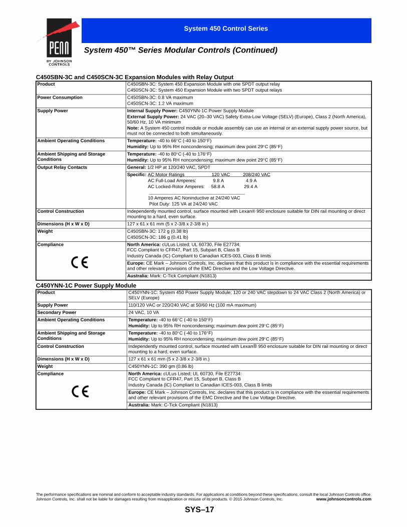
System 450™ Series Modular Controls (Continued)
System 450 Control Series
C450SBN-3C and C450SCN-3C Expansion Modules with Relay OutputProduct C450SBN-3C: System 450 Expansion Module with one SPDT output relay
C450SCN-3C: System 450 Expansion Module with two SPDT output relays
Power Consumption C450SBN-3C: 0.8 VA maximumC450SCN-3C: 1.2 VA maximum
Supply Power Internal Supply Power: C450YNN-1C Power Supply ModuleExternal Supply Power: 24 VAC (20–30 VAC) Safety Extra-Low Voltage (SELV) (Europe), Class 2 (North America), 50/60 Hz, 10 VA minimumNote: A System 450 control module or module assembly can use an internal or an external supply power source, but must not be connected to both simultaneously.
Ambient Operating Conditions Temperature: -40 to 66C (-40 to 150F)Humidity: Up to 95% RH noncondensing; maximum dew point 29C (85F)
Ambient Shipping and Storage Conditions
Temperature: -40 to 80C (-40 to 176F) Humidity: Up to 95% RH noncondensing; maximum dew point 29C (85F)
Output Relay Contacts General: 1/2 HP at 120/240 VAC, SPDT
Specific: AC Motor Ratings 120 VAC 208/240 VAC AC Full-Load Amperes: 9.8 A 4.9 A AC Locked-Rotor Amperes: 58.8 A 29.4 A _____________________________________ 10 Amperes AC Noninductive at 24/240 VAC Pilot Duty: 125 VA at 24/240 VAC
Control Construction Independently mounted control, surface mounted with Lexan® 950 enclosure suitable for DIN rail mounting or direct mounting to a hard, even surface.
Dimensions (H x W x D) 127 x 61 x 61 mm (5 x 2-3/8 x 2-3/8 in.)
Weight C450SBN-3C: 172 g (0.38 lb) C450SCN-3C: 186 g (0.41 lb)
Compliance North America: cULus Listed; UL 60730, File E27734; FCC Compliant to CFR47, Part 15, Subpart B, Class BIndustry Canada (IC) Compliant to Canadian ICES-003, Class B limits
Europe: CE Mark – Johnson Controls, Inc. declares that this product is in compliance with the essential requirements and other relevant provisions of the EMC Directive and the Low Voltage Directive.
Australia: Mark: C-Tick Compliant (N1813)
C450YNN-1C Power Supply ModuleProduct C450YNN-1C: System 450 Power Supply Module; 120 or 240 VAC stepdown to 24 VAC Class 2 (North America) or
SELV (Europe)
Supply Power 110/120 VAC or 220/240 VAC at 50/60 Hz (100 mA maximum)
Secondary Power 24 VAC, 10 VA
Ambient Operating Conditions Temperature: -40 to 66C (-40 to 150F)Humidity: Up to 95% RH noncondensing; maximum dew point 29C (85F)
Ambient Shipping and Storage Conditions
Temperature: -40 to 80C (-40 to 176F)Humidity: Up to 95% RH noncondensing; maximum dew point 29C (85F)
Control Construction Independently mounted control, surface mounted with Lexan® 950 enclosure suitable for DIN rail mounting or direct mounting to a hard, even surface.
Dimensions (H x W x D) 127 x 61 x 61 mm (5 x 2-3/8 x 2-3/8 in.)
Weight C450YNN-1C: 390 gm (0.86 lb)
Compliance North America: cULus Listed; UL 60730, File E27734:FCC Compliant to CFR47, Part 15, Subpart B, Class BIndustry Canada (IC) Compliant to Canadian ICES-003, Class B limits
Europe: CE Mark – Johnson Controls, Inc. declares that this product is in compliance with the essential requirements and other relevant provisions of the EMC Directive and the Low Voltage Directive.
Australia: Mark: C-Tick Compliant (N1813)
The performance specifications are nominal and conform to acceptable industry standards. For applications at conditions beyond these specifications, consult the local Johnson Controls office.Johnson Controls, Inc. shall not be liable for damages resulting from misapplication or misuse of its products. © 2015 Johnson Controls, Inc. www.johnsoncontrols.com
SYS–17

Code No. LIT- 1900861
C450CEN Control Module with Communication
System 450™ Series Control Module with Network Communications
System 450 Control Series
DescriptionSystem 450™ is a family of modular, digital electronic controls that is easily assembled and set up to provide reliable temperature, pressure, and humidity control for a wide variety of HVACR applications, commercial process applications, and industrial process applications.
The System 450 control system is designed to replace System 350™ and System 27 control systems and to provide many additional features and benefits with fewer than twenty model variations.
System 450 control modules provide a field-configurable out-of-the-box solution. Most System 450 control modules can control temperature, pressure, and humidity systems simultaneously.
A single C450 control module can be set up as a stand-alone control or connected to expansion modules to control up to ten On/Off relay and proportional analog outputs, based on any of the three available inputs.
System 450 Control Modules with Communications enable you to connect System 450 control systems to Modbus® or Ethernet networks for remote monitoring and setup. The Modbus communications control module is an RS485, RTU-compliant slave device. The Ethernet communications control module has an integral web server that can deliver web pages through a direct connection, on your LAN, or across the Internet.
Refer to the following documents for detailed information on designing, installing, setting up, and troubleshooting System 450 Series control systems with network communications:
• System 450™ Series Modular Controls Product Bulletin (LIT-12011458)
• System 450™ Series Modular Control Systems with Communications Control Modules Technical Bulletin (LIT-12011826)
• System 450™ Series Control Module with RS485 Modbus® Communications Installation Instructions (Part No. 24-7664-2926)
• System 450™ Series Control Module with Ethernet Communications Installation Instructions (Part No. 24-7664-2934)
Features• Durable, compact, interchangeable modular components with
plug-together connectors and DIN rail or direct wall mount capability eliminate field wiring between modules and allow you to quickly and easily design, assemble, install, and upgrade your control systems.
• Versatile, multipurpose, field-configurable control modules and expansion modules designed for global use allow you to create a wide variety of application-specific control systems capable of controlling temperature, pressure, or humidity, or all three conditions simultaneously, with only a small suite of module models.
• Up to three hard-wired input sensors and up to ten relay or analog outputs (in any combination) per control system allow you to build complex custom control systems while reducing your control system cost to only the cost of the required components.
• Control modules with bright backlit LCDs and four-button touch pad user interfaces provide quick, clear, visual status of your System 450 control system inputs and outputs with the touch of a button and enable you to quickly and easily set up and adjust your control system.
• An extensive suite of compatible temperature and humidity sensors, and pressure transducers allows you to monitor and control a wide range of HVACR and process conditions in a variety of standard and global units of measurement.
• High input signal selection enables your control system to monitor a temperature, pressure, or humidity condition with two or three sensors (of the same type) and control your system outputs based on the highest condition value sensed by the referenced sensors.
The performance specifications are nominal and conform to acceptable industry standards. ForJohnson Controls, Inc. shall not be liable for damages resulting from misapplication or misuse
SYS–
• Differential control enables your control system to monitor and maintain a temperature, pressure, or humidity differential between two sensor points within a system, process, or space.
• Ethernet communication capability through a built-in web server (Ethernet control modules only) allows you to monitor your control system status and set up or change the parameters by means of a direct Ethernet cable connection, through a LAN connection, or over the Internet. The built in web server delivers user-friendly web pages to client browsers on a desktop, laptop, tablet, or smart device.
• The web page server on Ethernet communication modules provides a simple, intuitive web interface for easy remote monitoring, setup, adjustment and remote monitoring of your control systems across Ethernet networks.
• RS485, RTU-compliant Modbus® network communication capability (Modbus control modules only) enables a head-end RS485 Modbus master controller to read and write control system status and setup parameters to the System 450 Modbus communication control module.
• Password protection for local access (Ethernet and Modbus control modules only) and password protection for remote access (Ethernet control module only) deters unauthorized changes to the control system settings, but allows local and remote monitoring of your control system status.
• Analog output signal limiting features (communication control modules only) allow you to select the rate and condition range at which the control updates the analog output signal, potentially reducing wear on the controlled equipment.
• Binary input with time delay (communication control modules only) allows you to use an external set of dry contacts and selectable time delays to control relay outputs.
applications at conditions beyond these specifications, consult the local Johnson Controls office.of its products. © 2015 Johnson Controls, Inc. www.johnsoncontrols.com
18

System 450™ Series Control Module with Network Communications (Continued)
System 450 Control Series
Selection Chart
Refer to the System 450 Compatible Sensors, Transducers, and Accessories Catalog Page (LIT-1900662) for temperature sensors, humidity sensors, and pressure transducers compatible with the System 450 Control Modules.
Repair Information
If the System 450™ Control Module with Ethernet or RS485 Modbus Communication fails to operate within its specifications, replace the unit. For a replacement System 450™ Control Module, contact a Johnson Controls® representative.
Technical Specifications
Communications System 450 Modules and Accessories Ordering InformationProduct Code Number
Product Description
C450CEN-1C Control Module with Ethernet Communications, LCD, and Four-Button Touchpad UI. (No onboard outputs available on control modules with network communications capabilities.)
C450CRN-1C Control Module with RS485 Modbus Communications, LCD, and Four-Button Touchpad UI. (No onboard outputs available on control modules with network communications capabilities.)
BKT287-1R DIN Rail; 0.30 m (12 in.) long
BKT287-2R DIN Rail; 1 m (39-1/3 in.) long
BKT287-3R DIN Rail; 0.61 m (24 in.) long
BKT287-4R DIN Rail; 0.36 m (14 in.) long
PLT344-1R DIN Rail End Clamps (2 clamps)
WHA-C450-100C System 450 module connection extension cable, 100 cm (3.3 ft) long
C450CEN-1C Control Module with Ethernet CommunicationsProduct C450CEN: System 450 control modules are sensing controls and operating controls with LCD and four-button
touchpad UI, Ethernet communications capability, and no outputs.C450CEN-1C: Control module with Ethernet communications capability
Supply Power Internal Supply Power: C450YNN-1C Power Supply ModuleExternal Supply Power: 24 VAC (20–30 VAC) Safety Extra-Low Voltage (SELV) (Europe), Class 2 (North America), 50/60 Hz, 10 VA minimumNote: A System 450 control module or module assembly can use an internal or an external supply power source, but must not be connected to both simultaneously.
Ambient Operating Conditions Temperature: -40 to 66C (-40 to 150F)Humidity: Up to 95% RH noncondensing; maximum dew point 29C (85F)
Ambient Shipping and Storage Conditions
Temperature: -40 to 80C (-40 to 176F)Humidity: Up to 95% RH noncondensing; maximum dew point 29C (85F)
Input Signal 0–5 VDC; 1,035 ohms at 25C (77F) for an A99 PTC Temperature Sensor
Analog Input Accuracy Resolution: 16 bits
Control Construction Independently mounted control, surface mounted with Lexan® 950 enclosure suitable for DIN rail mounting or direct mounting to a hard, even surface.
Dimensions (H x W x D) 127 x 63 x 63 mm (5 x 2-3/8 x 2-3/8 in.)
Weight C450CEN-1C: 207 g (0.46 lb)
Compliance North America: cULus Listed; UL 60730, File E27734; FCC Compliant to CFR47, Part 15, Subpart B, Class BIndustry Canada (IC) Compliant to Canadian ICES-003, Class B limits
Europe: CE Mark – Johnson Controls, Inc. declares that this product is in compliance with the essential requirements and other relevant provisions of the EMC Directive; Low Voltage Directive; CISPR22, class B.
Australia: Mark: C-Tick Compliant (N1813)
The performance specifications are nominal and conform to acceptable industry standards. For applications at conditions beyond these specifications, consult the local Johnson Controls office.Johnson Controls, Inc. shall not be liable for damages resulting from misapplication or misuse of its products. © 2015 Johnson Controls, Inc. www.johnsoncontrols.com
SYS–19

System 450™ Series Control Module with Network Communications (Continued)
System 450 Control Series
C450CRN-1C Control Module with RS485 Modbus CommunicationsProduct C450CRN-1C: System 450 control modules are sensing controls and operating controls with LCD and four-button
touchpad UI and no outputs. This control module is an RS485, RTU compliant Modbus slave device.
Supply Power Internal Supply Power: C450YNN-1C Power Supply ModuleExternal Supply Power: 24 VAC (20–30 VAC) Safety Extra-Low Voltage (SELV) (Europe), Class 2 (North America), 50/60 Hz, 10 VA minimumNote: A System 450 control module or module assembly can use an internal or an external supply power source, but must not be connected to both simultaneously.
Ambient Operating Conditions Temperature: -40 to 66C (-40 to 150F)Humidity: Up to 95% RH noncondensing; maximum dew point 29C (85F)
Ambient Shipping and Storage Conditions
Temperature: -40 to 80C (-40 to 176F)Humidity: Up to 95% RH noncondensing; maximum dew point 29C (85F)
Input Signal 0–5 VDC; 1,035 ohm at 25C (77F) for an A99 PTC Temperature Sensor
Analog Input Accuracy Resolution: 16 bit
Control Construction Independently mounted control, surface mounted with Lexan® 950 enclosure suitable for DIN rail mounting or direct mounting to a hard, even surface.
Dimensions (H x W x D) 127 x 63 x 63 mm (5 x 2-3/8 x 2-3/8 in.)
Weight C450CRN-1C: 207 g (0.46 lb)
Compliance North America: cULus Listed; UL 60730, File E27734: FCC Compliant to CFR47, Part 15, Subpart B, Class BIndustry Canada (IC) Compliant to Canadian ICES-003, Class B limits
Europe: CE Mark – Johnson Controls, Inc. declares that this product is in compliance with the essential requirements and other relevant provisions of the EMC Directive; Low Voltage Directive; CISPR22, class B
Australia: Mark: C-Tick Compliant (N1813)
The performance specifications are nominal and conform to acceptable industry standards. For applications at conditions beyond these specifications, consult the local Johnson Controls office.Johnson Controls, Inc. shall not be liable for damages resulting from misapplication or misuse of its products. © 2015 Johnson Controls, Inc. www.johnsoncontrols.com
SYS–20

System 450™ Reset Control Modules with Real-Time Clock and Relay Output
Code No. LIT-1900658
C450RCN-3 Reset Control Module withReal-Time Clock and Relay Output
System 450 Control Series
DescriptionSystem 450™ is a family of modular, digital electronic controls that is easily assembled and set up to provide reliable temperature, pressure, and humidity control for a wide variety of HVACR applications, commercial process applications, and industrial process applications.
System 450 Reset Control Modules provide many of the features of the standard models for temperature and humidity control. In addition, these modules provide setpoint reset, real-time setback scheduling, and run-time balancing (equal run time) capability.
The System 450 control system is designed to replace System 350™ and System 27 control systems, and to provide many additional features and benefits with fewer than twenty model variations.
System 450 control modules provide a field-configurable out-of-the-box solution. Most System 450 control modules can control temperature, pressure, and humidity systems simultaneously.
A single C450 control module can be set up as a stand-alone control or connected to expansion modules to control up to ten On/Off relay and proportional analog outputs, based on any of the three available inputs.
Refer to the following documents for important product application information:
• System 450™ Series Modular Controls Product Bulletin (LIT-12011458)
• System 450™ Series Modular Control Systems with Reset Control Modules Technical Bulletin (LIT-12011842)
• System 450™ Series Reset Control Modules with Real-Time Clock and Relay Output Installation Instructions (Part No. 24-7664-2888)
Features• Durable, compact, interchangeable modular components with
plug-together connectors and DIN rail or direct wall mount capability eliminate field wiring between modules and allow you to quickly and easily design, assemble, install, and upgrade your control systems.
• Versatile, multipurpose, field-configurable control modules and expansion modules designed for global use allow you to create a wide variety of application-specific control systems capable of controlling temperature, pressure, or humidity, or all three conditions simultaneously, with only a small suite of module models.
• Up to three hard-wired input sensors and up to ten relay or analog outputs (in any combination) per control system allow you to build complex custom control systems while reducing your control system cost to only the cost of the required components.
• Control Modules with bright backlit LCDs and four-button touch pad user interfaces provide quick, clear, visual status of your System 450 control system inputs and outputs with the touch of a button and enable you to quickly and easily set up and adjust your control system.
• Multipurpose, all-in-one control modules enable simple stand-alone, single-module control systems that are temperature, pressure, and humidity capable out of the box and easy to set up in the field to replace a wide variety of OEM HVACR and process controls.
• An extensive suite of compatible temperature and humidity sensors, and pressure transducers allows you to monitor and control a wide range of HVACR and process conditions in a variety of standard and global units of measurement.
• High input signal selection enables your control system to monitor a temperature, pressure, or humidity condition with two or three sensors (of the same type) and control your system outputs based on the highest condition value sensed by the referenced sensors.
The performance specifications are nominal and conform to acceptable industry standards. ForJohnson Controls, Inc. shall not be liable for damages resulting from misapplication or misuse
SYS–
• Differential control enables your control system to monitor and maintain a temperature, pressure, or humidity differential between two sensor points within a system, process, or space.
Reset Control Features• Adjustable minimum and maximum setpoint temperatures (reset
control modules only) enable compliance with the manufacturer’s specifications for your controlled HVACR and process equipment.
• Selectable shutdown-high and shutdown-low temperature settings (reset control modules only) saves you energy by shutting down controlled equipment when the ambient temperature either rises or drops to a point where heating or cooling is no longer required.
• Real time clock and adjustable setback temperature (reset control modules only) save you energy by setting back heating, cooling, or humidity setpoints during scheduled unoccupied periods (24-hour day, 7-day week schedule).
• User-defined reset control capability (reset control modules only) saves you energy in a wide variety of temperature and humidity reset control applications by adjusting the temperature or humidity control loop, based on changes in ambient outdoor temperature or other uncontrolled condition.
Repair Information
If the System 450 Reset Control Module fails to operate within its specifications, replace the unit. For a replacement System 450 Reset Control Module, contact the nearest Johnson Controls® representative.
applications at conditions beyond these specifications, consult the local Johnson Controls office.of its products. © 2015 Johnson Controls, Inc. www.johnsoncontrols.com
21

The performance specifications are nominal and conform to acceptable industry standards. For applications at conditions beyond these specifications, consult the local Johnson Controls office.Johnson Controls, Inc. shall not be liable for damages resulting from misapplication or misuse of its products. © 2015 Johnson Controls, Inc. www.johnsoncontrols.com
SYS–22
System 450™ Reset Control Modules with Real-Time Clock and Relay Output (Continued)
System 450 Control Series
Selection ChartRefer to the System 450 Compatible Sensors, Transducers, and Accessories Catalog Page (LIT-1900662) for temperature sensors and humidity sensors compatible with the System 450 Reset Control Modules. Reset Control Modules control temperature and humidity, but not pressure.
Technical Specifications
Reset System 450 Modules and Accessories Ordering InformationProduct Code Number
Product Description
C450RBN-3C Reset Control Module with LCD, Four-Button Touchpad UI, and SPDT relay output; provides one SPDT output relay. One A99BC-25C temperature sensor with 0.25 m (9-1/4 in.) silicon leads and one A99BC-300C temperature sensor with 3 m (9 ft 10 in.) silicon leads are included in the box with the Reset Control Module.
C450RCN-3C Reset Control Module with LCD, Four-Button Touchpad UI, and SPDT relay output; provides two SPDT output relays. One A99BC-25C temperature sensor with 0.25 m (9-1/4 in.) silicon leads and one A99BC-300C temperature sensor with 3 m (9 ft 10 in.) silicon leads are included in the box with the Reset Control Module.
BKT287-1R DIN Rail; 0.30 m (12 in.) long
BKT287-2R DIN Rail; 1 m (39-1/3 in.) long
BKT287-3R DIN Rail; 0.61 m (24 in.) long
BKT287-4R DIN Rail; 0.36 m (14 in.) long
PLT344-1R DIN Rail End Clamps (2 clamps)
WHA-C450-100C System 450 module connection extension cable, 100 cm (3.3 ft) long
C450RBN-3C and C450RCN-3C Reset Control Modules with Real-Time Clock and Relay OutputProduct C450RBN-3C and C450RCN-3C: System 450 Reset Control Module models are sensing controls and operating
controls with LCD, four-button touchpad, and SPDT relay outputC450RBN-3C: Control Module with one SPDT output relayC450RCN-3C: Control Module with two SPDT output relays
Power Consumption C450RBN-3C: 0.9 VA maximumC450RCN-3C: 1.3 VA maximum
Supply Power Internal Supply Power: C450YNN-1C Power Supply ModuleExternal Supply Power: 24 VAC (20–30 VAC) Safety Extra-Low Voltage (SELV) (Europe), Class 2 (North America), 50/60 Hz, 10 VA minimumNote: A System 450 control module or module assembly can use an internal or an external supply power source, but must not be connected to both simultaneously.
Ambient Operating Conditions Temperature: -40 to 66C (-40 to 150F)Humidity: Up to 95% RH noncondensing; maximum dew point 29C (85F)
Ambient Shipping and Storage Conditions Temperature: -40 to 80C (-40 to 176F)Humidity: Up to 95% RH noncondensing; maximum dew point 29C (85F)
Input Signal 0–5 VDC for humidity sensors1,035 ohms at 25C (77F) for A99 PTC temperature sensors
Output Relay Contacts General: 1/2 HP at 120/240 VAC, SPDT
Specific: AC Motor Ratings 120 VAC 208/240 VAC AC Full-load Amperes: 9.8 A 4.9 A AC Locked-Rotor Amperes: 58.8 A 29.4 A _____________________________________ 10 Amperes AC Non-inductive at 24/240 VAC Pilot Duty: 125 VA at 24/240 VAC
Clock Accuracy ±4 minutes per year
Clock Backup Power 12 hours (capacitor reserve)
Setback Events One occupied and one unoccupied event per day; 7 day schedule
Analog Input Accuracy Resolution: 14 bits
Control Construction Independently mounted control, surface mounted with Lexan® 950 enclosure suitable for DIN rail mounting or direct mounting to a hard, even surface.
Dimensions (H x W x D) 127 x 61 x 61 mm (5 x 2-3/8 x 2-3/8 in.)
Weight C450RBN-3C: 209 g (0.46 lb)C450RCN-3C: 222 g (0.49 lb)
Compliance North America: cULus Listed; UL 60730, File E27734; FCC Compliant to CFR47, Part 15, Subpart B, Class B; Industry Canada (IC) Compliant to Canadian ICES-003, Class B limits
Europe: CE Mark – Johnson Controls, Inc. declares that this product is in compliance with the essential requirements and other relevant provisions of the EMC Directive and the Low Voltage Directive.
Australia: Mark: C-Tick Compliant (N1813)
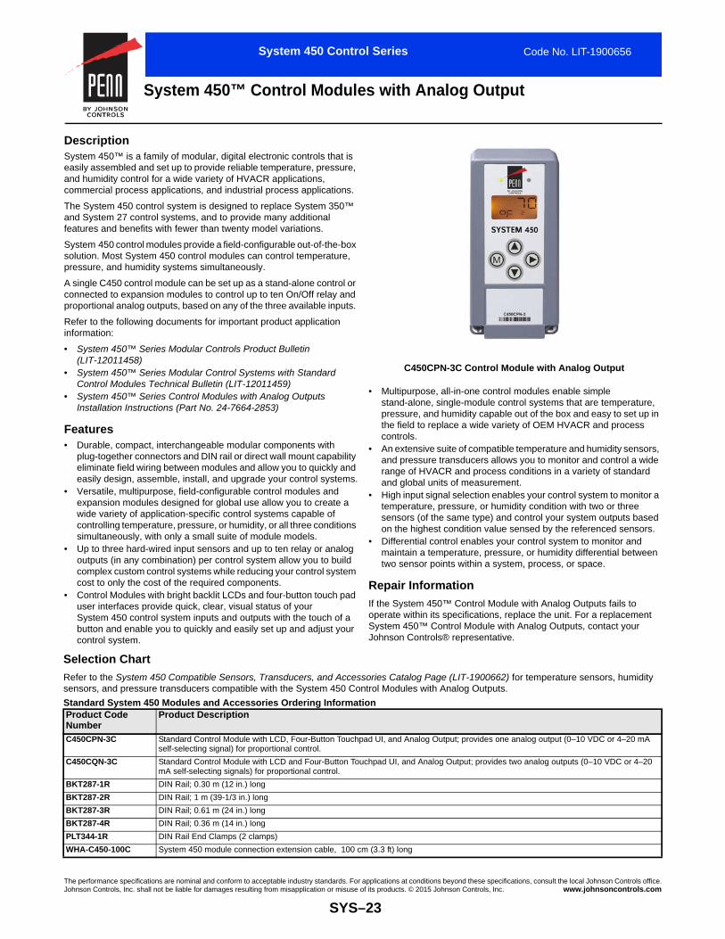
System 450™ Control Modules with Analog Output
Code No. LIT-1900656
C450CPN-3C Control Module with Analog Output
System 450 Control Series
DescriptionSystem 450™ is a family of modular, digital electronic controls that is easily assembled and set up to provide reliable temperature, pressure, and humidity control for a wide variety of HVACR applications, commercial process applications, and industrial process applications.
The System 450 control system is designed to replace System 350™ and System 27 control systems, and to provide many additional features and benefits with fewer than twenty model variations.
System 450 control modules provide a field-configurable out-of-the-box solution. Most System 450 control modules can control temperature, pressure, and humidity systems simultaneously.
A single C450 control module can be set up as a stand-alone control or connected to expansion modules to control up to ten On/Off relay and proportional analog outputs, based on any of the three available inputs.
Refer to the following documents for important product application information:
• System 450™ Series Modular Controls Product Bulletin (LIT-12011458)
• System 450™ Series Modular Control Systems with Standard Control Modules Technical Bulletin (LIT-12011459)
• System 450™ Series Control Modules with Analog Outputs Installation Instructions (Part No. 24-7664-2853)
Features• Durable, compact, interchangeable modular components with
plug-together connectors and DIN rail or direct wall mount capability eliminate field wiring between modules and allow you to quickly and easily design, assemble, install, and upgrade your control systems.
• Versatile, multipurpose, field-configurable control modules and expansion modules designed for global use allow you to create a wide variety of application-specific control systems capable of controlling temperature, pressure, or humidity, or all three conditions simultaneously, with only a small suite of module models.
• Up to three hard-wired input sensors and up to ten relay or analog outputs (in any combination) per control system allow you to build complex custom control systems while reducing your control system cost to only the cost of the required components.
• Control Modules with bright backlit LCDs and four-button touch pad user interfaces provide quick, clear, visual status of your System 450 control system inputs and outputs with the touch of a button and enable you to quickly and easily set up and adjust your control system.
•
•
•
•
R
IoSJ
The performance specifications are nominal and conform to acceptable industry standards. ForJohnson Controls, Inc. shall not be liable for damages resulting from misapplication or misuse
SYS–
Selection Chart
Refer to the System 450 Compatible Sensors, Transducers, and Accessensors, and pressure transducers compatible with the System 450 Co
Standard System 450 Modules and Accessories Ordering InformaProduct Code Number
Product Description
C450CPN-3C Standard Control Module with LCD, Four-Button Touchself-selecting signal) for proportional control.
C450CQN-3C Standard Control Module with LCD and Four-Button TomA self-selecting signals) for proportional control.
BKT287-1R DIN Rail; 0.30 m (12 in.) long
BKT287-2R DIN Rail; 1 m (39-1/3 in.) long
BKT287-3R DIN Rail; 0.61 m (24 in.) long
BKT287-4R DIN Rail; 0.36 m (14 in.) long
PLT344-1R DIN Rail End Clamps (2 clamps)
WHA-C450-100C System 450 module connection extension cable, 100 c
Multipurpose, all-in-one control modules enable simple stand-alone, single-module control systems that are temperature, pressure, and humidity capable out of the box and easy to set up in the field to replace a wide variety of OEM HVACR and process controls.An extensive suite of compatible temperature and humidity sensors, and pressure transducers allows you to monitor and control a wide range of HVACR and process conditions in a variety of standard and global units of measurement.High input signal selection enables your control system to monitor a temperature, pressure, or humidity condition with two or three sensors (of the same type) and control your system outputs based on the highest condition value sensed by the referenced sensors.Differential control enables your control system to monitor and maintain a temperature, pressure, or humidity differential between two sensor points within a system, process, or space.
epair Information
f the System 450™ Control Module with Analog Outputs fails to perate within its specifications, replace the unit. For a replacement ystem 450™ Control Module with Analog Outputs, contact your ohnson Controls® representative.
applications at conditions beyond these specifications, consult the local Johnson Controls office.of its products. © 2015 Johnson Controls, Inc. www.johnsoncontrols.com
23
sories Catalog Page (LIT-1900662) for temperature sensors, humidity ntrol Modules with Analog Outputs. tion
pad UI, and Analog Output; provides one analog output (0–10 VDC or 4–20 mA
uchpad UI, and Analog Output; provides two analog outputs (0–10 VDC or 4–20
m (3.3 ft) long

The performance specifications are nominal and conform to acceptable industry standards. For applications at conditions beyond these specifications, consult the local Johnson Controls office.Johnson Controls, Inc. shall not be liable for damages resulting from misapplication or misuse of its products. © 2015 Johnson Controls, Inc. www.johnsoncontrols.com
SYS–24
System 450™ Control Modules with Analog Output (Continued)
System 450 Control Series
Technical Specifications C450CPN-3C and C450CQN-3C Control Modules with Analog OutputProduct C450CPN-3C and C450CQN-3C: System 450 Control Module models are sensing controls and operating controls
with LCD, four-button touchpad, and SPDT analog outputC450CPN-3C: Control Module with one analog output C450CQN-3C: Control Module with two analog outputs
Power Consumption C450CPN-3C: 1.3 VA maximum using 0–10 V out; 1.5 VA maximum using 4–20 mA outC450CQN-3C: 2.0 VA maximum using 0–10 V out; 2.4 VA maximum using 4–20 mA out
Supply Power Internal Supply Power: C450YNN-1C Power Supply ModuleExternal Supply Power: 24 VAC (20–30 VAC) Safety Extra-Low Voltage (SELV) (Europe), Class 2 (North America), 50/60 Hz, 10 VA minimumNote: A System 450 control module or module assembly can use an internal or an external supply power source, but must not be connected to both simultaneously.
Ambient Operating Conditions Temperature: -40 to 66C (-40 to 150F) when using 0–10 VDC outputs; -40 to 40C (-40 to 104F) when using 4–20 mA outputsHumidity: Up to 95% RH noncondensing; maximum dew point 29C (85F)
Ambient Shipping and Storage Conditions Temperature: -40 to 80C (-40 to 176F)Humidity: Up to 95% RH noncondensing; maximum dew point 29C (85F)
Input Signal 0–5 VDC for humidity sensors and static pressure transducers0.5–4.5 VDC for ratiometric pressure transducers1,035 ohms at 25C (77F) for A99 PTC temperature sensors1,000 ohms at 21.1C (70F) for TE-6xxx Nickel temperature sensors
Analog Output Voltage Mode (0–10 VDC):10 VDC maximum output voltage10 mA maximum output currentRequires an external load of 1,000 ohms or moreThe AO operates in Voltage Mode when connected to devices with impedance greater than 1,000 ohms. Devices that fall below 1,000 ohms may not operate as intended with Voltage Mode applications.
Current Mode (4–20 mA):Requires an external load between 0–300 ohmsThe AO operates in Current Mode when connected to devices with impedance less than 300 ohms. Devices that rise above 300 ohms may not operate as intended with Current Mode applications.
Analog Input Accuracy Resolution: 14 bits
Control Construction Independently mounted control, surface mounted with Lexan® 950 enclosure suitable for DIN rail mounting or direct mounting to a hard, even surface.
Dimensions (H x W x D) 127 x 61 x 61 mm (5 x 2-3/8 x 2-3/8 in.)
Weight C450CPN-3C: 195 g (0.43 lb)C450CQN-3C: 195 g (0.43 lb)
Compliance North America: cULus Listed; UL 60730, File E27734; FCC Compliant to CFR47, Part 15, Subpart B, Class BIndustry Canada (IC) Compliant to Canadian ICES-003, Class B limits
Europe: CE Mark – Johnson Controls, Inc. declares that this product is in compliance with the essential requirements and other relevant provisions of the EMC Directive and the Low Voltage Directive.
Australia: Mark: C-Tick Compliant (N1813)

System 450™ Control Modules with Relay Output
Code No. LIT-1900657
C450CCN-3C Control Module with Relay Output
System 450 Control Series
DescriptionSystem 450™ is a family of modular, digital electronic controls that is easily assembled and set up to provide reliable temperature, pressure, and humidity control for a wide variety of HVACR applications, commercial process applications, and industrial process applications.
The System 450 control system is designed to replace System 350™ and System 27 control systems, and to provide many additional features and benefits with fewer than twenty model variations.
System 450 control modules provide a field-configurable out-of-the-box solution. Most System 450 control modules can control temperature, pressure, and humidity systems simultaneously.
A single C450 control module can be set up as a stand-alone control or connected to expansion modules to control up to ten On/Off relay and proportional analog outputs, based on any of the three available inputs.
Refer to the following documents for important product information:
• System 450™ Series Modular Controls Product Bulletin (LIT-12011458)
• System 450™ Series Modular Control Systems with Standard Control Modules Technical Bulletin (LIT-12011459)
• System 450™ Series Control Modules with Relay Outputs Installation Instructions (Part No. 24-7664-2896)
Features• Durable, compact, interchangeable modular components with
plug-together connectors and DIN rail or direct wall mount capability eliminate field wiring between modules and allow you to quickly and easily design, assemble, install, and upgrade your control systems.
• Versatile, multipurpose, field-configurable control modules and expansion modules designed for global use allow you to create a wide variety of application-specific control systems capable of controlling temperature, pressure, or humidity, or all three conditions simultaneously, with only a small suite of module models.
• Up to three hard-wired input sensors and up to ten relay or analog outputs (in any combination) per control system allow you to build complex custom control systems while reducing your control system cost to only the cost of the required components.
• Control Modules with bright backlit LCDs and four-button touch pad user interfaces provide quick, clear, visual status of your System 450 control system inputs and outputs with the touch of a button and enable you to quickly and easily set up and adjust your control system.
•
•
•
•
R
•
The performance specifications are nominal and conform to acceptable industry standards. FoJohnson Controls, Inc. shall not be liable for damages resulting from misapplication or misuse
SYS
Selection Chart
Refer to the System 450 Compatible Sensors, Transducers, and Accesensors, and pressure transducers compatible with the System 450 Co
Standard System 450 Modules and Accessories Ordering InformaProduct Code Number
Product Description
C450CBN-3C Standard Control Module with LCD, Four-Button TouchSPDT control.
C450CCN-3C Standard Control Module with LCD, Four-Button Touchfor SPDT control.
BKT287-1R DIN Rail; 0.30 m (12 in.) long
BKT287-2R DIN Rail; 1 m (39-1/3 in.) long
BKT287-3R DIN Rail; 0.61 m (24 in.) long
BKT287-4R DIN Rail; 0.36 m (14 in.) long
PLT344-1R DIN Rail End Clamps (2 clamps)
WHA-C450-100C System 450 module connection extension cable, 100
Multipurpose, all-in-one control modules enable simple stand-alone, single-module control systems that are temperature, pressure, and humidity capable out of the box and are easy to set up in the field to replace a wide variety of OEM HVACR and process controls.An extensive suite of compatible temperature and humidity sensors and pressure transducers allows you to monitor and control a wide range of HVACR and process conditions in a variety of standard and global units of measurement.High input signal selection enables your control system to monitor a temperature, pressure, or humidity condition with two or three sensors (of the same type) and control your system outputs based on the highest condition value sensed by the referenced sensors.Differential control enables your control system to monitor and maintain a temperature, pressure, or humidity differential between two sensor points within a system, process, or space.
epair Information
If the System 450™ Control Module with Relay Outputs fails to operate within its specifications, replace the unit. For a replacement System 450™ Control Module with Relay Outputs, contact a Johnson Controls® representative.
r applications at conditions beyond these specifications, consult the local Johnson Controls office. of its products. © 2015 Johnson Controls, Inc. www.johnsoncontrols.com
–25
ssories Catalog Page (LIT-1900662) for temperature sensors, humidity ntrol Modules with Relay Outputs. tion
pad UI, and Relay Output; provides one relay output (SPDT line-voltage relay) for
pad UI, and Relay Output; provides two relay outputs (SPDT line-voltage relays)
cm (3.3 ft) long

The performance specifications are nominal and conform to acceptable industry standards. For applications at conditions beyond these specifications, consult the local Johnson Controls office.Johnson Controls, Inc. shall not be liable for damages resulting from misapplication or misuse of its products. © 2015 Johnson Controls, Inc. www.johnsoncontrols.com
SYS–26
System 450™ Control Modules with Relay Output (Continued)
System 450 Control Series
Technical Specifications C450CBN-3C and C450CCN-3C Control Modules with Relay OutputProduct C450CBN-3C and C450CCN-3C: System 450 Control Module models are sensing controls and operating controls
with LCD, four-button touchpad, and SPDT relay outputC450CBN-3C: Control Module with one SPDT output relayC450CCN-3C: Control Module with two SPDT output relays
Power Consumption C450CBN-3C: 0.9 VA maximumC450CCN-3C: 1.3 VA maximum
Supply Power Internal Supply Power: C450YNN-1C Power Supply ModuleExternal Supply Power: 24 VAC (20–30 VAC) Safety Extra-Low Voltage (SELV) (Europe), Class 2 (North America), 50/60 Hz, 10 VA minimumNote: A System 450 control module or module assembly can use an internal or an external supply power source, but must not be connected to both simultaneously.
Ambient Operating Conditions Temperature: -40 to 66C (-40 to 150F)Humidity: Up to 95% RH noncondensing; maximum dew point 29C (85F)
Ambient Shipping and Storage Conditions Temperature: -40 to 80C (-40 to 176F)Humidity: Up to 95% RH noncondensing; maximum dew point 29C (85F)
Input Signal 0–5 VDC for humidity sensors and static pressure transducers0.5–4.5 VDC for ratiometric pressure transducers1,035 ohms at 25C (77F) for A99 PTC temperature sensors1,000 ohms at 21.1C (70F) for TE-6xxx Nickel temperature sensors
Output Relay Contacts General: 1/2 HP at 120/240 VAC, SPDT
Specific: AC Motor Ratings 120 VAC 208/240 VAC AC Full-load Amperes: 9.8 A 4.9 A Locked-Rotor Amperes: 58.8 A 29.4 A _____________________________________ 10 Amperes AC Non-inductive at 24/240 VAC Pilot Duty: 125 VA at 24/240 VAC
Analog Input Accuracy Resolution: 14 bits
Control Construction Independently mounted control, surface mounted with Lexan® 950 enclosure suitable for DIN rail mounting or direct mounting to a hard, even surface.
Dimensions (H x W x D) 127 x 61 x 61 mm (5 x 2-3/8 x 2-3/8 in.)
Weight C450CBN-3C: 209 g (0.46 lb)C450CCN-3C: 222 g (0.49 lb)
Compliance North America: cULus Listed; UL 60730, File E27734; FCC Compliant to CFR47, Part 15, Subpart B, Class B; Industry Canada (IC) Compliant to Canadian ICES-003, Class B limits
Europe: CE Mark – Johnson Controls, Inc. declares that this product is in compliance with the essential requirements and other relevant provisions of the EMC Directive and the Low Voltage Directive.
Australia: Mark: C-Tick Compliant (N1813)

System 450™ Control Module with Hybrid Analog Output
Code No. LIT-1900806
C450CPW-100 Control Module with Hybrid Analog Output
System 450 Control Series
DescriptionSystem 450™ is a family of modular, digital electronic controls that is easily assembled and set up to provide reliable temperature, pressure, and humidity control for a wide variety of HVACR applications, commercial process applications, and industrial process applications.
System 450 control modules provide a field-configurable out-of-the-box solution. Most System 450 control modules can control temperature, pressure, and humidity systems simultaneously.
A single C450 control module can be set up as a stand-alone control or connected to expansion modules to control up to ten On/Off relay and proportional analog outputs, based on any of the three available inputs.
The System 450 Control Module with Hybrid Analog Output has a single self-selecting analog output to optimize and extend the controlled speed range of variable speed electronically commutated (EC) motors.
Refer to the following documents for important product information:
• System 450™ Series Modular Controls Product Bulletin (LIT-12011458)
• System 450™ Series Modular Control Systems with Standard Control Modules Technical Bulletin (LIT-12011459)
• System 450™ Series Control Module with Hybrid Analog Output and High Input Signal Selection Installation Instructions (Part No. 24-7664-2802)
Features• Durable, compact, interchangeable modular components with
plug-together connectors and DIN rail or direct wall mount capability eliminate field wiring between modules and allow you to quickly and easily design, assemble, install, and upgrade your control systems.
• Versatile, multipurpose, field-configurable control modules and expansion modules designed for global use allow you to create a wide variety of application-specific control systems capable of controlling temperature, pressure, or humidity, or all three conditions simultaneously, with only a small suite of module models.
• Up to three hard-wired input sensors and up to ten relay or analog outputs (in any combination) per control system allow you to build complex custom control systems while reducing your control system cost to only the cost of the required components.
• Control Modules with bright backlit LCDs and four-button touch pad user interfaces provide quick, clear, visual status of your System 450 control system inputs and outputs with the touch of a button and enable you to quickly and easily set up and adjust your control system.
• Multipurpose, all-in-one control modules enable simple stand-alone, single-module control systems that are temperature, pressure, and humidity capable out of the box and easy to set up in the field to replace a wide variety of OEM HVACR and process controls.
•
•
•
R
IoSJ
The performance specifications are nominal and conform to acceptable industry standards. ForJohnson Controls, Inc. shall not be liable for damages resulting from misapplication or misuse
SYS–
An extensive suite of compatible temperature and humidity sensors, and pressure transducers allows you to monitor and control a wide range of HVACR and process conditions in a variety of standard and global units of measurement.High input signal selection enables your control system to monitor a temperature, pressure, or humidity condition with two or three sensors (of the same type) and control your system outputs based on the highest condition value sensed by the referenced sensors.Differential control enables your control system to monitor and maintain a temperature, pressure, or humidity differential between two sensor points within a system, process, or space.
epair Information
f the System 450™ Control Module with Hybrid Analog Output fails to perate within its specifications, replace the unit. For a replacement ystem 450™ Control Module with Hybrid Analog Output, contact a ohnson Controls® representative.
applications at conditions beyond these specifications, consult the local Johnson Controls office.of its products. © 2015 Johnson Controls, Inc. www.johnsoncontrols.com
27

The performance specifications are nominal and conform to acceptable industry standards. For applications at conditions beyond these specifications, consult the local Johnson Controls office.Johnson Controls, Inc. shall not be liable for damages resulting from misapplication or misuse of its products. © 2015 Johnson Controls, Inc. www.johnsoncontrols.com
SYS–28
System 450™ Control Module with Hybrid Analog Output (Continued)
System 450 Control Series
Selection Chart
Refer to the System 450 Compatible Sensors, Transducers, and Accessories Catalog Page (LIT-1900662) for temperature sensors, humidity sensors, and pressure transducers compatible with the System 450 Control Modules.
Technical Specifications
Hybrid System 450 Modules and Accessories Ordering InformationProduct Code Number
Product Description
C450CPW-100C Hybrid Analog Output Control Module with LCD, Four-Button Touchpad UI, Hybrid Analog Output and Optional High Input Signal Select; provides one hybrid analog output and optional high input signal select primarily used for variable-speed EC motor speed control.Only Analog Output 1 (OUTA1) can be configured as a hybrid analog output and/or use the High Input Signal Selection feature. These features are not available for any of the other outputs in a System 450 control system that uses the C450CPW-100C as the control module.
BKT287-1R DIN Rail; 0.30 m (12 in.) long
BKT287-2R DIN Rail; 1 m (39-1/3 in.) long
BKT287-3R DIN Rail; 0.61 m (24 in.) long
BKT287-4R DIN Rail; 0.36 m (14 in.) long
PLT344-1R DIN Rail End Clamps (2 clamps)
WHA-C450-100C System 450 module connection extension cable, 100 cm (3.3 ft) long
C450CPW-100C Control Module with Hybrid Analog OutputProduct C450CPW-100C System 450 control module is a sensing control and operating control with LCD, four-button
touchpad, and analog output with pulse-width modulation capability.
Power Consumption C450CPW-100C: 1.3 VA maximum using 0–10 V out; 1.5 VA maximum using 4–20 mA out
Supply Power Internal Supply Power: C450YNN-1C Power Supply ModuleExternal Supply Power: 24 VAC (20–30 VAC) Safety Extra-Low Voltage (SELV) (Europe), Class 2 (North America), 50/60 Hz, 10 VA minimumNote: A System 450 control module or module assembly can use an internal or an external supply power source, but must not be connected to both simultaneously.
Ambient Operating Conditions Temperature: -40 to 66C (-40 to 150F) when using 0–10 VDC outputs; -40 to 40C (-40 to 104F) when using 4–20 mA outputsHumidity: Up to 95% RH noncondensing; maximum dew point 29C (85F)
Ambient Shipping and Storage Conditions
Temperature: -40 to 80C (-40 to 176F)Humidity: Up to 95% RH noncondensing; maximum dew point 29C (85F)
Input Signal 0–5 VDC for humidity sensors and static pressure transducers0.5–4.5 VDC for ratiometric pressure transducers1,035 ohms at 25C (77F) for A99 PTC temperature sensors1,000 ohms at 21.1C (70F) for TE-6xxx Nickel temperature sensors
Analog Output Voltage Mode (0–10 VDC):10 VDC maximum output voltage10 mA maximum output currentRequires an external load of 1,000 ohms or moreThe AO operates in Voltage Mode when connected to devices with impedance greater than 1,000 ohms. Devices that fall below 1,000 ohms may not operate as intended with Voltage Mode applications.
Current Mode (4–20 mA):Requires an external load between 0–300 ohmsThe AO operates in Current Mode when connected to devices with impedance less than 300 ohms. Devices that rise above 300 ohms may not operate as intended with Current Mode applications.
Analog Input Accuracy Resolution: 14 bits
Control Construction Independently mounted control, surface mounted with Lexan® 950 enclosure suitable for DIN rail mounting or direct mounting to a hard, even surface.
Dimensions (H x W x D) 127 x 61 x 61 mm (5 x 2-3/8 x 2-3/8 in.)
Weight C450CPW-100C: 195 g (0.43 lb)
Compliance North America: cULus Listed; UL 60730, File E27734; FCC Compliant to CFR47, Part 15, Subpart B, Class BIndustry Canada (IC) Compliant to Canadian ICES-003, Class B limits
Europe: CE Mark – Johnson Controls, Inc. declares that this product is in compliance with the essential requirements and other relevant provisions of the EMC Directive and the Low Voltage Directive.
Australia: Mark: C-Tick Compliant (N1813)

System 450™ Expansion Modules with Analog Output
Code No. LIT-1900659
C450SQN-1C Expansion Module with Analog Output
System 450 Control Series
DescriptionSystem 450 expansion modules allow you to increase the number of outputs in your control system to meet your application requirements. The following models are available:
• C450SPN-1C: Analog Expansion Module with one analog output (each 0–10 VDC or 4–20 mA)
• C450SQN-1C: Analog Expansion Module with two analog outputs (each 0–10 VDC or 4–20 mA)
Refer to the following documents for important product application information:
• System 450™ Series Modular Controls Product Bulletin (LIT-12011458)
• System 450™ Series Expansion Modules with Analog Outputs Installation Instructions (Part No. 24-7664-2799)
Features• Durable, compact, interchangeable modular components with
plug-together connectors and DIN rail or direct wall mount capability eliminate field wiring between modules and allow you to quickly and easily design, assemble, install, and upgrade your control systems.
• Versatile, multipurpose, field-configurable control modules and expansion modules designed for global use allow you to create a wide variety of application-specific control systems capable of controlling temperature, pressure, or humidity, or all three conditions simultaneously, with only a small suite of module models.
• Up to three hard-wired input sensors and up to ten relay or analog outputs (in any combination) per control system allow you to build complex custom control systems while reducing your control system cost to only the cost of the required components.
The performance specifications are nominal and conform to acceptable industry standards. ForJohnson Controls, Inc. shall not be liable for damages resulting from misapplication or misuse
SYS–
Selection Chart Expansion System 450 Modules and Accessories Ordering InformProduct Code Number
Product Description
C450SPN-1C Analog Output Expansion Module; provides one analog
C450SQN-1C Analog Output Expansion Module; provides two analog
BKT287-1R DIN Rail; 0.30 m (12 in.) long
BKT287-2R DIN Rail; 1 m (39-1/3 in.) long
BKT287-3R DIN Rail; 0.61 m (24 in.) long
BKT287-4R DIN Rail; 0.36 m (14 in.) long
PLT344-1R DIN Rail End Clamps (2 clamps)
WHA-C450-100C System 450 module connection extension cable, 100 c
Repair Information
If the System 450™ Expansion Module with Analog Output fails to operate within its specifications, replace the unit. For a replacement System 450™ Expansion Module with Analog Output, contact a Johnson Controls® representative.
applications at conditions beyond these specifications, consult the local Johnson Controls office.of its products. © 2015 Johnson Controls, Inc. www.johnsoncontrols.com
29
ation
output (0–10 VDC or 4–20 mA self-selecting signal) for proportional control.
outputs (0–10 VDC or 4–20 mA self-selecting signals) for proportional control.
m (3.3 ft) long

The performance specifications are nominal and conform to acceptable industry standards. For applications at conditions beyond these specifications, consult the local Johnson Controls office.Johnson Controls, Inc. shall not be liable for damages resulting from misapplication or misuse of its products. © 2015 Johnson Controls, Inc. www.johnsoncontrols.com
SYS–30
System 450™ Expansion Modules with Analog Output (Continued)
System 450 Control Series
Technical Specifications C450SPN-1C and C450SQN-1C Expansion Modules with Analog OutputProduct C450SPN-1C: System 450 Expansion Module with one analog output
C450SQN-1C: System 450 Expansion Module with two analog outputs
Power Consumption C450SPN-1C: 1.1 VA maximum using 0–10 V out; 1.3 VA maximum using 4–20 mA outC450SQN-1C: 1.8 VA maximum using 0–10 V out; 2.2 VA maximum using 4–20 mA out
Supply Power Internal Supply Power: C450YNN-1C Power Supply ModuleExternal Supply Power: 24 VAC (20–30 VAC) Safety Extra-Low Voltage (SELV) (Europe), Class 2 (North America), 50/60 Hz, 10 VA minimumNote: A System 450 control module or module assembly can use an internal or an external supply power source, but must not be connected to both simultaneously.
Ambient Operating Conditions Temperature: -40 to 66C (-40 to 150F) when using 0 to 10 VDC outputs;-40 to 40C (-40 to 104F) when using 4 to 20 mA outputsHumidity: Up to 95% RH noncondensing; maximum dew point 29C (85F)
Ambient Shipping and Storage Conditions
Temperature: -40 to 80C (-40 to 176F)Humidity: Up to 95% RH noncondensing; maximum dew point 29C (85F)
Analog Output Voltage Mode (0 to 10 VDC):10 VDC maximum output voltage10 mA maximum output currentRequires an external load of 1,000 ohms or moreThe AO operates in Voltage Mode when connected to devices with impedance greater than 1,000 ohms. Devices that drop below 1,000 ohms may not operate as intended with Voltage Mode applications.
Current Mode (4 to 20 mA):Requires an external load between 0 to 300 ohmsThe AO operates in Current Mode when connected to devices with impedances less than 300 ohm. Devices that exceed 300 ohms may not operate as intended with Current Mode applications.
Control Construction Independently mounted control, surface mounted with Lexan® 950 enclosure suitable for DIN rail mounting or direct mounting to a hard, even surface.
Dimensions (H x W x D) 127 x 61 x 61 mm (5 x 2-3/8 x 2-3/8 in.)
Weight C450SPN-1C: 150 g (0.33 lb)C450SQN-1C: 150 g (0.33 lb)
Compliance North America: cULus Listed; UL 60730, File E27734, Vol. 1; FCC Compliant to CFR47, Part 15, Subpart B, Class BIndustry Canada (IC) Compliant to Canadian ICES-003, Class B limits
Europe: CE Mark - Johnson Controls, Inc., declares that this product is in compliance with the essential requirements and other relevant provisions of the Low Voltage Directive and the EMC Directive.
Australia: Mark: C-Tick Compliant (N1813)

System 450™ Expansion Modules with Relay Output
Code No. LIT-1900660
C450SCN-3C Expansion Module with Relay Output
System 450 Control Series
DescriptionSystem 450 expansion modules allow you to increase the number of outputs in your control system to meet your application requirements. The following models are available:
• C450SBN-3C: Relay Expansion Module with one relay output• C450SCN-3C: Relay Expansion Module with two relay outputs
Refer to the following documents for important product application information:
• System 450™ Series Modular Controls Product Bulletin (LIT-12011458)
• System 450™ Series Expansion Modules with Relay Outputs Installation Instructions (Part No. 24-7664-2896)
Features• Durable, compact, interchangeable modular components with
plug-together connectors and DIN rail or direct wall mount capability eliminate field wiring between modules and allow you to quickly and easily design, assemble, install, and upgrade your control systems.
• Versatile, multipurpose, field-configurable control modules and expansion modules designed for global use allow you to create a wide variety of application-specific control systems capable of controlling temperature, pressure, or humidity, or all three conditions simultaneously, with only a small suite of module models.
• Up to three hard-wired input sensors and up to ten relay or analog outputs (in any combination) per control system allow you to build complex custom control systems while reducing your control system cost to only the cost of the required components.
R
IoSJ
The performance specifications are nominal and conform to acceptable industry standards. ForJohnson Controls, Inc. shall not be liable for damages resulting from misapplication or misuse
SYS–
Selection Chart Expansion System 450 Modules and Accessories Ordering InformProduct Code Number
Product Description
C450SBN-3C Reset Control Module with LCD, Four-Button Touchpadtemperature sensor with 0.25 m (9-1/4 in.) silicon leadsincluded in the box with the Reset Control Module.
C450SCN-3C Reset Control Module with LCD, Four-Button Touchpadtemperature sensor with 0.25 m (9-1/4 in.) silicon leadsincluded in the box with the Reset Control Module.
BKT287-1R DIN Rail; 0.30 m (12 in.) long
BKT287-2R DIN Rail; 1 m (39-1/3 in.) long
BKT287-3R DIN Rail; 0.61 m (24 in.) long
BKT287-4R DIN Rail; 0.36 m (14 in.) long
PLT344-1R DIN Rail End Clamps (2 clamps)
WHA-C450-100C System 450 module connection extension cable, 100 c
epair Information
f the System 450™ Expansion Module with Relay Output fails to perate within its specifications, replace the unit. For a replacement ystem 450™ Expansion Module with Relay Output, contact a ohnson Controls® representative.
applications at conditions beyond these specifications, consult the local Johnson Controls office.of its products. © 2015 Johnson Controls, Inc. www.johnsoncontrols.com
31
ation
UI, and SPDT relay output; provides one SPDT output relay. One A99BC-25C and one A99BC-300C temperature sensor with 3 m (9 ft 10 in.) silicon leads are
UI, and SPDT relay output; provides two SPDT output relays. One A99BC-25C and one A99BC-300C temperature sensor with 3 m (9 ft 10 in.) silicon leads are
m (3.3 ft) long

The performance specifications are nominal and conform to acceptable industry standards. For applications at conditions beyond these specifications, consult the local Johnson Controls office.Johnson Controls, Inc. shall not be liable for damages resulting from misapplication or misuse of its products. © 2015 Johnson Controls, Inc. www.johnsoncontrols.com
SYS–32
System 450™ Expansion Modules with Relay Output (Continued)
System 450 Control Series
Technical SpecificationsC450SBN-3C and C450SCN-3C Expansion Modules with Relay OutputProduct C450SBN-3C: System 450 Expansion Module with one SPDT output relay
C450SCN-3C: System 450 Expansion Module with two SPDT output relays
Power Consumption C450SBN-3C: 0.8 VA maximumC450SCN-3C: 1.2 VA maximum
Supply Power Internal Supply Power: C450YNN-1C Power Supply ModuleExternal Supply Power: 24 VAC (20–30 VAC) Safety Extra-Low Voltage (SELV) (Europe), Class 2 (North America), 50/60 Hz, 10 VA minimumNote: A System 450 control module or module assembly can use an internal or an external supply power source, but must not be connected to both simultaneously.
Ambient Operating Conditions Temperature: -40 to 66C (-40 to 150F)Humidity: Up to 95% RH noncondensing; maximum dew point 29C (85F)
Ambient Shipping and Storage Conditions
Temperature: -40 to 80C (-40 to 176F) Humidity: Up to 95% RH noncondensing; maximum dew point 29C (85F)
Output Relay Contacts General: 1/2 HP at 120/240 VAC, SPDT
Specific: AC Motor Ratings 120 VAC 208/240 VAC AC Full-Load Amperes: 9.8 A 4.9 A AC Locked-Rotor Amperes: 58.8 A 29.4 A _____________________________________ 10 Amperes AC Noninductive at 24/240 VAC Pilot Duty: 125 VA at 24/240 VAC
Control Construction Independently mounted control, surface mounted with Lexan® 950 enclosure suitable for DIN rail mounting or direct mounting to a hard, even surface.
Dimensions (H x W x D) 127 x 61 x 61 mm (5 x 2-3/8 x 2-3/8 in.)
Weight C450SBN-3C: 172 g (0.38 lb) C450SCN-3C: 186 g (0.41 lb)
Compliance North America: cULus Listed; UL 60730, File E27734; FCC Compliant to CFR47, Part 15, Subpart B, Class BIndustry Canada (IC) Compliant to Canadian ICES-003, Class B limits
Europe: CE Mark – Johnson Controls, Inc. declares that this product is in compliance with the essential requirements and other relevant provisions of the EMC Directive and the Low Voltage Directive.
Australia: Mark: C-Tick Compliant (N1813)

The performance specifications are nominal and conform to acceptable industry standards. For applications at conditions beyond these specifications, consult the local Johnson Controls office.Johnson Controls, Inc. shall not be liable for damages resulting from misapplication or misuse of its products. © 2015 Johnson Controls, Inc. www.johnsoncontrols.com
SYS–33
System 450™ Power Module
Code No. LIT-1900661
DescriptionSystem 450™ modules require 24 VAC, Class 2 power. In applications where 24 VAC power is not available, the C450YNN-1C Power Module provides a convenient modular solution for transforming 120/240 VAC to 24 VAC power for your System 450 control systems.
Refer to the following documents for important product application information:
• System 450™ Series Modular Controls Product Bulletin (LIT-12011458)
• System 450™ Series Power Module Installation Instructions (Part No. 24-7664-2691)
Features• Durable, compact, interchangeable modular components with
plug-together connectors and DIN rail or direct wall mount capability eliminate field wiring between modules and allow you to quickly and easily design, assemble, install, and upgrade your control systems.
Repair Information
If the System 450 Power Module fails to operate within its specifications, replace the unit. For a replacement System 450 Power Module, contact a Johnson Controls® representative.
C450YNN-1C Power Module
Technical Specifications C450YNN-1C Power Supply ModuleProduct C450YNN-1C: System 450 Power Supply Module; 120 or 240 VAC stepdown to 24 VAC Class 2 (North America) or
SELV (Europe)
Supply Power 110/120 VAC or 220/240 VAC at 50/60 Hz (100 mA maximum)
Secondary Power 24 VAC, 10 VA
Ambient Operating Conditions Temperature: -40 to 66C (-40 to 150F)Humidity: Up to 95% RH noncondensing; maximum dew point 29C (85F)
Ambient Shipping and Storage Conditions
Temperature: -40 to 80C (-40 to 176F)Humidity: Up to 95% RH noncondensing; maximum dew point 29C (85F)
Control Construction Independently mounted control, surface mounted with Lexan® 950 enclosure suitable for DIN rail mounting or direct mounting to a hard, even surface.
Dimensions (H x W x D) 127 x 61 x 61 mm (5 x 2-3/8 x 2-3/8 in.)
Weight C450YNN-1C: 390 gm (0.86 lb)
Compliance North America: cULus Listed; UL 60730, File E27734:FCC Compliant to CFR47, Part 15, Subpart B, Class BIndustry Canada (IC) Compliant to Canadian ICES-003, Class B limits
Europe: CE Mark – Johnson Controls, Inc. declares that this product is in compliance with the essential requirements and other relevant provisions of the EMC Directive and the Low Voltage Directive.
Australia: Mark: C-Tick Compliant (N1813)
Selection Chart Power System 450 Modules and Accessories Ordering InformationProduct Code Number
Product Description
C450YNN-1C Power Module; provides 24 V to System 450 Module Assembly; 120 VAC or 240 VAC supply power input terminals.
BKT287-1R DIN Rail; 0.30 m (12 in.) long
BKT287-2R DIN Rail; 1 m (39-1/3 in.) long
BKT287-3R DIN Rail; 0.61 m (24 in.) long
BKT287-4R DIN Rail; 0.36 m (14 in.) long
PLT344-1R DIN Rail End Clamps (2 clamps)
WHA-C450-100C System 450 module connection extension cable, 100 cm (3.3 ft) long
System 450 Control Series

The performance specifications are nominal and conform to acceptable industry standards. For applications at conditions beyond these specifications, consult the local Johnson Controls office.Johnson Controls, Inc. shall not be liable for damages resulting from misapplication or misuse of its products. © 2015 Johnson Controls, Inc. www.johnsoncontrols.com
SYS–34
System 450™ Compatible Sensors, Transducers, and Accessories
Code No. LIT-1900662System 450 Control Series
DescriptionSystem 450 control modules are designed to operate with a variety of compatible sensors and transducers. The System 450 compatible sensors and transducers cover a wide range of temperature, pressure, and humidity conditions, allowing you to select the sensor or transducer that best fits your control system requirements.
For ease of installation and setup, the Sensor Type that you select in the UI for a sensor or transducer automatically determines the sensed condition, unit of measurement, minimum differential, setup value ranges, and the default setup values for each control system output that references the sensor or transducer.
Refer to the System 450™ Series Modular Controls Product Bulletin (LIT-12011458) for important product application information on System 450 Controls.
Refer to the following documents for important product application information on sensors used with System 450 Controls:
• A99B Series Temperature Sensors Product Technical Bulletin (LIT-125186)
• TrueRH™ Series HE-67xx Humidity Element with Temperature Sensors Product Bulletin (LIT-216245)
• HE-6800 Series Humidity Transmitters with Temperature Sensor Product Bulletin (LIT-12011625)
• P499 Series Electronic Pressure Transducers Product/Technical Bulletin (LIT-12011190)
• TE-6000 Series Temperature Sensing Elements Product Bulletin (LIT-216288)
• TE-6300 Series Temperature Sensors Product Bulletin (LIT-216320)
• TE-6800 Series Temperature Sensors Product Bulletin (LIT-12011542)
• Setra Systems Model DPT265 Very Low Differential Pressure Transducer Catalog Page
A99 Temperature Sensors
TE-6300 Series Temperature Sensors
TE-6000-1 Temperature Sensing Element
DPT265 Series Low Pressure Differential Pressure Transducers
Wall-Mount HE67S3 Humidity Sensor
Duct-Mount HE67S3 Humidity Sensor

System 450™ Compatible Sensors, Transducers, and Accessories (Continued)
System 450 Control Series
P499 Series Electronic Pressure Transducers
TE-6800 Series Wall Mount Temperature Sensors and HE-6800 Series Humidity Transmitters
with Temperature Sensors
Selection Charts
Use these tables to order System 450 compatible sensors, transducers, and accessories.
System 450 Compatible A99B Temperature Sensors and Accessories Ordering Information1
1. Refer to the A99B Series Temperature Sensors Product/Technical Bulletin (LIT-125186) on the Johnson Controls® Product Literature website for more information.
Product Code Number Product Description
A99BA-200C PTC Silicon Sensor with Shielded Cable; Cable Length 2 m (6-1/2 ft); Sensor Temperature Range: -40 to 120°C (-40 to 250°F)Cable Jacket Temperature Range: -40 to 100°C (-40 to 212°F)
A99BB-25C PTC Silicon Sensor with PVC Cable; Cable Length 0.25 m (9-3/4 in.); Sensor Temperature Range: -40 to 120°C (-40 to 250°F)Cable Jacket Temperature Range: -40 to 100°C (-40 to 212°F)
A99BB-200C PTC Silicon Sensor with PVC Cable; Cable Length 2 m (6-1/2 ft); Sensor Temperature Range: -40 to 120°C (-40 to 250°F)Cable Jacket Temperature Range: -40 to 100°C (-40 to 212°F)
A99BB-300C PTC Silicon Sensor with PVC Cable; Cable Length 3 m (9-3/4 ft); Sensor Temperature Range: -40 to 120°C (-40 to 250°F)Cable Jacket Temperature Range: -40 to 100°C (-40 to 212°F)
A99BB-500C PTC Silicon Sensor with PVC Cable; Cable Length 5 m (16-3/8 ft); Sensor Temperature Range: -40 to 120°C (-40 to 250°F)Cable Jacket Temperature Range: -40 to 100°C (-40 to 212°F)
A99BB-600C PTC Silicon Sensor with PVC Cable; Cable Length 6 m (19-1/2 ft); Sensor Temperature Range: -40 to 120°C (-40 to 250°F)Cable Jacket Temperature Range: -40 to 100°C (-40 to 212°F)
A99BC-25C PTC Silicon Sensor with High Temperature Silicon Cable; Cable Length 0.25 m (9-3/4 in.); Sensor Temperature Range: -40 to 120°C (-40 to 250°F)Cable Jacket Rated for Full Sensor Temperature Range.
A99BC-300C PTC Silicon Sensor with High Temperature Silicon Cable; Cable Length 3 m (9-3/4 ft)Sensor Temperature Range: -40 to 120°C (-40 to 250°F)Cable Jacket Rated for Full Sensor Temperature Range.
A99BC-1500C PTC Silicon Sensor with High Temperature Silicon Cable; Cable Length 15 m (49 ft)Sensor Temperature Range: -40 to 120°C (-40 to 250°F)Cable Jacket Rated for Full Sensor Temperature Range.
BOX10A-600R PVC Enclosure for A99 Sensor; Includes Wire Nuts and Conduit Connector (for Outdoor Sensor)
WEL11A-601R Immersion Well for A99 Sensor Liquid Sensing Applications
A99-CLP-1 Mounting Clip for A99 Temperature Sensor
ADP11A-600R Conduit Adaptor, 1/2 in. Snap-Fit EMT Conduit Adaptor (box of 10)
TE-6001-1 Duct Mounting Hardware with Handy Box for A99 Sensor
TE-6001-11 Duct Mounting Hardware without Handy Box for A99 Sensor
SHL10A-603R Sun Shield (for Use with Outside A99 Sensors in Sunny Locations)
System 450 Compatible TE-6000 Series 1,000 Ohm Nickel Temperature Sensors and Accessories Ordering InformationProduct Code Number Product Description
TE-6000-x TE6000 Series 1,000 ohm at 70F nickel temperature sensors (only). Only the TE-6000-6 sensor can be used for the entire HIC and HIF temperature range. Different sensing element packages are available for various applications.For a complete list of compatible 1,000 ohm nickel sensors, including sensor descriptions, technical specifications, and mounting accessories, refer to the TE-6000 Series Temperature Sensing Elements Product Bulletin (LIT-216288). (System 450 Sensor Types HIC and HIF)
System 450 Compatible TE-6300 Series 1,000 Ohm Nickel Temperature Sensors and Accessories Ordering InformationProduct Code Number Product Description
TE-631xx-x TE6300 Series 1,000 ohm at 70F nickel averaging and 1,000 ohm thin-film nickel temperature sensors (only). For a complete list of compatible 1,000 ohm nickel averaging and thin-film nickel sensors, including sensor descriptions, technical specifications, and mounting accessories, refer to the TE-6300 Series Temperature Sensors Product Bulletin (LIT-216320). (System 450 Sensor Types HIC and HIF)
The performance specifications are nominal and conform to acceptable industry standards. For applications at conditions beyond these specifications, consult the local Johnson Controls office.Johnson Controls, Inc. shall not be liable for damages resulting from misapplication or misuse of its products. © 2015 Johnson Controls, Inc. www.johnsoncontrols.com
SYS–35

System 450™ Compatible Sensors, Transducers, and Accessories (Continued)
System 450 Control Series
System 450 Compatible TE-68NT-0N00S 1,000 Ohm Nickel Temperature Sensor Ordering InformationProduct Code Number Product Description
TE-68NT-0N00S TE6800 Series 1,000 ohm nickel temperature sensor for wall-mount applications. For more information, including sensor description, technical specifications, and mounting accessories, refer to the TE-6800 Series Temperature Sensors Product Bulletin (LIT-12011542). (System 450 Sensor Types HIC and HIF)
System 450 Compatible HE67S3 Type Humidity Sensors with Integral A99B Temperature Sensor Ordering Information1
Product Code Number Product Description
HE-67S3-0N0BT Wall Mount Humidity Sensor with A99B Type Temperature Sensor: 10 to 90% RH;0 to 60C (32 to 140F)
HE-67S3-0N00P Duct Mount Humidity Sensor with A99B Type Temperature Sensor: 10 to 90% RH;0 to 60C (32 to 140F)
1. The HE-67S3 sensors require 24 VAC input and must use the 0–5 VDC output. Refer to the TrueRH Series HE-67xx Humidity Element with Temperature Sensors Product Bulletin (LIT-216245) on the Johnson Controls Product Literature website for more information, including technical specifications and mounting accessories.
System 450 Compatible HE6800 Series Humidity Transmitters with Temperature Sensor Ordering Information1
Product Code Number Product Description
HE-68N2-0N00WS Wall Mount Humidity Transmitter with Nickel Temperature Sensor: 10 to 90 ±2% RH; 0 to 55C (32 to 131F)
HE-68N3-0N00WS Wall Mount Humidity Transmitter with Nickel Temperature Sensor: 10 to 90 ±3% RH; 0 to 55C (32 to 131F)
1. The HE-6800 transmitters require 24 VAC input and must use the 0–5 VDC output. Refer to the HE-6800 Series Humidity Transmitters with Temperature Sensor Product Bulletin (LIT-12011625) on the Johnson Controls Product Literature website for more information, including technical specifications and mounting accessories.
System 450 Compatible Low Pressure Differential Transducer Ordering Information1 2
Product Code Number Product Description
DPT2650-R25B-AB Low Pressure Differential Transducer: -0.25 to 0.25 in. W.C. (System 450 Sensor Type: P 0.25)3
DPT2650-0R5D-AB Low Pressure Differential Transducer: 0 to 0.5 in. W.C. (System 450 Sensor Type: P 0.5)
DPT2650-2R5D-AB Low Pressure Differential Transducer: 0 to 2.5 in. W.C. (System 450 Sensor Type: P 2.5)
DPT2650-005D-AB Low Pressure Differential Transducer: 0 to 5.0 in. W.C. (System 450 Sensor Type: P 5)
DPT2650-10D-AB Low Pressure Differential Transducer: 0 to 10 in. W.C. (System 450 Sensor Type: P 10)
1. Refer to the Setra Systems Model DPT265 Very Low Differential Pressure Transducer Catalog Page on the Johnson Controls Product Literature website for more information.
2. The DPT265 sensors require 24 VAC input and must use the 0–5 VDC output. Refer to the Setra Systems Model DPT265 Very Low Differential Pressure Transducer Catalog Page on the Johnson Controls Product Literature website for more information.
3. Used only with Communications Control Modules.
System 450 Compatible P499 Series Transducers with 1/4 in. SAE 45 Flare Internal Thread with Depressor (Style 47) Ordering Information1 Product Code Number Product Description
P499RCP-401C -1 to 8 bar; order WHA-PKD3 type wire harness separately
P499RCP-402C -1 to 15 bar; order WH A-PKD3 type wire harness separately
P499RCP-404C 0 to 30 bar; order WHA-PKD3 type wire harness separately
P499RCP-405C 0 to 50 bar; order WHA-PKD3 type wire harness separately
P499RCPS100C -10 to 100 psis (sealed for wet and freeze/thaw applications); order WHA-PKD3 type wire harness separately
P499RCPS100K -10 to 100 psis (sealed for wet and freeze/thaw applications); WHA-PKD3-200C wire harness included
P499RCPS102C 0 to 200 psis (sealed for wet and freeze/thaw applications); order WHA-PKD3 type wire harness separately
P499RCPS102K 0 to 200 psis (sealed for wet and freeze/thaw applications); WHA-PKD3-200C wire harness included
P499RCP-101C 0 to 100 psig; order WHA-PKD3 type wire harness separately
P499RCP-101K 0 to 100 psig; WHA-PKD3-200C wire harness included
P499RCP-105C 0 to 500 psig; order WHA-PKD3 type wire harness separately
P499RCP-105K 0 to 500 psig; WHA-PKD3-200C wire harness included
P499RCP-107C 0 to 750 psig; order WHA-PKD3 type wire harness separately
P499RCP-107K 0 to 750 psig; WHA-PKD3-200C wire harness included
1. The P499 sensors must be powered with the +5 VDC and C terminals and the output is 0.5 to 4.5 VDC. Refer to the P499 Series Electronic Pressure Transducers Product/Technical Bulletin (LIT-12011190) on the Johnson Controls Product Literature website for more information.
The performance specifications are nominal and conform to acceptable industry standards. For applications at conditions beyond these specifications, consult the local Johnson Controls office.Johnson Controls, Inc. shall not be liable for damages resulting from misapplication or misuse of its products. © 2015 Johnson Controls, Inc. www.johnsoncontrols.com
SYS–36

System 450™ Compatible Sensors, Transducers, and Accessories (Continued)
System 450 Control Series
System 450 Compatible P499 Series Transducers with 1/8 in. 27 NPT External Thread (Style 49) Ordering Information1 Product Code Number Product Description
P499RAPS100C -10 to 100 psis (sealed for wet and freeze/thaw applications); order WHA-PKD3 type wire harness separately
P499RAPS100K -10 to 100 psis (sealed for wet and freeze/thaw applications); WHA-PKD3-200C wire harness included
P499RAPS102C 0 to 200 psis (sealed for wet and freeze/thaw applications); order WHA-PKD3 type wire harness separately
P499RAPS102K 0 to 200 psis (sealed for wet and freeze/thaw applications); WHA-PKD3-200C wire harness included
P499RAP-101C 0 to 100 psig; order WHA-PKD3 type wire harness separately
P499RAP-101K 0 to 100 psig; WHA-PKD3-200C wire harness included
P499RAP-102C 0 to 200 psig; order WHA-PKD3 type wire harness separately
P499RAP-105C 0 to 500 psig; order WHA-PKD3 type wire harness separately
P499RAP-105K 0 to 500 psig; WHA-PKD3-200C wire harness included
P499RAP-107C 0 to 750 psig; order WHA-PKD3 type wire harness separately
P499RAP-107K 0 to 750 psig; WHA-PKD3-200C wire harness included
1. The P499 sensors must be powered with the +5 VDC and C terminals and the output is 0.5 to 4.5 VDC. Refer to the P499 Series Electronic Pressure Transducers Product/Technical Bulletin (LIT-12011190) on the Johnson Controls Product Literature website for more information.
WHA-PKD3 Wire Harnesses Ordering Information1
Product Code Number Product Description
WHA-PKD3-200C Plug and 3-Wire Harness for P499 Electronic Pressure Transducers: 2.0 m (6-1/2 ft) cable
WHA-PKD3-400C Plug and 3-Wire Harness for P499 Electronic Pressure Transducers: 4.0 m (13 ft) cable
WHA-PKD3-600C Plug and 3-Wire Harness for P499 Electronic Pressure Transducers: 6.0 m (19-5/8 ft) cable
1. Refer to the P499 Series Electronic Pressure Transducers Product/Technical Bulletin (LIT-12011190) on the Johnson Controls Product Literature website for more information.
The performance specifications are nominal and conform to acceptable industry standards. For applications at conditions beyond these specifications, consult the local Johnson Controls office.Johnson Controls, Inc. shall not be liable for damages resulting from misapplication or misuse of its products. © 2015 Johnson Controls, Inc. www.johnsoncontrols.com
SYS–37

The performance specificaJohnson Controls, Inc. sha
ode No. LIT-1900713
IMPORTANT: Usonly as an operatiSystem 450 moduinjury or property dproperty, additionasystem. Incorporasupervisory or alato warn of or proteSystem 450 modu
Refer to the SystemControl Modules TecSeries Modular Coninstallation instructioprocedures, and imp
Sn-1 MasterTemperature Sens
(Outdoor Air)
Sn-1C
Sensor snaps into TE-6001-2
CBoiler Application Notes
Hot Water Supply Loop Reset
tions are nominal and conform to acceptable industry standards. For applications at conditions beyond these specifications, consult the local Johnson Controls office.ll not be liable for damages resulting from misapplication or misuse of its products. © 2015 Johnson Controls, Inc. www.johnsoncontrols.com
SYS–38
A hot water supply reset application saves energy and provides better space control by preventing overheating or underheating due to changes in outdoor air temperature. The following diagram illustrates how to set up the boiler, sensors, and mixing valve. Information on the following pages illustrates how to wire the control modules and how to enter the appropriate values in the sensor setup screen.
Note: In this example, the boiler water temperature is not being reset. Only the heating supply water loop temperature is being reset.
e this System 450™ modular control assembly ng control. Where failure or malfunction of the lar control assembly could lead to personal amage to the controlled equipment or other l precautions must be designed into the control te and maintain other devices, such as rm systems or safety or limit controls, intended ct against failure or malfunction of the lar control assembly.
450 Series Modular Control Systems with Reset hnical Bulletin (LIT-12011842), the System 450
trols Product Bulletin (LIT-12011458), and the ns for product specifications, detailed installation ortant product safety information.
Boiler, Sensor, and Mixing Valve Setup
or
3-WayMixing Valve
Sn-2 Loop SupplyTemperature Sensor
LoopHot
WaterSupply
Inlet Outlet
Inlet
LoopHot
WaterReturn
FIG
:sys
450_
boil
er_s
enso
r_se
tup
Sn-3 Boiler ReservoirTemperature Sensor
Boiler
Pump
Sn-2C
Sn-3C

The performance specifications are nominal and conform to acceptable industry standards. For applications at conditions beyond these specifications, consult the local Johnson Controls office.Johnson Controls, Inc. shall not be liable for damages resulting from misapplication or misuse of its products. © 2015 Johnson Controls, Inc. www.johnsoncontrols.com
SYS–39
Hot Water Supply Loop Reset (Continued)
Boiler Application Notes
The following diagram illustrates how to wire the control system for a hot water supply reset application.
Hot Water Supply Reset Wiring Using a C450RCN-x Reset Control Module, a C450SPN-x Expansion Module,and an External Power Supply
C
Hot Water Loop Supply Sensor
Sn-2 in Setup UI
Boiler ReservoirSn-3 in Setup UI
24 VC
S3 S2
C
S1
Master Sensor(Outdoor Air)
Sn-1 in Setup UI(A99 Temperature
Sensor
Active/PassiveSensor Jumpers(All jumpers set
to Passive)
120 VAC
BoilerCirculation
Pump
C450RCN-xControl ModuleOUTR1, OUTR2
C450SPN-xExpansion Module
OUTA3
24 VAC
COM
0–10 VDC
Sn-1Sn-2Sn-3
LC
1LN
O1
LNC
1
LC2
LNO
2LN
C2
AO1
COM
WIRING24V Sn2C C
CSn1 Sn3
5V
100 VA
MixingValve
Actuator
120/240VAC
24 VAC Class 2 or SELV
Transformer
L1
L2
100 VA to DriveMixing Valve
L1
N
FIG
:sys
450_
mod
ule_
boil
er_s
etup
Note: The C (Common) terminal on the inputterminal and the COM terminal on the analogoutput are connected internally in the control module.

The performance specifications are nominal and conform to acceptable industry standards. For applications at conditions beyond these specifications, consult the local Johnson Controls office.Johnson Controls, Inc. shall not be liable for damages resulting from misapplication or misuse of its products. © 2015 Johnson Controls, Inc. www.johnsoncontrols.com
SYS–40
Hot Water Supply Loop Reset (Continued)
Boiler Application Notes
With the control system wired, select Sn-3 for OUTR1 to control the boiler temperature. Select Sn-1 for OUTR2 to control the water circulation pump. To control the supply loop temperature based on a reset setpoint, use a mixing valve, along with the analog output of the C450SPN-x Expansion Module. Set up the Reset Setpoint Sensor (rES) and select the rES sensor to control OUTA3 and the mixing valve actuator.
The diagrams on the following pages illustrate how the values for the reset setpoint values are calculated.
Hot Water Supply Loop Reset Setup Example
RSET
OUTR1
OUTR2
OUTR3
TIME
SCHE
110MNSP
180MXSP
50RSTR
0RENd SdHI SdLO
-20SbK bAL
OFF
SENS1
Sn-3 185ON1
190OFF1
0ONT1
0OFFT1
0SbK1 SNF1
OFFSENS1
Sn-3
SENS2
Sn-1 60ON2
62OFF2
0ONT2
0OFFT2
0SbK2
SNF2
On
SNF3
On
SENS2
Sn-1
SENS3
rES -3Pb3
0OSET3
20OSP3
100OEP3
0I-C3 SENS3
rES
Note: Refer to the ( ) or the
( ) forinformation on setting the TIME and SCHE functions.
System 450 Series Modular Control Systems with Reset Control Modules Technical Bulletin LIT-12011842System 450 Series Reset Control Modules with Real-Time Clockand Relay Output Installation Instructions Part No. 24-7664-2888
FIG
: sys
450_
sens
or_i
nput
s
SENSSn-1
FSn-2
FSn-3
F 0OFFS3
0OFFS1
0OFFS2
M
Note: The Sensor Selection screens (in gray) only appear when you first set up each output. After you have selected a sensor for an output, the Sensor Selection screen only appears at the end of the Output Setup screens. If you need to select a different sensor for an output, navigate to the Sensor Edit screen at the end of the Output Setup screens, change the selected sensor, press the right arrow key, and enter the new values for the output.

The performance specifications are nominal and conform to acceptable industry standards. For applications at conditions beyond these specifications, consult the local Johnson Controls office.Johnson Controls, Inc. shall not be liable for damages resulting from misapplication or misuse of its products. © 2015 Johnson Controls, Inc. www.johnsoncontrols.com
SYS–41
Hot Water Supply Loop Reset (Continued)
Boiler Application Notes
The following diagram illustrates how the reset setpoint (RSP) is determined during occupied mode. The model is based on outdoor air temperature (OAT). In this example, OAT = 23°F and RSP = 148°F.
The following diagram illustrates how the RSP is determined during unoccupied mode. The model is also based on OAT, but in this example, OAT = 23°F and RSP = 128°F.
Calculated Reset Setpoint (RSP) for Loop Supply Water Temperature During Occupied Mode
148°F(Occupied RSP)
110°F(MNSP)
180°F(MXSP)
Sn-
2, L
oop
Su
pply
Wat
er T
emp
FIG
:sys
450_
rsp_
occu
pied
Boiler OFFRENd0°F
23°FSn-1, Outside Air Temp
RSTR50°F
SdHI65°F
Calculated RSP for Loop Supply Water Temperature During Unoccupied Mode
180°F
110°F
RENd0°F
RSTR50°F
148°F(Occupied RSP)
128°F(Unoccupied RSP)
Sn
-2,
Loo
p S
uppl
yW
ate
r Te
mp
23°FSn-1, Outside Air Temp
FIG
:sys
450_
rsp_
unoc
cupi
ed

The performance specifications are nominal and conform to acceptable industry standards. For applications at conditions beyond these specifications, consult the local Johnson Controls office.Johnson Controls, Inc. shall not be liable for damages resulting from misapplication or misuse of its products. © 2015 Johnson Controls, Inc. www.johnsoncontrols.com
SYS–42
Hot Water Supply Loop Reset (Continued)
Boiler Application Notes
When the loop hot water supply temperature at Sn-2 falls below the calculated RSP (148°F in this example), then the mixing valve, which was recirculating 20% return water, begins to mix in more boiler water.
When the loop supply temperature at Sn-2 reaches RSP -3F° (145°F in this example), then the mixing valve circulates 100% boiler water.
In this example, the normal control point is between 145°F and 148°F in OCC mode.
Control of Hot Water Supply to the Calculated RSP Temperature Using a Mixing Valve
Example with a calculated RSP=148°F:The normal control point on this analog output control ramp lies between 145°F and 148°F. During Setback (with Sbk = -20°F), the calculated RSP is reduced by 20°F, and this ramp becomes 125°F to 128°F.
OEP=100%Max Boiler Water
Note: In this example, only the loop temperature is being reset. The boiler water temperature is not being reset.
OSP=20%Min Boiler Water
OU
TA3
OU
TP
UT
%
Pb=-3 °F
OCC: 145°FUNOC: 125°F
Sn-2 Loop Supply Temp RSP: OCC: 148°F UNOC: 128°F
FIG
:sys
450_
loop
_con
trol
_tem
pera
ture

The performance specificaJohnson Controls, Inc. sh
ode No. LIT-1900714
IMPORTANT: Usonly as an operatSystem 450 moduinjury or property property, additionsystem. Incorporasupervisory or alato warn of or proteSystem 450 modu
Refer to the SystemControl Modules (LControls Product Buinstructions for prodand important prod
Sn-1C
Sensor snainto TE-6001
Sn-1 MasteTemperature Se
(Outdoor Ai
CChiller Application Notes
Chilled Water Supply Loop Reset Using an Actuated Mixing Valve
tions are nominal and conform to acceptable industry standards. For applications at conditions beyond these specifications, consult the local Johnson Controls office.all not be liable for damages resulting from misapplication or misuse of its products. © 2015 Johnson Controls, Inc. www.johnsoncontrols.com
SYS–43
e this System 450™ modular control assembly ing control. Where failure or malfunction of the lar control assembly could lead to personal
damage to the controlled equipment or other al precautions must be designed into the control te and maintain other devices, such as rm systems or safety or limit controls, intended ct against failure or malfunction of the lar control assembly.
A chilled water reset application saves energy and provides tight temperature control by raising or lowering the loop water supply temperature based on a proportionate drop in outdoor air temperature. The following diagram illustrates how to set up the chiller, sensors, and mixing valve. Information on the following pages illustrates how to wire the System 450 control modules and how to enter the appropriate values in the Sensor Setup screens.
Note: In this example, the chiller water temperature is not being reset. Only the cooling supply water loop temperature is being reset using the mixing valve.
450 Series Modular Control Systems with Reset IT-12011842), the System 450 Series Modular lletin (LIT-12011458), and the installation uct specifications, detailed installation procedures,
uct safety information.
Chiller, Sensor, and Mixing Valve Setup
Chiller
Sn-3 Chilled WaterSupply Sensor
Sn-2 Loop SupplyTemperature Sensor
Inlet Outlet
Inlet
Pump
LoopWaterSupply
LoopWaterReturn
3-WayMixing Valve
FIG
:sys
450_
chil
ler_
sens
or_s
etup
Sn-2C
ps -2
Sn-3C
rnsor
r)

The performance specifications are nominal and conform to acceptable industry standards. For applications at conditions beyond these specifications, consult the local Johnson Controls office.Johnson Controls, Inc. shall not be liable for damages resulting from misapplication or misuse of its products. © 2015 Johnson Controls, Inc. www.johnsoncontrols.com
SYS–44
Chilled Water Supply Loop Reset Using an Actuated Mixing Valve (Continued)
Chiller Application Notes
The following diagram illustrates how to wire the control modules for a chilled water supply reset application.
Chilled Water Supply Reset Wiring Using a C450RBN-x Reset Control Module, a C450SPN-x Expansion Module,and an External Power Supply
C
Loop Mixed Water Supply Sensor
Sn-2 in Setup UI
Chilled Water Supply Sensor
Sn-3 in Setup UI
24VC
Sn3 Sn2
C
Sn1
Master Sensor(Outdoor Air)
Sn-1 in Setup UI(A99 Temperature
Sensor)
Active/PassiveSensor Jumpers(All jumpers set
to Passive)
ChillerControlCircuit
C450RBN-xControl Module
OUTR1
C450SPN-x Expansion Module
OUTA2
MixingValve
Actuator24 VAC
COM
0–10 VDC
Sn-1Sn-2Sn-3
LC
1L
NO
1L
NC
1
AO1
COM
WIRING24V Sn2C C
CSn1 Sn3
5V
100 VA
120/240 VAC
24 VAC Class 2 or SELV
Transformer
L1
L2
100 VA to DriveMixing Valve
FIG
:sys
450_
mod
ule_
chil
ler_
setu
p

The performance specifications are nominal and conform to acceptable industry standards. For applications at conditions beyond these specifications, consult the local Johnson Controls office.Johnson Controls, Inc. shall not be liable for damages resulting from misapplication or misuse of its products. © 2015 Johnson Controls, Inc. www.johnsoncontrols.com
SYS–45
Chilled Water Supply Loop Reset Using an Actuated Mixing Valve (Continued)
Chiller Application Notes
With the control modules wired, select Sn-3 for OUTR1 to control the chiller compressor. To regulate the supply loop temperature based on a reset setpoint, use a mixing valve, along with the analog output of the C450SPN-x Expansion Module, and select rES as the sensor for OUTA2.
The diagrams on the following pages illustrate how the values for these inputs are calculated.
UI Screens for the Chilled Water Supply Reset Wiring Setup Example
Note: The Sensor Selection screens (in gray) only appear when you first set up each output. After you have selected a sensor for an output, the Sensor Selection screen only appears at the end of the Output Setup screens. If you need to select a different sensor for an output, navigate to the Sensor Edit screen at the end of the screens, change the selected sensor, press the right arrow key, and enter the new values for the output.
Output Setup
Note: Refer to the for information
on setting the TIME and SCHE functions.
System 450 Series Reset Control Modules with Real-Time Clock and Relay Output Installation Instructions (Part No. 24-7664-2772)

The performance specifications are nominal and conform to acceptable industry standards. For applications at conditions beyond these specifications, consult the local Johnson Controls office.Johnson Controls, Inc. shall not be liable for damages resulting from misapplication or misuse of its products. © 2015 Johnson Controls, Inc. www.johnsoncontrols.com
SYS–46
Chilled Water Supply Loop Reset Using an Actuated Mixing Valve (Continued)
Chiller Application Notes
The following diagram illustrates how the Reset Setpoint (RSP) is determined during occupied mode. The model is based on Outdoor Air Temperature (OAT). In this example, OAT = 85°F and RSP = 50°F.
The following diagram illustrates how the RSP is determined during unoccupied mode. The model is also based on OAT, but in this example, OAT = 85°F and RSP = 53°F.
Calculated Reset Setpoint (RSP) for Loop Supply Water Temperature during Occupied Mode
55°F(MXSP)
45°F(MNSP)
50°F (Occupied RSP)
RENd75°F
RSTR95°F
85°FSn-1 Outside Air Temp
Sn-
2, L
oop
Supp
lyW
ater
Tem
p
FIG
:sys
450_
rsp_
occu
pied
Calculated RSP for Loop Supply Water Temperature during Unoccupied Mode
Sn
-2 L
oop
Su
pply
Wa
ter
Te
mp
55°F
45°F
53°F (Unoccupied RSP)
50°F (Occupied RSP)
85°FSn-1 Outside Air Temp
RSTR95°F
RENd75°F
FIG
:sys
450_
rsp_
unoc
cupi
ed

The performance specifications are nominal and conform to acceptable industry standards. For applications at conditions beyond these specifications, consult the local Johnson Controls office.Johnson Controls, Inc. shall not be liable for damages resulting from misapplication or misuse of its products. © 2015 Johnson Controls, Inc. www.johnsoncontrols.com
SYS–47
Chilled Water Supply Loop Reset Using an Actuated Mixing Valve (Continued)
Chiller Application Notes
When the loop chilled water supply temperature at Sn-2 increases above the RSP (50°F in this example), then the mixing valve, which was recirculating 20% return water, begins to mix in more chilled water.
When the loop supply temperature at Sn-2 reaches RSP +2F° (52°F in this example), then the mixing valve circulates 100% chilled water.
In this example, the normal control point is between 50°F and 52°F in OCC mode.
Control of Chilled Water Supply to the Calculated RSP Temperature Using a Mixing Valve
Example with a calculated RSP=50°F: The normal control on this analog output control ramp lies between 50°F and 52°F. During Setback (with Sbk = 3F ), the calculated RSP is increased by 3F , and this ramp becomes 53°F to 55°F.
°°
RSP: OCC: 52°F UNOC: 55°F
Sn-2 Loop SupplyTemperature
OCC: 50°FUNOC: 53°F
Pb=2 °F
OSP=20%Min Chiller Water
OEP=100%Max Chiller Water
OU
TA O
UT
PU
T%
2
FIG
:sys
450_
loop
_con
trol
_tem
pera
ture

The performance specificaJohnson Controls, Inc. sh
ode No. LIT-1900900
CCondenser Rack Application NotesControlling Head Pressure on a Two-Circuit Condenser with High Input Signal Select
hen a cooling system has a two-circuit condenser with a single ooling fan, it is necessary to control the fan based on the condenser ircuit with the highest pressure. The C450CEN-x Control Module is apable of performing this function using the high input signal select eature.
ou must use identical sensors connected to Sn1 and Sn2 to enable he high input signal select feature (HI-2). Install two identical P499 lectronic Pressure Transducers on the high side of each circuit, and ire them as shown in the wiring diagram. The liquid line on the outlet ide of the condensers is the recommended mounting location. The 450CEN-x Control Module can perform high input signal select using p to three inputs, but this example only uses two inputs. Use the 450SPN-x Expansion Module in the place of the C450SQN-x xpansion Module if you do not need a spare output.
Refer to the System 450 Series Modular Control Systems with Communications Control Modules (LIT-12011826), the System 450 Series Modular Controls Product Bulletin (LIT-12011458), and the installation instructions for product specifications, detailed installation procedures, and important product safety information.
IMPORTANT: Use the System 450™ control module only as an operating control. Where failure or malfunction of the System 450 control module could lead to personal injury or property damage to the controlled equipment or other property, additional precautions must be designed into the control system. Incorporate and maintain other devices, such as supervisory or alarm systems or safety or limit controls, intended to warn of or protect against failure or malfunction of the System 450 control module.
Wcccf
YtEwsCuCE
tions are nominal and conform to acceptable industry standards. For applications at conditions beyond these specifications, consult the local Johnson Controls office.all not be liable for damages resulting from misapplication or misuse of its products. © 2015 Johnson Controls, Inc. www.johnsoncontrols.com
SYS–48
C450CEN-x Control Module Controlling Head Pressure on a Multi-Circuit Condenser with a Single Fan Using High Input Signal Select

The performance specifications are nominal and conform to acceptable industry standards. For applications at conditions beyond these specifications, consult the local Johnson Controls office.Johnson Controls, Inc. shall not be liable for damages resulting from misapplication or misuse of its products. © 2015 Johnson Controls, Inc. www.johnsoncontrols.com
SYS–49
Controlling Head Pressure on a Two-Circuit Condenser with High Input Signal Select (Continued)
Condenser Rack Application Notes
The High Input Signal Select 2 (HI-2) functional sensor is selected in this application example. When the sensors connected to Sn1 and Sn2 are the same sensor types, the HI-2 sensor is enabled for selection. When you select the HI-2 sensor for an output, the output is controlled by the sensor (Sn-1 or Sn-2) that is sensing the higher value of the two inputs.
The following screen captures show the web user interface on the C450CEN-x Control Module.
Note: The System 450 web UI screens and values shown are for the application example illustrated on the previous page. The screens and values for your application may vary depending the sensors connected and the desired setpoints.
System Configuration Screen
Status and UI Setup Screens for the C450CEN-x Control Module Controlling Head Pressure on a Multi-Circuit Condenser with a Single Fan Using High Output Signal Select Example

The performance specifications are nominal and conform to acceptable industry standards. For applications at conditions beyond these specifications, consult the local Johnson Controls office.Johnson Controls, Inc. shall not be liable for damages resulting from misapplication or misuse of its products. © 2015 Johnson Controls, Inc. www.johnsoncontrols.com
SYS–50
Controlling Head Pressure on a Two-Circuit Condenser with High Input Signal Select (Continued)
Condenser Rack Application Notes
Sensor Configuration Screen
Output Configuration Screen for OUTA1
Note: Refer to the System 450 Series Control Modules with Communications Technical Bulletin (LIT-12011826) for information on setting up the network parameters for your Ethernet network.

The performance specifiJohnson Controls, Inc. s
Code No. LIT-1900899Condenser Rack Application Notes
Small Refrigeration Rack Controller with Communications
n this example, the C450CEN-x Control Module controls a small efrigeration rack with two suction groups: a low temperature group and medium temperature group. The C450CEN-x Control Module, using variable frequency drive, controls the head pressure and the ondenser fan speed. You can set up your System 450 control system r edit the system's set up values via either the LCD and four-button local) UI on the control module or the web (remote) UI on your omputer using an Ethernet connection to the control module.
Refer to the System 450 Series Modular Control Systems with Communications Control Modules (LIT-12011826), the System 450 Series Modular Controls Product Bulletin (LIT-12011458), and the installation instructions for product specifications, detailed installation procedures, and important product safety information.
IMPORTANT: Use the System 450™ control module only as an operating control. Where failure or malfunction of the System 450 control module could lead to personal injury or property damage to the controlled equipment or other property, additional precautions must be designed into the control system. Incorporate and maintain other devices, such as supervisory or alarm systems or safety or limit controls, intended to warn of or protect against failure or malfunction of the System 450 control module.
Iraaco(c
cations are nominal and conform to acceptable industry standards. For applications at conditions beyond these specifications, consult the local Johnson Controls office.hall not be liable for damages resulting from misapplication or misuse of its products. © 2015 Johnson Controls, Inc. www.johnsoncontrols.com
SYS–51
C450CEN-x Control Module Controlling a Small Refrigeration Rack with Two Suction Groups

The performance specifications are nominal and conform to acceptable industry standards. For applications at conditions beyond these specifications, consult the local Johnson Controls office.Johnson Controls, Inc. shall not be liable for damages resulting from misapplication or misuse of its products. © 2015 Johnson Controls, Inc. www.johnsoncontrols.com
SYS–52
Small Refrigeration Rack Controller with Communications (Continued)
Condenser Rack Application Notes
Status and UI Setup Screens for C450CEN-x Control Module Controlling a Small Refrigeration Rack with Two Suction Groups
FIG
:sys
450_
ui_s
cree
ns
Note: The Sensor Selection screens (in gray) only appear when you first set up each output. After you have selected a sensor for anoutput, the Sensor Selection screen only appears at the end of the Output Setup screens. If you need to select a different sensor for anoutput, navigate to the Sensor Edit screen at the end of the Output Setup screens, change the selected sensor, press the right arrow key,and enter the new values for the output.
The screen captures on the following page show the web user interface on the C450CEN-x Control Module.
Note: This example is for illustrative purposes only. Conditions may vary using different applications.

The performance specifications are nominal and conform to acceptable industry standards. For applications at conditions beyond these specifications, consult the local Johnson Controls office.Johnson Controls, Inc. shall not be liable for damages resulting from misapplication or misuse of its products. © 2015 Johnson Controls, Inc. www.johnsoncontrols.com
SYS–53
Small Refrigeration Rack Controller with Communications (Continued)
Condenser Rack Application Notes
Sensor Configuration Screen
Note: Refer to the System 450 Series Control Modules with Communications Technical Bulletin (LIT-12011826) for information on setting up the network parameters for your Ethernet network.
System Overview Screen

The performance specifiJohnson Controls, Inc. s
Code No. LIT-1900901
P499
P499
P499
Suction Group 1
Suction Group 2
Suction Group 3
Condenser Rack Application Notes
Ten-Stage Rack Controller with Ethernet Communications
n this example, the C450CEN-x Control Module controls a small efrigeration rack with three suction groups. A low suction pressure roup for low temperature cases, medium suction pressure group for edium temperature cases, and high suction pressure group for high
emperature cases make up the three suction groups.
Refer to the System 450 Series Modular Control Systems with Communications Control Modules (LIT-12011826), the System 450 Series Modular Controls Product Bulletin (LIT-12011458), and the installation instructions for product specifications, detailed installation procedures, and important product safety information.
IMPORTANT: Use the System 450™ control module only as an operating control. Where failure or malfunction of the System 450 control module could lead to personal injury or property damage to the controlled equipment or other property, additional precautions must be designed into the control system. Incorporate and maintain other devices, such as supervisory or alarm systems or safety or limit controls, intended to warn of or protect against failure or malfunction of the System 450 control module.
Irgmt
cations are nominal and conform to acceptable industry standards. For applications at conditions beyond these specifications, consult the local Johnson Controls office.hall not be liable for damages resulting from misapplication or misuse of its products. © 2015 Johnson Controls, Inc. www.johnsoncontrols.com
SYS–54
C450CEN-x Control Module Controlling a Ten-Stage Rack Controller with Three Suction Groups
EthernetPort
240VAC
120VAC
C450CEN-xControl Module
WIRING24V Sn2COM C
CSn1 Sn3
5V
C450YNN-1Power Module
C450SCN-xExpansion ModuleOUTR1, OUTR2
LC1
LN
O1
LN
C1
LC2
LN
O2
LC1
LN
O1
LN
C1
LC2
LN
O2
WHA-C450-100C
Connect from right side of top row module to left side
of bottom row module.
C450SCN-xExpansion ModuleOUTR3, OUTR4
LC
1L
NO
1L
NC
1
LC
2LN
O2
LC
1L
NO
1L
NC
1
LC
2LN
O2
C450SCN-xExpansion ModuleOUTR5, OUTR6
LC
1L
NO
1L
NC
1
LC
2LN
O2
LC
1L
NO
1L
NC
1
LC
2LN
O2
C450SCN-xExpansion ModuleOUTR7, OUTR8
LC
1L
NO
1L
NC
1
LC
2LN
O2
LC
1L
NO
1L
NC
1
LC
2LN
O2
C450SCN-xExpansion ModuleOUTR9, OUTR10
LC
1L
NO
1L
NC
1
LC
2LN
O2
LC
1L
NO
1L
NC
1
LC
2LN
O2
Comp 1
Comp 2
Comp 3
Comp 4
Comp 5
Comp 6
Comp 7
Comp 8
Comp 9
Comp 10
L1
Neutral
C
C
Sn1
Sn2
C
Sn3
FIG
:sys
450_
suct
ion_
grou
ps
Optional 3.3 foot long moduleextension cable that can be usedto split up modules into two rows.

The performance specifications are nominal and conform to acceptable industry standards. For applications at conditions beyond these specifications, consult the local Johnson Controls office.Johnson Controls, Inc. shall not be liable for damages resulting from misapplication or misuse of its products. © 2015 Johnson Controls, Inc. www.johnsoncontrols.com
SYS–55
Ten-Stage Rack Controller with Ethernet Communications (Continued)
Condenser Rack Application Notes
In this example, compressors one through four are set up for Suction Group 1 (low pressure group for low temperature cases), compressors five through eight are set up for Suction Group 2 (medium pressure suction group for medium temperature cases), and compressors nine and ten are set up for Suction Group 3 (high pressure suction group for high temperature cases).
To better balance the runtime for all compressors in a suction group, pressure differentials (between the on and off values) for each compressor are set so the last compressor on is the last compressor off. The On Delay (ONd) and Off Delay (OFFd) values are used to prevent the compressors from short cycling. In the event of a sensor or sensor wiring failure of an output’s selected sensor, the Suction Group 1 outputs switch to on, two of the Suction Group 2 outputs switch to on, the other two outputs switch to off, and the Suction Group 3 outputs switch to off.
Status and UI Setup Screens for Ten-Stage Rack Controller with Three Suction Groups
OUTR4 On Sn-120 6 0 055
OUTR318 8 00 On Sn-15 5
OUTR216
ON2
10OFF2
0OFFT2
0ONT2
OnSNF2
Sn-15ONd2
5OFFd2
OUTR1 14ON1
12OFF1
0OFFT1
0ONT1
OnSNF1
Sn-1SENS1
5ONd1
5OFFd1
SENS P110Sn-1
P110Sn-2
P110Sn-3M
- --
- - -
- - -
- - -
- - -
SENS2
ON3 OFF3 OFFT3ONT3SNF3ONd3 OFFd3 SENS3
ON4 OFF4OFFT4ONT4
SNF4ONd4OFFd4 SENS4
OUTR5 On Sn-263 56 0 01010- - -
ON5 OFF5 OFFT5ONT5SNF5ONd5
OFFd5 SENS5
OUTR6 On Sn-265 54 0 01010- - -
ON6OFF6 OFFT6ONT6
SNF6ONd6OFFd6 SENS6
OUTR7 OFF Sn-267 52 0 01010- - -
ON7 OFF7OFFT7ONT7
SNF7ONd7 OFFd7SENS7
OUTR8 OFF Sn-269 50 0 01010- - -
ON8 OFF8 OFFT8ONT8SNF8ONd8 OFFd8
SENS8
OUTR9 OFF Sn-375 65 0 01030- - -
ON9 OFF9 OFFT9ONT9SNF9ONd9 OFFd9
SENS9
OUTR0 OFF Sn-378 63 0 01030- - -
ON0 OFF0OFFT0ONT0
SNF0ONd0OFFd0
SENS0
Sn-1
Sn-1
Sn-1
Sn-1SENS1
SENS2
SENS3
SENS4
Sn-2SENS5
Sn-2SENS6
Sn-2SENS7
Sn-2SENS8
Sn-3SENS9
Sn-3SENS0
FIG
:sys
450_
ui_s
cree
ns
Note: The Sensor Selection screens (in gray) only appear when you first set up each output. After you have selected a sensor for anoutput, the Sensor Selection screen only appears at the end of the Output Setup screens. If you need to select a different sensor for anoutput, navigate to the Sensor Edit screen at the end of the Output Setup screens, change the selected sensor, press the right arrow key,and enter the new values for the output.

The performance specifications are nominal and conform to acceptable industry standards. For applications at conditions beyond these specifications, consult the local Johnson Controls office.Johnson Controls, Inc. shall not be liable for damages resulting from misapplication or misuse of its products. © 2015 Johnson Controls, Inc. www.johnsoncontrols.com
SYS–56
Ten-Stage Rack Controller with Ethernet Communications (Continued)
Condenser Rack Application Notes
System Configuration Screen
The screen captures on the following pages show the web user interface on the C450CEN-x Control Module.
Note: This example is for illustrative purposes only. Conditions may vary using different applications.
Sensor (Input) Configuration Setup Screen

The performance specifications are nominal and conform to acceptable industry standards. For applications at conditions beyond these specifications, consult the local Johnson Controls office.Johnson Controls, Inc. shall not be liable for damages resulting from misapplication or misuse of its products. © 2015 Johnson Controls, Inc. www.johnsoncontrols.com
SYS–57
Ten-Stage Rack Controller with Ethernet Communications (Continued)
Condenser Rack Application Notes
Output Configuration Setup Screen for OUTR1
Note: Refer to the System 450 Series Control Modules with Communications Technical Bulletin (LIT-12011826) for information on setting up the network parameters for your Ethernet network.

The performance specifiJohnson Controls, Inc. s
Code No. LIT-1900897Condenser Rack Application Notes
P499Rxx-100C
P499Rxx-100C
P499Rxx-105C
(Low Temp) Sen
Suction Pressure(Medium Temp) S
Condenser PressSensor Sn3
Small Refrigeration Rack Controller with Ethernet Communication
ystem 450 can be used to control a small refrigeration rack with up to hree suction groups with a total of ten stages of compression.
n this example, the C450CEN-x Control Module with Ethernet ommunication controls a small refrigeration rack with two suction roups: a low temperature group and a medium temperature group. he low pressure suction groups has two compressors (Comp 1 and omp 2). The medium pressure suction has one compressor
Comp 3). This control system also controls the condenser fan motor.
CEN-xC450SCN-x
Expansion ModuleC450YNN-1C450SCN-x
Expansion Module
Refer to the System 450 Series Modular Control Systems with Communications Control Modules (LIT-12011826), the System 450 Series Modular Controls Product Bulletin (LIT-12011458), and the
IMPORTANT: Use the System 450™ control module only as an operating control. Where failure or malfunction of the System 450 control module could lead to personal injury or property damage to the controlled equipment or other property, additional precautions must be designed into the control system. Incorporate and maintain other devices, such as supervisory or alarm systems or safety or limit controls, intended to warn of or protect against failure or malfunction of the System 450 control module.
St
IcgTC(
C450Suction Pressure Group 1
cations are nominal and conform to acceptable industry standards. For applications at conditions beyond these specifications, consult the local Johnson Controls office.hall not be liable for damages resulting from misapplication or misuse of its products. © 2015 Johnson Controls, Inc. www.johnsoncontrols.com
SYS–58
C450CEN-x Control Module with Ethernet Communication Controlling a Small Refrigeration Rack
240VAC
120VAC
Control Module OUTR1, OUTR2Power Module
WIRING24V Sn2COM C
CSn1 Sn3
5V
LC
1L
NO
1L
NC
1
LC2
LNO
2
LC
1L
NO
1L
NC
1
LC2
LNO
2
sor Sn1
Group 2 ensor Sn2
ure
C
C
Sn1
Sn2
C
Sn3
Condenser Fan
Comp 3
Comp 1
Comp 2
L1
Neutral
OUTR3, OUTR4
LC
1L
NO
1L
NC
1
LC2
LNO
2
LC
1L
NO
1L
NC
1
LC2
LNO
2
FIG
:sys
450_
smal
l_re
frig

The performance specifications are nominal and conform to acceptable industry standards. For applications at conditions beyond these specifications, consult the local Johnson Controls office.Johnson Controls, Inc. shall not be liable for damages resulting from misapplication or misuse of its products. © 2015 Johnson Controls, Inc. www.johnsoncontrols.com
SYS–59
Small Refrigeration Rack Controller with Ethernet Communication (Continued)
Condenser Rack Application Notes
The screen captures on the following pages show the web user interface on the C450CEN-x Control Module.
This example is for illustrative purposes only. Conditions may vary using different applications.
System Configuration Screen
Example Status and UI Setup Screens for the C450CEN-x Control Module with Ethernet Communication Controlling a Small Refrigeration Rack
Note: The Sensor Selection screens (in gray) only appear when you first set up each output. After you have selected a sensor foran output, the Sensor Selection screen only appears at the end of the Output Setup screens. If you need to select a different sensorfor an output, navigate to the Sensor Edit screen at the end of the Output Setup screens, change the selected sensor, press the rightarrow key, and enter the new values for the output.

The performance specifications are nominal and conform to acceptable industry standards. For applications at conditions beyond these specifications, consult the local Johnson Controls office.Johnson Controls, Inc. shall not be liable for damages resulting from misapplication or misuse of its products. © 2015 Johnson Controls, Inc. www.johnsoncontrols.com
SYS–60
Small Refrigeration Rack Controller with Ethernet Communication (Continued)
Condenser Rack Application Notes
Sensor Configuration Screen
Output Configuration Screen for OUTR-1
Note: Refer to the System 450 Series Control Modules with Communications Technical Bulletin (LIT-12011826) for information on setting up the network parameters for your Ethernet network.

The performance specificaJohnson Controls, Inc. sh
IMPORTANT: Usonly as an operatSystem 450 moduinjury or property property, additionsystem. Incorporasupervisory or alato warn of or proteSystem 450 modu
ode No. LIT-1900637
Refer to the SystemStandard Control MSystem 450 Series A99B Series Temp(LIT-125186), and tspecifications, detasafety information.
SuTemp
Sn
OutTem
* For or seelectrConnany otermiexposdrainat ancable
CCooling Tower Application Notes
Cooling Tower Control with Two-Speed Fan/Low Temperature Lockout
tions are nominal and conform to acceptable industry standards. For applications at conditions beyond these specifications, consult the local Johnson Controls office.all not be liable for damages resulting from misapplication or misuse of its products. © 2015 Johnson Controls, Inc. www.johnsoncontrols.com
SYS–61
e this System 450™ modular control assembly ing control. Where failure or malfunction of the lar control assembly could lead to personal damage to the controlled equipment or other al precautions must be designed into the control te and maintain other devices, such as rm systems or safety or limit controls, intended ct against failure or malfunction of the lar control assembly.
A C450CBN-x Control Module with Relay Output, used with a C450SCN-x Expansion Module with Relay Output and two A99 Series Temperature sensors, monitors and controls the water temperature in the cooling tower sump.
On an increase in sump temperature (Sn-2), the low speed fan winding is energized by the normally open contact on the left side relay (OUTR2) of the expansion module, which is in series with the normally closed contact on the right side relay (OUTR3) of the expansion module. As temperature at Sn-2 increases, the right side relay energizes, breaking contact to the low speed winding and energizing the high speed winding. If the outside air temperature (Sn-1) falls below the desired lockout temperature, the System 450 control module de-energizes the fan circuit by breaking the power connection to the System 450 relay outputs (OUTR1).
The control module relay output (OUTR3) references Sn-1 and de-energizes power to the fans when the outside air temperature falls below the desired lockout temperature. Set up the desired setpoints for each relay. See the figures on the following pages to wire the components and set up the screens in the UI.
450 Series Modular Control Systems with odules Technical Bulletin (LIT-12011459), theModular Controls Product Bulletin (LIT-12011458), erature Sensors Product Technical Bulletin he installation instructions for product iled installation procedures, and important product
Wiring Diagram for Typical Cooling Tower Application Using System 450 Components
C450CBN-xControl Module
OUTR1
C450YNN-1Power Module
C450SCN-xExpansion ModuleOUTR2, OUTR3
mp erature-2
FIG
:clg
twr_
app
Low Speed FanHigh Speed Fan
120 VAC
side AirperatureSn-1
CSn1
C
Sn2
Common Fan
240VAC
120VAC
LC
1L
NO
1L
NC
1
WIRING24V Sn2C C
CSn1 Sn3
5V
LC
1L
NO
1LN
C1
LC2
LNO
2
LC
1L
NO
1LN
C1
LC2
LNO
2
L1
sensor cable runs over 50 feet nsor cables run in areas of high ical noise, use shielded cable. ect the cable shield drain wire to f the C terminals on the input nal block. Isolate and insulate any ed cable shield or cable shield
. Do not connect the cable shield y other point along the sensor run.
C
*Cable Shield

The performance specifications are nominal and conform to acceptable industry standards. For applications at conditions beyond these specifications, consult the local Johnson Controls office.Johnson Controls, Inc. shall not be liable for damages resulting from misapplication or misuse of its products. © 2015 Johnson Controls, Inc. www.johnsoncontrols.com
SYS–62
Cooling Tower Control with Two-Speed Fan/Low Temperature Lockout (Continued)
Cooling Tower Application Notes
UI Screens for the Typical Cooling Tower Application Using System 450 Components Example
_ _ _ _3
OUT1
OFFOUT2
OFFOUT3
OFF
50o 70
F2o
Status Screens:
Summary of UI Setup Screens:
SENS
OUTR1
OUTR3
Sn-1F
Sn-2F
Sn-30
OFFS1
0OFFS2
SENS1
Sn-1 58ON1
55OFF1
0ONT1
0OFFT1 SNF1
OFF
75ON2
80ON3
72OFF2
77OFF3
0ONT2
0ONT3
0OFFT2
0OFFT3
SNF2
OFF
SNF3
OFF
SENS2
Sn-2
SENS3
Sn-2
SENS1
Sn-1
SENS2
Sn-2
SENS3
Sn-2
FIG
:ctc
app_
scrn
s
M
Note: The Sensor Selection screens (in gray) only appear when you first set up each output. After you have selected a sensor for an output, the Sensor Selection screen only appears at the end of the Output Setup screens. If you need to select a different sensor for an output, navigate to the Sensor Edit screen at the end of the Output Setup screens, change the selected sensor, press the right arrow key, and enter the new values for the output.

The performance specifications are nominal and conform to acceptable industry standards. For applications at conditions beyond these specifications, consult the local Johnson Controls office.Johnson Controls, Inc. shall not be liable for damages resulting from misapplication or misuse of its products. © 2015 Johnson Controls, Inc. www.johnsoncontrols.com
SYS–63
Cooling Tower Control with Two-Speed Fan/Low Temperature Lockout (Continued)
Cooling Tower Application Notes
Cooling Tower Fan Control
Sn-2 Temperature ( F)°
Enable Fan
Disable Fan
OFF
ON
OUTR2
RelayState
Low Speed Fan
High Speed FanON
OFF
71 F 72 F 73 F 74 F 75 F 76 F 77 F 78 F 79° ° ° ° ° ° ° ° ° ° °F 80 F 81 F
Note: OUTR1 locks out the Cooling Tower Control when the outside air temperature (Sn-1) is below 55°F.
Sn-1 Outside Air Temperature ( F)°
53 F ° 54 F 55 F 56 F 57 F 58 F 59 F 60 F° ° ° ° ° ° °
OFFLockout Fan
Enable FanON
OUTR1

The performance specifications are nominal and conform to acceptable industry standards. For applications at conditions beyond these specifications, consult the local Johnson Controls office.Johnson Controls, Inc. shall not be liable for damages resulting from misapplication or misuse of its products. © 2015 Johnson Controls, Inc. www.johnsoncontrols.com
SYS–64
Code No. LIT-1900712
Two-Speed Fan Motor Control Using Any Compatible Pressure, Humidity, or Temperature Sensor
IMPORTANT: Use this System 450™ modular control assembly only as an operating control. Where failure or malfunction of the System 450 modular control assembly could lead to personal injury or property damage to the controlled equipment or other property, additional precautions must be designed into the control system. Incorporate and maintain other devices, such as supervisory or alarm systems or safety or limit controls, intended to warn of or protect against failure or malfunction of the System 450 modular control assembly.
You can wire a C450CCN-x Control Module and a C450YNN-1 Power Module, along with a pressure, humidity, or temperature sensor, to control a two-speed fan motor.
You can attach C450Sxx Series Expansion Modules and up to two additional sensors (pressure, humidity, or temperature) to create additional control loops, if desired.
Note: You can control this application based on temperature, pressure, or humidity. This example depicts a temperature application. Refer to the technical bulletin for more information on selecting and setting up System 450 compatible sensors for your application.
Refer to the System 450 Series Modular Control Systems with Standard Control Modules Technical Bulletin (LIT-12011459), theSystem 450 Series Modular Controls Product Bulletin (LIT-12011458), and the installation instructions for product specifications, detailed installation procedures, and important product safety information.
Wiring a C450CCN-x Control Module, a C450YNN-1 Power Module, and a Temperature Sensor to Control a Two-Speed Fan Motor
C450CCN-xControl ModuleOUTR1, OUTR2
C450YNN-1Power Module
240VAC
120VAC
LC1
LN
O1
LNC
1
LC
2LN
O2
LC1
LN
O1
LNC
1
LC
2LN
O2
WIRING24V Sn2C C
CSn1 Sn3
5V
120 VAC
FIG
:sys
450_
twos
peed
_fan
_mot
or_c
ontr
ol
LowSpeed
HighSpeed
L1
N
See Sensor Note
Series A99Sensor
Note: of choice shown wired to Sn1 and C (common) terminals.
Series A99 Sensor
CSn1
Cooling Tower Application Notes

The performance specifications are nominal and conform to acceptable industry standards. For applications at conditions beyond these specifications, consult the local Johnson Controls office.Johnson Controls, Inc. shall not be liable for damages resulting from misapplication or misuse of its products. © 2015 Johnson Controls, Inc. www.johnsoncontrols.com
SYS–65
Two-Speed Fan Motor Control Using Any Compatible Pressure, Humidity, or Temperature Sensor (Continued)
Cooling Tower Application Notes
Setup and UI Screens for the C450CCN-x Control Module, a C450YNN-1 Power Module, and a Temperature Sensor to Control a Two-Speed Fan Motor Example
FIG
:sys
450_
ui_s
cree
ns
- - - -
Note: The Sensor Selection screens (in gray) only appear when you first set up each output. After you have selected a sensor for an output, the Sensor Selection screen only appears at the end of the Output Setup screens. If you need to select a different sensor for an output, navigate to the Sensor Edit screen at the end of the screens, change the selected sensor, press the right arrow key, and enter the new values for the output.
Output Setup

The performance specificaJohnson Controls, Inc. sh
ode No. LIT-1900860
Standard Control MSystem 450 Seriesand the installationinstallation procedu
Comparison o
InpAnPrethe
High Pressur
Low Pressure
CDifferential Pressure Application Notes
Differential Control to Replace a Standard Differential Pressure Transmitter
IMPORTANT: Use the System 450™ control module only as an operating control. Where failure or malfunction of the System 450 control module could lead to personal injury or property damage to the controlled equipment or other property, additional precautions must be designed into the control system. Incorporate and maintain other devices, such as supervisory or alarm systems or safety or limit controls, intended to warn of or protect against failure or malfunction of the System 450 control module.
Refer to the System 450 Series Modular Control Systems with
tions are nominal and conform to acceptable industry standards. Forall not be liable for damages resulting from misapplication or misuse
SYS–
odules Technical Bulletin (LIT-12011459), the Modular Controls Product Bulletin (LIT-12011458), instructions for product specifications, detailed res, and important product safety information.
f a System 450 Differential Pressure Control to aPump to Regulate Diff
CO
MA
O1
C450CPN-Control Mod OUTA1
WIRING24V Sn2C C
CSn1 Sn3
5V
Speed Control for
WaterPump
uts:y two compatible P499 ssure Transducers of same pressure range.
e
You can use System 450 to measure a pressure difference across pumps, heat exchangers, and similar devices where you want to control a device using differential pressure. Compared to a Differential Pressure Transmitter (DPT), installing System 450 is simpler, requires less hardware, and is less labor-intensive, saving time and money. System 450 parameters are easy to configure and readjust, if necessary, making it much more flexible than a DPT.
A DPT requires a manifold, a bleeder valve, isolation valves, a bypass valve, and associated piping. Only the isolation valves are required for a System 450 installation.
In this example, a System 450 control system with two identical pressure transducers is set up to control pump speed based on the pressure differential detected between the Sn-1 and Sn-2 transducers. When Sn-1 and Sn-2 are the same Sensor type, the Differential Sensor (Sn-d) is automatically enabled and available for selection when you set up the control system outputs.
When the Differential Control sensor (Sn-d) is referenced, the differential sensor value is always equal to Sn-1 minus Sn-2.
The sensed differential value (Sn-d) between Sn-1 and Sn-2 is displayed in the System Status screens as either a temperature differential value (dIFT), pressure differential value (dIFP), or humidity differential value (dIFH). For example, if Sn-1 has a value of 58 and Sn-2 has a value of 55, Sn-d has a value of 3 (58 minus 55).
applications at conditions beyond these specifications, consult the local Johnson Controls office.of its products. © 2015 Johnson Controls, Inc. www.johnsoncontrols.com
66
Differential Pressure Transmitter Using a Variable Speed Water erential Water Pressure
High Pressure Port
Low Pressure Port
Valve A Valve B
Valve C
Differential Pressure
Transmitter
xule
Versus
This System 450 control application eliminates the need to install the piping manifold, bypass valve, and
bleeder valve used on a typical differential control application.
FIG
:sys
450_
diff
_pre
ssur
e
Speed Control for
WaterPump

The performance specifications are nominal and conform to acceptable industry standards. For applications at conditions beyond these specifications, consult the local Johnson Controls office.Johnson Controls, Inc. shall not be liable for damages resulting from misapplication or misuse of its products. © 2015 Johnson Controls, Inc. www.johnsoncontrols.com
SYS–67
Differential Control to Replace a Standard Differential Pressure Transmitter (Continued)
Differential Pressure Application Notes
UI Screen Parameters Needed to Set Up Sensors for Differential Pressure Control
FIG
:sys
450_
ui_s
cree
ns
Note: The Sensor Selection screens (in gray) only appear when you first set up each output. After you have selected a sensor for an output, the Sensor Selection screen only appears at the end of the Output Setup screens. If you need to select a different sensor for an output, navigate to the Sensor Edit screen at the end of the Output Setup screens, change the selected sensor, press the right arrow key, and enter the new values for the output.
58.0
Main Screens Auto-Scroll

The performance specificaJohnson Controls, Inc. sh
Refer to the SystemControl Modules TeSystem 450 Seriesand the installationinstallation procedu
IMPORTANT: Usoperating control.control module cothe controlled equmust be designedmaintain other desafety or limit confailure or malfunc
ode No. LIT-1900898
CEqual Runtime Application NotesAttaining Equal Runtimes on Redundant Mechanical Systems
tions are nominal and conform to acceptable industry standards. For applications at conditions beyond these specifications, consult the local Johnson Controls office.all not be liable for damages resulting from misapplication or misuse of its products. © 2015 Johnson Controls, Inc. www.johnsoncontrols.com
SYS–68
450 Series Modular Control Systems with Reset chnical Bulletin (LIT-12011842), the
Modular Controls Product Bulletin (LIT-12011458), instructions for product specifications, detailed res, and important product safety information
e the System 450™ control module only as an Where failure or malfunction of the System 450 uld lead to personal injury or property damage to ipment or other property, additional precautions into the control system. Incorporate and vices, such as supervisory or alarm systems or trols, intended to warn of or protect against tion of the System 450 control module.
The C450RCN-x Reset Control Module enables you to keep the runtimes approximately equal on applications with redundant equipment. This example uses two similar cooling units with a space setpoint of 55°F. To attain equal runtimes on both cooling units, you must use the Reset function (rES) in conjunction with the balancing function (bAL).
C450RCN-x Control Module Attaining Equal Runtimes on Redundant Mechanical Systems

The performance specifications are nominal and conform to acceptable industry standards. For applications at conditions beyond these specifications, consult the local Johnson Controls office.Johnson Controls, Inc. shall not be liable for damages resulting from misapplication or misuse of its products. © 2015 Johnson Controls, Inc. www.johnsoncontrols.com
SYS–69
Attaining Equal Runtimes on Redundant Mechanical Systems (Continued)
Equal Runtime Application Notes
In this example, Sensor 2 (Sn-2) is the space sensor. Sensor 1 (Sn-1) must be installed, although the physical location of Sn-1 is not important in this example. The desired 55°F space temperature setpoint is attained by setting both the minimum setpoint (MNSP) and the maximum setpoint (MXSP) to 55°F. The control cycles the output relay (unit) with the fewest hours, keeping the runtime hours approximately equal.
Status and UI Setup Screens for the C450RCN-x Control Module Attaining Equal Runtimes on Redundant Mechanical Systems Example
Note: The schedule setup for days 1 through 7 is not needed for this application; therefore, the SCHE setup screens are not needed.
M
SENS
RSET
- - -OUTR1
- - -OUTR2
- - -TIME
- - -SCHE
Sn-1 Sn-2
- -Sn-3
55 55
dIFF1
60
0ONT1
0
00
SNF1
OFF
0 0°F°FOFFS1 OFFS2
- - - - - -MNSP MXSP RSTR RENd SdHI SdLO SbK bAL
SENS1
rES-2
dIFF2
-2ONT2
0SNF2
OFFSENS2
rES-4
On
SENS1
rES
SENS2
rES
- - -
- - -
Note: The Sensor Selection screens (in gray) only appear when you first set up each output. After you have selected a sensor for an output, the Sensor Selection screen only appears at the end of the Output Setup screens. If you need to select a different sensor for an output, navigate to the Sensor Edit screen at the end of the Output Setup screens, change the selected sensor, press the right arrow key, and enter the new values for the output.
FIG
:sys
450_
ui_s
cree
ns
00

The performance specificaJohnson Controls, Inc. sh
ode No. LIT-1900698
IMPORTANT: Thintended to providconditions. Wheretemperature sensdamage to the coprecautions mustand maintain otheor safety or limit cfailure or malfuncsensors.
IMPORTANT: Whtemperature sensoconnect the cableterminal on the inpshield at any otheshield drain at theshield at more thathrough the sensooperation.
Note: Use shielde50 feet (15.25 mete
System 450 uses thTE-6000 Series 100apply sensor averagSeries Temperatureor the TE-6000 Seri(LIT-216288) for se
CGreenhouse/Humidor/Wine Cellar Application Notes
A99 and TE-6000 Temperature Sensor Averaging
tions are nominal and conform to acceptable industry standards. For applications at conditions beyond these specifications, consult the local Johnson Controls office.all not be liable for damages resulting from misapplication or misuse of its products. © 2015 Johnson Controls, Inc. www.johnsoncontrols.com
SYS–70
e A99 and TE-6000 temperature sensors are e an input to equipment under normal operating failure or malfunction of the A99 and TE-6000 ors could lead to personal injury or property ntrolled equipment or other property, additional be designed into the control system. Incorporate r devices, such as supervisory or alarm systems ontrols, intended to warn of or protect against tion of the A99 and TE-6000 temperature
In many applications, a single temperature sensor cannot provide an accurate temperature reading of the entire space. Sensors can be wired in a series/parallel arrangement to average the readings of all sensors in the network.
When averaging sensor readings, you must always have the same type of sensor (A99 or TE-6000) and the same number of parallel-connected legs as there are series-connected sensors per leg. See the following diagrams for an illustration of how averaging can be accomplished using four or nine sensors.
Note: The A99B Series Temperature Sensors and the TE-6000 Series Temperature are not compatible, and the sensors in the averaging arrays must be all A99B sensors or all TE-6000 sensors.
en connecting an A99 or a TE-6000 r with shielded cable to an electronic controller,
shield drain lead to a low-voltage common ut sensor terminal block. Do not connect the
r point along the cable. Isolate and insulate the sensor end of the cable. Connecting a cable n one point can enable transient currents to flow r cable shield, which can cause erratic control
d wire when you install the sensor more than rs) from the controller.
e A99 Series PTC Silicon Temperature Sensors or 0 Ohm Nickel Temperature Sensors. You can ing to System 450 applications. Refer to the A99B Sensors Product Technical Bulletin (LIT-125186)
es Temperature Sensing Elements Product Bulletin nsor information.
Four and Nine Temperature Sensors Wired in Series/Parallel Arrangement Schematics

The performance specifications are nominal and conform to acceptable industry standards. For applications at conditions beyond these specifications, consult the local Johnson Controls office.Johnson Controls, Inc. shall not be liable for damages resulting from misapplication or misuse of its products. © 2015 Johnson Controls, Inc. www.johnsoncontrols.com
SYS–71
A99 and TE-6000 Temperature Sensor Averaging (Continued)
Greenhouse/Humidor/Wine Cellar Application Notes
Wiring of A99 Series or TE-6000 1000 Ohm Nickel Series Sensors for Temperature Averaging Using a Shielded Cable
WIRING24V Sn2C C
CSn1 Sn3
5V
WIRING24V Sn2C C
CSn1 Sn3
5V
Cable Shield
C
Sn1
Splice Shield at allother Connection
Points
Connect Cable Shield to Cat Control Module
Sensor Terminal Block
C
Sn1
Isolate andTape Shield
Any System 450Standard Control
Module
Isolate andTape Shield
FIG
:sys
450_
shie
lded
_cab
le
Note: One of the two leads from the Series/Parallel sensor array is connected to Sn1, Sn2, or Sn3, and the other lead is connected to any common ( terminal. The cable shield, if used, is connected to any common terminal. All of the common terminals are connected together internally in the control module.
C)
(C)(C)

The performance specifications are nominal and conform to acceptable industry standards. For applications at conditions beyond these specifications, consult the local Johnson Controls office.Johnson Controls, Inc. shall not be liable for damages resulting from misapplication or misuse of its products. © 2015 Johnson Controls, Inc. www.johnsoncontrols.com
SYS–72
Proportional Temperature Control of M9200 Series Actuators with Remote Minimum Positioning
Code No. LIT-1900706
You can use a System 450 Control Module with analog output, a temperature sensor, and a Y45AA-9 Rheostat to control air temperature at the sensor by modulating an M9200 Series Actuator driving an outside air damper.
Use the rheostat to manually set the minimum air position of the damper between 0 and 50%. The temperature sensed at Sn-1 controls the damper position between the rheostat adjusted minimum position (0 to 50%) and full open.
Set the minimum output on the C450CPN-x Control Module to 0% rotation and then use the Y45AA-9 Rheostat to set the minimum position remotely.
IMPORTANT: Use this System 450™ modular control assembly only as an operating control. Where failure or malfunction of the System 450 modular control assembly could lead to personal injury or property damage to the controlled equipment or other property, additional precautions must be designed into the control system. Incorporate and maintain other devices, such as supervisory or alarm systems or safety or limit controls, intended to warn of or protect against failure or malfunction of the System 450 modular control assembly.
Refer to the System 450 Series Modular Control Systems with Standard Control Modules Technical Bulletin (LIT-12011459), theSystem 450 Series Modular Controls Product Bulletin (LIT-12011458), and the installation instructions for product specifications, detailed installation procedures, and important product safety information.
Wiring for Remote 0 to 50% Minimum Positioning Application
CO
MA
O1
WIRING24V Sn2C C
CSn1 Sn3
5V
C450CPN-xControl Module
OUTA1
COM
24VAC
0-10V24 VAC Class 2 or SELV
Transformer
1 2 3 4 5 6
M9200 Series Actuator
9060 30
0
L1
L2
24V
C
A99 Sensor
Series
Sn1
C
5V
Y45AA-90 to 50%
Field-Supplied 100 Volt (Minimum) Diode
FIG
:sys
450_
rem
otem
inpo
s_0t
o50
1
1 1
120/240VAC
Note: The C (Common) terminalon the input terminal and theCOM terminal on the analogoutput are connected internally in the control module.
Greenhouse/Humidor/Wine Cellar Application Notes

The performance specifications are nominal and conform to acceptable industry standards. For applications at conditions beyond these specifications, consult the local Johnson Controls office.Johnson Controls, Inc. shall not be liable for damages resulting from misapplication or misuse of its products. © 2015 Johnson Controls, Inc. www.johnsoncontrols.com
SYS–73
Proportional Temperature Control of M9200 Series Actuators with Remote Minimum Positioning (Continued)
Greenhouse/Humidor/Wine Cellar Application Notes
UI Screens for Wiring for the Remote 0 to 50% Minimum Positioning Application Example
FIG
:pro
port
iona
l_sc
rns
Note: The Sensor Selection screens (in gray) only appear when you first set up each output. After you have selected a sensor for an output, the Sensor Selection screen only appears at the end of the Output Setup screens. If you need to select a different sensor for an output, navigate to the Sensor Edit screen at the end of the Output Setup screens, change the selected sensor, press the right arrow key, and enter the new values for the output.
Note: OUTA1 controls the actuator.

The performance specifiJohnson Controls, Inc. s
Code No. LIT-1900879
Differ
H
Tem
Greenhouse/Humidor/Wine Cellar Application Notes
Room Temperature, Humidity, and Static Pressure Control System with Communications
n this example, the C450CEN-x Control Module with Ethernet ommunications controls the space temperature (heating and ooling), humidity, and the space static pressure of the application. The tatic pressure uses a floating control strategy, the heating and cooling mploy analog control (0 to 10 VDC), and the humidity is digitally ontrolled (on/off). Because this particular application is for a chicken atchery, high temperature and humidity levels are required.
Refer to the System 450 Series Modular Control Systems with Communications Control Modules (LIT-12011826), the System 450 Series Modular Controls Product Bulletin (LIT-12011458), and the installation instructions for product specifications, detailed installation procedures, and important product safety information.
IMPORTANT: Use the System 450™ control module only as an operating control. Where failure or malfunction of the System 450 control module could lead to personal injury or property damage to the controlled equipment or other property, additional precautions must be designed into the control system. Incorporate and maintain other devices, such as supervisory or alarm systems or safety or limit controls, intended to warn of or protect against failure or malfunction of the System 450 control module.
ICcsech
cations are nominal and conform to acceptable industry standards. For applications at conditions beyond these specifications, consult the local Johnson Controls office.hall not be liable for damages resulting from misapplication or misuse of its products. © 2015 Johnson Controls, Inc. www.johnsoncontrols.com
SYS–74
C450CEN-x Control Module Controlling Room Temperature, Humidity, and Static Pressure
C450SCN-xExpansion ModuleOUTR3, OUTR4
C450SQN-xExpansion Module
OUTA1, OUTA2
WIRING24V Sn2COM C
CSn1 Sn3
5V
LC1
LN
O1
LNC
1
LC
2LN
O2
LC1
LN
O1
LNC
1
LC
2LN
O2
AO
2C
OM
AO
1
24 VAC Class 2or SELV
Transformer
12
3
0(2)...10V
0(2)...10V
YU
2 1 3V
3A
1 4
=OFF
2
24V50/60H
z
RED 2
BLK 1
GRY 3
ORN 4
0(2)...10V
Propo
rtional
Factory
Wiring
0(2)...10V
0(2)...10V
YU
2 1 3V
3A 1
4
=OFF
2
24V50/60H
z
RED 2
BLK 1
GRY 3
ORN 4
0(2)...10V
Prop
ortional
Factory
Wiring
Cooling Actuator OUTA2
Heating ActuatorOUTA1
Static Pressure Damper ActuatorOUTR3 and OUTR4
Humidifier OUTR5
L1
L2
120/240 VAC
FIG
:sys
450_
c450
cen_
exm
pl
24V
C
Sn3
Sn1
24V
C
Sn2
24V
COM
AO2
COM
LNO1
LNC2
AO1
C450CEN-xControl Module
DPT2650-R25B-AB ential Air Pressure Sensor
E-67S3-0N00P Humidity and perature Sensor
LC1
LNO
1L
NC
1
C450SBN-xExpansion Module
OUTR5

The performance specifications are nominal and conform to acceptable industry standards. For applications at conditions beyond these specifications, consult the local Johnson Controls office.Johnson Controls, Inc. shall not be liable for damages resulting from misapplication or misuse of its products. © 2015 Johnson Controls, Inc. www.johnsoncontrols.com
SYS–75
Room Temperature, Humidity, and Static Pressure Control System with Communications (Continued)
Greenhouse/Humidor/Wine Cellar Application Notes
The screen captures on the following pages show the web user interface on the C450CEN-x Control Module. Click the Sensor button to set up sensors (inputs) and the tool bar next to any output to set up the output. You must be logged in to make any changes.
Note: This example is for illustrative purposes only. Conditions may vary using different applications.
Status and UI Setup Screens for a Room Temperature, Humidity, and Static Pressure Control System with Ethernet Communications
OUTR3 0.015O
0.025OFF3
0OFFT3
0 OFFSENS3
15ON
0OFFd3
0.060ON4
0.050OFF4
0OFFT4
0ONT4
OFFSENS4
15ON
0OFFd4
OFF45 55 0 000
- --SENS °F rH .25 0
OFFS1
- - -OUTA1 84
S82
E100
OEP1
5UP-R1
0OSP1
15 OFFSNF1
- - -OUTA2 85
S87 100
OEP2
50OSP2
30 OFF
0I-C1
0
M Sn-1
Sn-1bNd1
bNd2 SNF2
Sn-1
Sn-2 Sn-3
I-C2
Sn-3SNF3
Sn-3
Sn-2O OFF5 OFFT5ONT5OFFd5
P1P1
P2 P2
R1
ON
UP-R2
N3
N5
d3
d4
d5
- - -
OUTR4- - -
OUTR5- - -
Sn-3
Sn-3
Sn-1
Sn-1
Sn-2
SENS3
SENS4
SENS5
SENS1
SENS2
Note: The Sensor Selection screens (in gray) only appear when you first set up each output. After you have selected a sensor for an output, the Sensor Selection screen only appears at the end of the output setup screens. If you need to select a different sensor for an output, navigate to the Sensor Edit screen at the end of the output setup screens, change the selected sensor, press the right arrow key, and enter the new values for the output.
FIG
:sys
450_
ui_s
cree
ns
USER
- - -
AdMN
- - -
COMM- - -
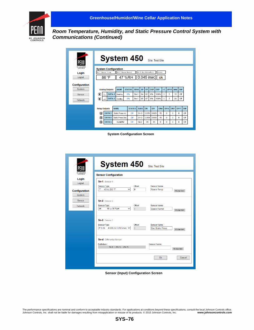
The performance specifications are nominal and conform to acceptable industry standards. For applications at conditions beyond these specifications, consult the local Johnson Controls office.Johnson Controls, Inc. shall not be liable for damages resulting from misapplication or misuse of its products. © 2015 Johnson Controls, Inc. www.johnsoncontrols.com
SYS–76
Room Temperature, Humidity, and Static Pressure Control System with Communications (Continued)
Greenhouse/Humidor/Wine Cellar Application Notes
System Configuration Screen
Sensor (Input) Configuration Screen

The performance specifications are nominal and conform to acceptable industry standards. For applications at conditions beyond these specifications, consult the local Johnson Controls office.Johnson Controls, Inc. shall not be liable for damages resulting from misapplication or misuse of its products. © 2015 Johnson Controls, Inc. www.johnsoncontrols.com
SYS–77
Room Temperature, Humidity, and Static Pressure Control System with Communications (Continued)
Greenhouse/Humidor/Wine Cellar Application Notes
Analog Output Configuration Screen
Relay Output Configuration Screen
Note: Refer to the System 450 Series Control Modules with Communications Technical Bulletin (LIT-12011826) for information on setting up the network parameters for your Ethernet network.

The performance specifications are nominal and conform to acceptable industry standards. For applications at conditions beyond these specifications, consult the local Johnson Controls office.Johnson Controls, Inc. shall not be liable for damages resulting from misapplication or misuse of its products. © 2015 Johnson Controls, Inc. www.johnsoncontrols.com
SYS–78
The C450CCN-x Control Module maintains the temperature with the OUTR1 output connected to the heating equipment and the OUTR2 output connected to the cooling equipment. See the wiring diagram for an illustration of this connection. Use a C450SCN-x Expansion Module to activate indicator lights or alarms in the event of out-of-range temperature conditions.
When the system is in operation, one of three status lights or audible alarms indicates the operating status.
IMPORTANT: Use this System 450™ modular control assembly only as an operating control. Where failure or malfunction of the System 450 modular control assembly could lead to personal injury or property damage to the controlled equipment or other property, additional precautions must be designed into the control system. Incorporate and maintain other devices, such as supervisory or alarm systems or safety or limit controls, intended to warn of or protect against failure or malfunction of the System 450 modular control assembly.
Code No. LIT-1900699
Heating and Cooling Control with System Status Indication
Refer to the System 450 Series Modular Control Systems with Standard Control Modules Technical Bulletin (LIT-12011459), theSystem 450 Series Modular Controls Product Bulletin (LIT-12011458), and the installation instructions for product specifications, detailed installation procedures, and important product safety information.
Heating and Cooling Control with System Status Lights Wiring Diagram
HeatingEquipment
CoolingEquipment
120 VAC
Series A99Sensor C450CCN-x
Control ModuleOUTR1, OUTR2
C450YNN-1Power Module
Low Normal High
Temperature
24, 120, or 230 VAC
C450SCN-xExpansion ModuleOUTR3, OUTR4
L1
N
Note: of choice shown wired to Sn1 and C (common) terminals.
Series A99 Sensor
CSn1
FIG
: sys
450_
light
s_w
irin
g_di
agra
m
LC
1L
NO
1LN
C1
LC2
LNO
2
LC
1L
NO
1LN
C1
LC2
LNO
2240VAC
120VAC
LC
1L
NO
1L
NC
1
LC2
LNO
2
LC
1L
NO
1L
NC
1
LC2
LNO
2WIRING24V Sn2C C
CSn1 Sn3
5V
L1
L2
Greenhouse/Humidor/Wine Cellar Application Notes

The performance specifications are nominal and conform to acceptable industry standards. For applications at conditions beyond these specifications, consult the local Johnson Controls office.Johnson Controls, Inc. shall not be liable for damages resulting from misapplication or misuse of its products. © 2015 Johnson Controls, Inc. www.johnsoncontrols.com
SYS–79
Heating and Cooling Control with System Status Indication (Continued)
Greenhouse/Humidor/Wine Cellar Application Notes
Application Operating Sequence
FIG
:sys
450_
app_
oper
atin
g_se
quen
ce_d
iagr
am
OUTR4
OUTR3 OFF
OFF
ON
ONRelayState
High Temperature Alarm
Low Temperature Alarm
OUTR2
OUTR1 OFF
OFF
ON
ONCooling
Heating
Temperature Low
Temperature High
Temperature Normal
Deadband
70 F 71° °F 72°F 73°F 74°F 75°F 76°F 77°F 78°F
Setup Screens for the Heating and Cooling Control Applications with System Status Indication System Example
Sn-1F
Sn-2 Sn-3
72ON1
76ON2
72ON3
77ON4
73OFF1
75OFF2
71OFF3
76OFF4
0ONT1
0ONT2
0ONT3
0ONT4
0OFFT1
0OFFT2
0OFFT3
0OFFT4
SNF1
OFF
SNF2
OFF
SNF3
On
SNF4
On
SENS1
Sn-1
SENS2
Sn-1
SENS3
Sn-1
SENS4
Sn-1
FIG
: sys
450_
ui_s
cree
ns
HeatingEquipment
CoolingEquipment
Low Temperature
Alarm
High Temperature
Alarm
SensorSetup SENS
SENS1
Sn-1
SENS2
Sn-1
SENS3
Sn-1
SENS4
Sn-1
Note: The Sensor Selection screens (in gray) only appear when you first set up each output. After you have selected a sensor for an output, the Sensor Selection screen only appears at the end of the Output Setup screens. If you need to select a different sensor for an output, navigate to the Sensor Edit screen at the end of the Output Setup screens, change the selected sensor, press the right arrow key, and enter the new values for the output.

Code No. LIT-1900708
Proportional Temperature, Pressure, or Humidity Control of an tuator
Greenhouse/Humidor/Wine Cellar Application Notes
M9100-GGA or M9100-GGC Ac
IMPORTANT: Use this System 450™ modular control assembly only as an operating control. Where failure or malfunction of the System 450 modular control assembly could lead to personal injury or property damage to the controlled equipment or other property, additional precautions must be designed into the control system. Incorporate and maintain other devices, such as supervisory or alarm systems or safety or limit controls, intended to warn of or protect against failure or malfunction of the System 450 modular control assembly.
The performance specifications are nominal and conform to acceptable industry standards. ForJohnson Controls, Inc. shall not be liable for damages resulting from misapplication or misuse
SYS–
Refer to the System 450 Series Modular Control Systems with Standard Control Modules Technical Bulletin (LIT-12011459), theSystem 450 Series Modular Controls Product Bulletin (LIT-12011458), and the installation instructions for product specifications, detailed installation procedures, and important product safety information.
A C450CPN-x Control Module Powered by aM9100-GGC Actuator Powered by
CO
MA
O1
WIRING24V Sn2C C
CSn1 Sn3
5V
C450CPN-xControl Module
OUTA1
24 VAC Class 2 or SELV
Transformer
L1
L2
120/240VAC
A99B Temperature SensorSn-1 Control Sensor
in UI Display( F Sensor Type)°
See Sensor Note
This application note illustrates how to wire a C450CPN-x Control Module to an M9100-GGA or M9100-GGC Actuator.
In these actuator application examples, Sn-1 is a °F (Sensor Type) and OUTA1 is an analog output that references the Sn-1 sensor. The M-9100 actuators are set up for control via a 2 to 10 VDC input signal from the System 450 control module. The System 450 control module provides 100% signal strength (10 VDC) at temperatures of 75°F and above, and 20% signal strength (2 VDC) at temperatures of 55°F and below. You can use any System 450 compatible sensor and any Setpoint or End Point values within the selected sensor’s defined range of values to control your application.
In the following application examples, a single temperature sensor is used to provide the input signal. You can also control these applications with a pressure, humidity, or functional sensor. Refer to the technical bulletin for complete information on selecting and setting up System 450 compatible sensors.
applications at conditions beyond these specifications, consult the local Johnson Controls office.of its products. © 2015 Johnson Controls, Inc. www.johnsoncontrols.com
80
C450YNN-1 Power Module Driving an M9100-GGA or a Dedicated 24 VAC External Transformer
240VAC
120VAC
Power Module C450YNN-1
24 VAC
COM
2-10V
120VAC
1 2 3 4 5 6
M9100-GGx Series Actuator
9060 30
0
FIG
:sys
450_
cont
rolp
ower

The performance specifications are nominal and conform to acceptable industry standards. For applications at conditions beyond these specifications, consult the local Johnson Controls office.Johnson Controls, Inc. shall not be liable for damages resulting from misapplication or misuse of its products. © 2015 Johnson Controls, Inc. www.johnsoncontrols.com
SYS–81
Proportional Temperature, Pressure, or Humidity Control of an M9100-GGA or M9100-GGC Actuator (Continued)
Greenhouse/Humidor/Wine Cellar Application Notes
A C450CPN-x Control Module Driving an M9100-GGA or M9100-GGC Actuator, All Powered by an External Transformer
CO
MA
O1
WIRING24V Sn2C C
CSn1 Sn3
5V
C450CPN-xControl Module
OUTA1
24 VAC
COM
2-10V
24 VAC Class 2 or SELV
Transformer
1 2 3 4 5 6
M9100-GGx Series Actuator
9060 30
0
L1
L2
FIG
:sys
450_
cont
roltr
ansf
orm
er
24V
C
120/240VAC
Note: The C (Common) terminalon the input terminal and theCOM terminal on the AnalogOutput are connected internally in the control module.
A99B Temperature SensorSn-1 Control Sensor
in UI Display( F Sensor Type)°
See Sensor Note
Sn1C
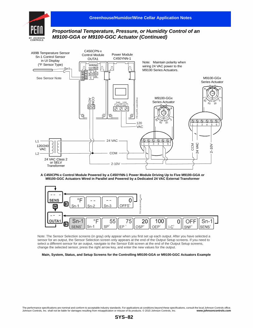
The performance specifications are nominal and conform to acceptable industry standards. For applications at conditions beyond these specifications, consult the local Johnson Controls office.Johnson Controls, Inc. shall not be liable for damages resulting from misapplication or misuse of its products. © 2015 Johnson Controls, Inc. www.johnsoncontrols.com
SYS–82
Proportional Temperature, Pressure, or Humidity Control of an M9100-GGA or M9100-GGC Actuator (Continued)
Greenhouse/Humidor/Wine Cellar Application Notes
A C450CPN-x Control Module Powered by a C450YNN-1 Power Module Driving Up to Five M9100-GGA orM9100-GGC Actuators Wired in Parallel and Powered by a Dedicated 24 VAC External Transformer
240VAC
120VAC
CO
MA
O1
WIRING24V Sn2C C
CSn1 Sn3
5V
C450CPN-xControl Module
OUTA1Power Module C450YNN-1
24 VAC
COM
2-10V
120VAC
24 VAC Class 2 or SELV
Transformer
1 2 3 4 5 6
1 2 3 4 5 6
Note: Maintain polarity when wiring 24 VAC power to the M9100 Series Actuators.
M9100-GGx Series Actuator
FIG
:sys
450_
cont
rol2
4vac
M9100-GGx Series Actuator
CC
M
24 V
AC
2–10
V
9060 30
0
9060 30
0
L1
L2
120/240VAC
A99B Temperature SensorSn-1 Control Sensor
in UI Display( F Sensor Type)°
See Sensor Note
Main, System, Status, and Setup Screens for the Controlling M9100-GGA or M9100-GGC Actuators Example
Note: The Sensor Selection screens (in gray) only appear when you first set up each output. After you have selected a sensor for an output, the Sensor Selection screen only appears at the end of the Output Setup screens. If you need to select a different sensor for an output, navigate to the Sensor Edit screen at the end of the Output Setup screens, change the selected sensor, press the right arrow key, and enter the new values for the output.

The performance speciJohnson Controls, Inc.
Code No. LIT-1900709
Refer to the SystStandard ControlSystem 450 Serieand the installatioinstallation proce
Note: This applcan control this ahumidity. Refer toselecting and setapplication.
Greenhouse/Humidor/Wine Cellar Application Notes
Proportional Control of a Barber-Colman® MMR-400 Actuator
In this System 450 application example, Sn-1 is a °F (Sensor Type) and OUTA1 is an analog output that references the Sn-1 sensor. The Barber-Colman® actuators are set up for a 0 to 10 VDC input signal from the control module, but the actuator can also be set up to respond to a 0 to 20 mA signal from the control module.
In this example, the control module provides 100% signal strength (10 VDC) at temperatures of 75°F and above, and 0% signal strength (0 VDC) at temperatures of 55°F and below. You can use any System 450 compatible sensor and any Setpoint or End Point value within the selected sensor’s defined range of values to
IMPORTANT: Use this System 450™ modular control assembly only as an operating control. Where failure or malfunction of the System 450 modular control assembly could lead to personal injury or property damage to the controlled equipment or other property, additional precautions must be designed into the control system. Incorporate and maintain other devices, such as supervisory or alarm systems or safety or limit controls, intended to warn of or protect against failure or malfunction of the System 450 modular control assembly.
fications are nominal and conform to acceptable industry standards. For applications at conditions beyond these specifications, consult the local Johnson Controls office.shall not be liable for damages resulting from misapplication or misuse of its products. © 2015 Johnson Controls, Inc. www.johnsoncontrols.com
SYS–83
em 450 Series Modular Control Systems with Modules Technical Bulletin (LIT-12011459), the s Modular Controls Product Bulletin (LIT-12011458), n instructions for product specifications, detailed
dures, and important product safety information.
ication example uses a temperature sensor, but you pplication based on temperature, pressure, or the technical bulletin for more information on
ting up System 450 compatible sensors for your
control this proportional damper application.
Terminal Connections ActuatorTerminal
C450CPN-x
Terminal Description
TR2 C Common
TR1 24V 24 VAC
16 AO1 Signal VDC
--------------------------- or -------------------------------
17 AO1 Signal mA
0–10 VDC Application with a Common Transformer
CO
MA
O1
C450CPN-xControl Module
OUTA1
WIRING24V Sn2C C
CSn1 Sn3
5V
L1
L2
FIG
:sys
450_
0to1
0vdc
_com
mtr
ans
24 VAC Class 2 or SELV
Transformer
24V
C
AO1
16TR2
TR1 9 17
Note: The C (Common) terminalson the input terminal blocks and the COM terminal on the analogoutput are connected internally inthe control module. The connection between C (on the control module) and TR2 on the actuator provides the common connection for the OUTA1 analog output.
120/240VAC
A99 Temperature SensorSn-1 Control Sensor
in UI Display( F Sensor Type)°
Note: Actuator terminal TR2 is internally connected to Terminal 9 on the actuator’s printed circuit board.

The performance specifications are nominal and conform to acceptable industry standards. For applications at conditions beyond these specifications, consult the local Johnson Controls office.Johnson Controls, Inc. shall not be liable for damages resulting from misapplication or misuse of its products. © 2015 Johnson Controls, Inc. www.johnsoncontrols.com
SYS–84
Proportional Control of a Barber-Colman® MMR-400 Actuator (Continued)
Greenhouse/Humidor/Wine Cellar Application Notes
Main, System, Status, and Setup Screens For the 0–10 VDC Application with a Common Transformer Example
Note: The Sensor Selection screens (in gray) only appear when you first set up each output. After you have selected a sensor for an output, the Sensor Selection screen only appears at the end of the Output Setup screens. If you need to select a different sensor for an output, navigate to the Sensor Edit screen at the end of the screens, change the selected sensor, press the right arrow key, and enter the new values for the output.
Output Setup

The performance specificaJohnson Controls, Inc. sh
ode No. LIT-1900865
Suction Pressure
Condenser PressuCondenser Pressu
Sp
CRefrigeration Application Notes
Two-Stage Cooling Application with Remote Communications Featuring On Delay Time and Analog Output Limiter Control
he On Delay and Off Delay Timers (ONd and OFFd) delay the control esponse before it acts on the sensed value. You can use the delay imers to prevent the control from responding to momentary sensor alue changes. ONd and OFFd, in addition to the Minimum On Timer nd Minimum Off Timer (ONT and OFFT), can also be used to set up nti-short cycling control for your equipment or to stagger the start of taged equipment.
n this example, a C450CEN-x Control Module controls a two-stage ooling system that includes head pressure control and a high space emperature alarm. The space sensor senses the temperature in the efrigerated space. When the temperature rises, the liquid-line olenoid valve (connected to the OUTR1 output) is energized. As the uction pressure rises, the low-pressure suction transducer senses the ise in pressure, and the first compressor (connected to the OUTR2 utput) starts after the on delay time expires. If the suction pressure
Refer to the System 450 Series Modular Control Systems with Communications Control Modules (LIT-12011826), the System 450 Series Modular Controls Product Bulletin (LIT-12011458), and the installation instructions for product specifications, detailed installation procedures, and important product safety information.
IMPORTANT: Use the System 450 control module only as an operating control. Where failure or malfunction of the System 450 control module could lead to personal injury or property damage to the controlled equipment or other property, additional precautions must be designed into the control system. Incorporate and maintain other devices, such as supervisory or alarm systems or safety or limit controls, intended to warn of or protect against failure or malfunction of the System 450 control module.
Trtvaas
Ictrssro
tions are nominal and conform to acceptable industry standards. For applications at conditions beyond these specifications, consult the local Johnson Controls office.all not be liable for damages resulting from misapplication or misuse of its products. © 2015 Johnson Controls, Inc. www.johnsoncontrols.com
SYS–85
continues to rise, the second compressor (connected to the OUTR3 output) starts, again after the on delay time expires. The on delay times prevent the compressors from responding immediately to changes in the sensor reading and prevent the compressors from short-cycling.
When the head pressure rises, the high-pressure discharge pressure sensor (Sn-3) senses the rise. This causes the analog output signal OUTA5, which controls the variable-frequency drive (VFD), to increase, which starts the condenser fan at low speed. If the head pressure continues to rise, the control increases the signal, and the condenser fan speed is increased to meet the demand. The output limiter features (UPR and bNd) prevent the VFD from hunting (over-actuating). If the temperature of the refrigerated space exceeds the high temperature alarm value (of 5F° in this example) for a period of time equal to or greater than the time delay, the remote alarm activates.
Wiring Diagram for a Two-Stage Cooling Application with Remote Communications Example
C450CEN-xControl Module
C450YNN-1Power Module
C450SCN-xExpansion ModuleOUTR1, OUTR2
C450SCN-xExpansion ModuleOUTR3, OUTR4
C450SPN-xExpansion Module
OUTA5
Transducer
re Transducer
Compressor 1
Alarm
Compressor 2
VFD
R1
R2
R3
R4
re Transducer
ace Temperature Sensor
Liquid Line Solenoid

The performance specifications are nominal and conform to acceptable industry standards. For applications at conditions beyond these specifications, consult the local Johnson Controls office.Johnson Controls, Inc. shall not be liable for damages resulting from misapplication or misuse of its products. © 2015 Johnson Controls, Inc. www.johnsoncontrols.com
SYS–86
Two-Stage Cooling Application with Remote Communications Featuring On Delay Time and Analog Output Limiter Control (Continued)
Refrigeration Application Notes
The screen captures on the following pages show the web user interface on the C450CEN-x Control Module.
Note: This example is for illustrative purposes only. Conditions may vary depending on the application.
UI Screens for the Two-Stage Cooling Application with Remote Communications Example
Note: The Sensor Selection screens (in gray) only appear when you first set up each output. After you have selected a sensor for an output, the Sensor Selection screen only appears at the end of the output setup screens. If you need to select a different sensor for an output, navigate to the Sensor Edit screen at the end of the output setup screens, change the selected sensor, press the right arrow key, and enter the new values for the output.
FIG
:sys
450_
ui_s
cree
ns
USER
- - -
AdMN- - -
COMM
- - -

The performance specifications are nominal and conform to acceptable industry standards. For applications at conditions beyond these specifications, consult the local Johnson Controls office.Johnson Controls, Inc. shall not be liable for damages resulting from misapplication or misuse of its products. © 2015 Johnson Controls, Inc. www.johnsoncontrols.com
SYS–87
Two-Stage Cooling Application with Remote Communications Featuring On Delay Time and Analog Output Limiter Control (Continued)
Refrigeration Application Notes
Input (Sensor) Configuration Screen
System Configuration Screen

The performance specifications are nominal and conform to acceptable industry standards. For applications at conditions beyond these specifications, consult the local Johnson Controls office.Johnson Controls, Inc. shall not be liable for damages resulting from misapplication or misuse of its products. © 2015 Johnson Controls, Inc. www.johnsoncontrols.com
SYS–88
Two-Stage Cooling Application with Remote Communications Featuring On Delay Time and Analog Output Limiter Control (Continued)
Refrigeration Application Notes
Output Configuration Screen for OUTA5
Output Configuration Screen for OUTR1
Note: Refer to the System 450 Series Control Modules with Communications Technical Bulletin (LIT-12011826) for information on setting up the network parameters for your Ethernet network.

The performance specificaJohnson Controls, Inc. sh
ode No. LIT-1900864
Refer to the SystemStandard Control MSystem 450 Series and the installation installation procedu
CSolar Collector Application Notes
Solar Heating Control Applications with Differential Temperature Control
IMPORTANT: Use the System 450™ control module only as an operating control. Where failure or malfunction of the System 450 control module could lead to personal injury or property damage to the controlled equipment or other property, additional precautions must be designed into the control system. Incorporate and maintain other devices, such as supervisory or alarm systems or safety or limit controls, intended to warn of or protect against failure or malfunction of the System 450 control module.
tions are nominal and conform to acceptable industry standards. Forall not be liable for damages resulting from misapplication or misuse
SYS–
450 Series Modular Control Systems with odules Technical Bulletin (LIT-12011459), the Modular Controls Product Bulletin (LIT-12011458), instructions for product specifications, detailed res, and important product safety information.
System 450 Solar Heating Control Applicati
240VAC
120VAC
WIRING24V Sn2C C
CSn1 Sn3
5V
LC
1LN
O1
LNC
1
LC2
LNO
2
LC
1LN
O1
LNC
1
LC2
LNO
2
L1
L2
C450CCN-xControl ModuleOUTR1, OUTR2
C450YNNPower Mod
C2
Stor
TE-6000-6Storage Tank
SensorSn-2
Room Temperature Circulating PumpControlled by Room Temperature (Sn-3)
A99B SeriesRoomSensorSn-3
C
C
CSn3
Sn2
Sn1
RoomHeating
Loop
C1
Note: If you require a wall mount sensor for the room sensensing element. If a TE-68NT-0N00S sensor is used, ch
In this solar heating example, a solar panel circulating pump is controlled by differential temperature (diFT). When the temperature of the solar panel is 10F° above the temperature of the water in the storage tank, the solar panel circulating pump begins to run.
When the differential temperature (dON1) is met, the normally open contacts of relay output 1 close, energizing C2 and starting the circulating pump. The pump cycles off when the differential temperature (dOFF1) falls to 5F°. The room temperature circulating pump is controlled by the room temperature sensor (Sn-3) and the storage tank sensor (Sn-2).
When heating is required, the normally open contact on Relay Output 2 (OUTR2) closes, energizing C1 and starting the room temperature circulating pump. Relay Output 3 (OUTR3) locks out the room temperature circulating pump if the water in the tank drops below 70°F, allowing the pump to restart when the water temperature rises to 75°F or higher.
applications at conditions beyond these specifications, consult the local Johnson Controls office.of its products. © 2015 Johnson Controls, Inc. www.johnsoncontrols.com
89
on with Differential Temperature Control Example
LC1
LNO
1LN
C1
TE-6000-6 High TemperatureSolar Panel
SensorSn-1
Sol
ar C
olle
ctor
-1ule
C450SBN-xExpansion
ModuleOUTR3
Solar Panel Circulating PumpControlled by Differential Temperature (Sn-d)
C2
C1
age Tank
FIG
:sys
450_
sola
r_di
ffco
ntro
l_di
agra
m
TE Series Temperature Sensor
sor, order a TE-68NT-0N00S Wall Mount Sensor with a nickel Sn-3 value to HI-F.ange the

The performance specifications are nominal and conform to acceptable industry standards. For applications at conditions beyond these specifications, consult the local Johnson Controls office.Johnson Controls, Inc. shall not be liable for damages resulting from misapplication or misuse of its products. © 2015 Johnson Controls, Inc. www.johnsoncontrols.com
SYS–90
Solar Heating Control Applications with Differential Temperature Control (Continued)
Solar Collector Application Notes
System 450 UI Status and Setup Screens for Solar Heating Control Applications
SENSSn-1 Sn-2 Sn-3
OUTR1
OUTR2
5dOFF1
65ON2
68OFF2
0ONT1
0ONT2
0OFFT1
0OFFT2
SNF2
OFF
SNF2
OFF
SENS1
Sn-d
SENS2
Sn-3
dON1
10
M OFFS1
0
OUTR3 75 70OFF2
0ONT3
0OFFT3 SNF3
OFFSENS3
Sn-2
F 0OFFS2
0OFFS3
O N3
SENS1
Sn-d
SENS2
Sn-3
SENS3
Sn-2
Note: The Sensor Selection screens (in gray) only appear when you first set up each output. After you have selected a sensor for an output, the Sensor Selection screen only appears at the end of the output setup screens. If you need to select a different sensor for an output, navigate to the Sensor Edit screen at the end of the output setup screens, change the selected sensor, press the right arrow key, and enter the new values for the output.
FIG
:sys
450_
ui_s
cree
ns
HI F HI F
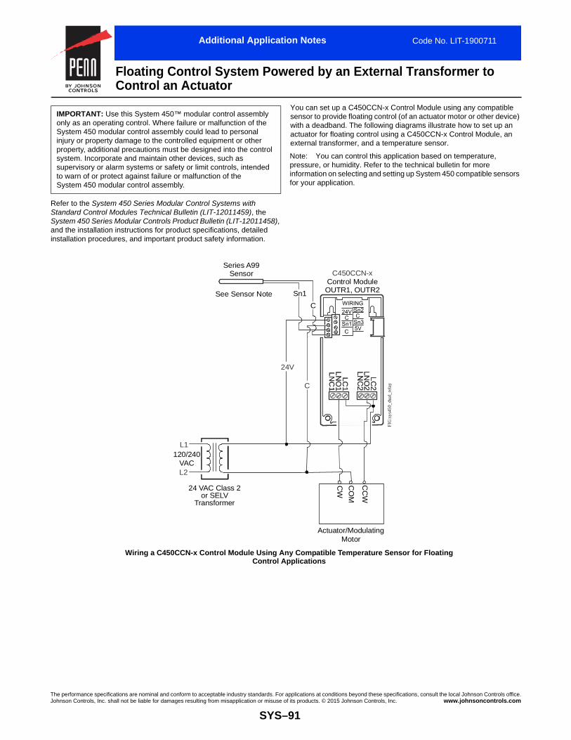
The performance specificaJohnson Controls, Inc. sh
ode No. LIT-1900711
IMPORTANT: Usonly as an operatSystem 450 moduinjury or property property, additionsystem. Incorporasupervisory or alato warn of or protSystem 450 modu
Refer to the SystemStandard Control MSystem 450 Series and the installation installation procedu
CAdditional Application Notes
Floating Control System Powered by an External Transformer to Control an Actuator
tions are nominal and conform to acceptable industry standards. For applications at conditions beyond these specifications, consult the local Johnson Controls office.all not be liable for damages resulting from misapplication or misuse of its products. © 2015 Johnson Controls, Inc. www.johnsoncontrols.com
SYS–91
e this System 450™ modular control assembly ing control. Where failure or malfunction of the lar control assembly could lead to personal
damage to the controlled equipment or other al precautions must be designed into the control te and maintain other devices, such as rm systems or safety or limit controls, intended
ect against failure or malfunction of the lar control assembly.
You can set up a C450CCN-x Control Module using any compatible sensor to provide floating control (of an actuator motor or other device) with a deadband. The following diagrams illustrate how to set up an actuator for floating control using a C450CCN-x Control Module, an external transformer, and a temperature sensor.
450 Series Modular Control Systems with odules Technical Bulletin (LIT-12011459), theModular Controls Product Bulletin (LIT-12011458), instructions for product specifications, detailed res, and important product safety information.
Note: You can control this application based on temperature, pressure, or humidity. Refer to the technical bulletin for more information on selecting and setting up System 450 compatible sensors for your application.
Wiring a C450CCN-x Control Module Using Any Compatible Temperature Sensor for Floating Control Applications
24 VAC Class 2 or SELV
Transformer
L1
L2
WIRING24V Sn2C C
CSn1 Sn3
5V
LC1
LN
O1
LNC
1
LC
2LN
O2
LC1
LN
O1
LNC
1
LC
2LN
O2
C450CCN-xControl ModuleOUTR1, OUTR2
FIG
:sys
450_
dual
_rel
ay
Actuator/Modulating Motor
CC
W
CO
M
CW
120/240VAC
24V
C
See Sensor Note
Series A99Sensor
Sn1
C

The performance specifications are nominal and conform to acceptable industry standards. For applications at conditions beyond these specifications, consult the local Johnson Controls office.Johnson Controls, Inc. shall not be liable for damages resulting from misapplication or misuse of its products. © 2015 Johnson Controls, Inc. www.johnsoncontrols.com
SYS–92
Floating Control System Powered by an External Transformer to Control an Actuator (Continued)
Additional Application Notes
Floating Control Diagram
OUTR1
OUTR2
Drive CCW
Deadband
Drive CWOFF to ON
ON to OFF
OFF
ON
Note: This graph represents a temperature example, but you can use a pressure or humidity sensor instead.
68°F 70°F 74°F 76°F72°F
Main, System, Status, and Setup Screens For the Floating Control Application Example ThatControls Temperature
Note: The Sensor Selection screens (in gray) only appear when you first set up each output. After you have selected a sensor for an output, the Sensor Selection screen only appears at the end of the Output Setup screens. If you need to select a different sensor for an output, navigate to the Sensor Edit screen at the end of the screens, change the selected sensor, press the right arrow key, and enter the new values for the output.
Output Setup

The performance specifiJohnson Controls, Inc. s
Code No. LIT-1900863
Refer to the SysteCommunications CSeries Modular Coinstallation instrucprocedures, and im
0-5Wi
Additional Application Notes
Head Pressure Control - Water Source Heat Pump with Analog Output Limiter Control
In this example, the C450CEN-x Control Module controls head pressure on a water source heat pump for both heating and cooling. In this type of application, the head pressure is typically lower when the heat pump is operating in heating mode, and the pressure is higher when operating in cooling mode. AO1 is controlling the head pressure in the heating mode and AO2 is controlling the head pressure in the cooling mode. The analog output limiter function prevents the valve from excessive modulating.
IMPORTANT: Use the System 450™ control module only as an operating control. Where failure or malfunction of the System 450 control module could lead to personal injury or property damage to the controlled equipment or other property, additional precautions must be designed into the control system. Incorporate and maintain other devices, such as supervisory or alarm systems or safety or limit controls, intended to warn of or protect against failure or malfunction of the System 450 control module.
cations are nominal and conform to acceptable industry standards. For applications at conditions beyond these specifications, consult the local Johnson Controls office.hall not be liable for damages resulting from misapplication or misuse of its products. © 2015 Johnson Controls, Inc. www.johnsoncontrols.com
SYS–93
m 450 Series Modular Control Systems with ontrol Modules (LIT-12011826), the System 450 ntrols Product Bulletin (LIT-12011458), and the
tions for product specifications, detailed installation portant product safety information.
Controlling Head Pressure on a Water Source Heat Pump for both Heating and Cooling
24 VAC Class 2or SELV
Transformer
C450SQN-xExpansion Module
OUTA1, OUTA2C450CEN-x
Control Module
WIRING24V Sn2COM C
CSn1 Sn3
5V
AO
2C
OM
AO
1
00 psi Pressure Transducer re to Sn1
Head Pressure Transducer Install on Liquid LineAfter Condenser Coil
VG1241BL+9T4GGA Valvewith VA9104-GGA-2 Valve Motor. 0-10VDC NSR Direct Acting (Fail in Place)
Note: A wire lead from COM on the analog output terminal block is not required because all of the common terminals (COM and C) in the module assembly are connected internally. COM on the control module input terminal block is connected to COM on the actuator and serves as the analog output common connection.
Com 1+24v 2Input 3Position 4
Sn1
5V
L1
L2
120/240VAC
FIG
:sys
450_
heat
_pum
p
24V
COM
Note: When the analog outputs are connected together, they function as a high signal select output.

The performance specifications are nominal and conform to acceptable industry standards. For applications at conditions beyond these specifications, consult the local Johnson Controls office.Johnson Controls, Inc. shall not be liable for damages resulting from misapplication or misuse of its products. © 2015 Johnson Controls, Inc. www.johnsoncontrols.com
SYS–94
Head Pressure Control - Water Source Heat Pump with Analog Output Limiter Control (Continued)
Additional Application Notes
In this example, the sensor input Sn-1 is set to P500 (with a range from 0 to 500 psi). The Sn-2 and Sn-3 inputs are not used.
The sensor outputs AO1 and AO2 on the C450SQN-x Expansion Module are configured as separate control feedback loops, but both use Sn1 as the input sensor and both control the valve actuator motor.
The screen captures on the following pages show the web user interface on the C450CEN-x Control Module.
Note: This example is for illustrative purposes only. Conditions may vary using different applications.
OUTA1 is used for heating mode (lower head pressure operating range), and OUTA2 is used for cooling mode (higher head pressure operating range).
The update rate and output deadband settings are used to minimize changes to the valve position. These parameters form the analog output limiter.
System Output Diagrams Showing Heating and Cooling Modes for the Head Pressure Control Example
Heating Mode
ProportionalBand
OEP
OSP
100%
0%
EP=110 psi SP=195 psi SP=300 psi EP=360 psi
100%
Cooling Mode
0%
AO2
ProportionalBandOEP
OSP
FIG
:sys
450_
grap
hs
Example Status and UI Setup Screens for Controlling Head Pressure on a Water Source Heat Pump for Both Heating and Cooling
Note: The Sensor Selection screens (in gray) only appear when you first set up each output. After you have selected a sensor for an output, the Sensor Selection screen only appears at the end of the Output Setup screens. If you need to select a different sensor for an output, navigate to the Sensor Edit screen at the end of the Output Setup screens, change the selected sensor, press the right arrow key, and enter the new values for the output.
FIG
:sys
450_
ui_s
cree
ns
Refer to the for more information.
System 450 Series Control Modules with Communications Technical Bulletin (LIT-12011826)USER
- - -
AdMN- - -
COMM
- - -

The performance specifications are nominal and conform to acceptable industry standards. For applications at conditions beyond these specifications, consult the local Johnson Controls office.Johnson Controls, Inc. shall not be liable for damages resulting from misapplication or misuse of its products. © 2015 Johnson Controls, Inc. www.johnsoncontrols.com
SYS–95
Head Pressure Control - Water Source Heat Pump with Analog Output Limiter Control (Continued)
Additional Application Notes
OUTA-1 Configuration Screen
Sensor Configuration Screen

The performance specifications are nominal and conform to acceptable industry standards. For applications at conditions beyond these specifications, consult the local Johnson Controls office.Johnson Controls, Inc. shall not be liable for damages resulting from misapplication or misuse of its products. © 2015 Johnson Controls, Inc. www.johnsoncontrols.com
SYS–96
Head Pressure Control - Water Source Heat Pump with Analog Output Limiter Control (Continued)
Additional Application Notes
OUTA-2 Configuration Screen
Note: Refer to the System 450 Series Control Modules with Communications Technical Bulletin (LIT-12011826) for information on setting up the network parameters for your Ethernet network.

The performance specifications are nominal and conform to acceptable industry standards. For applications at conditions beyond these specifications, consult the local Johnson Controls office.Johnson Controls, Inc. shall not be liable for damages resulting from misapplication or misuse of its products. © 2015 Johnson Controls, Inc. www.johnsoncontrols.com
SYS–97
Code No. LIT-1900710
Extending A99 Sensor Cables
IMPORTANT: The A99 temperature sensor is intended to provide an input to equipment under normal operating conditions. Where failure or malfunction of the A99 temperature sensor could lead to personal injury or property damage to the controlled equipment or other property, additional precautions must be designed into the control system. Incorporate and maintain other devices, such as supervisory or alarm systems or safety or limit controls, intended to warn of or protect against failure or malfunction of the A99 temperature sensor.
When the A99x Sensor is installed more than 50 feet (15.25 meters) from the controller, the resistance of the wire in the cable can create a significant deviation to the sensor reading. Use the following procedure to compensate for the deviation.
1. Use one of the following formulas to calculate the total wire resistance (error):a. Total wire resistance (ohms) = 2 x (Length of wire cable in meters) x (Resistance in ohms/meter)b. Total wire resistance (ohms) = 2 x (Length of wire cable in feet) x (Resistance in ohms/foot)
Ohm Resistance of Typical Stranded Copper Wire
2. Determine the approximate temperature control point of the remote-mounted A99 Sensor, and then use that °F or °C temperature in one of the following formulas to determine the ohms/degree at that temperature:• Ohms/°C = (0.0339 x °C) + 6.78• Ohms/°F = (0.01045 x °F) + 3.42
3. Calculate the wire resistance error in °F or °C: Error = (ohm wire resistance error)/(ohms/degree value at control point)
Wire Size Cross Section Area
Resistance
American Wire Gauge (AWG)
Metric (mm) Circular mils Ohm/foot Ohm/meter
26 254 .0418 .137
24 404 .0262 .0859
22 642 .0165 .054
.50 987 .0107 .0352
20 1,022 .0104 .034
.75 1,480 .0071 .0234
18 1,624 .0065 .0214
1.0 1,974 .0054 .0176
Metric Example
If the A99 Sensor used for Sn-1 and Sn-2 inputs is installed 50 meters (164 feet) from the C450 control using 0.5 mm wire, the total wire resistance (error) is:
2 x 50 x 0.0352 = 3.52 ohms
Then, if the A99 Sensor controls a process at 25°C, the ohms/°C is:
(0.0339 x 25) + 6.78 = 7.63 ohms/°C
Therefore, the error is:
3.52/7.63 = 0.46°C
So, the C450 control sensor inputs for Sn-1 and Sn-2 should be offset by -0.5°C.
English Example
If the A99 Sensor used for Sn-1 and Sn-2 inputs is installed 300 feet (91.44 meters) from the C450 control using 18 AWG wire, the total wire resistance (error) is:
2 x 300 x 0.0065 = 3.9 ohms
Then, if the A99 Sensor controls a process at 70°F, the ohms/°F is:
(0.01045 x 70) + 3.42 = 4.15 ohms/°F
Therefore, the error is:
3.9/4.15 = 0.94°F
So, the C450 control sensor inputs for Sn-1 and Sn-2 should be offset by -1°F.
The following diagram illustrates how to enter this offset in the C450 Sensor Setup screen.
Refer to the System 450 Series Modular Controls Product Bulletin (LIT-12011458), the A99B Series Temperature Sensors Product/Technical Bulletin (LIT-125186), and the installation instructions for product specifications, detailed installation procedures, and important product safety information.
IMPORTANT: When connecting an A99 temperature sensor with shielded cable to an electronic controller, connect the cable shield drain lead to a low-voltage common terminal on the input sensor terminal block. Do not connect the shield at any other point along the cable. Isolate and insulate the shield drain at the sensor end of the cable. Connecting a cable shield at more than one point can enable transient currents to flow through the sensor cable shield, which can cause erratic control operation.
Note: Use shielded wire when you install the sensor more than 50 feet (15.25 meters) from the controller.
Additional Application Notes

The performance specifications are nominal and conform to acceptable industry standards. For applications at conditions beyond these specifications, consult the local Johnson Controls office.Johnson Controls, Inc. shall not be liable for damages resulting from misapplication or misuse of its products. © 2015 Johnson Controls, Inc. www.johnsoncontrols.com
SYS–98
Extending A99 Sensor Cables (Continued)
Additional Application Notes
Press and hold + for 5 seconds to go tothe Setup Start screens.
Setting Up Sensor Temperature Offsets in the System 450 UI
SYS–99
NOTES

SYS–100
NOTES

REFRIGERATION CONTROLS
Johnson Controls offers a broad line of innovative, high-performing and energy-saving
HVAC and refrigeration controls
VALVES
VARIABLE SPEED DRIVES
ACTUATORS
PNEUMATICSDAMPERS, LOUVERS & AIR MEASURING PRODUCTS
SENSORS & THERMOSTATS HVAC CONTROL PANEL PRODUCTS

Printed on recycled paper.
Johnson Controls, the Johnson Controls logo and the PENN by Johnson Controls logo are registered trademarks of Johnson Controls, Inc. in the United States of America and other countries. Other trademarks used herein may be trademarks or registered trademarks of other companies.
© 2015 Johnson Controls, Inc. P.O. Box 423, Milwaukee, WI 53201 Printed in USA PUBL-7644www.johnsoncontrols.com
For more information, or to purchase Johnson Controls products, call 1-800-275-5676 or 1-800-482-2778.
We are in the business of
building efficiency. We create buildings
and environments that help people achieve
and enterprises succeed. We do that by delivering
energy savings. Operational savings. And sustainable
solutions. In fact, PENN commercial refrigeration
controls by Johnson Controls have been
serving the cooling needs of millions of
customers for the past 95 years.