
OptiX RTN 905e Radio Transmission System V100R010 IDU ...
40
HUAWEI TECHNOLOGIES CO., LTD. OptiX RTN 905e Radio Transmission System V100R010 IDU Quick Installation Guide (Indoor) Issue: 01 Date: 2017-05-30
-
Upload
khangminh22 -
Category
Documents
-
view
2 -
download
0
Transcript of OptiX RTN 905e Radio Transmission System V100R010 IDU ...

HUAWEI TECHNOLOGIES CO., LTD.
OptiX RTN 905e Radio Transmission System
V100R010
IDU Quick Installation Guide (Indoor)
Issue: 01
Date: 2017-05-30

Huawei Technologies Co., Ltd.
Address: Huawei Industrial Base
Bantian, Longgang
Shenzhen 518129
People's Republic of China
Website: http://www.huawei.com
Email: [email protected]
No part of this document may be reproduced or transmitted in any form or by any means without prior
written consent of Huawei Technologies Co., Ltd.
Copyright © Huawei Technologies Co., Ltd. 2017. All rights reserved.
Trademarks and Permissions
and other Huawei trademarks are trademarks of Huawei Technologies Co., Ltd.
All other trademarks and trade names mentioned in this document are the property of their respective
holders.
Notice
The purchased products, services and features are stipulated by the contract made between Huawei and
the customer. All or part of the products, services and features described in this document may not be
within the purchase scope or the usage scope. Unless otherwise specified in the contract, all statements,
information, and recommendations in this document are provided "AS IS" without warranties, guarantees
or representations of any kind, either express or implied.
The information in this document is subject to change without notice. Every effort has been made in the
preparation of this document to ensure accuracy of the contents, but all statements, information, and
recommendations in this document do not constitute a warranty of any kind, express or implied.

Before You Start
0
Installation Process
PrecautionsPage 2
Start
Precautions for Handling
the RTN 905e Toggle
Lever SwitchPage 4
Precautions for
Handling RTN 905e IF
Jumpers
Page 5
Introduction to the
IDU 905e EquipmentPage 7
Installing the IDU 905ePages
8 to 13
Optional: Installing the
E1 Panel
Pages
13 to 14
Installing IDU CablesPages
15 to 25
Checking the
InstallationPage 34
End
Installing Power
Cables
Pages
15 to 16
Installing FibersPages
17 to 18
Installing E1 CablesPage 16
Installing IF CablesPage 19
Installing Ethernet
Service CablesPage 18
Installing NMS CablesPage 21
Installing Cascade
Cables and XPIC
Cables
Page 20
Preparing and
Installing External
Alarm Cables
Page 22
Preparing and
Installing External
Clock Cables
Page 24
Preparing and
Installing Synchronous
Data Cables
Page 23
Cable LayoutPage 25
Installing the Chassis
in a 19-Inch CabinetPages
8 to 9
Installing the Chassis
in an ETSI Cabinet
Pages
9 to 10
Wall Mounting
the Chassis
Pages
11 to 12
Desk Mounting
the ChassisPage 13
Installation ToolsPage 6
Precautions for
Handling RTN 905e IF
Cables
Page 5
Precautions for
Handling
Power Cables
Page 3
Installing the Chassis
in a 23-Inch Cabinet
Pages
10 to 11

11
Commissioning Process
Powering On the
EquipmentPage 26
Start
Configuring NE Data
(Using the Web LCT)Page 28
Aligning AntennasPages
29 to 31
Checking the Status of
Radio LinksPage 31
Aligning Single-
Polarized Antennas
Pages
29 to 30
Aligning Dual-
Polarized Antennas
Pages
30 to 31
End
Configuring NE Data
(Using the USB Flash
Drive)
Page 27
Configuring NE Data
(Using the Hand-Held
Tool)
Page 28

2
Precautions
This document provides guidelines for quick hardware installation.
This document does not describe assembly of equipment prior to delivery; it only describes procedures
for onsite installation.
Electrostatic Discharge
To prevent damage to sensitive components caused by electrostatic discharge, wear ESD gloves or an
ESD wrist strap when handling the equipment, boards, or IC chips. Ensure that the ESD wrist strap is
properly grounded.
Binding Cables
Bind fibers or cables inside a cabinet at intervals of not more than 250 mm and user cables at intervals of
not more than 200 mm.
Bind fibers, cables, or corrugated pipes outside a cabinet at intervals equal to the distance between two
horizontal beams. If the cable trough does not have any beams, the intervals should not exceed 250 mm.
Pre-installation Check
Before beginning the installation, check the equipment room, cabinet, power supply, ground cables,
fibers, and associated facilities to confirm that all preparations are complete.
Power Supply
The equipment uses a -48 V/-60 V DC power supply. An AC power supply or a high-voltage power
supply may cause equipment damage or even human injuries and therefore is forbidden.
CAUTION
ESD
OptiX RTN 905

3
Prior to installing power cables on the RTN 905e, confirm that the following conditions are met.
The ground point on the column of the cabinet or the indoor ground bar is properly grounded.
Ensure that the power cable is properly connected to the positive and negative terminals of the power
supply device.Install a circuit breaker on each negative terminal of the power supply device.
The recommended fuse capacity is 16 A. This prevents a power loop from being formed by connecting the
positive terminal of the RTN 905e power cable to the negative terminal of the power supply device
and therefore protects the power cable and power supply device.
The positive terminals of the power supply device connected to the RTN 905e are grounded. If terminals
are not properly grounded, the devices may be damaged.
PSU
PGND
Precautions for Handling Power Cables
SW
SW
DC power port
1
2
3
To the ground point on the column of the cabinet or the indoor ground bar

4
Position and Description of the Toggle Lever Switch
Turning on the switch
Precautions for Handling the RTN 905e Toggle Lever Switch
You must first pull out the toggle lever switch
before turning it.
I: ON
O: OFF
Turning off the switch
1
1
2
2
3
3Pull the switch out gently. Turn the switch. Release the switch.
1
1
2
2
3
3Pull the switch out gently. Turn the switch. Release the switch.

5
Power off the ODU. Install or remove an IF fiber connected to the ODU.
Precautions for Handling RTN 905e IF Jumpers
Power off the ODU before you remove or install an
IF jumper connected to the ODU.
Do not remove or install an IF jumper connected to
the ODU while the ODU is powered on.
Power off the ODU before you remove or
install an IF cable connected to the ODU.
Do not remove or install an IF cable connected to
the ODU while the ODU is powered on.
Power off the ODU. Install or remove an IF cable connected to the ODU.
Precautions for Handling RTN 905e IF Cables

Installation Tools
6
Measuring tape Phillips screwdriver Flat-head screwdriver
Adjustable wrench
Level
Socket wrench Torque wrench Hex key
Wire clippersDiagonal pliersNeedle-nose pliersCombination pliers
Bayonet wrench
Utility knife
Claw hammer
Marker
Ladder
CompassLifting slingPulleyESD gloves
Multimeter PVC tapeFileWaterproof
insulation tape

7
1 Ports
Introduction to the IDU 905e Equipment
Ground screw
DC-C power socket (Caution!
See "Precautions for
Handling Power Cables.")
NE status indicator
1
2
3 Mini USB port
5
IF ports to the ODU/ODU switches
6
Radio link status indicator
7
8
Status indicators of the GE/FE service ports (SFP modules)
9
USB port/Status
indicator
10
11
12NMS port/NMS serial port
NE cascading port/Asynchronous data port
Clock port (CLK)/High-precision
time port (TOD)/Outdoor cabinet
monitoring port (MON)
4
Alarm input/output port
Power over Ethernet
port
GE/FE service ports (SFP modules)
STM-1 service ports16
17
16xE1 ports13
14
15
18
COMBO ports
Port for the ESD wrist strap19
MN1 subboard
FE/GE service electrical ports (RJ-45 connectors)20
1
2
3
4
5
6
7
8
9
10
11 13 16
12
14 15 17 1918
20

8
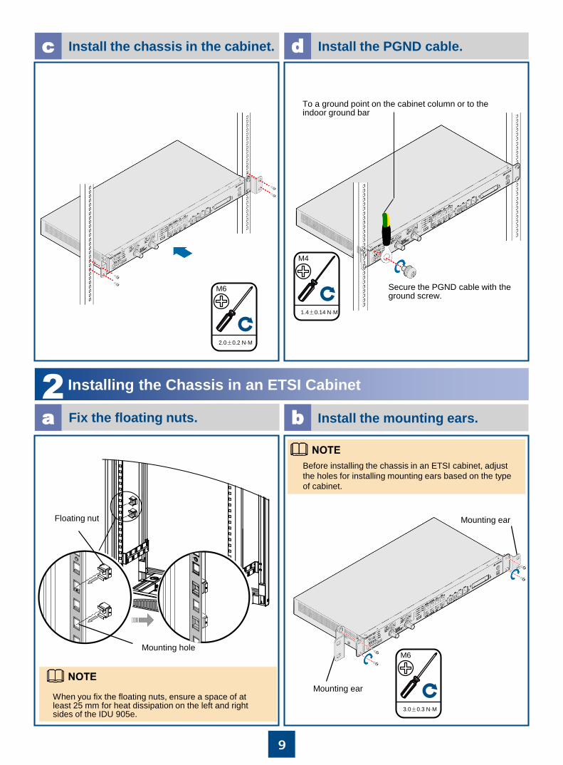
1Installing the Chassis in a 19-Inch Cabinet
Mounting hole
Keep the ground screw for installing the protection ground (PGND) cable.
When you fix the floating nuts, ensure a space of at least 25 mm for heat dissipation on the left and right sides of the IDU 905e.
Floating nut
Fix the floating nuts.a
Remove the ground screw.b
Installing the IDU 905e
9
Install the chassis in the cabinet.c Install the PGND cable.d
Secure the PGND cable with the ground screw.
Install the mounting ears.a b
2Installing the Chassis in an ETSI Cabinet
Fix the floating nuts.
Mounting earWhen you fix the floating nuts, ensure a space of at least 25 mm for heat dissipation on the left and right sides of the IDU 905e.
2.0±0.2 N·M
M6
3.0±0.3 N·M
M6
1.4±0.14 N·M
M4
Floating nut
Mounting hole
To a ground point on the cabinet column or to the indoor ground bar
Before installing the chassis in an ETSI cabinet, adjust
the holes for installing mounting ears based on the type
of cabinet.
Mounting ear

10
d Install the PGND cable.c Install the chassis in the cabinet.
Secure the PGND cable with the ground screw.
3Installing the Chassis in a 23-Inch Cabinet
1.4±0.14 N·M
M4
2.0±0.2 N·M
M6
To a ground point on the cabinet column or to the indoor ground bar
23-Inch Mounting ear
23-Inch Mounting ear
1.4±0.14 N·M
M6
Remove the mounting ears.a Install the mounting ears.b
Store the removed screws properly for installing 23-
inch mounting ears.
NOTE

11
Remove the mounting ears.a Install the mounting ears.b
4Wall Mounting the Chassis
Rotate the mounting ears 90 degrees and install them as shown in this figure.
d Install the PGND cable.c Install the chassis in the cabinet.
Secure the PGND cable with the ground screw.
1.4±0.14 N·M
M4
To a ground point on the cabinet column or to the indoor ground bar
2.0±0.2 N·M
M6
12
8
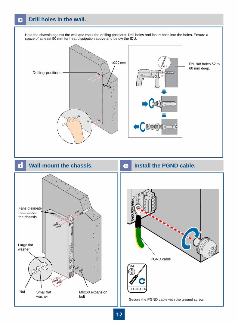
Drilling positions
Drill holes in the wall.c
Wall-mount the chassis.d Install the PGND cable.e
PGND cable
M6x60 expansion
bolt
Drill Ф8 holes 52 to
60 mm deep.
Nut Small flat
washer
Large flat
washer
Secure the PGND cable with the ground screw.
≥300 mm
Hold the chassis against the wall and mark the drilling positions. Drill holes and insert bolts into the holes. Ensure a space of at least 50 mm for heat dissipation above and below the IDU.
1.4±0.14 N·M
M4
Fans dissipate
heat above
the chassis.

13
Install the base plates.a Install the PGND cable.b
4Desk Mounting the Chassis
Do not place any objects that may impede heat dissipation next to the chassis.
PGND cable
Secure the PGND cable with the ground screw.
Base plate
1Fix the floating nuts.
Optional: Installing the E1 Panel
Remove the mounting ears and install the base plates.
1.4±0.14 N·M
M4
Floating nut
Mounting hole

14
2Secure the E1 Panel.
3Install the PGND cable for the E1 panel.
To a ground point on the cabinet column or to the indoor ground bar
15
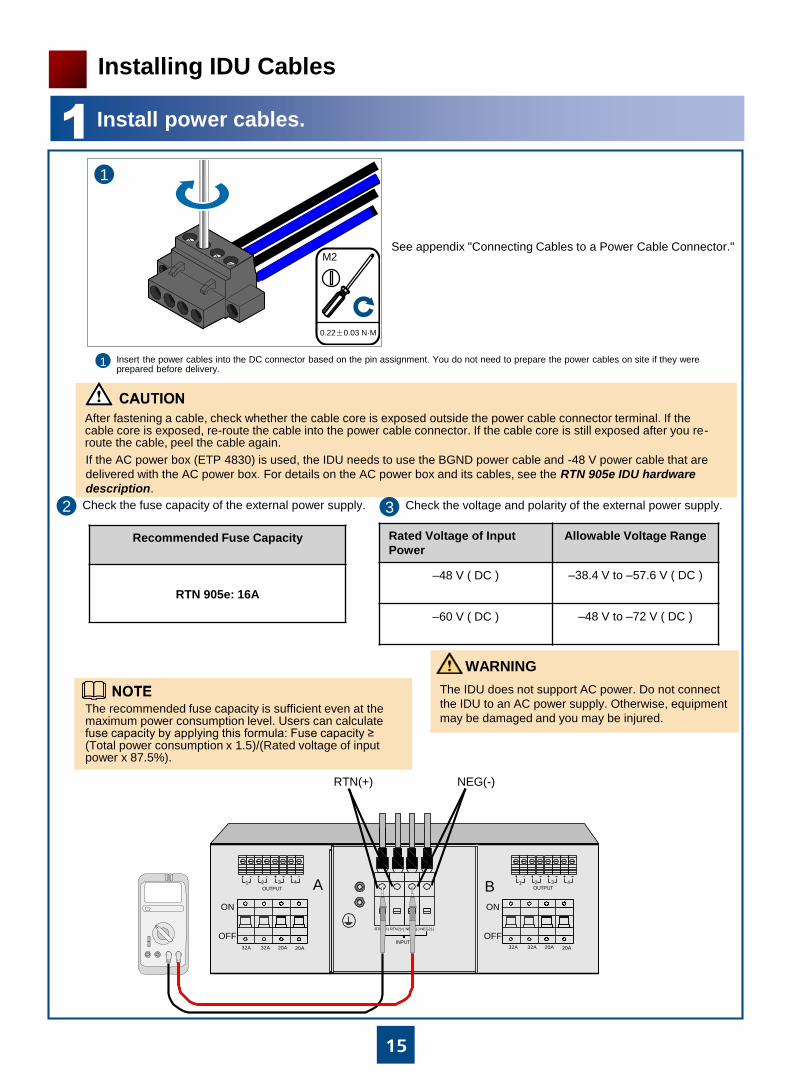
1Install power cables.
Insert the power cables into the DC connector based on the pin assignment. You do not need to prepare the power cables on site if they were prepared before delivery.
After fastening a cable, check whether the cable core is exposed outside the power cable connector terminal. If the cable core is exposed, re-route the cable into the power cable connector. If the cable core is still exposed after you re-route the cable, peel the cable again.
NEG2(-)
INPUT
RTN2(+)RTN1(+) NEG1(-)
ON
OFF20A32A 32A 20A
ON
OFF
1 2 3 4 1 2 3 4
20A32A 32A 20A
OUTPUT OUTPUTA B
Check the fuse capacity of the external power supply. Check the voltage and polarity of the external power supply.
Recommended Fuse Capacity
RTN 905e: 16A
Rated Voltage of Input
Power
Allowable Voltage Range
–48 V ( DC ) –38.4 V to –57.6 V ( DC )
–60 V ( DC ) –48 V to –72 V ( DC )
RTN(+) NEG(-)
The recommended fuse capacity is sufficient even at the maximum power consumption level. Users can calculate fuse capacity by applying this formula: Fuse capacity ≥ (Total power consumption x 1.5)/(Rated voltage of input power x 87.5%).
Installing IDU Cables
If the AC power box (ETP 4830) is used, the IDU needs to use the BGND power cable and -48 V power cable that are
delivered with the AC power box. For details on the AC power box and its cables, see the RTN 905e IDU hardware
description.
1
0.22±0.03 N·M
M2
1
2 3
See appendix "Connecting Cables to a Power Cable Connector."
WARNING
The IDU does not support AC power. Do not connect
the IDU to an AC power supply. Otherwise, equipment
may be damaged and you may be injured.

16
Confirm that the circuit breaker of the PDU is switched to the off position. Insert the DC connector into the power port on the chassis. Confirm that the two groups of power cables are connected to different power modules. Secure the DC connector with bolts.
aOptional: Install E1 cables connected to an E1 panel.b
2Install E1 cables.
For information about the wire sequence of E1 cables, see the pin assignment information delivered with these E1 cables or the cable section in the RTN 905e IDU Hardware Description.
When assembling the DDF-side connector for a 1.6 mm diameter E1 cable, use a type 75-1-1 connector and a pair of 2.5 mm or 1.7 mm crimping tool.
0.4±0.03 N·M
M2.5
0.4-0.5 N·M
M2.5
Optional: Install E1 cables connected to another device.
To another device
If an external power box is used, cut off the input of the power box
before you connect power cables.
CAUTION

17
3Install fibers.
Precautionsa
Always wear protective glasses or goggles when you look directly at an optical port. (Figure 1)
Coil fibers from other sites on the ODF and connect them to the local cabinet. Do not coil the fibers from
other equipment rooms inside the local cabinet.
Fiber cap
Swappable optical moduleDustproof cap
10 cm
Avoid damage to fiber connectors when you lay fibers.
After fibers are installed, insert dustproof caps into unused optical ports and plug fiber caps on unused
fibers. (Figure 2)
Tape over the cuts of a closed corrugated pipe before threading fibers through it. Tape over the cuts of an open
corrugated pipe after threading fibers through it.
After you thread fibers through a corrugated pipe, wrap tape around the cut of the pipe (Figure 3).
Do not thread too many fibers through one pipe. If 2 mm-diameter fibers are used, threading no more than 60
fibers through an open corrugated pipe and no more than 20 fibers through a closed corrugated pipe is
recommended. The pipe section secured inside a cabinet should be about 10 cm in length (Figure 4).
Figure 1 Figure 2
Figure 3 Figure 4
Short-jacketed fiber

18
Install fibers.b
GE5
GE6
OUT
IN
4Install Ethernet service cables.
Install Ethernet service cables.a
To an Ethernet device
Ethernet ports on the RTN 905e support the MDI/MDI-X adaptation function. Either crossover or straight-through network cables can be used to connect the Ethernet ports. Straight-through cables are recommended.
GE1GE3

19
5Install IF cables.
Install IF jumpers.a
Connect IF jumpers and IF cables.b
Power off the ODU before you install IF jumpers.
If RG-8U or 1/2-inch IF cables are used, use IF jumpers to connect IF cables and the IDU. If 5D IF cables are used, connect IF cables directly to the IDU.
N type (5/8"), 0.8 to 1.1 N/M
Test the connectivity of the IF cable when you connect a cable to an IF jumper.Connect an IF jumper and an IF cable based on engineering design documents and the network plan.
IF jumperIF cable
OFF
OFF

20a
6 a. Installing 1+1/TDM Cascade Cables and XPIC Cables
Installing 1+1/TDM cascade cables
Installing XPIC cables
The X-IN port on an RTN 905e must be connected to the X-OUT port on another RTN 905e.
Note
If the XPIC function is disabled on an RTN 905e, do not use an XPIC cable to connect the X-IN and X-OUT ports
on the RTN 905e. Otherwise, the RTN 905e performance will be affected.
Caution
1+1/TDMA
TDMB
RTN 905e
RTN 905e
RTN 905e
1+1/TDMARTN 905e
RTN 905e
1+1/TDMA
X-INX-OUT
X-IN X-OUT

20b
6 b. Installing COMBO/XPIC Cables
Installing COMBO cables
Installing XPIC cables
The X-IN port of an RTN 905e must be connected to the X-OUT port of another RTN 905e.
NOTE
Do not use an XPIC cable to connect the X-IN and X-OUT ports on an RTN 905e where XPIC is disabled.
Otherwise, the performance of the RTN 905e will be affected.
Caution
• The first cascading port is a versatile cascading port.
• The second cascading port is a TDM/CES cascading port.
COMBO-1RTN 905e
RTN 905e
COMBO-1
RTN 905e
RTN 905e
COMBO-1
X-IN X-OUT
X-IN X-OUT
COMBO-1

21
7Installing NMS Cables
Install an NMS cable on a gateway NE.a
NMS/COM
NMS
Install NMS cables on multiple NEs at one site.b
NMS
Assemble crossover network cables or straight-through network cables on site.
Avoid forming any loops when installing network cables.
Use NMS cascading cables only for NEs that do not communicate service data.
NMS/COM
EXT/S1

22
8Preparing and Installing External Alarm Cables
Make an external alarm cable based on pin assignments.a
Install an external alarm cable.b
16 mm
Pin 1
Pin 8
Pin Assignments for External Alarm Cables
Pin Color Relationship Function
1
2
3
6
4
5
7
8
White/Orange
Orange
White/Green
Green
Blue
White/Blue
White/Brown
Brown
Twisted pair
Twisted pair
Twisted pair
Twisted pair
First alarm signal input
Ground of first alarm signal input
Second alarm signal input
Ground of second alarm signal input
Third alarm signal input
Ground of third alarm signal input
Positive of first alarm signal output
ALMI/ALMO
Negative of first alarm signal output
Pin 1
Pin 8

23
9Preparing and Installing Asynchronous Data Cables
Make an asynchronous data cable according to the pin assignment.a
Install asynchronous data cables on the RTN 905e.b
To a asynchronous data communication device
16 mm
Pin 1
Pin 8
EXT/S1
Positive for transmitting data by the NMS cascading port
Pin assignments for Asynchronous Data Cables
Pin Color Function
White/Orange
Orange
White/Green
Green
Blue
White/Blue
White/Brown
Brown
1
2
3
6
4
5
7
8
Negative for transmitting data by the NMS cascading port
Positive for receiving data by the NMS cascading port
Negative for receiving data by the NMS cascading port
Ground for the 19.2 kbit/s asynchronous data port
Reserved
Receiving data by the 19.2 kbit/s asynchronous data port
Transmitting data by the 19.2 kbit/s asynchronous data port
Twisted pair
Twisted pair
Twisted pair
Twisted pair
Relationship
Pin 1
Pin 8

24
10Preparing and Installing External Clock Cables
Make an external clock cable based on pin assignments.a
Install external clock cables.b
CLK/TOD/MON
Pin assignments for External Clock Cables
Pin Color Relationship External ClockExternal Time Input
(1PPS+Time Information)
External Time Output
(1PPS+Time Information)
External Time Input
(DCLS)
External Time Output
(DCLS)
1 White/
Orange Twisted pair
Negative for receiving
external clock signalsReserved
2 OrangePositive for receiving
external clock signals
3White/
Green
Twisted pair
ReservedNegative for 1PPS signal
input (RS422 level)
Negative for 1PPS signal
input (RS422 level)
Negative for DCLS
signal input (RS422
level)
Negative for DCLS signal
output (RS422 level)
6 Green ReservedPositive for 1PPS signal
RS422 input/output
Positive for DCLS signal
RS422 input/output
Positive for DCLS signal
input (RS422 level)
Positive for DCLS signal
output (RS422 level)
4 Blue
Twisted pair
Negative for
transmitting external
clock signalsGround
5 White/BluePositive for transmitting
external clock signals
7 White/Brown
Twisted pair
ReservedNegative for time signal
input (RS422 level)
Negative for time signal
output (RS422 level)
Reserved
8 Brown ReservedPositive for time signal
RS422 input/output
Positive for time signal output
(RS422 level)
16 mm
Pin 1
Pin 8
Pin 1
Pin 8

25
Cable connectionsa
11Cable Layout
Cable Layoutb
Asynchronous data cable
External clock cable
5
NMS cable
6
4
Power cables
IF jumper
1
2
3
PGND cable 7
8
External alarm cable
9
Ethernet service cables
Ethernet service fibers
10
11
TDM service concatenation cables
E1 cables
1
23
4
5
6
78
9
10
11
26
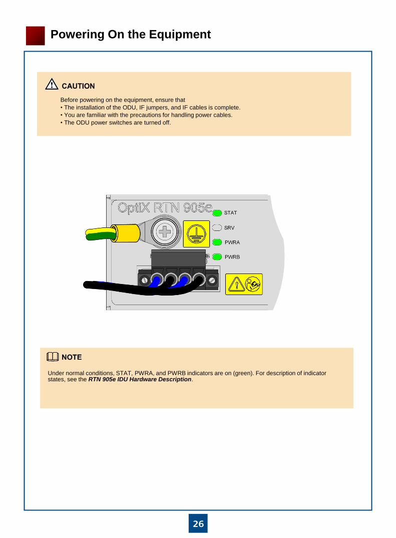
Powering On the Equipment
Before powering on the equipment, ensure that
• The installation of the ODU, IF jumpers, and IF cables is complete.
• You are familiar with the precautions for handling power cables.
• The ODU power switches are turned off.
Under normal conditions, STAT, PWRA, and PWRB indicators are on (green). For description of indicator states, see the RTN 905e IDU Hardware Description.

27
Configuring NE Data (Using the USB Flash Drive)
The USB flash drive loads software, system parameters, and scripts for commissioning a newly deployed site.
Insert a USB flash drive.
For the functions, working principles, and types of USB flash drives supported, see the RTN 905e IDU Hardware Description.
For a description of the indicators on the USB flash drive, see the RTN 905e Commissioning Guide.
Normally, after data is loaded from the USB flash drive to the OptiX RTN 905, the USB port status indicator should be
on (green).
USB port status indicator

NMS/COM
NMS
NMS/COM
手持终端
28
Configuring NE Data (Using the Web LCT)
Configuring NE Data (Using the Hand-Held Tool)
Connect the NMS/COM port to a hand-held tool.
You can use the Web LCT to configure NE data, including basic NE data, IF/ODU information for the radio links, and parameters for IF and ODU ports.
You can use the hand-held tool to configure NE data, including basic NE data, IF/ODU information for the
radio link, parameters for IF and ODU ports, and DCN parameters.
Connect the NMS/COM port to the PC where the Web LCT is running.

29
Aligning Antennas
1Aligning Single-Polarized Antennas
Use the installation positions and heights of local and remote antennas to determine their azimuths. Adjust the pitch angles of the antennas to the horizontal position.
Connect a multimeter to the received signal strength indicator (RSSI) port on the ODU at the local end and measure the voltage value VBNC.
Level adjustment screw
Elevation adjustment screw
The red line of the multimeter is connected to the core of the RSSI port, and the black line is connected to the ground pin.
a
b
c
Secure the remote antenna and loosen/tighten the level adjustment screw to turn antenna widely in the horizontal direction.
If three signal peaks are tracked, adjust the azimuth of the antenna until the received signal level (RSL) reaches the peak value at position 2.
If two signal peaks are tracked, adjust the azimuth of the antenna until the RSL reaches the middle of positions 4 and 5. Then, adjust the pitch angle of the antenna using the elevation adjustment screw until the three signal peaks on the line AA' appear. Finally, adjust the azimuth of the antenna until the RSL reaches the peak value at position 2.
If one signal peak is tracked, adjust the azimuth of the antenna until the RSL reaches the middle of positions 6 and 7. Then, adjust the pitch angle of the antenna using the elevation adjustment screw until the three signal peaks on the line AA' appear. Finally, adjust the azimuth of the antenna until the RSL reaches the peak value at position 2.

30
各路径信号值
31
2
B
7
4 5
6
A
B'
A'
C'C
A'A
B B'
C C'
天线不同仰角下扫描路径的正面图
2
4
6 7
1 3
5
Front view of the tracking lines at different
elevation angles for the antenna
RSL values of each line
2Aligning Dual-Polarized Antennas
Power off the vertically-polarized ODUs and power
on the horizontally-polarized ODUs at both ends of
a radio link. This ensures that the antennas at both
ends transmit horizontally polarized signals.
Adjust the azimuth and pitch angle of the antennas
at both ends by referring to the description in
"Aligning Single-Polarized Antennas." Ensure that
the main lobes of the horizontally-polarized signals
are aligned.
Loosen/Tighten the elevation adjustment screw to turn the local antenna vertically. Adjust the pitch angle until the RSL reaches the peak within the tracked range.
Repeat Steps 3 to 4 to ensure that three signal peaks are tracked both horizontally and vertically. When the local RSL reaches the maximum peak value, secure the local antenna.
Adjust the remote antenna to ensure that the RSL at the local end and the RSL at the remote end reach the peak value. Check that the ODU indicator on the IF board is off. If the ODU indicator on the IF board is yellow and blinks every 300 ms, continue aligning the antennas.
Tighten all the screws on the antennas after the alignment is completed.
If an OMT is used to connect the ODUs to the antenna in direct mount mode, the alignment procedure for these
antennas is the same as that for single-polarized antennas. If soft waveguides are used to connect the ODUs to
the antenna in separate mount mode, follow the procedure below to align the antennas.

31
LINK indicator
Checking the Status of Radio Links
Use a multimeter to measure the RSL (P1) on the RSSI port of the horizontally-polarized ODU at the local end.
Power on the vertically-polarized ODU at the local end. Use a multimeter to measure the RSL on the RSSI port of
the vertically-polarized ODU. Release the holders of the feed boom and turn the feed boom gently until the RSL
reaches the minimum value (P2). The calculated XPD1 (XPD1 = P1 - P2) cannot be lower than 24 dB. Record the
current angle (D1) of the feed boom.
Power off the horizontally-polarized ODUs and power on the vertically-polarized ODUs at both ends of the radio
link. Adjust the azimuth and pitch angle of the antennas by referring to the description in "Aligning Single-
Polarized Antennas". Ensure that the main lobes of the vertically-polarized signals are aligned.
Refer to Steps 3 and 4 to ensure that the calculated XPD2 (XPD2 = P3 - P4) is higher than or equal to 24 dB.
Record the current angle (D2) of the feed boom.
Repeat Steps 1 to 6 to gently adjust the feed boom (ranging from D1 to D2), and ensure that XPD1 and XPD2 are
higher than or equal to 24 dB.
Tighten all the screws on the antennas after the alignment is completed.
Check the status of the LINK indicator on the front panel of the chassis.
If the LINK indicator is on (green), the radio link is functioning properly.
If the LINK indicator is on (red), check whether the configuration data is correct. If the configuration data is
incorrect, configure correct data.
If the LINK indicator blinks yellow at intervals of 300 ms, check whether the antennas are aligned properly. If the
antennas are not aligned properly, realign the antennas.
If the LINK indicator is off, check whether the logical units of the IF unit and the ODU have been added on the
NMS. If yes, check for a fault in the IF jumper, IF cable, or the ODU.
3
4
5
6
7
8
a
b
c
d

32
Checking the Installation
No. What to Check For
1 The chassis is installed securely in the position specified in the engineering design documents. If the cabinet
door is closed, the door should not press against the chassis or any cables.
2 Chassis components have no paint spatters, damage, or stains.
Re-paint or clean components, as required.
3 Cable routes comply with the engineering design documents and facilitate maintenance and expansion.
4 Cables are not damaged, broken, or spliced together.
5 Cable cores have been tested for connectivity.
6 Cables are properly bound. Cable ties are installed at equal intervals and face in the same direction. Cable ties
have been trimmed after tying and there are no rough edges.
7 Signal cables are routed correctly in the cabinet.
8 Cables outside the cabinet are routed as follows:
•Cables are run neatly and are not cross-connected.
•If a cable ladder is used, the cables are bound onto the ladder beam neatly. If the cable tray extends 0.8 m or
more above the cabinet top, a cable ladder is installed to support the cables and ease stress.
9 Cable turns are smooth and have a large bending radius.
10 Cable labels are filled in correctly, attached securely, and are aligned to face in the same direction. Preferably,
labels are attached at least 2 cm away from connectors.
11 The power cable and ground cable are routed separately from signal cables.
12 Unused cable connectors are protected. For example, protective caps are installed on unused connectors.
13 Cable connectors are inserted securely and the screws on the connectors are tightened.
14 Corrugated pipes for fiber jumpers are inserted 10 cm into the cabinet and bound securely.
15 The cuts for jumpers on corrugated pipes are either smooth or have been wrapped with insulation tape.
16 Jumpers are bound gently to ensure free move in cable ties.
17 Connecting points of fiber jumpers are clean. Protective caps (plugs) are installed on unused fiber connectors
and optical ports.
19 The positive terminals of the power supply device connected to the RTN 905e are properly grounded.
20 The ground point on the column of the cabinet or the indoor ground bar is properly grounded.

Connecting Cables to a Power Cable Connector
Obtaining Tools, Cables, and a Power Cable Connector1
33
Appendix
Ruler Diagonal pliers Utility knife Flat-head screwdriver
Two 0 V black ground cables
Two -48 V blue power cables
Power cable connector
Peeling Cables2
Use one side of the power cable connector as the peeling length reference plane.
1
Peeling length reference plane (9 mm)
Use a pair of diagonal pliers to trim off one end of a -48 V power cable. Place the cable on the peeling length reference plane, and leave a 1 mm space between the left edge of the reference plane and the trimmed end of the cable. Use a utility knife to make a mark on the cable that is aligned with the right edge of the reference plane.
2
9 mm
8 mm
Peeling length (8 mm)
1 mm
8 mm
3 Peel the cable using the diagonal pliers.
8 mm
Cable core
4 Repeat steps 1-3 to peel a 0 V ground cable.
Note
If a ruler is available, you can use the ruler to measure an 8 mm peeling length after trimming off one end of a cable.
8 mm
Cable core
Peeling length reference plane

Connecting Cables to a Power Cable Connector
Connecting Cables to the Power Cable Connector3
34
Appendix
Route a cable into the power cable connector.
1
Power Cable Connector Terminal
Cable
1- -48 V power cable (blue)
1+ 0 V ground cable (black)
2- -48 V power cable (blue)
2+ 0 V ground cable (black)
Fasten the cable.2 Pull the cable slightly. If the cable is loose, fasten it again.
3
After fastening a cable, check whether the cable core is exposed outside the power cable connector terminal. If the cable core is exposed, re-route the cable into the power cable connector. If the cable core is still exposed after you re-route the cable, peel the cable again.
After the power switch is turned on, sparks may be generated at the exposed cable core when an inappropriate operation is performed.
Caution
Pull the cable slightly.
Repeat steps 1-3 to connect all cables to the power cable connector.
4
All the cables are fastened, and no cable core is exposed outside the power cable connector.

Installing the MN1 Subboard
35
Appendix
Remove the filler panel from
the slot for the MN1 subboard.
1
Install the MN1 subboard.2
Screw the MN1 subboard.3

HUAWEI TECHNOLOGIES CO., LTD.Huawei Industrial Base Bantian Longgang
Shenzhen 518129
People’s Republic of China
www.huawei.com