OptiX RTN 950A Radio Transmission System V100 IDU Quick ...
26
HUAWEI TECHNOLOGIES CO., LTD. OptiX RTN 950A Radio Transmission System V100 IDU Quick Installation Guide for Outdoor Cabinets (OMB Cabinets) Issue: 02 Date: 2021-09-30
-
Upload
khangminh22 -
Category
Documents
-
view
0 -
download
0
Transcript of OptiX RTN 950A Radio Transmission System V100 IDU Quick ...

HUAWEI TECHNOLOGIES CO., LTD.
OptiX RTN 950A Radio Transmission System V100
IDU Quick Installation Guide for Outdoor Cabinets (OMB Cabinets)
Issue: 02
Date: 2021-09-30

Huawei Technologies Co., Ltd.Address: Huawei Industrial Base
Bantian, Longgang
Shenzhen 518129
People's Republic of China
Website: http://www.huawei.com
Email: [email protected]
No part of this document may be reproduced or transmitted in any form or by any means withoutprior written consent of Huawei Technologies Co., Ltd.
Copyright © Huawei Technologies Co., Ltd. 2021. All rights reserved.
Trademarks and Permissions
and other Huawei trademarks are trademarks of Huawei Technologies Co., Ltd.
All other trademarks and trade names mentioned in this document are the property of theirrespective holders.
Notice The purchased products, services and features are stipulated by the contract made between Huaweiand the customer. All or part of the products, services and features described in this document maynot be within the purchase scope or the usage scope. Unless otherwise specified in the contract, allstatements, information, and recommendations in this document are provided "AS IS" withoutwarranties, guarantees or representations of any kind, either express or implied.
The information in this document is subject to change without notice. Every effort has been made inthe preparation of this document to ensure accuracy of the contents, but all statements, information,and recommendations in this document do not constitute a warranty of any kind, express or implied.

1
Precautions
Following All Safety PrecautionsBefore any operation, read the instructions and precautions in this document carefully to minimize the possibility of accidents.The Danger, Caution, and Note items in this document do not cover all the safety precautions that must be observed. They provide only the generic safety precautions for operations.When operating Huawei products and equipment, you must comply with safety precautions and special safety instructions relevant to the corresponding equipment provided by Huawei. The safety precautions in this document are relevant only to Huawei products. Huawei is not liable for any consequence that results from violation of universal regulations for safety operations and safety codes on design, production, and equipment use.
Complying with Local Safety RegulationsWhen operating the product or equipment, comply with local safety regulations.
Qualified Personnel OnlyInstallation and maintenance personnel must be trained to perform operations correctly and safely.
Personnel SafetyThe high-voltage power supply provides power for running the system. Avoid direct contact with the high-voltage power supply or contact through damp objects. Failure to do so causes serious injury or death.Non-standard and incorrect operations on the high-voltage power supply may result in fire and electric shock.Do not perform operations on high-voltage and AC power supply facilities or on a tower or mast in the case of thunderstorm. Failure to do so causes serious injury or death.Ground the device before powering it on. Failure to do so causes damage to the device or personal injury.Power off the device before performing operations on the power supply facilities.
Personnel SafetyHigh power radio-frequency signals are harmful to the human body. Ensure that the transmitter antennas are muted before installing or maintaining an antenna on a tower or mast that holds a large number of transmitter antennas.Do not stand close to, or look into the optical fiber outlet without eye protection when handling optical fibers.Take preventive measures when drilling holes. Otherwise, dust may hurt your eyes or you may inhale the dust.Power off the batteries before connecting the cables to the batteries. Failure to do so causes personal injury.When working at heights, be cautious about falling objects.
Device SafetyCheck the electrical connection of the device before operation and ensure that the device is securely grounded.The static electricity discharged from the human body may damage the electrostatic sensitive components, such as large-scale integrated circuits (LSIs), on the circuit board. Wear an ESD wrist strap or ESD gloves when handling a circuit board.
2
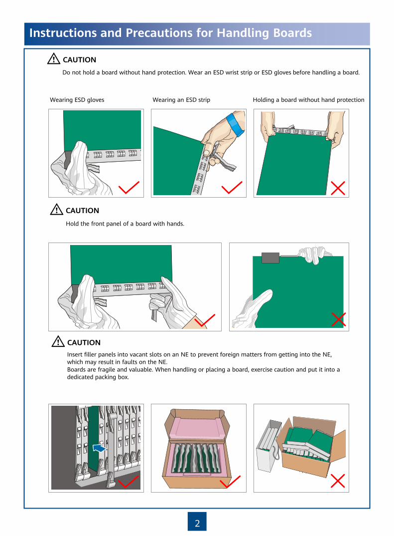
Do not hold a board without hand protection. Wear an ESD wrist strip or ESD gloves before handling a board.
Insert filler panels into vacant slots on an NE to prevent foreign matters from getting into the NE, which may result in faults on the NE.Boards are fragile and valuable. When handling or placing a board, exercise caution and put it into a dedicated packing box.
Holding a board without hand protectionWearing ESD gloves Wearing an ESD strip
Hold the front panel of a board with hands.
Instructions and Precautions for Handling Boards
CAUTION
CAUTION
CAUTION

3
Instructions and Precautions for Handling Power Cable Terminals
Do not pick up the tail end of the red latch by using a finger or a screwdriver to avoid damage.
Press the front of the red latch. Properly move the red latch outwards.
1
2
1
2
2
2
1
1
CAUTION

4
Tools for Installation
Network cable tester Coax stripper
Long measuring tape Phillips screwdriver Flat-head screwdriver Adjustable WrenchLevel
COAX crimping toolSocket wrench Torque wrench Hex key Wire clippers
Wire stripper RJ45 crimping tool Diagonal pliers Cold press pliers Needle-nose pliers
Combination pliers Bayonet wrench
Utility knife Claw hammerHammer drill Marker
Ladder Electric iron
Antistatic gloves
Heat gunMultimeter
ESD gloves
Binding strap Insulation tape
ESD wrist strap Impact tool
File
Vacuum cleaner
5
Introduction to the Equipment
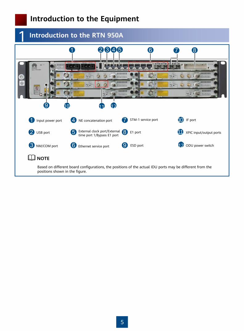
1 Introduction to the RTN 950A
Input power port
Ethernet service portNM/COM port
Based on different board configurations, the positions of the actual IDU ports may be different from the positions shown in the figure.
NE concatenation port
NOTE
10
11
STM-1 service port
ESD port
External clock port/External time port 1/Bypass E1 port
XPIC input/output ports
10 1211
USB port
12
IF port
E1 port
ODU power switch
6
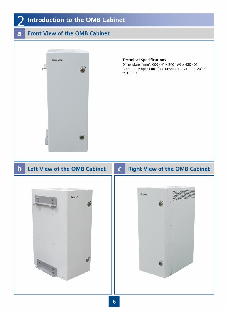
2 Introduction to the OMB Cabinet
Front View of the OMB Cabineta
Technical SpecificationsDimensions (mm): 600 (H) x 240 (W) x 430 (D)Ambient temperature (no sunshine radiation): -20°C to +50°C
Left View of the OMB Cabinetb Right View of the OMB Cabinetc

7
Fan assembly (internal circulating)
About the Internal Structure of the OMB Cabinetd
Internal Structure of the OMB Cabinet (AC Power Supply)
Internal Structure of the OMB Cabinet (DC Power Supply)
HEUA
OMB cabinet (AC power supply)
Fan assembly (external circulating)
AC/DC power supply facility
PMU module
Fan assembly (internal circulating)
HEUA
OMB cabinet (DC power supply)
Fan assembly (external circulating)
DCDU-03B
Cable trough
AC surge protection box

8
Installation Scenarios of the Cabinets
1 Installation Scenarios of the OMB Cabinet
Dimensions of the OMB Cabineta
Recommended Requirements of the OMB Cabinetb Minimum Requirements of the
OMB Cabinetc
≥200 mm
≥150 m
m
≥600 mm
≥500 mm
≥200 mm
≥300 m
m
≥800 mm
≥600 mm
600
mm

9
Installation Modesd
Installing the OMB cabinet on a pole Installing the OMB cabinet on a wall
The OMB cabinet provides a small space. Therefore, it is not recommended that you use the OMB cabinet in an area where the ambient temperature is lower than –20°C in winter. It is recommended that you use the APM30H or TMC11H cabinet that is configured with a heater.
2 Installing the OMB Cabinet
Installing the OMB Cabinet on a Walla
210mm
378m
m
210mm
378m
m
Determine the position of the backplane on the wall, and mark the four anchor points by using a marker.
Drill the holes and install the expansion bolt assembly.
55~60mm90
φ14
3
45 6
20~30mm
。
Bolt M10x75Spring washer 10Plastic tubeFlat washer 10Expansion bolt
NOTE

10
Install the backplane of the OMB frame on the wall.
Install the OMB frame on the backplane.
Installing the OMB Cabinet on a Poleb
Install the first upper fastener assembly on the pole.
Flat washer
Spring washer
M10x180 bolt
Install the lower fastener assembly on the backplane.
M10x40 bolt
M6 screw2.0±0.2 N·m
M6
30±3 N•m
M10

11
Install the backplane on the pole.
Install the mounting brackets for the OMB frame.
Install the OMB frame on the backplane.
30±3 N•m
M10

12
Outdoor Pole-Mounting Scenario
1 Dedicated Outdoor Installation
Installing the RTN 950A in the OMB Cabinet (AC Power Supply)a
Installing the RTN 950A in the OMB Cabinet (DC Power Supply)b

13
Installing the Assemblies
1 Installing the RTN 950A
When installing the RTN 950A, ensure that the fan assembly is installed in the lower part of the cabinet. When being installed in the AC or DC powered OMB cabinet, the RTN 950A can work as only a repeater. When using service cables such as E1 cables and Ethernet cables, install the RTN 950A in the APM30H or TMC11H cabinet.
Fan assembly
CAUTION
14
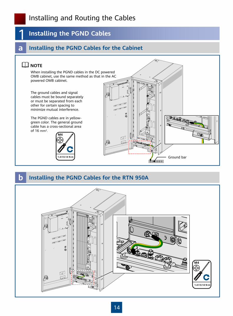
1 Installing the PGND Cables
Installing the PGND Cables for the Cabineta
When installing the PGND cables in the DC powered OMB cabinet, use the same method as that in the AC powered OMB cabinet.
Ground bar
Installing the PGND Cables for the RTN 950Ab
The ground cables and signal cables must be bound separately or must be separated from each other for certain spacing to minimize mutual interference.
The PGND cables are in yellow-green color. The general ground cable has a cross-sectional area of 16 mm2.
NOTE
Installing and Routing the Cables
1.4±0.14 N·m
M4
1.4±0.14 N·m
M4

15
Installing the Input Power Cable for the OMB Cabinet (AC Power Supply)a
Installing the Input Power Cable for the RTN 950Ab
1
1
2 Installing and Routing the Power Cables – AC Power Supply
For AC OMB cabinets of Ver. C, connect the two power cables from RTN 950A to any two power output terminals (such as terminals LOAD6 and LOAD7) with the maximum output current of 30 A. For information about assembling the easy power receptacle (pressfit type) connector, see "Appendixes."
a
b
b
a N
PEL

16
Installing the Input Power Cable for the OMB Cabineta
Installing the Input Power Cable for the RTN 950Ab
1
RTN(+)
NEG(-)
3 Installing and Routing the Power Cables – DC Power Supply
For AC OMB cabinets of Ver. C, connect the two power cables from RTN 950A to any two power output terminals (such as terminals LOAD6 and LOAD7) with the maximum output current of 30 A. For information about assembling the easy power receptacle (pressfit type) connector, see "Appendixes ".
1

17
4 Installing the Service Cables for the Equipment – AC Power Supply
Installing IF Cablesa
Installing Fibersb
Rubber block
Insulation tube
Binding strap

CS
H
ST
AT
PR
OG
SY
NC
SR
V
NMS/COM EXT CLK/TOD1 TOD2CF RCV RST
AC
T
18
Installing Signal Monitoring Cablesc
•Mapping Relationships Between the Signals over Different Cables
COM_IN portHEUA board
TOD2 port
8 7 6 5 4 3 2 1
RJ-45 Connector of the Network Port to the Cable on the CMUA (COMIN) Board
RJ-45 Connector (TOD2) of the Network Port to the Cable on the CSH/CST Board
Pin 1 TX+ White/Orange Pin 6 RX+ White/Orange
Pin 2 TX- Orange Pin 3 RX- Orange
Pin 4 RX+ Blue Pin 8 TX+ Blue
Pin 5 RX- White/Blue Pin 7 TX- White/Blue
Pin 8 GND Brown Pin 5 GND Brown
Pin 3/6/7 No connected - Pin 1/2/4 No
connected -
When using the CSHO board, connect the signal monitoring cable to the MON/TOD2 port. NOTE

19
5 Installing the Service Cables for the Equipment – DC Power Supply
Installation Effectiveness of the Service Cablesa
FiberSignal monitoring cableIF cable

20
1 Checking Cabinet Installation
Checking the Installation
2 Checking Installation Environment
No. What to Check For
1 No fingerprints or other smears exist on the exterior of the equipment cabinet.
2 No excessive adhesive tapes or cable ties exist on the cables.
3 No tapes, cable ties, wastepaper, or packing bags are left around the equipment cabinet.
4 All the items around the equipment are neat, clean, and intact.
No. What to Check For
1 The layout of the cabinet complies with the engineering designs.
2 In pole-mounting mode, the mounting brackets are fixed securely, and the frame is fixed properly and is not distorted.
3 In wall-mounting mode, the holes for the frame are in proper contact with the holes for the expansion bolt, and the frame and the wall surface are in proper horizontal contact.
4 In wall-mounting mode, the cabinet is installed securely and does not swing when you shake it.
5 The waterproof cover of the bottom port and the hang chains are bound with the surrounding cables.
6 The surface of the overall equipment is clean and tidy. The exterior paint is intact.
7 The door and lock of the cabinet are proper.
8 All labels, tags, and nameplates are correct, legible, and complete.
21
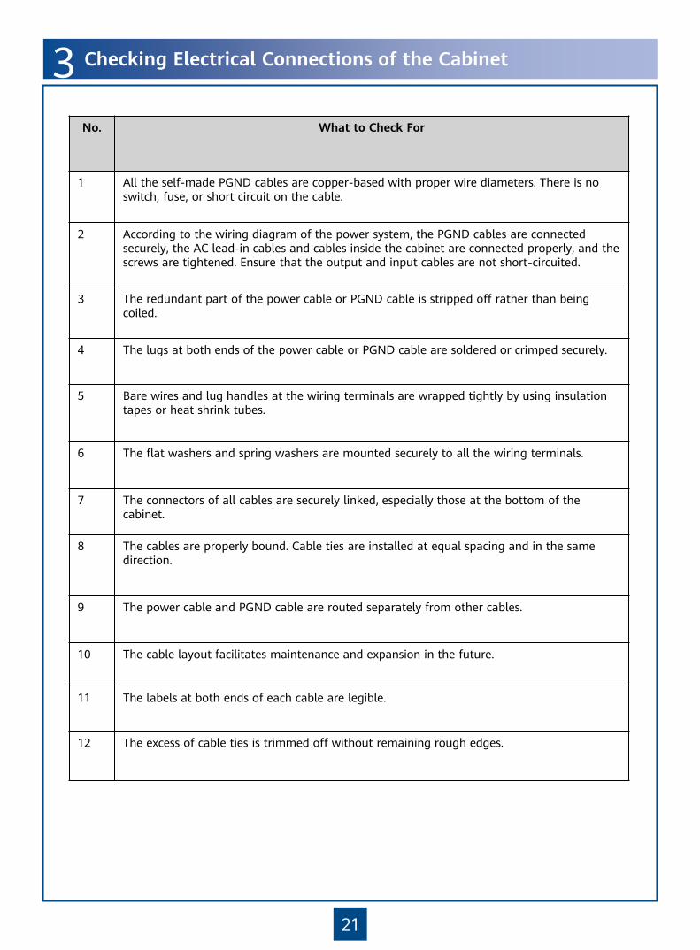
3 Checking Electrical Connections of the Cabinet
No. What to Check For
1 All the self-made PGND cables are copper-based with proper wire diameters. There is no switch, fuse, or short circuit on the cable.
2 According to the wiring diagram of the power system, the PGND cables are connected securely, the AC lead-in cables and cables inside the cabinet are connected properly, and the screws are tightened. Ensure that the output and input cables are not short-circuited.
3 The redundant part of the power cable or PGND cable is stripped off rather than being coiled.
4 The lugs at both ends of the power cable or PGND cable are soldered or crimped securely.
5 Bare wires and lug handles at the wiring terminals are wrapped tightly by using insulation tapes or heat shrink tubes.
6 The flat washers and spring washers are mounted securely to all the wiring terminals.
7 The connectors of all cables are securely linked, especially those at the bottom of the cabinet.
8 The cables are properly bound. Cable ties are installed at equal spacing and in the same direction.
9 The power cable and PGND cable are routed separately from other cables.
10 The cable layout facilitates maintenance and expansion in the future.
11 The labels at both ends of each cable are legible.
12 The excess of cable ties is trimmed off without remaining rough edges.

22
1 Layout of the Cable Holes
Appendixes
Layout of the cable holes at the left bottom of the cabinet:
Layout of the cable holes at the right bottom of the cabinet:
Cable Name Cable Hole Position Cable Hole Name
Power input cable of an AC/DC cabinet
Right cable hole
General ground cable of an AC/DC cabinet
Right cable hole
IF cable, Ethernet cable, and E1 cable Right cable hole
Optical fiber Left cable hole
Select any one.
Select any one.
Select any one.
For cabinets of Ver. C, the number of cable holes is increased from 7 to 15. Select cable outlets based on requirements.
For cabinets of Ver. C, the number of cable holes is increased from 4 to 6. Select cable outlets based on requirements.
For cabinets of Ver. C, the number of cable holes is decreased from 5 to 3. Select cable outlets based on requirements.

23
2 Installing the Cables on the Cable Module
Remove the screws from the cable module.
Remove the cable module from the cable trough.
Route the cable from the bottom of the cable trough upwards through the corresponding cable hole on the cable module, and ensure that the cable connector is idle.
After routing all the cables through the cable hole on the waterproof cable module, connect the cable connector to the corresponding port on the equipment.
For information about the position of the cable holes, cable routes, and installation methods, see the description of the installation procedure.
NOTE

HUAWEI TECHNOLOGIES CO., LTD.Huawei Industrial Base Bantian Longgang
Shenzhen 518129People’s Republic of China
www.huawei.com