Facilitating Faster Broadband Deployment - International ...
Upload
khangminh22Category
view
1download
0
IPv6 Deployment Guide for Cisco Collaboration Systems Release 12.xand 14First Published: 2017-09-06
Last Modified: 2022-06-13
Americas HeadquartersCisco Systems, Inc.170 West Tasman DriveSan Jose, CA 95134-1706USAhttp://www.cisco.comTel: 408 526-4000
800 553-NETS (6387)Fax: 408 527-0883

© 2022 Cisco Systems, Inc. All rights reserved.

C O N T E N T S
IPv6 Introduction 1C H A P T E R 1
Documentation Changes 1
IPv6 Deployment Overview 2
Move Toward IPv6-Only Network 4
Deployment Recommendations for Enterprise Networks 5
Comparison of IPv4 and IPv6 6
Why Deploy IPv6? 6
Advantages of IPv6 Over IPv4 7
IPv6 Basics 9C H A P T E R 2
IPv6 Basics Overview 9
IPv6 Addressing 9
IPv6 Unicast Addresses: Network and Host IDs 10
Types of IPv6 Addresses 11
Address Scopes 11
Global Unicast Addresses 11
Unique Local Unicast Addresses 12
Link Local Unicast Addresses 13
IPv6 Multicast Addresses 13
Address Assignment for IPv6 Devices 14
Manual Configuration 14
IPv6 Stateless Address Auto-Configuration (RFC2462) 15
DHCP for IPv6 15
Stateless DHCP 16
Stateful DHCP 16
IPv6 Address Assignment Table 16
IPv6 Deployment Guide for Cisco Collaboration Systems Release 12.x and 14iii

DNS for IPv6 17
IP Addressing Modes for Cisco Collaboration Products 19C H A P T E R 3
IP Addressing Modes 19
Recommended IPv6 Addressing Modes for CSR 12.1/12.0 Products 20
IPv6 Addressing in Cisco Collaboration Products 26
Cisco Unified Communications Manager and IPv6 Addresses 26
Cisco IP Phones and IPv6 Addresses 27
Cisco IOS Devices and IPv6 Addresses 28
Configuration Parameters and Features for IPv6 in Unified CM 28
Common Device Configuration 29
IP Addressing Mode for IPv6 Phones 30
IP Addressing Modes for Media Streams Between Devices 31
Common Device Profile Configuration for SIP Trunks 33
Alternative Network Address Types 34
Cluster-Wide Configuration (Enterprise Parameters) 35
IPv6 Address Configuration for Unified CM 36
Collaboration Deployment Models for IPv6 39C H A P T E R 4
Collaboration Deployment Models for IPv6 Overview 39
Single-Site Deployments 39
Best Practices for IPv6 Single-Site Deployments 40
The Campus LAN 41
Multi-Site WAN Deployments with Distributed Call Processing 42
Best Practices: Multi-Site WAN Deployments with Distributed Call Processing 43
Multi-Site Deployments with Centralized Call Processing and Unified SRST 44
Best Practices: Multi-Site Deployments with Centralized Call Processing 46
Call Admission Control 46
Intra-Cluster Communications 46
Clustering Over the WAN 46
Call Detail Records and Call Management Records 47
Network Infrastructure 49C H A P T E R 5
Network Infrastructure Overview 49
IPv6 Deployment Guide for Cisco Collaboration Systems Release 12.x and 14iv
Contents

LAN Infrastructure 50
General IPv6 LAN Design Guidance 50
IPv6 Design Guidance for Collaboration Campus Networks 50
First-Hop Redundancy Protocols 51
Network Services 52
IPv6 Domain Name System (DNS) 52
Dynamic Host Configuration Protocol for IPv6 (DHCPv6) 52
DHCP and IPv4-only or IPv6-only Phones 53
DHCP Server Recommendations 53
DHCP Relay Agent 53
Cisco IOS DHCPv6 Server 53
Example Configuration for a Cisco IOS IPv6 DHCP Server 54
Trivial File Transfer Protocol (TFTP) 55
Network Time Protocol (NTP) 55
WAN Infrastructure 56
General IPv6 WAN Design Guidance 56
IPv6 Design Guidance for Unified Communications WAN Infrastructures 56
Call Admission Control 57
IPv6 Bandwidth Provisioning 58
IPv6 Voice Bearer Traffic 59
IPv6 Bandwidth Calculations 59
Compressed RTP (cRTP) 60
Call Control Traffic Provisioning 61
RSVP 62
WLAN 62
Network Management 62
Cisco Prime Collaboration 62
Gateways 63C H A P T E R 6
Gateways Overview 63
Trunks 65C H A P T E R 7
Trunks Overview 65
IPv6 SIP Trunks Configuration 66
IPv6 Deployment Guide for Cisco Collaboration Systems Release 12.x and 14v
Contents

Common Device Configuration Settings for SIP Trunks 66
SIP Trunk IP Addressing Mode 66
SIP Trunk IP Addressing Mode Preference for Signaling 67
Alternative Network Address Types (ANAT) 68
Recommended IPv6 SIP Trunk Configurations and Associated Call Flows 69
Early Offer and SIP Trunk Calls 70
Delayed Offer and SIP Trunks 70
Unified CM SIP Trunk Signaling 71
IP Addressing Version Used for SIP Signaling for Outbound 71
IP Addressing Version Used for SIP Signaling for Inbound 71
Media Address Selection for Calls over Dual-Stack SIP Trunks (For DoD Networks Only) 72
Media Selection for Outbound IPv6 Early Offer Calls Without ANAT 72
Media Selection for Inbound Early Offer Calls Without ANAT (IPv6 Not Supported) 73
SIP Early Offer Calls with ANAT 75
Alternative Network Address Types (ANAT) 75
Media Selection for Outbound Early Offer Calls with ANAT 75
Media Selection for Inbound Early Offer Calls With ANAT 77
SIP Trunks Using Delayed Offer 78
Media Selection for Outbound Delayed Offer Calls Over Unified CM SIP Trunks Without ANAT 78
Media Selection for Inbound Delayed Offer Calls Over Unified CM SIP Trunks Without ANAT 81
Media Selection for Delayed Offer Calls Over Unified CM SIP Trunks With ANAT 82
Media Selection for Outbound Delayed Offer Calls with ANAT 83
Inbound Delayed Offer Calls with ANAT 85
Inbound Delayed Offer Calls with ANAT and Supported: sdp-anat 85
Inbound Delayed Offer Calls with ANAT and Require: sdp-anat 86
Media Resources and Music on Hold 89C H A P T E R 8
Media Resources and Music on Hold Overview 89
Media Termination Point (MTP) 89
IPv6 and Other Media Resources 92
Call Processing and Call Admission Control 95C H A P T E R 9
Call Processing and Call Admission Control Overview 95
Call Processing 95
IPv6 Deployment Guide for Cisco Collaboration Systems Release 12.x and 14vi
Contents

Enable Call Processing for IPv6 95
Configure IPv6 on Each Server in Cluster Using CLI 95
Configure Unified CM Server IPv6 Address Using GUI 96
Define Unified CM Server IPv6 Addresses 97
Cluster-Wide IPv6 Configuration 98
Intra-Cluster Communications 99
TFTP Server 99
Unified CM CTI 100
Unified CM AXL/SOAP 100
SNMP 100
Cisco Collaboration Applications 100
Unified CM Platform Capacity Planning 100
Interoperability of Unified CM and Unified CM Express 100
Call Admission Control (CAC) 100
Call Admission Control with Unified Communications IPv6 Deployments 101
Locations-Based Call Counting Call Admission Control 102
Dial Plan 103C H A P T E R 1 0
Dial Plan Overview 103
IPv6 and Unified CM Dial Plans 104
SIP IPv6 Route Patterns 104
Path Selection Considerations for IPv6 Calls 106
Call Routing in Cisco IOS IPv6 Dial Peers 106
Emergency Services 106
Applications 109C H A P T E R 1 1
Applications Overview 109
IP Video Telephony 113C H A P T E R 1 2
IP Video Telephony Overview 113
IP Telephony Migration Options 115C H A P T E R 1 3
IP Telephony Migration Options Overview 115
IPv6 Deployment Guide for Cisco Collaboration Systems Release 12.x and 14vii
Contents

Security 117C H A P T E R 1 4
Security Overview 117
Privacy and Encryption for IPv6 Voice Signaling and Media 117
Encrypted Media and MTPs Between IPv4 and IPv6 118
CAPF and CTL 119
IPv6 Collaboration Traffic and Firewalls 119
Cisco Unified Border Element 120
Security and IPv6 Traffic 120
Collaboration Endpoints 121C H A P T E R 1 5
IPv6 Capabilities of Collaboration Endpoints 121
IPv6 Support on Cisco IP Phones 121
Common Device Configuration Profile 122
Default Common Device Configuration Profile 124
Other IP Phone Functions 124
IPv6-Only Phones 125
Appendix 127C H A P T E R 1 6
Product Configuration Resources for IPv6 127
Document Direction 128
Deprecation of ANAT SIP SDP Attributes 129
IPv6 Deployment Guide for Cisco Collaboration Systems Release 12.x and 14viii
Contents

C H A P T E R 1IPv6 Introduction
• Documentation Changes, on page 1• IPv6 Deployment Overview, on page 2• Move Toward IPv6-Only Network, on page 4• Deployment Recommendations for Enterprise Networks, on page 5• Comparison of IPv4 and IPv6, on page 6
Documentation ChangesTable 1: Documentation Changes
Link to TopicChangeDate
Recommended IPv6 AddressingModes for CSR 12.1/12.0 Products
Updated the table "Table 9:Supported Addressing Modes forCSR 12.1/12.0 CommunicationGateways".
June 08, 2022
Removed redundant topics fromCall Processing and CallAdmission Control chapter.
Updated title to include Release 14.
April 01, 2021
Changed book title to 12.x toinclude Cisco CollaborationSsystem Release 12.5.
April 10, 2019
IPv6 Deployment Guide for Cisco Collaboration Systems Release 12.x and 141

Link to TopicChangeDate
IPv6 Deployment OverviewUpdated overview based on CiscoCollaboration Systems Release(CSR) 12.1.
April 30, 2018
Deployment Recommendations forEnterprise Networks
Updated deployment gaps for CSR12.1.
IPv6 Multicast Addresses, on page13
Added a note about IPv6 multicastapplication.
IP Addressing Modes• Updated the recommendedIPv6 addressing modes forCSR 12.1 endpoints.
• Added Cisco Meeting Serverand Cisco TelePresenceManagement Suite.
IPv6 Bandwidth ProvisioningUpdated the note for CSR 12.1.
Applications Overview• Added Cisco Meeting Serverand Cisco TelePresenceManagement Suite in VideoConferencing section.
• Added Multistream videosection.
• Updated Unified CM IM andPresence Service section toinclude dual-stack.
Product Configuration Resourcesfor IPv6
Added:
• Cisco TelePresence EX Series
• Cisco Meeting Server
• Cisco TelePresenceManagement Suite
IPv6 Deployment OverviewThis document describes our recommendations on how to transition your Cisco Collaboration network designto use IPv6 in a dual-stack (IPv4 and IPv6) environment.
This document does not describe how to implement IPv6 in the campus and WAN, but does refer you to otherdocuments for those details. It is assumed that data IPv6 desktop services are deployed first, for exampleinternet access when Collaboration IPv6 upgrade is initiated in a dual-stack mode.
IPv6 Deployment Guide for Cisco Collaboration Systems Release 12.x and 142
IPv6 IntroductionIPv6 Deployment Overview

Application Server Addressing Mode
All Collaborations applications servers are deployed in IPv4 and IPv6 stacks to support IPv4 or IPv6 devicesand components.
Branch Office Addressing Mode
In Cisco Collaboration Systems Release (CSR) 12.1, a branch office can be in one of the following IP addressingmodes. A cluster can support the following types of IP addressing modes and all can co-exist.
• Traditional IPv4-only configuration where the LAN is IPv4-only or dual-stack.
• IPv6-only configuration where the LAN is dual-stack.
• Dual-stack sites that support IPv4 stack or IPv6 stack devices, where the LAN is dual-stack.
• US Department of Defense (DoD) dual-stack based on session initiation protocol (SIP) session descriptionprotocol (SDP) Alternative Network Address Types (ANAT) (not recommended), where the LAN isdual-stack.
CSR 12.1 provides IPv6-only site or branch offices that can have the following components:
• Cisco 4000 Series Integrated Services Routers (ISR) Edge Routers
• PSTN GW
• SRST
• Audio Conference
• MTP
• Endpoints
• Video TP CE (Cisco DX Series, Cisco TelePresence MX, SX, and EX and Series)
• Cisco IP Phone 7800 and 8800 Series
• Conference IP Phone (8832)
• On-premise Cisco Jabber (Jabber)
• ATA FAX
Cisco Technical Assistance Center (TAC) supports only solution tested components.Note
We strongly recommend that you use this document with following guides that provide in-depth guidance onCollaboration deployments using IPv4:
• Cisco Collaboration System Solution Reference Network Design (SRND), available at:http://www.cisco.com/go/ucsrnd.
• Cisco Preferred Architecture for Enterprise Collaboration 11.6 Design Overview, available at:http://www.cisco.com/c/dam/en/us/td/docs/solutions/PA/enterprise/11x/clbpa116.pdf
IPv6 Deployment Guide for Cisco Collaboration Systems Release 12.x and 143
IPv6 IntroductionIPv6 Deployment Overview
Cisco Collaboration IPv6 transition follows the Cisco Preferred Architecture (PA) recommended deploymentof IPv4 products:
• Cisco Unified Communications Manager (Unified CM) is the call control server.
• Cisco IP Phones, Jabber clients, and Cisco TelePresence video endpoints use SIP to register directly toUnified CM.
• Unified CM cluster’s failover mechanism provides endpoint registration redundancy. If a WAN failureoccurs, and endpoints at remote locations cannot register to Unified CM, they use SRST functionalityfor local and PSTN calls. However, some services such as Jabber presence might not be available.
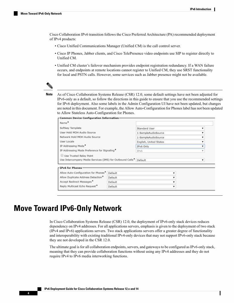
As of Cisco Collaboration Systems Release (CSR) 12.0, some default settings have not been adjusted forIPv6-only as a default, so follow the directions in this guide to ensure that you use the recommended settingsfor IPv6 deployment. Also some labels in the Admin Configuration UI have not been updated, but changesare noted in this document. For example, the Allow Auto-Configuration for Phones label has not been updatedto Allow Stateless Auto-Configuration for Phones.
Note
Move Toward IPv6-Only NetworkIn Cisco Collaboration Systems Release (CSR) 12.0, the deployment of IPv6-only stack devices reducesdependency on IPv4 addresses. For all applications servers, emphasis is given to the deployment of two stack(IPv4 and IPv6) applications servers. Two stack applications servers offer a greater degree of functionalityand interoperability with existing traditional IPv4-only devices that may not support IPv6-only stack becausethey are not developed in the CSR 12.0.
The ultimate goal is for all collaboration endpoints, servers, and gateways to be configured as IPv6-only stack,meaning that they can provide collaboration functions without using any IPv4 addresses and they do notrequire IPv4 to IPv6 media interworking functions.
IPv6 Deployment Guide for Cisco Collaboration Systems Release 12.x and 144
IPv6 IntroductionMove Toward IPv6-Only Network

Table 2: Reduction in IPv4 Addresses
Percent Reductionin IPv4 Addresses
IPv4 AddressesAfter DeployingIPv6-only Endpoints
IPv4 AddressesBefore DeployingIPv6-only Endpoints
Servers andGateways(Dual-stack or IPv4)
Scale of Deployment(Endpoints)
98.8%65066500
99.7%135,013135,000
99.8%2510,0252510,000
The scope of this document is limited to the solutions that were tested and approved by Cisco. SupportedIPv4-only stack applications are limited to those stated in this document. It is assumed that IP phones andgateways are configured with either an IPv4-only stack or IPv6-only stack using SIP signaling. Supportedapplication servers support IPv4-only and IPv6-only stacks (dual-stack). Any applications that we did notdevelop or test are not supported by Cisco TAC. In IPv6 supported network configurations, Skinny ClientControl Protocol (SCCP) for IP phones, voice gateways (Cisco VG Series Gateways), and Cisco UnityConnection are not configured and not tested except for the use of media termination points (MTP) by CiscoUnified Communications Manager.
Note
Deployment Recommendations for Enterprise NetworksIPv4-only stack or IPv6-only stack devices support:
• Single-site call processing deployments.
• Multi-site distributed call processing deployments.
• Multi-site deployments with centralized call processing.
To move toward an IPv6 deployment and reduce dependency on IPv4 addresses, we recommend that youdeploy:
• IPv6-only stack SIP phones, SIP gateways, and SIP trunks.
• IPv4-only stack and IPv6-only stack (dual-stack) Cisco Unified Communications Manager (Unified CM)clusters and other application servers.
For SIP trunks, we do not recommend use of Alternative Network Address Types (ANAT). ANAT requiresIPv4 addresses and does not mitigate IPv4 exhaustion in an IPv6 network. ANAT is applicable only to USDepartment of Defense (DoD) deployments with Joint Interoperability Test Command (JITC) certification.Also, the PSTN SIP trunk service provider does not support ANAT.
Note
IPv6 Deployment Guide for Cisco Collaboration Systems Release 12.x and 145
IPv6 IntroductionDeployment Recommendations for Enterprise Networks

CSR 12.1/12.0 Deployment Gaps
When you transition from a traditional IPv4 network to an IPv6 dual-stack network deployment, the followingfunctionality is not supported and is not tested.
• IPv6-only stack site or branch office (LAN)
• IPv6-only data center
• All IP phones with SCCP signaling
• Secure IP phones, CE endpoints, and gateways
• Applications based on ISR and ISR G2 Routers
• IP phone VPN
• IP phones with NTP
• Video conference deployment based on Cisco TelePresence Conductor, Cisco TelePresence MCU, andCisco TelePresence Server
• Mobile Remote Access (MRA)
• Cisco Expressway MRA support
• Off-premise Cisco Jabber
• Cisco Meeting Server
• Cisco TelePresence Management Suite
• SCCP signaling configuration IP phones
• SIP with ANAT signaling configuration
• RSVP call admission control
• Cisco Spark Hybrid Services
• Third-party API products
• Media Gateway Control Protocol (MGCP) gateways
• Unified CM supported H.323 gateways
• Products that are End-of-Support
Comparison of IPv4 and IPv6This section provides a brief description of the motivation behind deploying IPv6, and a summary comparisonof IPv4 and IPv6.
Why Deploy IPv6?The deployment of IPv6 is primarily driven by IPv4 address exhaustion. As the worldwide usage of IP networksincreases, the number of applications, devices, and services requiring IP addresses is rapidly increasing.
IPv6 Deployment Guide for Cisco Collaboration Systems Release 12.x and 146
IPv6 IntroductionComparison of IPv4 and IPv6

According to the Internet Assigned Numbers Authority (IANA) and Regional Internet Registries, their poolof unallocated IPv4 addresses is exhausted. For example, all area wireless networks in the American Registryfor Internet Numbers (ARIN) are IPv6-only stack.
Because the current IPv4 address space is unable to satisfy the potential huge increase in the number of usersand the geographical needs of the Internet expansion, many companies are either migrating to or planningtheir migration to IPv6, which offers a virtually unlimited supply of IP addresses.
Transforming the Internet from IPv4 to IPv6 is likely to take several years. During this period, IPv4 willco-exist with and then gradually be replaced by IPv6.
Advantages of IPv6 Over IPv4As a new version of the Internet Protocol, IPv6 provides the following advantages over IPv4:
• Larger address space (Supported in Cisco Collaboration Systems Release (CSR) 12.0)
The main feature of IPv6 that is driving adoption today is the larger address space. Addresses in IPv6are 128 bits long compared to 32 bits in IPv4. The larger address space avoids the potential exhaustionof the IPv4 address space without the need for network address translation (NAT) or other devices thatbreak the end-to-end nature of Internet traffic. By avoiding the need for complex sub-netting schemes,IPv6 addressing schemes are easier to understand, making administration of medium and large networkssimpler.
• Address scopes (Supported in CSR 12.0)
IPv6 introduces the concept of address scopes. An address scope defines the region, or span, where anaddress can be defined as a unique identifier of an interface. These spans are the link, the site network,and the global network, corresponding to link-local, site-local (or unique local unicast), and globaladdresses.
• Stateless Address Auto-Configuration (SLAAC) (Supported in CSR 12.0)
IPv6 hosts can be configured automatically when connected to a routed IPv6 network using ICMPv6router discovery messages. Address reconfiguration is also simplified. If IPv6 auto-configuration is notsuitable, a host can use stateful configuration (DHCPv6) or can be configured manually.
• Multicast (Not supported in CSR 12.0)
Multicast is part of the base specifications in IPv6, unlike IPv4, where it was introduced later. Like IPv6unicast addresses, the IPv6 multicast address range is much larger than that of IPv4. IPv6 does not havea link-local broadcast facility; the same effect can be achieved by multicasting to the all-hosts groupaddress (FF02::1).
• Streamlined header format and flow identification (Not supported in CSR 12.0)
The IPv6 header format reduces router processing overhead by using a fixed header length, performingfragmentation on hosts instead of routers, and using an improved header extension method and a newflow label to identify traffic flows requiring special treatment.
• Mobile IPv6 (Not supported in CSR 12.0)
Mobile IPv6 allows a mobile node to change its locations and addresses, while maintaining a connectionto a specific address that is always assigned to the mobile node and through which the mobile node isalways reachable. Mobile IPv6 provides transport layer connection survivability when a node movesfrom one link to another by performing address maintenance for mobile nodes at the Internet layer.
IPv6 Deployment Guide for Cisco Collaboration Systems Release 12.x and 147
IPv6 IntroductionAdvantages of IPv6 Over IPv4

Mobile IPv6 is not supported by Cisco IP Phones or other collaborationcomponents.
Note
• Network-layer security (Not supported)
IPsec, the protocol for IP network-layer encryption and authentication, is part of the base protocol suitein IPv6. This is unlike IPv4, where IPsec is optional. Because of its reduced payload and performanceoverhead, products use TLS and SRTP for authentication and encryption.
The following table summarizes the differences between IPv4 and IPv6 services.
Table 3: IPv4 and IPv6 Services
IPv6 FeatureIPv4 FeatureIP Service
128-bit, multiple scopes32-bit, NATAddress range
Stateless, Easy Reconfiguration,DHCP
DHCPAuto-configuration
RIPng, OSPFv3, IS-IS, EIGRP,MP-BGP
RIP, OSPFv2, IS-IS, EIGRP,MP-BGP
Routing
IPsecIPsecIP Security
Mobile IP with direct routingMobile IPMobility
Differentiated Service, IntegratedService
Differentiated Service, IntegratedService
Quality of Service (QoS)
MLD, PIM, and Multicast BGP;Scope Identifier
IGMP, PIM, and Multicast BGPIP multicast
IPv6 Deployment Guide for Cisco Collaboration Systems Release 12.x and 148
IPv6 IntroductionAdvantages of IPv6 Over IPv4

C H A P T E R 2IPv6 Basics
• IPv6 Basics Overview, on page 9• IPv6 Addressing, on page 9• IPv6 Unicast Addresses: Network and Host IDs, on page 10• Types of IPv6 Addresses, on page 11• Address Assignment for IPv6 Devices, on page 14• DNS for IPv6, on page 17
IPv6 Basics OverviewThis chapter provides an introduction to the basics of IPv6 addressing, including the various address types,address assignment options, new DHCP features, and DNS. For further reading on IPv6, you can refer to thefollowing documentation:
• IPv6 Fundamentals: A Straightforward Approach to Understanding IPv6, 2nd Edition, a Cisco Presspublication available as a: book or video.
• IPv6 Design and Deployment LiveLessons, a Cisco Press publication available throughhttp://www.ciscopress.com/store/ipv6-design-and-deployment-livelessons-9780134655512
• Other Cisco online documentation at http://www.cisco.com/go/ipv6
IPv6 AddressingAn IPv6 address consists of 8 sets of 16-bit hexadecimal values separated by colons (:), totaling 128 bits inlength. For example:
2001:0db8:1234:5678:9abc:def0:1234:5678
You can omit leading zeros. For consecutive zeros in contiguous blocks, you can use a double colon (::).Double colons can appear only once in the address.
For example, here is the complete address:
2001:0db8:0000:130F:0000:0000:087C:140B
IPv6 Deployment Guide for Cisco Collaboration Systems Release 12.x and 149
Here is the abbreviation:
2001:0db8:0:130F::87C:140B
As with IPv4 addresses, you can represent an IPv6 address network prefix the same way:
2001:db8:12::/64
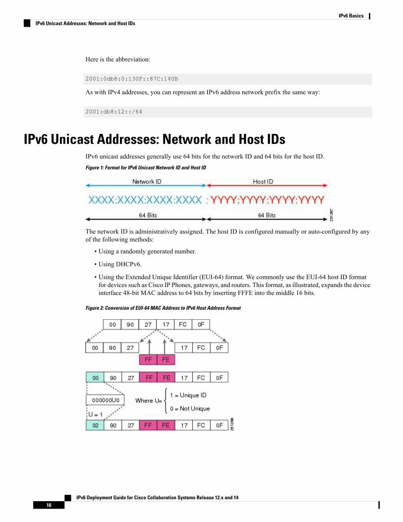
IPv6 Unicast Addresses: Network and Host IDsIPv6 unicast addresses generally use 64 bits for the network ID and 64 bits for the host ID.
Figure 1: Format for IPv6 Unicast Network ID and Host ID
The network ID is administratively assigned. The host ID is configured manually or auto-configured by anyof the following methods:
• Using a randomly generated number.
• Using DHCPv6.
• Using the Extended Unique Identifier (EUI-64) format. We commonly use the EUI-64 host ID formatfor devices such as Cisco IP Phones, gateways, and routers. This format, as illustrated, expands the deviceinterface 48-bit MAC address to 64 bits by inserting FFFE into the middle 16 bits.
Figure 2: Conversion of EUI-64 MAC Address to IPv6 Host Address Format
IPv6 Deployment Guide for Cisco Collaboration Systems Release 12.x and 1410
IPv6 BasicsIPv6 Unicast Addresses: Network and Host IDs

Types of IPv6 AddressesAs with IPv4, IPv6 addresses are assigned to interfaces. However, unlike IPv4, an IPv6 interface is expectedto have multiple addresses. There are several types:
• Unicast address—Identifies a single node or interface. Traffic destined for a unicast address is forwardedto a single interface.
• Multicast address—Identifies a group of nodes or interfaces. Traffic destined for a multicast address isforwarded to all the nodes in the group.
• Anycast address—Identifies a group of nodes or interfaces. Traffic destined to an anycast address isforwarded to the nearest node in the group. An anycast address is essentially a unicast address assignedto multiple devices with a host ID = 0000:0000:0000:0000. (Anycast addresses are not widely usedtoday.)
With IPv6, broadcast addresses are no longer used. Broadcast addresses are too resource intensive, so IPv6uses multicast addresses instead.
Address ScopesAn address scope defines the region where an address can be defined as a unique identifier of an interface.These scopes or regions are the link, the site network, and the global network, corresponding to link-local,unique local unicast, and global addresses.
Global Unicast AddressesGlobal unicast addresses are:
• Routable and reachable across the Internet.
• IPv6 addresses for widespread generic use.
• Structured as a hierarchy to allow address aggregation.
• Identified by their three high-level bits set to 001 (2000::/3).
IPv6 Deployment Guide for Cisco Collaboration Systems Release 12.x and 1411
IPv6 BasicsTypes of IPv6 Addresses

Figure 3: Format for Global Unicast Addresses
The global routing prefix is assigned to a service provider by the Internet Assigned Numbers Authority (IANA).The site level aggregator (SLA), or subnet ID, is assigned to a customer by their service provider. The LANID represents individual networks within the customer site and is administered by the customer.
The Host or Interface ID has the same meaning for all unicast addresses. It is 64 bits long and is typicallycreated by using the EUI-64 format.
Example:
2001:0DB8:BBBB:CCCC:0987:65FF:FE01:2345
Unique Local Unicast AddressesUnique local unicast addresses are:
• Analogous to private IPv4 addresses (for example, 10.1.1.254)
• Used for local communications, inter-site VPNs, and so forth
• Not routable on the Internet (routing would require IPv6 NAT)
Figure 4: Format of Local Unique Address
Global IDs do not have to be aggregated and are defined by the administrator of the local domain. Subnet IDsare also defined by the administrator of the local domain. Subnet IDs are typically defined using a hierarchicaladdressing plan to allow for route summarization.
The Host or Interface ID has the same meaning for all unicast addresses. It is 64 bits long and is typicallycreated by using the EUI-64 format.
IPv6 Deployment Guide for Cisco Collaboration Systems Release 12.x and 1412
IPv6 BasicsUnique Local Unicast Addresses

Example:
FD00:aaaa:bbbb:CCCC:0987:65FF:FE01:2345
Link Local Unicast AddressesLink local unicast addresses are:
• Mandatory addresses that are used exclusively for communication between two IPv6 devices on the samelink.
• Automatically assigned by device when IPv6 is enabled.
• Not routable addresses. Their scope is link-specific only.
• Identified by the first 10 bits (FE80).
Figure 5: Format of Link Local Unicast Address
The remaining 54 bits of the network ID could be zero or any manually configured value. The interface IDhas the same meaning for all unicast addresses. It is 64 bits long and is typically created by using the EUI-64format.
Example:
FE80:0000:0000:0000:0987:65FF:FE01:2345
This address would generally be represented in shorthand notation as:
FE80::987:65FF:FE01:2345
IPv6 Multicast AddressesIPv6 multicast addresses have an 8-bit prefix, FF00::/8 (1111 1111). The second octet defines the lifetimeand scope of the multicast address.
Figure 6: Multicast Address Format
Multicast addresses are always destination addresses. Multicast addresses are used for router solicitations(RS), router advertisements (RA), DHCPv6, multicast applications, and so forth.
IPv6 Deployment Guide for Cisco Collaboration Systems Release 12.x and 1413
IPv6 BasicsLink Local Unicast Addresses

IPv6 clients do not require a default gateway configuration because routers are discovered using RSs andRAs.
Note
Table 4: Common Multicast Addresses
MeaningScopeAddress
Same nodeNode-localFF01::1
All nodes on a linkLink-localFF02::1
Same routerNode-localFF01::2
All routers on a linkLink-localFF02::2
All routers on the InternetSite-localFF05::2
Solicited nodeLink-localFF02::1:FFxx:xxxx
For more information on IPv6 multicast addresses, refer to the IANA documentation:http://www.iana.org/assignments/ipv6-multicast-addresses.
IPv6 multicast application is not developed in Collaboration products, and is not supported industry widethrough service provider networks.
Note
Address Assignment for IPv6 DevicesAddresses can be assigned in the following ways:
• Manual Configuration, on page 14
• IPv6 Stateless Address Auto-Configuration (RFC2462), on page 15
• DHCP for IPv6, on page 15
• Stateless DHCP, on page 16
• Stateful DHCP, on page 16
Manual ConfigurationBecause IPv6 addresses are so complex, you won't want to configure many of them manually. There's toomuch administrative overhead. But you might want static addresses for router interfaces and certain networkresources.
IPv6 Deployment Guide for Cisco Collaboration Systems Release 12.x and 1414
IPv6 BasicsAddress Assignment for IPv6 Devices

IPv6 Stateless Address Auto-Configuration (RFC2462)One of the easiest ways to assign IP addresses is to set up IPv6 Stateless address auto-configuration (SLAAC)on an IPv6 router.
The network administrator configures the router to send Router Advertisement (RA) announcements onto thelink. Then the on-link connected IPv6 nodes configure themselves with an IPv6 address and routing parameters.
They get the IPv6 network prefix from the link-local router's RAs. They create the IPv6 host ID by using thedevice's MAC address and the EUI-64 format for host IDs.
DHCP for IPv6IPv6 devices use multicast to acquire IP addresses and to find DHCPv6 servers. The basic DHCPv6 client-serverconcept is similar to DHCP for IPv4. If a client wants to receive configuration parameters, it sends out arequest on the attached local network to detect available DHCPv6 servers.
•• The DHCPv6 client requests parameters from an available server. This is done using Solicit and Advertise
message and well-known DHCPv6 multicast addresses.
• The server responds with the requested information in a Reply message. As with DHCPv4, DHCPv6uses an architectural concept of "options" to carry more parameters and information within DHCPv6messages.
Figure 7: IPv6 DHCP Messages
The DHCPv6 client knows whether to use DHCPv6 based upon the instruction from a router on its link-localnetwork. The default gateway has two configurable bits in its Router Advertisement (RA) available for thispurpose:
• O bit—When this bit is set, the client can use DHCPv6 to retrieve other configuration parameters (forexample, TFTP server address or DNS server address) but not the client's IP address.
• M bit—When this bit is set, the client can use DHCPv6 to retrieve a managed IPv6 address and otherconfiguration parameters from a DHCPv6 server.
IPv6 Deployment Guide for Cisco Collaboration Systems Release 12.x and 1415
IPv6 BasicsIPv6 Stateless Address Auto-Configuration (RFC2462)
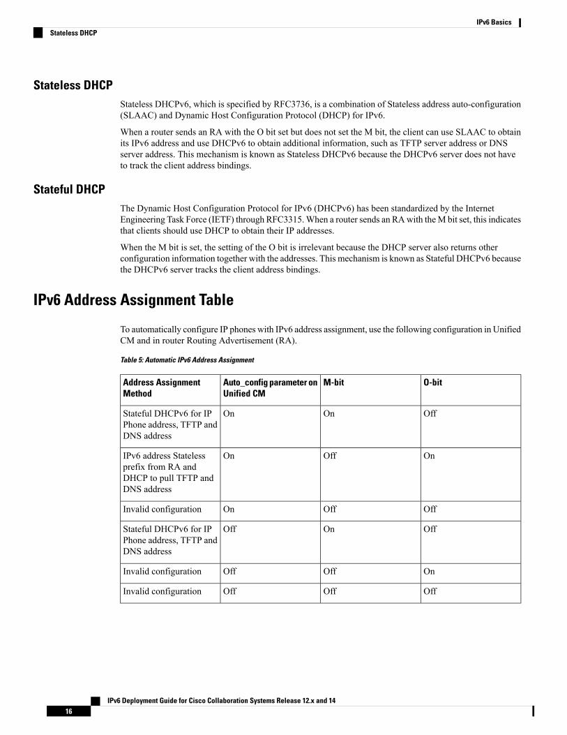
Stateless DHCPStateless DHCPv6, which is specified by RFC3736, is a combination of Stateless address auto-configuration(SLAAC) and Dynamic Host Configuration Protocol (DHCP) for IPv6.
When a router sends an RA with the O bit set but does not set the M bit, the client can use SLAAC to obtainits IPv6 address and use DHCPv6 to obtain additional information, such as TFTP server address or DNSserver address. This mechanism is known as Stateless DHCPv6 because the DHCPv6 server does not haveto track the client address bindings.
Stateful DHCPThe Dynamic Host Configuration Protocol for IPv6 (DHCPv6) has been standardized by the InternetEngineering Task Force (IETF) through RFC3315. When a router sends an RA with the M bit set, this indicatesthat clients should use DHCP to obtain their IP addresses.
When the M bit is set, the setting of the O bit is irrelevant because the DHCP server also returns otherconfiguration information together with the addresses. This mechanism is known as Stateful DHCPv6 becausethe DHCPv6 server tracks the client address bindings.
IPv6 Address Assignment Table
To automatically configure IP phones with IPv6 address assignment, use the following configuration in UnifiedCM and in router Routing Advertisement (RA).
Table 5: Automatic IPv6 Address Assignment
O-bitM-bitAuto_config parameter onUnified CM
Address AssignmentMethod
OffOnOnStateful DHCPv6 for IPPhone address, TFTP andDNS address
OnOffOnIPv6 address Statelessprefix from RA andDHCP to pull TFTP andDNS address
OffOffOnInvalid configuration
OffOnOffStateful DHCPv6 for IPPhone address, TFTP andDNS address
OnOffOffInvalid configuration
OffOffOffInvalid configuration
IPv6 Deployment Guide for Cisco Collaboration Systems Release 12.x and 1416
IPv6 BasicsStateless DHCP

DNS for IPv6Cisco Unified Communications Manager (Unified CM) uses DNS name-to-address resolution in the followingcases:
• If DNS names are used to define Unified CM servers (not recommended)
• If SIP route patterns use DNS names to define destinations
• If SIP trunks use DNS names to define trunk destinations
For IPv6, the principles of DNS are the same as for IPv4, with the following exceptions:
• The nomenclature is different (AAAA records are used instead of A records).
• DNS name-to-address queries can return multiple IPv6 addresses.
Table 6: Comparison of DNS Name and Address Resolution
IPv6IPv4Resolution of:
AAAA record:
www.abc.test AAAA2001:db8:C18:1::2
A record:
www.abc.test. A 192.168.30.1
Hostname to IP address
PTR record:
2.0.0.0.0.0.0.0.0.0.0.0.0.0.0.0.1.0.0.0.8.1.c.0.
8.b.d.0.1.0.0.2.ip6.arpa PTRwww.abc.test.
PTR record:
1.30.168.192.in-addr.arpa. PTR
www.abc.test.
IP address to hostname
IPv6 Deployment Guide for Cisco Collaboration Systems Release 12.x and 1417
IPv6 BasicsDNS for IPv6

IPv6 Deployment Guide for Cisco Collaboration Systems Release 12.x and 1418
IPv6 BasicsDNS for IPv6

C H A P T E R 3IP Addressing Modes for Cisco CollaborationProducts
• IP Addressing Modes, on page 19• Recommended IPv6 Addressing Modes for CSR 12.1/12.0 Products , on page 20• IPv6 Addressing in Cisco Collaboration Products, on page 26• Configuration Parameters and Features for IPv6 in Unified CM, on page 28
IP Addressing ModesIP addressing modes specify the types of addresses that a device can communicate with and understand. Thefollowing IP addressing modes are used as part of the Cisco Collaboration Systems Release (CSR) 12.0.
Table 7: IP Addressing Modes
NotesDescriptionIP Addressing Mode
Used for some endpointsand gateways.
IPv4-only stack
Used for some endpointsand gateways.
IPv6-only stack
The session initiationprotocol (SIP) sessiondescription protocol(SDP) alternative networkaddress type (ANAT)attribute should not beconfigured to transition toIPv6-only. It is applicablefor the DoD networks.
Used for applicationsservers, such as CiscoUnified CommunicationsManager, Cisco UnityConnection, CiscoEmergency Responder,and Cisco UnifiedSurvivable Remote SiteTelephony (UnifiedSRST). Also applicable todual-stack endpoints thatrequire ANAT support.
Two stacks: IPv4-onlyand IPv6-only
IPv6 Deployment Guide for Cisco Collaboration Systems Release 12.x and 1419

NotesDescriptionIP Addressing Mode
IPv6 aware devicescommunicate with IPv4addresses, but can receiveand understand IPv6addresses embedded inapplication protocol dataunits (PDUs).
Used for applicationsservers that use IPv4 totransport IPv6 applicationinformation, such as theCisco Prime CollaborationProvisioning module,Cisco EmergencyResponder, and UnifiedCM.
IPv6 Aware
The ANAT SDPGrouping Frameworkshould not be configuredin Collaboration products.We are removingdual-stack support tofollow IETF deprecationof RFC 4091 and 4092.Dual-stack implies, bothIPv4 and IPv6 addressesare available to use forboth signaling and media.For media, dual-stackdevices can take fulladvantage of the fact thatthey support both IPv4and IPv6 when theycommunicate to any otherdevice. For signaling, theIP addressing mode is setto either IPv4 or IPv6 bythe device configuration.However, thisfunctionality preventstransition to an IPv6-onlystack network. From CSR12.0 onward, the term,dual-stack is applicableonly for DoD network'sendpoint deployments.
Used only for CiscoUnified IP Phones 6900and 7900 Series for DoDnetworks. We do notrecommend dual-stack forenterprise networks. It isapplicable for the DoDnetwork.
Dual-stack endpointsrequire IPv4 and IPv6addresses to support SIPSDP ANAT. Thesedevices communicate withand understand both IPv4and IPv6 addresses.
Dual-stack
Recommended IPv6 Addressing Modes for CSR 12.1/12.0Products
For Collaboration IPv6 implementations, we recommend that you configure:
• IPv6-only stack for endpoints and gateways where supported.
IPv6 Deployment Guide for Cisco Collaboration Systems Release 12.x and 1420
IP Addressing Modes for Cisco Collaboration ProductsRecommended IPv6 Addressing Modes for CSR 12.1/12.0 Products

• IPv4-only and IPv6-only stack for application servers and interfaces where supported. Unified CM andother applications ensure interoperability with existing IPv4-only devices and applications.
The following tables illustrate the recommended SIP IP addressing modes for Cisco Collaboration SystemsRelease (CSR) 12.1/12.0 products. Any products not listed here should be configured in IPv4-only stack.
For a list of product configuration resources for IPv6, see Product Configuration Resources for IPv6, on page127.
Note
Table 8: Recommended IPv6 Addressing Modes for CSR 12.1/12.0 Endpoints
CommentsSolution Testedin CSR 12.1/12.0
Two Stacks:IPv4 and IPv6
IPv6-onlyIPv4-onlyEndpoint (SIP)
YesNoYesNoCisco IP Phone7811, 7821,7841, 7861
YesNoYesNoCisco IP Phone8811, 8841,8845, 8851,8861, 8865
YesNoNoYesCisco IPConferencePhone 7832
YesNoYesYesCisco IPConferencePhone 8832
IPv6-only is foron-premiseJabber desktopdeployment. NoANAT.
NoYesYesNoCisco Jabber
IPv6 Deployment Guide for Cisco Collaboration Systems Release 12.x and 1421
IP Addressing Modes for Cisco Collaboration ProductsRecommended IPv6 Addressing Modes for CSR 12.1/12.0 Products

CommentsSolution Testedin CSR 12.1/12.0
Two Stacks:IPv4 and IPv6
IPv6-onlyIPv4-onlyEndpoint (SIP)
Deploy as IPv4SIP phone.
PartialNoNoYes, SIPCisco Unified IPPhone 6901,7945G, 7965G,7975G, andUnified IPPhoneExpansionModule 7916
Supported butEnd-of-Sale:
6911, 6921,6941, 6945,6961, 7931G,7942G, 7962G,Unified IPConferenceStation 7937G,Unified IPPhoneExpansionModule 7915,Unified WirelessIP Phone 7925G,7925G-EX,7926G
End-of-Support:7906G, 7911G,7941G, 7941GE,7942G, 7961G,7961GE, 7962G,7970G,7971G-GE
Manualconfigurationonly. DHCPIPv6 is notsupported.
NoNoYesNoCisco DX70 andDX80
NoNoYesNoCiscoTelePresenceMX Series, SXSeries
IPv6 Deployment Guide for Cisco Collaboration Systems Release 12.x and 1422
IP Addressing Modes for Cisco Collaboration ProductsRecommended IPv6 Addressing Modes for CSR 12.1/12.0 Products

CommentsSolution Testedin CSR 12.1/12.0
Two Stacks:IPv4 and IPv6
IPv6-onlyIPv4-onlyEndpoint (SIP)
YesNoYesYesCiscoTelePresenceSystem EXSeries
NoNoYesNoCisco WebexRoom Series,Board Series,Desk Series
NoNoNoYesCisco WebexShare
NoNoYesNoWi-Fi enableddevices: CiscoIP Phone 8861,8865
NoNoNoYesCisco IPCommunicator
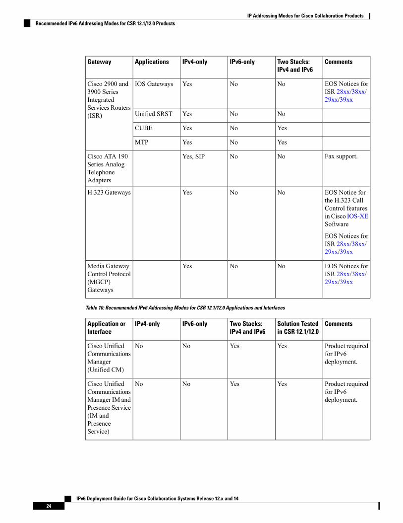
Table 9: Supported Addressing Modes for CSR 12.1/12.0 Communication Gateways
CommentsTwo Stacks:IPv4 and IPv6
IPv6-onlyIPv4-onlyApplicationsGateway
The “Yes” and “No” means whether the IP Addressing mode is supported ornot.
Note
For moreinformation, seeCisco IOSUnifiedCommunicationsGateways withSIP
YesNoYesIOS GatewaysCisco 4000Series IntegratedServices Routers(ISR)
YesNoYesUnified SRST
Only ISR G2tested.
YesNoYesCUBE
Only ISR 4000tested.
YesNoYesMTP
IPv6 Deployment Guide for Cisco Collaboration Systems Release 12.x and 1423
IP Addressing Modes for Cisco Collaboration ProductsRecommended IPv6 Addressing Modes for CSR 12.1/12.0 Products
CommentsTwo Stacks:IPv4 and IPv6
IPv6-onlyIPv4-onlyApplicationsGateway
EOS Notices forISR 28xx/38xx/29xx/39xx
NoNoYesIOS GatewaysCisco 2900 and3900 SeriesIntegratedServices Routers(ISR) NoNoYesUnified SRST
YesNoYesCUBE
YesNoYesMTP
Fax support.NoNoYes, SIPCisco ATA 190Series AnalogTelephoneAdapters
EOS Notice forthe H.323 CallControl featuresin Cisco IOS-XESoftware
EOS Notices forISR 28xx/38xx/29xx/39xx
NoNoYesH.323 Gateways
EOS Notices forISR 28xx/38xx/29xx/39xx
NoNoYesMedia GatewayControl Protocol(MGCP)Gateways
Table 10: Recommended IPv6 Addressing Modes for CSR 12.1/12.0 Applications and Interfaces
CommentsSolution Testedin CSR 12.1/12.0
Two Stacks:IPv4 and IPv6
IPv6-onlyIPv4-onlyApplication orInterface
Product requiredfor IPv6deployment.
YesYesNoNoCisco UnifiedCommunicationsManager(Unified CM)
Product requiredfor IPv6deployment.
YesYesNoNoCisco UnifiedCommunicationsManager IM andPresence Service(IM andPresenceService)
IPv6 Deployment Guide for Cisco Collaboration Systems Release 12.x and 1424
IP Addressing Modes for Cisco Collaboration ProductsRecommended IPv6 Addressing Modes for CSR 12.1/12.0 Products

CommentsSolution Testedin CSR 12.1/12.0
Two Stacks:IPv4 and IPv6
IPv6-onlyIPv4-onlyApplication orInterface
NoNoNoYesCisco UnifiedCommunicationsManagerExpress (UnifiedCME)
Product requiredfor IPv6deployment forISR G3.
YesYesNoNoCisco UnifiedSurvivableRemote SiteTelephony(Unified SRST)
For AgentIPv6-only stack,NAT64.
By customerYesNoNoCisco UnifiedContact CenterEnterprise(Unified CCE)
For AgentIPv6-only stack,NAT64.
By customerYesNoNoCisco UnifiedContact CenterExpress (UnifiedCCX)
YesYesNoNoCiscoEmergencyResponder(EmergencyResponder)
YesYesNoNoCisco UnityConnection
YesNoNoYesCisco MeetingServer
YesNoNoYesCiscoTelePresenceManagementSuite
NoNoNoYesCisco UnityExpress
EOS NoticeNoNoNoYesEnd-of-Sale:Cisco UnifiedMeetingPlace
Applicable toIOS Gateways,Unified SRST,CUBE.
By customerYesNoNoCisco PrimeCollaboration
IPv6 Deployment Guide for Cisco Collaboration Systems Release 12.x and 1425
IP Addressing Modes for Cisco Collaboration ProductsRecommended IPv6 Addressing Modes for CSR 12.1/12.0 Products

CommentsSolution Testedin CSR 12.1/12.0
Two Stacks:IPv4 and IPv6
IPv6-onlyIPv4-onlyApplication orInterface
Applicable toUnified CM, IMand PresenceService, CiscoUnityConnection.
By customerYesNoNoCisco SmartSoftwareLicensing
YesYesYesYesLAN/WAN
YesYesYesYesDynamic HostConfigurationProtocol(DHCP)
YesYesYesYesDomain NameSystem (DNS)
YesYesYesYesDirectory LDAP
Except forUnified CCEand UnifiedCCX, whichhave internalNAT64.
NoNoNoNoNAT64
IPv6 Addressing in Cisco Collaboration ProductsAs you design your network, you'll need information about the number of IPv6 addresses that the variousproducts can support.
Cisco Unified Communications Manager and IPv6 AddressesEach Cisco Media Convergence Server (MCS) can support the following addresses simultaneously:
• One IPv6 link local address (for example, FE80::987:65FF:FE01:2345)
• Either of the following:
• One IPv6 unique local address (ULA), for example:
FD00:AAAA:BBBB:CCCC:0987:65FF:FE01:2345
• One IPv6 global address (GA), for example:
2001:0DB8:BBBB:CCCC:0987:65FF:FE01:2345
IPv6 Deployment Guide for Cisco Collaboration Systems Release 12.x and 1426
IP Addressing Modes for Cisco Collaboration ProductsIPv6 Addressing in Cisco Collaboration Products

• One IPv4 address
All IPv6 devices must have a link local address that is automatically created.
A unique local address is equivalent to a private address in IPv4 (for example, 10.10.10.1).
A global address is a globally unique public address.
Your IPv6 administrator decides on the selection of the address type. To route traffic from devices usingunique local addresses over a public network, IPv6 NAT is required to convert unique local addresses toglobal addresses. We have not solution tested and do not recommend an IPv6 NAT-based solution.
Note
Cisco IP Phones and IPv6 AddressesA Cisco IP Phone can support a combination of the following addresses:
• One IPv6 link local address (for example, FE80::987:65FF:FE01:2345)
• Multiple IPv6 unique local addresses (for example, FD00:AAAA:BBBB:CCCC:0987:65FF:FE01:2345)
• Multiple IPv6 global addresses (for example, 2001:0DB8:BBBB:CCCC:0987:65FF:FE01:2345)
• One IPv4 address
Cisco IP Phones must support one link local address and can support a combination of up to 20 global orunique local addresses. The IP phone can use only IPv6 highest address scopes that can be received (RFC4193) (global address or unique local IPv6 addresses) to register to Unified CM. After registration, this IPv6address is used for signaling and media.
The following characteristics also apply to IPv6 addresses on IP phones:
• A link local address is never sent to Cisco Unified Communications Manager as a signaling and mediaaddress.
• If the IP phone has both unique local and global addresses, the highest scoped global addresses takeprecedence over unique local addresses.
• If the IP phone has multiple unique local addresses or multiple global addresses, the first address configuredis the one used for signaling and media.
The following priority order applies to IPv6 addresses configured on an IP phone:
1. Use the IPv6 address configured manually through the phone's user interface (UI).
2. If an IPv6 address has not been configured manually on the phone, use Stateful DHCPv6 to assignan IPv6 address for IP phone, TFTP, and DNS.
3. If a manually configured address or a Stateful DHCPv6 address is not available, but statelessauto-configuration (SLAAC) is enabled for the phone, then the phone uses SLAAC to create an IPv6address.
IPv6 Deployment Guide for Cisco Collaboration Systems Release 12.x and 1427
IP Addressing Modes for Cisco Collaboration ProductsCisco IP Phones and IPv6 Addresses
In Cisco Unified Communications Manager, SLAAC is On by default. WithSLAAC, the phone uses the IPv6 network prefix advertised in the link localrouter's Router Advertisements (RAs). The phone creates the IPv6 host ID byusing the phone's MAC address and the EUI-64 format for host IDs. If SLAACis used, Stateless DHCP IPv6 provides IPv6 address for TFTP and DNS server.
Note
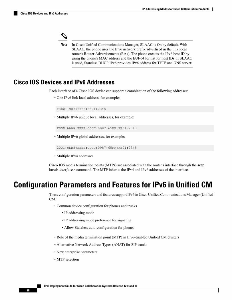
Cisco IOS Devices and IPv6 AddressesEach interface of a Cisco IOS device can support a combination of the following addresses:
• One IPv6 link local address, for example:
FE80::987:65FF:FE01:2345
• Multiple IPv6 unique local addresses, for example:
FD00:AAAA:BBBB:CCCC:0987:65FF:FE01:2345
• Multiple IPv6 global addresses, for example:
2001:0DB8:BBBB:CCCC:0987:65FF:FE01:2345
• Multiple IPv4 addresses
Cisco IOS media termination points (MTPs) are associated with the router's interface through the sccplocal<interface> command. The MTP inherits the IPv4 and IPv6 addresses of the interface.
Configuration Parameters and Features for IPv6 in Unified CMThese configuration parameters and features support IPv6 in Cisco Unified Communications Manager (UnifiedCM):
• Common device configuration for phones and trunks
• IP addressing mode
• IP addressing mode preference for signaling
• Allow Stateless auto-configuration for phones
• Role of the media termination point (MTP) in IPv6-enabled Unified CM clusters
• Alternative Network Address Types (ANAT) for SIP trunks
• New enterprise parameters
• MTP selection
IPv6 Deployment Guide for Cisco Collaboration Systems Release 12.x and 1428
IP Addressing Modes for Cisco Collaboration ProductsCisco IOS Devices and IPv6 Addresses
You can enable and configure IPv6 for an entire cluster and you can configure your IPv6 devices (as shownin Recommended IPv6 Addressing Modes for CSR 12.1/12.0 Products , on page 20) to use IPv6 for signalingand media.
Common Device ConfigurationRather than add IPv6 configuration parameters to specific IP phones and SIP trunks and phones, you can useUnified CM's common device configuration template. This template contains the IPv6-specific configurationparameters for IP phones and SIP trunks. You can create and associate multiple common device configurationprofiles to IP phones and SIP trunks.
To find the template, choose Device > Device Settings > Common Device Configuration.
The profile contains this configuration information for IPv6:
• IP Addressing Mode
• IP Addressing Mode Preference for Signaling
• Allow (Stateless) Auto-Configuration for Phones
Default Common Device Configuration
There is no default common device configuration profile. Devices are initially set to <None>. If you enableIPv6 in the Unified CM cluster in this <None> configuration, then your IPv6 devices adopt the followingsettings:
• IP Addressing Mode = IPv4 and IPv6
• IP Addressing Mode Preference for Signaling = Use System Default
• Allow (Stateless) Auto-Configuration for Phones = Default
For enterprise deployment models of CSR 12.0, you must configure IP Addressing Mode to IPv6.Note
IPv6 Deployment Guide for Cisco Collaboration Systems Release 12.x and 1429
IP Addressing Modes for Cisco Collaboration ProductsCommon Device Configuration

Figure 8: Initial Common Device Configuration Settings
IP Addressing Mode for IPv6 PhonesAfter you configure the common device configuration profile and assign it to your phones, the specified IPaddressing modes will be applied. The IP addressing modes are:
• IPv4 Only—The phone acquires and uses only one IPv4 address for all signaling and media. If the phoneacquired an IPv6 address previously, it releases the IPv6 address.
• IPv6 Only—The phone acquires and uses only one IPv6 address for all signaling and media. If the phoneacquired an IPv4 address previously, it releases the IPv4 address.
• IPv4 and IPv6 (Not applicable for CSR 12.0)—The phone acquires and uses one IPv4 address and oneIPv6 address. It can use the appropriate address as required for media. It uses either the IPv4 address orthe IPv6 address for call control signaling.
IPv6 Deployment Guide for Cisco Collaboration Systems Release 12.x and 1430
IP Addressing Modes for Cisco Collaboration ProductsIP Addressing Mode for IPv6 Phones

For enterprise deployment models of the CSR 12.0, IPv4 and IPv6 is notapplicable. You must configure IPv6 Only or IPv4 Only as recommended inRecommended IPv6 Addressing Modes for CSR 12.1/12.0 Products , on page20.
Note
Figure 9: Setting the Phone IP Addressing Mode
If IPv6 is enabled in the Unified CM cluster, the default phone setting for IP addressing mode is IPv6. IPphones should not be configured for IPv4 and IPv6, it should be configured for IPv6-only phones.
We recommend IPv6 Only endpoints for the CSR 12.0 enterprise deployment as shown in RecommendedIPv6 Addressing Modes for CSR 12.1/12.0 Products , on page 20.
Note
IP Addressing Modes for Media Streams Between DevicesDepending on the devices that you have chosen and the configuration profiles that you have set up, you canpotentially have an assortment of devices using IPv4 addresses or IPv6 addresses. For two devices (such asphones) that support mismatched addressing modes, an IP addressing version incompatibility exists when adevice with an IPv4 address wants to establish a RTP voice stream with a device with an IPv6 address. Toresolve this IP addressing incompatibility for media, Unified CM dynamically inserts a media terminationpoint (MTP) to convert the media stream from IPv4 to IPv6 or conversely. For more information on how andwhen MTPs are used for IPv6 calls, see Media Resources and Music on Hold Overview, on page 89.
IP Addressing Mode Preference for Signaling for Phones
The phone IP Addressing Mode Preference for Signaling has three settings:
• IPv4—The phone uses its IPv4 address for call control signaling to Unified CM.
• IPv6—The phone uses its IPv6 address for call control signaling to Unified CM.
IPv6 Deployment Guide for Cisco Collaboration Systems Release 12.x and 1431
IP Addressing Modes for Cisco Collaboration ProductsIP Addressing Modes for Media Streams Between Devices

• Use System Default—The phone uses the cluster-wide setting for IP Addressing Mode for Signaling ifit has an address of that type. At first glance, you might worry that a cluster-wide setting could lead toincompatibility issues: What if a phone is using an IPv4 address and it tries to set up a voice stream witha phone that is using an IPv6 address? Unified CM handles this situation dynamically. It inserts an MTPthat converts the media stream from IPv4 to IPv6 and back again.
Figure 10: Common Device Configuration Information: IP Addressing Mode Preference for Signaling
Allow (Stateless) Auto-Configuration for Phones
You can allow phones to receive an IP address and other information automatically. Your options are partlydependent on how you configure the link local router.
Figure 11: Common Device Configuration Information: Allow (Stateless) Auto-Configuration for Phones
You have these options:
IPv6 Deployment Guide for Cisco Collaboration Systems Release 12.x and 1432
IP Addressing Modes for Cisco Collaboration ProductsIP Addressing Modes for Media Streams Between Devices

• On—The phone can use Stateless Address Auto-Configuration (SLAAC), if supported by the link localrouter's configuration. It depends on the O and M bits in the Router Advertisements (RAs).
• If the O-bit is set—The router allows the phone to use SLAAC to acquire its IP address and to usethe DHCP server to acquire other information (such as the TFTP server address and DNS serveraddress). This is known as stateless DHCP IPv6.
• If the M-bit is set—The router does not allow the phone to use SLAAC but allows it to use theDHCP server to acquire its IP address and other information. This is known as stateful DHCP.
• If neither bit is set—The router allows the phone to use SLAAC to acquire an IP address but doesnot allow it to use DHCP for other information. You need to configure a TFTP server addressthrough the phone’s user interface (UI). The phone uses this TFTP server to download itsconfiguration file and register to Unified CM. We do not recommend this for a productionenvironment.
• Off—The phone does not use SLAAC to acquire an IPv6 address. In this case, the phone should usestateful DHCPv6 to acquire an IPv6 address and TFTP server address.
• Default—The phone uses the cluster-wide enterprise parameter configuration value for Allow (Stateless)Auto-Configuration for Phones. If IPv6 is enabled in the Unified CM cluster, the phone's default settingfor Allow (Stateless) Auto-Configuration for Phones setting is Default. If the IP phone supports IPv6-only,it adopts the cluster-wide setting for Allow (Stateless) Auto-Configuration for Phones, but all IPv4 phonesignore this setting.
Common Device Profile Configuration for SIP TrunksYou can apply SIP trunk configuration settings through the Common Device Configuration profile that youcreate and assign to the IPv6-Only SIP trunk with ANAT disabled.
With IPv6 enabled and with IPv4 addresses defined on the Unified CM server, you can configure the SIPtrunk to use either of these addresses as its source IP address for SIP signaling. The SIP trunk also listens forincoming SIP signaling on the configured incoming port number of the server's IPv4 or IPv6 address.
IP Addressing Mode for SIP Trunks
The SIP trunk IP addressing mode has three settings:
• IPv4 Only—The SIP trunk uses the Unified CM IPv4 address for signaling and either an MTP or phoneIPv4 address for media.
• IPv6 Only—The SIP trunk uses the IPv6 address for signaling and either an MTP or phone IPv6 addressfor media.
• IPv4 and IPv6 (Not applicable for CSR 12.0.)—For signaling, the SIP trunk will use either the UnifiedCM IPv4 address or the Unified CM IPv6 address. For media, the SIP trunk will use either an MTP IPv4and/or IPv6 address or the phone IPv4 and/or IPv6 address.
If IPv6 is enabled in the Unified CM cluster, the default SIP trunk setting for the IP Addressing mode is IPv4and IPv6. All IPv4 trunks (H.323 and MGCP) will ignore this setting.
We recommend setting the IP addressing mode for IPv6 SIP trunks to IPv4 or IPv6. The IPv6 Only setting isrecommended and can be used in production environments.
IPv6 Deployment Guide for Cisco Collaboration Systems Release 12.x and 1433
IP Addressing Modes for Cisco Collaboration ProductsCommon Device Profile Configuration for SIP Trunks

For more information on these SIP trunk IP addressing modes, see SIP Trunks Using Delayed Offer, on page78.
IP Addressing Mode Preference for Signaling for SIP Trunks
The SIP trunk IP Addressing Mode Preference for Signaling is used only for outbound calls. Unified CMlistens for incoming SIP signaling on the configured incoming port number of the server's address.
The SIP trunk IP Addressing Mode Preference for Signaling has three settings:
• IPv4—The SIP trunk uses the Unified CM IPv4 address as its source address for SIP signaling.
• IPv6—The SIP trunk uses the Unified CM IPv6 address as its source address for SIP signaling.
If IPv6 is enabled in the Unified CM cluster, this is the default SIP trunk settingfor IP Addressing Mode Preference for Signaling. All IPv4 trunks ignore thissetting.
Note
• Use System Default—The SIP trunk uses the cluster-wide enterprise parameter configuration value forits IP addressing mode for signaling.
If IPv6 is enabled in the Unified CM cluster, the default SIP trunk setting for IP Addressing Mode Preferencefor Signaling is Use System Default. With this setting the SIP trunk will adopt the cluster-wide setting forIP Addressing Mode Preference for Signaling. All IPv4 trunks will ignore this setting.
The SIP trunk IP Addressing Mode Preference for Signaling is used only for outbound calls. Unified CM willlisten for incoming SIP signaling on the configured incoming port number of the server's IPv4 and IPv6address.
Allow Auto-Configuration for Phones
The parameter to Allow Auto-Configuration for Phones is not used by SIP trunks.
Alternative Network Address Types
Alternative Network Address Types (ANAT) is not applicable for CSR 12.0. ANAT is not applicable for allCSR 12.0 products. IPv4 to IPv6 media interworking is supported by Unified CM inserting MTPs.
Note
ANAT is used in the SIP Offer and Answer exchange by dual-stack SIP trunks. ANAT allows these SIPdevices to send both IPv4 and IPv6 addresses in the Session Description Protocol (SDP) body of a SIP Offer,and to return in the SDP body of the SIP Answer a preferred IP address (IPv4 or IPv6) with which to establisha voice connection.
We support ANAT over dual-stack (IPv4 and IPv4) SIP trunks. ANAT must be supported by both ends ofthe SIP trunk. You can enable ANAT by checking the Enable ANAT check box on the SIP profile associatedwith the SIP trunk. ANAT can be used with both Early Offer and Delayed Offer calls.
IPv6 Deployment Guide for Cisco Collaboration Systems Release 12.x and 1434
IP Addressing Modes for Cisco Collaboration ProductsAlternative Network Address Types

Enable ANAT only on SIP trunks with an IP addressing mode setting of IPv4 and IPv6.Note
Figure 12: SIP Trunk Profile Configuration
Cluster-Wide Configuration (Enterprise Parameters)
Before configuring the cluster-wide parameters in Unified CM, configure each server with an IPv6 address.For details on Unified CM IPv6 address configuration, see Configuring IPv6 in Cisco Unified CM, page A-1.In the Unified CM Administration interface, select Enterprise Parameters > IPv6 Configuration Modesto configure the following cluster-wide IPv6 settings for each Unified CM server.
• Enable IPv6
• IP Addressing Mode Preference for Media
• IP Addressing Mode Preference for Signaling
• Allow Auto-Configuration for Phones
Figure 13: Cluster-Wide IPv6 Configuration Modes
Enable IPv6
Set this parameter to True to enable IPv6. False is the default setting.
IP Addressing Mode Preference for Media
IP Addressing Mode Preference for Media has two setting options:
• IPv4 (Default setting)
• IPv6 (Recommended setting)
IPv6 Deployment Guide for Cisco Collaboration Systems Release 12.x and 1435
IP Addressing Modes for Cisco Collaboration ProductsCluster-Wide Configuration (Enterprise Parameters)

The cluster-wide IP Addressing Mode Preference for Media is different than the device-level IP addressingmode. The cluster-wide IP Addressing Mode Preference for Media:
• Selects which IP addressing version will be used for media when a call is made between two dual-stackdevices (Not applicable for the CSR 12.0 deployment)
• Is used when there is a mismatch in supported IP addressing versions between two devices. For example,if an IPv6-only device calls an IPv4-only device, an MTP must be inserted into the media path to convertfrom IPv4 to IPv6, and conversely.
Typically, both devices have MTP media resources available to them in their media resource group (MRG).The IP Addressing Mode Preference for Media is used to select which device's MTP is used to convert fromIPv4 to IPv6 (and conversely) for the call, as follows:
• If the IP Addressing Mode Preference for Media is set to IPv4, the MTP associated with the IPv6-onlydevice is selected, so that the longest call leg between the device and the MTP uses IPv4.
• If the IP Addressing Mode Preference for Media is set to IPv6, the MTP associated with the IPv4-onlydevice is selected, so that the longest call leg between the device and the MTP uses IPv6.
• If the preferred device’s MTP is not available, the other device's MTP is used.
• If no MTPs are available, the call fails.
MTP resource allocation is discussed in detail in Media Resources and Music on Hold, on page 89.
IP Addressing Mode Preference for Signaling
The cluster-wide setting for the IP Addressing Mode Preference for Signaling is used by devices whose IPAddressing Mode Preference for Signaling is set to Use System Default. The IP Addressing Mode Preferencefor Signaling has two setting options:
• IPv4 (Default setting)
• IPv6 (Recommended setting)
Allow (Stateless) Auto-Configuration for Phones
The cluster-wide setting to Allow (Stateless) Auto-Configuration for Phones is used by phones whose Allow(Stateless) Auto-Configuration for Phones parameter is set to Default. The parameter to Allow (Stateless)Auto-Configuration for Phones has two setting options:
• On (Default setting)
• Off
IPv6 Address Configuration for Unified CMAfter you configure an IPv6 address for the Unified CM server, you must also configure this address in theUnified CM Administration graphical user interface. This IPv6 address is used in the device configurationfiles stored on the cluster's TFTP servers. IPv6 devices can use this address to register with Unified CM. Aserver name can also be used, but an IPv6 DNS server is required to resolve this name to an IPv6 address.
IPv6 Deployment Guide for Cisco Collaboration Systems Release 12.x and 1436
IP Addressing Modes for Cisco Collaboration ProductsIPv6 Address Configuration for Unified CM

Figure 14:
IPv6 Deployment Guide for Cisco Collaboration Systems Release 12.x and 1437
IP Addressing Modes for Cisco Collaboration ProductsIPv6 Address Configuration for Unified CM

IPv6 Deployment Guide for Cisco Collaboration Systems Release 12.x and 1438
IP Addressing Modes for Cisco Collaboration ProductsIPv6 Address Configuration for Unified CM

C H A P T E R 4Collaboration Deployment Models for IPv6
• Collaboration Deployment Models for IPv6 Overview, on page 39• Single-Site Deployments, on page 39• Multi-Site WAN Deployments with Distributed Call Processing, on page 42• Multi-Site Deployments with Centralized Call Processing and Unified SRST, on page 44• Call Admission Control, on page 46• Intra-Cluster Communications, on page 46• Clustering Over the WAN, on page 46• Call Detail Records and Call Management Records, on page 47
Collaboration Deployment Models for IPv6 OverviewThis chapter describes the deployment models you can use with IPv6 in Cisco Collaboration networks. CiscoUnified Communications Manager (Unified CM) 12.0 supports the following traditional IPv4 deploymentmodel examples:
• Single-site deployments
• Multi-site WAN deployments with distributed call processing
• Multi-site deployments with centralized call processing and Cisco Unified Survivable Remote SiteTelephony (Unified SRST)
With all of these deployment models, IPv6 endpoints should be configured as IPv6 with a preference of IPv6for signaling and media. This configuration maximizes the amount of IPv6 traffic with the use of mediatermination points (MTPs) for conversions between IPv4 and IPv6.
Single-Site DeploymentsThe single-site model for Cisco Collaboration consists of a call processing agent cluster located at a singlesite, or campus, with no telephony services provided over an IP WAN. An enterprise would typically deploythe single-site model over a LAN or metropolitan area network (MAN), which carries the voice, video, andIM traffic within the site. In this model, calls beyond the LAN or MAN use the public switched telephonenetwork (PSTN).
IPv6 Deployment Guide for Cisco Collaboration Systems Release 12.x and 1439

Figure 15: Single-Site IPv6 Deployment
The characteristics and benefits of the IPv6 single-site model are the same as for IPv4 single-site deployments,as described in the Cisco Collaboration Solution Reference Network Design (SRND), available athttp://www.cisco.com/go/ucsrnd. The IPv6 single-site model includes the additional IPv6-only endpoints anddual stack application servers' product capabilities and features discussed throughout this document. As shownin Recommended IPv6 Addressing Modes for CSR 12.1/12.0 Products , on page 20, CSR 12.0 will not deploydual stack endpoints.
Best Practices for IPv6 Single-Site DeploymentsSingle-site IPv6 deployments can contain a mixture of IPv4 and IPv6 devices. IPv6 phones can be configuredas:
• IPv4-only
• IPv4 and IPv6 (Not Recommended)
• IPv6 only (Key feature of CSR 12.0)
Not applicable for the CSR 12.0 deployment:
• If IPv6 phones are configured as dual stack (IPv4 and IPv6), they should also be configured as follows:
• To use IPv6 for signaling to Unified CM.
• To prefer IPv6 over IPv4 for media.
IPv6 Deployment Guide for Cisco Collaboration Systems Release 12.x and 1440
Collaboration Deployment Models for IPv6Best Practices for IPv6 Single-Site Deployments

One or more ISDN PSTN gateways can be deployed in a single-site deployment. If only one gateway isdeployed, Cisco IOS ISR 4000 SIP gateway should be used.
ISR 2G routers do not support IPv6-only gateways.Note
Both the Unified CM SIP trunk and Cisco IOS SIP gateway should be configured as follows:
• IPv6-only stack
• ANAT disabled for enterprise network
• To use IPv6 for signaling and media.
The Unified CM SIP trunk and the SIP gateway can be configured to use:
• SIP Delayed Offer (With MTP Required unchecked, although MTPs may be inserted dynamically forsome calls for conversions between IPv4 and IPv6 addresses.)
SIP Early Offer IPv6-only trunk is not supported in the CSR 12.0.Note
If a single IPv6 gateway is used and the cluster-wide preference for media is set to IPv6, an MTP is used forall calls to IPv4-only devices to convert from IPv4 to IPv6 protocol. If the widespread use of MTPs is notacceptable in the single-site deployment, configure two PSTN gateways instead of just one. Configure oneas IPv4-only SIP gateway using SIP Delayed Offer as described above, and the other as a standard IPv6-onlygateway. Calling search spaces and partitions can then be used to direct PSTN calls from IPv4-only andIPv6-only devices to their respective gateways.
For specific device configuration options and preferences, refer to the chapters on Trunks, on page 65, andCollaboration Endpoints, on page 121.
The Campus LANIf the campus LAN uses Layer 2 switching only, enable Multicast Listener Discovery (MLD) in the campusswitches if it is supported. Enabling MLD is not mandatory, but it is preferred because it reduces unwantedmulticast traffic in the LAN.
If the campus LAN also includes Layer 3 routing devices, configure these devices to support dual-stack (IPv4and IPv6) routing. IPv6-only stack is not supported in CSR 12.0.
If a single PSTN gateway (as previously described) is used in this deployment model, then all Layer 3 LANrouting devices must be configured as dual-stack. If two gateways are used (one IPv6-only and one IPv4-only),then the portions of the network that contain IPv4-only devices do not have to be configured for dual-stackrouting.
Note
IPv6 Deployment Guide for Cisco Collaboration Systems Release 12.x and 1441
Collaboration Deployment Models for IPv6The Campus LAN

Multi-Site WAN Deployments with Distributed Call ProcessingThe model for a multi-site WAN deployment with distributed call processing consists of multiple independentsites, each with its own call processing cluster connected to an IP WAN that carries voice traffic between thedistributed sites.
Figure 16: Multi-Site Deployment with Distributed Call Processing
Each site in the distributed call processing model can be one of the following:
• A single site with its own call processing agent, which can be either a:
• Dual-stack (IPv4 and IPv6) Cisco Unified Communications Manager (Unified CM)
• Standard (IPv4-only) Cisco Unified Communications Manager (Unified CM)
• Standard (IPv4-only) Cisco Unified Communications Manager Express (Unified CME)
• Other IP PBX:
• A standard (IPv4-only) centralized call processing site and all of its associated remote sites
IPv6 Deployment Guide for Cisco Collaboration Systems Release 12.x and 1442
Collaboration Deployment Models for IPv6Multi-Site WAN Deployments with Distributed Call Processing
• A legacy PBX with Voice over IP (VoIP) gateway (IPv4-only or IPv6-only)
For dual-stack (IPv4 and IPv6) sites, the devices can be configured as either IPv4-only or IPv6-only. Thisconfiguration maximizes the amount of IPv6 traffic with the use of MTPs for conversions between IPv4 andIPv6 addresses.
The characteristics and benefits of an IPv6 multi-site WAN deployment with distributed call processing arethe same as those for IPv4 multi-site WAN deployments with distributed call processing, as described in theCisco Collaboration System Solution Reference Network Design (SRND), available athttp://www.cisco.com/go/ucsrnd. The IPv6 multi-site model includes the additional IPv6-only and IPv6-onlyproduct capabilities and features discussed in this document.
Best Practices: Multi-Site WAN Deployments with Distributed Call ProcessingA multi-site WAN deployment with distributed call processing has many of the same requirements as a singlesite. Follow the best practices from the single site model in addition to the ones listed here for the distributedcall processing model.
IPv6 Unified CM clusters in multi-site WAN deployments with distributed call processing can use IPv6-onlyenabled SIP Delayed Offer intercluster trunks to connect to other IPv6 Unified CM clusters. However, forintercluster trunk connections to IPv4-only Unified CM clusters, we recommend using IPv4 SIP trunk delayedoffer, not IPv6 intercluster trunks.
If IPv6-enabled SIP intercluster trunks are used, the WAN must support dual-stack (IPv4 and IPv6) routing.Note
Configure the Unified CM SIP intercluster trunks as follows:
• IPv6-only or IPv4-only (no ANAT is required).
• With ANAT disabled.
• To use IPv6 for signaling and media.
Configure the Unified CM SIP intercluster trunk to use:
• SIP Delayed Offer with MTP Required unchecked. Although MTPs may be inserted dynamically forsome calls for conversions between IPv4 and IPv6 addresses.
SIP IPv6-only trunk Early Offer with MTP Required checked and used for everycall is not supported.
Note
For specific device configuration options and preferences, refer to Trunks, on page 65, and CollaborationEndpoints, on page 121.
IPv6 Deployment Guide for Cisco Collaboration Systems Release 12.x and 1443
Collaboration Deployment Models for IPv6Best Practices: Multi-Site WAN Deployments with Distributed Call Processing

Multi-Site Deployments with Centralized Call Processing andUnified SRST
In this call processing deployment model, endpoints can be located remotely from the call processing service(Unified CM cluster), across a QoS-enabled Wide Area Network (WAN). Due to the limited quantity ofbandwidth available across the WAN, call admission control is required to manage the number of calls admittedon any given WAN link, to keep the load within the limits of the available bandwidth. On-net communicationbetween the endpoints traverses either a LAN/MAN (when endpoints are located in the same site) or a WAN(when endpoints are located in different sites). Communication outside the enterprise goes over an externalnetwork such as the PSTN, through a gateway that is typically co-located with the endpoint.
The IP WAN also carries call control signaling between the central site and the remote sites. The followingfigure illustrates a typical centralized call processing deployment, with a Unified CM cluster as the callprocessing agent at the central site and an IP WAN to connect all the sites.
IPv6 Deployment Guide for Cisco Collaboration Systems Release 12.x and 1444
Collaboration Deployment Models for IPv6Multi-Site Deployments with Centralized Call Processing and Unified SRST

Figure 17: Multi-Site Deployment with Centralized Call Processing and SRST
For IPv6-enabled multi-site centralized call processing deployments, the centralized Unified CM cluster isenabled for IPv4 and IPv6. Each site may be configured as dual-stacks or IPv4-only. For dual-stack (IPv4and IPv6) sites, IPv6 devices should be configured as IPv6-only with a preference of IPv6 for signaling andmedia. This configuration maximizes the amount of IPv6 traffic using MTPs for conversions between IPv4and IPv6 addresses.
The characteristics and benefits of an IPv6 multi-site centralized call processing deployment are the same asfor IPv4 multi-site centralized call processing deployments, as described in the Cisco Collaboration SystemSolution Reference Network Design (SRND), available at http://www.cisco.com/go/ucsrnd. However, the IPv6multi-site centralized call processing deployment model includes the additional IPv6-only product capabilitiesand features discussed in this document.
IPv6 Deployment Guide for Cisco Collaboration Systems Release 12.x and 1445
Collaboration Deployment Models for IPv6Multi-Site Deployments with Centralized Call Processing and Unified SRST

Best Practices: Multi-Site Deployments with Centralized Call ProcessingIPv6 multi-site deployments with centralized call processing can contain sites with a mixture of traditionalIPv4 and IPv6 devices. In each IPv6-enabled site, follow the best practices from the single-site model inaddition to the ones listed here for the centralized call processing model.
You can configure IPv6-capable phones as:
• IPv4-only
• IPv4 and IPv6 (Recommended for DoD only.)
• IPv6-only (Recommended for production environments.)
The IP WAN in IPv6 multi-site deployments with centralized call processing must support dual-stack (IPv4and IPv6) routing.
Unified SRST ISR 4000 routers at remote sites support IPv6-only or IPv4-only IP Phones in SRST mode.These SRST routers revert to original mode when the Unified CM cluster is restored. DoD supported dual-stackIP phones with ANAT are not supported in SRST mode and are not recommended for deployment at remotesites. They operate in IPv6-only mode.
Call Admission ControlFor multi-site deployments with distributed or centralized call processing, use locations-based call admissioncontrol and a WAN based on either Multiprotocol Label Switching (MPLS) or a hub-and-spoke topology.For more information on call admission control, refer to the Cisco Collaboration System Solution ReferenceNetwork Design (SRND), available at http://www.cisco.com/go/ucsrnd.
MPLS design is supported, but is not committed and is not solution tested.Note
Intra-Cluster CommunicationsAll intra-cluster server-to-server communications, such as Intra-Cluster Communication Signaling (ICCS)traffic, database traffic, and firewall management real-time traffic, use IPv4-only.
Clustering Over the WANWe have tested clustering over the WAN with dual-stack Unified Communications Manager clusters, whereIPv4 is used for intra-cluster communication such as ICCS and IPv6 is used for inter-cluster communicationover SIP trunks.
IPv6 Deployment Guide for Cisco Collaboration Systems Release 12.x and 1446
Collaboration Deployment Models for IPv6Best Practices: Multi-Site Deployments with Centralized Call Processing

Call Detail Records and Call Management RecordsCall detail records (CDR) and call management records (CMR), when enabled, are collected by each subscriberserver and are uploaded periodically to the publisher server, which stores the records in the CDR Analysisand Reporting (CAR) database. CDR and CMR collect and store both IPv4 and IPv6 addresses. These serversinterface with IPv4 addresses that are IPv6-aware.
IPv6 Deployment Guide for Cisco Collaboration Systems Release 12.x and 1447
Collaboration Deployment Models for IPv6Call Detail Records and Call Management Records

IPv6 Deployment Guide for Cisco Collaboration Systems Release 12.x and 1448
Collaboration Deployment Models for IPv6Call Detail Records and Call Management Records

C H A P T E R 5Network Infrastructure
• Network Infrastructure Overview, on page 49• LAN Infrastructure, on page 50• Network Services, on page 52• WAN Infrastructure, on page 56• Call Admission Control, on page 57• IPv6 Bandwidth Provisioning, on page 58• Network Management, on page 62
Network Infrastructure OverviewThe requirements of the network infrastructure needed to build an IPv6 Collaboration system in an enterpriseenvironment are very similar to those for an IPv4 Collaboration system. Unified Communications places strictrequirements on IP packet loss, packet delay, and delay variation (or jitter). Therefore, you must enable mostof the Quality of Service (QoS) mechanisms available on Cisco switches and routers throughout the network.For the same reasons, redundant devices and network links that provide quick convergence after networkfailures or topology changes are also important to ensure a highly available infrastructure. The Cisco Catalyst6000 Series and Catalyst 4000 Series Switches use the same QoS architecture (DSCP) for IPv6 as they usedfor IPv4. With the exception of the Cisco Catalyst 3560 Series and 3750 Series Switches (which support QoStrust features only for IPv6), the same QoS mechanisms (such as classification, policing, queuing, and soforth) used for IPv4 Unified Communications traffic in Cisco switches and routers can also be applied to IPv6Unified Communications traffic. Likewise, the redundant design and availability mechanisms for IPv4 networksare generally available in Cisco switches and routers for IPv6.
This chapter discusses recommendations specific to IPv6 for Unified Communications network infrastructures.For other guidance on standard network infrastructure features required in IPv4 Unified Communicationsnetworks, refer to the Cisco Collaboration System Solution Reference Network Design (SRND), availableat: https://www.cisco.com/c/en/us/td/docs/voice_ip_comm/uc_system/design/guides/UCgoList.html.
The following list summarizes the key network infrastructure recommendations for IPv6 UnifiedCommunications networks:
• For Layer 2 switched networks, enable Multicast Listener Discovery (MLD) snooping, if possible, sothat multicast traffic can be forwarded selectively to the ports that you want to receive the data.
• Layer 3 routed networks require a mechanism to transport IPv6 traffic. Native two stacks (IPv4 and IPv6)routing is recommended, although various other IPv6 tunneling mechanisms may also be used.
IPv6 Deployment Guide for Cisco Collaboration Systems Release 12.x and 1449

• Use Hot Standby Router Protocol (HRSP) or Gateway Load Balancing Protocol (GLBP) if those protocolsare supported by your Layer 3 campus devices. Otherwise, use IPv6 Neighbor Unreachability Detection.
• IPv6 traffic uses larger headers, which you must factor into the bandwidth requirements for IPv6 traffic,especially in the WAN where bandwidth can be limited.
• For intercluster IPv6 traffic over IPv6-only or IPv4-only SIP intercluster trunks, use call admissioncontrol that is based on topology-unaware locations. (RSVP is not supported for IPv6). Topology-unawarecall admission control requires a hub-and-spoke topology for the WAN, or a spokeless hub in the caseof a Multiprotocol Label Switching (MPLS) virtual private network (VPN).
LAN InfrastructureCampus LAN infrastructure design is extremely important for proper IP telephony operation on a convergednetwork. Proper LAN infrastructure design requires following basic configuration and design best practicesfor deploying a highly available network. Furthermore, proper LAN infrastructure design requires deployingend-to-end QoS on the network. This section discusses specific IPv6 design guidance for campus networks.For general guidance on designing collaboration campus networks, refer to the Cisco Collaboration SystemSolution Reference Network Design (SRND), available at http://www.cisco.com/go/ucsrnd.
General IPv6 LAN Design GuidanceThe following sources provide general guidance for designing IPv6 networks:
• Introduction to IPv6 in Cisco products
http://www.cisco.com/go/ipv6
• Deploying IPv6 in Campus Networks
http://www.cisco.com/en/US/docs/solutions/Enterprise/Campus/CampIPv6.html
• Deploying IPv6 in Branch Networks
http://www.cisco.com/en/US/docs/solutions/Enterprise/Branch/BrchIPv6.html
IPv6 Design Guidance for Collaboration Campus Networks
The following sections provide design guidance for deploying IPv6 in collaboration campus networks.
MLD and MLD Snooping in Switched Layer 2 IPv6 Campus Networks
IPv6 multicast routers use Multicast Listener Discovery (MLD) protocol to discover the presence of multicastlisteners (nodes wishing to receive IPv6 multicast packets) on its directly attached links and to discover whichmulticast packets are of interest to neighboring nodes.
MLD snooping is similar to Internet Group Management Protocol (IGMP) snooping for IPv4. With MLDsnooping, IPv6 multicast data is selectively forwarded to a list of ports that want to receive the data, insteadof being flooded to all ports in a VLAN. This list is constructed by snooping IPv6 multicast control packets.If possible, enable Multicast Listener Discovery (MLD) snooping in your IPv6 LAN to reduce unwantedmulticast traffic.
IPv6 Deployment Guide for Cisco Collaboration Systems Release 12.x and 1450
Network InfrastructureLAN Infrastructure

Layer 3 Campus Networks
We recommend using dual-stack (IPv4 and IPv6) routing in Layer 3 campus IPv6 networks. The Cisco CatalystSeries Switches support Static, Routing Information Protocol next generation (RIPng), Enhanced InteriorGateway Routing Protocol (EIGRP), and Open Shortest Path First version 3 (OSPFv3) routing for IPv6.
Figure 18: Dual-Stack Routing in a Campus Network
First-Hop Redundancy ProtocolsIn the campus model, where the distribution switches are the L2/L3 boundary, they also act as the defaultgateway for the entire Layer 2 domain that they support. Some form of redundancy is required because thisenvironment can be large and a considerable outage could occur if the device acting as the default gatewayfails.
Hot Standby Router Protocol (HSRP) and Gateway Load Balancing Protocol (GLBP) first-hop redundancyprotocols should be your first choice for high availability at the L2/L3 boundary and they also have usefulfeatures such as interface tracking, router prioritization, and preemption.
For IPv6 campus networks, the following Cisco IOS routing platforms support HSRP and GLBP first-hopredundancy protocols for IPv6:
• HSRP for IPv6 is supported on Cisco Catalyst 6500 Series Switches
• GLBP is supported on Cisco Catalyst 6500 Series Switches
If your design does not permit the use of HSRP or GLBP, you can use Neighbor Unreachability Detection(NUD). However, due to its limitations in comparison to first-hop redundancy protocols, NUD is notrecommended for collaboration IPv6 designs
Neighbor Discovery for IPv6 (RFC 2461) implements the use of NUD. NUD is a mechanism that enables ahost to determine whether a router (neighbor) in the host's default gateway list is unreachable. Hosts receivethe NUD value (which is known as the "reachable time") from the routers on the local link through regularlysent router advertisements (RAs). The default reachable time is 30 seconds and is configurable. NeighborUnreachability Detection can be used where first-hop redundancy protocols are not available; however, dueto its limitations in comparison to first-hop redundancy protocols, Neighbor Unreachability Detection is notrecommended for Unified Communications IPv6 designs.
Note
IPv6 Deployment Guide for Cisco Collaboration Systems Release 12.x and 1451
Network InfrastructureFirst-Hop Redundancy Protocols

For additional information on configuring first-hop redundancy protocols, refer to the Cisco IOS IPv6Configuration Guide, available at:https://www.cisco.com/c/en/us/support/switches/catalyst-3850-series-switches/products-installation-and-configuration-guides-list.html.
Network ServicesAs with IPv4 collaboration systems, the deployment of an IPv6 collaboration system requires the coordinateddesign of a well-structured, highly available, and resilient network infrastructure. It also requires an integratedset of IPv6 network services including Domain Name System (DNS), Dynamic Host Configuration Protocol(DHCP), and Trivial File Transfer Protocol (TFTP). The deployment guidelines for these network servicesare generally the same as for IPv4 collaboration systems, but IPv6 network services are configured differentlyto support their IPv6 functionality. This section discusses the product and configuration details for IPv6network services.
IPv6 Domain Name System (DNS)As with IPv4, IPv6 DNS enables the mapping of hostnames and network services to IPv6 addresses within anetwork or networks. DNS servers deployed within a network provide a database that maps network servicesto hostnames and, in turn, hostnames to IPv6 addresses. Devices on the network can query the DNS serverand receive IPv6 addresses for other devices in the network, facilitating communications between networkdevices. Complete reliance on a single network service such as DNS can introduce an element of risk whena critical collaboration system is deployed. If the DNS server becomes unavailable and a network device isrelying on that server to provide a hostname-to-IP-address mapping, communications will fail. For this reason,in networks requiring high availability, we recommend that you do not rely on DNS name resolution for anycommunication between Cisco Unified Communications Manager (Unified CM) and the endpoints.
Unified CM can use DNS name-to-address resolution in the following situations:
• DNS names are used to define Unified CM servers and all other applications servers (Not recommended).
• SIP route patterns use DNS names to define destinations.
• SIP trunks use DNS names to define trunk destinations.
We recommend that you use Cisco Network Registrar (CNR) or Microsoft Windows server as an IPv4 andIPv6 DNS server in your collaboration network. Other DNS server products may be used, but we have nottested them.
Dynamic Host Configuration Protocol for IPv6 (DHCPv6)IP phones can use DHCPv6 to obtain all of the initial configuration information that they need to register withUnified CM: an IPv6 address and an IPv6 TFTP server address.
In both IPv4 and IPv6 networks, DHCP eases the administrative burden of manually configuring each hostwith an IP address and other configuration information. DHCP also provides automatic reconfiguration ofnetwork addresses when devices are moved between subnets. We recommend Stateful DHCP host configurationfor both IPv4 or IPv6 IP phones.
IPv6 Deployment Guide for Cisco Collaboration Systems Release 12.x and 1452
Network InfrastructureNetwork Services

Unlike IPv4, which can use DHCP to inform a host of its default router, an IPv6 host uses Neighbor Discoveryto find its local routers.
Note
IPv6 devices can use the DHCPv6 server in two ways:
• Stateful DHCP (Recommended)—Where the device retrieves its IP address and any other addressinformation that it requires, such as TFTP server address, from the DHCP server.
• Stateless DHCP—Where the device uses stateless address auto-configuration (SLAAC) to obtain an IPaddress and uses the DHCP server to retrieve other information that it requires, such as TFTP serveraddress.
DHCP and IPv4-only or IPv6-only PhonesWhen the power is cycled on a dual-stack (IPv4 or IPv6) phone, it requests both IPv4 and IPv6 addresses andTFTP server information from its DHCP server(s). The phone then requests its configuration file from theTFTP server, which contains information about its IP Addressing Mode setting. If the IP Addressing Modeis set to IPv4 only, the IP phone releases its IPv6 address; and if the IP Addressing Mode is set to IPv6-only,the IP phone releases its IPv4 address. If the IP Addressing Mode is set to IPv4 and IPv6, the IP Phone retainsboth addresses and uses the setting of the IP Addressing Mode Preference for Signaling (IPv4 or IPv6) in theconfiguration file to select which address to use to register with and signal to its Unified CM server(s).
DHCP Server RecommendationsWe recommend that you use either a Cisco Network Registrar IPv4 and IPv6 DHCP server or a Cisco IOSIPv4 and IPv6 DHCP server in your collaboration network. Other DHCP server products from MicrosoftWindows may be used, but we have not fully tested them.
DHCP Relay AgentA DHCP relay agent is used to relay messages between the client and server. DHCP relay agent operation istransparent to the client. A client locates a DHCP server using a reserved, link-scoped multicast address, whichtypically requires the DHCP client and the server to be attached to the same link. However, in some situationsit is desirable to allow a DHCP client to send a message to a DHCP server that is not connected to the samelink. Use the dhcp relay destination command on your Cisco IOS router to forward DHCP client requeststo a distant DHCP server.
The DHCP relay command is configured at the interface level, as follows:
• dhcp relay destination ipv6-address <interface-type interface-number>
Cisco IOS DHCPv6 ServerCurrent Cisco IOS releases support Cisco IOS DHCPv6 server functionality, but not all platforms supportIPv6 vendor-specific options. Cisco Catalyst platforms support the IPv6 DHCP server with vendor-specificoptions in the latest Cisco IOS Release. Cisco IOS Router platforms support IPv6 DHCP server functionalitywith support for vendor-specific options in the latest Cisco IOS Release.
IPv6 Deployment Guide for Cisco Collaboration Systems Release 12.x and 1453
Network InfrastructureDHCP and IPv4-only or IPv6-only Phones
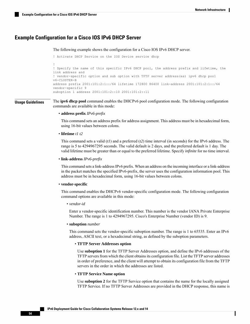
Example Configuration for a Cisco IOS IPv6 DHCP Server
The following example shows the configuration for a Cisco IOS IPv6 DHCP server.! Activate DHCP Service on the IOS Device service dhcp
!! Specify the name of this specific IPv6 DHCP pool, the address prefix and lifetime, thelink address and! vendor-specific option and sub option with TFTP server address(es) ipv6 dhcp poolv6-CLUSTER-Baddress prefix 2001:101:2:1::/64 lifetime 172800 86400 link-address 2001:101:2:1::/64vendor-specific 9suboption 1 address 2001:101:2::10 2001:101:2::11
Usage Guidelines The ipv6 dhcp pool command enables the DHCPv6 pool configuration mode. The following configurationcommands are available in this mode:
• address prefix IPv6-prefix
This command sets an address prefix for address assignment. This address must be in hexadecimal form,using 16-bit values between colons.
• lifetime t1 t2
This command sets a valid (t1) and a preferred (t2) time interval (in seconds) for the IPv6 address. Therange is 5 to 4294967295 seconds. The valid default is 2 days, and the preferred default is 1 day. Thevalid lifetime must be greater than or equal to the preferred lifetime. Specify infinite for no time interval.
• link-address IPv6-prefix
This command sets a link-address IPv6 prefix. When an address on the incoming interface or a link-addressin the packet matches the specified IPv6-prefix, the server uses the configuration information pool. Thisaddress must be in hexadecimal form, using 16-bit values between colons.
• vendor-specific
This command enables the DHCPv6 vendor-specific configuration mode. The following configurationcommand options are available in this mode:
• vendor-id
Enter a vendor-specific identification number. This number is the vendor IANA Private EnterpriseNumber. The range is 1 to 4294967295. Cisco's Enterprise Number (vendor ID) is 9.
• suboption number
This command sets the vendor-specific suboption number. The range is 1 to 65535. Enter an IPv6address, ASCII text, or a hexadecimal string, as defined by the suboption parameters.
• TFTP Server Addresses option
Use suboption 1 for the TFTP Server Addresses option, and define the IPv6 addresses of theTFTP servers from which the client obtains its configuration file. List the TFTP server addressesin order of preference, and the client will attempt to obtain its configuration file from the TFTPservers in the order in which the addresses are listed.
• TFTP Service Name option
Use suboption 2 for the TFTP Service option that contains the name for the locally assignedTFTP Service. If no TFTP Server Addresses are provided in the DHCP response, this name is
IPv6 Deployment Guide for Cisco Collaboration Systems Release 12.x and 1454
Network InfrastructureExample Configuration for a Cisco IOS IPv6 DHCP Server

resolved though a DNS service query. The name resolution may result in several addressesreturned by the DNS server. This list contains the addresses of the TFTP servers from whichthe client obtains its configuration file. The TFTP server addresses are returned with an orderof preference, and the client attempts to contact the target server with the lowest-numberedpriority.
After you create the DHCPv6 configuration information pool, use the ipv6 dhcp server interface configurationcommand to associate the pool with a server on an interface. However, if you do not configure an informationpool, you still need to use the ipv6 dhcp server interface configuration command to enable the DHCPv6server function on an interface.
When you associate a DHCPv6 pool with an interface, only that pool services requests on the associatedinterface. The pool can also service other interfaces. If you do not associate a DHCPv6 pool with an interface,that pool can service requests on any interface.
Not using any IPv6 address prefix means that the pool returns only configured options.
The link-address keyword allows matching a link address without necessarily allocating an address. You canmatch the pool from multiple relays by using multiple link-address configuration commands inside a pool.
Because a longest match is performed on either the address pool information or the link information, you canconfigure one pool to allocate addresses and another pool on a subprefix that returns only configured options.
Trivial File Transfer Protocol (TFTP)Within any Cisco Unified Communications Manager (Unified CM) system, endpoints such as IP phones relyon a TFTP-based process to acquire configuration files, software images, and other endpoint-specificinformation. The Cisco TFTP service is a file serving system that can run on one or more Unified CM servers.It builds configuration files and serves firmware files, ringer files, device configuration files, and so forth, toendpoints. To allow the TFTP server to serve files to devices using IPv6 signaling, the TFTP server inheritsthe IPv6 server address (the address configured through the server OS command line interface or the CiscoUnified Operating System Administration graphical user interface).
Peer-to-peer image file distribution is not supported with IPv6. However, a local IPv6 load server can beconfigured on IPv6 phones.
Note
Network Time Protocol (NTP)Network Time Protocol (NTP) enables network devices to synchronize their clocks to a network time serveror network-capable clock. NTP is critical for ensuring that all devices in a network have the same time. Whentroubleshooting or managing a collaboration network, it is crucial to synchronize the time stamps within allerror and security logs, traces, and system reports on devices throughout the network. This synchronizationenables administrators to recreate network activities and behaviors based on a common timeline. Billingrecords and call detail records (CDRs) also require accurate synchronized time.
IPv6 Deployment Guide for Cisco Collaboration Systems Release 12.x and 1455
Network InfrastructureTrivial File Transfer Protocol (TFTP)

Unified CM NTP Time Synchronization
Unified CM supports NTP for IPv6. You can configure NTP v6 addresses through Unified CM Admin UI,BAT, and AXL. NTP v6 addresses are sent to a SIP Phone through phone configuration. In CSR 12.0, IPphones do not use IPv6 addresses configured for NTP server under Phone NTP References.
IP Phone NTP Time Synchronization
IP Phone NTP Time Synchronization for IPv6 is not supported.
Cisco IOS and CatOS NTP Time Synchronization
Cisco IOS and Cisco Catalyst OS (CatOS) do not support NTP for IPv6. If Cisco IOS NTP is used, IPv4 NTPshould be used for clock synchronization.
WAN InfrastructureProper WAN infrastructure design is important for normal collaboration operation on a converged network.Proper infrastructure design requires following basic configuration and design best practices for deploying aWAN that is as highly available as possible and that provides guaranteed throughput. Furthermore, properWAN infrastructure design requires deploying end-to-end QoS on all WAN links. This section discussesspecific IPv6 design guidance for WAN infrastructures in collaboration networks. For general guidance ondesigning WAN infrastructures for collaboration deployments, refer to the Cisco Collaboration System SolutionReference Network Design (SRND), available at http://www.cisco.com/go/ucsrnd.
General IPv6 WAN Design GuidanceThe following sources provide general guidance for designing IPv6 WAN infrastructures:
• Introduction to IPv6 in Cisco products
http://www.cisco.com/en/US/products/ps6553/products_ios_technology_home.html
• Deploying IPv6 in Branch Networks
http://www.cisco.com/c/en/us/td/docs/solutions/Enterprise/Branch/BrchIPv6.html
IPv6 Design Guidance for Unified Communications WAN InfrastructuresYou may choose to run IPv6 Unified Communications traffic within your campus network only, in whichcase you can use standard IPv4 intercluster trunks between Unified CM clusters. If you wish to send IPv6Unified Communications traffic between Unified CM clusters, then you must use IPv6 SIP intercluster trunksand an IPv6 WAN. Cisco recommends the deployment of both IPv4 and IPv6 routing protocols (a dual-stackWAN) for transporting IPv6 traffic over your WAN infrastructure.
IPv6 Deployment Guide for Cisco Collaboration Systems Release 12.x and 1456
Network InfrastructureWAN Infrastructure

Figure 19: Dual-Stack WAN Infrastructure
The following deployment options are available for deploying IPv6 in a branch campus and across the WAN;however, we did not solution test these options.
• Run dual-stack (IPv4 and IPv6) routing protocols (Recommended).
• Deploy tunneling of IPv6 over IPv4 using:
• Manually configured GRE tunnels
• Manually configured IPv6 over IPv4 tunnels
• Automatically configured IPv6-to-IPv4 (6 to 4) tunnels (RFC 3056)
• IPSEC can also be used to send IPv6 traffic securely in IPv4 tunnels for VPNs.
Call Admission ControlUnified CM supports only locations-based topology-unaware call admission control for IPv6. ResourceReservation Protocol (RSVP) cannot be used as a call admission control technique within the cluster or betweenclusters. Likewise, Unified CM IPv4 and IPv6 SIP trunks support only locations-based call admission control.
Topology-unaware call admission control requires a hub-and-spoke topology for the WAN, or a spokelesshub in the case of a Multiprotocol Label Switching (MPLS) virtual private network (VPN). This topologyensures that call admission control, provided by Unified CM's locations mechanism, works properly to trackthe bandwidth available between any two sites in the WAN.
Because using IPv6 requires 20 more bytes of data in its header than IPv4, an IPv6 call requires more bandwidththan a similar IPv4 call that uses the same type of codec and media payload.
To reserve and adjust the location-based bandwidth for a call that uses IPv6, Unified CM calculates the IPbandwidth that is needed for an IPv6 call using any supported codec. After the device contacts Unified CMfor bandwidth reservation during the call setup, Unified CM identifies the IP version. If the call uses IPv6,Unified CM reserves the bandwidth for IPv6; and if the call uses IPv4, Unified CM reserves the bandwidth
IPv6 Deployment Guide for Cisco Collaboration Systems Release 12.x and 1457
Network InfrastructureCall Admission Control

for IPv4. If both IP versions are supported by the devices, Unified CM initially reserves the IPv6 bandwidthand, if required, adjusts the bandwidth after media negotiation occurs. If Unified CM cannot identify the IPversion used for the call, the call is extended over a SIP trunk using ANAT when applicable.
Locations-Based Call-Counting Call Admission Control
Unified CM also supports a type of locations-based, topology-unaware call admission control know as callcounting. Less sophisticated than standard Unified CM locations-based call admission control, call countinguses a fixed bandwidth value for each voice and video call irrespective of the codec or actual bandwidth used.
For call-counting call admission control, the following default values are used for Layer 3 voice and videobandwidth when calculating the amount of available bandwidth at a location:
• A voice call = 102 kbps
• A video call = 500 kbps
Although call counting provides a simplified form of call admission control (CAC), it also has the disadvantagethat bandwidth reserved for voice and video in the WAN might not be used efficiently.
To enable call counting in Unified CM Administration, select Service Parameters > Clusterwide Parameters(Call Admission Control). The default setting for Call Counting CAC Enabled is False. The voice andvideo bandwidth values for call counting are configurable.
Figure 20: Configuring Call Counting for Call Admission Control
IPv6 Bandwidth ProvisioningFor general recommendations on bandwidth provisioning for collaboration traffic, refer to the bandwidthprovisioning information in the Cisco Collaboration System Solution Reference Network Design (SRND),available at http://www.cisco.com/go/ucsrnd. However, when provisioning for IPv6 voice bearer traffic, youmust consider the additional 20-byte overhead of the IPv6 header.
In CSR 12.1, IPv6 video dual-stack ANAT traffic is not solution tested. To determine the bandwidthrequirements for video flows, refer to the bandwidth provisioning information in the Cisco CollaborationSystem Solution Reference Network Design (SRND), available at http://www.cisco.com/go/ucsrnd.
Note
IPv6 Deployment Guide for Cisco Collaboration Systems Release 12.x and 1458
Network InfrastructureIPv6 Bandwidth Provisioning

IPv6 Voice Bearer Traffic
As illustrated in the following figure, a Voice-over-IPv6 (VoIPv6) packet consists of the voice payload,Real-Time Transport Protocol (RTP) header, User Datagram Protocol (UDP) header, IPv6 header and Layer2 Link header. When Secure Real-Time Transport Protocol (SRTP) encryption is used, the voice payload foreach packet increases by 4 bytes. The link header varies in size according to the Layer 2 media used.
Figure 21: Typical VoIPv6 Packet
IPv6 Bandwidth Calculations
To calculate the bandwidth consumed by VoIPv6 streams, add the packet payload and all headers (in bits),then multiplying by the packet rate per second, as follows:
• Layer 2 bandwidth in kbps = [(Packets per second) ∗ (X bytes for voice payload + 60 bytes forRTP/UDP/IP headers + Y bytes for Layer 2 overhead) ∗ 8 bits] / 1000
• Layer 3 bandwidth in kbps = [(Packets per second) ∗ (X bytes for voice payload + 60 bytes forRTP/UDP/IP headers) ∗ 8 bits] / 1000
• Packets per second = [1/(sampling rate in msec)] ∗ 1000
• Voice payload in bytes = [(codec bit rate in kbps) ∗ (sampling rate in msec)] / 8
The following table details the Layer 3 bandwidth per VoIPv6 flow. It lists the bandwidth consumed by thevoice payload and IPv6 header only, at a default packet rate of 50 packets per second (pps) and at a rate of33.3 pps for both non-encrypted and encrypted payloads. It does not include Layer 2 header overhead. Thecodec sampling rate can be adjusted through the Unified CM Service Parameters menu.
Table 11: Layer 3 Bandwidth per VoIPv6 Flow
Bandwidth PerConversation
Packets Per SecondVoice Payload inBytes
Sampling RateCODEC
88.0 kbps50.016020msG.711 andG.722-64k
89.6 kbps50.016420msG.711 andG.722-64k (SRTP)
79.2 kbps33.324030msG.711 andG.722-64k
81.0 kbps33.324430msG.711 andG.722-64k (SRTP)
IPv6 Deployment Guide for Cisco Collaboration Systems Release 12.x and 1459
Network InfrastructureIPv6 Voice Bearer Traffic

Bandwidth PerConversation
Packets Per SecondVoice Payload inBytes
Sampling RateCODEC
39.2 kbps50.03820msiLBC
40.8 kbps50.04220msiLBC (SRTP)
29.3 kbps33.35030msiLBC
30.4 kbps33.35430msiLBC (SRTP)
32.0 kbps50.02020msG.729A
33.6 kbps50.02420msG.729A (SRTP)
24.0 kbps33.33030msG.729A
25.0 kbps33.33430msG.729A (SRTP)
Compressed RTP (cRTP)
Cisco IOS does not currently support Compressed RTP for IPv6.
A more accurate method of bandwidth provisioning is to include the Layer 2 headers in the bandwidthcalculations. The following table lists the amount of bandwidth consumed by IPv6 voice traffic when theLayer 2 headers are included in the calculations.
Table 12: Bandwidth Consumption with Layer 2 Headers Included
Header Type and SizeCODEC typeand packetrate(packetsper second)
WLAN
24 Bytes
MPLS
4 Bytes
MLPPP
10 Bytes
Frame Relay
4 Bytes
ATM
53-ByteCells with a48-BytePayload
PPP
6 Bytes
Ethernet 14
97.6 kbps89.6 kbps92 kbps89.6 kbps109.2 kbps90.4 kbps93.6 kbpsG.711 andG.722-64kat 50.0 pps
99.2 kbps91.2 kbps93.6 kbps91.2 kbps110.8 kbps92 kbps95.2 kbpsG.711 andG.722-64k(SRTP) at50.0 pps
86.3 kbps80.1 kbps82.6 kbps80.1 kbps94.0 kbps81.5 kbps83.7 kbpsG.711 andG.722-64kat 33.3 pps
IPv6 Deployment Guide for Cisco Collaboration Systems Release 12.x and 1460
Network InfrastructureCompressed RTP (cRTP)

Header Type and SizeCODEC typeand packetrate(packetsper second)
WLAN
24 Bytes
MPLS
4 Bytes
MLPPP
10 Bytes
Frame Relay
4 Bytes
ATM
53-ByteCells with a48-BytePayload
PPP
6 Bytes
Ethernet 14
87.4 kbps82.1 kbps83.7 kbps82.1 kbps95.1 kbps82.6 kbps84.7 kbpsG.711 andG.722-64k(SRTP) at33.3 pps
48.8 kbps40.8 kbps43.2 kbps40.8 kbps60.4 kbps41.6 kbps44.8 kbpsiLBC at50.0 pps
50.4 kbps42.4 kbps44.8 kbps42.4 kbps62.0 kbps43.2 kbps46.4 kbpsiLBC(SRTP) at50.0 pps
35.7 kbps30.4 kbps32.0 kbps30.4 kbps43.5 kbps30.9 kbps33.0 kbpsiLBC at33.3 pps
36.8 kbps31.5 kbps33.1 kbps31.5 kbps44.5 kbps32.0 kbps34.1 kbpsiLBC(SRTP) at33.3 pps
41.6 kbps33.6 kbps36.0 kbps33.6 kbps53.2 kbps33.4 kbps37.6 kbpsG.729A at50.0 pps
43.2 kbps35.2 kbps37.6 kbps35.2 kbps54.8 kbps36.0 kbps39.2 kbpsG.729A(SRTP) at50.0 pps
30.4 kbps25.1 kbps26.7 kbps25.1 kbps38.1 kbps25.6 kbps27.7 kbpsG.729A at33.3 pps
31.5 kbps26.1 kbps27.8 kbps26.1 kbps39.2 kbps26.7 kbps28.8 kbpsG729A(SRTP) at33.3 pps
Call Control Traffic Provisioning
Provisioning for call control traffic should not be a concern in a single-site Unified CM campus deployment.For multi-site WAN deployments with centralized or distributed call processing, you also need to considerbandwidth provisioning for inter-site signaling or intercluster trunk signaling traffic. For information onbandwidth provisioning for call control traffic over IPv4 trunks, refer to the Cisco Collaboration SystemSolution Reference Network Design (SRND), available at http://www.cisco.com/go/ucsrnd. For IPv6 signaling,add 10% to the bandwidth value calculated for call control traffic over IPv4.
IPv6 Deployment Guide for Cisco Collaboration Systems Release 12.x and 1461
Network InfrastructureCall Control Traffic Provisioning

RSVP
Resource Reservation Protocol (RSVP) call admission control is not supported for IPv6 calls. RSVP is notsupported over Unified CM SIP trunks. Instead, use locations-based call admission control for interclustertrunks. We do not recommend the deployment of IPv6 in networks that use RSVP for call admission control.
WLAN
IPv6 is not supported by any Cisco wireless device. These devices support IPv4 only.
Network ManagementThis section discusses Cisco Prime Collaboration, a network management product.
Cisco Prime CollaborationIPv6-aware Cisco Prime Collaboration provides simplified, unified management across voice and videocollaboration networks. It offers automated provisioning, real-time monitoring, and proactive troubleshooting,plus long term trending and analytics—in one integrated product.
Cisco Prime Collaboration Advanced includes three separate modules:
• Provisioning (IPv6-aware and supports dual-stack and IPv6-only devices)
• Assurance (IPv4-only)
• Analytics (IPv4-only)
Cisco Prime Collaboration Standard includes a subset of the features available in the Provisioning and Assurancemodules. The Analytics module and Cisco Prime Collaboration Contact Center Assurance are available aspart of the Cisco Prime Collaboration Advanced offer only (IPv4-only).
IPv6 Deployment Guide for Cisco Collaboration Systems Release 12.x and 1462
Network InfrastructureRSVP

C H A P T E R 6Gateways
• Gateways Overview, on page 63
Gateways OverviewGateways provide a number of methods for connecting an IP telephony network to the public switchedtelephone network (PSTN), legacy PBX systems, key systems, or analogue devices. Gateways range fromspecialized, entry-level and standalone voice gateways to high-end, feature-rich integrated routers and CiscoCatalyst gateways. For general guidance on gateway selection and features, refer to the Cisco CollaborationSystem Solution Reference Network Design (SRND), available at http://www.cisco.com/go/ucsrnd.
• IPv4-only stack supported gateways with SIP protocol as shown in: Recommended IPv6 AddressingModes for CSR 12.1/12.0 Products , on page 20.
• Software and hardware media termination points (MTPs) for conversion between IPv4 and IPv6 useSCCP IPv4 signaling to Unified CM.
• All other gateway connections that use SCCP, H.323, and MGCP signaling protocols between UnifiedCM and the gateway have been deprecated.
• You can combine ISDN gateways, Unified SRST analog port, and MTP functionality on a single CiscoIntegrated Services Router (ISR) 4000 platform. Unified SRST and CUBE cannot co-exist in the sameISR 4000 router.
• Cisco 2800 and 3800 Series Integrated Services Routers and Cisco VG Series Gateways must be configuredas IPv4-only stack gateway. IPv6 functions will not be supported in CSR 12.0.
IPv6 Deployment Guide for Cisco Collaboration Systems Release 12.x and 1463

IPv6 Deployment Guide for Cisco Collaboration Systems Release 12.x and 1464
GatewaysGateways Overview

C H A P T E R 7Trunks
• Trunks Overview, on page 65• IPv6 SIP Trunks Configuration, on page 66• Alternative Network Address Types (ANAT), on page 68• Recommended IPv6 SIP Trunk Configurations and Associated Call Flows, on page 69• Media Address Selection for Calls over Dual-Stack SIP Trunks (For DoD Networks Only), on page 72• SIP Early Offer Calls with ANAT, on page 75• SIP Trunks Using Delayed Offer, on page 78
Trunks OverviewCisco Unified Communications Manager (Unified CM) supports several different types of IP trunks forconnectivity with external devices:
• H.225 (H.323)
• SIP
• Intercluster trunks
Only SIP trunks and SIP intercluster trunks can support IPv6. This chapter describes the new IPv6 featuresand capabilities of these trunks. For information on the general capabilities and functions of Unified CMtrunks, refer to the Cisco Collaboration System Solution Reference Network Design (SRND), available athttp://www.cisco.com/go/ucsrnd.
There are several possible configurations for Unified CM SIP trunks:
• Inbound and outbound SIP Early Offer trunk calls
• Inbound and outbound SIP Early Offer trunk calls with Alternative Network Address Types (ANAT)enabled
• Inbound and outbound SIP Delayed Offer trunk calls (This chapter focuses on this recommended option)
• Inbound and outbound SIP Delayed Offer trunk calls with ANAT enabled
IPv6 Deployment Guide for Cisco Collaboration Systems Release 12.x and 1465

IPv6 SIP Trunks ConfigurationTo configure SIP trunks to gateways and Unified CM SIP intercluster trunks, select Devices > Trunks > SIPTrunk in Unified CM Administration.
The SIP trunk configuration settings discussed in this section are applied through the Common DeviceConfiguration profile that is created and assigned to the SIP trunk (IP Addressing Mode and IP AddressingMode Preference for Signaling), and through the SIP Profile configuration assigned to the SIP trunk (EnableANAT should be disabled). The IPv4 to IPv6 media interworking is supported by Unified CM inserting MTPs.
Figure 22: Trunk Configuration in Unified CM Administration
Common Device Configuration Settings for SIP TrunksThis section describes the configuration settings for SIP trunks.
SIP Trunk IP Addressing Mode
You can configure the IP Addressing Mode to one of the following settings:
• IPv4
IPv6 Deployment Guide for Cisco Collaboration Systems Release 12.x and 1466
TrunksIPv6 SIP Trunks Configuration

In this mode, the SIP trunk uses the Unified CM IPv4 address for signaling and either an MTP or phoneIPv4 address for media.
• IPv6
In this mode, the SIP trunk uses the Unified CM IPv6 address for signaling and either an MTP or phoneIPv6 address for media.
• IPv4 and IPv6 (Not recommended, applicable to DoD network)
The SIP trunk uses either the Unified CM IPv4 address or the Unified CM IPv6 address for signaling,and an MTP. We recommend IPv6 Only for production environments.
Figure 23: IP Addressing Mode
SIP Trunk IP Addressing Mode Preference for Signaling
You can configure the IP Addressing Mode Preference for Signaling to one of the following settings:
• IPv4
In this mode, the SIP trunk uses the Unified CM IPv4 server address as its source address for SIP signaling.
• IPv6
In this mode, the SIP trunk uses the Unified CM IPv6 server address as its source address for SIP signaling.
• Use System Default
In this mode, the SIP trunk uses the cluster-wide Enterprise Parameter configuration value for its IPaddressing mode for signaling.
If IPv6 is enabled in the Unified CM cluster, the default SIP trunk setting for the IP Addressing Mode forSignaling is Use System Default. With this setting, the SIP trunk adopts the cluster-wide setting for its IPaddressing mode for signaling, if the trunk is configured with a destination address of that type. All IPv4trunks ignore this setting.
IPv6 Deployment Guide for Cisco Collaboration Systems Release 12.x and 1467
TrunksSIP Trunk IP Addressing Mode Preference for Signaling

The SIP trunk's IP Addressing Mode Preference for Signaling is used only for outbound calls. Unified CMlistens for incoming SIP signaling on both the IPv4 and IPv6 address.
Figure 24: P Addressing Mode Preference for Signaling
Allow Auto-Configuration for Phones
The setting of Allow Stateful Auto-Configuration for Phones is not used by SIP trunks.
Alternative Network Address Types (ANAT)ANAT is used in the SIP Offer and Answer exchange between dual-stack SIP trunks. ANAT allows SIPdevices to send both IPv4 and IPv6 addresses in the Session Description Protocol (SDP) body of a SIP Offer,and to return in the SDP body of the SIP Answer a preferred IP address (IPv4 or IPv6) with which to establisha media connection.
We support ANAT over dual-stack (IPv4 and IPv4) SIP trunks. ANAT must be supported by both ends ofthe SIP trunk. To enable ANAT, check the Enable ANAT check box on the SIP Profile associated with theSIP trunk. ANAT can be used with both Early Offer and Delayed Offer calls.
In CSR 12.0, ANAT is not configured and not supported by Unified CM and Unified SRST.Note
Enable ANAT only on SIP trunks with an IP Addressing Mode setting of IPv4 and IPv6.
IPv6 Deployment Guide for Cisco Collaboration Systems Release 12.x and 1468
TrunksAlternative Network Address Types (ANAT)

Figure 25: Enabling ANAT in the SIP Trunk Profile
Cluster-Wide Configuration Settings That Affect ANAT-Enabled SIP Trunk Calls
The cluster-wide setting Addressing Mode Preference for Media specifies which addressing version to usewhen a Unified CM SIP trunk with ANAT enabled receives an IPv6 and an IPv4 address in the SDP body ofa SIP Offer. This cluster-wide setting also determines whether the phone's or trunk’s MTP is selected whenan MTP is dynamically inserted in a call through a SIP trunk.
Recommended IPv6 SIP Trunk Configurations and AssociatedCall Flows
How you configure your Unified CM IPv6 SIP trunk will, to some extent, depend upon the capabilities of thefar-end SIP trunk device. Usually this far-end SIP trunk device is another Unified CM cluster, IPv6 SIPgateway, or third-party IPv6 SIP call agent.
Some general guidance on IPv6 SIP trunk configuration:
• IPv6 SIP trunks should be configured with an IP addressing mode of IPv4 and IPv6.
• If ANAT is required, then the trunk's IP addressing mode must be set to IPv4 and IPv6.
• If ANAT is required, both trunk devices must support it.
• SIP Early Offer and SIP Delayed Offer are supported, both in symmetric and asymmetric configurations,as follows:
• Outbound and inbound SIP Early Offer (Recommended option)
• Outbound and inbound SIP Delayed Offer
• Outbound SIP Early Offer and inbound SIP Delayed Offer
• Outbound SIP Delayed Offer and inbound SIP Early Offer
IPv6 Deployment Guide for Cisco Collaboration Systems Release 12.x and 1469
TrunksRecommended IPv6 SIP Trunk Configurations and Associated Call Flows

In CSR 12.0, SIP Early Offer does not support IPv6. CUBE or Unified SRST gateways will not supportANAT.
Note
Early Offer and SIP Trunk Calls
For all Unified CM SIP trunks, you must check the MTP required check box on the trunk configuration pageto enable SIP Early Offer in IPv4 (IPv6 does not support Early Offer). When MTP required is checked, amedia termination point (MTP) is used in the media path for all inbound and outbound calls. This staticallyassigned MTP affects all calls in the following ways:
• Because the MTP is placed in the media path for all calls, rather than having one call leg from the callingphone to the called phone, the insertion of the MTP creates two legs: one from the calling phone to theMTP, and the other from the MTP to the called phone. For signaling purposes, this can be considered tobe two calls. The calling phone and MTP negotiate media capabilities (such as codec, IP addresses, andUDP port numbers to be used), as do the MTP and the called phone at the far end of the SIP trunk.
• The statically assigned MTP (MTP required checked) must be configured to use one codec type (G711or G729). Assigning a single voice codec to this statically assigned MTP disables the use of thepass-through codec. This, in turn, prevents the negotiation of the pass-through codec that is required forvideo calls or encrypted calls. (T.38 fax calls are supported with statically assigned MTPs.) Therefore,if support for video or encryption is required over the SIP trunk, SIP Delayed Offer (no statically assignedMTP) must be used.
The pass-through codec should be configured on all dynamically inserted MTPs.To enable the use of the pass-through codec, configure the MTP with both astandard codec and the pass-through codec.
Note
If SIP Early Offer is required for dual-stack SIP Unified CM trunks, then you must configure the Cisco IOSMTP to use both an IPv6 and IPv4 address. For details, see Media Resources and Music on Hold Overview,on page 89.
Delayed Offer and SIP Trunks
Delayed Offer trunks do not have a statically assigned MTP and therefore MTP resources are not used forevery call. For Delayed Offer calls, Unified CM attempts to set up the call using a single call leg between thecalling and called device, and in doing so must consider the IP addressing mode configuration of both theUnified CM trunk and the IP phone registered with Unified CM. In certain calls where there are IP addressingmode mismatches between the Unified CM trunk and the registered phone, Unified CM dynamically insertsan MTP to resolve this mismatch. The pass-through codec is supported by this dynamically inserted MTP,and video calls and encrypted calls can be established with this MTP in the call path. The pass-through codecshould be configured on all dynamically inserted MTPs. To enable the use of the pass-through codec, configurethe MTP with both a standard codec and the pass-through codec.
IPv6 Deployment Guide for Cisco Collaboration Systems Release 12.x and 1470
TrunksEarly Offer and SIP Trunk Calls
Unified CM SIP Trunk Signaling
The following factors affect which IP addressing version is used for signaling on Unified CM SIP trunks:
• Call direction
• IP addressing mode of the trunk
• Configured destination addresses of the trunk
• Trunk's IP addressing mode preference for signaling
• Cluster-wide IP addressing mode preference for signaling
IP Addressing Version Used for SIP Signaling for Outbound
The IP addressing version for signaling is determined by the following factors, in the order listed here:
1. The IP Addressing Mode of the SIP trunk (IPv4 or IPv6)
2. The configured destination addresses of the SIP trunk (IPv4 or IPv6)
• If only one destination address is configured (IPv4 or IPv6), the IP addressing version must matchthe IP Addressing Mode of the trunk. If these two values do not match, the SIP trunk connection isnot established.
• If two trunk destination addresses are configured (IPv4 and IPv6), then the IP addressing version isdetermined by the SIP trunk's IP Addressing Mode Preference for Signaling (IPv4, IPv6, or UseSystem Default). If the Use System Default setting is used, then the IP addressing version isdetermined by the cluster-wide IP Addressing Mode Preference for Signaling (IPv4 or IPv6).
IP Addressing Version Used for SIP Signaling for Inbound
For inbound calls, the IP addressing version used for signaling is based on the trunk destination addresses andport numbers configured in Unified CM. If the signaling source address and port number received from thecalling device match a configured destination address and port number on the SIP trunk, then the signalingconnection is established.
Unified CM provides the following configuration setting options for the SIP trunk destination address:
• One IPv4 address configured
• One IPv6 address configured
• One IPv4 and one IPv6 address configured (For DoD network only)
If IPv6 is enabled in the cluster, Unified CM servers listen for incoming SIP trunk calls destined to theirconfigured IPv4 and IPv6 addresses and source port number.
IPv6 Deployment Guide for Cisco Collaboration Systems Release 12.x and 1471
TrunksUnified CM SIP Trunk Signaling

Media Address Selection for Calls over Dual-Stack SIP Trunks(For DoD Networks Only)
For DoD networks only.Note
Many configuration options are possible for SIP trunks. Trunks may be single or dual stack, have ANATenabled or disabled, and use SIP Early Offer or SIP Delayed Offer. This chapter, while not exhaustive, discussesthe significant configuration options and their outcomes in terms of the addresses that are exchanged and usedfor media. Early Offer call scenarios are considered first, followed by Delayed Offer call scenarios.
Depending on the call scenario, media address selection for calls over dual-stack SIP trunks can be based on:
• Call direction
• Whether Delayed Offer or Early Offer is used
• The IP Addressing Mode of the trunk
• The cluster-wide IP Addressing Mode Preference for Media
• The IP Addressing Mode of the phone
The remaining sections of this chapter review media selection for the following Unified CM call flows:
• SIP Early Offer calls
• Outbound Early Offer calls without ANAT
• Inbound Early Offer calls without ANAT
• Outbound Early Offer calls with ANAT
• Inbound Early Offer calls with ANAT
• SIP Delayed Offer calls
• Outbound Delayed Offer calls without ANAT
• Inbound Delayed Offer calls without ANAT
• Outbound Delayed Offer calls with ANAT
• Inbound Delayed Offer calls with ANAT
Media Selection for Outbound IPv6 Early Offer Calls Without ANAT
This is not supported in CSR 12.0Note
IPv6 Deployment Guide for Cisco Collaboration Systems Release 12.x and 1472
TrunksMedia Address Selection for Calls over Dual-Stack SIP Trunks (For DoD Networks Only)
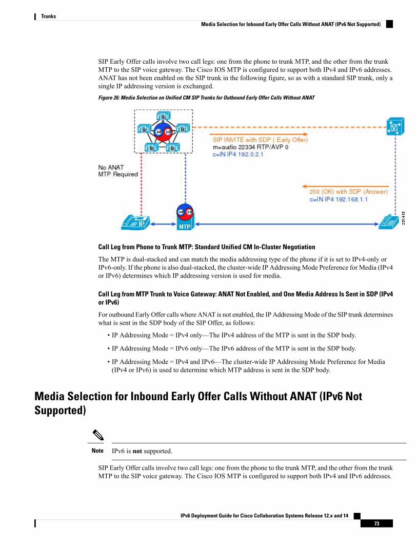
SIP Early Offer calls involve two call legs: one from the phone to trunk MTP, and the other from the trunkMTP to the SIP voice gateway. The Cisco IOS MTP is configured to support both IPv4 and IPv6 addresses.ANAT has not been enabled on the SIP trunk in the following figure, so as with a standard SIP trunk, only asingle IP addressing version is exchanged.
Figure 26: Media Selection on Unified CM SIP Trunks for Outbound Early Offer Calls Without ANAT
Call Leg from Phone to Trunk MTP: Standard Unified CM In-Cluster Negotiation
The MTP is dual-stacked and can match the media addressing type of the phone if it is set to IPv4-only orIPv6-only. If the phone is also dual-stacked, the cluster-wide IP Addressing Mode Preference for Media (IPv4or IPv6) determines which IP addressing version is used for media.
Call Leg from MTP Trunk to Voice Gateway: ANAT Not Enabled, and One Media Address Is Sent in SDP (IPv4or IPv6)
For outbound Early Offer calls where ANAT is not enabled, the IP Addressing Mode of the SIP trunk determineswhat is sent in the SDP body of the SIP Offer, as follows:
• IP Addressing Mode = IPv4 only—The IPv4 address of the MTP is sent in the SDP body.
• IP Addressing Mode = IPv6 only—The IPv6 address of the MTP is sent in the SDP body.
• IP Addressing Mode = IPv4 and IPv6—The cluster-wide IP Addressing Mode Preference for Media(IPv4 or IPv6) is used to determine which MTP address is sent in the SDP body.
Media Selection for Inbound Early Offer Calls Without ANAT (IPv6 NotSupported)
IPv6 is not supported.Note
SIP Early Offer calls involve two call legs: one from the phone to the trunk MTP, and the other from the trunkMTP to the SIP voice gateway. The Cisco IOS MTP is configured to support both IPv4 and IPv6 addresses.
IPv6 Deployment Guide for Cisco Collaboration Systems Release 12.x and 1473
TrunksMedia Selection for Inbound Early Offer Calls Without ANAT (IPv6 Not Supported)

ANAT has not been enabled on the SIP trunk in Figure 7-6, so as with a standard SIP trunk, only a single IPaddressing version is exchanged in the SIP Offer and Answer.
Figure 27: Media Selection on Unified CM SIP Trunks for Inbound Early Offer Calls Without ANAT
Call Leg from Trunk MTP to Phone: Standard Unified CM In-Cluster Negotiation
The MTP is dual-stacked and can match the media addressing type of the phone if it is set to IPv4 only orIPv6 only. If the phone is also dual-stacked, the cluster-wide IP Addressing Mode Preference for Media (IPv4or IPv6) determines which IP addressing version is used for media.
Call Leg from Voice Gateway to Trunk MTP: ANAT Not Enabled, and One Media Address Is Received in SDP
For inbound Early Offer calls where ANAT is not enabled, the IP Addressing Mode of the SIP trunk determineswhether the address received in the SDP body of the SIP Offer is accepted or rejected, as follows:
• IP Addressing Mode = IPv4 only:
• If an IPv4 address is received in the SDP body, proceed with the call.
• If an IPv6 address is received in the SDP body, reject the call.
• IP Addressing Mode = IPv6 only:
• If an IPv6 address is received in the SDP body, proceed with the call.
• If an IPv4 address is received in the SDP body, reject the call.
For these trunk calls, Unified CM does not insert an MTP to resolve a mediaaddressing version mismatch between the two voice devices.
Note
• IP Addressing Mode = IPv4 and IPv6:
• If an IPv4 address is received in the SDP body, proceed with the call.
• If an IPv6 address is received in the SDP body, proceed with the call.
IPv6 Deployment Guide for Cisco Collaboration Systems Release 12.x and 1474
TrunksMedia Selection for Inbound Early Offer Calls Without ANAT (IPv6 Not Supported)

SIP Early Offer Calls with ANAT
This is not supported in CSR 12.0Note
For the two call scenarios in this section, the SIP trunks use ANAT to exchange and negotiate IPv4 and IPv6addresses for the media connection between the called and calling endpoints.
Alternative Network Address Types (ANAT)
ANAT is used in the SIP Offer and Answer exchange between dual-stack SIP trunks. ANAT allows devicesto send both IPv4 and IPv6 addresses in the SDP body of the SIP Offer, and to return in the SDP body of theSIP Answer, a preferred IP address (IPv4 or IPv6) with which to establish a media connection.
The use of ANAT on a dual-stack SIP trunk is indicated in the header of the SIP Invite. The field Require:sdp-anat is used by Unified CM SIP trunks using Early Offer, and the field Supported: sdp-anat is used byUnified CM SIP trunks using Delayed Offer. The Require: sdp-anat value indicates to the far end of the SIPtrunk connection that an ANAT response must be supported. The Supported: sdp-anat value indicates tothe far end of the SIP trunk connection that an ANAT response should be supported.
We support ANAT on dual-stack SIP trunks only; that is, on SIP trunks configured with an addressing modeof IPv4 and IPv6.
The receipt of Require: sdp-anat or Supported: sdp-anat does not affect how Unified CM responds toinbound Invites on trunks configured for SIP Early Offer, but it does effect how MTPs are assigned dynamicallyfor inbound calls to Unified CM SIP trunks using Delayed Offer.
Unified CM supports ANAT over dual-stack (IPv4 and IPv6) SIP trunks. If ANAT is enabled, it should beconfigured on both ends of the SIP trunk. If Require: sdp-anat is sent in the SIP Invite and the receiving SIPtrunk does not support ANAT, all calls are rejected. To enable ANAT, check the Enable ANAT check boxon the SIP Profile associated with the SIP trunk. ANAT can be used with both Early Offer and Delayed Offercalls.
ANAT should be enabled only on SIP trunks with an IP Addressing Mode setting of IPv4 and IPv6. EnablingANAT on a single-stack SIP trunk (IPv4 only or IPv6 only) does not really make sense because only one IPaddress can be offered. Therefore, we do not support ANAT on single-stack (IPv6 only or IPv4 only) SIPtrunks.
Media Selection for Outbound Early Offer Calls with ANAT
This is not supported in CSR 12.0Note
The following figure shows a simplified version the SIP Early Offer and SIP Answer using ANAT on dual-stackSIP trunks.
IPv6 Deployment Guide for Cisco Collaboration Systems Release 12.x and 1475
TrunksSIP Early Offer Calls with ANAT

SIP Early Offer calls involve two call legs: one from the phone to the trunk MTP, and the other from the trunkMTP to the SIP voice gateway. The Cisco IOS MTP is configured to support both IPv4 and IPv6 addresses.ANAT has been enabled on this SIP trunk, so both IPv4 and IPv6 addresses are exchanged in the SIP Offerand Answer.
Figure 28: Media Selection on Unified CM SIP Trunks for Outbound Early Offer Calls with ANAT
Call Leg from Phone to Trunk MTP: Standard Unified CM In-Cluster Negotiation
The MTP is dual-stacked and can match the media addressing type of the phone if it is set to IPv4-only orIPv6-only. If the phone is also dual-stacked, the cluster-wide IP Addressing Mode Preference for Media (IPv4or IPv6) determines which IP addressing version is used for media.
Call Leg from MTP Trunk to Voice Gateway: ANAT Enabled, and Two Media Addresses Sent in SDP (IPv4 andIPv6)
Unified CM selects the media address preference indicated in the SDP body of the ANAT SIP Offer by usingthe cluster-wide setting for IP Addressing Mode Preference for Media. The IP Addressing Mode of the trunkmust set to IPv4 and IPv6. The trunk's IP Addressing Mode could be set to IPv4-only or IPv6-only, but thiswould defeat the purpose of ANAT because only one address would be sent. (The trunk's IP Addressing Modeoverrides the ANAT setting.)
The called device (voice gateway) selects which addressing version to use for the voice call. The caller'spreference does not have to be honored.
Outbound SIP Early Offer
The SIP header of the Invite with the outbound SIP Early Offer contains the Require: sdp-anat field, indicatingthat ANAT must be supported by the far-end SIP device. For outbound SIP Offers on Unified CM SIP trunksconfigured for Early Offer, for all calls the SDP body of the SIP Offer includes the IPv4 address and UDPport number and the IPv6 address and UDP port number of the trunk's statically assigned MTP. The preferredaddressing version for Unified CM is also indicated in the SDP body, and the field a=group:ANAT 2 1indicates that the second address (the IPv6 address) is preferred by Unified CM. For Early Offer calls, thispreference is selected based on the cluster-wide IP Addressing Mode Preference for Media.
IPv6 Deployment Guide for Cisco Collaboration Systems Release 12.x and 1476
TrunksMedia Selection for Outbound Early Offer Calls with ANAT

Inbound SIP Answer
When the far-end SIP trunk receives an Invite with Require: sdp-anat, it must support ANAT and shouldreturn an ANAT-based response in its SIP Answer. If ANAT is not supported by the far-end SIP trunk, itshould reject the call. In the previous figure, a=group:ANAT 2 indicates the gateway's choice of its IPv6address and port number for the voice call. Notice that the gateway's IPv6 address and IPv4 address are bothincluded in the Answer; however, only the IPv6 UDP port number is returned, and the IPv4 UDP port numberis set to zero.
Media Selection for Inbound Early Offer Calls With ANAT
This is not supported in CSR 12.0Note
The following figure shows a simplified version the SIP Early Offer and SIP Answer using ANAT on dual-stackSIP trunks.
SIP Early Offer calls involve two call legs: one from the phone to the trunk MTP, and the other from the trunkMTP to the SIP voice gateway. The Cisco IOS MTP is configured to support both IPv4 and IPv6 addresses.ANAT has been enabled on this SIP trunk, so both IPv4 and IPv6 addresses will be exchanged in the SIPOffer and Answer.
Figure 29: Media Selection on Unified CM SIP Trunks for Inbound Early Offer Calls with ANAT
Call Leg from Trunk MTP to Phone: Standard Unified CM In-Cluster Negotiation
The MTP is dual-stacked and can match the media addressing version of the phone if it is set to IPv4-only orIPv6-only. If the phone is also dual stacked, the cluster-wide IP Addressing Mode Preference for Media (IPv4or IPv6) is used to select which IP addressing version is used for media.
IPv6 Deployment Guide for Cisco Collaboration Systems Release 12.x and 1477
TrunksMedia Selection for Inbound Early Offer Calls With ANAT

Call Leg from Voice Gateway to Trunk MTP: ANAT Enabled, and IPv4 and IPv6 Media Addresses Receivedin SDP
Unified CM does not honor the indicated address preference in the SDP body of the received SIP Offer. Fordual-stack Unified CM SIP trunks (IP Addressing Mode = IPv4 and IPv6), Unified CM selects the addressingversion for the voice call based on the setting of the cluster-wide IP Addressing Mode Preference for Media.
Inbound SIP Early Offer
The SIP header of the Invite with the outbound SIP Early Offer contains the Require: sdp-anat field, indicatingthat ANAT must be supported by Unified CM. The SDP body of the SIP Offer includes the IPv4 address andUDP port number and the IPv6 address and UDP port number of the calling device. The preferred addressingversion of the calling device is also indicated in the SDP body, and the field a=group:ANAT 2 1 indicatesthat the second address (the IPv6 address) is preferred.
Outbound SIP Answer
When the Unified CM SIP Early Offer trunk receives an Invite with Require: sdp-anat, it must supportANAT and should return an ANAT-based response in its SIP Answer. If ANAT is not supported by the UnifiedCM SIP trunk, it will reject the call. For Unified CM trunks configured for Early Offer, Unified CM returnsthe IPv4 and IPv6 addresses of the trunk MTP in its SIP Answers. In the previous figure, a=group:ANAT 2indicates Unified CM’s choice for the IPv6 address and port number of the MTP for the voice call. Noticethat the MTP's IPv6 address and IPv4 address are both included in the Answer; however, only the IPv6 UDPport number is returned, and the IPv4 UDP port number is set to zero.
Unified CM selects the addressing version for the voice call based on the setting of the cluster-wide IPAddressing Mode Preference for Media. The incoming preference is not honored by Unified CM.
Note
SIP Trunks Using Delayed OfferWith Delayed Offer, SIP trunks do not use a statically assigned MTP, and typically only one call leg is createdbetween the calling phone and called phone or device. From the perspective of Unified CM, this makes theselection of which IP addressing version to use a little more involved because in this case both the trunk'ssettings and the phone's settings must be taken into account.
Media Selection for Outbound Delayed Offer Calls Over Unified CM SIP TrunksWithout ANAT
As shown in the following figure, SIP Delayed Offer calls typically involve a single call leg from the phoneto the SIP voice gateway. ANAT has not been enabled on this SIP trunk, so as with a standard SIP trunk, onlya single IP addressing version is exchanged in the SIP Offer and Answer.
IPv6 Deployment Guide for Cisco Collaboration Systems Release 12.x and 1478
TrunksSIP Trunks Using Delayed Offer

Figure 30: Media Selection on Unified CM SIP Trunks for Outbound Delayed Offer Calls Without ANAT
For outbound Delayed Offer calls, the IP Addressing Mode settings of both the trunk and the phone influencethe call setup in the following ways:
• The IP Addressing Mode setting of the trunk determines whether the received SIP Offer is accepted orrejected.
• The IP Addressing Mode setting of the phone determines which address (phone or MTP) is returned inthe SIP Answer from Unified CM.
In this scenario, Unified CM can dynamically insert an MTP, if needed, into the call to convert the IP addressingversion of the voice media stream between the calling and called devices. As mentioned previously, dynamicallyinserted MTPs support the pass-through codec, allowing video calls and encrypted calls to be established.
IP Addressing Mode of the Trunk
• IP Addressing Mode = IPv4 only:
• If an IPv4 address is received in the SDP body, proceed with the call.
• If an IPv6 address is received in the SDP body, reject the call.
• IP Addressing Mode = IPv6 only:
• If an IPv6 address is received in the SDP body, proceed with the call.
• If an IPv4 address is received in the SDP body, reject the call.
For trunk call signaling, Unified CM does not insert an MTP to resolve a mediaaddressing version mismatch.
Note
• IP Addressing Mode = IPv4 and IPv6 (Recommended configuration):
• If an IPv4 address is received in the SDP body, proceed with the call.
IPv6 Deployment Guide for Cisco Collaboration Systems Release 12.x and 1479
TrunksMedia Selection for Outbound Delayed Offer Calls Over Unified CM SIP Trunks Without ANAT

• If an IPv6 address is received in the SDP body, proceed with the call.
For SIP trunks using Delayed Offer and not using ANAT, the recommended trunk IP Addressing Mode settingis IPv4 and IPv6 because both IPv6 calls and IPv4 calls are accepted by the trunk.
IP Addressing Mode of the Phone
• IP Addressing Mode = IPv4 only:
• If an IPv4 address is received in the SDP body, proceed with the call and return the IPv4 addressof the phone in the SDP body of the SIP answer.
• If an IPv6 address is received in the SDP body, dynamically insert an MTP into the media path toconvert IP addressing versions, then proceed with the call. Return the IPv6 address of the MTP inthe SDP body of the SIP answer.
• IP Addressing Mode = IPv6 only:
• If an IPv6 address is received in the SDP body, proceed with the call and return the IPv6 addressof the phone in the SDP body of the SIP answer.
• If an IPv4 address is received in the SDP body, dynamically insert an MTP into the media path toconvert IP addressing versions, then proceed with the call. Return the IPv4 address of the MTP inthe SDP body of the SIP answer.
• IP Addressing Mode = IPv4 and IPv6:
• If an IPv4 address is received in the SDP body, proceed with the call and return the IPv4 addressof the phone in the SDP body of the SIP answer.
• If an IPv6 address is received in the SDP body, proceed with the call and return the IPv6 addressof the phone in the SDP body of the SIP answer.
When an MTP Is Required, Will the MTP of the Phone or the Trunk Be Used?
The cluster-wide IP Addressing Mode Preference for Media determines whether the MTP of the phone or ofthe trunk is used to convert the voice media stream between IPv4 and IPv6. This preference is used to selectan MTP so that the longest Real-Time Transport Protocol (RTP) call leg in the cluster matches the cluster-widepreference.
Deployment Considerations for Delayed Offer Calls over Trunks without ANAT
If a call from an IPv4-only phone receives a SIP Offer that contains an IPv6 address, or if a call from anIPv6-only phone receives a SIP Offer that contains an IPv4 address, Unified CM dynamically inserts an MTPto convert between IPv4 and IPv6. In deployments with large numbers of IPv4-only phones, any SIP trunkcall to or from an IPv6-only device requires an MTP for conversion between IPv4 and IPv6. Therefore, werecommend that you provide MTP resources for IPv4-only and IPv6-only devices in the Unified CM cluster.
IPv6 Deployment Guide for Cisco Collaboration Systems Release 12.x and 1480
TrunksMedia Selection for Outbound Delayed Offer Calls Over Unified CM SIP Trunks Without ANAT

Media Selection for Inbound Delayed Offer Calls Over Unified CM SIP TrunksWithout ANAT
As shown in the following figure, SIP Delayed Offer calls typically involve a single call leg from the phoneto the SIP voice gateway. ANAT has not been enabled on this SIP trunk, so as with a standard SIP trunk, onlya single IP addressing version is exchanged in the SIP Offer and Answer.
Figure 31: Media Selection on Unified CM SIP Trunks for Inbound Delayed Offer Calls Without ANAT
For inbound Delayed Offer calls, the combined settings of the IP Addressing Mode of both the trunk and thephone determine which IP addressing version and which device's IP address is sent in the SDP body of theSIP Offer.
For inbound Delayed Offer calls, if a mismatch exists between the IP addressing modes of the phone and thetrunk, Unified CM can dynamically insert an MTP into the call path to convert the IP addressing version ofthe voice media stream from the IP phone, so that it matches that configured on the trunk. In this case, theaddress of the MTP is sent in the SDP body of Unified CM's SIP Offer.
For SIP trunks using Delayed Offer and not using ANAT, the recommended IP Addressing Mode setting forthe trunk is IPv4 and IPv6. With this setting, Unified CM does not need to insert MTPs for inbound SIPDelayed Offer calls.
When an MTP Is Required, Will the MTP of the Phone or the Trunk Be Used?
The cluster-wide IP Addressing Mode Preference for Media determines whether the MTP of the phone or ofthe trunk is used to convert the voice media stream between IPv4 and IPv6. See the following table for details.This preference is used to select an MTP so that the longest Real-Time Transport Protocol (RTP) call leg inthe cluster matches the cluster-wide preference.
As mentioned previously, dynamically inserted MTPs do support the pass-through codec, allowing video callsand encrypted calls to be established.
IPv6 Deployment Guide for Cisco Collaboration Systems Release 12.x and 1481
TrunksMedia Selection for Inbound Delayed Offer Calls Over Unified CM SIP Trunks Without ANAT

Table 13: IP Addressing Mode Preference for Media
Address Sent in SIP Offer byUnified CM
IP Addressing Mode of TrunkIP Addressing Mode of Phone
IPv4 address of phoneIPv4 OnlyIPv4 Only
IPv4 address of phoneIPv4 and IPv6IPv4 Only
IPv6 address of phoneIPv6 OnlyIPv6 Only
IPv6 address of phoneIPv4 and IPv6IPv6 Only
Insert an MTP and use its IPv6address.
IPv6 OnlyIPv4 Only
Insert an MTP and use its IPv4address.
IPv4 OnlyIPv6 Only
IPv4 address of phoneIPv4 OnlyIPv4 and IPv6
IPv6 address of phoneIPv6 OnlyIPv4 and IPv6
IPv4 or IPv6 address of phone1IPv4 and IPv6 OnlyIPv4 and IPv6
1 The cluster-wide IP Addressing Mode Preference for Media determines which phone address (IPv4 orIPv6) Unified CM sends in the SDP body of the SIP Offer.
Media Selection for Delayed Offer Calls Over Unified CM SIP Trunks WithANAT
In the following call scenarios, the SIP trunks use ANAT to exchange IPv4 and IPv6 addresses for the mediaconnection between the called and calling endpoints:
• Outbound Delayed Offer calls with ANAT.
• Inbound Delayed Offer calls with ANAT, where Supported: sdp-anat is received.
• Inbound Delayed Offer calls with ANAT, where Require: sdp-anat is received.
Alternative Network Address Types (ANAT)
ANAT is used in the SIP Offer and Answer exchange between dual-stack SIP trunks. ANAT allows SIPdevices to send both IPv4 and IPv6 addresses in the SDP body of the SIP Offer, and to return in the SDP bodyof the SIP Answer, the preferred IP address (IPv4 or IPv6) with which to establish a media connection.
The use of ANAT on a SIP trunk is indicated in the header of the SIP Invite. The field Require: sdp-anat isused by Unified CM SIP trunks using Early Offer, and the field Supported: sdp-anat is used by Unified CMSIP trunks using Delayed Offer. The Require: sdp-anat value indicates to the far end of the SIP trunkconnection that an ANAT response must be supported. The Supported: sdp-anat value indicates to the farend of the SIP trunk connection that an ANAT response should be supported.
IPv6 Deployment Guide for Cisco Collaboration Systems Release 12.x and 1482
TrunksMedia Selection for Delayed Offer Calls Over Unified CM SIP Trunks With ANAT

For inbound calls to Unified CM SIP trunks using Delayed Offer, the receipt of these require or supportedsdp-anat values by Unified CM has the following effects on how MTPs are assigned dynamically:
• If Unified CM receives an Invite with Require: sdp-anat, it returns two IP addresses in the SDP bodyof its ANAT SIP Offer (and therefore inserts an MTP for calls to IPv4-only and IPv6-only devices).
• If Unified CM receives an Invite with Supported: sdp-anat, it returns the IP addresses supported bythe called device in the SDP body of its SIP Offer. In the case of an IP addressing version mismatchbetween the calling and called device for calls between Unified CM clusters, the calling Unified CMcluster inserts an MTP for conversions between IPv4 and IPv6.
• MTPs are not needed for calls to ANAT-enabled dual-stack Unified CM SIP trunks where Supported:sdp-anat is received; whereas when Require: sdp-anat is received by Unified CM, MTPs are neededfor single-stack (IPv4-only or IPv6-only) endpoints.
Unified CM supports ANAT over dual-stack (IPv4 and IPv6) SIP trunks. If ANAT is enabled, it should beconfigured on both ends of the SIP trunk. (If Require: sdp-anat is sent in the SIP Invite and the receivingSIP trunk does not support ANAT, all calls are rejected.) To enable ANAT, check the Enable ANAT checkbox on the SIP Profile associated with the SIP trunk. ANAT can be used with both Early Offer and DelayedOffer calls.
ANAT should be enabled only on SIP trunks with an IP Addressing Mode setting of IPv4 and IPv6. EnablingANAT on a single-stack SIP trunk (IPv4 only or IPv6 only) does not really make sense because only one IPaddress can be offered.
Media Selection for Outbound Delayed Offer Calls with ANAT
The following figure shows a simplified version of the SIP Delayed Offer and SIP Answer using ANAT ondual-stack SIP trunks.
SIP Delayed Offer calls typically involve a single call leg from the phone to SIP voice gateway. For outboundSIP Delayed Offer calls, Unified CM sends Supported: sdp-anat in its SIP Invite.
Figure 32: Media Selection on Unified CM SIP Trunks for Outbound Delayed Offer Calls with ANAT
IPv6 Deployment Guide for Cisco Collaboration Systems Release 12.x and 1483
TrunksMedia Selection for Outbound Delayed Offer Calls with ANAT

Outbound SIP Invite
The SIP header of the outbound Delayed Offer SIP Invite contains Supported: sdp-anat, indicating to thefar-end device that ANAT is supported by this Unified CM trunk and should be supported by the far-endtrunk. If ANAT is not supported by the far-end trunk, the call can still proceed, and only a single IP addressis returned in the (non-ANAT) SIP Offer. In this case, Unified CM selects a media address (and inserts MTPsif required), as described in Media Selection for Outbound Delayed Offer Calls Over Unified CM SIP TrunksWithout ANAT, on page 78.
Inbound SIP Delayed Offer
The SDP body of the inbound SIP Offer includes the IPv4 address and UDP port number as well as the IPv6address and UDP port number of the voice gateway. The preferred addressing version of the gateway is alsoindicated in the SDP body, and a=group:ANAT 2 1 indicates that the second address (the IPv6 address) ispreferred by the gateway. For Cisco IOS gateways, the ANAT IP addressing version preference is configuredat the voice service voip level using the protocol mode dual-stack preference CLI command.
Outbound SIP Answer
With ANAT supported but not required, the SIP Answer from Unified CM does not have to contain both anIPv4 and an IPv6 address. If the calling device supports IPv4 Only or IPv6 Only, then only a single IP addressis sent in the SDP body of the outbound SIP Answer. For the call shown in the previous figure, both the callingphone and trunk support both IPv4 and IPv6, in which case both addresses of the phone are sent in the SIPAnswer. The a=group:ANAT 2 indicates Unified CM's choice of the phone's IPv6 address and port numberfor the voice call. In this example, the phone's IPv6 address and IPv4 address are both included in the SIPAnswer; however, only the IPv6 UDP port number is returned, and the IPv4 UDP port number is set to zero.
Unified CM does not have to honor the IP addressing version preference received in the SIP Offer. The mediaaddressing version preference sent by Unified CM in the SDP Answer is set by the cluster-wide IP AddressingMode Preference for Media.
Note
Table 14: Addresses Sent in the SIP Answer from a Dual-Stack ANAT-Enabled Unified CM SIP Trunk
Address Sent in SIP Answer byUnified CM
IP Addressing Mode of TrunkIP Addressing Mode of Phone
IPv4 address of the phoneIPv4 and IPv6IPv4
IPv6 address of the phoneIPv4 and IPv6IPv6
IPv4 and IPv6 addresses of thephone2
IPv4 and IPv6IPv4 and IPv6
2 The media addressing version preference sent in the SDP Answer is set by the cluster-wide IP AddressingMode Preference for Media.
When only one valid IP address and UDP port number is available to be returned by Unified CM in the SIPAnswer, a second invalid address (typically the IPv4 or IPv6 address received in the SIP Offer) is returnedin the SIP Answer, with its UDP port number set to 0.
IPv6 Deployment Guide for Cisco Collaboration Systems Release 12.x and 1484
TrunksMedia Selection for Outbound Delayed Offer Calls with ANAT

Inbound Delayed Offer Calls with ANAT
Based on the far-end trunk configuration, inbound SIP Invites to Unified CM from a trunk using DelayedOffer and ANAT could contain either Require: sdp-anat or Supported: sdp-anat in the SIP header. Dual-stackUnified CM SIP trunks respond as follows to inbound calls with each of these settings:
• With Require: sdp-anat, Unified CM always sends a valid IPv4 address and a valid IPv6 address in theSIP Offer.
• With Supported: sdp-anat, Unified CM sends the IP addresses supported by the called device.
For inbound calls to ANAT-enabled dual-stack Unified CM SIP trunks where Supported: sdp-anat is receivedin the SIP Invite, Unified CM does not have to use MTPs; whereas when Require: sdp-anat is received byUnified CM, MTPs must be used for single-stack (IPv4-only or IPv6-only) endpoints.
Unified CM trunks always send Supported: sdp-anat in Delayed Offer SIP Invites. The default setting forCisco IOS gateways is to send Require: sdp-anat Early Offer calls.
Note
Inbound Delayed Offer Calls with ANAT and Supported: sdp-anat
The following figure shows a simplified version of the SIP Offer and SIP Answer using ANAT, where thecalling trunk sends Supported: sdp-anat in its SIP Invite. As illustrated, SIP Delayed Offer calls typicallyinvolve a single call leg from the phone to the SIP voice gateway.
Figure 33: Media Selection on Unified CM SIP Trunks for Inbound Delayed Offer Calls with ANAT and Supported: sdp anat
Inbound SIP Invite
The SIP header of the inbound Delayed Offer SIP Invite contains sdp-anat in the Supported field, indicatingto Unified CM that an ANAT response should be supported by this trunk. For Cisco IOS gateways, you can
IPv6 Deployment Guide for Cisco Collaboration Systems Release 12.x and 1485
TrunksInbound Delayed Offer Calls with ANAT

configure the ANAT IP addressing version preference at the voice service voip level by using the followingCLI command.protocol mode dual-stack preference
Outbound SIP Offer
With ANAT supported but not required, Unified CM's outbound SIP Offer does not have to contain both anIPv4 address and an IPv6 address. If the called device supports IPv4 Only or IPv6 Only, then only a singleIP address is sent in the SDP body of the SIP Offer. For the call shown in the previous figure, both the calledphone and the trunk support both IPv4 and IPv6, in which case the SDP body of the SIP Delayed Offer includesthe IPv4 address and UDP port number as well as the IPv6 address and UDP port number of the called IPphone. The preferred addressing version of Unified CM is also indicated in the SDP body, and a=group:ANAT2 1 indicates that the second address (the IPv6 address) is preferred by Unified CM. For outbound DelayedOffer calls, this preference is selected based on the cluster-wide IP Addressing Mode Preference for Media.
Inbound SIP Answer
If Unified CM sends a single address in its SIP Offer, the calling trunk should respond as if it is a DelayedOffer call without ANAT enabled. For the call shown in the previous figure, both the called phone and thetrunk support both IPv4 and IPv6. In the received SIP Answer, a=group:ANAT 2 indicates the gateway'schoice of its IPv6 address and port number for the voice call. Both the gateway's IPv6 address and its IPv4address are included in the SIP Answer; however, only the IPv6 UDP port number is returned, and the IPv4UDP port number is set to zero.
The called device does not have to honor the IP addressing version preference of the calling device.Note
If only one IP address is available to be sent in the SIP Offer, then only this single IP address is sent, andaccordingly only one address (of the same IP addressing version) is expected in the SIP Answer.
Table 15: Addresses Sent in the SIP Offer from a Dual-Stack ANAT-Enabled Unified CM SIP Trunk
Address Sent in SIP Offer fromUnified CM
IP Addressing Mode of TrunkIP Addressing Mode of Phone
IPv4 address of phoneIPv4 and IPv6IPv4
IPv6 address of phoneIPv4 and IPv6IPv6
IPv4 and IPv6 addresses of phoneIPv4 and IPv6IPv4 and IPv6
Inbound Delayed Offer Calls with ANAT and Require: sdp-anat
The following figure shows a simplified version of the SIP Offer and SIP Answer using ANAT, where thecalling device sends Require: sdp-anat in its SIP Invite. As illustrated, SIP Delayed Offer calls typicallyinvolve a single call leg from the phone to the SIP voice gateway.
IPv6 Deployment Guide for Cisco Collaboration Systems Release 12.x and 1486
TrunksInbound Delayed Offer Calls with ANAT and Require: sdp-anat

Figure 34: Media Selection on Unified CM SIP Trunks for Inbound Delayed Offer Calls with ANAT and Require: sdp anat
Inbound SIP Invite
The SIP header of the inbound Delayed Offer SIP Invite contains sdp-anat in the Require field, indicatingthat ANAT responses must be supported by this Unified CM trunk. For Cisco IOS gateways, you can configurethe ANAT IP addressing version preference at the voice service voip level by using the following CLIcommand.protocol mode dual-stack preference
Outbound SIP Offer
With ANAT required, Unified CM's SIP Offer must contain both an IPv4 and an IPv6 address. If the calleddevice supports an addressing mode of IPv4 Only or IPv6 Only, then Unified CM dynamically inserts anMTP and sends its IPv4 address and its IPv6 address in the SDP body of the SIP Offer. For the call shown inthe previous figure both the called phone and trunk support both IPv4 and IPv6, in which case the SDP bodyof the SIP Delayed Offer includes the IPv4 address and UDP port number as well as the IPv6 address andUDP port number of the called IP phone. Unified CM's preferred addressing version is also indicated in theSDP body, and a=group:ANAT 2 1 indicates that the second address (the IPv6 address) is preferred byUnified CM. For Outbound Delayed Offer calls, the cluster-wide IP Addressing Mode Preference for Mediadetermines this preference.
Inbound SIP Answer
When ANAT is required by the calling trunk, it sends an ANAT-based response in its SIP answer. In thereceived SIP Answer, a=group:ANAT 2 indicates the gateway's choice of its IPv6 address and port numberfor the voice call. Both the gateway's IPv6 address and its IPv4 address are included in the SIP Answer;however, only the IPv6 UDP port number is returned, and the IPv4 UDP port number is set to zero.
The called device does not have to honor the IP addressing version preference of the calling device.Note
For inbound Delayed Offer calls with Require: sdp-anat in the received Invite, the IP Addressing Mode ofthe trunk is set to IPv4 and IPv6. If a mismatch exists between the phone's and the trunk's IP Addressing
IPv6 Deployment Guide for Cisco Collaboration Systems Release 12.x and 1487
TrunksInbound Delayed Offer Calls with ANAT and Require: sdp-anat

Modes, Unified CM dynamically inserts an MTP into the call path and sends the MTP's IPv4 and IPv6 addressesin the SDP body of SIP Offer from Unified CM.
When an MTP Is Required, Will the MTP of the Phone or the Trunk Be Used?
The cluster-wide IP Addressing Mode Preference for Media determines whether the MTP of the phone or ofthe trunk is used to convert the voice media stream between IPv4 and IPv6. This preference is used to selectan MTP so that the longest Real-Time Transport Protocol (RTP) call leg in the cluster matches the cluster-widepreference.
Dynamically inserted MTPs do support the pass-through codec, allowing video calls and encrypted calls tobe established.
Table 16: Addresses Sent in the SIP Offer from a Dual-Stack ANAT-Enabled Unified CM SIP Trunk
Address sent in SIP Offer fromUnified CM
IP Addressing Mode of TrunkIP Addressing Mode of Phone
Insert MTP, and send IPv4 andIPv6 addresses of MTP.
IPv4 and IPv6IPv4
Insert MTP, and send IPv4 andIPv6 addresses of MTP.
IPv4 and IPv6IPv6
IPv4 and IPv6 addresses of phoneIPv4 and IPv6IPv4 and IPv6
IPv6 Deployment Guide for Cisco Collaboration Systems Release 12.x and 1488
TrunksInbound Delayed Offer Calls with ANAT and Require: sdp-anat

C H A P T E R 8Media Resources and Music on Hold
• Media Resources and Music on Hold Overview, on page 89• Media Termination Point (MTP), on page 89• IPv6 and Other Media Resources, on page 92
Media Resources and Music on Hold OverviewA media resource is a software-based or hardware-based entity that performs media processing functions onthe data streams to which it is connected. Media processing functions include mixing multiple streams tocreate one output stream (conferencing), passing the stream from one connection to another (media terminationpoint), converting the data stream from one compression type to another (transcoding), echo cancellation,signaling, termination of a voice stream from a TDM circuit (coding and decoding), packetization of a stream,streaming audio (Annunciator and Music on Hold), and so forth.
This chapter focuses on new media termination point (MTP) functionality introduced to support IPv6Collaboration deployments: namely, the capability of Cisco IOS MTPs to convert a voice media stream fromIPv4 to IPv6 and conversely. Other media resources such as conferencing and transcoding are also discussedin context with this new MTP functionality. For all other media resource and Music on Hold (MoH) designguidance, refer to the Cisco Collaboration System Solution Reference Network Design (SRND), available athttp://www.cisco.com/go/ucsrnd.
Media Termination Point (MTP)The following Cisco Integrated Services Router (ISR) MTPs support media conversion between IPv4 andIPv6 for devices with mismatched media IP address versions:
• Cisco IOS hardware MTPs—Digital signal processors (DSPs) on the Cisco ISR Motherboard andNM-HDV2 with PVDM2 DSPs
• Cisco IOS software MTPs
Cisco IOS Release IOS XE Everest 16.6.1 and above supports these MTPs.
IPv6 Deployment Guide for Cisco Collaboration Systems Release 12.x and 1489

Address Conversion Between IPv4 and IPv6
When a mismatch exists between the IP addressing versions supported by two devices, Unified CM dynamicallyinserts an MTP resource to convert the voice media stream from IPv4 to IPv6 and conversely. Dynamicallyinserted MTPs support the pass-through codec, which allows the MTP to support not only voice calls but alsovideo calls and encrypted calls. The pass-through codec should be configured on all dynamically insertedMTPs. To enable the use of the pass-through codec, configure the MTP with both a standard codec and thepass-through codec.
Unified CM trunks can also be configured with a statically assigned MTP (MTP Required check box checked).The trunk's statically defined MTP does not support the pass-through codec and supports only a singleconfigured codec (G.711 or G.729), which limits all calls that use this trunk to either G.711 or G.729 voicecalls and T.38 Fax calls only. This statically assigned MTP also has the capability to convert the voice mediastream from IPv4 to IPv6 and conversely.
To be dynamically or statically inserted into a call path, the Cisco IOS MTPs must be associated with themedia resource group (MRG) for each device (phone or trunk).
The following Cisco IOS configuration is an example of a software MTP. The sccp local GigabitEthernet0/0command associates the IPv4 and IPv6 addresses on this interface with the MTP for both SCCP signalingand media addresses.interface GigabitEthernet0/0ip address 192.168.1.5 255.255.255.0! MTP's IPv4 addressipv6 address 2001:0db8:101:1:1::5/64! MTP's IPv6 address!sccp local GigabitEthernet0/0sccp ccm 192.168.0.15 identifier 1 version 7.0! Unified CM's IPv4 addresssccp ccm 2001: 0db8:101:1::15 identifier 2 version 7.0! Unified CM's IPv6 addresssccp!sccp ccm group 1associate ccm 1 priority 1associate ccm 2 priority 2associate profile 1 register MTP-1!dspfarm profile 1 mtpcodec g711ulawcodec pass-throughmaximum sessions software 100associate application SCCP!
The following figure shows when an MTP is inserted between two devices to convert from IPv4 to IPv6, andconversely. However, both devices can have MTP resources available in their media resource groups, andUnified CM must decide which MTP to use. Unified CM uses the cluster-wide setting of IP Addressing ModePreference for Media to determine which MTP to use for conversions between IPv4 and IPv6.
IPv6 Deployment Guide for Cisco Collaboration Systems Release 12.x and 1490
Media Resources and Music on HoldMedia Termination Point (MTP)

Figure 35: MTP Insertion for Address Conversion Between IPv4 and IPv6
If the cluster-wide IP Addressing Mode Preference for Media is set to IPv6, Unified CM chooses the MTPassociated with the IPv4 device.
Figure 36: Unified CM Chooses MTP of the IPv4 Device
Conversely, if the cluster-wide IP Addressing Mode Preference for Media is set to IPv4, Unified CM choosesthe MTP associated with the IPv6 device.
IPv6 Deployment Guide for Cisco Collaboration Systems Release 12.x and 1491
Media Resources and Music on HoldMedia Termination Point (MTP)

Figure 37: Unified CM Chooses MTP of the IPv6 Device
By choosing the device whose addressing mode does not match the cluster-wide IP Addressing Mode Preferencefor Media, Unified CM selects the cluster-wide media preference value that matches the longest call legbetween the two devices in the cluster.
If the preferred device's MTP is not available, the other device's MTP is used as a last resort. If no MTPs areavailable, the call fails.
Note
Transcoder DSP resources can also be used as hardware MTPs. If both transcoding resources and softwareMTPs exist in the same media resource group, Unified CM uses these media resources in a round-robin fashionfor conversions between IPv4 and IPv6. To prioritize transcoding DSP resources for transcoding purposesonly, place the software MTP and hardware MTPs in a separate media resource group (MRG) and give thisMRG precedence (a higher order) over the transcoder MRG in the media resource group list (MRGL).
The number of MTPs required is based on the traffic that requires media header addressing conversation fromIPv4 to IPv6. In the worst case, the number of MTPs required is the same as the number of IPv6-only devicesthat are in service. The MTPs should be located in a site where IPv4-only phones are deployed. For IPv6-onlysites, the MTPs should be located where servers are deployed, for example, in a data center. MTPs should belocated where IPv4 and IPv6 addresses are available. Quicker transition to IPv6- only devices is recommendedto phase out MTPs from a network.
IPv6 and Other Media ResourcesThe following media resources do not support IPv6 for voice. If these resources are invoked, an MTP resourceis required to convert the voice stream between IPv6 and IPv4, as shown in the following figure.
• Video conferencing
• Video Transcoding
• IPv6 Music on Hold (MoH)
IPv6 Deployment Guide for Cisco Collaboration Systems Release 12.x and 1492
Media Resources and Music on HoldIPv6 and Other Media Resources

Figure 38: MTP Inserted for Conversions Between IPv4 and IPv6
Voice conferencing resources and hardware MTP resources can reside on the same DSP. Similarly, voicetranscoding resources and hardware MTP resources can reside on the same DSP.
IPv6-only devices do not support multicast music on hold.
Cisco IOS RSVP Agent and IPv6
The Cisco IOS Resource Reservation Protocol (RSVP) agent does not support IPv6, and RSVPv4 cannot beused within the cluster for call admission control. For SIP trunks and intercluster trunks, locations-based calladmission control must be used.
IPv4 to IPv6 Conversion When Multiple MTPs Exist Within a Media Resource Group (MRG)
Unified CM server-based MTPs do not support the pass-through codec. If Cisco IOS MTPs (which supportthe pass-through codec) and Unified CM MTPs (which do not support the pass-through codec) are listed inthe same media resource group, Unified CM requests an MTP with pass-through codec support for conversionsbetween IPv4 and IPv6.
If an MTP is statically assigned to the SIP trunk (Early Offer), then conversions between IPv4 an dIPv6 canoccur only for the codec specified on the MTP (G.711 or G.729).
IPv6 Deployment Guide for Cisco Collaboration Systems Release 12.x and 1493
Media Resources and Music on HoldIPv6 and Other Media Resources

IPv6 Deployment Guide for Cisco Collaboration Systems Release 12.x and 1494
Media Resources and Music on HoldIPv6 and Other Media Resources

C H A P T E R 9Call Processing and Call Admission Control
• Call Processing and Call Admission Control Overview, on page 95• Call Processing, on page 95• Call Admission Control (CAC), on page 100
Call Processing and Call Admission Control OverviewThis chapter discusses aspects of call processing and call admission control that apply specifically to IPv6.
Call ProcessingThis section describes a few changes to call processing operation for IPv6, along with some IPv6 configurationinformation. For information on designing scalable and resilient call processing systems with Cisco UnifiedCommunications Manager (Unified CM), refer to the Cisco Collaboration System Solution Reference NetworkDesign (SRND), available at http://www.cisco.com/go/ucsrnd.
Enable Call Processing for IPv6
To enable call processing for IPv6, you must first enable IPv6 throughout the Cisco Unified CommunicationsManager (Unified CM) cluster, as outlined in the following steps:
1. Configure IPv6 on each server in the Unified CM cluster, either through the server operating system (OS)command line interface (CLI) or through the Cisco Unified Operating System Administration graphicaluser interface (GUI).
2. Configure IPv6 in Cisco Unified CM Administration.
Configure IPv6 on Each Server in Cluster Using CLIBefore you enable IPv6 in Cisco Unified CM Administration, you must configure IPv6 on each server in thecluster by using the following server operating system (OS) CLI commands:
IPv6 Deployment Guide for Cisco Collaboration Systems Release 12.x and 1495

Procedure
Step 1 Enable IPv6 by using the set network ipv6 service enable command.Step 2 Set a static IPv6 address for your server by using the set network ipv6 static_address <addr> <mask>
command. The DHCPv6 client is also supported, but its use is not recommended.Step 3 To view the platform's IPv6 address settings, use the show network ipv6 settings command. Example output
from this command is as follows:IPv6 : enabledDHCPv6 : disabledIPv6 addresses:Address:2001:db8:c18:1:21c:c4ff:feef:ca0 Mask:64Scope:Global Duplicate:noAddress:fe80::21c:c4ff:feef:ca0 Mask:64Scope:Link
Configure Unified CM Server IPv6 Address Using GUIYou can configure the IPv6 address of the server platform by using the Cisco Unified Operating SystemAdministration GUI.
Procedure
To set the address, select Settings > IP > Ethernet IPv6.
The following figure shows how to configure the IPv6 address of the server platform by using the CiscoUnified Operating System Administration GUI.
IPv6 Deployment Guide for Cisco Collaboration Systems Release 12.x and 1496
Call Processing and Call Admission ControlConfigure Unified CM Server IPv6 Address Using GUI

Figure 39: Configuring the Server Platform IPv6 Address in Cisco Unified Operating System Administration
Define Unified CM Server IPv6 Addresses
After you configure the server platform IPv6 address, define the IPv6 address for each Unified CM server byusing Cisco Unified CM Administration. Select System > Server, and enter the IPv6 address in the IPv6Name field. This IPv6 address allows IP phones to retrieve the IPv6 address of this Unified CM from theconfiguration file downloaded from the TFTP server.
IPv6 Deployment Guide for Cisco Collaboration Systems Release 12.x and 1497
Call Processing and Call Admission ControlDefine Unified CM Server IPv6 Addresses

Figure 40: Configuring the Unified CM Server IPv6 Address in Unified CM Administration
Cluster-Wide IPv6 Configuration
You can configure the following cluster-wide IPv6 settings for each Unified CM server through the EnterpriseParameters page for IPv6 and IPv6 for Phones in Unified CM Administration:
• Enable IPv6 (Set to True)
• IP Addressing Mode Preference for Media (Set to IPv6)
• IP Addressing Mode Preference for Signaling (Set to IPv6)
• Allow Auto-Configuration for Phones (Set to On)
Figure 41: Cluster-Wide IPv6 Configuration Modes
Enable IPv6
Set this parameter to True to enable IPv6. The default setting is False.
IP Addressing Mode Preference for Media
This parameter has two setting options:
• IPv4 (Default)
• IPv6 (Set to IPv6)
IPv6 Deployment Guide for Cisco Collaboration Systems Release 12.x and 1498
Call Processing and Call Admission ControlCluster-Wide IPv6 Configuration

This cluster-wide IP Addressing Mode Preference for Media is different than the device-level IP addressingmode, and it serves two purposes:
• The cluster-wide Addressing Mode Preference for Media is used to select which IP addressing versionto use for media when a call is made between two dual-stack devices.
• The cluster-wide Addressing Mode Preference for Media is also used when there is a mismatch insupported IP addressing versions between two devices. If an IPv6-only device calls an IPv4-only device,an MTP must be inserted into the media path to convert between IPv4 and IPv6. Typically both deviceswill have MTP media resources available to them in their media resource group (MRG). The cluster-wideAddressing Mode Preference for Media determines which device's MTP is used to convert between IPv4and IPv6 for the call.
MTP resource allocation is discussed in detail in Media Resources and Music on Hold Overview, on page89.
IP Addressing Mode Preference for Signaling
The cluster-wide IP Addressing Mode Preference for Signaling setting is used by devices whose IP AddressingMode Preference for Signaling is set to Use System Default. The cluster-wide IP Addressing Mode Preferencefor Signaling has two setting options:
• IPv4 (Default)
• IPv6 (Set to IPv6)
Allow Auto-Configuration for Phones
The cluster-wide setting of Allow Auto-Configuration for Phones is used by phones whose AllowAuto-Configuration for Phones parameter is set to Default. Allow Auto-Configuration for Phones has twosettings:
• On (Default)
• Off
Intra-Cluster Communications
There are two primary types of intra-cluster communications, database replication and Intra-ClusterCommunication Signaling (ICCS), both of which support IPv4-only.
TFTP Server
Within any Unified CM system, endpoints such as IP phones rely on a TFTP process to acquire configurationfiles, software images, and other endpoint-specific information. The Cisco TFTP service is a file servingsystem that can run on one or more Unified CM servers. It builds configuration files and serves firmwarefiles, ringer files, device configuration files, and so forth, to endpoints.
When IPv6 is enabled in the Unified CM cluster, the TFTP server inherits its IPv6 server address from theconfigured server address. This allows the TFTP server to serve files to devices using IPv6 signaling.
IPv6 Deployment Guide for Cisco Collaboration Systems Release 12.x and 1499
Call Processing and Call Admission ControlIntra-Cluster Communications

Unified CM CTI
Computer Telephony Integration (CTI) provides IP address information through the JTAPI and TAPI interfaces,which can support IPv4 and IPv6 addresses. To support IPv6, applications need to use a JTAPI/TAPI clientinterface version that supports IPv6.
Unified CM AXL/SOAP
Unified CM's Administrative XML (AXL) Simple Object Access Protocol (SOAP) interface is IPv6-aware.The AXL/SOAP interface communicates with IPv4 addresses, but it can receive and understand IPv6 addressesembedded in application protocol data units (PDUs).
SNMP
Simple Network Management Protocol (SNMP) for Unified CM includes:
• SNMPv6 MIB support.
• Ability to accept SNMP requests from v6-only hosts.
• Ability to configure v6-only SNMP Notification Destination.
• IPv6 support for SNMP V1/V2C/V3 protocols.
Cisco Collaboration ApplicationsCisco Collaboration applications servers that are documented in this document are dual-stack, but Cisco PrimeCollaboration is IPv6-aware. All the third-party applications remain in IPv4-only and are IPv6 aware whereapplicable.
Unified CM Platform Capacity Planning
IPv6 addresses require more Unified CM server memory when compared with IPv4 addresses. Therefore, ina Unified CM deployment with many IPv6 devices, the busy hour call completion (BHCC) capacity isapproximately 3% to 5% less than the capacity of IPv4-only deployments.
Interoperability of Unified CM and Unified CM Express
Cisco Unified Communications Manager Express (Unified CME) supports IPv4-only. If you are deployingUnified CME with Unified CM, the interface is IPv4-only. Follow the design guidance in the CiscoCollaboration System Solution Reference Network Design (SRND), available at http://www.cisco.com/go/ucsrnd.
Call Admission Control (CAC)IPv6-enabled Unified CM supports single-site deployments, multi-site WAN deployments with distributedcall processing, and multi site deployments with centralized call processing. Call admission control is requiredwhere calls are made over a WAN between remote sites on the same cluster or between Unified CM clusters.
IPv6 Deployment Guide for Cisco Collaboration Systems Release 12.x and 14100
Call Processing and Call Admission ControlUnified CM CTI

Figure 42: Multi-Site Collaboration Deployment
Call Admission Control with Unified Communications IPv6 Deployments
Collaboration IPv6 deployments with Unified CM support locations-based topology-unaware call admissioncontrol only for calls between remote sites in the same cluster and over intercluster trunks. Topology-unawarecall admission control requires the WAN to be hub-and-spoke, or a spokeless hub in the case of a MultiprotocolLabel Switching (MPLS) virtual private network (VPN). This topology ensures that call admission control,provided by the locations configuration mechanism in Unified CM, works properly in tracking the bandwidthavailable between any two sites in the WAN. For general guidance on topology-unaware call admissioncontrol, refer to the Cisco Collaboration System Solution Reference Network Design (SRND), available athttp://www.cisco.com/go/ucsrnd.
Topology-aware Resource Reservation Protocol (RSVP) cannot be used within the cluster or between clustersas a call admission control technique. For IPv6-enabled Unified CM clusters:
• Locations-based call admission control must be used between sites controlled by the same Unified CMcluster.
IPv6 Deployment Guide for Cisco Collaboration Systems Release 12.x and 14101
Call Processing and Call Admission ControlCall Admission Control with Unified Communications IPv6 Deployments

• Unified CM SIP trunks support only locations-based call admission control (IPv4 and/or IPv6).
• Unified CM MGCP trunks support only locations-based call admission control (IPv4-only).
• Unified CM H.323 trunks support locations-based call admission control and gatekeeper-controlled calladmission (IPv4-only).
For IPv6 traffic, Unified CM uses the values shown in Table 11: Layer 3 Bandwidth per VoIPv6 Flow, onpage 59 in its locations-based call admission control algorithm.
Locations-Based Call Counting Call Admission Control
Unified CM also supports a type of locations-based, topology-unaware call admission control known as callcounting. Less sophisticated than standard Unified CM locations-based call admission control, call countinguses a fixed bandwidth value for each voice and video call, irrespective of the codec or actual bandwidth used.
For call counting, the following default values are used for Layer 3 voice and video bandwidth when calculatingthe amount of available bandwidth at a location:
• Voice calls = 102 kbps
• Video calls = 500 kbps
Although call counting provides a simplified form of call admission control, it also has the disadvantage thatbandwidth reserved for voice and video in the WAN might not be used efficiently.
To enable call counting in Unified CM Administration, select Service Parameters > Clusterwide Parameters(Call Admission Control). The default setting for Call Counting CAC Enabled is False. The voice andvideo bandwidth values for call counting are configurable.
Figure 43: Configuring Call Counting
IPv6 Deployment Guide for Cisco Collaboration Systems Release 12.x and 14102
Call Processing and Call Admission ControlLocations-Based Call Counting Call Admission Control

C H A P T E R 10Dial Plan
• Dial Plan Overview, on page 103• IPv6 and Unified CM Dial Plans, on page 104• Call Routing in Cisco IOS IPv6 Dial Peers, on page 106• Emergency Services, on page 106
Dial Plan OverviewThe dial plan is one of the key elements of a Unified Communications system, and an integral part of all callprocessing agents. Generally, the dial plan is responsible for instructing the call processing agent on how toroute calls. Specifically, the dial plan performs the following main functions:
• Endpoint addressing
Reachability of internal destinations is provided by assigning directory numbers (DNs) to all endpoints.
• Path selection
Depending on the calling device, different paths can be selected to reach the same destination.
• Calling privileges
Different groups of devices can be assigned to different classes of service, by granting or denying accessto certain destinations.
• Digit manipulation
Sometimes, it is necessary to manipulate the dialed string before routing the call.
• Call coverage
Special groups of devices can be created to handle incoming calls for a certain service according todifferent rules (top-down, circular hunt, longest idle, or broadcast).
For general dial plan guidance and design considerations, refer to the Cisco Collaboration Solution ReferenceNetwork Design (SRND), available at http://www.cisco.com/go/ucsrnd.
IPv6 Deployment Guide for Cisco Collaboration Systems Release 12.x and 14103

IPv6 and Unified CM Dial PlansThe deployment of IPv6 with Cisco Unified Communications Manager (Unified CM) affects two areas ofdial plan functionality:
• IPv6 addressing for SIP route patterns
• Path selection considerations for IPv6 calls over IPv6-capable networks
SIP IPv6 Route Patterns
Unified CM can use SIP route patterns to route or block both internal and external calls to SIP endpoints. SIProute patterns can use the destination domain name, an IPv4 address, or an IPv6 address to provide a matchfor call routing.
A SIP request to call a device can take either of the following forms:
• Using an address:
INVITE sip:5001@2001:0db8:2::1 5060 SIP/2.0
• Using a domain name:
INVITE sip:[email protected] 5060 SIP/2.0
To process the SIP request, the Unified CM administrator can add domains, IP addresses, and IP networkaddresses, and associate them to SIP trunks (only), as shown in the following figure. This method allowsrequests that are destined for these domains to be routed through particular SIP trunk interfaces.
IPv6 Deployment Guide for Cisco Collaboration Systems Release 12.x and 14104
Dial PlanIPv6 and Unified CM Dial Plans

Figure 44: SIP Route Pattern Configuration in Unified CM
The following guidelines and examples apply to SIP route patterns:
• Domain name examples:
• example.com
• my-pc.example.com
• *.com
• rtp-ccm[1-5].example.com
• Valid characters for domain names:
[, -, ., 0-9, A-Z, a-z, *, and ]
• If domains names are used, then DNS must be configured in the Unified CM cluster.
• IPv4 address examples:
• 192.168.201.119 (explicit IP host address)
IPv6 Deployment Guide for Cisco Collaboration Systems Release 12.x and 14105
Dial PlanSIP IPv6 Route Patterns

• 192.168.0.0/16 (IP network)
• IPv6 address examples:
• 2001:0db8:2::1 (explicit IPv6 host address)
• 2001::/16 (IPv6 network)
• Valid characters for IPv6 addresses:
0-9, A-F, :, and /
Path Selection Considerations for IPv6 Calls
If you create an IPv6 route pattern, then that route pattern must be associated with an IPv6-capable SIP trunk.Likewise, the campus network or WAN that the IPv6 call traverses must be IPv6-capable.
Call Routing in Cisco IOS IPv6 Dial PeersThe following example shows a typical Cisco IOS IPv6 dial peer. Note that Alternative Network AddressTypes (ANAT) has been configured on this dial peer, thus allowing either an IPv4 address or IPv6 addressto be negotiated for media. The session target can be configured with only one address, either IPv4 or IPv6.dial-peer voice 1 voipdescription **** SIP Trunk to CUCM ****destination-pattern 5...voice-class sip anatsession protocol sipv2session target ipv6:[2001:db8:caf0:101:21b:78ff:fe7a:5d86]session transport tcpdtmf-relay rtp-nteno vad
Emergency ServicesCisco Emergency Responder (Emergency Responder) can track the IPv6-only phones through the switchport-based tracking, or access point-based tracking, or as manually configured phones. For the switch port-basedtracking, Emergency Responder can talk to Cisco switches configured as the IPv4 address or IPv6 addressthrough the SNMP protocol. Access point-based tracking requires the IPv6-only phone to communicate itsupstream infrastructure information to Unified CM. For more information on Access Point Configuration andDiscovery, refer to the Cisco Emergency Responder Administration Guide.
Emergency Responder tracks registered endpoints in Unified CM and provides Emergency Call Treatmentfor reaching correct PSAP and with correct Location information.
Emergency Responder interfaces with the following components:
• A Unified CM cluster by the following methods:
IPv6 Deployment Guide for Cisco Collaboration Systems Release 12.x and 14106
Dial PlanPath Selection Considerations for IPv6 Calls

• JTAPI, SNMP V3/V2, and AXL using IPv4 interface, to collect IPv6 information about its configuredIP Phones. Emergency Responder and Unified CM are IPv6-aware.
• JTAPI, to allow for the call processing associated with redirection of the call to the proper PSAPgateway.
• The access switches (through SNMP IPv4 or IPv6) where the phones associated with Unified CM areconnected. Unified CM is IPv6-aware to communicate with Emergency Responder using IPv4 transport.The Emergency Responder to Switch interface is IPv6, supporting SNMP V3/V2.
Emergency Responder Limitations for IPv6-Only Endpoints
Some limitations for IPv6-only endpoints include:
• A call coming to Emergency Responder from an analog phone must be connected to an IPv4 gateway.
• Teleworker and off-premises features work only with IPv4.
IPv6 Deployment Guide for Cisco Collaboration Systems Release 12.x and 14107
Dial PlanEmergency Services

IPv6 Deployment Guide for Cisco Collaboration Systems Release 12.x and 14108
Dial PlanEmergency Services

C H A P T E R 11Applications
• Applications Overview, on page 109
Applications OverviewAll Cisco applications that can terminate voice media support IPv4-only. For these applications, if a call isextended from an IPv6-only device to the IPv4-only application, Cisco Unified Communications Manager(Unified CM) inserts a media termination point (MTP) to convert the voice media from IPv6 to IPv4, as shownin the following figure.
Figure 45: MTP Inserted for Conversion Between IPv6 and IPv4
Voicemail
Cisco Unity Connection supports IPv6 for all interfaces, and Cisco Unity Express supports IPv4 only.
LDAP Directory Integration
Unified CM supports IPv4 with Lightweight Directory Access Protocol (LDAP) for directory sync. IP Phones8800/7800 exercise UDS (http). IP Phones use CCMPD and CCMCIP services for Personal and CorporateDirectory. These services are IPv6 compliant. Back-end interfaces from Unified CM to AD are not validatedfor IPv6, and should be IPv4-only.
IPv6 Deployment Guide for Cisco Collaboration Systems Release 12.x and 14109

Native Unified CM Applications
Cluster-wide Extension Mobility, IP Phones Services, Cisco Unified Communications Manager Assistant,Cisco Unified Communications Attendant Console, MRA, and Web Dialer support IPv4-only.
Video Conferencing
Cisco Meeting Server and Cisco TelePresence Management Suite (TMS) for video conference support is ina traditional IPv4 stack. IPv4 or IPv6 endpoints are supported in a cluster. Any IPv6-only endpoint can joinCisco Meeting Server video conference service. Additional MTP is required in Unified CM to provide mediainter-working IPv4 to IPv6.
Multistream Video
Multistream video that allows an IPv4 or IPv6 endpoint to send multiple resolution video streams is supported.The bridge passes the most appropriate streams to the far-end video units that can be IPv4 or IPv6 stack. Thefar end video unit receives a full resolution stream of the active speakers.
Device Mobility
Device Mobility is supported only for IPv4-only, IPv6-only, and dual-stack devices.
Unified CM IM and Presence Service
Cisco Unified Communications Manager IM and Presence Service (IM and Presence Service), Cisco IM andPresence Service Client, and Cisco IP Phone Messenger support dual-stack or IPv6-only.
Cisco Mobility Applications
Mobility applications support IPv6-only.
Cisco Jabber Applications
Cisco Jabber applications support IPv6-only for desktop on-premise application deployments only. For MRA,Jabber should be configured for dual-stack (with IPv6 preferred) because of the IPv6-only support limitationin Cisco Expressway. In this dual-stack, ANAT as media is not applicable; it is for applications server interfaceonly based on RFC 6555. Jabber applications in Android and iOS 3G/4G mobile networks will support IPv6because of a NAT64 solution developed by mobile network service providers. In an off-premise deployment,we recommend Jabber dual-stack due to users roaming in various service provider networks.
Cisco Unified Survivable Remote Site Telephony
Cisco Unified Survivable Remote Site Telephony (Unified SRST) functions as a dual-stack application serverthat supports the following devices, which have IP phone line side feature such as: Hold/Resume, Forwarding,3WC, Transfer, MOH, ATA Fax in IPv4 mode:
• Unified SRST 12.0 supports the following Cisco IP Phones for voice only services in IPv6-only addressingmode using SIP signaling based on the ISR 4K Routers:
• Support for Cisco IP Phone 7811, 7821, 7841 and 7861
• Support for Cisco IP Phones 8811, 8841, 8845, 8851, 8861, and 8865
• Not supported endpoints: Jabber and SCCP IP Phones
IPv6 Deployment Guide for Cisco Collaboration Systems Release 12.x and 14110
ApplicationsApplications Overview
• Unified SRST 12.0 will not support SCCP signaling and SIP SDP ANAT dual-stack attributes to supportmedia selection that can be IPv4 or IPv6.
• All the legacy dual-stack phones default to IPv4-only SIP mode in Unified CM.
• PSTN gateways are configurable to SIP IPv4-only or IPv6-only. This gateway supports incoming,outgoing, and emergency calls to service provider PSTN.
• Media Inter-working: Unified SRST provides IPv4 to IPv6 RTP media inter-working for voice and videoendpoints. This media inter-working is required when using IPv6-only endpoints, or when gateways areconfigured to IPv4-only mode.
For more information, refer to the Cisco Unified SCCP and SIP SRST System Administrator Guide.
IPv6 Deployment Guide for Cisco Collaboration Systems Release 12.x and 14111
ApplicationsApplications Overview

IPv6 Deployment Guide for Cisco Collaboration Systems Release 12.x and 14112
ApplicationsApplications Overview

C H A P T E R 12IP Video Telephony
• IP Video Telephony Overview, on page 113
IP Video Telephony Overview
IP video telephony was not tested in CSR 12.0.Note
IPv6 transition will follow Cisco Preferred Architecture deployment recommendations of IPv4. Cisco UnifiedCommunications Manager (Unified CM) is the call control server for the Cisco Preferred Architecture forEnterprise Collaboration deployment. Cisco IP Phones, Cisco Jabber clients, and Cisco TelePresence videoendpoints use SIP to register directly to Unified CM. The Unified CM cluster’s failover mechanism providesendpoint registration redundancy. If a WAN failure occurs and endpoints at remote locations cannot registerto Unified CM, they use SRST functionality for local and PSTN calls, but some services such as voicemailand presence might not be available.
Although we have not tested these, the Cisco DX Series, and Cisco TelePresence MX, SX, and IX5000 Seriesproducts that are specified in the Preferred architecture document are available to you for lab testing inIPv6-only mode. The major gap in testing is support of DHCP IPv6. You will need to configure all the productsmanually with IPv6 addresses. This solution testing is limited to on-premise devices without MRA support.Cisco Expressway does not support IPv6. Various video conference solutions including Cisco TelePresenceManagement Suite are out of scope for lab testing and remain in IPv4 addressing mode.
In CSR 12.0, IP video telephony was not solution tested for IP Phones, TelePresence endpoints, andconferencing components and is not supported. You can work with your Cisco account team for lab testingguidelines at your location.
Note
IPv6 Deployment Guide for Cisco Collaboration Systems Release 12.x and 14113
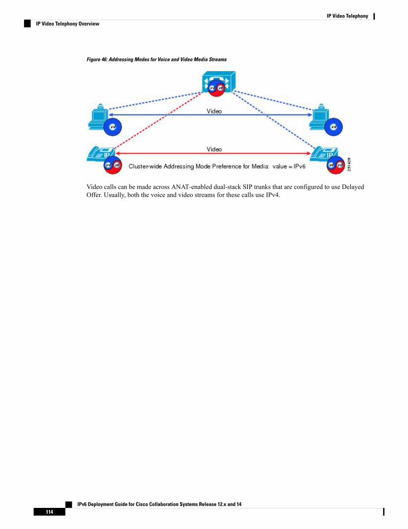
Figure 46: Addressing Modes for Voice and Video Media Streams
Video calls can be made across ANAT-enabled dual-stack SIP trunks that are configured to use DelayedOffer. Usually, both the voice and video streams for these calls use IPv4.
IPv6 Deployment Guide for Cisco Collaboration Systems Release 12.x and 14114
IP Video TelephonyIP Video Telephony Overview
C H A P T E R 13IP Telephony Migration Options
• IP Telephony Migration Options Overview, on page 115
IP Telephony Migration Options OverviewFor first-time installations of IPv6 with Cisco Unified Communications Manager (Unified CM) or an upgradeto a traditional deployment, we recommend the following guidelines:
Deployment Models
For Cisco Unified CM IPv6 is supported for single-site deployments, multi-site deployments with distributedcall processing, and multi-site deployments with centralized call processing. Minimum IPv6 deploymentrequires the following products:
• Dual-stack IPv6 Unified CM server
• MTP for media interworking
• IPv6-only IP Phones
All other components and interfaces can remain in IPv4. Unified CM will insert MTPs to provide mediainterworking for various use cases.
Campus Network and WAN
Before you enable IPv6 in the Unified CM cluster, make sure that both the campus network and the WANsupport both IPv4 and IPv6 traffic. Dual-stack (IPv4 and IPv6) routing is recommended for Layer 3 campusesand WANs.
Cluster-Wide IPv6 Configuration Settings
To maximize the amount of IPv6 traffic on your Unified Communications network, use the following settingsfor the cluster-wide IPv6 Enterprise Parameters:
• Enable IPv6: True
• IP Addressing Mode Preference for Media: IPv6
• IP Addressing Mode Preference for Signaling: IPv6
IPv6 Deployment Guide for Cisco Collaboration Systems Release 12.x and 14115

Common Device Configuration Profiles
Use multiple Common Device Configuration Profiles so that individual phones and trunks or groups of phonesand SIP trunks can be selectively configured to support IPv6.
The Common Device Configuration Profile in Unified CM Administration (Device > Device Settings >Common Device Configuration) contains the following IPv6 configuration information:
• IP Addressing Mode
• IP Addressing Mode Preference for Signaling
• Allow Stateful Auto-Configuration for Phones
DHCP
Stateful DHCPv6 is recommended, although stateless DHCP can also be used with Stateless AddressAuto-Configuration (SLAAC) for phones.
MTPs
For multi-site distributed call processing deployments, you will most likely need to use Cisco IOS mediatermination points (MTPs) for conversions between IPv4 and IPv6. These MTPs should be associated withboth phone and SIP trunk media resource groups (MRGs).
IPv6 SIP Trunks
IPv6 SIP trunks should be configured as Delayed Offer without Alternative Network Address Types (ANAT)enabled. However, SIP trunks configured for Early Offer (MTP Required) using an MTP resource for everycall are do not support video calls or encrypted calls.
IP Phones
IPv6-only phone support is a major feature of CSR 12.0, as it helps to mitigate IPv4 exhaustion. We recommendthat you configure all IP Phones as IPv6-only where applicable. All other IP Phones must be configured asIPv4. Dual-stack IP Phones require ANAT which is not supported in Unified SRST call agents.
ISDN PSTN Gateway and SRST ISR 4000
To transition to an IPv6-only network and to reduce the MTP requirements, configure ISDN PSTN gatewaysand SRST ISR 4000 with Delay Offered SIP IPv6-only trunk.
IPv6 Deployment Guide for Cisco Collaboration Systems Release 12.x and 14116
IP Telephony Migration OptionsIP Telephony Migration Options Overview

C H A P T E R 14Security
• Security Overview, on page 117• Privacy and Encryption for IPv6 Voice Signaling and Media, on page 117• Encrypted Media and MTPs Between IPv4 and IPv6, on page 118• CAPF and CTL, on page 119• IPv6 Collaboration Traffic and Firewalls, on page 119• Cisco Unified Border Element, on page 120• Security and IPv6 Traffic, on page 120
Security OverviewWhen comparing IPv4 and IPv6 in terms of how secure each protocol is, IPv6 has some advantages and somedisadvantages, but overall it is no more or less secure than IPv4. One inherent benefit of IPv6 is the enormoussize of IPv6 subnets and networks, which offer improvements in protection against automated scanning andworm propagation. Typical security drawbacks are the addressing complexity of IPv6 and the likelihood thatnetwork administrators will not be familiar with the IPv6 protocol and IPv6 security tools.
In general, most of the legacy issues with IPv4 security remain in IPv6. For example, Address ResolutionProtocol (ARP) security issues in IPv4 are replaced with neighbor discovery (ND) security issues in IPv6.
In CSR 12.0, IPv6 security settings have the same functionality as IPv4, such as Firewall, sRTP and TLS.
Privacy and Encryption for IPv6 Voice Signaling and Media
This was not solution tested for voice service in CSR 12.0.Note
The Internet Engineering Task Force (IETF) and RFCs 4301-4303 mandate authentication and encryption forIPv6 using IP Security (IPsec). However, to avoid interworking issues with legacy IPv4 UnifiedCommunications endpoints, Cisco Unified Communications Manager (Unified CM) IPv4 and IPv6 deploymentscontinue to use Transport Layer Security (TLS) and Secure Real-Time Transport Protocol (SRTP) forauthentication and encryption between IP phones and between IP phones and SIP gateways and trunks.
IPsec can also be used for IPv4-based H.323 and Media Gateway Control Protocol (MGCP) gatewayconnections.
IPv6 Deployment Guide for Cisco Collaboration Systems Release 12.x and 14117

Cisco Unified CM provides the following secure transport protocols:
• Transport Layer Security (TLS)
TSL provides secure and reliable data transfer between two systems or devices by using secure ports andcertificate exchange. TLS secures and controls connections between Unified CM-controlled systems,devices, and processes to prevent access to the voice domain. Unified CM uses TLS to secure SkinnyClient Control Protocol (SCCP) calls to phones that are running SCCP, and to secure SIP calls to phonesor trunks that are running SIP.
• IP Security (IPsec)
IPsec provides secure and reliable data transfer between Unified CM and gateways. IPv4-based IPsecimplements signaling authentication and encryption to Cisco IOS MGCP and H.323 gateways.
You can add Secure Real-Time Transport Protocol (SRTP) to TLS and IPsec transport services for the nextlevel of security on devices that support SRTP. SRTP authenticates and encrypts the media stream to ensurethat voice conversations originating or terminating on Cisco Unified IP Phones and either TDM or analogvoice gateway ports, are protected from eavesdroppers who might have gained access to the voice domain.SRTP adds protection against replay attacks.
For more information on Unified CM security, refer to the Cisco Unified Communications Manager SecurityGuide, available at:
http://www.cisco.com/c/en/us/support/unified-communications/unified-communications-manager-callmanager/products-maintenance-guides-list.html
Encrypted Media and MTPs Between IPv4 and IPv6Unified CM supports encrypted calls between dual-stack (IPv4 and IPv6) and single-stack (IPv4 or IPv6)devices. If an IP addressing version mismatch exists between the called and calling device, Unified CMdynamically inserts an MTP to convert the IP header of the encrypted voice stream. This dynamically insertedMTP uses its pass-through codec for the encrypted media stream and changes only the IP headers from IPv4to IPv6 and conversely.
IPv6 Deployment Guide for Cisco Collaboration Systems Release 12.x and 14118
SecurityEncrypted Media and MTPs Between IPv4 and IPv6

Figure 47: Addressing Mode Resolution by Unified CM
CAPF and CTLCertificate Authority Proxy Function (CAPF) supports both IPv4 and IPv6 addressing and uses TCP/IP tocommunicate with phones and to perform its standard security certificate functions. In an IPv6-enabled UnifiedCM cluster, CAPF has the following capabilities:
• Issuing and upgrading certificates to IPv4-only IP phones
• Issuing and upgrading certificates to IPv6-only IP phones
• Issuing and upgrading certificates to dual-stack (IPv4 and IPv6) IP phones
No new IPv6 functionality is needed for Certificate Trust List (CTL).
IPv6 Collaboration Traffic and FirewallsThe Cisco Adaptive Security Appliance (ASA) supports SCCP or SIP for IPv6, therefore can be used to openpinholes dynamically for IPv6 voice traffic. This product supports basic firewall and traffic filtering functionfor IPv6 traffic.
If you want to implement basic firewall capability for IPv6, refer to the following documents:
IPv6 Deployment Guide for Cisco Collaboration Systems Release 12.x and 14119
SecurityCAPF and CTL

• Cisco ASA 5500-X Series Firewalls Configuration Guides
https://www.cisco.com/c/en/us/support/security/asa-5500-series-next-generation-firewalls/products-installation-and-configuration-guides-list.html
• Catalyst 6500 Series Switch Configuration Guides
https://www.cisco.com/c/en/us/support/switches/catalyst-6500-series-switches/products-installation-and-configuration-guides-list.html
Cisco Unified Border ElementThe Cisco IOS-based ISR 4000 G3 Cisco Unified Border Element can:
• Terminate a SIP IPv6 call on one leg of a session, and generate a SIP IPv4 call on the other leg.
• Terminate a SIP IPv6 call on one leg of a session, and generate a SIP IPv6 call on the other leg.
This functionality allows for basic interconnection between enterprise IPv6 networks and service providerIPv4 networks.
Basic calls with both media and signaling processing are supported. Basic Supplementary Services over IPv6are supported, but H.323 IPv6 calls are not supported.
Security and IPv6 TrafficFuture releases of the Cisco security platforms and products mentioned in this chapter will support IPv6collaboration traffic. However, until these products do support IPv6 for collaboration traffic, we recommendthat you keep all IPv6 voice traffic within your enterprise network.
If you want to use firewalls within your campus network (for example, to secure Unified CM, centralizedmedia resources, and other voice applications), then change the Unified CM IP Addressing Mode Preferencefor Signaling to IPv4 to allow inspection for all SCCP and SIP signaling traffic. As an alternative, you canuse access control lists (ACLs) to open the firewall for IPv6 traffic.
IPv6 Deployment Guide for Cisco Collaboration Systems Release 12.x and 14120
SecurityCisco Unified Border Element

C H A P T E R 15Collaboration Endpoints
• IPv6 Capabilities of Collaboration Endpoints, on page 121• IPv6 Support on Cisco IP Phones, on page 121
IPv6 Capabilities of Collaboration EndpointsThis chapter describes a subset of the Cisco Collaboration endpoints and their IPv6 capabilities. The followingtable lists the endpoint types and summarizes their IPv6 capabilities. IPv6 support extends to only a subsetof the Cisco analog gateways and IP phones. The following sections discuss these devices in more detail.
Table 17: IPv6 Capabilities of Collaboration Endpoints
IPv6 CapabilityEndpoint Type
ISR 4000 does not support Cisco VG Series Gatewaysfor IPv6-only.
Analog gateways
Cisco Unified IP Phones 7800 and 8800 Series supportIPv6-only.
Cisco IP Phones
Jabber software-based endpoints support IPv6.Software-based endpoints
No wireless endpoints support IPv6.Wireless endpoints
Conference stations support IPv6.Cisco Unified IP Conference Station
Not solution tested.Cisco TelePresence video endpoints (CE software)
Third-party IPv6-capable phones are not supported.Third-party SIP IP phones
IPv6 Support on Cisco IP PhonesFor a list of the CSR 12.0 endpoints that support IPv6-only, see Recommended IPv6 Addressing Modes forCSR 12.1/12.0 Products , on page 20. Any endpoints not listed there should be configured in IPv4-only stack.
When a phone with a single IPv4 address needs to communicate with a phone with a single IPv6 address, anIP addressing version incompatibility exists. To resolve this media addressing incompatibility, Unified CM
IPv6 Deployment Guide for Cisco Collaboration Systems Release 12.x and 14121

dynamically inserts a media termination point (MTP) to convert the media stream from IPv4 to IPv6 (andconversely).
IP Phone Deployment Considerations in an IPv6 Network
The PC Voice LAN Access setting on IP phones is typically used to allow the monitoring of IP phone trafficby monitoring and recording applications and by network monitoring software. This setting also allowsmulticast traffic to be propagated from the voice VLAN to the IP phone's PC port. By default, the PC VoiceVLAN Access setting is enabled on IP phones.
In IPv6-enabled networks, this default PC Voice VLAN Access setting allows Router Advertisement (RA)multicast messages to be sent from the voice VLAN to the IP phone's PC port. Ordinarily, the PC should dropany packets that it receives with a voice VLAN tag because it is not configured for the voice VLAN and doesnot understand 802.1g tagging. However, if the PC does accept packets with a voice VLAN tag and uses anRA from the voice VLAN, it can cause an IPv6 address from the voice VLAN to be assigned to the PC.
If you encounter the issue of incorrect IPv6 address assignment for PC port devices, use either of the followingtechniques to resolve this issue:
• Set the prefix lifetime of RAs sent by routers in the voice VLAN to a shorter lifetime value than the RAssent by routers in the data VLAN, and also ensure that routers in the data VLAN have higher prioritythan those in the voice VLAN. IPv6 devices in the data VLAN using the Address Selection Algorithm(RFC 3484) choose the Network Prefix included in RAs with the longest lifetime, and thus prefer routersin the data VLAN.
• For all IP phones with connected devices that are affected by the above issue, set the IP phone's PC VoiceVLAN Access setting to disabled. For large numbers of phones, this configuration change can bebulk-provisioned through the Unified CM Bulk Administration Tool (BAT).
Common Device Configuration Profile
The process for configuring IPv6 on the phones is similar to that for SIP trunks. In Cisco Unified CMAdministration, select Device > Device Settings > Common Device Configuration > to create and configurea Common Device Configuration Profile and associated it with one or more IP phones. The Common DeviceConfiguration Profile contains the following IPv6 configuration information:
• IP Addressing Mode
• IP Addressing Mode Preference for Signaling
• Allow Auto-Configuration for Phones
IP Addressing Mode
The phone IP Addressing Mode has three settings:
• IPv4 Only
In this mode, the phone acquires and uses only one IPv4 address for all signaling and media. If the phonehas previously acquired an IPv6 address, it releases that address.
• IPv6 Only
IPv6 Deployment Guide for Cisco Collaboration Systems Release 12.x and 14122
Collaboration EndpointsCommon Device Configuration Profile

In this mode, the phone acquires and uses only one IPv6 address for all signaling and media. If the phonehas previously acquired an IPv4 address, it releases that address.
• IPv4 and IPv6
In this mode, the phone acquires and uses one IPv4 address and one IPv6 address. It can use the IPv4and the IPv6 address as required for media. It uses either the IPv4 address or the IPv6 address for callcontrol signaling to Unified CM.
If IPv6 is enabled in the Unified CM cluster, the default phone setting for IP Addressing Mode is IPv4 andIPv6. If the IP phone supports both IPv4 and IPv6, it will adopt this setting, but all IPv4-only phones willignore this setting.
We recommend setting the phone IP Addressing Mode to IPv4 and IPv6. A setting of IPv6 Only is notrecommended and should be used only in test environments. For more information on IPv6-only phonefunctionality, see IPv6-Only Phones, page 15-7.
IP Addressing Mode Preference for Signaling
The phone IP Addressing Mode Preference for Signaling has three settings:
• IPv4
If the phone has an IPv4 address, it uses that IPv4 address for call control signaling to Unified CM.
• IPv6
If the phone has an IPv6 address, it uses that IPv6 address for call control signaling to Unified CM.
• Use System Default
In this case, the phone uses the cluster-wide Enterprise Parameter configuration value for its IP AddressingMode for Signaling.
If IPv6 is enabled in the Unified CM cluster, the default phone setting for IP Addressing Mode for Signalingis Use System Default. If the IP phone supports either IPv6 or both IPv4 and IPv6, it will adopt the cluster-widesetting for IP Addressing Mode for Signaling, but all IPv4-only phones will ignore this setting.
Allow Auto-Configuration for Phones
Allow Auto-Configuration for Phones has three settings:
• On
With this setting, the phone is allowed to use Stateless Auto Address Configuration (SLAAC) to acquirean IPv6 address. Whether or not the phone uses SLAAC depends on the link-local router's O and M bitconfiguration for router advertisements (RAs), as follows:
• If the O bit is set in the router's RAs, the phone uses SLAAC to acquire an IPv6 address and usesthe DHCP server to acquire other information such as the TFTP server address.
• If the M bit is set in the router's RAs, the phone does not use SLAAC. Instead, it uses the DHCPserver to acquire its IP address and other information (Stateful DHCP).
• If neither the M bit nor the O bit is set, the phone uses SLAAC to acquire an IP address and doesnot use DHCP for other information. The phone also requires a TFTP server address to downloadits configuration file and register to Unified CM. This TFTP server address can be configuredmanually through the phone’s user interface (UI).
IPv6 Deployment Guide for Cisco Collaboration Systems Release 12.x and 14123
Collaboration EndpointsCommon Device Configuration Profile

• Off
With this setting, the phone does not use Stateless Auto Address Configuration (SLAAC) to acquire anIPv6 address. In this case, the phone can either be configured manually or use Stateful DHCPv6 to acquirean IPv6 address and TFTP server address.
• Default
With this setting, the phone uses the cluster-wide Enterprise Parameter configuration value for AllowAuto-Configuration for Phones.
Default Common Device Configuration Profile
By default, there are no Common Device Configuration profiles configured, and each device is associatedwith a <None> Common Device Configuration. If IPv6 is enabled in the Unified CM cluster with this defaultconfiguration, IPv6-capable devices adopt the following settings:
• IP Addressing Mode = IPv4 or IPv6
• IP Addressing Mode Preference for Signaling = Use System Default
• Allow Auto-Configuration for Phones = Default
Figure 48: Effect of IP Addressing Mode for Media on MTP Usage for IP Phones
Other IP Phone Functions
The following functions also affect the use of IPv6 on Cisco IP Phones.
TFTP
As previously described, TFTP servers support both IPv4 and IPv6 addresses. IPv4-only phones use theirreceived IPv4 TFTP address to reach the TFTP server, and IPv6-only phones use their received IPv6 TFTPaddress to reach the TFTP server. Dual-stack phones can use either their IPv4 or IPv6 TFTP address to reachthe TFTP server.
IPv6 Deployment Guide for Cisco Collaboration Systems Release 12.x and 14124
Collaboration EndpointsDefault Common Device Configuration Profile

The following IPv6 information is sent to the phone in its configuration file from the TFTP server:
• Unified CM IPv4 and IPv6 addresses
• The setting for IP Addressing Mode
• The setting for IP Addressing Mode Preference for Signaling
• The setting for Allow Stateless Auto-Configuration for Phones
Unified CM Registration for Dual-Stack IP Phones
Dual-stack phones attempt to connect to Unified CM by using the preferred (IPv4 or IPv6) address specifiedin the IP Addressing Mode Preference for Signaling parameter found in the TFTP configuration file. If thefirst attempt at connection fails due to a TCP timeout, the phone then attempts to connect to Unified CM usingits other address.
IP Phone HTTP Server Functionality
The HTTP server function of all IP phones uses IPv4-only or IPv6-only. The HTTP server provides severalfunctions, including:
• Phone User Interface access to:
• Directory search functions
• Call history
• All IP Phone Services
• Extension Mobility
• IPv4-only supported Quality Report Tool (QRT)
• Web access to the phone through the Unified CM phone administration graphical user interface
CDP and LLDP
IP phones support the sending and receiving of IPv4 and IPv6 addresses in data link layer Cisco DiscoveryProtocol (CDP) and Link Layer Discovery Protocol (LLDP) messages. Currently, Cisco applications do notuse any of the IPv6 addresses sent in LLDP messages. CDP is applicable to Emergency Responder anddiscovery of a desk phone device.
IPv6-Only Phones
IP phones configured with an IP addressing mode of IPv6-only are subject to a number of functional limitationsthat must be evaluated before any production network deployments. Those limitations are described here:
• The following functions are not available to IPv6-only phones:
• EMCC
• NTPv6
IPv6 Deployment Guide for Cisco Collaboration Systems Release 12.x and 14125
Collaboration EndpointsIPv6-Only Phones

• Peer Firmware Sharing (PFS) for the distribution of files between like phones is not supported forIPv6-only phones. IPv6-capable phones do support a load server using an IPv6 address.
• CAST Protocol for Jabber, Establish and maintain a connection to the desk phone device
• MRA
• Power Save Plus (EnergyWise), need Switch support (No future plan, deprecated by switch)
• VPNv6
• IPv6-only Out-of-Band and Boot
• IPv6 multicast (MOH), Unified CM does not support IPv6 multicast MOH (Not a solutionrequirement)
• Device mobility uses IP subnet information to locate mobile devices and this function is not supportedfor IPv6-only phones.
IPv6 Deployment Guide for Cisco Collaboration Systems Release 12.x and 14126
Collaboration EndpointsIPv6-Only Phones

C H A P T E R 16Appendix
• Product Configuration Resources for IPv6, on page 127• Document Direction, on page 128• Deprecation of ANAT SIP SDP Attributes, on page 129
Product Configuration Resources for IPv6To configure CSR 12.1/12.0 products for IPv6, refer to the product configuration guides.
Table 18: CSR 12.1/12.0 Endpoints
IPv6 Configuration ResourcesEndpoint (SIP)
Administration GuidesCisco IP Phone 7800 Series
Administration GuidesCisco IP Phone 8800 Series
On-Premises Deployment GuideCisco Jabber
SupportCisco DX70 and DX80 (CE endpoints)
SupportCisco TelePresence MX Series (CE endpoints)
SupportCisco TelePresence SX Series (CE endpoints)
SupportCisco TelePresence EX Series (CE endpoints)
Table 19: CSR 12.1/12.0 Communication Gateways
IPv6 Configuration ResourcesGateway
Configuration GuidesCisco 4000 Series Integrated Services Routers (ISR)
CUBE Configuration GuideCisco 2900 and 3900 Series Integrated ServicesRouters (ISR) (For CUBE)
IPv6 Deployment Guide for Cisco Collaboration Systems Release 12.x and 14127

Table 20: CSR 12.1/12.0 Applications and Interfaces
IPv6 Configuration ResourcesApplication or Interface
System Configuration GuideCisco Unified Communications Manager (UnifiedCM)
Configuration and Administration GuideUnified CM IM and Presence Service (IM andPresence Service)
Administration GuidesCisco Unified Survivable Remote Site Telephony(Unified SRST)
Solution Design GuideCisco Unified Contact Center Enterprise (UnifiedCCE)
Solution Design GuideCisco Unified Contact Center Express (Unified CCX)
Administration GuideCisco Emergency Responder
System Administration Guide
Integration Guide
Cisco Unity Connection
SupportCisco Meeting Server
SupportCisco TelePresence Management Suite
SupportCisco Prime Collaboration
Document DirectionThis document is based Collaboration IP endpoints being dual-stack, which was driven by the DoDrequirements, where IPv4 exhaustion was not the driver to deploy IPv6. DoD's direction was to roll out IPv6slowly, not to have IPv6-only networks. To reduce IPv4 and IPv6 media inter-working (MTP), each endpointwas implemented with both IPv4 and IPv6 addresses using SIP SDP attributes of ANAT. For enterprisenetworks, it was not acceptable to assign IPv4 addresses to IPv6 devices. Their expectation was to assign onlyIPv6 addresses in all deployment use cases.
Starting in CSR 12.0, we recommend deploying IPv6-only device configuration where applicable, typicallyendpoints and PSTN gateways. All applications servers need IPv4 address and IPv6 address (dual-stack) tosupport all traditional IPv4 devices until all devices are IPv6-only capable including third-party products andapplications.
This document includes the current ANAT configuration information that is not solution tested and TACsupported in CSR 12.1/12.0. The Unified CM and DoD default values are the same as shown in variousconfiguration tabs.
We will update this document in the future based on the market requirements and approval by DoD todeprecation of the ANAT RFCs 4091 and 4092. The Unified CM configuration tabs will be updated accordinglywith new default values of IPv6 in the next major release.
IPv6 Deployment Guide for Cisco Collaboration Systems Release 12.x and 14128
AppendixDocument Direction

To reduce dependency on IPv4 addresses, you can upgrade the following on-premise deployment modes toIPv6: single-site call processing deployments; multi-site distributed call-processing deployments; and multi-sitedeployments with centralized call processing. We recommend that you upgrade and configure:
• IPv6-only stack SIP phones, SIP gateways, and SIP trunks.
• IPv4-only stack and IPv6-only stack (dual-stack) Unified CM clusters and other application servers.
• All third-party products and applications in IPv4-only.
Deprecation of ANAT SIP SDP AttributesDepartment of Defense (DoD) certification requirements drove the development of Alternative NetworkAddress Types (ANAT) RFC 4091 and 4092. ANAT allows a set of network addresses to establish a mediastream is useful in environments with both IPv4-only hosts and IPv6-only hosts. For this functionality, all thedevices need IPv4 address and IPv6 address assignment. ANAT was also implemented in Cisco UnifiedCommunication System Release 7.1.2. However, since all device need both IPv4 and IPv6 addresses, ANATdoes not help to reduce dependency on the now depleted number of IPv4 addresses. Based on large enterprisecustomer feedback, and their need for new IP addresses, ANAT SIP SDP attributes have since been deprecatedby Internet Engineering Task Force (IETF).
Starting with CSR 12.0, we recommend deploying IPv6-only device configuration where applicable (typicallyendpoints). All servers, third-party products, and applications need IPv4 addresses and IPv6 addresses tosupport all traditional IPv4 devices until all devices are IPv6-only capable.
IPv6 Deployment Guide for Cisco Collaboration Systems Release 12.x and 14129
AppendixDeprecation of ANAT SIP SDP Attributes

IPv6 Deployment Guide for Cisco Collaboration Systems Release 12.x and 14130
AppendixDeprecation of ANAT SIP SDP Attributes
Copyright © 2022 FDOKUMEN