IPv6 Enablement Support Services IPv6 VPN Implementation ...
311
Department of Veterans Affairs IPv6 Enablement Support Services IPv6 VPN Implementation Plan CLIN #: 0002AB Contract: VA118-11-P-0096 Solicitation Number: VA118-11-RP-0611 May 31, 2012 Version 1.0
-
Upload
khangminh22 -
Category
Documents
-
view
8 -
download
0
Transcript of IPv6 Enablement Support Services IPv6 VPN Implementation ...

Department of Veterans Affairs
IPv6 Enablement Support Services
IPv6 VPN Implementation Plan
CLIN #: 0002AB
Contract: VA118-11-P-0096
Solicitation Number: VA118-11-RP-0611
May 31, 2012
Version 1.0

Department of Veterans Affairs IPv6 Enablement Support Services
IPv6 VPN Implementation Plan 5/31/2012 i
Revision History
Version Purpose Author Function Date
v0.1 Draft The Ventura Group Service Transition Outline 2/18/2012
v0.2 Draft Greg Taylor Functional Updates =A 4/11/2012
v0.3 Draft Greg Taylor Editorial Changes & Updates =A,M,D 4/25/2012
v1.0 Final Greg Taylor Finalized Version 5/31/2012
* The following symbols can be used to represent the type of change noted: A = Added M = Modified D = Deleted

Department of Veterans Affairs
IPv6 Enablement Support Services
IPv6 VPN Implementation Plan 5/31/2012 2
Table of Contents
1 EXECUTIVE SUMMARY ................................................................................................................................. 5
2 INTRODUCTION ............................................................................................................................................... 5
2.1 PURPOSE AND SCOPE ...................................................................................................................................... 6 2.2 DOCUMENT ORGANIZATION ........................................................................................................................... 6
3 IPV6 VPN BUSINESS DRIVERS ...................................................................................................................... 7
3.1 IMPROVED EMERGENCY RESPONSIVENESS AND CONTINUITY OF OPERATIONS .............................................. 8 3.2 IPV6 FEATURES AND BENEFITS ...................................................................................................................... 8
4 VPN ASSESSMENT SUMMARY ..................................................................................................................... 9
5 RESOURCE REQUIREMENTS ..................................................................................................................... 10
5.1 THE PROJECT TEAM...................................................................................................................................... 10 5.2 PROJECT OWNER .......................................................................................................................................... 11 5.3 STAKEHOLDERS ............................................................................................................................................ 12
5.3.1 IPv6 Working Group ............................................................................................................................ 12 5.4 EXTERNAL DEPENDENCIES ........................................................................................................................... 13 5.5 SUCCESS INDICATORS ................................................................................................................................... 13
6 TRANSITION PROCESS ................................................................................................................................. 14
6.1 SCHEDULE .................................................................................................................................................... 15 6.2 WBS ............................................................................................................................................................ 16
7 TRANSITION COST ELEMENTS ................................................................................................................. 16
USER HARDWARE COSTS........................................................................................................................................... 17 7.1 INDUSTRY RESEARCH RA.1 .................................................................................................................. 17
7.1.1 Baseline Penetration Estimated RA.2 .................................................................................................. 17 7.1.2 Identify Transition Mechanisms ........................................................................................................... 18 7.1.3 Identify Network Testing Strategy ........................................................................................................ 18 7.1.4 Training Guidelines ............................................................................................................................. 19 7.1.5 Identify Training Needs ....................................................................................................................... 19 7.1.6 Project Assumptions and Dependencies .............................................................................................. 20 7.1.7 Transitioning from IPv4 to IPv6 .......................................................................................................... 20 7.1.8 Notional Costs RA.3 ............................................................................................................................. 21 7.1.9 Baseline Benefits RA.4 ......................................................................................................................... 21
8 IPV6 VPN IMPLEMENTATION OVERVIEW ............................................................................................. 23
8.1 PHASE I ........................................................................................................................................................ 23 8.2 PHASE II ....................................................................................................................................................... 23 8.3 PHASE III ...................................................................................................................................................... 23 8.4 EQUIPMENT CONFIGURATION REQUIREMENTS ............................................................................................. 23 8.5 VA RESPONSIBILITIES .................................................................................................................................. 23
8.5.1 Updating the Enterprise Architecture .................................................................................................. 24
9 IPV6 PILOT IMPLEMENTATION PLAN .................................................................................................... 24
9.1 PHASE I ........................................................................................................................................................ 24 9.1.1 Acceptance Test Planning .................................................................................................................... 25
9.2 PHASE II ....................................................................................................................................................... 25 9.2.1 Enterprise Infrastructure IPv6/IPv4 Dual Stack Pilot Rollout ............................................................ 25 9.2.2 Configuring the Internet Gateway ....................................................................................................... 49

Department of Veterans Affairs
IPv6 Enablement Support Services
IPv6 VPN Implementation Plan 5/31/2012 3
9.2.3 NetScaler Installation and Configuration ............................................................................................ 83 9.2.4 Parameters Description ....................................................................................................................... 88 9.2.5 Configuring Access Control Lists ........................................................................................................ 89 9.2.6 Managing the Citrix NetScaler ............................................................................................................ 94 9.2.7 Implementing IPv6 on NetScaler ....................................................................................................... 101 9.2.8 Customizing VIP IPv6 Addresses ....................................................................................................... 105 9.2.9 Configuring Neighbor Discovery and Router Learning .................................................................... 109 9.2.10 Router Learning ................................................................................................................................. 111 9.2.11 Adding IPv6 Support to NetScaler Features ...................................................................................... 111 9.2.12 VLAN Support .................................................................................................................................... 111 9.2.13 Simple Deployment Scenario ............................................................................................................. 111 9.2.14 Transition VPN Tunneling ................................................................................................................. 114 9.2.15 Configuring Citrix MetaFrame Services ............................................................................................ 114 9.2.16 Overview ............................................................................................................................................ 115 9.2.17 Enabling WebVPN ............................................................................................................................. 123 9.2.18 Configuring Citrix MetaFrame Services and Configuring a Citrix Access Method .......................... 133 9.2.19 Configuring Group Policies ............................................................................................................... 142 9.2.20 Empty Server Group Message ........................................................................................................... 151 9.2.21 Configuring Tunneling Protocols ...................................................................................................... 154 9.2.22 Configuring Firewall Attributes ........................................................................................................ 171 9.2.23 Configuring Attributes for VPN Hardware Clients ........................................................................... 174 9.2.24 Configuring Server and List Arguments Using the WebVPN Other Tab ........................................... 185 9.2.25 Configuring IPv6 Default and Static Routes ...................................................................................... 194 9.2.26 To show IPv6 mld traffic .................................................................................................................... 200 9.2.27 Enrolling for Digital Certificates....................................................................................................... 210 9.2.28 Management features: ....................................................................................................................... 216 9.2.29 Configuring an LDAP AAA Server .................................................................................................... 220 9.2.30 Overview of LDAP Transactions ....................................................................................................... 220 9.2.31 Configuring Load Balancing ............................................................................................................. 232 9.2.32 Cisco Unity Connection Cluster Overview ........................................................................................ 235 9.2.33 Mixed Cluster Options ....................................................................................................................... 239 9.2.34 Configuring VPN Session Limits ....................................................................................................... 241 9.2.35 Configuring Single Sign-on for WebVPN .......................................................................................... 241 9.2.36 Configuring SSO Authentication Using Site Minder ......................................................................... 242 9.2.37 Gathering HTTP Form Data ............................................................................................................. 250 9.2.38 Configuring SSO with HTTP Form Protocol ..................................................................................... 252 9.2.39 Configuring the SSL VPN Client........................................................................................................ 257 9.2.40 Steps to configure VA Users for LDAP AAA Server .......................................................................... 268 9.2.41 End Point User Hardware ................................................................................................................. 281 9.2.42 Telecommuter Matrixes ..................................................................................................................... 285 9.2.43 Future VA VPN Considerations ......................................................................................................... 286 9.2.44 Arris Installation Instructions ............................................................................................................ 291 9.2.45 How to set up the Cisco E4200 Linksys series router ........................................................................ 292 9.2.46 How to manually set up your Internet connection ............................................................................. 296
9.3 PHASE III .................................................................................................................................................... 305 9.3.1 VPN IPv6 Considerations .................................................................................................................. 305 9.3.2 Client/server application support: ..................................................................................................... 305 9.3.3 Network extension: ............................................................................................................................ 305 9.3.4 Endpoint security: .............................................................................................................................. 305 9.3.5 Clientless operation: .......................................................................................................................... 305 9.3.6 Transition and Network Security Considerations: ............................................................................. 305
10 SUMMARY .................................................................................................................................................. 309
List of Figures
Department of Veterans Affairs
IPv6 Enablement Support Services
IPv6 VPN Implementation Plan 5/31/2012 4
FIGURE 1: TRANSITION PROCESS ..................................................................................................................................... 14
FIGURE 2: SCHEDULE ..................................................................................................................................................... 15
FIGURE 3: PROJECT PLANNING IPV6 VPN IMPLEMENTATION .............................................................................................. 16
FIGURE 4: PENETRATION ESTIMATES OF IPV6 IN THE UNITED STATES ................................................................................. 18
FIGURE 5: SIMPLE IPV6 VPN ARCHITECTURE ................................................................................................................... 28
FIGURE 6: MULTIPROTOCOL VRF .................................................................................................................................... 31
FIGURE 7: INTERNET ACCESS TOPOLOGY ......................................................................................................................... 33
FIGURE 8: INTER-PROVIDER SCENARIOS ........................................................................................................................... 34
FIGURE 9: CSC 6VPE CONFIGURATION EXAMPLES .......................................................................................................... 35
FIGURE 10: ROUTE REFLECTOR PEERING DESIGN ............................................................................................................. 42
FIGURE 11: BGP PEERING POINTS FOR ENABLING INTERAUTONOMOUS SYSTEM SCENARIO C .............................................. 58
FIGURE 12: SERVERS AND URL LISTS IN THE DFLTGRPPOLICY AND AN ALTERNATIVE GROUP POLICY ................................ 133
FIGURE 13: NEIGHBOR SOLICITATION AND RESPONSE PROCESS ...................................................................................... 196
FIGURE 14: ROUTER ADVERTISEMENT MESSAGE............................................................................................................. 197
FIGURE 15: NEIGHBOR SOLICITATION MESSAGE.............................................................................................................. 205
FIGURE 16: ROUTER ADVERTISEMENT MESSAGE............................................................................................................. 206
FIGURE 17: ACTION-URI, HIDDEN, USERNAME AND PASSWORD PARAMETERS ...................................................................... 251
FIGURE 18: AUTHORIZATION COOKIES IN SAMPLE HTTP ANALYZER OUTPUT ...................................................................... 252
FIGURE 19: ASDM WINDOW WITH AAA SERVERS AREA DISPLAYED ................................................................................ 253
FIGURE 20: THE ADD AAA SERVER GROUP DIALOG BOX................................................................................................ 254
FIGURE 21: THE ADD AAA SERVER GROUP DIALOG BOX................................................................................................ 255
FIGURE 22: SSL VPN CLIENT WINDOW ......................................................................................................................... 257
FIGURE 23: ADD SSL VPN CLIENT IMAGE DIALOG ......................................................................................................... 258
FIGURE 24: UPLOAD IMAGE DIALOG ............................................................................................................................... 258
FIGURE 25: SSL VPN CLIENT WINDOW WITH SVC IMAGES ............................................................................................. 259
FIGURE 26: ENABLE SSL VPN CLIENT CHECK BOX........................................................................................................ 259
FIGURE 27: WEBVPN ACCESS WINDOW ........................................................................................................................ 260
FIGURE 28: ENABLING THE INTERFACE ........................................................................................................................... 260
FIGURE 29: ADD IP POOL DIALOG ................................................................................................................................. 261
FIGURE 30: TUNNEL GROUP WINDOW ............................................................................................................................ 261
FIGURE 31: EDIT TUNNEL GROUP, GENERAL TAB, CLIENT ADDRESS ASSIGNMENT TAB ..................................................... 262
FIGURE 32: TUNNEL GROUP WINDOW ............................................................................................................................ 263
FIGURE 33: EDIT TUNNEL GROUP DIALOG, GENERAL TAB, BASIC TAB ............................................................................. 263
FIGURE 34: EDIT TUNNEL GROUP DIALOG, WEBVPN TAB, GROUP ALIASES AND URLS TAB ............................................. 264
FIGURE 35: WEBVPN ACCESS WINDOW, ENABLE TUNNEL GROUP .................................................................................. 264
FIGURE 36: EDIT INTERNAL GROUP POLICY, GENERAL TAB ............................................................................................. 265
FIGURE 37: SSL VPN CLIENT TAB ................................................................................................................................ 265
FIGURE 38: VPN STATISTICS SESSIONS WINDOW ........................................................................................................... 267
FIGURE 39: SESSION DETAILS WINDOW ......................................................................................................................... 267

Department of Veterans Affairs
IPv6 Enablement Support Services
IPv6 VPN Implementation Plan 5/31/2012 5
FIGURE 40: LOGGING OFF SESSIONS ............................................................................................................................. 268
FIGURE 41: LDAP AUTHENTICATION AND AUTHORIZATION TRANSACTION FLOW ............................................................... 268
FIGURE 42: LDAP ATTRIBUTE MAP AREA ...................................................................................................................... 269
FIGURE 43: ADD LDAP ATTRIBUTE MAP DIALOG BOX - MAP NAME TAB SELECTED .......................................................... 270
FIGURE 44: ADD LDAP ATTRIBUTES MAP VALUE DIALOG BOX ....................................................................................... 271
FIGURE 45: THE ASDM WINDOW WITH AAA SERVERS SELECTED ................................................................................... 272
FIGURE 46: THE ADD AAA SERVER GROUP DIALOG BOX................................................................................................ 273
FIGURE 47: THE ADD AAA SERVER DIALOG BOX ........................................................................................................... 274
FIGURE 48: ADD GROUP POLICY DIALOG BOX ................................................................................................................ 277
FIGURE 49: TUNNEL GROUP AREA ................................................................................................................................. 278
FIGURE 50: ADD TUNNEL GROUP DIALOG BOX WITH GENERAL AND AAA TABS SELECTED ................................................ 279
FIGURE 51: ROUTER ADVERTISEMENT MESSAGE............................................................................................................. 290
List of Tables
TABLE 1: HOME MODEM ANALYSIS ................................................................................................................................ 282
TABLE 2: MIFI/USB MODEM ANALYSIS .......................................................................................................................... 283
TABLE 3: MIFI/USB MODEM ANALYSIS .......................................................................................................................... 285
1 Executive Summary
The Office of Management and Budget (OMB) issued an IPv6 memorandum in August 2005 that mandated IPv6 capability compliance by June 2008. IPv6, sometimes called the "next generation" Internet Protocol (IPng), was designed by the Internet Engineering Task Force (IETF) to replace the current version Internet Protocol, IP Version 4 (IPv4), which is now more than twenty years old. Currently, Veteran Affairs (VA) is moving forward with leveraging IPv6 within their VPN infrastructure. Because of the growing Global use of the Internet and an exponentially increasing number of appliances that can be connected to the Web, the limited addressing scheme of IPv4 is causing a severe shortage of available IP addresses. This document provides end to end configuration guidelines for the purposes of enabling IPv6 VPN functionality within the Veterans Administration (VA) networking enterprise environment. This document details information about the VA implementation plan for the existing IPv4 and future IPv6 architecture, it provides a plan to transition from the IPv4 as-is to the IPv6 to-be VPN network environment. Lastly, high-level transition costs were estimated.
2 Introduction
In order to utilize IPv6 within the VA VPN environment, VA’s current inventory of IPv4 devices need to be examined to determine their ability to process the IPv6 addressing and if not, determine what needs to be done to enable IPv6 transactions. Each device (or group of like devices based on make, model, software version, etc) needs to be analyzed to answer the following questions:
a. Which Layer 3 VPN devices are ready to pass IPv6 traffic? b. Which VPN devices are capable of supporting IPv6 traffic (i.e., requires IOS or memory
upgrade)? c. Which VPN devices will never be capable of supporting IPv6 traffic (i.e., needs to be replaced
with newer device)?
VA has completed a VPN assessment for its VPN capable devices and has presented this information along with its potential impact. This information can be found within the VPN IPv6 Assessment document.

Department of Veterans Affairs
IPv6 Enablement Support Services
IPv6 VPN Implementation Plan 5/31/2012 6
2.1 Purpose and Scope
This document provides the step-by-step processes to enable IPv6 within the current VPN environment. It also provides configuration requirements to enable its telecommuters and mobile workforce to access VA resources on the enterprise. This implementation plan maps the end-to-end “mission thread” that identifies the networks, devices and applications that are involved in establishing a VPN connection for a typical VA telecommuter. From there, each component associated to the mission thread is configured to support IPv6. There are many components in the VPN telecommuting mission thread and this document will include at a minimum, selected elements of the following:
Hardware
o End-user/teleworkers computer/device o VPN servers/equipment o Routers/security devices in the communications path
Software o End user VPN software o VPN server software o Network management, monitoring and security software to support the network o Reporting software
Network Services o End user ISP o VA Gateway ISPs o VA WAN connectivity o VA LAN connectivity
The material presented in this document is believed to be accurate at the time of its writing. It is presented without warranty of any kind expressed or implied. Users must take all responsibility for the use or application of the processes described in this document. This material is sourced from © 2007 Cisco Systems, Inc. All rights reserved. Cisco Systems, Inc., 170 West Tasman Drive, San Jose, CA 95134-1706, the Microsoft Corporation, Understanding IPv6 www.microsoftpress.com, National Institute of Standards NIST www.crc.nist.gov/publications, Citrix Systems, Inc., 2009 www.support.citrix.com. Any Internet Protocol (IP) addresses used in this document are not intended to be actual addresses. Any examples, command display output, and figures included in the document are shown for illustrative purposes only. The illustrative addresses should be replaced with the actual addresses specific to the VA connectivity requirements.
2.2 Document Organization
This document is composed of ten chapters with the associated list of tables and figures: 1 Executive Summary, 2 Introduction, 3 VA IPv6 Business Drivers, 4 VPN, Assessment Summary, 5 Resource Requirements, 6 Transition Process (WBS), 7 Transition Cost elements, 8 VPN Implementation Overview, 9 Phased IPv6 Implementation Plan, 10 Summary and a List of Tables and Figures. Chapter one, Executive Summary, provides an overview of the information contained herein. Chapter two, Introduction, provides background information and discusses purpose and scope. Chapter three, VA IPv6 Business Drivers, discusses the internal and external drivers influencing the transition and an explanation of the features, benefits, and challenges of introducing IPv6 into the networking environment. It provides an overview of the features and benefits of implementing the new IPv6 framework. Chapter four, VPN Assessment Summary looks at the current status of the VA’s infrastructure, associated equipment and its ability to support IPv6 services.

Department of Veterans Affairs
IPv6 Enablement Support Services
IPv6 VPN Implementation Plan 5/31/2012 7
Chapter five, Resource Requirements, provides an overview of the general staffing and external elements, and typical skill levels required to successfully execute the implementation. Chapter six contains the Transition Process with the Work Breakdown Structure (WBS), and the transitional elements required to implement IPv6 in the enterprise. Chapter seven, IPv6 VPN Transition Cost Elements, looks at the approximate resource requirements, cost and man-hours associated with the Phases of the implementation. Chapter eight, IPv6 Implementation Plan Overview, looks at the transition process, key configuration elements and transition sequence. Chapter nine, IPv6 Phased Implementation Plan, outlines the steps required to integrate IPv6 into the current enterprise architecture. The activity outlines a fazed approach to the transition process and the configuration elements that need to be addressed during that transition process. It outlines the resource requirements, and configuration steps required to effect the IPv6 VPN transition. It addresses the key elements of the transition plan, taking into consideration “industry best practices” and recommendations in several of the most critical areas of the IPv6 VPN transition that are relevant to the introduction of IPv6 into the VA network environment. Chapter Ten, Summary
3 IPv6 VPN Business Drivers
It has been established that Telework yields multiple benefits to the Federal Government, the individual employee, and the community. Telework is becoming increasingly prevalent in the VA workforce because its proven results and reliability are shown to significantly improve life holistically. Its results are so proven in fact, that Public Law 106-346 §359 which require Federal agencies to “establish a policy under which eligible employees of the agency may participate in telecommuting to the maximum extent possible without diminished employee performance.” This VPN implementation plan responds directly to that requirement.
Key benefits stemming from the implementation of the telework program in VA include:
A VA workforce that is capable of teleworking on a regular basis and that is capable of leveraging its decentralized work settings to maintain continuity of operations (COOP) in the face of a natural disaster, terrorist attack, or other emergency situations.
Telework contributes to a greener environment by diminishing vehicle carbon emissions as a result of a truncated or nonexistent employee commute.
The job performance of teleworkers has been documented to either exceed or remain on par with that of workers in a traditional workplace arrangement.
Telework increases personal freedom and flexibility, thereby improving morale and decreasing stress.
A strong VA telework program improves employee retention and recruitment by increasing an employer’s attractiveness in the current competitive job market.
A VA telework program will accommodate workers with disabilities.
Telework permits more time for employees to care for their loved ones.
Telework can enable reduced demand for office space as well as reduced facility operating costs.

Department of Veterans Affairs
IPv6 Enablement Support Services
IPv6 VPN Implementation Plan 5/31/2012 8
Telework allows for optimal use of technological advances.
3.1 Improved Emergency Responsiveness and Continuity of Operations
Telework is a key factor in emergency planning, response, and prevention because it allows for the continuity of operations (COOP) or business continuity plans, where catastrophe would inhibit the necessary protocols. Essentially, telework decentralizes and spreads the workforce to reduce the ratio of those impacted by a disaster. In fact, many public and private sector workplace policies now contain a telework component for COOP in the wake of the NYC terrorist attacks in 2001, hurricane Katrina, and potential pandemic or other widespread illnesses. The Bush Administration, in particular, made clear the necessity for emergency planning and response. On May 3, 2006, President Bush issued the Implementation Plan for the National Strategy for Pandemic Influenza, which outlines the government’s approach for dealing with the threat of pandemic influenza. It states: “All departments and agencies will be responsible for developing pandemic plans that ensure that the department or agency will be able to maintain its essential functions and services in the face of significant and sustained absenteeism.” With the internet transitioning to an IPv6 platform, IPv6 only users will be coming online and will require access to VA resources via the new IPV6 platform. Without the transition VA would not be able to support the next generation of teleworkers.
Implementation Plan for the National Strategy for Pandemic Influenza, Homeland Security Council. May 2006. pg. 30. http://www.whitehouse.gov/homeland/nspi_implementation.pdf. The evolution of the IPv6 protocol represents the work of many different Internet Engineering Task Force (IETF) proposals and working groups and represents several years of effort. IPv6 was designed to build on the existing features of IPv4 and provide new services and capabilities. The rationale is to:
Extend the IP address space enough to offer a unique IP address to any device.
Enable stateless IP auto-configuration and improved “plug and play” support
Provide support for network address renumbering.
Enable mandatory implementation of IP Security (IPSec) support for all fully IPv6-compliant.
Improve support for IP Mobility.
3.2 IPv6 Features and Benefits
Listed below is an overview of several features and benefits IPv6 enabled VPN is intended to provide.
Larger address space – IPv6 increases the IP address size from 32 bits to 128 bits. Increasing the size of the address field increases the number of unique IP addresses from approximately 4,300,000,000 (4.3×10
9) to 340,282,366,920,938,463,463,374,607,431,768,211,456 (3.4×10
38).
Increasing the address space to 128 bits provides the following additional potential benefits:
Enhanced applications functionality – Simplifies direct peer-to-peer applications and networking by providing a unique address to each device.
End-to-end transparency – The increased number of available addresses reduce the need to use address translation technologies.
Hierarchical addressing – The hierarchical addressing scheme provides for address summarization and aggregation. These approaches simplify routing and manage routing table growth.
Auto-configuration – Clients using IPv4 addresses use the Dynamic Host Configuration Protocol (DHCP) server to establish an address each time they log into a network. This address

Department of Veterans Affairs
IPv6 Enablement Support Services
IPv6 VPN Implementation Plan 5/31/2012 9
assignment process is called stateful auto-configuration. IPv6 supports a revised DHCPv6 protocol that supports stateful auto-configuration and supports the stateless auto-configuration of nodes. Stateless auto-configuration does not require a DHCP server to obtain addresses. Stateless auto-configuration uses router advertisements to create a unique address. This creates a “plug-and-play” environment, simplifying address management and administration. IPv6 also allows automatic address configuration and reconfiguration. This capability allows administrators to re-number network addresses without accessing all clients.
Scalability of multicast routing – IPv6 provides a much larger pool of multicast addresses with multiple scoping options.
4 VPN Assessment Summary
The ability to support IPv6 services for operational traffic that is carried over the Internet is critical. Not only will VA soon begin to see IPv6 only teleworkers and business partners, more importantly VA will begin to see IPv6 only veterans. With as many as 40% of veterans living in rural areas, many are connected to limited or slower broadband services. With the exhaustion of IPv4 addresses, as the Administrations National Broadband Deployment Plan is realized in the next several years, the new broadband providers will only have IPv6 addresses to deploy to veterans. Thus, IPv6 only veterans could quickly become one of the fastest growing populations for VA’s Internet based services. VA has established two core VPN methodologies: one based on Cisco’s ASA 5500 series platform and one based on Citrix. VA is moving many of the users away from the Cisco ASA solution unless they need the ability to access printing and other specific capabilities on the VA Enterprise Network and towards the Citrix environment that incorporates a virtualized interface. With the correct software releases, both solution sets provide robust IPv6 capabilities. Citrix adopted IPv6 as far back as 2007 and Cisco recently has had their ASA 5500 series pass USGv6 certification. The VPN Assessment utilized a “mission thread” approach to assess VA’s VPNs for IPv6. For each type of VPN (Cisco ASA and Citrix), three distinct environments were identified and the equipment, software and services were analyzed for the purposes of establishing end-to-end VPN capabilities. The three environments included:
End User
Internet Connectivity
VA Internet Gateway It is interesting to note that teleworkers could establish a VPN connection utilizing IPv6 (once supported in the VA environment) which would then pass IPv4 and IPv6 within the VPN tunnel. Thus, even if VA does not have any IPv6 enabled applications, it could still implement an IPv6 VPN solution for Telework. It should also be noted that the VPN tunnel will be established in either IPv4 or IPv6 for each tunnel session and will not switch between the protocols during a session. The results of the assessment included the following findings:
The VA Internet Gateways currently support IPv6 and should be able to support IPv6 based VPNs with minor modifications to equipment rule sets.
The Cisco ASA 5500 series and Citrix provides robust IPv6 support in later releases of their operating system.
Several of the Cisco ASA series routers deployed did not meet the operating system version for the USGv6 testing, thus to enable various aspects of IPv6 functionality, there may be a requirement to upgrade these devices to a later operating system version. There is the potential that this could require additional modifications to the supporting hardware. The specific hardware
Department of Veterans Affairs
IPv6 Enablement Support Services
IPv6 VPN Implementation Plan 5/31/2012 10
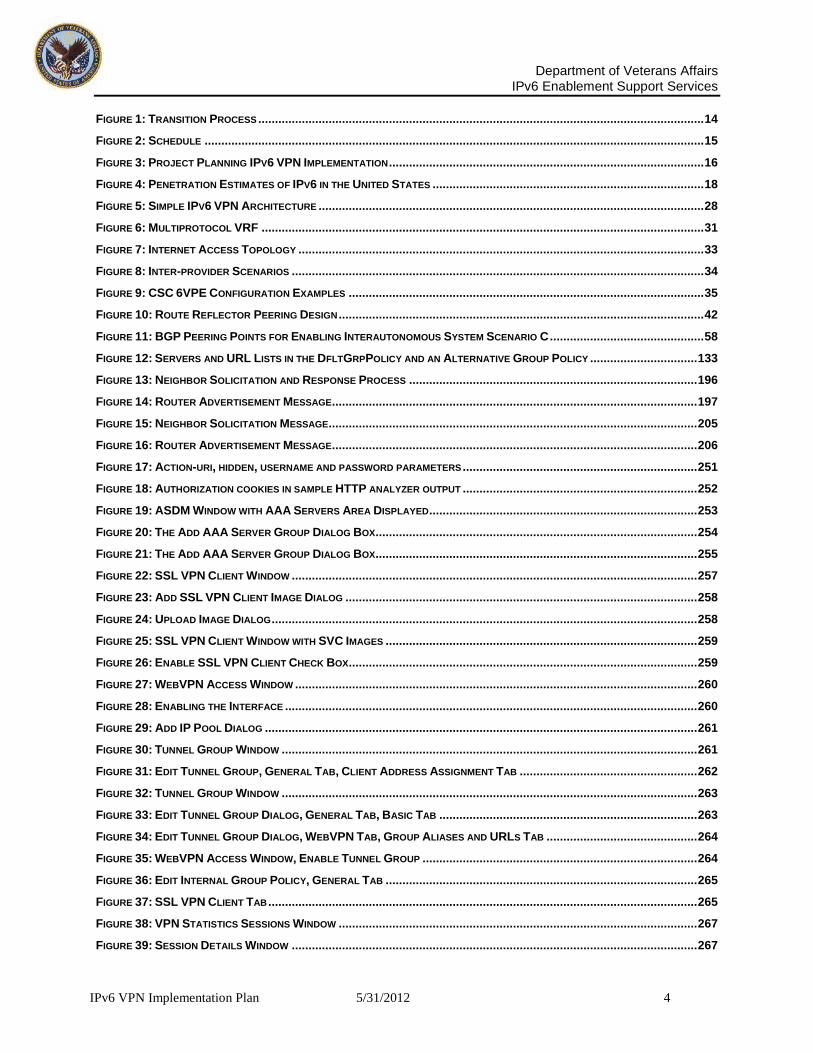
addressed within this document is the ASA 5510 v7.2, ASA 5520 v 8.3, ASA 5580 v8.2, ASA 5540 v7.2 and the ASA 5500 v8.3
The Citrix and Cisco end-user VPN clients appear to support IPv6; however, most VA laptops utilize Windows XP which has limited IPv6 support. Microsoft recommends that VA not attempt to use Windows XP for IPv6 deployments and upgrade to Windows 7, which is on VA’s modernization plan.
Since the RESCUE client was customized in-house, it could not be conclusively determined that it supported IPv6 at this time. Specific testing would be required to determine its ability to support IPv6. However, there is an issue identified that the current RESCUE client may not be compatible with Windows 7 and VA could sunset the Cisco ASA VPN solution and move completely to Citrix.
Many of the latest mobile devices provide some level of IPv6 support in their operating system, including iPads, iPhones and Android devices.
It is likely that the end-user or teleworkers home office will require upgrading their existing wireless router and modem to ensure IPv6 capability. There are several routers and modems on the market now with IPv6 support but a standard should be developed to ensure interoperability and the ability to troubleshoot issues. Replacing these devices should be a limited expense due to the relatively low cost of the devices.
Native IPv6 connectivity to home teleworkers is one of the largest challenges that will be faced. Few home Internet providers have deployed IPv6 and even those that have possess limited deployment. It is likely that a transition technology such as tunneling will be required to establish IPv6 connectivity with teleworkers. This could be accomplished on a wide-scale basis for a relatively low cost by utilizing the existing deployment of tunnel broker networks from carriers such as Hurricane Electric. This would keep performance high and cost low as teleworkers could utilize IPv6 enabled home routers to establish the connection and VA would only see native IPv6 traffic in their gateways. Another option would be through the use of tunnel brokers deployed at VA Internet Gateways in such a way that it would not violate VA security policies.
It should be noted that this was based on the analysis of the elements based on a variety of material including vendor documentation, test lab results, discussion with subject matter experts and other formal and informal sources of information. It is recommended that the finding be confirmed through the use of lab-based testing to ensure the implementation plan deliverable considers all factors for execution.
5 Resource Requirements
5.1 The Project Team
The projected team is the group responsible for planning and executing the project. It consists of a Project Sponsor, the Project Manager and a variable number of Project Team members, both internal and external. These individuals are brought in to deliver their task elements according to the project schedule. VPN team members will come from many areas of the VA network support departments. They can be inside or outside consultants. Some of the roles they will fill on the project are: Engineers, Technical Managers (Leads) and Functional Mangers (Leads), program analysts, functional business analysts, subject matter experts, data delivery specialists, external consultants with in-depth knowledge of the product or process for implementation, testing team, infrastructure experts, middleware support, data administration, etc. It is recommended that an appropriate mix of Cisco professionals be on staff. That staff can consist of the following Cisco Certified Professionals or equivalents: Cisco Certified Network Associate (CCNA)

Department of Veterans Affairs
IPv6 Enablement Support Services
IPv6 VPN Implementation Plan 5/31/2012 11
The CCNA has all the skills and knowledge necessary to install, configure, and operate simple-routed LAN, routed WAN and switched Virtual LAN (VLAN) networks. Understand and configure IP, IGRP, EIGRP, OSPF, serial interfaces, Frame Relay, IP RIP, VLANs, Ethernet, and access lists. Install and/or configure a network. Optimize WAN through Internet-access solutions that reduce bandwidth and WAN costs, using features such as filtering with access lists, bandwidth on demand (BOD), and dial-on-demand routing (DDR). CCNA has hands-on experience in configuring routers and switches. Cisco Certified Network Professional (CCNP) The CCNP has an understanding of routing and internetworking issues and is not limited to Cisco solutions. The CCNP understands complex networks, such as IP, IGRP, IPX, async routing, AppleTalk, extended access lists, IP RIP, route redistribution, IPX RIP, route summarization, OSPF, VLSM, BGP, serial, IGRP, Frame Relay, ISDN, ISL, X.25, DDR, PSTN, PPP, VLANs, Ethernet, ATM LAN emulation, access lists, 802.10, FDDI, and transparent and translational bridging. Is able to Install and/or configure a network to increase bandwidth, attain quicker network response times, and improve reliability and quality of service. Cisco Certified Internetwork Expert (CCIE) The Cisco Certified Internetwork Expert (CCIE). IP and IP routing, optical networking, DSL, dial, cable, wireless, WAN switching, content networking, and voice. The CCIE has an understanding of routing and switching, IP routing, non-IP desktop protocols such as IPX, and bridge- and switch-related technologies. Cisco Certified Design Associate (CCDA) The CCDA can design routed LAN, routed WAN and switched LAN and ATM LANE networks, uses network-layer addressing, filters with access lists and uses and propagates VLANs. Cisco Certified Design Professional (CCDP) The CCDP can design Cisco Network Service Architectures Cisco Certified Security Professional (CCSP) The CCSP provides security proficiency by using Cisco gear, specifically IDS, PIX Firewall, and VPN Concentrators.
5.2 Project Owner
The Executive Sponsor is a manager with demonstrable interest in the outcome of the project and who is ultimately responsible for securing spending authority and resources for the project. Ideally, the Executive Sponsor is the highest-ranking manager possible, in proportion to the project size and scope. The Executive Sponsor acts as a vocal and visible champion, legitimizes the project’s goals and objectives, keeps abreast of major project activities and is the ultimate decision-maker for the VPN implementation project. The Executive Sponsor provides support for the Project Sponsor and/or Project Director and Project Manager has final approval of all scope changes and signs off on approvals to proceed to each succeeding project phase. The Executive Sponsor may elect to delegate some of the above responsibilities to the Project Sponsor and/or Project Director.
The Project Sponsor and/or Project Director is a manager with demonstrable interest in the outcome of the project who is responsible for securing spending authority and resources for the project. The Project Sponsor acts as a vocal and visible champion, legitimizes the project’s goals and objectives, keeps abreast of major project activities, and is a decision-maker for the project. The Project Sponsor will participate in and/or lead project initiation and the development of the Project Charter. He or she will participate in project planning (high level) and the development of the Project Initiation Plan. The Project Sponsor provides support for the Project Manager by assisting with major issues, problems and policy conflicts, removing obstacles and is active in planning the scope; approving scope changes; signing off on major deliverables and signing off on approvals to proceed to each succeeding project phase. The

Department of Veterans Affairs
IPv6 Enablement Support Services
IPv6 VPN Implementation Plan 5/31/2012 12
Project Sponsor generally chairs the steering committee. The Project Sponsor may elect to delegate any of the above responsibilities to other personnel either on or outside of the Project Team
5.3 Stakeholders
Stakeholders are all those groups, units, individuals, or agencies, internal or external to VA, which are impacted by or can impact the outcomes of the project. This includes the project team, sponsors, steering committee, customers, network users and co-workers who will be affected by the implementation and work practices due to the new connectivity and service. This could include customer managers affected by modified workflows or logistics customer correspondents affected by the quantity or quality of newly available information and other similarly affected groups.
Dept of Veterans Affairs OBS
Key Stakeholders are a subset of Stakeholders who, if their support were to be withdrawn, would cause the project to fail.
5.3.1 IPv6 Working Group
An IPv6 Working Group was established and will operate at a minimum until the completion of the network backbone transition from IPv4 to IPv6. The IPv6 Working Group is comprised of all VA IPv6 leads and other subject matter experts (as determined and requested by the membership of the group). The IPv6 Working Group will also charter sub-working groups focusing on several functional areas relevant to Federal government IPv6 transition as necessary. Some of the functional areas include (but are not limited to):

Department of Veterans Affairs
IPv6 Enablement Support Services
IPv6 VPN Implementation Plan 5/31/2012 13
Standards
Cyber security
Testing
Address Allocation and Management
Acquisition The IPv6 Working Group Chair is responsible for communicating directly with VA IPv6 leads regarding membership and will facilitate all meetings of the Working Group. The Chair is responsible for regularly reporting status to OMB. The Group is responsible for developing and documenting plans such as a charter, mission, vision, goals, action plan, etc. The IPv6 VA leads are also responsible for communicating IPv6 requirements to the VA and serve as a primary IPv6 point of contact for the VA.
5.4 External Dependencies
Multiprotocol Label Switching (MPLS) is a mechanism in high-performance networks that direct data from one network node to the next based on short path labels rather than long network addresses avoiding complex lookups in a routing table. The labels identify virtual links (paths) between distant nodes rather than endpoints. MPLS can encapsulate packets of various network protocols. The Border Gateway
Protocol over Multiprotocol Label Switching VPN feature represents an implementation of the provider edge
(PE)-based VPN model. This section describes the IPv6 VPN over MPLS feature. In principle there is no difference between IPv4 VPNs and IPv6 VPNs. In both IPv4 and IPv6 multiprotocol Border Gateway Protocol (BGP) is the centerpiece of the Multiprotocol Label Switching (MPLS) VPN for IPv6 (VPNv6) architecture. It is used to distribute IPv6 routes over the service provider backbone using the same procedures to work with overlapping addresses, redistribution policies, and scalability issues.
5.5 Success Indicators
VA’s Phased Project Schedule for IPv6 VPN Deployment Phase I
Test Lab Build out Establish an IPv6 test network Begin application migration Configure a DNS infrastructure to support AAAA records add dynamic updates Determine if IPv4 hosts are IPv6 infrastructure ready Gate Review and close out of Phase I
Phase II Deploy a tuned IPv6 infrastructure Enroll Digital Certificates Configure Citrix MetaFrame Services Configure Client Update Configure Group Policies Configure LDAP AAA Server Configure Load Balancing Evaluate Mixed Cluster Scenarios Configure Single Sign-on for WebVPN Configure the SSL VPN Client Connect portions of the VA intranet over the IPv6 internet Gate Review and close out of Phase II
PHASE III - Enterprise Implementation
Lessons Learned
Update Implementation Approach
Develop Communications Plan
Enterprise Implementation

Department of Veterans Affairs
IPv6 Enablement Support Services
IPv6 VPN Implementation Plan 5/31/2012 14
Enterprise Implementation Complete Gate Review and close out of Phase III
6 Transition Process
An essential part of this transition is the Layer 3 device upgrade and replacement of End-of-Life devices that don’t support IPv6. Based on the VPN Assessment document, a few of these devices are currently IPv6 ready. The majority are IPv6 capable and could support IPv6 packets once the IOS version is upgraded. Although the majority of these devices are capable or ready, it does not mean that these devices are able to perform optimally with the day to day VPN traffic load. Therefore, every existing device must be carefully examined and performance tested by simulating traffic loads which closely resemble the actual network. If a device is marginally capable (CPU or I/O bound) of handling the traffic load, a long term refresh cycle must be planned. This process is depicted in the Figure below.
Figure 1: Transition Process
Analyze Layer 3 Device
Inventory and for Each
Device:Device
Inventory
Start
Device Need
Memory Upgrade?
Device is
capable of Memory
Upgrade?
End
Device
End of Life?
Device is IPv6 Capable
Upgrade device with
IPv6 IOS
Version (If Required)
Upgrade the device
with sufficient memory
to support IPv6
Yes
Device is IPv6 Ready
Submit Product Test
Request Form (PTRF) for
IPv6 Performance Testing
Performance
Acceptable?
Yes
Start the Technology
Insertion (TI) Process for
Suitable Replacement
No
End
Start the Technology
Insertion (TI) Process for
suitable replacement
End
Yes
Device
IPv6 Ready?
No
End
Submit Product Test
Request Form (PTRF) for
IPv6 Performance Testing
Performance
Acceptable?
Yes
Start the Technology
Insertion (TI) Process for
Suitable Replacement
No
End
Yes
No
No
Upgrade device with
IPv6 IOS
version
Start the Technology
Insertion (TI) Process for
Suitable Replacement
End
No
Yes

Department of Veterans Affairs
IPv6 Enablement Support Services
IPv6 VPN Implementation Plan 5/31/2012 15
6.1 Schedule
Figure 2: Schedule

Department of Veterans Affairs
IPv6 Enablement Support Services
IPv6 VPN Implementation Plan 5/31/2012 16
6.2 WBS
Figure 3: Project Planning IPv6 VPN Implementation
7 Transition Cost Elements
Transition costs will stem from several sources but will likely come from software and hardware, training, application porting, consulting services and operational costs. IPv6 is to be fazed into the VA infrastructure and applications through their lifecycle management processes. VA is expected to acquire IPv6 capability while upgrading infrastructure as part of the normal technology amortization/replacement lifecycle. The availability of transition mechanisms will allow VA to replace only that equipment deemed necessary to facilitate IPv6 integration. As equipment is replaced with newer equipment, native IPv6 capability will be part of the equipment’s basic operating capability. Consequently, the cost of transition from equipment replacement should be significantly minimized.
ID WBS Task Name Work Duration Start Finish
0 0 IPV6 PILOT IMPLEMENTATION PLAN 1,334.88 ... 87.9 days Fri 6/1/12 Tue 10/2/121 1 PHASE I 408.48 hrs 30 days Fri 6/1/12 Thu 7/12/122 1.1 Acceptance Test Planning 40 hrs 5 days Fri 6/1/12 Thu 6/7/123 1.2 Verify & Validate User Requirements 64 hrs 8 days Fri 6/8/12 Tue 6/19/124 1.3 Identify Hardware/Software Requirements 0 hrs 5 days Wed 6/20/12 Tue 6/26/125 1.4 Develop IPv6/IPv4 Dual Stack Configuration Guides 26.4 hrs 5 days Wed 6/27/12 Tue 7/3/126 1.5 Develop Telecommuter Matrixes 31.68 hrs 6 days Wed 6/27/12 Wed 7/4/127 1.6 Configure Test Lab 26.4 hrs 5 days Fri 6/29/12 Thu 7/5/128 1.7 Perform End-to-End IPv6 VPN Connectivity Tests 80 hrs 5 days Fri 7/6/12 Thu 7/12/129 1.8 Report Test Results 64 hrs 4 days Mon 7/9/12 Thu 7/12/12
10 1.9 Develop Lessons Learned/Update Implementation Approach64 hrs 4 days Mon 7/9/12 Thu 7/12/1211 1.10 Develop Mini-Risk Assessment & A&A Documentation 12 hrs 15 days Fri 6/22/12 Thu 7/12/1212 2 PHASE II 478.4 hrs 29.9 days Fri 7/13/12 Thu 8/23/1213 2.1 Enterprise Infrastructure IPv6/IPv4 Dual Stack Pilot Rollout 10.4 hrs 0.65 days Fri 7/13/12 Fri 7/13/1214 2.2 Configuring the Internet Gateway 10.4 hrs 0.65 days Fri 7/13/12 Mon 7/16/1215 2.3 NetScaler Installation and Configuration 10.4 hrs 0.65 days Mon 7/16/12 Mon 7/16/1216 2.4 Parameters Description 10.4 hrs 0.65 days Mon 7/16/12 Tue 7/17/1217 2.5 Configuring Access Control Lists 10.4 hrs 0.65 days Tue 7/17/12 Wed 7/18/1218 2.6 Managing the Citrix NetScaler 10.4 hrs 0.65 days Wed 7/18/12 Wed 7/18/1219 2.7 Implementing IPv6 on NetScaler 10.4 hrs 0.65 days Wed 7/18/12 Thu 7/19/1220 2.8 Customizing VIP IPv6 Addresses 10.4 hrs 0.65 days Thu 7/19/12 Fri 7/20/1221 2.9 Configuring Neighbor Discovery and Router Learning 10.4 hrs 0.65 days Fri 7/20/12 Fri 7/20/1222 2.10 Router Learning 10.4 hrs 0.65 days Fri 7/20/12 Mon 7/23/1223 2.11 Adding IPv6 Support to NetScaler Features 10.4 hrs 0.65 days Mon 7/23/12 Tue 7/24/1224 2.12 VLAN Support 10.4 hrs 0.65 days Tue 7/24/12 Tue 7/24/1225 2.13 Simple Deployment Scenario 10.4 hrs 0.65 days Tue 7/24/12 Wed 7/25/1226 2.14 Transition VPN Tunneling 10.4 hrs 0.65 days Wed 7/25/12 Thu 7/26/1227 2.15 Configuring Citrix MetaFrame Services 10.4 hrs 0.65 days Thu 7/26/12 Thu 7/26/1228 2.16 Overview 10.4 hrs 0.65 days Thu 7/26/12 Fri 7/27/1229 2.17 Enabling WebVPN 10.4 hrs 0.65 days Fri 7/27/12 Mon 7/30/1230 2.18 Configuring Citrix MetaFrame Services and Configuring a Citrix Access Method10.4 hrs 0.65 days Mon 7/30/12 Mon 7/30/1231 2.19 Configuring Group Policies 10.4 hrs 0.65 days Mon 7/30/12 Tue 7/31/1232 2.20 Empty Server Group Message 10.4 hrs 0.65 days Tue 7/31/12 Tue 7/31/1233 2.21 Configuring Tunneling Protocols 10.4 hrs 0.65 days Wed 8/1/12 Wed 8/1/1234 2.22 Configuring Firewall Attributes 10.4 hrs 0.65 days Wed 8/1/12 Thu 8/2/1235 2.23 Configuring Attributes for VPN Hardware Clients 10.4 hrs 0.65 days Thu 8/2/12 Thu 8/2/1236 2.24 Configuring Server and List Arguments Using the WebVPN Other Tab10.4 hrs 0.65 days Thu 8/2/12 Fri 8/3/1237 2.25 Configuring IPv6 Default and Static Routes 10.4 hrs 0.65 days Fri 8/3/12 Mon 8/6/1238 2.26 To show IPv6 mld traffic 10.4 hrs 0.65 days Mon 8/6/12 Mon 8/6/1239 2.27 Enrolling for Digital Certificates 10.4 hrs 0.65 days Mon 8/6/12 Tue 8/7/1240 2.28 Management features: 10.4 hrs 0.65 days Tue 8/7/12 Wed 8/8/1241 2.29 Configuring an LDAP AAA Server 10.4 hrs 0.65 days Wed 8/8/12 Wed 8/8/1242 2.30 Overview of LDAP Transactions 10.4 hrs 0.65 days Wed 8/8/12 Thu 8/9/1243 2.31 Configuring Load Balancing 10.4 hrs 0.65 days Thu 8/9/12 Fri 8/10/1244 2.32 Cisco Unity Connection Cluster Overview 10.4 hrs 0.65 days Fri 8/10/12 Fri 8/10/1245 2.33 Mixed Cluster Options 10.4 hrs 0.65 days Fri 8/10/12 Mon 8/13/1246 2.34 Configuring VPN Session Limits 10.4 hrs 0.65 days Mon 8/13/12 Tue 8/14/1247 2.35 Configuring Single Sign-on for WebVPN 10.4 hrs 0.65 days Tue 8/14/12 Tue 8/14/1248 2.36 Configuring SSO Authentication Using Site Minder 10.4 hrs 0.65 days Tue 8/14/12 Wed 8/15/1249 2.37 Gathering HTTP Form Data 10.4 hrs 0.65 days Wed 8/15/12 Thu 8/16/1250 2.38 Configuring SSO with HTTP Form Protocol 10.4 hrs 0.65 days Thu 8/16/12 Thu 8/16/1251 2.39 Configuring the SSL VPN Client 10.4 hrs 0.65 days Thu 8/16/12 Fri 8/17/1252 2.40 Steps to configure VA Users for LDAP AAA Server 10.4 hrs 0.65 days Fri 8/17/12 Fri 8/17/1253 2.41 End Point User Hardware 10.4 hrs 0.65 days Mon 8/20/12 Mon 8/20/1254 2.42 Telecommuter Matrixes 10.4 hrs 0.65 days Mon 8/20/12 Tue 8/21/1255 2.43 Future VA VPN Considerations 10.4 hrs 0.65 days Tue 8/21/12 Tue 8/21/1256 2.44 Arris Installation Instructions 10.4 hrs 0.65 days Tue 8/21/12 Wed 8/22/1257 2.45 How to set up the Cisco E4200 Linksys series router 10.4 hrs 0.65 days Wed 8/22/12 Thu 8/23/1258 2.46 How to manually set up your Internet connection 10.4 hrs 0.65 days Thu 8/23/12 Thu 8/23/1259 3 PHASE III 448 hrs 28 days Thu 8/23/12 Tue 10/2/1260 3.1 VPN IPV6 CONSIDERATIONS 64 hrs 4 days Thu 8/23/12 Wed 8/29/1261 3.2 CLIENT/SERVER APPLICATION SUPPORT: 64 hrs 4 days Wed 8/29/12 Tue 9/4/1262 3.3 NETWORK EXTENSION: 80 hrs 5 days Tue 9/4/12 Tue 9/11/1263 3.4 ENDPOINT SECURITY: 80 hrs 5 days Tue 9/11/12 Tue 9/18/1264 3.5 CLIENTLESS OPERATION: 80 hrs 5 days Tue 9/18/12 Tue 9/25/1265 3.6 TRANSITION AND NETWORK SECURITY CONSIDERATIONS: 80 hrs 5 days Tue 9/25/12 Tue 10/2/12
'09 '341984 2034
Department of Veterans Affairs
IPv6 Enablement Support Services
IPv6 VPN Implementation Plan 5/31/2012 17
User hardware costs will vary according to user configuration and hardware requirements. It would
be comprised of ISP equipment costs and service enablement costs. Hardware for user connectivity should be in the range of approximately $200 to $300 dollars per user. Professional services may be required and come in the form of installation and configuration assistance and/or help desk support. Training will be an important part of the integration process. VA will potentially need to make plans for training their staff and consider providing helpdesk support for the end point users. The specific cost of training each person will depend upon the role they play in the integration process. Professional services will be another cost of integration. These professional services may come in the form of transition planning assistance, development of a test plan, deployment assistance, and/or help desk support. Regardless of the type of services acquired, professional services are likely to be a component of any VA’s transition costs.
7.1 INDUSTRY RESEARCH RA.1
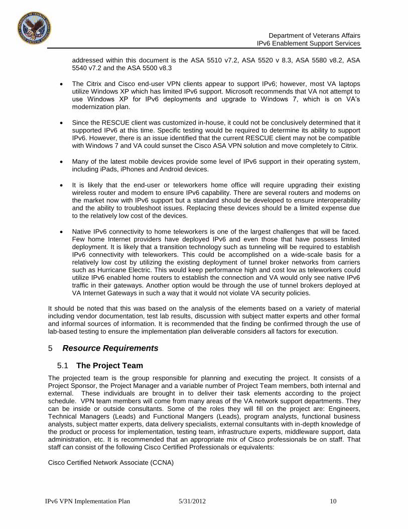
The cost and benefits estimates were developed by RTI through a series of 30 interviews with stakeholders external to VA. Stakeholders included infrastructure vendors, application vendors, Internet service providers (ISPs), and a variety of Internet users (e.g., infrastructure, corporate, government, institutional, and independent/home). In these interviews, RTI asked questions related to the timing of available IPv6 infrastructure components and applications and the likely adoption rates and costs for each stakeholder group. As shown in Table RA-1, interview findings were combined with other information provided through informal discussions and the Department of Commerce (DoC) IPv6 Task Force’s Request for Comment (RFC).
Table RA-1 Informal Discussions, RFC Commenter’s and Interviews
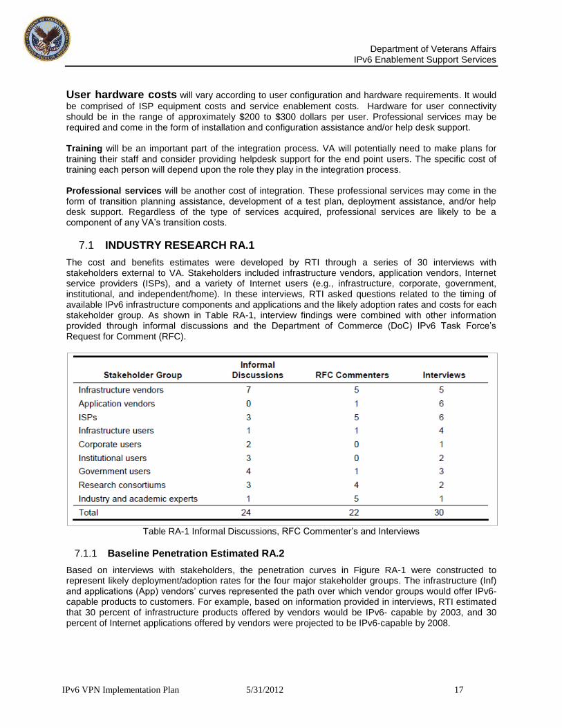
7.1.1 Baseline Penetration Estimated RA.2
Based on interviews with stakeholders, the penetration curves in Figure RA-1 were constructed to represent likely deployment/adoption rates for the four major stakeholder groups. The infrastructure (Inf) and applications (App) vendors’ curves represented the path over which vendor groups would offer IPv6-capable products to customers. For example, based on information provided in interviews, RTI estimated that 30 percent of infrastructure products offered by vendors would be IPv6- capable by 2003, and 30 percent of Internet applications offered by vendors were projected to be IPv6-capable by 2008.

Department of Veterans Affairs
IPv6 Enablement Support Services
IPv6 VPN Implementation Plan 5/31/2012 18
Figure 4: Penetration Estimates of IPv6 in the United States
Percent The ISP curve represents the share of ISPs’ networks that were expected to be IPv6-enabled. As shown in Figure RA-1, on average, RTI estimated that 30 percent of ISPs’ networks would be IPv6-enabled by 2010. Similarly, the users curve represents the share of users’ networks (including infrastructure vendors, application vendors, and ISPs’ internal network users) that were projected to be IPv6-enabled. For example, on average, 30 percent of users’ networks were projected to be IPv6-enable by 2012.
7.1.2 Identify Transition Mechanisms
The objective of this section is to identify the different transition mechanisms and options available to VA while planning its adoption of IPv6 within a VPN environment. These mechanisms are intended to ensure interoperability between IPv4 and IPv6 and can be categorized in the following three broad classes: dual-stack, tunnels, and translation mechanisms. In order to identify the best suited transition mechanisms for VA, it is recommended that the VA have an in-depth up-to-date understanding of its current IT environment. This understanding will help support the best suited transition mechanisms. It is important to note that one size does not fit all. While selecting a mechanism, the key objective should be to reduce the impact on the existing environment. It should also be noted that VA does not have to only use one transition mechanism but can select multiple transition mechanisms as best fits their deployment needs. When selecting a transition mechanism one must consider the functionality required, its scalability characteristic, and the security implications of each mechanism. It is also important to request that IPv6 products comply with the requirements and to monitor CERTS alerts as the introduction of new IPv6 features and software code could lead to vulnerabilities. Also, domain name system (DNS) servers must support IPv6 resource records.
7.1.3 Identify Network Testing Strategy
Before VA deploys IPv6 it is important to test IPv6 for the VPN network. In some cases collaboration for IPv6 testing of implementations will reduce the effort for testing, but VA will need to identify their specific network testing requirements. In addition, VA can work with the industry standards to test their network access and some of the IPv6 features that require wide-area-network testing.

Department of Veterans Affairs
IPv6 Enablement Support Services
IPv6 VPN Implementation Plan 5/31/2012 19
7.1.4 Training Guidelines
The goal of a training strategy is to provide training and ensure that all required participants have the necessary knowledge of the IPv6 protocol by the completion of the transition to native IPv6 protocol. The training strategy is broken down into three different target groups: network IT Specialist training, implementation team training, and general socialization and management training. Complete training will be provided to the IT Specialists, and the implementation team’s SME’s on how the protocol functions and how new technology interacts with various network devices, systems and legacy applications to perform routine jobs. General socialization and management training will cover from introduction to working in IPv6 and ensure a complete understanding of how to use the IPv6 in realistic work environments that allow completion of daily processes. The focus of the training efforts will be to ensure that VA is “ready” to go live. This readiness includes training the right people in the right processes at the right time and educating them with the essential knowledge to do their job well. Training should be aimed at the three major target groups:
a. IT Specialists – Network Engineers b. Implementation Team – Tiger Team SME’s c. General Management
Currently, functional support areas within VA are divided and there may be some areas of overlap. Given the increasing scale and complexity that will characterize the next generation IPv6, it may be beneficial to cross-train the network team members in other disciplines so that, at a minimum, they have a better understanding of those disciplines and potentially can backfill other team members if needed. Standardized relevant training materials are essential to the successful implementation of the IPv6 protocol. Appropriate training infrastructure (training system and training data) and logistics will need to be reviewed and prepared before the specialist training. Requirements of the training infrastructure have been and will be continuously communicated:
d. During the training sessions, connection of the trainers and specialists to the Test network will need to be stable and fast (steps taking longer than 2 minutes will not be tolerated from the specialists perspective).
e. The training location should not be limited to permanent training facilities. Other possible locations include conference rooms, offices and training facilities from third-party companies.
f. It is necessary to provide a risk-free practice environment so that the users can practice in their leisure after they complete the formal classroom training.
g. Post-live training will be required for new hire training
7.1.5 Identify Training Needs
There are a number of factors that will affect the success and duration of the transition process. At the top of that list of factors are: adequate planning, a well developed IT strategy, and training. IPv6, while built on many of the fundamental principles of IPv4, is different enough that most IT personnel will require formalized training. The level of training required will vary and depend upon the role a member of the agency’s IT staff plays in developing, deploying, and supporting IPv6 integration. For the purposes of clarification, three main categories of education are specified: Awareness – This is generalized information about IPv6 and IPv6-related issues. This type of education is most commonly found via workshops, seminars, conferences, and summits. These types of events typically provide an overview of IPv6 technologies, identify vendors that support IPv6, and provide

Department of Veterans Affairs
IPv6 Enablement Support Services
IPv6 VPN Implementation Plan 5/31/2012 20
participants with a rudimentary understanding of the IPv6 technology as well as business drivers, deployment issues, and potential services/products enabled by IPv6. Architectural – Training in this category should be very detailed and oriented toward those individuals who will have primary responsibility for architecting and deploying IPv6. Although the type of subject matter will be quite broad, particular attention should be paid to the fundamentals of IPv6, DNS and DHCPv6, auto-configuration, IPv6 address allocation, transition mechanism, security principles for IPv6 environments, and mobility. Additional topics covered should be routing, multicasting, and principles for connecting to the IPv6 Internet. These topics are the areas where participants will encounter the greatest number of new subjects (relative to IPv4), and will have the greatest impact on the development of successful integration plans. Operational – Once IPv6 has been integrated into the network, it will need to be supported. Operational training should consist mainly of job specific education targeted to a participant’s job responsibilities. Core topics such as the fundamentals of IPv6, auto-configuration, and transition mechanisms should undoubtedly be covered. However, the bulk of operational training should focus on supporting applications or protocols that run over IPv6. One example is training for system administrators focusing on supporting IPv6-enabled e-mail and web servers. Operational training will often be hardware or software specific, generally produced by, or for, a particular vendor product.
7.1.6 Project Assumptions and Dependencies
The exhaustion of IP addresses signals a new urgency in the evolution of electronic communication. In the coming years, the Internet will gradually faze in IPv6. This will usher in the next-generation of electronic communication. IPv6 has an unlimited number of IP addresses which makes room for millions of new users to come online with billions of new devices and web-based applications. The VA IPv6 transformation won’t happen overnight. IPv4 & IPv6 protocols aren’t interchangeable or compatible, so you have to run them both in parallel on networks. A phased in approach is the cost-effective way to move to the next-generation Internet protocol. The smart way to proceed is a phased approach that consists of network assessment, hardware and software inventories, risk assessments, compatibility testing, upgrading where necessary, develop a migration plan, implement, and test.
7.1.7 Transitioning from IPv4 to IPv6
The pilot will implement Microsoft Windows with IPv6/IPv4 capabilities on a VA pilot workstation; implement Microsoft Windows Server 2008 IPv6/IPv4 on a pilot server, and Microsoft Windows Server 2008 applications on pilot servers. The pilot environment will be tested and monitored and the procedures used for the pilot will be reviewed and refined, lessons learned will be documented, connectivity and application tests will be conducted and results captured. Upon completion of the pilot, a phased implementation for each location should be scheduled. All VPN devices will need to be tested prior to the VPN implementation. The Cisco ASA 5500 series offer two types of SSL VPN, a key technology for remote access to VA network resources:
Clientless SSL VPN provides access to Web applications, such as email, and network portals via Web browsers and Java components. It requires no client software.
The Any Connect SSL VPN Client provides direct access to VA network resources, just like an IPSec client.
Using Datagram Transport Layer Security (DTLS), the client improves the performance of real-time applications that are sensitive to packet delays by avoiding latency and bandwidth problems associated with some SSL-only connections. Both clientless and Any Connect client connections use posture assessment policies. You can define these policies to evaluate whether an endpoint is a corporate or public entity with the properly configured operating systems, firewall, antivirus software, and antispyware that you require. The security appliance software includes two SSL VPN licenses, allowing two simultaneous SSL VPN connections of any combination of clientless or client connections. The following

Department of Veterans Affairs
IPv6 Enablement Support Services
IPv6 VPN Implementation Plan 5/31/2012 21
represents the Cisco ASA 5500 series of equipment. Some code versions have known failover challenges.
7.1.8 Notional Costs RA.3
Based on these penetration projections, RTI estimated that the present value of costs for all stakeholder groups to transition to IPv6 will be approximately $25 billion. These costs will primarily occur over the period from 1997 to 2025. As shown in Table RA-2, RTI estimated that users would incur approximately 92 percent of U.S. transition costs, with ISPs and vendors accounting for 0.5 and 8 percent, respectively.
Table RA-2. Summary of Transition Costs from IPv4 to IPv6 (PV) Millions Interviews with stakeholders indicated that hardware and software costs to upgrade to IPv6 will be negligible for the majority of Internet users because IPv6 capabilities will be deployed as part of routine upgrade cycles. Over the next 4 or 5 years, the majority of network hardware, operating systems, and network-enabled software packages (e.g., databases, email) sold will include IPv6 capabilities. As a result, labor costs will constitute the majority of the cost of upgrading to IPv6 for users and training will constitute the majority of these additional labor costs. Training on the fundamentals and implementation of the IPv6 protocol will depend on individual staff’s relative needs based on past experience with IPv4 and potential future applications.
7.1.9 Baseline Benefits RA.4
A general consensus among participating stakeholders exists that IPv6 is technically superior to IPv4; however, there is wide disagreement over the timing, magnitude, and distribution across stakeholder groups of potential benefits. Many of the benefits that were mentioned in interviews hinge on removing and/or changing the management of middle boxes, such as Network Address Translation (NAT) devices and firewalls because they currently disrupt certain types of end-to-end (E2E) communications. Additionally, other potential IPv6 benefits, such as improved security and new quality of service (QoS) capabilities, will likely not be realized without major changes to Internet security models being used today and considerable research and testing in other areas. Because of the speculative nature of future IPv6 benefits, it is difficult to estimate future benefits in dollars. Increased security is a frequently mentioned benefit associated with IPv6. However, the magnitude of security benefits is conditional on removing deployment barriers for existing infra-technologies, such as PKI, and developing other infra-technologies such as end-to-end (E2E) security models. Stakeholders’ hypothesized impacts to provide insights into the potential magnitude of IPv6 benefits. As shown in Table RA-3, benefits are grouped into four general categories. Near-term benefits include increased use of Voice over IP (VoIP) and new mobile data services. Long-term benefits potentially include increased Internet security and efficiency gains from removing NATs.

Department of Veterans Affairs
IPv6 Enablement Support Services
IPv6 VPN Implementation Plan 5/31/2012 22
7.1.9.1 Table RA-3. Several Benefit/Application Categories
Notes 1 “Enabled” means that some portion of internal networking infrastructure hardware and software (e.g., routers, servers, and operating systems) is able to send and receive IPv6 messages (as opposed to being IPv6 “capable,” which means the functionality is included within the hardware and software but is not “turned on.”) 2 This figure is based on information provided by stakeholders participating in interviews conducted by RTI. 6 Interview participants indicated that adoption of IPv6 by most stakeholders would be distributed over the next 20 years, and many costs have already been borne, back until at least 1997. Each generation of a major Internet standard, such as IP, has a long life time, as evidenced by the fact that IPv4 has been in use for more than 20 years. IPv6 Economic Impact Assessment
3 End-to-end (E2E) implies that the transmission can be implemented based solely on the knowledge of the applications at the end points of the communications system. 4 In order for many of the potential benefits of IPv6 to be realized, NAT devices will likely need to be removed in a significant portion of the current Internet infrastructure. The cost of removing NATs will be potentially large due to redesigning and restructuring network connecting hosts, changing firewalls and established security procedures, and learning to function without a network component which has been in place in networks for almost a decade.
Department of Veterans Affairs
IPv6 Enablement Support Services
IPv6 VPN Implementation Plan 5/31/2012 23
8 IPv6 VPN Implementation Overview
8.1 Phase I
Planning and testing should take approximately 30 days based on the utilization of two individuals, one with a mix of design level experience and the other individual focused on enablement. The objective of the test lab is to setup and develop gateway implementation and testing guides help develop technologies and deployment scenarios as well as to provide a comprehensive configuration walkthrough that can be tested exclusively in a lab environment. The test lab provides a set of server and client computers that define standard names, IP addresses and network configuration settings. The optional lab modules extend the base guide to demonstrate common deployment scenarios whose processes can be documented and proven functional for the production environment. It develops load balancing strategy and array configuration with a simulated Internet, intranet, and home network
8.2 Phase II
Duration, approximately 30 days based on the utilization of at least one individual with design level experience but with both individuals focused on enablement. This phase enables direct access to the new features in the production environment. It begins to touch systems that enable remote users to securely access the intranet and shared folders in the production environment but on a limited basis. This phase enables connectivity to the virtual private network (VPN). This level of access extends the benefits of the enterprise across the infrastructure by enhancing availability and scalability, as well as starting the deployment and testing the ongoing management.
8.3 Phase III
Duration, approximately 28 days based on the utilization of at least one individual with design level experience with both individuals focused on enablement. Finally, VA will incur operational costs as they begin making their network backbone IPv6-ready so as to be positioned to leverage the benefits of IPv6. This phase fully enables remote users to securely access intranet shared folders, web sites, and applications by connecting to the virtual private network (VPN). The access extends the benefits of VA across the infrastructure by enhancing availability and scalability, as well as simplifying deployments and ongoing management. This phase also perfects and documents the step-by-step instructions for extending the test lab processes into the enterprise.
8.4 Equipment Configuration Requirements
IPv6 is an enterprise transformation driven by business, environmental, and technology factors, the scope and impact of which extend well beyond the IT organization. Since IPv6 has the potential to impact VA decisions about business performance, business processes, information, technology infrastructure, security and other strategic initiatives, IPv6 should be incorporated within the VA’s strategic planning and enterprise architecture (EA) development activities.
8.5 VA Responsibilities
To appropriately address the requirements in OMB Memorandum 05-22, related to VA enterprise architecture submissions to OMB in February 2006, VA should: Incorporate IPv6 into their IRM Strategic Plan, update their enterprise architecture, including:
The baseline architecture
The target architecture
The transition strategy
Other enterprise architecture documentation, as necessary
Complete their IPv6 transition plan
Complete their IPv6 progress report.
Department of Veterans Affairs
IPv6 Enablement Support Services
IPv6 VPN Implementation Plan 5/31/2012 24
For the scorecard, VA is required to provide enterprise architecture submissions. For other, non-scorecard related considerations; OMB will be looking at VA’s IPv6 Transition Plan and IPv6 Progress Report. Additionally, though VA is not required to submit enterprise architecture plans, they can still benefit from the guidance provided by developing the plan. VA should create a cross-functional team to support IPv6 transition planning and implementation, including representatives from VA lines of business, infrastructure, application development, security, enterprise architecture, capital planning, and procurement. The IPv6 team should remain actively engaged with VA leadership through all phases of the transformation effort.
8.5.1 Updating the Enterprise Architecture
VA is required to have three primary elements within their enterprise architectures: a baseline (as-is) architecture, a target (to-be) architecture, and a transition strategy that defines the process of migrating from the baseline to the target architecture. IPv6 should be incorporated into each of these perspectives of the VA enterprise architecture. The baseline architecture should include IT assets affected by the IPv6 transition as per the IP device and technology inventories required by OMB Memorandum 05-22. The target architecture should reflect not only the impact on VA networking components, but should also reflect the impact of IPv6 on other architectural views such as Business, Strategy and Performance, Data, Service Component, Technology, Security and Privacy. The VA’s IPv6 transition plan should be consistent with the EA transition strategy. OMB Memorandum 05-22 requires VA to perform an inventory of their existing IT infrastructure to determine which assets will be affected by the transition of the network backbone to IPv6. The initial inventory must list networking hardware within the backbone. The second inventory is much broader and should include not only networking hardware, but applications, operating systems, and other devices impacted by the transition of the network backbone to IPv6. VA should utilize the inventory data to update the current technology and service component views of their baseline architecture, specifically: The Service Component architectural view should be updated to incorporate IP dependency information for VA IT assets. Assets which depend on IP (but are not IPv6 compliant) can be identified directly from the architecture and prioritized accordingly within the VA’s capital planning activities. The Technology architectural view should be updated to reflect which technology assets within the VA either provide or require IP services and whether those assets such as routers and servers, are capable of being upgraded to support IPv6.
9 IPv6 Pilot Implementation Plan
9.1 Phase I
ASA Configuration Guide Instructions This section illustrates an overview of the process of configuring SSL VPN features and capabilities of the ASA 5500 series Adaptive Security Appliance, and the Citrix Netscaler The Cisco ASA 5500 offers two types of SSL VPN, a key technology for remote access to VA resources:
Clientless SSL VPN provides access to Web applications, such as email, and corporate portals via Web browsers and Java components. It requires no client software.
The Any Connect SSL VPN Client provides direct access to VA resources, just like an IPSec client. Using Datagram Transport Layer Security (DTLS), the client improves the performance of real-time applications that are sensitive to packet delays by avoiding latency and bandwidth problems associated with some SSL-only connections.

Department of Veterans Affairs
IPv6 Enablement Support Services
IPv6 VPN Implementation Plan 5/31/2012 25
Both clientless and Any Connect client connections use posture assessment policies. These policies can be defined to evaluate whether an endpoint is a VA or public entity with the properly configured operating systems, firewall, antivirus software, and antispyware that is required. The security appliance software includes two SSL VPN licenses, allowing two simultaneous SSL VPN connections of any combination of clientless or client connections. Additional Information This section develops configuration tasks for Dynamic Access Policies (DAP)—a powerful tool for controlling access to corporate resources regardless of the location or security posture of the end user device. http://www.cisco.com/en/US/products/ps6120/products_white_paper09186a00809fcf38.shtml http://www.cisco.com/en/US/docs/security/asa/asa80/configuration/guide/extsvr.html http://www.cisco.com/en/US/products/ps6121/products_installation_and_configuration_guides_list.html
9.1.1 Acceptance Test Planning
Finalizing VA IPv6/IPv4 Dual Stack rollout and IPv6/IPv4 Dual Stack Pilot, IPv6/IPv6 Dual Stack rollout schedule and creating the VA IPv6/IPv4 Dual Stack Test and Acceptance Plans are the next steps in the process. The acceptance test plan will identify specific tests and criteria for IPv6/IPv4 connectivity and application tests are working properly in the new configuration. IPv6/IPv4 Dual Stack Configuration Guides Configuration guidelines and instructions for implementing the new operating systems will need to be documented. Build guides for Microsoft Windows 7, Windows Server 2008, and Windows Server 2008 Applications using Ipv6/IPv4 will be the deliverable of this task. Network Services Configuration Guides for DNS and DHCPv6 will also need to be created and configuration settings documented. Procedures for configuring, installing and deploying IPv6/IPv4 dual stack configurations for applications, databases and services utilizing Solaris and Linux servers need to be prepared during this step.
9.2 Phase II
9.2.1 Enterprise Infrastructure IPv6/IPv4 Dual Stack Pilot Rollout
In preparation of the IPv6/IPv4 dual stack pilot, a series of activities will need to be accomplished prior to the pilot in order to support the IPv6 pilot devices and secure the environment. The first step will be to enable IPv6/IPv4 Dual Stack capabilities on VA Security Devices. The process will include enabling IPv6 on VA Firewalls, enabling IPv6 capabilities on VA security devices, and establishing monitoring and incident response procedures for IPv6 traffic.
9.2.1.1 IPv6/IPv4 Dual Stack Pilot on VA Routers and Switches
Although all VA routers and switches were replaced or upgraded to support the IPv6 protocol, all of the devices have not been configured to run the protocol. VA routers will need to be reconfigured to enable IPv6/IPv4 Dual Stack capabilities. VA routers and switches that need to be configured to run the protocol and IPv6 routing needs to be enabled on edge routers and internal routers to enable IPv6 traffic to communicate throughout the initial pilot locations and ultimately throughout the VA.
9.2.1.2 IPv6/IPv4 Dual Stack Implementation Pilot VA Headquarters
The introduction of new technology within the VA environment is typically piloted on select devices within the Office of the Chief Information Officer. The pilot will require the upgrading of Windows IPv6/IPv4 on VA pilot workstations, the implementation of Windows Server 2008 IPv6/IPv4 on VA pilot servers, and the implementation of Windows Server 2008 Applications Ipv6/IPv4 VA on pilot systems. During the pilot, the environment will need to be tested and monitored using the Acceptance Plan test cases and criteria. Procedures and configurations for the pilot will need to be reviewed and refined and the guides used for

Department of Veterans Affairs
IPv6 Enablement Support Services
IPv6 VPN Implementation Plan 5/31/2012 26
the pilot will need to be updated to capture deviations from the initial baseline configurations and to document lessons learned. Once configurations are final and the environment stabilizes, the VA IPv6/IPv4 Dual Stack Application tests will be conducted in order to validate the pilot and enable management to approve moving forward with the rollout.
9.2.1.3 Enterprise Infrastructure IPv6 Dual/ Stack Rollout
The next step of the VA IPv6/IPv4 Dual Stack Implementation will be for the VA Headquarters workstations, servers, devices and user community. Microsoft Windows 7 desktops configured with an IPv6/IPv4 configuration will be systematically rolled out to all VA HQ workstations. Microsoft Windows Server 2008 configured with an IPv6/IPv4 stack will be rolled out to all VA HQ servers and specific application servers will implement Microsoft Windows Server 2008 as well. It is understood that not all server applications will be migrated and that some applications will be replaced by newer products during this phase of the project and other applications will begin to be fazed out over time and will remain in their current state.
9.2.1.4 IPv6/IPv4 Dual Stack Implementation Regional Office Pilot
Upon completion of the VA Headquarters environment, the focus of the technology upgrade will shift to the Regions, District Offices and Service Centers. Pilot sites will be designated and the implementation of Microsoft Windows 7 IPv6/IPv4 and Microsoft Windows Server 2008 will begin. Where required, Microsoft Windows Server 2008 Applications will be updated and replace existing capabilities. Upon successful completion of the pilot, the remaining offices will be scheduled based on Region.
9.2.1.5 IPv6/IPv4 Dual Stack Regional Office Implementation
Implement Windows 7 IPv6/IPv4 on VA District Office workstations, implement Windows Server 2008 IPv6/IPv4 on VA District Office servers, and implement Windows Server 2008 Application Ipv6/IPv4 VA District Office servers in the following locations:
9.2.1.6 Key Equipment Configuration Requirements
9.2.1.6.1 Basic IPv6 VPN over MPLS Functionality IPv6 VPN takes advantage of the coexistence between IPv6 and IPv4 by leveraging an existent MPLS IPv4 core network. This approach is called 6VPE. The following sections describe concepts for basic IPv6 MPLS VPN functionality: Prerequisites for Implementing IPv6 VPN over MPLS
The VA network must be running IPv6 compatible Cisco IOS services before you configure IPv6 VPN operation:
MPLS in provider backbone routers
MPLS with VPN code in provider routers with VPN PE routers
BGP in all routers providing a VPN service
Cisco Express forwarding switching in every MPLS-enabled router
Class of Service (CoS) feature
9.2.1.7 Restrictions for Implementing IPv6 VPN over MPLS
6VPE supports an MPLS IPv4-signaled core. An MPLS IPv6-signaled core is not supported.
9.2.1.8 Information about Implementing IPv6 VPN over MPLS
This section provides information about implementing IPv6 VPN over MPLS.

Department of Veterans Affairs
IPv6 Enablement Support Services
IPv6 VPN Implementation Plan 5/31/2012 27
IPv6 VPN over MPLS Overview
Addressing Considerations for IPv6 VPN over MPLS
Basic IPv6 VPN over MPLS Functionality
Advanced IPv6 MPLS VPN Functionality
BGP IPv6 PIC Edge for IP MPLS
9.2.1.9 IPv6 VPN over MPLS Overview
Multiprotocol BGP is the centerpiece of the MPLS IPv6 VPN architecture in both IPv4 and IPv6. It is used to distribute IPv6 routes over the service provider backbone, using the same procedures to work with overlapping addresses, redistribution policies, and scalability issues.
Although IPv6 should not have overlapping address space, IPv6 addresses are prepended with a route distinguisher (RD). A network layer reach-ability information (NLRI) 3-tuple format (which contains length, IPv6 prefix, and label) is defined to distribute these routes using multiprotocol BGP. The extended community attributes—the route target—is used to control redistribution of routing information by tagging exported routes and filtering imported ones.
For scalability, route reflectors can be used to concentrate routing paths and avoid a full PE mesh. BGP features in IPv6, such as route refresh, automatic route filtering, and outbound route filtering, help reduce the number of routes held in each PE. This document focuses on the following differences between IPv6 and IPv4:
Creation of a new multiprotocol BGP IPv6 VPN address family and specification of an IPv6 VPN address format
Specification of a new IPv6 VPN NLRI
Specification of BGP next-hop encoding when the router has an IPv4-based MPLS core
Some IPv6 VPN features, such as inter-provider and Carrier Supporting Carrier (CSC) topologies, are specific to BGP-MPLS IPv6 VPN. For instance, the link between Autonomous System Boundary Routers (ASBRs) might support IPv4 only, IPv6 only, or both independently of the address family being transported.
9.2.1.10 Addressing Considerations for IPv6 VPN over MPLS
Regardless of the VPN model deployed (such as customer edge [CE]-based, PE-based, etc.), an addressing plan must be defined for the VPN that allows hosts to communicate with other sites using one site within one VPN and with public resources.
VPN IPv4 sites often use private addressing for their addressing plan. These addresses need not be registered and they are not routable on the public network. Whenever a host within a private site needs to access a public domain, it goes through a device that finds a public address on its behalf. With IPv4, this can be a network address translator or an application proxy.
Given the larger address space available with IPv6, the easiest approach to IPv6 addressing is to use IPv6 global addresses for the private addressing plan. Another approach is to use unique local addresses (ULAs). ULAs are easy to filter at site boundaries based on their scope. ULAs are also Internet service provider (ISP)-independent and can be used for communications inside a site without any permanent or intermittent Internet connectivity.

Department of Veterans Affairs
IPv6 Enablement Support Services
IPv6 VPN Implementation Plan 5/31/2012 28
In 6VPE, ULAs are treated as regular global addresses. The router configuration filters ULA prefixes to prevent them from appearing in the public domain. Link-local addresses on the peer will not be announced by BGP (IPv6 or IPv6 VPN) speakers.
A host within a private site that needs to access a public domain can do so through an IPv6 application proxy (such as a web proxy for accessing web pages), which accesses the public resource on the host's behalf with a global routable address, or the host can use a public address of its own. In the latter case, if ULAs have been deployed, the IPv6 host also is configured with a routable global address. A source address selection algorithm is used to select one or the other, based on the destination address.
9.2.1.11 IPv6 VPN over MPLS Functionality
IPv6 VPN takes advantage of the coexistence between IPv6 and IPv4 by leveraging an existent MPLS IPv4 core network. This approach is called 6VPE. The following sections describe concepts for basic IPv6 MPLS VPN functionality:
9.2.1.12 IPv6 VPN Architecture Overview
Figure 1 illustrates the important aspects of the IPv6 VPN architecture.
Figure 5: Simple IPv6 VPN Architecture
The CE routers are connected to the provider's backbone using PE routers. The PE routers are connected using provider (P1 and P2 in Figure 6.1.8a) routers. The provider (P) routers are unaware of VPN routes, and, in the case of 6VPE, may support only IPv4. Only PE routers perform VPN-specific tasks. For 6VPE, the PE routers are dual-stack (IPv4 and IPv6) routers.
The routing component of the VPN operation is divided into core routing and edge routing. Core routing, which involves PE routers and P routers, typically is performed by an IPv4 Interior Gateway Protocol (IGP) such as Open Shortest Path First (OSPF) or Intermediate System-to-Intermediate System (IS-IS). In Figure 1, the IGP distributes only routes internal to the provider's autonomous system. The core routing enables connectivity among P and PE routers.
Edge routing takes place in two directions: routing between PE pairs and routing between a PE and a CE. Routing between PE pairs is achieved using multiprotocol internal BGP (iBGP) using the IPv6 VPN address family. This method distributes routes learned from CEs through PE-CE routing, using appropriate route export policies at the ingress PE router and appropriate route import policies at the egress PE router.
Department of Veterans Affairs
IPv6 Enablement Support Services
IPv6 VPN Implementation Plan 5/31/2012 29
Routing between the CE and its PE is achieved using a routing protocol that is VPN routing and forwarding (VRF) aware. Static routes, external BGP (eBGP), and Enhanced Interior Gateway Routing Protocol (EIGRP) are VRF instance aware. In Figure 6.1.8a, eBGP is used between the CE (CE1) and the PE (PE1). At the same time, the CE runs an IPv6 IGP (such as OSPFv3 or IS-IS for IPv6) within the VPN site (site1 in Figure 6.1.8a). The CE redistributes IGP routes into multiprotocol-eBGP address family IPv6. At the PE, these routes are installed in the VRF named vrf1, and forwarded to the remote PEs (PE2 in Figure 6.1.8a), according to export policies defined for this VRF.
9.2.1.13 IPv6 VPN Next Hop
When the router announces a prefix using the MP_REACH_NLRI attribute, MP-BGP running on one PE inserts a BGP next hop in the update message sent to a remote PE. This next hop is either propagated from the received update (for instance, if the PE is a route reflector), or it is the address of the PE sending the update message (the egress PE).
For the IPv6 VPN address family, the next hop must be an IPv6 VPN address, regardless of the nature of the network between the PE speakers. Because the RD has no significance (the address is not part of any VPN), it is set to 0. If the provider network is a native IPv6 network, the remaining part of the next hop is the IPv6 address of the egress PE. Otherwise, it is an IPv4 address used as an IPv6-mapped address (for example, ::FFFF:IPv4-address).
See the "Example: IPv6 VPN Configuration Using IPv4 Next Hop" section for an example of IPv6 VPN next-hop configuration.
9.2.1.14 MPLS Forwarding
Virtual Routing and Forwarding is a technology implemented in the IP network routers that allows multiple instances of a routing table to exist on the same router in the same time. Since each VRF is independent, the same IP subnet can exist in 2 different VRFs, basically you can overlap one IP address in 2 VRFs but without conflicting with each other. Even this is possible; I would not suggest doing so, unless you have a very good reason to do it. VRF is VPN Routing and Forwarding which is a key element in Cisco’s MPLS (Multiprotocol Label Switching) VPN technology. Internet service providers often take advantage of VRF to create separate virtual private networks (VPNs) for customers. Some advantages of using this technology is that VA can provision scalable IP MPLS VPN services, generate reports (e.g. audit for services), Service Level Agreements (SLA) contracts and more… To summarize, virtual networks enable administrators to split a physical link into multiple virtual links completely isolated one from the others. Typically, a virtual network will be dedicated to traffic from a specific application or from specific users / customers. VRF is primarily used in the MPLS VPN environment, due to the fact that granularity is important and VRF help network engineers to isolate and provide security for its users or to separate services on the VA intranet. MPLS functionality is based on (P) provider routers, or (PE) provider edge routers or (CE) customer edge routers. Each of these routers must be configured in order for MPLS to work within the VA enterprise architecture. This document also touches on the MPLS technology, so as to better illustrate the topology presented: One PE router can hold and manage multiple virtual routing tables, one for each user if necessary. In the VA’s private Intranet, there is use of MPLS VPN to separate some services. The basic functionality is the same. The actual configuration of VRF is not too complicated. There are two main components to a VRF: The route distinguisher (RD) and the route target (RT)

Department of Veterans Affairs
IPv6 Enablement Support Services
IPv6 VPN Implementation Plan 5/31/2012 30
The route distinguisher (RD) is a number which help identify a VPN in a provider’s network and allow for overlapping IP space. The route target (RT) indicates the VPN membership of a route and allows VPN routes to be imported or exported into or out of your VRF’s. The RT functions like a routing policy; it determines how routes are distributed throughout the particular VPN. The (RD) / (RT) are 8-byte (64-bit) number which can be written down as follows: -16-bit AS number: your 32-bit number (e.g.) 65000:100 Or -32 –bit IP address: your 16-bit number (e.g.) xxx.xxx.xxx.x:10 Usually the first method is used most often. For some very basic VRF configuration follow these steps: Enter VRF configuration mode and assign a VRF name. Router(config)#ipvrfvrf-name Creates a VPN route distinguisher (RD) following one of the 16bit-ASN:32bit-number or 32bit IP:16bit-number Router(config-vrf)#route-distinguisher Creates a list of import and or export route target communities for the specified VRF. Router(config-vrf)#route-target {import| export | both} route-distinguisher (Optional Step) Associates the specified route map with the VRF. Router(config-vrf)# import map route-map Specifies an interface and enters interface configuration mode. Router(config)#interface type number Associates a VRF with an interface or sub-interface. Router(config-vrf)#ip vrfforwarding vrf-name To check your configuration, you can use ping or traceroute tools, but remember to use “vrf vrf-name” parameter: Router# pingvrf vrf-name IP-address You can also check the virtual routing table: Router# show ip route vrf vrf-name Implementing VRF functionality can help develop more granularity in the connection and it makes troubleshooting easier, particularly where there are a lot of IP addresses under management.
Upon receiving IPv6 traffic from one customer site, the ingress PE router uses MPLS to tunnel IPv6 VPN packets over the backbone toward the egress PE router identified as the BGP next hop. The ingress PE router typically prepends the IPv6 packets with the outer and inner labels before putting the packet on the egress interface.
Under normal operation, a P router along the forwarding path does not look inside the frame beyond the first label. The P router either swaps the incoming label with an outgoing one, or removes the incoming label if the next router is a PE router. Removing the incoming label is called penultimate hop popping. The remaining label (BGP label) is used to identify the egress PE interface toward the customer site. It also hides the protocol version (IPv6) from the last P router, which would otherwise need to forward an IPv6 packet.
A P router is ignorant about IPv6 VPN routes. The IPv6 header remains hidden under one or more MPLS labels. When the P router receives an MPLS-encapsulated IPv6 packet that cannot be delivered, it has two options. If the P router is IPv6 aware, it exposes the IPv6 header, builds an Internet Control Message

Department of Veterans Affairs
IPv6 Enablement Support Services
IPv6 VPN Implementation Plan 5/31/2012 31
Protocol (ICMP) for IPv6 message, and sends the message, which is MPLS encapsulated, to the source of the original packet. If the P router is not IPv6 aware, it drops the packet.
9.2.1.15 6VPE over GRE Tunnels
In some Cisco IOS releases, the ingress PE router uses IPv4 generic routing encapsulation (GRE) tunnels combined with 6VPE over MPLS to tunnel IPv6 VPN packets over the backbone toward the egress PE router identified as the BGP next hop.
9.2.1.16 VRF Concepts
A VRF is a virtual routing and forwarding entity that works with a private customer-specific Routing Information Base (RIB) and Forwarding Information Base (FIB). Although IPv4 and IPv6 routing tables are distinct, it is convenient for the two protocols to share the same VRF for a specific customer.
IPv6 VPN customers are likely to be existing VPNv4 customers that are either deploying dual-stack hosts and routers or shadowing some of their IPv4 infrastructure with IPv6 nodes. Several deployment models are possible. Some customers use separate logical interfaces for IPv4 and IPv6 and define separate VRFs on each. Although this approach provides flexibility to configure separate policies for IPv4 and IPv6, it prevents sharing the same policy. Another approach, the multiprotocol VRF, keeps a single VRF on the PE-CE interface, and enables it for IPv4, IPv6, or both. It is then possible to define common or separate policies for each IP version. With this approach, a VRF is better defined as the set of tables, interfaces, and policies found at the PE, and are used by sites of a particular VPN connected to this PE.
Figure 2 illustrates the multiprotocol VRF, in which the VRF named vrf1is enabled for both IPv4 and IPv6 and is associated with two interfaces (IF1, IF2), two sets of tables (IPv4 RIB and FIB and IPv6 RIB and FIB), and a set of common or distinct policies.
For information on how to configure a VRF in IPv6, see the "Configuring a Virtual Routing and Forwarding Instance for IPv6" section.
Figure 6: Multiprotocol VRF

Department of Veterans Affairs
IPv6 Enablement Support Services
IPv6 VPN Implementation Plan 5/31/2012 32
9.2.1.17 IPv6 VPN Scalability
PE-based VPNs such as BGP-MPLS IPv6 VPN scale better than CE-based VPNs. A network designer must consider scaling when designing the network. Scaling a BGP-MPLS IPv6 VPN is similar to scaling a BGP-MPLS IPv4 VPN. The following points need to be considered:
Routing table size, which includes the size of VRF tables and BGP tables
Number of BGP sessions, which grows as a square number of PEs
Routing table size concerns occur with PEs that handles many customer sites. Not only does the PEs have one RIB and FIB per connected customer, but also the PEs' BGP tables, which total all entries from individual VRFs, grow accordingly. Another scalability problem occurs when the number of PEs in the provider network grows beyond a certain level. Assuming that a significant number of sites belonging to the same VPN are spread over many PEs, the number of multiprotocol BGP sessions may rapidly become prohibitive: (n-1) x n/2, where n is the number of PEs.
The following features are included in IPv6 VPN over MPLS:
Route refresh and automatic route filtering—Limits the size of routing tables, because only routes imported into a VRF are kept locally. When the import policy changes, a route refresh can be sent to query a retransmission of routing updates.
Outbound route filtering (ORF)—allows the ingress PE to advertise filters to the egress PE so that updates are not sent unnecessarily over the network.
Route reflectors—Route reflectors (RRs) are iBGP peers that propagate iBGP routes learned from other iBGP peers. RRs are used to concentrate iBGP sessions.
9.2.1.18 Advanced IPv6 MPLS VPN Functionality
Advanced MPLS features such as accessing the Internet from a VPN for IPv4, multiautonomous-system backbones, and CSCs are generally the same for IPv6 as for IPv4. However, there are differences in addressing and in the way 6VPE operates over an IPv4 backbone.
The following sections describe concepts for advanced IPv6 MPLS VPN functionality:
Internet Access
Multiautonomous-System Backbones
Carrier Supporting Carriers
9.2.1.19 Internet Access
Most VPN sites require access to the Internet. RFC 4364 describes a set of models for enabling VPN access to the Internet. All these models apply to IPv6 VPNs as well. In one approach, one interface is used by the CE to connect to the Internet and a different one to connect to the VRF. Another model is in which all Internet routes are redistributed into the VRF. This approach has the disadvantage of requiring the Internet routes to be replicated in each VRF.
In one scenario, a static route is inserted into the VRF table, with a next hop that points to the Internet gateway found in the IPv6 default table. Figure 3 illustrates this scenario, in which Internet access is provided to the customer in the VRF named vrf1.

Department of Veterans Affairs
IPv6 Enablement Support Services
IPv6 VPN Implementation Plan 5/31/2012 33
Figure 7: Internet Access Topology
For a customer site to access public resources over the Internet, this site must be known by a public prefix. Unlike IPv4, IPv6 does not offer a Network Address Translation (NAT) mechanism that allows translating private addresses into public addresses when leaving the site boundaries. Not only does that imply that hosts within the site speak with public addresses, but also that these addresses (or the prefix they belong to) must appear in the public domain.
For outbound traffic, the default route configured in the VRF table at ingress PE (PE1) directs traffic for destinations outside the VPN to the Internet gateway.
For inbound traffic, a route must exist at the Internet gateway to direct the traffic for a customer site via its PE of attachment (PE1 in Figure 3). This route can be distributed by the ingress PE (PE1) using multiprotocol iBGP (with the IPv6 address family configuration), so no specific configuration needs to be done on a per VPN PE basis at the Internet gateway. Nevertheless, for inbound traffic at PE1, a route must exist in the default table for the customer site global prefix pointing to the VRF of the site.
9.2.1.20 Multi-autonomous-System Backbones
The problem of inter-provider VPNs is similar for IPv6 and IPv4, assuming that IPv6 was deployed everywhere IPv4 was deployed.
In IPv6 deployments that cross autonomous system boundaries, providers may have to obtain a peering model, or work with the peering model put in place for VPNv4.

Department of Veterans Affairs
IPv6 Enablement Support Services
IPv6 VPN Implementation Plan 5/31/2012 34
Figure 8: Inter-provider Scenarios
Depending on the network protocol used between ASBRs, the three scenarios shown in Figure 4 can have several implementation options. For instance, scenario B, which suggests a multiprotocol eBGP IPv6 VPN peering between ASBRs, could use either an IPv6 or an IPv4 link.
In scenario C, multihop multiprotocol eBGP redistributes IPv6 VPN routes across route reflectors in different autonomous systems. Labeled IPv4 routes to the PEs (in the 6VPE case) need to be advertised across ASBRs so that a complete labeled switch path is set up end to end.
9.2.1.21 Carrier Supporting Carriers
The CSC feature provides VPN access to a customer service provider, so this service needs to exchange routes and send traffic over the ISP MPLS backbone. The only difference from a regular PE is that it provides MPLS-to-MPLS forwarding on the CSC-CE to CSC-PE interface, rather than IP-to-MPLS forwarding.

Department of Veterans Affairs
IPv6 Enablement Support Services
IPv6 VPN Implementation Plan 5/31/2012 35
Figure 9: CSC 6VPE Configuration Examples
For information on configuring CSC for BGP-MPLS VPN for IPv6, see the "Configuring CSC for IPv6 VPN" section.
9.2.1.22 BGP IPv6 PIC Edge for IP MPLS
The BGP IPv6 PIC Edge for IP MPLS feature improves convergence for both core and edge failures after a network failure. The BGP IPv6 prefix-independent convergence (PIC) edge for IP MPLS feature creates and stores a backup or alternate path in the RIB, FIB, and in Cisco Express Forwarding, so that the backup or alternate path can immediately take over wherever a failure is detected, thus enabling fast failover.
9.2.1.23 How to Implement IPv6 VPN over MPLS
9.2.1.23.1 Configuring a Virtual Routing and Forwarding Instance for IPv6
A VRF is an address family-independent object that can be enabled and configured for each of the supported address families. Configuring a VRF consists of the following three steps:
Configuring the address-family-independent part of the VRF
Enabling and configuring IPv4 for the VRF
Enabling and configuring IPv6 for the VRF
A VRF is given a name and an RD. The RD is configured outside the context of the address family, although the RD is used to distinguish overlapping addresses within the context of a particular BGP address family. Having separate RDs for IPv4 VPN addresses and IPv6 VPN addresses does not matter. On Cisco routers, the RDs are the same in order to simplify configuration and VPN management.
VA Engineers can configure policies in common between IPv4 and IPv6 when not using an address family context. This feature is shared route targets (import and export), and it is useful in a migration scenario, where IPv4 policies already are configured and IPv6 policies should be the same as the IPv4 policies.
The IPv4 and IPv6 address family can each be enabled and configured separately. Note that the route-target policies entered at this level override global policies that may have been specified during address family-independent configuration.
SUMMARY STEPS 1. Enable 2. Configure terminal 3. mls ipv6 vrf
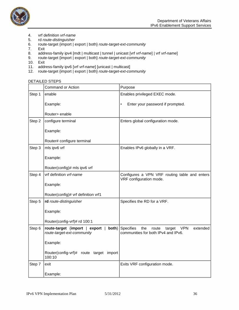
Department of Veterans Affairs
IPv6 Enablement Support Services
IPv6 VPN Implementation Plan 5/31/2012 36
4. vrf definition vrf-name 5. rd route-distinguisher 6. route-target {import | export | both} route-target-ext-community 7. Exit 8. address-family ipv4 [mdt | multicast | tunnel | unicast [vrf vrf-name] | vrf vrf-name] 9. route-target {import | export | both} route-target-ext-community 10. Exit 11. address-family ipv6 [vrf vrf-name] [unicast | multicast] 12. route-target {import | export | both} route-target-ext-community
DETAILED STEPS
Command or Action Purpose
Step 1 enable
Example:
Router> enable
Enables privileged EXEC mode.
• Enter your password if prompted.
Step 2 configure terminal
Example:
Router# configure terminal
Enters global configuration mode.
Step 3 mls ipv6 vrf
Example:
Router(config)# mls ipv6 vrf
Enables IPv6 globally in a VRF.
Step 4 vrf definition vrf-name
Example:
Router(config)# vrf definition vrf1
Configures a VPN VRF routing table and enters VRF configuration mode.
Step 5 rd route-distinguisher
Example:
Router(config-vrf)# rd 100:1
Specifies the RD for a VRF.
Step 6 route-target {import | export | both} route-target-ext-community
Example:
Router(config-vrf)# route target import 100:10
Specifies the route target VPN extended communities for both IPv4 and IPv6.
Step 7 exit
Example:
Exits VRF configuration mode.

Department of Veterans Affairs
IPv6 Enablement Support Services
IPv6 VPN Implementation Plan 5/31/2012 37
Router(config-vrf)# exit
Step 8 address-family ipv4 [mdt | multicast | tunnel | unicast [vrf vrf-name] | vrf vrf-name]
Example:
Router(config)# address-family ipv4
Enters address family configuration mode to configure a routing session using standard IPv4 address prefixes.
Step 9 route-target {import | export | both} route-target-ext-community
Example:
Router(config-vrf-af)# route target import 100:11
Specifies the route target VPN extended communities specific to IPv4.
Step 10
exit
Example:
Router(config-vrf-af)# exit
Exits address family configuration mode on this VRF.
Step 11
address-family ipv6 [vrf vrf-name] [unicast | multicast]
Example:
Router(config-vrf)# address-family ipv6
Enters address family configuration mode for configuring routing sessions such as BGP that use standard IPv6 address prefixes.
Step 12
route-target {import | export | both} route-target-ext-community
Example:
Router(config-vrf-af)# route target import 100:12
Specifies the route target VPN extended communities specific to IPv6.
9.2.1.23.2 Binding a VRF to an Interface
In order to specify which interface belongs to which VRF, use the vrf forwarding command for both IPv4 and IPv6. An interface cannot belong to more than one VRF. When the interface is bound to a VRF, previously configured addresses (IPv4 and IPv6) are removed, and they must be reconfigured.
SUMMARY STEPS 1. Enable 2. Configure terminal 3. Interface type number 4. vrf forwarding vrf-name 5. ip address ip-address mask [secondary] 6. ipv6 address {ipv6-address/prefix-length | prefix-name sub-bits/prefix-length}
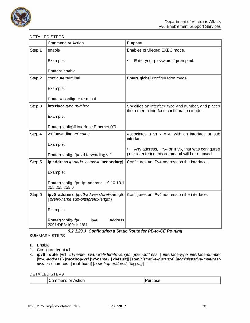
Department of Veterans Affairs
IPv6 Enablement Support Services
IPv6 VPN Implementation Plan 5/31/2012 38
DETAILED STEPS
Command or Action Purpose
Step 1 enable
Example:
Router> enable
Enables privileged EXEC mode.
• Enter your password if prompted.
Step 2 configure terminal
Example:
Router# configure terminal
Enters global configuration mode.
Step 3 interface type number
Example:
Router(config)# interface Ethernet 0/0
Specifies an interface type and number, and places the router in interface configuration mode.
Step 4 vrf forwarding vrf-name
Example:
Router(config-if)# vrf forwarding vrf1
Associates a VPN VRF with an interface or sub interface.
• Any address, IPv4 or IPv6, that was configured prior to entering this command will be removed.
Step 5 ip address ip-address mask [secondary]
Example:
Router(config-if)# ip address 10.10.10.1 255.255.255.0
Configures an IPv4 address on the interface.
Step 6 ipv6 address {ipv6-address/prefix-length | prefix-name sub-bits/prefix-length}
Example:
Router(config-if)# ipv6 address 2001:DB8:100:1::1/64
Configures an IPv6 address on the interface.
9.2.1.23.3 Configuring a Static Route for PE-to-CE Routing SUMMARY STEPS 1. Enable 2. Configure terminal 3. ipv6 route [vrf vrf-name] ipv6-prefix/prefix-length {ipv6-address | interface-type interface-number
[ipv6-address]} [nexthop-vrf [vrf-name1 | default]] [administrative-distance] [administrative-multicast-distance | unicast | multicast] [next-hop-address] [tag tag]
DETAILED STEPS
Command or Action Purpose

Department of Veterans Affairs
IPv6 Enablement Support Services
IPv6 VPN Implementation Plan 5/31/2012 39
Step 1 enable
Example:
Router> enable
Enables privileged EXEC mode.
• Enter your password if prompted.
Step 2 configure terminal
Example:
Router# configure terminal
Enters global configuration mode.
Step 3 ipv6 route [vrf vrf-name] ipv6-prefix/prefix-length {ipv6-address | interface-type interface-number [ipv6-address]} [nexthop-vrf [vrf-name1 | default]] [administrative-distance] [administrative-multicast-distance | unicast | multicast] [next-hop-address] [tag tag]
Example:
Router(config)# ipv6 route vrf vrf1 ::/0 2001:DB8:200::1 nexthop-vrf default
Installs the specified IPv6 static route using the specified next hop.
9.2.1.23.4 Configuring eBGP PE-to-CE Routing Sessions SUMMARY STEPS 1. enable 2. configure terminal 3. router bgp autonomous-system-number 4. address-family ipv6 [vrf vrf-name] [unicast | multicast] 5. neighbor {ip-address | ipv6-address | peer-group-name} remote-as as-number 6. neighbor {ip-address | peer-group-name | ipv6-address} activate
DETAILED STEPS
Command or Action Purpose
Step 1 enable
Example:
Router> enable
Enables privileged EXEC mode.
• Enter your password if prompted.
Step 2 configure terminal
Example:
Router# configure terminal
Enters global configuration mode.
Step 3 router bgp autonomous-system-number
Example:
Router(config)# router bgp 100
Configures the BGP routing process.

Department of Veterans Affairs
IPv6 Enablement Support Services
IPv6 VPN Implementation Plan 5/31/2012 40
Step 4 address-family ipv6 [vrf vrf-name] [unicast | multicast]
Example:
Router(config-router)# address-family ipv6 vrf vrf1
Enters address family configuration mode.
Step 5 neighbor {ip-address | ipv6-address | peer-group-name} remote-as as-number
Example:
Router(config-router-af)# neighbor 2001:DB8:100:1::2 remote-as 200
Adds an entry to the multiprotocol BGP neighbor table.
Step 6 neighbor {ip-address | peer-group-name |ipv6-address} activate
Example:
Router(config-router-af)# neighbor 2001:DB8:100:1::2 activate
Enables the exchange of information for this address family with the specified BGP neighbor.
9.2.1.23.5 Configuring the IPv6 VPN Address Family for iBGP SUMMARY STEPS 1. enable 2. configure terminal 3. router bgp autonomous-system-number 4. neighbor {ip-address | ipv6-address | peer-group-name} remote-as as-number 5. neighbor {ip-address | ipv6-address | peer-group-name} update-source interface-type interface-
number 6. address-family vpnv6 [unicast] 7. neighbor {ip-address | peer-group-name | ipv6-address} activate 8. neighbor {ip-address | ipv6-address | peer-group-name} send-community [both | standard |
extended] 9. exit
DETAILED STEPS
Command or Action Purpose
Step 1 enable
Example:
Router> enable
Enables privileged EXEC mode.
• Enter your password if prompted.
Step 2 configure terminal
Example:
Router# configure terminal
Enters global configuration mode.

Department of Veterans Affairs
IPv6 Enablement Support Services
IPv6 VPN Implementation Plan 5/31/2012 41
Step 3 router bgp autonomous-system-number
Example:
Router(config)# router bgp 100
Configures the BGP routing process.
Step 4 neighbor {ip-address | ipv6-address | peer-group-name} remote-as as-number
Example:
Router(config-router)# neighbor 192.168.2.11 remote-as 100
Adds an entry to the multiprotocol BGP neighbor table.
• In IPv6 VPN, the peer address typically is an IPv4 address, in order to enable the BGP session to be transported over the IPv4-based core network.
Step 5 neighbor {ip-address | ipv6-address | peer-group-name} update-source interface-typeinterface-number
Example:
Router(config-router)# neighbor 192.168.2.11 update-source Loopback 0
Enables the BGP session to use a source address on the specified interface.
Step 6 address-family vpnv6 [unicast]
Example:
Router(config-router)# address-family vpnv6
Places the router in address family configuration mode for configuring routing sessions.
Step 7 neighbor {ip-address | peer-group-name | ipv6-address} activate
Example:
Router(config-router-af)# neighbor 192.168.2.11 activate
Enables the exchange of information for this address family with the specified BGP neighbor.
Step 8 neighbor {ip-address | ipv6-address | peer-group-name} send-community [both | standard | extended]
Example:
Router(config-router-af)# neighbor 192.168.2.11 send-community extended
Specifies that a community’s attribute should be sent to the BGP neighbor.
Step 9 exit
Example:
Router(config-router-af)# exit
Exits address family configuration mode.

Department of Veterans Affairs
IPv6 Enablement Support Services
IPv6 VPN Implementation Plan 5/31/2012 42
9.2.1.23.6 Configuring Route Reflectors for Improved Scalability
In this task, two RRs are configured for redundancy reasons. Deploying RRs improves scalability by drastically reducing the number of BGP sessions. One RR usually peers with many iBGP speakers, preventing a full mesh of BGP sessions.
In an MPLS-based core, RRs are not part of the label switch paths and can be located anywhere in the network. For example, in a flat RR design, RRs can be deployed at Level 1 points of presence (POPs) and peer together in a full-mesh topology. In a hierarchical RR design, RRs could be deployed at Level 1 and Level 2 POPs, with Level 1 POPs peering together and with Level 2 RRs.
In a typical case where 6VPE is deployed in a preexisting MPLS network (for example, providing VPNv4 services), it is likely that some RR design is already in place, and a similar RR infrastructure for IPv6 VPN services can be deployed. Figure 6 illustrates the main peering points between the RR in the ISP POP and the set of its RR clients.
Figure 10: Route Reflector Peering Design
The following list of BGP RR clients must be configured at each IPv6 RR (RR6 and RR6_1 in Figure 6) router, at each POP:
PE routers (PE-VPN) of the POP providing IPv6 VPN access to the ISP customers. This includes both IPv6 VPN (6VPE) peering for interconnecting customer sites and IPv6 peering (6PE) for providing Internet access to VPN customers (see the "Configuring Internet Access" section).
Internet gateway (IGW) located in the POP in order to provide PE customers with access to the IPv6 Internet (see the "Configuring Internet Access" section).
RRs from other service providers. This feature is used to provide interautonomous-system connectivity, and it includes both IPv6 and IPv6 VPN peering. This service is described in the "Configuring a Multiautonomous-System Backbone for IPv6 VPN" section.
RRs in other POPs. All RRs peer together, with both IPv6 and IPv6 VPN address families enabled.

Department of Veterans Affairs
IPv6 Enablement Support Services
IPv6 VPN Implementation Plan 5/31/2012 43
SUMMARY STEPS 1. enable 2. configure terminal 3. router bgp autonomous-system-number 4. neighbor {ip-address | ipv6-address | peer-group-name} remote-as as-number 5. neighbor {ip-address | ipv6-address | peer-group-name} update-source interface-type interface-
number 6. neighbor {ip-address | ipv6-address | peer-group-name} remote-as as-number 7. neighbor {ip-address | ipv6-address | peer-group-name} update-source interface-type interface-
number 8. neighbor {ip-address | ipv6-address | peer-group-name} remote-as as-number 9. neighbor {ip-address | ipv6-address | peer-group-name} update-source interface-type interface-
number 10. neighbor {ip-address | ipv6-address | peer-group-name} remote-as as-number 11. neighbor {ip-address | ipv6-address | peer-group-name} update-source interface-type interface-
number 12. neighbor {ip-address | ipv6-address | peer-group-name} ebgp-multihop [ttl] 13. address-family ipv6 14. neighbor {ip-address | peer-group-name | ipv6-address} activate 15. neighbor {ip-address | ipv6-address | peer-group-name} send-label 16. neighbor {ip-address | ipv6-address | peer-group-name} route-reflector-client 17. neighbor {ip-address | peer-group-name | ipv6-address} activate 18. neighbor {ip-address | ipv6-address | peer-group-name} send-label 19. neighbor {ip-address | ipv6-address | peer-group-name} route-reflector-client 20. neighbor {ip-address | peer-group-name | ipv6-address} activate 21. neighbor {ip-address | ipv6-address | peer-group-name} send-label 22. neighbor {ip-address | ipv6-address | peer-group-name} route-reflector-client 23. exit 24. address-family vpnv6 [unicast] 25. neighbor {ip-address | peer-group-name | ipv6-address} activate 26. neighbor {ip-address | ipv6-address | peer-group-name} send-community [both | standard |
extended] 27. neighbor {ip-address | ipv6-address | peer-group-name} route-reflector-client 28. neighbor {ip-address | peer-group-name | ipv6-address} activate 29. neighbor {ip-address | ipv6-address | peer-group-name} send-community [both | standard |
extended] 30. neighbor {ip-address | ipv6-address | peer-group-name} route-reflector-client 31. neighbor {ip-address | peer-group-name | ipv6-address} activate 32. neighbor {ip-address | ipv6-address | peer-group-name} send-community [both | standard |
extended] 33. neighbor {ip-address | ipv6-address | peer-group-name} route-reflector-client 34. neighbor {ip-address | ipv6-address | peer-group-name} next-hop-unchanged [allpaths]
DETAILED STEPS
Command or Action Purpose
Step 1 enable
Example:
Router> enable
Enables privileged EXEC mode.
• Enter your password if prompted.

Department of Veterans Affairs
IPv6 Enablement Support Services
IPv6 VPN Implementation Plan 5/31/2012 44
Step 2 configure terminal
Example:
Router# configure terminal
Enters global configuration mode.
Step 3 router bgp autonomous-system-number
Example:
Router(config)# router bgp 100
Configures the BGP routing process.
Step 4 neighbor {ip-address | ipv6-address | peer-group-name} remote-as as-number
Example:
Router(config-router)# neighbor 192.168.2.101 remote-as 100
Adds an entry to the multiprotocol BGP neighbor table, and provides peering with the Internet gateway in order to provide Internet access.
Step 5 neighbor {ip-address | ipv6-address | peer-group-name} update-source interface-type interface-number
Example:
Router(config-router)# neighbor 192.168.2.101 update-source Loopback 0
Enables the BGP session to use a source address on the specified interface.
Step 6 neighbor {ip-address | ipv6-address | peer-group-name} remote-as as-number
Example:
Router(config-router)# neighbor 192.168.2.121 remote-as 100
Adds an entry to the multiprotocol BGP neighbor table, and provides peering with the other POP's RR.
Step 7 neighbor {ip-address | ipv6-address | peer-group-name} update-source interface-type interface-number
Example:
Router(config-router)# neighbor 192.168.2.121 update-source Loopback 0
Enables the BGP session to use a source address on the specified interface.
Step 8 neighbor {ip-address | ipv6- Adds an entry to the multiprotocol BGP neighbor table.

Department of Veterans Affairs
IPv6 Enablement Support Services
IPv6 VPN Implementation Plan 5/31/2012 45
address |peer-group-name} remote-as as-number
Example:
Router(config-router)# neighbor 192.168.2.127 remote-as 100
Step 9 neighbor {ip-address | ipv6-address | peer-group-name} update-source interface-type interface-number
Example:
Router(config-router)# neighbor 192.168.2.127 update-source Loopback 0
Enables the BGP session to use a source address on the specified interface.
Step 10 neighbor {ip-address | ipv6-address | peer-group-name} remote-as as-number
Example:
Router(config-router)# neighbor 192.168.2.1 remote-as 200
(Optional) Adds an entry to the multiprotocol BGP neighbor table, and provides peering with the RR of the peer ISP in order to provide inter-VPN service.
Step 11 neighbor {ip-address | ipv6-address | peer-group-name} update-source interface-type interface-number
Example:
Router(config-router)# neighbor 192.168.2.1 update-source Loopback 0
(Optional) Enables the BGP session to use a source address on the specified interface.
Step 12 neighbor {ip-address | ipv6-address | peer-group-name} ebgp-multihop [ttl]
Example:
Router(config-router)# neighbor 192.168.2.1 ebgp-multihop
(Optional) Accepts and attempts BGP connections to external peers residing on networks that are not directly connected.
Step 13 address-family ipv6
Example:
Router(config-router)# address-family ipv6
(Optional) Enters address family configuration mode in order to provide Internet access service.

Department of Veterans Affairs
IPv6 Enablement Support Services
IPv6 VPN Implementation Plan 5/31/2012 46
Step 14 neighbor {ip-address | peer-group-name | ipv6-address} activate
Example:
Router(config-router-af)# neighbor 192.168.2.101 activate
(Optional) Enables the exchange of information for this address family with the specified neighbor.
Step 15 neighbor {ip-address | ipv6-address | peer-group-name} send-label
Example:
Router(config-router-af)# neighbor 192.168.2.101 send-label
(Optional) Enables a BGP router to send MPLS labels with BGP routes to a neighboring BGP router.
Step 16 neighbor {ip-address | ipv6-address | peer-group-name} route-reflector-client
Example:
Router(config-router-af)# neighbor 192.168.2.101 route-reflector-client
(Optional) Configures the router as a BGP route reflector and configures the specified neighbor as its client.
Step 17 neighbor {ip-address | peer-group-name | ipv6-address} activate
Example:
Router(config-router-af)# neighbor 192.168.2.121 activate
(Optional) Enables the exchange of information for this address family with the specified BGP neighbor.
Step 18 neighbor {ip-address | ipv6-address | peer-group-name} send-label
Example:
Router(config-router-af)# neighbor 192.168.2.121 send-label
(Optional) Enables a BGP router to send MPLS labels with BGP routes to a neighboring BGP router.
Step 19 neighbor {ip-address | ipv6-address | peer-group-name} route-reflector-client
Example:
Router(config-router-af)# neighbor 192.168.2.121 route-reflector-client
(Optional) Configures the specified neighbor as a route reflector client.
Step 20 neighbor {ip-address | peer-group- (Optional) Enables the exchange of information for this address family with the specified BGP neighbor.

Department of Veterans Affairs
IPv6 Enablement Support Services
IPv6 VPN Implementation Plan 5/31/2012 47
name | ipv6-address} activate
Example:
Router(config-router-af)# neighbor 192.168.2.127 activate
Step 21 neighbor {ip-address | ipv6-address | peer-group-name} send-label
Example:
Router(config-router-af)# neighbor 192.168.2.127 send-label
(Optional) Enables a BGP router to send MPLS labels with BGP routes to a neighboring BGP router.
Step 22 neighbor {ip-address | ipv6-address | peer-group-name} route-reflector-client
Example:
Router(config-router-af)# neighbor 192.168.2.127 route-reflector-client
(Optional) Configures the specified neighbor as a route reflector client.
Step 23 exit
Example:
Router(config-router-af)# exit
(Optional) Exits address family configuration mode.
Step 24 address-family vpnv6 [unicast]
Example:
Router(config-router)# address-family vpnv6
Places the router in address family configuration mode for configuring routing sessions.
Step 25 neighbor {ip-address | peer-group-name | ipv6-address} activate
Example:
Router(config-router-af)# neighbor 192.168.2.121 activate
Enables the exchange of information for this address family with the specified BGP neighbor.
Step 26 neighbor {ip-address | ipv6-address | peer-group-name} send-community [both | standard | extended]
Example:
Router(config-router-af)# neighbor
Specifies that a community’s attribute should be sent to the BGP neighbor.
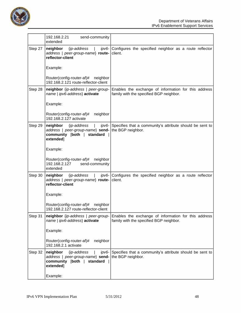
Department of Veterans Affairs
IPv6 Enablement Support Services
IPv6 VPN Implementation Plan 5/31/2012 48
192.168.2.21 send-community extended
Step 27 neighbor {ip-address | ipv6-address | peer-group-name} route-reflector-client
Example:
Router(config-router-af)# neighbor 192.168.2.121 route-reflector-client
Configures the specified neighbor as a route reflector client.
Step 28 neighbor {ip-address | peer-group-name | ipv6-address} activate
Example:
Router(config-router-af)# neighbor 192.168.2.127 activate
Enables the exchange of information for this address family with the specified BGP neighbor.
Step 29 neighbor {ip-address | ipv6-address | peer-group-name} send-community [both | standard | extended]
Example:
Router(config-router-af)# neighbor 192.168.2.127 send-community extended
Specifies that a community’s attribute should be sent to the BGP neighbor.
Step 30 neighbor {ip-address | ipv6-address | peer-group-name} route-reflector-client
Example:
Router(config-router-af)# neighbor 192.168.2.127 route-reflector-client
Configures the specified neighbor as a route reflector client.
Step 31 neighbor {ip-address | peer-group-name | ipv6-address} activate
Example:
Router(config-router-af)# neighbor 192.168.2.1 activate
Enables the exchange of information for this address family with the specified BGP neighbor.
Step 32 neighbor {ip-address | ipv6-address | peer-group-name} send-community [both | standard | extended]
Example:
Specifies that a community’s attribute should be sent to the BGP neighbor.

Department of Veterans Affairs
IPv6 Enablement Support Services
IPv6 VPN Implementation Plan 5/31/2012 49
Router(config-router-af)# neighbor 192.168.2.1 send-community extended
Step 33 neighbor {ip-address | ipv6-address | peer-group-name} route-reflector-client
Example:
Router(config-router-af)# neighbor 192.168.2.1 route-reflector-client
Configures the specified neighbor as a route reflector client.
Step 34 neighbor {ip-address | ipv6-address | peer-group-name} next-hop-unchanged [allpaths]
Example:
Router(config-router-af)# neighbor 192.168.2.1 next-hop-unchanged allpaths
Enables an EBGP multihop peer to propagate to the next hop unchanged for paths.
9.2.1.23.7 Configuring Internet Access
Customers with IPv6 VPN access need to have access to the Internet through IPv6. The design of this service is similar to a global Internet access service. 6VPE routers located in a Level 1 POP (colocated with an IGW router) can access the IGW natively, whereas 6VPE routers located in Level 2 and Level 3 POPs with no direct access to the IGW can access the IGW in their closest Level 1 POP over 6PE.
Configuring VPN Internet access in such a 6VPE router involves configuring BGP peering with the IGW (in most cases through the IPv6 RR, as described in the "Configuring Route Reflectors for Improved Scalability" section). Then the user must configure cross-table routing to enable communication between the private domain (the VRF) and the public domain (the Internet).
Figure 3 illustrates the following configuration tasks:
Configuring the Internet Gateway
Configuring the IPv6 VPN PE
9.2.2 Configuring the Internet Gateway
Configuring iBGP 6PE Peering to the VPN PE
Configuring the Internet Gateway as the Gateway to the Public Domain
Configuring eBGP Peering to the Internet
9.2.2.1.1 Configuring iBGP 6PE Peering to the VPN PE SUMMARY STEPS 1. enable 2. configure terminal 3. router bgp autonomous-system-number

Department of Veterans Affairs
IPv6 Enablement Support Services
IPv6 VPN Implementation Plan 5/31/2012 50
4. neighbor {ip-address | ipv6-address | peer-group-name} remote-as as-number 5. neighbor {ip-address | ipv6-address | peer-group-name} update-source interface-type interface-
number 6. address-family ipv6 7. neighbor {ip-address | peer-group-name | ipv6-address} activate 8. neighbor {ip-address | ipv6-address | peer-group-name} send-label
DETAILED STEPS
Command or Action Purpose
Step 1 enable
Example:
Router> enable
Enables privileged EXEC mode.
• Enter your password if prompted.
Step 2 configure terminal
Example:
Router# configure terminal
Enters global configuration mode.
Step 3 router bgp autonomous-system-number
Example:
Router(config)# router bgp 100
Configures the BGP routing process.
Step 4 neighbor {ip-address | ipv6-address | peer-group-name} remote-as as-number
Example:
Router(config-router)# neighbor 192.168.2.127 remote-as 100
Adds an entry to the multiprotocol BGP neighbor table to provide peering with the VPN PE.
Step 5 neighbor {ip-address | ipv6-address | peer-group-name} update-source interface-type interface-number
Example:
Router(config-router)# neighbor 192.168.2.127 update-source Loopback 0
Enables the BGP session to use a source address on the specified interface.
Step 6 address-family ipv6
Example:
Router(config-router)# address-family ipv6
Enters address family configuration mode in order to exchange global table reach-ability.
Step 7 neighbor {ip-address | peer-group-name Enables the exchange of information for this address family with the specified BGP neighbor.

Department of Veterans Affairs
IPv6 Enablement Support Services
IPv6 VPN Implementation Plan 5/31/2012 51
| ipv6-address} activate
Example:
Router(config-router-af)# neighbor 192.168.2.127 activate
Step 8 neighbor {ip-address | ipv6-address | peer-group-name} send-label
Example:
Router(config-router-af)# neighbor 192.168.2.127 send-label
Enables a BGP router to send MPLS labels with BGP routes to a neighboring BGP router, and allows the PE VPN to reach the Internet gateway over MPLS.
9.2.2.1.2 Configuring the Internet Gateway as the Gateway to the Public Domain
Use the 6PE peering configuration established in the "Configuring iBGP 6PE peering to the VPN PE" section to perform this task.
SUMMARY STEPS 1. enable 2. configure terminal 3. router bgp autonomous-system-number 4. address-family ipv6 5. network ipv6-address/prefix-length
DETAILED STEPS
Command or Action Purpose
Step 1 enable
Example:
Router> enable
Enables privileged EXEC mode.
• Enter your password if prompted.
Step 2 configure terminal
Example:
Router# configure terminal
Enters global configuration mode.
Step 3 router bgp autonomous-system-number
Example:
Router(config)# router bgp 100
Configures the BGP routing process.
Step 4 address-family ipv6
Example:
Router(config-router)# address-family ipv6
Enters address family configuration mode in order to exchange global table reach-ability.

Department of Veterans Affairs
IPv6 Enablement Support Services
IPv6 VPN Implementation Plan 5/31/2012 52
Step 5 network ipv6-address/prefix-length
Example:
Router(config-router-af)# network 2001:DB8:100::1/128
Configures the network source of the next hop to be used by the PE VPN.
9.2.2.1.3 Configuring eBGP Peering to the Internet SUMMARY STEPS 1. enable 2. configure terminal 3. router bgp autonomous-system-number 4. neighbor {ip-address | ipv6-address | peer-group-name} remote-as as-number 5. address-family ipv6 6. neighbor {ip-address | peer-group-name | ipv6-address} activate 7. aggregate-address address mask [as-set] [summary-only] [suppress-map map-name] [advertise-
map map-name] [attribute-map map-name]
DETAILED STEPS
Command or Action Purpose
Step 1 enable
Example:
Router> enable
Enables privileged EXEC mode.
• Enter your password if prompted.
Step 2 configure terminal
Example:
Router# configure terminal
Enters global configuration mode.
Step 3 router bgp autonomous-system-number
Example:
Router(config)# router bgp 100
Configures the BGP routing process.
Step 4 neighbor {ip-address | ipv6-address | peer-group-name} remote-as as-number
Example:
Router(config-router)# neighbor FE80::300::1%Ethernet0/0 remote-as 300
Adds an entry to the multiprotocol BGP neighbor table, and provides peering with PE (PE-VPN).
• The peering is done over link-local addresses.
Step 5 address-family ipv6
Example:
Router(config-router)# address-family ipv6
Enters address family configuration mode in order to exchange global table reach-ability.
Step 6 neighbor {ip-address | peer-group-name | ipv6- Enables the exchange of information for this
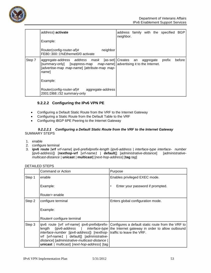
Department of Veterans Affairs
IPv6 Enablement Support Services
IPv6 VPN Implementation Plan 5/31/2012 53
address} activate
Example:
Router(config-router-af)# neighbor FE80::300::1%Ethernet0/0 activate
address family with the specified BGP neighbor.
Step 7 aggregate-address address mask [as-set] [summary-only] [suppress-map map-name] [advertise-map map-name] [attribute-map map-name]
Example:
Router(config-router-af)# aggregate-address 2001:DB8::/32 summary-only
Creates an aggregate prefix before advertising it to the Internet.
9.2.2.2 Configuring the IPv6 VPN PE
Configuring a Default Static Route from the VRF to the Internet Gateway
Configuring a Static Route from the Default Table to the VRF
Configuring iBGP 6PE Peering to the Internet Gateway
9.2.2.2.1 Configuring a Default Static Route from the VRF to the Internet Gateway SUMMARY STEPS 1. enable 2. configure terminal 3. ipv6 route [vrf vrf-name] ipv6-prefix/prefix-length {ipv6-address | interface-type interface- number
[ipv6-address]} [nexthop-vrf [vrf-name1 | default]] [administrative-distance] [administrative-multicast-distance | unicast | multicast] [next-hop-address] [tag tag]
DETAILED STEPS
Command or Action Purpose
Step 1 enable
Example:
Router> enable
Enables privileged EXEC mode.
• Enter your password if prompted.
Step 2 configure terminal
Example:
Router# configure terminal
Enters global configuration mode.
Step 3 ipv6 route [vrf vrf-name] ipv6-prefix/prefix-length {ipv6-address | interface-type interface-number [ipv6-address]} [nexthop-vrf [vrf-name1 | default]] [administrative-distance] [administrative-multicast-distance | unicast | multicast] [next-hop-address] [tag
Configures a default static route from the VRF to the Internet gateway in order to allow outbound traffic to leave the VRF.
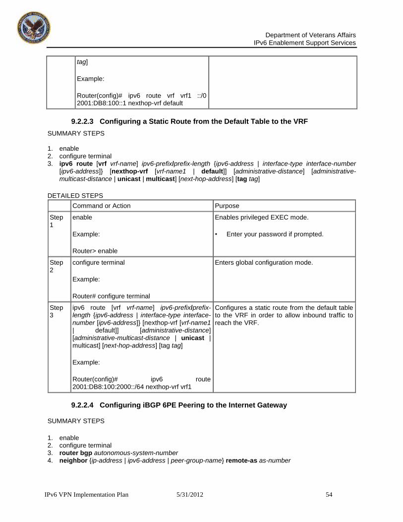
Department of Veterans Affairs
IPv6 Enablement Support Services
IPv6 VPN Implementation Plan 5/31/2012 54
tag]
Example:
Router(config)# ipv6 route vrf vrf1 ::/0 2001:DB8:100::1 nexthop-vrf default
9.2.2.3 Configuring a Static Route from the Default Table to the VRF
SUMMARY STEPS 1. enable 2. configure terminal 3. ipv6 route [vrf vrf-name] ipv6-prefix/prefix-length {ipv6-address | interface-type interface-number
[ipv6-address]} [nexthop-vrf [vrf-name1 | default]] [administrative-distance] [administrative- multicast-distance | unicast | multicast] [next-hop-address] [tag tag]
DETAILED STEPS
Command or Action Purpose
Step 1
enable
Example:
Router> enable
Enables privileged EXEC mode.
• Enter your password if prompted.
Step 2
configure terminal
Example:
Router# configure terminal
Enters global configuration mode.
Step 3
ipv6 route [vrf vrf-name] ipv6-prefix/prefix-length {ipv6-address | interface-type interface-number [ipv6-address]} [nexthop-vrf [vrf-name1 | default]] [administrative-distance] [administrative-multicast-distance | unicast | multicast] [next-hop-address] [tag tag]
Example:
Router(config)# ipv6 route 2001:DB8:100:2000::/64 nexthop-vrf vrf1
Configures a static route from the default table to the VRF in order to allow inbound traffic to reach the VRF.
9.2.2.4 Configuring iBGP 6PE Peering to the Internet Gateway
SUMMARY STEPS
1. enable 2. configure terminal 3. router bgp autonomous-system-number 4. neighbor {ip-address | ipv6-address | peer-group-name} remote-as as-number

Department of Veterans Affairs
IPv6 Enablement Support Services
IPv6 VPN Implementation Plan 5/31/2012 55
5. neighbor {ip-address | ipv6-address | peer-group-name} update-source interface-type interface- number
6. address-family ipv6 [vrf vrf-name] [unicast | multicast] 7. neighbor {ip-address | peer-group-name | ipv6-address} activate 8. neighbor {ip-address | ipv6-address | peer-group-name} send-label 9. network ipv6-address/prefix-length
DETAILED STEPS
Command or Action Purpose
Step 1 enable
Example:
Router> enable
Enables privileged EXEC mode.
• Enter your password if prompted.
Step 2 configure terminal
Example:
Router# configure terminal
Enters global configuration mode.
Step 3 router bgp autonomous-system-number
Example:
Router(config)# router bgp 100
Configures the BGP routing process.
Step 4 neighbor {ip-address | ipv6-address | peer-group-name} remote-as as-number
Example:
Router(config-router)# neighbor 192.168.2.101 remote-as 100
Adds an entry to the multiprotocol BGP neighbor table for peering with the Internet gateway.
Step 5 neighbor {ip-address | ipv6-address | peer-group-name} update-source interface-type interface-number
Example:
Router(config-router)# neighbor 192.168.2.101 update-source Loopback 0
Enables the BGP session to use a source address on the specified interface.
Step 6 address-family ipv6 [vrf vrf-name] [unicast | multicast]
Example:
Router(config-router)# address-family ipv6
Enters address family configuration mode in order to exchange global table reach-ability.
Step 7 neighbor {ip-address | peer-group-name | Enables the exchange of information for this

Department of Veterans Affairs
IPv6 Enablement Support Services
IPv6 VPN Implementation Plan 5/31/2012 56
ipv6-address} activate
Example:
Router(config-router-af)# neighbor 192.168.2.101 activate
address family with the specified BGP neighbor.
Step 8 neighbor {ip-address | ipv6-address | peer-group-name} send-label
Example:
Router(config-router-af)# neighbor 192.168.2.101 send-label
Enables label exchange for this address family to this neighbor in order to enable the VPN PE to reach the Internet gateway over MPLS.
Step 9 network ipv6-address/prefix-length
Example:
Router(config-router-af)# network 2001:DB8:100:2000::/64
Provides the VRF prefix to the Internet gateway.
9.2.2.5 Configuring a Multiautonomous-System Backbone for IPv6 VPN
Two VPN sites may be connected to different autonomous systems because the sites are connected to different service providers. The PE routers attached to that VPN is then unable to maintain iBGP connections with each other or with a common route reflector. In this situation, there must be some way to use eBGP to distribute VPN-IPv6 addresses.
The following configuration example illustrates two scenarios, one in which a multiprotocol eBGP-IPv6 VPN peering between ASBRs uses an IPv4 link, and the same scenario using an IPv6 link. If the peering between ASBRs is performed over an IPv4 link, the BGP configuration on ASBR1 is as follows:
router bgp 1001
no bgp default ipv4-unicast
no bgp default route-target filter
neighbor 192.1.1.1 remote-as 1002
neighbor 192.168.2.11 remote-as 1001
neighbor 192.168.2.11 update-source Loopback1
!
address-family vpnv6
!Peering to ASBR2 over an IPv4 link

Department of Veterans Affairs
IPv6 Enablement Support Services
IPv6 VPN Implementation Plan 5/31/2012 57
neighbor 192.1.1.1 activate
neighbor 192.1.1.1 send-community extended
!Peering to PE1 over an IPv4 link
neighbor 192.168.2.11 activate
neighbor 192.168.2.11 next-hop-self
neighbor 192.168.2.11 send-community extended
If the peering between ASBRs is performed over an IPv6 link, the BGP configuration on ASBR1 is as follows:
router bgp 1001 neighbor 2001:DB8:101::72d remote-as 1002 ! address-family vpnv6 !Peering to ASBR2 over an IPv6 link neighbor 2001:DB8:101::72d activate neighbor 2001:DB8:101::72d send-community extended
The next several tasks describe how to configure the PE VPN for a multiautonomous-system backbone using multihop multiprotocol eBGP to redistribute VPN routes across RRs in different autonomous systems. Labeled IPv4 routes to the PEs are advertised across ASBRs so that a complete label switch path (LSP) is set up end to end.
In this scenario, the ASBRs are not VPN aware; only the RRs are VPN aware. The following configuration should be available and understood:
The ASBRs are providing the PEs' loopback addresses to service providers they peer with. That includes:
o The VPN PE's IPv4 loopback address (/32) for enabling next-hop resolution at the remote service provider location.
o The VPN RR's IPv4 loopback address (/32) for enabling interprovider (inter-RR) eBGP peering.
For the VPN PE's IPv4 loopback address, the address providing is performed over multiprotocol BGP, with the label, up to the remote PEs, so that the label establishes an end-to-end LSP. Therefore, the following MP-BGP peering was set up for VPNv4:
o VPN PEs are iBGP peering with VPN RRs. o ASBRs are iBGP peering with VPN RRs. o ASBRs are eBGP peering with the remote service provider ASBR.
The VPN RRs of each service provider are peering together over eBGP and exchanging VPN routes. The next hop is forwarded unchanged, so that the end-to-end LSP is not via RRs.
To enable IPv6 VPN interautonomous-system access in this scenario, the ISP needs to modify the configurations at the PE VPN and at the RR. The same RRs are set up to provide a similar service for VPNv4. In that context, because the peering between the RR and the ASBR and between ASBRs is solely to exchange labels for IPv4 next hops used by both IPv4 VPN and IPv6 VPN, the ASBRs remain completely IPv6 unaware, and no configuration change is required there.

Department of Veterans Affairs
IPv6 Enablement Support Services
IPv6 VPN Implementation Plan 5/31/2012 58
Figure 7 shows the BGP peering points required to enable IPv6 interprovider connectivity from the PE-VPN router (providing IPv6 VPN access) to the xxCom network.
Figure 11: BGP Peering Points for Enabling Interautonomous System Scenario C
The following additional BGP peering are necessary to enable interautonomous-system communication from the IPv6 VPN PE located in the Level 2 POP:
IPv4 with label peering from the PE VPN to the route reflector named RR1 (which is already configured if VPNv4 interautonomous system is deployed on the same nodes, using the same LSP).
IPv4 with label peering from RR1 to ASBR1.
IPv4 with label peering between ASBR1 and ASBR2.
IPv6 VPN peering between RR1 and RR2 (which is the route reflector in the other autonomous systems) to exchange IPv6 VPN routes.
IPv6 VPN peering with RR1. If the same route reflectors used to scale the IPv6 VPN service are used for interautonomous-system capability, then this function might also be already configured.
Configuring the multiautonomous-system backbone for IPv6 VPN consists of the following tasks:
Configuring the PE VPN for a Multiautonomous-System Backbone
Configuring the Route Reflector for a Multiautonomous-System Backbone
Configuring the ASBR
9.2.2.6 Configuring the PE VPN for a Multiautonomous-System Backbone
Configuring iBGP IPv6 VPN Peering to a Route Reflector
Configuring IPv4 and Label iBGP Peering to a Route Reflector
9.2.2.7 Configuring iBGP IPv6 VPN Peering to a Route Reflector
Perform this task to configure iBGP IPv6 VPN peering to a route reflector named RR1.

Department of Veterans Affairs
IPv6 Enablement Support Services
IPv6 VPN Implementation Plan 5/31/2012 59
SUMMARY STEPS 1. enable 2. configure terminal 3. router bgp autonomous-system-number 4. neighbor {ip-address | ipv6-address | peer-group-name} remote-as as-number 5. neighbor {ip-address | ipv6-address | peer-group-name} update-source interface-type interface-
number 6. address-family vpnv6 [unicast] 7. neighbor {ip-address | peer-group 8. neighbor {ip-address | ipv6-address | peer-group-name} send-community [both | standard |
extended] 9. exit
DETAILED STEPS
Command or Action Purpose
Step 1 enable
Example:
Router> enable
Enables privileged EXEC mode.
• Enter your password if prompted.
Step 2 configure terminal
Example:
Router# configure terminal
Enters global configuration mode.
Step 3 router bgp autonomous-system-number
Example:
Router(config)# router bgp 100
Configures the BGP routing process.
Step 4 neighbor {ip-address | ipv6-address | peer-group-name} remote-as as-number
Example:
Router(config-router)# neighbor 192.168.2.115 remote-as 100
Adds an entry to the multiprotocol BGP neighbor table for peering with the route reflector with interautonomous-system functionality.
Step 5 neighbor {ip-address | ipv6-address | peer-group-name} update-source interface-type interface-number
Example:
Router(config-router)# neighbor 192.168.2.115 update-source Loopback 0
Enables the BGP session to use a source address on the specified interface.

Department of Veterans Affairs
IPv6 Enablement Support Services
IPv6 VPN Implementation Plan 5/31/2012 60
Step 6 address-family vpnv6 [unicast]
Example:
Router(config-router)# address-family vpnv6
(Optional) Places the router in address family configuration mode for configuring routing sessions.
Step 7 neighbor {ip-address | peer-group-name | ipv6-address} activate
Example:
Router(config-router-af)# neighbor 192.168.2.115 activate
Enables the exchange of information for this address family with the specified BGP neighbor.
Step 8 neighbor {ip-address | ipv6-address | peer-group-name} send-community [both | standard | extended]
Example:
Router(config-router-af)# neighbor 192.168.2.115 send-community extended
Specifies that a community’s attribute should be sent to the BGP neighbor.
Step 9 exit
Example:
Router(config-router-af)# exit
Exits address family configuration mode.
9.2.2.8 Configuring IPv4 and Label iBGP Peering to a Route Reflector
Perform this task to configure IPv4 and label iBGP peering to a route reflector named RR1.
SUMMARY STEPS 1. enable 2. configure terminal 3. router bgp autonomous-system-number 4. address-family ipv4 [mdt | multicast | tunnel | unicast [vrf vrf-name] | vrf vrf-name] 5. neighbor {ip-address | peer-group-name | ipv6-address} activate 6. neighbor {ip-address | ipv6-address | peer-group-name} send-label
DETAILED STEPS
Command or Action Purpose
Step 1 enable
Example:
Router> enable
Enables privileged EXEC mode.
• Enter your password if prompted.
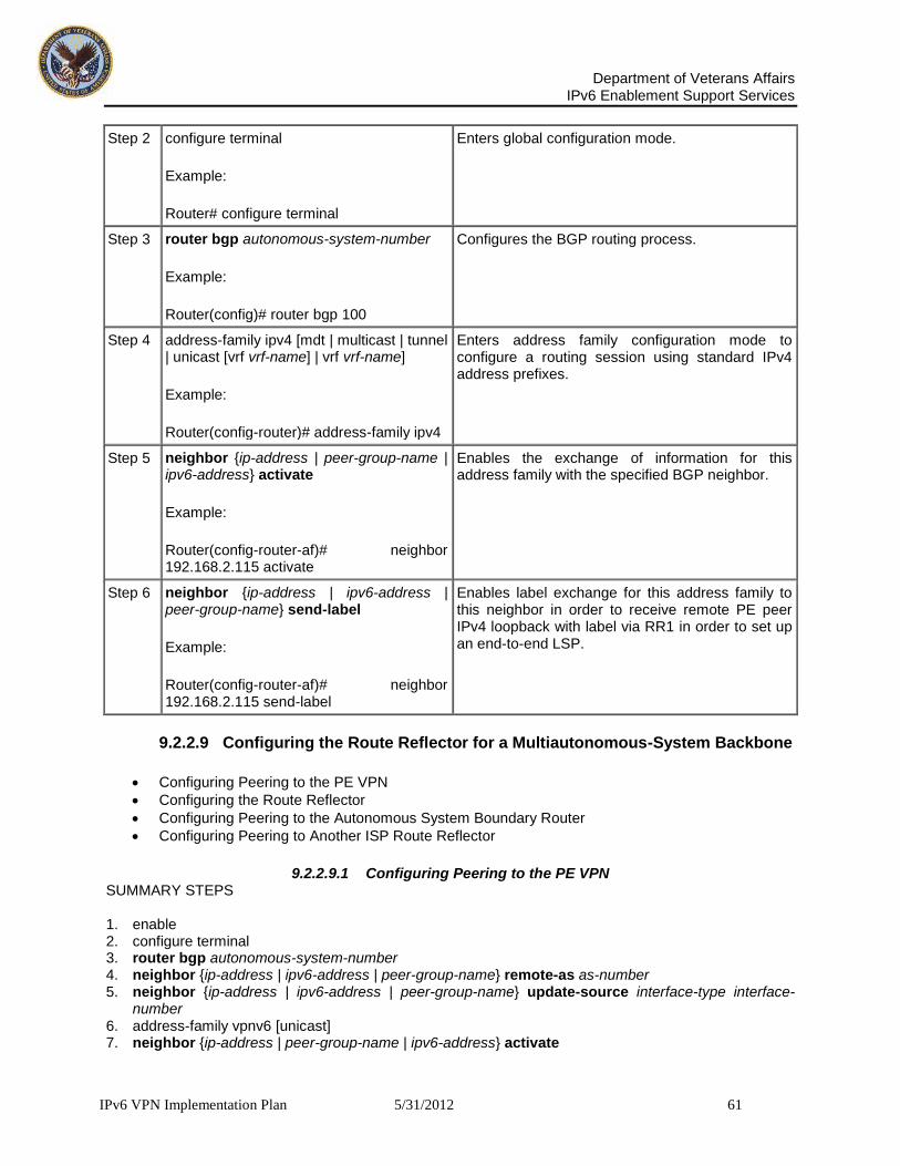
Department of Veterans Affairs
IPv6 Enablement Support Services
IPv6 VPN Implementation Plan 5/31/2012 61
Step 2 configure terminal
Example:
Router# configure terminal
Enters global configuration mode.
Step 3 router bgp autonomous-system-number
Example:
Router(config)# router bgp 100
Configures the BGP routing process.
Step 4 address-family ipv4 [mdt | multicast | tunnel | unicast [vrf vrf-name] | vrf vrf-name]
Example:
Router(config-router)# address-family ipv4
Enters address family configuration mode to configure a routing session using standard IPv4 address prefixes.
Step 5 neighbor {ip-address | peer-group-name | ipv6-address} activate
Example:
Router(config-router-af)# neighbor 192.168.2.115 activate
Enables the exchange of information for this address family with the specified BGP neighbor.
Step 6 neighbor {ip-address | ipv6-address | peer-group-name} send-label
Example:
Router(config-router-af)# neighbor 192.168.2.115 send-label
Enables label exchange for this address family to this neighbor in order to receive remote PE peer IPv4 loopback with label via RR1 in order to set up an end-to-end LSP.
9.2.2.9 Configuring the Route Reflector for a Multiautonomous-System Backbone
Configuring Peering to the PE VPN
Configuring the Route Reflector
Configuring Peering to the Autonomous System Boundary Router
Configuring Peering to Another ISP Route Reflector
9.2.2.9.1 Configuring Peering to the PE VPN SUMMARY STEPS 1. enable 2. configure terminal 3. router bgp autonomous-system-number 4. neighbor {ip-address | ipv6-address | peer-group-name} remote-as as-number 5. neighbor {ip-address | ipv6-address | peer-group-name} update-source interface-type interface-
number 6. address-family vpnv6 [unicast] 7. neighbor {ip-address | peer-group-name | ipv6-address} activate

Department of Veterans Affairs
IPv6 Enablement Support Services
IPv6 VPN Implementation Plan 5/31/2012 62
8. neighbor {ip-address | ipv6-address | peer-group-name} send-community [both | standard | extended]
9. exit 10. address-family ipv4 [mdt | multicast | tunnel | unicast [vrf vrf-name] | vrf vrf-name] 11. neighbor {ip-address | peer-group-name | ipv6-address} activate 12. neighbor {ip-address | ipv6-address | peer-group-name} send-label 13. exit
DETAILED STEPS
Command or Action Purpose
Step 1 enable
Example:
Router> enable
Enables privileged EXEC mode.
• Enter your password if prompted.
Step 2 configure terminal
Example:
Router# configure terminal
Enters global configuration mode.
Step 3 router bgp autonomous-system-number
Example:
Router(config)# router bgp 100
Configures the BGP routing process.
Step 4 neighbor {ip-address | ipv6-address | peer-group-name} remote-as as-number
Example:
Router(config-router)# neighbor 192.168.2.115 remote-as 100
Adds an entry to the multiprotocol BGP neighbor table for peering with the route reflector for interautonomous system.
Step 5 neighbor {ip-address | ipv6-address | peer-group-name} update-source interface-type interface-number
Example:
Router(config-router)# neighbor 192.168.2.115 update-source Loopback 0
Enables the BGP session to use a source address on the specified interface.
Step 6 address-family vpnv6 [unicast]
Example:
Router(config-router)# address-family vpnv6
(Optional) Places the router in address family configuration mode.
Step 7 neighbor {ip-address | peer-group-name | Enables the exchange of information for this address family with the specified BGP neighbor.

Department of Veterans Affairs
IPv6 Enablement Support Services
IPv6 VPN Implementation Plan 5/31/2012 63
ipv6-address} activate
Example:
Router(config-router-af)# neighbor 192.168.2.115 activate
Step 8 neighbor {ip-address | ipv6-address | peer-group-name} send-community [both | standard | extended]
Example:
Router(config-router-af)# neighbor 192.168.2.115 send-community extended
Specifies that a community attribute should be sent to the BGP neighbor.
Step 9 exit
Example:
Router(config-router-af)# exit
Exits address family configuration mode.
Step 10 address-family ipv4 [mdt | multicast | tunnel | unicast [vrf vrf-name] | vrf vrf-name]
Example:
Router(config-router)# address-family ipv4
Enters address family configuration mode to configure a routing session using standard IPv4 address prefixes.
Step 11 neighbor {ip-address | peer-group-name | ipv6-address} activate
Example:
Router(config-router-af)# neighbor 192.168.2.115 activate
Enables the exchange of information for this address family with the specified BGP neighbor.
Step 12 neighbor {ip-address | ipv6-address | peer-group-name} send-label
Example:
Router(config-router-af)# neighbor 192.168.2.115 send-label
Enables label exchange for this address family to this neighbor in order to send to the local PE the remote PE IPv4 loopback with a label in order to set up an end-to-end LSP.
Step 13 exit
Example:
Router(config-router-af)# exit
Exits address family configuration mode.
9.2.2.10 Configuring the Route Reflector
SUMMARY STEPS

Department of Veterans Affairs
IPv6 Enablement Support Services
IPv6 VPN Implementation Plan 5/31/2012 64
1. enable 2. configure terminal 3. router bgp autonomous-system-number 4. neighbor {ip-address | ipv6-address | peer-group-name} remote-as as-number 5. neighbor {ip-address | ipv6-address | peer-group-name} update-source interface-type interface-
number 6. address-family vpnv6 [unicast] 7. neighbor {ip-address | peer-group-name | ipv6-address} activate 8. neighbor {ip-address | ipv6-address | peer-group-name} send-community [both | standard |
extended] 9. neighbor {ip-address | ipv6-address | peer-group-name} route-reflector-client 10. exit 11. address-family ipv4 [mdt | multicast | tunnel | unicast [vrf vrf-name] | vrf vrf-name] 12. neighbor {ip-address | peer-group-name | ipv6-address} activate 13. neighbor {ip-address | ipv6-address | peer-group-name} send-label 14. exit
DETAILED STEPS
Command or Action Purpose
Step 1 enable
Example:
Router> enable
Enables privileged EXEC mode.
• Enter your password if prompted.
Step 2 configure terminal
Example:
Router# configure terminal
Enters global configuration mode.
Step 3 router bgp autonomous-system-number
Example:
Router(config)# router bgp 100
Configures the BGP routing process.
Step 4 neighbor {ip-address | ipv6-address | peer-group-name} remote-as as-number
Example:
Router(config-router)# neighbor 192.168.2.127 remote-as 100
Adds an entry to the multiprotocol BGP neighbor table for peering with the VPN PE for interautonomous system.
Step 5 neighbor {ip-address | ipv6-address | peer-group-name} update-source interface-type interface-number
Example:
Enables the BGP session to use a source address on the specified interface.

Department of Veterans Affairs
IPv6 Enablement Support Services
IPv6 VPN Implementation Plan 5/31/2012 65
Router(config-router)# neighbor 192.168.2.127 update-source Loopback 0
Step 6 address-family vpnv6 [unicast]
Example:
Router(config-router)# address-family vpnv6
(Optional) Places the router in address family configuration mode.
Step 7 neighbor {ip-address | peer-group-name | ipv6-address} activate
Example:
Router(config-router-af)# neighbor 192.168.2.127 activate
Enables the exchange of information for this address family with the specified neighbor.
Step 8 neighbor {ip-address | ipv6-address | peer-group-name} send-community [both | standard | extended]
Example:
Router(config-router-af)# neighbor 192.168.2.127 send-community extended
Specifies that a community attribute should be sent to the BGP neighbor.
Step 9 neighbor {ip-address | ipv6-address | peer-group-name} route-reflector-client
Example:
Router(config-router-af)# neighbor 192.168.2.127 route-reflector-client
Configures the specified neighbor as a route reflector client.
Step 10 exit
Example:
Router(config-router-af)# exit
Exits address family configuration mode.
Step 11 address-family ipv4 [mdt | multicast | tunnel | unicast [vrf vrf-name] | vrf vrf-name]
Example:
Router(config-router)# address-family ipv4
Enters address family configuration mode to configure a routing session using standard IPv4 address prefixes.
Step 12 neighbor {ip-address | peer-group- Enables the exchange of information for this address

Department of Veterans Affairs
IPv6 Enablement Support Services
IPv6 VPN Implementation Plan 5/31/2012 66
name | ipv6-address} activate
Example:
Router(config-router-af)# neighbor 192.168.2.127 activate
family with the specified neighbor.
Step 13 neighbor {ip-address | ipv6-address | peer-group-name} send-label
Example:
Router(config-router-af)# neighbor 192.168.2.127 send-label
Enables label exchange for this address family to this neighbor in order to send to the local PE the remote PE IPv4 loopback with a label in order to set up an end-to-end LSP.
Step 14 exit
Example:
Router(config-router-af)# exit
Exits address family configuration mode.
9.2.2.11 Configuring Peering to the Autonomous System Boundary Router
SUMMARY STEPS 1. enable 2. configure terminal 3. router bgp autonomous-system-number 4. neighbor {ip-address | ipv6-address | peer-group-name} remote-as as-number 5. neighbor {ip-address | ipv6-address | peer-group-name} update-source interface-type interface-
number 6. address-family ipv4 [mdt | multicast | tunnel | unicast [vrf vrf-name] | vrf vrf-name] 7. neighbor {ip-address | peer-group-name | ipv6-address} activate 8. neighbor {ip-address | ipv6-address | peer-group-name} send-label 9. exit
DETAILED STEPS
Command or Action Purpose
Step 1 enable
Example:
Router> enable
Enables privileged EXEC mode.
• Enter your password if prompted.
Step 2 configure terminal
Example:
Router# configure terminal
Enters global configuration mode.
Step 3 router bgp autonomous-system-number
Example:
Configures the BGP routing process.

Department of Veterans Affairs
IPv6 Enablement Support Services
IPv6 VPN Implementation Plan 5/31/2012 67
Router(config)# router bgp 100
Step 4 neighbor {ip-address | ipv6-address | peer-group-name} remote-as as-number
Example:
Router(config-router)# neighbor 192.168.2.102 remote-as 100
Adds an entry to the multiprotocol BGP neighbor table for peering with the ASBR1.
Step 5 neighbor {ip-address | ipv6-address | peer-group-name} update-source interface-type interface-number
Example:
Router(config-router)# neighbor 192.168.2.102 update-source Loopback 0
Enables the BGP session to use a source address on the specified interface.
Step 6 address-family ipv4 [mdt | multicast | tunnel | unicast [vrf vrf-name] | vrf vrf-name]
Example:
Router(config-router)# address-family ipv4
Enters address family configuration mode to configure a routing session using standard IPv4 address prefixes.
Step 7 neighbor {ip-address | peer-group-name | ipv6-address} activate
Example:
Router(config-router-af)# neighbor 192.168.2.102 activate
Enables the exchange of information for this address family with the specified BGP neighbor.
Step 8 neighbor {ip-address | ipv6-address | peer-group-name} send-label
Example:
Router(config-router-af)# neighbor 192.168.2.102 send-label
Enables label exchange for this address family to this neighbor in order to receive the remote PE IPv4 loopback with the label set to an end-to-end LSP.
Step 9 exit
Example:
Router(config-router-af)# exit
Exits address family configuration mode.
9.2.2.12 Configuring Peering to another ISP Route Reflector
Perform this task to configure peering to an ISP route reflector named RR2.
SUMMARY STEPS

Department of Veterans Affairs
IPv6 Enablement Support Services
IPv6 VPN Implementation Plan 5/31/2012 68
1. enable 2. configure terminal 3. router bgp autonomous-system-number 4. neighbor {ip-address | ipv6-address | peer-group-name} remote-as as-number 5. neighbor {ip-address | ipv6-address | peer-group-name} update-source interface-type interface-
number 6. neighbor {ip-address | ipv6-address | peer-group-name} ebgp-multihop [ttl] 7. address-family vpnv6 [unicast] 8. neighbor {ip-address | peer-group-name | ipv6-address} activate 9. neighbor {ip-address | ipv6-address | peer-group-name} send-community [both | standard |
extended] 10. neighbor {ip-address | ipv6-address | peer-group-name} next-hop-unchanged [allpaths]
DETAILED STEPS
Command or Action Purpose
Step 1 enable
Example:
Router> enable
Enables privileged EXEC mode.
• Enter your password if prompted.
Step 2 configure terminal
Example:
Router# configure terminal
Enters global configuration mode.
Step 3 router bgp autonomous-system-number
Example:
Router(config)# router bgp 100
Configures the BGP routing process.
Step 4 neighbor {ip-address | ipv6-address | peer-group-name} remote-as as-number
Example:
Router(config-router)# neighbor 192.168.2.1 remote-as 100
Adds an entry to the multiprotocol BGP neighbor table for eBGP peering with RR2.
Step 5 neighbor {ip-address | ipv6-address | peer-group-name} update-source interface-type interface-number
Example:
Router(config-router)# neighbor 192.168.2.1 update-source Loopback 0
Enables the BGP session to use a source address on the specified interface.
Step 6 neighbor {ip-address | ipv6-address | peer- (Optional) Accepts and attempts BGP connections to external peers residing on networks that are not directly connected.

Department of Veterans Affairs
IPv6 Enablement Support Services
IPv6 VPN Implementation Plan 5/31/2012 69
group-name} ebgp-multihop [ttl]
Example:
Router(config-router)# neighbor 192.168.2.1 ebgp-multihop
Step 7 address-family vpnv6 [unicast]
Example:
Router(config-router)# address-family vpnv6
(Optional) Places the router in address family configuration mode for configuring routing sessions.
Step 8 neighbor {ip-address | peer-group-name | ipv6-address} activate
Example:
Router(config-router-af)# neighbor 192.168.2.1 activate
Enables the exchange of information for this address family with the specified BGP neighbor.
Step 9 neighbor {ip-address | ipv6-address | peer-group-name} send-community [both | standard | extended]
Example:
Router(config-router-af)# neighbor 192.168.2.1 send-community extended
Specifies that a community’s attribute should be sent to the BGP neighbor.
Step 10
neighbor {ip-address | ipv6-address | peer-group-name} next-hop-unchanged [allpaths]
Example:
Router(config-router-af)# neighbor 192.168.2.1 next-hop-unchanged allpaths
Enables an eBGP multihop peer to propagate to the next hop unchanged for paths.
9.2.2.13 Configuring the ASBR
Perform this task to configure peering to an ISP route reflector named RR2.
Configuring Peering with Router Reflector RR1
Configuring Peering with the Other ISP ASBR2
9.2.2.14 Configuring Peering with Router Reflector RR1
Perform this task to configure peering with a route reflector named RR1.
SUMMARY STEPS

Department of Veterans Affairs
IPv6 Enablement Support Services
IPv6 VPN Implementation Plan 5/31/2012 70
1. enable 2. configure terminal 3. router bgp autonomous-system-number 4. neighbor {ip-address | ipv6-address | peer-group-name} remote-as as-number 5. neighbor {ip-address | ipv6-address | peer-group-name} update-source interface-type interface-
number 6. address-family ipv4 [mdt | multicast | tunnel | unicast [vrf vrf-name] | vrf vrf-name] 7. neighbor {ip-address | peer-group-name | ipv6-address} activate 8. neighbor {ip-address | ipv6-address | peer-group-name} send-label 9. exit
DETAILED STEPS
Command or Action Purpose
Step 1 enable
Example:
Router> enable
Enables privileged EXEC mode.
• Enter your password if prompted.
Step 2 configure terminal
Example:
Router# configure terminal
Enters global configuration mode.
Step 3 router bgp autonomous-system-number
Example:
Router(config)# router bgp 100
Configures the BGP routing process.
Step 4 neighbor {ip-address | ipv6-address | peer-group-name} remote-as as-number
Example:
Router(config-router)# neighbor 192.168.2.115 remote-as 100
Adds an entry to the multiprotocol BGP neighbor table for peering with RR1.
Step 5 neighbor {ip-address | ipv6-address | peer-group-name} update-source interface-type interface-number
Example:
Router(config-router)# neighbor 192.168.2.115 update-source Loopback 0
Enables the BGP session to use a source address on the specified interface.
Step 6 address-family ipv4 [mdt | multicast | tunnel | unicast [vrf vrf-name] | vrf vrf-name]
Example:
Enters address family configuration mode to configure a routing session using standard IPv4 address prefixes.

Department of Veterans Affairs
IPv6 Enablement Support Services
IPv6 VPN Implementation Plan 5/31/2012 71
Router(config-router)# address-family ipv4
Step 7 neighbor {ip-address | peer-group-name | ipv6-address} activate
Example:
Router(config-router-af)# neighbor 192.168.2.115 activate
Enables the exchange of information for this address family with the specified BGP neighbor.
Step 8 neighbor {ip-address | ipv6-address | peer-group-name} send-label
Example:
Router(config-router-af)# neighbor 192.168.2.115 send-label
Enables label exchange for this address family to this neighbor in order to send to the local PE the remote PE IPv4 loopback with a label in order to set up an end-to-end LSP.
Step 9 exit
Example:
Router(config-router-af)# exit
Exits address family configuration mode.
9.2.2.15 Configuring Peering with the Other ISP ASBR2
Perform this task to configure peering with ASBR2.
SUMMARY STEPS 1. enable 2. configure terminal 3. router bgp autonomous-system-number 4. neighbor {ip-address | ipv6-address | peer-group-name} remote-as as-number 5. neighbor {ip-address | ipv6-address | peer-group-name} update-source interface-type interface-
number 6. neighbor {ip-address | ipv6-address | peer-group-name} ebgp-multihop [ttl] 7. address-family ipv4 [mdt | multicast | tunnel | unicast [vrf vrf-name] | vrf vrf-name] 8. neighbor {ip-address | peer-group-name | ipv6-address} activate 9. neighbor {ip-address | ipv6-address | peer-group-name} send-label 10. network {network-number [mask network-mask] | nsap-prefix} [route-map map-tag] 11. network {network-number [mask network-mask] | nsap-prefix} [route-map map-tag]
DETAILED STEPS
Command or Action Purpose
Step 1 enable
Example:
Router> enable
Enables privileged EXEC mode.
• Enter your password if prompted.

Department of Veterans Affairs
IPv6 Enablement Support Services
IPv6 VPN Implementation Plan 5/31/2012 72
Step 2 configure terminal
Example:
Router# configure terminal
Enters global configuration mode.
Step 3 router bgp autonomous-system-number
Example:
Router(config)# router bgp 100
Configures the BGP routing process.
Step 4 neighbor {ip-address | ipv6-address | peer-group-name} remote-as as-number
Example:
Router(config-router)# neighbor 192.168.3.1 remote-as 100
Adds an entry to the multiprotocol BGP neighbor table for peering with the ASBR2.
Step 5 neighbor {ip-address | ipv6-address | peer-group-name} update-source interface-type interface-number
Example:
Router(config-router)# neighbor 192.168.3.1 update-source Loopback 0
Enables the BGP session to use a source address on the specified interface.
Step 6 neighbor {ip-address | ipv6-address | peer-group-name} ebgp-multihop [ttl]
Example:
Router(config-router)# neighbor 192.168.3.1 ebgp-multihop
Accepts and attempts BGP connections to external peers residing on networks that are not directly connected.
Step 7 address-family ipv4 [mdt | multicast | tunnel | unicast [vrf vrf-name] | vrf vrf-name]
Example:
Router(config-router)# address-family ipv4
Enters address family configuration mode to configure a routing session using standard IPv4 address prefixes.
Step 8 neighbor {ip-address | peer-group-name | ipv6-address} activate
Example:
Router(config-router-af)# neighbor 192.168.3.1 activate
Enables the exchange of information for this address family with the specified BGP neighbor.
Step 9 neighbor {ip-address | ipv6-address | Enables label exchange for this address family to this neighbor in order to receive the remote PE

Department of Veterans Affairs
IPv6 Enablement Support Services
IPv6 VPN Implementation Plan 5/31/2012 73
peer-group-name} send-label
Example:
Router(config-router-af)# neighbor 192.168.3.1 send-label
IPv4 loopback with a label in order to set up an end-to-end LSP.
Step 10
network {network-number [mask network-mask] |nsap-prefix} [route-map map-tag]
Example:
Router(config-router-af)# network 192.168.2.27 mask 255.255.255.255
Flags a network as local to this autonomous system and enters the network to the BGP table. This configuration is for the PE VPN loopback.
Step 11
network {network-number [mask network-mask] |nsap-prefix} [route-map map-tag]
Example:
Router(config-router-af)# network 192.168.2.15 mask 255.255.255.255
Flags a network as local to this autonomous system and enters the network to the BGP table. This configuration is for the RR1 loopback.
9.2.2.16 Configuring CSC for IPv6 VPN
Perform this task to configure CsC-PE1 peering configuration with CsC-CE1.
SUMMARY STEPS 1. enable 2. configure terminal 3. hostname name 4. router bgp autonomous-system-number 5. address-family ipv6 [vrf vrf-name] [unicast | multicast] 6. neighbor {ip-address | ipv6-address | peer-group-name} remote-as as-number 7. neighbor {ip-address | peer-group-name | ipv6-address} activate 8. neighbor {ip-address | ipv6-address | peer-group-name} send-label
DETAILED STEPS
Command or Action Purpose
Step 1
enable
Example:
Router> enable
Enables privileged EXEC mode.
• Enter your password if prompted.
Step 2
configure terminal
Example:
Router# configure terminal
Enters global configuration mode.

Department of Veterans Affairs
IPv6 Enablement Support Services
IPv6 VPN Implementation Plan 5/31/2012 74
Step 3
hostname name
Example:
Router(config)# hostname CSC-PE1
Specifies or modifies the host name for the network server.
Step 4
router bgp autonomous-system-number
Example:
Router(config)# router bgp 100
Configures the BGP routing process.
Step 5
address-family ipv6 [vrf vrf-name] [unicast | multicast]
Example:
Router(config-router)# address-family ipv6 vrf ISP2
Enters address family configuration mode.
Step 6
neighbor {ip-address | ipv6-address | peer-group-name} remote-as as-number
Example:
Router(config-router-af)# neighbor FE80::866C:99%Serial0/0 remote-as 200
Adds an entry to the multiprotocol BGP neighbor table.
Step 7
neighbor {ip-address | peer-group-name | ipv6-address} activate
Example:
Router(config-router-af)# neighbor FE80::866C:99%Serial0/0 activate
Enables the exchange of information for this address family with the specified BGP neighbor.
Step 8
neighbor {ip-address | ipv6-address | peer-group-name} send-label
Example:
Router(config-router-af)# neighbor FE80::866C:99%Serial0/0 send-label
Enables label exchange for this address family to this neighbor.
9.2.2.17 Configuring BGP IPv6 PIC Edge for IP MPLS
Because many service provider networks contain many VRFs, the BGP PIC feature allows you to configure BGP PIC feature for all VRFs at once. Performing this task in IPv6 address family configuration mode protects IPv6 VRFs.
SUMMARY STEPS 1. enable

Department of Veterans Affairs
IPv6 Enablement Support Services
IPv6 VPN Implementation Plan 5/31/2012 75
2. configure terminal 3. router bgp autonomous-system-number 4. address-family ipv6 [vrf vrf-name] [unicast | multicast | vpnv6] 5. bgp additional-paths install 6. bgp recursion host
DETAILED STEPS
Command or Action Purpose
Step 1 enable
Example:
Router> enable
Enables privileged EXEC mode.
• Enter your password if prompted.
Step 2 configure terminal
Example:
Router# configure terminal
Enters global configuration mode.
Step 3 router bgp autonomous-system-number
Example:
Router(config)# router bgp 100
Configures the BGP routing process.
Step 4 address-family ipv6 [vrf vrf-name] [unicast | multicast | vpnv6]
Example:
Router(config-router)# address-family ipv6 vrf_pic
Specifies a VRF table named vrf_pic, and enters IPv6 address family configuration mode.
Step 5 bgp additional-paths install
Example:
Router(config-router-af)# bgp additional-paths install
Calculates a backup path and installs it into the RIB and Cisco Express Forwarding.
Step 6 bgp recursion host
Example:
Router(config-router-af)# bgp recursion host
Enables the recursive-via-host flag for IPv6 address families.
9.2.2.18 Verifying and Troubleshooting IPv6 VPN
When users troubleshoot IPv6, any function that works similarly to VPNv4 will likely work for IPv6, therefore minimizes the learning curve for new IPv6 users. Few of the tools and commands used to

Department of Veterans Affairs
IPv6 Enablement Support Services
IPv6 VPN Implementation Plan 5/31/2012 76
troubleshoot 6PE and 6VPE are specific to IPv6; rather, the troubleshooting methodology is the same for both IPv4 and IPv6, and the commands and tools often vary by only one keyword.
Verifying and Troubleshooting Routing
Verifying and Troubleshooting Forwarding
Debugging Routing and Forwarding
9.2.2.18.1 Verifying and Troubleshooting Routing
Deploying 6PE and 6VPE involves principally BGP. The same set of commands used for VPNv4 can be used (with different set of arguments) for IPv6, and similar outputs are obtained.
BGP IPv6 Activity Summary
Dumping the BGP IPv6 Tables
Dumping the IPv6 Routing Tables
Transition and Configuration
Due to the existing VA VPN network design complexities and management operations, it is recommended to establish a separate set of Hub Routers at each gateway to handle the IPv6 VPN traffic to ensure there would be no adverse effects to the existing IPv4 network performance and operation. This also involves installing a new set of IPv6 DNS and DHCP servers. For each field office location (regardless of which provider network is used) the Router IOS should be upgraded and a dual stack configured to utilize each of the two VPN enabled hub routers to provide service for the site’s respective region. A failure of either of these VPN enabled routers will result in no loss of connectivity for the field site, as all network destinations will be reachable via the other remaining connections. Additionally, the following activities should be performed:
Utilize existing MPLS network backbone to transfer the IPv4 VPN traffic
Utilize the existing EIGRP, IGRP, eBGP and BGP network routing Protocols for inter and routing table advertisement and updates

Department of Veterans Affairs
IPv6 Enablement Support Services
IPv6 VPN Implementation Plan 5/31/2012 77
9.2.2.19 GUI and Command-Line Configuration
With windows server 2008 and Vista, you can manually configure IPv6 settings via two methods.
You can use the Windows GUI from the properties of the IPv6 component in the network connections folder.
Using the windows command prompt with commands such as netsh interface ipv6 context.
Sample Command Line Tools:
Command Description
? Gives you a help screen
0.0.0.0 255.255.255.255 A wildcard command
config terminal Puts you in global configuration mode and changes the running-config
config-register Tells the router how to boot and to change the configuration register setting
confreg Changes the configure register of a router from Rom monitor mode
copy flash tftp Copies a file from flash memory to a TFTP host
copy run start Short for copy running-config startupconfig; places a configuration into NVRAM
copy run tftp Copies the running-config file to a TFTP host
copy running-config startup-config Saves the configuration on a 2950 switch
copy tftp flash Copies a file from a TFTP host to flash memory
copy tftp run Copies a configuration from a TFTP host to the running-config file
Ctrl+A Moves your cursor to the beginning of the line
Ctrl+D Deletes a single character
Ctrl+E Moves your cursor to the end of the line
Ctrl+F Moves forward one character
Ctrl+R Redisplays a line
Ctrl+Shift+6, then X (keyboard combination)
Returns you to the originating router when you telnet to numerous routers
Ctrl+U Erases a line
Ctrl+W Erases a word
Ctrl+Z Ends configuration mode and returns to EXEC
debug dialer Shows you the call setup and teardown procedures
debug frame-relay lmi Shows the lmi exchanges between the router and the Frame Relay switch
debug ip igrp events Provides a summary of the IGRP routing information running on the network
debug ip igrp transactions Shows message requests from neighbor routers asking for an update and the broadcasts sent from your router to that neighbor router
debug ip rip Sends console messages displaying

Department of Veterans Affairs
IPv6 Enablement Support Services
IPv6 VPN Implementation Plan 5/31/2012 78
information about RIP packets being sent and received on a router interface
debug isdn q921 Shows layer-2 processes
Command Description
debug isdn q931 Shows layer-3 processes 11
delete nvram Deletes the contents of NVRAM on a 1900 switch
description Sets a description on an interface
dialer idle-timeout number Tells the BRI line when to drop if no interesting traffic is found
dialer list number protocol permit/deny Specifies interesting traffic for a DDR link
dialer load-threshold number inbound/outbound/either
Sets the parameters that describe when the second BRI comes up on an ISDN link
dialer map protocol address name hostname number
Used instead of a dialer string to provide more security in an ISDN network
Dialer next hop address name hostname dial string
Used instead of a dialer string to provide more security in an ISDN network.
dialer string Sets the phone number to dial for a BRI interface
disable Takes you from privileged mode back to user mode
disconnect Disconnects a connection to a remote router from the originating router
enable Puts you into privileged mode
enable password Sets the unencrypted enable password
enable password level 1 password Sets the user mode password on a 1900 switch
enable password level 15 password Sets the enable password on a 1900 switch
enable secret Sets the encrypted enable secret password. Supersedes the enable password if set
enable secret password Sets the enable password on a 1900 and 2950 switch
encapsulation Sets the frame type used on an interface
encapsulation dot1q vlan# Sets the encapsulation on a routers trunk port to 802.1Q encapsulation
encapsulation frame-relay Changes the encapsulation to Frame Relay on a serial link
encapsulation frame-relay ietf Sets the encapsulation type to the Internet Engineering Task Force (IETF); connects Cisco routers to off-brand routers
encapsulation hdlc Restores the default encapsulation of HDLC on a serial link
encapsulation isl vlan# Sets the encapsulation on a routers trunk port to isl encapsulation
encapsulation ppp Changes the encapsulation on a serial link to PPP
erase startup Deletes the startup-config
erase startup-config Deletes the contents of NVRAM on a router
Esc+B Moves back one word
Esc+F Moves forward one word
exec-timeout Sets the timeout in seconds and minutes

Department of Veterans Affairs
IPv6 Enablement Support Services
IPv6 VPN Implementation Plan 5/31/2012 79
for the console connection
exit Disconnects a connection to a remote router via Telnet
frame-relay interface-dlci Configures the PVC address on a serial interface or subinterface
frame-relay lmi-type Configures the LMI type on a serial link
frame-relay map protocol address DLCI Creates a static mapping for use with a Frame Relay network
host Specifies a single host address
hostname name Sets the name of a router or a switch
int vlan1 Chooses the default VLAN on a 2950 switch
interface Puts you in interface configuration mode; also used with show commands
Interface fastethernet0/0 Puts you in interface configuration mode for a Fast Ethernet port; also used with show commands
Interface fastethernet0/0.1 Creates a subinterface
interface int Puts you in configuration mode for the specified interface and can be used for show commands.
interface s0.16 multipoint Creates a multipoint subinterface on a serial link that can be used with Frame Relay networks
Command Description
interface s0.16 point-to-point Creates a point-to-point subinterface on a serial link that can be used with Frame Relay
interface serial 5 Puts you in configuration mode for interface serial 5 and can be used for show commands
ip access-group Applies an IP access list to an interface
ip address Sets an IP address on an interface or a switch
ip address ip_address mask Sets the IP address on a device
ip classless A global configuration command used to tell a router to forward packets to a default route when the destination network is not in the routing table
ip default-gateway ip_address Sets the default gateway on a 1900 and 2950 switch
ip domain-lookup Turns on DNS lookup (which is on by default)
ip domain-name Appends a domain name to a DNS lookup
ip host Creates a host table on a router
ip name-server Sets the IP address of up to six DNS servers
ip route Creates static and default routes on a router
isdn spid1 Sets the number that identifies the first DS0 to the ISDN switch
isdn spid2 Sets the number that identifies the second DS0 to the ISDN switch

Department of Veterans Affairs
IPv6 Enablement Support Services
IPv6 VPN Implementation Plan 5/31/2012 80
isdn switch-type Sets the type of ISDN switch that the router will communicate with; can be set at interface level or global configuration mode
line Puts you in configuration mode to change or set your user mode passwords
line aux Puts you in the auxiliary interface configuration mode
line console 0 Puts you in console configuration mode
line vty Puts you in VTY (Telnet) interface configuration mode
logging synchronous Stops console messages from overwriting your command-line input
logout Logs you out of your console session
media-type Sets the hardware media type on an interface
network Tells the routing protocol what network to advertise
network ip-address Enables EIGRP on the local interfaces that reside on the specified networks. EIGRP is configured with a classful address.
network network-number wild-card area area-id
Enables OSPF on a specific interface or set of interfaces that reside on the specified network. These interfaces will reside in the specified area.
no auto-summary Turns off the automatic summarization of routes at classful boundaries.
no cdp enable Turns off CDP on an individual interface
no cdp run Turns off CDP completely on a router
no inverse-arp Turns off the dynamic IARP used with Frame Relay; static mappings must be configured
no ip domain-lookup Turns off DNS lookup
no ip host Removes a hostname from a host table
No ip route Removes a static or default route
no shutdown Turns on an interface
o/r 0x2142 Changes a 2501 to boot without using the contents of NVRAM
passive-interface interface-type interface-number
Identifies interfaces that do not participate in EIGRP updates.
ping Tests IP connectivity to a remote device
ppp authentication chap Tells PPP to use CHAP authentication
ppp authentication pap Tells PPP to use PAP authentication
reload Reboots the router
Command Description
router eigrp as Starts EIGRP processes on a router using a specific autonomous system number.
router igrp as Turns on IP IGRP routing on a router
router ospf process-id Activates the OSPF routing process and identifies the process-id under which it will run. Process-id is in the range 1-65535.
router rip Puts you in router rip configuration mode
Service password-encryption Encrypts the user mode and enable password

Department of Veterans Affairs
IPv6 Enablement Support Services
IPv6 VPN Implementation Plan 5/31/2012 81
sh ip Shows the IP configuration information on a 1900 switch
sh vlan Shows the VLAN database
sh vlan brief Shows a brief overview of the VLAN database
sh vtp Displays the VTP configured information on a switch
show access-lists Shows all the access lists configured on the router
show access-lists 110 Shows only access list 110
show cdp Displays the CDP timer and hold time frequencies
show cdp entry * Same as show cdp neighbor detail, but does not work on a 1900 switch
show cdp interface Shows the individual interfaces enabled with CDP
show cdp neighbor Shows the directly connected neighbors and the details about them
show cdp neighbor detail Shows the IP address and IOS version and type, and includes all of the information from the show cdp neighbor command
show cdp traffic Shows the CDP packets sent and received on a device and any errors
show controllers int Shows the DTE or DCE status of an interface.
show controllers s 0 Shows the DTE or DCE status of an interface
show dialer Shows the number of times the dialer string has been reached, the idle-timeout values of each B channel, the length of call, and the name of the router to which the interface is connected
show flash Shows the files in flash memory
show frame-relay lmi Shows the LMI type on a serial interface
show frame-relay map Shows the static and dynamic Network layer–to–PVC mappings
show frame-relay pvc Shows the configured PVCs and DLCI numbers configured on a router
show history Shows you the last 10 commands entered by default
show hosts Shows the contents of the host table
show interface s0 Shows the statistics of interface serial 0
show interfaces int Shows the statistics of an interface.
show ip access-lists Shows only the IP access lists
show ip eigrp neighbors Shows all EIGRP neighbors.
show ip eigrp topology Shows entries in the EIGRP topology table.
show ip eigrp traffic Shows the packet count for EIGRP packets sent and received.
show ip interface Shows which interfaces have IP access lists applied
show ip ospf Summarizes all relative OSPF information, such as OSPF processes, Router ID, area assignments, authentication, and SPF

Department of Veterans Affairs
IPv6 Enablement Support Services
IPv6 VPN Implementation Plan 5/31/2012 82
statistics.
show ip ospf database Displays the link-state topology database.
show ip ospf interface Displays interface OSPF parameters and other OSPF information specific to the interface.
show ip ospf neighbor Displays each OSPF neighbor and adjacency status.
show ip ospf process-id Shows the same information as the show ip ospf command, but only for the specified process.
show ip protocols Shows the routing protocols and timers associated with each routing protocol configured on a router
show ip route Displays the IP routing table
show isdn active Shows the number called and whether a call is in progress
show isdn status Shows if your SPIDs are valid and if you are connected and communicating with the provider’s switch
show protocols Shows the routed protocols and network addresses configured on each interface
show running-config Also abbreviated to show run; shows the configuration currently running on the router
show sessions Shows your connections via Telnet to remote devices
show start Short for show startup-config; shows the backup configuration stored in NVRAM
show terminal Shows you your configured history size
show users Displays the users that are telnetted into your device.
show version Gives the IOS information of the switch, as well as the uptime and base Ethernet address
shutdown Puts an interface in administratively down mode
switchport access vlan vlan# Sets a port on a 2950 to a specific VLAN membership
switchport mode trunk Sets a port on a 2950 to trunking mode
Tab Finishes typing a command for you
telnet Connects, views, and runs programs on a remote device
terminal history size Changes your history size from the default of 10 up to 256
tftp-server flash:ios-name Creates a TFTP-server host for a router system image that is run in flash memory.
trace Tests a connection to a remote device and shows the path it took through the internetwork to find the remote device
traceroute Tests IP connectivity
traffic-share balanced Tells the IGRP routing protocol to share links inversely proportional to the metrics
traffic-share min Tells the IGRP routing process to use
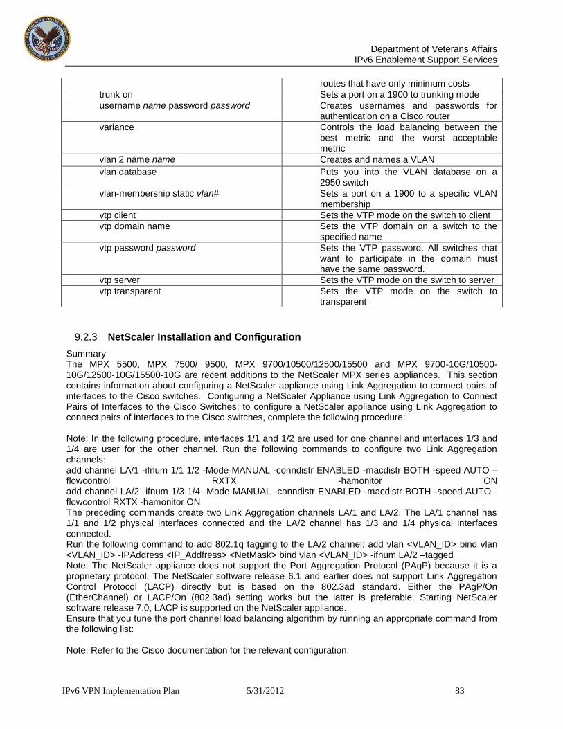
Department of Veterans Affairs
IPv6 Enablement Support Services
IPv6 VPN Implementation Plan 5/31/2012 83
routes that have only minimum costs
trunk on Sets a port on a 1900 to trunking mode
username name password password Creates usernames and passwords for authentication on a Cisco router
variance Controls the load balancing between the best metric and the worst acceptable metric
vlan 2 name name Creates and names a VLAN
vlan database Puts you into the VLAN database on a 2950 switch
vlan-membership static vlan# Sets a port on a 1900 to a specific VLAN membership
vtp client Sets the VTP mode on the switch to client
vtp domain name Sets the VTP domain on a switch to the specified name
vtp password password Sets the VTP password. All switches that want to participate in the domain must have the same password.
vtp server Sets the VTP mode on the switch to server
vtp transparent Sets the VTP mode on the switch to transparent
9.2.3 NetScaler Installation and Configuration
Summary The MPX 5500, MPX 7500/ 9500, MPX 9700/10500/12500/15500 and MPX 9700-10G/10500-10G/12500-10G/15500-10G are recent additions to the NetScaler MPX series appliances. This section contains information about configuring a NetScaler appliance using Link Aggregation to connect pairs of interfaces to the Cisco switches. Configuring a NetScaler Appliance using Link Aggregation to Connect Pairs of Interfaces to the Cisco Switches; to configure a NetScaler appliance using Link Aggregation to connect pairs of interfaces to the Cisco switches, complete the following procedure: Note: In the following procedure, interfaces 1/1 and 1/2 are used for one channel and interfaces 1/3 and 1/4 are user for the other channel. Run the following commands to configure two Link Aggregation channels: add channel LA/1 -ifnum 1/1 1/2 -Mode MANUAL -conndistr ENABLED -macdistr BOTH -speed AUTO –flowcontrol RXTX -hamonitor ON add channel LA/2 -ifnum 1/3 1/4 -Mode MANUAL -conndistr ENABLED -macdistr BOTH -speed AUTO -flowcontrol RXTX -hamonitor ON The preceding commands create two Link Aggregation channels LA/1 and LA/2. The LA/1 channel has 1/1 and 1/2 physical interfaces connected and the LA/2 channel has 1/3 and 1/4 physical interfaces connected. Run the following command to add 802.1q tagging to the LA/2 channel: add vlan <VLAN_ID> bind vlan <VLAN_ID> -IPAddress <IP_Addfress> <NetMask> bind vlan <VLAN_ID> -ifnum LA/2 –tagged Note: The NetScaler appliance does not support the Port Aggregation Protocol (PAgP) because it is a proprietary protocol. The NetScaler software release 6.1 and earlier does not support Link Aggregation Control Protocol (LACP) directly but is based on the 802.3ad standard. Either the PAgP/On (EtherChannel) or LACP/On (802.3ad) setting works but the latter is preferable. Starting NetScaler software release 7.0, LACP is supported on the NetScaler appliance. Ensure that you tune the port channel load balancing algorithm by running an appropriate command from the following list: Note: Refer to the Cisco documentation for the relevant configuration.
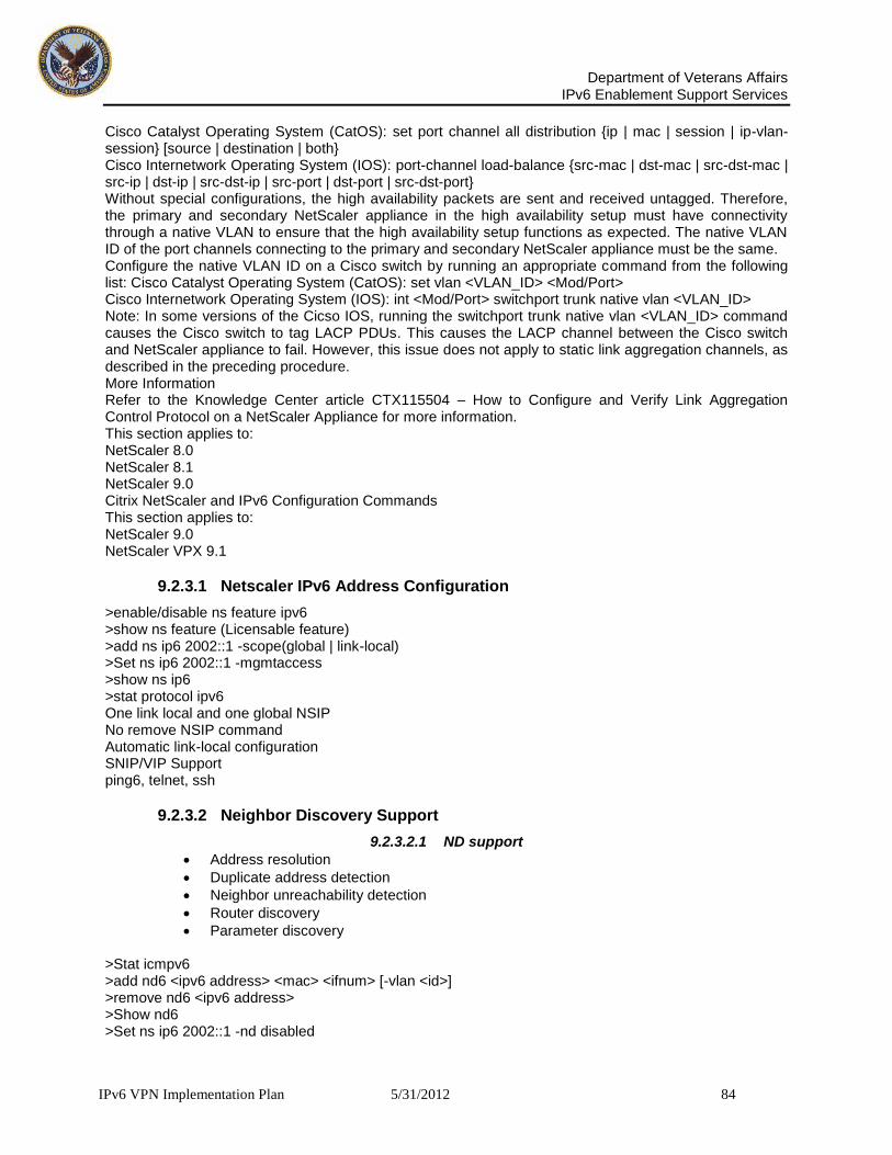
Department of Veterans Affairs
IPv6 Enablement Support Services
IPv6 VPN Implementation Plan 5/31/2012 84
Cisco Catalyst Operating System (CatOS): set port channel all distribution {ip | mac | session | ip-vlan-session} [source | destination | both} Cisco Internetwork Operating System (IOS): port-channel load-balance {src-mac | dst-mac | src-dst-mac | src-ip | dst-ip | src-dst-ip | src-port | dst-port | src-dst-port} Without special configurations, the high availability packets are sent and received untagged. Therefore, the primary and secondary NetScaler appliance in the high availability setup must have connectivity through a native VLAN to ensure that the high availability setup functions as expected. The native VLAN ID of the port channels connecting to the primary and secondary NetScaler appliance must be the same. Configure the native VLAN ID on a Cisco switch by running an appropriate command from the following list: Cisco Catalyst Operating System (CatOS): set vlan <VLAN_ID> <Mod/Port> Cisco Internetwork Operating System (IOS): int <Mod/Port> switchport trunk native vlan <VLAN_ID> Note: In some versions of the Cicso IOS, running the switchport trunk native vlan <VLAN_ID> command causes the Cisco switch to tag LACP PDUs. This causes the LACP channel between the Cisco switch and NetScaler appliance to fail. However, this issue does not apply to static link aggregation channels, as described in the preceding procedure. More Information Refer to the Knowledge Center article CTX115504 – How to Configure and Verify Link Aggregation Control Protocol on a NetScaler Appliance for more information. This section applies to: NetScaler 8.0 NetScaler 8.1 NetScaler 9.0 Citrix NetScaler and IPv6 Configuration Commands This section applies to: NetScaler 9.0 NetScaler VPX 9.1
9.2.3.1 Netscaler IPv6 Address Configuration
>enable/disable ns feature ipv6 >show ns feature (Licensable feature) >add ns ip6 2002::1 -scope(global | link-local) >Set ns ip6 2002::1 -mgmtaccess >show ns ip6 >stat protocol ipv6 One link local and one global NSIP No remove NSIP command Automatic link-local configuration SNIP/VIP Support ping6, telnet, ssh
9.2.3.2 Neighbor Discovery Support
9.2.3.2.1 ND support
Address resolution
Duplicate address detection
Neighbor unreachability detection
Router discovery
Parameter discovery >Stat icmpv6 >add nd6 <ipv6 address> <mac> <ifnum> [-vlan <id>] >remove nd6 <ipv6 address> >Show nd6 >Set ns ip6 2002::1 -nd disabled

Department of Veterans Affairs
IPv6 Enablement Support Services
IPv6 VPN Implementation Plan 5/31/2012 85
9.2.3.3 Static Routing
Configure static routes using IPv6 address to any destination.
Assign values for the distance and metric of static routes, this provides an option to configure backup routes.
Enable advertising of static routes to IPv6 dynamic routing protocols.
9.2.3.4 Static Route -- Configurations
To add a static route add route6 <network> <gateway> [-vlan <positive_integer>] [-weight <positive_integer>] [-distance <positive_integer>] [-cost <positive_integer>] [-advertise ( DISABLED | ENABLED )] where: vlan – vlan ID in case the gateway is a link-local IPv6 address weight – weight of this route. This is used to do a weighted hash-based traffic distribution, in case of ECMP routes distance – the distance value of the route cost – cost metric of the route advertise – the state of advertisement of the route to dynamic routing protocols Example: > add route6 2001::/48 501::4 -distance 2 -advertise ENABLED Done To set route parameters: set route6 <network> <gateway> [-vlan <positive_integer>] [-weight <positive_integer>] [-distance <positive_integer>] [-cost <positive_integer>] [-advertise ( DISABLED | ENABLED )] Example: >set route6 2001::/48 501::4 -weight 7 -advertise DISABLED To delete route: rm route6 <network> <gateway> [-vlan <positive_integer>] Example: > rm route6 2001::/48 501::4 Done To clear the routes: clear route6 <route-type> To display route:

Department of Veterans Affairs
IPv6 Enablement Support Services
IPv6 VPN Implementation Plan 5/31/2012 86
show route6 [<network> [<gateway>]] Example: >show route6 Flags: S - Static, C - Connected, R - RA Route, A - Active, O - OSPFV3, P – Permanent Network Gateway Vlan Flags ------- ------- ---- ----- ::1/128 ::1 1 PA 2001::/48 501::4 0 SA fe80::/64 fe80::20a:5eff:fe57:7f5c 1 CA Done Basic feature Support Vlan support
add vlan <id>
Bind vlan <id> [-ipaddress <ipv4 / ipv6>] [-ifnum <interface>]
Unbind vlan <id> [-ipaddress <ipv4/ipv6>] [-ifnum <interface>]
remove vlan <id>
Show vlan [<id>] ACL6 support
Add ns acl6 <acl6name> <acl6action> <parameters…>
Remove ns acl6 <acl6name>
Show ns acl6 [<acl6name>]
Apply acl6
9.2.3.5 Network Installation and Configuration
Overview This section describes the basic networking features of the Citrix NetScaler System (system) and provides instructions for configuring them. Topics include:
• Configuring System-Owned IP Addresses • Configuring Modes of Packet Forwarding • Proxying Connections • Configuring VMAC • Configuring Access Control Lists • Configuring Bridge Tables
9.2.3.6 Configuring System-Owned IP Addresses
The system communicates with other devices using a set of IP addresses. These IP addresses enable the system to abstract servers and to multiplex connections. The system owns the following IP addresses:
NetScaler IP address (NSIP). The NetScaler IP address is the IP address of the Citrix NetScaler system. The system is managed by using this IP address.
Subnet IP address (SNIP). Subnet IP address is the IP address that an external host residing on another subnet uses to access a system. The system determines the next hop for a service

Department of Veterans Affairs
IPv6 Enablement Support Services
IPv6 VPN Implementation Plan 5/31/2012 87
from the routing table and if the IP address of the hop is within the range of SNIPs, the system uses SNIP to source traffic to the service.
Mapped IP address (MIP). Mapped IP addresses (MIP) are used for external connections from the system. MIP can be considered as a default SNIP when a SNIP cannot be used.
Virtual IP address/Vserver IP address (VIP). The virtual server IP address (VIP) is the IP address associated with a vserver. This IP address is optional and can be used when you create a vserver.
GSLB site IP address (optional). The GSLB site IP address is the IP address associated with a GSLB site. This IP address is optional and can be used when you create a GSLB site.
9.2.3.7 Creating the NetScaler IP Address
The NetScaler IP address (also called management IP address) is the IP address of the system. By default, the system is managed using this IP address. The system can only have a single NSIP. You must add this IP address when you configure the system for the first time. If you modify this IP address, you must reboot the system. Note: Configuring the NetScaler IP address is mandatory. The following example describes the procedure to set the NSIP address to 10.102.29.170, subnet mask to 255.255.255.0, and host name to NS170.
9.2.3.8 To configure the NetScaler IP address using the configuration utility
1. In the Navigation Pane, click NetScaler. The System Information page appears in the Details Pane.
2. Click Setup Wizard. The Setup Wizard dialog box appears. 3. Click Next. The IP Addresses page appears. 4. Under System IP Address Configuration, in the IP Address, Netmask, and Host Name
text boxes, type the IP address, subnet mask, and the host name, for example, 10.102.29.170, 255.255.255.0, and NS170.
5. Follow the instructions provided in the Setup Wizard to complete the configuration.
9.2.3.9 To configure the NetScaler IP address using the NetScaler command line
At the NetScaler command prompt, type:
set ns config -ipaddress 10.102.29.170 -netmask 255.255.255.0
9.2.3.10 Configuring IP Address Types
The section describes the basic instructions that you must follow to configure system-owned IP addresses. This section describes the procedures to configure the following types of IP addresses:
9.2.3.11 Network Configuration
Subnet IP address
Mapped IP address
Virtual server IP address
GSLB site IP address

Department of Veterans Affairs
IPv6 Enablement Support Services
IPv6 VPN Implementation Plan 5/31/2012 88
The following example describes the procedure to create an IP address 10.102.29.54 of type subnet IP address and subnet mask 255.255.255.0.
9.2.3.12 To configure an IP address using the configuration utility
1. In the Navigation Pane, expand Network and click IPs. The IPs page appears in the Details Pane.
2. Click Add. The Create IP dialog box appears. 3. In the IP Address and Netmask text boxes, type the subnet IP address and mask, for
example, 10.102.29.54 and 255.255.255.0.
4. Click Create and click Close. The subnet IP address you created appears in the IPs
page. This is shown in the following figure.
9.2.4 Parameters Description
The parameter does not provide an NSIP option, as NSIP must be configured using a different procedure.

Department of Veterans Affairs
IPv6 Enablement Support Services
IPv6 VPN Implementation Plan 5/31/2012 89
1. IP Address: The IP address of the entity is a mandatory parameter. Netmask The netmask associated with the IP.
2. Type: The type of the IP address. The valid options for this parameter are SNIP, VIP, MIP, and GSLBsiteIP. The default value is SNIP.
9.2.5 Configuring Access Control Lists
You can configure Access Control Lists (ACLs) and configure the system to compare incoming packets against the ACLs. If a packet matches an ACL rule, the system applies the action specified by the rule. Otherwise, the system applies the default action (ALLOW), and the packet is processed normally. Two types of ACLs are available on the system,
Simple ACLs
Extended ACLs
9.2.5.1 Configuring Simple ACLs
Simple ACLs filter a packet based only on the source IP address and destination port. Simple ACLs take precedence over extended ACLs. If a simple ACL returns the DENY value, the system takes a simple ACL action. Otherwise, the extended ACL is applied. This is illustrated by the following figure. Simple and Extended ACLs Flow Sequence
9.2.5.2 Creating Simple ACLs
The following example describes the procedure to create a simple ACL rule1 that causes the system to drop IP packets that originate from the computer with IP address 10.102.29.10. This rule is an “all port” rule; that is, it is applied to packets from the configured IP address directed to any port. After such a rule is configured, the system does not allow you to configure a specific port rule using the same IP address, because the “all port” rule overrides any specific port rule. However, if an “all port” rule is not configured, you can configure multiple specific port rules on the system. For example, after rule1 is created, if you attempt to configure rule2 as a port 80 rule, the system shows an error. However, you can add multiple specific port rules if an “all port” rule is not configured for the same IP address. To create a simple ACL, use the parameters described in the following table.
9.2.5.3 Parameters Description
Name The alphanumeric name of the ACL. Source IP Address (subnet or host) The IP address of the source machine. You can also specify a range or a specific address. You can specify an IP address with a value of 0.0.0.0.
9.2.5.4 NetScaler Network Configuration
9.2.5.5 To create a Simple ACL using the configuration utility
1. In the Navigation Pane, expand Network and click ACLs. The ACLs page appears in the
Details Pane. 3. Click Add. The Add ACL dialog box appears. 4. In the Name and Source IP Address text boxes, type the name of ACL and IP address, for
example, rule1 and 10.102.29.10. 5. Click Create and click Close. The ACL you created appears in the ACLs page.
To create a simple ACL using the NetScaler command line
At the NetScaler command prompt, type:

Department of Veterans Affairs
IPv6 Enablement Support Services
IPv6 VPN Implementation Plan 5/31/2012 90
add simpleacl rule1 deny -srcip 10.102.29.10
9.2.5.6 Configuring an Expiry Time on Simple ACL
You can configure simple ACLs to be valid for a specified time. The specified time for which the simple ACL is valid is known as Time to Live (TTL). ACLs with TTLs are not saved when you save the configuration. To configure the TTL value, use the TTL parameter described in the following table. The following example illustrates the steps to configure a simple ACL with a TTL value of 10 seconds. You can only configure the TTL value when you create a simple ACL. You cannot modify the TTL value for the existing rule. Parameters Description
TTL The time to expire this ACL (in seconds). The minimum value is 1 and the maximum value is 0x7FFFFFFF.
9.2.5.7 To configure an expiry time using the configuration utility
In the Navigation Pane, expand Network and click ACLs. The ACLs page appears in the Details Pane. Click Add. The Add ACL dialog box appears. In the Name, Source IP Address and TTL (secs) text boxes, type the name of the ACL, the IP address, and the TTL, for example, Block_20, 10.102.29.20, and 10. Click Create and click Close. The ACL you created appears in the ACLs page.
9.2.5.7.1 To configure an expiry time using the NetScaler command line
At the NetScaler command prompt, type:
add simpleacl block_20 deny -srcip 10.102.29.11 -TTL 10
9.2.5.8 Removing Simple ACL
This section describes the procedure to remove simple ACLs.
9.2.5.9 To remove a simple ACL using the configuration utility
In the Navigation Pane, expand Network and click ACLs. The ACLs page appears in the Details Pane. Select the ACL that you want to remove, for example, rule1. Click Remove. The Remove pop-up window appears. Click Yes.
9.2.5.10 To remove a simple ACL using the NetScaler command line
At the NetScaler command prompt, type:
remove simpleacl rule1
9.2.5.11 Clearing all Simple ACLs
This section describes the procedure to remove all configured ACLs. To remove all simple ACLs using the configuration utility
In the Navigation Pane, expand Network and click ACLs. The ACLs page appears in the Details Pane.
Click Clear. The Clear Simple ACL (s) pop-up window appears.

Department of Veterans Affairs
IPv6 Enablement Support Services
IPv6 VPN Implementation Plan 5/31/2012 91
Click Yes. To remove all simple ACLs using the NetScaler command line
At the NetScaler command prompt, type:
clear simpleacl Verifying the Configuration
This section describes the procedure to verify the ACLs that you have configured. This is useful for troubleshooting.
9.2.5.12 Viewing an Simple ACL
You can view the properties such as name, action, and protocol of the configured ACLs. The details of the ACLs can be used to troubleshoot any fault in the configuration. The following example describes the steps to view the properties of the ACLs.
9.2.5.13 To view the ACLs using the configuration utility
In the Navigation Pane, expand Network and click ACLs. The ACLs page appears in the Details Pane. The details of the available ACLs appear in this page.
Verify that the configured ACL rule1 appears.
Select the ACL rule1 and in the Details section, verify that the parameters displayed are as configured.
9.2.5.14 To view the simple ACLs using the NetScaler command line
At the NetScaler command prompt, type:
show simpleacl
9.2.5.15 Viewing the Statistics of a Simple ACL
This section describes the procedure to view the statistics of an ACL. You can use the statistics of the ACLs to find the anonymous values and debug the working of the ACL.
9.2.5.16 To view the statistics of a simple ACL using the configuration utility
In the Navigation Pane, expand Network and click ACLs. The ACLs page appears in the Details Pane.
Select the ACL whose statistics you want to view, for example, rule1.
Click Statistics. The ACL Statistics dialog box appears. This page displays the following information about the selected simple ACL: Simple ACL Hits, Allow Simple ACL Hits, Deny Simple ACL Hits, Bridge Simple ACL Hits, and Simple ACL Misses.
9.2.5.17 To view the statistics of the simple ACLs using the NetScaler command line
At the NetScaler command prompt, type:
stat simpleacl

Department of Veterans Affairs
IPv6 Enablement Support Services
IPv6 VPN Implementation Plan 5/31/2012 92
9.2.5.18 Configuring Extended ACLs
Extended ACLs can filter packets based on the parameters of the packet, such as source IP address, source port, action, and so on. When you configure simple and extended ACLs, the simple ACLs take precedence over the extended ACLs.
9.2.5.19 Creating Extended ACLs
This section describes the procedure to create extended ACLs. An ACL defines the condition that a packet must satisfy for the system to process the packet, bridge the packet, or drop the packet. These actions are known as “processing modes.” The processing modes are:
ALLOW - The system processes the packet.
BRIDGE – The system bridges the packet to the destination without processing it.
DENY – The system drops the packet. The system processes an IP packet directly when both of the following conditions exist:
ACLs are configured on the system.
The IP packet does not match any of the ACLs The system does not support outbound ACLs. For example, you create an ACL that denies the packets from destination IP address 10.102.29.234. When the system sends a ping request to 10.102.29.234, it is not evaluated by the blockping ACL, because the traffic originated from the system. To configure an extended ACL, use the parameters described in the following. Parameters Description
Name the alphanumeric name of the ACL. Source IP Address (subnet or host)
The IP address of the source machine. You can specify a range or a specific address. You can also specify an IP address with a value of 0.0.0.0.
Action: The action associated with the ACL. The valid options for this parameter are BRIDGE, DENY, and ALLOW. Operator: You can use the following operators while creating ACLs: = and !=. You cannot create two ACLs with the same parameters. If you attempt to create a duplicate, an error message appears. Note: You must configure the simple ACL first, before configuring an extended ACL. The following example describes the procedure to create an ACL named rule. The system drops the IP packets originating from the device when its source IP address is between 10.102.0.0 and 10.102.255.255.
9.2.5.20 To create an extended ACL using the configuration utility
In the Navigation Pane, expand Network and click ACLs. The ACLs page appears in the Details Pane.
Click the Extended ACL tab and click Add. The Add ACL dialog box appears.
In the Name text box, type the name of the ACL, for example, rule1.
In the Action and Operator list boxes, select the action and operator that you want to configure, for example, DENY and =.
Under Source, in the Low and High text boxes, type the IP addresses, for example, 10.102.0.0 and 10.102.255.255.
Click Create and click Close. The ACL you created appears in the ACLs page. Extended ACL Page To create a extended ACL using the NetScaler command line

Department of Veterans Affairs
IPv6 Enablement Support Services
IPv6 VPN Implementation Plan 5/31/2012 93
At the NetScaler command prompt, type: add ns acl rule1 deny -srcip 10.102.0.0-10.102.255.255
9.2.5.21 Applying an ACL
After you create an extended ACL, you must activate it using the following procedure. This procedure re-applies all of the ACLs. For example, if you have created the ACLs rule1 through rule10, and then you create rule11 ACL, all of the ACLs (rule1 through rule11) are freshly applied. If a session has a DENY ACL related to it, the session is destroyed. You must apply this procedure after every action you perform on an ACL. For example, you must follow this procedure after disabling an ACL. Note: Extended ACLs created on the system do not work until they are applied.
9.2.5.21.1 To apply an ACL using the configuration utility
In the Navigation Pane, expand Network and click ACLs. The ACLs page appears in the Details Pane.
Click the Extended ACL tab and select the ACL that you want to apply, for example, rule1.
Click Commit. The Apply ACL(s) pop-up window appears.
Click Yes.
9.2.5.21.2 To apply an ACL using the NetScaler command line At the NetScaler command prompt, type: apply ns acls
9.2.5.22 Managing ACLs
This section describes the parameters and procedures to remove, enable, and disable simple and extended ACLs.
9.2.5.23 Removing Extended ACLs
This section describes the procedure to remove extended ACLs. To remove a simple ACL using the configuration utility
In the Navigation Pane, expand Network and click ACLs. The ACLs page appears in the Details Pane.
Click the Extended ACL tab and select the ACL that you want to remove.
Click Remove. The Remove pop-up window appears.
Click Yes.
9.2.5.24 Section 3 Basic Network Configuration
To remove an ACL using the NetScaler command line
At the NetScaler command prompt, type: rm ns acl rule1 Clearing all Extended ACLs This procedure provides instruction to remove the configured extended ACLs.
9.2.5.25 To remove all extended ACLs using the configuration utility
In the Navigation Pane, expand Network and click ACLs. The ACLs page appears in the Details Pane.
Click the Extended ACL tab.

Department of Veterans Affairs
IPv6 Enablement Support Services
IPv6 VPN Implementation Plan 5/31/2012 94
Click Clear. The Clear ACL (s) pop-up window appears.
Click Yes.
9.2.5.26 To remove all extended ACLs using the NetScaler command line
At the NetScaler command prompt, type: clear ns acl
9.2.5.27 Enabling and Disabling an ACL
This section describes the procedures to enable or disable extended ACLs. By default, the ACLs are enabled. This means that when ACLs are applied, the system compares incoming packets against the configured ACLs. If an ACL is not required to be part of the lookup table, but needs to be retained in the configuration, it must be disabled before the ACLs are applied. After the ACLs are applied, the system does not compare incoming packets against disabled ACLs.
9.2.5.28 To disable an ACL using the configuration utility
In the Navigation Pane, expand Network and click ACLs. The ACLs page appears in the Details Pane.
Click the Extended ACL tab and select the ACL that you want to disable, for example, rule1.
Click Disable.
9.2.5.29 To disable an ACL using the NetScaler command line
At the NetScaler command prompt, type: disable ns acl rule1 Enable the ACL The example provides instruction to enable the ACL. To enable an ACL using the configuration utility
In the Navigation Pane, expand Network and click ACLs. The ACLs page appears in the Details Pane.
Click the Extended ACL tab.
Select the ACL that you want to enable, for example, rule1.
Click Enable.
9.2.5.30 To enable an ACL using the NetScaler command line
At the NetScaler command prompt, type: enable ns acl rule1
9.2.6 Managing the Citrix NetScaler
This section describes how to manage the Citrix NetScaler. The section provides instructions on performing common tasks, including configuring SNMP, managing system users and groups, and configuring a number of other features. Topics in this section include:
SNMP
Users and Groups
Role-Based Authorization Command Policies
Configuring Clock Synchronization
System Logging
Path Maximum Transmission Unit Discovery

Department of Veterans Affairs
IPv6 Enablement Support Services
IPv6 VPN Implementation Plan 5/31/2012 95
Auto detected Services SNMP The system supports SNMP for a wide range of network management functions. The following subsections explain which SNMP features are supported, and how to configure SNMP support on the NetScaler. How It Works Each SNMP network management application uses SNMP to communicate with the SNMP agent on the NetScaler. The SNMP agent then searches the MIB to collect the data requested by the network management application, and provides the information to the application. NetScaler Supporting SNMP To configure SNMP support on the NetScaler, you will use GUI to do the following:
Assign access privileges to network management applications and their users.
Specify NetScaler information that can be displayed from the NetScaler SNMP MIB.
Specify SNMP traps that track various parameters, such as CPU usage and interfaces status. The NetScaler supports enterprise-specific MIBs. They are:
A subset of standard MIB-2 groups. Provides the MIB-2 groups SYSTEM, IF, ICMP, UDP, SNMP.
A system enterprise MIB. Provides NetScaler-specific configuration and statistics.
9.2.6.1 Managing the Citrix NetScaler xvii
The SNMP agent on the NetScaler supports SNMP version 1 (SNMPv1), SNMP version 2 (SNMPv2), and SNMP version 3 (SNMPv3). As a result, the SNMP agent operates in bilingual mode, allowing it to handle SNMPv2 queries, such as Get-Bulk. The SNMP agent also sends out traps compliant with SNMPv2, and supports SNMPv2 data-types, such as counter64. SNMPv1 managers (programs on other servers that request SNMP information from the NetScaler) use the NS-MIB-smiv1.mib file when processing SNMP queries. SNMPv2 managers use the NS-MIB-smiv2.mib file.
9.2.6.2 Configuring SNMP V1 and V2
This section describes configuring SNMP V1 and V2. Before you can use SNMP in the NetScaler, you must configure it to allow the appropriate SNMP managers access, and provide it with the necessary NetScaler-specific information. The configuration process consists of these tasks:
1. Set the access control list for SNMP managers. 2. Set the SNMP community, which defines access privileges (Read operation). 3. Set the NetScaler’s MIB variables: NetScaler name, contact person for that NetScaler and
NetScaler location. 4. Set which traps will be enabled and where trap notifications will be displayed. You can also set
the source IP of the SNMP trap to MIP or SNIP. 5. Set the threshold level, (the level at which an event is recorded and an alarm is generated) for all
traps. The threshold level defines which set of events will generate an alarm (notification message) to an SNMP network management application.
6. If you want the SNMP service to respond to SNMP queries on IPs other than the NSIP, add the additional IPs to the NetScaler configuration.
7. Import the appropriate SNMP MIB files. 8. If the HP OpenView SNMP manager is installed on your workstation, copy the NS-MIB-smiv2.mib
file from the NetScaler Product CD, / Utilities/SNMP/HP_OpenView directory, or download it from the FTP site ftp.netscaler.com.

Department of Veterans Affairs
IPv6 Enablement Support Services
IPv6 VPN Implementation Plan 5/31/2012 96
9. If the WhatsUpGold SNMP manager is installed on your workstation, copy the traps.txt and mib.txt files from the NetScaler Product CD, / Utilities/SNMP/WhatsUpGold directory, or download it from the FTP site ftp.netscaler.com.
Note: For information regarding the Username and Password used to connect to the FTP site, contact the NetScaler product support group.
9.2.6.3 Adding SNMP Manager
This section covers the procedure for adding a SNMP Manager. You also configure the management application, which complies with SNMP version 1 or SNMP version 2, to access to the NetScaler. The netmask parameter can be used to grant access from entire subnets. Up to a maximum of 100 networks management hosts or networks can be added. Note: If you do not configure at least one SNMP manager, the NetScaler accepts and responds to SNMP queries from all IPs on the network. If you configure one or more SNMP managers, it accepts and responds to only SNMP queries from the specified IPs. To add a SNMP Manager, use the parameters listed in the following table: In the following example, a SNMP manager having IP address 10.102.29.5 and subnet mask 255.255.255.0 is created. To add an SNMP manager
In the left pane, expand System, click SNMP and click Managers. The Managers page appears on the right pane.
Click Add. The Create Manager dialog box appears.
In the IP Address text box, type the IP address. For example, 10.102.29.5.
Click Add. To add an SNMP manager using the NetScaler command line
At the NetScaler command prompt, type: add snmp manager 10.102.29.5 Parameter Description IP Address The IP/Network address of the management station. Netmask The subnet of management stations. Configuring SNMP Traps and Alarms This section describes configuring SNMP Traps and Alarms. In addition to providing information on specific request, the NetScaler can be configured to display an alarm, or notification message, in a window on a designated computer or computers whenever a particular type of event occurs. This type of notification is called an SNMP trap, and it helps administrators monitor the NetScaler and respond promptly to any issues. Note: SNMP manager to listen for traps with this community name. The default community name is “public”. You can configure the NetScaler to send SNMP traps with source IP other than NSIP. You can set the source IP of an SNMP trap to either MIP or SNIP. The NetScaler supports two types of generic SNMP traps and 57 types of enterprise-specific traps. A maximum of 5 IP addresses can be entered for enterprise-specific trap destinations. A maximum of five IP addresses can be entered for generic trap destinations. If more than 10 authentication traps are generated within 20 seconds, no traps will be generated for the next 60 seconds. The following table shows the generic traps that the NetScaler supports, with brief descriptions: The following table shows the specific SNMP traps that the NetScaler supports, with brief descriptions:

Department of Veterans Affairs
IPv6 Enablement Support Services
IPv6 VPN Implementation Plan 5/31/2012 97
Generic trap Name Description
authenticationFailure An SNMP management application without access privileges attempts to access the NetScaler.
coldStart An SNMP entity, acting in an agent role, reinitializes itself and its configuration may have been altered.
linkUp This trap indicates that the sending protocol entity recognizes that one of the communication links represented in the agent's configuration has come up.
linkDown This trap indicates that the sending protocol entity recognizes a failure in one of the communication links represented in the agent's configuration.
Specific Trap Name Description
averageCpuUtilization This trap indicates that the average CPU usage in the multi-processor NetScaler has exceeded the high threshold.
averageCpuUtilizationNormal This trap indicates that the average CPU usage in the multi-processor NetScaler has come back to normal after exceeding the predefined threshold .
changeToPrimary This trap indicates that the NetScaler is now operating in the primary mode.
changeToSecondary This trap indicates that the NetScaler is now operating as a secondary node.
cpuUtilization This trap indicates that CPU utilization exceeds the predefined threshold.
cpuUtilizationNormal CPU utilization has returned to normal after exceeding the predefined threshold and generating a cpuUtilization trap.
diskUsageHigh This trap indicates that disk usage has gone high.
diskUsageNormal This trap indicates that disk usage has returned to normal.
entityup The state of the interface, vserver, or physical service changes to UP.
entitydown The state of the interface, vserver, or physical service changes to DOWN.
fanSpeedLow This trap indicates that a fan speed has gone below an alarm threshold. Note: The fan speed varies from 4000 through 6500 on all platforms. An alarm threshold of 25% of the minimum is recommended.
fanSpeedNormal This trap indicates that a fan speed has returned to normal.
interfaceThroughputLow This trap indicates that interface throughput is low.
interfaceThroughputNormal This trap indicates that interface throughput has returned to normal.
maxClients The number of clients for a service reaches the maximum number allowed for that service.
maxClientsNormal The number of clients for a service falls below 70% of the maximum number allowed for that service after a maxClients trap has been generated.
memoryUtilization Memory utilization exceeds the predefined threshold.
memoryUtilizationNormal Memory utilization returns to normal after a memoryUtilization trap has been generated.
Specific Trap Name Description
monRespTimeoutAboveThresh This trap is sent when the response timeout for a monitor probe exceeds the configured threshold.
monRespTimeoutBelowThresh This trap is sent when the response timeout for a monitor probe comes back to normal, less than the threshold set.
netscalerLoginFailure This trap is sent to the configured SNMP managers every time a user's login to the NetScaler fails.
NetScalerConfigChange A change has been made to your NetScaler configuration. Note: This trap is not generated when the configuration is being restored from the ns.conf file.
netScalerConfigSave This trap is sent when the configuration on the NetScaler is saved.
serviceRequestRate The request rate on a service exceeds the predefined threshold.

Department of Veterans Affairs
IPv6 Enablement Support Services
IPv6 VPN Implementation Plan 5/31/2012 98
serviceRequestRateNormal The request rate on a service returns to normal after a serviceRequestRate trap is generated.
serviceRxBytesRate This trap is sent when the request bytes/s of a service exceeds a threshold value.
serviceRxBytesRateNormal This trap is sent when the request bytes/s of a service returns to normal.
serviceTxBytesRate This trap is sent when the response bytes/s of a service exceeds a threshold value.
serviceTxBytesRateNormal This trap is sent when the response bytes/s of a service returns to normal.
serviceSynfloodRate This trap is sent when the number of unacknowledged syns for a service exceeds athreshold value.
serviceSynfloodNormal This trap is sent when the number of unacknowledged syns for a service returns to normal.
sslCertificateExpiry This trap is sent as an advance notification when an SSL certificate is due to expire.
svcGrpMemberRequestRate This trap is sent when the request rate on a service group member exceeds a threshold value.
svcGrpMemberRequestRateNormal This trap is sent when the request rate on a service group member returns to normal.
Specific Trap Name Description
svcGrpMemberRxBytesRate This trap is sent when the request bytes per second of a service group exceeds a threshold value.
svcGrpMemberRxBytesRateNormal This trap is sent when the request bytes per second of a service group returns to normal.
svcGrpMemberTxBytesRate This trap is sent when the response bytes per second of a service group exceeds a threshold value.
svcGrpMemberTxBytesRateNormal This trap is sent when the response bytes per second of a service group returns to normal.
svcGrpMemberSynfloodRate This trap is sent when the number of unacknowledged SYN packets for a service group exceeds a threshold value.
svcGrpMemberSynfloodNormal This trap is sent when the number of unacknowledged SYN packets for a service group returns to normal.
svcGrpMemberMaxClients This trap is sent when the number of clients hits the maxClients value for a service group member.
svcGrpMemberMaxClientsNormal This trap is sent when the number of clients falls below 70% of maxClients value for a service group member.
synflood The rate at which unacknowledged SYN packets are received exceeds the predefined threshold.
synfloodNormal The rate at which unacknowledged SYN packets are received returns to normal after a synflood trap has been generated.
temperatureHigh This trap indicates that a temperature has gone high. The temperature is measured in degree centigrade (0C).
temperatureNormal This trap indicates that a temperature has returned to normal.
vServerRequestRate The request rate on a vserver exceeds the predefined threshold. By default, this threshold is.
vServerRequestRateNormal The request rate on a vserver returns to normal after a vServerRequestRate trap is generated.
vserverRxBytesRate This trap is sent when the request bytes/s of avserver exceeds a threshold value.
vserverRxBytesRateNormal This trap is sent when the request bytes/s of a vServer returns to normal.

Department of Veterans Affairs
IPv6 Enablement Support Services
IPv6 VPN Implementation Plan 5/31/2012 99
vserverTxBytesRate This trap is sent when the response bytes/s of a vserver exceeds a threshold value.
9.2.6.4 Adding SNMP Trap
The SNMP traps are asynchronous events generated by the agent to indicate the state of the NetScaler. The destination to which these traps should be sent by the NetScaler is configured through the following procedure: To add a SNMP Trap, use the parameters listed in the following: In the following, a SNMP trap, with trap destination IP address 10.102.29.3 and trap class, specific, is created.
vserverTxBytesRateNormal This trap is sent when the response bytes/s of a vServer returns to normal.
vserverSynfloodRate This trap is sent when the number of unacknowledged syns for a vserver exceeds a threshold value.
vserverSynfloodNormal This trap is sent when the number of unacknowledged syns for a vserver returns to normal.
voltageLow This trap indicates that a voltage has gone low.
voltageNormal This trap indicates that a voltage has returned to normal.
voltageHigh This trap indicates that a voltage has gone high. Note: The three traps voltageLow, voltageNormal, and voltageHigh are based on v33main and v33stby (mV). The normalvalue ranges from 2970mV through 3630mV. Parameter Description Trap Class The Trap Type. The Generic type causes the standard SNMP traps supported by the NetScaler to be sent to the destination, while the Specific trap type sets the destination for specific traps. Possible values: generic, specific Trap Destination The IP address of the trap destination. To add an SNMP Trap
In the left pane, expand System, click SNMP and click Traps. The Traps page appears on the right pane.
Click Add. The Add Trap dialog box appears.
In the IP Address text box, type the IP address. For example, 10.102.29.3.
Click Add. To add an SNMP Trap using the NetScaler command line At the NetScaler command prompt, type:
add SNMP trap specific 10.102.29.3
9.2.6.4.1 Modifying SNMP Traps This section covers procedure for modifying SNMP traps. This section covers the following topics:
Setting the Trap Destination Port
Setting the SNMP Version of the Trap PDU to be Sent
Setting the Source IP of the SNMP Traps
Setting the Community String
Setting the Severity of the Trap

Department of Veterans Affairs
IPv6 Enablement Support Services
IPv6 VPN Implementation Plan 5/31/2012 100
9.2.6.4.2 Setting the Trap Destination Port This section covers procedure for setting the destination port of the trap. The trap destination port is the one on which the SNMP manager receives traps. If this is not configured correctly the traps will not reach the SNMP manager. To set the destination port, use the parameters listed in the following: In the following, the SNMP destination port is set to 163. The following summarizes the parameters values: Parameter Description
Destination Port The destination port of the SNMP trap. Default value: 162 Minimum value: 1 To set the trap destination port
In the left pane, expand System, click SNMP, and then click Traps. The SNMP Traps page appears on the right pane.
In the SNMP Traps page, select the trap for which you want to set the trap destination port.
In the Destination Port, type a destination port, for example, 163.
Click OK. To set the trap destination port using the NetScaler command line
At the NetScaler command prompt, type:
set snmp trap specific 10.102.29.3 destPort 163
9.2.6.4.3 Setting the SNMP Version of the Trap PDU to be Sent This section covers procedure for setting the SNMP Version. The SNMP version is sent with the trap PDU. To set SNMP version, use the parameters listed in the following: In the following example, the SNMP version, V1, option is selected: To set SNMP version of the trap
In the left pane, expand System, click SNMP, and then click Traps. The SNMP Traps page appears on the right pane.
In the SNMP Traps page select the trap for which you want to set the SNMP version to be sent with the trap.
In the Version, select a SNMP Version, for example, V1.
Click OK. Version The SNMP version of the trap PDU to be sent. Source IP The source IP of the SNMP traps. Community Name SNMP trap community string Default value: public. Parameter Description Version The SNMP version of the trap PDU to be sent. Setting the Source IP of the SNMP Traps You can configure the NetScaler to send SNMP traps with source IP other than NSIP. You can set the source IP of an SNMP trap to either MIP or SNIP. To set the source IP of the SNMP traps, use the parameters listed in the following: In the following example, an IP address, 10.102.29.54 is set for the source IP of SNMP trap: To set the source IP of the SNMP trap

Department of Veterans Affairs
IPv6 Enablement Support Services
IPv6 VPN Implementation Plan 5/31/2012 101
In the left pane, expand System, click SNMP, and then click Traps. The SNMP Traps page appears on the right pane.
In the SNMP Traps page select the trap for which you want to set the community string.
In the source IP text box, type an IP address. For example, 10.102.29.54.
Click OK.
9.2.6.5 Setting the Community String
This section covers procedure for setting the community string. The community string is sent with the trap PDU. To set community string of the SNMP traps, use the parameters listed in the following: To set the community string
In the left pane, expand System, click SNMP, and then click Traps. The SNMP Traps page appears on the right pane.
In the SNMP Traps page select the trap for which you want to set the community string.
In the Community Name text box, type the name of the SNMP string which you want to include in the SNMP traps. For example, com1.
Click OK. Parameter Description Source IP The source IP of the SNMP traps.
Community Name The SNMP trap community string. The default value is public. Setting the Severity of the SNMP Trap You can configure a NetScaler to send specific traps based on severity, to the SNMP manager. There are 5 severity types: Critical, Major, Minor, Warning, Informational. These severity types are only tags which are for your ease. The trap is sent only when the severity of the alarm matches the severity configured in traps. To set minimum severity of the SNMP traps, use the parameters listed in the following: To set the severity of the trap
In the left pane, expand System, click SNMP, and then click Traps. The SNMP Traps page appears on the right pane.
In the SNMP Traps page select the trap for which you want to set the minimum severity.
Click Open. The Modify SNMP Trap dialog box appears.
In Severity, select a severity option. For example, Major.
Click Ok.
9.2.6.6 Removing a SNMP Trap
This section covers procedure for removing SNMP traps. When a trap is removed the trap messages are no longer sending to this trap destination. To remove a SNMP trap
In the left pane, expand System, click SNMP, and then click Traps. The SNMP Traps page appears on the right pane.
In the SNMP Traps page, select the trap which you want to remove.
Click Remove. The Remove pop-up window appears.
Click Yes.
9.2.7 Implementing IPv6 on NetScaler
IPv6 support is a licensed feature, which you have to enable before you can use or configure it. The next step is to add VA IPv6 addresses. For most users, adding the addresses and customizing them are

Department of Veterans Affairs
IPv6 Enablement Support Services
IPv6 VPN Implementation Plan 5/31/2012 102
separate procedures, followed by verifying the configuration. You can display IPv6 statistics to monitor your configuration. Any examples, command display output, and figures included in the document are shown for illustrative purposes only. The illustrative addresses should be replaced with the actual addresses specific to your connectivity and configuration requirements.
Enabling or Disabling IPv6 on NetScaler If IPv6 is disabled, the NetScaler does not process IPv6 packets. It displays the following warning when you run an unsupported command: "Warning: Feature(s) not enabled [IPv6PT]" The following message appears if you attempt to run IPv6 commands without the appropriate license: "ERROR: Feature(s) not licensed" After licensing the feature, use either of the following procedures to enable or disable IPv6. To enable or disable IPv6 using the configuration utility 1. In the navigation pane, expand System and click Settings. 2. In the Settings page, under the Modes & Features group, click change advanced features. 3. In the Configure Advanced Features dialog box, do one of the following:
To enable IPv6, select the IPv6 Protocol Translation check box.
Server Side Support (IPv6 addresses for vservers, services) Yes
Tools Support (Packet capture, nserrinject, nstxtest, nsapimgr, nsconmsg) Yes
USIP (Use source IP) and DSR (Direct Server Return) for IPv6 Yes
SNMP and CVPN for IPv6 Yes
HA with native IPv6 node address No
IPv6 addresses for MIPs No
Path-MTU discovery for IPv6 No Supported and Unsupported IPv6 Features

Department of Veterans Affairs
IPv6 Enablement Support Services
IPv6 VPN Implementation Plan 5/31/2012 103
Features Supported on NetScaler To disable IPv6
Clear the IPv6 Protocol Translation check box. Click OK.
In the Enable/Disable Feature(s)? dialog box, click Yes. To enable or disable IPv6 using the NetScaler command line At the NetScaler command prompt, type one of the following:
enable ns feature Value
disable ns feature Value Example:
enable ns feature ipv6pt
disable ns feature ipv6pt Adding an IPv6 Address You can configure one global NSIP IPv6 address at run time. If you create a new global IPv6 NSIP, the old one is overwritten. The NetScaler is configured with one link local address that can be modified. Both of these addresses respond to ping, telnet, and ssh. You can configure NSIPs and SNIPs for management access. Management access is enabled by default for NSIP. However, it is disabled by default for SNIP. The NetScaler does not support MIPs with IPv6 addresses. If default routes are not configured, packets that do not belong to the NSIP subnet are dropped. The following table lists and describes the parameters required for adding a basic IPv6 address. The following procedure includes an example for adding fe80::2c0:95ff:fec5:d9b8 as a link-local IPv6 address. IPv6 Basic Parameters Parameters Specifies IPv6Address Unique identification used to represent the NetScaler. IPv6 address. Mandatory parameter. Scope (scope) Scope of the IPV6 address. Possible values: global and link-local. Default: global. Type (type) Type of IPV6 address. Possible values: NSIP, SNIP, and VIP. Default: SNIP. Mapped IP (map) Mapped IPV4 address for IPV6. All incoming requests are translated into a form that is acceptable to the servers by modifying the host header information. To add an IPv6 address using the configuration utility
1. In the navigation pane, expand Network and click IPs. 2. In the IPs page, on the IPV6s tab, click Add. 3. In the Create IP6 dialog box, in the IPv6 Address text box, type the IPv6 address that you
want to configure (for example, fe80::2c0:95ff:fec5:d9b8). 4. In the Scope drop-down list box, select the scope of the IPv6 address (for example, link-
local). 5. Click Create and click Close.
To add an IPv6 address using the NetScaler command line At the NetScaler command prompt, type: add nsip6 IPv6Address -scope Value The following table lists and describes the parameters required for adding a basic IPv6 address. The following procedure includes an example for adding fe80::2c0:95ff:fec5:d9b8 as a link-local IPv6 address. IPv6 Basic Parameters

Department of Veterans Affairs
IPv6 Enablement Support Services
IPv6 VPN Implementation Plan 5/31/2012 104
Example add nsip6 fe80::2c0:95ff:fec5:d9b8 -scope link-local The following procedure includes examples for adding a global IPv6 address (2002::50) with a specified prefix length (64). Note: You can configure only one link-local IPv6 address. The default linklocal IPv6 address type is SNIP. To add an IPv6 address with prefix length using the configuration utility
1. In the navigation pane, expand Network and click IPs. 2. In the IPs page, click the IPV6s tab and click Add. 3. In the Create IP6 dialog box, in the IPv6 Address text box, type the IPv6 address and prefix
length that you want to configure (for example, 2002::50/64). 4. In the Scope drop-down list box, select the scope of the IPv6 address (for example, global). 5. In the Type drop-down list box, select the type of the IPv6 address (for example, NSIP). 6. Click Create and click Close.
To add an IPv6 address with prefix length using the NetScaler command line At the NetScaler command prompt, type: add nsip6 IPv6Address/Prefixlen -scope Value -type Value Example add nsip6 2002::50/64 -scope global -type NSIP

Department of Veterans Affairs
IPv6 Enablement Support Services
IPv6 VPN Implementation Plan 5/31/2012 105
The following procedures include examples for modifying IPv6 address 2008:0:0:0:0:0:0:13/128 to enable management access control. These procedures do not affect the existing connections. To modify a SNIP or NSIP IPv6 address using the configuration utility
1. In the navigation pane, expand Network and click IPs. 2. In the IPs page, click the IPV6s tab and select the IP address that you want to modify (for
example, 2008:0:0:0:0:0:0:13/64). 3. Click Open. 4. Customizable Parameters of SNIP and NSIP IPv6 Address
5. In the Configure IPV6 dialog box, select the parameter or parameters to enable (for
example, under Application Access Controls, select the Enable Management Access control to support the below listed applications check box, and then select the application(s) to enable.
6. Click OK.
To modify an IPv6 address using the NetScaler command line At the NetScaler command prompt, type: set ns ip6 IPAddress -Parameter value Example set ns ip6 2008:0:0:0:0:0:0:13/64 -mgmtAccess enabled
9.2.8 Customizing VIP IPv6 Addresses
The virtual server IPv6 address (VIP) is the IP address associated with a vserver.

Department of Veterans Affairs
IPv6 Enablement Support Services
IPv6 VPN Implementation Plan 5/31/2012 106
Specifying a VIP is not mandatory when you initially configure the NetScaler. You can host the same vserver on multiple NetScaler’s residing on the same broadcast domain by using ICMP attributes. The following table describes the parameters used to customize an IPv6 VIP address.
Parameters of VIP IPv6 Address Parameter Specifies ICMP (icmp)Use Internet Control Message Protocol (ICMP) to send error messages. The user network applications that use ICMP are ping and traceroute. Possible values: Enabled and Disabled. Default: Enabled. Virtual Server (virtualServer)Vserver attribute of the IPv6 address. Possible values: Enabled and Disabled. Default: Enabled. ND Responses (nd)Send neighbor discovery responses from this IPv6 address. Possible values: Enabled and Disabled. Default: Enabled. Host Route (hostRoute) Advertising a route to this address. Possible values: Enabled and Disabled. Default: Disabled. Host Route Gateway (ip6hostRtGw) IPv6 address of the network that is advertised as the route to connect the network to external networks such as the Internet. Default: 0 metric (metric) Value used by routing algorithms to compare performance of the route. The route with lowest metric is the preferred route. Based on the routing protocol selected, a default value is assigned to the route. To change the default value, assign a value to this parameter. Possible values: + a to -z.

Department of Veterans Affairs
IPv6 Enablement Support Services
IPv6 VPN Implementation Plan 5/31/2012 107
If Host Route is disabled, this route is not advertised. The following procedure includes example for modifying VIP IPv6 address 2002:0:0:0:0:0:0:45/128 by enabling host route advertising and specifying OSPF advertising. To modify a VIP IPv6 address using the configuration utility
1. In the navigation pane, expand Network and click IPs. 2. In the IPs page, click the IPV6s tab and select the VIP IPv6 address that you want to modify (for
example, 2002:0:0:0:0:0:0:45/64). 3. Click Open. 4. In the Configure IPV6 dialog box, select or enter values for the parameters you want to set. For
example, in the Host Route, VIP RHI Controls, and OSPF6 Route Adv Type list boxes, select the host route, VIP RHI controls, and OSPF6 route advertisement type (for example, enabled, ONE_VSERVER, External).
5. Click OK. To modify an IPv6 address using the NetScaler command line At the NetScaler command prompt, type: set ns ip6 IPAddress -Parameter value Example: set ns ip6 2002:0:0:0:0:0:0:45/64 -mgmtAccess enabled
9.2.8.1 Verifying the Configuration
When your configuration is complete, display the IPv6 parameters to verify their settings. VIP RHI Controls (vserverRHILevel) Advertise the host route associated with the VIP when the specified vservers are UP. Possible values: ONE_VSERVER, ALL_VSERVERS, and NONE. Default: ONE_VSERVER. OSPF6 Route Adv Type (ospf6LSAtype) Route Advertisement type used by the OSPF6 protocol to discover and maintain neighbor relationships. Possible values: Intra_Area, External. Default: External. OSPF Area ID (ospfArea)Logical collection of OSPF networks, routers, and links that are identified by an Area ID. Possible values: 0. Parameters of VIP IPv6 Address To display a configured IPv6 address using the configuration utility
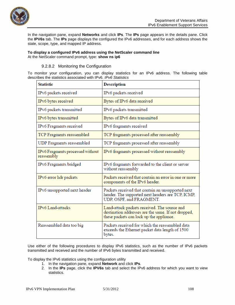
Department of Veterans Affairs
IPv6 Enablement Support Services
IPv6 VPN Implementation Plan 5/31/2012 108
In the navigation pane, expand Networks and click IPs. The IPs page appears in the details pane. Click the IPV6s tab. The IPs page displays the configured the IPv6 addresses, and for each address shows the state, scope, type, and mapped IP address. To display a configured IPv6 address using the NetScaler command line At the NetScaler command prompt, type: show ns ip6
9.2.8.2 Monitoring the Configuration
To monitor your configuration, you can display statistics for an IPv6 address. The following table describes the statistics associated with IPv6. IPv6 Statistics
Use either of the following procedures to display IPv6 statistics, such as the number of IPv6 packets transmitted and received and the number of IPv6 bytes transmitted and received. To display the IPv6 statistics using the configuration utility
1. In the navigation pane, expand Network and click IPs. 2. In the IPs page, click the IPV6s tab and select the IPv6 address for which you want to view
statistics.

Department of Veterans Affairs
IPv6 Enablement Support Services
IPv6 VPN Implementation Plan 5/31/2012 109
3. Click Statistics. To view the IPv6 statistics using the NetScaler command line At the NetScaler command prompt, type: stat protocol ipv6
9.2.9 Configuring Neighbor Discovery and Router Learning
The NetScaler supports neighbor discovery (ND) for IPv6. When the state of a vserver changes from down to up, the NetScaler sends gratuitous NA or unsolicited NA messages. The NetScaler also supports and router learning.
9.2.9.1 Neighbor Discovery
Neighbor discovery (ND) is one of the most important protocols of IPv6. It is a message-based protocol that combines the functionality of the Address Resolution Protocol (ARP), Internet Control Message Protocol (ICMP), and Router Discovery. ND allows nodes to advertise their link layer addresses and obtain the MAC addresses or link layer addresses of the neighboring nodes. This process is performed by the Neighbor Discovery protocol (ND6). Neighbor discovery can perform the following functions: Router Discovery. Enables a host to discover the local routers on an attached link and automatically configure a default router. Prefix Discovery. Enables the host to discover the network prefixes for local destinations. Zero fragment length received Packets received with a fragment length of 0 bytes. IPv6 Statistics Statistic Description Note: Currently, the NetScaler does not support Prefix Discovery. Parameter Discovery. Enables a host to discover additional operating parameters, such as MTU and the default hop limit for outbound traffic. Address Auto configuration. Enables hosts to automatically configure IP addresses for interfaces both with and without stateful address configuration services such as DHCPv6. The NetScaler does not support Address Auto configuration for Global IPv6 addresses. Address Resolution. Equivalent to ARP in IPv4, enables a node to resolve a neighboring node's IPv6 address to its link-layer address. Neighbor Unreachability Detection. Enables a node to determine the reach-ability state of a neighbor. Duplicate Address Detection. Enables a node to determine whether an NSIP address is already in use by a neighboring node. Redirect. Equivalent to the IPv4 ICMP Redirect message, enables a router to redirect the host to a better first-hop IPv6 address to reach a destination. Note: The NetScaler does not support IPv6 Redirect. To enable neighbor discovery, you must create entries for the neighbors.
9.2.9.2 Adding IPv6 Neighbors
The following table describes the parameters required for adding an IPv6 neighbor. To add an IPv6 neighbor using the configuration utility

Department of Veterans Affairs
IPv6 Enablement Support Services
IPv6 VPN Implementation Plan 5/31/2012 110
1. In the navigation pane, expand Network and click IPv6 Neighbors.
Neighbor Discovery Parameters Parameter Specifies Neighbor (neighbor) IPv6 neighbor entry. Mandatory. MAC Address (mac) Unique address assigned to identify the network appliance. Mandatory. Interface (ifnum) The interface on which the MAC resides. Mandatory. VLAN (vlan) Virtual LAN (VLAN) that the neighbor is part of.
2. In the IPv6 Neighbors page, click Add. 3. In the Create IPv6 Neighbor dialog box, in the Neighbor and MAC
Address text boxes, respectively, type IPv6 address and MAC Address of the neighbor (for example, 3ffe:100:100::1, 00:d0:68:0b:58:da).
4. If the neighbor is part of a VLAN, in the and VLAN field, type the VLAN ID (for example, 1). 5. In the Interface list box, select the interface of the neighbor (for example, LO/1). 6. Click Create, and click Close.
To add an IPv6 neighbor using the NetScaler command line At the NetScaler command prompt, type: add nd6 Neighbor MACAddress IFnum [-vlan Value] Example add nd6 3ffe:100:100::1 00:d0:68:0b:58:da 1/3 -vlan 1
9.2.9.3 Removing IPv6 Neighbors
Use either of the following procedures to remove a single Neighbor Discovery (ND6) entry from the NetScaler. To remove a neighbor discovery entry using the configuration utility
1. In the navigation pane, expand Network and click IPv6 Neighbor. 2. In the IPv6 Neighbors page, select the neighbor entry that you want to remove (for
example,3ffe:100:100::1).
3. Click Remove. To remove a neighbor discovery entry using the NetScaler command line At the NetScaler command prompt, type: rm nd6 Neighbor -vlan Value Example rm nd6 3ffe:100:100::1 -vlan 1 Use either of the following procedures to clear the Neighbor Discovery (ND6) entries from the NetScaler. To remove neighbor discovery entries using the configuration utility 1. In the navigation pane, expand Network and click IPv6 Neighbor. 178 Citrix NetScaler Networking Guide 2. In the IPv6 Neighbors page, click Clear. To remove neighbor discovery entries using the NetScaler command line At the NetScaler command prompt, type: clear nd6

Department of Veterans Affairs
IPv6 Enablement Support Services
IPv6 VPN Implementation Plan 5/31/2012 111
9.2.9.4 Displaying Discovered Neighbors
Use either of the following procedures to display information about the neighbors configured for discovery. To view discovered neighbors using the configuration utility In the navigation pane, expand Network and click IPv6 Neighbor. The IPv6 Neighbors page appears in the details pane, displaying information about the Neighbors, MAC Address, VLAN, Interface, State, and Time parameters. To view discovered neighbors using the NetScaler command line At the NetScaler command prompt, type: show nd6
9.2.10 Router Learning
The NetScaler can learn default routers from RA and RS messages. However, the NetScaler ignores other properties in RA messages, such as prefix list and MTU. Use either of the following procedures to enable router advertisement learning. To enable router discovery learning using the configuration utility
1. In the navigation pane, click Network. 2. In the Network page, click the Router Advertisement Learning link. 3. In the Configure RA Learning dialog box, select the Enable Router Advertisement Learning
check box. 4. Click OK.
To enable router discovery learning using the NetScaler command line At the NetScaler command prompt, type: set ipv6 -ralearning Value
Example set ipv6 -ralearning enabled
9.2.11 Adding IPv6 Support to NetScaler Features
A number of NetScaler components use IPv6 addresses or support the use of IPv6 addresses. The following table lists components that support IPv6 addresses and the sections that document them. You can also configure LB, CS, and CR vservers with IPv6 addresses, and you can create IPv6 VLANs. You can configure host header modification to send IPv6 requests to servers with IPv4 addresses, and VIP insertion to enable the servers to identify IPv6 vservers that send requests.
9.2.12 VLAN Support
If you need to send broadcast or multicast packets without identifying the VLAN (for example, during DAD for NSIP, or ND6 for the next hop of the route), you can configure the NetScaler to send the packet on all the interfaces with appropriate tagging. The VLAN is identified by ND6, and a data packet is sent only on the VLAN. For more information on ND6 and VLANs, see “Adding IPv6 Neighbors”. Port-based VLANs are common for IPv4 and IPv6. Prefix-based VLANs are supported for IPv6.
9.2.13 Simple Deployment Scenario
Following is an example of a simple load balancing set-up consisting of an IPv6 vserver and IPv4 services. The following table summarizes the names and values of the entities that must be configured on the NetScaler.

Department of Veterans Affairs
IPv6 Enablement Support Services
IPv6 VPN Implementation Plan 5/31/2012 112
Entity values to be configured on the NetScaler Entity Type Name Value LB Vserver VS1_IPv6 2002::9 Services SVC1 10.102.29.1 SVC2 10.102.29.2 The following figure shows the entities and values of the parameters to be configured on the NetScaler. To configure this deployment scenario, you need to do the following:
1. Create an IPv6 service 2. Create an IPv6 LB vserver 3. Bind the services to the vserver
The following procedure describes the steps to add two services, SVC1 and SVC2, of type HTTP. To create the IPv4 services using the configuration utility
1. In the navigation pane, expand Load Balancing and click Services. 2. On the Services page, click Add. 3. In the Create Service dialog box, in the Service Name, Server, and Port 1. text boxes, type the name, IP address, and port of the service (for example, 2. SVC1, 10.102.29.1, and 80). 3. In the Protocol drop-down list box, select the type of the service (for example, HTTP). 4. Click Create and click Close. 5. Repeat Steps 1-5 to create a service SVC2 with IP address 10.102.29.2 and port 80.
To create the IPv4 services using the NetScaler command line At the NetScaler command prompt, type: add service Name IPAddress Protocol Port add service Name IPAddress Protocol Port Example add service SVC1 10.102.29.1 HTTP 80 add service SVC2 10.102.29.2 HTTP 80 You can use either of the following procedures to add an IPv6 vserver named VS1_IPv6 of type HTTP, with an IP address of 2002::9. To create the IPv6 vserver using the configuration utility
1. In the navigation pane, expand Load Balancing and click Virtual Servers. 2. In the Load Balancing Virtual Servers page, click Add. 3. In the Create Virtual Servers (Load Balancing) dialog box, select the IPv6 check box. 4. In the Name, Port, and IP Addresses text boxes, type the name, port, and IP address of the
vserver (for example, VS1_IPv6, 80, and 2002::9). 5. Click Create and click Close. 6.
To create the IPv6 vserver using the NetScaler command line At the NetScaler command prompt, type: add lb vserver Name Protocol IPv6Address Port Example add lb vserver VS1_IPv6 HTTP 2002::9 80 Use either of the following procedures to bind the services to the vserver. To bind a service to an LB vserver using the configuration utility
1. In the navigation pane, expand Load Balancing and click Virtual Servers.

Department of Veterans Affairs
IPv6 Enablement Support Services
IPv6 VPN Implementation Plan 5/31/2012 113
2. In the Load Balancing Virtual Servers page, select the vserver for which you want to bind the service (for example, VS1_IPv6).
3. Click Open. 4. In the Configure Virtual Server (Load Balancing) dialog box, on the
Services tab, select the Active check box corresponding to the service that you want to bind to the vserver (for example, SVC1).
5. Click OK. 6. Repeat Steps 1-4 to bind the service (for example, SVC2 to the vserver).
To bind a service to an LB vserver using the NetScaler command line At the NetScaler command prompt, type: bind lb vserver Name service Example bind lb vserver VS1_IPv6 SVC1 The vservers receive IPv6 packets and the NetScaler performs Protocol Translation (RFC 2765) before sending traffic to the IPv4-based services.
9.2.13.1 Host Header Modification
When an HTTP request has an IPv6 address in the host header, and the server does not understand the IPv6 address, you must map the IPv6 address to an IPv4 address. The IPv4 address is then used in the host header of the HTTP request sent to the vserver. The following procedures include examples for mapping the IPv4 address 200.200.200.200 to the VIP 2002::9. To change the IPv6 address in the host header to an IPv4 address using the configuration utility
1. In the navigation pane, expand Networks and click IPs. 2. In the IPs page, click the IPV6s tab and select the IP address for which you want to
configure a mapped IP address, for example, 2002:0:0:0:0:0:0:9. 3. Click Open. 4. In the Configure IP6 dialog box, in the Mapped IP text box, type the mapped IP address that
you want to configure, for example, 200.200.200.200. 5. Click OK.
To change the IPv6 address in the host header to an IPv4 address using the NetScaler command line At the NetScaler command prompt, type: set ns ip6 IPv6Address -map IPAddress Example set ns ip6 2002::9 -map 200.200.200.200
9.2.13.2 VIP Insertion
If an IPv6 address is sent to an IPv4-based server, the server may not understand the IP address in the HTTP header, and may generate an error. To avoid this, you can map an IPv4 address to the IPv6 VIP and enable VIP insertion The following procedures include examples for mapping IPv4 address 200.200.200.200 to VIP 2002::9. To configure a mapped IPv6 address using the configuration utility
1. In the navigation pane, expand Networks and click IPs. 2. In the IPs page, click the IPV6s tab and select the IP address for which you 1. want to configure a mapped IP address (for example, 2002:0:0:0:0:0:0:9). 2. Click Open.

Department of Veterans Affairs
IPv6 Enablement Support Services
IPv6 VPN Implementation Plan 5/31/2012 114
3. In the Configure IP6 dialog box, in the Mapped IP text box, type the mapped IP address that you want to configure (for example, 200.200.200.200).
4. Click OK. To configure a mapped IPv6 address using the NetScaler command line At the NetScaler command prompt, type: set ns ip6 IPv6Address -map IPAddress Example set ns ip6 2002::9 -map 200.200.200.200 Use either of the following procedures to enable insertion of an Ipv4 VIP address and port number in the HTTP requests sent to the servers. To enable VIP insertion using the configuration utility
1. In the navigation pane, expand Load Balancing and click Virtual Servers. 2. In the Load Balancing Virtual Servers page, in the Load Balancing
Virtual Servers page, select the vserver that you want to enable port insertion (for example, VS1_IPv6). 3. Click Open. 4. In the Configure Virtual Server (Load Balancing) dialog box, click the Advanced tab. 5. In the Vserver IP Port Insertion drop-down list box, select VIPADDR. 6. In the Vserver IP Port Insertion text box, type the vip header.
To enable VIP insertion using the NetScaler command line At the NetScaler command prompt, type: set lb vserver Name -insertVserverIPPort Value Example set lb vserver VS1_IPv6 -insertVserverIPPort ON
9.2.14 Transition VPN Tunneling
v6 over v4 VPN Tunnel allows the V4 and V6 applications data traffic to coexist. The existing DMVPN logical connections from each remote site will encapsulate the IPv6 packets from each remote site through the existing Verizon and Sprint MPLS network backbone. This transition option is most relevant to VA. If VPN tunnels are used to encapsulate IPv4 within IPv6, or IPv6 within IPv4 the following must be considered:
The tunnel endpoints between the VPN should be secured as the traffic transits the VPN.
When an encapsulated IPv6 packet enters or leaves the VPN and Intrusion Detection is required, it should be understood that the Intrusion Detection application or other network security method used to permit a packet on that network, has been ported to IPv6, as previously identified.
Wireless network access from IPv6 nodes requires in-depth security analysis for implementation when stateless auto-configuration is used, in addition to current methods to secure IPv4 wireless networks.
Seamless Mobility with IPv6 will need to support the required security as identified by the VA to permit secure access to the network whether across the internal network, or remote from an external network.
9.2.15 Configuring Citrix MetaFrame Services
WebVPN users can use a connection to the security appliance to access Citrix MetaFrame services. The following functional areas introduce this function, list the prerequisites, and describe how to use ASDM to configure the security appliance to support this function:
Department of Veterans Affairs
IPv6 Enablement Support Services
IPv6 VPN Implementation Plan 5/31/2012 115
• Before You Begin, • Adding a Trust point, • Authenticating the Certificate Authority, • Enrolling the Certificate, • Applying the Trust point to an Interface, • Enabling WebVPN, • Enabling Citrix, • Configuring a Citrix Access Method, Note As you follow the instructions in this section, click Help for more information about the attributes shown in the ASDM windows.
9.2.16 Overview
The security appliance lets Citrix Independent Computing Architecture (ICA) clients access VA enterprise applications running on a Citrix Presentation Server over a WebVPN connection. You can redirect the WebVPN home page to the Citrix web server, add a link to the server on the WebVPN home page, or instruct users to enter the URL of the server to access Citrix MetaFrame services. When a WebVPN user connects to the Citrix web server, the Citrix Web Interface authenticates the user and lets the user access VA resources. Note Within this configuration, the security appliance functions as the Citrix secure gateway. Complete the instructions in the following sections to configure security appliance support for Citrix MetaFrame services running on one or more Citrix Presentation Servers.
9.2.16.1 Before You Begin
Before following the instructions in this section, configure the Citrix Web Interface software to operate in a mode that does not use the Citrix secure gateway. Note All browsers connecting to the Citrix server must support 128-bit encryption.
9.2.16.2 Adding a Trust point
These instructions describe how to add a trust point to the security appliance configuration to satisfy a Citrix connection requirement. A trust point contains the identity of a certificate authority, CA-specific configuration parameters, and an association with one enrolled identity certificate. You need one trust point to connect with the Citrix server. You can configure up to two trust points, each to be assigned to a different interface on the security appliance; however, you can assign a single trust point to two interfaces. Add a trust point to the security appliance configuration as follows: Step 1 Choose Configuration > Properties > Certificate > Trustpoint > Configuration. The Trust point Configuration window opens.

Department of Veterans Affairs
IPv6 Enablement Support Services
IPv6 VPN Implementation Plan 5/31/2012 116
Trust point Configuration
Step 2 Click Add. The Add Trustpoint Configuration window opens (Figure 2-2).

Department of Veterans Affairs
IPv6 Enablement Support Services
IPv6 VPN Implementation Plan 5/31/2012 117
Add Trustpoint Configuration
Step 3 Enter a value, such as the name of the certificate, in the Trustpoint Name field to uniquely identify this trust point and provide a visual association to the certificate. Step 4 Click either of the following attributes:
Use manual enrollment This option specifies the intention to generate a PKCS10 certification request. The CA issues a certificate to the security appliance based on the request, and the certificate is installed on the security appliance by importing the new certificate.
Use automatic enrollment If you choose this option, enter the URL for automatic enrollment in the Enrollment URL field. The automatic enrollment option specifies the intention to use SCEP mode. When the trust point is configured for SCEP enrollment, the security appliance downloads the certificate using the SCEP protocol. Step 5 Click Certificate Parameters. The Certificate Parameters window opens.

Department of Veterans Affairs
IPv6 Enablement Support Services
IPv6 VPN Implementation Plan 5/31/2012 118
Certificate Parameters
Step 6 Click Specify FQDN. Step 7 Enter the fully qualified domain name used in the Subject Alternative Name extension of the certificate into the Specify FQDN field. The FQDN addresses the server program to which to send requests. Step 8 Click Edit. The Edit DN window opens (Figure 2-4).

Department of Veterans Affairs
IPv6 Enablement Support Services
IPv6 VPN Implementation Plan 5/31/2012 119
Edit DN
Step 9 Select Common Name from the drop-down list next to the Attribute field. Step 10 Enter the FQDN you entered in Step 6 into the Value field and click Add. The Citrix ICA connection application requires a fully qualified domain name (FQDN) in the common name (CN) field of the SSL certificate. Caution Do not specify an IP address as the CN. ASDM inserts the new entry into the table on the right. Step 11 Click OK three times. ASDM inserts the new trust point into the Trustpoint Configuration table (Figure 2-1). Step 12 Click Apply to save the trustpoint to the Flash device.
9.2.16.3 Authenticating the Certificate Authority
Now that you have a trust point, you need to authenticate the certificate authority, as follows: Step 1 Choose Configuration > Properties > Certificate > Authentication. The Authentication window opens (Figure 2-5).
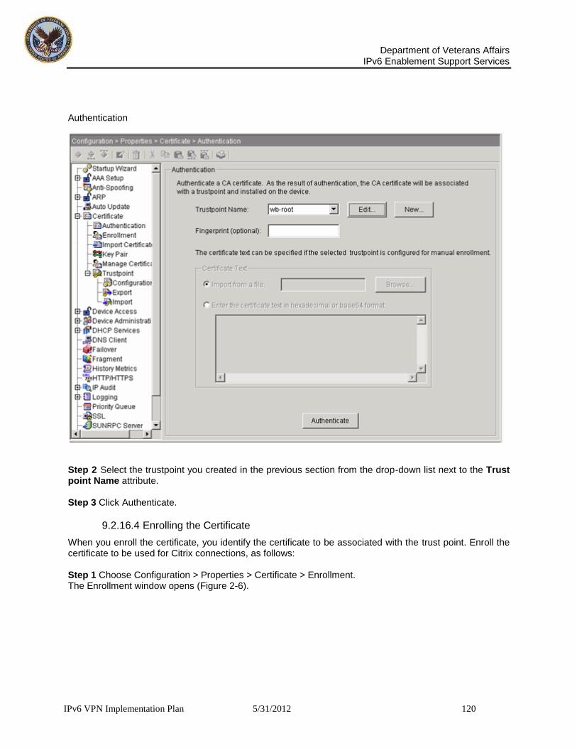
Department of Veterans Affairs
IPv6 Enablement Support Services
IPv6 VPN Implementation Plan 5/31/2012 120
Authentication
Step 2 Select the trustpoint you created in the previous section from the drop-down list next to the Trust point Name attribute. Step 3 Click Authenticate.
9.2.16.4 Enrolling the Certificate
When you enroll the certificate, you identify the certificate to be associated with the trust point. Enroll the certificate to be used for Citrix connections, as follows: Step 1 Choose Configuration > Properties > Certificate > Enrollment. The Enrollment window opens (Figure 2-6).

Department of Veterans Affairs
IPv6 Enablement Support Services
IPv6 VPN Implementation Plan 5/31/2012 121
Enrollment
Step 2 Select the trust point you created in the previous section from the drop-down list next to the Trustpoint Name attribute. Step 3 Click Enroll.
9.2.16.5 Applying the Trust point to an Interface
These instructions describe how to apply the trust point to the security appliance interface to be used to terminate WebVPN sessions to the Citrix server. You can, but are not required, to use this interface exclusively for Citrix connections. Apply the trust point to the interface as follows: Step 1 Choose Configuration > Properties > SSL. The SSL window opens.

Department of Veterans Affairs
IPv6 Enablement Support Services
IPv6 VPN Implementation Plan 5/31/2012 122
SSL
Step 2 Do either of the following:
• Select the trustpoint next to the Fallback Trust point attribute if you want any interface to use the trustpoint if it doesn’t have a specific trust point assigned, then click Apply to save the configuration change to the Flash device. This step completes the assignment of the trust point to the interface.
• Double-click the interface to be used to terminate WebVPN sessions to the Citrix server, to make an explicit assignment of the trust point to the interface. Typically, the interface used to terminate these sessions is the outside interface. The Edit SSL Trustpoint window opens (Figure 2-8).

Department of Veterans Affairs
IPv6 Enablement Support Services
IPv6 VPN Implementation Plan 5/31/2012 123
Edit SSL Trust point
Select the trust point next to the Primary Enrolled Trust point attribute and click OK, then click Apply to save the configuration change to the Flash device.
9.2.17 Enabling WebVPN
Remote access to Citrix MetaFrame services requires WebVPN tunneling to be enabled. Enable WebVPN on the group policy applied to the users for whom you want to provide these services as follows: Step 1 Choose Configuration > VPN > General > Group Policy. The Group Policy window opens (Figure 2-9). Group Policy

Department of Veterans Affairs
IPv6 Enablement Support Services
IPv6 VPN Implementation Plan 5/31/2012 124
Step 2 Use one of the following strategies:
• Set the default group policy to enable WebVPN tunneling. By default, group policies and users inherit the settings of the default group policy. Double-click the DfltGrpPolicy entry in the Group Policy table, verify the General tab is open, check WebVPN next to Tunneling Protocols, and click OK. • Limit WebVPN to alternative group policies for which you want to provide Citrix MetaFrame services.
By default, users inherit the tunneling protocols from their assigned group policies. For each internal or external group policy for which you want to provide access to Citrix MetaFrame services, double-click the policy in the Group Policy table, verify the General tab is open, clear the Inherit check box next to Tunneling Protocols, check WebVPN, and click OK. Note You can also create a new group policy to enable WebVPN services, but if you do, you also need to assign the group policy to the users to whom you want to grant this access right. For more information about configuring group policies, see Section 4, “Configuring Group Policies” compares the General tab in the DfltGrpPolicy to that of alternative policies.

Department of Veterans Affairs
IPv6 Enablement Support Services
IPv6 VPN Implementation Plan 5/31/2012 125
WebVPN Option in the DfltGrpPolicy and an Alternative Group Policy
Note If you check the Inherit check box in an alternative group policy, the policy uses the WebVPN setting of the default group policy. Clearing the Inherit check box allows you to customize an alternative group policy’s WebVPN setting, making it independent from the default group policy’s WebVPN setting. Step 3 Click Apply to save the modified group policies to the Flash device.
9.2.17.1 Enabling Citrix
You can enable Citrix MetaFrame services in the default group policy, alternative group policies, or individual user accounts. Refer to the section that names the strategy you prefer to use. • Enabling Citrix on a Group Policy, • Enabling Citrix on a User Account
9.2.17.1.1 Enabling Citrix on a Group Policy Enable Citrix MetaFrame services on one or more group policies, as follows: Step 1 Choose Configuration > VPN > General > Group Policy. The Group Policy window opens. Step 2 Use one of the following strategies to enable Citrix MetaFrame services: • Set the default group policy to enable Citrix.
By default, alternative group policies and users inherit the settings of the default group policy. Double-click the DfltGrpPolicy entry in the Group Policy table, open the WebVPN > Functions tab, check Enable Citrix MetaFrame, and click OK. • Set the alternative group policies for which you want to configure support for Citrix to enable
WebVPN tunneling. By default, users inherit the Functions settings from their respective assigned group policies. For each internal or external group policy for which you want to enable Citrix access, double-click the policy in the Group Policy table, open the WebVPN > Functions tab, clear Inherit, check Enable Citrix MetaFrame, and click OK. This compares the WebVPN > Functions tab in the DfltGrpPolicy to that of alternative policies.

Department of Veterans Affairs
IPv6 Enablement Support Services
IPv6 VPN Implementation Plan 5/31/2012 126
Enable Citrix MetaFrame in the DfltGrpPolicy and an Alternative Group Policy
If you check the Inherit check box in an alternative group policy, the policy uses the Enable Citrix MetaFrame of the default group policy. Clearing the Inherit check box allows you to customize an alternative group policy’s Functions settings, making them independent from the default group policy’s WebVPN setting. Tip The URL Enable entry attribute shown in, if checked, lets remote users type the URL of the Citrix server in the WebVPN home page or floating toolbar. Redirecting the home page to the Citrix server or creating a link to the home page and floating toolbar are other ways you can let users connect to the Citrix server. By default, the URL Enable entry attribute is checked in the default group policy. ASDM automatically inserts a check mark to enable this attribute if you clear Inherit in an alternative group policy. Use the default setting (checked) if you want to let users enter URLs, including the URL of the Citrix server. Otherwise, clear this attribute. The section, configuring a Citrix Access Method, provides more information about the options available to provide WebVPN access to a Citrix server.

Department of Veterans Affairs
IPv6 Enablement Support Services
IPv6 VPN Implementation Plan 5/31/2012 127
9.2.17.2 Enabling Citrix on a User Account
As an alternative to enabling Citrix services on group policies applied to users, you can modify user accounts to support Citrix MetaFrame Services. Follow this procedure once for each user account you want to modify. Step 1 Choose Configuration > Properties > Device Administration > User Accounts. The User Accounts window opens. User Accounts
Step 2 Double-click the user name.

Department of Veterans Affairs
IPv6 Enablement Support Services
IPv6 VPN Implementation Plan 5/31/2012 128
Step 3 Open the WebVPN > Functions tab. Edit User Account — WebVPN Functions
Step 4 Clear the Inherit check box and check Enable Citrix MetaFrame. If you check the Inherit check box, the user account uses all of its Functions settings from the assigned group policy. Clearing the Inherit check box lets you customize the Functions settings for that user. Step 5 Make sure that the other Functions settings are appropriate for the user. Tip The URL Enable entry attribute shown if checked, lets the user type the URL of the Citrix server in the WebVPN home page or floating toolbar. Redirecting the home page to the Citrix server or creating a link to the home page and floating toolbar are other ways you can let users connect to the Citrix server. By default, the URL Enable entry attribute is checked in the default group policy. ASDM automatically inserts a check mark to enable this attribute if you clear the Inherit check box in the user account. Use the default

Department of Veterans Affairs
IPv6 Enablement Support Services
IPv6 VPN Implementation Plan 5/31/2012 129
setting (checked) if you want to let the user enter URLs, including the URL of the Citrix server. Otherwise, clear this attribute. The section, configuring a Citrix Access Method, provides more information about the options available to provide WebVPN access to a Citrix server. Step 6 Click OK. Step 7 Click Apply to save the modified user accounts to the Flash device. Note Now that you have cleared the Inherit check box for the Functions settings, the user may lose access to features that were enabled. To view the previously inherited Functions settings, open the VPN Policy tab and note the Group Policy setting. Choose Configuration > VPN > General > Group Policy, double-click the group policy name that matches the Group Policy setting you previously viewed, and view the settings in the group policy’s WebVPN > Functions tab.
9.2.17.3 Configuring a Citrix Access Method
To let users connect to a Citrix MetaFrame server, they need a facility for doing so on the WebVPN home page or toolbar. To provide a means to connect to the Citrix server, refer to the section that names the method you want to use. • Redirecting the WebVPN User Home Page to the Citrix Server • Adding a Link on the WebVPN Home Page to the Citrix Server • Enabling URL Entry on the WebVPN Home Page
9.2.17.3.1 Redirecting the WebVPN User Home Page to the Citrix Server To let WebVPN users access a Citrix server, you can specify its URL as the remote user’s WebVPN home page. Use at least one of the following sections to change the URL of the home page: • Redirecting the Home Page on a Group Policy • Redirecting the Home Page on a User Account
9.2.17.3.2 Redirecting the Home Page on a Group Policy Redirect the WebVPN home page to the URL of a Citrix MetaFrame server in one or more group policies, as follows: Step 1 Choose Configuration > VPN > General > Group Policy. The Group Policy window opens. Step 2 Use one of the following strategies to redirect the WebVPN home page: • Set the default group policy to redirect the WebVPN home page.
By default, alternative group policies and users inherit the Custom Homepage setting of the default group policy. Double-click the DfltGrpPolicy entry in the Group Policy table, open the WebVPN > Homepage tab, click Specify URL, select http from the drop-down menu, enter the URL of the Citrix server in the field to the right, and click OK.
• Set the alternative group policies to redirect the WebVPN home page. By default, users inherit the Custom Homepage setting from their respective assigned group policies.
Configuring a Citrix Access Method For each internal or external group policy for which you want to redirect the WebVPN home page, double-click the policy in the Group Policy table, open the WebVPN > Homepage tab, clear Inherit in the Custom Homepage area, click Specify URL, select http from the drop-down menu, enter the URL of the Citrix server in the field to the right, and click OK.
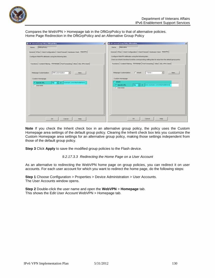
Department of Veterans Affairs
IPv6 Enablement Support Services
IPv6 VPN Implementation Plan 5/31/2012 130
Compares the WebVPN > Homepage tab in the DfltGrpPolicy to that of alternative policies. Home Page Redirection in the DfltGrpPolicy and an Alternative Group Policy
Note If you check the Inherit check box in an alternative group policy, the policy uses the Custom Homepage area settings of the default group policy. Clearing the Inherit check box lets you customize the Custom Homepage area settings for an alternative group policy, making those settings independent from those of the default group policy. Step 3 Click Apply to save the modified group policies to the Flash device.
9.2.17.3.3 Redirecting the Home Page on a User Account As an alternative to redirecting the WebVPN home page on group policies, you can redirect it on user accounts. For each user account for which you want to redirect the home page, do the following steps: Step 1 Choose Configuration > Properties > Device Administration > User Accounts. The User Accounts window opens. Step 2 Double-click the user name and open the WebVPN > Homepage tab. This shows the Edit User Account WebVPN > Homepage tab.

Department of Veterans Affairs
IPv6 Enablement Support Services
IPv6 VPN Implementation Plan 5/31/2012 131
Edit User Account WebVPN > Homepage Tab
Step 3 Clear the Inherit check box in the Custom Homepage area, click Specify URL, select http from the drop-down menu, enter the URL of the Citrix server in the field to the right, and click OK. Note If you check the Inherit check box, the user account uses Custom Homepage settings from the Assigned group policy. Clearing the Inherit check box lets you customize the settings for that user. Step 4 Click Apply to save the modified user accounts to the Flash device.

Department of Veterans Affairs
IPv6 Enablement Support Services
IPv6 VPN Implementation Plan 5/31/2012 132
9.2.17.4 Adding a Link on the WebVPN Home Page to the Citrix Server
To let WebVPN users access a Citrix server, you can display a link to the server on the WebVPN homepage and floating toolbar (Figure 2-16). WebVPN Home Page and Floating Toolbar
Users only need to click on the Citrix link in the Web Bookmarks menu or list to access the Citrix server. Use the instructions in the following sections to prepare and configure the link to the Citrix server. • Examining the URL List Mappings • Configuring the Link to the Citrix Server
9.2.17.4.1 Examining the URL List Mappings Inserting a URL onto the WebVPN home page requires modifying one or more existing lists of URLs or adding one or more new lists. (A “list” can consist of only one URL.) To know which lists to modify or whether to add a new list, you need to know whether the group policies and user accounts for whom you want to create a Citrix link are using a list, and if so, which list. Examine the current group policy and user account configuration to determine how to proceed, as follows: Step 1 Choose Configuration > VPN > General > Group Policy. The Group Policy window opens. Step 2 For each group policy, double-click the policy name and open the WebVPN > Other tab. Figure 2-17 compares the WebVPN > Other tab of the default group policy to that of the alternative policy.

Department of Veterans Affairs
IPv6 Enablement Support Services
IPv6 VPN Implementation Plan 5/31/2012 133
9.2.18 Configuring Citrix MetaFrame Services and Configuring a Citrix Access Method
Figure 12: Servers and URL Lists in the DfltGrpPolicy and an Alternative Group Policy Step 3 Note the values of the Servers and URLs Lists attributes, then click Cancel. Step 4 Choose Configuration > Properties > Device Administration > User Accounts. The User Accounts window opens. Step 5 For each user account for which you are adding support for Citrix services, double-click the policy name and open the WebVPN > Other tab. This shows the Servers and URL Lists attributes on the WebVPN > Other tab of an example user account.

Department of Veterans Affairs
IPv6 Enablement Support Services
IPv6 VPN Implementation Plan 5/31/2012 134
Configuring a Citrix Access Method Servers and URL Lists Attribute in a User Account
Step 6 Note the values of the Servers and URLs Lists attributes, then click Cancel.
9.2.18.1 Configuring the Link to the Citrix Server
Now that you know whether the group policies and users for whom you want to provide Citrix MetaFrame services are using URL lists, and the names of any URL lists they are using, you are qualified to modify the security appliance configuration of servers and URLs to create the link to the Citrix server. Create the link to the Citrix server and assign it to the group policies and users for whom you are configuring Citrix access, as follows: Step 1 Choose Configuration > VPN > WebVPN > Servers and URLs. The Servers and URLs window opens (Figure 2-19).

Department of Veterans Affairs
IPv6 Enablement Support Services
IPv6 VPN Implementation Plan 5/31/2012 135
9.2.18.2 Configuring a Citrix Access Method
Servers and URLs
Each list displayed in this window consists of the link names (URL Display Names) and their associated URLs. Following the configuration of a new list, you assign it to at least one group policy or user account to display the list on the WebVPN home page and floating toolbar. If you add a link to a list that is already assigned to a group policy or user account, the WebVPN home page and floating toolbar automatically add the link for each subsequent login. Note The Servers and URLs lists have a one-to-one association with the default group policy, and a one-to-many relationship to alternative group policies and user accounts. You can assign one list to more than one group policy and user account, but you cannot assign more than one list to the same group policy or user account. Step 2 Continue with the instructions in one of the following sections:
• See Adding a Servers and URLs List if the group policies or user accounts for which you are configuring Citrix services do not have an assigned Servers and URLs list. • See Adding a URL to a Servers and URLs List if the group policies or user accounts for which
you are configuring Citrix services already have an assigned Servers and URLs list.

Department of Veterans Affairs
IPv6 Enablement Support Services
IPv6 VPN Implementation Plan 5/31/2012 136
Adding a Servers and URLs List Continue with the instructions from the previous section to add a Servers and URLs list if the group profiles or user accounts for which you are configuring access to Citrix MetaFrame services do not already have an assigned Servers and URLs list: Step 1 Click Add in the Servers and URLs window shown in. The Add Server and URL List window opens
Add Server and URL List Step 2 Enter a name in the List Name field to differentiate this list from the others in the Servers and URLs configuration. We suggest a name that describes the intent of the group profiles and user accounts for which you want to use them.

Department of Veterans Affairs
IPv6 Enablement Support Services
IPv6 VPN Implementation Plan 5/31/2012 137
Step 3 Click Add to create the Citrix link. The Add Server or URL window opens.
Add Server or URL Step 4 Select http from the drop-down menu, enter the URL of the Citrix server in the field to the right, and click OK. ASDM inserts the URL entry into the Add Server and URL List table shown. Step 5 Click OK. ASDM inserts the list entry into the Servers and URLs window shown. Step 6 Click Apply to save the modified Servers and URLs configuration to the Flash device. Step 7 Choose Configuration > VPN > General > Group Policy. The Group Policy window opens. Step 8 For each group policy for which you want to provide a URL to the Citrix MetaFrame server, double-click the group policy, open the WebVPN > Other tab, clear the Inherit check box next to Servers and URL Lists if the group policy is an alternative to the default group policy, select the list you created in the drop-down menu to the right of the Servers and URL Lists attribute, and click OK. Step 9 Click Apply to save the modified group policies to the Flash device. Step 10 Choose Configuration > Properties > Device Administration > User Accounts. The User Accounts window opens. Step 11 For each custom user account for which you want to provide a URL to the Citrix MetaFrame server, double-click the user account, open the WebVPN > Other tab, clear the Inherit check box next to the Servers and URL Lists attribute, select the list you created in the drop-down menu to the right of Servers and URL Lists, and click OK. Step 12 Click Apply to save the modified user accounts to the Flash device. Adding a URL to a Servers and URLs List

Department of Veterans Affairs
IPv6 Enablement Support Services
IPv6 VPN Implementation Plan 5/31/2012 138
Continue with the instructions to modify an entry in the Servers and URLs table displayed. Use these instructions only if the group policies or user accounts for which you want to add a URL to the Citrix server already have a Servers and URLs list assignment. Step 1 Double-click the entry in the Servers and URLs window. The Edit Server and URL List window opens. Edit Server and URL List
Step 2 Click Add to insert the Citrix link into this list. The Add Server or URL window opens. Add Server or URL
Department of Veterans Affairs
IPv6 Enablement Support Services
IPv6 VPN Implementation Plan 5/31/2012 139
Step 3 Select http from the drop-down menu, enter the URL of the Citrix server in the field to the right, and click OK. ASDM inserts the URL entry into the Edit Server and URL List table shown. Step 4 Click OK. ASDM inserts the list entry into the Servers and URLs window shown. Step 5 Click Apply to save the modified list to the Flash device. Note This step completes the configuration of the link to the Citrix server if the Servers and URLs list is already assigned to all of the group policies and user accounts for which you want to add a link to the Citrix server. If it is not, continue with the remaining instructions. Step 6 Choose Configuration > VPN > General > Group Policy. The Group Policy window opens. Step 7 For each group policy for which you want to assign the list containing the newly added link to the Citrix server, double-click the group policy, open the WebVPN > Other tab, clear the Inherit check box next to Servers and URL Lists if the group policy is an alternative to the default group policy, select the list you created in the drop-down menu to the right of Servers and URL Lists, and click OK. Step 8 Click Apply to save the modified group policies to the Flash device. Step 9 Choose Configuration > Properties > Device Administration > User Accounts. The User Accounts window opens. Step 10 For each custom user account for which you want to assign the list containing the newly added link to the Citrix server, double-click the user account, open the WebVPN > Other tab, clear Inherit check box next to Servers and URL Lists, select the list you created in the drop-down menu to the right of Servers and URL Lists, and click OK. Step 11 Click Apply to save the modified user accounts to the Flash device.
9.2.18.3 Enabling URL Entry on the WebVPN Home Page
To let WebVPN users access a Citrix server, you can enable URL entry and send them the URL to enter to access the server. Users enter the URL into the Enter Web Address field of the WebVPN home page or floating toolbar. The default setting of the Enable URL Entry attribute in the default group policy is checked. The Enable URL Entry attribute in the WebVPN > Functions tab of the group policy or user account, if checked, lets remote users type the URL of the Citrix server in the WebVPN home page or floating toolbar. By default, the Enable URL Entry attribute shown on the left side is checked in the default group policy. ASDM automatically inserts a check mark to enable this parameter if you inherit in an alternative group policy or user account. Use the default setting (checked) if you want to let users enter URLs, including the URL of the Citrix server. Otherwise, clear this attribute. Because the Enable URL Entry attribute is enabled by default, it is unlikely that you will need to do anything to display the Enter Web Address field on the WebVPN home page or floating toolbar. We do, however, recommend that you check the value of this attribute for each group policy and user account to be sure that users can use the Enter Web Address field. Make sure the Enable URL Entry attribute is either checked or inherited from each applicable group policy or user account, as follows: Step 1 For each group policy for which you enabled Citrix MetaFrame services, choose Configuration > VPN > General > Group Policy, double-click the entry in the Group Policy table (beginning with the DfltGrpPolicy if you are using it for Citrix access), open the WebVPN > Functions tab, check Inherit or both Enable URL Entry and Enable Citrix MetaFrame, click OK, and click Apply. Step 2 For each user account for which you enabled Citrix MetaFrame services, choose configuration > Properties > Device Administration > User Accounts, double-click the entry in the User Accounts table, open the WebVPN > Functions tab, check Inherit or both Enable URL Entry and Enable Citrix MetaFrame, click OK, and click Apply.

Department of Veterans Affairs
IPv6 Enablement Support Services
IPv6 VPN Implementation Plan 5/31/2012 140
9.2.18.4 Configuring Client Update
The client update feature lets administrators at a central location automatically notify VPN client users that it is time to update the VPN client software and the VPN 3002 hardware client image. If the client is already running a software version on the list of revision numbers, it does not need to update its software. If the client is not running a software version on the list, it should update. This procedure applies only to the IPSec remote-access tunnel-group type. Remote users might be using outdated VPN software or hardware client versions. You can perform a client-update at any time to do the following functions:
Enable updating client revisions
Specify the types and revision numbers of clients to which the update applies
Provide a URL or IP address from which to get the update
Optionally notify Windows client users that they should update their VPN client version.
For Windows clients, you can provide a mechanism for users to accomplish the update.
For VPN 3002 hardware client users, the update occurs automatically, with no notification. To configure a client-update, perform the following steps. Step 1 Go to the client update window by choosing the path Configuration > VPN > General > Client Update. The Client Update window opens.
Step 2 Enable client update by checking the Enable Client Update check box. Step 3 Select the type of client for which you want to apply the client update. The available client types are All Windows-Based, Windows 95, 98 or ME, Windows NT 4.0, 2000 or XP, and VPN 3002 Hardware Client. If the client is already running a software version on the list of revision numbers, it does not need to update its software. If the client is not running a software version on the list, it should update. You can specify up to three of these client update entries. The All Windows Based selection covers all of the allowable Windows platforms. If you select this, do not specify the individual Windows client types.
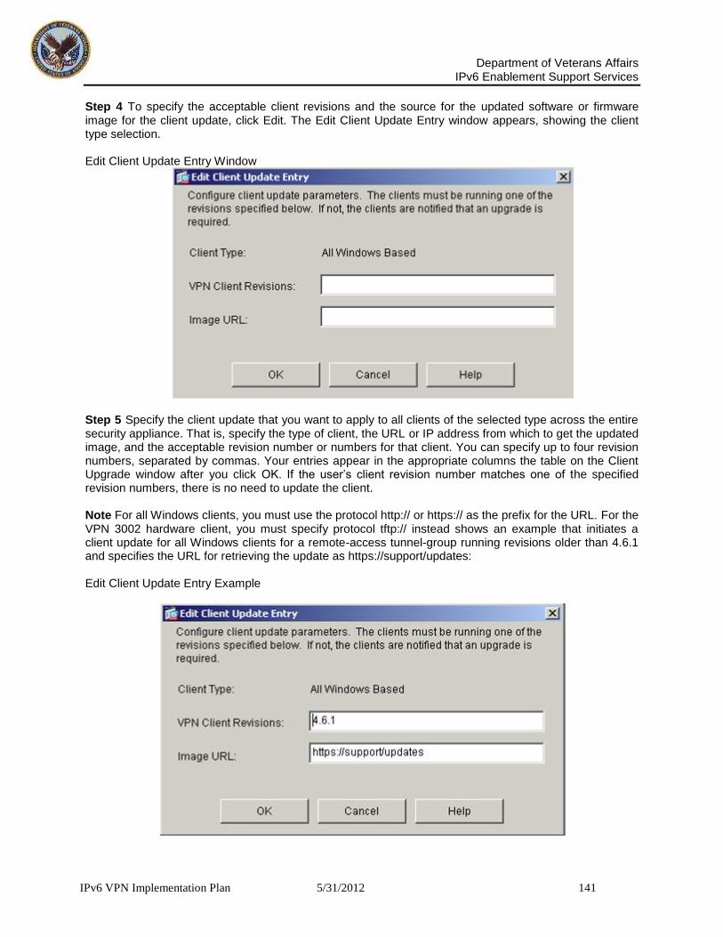
Department of Veterans Affairs
IPv6 Enablement Support Services
IPv6 VPN Implementation Plan 5/31/2012 141
Step 4 To specify the acceptable client revisions and the source for the updated software or firmware image for the client update, click Edit. The Edit Client Update Entry window appears, showing the client type selection. Edit Client Update Entry Window
Step 5 Specify the client update that you want to apply to all clients of the selected type across the entire security appliance. That is, specify the type of client, the URL or IP address from which to get the updated image, and the acceptable revision number or numbers for that client. You can specify up to four revision numbers, separated by commas. Your entries appear in the appropriate columns the table on the Client Upgrade window after you click OK. If the user’s client revision number matches one of the specified revision numbers, there is no need to update the client. Note For all Windows clients, you must use the protocol http:// or https:// as the prefix for the URL. For the VPN 3002 hardware client, you must specify protocol tftp:// instead shows an example that initiates a client update for all Windows clients for a remote-access tunnel-group running revisions older than 4.6.1 and specifies the URL for retrieving the update as https://support/updates: Edit Client Update Entry Example
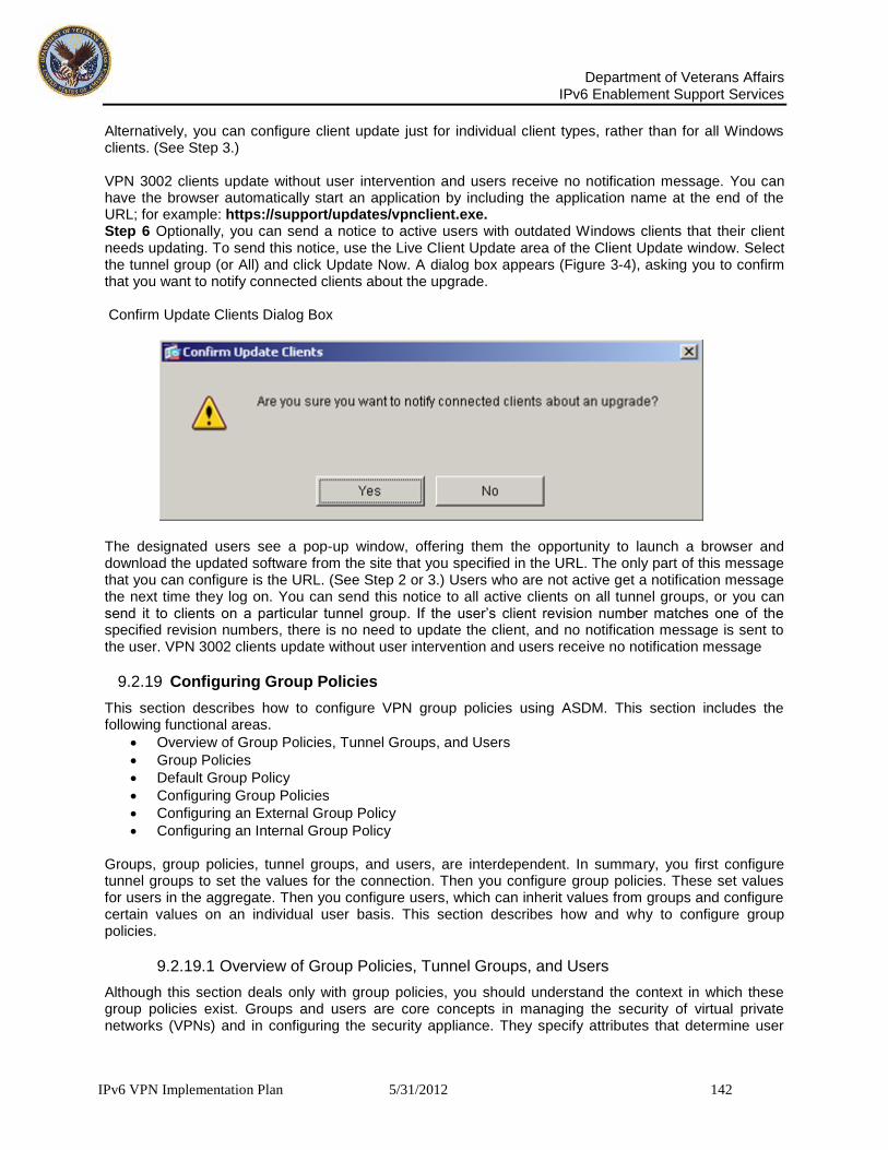
Department of Veterans Affairs
IPv6 Enablement Support Services
IPv6 VPN Implementation Plan 5/31/2012 142
Alternatively, you can configure client update just for individual client types, rather than for all Windows clients. (See Step 3.) VPN 3002 clients update without user intervention and users receive no notification message. You can have the browser automatically start an application by including the application name at the end of the URL; for example: https://support/updates/vpnclient.exe. Step 6 Optionally, you can send a notice to active users with outdated Windows clients that their client needs updating. To send this notice, use the Live Client Update area of the Client Update window. Select the tunnel group (or All) and click Update Now. A dialog box appears (Figure 3-4), asking you to confirm that you want to notify connected clients about the upgrade. Confirm Update Clients Dialog Box
The designated users see a pop-up window, offering them the opportunity to launch a browser and download the updated software from the site that you specified in the URL. The only part of this message that you can configure is the URL. (See Step 2 or 3.) Users who are not active get a notification message the next time they log on. You can send this notice to all active clients on all tunnel groups, or you can send it to clients on a particular tunnel group. If the user’s client revision number matches one of the specified revision numbers, there is no need to update the client, and no notification message is sent to the user. VPN 3002 clients update without user intervention and users receive no notification message
9.2.19 Configuring Group Policies
This section describes how to configure VPN group policies using ASDM. This section includes the following functional areas.
Overview of Group Policies, Tunnel Groups, and Users
Group Policies
Default Group Policy
Configuring Group Policies
Configuring an External Group Policy
Configuring an Internal Group Policy Groups, group policies, tunnel groups, and users, are interdependent. In summary, you first configure tunnel groups to set the values for the connection. Then you configure group policies. These set values for users in the aggregate. Then you configure users, which can inherit values from groups and configure certain values on an individual user basis. This section describes how and why to configure group policies.
9.2.19.1 Overview of Group Policies, Tunnel Groups, and Users
Although this section deals only with group policies, you should understand the context in which these group policies exist. Groups and users are core concepts in managing the security of virtual private networks (VPNs) and in configuring the security appliance. They specify attributes that determine user

Department of Veterans Affairs
IPv6 Enablement Support Services
IPv6 VPN Implementation Plan 5/31/2012 143
access to and use of the VPN. A group is a collection of users treated as a single entity. Users get their attributes from group policies. Tunnel groups identify the group policy for a specific connection. If you do not assign a particular group policy to a user, the default group policy for the connection applies. Tunnel groups and group policies simplify system management. To streamline the configuration task, the security appliance provides a default LAN-to-LAN tunnel group, a default remote access tunnel group, a default WebVPN tunnel group, and a default group policy (DfltGrpPolicy). The default tunnel groups and group policy provide settings that are likely to be common for many users. As you add users, you can specify that they “inherit” parameters from a group policy. Thus you can quickly configure VPN access for large numbers of users. If you decide to grant identical rights to all VPN users, then you do not need to configure specific tunnel groups or group policies, but VPNs seldom work that way. For example, you might allow a finance group to access one part of a private network, a customer support group to access another part, and an MIS group to access other parts. In addition, you might allow specific users within MIS to access systems that other MIS users cannot access. Tunnel groups and group policies provide the flexibility to do so securely. Note The security appliance also includes the concept of object groups, which are a superset of network lists. Object groups let you define VPN access to ports as well as networks. Object groups relate to ACLs rather than to group policies and tunnel groups. For more information about using object groups, see Cisco Security Appliance Command Line Configuration Guide, Section 13, “Identifying Traffic with Access Lists.”
9.2.19.1.1 Group Policies A group policy is a set of user-oriented attribute/value pairs for IPSec connections that are stored either internally (locally) on the device or externally on a RADIUS or LDAP server. A tunnel group uses a group policy that sets terms for user connections after the tunnel is established. Group policies let you apply whole sets of attributes to a user or a group of users, rather than having to specify each attribute individually for each user. You can also modify the group-policy attributes for a specific user To assign a group policy to users or to modify a group policy for specific users, select Configuration > VPN > General > Group Policy.

Department of Veterans Affairs
IPv6 Enablement Support Services
IPv6 VPN Implementation Plan 5/31/2012 144
Group Policy Window
. You can configure internal and external group policies. Internal groups are configured on the security appliance internal database. External groups are configured on an external authentication server, such as RADIUS or LDAP. Group policies include the following attributes:
Identity
Server definitions
Client firewall settings
Tunneling protocols
IPSec settings
Hardware client settings
Filters
Client configuration settings
WebVPN functions
Connection settings
9.2.19.1.2 Default Group Policy
The security appliance supplies a default group policy, named DfltGrpPolicy, which always exists on the security appliance. This default group policy does not take effect unless you configure the security appliance to use it. DfltGrpPolicy is always an internal group policy. You can modify this default group policy, but you cannot delete it. When you configure other group policies, any attribute that you do not explicitly specify takes its value from the default group policy. The Group Policy window lets you manage VPN group policies. Configuring the default VPN group policy lets users inherit attributes that you have not configured at the individual group or username level. By default, VPN users have no group policy association. The group policy information is used by VPN tunnel groups and user accounts. The “child”

Department of Veterans Affairs
IPv6 Enablement Support Services
IPv6 VPN Implementation Plan 5/31/2012 145
windows, tabs, and dialog boxes let you configure the default group parameters. These parameters are those that are most likely to be common across all groups and users, and they streamline the configuration task. Groups can “inherit” parameters from this default group, and users can “inherit” parameters from their group or the default group. You can override these parameters as you configure groups and users. To modify the default group policy, select DfltGrpPolicy in the table on the Group Policy window and click Edit. The Edit Internal Group Policy: DfltGrpPolicy window appears: Edit Internal Group Policy: DfltGrpPolicy Window
To change any of the attributes of the default group policy, work through the selections on the various tabs on the Edit Internal Group Policy: DfltGrpPolicy window, just as you would for any other internal group policy, as described in Configuring an Internal Group Policy The default group policy, DfltGrpPolicy, that the security appliance has the following attributes: group-policy DfltGrpPolicy internal group-policy DfltGrpPolicy attributes

Department of Veterans Affairs
IPv6 Enablement Support Services
IPv6 VPN Implementation Plan 5/31/2012 146
wins-server none dns-server none vpn-access-hours none vpn-simultaneous-logins 3 vpn-idle-timeout 30 vpn-session-timeout none vpn-filter none vpn-tunnel-protocol IPSec password-storage disable ip-comp disable re-xauth disable group-lock none pfs disable banner none ipsec-udp disable ipsec-udp-port 10000 split-tunnel-policy tunnelall split-tunnel-network-list none default-domain none split-dns none secure-unit-authentication disable user-authentication disable user-authentication-idle-timeout 30 ip-phone-bypass disable leap-bypass disable nem disable backup-servers keep-client-config client-firewall none client-access-rule none webvpn functions url-entry no html-content-filter no homepage no filter no url-list no port-forward port-forward-name value Application Access
9.2.19.1.3 Configuring Group Policies This section includes the following functional areas:
Default Group Policy,
Adding an External Group Policy
Editing an External Group Policy
Configuring Internal Group Policy General Attributes
Configuring IPSec Attributes
Configuring Client Configuration Parameters
Configuring Attributes for VPN Hardware Clients
Configuring Group-Policy WebVPN Attributes A group policy can apply to any kind of tunnel. In each case, if you do not explicitly define a parameter, the group takes the value from the default group policy. To configure (add or modify) a group policy, follow the steps in the subsequent sections. If you click the Add dialog box, a small menu appears giving you the option to create a new internal group policy, or an external group policy that is stored externally on a RADIUS or LDAP server. Both the Add Internal Group Policy window and the Edit Group Policy

Department of Veterans Affairs
IPv6 Enablement Support Services
IPv6 VPN Implementation Plan 5/31/2012 147
window include six tabbed sections. If you click the WebVPN tab, you expose six additional tabs. Click each tab to display its parameters. As you move from tab to tab, the security appliance retains your settings. When you have finished setting parameters on all tabbed sections, click OK or Cancel. In these dialog boxes, you configure the following kinds of parameters:
General Parameters: Protocols, filtering, connection settings, and servers.
IPSec Parameters: IP Security tunneling protocol parameters and client access rules.
Client Configuration Parameters: Banner, password storage, split-tunneling policy, default domain name, IPSec over UDP, backup servers.
Client FW Parameters: VPN Client personal firewall requirements.
Hardware Client Parameters: Interactive hardware client and individual user authentication; network extension mode.
WebVPN Parameters: SSL VPN access. Before configuring these parameters, you should configure:
Access hours.
Rules and filters.
IPSec Security Associations.
Network lists for filtering and split tunneling
User authentication servers, and specifically the internal authentication server.
9.2.19.1.4 Configuring an External Group Policy
External group policies take their attribute values from the external server that you specify. For an external group policy, you must identify the AAA server group that the security appliance can query for attributes and specify the password to use when retrieving attributes from the external AAA server group. If you are using an external authentication server, keep in mind that usernames and group names must be unique. When naming a group, do not pick a name that matches the name of any external user. Conversely, when assigning a name to an external user, do not choose the name of any existing group. The security appliance supports user authorization on an external LDAP or RADIUS server. Before you configure the security appliance to use an external server, you must configure the server with the correct security appliance authorization attributes and, from a subset of these attributes, assign specific permissions to individual users. Follow the instructions in the Cisco Security Appliance Command Line Configuration Guide, Appendix E, “Configuring an External Server for Security Appliance User Authorization” to configure your external server.

Department of Veterans Affairs
IPv6 Enablement Support Services
IPv6 VPN Implementation Plan 5/31/2012 148
9.2.19.1.5 Adding an External Group Policy
The following steps explain how to add an external group policy. Step 1 To add an external group policy, select Configuration > VPN > General > Group Policy, click Add, and select External Group Policy from the menu.
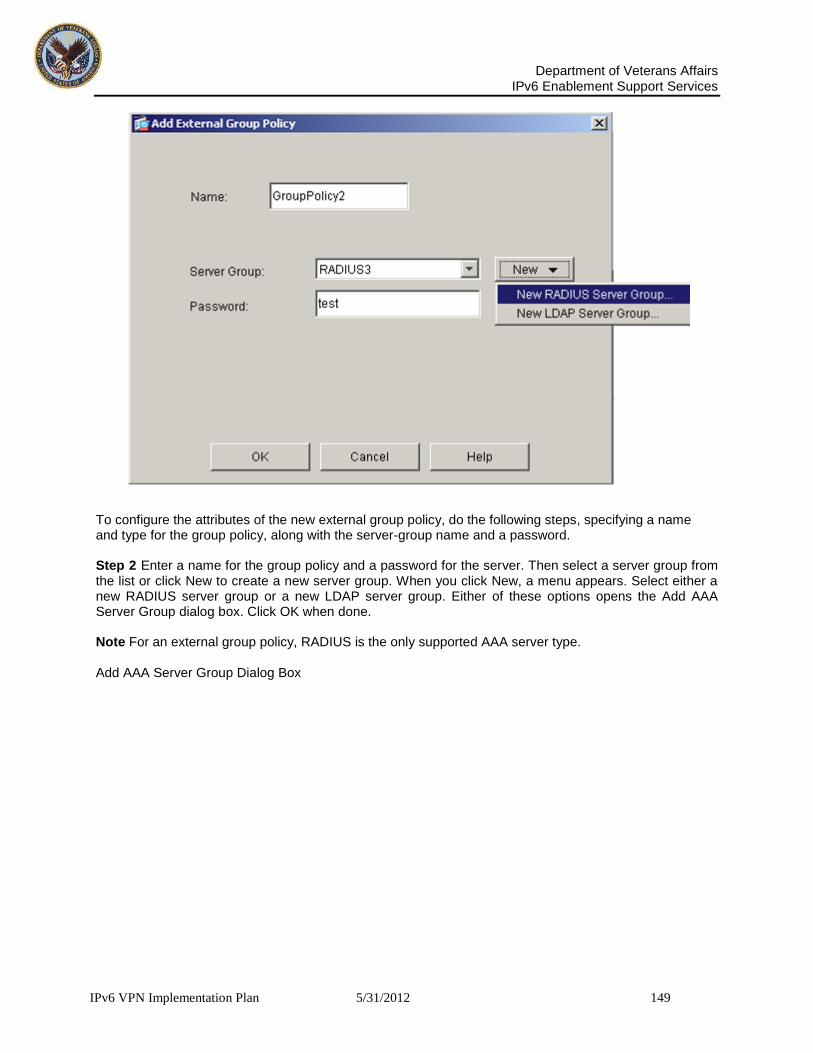
Department of Veterans Affairs
IPv6 Enablement Support Services
IPv6 VPN Implementation Plan 5/31/2012 149
To configure the attributes of the new external group policy, do the following steps, specifying a name and type for the group policy, along with the server-group name and a password. Step 2 Enter a name for the group policy and a password for the server. Then select a server group from the list or click New to create a new server group. When you click New, a menu appears. Select either a new RADIUS server group or a new LDAP server group. Either of these options opens the Add AAA Server Group dialog box. Click OK when done. Note For an external group policy, RADIUS is the only supported AAA server type. Add AAA Server Group Dialog Box

Department of Veterans Affairs
IPv6 Enablement Support Services
IPv6 VPN Implementation Plan 5/31/2012 150
Step 3 Configure the AAA server group parameters. The Add AAA Server Group dialog box lets you configure a new AAA server group with the following attributes. The Accounting Mode attribute applies only to RADIUS and TACACS+ protocols.
Server Group—Specifies the name of the server group.
Protocol—(Display only) Indicates whether this is a RADIUS or an LDAP server group. For an external group policy, this is always RADIUS.
Accounting Mode—(RADIUS and TACACS+ protocols only) indicates whether to use simultaneous or single accounting mode. In single mode, the security appliance sends accounting data to only one server. In simultaneous mode, the security appliance sends accounting data to all servers in the group.
Reactivation Mode—Specifies the method by which failed servers are reactivated: Depletion or Timed reactivation mode. In Depletion mode, failed servers are reactivated only after all of the servers in the group become inactive. In Timed mode, failed servers are reactivated after 30 seconds of down time.
Dead Time—Specifies, for depletion mode, the number of minutes that must elapse between the disabling of the last server in the group and the subsequent re-enabling of all servers. This field is not available for timed mode.
Max Failed Attempts— Specifies the number (an integer in the range 1 through 5) of failed connection attempts allowed before declaring a nonresponsive server inactive.
Note You can configure several vendor-specific attributes (VSAs), as described in Cisco Security Appliance Command Line Configuration Guide Appendix E, “Configuring an External Server for Security Appliance User Authorization”. If a RADIUS server is configured to return the Class attribute (#25), the security appliance uses that attribute to authenticate the Group Name. On the RADIUS server, the attribute must be formatted as: OU=groupname; where groupname is identical to the Group Name configured on the security appliance—for example, OU=Finance.

Department of Veterans Affairs
IPv6 Enablement Support Services
IPv6 VPN Implementation Plan 5/31/2012 151
9.2.20 Empty Server Group Message
If the server group name that you specify does not contain any servers, you see the following message: Empty Server Group Message
To add servers to a group, select Configuration > Properties >AAA Setup > AAA Groups. To continue after seeing this message, click OK. To exit the external group configuration procedure, click Cancel.
9.2.20.1 Editing an External Group Policy
The procedures for editing a group policy are similar to those for adding, except that when you click Edit on the Group Policy window, the Edit Group Policy window appears, with the Name field already filled in. The rest of the fields on this window are the same. You can also add a AAA server group when you edit an external group policy. See Steps 2 and 3 of Adding an External Group Policy
9.2.20.1.1 Configuring an Internal Group Policy Internal group policies are configured on the security appliance internal database. To configure the attributes of the new internal group policy, do the following steps. Step 1 To add or edit an internal group policy, select Configuration >VPN > General >Group Policy. The Group Policy window appears. Add Internal Group Policy

Department of Veterans Affairs
IPv6 Enablement Support Services
IPv6 VPN Implementation Plan 5/31/2012 152
Step 2 Click Add or Edit.
If you are adding an internal group policy, select Internal Group Policy from the menu. The Add Internal Group Policy window appears.
If you are editing an internal group policy, the Edit Internal Group Policy window appears. The contents of these windows are similar, the only difference being that for editing, the Name field is display-only. Because of this similarity, the following procedures show only the Add Internal Group Policy window.

Department of Veterans Affairs
IPv6 Enablement Support Services
IPv6 VPN Implementation Plan 5/31/2012 153
Figure 4-8 Add Internal Group Policy Window
This window offers several tabs, on which you configure function-specific attributes. In most cases, you can check the Inherit check box to take the corresponding setting from the default group policy. Allowing inheritance can greatly simplify the configuration process. You can explicitly configure those attributes that you do not want to be inherited. The following sections explain how to configure the group policy attributes for an internal group policy.
9.2.20.1.2 Configuring Internal Group Policy General Attributes
The Add or Edit Internal Group Policy window, General tab lets you configure tunneling protocols, ACL filters, connection settings, and servers for the group policy being added or modified. For each of the fields on this window, checking the Inherit check box lets the corresponding setting take its value from the default group policy. Clearing the Inherit check box lets you configure specific values. The following sections explain how to configure the values of each of the attributes in the General tab.

Department of Veterans Affairs
IPv6 Enablement Support Services
IPv6 VPN Implementation Plan 5/31/2012 154
9.2.21 Configuring Tunneling Protocols
Select the tunneling protocol or protocols that this group can use. Users can use only the selected protocols. You must configure at least one tunneling mode for users to connect over a VPN tunnel. The default is IPSec. The choices are as follows:
IPSec—IP Security Protocol. Regarded as the most secure protocol, IPSec provides the most complete architecture for VPN tunnels. Both LAN-to-LAN (peer-to-peer) connections and client-to-LAN connections can use IPSec. When you check the IPSec check box, the security appliance negotiates an IPSec tunnel between two peers (a remote access client or another secure gateway) and creates security associations that govern authentication, encryption, encapsulation, and key management.
WebVPN—VPN via SSL/TLS. Checking the WebVPN check box provides VPN services to remote users via an HTTPS-enabled web browser and does not require a client (either hardware or software). This protocol uses a web browser to establish a secure remote-access tunnel to a security appliance. WebVPN can provide easy access to a broad range of enterprise resources, including VA websites, web-enabled applications, NT/AD file share (web-enabled), e-mail, and other TCP-based applications from almost any computer that can reach HTTPS Internet sites.
Note If no protocol is selected, an error message appears. To remove a protocol attribute from the running configuration, clear the check box for that protocol.
9.2.21.1 Configuring the ACL Filter
Filters consist of rules that determine whether to allow or reject tunneled data packets coming through the security appliance, based on criteria such as source address, destination address, and protocol. You configure ACLs to permit or deny various types of traffic for this group policy. (You can also configure this attribute in username mode, in which case the value configured under username supersedes the group-policy value.) Note The security appliance supports only an inbound ACL on an interface. At the end of each ACL, there is an implicit, unwritten rule that denies all traffic that is not permitted. If traffic is not explicitly permitted by an access control entry (ACE), it is denied. ACEs are referred to as rules in this topic: To specify that you want the group policy to inherit the filter from the default group policy, click the Inherit check box. To specify a different filter, either select a filter from the menu or select None. With any of these options, you do not add or modify an existing filter, so you can skip to Configuring General VPN Connection Settings Attributes in these instructions. To create a new filter (ACL) or modify an existing filter, click Manage. The ACL Manager dialog box appears. In this dialog box, you can add, edit, and delete Access Control Lists (ACLs) and Extended Access Control Lists (ACEs) to control the access of a specific host or network to another host/network, including the protocol or port that can be used. To remove an ACL from the group policy, select None from the menu. To delete a group policy from the configuration, click Delete in the ACL Manager dialog box. A group policy can inherit this value from another group policy. To prevent inheriting a value, select None instead of specifying an ACL name. The None option indicates that there is no access list and sets a null value, thereby disallowing an access list. Note A group policy can inherit this value from another group policy. This is the default behavior and is indicated by a checked Inherit check box. However, you do not know at the configuration time what values the group policy is inheriting. To ensure that no ACL is associated with a particular group policy, clear the Inherit check box and select None in the ACL (Filter/Web-VPN ACL ID/...) drop-down list. If you are dealing with one of the default group policies, the part about inheritance is inapplicable, so only selecting None is relevant.

Department of Veterans Affairs
IPv6 Enablement Support Services
IPv6 VPN Implementation Plan 5/31/2012 155
ACL Manager Dialog Box
The fields in this dialog box are as follows:
# column—Indicates the order of evaluation for the rule. Implicit rules are not numbered, but are represented by a hyphen.
Rule Enabled—Enables or disables a rule. Implicit rules cannot be disabled.
Action—Shows the action that applies to the rule, either Permit or Deny.
Source Host/Network—Shows the IP addresses that are permitted or denied to send traffic to the IP addresses listed in the Destination Host/Network column. An address column might contain an interface name with the word any, such as inside: any. This means that any host on the inside interface is affected by the rule.
Destination Host/Network—Shows the IP addresses that are permitted or denied to send traffic to the IP addresses listed in the Source Host/Network column. In detail mode (see the Show Detail radio button), an address column might contain an interface name with the word any, such as outside: This means that any host on the outside interface is affected by the rule. An address column might also contain IP addresses in square brackets; for example [209.165.201.1-209.165.201.30]. These addresses are translated addresses. When an inside host makes a connection to an outside host, the firewall maps the address of the inside host to an address from the pool. After a host creates an outbound connection, the firewall maintains this address mapping. The address mapping structure is called an xlate, and remains in memory for a period of time. During this time, outside hosts can initiate connections to the inside host using the translated address from the pool, if allowed by the ACL. Normally, outside-to-inside connections require a static translation so that the inside host always uses the same IP address.
Service—Names the service and protocol specified by the rule.
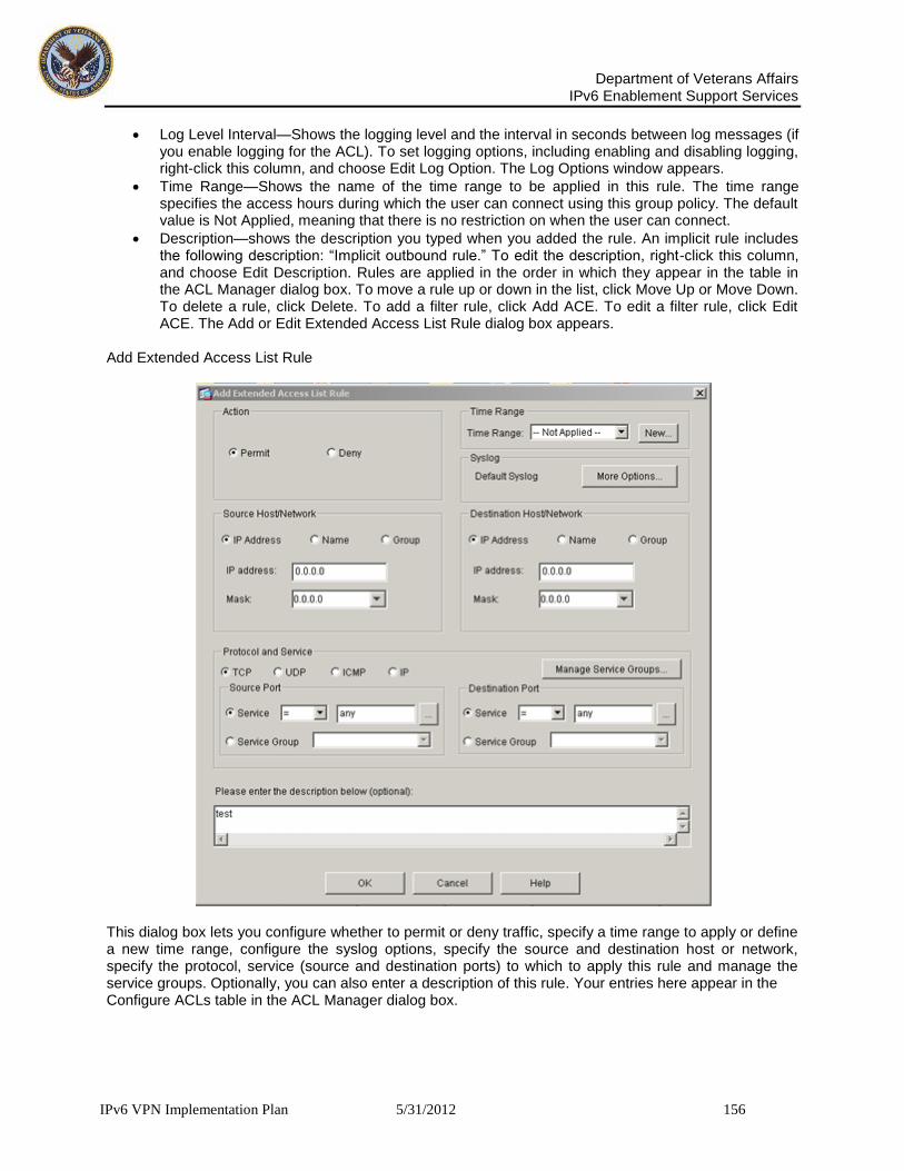
Department of Veterans Affairs
IPv6 Enablement Support Services
IPv6 VPN Implementation Plan 5/31/2012 156
Log Level Interval—Shows the logging level and the interval in seconds between log messages (if you enable logging for the ACL). To set logging options, including enabling and disabling logging, right-click this column, and choose Edit Log Option. The Log Options window appears.
Time Range—Shows the name of the time range to be applied in this rule. The time range specifies the access hours during which the user can connect using this group policy. The default value is Not Applied, meaning that there is no restriction on when the user can connect.
Description—shows the description you typed when you added the rule. An implicit rule includes the following description: “Implicit outbound rule.” To edit the description, right-click this column, and choose Edit Description. Rules are applied in the order in which they appear in the table in the ACL Manager dialog box. To move a rule up or down in the list, click Move Up or Move Down. To delete a rule, click Delete. To add a filter rule, click Add ACE. To edit a filter rule, click Edit ACE. The Add or Edit Extended Access List Rule dialog box appears.
Add Extended Access List Rule
This dialog box lets you configure whether to permit or deny traffic, specify a time range to apply or define a new time range, configure the syslog options, specify the source and destination host or network, specify the protocol, service (source and destination ports) to which to apply this rule and manage the service groups. Optionally, you can also enter a description of this rule. Your entries here appear in the Configure ACLs table in the ACL Manager dialog box.

Department of Veterans Affairs
IPv6 Enablement Support Services
IPv6 VPN Implementation Plan 5/31/2012 157
9.2.21.2 Configuring Syslog Options (Extended Access List Rule Dialog Box)
To specify the system log as something other than the default syslog, click More Options in the Syslog area. The Log Options dialog box appears, in which you can configure the system log options. Syslog Dialog Box—Log Options
9.2.21.2.1 Log Options The Log Options dialog box lets you set logging options for each access control entry (also called a rule) for an access control list. Conduits and outbound lists do not support logging. See the online Help for Configuration > Properties > Logging > Logging Setup and subsequent windows for an explanation of how to set global logging options. The Log Options dialog box lets you choose the type of logging mechanism to use:
The default logging behavior is that if a packet is denied, then the security appliance generates log message 106023. If a packet is permitted, no syslog message appears. Select this option to return to the default logging behavior.
Enable logging for the rule. The security appliance generates a syslog message when a new flow is permitted or denied by the rule. Subsequent syslog messages are generated at the end of an interval to summarize the hit count of the flow. The default interval is 300 seconds. You may specify another interval, from 1 through 600 seconds. By default, syslog messages are generated
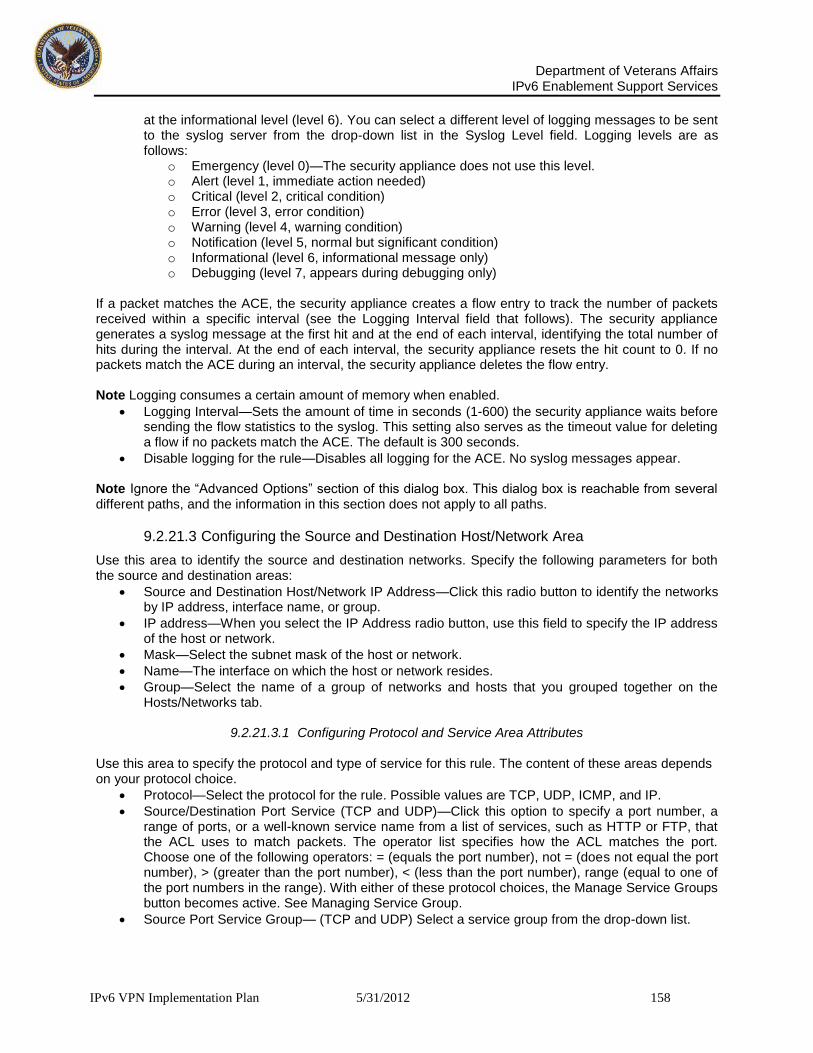
Department of Veterans Affairs
IPv6 Enablement Support Services
IPv6 VPN Implementation Plan 5/31/2012 158
at the informational level (level 6). You can select a different level of logging messages to be sent to the syslog server from the drop-down list in the Syslog Level field. Logging levels are as follows:
o Emergency (level 0)—The security appliance does not use this level. o Alert (level 1, immediate action needed) o Critical (level 2, critical condition) o Error (level 3, error condition) o Warning (level 4, warning condition) o Notification (level 5, normal but significant condition) o Informational (level 6, informational message only) o Debugging (level 7, appears during debugging only)
If a packet matches the ACE, the security appliance creates a flow entry to track the number of packets received within a specific interval (see the Logging Interval field that follows). The security appliance generates a syslog message at the first hit and at the end of each interval, identifying the total number of hits during the interval. At the end of each interval, the security appliance resets the hit count to 0. If no packets match the ACE during an interval, the security appliance deletes the flow entry. Note Logging consumes a certain amount of memory when enabled.
Logging Interval—Sets the amount of time in seconds (1-600) the security appliance waits before sending the flow statistics to the syslog. This setting also serves as the timeout value for deleting a flow if no packets match the ACE. The default is 300 seconds.
Disable logging for the rule—Disables all logging for the ACE. No syslog messages appear. Note Ignore the “Advanced Options” section of this dialog box. This dialog box is reachable from several different paths, and the information in this section does not apply to all paths.
9.2.21.3 Configuring the Source and Destination Host/Network Area
Use this area to identify the source and destination networks. Specify the following parameters for both the source and destination areas:
Source and Destination Host/Network IP Address—Click this radio button to identify the networks by IP address, interface name, or group.
IP address—When you select the IP Address radio button, use this field to specify the IP address of the host or network.
Mask—Select the subnet mask of the host or network.
Name—The interface on which the host or network resides.
Group—Select the name of a group of networks and hosts that you grouped together on the Hosts/Networks tab.
9.2.21.3.1 Configuring Protocol and Service Area Attributes Use this area to specify the protocol and type of service for this rule. The content of these areas depends on your protocol choice.
Protocol—Select the protocol for the rule. Possible values are TCP, UDP, ICMP, and IP.
Source/Destination Port Service (TCP and UDP)—Click this option to specify a port number, a range of ports, or a well-known service name from a list of services, such as HTTP or FTP, that the ACL uses to match packets. The operator list specifies how the ACL matches the port. Choose one of the following operators: = (equals the port number), not = (does not equal the port number), > (greater than the port number), < (less than the port number), range (equal to one of the port numbers in the range). With either of these protocol choices, the Manage Service Groups button becomes active. See Managing Service Group.
Source Port Service Group— (TCP and UDP) Select a service group from the drop-down list.

Department of Veterans Affairs
IPv6 Enablement Support Services
IPv6 VPN Implementation Plan 5/31/2012 159
Protocol and Service, ICMP, ICMP Type—Select the ICMP type for the rule in the ICMP type box. The browse button (indicated by ...) displays the Service dialog box, which lets you select an ICMP type from a preconfigured list.
Protocol and Service, IP, IP Protocol—Specifies the IP protocol for the rule in the IP protocol box. The browse button(...) displays the Protocols dialog box, which lets you select an IP protocol from a preconfigured list.
9.2.21.4 Managing Service Groups
Service groups let you identify multiple non-contiguous port numbers that you want the ACL to match. For example, if you want to filter HTTP, FTP, and port numbers 5, 8, and 9, define a service group that includes all these ports. Without service groups, you would have to create a separate rule for each port. You can create service groups for TCP, UDP, and TCP-UDP. A service group with the TCP-UDP protocol contains services, ports, and ranges that might use either the TCP or UDP protocol. In the Protocol and Service area of the Add Extended Access List rule dialog box, you configure the connection protocol and the type of service or the service group for the source and destination ports. If you do not want to make any changes, go on to the Description field. To manage these service groups, click Manage Service Groups. The Manage Service Groups dialog box (Figure 4-12) appears. Manage Service Groups Dialog Box
The Manage Service Groups dialog box lets you associate multiple TCP, UDP, or TCP-UDP services (ports) in a named group. You can then use the service group in an access or IPSec rule, a conduit, or other functions within ASDM and the CLI. The term service refers to higher layer protocols associated with application level services having well known port numbers and “literal” names such as ftp, telnet, and smtp. The security appliance permits the following TCP literal names: bgp, chargen, cmd, daytime, discard, domain, echo, exec, finger, ftp, ftp-data, gopher, h323, hostname, http, ident, irc, klogin, kshell, lpd, nntp, pop2, pop3, pptp, smtp, sqlnet, sunrpc, tacacs, talk, telnet, time, uucp, whois, www.

Department of Veterans Affairs
IPv6 Enablement Support Services
IPv6 VPN Implementation Plan 5/31/2012 160
The Name of a service group must be unique to all four types of object groups. For example, a service group and a network group may not share the same name. Multiple service groups can be nested into a “group of groups” and used the same as a single group. When a service object group is deleted, it is removed from all service object groups where it is used. If a service group is used in an access rule, do not remove it. A service group used in an access rule cannot be made empty. The fields in the Manage Service Groups dialog box are as follows:
o Manage a group of TCP.UDP services/ports—Select one of the following options: o TCP—Select this option to add TCP services or port numbers to an object group. o UDP—Select this option to add UDP services or port numbers to an object group. o TCP-UDP—Select this option to add services or port numbers that are common to TCP
and UDP to an object group. o The Service Group table—This table contains a descriptive name for each service object
group. To modify or delete a group on this list, select the group and choose Edit or Delete. To add a new group to this list, choose Add. Clicking Add or Edit opens the Add or Edit Service Group dialog box
Add Service Group Dialog Box

Department of Veterans Affairs
IPv6 Enablement Support Services
IPv6 VPN Implementation Plan 5/31/2012 161
9.2.21.4.1 Adding or Editing a Service Group
The Add or Edit Service Group dialog box lets you manage a group of TCP/UDP services/ports. The fields are as follows:
Service Group Name — Specifies the name of the service group. The name must be unique for all object groups. A service group name cannot share a name with a network group.
Description — Specifies a description of the service group.
Service — Lets you select services for the service group from a predefined drop-down list.
Range/Port # — Lets you specify a range of ports for the service group.
9.2.21.5 Configuring General VPN Connection Settings Attributes
Follow the steps in this section to configure attributes that set the values of VPN connection attributes. These attributes control the access hours, the number of simultaneous logins allowed, the timeouts, the name of the ACL to use for VPN connections, and the tunnel protocol. For all the attributes in this section, you can check the Inherit check box to allow the group policy to inherit a value from the default group policy.
9.2.21.5.1 Configuring Access Hours The VPN access hours determine when users in this group can connect to the security appliance. To set the VPN access hours, you associate a group policy with a previously configured time-range policy, which determines the actual access hours. A time range is a variable specifying the range of access hours during which a user can connect to the security appliance using this group policy. You select the name of this variable from a menu when you want to restrict access hours.

Department of Veterans Affairs
IPv6 Enablement Support Services
IPv6 VPN Implementation Plan 5/31/2012 162
9.2.21.5.2 Configuring an Internal Group Policy
To view the characteristics of the existing time ranges, select Configuration > Global Objects > Time Ranges. To select an existing time range to use with an ACL filter, choose a name from the drop-down Time Range menu in the Add/Edit Extended Access List Rule dialog box. To specify no time range restriction for this filter, choose Not Applied from the menu. In either case, since you are not defining a new time range, skip to Configuring Syslog Options (Extended Access List Rule Dialog Box). You can check the Inherit check box to allow the group policy to inherit the access hour’s variable from the group policy. If you choose this option, skip to Configuring Simultaneous Logins. To define a new time range, click New in the Time Range area in the Add Extended Access List Rule dialog box. The Add Time Range dialog box appears. Add Time Range Dialog Box
First, specify a name for this time range. When needed, you select this time range by choosing this name from a drop-down list when you configure a group policy with a time range. Specify the starting and ending times. If you configure specific starting and ending times, note that these times are inclusive. You can further constrain the active time of this range by specifying recurring time ranges, which are active within the start and end times specified. To remove a recurring time range, select the range and click Delete. To add or edit a recurring time range, click Add or Edit. The Add or Edit Recurring Time Ranges dialog box appears (Figure 4-15).

Department of Veterans Affairs
IPv6 Enablement Support Services
IPv6 VPN Implementation Plan 5/31/2012 163
Add or Edit Recurring Time Ranges Dialog Box.
Specify the recurring time ranges either as days of the week and times on which this recurring range is active or as a weekly interval when this recurring range is active, and click OK. Click OK to complete the configuration on the Add Time Range dialog box.
9.2.21.5.3 Configuring Simultaneous Logins Specify the number of simultaneous logins allowed for any user. The default value is 3. The range is an integer in the range 0 through 2147483647. A group policy can inherit this value from another group policy. Enter 0 to disable login and prevent user access. Caution While the maximum limit for the number of simultaneous logins is very large, allowing several could compromise security and affect performance.
9.2.21.5.4 Configuring Maximum Connect Time
Configure a maximum amount of time for VPN connections. At the end of this period of time, the security appliance terminates the connection. To allow unlimited connection time, check the Unlimited check box. To configure a specific time limit, clear the Unlimited check box. This makes the minute’s field available. The minimum time is 1 minute, and the maximum time is 35791394 minutes. There is no default value.
Department of Veterans Affairs
IPv6 Enablement Support Services
IPv6 VPN Implementation Plan 5/31/2012 164
9.2.21.5.5 Configuring User Idle Timeout Configure the user idle timeout period by either checking the Unlimited check box or specifying a number of minutes that the system can remain idle. If there is no communication activity on the connection in this period, the security appliance terminates the connection. The minimum time is 1 minute, and the maximum time is 35791394 minutes. The default is 30 minutes.
9.2.21.6 Configuring WINS and DNS Servers and DHCP Scope
You can configure primary and secondary WINS servers and DNS servers and the DHCP scope. The default value in each case is none. To configure these attributes, do the following steps: Step 1 Specify the primary and secondary DNS servers. The first IP address specified is that of the primary DNS server. The second (optional) IP address is that of the secondary DNS server. Leaving the first field blank instead of providing an IP address sets DNS servers to a null value, which allows no DNS servers and prevents inheriting a value from a default or specified group policy. Every time that you enter a DNS Server value, you overwrite the existing setting. For example, if you configure the primary DNS server as 10.10.10.15 and later configure the primary DNS server to be 10.10.10.30, the later specification overwrites the first, and 10.10.10.30 becomes the primary DNS server. Step 2 Specify the primary and secondary WINS servers. The first IP address specified is that of the primary WINS server. The second (optional) IP address is that of the secondary WINS server. Specifying the none keyword instead of an IP address sets WINS servers to a null value, which allows no WINS servers and prevents inheriting a value from a default or specified group policy. Every time that you enter the wins-server command, you overwrite the existing setting. For example, if you configure WINS server x.x.x.x and then configure WINS server y.y.y.y, the second command overwrites the first, and y.y.y.y becomes the sole WINS server. The same is true for multiple servers. To add a WINS server rather than overwrite previously configured servers, include the IP addresses of all WINS servers when you enter this command. The following example shows how to configure WINS servers with the IP addresses 10.10.10.15 and 10.10.10.30 for the group policy named FirstGroup: Step 3 Specify the DHCP scope; that is the range of servers IP addresses the security appliance DHCP server should use to assign addresses to users of this group policy.

Department of Veterans Affairs
IPv6 Enablement Support Services
IPv6 VPN Implementation Plan 5/31/2012 165
9.2.21.7 Configuring IPSec Attributes
The IPSec tab on the Add or Edit Internal Group Policy window lets you specify security attributes for this group policy. At the IPSec tab Add Internal Group Policy Window, IPSec Tab
Check an Inherit check box to let the corresponding setting take its value from the default group policy. The following sections explain how to configure the attributes on this tab.
9.2.21.7.1 Configuring Reauthentication on IKE Rekey Specify whether to require that users reauthenticate on IKE rekey by choosing Enable or Disable. If you enable reauthentication on IKE rekey, the security appliance prompts the user to enter a username and password during initial Phase 1 IKE negotiation and also prompts for user authentication whenever an IKE rekey occurs. Reauthentication provides additional security. Reauthentication on IKE rekey is disabled by default if you clear the Inherit check box. If the configured rekey interval is very short, users might find the repeated authorization requests inconvenient. To avoid repeated authorization requests, disable reauthentication. To check the configured rekey statistics, select Monitoring > VPN > VPN Statistics > Crypto Statistics to view the security association statistics. Note Reauthentication fails if there is no user at the other end of the connection.
9.2.21.8 Configuring IP Compression
Specify whether to enable IP compression, which is disabled by default. Enabling data compression might speed up data transmission rates for remote dial-in users connecting with modems. IP compression is disabled by default. Caution Data compression increases the memory requirement and CPU usage for each user session and consequently decreases the overall throughput of the security appliance. For this reason, we

Department of Veterans Affairs
IPv6 Enablement Support Services
IPv6 VPN Implementation Plan 5/31/2012 166
recommend that you enable data compression only for remote users connecting with a modem. Design a group policy specific to modem users, and enable compression only for them. To enable or disable LZS IP compression, select Enable or Disable.
9.2.21.9 Configuring Perfect Forward Secrecy
Specify whether to enable perfect forward secrecy. In IPSec negotiations, perfect forward secrecy ensures that each new cryptographic key is unrelated to any previous key. A group policy can inherit a value for perfect forward secrecy from the default group policy if you check the Inherit check box. Otherwise, perfect forward secrecy is disabled by default. To enable or disable perfect forward secrecy, select Enable or Disable.
9.2.21.10 Configuring Tunnel Group Locking
Specify whether to restrict remote users to access only through the tunnel group, by enabling or disabling the Tunnel Group Lock attribute. The tunnel-grp-name variable specifies the name of an existing tunnel group that the security appliance requires for the user to connect. Tunnel group lock restricts users by checking if the group configured in the VPN client is the same as the tunnel group to which the user is assigned. If it is not, the security appliance prevents the user from connecting. If you do not configure group-lock, the security appliance authenticates users without regard to the assigned group. Group locking is disabled by default. To remove the group-lock attribute from the running configuration, enter the no form of this command. This option allows inheritance of a value from another group policy. To disable group-lock, enter the group-lock command with the none keyword. The none keyword sets group-lock to a null value, thereby allowing no group-lock restriction. It also prevents inheriting a group-lock value from a default or specified group policy.
9.2.21.11 Configuring Client Access Rules
The Client Access Rules area lets you specify up to 25 rules that determine whether to permit or deny access by certain types and versions of VPN clients. Either the group policy can inherit these rules from the default group policy, or you can specify particular rules for this group policy. The table in this area shows the priority, action, client type and VPN client version that each rule specifies. To configure rules that limit the remote access client types and versions that can connect via IPSec through the security appliance, clear the Inherit check box. This makes the buttons at the side of the table active. By default, there are no access rules. When there are no client access rules, all client types and versions can connect. To delete individual rules, click Delete. The columns in the Client Access Rules table are as follows:
Priority — Shows the priority for this rule. Determines the priority of the rule. The rule with the lowest integer has the highest priority. Therefore, the rule with the lowest integer that matches a client type and/or version is the rule that applies. If a lower priority rule contradicts, the security appliance ignores it.
Action — Specifies whether this rule permits or denies access for clients of a particular type and version.
VPN Client Type — Specifies the type of VPN client to which this rule applies, software or hardware, and for software clients, all Windows clients or a subset. Identifies device types via free-form strings, for example VPN 3002. A string must match exactly its appearance in the show vpn-sessiondb remote display, except that you can use the * character as a wildcard.
VPN Client Version —Specifies the version or versions of the VPN client to which this rule applies. This box contains a comma-separated list of software or firmware images appropriate for this client.
Identifies the device version via free-form strings, for example 7.0. A string must match exactly its appearance in the show vpn-sessiondb remote display, except that you can use the * character as a

Department of Veterans Affairs
IPv6 Enablement Support Services
IPv6 VPN Implementation Plan 5/31/2012 167
wildcard. To add a new rule for an IPSec group policy, click Add. To modify an existing rule for an IPSec group policy, click Edit. The Add or Edit Client Access Rule dialog box appears. Add Client Access Rule Dialog Box
Construct rules according to these caveats:
If you do not define any rules, the security appliance permits all connection types.
When a client matches none of the rules, the security appliance denies the connection. This means that if you define a deny rule, you must also define at least one permit rule, or the security appliance denies all connections.
For both software and hardware clients, type and version must match exactly their appearance in the Monitoring > VPN > VPN Statistics > Sessions window.
The * character is a wildcard, which you can use multiple times in each rule. For example, specifying the VPN client version as version 3.* in a client access rule applies that rule to the specified client type running release versions 3.x software.
You can construct a maximum of 25 rules per group policy.
There is a limit of 255 characters for an entire set of rules.
You can use n/a for clients that do not send client type and/or version.
9.2.21.12 Configuring Client Configuration Parameters
Use the Client Configuration tab of the Add/Edit Internal Group Policy Window (Figure 4-18) to configure the following parameters:
Banner
Default Domain
Split Tunnel DNS Names
Split Tunnel Policy
Split Tunnel Network List
Cisco Client Parameters

Department of Veterans Affairs
IPv6 Enablement Support Services
IPv6 VPN Implementation Plan 5/31/2012 168
Edit Internal Group Policy Client Configuration Window
9.2.21.13 Configuring the Banner Message
The banner is a message that is displayed to remote clients when they connect. The default is no banner. If you choose not to inherit the banner from the default group policy, clear the Inherit check box and click Edit Banner. The View/Config Banner dialog box appears. View/Config Banner Dialog Box

Department of Veterans Affairs
IPv6 Enablement Support Services
IPv6 VPN Implementation Plan 5/31/2012 169
To specify the banner, or welcome message, if any, that you want to display, enter the banner text, up to 510 characters in length. Enter the “\n” sequence to insert a carriage return. Note A carriage-return/line-feed included in the banner counts as two characters. To delete a banner, remove the text.
9.2.21.14 Configuring Domain Attributes for Tunneling
You can specify a default domain name for tunneled packets or a list of domains to be resolved through the split tunnel. The following sections describe how to set these domains.
9.2.21.14.1 Defining a Default Domain Name for Tunneled Packets The security appliance passes the default domain name to the IPSec client to append to DNS queries that omit the domain field. When there are no default domain names, users inherit the default domain name in the default group policy. To specify the default domain name for users of the group policy, clear the Inherit check box and enter the default domain name in the field. The domain name that you enter identifies the default domain name for the group. To specify that there is no default domain name, leave this field blank. This command sets a default domain name with a null value, which disallows a default domain name and prevents inheriting a default domain name from a default or specified group policy.
9.2.21.14.2 Defining a List of Domains for Split Tunneling To provide a list of domains for split-tunneling, clear the Inherit check box and enter a space-delimited list of domains to be resolved through the split tunnel. When there are no split tunneling domain lists, users inherit any that exist in the default group policy. To prevent users from inheriting such split tunneling domain lists, leave this list blank. The domain name attribute provides a domain name that the security appliance resolves through the split tunnel. Leaving this list blank indicates that there is no split DNS list. It also sets a split DNS list with a null value, thereby disallowing a split DNS list, and prevents inheriting a split DNS list from a default or specified group policy. Enter a single space to separate each entry in the list of domains. There is no limit on the number of entries, but the entire string can be no longer than 255 characters. You can use only alphanumeric characters, hyphens (-), and periods (.). If the default domain name is to be resolved through the tunnel, you must explicitly include that name in this list.
9.2.21.14.3 Configuring Split-Tunneling Attributes Split tunneling lets a remote-access IPSec client conditionally direct packets over an IPSec tunnel in encrypted form or to a network interface in clear text form. With split tunneling enabled, packets not bound for destinations on the other side of the IPSec tunnel do not have to be encrypted, sent across the tunnel, decrypted, and then routed to a final destination. This command applies this split tunneling policy to a specific network.
9.2.21.14.4 Setting the Split-Tunneling Policy Set the rules for tunneling traffic by specifying the split-tunneling policy. The default is to tunnel all traffic. To set a split tunneling policy, clear the Inherit check box and select the split-tunnel policy from the drop-down menu. To remove the split-tunnel policy attribute from the running configuration, leave this field blank. This enables inheritance of a value for split tunneling from another group policy.
Select Tunnel All Networks to specify that no traffic goes in the clear or to any other destination than the security appliance. This, in effect, disables split tunneling. Remote users reach Internet

Department of Veterans Affairs
IPv6 Enablement Support Services
IPv6 VPN Implementation Plan 5/31/2012 170
networks through the VA network and do not have access to local networks. This is the default option.
Select Tunnel Network List Below to tunnel all traffic from or to the specified networks. This option enables split tunneling. It lets you create a network list of addresses to tunnel. Data to all other addresses travels in the clear and is routed by the remote user’s Internet service provider.
Select Exclude Network List Below to define a list of networks to which traffic goes in the clear. This feature is useful for remote users who want to access devices on their local network, such as printers, while they are connected to the VA network through a tunnel. This option applies only to the Cisco VPN client. Note Split tunneling is primarily a traffic management feature, not a security feature. For optimum security, we recommend that you do not enable split tunneling.
9.2.21.14.5 Creating a Network List for Split-Tunneling
Select a network list name for split tunneling from the Split Tunnel Network List drop-down menu. Split tunneling network lists distinguish networks that require traffic to travel across the tunnel from those that do not require tunneling. The security appliance makes split tunneling decisions on the basis of a network list, which is an ACL that consists of a list of addresses on the private network. Only standard-type ACLs are allowed. Clicking Manage opens the ACL Manager dialog box, where you can configure the ACLs. For information on using ACL Manager dialog box, see Configuring the ACL Filter. The access-list name that you select identifies an access list that enumerates the networks to tunnel or not tunnel. Selecting None indicates that there is no network list for split tunneling; the security appliance tunnels all traffic. Selecting None sets a split tunneling network list with a null value, thereby disallowing split tunneling. It also prevents inheriting a default split tunneling network list from a default or specified group policy.
9.2.21.15 Configuring Cisco Client Parameters
The attributes in the Cisco Client Parameters area specify certain security settings for the group, including password storage, IPSec over UPD settings, and IPSec backup servers.
9.2.21.16 Configuring Password Storage
You can specify whether to let users store their login passwords on the client system. For security reasons, password storage is disabled by default. Enable password storage only on systems that you know to be in secure sites. To enable or disable password storage, clear the Inherit check box for the Store Password on Client System attribute and select either Yes (enable) or No (disable). This action does not apply to interactive hardware client authentication or individual user authentication for hardware clients.
9.2.21.17 Configuring IPSec-UDP Attributes
IPSec over UDP, sometimes called IPSec through NAT, lets a Cisco VPN client or hardware client connect via UDP to a security appliance that is running NAT. It is disabled by default. IPSec over UDP is proprietary; it applies only to remote-access connections, and it requires mode configuration. The security appliance exchanges configuration parameters with the client while negotiating SAs. Using IPSec over UDP may slightly degrade system performance. To enable or disable IPSec over UDP, clear the Inherit check box and choose either Enable or Disable. The Cisco VPN client must also be configured to use IPSec over UDP (it is configured to use it by default). The VPN 3002 requires no configuration to use IPSec over UDP. To use IPSec over UDP, you must also configure the IPSec over UDP Port attribute, which sets a UDP port number for IPSec over UDP. In IPSec negotiations, the security appliance listens on the configured port and forwards UDP traffic for that port even if other filter rules drop UDP traffic. To configure the
Department of Veterans Affairs
IPv6 Enablement Support Services
IPv6 VPN Implementation Plan 5/31/2012 171
IPSec over UDP Port attribute, clear the Inherit check box and enter a port number into the field. The port numbers can range from 4001 through 49151. The default port value is 10000.
9.2.21.17.1 Configuring IPSec Backup Servers Configure backup servers if you plan on using them. IPSec backup servers let a VPN client connect to the central site when the primary security appliance is unavailable. When you configure backup servers, the security appliance pushes the server list to the client as the IPSec tunnel is established. Backup servers do not exist until you configure them, either on the client or on the primary security appliance. Configure backup servers either on the client or on the primary security appliance. If you configure backup servers on the security appliance, it pushes the backup server policy to the clients in the group, replacing the backup server list on the client if one is configured. Note If you are using hostnames, it is wise to have backup DNS and WINS servers on a separate network from that of the primary DNS and WINS servers. Otherwise, if clients behind a hardware client obtain DNS and WINS information from the hardware client via DHCP, and the connection to the primary server is lost, and the backup servers have different DNS and WINS information, clients cannot be updated until the DHCP lease expires. In addition, if you use hostnames and the DNS server is unavailable, significant delays can occur. To specify one or more backup servers or to remove the configured backup server or servers from the client configuration, do the following: Step 1 Clear the Inherit check box. Step 2 Select one of the following options from the drop-down menu:
Keep Client Configuration— Specifies that the security appliance sends no backup server information to the client. The client uses its own backup server list, if configured. This is the default.
Clear Client Configuration—Specifies that the client uses no backup servers. The security appliance pushes a null server list.
Use the Backup Servers Below—Specifies that you want to configure a list of servers to use if the primary security appliance is unavailable.
Step 3 If you select Use the Backup Servers Below, you must fill in one or more server addresses in the Server Addresses field. This list is a space-delimited, priority-ordered list of servers for the VPN client to use when the primary security appliance is unavailable. This list identifies servers by IP address or hostname. The list can be 500 characters long, and it can contain up to10 entries.
9.2.22 Configuring Firewall Attributes
A firewall isolates and protects a computer from the Internet by inspecting each inbound and outbound individual packet of data to determine whether to allow or drop it. Firewalls provide extra security if remote users in a group have split tunneling configured. In this case, the firewall protects the user’s PC, and thereby the VA network, from intrusions by way of the Internet or the user’s local LAN. Remote users connecting to the security appliance with the VPN client can choose the appropriate firewall option. When there are no firewall policies, users inherit any that exist in the default or other group policy. Set personal firewall policies that the security appliance pushes to the VPN client during IKE tunnel negotiation on the Client Firewall tab. Edit Internal Group Policy Client Firewall Tab

Department of Veterans Affairs
IPv6 Enablement Support Services
IPv6 VPN Implementation Plan 5/31/2012 172
Note Only VPN clients running Microsoft Windows can use these firewall features. They are currently not available to hardware clients or other (non-Windows) software clients. The following examples illustrate the use of the client firewall. In the first scenario, a remote user has a personal firewall installed on the PC. The VPN client enforces firewall policy defined on the local firewall, and it monitors that firewall to make sure it is running. If the firewall stops running, the VPN client drops the connection to the security appliance. (This firewall enforcement mechanism is called Are You There (AYT), because the VPN client monitors the firewall by sending it periodic “are you there?” messages; if no reply comes, the VPN client knows the firewall is down and terminates its connection to the security appliance.) The network administrator might configure these PC firewalls originally, but with this approach, each user can customize his or her own configuration. In the second scenario, you might prefer to enforce a centralized firewall policy for personal firewalls on VPN client PCs. A common example would be to block Internet traffic to remote PCs in a group using split tunneling. This approach protects the PCs, and therefore the central site, from intrusions from the Internet while tunnels are established. This firewall scenario is called push policy or Central Protection Policy (CPP). On the security appliance, you create a set of traffic management rules to enforce on the VPN client, associate those rules with a filter, and designate that filter as the firewall policy. The security appliance pushes this policy down to the VPN client. The VPN client then in turn passes the policy to the local firewall, which enforces it. The Add or Edit Internal Group Policy window, Client Firewall tab, lets you configure firewall settings for VPN clients for the group policy being added or modified. To specify the client firewall settings, clear the Inherit check box and configure the following attributes in the Client Firewall Attributes area

Department of Veterans Affairs
IPv6 Enablement Support Services
IPv6 VPN Implementation Plan 5/31/2012 173
9.2.22.1 Configuring Firewall Setting
Specify whether there is no firewall, or whether the firewall is optional or required by selecting the appropriate setting from the drop-down menu. Note If you have remote users in this group who do not yet have firewall capacity, choose Firewall Optional. The Firewall Optional setting allows all the users in the group to connect. Those who have a firewall can use it; users that connect without a firewall receive a warning message. This setting is useful if you are creating a group in which some users have firewall support and others do not—for example, you may have a group that is in gradual transition, in which some members have set up firewall capacity and others have not yet done so.
9.2.22.2 Configuring Firewall Type
Select the type of firewall (or no firewall) from the drop-down menu. The options are:
No Firewall—Indicates that there is no client firewall policy and prevents inheriting a firewall policy from a default or specified group policy.
Cisco Integrated Firewall—Selects the Cisco Integrated Firewall type.
Cisco Security Agent—Selects the Cisco Intrusion Prevention Security Agent firewall type.
Zone Labs Firewalls—Selects either the Zone Labs Zone Alarm or the Zone Alarm Pro firewall type or both.
Sygate Personal Firewalls—Selects either the Sygate Personal firewall type, the Sygate Personal Pro firewall type, or the Sygate Security Agent firewall type.
Network ICE, Black ICE Firewall—Selects the Network ICE Black ICE firewall type.
Custom Firewall—Indicates that this policy uses a custom firewall. With this selection, the Custom Firewall and Firewall Policy areas become active.
9.2.22.3 Configuring a Custom Firewall
If you selected Custom Firewall as the firewall type, you must also configure the custom firewall attributes, as follows:
Vendor ID—Identifies the firewall vendor.
Product ID—Identifies the model or product name of the firewall product.
Description—Optionally provides additional information about the custom firewall. Configure the Firewall Policy attributes to specify the source and characteristics of the firewall policy, as follows:
Policy defined by remote firewall (AYT)—Specifies that the policy is to use the firewall installed on the remote user PC and, after the connection is established, polls that firewall every 30 seconds to ensure that it is running. This is the “Are You There” or AYT mechanism. The local firewall enforces the firewall policy on the VPN client. The security appliance allows VPN clients in this group to connect only if they have the designated firewall installed and running. If the designated firewall is not running, the connection fails.
Policy Pushed (CPP)—Enforces a centralized firewall policy for personal firewalls on VPN client PCs. This firewall policy is called “push policy” or Central Protection Policy, because the policy is pushed from the peer. If you select this option, the Inbound Traffic Policy and Outbound Traffic Policy lists and the Manage button become active. The security appliance enforces on the VPN clients in this group the traffic management rules defined by the filter you choose from the Policy Pushed (CPP) drop-down menu. The choices available on the menu are filters defined on this security appliance, including the default filters. Keep in mind that the security appliance pushes these rules down to the VPN client, so you should create and define these rules relative to the VPN client, not the security appliance. For example, “in” and “out” refer to traffic coming into the VPN client or going outbound from the VPN client. If the VPN client also has a local firewall, the policy pushed from the security appliance works with the policy of the local firewall. Any packet

Department of Veterans Affairs
IPv6 Enablement Support Services
IPv6 VPN Implementation Plan 5/31/2012 174
that is blocked by the rules of either firewall is dropped. If you select Policy Pushed (CPP), you must also select the policies that the client uses for inbound and outbound traffic.
Clicking Manage opens the ACL Manager dialog box, in which you can create a set of traffic management rules to enforce on the VPN client, associate those rules with a filter, and designate that filter as the firewall policy. The security appliance pushes this policy down to the VPN client, which, in turn, passes the policy to the local firewall, which enforces it.
9.2.23 Configuring Attributes for VPN Hardware Clients
The Add or Edit Internal Group Policy Hardware Client tab (Figure 4-21) lets you configure attributes specific to VPN hardware clients. On this tab you can enable or disable secure unit authentication and user authentication and set a user authentication timeout value for VPN hardware clients. You can also allow Cisco IP phones and LEAP packets to bypass individual user authentication and allow hardware clients using Network Extension Mode to connect. Edit Internal Group Policy Hardware Client Tab
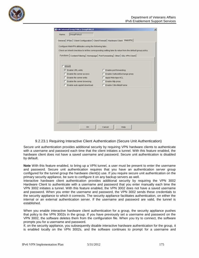
Department of Veterans Affairs
IPv6 Enablement Support Services
IPv6 VPN Implementation Plan 5/31/2012 175
9.2.23.1 Requiring Interactive Client Authentication (Secure Unit Authentication)
Secure unit authentication provides additional security by requiring VPN hardware clients to authenticate with a username and password each time that the client initiates a tunnel. With this feature enabled, the hardware client does not have a saved username and password. Secure unit authentication is disabled by default. Note With this feature enabled, to bring up a VPN tunnel, a user must be present to enter the username and password. Secure unit authentication requires that you have an authentication server group configured for the tunnel group the hardware client(s) use. If you require secure unit authentication on the primary security appliance, be sure to configure it on any backup servers as well. Interactive hardware client authentication provides additional security by requiring the VPN 3002 Hardware Client to authenticate with a username and password that you enter manually each time the VPN 3002 initiates a tunnel. With this feature enabled, the VPN 3002 does not have a saved username and password. When you enter the username and password, the VPN 3002 sends these credentials to the security appliance to which it connects. The security appliance facilitates authentication, on either the internal or an external authentication server. If the username and password are valid, the tunnel is established. When you enable interactive hardware client authentication for a group, the security appliance pushes that policy to the VPN 3002s in the group. If you have previously set a username and password on the VPN 3002, the software deletes them from the configuration file. When you try to connect, the software prompts you for a username and password. If, on the security appliance, you subsequently disable interactive hardware authentication for the group, it is enabled locally on the VPN 3002s, and the software continues to prompt for a username and

Department of Veterans Affairs
IPv6 Enablement Support Services
IPv6 VPN Implementation Plan 5/31/2012 176
password. This lets the VPN 3002 connect, even though it lacks a saved username and password, and the security appliance has disabled interactive hardware client authentication. If you subsequently configure a username and password, the feature is disabled, and the prompt no longer displays. The VPN 3002 connects to the security appliance using the saved username and password. Specify whether to enable or disable the requirement for interactive client authentication by clearing the Inherit check box and selecting either Enable or Disable. This parameter is disabled by default.
9.2.23.2 Requiring Individual User Authentication
When enabled, user authentication requires that individual users behind a hardware client authenticate to gain access to the network across the tunnel. Individual users authenticate according to the order of authentication servers that you configure. Individual user authentication for these users is disabled by default. To display a banner to VPN 3002 devices in a group, individual user authentication must be enabled. If you require user authentication on the primary security appliance, be sure to configure it on any backup servers as well. Individual user authentication protects the central site from access by unauthorized persons on the private network of the VPN 3002. When you enable individual user authentication, each user that connects through a VPN 3002 must open a web browser and manually enter a valid username and password to access the network behind the security appliance, even though the tunnel already exists. Note You cannot use the command-line interface to log in if user authentication is enabled. You must use a browser. If you have a default home page on the remote network behind the security appliance, or if you direct the browser to a website on the remote network behind the security appliance, the VPN 3002 directs the browser to the proper pages for user login. When you successfully log in, the browser displays the page you originally entered. If you try to access resources on the network behind the security appliance that are not web-based, for example, e-mail, the connection fails until you authenticate using a browser. To authenticate, you must enter the IP address for the private interface of the VPN 3002 in the browser Location or Address field. The browser then displays the login screen for the VPN 3002. To authenticate, click the Connect/Login Status button. One user can log in for a maximum of four sessions simultaneously. Individual users authenticate according to the order of authentication servers that you configure for a group.
9.2.23.3 Configuring an Idle Timeout
To set an idle timeout for individual users behind hardware clients, clear the Inherit check box and either check the Unlimited check box to specify that there is no idle timeout or specify a specific number of minutes. If there is no communication activity by a user behind a hardware client in the idle timeout period, the security appliance terminates the client’s access.
9.2.23.4 Configuring an Internal Group Policy
Note The user-authentication-idle-timeout command terminates only the client’s access through the VPN tunnel, not the VPN tunnel itself. The minute’s field specifies the number of minutes in the idle timeout period. The minimum is 1 minute, the default is 30 minutes, and the maximum is 35791394 minutes. If you clear both the Inherit and Unlimited check boxes, you must specify a value in the minute’s field.
9.2.23.5 Configuring IP Phone Bypass
You can allow Cisco IP phones to bypass individual user authentication behind a hardware client. To enable or disable IP Phone Bypass, clear the Inherit check box and select Enable or Disable. IP Phone Bypass lets IP phones behind hardware clients connect without undergoing user authentication processes. IP Phone Bypass is disabled by default. If enabled, secure unit authentication remains in effect.
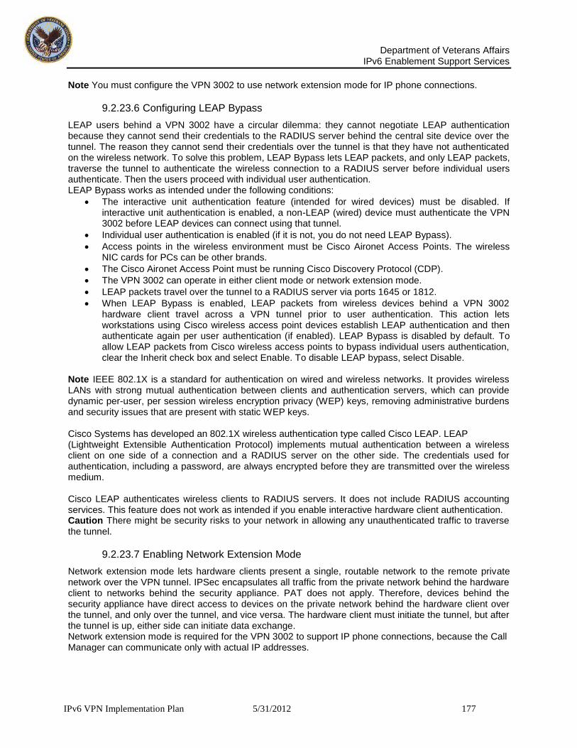
Department of Veterans Affairs
IPv6 Enablement Support Services
IPv6 VPN Implementation Plan 5/31/2012 177
Note You must configure the VPN 3002 to use network extension mode for IP phone connections.
9.2.23.6 Configuring LEAP Bypass
LEAP users behind a VPN 3002 have a circular dilemma: they cannot negotiate LEAP authentication because they cannot send their credentials to the RADIUS server behind the central site device over the tunnel. The reason they cannot send their credentials over the tunnel is that they have not authenticated on the wireless network. To solve this problem, LEAP Bypass lets LEAP packets, and only LEAP packets, traverse the tunnel to authenticate the wireless connection to a RADIUS server before individual users authenticate. Then the users proceed with individual user authentication. LEAP Bypass works as intended under the following conditions:
The interactive unit authentication feature (intended for wired devices) must be disabled. If interactive unit authentication is enabled, a non-LEAP (wired) device must authenticate the VPN 3002 before LEAP devices can connect using that tunnel.
Individual user authentication is enabled (if it is not, you do not need LEAP Bypass).
Access points in the wireless environment must be Cisco Aironet Access Points. The wireless NIC cards for PCs can be other brands.
The Cisco Aironet Access Point must be running Cisco Discovery Protocol (CDP).
The VPN 3002 can operate in either client mode or network extension mode.
LEAP packets travel over the tunnel to a RADIUS server via ports 1645 or 1812.
When LEAP Bypass is enabled, LEAP packets from wireless devices behind a VPN 3002 hardware client travel across a VPN tunnel prior to user authentication. This action lets workstations using Cisco wireless access point devices establish LEAP authentication and then authenticate again per user authentication (if enabled). LEAP Bypass is disabled by default. To allow LEAP packets from Cisco wireless access points to bypass individual users authentication, clear the Inherit check box and select Enable. To disable LEAP bypass, select Disable.
Note IEEE 802.1X is a standard for authentication on wired and wireless networks. It provides wireless LANs with strong mutual authentication between clients and authentication servers, which can provide dynamic per-user, per session wireless encryption privacy (WEP) keys, removing administrative burdens and security issues that are present with static WEP keys. Cisco Systems has developed an 802.1X wireless authentication type called Cisco LEAP. LEAP (Lightweight Extensible Authentication Protocol) implements mutual authentication between a wireless client on one side of a connection and a RADIUS server on the other side. The credentials used for authentication, including a password, are always encrypted before they are transmitted over the wireless medium. Cisco LEAP authenticates wireless clients to RADIUS servers. It does not include RADIUS accounting services. This feature does not work as intended if you enable interactive hardware client authentication. Caution There might be security risks to your network in allowing any unauthenticated traffic to traverse the tunnel.
9.2.23.7 Enabling Network Extension Mode
Network extension mode lets hardware clients present a single, routable network to the remote private network over the VPN tunnel. IPSec encapsulates all traffic from the private network behind the hardware client to networks behind the security appliance. PAT does not apply. Therefore, devices behind the security appliance have direct access to devices on the private network behind the hardware client over the tunnel, and only over the tunnel, and vice versa. The hardware client must initiate the tunnel, but after the tunnel is up, either side can initiate data exchange. Network extension mode is required for the VPN 3002 to support IP phone connections, because the Call Manager can communicate only with actual IP addresses.

Department of Veterans Affairs
IPv6 Enablement Support Services
IPv6 VPN Implementation Plan 5/31/2012 178
Note If you disallow network extension mode, the default setting, the VPN 3002 can connect to this security appliance in PAT mode only. If you disallow network extension mode here, be careful to configure all VPN 3002s in a group for PAT mode. If a VPN 3002 is configured to use network extension mode and the security appliance to which it connects disallows network extension mode, the VPN 3002 attempts to connect every 4 seconds, and every attempt is rejected. In this situation, the VPN 3002 puts an unnecessary processing load on the security appliance to which it connects; if large numbers of VPN 3002s are misconfigured in this way, the security appliance has a reduced ability to provide service. Enable or disable network extension mode for hardware clients by clearing the Inherit check box and selecting Enable or Disable.
9.2.23.8 Configuring Group-Policy WebVPN Attributes
WebVPN lets users establish a secure, remote-access VPN tunnel to the security appliance using a web browser. There is no need for either a software or hardware client. WebVPN provides easy access to a broad range of web resources and web-enabled applications from almost any computer that can reach HTTPS Internet sites. WebVPN uses SSL and its successor, TLS1, to provide a secure connection between remote users and specific, supported internal resources that you configure at a central site. The security appliance recognizes connections that need to be proxied, and the HTTP server interacts with the authentication subsystem to authenticate users. By default, WebVPN is disabled. You can customize a WebVPN configuration for specific internal group policies. In the Add or Edit Internal Group Policy WebVPN tab, you can specify whether to inherit the settings for all the functions or customize the WebVPN attributes, each of which is described in the subsequent sections:
Functions
Content Filtering
Homepage
Port Forwarding
Other (such as servers and URL lists)
SSL VPN Client (SVC) In many instances, you define the WebVPN attributes as part of configuring WebVPN, then you apply those definitions to specific groups when you configure the group-policy webvpn attributes. The attributes in the WebVPN tab for group policies define access to files, MAPI proxy, URLs and TCP applications over WebVPN. They also identify ACLs and types of traffic to filter. WebVPN is disabled by default. See the description of WebVPN in the online Help for this tab and the Cisco Security Appliance Command Line Configuration Guide and Cisco Security Appliance Command Reference for more information about configuring the WebVPN attributes. You do not need to configure WebVPN to use e-mail proxies.
9.2.23.8.1 Configuring Group-Policy WebVPN Function Tab Attributes The Functions tab lets you configure basic WebVPN functions. To configure the WebVPN functions (such as file access and file browsing, HTTP Proxy, MAPI Proxy, and URL entry over WebVPN) that you want to enable, clear the Inherit check box and check the check boxes for the individual functions that you want to enable or apply. These functions are disabled by default.

Department of Veterans Affairs
IPv6 Enablement Support Services
IPv6 VPN Implementation Plan 5/31/2012 179
Edit Internal Group Policy WebVPN Tab Functions Tab
The functions that you can configure on this tab are as follows:
Enable URL entry—Enables or disables user entry of URLs and places the URL entry box on the home page. When enabled, the security appliance still restricts URLs with any configured URL or network ACLs. Users can enter web addresses in the URL entry box, and use WebVPN to access those websites. When URL entry is disabled, the security appliance restricts WebVPN users to the URLs on the home page. Using WebVPN does not ensure that communication with every site is secure. WebVPN ensures the security of data transmission between the remote user's PC or workstation and the security appliance on the VA network. If a user then accesses a non-HTTPS web resource (located on the Internet or on the internal network), the communication from the VA security appliance to the destination web server is not secured. In a WebVPN connection, the security appliance acts as a proxy between the end user's web browser and target web servers. When a WebVPN user connects to an SSL-enabled web server, the security appliance establishes a secure connection and validates the server's SSL certificate. The end user's browser never receives the presented certificate, so therefore cannot examine and validate the certificate. The current implementation of WebVPN does not permit communication with sites that present expired certificates. Neither does the security appliance perform trusted CA certificate validation. Therefore, WebVPN users cannot analyze the certificate an SSL-enabled web-server presents before communicating with it. To limit Internet access for WebVPN users, deselect the Enable URL Entry field. This prevents WebVPN users from surfing the Web during a WebVPN connection.
Enable file server access—Enables or disables Windows file access (SMB/CIFS files only) through HTTPS. When enabled, the WebVPN home page lists file servers in the server list. You must enable file access to enable file browsing and/or file entry. When this box is checked, users can access Windows files on the network. If you enable only this parameter for WebVPN file sharing, users can access only servers that you configure in the Servers and URLs area (see the

Department of Veterans Affairs
IPv6 Enablement Support Services
IPv6 VPN Implementation Plan 5/31/2012 180
description of Configuring Server and List Arguments Using the WebVPN Other Tab). To let user’s access servers directly or to browse servers on the network, see the Enable file server entry and Enable file server browsing attribute descriptions. With this check box checked, users can download, edit, delete, rename, and move files. They can also add files and folders. Shares must also be configured for user access on the applicable Windows servers. Users might have to be authenticated before accessing files, depending on network requirements. File access, server/domain access, and browsing require that you configure a WINS server or a master browser, typically on the same network as the security appliance, or reachable from that network. The WINS server or master browser provides the security appliance with an list of the resources on the network. You cannot use a DNS server instead.
Note File access is not supported in an Active Native Directory environment when used with Dynamic DNS. It is supported if used with a WINS server.
Enable file server entry—Enables of disables user ability to enter names of file servers, places the file server entry box on the portal page. File server access must be enabled. With this check box checked, users can enter pathnames to directly Windows files. They can download, edit, delete, rename, and move files. They can also add files and folders. Again, shares must also be configured for user access on the applicable Windows servers. Users might have to be authenticated before accessing files, depending on network requirements.
Enable file server browsing—Enables or disables browsing for file the Windows network for domains/workgroups, file servers and shares. You must enable file browsing to allow user entry of a file server. File server access must be enabled. With this check box checked, users can select domains and workgroups and can browse servers and shares within those domains. Shares must also be configured for user access on the applicable Windows servers. Users may need to be authenticated before accessing servers, according to network requirements.
Enable auto applet download—Lets users automatically download and start the port forwarding java applet upon WebVPN login. Disabled by default, you can enable this feature only if port forwarding, Outlook/Exchange proxy, or HTTP proxy is also enabled. You can also enable auto applet download in the default group policy (DfltGrpPolicy) or in user-defined group policies.
Enable port forwarding—WebVPN Port Forwarding provides access for remote users in the group to client/server applications that communicate over known, fixed TCP/IP ports. Remote users can use client applications that are installed on their local PC and securely access a remote server that supports that application. Cisco has tested the following applications: Windows Terminal Services, Telnet, and Secure FTP (FTP over SSH), Perforce, Outlook Express, and Lotus Notes. Other TCP-based applications may also work, but Cisco has not tested them.
Note Port Forwarding does not work with some SSL/TLS versions. With this check box checked users can access client/server applications by mapping TCP ports on the local and remote systems. Note When users authenticate using digital certificates, the TCP Port Forwarding JAVA applet does not work. JAVA cannot access the web browser's keystore; therefore JAVA cannot use the certificates that the browser uses for user authentication, and the application cannot start. Do not use digital certificates to authenticate WebVPN users if you want them to be able to access applications.
Enable Outlook/Exchange proxy—Enables or disables Microsoft Outlook/Exchange e-mail proxy.
Apply Web-type ACL—Applies the WebVPN access control list defined for the users of this group.
Enable HTTP proxy—Enables or disables the forwarding of an HTTP applet proxy to the client. The proxy is useful for technologies that interfere with proper content transformation (“mangling”), such as Java, ActiveX, and Flash. It bypasses mangling while ensuring the continued use of the security appliance. The forwarded proxy modifies the browser’s old proxy configuration automatically and redirects all HTTP and HTTPS requests to the new proxy configuration. It supports virtually all client side technologies, including HTML, CSS, JavaScript, VBScript, ActiveX, and Java. The only browser supported is Microsoft Internet Explorer.

Department of Veterans Affairs
IPv6 Enablement Support Services
IPv6 VPN Implementation Plan 5/31/2012 181
Enable Citrix/MetaFrame—Enables support for terminal services from a MetaFrame Application Server to the client. This attribute lets the security appliance act as a secure gateway within a secure Citrix configuration. These services provide users with access to MetaFrame applications through a standard Web browser.
9.2.23.9 Configuring Content Filtering Tab Attributes
The Content Filtering tab lets you configure the security appliance to block or remove the parts of websites that use Java or Active X, scripts, display images, and deliver cookies. By default, these parameters are disabled, which means that no filtering occurs. To configure the WebVPN filters, clear the Inherit check box and check the check boxes for the individual filters that you want to enable. These functions are disabled by default. Edit Internal Group Policy WebVPN Tab, Content Filtering Tab
The filters that you can configure on this tab are as follows:
Filter Java/ActiveX—Removes references to Java and ActiveX; that is, it removes <applet>, <embed> and <object> tags from HTML.
Filter scripts—Removes references to scripting; that is, it removes <script> tags from HTML.
Filter images—Removes <img> tags from HTML. Removing images dramatically speeds the delivery of web pages.
Filter cookies from images—Removes cookies that are delivered with images. This might preserve user privacy, because advertisers use cookies to track visitors.

Department of Veterans Affairs
IPv6 Enablement Support Services
IPv6 VPN Implementation Plan 5/31/2012 182
9.2.23.10 Configuring the User Homepage
ASDM lets you customize a home page that the user sees upon logging in. You define a home page customization (such as color, logo, and so on) as part of the WebVPN configuration, and then apply that customization when you configure a particular group policy. The Add or Edit Group Policy window, WebVPN tab, Homepage tab (Figure 4-24), lets you configure what, if any, home page that you want users to see upon logging in and specify the name of any previously defined customization that you want to apply to change the look-and-feel of that login web page. There is no default home page, and the default for customization is no customization. For information about configuring web-page customizations, see the online help for Configuration > VPN > WebVPN > Webpage Customization. Edit Internal Group Policy WebVPN Tab Homepage Tab
To specify the Webpage Customization attribute, clear the Inherit check box and either select the name of a customization from the drop-down menu or click “New” to define a new customization. Clicking New opens the Add Customization Object dialog box. Click the Homepage tab in that dialog box to configure the customizations for the user home page. The other tabs in this dialog box configure other web page customizations to apply to the various GUI pages that the user sees. For information about how to configure web page customizations, see the online Help for that dialog box. Regardless of whether you specify customizations, you can specify a particular home page that the user sees upon logging in. There is no default home page. To specify a URL for the web page that you want to display when a user in this group logs in, clear the Inherit check box in the Custom Homepage area and select Specify URL. Select either http or https (the default) as http or https as the connection protocol for the home page. In the field to the right of the :// characters, specify the URL of the Web page to use as the home page.

Department of Veterans Affairs
IPv6 Enablement Support Services
IPv6 VPN Implementation Plan 5/31/2012 183
To remove a configured home page, select Use None. This sets a null value, thereby disallowing a home page and prevents inheriting an home page.
9.2.23.11 Enabling Port Forwarding (WebVPN Application Access) for a Group Policy
Port forwarding, also known as application access, lets you control the list of applications that WebVPN users can access through their remote connection. Port forwarding is disabled by default. The Add or Edit Group Policy window, WebVPN tab, Port Forwarding tab, lets you configure port forwarding parameters. Edit Internal Group Policy WebVPN Tab Port Forwarding Tab
You configure a list of applications to make available through port forwarding either as part of the WebVPN configuration or in the group-policy Port Forwarding tab. To apply port forwarding to a group policy, clear the Inherit check box or boxes and configure the following fields:
Port Forwarding List—Specifies whether to inherit the port forwarding list from the default group policy, select one from the list, or create a new port forwarding list. The default is None which prevents inheriting a port forwarding list.
Click New to create a new port-forwarding applications list. Clicking New opens a dialog box in which you can add a new port forwarding list. See the description of the Add or Edit Port Forwarding List window.
Applet Name—Specifies whether to inherit the applet name or to use the name specified in the field. Specify this name to identify port forwarding to end users. The name you configure appears

Department of Veterans Affairs
IPv6 Enablement Support Services
IPv6 VPN Implementation Plan 5/31/2012 184
in the end user interface as a hotlink. When users click this link, a Java applet opens a window that displays a table that lists and provides access to port forwarding applications that you configure for these users. The default applet name is Application Access. The Add or Edit Port Forwarding List dialog box (Figure 4-26) lets you configure a new port forwarding list entry or modify an existing entry for WebVPN users for the group policy being added or modified.
Add Port Forwarding List Dialog Box
To add a port forwarding list, click Add and configure the following fields. To edit an existing port forwarding list, select the list entry in the table area, then click Edit and configure the appropriate fields. To remove a port forwarding entry from this list, click Delete. The field descriptions follow:
List Name—Specifies the name of this port forwarding list. If list entries already exist, the Add, Edit, and Delete buttons are active. The table below the list name contains the following columns:
Local TCP Port—Specifies the local TCP port for this list.
Remote Server—Specifies the name or IP address of the remote peer.
Remote TCP Port—Specifies the TCP port used on the remote peer.
Description—Provides a brief description of this list. Note Port forwarding supports only those TCP applications that use static TCP ports. It does not support applications that use dynamic ports or multiple TCP ports. For example, SecureFTP, which uses port 22, works over WebVPN port forwarding, but standard FTP, which uses ports 20 and 21, does not.

Department of Veterans Affairs
IPv6 Enablement Support Services
IPv6 VPN Implementation Plan 5/31/2012 185
9.2.24 Configuring Server and List Arguments Using the WebVPN Other Tab
The Add or Edit Group Policy window, WebVPN tab, Other tab, lets you configure servers and URL lists and the Web-type ACL ID. Edit Internal Group Policy WebVPN Tab Other Tab
This tab lets you configure an assortment of server and management functions, as follows. To configure individual fields, clear the Inherit check box for that field.
Servers and URL Lists specifies whether to inherit the list of Servers and URLs, to select an existing list, or to create a new list. Select the name of a list from the drop-down menu or click New, which opens the Add Server and URL List dialog box (Figure 4-28), in which you can add a new server or URL to the list. The URL display name that you add in this dialog box appears in the list for the Servers and URL Lists argument in the Add or Edit Internal Group Policy WebVPN tab Other tab window. To change the order of entries in the URL list, click Move Up or Move Down. There is no default URL list.

Department of Veterans Affairs
IPv6 Enablement Support Services
IPv6 VPN Implementation Plan 5/31/2012 186
Add Server and URL List Dialog Box
You configure ACLs to permit or deny various types of traffic for this group policy. You then apply those ACLs for WebVPN traffic. Web-Type ACL ID specifies the name of the access list to apply for WebVPN connections for this group policy. If you clear the Inherit check box, select the identifier of an existing Web-Type ACL to use, or add or modify a web-type ACL. To remove the access list, and to prevent inheriting filter values, select None from the drop-down list.
Clicking Manage opens the Web Type ACL dialog box in which you can manage webtype ACLs. Web Type ACL Dialog Box
Clicking Add ACL, Add ACE, or Edit ACE opens a dialog box in which you can perform these functions. See Configuring the ACL Filter, for an explanation of the fields and buttons on these dialog boxes. Figure 4-30 shows the Add Web-Type ACL dialog box.

Department of Veterans Affairs
IPv6 Enablement Support Services
IPv6 VPN Implementation Plan 5/31/2012 187
Add Web-Type ACL Dialog Box
The ACL ID value provides the name of the previously configured access list. After you add a Web Type ACL, you can configure that ACL by clicking Add ACE. This opens the Add Web Type ACE dialog box, in which you configure the action (permit/deny), filter (URL or IP address, subnet mask, and port), syslog options, and time range name, just as you would for other ACLs/ACEs. Note To use ACL filtering with WebVPN, you must define the WebVPN-Type ACL here. WebVPN does not use ACLs defined in the ACL Manager.
Single sign-on support, available only for WebVPN, lets users access different secure services on different servers without entering a username and password more than once. The SSO Server attribute specifies whether to inherit the single-sign-on server setting, to select an existing SSO server from the list, or to add a new SSO server. The default policy assigned to the SSO server is DfltGrpPolicy. To remove the assignment and prevent inheriting the default policy, select None from the drop-down list.
Note This attribute requires that your configuration include CA Site Minder. Click New to open the Add SSO Server dialog box (Figure 4-31) in which you can add a new server to the list. Add SSO Server
Configure the fields in this dialog box as follows:

Department of Veterans Affairs
IPv6 Enablement Support Services
IPv6 VPN Implementation Plan 5/31/2012 188
Specify the name of the server in the Server Name field. This name appears in the drop-down menu for the SSO Server attribute in the Add or Edit Internal Group Policy WebVPN tab Other tab. If you are editing, instead of adding, a server, this field is display only; it displays the name of the selected SSO server.
The Authentication Type field is display only. It displays the type of SSO server. The type currently supported by the security appliance is Site Minder.
In the URL field, select the protocol (http or https) from the drop-down menu, then enter the SSO server URL to which the security appliance makes SSO authentication requests.
Enter a Secret Key to use to encrypt authentication requests to the SSO server. Key characters can be any regular or shifted alphanumeric characters. There is no minimum or maximum number of characters. The secret key is similar to a password: you create it, save it, and configure it. It is configured on both the security appliance and the Site Minder Policy Server using the Cisco Java plug-in authentication scheme.
In the Maximum Retries field, enter the number of times the security appliance retries a failed SSO authentication attempt before the authentication times-out. The range is from 1 to 5 retries inclusive, and the default is 3 retries.
In the Request Timeout field, enter the number of seconds before a failed SSO authentication attempt times out. The range is from1 to 30 seconds inclusive, and the default is 5 seconds.
o HTTP Compression specifies whether to inherit the HTTP Compression setting from the default group, or explicitly to enable or disable HTTP compression. To enable or disable compression of HTTP data over an SVC connection for a specific group policy, clear the Inherit check box and select Enable or Disable, as appropriate. By default, SVC compression is enabled.
Network devices exchange short keep alive messages to ensure that the virtual circuit between them is still active. The length of these messages can vary. The Keep alive Ignore attribute lets you tell the security appliance to consider all messages that are less than or equal to the specified size as keep alive messages and not as traffic when updating the session timer. The range is 0 through 900 KB. The default is 4 KB.
The Deny Message attribute configures a message to be delivered to remote users who log in to WebVPN successfully, but have no VPN privileges, as follows:
o Check the Inherit check box to inherit from the default group the message to be sent to remote users who log in to WebVPN successfully, but have no VPN privileges.
o Clear the Inherit check box and erase any text in the field, to not send a message to remote users who log into WebVPN successfully, but have no VPN privileges.
o Clear the Inherit check box and create or modify the message in the field, to be sent to remote users who log in to WebVPN successfully, but have no VPN privileges. The message can be up to 491 alphanumeric characters long, including special characters, spaces, and punctuation, but not counting the enclosing quotation marks. Carriage return/line feeds count as two characters. The text appears on the remote user’s browser upon login. The default deny message is: “Login was successful, but because certain criteria have not been met or due to some specific group policy, you do not have permission to use any of the VPN features. Contact your IT administrator for more information.”
9.2.24.1 Configuring the SSL VPN Client Tab Attributes
The SSL VPN Client (SVC) is a VPN tunneling technology that gives remote users the benefits of an IPSec VPN client without the need for network administrators to install and configure IPSec VPN clients on remote computers. The SVC uses the SSL encryption that is already present on the remote computer as well as the WebVPN login and authentication of the security appliance. To establish an SVC session, the remote user enters the IP address of a WebVPN interface of the security appliance in the browser, and the browser connects to that interface and displays the WebVPN login screen. If the user satisfies the login and authentication, and the security appliance identifies the user as requiring the SVC, the security appliance downloads the SVC to the remote computer. If the

Department of Veterans Affairs
IPv6 Enablement Support Services
IPv6 VPN Implementation Plan 5/31/2012 189
security appliance identifies the user as having the option to use the SVC, the security appliance downloads the SVC to the remote computer while presenting a link on the user screen to skip the SVC installation. After downloading, the SVC installs and configures itself, and then the SVC either remains or uninstalls itself (depending on the configuration) from the remote computer when the connection terminates. The security appliance might have several unique SVC images residing in cache memory for different remote computer operating systems. When the user attempts to connect, the security appliance can consecutively download portions of these images to the remote computer until the image and operating system match, at which point it downloads the entire SVC. You can order the SVC images to minimize connection setup time, with the first image downloaded representing the most commonly-encountered remote computer operating system. For complete information about installing and using SVC, see Cisco Security Appliance Command Line Configuration Guide, Section 31, “Configuring SSL VPN Client.” After enabling SVC, as described in that configuration guide section, you can enable or require SVC features for a specific group. This feature is disabled by default. If you enable or require SVC, you can then enable a succession of svc commands, described in this section. The Edit Internal Group Policy window WebVPN tab SSL VPN tab lets you configure connection settings for the SSL VPN Client. Each attribute can inherit its value from the default group policy, or, if you clear the Inherit check box, you can explicitly configure individual attributes. Figure 4-32 Edit Internal Group Policy WebVPN Tab SSL VPN Client Tab
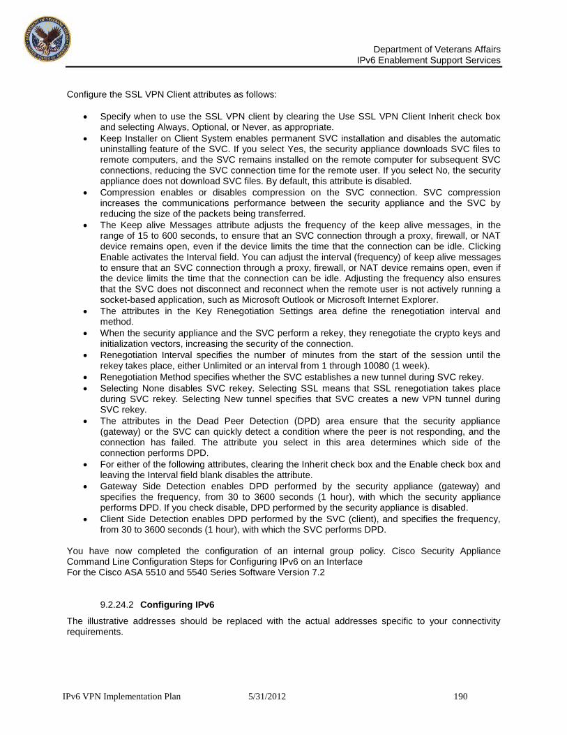
Department of Veterans Affairs
IPv6 Enablement Support Services
IPv6 VPN Implementation Plan 5/31/2012 190
Configure the SSL VPN Client attributes as follows:
Specify when to use the SSL VPN client by clearing the Use SSL VPN Client Inherit check box and selecting Always, Optional, or Never, as appropriate.
Keep Installer on Client System enables permanent SVC installation and disables the automatic uninstalling feature of the SVC. If you select Yes, the security appliance downloads SVC files to remote computers, and the SVC remains installed on the remote computer for subsequent SVC connections, reducing the SVC connection time for the remote user. If you select No, the security appliance does not download SVC files. By default, this attribute is disabled.
Compression enables or disables compression on the SVC connection. SVC compression increases the communications performance between the security appliance and the SVC by reducing the size of the packets being transferred.
The Keep alive Messages attribute adjusts the frequency of the keep alive messages, in the range of 15 to 600 seconds, to ensure that an SVC connection through a proxy, firewall, or NAT device remains open, even if the device limits the time that the connection can be idle. Clicking Enable activates the Interval field. You can adjust the interval (frequency) of keep alive messages to ensure that an SVC connection through a proxy, firewall, or NAT device remains open, even if the device limits the time that the connection can be idle. Adjusting the frequency also ensures that the SVC does not disconnect and reconnect when the remote user is not actively running a socket-based application, such as Microsoft Outlook or Microsoft Internet Explorer.
The attributes in the Key Renegotiation Settings area define the renegotiation interval and method.
When the security appliance and the SVC perform a rekey, they renegotiate the crypto keys and initialization vectors, increasing the security of the connection.
Renegotiation Interval specifies the number of minutes from the start of the session until the rekey takes place, either Unlimited or an interval from 1 through 10080 (1 week).
Renegotiation Method specifies whether the SVC establishes a new tunnel during SVC rekey.
Selecting None disables SVC rekey. Selecting SSL means that SSL renegotiation takes place during SVC rekey. Selecting New tunnel specifies that SVC creates a new VPN tunnel during SVC rekey.
The attributes in the Dead Peer Detection (DPD) area ensure that the security appliance (gateway) or the SVC can quickly detect a condition where the peer is not responding, and the connection has failed. The attribute you select in this area determines which side of the connection performs DPD.
For either of the following attributes, clearing the Inherit check box and the Enable check box and leaving the Interval field blank disables the attribute.
Gateway Side Detection enables DPD performed by the security appliance (gateway) and specifies the frequency, from 30 to 3600 seconds (1 hour), with which the security appliance performs DPD. If you check disable, DPD performed by the security appliance is disabled.
Client Side Detection enables DPD performed by the SVC (client), and specifies the frequency, from 30 to 3600 seconds (1 hour), with which the SVC performs DPD.
You have now completed the configuration of an internal group policy. Cisco Security Appliance Command Line Configuration Steps for Configuring IPv6 on an Interface For the Cisco ASA 5510 and 5540 Series Software Version 7.2
9.2.24.2 Configuring IPv6
The illustrative addresses should be replaced with the actual addresses specific to your connectivity requirements.

Department of Veterans Affairs
IPv6 Enablement Support Services
IPv6 VPN Implementation Plan 5/31/2012 191
9.2.24.2.1 IPv6-enabled Commands This section describes how to enable and configure IPv6 on the ASA 5510 or 5540 security appliance using software version 7.2. IPv6 is available in Routed firewall mode only. This section includes the following sections:
IPv6-enabled Commands
Configuring IPv6
Verifying the IPv6 Configuration
9.2.24.3 IPv6-enabled Commands
The following security appliance commands can accept and display IPv6 addresses:
capture
configure
copy
http
name
object-group
ping
show conn
show local-host
show tcpstat
ssh
telnet
tftp-server
who
write
Note Failover does not support IPv6. The ipv6 address command does not support setting standby addresses for failover configurations. The failover interface ip command does not support using IPv6 addresses on the failover and Stateful Failover interfaces. When entering IPv6 addresses in commands that support them, simply enter the IPv6 address using standard IPv6 notation, for example ping fe80::2e0:b6ff:fe01:3b7a. The security appliance correctly recognizes and processes the IPv6 address. However, you must enclose the IPv6 address in square brackets ([ ]) in the following situations:
You need to specify a port number with the address, for example [fe80::2e0:b6ff:fe01:3b7a]:8080.
The command uses a colon as a separator, such as the write net and config net commands, for example configure net [fe80::2e0:b6ff:fe01:3b7a]:/tftp/config/pixconfig.
The following commands were modified to work for IPv6:
debug
fragment
ip verify
mtu
icmp (entered as ipv6 icmp)

Department of Veterans Affairs
IPv6 Enablement Support Services
IPv6 VPN Implementation Plan 5/31/2012 192
The following inspection engines support IPv6:
FTP
HTTP
ICMP
SMTP
TCP
UDP
9.2.24.4 IPv6 Configuration Steps
This section contains the following steps:
Configuring IPv6 on an Interface
Configuring a Dual IP Stack on an Interface
Enforcing the Use of Modified EUI-64 Interface IDs in IPv6 Addresses
Configuring IPv6 Duplicate Address Detection
Configuring IPv6 Default and Static Routes
Configuring IPv6 Access Lists
Configuring IPv6 Neighbor Discovery
Configuring a Static IPv6 Neighbor
9.2.24.4.1 Configuring IPv6 on an Interface At a minimum, each interface needs to be configured with an IPv6 link-local address. Additionally, you can add a site-local and global address to the interface. Note The security appliance does not support IPv6 anycast addresses. You can configure both IPv6 and IPv4 addresses on an interface. To configure IPv6 on an interface, perform the following steps: Step 1 Enter interface configuration mode for the interface on which you are configuring the IPv6 addresses: hostname(config)# interface if
Step 2 Configure an IPv6 address on the interface. You can assign several IPv6 addresses to an interface, such as an IPv6 link-local, site-local, and global address. However, at a minimum, you must configure a link-local address. There are several methods for configuring IPv6 addresses. Pick the method that suits your needs from the following:
The simplest method is to enable stateless auto configuration on the interface. Enabling stateless auto configuration on the interface configures IPv6 addresses based on prefixes received in Router Advertisement messages. A link-local address, based on the Modified EUI-64 interface ID, is automatically generated for the interface when stateless auto configuration is enabled. To enable stateless auto configuration, enter the following command: hostname(config-if)# ipv6 address
autoconfig If you only need to configure a link-local address on the interface and are not going to assign any
other IPv6 addresses to the interface, you have the option of manually defining the link-local address or generating one based on the interface MAC address (Modified EUI-64 format):
o Enter the following command to manually specify the link-local address: hostname(config-if)# ipv6 address ipv6-address link-local

Department of Veterans Affairs
IPv6 Enablement Support Services
IPv6 VPN Implementation Plan 5/31/2012 193
o Enter the following command to enable IPv6 on the interface and automatically generate the link-local address using the Modified EUI-64 interface ID based on the interface MAC address: hostname(config-if)# ipv6 enable
Note You do not need to use the ipv6 enable command if you enter any other ipv6 address commands on an interface; IPv6 support is automatically enabled as soon as you assign an IPv6 address to the interface.
Assign a site-local or global address to the interface. When you assign a site-local or global address, a link-local address is automatically created. Enter the following command to add a global or site-local address to the interface. Use the optional eui-64 keyword to use the Modified EUI-64 interface ID in the low order 64 bits of the address. hostname(config-if)# ipv6 address ipv6-address [eui-64]
Step 3 (Optional) Suppress Router Advertisement messages on an interface. By default, Router Advertisement
messages are automatically sent in response to router solicitation messages. You may want to disable these messages on any interface for which you do not want the security appliance to supply the IPv6 prefix (for example, the outside interface). Enter the following command to suppress Router Advertisement messages on an interface: hostname(config-if)# ipv6 nd suppress-ra
9.2.24.4.2 Configuring a Dual IP Stack on an Interface The security appliance supports the configuration of both IPv6 and IPv4 on an interface. You do not need to enter any special commands to do so; simply enter the IPv4 configuration commands and IPv6 configuration commands as you normally would. Make sure you configure a default route for both IPv4 and IPv6.
9.2.24.5 Configuring IPv6 Duplicate Address Detection
During the stateless auto configuration process, duplicate address detection verifies the uniqueness of new unicast IPv6 addresses before the addresses are assigned to interfaces (the new addresses remain in a tentative state while duplicate address detection is performed). Duplicate address detection is performed first on the new link-local address. When the link local address is verified as unique, then duplicate address detection is performed all the other IPv6 unicast addresses on the interface. Duplicate address detection is suspended on interfaces that are administratively down. While an interface is administratively down, the unicast IPv6 addresses assigned to the interface are set to a pending state. An interface returning to an administratively up state restarts duplicate address detection for all of the unicast IPv6 addresses on the interface. When a duplicate address is identified, the state of the address is set to DUPLICATE, the address is not used, and the following error message is generated: %PIX|ASA-4-325002: Duplicate address ipv6_address/MAC_address on interface If the duplicate address is the link-local address of the interface, the processing of IPv6 packets is disabled on the interface. If the duplicate address is a global address, the address is not used. However, all configuration commands associated with the duplicate address remain as configured while the state of the address is set to DUPLICATE. If the link-local address for an interface changes, duplicate address detection is performed on the new link-local address and all of the other IPv6 address associated with the interface are regenerated (duplicate address detection is performed only on the new link-local address). The security appliance uses neighbor solicitation messages to perform duplicate address detection. By default, the number of times an interface performs duplicate address detection is 1.

Department of Veterans Affairs
IPv6 Enablement Support Services
IPv6 VPN Implementation Plan 5/31/2012 194
To change the number of duplicate address detection attempts, enter the following command: hostname(config-if)# ipv6 nd dad attempts value The value argument can be any value from 0 to 600. Setting the value argument to 0 disables duplicate address detection on the interface. When you configure an interface to send out more than one duplicate address detection attempt, you can also use the ipv6 nd ns-interval command to configure the interval at which the neighbor solicitation messages are sent out. By default, they are sent out once every 1000 milliseconds. To change the neighbor solicitation message interval, enter the following command: hostname(config-if)# ipv6 nd ns-interval value The value argument can be from 1000 to 3600000 milliseconds.
9.2.25 Configuring IPv6 Default and Static Routes
The security appliance automatically routes IPv6 traffic between directly connected hosts if the interfaces to which the hosts are attached are enabled for IPv6 and the IPv6 ACLs allow the traffic. The security appliance does not support dynamic routing protocols. Therefore, to route IPv6 traffic to a non-connected host or network, you need to define a static route to the host or network or, at a minimum, a default route. Without a static or default route defined, traffic to non-connected hosts or networks generate the following error message: %PIX|ASA-6-110001: No route to dest_address from source_address You can add a default route and static routes using the ipv6 route command. To configure an IPv6 default route and static routes, perform the following steps: Step 1 To add the default route, use the following command: hostname(config)# ipv6 route if_name ::/0 next_hop_ipv6_addr The address ::/0 is the IPv6 equivalent of “any.” Step 2 (Optional) Define IPv6 static routes. Use the following command to add an IPv6 static route to the IPv6 routing table: hostname(config)# ipv6 route if_name destination next_hop_ipv6_addr [admin_distance] Note The ipv6 route command works like the route command used to define IPv4 static routes.
9.2.25.1 Configuring IPv6 Access Lists
Configuring an IPv6 access list is similar configuring an IPv4 access, but with IPv6 addresses. To configure an IPv6 access list, perform the following steps: Step 1 Create an access entry. To create an access list, use the ipv6 access-list command to create entries for the access list. There are two main forms of this command to choose from, one for creating access list entries specifically for ICMP traffic, and one to create access list entries for all other types of IP traffic.
To create an IPv6 access list entry specifically for ICMP traffic, enter the following command: hostname(config)# ipv6 access-list id [line num] {permit | deny} icmp source destination [icmp_type]
To create an IPv6 access list entry, enter the following command: hostname(config)# ipv6 access-list id [line num] {permit | deny} protocol source [src_port] destination [dst_port] The following describes the arguments for the ipv6 access-list command:
id—The name of the access list. Use the same id in each command when you are entering multiple entries for an access list.

Department of Veterans Affairs
IPv6 Enablement Support Services
IPv6 VPN Implementation Plan 5/31/2012 195
line num—When adding an entry to an access list, you can specify the line number in the list where the entry should appear.
permit | deny—Determines whether the specified traffic is blocked or allowed to pass.
icmp—Indicates that the access list entry applies to ICMP traffic.
protocol—Specifies the traffic being controlled by the access list entry. This can be the name (ip, tcp, or udp) or number (1-254) of an IP protocol. Alternatively, you can specify a protocol object group using object-group grp_id.
source and destination—Specifies the source or destination of the traffic. The source or destination can be an IPv6 prefix, in the format prefix/length, to indicate a range of addresses, the keyword any, to specify any address, or a specific host designated by host host_ipv6_addr.
src_port and dst_port—The source and destination port (or service) argument. Enter an operator (lt for less than, gt for greater than, eq for equal to, neq for not equal to, or range for an inclusive range) followed by a space and a port number (or two port numbers separated by a space for the range keyword).
icmp_type—Specifies the ICMP message type being filtered by the access rule. The value can be a valid ICMP type number (from 0 to 155) or one of the ICMP type literals as shown in Appendix D, “Addresses, Protocols, and Ports”. Alternatively, you can specify an ICMP object group using object-group id. Step 2 To apply the access list to an interface, enter the following command: hostname(config)# access-group access_list_name {in | out} interface if_name
9.2.25.2 Configuring IPv6 Neighbor Discovery
The IPv6 neighbor discovery process uses ICMPv6 messages and solicited-node multicast addresses to determine the link-layer address of a neighbor on the same network (local link), verify the reach-ability of a neighbor, and keep track of neighboring routers. This section contains the following topics:
Configuring Neighbor Solicitation Messages
Configuring Router Advertisement Messages
Multicast Listener Discovery Support
9.2.25.2.1 Configuring Neighbor Solicitation Messages
Neighbor solicitation messages (ICMPv6 Type 135) are sent on the local link by nodes attempting to discover the link-layer addresses of other nodes on the local link. The neighbor solicitation message is sent to the solicited-node multicast address. The source address in the neighbor solicitation message is the IPv6 address of the node sending the neighbor solicitation message. The neighbor solicitation message also includes the link-layer address of the source node. After receiving a neighbor solicitation message, the destination node replies by sending a neighbor advertisement message (ICPMv6 Type 136) on the local link. The source address in the neighbor advertisement message is the IPv6 address of the node sending the neighbor advertisement message; the destination address is the IPv6 address of the node that sent the neighbor solicitation message. The data portion of the neighbor advertisement message includes the link-layer address of the node sending the neighbor advertisement message. After the source node receives the neighbor advertisement, the source node and destination node can communicate.

Department of Veterans Affairs
IPv6 Enablement Support Services
IPv6 VPN Implementation Plan 5/31/2012 196
Figure 13: Neighbor Solicitation and Response Process
Neighbor solicitation messages are also used to verify the reach-ability of a neighbor after the link-layer address of a neighbor is identified. When a node wants to verifying the reach-ability of a neighbor, the destination address in a neighbor solicitation message is the unicast address of the neighbor. Neighbor advertisement messages are also sent when there is a change in the link-layer address of a node on a local link. When there is such a change, the destination address for the neighbor advertisement is the all-nodes multicast address. You can configure the neighbor solicitation message interval and neighbor reachable time on a per-interface basis. See the following topics for more information:
Configuring the Neighbor Solicitation Message Interval
Configuring the Neighbor Reachable Time
Configuring the Neighbor Solicitation Message Interval To configure the interval between IPv6 neighbor solicitation retransmissions on an interface, enter the following command: hostname(config-if)# ipv6 nd ns-interval value Valid values for the value argument range from 1000 to 3600000 milliseconds. The default value is 1000 milliseconds. This setting is also sent in router advertisement messages. Configuring the Neighbor Reachable Time The neighbor reachable time enables detecting unavailable neighbors. Shorter configured times enable detecting unavailable neighbors more quickly; however, shorter times consume more IPv6 network bandwidth and processing resources in all IPv6 network devices. Very short configured times are not recommended in normal IPv6 operation. To configure the amount of time that a remote IPv6 node is considered reachable after a reach-ability confirmation event has occurred, enter the following command: hostname(config-if)# ipv6 nd reachable-time value Valid values for the value argument range from 0 to 3600000 milliseconds. The default is 0. This information is also sent in router advertisement messages. When 0 is used for the value, the reachable time is sent as undetermined. It is up to the receiving devices to set and track the reachable time value. To see the time used by the security appliance when this value is set to 0, use the show ipv6 interface command to display information about the IPv6 interface, including the ND reachable time being used.

Department of Veterans Affairs
IPv6 Enablement Support Services
IPv6 VPN Implementation Plan 5/31/2012 197
9.2.25.3 Configuring Router Advertisement Messages
Router advertisement messages (ICMPv6 Type 134) are periodically sent out each IPv6 configured interface of security appliance. The router advertisement messages are sent to the all-nodes multicast address.
Figure 14: Router Advertisement Message
Router advertisement messages typically include the following information:
One or more IPv6 prefix that nodes on the local link can use to automatically configure their IPv6 addresses.
Lifetime information for each prefix included in the advertisement.
Sets of flags that indicate the type of auto configuration (stateless or stateful) that can be completed.
Default router information (whether the router sending the advertisement should be used as a default router and, if so, the amount of time (in seconds) the router should be used as a default router).
Additional information for hosts, such as the hop limit and MTU a host should use in packets that it originates.
The amount of time between neighbor solicitation message retransmissions on a given link.
The amount of time a node considers a neighbor reachable.
Router advertisements are also sent in response to router solicitation messages (ICMPv6 Type 133). Router solicitation messages are sent by hosts at system startup so that the hosts can immediately auto configure without needing to wait for the next scheduled router advertisement message. Because router solicitation messages are usually sent by hosts at system startup, and the host does not have a configured unicast address, the source address in router solicitation messages is usually the unspecified IPv6 address (0:0:0:0:0:0:0:0). If the host has a configured unicast address, the unicast address of the interface sending the router solicitation message is used as the source address in the message. The destination address in router solicitation messages is the all-routers multicast address with a scope of the link. When a router advertisement is sent in response to a router solicitation, the destination address in the router advertisement message is the unicast address of the source of the router solicitation message. You can configure the following settings for router advertisement messages:
The time interval between periodic router advertisement messages.
The router lifetime value, which indicates the amount of time IPv6 nodes should consider security appliance to be the default router.
The IPv6 network prefixes in use on the link.
Whether or not an interface transmits router advertisement messages.

Department of Veterans Affairs
IPv6 Enablement Support Services
IPv6 VPN Implementation Plan 5/31/2012 198
Unless otherwise noted, the router advertisement message settings are specific to an interface and are entered in interface configuration mode. See the following topics for information about changing these settings:
Configuring the Router Advertisement Transmission Interval
Configuring the Router Lifetime Value
Configuring the IPv6 Prefix
Suppressing Router Advertisement Messages
Configuring the Router Advertisement Transmission Interval By default, router advertisements are sent out every 200 seconds. To change the interval between router advertisement transmissions on an interface, enter the following command: ipv6 nd ra-interval [msec] value Valid values range from 3 to 1800 seconds (or 500 to 1800000 milliseconds if the msec keyword is used). The interval between transmissions should be less than or equal to the IPv6 router advertisement lifetime if security appliance is configured as a default router by using the ipv6 nd ra-lifetime command. To prevent synchronization with other IPv6 nodes, randomly adjust the actual value used to within 20 percent of the desired value. Configuring the Router Lifetime Value The router lifetime value specifies how long nodes on the local link should consider security appliance as the default router on the link. To configure the router lifetime value in IPv6 router advertisements on an interface, enter the following command: hostname(config-if)# ipv6 nd ra-lifetime seconds Valid values range from 0 to 9000 seconds. The default is 1800 seconds. Entering 0 indicates that security appliance should not be considered a default router on the selected interface. Configuring the IPv6 Prefix Stateless auto configuration uses IPv6 prefixes provided in router advertisement messages to create the global unicast address from the link-local address. To configure which IPv6 prefixes are included in IPv6 router advertisements, enter the following command: hostname (config-if)# ipv6 nd prefix ipv6-prefix/prefix-length Note For stateless auto configuration to work properly, the advertised prefix length in router advertisement messages must always be 64 bits. Suppressing Router Advertisement Messages By default, Router Advertisement messages are automatically sent in response to router solicitation messages. You may want to disable these messages on any interface for which you do not want security appliance to supply the IPv6 prefix (for example, the outside interface). To suppress IPv6 router advertisement transmissions on an interface, enter the following command: hostname (config-if) # ipv6 nd suppress-ra Entering this command causes the security appliance to appear as a regular IPv6 neighbor on the link and not as an IPv6 router. Multicast Listener Discovery Support Multicast Listener Discovery Protocol (MLD) Version 2 is supported to discover the presence of multicast address listeners on their directly attached links, and to discover specifically which multicast addresses

Department of Veterans Affairs
IPv6 Enablement Support Services
IPv6 VPN Implementation Plan 5/31/2012 199
are of interest to those neighboring nodes. ASA becomes a multicast address listener, or a host, but not a multicast router, and responds to Multicast Listener Queries and sends Multicast Lis-tener Reports only. The following commands were added or enhanced to support MLD:
clear ipv6 mld traffic Command
show ipv6 mld Command
9.2.25.3.1 Configuring a Static IPv6 Neighbor You can manually define a neighbor in the IPv6 neighbor cache. If an entry for the specified IPv6 address already exists in the neighbor discovery cache—learned through the IPv6 neighbor discovery process—the entry is automatically converted to a static entry. Static entries in the IPv6 neighbor discovery cache are not modified by the neighbor discovery process. To configure a static entry in the IPv6 neighbor discovery cache, enter the following command: hostname(config-if)# ipv6 neighbor ipv6_address if_name mac_address The ipv6_address argument is the link-local IPv6 address of the neighbor, the if_name argument is the interface through which the neighbor is available, and the mac_address argument is the MAC address of the neighbor interface. Note The clear ipv6 neighbors command does not remove static entries from the IPv6 neighbor discovery cache; it only clears the dynamic entries.
9.2.25.3.2 Verifying the IPv6 Configuration This section describes how to verify your IPv6 configuration. You can use various clear, and show commands to verify your IPv6 settings. This section includes the following topics:
The show ipv6 interface Command
The show ipv6 route Command
The show ipv6 mld traffic Command
9.2.25.3.3 To Show ipv6 Interface To display the IPv6 interface settings, enter the following command: hostname# show ipv6 interface [if_name] Including the interface name, such as “outside”, displays the settings for the specified interface. Excluding the name from the command displays the setting for all interfaces that have IPv6 enabled on them. The output for the command shows the following:
The name and status of the interface.
The link-local and global unicast addresses.
The multicast groups the interface belongs to.
ICMP redirect and error message settings.
Neighbor discovery settings.
The following is sample output from the show ipv6 interface command: hostname# show ipv6 interface ipv6interface is down, line protocol is down IPv6 is enabled, link-local address is fe80::20d:88ff:feee:6a82 [TENTATIVE] No global unicast address is configured Joined group address(es): ff02::1 ff02::1:ffee:6a82 ICMP error messages limited to one every 100 milliseconds ICMP redirects are enabled ND DAD is enabled, number of DAD attempts: 1 ND reachable time is 30000 milliseconds

Department of Veterans Affairs
IPv6 Enablement Support Services
IPv6 VPN Implementation Plan 5/31/2012 200
Note The show interface command only displays the IPv4 settings for an interface. To see the IPv6 configuration on an interface, you need to use the show ipv6 interface command. The show ipv6 interface command does not display any IPv4 settings for the interface (if both types of addresses are configured on the interface).
9.2.25.3.4 To show ipv6 Route To display the routes in the IPv6 routing table, enter the following command: hostname# show ipv6 route The output from the show ipv6 route command is similar to the IPv4 show route command. It displays the following information:
The protocol that derived the route.
The IPv6 prefix of the remote network.
The administrative distance and metric for the route.
The address of the next-hop router.
The interface through which the next hop router to the specified network is reached.
The following is sample output from the show ipv6 route command: hostname# show ipv6 route IPv6 Routing Table - 7 entries Codes: C - Connected, L - Local, S - Static, R - RIP, B - BGP U - Per-user Static route I1 - ISIS L1, I2 - ISIS L2, IA - ISIS interarea O - OSPF intra, OI - OSPF inter, OE1 - OSPF ext 1, OE2 - OSPF ext 2 L fe80::/10 [0/0] via ::, inside L fec0::a:0:0:a0a:a70/128 [0/0] via ::, inside C fec0:0:0:a::/64 [0/0] via ::, inside L ff00::/8 [0/0] via ::, inside
9.2.26 To show IPv6 mld traffic
To display the MLD traffic counters in the IPv6 routing table, enter the following command: hostname# show ipv6 mld traffic The output from the show ipv6 mld traffic command displays whether the expected number of MLD protocol messages have been received and sent. The following is sample output from the show ipv6 mld traffic command: hostname# show ipv6 mld traffic show ipv6 mld traffic MLD Traffic Counters Elapsed time since counters cleared: 00:01:19 Received Sent Valid MLD Packets 1 3 Queries 1 0 Reports 0 3 Leaves 0 0 Mtrace packets 0 0 Errors:

Department of Veterans Affairs
IPv6 Enablement Support Services
IPv6 VPN Implementation Plan 5/31/2012 201
Malformed Packets 0 Martian source 0 Non link-local source 0 Hop limit is not equal to 1 0
9.2.26.1 Configuring IPv6 on an Interface
At a minimum, each interface needs to be configured with an IPv6 link-local address. Additionally, you can add a site-local and global address to the interface. Note The security appliance does not support IPv6 anycast addresses. You can configure both IPv6 and IPv4 addresses on an interface. To configure IPv6 on an interface, perform the following steps: Step 1 Enter interface configuration mode for the interface on which you are configuring the IPv6 addresses: hostname(config)# interface if Step 2 Configure an IPv6 address on the interface. You can assign several IPv6 addresses to an interface, such as an IPv6 link-local, site-local, and global address. However, at a minimum, you must configure a link-local address. There are several methods for configuring IPv6 addresses. Pick the method that suits your needs from the following:
The simplest method is to enable stateless auto configuration on the interface. Enabling stateless auto configuration on the interface configures IPv6 addresses based on prefixes received in Router Advertisement messages. A link-local address, based on the Modified EUI-64 interface ID, is automatically generated for the interface when stateless auto configuration is enabled. To enable stateless auto configuration, enter the following command:
o hostname(config-if)# ipv6 address autoconfig
If you only need to configure a link-local address on the interface and are not going to assign any other IPv6 addresses to the interface, you have the option of manually defining the link-local address or generating one based on the interface MAC address (Modified EUI-64 format):
o Enter the following command to manually specify the link-local address: hostname(config-if)# ipv6 address ipv6-address link-local
o Enter the following command to enable IPv6 on the interface and automatically generate the link-local address using the Modified EUI-64 interface ID based on the interface MAC address: hostname(config-if)# ipv6 enable
Note You do not need to use the ipv6 enable command if you enter any other ipv6 address commands on an interface; IPv6 support is automatically enabled as soon as you assign an IPv6 address to the interface.
Assign a site-local or global address to the interface. When you assign a site-local or global address, a link-local address is automatically created. Enter the following command to add a global or site-local address to the interface. Use the optional eui-64 keyword to use the Modified EUI-64 interface ID in the low order 64 bits of the address.
hostname(config-if)# ipv6 address ipv6-address [eui-64] Step 3 (Optional) Suppress Router Advertisement messages on an interface. By default, Router Advertisement messages are automatically sent in response to router solicitation messages. You may want to disable these messages on any interface for which you do not want the security appliance to supply the IPv6 prefix (for example, the outside interface). Enter the following command to suppress Router Advertisement messages on an interface:

Department of Veterans Affairs
IPv6 Enablement Support Services
IPv6 VPN Implementation Plan 5/31/2012 202
hostname(config-if)# ipv6 nd suppress-ra
9.2.26.1.1 Configuring a Dual IP Stack on an Interface The security appliance supports the configuration of both IPv6 and IPv4 on an interface. You do not need to enter any special commands to do so; simply enter the IPv4 configuration commands and IPv6 configuration commands as you normally would. Make sure you configure a default route for both IPv4 and IPv6.
9.2.26.2 Configuring IPv6 Duplicate Address Detection
During the stateless auto configuration process, duplicate address detection verifies the uniqueness of new unicast IPv6 addresses before the addresses are assigned to interfaces (the new addresses remain in a tentative state while duplicate address detection is performed). Duplicate address detection is performed first on the new link-local address. When the link local address is verified as unique, then duplicate address detection is performed all the other IPv6 unicast addresses on the interface. Duplicate address detection is suspended on interfaces that are administratively down. While an interface is administratively down, the unicast IPv6 addresses assigned to the interface are set to a pending state. An interface returning to an administratively up state restarts duplicate address detection for all of the unicast IPv6 addresses on the interface. When a duplicate address is identified, the state of the address is set to DUPLICATE, the address is not used, and the following error /message is generated: %PIX|ASA-4-325002: Duplicate address ipv6_address/MAC_address on interface If the duplicate address is the link-local address of the interface, the processing of IPv6 packets is disabled on the interface. If the duplicate address is a global address, the address is not used. However, all configuration commands associated with the duplicate address remain as configured while the state of the address is set to DUPLICATE. If the link-local address for an interface changes, duplicate address detection is performed on the new link-local address and all of the other IPv6 address associated with the interface are regenerated (duplicate address detection is performed only on the new link-local address). The security appliance uses neighbor solicitation messages to perform duplicate address detection. By default, the number of times an interface performs duplicate address detection is 1. To change the number of duplicate address detection attempts, enter the following command: hostname(config-if)# ipv6 nd dad attempts value The value argument can be any value from 0 to 600. Setting the value argument to 0 disables duplicate address detection on the interface. When you configure an interface to send out more than one duplicate address detection attempt, you can also use the ipv6 nd ns-interval command to configure the interval at which the neighbor solicitation messages are sent out. By default, they are sent out once every 1000 milliseconds. To change the neighbor solicitation message interval, enter the following command: hostname(config-if)# ipv6 nd ns-interval value The value argument can be from 1000 to 3600000 milliseconds.

Department of Veterans Affairs
IPv6 Enablement Support Services
IPv6 VPN Implementation Plan 5/31/2012 203
Note Changing this value changes it for all neighbor solicitation messages sent out on the interface, not just those used for duplicate address detection.
9.2.26.3 Configuring IPv6 Default and Static Routes
The security appliance automatically routes IPv6 traffic between directly connected hosts if the interfaces to which the hosts are attached are enabled for IPv6 and the IPv6 ACLs allow the traffic. The security appliance does not support dynamic routing protocols. Therefore, to route IPv6 traffic to a non-connected host or network, you need to define a static route to the host or network or, at a minimum, a default route. Without a static or default route defined, traffic to non-connected hosts or networks generate the following error message: %PIX|ASA-6-110001: No route to dest_address from source_address You can add a default route and static routes using the ipv6 route command. To configure an IPv6 default route and static routes, perform the following steps: Step 1 To add the default route, use the following command: hostname(config)# ipv6 route if_name ::/0 next_hop_ipv6_addr The address ::/0 is the IPv6 equivalent of "any." Step 2 (Optional) Define IPv6 static routes. Use the following command to add an IPv6 static route to the IPv6 routing table: hostname(config)# ipv6 route if_name destination next_hop_ipv6_addr [admin_distance] Note The ipv6 route command works like the route command used to define IPv4 static routes.
9.2.26.4 Configuring IPv6 Access Lists
Configuring an IPv6 access list is similar configuring an IPv4 access, but with IPv6 addresses. To configure an IPv6 access list, perform the following steps: Step 1 Create an access entry. To create an access list, use the ipv6 access-list command to create entries for the access list. There are two main forms of this command to choose from, one for creating access list entries specifically for ICMP traffic, and one to create access list entries for all other types of IP traffic. To create an IPv6 access list entry specifically for ICMP traffic, enter the following command: hostname (config)# ipv6 access-list id [line num] {permit | deny} icmp source destination [icmp_type]
To create an IPv6 access list entry, enter the following command: hostname(config)# ipv6 access-list id [line num] {permit | deny} protocol source [src_port] destination [dst_port] The following describes the arguments for the ipv6 access-list command:
id—The name of the access list. Use the same id in each command when you are entering multiple entries for an access list.
line num—When adding an entry to an access list, you can specify the line number in the list where the entry should appear.
permit | deny—Determines whether the specified traffic is blocked or allowed to pass.

Department of Veterans Affairs
IPv6 Enablement Support Services
IPv6 VPN Implementation Plan 5/31/2012 204
icmp—Indicates that the access list entry applies to ICMP traffic.
protocol—Specifies the traffic being controlled by the access list entry. This can be the name (ip, tcp, or udp) or number (1-254) of an IP protocol. Alternatively, you can specify a protocol object group using object-group grp_id.
source and destination—Specifies the source or destination of the traffic. The source or destination can be an IPv6 prefix, in the format prefix/length, to indicate a range of addresses, the keyword any, to specify any address, or a specific host designated by host host_ipv6_addr.
src_port and dst_port—The source and destination port (or service) argument. Enter an operator (lt for less than, gt for greater than, eq for equal to, neq for not equal to, or range for an inclusive range) followed by a space and a port number (or two port numbers separated by a space for the range keyword).
icmp_type—Specifies the ICMP message type being filtered by the access rule. The value can be a valid ICMP type number (from 0 to 155) or one of the ICMP type literals as shown in Appendix D, "Addresses, Protocols, and Ports". Alternatively, you can specify an ICMP object group using object-group id.
Step 2 To apply the access list to an interface, enter the following command: hostname(config)# access-group access_list_name {in | out} interface if_name
9.2.26.5 Configuring IPv6 Neighbor Discovery
The IPv6 neighbor discovery process uses ICMPv6 messages and solicited-node multicast addresses to determine the link-layer address of a neighbor on the same network (local link), verify the reach-ability of a neighbor, and keep track of neighboring routers. This section contains the following topics:
Configuring Neighbor Solicitation Messages
Configuring Router Advertisement Messages
Multicast Listener Discovery Support
Configuring Neighbor Solicitation Messages Neighbor solicitation messages (ICMPv6 Type 135) are sent on the local link by nodes attempting to discover the link-layer addresses of other nodes on the local link. The neighbor solicitation message is sent to the solicited-node multicast address. The source address in the neighbor solicitation message is the IPv6 address of the node sending the neighbor solicitation message. The neighbor solicitation message also includes the link-layer address of the source node. After receiving a neighbor solicitation message, the destination node replies by sending a neighbor advertisement message (ICPMv6 Type 136) on the local link. The source address in the neighbor advertisement message is the IPv6 address of the node sending the neighbor advertisement message; the destination address is the IPv6 address of the node that sent the neighbor solicitation message. The data portion of the neighbor advertisement message includes the link-layer address of the node sending the neighbor advertisement message. After the source node receives the neighbor advertisement, the source node and destination node can communicate. Figure 12-1 shows the neighbor solicitation and response process.

Department of Veterans Affairs
IPv6 Enablement Support Services
IPv6 VPN Implementation Plan 5/31/2012 205
Figure 15: Neighbor Solicitation Message Neighbor solicitation messages are also used to verify the reach-ability of a neighbor after the link-layer address of a neighbor is identified. When a node wants to verifying the reach-ability of a neighbor, the destination address in a neighbor solicitation message is the unicast address of the neighbor. Neighbor advertisement messages are also sent when there is a change in the link-layer address of a node on a local link. When there is such a change, the destination address for the neighbor advertisement is the all-nodes multicast address. You can configure the neighbor solicitation message interval and neighbor reachable time on a per-interface basis. See the following topics for more information:
Configuring the Neighbor Solicitation Message Interval
Configuring the Neighbor Reachable Time
9.2.26.6 Configuring the Neighbor Solicitation Message Interval
To configure the interval between IPv6 neighbor solicitation retransmissions on an interface, enter the following command: hostname(config-if)# ipv6 nd ns-interval value Valid values for the value argument range from 1000 to 3600000 milliseconds. The default value is 1000 milliseconds. This setting is also sent in router advertisement messages.
9.2.26.7 Configuring the Neighbor Reachable Time
The neighbor reachable time enables detecting unavailable neighbors. Shorter configured times enable detecting unavailable neighbors more quickly; however, shorter times consume more IPv6 network bandwidth and processing resources in all IPv6 network devices. Very short configured times are not recommended in normal IPv6 operation. To configure the amount of time that a remote IPv6 node is considered reachable after a reach-ability confirmation event has occurred, enter the following command:

Department of Veterans Affairs
IPv6 Enablement Support Services
IPv6 VPN Implementation Plan 5/31/2012 206
hostname(config-if)# ipv6 nd reachable-time value Valid values for the value argument range from 0 to 3600000 milliseconds. The default is 0. This information is also sent in router advertisement messages. When 0 is used for the value, the reachable time is sent as undetermined. It is up to the receiving devices to set and track the reachable time value. To see the time used by the security appliance when this value is set to 0, use the show ipv6 interface command to display information about the IPv6 interface, including the ND reachable time being used.
9.2.26.8 Configuring Router Advertisement Messages
Router advertisement messages (ICMPv6 Type 134) are periodically sent out each IPv6 configured interface of security appliance. The router advertisement messages are sent to the all-nodes multicast address.
Figure 16: Router Advertisement Message Router advertisement messages typically include the following information:
One or more IPv6 prefix that nodes on the local link can use to automatically configure their IPv6 addresses.
Lifetime information for each prefix included in the advertisement.
Sets of flags that indicate the type of auto configuration (stateless or stateful) that can be completed.
Default router information (whether the router sending the advertisement should be used as a default router and, if so, the amount of time (in seconds) the router should be used as a default router).
Additional information for hosts, such as the hop limit and MTU a host should use in packets that it originates.
The amount of time between neighbor solicitation message retransmissions on a given link.
The amount of time a node considers a neighbor reachable. Router advertisements are also sent in response to router solicitation messages (ICMPv6 Type 133). Router solicitation messages are sent by hosts at system startup so that the host can immediately auto configure without needing to wait for the next scheduled router advertisement message. Because router solicitation messages are usually sent by hosts at system startup, and the host does not have a configured unicast address, the source address in router solicitation messages is usually the unspecified IPv6 address (0:0:0:0:0:0:0:0). If the host has a configured unicast address, the unicast address of the interface sending the router solicitation message is used as the source address in the message. The destination address in router solicitation messages is the all-routers multicast address with a scope of the link. When a router advertisement is sent in response to a router solicitation, the destination address in the router advertisement message is the unicast address of the source of the router solicitation message. You can configure the following settings for router advertisement messages:

Department of Veterans Affairs
IPv6 Enablement Support Services
IPv6 VPN Implementation Plan 5/31/2012 207
The time interval between periodic router advertisement messages.
The router lifetime value, which indicates the amount of time IPv6 nodes should consider security appliance to be the default router.
The IPv6 network prefixes in use on the link.
Whether or not an interface transmits router advertisement messages.
Unless otherwise noted, the router advertisement message settings are specific to an interface and are entered in interface configuration mode. See the following topics for information about changing these settings:
Configuring the Router Advertisement Transmission Interval
Configuring the Router Lifetime Value
Configuring the IPv6 Prefix
Suppressing Router Advertisement Messages
9.2.26.8.1 Configuring the Router Advertisement Transmission Interval By default, router advertisements are sent out every 200 seconds. To change the interval between router advertisement transmissions on an interface, enter the following command: ipv6 nd ra-interval [msec] value Valid values range from 3 to 1800 seconds (or 500 to 1800000 milliseconds if the msec keyword is used). The interval between transmissions should be less than or equal to the IPv6 router advertisement lifetime if security appliance is configured as a default router by using the ipv6 nd ra-lifetime command. To prevent synchronization with other IPv6 nodes, randomly adjust the actual value used to within 20 percent of the desired value.
9.2.26.8.2 Configuring the Router Lifetime Value
The router lifetime value specifies how long nodes on the local link should consider security appliance as the default router on the link. To configure the router lifetime value in IPv6 router advertisements on an interface, enter the following command: hostname(config-if)# ipv6 nd ra-lifetime seconds Valid values range from 0 to 9000 seconds. The default is 1800 seconds. Entering 0 indicates that security appliance should not be considered a default router on the selected interface.
9.2.26.8.3 Configuring the IPv6 Prefix Stateless auto configuration uses IPv6 prefixes provided in router advertisement messages to create the global unicast address from the link-local address. To configure which IPv6 prefixes are included in IPv6 router advertisements, enter the following command: hostname(config-if)# ipv6 nd prefix ipv6-prefix/prefix-length
Note For stateless auto configuration to work properly, the advertised prefix length in router advertisement messages must always be 64 bits.

Department of Veterans Affairs
IPv6 Enablement Support Services
IPv6 VPN Implementation Plan 5/31/2012 208
9.2.26.8.4 Suppressing Router Advertisement Messages
By default, Router Advertisement messages are automatically sent in response to router solicitation messages. You may want to disable these messages on any interface for which you do not want security appliance to supply the IPv6 prefix (for example, the outside interface). To suppress IPv6 router advertisement transmissions on an interface, enter the following command: hostname(config-if)# ipv6 nd suppress-ra Entering this command causes the security appliance to appear as a regular IPv6 neighbor on the link and not as an IPv6 router.
9.2.26.9 Multicast Listener Discovery Support
Multicast Listener Discovery Protocol (MLD) Version 2 is supported to discover the presence of multicast address listeners on their directly attached links, and to discover specifically which multicast addresses are of interest to those neighboring nodes. ASA becomes a multicast address listener, or a host, but not a multicast router, and responds to Multicast Listener Queries and sends Multicast Listener Reports only. The following commands were added or enhanced to support MLD:
clear ipv6 mld traffic Command
show ipv6 mld Command
9.2.26.10 Configuring a Static IPv6 Neighbor
You can manually define a neighbor in the IPv6 neighbor cache. If an entry for the specified IPv6 address already exists in the neighbor discovery cache—learned through the IPv6 neighbor discovery process—the entry is automatically converted to a static entry. Static entries in the IPv6 neighbor discovery cache are not modified by the neighbor discovery process. To configure a static entry in the IPv6 neighbor discovery cache, enter the following command: hostname(config-if)# ipv6 neighbor ipv6_address if_name mac_address The ipv6_address argument is the link-local IPv6 address of the neighbor, the if_name argument is the interface through which the neighbor is available, and the mac_address argument is the MAC address of the neighbor interface. Note The clear ipv6 neighbors command does not remove static entries from the IPv6 neighbor discovery cache; it only clears the dynamic entries.
9.2.26.10.1 Verifying the IPv6 Configuration This section describes how to verify your IPv6 configuration. You can use various clear, and show commands to verify your IPv6 settings. This section includes the following topics:
The show ipv6 interface Command
The show ipv6 route Command
The show ipv6 mld traffic Command

Department of Veterans Affairs
IPv6 Enablement Support Services
IPv6 VPN Implementation Plan 5/31/2012 209
The show ipv6 interface Command To display the IPv6 interface settings, enter the following command: hostname# show ipv6 interface [if_name] Including the interface name, such as "outside", displays the settings for the specified interface. Excluding the name from the command displays the setting for all interfaces that have IPv6 enabled on them. The output for the command shows the following:
The name and status of the interface.
The link-local and global unicast addresses.
The multicast groups the interface belongs to.
ICMP redirect and error message settings.
Neighbor discovery settings.
The following is sample output from the show ipv6 interface command: hostname# show ipv6 interface IPv6interface is down, line protocol is down IPv6 is enabled, link-local address is fe80::20d:88ff:feee:6a82 [TENTATIVE] No global unicast address is configured Joined group address(es): ff02::1 ff02::1:ffee:6a82 ICMP error messages limited to one every 100 milliseconds ICMP redirects are enabled ND DAD is enabled, number of DAD attempts: 1 ND reachable time is 30000 milliseconds Note The show interface command only displays the IPv4 settings for an interface. To see the IPv6 configuration on an interface, you need to use the show ipv6 interface command. The show ipv6 interface command does not display any IPv4 settings for the interface (if both types of addresses are configured on the interface). The show ipv6 route Command To display the routes in the IPv6 routing table, enter the following command: hostname# show ipv6 route The output from the show ipv6 route command is similar to the IPv4 show route command. It displays the following information:
The protocol that derived the route.
The IPv6 prefix of the remote network.
The administrative distance and metric for the route.
The address of the next-hop router.
The interface through which the next hop router to the specified network is reached.
The following is sample output from the show ipv6 route command: hostname# show ipv6 route IPv6 Routing Table - 7 entries

Department of Veterans Affairs
IPv6 Enablement Support Services
IPv6 VPN Implementation Plan 5/31/2012 210
Codes: C - Connected, L - Local, S - Static, R - RIP, B - BGP U - Per-user Static route I1 - ISIS L1, I2 - ISIS L2, IA - ISIS interarea O - OSPF intra, OI - OSPF inter, OE1 - OSPF ext 1, OE2 - OSPF ext 2
L fe80::/10 [0/0] via ::, inside L fec0::a:0:0:a0a:a70/128 [0/0] via ::, inside C fec0:0:0:a::/64 [0/0] via ::, inside L ff00::/8 [0/0] via ::, inside The show ipv6 mld traffic Command To display the MLD traffic counters in the IPv6 routing table, enter the following command: hostname# show ipv6 mld traffic The output from the show ipv6 mld traffic command displays whether the expected number of MLD protocol messages have been received and sent. The following is sample output from the show ipv6 mld traffic command: hostname# show ipv6 mld traffic show ipv6 mld traffic MLD Traffic Counters Elapsed time since counters cleared: 00:01:19
Received Sent
Valid MLD Packets 1 3
Queries 1 0
Reports 0 3
Leaves 0 0
Mtrace Packets 0 0
Errors:
Malformed Packets 0
Martian source 0
Non link-local source 0
Hop limit is not equal to 1 0
9.2.27 Enrolling for Digital Certificates
This section describes how to enroll for a digital certificate using ASDM. Once enrolled, you can use the certificate to authenticate VPN LAN-to-LAN tunnels and remote access tunnels. If you intend to use only preshared keys to authenticate, you do not need to read this section. This section includes the following functional areas:
Overview of Configuration Procedure,
Understanding Key Pairs,
Generating an RSA Key Pair,
Creating the Trust point,
Obtaining Certificates with SCEP,
Enrolling with the Certificate Authority,
Managing Certificates,

Department of Veterans Affairs
IPv6 Enablement Support Services
IPv6 VPN Implementation Plan 5/31/2012 211
Note As you following the instructions in this section, click Help for more information about the attributes shown in the ASDM windows.
9.2.27.1 Overview of Configuration Procedure
To enroll with a CA and get an identity certificate for authenticating tunnels, complete the following tasks. Note This example shows automatic (SCEP) enrollment.
1. Create a key pair for the identity certificate. The key pair can be either RSA or DSA. However, for automatic enrollment, you must use RSA keys. The instructions in the sections that follow show how to generate an RSA key pair.
2. Create a trust point. The name of the trust point in this example is newmsroot. 3. Configure an enrollment URL. The URL this example uses is
http://10.20.30.40/certsrv/mscep/mscep.dll. 4. Authenticate the CA. 5. Enroll with the CA, which gets an identity certificate onto the ASA.
9.2.27.2 Understanding Key Pairs
Each peer has a key pair containing both a public and a private key. These keys act as complements; any communication encrypted with one can be decrypted with the other. Key pairs can be either RSA keys or DSA keys. Support for these two types of keys differs as follows:
DSA keys cannot be used for SSH or SSL. To enable SSH or SSL access to a security appliance, use RSA keys.
SCEP enrollment supports only the certification of RSA keys. If you use DSA keys, you must use manual enrollment.
For the purposes of generating keys, the maximum key modulus for RSA keys is 2048, and the maximum key modulus for DSA keys is 1024. The default size for either is 1024 bits.
For signature operations, the maximum key sizes are 4096 bits for RSA keys and 1024 bits for DSA keys.
You can generate a general purpose RSA key pair used for both signing and encryption, or usage RSA key pairs separated for each respective purpose, thus requiring two certificates for the corresponding identity. The default setting is general purpose. This topic does not apply to a DSA key pair because it is only for signing. To configure a key pair for a certificate, you specify the labels to identify the key pair to be generated. The following sections show how to generate an RSA key pair with a specified label using ASDM, and use the default settings for the other parameters.
9.2.27.2.1 Generating an RSA Key Pair To generate an RSA key pair, perform the following steps. Step 1 In the Configuration > Properties > Certificate > Key Pair window, click Add. Step 2 Configure the information in the Add Key Pair dialog box:
a) Name—Click to use the default name, or type a name for the key pair(s). This example uses the default RSA key, but you could, instead, enter a name such as key1.
b) Size list—For an RSA key pair, the Size list displays the options: 512, 768, 1024, or 2048. The default size is 1024. This example accepts the default setting.
c) Type options—Type options are RSA and DSA. For this example, accept the default setting, RSA.
d) Usage options—(Applicable only if the Type is RSA.) The options are General Purpose (one pair for both signing and encryption) and Special (one pair for each respective function). For this example, accept the default setting (General Purpose).
Step 3 Click Generate Now.

Department of Veterans Affairs
IPv6 Enablement Support Services
IPv6 VPN Implementation Plan 5/31/2012 212
Step 4 To view the key pair generated, click Show Details. ASDM displays information about the key pair.
9.2.27.2.2 Creating the Trust point A trust point represents a CA/identity pair and contains the identity of the CA, CA-specific configuration parameters, and an association with one enrolled identity certificate. Refer to the section that names the interface you want to use to create a trust point. To create a trust point, perform the following steps. Step 1 In the Configuration > Properties > Certificate > Trustpoint > Configuration window, click Add. Step 2 Configure the basic information in the Add Trustpoint Configuration dialog box. For all other parameters, accept the default values.
a) Trustpoint Name field—Type the trustpoint name in the Trustpoint Name field. For this example, the name is newmsroot.
b) Enrollment URL field—In the Enrollment Settings window, under the Enrollment Mode area, click the Use automatic enrollment option. Then type the enrollment URL in the field. For this example, type 10.20.30.40/certsrv/mscep/mscep.dll.
Step 3 Configure the subject name using the common name (CN) and the name of the organizational unit (OU):
a) In the Enrollment Settings window, select the key pair you configured for this trust point in the Key Pair list. For this example, the key pair is key1.
b) In the Enrollment Settings window, click Certificate Parameters. c) To add subject distinguished (X.500) name values, click Edit in the Certificate Parameters
dialog box.

Department of Veterans Affairs
IPv6 Enablement Support Services
IPv6 VPN Implementation Plan 5/31/2012 213
d) In the Edit DN area under DN Attribute to be Added, select an attribute in the Attribute list and type a value in the Value field. Then click Add. After entering the DN information, click OK.
For this example, first select Common Name (CN), type Pat in the Value field, and click Add; then select Department (OU) and type Techpubs in the Value field shows what you have entered in the Edit DN dialog box.
Subject Name Attributes and Values Step 4 After reviewing the dialog box, click OK, then click OK in the remaining two dialog boxes.
9.2.27.2.3 Obtaining Certificates with SCEP This section shows how to configure certificates using SCEP. Repeat the instructions for each trust point you configure for automatic enrollment. As you complete the instructions for each trust point, the security appliance receives a CA certificate for the trust point and one or two certificates for signing and encryption purposes. If you do not follow these procedures, the security appliance prompts you to paste the base-64 formatted CA certificate into the text box. If you use DSA keys, the certificate received is for signing only. If you use general-purpose RSA keys, the certificate received is for signing and encryption. If you use separate RSA keys for signing and encryption, the security appliance receives separate certificates for each purpose. To obtain certificates, perform the following steps. Step 1 Select the Configuration >Properties > Certificate > Authentication window. Step 2 In the Trust point Name list, select the name of the trust point. For this example, select newmsroot. Step 3 Click Authenticate. Step 4 Click Apply. When ASDM displays the Authentication Successful dialog, click OK.
9.2.27.2.4 Enrolling with the Certificate Authority After you configure the trust point and authenticate with it, you can enroll for an identity certificate by performing the following steps. Step 1 In the Configuration > Properties > Certificate > Enrollment window, select the trust point in the Trustpoint Name list. For this example, you would select newmsroot. Step 2 Click Enroll.
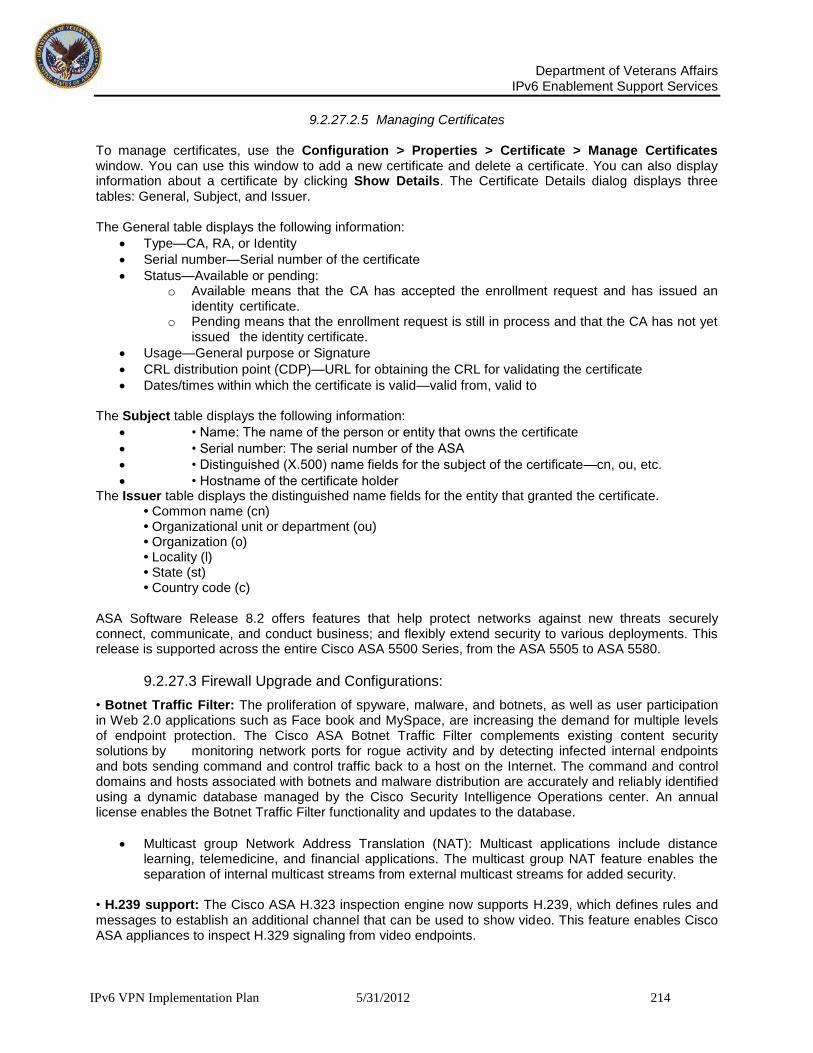
Department of Veterans Affairs
IPv6 Enablement Support Services
IPv6 VPN Implementation Plan 5/31/2012 214
9.2.27.2.5 Managing Certificates To manage certificates, use the Configuration > Properties > Certificate > Manage Certificates window. You can use this window to add a new certificate and delete a certificate. You can also display information about a certificate by clicking Show Details. The Certificate Details dialog displays three tables: General, Subject, and Issuer. The General table displays the following information:
Type—CA, RA, or Identity
Serial number—Serial number of the certificate
Status—Available or pending: o Available means that the CA has accepted the enrollment request and has issued an
identity certificate. o Pending means that the enrollment request is still in process and that the CA has not yet
issued the identity certificate.
Usage—General purpose or Signature
CRL distribution point (CDP)—URL for obtaining the CRL for validating the certificate
Dates/times within which the certificate is valid—valid from, valid to
The Subject table displays the following information:
• Name: The name of the person or entity that owns the certificate
• Serial number: The serial number of the ASA
• Distinguished (X.500) name fields for the subject of the certificate—cn, ou, etc.
• Hostname of the certificate holder The Issuer table displays the distinguished name fields for the entity that granted the certificate. • Common name (cn) • Organizational unit or department (ou) • Organization (o) • Locality (l) • State (st) • Country code (c) ASA Software Release 8.2 offers features that help protect networks against new threats securely connect, communicate, and conduct business; and flexibly extend security to various deployments. This release is supported across the entire Cisco ASA 5500 Series, from the ASA 5505 to ASA 5580.
9.2.27.3 Firewall Upgrade and Configurations:
• Botnet Traffic Filter: The proliferation of spyware, malware, and botnets, as well as user participation in Web 2.0 applications such as Face book and MySpace, are increasing the demand for multiple levels of endpoint protection. The Cisco ASA Botnet Traffic Filter complements existing content security solutions by monitoring network ports for rogue activity and by detecting infected internal endpoints and bots sending command and control traffic back to a host on the Internet. The command and control domains and hosts associated with botnets and malware distribution are accurately and reliably identified using a dynamic database managed by the Cisco Security Intelligence Operations center. An annual license enables the Botnet Traffic Filter functionality and updates to the database.
Multicast group Network Address Translation (NAT): Multicast applications include distance learning, telemedicine, and financial applications. The multicast group NAT feature enables the separation of internal multicast streams from external multicast streams for added security.
• H.239 support: The Cisco ASA H.323 inspection engine now supports H.239, which defines rules and messages to establish an additional channel that can be used to show video. This feature enables Cisco ASA appliances to inspect H.329 signaling from video endpoints.

Department of Veterans Affairs
IPv6 Enablement Support Services
IPv6 VPN Implementation Plan 5/31/2012 215
• Unified Communications Proxy on the Cisco ASA 5580: This feature extends Cisco ASA Unified Communications Proxy features-Phone Proxy, Mobility Proxy, Presence Federation Proxy, and Transport Layer Security (TLS) Proxy-to the Cisco ASA 5580. This increases the maximum capacity of the Unified Communications Proxy solution to 10,000 sessions for TLS Proxy, Mobility Proxy, and Presence Federation Proxy, and to 5000 sessions for Phone Proxy. • ASA Phone Proxy media termination address for multiple interfaces The Phone Proxy requires a media termination address to terminate media from remote phones. For customers with security policies that prevent external routes on the internal network, this feature delivers the ability to configure the media termination address for multiple interfaces, eliminating the need to deploy a NAT device between the internal network and the Phone Proxy. • Transparent firewall mode support for IPv6 addressing: Cisco ASA Software Release 8.2 flexibly extends the support of IPv6 addressing in transparent firewall mode to enable quick ASA deployments into existing IPv6 networks without requiring IP readdressing. • 250 VLANs on the Cisco ASA 5580: The number of virtual interfaces available on the Cisco ASA 5580 has increased from 50 to 250. • TCP state bypass: With Cisco ASA Software Release 8.2, business can selectively disable firewall TCP inspection on ASA appliances. This is useful for allowing certain traffic to flow through in asymmetric routing scenarios when two ASA appliances are in different locations that are not adjacent to Layer 2. • IPv6 support for AIP SSM modules: The Cisco ASA now supports IPv6 capabilities on the Cisco ASA AIP SSM modules. Customers can send IPv6 packets from the ASA to the AIP SSM modules for both IPv6 and IPv4 IPS inspection. Minimum IPS software required is Cisco IPS software version 6.2.
9.2.27.4 Remote-access VPN features:
• Cisco Any Connect Essentials: This feature offers basic Any Connect tunneling support for customers who require VPN remote access but do not need Cisco Secure Desktop features or clientless SSL VPN capabilities. Any Connect Essentials supports mobile connectivity options with the Any Connect Mobile license. Upgrade to the full-featured Any Connect Premium license (traditional Any Connect) is available by applying a traditional Any Connect license or shared license to the ASA appliance. • Shared license support for SSL VPN: The shared license server device (holding the shared license) and participant devices must be able to communicate with one another on an internal network either directly or through a VPN connection. Each participating device must have a license that enables the shared licensing capability. Shared licenses support the full Any Connect feature set, including Cisco Secure Desktop and clientless SSL VPN. • Cisco Any Connect Mobile: Any Connect Mobile provides Windows Mobile 5.0, 6.0, and 6.1 full client support for touch-screen Windows Mobile devices. Any Connect Mobile is compatible with Any Connect Essentials and Premium (traditional Any Connect) licenses, as well as with shared licenses. • Pre-fill username from certificate: This security feature facilitates user login by pre-filling the username in username/password authentication from a field of the user's certificate. • Double authentication: This feature enables the validation of two separate sets of credentials at login. For example, one-time password (OTP) can be used as the primary authentication and an Active Directory domain credential can be used for the secondary authentication method.

Department of Veterans Affairs
IPv6 Enablement Support Services
IPv6 VPN Implementation Plan 5/31/2012 216
• Per-group certificate authentication enable: This feature allows administrators to configure whether to require a certificate on a per-URL or per-FQDN basis. This setting is global on all Cisco ASA Software releases. • Per-group Cisco Secure Desktop enable: This feature allows administrators to configure Cisco Secure Desktop functions on a per-URL or per-FQDN basis. This setting is global on all Cisco ASA Software releases. • Microsoft SharePoint 2007 support: Cisco ASA Software Release 8.2 provides official Microsoft SharePoint 2007 support for clientless SSL VPN connections. • EKU tunnel group: Cisco ASA Software Release 8.2 provides an extended key usage (EKU) extension in the tunnel-group map.
9.2.28 Management features:
• Cisco Adaptive Security Device Manager (ASDM) Public Server Configuration Wizard: This wizard enables administrators to easily automate the process of configuring an ASA appliance to allow certain internal servers such as email or web servers to be publicly accessible on the Internet. • Cisco ASDM OTP authentication, authorization, and accounting (AAA) support: This support allows administrative users to authenticate Cisco ASA appliances and ASDM through OTPs supported by RSA SecureID. This feature addresses security concerns associated with administrators using static passwords for authentication. • Cisco ASDM support for Cisco Secure Desktop customization: This ASDM enhancement allows customers to customize how Cisco Secure Desktop screens are displayed to remote users, allowing administrators to show appropriate screens depending on a user's responsibilities and job functions. • SNMPv3 support: Cisco ASA Software Release 8.2 supports Simple Network Management Protocol (SNMP) version 3, the newest version of SNMP, adding authentication and privacy options to secure protocol operations. • Cisco NetFlow Secure Event Logging: This feature was originally introduced on the Cisco ASA 5580, and is now extended to other Cisco ASA models to provide administrators with more comprehensive event logging information.
9.2.28.1 Upgrade Paths
All Cisco ASA Software Releases (7.0, 7.2, 8.0, and 8.1) can be upgraded to Release 8.2. Table 1. Ordering Information for Cisco ASA Software Release 8.2
Software Licenses Part Number
Cisco ASA 5500 Series Software Release 8.2 SF-ASA-8.2-K8
Cisco ASA 5500 Series Software Release 8.2 for ASA 5505
SF-ASA5505-8.2-K8
Unified Communications Proxy Licenses Part Number
ASA 5500 UC Proxy 5000 sessions ASA-UC-5000
ASA 5500 UC Proxy 5000 sessions ASA-UC-5000=

Department of Veterans Affairs
IPv6 Enablement Support Services
IPv6 VPN Implementation Plan 5/31/2012 217
ASA 5500 UC Proxy 10000 sessions ASA-UC-10000
ASA 5500 UC Proxy 10000 sessions ASA-UC-10000=
ASA 5500 UC Proxy 3000 to 5000 upgrade sessions ASA-UC-3000-5000=
ASA 5500 UC Proxy 5000 to 10000 upgrade sessions ASA-UC-5000-10000=
Botnet Traffic Filter Licenses Part Number
ASA 5505 Botnet Traffic Filter License for 1 Year ASA5505-BOT-1YR=
ASA 5510 Botnet Traffic Filter License for 1 Year ASA5510-BOT-1YR=
ASA 5520 Botnet Traffic Filter License for 1 Year ASA5520-BOT-1YR=
ASA 5540 Botnet Traffic Filter License for 1 Year ASA5540-BOT-1YR=
ASA 5550 Botnet Traffic Filter License for 1 Year ASA5550-BOT-1YR=
ASA 5580 Botnet Traffic Filter License for 1 Year ASA5580-BOT-1YR=
VPN Anyconnect Licenses Part Number
Any Connect Mobile-ASA 5505 (req. Essentials or Premium)
ASA-AC-M-5505=
Any Connect Mobile-ASA 5510 (req. Essentials or Premium)
ASA-AC-M-5510=
Any Connect Mobile-ASA 5520 (req. Essentials or Premium)
ASA-AC-M-5520=
Any Connect Mobile-ASA 5540 (req. Essentials or Premium)
ASA-AC-M-5540=
Any Connect Mobile-ASA 5550 (req. Essentials or Premium)
ASA-AC-M-5550=
Any Connect Mobile-ASA 5580 (req. Essentials or Premium)
ASA-AC-M-5580=
Any Connect Essentials VPN License-ASA 5505 (25 Prs) ASA-AC-E-5505=
Any Connect Essentials VPN License-ASA 5510 (250 Prs) ASA-AC-E-5510=
Any Connect Essentials VPN License-ASA 5520 (750 Prs) ASA-AC-E-5520=
Any Connect Essentials VPN License-ASA 5540 (2500 Prs)
ASA-AC-E-5540=
Any Connect Essentials VPN License-ASA 5550 (5000 Prs)
ASA-AC-E-5550=
Any Connect Essentials VPN License-ASA 5580 (10K Prs) ASA-AC-E-5580=

Department of Veterans Affairs
IPv6 Enablement Support Services
IPv6 VPN Implementation Plan 5/31/2012 218
VPN Shared Licenses Part Number
Premium Shared VPN Server License-500 users ASA-VPNS-500=
Premium Shared VPN Server License-1000 users ASA-VPNS-1000=
Premium Shared VPN Server License-2500 users ASA-VPNS-2500=
Premium Shared VPN Server License-5000 users ASA-VPNS-5000=
Premium Shared VPN Server License-7500 users ASA-VPNS-7500=
Premium Shared VPN Server License-10K users ASA-VPNS-10K=
Premium Shared VPN Server License-20K users ASA-VPNS-20K=
Premium Shared VPN Server License-30K users ASA-VPNS-30K=
Premium Shared VPN Server License-40K users ASA-VPNS-40K=
Premium Shared VPN Server License-50K users ASA-VPNS-50K=
Premium Shared VPN Server License-100K users ASA-VPNS-100K=
Premium Shared VPN Participant License-ASA 5510 ASA-VPNP-5510=
Premium Shared VPN Participant License-ASA 5520 ASA-VPNP-5520=
Premium Shared VPN Participant License-ASA 5540 ASA-VPNP-5540=
Premium Shared VPN Participant License-ASA 5550 ASA-VPNP-5550=
Premium Shared VPN Participant License-ASA 5580 ASA-VPNP-5580=
9.2.28.2 Configuring IPv6 on the ASA 5500 5520 v8.3
This section describes how to configure IPv6 addressing. On the ASA 5500, 5520 software version 8.3 For transparent mode, use this section for the Management 0/0 or 0/1 interface. Any Internet Protocol (IP) addresses used in this document are not intended to be actual addresses. Any examples, command display output, and figures included in the document are shown for illustrative purposes only. The illustrative addresses should be replaced with the actual addresses specific to your connectivity requirements.
9.2.28.3 Information About IPv6 Addressing
When you configure an IPv6 address on an interface, you can assign one or several IPv6 addresses to the interface at one time, such as an IPv6 link-local address and a global address. However, at a minimum, you must configure a link-local address. Every IPv6-enabled interface must include at least one link-local address. When you configure a global address, a link-local address is automatically configured on the interface, so you do not also need to specifically configure a link-local address. These link-local addresses can only be used to communicate with other hosts on the same physical link. Note If you want to only configure the link-local addresses, see the ipv6 enable (to auto-configure) or ipv6 address link-local (to manually configure) command in the Cisco ASA 5500 Series CommandReference. When IPv6 is used over Ethernet networks, the Ethernet MAC address can be used

Department of Veterans Affairs
IPv6 Enablement Support Services
IPv6 VPN Implementation Plan 5/31/2012 219
to generate the 64-bit interface ID for the host. This is called the EUI-64 address. Because MAC addresses use 48 bits, additional bits must be inserted to fill the 64 bits required. The last 64 bits are used for the interface ID. For example, FE80::/10 is a link-local unicast IPv6 address type in hexadecimal format.
9.2.28.4 Information about Duplicate Address Detection
During the stateless auto configuration process, duplicate address detection (DAD) verifies the uniqueness of new unicast IPv6 addresses before the addresses are assigned to interfaces (the new addresses remain in a tentative state while duplicate address detection is performed). Duplicate address detection is performed first on the new link-local address. When the link local address is verified as unique, then duplicate address detection is performed all the other IPv6 unicast addresses on the interface. Duplicate address detection is suspended on interfaces that are administratively down. While an interface is administratively down, the unicast IPv6 addresses assigned to the interface are set to a pending state. An interface returning to an administratively up state restarts duplicate address detection for all of the unicast IPv6 addresses on the interface. When a duplicate address is identified, the state of the address is set to DUPLICATE, the address is not used, and the following error message is generated: %ASA-4-325002: Duplicate address ipv6_address/MAC_address on interface If the duplicate address is the link-local address of the interface, the processing of IPv6 packets is disabled on the interface. If the duplicate address is a global address, the address is not used. However, all configuration commands associated with the duplicate address remain as configured while the state of the address is set to DUPLICATE. If the link-local address for an interface changes, duplicate address detection is performed on the new link-local address and all of the other IPv6 address associated with the interface are regenerated (duplicate address detection is performed only on the new link-local address). The adaptive security appliance uses neighbor solicitation messages to perform duplicate address detection. By default, the number of times an interface performs duplicate address detection is 1. Restrictions The adaptive security appliance does not support IPv6 anycast addresses. Step 1 Do one of the following: ipv6 address autoconfig Example: hostname(config-if)# ipv6 address autoconfig Enables stateless auto configuration on the interface. Enabling stateless auto configuration on the interface configures IPv6 addresses based on prefixes received in Router Advertisement messages. A link-local address, based on the Modified EUI-64 interface ID, is automatically generated for the interface when stateless auto configuration is enabled. ipv6 address ipv6-prefix/prefix-length [eui-64] Example: hostname(config-if)# ipv6 address 2001:0DB8::BA98:0:3210/48 Assigns a global address to the interface. When you assign a global address, the link-local address is automatically created for the interface. Use the optional eui-64 keyword to use the Modified EUI-64 interface ID in the low order 64 bits of the address. Step 2 (Optional)

Department of Veterans Affairs
IPv6 Enablement Support Services
IPv6 VPN Implementation Plan 5/31/2012 220
ipv6 nd suppress-ra Example: hostname(config-if)# ipv6 nd suppress-ra Suppresses Router Advertisement messages on an interface. Bydefault, Router Advertisement messages are automatically sent in response to router solicitation messages. You may want to disable these messages on any interface for which you do not want the adaptive security appliance to supply the IPv6 prefix (for example, the outside interface). Step 3 (Optional) ipv6 nd dad attempts value Example: hostname(config-if)# ipv6 nd dad attempts 3 Changes the number of duplicate address detection attempts. The value argument can be any value from 0 to 600. Setting the value argument to 0 disables duplicate address detection on the interface. By default, the number of times an interface performs duplicate address detection is 1. Step 4 (Optional) ipv6 nd ns-interval value Example: hostname(config-if)# ipv6 nd ns-interval 2000 Changes the neighbor solicitation message interval. When you configure an interface to send out more than one duplicate address detection attempt with the ipv6 nd dad attempts command, this command configures the interval at which the neighbor solicitation messages are sent out. By default, they are sent out once every 1000 milliseconds. The value argument can be from 1000 to 3600000 milliseconds. Note Changing this value changes it for all neighbor solicitation messages sent out on the interface, not just those used for duplicate address detection. Step 5 (Optional) ipv6 enforce-eui64 if_name Example: hostname(config)# ipv6 enforce-eui64 inside Enforces the use of Modified EUI-64 format interface identifiers in IPv6 addresses on a local link. The if_name argument is the name of the interface, as specified by the nameif command, on which you are enabling the address format enforcement.
9.2.29 Configuring an LDAP AAA Server
This section presents an example configuration procedure for configuring security appliance user authentication and authorization using a Microsoft Active Directory Server (LDAP) that is on the same internal network as the security appliance. It includes the following functional areas.
Overview of LDAP Transactions,
Creating an LDAP Attribute Map,
Configuring AAA Server Groups and Servers,
Configuring the Group Policy for LDAP Authorization,
Configuring a Tunnel Group for LDAP Authentication,
9.2.30 Overview of LDAP Transactions
LDAP Authentication and Authorization Transaction Flow

Department of Veterans Affairs
IPv6 Enablement Support Services
IPv6 VPN Implementation Plan 5/31/2012 221
9.2.30.1.1 Creating an LDAP Attribute Map To configure the security appliance for LDAP authentication and authorization, you must first create an LDAP attribute map which maps customer-defined attribute names to Cisco LDAP attribute names. This prevents you from having to rename your existing attributes using the Cisco names that the security appliance understands. Note To use the attribute mapping features correctly, you need to understand the Cisco LDAP attribute names and values as well as the user-defined attribute names and values. See the Cisco Security Appliance Command Line Configuration Guide appendix, “Configuring an External Server for Authorization and Authentication” for the list of Cisco LDAP attributes. To create a new LDAP attribute map, perform the following steps:

Department of Veterans Affairs
IPv6 Enablement Support Services
IPv6 VPN Implementation Plan 5/31/2012 222
Step 1 In the Cisco ASDM window, choose Configuration > Properties > AAA Setup > LDAP Attribute Map. The LDAP Attribute Map area appears in the window on the right as shown in. LDAP Attribute Map Area

Department of Veterans Affairs
IPv6 Enablement Support Services
IPv6 VPN Implementation Plan 5/31/2012 223
Step 2 In the LDAP Attribute Map area, click Add. The Add LDAP Attribute Map dialog box appears. Add LDAP Attribute Map Dialog Box - Map Name Tab Selected
Step 3 In the Name field above the tabs, enter a name for the LDAP attribute map. In this example, we name the attribute map ActiveDirectoryMapTable.
Step 4 If the Map Name tab is not selected, choose it now.
Step 5 In the Custom Name (user-defined attribute name) field on the Map Name tab, enter the name of an attribute that you want to map to a Cisco attribute name. In this example, the custom name is department.
Step 6 Choose a Cisco name from the Cisco Name menu. The custom name maps to this Cisco name. In this example, the Cisco name is cVPN3000-IETF-Radius-Class. As shown in Figure 5-1, the security appliance receives the user attributes from the authentication server upon validation of the user credentials. If a class attribute is among the user attributes returned, the security appliance interprets it as the group policy for that user, and it sends a request to the AAA server group configured for this group policy to obtain the group attributes.
Step 7 Click Add to include the name mapping in the attribute map.
Step 8 Click the Map Value tab and then click Add on the Map Value tab. The Add LDAP Attributes Map Value dialog box appears.

Department of Veterans Affairs
IPv6 Enablement Support Services
IPv6 VPN Implementation Plan 5/31/2012 224
Add LDAP Attributes Map Value Dialog Box
Step 9 From the Custom Name menu, choose the custom attribute for which you want to map a value.
Step 10 Enter the custom (user-defined) value in the Custom Value field.
Step 11 Enter the Cisco value in the Cisco Value field.
Step 12 Click Add to include the value mapping in the attribute map.
Step 13 Repeat Step 4 through Step 12 for each attribute name and value to be mapped.
Step 14 After you have completed mapping all the names and values, click OK at the bottom of the Add LDAP Attribute Map window. Step 15 Click Apply to complete the new LDAP attribute map and add it to the running security appliance configuration.
9.2.30.1.2 Configuring AAA Server Groups and Servers Next, you configure AAA server groups and the AAA servers that go into them. You must configure two AAA server groups. You configure one server group as an authentication server group containing an authentication server that requests an LDAP search of the user records. You configure the other server group as an authorization server group containing an authorization server that requests an LDAP search of the group records. One notable difference between the two groups is that the AAA servers have different base DN fields to specify different Active Directory folders to search.
9.2.30.1.3 Creating the LDAP AAA Server Groups To configure the two server groups, perform the following steps:

Department of Veterans Affairs
IPv6 Enablement Support Services
IPv6 VPN Implementation Plan 5/31/2012 225
Step 1 In the Cisco ASDM window, choose Configuration > Properties > AAA Setup > AAA Servers. The AAA Servers area appears in the right half of the window. The ASDM Window with AAA Servers Selected
The fields in the AAA Servers area are grouped into two areas: the Server Groups area and the Servers in the Selected Group area. The Server Groups area lets you configure AAA server groups and the protocols the security appliance uses to communicate with the servers listed in each group.

Department of Veterans Affairs
IPv6 Enablement Support Services
IPv6 VPN Implementation Plan 5/31/2012 226
Step 2 In the Server Groups area, click Add. The Add AAA Server Group dialog box appears. The Add AAA Server Group Dialog Box
Step 3 Enter the name of the server group in the Server Group field. Use different names for the authentication server group and the authorization server group. In this example, we name the authentication server group ldap-authenticat (authenticate is truncated because of a sixteen character maximum) and the authorization server group ldap-authorize.
Step 4 Choose LDAP from the Protocol menu.
Step 5 For the Reactivation Mode, choose one of the following:
Depletion—Configures the security appliance to reactivate failed servers only after all of the servers in the group are inactive.
Timed—Configures the security appliance to reactive failed servers after 30 seconds of down time.
Step 6 In the Dead Time field, enter the number of minutes that elapse between the disabling of the last server in the group and the subsequent reenabling of all servers. This field is not vailable if you selected Timed mode in Step 5.
Step 7 In the Max Failed Attempts field, enter the number of failed connection attempts (1 through 5) allowed before declaring a nonresponsive server inactive.
Step 8 Click OK to enter the newly configured server into the Server Groups table.
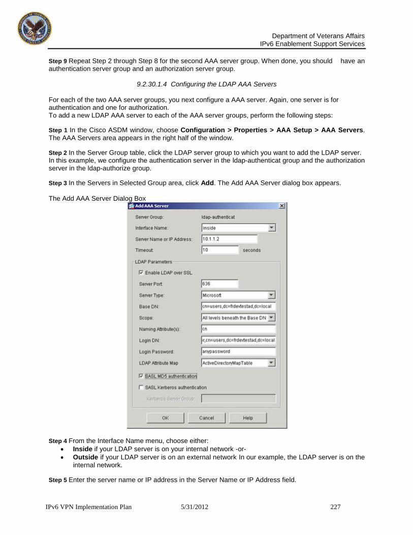
Department of Veterans Affairs
IPv6 Enablement Support Services
IPv6 VPN Implementation Plan 5/31/2012 227
Step 9 Repeat Step 2 through Step 8 for the second AAA server group. When done, you should have an authentication server group and an authorization server group.
9.2.30.1.4 Configuring the LDAP AAA Servers For each of the two AAA server groups, you next configure a AAA server. Again, one server is for authentication and one for authorization. To add a new LDAP AAA server to each of the AAA server groups, perform the following steps:
Step 1 In the Cisco ASDM window, choose Configuration > Properties > AAA Setup > AAA Servers. The AAA Servers area appears in the right half of the window.
Step 2 In the Server Group table, click the LDAP server group to which you want to add the LDAP server. In this example, we configure the authentication server in the ldap-authenticat group and the authorization server in the ldap-authorize group.
Step 3 In the Servers in Selected Group area, click Add. The Add AAA Server dialog box appears. The Add AAA Server Dialog Box
Step 4 From the Interface Name menu, choose either:
Inside if your LDAP server is on your internal network -or-
Outside if your LDAP server is on an external network In our example, the LDAP server is on the internal network.
Step 5 Enter the server name or IP address in the Server Name or IP Address field.

Department of Veterans Affairs
IPv6 Enablement Support Services
IPv6 VPN Implementation Plan 5/31/2012 228
In our example, we use the IP address. Step 6 In the Timeout field, enter the timeout interval in seconds. This is the time after which the security appliance gives up on the request to the primary AAA server. If there is a standby server in the server group, the security appliance sends the request to the backup server.
Step 7 In the LDAP Parameters area, check Enable LDAP over SSL if you want all communications between the security appliance and the LDAP directory to be encrypted with SSL. Warning If you do not check Enable LDAP over SSL, the security appliance and the LDAP directory exchange all data in the clear, including sensitive authentication and authorization data. Step 8 Enter the server port to use in the Server Port field. This is the TCP port number by which you access the server.
Step 9 From the Server Type menu, choose one of the following:
Sun Microsystems JAVA System Directory Server (formerly the Sun ONE Directory Server) - or -
Microsoft Active Directory - or -
Detect automatically The security appliance supports authentication and password management features only on the Sun Microsystems JAVA System Directory Server (formerly named the Sun ONE Directory Server) and the Microsoft Active Directory. With any other type of LDAP server, such as a Novell or OpenLDAP server, it only supports LDAP authorization functions and CRL (certificate revocation list) retrieval. By selecting Detect automatically, you let the security appliance determine if the server is a Microsoft or a Sun server. Note The DN configured on the security appliance to access a Sun directory server must be able to access the default password policy on that server. We recommend using the directory administrator, or a user with directory administrator privileges, as the DN. Alternatively, you can place an ACI on the default password policy. Step 10 Enter one of the following into the Base DN field:
The base DN of the Active Directory folder holding the user attributes (typically a users folder) if you are configuring the authentication server - or -
The base DN of the Active Directory folder holding the group attributes (typically a group folder) if you are configuring the authorization server
The base DN is the location in the LDAP hierarchy where the server should begin searching when it receives an authorization request. For example, OU=people, dc=cisco, dc=com.
Step 11 From the Scope menu, select one of the following:
One level beneath the Base DN - or -
All levels beneath the Base DN The scope specifies the extent of the search in the LDAP hierarchy that the server should make when it receives an authorization request. One Level Beneath the Base DN specifies a search only one level beneath the Base DN. This option is quicker. All Levels Beneath the Base DN specifies a search of the entire subtree hierarchy. This option takes more time. Step 12 In the Naming Attribute(s) field, enter the Relative Distinguished Name attribute (or attributes) that uniquely identifies an entry on the LDAP server. Common naming attributes are Common Name (cn) and User ID (uid).
Step 13 In the Login DN field, perform one of the following:

Department of Veterans Affairs
IPv6 Enablement Support Services
IPv6 VPN Implementation Plan 5/31/2012 229
Enter the name of the directory object for security appliance authenticated binding. For example, cn=Administrator, cn=users, ou=people, dc=Example Corporation, dc=com. - or -
Leave this field blank for anonymous access.
Some LDAP servers, including the Microsoft Active Directory server, require the security appliance to establish a handshake via authenticated binding before accepting requests for LDAP operations. The security appliance identifies itself for authenticated binding by including a Login DN field with the user authentication request. The Login DN field defines the security appliance authentication characteristics which should correspond to those of a user with administration privileges.
Step 14 Enter the password associated with the Login DN in the Login Password field. The characters you type appear as asterisks.
Step 15 From the LDAP Attribute Map menu, choose the LDAP attribute map to apply to the LDAP server. The LDAP attribute map translates user-defined LDAP attribute names and values into Cisco attribute names and values. To configure a new LDAP attribute map, see Creating an LDAP Attribute Map.
Step 16 Check SASL MD5 Authentication to use the MD5 mechanism of the Simple Authentication and Security Layer (SASL) to secure authentication communications between the security appliance and the LDAP server.
Step 17 Check SASL Kerberos Authentication to use the Kerberos mechanism of the Simple Authentication and Security Layer to secure authentication communications between the security appliance and the LDAP server. Note If you configure more than one SASL method for a server, the security appliance uses the strongest method supported by both the server and the security appliance. For example, if both MD5 and Kerberos are supported by both the server and the security appliance, the security appliance selects Kerberos to secure communication with the server.
Step 18 If you checked SASL Kerberos authentication in Step 17, enter the Kerberos server group used for authentication in the Kerberos Server Group field.
Step 19 Repeat Step 3 through Step 18 to configure a AAA server in the other AAA server group.
9.2.30.2 Configuring the Group Policy for LDAP Authorization
After configuring the LDAP attribute map, the AAA server groups, and the LDAP servers within the groups, you next create an external group-policy that associates the group-name with the LDAP authorization server. Note Comprehensive procedures for configuring group policies are provided elsewhere in this guide. The following steps are only those that apply to configuring AAA with LDAP. To create a new group policy and assign the LDAP authorization server group to it, perform the following steps:
Step 1 In the Cisco ASDM window, select Configuration > VPN > General > Group Policy. The Group Policy area appears in the right half of the window.
Step 2 Click Add and choose either Internal Group Policy or External Group Policy. In this example, we choose External Group Policy because the LDAP server is external to the security appliance. The Add Group Policy dialog box appears.

Department of Veterans Affairs
IPv6 Enablement Support Services
IPv6 VPN Implementation Plan 5/31/2012 230
Add Group Policy Dialog Box
Step 3 Enter the name of the new group policy in the name field. The group policy name is web1 in our example.
Step 4 From the Server Group menu, choose the AAA authorization server group you created previously. In our example, this is the server group named ldap-authorize.
Step 5 Click OK and then Apply to create the new group policy.

Department of Veterans Affairs
IPv6 Enablement Support Services
IPv6 VPN Implementation Plan 5/31/2012 231
9.2.30.2.1 Configuring a Tunnel Group for LDAP Authentication In the final major task, you create a tunnel-group that specifies LDAP authentication by performing the following steps: Step 1 In the Cisco ASDM window, select Configuration > VPN > General > Tunnel Group. The Tunnel Group area appears on the right side of the ASDM window. Tunnel Group Area
Step 2 Click Add in the tunnel Group area and choose the type of tunnel group. In our example, we choose IPSec for Remote Access. The Add Tunnel Group dialog box appears.

Department of Veterans Affairs
IPv6 Enablement Support Services
IPv6 VPN Implementation Plan 5/31/2012 232
Step 3 Choose the General tab, and then choose the AAA tab, as shown in Figure 5-10. Add Tunnel Group Dialog Box with General and AAA Tabs Selected
Step 4 Enter the name of the tunnel group in the Name field. In our example, the tunnel group name is ipsec-tunnelgroup.
Step 5 From the Authentication Server Group menu, chose the AAA server group you configured for authentication. In our example, the authentication server group name is ldap-authenticat.
Step 6 Click OK at the bottom of the Add Tunnel Group dialog box.
Step 7 Click Apply at the bottom of the ASDM window to include the changes to the running configuration. You have completed this example of the minimal steps required to configure the security appliance for LDAP authentication and authorization.
9.2.31 Configuring Load Balancing
This section describes how to configure load balancing using ASDM. It include the following functional areas.
Overview,
Implementing Load Balancing

Department of Veterans Affairs
IPv6 Enablement Support Services
IPv6 VPN Implementation Plan 5/31/2012 233
VPN Load-Balancing Cluster Configurations
Configuring Load Balancing
Configuring VPN Session Limits
9.2.31.1 Overview
If you have a remote-access configuration in which you are using two or more security appliances or VPN Concentrators connected on the same network to handle remote sessions, you can configure these devices to share their session load. This feature is called load balancing. To implement load balancing, group together logically two or more devices on the same private LAN-to-LAN network, private subnet, and public subnet into a virtual cluster. All devices in the virtual cluster carry session loads. Load balancing directs session traffic to the least loaded device in the cluster, thus distributing the load among all devices. It makes efficient use of system resources and provides increased performance and high availability. One device in the virtual cluster, the virtual cluster master, directs incoming traffic to the other devices, called secondary devices. The virtual cluster master monitors all devices in the cluster, keeps track of how busy each is, and distributes the session load accordingly. The role of virtual cluster master is not tied to a physical device; it can shift among devices. For example, if the current virtual cluster master fails, one of the secondary devices in the cluster takes over that role and immediately becomes the new virtual cluster master. The virtual cluster appears to outside clients as a single virtual cluster IP address. This IP address is not tied to a specific physical device. It belongs to the current virtual cluster master; that is, it is a virtual address. A VPN Client attempting to establish a connection connects first to this virtual cluster IP address. The virtual cluster master then sends back to the client the public IP address of the least-loaded available host in the cluster. In a second transaction (transparent to the user), the client connects directly to that host. In this way, the virtual cluster master directs traffic evenly and efficiently across resources. Note All clients other than the Cisco VPN Client or the Cisco VPN 3002 Hardware Client connect directly to the security appliance as usual; they do not use the virtual cluster IP address. If a machine in the cluster fails, the terminated sessions can immediately reconnect to the virtual cluster IP address. The virtual cluster master then directs these connections to another active device in the cluster. Should the virtual cluster master itself fail, another device in the cluster immediately and automatically takes over as the new virtual session master. Even if several devices in the cluster fail, users can continue to connect to the cluster as long as any one device in the cluster is up and available.
9.2.31.2 Implementing Load Balancing
Enabling load balancing involves:
Configuring the load-balancing cluster by establishing a common virtual cluster IP address, UDP port (if necessary), and IPSec shared secret for the cluster. These values are identical for every device in the cluster.
Configuring the participating device by enabling load balancing on the device and defining device-specific properties. These values vary from device to device.
Note VPN load balancing requires an active 3DES/AES license. The security appliance checks for the existence of this crypto license before enabling load balancing. If it does not detect an active 3DES or AES license, the security appliance prevents the enabling of load balancing and also prevents internal configuration of 3DES by the load balancing system, unless the license permits this usage.
9.2.31.3 Prerequisites
Load balancing is disabled by default. You must explicitly enable load balancing.

Department of Veterans Affairs
IPv6 Enablement Support Services
IPv6 VPN Implementation Plan 5/31/2012 234
You must have first configured the public and private interfaces and also have previously configured the interface to which the virtual cluster IP address refers. All devices that participate in a cluster must share the same cluster-specific values: IP address, encryption settings, encryption key, and port.
9.2.31.4 Eligible Platforms
A load-balancing cluster can include security appliance models ASA 5520 and higher, running ASA Release 7.1(1) software or ASA Release 7.0(x) software. You can also include VPN 3000 Series Concentrators in the cluster. While mixed configurations are possible, administration is generally simpler if the cluster is homogeneous.
9.2.31.5 Eligible Clients
Load balancing is effective only on remote sessions initiated with the following clients:
Cisco VPN Client (Release 3.0 and later)
Cisco VPN 3002 Hardware Client (Release 3.5 or later)
Cisco PIX 501/506E when acting as an Easy VPN client. Load balancing works with both IPSec clients and WebVPN sessions. All other clients, including LAN-to-LAN connections can connect to a security appliance on which load balancing is enabled, but they cannot participate in load balancing.
9.2.31.6 VPN Load-Balancing Cluster Configurations
A load-balancing cluster can consist of all ASA Release 7.0(x) security appliances, all ASA Release 7.1(1) security appliances, all VPN 3000 Concentrators, or a mixture of these, subject to the following restrictions:
Load-balancing clusters that consist of all ASA 7.0(x) security appliances, all ASA 7.1(1) security appliances, or all VPN 3000 Concentrators can run load balancing for a mixture of IPSec and WebVPN sessions.
Load-balancing clusters that consist of a both of ASA 7.0(x) security appliances and VPN 3000 Concentrators can run load balancing for a mixture of IPSec and WebVPN sessions.
Load-balancing clusters that include ASA 7.1(1) security appliances and either ASA 7.0(x) or VPN 3000 Concentrators or both can support only IPSec sessions. In such a configuration, however, the ASA 7.1(1) security appliances might not reach their full IPSec capacity. Scenario 1: Mixed Cluster with No WebVPN Connections, illustrates this situation.
With Release 7.1(1), IPSec and WebVPN sessions count or weigh equally in determining the load that each device in the cluster carries. This represents a departure from the load balancing calculation for the ASA Release 7.0(x) software and the VPN 3000 Concentrator, in that these platforms both use a weighting algorithm that calculates 1 WebVPN session as equivalent in load to 10 IPSec sessions. The virtual master of the cluster assigns session loads to the members of the cluster. An ASA Release 7.1(1) security appliance regards all sessions, WebVPN or IPSec, as equal and assigns them accordingly. An ASA Release 7.0(x) security appliance or a VPN 3000 Concentrator performs the 10:1 weighting calculations in assigning session loads. If you have a mixed configuration—that is, if your load-balancing cluster includes devices running a mixture of ASA software releases or at least one security appliance running ASA Release 7.1(1) and a VPN 3000 Concentrator—the difference in weighting algorithms becomes an issue if the initial cluster master fails and another device takes over as master. Suppose, for example, a security appliance running ASA Release 7.1(1) software is the initial cluster master. Then that device fails. Another device in the cluster takes over automatically as master and applies its own load-balancing algorithm to determine processor loads within the cluster. A cluster master running ASA Release 7.1(1) software cannot weight session loads in any way other than what that

Department of Veterans Affairs
IPv6 Enablement Support Services
IPv6 VPN Implementation Plan 5/31/2012 235
software provides. Therefore, it cannot assign a combination of IPSec and WebVPN session loads properly to ASA devices running earlier versions or to VPN 3000 Concentrators. Conversely, a VPN 3000 Concentrator acting as the cluster master cannot assign loads properly to an ASA Release 7.1(1) security appliance. Scenario 2: Mixed Cluster Handling WebVPN Connections, illustrates this dilemma. Note You can configure the number of IPSec and WebVPN sessions to allow, up to the maximum allowed by your configuration and license. See Configuring VPN Session Limits for a description of how to set these limits.
9.2.32 Cisco Unity Connection Cluster Overview
Cisco Unity Connection supports a Connection cluster configuration of two Connection servers to provide high availability and redundancy. The Connection servers handle calls, HTTP, and IMAP requests. If only one server in the Connection cluster is functioning, the remaining server preserves the system functionality by handling all calls, HTTP requests, and IMAP requests for the Connection cluster. Note that each server in the Connection cluster must have enough voice messaging ports to handle all calls for the Connection cluster. The first server installed is the publisher server for the Connection cluster; the second server installed is the subscriber server. These terms are used to define the database relationship during installation. The separation of roles is consistent with the Cisco Unified Communications Manager cluster schema in which there is always one publisher server and multiple subscriber servers. (Note that Connection runs on the Cisco Unified CM platform). Unlike a Cisco Unified CM cluster, however, Connection supports only two Connection servers in the Connection cluster. For a network diagram of a Connection cluster integrated with Cisco Unified CM, Cisco Unity Connection Cluster Integrated with Cisco Unified Communications Manager
A Connection cluster server pair supports up to 20,000 users. In this configuration, both servers can support up to 250 voice messaging ports each for a cumulative total of 500 voice messaging ports when
Department of Veterans Affairs
IPv6 Enablement Support Services
IPv6 VPN Implementation Plan 5/31/2012 236
both servers are active. If only one server is active, the port capacity is lowered to a maximum of 250 ports. For more information on capacity planning for a Connection cluster, see the Cisco Unity Connection 8.x Supported Platforms List at: http://www.cisco.com/en/US/docs/voice_ip_comm/connection/8x/supported_platforms/8xcucspl.html. Note A Connection cluster server pair supports up to 20,000 IMAP Idle clients (250 sessions). If the IMAP clients that connect to the Connection server do not support IMAP Idle, each of these clients must be counted as 4 IMAP Idle clients. For example, deploying 4 non-IMAP Idle clients is the same as deploying 16 IMAP Idle clients. See the “IMAP Clients Used to Access Connection Voice Messages” for a discussion of IMAP Idle and non-IMAP Idle clients.
9.2.32.1 Publisher Server
The publisher server is required in a Connection cluster, and there can be only one publisher server in a Connection cluster server pair. The publisher server is the first server to be installed, and it provides the database and message store services to the subscriber server in the Connection cluster server pair. For information on installing a Connection cluster server pair, see the “Overview of Mandatory Tasks for Installing a Cisco Unity Connection 8.x System” chapter of the Installation Guide for Cisco Unity Connection Release 8.x, at: http://www.cisco.com/en/US/docs/voice_ip_comm/connection/8x/installation/guide/8xcucigx.html. Cisco Unified Communications Manager. As a best practice, we recommend that you direct the majority of client traffic (for example, IMAP and the Cisco Personal Communications Assistant) and administration traffic (for example, Cisco Unity Connection Administration, the Bulk Administration Tool, and backup operations) to the publisher server in a Connection cluster server pair. However, we recommend that the majority of call traffic (for example, SCCP, SIP, or PIMG/TIMG) be directed to the subscriber server in a Connection cluster server pair rather than to the publisher server. Additional call traffic can be directed to the publisher server, if needed, but the call traffic should be directed to the subscriber server first.
9.2.32.2 Subscriber Server
When installing the subscriber server in a Connection cluster server pair, you provide the IP address or hostname of the publisher server. After the software is installed, the subscriber server subscribes to the publisher server to obtain a copy of the database and message store. There can be only one subscriber server in a Connection cluster server pair. As a best practice, we recommend that you direct the majority of call traffic (for example, SCCP, SIP, or PIMG/TIMG) to the subscriber server in a Connection cluster server pair. Additional call traffic can be directed to the publisher server, if needed, but the call traffic should be directed to the subscriber server first. Most of the client traffic (for example, IMAP and the Cisco Personal Communications Assistant) and administration traffic (for example, Cisco Unity Connection Administration, the Bulk Administration Tool, and backup operations) should be directed to the publisher server in a Connection cluster server pair. Additional client and administration traffic can be directed to the subscriber server, if needed, but the client and administration traffic should be directed to the publisher server first.
9.2.32.3 Requirements for Cisco Unity Connection Cisco Unity
Connection Cluster For current Cisco Unity Connection cluster requirements, see the System Requirements for Cisco Unity Connection Release 8.x at http://www.cisco.com/en/US/docs/voice_ip_comm/connection/8x/requirements/8xcucsysreqs.html.
9.2.32.4 Support for Installing the Cisco Unity Connection Servers in
Separate Buildings or Sites

Department of Veterans Affairs
IPv6 Enablement Support Services
IPv6 VPN Implementation Plan 5/31/2012 237
Cisco Unity Connection supports the Connection cluster configuration in which the Connection servers are installed in separate buildings or sites. This configuration requires a maximum round-trip latency of no more than 150 ms, and a minimum amount of guaranteed bandwidth with any steady-state congestion that depends on the number of voice messaging ports on each server in the cluster, as follows:
For 50 voice messaging ports on each server—7 Mbps
For 100 voice messaging ports on each server—14 Mbps
For 150 voice messaging ports on each server—21 Mbps
For 200 voice messaging ports on each server—28 Mbps
For 250 voice messaging ports on each server—35 Mbps The minimum amount of required bandwidth is linear, so you can calculate the required bandwidth for other port quantities based on the above numbers. For example, for 60 voice messaging ports, 8.4 Mbps is required. (7 / 50 x 60 = 8.4 Mbps) Note The bandwidth numbers above are intended as guidelines to ensure proper operation of an active-
active cluster with respect to synchronization traffic between the two servers. Additional conditions such as network congestion, CPU utilization, and message size may contribute to lower throughput than expected. Call-control and call-quality requirements are in addition to the guidelines above and should be calculated by using the bandwidth recommendations in the applicable Cisco Unified Communications SRND at: http://www.cisco.com/en/US/solutions/ns340/ns414/ns742/ns818/landing_uc_mgr.html. If you plan to utilize a traffic prioritization scheme between the servers in the cluster, you can use the CLI command utils cuc networking dscp on to mark intracluster data and message traffic with a differentiated services code point (DSCP) value of 18. By default, traffic is not marked. The CLI command should be entered on both servers in the cluster. For more information on CLI commands, see the applicable Command Line Interface Reference Guide for Cisco Unified Communications Solutions at: http://www.cisco.com/en/US/products/ps6509/prod_maintenance_guides_list.html. For additional cluster requirements, see the System Requirements for Cisco Unity Connection Release 8.x at: http://www.cisco.com/en/US/docs/voice_ip_comm/connection/8x/requirements/8xcucsysreqs.html.
9.2.32.5 Balancing the Load of Calls That the Cisco Unity Connection
Servers Handle Although it is possible to balance the load of calls that the Cisco Unity Connection servers handle in a Connection cluster, we recommend that most call traffic be directed to the subscriber server. This configuration follows the Cisco Unified Communications Manager cluster model of allowing call traffic only on subscriber servers. Cisco Unified Communications Manager by Skinny Client Control Protocol (SCCP) When integrating Connection with Cisco Unified CM by Skinny Client Control Protocol (SCCP), it is possible to balance the voice traffic that the Cisco Unity Connection server pair handles by using one of the following methods:
(Recommended) In Cisco Unified Communications Manager Administration (on the Call Routing > Route/Hunt > Line Group page), use Top Down as the distribution algorithm for the line group that contains directory numbers of ports that will answer calls on both servers in the Connection cluster. In Connection Administration, all the ports that share the same device name prefix will be in a one port group. (If there are ports that share a different device name prefix, they must be in a separate port group.) Beginning with the answering port that has the lowest number in its display name, assign half the answering ports to the subscriber server so that the subscriber server will answer most incoming calls. Assign the remaining answering ports to the publisher server. Then beginning with the dial-out port that has the lowest number in its display name, assign half the dial-out ports to the primary server so that the primary server will handle MWIs and notification calls. Assign the remaining dial-out ports to the subscriber server.
In Cisco Unified Communications Manager Administration (on the Call Routing > Route/Hunt >

Department of Veterans Affairs
IPv6 Enablement Support Services
IPv6 VPN Implementation Plan 5/31/2012 238
Line Group page), use Longest Idle Time as the distribution algorithm for the line group that contains directory numbers of ports that will answer calls on both servers in the Connection cluster. In Connection Administration, all the ports will be in a single port group. The first half of the answering ports and dial-out ports will be assigned to the publisher server and the remaining ports will be assigned to the subscriber server in the Connection cluster.
When integrating with Cisco Unified CM through a SIP trunk, it is possible to balance voice traffic that the Connection cluster server pair handles by using one of the following methods:
(Recommended) Use a Route List in Cisco Unified CM.
Use DNS-SRV – RFC 2782.
Use a SIP gateway DNS-SRV. TDM-Based (Circuit-Switched) Phone System through PIMG/TIMG Units When integrating with a TDM-based (circuit-switched) phone system through PIMG/TIMG units, it is possible to balance the load of voice traffic that the Connection cluster server pair handles by using one of the following methods:
(Recommended) Turn on load balancing on the PIMG/TIMG units.
Use load balancing on the TDM based PBX. Note We recommend that you also turn on fault tolerance on the PIMG/TIMG units. This allows the
PIMG/TIMG units to redirect calls to either server in the Connection cluster if one server is unavailable to take calls.
9.2.32.6 Load Balancing Clients in a Cisco Unity Connection Cluster
Although it is possible to balance client and administration requests that the Cisco Unity Connection cluster server pair handles (for example, from the Cisco Personal Communications Assistant (PCA), IMAP, and Cisco Unity Connection Administration), we recommend that most client and administration traffic be directed to the publisher server. In order to balance client requests, it is necessary to use DNS A-records. DNS A-records allow client DNS lookups to resolve to either server in a round-robin fashion. Note If one server in a Connection cluster server pair stops functioning and failover occurs, clients such as the Cisco PCA and IMAP clients may need to authenticate again by signing in. We do not recommend using DNS to load balance with multiple A-records because this method does not account for server unavailability (for example, if one of the servers in a Connection cluster server pair stops functioning). The DNS server cannot determine the availability of a server IP address that is listed in an A-record. It may be necessary for the clients to attempt DNS resolution multiple times before they connect to a functioning Connection server in a Connection cluster server pair.
9.2.32.7 Configuration for Dial-out Voice Messaging Ports
Each Cisco Unity Connection server in a Connection cluster must have voice messaging ports designated for the following dial-out functions in case either server has an outage:
Sending message waiting indicators (MWIs).
Performing message notifications.
Allowing telephone record and playback (TRAP) connections. As a best practice, we recommend that you dedicate an adequate number of voice messaging ports for these dial-out functions. These dedicated dial-out ports should not receive incoming calls and should not be enabled for answering calls.

Department of Veterans Affairs
IPv6 Enablement Support Services
IPv6 VPN Implementation Plan 5/31/2012 239
9.2.32.8 For More Information
Configuring Cisco Unity Connection Ports and Port Groups to Support a Cisco Unity Connection Cluster and the Various Phone System Integrations See the applicable Cisco Unity Connection integration guide at
http://www.cisco.com/en/US/products/ps6509/products_installation_and_configuration_guides_list.html, and the Cluster Configuration and Administration Guide for Cisco Unity Connection Release 8.x at: http://www.cisco.com/en/US/docs/voice_ip_comm/connection/8x/cluster_administration/guide/8xcuccagx.html. Configuring Cisco Unity Connection Clients to Support a Cisco Unity Connection Cluster The Cluster Configuration and Administration Guide for Cisco Unity Connection Release 8.x at http://www.cisco.com/en/US/docs/voice_ip_comm/connection/8x/cluster_administration/guide/8xcuccagx.html.
9.2.33 Mixed Cluster Options
The following scenarios illustrate the use of VPN load balancing in clusters consisting of a mixture of security appliances running ASA Release 7.1(1) and ASA Release 7.0(x) software, as well as VPN 3000 Series Concentrators.
9.2.33.1 Scenario 1: Mixed Cluster with No WebVPN Connections
In this scenario, the cluster consists of a mixture of security appliances and VPN 3000 Concentrators. Some of the security appliance cluster peers are running ASA Release 7.0(x), and some are running Release 7.1(1). The pre-7.1(1) and VPN 3000 peers do not have any SSL VPN connections, and the 7.1(1) cluster peers have only the base SSL VPN license, which allows two WebVPN sessions, but there are no SSL VPN connections. In this case, all the connections are IPSec, and load balancing works fine. The two WebVPN licenses have a very small effect on the user’s taking advantage of the maximum IPSec session limit, and then only when a VPN 3000 Concentrator is the cluster master. In general, the smaller the number of WebVPN licenses is on a security appliance in a mixed cluster, the smaller the effect on the ASA 7.1(1) device being able to reach its IPSec session limit in a scenario where there are only IPSec sessions.
9.2.33.2 Scenario 2: Mixed Cluster Handling WebVPN Connections
This scenario is similar to the previous one, in that the cluster consists of a mixture of security appliances and VPN 3000 Concentrators. Some of the security appliance cluster peers are running ASA Release 7.0(x) and some are running Release 7.1(1). In this case, however, the cluster is handling SSL VPN connections as well as IPSec connections. If a device that is running software earlier than ASA Release 7.1(1) is the cluster master, the master applies the protocol and logic in effect prior to Release 7.1(1). That is, sessions might be directed to load-balancing peers that have exceeded their session limit. In that case, the user is denied access. If the cluster master is a device running ASA Release 7.0(x) software, the old session-weighting algorithm applies only to the pre-7.1(1) peers in the cluster. No one should be denied access in this case. Because the pre-7.1(1) peers use the session-weighting algorithm, they are more lightly loaded. An issue arises, however, because you cannot guarantee that the 7.1(1) peer is always the cluster master. If the cluster master fails, another peer assumes the role of master. The new master might be any of the eligible peers. Because of the innately unpredictability of the results, we recommend that you avoid configuring this type of cluster.

Department of Veterans Affairs
IPv6 Enablement Support Services
IPv6 VPN Implementation Plan 5/31/2012 240
9.2.33.3 Configuring Load Balancing
To configure load balancing on a security appliance running ASA Release 7.1(1) software, configure the following elements for each device that participates in the cluster.
Public and private interfaces
VPN load-balancing cluster attributes Note All participants in the cluster must have an identical cluster configuration, except for the device priority within the cluster.
9.2.33.4 Configuring the Public and Private Interfaces for Load Balancing
To configure a load-balancing cluster, select Configuration > VPN > Load Balancing. Load Balancing Window To configure load balancing, do the following steps: Step 1 Check the Participate in Load Balancing check box.
Step 2 Configure the attributes in the VPN Cluster Configuration area, as follows:
Note All servers in the cluster must have an identical cluster configuration. a. Enter the Cluster IP Address. This is the single IP address that represents the entire virtual
cluster. Choose an IP address that is within the public subnet address range shared by all the security appliances in the virtual cluster.
b. Specify the UDP Port for the virtual cluster in which this device participates. The default value is 9023. If another application is using this port, enter the UDP destination port number you want to use for load balancing.
c. Optionally, enable IPSec encryption for the cluster by checking the check box for Enable IPSec Encryption. The default is no encryption. This attribute enables or disables IPSec encryption. If you configure this attribute, you must also specify and verify a shared secret. The security appliances in the virtual cluster communicate via LAN-to-LAN tunnels using IPSec. To ensure that all load-balancing information communicated between the devices is encrypted, enable this attribute.
Note When using encryption, you must have previously configured the load-balancing inside interface. If that interface is not enabled, an error message appears when you try to configure cluster encryption. If the load-balancing inside interface was enabled when you configured cluster encryption, but was disabled before you configured the participation of the device in the virtual cluster, you get an error message when you select the Participate in Load Balancing Cluster check box, and encryption is not enabled for the cluster.
d. If you enable cluster encryption, you must also specify the IPSec shared secret by entering a value in the IPSec Shared Secret field, then entering the same value in the Verify Secret field. These fields must match. This command specifies the shared secret to between IPSec peers when you have enabled IPSec encryption. The value you enter in the field appears as consecutive asterisk characters Step 3 Configure the attributes in the VPN Server Configuration area, as follows:
a. Select the Public interface on the security appliance. This command specifies the name or IP address of the public interface for load balancing for this device. The default value is outside.
b. Select the Private interface on the security appliance. This command specifies the name or IP address of the private interface for load balancing for this device. The default value is inside.
c. Set the priority to assign to this device within the cluster. The range is from 1 to 10. The priority indicates the likelihood of this device becoming the virtual cluster master, either at start-up or when an existing master fails. The higher you set the priority (for example, 10), the more likely it is that this device becomes the virtual cluster master.
d. If you want to apply network address translation for this device, enter the NAT Assigned IP Address for the device.

Department of Veterans Affairs
IPv6 Enablement Support Services
IPv6 VPN Implementation Plan 5/31/2012 241
9.2.34 Configuring VPN Session Limits
You can run as many IPSec and WebVPN sessions as your platform and license for the security appliance supports. To view the licensing information for your security appliance, select the Home icon at the top of the opening window for ASDM and select the License tab. License Information To limit the maximum number of active IPSec VPN sessions to a lower value than the security appliance allows, select Configuration > VPN > General > VPN System Options. VPN System Options Window Specify the limit that you want to apply in the Maximum Active IPSec VPN Sessions field. The maximum number of sessions depends on your license. This limit affects the calculated load percentage for VPN Load Balancing. For example, if the security appliance license allows 750 IPSec sessions, and you want to limit the number of IPSec sessions to 500, enter 500 in the Maximum Active IPSec VPN Sessions field. To remove the session limit, clear the Limit the maximum number of active IPSec VPN sessions check box.
9.2.35 Configuring Single Sign-on for WebVPN
This section presents example procedures for configuring SSO for WebVPN users. It includes the following functional areas:
Using Single Sign-on with WebVPN
Configuring SSO Authentication Using Site Minder
Configuring SSO with the HTTP Form Protocol
9.2.35.1 Using Single Sign-on with WebVPN
Single sign-on lets WebVPN users enter a username and password only once to access multiple protected services and web servers. In general, the SSO mechanism either starts as part of the AAA process or just after successful user authentication to a AAA server. The WebVPN server running on the security appliance acts as a proxy for the user to the authenticating server. When a user logs in, the WebVPN server sends an SSO authentication request, including username and password, to the authenticating server using HTTPS. If the server approves the authentication request, it returns an SSO authentication cookie to the WebVPN server. The security appliance keeps this cookie on behalf of the user and uses it to authenticate the user to secure websites within the domain protected by the SSO server. While WebVPN supports three SSO authentication methods, two can be configured with ASDM: SSO with the Computer Associates eTrust Site Minder server (formerly Netegrity Site Minder), and SSO using the HTTP Form protocol. The third method, SSO with HTTP Basic and NTLMv1 (NT LAN Manager) authentication, is currently only configurable using the security appliance command line interface. illustrates the following major SSO authentication steps that are used by all three methods: 1. A WebVPN user first enters a username and password to log into the WebVPN server on the security appliance. 2. The WebVPN server acts as a proxy for the user and forwards the form data (username and password) to an authenticating web server. 3. If the authenticating web server approves the user data, it returns an authentication cookie to the WebVPN server where it is stored on behalf of the user. 4. The WebVPN server establishes a tunnel to the user. 5. The user can now access other websites within the protected SSO environment without reentering a username and password.
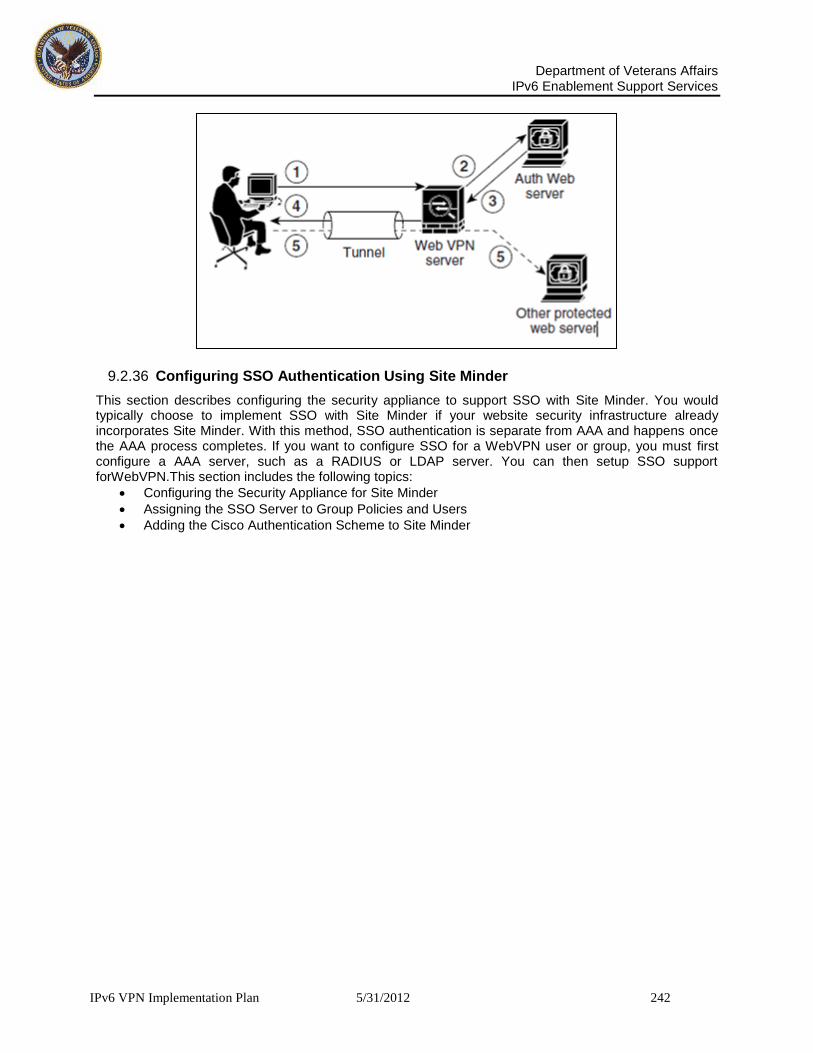
Department of Veterans Affairs
IPv6 Enablement Support Services
IPv6 VPN Implementation Plan 5/31/2012 242
9.2.36 Configuring SSO Authentication Using Site Minder
This section describes configuring the security appliance to support SSO with Site Minder. You would typically choose to implement SSO with Site Minder if your website security infrastructure already incorporates Site Minder. With this method, SSO authentication is separate from AAA and happens once the AAA process completes. If you want to configure SSO for a WebVPN user or group, you must first configure a AAA server, such as a RADIUS or LDAP server. You can then setup SSO support forWebVPN.This section includes the following topics:
Configuring the Security Appliance for Site Minder
Assigning the SSO Server to Group Policies and Users
Adding the Cisco Authentication Scheme to Site Minder
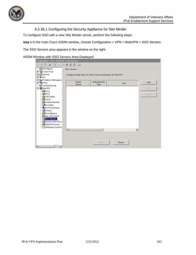
Department of Veterans Affairs
IPv6 Enablement Support Services
IPv6 VPN Implementation Plan 5/31/2012 243
9.2.36.1 Configuring the Security Appliance for Site Minder
To configure SSO with a new Site Minder server, perform the following steps:
Step 1 In the main Cisco ASDM window, choose Configuration > VPN > WebVPN > SSO Servers. The SSO Servers area appears in the window on the right. ASDM Window with SSO Servers Area Displayed

Department of Veterans Affairs
IPv6 Enablement Support Services
IPv6 VPN Implementation Plan 5/31/2012 244
Step 2 Click Add in the SSO Servers area. The Add SSO Server dialog box appears. Add SSO Server Dialog Box
Step 3 In the Server Name field, enter the name of the Site Minder SSO server. The minimum number of characters is 4, and the maximum is 31.
9.2.36.2 Configuring SSO Authentication Using Site Minder
In this example, the server name is Example.
Step 4 Enter the SSO server URL by performing the following steps: a. Choose either HTTP or HTTPS from the menu. In this example, we choose HTTPS to secure the authentication messages between the security appliance and the Site Minder server. b. Enter the rest of the complete server URL. In this example, the rest of the URL is www.Example.com. This is the SSO server URL to which the security appliance makes SSO authentication requests.
Step 5 Enter the secret key in the Secret Key field. This is the key used to encrypt authentication communications with the SSO server. The key can be comprised of any regular or shifted alphanumeric character. There is no minimum or maximum number of characters. The secret key is similar to a password: you create it, save it, and enter it on both the security appliance and the Site Minder Policy Server. See Adding the Cisco Authentication Scheme to Site Minder. In this example, the secret key is AtaL8rD8! Step 6 In the Maximum Retries field, enter the number of times the security appliance retries a failed SSO authentication attempt. This step is optional.

Department of Veterans Affairs
IPv6 Enablement Support Services
IPv6 VPN Implementation Plan 5/31/2012 245
The range is 1 to 5 retries, and the default number of retries is 3. In this example, the maximum retries is 3. Step 7 In the Request Timeout field, enter the number of seconds before a failed SSO authentication attempt times out. This step is optional. The range is from 1 to 30 seconds inclusive, and the default is 5 seconds. In this example, timeout occurs after 5 seconds. Step 8 Click OK to enter this new SSO server in the SSO Server table in the ASDM window.
Step 9 Click Apply to add the new SSO server to the running security appliance configuration.
9.2.36.3 Assigning the SSO Server to Group Policies and Users
After you configure the SSO server, you must specify SSO authentication for either a group policy or a user. This section includes:
Assigning the SSO Server to a Group Policy
Assigning the SSO Server to a User
9.2.36.4 Assigning the SSO Server to a Group Policy
Note Comprehensive procedures for configuring group policies are provided elsewhere in this guide. The following steps are only those that apply to configuring a Site Minder SSO server. To assign the SSO server to a group policy, perform the following steps: Step 1 In the main Cisco ASDM window, choose Configuration > VPN > General > Group Policy. The Group Policy area appears in the window. ASDM Window with Group Policy Area Displayed

Department of Veterans Affairs
IPv6 Enablement Support Services
IPv6 VPN Implementation Plan 5/31/2012 246
Step 2 In the Group Policy table, click the group policy to which you want to assign the Site Minder SSO server.
Step 3 Click Edit. The Edit Internal Group Policy dialog box appears. The Edit Internal Group Policy Dialog Box
Step 4 Click the General tab and then click the Other tab on the General tab.
Step 5 Next to SSO Server, do the following:
Clear the SSO Server Inherit check box.
Choose the new SSO server from the menu. In this example, the SSO server is named Example.
Step 6 Click OK to return to the ASDM window.
Step 7 Click Apply to enter the assignment into the running security appliance configuration.
9.2.36.5 Assigning the SSO Server to a User
Note Comprehensive procedures for configuring users are provided elsewhere in this guide. The following steps are only those that apply to configuring a Site Minder SSO server. You can also assign the SSO server to a user by performing the following steps: Step 1 In the main Cisco ASDM window, choose Configuration > Properties > Device Administration > Users. The User Accounts area appears in the window.

Department of Veterans Affairs
IPv6 Enablement Support Services
IPv6 VPN Implementation Plan 5/31/2012 247
ASDM Window with User Accounts Area Displayed
Step 2 From the User Accounts table, click the User Name you want to assign the Site Minder SSO server to.

Department of Veterans Affairs
IPv6 Enablement Support Services
IPv6 VPN Implementation Plan 5/31/2012 248
Step 3 Click Add. Edit User Account dialog box.
The Edit User Account Dialog Box Step 4 Click the WebVPN tab and then click the Other tab on the WebVPN tab.
Step 5 Next to SSO Server, do the following:
Clear the SSO Server Inherit check box.
Choose the new SSO server from the menu. In this example, the SSO server is named Example.
Step 6 Click OK to return to the ASDM window.
Step 7 Click Apply to enter the assignment into the running security appliance configuration.

Department of Veterans Affairs
IPv6 Enablement Support Services
IPv6 VPN Implementation Plan 5/31/2012 249
9.2.36.6 Adding the Cisco Authentication Scheme to Site Minder
Besides configuring the security appliance for SSO with Site Minder, you must also configure your Computer Associates Site Minder Policy Server with the Cisco authentication scheme, provided as a Java plug-in. Note • Configuring the Site Minder Policy Server requires experience with Site Minder.
This section presents general tasks, not a complete procedure.
Refer to the CA Site Minder documentation for the complete procedure for adding a custom authentication scheme.
To configure the Cisco authentication scheme on your Site Minder Policy Server, perform these following tasks:
Step 1 With the Site minder Administration utility, create a custom authentication scheme being sure to use the following specific arguments:
In the Library field, enter smjavaapi.
In the Secret field, enter the same secret configured on the security appliance. You configure this on the security appliance with either the policy-server-secret command at the command line interface or in the Secret Key field of the Add SSO Server dialog box in ASDM.
In the Parameter field, enter CiscoAuthAPI.
Step 2 Copy the file cisco_vpn_auth.jar from the CD to the default library directory for the Site Minder server.
9.2.36.7 Configuring SSO with the HTTP Form Protocol
This section describes using the HTTP Form protocol for SSO. The HTTP Form protocol is a common approach to SSO authentication that can also qualify as a AAA method. It provides a secure method for exchanging authentication information between WebVPN users and authenticating web servers. As a common protocol, it is highly compatible with web servers and web-based SSO products, and you can use it in conjunction with other AAA servers such as RADIUS or LDAP servers. As with Site Minder, the security appliance serves as a proxy for WebVPN users to an authenticating web server but, in this case, it uses HTTP Form protocol and the POST method for requests. You must configure the security appliance to send and receive form data. Note To configure SSO with the HTTP Form protocol correctly, you must have a thorough working knowledge of authentication and HTTP protocol exchanges. While you would expect to configure form parameters that let the security appliance include POST data such as the username and password, you initially might not be aware of additional hidden parameters that the web server requires. Some authentication applications expect hidden data which is neither visible to nor entered by the user. You can, however, discover hidden parameters that the authenticating web server expects by making a direct authentication request to the web server from your browser without the security appliance in the middle acting as a proxy. Analyzing the web server response using a HTTP header analyzer reveals hidden parameters in a format similar to the following: <param name>=<URL encoded value>&<param name>=<URL encoded> Some hidden parameters are mandatory and some are optional. If the web server requires data for a hidden parameter, it rejects any authentication POST request that omits that data. Because a header analyzer does not tell you if a hidden parameter is mandatory or not, we recommend that you include all hidden parameters until you determine which are mandatory. This section describes:
Gathering HTTP Form Data
Configuring SSO with HTTP Form Protocol
Assigning the SSO Server to a Tunnel Group

Department of Veterans Affairs
IPv6 Enablement Support Services
IPv6 VPN Implementation Plan 5/31/2012 250
9.2.37 Gathering HTTP Form Data
This section presents the steps for discovering and gathering the HTTP Form data required to configure SSO if you do not already know what the data is. To gather the data, you must analyze responses from the authenticating web server using an HTTP header analyzer. To gather parameter data, perform the following steps: Step 1 Start your browser and HTTP header analyzer, and connect directly to the web server login page without going through the security appliance. The web server login page loads into your browser. Step 2 Examine the login exchange with your HTTP header analyzer. If the web server has loaded a cookie with the login page, copy this login page URL. It is the Start URL. Step 3 Enter the username and password to log in to the web server, and press Enter. This action generates the authentication POST request that you examine using the HTTP header analyzer. An example POST request with host HTTP header and body follows: POST /emco/myemco/authc/forms/MCOlogin.fcc?TYPE=33554433&REALMOID=06-000430e1-7443-125c-ac05-83 846dc90034&GUID=&SMAUTHREASON=0&METHOD=GET&SMAGENTNAME=$SM$5FZmjnk3DRNwNjk2KcqVCFbIrNT9%2b J0H0KPshFtg6rB1UV2PxkHqLw%3d%3d&TARGET=https%3A%2F%2Fwww.example.com%2Femco%2Fmyemco%2F HTTP/1.1 Host: www.example.com (BODY) SMENC=ISO-8859-1&SMLOCALE=US-EN&USERID=Anyuser&USER_PASSWORD=XXXXXX&target=https%3A%2F%2Fw ww.example.com%2Femco%2Fmyemco%2F&smauthreason=0 Step 4 Examine the POST request and copy the protocol, host, and the complete URL. This is needed to configure the action-uri parameter later.
Step 5 Examine the POST request body and copy the following: a. Username parameter. In this example, the parameter is user-id (not the value any user). b. Password parameter In this example, the parameter is user password. c. Hidden parameter
This parameter is everything in the POST body except the username and password parameters. In this example, the hidden parameter is: SMENC=ISO-8859-1&SMLOCALE=US-EN&target=https%3A%2F%2Fwww.example.com%2Fe mco%2Fmyemco%2F&smauthreason=0 Hidden parameters are typically presented in the following format: <param name>=<URL encoded value>&<param name>=<URL encoded> Some hidden parameters are mandatory and some are optional. If the web server requires data for a hidden parameter, it rejects any authentication POST request that omits that data. Because a header analyzer does not tell you if a hidden parameter is mandatory or not, we recommend that you include all hidden parameters until you determine which are mandatory. Figure 7-8 highlights the action URI, hidden, username and password parameters found using an HTTP header analyzer. This is only an example; output varies widely across different websites.

Department of Veterans Affairs
IPv6 Enablement Support Services
IPv6 VPN Implementation Plan 5/31/2012 251
Figure 17: Action-uri, hidden, username and password parameters Step 6 If you successfully log in to the web server, examine the server response with the HTTP header analyzer to locate the name of the session cookie set by the server in your browser. This is the Authentication Cookie Name value. In the following server response header, the name of the session cookie is SMSESSION. You just need the name, not the value. Set-Cookie: SMSESSION=yN4Yp5hHVNDgs4FT8dn7+Rwev41hsE49XlKc+1twie0gqnjbhkTkUnR8XWP3hvDH6PZPbHIHtWLDKTa8 ngDB/lbYTjIxrbDx8WPWwaG3CxVa3adOxHFR8yjD55GevK3ZF4ujgU1lhO6fta0dSSOSepWvnsCb7IFxCw+MGiw0o8 8uHa2t4l+SillqfJvcpuXfiIAO06D/gtDF40Ow5YKHEl2KhDEvv+yQzxwfEz2cl7Ef5iMr8LgGcDK7qvMcvrgUqx68 JQOK2+RSwtHQ15bCZmsDU5vQVCvSQWC8OMHNGwpS253XwRLvd/h6S/tM0k98QMv+i3N8oOdj1V7flBqecH7+kVrU01 F6oFzr0zM1kMyLr5HhlVDh7B0k9wp0dUFZiAzaf43jupD5f6CEkuLeudYW1xgNzsR8eqtPK6t1gFJyOn0s7QdNQ7q9 knsPJsekRAH9hrLBhWBLTU/3B1QS94wEGD2YTuiW36TiP14hYwOlCAYRj2/bY3+lYzVu7EmzMQ+UefYxh4cF2gYD8R ZL2RwmP9JV5l48I3XBFPNUw/3V5jf7nRuLr/CdfK3OO8+Pa3V6/nNhokErSgyxjzMd88DVzM41LxxaUDhbcmkoHT9I mzBvKzJX0J+o7FoUDFOxEdIqlAN4GNqk49cpi2sXDbIarALp6Bl3+tbB4MlHGH+0CPscZXqoi/kon9YmGauHyRs+0m 6wthdlAmCnvlJCDfDoXtn8DpabgiW6VDTrvl3SGPyQtUv7Wdahuq5SxbUzjY2JxQnrUtwB977NCzYu2sOtN+dsEReW J6ueyJBbMzKyzUB4L3i5uSYN50B4PCv1w5KdRKa5p3N0Nfq6RM6dfipMEJw0Ny1sZ7ohz3fbvQ/YZ7lw/k7ods/8Vb aR15ivkE8dSCzuf/AInHtCzuQ6wApzEp9CUoG8/dapWriHjNoi4llJOgCst33wEhxFxcWy2UWxs4EZSjsI5GyBnefS QTPVfma5dc/emWor9vWr0HnTQaHP5rg5dTNqunkDEdMIHfbeP3F90cZejVzihM6igiS6P/CEJAjE;Domain=.examp le.com;Path=/

Department of Veterans Affairs
IPv6 Enablement Support Services
IPv6 VPN Implementation Plan 5/31/2012 252
Figure 17 shows an example of authorization cookies in HTTP analyzer output. This is only an example; output varies widely across different websites.
Figure 18: Authorization cookies in sample HTTP analyzer output
In some cases, the server may set the same cookie regardless of whether the authentication was successful or not. Such a cookie is unacceptable for SSO purposes. Step 7 To confirm that the cookies are different, repeat Step 1 through Step 6 using invalid login credentials and then compare the “failure” cookie with the “success” cookie. You now have the necessary parameter data to configure the security appliance for SSO with HTTP Form protocol.
9.2.38 Configuring SSO with HTTP Form Protocol
This section presents an example procedure for configuring SSO with the HTTP Form protocol using the parameters gathered in the previous section. In this procedure, there are steps that are always required and steps that are sometimes required. The steps that are always required are the configuration of the:
Action URI
Username parameter
Password parameter The other steps are only required if the authenticating web server requires them. They are the configuration of:
A start URL
Hidden parameters
An authentication cookie name Perform the following steps to configure the security appliance to use HTTP Form protocol for SSO:
Step 1 In the main Cisco ASDM window, choose Configuration > Properties > AAA Setup > AAA Servers. The AAA Servers area appears in the window as shown in Figure 18.

Department of Veterans Affairs
IPv6 Enablement Support Services
IPv6 VPN Implementation Plan 5/31/2012 253
Figure 19: ASDM Window with AAA Servers Area Displayed
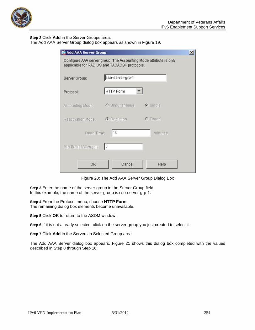
Department of Veterans Affairs
IPv6 Enablement Support Services
IPv6 VPN Implementation Plan 5/31/2012 254
Step 2 Click Add in the Server Groups area. The Add AAA Server Group dialog box appears as shown in Figure 19.
Figure 20: The Add AAA Server Group Dialog Box Step 3 Enter the name of the server group in the Server Group field. In this example, the name of the server group is sso-server-grp-1.
Step 4 From the Protocol menu, choose HTTP Form. The remaining dialog box elements become unavailable.
Step 5 Click OK to return to the ASDM window.
Step 6 If it is not already selected, click on the server group you just created to select it.
Step 7 Click Add in the Servers in Selected Group area. The Add AAA Server dialog box appears. Figure 21 shows this dialog box completed with the values described in Step 8 through Step 16.

Department of Veterans Affairs
IPv6 Enablement Support Services
IPv6 VPN Implementation Plan 5/31/2012 255
Figure 21: The Add AAA Server Group Dialog Box
Step 8 From the Interface Name menu, choose inside, outside, or management. In this example, we choose inside. Interface name selection does not affect functionality.
Step 9 In the Server Name or IP Address field, enter either the name or address of the authenticating web server. In this example, we enter the internal IP address.
Step 10 In the Timeout field, enter the time in seconds before a failed SSO authentication attempt times out.
Step 11 If the authenticating web server sets a pre-login cookie, configure the start URL from which to retrieve the pre-login cookie from the web server by performing the following steps:
a. In the Start URL menu, choose one of the following: – http for unencrypted messaging between the security appliance and the web server - or- – https for secure messaging between the security appliance and the web server
b. In the Start URL field, enter the rest of the complete start URL for the authenticating web server. In this example, the complete start URL is http://example.com/east/Area.do?
Step 12 In the Action URI field, enter the URI for the authentication program on the web server. The maximum number of characters for a complete URI is 2048. The action URI in this example follows: http://www.example.com/auth/index.html/appdir/authc/forms/MCOlogin.fcc?TYPE=33554433&REALM OID=06-000a1311-a828-1185-ab41-8333b16a0008&GUID=&SMAUTHREASON=0&METHOD=GET&SMAGENTNAME=$S

Department of Veterans Affairs
IPv6 Enablement Support Services
IPv6 VPN Implementation Plan 5/31/2012 256
M$5FZmjnk3DRNwNjk2KcqVCFbIrNT9%2bJ0H0KPshFtg6rB1UV2PxkHqLw%3d%3d&TARGET=https%3A%2F%2Fauth .example.com Note You must include the hostname and protocol in the action URI. In the preceding example, these appear at the start of the URI in http://www.example.com. Step 13 In the Username field, enter the name of the username parameter for the HTTP POST request. In this example, the username parameter is named user-id. Step 14 In the Password field, enter the name of the password parameter for the HTTP POST request. In this example, the password parameter is named user password. Step 15 If the web server expects hidden parameters in the POST request, enter the hidden parameters expected in the Hidden Values field. In this example, the Hidden Values entry is: SMENC=ISO-8859-1&SMLOCALE=US-EN&target=https%3A%2F%2Fwww.example.com%2Femco %2Fappdir%2FAreaRoot.do%3FEMCOPageCode%3DENG&smauthreason=0 This entry, excerpted from a POST request, includes four form entries and their values, each separated by an &. The four entries and their values are:
SMENC with a value of ISO-8859-1
SMLOCALE with a value of US-EN
target with a value of: https%3A%2F%2Fwww.example.com%2Femco%2Fappdir%2FAreaRoot.do %3FEMCOPageCode%3DENG
smauthreason with a value of 0
Step 16 Enter the name of the authentication cookie in the Authentication Cookie Name field. This step is optional. In this example, the authentication cookie name is ExampAuthCookie.
Step 17 Click OK to return to the ASDM window.
Step 18 Click Apply to add the new SSO server and server group to the running configuration.
9.2.38.1 Assigning the SSO Server to a Tunnel Group
The final task is to assign the new SSO server to a new or existing tunnel group. In this example, we assign the SSO server to a new WebVPN tunnel group named WebVPNGroup1 by performing the following steps:
Step 1 In the main Cisco ASDM window, choose Configuration > VPN > General > Tunnel Group.
Step 2 Click Add and choose WebVPN Access. The Add Tunnel Group dialog box appears with the General and Basic tabs displayed.
Step 3 Enter the name of the new tunnel group in the Name field. In this example, the name is WebVPNGroup1.
Step 4 Click the AAA tab and select the new SSO server group from the Authentication Server Group menu. In this example, the name of the server group is sso-server-grp-1. Step 5 Click OK to return to the Configuration > VPN > General > Tunnel Group window, and then click Apply to add the tunnel group to the running configuration.

Department of Veterans Affairs
IPv6 Enablement Support Services
IPv6 VPN Implementation Plan 5/31/2012 257
9.2.39 Configuring the SSL VPN Client
The SSL VPN Client (SVC) is a VPN tunneling technology that gives remote users the benefits of an IPSec VPN client without the need for network administrators to install and configure IPSec VPN clients on remote computers. The SVC uses the SSL encryption that is already present on the remote computer as well as the WebVPN login and authentication of the security appliance. To establish an SVC session, the remote user enters the IP address of a WebVPN interface of the security appliance in the browser, and the browser connects to that interface and displays the WebVPN login window. If the user satisfies the login and authentication, and the security appliance identifies the user as requiring the SVC, the security appliance downloads the SVC to the remote computer. If the security appliance identifies the user as having the option to use the SVC, the security appliance downloads the SVC to the remote computer while presenting a link on the window to skip the SVC installation. After downloading, the SVC installs and configures itself, and then the SVC either remains or uninstalls itself (depending on the configuration) from the remote computer when the connection terminates. This section covers the following topics:
Installing SVC
Configuring SVC
Viewing SVC Sessions
Logging Off SVC Sessions
9.2.39.1 Installing SVC
Installing SVC consists of uploading the SVC images to the flash memory, identifying to the security appliance the files on the flash memory to be used as SVC images, and setting the order in which it downloads the images to the remote computer. Perform the following steps to install SVC: Step 1 Upload the SVC images to the security appliance. On the ASDM toolbar, Select Configuration > VPN > WebVPN > SSL VPN Client. The SSL VPN Client panel appears. (Figure 21). This window lists any SVC files that have been identified as SVC images. The order in which they appear in the table reflects the order that they download to the remote computer.
Figure 22: SSL VPN Client Window

Department of Veterans Affairs
IPv6 Enablement Support Services
IPv6 VPN Implementation Plan 5/31/2012 258
To add an SVC image, Click Add. The Add SSL VPN Client Image dialog box appears (Figure 19).
Figure 23: Add SSL VPN Client Image Dialog
If you already have an image located in the flash memory of the security appliance, you can enter the name of the image in the Flash SVC Image field, and click OK. Otherwise, click Upload to browse the computer that is running ASDM. The Upload Image dialog box appears (Figure 19).
Figure 24: Upload Image Dialog Enter the paths for the Local File Path and the Flash File System Path, or browse for the paths, and click Upload File. The SSL VPN Client window now shows the SVC images you identified (Figure 24).

Department of Veterans Affairs
IPv6 Enablement Support Services
IPv6 VPN Implementation Plan 5/31/2012 259
Figure 25: SSL VPN Client Window with SVC Images
Step 2 Click on an image name, and use the Move Down button to change the position of the image within the list. This establishes the order in which the security appliance downloads them to the remote computer. It downloads the SVC image at the top of the list of images first. Therefore, you should move the image used by the most commonly-encountered operating system to the top of the list.
Step 3 Check the Enable SSL VPN Client check box to enable the security appliance to download the SVC image(s) (Figure 21).
Figure 26: Enable SSL VPN Client Check Box

Department of Veterans Affairs
IPv6 Enablement Support Services
IPv6 VPN Implementation Plan 5/31/2012 260
9.2.39.1.1 Configuring SVC To configure SVC, perform the following steps: Step 1 Enable WebVPN on an interface. From the navigation pane, choose WebVPN Access. The WebVPN Access window appears (Figure 26).
Figure 27: WebVPN Access Window Highlight an interface and click Enable (Figure 27).
Figure 28: Enabling the Interface Step 2 Configure a method of address assignment SSL VPN Client:configuring:. You can use DHCP, and/or user-assigned addressing. You can also create a local IP address pool and assign the pool to a tunnel group. To create an IP address pool, choose Configuration > VPN > IP Address Management > IP Pools.

Department of Veterans Affairs
IPv6 Enablement Support Services
IPv6 VPN Implementation Plan 5/31/2012 261
Click Add. The Add IP Pool dialog appears (Figure 28).
Figure 29: Add IP Pool Dialog
Enter the name of the new IP address pool. Enter the starting and ending IP addresses, and enter the subnet mask and click OK. Step 3 Assign the IP address pool to a tunnel group. To do this, choose Configuration >VPN > General >Tunnel Group. The Tunnel Group panel appears (Figure 8-9):
Figure 30: Tunnel Group Window Highlight a tunnel group in the table, and click Edit. The Edit Tunnel Group dialog appears. Click the Client Address Assignment tab. The Client Address Assignment tab appears (Figure 30), containing the Address Pools group box:

Department of Veterans Affairs
IPv6 Enablement Support Services
IPv6 VPN Implementation Plan 5/31/2012 262
Figure 31: Edit Tunnel Group, General Tab, Client Address Assignment Tab In the Address Pools group box, choose an address pool to assign to the tunnel group and click Add. Step 4 Assign a default group policy to the tunnel group. Select Configuration > VPN > General > Tunnel Group. The Tunnel Group window appears (Figure 31).

Department of Veterans Affairs
IPv6 Enablement Support Services
IPv6 VPN Implementation Plan 5/31/2012 263
Figure 32: Tunnel Group Window Choose a WebVPN tunnel group from the table, and click Edit. The Edit Tunnel Group dialog, General tab appears (Figure 32).
Figure 33: Edit Tunnel Group Dialog, General Tab, Basic Tab Choose a group policy in the Group Policy list and click OK.

Department of Veterans Affairs
IPv6 Enablement Support Services
IPv6 VPN Implementation Plan 5/31/2012 264
Step 5 Create and enable a group alias that appears in the group list on the WebVPN Login page. Click the WebVPN tab, and then click the Group Aliases and URLs tab. The Group Aliases and URLs tab appears (Figure 33):
Figure 34: Edit Tunnel Group Dialog, WebVPN Tab, Group Aliases and URLs Tab Enter the name of the new alias in the Alias field. Click Add to add it as a new alias. Click the Enable check box to enable group aliases and URLs.
Step 6 Enable the display of the tunnel-group list on the WebVPN Login page. Choose Configuration > VPN > WebVPN > WebVPN Access. The WebVPN Access panel appears (Figure 34) Click the Enable Tunnel Group Drop-Down List on WebVPN Login Page check box, and click Apply.
Figure 35: WebVPN Access Window, Enable Tunnel Group Drop-Down List on WebVPN Login Page Check Box

Department of Veterans Affairs
IPv6 Enablement Support Services
IPv6 VPN Implementation Plan 5/31/2012 265
Step 7 Identify WebVPN as a permitted VPN tunneling protocol for the group or user. Choose Configuration > VPN > General > Group Policy from the navigation pane. Highlight the group policy in the Group Policy table, and click Edit. The General Tab of the Edit Internal Group Policy dialog appears (Figure 8-15):
Figure 36: Edit Internal Group Policy, General Tab
Check the WebVPN check box to include WebVPN as a tunneling protocol.
Step 8 Configure SVC features for a user or group. There features are shown in the SSL VPN Client tab of both the Edit User Accounts dialog and the Edit Group Policy dialog. To display the SSL VPN Client tab. For users:
Click Configuration > Properties > Device Administration > User Accounts. The User Accounts panel appears.
Choose a user in the table, and click Edit. The Edit User Account dialog, General tab appears.
Click the WebVPN tab, and then click the SSL VPN tab. The SSL VPN Client tab appears
Figure 36. To display the SSL VPN Client tab for groups, do the following:
Click Configuration > VPN > WebVPN > Group Policies. The Group Policy panel appears.
Choose a group policy in the table, and click Edit. The Edit Internal Group Policy dialog, General tab appears.
Click the WebVPN tab, and then click the SSL VPN tab. The SSL VPN Client tab appears. It is identical to the SSL VPN Client tab displayed for user accounts in Figure 8-16, but it does not include Inherit check boxes for the features.
Figure 37: SSL VPN Client Tab
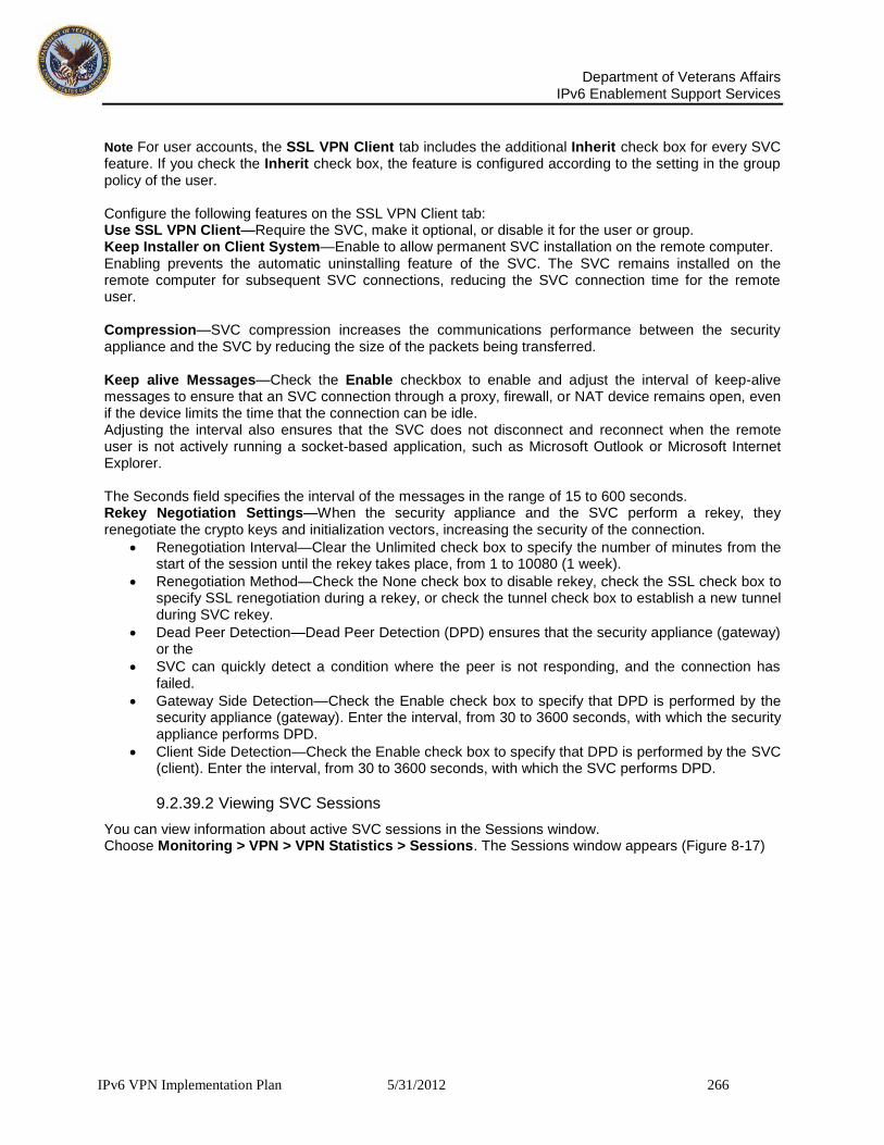
Department of Veterans Affairs
IPv6 Enablement Support Services
IPv6 VPN Implementation Plan 5/31/2012 266
Note For user accounts, the SSL VPN Client tab includes the additional Inherit check box for every SVC feature. If you check the Inherit check box, the feature is configured according to the setting in the group policy of the user. Configure the following features on the SSL VPN Client tab: Use SSL VPN Client—Require the SVC, make it optional, or disable it for the user or group. Keep Installer on Client System—Enable to allow permanent SVC installation on the remote computer. Enabling prevents the automatic uninstalling feature of the SVC. The SVC remains installed on the remote computer for subsequent SVC connections, reducing the SVC connection time for the remote user. Compression—SVC compression increases the communications performance between the security appliance and the SVC by reducing the size of the packets being transferred. Keep alive Messages—Check the Enable checkbox to enable and adjust the interval of keep-alive messages to ensure that an SVC connection through a proxy, firewall, or NAT device remains open, even if the device limits the time that the connection can be idle. Adjusting the interval also ensures that the SVC does not disconnect and reconnect when the remote user is not actively running a socket-based application, such as Microsoft Outlook or Microsoft Internet Explorer. The Seconds field specifies the interval of the messages in the range of 15 to 600 seconds. Rekey Negotiation Settings—When the security appliance and the SVC perform a rekey, they renegotiate the crypto keys and initialization vectors, increasing the security of the connection.
Renegotiation Interval—Clear the Unlimited check box to specify the number of minutes from the start of the session until the rekey takes place, from 1 to 10080 (1 week).
Renegotiation Method—Check the None check box to disable rekey, check the SSL check box to specify SSL renegotiation during a rekey, or check the tunnel check box to establish a new tunnel during SVC rekey.
Dead Peer Detection—Dead Peer Detection (DPD) ensures that the security appliance (gateway) or the
SVC can quickly detect a condition where the peer is not responding, and the connection has failed.
Gateway Side Detection—Check the Enable check box to specify that DPD is performed by the security appliance (gateway). Enter the interval, from 30 to 3600 seconds, with which the security appliance performs DPD.
Client Side Detection—Check the Enable check box to specify that DPD is performed by the SVC (client). Enter the interval, from 30 to 3600 seconds, with which the SVC performs DPD.
9.2.39.2 Viewing SVC Sessions
You can view information about active SVC sessions in the Sessions window. Choose Monitoring > VPN > VPN Statistics > Sessions. The Sessions window appears (Figure 8-17)

Department of Veterans Affairs
IPv6 Enablement Support Services
IPv6 VPN Implementation Plan 5/31/2012 267
Figure 38: VPN Statistics Sessions Window You can view details about active SVC sessions in the Session Details window. Choose a session in the session table, and click Details. The Session Details window appears (Figure 38):
Figure 39: Session Details Window

Department of Veterans Affairs
IPv6 Enablement Support Services
IPv6 VPN Implementation Plan 5/31/2012 268
9.2.39.3 Logging Off SVC Sessions
To log off all SVC sessions, choose the session that you want to terminate from the list of active sessions in the Session table. Click Logout. The session terminates.
Figure 40: Logging Off Sessions
9.2.40 Steps to configure VA Users for LDAP AAA Server
9.2.40.1 Overview of LDAP Transactions
Figure 40 shows the major transactions in security appliance user authentication and authorization using an LDAP directory server.
Figure 41: LDAP Authentication and Authorization Transaction Flow

Department of Veterans Affairs
IPv6 Enablement Support Services
IPv6 VPN Implementation Plan 5/31/2012 269
9.2.40.2 Creating an LDAP Attribute Map
To configure the security appliance for LDAP authentication and authorization, you must first create an LDAP attribute map which maps customer-defined attribute names to Cisco LDAP attribute names. This prevents you from having to rename your existing attributes using the Cisco names that the security appliance understands. Note To use the attribute mapping features correctly, you need to understand the Cisco LDAP attribute names and values as well as the user-defined attribute names and values. See the Cisco Security Appliance Command Line Configuration Guide appendix, “Configuring an External Server for Authorization and Authentication” for the list of Cisco LDAP attributes. To create a new LDAP attribute map, perform the following steps: Step 1 In the Cisco ASDM window, choose Configuration > Properties > AAA Setup > LDAP Attribute Map. The LDAP Attribute Map area appears in the window on the right as shown in Figure 41.
Figure 42: LDAP Attribute Map Area

Department of Veterans Affairs
IPv6 Enablement Support Services
IPv6 VPN Implementation Plan 5/31/2012 270
Step 2 In the LDAP Attribute Map area, click Add. The Add LDAP Attribute Map dialog box appears as shown in Figure 42.
Figure 43: Add LDAP Attribute Map Dialog Box - Map Name Tab Selected Step 3 In the Name field above the tabs, enter a name for the LDAP attribute map. In this example, we name the attribute map Active Directory Map Table. Step 4 If the Map Name tab is not selected, choose it now. Step 5 In the Custom Name (user-defined attribute name) field on the Map Name tab, enter the name of an attribute that you want to map to a Cisco attribute name. In this example, the custom name is department. Step 6 Choose a Cisco name from the Cisco Name menu. The custom name maps to this Cisco name. In this example, the Cisco name is cVPN3000-IETF-Radius-Class. As shown in Figure 40, the security appliance receives the user attributes from the authentication server upon validation of the user credentials. If a class attribute is among the user attributes returned, the security appliance interprets it as the group policy for that user, and it sends a request to the AAA server group configured for this group policy to obtain the group attributes. Step 7 Click Add to include the name mapping in the attribute map.

Department of Veterans Affairs
IPv6 Enablement Support Services
IPv6 VPN Implementation Plan 5/31/2012 271
Step 8 Click the Map Value tab and then click Add on the Map Value tab. The Add LDAP Attributes Map Value dialog box appears as shown in Figure 43.
Figure 44: Add LDAP Attributes Map Value Dialog Box Step 9 From the Custom Name menu, choose the custom attribute for which you want to map a value. Step 10 Enter the custom (user-defined) value in the Custom Value field. Step 11 Enter the Cisco value in the Cisco Value field. Step 12 Click Add to include the value mapping in the attribute map. Step 13 Repeat Step 4 through Step 12 for each attribute name and value to be mapped. Step 14 After you have completed mapping all the names and values, click OK at the bottom of the Add LDAP Attribute Map window. Step 15 Click Apply to complete the new LDAP attribute map and add it to the running security appliance configuration.
9.2.40.3 Configuring AAA Server Groups and Servers
Next, you configure AAA server groups and the AAA servers that go into them. You must configure two AAA server groups. You configure one server group as an authentication server group containing an authentication server that requests an LDAP search of the user records. You configure the other server group as an authorization server group containing an authorization server that requests an LDAP search of the group records. One notable difference between the two groups is that the AAA servers have different base DN fields to specify different Active Directory folders to search.

Department of Veterans Affairs
IPv6 Enablement Support Services
IPv6 VPN Implementation Plan 5/31/2012 272
9.2.40.3.1 Creating the LDAP AAA Server Groups To configure the two server groups, perform the following steps: Step 1 In the Cisco ASDM window, choose Configuration > Properties > AAA Setup > AAA Servers. The AAA Servers area appears in the right half of the window as shown in Figure 44.
Figure 45: The ASDM Window with AAA Servers Selected The fields in the AAA Servers area are grouped into two areas: the Server Groups area and the Servers In The Selected Group area. The Server Groups area lets you configure AAA server groups and the protocols the security appliance uses to communicate with the servers listed in each group.

Department of Veterans Affairs
IPv6 Enablement Support Services
IPv6 VPN Implementation Plan 5/31/2012 273
Step 2 In the Server Groups area, click Add. The Add AAA Server Group dialog box appears as shown in Figure 45.
Figure 46: The Add AAA Server Group Dialog Box
Step 3 Enter the name of the server group in the Server Group field. Use different names for the authentication server group and the authorization server group. In this example, we name the authentication server group ldap-authenticat (authenticate is truncated because of a sixteen character maximum) and the authorization server group ldap-authorize. Step 4 Choose LDAP from the Protocol menu. Step 5 For the Reactivation Mode, choose one of the following: • Depletion — Configures the security appliance to reactivate failed servers only after all of the
servers in the group are inactive. • Timed — Configures the security appliance to reactive failed servers after 30 seconds of down time.
Step 6 In the Dead Time field, enter the number of minutes that elapse between the disabling of the last server in the group and the subsequent re-enabling of all servers. This field is not available if you selected Timed mode in Step 5. Step 7 In the Max Failed Attempts field, enter the number of failed connection attempts (1 through 5) allowed before declaring a nonresponsive server inactive. Step 8 Click OK to enter the newly configured server into the Server Groups table. Step 9 Repeat Step 2 through Step 8 for the second AAA server group. When done, you should have an authentication server group and an authorization server group.
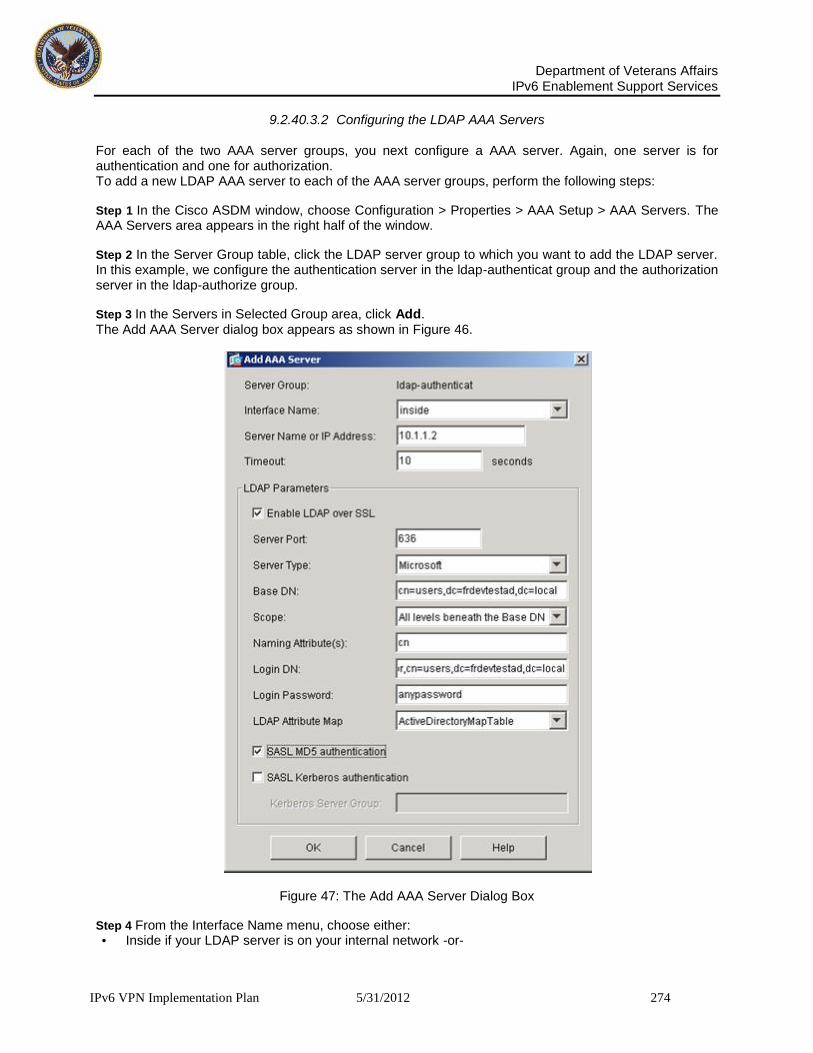
Department of Veterans Affairs
IPv6 Enablement Support Services
IPv6 VPN Implementation Plan 5/31/2012 274
9.2.40.3.2 Configuring the LDAP AAA Servers For each of the two AAA server groups, you next configure a AAA server. Again, one server is for authentication and one for authorization. To add a new LDAP AAA server to each of the AAA server groups, perform the following steps:
Step 1 In the Cisco ASDM window, choose Configuration > Properties > AAA Setup > AAA Servers. The AAA Servers area appears in the right half of the window.
Step 2 In the Server Group table, click the LDAP server group to which you want to add the LDAP server. In this example, we configure the authentication server in the ldap-authenticat group and the authorization server in the ldap-authorize group.
Step 3 In the Servers in Selected Group area, click Add. The Add AAA Server dialog box appears as shown in Figure 46.
Figure 47: The Add AAA Server Dialog Box
Step 4 From the Interface Name menu, choose either: • Inside if your LDAP server is on your internal network -or-

Department of Veterans Affairs
IPv6 Enablement Support Services
IPv6 VPN Implementation Plan 5/31/2012 275
• Outside if your LDAP server is on an external network In our example, the LDAP server is on the internal network. Step 5 Enter the server name or IP address in the Server Name or IP Address field. In our example, we use the IP address. Step 6 In the Timeout field, enter the timeout interval in seconds. This is the time after which the security appliance gives up on the request to the primary AAA server. If there is a standby server in the server group, the security appliance sends the request to the backup server.
Step 7 In the LDAP Parameters area, check Enable LDAP over SSL if you want all communications between the security appliance and the LDAP directory to be encrypted with SSL. Warning If you do not check Enable LDAP over SSL, the security appliance and the LDAP directory exchange all data in the clear, including sensitive authentication and authorization data. Step 8 Enter the server port to use in the Server Port field. This is the TCP port number by which you access the server. Step 9 From the Server Type menu, choose one of the following: • Sun Microsystems JAVA System Directory Server (formerly the Sun ONE Directory Server) – or • Microsoft Active Directory - or - • Detect automatically
The security appliance supports authentication and password management features only on the Sun Microsystems JAVA System Directory Server (formerly named the Sun ONE Directory Server) and the Microsoft Active Directory. With any other type of LDAP server, such as a Novell or Open LDAP server, it only supports LDAP authorization functions and CRL (certificate revocation list) retrieval. By selecting Detect automatically, you let the security appliance determine if the server is a Microsoft or a Sun server. Note The DN configured on the security appliance to access a Sun directory server must be able to access the default password policy on that server. We recommend using the directory administrator, or a user with directory administrator privileges, as the DN. Alternatively, you can place an ACI on the default password policy. Step 10 Enter one of the following into the Base DN field: • The base DN of the Active Directory folder holding the user attributes (typically a users folder) if you
are configuring the authentication server - or - • The base DN of the Active Directory folder holding the group attributes (typically a group folder) if
you are configuring the authorization server The base DN is the location in the LDAP hierarchy where the server should begin searching when it receives an authorization request. For example, OU=people, dc=cisco, dc=com. Step 11 From the Scope menu, select one of the following: • One level beneath the Base DN - or - • All levels beneath the Base DN
The scope specifies the extent of the search in the LDAP hierarchy that the server should make when it receives an authorization request. One Level Beneath the Base DN specifies a search only one level beneath the Base DN. This option is quicker. All Levels Beneath the Base DN specifies a search of the entire sub tree hierarchy. This option takes more time.

Department of Veterans Affairs
IPv6 Enablement Support Services
IPv6 VPN Implementation Plan 5/31/2012 276
Step 12 In the Naming Attribute(s) field, enter the Relative Distinguished Name attribute that uniquely identifies an entry on the LDAP server. Common naming attributes are Common Name (cn) and User ID (uid).
Step 13 In the Login DN field, perform one of the following: • Enter the name of the directory object for security appliance authenticated binding. For example,
cn=Administrator, cn=users, ou=people, dc=Example Corporation, dc=com. - or -
• Leave this field blank for anonymous access. Some LDAP servers, including the Microsoft Active Directory server, require the security appliance to establish a handshake via authenticated binding before accepting requests for LDAP operations. The security appliance identifies itself for authenticated binding by including a Login DN field with the user authentication request. The Login DN field defines the security appliance authentication characteristics which should correspond to those of a user with administration privileges. Step 14 Enter the password associated with the Login DN in the Login Password field. The characters you type appear as asterisks. Step 15 From the LDAP Attribute Map menu, choose the LDAP attribute map to apply to the LDAP server. The LDAP attribute map translates user-defined LDAP attribute names and values into Cisco attribute names and values. To configure a new LDAP attribute map, see Creating an LDAP Attribute Map. Step 16 Check SASL MD5 Authentication to use the MD5 mechanism of the Simple Authentication and Security Layer (SASL) to secure authentication communications between the security appliance and the LDAP server.
Step 17 Check SASL Kerberos Authentication to use the Kerberos mechanism of the Simple Authentication and Security Layer to secure authentication communications between the security appliance and the LDAP server. Note If you configure more than one SASL method for a server, the security appliance uses the strongest method supported by both the server and the security appliance. For example, if both MD5 and Kerberos are supported by both the server and the security appliance, the security appliance selects Kerberos to secure communication with the server. Step 18 If you checked SASL Kerberos authentication in Step 17, enter the Kerberos server group used for authentication in the Kerberos Server Group field.
Step 19 Repeat Step 3 through Step 18 to configure a AAA server in the other AAA server group. Configuring the Group Policy for LDAP and Tunnel Authorization After configuring the LDAP attribute map, the AAA server groups, and the LDAP servers within the groups, you next create an external group-policy that associates the group-name with the LDAP authorization server. Note Comprehensive procedures for configuring group policies are provided elsewhere in this guide. The following steps are only those that apply to configuring AAA with LDAP. To create a new group policy and assign the LDAP authorization server group to it, perform the following steps: Step 1 In the Cisco ASDM window, select Configuration > VPN > General > Group Policy. The Group Policy area appears in the right half of the window.

Department of Veterans Affairs
IPv6 Enablement Support Services
IPv6 VPN Implementation Plan 5/31/2012 277
Step 2 Click Add and choose either Internal Group Policy or External Group Policy. In this example, we choose External Group Policy because the LDAP server is external to the security appliance. The Add Group Policy dialog box appears as shown in Figure 47.
Figure 48: Add Group Policy Dialog Box Step 3 Enter the name of the new group policy in the name field. The group policy name is web1 in our example. Step 4 From the Server Group menu, choose the AAA authorization server group you created previously. In our example, this is the server group named ldap-authorize. Step 5 Click OK and then Apply to create the new group policy.
9.2.40.3.3 Configuring a Tunnel Group for LDAP Authentication In the final major task, you create a tunnel-group that specifies LDAP authentication by performing the following steps:

Department of Veterans Affairs
IPv6 Enablement Support Services
IPv6 VPN Implementation Plan 5/31/2012 278
Step 1 In the Cisco ASDM window, select Configuration > VPN > General > Tunnel Group. The Tunnel Group area appears on the right side of the ASDM window as shown in Figure 5-9.
Figure 49: Tunnel Group Area Step 2 Click Add in the tunnel Group area and choose the type of tunnel group. In our example, we choose IPSec for Remote Access. The Add Tunnel Group dialog box appears.

Department of Veterans Affairs
IPv6 Enablement Support Services
IPv6 VPN Implementation Plan 5/31/2012 279
Step 3 Choose the General tab, and then choose the AAA tab, as shown in Figure 49.
Figure 50: Add Tunnel Group Dialog Box with General and AAA Tabs Selected
Step 4 Enter the name of the tunnel group in the Name field. In our example, the tunnel group name is ipsec-tunnelgroup. Step 5 From the Authentication Server Group menu, chose the AAA server group you configured for authentication. In our example, the authentication server group name is ldap-authenticat. Step 6 Click OK at the bottom of the Add Tunnel Group dialog box.

Department of Veterans Affairs
IPv6 Enablement Support Services
IPv6 VPN Implementation Plan 5/31/2012 280
Step 7 Click Apply at the bottom of the ASDM window to include the changes to the running configuration. You have completed this example of the minimal steps required to configure the security appliance for LDAP authentication and authorization. Specifications of Past and Present ASA 5500 Series Models

Department of Veterans Affairs
IPv6 Enablement Support Services
IPv6 VPN Implementation Plan 5/31/2012 281
9.2.41 End Point User Hardware
Make Model Comments
Apple Airport Extreme IPv6 (6to4 and manual tunnels (Teredo), requires Mac OS X or MS-Windows to configure (no web UI). PPPoE, DHCP support.
Cisco Cisco 827H IPv6 Tunneling support in IP PLUS 12.4. Although it supports IPv6, this IOS has limited functionalities (No Firewall, IPSEC, CBAC).
Cisco Cisco 83x IPv6 support in IP/FW/PLUS 3DES (k9o3sy6) 12.4 IOS.
Cisco Cisco 87x IPv6 support in advipservicesk9 IOS 87x (128Mb RAM/28 Flash), also in adventerprisek9 for 876 router.
Cisco(Linksys) Linksys E-Series
New Firmware Now Available for Select Linksys E-Series Wireless Routers –IPV6 Ready Logo Phase 2 (Gold) - Cisco Blog October 25, 2011.
D-Link DIR-615
DIR-615 - Wireless b/g/n Router. IPv6 supported in some models. Hardware revision C with firmware 3.01 supports IPv6 both natively and with tunnels (including 6-in-4 static).
D-Link DIR-825 DIR-825 Wireless a/g/n Router. IPv6 Phase 2 Ready (gold logo).
D-Link DIR-645 Whole Home Router, dual stack, IPv6 configuration capability built-in.
D-LINK DIR-615
IPV6 Enabled: IPv6 over PPPoE, Static Address and Route, Tunneling, IGMPv2, QoS. Manual and web-based configuration, Stateful and SLAAC/DHCPv6.
Netgear FVS318N
IPV6 support. Stateful/stateless autoconfig, DHCPv6, 4to6 and 6to4 tunneling, ISATAP, DDNS. Can be setup for IPv4 only or IPv6 over IPv4.
Trendnet TEW-692GR
True dual-band with both the 2.4GHz and 5GHz bands, being able to handle the new and higher 450Mbps wireless speed. Offers long range, Gigabit Ethernet, and an easy-to-use Web interface. No IPv6 support.
Asus RT-N56U True dual-band 300Mbps, stellar 5Ghz performance, long range. No IPv6 support
Linksys E-Series E4200
True dual-band with 450Mbps on the 5GHz band; Gigabit Ethernet; a long range; NAS functionality; Includes Cisco Connect, an intuitive software application that helps home users set up and manage their home wireless network with ease. Requires a live Internet connection for the initial setup.

Department of Veterans Affairs
IPv6 Enablement Support Services
IPv6 VPN Implementation Plan 5/31/2012 282
Make Model Comments
Linksys E-Series E4200 v2
IPv6 Enabled. Just released on the market. True dual-band with concurrent 450Mbps on both 5GHz and 2.4GHz bands, Gigabit Ethernet, 5GHz wireless throughput, and Cisco Connect, an intuitive software application that helps home users set up and manage a home wireless network with ease. Features a faster processor for network storage and can host up to 50 guest clients.
Netgear WNDR3700 IPv6 support is listed in the specifications.
Netgear WNDR3800 True dual-band support, IPv6 support, cloud-based storage.
Netgear WNDR4500 IPv6 support is listed in the specifications.
Some of the devices listed above do not have IPv6 capabilities at all. Several other devices in the table provide IPv6 capabilities in a dual stack IPv4/IPv6 mode which make them dependent on the end-user’s ISP capabilities to tunnel and route the traffic. In most cases, the IPv6 capabilities can be added on to the device through firmware upgrade from the user’s ISP. The latest entry on the market from Cisco, the Linksys E4200v2, is the first truly IPv6 enabled router for home use. It offers 450Mbps on the 5GHz and 2.4GHz bands, as well as, a user friendly configuration interface to setup and manage the home network. Coming from the industry leader, this router may very well be a harbinger of a new generation of home routers that will facilitate the transition to the IPv6-native protocol in the future.
9.2.41.1 Home Modems
Due to the integrated nature of many of the communication modems, the ability to support IPv6 can be impacted, even though they are not considered a layer 3 device. One important example is with the Data Over Cable Service Interface Specification (DOCSIS) standard. DOCSIS modems are managed via an IP address. Many of the DOCSIS modems deployed today are DOCSIS 2.0, which does not support IPv6. The 'DOCSIS 2.0 + IPv6' specification also support for IPv6 on DOCSIS 2.0 cable modems via a firmware upgrade. DOCSIS 3.0 adds management over IPv6 and provides for higher speed service. Several common modems for home Internet connectivity are listed in the table below.
Make Model Type IPv6 Status
Actiontec MI424WR FiOS IPv4 upgradeable to IPV6 capability in 01/2012. Firmware upgrade to be pushed in by Verizon.
Motorola SB6120 Cable IPv4/IPV6 support, DOCSIS 3.0. Dual stack IPv4/IPv6.
UBEE (Ambit) U10C035 Cable Dual stack IPv4/IPv6. IPv6 support DOCSIS 3.0.
Table 1: Home Modem Analysis
9.2.41.2 MiFi/AirCards
MiFi and AirCard (also known as USB modems) provide users with a method of connecting their devices to the Internet using wireless carriers’ 3G or 4G networks. The table below provides a review of many of the popular MiFi and USB Modems. As a general rule, wireless carriers are not supporting IPv6 in 3G. Verizon Wireless has provided wide-spread support for IPv6 in its 4G LTE network as a requirement. Thus, all USB Modem devices connecting to the network will support IPv6 connectivity for the user-device it is connected too. However, in the case of Verizon, they assign a single IPv6 address to the device (a /128), thus MiFi’s currently are not able to support wireless IPv6 connection to end user devices. They still utilize NAT and provide IPv4 addresses.

Department of Veterans Affairs
IPv6 Enablement Support Services
IPv6 VPN Implementation Plan 5/31/2012 283
Make Model Carrier Network IPv6 Status
Novatel MiFi4082 Sprint 3G/4G Capable IPv6 Status Unknown – Research in progress
Novatel MiFi4510L Verizon Wireless 3G/4G Capable IPv6 Status Unknown – Research in progress
Novatel MiFi3352 Sprint, Verizon Wireless
3G Capable IPv6 Not Supported on 3G
Novatel MiFi2352 Sprint, Verizon Wireless
3G Capable IPv6 Not Supported on 3G
Novatel MiFi2372 AT&T 3G Capable IPv6 Not Supported on 3G
Novatel MiFi2200 Sprint, Virgin Mobile, Verizon Wireless
3G Capable IPv6 Not Supported on 3G
Samsung SCH-LC11 Verizon Wireless 3G/4G Capable IPv6 Status Unknown – Research in progress
NetComm MyZone On the go 3G Capable IPv6 Not Supported on 3G
Sierra Wireless
Overdrive Sprint 3G/4G Capable IPv6 Status Unknown – Research in progress
D-Link DIR-457/MyPocket
On the go 3G Capable IPv6 Not Supported on 3G
Verizon Wireless
LTE USB Modem 551L
Verizon Wireless 3G/4G Capable IPv6 Supported
Pantech LTE USB Modem UML290
Verizon Wireless 3G/4G Capable IPv6 Supported
LG USB Modem VL600
Verizon Wireless 3G/4G Capable IPv6 Supported
Table 2: MiFi/USB Modem Analysis
While all wireless providers in the US are in an active transition to convert or adopt IPv6 capabilities, Verizon Wireless is in the lead with the mandate that all 4G LTE be IPv6 ready. The plan to begin deploying IPv6 to our VA Telecommuters will be accomplished in Phases. Initially the transition has been done in a limited fashion but will soon expand to other areas of VA network. Ipv4 will not initially be disabled by the ISP providers; they will continue to provide an IPv4 address to each telecommuter as well as IPv6 addresses come online. IPv4 will remain as-is while IPv6 is introduced. This model will offer the greatest flexibility during the Ipv6 transition. The ISP user installations will be done in Phases. The first phase of deployment, we will enable IPv6 on selected standalone computers. They will begin with a small number of DOCSIS 3.0 cable modem models (see those modems noted as IPv6-ready which will expand over time. However, the ISP may not directly enable IPv6 functionality on end user systems as this depends upon the capabilities of that computer's operating system. The current major consumer operating systems capable of this are Windows 7, Windows 7, and Mac OS X 10.7 (Lion). They are using Native Dual Stack, which means a customer gets both IPv6 and IPv4 addresses simultaneously. As a result no tunneling or Network Address Translation (NAT) is necessary. This

Department of Veterans Affairs
IPv6 Enablement Support Services
IPv6 VPN Implementation Plan 5/31/2012 284
approach offers meaningful performance benefits to our customers compared to the alternatives. The following devices represent the Ipv6 capability.
9.2.41.3 DOCSIS Modem Devices
If a customer has difficulty connecting users can run a simple test to see if the connected equipment is
IPv6 ready by visiting the http://test-ipv6.com/ system readiness test site. If a problem is discovered,
instructions will be provided on that page. In addition, for Windows users that experience a problem, Microsoft has released a fix. AT&T has been planning for the IPv6 transition since 2006, and has completed or is near completing the necessary connectivity steps, including:
Enabling network to support IPv6
Offering dual-stack IPv4/IPv6 services to enterprise customers.
Providing and enabling IPv6-compatible modems, routers and gateways AT&T is currently running a dual-stack network infrastructure that supports both IPv4 and IPv6. The AT&T Dual-stack network has the ability to send and receive both IPv4 and IPv6 information. Most current implementations of IPv6, including AT&T's, use dual-stack technology. IPv4-based networks are expected

Department of Veterans Affairs
IPv6 Enablement Support Services
IPv6 VPN Implementation Plan 5/31/2012 285
to co-exist with IPv6-based networks for many years. AT&T has been planning for the IPv6 transition since 2006. ATT will make the U-verse Residential Gateway IPv6-capable by automatically updating its firmware*. These updates began in 2011 and are expected to continue through end-of-year 2012. It's important to note that IPv4 and IPv6 will co-exist for a long time:
Dual Stack, allows IPv4 and IPv6 to co-exist in the same devices and networks.
Tunneling, allows IPv6 packets to be transmitted over an IPv4 infrastructure - and vice-versa - later on when IPv6 becomes the more prevalent network this will not be required.
Translation, allows IPv6-only devices to communicate with IPv4-only devices. AT&T High Speed Internet service will continue the deployment of Ipv6. It's important to note that the transition to IPv6 will be invisible to most of the ATT connected VA telecommuters. This will enable them to continue to access the Internet and content with no change in the user connectivity process. If the VA telecommuter is an AT&T customer and has one of the following models, they do not need to take any action to receive this routine and automatic update:
2Wire/Pace 3600
2Wire/Pace 3800
2Wire/Pace 3801
2Wire/Pace i38HG (iNID)
Motorola NVG510 (Compatible Now!) * Note: Motorola 2210 and 2Wire/Pace 2701 AT&T High-Speed Internet Residential Gateways (purchased) cannot be updated to become IPv6-capable. Instead, replacement IPv6-compatible equipment is available for purchase through the AT&T Equipment Shop.
Table 3: MiFi/USB Modem Analysis
While all wireless providers in the US are in an active transition to convert or adopt IPv6 capabilities, Verizon Wireless is in the lead with the mandate that all 4G LTE be IPv6 ready. This is the first phase of our IPv6 deployment. As with any pilot market deployment of new technology, it is possible that a technical issue may arise which causes us to delay our next steps or even to temporarily disable IPv6 in existing pilot markets? Assuming no issues are encountered, we will expand to additional CMTSs in our network. This will most likely happen first in those areas where we have already been conducting IPv6 trials. At the same time, we will be working to expand the number of eligible cable modem models that can support IPv6. In a subsequent phase we will enable customers with home gateway devices to use IPv6, but we are not yet prepared to commit to a date for doing so since this will, in part, depend upon how the first phase of our pilot market deployment proceeds.
9.2.42 Telecommuter Matrixes
VA generates reports weekly which reflect the actual number of users, not just login sessions. Our team was able to work closely with VA Network Security Operations Center (NSOC) to obtain the below statistical user chart. VA’s goal is to get rid of the 1VA VPN solution. They are currently supporting some 2800 users on that protocol, down from 21000 early in 2011. The chart below illustrates I great detail the total numbers of contractors and government employees and what method of VPN they leverage to obtain access to the VA network. The telecommuter matrixes take into consideration the pilot program that was designed to integrate and execute the working plan for a common identification card system for Federal Employees and Contractors. The Pilot Program has provided the project team with experience and insight into process improvements, which will be incorporated into the production release. Through the experience gained in the Pilot Program, the production is expected to provide a robust system solution that is easily operated and maintained.

Department of Veterans Affairs
IPv6 Enablement Support Services
IPv6 VPN Implementation Plan 5/31/2012 286
Total
User Type Access Type Authorized
Contractor VA Employee
One-VA VPN
RESCUE CAG
406 343 63 X
397 316 81 X X
1,101 594 507 X
X
14,416 1,502 12,914
X
30,782 3,030 27,752
X X
943 530 413 X X X
12,881 2,144 10,737
X
60,926 8,459 52,467 Totals
Citrix OE ONE-VA GFE
461 2536 9991 14106 The below illustration shows VA Region 1. This is a solid example of the type of telecommuter utilization. VA is made up of Regions 1-7, they all are geographical, per the map here located here:
http://www2.va.gov/directory/guide/division_flsh.asp?dnum=1. The regions are made up of
VISNs. Regions 5-7 are the VA business units that the NSOC treats as separate regions. R7 (AAC) = Austin Automation Center covers all other NOCs and Data Centers. VHAMaster is VHA as a region, and DVA is mostly the OIT users across the footprint. The region 1 chart shows the weekly summary of the totals for the region inclusive of business units/regions. The chart has totals by VA internal domains/type of connection. The data covers 9 months, week-by-week. The color-coded bar (connection type) rising or falling over that period of time shows the usage. The similar bar patterns in each region also tells the similarities. This is a solid chart that illustrates all connections.
9.2.43 Future VA VPN Considerations
9.2.43.1 Mobile IPv6
Mobile IPv6 is an IETF standard that has added the roaming capabilities of mobile nodes in IPv6 network. RFC 3775 has described this standard in detail. The major benefit of this standard is that the mobile nodes (as IPv6 nodes) change their point-of-attachment to the IPv6 Internet without changing their IP address. This allows mobile devices to move from one network to another and still maintain existing connections. Although Mobile IPv6 is mainly targeted for mobile devices, it is equally applicable for wired environments. The need for Mobile IPv6 is necessary because the mobile nodes in fixed IPv6 networks cannot maintain the previously connected link (using the address assigned from the previously connected link) when changing location. To accomplish the need for mobility, connections to mobile IPv6 nodes are made (without user interaction) with a specific address that is always assigned to the mobile node, and through which the mobile node is always reachable. Mobile IPv6 is expected to be used in IP over WLAN, WiMAX or BWA.

Department of Veterans Affairs
IPv6 Enablement Support Services
IPv6 VPN Implementation Plan 5/31/2012 287
Several terms and information are necessary to understand Mobile IPv6: A foreign link defines a link that is not the mobile nodes home link. A Care-of address denotes an address that is used by the mobile node while it is attached to a foreign link. Whenever a mobile node moves from the home link to a foreign link, it is always (still) reachable by its home address, regardless of its location in IPv6 network. Home address signifies that the mobile node is logically connected to the home link. Also, the association of a home address with a care-of address for a mobile node is known as a binding. Home agent is a router (on the home link) that maintains registrations of mobile nodes that are away from home and their current addresses. A Correspondent node is an IPv6 (not necessarily Mobile IPv6 capable) node that communicates with a mobile node. Mobile IPv6 uses the IPv6 features such as address auto-configuration, Neighbor discovery and extension header for its operation. It uses both types of auto-configuration such as stateless (Network prefix + interface ID) and stateful auto-configuration (DHCPv6). The neighbor discovery feature allows performing the following:
How each other’s presence is discovered and how to find routers;
How each other’s link layer addresses are determined; and
How to maintain reach ability information. Extension headers provide routing headers for route optimization and destinations option header for mobile node originated diagrams. In addition, Mobile IPv6 also requires mobile nodes to carry out IPv6 decapsulation. When a mobile node is away from home, it sends information about its current location to the home agent. A node that wants to communicate with a mobile node uses the home address of the mobile node to send packets. The home agent intercepts these packets, and using a table, tunnels the packets to the mobile node's care-of address Mobile IPv6 uses care-of address as source address in foreign links. Also, to support natural route optimization, the Correspondent node uses IPv6 routing header than the IP encapsulation. The following discussion makes Mobile IPv6 understanding clear by highlighting the benefit of Mobile IPv6 over mobile IPv4. Route Optimization is a built-in feature for Mobile IPv6. In mobile IPv4, this feature was available via an optional set of extensions that was not supported by all nodes. There is no requirement of foreign Agents in Mobile IPv6. As mentioned previously, Neighbor Discovery and Address Auto-configuration features enable mobile nodes to function in any location without the services of any special router in that location. There is no ingress filtering problem in Mobile IPv6 (In Mobile IPv4 this happens because the correspondent node puts its home address as the source address of the packet). In Mobile IPv6, the correspondent node puts the “care-of” address as the source address and having a Home Address Destination option, allows the use of the “care-of” address to be transparent over the IP layer.
9.2.43.2 VPN RSA Tokens
Most VPN Client allows users to RSA SecurID Authenticate to establish end-to-end, encrypted VPN tunnels for secure connectivity for mobile employees or teleworkers. This authentication can be done with either Native RSA SecurID authentication or with RADIUS. The end user running on a Windows platform can also take advantage of additional integration work by using the RSA Software Token or the RSA SecurID 800 token. The VPN client can pull the token code from the RSA Software Token or RSA SecurID 800 token running on the same machine and couple the PIN and token code so that users only need to enter their PIN during an authentication. This type of authentication can be leveraged within the

Department of Veterans Affairs
IPv6 Enablement Support Services
IPv6 VPN Implementation Plan 5/31/2012 288
VA environment. While the RSA token should work seamlessly over IPv6, special deployments and testing should occur to ensure interoperability.
9.2.43.3 VPN Clients on Mobile Devices
Mobile VPN solutions are designed to adapt transparently to these changes. In a Mobile VPN, a VPN server still sits at the edge of your company network, enabling secure tunneled access by authenticated, authorized VPN clients. Mobile VPN tunnels are not tied to physical IP addresses; instead, each tunnel is bound to a logical IP address. That logical IP address sticks to the mobile device no matter where it may roam. For example, a mobile VPN client can:
Roam from one wireless AP to another at a public Wi-Fi hot spot.
Leave Wi-Fi coverage and start using a 3G connection (e.g., EV-DO).
Leave 3G coverage and start using a slower 2G connection (e.g., 1xRTT).
Return to the office and start using a docked Ethernet LAN connection. In this example, the mobile VPN client uses four or five different physical IP addresses while retaining one logical IP address. Applications running on the mobile device and inside the corporate network communicate through that one logical IP address, remaining blissfully unaware of the user's motion and associated physical/network transitions. Readers with large wireless LANs may already be familiar with AP roaming issues. In fact, many WLAN switches use fast handoff and subnet roaming to reduce latency and avoid re-authentication by Wi-Fi clients inside a private WLAN. Unfortunately, those solutions can't help mobile users who need to roam between entirely separate networks that are owned and operated by third parties. Furthermore, subnet roaming is just one of many difficult challenges that face mobile users. Many mobile VPNs take steps to smooth over additional hurdles: A roaming Wi-Fi client may lose connectivity for tens to hundreds of milliseconds during an AP-to-AP handoff. But a mobile user can easily lose connectivity for minutes, hours or even days while passing through a no-coverage zone.
Wi-Fi clients roaming within a given ESSID encounter consistent security throughout the WLAN. But a mobile user roaming from a public Wi-Fi hot spot to a carrier 3G or 4G networks to a secure enterprise WLAN will be required to complete three separate network logins, and repeated application logins as well.
Wi-Fi clients can use the 802.11 power-save option to doze briefly and save battery without losing their AP associations, but a PDA or smart phone that "falls asleep" to save battery when not in use has no standard mechanism to keep application sessions alive until full power is resumed.
Wi-Fi clients automatically choose the best AP, based on observable metrics such as signal strength and error rate. But a mobile device with more than one type of network connection may also need to consider such factors as cost, security and corporate preferences.
Wi-Fi standards enable dynamic rate shifting; administrators can establish minimum acceptable rates. By comparison, mobile devices tend to encounter a much broader range of network characteristics that can be difficult to predict, let alone control.
Mobile VPN products tackle all of these challenges to some degree, in particular, mobile VPNs deliver network and application persistence. When a mobile VPN client roams subnets, swaps adapters, falls asleep, or enters a coverage gap, the VPN server stands in for the client. That server maintains the client's network state to avoid domain and application re-authentication. It may respond to API calls to prevent application blocking or to hold messages sent to the client. When reach ability returns, mobile users can simply resume working exactly where they left off subject to the interaction constraints imposed by each application. Mobile VPN products operate over many kinds of

Department of Veterans Affairs
IPv6 Enablement Support Services
IPv6 VPN Implementation Plan 5/31/2012 289
networks, from satellite links and GSM to Wi-Fi and 3G. Some mobile VPNs are network-agnostic, sending exactly the same messages over any data link. Others are network-aware, adjusting messages to optimize performance over high-latency or low-bandwidth links. Some mobile VPNs simply use the connection with the highest data rate. Others let you control link selection and/or automate network authentication with configurable policies. The use of Mobile IPv6 could be shown to work in conjunction with Mobile VPN clients or could potentially replace separate mobile IPv6 clients.
9.2.43.4 VPN Access using VA PIV Cards
The Personal Identity Verification (PIV) card will be required for all U.S. Government employees and contractors to gain physical and logical access to government resources. The card will be used for access to secured buildings, as well as, to access computer resources. The card was mandated by Homeland Security Presidential Directive, number 12 (HSPD-12). NIST has further developed the card and associated practices by publishing FIPS 201, and developing the PIV Program to work on additional guidelines, reference implementations and conformance testing. Part two of FIPS 201 "describes the card elements, system interfaces, and security controls required to securely store, process, and retrieve identity credentials from the card. The physical card characteristics, storage media, and data elements that make up identity credentials are specified in this standard." The PIV Card Pilot was successfully launched in October 2006 at the Veterans Affairs Central Office (VACO) in Washington D.C. The goal of the Pilot program was to integrate and execute a working plan for a common identification card system for Federal Employees and Contractors. The Pilot Program has provided the project team with experience and insight into process improvements, which will be incorporated into the production release. Through the experience gained in the Pilot Program, the production is expected to provide a robust system solution that is easily operated and maintained. Microsoft Direct Access Direct Access is a remote access solution available in Windows 7 and Windows Server 2008 R2. Unlike a VPN, Direct Access (DA) is highly automated, from the user's perspective, and does not require a separate application or user login. The figure below outlines a high-level architecture of the DA solution. Direct Access is an IPv6-only solution that can utilize native IPv6 connectivity or IPv6 transition technologies for connection. Using the transition mechanism of 6to4, ISATAP, Teredo, and a Microsoft proprietary mechanism, IP-HTTPS, the DA client will connect to the Direct Access server in almost any network connectivity environment, as long as there Internet access. Note that if native IPv6 connectivity is present, tunneling is not required. The DA server itself will act as an ISATAP server, a Teredo Server to facilitate DA client IPv6 connectivity, as well as, IPv6 connectivity with dual stacked internal resource, and connect with a NAT64/DNS64 device to reach IPv4-only services inside the corporate domain.

Department of Veterans Affairs
IPv6 Enablement Support Services
IPv6 VPN Implementation Plan 5/31/2012 290
IPv4 Internet
DMZ
Active Directory
Domain Services
DNS
Native IPv6-capable
internal systems
(where network
supports native routed
IPv6 to host)
DA Client
IPv4-only
application
servers
Intranet IPsec
Tunnel
Infrastructure
IPsec Tunnel
Direct Access
Server
NAT64/
DNS64
2x Internet
IPv4 addresses
ISATAP tunnels
(IPv6 in IPv4)
IPv6 ISATAP
capable internal
systems
Native IPv4 traffic
IPv6 in IPv4 Tunnel to DA server
(Teredo, 6to4, IP-HTTPS)
IPv6 traffic to IPv6-capable
infrastructure (DNS, DCs, and IPv4
infrastructure through NAT64/
DNS64)
IPv6 traffic to rest of IPv6
intranet resources (and IPv4-
only resources through NAT64/
DNS64)
Native IPv6 traffic
ISATAP tunnels
(IPv6 in IPv4)
IPv4-only
management servers
Internet Firewall(permits IPv6 tunnel: Teredo, 6to4,
IP-HTTPS
Figure 51: Router Advertisement Message As the figure demonstrates, there are actually two tunnels to the DA client. One tunnel is an infrastructure tunnel. This facilitates communication between the client node and management services inside the corporate domain (such as policy engines, configuration management servers, and security services) before the user even logs in. This infrastructure tunnel allows corporate IT administrators to manage remote user devices and enforce security and patch policies before device is even allowed access to other corporate resources, network file share as an example. The other tunnel is the intranet IPSec tunnel. This is enabled once the device has been authenticated (and policy enforced) across the infrastructure tunnel and the user logs in with their normal credentials. DA supports two factor authentication, including the use of smartcards. DA allows both forced tunneling and split tunneling, though defaults to split tunneling to maximize efficiency of traffic carried over the intranet tunnel. The architecture identified here is general and applies to the DA solution "out of the box" with Windows 7 (Enterprise edition) and Windows Server 2008 R2. DA is also integrated with the Microsoft Forefront Universal Access Gateway (UAG), which provides greater scalability for DA and inherent support of a NAT64/DNS64 capability.
9.2.43.5 Configuring the Arris User Equipment
9.2.43.5.1 Downloading USB Drivers from ARRIS website and installing them on Your PC Download Instructions Select appropriate driver for your cable modem from the ARRIS website. Double click on the appropriate driver. Save the file to you PC. Requirements Make sure you have the following before attempting to install the USB drivers: . PC with: . at least one free USB port . one of: Windows 98SE, Windows 2000, Windows ME, or Windows XP (Windows 95 and Windows NT are not supported) . USB Drivers executable program downloaded from the ARRIS webpage . USB A/B Cable of appropriate length (a cable is included in your Cable Modem package)

Department of Veterans Affairs
IPv6 Enablement Support Services
IPv6 VPN Implementation Plan 5/31/2012 291
9.2.44 Arris Installation Instructions
When you plug the Cable Modem into the PC.s USB port, Windows automatically detects the hardware and begins installing the USB drivers. Always perform these steps in the order shown to minimize possible problems. For example, if you plug in the USB cable before downloading the file, Windows may install the wrong driver. Installing USB Drivers on Windows 98SE Follow these steps to install USB drivers on Windows 98 Second Edition. 1 Make sure the Cable Modem is on (the Power light should be on). If not, connect the AC adapter. 2 Plug the appropriate end of the USB cable into the Cable Modem and the other end into the computer's USB port. The following window appears, indicating that the PC has detected a new USB device: 3 Wait for the system to start the Add New Hardware Wizard and display the following window (there may be a short delay): 4 Select Search for the best driver. and click the Next button. 5 Make sure .specify the location. is selected and select the location where you have downloaded the drivers. Then click the next button. The wizard searches the specified locations, then displays the location and name of the appropriate driver. 6 Click the Next button. The wizard installs the drivers, then displays a window indicating that the installation is complete. Installing USB Drivers on Windows 2000 Follow these steps to install USB drivers on Windows 2000. 1 Make sure the Cable Modem is on (the Power light should be on). If not, connect the AC Adapter 2 Plug the appropriate end of the USB cable into the Cable Modem and the other end into the computer's USB port. The following window appears, indicating that the PC has detected a new USB device: 3 Wait for the system to start the installation wizard and display the following window (there may be a short delay): 4 Click the Next button. The wizard prompts you for the location of the drivers. Note: The dialog indicates that the wizard is looking for the ARRIS RNDIS (Remote Network Device Interface Specification) driver for the Cable Modem. 5 Select .Search for a suitable driver...., then click the Next button. The wizard displays a list of search options. 6 Make sure the specify location option is selected (checked), then click the Next button. The wizard searches the specified locations, then displays the location and name of the appropriate driver. 7 Click the Next button. The wizard installs the drivers, then displays a window indicating that the installation is complete. 8 Click the Finish button. Installing USB Drivers on Windows XP Follow these steps to install USB drivers on Windows XP. 1 Make sure the Cable Modem is on (the Power light should be on). If not, connect the AC adapter.

Department of Veterans Affairs
IPv6 Enablement Support Services
IPv6 VPN Implementation Plan 5/31/2012 292
2 Plug the appropriate end of the USB cable into the Cable Modem and the other end into the computer’s USB port. The following window appears, indicating that the PC has detected a new USB device: 3 Click the Next button. The wizard prompts you for the location of the drivers. 4 Select. Search for the best driver and Include this location in the search.. Indicate the location where you downloaded the file. Click the Next button. The wizard installs the drivers, and then displays a window indicating that the installation is complete. 5 Click the Finish button. Installing USB Drivers on Windows ME Follow these steps to install USB drivers on Windows Millennium Edition. 1 Make sure the Cable Modem is on (the Power light should be on). If not, connect the AC adapter. 2 Plug the appropriate end of the USB cable into the Cable Modem and the other end into the computer’s USB port. The following window appears, indicating that the PC is installing drivers for a new USB device: 3 When the window disappears, installation is complete. Contact your cable company if you see an error message of any kind.
9.2.45 How to set up the Cisco E4200 Linksys series router
The easiest and fastest way to set up the router is to run the Cisco Connect setup software. You can find Cisco Connect on the CD that came with the router or download it from the router’s support site at Linksys.com/support. Cisco Connect shows you how to connect the router to your home network, step by step. To get started, see “How to start Cisco Connect” below. Advanced users can set up the router manually using the browser-based utility. How to start Cisco Connect: When you run the setup CD, Cisco Connect (the router’s setup software) is automatically installed onto your computer. You can then use Cisco Connect to easily manage the router. To install Cisco Connect on another computer after the router has been set up, see “How to install Cisco Connect on another computer”. Notes: The Cisco Connect CD works with only the specific router model. The setup CD, you can download the software from Linksys.com/support. To start Cisco Connect for the first time:
1. Insert the CD into your CD or DVD drive. 2. Click Set up your Linksys Router.

Department of Veterans Affairs
IPv6 Enablement Support Services
IPv6 VPN Implementation Plan 5/31/2012 293
If you do not see this: •• For Windows, click Start, Computer, then double-click the CD drive and the Setup icon. •• For Mac, double-click the CD icon on your desktop, and then double-click the Setup icon.
3. Follow the on-screen instructions to complete the router setup. When setup has finished, Cisco Connect has also been installed onto your hard drive.
After the router has been set up and Cisco Connect has been installed, you can use Cisco Connect to easily manage many of the router’s settings. To start Cisco Connect on a Windows computer:
Click Start, All Programs, and then click Cisco Connect. The Cisco Connect main menu opens. To start Cisco Connect on a Mac OS X computer: Open the Applications folder, and then double-click the Cisco Connect icon. The Cisco Connect main menu opens.
. When finished, Cisco Connect has also been installed onto the computer’s hard drive. Caution After the router has been set up, do not run the setup CD to install Cisco Connect to another computer. If you run the setup CD again, you will be prompted to enter the router’s network name (SSID) and password. Linksys E-Series Setting Up: Basics How to improve your wireless connection speed Follow these tips to improve your network’s wireless connection speed: •• Make sure that the router is in a good location: •• For the widest coverage area, install the router near the center of your home, and near the ceiling, if possible. •• Avoid placing the router on or near metal objects (such as file cabinets and metal furniture), reflective surfaces (such as glass or mirrors), or masonry walls. •• Any obstruction can weaken the wireless signal (even non-metallic objects), so the fewer obstructions between the router and the wireless device, the better. •• Place the router in a location away from other electronics, motors, and fluorescent lighting. •• Many environmental variables can affect the router’s performance, so if your wireless signal is weak, place the router in several locations and test the signal strength to determine the ideal position. •• If possible, upgrade wireless network interfaces (such as wireless network cards in computers) from older wireless standards to 802.11n. If a wirelessly networked device uses an older standard, the performance of the entire wireless network may be slower.

Department of Veterans Affairs
IPv6 Enablement Support Services
IPv6 VPN Implementation Plan 5/31/2012 294
How to test your Internet connection speed
To test your Internet connection speed:
1. Run Cisco Connect, and then click Change under Router settings. The Router settings screen opens.
2. Click Launch Test under Internet Speed. The Internet speed test screen opens. 3. Follow the on-screen instructions to complete the test.
If you configured the router using Cisco Connect, your network is secure. During setup, Cisco Connect creates a name for your network, enables industry standard WPA/WPA2 wireless security, and assigns a highly secure password for your wireless network and the administrator’s account. To confirm that your network is secure:
1. Run Cisco Connect.

Department of Veterans Affairs
IPv6 Enablement Support Services
IPv6 VPN Implementation Plan 5/31/2012 295
2. In the upper-right corner of the screen, check for the green light that indicates the router is online and secure. If the green light is on, no additional action is required to secure your network.
How to change the router’s name and password You can change the name and password of the router, but if you do so, all wireless devices connected to the router will lose their Internet connection until you reconnect them using the new router name and password. Caution If you change the router’s name and password using the browser based utility, you may not be able to manage the router using Cisco Connect. We recommend using the procedure below to change the router’s login information. To change the router’s name and password:
1. Run Cisco Connect, then click Change under Router settings. 2. Under Personalize, click Change. A Changing router name and password warning appears
3. Click Yes if you want to continue. 4. Enter the new router name and password, then click Change.
Tip After you make changes, update your Easy Setup Key to make it easier to reconnect all of the other computers on the network. Although running Cisco Connect is the easiest way to set up and maintain the router, advanced users may want to manually configure the router. Be careful when changing settings using this method. To manually set up the router:
1. If you have started the Cisco Connect setup, exit Cisco Connect. 2. Connect the router’s power adapter to a power outlet. 3. Connect an Ethernet cable to the computer and to an available numbered Ethernet (blue) port on
the back of the router. 4. Open a web browser on the computer and open the address 192.168.1.1.
A login window appears. If the router is version 2 (look for V2 on router’s bottom label), you can go to myrouter.local instead.
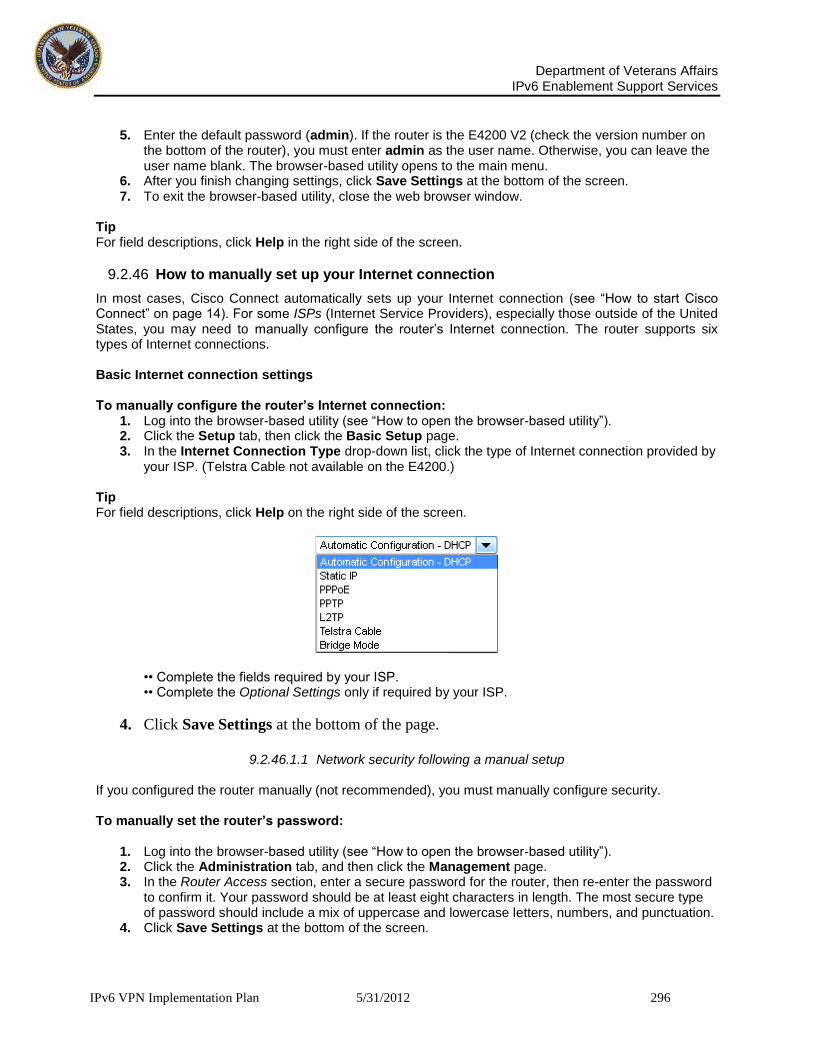
Department of Veterans Affairs
IPv6 Enablement Support Services
IPv6 VPN Implementation Plan 5/31/2012 296
5. Enter the default password (admin). If the router is the E4200 V2 (check the version number on
the bottom of the router), you must enter admin as the user name. Otherwise, you can leave the user name blank. The browser-based utility opens to the main menu.
6. After you finish changing settings, click Save Settings at the bottom of the screen. 7. To exit the browser-based utility, close the web browser window.
Tip For field descriptions, click Help in the right side of the screen.
9.2.46 How to manually set up your Internet connection
In most cases, Cisco Connect automatically sets up your Internet connection (see “How to start Cisco Connect” on page 14). For some ISPs (Internet Service Providers), especially those outside of the United States, you may need to manually configure the router’s Internet connection. The router supports six types of Internet connections. Basic Internet connection settings To manually configure the router’s Internet connection:
1. Log into the browser-based utility (see “How to open the browser-based utility”). 2. Click the Setup tab, then click the Basic Setup page. 3. In the Internet Connection Type drop-down list, click the type of Internet connection provided by
your ISP. (Telstra Cable not available on the E4200.) Tip For field descriptions, click Help on the right side of the screen.
•• Complete the fields required by your ISP. •• Complete the Optional Settings only if required by your ISP.
4. Click Save Settings at the bottom of the page.
9.2.46.1.1 Network security following a manual setup
If you configured the router manually (not recommended), you must manually configure security. To manually set the router’s password:
1. Log into the browser-based utility (see “How to open the browser-based utility”). 2. Click the Administration tab, and then click the Management page. 3. In the Router Access section, enter a secure password for the router, then re-enter the password
to confirm it. Your password should be at least eight characters in length. The most secure type of password should include a mix of uppercase and lowercase letters, numbers, and punctuation.
4. Click Save Settings at the bottom of the screen.

Department of Veterans Affairs
IPv6 Enablement Support Services
IPv6 VPN Implementation Plan 5/31/2012 297
To manually set the router’s network name (SSID):
1. Log into the browser-based utility (see “How to open the browser-based utility”). 2. Click the Wireless tab, then click the Wireless Settings page (for E4200 routers) or Basic
Wireless Settings page (for non-E4200 routers). 3. For Configuration View, select Manual. 4. Enter a new network name in the Network Name (SSID) field, and then click Save Settings at
the bottom of the screen.
Improving Security Linksys E-Series Improving Security To manually set the router’s wireless security settings:
1. Log into the browser-based utility (see “How to open the browser-based utility”). 2. Click the Wireless tab, then click the Wireless Settings page (for E4200 routers) or Basic
Wireless Settings page (for non-E4200 routers). 3. Select your preferred security type from the Security Mode drop-down list For most home
networks, we recommend WPA2/WPA Mixed Mode. 4. Enter a passphrase (security key) for your wireless network in the Passphrase field. The most
secure type of security key should include a mix of uppercase and lowercase letters, numbers, and punctuation.
5. Click Save Settings at the bottom of the screen. How to set up wireless security using Wi-Fi Protected Setup Wi-Fi Protected Setup™ is a feature of the router that makes it easy to add devices to the wireless network. If you have network devices, such as wireless printers, that support Wi-Fi Protected Setup, then you can use Wi-Fi Protected Setup to add the devices. Wi-Fi Protected Setup activity light The power indicator light on the back of the router (or on top for the E4200) indicates the status of Wi-Fi Protected Setup while you are connecting devices. •• When Wi-Fi Protected Setup is connecting a network device, the light flashes slowly. •• If there is an error, the light flashes quickly for two minutes. Wait until it stops flashing, and then try again. •• When Wi-Fi Protected Setup has finished connecting a device, the light is continuously lit. •• Wait until the light is continuously lit before starting the next Wi-Fi Protected Setup session. Connect network devices using one of the three methods below. Note Wi-Fi Protected Setup configures one device at a time. Repeat the instructions for each device that supports Wi-Fi Protected Setup. Connecting a device using the Wi-Fi Protected Setup button Use this method if your device has a Wi-Fi Protected Setup button or prompts you to press the Wi-Fi Protected Setup button on the router. To connect a device using the Wi-Fi Protected Setup button:
1. Press the Wi-Fi Protected Setup button on the network device you are connecting to. 2. Press the Wi-Fi Protected Setup button on the back of the router. - OR –

Department of Veterans Affairs
IPv6 Enablement Support Services
IPv6 VPN Implementation Plan 5/31/2012 298
a. Log into the browser-based utility (see “How to open the browser based utility”). b. Click the Wireless tab, then, if the router is not an E4200, click the Basic Wireless
Settings. c. Click Wi-Fi Protected Setup. d. Click the Wi-Fi Protected Setup button in the router’s Wi-Fi Protected Setup screen. e. After the device has been configured, click OK.
IPv6 Internet connection settings For E900 E1200V2 E1500 E2500 E3200 E4200 IPv6 protocol uses simplified packet headers and requires IPSec. It also has improved support for mobile IP and computing devices. If routers that support IPv6, an IPv6 Setup page is available under the Setup tab. Note To use the router’s IPv6 Internet connection settings, IPv6 service from your ISP (Internet service provider) is required. For more information on this service, ask your ISP. To manually configure the router’s IPv6 settings:
1. Log into the browser-based utility (see “How to open the browser-based utility”). 2. Click the Setup tab, then click the IPv6 Setup page. 3. IPv6 - Automatic—Select Enabled to automatically use IPv6 for all network addressing. 4. 6rd Tunnel—Allows the router to send IPv6 IP addresses over IPv4 networks. To enable this
option, IPv6 - Automatic must be set to Disabled. To let the router handle the 6rd Tunnel settings (such as prefixes and address masks), change the 6rd Tunnel setting to Automatic Configuration. Select Manual Configuration to change these settings manually.
•• Prefix—Enter the prefix address used for the tunnel provided by the ISP. •• Prefix Length—Enter the prefix length used for the tunnel provided by the ISP. •• Border Relay—Enter the border relay address used for the tunnel provided by the ISP. •• IPv4 Address Mask—Enter the IPv4 address mask length used for the tunnel provided by the ISP.
5. Click Save Settings at the bottom of the page.
9.2.46.1.2 To reconfigure your wireless network:
1. Log into the browser-based utility (see “How to open the browser-based utility”). 2. Click the Wireless tab, then click the Basic Wireless Settings or Wireless Settings page. 3. Click Manual. This enables you to make changes to all of the fields below. 4.

Department of Veterans Affairs
IPv6 Enablement Support Services
IPv6 VPN Implementation Plan 5/31/2012 299
a. Network Mode - Your choice depends upon the clients that will connect to your network. If all of your devices are Wireless-N capable, you can select Wireless-N Only for either or both bands. On the 5 GHz band, you can select:
•• Mixed (default), which accepts connections from 802.11a or 802.11n clients •• Wireless-A Only (802.11a only) •• Wireless-N Only (802.11n only) •• Disabled, which disables the 5.0 GHz band on this router On the 2.4 GHz band, you can select: •• Mixed •• Wireless-B/G Only •• Wireless-B only •• Wireless-G Only •• Wireless-N Only •• Disabled
b. Network Name (SSID) - Provide a unique SSID for your 5 GHz wireless network. The name must not exceed 32 keyboard characters.
In the example above, the 5 GHz wireless network was renamed BronzeEagle5GHz.
c. Channel Width - We recommend that you keep the default (Auto) settings. In Auto mode, the router and the network clients automatically switch to the 40 MHz mode if:
•• Your wireless clients support the 40 MHz mode (sometimes called Bonded mode) in which two 20 MHz channels are bonded together for better performance. •• There is no adjacent interference. With more available channels and less chance of interference on the 5 GHz band, you have the option to force the 40MHz mode. On the 5GHz band, you can select: •• Auto (20 MHz or 40 MHz) •• 20 MHz Only •• 40 MHz Only Linksys E-Series Setting Up: Advanced On the 2.4 GHz band, you can select: •• Auto (20 MHz or 40Mhz) •• 20 MHz Only
d. Channel - Choose the operating channel for each band. The router will automatically select the channel with the least amount of interference if you leave the default Auto or Auto (DFS) setting. We recommend keeping the default settings for both bands.
e. SSID Broadcast - When wireless clients look for wireless networks to connect to, they detect the SSID (wireless network name) broadcast by the router. To broadcast the router’s SSID, keep the default setting (Enabled). If you do not want to broadcast the router’s SSID, select Disabled. It is recommend that the default setting remain (Enabled) for both bands.
f. Security Mode (setting is on this page for the E4200, and on the Wireless > Wireless Security page for other routers) - The 5 GHz and 2.4 GHz networks can use different security options. Select the security option for each wireless network. If the security mode you select requires a passphrase, a Passphrase field appears, and you must enter a passphrase.
Tip Wireless-N networks should use the WP2-Personal security mode for best performance. 4. To apply your changes, click Save Settings at the bottom of the screen. How to connect a device using its Wi-Fi Protected Setup PIN. Use this method if your device has a Wi-Fi Protected Setup PIN (Personal Identification Number).

Department of Veterans Affairs
IPv6 Enablement Support Services
IPv6 VPN Implementation Plan 5/31/2012 300
To connect a device using the device’s Wi-Fi Protected Setup PIN:
1. Log into the browser-based utility (see “How to open the browser-based utility”). 2. Click the Wireless tab, then, if the router is not an E4200, click the Basic Wireless Settings
page. 3. Click Wi-Fi Protected Setup. 4. Enter the PIN from the device into the PIN field on the router’s Wi-Fi Protected Setup screen,
then click Register.
5. After the device has been connected, click OK. How to improve security using the built-in firewall By default, the firewall settings in the router have been optimized for most home environments, so no changes are needed. The SPI (Stateful Packet Inspection) firewall is enabled by default. In addition, anonymous Internet requests and IDENT requests are filtered by default. All web filters are disabled, because enabling them may cause problems for sites that depend on ActiveX controls, Java, or cookies. General firewall settings To change your firewall settings:
1. Log into the browser-based utility (see “How to open the browser-based utility”). 2. Click the Security tab, and then click the Firewall page.
3. Select each setting that you want to change. Tip For descriptions of the filters, click Help on the right side of the screen. More complete descriptions are included below. •• SPI Firewall Protection—this helps protect your local network from Internet threats. This option is enabled by default. On some router models, this setting is separated into IPv6 and IPv4 options so that each can be handled separately. Caution To help protect the network, you should keep this option enabled. •• Filter Anonymous Internet Requests—this filter blocks Internet requests from unknown sources such as ping requests. This option is enabled by default.

Department of Veterans Affairs
IPv6 Enablement Support Services
IPv6 VPN Implementation Plan 5/31/2012 301
•• Filter Multicast—Multicasting allows a single transmission to simultaneously reach specific recipients within your local network. Select this option to block multicasting. This option is disabled by default. •• Filter Internet NAT Redirection for IPv4 Internet Only—this filter prevents a local computer from using a URL or Internet IP address to access the local server. Select this option to enable the filter. This option is disabled by default. On some router models, this setting applies to IPv4 Internet only. •• Filter IDENT (Port 113)—this filter prevents port 113 from being scanned by devices from the Internet. This option is enabled by default.
4. Click Save Settings to update your changes.
9.2.46.1.3 IPv6 firewall settings For E900 E1200V2 E1500 E2500 E3200 E4200 The IPv6 firewall lets you customize IPv6 port services for applications. When users send these types of requests to your network via the Internet, the router will allow those requests to the appropriate computers. Note To use the router’s IPv6 Internet connection settings, IPv6 service from the ISP (Internet service provider) is required. For more information on this service, ask the ISP. To set IPv6 firewall settings:
1. Log into the browser-based utility (see “How to open the browser-based utility”). 2. Click the Applications & Gaming tab, and then click the IPv6 Firewall page.
3. Select each setting that you want to change. •• Description—Enter a description of the application. •• IPv6 Address—Enter the IPv6 address of the computer that should receive the traffic. •• Allow—Select the protocol(s) and range of port(s) used by incoming traffic.
4. Click Apply to save your changes. The Allowing Ports section lists the settings you have saved. 5. To change a saved setting, click Edit. To delete a saved setting, click Remove.
Linksys E-Series Using an External Drive Linksys E-Series Port Forwarding and Port Triggering How to set up port forwarding. Port forwarding is a feature that forwards inbound traffic from the Internet on a specific port or ports to a specific device or port on your local network. You can set up port forwarding for:
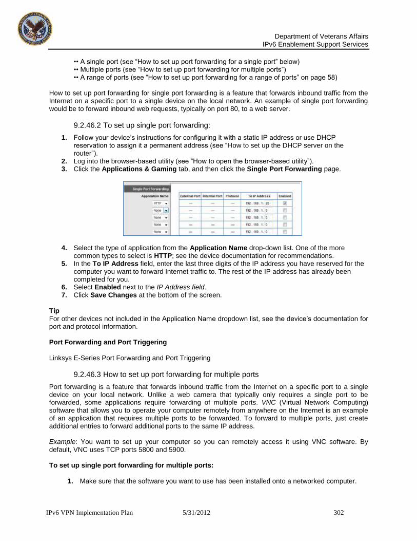
Department of Veterans Affairs
IPv6 Enablement Support Services
IPv6 VPN Implementation Plan 5/31/2012 302
•• A single port (see “How to set up port forwarding for a single port” below) •• Multiple ports (see “How to set up port forwarding for multiple ports”) •• A range of ports (see “How to set up port forwarding for a range of ports” on page 58) How to set up port forwarding for single port forwarding is a feature that forwards inbound traffic from the Internet on a specific port to a single device on the local network. An example of single port forwarding would be to forward inbound web requests, typically on port 80, to a web server.
9.2.46.2 To set up single port forwarding:
1. Follow your device’s instructions for configuring it with a static IP address or use DHCP reservation to assign it a permanent address (see “How to set up the DHCP server on the router”).
2. Log into the browser-based utility (see “How to open the browser-based utility”). 3. Click the Applications & Gaming tab, and then click the Single Port Forwarding page.
4. Select the type of application from the Application Name drop-down list. One of the more common types to select is HTTP; see the device documentation for recommendations.
5. In the To IP Address field, enter the last three digits of the IP address you have reserved for the computer you want to forward Internet traffic to. The rest of the IP address has already been completed for you.
6. Select Enabled next to the IP Address field. 7. Click Save Changes at the bottom of the screen.
Tip For other devices not included in the Application Name dropdown list, see the device’s documentation for port and protocol information. Port Forwarding and Port Triggering Linksys E-Series Port Forwarding and Port Triggering
9.2.46.3 How to set up port forwarding for multiple ports
Port forwarding is a feature that forwards inbound traffic from the Internet on a specific port to a single device on your local network. Unlike a web camera that typically only requires a single port to be forwarded, some applications require forwarding of multiple ports. VNC (Virtual Network Computing) software that allows you to operate your computer remotely from anywhere on the Internet is an example of an application that requires multiple ports to be forwarded. To forward to multiple ports, just create additional entries to forward additional ports to the same IP address. Example: You want to set up your computer so you can remotely access it using VNC software. By default, VNC uses TCP ports 5800 and 5900. To set up single port forwarding for multiple ports:
1. Make sure that the software you want to use has been installed onto a networked computer.

Department of Veterans Affairs
IPv6 Enablement Support Services
IPv6 VPN Implementation Plan 5/31/2012 303
2. Log into the browser-based utility (see “How to open the browser-based utility”). 3. Set up DHCP reservation for the IP address of the computer on which you installed the
software. (See “How to set up the DHCP server on the router”). 4. Click the Applications & Gaming tab, and then click the Single Port Forwarding page. 5. For each entry, enter a descriptive name in the Application Name field. 6. For each entry, enter in the same port number for the External Port and the Internal Port. 7. In the To IP Address field, enter the last three digits of the IP address you have reserved for
the computer you want to forward Internet traffic to. The rest of the IP address has already been completed for you.
8. Select Enabled next to the IP Address field.
9. Click Save Changes at the bottom of the screen.
Note If you want to use software such as VNC on multiple computers, you will need to reconfigure the default ports that VNC uses on each additional computer. Then, create additional port forwarding entries for each additional computer. See your software’s documentation for help. How to set up port forwarding for a range of ports Port forwarding is a feature that forwards inbound traffic from the Internet on a range of ports to a single device on your local network. Unlike a web camera that typically only requires a single port to be forwarded, some applications require forwarding to a range of ports. Example: You want to set up your computer so you can use Bit Torrent, a popular peer-to-peer file sharing application. Bit Torrent uses port 6881 by default. If that port is busy, the requesting Bit Torrent client tries the next port in sequence. The most common configuration for home routers with a single Bit Torrent computer is to set up port forwarding using a range of ports starting with 6881 and ending with port 6889. Linksys E-Series Port Forwarding and Port Triggering
9.2.46.3.1 To set up port range forwarding:
1. Log into the browser-based utility (see “How to open the browser-based utility”). 2. Set up a DHCP reservation for the IP address of the computer on which you installed the
software. (See “How to set up the DHCP server on the router”). In this example, the IP address of the desktop computer with Bit Torrent installed is 192.168.1.140.
3. Click the Applications & Gaming tab, and then click the Port Range Forwarding page. 4. Enter a descriptive name, and then enter the Start Port and the End Port values to specify the
range. In this example, the range is 6881 to 6889. 5. Select TCP as the protocol. \ 6. In the To IP Address field, enter the last 3 digits of the IP address of the device running the
software. The rest of the IP address fields already completed. In this example, you would enter 140.
7. Select Enabled next to the To IP Address field.
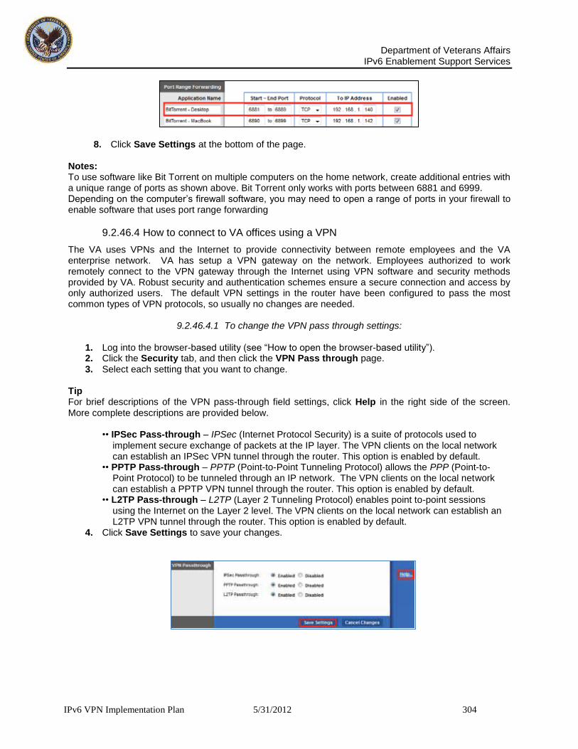
Department of Veterans Affairs
IPv6 Enablement Support Services
IPv6 VPN Implementation Plan 5/31/2012 304
8. Click Save Settings at the bottom of the page.
Notes: To use software like Bit Torrent on multiple computers on the home network, create additional entries with a unique range of ports as shown above. Bit Torrent only works with ports between 6881 and 6999. Depending on the computer’s firewall software, you may need to open a range of ports in your firewall to enable software that uses port range forwarding
9.2.46.4 How to connect to VA offices using a VPN
The VA uses VPNs and the Internet to provide connectivity between remote employees and the VA enterprise network. VA has setup a VPN gateway on the network. Employees authorized to work remotely connect to the VPN gateway through the Internet using VPN software and security methods provided by VA. Robust security and authentication schemes ensure a secure connection and access by only authorized users. The default VPN settings in the router have been configured to pass the most common types of VPN protocols, so usually no changes are needed.
9.2.46.4.1 To change the VPN pass through settings:
1. Log into the browser-based utility (see “How to open the browser-based utility”). 2. Click the Security tab, and then click the VPN Pass through page. 3. Select each setting that you want to change.
Tip For brief descriptions of the VPN pass-through field settings, click Help in the right side of the screen. More complete descriptions are provided below. •• IPSec Pass-through – IPSec (Internet Protocol Security) is a suite of protocols used to implement secure exchange of packets at the IP layer. The VPN clients on the local network can establish an IPSec VPN tunnel through the router. This option is enabled by default. •• PPTP Pass-through – PPTP (Point-to-Point Tunneling Protocol) allows the PPP (Point-to- Point Protocol) to be tunneled through an IP network. The VPN clients on the local network can establish a PPTP VPN tunnel through the router. This option is enabled by default. •• L2TP Pass-through – L2TP (Layer 2 Tunneling Protocol) enables point to-point sessions using the Internet on the Layer 2 level. The VPN clients on the local network can establish an L2TP VPN tunnel through the router. This option is enabled by default.
4. Click Save Settings to save your changes.

Department of Veterans Affairs
IPv6 Enablement Support Services
IPv6 VPN Implementation Plan 5/31/2012 305
9.3 Phase III
9.3.1 VPN IPv6 Considerations
Application and client IPv6 interoperability is the biggest challenge for VPNs. VPNs must be able to export a large variety of applications to remote connections of various types leveraging IPv6. There are many factors that can affect IPv6 interoperability, including operating system type and version, browser type and version, device type (e.g., laptop, PDA, smart phone), location (e.g., home or public kiosk), and the specifics of the applications and protocols to be accessed. For example, some VPN products offer support for PDAs, but most offer limited support for smart phones. Some VPN devices support phones via a browser, for web-based access, but few support them from an agent perspective, allowing access to client/server applications.
9.3.2 Client/server application support:
VPNs are also still struggling with IPv6 communication with client/server applications. Some VPNs use application translation and network extension, along with special clients, to establish the appropriate access. Each VPN product that uses network extension tends to have a unique solution to the IPv6 client/server application communication. In addition, not all VPN products support the same applications; some support more than others and each has niche areas regarding IPv4 and IPv6 support.
9.3.3 Network extension:
Although the network extension function is a core part of VPN tunnels, it still presents several IPv6 challenges. Network extension requires a client to be installed on the end user’s system that supports IPv6. Installing this client on a public kiosk or on a PC that has policies against downloading programs and plug-ins may not be possible due to insufficient privileges. Because network extension gives a remote user complete access to internal systems, specific per application access controls may be difficult to enforce.
9.3.4 Endpoint security:
Endpoint security for unmanaged PCs and VA computers also remains an IPv6 challenge. Two major issues are trust at the endpoint responses to the host integrity checks and performing proper sanitization of sensitive information from the client system when the IPv6 session is terminated. Unmanaged public client systems are less likely to have antivirus and firewall software enabled and up-to-date. A compromised public computer could trick the host integrity checks by circumventing them or by simulating firewalls, antivirus software, and other required security controls. The systems are also more likely to be infected with malware, such as Trojan horses and keystroke loggers that could gain access to passwords and other sensitive information. In addition, proper sanitization of these systems after the session terminates often requires elevated privileges.
9.3.5 Clientless operation:
VPNs are often described as being clientless, which is used as a selling point over traditional IPSec VPNs. For Web-enabled applications, the Web browser is the only client piece needed to connect to them via a VPN portal. In other cases, dynamically downloaded agents, which may require software installation, are needed to provide access to legacy and client/server applications and network layer connections to non-Web enabled applications; these are the hallmarks of VPN tunneling. Proper privileges are needed to install the software and make appropriate system configurations.
9.3.6 Transition and Network Security Considerations:
IPv6 deployment faces a number of challenges, including: 1) the IPv6 costs and risks, 2) the fact that NAT is required to incrementally deploy IPv6 yet appears to eliminate the need for IPv6, and 3) the inability to really use the IPv6 features effectively during incremental deployment. This section considers possible initial deployment considerations to illustrate the difficulties and then discuss some further risks.
Department of Veterans Affairs
IPv6 Enablement Support Services
IPv6 VPN Implementation Plan 5/31/2012 306
IPv6 should be first deployed at the VA enterprise level. However, to deploy IPv6 in some portions of the VA network would require network address translation between the IPv6 portion and the ``legacy'' IPv4 portion, including the rest of the Internet. However, given network address translation, it would be lower risk to instead deploy more IPv4 using a private address domain and thereby gain sufficient addresses for the immediate enterprise needs. This route would eliminate the risks of disrupting the VA end hosts, routers and multi-layer switches, and network management systems to upgrade to IPv6. NAT-based solutions are widely deployed and well-understood whereas IPv6 support is still largely experimental. Thus, it seems difficult to get IPv6 deployed initially in an enterprise network. Another view is that IPv6 should be deployed first in the VA backbone of the Internet. Yet, this appears to expose the ISP to unjustified costs and risks. The VA backbone has multiple nodes so addresses must go to IPv6. Moreover, the ISP would have to support both IPv4 and IPv6 unless its customers simultaneously convert. (Dual-stack mechanisms and tunneling consume extra network and human resources over supporting just IPv4.) Finally, the ISP would have to provide backbone routers with adequate performance. However, there is no existing market for such products and relatively little investment in this direction because there is no significant amount of IPv6 traffic. So, it is not clear where and when an ISP would get these routers from even it decided to convert to IPv6.
Yet another view is that IPv6 might be widely deployed by some wireless service such as cellular phones. However, this move would incur higher packet overhead unless header compression can be very effective. Also, the average packet size with wireless tends to be smaller, both because the technology and because voice uses small packets. Moreover, a key challenge with wireless is dealing with many units collecting in the same cell, whether they are cell phones, wireless appliances in the home or other wireless mobile devices. If IPv6 does increase the packet overhead significantly, it effectively reduces the maximum number of units that can be served per cell in the worst case, thus increasing the cost. Moreover, wireless only has to transmit to the nearest (wired) receiver, which offers an opportunity to translate the packets to another format for the wired infrastructure, as proposed in the widely supported WAP standard. The arguments for IPv6 based on auto configuration may also be less compelling given that wireless devices have to authenticate themselves when entering a realm, giving ample mechanism and opportunity to do DHCP-like address assignment at that point. Finally, having fixed IPv6 addresses for mobile hosts is mostly interesting to support mobile IP, yet mobile IP has received relatively little deployment to date, given the routing difficulties and solutions that exist at the higher level. Until mobile IP is more compelling and excessive header overhead is shown not be an issue, or until another compelling reason is identified for IPv6 on cellular phones, it is hard to see IPv6 being deployed in this domain.
Although the IPv6 work has shown admirable restraint in avoiding gratuitous changes over IPv4, there are enough of these differences from IPv4 to have legitimate concern that unanticipated problems will arise, given that existing applications were designed, debugged and deployed up based on IPv4. In particular, with IPv6, the address assignment in the high-order 64 bits is allocated to ISPs so, if an enterprise network is served by two ISPs (for fault-tolerance or choice of service), every IPv6 host in the enterprise is effectively multi-homed, with two separate addresses per host, one for each of the ISPs. If one of the ISP's service fails, the addresses used by those sending to this network have to change to those associated with the other ISP for fail-over to occur, unless one of the complex tunneling or rerouting schemes currently being researched to handle this problem can be made to work reliably, or some other solution is available.
IPv6 introduces a privacy risk because it encodes information in the addresses, making this information externally visible. For instance, with IPv6, one can determine a company's ISP based on the addresses used by its hosts. IPv6 also makes every host that uses multiple ISPs effectively multi-homed. IPv6 addresses can also encode MAC addresses that can reveal the manufacturers of the Ethernet interfaces in the hosts. These issues have already caught the attention of privacy groups.
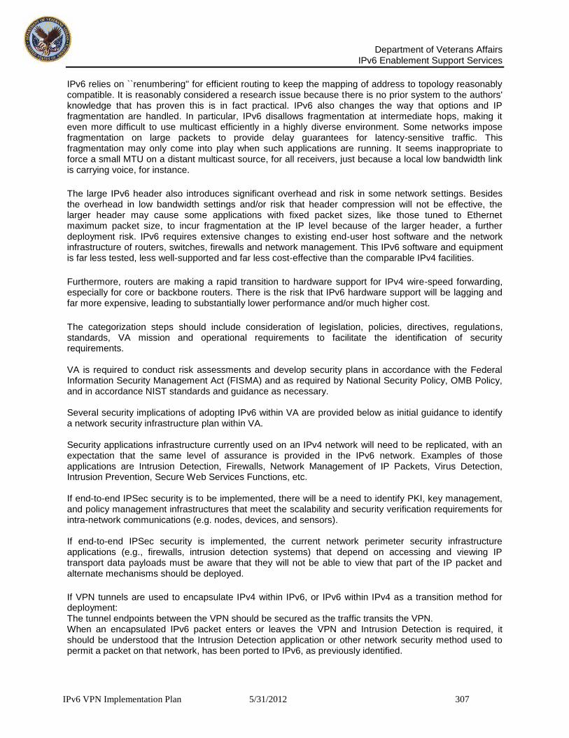
Department of Veterans Affairs
IPv6 Enablement Support Services
IPv6 VPN Implementation Plan 5/31/2012 307
IPv6 relies on ``renumbering'' for efficient routing to keep the mapping of address to topology reasonably compatible. It is reasonably considered a research issue because there is no prior system to the authors' knowledge that has proven this is in fact practical. IPv6 also changes the way that options and IP fragmentation are handled. In particular, IPv6 disallows fragmentation at intermediate hops, making it even more difficult to use multicast efficiently in a highly diverse environment. Some networks impose fragmentation on large packets to provide delay guarantees for latency-sensitive traffic. This fragmentation may only come into play when such applications are running. It seems inappropriate to force a small MTU on a distant multicast source, for all receivers, just because a local low bandwidth link is carrying voice, for instance.
The large IPv6 header also introduces significant overhead and risk in some network settings. Besides the overhead in low bandwidth settings and/or risk that header compression will not be effective, the larger header may cause some applications with fixed packet sizes, like those tuned to Ethernet maximum packet size, to incur fragmentation at the IP level because of the larger header, a further deployment risk. IPv6 requires extensive changes to existing end-user host software and the network infrastructure of routers, switches, firewalls and network management. This IPv6 software and equipment is far less tested, less well-supported and far less cost-effective than the comparable IPv4 facilities.
Furthermore, routers are making a rapid transition to hardware support for IPv4 wire-speed forwarding, especially for core or backbone routers. There is the risk that IPv6 hardware support will be lagging and far more expensive, leading to substantially lower performance and/or much higher cost.
The categorization steps should include consideration of legislation, policies, directives, regulations, standards, VA mission and operational requirements to facilitate the identification of security requirements. VA is required to conduct risk assessments and develop security plans in accordance with the Federal Information Security Management Act (FISMA) and as required by National Security Policy, OMB Policy, and in accordance NIST standards and guidance as necessary. Several security implications of adopting IPv6 within VA are provided below as initial guidance to identify a network security infrastructure plan within VA. Security applications infrastructure currently used on an IPv4 network will need to be replicated, with an expectation that the same level of assurance is provided in the IPv6 network. Examples of those applications are Intrusion Detection, Firewalls, Network Management of IP Packets, Virus Detection, Intrusion Prevention, Secure Web Services Functions, etc. If end-to-end IPSec security is to be implemented, there will be a need to identify PKI, key management, and policy management infrastructures that meet the scalability and security verification requirements for intra-network communications (e.g. nodes, devices, and sensors). If end-to-end IPSec security is implemented, the current network perimeter security infrastructure applications (e.g., firewalls, intrusion detection systems) that depend on accessing and viewing IP transport data payloads must be aware that they will not be able to view that part of the IP packet and alternate mechanisms should be deployed.
If VPN tunnels are used to encapsulate IPv4 within IPv6, or IPv6 within IPv4 as a transition method for deployment: The tunnel endpoints between the VPN should be secured as the traffic transits the VPN. When an encapsulated IPv6 packet enters or leaves the VPN and Intrusion Detection is required, it should be understood that the Intrusion Detection application or other network security method used to permit a packet on that network, has been ported to IPv6, as previously identified.

Department of Veterans Affairs
IPv6 Enablement Support Services
IPv6 VPN Implementation Plan 5/31/2012 308
Wireless network access from IPv6 nodes require in depth security analysis for implementation when stateless auto-configuration is used, in addition to current methods to secure IPv4 wireless networks. Seamless Mobility with IPv6 will need to support the required security as identified by the VA to permit secure access to the network whether across the internal network, or remote from an external network. IPv6 on a network should not be turned on by default unless all network security infrastructures are implemented. (Note that some products may have IPv6 enabled out-of-the-box.) With the current upgrading of VA' technical environments, many VPN devices have IPv6 capabilities already. It is anticipated many new threats and vulnerabilities will arise as attackers devote more attention to IPv6. As such, careful planning and additional attention to operating in a dual environment will be needed to deal with potential new threats and must be addressed by the VA accordingly. IPv6 can be implemented securely on a network, but the guidance above is important to do it in the most secure manner possible.
Finally, early adopters risk being orphaned if IPv6 is not widely deployed soon after they make the move, incurring the cost of backing out of IPv6 as well as the risks and costs of conversion. The lack of IPv6 deployment to date provides empirical support to the above concerns.
Given mission-critical nature of networks and the rapid growth of traffic that the VA networks are confronting, few can afford to take on the IPv6 challenges and risks at this time. Below are some concerns VA must be aware of and find migrations strategies for each.
Cyber security issues have received significant attention over the last several years as the amount of valuable and sensitive data that is available online continues to increase. Configuration management has always been a key component of any IT implementation with security policy and the Federal Desktop Core Configuration (FDCC) seeking to leverage creating a standard to which all Windows desktop systems must comply. Doing so eliminates a wide range of potential attacks by disabling unneeded services, applying patches in a timely manner, establishing strong access controls, and many other important configuration options available within the operating system. The Windows FDCC is based on DoD customization of the Microsoft Security Guides for both Windows and Internet Explorer. In this implementation standardization will play an important part in the network management, maintenance and upgrade. Any healthcare provider that electronically stores, processes or transmits medical records, medical claims, remittances, or certifications must comply with HIPAA regulations. The HIPAA Security Rule addresses the privacy protection of electronic protected health information (PHI). The Security Rule deals with identifiable health information as defined by 18 HIPAA identifiers. The Security Rule defines standards, procedures and methods for protecting electronic PHI with attention to how PHI is stored, accessed, transmitted, and audited. The HIPPA Security Rule addresses three aspects of security:
Administrative Safeguards - Assignment of a HIPPA security compliance team.
Physical Safeguards - Protection of electronic systems, equipment and data.
Technical Safeguards - Authentication & encryption used to control data access.
Covered entities need to perform a Risk Analysis and utilize Risk Management methodologies so vulnerabilities and possible risks can be reduced. VA should assign a security analyst or officer who is responsible for maintaining and enforcing the HIPAA standards within the organization. Hardware, Software and Transmission Security Organizations should have a hardware firewall in place for the external nodes connecting to the VA enterprise infrastructure. Transmission of personal information should be encrypted and comply with HIPAA rulings. External operating systems should be hardened and up to date. Policies should cover the updating of hardware, firmware, operating systems and applications for both VA internal and external systems that connect to the VA infrastructure.

Department of Veterans Affairs
IPv6 Enablement Support Services
IPv6 VPN Implementation Plan 5/31/2012 309
Core ISP needs: Routers must support dual stack Tools for Provisioning, Address Assignment DHCPv6 and DNS Integration Monitoring & Measurement over v6 New line cards are often required Subscriber support: Authentication and session setup, e.g. PPPoE, IPoE, DHCP Provisioning, back-end database; How to scale the routing/provisioning combo to deal with millions of VA customers using stable prefix delegation Consumer equipment considerations: Most DSL Modems do not support v6 Most Firewalls do not support v6 Teredo does not really scale [and 6 to4 cannot traverse a NAT]
Firewalls: Less than 1/3 had IPv6 Transport 25% supported IPv6 Routing
To address the problem of new dual stack hosts exhausting sparse in the IPv4 address space: Allow IPv6 hosts to temporarily acquire an IPv4 global address; Use a DHCPv6 server within each domain, Assign IPv4 address on temporary basis In instances where IPv6 hosts remain online, the temporary assignment becomes permanent… i.e. does not eradicate the problem altogether but acts as a stop gap solution for the IPv4 global addressing issue.
10 Summary
The exhaustion of IP addresses signals a new urgency in the evolution of electronic communication. In the coming years, the Internet will gradually faze in IPv6. This will usher in the next-generation of electronic communication. IPv6 has an unlimited number of IP addresses, which makes room for millions of new users to come online with billions of new devices and web-based applications. Federal agencies are mandated to implement IPv6. Some forward looking organizations and countries have begun implementing IPv6 on their networks, the IPv6 transformation won’t happen overnight. IPv4 & IPv6 protocols aren’t interchangeable or compatible, so you have to run them both in parallel on networks. A fazed in approach is the cost-effective way to move to the next-generation Internet protocol. The smart way to proceed is a fazed approach that consists of network assessment, hardware and software inventories, risk assessments, compatibility testing, upgrading where necessary, develop a migration plan, implement, and test. Step 1: Complete a network assessment You need to know what IPv6-capable equipment might already be on the VA network and what new equipment purchases will have to be made. The industry has been moving toward IPv6 for more than 10 years, and many vendors, including Cisco, HP and others have already added IPv6 capabilities to their networking gear. Most new routers or switches developed within the past few years may be IPv6 ready. IPv6 could be quietly active on the existing network and could represent a gaping hole in the network defenses. VA has to take an active role in locking down all hardware on the existing network. Step 2: Complete a software inventory Like networking hardware, many operating systems are also IPv6-enabled, and some are even switched on by default. IPv6 will impact every corner of IT systems, including applications. We need to identify software that’s currently handling IPv6 traffic, such as Microsoft Windows 7, and if there are web-based applications that will need to be retooled for the new Internet protocol. Validate, update or replace any in-house developed software that is not IPv6 aware. Step 3: Understand how an IPv6 implementation will impact operations. This step defines the path VA will take in the IPv6 transformation. The next-generation Internet promises to be an Internet of hyper-connected nodes. New devices will come online and communicate with each other; VA will be able to glean deep insights into the vast amounts of new data that can gathered, and programmers will develop innovative peer-to-peer applications to take advantage of the capabilities of IPv6. Every agency has to decide how and when it will phase in IPv6. Aggressive early adopters may

Department of Veterans Affairs
IPv6 Enablement Support Services
IPv6 VPN Implementation Plan 5/31/2012 310
choose to faze IPv6 in now across the enterprise and develop apps based on IPv6. Other agencies may decide to block all IPv6 traffic from their networks and wait to deploy the new protocol. Most agencies will be somewhere in between, allowing some IPv6 traffic across their firewall and slowly phasing in an IPv6 infrastructure over time. Deciding which process is right for VA will shape the IPv6 migration plan. Step 4: Develop a migration plan Agencies should faze IPv6 in over time instead of taking a rip-and-replace approach to the infrastructure. Some networking gear will have to be upgraded or replaced to support the new Internet protocol, but rolling it all out at once is likely to be more expensive than it needs to be. Add IPv6 equipment to the existing purchase plan, identifying line items that can be swapped out for IPv6-enabled products. The migration plan should identify where in your enterprise the first implementations of IPv6 should go. VA should roll IPv6 out in the LAB environment then extend into R&D departments first? Does VA want to keep it at the edge of the network? Or should the rollout begin at the core of your network, where it might be easier to mirror the existing IPv4 network with the new IPv6 network? The migration plan must also take into consideration the technique that will be used to implement IPv6. IPv6 traffic must run in a parallel, separate network from IPv4 traffic. You can use the same equipment to do this, which is called dual-stacking. Factor in, all the security measures in place to filter and monitor IPv4 traffic – those same security measures must also be in place for IPv6 traffic. Step 5: Go Live with IPv6 VPN The migration plan must take into consideration the techniques used to implement IPv6. After identifying where to start the first phase of the IPv6 migration, the new hardware has been installed or upgraded, the software has been enabled, and the security tools for the new network have been configured, you simply allow IPv6 traffic to start flowing across the network. And the next-generation Internet is live. IPv6 traffic must run in a parallel, separate network from IPv4 traffic. You can use the same equipment to implement dual-stacking. Factor in the security measures you have in place to filter and monitor IPv4 traffic – those same security measures must also be in place for IPv6 traffic.