Leveraging Proxy Mobile IPv6 with SDN - Networking ...
34
Leveraging Proxy Mobile IPv6 with SDN Syed M. Raza, Dongsoo S. Kim, DongRyeol Shin, Hyunseung Choo College of Information and Communication Engineering, Sungkyunkwan University, Korea {s.moh.raza, dskim61, drshin, choo}@skku.edu Abstract The existing PMIPv6 suffers from a long handover latency which in turn causes significant packet loss that is unacceptable for seamless realtime services such as multimedia streaming. This paper 1 proposes an OpenFlow-enabled PMIPv6 (OF-PMIPv6) in which the control of access gateways is centralized at an OpenFlow controller of a foreign network. The proposed OF-PMIPv6 separates the control path from the data path by performing the mobility control at the controller, whereas the data path remain direct between a mobile access gateway and the local mobility anchor in the form of IP tunnel. A group of simple OpenFlow-enabled access gateways performs link-layer control and monitoring activities for supporting the sophisticated mobility of mobile nodes and communicates with the controller through the standard OpenFlow protocol. The controller performs network-layer mobility signaling on behalf of the mobile access gateways and communicates with the local mobility anchor in the PMIPv6 domain. Benefiting from the centralized view and information of the proposed OF-PMIPv6 architecture, the au- thentication and configuration information are cached and reused at the controller of the foreign network to significantly reduce the handover latency. Analytical analysis of the proposed OF-PMIPv6 reactive and proactive handover schemes shows 38% and 66% decrease is the latency respectively. The initial results gathered from the OF-PMIPv6 testbed suggest the similar improvements. 1 Note: This manuscript is an extended version of the paper presented and published in ACM IMCOM 2014 1
-
Upload
khangminh22 -
Category
Documents
-
view
1 -
download
0
Transcript of Leveraging Proxy Mobile IPv6 with SDN - Networking ...

Leveraging Proxy Mobile IPv6 with SDN
Syed M. Raza, Dongsoo S. Kim, DongRyeol Shin, Hyunseung ChooCollege of Information and Communication Engineering,
Sungkyunkwan University, Korea
{s.moh.raza, dskim61, drshin, choo}@skku.edu
Abstract
The existing PMIPv6 suffers from a long handover latency which in turn causes significant packet loss
that is unacceptable for seamless realtime services such as multimedia streaming. This paper1 proposes
an OpenFlow-enabled PMIPv6 (OF-PMIPv6) in which the control of access gateways is centralized at
an OpenFlow controller of a foreign network. The proposed OF-PMIPv6 separates the control path
from the data path by performing the mobility control at the controller, whereas the data path remain
direct between a mobile access gateway and the local mobility anchor in the form of IP tunnel. A group
of simple OpenFlow-enabled access gateways performs link-layer control and monitoring activities for
supporting the sophisticated mobility of mobile nodes and communicates with the controller through
the standard OpenFlow protocol. The controller performs network-layer mobility signaling on behalf of
the mobile access gateways and communicates with the local mobility anchor in the PMIPv6 domain.
Benefiting from the centralized view and information of the proposed OF-PMIPv6 architecture, the au-
thentication and configuration information are cached and reused at the controller of the foreign network
to significantly reduce the handover latency. Analytical analysis of the proposed OF-PMIPv6 reactive
and proactive handover schemes shows 38% and 66% decrease is the latency respectively. The initial
results gathered from the OF-PMIPv6 testbed suggest the similar improvements.1Note: This manuscript is an extended version of the paper presented and published in ACM IMCOM 2014
1

1. INTRODUCTION
Raging technological advancements in the last decade and the increasing availability of high speed In-
ternet have exponentially increased the usage of mobile devices. As the hardware in mobile devices is
getting more advanced and the data rates exponentially growing, users are more inclined to use media
enriched, interactive and realtime services on the go. Mobility management is essential to provide the
seamless and delay free experience to the users.
The current architecture of the IP protocol and the Internet client/server model doesnt facilitate the net-
work layer mobility management. A logical connection between the client and the server is based on
socket comprising of IP addresses, port numbers of the two terminals and the protocol. The connection
has to be reestablished in case any of these parameters alter. In the mobile environment the client IP ad-
dress and port number changes, as the mobile device attaches to a different gateway. Therefore with each
new IP address client reestablishes the logical connection with the server, this disruption in connection
causes the delay and degradation in the service.
Proxy Mobile IPv6 (PMIPv6) [1] is a network based mobility management protocol, standardized by the
Internet Engineering Task Force (IETF). The PMIPv6 maintains the constant IPv6 address of the mo-
bile node within its domain through the stateless auto IPv6 address configuration mechanism. A socket
connection is maintained in the PMIPv6 even when a MN attaches to a different gateway, but the delay
caused by control signaling during the handover is excessive and unacceptable for realtime services.
Vigorous research has been conducted on the PMIPv6 and many schemes tried to reduce the handover
delay and packet loss [11-13]. Fast Proxy Mobile IPv6 (FPMIPv6) [14] utilizes the information from the
mobile node (MN) to perform proactive handover, and hence doesnt conform to the fundamental concept
of the network based protocol and in turn PMIPv6. Other pure network based schemes reduce the han-
dover delay and packet loss to great extent at the cost of computation intensity. This cost either resides
on the Mobile Access Gateway (MAG) or on the Local Mobility Anchor (LMA) [12-13]. Most of the
2

schemes, also introduces extensive control signaling by MAG and LMA which imposes high bandwidth
requirements. High computation and bandwidth requirements make most of the schemes impractical.
A separate central entity helps the PMIPv6 architecture to perform the mobility management algorithms
without over burdening the MAG and the LMA with intensive computation and bandwidth requirements.
The central entity in the PMIPv6 architecture can be realized through the concept of Software Defined
Networks (SDN). SDN decouples the control plane of the network elements (e.g. access points, switches,
routers etc.) from their data plane; and places it at a centralized entity called Controller in a form of a
software application. The concept of SDN has surfaced over the years in the academic and industrial
communities in many different forms. However, the first truthful and widely accepted implementation of
the SDN concept is OpenFlow (OF), which was presented in 2008 [2].
OpenFlow is a communication protocol standardized by the Open Networking Foundation (ONF) [3].
A centralized controller in the OF network controls the forwarding plane of the network elements. All
the network elements must implements the OF protocol in order to be part of the OF network. The net-
work control logic resides in the centralized controller, and network elements are only responsible for
forwarding packets per flow as per instructions provided by the controller.
The centralized nature of the OpenFlow presents it as a viable candidate for the central separate entity in
the PMIPv6. All the mobility management related computationally intensive algorithms can be deployed
on the controller. The benefits obtained from introduction of the controller in the PMIPv6 architecture
are three fold. 1) The MAGs and LMA are not overburdened with mobility management schemes 2) The
implementation of the MAGs is even simpler than the MAGs of PMIPv6 architecture and 3) Comprehen-
sive and efficient handover mechanisms can be realized, as OF controller maintains the complete state of
the PMIPv6 domain.
In this paper, we present OpenFlow based PMIPv6 architecture (OF-PMIPv6). The detailed architecture
of the OF-PMIPv6 and its analytical model along with analysis is thoroughly discussed, to evaluate its
benefits over the standard PMIPv6. Brief implementation details of the OF-PMIPv6 testbed, and some
3

initial results are presented towards the end. The rest of the paper is managed as follows. Section II
presents our motivation for this work and some background concepts related to the PMIPv6 and the
OpenFlow. The OF-PMIPv6 architecture, its different components and their functioning are thoroughly
discussed in Section III. Section IV presents the analytical models for the PMIPv6 and the OF-PMIPv6
which are later utilized in the evaluation. The brief discussion related to the OF-PMIPv6 testbed imple-
mentation is presented in Section V. The performance evaluation based on the PMIPv6 and OF-PMIPv6
analytical models and the initial results from the OF-PMIPv6 testbed, is presented in Section VI. Finally
conclusions are drawn and future directions are discussed in Section VII.
2. MOTIVATION AND BACKGROUND
Handovers in 802.11 suffers from high latency and the main contributor to it is the process of searching
for a new access point [4]. It has also been reported that for IPv6 90% of the total (layer 2 + layer 3)
delay is caused by layer 3 handover mainly because of the duplicate address detection and move detection
phase. Charles et al [5] presents that how mobility can be supported in IPv6 through binding the MNs
care of address in the foreign network with its home agent in the home network. A lot of work has been
done in order to reduce handover delay in IPv6. Koodi et al [6] presents the Fast Mobile IPv6 which
enables the MN to quickly detect that it has moved to a new subnet by providing the new access point
and the associated subnet prefix information when the MN is still connected to its current subnet. In [7]
authors have provided a draft of proposal which discusses that how IEEE 802.11 Management frames can
be extended and utilized to advertise the capability information of the access points. They recommended
an improved moment detection mechanism by avoiding unnecessary layer 3 messaging over the wireless
link. Janise et al [8] proposes a two-path handover mechanism in the Mobile IPv6, which maintains
the QoS for multimedia traffic while enabling large-scale support in the Internet. These mobile based
mobility management schemes require an MN to be actively involved during the handover decision and
execution procedure. A network based mobility management standard of PMIPv6 [1], handles all the
4

mobility related signaling without involving the MN. This provides opportunities for the innovation in
the networks to handle the mobility management without enforcing any changes in the MN, which is an
important factor in terms of compatibility of MN with the network.
2.1 Proxy Mobile IPv6 (PMIPv6)
In PMIPv6, all data communication between a mobile node (MN) and a corresponding node (CN) moves
through a local mobility anchor (LMA). The LMA serves as a home agent for the mobile node. It is
considered as the topological anchor point for the mobile nodes home network prefix and manages the
mobile nodes binding state [1]. When a mobile node first enters in a PMIPv6 domain it needs to register
itself with the LMA. This control signaling is performed by a mobile access gateway (MAG) on behalf
of the mobile node. After completion of layer 2 connectivity, the mobile node sends a Router Solicitation
(RS) message to the gateway [1]. On receiving the RS message, the gateway sends the mobile node ID to
Authentication, Authorization and Accounting server (AAA server) for authentication. In response AAA
server authenticates the mobile node and provides a home network prefix (HNP) of the mobile node to the
gateway. That in turn sends a Proxy Binding Update (PBU) message to LMA, which contains the mobile
node ID and the HNP. The LMA creates/updates a IP tunnel to the gateway and makes appropriate entries
in its routing table before sending a Proxy Binding Acknowledgement (PBA) message to the gateway.
On the acknowledgement, the gateway makes a routing table entry and creates/updates a IP tunnel to the
LMA. This sets up a bi-directional IP tunnel between the gateway and the LMA for data communication.
The gateway sends Router Advertisement (RA) message to the mobile node before the flow of data
packets begins between the mobile node and the corresponding node via the LMA.
In case of handover, the mobile node disconnects from the gateway (pMAG) it has been connected to
and sends an RS message to a next gateway (nMAG). The rest of the control signaling is similar to MN
registration process. The corresponding node is oblivious to the mobile node handover, as the LMA
makes changes in its routing table and routes the received data packets from the CN over the new IP
5

tunnel created with the next gateway while maintaining the MN IP address. All the PMIPv6 control
signaling for the handover increases the latency to be unacceptable for realtime services.
Many schemes have been proposed to improve the PMIPv6 handover latency. FPMIPv6 [14] reduces
the handover latency and packet loss considerably by allowing the MN in the control signaling which
does not go along with the fundamental concept of PMIPv6. Jeon et al [10] have proposed a solution
of two-phase tunnel control based on the IEEE 802.21 to handle the early packet forwarding problem
in the FPMIPv6. Smart buffering [13] reduces the packet loss on the expense of control signaling and
extra memory requirement; tough handover delay remains same as the standard PMIPv6. Kim et al [11]
proposed a solution to mitigate the packet loss during the handover in PMIPv6 by introducing a buffering
mechanism at the LMA, requiring the larger buffering space at the LMA to cater the needs of all the MNs
for a large scale network. Oh et al [12] also proposed a mechanism to relieve the packet loss during the
handover by buffering the packets at the optical buffering module of the LMA and reduce the handover
latency as well by simplifying the authentication mechanism during the PMIPv6 handover process.
2.2 OpenFlow
The concept of SDN has been floating in the academic circles for a long time, and Openflow (OF) [2]
has recently emerged as the first implementation of SDN. The initial motivation for the OF was to enable
researchers to perform their research on real production networks. The OF network architecture has
been found out to be very consistent with the SDN architecture. The OF has been opted to implement
the SDN concept in different domains of networks, e.g. wireless sensor networks, mesh networks, data
centers, etc. It consists of a set of OF-enabled network devices (switch/router/access point) and an OF
controller as presented in the Figure 1. A network device consists of two separate components, a data
plane and a control plane. The data plane is responsible for packet forwarding whereas the control
plane takes care of communication between the OF switch and the OF controller over a secure TCP
connection. The main objective is to make control functions more centralized rather than distributed.
6
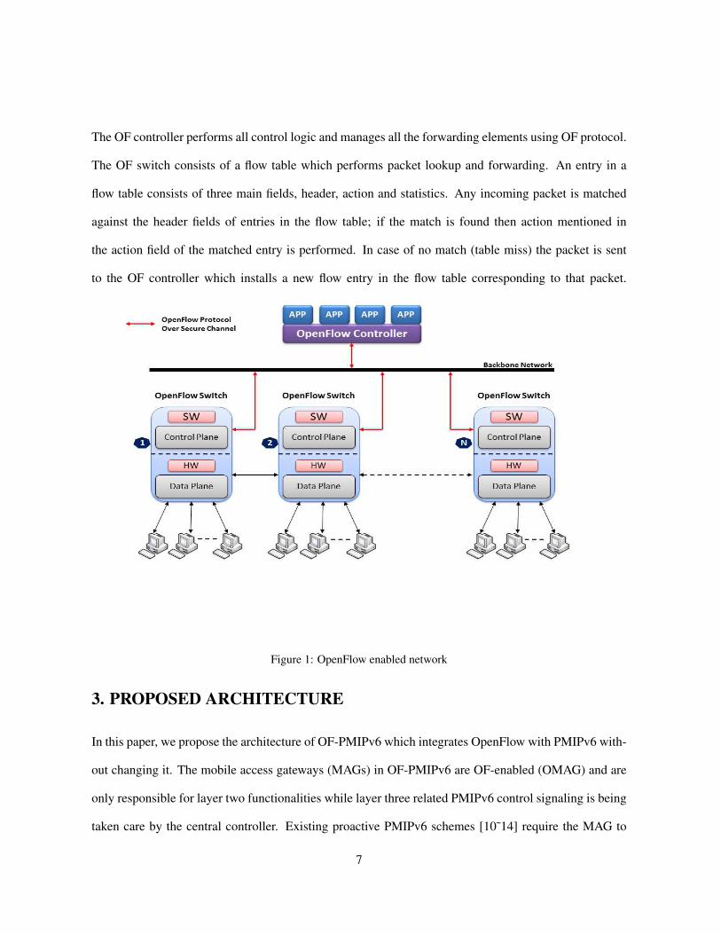
The OF controller performs all control logic and manages all the forwarding elements using OF protocol.
The OF switch consists of a flow table which performs packet lookup and forwarding. An entry in a
flow table consists of three main fields, header, action and statistics. Any incoming packet is matched
against the header fields of entries in the flow table; if the match is found then action mentioned in
the action field of the matched entry is performed. In case of no match (table miss) the packet is sent
to the OF controller which installs a new flow entry in the flow table corresponding to that packet.
Figure 1: OpenFlow enabled network
3. PROPOSED ARCHITECTURE
In this paper, we propose the architecture of OF-PMIPv6 which integrates OpenFlow with PMIPv6 with-
out changing it. The mobile access gateways (MAGs) in OF-PMIPv6 are OF-enabled (OMAG) and are
only responsible for layer two functionalities while layer three related PMIPv6 control signaling is being
taken care by the central controller. Existing proactive PMIPv6 schemes [10˜14] require the MAG to
7

have incompatible functionalities which makes it very complex and renders the whole scheme inextensi-
ble and un-scalable.
Our design of OF-PMIPv6 architecture is motivated by lower handover latency, reduced packet loss, sim-
plicity, extensibility, scalability, sustainability and compatibility with existing PMIPv6 and scalability.
Applying proactive scheme, the handover latency and packet loss in proposed architecture should be in
the range where they do not disrupt realtime services, while not burdening the gateways and the LMA
with extensive control signaling. The proposed architecture should be extensible by easily incorporat-
ing different mobility management schemes for reducing handover latency and packet loss, and should
provide scalability over addition/removal of network elements. Sustainability and compatibility are key
design features, where the proposed architecture should cater the requirements of a production network
and is able to work with the standard PMIPv6 [1] as well.
3.1 OF-PMIPv6 Architecture
In the OF-PMIPv6 architecture, the OMAGs are considered as the access network to which MN makes
a layer two attachment and they also serve as a gateway for the MN. The OMAGs perform the PMIPv6
control signaling with the OF controller in the backbone/core network of the service provider. The LMA
and the AAA servers reside in the home network of the MN. On behalf of the OMAGs the OF controller
performs the PMIPv6 control signaling with the LMA and the AAA through layer 3 messages and this
communication travels through the network X (as show in Figure 2). In case when the MN is in the home
network, the network X between the OF controller and the LMA/AAA is the same service provider net-
work. However if the MN is in the foreign network then the network X can be Internet or any other
network. Bi directional IP data tunnel is created between the LMA and the OMAG for the transmission
of data packets. Figure 2 presents the overall architecture of OF-PMIPv6.
Both control signaling and data communication in the PMIPv6 takes place over the same path between
the MAG and the LMA. The OF-PMIPv6 separates the control signaling path from the data communi-
8

cation path. The OF controller performs the PMIPv6 control signaling with the LMA/AAA on behalf of
all the OMAGs, hence logically virtualizing multiple OMAGs as one OMAG, therefore we can consider
it as a virtual mobility access gateway (vMAG). Communication between the OMAGs and the vMAG is
over the OF protocol. This logical separation of the paths is evident from the Figure 2. As the control
signaling has been offloaded from the OMAGs to the OF controller therefore they are only responsible
for layer two functionalities and IP tunnel management.
Figure 2: OF-PMIPv6 network architecture
3.2 OF-PMIPv6 Components
3.2.1 OMAG
OMAG is the mainly evolved component in the OF-PMIPv6 in comparison with the PMIPv6. In OMAG
the responsibility of the PMIPv6 control signaling with the LMA is offloaded to the OF controller, and
OMAG communicates with the OF controller by implementing the OF protocol. Therefore main func-
tionalities of an OMAG are layer two forwarding of the data packets, IP tunnel management and MNs
link state monitoring for the proactive scheme.
9

Link State Monitoring:
OMAG monitors the link state of the MNs attached to it or are within its footprint, by reading the RSS
value of the received frames/packets. These link state values are maintained as EMA, and are reported
to the OF controller periodically or in case of an event. An event occurs when the link state of an MN
crosses over either a lower threshold (too bad) or a higher threshold (too good). To monitor the link state
of the MNs which are not attached to the OMAG, monitor mode of the IEEE 802.11 is utilized.
OF Protocol:
OMAG is required to communicate MN link state values and PMIPv6 related signaling with OF con-
troller through OF protocol. For this purpose, OMAGs in the OF-PMIPv6 architecture implement the
OF protocol v1.3. To handle the OMAGs PMIPv6 related control signaling and other control messaging
with the OF controller which is outside the scope of the OF protocol, the extension of the OF protocol is
being done by using the experimenter message type.
Tunnel Management:
From PMIPv6 perspective, the main responsibility of an OMAG is to maintain the status of the IP tun-
nels between an OMAG and the LMA in terms of each MN. In case of proactive scheme an OMAG
maintains the status of the tunnel as provisional and conclusive. When the tunnel status is provisional
for a particular MN, the OMAG buffers the data packets received from the tunnel for that MN, without
forwarding them to the MN. These buffered data packets are flushed to the MN and the packets received
from the tunnel are also forwarded to the MN without buffering once the status is changed to conclusive.
3.2.2 OF Controller
The OF controller resides in the backbone network as presented in Figure 2. In OF-PMIPv6, the OF con-
troller acts as a central control entity and performs the PMIPv6 related control signaling with the LMA
on behalf of all the OMAGs in the OF-PMIPv6 domain, therefore it requires to communicate both with
the OMAGs and the LMA. OF controllers in built modules takes care of much of the OF communication
10
with the OMAG, however added modules are required to support mobility related communication with
the OMAG and the LMA. As the OF controller has the complete view of the network and MN states,
therefore it can perform proactive handovers in addition to the PMIPv6 reactive handovers. Mobility
management module of the OF controller performs the reactive and proactive handovers while maintain-
ing the proper state of the MN during the handover process.
OF Module:
OF module is responsible for communicating PMIPv6 control and Mobility related messages with OMAG.
The OF module also facilitate the communication between different modules in the OF controller. The
main purpose of the OF protocol is to handle the forwarding plane of the network elements, therefore
there is no support available for PMIPv6 in the standard OpenFlow. In OF-PMIPv6 the experimenter
message type of the OF protocol is used to define a separate protocol to support the PMIPv6 and other
control signaling between the OF controller and the OMAGs, which is the responsibility of the OF mod-
ule.
PMIPv6 Module:
PMIPv6 module is responsible for performing PMIPv6 standard communication with LMA and AAA
server. It receives information from the OF module and accordingly constructs the PMIPv6 message
(e.g. PBU message) and sends it to LMA or AAA server. Similarly, it receives a response from LMA
or AAA server, extracts the information from the response message and sends it to the OF module for
further processing.
Mobility Management Module:
Mobility Management module consists of a Connectivity Database (C-DB) which maintains the informa-
tion of the MNs such as MN ID, LMA ID, attached OMAG ID and MN link state values from different
OMAGs. For each link state value a timestamp is also recorded and values which are older than a partic-
ular time are considered expired. Once all the link state values for a MN are expired then it is considered
to have left the OF-PMIPv6 domain. To perform the proactive handover link state values in the C-DB are
11

utilized to determine the handover initiation instant and the next OMAG (nOMAG). During the reactive
or proactive handover the proper state of the MN is maintained by the mobility management module.
3.3 OF-PMIPv6 Working
3.3.1 MN Registration in OF-PMIPv6
Upon entering the OF-PMIPv6 domain, MN connects itself to a OMAG and sends a RS message. The
OMAG forwards this RS packet to the OF controller via OF protocol (OF-RS message). The controller
extracts the OF-RS message and further extracts the MN ID. On finding no entry against the received MN
ID in the C-DB, the controller sends it to the AAA server for authentication. AAA server authenticates
the MN ID and provides the Home-Network Prefix (HNP) of the MN to the controller. Once the authen-
tication and the HNP are received the controller sends a PBU message to the LMA. In PMIPv6 PBU
message contains the MN ID and MN HNP, whereas in OF-PMIPv6, PBU message also contains the ID
of OMAG from whom the RS message is received, as LMA is required to create IP tunnel between itself
and the OMAG. After making routing table entries, LMA replies to the controller with a PBA message.
On receiving a PBA message from the LMA, the controller sends message to the OMAG for creation
of an IP tunnel to the LMA. OMAG updates its routing tables and creates an IP tunnel with the LMA
if it does not exist already. Also controller sends a RA message to the MN via OMAG (OF-RA). The
controller updates the C-DB with the information of the newly registered MN. Registration completes
when MN receives the RA message. Figure 3 presents the above explained control signaling in the MN
registration procedure.
12

Figure 3: MN registration in OF-PMIPv6
3.3.2 MN Handover in OF-PMIPv6
OF-PMIPv6 works either in reactive or proactive mode depending on the configuration of the OF con-
troller and OMAG.
3.3.2.1 Reactive Mode
In the OF-PMIPv6 reactive mode, MN handover is almost similar as handover in PMIPv6 [1] with minor
differences. First is that upon receiving the RS message from the MN, OMAG doesnt not send the PBU
message to LMA, instead forwards the OF-RS message to the controller, and the controller takes care of
rest of the control signaling with LMA similar to MN registration procedure in OF-PMIPv6. Secondly in
PMIPv6 nMAG has to re-authenticate the MN with AAA server, as it cannot distinguish whether MN has
sent the RS message in case of handover or in case of registration. This causes increase in the handover
latency. In OF-PMIPv6 the controller doesnt need to re-authenticate MN with AAA server as it already
13

has corresponding MN information in C-DB, this is presented in Figure 4 through Self-Authentication
internal message in the controller. To make sure that there is no bogus MN record in the C-DB, OF
controller only keeps the record of those MNs which are connected with OF-PMIPv6 network at the par-
ticular given time. In reactive mode correct state of the C-DB is ensured through the MN lost report sent
by the OMAG, as in the reactive mode there are no link state messages. On receiving the MN connection
lost report the controller initiates a timer (validation timer), and if the controller does not receive the RS
message from the same MN before the expiration of validation timer the MN record is removed, other-
wise it is kept. Exclusion of re-authentication reduces the handover latency of the OF-PMIPv6 reactive
mode comparing to the PMIPv6. It is important to note that the controllers internal Self-Authentication
message does not imply that some authentication protocol or algorithm is incorporated.
Figure 4: Reactive mode handover in OF-PMIPv6
3.3.2.2 Proactive Mode
In proactive mode of the OF-PMIPv6, the MN point of attachment (pOMAG) constantly monitors the
link state of the MN and as soon as the values drops below the lower threshold it reports it to the OF
14

controller. The controller updates the concerned fields of C-DB from the received information. Other
OMAGs in the vicinity overhears the communication of the MN with pOMAG and reports the MN
link state to the controller. Once the controller determines that the MN link state reported by some
other OMAG is better than the link state of the MN with the pOMAG, it initiates the handover process.
Handover decision and selection of nOMAG is presented in Figure 5 through OF controller internal
Handover-Decision message. Once the controller determines the nOMAG, it sends nOMAG the Tunnel-
Init message which provisional status. On receiving Tunnel-Init message nOMAG make appropriate
entries in its routing table and creates an IP tunnel to the LMA with provisional status. Simultaneously
the controller sends the PBU message to the LMA with MN ID, HNP and nOMAG ID. The LMA updates
the binding entry for the MN with nOMAG information and creates an IP tunnel with the nOMAG. It is
important to note that IP tunnel on LMA does not has any status and LMA always forward the received
data packets according to the routing table entries. Upon updating the binding entry, the LMA sends the
PBA message to the controller. Here onwards LMA forwards the data packets from the corresponding
node to the nOMAG, where nOMAG buffer the received packets.
Meanwhile the controller, on receiving PBA message from the LMA, sends a redirect request (RR) mes-
sage to the MN through pOMAG and starts an expiration timer. On receiving RR message, the MN
disconnects from the pOMAG and connects to the nOMAG by sending RS message. nOMAG forwards
the received RS message to OF controller (OF-RS). On receiving the OF-RS message OF controller ter-
minates the expiration timer. If the value of expiration timer is elapsed and no OF-RS is received, then
the controller resends the RR message to the MN and restarts the expiration timer. In the meantime OF
controller receives the PBA message from LMA. The controller creates the RA message and sends it to
the MN via nOMAG (OF-RA). On receiving the OF-RA message nOMAG changes the tunnel status to
conclusive, forwards the RA message to the MN and also flushes all the buffered packets to the MN. This
completes the MN handover procedure in the proactive mode of the OF-PMIPv6. Figure 5 presents the
aforementioned explained proactive mode of the OF-PMIPv6.
15

Figure 5: Proactive handover in OF-PMIPv6
It can be concluded that handover latency and packet loss in proactive mode of the OF-PMIPv6 is im-
mensely less comparing to the PMIPv6 or the reactive mode of OF-PMIPv6. This reduced handover
latency is mainly because, in PMIPv6 a MAG is responsible for layer two connectivity, layer three con-
nectivity, control signaling and data transmission, and as these functions are dependent on each other
MAG cannot introduce parallelism. Whereas in OF-PMIPv6 the presence of a controller provides a
unique opportunity to offload the layer three control signaling from MAG to the controller and this en-
ables us to perform various control signaling parallel to each other, as shown in the Figure 5.
4. ANALYTICAL MODELING
In this section we mathematically model PMIPv6 and OF-PMIPv6.
16

4.1 Handover Latency
Handover latency of PMIPv6 and OF-PMIPv6 is being mathematically modeled based on the delay that
occurs during the control signaling. Handover latency is defined as the period in which the MN does not
receive data packets.
4.1.1 PMIPv6
A handover process in PMIPv6 starts when a pMAG recognizes that RSS of MN RSS is less than a
threshold after MN has moved out of its footprint, and ends when MN receives a RA packet from the
nMAG. The handover latency is the result of propagation delay experienced by control signals. The
processing time taken by each component (e.g. AAA, LMA) is ignored. The handover latency is defined
as follows [12]:
HTPM = tWRS + tR + tA + tp , (1)
where tWRS is the time MN takes to establish the layer 2 connection before sending the RS message
to MAG. This time can vary immensely as it depends upon the layer 2 scanning mechanism of the
MN. tR (tRS + tRA) is the time RS and RA messages take to reach MAG and MN on the wireless
channel, respectively. Delay experienced in authenticating the MN with AAA server is expressed as tA
(tAAAreq + tAAAres). Delay experienced by the MAG in preforming the control signaling with LMA is
expressed as tP (tPBU + tPBA).
4.1.2 OF-PMIPv6 Reactive Mode
In reactive mode of OF-PMIPv6 the start and end points of the handover process are same as the PMIPv6.
However, OF-PMIPv6 reuses the cached information in the controller for authenticating the MN. Figure
4 describes a reactive handover process in OF-PMIPv6, through which following equation describes the
handover latency.
HTRE = tWRS + tR + tOF−R + tp , (2)
17

where tOF−R (tOF−RS + tOF−RA) is the delay experienced by the OF-RS and OF-RA messages be-
tween the OMAG and the controller. In the OF-PMIPv6 reactive mode, handover latency is not affected
by the ttunnel−init message as it is sent while controller is waiting for the PBA message from the LMA,
hence it is not included in the Eq. 2.
4.1.3 OF-PMIPv6 Proactive Mode
A handover in proactive mode starts when a MN receives a RR message from a pOMAG. As the RR
message contains the identity of a nOMAG, the MN does not need to perform the layer two scanning
and can establish a layer two connection with the nOMAG almost instantly and sends a RS message
right after the layer two connection is established. Exclusion of layer two scanning reduces the value of
layer two handover tWRS . In the proactive mode, the nOMAG may receive an OF-RA message from
the controller before it receives the RS message from the MN for the case where LMA is in the same
backbone network or in close vicinity with the controller and nOMAG. It can send a RA message to the
MN upon receiving the RS message without spending time for authentication and binding update. As
sending of OF-RA message by the controller depends on response from the LMA, therefore if LMA is
in the distant network the nOMAG might not receive the OF-RA message in time to timely respond the
RS message from the MN, causing MN to wait for the RA message and increasing the handover latency.
Handover in the proactive mode completes when the MN receives the RA message. It is important to note
that although the handover process in the proactive modes initiates earlier, but the actual handover begins
when the MN disconnects from the pOMAG after receiving the RR message. The handover latency in
the proactive mode can be formulated as follows.
HTPR = tWRS + tR +max
(((tP + tOF−RA)− (tWRS + tRS)
), 0
), (3)
where (tP + tOF−RA) − (tWRS + tRS) represents the extra delay causing by the communication with
LMA because of its distant location.
18

4.2 MN Registration Latency
When an MN enters in the PMIPv6 domain, it registers itself by sending a RS packet to a MAG. The
MAG registers the MN after performing the authentication with an AAA server, and then performs the
rest of the PMIPv6 signaling. The MN registration process completes when the MN receives an RA
packet from the MAG. In the PMIPv6, the MN registration process repeats every time the MN performs
handover and connects to a new MAG. In OF-PMIPv6 the MN registration process is performed when
the MN enters in an OF-PMIPv6 domain, and MN registration is not required in the case of reactive
or proactive handover process in the OF-PMIPv6, as the MN information is cached in the controller
and utilized during the handover process. Therefore the MN registration latency in the OF-PMIPv6 is
different comparing to the reactive or proactive handovers, and required to be modeled separately.
In PMIPv6 the MN registration latency can be defined as the time delay between the MN sending the RS
packet and receiving the RA packet, and is almost similar to the PMIPv6 handover latency except for the
layer two connection delay as the PMIPv6 registration begins with the RS message.
RTPM = HTPM − tWRS (4)
In comparison to the PMIPv6, the MN registration latency is slightly increased in OF-PMIPv6 because
of an extra step for the control signaling with the controller. However the increase in latency can be
minimal when the controller resides in a same backbone network as the OMAGs. The MN registration
latency can be defined as follows.
RTOF = (HTRE − tWRS) + tA , (5)
where tA is the authentication delay with the AAA which is required in the case of MN registration in
OF-PMIPv6. Similar to PMIPv6, layer two connection delay is not part of the MN registration latency
in OF-PMIPv6.
19

4.3 Buffering Cost
Buffering of data packets is required to minimize the packet loss which might occur during the MNs
handover. The space required for the buffering is referred to as buffering cost. Depending on the scheme
in use, buffering of data packets is generally performed either on the pMAG or nMAG during a handover
process, and buffered data packets are forwarded to the MN by the pMAG or nMAG upon its attachment
to an nMAG.
The standard PMIPv6 [1] does not has any buffering mechanism and so does the OF-PMIPv6 in the
reactive mode, because the identity of the nOMAG is not known before the handover and there is no
communication between the pOMAG and the nOMAG. However, in the OF-PMIPv6 proactive mode
identity of the nOMAG is known to the controller and hence the buffering is performed at the nOMAG
to minimize the packet loss which might occur during the handover. Buffering for a MN starts at the
nOMAG on the completion of the bidirectional tunnel between itself and the LMA, and continues until
it receives the RS message from the MN.
The required space for single MN at the nOMAG is the accumulative size of data packets received at the
nOMAG in the time period starting from arrival of the PBU message at LMA with the nOMAG ID and
ending when the nOMAG receives the RS message from the MN. For an MN the required buffer size is
directly proportional to the data rate (α) of a session between the MN and its CN and the total number
of sessions (E(S)) [22]. The buffering cost at nOMAG for an MN can be described as:
BC =
E(S)∑i
αi ×HT , (6)
where HT is the handover latency and depends on the scheme in use
4.4 Packet Loss
Packet loss can be defined as the number of packets that are transmitted by a CN but fail to reach the MN.
In case of no buffering mechanism the packets arriving during the MN handover process are dropped/lost.
In PMIPv6 and OF-PMIPv6 reactive mode, received packets during the handover are lost as there is no
20
buffering mechanism in place. During an MN handover process, the amount of packet loss in case of no
buffering mechanism, is equal to the buffering cost. The packet loss for PMIPv6 is given by.
PLPM =
E(S)∑i
αi ×HTPM (7)
And for OF-PMIPv6 reactive mode it can be described as.
PLRE =
E(S)∑i
αi ×HTRE , (8)
whereHTPM andHTRE are handover latency in PMIPv6 and reactive OF-PMIPv6 respectively. In case
of the proactive mode, OF-PMIPv6 can reduce the packet loss by buffering the packets unless the buffer
in nOMAG overflows [22]. Packet loss in OF-PMIPv6 proactive mode can be formulated as.
PLPR = max
(((
E(S)∑i
αi ×HTPR)−B), 0
), (9)
where B is the buffer capacity allocated for a single MN at the nOMAG and∑E(S)
i αi ×HTPR is the
required buffer size. There will be no buffer overflow (packet loss) if the allocated buffer capacity B in
the nOMAG is larger than the required size.
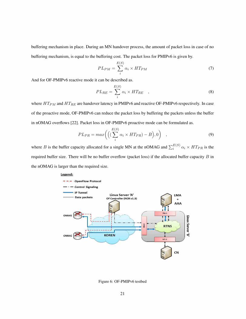
Figure 6: OF-PMIPv6 testbed
21

5. IMPLEMENTATION
To evaluate the performance of the proposed schemes, an integrated PMIPv6 and OpenFlow testbed is
developed to advocate the feasibility, practicality and benefits of the OF-PMIPv6 in realistic situations
of the production networks. Figure 6 presents the architecture of the OF-PMIPv6 testbed. The testbed
utilizes the OpenFlow version 1.3 [3] and an open source implementation of PMIPv6 [23].
5.1 OMAG Implementation
The testbed currently has five OMAGs which are connected to the KOREN (Korean Advance Research
Network) which is a backbone network connecting six major cities in Korea with many international
countries. As presented in the section 4.2.1 an OMAG in OF-PMIPv6 is required to perform partial
functionalities of an MAG in the PMIPv6, and a complete OF protocol. It also has to handle several
control messages which are not supported by the OF protocol. To suffice these requirements, the open
source router implementation for embedded device (OpenWRT) [20] is deployed on the Alix 2d2 devel-
opment kit [19]. An open source implementation of OF protocol for the switches [21] is utilized on the
OMAGs, and is extended to support OF-PMIPv6 control signaling through experimenter message type.
A developed tunnel management module manages and creates an IP tunnel with the LMA and makes
appropriate entries in the routing table (in Linux kernel). A link state monitoring module is developed
in the user space of the OMAG to periodically measure the RSSI of all the nearby MNs by utilizing the
monitor mode of the IEEE 802.11 for a predefined interval. The collected link state information of the
MNs is sent to the OF controller by an experimenter message.
5.2 OF Controller Implementation
The OF controller is connected to the KOREN network and serves as a central control entity in OF-
PMIPv6. The open source implementation of NOX supporting OF protocol v1.3 [21] is used as the
OF module in the controller which is responsible for all communications with an OMAG either through
22
regular OF protocol message types or experimenter message type. A mobility management module is
developed as part of the OF module, whereas PMIPv6 module for communication with LMA, executes
as a separate process and communicates with OF module through IPC.
State of an MN is maintained as not registered, already registered or updated registration in a connectivity
database. OF module performs the MN state transition on receiving OF-PMIPv6 protocol messages.
NOT REGISTERED: It occurs when an MN connects to the OF-PMIPv6 domain and no prior entry
exists in the C-DB. OF module creates a new entry for the MN in the C-DB after an authentication with
AAA server, and via PMIPv6 module communicate with a LMA in order to establish the IP tunnel. On
receiving acknowledgement from the LMA, the PMIPv6 module responds to the OF module with a RA
message, which is then forwarded to the MN via OMAG.
ALREADY REGISTERED: It occurs when a controller receives a RS message from the current OMAG
of the already registered MN. In response the controller simply resends a RA message to the MN via its
current OMAG, as it already has the RA message in the C-DB.
UPDATE REGISTRATION: If the entry for an MN already exists in the C-DB for which the RS packet
is received but the ID of the OMAG in C-DB is not similar to the ID of the OMAG which has sent the
OF-RS message, then this is considered as the UPDATE REGISTRATION case. This case occurs when
a MN handover from one OMAG to another. In response, the information of the new OMAG is updated
in the C-DB, the PMIPv6 module communicates with the LMA in order to establish the tunnel, and
meanwhile the OF module sends the OF-RA message (which is already in the C-DB) and Tunnel-Init
message of OF-PMIPv6 protocol to the new OMAG.
5.3 Real Time Network Simulator (RTNS)
The OF-PMIPv6 testbed aims to provide a realistic production network environment in which the LMA
is usually present in the MNs home network along with an AAA server and a CN can be anywhere
in the world. We have developed a Real Time Network Simulator (RTNS) in NS3 which emulates the
23

background traffic and network delay as experienced in the real network. RTNS runs on a dedicated
Linux server, attached to the KOREN network. Details regarding the RTNS are out of the scope of this
paper; however it is essential to mention the role of RTNS in the OF-PMIPv6 testbed. As presented in
the Figure 6, the control messages from the OF controller to LMA and vice versa goes through RTNS in
order to introduce the network delay experienced in the real network. Similarly the IP tunnel between
OMAG and LMA goes through the RTNS, so the data packets experience the same delay as control
messages do. The LMA strips off the tunnel IP header from the data packets received from the IP tunnels
with OMAGs and forwards them back to RTNS and this time RTNS forwards the data packets to the
CN after introducing a corresponding delay, and the same is performed in the reverse direction. In other
words, RTNS works as a router, which introduces the delay in the packets according to different realistic
scenarios.
6 PERFORMANCE EVALUATION
This section discusses the performance evaluation of the OF-PMIPv6 based on the analytical model and
experimental results from the testbed.
6.1 Analytical Evaluation
Analytical evaluation between PMIPv6 and OF-PMIPv6 is drawn using handover latency and packet loss
as the comparison factors. Table 1 shows the values of the parameters used in the evaluation [12][15]-
[18].
24

Table 1: Parameters used in the comparison
Parameters Symbols ValuesLayer two connection delay tWRS 0.2sTransmission time for RS tRS 0.015sTransmission time for RS and RA messages tR = tRS + tRA 0.03sTransmission time for authentication tA = tAAAreq + tAAAres 0.005s to 0.4sTransmission time for control signaling with LMA tP = tPBU + tPBA 0.005s to 0.4sTransmission time for OF-RA tOF−RA 0.005sTransmission time for OF messages tOF−R = tOF−RS + tOF−RA 0.01sAllocated buffer capacity for a MN at OMAG B 1500KBSession rate αi 1MbpsNumber of sessions at a MN E(S) 5
Layer two connection delay is heavily dependent on the manufacturing of the wireless card in mobile
nodes and OMAG [25], as different manufacturers follow different message sequences and development
techniques. For our analysis, we have considered the value of tWRS averaged from the results presented
in [4][24][25]. The authentication delay is same as communication delay with LMA because the AAA
server is considered to be in the home network of the MN along with the LMA. In our analysis, we
have considered these delays in two cases, where MN is very near to the LMA and AAA servers in the
home network to the case where MN is in foreign network on another continent. The OF controller is
always considered to be present in the backbone network to which MN is connected, therefore the delay
experienced by OF-RA and OF-RS messages remain constant.
6.1.1 Handover Latency Comparison
Based on values in Table 1 and equations 1, 2 and 3, theoretical performance comparison for handover
latency in PMIPv6, OF-PMIPv6 reactive mode and OF-PMIPv6 proactive mode is presented in Figure
7, as a function of increasing communication delay with the LMA.
25

Figure 7: Handover latency comparison results
The handover latency for OF-PMIPv6 reactive mode is slightly higher than PMIPv6 when an OMAG is
nearer to the LMA and AAA servers than it is to the OF controller which is in the backbone network.
As the MN moves to foreign network, the distance and communication delay increases between the
OMAG and LMA/AAA servers, and the performance of OF-PMIPv6 improves comparing to PMIPv6.
This improvement is down to the reuse of MN cached information at the controller for authentication.
In case of OF-PMIPv6 proactive mode the handover latency remains constant when the controller’s
communication delay with LMA is less than MN switches over delay from the pOMAG to nOMAG,
and starts to increase after that. Once the MN is in different continent than LMA/AAA servers, the
communication delay with LMA/AAA reaches 0.4sec, and in this case the handover latency is improved
by 38% and 66% in case of OF-PMIPv6 reactive and proactive mode respectively comparing to PMIPv6.
26

6.1.2 MN Registration Latency Comparison
The MN registration process is similar in both OF-PMIPv6 reactive and proactive modes, and has slightly
higher latency than that of PMIPv6 because of an extra control step in form of the OF controller. Based
on the equations 4 and 5, the difference in registration latencies of OF-PMIPv6 and PMIPv6 is 0.01sec
and it remains constant for any value of communication delay with the LMA.
6.1.3 Packet Loss Comparison
Packet loss comparison is drawn between PMIPv6 and OF-PMIPv6 (reactive and proactive modes) based
on equations 7, 8 and 9. Figure 8 shows the packet loss comparison results based on the communication
delay with the LMA. The number of sessions (E(S)) a MN has at any given time are considered to be
five, and each session has constant data rate (α) of 1Mbps. Considering the fact that MAG and OMAG
is/are embedded device(s) with limited memory space we have assumed 1500KB buffer space allocated
to a MN at the time of handover. The packet loss for OF-PMIPv6 reactive and standard PMIPv6 is
directly proportional to the handover latency, therefore PMIPv6 suffers with the maximum amount of
packet loss as its handover latency (HTPM ) is the largest, and Figure 8 shows the same packet loss pat-
tern as the handover latency in Figure 7. Because of the buffering mechanism in nOMAG, OF-PMIPv6
proactive initially does not suffer with the packet loss during the MN handover process. However, as
the communication delay with LMA increases, the handover latency of OF-PMIPv6 proactive increases;
causing more packet loss than allocated buffer capacity and buffer overflow. Comparing to standard
PMIPv6 the OF-PMIPv6 in reactive and proactive reduces the packet loss by 38% and 88% respectively.
27

Figure 8: Packet loss comparison results
Initially the handover latency of reactive OF-PMIPv6 is little higher than PMIPv6, therefore it causes the
packet loss in OF-PMIPv6 reactive to be slightly higher as well than PMIPv6.
6.2 Experimental Evaluation
Preliminary results for MN registration and reactive handover latency in the OF-PMIPv6 domain are
gathered using the OF-PMIPv6 testbed. RTNS module is not utilized in these experiments; therefore
all the communication between OMAG, OF controller, LMA and AAA experiences the same delay in
the backbone network. The results for MN registration are gathered through the experimental setup
in which a MN sends the RS message after connecting to OMAG, and receives the RA message after
OF controller performs the authentication and proxy binding communication with the LMA. The MN
registration latency is measured on the MN in terms of time difference between sending the RS message
and receiving the RA message. The Figure 9 shows the result of MN registration latency gathered from
ten experimental runs. The average MN registration latency resulted from the ten experiments is 0.0411s.
28

Figure 9: MN registration latency in OF-PMIPv6 testbed
The results for MN registration latency in OF-PMIPv6 testbed shown in the Figure 9 are in line with
the results from the analytical model (when communication delay with LMA is 0.005s) and confirm its
correctness.
MN handover latency is calculated as a time period starting from MN disconnection from the pOMAG
and ending on connection with the nOMAG. To perform this experiment pOMAG and nOMAG are
placed in a way so that there is minimum footprint overlap between the two OMAGs, and a person
holds a mobile node and moves from one OMAG to the other on a predefined path with walking speed.
Initially the mobile node is connects to the pOMAG and registers its self to the OF-PMIPv6 domain.
After registration the person starts walking towards the nOMAG, and as the signals from the pOMAG
become very weak, the MN disconnects from the pOMAG and connects to the nOMAG. The handover
latency of the MN on OF-PMIPv6 is calculated as the time difference between when MN sends the RS
message to nOMAG and receives the RA message. The delay for layer two connection is not included
in the experimental results. The Figure 10 shows the results for the MN handover latency over ten
29

experiments. The average MN handover latency resulted from the ten experiments is 0.0307s.
Figure 10: Reactive OF-PMIPv6 handover latency in OF-PMIPv6 testbed
The results in the Figure 10 are much less than those from analytical analysis, however reactive OF-
PMIPv6 handover latency from analytical results without layer two connection delay tWRS becomes in
line with our results from the OF-PMIPv6 testbed.
It is worth mentioning that the MN handover latency in OF-PMIPv6 testbed is not calculated from the
time it disconnects from the pOMAG. This is because the disconnection from the pOMAG and the
decision to connect to the nOMAG is done by network manager in the MN operating system. During the
experiments it was found out that network manager in different operating systems may work in different
manner and that the network manager in the Windows 7 OS connects to the nOMAG most promptly after
disconnecting from the pOMAG. However the network manager in Windows 7 OS stays connected to
the pOMAG even when the received signal strength is not sufficient for transmission of any data. This
phenomenon is presented in the Figure 11, where packet loss begins much earlier than the disconnection
of the MN from pOMAG.
30

Figure 11: The goodput at the MN during the reactive handover
From the Figure 11 it is evident that the goodput at the MN drops to zero way before the handover is
triggered at the 67th second by the network manager. The packet loss calculated through the analytical
modeling, is for the handover latency which is calculated to be under 1s, whereas Figure 11 shows that
the MN receives no data after 30s till 68.5s causing huge amount of packet loss. To provide the seamless
mobility and disruption free realtime services, it is necessary that the handover at the MN is triggered
before it moves out of the effective range of the OMAG. The result from Figure 11 advocates the need
and importance of our proposed proactive OF-PMIPv6 handover scheme. It is important to note that
Figure 11 shows the result from only single experiment run and the values for throughput and service
disruption period slightly vary with every experiment run.
7. CONCLUSION AND FUTURE WORK
A proposed OpenFlow supported PMIPv6 architecture (OF-PMIPv6) is presented in this paper, which
separates the control path from data path and centralizes the control at a controller. Although OF-PMIPv6
31

introduces an extra step of control signaling, the experiment results show that its effect is minimal on the
handover latency and packet loss. Benefits of the OF-PMIPv6 are discussed along with a detailed expla-
nation of the architecture and specific functionalities of its different components. Based on OF-PMIPv6
architecture, reactive and proactive handover schemes are presented in this paper, which achieve 38% and
66% improvement in terms of handover latency and 38% and 88% in terms of packet loss, over PMIPv6
respectively. Brief description of the OF-PMIPv6 testbed and initial results from it are also included in
this paper. In future proactive OF-PMIPv6 handover scheme will be implemented on the OF-PMIPv6
testbed, and results will be collected while using RTNS module to create realistic production network
environments. We plan to implement different schemes on our testbed to do performance comparison
with OF-PMIPv6. Finally the OF-PMIPv6 protocol, architecture and testbed will be extended to support
the vertical handovers.
8. REFERENCES
1. S. Gundavelli, K. Leung, V. Devarapalli, K. Chowdhury and B. Patil, ”Proxy mobile IPv6,” RFC
5213, August 2008.
2. N. McKeown, T. Anderson, H. Balakrishnan, G. Peterson, J. Rexford, S. Shenker and J. Turner,
”OpenFlow: Enabling innovation in campus networks,” ACM SIGCOMM, April 2008.
3. OpenFlow specifications, ”https://www.opennetworking.org/sdn-resources/onf-specifications,” last
accessed on October first 2014.
4. M. Siksik, H. Alnuweiri and S. Zahir, ”A detailed characterization of the handover process using
mobile IPv6 in 802.11 networks,” IEEE PACRIM, August 2005.
5. C.E. Perkins and D.B. Johnson, ”Mobility support in IPv6,” ACM MOBICOM, November 1996.
6. R. Koodli, ”Fast handovers for mobile IPv6,” RFC 4068, July 2005.
32

7. P. Tan, ”Recommendations for archiving seamless IPv6 handover in 802.11 networks,” IETF draft-
paultan-seamless-ipv6-handoff-802-00.txt, March 2003.
8. J. McNair, I.F. Akyildiz and M.D. Bender, ”Handoffs for real-time traffic in mobile IP version 6
networks,” IEEE GLOBECOM, November 2001.
9. D. Johnson, C. Perkins and J. Arkko, ”Mobility support in IPv6,” RFC 3775, July 2004.
10. S. Jeon, N. Kang and Y. Kim, ”Enhanced predictive handover for fast proxy mobile IPv6,” IEICE
Transactions on Communications, November 2009.
11. K. Kim, H. Lee, H. Choi and Y. Han, ”Efficient buffering scheme in the LMA for seamless handover
in PMIPv6,” IEICE Transactions on Communications, February 2012.
12. S. Oh and H. Choo, ”Low latency handover scheme based on optical buffering at LMA in proxy
MIPv6 networks,” ICCSA, July 2009.
13. H. Choi, K. Kim, H. Lee, S. Min and Y. Han, ”Smart buffering for seamless handover in proxy
mobile IPv6,” Journal of Wireless Communications and Mobile Computing, April 2011.
14. H. Yokota, K. Chowdhury, R. Koodli, B. Patil and F. Xia, ”Fast handover for proxy mobile IPv6,”
IETF RFC 5949, September 2010.
15. C. Makaya and S. Pierre, ”An analytical framework for performance evaluation of IPv6-based
mobility management protocols,” IEEE Transactions on Wireless Communications, March 2008.
16. C.M. Mueller and Oliver Blume, ”Network-based mobility with proxy mobile IPv6,” IEEE PIMRC,
September 2007.
17. J.H. Lee and T. Ernst, ”Lightweight network mobility within PMIPv6 for transportation systems,”
IEEE Systems Journal, September 2011.
33
18. S. Jeon, N. Kang and Y. Kim, ”Resource-efficient network mobility support in proxy mobile IPv6
domain,” AEU International Journal of Electronics and Communications, May 2012.
19. Alix development boards by PCEngine, ”http://www.pcengines.ch/alix.htm,” last accessed on Oc-
tober first 2014.
20. Open source router kernel for embedded devices, ”https://openwrt.org/,” last accessed on October
first 2014.
21. Implementation of OpenFlow v1.3 for controller and switch, ”https://github.com/CPqD/,” last ac-
cessed on October first 2014.
22. G. Jo, H.J. Choe and H. Choo, ”Predictive handover scheme using mobility history in PMIPv6,”
ACM RACS, October 2013.
23. Open source implementation of PMIPv6, ”http://www.openairinterface.org/openairinterface-proxy-
mobile-ipv6-oai-pmipv6,” last accessed on October first 2014.
24. H. Velayos and G. Karlsson, ”Techniques to reduce the IEEE 802.11b handoff time,” Laboratory
for Communication Networks, KTH, Royal Institute of Technology, Stockholm, Sweden, TRITA-
IMIT-LCN R, April 2003.
25. A. Mishra, M. ho Shin and W.A. Arbaugh, ”An empirical analysis of the IEEE 802.11 MAC layer
handoff process,” ACM Computer Communications Review Newsletter, April 2003.
34