Louisville Built Front Load Washer - Appliance Aid
72
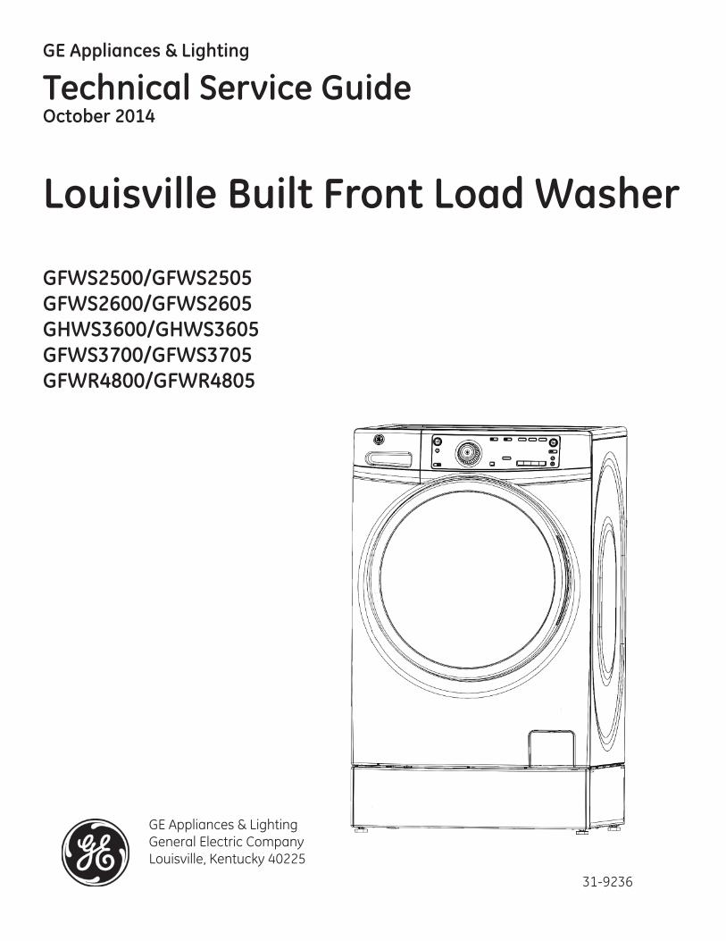
GE Appliances & Lighting Technical Service Guide October 2014 Louisville Built Front Load Washer GFWS2500/GFWS2505 GFWS2600/GFWS2605 GHWS3600/GHWS3605 GFWS3700/GFWS3705 GFWR4800/GFWR4805 31-9236 GE Appliances & Lighting General Electric Company Louisville, Kentucky 40225
-
Upload
khangminh22 -
Category
Documents
-
view
1 -
download
0
Transcript of Louisville Built Front Load Washer - Appliance Aid
GE Appliances & Lighting
Technical Service GuideOctober 2014
Louisville Built Front Load Washer
GFWS2500/GFWS2505GFWS2600/GFWS2605GHWS3600/GHWS3605GFWS3700/GFWS3705GFWR4800/GFWR4805
31-9236
GE Appliances & LightingGeneral Electric CompanyLouisville, Kentucky 40225

Safety Information
Important Safety Notice
The information in this service guide is intended for use by individuals possessing adequate backgrounds of electrical, electronic, and mechanical experience. Any attempt to repair a major appliance may result in personal injury and property damage. The manufacturer or seller cannot be responsible for the interpreta-tion of this information, nor can it assume any liability in connection with its use.
Warning
To avoid personal injury, follow OSHA Lock-out Tag-out Standard requirements controlling and maintain-ing a zero energy state. To perform necessary live power electrical diagnostics, electrical safety personal protective equipment (PPE) and barriers must be utilized to comply with OSHA electrical safety require-ments.
Reconnect all Grounding Devices
If grounding wires, screws, straps, clips ,nuts, or washers used to complete a path to ground are removed for service, they must be returned to their original position and properly fastened.
GE Appliances & Lighting
Technical Service Guide
Copyright © 2014
All rights reserved. This service guide may not be reproduced in whole or part in any form without written permission from the General Electric Company.
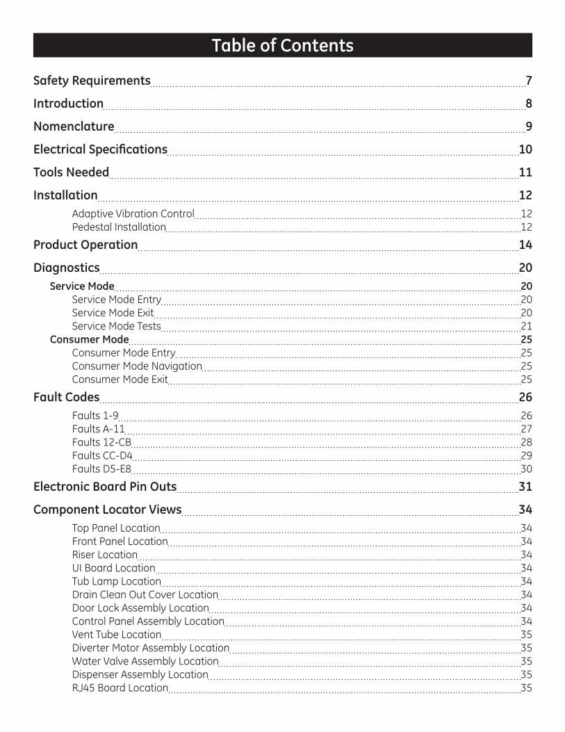
Table of Contents
Safety Requirements 7
Introduction 8
Nomenclature 9
Electrical Specifi cations 10
Tools Needed 11
Installation 12Adaptive Vibration Control 12Pedestal Installation 12
Product Operation 14
Diagnostics 20Service Mode 20
Service Mode Entry 20Service Mode Exit 20Service Mode Tests 21
Consumer Mode 25Consumer Mode Entry 25Consumer Mode Navigation 25Consumer Mode Exit 25
Fault Codes 26Faults 1-9 26Faults A-11 27Faults 12-CB 28Faults CC-D4 29Faults D5-E8 30
Electronic Board Pin Outs 31
Component Locator Views 34Top Panel Location 34Front Panel Location 34Riser Location 34UI Board Location 34Tub Lamp Location 34Drain Clean Out Cover Location 34Door Lock Assembly Location 34Control Panel Assembly Location 34Vent Tube Location 35Diverter Motor Assembly Location 35Water Valve Assembly Location 35Dispenser Assembly Location 35RJ45 Board Location 35

4
Overnight Dry Fan Location 35Pressure Sensor Location 35Top Counterweight Location 35IMC Board Location 35Stator Location 36Heater Location 36RJ45 Connection Location 36Rotor Location 36Hall Sensor Location 36Thermistor Connector 36Main Fill Hose Location 36Thermistor Location 36Vent Location 36Tub and Basket Exploded View 37Door Exploded View 37
Tub and Structure 38Door Assembly 38
Door Assembly Removal 38Door Frame 38
Door Frame Removal 38Door Glass 39
Door Glass Removal 39Door Hinge 39
Door Hinge Removal 39Door Handle 40
Door Handle Removal 40Door Cover 40
Door Cover Removal 40Door Cover Protect 40
Door Cover Protect Removal 41Door Lock Assembly 41
Door Lock Assembly Strip Circuit 41Door Lock Assembly Tests 41Door Lock Assembly Diagnostics 41Door Lock Assembly Removal 42
Tub Gasket 42Tub Gasket Removal 42Tub Gasket Reinstallation 42
Tub Lamp 43Tub Lamp Strip Circuit 43Tub Lamp Diagnostics 43Tub Lamp Removal 43
Control Panel 43Control Panel Removal 44
UI Board 44UI Board Strip Circuit 45UI Board Tests 45UI Board Diagnostics 45UI Board Removal 45

5
Button Tree 45Button Tree Removal 45
IMC Board 47IMC Board Tests 47IMC Board Diagnostics 47IMC Board Removal 47
RJ45 Board 48RJ45 Board Strip Circuit 48RJ45 Board Removal 48
Top Panel 49Top Panel Removal 49
Front Panel 49Front Panel Removal 49
Rear Panel 50Rear Panel Removal 50
Leveling Leg 50Riser 51
Riser Removal 51Front Tub 51
Front Tub Removal 51Inner Tub 53
Inner Tub Removal 53Balance Ring 53
Balance Ring Removal 53Baffl e 54
Baffl e Removal 54Rear Tub 55
Rear Tub Removal 55
Drive System 56Rotor 56
Rotor Removal 56Stator 56
Stator Strip Circuit 57Stator Diagnostics 57Stator Removal 57
Hall Sensor 58Hall Sensor Strip Circuit 58Hall Sensor Tests 58Hall Sensor Diagnostics 58Hall Sensor Removal 58
Fill System 59Water Valve Assembly 59
Water Valve Strip Circuit 59Water Valve Tests 59Water Valve Removal 59
Pressure Sensor 60Pressure Sensor Strip Circuit 60Pressure Sensor Chart 60
6
Pressure Sensor Tests 60Pressure Sensor Removal 60
Heater 61Heater Strip Circuit 61Heater Tests 61Heater Diagnostics 61Heater Removal 61
Thermistor 62Thermistor Chart 62Thermistor Tests 62Thermistor Removal 62
Dispenser Assembly 62Dispenser Assembly Tests 63Dispenser Assembly Diagnostics 63Dispenser Assembly Removal 63
Diverter Motor Assembly 64Diverter Motor Assembly Strip Circuit 64Diverter Motor Assembly Tests 64Diverter Motor Assembly Diagnostics 64Diverter Motor Assembly Removal 65
Wash System 66Drain Pump 66
Drain Pump Strip Circuit 66Drain Pump Tests 66Drain Pump Diagnostics 66Drain Pump Removal 66
Recirculation Pump 67Recirculation Pump Strip Circuit 67Recirculation Pump Tests 68Recirculation Pump Diagnostics 68Recirculation Pump Removal 68
Overnight Dry Fan 68Overnight Dry Fan Strip Circuit 68Overnight Dry Fan Tests 68Overnight Dry Fan Diagnostics 68Overnight Dry Fan Removal 68
Schematic 70
Index 71

7
Safety Requirements
Ge Factory Service Employees are required to use safety glasses with side shields, safety gloves and steel toe shoes for all repairs.
Steel Toed Work BootElectrically Rated Glove and
Dyneema® Cut Resistant Glove Keeper Dyneema® Cut Resistant Glove
Cut Resistant Sleeve(s) Plano Type Safety Glasses
Prescription Safety GlassesSafety Glasses must be ANSI
Z87.1-2003 compliant
Brazing Glasses
WARNINGPrior to disassembly of the front load washer to access components, GE Factory Service technicians are REQUIRED to follow the Lockout/Tagout (LOTO) 6 Step Process:
Step 1Plan and Prepare
Step 4Apply LOTTO device and lock
Step 2Shut down the appliance
Step 5Control (discharge) stored energy
Step 3Isolate the appliance
Step 6“Try It” verify the appliance is locked out

8
Introduction
Louisville built front load washers feature a new look, a new direct drive motor system, dual balance rings, combined machine control/inverter board, recirculation pump, overnight dry fan and integrated riser. Some features are not available on all models, see below.
All models have the following:
2 Electronic Boards• User Interface (UI) Board - The UI board provides user interface and software instructions defi ning
wash algorithms.
• Inverter Machine Control (IMC)) Board - The IMC board generates 3-phase DC voltage used to drive the motor and contains the relays used to operate loads.
Inverter Controlled Direct Drive Motor• Rotor• Stator• Hall Sensor
Dual Balance Rings• Front Balance Ring • Rear Balance Ring
Some Models have the following:
• LED Tub Lamp• Recirculation Pump• Overnight Dry Fan• Integrated Riser
Model Summary TableGFWS2500F GFWS2505F
GFWS2600F GFWS2605F
GFWR2700 / GFWR2705
GHWS3600/GHWS3605
GFWS3700 / GFWS3705
GFWR4800F GFWR4805F
Capacity 4.3 cubic ft 4.3 cubic ft 4.3 cubic ft 4.6 cubic ft 4.6 cubic ft 4.6 cubic ftRinse Levels 2 - normal/
extra2 - normal/extra
2 - normal/extra
3- normal/extra/max
3- normal/extra/max
3- normal/extra/max
Recirc Pump No No No No Yes YesTub Lamp No No No Yes No YesOver night Dry
No No No No No Yes
Integrated Riser
No No Yes No No Yes
9
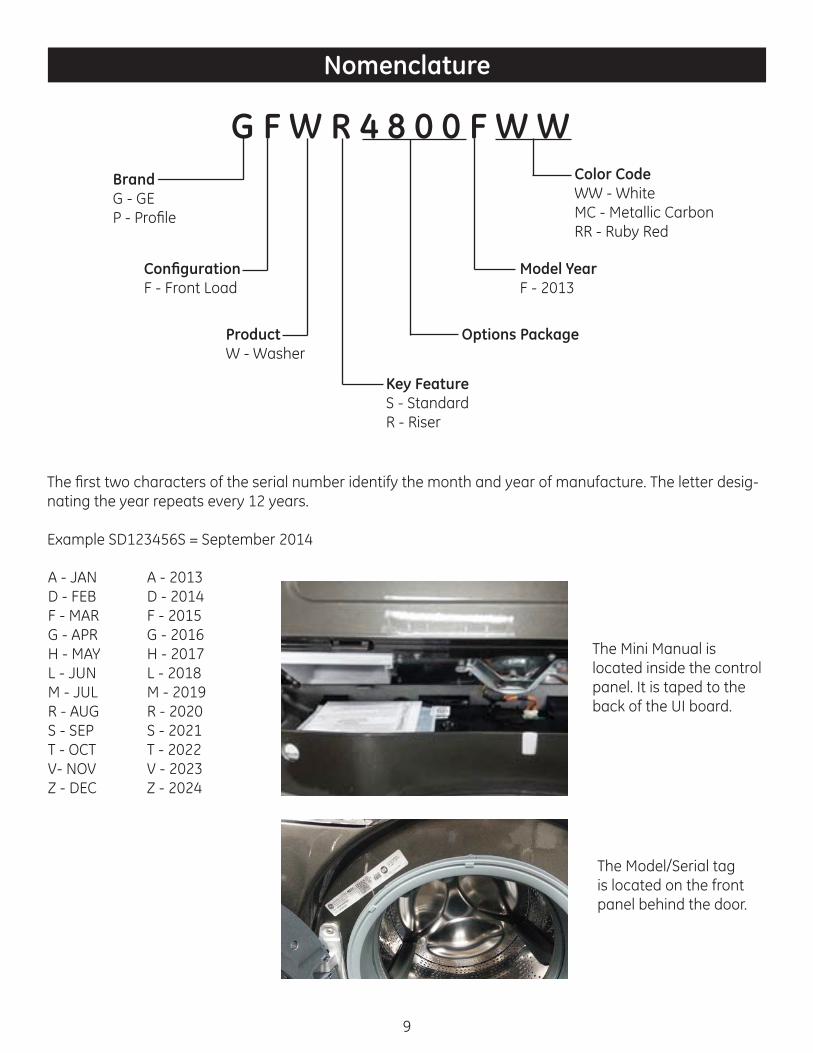
Nomenclature
G F W R 4 8 0 0 F W WBrandG - GEP - Profi le
Confi gurationF - Front Load
ProductW - Washer
Key FeatureS - StandardR - Riser
Options Package
Model YearF - 2013
Color CodeWW - WhiteMC - Metallic CarbonRR - Ruby Red
The fi rst two characters of the serial number identify the month and year of manufacture. The letter desig-nating the year repeats every 12 years.
Example SD123456S = September 2014
A - JAND - FEBF - MARG - APRH - MAYL - JUNM - JULR - AUGS - SEPT - OCTV- NOVZ - DEC
A - 2013D - 2014F - 2015G - 2016H - 2017L - 2018M - 2019R - 2020S - 2021T - 2022V - 2023Z - 2024
The Mini Manual is located inside the control panel. It is taped to the back of the UI board.
The Model/Serial tag is located on the front panel behind the door.

10
Electrical Specifi cations
Component Operating Voltage Resistance Wattage FrequencyDiverter Motor Motor - 120 VAC
Position Switch - 5 VDC1.4 kΩ N/A N/A
Door Lock Solenoid 120 VAC 50 Ω N/A N/ADrain Pump 120 VAC 14.8 Ω N/A N/AFlow Meter 12 VDC N/A N/A N/AHeater 120 VAC 14.6 Ω ~1000 N/AOvernight Dry Fan 12 VDC N/A N/A N/APressure Sensor 5 VDC N/A N/A See Chart * BelowRecirculation Pump 120 VAC 14.6 Ω N/A N/AStator 3 Phase DC 16.6 Ω per
phaseN/A N/A
Thermistor 5 VDC See Thermistor Chart
N/A See Chart ** Below
Tub Lamp 3.1 VDC N/A N/A N/AWater Valve 120 VAC 1 kΩ N/A N/A
Resistance Temperature36.5 k 32 °F14.7 k 68 °F12.0 k 77 °F9.8 k 86 °F8.0 k 95 °F6.6 k 104 °F.5 k 257°F
Water Level Name Amount of water in basket
Frequency
Empty N/A 44.67 HzSteam Reset -0.4” 43.68 HzSteam Set 0” 43.45 HzFoam Reset .68 “ 43.02 HzFoam Set 1.47” 42.54 HzMain Reset 1.86” 42.30 HzMain Set 2.85” 41.71 HzDoor Drain Reset 4.72” 40.57 HzDoor Drain Set 5.47” 40.11 HzOverfl ow Set 10.56” 37.04 Hz
Frequency Chart * Thermistor Chart **

11
Tools Needed
Large fl at head screwdriver
Small fl at head screwdriver
#2 Phillips head screwdriver
1/4” Nut driver
5/16” Nut driver
T20 Torx
T25 Torx
Hose clamp pliers
Slip joint pliers
Side cutter pliers
3/8” socket
1/2” socket
9/16” socket
10mm socket
12” extension
NO SPECIAL TOOLS NEEDED

Adaptive Vibration Control
This GE washer is equipped with Adaptive Vibration Control Technology. Using information about the fl oor, this system can reduce vibration and improve spin performance in some installations by adapting the spin cycle. The DEFAULT confi guration is specially designed to provide optimal performance across the widest range of fl oor types. Follow the procedure below to enable more specifi c adaptive settings. The washer can be returned quickly and easily to the DEFAULT confi guration at any time using the same procedure.
Floor Type Selection1. Place control in the idle state. (Make sure no cycles or options are selected but that the washers Power
is on.)2. Press and hold the Power and Spin keys at the same time for 3 seconds.3. Only the Power, Start and display lights will be lit in this mode.4. Pressing the Power key in this mode will return the control to the idle state and the defaults will be
restored.5. Rotate the selector knob to select the Floor Type, per the table below.
Display Floor TypeF0 DefaultF1 Concrete FloorF2 Second Floor, all surface typesF3 First Floor, Tile surfaceF4 First Floor, Linoleum surfaceF5 `First Floor, wood surface
6. Press the Start key to make selection.a. For riser models, the programming of the washers Adaptive Vibration Control is now complete.b. For all other models (GFWS2500, GFWS2505, GFWS2600, GFWS2605, GHWS3600, GHWS3605,
GFWS3700 and GFWS3705) – proceed to the pedestal selection (steps 7&8).7. Rotate the selector knob to select the Pedestal Type per table below.
Display Pedestal TypeP0 No Pedestal (Default Setting)P1 Pedestal
8. Press the Start key to make selection, the programming of the washers Adaptive Vibration Control is now complete.
Pedestal InstallationRemove the packaging. Flatten the product carton to use as a pad to lay the washer or dryer down on its side. Continue using the carton to protect the fi nished fl oor in front of the installation location.
Washer Prep1. Carefully lay down the washer on its back to access the leveling legs on its bottom.2. The washer shipping bolts must remain in place until the washer is returned to an upright position.
Installation

13
3. Use an adjustable wrench to remove the washer leveling legs.
Pedestal Prep1. Pull the pedestal drawer out as far as it will go.2. Remove screws from drawer slides. Slide drawer out of the base and set aside.
Install the pedestal to the washer1. Place the pedestal against the bottom of the unit. Check to be sure the drawer front is at the front of
the washer.2. Align the holes in the pedestal with the holes in the bottom of the unit. Use a 9/16 in. socket wrench to
install the 4 washer mounting bolts through the pedestal and into the unit – do not tighten.3. Slide the pedestal toward the unit until it is aligned front to back. Use a 9/16 in. socket wrench to
securely tighten the bolts.4. Stand the washer or upright. Move it close to its fi nal location.5. Make sure that the washer is level by placing a level on top. Check side to side and front to back.6. Use an open ended wrench to adjust the legs in and out. Tighten the lock nut against the bottom of the
pedestal. Note: To minimize vibration, the locking nuts must be tight.7. Reinstall the drawer.8. Remove the 4 shipping screws on the back side of the washer.
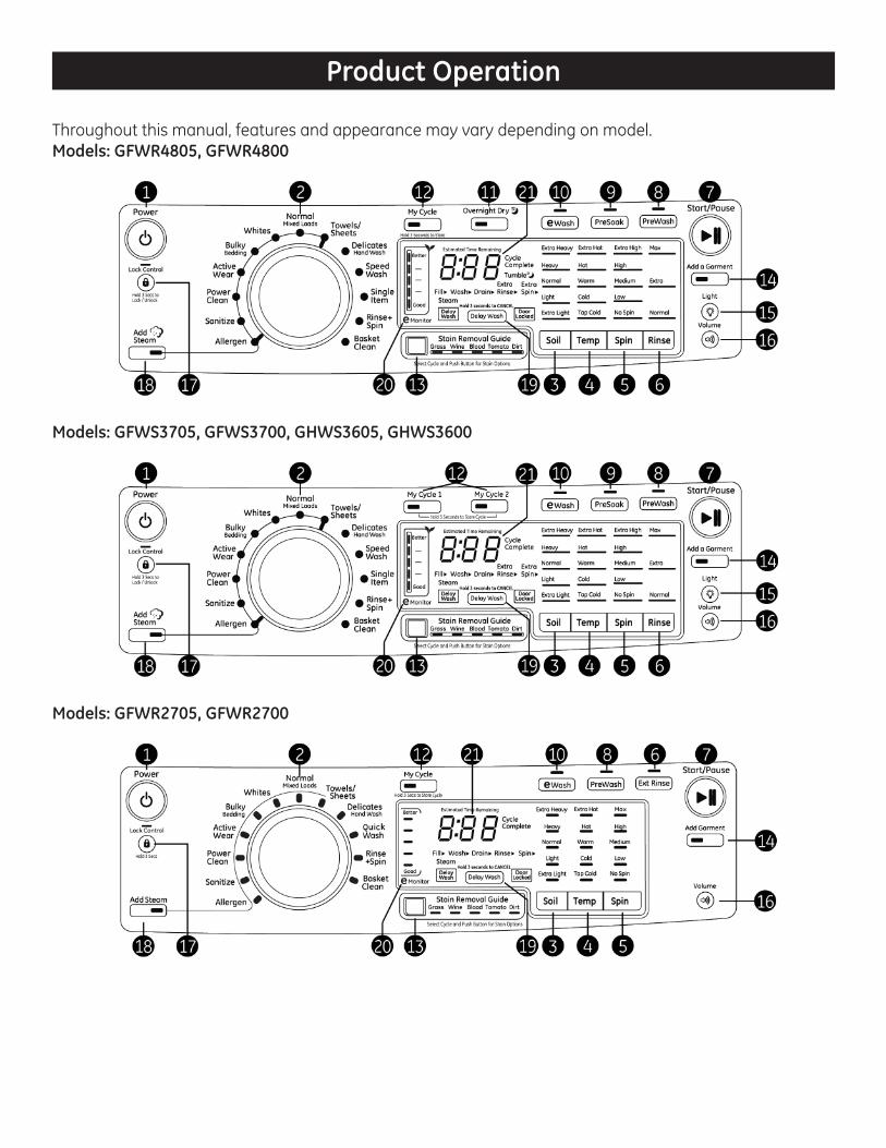
Throughout this manual, features and appearance may vary depending on model.Models: GFWR4805, GFWR4800
Models: GFWS3705, GFWS3700, GHWS3605, GHWS3600
Models: GFWR2705, GFWR2700
Product Operation

Models: GFWS2605, GFWS2600
Models: GFWS2505, GFWS2500
1. PowerPress to “wake up” the display. If the display is active, press to put the washer into standby mode.NOTE: Pressing Power does not disconnect the appliance from the power supply.
2. Wash CyclesThe wash cycles are optimized for specifi c types of wash loads. The chart below will help matchthe wash setting with the loads. The GentleClean™ lifters lightly tumble the clothes into the waterand detergent solution to clean the load.
Normal/MixedLoads*
For heavily to lightly soiled colorfast cottons, household linens, work and play clothes.
Whites* For heavily to lightly soiled white laundry, work and play clothes.Bulky Bedding* For large items such as comforters, blankets, small rugs and similar bulky items.Active Wear* For active sports, exercise and some casual wear clothes. Fabrics include
modern technology fi nishes and fi bers such as spandex, stretch and microfi -bers.
Power Clean* For heavily soiled items which require extra cleaning power.Sanitize* For increased water temperature which will sanitize and kill more than 99.9% of
many common bacteria found in home laundry.
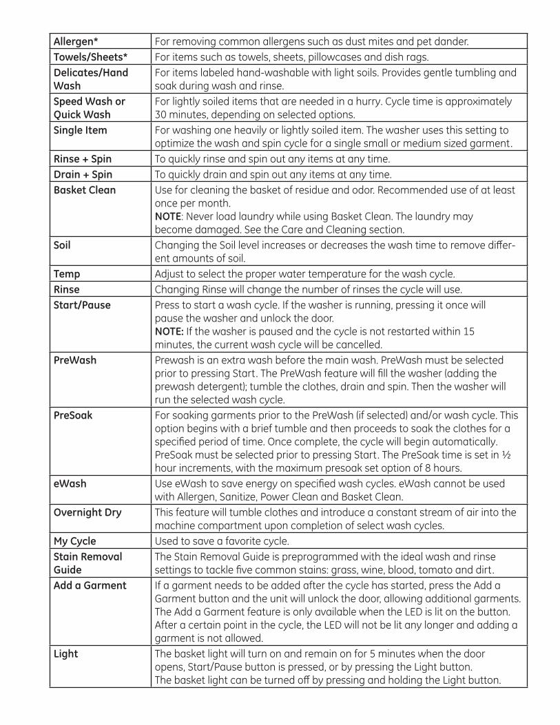
Allergen* For removing common allergens such as dust mites and pet dander. Towels/Sheets* For items such as towels, sheets, pillowcases and dish rags.Delicates/HandWash
For items labeled hand-washable with light soils. Provides gentle tumbling and soak during wash and rinse.
Speed Wash orQuick Wash
For lightly soiled items that are needed in a hurry. Cycle time is approximately 30 minutes, depending on selected options.
Single Item For washing one heavily or lightly soiled item. The washer uses this setting to optimize the wash and spin cycle for a single small or medium sized garment.
Rinse + Spin To quickly rinse and spin out any items at any time.Drain + Spin To quickly drain and spin out any items at any time.Basket Clean Use for cleaning the basket of residue and odor. Recommended use of at least
once per month.NOTE: Never load laundry while using Basket Clean. The laundry maybecome damaged. See the Care and Cleaning section.
Soil Changing the Soil level increases or decreases the wash time to remove diff er-ent amounts of soil.
Temp Adjust to select the proper water temperature for the wash cycle. Rinse Changing Rinse will change the number of rinses the cycle will use. Start/Pause Press to start a wash cycle. If the washer is running, pressing it once will
pause the washer and unlock the door.NOTE: If the washer is paused and the cycle is not restarted within 15minutes, the current wash cycle will be cancelled.
PreWash Prewash is an extra wash before the main wash. PreWash must be selected prior to pressing Start. The PreWash feature will fi ll the washer (adding the prewash detergent); tumble the clothes, drain and spin. Then the washer will run the selected wash cycle.
PreSoak For soaking garments prior to the PreWash (if selected) and/or wash cycle. This option begins with a brief tumble and then proceeds to soak the clothes for a specifi ed period of time. Once complete, the cycle will begin automatically.PreSoak must be selected prior to pressing Start. The PreSoak time is set in ½ hour increments, with the maximum presoak set option of 8 hours.
eWash Use eWash to save energy on specifi ed wash cycles. eWash cannot be used with Allergen, Sanitize, Power Clean and Basket Clean.
Overnight Dry This feature will tumble clothes and introduce a constant stream of air into the machine compartment upon completion of select wash cycles.
My Cycle Used to save a favorite cycle.Stain Removal Guide
The Stain Removal Guide is preprogrammed with the ideal wash and rinsesettings to tackle fi ve common stains: grass, wine, blood, tomato and dirt.
Add a Garment If a garment needs to be added after the cycle has started, press the Add aGarment button and the unit will unlock the door, allowing additional garments. The Add a Garment feature is only available when the LED is lit on the button. After a certain point in the cycle, the LED will not be lit any longer and adding a garment is not allowed.
Light The basket light will turn on and remain on for 5 minutes when the dooropens, Start/Pause button is pressed, or by pressing the Light button.The basket light can be turned off by pressing and holding the Light button.
17
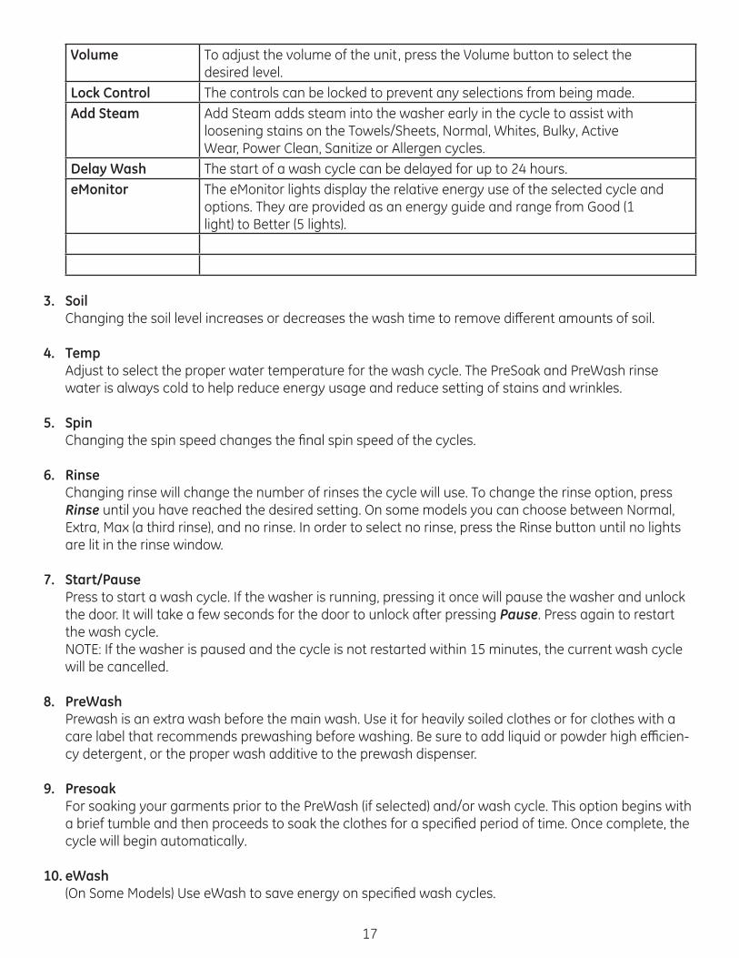
Volume To adjust the volume of the unit, press the Volume button to select thedesired level.
Lock Control The controls can be locked to prevent any selections from being made.Add Steam Add Steam adds steam into the washer early in the cycle to assist with
loosening stains on the Towels/Sheets, Normal, Whites, Bulky, ActiveWear, Power Clean, Sanitize or Allergen cycles.
Delay Wash The start of a wash cycle can be delayed for up to 24 hours.eMonitor The eMonitor lights display the relative energy use of the selected cycle and
options. They are provided as an energy guide and range from Good (1light) to Better (5 lights).
3. SoilChanging the soil level increases or decreases the wash time to remove diff erent amounts of soil.
4. TempAdjust to select the proper water temperature for the wash cycle. The PreSoak and PreWash rinse water is always cold to help reduce energy usage and reduce setting of stains and wrinkles.
5. SpinChanging the spin speed changes the fi nal spin speed of the cycles.
6. RinseChanging rinse will change the number of rinses the cycle will use. To change the rinse option, press Rinse until you have reached the desired setting. On some models you can choose between Normal, Extra, Max (a third rinse), and no rinse. In order to select no rinse, press the Rinse button until no lights are lit in the rinse window.
7. Start/PausePress to start a wash cycle. If the washer is running, pressing it once will pause the washer and unlock the door. It will take a few seconds for the door to unlock after pressing Pause. Press again to restart the wash cycle.NOTE: If the washer is paused and the cycle is not restarted within 15 minutes, the current wash cycle will be cancelled.
8. PreWashPrewash is an extra wash before the main wash. Use it for heavily soiled clothes or for clothes with a care label that recommends prewashing before washing. Be sure to add liquid or powder high effi cien-cy detergent, or the proper wash additive to the prewash dispenser.
9. PresoakFor soaking your garments prior to the PreWash (if selected) and/or wash cycle. This option begins with a brief tumble and then proceeds to soak the clothes for a specifi ed period of time. Once complete, the cycle will begin automatically.
10. eWash(On Some Models) Use eWash to save energy on specifi ed wash cycles.

18
11. Overnight Dry(On Some Models) Overnight Dry is available on the following cycles: Active Wear, Whites, Normal and Single Item. Overnight Dry is intended for smaller loads only. This feature is intended for use when clothes need to be washed, dried and ready to wear or fi nished the next morning. This feature will tumble clothes and introduce a constant stream of air into the machine compartment upon completion of select wash cycles. Clothes can be removed at any time by pressing Pause.
12. My Cycle(On some models there is a My Cycle 1 and My Cycle 2) To save a favorite cycle, set the desired settings for wash cycle, soil level, spin speed and wash temp settings and hold down the My Cycle button for 3 seconds. A beep will sound to indicate the cycle has been saved. To use your custom cycle, press the My Cycle button before washing a load. To change the saved cycle, set the desired settings and hold down the My Cycle button for 3 seconds
13. Stain Removal Guide(On Some Models) The Stain Removal Guide is pre-programmed with the ideal wash and rinse settings to tackle fi ve common stains: grass, wine, blood, tomato and dirt. To use this feature, select the desired wash cycle and then press the Stain Removal Guide button until the stain you want to remove is highlighted. Once selected, press the Start button to start the cycle.
14. Add A Garment(On Some Models) If you need to add a garment after the cycle has started, press the Add a Garment button and the unit will unlock the door, allowing additional garments. The Add a Garment feature is only available when the LED is lit on the button. After a certain point in the cycle, the LED will not be lit any longer and adding a garment is not allowed.
15. Light(On Some Models) The basket light will turn on and remain on for 5 minutes when the door opens, Start/Pause button is pressed, or by pressing the Light button.
16. VolumeTo adjust the volume of the unit, press the Volume button to select the desired level.
17. Lock ControlYou can lock the controls to prevent any selections from being made. Or you can lock or unlock the controls after you have started a cycle. Children cannot accidentally start the washer by touching buttons with this option selected. To lock the washer, press and hold the Lock Control button for 3 seconds.
18. Add SteamAdd Steam adds steam into the washer early in the cycle to assist with loosening stains on the Towels/Sheets, Normal, Whites, Bulky, Active Wear, Power Clean, Sanitize or Allergen cycles.
19. Delay WashYou can delay the start of a wash cycle for up to 24 hours. Press the Delay Wash button to choose the amount of time you want to delay the start of the wash cycle. Once the desired time is reached, press the Start button. The machine will count down and start automatically at the correct time.

19
20. eMonitorThe eMonitor lights display the relative energy use of your selected cycle and options. They are provid-ed as an energy guide and range from Good (1 light) to Better (5 lights). Some special cycles will not provide a display.
21. DisplayDisplays the approximate time remaining until the end of the cycle. NOTE: The cycle time is aff ected by how long it takes the washer to fi ll. This depends on the water pressure in your home. The “smart” timer “learns” the amount of time it takes to fi ll your washer and adjusts the total time accordingly.
Load Examples
Work Wear Linens Mixed Loads Delicates Speed Wash4 Jeans5 Work Wear Shirts5 Work Wear Pants
2 Bath Sheets10 Bath Towels/ 12Washcloths7 Hand Towels/ 2Terrycloth BathMatsOR2 Flat Queen-SizedSheets2 Fitted Queen-Sized Sheets4 Pillowcases
4 Pillowcases2 Hand Towels2 Flat Sheets/ 2Fitted Sheets2 Bath Towels/ 4WashclothsOR6 Shirts (Men’s orWomen’s)4 Pair Pants(Khakis or Twills)5 T-shirts7 Pairs of Boxers4 Pairs of ShortsOR6 T-shirts4 Pairs ofSweatpants4 Sweatshirts2 Hoodies7 Pairs of Socks
7 Bras7 Panties3 Slips2 Camisoles4 Nightgowns* Using a nylon mesh bag for small items is recommended.
2 Casual WearWork Shirts1 Pair Casual WearWork PantsOR3 Soccer Uniforms

Diagnostics
Service ModeThe control must be in the idle state (display lit but not in a cycle) to enter Service Mode. Keys are labeled diff erently on certain models. Press the following key sequence that matches the keys on the model being serviced.
Service Mode EntryModels with Ext Rinse key:Press and release the Ext Rinse key, then press and release the Delay Wash key, then press and release the Ext Rinse key, then press and release the Delay Wash key.
Models with Rinse key:Press and release the Rinse key , then press and release the Delay Wash key, then press and release the Rinse key, then press and release the Delay Wash key.
Navigate Service Mode• Rotate the cycle select knob CW to increase the test number.• Rotate the cycle select knob CCW to decrease the test number.• Press the Start key to enter a test.• Turn the cycle select knob to exit the test.
Service Mode ExitPress the Power key or disconnect power to unit. Service mode will automatically be exited after 30 minutes of inactivity.
Service Mode Tests
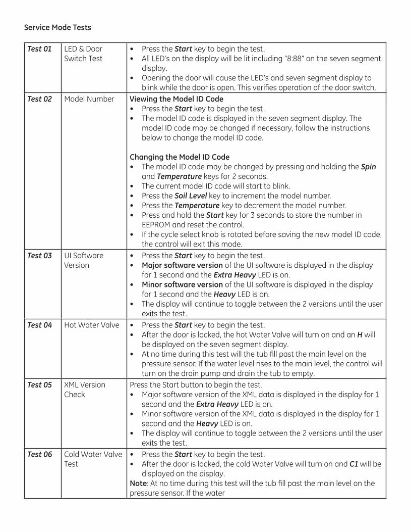
Test 01 LED & Door Switch Test
• Press the Start key to begin the test.• All LED’s on the display will be lit including “8:88” on the seven segment
display.• Opening the door will cause the LED’s and seven segment display to
blink while the door is open. This verifi es operation of the door switch.Test 02 Model Number Viewing the Model ID Code
• Press the Start key to begin the test.• The model ID code is displayed in the seven segment display. The
model ID code may be changed if necessary, follow the instructions below to change the model ID code.
Changing the Model ID Code• The model ID code may be changed by pressing and holding the Spin
and Temperature keys for 2 seconds.• The current model ID code will start to blink.• Press the Soil Level key to increment the model number.• Press the Temperature key to decrement the model number.• Press and hold the Start key for 3 seconds to store the number in
EEPROM and reset the control.• If the cycle select knob is rotated before saving the new model ID code,
the control will exit this mode.Test 03 UI Software
Version• Press the Start key to begin the test.• Major software version of the UI software is displayed in the display
for 1 second and the Extra Heavy LED is on.• Minor software version of the UI software is displayed in the display
for 1 second and the Heavy LED is on.• The display will continue to toggle between the 2 versions until the user
exits the test.Test 04 Hot Water Valve • Press the Start key to begin the test.
• After the door is locked, the hot Water Valve will turn on and an H will be displayed on the seven segment display.
• At no time during this test will the tub fi ll past the main level on the pressure sensor. If the water level rises to the main level, the control will turn on the drain pump and drain the tub to empty.
Test 05 XML Version Check
Press the Start button to begin the test.• Major software version of the XML data is displayed in the display for 1
second and the Extra Heavy LED is on.• Minor software version of the XML data is displayed in the display for 1
second and the Heavy LED is on.• The display will continue to toggle between the 2 versions until the user
exits the test.Test 06 Cold Water Valve
Test• Press the Start key to begin the test.• After the door is locked, the cold Water Valve will turn on and C1 will be
displayed on the display.Note: At no time during this test will the tub fi ll past the main level on the pressure sensor. If the water

Test 07 MC Software Version Check
• Press the Start key to begin the test.• Major software version of the MC software is displayed in the display
for 1 second and the Extra Heavy LED is on.• Minor software version of the MC software is displayed in the display
for 1 second and the Heavy LED is on.• The display will continue to toggle between the 2 versions until the user
exits the test. Test 08 Dispenser Test • Press the Start key to begin the test.
• After the door is locked, the dispenser will move to the Pre-wash position and pdt will be displayed on the display. Once the Pre-wash position has been reached the control will turn on the cold water valve.
• Press the Start key again, and the cold water valve will turn off and the dispenser will move to the detergent position and dtt will be displayed on the display. Once the detergent position has been reached the control will turn on the cold water valve.
• Press the Start key again, and the cold Water Valve will turn off and the dispenser will move to the softener position and Fdt will be displayed on the display. Once the softener position has been reached the control will turn on the cold water valve.
• Press the Start key again, and the cold Water Valve will turn off and the dispenser will move to the bleach position and bdt will be displayed on the display. Once the bleach position has been reached the control will turn on the cold water valve.
• Pressing Start again will restart the test.
Test 09 Inverter Software Version
• Press the Start key to begin the test.• Major software version of the inverter software is displayed in the
display for 1 second and the Extra Heavy LED is on.• Minor software version of the inverter software is displayed in the
display for 1 second and the Heavy LED is on.• The display will continue to toggle between the 2 versions until the user
exits the test.
Test 10 Tumble Test • Press the Start key to begin the test.• After the door is locked, A will be displayed in the display.• The tumble test will rotate the basket slowly in both directions.
Test 11 Spin Test • Press the Start key to begin the test.• After the door is locked, S will be displayed in the display. If the water
level is above empty at the start of the test, the tub will be drained to empty. The unit will begin spin, and display the spin speed in the display.
• The spin test will spin the wash basket at 500 RPM, 1000 RPM, 1100 RPM, and 1250 RPM, pressing the Start key advances to the next higher speed. Once a higher speed has been selected, if a lower speed is desired, T 11 must be exited and then re-entered.
Note: The seven segment display is only capable of displaying values from 000 - 999. To compensate for this, an A is used in the hundreds position to represent 1000, a b is used in the hundreds position to represent 1100, and a C is used in the hundred position to represent 1200. Ex. C11 = 1211 RPM.

Test 12 Drain Pump Test Press the Start key to begin the test.Drain pump comes on and P1 is displayed in the display.
Test 13 Heater Test • Press the Start key to begin the test.• Water temperature in °F is displayed in the display.• If water is present at the start of the test, the tub will be drained to
empty. Otherwise, the tub will fi ll to the appropriate water level and the heater will be turned on.
Note: If at any time during the test the water level gets too low, the heater will be turned off and the water valve will be turned on until the water level reaches a safe heater operating temperature, then the heater will be turned back on.
Test 14 Door Lock Test • Press the Start key to begin the test.• The door will lock and LC will be displayed in the display.• Pressing the Start key again will unlock the door and UL will be
displayed in the display.Test 15 Out of Balance
Test• Press the Start key to begin the test.• If water is present at the start of the test, the tub will be drained to
empty. • Washer spins at 100 RPM and OOB value will be displayed in the
displayed will display.Test 16 Pressure Sensor
Test• Press the Start key to begin the test.• If water is present at the start of the test, the tub will be drained to
empty. • Hot and cold water valves are energized and the pressure sensor
frequency is displayed in the display with 1 decimal point of resolution. (i.e.: XX.X Hz. See Pressure Sensor for frequencies.)
Note: The control will continue fi lling until the overfl ow level is reached, at that time the water valves will be turned off and the drain pump will be energized until the tub is drained to empty.
Test 17 Flow Meter Test • Press the Start key to begin the test.• If water is present at the start of the test, the tub will be drained to
empty. • Hot and cold water valves are energized and the fl ow rate in liters/
minute is displayed in the display with 1 decimal point of resolution. (i.e.: XX.X L/M)
Note: The control will continue fi lling until the overfl ow level is reached, at that time the water valves will be turned off and the drain pump will be energized until the tub is drained to empty.
Test 18 UI Critical Software Version Check
• Press the Start key to begin the test.• Major software version of the UI software is displayed in the display
for 1 second and the Extra Heavy LED is on.• Minor software version of the UI software is displayed in the display
for 1 second and the Heavy LED is on.The display will continue to toggle between the 2 versions until the user exits the test.

Test 19 Mc Critical Software Version Check
• Press the Start key to begin the test.• Major software version of the MC software is displayed in the display
for 1 second and the Extra Heavy LED is on.• Minor software version of the MC software is displayed in the display
for 1 second and the Heavy LED is on.The display will continue to toggle between the 2 versions until the user exits the test.
Test 20 Inverter Critical Software Version Check
• Press the Start key to begin the test.• Major software version of the Inverter software is displayed in the
display for 1 second and the Extra Heavy LED is on.• Minor software version of the Inverter software is displayed in the
display for 1 second and the Heavy LED is on.The display will continue to toggle between the 2 versions until the user exits the test.
Test 21 Fault Codes Fault codes are displayed in HEX format. No fault codes will display “- - -”.• Press the Start key to begin the test.• The fi rst fault code found in the fault code log is displayed in the
display.• Each press of the Start key will advance to the next fault code.Note: Fault Codes are cleared in Test 22.
Test 22 Clear Fault Codes • Press the Start key to begin the test.• If error codes are present Er will be displayed in the display. If no error
codes are present “- - -” will be displayed in the display.• Pressing and holding the Start key for 3 seconds sounds a tone and
clears the fault codes from memory. When the fault codes have been cleared, “- - -” will be displayed in the display.
Test 23 Clear EEPROM • Press the Start key to begin the test.• EE will be displayed in the display.• Pressing and holding the Start key for 3 seconds sounds a tone and
resets the EEPROM. When the EEPROM has been reset, “- - -” will be displayed in the display.
Note: Clearing the EEPROM will clear all existing fault codes but the model ID code will remain unchanged.
Test 24 Slow Ramp Test • Press the Start key to begin the test.• If water is present at the start of the test, the tub will be drained to
empty. • After the door is locked the motor will ramp up to 1250 RPM at 2 RPM
per second. The spin speed will be displayed in the display.Note; The seven segment display is only capable of displaying values from 000 - 999. To compensate for this, an A is used in the hundreds position to represent 1000, a b is used in the hundreds position to represent 1100, and a C is used in the hundred position to represent 1200. Ex. C11 = 1211 RPM.

25
Test 25 Low Flow (Steam) Water Valve Test
• Press the Start key to begin the test.• After the door locks the low fl ow water valve is energized and the
pressure sensor frequency is displayed in the display with 1 decimal point of resolution. (i.e.: XX.X Hz. See Pressure Sensor for frequencies.)
Note: The control will continue fi lling until the overfl ow level is reached, at that time the water valves will be turned off and the drain pump will be energized until the tub is drained to empty
Test 26 Recirculation Pump Test
• Press the Start key to begin the test.• The door locks and the cold water valve is energized until the main
water level is reached, at that time the cold water valve will be de-energized and the recirculation pump will be energized.
Note: If the water level falls below the main water level, the recirculation pump will de-energized.
Test 27 Overnight Dry Fan Test
• Press the Start key to begin the test.• The door locks, the overnight dry fan is energized, and onr is displayed
in the display.
Consumer Mode
Consumer mode is a special mode that allows the consumer to see fault codes.
Consumer Mode Entry• The control must be in the idle state to enter consumer mode.• Simultaneously press and hold Power, Soil Level and Temperature for 3 seconds.
Consumer Mode Navigation• Upon entering consumer fault code mode the control will display the number in HEX format.• Fault codes will only be displayed if they are active.• Pressing the Start key displays the next fault code in the fault code log.• If there are no fault codes in the log, the control will display “―” on the seven segment display.
Consumer Mode Exit• Press the Power key.• The control will return to the idle state 30 minutes after entering consumer fault code mode.• Disconnect power from the appliance.
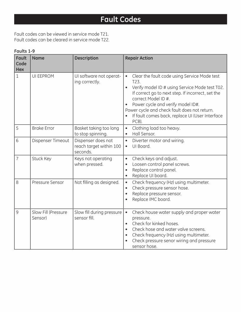
Fault Codes
Fault codes can be viewed in service mode T21.Fault codes can be cleared in service mode T22.
Faults 1-9Fault Code Hex
Name Description Repair Action
1 UI EEPROM UI software not operat-ing correctly.
• Clear the fault code using Service Mode test T23.
• Verify model ID # using Service Mode test T02. If correct go to next step. If incorrect, set the correct Model ID #.
• Power cycle and verify model ID#.Power cycle and check fault does not return.• If fault comes back, replace UI (User Interface
PCB).5 Brake Error Basket taking too long
to stop spinning.• Clothing load too heavy.• Hall Sensor.
6 Dispenser Timeout Dispenser does not reach target within 100 seconds.
• Diverter motor and wiring.• UI Board.
7 Stuck Key Keys not operating when pressed.
• Check keys and adjust.• Loosen control panel screws.• Replace control panel.• Replace UI board.
8 Pressure Sensor Not fi lling as designed. • Check frequency (Hz) using multimeter. • Check pressure sensor hose.• Replace pressure sensor.• Replace IMC board.
9 Slow Fill (Pressure Sensor)
Slow fi ll during pressure sensor fi ll.
• Check house water supply and proper water pressure.
• Check for kinked hoses.• Check hose and water valve screens.• Check frequency (Hz) using multimeter. • Check pressure senor wiring and pressure
sensor hose.

Faults A-11
Fault Code Hex
Name Description Repair Action
A Slow Fill (Flow Meter)
Slow fi ll during fl ow meter fi ll.
• Check house water supply and proper water pressure.
• Check for kinked hoses.• Check hose and water valve screens.• Check fl ow meter wiring.• Replace fl ow meter.• Replace IMC board.
B Drain Pump Water remaining it tub. • Check drain pump clean out.• Check installation instructions for proper
standpipe height.• Check pressure sensor frequency.
C Overfl ow Condition Water level went above the overfl ow level on 2 separate occasions.
• Check for water valve sticking open.• Check pressure sensor frequency.
D Inverter Communi-cation Timeout
The UI has not received the inverter status message in 10 seconds.
• Reset control boards by unplugging the washer for 30 seconds.
• Check the wiring between the IMC and UI boards.
• If still no operation, replace IMC (Inverter Machine Control).
E Door Open While the unit was running the door was detected as open.
• Ensure proper loading (Unbalanced loads can cause this).
• Check for door closing properly or warped door.
• Check door lock and wiring.F Door Unlocked While the unit was
running the door was detected as unlocked.
• Ensure proper loading (Unbalanced loads can cause this).
• Check for door closing properly or warped door.
• Check door lock and wiring.10 Max Water Volume More than 13 gallons
of water entered tub. Max Water Volume is reset each time the unit drains
• Check fl ow meter and fl ow meter wiring.• Check pressure sensor, pressure sensor
wiring and pressure sensor hose.• Replace pressure sensor.• Replace fl ow meter.• Replace IMC board.
11 Door Lock Error Door fails to lock after more than 3 attempts.
• Check for door closing properly or warped door.
• Check for broken or deformed door latch.• Check door lock and wiring.

Fault Code Hex
Name Description Repair Action
12 Door Unlock Error Door fails to unlock after more than 3 attempts.
• Check for door closing properly or warped door.
• Check for broken or deformed door latch.• Check door lock and wiring.
13 Flow Meter Error The water volume as read from the fl ow meter has not increased by 1.0 liters within 10 seconds after the fi ll has started.
• Check house water supply and proper water pressure.
• Check for kinked hoses.• Check hose and water valve screens.• Check fl ow meter and fl ow meter wiring.
14 Recirculation Pump Error
The frequency of the pressure sensor did not change while the recirculation pump was in operation.
• Check drain pump clean out.• Check recirculation pump in service mode.
68 Pressure Sensor Out of Range
Pressure sensor value is > 47 hz or < 35 hz.
• Replace pressure sensor.• Replace IMC board.
6A Thermistor Open Thermistor resistance too high.
• Check for open thermistor harness.• Check thermistor resistance.• Replace thermistor.• Replace IMC board.
6B Thermistor Short Thermistor resistance too low.
• Check for shorted thermistor harness.• Check thermistor resistance.• Replace thermistor.• Replace IMC board.
70 Target Volume Overfl ow
Target fi ll volume is greater than the MAX fi ll volume.
• Replace UI board.
72 Inverter Spin Redundancy
IMC detected basket rotation while the door was either unlocked or opened.
• Check door switch wiring.• Replace door lock assembly.• Replace IMC board.
C9 IMC Fault IMC Fault • If fault persists, or unit does not spin, replace IMC board.
CA IMC Fault IMC Fault • If fault persists, or unit does not spin, replace IMC board.
CB DC Bus Brownout DC bus voltage too low. • Check AC line voltage is correct.• If fault persists, or unit does not spin, replace
IMC board.
Faults 12-CB

Fault Code Hex
Name Description Repair Action
CC, CD, CE, CF
IMC Fault IMC Fault • Reset IMC by unplugging washer for 30 seconds. Attempt to operate Drain and Spin cycle.
• Enter Service Mode and check that fault has cleared.
• If fault persists, or unit does not spin, replace IMC (Inverter Machine Control).
D0 Basket Strike Detected
Basket hit side panel. • Unbalanced issue.
D1 Phase Current Error Motor phase current exceeds 4.5 amps for more than 5 minutes.
• Wash load too heavy.• Item caught between tubs.
D2 Locked Rotor Locked Rotor • Check the motor and basket is free to spin.• Reset IMC by unplugging washer from• 30 seconds. Attempt to operate a Drain and
Spin cycle.• Enter Service Mode and check that fault has
cleared.• Check harness and motor connections.• If fault persists, or unit does not spin, replace
IMC (Inverter Machine Control).D3 Hall Sensor Fault Issue with pulses from
the hall sensor.• Reset IMC by unplugging washer from 30
seconds. Attempt to operate a Drain and Spin cycle.
• Enter Service Mode and check that fault has cleared.
• If fault persists or unit does not spin, check hall sensor harness and module.
• If hall sensor and harness check OK, replace IMC (Inverter Machine Control).
D4 IMC Communica-tion Fault
Inverter failed to receive a valid commu-nication for 10 seconds.
• Reset control boards by unplugging the washer for 30 seconds.
• Check the wiring between the IMC and UI boards.
Faults CC-D4

30
D5D6D7D8D9DADBDCDDDEDFE0E1E2E3E4E5E6E7
IMC Fault IMC Fault • Reset IMC by unplugging washer for 30 seconds. Attempt to operate Drain and Spin cycle.
• Enter Service Mode and check that fault has cleared.
• If fault persists, or unit does not spin, replace IMC (Inverter Machine Control).
E8 Motor Over-temp Motor temperature exceeds 180 degrees F.
• Load too heavy.• Item caught between wash basket and outer
tub.
Faults D5-E8

Electronic Board Pin Outs
IMC Board
J701-1
J701-6
J702-1
J501-1
J603-1
J204-1
J102-1J1001-1
J101-4J8
03-1
J101
-1
IMC J101 pin1 – Chassis GND to IMC boardIMC J101 pin 2 – Neutral supply to IMC boardIMC J101 pin 3 – Line supply to IMC BoardIMC J101 pin 4 – Neutral connection to water valvesIMC J101 pin 5 – Not UsedIMC J101 pin 6 – Neutral connection to Door Lock, Drain Pump and Recirculation Pump
IMC J803 pin 1 – Not UsedIMC J803 pin 2 – Not UsedIMC J803 pin 3 – Switched line voltage to Heater
IMC J701 pin 1 – Door Lock Switch position input to IMC boardIMC J701 pin 2 – Not UsedIMC J701 pin 3 – Switched line voltage to Recirculation PumpIMC J701 pin 4 – Switched line voltage to Drain PumpIMC J701 pin 5 – Switched line voltage to Door Lock solenoidIMC J701 pin 6 – Switched line voltage to Diverter Motor

32
IMC J702 pin 1 - Switched line voltage to Hot ValveIMC J702 pin 2 - Switched line voltage to Cold ValveIMC J702 pin 3 - Switched line voltage to Steam ValveIMC J702 pin 4 - Not UsedIMC J702 pin 5 - Not UsedIMC J702 pin 6 - Not Used
IMC J501 pin 1 – DC GND to ThermistorIMC J501 pin 2 – DC GND to Pressure SensorIMC J501 pin 3 – DC GND to Diverter Position SwitchIMC J501 pin 4 – Not UsedIMC J501 pin 5 – Not UsedIMC J501 pin 6 – Diverter Position Switch input to IMC boardIMC J501 pin 7 – Thermistor input to IMC boardIMC J501 pin 8 – Not UsedIMC J501 pin 9 – Not UsedIMC J501 pin 10 – Presasure Sensor input to IMC boardIMC J501 pin 11 – Flow Meter input to IMC boardIMC J501 pin 12 – 5 VDC supply to Pressure SensorIMC J501 pin 13 – 12 VDC supply to Flow Meter
IMC J603 pin 1 – DC GND to UI boardIMC J603 pin 2 – Comm LineIMC J603 pin 3 – 7.5 VDC supply to UI boardIMC J603 pin 4 – 12 VDC supply to UI board
IMC J204 pin 1 – DC GND to Tub LampIMC J204 pin 2 – DC Supply to Tub Lamp
IMC J102 pin 1 – DC GND to Overnight Dry FanIMC J102 pin 2 – DC Supply to Overnight Dry Fan
IMC J1203A pin 1 – GND (Motor cable shield)IMC J1203A pin 2 – Stator Voltage (phase 3)IMC J1203A pin 3 – Stator Voltage (phase 2)IMC J1203A pin 4 – Stator Voltage (phase 1)
IMC J1001 pin 1 – DC GNDIMC J1001 pin 2 – Hall Sensor 3IMC J1001 pin 3 – Hall Sensor 2IMC J1001 pin 4 – Hall Sensor 1IMC J1001 pin 5 – 16 VDCIMC J1001 pin 6 – Not Used

33
UI Board Pin Out
J201
-1
UI J201 pin 1 - +12 VDC from IMC boardUI J201 pin 2 - Comm LineUI J201 pin 3 - +7.5 VDC from IMC boardUI J201 pin 4 - Not UsedUI J201 pin 5 - DC GND from IMC boardUI J201 pin 6 - DC GND to RJ45 boardUI J201 pin 7 - Comm LineUI J201 pin 8 - +12 VDC to RJ45 board
RJ45 Board
J203-1

34
Component Locator Views
Drain Clean Out Cover Location
Door Lock Assembly Location
UI Board Location
Tub
Lam
p Lo
catio
n
Riser Location
Control Panel Assembly Location
Top Panel Location
Front Panel Location
Front View

35
Top View
Dispenser Assembly Location
RJ45 Board Location
Overnight D
ry Fan Location
IMC Board Location
Pressure Sensor Location
Top Counterweight Location
Water Valve Assembly Location
Diverter Motor Assembly Location
Vent Tube Location

36
Heater Location Thermistor Location
Thermistor Connector
Rotor Location
Stator Location
Hall Sensor Location
RJ45 Connection Location
Main Fill Hose Location
Vent Location
Under Rotor
Under Stator
Rear View

37
Tub and Basket Exploded View
Gasket Nozzle Location
Rear Gasket Clamp
Bottom Counterweight
Front Tub Location
Top Counterweight Location
Overnight Dry Filter Location
ONR Hose Location
Door Exploded View
Door Striker Location
Door Cover Protect Location
Door Frame Location
Doo
r Hin
ge L
ocat
ion
Doo
r Hin
ge C
over
Loc
atio
n
Door Glass Location
Door Cover Location
Fron
t Gas
ket C
lam
p Lo
catio
n
Tub
Gas
ket L
ocat
ion
Inner Tub Location
Front Balance Ring Location
Rear Balance Ring Location
Baffl e Location
Rear Tub Location
O-Ring Seal Location
ON
R Spray Nozzle Location
38
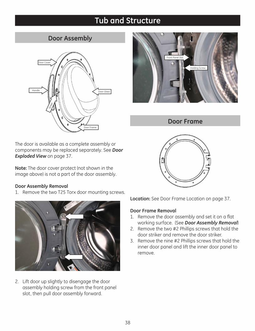
Door Assembly
Handle
Strik
er
Door Glass
Door Frame
Door Cover
The door is available as a complete assembly or components may be replaced separately. See Door Exploded View on pag e 37.
Note: The door cover protect (not shown in the image above) is not a part of the door assembly.
Door Assembly Removal1. Remove the two T25 Torx door mounting screws.
2. Lift door up slightly to disengage the door assembly holding screw from the front panel slot, then pull door assembly forward.
Holding Screw
Front Panel Slot
Door Frame
Location: See Door Frame Location on page 37.
Door Frame Removal1. Remove the door assembly and set it on a fl at
working surface. (See Door Assembly Removal)2. Remove the two #2 Phillips screws that hold the
door striker and remove the door striker.3. Remove the nine #2 Phillips screws that hold the
inner door panel and lift the inner door panel to remove.
Tub and Structure

39
#2 Phillips
#2 Phillips
#2 Phillips
#2 Phillips#2 Phillips
#2 Phillips#2 Phillips
#2 Phillips
#2 Phillips
#2 Phillips
#2 Phillips
Door Glass
Locator
Locator
Locator
Door Glass
Location: See Door Glass Location on page 37.
Door Glass Removal1. Remove the door assembly. (See Door Assembly
Removal)2. Remove the door frame. (See Door Frame
Removal)3. Lift Door glass to remove.
Note: When reinstalling the door, use locators shown above to properly align the door.
Door Hinge
Hinge Bushing
Hinge Bushing
Hinge Bushing
Hinge Bushing
Support Screw
Location: See Door Hinge Location on page 37.
Door Hinge Removal1. Remove the door assembly. (See Door Assembly
Removal)2. Remove the door frame. (See Door Frame
Removal)3. Remove the eight hinge plate screws and set
plate aside.
1/4” Hex
1/4” Hex
1/4” Hex
1/4” Hex
1/4” Hex
1/4” Hex
1/4” Hex
1/4” Hex
4. Remove hinge.
Note: When reinstalling the door hinge, ensure the hinge bushing are in place.
40
Door Handle
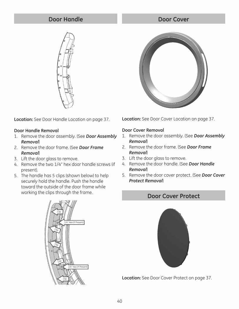
Location: See Door Handle Location on page 37.
Door Handle Removal1. Remove the door assembly. (See Door Assembly
Removal)2. Remove the door frame. (See Door Frame
Removal)3. Lift the door glass to remove.4. Remove the two 1/4” hex door handle screws (if
present).5. The handle has 5 clips (shown below) to help
securely hold the handle. Push the handle toward the outside of the door frame while working the clips through the frame.
Clip
Clip
Clip
Clip
Clip
1/4” Hex (If Present)
1/4” Hex (If Present)
Door Cover
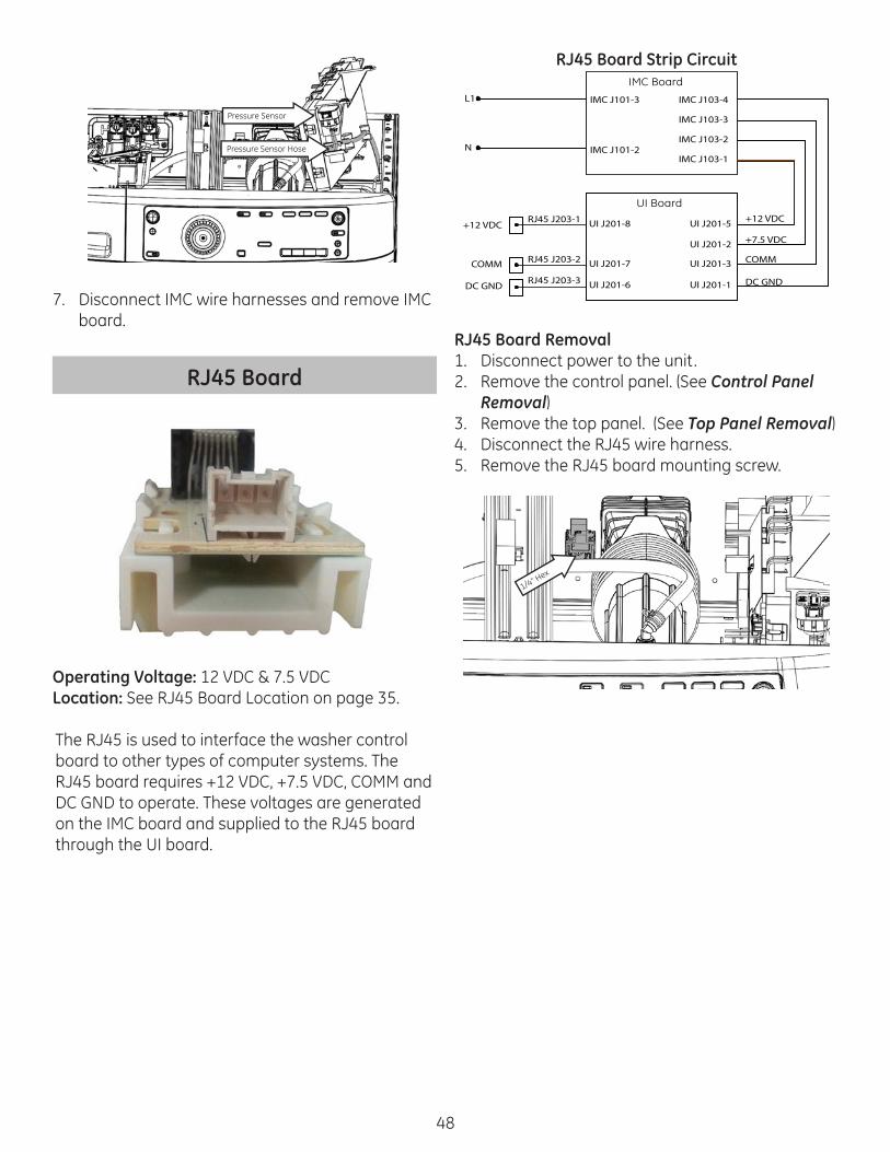
Location: See Door Cover Location on page 37.
Door Cover Removal1. Remove the door assembly. (See Door Assembly
Removal)2. Remove the door frame. (See Door Frame
Removal)3. Lift the door glass to remove.4. Remove the door handle. (See Door Handle
Removal)5. Remove the door cover protect. (See Door Cover
Protect Removal)
Door Cover Protect
Location: See Door Cover Protect on page 37.

41
Door Cover Protect Removal1. Remove the door assembly. (See Door Assembly
Removal)2. Remove the door frame. (See Door Frame
Removal)3. Lift the door glass to remove.4. Unsnap the twelve snaps to remove the door
cover protect.
Clip
Clip
Clip
Door Lock Assembly
Door Switch
Manual Unlock
Pin 3
Pin 1
Pin 2
Solenoid Operating Voltage: 120 VACSolenoid Resistance: 50 ΩLocation: See Door Lock Assembly Location on page 34.
The door lock assembly mechanically locks and unlocks the door, and gives door switch and door lock status to the IMC board. Each time the solenoid is operated the position of the mechanical lock and the door lock switch changes position.
The door can be manually unlocked by press-ing down on the manual unlock lever (See Image Above).
Door Lock Assembly Strip Circuit
IMC J701-6 D
To Neutral IMC J101-2
Diverter Motor
Locking and UnlockingNeutral is switched to the door lock assembly by the door switch. L1 is pulsed to the other side of the solenoid from IMC J701-5 when the door is locked or unlocked.
Door Position DetectionWhen the door switch is closed, neutral is present atIMC J701-5 indicating that the door is closed. When the door switch is open, neutral is not presentat IMC J701-5 indicating that the door is open.
Lock Position SensingWhen the door is locked the lock switch will be closed, causing neutral to be present at IMC J701-1 indicating that the door is locked. When the door is not locked the lock switch will be open and neutral will not be present at IMC J701-1 indicating the door is not locked.
Door Lock Assembly Tests1. Enter Service Mode.2. Run Test 14.
a. Press the Start button to begin the test.b. The door will lock and the LC will be displayed
in the display.c. Pressing the Start button again will unlock the
door and UL will be displayed in the display.
Door Lock Assembly DiagnosticsSolenoid Not Operating1. Disconnect power to unit.2. Disconnect IMC J701. While holding the door
switch in, check resistance between IMC J701-5 and IMC J101-6.a. If resistance is greater than 15Ω, check wiring
and replace door lock assembly if wiring is ok.b. If resistance is ~15Ω replace IMC board.

42
Door Lock Assembly Removal1. Disconnect power to the unit.2. Remove the front gasket clamp. (See Tub Gasket
Removal)3. Remove the two T-25 door lock mounting screws.4. Pull the door lock assembly out through the
opening.
Tub Gasket
Tub Lamp EntryGlass Clean & Recirc Entry
Alignment Arrow
Drain Holes
Location: See Tub Gasket Location on page 37.
The tub gasket is referenced as Main Gasket in IPC. There are two diff erent tub gaskets, one gasket is used on models with tub lamps and another is used on models without tub lamps.
There are fi ve drain holes located at the bottom of the gasket that allows water trapped in the gasket to drain back into the tub. When reinstalling the gasket these holes must line up with the holes in the front tub.
Tub Gasket Removal1. Disconnect power to unit. Using a fl at blade
screw driver or needle nose pliers, remove the front gasket clamp as shown below.
2. Remove the tub lamp if present. (See Tub Lamp Removal)
3. Remove the glass clean hose and recirculation hose if present.
Tub Lamp
Recirc HoseGlass Clean Hose
4. Loosen the 1/4” gasket clamp screw until the tub gasket can be pulled off .
5. Grasp the front edge of the gasket and pull it forward to remove.
Tub Gasket Reinstallation1. Align the drain holes at the bottom of the door
gasket with the drain holes in the front tub.
1/4” Hex

43
2. Starting at the bottom, attach the inside gasket lip to the front tub inside lip.
3. Ensure gasket drain holes remain aligned with the front tub drain holes.
4. Attach the outside gasket clamp lip to the outside lip of the front tub.
5. Reinstall the inside gasket clamp with the head of the clamp adjustment screw pointed up and posi-tioned at approximately the 3 o’clock position.
6. Tighten the inside clamp snugly, do not deform the clamp by over tightening.
7. Reinstall tub lamp and hoses.8. Attach the front panel gasket lip to the front
panel lip and reinstall clamp.9. Check for water leaks.
Tub Lamp
Operating Voltage: 3.1 VDCResistance: N/A Location: See Tub Lamp Location on page 34.
The tub lamp is an LED light. It is energized as soon as the door is opened or when the Light button is pressed. The lamp fades in intensity from on to off or off to on, transition time is approximately 1 second. A software timer limits the on time of the lamp to a maximum of 5 minutes. Pressing the Light button will reenergize the lamp and restart the 5 timer.
Note: Tub lamp leads cannot be removed from the lamp. The lamp harness is part of the tub lamp.
Tub Lamp Strip CircuitIMC J702-1
IMC J101-4
3.1 VDC
DC GND
L
Tub Lamp Diagnostics1. Press the Light button to energize the lamp.2. Check for 3.1 VDC between IMC J204 pins 1 & 2.
• If 3.1 VDC is present replace the tub lamp• If 3.1 VDC is not present replace the IMC
board.
Tub Lamp Removal 1. Disconnect power to the unit.2. Remove the front clamp of the tub gasket and
pull the gasket down to access the tub lamp. (See Tub Gasket Removal)
3. Carefully pull the tub lamp out of the top of the tub gasket.
Note: When reinstalling the tub lamp, ensure the tub lamp bottoms out in the gasket.
Control PanelControl Panel Components
#2 Phillips
T-20 TorxKnob Retainer
Knob
5/16” Hex
UI Board
Button Trees
#2 Phillips
Control Panel
Location: See Control Panel Location on page 34.
The control panel is a plastic housing with graphics. The button trees, knob, knob retainer and UI board must be obtained separately.

44
Control Panel Removal1. Remove the cycle select knob by pulling it for-
ward.2. Remove the knob retainer by pulling it forward.3. Remove the dispenser drawer by pulling drawer
outward while pressing down on the drawer release.
Drawer Release
4. Remove the one T-20 and two #2 Phillips control panel screws.
#2 Phillips#2 Phillips
T-20
5. Pull the left side of the control panel slightly forward (as shown below) and lift the left side up fi rst, then lift the right side up to remove.
6. Disconnect the UI wire harness and cut the UI wire tie.
Note: Install a new UI wire tie when reassembling.
UI Board
Operating Voltage 1: +12 VDCOperating Voltage 2: +7.5 VDCCOMM Voltage: Pulsating DC Location: See UI Board Location on page 34.
The UI (User Interface) board provides a means of communication between the washer and the con-sumer. The UI board contains software algorithms that control the washer.
When the UI board is replaced, a new model ID number has to be programmed. Once the UI board has been replaced, it may sometimes power up with all of the UI LED’s blinking. If this is the case, follow the steps below. If this is not the case, set the model ID in service mode Test 02.
1. Simultaneously press and hold the Temp and Spin buttons for 3 seconds.
2. Press the Soil button to increase or press the Temp button to decrease the model ID selection until the correct model ID number is displayed per the table on next page.

45
Appliance Model Number Model ID #GFWR4800F / GFWR4805F 3GFWS3600F / GFWS3605F 2GHWS2600F / GHWS2605F 1GFWS2500F / GFWS2505F 0GFWS3700F / GFWS3705F 5
UI Board Strip CircuitL1
N
IMC J101-3
IMC J101-2
IMC J603-4
IMC J603-3
IMC J603-2
IMC J603-1
+12 VDC
+7.5 VDC
COMM
DC GND
UI J201-5
UI J201-2
UI J201-3
UI J201-1
UI Board Tests• Run Test 01 for LED operation.• Run Test 02 for viewing and changing model ID
code.• Run Test 03 for UI software version.• Run Test 18 for UI Critical Software Version.
UI Board Diagnostics1. Check for 120 VAC at IMC J101 pins 2 & 3.
a. If 120 VAC is present go to step 2.b. If 120 VAC is not present check house supply
voltage.2. Check for 12 VDC between IMC J603 pins 1 & 4
and 7.5 VDC between IMC J603 pins 1 & 3.a. If either voltage is not present replace the IMC
board.b. If both voltages are present go to step 3.
3. Check for 12 VDC between UI J201 pins 1 & 5 and 7.5 VDC between UI J201 pins 3 & 5.a. If either voltage is not present, check wiring
between the UI board and the IMC board.b. If both voltages are present, replace the UI
board.
UI Board Removal1. Disconnect power to the unit.2. Remove the control panel. (See Control Panel
Removal)3. Remove the six 5/16” hex UI screws.
5/16” Hex
5/16” Hex 5/16” Hex
5/16” Hex5/16” Hex
5/16” Hex
4. Remove the UI board.
Button Tree
Tree (A)
Tree (B)
Tree (C)
Tree
(D)Tree
(E)
Tree
(F)
Button trees are used to press the micro switches on the UI board and to provide a light path between the LED’s on the UI board and the control panel. Five button trees are used.
Button Tree Removal1. Remove the control panel. (See Control Panel
Removal)2. Remove the UI board. (See UI Board Removal)3. Remove button trees:
Button Tree (A)1. Push the button tree to disengage the front clips.2. Pivot button tree up to disengage the rear clips.

46
Front Clip
Rear Clip
Front Clip
Front Clip
Rear Clip
Button Tree (B)1. Remove button tree (C).2. Disengage the three clips and lift button tree out.
ClipClip Clip
Button Tree (C)Lift up the outside of the button tree, then pivot it up until it disengages the inside clips.
Outside
Inside Clip
Inside Clip
Button Tree (D)Lift button tree to remove, no clips used.
Button Tree (D)
Button Tree (E)Push the button tree toward the bottom of the con-trol to disengage the clips, then lift button tree up.
Clip Clip
Button Tree (F)Lift clips to remove.
Clip
Clip

47
IMC Board
Operating Voltage: 120 VAC Location: See IMC Board Location on page 35.
The IMC board is two electronic systems in one board. One part of the IMC board converts 120 VAC into high voltage three phase DC to drive the mo-tor. The other part of the board converts 120 VAC to lower voltage DC voltages that are used by other components in the washer. The IMC also contains relays that operate the various other loads.
IMC Board Tests• Enter Service Mode.• Run Test 07 for MC Software Version.• Run Test 09 for Inverter Software Version.• Run Test 19 for MC Critical Software Version.• Run Test 20 for Inverter Critical Software Version.
IMC Board Diagnostics1. Check for 120 VAC at IMC J101 pins 2 & 3.
a. If 120 VAC is present, go to step 2.b. If 120 VAC is not present, check house supply
voltage.2. Check for 12 VDC between IMC J603 pins 1 & 4
and 7.5 VDC at IMC J603 pins 1 & 3.a. If both voltages are present, go to step 3.b. If either voltage is not present, replace IMC
board.3. Check for pulsating DC voltage between IMC J603
pins 1 & 2.a. If pulsating DC voltage is present, IMC board
is ok.b. If pulsating DC voltage is not present, replace
IMC board.
IMC Board Removal1. Disconnect power to the unit.2. Remove the control panel. (See Control Panel
Removal)3. Remove the top panel. (See Top Panel Removal) 4. Remove the three 1/4” IMC screws.
1/4” Hex
1/4” Hex
1/4” Hex
5. Slide the IMC board slightly away from the side panel to disengage the IMC board mounting studs. Mounting studs are shown below.
Rear View
Stud
Stud
6. Remove the pressure sensor hose from the pressure sensor and from the IMC channel.
48
Pressure Sensor
Pressure Sensor Hose
7. Disconnect IMC wire harnesses and remove IMC board.
RJ45 Board
Operating Voltage: 12 VDC & 7.5 VDC Location: See RJ45 Board Location on page 35.
The RJ45 is used to interface the washer control board to other types of computer systems. The RJ45 board requires +12 VDC, +7.5 VDC, COMM and DC GND to operate. These voltages are generated on the IMC board and supplied to the RJ45 board through the UI board.
RJ45 Board Strip Circuit
IMC J101-3
IMC J101-2
L1
N
IMC J103-4
IMC J103-3
IMC J103-2
IMC J103-1
DC GND
COMM
+7.5 VDC
+12 VDC
RJ45 J203-3
RJ45 J203-2
RJ45 J203-1
UI J201-1
UI J201-3
UI J201-2
UI J201-5
UI J201-6
UI J201-7
UI J201-8
DC GND
COMM
+12 VDC
IMC Board
UI Board
RJ45 Board Removal1. Disconnect power to the unit.2. Remove the control panel. (See Control Panel
Removal)3. Remove the top panel. (See Top Panel Removal)4. Disconnect the RJ45 wire harness.5. Remove the RJ45 board mounting screw.
1/4” Hex

49
Top Panel
Location: See Top Panel Location on page 34.
Top Panel Removal1. Remove the control panel. (See Control Panel
Removal)2. Remove the four 1/4” hex head top panel
screws.
1/4
Hex
1/4
Hex
1/4
Hex
1/4
Hex
3. Pull top panel forward slightly and lift up to remove.
Front Panel
Hinge Stiff ener Bracket
Front Panel
Location: See Front Panel Location on page 34.
Front Panel Removal1. Remove the control panel. (See Control Panel
Removal)2. To Reduce weight, remove the door assembly.
(See Door Assembly Removal)3. Remove the door lock assembly. (See Door Lock
Removal)4. Remove the tub gasket from the front panel. (See
Tub Gasket Removal)5. Remove the two 1/4” hex pump enclosure screws
and remove the pump enclosure.
1/4” Hex
1/4” Hex
6. If the washer is on a riser, remove the riser front panel. (See Riser Removal)

50
7. Remove the three 1/4” hex head screws on the bottom of the front panel.
14” H
ex
14” H
ex
14” H
ex8. Remove the four 1/4” hex head screws on the top
of the front panel.
1/4” Hex 1/4” Hex
1/4” Hex 1/4” Hex
9. Lift the front panel slightly upward and pull for-ward to remove.
Rear Panel
Rear Panel Removal1. Disconnect power and water supply to unit.2. Remove the nineteen 1/4” hex head rear panel
screws and remove the rear panel.
Leveling Leg
Leveling Leg
Jamb Nut
When adjusting or reinstalling the leveling legs, make sure the jamb nuts are tightened to prevent vibration.

51
Riser
Location: See Riser Location on page 34.
The riser is an integrated part of the washing machine and cannot be permanently removed. The purpose of the riser is to add an additional 7 inches of height to the washer.
Riser Removal1. Disconnect power and water supply to unit.
Move washer to an area that allows room to access the front and back side of the washer.
2. Remove control panel. (See Control Panel Removal)
3. Remove front panel. (See Front Panel Removal) 4. Remove rear panel. (See Rear Panel Removal) 5. Lay unit on its side and remove the four riser
mounting bolts.
9/16 Hex
9/16 Hex
9/16 Hex
9/16 Hex
Front Tub
Front Tub
Overnight Dry Filter
O-RIng Seal
Location: See Front Tub Location on page 37.
The front tub is mated to the rear tub with sixteen 3/8” hex head screws. An O-ring seal shown above (not part of the front tub) is placed between the two tubs to prevent water leaks.
On models that have the overnight dry feature, an air fi lter is housed inside the overnight dry hose collar as show above.
Front Tub Removal1. Disconnect power to the unit.2. Remove the control panel. (See Control Panel)3. Remove the top panel. (See Top Panel)

52
4. Remove the front panel. (See Front Panel)5. Remove wire tie (A) and cut the two wires ties (B)
from the top brace.6. Remove the two 1/4“ top brace screws and set
the top brace aside.
1/4” Hex
1/4” Hex
Wire Tie A
1/4” Hex
Wire Tie B
7. Remove the glass clean hose, recirculation pump hose (if present) and tub lamp (if present).
Tub Lamp
Glass Clean Hose
Recirc Pump Hose
8. Remove the nine 1/4” hex head front brace screws and the 7/16” hex head control panel stud.
1/4” Hex1/4” Hex
1/4” Hex
1/4” Hex
1/4” Hex1/4” Hex
1/4” Hex1/4” Hex
1/4” Hex
7/16” Hex
9. Pull the glass clean hose and recirculation hose (if present) out of the wire ties on the front brace and set front brace aside.
Recirculation Pump Hose Glass Clean Hose
10. Remove the counterweights. 11. Remove the dispenser assembly. (See Dispenser
Assembly)12. Remove the top damper pins from both front
dampers and tilt dampers toward the side panels.
RF DamperLF Damper
13. Remove the sixteen 3/8” hex head tub bolts and carefully remove the front tub out through the front of the cabinet.
14. If replacing the front tub, remove the tub gasket. (See Tub Gasket Removal)
Note: When reinstalling the front tub, ensure the O-Ring is in place. When reinstalling bolts, do not fully tighten tub bolts until all bolts are snugly in place, then tighten tub bolts in a cross pattern to ensure front tub pulls up evenly against the rear tub.

53
Inner Tub
Front Balance Ring
Rear Balance Ring
Tub
Baffl
e
Basket
Location: See Inner Tub Location on page 37.
The basket and trunnion assembly consists of the wash basket and trunnion only. The front balance ring, rear balance ring and baffl es are not a part of the assembly.
Inner Tub Removal1. Remove the front tub. ( See Front Tub Removal)2. Remove the Rear Panel. (See Rear Panel Remov-
al)3. Remove the rotor. (See Rotor Removal)4. Pull the inner tub out through the front of
washer.
Balance Ring
Location: See Front Balance Ring Location and See Rear Balance Ring Location on page 37.
Balance rings contain food grade silicone and several steel ball bearings that counteract unbal-anced loads by shifting the liquid and ball bearings to the opposite side of the unbalance weight.
If a balance ring has leaked, an oily residue can be felt on the wash basket and clothing. Silicone residue can be removed by cleaning with soap and water and running the basket clean cycle. The washer will also make a loud rattling noise and have excessive vibration in spin. It is unlikely that high speed spin can be achieved with a damaged balance ring.
The balance rings are semi-transparent which allows the liquid level to verifi ed as shown below.
Liquid Levelq
It is normal for the tub assembly to move around quite a bit until the ball bearings have become correctly positioned, especially between 150 – 300 rpm. Once the ball bearings are in position the tub assembly movement will lessen greatly.
Balance Ring RemovalThe inner tub must be removed in order to replace the rear balance ring. (See Inner Tub Removal)
The front balance ring can be replaced by removing the front tub only. (See Front Tub Removal.)
To remove the balance ring from the basket and trunnion assembly, remove the six T 20 Torx screws that hold the balance ring in place and pull the balance ring out.

54
Baffl e
Screw Goes HereClip
ClipClip
Clip
Clip
Clip
Location: See Baffl e Location on page 37.
Baffl es are secured to the inner tub with locking clips and a single stainless steel #2 Phillips head screw. The baffl e screw can be accessed without removing the inner tub by going through the outer tub at the overnight dry collar.
Outer Tub Collar
Collar
On models with the Overnight Dry Feature, the baffl e screw can be accessed by removing the overnight dry hose.
On models without the Overnight Dry Feature the Baffl e Replacement Kit WH49X20172 can be used. The kit includes a template and drill bit to drill an access hole through the outer tub. A rubber cap and hose clamp are used to seal off the tub collar after the repair is completed.
Baffl e Removal1. Disconnect power to unit.2. Remove the control panel. (See Control Panel
Removal)3. Remove the top panel. (See Top Panel Removal)4. For overnight dry models, loosen the 5/16”
overnight dry hose clamp and remove the hose.
5/16” Hex Clamp Screw
5. For overnight dry models, remove the overnight dry fi lter from the collar.
6. For non-overnight dry models, follow instruc-tions in the Baffl e Replacement Kit to access the baffl e screw.
7. Rotate the wash basket to line up the baffl e screw and tub tab with the tub collar as shown below.
8. Remove the # 2 Phillips head baffl e screw.9. Using a fl oat blade screwdriver, bend the tub tab
up.10. Slide the baffl e toward the rear to disengage
the baffl e clips, then pull baffl e away from wash basket to remove.
Remove #2 Phillips ScrewBend Tub Tab Up
Baffl e Clip
Baffl e Clip
Note: When baffl e is reinstalled on non-overnight dry models, ensure the rubber collar cover and clamp is installed.

55
Rear Tub
O-Ring Seal
Rear Tub
Sump Collar
Rear Bearing
Location: See Rear Tub Location on page 37.
The rear bearing is molded into the rear tub and cannot be replaced separately. The O-Ring seal is not part of the rear tub, and it is not neces-sary to replace the O-Ring when rejoining the two tubs unless the seal is damaged. No lubrication is required for the O-Ring.
Rear Tub Removal1. Disconnect power to unit.2. Remove the front tub.
(See Front Tub Removal)3. Remove the IMC board. (See IMC Board Remov-
al)4. Remove the dispenser assembly (See Dispenser
Assembly)5. Remove the inner tub.
(See Inner Tub Removal)6. Remove the back cover. (See Back Cover
Removal)7. Remove the rotor. (See Rotor Removal)8. Remove the stator. (See Stator Removal)9. Remove the hall sensor. (See Hall Sensor
Removal)10. Remove the heater and thermistor wire harness-
es.
Heater Connections
Thermistor Harness
11. Remove the four 1/4” bottom rear brace screws and set the bottom rear brace aside.
1/4” Hex
1/4” Hex
1/4” Hex
1/4” Hex
12. Remove the pressure sensor hose and the air chamber hose from the air chamber.
13. Remove the two 1/4” hex air chamber screws and remove the air chamber.
Pressure Sensor Hose
Air Chamber Hose
1/4” Hex
1/4” Hex
14. Remove the rear upper damper pins.15. Unhook both rear springs from the rear tub and
remove rear tub.

56
Rotor
Location: See Rotor Location on page 36.
The rotor is the mechanical portion of the motor system that applies rotational force to the wash basket. A series of magnets around the perimeter of the rotor interact with the electromagnetic fi eld created by current fl ow through the stator windings.This interaction causes a pushing and pulling eff ect on the rotor, causing the rotor to rotate.
Rotors are inherently reliable components. Most issues will be related to cracked or missing magnets, a cracked housing or out of roundness.These issues will likely not aff ect washer perfor-mance but will create noisy operation. Inspect magnets and housing and verify rotor is not out of round.
Rotor Removal1. Disconnect power to the unit.2. Remove the rear panel. (See Rear Panel Removal)3. Remove the 1/2” standard thread rotor bolt and
pull rotor forward.
Note: The rotor is hard to remove because of the interaction of the rotor magnets with the stator, rock the rotor back and forth while pulling it forward.
Stator
Phase 2 Phase 1
Phase 3
Operating Voltage: 3 Phase DCResistance: 16.6 Ω phase-phaseLocation: See Rotor Location on page 36.
The stator is wound in such a way as to produce three changing electromagnetic fi elds that interact with the magnets of the rotor to produce rotational force. The electromagnetic fi elds are created by passing current through the phase wires. Each current is phased so that its electromagnetic fi eld is opposite polarity of the rotor magnets.
Drive System

57
Stator Strip CircuitL1
N
IMC J101-3
IMC J101-2
IMC J1203A - 4
213
IMC J1203A - 3
IMC J1203A - 2
IMC J1203A - 1
Stator DiagnosticsStator voltage cannot be tested. If there are any problems detected with the stator, the inverter will stop supplying voltage to it . Do the following to test the stator.1. Verify the phase wires are properly connected to
the stator.2. Check stator resistance by disconnecting IMC
J1203A and connect the meter lead between each phase wire. Resistance should be ~ 16.6 Ω.
Stator Removal1. Disconnect power to the unit.2. Remove the rear panel. (See Rear Panel Remov-
al)3. Remove the 1/2” standard thread rotor nut and
pull the rotor forward.
Note: The rotor is hard to remove because of the interaction of the rotor magnets with the stator, rock the rotor back and forth while pulling forward to remove.
4. Remove the three 1/2” hex stator bolts.
1/2” Hex
1/2” Hex
1/2” Hex
5. Tilt the stator and rest it on the brace as shown below.
6. Remove the hall sensor. (See Hall Sensor Removal)
7. Disconnect the three pin wire connector.
Note: When reinstalling this connector, make sure the connector pins engage properly with the stator and push the connector until it is fully seated.

58
Hall Sensor
Harness Connector
Fron
t Clip
Rear Clip
Hal
l A
Hal
l B
Hal
l C
Fron
t Clip
Operating Voltage: 16 VDCResistance: N/ALocation: See Hall Sensor Location on page 36.
The hall sensor assembly is used to measure rotorRPM. Three hall sensors are used to provide better resolution. The hall sensor assembly snaps onto the stator and is oriented so that the hall sensors are in very close proximity to the rotor magnets.
A hall sensor is a transducer that varies its output voltage in response to a magnetic fi eld. Voltage output is changed in the hall sensor each time a rotor magnet passes by. This changing voltage is detected by the IMC board and is used to determine rotor speed.
Hall Sensor Strip Circuit
L1
N
IMC J101-3
IMC J101-2
IMC J1001 - 1
Hall Sensor
IMC J1001 - 3
IMC J1001 - 2
IMC J1001 - 4
IMC J1001 - 5
1
2564
Hall Sensor Tests1. Remove the door striker and insert it into the
door lock assembly.2. Enter service mode and select Test 11.
3. Press the Start key.4. Press and hold the door switch and wait for
“000“ to appear in the display.5. Rotate the wash basket by hand in either direc-
tion. As the basket spins, the RPM value will be displayed in the display.
Hall Sensor Diagnostics1. Verify hall senor mounting. The hall sensor may
have become unclipped.2. Check wiring between hall sensor assembly and
IMC board.3. If hall sensor mounting and wiring are good,
replace the hall sensor.
Hall Sensor Removal1. Disconnect power to the unit.2. Remove the rear panel. (See Rear Panel Remov-
al)3. Remove the rotor. (See Rotor Removal)4. Remove the stator. (See Stator Removal)5. Disconnect the hall sensor harness and unclip
the front hall sensor clips fi rst then unclip the rear clip.
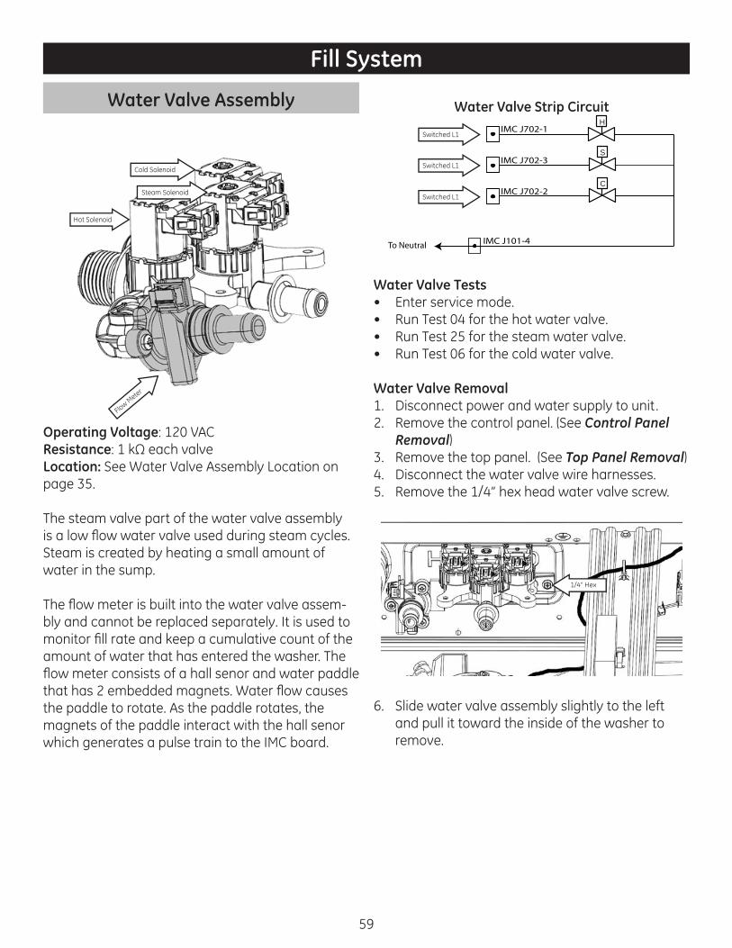
59
Water Valve Assembly
Hot Solenoid
Steam Solenoid
Cold Solenoid
Flow Meter
Operating Voltage: 120 VACResistance: 1 kΩ each valveLocation: See Water Valve Assembly Location on page 35.
The steam valve part of the water valve assembly is a low fl ow water valve used during steam cycles. Steam is created by heating a small amount of water in the sump.
The fl ow meter is built into the water valve assem-bly and cannot be replaced separately. It is used to monitor fi ll rate and keep a cumulative count of the amount of water that has entered the washer. The fl ow meter consists of a hall senor and water paddle that has 2 embedded magnets. Water fl ow causes the paddle to rotate. As the paddle rotates, the magnets of the paddle interact with the hall senor which generates a pulse train to the IMC board.
Water Valve Strip Circuit
IMC J702-3
To Neutral
IMC J702-1H
S
IMC J702-2C
IMC J101-4
Switched L1
Switched L1
Switched L1
Water Valve Tests• Enter service mode.• Run Test 04 for the hot water valve.• Run Test 25 for the steam water valve.• Run Test 06 for the cold water valve.
Water Valve Removal1. Disconnect power and water supply to unit.2. Remove the control panel. (See Control Panel
Removal)3. Remove the top panel. (See Top Panel Removal)4. Disconnect the water valve wire harnesses.5. Remove the 1/4” hex head water valve screw.
1/4” Hex
6. Slide water valve assembly slightly to the left and pull it toward the inside of the washer to remove.
Fill System
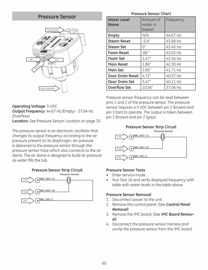
60
Pressure Sensor
Tan
Brown
Grey
Mounting Clip
Hose Connection
Operating Voltage: 5 VDCOutput Frequency: 44.67 Hz (Empty) - 37.04 Hz (Overfl ow)Location: See Pressure Sensor Location on page 35.
The pressure sensor is an electronic oscillator that changes its output frequency according to the air pressure present on its diaphragm. Air pressure is delivered to the pressure sensor through the pressure sensor hose which also connects to the air dome. The air dome is designed to build air pressure as water fi lls the tub.
Pressure Sensor Strip Circuit
IMC J501-10
IMC J501-12
IMC J501-2
5 VDC
Output
GND
Pressure Sensor
Pressure Sensor Chart Water Level Name
Amount of water in basket
Frequency
Empty N/A 44.67 HzSteam Reset -0.4” 43.68 HzSteam Set 0” 43.45 HzFoam Reset .68 “ 43.02 HzFoam Set 1.47” 42.54 HzMain Reset 1.86” 42.30 HzMain Set 2.85” 41.71 HzDoor Drain Reset 4.72” 40.57 HzDoor Drain Set 5.47” 40.11 HzOverfl ow Set 10.56” 37.04 Hz
Pressure sensor frequency can be read between pins 1 and 2 of the pressure sensor. The pressure sensor requires a 5 VDC between pin 2 (brown) and pin 3 (tan) to operate. The output is taken between pin 1 (brown) and pin 2 (grey).
Pressure Sensor Strip Circuit
IMC J501-10
IMC J501-12
IMC J501-2
5 VDC
Output
GND
Pressure Sensor
Pressure Sensor Tests• Enter service mode.• Run Test 16 and verify displayed frequency with
table with water levels in the table above.
Pressure Sensor Removal1. Disconnect power to the unit.2. Remove the control panel. (See Control Panel
Removal)3. Remove the IMC board. (See IMC Board Remov-
al)4. Disconnect the pressure sensor harness and
unclip the pressure sensor from the IMC board.

61
Hose Connection
Heater
Heater Bracket
Heater
Heater Shield
Operating Voltage: 120 VACResistance: 14.6 ΩCurrent: 8.2 AmpsWatts: 986Location: See Pressure Sensor Location on page 35.
The heater is used on the “Allergen” and “Sanitize” cycles or any cycle that allows “Add Steam”. Add steam is a cycle modifi er that causes the washer to produce steam and tumble for approximately 20 minutes at the beginning of the cycle. Once the steam cycle has completed, the normal wash cycle begins.
Heater Strip CircuitIMC J803-3
IMC J501-2
Switched L1
Heater
Door Lock Pin 2
Door Lock Pin 1
To Neutral
Heater Tests1. Enter service mode.2. Run Test 13.3. Verify heater operation by watching the thermis-
tor temperature on the display.
Heater Diagnostics1. Operate the heater in service mode.2. Check current draw on the wire connected to
IMC J803 pin 2 (navy with white tracer).a. If current draw is ~ 8 amps heater is operating
properly.b. If current draw is 0 amps go to step 3.
3. Check for 12 VAC between IMC J802 pin3 and IMC J101 pin 2.a. If 120 VAC is not present replace the IMC
board.b. If 120 VAC is present go to step 4.
4. Check for 120 VAC at the heater.a. If 120 VAC is present replace the heater.b. If 120 VAC is not present check wiring to
heater.
Heater Removal1. Disconnect power to the unit.2. Remove the rear panel. (See Rear Panel Remov-
al)3. Disconnect the heater wires.4. Remove the 10 mm heater nut.5. Pull the heater out to remove.
Heater Connections
8 mm Nut

62
Thermistor
Operating Voltage: 5 VDCResistance: See Chart BelowLocation: See Thermistor Location on page 36.
Thermistor Chart36.5 k 32 °F14.7 k 68 °F12.0 k 77 °F9.8 k 86 °F8.0 k 95 °F6.6 k 104 °F.5 k 257°F
Thermistor Tests1. Enter service mode.2. Run Test 13.3. Verify temperature change while the heater is
on.
Thermistor Removal1. Disconnect power to the unit.2. Remove the rear cover. (See Rear Cover Remov-
al).3. Disconnect the thermistor harness.4. Remove thermistor.Note: When reinstalling the thermistor ensure the thermistor O-Ring is in place.
Dispenser Assembly
Flow Restricter
O-Ring
Location: See Dispenser Assembly Location on page 35.
The dispenser assembly is used to dispense deter-gent, bleach and fabric softener into the wash load. Additives are placed in the detergent dispenser drawer (shown below) where they will be fl ushed into the wash at the appropriate time.
Water is routed to the dispenser assembly any time a water valve is energized. A water diverter is used to direct the incoming water to one of four compart-ments as shown below.
Diverter
Pre-wash
Main Wash
Fabric Softener
Bleach
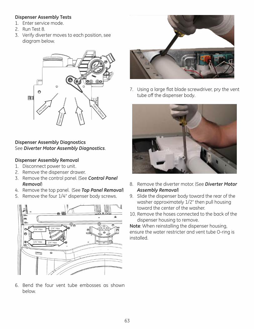
63
Dispenser Assembly Tests1. Enter service mode.2. Run Test 8.3. Verify diverter moves to each position, see
diagram below.
Pre-wash
Mai
n W
ash Bleach
Fabric Softener
Dispenser Assembly DiagnosticsSee Diverter Motor Assembly Diagnostics.
Dispenser Assembly Removal1. Disconnect power to unit.2. Remove the dispenser drawer.3. Remove the control panel. (See Control Panel
Removal)4. Remove the top panel. (See Top Panel Removal)5. Remove the four 1/4” dispenser body screws.
1/4” Hex
1/4” Hex
1/4” Hex
1/4” Hex
6. Bend the four vent tube embosses as shown below.
7. Using a large fl at blade screwdriver, pry the vent tube off the dispenser body.
8. Remove the diverter motor. (See Diverter Motor Assembly Removal)
9. Slide the dispenser body toward the rear of the washer approximately 1/2” then pull housing toward the center of the washer.
10. Remove the hoses connected to the back of the dispenser housing to remove.
Note: When reinstalling the dispenser housing, ensure the water restricter and vent tube O-ring is installed.

64
Diverter Motor Assembly
Pin 1
Pin 4
Motor Operating Voltage: 120 VACMotor Resistance: 1.4 kΩSwitch Operating Voltage: 5 VDCLocation: See Diverter Motor Assembly Location on page 35.
The diverter assembly consists of a drive motor and position switch. It is used to position the water diverter to the appropriate position for dispens-ing additives. The diverter motor is connected to a lobed cam that operates the diverter switch as it rotates.
Internal View
Lobe
Lobe
Lobe
Lobe
Switc
h Co
ntac
t
Switc
h Co
ntac
t
+5 VDC In
+5 VDC Out
Motor (L1)
Motor (N)
Diverter Motor Assembly Strip Circuit
IMC J501-7
IMC J701-6 D
To Neutral IMC J101-2
Diverter Motor
Position Switch
IMC J501-2
Switched L1
+5 VDC
To Sensing Circuits
Diverter Motor Assembly Tests1. Enter service mode.2. Run Test 08.
a. Press the Start key to begin the test. The dispenser will move to the pre-wash compart-ment, pdt will be displayed and the cold water valve will be energized
b. Each successive press of the Start key will ad-vance the dispenser to the next position and display the compartment name.
Diverter Motor Assembly Diagnostics
Diverter Motor Not Running1. Operate the diverter motor is service mode.2. Check for 120 VAC between pins 3 and 4 of the
diverter motor.a. If 120 VAC is present and the diverter motor is
not rotating, replace the diverter motor as-sembly.
b. If 120 VAC is not present check wiring between the diverter motor and IMC board. If wiring is ok, replace IMC board.
Diverter Motor Runs Continuously1. Disconnect the diverter motor harness and
check for 5 VDC between the orange and brown wires.a. If 5 VDC is not present, check wiring to IMC
board. If wiring is OK, replace the IMC board.b. If 5 VDC is present, reconnect harness and go
to step 2.3. Operate the diverter motor in service mode.4. Check for voltage changes between pins 1 and 2

65
of the diverter motor connector as the motor is rotating.a. If voltage is switching between 5 VDC and 0
VDC and the diverter runs continuously, re-place the IMC board.
b. If voltage is a constant 5 VDC or 0 VDC, re-place the diverter assembly.
Diverter Motor Assembly Removal1. Disconnect power to the unit.2. Remove the control panel. (See Control Panel
Removal)3. Disconnect the diverter motor harness.4. Using a fl at blade screwdriver, pry up the diverter
linkage arm from the diverter motor assembly.5. Remove the two 1/4” hex diverter motor screws
and lift motor assembly up.

66
Drain Pump
Operating Voltage: 120 VACResistance: 14.8 Ω
Drain Pump Location (Front View)
Recirculation Pump
Drain Pump
Drain pump operation is controlled by a relay on the IMC board. The drain pump will be energized any time the pressure sensor frequency reads above the overfl ow level.
Drain Pump Strip Circuit
IMC J701-4 D
To Neutral IMC J101-2
Drain Pump
Switched L1
Drain Pump Tests1. Enter service mode.2. Run Test 12.
3. Press the Start key to begin the test.4. The door locks and the cold water valve is turned
on. The control will fi ll to the main water level, and then turn off the valve.
Drain Pump Diagnostics5. Check for current draw at IMC J701-4.
a. If current draw is detected and water is not draining, check for foreign material in pump and pump fi lter.
b. If no current draw is detected, go to step 2.6. Check for 120 VAC between IMC J701-4 and IMC
J101-2.a. If 120 VAC is not present replace the IMC
board.b. If 120 VAC is present check wiring between
IMC board and pump. If wiring is ok replace pump.
Drain Pump Removal1. Disconnect power to the unit.2. Open the pump clean out and drain excess water.3. Remove the control panel. (See Control Panel
Removal)4. Remove the front panel. (See Front Panel Re-
moval)5. Remove the wire harnesses from the drain pump
and recirculation pump (if present).
Drain Pump Harness
Recirc Pump Harness
6. Remove the right front top damper pin and push the damper aside.
7. Remove the drain pump hose.8. Remove the recirculation pump hose (if present).9. Remove the 5/16” sump hose clamp and remove
Wash System

67
sump hose.10. Remove the two 1/4” pump housing mounting
screws.
1/4” Hex 1/4” Hex
11. Slide the pump housing backward to disengage the front locator pins.
Locator Pin
Locator Pin
12. Remove the three T-20 pump screws and re-move the pump.
Recirculation Pump
Operating Voltage: 120 VACResistance: 14.8 Ω
Drain Pump Location (Front View)
Recirculation Pump
Drain Pump
Recirculation pump operation is controlled by a relay on the IMC board. Recirculation pump opera-tion is monitored by the IMC through the pressure sensor. Before the recirculation pump starts, the IMC board records the current pressure sensor reading. When the recirculation pump is started, the IMC board looks for the pressure sensor reading to drop slightly. If this drop does not occur, the IMC sets a recirculation pump error code.
Recirculation Pump Strip Circuit
IMC J701-3 R
To Neutral IMC J101-2
Recirculation Pump

68
Recirculation Pump Tests1. Enter service mode.2. Run Test 26.3. Press the Start key to begin the test.4. The door locks and the cold water valve is turned
on. The control will fi ll to the main water level and then turn off the water valve. When the water level is above the Recirculation Pump Set level, the recirculation pump will operate. If the water level is below the Recirculation Pump Set level, the recirculation pump will turn off .
Recirculation Pump Diagnostics1. Check for current draw at IMC J701-3.
• If current draw is detected and water is not circulating, check for foreign material in pump and pump fi lter.
• If no current draw is detected, go to step 2.2. Check for 120 VAC between IMC J701-3 and IMC
J101-2.• If 120 VAC is not present replace the IMC
board.• If 120 VAC is present check wiring between
IMC board and pump. If wiring is ok replace pump.
Recirculation Pump RemovalSee Drain Pump Removal.
Overnight Dry Fan
Housing Fan
Operating Voltage: 13.7 VDCResistance: N/ALocation: See Overnight Dry Fan Location on page 35.
The overnight dry fan is used when the Overnight Dry feature is selected. Overnight dry is intended for smaller loads only and is not available on all cycles.
Choose a cycle that allows this feature then press the Overnight Dry button, the overnight dry LED will light up. Press Start and the wash cycle will start. Overnight dry takes place once the wash cycle is completed. Drying is accomplished by tumbling the clothes and moving a steady stream of air through the machine. The fan only operates at one speed.
Overnight Dry Fan Strip Circuit
IMC J102-1 OND
IMC J102-3
OND Fan Motor
DC GND
13.7 VDC
Overnight Dry Fan Tests1. Enter service mode.2. Run Test 27.3. Verify fan operation.
Overnight Dry Fan Diagnostics1. Operate the fan motor in service mode.2. Check for 13 VDC at the overnight dry fan
connector.• If 13 VDC is present replace motor. • If 13 VDC is not present go to step 3.
3. Check for 13 VDC at IMC J102 pins 1 & 3.• If 13 VDC is present, check wire harness.• If 13 VDC is not present, replace the IMC
board.
Overnight Dry Fan Removal1. Disconnect power to the unit.2. Remove the control panel. (See Control Panel
Removal) 3. Remove the top panel. (See Top Panel Remov-
al) 4. Disconnect the overnight dry fan connector.5. Remove the overnight dry fan hose.6. Remove the 2 fan housing mounting screws.
One is located at the top center of the fan housing and the other is located at the bottom center of the fan housing.

69
1/4” Hex
1/4” Hex
OND Hose Tab
OND Hose Tab
7. Remove fan and housing from rear brace and pull the fan motor out of fan housing.
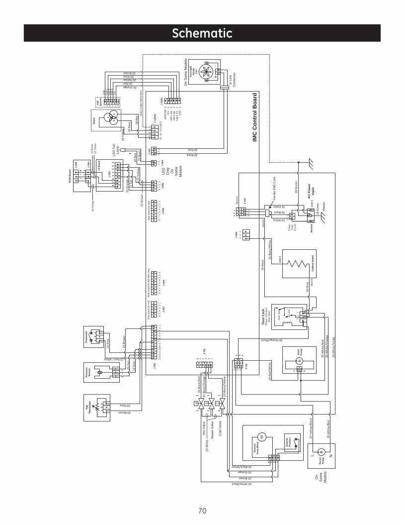
70
Schematic
S CH
D
Inpu
t8 7
6
5
4 3
2
1
J 10
2
GN
DH
all C
Hal
l A
+_
20-B
lack
2
1
Div
erte
r A
ssy
Mot
or
Div
erte
r Po
sitio
n
4 3 2 1
20-White/Black
20-Brown
20-Orange
20-Black/White
M
RR
ecirc
Pu
mp
L N20
-Whi
te/R
ed
20-Y
ello
w/B
lack
On
Som
e M
odel
s
Dra
in
Pum
p
1 23 2 1 J 70
1
6 5 4
Neu
tral
Doo
r Loc
kS
how
n U
nloc
ked,
D
oor O
pen
3 2
1
Doo
r Sw
.
Lock
20-R
ed/W
hite
20-W
hite
/Red
20-W
hite
/Ora
nge
20-W
hite
/Vio
let20-Orange/Black
16-G
ray
Cal
Rod
Hea
ter
Line
1N
eutr
al
Cha
ssis
AC
Pow
er
Pow
er
Cor
d In
-Lin
e
Neu
tral
Line
1
18-G
reen
16-Green
16-N
avy/
Whi
te
16-White
16-A
qua
16-Black
18-G
reen
Ferr
ite E
MI C
ore
J 80
3
J 10
13
2 1
6 5
4
3 2
1
Neu
tral
IMC
Con
trol
Boa
rd
Ove
rnig
ht
R
eady
Fan
+_
In L
ine
Con
nect
or
On
Som
e M
odel
s
Vcc
Hal
l B
20-Yellow20-Red
20-Orange
20-Navy20-Brown
Stat
orH
all
Sens
or
13
21 4 6 5 2 3
18-R
ed
18-N
avy
18-Y
ello
w
Mot
or C
able
Shi
eld
Wire
J 60
38
7 6
5 4
3 2
1J
602
4 3
2 1
UI B
oard
1
2
3
J 20
1
J 20
3
1
7
8
J 20
2
RJ4
5 B
oard
(Not
Use
d O
n H
A)
22-Y
ello
w
22-T
an22
-Ora
nge
22-B
row
n
20-R
ed
22 O
rang
e
5 4 3 2 1
J 10
01
J 12
03A
6
P1
P2
P3
SH
LD
4 3
2
1
Hal
l 3 (C
)
Hal
l 1 (A
)H
all 2
(B)
GN
D
Vcc
MTR
TMP
J 20
42
13
2 1
20-Black
20-Red
LED
Onl
yO
n S
ome
Mod
els
LED
Tub
La
mp
22 B
row
n22
Yel
low
13 1
2 11
10
9 8
7 6
5 4
3 2
1
J 50
1
J 40
76
5 4
3 2
19
8 7
6 5
4 3
2 1
J 50
2
6 5 4 3 2 1
J 70
2
(Not
Use
d O
n H
A M
id L
ine)
(Not
Use
d O
n H
A)
Flow
met
er
1
2
3
Tub
Ther
mis
tor
1 2
3
Pres
sure
Se
nsor
3 1
2
22-P
ink
20-Brown
20-Navy
22-G
ray
22-T
an22
-Bro
wn
22-Red / White
Col
d V
alve
Hot
Val
ve
Ste
am V
alve
2
1
2
1
2
1
20-W
hite
20-B
lack
/Yel
low
20-B
lack
/Ora
nge
20-B
lack
/Red

71
Adaptive Vibration Control 12Baffl e 54
Baffl e Removal 54Balance Ring 53
Balance Ring Removal 53Button Tree 45
Button Tree Removal 45Component Locator Views 34Consumer Mode 25
Consumer Mode Entry 25Consumer Mode Exit 25Consumer Mode Navigation 25
Control Panel 43Control Panel Removal 44
Diagnostics 20Dispenser Assembly 62
Dispenser Assembly Diagnostics 63Dispenser Assembly Removal 63Dispenser Assembly Tests 63
Diverter Motor Assembly 64Diverter Motor Assembly Diagnostics 64Diverter Motor Assembly Removal 65Diverter Motor Assembly Strip Circuit 64Diverter Motor Assembly Tests 64
Door Assembly 38Door Assembly Removal 38
Door Cover 40Door Cover Protect 40
Door Cover Protect Removal 41Door Cover Removal 40Door Exploded View 37
Door Frame 38Door Frame Removal 38
Door Glass 39Door Glass Removal 39
Door Handle 40Door Handle Removal 40
Door Hinge 39Door Hinge Removal 39
Door Lock Assembly 41Door Lock Assembly Diagnostics 41Door Lock Assembly Removal 42Door Lock Assembly Strip Circuit 41Door Lock Assembly Tests 41
Drain Pump 66Drain Pump Diagnostics 66
Drain Pump Removal 66Drain Pump Strip Circuit 66Drain Pump Tests 66
Drive System 56Electrical Specifi cations 10Electronic Board Pin Outs 31Fault Codes 26
Faults 1-9 26Faults 12-CB 28Faults A-11 27Faults CC-D4 29Faults D5-E8 30
Fill System 59Front Panel 49
Front Panel Removal 49Front Tub 51
Front Tub Removal 51Hall Sensor 58
Hall Sensor Diagnostics 58Hall Sensor Removal 58Hall Sensor Strip Circuit 58Hall Sensor Tests 58
Heater 61Heater Diagnostics 61Heater Removal 61Heater Strip Circuit 61Heater Tests 61
IMC Board 47IMC Board Diagnostics 47IMC Board Removal 47IMC Board Tests 47
Index 71Inner Tub 53
Inner Tub Removal 53Installation 12Introduction 8Leveling Leg 50Nomenclature 9Overnight Dry Fan 68
Overnight Dry Fan Diagnostics 68Overnight Dry Fan Removal 68Overnight Dry Fan Strip Circuit 68Overnight Dry Fan Tests 68Pedestal Installation 12
Pressure Sensor 60Pressure Sensor Chart 60
Index

72
Pressure Sensor Removal 60Pressure Sensor Strip Circuit 60Pressure Sensor Tests 60
Product Operation 14Rear Panel 50
Rear Panel Removal 50Rear Tub 55
Rear Tub Removal 55Recirculation Pump 67
Recirculation Pump Diagnostics 68Recirculation Pump Removal 68Recirculation Pump Strip Circuit 67Recirculation Pump Tests 68
Riser 51Riser Removal 51
RJ45 Board 48RJ45 Board Removal 48RJ45 Board Strip Circuit 48
Rotor 56Rotor Removal 56
Safety Requirements 7Schematic 70Service Mode 20
Service Mode Entry 20Service Mode Exit 20Service Mode Tests 21
Stator 56Stator Diagnostics 57Stator Removal 57Stator Strip Circuit 57
Thermistor 62Thermistor Chart 62Thermistor Removal 62Thermistor Tests 62
Tools Needed 11Top Panel 49
Top Panel Removal 49Tub and Basket Exploded View 37
Tub and Structure 38Tub Gasket 42
Tub Gasket Reinstallation 42Tub Gasket Removal 42
Tub Lamp 43Tub Lamp Diagnostics 43Tub Lamp Removal 43Tub Lamp Strip Circuit 43
UI Board 44UI Board Diagnostics 45UI Board Removal 45UI Board Strip Circuit 45
UI Board Tests 45Wash System 66Water Valve Assembly 59
Water Valve Removal 59Water Valve Strip Circuit 59Water Valve Tests 59