SERVICE MANUAL - Appliance Factory Parts
54
100 WASHING MACHINE SERVICE MANUAL READ THIS MANUAL CAREFULLY TO DIAGNOSE PROBLEMS CORRECTLY BEFORE SERVICING THE UNIT. MODEL: WM2455H* / WM2301H* CAUTION Website: http: //www.LGEservice.com E-mail: http: //www.LGEservice.com/techsup.html !
-
Upload
khangminh22 -
Category
Documents
-
view
3 -
download
0
Transcript of SERVICE MANUAL - Appliance Factory Parts
100
WASHING MACHINESERVICE MANUAL
READ THIS MANUAL CAREFULLY TO DIAGNOSE PROBLEMS CORRECTLY BEFORE SERVICING THE UNIT.
MODEL: WM2455H* / WM2301H*
CAUTION
Website: http: //www.LGEservice.comE-mail: http: //www.LGEservice.com/techsup.html
!

101
MAR. 2007 PRINTED IN KOREA P/No.: MFL30599107
2
CONTENTS1. SPECIFICATIONS ............................................................................................................... 3
2. FEATURES AND TECHNICAL EXPLANATION ................................................................. 4
3. PARTS IDENTIFICATION ................................................................................................... 7
4. INSTALLATION AND TEST ................................................................................................ 8
5. OPERATION ...................................................................................................................... 115-1. CONTROL PANEL FEATURES ................................................................................. 115-2. CYCLE GUIDE ........................................................................................................... 135-3. SPECIAL FUNCTIONS .............................................................................................. 145-4. EXPLANATION OF EACH PROCESS ....................................................................... 15
6. WIRING DIAGRAM/PROGRAM CHART .......................................................................... 17
7. TEST MODE ..................................................................................................................... 197-1. SAFETY CAUTION .................................................................................................... 197-2. LOAD TEST MODE ................................................................................................... 197-3. HOW TO CHECK THE WATER LEVEL FREQUENCY ............................................. 19
8. TROUBLESHOOTING ...................................................................................................... 208-1. SAFETY CAUTION .................................................................................................... 208-2. ERROR MODE SUMMARY ...................................................................................... 208-3. TROUBLESHOOTING SUMMARY ......................................................................... 228-4. TROUBLESHOOTING WITH ERROR ....................................................................... 238-5. TROUBLESHOOTING ELSE ..................................................................................... 30
9. COMPONENT TESTING INFORMATION ........................................................................ 359-1. FILTER ASSEMBLY (LINE FILTER) .......................................................................... 359-2. DOOR LOOK SWITCH ASSEMBLY .......................................................................... 369-3. STATOR ASSEMBLY ................................................................................................. 389-4. PUMP MOTOR ASSEMBLY .......................................................................................419-5. INLET VALVE ASSEMBLY ......................................................................................... 429-6. HEATER ASSEMBLY ................................................................................................. 439-7. THERMISTOR ASSEMBLY ....................................................................................... 44
10. DISASSEMBLY INSTRUCTIONS .................................................................................... 45
11.EXPLODED VIEW ............................................................................................................ 5111-1. CABINET AND CONTROL PANEL ASSEMBLY ...................................................... 5111-2. DRUM AND TUB ASSEMBLY .................................................................................. 5211-3. DISPENSER ASSEMBLY ........................................................................................ 53

3
1. SPECIFICATIONS
ITEM WM2455H* / WM2301H*
COLOR W:BLUE WHITE, G:PEARLY GRAY, R:CANDY APPLE RED
POWER SUPPLY AC 120 V, 60 Hz
PRODUCT WEIGHT 192 lbs (87kg)
WASHING 280 W
DRAIN MOTOR 80 W
WASH HEATER 1000 W
WASH 46 rpm
SPIN 0-1200 rpm
CYCLES 9
WASH/RINSE TEMPERATURES 5
SPIN SPEEDS 4
OPTIONS Prewash, Rinse+Spin, Extra Rinse, Water Plus, Stain Cycle
WATER CIRCULATION _
OPERATIONAL WATER PRESSURE 14.5-116 psi (100-800 kPa)
CONTROL TYPE Electronic
WASH CAPACITY [cu.ft] 3.63 (4.2 IEC)
DIMENSIONS 27” (W) X 29 3/4” (D) X 3811/16” (H), 5013/16” (D, door open)
DELAY WASH up to 19 hours
DOOR SWITCH TYPE PTC + Solenoid
WATER LEVEL 10 steps (by sensor)
LAUNDRY LOAD SENSING Incorporated
ERROR DIAGNOSIS Incorporated
AUTO POWER OFF Incorporated
CHILD LOCK Incorporated
RLM ENABLE _
STEAM _
ELECTRIC POWER
CONSUMTION
REVOLUTION SPEED

4
2. FEATURES & TECHNICAL EXPLANATION
2-1. FEATURES
Ultra CapacityThe Larger drum enables not just higher head drop and strongercentrifugal force, but also less tangling and wrinkling of thelaundry. Heavier loads, such as king size comforters, blankets,and curtains, can be washed.
Direct Drive SystemThe advanced Brushless DC motor directly drives the drumwithout belt and pulley.
Tilted Drum and Extra Large Door OpeningTilted drum and extra large opening make it possible to loadand unload clothing more easily.
RollerJets Washing ball enhances the wash performance and reducesdamage to the clothing. The jets spray and help tumble clothes toenhance washing performance while maintaining fabric care.
Automatic Wash Load Detection Automatically detects the load and optimizes the washing time.
Built-in HeaterInternal heater helps to maintain water temperature at itsoptimum level for selected cycles.
Child LockThe Child lock prevents children from pressing any button tochange the settings during operation.
추가선택, 예약,
추가선택, 예약,
5
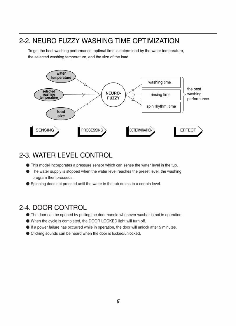
2-2. NEURO FUZZY WASHING TIME OPTIMIZATIONTo get the best washing performance, optimal time is determined by the water temperature,
the selected washing temperature, and the size of the load.
2-3. WATER LEVEL CONTROL This model incorporates a pressure sensor which can sense the water level in the tub.
The water supply is stopped when the water level reaches the preset level, the washing
program then proceeds.
Spinning does not proceed until the water in the tub drains to a certain level.
2-4. DOOR CONTROL The door can be opened by pulling the door handle whenever washer is not in operation.
When the cycle is completed, the DOOR LOCKED light will turn off.
If a power failure has occurred while in operation, the door will unlock after 5 minutes.
Clicking sounds can be heard when the door is locked/unlocked.
NEURO-FUZZY
loadsize
selectedwashing
temperature
watertemperature
washing time
rinsing time
spin rhythm, time
the bestwashingperformance
SENSING PROCESSING DETERMINATION EFFECT

6
2-5. THE DOOR CAN NOT BE OPENEDWhile program is operating.
When a power failed and power plug is taken out in operation.
While Door Lock lights turn on.
While the motor is in the process of intertial rotating, through the operation is paused.
2-6. DOOR LOCKED LAMP LIGHTSWhen the frequency of water level is lower than 22.9 kHz
(It can be canceled when the frequency is more than 23.8 kHz)
When the temperature inside the tub is higher than 45 °C and water level is not 25.5 kHz
(It can be canceled when the water level is 25.5 kHz or the temperature inside the tub is lower
than 40 °C)
2-7. CHILD LOCKUse this option to prevent unwanted use of the washer. Press and hold PRE WASH button for 3
seconds to lock/unlock control.
When child lock is set, CHILD LOCK lights and all buttons are disabled except the Power button.
You can lock the controls of the wash while washing.

7
3. PARTS IDENTIFICATION
ACCESSORIES
Drum Light
Door Seal
Hose retainer
Hot/Cold (1 each)Hose
Wrench for removing shipping bolts and leveling the washer
Tie strapto secure drain hose to standpipe, inlet hose, or laundry tub
Cap (4 each)to cover the holes created afterremoving the shipping bolts
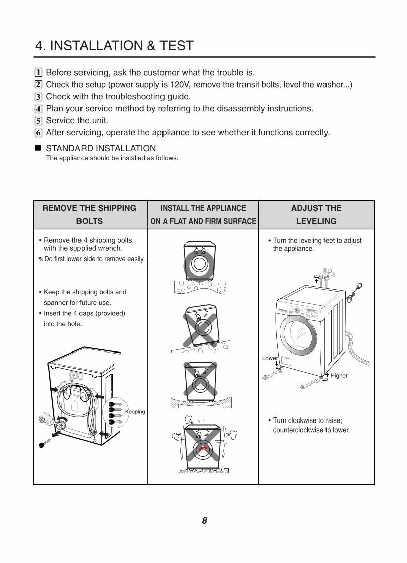
4. INSTALLATION & TEST
Before servicing, ask the customer what the trouble is.Check the setup (power supply is 120V, remove the transit bolts, level the washer...)Check with the troubleshooting guide.Plan your service method by referring to the disassembly instructions.Service the unit.After servicing, operate the appliance to see whether it functions correctly.
STANDARD INSTALLATIONThe appliance should be installed as follows:
1
2
34
56
6REMOVE THE SHIPPING
BOLTS
• Remove the 4 shipping boltswith the supplied wrench.
Do first lower side to remove easily.
• Turn the leveling feet to adjustthe appliance.
• Turn clockwise to raise;counterclockwise to lower.
• Keep the shipping bolts and
spanner for future use.
• Insert the 4 caps (provided)
into the hole.
ADJUST THE
LEVELING
INSTALL THE APPLIANCE
ON A FLAT AND FIRM SURFACE
8

9
HOW TO CONNECT THE INLET HOSE
Verify that the rubber washer is inside of the
valve connector.
Tighten the inlet hose securely to prevent leaks.
CONNECT THE DRAIN HOSE
CONNECT POWER PLUG
※ The end of the drain hose should be placed less than 96” from the floor.
· Connect the power plug to the wall outlet. · Avoid connecting several electric devices, asdoing so may cause a fire.
· Make sure that the hose is not twisted. · Avoid submerging the end of the hose.

10
TEST OPERATION
1 Preparation forwashing.
• Connect the power plug tothe outlet.
• Connect the inlet hose.
3 Press the Start/Pausebutton.
• Listen for a click to determine ifthe door has locked.
6 Check the water heatingfunction.
• Press the WASH/RINSE buttonand the present temperature willbe displayed.
5 Check the automaticreverse rotation.
4 Check the water supply.
• Check if water is suppliedthrough the detergent dispenser.
7 Check the drain and spinfunctions.
• Power off and the power on.
• Press the SPIN SPEED button.
• Press the START/PAUSE button.
• Check the spin and drain
functions.
8 Press theSTART/PAUSE button.
9 Water removal.
• If SERVICE is needed during
check, remove the remaining
water by pulling out the hose cap.
2 Press the POWER button.
• Listen for a click to determine
if the door is unlocking.
7
• Check if the drum rotatesclockwise and counterclockwise.
11
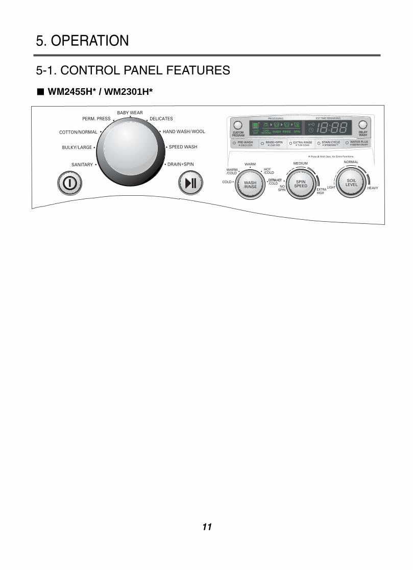
5. OPERATION
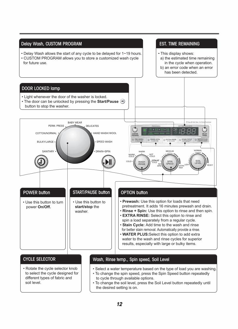
5-1. CONTROL PANEL FEATURES
WM2455H* / WM2301H*
12
EST. TIME REMAINING
• This display shows: a) the estimated time remaining in the cycle when operation. b) an error code when an error has been detected.
CYCLE SELECTOR
• Rotate the cycle selector knob to select the cycle designed for different types of fabric and soil level.
START/PAUSE button
• Use this button to start/stop the washer.
Wash, Rinse temp., Spin speed, Soil Level
• Select a water temperature based on the type of load you are washing.• To change the spin speed, press the Spin Speed button repeatedly to cycle through available options.• To change the soil level, press the Soil Level button repeatedly until the desired setting is on.
OPTION button
• Prewash: Use this option for loads that need pretreatment. It adds 16 minutes prewash and drain.• Rinse + Spin: Use this option to rinse and then spin.• EXTRA RINSE: Select this option to rinse and spin a load separately from a regular cycle.• Stain Cycle: Add time to the wash and rinse for better stain removal. Automatically provide a rinse.• WATER PLUS:Select this option to add extra water to the wash and rinse cycles for superior results, especially with large or bulky items.
POWER button
• Use this button to turn power On/Off.
Delay Wash, CUSTOM PROGRAM
• Delay Wash allows the start of any cycle to be delayed for 1~19 hours.• CUSTOM PROGRAM allows you to store a customized wash cycle for future use.
DOOR LOCKED lamp
• Light whenever the door of the washer is locked.• The door can be unlocked by pressing the Start/Pause button to stop the washer.

Cycle Fabric type Spin Speed Soil LevelWash/Rinse
Temp.Pre-
WashRinse +
SpinExtraRinse
StainCycle
WaterPlus
SanitaryHeavily soiledunderwear, workclothes, diapers, etc.
Extra Hot/Cold
Extra High (==)No Spin (*)
Low (---)Medium ( )
High(==)
HeavyLight
Normal
Bulky/Large Large items such asblankets and comforters
Warm/Cold
Medium ( )No Spin (*)
Warm/WarmHot/ColdCold/Cold
Low (---)
HeavyLight
Normal
Perm. Press
Dress shirts/pants,wrinkle free clothing,poly/cotton blendclothing, tablecloths
Warm/Cold
High (==)No Spin (*)
Low (---)
Warm/WarmHot/ColdCold/Cold
Medium ( )
HeavyLight
Normal
Cotton/Normal
Cotton, linen, towels,shirts, sheets, jeans,mixed loads
Warm/Cold
Warm/WarmHot/ColdCold/Cold
High (==)
HeavyLight
Normal
Baby Wear Lightly soiledbaby wear
Extra Hot/Cold
Extra High (==)No Spin (*)Low (---)
Medium ( )
Hot/Cold
High (==)
Light
Normal
DelicatesDress shirts/blousesnylons, sheer or lacygarments
Cold/Cold
No Spin (*)Low (---)
Warm/ColdWarm/Warm
Medium ( )
HeavyLight
Normal
Hand Wash/Wool
Items labeled“hand washable”
Cold/Cold
Medium ( )No Spin (*)
Warm/ColdWarm/Warm
Low (---)
Light
Normal
Speed Wash
Lightly soiled clothingand small loads
Hot/Cold
No Spin (*)Low (---)
Medium ( )High (==)
Cold/ColdWarm/Cold
Warm/Warm
Extra High (==)
NormalHeavy
Light
Drin +Spin
Drain, Spin Only Extra High (==)No Spin (*)
Low (---)Medium ( )
High(==)
Extra High (==)No Spin (*)
Low (---)Medium ( )
13
5-2. CYCLE GUIDEThe cycle guide below shows the options and recommended fabric types for each cycle.
NOTE: To protect your garments, not every wash/rinse temperature, spin speed, soil level, or option is availablewith every cycle.

14
5-3. SPECIAL FUNCTIONSThe option buttons also activate special functions, including CHILD LOCK, LOAD SIZE, TUB CLEAN, andSPIN SENSE. Press and hold the option button marked with the special function for 3 seconds to activate.
CHILD LOCKUse this option to prevent unwanted use of the washer or to keep cycle settings from beingchanged while the washer is operating. Press and hold the PREWASH button for 3 secondsto activate or deactivate CHILD LOCK. CHILD LOCK will be shown in the display, and allcontrols are disabled except the ON/OFF button. The washer can be locked during a cycle.
LOAD SIZEAt the beginning of the cycle, the washer tumbles the load and detects the weight of theclothes.The display will indicate the approximate load size in the LOAD SIZE display. This allows youto Adjust the amount of detergent and other additives for best results and improved efficiency.
TUB CLEANA buildup of detergent residue can occur in the wash tub over time and can lead to a mildewor musty smell. The TUB CLEAN cycle is specially designed to remove this buildup. Pressand hold the EXTRA RINSE button for 3 seconds to activate this cycle. The display will showa message to add liquid bleach to the dispenser. After the cycle has ended, open the doorand allow the drum interior to dry completely. NOTE: Do NOT use this cycle with clothes, and do NOT add detergent or fabric softener.
SPIN SENSETo activate SPINSENSE :While the washing machine is runnung in any cycle, press and hold the STAIN CYCLE buttonfor 3 seconds. The SPIN SPEED button light will blink while the washer is running to showthat SPINSENSE is active. The SPINSENSE function will remain active for every cycle, evenafter a power failure.To cancel SPINSENSE :Press and hold the STAIN CYCLE button for 3 seconds to turn off the SPINSENSEfunction
BEEPER ON/OFFYou may turn the end-of-cycle beeper on or off with the WATER PLUS button during thecycle. Press and hold the WATER PLUS button for 3 seconds to turn the beeper off. Pressand hold the WATER PLUS button again for 3 seconds to turn the beeper back on.
15
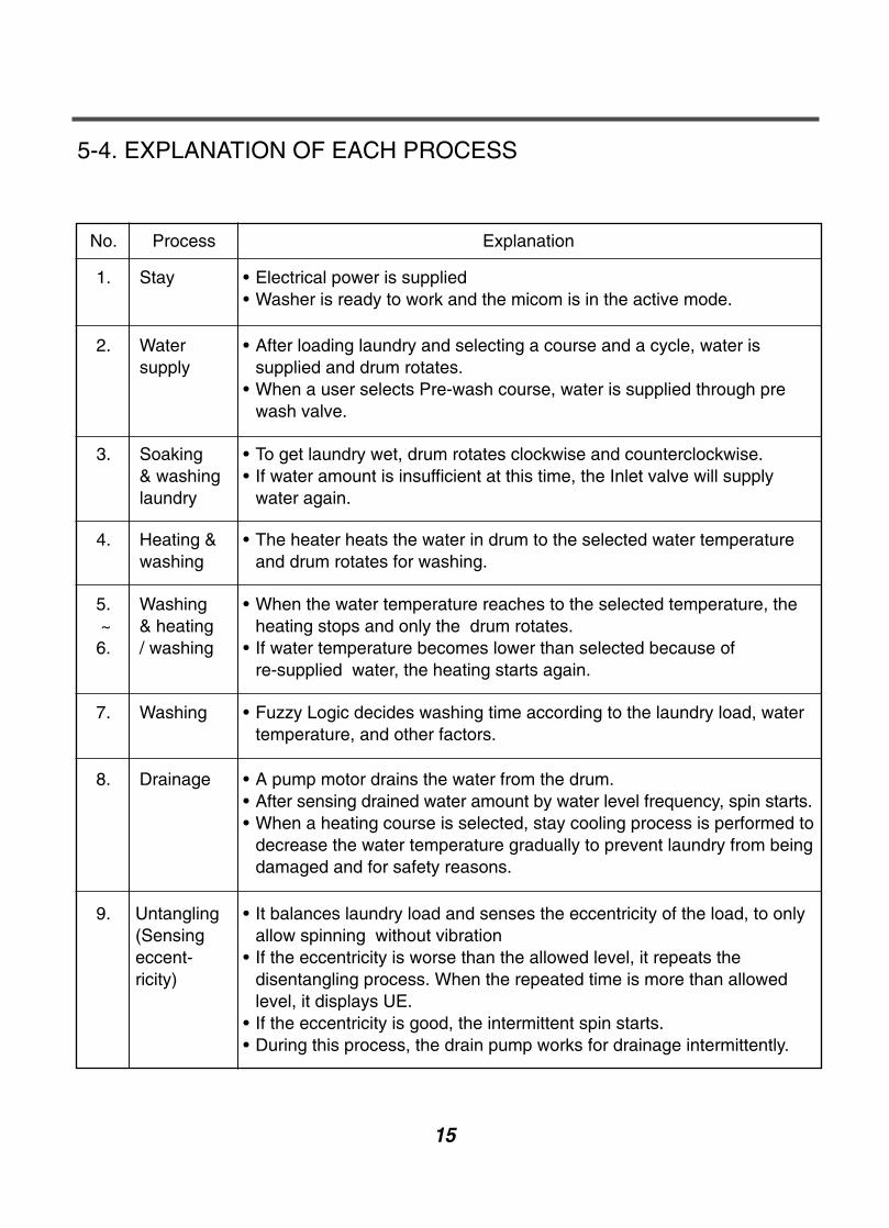
5-4. EXPLANATION OF EACH PROCESS
No. Process Explanation
1. Stay • Electrical power is supplied• Washer is ready to work and the micom is in the active mode.
2. Watersupply
• After loading laundry and selecting a course and a cycle, water issupplied and drum rotates.
• When a user selects Pre-wash course, water is supplied through prewash valve.
3. Soaking& washinglaundry
• To get laundry wet, drum rotates clockwise and counterclockwise.• If water amount is insufficient at this time, the Inlet valve will supply
water again.
4. Heating &washing
• The heater heats the water in drum to the selected water temperatureand drum rotates for washing.
5.~6.
Washing& heating/ washing
• When the water temperature reaches to the selected temperature, theheating stops and only the drum rotates.
• If water temperature becomes lower than selected because of re-supplied water, the heating starts again.
7. Washing • Fuzzy Logic decides washing time according to the laundry load, watertemperature, and other factors.
8. Drainage • A pump motor drains the water from the drum.• After sensing drained water amount by water level frequency, spin starts.• When a heating course is selected, stay cooling process is performed to
decrease the water temperature gradually to prevent laundry from beingdamaged and for safety reasons.
9. Untangling(Sensingeccent-ricity)
• It balances laundry load and senses the eccentricity of the load, to onlyallow spinning without vibration
• If the eccentricity is worse than the allowed level, it repeats thedisentangling process. When the repeated time is more than allowedlevel, it displays UE.
• If the eccentricity is good, the intermittent spin starts.• During this process, the drain pump works for drainage intermittently.

16
No. Process Explanation
A. Intermittentspin
• To reach the correct set speed, the motor rotates clockwise andcounterclockwise directions after spin process starts.
• If the water level frequency is lower than 23.0 kHz, a washer sensessuds and starts suds removal process.
B. Rinsespin
• In this process, the remaining water during washing process isextracted and the selected speed is kept.
• Removing suds process is in active mode at this cycle.
C. Remainingspin
• After spin finishes, the drum rotates by remaining spin power until it stops.Motor power is off.
• This process is overlapped with next process.
D. Rinse watersupply
• Water supply for rinse process
E. Rinse • Rinsing process.
F. Lastdrainage
• After spin finishes and power is not supplied to motor, the drumrotates by remaining spin power
• If rinse hold is selected, the drainage is not proceeded after rinsefinishes.
G. Disentangling • The same as item 9.
H. Intermittent spin • The same as item A.
I. Main spin1 • The same as item B.
J. Main spin2 • At the end of a main spin, the spin speed will reach the selected rpm.
K. Remaining spin • The same with item C.
L. Disentangling • After spin finishes, disentangling starts to remove unbalancedlaundry.
M. End • After 'end' signal is displayed, it stays for 8 seconds and power isautomatically turned off. (Auto type door switch)
• After door switch is off, end signal is displayed in the case ofmanual type and it takes around 2 minute to turn off door switch.
17
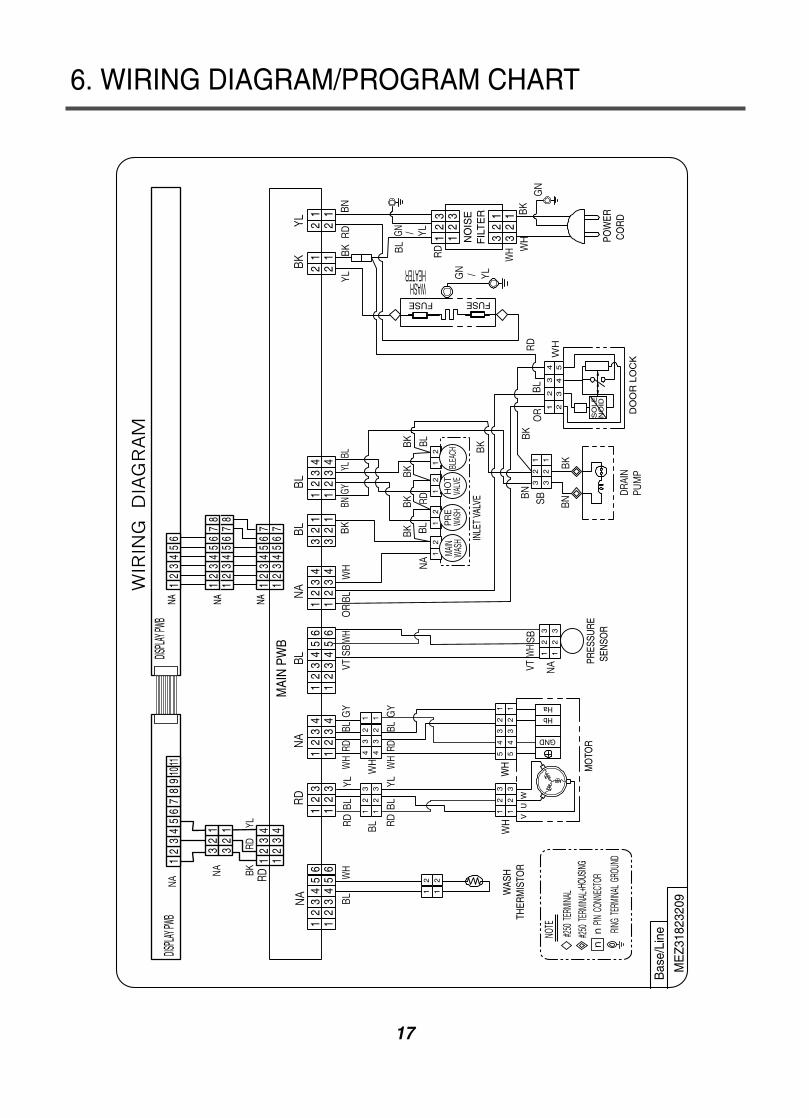
6. WIRING DIAGRAM/PROGRAM CHART

18
7. TEST MODE
19
7-1. SAFETY CAUTIONThere's built-in AC 120V and DC power in output terminal of PWB assembly in common. Be careful electricshock when disconnecting parts while trouble shooting. (Wear Electro Static Discharge gloves when working.)After cutting off the power when changing PWB assembly, disconnect or assemble.Be careful static when handling PWB assembly, and use Electro Static Discharge plastic pack when deliveringor keeping it.
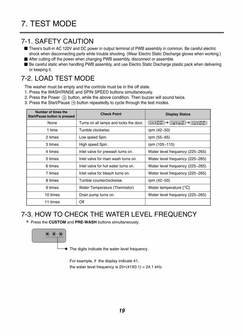
7-2. LOAD TEST MODEThe washer must be empty and the controls must be in the off state. 1. Press the WASH/RINSE and SPIN SPEED buttons simultaneously.2. Press the Power button, while the above condition. Then buzzer will sound twice.3. Press the Start/Pause button repeatedly to cycle through the test modes.
7-3. HOW TO CHECK THE WATER LEVEL FREQUENCYPress the CUSTOM and PRE-WASH buttons simultaneously.
None
1 time
2 times
3 times
4 times
5 times
6 times
7 times
8 times
9 times
10 times
11 times
Turns on all lamps and locks the door.
Tumble clockwise.
Low speed Spin.
High speed Spin.
Inlet valve for prewash turns on.
Inlet valve for main wash turns on.
Inlet valve for hot water turns on.
Inlet valve for bleach turns on.
Tumble counterclockwise.
Water Temperature (Thermistor)
Drain pump turns on.
Off
rpm (42~50)
rpm (55~65)
rpm (105~115)
Water level frequency (225~265)
Water level frequency (225~265)
Water level frequency (225~265)
Water level frequency (225~265)
rpm (42~50)
Water temperature [°C]
Water level frequency (225~265)
The digits indicate the water level frequency.
For example, if the display indicate 41,
the water level frequency is 20+(41X0.1) = 24.1 kHz.
Number of times theStart/Pause button is pressed
Check Point Display Status

There’s built-in AC 120V and DC power in output terminal of PWB assembly in common. Be carefulelectric shock when disconnecting parts while trouble shooting. (Wear Electro Static Discharge gloveswhen working.)After cutting off the power when changing PWB assembly, disconnect or assemble.Be careful static when handling PWB assembly, and use Electro Static Discharge plastic pack whendelivering or keeping it.
20
8. TROUBLESHOOTING
8-1. SAFETY CAUTION
8-2.ERROR MODE SUMMERY
ERROR SYMPTOM CAUSE
WATER INLET
ERROR1
IMBALANCE
ERROR2
DRAIN
ERROR3
OVER FLOW
ERROR4
PRESSURE
SENEOR
ERROR
5
DOOR OPEN
ERROR6
HEATING
ERROR7
• Correct water level (246) is not reached within 8 minutes after water is supplied or it does not reach the preset waterlevel within 25 minutes.
• The load is too small.• The appliance is tilted.• Laundry is gathered to one side.• Non distributable things are put into the drum.
• Door not all the way closed.• Loose electrical connections at Door switch and PWB
Assembly.• The DOOR SWITCH ASSEMBLY is out of order.
• Not fully drained within 10 minutes.
• The SENSOR SWITCH ASSEMBLY is out of order.
• The THERMISTOR is out order.
• Water is overflowing (water level frequency is over 213). If is displayed, the drain pump will operate to drain
the water automatically.
If you press the START/PAUSE button when an error is displayed, any error except willdisappear and the machine will go into the pause status.In case of , , if the error is not resolved within 20 seconds, or the in case of othererrors, if the error is not resolved within 4 minutes, power will be turned off automatically and the errorcode will blink. But in the case of , power will not be turned off.

21
ERROR SYMPTOM CAUSE
LOCKED
MOTOR
ERROR
8
EEPROM
ERROR9
POWER
FAILURE10
• The connector (3-pin, male, white) in the MOTOR HARNESSis not connected to the connector (3-pin, female, white) ofSTATOR ASSEMBLY.
• The electric contact between the connectors (3-pin, male,white) in the MOTOR HARNESS and 4-pin, female, whiteconnector in the MAIN PWB ASSEMBLY is bad or unstable.
• The MOTOR HARNESS between the STATOR ASSEMBLYand MAIN PWB ASSEMBLY is cut (open circuited).
• The hall sensor is out of order/defective.
• EEPROM is out of order.Displayed only when the START/PAUSE button is first pressed in the Load Test Mode.
• After the power supply is stopped while washing machine isworking, the power is supplied rapidly

22
8-3. TROUBLESHOOTING SUMMARY
Rem
ark
Res
ult
(tol
eran
ce
5%)
At 8
6 (
30
)A
t 104
(
40
)A
t 140
(
60
)A
t 158
(
70
)A
t 203
(
95
)A
t 221
(
105
)
39.5
k Ω
26.1
k Ω
12.1
k Ω
8.5
kΩ
3.8
k Ω
2.8
k Ω
Th
erm
isto
rP
in4:
Was
h th
erm
isto
r
Mo
tor
Hal
l Sen
sor
RD
Pin
1: U
Pin
2: V
Pin
3: W
NA
Pin
1: +
Pin
2: H
b
Pin
3: H
a
Pin
4: G
ND
Do
or
Sw
itch
NA
Pin
1: P
TC
Pin
2: P
TC
Inle
t Val
veN
A_P
in3:
Mai
n w
ash
BL3
BL4
Pin
1: C
omm
onP
in2:
Pre
was
h
Pin
3: B
leac
hP
in4:
Hot
val
ve
Res
ult
Test
Poi
nts
8~12
k Ω
8~12
kΩ
10~
15 V
dc10
Vdc
10 V
dc
Rem
ark
Vol
tage
Inpu
tP
ulsi
ng S
igna
lP
ulsi
ng S
igna
l
Pin
1 ~
Pin
2P
in1
~ P
in3
Pin
1 ~
Pin
4
Pin
2 ~
Pin
4P
in3
~ P
in4
Res
ult
Test
Poi
nts
700-
1500
Ω60
-90
ΩIn
finity
120
Vac
Rem
ark
At 7
7(2
5)
At 7
7(2
5)
Vol
tage
Inpu
t
Pin
2 ~
Pin
4P
in3
~ P
in4
Pin
4 ~
Pin
5
Pin
2 ~
Pin
4
stea
m g
ener
ator
Res
ult
Test
Poi
nts
0 Ω
0 Ω
WH
_Pin
1 ~
RD
Pin
3W
H_P
in3
~ R
D P
in1
Hea
ter:
12
~18
Pin
1 to
Pin
2:
0.8~
1.2
Hea
ter
BK
Pin
1: V
ac (
inpu
t)P
in2
: Was
h he
ater
Y
L P
in1:
Vac
Pin
2 : W
ash
heat
er
Ω
Ω
Pu
mp
B
L4 P
in1:
Dra
in p
ump
1. P
ump
runn
ing:
120
V
5%2.
Sto
pped
Mot
or/P
ump:
0~
1V
10 ~
20
Ω
Res
ult
Test
Poi
nts
5~15
Ω5~
15Ω
5~15
Ω
Pin
1 ~
Pin
2
Pin
2 ~
Pin
3P
in3
~ P
in1
Was
h t
her
mis
tor
Pu
mp
Dra
in p
ump
:

23
8-4. TROUBLESHOOTING WITH ERROR
INLET VALVE ERROR
Is displayed?
When you press bothCUSTOM button andPRE-WASH buttonsimultaneously,is the water level frequencybelow 24.6 kHz?(Refer to 7-3.)
Is filter inlet valve cloggedwith foreign material?
Is the connector connected toinlet valve assemblydisconnected ordisassembled?
Is resistance betweeneach terminal of INLETVALVE ASSEMBLY0.8-1.2 kΩ?(Refer to 9-5 inlet valveassembly)
Clean orreplace the filter.
Check the AIRCHAMBERand the tube(clogged).
Yes
No
No
Yes
Yes
Reconnect orrepairthe connector.
Replace theINLET VALVEASSEMBLY.
Yes
Yes
Is the voltage of the inletvalve connector 120 V AC?(Check the all terminal ofINLET VALVE ASSEMBLYwhile the power is on.)
Replace theINLET VALVEASSEMBLY.
No
Yes
Is the connector connected toMAIN PWB assemblydisconnected or dis-assembled?(NA4, BL3, BL4)
Reconnect orrepairthe connector.
No
Yes
Yes
Is Electrical connectioncorrect?(Refer to 9-5 wiring diagram)
Replace theMAIN HARNESS.No
No
After checking connector,is the water level frequencybelow 24.6 kHz?(Refer to 7-3)
Replace the MAIN PWBASSEMBLY.
[Note] Environmental safety check list1) No water tap leakage2) No water tap freeze3) No entanglement of water supply hose4) No water shortage5) No shrinkage on water supply hose due to
a possible misuse of hot and cold water6) No water supply hose leakage
Check thePRESSURESWITCH.
Yes
No
No

DRAIN ERROR
Is displayed?
Is the connector connectedto pump motor assemblydisconnected ordisassembled?
Reconnect orrepairthe connector.
Yes
Yes
Drain pump
Connection connector
No
Yes
When you press bothCUSTOM button andPRE-WASH buttonsimultaneously, is thewater level frequencybelow 26.0 kHz?(Refer to 7-3)
Check the AIRCHAMBER,the tube(clogged),and pressswitch
Is the coil of the drainpump too high or low?(resistance of the coilis 10-20Ω)(Refer to 9-4 Pump motorassembly)
Replace theDRAIN PUMPASSEMBLY.
No
Yes
Is the voltage betweenconnectors out of range?(BL4 pin1~ BL3 pin1)- After remove TerminalPosition Assurance (TPA)of connector, check asfollows.- And if you finish to measurethe valve, You should putTPA as original form.
- Pump running : 120V±5%- Stopped Motor/Pump : 0~1V Method1. Press the Power button, while the SPIN SPEED
button and WASH/RINSES button is pressedsimultaneously.
2. Press Start/Pause button.: 1 time Pump slow-speed running: 2 times Pump mid-speed running: 3 times Pump high-speed running: 4 times Stop the Motor/Pump
[Note] Environmental check list1) The drainage hose must not stay in a lower position.2) The drainage hose must not be bent or
clogged in any way due to the surroundingphysical configuration.
3) The drainage hose must not get frozen at all times.4) The drainage pump must not have any improper
substance or material inside that may causea machine breakdown.
Replace theMAIN PWBASSEMBLY.
Yes
No
24

25
HEATING ERROR
Is displayed?
Is the connector connectedto heater disconnected ordisassembled?
Reconnect orrepairthe connector
Yes
Yes
Is Check heaterresistance out of range?(12~18 Ω)(Refer to 9-6 Heaterassembly.)
Replace theHEATERASSEMBLY
Yes
No
No
Is thermistor resistanceout of range?(about 39.5 kΩ at 30°C)(Refer to 9-7 thermistorassembly)
Replace theTHERMISTORASSEMBLY
Yes
No
Check the trans of waterinfiltration into thermistorterminal.- Does the water infiltrate
thermistor terminal?
[Note]Chances that the cause occurs from themain controller are very little.Sensing part of the circuit (tE) consists ofonly resistors and capacitors.
Replace theTHERMISTORASSEMBLY
Yes
Wash heater
Is the connector connected tothermistor disconnected ordisassembled?
Reconnect orrepairthe connector
Yes
No
Wash thermistor

LOCKED MOTOR ERROR
Is displayed?
Check the connectors below.Is the connector disconnectedor disassembled?(motor hall sensor connector,motor drive connector)- part of main PWB
assembly (RD4, NA1)
Reconnectthe connector.(connector /wire / motor)
Replacethe ROTOR
Yes
Yes
Motor Drive (RD4)
Is rotor magnet cracked?
Hall sensor (NA1)
Motor Drive Hall Sensor
- part of wire
- part of motor
MotorYes
No
Yes
Yes
Magnet
Replacethe STATOR
Is the resistance valuesin the range of 5 to 15 Ω?(U-V, V-W, W-V:U=1, V=2, W=3)- After pull out the RD4
connector, check theterminal of the connectorin wire. (Red 3P, male)
No
Replacethe Hallsensor
Is hall sensor out oforder? (Refer to 9-3Stator assembly/Hallsensor.)
Yes
No
Replace theMAIN PWBASSEMBLY
Check the IPM in thecontroller. No
26
27
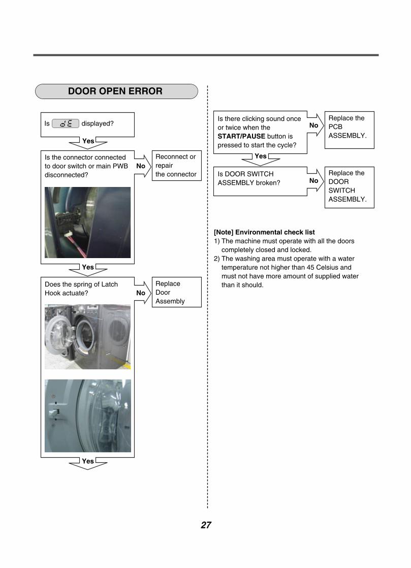
DOOR OPEN ERROR
Is displayed?
Yes
Is the connector connectedto door switch or main PWBdisconnected?
Reconnect orrepairthe connector
Yes
No
Is there clicking sound onceor twice when theSTART/PAUSE button ispressed to start the cycle?
Replace thePCBASSEMBLY.
No
Is DOOR SWITCHASSEMBLY broken?
Replace theDOORSWITCHASSEMBLY.
No
Yes
Does the spring of LatchHook actuate?
ReplaceDoorAssembly
Yes
No
[Note] Environmental check list1) The machine must operate with all the doors
completely closed and locked.2) The washing area must operate with a water
temperature not higher than 45 Celsius andmust not have more amount of supplied waterthan it should.

UNBALANCE ERROR OVER FLOW ERROR
[Note] Environmental check list1) Removal of transportation-based fixed bolt.2) Confirmation on the material to see if it is capable
of handling two different types of blanket materials.
Is displayed?
Yes
Does the laundry leantoward one side, not evenlyput in the DRUM assembly?
Put laundryevenlyIn the DRUMassembly
Yes
Is the washing machineinstalled at an angle?
Adjust theheight ofwashingmachineto be kepthorizontally
Yes
No
Is displayed?
Yes
When you press bothCUSTOM button and PRE-WASH buttonsimultaneously, is thewater level frequency over21.3kHz? (Refer to 7-3)
Check the AIRCHAMBERand the tube(clogged).
No
Does the inlet valve workwhen the power is notapplied?
Replace theINLET VALVE ASSEMBLY
If the inletvalve workcontinuouslywhen the poweris applied,Replace theMAIN PWBASSEMBLY
No
Yes
Yes
28

29
PRESSURE SENSOR ERROR
Is displayed?
Yes
Is the connector connectedto pressure sensordisconnected ordisassembled?
Reconnect orrepairthe connector
No
No
Yes
Is the resistance of thepressure sensor out ofrange?(pin 1~ pin 3)(21~23 Ω ±10%)
Replace thepressureswitch
No
Yes
Is the AIR CHAMBER andthe tube clogged?
Replace the MAIN PWBassembly.
Fix the airchamberand removethe foreignmaterial.
Yes
30
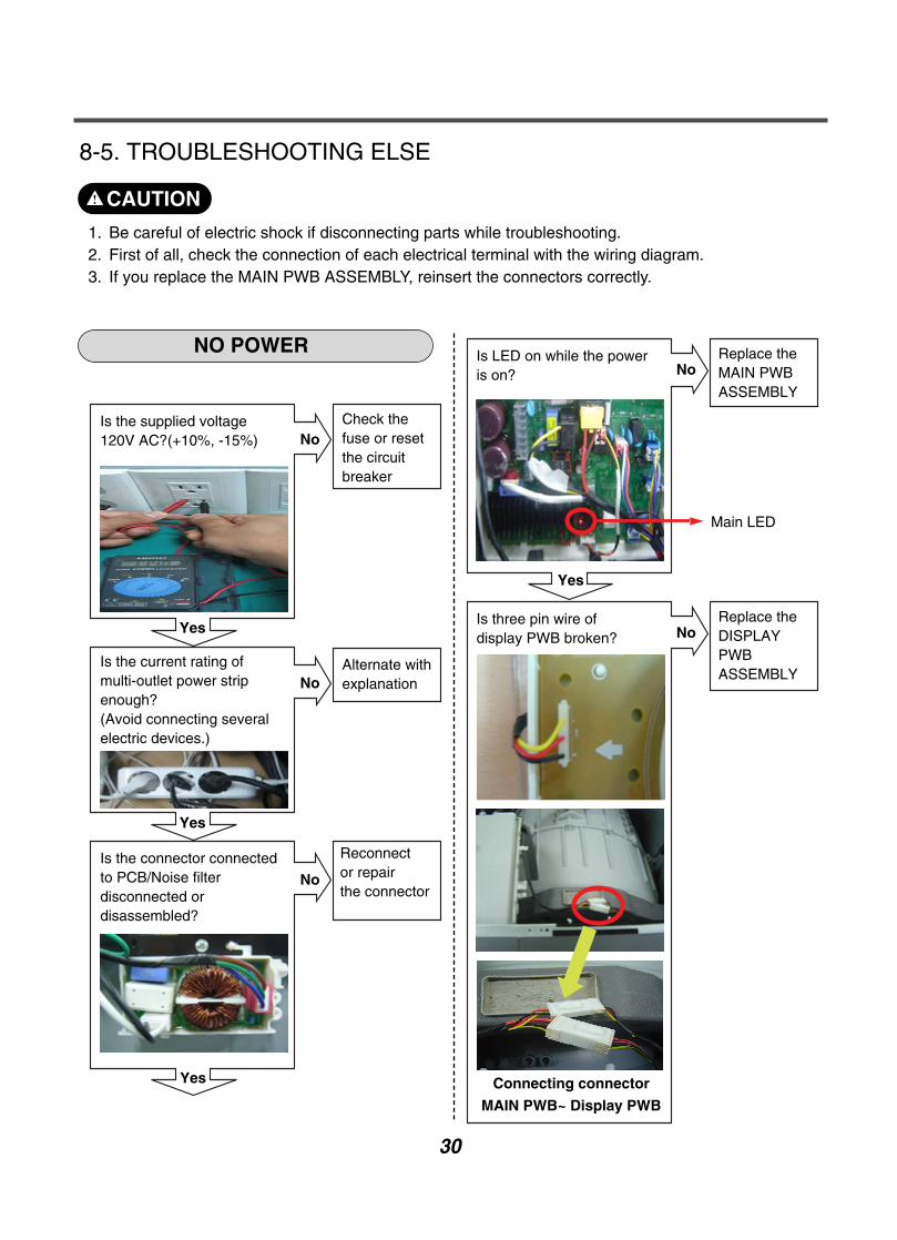
8-5. TROUBLESHOOTING ELSE
NO POWER
1. Be careful of electric shock if disconnecting parts while troubleshooting.2. First of all, check the connection of each electrical terminal with the wiring diagram.3. If you replace the MAIN PWB ASSEMBLY, reinsert the connectors correctly.
CAUTION
Check thefuse or resetthe circuitbreaker
Yes
No
Is the current rating ofmulti-outlet power stripenough?(Avoid connecting severalelectric devices.)
Is the supplied voltage120V AC?(+10%, -15%)
Alternate withexplanation
Yes
Yes
No
Is the connector connectedto PCB/Noise filterdisconnected ordisassembled?
Reconnector repairthe connector
No
Replace theMAIN PWBASSEMBLY
Yes
NoIs LED on while the poweris on?
Replace theDISPLAYPWBASSEMBLY
Connecting connector
MAIN PWB~ Display PWB
NoIs three pin wire ofdisplay PWB broken?
Main LED

31
BUTTON DOESN’T WORK
Is the connector connectedto Main PWB / DisplayPWB disconnected ordisassembled?
Reconnect orRepairthe connector
Yes
Is the display PCB broken?(check the buzzer soundand LED light while pushthe button.)
Replace theDISPLAYPWBASSEMBLY
Yes
Is the button of panel stuck? Repair thebuttonYes
No
No
32
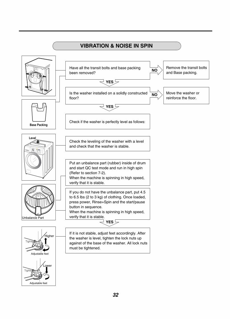
VIBRATION & NOISE IN SPIN
Remove the transit boltsand Base packing.
Move the washer orreinforce the floor.
YES
YES
YES
NO
NO
Have all the transit bolts and base packingbeen removed?
Is the washer installed on a solidly constructedfloor?
Check if the washer is perfectly level as follows:
Check the leveling of the washer with a leveland check that the washer is stable.
Put an unbalance part (rubber) inside of drumand start QC test mode and run in high spin(Refer to section 7-2). When the machine is spinning in high speed,verify that it is stable.
If you do not have the unbalance part, put 4.5to 6.5 lbs (2 to 3 kg) of clothing. Once loaded,press power, Rinse+Spin and the start/pausebutton in sequence.When the machine is spinning in high speed,verify that it is stable.
If it is not stable, adjust feet accordingly. Afterthe washer is level, tighten the lock nuts upagainst of the base of the washer. All lock nutsmust be tightened.

33
DETERGENT DOES NOT FLOW IN
Refer to NO WATER SUPPLY
Check the wiring.
Clean the dispenser.
Put the detergent in thecorrect place.
YES
YES
YES
YES
NO
NO
NO
Is water supplied?
Is the detergent caked or hardened?
Are receptacles correctly connected to theterminals of the INLET VALVE ASSEMBLY?
Has detergent been put in the correctcompartment of the dispenser?
34
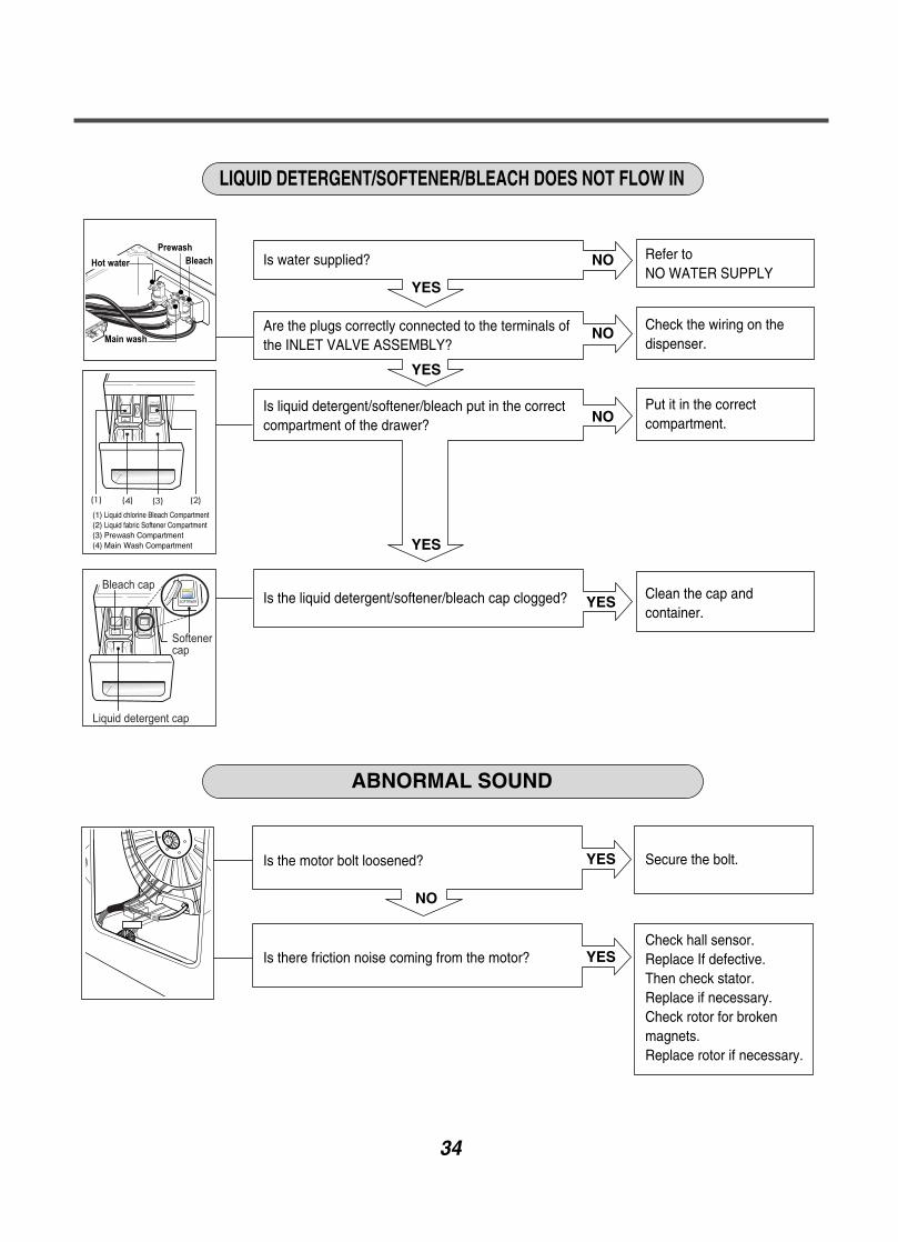
LIQUID DETERGENT/SOFTENER/BLEACH DOES NOT FLOW IN
ABNORMAL SOUND
Refer to NO WATER SUPPLY
Check the wiring on thedispenser.
Put it in the correctcompartment.
Clean the cap andcontainer.
Secure the bolt.
Check hall sensor.Replace If defective.Then check stator.Replace if necessary.Check rotor for brokenmagnets.Replace rotor if necessary.
YES
NO
YES
YES
YES
YES
YES
NO
NO
NO
Is water supplied?
Are the plugs correctly connected to the terminals ofthe INLET VALVE ASSEMBLY?
Is liquid detergent/softener/bleach put in the correctcompartment of the drawer?
Is the liquid detergent/softener/bleach cap clogged?
Is the motor bolt loosened?
Is there friction noise coming from the motor?

35
9-1. FILTER ASSEMBLY (LINE FILTER)
9. COMPONENT TESTING INFORMATION
When Resistance (Ohm) checking the Component, be sure to turn the power off,and do voltage discharge sufficiently.
Wiringdiagram
Circuit in the MAIN PWB / Wiring Diagram
Vac MAIN PWBASSEMBLY
WH RD
LI L2RI CI
C2
C3
1 1
2 2
3 3
3 3
2 2
1 1
Testpoints
and
Result
Test Points Result
WH (1) to RD (3)
WH (3) to RD (1)
0 Ω0 Ω
(1) (3)
(3)(1) RD
WH
WARNING

36
9-2. DOOR LOCK SWITCH ASSEMBLY
Wiringdiagram
Circuit in the MAIN PWB / Wiring Diagram
MAIN PWB
Vdc
Vac
MICOM 12V12V
4 13 2
4 13 2
Relay RelayNA4
1234
1234
234
PTC
PTC
Door switch
SO
LEN
OID5
YLBL
RDBK
ACCommonterminalof Valve
Function The Door Lock Switch Assembly consists of a Heating PTC, a Bimetal,a Protection PTC, and a Solenoid. It locks the door during a wash cycle.
1.Operation for door closing- After the system turns on, PTC heating starts up through terminal 2~4’s
authorizing the power on.- After PTC heating starts up and before solenoid operation is driven,
force the system to the off position through CAM.Door close
- Authorizing one impulse through terminal 3~4 (PTC & solenoid) willmake the door locked.
- Door lock is detected when switches in terminal 4~5 are set closed.CAM rotation will forcibly clear off the connection.The maximum, allowable number of impulse authorizations is 2.Upon the third authorization of the impulse, the position of CAM goesback to the door-open position.
- Authorizing the impulse occurs in 4.5 seconds upon input for maxperformance and two authorization processes are allowed at most.
Normal operation period of PTC heating: 1.5 – 5 seconds.(Defects from the development process.)
2.Operation for door opening- With a temporary stop, door automatically opens by CAM rotations after
authorizing the impulse from the terminal 3 ~ 4 and the power turns off – maximum of 3 times of the authorizing period.
- Upon the fourth authorization of the impulse, the position of CAM goesback to the door-close position.

37
Testpoints
ResultTest Points
(2) to (4)
(3) to (4)
(4) to (5)
(2) to (4)
Result
700-1500 Ω60-90 ΩInfinity
120 Vac
Remarks
At 77°F (25°C)
At 77°F (25°C)
Voltage Input
(2)(3)
(4)(5)

38
9-3. STATOR ASSEMBLY
Wiringdiagram
Circuit in the MAIN PWB / Wiring Diagram
MAIN PWB
MICOM
Ha
12V
NA1NA
WH WHGND
MO
TORHb
Ha
RD RDBLBL
GY
YLwwvu
vu
BLRD
RDRD4
IPM
GY
YL wuv
BLRD
1
1 12
34
23
123
123
123
123
1
32 2
1
3
4
12345
12345
234
1234
Hb
Function
Test points(Windings)
Result(Windings)
The DD motor can be driven from stopped to maximum speed in infinite steps ineither direction.There are 36 poles on the stator; 12 permanent magnets spaced around the rotor.There are no brushes to wear out. Unlike a more traditional brushless motor, therotor surrounds the stator rather than being attached to it.
Test Points Result
(1) to (2)
(2) to (3)
(3) to (1)
5-15 Ω5-15 Ω5-15 Ω
WINDINGS
HALL SENSOR
(1)(2)
(3)

39
Test point
and
Result(Hall Sensor)
The hall sensor determines the speed and direction of the motor.It also can read that the load is off balance when the drum speed fluctuates.
- Voltage Testing Hall Sensor at Stator
If measuring voltage from the Main PCB Assembly to the Hall Sensor, use thefollowing steps:1. Unplug power cord.2. Remove rear washer panel.3. Locate Hall sensor connector on the stator behind the rotor.4. Place meter leads on terminals 5 to 4, white to gray.5. Plug in power cord, close door, and press power button.
DO NOT PRESS START!6. You should measure 10 to 15 Vdc. If 10 to 15 Vdc is present, control board,
white wire, and gray wire are OK! If not follow testing output voltages on controlboard in next section.
(1) (3) (5)(2) (4)

40
Test Point
and
Result (Hall Sensor)
1. Unplug power cord.2. Remove rear panel.3. Remove Washer Top.4. Remove Main PCB Assembly cover as shown in Figure below.5. Locate the white Hall Sensor 4 wire connector using wiring diagram wire colors
as your guide.6. Plug in power cord, close door, and press power button. DO NOT PRESS
START!7. Place meter leads on White & Gray wires. You should read 10 to 15 Vdc output
from the Main PCB Assembly to the Hall sensor. If no 10 to 15 Vdc ismeasured the control board is defective.
8. Place meters leads on Blue to Gray. Turn motor rotor slowly by hand. Youshould measure a pulsing 10 Vdc. Place meter leads on Red to Gray. Turnmotor rotor slowly by hand. You should measure a pulsing 10 Vdc. If both testsmeasure a pulsing 10 Vdc, hall sensor and harness OK. If either or both testsmeasures 9 to 10 volts, but does not pulse or change, Hall sensor has failedand must be replaced. IF zero (0) voltage is measured on either test, check red& blue wires for continuity. Repair or replace harness as needed.
- Voltage Testing Hall Sensor from the Main PCB Assembly
7. To measure output signal voltage from the hall sensor, carefully move testleads to terminals 1 to 4, blue and gray. Slowly rotate motor rotor by hand. You should read a pulsing 10 Vdc. If 10 Vdc is measured from 1 to 4, movelead on blue wire to red wire, terminal 2. Repeat rotating motor rotor by hand.You should read a pulsing 10 Vdc from red to gray.
8. If pulsing 10 Vdc is measured from 1 to 4 and 2 to 4, hall sensor is OK! If eithertest netted only 9 to 10 Vdc without changing (no pulsing) the hall sensor islikely defective. Disconnect power by unplugging washer and ohm check hallsensor to verify failure of the hall sensor.
Test Points
(1) to (2)
(1) to (3)
(1) to (4)
(2) to (4)
(3) to (4)
Result
8-12 kΩ8-12 kΩ
10-15 Vdc
10 Vdc
10 Vdc
Remarks
Voltage Input
Pulsing Signal
Pulsing Signal
(3) (4)
(1) (2)
41
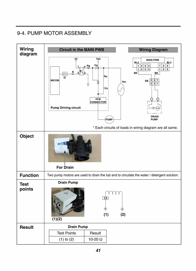
9-4. PUMP MOTOR ASSEMBLY
Wiringdiagram
Circuit in the MAIN PWB Wiring Diagram
MICOMIC
R
5V
Rg Cg
Vdc
Rs
Cs
PCBCONNECTOR
PUMP
Vac
2
1 4
3
Pump Driving circuit
MAIN PWBBL4
1 2 3 1 2 3
3 2 13 2 1
1 2 34
1 2 3 4
BL3
SB
BKBN
DRAINPUMP
Object
Function
Testpoints
Result
* Each circuits of loads in wiring diagram are all same.
Two pump motors are used to drain the tub and to circulate the water / detergent solution.
Drain Pump
Drain Pump
Test Points Result
(1) to (2) 10-20 Ω
T.P
For Drain
(1)(2)(1) (2)
42
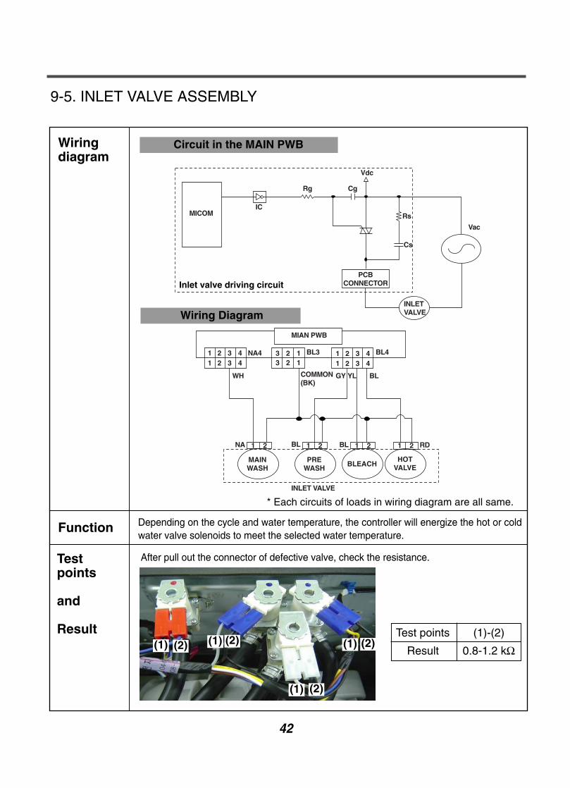
9-5. INLET VALVE ASSEMBLY
Wiringdiagram
Circuit in the MAIN PWB
INLETVALVE
Vac
Rs
Vdc
CgRg
ICMICOM
Cs
PCBCONNECTORInlet valve driving circuit
Function
Testpoints
and
Result
Depending on the cycle and water temperature, the controller will energize the hot or coldwater valve solenoids to meet the selected water temperature.
After pull out the connector of defective valve, check the resistance.
Test points (1)-(2)
Result 0.8-1.2 kΩ
Wiring Diagram
MAINWASH
PREWASH
BLEACHHOT
VALVE
1 2 1 2 1 2 1 2 RDBLBLNA
WH
NA4
GY YL BL
BL4BL3 4321123123 4321
43214321
COMMON(BK)
MIAN PWB
INLET VALVE
* Each circuits of loads in wiring diagram are all same.
(1) (2) (1) (2)
(1) (2)
(1) (2)

43
9-6. HEATER ASSEMBLY
Wiringdiagram
Circuit in the MAIN PWB
MICOM
12V
X100
Heater
Vac
43
43
Tab Relay
Heater driving circuit
Wiring diagram
MAIN PWB
1 21 2
1 21 2
BKYL
BN RD BK
(X71) (X134)
WASHHEATER
YL
FU
SE
Function
Testpoints
Result
1. The Wash Heater is designed to raise the wash water to the desired temperatureselection during certain wash cycles.
2. The Steam generator heater is designed to make the water to the steam duringsteam cycles.
Wash Heater
* Each circuits of loads in wiring diagram are all same.
Wash Heater
Test Points Result
(1) to (2) 12-18 Ω
(1) (2)

44
9-7. THERMISTOR ASSEMBLY
Wiringdiagram
Circuit in the MAIN PWB / Wiring Diagram
MAIN PWB
MICOM
NA3
BL
WH
1
2
WASHTHERMISTOR
3
4
5
6
15V
5V
RR
RR
C
C C
C
2
3
4
5
6
Function
Testpoints& Result
The thermistor (temperature sensor) is used to monitor water temperature in the tubor Steam Generator.
Wash Thermistor
(1)
(2)
TestPoints
(1)
to
(2)
Result(tolerance ±5%)
39.5 kΩ
26.1 kΩ
12.1 kΩ
8.5 kΩ
3.8 kΩ
2.8 kΩ
Remarks
At 86°F (30°C)
At 104°F (40°C)
At 140°F (60°C)
At 158°F (70°C)
At 203°F (95°C)
At 221°F (105°C)

10. DISASSEMBLY INSTRUCTIONS
45
CONTROL PANEL ASSEMBLY
1 Unscrew 2 screws on the back of the top plate.
Be sure to unplug the machine before disassembling and repairing the parts.
2 Pull the top plate backward and upward as shown.
4 Pull out the drawer and unscrew 2 screws.
5 Remove one screw.
8 Disassemble the Display PWB Assembly.
6 Lift the side the control panel assembly and
pull it out
7 Unscrew the 8 screws from the control panel
assembly.
3 Disconnect the Display PWB assembly connector
from trans cable.

46
MAIN PWB ASSEMBLY
1 Disconnect the POWER connector and SENSOR
SWITCH ASSEMBLY.
2 Remove the Protective cover.
3 Disconnect the connectors.
4 Unscrew 1 screw on the back.
5 Remove the Main PWB.
47
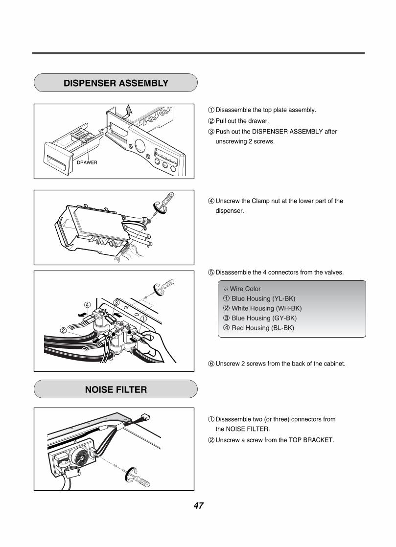
Wire Color
Blue Housing (YL-BK)
White Housing (WH-BK)
Blue Housing (GY-BK)
Red Housing (BL-BK)
DISPENSER ASSEMBLY
NOISE FILTER
1 Disassemble the top plate assembly.
2 Pull out the drawer.
1 Disassemble two (or three) connectors from
the NOISE FILTER.
2 Unscrew a screw from the TOP BRACKET.
4 Unscrew the Clamp nut at the lower part of the
dispenser.
5 Disassemble the 4 connectors from the valves.
6 Unscrew 2 screws from the back of the cabinet.
3 Push out the DISPENSER ASSEMBLY after
unscrewing 2 screws.
1
2
3
4
48
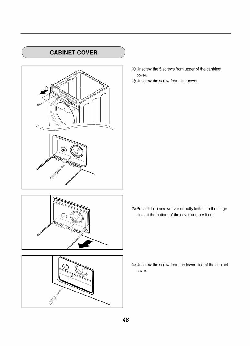
CABINET COVER
1 Unscrew the 5 screws from upper of the canbinet
cover.2 Unscrew the screw from filter cover.
3 Put a flat ( -) screwdriver or putty knife into the hinge
slots at the bottom of the cover and pry it out.
4 Unscrew the screw from the lower side of the cabinet
cover.

49
5 Open the door.
6 Disassemble the clamp assembly.
7 Tilt the cabinet cover.
8 Disconnect the door switch connector.
9 Lift and separate the cabinet cover.
10 Disassemble the clamp assembly.
11 Disassemble the gasket.
NOTE: When assembling the CABINET
COVER, connect the door switch connector.

50
MOTOR/DAMPER
1 Disassemble the back cover.
2 Remove the bolt.
3 Pull out the Rotor.
1 Unscrew the 2 screws from the tub bracket.
2 Remove the 6 bolts on the stator.
3 Unplug the 2 connectors from the stator.
1 Disassemble the damper hinges from the tub and
base.
NOTE
If you pull the dampers apart, the must be
replaced. If you do not separate them, they
can be re-used.

51
A450
A485
A455
A410
A152
A111A110
A150
A154
A140
A310
A303
A300
A200
A155
A440
A430
A100
A101
A133
A130
A151 A153A131
A201
A220
F110
F215
F210
A105 A106A104A102
A103
A390
Printed materials
Description*Owner’s Manual
*Energy Label
Loc No.
*Service Manual
*Wiring Diagram
*Quick Start Guides
*Installation Sheet
G001
G002
G004
G005
G006
G007
“The following parts are not illustrated"
A141
11-1. CABINET & CONTROL PANEL ASSEMBLY
11. EXPLODED VIEW
52
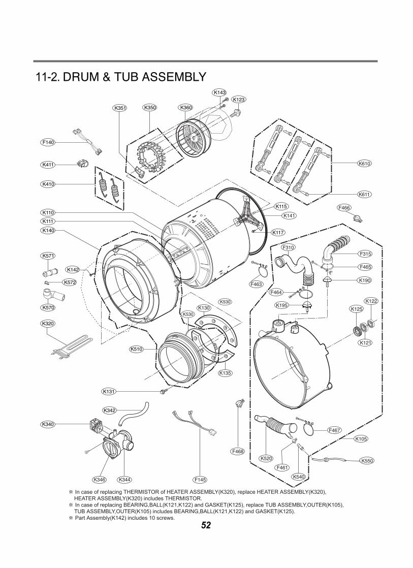
11-2. DRUM & TUB ASSEMBLY
K344K346
K123
K111
K140
K110
K410
K411
F140
K351 K350 K360
K143
K340
K320
K510
K342
K131
F466
K130
K610
K611
F145
F468
K135
K530
K530
※ In case of replacing THERMISTOR of HEATER ASSEMBLY(K320), replace HEATER ASSEMBLY(K320), HEATER ASSEMBLY(K320) includes THERMISTOR.※ In case of replacing BEARING,BALL(K121,K122) and GASKET(K125), replace TUB ASSEMBLY,OUTER(K105), TUB ASSEMBLY,OUTER(K105) includes BEARING,BALL(K121,K122) and GASKET(K125).※ Part Assembly(K142) includes 10 screws.
F315
F465
K125
F467
F463
F464
F310
K121
K122
K550
K540
F461
K520
K105
K190
K195
K142
K571
K572
K570
K115
K141
K117

53
11-3. DISPENSER ASSEMBLY
HOT (RED)
COLD (BLUE)
F300
F227
F220
F225
F430
F170
F160
F441
F120
F130
F432
A275
A276
F226
F323
F462
F322
F321