ELECTRIC & GAS DRYER SERVICE MANUAL - Appliance ...
45
ELECTRIC & GAS DRYER SERVICE MANUAL CAUTION READ THIS MANUAL CAREFULLY TO DIAGNOSE TROUBLES CORRECTLY BEFORE OFFERING SERVICE. MODEL : 796.8044*.900 / 796.8044*.900 796.9044*.900 / 796.9044*.900 Website:http://www.sears.com
-
Upload
khangminh22 -
Category
Documents
-
view
0 -
download
0
Transcript of ELECTRIC & GAS DRYER SERVICE MANUAL - Appliance ...

ELECTRIC & GAS DRYERSERVICE MANUALCAUTION
READ THIS MANUAL CAREFULLY TO DIAGNOSE TROUBLES CORRECTLY BEFORE OFFERING SERVICE.
MODEL : 796.8044*.900 / 796.8044*.900796.9044*.900 / 796.9044*.900
Website:http://www.sears.com

AUG. 2009 PRINTED IN KOREA P/No.:MFL62119909

2
To avoid personal injury, disconnect power before servicing this product. If electrical power is requiredfor diagnosis or test purposes, disconnect the power immediately after performing the necessary checks.
! WARNING !
WHAT TO DO IF YOU SMELL GAS:
IMPORTANT SAFETY NOTICEThe information in this service guide is intended for use by individuals possessing adequate backgrounds
of electrical, electronic, and mechanical experience. Any attempt to repair a major appliance may result inpersonal injury and property damage. The manufacturer or seller cannot be responsible for theinterpretation of this information, nor can it assume any liability in connection with its use.
RECONNECT ALL GROUNDING DEVICESIf grounding wires, screws, straps, clips, nuts, or washers used to complete a path to ground are
removed for service, they must be returned to their original position and properly fastened.
IMPORTANTElectrostatic Discharge (ESD)
Sensitive ElectronicsESD problems are present everywhere. ESD may damage or weaken the electronic
control assembly. The new control assembly may appear to work well after repair isfinished, but failure may occur at a later date due to ESD stress. Use an anti-static wrist strap. Connect wrist strap to green ground connection point or unpainted
metal in the appliance.- OR -
Touch your finger repeatedly to a green ground connection point or unpainted metal in the appliance. Before removing the part from its package, touch the anti-static bag to a green ground connection
point or unpainted metal in the appliance. Avoid touching electronic parts or terminal contacts; handle electronic control assembly by edges only. When repackaging failed electronic control assembly in anti-static bag, observe above instructions.
Do not try to light a match, or cigarette, or turn onany gas or electrical appliance.
Do not touch any electrical switches. Do not use anyphone in your building.
Clear the room, building or area of all occupants.
Immediately call your gas supplier from a neighbor’sphone. Follow the gas supplier’s instructionscarefully.
If you cannot reach your gas supplier, call the firedepartment.

3
CONTENTS
1. SPECIFICATIONS ..................................................................................................................42. FEATURES AND BENEFITS .................................................................................................... 53. INSTALLATION INSTRUCTIONS ............................................................................................ 64. COLUMBUS DRYER CYCLE PROCESS .................................................................................... 95. COMPONENT TESTING INFORMATION ..............................................................................106. MOTOR DIAGRAM AND SCHEMATIC..................................................................................137. CONTROL LAY - OUT .........................................................................................................148. WIRING DIAGRAM ............................................................................................................159. STEAM FUNCTION ............................................................................................................16
9-1. STEAM CYCLE GUIDE .................................................................................................169-2. TROUBLESHOOTING FOR STEAM DRYER ....................................................................179-3. DISPLAY FAULT/ERROR CODES FOR STEAM DRYER .....................................................17
10. DIAGNOSTIC TEST ...........................................................................................................1810-1. TEST 1 120VAC ELECTRICAL SUPPLY ........................................................................1910-2. TEST 2 THERMISTOR TEST --- MEASURE WITH POWER OFF ......................................2210-3. TEST 3 MOTOR TEST ...............................................................................................2310-4. TEST 4 MOISTURE SENSOR ....................................................................................2410-5. TEST 5 DOOR SWITCH TEST ..................................................................................2510-6. TEST 6 HEATER SWITCH TEST - ELECTRIC TYPE..........................................................2610-7. TEST 7 GAS VALVE TEST - GAS TYPE........................................................................27
11. CHANGE GAS SETTING (NATURAL GAS, PROPANE GAS) ...............................................2812. DISASSEMBLY INSTRUCTIONS ..........................................................................................3013. EXPLODED VIEW ..............................................................................................................40
13-1. CONTROL PANEL & PLATE ASSEMBLY .......................................................................4013-2. PANEL DRAWER ASSEMBLY & GUIDE ASSEMBLY ......................................................4113-3. CABINET & DOOR ASSEMBLY ..................................................................................4213-4-1. DRUM & MOTOR ASSEMBLY : ELECTRIC TYPE ........................................................4313-4-1. DRUM & MOTOR ASSEMBLY : GAS TYPE ...............................................................44

1 SPECIFICATIONS
4
ITEM796.8044*.900 / 796.8044*.900 /796.9044*.900 / 796.9044*.900
REMARK
White / Patina Beige
Spray
Color
Top Plate
Door Trim
ELECTRICITYCONSUMPTION
MOTOR
HEATER
LAMP
GAS VALVE
CONTROL TYPE
DRUM CAPACITY
Weight (lbs): Net/Gross
No. of Programs
No. of Dry Option
No. of Temperature Controls
No. of Dry Levels
Audible End of Cycle Beeper
Moisture
Temperature
Reversible Door
Drum
Dryer Rack
Child lock
Interior Light
Product (WXHXD)
Packing (WXHXD)
Sensor
POWER SUPPLY
Material &Finish
Light Gray
120V / 240V 60Hz (26A)
250W (4.5A)
5400W (22.5A)
15W (125mA)
13W (110mA) X 2
Electronic
7.3 cu.ft.
126 / 144
9
5
5
5
High / Low / Off
Equipped
Equipped
Adopted
Double Coated Steel
Equipped
Equipped
Equipped
27" x 38" x 28 1/3"
29 1/2" x 44 3/4" x 30 3/4"
AC 120V
AC 240V ( ELECTRIC TYPE)
AC 120V
AC 120V ( GAS TYPE)
Electro sensor
Thermistor

2 FEATURES AND BENEFITS
5
Apply Model : 796.8044*.900 / 796.8044*.900 / 796.9044*.900 / 796.9044*.900

6
3-1. POWER CORD
INSTALLATION INSTRUCTIONS3
1) 4-wire connection
1. External ground connector - Dotted line showsposition of NEUTRAL ground wire before beingmoved to center terminal block screw
2. Center silver-colored terminal block screw3. Green wire of harness
1. External ground connector2. Green or bare copper wire of power supply cord3. 3/4 in. (1.9 cm) UL-listed strain relief4. Center silver-colored terminal block screw5. Neutral grounding wire (green)6. Neutral wire (white)
5. Connect the other wires to outer terminal blockscrews. Tighten screws.
6. Tighten strain relief screws.
7. Insert tab of terminal block cover into slot of dryerrear panel Secure cover with hold-down screw.
3. Connect ground wire (green or bare) of powersupply cable to external ground conductor screw.Tighten screw.
4. Connect neutral wire (white or center wire) ofpower supply cord to the center, silver coloredterminal screw of the terminal block.
1. 4-wire receptacle (NEMA type 14-30R)2. 4-prong plug3. Ground prong4. Neutral prong5. Spade terminals with upturned ends6. 3/4 in. (1.9 cm) UL approved strain relief7. Ring terminals
1. Remove center terminal block screw.
2. Remove appliance ground wire (green) fromexternal ground connector screw. Fasten it undercenter, silver colored terminal block screw.
IMPORTANT: A 4-wire connection isrequired for mobilehomes and where localcodes do not permit theuse of 3 wire connections.
1 2
3 4 5 7
6
65
3
2
14
31
2

7
2) 3-wire connection
Use where local codes permit connectingcabinet-ground conductor to neutral wire.
1. Remove center terminal block screw.
2. Remove appliance ground wire (green) fromexternal ground connector screw. Connectappliance ground wire and the neutral wire (whiteor center wire) of power supply cord/cable undercenter, silver colored terminal block screw.Tighten screw.
3. Connect the other wires to outer terminal blockscrews. Tighten screws.
Use where local codes permit connectingcabinet-ground conductor to neutral wire.
3) Optional 3-wire connection
1. Loosen or remove center terminal block screw.
2. Connect neutral wire (white or center wire) ofpower supply cord to the center, silver coloredterminal screw of the terminal block. Tighten screw.
1. External ground connector2. Neutral grounding wire (green)3. Center silver-colored terminal block screw4. Neutral wire (white or center wire)5. 3/4 in. (1.9 cm) UL-listed strain relief
3. Connect the other wires to outer terminal blockscrews. Tighten screws.
4. Tighten strain relief screws.
5. Insert tab of terminal block cover into slot of dryerrear panel. Secure cover with hold-down screw.
4. Tighten strain relief screws.
5. Insert tab of terminal block cover into slot of dryerrear panel. Secure cover with hold-down screw.
6. Connect a separate copper ground wire from theexternal ground connector screw to an adequateground.
1. External ground connector2. Neutral grounding wire (green)3. Neutral wire (white or center wire)4. Grounding path determined by a qualified electrician
1. 3-wire receptacle (NEMA type 10-30R)2. 3-wire plug3. Neutral prong4. Spade terminals with up turned ends5. 3/4 in. (1.9 cm) UL approved strain relief6. Ring terminals7. Neutral (white or center wire)
3
12
4
42
5
13
4
7 6
52
3
1

8
3-2. Connect Gas Supply Pipe (Gas Dryer ONLY)
2
35
1
4
1. Make certain your dryer is equipped for use with thetype of gas in your laundry room. Dryer is equippedat the factory for Natural Gas with a 3/8” N.P.T. gasconnection.
2. Remove the shipping cap from the gas connectionat the rear of the dryer. Make sure you do notdamage the pipe thread when removing the cap.
3. Connect to gas supply pipe using a new flexiblestainless steel connector.
4. Tighten all connections securely. Turn on gas andcheck all pipe connections (internal & external) forgas leaks with a non-corrosive leak detection fluid.
5. For L.P. (Liquefied Petroleum) gas connection, referto section on Gas Requirements.
For further assistance, refer to section on Gas Requirements.
1 New Stainless Steel Flexible Connector - Useonly if allowed by local codes (Use DesignA.G.A. Certified Connector)
2 1/8” N.P.T. Pipe Plug (for checking inlet gas pressure)
3 Equipment Shut-Off Valve-Installed within 6’(1.8 m) of dryer
4 Black Iron PipeShorter than 20’ (6.1 m) - Use 3/8” pipeLonger than 20’ (6.1 m) - Use 1/2” pipe
5 3/8” N.P.T. Gas Connection

4 DRYER CYCLE PROCESS
9
* Sensor dry : “Dry Level” is set by users.** Manual dry : “Temperature control” is set by users.Default settings can be adjusted by users.
Steam Refresh Mid High
Steam Sanitize
Heavy duty
Small Load
Air / Rack dry
70
54
55
41
36
32
30
50
Apply Model : 796.8044*.900 / 796.9044*.900

10
When checking the Component, be sure to turn the power off, and do voltage discharge sufficiently.
COMPONENT TESTING INFORMATION5
! CAUTION
Component Test Procedure Check result Remark
1. Thermal cut off
• Check Top Marking :N130
Measure resistance of terminalto terminal
① Open at 284 ± 12°F(140 ± 7°C)
② Auto reset -31°F (-35°C)Same shape as Outlet Thermostat.
If thermal fuse is open mustbe replaced
① Resistance value ≒ ∞
② Continuity (250°F ↓) < 1Ω
• Heater case-Safety
• Electric type
2. Hi limit Thermostat (Auto reset)
Measure resistance of terminalto terminal
① Open at 257 ± 9°F(125 ± 5°C)
② Close at 221 ± 9°F(105 ± 5°C)
① Resistance value ≒ ∞
② Resistance value < 5Ω
• Heater case - Hi limit
• Electric type
3. Outlet Thermostat ( Auto reset)
• Check Top Marking :N85
Measure resistance of terminalto terminal
① Open at 185 ± 9°F (85 ± 5°C)
② Close at 149 ± 9°F(65 ± 5°C)
Same shape as Thermal cut off.
① Resistance value ≒ ∞
② Resistance value < 5Ω
• Blow housing -Safety
• Electric type
4. Lamp holder Measure resistance of terminalto terminal
Resistance value :80Ω ~ 100Ω
6. Idler switch Measure resistance of thefollowing terminal :
“COM - NC”
1. lever open
① Resistance value < 1Ω2. Lever push (close)
② Resistance value ≒ ∞
5. Door switch Measure resistance of thefollowing terminal
1) Door switch knob : open
① Terminal : “COM” - “NC” (1-3)② Terminal : “COM” - “NO” (1-2)
2) Door switch push : push
① Terminal : “COM” - “NC” (1-3)② Terminal : “COM” - “NO” (1-2)
① Resistance value < 1Ω② Resistance value ≒ ∞
① Resistance value ≒ ∞② Resistance value < 1Ω
The state thatKnob ispressed isopposite toOpencondition.

11
Component Test Procedure Check result Remark
7. Heater Measure resistance of thefollowing terminal
① Terminal : 1 (COM) - 2② Terminal : 1 (COM) - 3③ Terminal : 2 - 3
① Resistance value : 10Ω② Resistance value : 10Ω③ Resistance value : 20Ω
• Electric type
8. Thermistor Measure resistance of terminalto terminal
Temperature condition :58°F ~ (10~40°C)58°F ~ 104F (10~40°C)
Resistance value : 10Ω • Heater case - Hi limit
• Electric type
9. Motor • See Page 13
10. Gas valvevalve 1
valve 2
Measure resistance of thefollowing terminal
① Valve 1 terminal② Valve 2 terminal
① Resistance value : > 1.5kg ~② Resistance value :
> 1.5~2.5kg
• Gas type
11. Igniter Measure resistance of terminalto terminal
Resistance value : 100~800Ω • Gas type
12. Frame Detect Measure resistance of terminalto terminal
① Open at 370°F ((Maximum)② Close at 320°F
① Resistance value ≒ ∞② Resistance value < 1Ω
• Gas type
①
②③

12
Component Test Procedure Check result Remark
13. Hi-limit Thermostat(Auto reset)
• Check Top Marking :N95
Measure resistance of terminalto terminal
① Open at 203 ± 7°F (95 ± 5°C)② Close at 158 ± 9°F (70 ± 5°C)
① Resistance value ≒ ∞② Continuity < 1Ω
• Gas type
• Gas funnel-Hi-limit
13. Thermal Cut off(Manual reset)
• Check Top Marking :N110
Measure resistance of terminalto terminal
① Open at 230 ± 12°F(110 ± 7°C)
② Manual reset
If thermal fuse is open mustbe replaced
① Resistance value ≒ ∞
② Continuity < 1Ω
• Gas type
• Gas funnel-Safety

13
MOTOR DIAGRAM AND SCHEMATIC6
Contact On / Off by Centrifugal Switch
STOP MODE (When Motor does not operate)
RUN MODE (Motor operates)
When checking Component, be sure to turn Power off, then do voltage discharge sufficiently.NOTE
Centrifugal switchCentrifugal switch
(Pull Drive forward)

7 CONROL LAY - OUT
PWB ASSEMBLY DISPLAY LAY-OUT
PWB ASSEMBLY LAY-OUT
14

8 WIRING DIAGRAM
15
ELECTRIC DRYER WIRING DIAGRAM
Label all wires prior to disconnection when servicing controls. Wiringerrors can cause improper and dangrous operation. Verify properoperation after servicing.
GAS DRYER WIRING DIAGRAM
Apply Model : 796.8044*.900 / 796.8044*.900
Apply Model : 796.9044*.900 / 796.9044*.900
!

16
9-1. Steam Cycle Guide
IMPORTANT NOTES ABOUT STEAM CYCLES:
The steam feeder must be filled with water up to the MAX line. Otherwise, an error messagewill be displayed.
If the lint filter or exhaust duct is clogged, the Steam options will not give proper results.
For best results, load articles of similar size and fabric type. Do not overload.
Water only - Do not add any additives or other materials as these will damage your dryer.
Before moving the dryer, make sure the steam feeder is empty.
Best results are obtained with cotton/poly blend fabrics.
STEAMTEMP.
CONTROLDRY
LEVELFABRIC STATE
FABRIC TYPE
MAXIMUM AMOUNT
DEFAULT TIME
9 STEAM FUNCTION
STEAM SANITIZE
STEAM REFRESH
NORMALBULKY/BEDDING
HEAVY DUTYCASUAL,
DELICATESSMALL LOAD
TIMED DRY
+REDUCESTATIC
+REDUCESTATIC
+REDUCESTATIC
39 minutes
20 minutes
10 minutesOnly reduce
static
Followselected
cycle
45 minutes
Dry
Dry
Dry
Wet
Wet
Comforter Bedding
Children’sclothing
Single (1 each)
3 lbs.
ComforterShirts*
Single (1 each)5 each
Shirts* 8 lbs.(18 Items.)
Follow selected
cycle
8 lbs.(18 Items.)
Follow selected
temp
8 lbs.(18 Items.)

17
9-2. Troubleshooting for Steam Dryer
9-3. Display Fault/Error Codes for Steam Dryer
PROBLEM
Water drips from nozzle when Steam Cycle starts.
This is normal.
This is normal.
This is normal.
This is normal.
This is steam condensation. The dripping water will stop after a short time.
The drum does not turn during Steam Cycle.
The drum is turned off and only tumbles intermittently so that the steam vapor remains in the drum.
Can not see steam vapor at the beginning ofcycle.
The display shows: MORE TIMEpressed.
Pressing the MORE TIME button adjusts the load size from 1 to 5 articles or a big load indicated by in the display.
Steam is not visible during Steam Cycle.
This is normal. Steam vapor is difficult to see when the door is closed, although condensation may form on the inside of the door.
Steam is released at different stages of the cycle for each option. Steam will not normally be visible, although condensation may form on the inside of the door.
Top plate of the dryer is very warm.
Top plate gets very warm during steam operation.
SOLUTIONSPOSSIBLE CAUSES
The error codes below will be displayed when attempting to start a dryingcycle, or after activating the Diagnostic Test mode.
tE4
E1
E3
E4
E5
Thermistor ofsteam generator
Steam generator thermistor open or shorted. tE4 error is only displayed in the test mode. Replace the steam generator.
If water in the steam feeder is less than about 2/3 full, this error may be displayed. Fill the feeder and restart the cycle.
Steam generator element is not heating and generator may need to be replaced.
E5 error is only displayed in the test mode. Replace the steam feeder pump.
Check the hose and nozzle for clogging. CAUTION: The hose and nozzle will be extremely hot during and immerdiately after steam operation.
Steam generator temperature exceeds 116 deg for more than 3 seconds. Steam hose or nozzle is clogged.
Sensors do not detect that steam generatoris full within 60 seconds.
Steam generator temperature does not rise 4∞C every 2 minutes or the temperature is less than 80∞C for 3 secondsafter steam temperature has been reached.
When the AD value of the pump less than 10 in the test mode.
Steam generator
Steam generator
Steam generator
Pump
DISPLAY CAUSE REMARKCHECKING PART

18
ACTIVATING THE DIAGNOSTIC TEST MODE1. UNIT must be in standby (unit plugged in, display off)
2. Press POWER while pressing MORE TIME and LESS TIME simultaneously.
3. Press START/PAUSE button to advance through diagnostics.
To check pump operation:When pressed 4 times in the test mode, If the AD value of the pump is higher than 10 on the display, the pump is normal. If it is lower than 10, E5 error will be displayed.
DIAGNOSTIC TEST101. This TEST should be used for Factory test /Service test. Do not use this DIAGNOSTIC TEST other than specified.
2. Activating the Heater manually with the Door open may trip the Thermostat attached to the Heater, therefore do not activate itmanually. (Do not press the door switch to operate the heater while the door is open )
CHECKING DISPLAY CHECKPOINTACTION
Pressing the START/PAUSE
8E9(Elec Type)898(Gas Type)
Standard
Displays Moisture Sensor Operation :
ELECTRIC TYPE: Heater 1 and heater 2 are energized - 5400 W
GAS TYPE: Gas valve is energized (Temperature in the drum is displayed in degrees C.)
If moisture sensor is contacted with damp cloth. The display number isbelow 180 in normal condition
Current Temp.(5~70)
ELECTRIC TYPE Heater 1 is energized - 2700 W
GAS TYPE Valve runs(Temperature in the drum is displayed in degrees C.)
Current Temp.(5~70)
11 = Lowpump*
255 = Highpump*
Electric control &
Temperature sensorNone
30 = Lowmoisture
239 = Highmoisture
Motor+ControllerOnce
4 times
V00 PGM Ver (8E8-V008E8)Thermistor open
tE2 Thermistor shortedtE4 AG Thermistor open or shorted
tE1
Motor runs
Pump runs
Power off
Twice
ELECTRIC TYPE Motor+Heater1(2700W)
GAS TYPEMotor+Gas valve
3 times
ELECTRIC TYPE Motor+Heater1+Heater2 (5400W)
GAS TYPEMotor+Gas valve
Motor,Pump,Heater2 offLoads, Controller off
Motor+Pump+Heater2(runs for 1sec)
(Heater1 off)
OOE5 Pump Error
5 times6 times

19
With the dryer plugged in, press thePOWER button to turn on dryer.
Replace the power cord.
Check the voltage at the main PCBbetween WH1-1 (WH) and the blackwire on the black tab relay. Is 120VAC present while pressing the startbutton?
(NOTE: For gas dryers skip this step.)With the dryer plugged in, check thevoltage at the terminal block betweenthe neutral (WH) and L1 (BK)terminals. Is the voltage 120 VACwhile pressing the START/PAUSEbutton?
With the dryer plugged in, check thevoltage at the power cord plugbetween the neutral and L1 (and L2for electric dryers). Is the voltage 120VAC while pressing theSTART/PAUSE button?
•Replacemain PCB.
•ReplacedisplayPCB.
•Checkpower cord.
•Checkterminalblockconnections.
•Check thepowersupply fuseor circuitbreaker.
•Check thereceptacleconnections.YES
YES
NO
NO
NO
YES
YES
NOTE: To properly check power supply in case of floating neutral or high resistance connections, a load must be applied to the circuit. It isimportant that the power button be pressed while checking the voltages asdescribed below.
Test 1 120V AC Electrical supply

20
Caution
Trouble Symptom
2. Status Mode Of The Connection
1.Power Connection
Measurement Condition
When measuring power, be sure to wear insulated gloves, to and avoid anelectric shock.
Check the Tab Relays Connection properly.
With Dryer Power On; Connector linked to Controller.
T a
T a
Trans
Tab Relay 1 Tab Relay 2
B R
HighMid HighMedium
HighMid HighMedium
Temperature Control below 68±4°C.Turn on Heater1 and Heater2.
Temperature Control below 70±4°C.Turn on Burner
Temperature Control below 47±4°C.Turn on Burner
Temperature Control below 52±4°C.Only Turn on Heater1.
on
on
O O
OO
onoff off
on on on
LowExtra Low
PCB ASSEMBLY LAYOUTLowExtra Low
T a R
Connector Housing
Black
Check the Matching color Between Harness wire and Tab Relay.(Black Housing – Black Tab Relay)
Check the Matching color Between Harness wire and Tab Relay.(White Housing – White Tab Relay)
White
Color
< Table1 > : Connection of the Tab Relay with Heater (Elec)
< Table 2 > : Connection of the Tab Relay with Burner (Gas)
< Table1 > : Connection of Tab Relay with the Tab Relay of the PCB ASSEMBLY (Elec)
Harness
ConnectionRemark
PCB
1
2
Yellow Wire
Black Wire
Connector Housing Tap relay 1
Tap relay 2
1
2
Blue Wire
Black Wire
Connector Housing

21
3. Status Mode Of wrong Connection
1.Black and White Housing
2.Black Housing
3.White Housing
4.Black and White Housing
5.Black and White Housing
Off
Off
Normal
Heater2
Off
Off
Off
Normal
Heater1
Off
Power Off
Power Off
Power On
Power On
Power Off
Wire ①, ② CROSS
Wire ①, ② CROSS
Wire ①, ② CROSS
Housing CROSS
Housing and Wire ①, ②CROSS
Items CaseHeater1
Operation(black)Heater2
operation(White) PCB condition Of operation
1.Black and White Housing Off Off Power OffWire ①, ② CROSS
Items CaseHeater1
Operation(black)Heater2
operation(White) PCB condition Of operation
- In case of power failure(<Table1>-1,2,5,<Table2>-1), Please check the Connection of “2.Status Table of Connection”. In case of power failure(<Table1>-4), please check the Connection of “2. Status Table of Connection”. Because improper
Connection of the equipment-dryer can be damaged of changing heater.
! CAUTION
Connector Housing Black
Check the Matching color Between Harness wire and Tab Relay.(Black Housing – Black Tab Relay)
Color
< Table 2 > : Connection of Tab Relay with PCB ASSEMBLY (Gas)
< Table1 > : Wrong Connection of the Tab Relay and Connector Housing (Elec)
< Table2 > : Wrong Connection of the Tab Relay and Connector Housing (Gas)
Harness RemarkPCB
Tap relay 1
1
2
Blue Wire
Black Wire
Connector Housing

22
Disconnect the thermistorfrom the harness connectorand measure the resistanceof the thermistor. Does theresistance measured matchthe temperature of thethermistor in the chart? (Useroom temperature unless thethermistor is warm fromrunning the dryer.)
•Measure resistance of all wires. Resistance should be < 0 Ω. •Check all thermistor harness connectors for corrosion, loose/bent pins,broken wires, etc.
•Check all harness wires for cuts, or broken wires.
Measure the resistance betweenthe NA6-1 (RD) and NA6-4 (BL).Does the resistance measuredmatch the temperature of thethermistor in the chart? (Useroom temperature unless thethermistor is warm from runningthe dryer.)
Disconnect the NA6connector from the mainPCB.
Measure the resistancebetween the NA6-6 (GN) pinand a chassis ground screw.Is the resistance <1 Ω ?
•Replace themain PCB
•Check allwiring harnessconnections,wires andgroundscrews.
•Replace thethermistor
Test 2 Thermistor Test---Measure with Power Off
YES
NO
YES
NO
NO
YES

23
• Replace the outletthermal fuse.
• Check the thermistor(test # 3).
• Check exhaustsystem for restrictions.
With the connectors disconnected,check the resistance between theterminals of the thermal fuse on theblower housing. Is the resistance 0Ω ?
YES
NO
Is the arm of the idler pulleycontacting the belt switch lever?(Normal operating position is NOCONTACT.)
With the connectors disconnected, checkthe resistance between terminals 1 and 2(N.O.) of the belt switch on the motormount. Is the resistance <1 Ω with noswitch contact?
•Check idler pulleyand arm.
•Check drum beltcondition(stretched/broken)
•Check drum beltrouting
•Replace the beltswitch.
• Check Motor. (Refer to MOTOR DIAGRAM AND SCHEMATIC.)• Check if control connector is plugged in.
YES
YES
NO
•Recheck voltage atmain PCB andreplace if novoltage.
With the connectors disconnected,check the resistance between BL2-1(BN) and BL3-3 (YL). Is theresistance 2-4 Ω ?
Measure with the door closed.
YES
NO
With the connectors disconnected,check the resistance between WH1-1 (WH) and BL3-2 (BN). Is theresistance 2-4 Ω ?
Measure with the door closed.
In diagnostic test mode, press theSTART / PAUSE button. Is thevoltage 120 VAC between WH1-1(WH) and BL3-1 (BN)?
•Recheck voltage atmain PCB andreplace if novoltage.
•Replace mainPCB
YES
YES
NO
NO
YES
•Check door switchactivation.
•Check wiringharness andconnections.
•See DOORSWITCH TEST #5.
With the connectors disconnected,check the resistance between WH1-1 (WH) and BL3-3 (YL). Is theresistance 0 Ω ?
Measure with the door closed.
NO
Test 3 Motor test

24
Disconnect the NA6 connectorfrom the main PCB. Measurethe resistance between theNA6-6 (GN) pin and a chassisground screw. Is the resistance<1 Ω ?
Put a jumper between NA6-2(OR) and NA6-4 (BL) to createa circuit connection for thecontinuity test in the next step.
Measure the resistancebetween the two moisturesensor bars on the in the lintfilter housing inside the drum.Is the resistance <1 Ω?
Check all connections andwires between the NA6terminal at the main PCB andthe sensor bars. Check theresistance is 0Ω.
•Measure the resistance of all wires.Resistance should be < 1 Ω.
•Check all sensor harness connectors forcorrosion, loose/bent pins, broken wires,etc.
•Check all harness wires between the mainPCB and the sensor for cuts, or brokenwires.
•Check allwiringharnessconnections,wires andgroundscrews.
•Replace themain PCB.
Test 4 Moisture sensor
YES
YES
YES
YES
NO
NO

25
Disconnect the WH1 and BL3connector from the main PCB.Measure the resistance betweenthe NA6-6 (GN) pin and a chassisground screw. Is the resistance <1Ω ?
Disconnect the WH1 and BL3connector from the main PCB.Measure the resistance betweenWH1-1 (WH) and BL3-3 (YL). Is theresistance < 1 Ω with the doorclosed and Ω with the dooropen?
*Skip this step if the dryer does nothave a drum light.Disconnect the BL3 and the blacktab relay connectors from the mainPCB. Measure the resistancebetween BL3-3 (YL) and the BK wireon the black tab relay connector. Isthe resistance <1 Ω with the dooropened and Ω with the doorclosed?
Refer to the individual door switch and lightbulb/socket component tests.
•Replace themain PCB.
•Replace thelight bulb.
•Replace thelight socket.
3
BL3
Test 5 Door switch test
YES
YES
NO
NO
NO
26
Test 6 Heater switch test - Electric Type
Disconnect the YL3, black tabrelay and white tab relayconnectors at the main PCB.Measure the resistance betweenYL3-1 (WH) and the YL wire onthe black tab relay connector. Isthe resistance 18-22 Ω ?
Measure the resistance betweenYL3-1 (WH) and the BL wire onthe white tab relay connector. Isthe resistance 18-22 Ω ?
•Check wiring andconnectors to theelement.
•See elementcomponent test.
•Check wiring andconnectors to theelement.
•See elementcomponent test.
•Check wiring andconnectors to theelement.
•See elementcomponent test.
•Check powersupply.
•Replace theelement.
Measure the resistance betweenthe YL wire on the black tab relayand the BL wire on the white tabrelay connectors. Is theresistance 36-44 Ω ?
Measure the resistance betweenterminals 1 (RD) and the heaterhousing. Is the resistance Ω ?
Refer to the hi-limit thermostat and thermal cutoff component tests.
Enter diagnostic mode and pressthe START/PAUSE button twice.Measure the voltage betweenYL3-1(WH) and the YL wire onthe black tab relay. Is thevoltage 240 VAC?
YL3
YES
YES
YES
YES
YES
NO
NO
NO
NO
NO

27
• Check wiring and connectorsto gas valve.
• See gas valve componenttest.
• Check wiring and connectorsto gas valve.
• See gas valve componenttest.
• Check wiring and connectorsto flame sensor.
• See flame sensor componenttest.
• Check wiring and connectorsto the ignitor
• See ignitor component test
Disconnect the BL3 Connectorfrom the main PCB and measurethe resistance between BL3-1(RD) and BL3-2 (PK). Is theresistance 1.5k-2.5k Ω ?
Measure the resistance betweenBL3-1 (RD) and BL3-3 (WH). Isthe resistance 1.5k-2.5k Ω ?
Disconnect the YL3 connectorfrom the main PCB. Measurethe resistance between YL3-1(GY) and YL3-3 (BL). Is theresistance <1 Ω ?
The flame sensor is closed and the ignitor is OK. • Perform the functional test above.• Check all wiring and connectors to gas valve components.• Check gas supply.
BL3
YL2
Measure the resistance betweenYL3-3 (BL) and the blue wire onthe black tab relay. Is theresistance 100-800 Ω ?
Test 7 GAS Valve test - Gas Type
YES
YES
YES
YES
NO
NO
NO
NO

28
After Natural Gas Setting, applying Propane Gas Orifice or wrong use of Natural GasOrifice will result in fire. Conversion must be made by a qualified technician.
Initially, Natural Gas mode is set. Propane Gas Orifice is on sale as a Service
Part to authorized servicers only.
CHANGE GAS SETTING (NATURAL GAS, PROPANE GAS)11
! Warning
STEP 1 : VALVE SETTING
Full open“Change screw”
STEP 2 : ORIFICE CHANGE
Orifice
Gas type
Natural Gas
Propane Gas
Marking
NCU
PCU
ShapeOrifice P/No
4948EL4001B
4948EL4002B
Close“Change screw”
① Remove 2 screws.② Disassemble the pipe assembly.③ Replace Natural Gas orifice with Propane Gas orifice.
※ Kit contents : Orifice (Dia. = 1.613mm, for Propane Gas): Replace Label: Instruction sheet

29
GAS VALVE FLOW
GAS IGNITION GAS VALVE STRUCTURE
START KEY PUSH
VALVE 1 ON (VALVE 2 OFF)
IGNITER ON
IGNITERTEMPERATURE ABOUT
2499°F(1343°C)
FLAME DETECT OPENIGNITER OFF 374°C(190°C)
VALVE 2 ON
GAS IGNITION
DRYING VALVE 2 OFF
FLAME DETECT CLOSE
NO
NO
YES
YES
START
ON
ON
ON
GAS IGNITION
CLOSE OPEN
OFF
OFF
VALVE 1
IGNITER
VALVE 2
FLAMEDETECT

30
Disassemble and repair the unit only after pulling out power plug from the outlet.
1. Remove 1 screw on the safety guard.
2. Remove 3 screws on the upper plate.
TOP PLATE
3. Push the top plate backward.
4. Lift the top plate
When you disassemble the top plate,be sure to take gloves and carefulplates edge. Failure to do so cancause serious injury.
WARNING !
12 DISASSEMBLY INSTRUCTION

31
1. Pull out the drawer
2. Lift out the water tank.
3. Remove 2 screws on the control panel.

32
1. Remove 1 screw on the control panel frame.
2. Disconnect the connectors.
3. Pull the control panel assembly upward andthen forward.
4. Remove 8 screws on the PWB(PCB)assembly, display.
5. Disassemble the control panel assembly.
When you disassemble the control panel, besure to take gloves and careful panel framesedge. Failure to do so can cause serious injury.
! WARNING !

33
COVER CABINET
1. Disassemble the top plate.
2. Disassemble the control panel assembly.
3. Disassemble the door assembly.
4. Remove 2 screws.
5. Remove 4 screws from the top of cabinet cover.
6. Disconnect the harness of door switch.

34
1. Remove 2 screws on the frame body.
2. Push the Guide ASM to the back sideand then lift it.
3. Separate hoses from the pump andgenerator.
4. Lift a pump and a generator up.

35
1. Remove 4 screws on the frame bodyand then disassemble the frame body.
2. Remove 4 screws on the panel frameand then disassemble the panel frame.
36
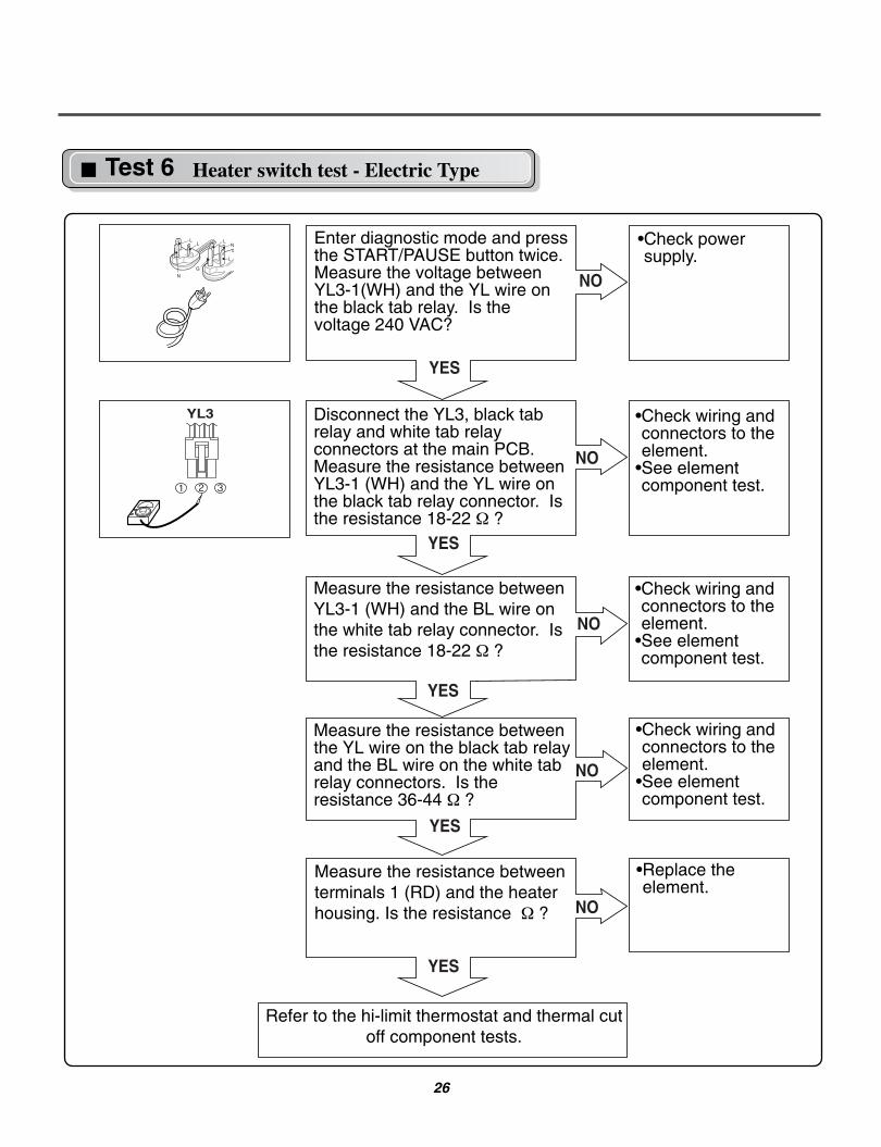
1. Open the top plate.
2. Remove Cover Cabinet.
3. Disconnect the door lamp and electro sensor connector.
4. Remove 4 screws.
5. Disassemble the Tub Drum [Front].
TUB DRUM [FRONT]
1. Open the top plate.
2. Remove the Cover Cabinet and Tub drum [front].
3. Disengage belt from motor and idler pulleys.
4. Carefully remove Drum out through front of dryer.
DRUM ASSEMBLY
-1
-2
-1
1. Open the door.
2. Remove the screw holding the drum lamp shieldin place.
3. Slide the shield up and remove.
4. Remove the bulb and replace with a 15 watt, 120 volt candelabra-base bulb.
5. Replace the lamp shield and screw.
CHANGING THE DRUM LAMP
When you disassemble the lamp connector, besure to take gloves and careful cabinet edge.Failure to do so can cause serious injury.
! WARNING !

37
1. Remove screw & exhaust duct.
DRYER EXHAUST CHANGE
PORTION “A”
DUCTTAPE
DUCTTAPE
DUCTTAPE
3. Reconnect the new duct[11 in(28cm)] to theblower housing, and attach the duct to the base.
2. Detach and remove the bottom, left or right sideknockout as desired.
4. Pre-assemble 4" elbow with 4" duct. Wrap duct tape around joint.
5. Insert duct assembly, elbow first, through the sideopening and connect the elbow to the dryerinternal duct.
When you disassemble and install ventilation, besure to take gloves and careful exhaust edge.Failure to do so can cause serious injury.
! WARNING !

38
1. Remove the filter.
2. Remove 3 screws.
3. Pull the grill.
4. Disconnect electro sensor.
FILTER ASSEMBLY
1. Open the top plate.
2. Remove the Cover Cabinet and Tub Drum [Front].
3. Remove the Drum assembly.
4. Remove 2 screws and cover(Air guide).
5. Remove the bolt and washer.
6. Pull the fan.
7. Disconnect the motor clamp and motor.
BLOWER HOUSING
1. Open the top plate.
2. Remove the Cover Cabinet and Tub Drum [Front].
3. Remove the Drum assembly.
4. Remove 7 screws.
5. Pull the Tub Drum [Rear] towards the front.
BACK COVER

39
1. Open the top plate.
2. Remove the Cover Cabinet.
3. Remove filter and 2 screws.
4. Pull the air duct towards the front.
AIR DUCT
1. Open the top plate.
2. Remove the Cover Cabinet and Tub Drum [Front].
3. Remove the Drum assembly and Tub Drum [Rear].
4. Disconnect Air duct from the Tub Drum [Front].
5. Remove the roller from the Tub Drum [Front] and Tub Drum [Rear].
ROLLERS

40
13-1. Control Panel & Plate Assembly
A210
A211
A130
A110
A120
A140
13 EXPLODED VIEW

41
13-2. Panel Drawer Assembly & Guide Assembly
K505
K507
A360
A172
A171
A350
K501
K502K508
K506
A090
A160
A170
A161
A162
K503
K504

42
13-3. Cabinet & Door Assembly
A600
A305
A320
A300
A310
A700
A390 A800
A590
A570
A330
A500
A510
A460A410A450
A430
A420
A400
A530
A560
A525
A540
A520
A550

43
13-4-1. Drum & Motor Assembly: Electric Type
K640
K120
K140
K400 K420 K410 F200
K310
K610
K330 K340
K130
K100
K221
K222
K210
K350
K240
F120
F130
F110
F140K510K540
K650
K651
K600
K520
K550 K560
K620
K530
K320
K251
K360
K251
K230
K250
K250

44
13-4-2. Drum & Motor Assembly: Gas type
M210
M180
M160
M170
M171
M140
M240M150 022M141M
M230M110
M181 M250
M190
K640
K120
K140
K310
K610
K330 K340
K130
K100
K221
K222
K210
K350
K240
K510K540
K650
K651
K600
K520
K550 K560
K620
K530
K320
K251
K360
K251
K230
K400 K420 K410 F200
K250
K250
M171: Propane Gas orificeM170: Natural Gas orifice