DISHWASHER SERVICE MANUAL - Appliance Assistant
43
DISHWASHER SERVICE MANUAL BEFORE SERVICING THE UNIT, PLEASE READ THIS MANUAL CAREFULLY FOR SAFETY AND CORRECT SERVICES. NOTE MODEL : LDF6920(WW,BB,ST)
-
Upload
khangminh22 -
Category
Documents
-
view
0 -
download
0
Transcript of DISHWASHER SERVICE MANUAL - Appliance Assistant
DISHWASHERSERVICE MANUAL
BEFORE SERVICING THE UNIT, PLEASE READ THIS MANUAL CAREFULLYFOR SAFETY AND CORRECT SERVICES.
NOTE
MODEL : LDF6920(WW,BB,ST)

- 3 -
1. CAUTION......................................................................................................................... 4
2. SPECIFICATIONS ........................................................................................................... 5
3. WIRING DIAGRAM........................................................................................................ 6
4. FEATURES & TECHNICAL EXPLANATION ................................................................... 7
5. PARTS NAME ................................................................................................................ 11
6. PROGRAM CHART ..................................................................................................... 12
7. HOW TO DISASSEMBLE ............................................................................................ 13
8. TROUBLE SHOOTING METHODS.............................................................................. 22A. TROUBLE SHOOTING ACCORDING TO DISPLAYED ERROR MESSAGE...........22B. TROUBLE DIAGNOSES AND REPAIR BY SYMPTOM........................................... 24
9. INSTALLATION INSTRUCTION ................................................................................... 28
10. EXPLODED VIEW .......................................................................................................35
CONTENTS

- 4 -
DISCONNECT POWER CORD BEFORE SERVICING
RECONNECT ALL GROUNDING DEVICES
IMPORTANT SAFETY NOTICE !
This service information is intended for individuals possessing adequate backgrounds of electrical,electronic and mechanical experience.Any attempt to repair this appliance may result in personal injury and property damage.The manufacturer or seller can not be responsiblefor the interpretation of this information, nor can it assume any liability in connection with its use.
CAUTION !

- 5 -
2. SPECIFICATION
Rated Voltage / Frequency AC 120V/60Hz
Installation Built-In
Place Settings 16
Product Dimension(in) 23 3/4̋ x 24 5/8̋ x 33 1/2̋
Product Weight(lbs) 90lbs
Door Color White, Black, Stainless
Tub Material Stainless Steel
Control Electronic
Rated Power(Watt) 1,350
Heater Power(Watt) 1,200
Programs 5
Upper Rack Position manual
Lower Rack 50% Fold down
Water Consumption 10-26 (Normal)
Power Consumption(kWh/year) 285-310
Operating Time (min) 101-135 (Normal)
Fan Dry System Yes
Delay Start Function Yes
Auto-Off Power Switch Yes
Process Monitor Yes
Wash Level 5
Racks Nylon Coating
Operating Water Pressure (Bar) 20-120 (140-830kPa)
ITEM SPECIFICATION

- 6 -
6920 serise
3. WIRING DIAGRAM
- 7 -
4. FEATURES & TECHNICAL EXPLANATION
4-1. Product Features
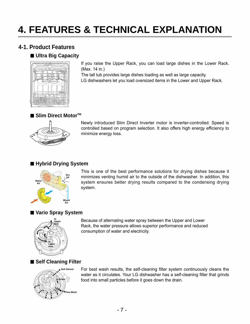
If you raise the Upper Rack, you can load large dishes in the Lower Rack.(Max. 14 in.)The tall tub provides large dishes loading as well as large capacity.LG dishwashers let you load oversized items in the Lower and Upper Rack.
Newly introduced Slim Direct Inverter motor is inverter-controlled. Speed iscontrolled based on program selection. It also offers high energy efficiency tominimize energy loss.
This is one of the best performance solutions for drying dishes because itminimizes venting humid air to the outside of the dishwasher. In addition, thissystem ensures better drying results compared to the condensing dryingsystem.
Because of alternating water spray between the Upper and LowerRack, the water pressure allows superior performance and reducedconsumption of water and electricity.
For best wash results, the self-cleaning filter system continuously cleans thewater as it circulates. Your LG dishwasher has a self-cleaning filter that grindsfood into small particles before it goes down the drain.
■■ Ultra Big Capacity
■■ Slim Direct MotorTM
■■ Hybrid Drying System
■■ Vario Spray System
■■ Self Cleaning Filter
MoistAir
DryAir
MixedAir
toUpperArm
toLowerArm
Soil Sensor
Fine Mesh
to Drain

- 8 -
PROGRAM
• Press the program thatcorresponds to yourdesired wash cycle.
CANCEL
• To cancel a runningprogram, open the door,then press and hold thePower Scrub andNormal buttons for 3seconds.
INDICATOR
• Child lock: Lamp will turn onwhen Child Lock setting is on.
• Rinse Aid: Refill with Rinse aidwhen Lamp turns on.
This program is for very heavily soiled loads
This program is for normally soiled everyday loads.
This program is for washing delicate items like glasses.
This program is for very lightly soiled loads.
This program is to wash some items loaded on the upper rack.
Normal
Rinse Only
Upper Only
Delicate
Power Scrub
■■ Control panel may vary on some models.
4-2. Display Panel LDF 6920 Series
- 9 -
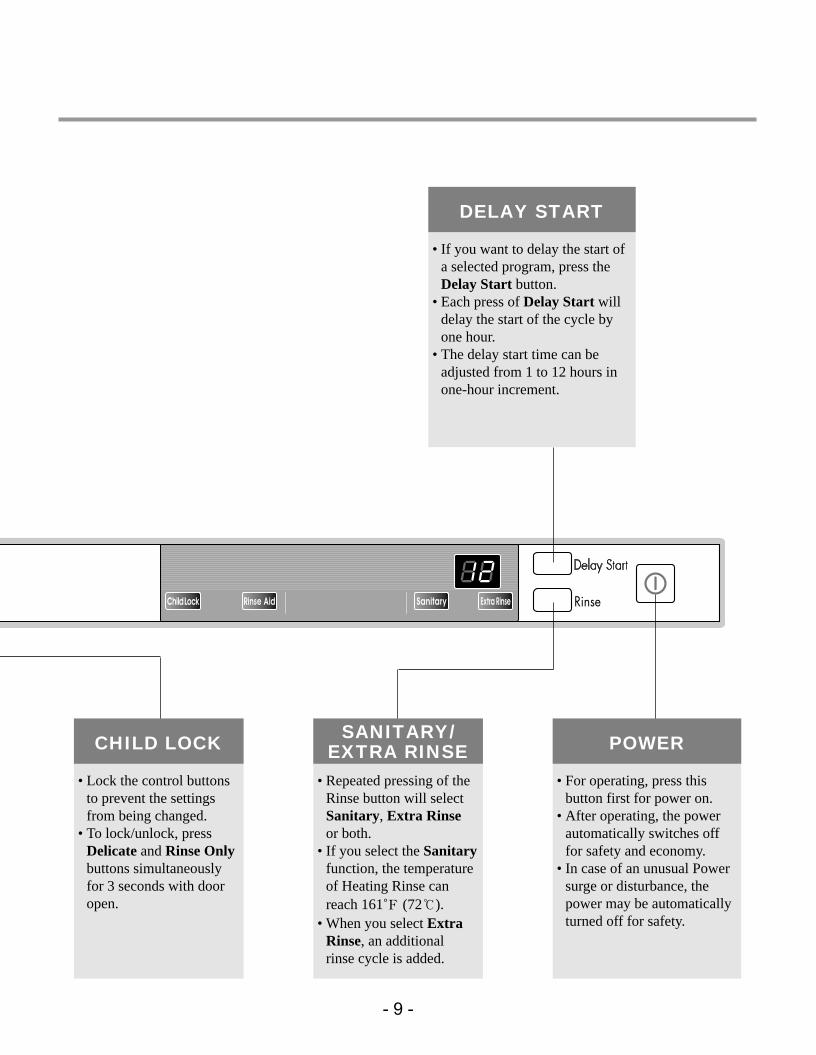
DELAY START
• If you want to delay the start ofa selected program, press theDelay Start button.
• Each press of Delay Start willdelay the start of the cycle byone hour.
• The delay start time can beadjusted from 1 to 12 hours inone-hour increment.
POWER
• For operating, press thisbutton first for power on.
• After operating, the powerautomatically switches offfor safety and economy.
• In case of an unusual Powersurge or disturbance, thepower may be automaticallyturned off for safety.
CHILD LOCK
• Lock the control buttonsto prevent the settingsfrom being changed.
• To lock/unlock, pressDelicate and Rinse Onlybuttons simultaneouslyfor 3 seconds with dooropen.
SANITARY/EXTRA RINSE
• Repeated pressing of theRinse button will selectSanitary, Extra Rinseor both.
• If you select the Sanitaryfunction, the temperatureof Heating Rinse canreach 161。F (72℃).
• When you select ExtraRinse, an additionalrinse cycle is added.

- 10 -
4-3. TEST MODE LDF 6810/6920 SeriesCHECK PROGRAM
BUTTON The number ofpushing button
TopDisplay Load and Checking points Door open/
closedUpper Only + Time Delay +POWER
Power ScrubNormalDelicateRinse OnlyUpper Only
Rinse
Time Delay
1 TIME
1 TIME1 TIME1 TIME1 TIME1 TIME
1 TIME
1 TIME
2 TIME
3 TIME4 TIME5 TIME
6 TIME
7 TIME8 TIME9 TIME
10 TIME
11 TIME
12 TIME
13 TIME
Soil Level
32
33Frequency
35
36
3738
Temp.(*C)
3A
3b
3c
3H/U5
1122334455
66
Soil Sensor
Wash Pump
Drain PumpInlet ValveDispenser
Heater(for 10 sec)
Fan
ThermistorLower Nozzle
(VARIO)Upper Nozzle
(VARIO)Wash-Drain-Water Supply
Auto-Off
Child Lock + Rinse AidSanitary-ExtraPower Scrub +
Normal + DelicateRinse Only + Upper Only
Rinse Aid
All LEDs are lighting
All LEDs are lightingAll LEDs are lightingAll LEDs are lightingAll LEDs are lightingAll LEDs are lighting
All LEDs are lighting
Both
BothBothBothBothBothBothBothBothBoth
Closed
BothClosedClosed
Closed
Closed
Both
Closed
Closed
Closed
Closed

- 11 -
5. PARTS NAME
� Control Panel� Door Handle� Front Cover� Lower Cover� Leveling Foot� Base� Top Spray Arm� Upper Spray Arm� Lower Spray Arm
� Detergent & Rinse Aid Dispenser� Vapor Vent Cover� Upper Rack� Cutlery Basket� Lower Rack� Top Display� Power Button
※ The appearance and specifications may be varied without notice according to localities.
5-3. LDF 6810 Series
INSTALL BRACKET WOOD SCREW

- 12 -
6. PROGRAM CHART(SCHEMATIC DIAGRAM)
Prog
ram
cha
rt
LDF 6920 Series

- 13 -- 13 -
BEFORE DISASSEMBLING THE DISHWASHER ;1) Remove the cord from electric outlet to avoid electric shock.2) Close the Water Tap (faucet).3) Remove all dishes and items in the dishwasher.4) Remove the Lower Rack and the Upper Rack.5) Remove the inlet hose and drain hose connetion to avoid the hose damages.6) Prepare some towels to avoid floor wet by the water left in the dishwasher.
7. HOW TO DISASSEMBLE
7-1. FULL DISASSEMBLE1. Lower Cover and Lower Felt
1) Remove the front 2 screws.2) Remove the Inlet Hose and Power Supply
Cable.
2. Tub Felt1) Tub Felt
Lower Cover
Tub Felt

- 14 -- 14 -
Control Panel Front Cover
Controller
Controller
Latch Assembly
3-1. Door Assembly 1) Front Cover
Open the door.Remove 12 screws(stainless).
2) Control Panel Assembly
Remove 2 screws(Stainless).Remove the wire connections.Be sure the wiring should not bechanged in reassemblingRemove the Latch assembly.Remove the Front Display.Remove 8 screws for Controller.

- 15 -- 15 -
Fan Assembly
Inner CoverGasket
Flange
Hose
Detergent Dispenser
Door Hinge
Air Duct
Door Bracket
Hinge Bracket
Hinge Spring
3) Fan Assembly
Open the door.Remove 4 screws and a earth screw forDoor Bracket.Remove the wire connetions.Remove the Air Duct.Turn the Inner Cover counterclockwise.
4) Detergent Dispenser
Close the doorRemove the wire connections.Remove 6 screws with brackets.Push the Detergent slowly pulling up thethe Flange by Standard Screwdriver.
5) Door Spring (Right & Left)
Push the Spring upwards and take it offfrom the Hinge Bracket.Be careful not to be injured by thesharpedge of Tub.Take off the Hinge Link from the Hinge.
6) Door Liner
Open the door.Pull the Door Liner and take it off fromthe Hinge Supporter.
Door Liner Assembly
Hinge Supporter

- 16 -- 16 -
Lead Wire Holer Hook
Lead Wire HolerLower Frame
Drain Hose
Drain Hose Holder
4. Lower Frame 1) Press the holder hook as shown in figure.2) Remove 4 screws.
6. Drain Hose Holder 1) Press the holder hook as shown in figure.2) Pull the Drain Hose and remove the Drain
Hose Holder.
5. Put the Dishwasher upside down.

- 17 -- 17 -
7. Base Cover 1) Remove 2 screws.2) Pull the Base Cover out.
8. Harness & Hose Assembly 1) Remove the wiring connections.2) Remove the Hose connections from
Sump Assembly.
You can see the information of WiringDiagram at the back of Lower Cover.
Cabinet Base
Base Cover

- 18 -- 18 -
9. Cabinet Base1) Remove 8 screws.2) Lift it upward.
Cabinet Base
10. Foot & Nut1) Pull the Foot twisting2) Pull the Nut pushing the hook.
Nut
Foot
11. Rear Leg Adjustment System1) Remove 2 screws.2) Pull the Holder.3) Pull the Leg Adjust.4) Pull the Shaft Assembly.
Holder
Leg Adjust
Shaft Assembly

- 19 -- 19 -
Sump Holder
HookSumpAssembly
14. Sump Assembly
Remove 2 screws.Remove the Sump Holder and push theSump Assembly down with pulling asideHook.Be careful not to drop the SumpAssembly to the bottom.
Inlet ValveCabinet Base
Air BrakerNut
Gasket
Air BrakerAssembly
12. Inlet Valve1) You can disassemble the lnlet Valve by
removing the 2 screws.
13. Air Braker Assembly1) Disconnect the 3 hoses assembly.2) Turn the Air Braker Nut counterclockwise.
Be careful the o-ring should not be lost.

- 20 -- 20 -
2) Vario Motor
Remove 2 screws for Vario Motor.Pull the Vario Motor and Micro S/W.
3) Soil Sensor
Pull the Soil Sensor.
Vario Motor
MicroS/W
SoilSensor
1) Heater & Drain Motor
Pull the Heater out of the Sump afterreleasing the nut.Remove 3 screws.
Drain Pump
Heater

- 21 -
15. Holder Supporter, Tub Packingand Hinge Supporter Assembly.
When you reassemble the Sump Assembly, becareful not to kink, tear and take off the seals.
You must take off Stopper Roller(F117) by –screwdriver to change the Rail Assembly.(Stopper Roller could be broken while you aretaking off. So you should be careful not to behurt and have extra stopper rollers ready atservicing at all times)
Rotate the screwdriver, after slide it into thegap between Stopper Roller and Rail Roller.

- 22 -- 22 -
A. TROUBLE SHOOTING ACCORDING TO DISPLAYED ERROR MESSAGE
ERROR MESSAGE POSSIBLE CAUSE REMEDYFOR ERROR OCCURRENCE
The Water Supply Tap is closed.The Water Supply is shut off.The Inlet Hose is kinked.The Water Pressure is very low.(below 10 psi)Inlet Valve is OK?The filter of Inlet Valve is cloggedby impure water.The Hall sensor is OK?The Impeller of Air Guide is bound.
The Drain Hose kinked or blocked.
Wiring connection is OK?
The drain outlet of sump is
blocked.The Drain Pump/Motor or circuit is
troubled.
Water leakage in Hose connections.
Water is leaked by damages.
The Motor Water Seal leakage of
Sump assembly.The height of Drain Hose connection
(sink-Drain Hose) is not over 20″.
Impeller of the Washing Pump is
worn away.
Remove the cause of kink or block.
Check the wiring connection.
Measure the electric resistance of
Drain Motor. (20-40 )
Replace the Drain Motor or repair
the Circuit.
Replace the connections of Hose.
Check the point of damages and
repair or replace the related parts.Read the Installation Instructions
(page 9) and fix it to therecommended Height.Replace the Impeller of the
Washing Pump.
Take action on Water Supplydevice.
Measure the electric resistance ofInlet Valve. (950-1300 )Clean the filter of Inlet Valve.Check the frequency of Inlet Waterby the Test Mode.Replace the Air Braker.
Not reached to the nor-mal water level in spiteof 10 min. water supply
INLET ERROR
displayed
Condition
Not fully drained out inspite of 5 min. drainoperation
The excessive RPM ofWashing Motorhappened during Washcycle due to waterleakage.
DRAIN ERROR
displayed
Condition
LEAKAGE ERROR
displayed
Condition
8.TROUBLE SHOOTING METHODS

- 23 -- 23 -
ERROR MESSAGE POSSIBLE CAUSE REMEDYFOR ERROR OCCURRENCE
The Inlet Valve is troubled.
The Controller is troubled.
The Inlet Water Temperature is
very high. (over 194 )
Wiring connection is OK?
The Thermistor is OK?
Wiring connection is OK?
The Impeller of Washing Pump is
locked.The rotor of Washing Motor is
locked.The Blade is locked.
Check the temperature. (Test Mode)If the temperature is displayed,
adjust the Inlet WaterTemperature to 120 .
If the temperature is notdisplayed,
check the wiring connection.check the electric resistanceof Thermistor. (11~14k at 77 )Replace the PCB.
Replace the Inlet Valve.
Repair or replace the Controller.
Excessive water is sup-plied than normal waterlevel.(Automatically drainPump operated.)
EXCESS ERROR
displayed
Condition
The resistance of ther-mistor not normally out put.
THERMAL ERROR
displayed
Condition
Check the wiring connection.
Replace the cause of restriction.
Replace the Washing Motor.
Replace the PCB.
The Motor is workingabnormally.
MOTOR ERROR
displayed
Condition
The Circuit of Heater is troubled.
The Thermistor is troubled.
The Heater is shorted.
The Relay Circuit is troubled.
Repair the Circuit of Heater.
Replace the Thermistor.
Replace the Heater.
Repair the Relay Circuit..
The water is not heated orthe temperature in the Tubis overheated to over 194ßF
HEATER ERROR
displayed
Condition

- 24 -- 24 -
No Power on when the power button pressed.
The Power connectionis correctly connected.
The Fuse or Circuit Breaker of house is O.K?
The Power Switch or the Circuit is O.K?
• Re-connect the Powr connection.
• Check the electricity is failed or not.
• Replace the Fuse or Circuit Breaker of house.
• Check the Power Switch or the circuit and repair it.
Check t he Con t ro l l e r. (Powe r C i r cu i t )
B. TROUBLE DIAGNOSES AND REPAIR BY SYMPTOM
NO
NO
YES
YES
YES
NO

- 25 -- 25 -
The Wash Pump/Motor does not run.
The Door is tightly closed?
The Wiring connectionsis OK?
The Blade is not locked by a small and sharp object?
• close the Door tightly.• Check the Door Switch in Latch Handle.
• Re-connect the wiring connections related to theWashing Motor.
• Remove the cause of lock or replace the Blade.
Replace the Wahing Pump/Motor
NO
NO
NO
YES
YES
YES
- 26 -- 26 -
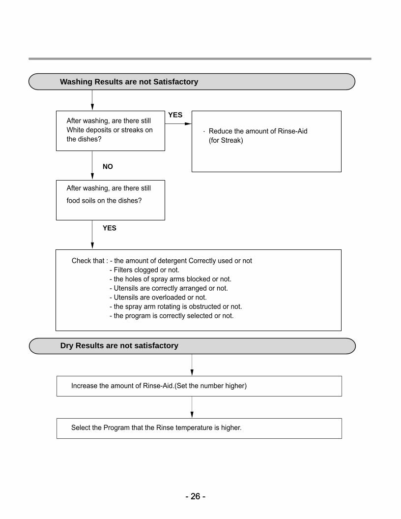
Washing Results are not Satisfactory
After washing, are there still White deposits or streaks onthe dishes?
NO
After washing, are there still
food soils on the dishes?
YES
Check that : - the amount of detergent Correctly used or not- Filters clogged or not.- the holes of spray arms blocked or not.- Utensils are correctly arranged or not.- Utensils are overloaded or not.- the spray arm rotating is obstructed or not.- the program is correctly selected or not.
Reduce the amount of Rinse-Aid(for Streak)
YES
Dry Results are not satisfactory
Increase the amount of Rinse-Aid.(Set the number higher)
Select the Program that the Rinse temperature is higher.

- 27 -- 27 -
Power Button not automatically off after operation.
Check the button is blocked by foreign materials.
Check the Power Switch.(Replace it, if necessary.)
Check the Controller.(Replace it, if necessary.)

- 28 -- 28 -
9. INSTALLATION INSTRUCTION
Step 1: PREPARE CUPBOARD OPENING
1. This dishwasher is designed to fit a standard dishwasher opening as shown below.
2. Select a location as close to sink as possible for easy connections to water and drain lines.
3. The dishwasher should not be installed more than 10 ft. (3m) from the sink for properdrainage.
4. If dishwasher is to be installed in a corner, a minimum of 2 in. (50mm) is required betweenthe dishwasher and an adjacent a wall.
■ Ensure the floor under the dishwasher is at the same level as the rest of the room toallow for any service requirements.
If dishwasher will sit directly onsubflooring, subfloor should besealed with a waterproof paint orsealer to prevent damage fromsteam.
Drill a 1-1/2″″(38mm) dia hole or cutout for drain hose, inlet hose andelectrical cables on either side. approx. 4″″(100mm, W) X 4″″(100mm, H)
These openings must be within 4″″
(100mm) from the floor and 1-5/8″(40mm) from the back wall. If there isa floor in the cabinet under the sink,it will also be necessary to drill or cutthrough the floor to connect thewater and drain under the sink.
33 1
/2″(
851m
m)m
in.

- 29 -- 29 -
WARNINGFor personal safety, remove house fuse or open circuit breaker before installation. Do not use an extension cord or adapter plug with this dishwasher.Electrical and grounding connections must comply with the national electricalcode/provincial and municipal code and/or other local codes.
Figure A
Step 2: PREPARE THE ELECTRICAL WIRING
1. This appliance must be operated with correct voltage as shown in this manual and on therating plate, and connected to an individual, properly grounded branch circuit, protectedby time delay fuse. Wiring must be 3 wires including ground.
2. The wiring or cord should be in an accessible location adjacent to, and not behind thedishwasher and within 4 ft. (1.2m) of the dishwasher side.
3. The wiring or cord must be grounded properly, if in doubt, have it checked by a qualifiedelectrician. No other appliance shall be connected to the same outlet by a double adapteror similar plug.
4. The wiring or cord must be oriented as shown in Figure A below.
5. Check the dishwasher for any damage before trying to install it.
6. Make sure water line and Electrical line are oriented in the bottom channels as shown inthe figure below.If you find any damage to the dishwasher, Please contact your dealer or builderimmediately.

- 30 -- 30 -
Step 3: PREPARE THE WATER SUPPLY CONNECTION
1. This dishwasher may be connected to either hot or cold water. If the water can not bemaintained below 149℉℉ (65℃), the dishwasher must be connected to cold water.
2. When connecting the dishwasher water line, sealing tape or compound should be used toavoid leaks.
3. When connecting the dishwasher water line, the house supply should be shut off.
4. The Water Supply Tube must be oriented as shown in Figure A on page 6.
Step 4: PREPARE DISHWASHER FOR INSTALLATION
1. Adjust the legs to the required height to fit properly under the countertop as shown below.
2. Check the level of dishwasher by using level.
■■ Left side – turn theadjusting screwcounterclockwise to lowerthe leg and raise the rearof the dishwasher.
■■ Right side – turn theadjusting screw clockwiseto lower the leg and raisethe rear of the dishwasher.
■■ Front feet can be adjustedfrom the top using a 1/4〃square drive wrench.

- 31 -- 31 -
1. Remove the Lower Cover and orient dishwasher as shown below.
2. Before sliding the dishwasher into the cupboard opening, make all necessary heightadjustments using the legs.
3. Slide the dishwasher into the cabinet opening carefully. Make sure that the drain hoseinside the cabinet is not kinked.
4. Follow the instruction as in Figure B.
Step 5: INSTALL THE DISHWASHER IN CUPBOARD

- 32 -- 32 -
Step 6: DRAIN LINE CONNECTION
1. If the end of the drain hose does not fit to the drain line, use an adapter (not supplied) thatmust be resistant to heat and detergent and may be obtained from a plumbing shop.
2. There are 2 typical connections as shown in Figures C & D.
① There may be other options than shown here for connection the drain hose. The drainconnection must meet local plumbing regulations.
② The S trap spigot must be drilled out cleanly and free of obstruction to its maximuminternal diameter, if used for drainage.
③ To prevent syphoning, one of the following instruction methods must be followed:
�Follow local codes and ordinances.
�Do not exceed 10 ft. (3m) distanceto drain.
�Do not connect drain lines fromother devices to the dishwasherdrain hose.
Drain Requirements
Figure C: Connection to Disposer or waste Tee.
Figure D: Connection to Air Gap.

- 33 -- 33 -
Step 7: WATER SUPPLY CONNECTION
1. When connecting, sealing tape orsealing compound should beused to avoid water leaks.
2. Before connecting, turn off the watersupply.
3. After fitting the Elbow into theInlet Valve, slide the FlexibleStainless Tube or Copper Tubeinto the Elbow.
4. Tighten the nut and make surethat the line is not kinked orsharply bent.
Inlet Valve
Water Supply Tube
Elbow
1. Before beginning, turn off electricalpower to the unit at the circuit breaker.
2. Remove the Junction Cover and thenInstall the Strain Relief.
3. Twist Wire Connectors tightly on thewires. Wrap each connection withElectrical tape.
4. Check again and make sure that allwires are connected correctly, black toblack, white to white, green to green(ground to ground).
5. Replace the Junction Cover.
Junction Cover
Step 8: ELECTRICAL POWER CONNECTION
Junction Box
- 34 -- 34 -
Step 9: FINAL CHECKS
1. Turn electrical power back on at the circuit breaker.
2. Turn house water supply back on.
3. Operate the dishwasher through one cycle (Quick cycle is recommended) to check forwater leaks and operating conditions.
4. Replace the Lower Cover.

- 35 -
Printedmaterials
Description
*Owner’s Manual
*Energy Label
Loc No.
*Service Manual
G001
G002
G004
“The following parts are not illustrated" ACCESSORIES
E005
- 35 -
10. EXPLODED VIEW

- 36 -- 36 -
EXPLODED VIEW
F001
M100
M210
M105
M261
M266
M260
A160
A130
A040
A003
F101
E005
E010

- 37 -
M086
F045 F060
F050
F022
M090
F043
F011
F013 F117
F144
F110 F132
F143
F117
F210
F011
F013
M006
M005
F171
F041
F040
F042
F080
EXPLODED VIEW - TUB ASSEMBLY

- 38 -- 38 -
EXPLODED VIEW - RACK ASSEMBLY
A110
A050 F191
F192
F004
F005
A070
A060
A074
A073A150
A140
A141 A142
A151
A152
A080
A101
A102
A103
- 39 -
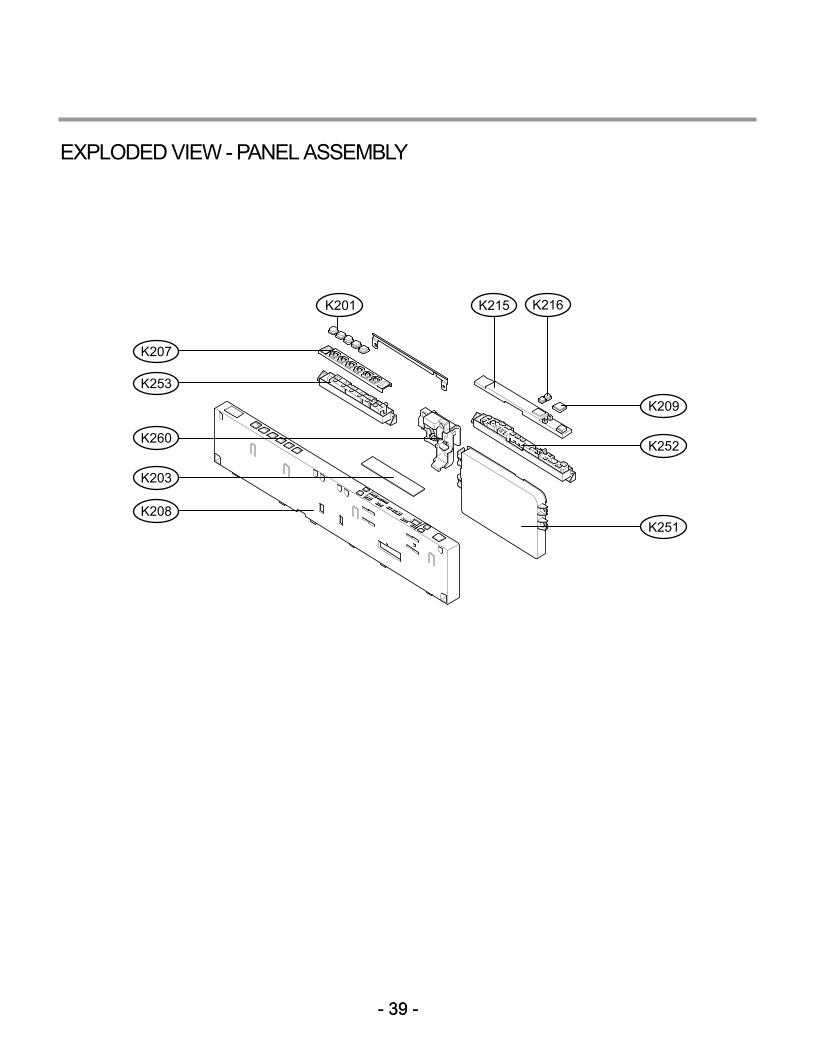
K260
K203
K208
K209
K201
K207
K215
K251
K216
K253
K252
EXPLODED VIEW - PANEL ASSEMBLY
- 39 -

- 40 -
K002
A120
K030
K010
K217
K005
K001
K122K110 K121K101
F174
F142
F141
K124
K140
K100
K141
- 40 -
EXPLODED VIEW - DOOR ASSEMBLY

- 41 -- 41 -
M001
M110
M038
M025
M035
M130
M036
M007
M087
M060M081
M120
M034M088
M027
M028
M026
M050
M031
M220
EXPLODED VIEW - SUMP ASSEMBLY

- 42 -
MEMO

- 43 -
MEMO

P/No. : MFL37554803