HEAT PUMP DRYER SERVICE MANUAL
47
HEAT PUMP DRYER SERVICE MANUAL CAUTION READ THIS MANUAL CAREFULLY TO DIAGNOSE TROUBLE CORRECTLY BEFORE OFFERING SERVICE. MODEL : RC9055*P*Z (RH9051WH) RC8055*P*Z (RH8051WH) RC7055*P*Z (RH7050WH)
-
Upload
khangminh22 -
Category
Documents
-
view
3 -
download
0
Transcript of HEAT PUMP DRYER SERVICE MANUAL

HEAT PUMP DRYERSERVICE MANUALCAUTIONREAD THIS MANUAL CAREFULLY TO DIAGNOSE TROUBLE CORRECTLY BEFORE OFFERING SERVICE.
MODEL : RC9055*P*Z (RH9051WH) RC8055*P*Z (RH8051WH) RC7055*P*Z (RH7050WH)
!� W�ARNING !�
IMPOR�The information in this service maual is intended for use by individuals possessing adequate backgroundsof electrical, electronic, and mechanical experience. Any attempt to repair a major appliance may result inpersonal injury and property damage. The manufacturer or seller cannot be responsible for theinterpretation of this information, nor can it assume any liability in connection with its use.
To reduce the risk of injury to persons, follow all industry recommended safety procedures including theuse of long sleeved gloves and safety glasses. could result in property damage, injury to persons or death.
RECONNECT ALL GROUNDING DEVICES�If grounding wires, screws, straps, clips, nuts, or washers used to complete a path to ground are
removed for service, they must be returned to their original position and properly fastened.
Electrostatic Discharge (ESD)Sensitive Electronics
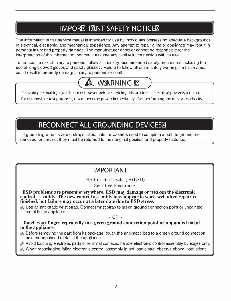
ESD problems are present everywhere. ESD may damage or weaken the electroniccontrol assembly. The new control assembly may appear to work well after repair isfinished, but failure may occur at a later date due to ESD stress.¡Æ Use an anti-static wrist strap. Connect wrist strap to green ground connection point or unpainted
metal in the appliance.- OR -
Touch your finger repeatedly to a green ground connection point or unpainted metal in the appliance.¡Æ Before removing the part from its package, touch the anti-static bag to a green ground connection
point or unpainted metal in the appliance.¡Æ Avoid touching electronic parts or terminal contacts; handle electronic control assembly by edges only.¡Æ When repackaging failed electronic control assembly in anti-static bag, observe above instructions.
T�ANT SAFETY NOTICE�
To avoid personal injury, , disconnect power before servicing this product. If electrical power is requiredfor diagnosis or test purposes, disconnect the power immediately after performing the necessary checks.
IMPORTANT
Failure to follow all of the safety warnings in this manual
2

CONTENTS
1. SPECIFICATIONS .............................................................................................................................................................. 4
2. FEATURES AND LOOK .................................................................................................................................................... 5
3. PART IDENTIFICATION .................................................................................................................................................... 6
4. PROGRAM CYCLE ............................................................................................................................................................ 7
5. INSTALLATION INSTRUCTIONS ................................................................................................................................ 10
6. MAINTENANCE INSTRUCTIONS .............................................................................................................................. 13
7. COMPONENT TESTING TIPS ...................................................................................................................................... 15
8. WIRING DIAGRAM ........................................................................................................................................................ 18
9. TROUBLESHOOTING ................................................................................................................................................... 19
10. DIAGNOSTIC TEST...................................................................................................................................................... 24
11. DISASSEMBLE INSTRUCTIONS ............................................................................................................................. 37
12. EXPLODED VIEW ....................................................................................................................................................... 43
3

IDENTIFICATION1
4
SPECIFICATIONS1
ITEMS RC9055*P*Z / RC8055*P*Z / RC7055*P*ZRH9051WH / RH8051WH / RH7050WH REMARK
DRYING TYPE
WEIGHT
DIMENSION
STANDARD DRYING CAPACITY
CONTROL TYPE
POWER SUPPLY
MOTOR
HEATER
COMPRESSOR
LED LAMP
DOOR SWITCH
THERMOSTAT
DRUM VOLUME
Micom electronic Control
1. Pipe Temperature:2 thermistors (Eva in and Comp out)
2. Drum Temperature:1 thermistor
3. Main Heater : 1 thermistor
4. Humidity : Electrode sensor
5. Filter Sensing : Magnet , Reed switch
6. Sump water Sensing : Electrode sensor
Removable
52~53 rpm
Stainless steel
Available
Running status indicator (all)
Error display (all)
Condensation
Opaque : 56kg (Gross : 61kg)Glass : 57kg (Gross : 62kg)
600(W) x 640(D) x 850(H)
9.0kg / 8.0kg / 7.0kg
Electronic Control
AC230V, 50Hz(16A)
210W
1000W
690W
DC12V (30mA)
250V(5A)
240V(25A)
121 Liter
Over current protect (Motor)
Over Load Protect (Compressor)
ThermostatP/N:LPLN7269
Dafault : High
Dafault : Off
Dafault : Off
Maximum : 100 min
Minimum : 15 min
3~19 hours
SAFETY DEVICES
SENSOR
FILTER
DRUM SPEED
DRUM
DRYER RACK
CHILD LOCK
BUZZER
ANTI-CREASE
FAVORITE (MORE)
(LESS)
TIME DELAY
DRUM INTERIOR LIGHT
LED DISPLAY
IDENTIFICATION1
5
Energy
save
1%
- --
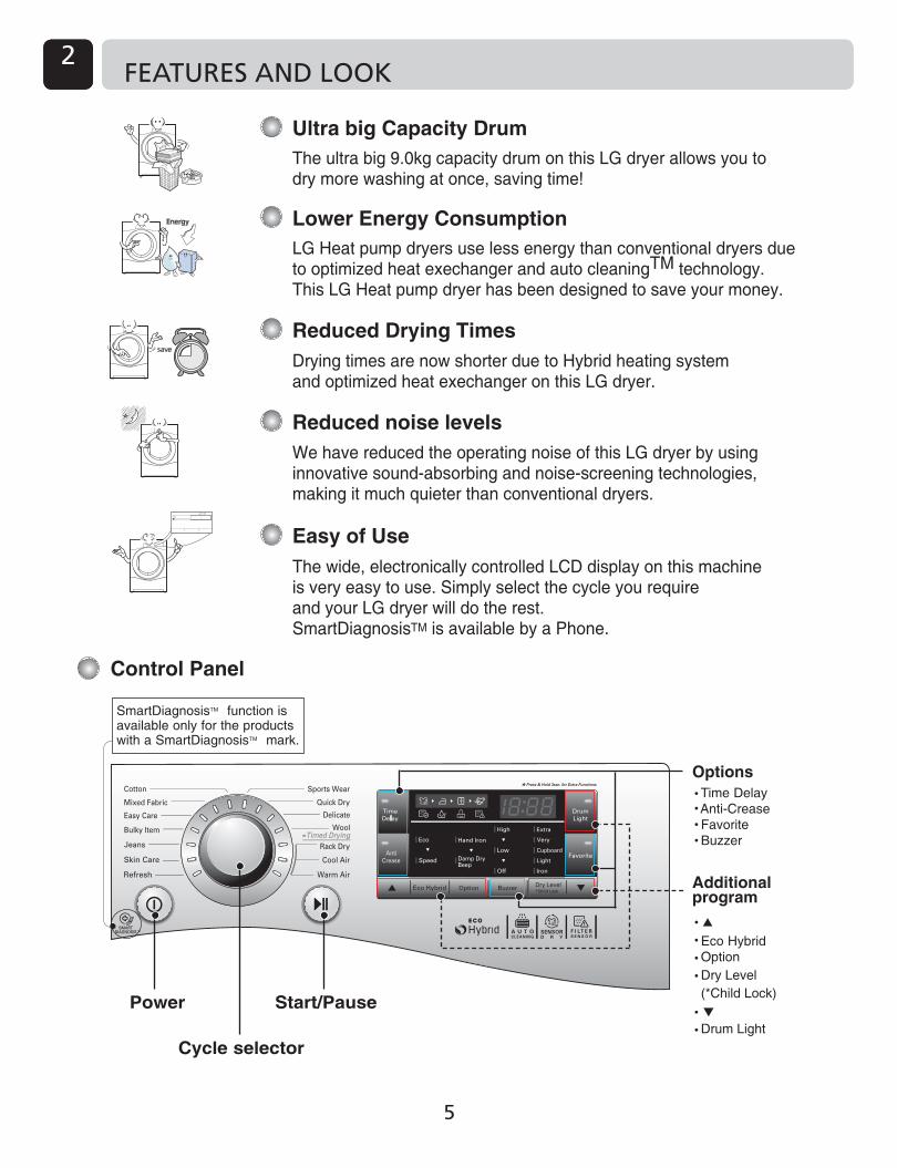
Cycle selector
Start/PausePower
Additional program
Eco Hybrid Option Dry Level(*Child Lock)
OptionsTime DelayAnti-CreaseFavoriteBuzzer
SmartDiagnosis function isavailable only for the productswith a SmartDiagnosis mark.
Drum Light
TM
TM
Control Panel
FEATURES AND LOOK2
Ultra big Capacity Drum
Lower Energy Consumption
Reduced Drying Times
Reduced noise levels
Easy of Use
The ultra big 9.0kg capacity drum on this LG dryer allows you todry more washing at once, saving time!
LG Heat pump dryers use less energy than conventional dryers dueto optimized heat exechanger and auto cleaningTM technology.This LG Heat pump dryer has been designed to save your money.
Drying times are now shorter due to Hybrid heating systemand optimized heat exechanger on this LG dryer.
We have reduced the operating noise of this LG dryer by usinginnovative sound-absorbing and noise-screening technologies,making it much quieter than conventional dryers.
The wide, electronically controlled LCD display on this machineis very easy to use. Simply select the cycle you requireand your LG dryer will do the rest.SmartDiagnosisTM is available by a Phone.

IDENTIFICATION1 PART IDENTIFICATION3
1. Drain Hose Assembly ( Purchased Seperately )
P/No. : 5001EL2001A P/No. : 3751EL1002C
2. Dryer Rack Assembly
3. Stacking kit Assembly ( Purchased Seperately)
Accessory parts
6
Holder : 2EA, Screw : 4EA
Purchased Separately
Product Layout
RC*055*PZ / RC*055*P2Z / RC*055*P3ZRH9051WH / RH8051WH
RC*055*P1Z / RH7050WH
Water Container
Control Panel
Air Ventilation Grill
Opaque DoorGlass Door

IDENTIFICATIONPROGRAM CYCLE4
Cycle selector
Start/PausePower
Additional program
Eco Hybrid Option Dry Level(*Child Lock)
OptionsTime DelayAnti-CreaseFavoriteBuzzer
SmartDiagnosis function isavailable only for the productswith a SmartDiagnosis mark.
Drum Light
TM
TM
7
Time DelayYou can use the Time Delay option to delay the finishing time of drying cycle. Maximum Time Delay is 19 hours.Minimum Time Delay is 3 hours.1. Turn the dryer on.2. Select a cycle.3. Set time delay hour by press the
“▲”, “▼” button.4. Press Start/Pause button.Anti-CreaseThe Anti-Crease option prevents creases that are formed when the laundry is not unloaded promptly at the end of the drying cycle. When Anti Crease is selected, the dryer repeatedly runs and pauses, giving you 2 hours to unload the laundry. If the door is opened during the Anti-Crease option, the option is cancelled.FavoriteFavorite option allows you to store a customized dry cycle for future use.1. Turn the dryer on.2. Select a cycle.3. Select the option or additional program.
(Anti-Crease, Eco HybridTM etc.)4. Press and hold Favorite option button for 3
seconds.The Favorite option is now stored for future use. To reuse the stored cycle, select Favorite option and press the Start/Pause.Drum LightWhilst the dryer is running it is possible to see inside the drum if you select the Drum Light function.Light on : Door is opened.
For 3 sec drum light button are selected.
Light off : Door is closed. Off automatically.Eco HybridTM
This additional program is able to save energy or time.Eco: energy saving course. (Heat Pump only)Hybrid: time saving course. (Heat Pump +
Heater) You will see “ speed ” indication on the LED.
Note
OptionHand Iron This function remains more moist than the condition for ironing.
Damp Dry BeepThis function lets you know when the clothes are ready for ironing.
Cycle Dry Level
Iron Hand Ironis available
OptionCotton
Mixed FabricEasy care
NoteCycle Dry Level
ExtraVery
CupboardLight
Damp Dry Beepis available
OptionCotton
Mixed Fabric
Easy care
Buzzer This is a option to enable you to adjust volume of beeper sound.
For the safety of your children, press Dry Level button for about 3 seconds. You will see “ ” indication on the LED. You can see “ ” sign on LED window.- All controls except Child Lock and Power
buttons will be disabled.- Child Lock lasts after the end of cycle.
Child Lock ( & )
NoteFor “Child Lock is off ”, press Dry Levelbutton for about 3 seconds.
0:11Time Left

IDENTIFICATION1 PROGRAM CYCLE4
8
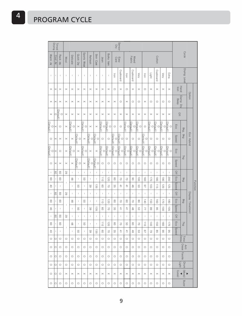
Cycle Selection Table
CAUTIONIf the load is less than 1kg, please use the “Warm Air” Cycle in Timed Drying Cycle.Wool items should be dried using the “Wool” Cycle and heat-sensitive fabrics including silk, underwear andlingerie should be dried using the “Delicate” Cycle. Please comply with the recommended laundry load when you select your desired Cycle- found on page 19. Otherwise, your clothes may be damaged.
Sensor Dry CycleCycle Laundry Type Detail Drying Level
Timed Drying Cycle
Extra
Very
Cupboard
Light
Iron
Iron
Iron
-
-
-
--
-
-
-
-
-
-
Cupboard
Cupboard
Very
Towels, dressing gowns and bed linen
For thick and quilted fabrics
Terry towels, tea towels, towels and bed linen
For thick and quilted fabrics that do not need to be ironed
Bath towels, tea towels, underwear and cotton socks For fabrics that do not need to be ironed
Sheets, pillowcase and towels For fabrics that do not need to be ironedBed linen, table linen, towels, T-shirts, polo shirts and work clothes
For fabrics that do need to be ironed
Mixed Fabric
Bed linen, table linen, tracksuits, anoraks and blankets
For thick and quilted fabrics that do not need to be ironed
Shirts and blouses For fabrics that do not need to be ironedTrousers, dressers, skirts and blouses For fabrics that do need to be ironed
Tumbles without heatAll fabrics that need refreshingCool Air
T-shirts, pillowcase, and towelsSkin Care
Shirts and blousesRefresh(Refer to the Note)
For cotton fabrics which do not need to be ironed
Odor removal of fabric(For fabrics in need of odor removal)
Bath towels, bath robes, dishcloth and quilted fabrics made of acrylic
Warm Air Small Items & damp clothing Everyday items suitable for heat drying
Silk, wool, delicate lingerieRack Dry Refresh clothes without tumble drying
Shirts, T-shirts, trousers, under-wear and socks
For polyamide, acrylic, and polyester that do not need to be ironed
Easy careShirts, T-shirts, under-wear, anoraks and socks
For polyamide, acrylic, polyester that do need to be ironed
Soccer kit and training wearSports Wear For polyester material
Jeans and colour fading garments.Jeans For jeans which do not need to be ironed
Silk, fine fabrics and lingerieDelicate For fabrics that are heat-sensitive like synthetic fabrics
WoolWool For wool fabrics
Bed clothes, sheetsBulky Item For bulky items
Linen and towels, excluding fabrics applied to delicate, sports wear, bulky Item cycle.
For small loads of suitable fabrics with short drying timesQuick Dry
Cotton
NoteWhen using the “Refresh” course, please spray cold or warm water on the fabric for a fresher outcome. (The recommend amount is 20cc of water per shirt.)
IDENTIFICATIONPROGRAM CYCLE4
Eco
Speed
Eco
Speed
Off
Eco
Speed
Off
Eco
Speed
Off
Eco
Speed
Extra
XO
XO
( Defa
ult)
OO
( Defa
ult)
O-
200
125
-180
105
-170
95
OO
OO
XO
Very
XO
XO
(Defa
ult)
OO
( Defa
ult)
O-
190
120
-170
100
-160
90
OO
OO
XO
Cupboard
XO
XO
(Defa
ult )
OO
( Defa
ult)
O-
180
115
-160
95
-150
85
OO
OO
XO
Lig
ht
XO
XO
( Defa
ult)
OO
(Defa
ult)
O-
170
103
-150
89
-140
79
OO
OO
XO
Iron
OX
XO
O(D
efa
ult)
O(D
efa
ult )
O-
160
97
-140
77
-110
67
OO
OO
XO
Very
XO
XO
( Defa
ult)
OO
( Defa
ult)
O-
100
53
-80
53
-70
53
OO
OO
XO
Cupboard
XO
XO
(Defa
ult )
OO
( Defa
ult)
O-
90
48
-70
48
-60
48
OO
OO
XO
OO
Functio
n
Drying Level
Cyc
leMixe
dFabric
Cotto
n
Tim
eD
ela
y
Anti
Crease
FavoriteB
uzzer9kg
▲(M
ore
)▼
(Less)
Dru
m
Lig
ht
Optio
n
Hand
Iron
Damp Dry
Beep
Off
7kg
Display Time(min)
8kg, 9kg
Eco Hybrid
gk
8g
k7
Iron
OX
XO
(Defa
ult )
OO
( Defa
ult)
O-
70
41
-60
41
-50
41
OO
OO
XO
Cupboard
XO
XO
O(D
efa
ult)
O(D
efa
ult)
O-
70
41
-70
41
-70
41
OO
OO
XO
Iron
OX
XO
O(D
efa
ult )
O(D
efa
ult)
O-
60
35
-60
35
-60
35
OO
OO
XO
Bulky Item
-X
XX
O( D
efa
ult )
OO
( Defa
ult)
O-
120
70
-120
70
-120
70
OO
OO
XO
Jean
-X
XX
O( D
efa
ult )
OO
( Defa
ult)
O-
110
60
-110
60
-110
60
OO
OO
XO
Skin Care
-X
XX
XO
(Defa
ult )
XO
(Defa
ult )
--
135
--
135
--
135
OO
OO
XO
Refre
sh
-X
XX
XO
(Defa
ult)
XO
(Defa
ult )
--
39
--
39
--
39
OO
OO
XO
Sports Wear
-X
XX
O( D
efa
ult)
XO
(Defa
ult)
X-
50
--
50
--
50
-O
OO
OX
O
Quick Dry
-X
XX
XO
(Defa
ult)
XO
(Defa
ult )
--
50
--
50
--
50
OO
OO
XO
Delic
ate
-X
XX
O(D
efa
ult)
XO
(Defa
ult)
X-
48
--
48
--
48
-O
OO
OX
O
Wool
-X
XX
XX
XX
29
29
29
OO
OO
XO
Rack dry
-X
XO
(Defa
ult)
OX
OX
60
60
-60
60
-60
60
-O
OO
OO
O
Cool Air
-X
XO
XX
XX
60
--
60
--
60
--
OO
OO
OO
Warm Air
-X
XX
O( D
efa
ult )
OO
( Defa
ult)
O-
60
40
-60
40
-60
40
OO
OO
OO
Easy
Care
Sensor
Dry
Tim
ed
Dryin
g
--
-
9

IDENTIFICATION1 INSTALLATION INSTRUCTIONS5
10
Level the Dryer1. Leveling the dryer prevents unnecessary noise
and vibration. Place your dryer on a solid,level floor.
Place the dryer in an area free from flammablematerials, condensation and not liable tofreezing.
2. If the dryer is not properly level, adjust the frontlevelling feet as necessary.
Turn them clockwise to raise and counter-clockwise to lower until the dryer nolonger wobbles, both front-to-back and side-to-side.
�djustable �eet
�djustable �eet �djustable �eet
����� �� ������������ �� ������
1. Leveling the dryer prevents unnecessary noiseand vibration. Place your dryer on a solid,level floor.
Place the dryer in an area free from flammablematerials, condensation and not liable tofreezing.
2. If the dryer is not properly level, adjust the frontlevelling feet as necessary.
Turn them clockwise to raise and counter-clockwise to lower until the dryer nolonger wobbles, both front-to-back and side-to-side.
�djustable �eet
�djustable �eet �djustable �eet
����� �� ������������ �� ������

IDENTIFICATIONINSTALLATION INSTRUCTIONS5
11
Shape and
assemblydirection
21.7 inch(550mm)
Washer Top plate size23.6 inch(600mm)
Stacking KitIn order to stack this dryer an LG stacking kit is required.
This dryer may only be stacked on top of an LG washer. DO NOT attempt to stack this dryer on any other washer, as damage, injury or property damage could result.
Installation Procedure1. Place the LG dryer on the LG washing machine.2. Remove the two screws from the bottom of the rear
cover on each side as illustrated below.
3. Align the stacking kit holes and the rear cover holes.
3-1) 23.6 inch(600mm)
3-2) 21.7 inch(550mm)
¥ Fasten the 2 screws that were removed earlier from dryer to stacking kit.
¥ Use 4 screws in accessory box [0.6inch(16mm)] to assemble washer rear cover and stacking kit.
¥ The procedure for the opposite side will be the same.
WARNING¥ Incorrect installation can cause serious
accidents. ¥ The weight of the dryer and the height of
installation makes the stacking procedure too risky for one person. This procedure should be performed by 2 or more experienced service personnel.
¥ The dryer is not suitable for a built-in installation. Please do not install as a built-in appliance.
¥ Do not operate if the dryer is disassembled.
Dryer
Washer

IDENTIFICATION1 INSTALLATION INSTRUCTIONS5
12

IDENTIFICATIONMAINTENANCE INSTRUCTIONS6 C
1. Take connectingkit out.
Moisture Sensor?The device senses the moisture level of thelaundry during operation, which means it mustbe cleaned regularly to remove any build up oflime scale on the surface of the sensor. Wipethe sensors inside drum. (as illustrated)
�. �eparatewater containerhose fromthe kit.
�. �onnectdrain hoseto the kit.
Con�ense� � �ter �r�in�out �ormall y, condensed water is pumped up to thewater container where water is collected until manually emptied. Water can also be drainedout directly to a mains drain, especially when thedryer is stacked on top of a washing machine.With a connecting kit for the mains drain hose,simply change the water path and re�route to thedrainage facility as below�
�ote� � �r� �ir is e���uste� t�rou�� t�e
�enti��tion �ri��e.� ��e�u�te �enti��tion s�ou�� � e �ro�i�e�
to ��oi� t�e � ��� ��o� o� ��ses into t�eroo� �ro� units � urnin� ot�er �ue�s�su�� � s o�en �ires.
� enti��tion �ri��e �n� Coo� �ir�n�et �ri��e� acuum the front ventilation grille ��� times ayear to make sure there is no build up of lint ordirt that may cause improper air flow.
13
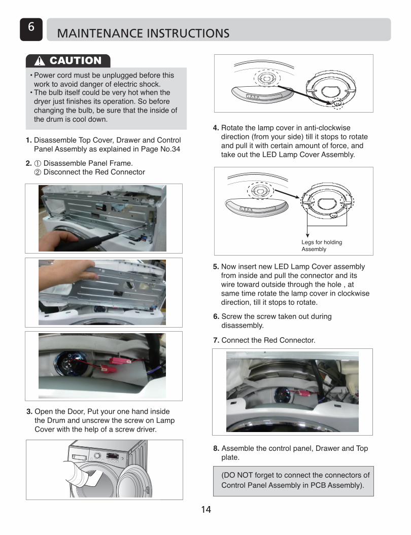
MAINTENANCE INSTRUCTIONS6
14

COMPONENT TESTING TIPS7
15
15
IDENTIFICATION1 COMPONENT TESTING TIPS7
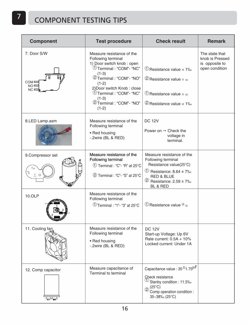
Component Test procedure Check result Remark
The state that knob is Pressed is opposite to open condition
Measure resistance of the Following terminal1) Door switch knob : open
Measure resistance of the Following terminal
Measure resistance of the Following terminal
Measure capacitance of Terminal to terminal
2)Door switch Knob : close
DC 12V
Power on Check the voltage in terminal.
Measure resistance of theFollowing terminal
• Red housing -.2wire (BL & RED)
• Red housing -.2wire (BL & RED)
8.LED Lamp.asm
9.Compressor set
10.OLP
11. Cooling fan
12. Comp capacitor
7. Door S/W
Resistance value < 1‰
Resistance value ÷ ∞
Resistance value ÷ ∞
Resistance value < 1‰
Terminal : “COM”- “NC” (1-3)Terminal : “COM”- “NO” (1-2)
Terminal : “COM”- “NC” (1-3)Terminal : “COM”- “NO” (1-2)
1
2
2
Measure resistance of the Following terminal
1
Measure resistance of the Following terminal
DC 12VStart-up Voltage: Up 6VRate current: 0.5A + 10%Locked current: Under 1A
Resistance value(25°C)
Resistance: 8.64 ± 7‰ RED & BLUEResistance: 2.59 ± 7‰ BL & RED
1
2
1
Resistance value ∞1
2
1
2
1
2
Terminal : “C”- “R” at 25°C Terminal : “C”- “S” at 25°C
Measure resistance of the Following terminal
1 Terminal : “1”- “3” at 25°C
Capacitance value : 35 1.75
Check resistance Stanby condition : 11.5‰
(25°C) Comp operation condition :
35~38‰ (25°C)
1
2
16
IDENTIFICATIONCOMPONENT TESTING TIPS7
1�4�
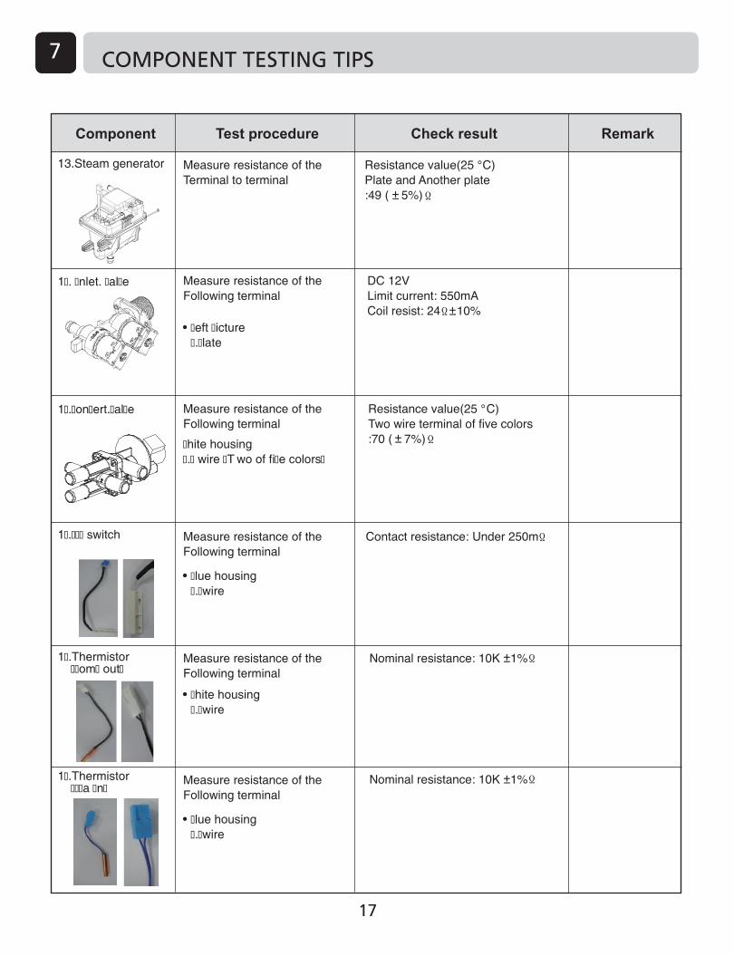
COMPONENT TESTING TIPS�7�
13.Steam generator Measure resistance of the Terminal to terminal
Measure resistance of the Following terminal
Measure resistance of the Following terminal
�hite housing�.� wire �T wo of fi�e colors�
Measure resistance of the Following terminal
�lue housing�.�wire
Measure resistance of the Following terminal
Measure resistance of the Following terminal
1�. �nlet. �al�e
1�.�on�ert.�al�e
1�.��� switch
1�.Thermistor ��om� out�
1�.Thermistor ���a �n�
�eft �icture�.�late
�hite housing�.�wire
�lue housing�.�wire
17

IDENTIFICATION1 WIRING DIAGRAM8
18

IDENTIFICATIONTROUBLESHOOTING9
→ →
→ →
→ → →
→
▲ ▼
→
→
19

IDENTIFICATION1 TROUBLESHOOTING9
20

IDENTIFICATION
Error Mode
TROUBLESHOOTING9
21

IDENTIFICATION1 TROUBLESHOOTING9
Error Mode
Display symptom Check point
-.Fire detection of drum through low thermistor temp detecting.-.Low Thermistor Open/Short Error.
-.Filter is not replaced.-.Dryer does not work
1) Connector ¡� not assembled?- Open Check weather connector in connected correct or not?2) If the covering has been peeled away or touch? - Short If the penetration of water? - Short Check if any damage in harness or not?3) Thermistor element ¡� dead Check if thermistor resistance in normal or not?4) Check the voltage from main PCB to thermistor High or low voltage? ¡� Replace Main PCB* See page No.17* Thermistor Resistance : 10k¥�¡�5% at 25¡�
1.Check the filter is properly seated.2.Check the magnet in filter.3.Check the Reed switch is normal or not.
22

IDENTIFICATIONTROUBLESHOOTING9
23
NO�
Power-On
Power-Off
Press Power button
LED¡'SegmentOn
Press Start/Pause button
Drum notRoating
Door Open?
Lamp on?
Lamp Broken Connector malfunction
Start button Lock:: No buzzer
Plugged in
Low voltage
LED broken,connector malfunction.
Low temperature
Circuit breakertrip
Power buttonLock:No buzzer
Harness Wirebroken
Display pcb wire broken,not connected
Replace Belt
Clean Filter orCheck the Eva Clogging
Empty watercontainer
Drum Belt broken
Clean Filter signdisplay
Empty water signdisplay
Reduce clothes load,Spin the load more
Check motor TP Trip,Check blower damage(locking)
Door is not closed (" ") display
Insert Filter signdisplay
See the Page 24check list
Check the magnet,Replace the Filter
ProperlyDrying?
(Dryness level & Time)
LQC Mode 1Check LEV
Check Heater Power
Check Comp Power
Check Comp OLP Trip
Check Thermostat Trip
Speed Mode
Check surrounding Temp.of product placed
Check LEV failure?-. Resistance : 46 3.7 (20¡C)-. Housing connection-. Initial Eva in Temp. Drop

IDENTIFICATION1 DIAGNOSTIC TEST10
Test 1 : ELECTRIC SUPPLY & CONTROL CHECK
Trouble Symptom : No power to the dryer or the controller
Measurement condition : Power is on. [ Caution] Electric shock. Please test after grounding check.
Power voltage is withinstandard range (AC 215V~245V)?
¥ Check the - Circuit breaker
¥ Check after disconnecting Yellow relay and Black relay connector of Main PCB.
¥ Check the range of Blue and Brown wire is within AC 215 ~245V?
¥ Check the short of harness assembly and the connection.
¥ Check or replace the Power cord.
¥ Check or replace the Noise filter.
¥ Check or replace the Controller.
24
IDENTIFICATIONDIAGNOSTIC TEST10
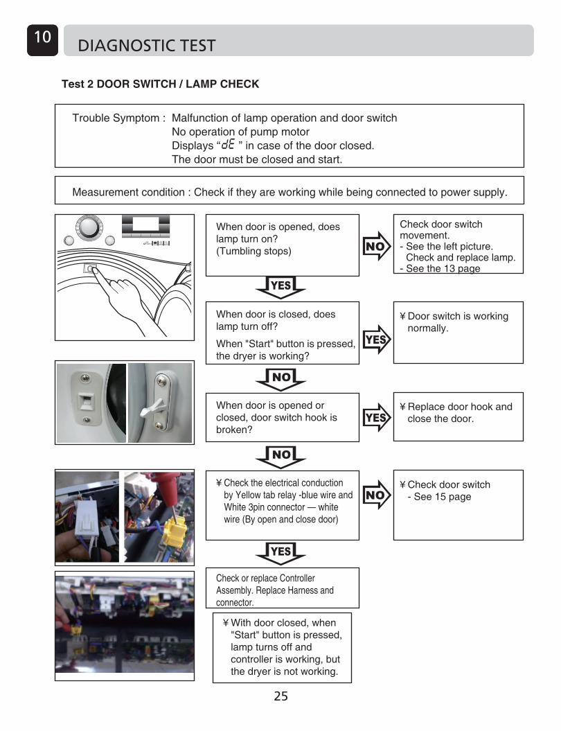
Test 2 DOOR SWITCH / LAMP CHECK
Trouble Symptom : Malfunction of lamp operation and door switch No operation of pump motor Displays “ ” in case of the door closed. The door must be closed and start.
Check door switch movement. - See the left picture.
Check and replace lamp.- See the 13 page
¥ Door switch is working normally.
¥ Replace door hook and close the door.
¥ Check door switch - See 15 page
Measurement condition : Check if they are working while being connected to power supply.
When door is closed, does lamp turn off?
When "Start" button is pressed, the dryer is working?
When door is opened, doeslamp turn on?(Tumbling stops)
When door is opened or closed, door switch hook is broken?
Check or replace Controller Assembly. Replace Harness and connector.
¥ With door closed, when "Start" button is pressed, lamp turns off and controller is working, but the dryer is not working.
¥ Check the electrical conduction by Yellow tab relay -blue wire and White 3pin connector — white wire (By open and close door)
25

IDENTIFICATION1
¥ Check white 3 pin female connector from motor.
- Resistance check¥ Check white 3 pin male
connector from controller. (when power cord is plugged)
- two wire in white 3pin male connector : 220~240V
DIAGNOSTIC TEST10
Test 3 Motor check
Trouble Symptom : Motor malfunction, Occurrence of the “Clean filter” repeatedly
¥ Before check process, Check the motor rotating by the LQC test mode "See the 18 page”.
¥ When power is on and pressed the start button, does motor operate?
¥ Is there any abnormal noise during operation?
¥ Check controller -See page 17 (PCB Assembly Lay-out)
¥ Check the harness connection.
- Motor part : White 3 pin housing. - Controller part : Red 3 pin housing ( Orange and Blue wire ). - Capacitor part : White 2 pin housing. ¥ Check the belt ( position /
broken ).¥ Check the Controller - TR1 , TR2 Broken ? ¥ Check the slide ( 3 ea ).
¥ Check Capacitor volume. Power on & press the start button.
- See the left picture.¥ Check belt is burst.¥ Check structural restriction. ( Motor supporter / Air guide
Blower )
¥ Check or replace Motor - Check Motor TP
¥ Check Harness connection ¥ Check the Motor resistance.
(see page 15 )
Measurement condition : ¥ Power cord is unpluged. ¥ Door is closed. ¥ Check the user condition. - Put overload into drum? - Normally Input Voltage and Hertz? ¥ Pre-Check door switch (If door switch has contact problem, motor should not operate.)
26

IDENTIFICATIONDIAGNOSTIC TEST10
Test 4 Heater check
Trouble Symptom : Heater is not working. Drying failure. The designated temperature is not reached.
Measurement condition : Power cord is unplugged.
1. Check if Lint filter is damaged or clogged.
2. Check if condensing unit is clogged or not.
Trouble Symptom : Motor malfunction, ventilation error
Heater On/Off occursfrequently
1
¥ Check and replace controller.
¥ See page 17, PCB assembly lay-out.
¥ Check harness & connection
¥ Check the resistance of thermostat to heater. Is it less than 1‰?
¥ Replace Heater
¥ Check harness & connection
Manually reset thermostat(Press button ).And check resistance thermostat.
¥ Check the heater resistance. 1) Yellow tab relay violet wire ~
White tab relay yellow wire : 50‰ ?
2) White connector 2wire : 50‰ ? ( See photo on the left )
27

IDENTIFICATION1 DIAGNOSTIC TEST10
Test 5 Pump check
Trouble Symptom : LED display show " OE " signals.
¥ Disassemble Pump - Check foreign objects - Check impeller restriction - Check connection hose clogged
(Measure with power on)On LQC test mode, when Pump is on,Can you hear any operating noise?
Measurement condition : Power cord is unplugged. Check the hose blocked with foreign body or kinked.
(Measure after power is off.)With Yellow 3pin disconnected from controller, YL3 white wire - YL3 orange wire resistance ranges 4.5‰ ? YL3 white wire - YL3 yellow wire resistance ranges 4.5‰ ?
¥ Check or replace pump ¥ Check harness &
connection
¥ Check Pump sensor With White 6pin disconnected from controller,
check White6 blue ~ White6 blue resistance.
-.If there is water: 5M‰ level ( 25°C) -.If there is no water: 0M‰ level ( 25°C)
28

IDENTIFICATIONDIAGNOSTIC TEST10
Test 6 Thermister check
Trouble Symptom : Poor drying performance(over-drying or no drying). Abnormal thermistor operation.
Measurement condition : Power cord is unplugged.
DryerTemperature
¥ Check harness & connection
DryerTemperature
Resistance
TH-Heater
250~180k‰
180~113k‰
TH-Drum
19~111k‰
11~8k‰
8~5k‰
TH-Drum
19~111k‰
11~8k‰
8~5k‰
ResistanceRemark
TH1
113~75k‰
75~50k‰
50k‰
TH2
5~4k‰
4~2.5k‰
2.5k‰
10
20~30
30~40
DryerTemperature
40~50
50~60
60
With White9,White 6 disconnected fromController, check1) High temperature thermistor ( Wire color : White) White 6 pin white ~White 6 pin red resistance ranges table data according to surrounding temperature.2) Low temperature thermistor ( Wire color : Blue) White 9 pin Blue ~White 9 pin white resistance ranges table data according to surrounding temperature.
¥ Check and replace thermistor.
1) Check disconnected Housing or
severed Wire. 2) Check the resistance of thermistor. 3) Replace controller and then recheck, if anything else occurs.
29

IDENTIFICATION1 DIAGNOSTIC TEST10
27
DIAGNOSTIC TEST11
30

IDENTIFICATIONDIAGNOSTIC TEST10
Test 8
Check if they are working while being connected to power supply.
Is the product leveled?(Check shaking / tilt )
Is it installed to Built In / Under environment?
Is thermistor normal?
Is comp operation properly?1) Power On2) Display dataview mode3) Comp on after 1min from start.4) After comp on, check corresponding the temp. -. Comp T : Is it rising? -. Eva in : Is it rising after falling?
1. Is OLP normal?2. Is Comp resistance normal?3. Is capacitor resistance normal? (refer to page 16)4. Is LEV resistance normal?5. Check trace of oil leakage around Comp.
2.For Comp defect -. Replace Comp (Refer to R code - C145 , Page 45)3. For LEV defect -. Replace LEV.
Is thermistor resistance normal?(Refer to resistance and measurement method, page 15~17)
Replace thermistor.
Improve dryer installation environment.( Refer to installation environment, Page 10~12 )
Leg leveling(Refer to how to adjust leveling, Page 10 )
Check Evaporator clogging status
( Refer to humidity sensor inspection method, Page 30 )
Does the defect occur after PCB replacement ?
Clean filter.Clean Evaporator clogging.(Refer to e�ploded view , Page 45)
�O The course �how details1234567��101112
Refresh�kin Care�eansBulky ItemEasy Care�i�ed FabricCotten�ports � ear�uick DryDelicate� oolRack Dry
�umidity valuesLow TempComp TempT�heater (�igh Thermistor)Eva in Temp
�ump � ater LevelDrain Pump RP�LEV Pulse�ain P�� Tool�ain V ersion
¡�Check the status of the actions Sensor- Drum Light + Buzzer 3 when entering Pressing enter,� Once again press the same key fot three seconds � to escape.- Turn the Jog Dial in data view state data can be � checked as shown below.- Not to enter the Child lock status.- Apply the model : Only Touch LED model.
31

IDENTIFICATION1 DIAGNOSTIC TEST10
Test 9
* Standard Time: Eco Mode ¡� Over 225min, Speed: Over 180min * Drying Condition: Cotton-Cupboard, 9kg Cotton Clothes, Spin rpm: Over 1,000rpm
Measurement condition : Check if they are working while being connected to power supply.
Is the product leveled? (Check shaking / tilt )
3) Is it installed to Built in / Under environment?
Improve dryer installationenvironment.(Refer to installation environment, Page 10~12)
1.Check resistance 2.Check harness & connection.
1. Is OLP normal?2. Is Comp resistance normal?3. Is capacitor resistance normal? (refer to page 16)4. Is LEV resistance normal?5. Check trace of oil leakage around Comp.
( Refer to humidity sensor inspection method, Page 30 )
Does the defect occur after PCB replacement ?
2.For Comp defect -. Replace Comp (Refer to R code - C145 , Page 45)3. For LEV defect -. Replace LEV.
4) After Comp on, check corresponding thermistor temp.
Release thermostat trip or replace thermostat.
Replace heater or repair connection.
Leg leveling(Refer to how to leveling, Page 10)
NO The course Show details123456789101112
RefreshSkin CareJeansBulky ItemEasy CareMixed FabricCottenSports WearQuick DryDelicateWoolRack Dry
Humidity valuesLow TempComp TempT_heater (High Thermistor)Eva in Temp
Sump Water LevelDrain Pump RPMLEV PulseMain PGM ToolMain Version
¡�Check the status of the actions Sensor- Drum Light + Buzzer 3 when entering Pressing enter,� Once again press the same key fot three seconds � to escape.- Turn the Jog Dial in data view state data can be � checked as shown below.- Not to enter the Child lock status.- Apply the model : Only Touch LED model.
32

IDENTIFICATIONDIAGNOSTIC TEST10
Test 10
Measurement condition : Check if they are working when connected to power supply.
Is the product leveled?(Check shaking / tilt )
Adjust product leveling(Refer to how to leveling, Page 10)
Adjust pipe position to insure minimum 5mm gap with pipe or mold
Adjust pipe position to insure minimum 5mm gap with pipe or mold
Is Belt properly assembled to Pulley?
Is Journal Bearing grease properlySprayed?( Refer to exploded view , Refer to picture C page35 )
Replace Journal bearing (D122)
Refer to picture A , page35
Replace real seal (D152)
Note: The roler noise (dung dung dung) at the initial operation, and pump and water flowing noise during auto cleaningTM are normal noises of the product. If noise of metal materials bumping each other occurs, check if screw is properly locked or if it is properly assembled.
Is the washer between Drum andRear cover flat?( Refer to picture D , page35 )
2) After Comp on, check corresponding thermistor temp. ta ~ ta~ ta~ sound)
NO The course Show details123456789101112
RefreshSkin CareJeansBulky ItemEasy CareMixed FabricCottenSports WearQuick DryDelicateWoolRack Dry
Humidity valuesLow TempComp TempT_heater (High Thermistor)Eva in Temp
Sump Water LevelDrain Pump RPMLEV PulseMain PGM ToolMain Version
¡�Check the status of the actions Sensor- Drum Light + Buzzer 3 when entering � Pressing enter, Once again press the same key � fot three seconds to escape.- Turn the Jog Dial in data view state data can be � checked as shown below.- Not to enter the Child lock status.- Apply the model : Only Touch LED model.
33

IDENTIFICATION1 DIAGNOSTIC TEST10
Test 11
3. Convert LCD Display to Data View Mode.4. After Start, when the first Pumping is completed, put 1/3 water in Drawer, and pour around Dispenser water discharge hole slowly until "Sump W" value becomes "001" among Data View categories. (When it becomes "001", water supply shall be stopped immediately.)5. Check electric parts , mechanical parts, hose connection in the left bottom and water leakage at the bottom of Base.
( Refer to page41 )
( Refer to picture E , page35 )
( Refer to picture F , page35 )
-. Pump Cover assembly status (Gap, Screw missing, etc.)
NO The course Show details123456789101112
RefreshSkin CareJeansBulky ItemEasy CareMixed FabricCottenSports WearQuick DryDelicateWoolRack Dry
Humidity valuesLow TempComp TempT_heater (High Thermistor)Eva in Temp
Sump Water LevelDrain Pump RPMLEV PulseMain PGM ToolMain Version
¡�Check the status of the actions Sensor- Drum Light + Buzzer 3 when entering � Pressing enter, Once again press the same key � fot three seconds to escape.- Turn the Jog Dial in data view state data can be � checked as shown below.- Not to enter the Child lock status.- Apply the model : Only Touch LED model.
34

IDENTIFICATIONDIAGNOSTIC TEST10
Reference picture
Picture A Picture B Picture C
Picture D Picture E Picture F
35

IDENTIFICATION1 DIAGNOSTIC TEST10
PCB Layout (Main)
Motor
Display Power
CompressorPCB POWER
BLDC Pump
SUMP SENSING(No 1,4)HIGH THERMISTOR(No 2,3)COMP THERMISTOR(No 2,6)EVA INLET THERMISTOR(No 2,5)5V(No 2)
GROUND
BL(8PIN)
MAIN TO DISPLAYCOMUNICATION
Control Valve (No 2,3,4,5)LEV (No 6,7,8,9)COOLING FAN (No 10,11)13V (No 1)
WH(11PIN) WH(9PIN)
DOOR LAMP (No 1,2)FILTER SENSING (No 3,4)LOW THERMISTOR (No 5,6)ELECTRODE (No 3,9)
Door SW
36
IDENTIFICATIONDISASSEMBLE INSTRUCTIONS11
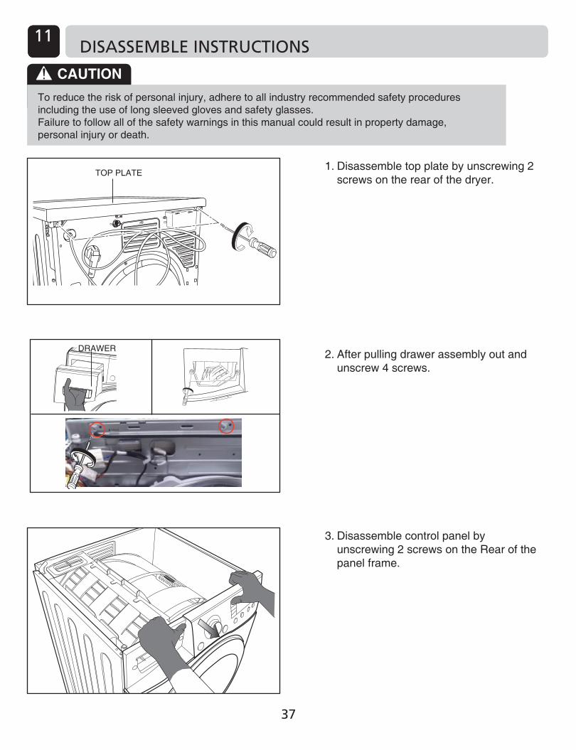
1. Disassemble top plate by unscrewing 2 screws on the rear of the dryer.
2. After pulling drawer assembly out and unscrew 4 screws.
3. Disassemble control panel by unscrewing 2 screws on the Rear of the panel frame.
DRAWER
TOP PLATE
CAUTIONTo reduce the risk of personal injury, adhere to all industry recommended safety procedures including the use of long sleeved gloves and safety glasses.Failure to follow all of the safety warnings in this manual could result in property damage, personal injury or death.
37

IDENTIFICATION1 DISASSEMBLE INSTRUCTIONS11
5. Disassemble cabinet by unscrewing 2 at the top and 3 at the rear (Left and right are the same).
6. Disassemble panel frame by unscrewing 4 at the front.
4. Disassemble the lower cover by pulling to the front.
2nd
Pul
l
1st P
ull
CABINET
DRAWER
PANEL FRAME
38

IDENTIFICATIONDISASSEMBLE INSTRUCTIONS11
8-1. Disassemble the spring holder.
8-2. Releasing the belt on the pulley.
9-1. Disassemble the main PWB cover as pulling the hook.
9-2. Pull out the harness from the housing.
¤� Pull the hook
¤Ł P
ULL
¤º
¤Œ
¤� Pull the hook
¤Ł P
ULL
¤º
¤Œ
7-1. Disassemle the door by releasing the 2 screws.
7-2. Disassemble the door switch.
7-3. Disassemble the cabinet cover by releasing the 10 screws.
7-4. Disassemble the Door Switch.
7-5. Disassemble the cover, cabinet.CABINET COVER
DOOR
Pull
DOOR SWITCH
Pull
1
Pull the Hook
Push
1
2
2
39

IDENTIFICATION1 DISASSEMBLE INSTRUCTIONS11
Note
If the hose is assembled unsuitable “empty water” error message will be indicated on the LED or LCD display.
11. Disassemble the housing of motor, compressor, heater and thermistor.
12. Releasing the dispenser by unscrewing 1 screw.
10. Disassembling the side frame by releasing 4 screws
DISPENSER
Heater thermistor (WH Small 2pin)
Heater housing (WH Big 2pin)
Motor housing (WH 3pin)
Compressor housing (BLUE 3pin)
40

IDENTIFICATION
1.Disassemble the hose. -.Check Hose ⓐ to and ⓑ to and
2.Remove the hose. -.Hose ⓑ to (Check holder ) -.Hose ⓐ to
Note
If hoses are not properly connected,there is a risk of leak.
ⓐ
ⓑ
DISASSEMBLE INSTRUCTIONS11
41

IDENTIFICATION1 DISASSEMBLE INSTRUCTIONS11
13-1. Disassemble the duct by releasing the 7 screws.
13-2. Release the drum nut using tool.
13-3. Disassemble the air guide by releasing the 1 screw.
14-1. Disassemble the COVER REAR by releasing the 2 screws.
14-2. Disassemble the drum.
DUCT
COVER REAR
AIR GUIDE
42

IDENTIFICATIONEXPLODED VIEW 12
Control Panel & Top plate Assembly
A111
A120
A130
A110
A200
A113
A100
A190
A180
A150
A160
43
A114
A115

IDENTIFICATION1
Cabinet Cover & Door Assembly
B120
B214
B140
B130
B150
B127
B100
B107
B106
B102
B101
B103
B200
B125
B124
B210
B180
B212
B213
B211
Opaque round door
B106
B102
B107
B103B100
B103
B100
B101
B102
B106
Transparent door
Black tint door
B107
NoteNote
B121
B126
B123
B139
44
EXPLODED VIEW 12
B109
B109
B109
If you want to exchangethemistor, Replace B139 assembly
If you want to replace the B150 part(Locker Assembly),Check out the product manufacture date on the rating label.And apply it as shown below.- Products produced before February ,2014:4027EL1001A- products produced since February ,2014 :AFK73489601
B160
B217B216 B215
B122
B128

IDENTIFICATION
Base & Motor Assembly
C290C291
C200
C120
C311C312
C360
C313
C350C319
C316
C317
C318
C315
C314
C600C250
C251
C145
C252
C147
C253
C148
C143
C142C146
C160
C230
C240
C180
C240
C230
C150
C165
C140
C310C360
C361
C241
EXPLODED VIEW 12
45
A112
C144
Low Temp
C362 C365
High Temp
Thermister Harness

IDENTIFICATION1 EXPLODED VIEW12
Back Cover & Drum Assembly
D122
D120
D128
D100
D110
D121
D130
D157D151
D170
D173
D210
D200
D180C360D150
D152
D158
D156 D157
46

AUGUST. 2011 PRINTED IN KOREA P/No.: 3828EL9001Y