
Cascade fuzzy control for gas engine driven heat pump
10
Cascade fuzzy control for gas engine driven heat pump Shuze Li a, * , Wugao Zhang a , Rongrong Zhang a , Dexu Lv b , Zhen Huang a a Institute of Internal Combustion Engines, School of Mechanical Engineering, Shanghai Jiaotong University, 200030 Shanghai, PR China b Wonders Information Co. Ltd., 4F Building 18, 481 Gui Ping Road, 200233 Shanghai, PR China Received 2 May 2004; accepted 19 September 2004 Available online 5 November 2004 Abstract In addition to absorption chillers, todayÕs gas cooling technology includes gas engine driven heat pump systems (GEHP) in a range of capacities and temperature capacities suitable for most commercial air con- ditioning and refrigeration applications. Much is expected from GEHPs as a product that would help sat- isfy the air conditioning system demand from medium and small sized buildings, restrict electric power demand peaks in summer and save energy in general. This article describes a kind of control strategy for a GEHP, a cascade fuzzy control. GEHPs have large and varying time constants and their dynamic modeling cannot be easily achieved. A cascade control strategy is effective for systems that have large time constants and disturbances, and a fuzzy control strategy is fit for a system that lacks an accurate model. This cascade fuzzy control structure brings together the best merits of fuzzy control and cascade control structures. The performance of the cascade fuzzy control is compared to that of a cascade PI (proportional and integral) control strategy, and it is shown by example that the cascade fuzzy control strategy gives a better performance, reduced reaction time and smaller overshoot temperature. Ó 2004 Elsevier Ltd. All rights reserved. Keywords: Gas engine driven heat pump; Cascade fuzzy control; PI control 0196-8904/$ - see front matter Ó 2004 Elsevier Ltd. All rights reserved. doi:10.1016/j.enconman.2004.09.003 * Corresponding author. Tel.: +86 21 6407 4085; fax: +86 21 6407 8095. E-mail addresses: [email protected], [email protected] (S. Li). www.elsevier.com/locate/enconman Energy Conversion and Management 46 (2005) 1757–1766
-
Upload
independent -
Category
Documents
-
view
2 -
download
0
Transcript of Cascade fuzzy control for gas engine driven heat pump

www.elsevier.com/locate/enconman
Energy Conversion and Management 46 (2005) 1757–1766
Cascade fuzzy control for gas engine driven heat pump
Shuze Li a,*, Wugao Zhang a, Rongrong Zhang a, Dexu Lv b, Zhen Huang a
a Institute of Internal Combustion Engines, School of Mechanical Engineering,
Shanghai Jiaotong University, 200030 Shanghai, PR Chinab Wonders Information Co. Ltd., 4F Building 18, 481 Gui Ping Road, 200233 Shanghai, PR China
Received 2 May 2004; accepted 19 September 2004
Available online 5 November 2004
Abstract
In addition to absorption chillers, today�s gas cooling technology includes gas engine driven heat pumpsystems (GEHP) in a range of capacities and temperature capacities suitable for most commercial air con-
ditioning and refrigeration applications. Much is expected from GEHPs as a product that would help sat-
isfy the air conditioning system demand from medium and small sized buildings, restrict electric powerdemand peaks in summer and save energy in general. This article describes a kind of control strategy
for a GEHP, a cascade fuzzy control. GEHPs have large and varying time constants and their dynamic
modeling cannot be easily achieved. A cascade control strategy is effective for systems that have large time
constants and disturbances, and a fuzzy control strategy is fit for a system that lacks an accurate model.
This cascade fuzzy control structure brings together the best merits of fuzzy control and cascade control
structures. The performance of the cascade fuzzy control is compared to that of a cascade PI (proportional
and integral) control strategy, and it is shown by example that the cascade fuzzy control strategy gives a
better performance, reduced reaction time and smaller overshoot temperature.� 2004 Elsevier Ltd. All rights reserved.
Keywords: Gas engine driven heat pump; Cascade fuzzy control; PI control
0196-8904/$ - see front matter � 2004 Elsevier Ltd. All rights reserved.doi:10.1016/j.enconman.2004.09.003
* Corresponding author. Tel.: +86 21 6407 4085; fax: +86 21 6407 8095.
E-mail addresses: [email protected], [email protected] (S. Li).

1758 S. Li et al. / Energy Conversion and Management 46 (2005) 1757–1766
1. Introduction
In many instances, a gas engine driven heat pump (GEHP) is a more attractive climate controlsystem than the conventional air conditioner [1,2], e.g.:(1) Variable speed operation: Typically, the GEHP can cycle at minimum speed and modulate
between a minimum and maximum speed to match the required load. The minimum and maxi-mum speeds are decided by the performance of a different engine and compressor. As a result,the part load efficiency of such a system will be high. Its seasonal operational cost and cyclinglosses will be lower than those of a single speed system with an on–off control system.(2) Engine heat recovery: The engine�s heat efficiency is not very high (about 30–45% for gas
engines now). The heat of fuel combustion is wasted through exhaust gases, cooling water andthe engine block. However, the system�s efficiency will be increased by recovering the heat fromthe cooling water and the exhaust gases in the heating mode.(3) Natural gas fuel: The GEHP also differs from an electric heat pump (EHP) in the energy
they use, primarily natural gas or propane instead of electricity. So, a GEHP is preferred in a re-gion where electric costs are high and natural gas is readily available.The system blends two subsystems: the engine and the heat pump system. The time constants of
the two subsystems are different (the engine�s time constant is small and that of the heat pumpsystem�s is large), and both frequently change according to the operating demands. In addition,there is lag time in the GEHP. So it is very difficult to decide upon the control strategy for theGEHP. Under some conditions, a predictive control algorithm is more effective than a feedbackcontrol (e.g., PID control) when large time constants and lag times are present [3]. However, apredictive control algorithm cannot be applied to the system directly because its dynamics arenot predictable. In order to apply the predictive algorithm, some learning process is necessaryto identify the model�s current parameters and estimate those of the future. The controller mustcalculate these quickly to meet the system�s real time requirements. If the predictive algorithmwere introduced, it would spend much time in identifying the system�s dynamic model. The sys-tem�s adaptability to different conditions will lead to some problems.During the development of control theory, many new strategies have been put forward, e.g.,
fuzzy control, neural network control etc. Each of the strategies have their own characteristicsand can be adapted to many kinds of systems. One merit of fuzzy control is that the system�smodel can be unknown. So, it is very promising for the GEHP system.Based on the characteristics of the GEHP system, in this paper, we propose a cascade fuzzy con-
trol algorithm. It controls the return water temperature through an outer loop (first loop) and con-trols the engine speed through an inner loop (second loop). In the following sections, the GEHPsystem to be controlled will be explained first, then the fuzzy cascade control algorithm is proposedand, finally, the effectiveness of the proposed method is shown for different changes in demand.
2. The GEHP system
A heat pump is used to transfer thermal energy from a low temperature reservoir to a hightemperature field to cool or heat. The GEHP is a new type of heat pump in which the compressor(the core part) is driven by a gas engine.

1 2 34
return water
78
9
11
10
13
12
6
5
supply water
heating cyclecooling cycle
1.gas engine 2.open type compressor 3. four-way valve 4.plate heat exchanger 5. supply water pump 6.expansion valve 7. fin-tube heat exchanger 8.engine waste heat radiation 9.gas to water heat exchanger 10.Three-way valve of engine cooling water 11. water to water heat exchanger 12.engine cooling water pump 13. three-way valve of supply water
Fig. 1. Schematic diagram of GHEP.
S. Li et al. / Energy Conversion and Management 46 (2005) 1757–1766 1759
As shown in Fig. 1, the GEHP system consists of the gas engine, an open type compressor, twopumps, valves, expansion valve, heat recovery heat exchangers and gas supply equipment withsome pipes and wires connecting them. Some sensors are used to measure the mediums� (includingexhaust gas, water, liquor condensate) temperature, pressure and flux in the system. The control-ler was used to analyze these signals to control the operation of the system. It depended on thefour way valve to choose the cooling cycle or heating cycle. The heat exchanger was used to utilizethe exhaust gas heat energy and the circulation water heat energy.The return water temperature of the unit is controlled by adjusting the opening angle of the
engine�s throttle. In the GEHP system, if the thermal load of the air conditioning system changes,the return water temperature will also change. Consequently, the supply water temperature of thesystem will be affected. The aim of the control system is to adjust the return water temperature toa constant value and thus to ensure the capacity of the system to match the demand of the airconditioning load. The superheat degree of the refrigerant and the pressure of the refrigerant atthe discharge point, as controlled by the electric expansion valve, were not considered in thispaper.
3. Control design
The system�s operation depends on the controller, which adjusts the executor (e.g., motors andvalves) to meet the demands. It affects the performance of the whole system. The control strategyis the most important part of the controller. There are many strategies including traditional con-trol, modern control, intelligent control etc. They are designed to fit different types of systems. Inthis section, a strategy to control the GEHP system is described. The proposed cascade fuzzy con-trol strategy is based on a cascade control approach with a fuzzy feedback controller.
3.1. Control strategy
Since the GEHP system has many parameters that are, in general, uncertain or unknown, it isdifficult to determine a required control strategy from a mathematical model. Some control strat-egies based on a model, such as internal module control, model reference adaptive control, pre-dictive control etc., cannot be used for this type of system. We will follow a feedback control

1760 S. Li et al. / Energy Conversion and Management 46 (2005) 1757–1766
approach to design all loops of the cascade control scheme. Successful applications of cascadecontrol include control of several chemical [4] and mechanical processes. A cascade control struc-ture has two feedback controllers with the output of the first controller changing the set point ofthe second controller [5].In the cascade control system, the first control loop is a constant value control system, but the
second control loop is a following control system. The output (gas engine speed for this system) ofthe first loop varies according the load (temperature variance for this system). This makes the setvalue of the second controller change to follow the load. In this way, the cascade control systemhas the capability of autoadaptation and is, thus, especially recommended for the GEHP system.
3.2. A control scheme for the GEHP
During the system operation, the speed of the engine needs to be adjusted under some condi-tion, e.g., a disturbance of the thermal load. When the thermal load increases, the engine speedshould be increased to match the load, but when the thermal load decreases, the speed should de-crease to save energy. However, the thermal capacity of the air conditioning system is large, andso, the return water temperature changes very slowly. Since the time constant from temperature tospeed is large, it is hard for the controller to control the speed of engine in time. When the con-troller receives the temperature alteration through the sensors, it is already too late. That is to say,the dynamic error will be large. In order to avoid this, cascade control was introduced in the con-trol system. The control system block diagram is shown in Fig. 2.
3.2.1. Secondary control loop design
In the cascade control system, the secondary controller can overcome the disturbance in the sec-ond loop. So, the main disturbance, whose frequency and amplitude are both large, should be in-cluded in this loop. For the GEHP system, the engine speed changes rapidly following a variationin operating condition. So, the engine is disturbed easily in a GEHP system. When the speed ofthe engine rises, the supply water temperature will rise after a lag time. At that time, the controllerwould not adjust the throttle if the first control loop did not exist because the temperature has notyet changed. So, the engine speed should be the control input to the secondary loop. If that loopexisted, the throttle would be adjusted to keep the speed of the engine unchanged or changed verylittle. The temperature change of the supply water would be very small. Furthermore, the first
Firstcontroller
Secondsensor
Firstsensor
Engine Heat pump
Set pointTemperature ofreturn water
Disturbance 1 Disturbance 2
Throttle+
-+
-
Secondary loop
First loop
Secondarycontroller
Engine speed
Fig. 2. Schematic diagram of cascade control system.

S. Li et al. / Energy Conversion and Management 46 (2005) 1757–1766 1761
controller can aim to overcome this error. The whole effect should be better than one loop if thesedisturbances had been included in the second loop.Since the engine has fast dynamics, in the second loop, we consider a simple proportional and
integral action to control throttle angle with current speed as the control input.
3.2.2. First loop designFuzzy set theory was introduced by Zadeh [6] in 1965, and the first fuzzy logic control algo-
rithm was implemented by Mamdani [7] on a steam engine in 1974. In the following years, fuzzylogic control has been widely used in many industrial applications successfully and has demon-strated significant achievements [8]. Fuzzy control is fit for systems whose accurate model cannotbe established. Fuzzy control can utilize any available information, including that provided by ex-perts. This information is very important in practice. So, fuzzy control was chosen as the strategyof the first control loop.Usually the inputs of fuzzy control are the control object�s value and its change in speed. The
output is the control variable�s increment. For a GEHP system, the inputs are the return watertemperature and its change in speed. The output is the engine speed increment for incrementalcontrol.Altogether, cascade fuzzy control has the merits of both fuzzy control and cascade control. The
secondary loop controls the engine speed and suppresses the disturbances to the engine. The firstloop controls the temperature as adapted to the thermal load of the whole system. The secondarycontroller uses a simple PI control logic. The first controller uses fuzzy control logic.In the following, the detailed design parameters are described.
4. Control system parameter design
Generally, the time constant of the secondary control loop is small. This will help to conquerthe inertial lag time of the whole system. The working frequency oscillation will dampen, and theperiod of the system response will shorten, thus improving the control quality of the whole system.In order to achieve the best adjustment process and improve the dynamic and static character-
istics of the system, the parameters of the controller must be carefully chosen. The step-by-stepmethod of approach was adopted to design the GEHP system.The following describes the detailed steps:
(1) Cut down the first loop, close the secondary loop and design the parameters of the secondarycontroller according to the design method for a single loop system.
(2) Close the first and secondary loop, keep the parameters of the second controller obtainedfrom the previous step and design the parameters of the first controller according to thedesign method for a single loop system.
(3) Close the first and secondary loop, keep the parameters of the first controller gotten from theprevious step and design the parameters of the secondary controller again.
(4) If the target was satisfied, the selecting procedure is completed. Otherwise, go to step 2 tobegin the next design cycle.

Table 1
The whole control table
E EC
�6 �5 �4 �3 �2 �1 0 1 2 3 4 5 6
Vs
�6 7 6 7 6 7 7 7 4 4 2 0 0 0
�5 6 6 6 6 6 6 6 4 6 2 0 0 0
�4 7 6 7 6 7 7 7 4 4 2 0 0 0
�3 7 6 6 6 6 6 6 3 3 0 �1 �1 �1�2 4 4 4 5 4 4 4 1 0 0 �3 �2 �1�1 4 4 4 5 4 4 1 0 0 0 �3 �2 �10 4 4 4 5 1 1 0 �1 �1 �1 �4 �4 �41 2 2 2 2 0 0 �1 �4 �4 �3 �4 �4 �42 1 2 1 2 0 �3 �4 �4 �4 �3 �4 �4 �43 0 0 0 0 �3 �3 �6 �6 �6 �6 �6 �6 �64 0 0 0 �2 �4 �4 �7 �7 �6 �7 �7 �6 �75 0 0 0 �2 �4 �4 �6 �6 �6 �6 �6 �6 �66 0 0 0 �2 �4 �4 �7 �7 �7 �6 �7 �6 �7
1762 S. Li et al. / Energy Conversion and Management 46 (2005) 1757–1766
It is easy to decide the proportional and integral coefficient of the secondary controller, but it isdifficult to design the parameters of the fuzzy control of the first controller because the input ofthe fuzzy controller must be a fuzzy quantity and its output is also a fuzzy quantity. During thefuzzy inference process, there are five steps in succession, which are fuzzification of the input var-iables, application of the fuzzy operator (AND or OR) in the antecedent, implication from theantecedent to the consequent, aggregation of the consequents across the rules and defuzzification.For a real time control system, it spends much time to complete the five steps described above.
The control system�s reaction will be late if the controller�s computing speed is not fast enough. Inorder to reduce the number of calculations, a control table is introduced. That is to say, a table ofinput variables, output variable and control rules deduces the whole control table (Table 1) offline. In practice, what is needed is only to find the Vs (set speed�s variation here) in the whole con-trol table according to E (the error of return temperature and set temperature) and EC (dE/dt).
5. The consequent of test and discussion
The test object is a natural gas engine heat pump (Fig. 3). The natural gas engine was rebuiltfrom a gasoline engine. The compressor is an open type compressor. The experiment is to test theresponse when the set temperature steps suddenly from 44 �C to 45�C and the speed of the engineincreases 100rpm after stabilization. Figs. 4–6 1 show the temperature curves during the controlprocess using PI and fuzzy control in the first control loop.
1 The symbols in the figures are: T—the temperature of return water; Kp—the coefficient of proportion; Ki—the
coefficient of integral; Tse—the control period of second control loop; Tfst—the control period of first control loop;
K1—ratio from DT to E; K2—ratio from DT/Dt to EC; K3—ratio from Vs to DV; E, EC—the input of fuzzy control;Vs—the output of fuzzy control.

Fig. 3. Photo of the test bench.
S. Li et al. / Energy Conversion and Management 46 (2005) 1757–1766 1763
For PI and fuzzy control, several parameters have been chosen to compare their effects.(1) Influence of control period: No matter what method (fuzzy or PI control) was adopted in
the main control loop, when the control period of the first control increased, the response velocityof the control variant increased, but the over shoot also increased. However, when fuzzy controlwas introduced using the same control period, the stabilization time shortened obviously.(2) Influence of Kp, Ki in PI control: When the first loop is using PI incremental control, increas-
ing Kp increases the overshoot, and the stabilization time shortens (Fig. 4, curves 1 and 3). The Kivariation influences the control quality only a little.(3) Influence of fuzzy table look-up method: There is a static error in curves 1, 2 and 3 in Fig. 5
because the look-up method uses the nearest input value, making the output discontinuous.Therefore, the engine speed cannot be precisely adjusted to fit the thermal load. Using an inter-polation method (Fig. 5, curve 4), the speed can be adjusted continuously and the static error canbe reduced or eliminated, but the computing time will increase. In that case, the controller�s com-puting capability must be improved.(4) Influence of different ranges of DT, DT/Dt and DV: In the whole control table, the ranges of E,
EC and Vs are fixed, so a change of K1, K2 and K3 means a change of the range of DT, DT/Dt andDV. IncreasingK1,K2 will decrease the range of DT, DT/Dt, and the response speed will be fast (Fig.6, curves 1, 3 and 4). Increasing K3 will increase the range of DV and the response speed will be fast(Fig. 6, curves 1 and 2). The effect of K3 is biggest effect of these, and the effect of K1 is also big.(5) The suppressive effect to disturbance in second loop: From Figs. 4–6, it is clear that the
cascade control strategy can suppress the disturbance in the second loop. The adjusting time isshorter if the fuzzy method is applied in the first loop rather than the PI method.

Fig. 4. Step responses using PI control in the first control loop.
Fig. 5. Step responses using fuzzy control in the first control loop with different control period and table looking-up
method.
1764 S. Li et al. / Energy Conversion and Management 46 (2005) 1757–1766
Thus, all coefficients in the control system affect the performance in different modes. So, theyshould be chosen according to the demands of the special system and the operating conditions.
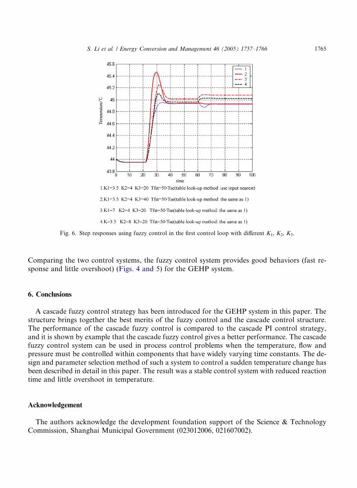
Fig. 6. Step responses using fuzzy control in the first control loop with different K1, K2, K3.
S. Li et al. / Energy Conversion and Management 46 (2005) 1757–1766 1765
Comparing the two control systems, the fuzzy control system provides good behaviors (fast re-sponse and little overshoot) (Figs. 4 and 5) for the GEHP system.
6. Conclusions
A cascade fuzzy control strategy has been introduced for the GEHP system in this paper. Thestructure brings together the best merits of the fuzzy control and the cascade control structure.The performance of the cascade fuzzy control is compared to the cascade PI control strategy,and it is shown by example that the cascade fuzzy control gives a better performance. The cascadefuzzy control system can be used in process control problems when the temperature, flow andpressure must be controlled within components that have widely varying time constants. The de-sign and parameter selection method of such a system to control a sudden temperature change hasbeen described in detail in this paper. The result was a stable control system with reduced reactiontime and little overshoot in temperature.
Acknowledgement
The authors acknowledge the development foundation support of the Science & TechnologyCommission, Shanghai Municipal Government (023012006, 021607002).

1766 S. Li et al. / Energy Conversion and Management 46 (2005) 1757–1766
References
[1] Nowakowski GA, Inada M, Dearing MP. Development and field testing of a high-efficiency engine-driven gas heat
pump for light commercial applications. ASHRAE Transactions, AN-92-10-4. p. 994–1000.
[2] Nowakowski Gary A. An introduction and status update on unitary engine-driven heat pumps. ASHRAE J
1996:42–7.
[3] Hasegawa Y, Nakano T, Fukuda T, Vachkov G, et al. Learning predictive control for gas heat pump. Conference of
the IEEE Volume: 2, 22–28 Oct. 2000. p. 1062–7.
[4] Russo LR, Bequette BW. State space versus input–output representations for cascade control of unstable systems.
Ind Eng Chem Res 1997;36:2271–8.
[5] Bequette BW. Nonlinear control of chemical processes: a review. Ind Eng Chem Res 1991;30:1391–413.
[6] Zadeh LA. Fuzzy sets. Inform Control 1965;8:338–53.
[7] Mamdani EH. Application of fuzzy algorithms for control of simple dynamic plant. IEEE Proc 1974;121(12):
1585–8.
[8] Yes�il E, Guzelkaya M, Eksin I. Self tuning fuzzy PID type load and frequency controller. Energy Convers Manage2004;45:377–90.