Mark 55 Push/Pull - Cascade Corporation
38
Cascade is a Registered Trademark of Cascade Corporation cascade corporation ERVICE MANUAL SUPPLEMENT S Mark 55 Push/Pull Manual Number 6878081 NOTE: This manual covers platens, adjustable platen cylinders, sideshift cylinder and valves. Refer to the E-Series Push/Pull and Load Push Service Manual, Part No. 686455, for servicing the faceplate, arm mechanism, push/pull valve, load push valve, and cylinders. E-Series
-
Upload
khangminh22 -
Category
Documents
-
view
2 -
download
0
Transcript of Mark 55 Push/Pull - Cascade Corporation

Cascade is a Registered Trademark of Cascade Corporation
cascadecorporation
ERVICE MANUAL SUPPLEMENTS
Mark 55 Push/Pull
Manual Number 6878081
NOTE: This manual covers platens, adjustable platen cylinders, sideshift cylinder and valves. Refer to the E-Series Push/Pull and Load Push Service Manual, Part No. 686455, for servicing the faceplate, arm mechanism, push/pull valve, load push valve, and cylinders.
E-Series

ONTENTSC
i 6878081
PageINTRODUCTION, Section 1
Introduction 1Special Definitions 1
PERIODIC MAINTENANCE, Section 2100-Hour Maintenance 2500-Hour Maintenance 21000-Hour Maintenance 22000-Hour Maintenance 3
TROUBLESHOOTING, Section 3General Procedures 4
Truck System Requirements 4Tools Required 4Troubleshooting Chart 4
Plumbing 5Hosing Diagram – Two Solenoids 5Circuit Schematic – Two Solenoids 6Hosing Diagram – Three Solenoids 7Circuit Schematic – Three Solenoids 8Hosing Diagram – Sequence Valve 9Circuit Schematic – Sequence Valve 11Hosing Diagram – Radio Frequency Valve 12Circuit Schematic – Radio Frequency Valve 13Sideshift Circuit 14Position Platens Circuit 15Electrical Circuit 16
SERVICE, Section 4Attachment Removal 17Faceplate and Arm Mechanism Components 18Adjustable Platen Cylinder 19
Removal, Inspection and Replacement 19Rod Seal Replacement 20
PageSERVICE, Section 4 (continued)
Sideshift Cylinder 21Removal and Installation 21Inspection 21Rod Seal Replacement 22
Bearings 23Bearing Lubrication 23Bearing Service 23
Platens 24Platen Removal 24Platen Tip Adjustment 25Platen Tip Repair 26
Sequence Valve 28Valve Removal 28Valve Service 28Valve Adjustment 29
Radio Frequency Valve 30Valve Removal 30Valve Service 31
Solenoid 32Coil Service 32Valve Service 32
SPECIFICATIONS, Section 5Specifications 33
Hydraulics 33Auxiliary Valve Functions 34Truck Carriage 34Torque Values 35

NTRODUCTIONI
6878081 1
1.1 IntroductionThis manual provides the Periodic Maintenance, Troubleshooting, Service and Specifications for Cascade E-Series Mark 55 Push/Pull attachments.
In any communication about the attachment, refer to the product catalog and serial numbers stamped on the nameplate, as shown. If the nameplate is missing, the numbers can be found stamped on the top left side (driver's view) of the frame.
IMPORTANT: All hoses, tubes and fittings on these attachments are metric.
NOTE: Specifications are shown in both US and (Metric) units. All fasteners have a torque value range of ±10% of stated value.
1.2 Special DefinitionsThe statements shown appear throughout this manual where special emphasis is required. Read all WARNINGS and CAUTIONS before proceeding with any work. Statements labeled IMPORTANT and NOTE are provided as additional information of special significance or to make your job easier.
WARNING - A statement preceded by WARNING is information that should be acted upon to prevent bodily injury. A WARNING is always inside a ruled box.
CAUTION - A statement preceded by CAUTION is information that should be acted upon to prevent machine damage.
IMPORTANT - A statement preceded by IMPORTANT is information that possesses special significance.
NOTE - A statement preceded by NOTE is information that is handy to know and may make your job easier.
PP2328.eps
35E-PHS-A012
PTL 123456-1R0
35E-PHS-A012
PTL 123456-1R0Nameplate
68780812
ERIODIC MAINTENANCEP
PP2328.eps
2.2 500-Hour MaintenanceAfter each 500 hours of truck operation, in addition to the 100-hour maintenance, perform the following procedures:
• Apply general-purpose chassis grease to sideshift upper bearing grease fittings and lower bearings.
• Tighten platen hooks capscrews to 515 ft.-lbs. (700 Nm).
• Check hook clearance between the lower mounting hooks and the truck carriage bar:
Quick-Change Hooks – 3/16 in. (5 mm) maximum.
Bolt-on Hooks – Tight against lower carriage bar if non-sideshifting or 3/16 in. (5 mm) maximum if sideshifting.
• If hook adjustment is necessary, refer Section 4.1, Step 2. Tighten the lower hook mounting capscrews to 120 ft.-lbs. (165 Nm).
2.1 100-Hour MaintenanceEvery time the lift truck is serviced or every 100 hours of truck operation, whichever comes first, complete the following maintenance on the attachment:
• Check for loose or missing bolts, worn or damaged hoses and hydraulic leaks.
WARNING: After completing maintenance procedures, always test the attachment through five complete cycles. First test the attachment empty, then test with a load to make sure the attachment operates correctly before returning it to the job.
2.3 1000-Hour MaintenanceAfter each 1000 hours of truck operation, in addition to the 100 and 500-hour maintenance, perform the following procedures:
• Inspect upper and lower bearings for wear. If any bearing is worn to less than 0.09 in. (2.5 mm) thickness, replace the entire bearing set.
PP2329.eps
Platen Hook Capscrews
SIdeshifterRetainingCapscrews
QD Lower Hook
Lower Bearing
Platen Hook Capscrews
Lower Hook
Upper Bearing Lubrication Point
CAUTION: For attachment used in extreme conditions, refer to TB 297 in place of this periodic maintenance. Failure to follow this schedule may result in attachment failure and void warranty.
IMPORTANT: This section covers periodic maintenance to frame components and platens. In addition to the periodic maintenance below, perform the periodic maintenance found in E-Series Push/Pull and Load Push Service Manual, Part No. 686455.
WARNING: Platen capscrews must be tightened regularly to prevent equipment damage or personnel injury
6878081 3
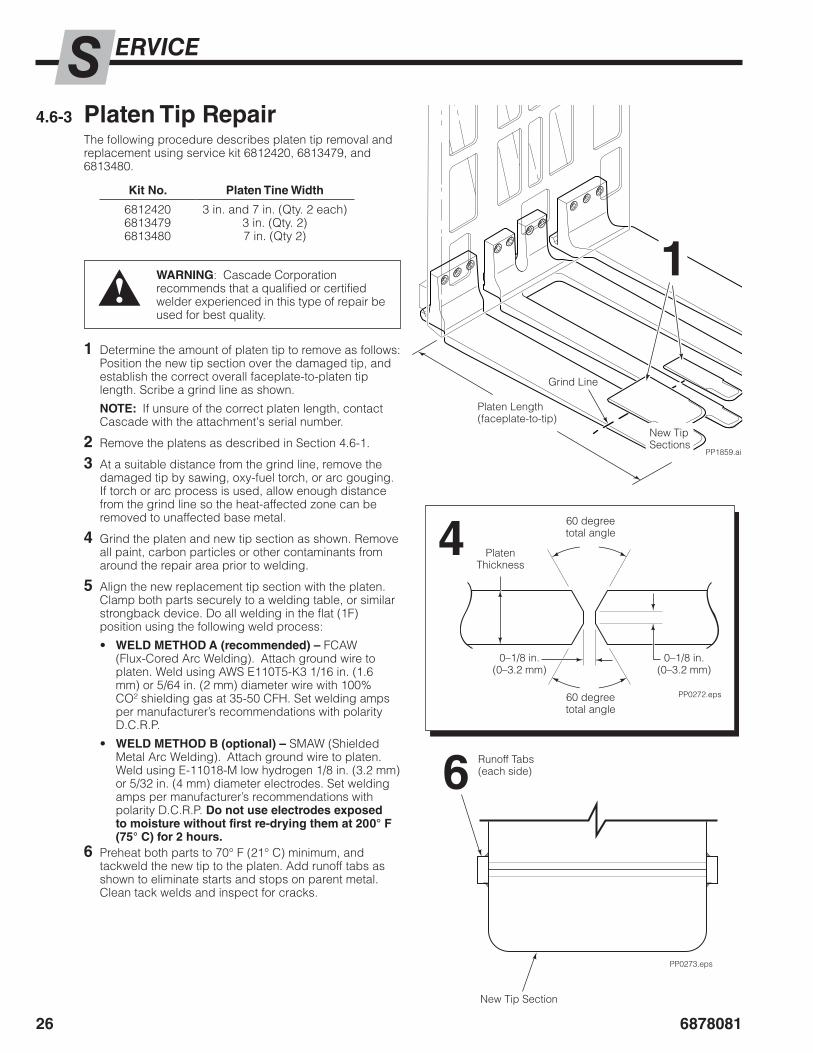
ERIODIC MAINTENANCEP2.4 2000-Hour Maintenance
After 2000 hours of truck operation, in addition to the 100, 500 and 1000-hour maintenance, forks in use shall be inspected at intervals of not more than 12 months (for single shift operations) or whenever any defect or permanent deformation is detected. Severe applications will require more frequent inspection.
Fork inspection shall be carried out by trained personnel to detect any damage that might impair safe use. Any fork that is defective shall be removed from service. Reference ANSI/ITSDF B56.1.
Inspect for the following defects:
• Surface cracks• Straightness of blade and shank• Fork angle• Difference in height of fork tips• Positioning lock• Wear on fork blade and shank• Wear on fork hooks• Legibility of marking
NOTE: Fork Safety Kit 3014162 contains wear calipers, inspection sheets and safety poster. Also available is fork hook & carriage wear gauge 209560 (Class II), 209561 (Class III) and 6104118 (Class IV).

68780814
ROUBLESHOOTINGT3.1 General Procedures3.1-1 Truck System Requirements
• Truck hydraulic pressure should be within the range shown in Specifications, Section 5.1. Pressure to the attachment must not exceed 2300 psi (160 bar).
• Hydraulic flow should be within the volume range as shown in Specifications, Section 5.1.
• Hydraulic fluid supplied to the attachment must meet the requirements as shown in Specifications, Section 5.1.
WARNING: Before servicing any hydraulic component, relieve pressure in the system. Turn the truck off and move the truck auxiliary control valves several times in both directions.
After completing any service procedure, test the attachment through several cycles. First test the attachment empty to bleed any air trapped in the system to the truck tank. Then test the attachment with a load to be sure it operates correctly before returning to the job.
Stay clear of the load while testing. Do not raise the load more than 4 in. (10 cm) off the floor while testing.
PressureGauge ▲
No. 6 and No. 8JIC Swivel Tee
No. 4-6 Pipe/JIC ▲
No. 6-6 Hose ▲
(2) No. 6-8 JIC Reducer
Flow Meter
No. 4, No. 6 ▲ and No. 8 JIC/O-Ring
No. 6-8 JIC Reducer
(2) No. 8-12 JIC/ O-Ring
GA0013.eps
GA0014.eps
IMPORTANT: Troubleshooting the PUSH/PULL circuit can be found in the E-Series Push/Pull and Load Push Service Manual, Part No. 686455.
AC0127.eps
Quick-Coupler
No. 4 and No. 6 Male Straight or JIC Thread O-ring Coupler
No. 6 Female Straight Thread O-ring Coupler
3.1-2 Tools RequiredIn addition to a normal selection of hand tools, the following are required:
• Inline flow meter:20 GPM (75 L/min) – Cascade Part No. 671477
• Pressure Gauge Kit: 3000 psi (207 bar) – Cascade Part No. 671212
• Assorted fittings, lines, drain hoses and quick-couplers as required.
3.1-2 Troubleshooting Chart
Flow Meter Kits:671477 – 75 L/min (20 GPM)
Pressure Gauge Kit:671212
Determine All The Facts – It is important that all the facts regarding the problem are gathered before beginning service procedures. The first step is to talk to the equipment operator. Ask for a complete description of the malfunction. The following guidelines can then be used as a starting point to begin troubleshooting procedures:
Sideshift Circuit• Attachment will not sideshift.• Attachment sideshifts slowly.To correct one of these problems, see Section 3.3.
Platen Position Circuit• Attachment will not position platens.To correct one of these problems, see Section 3.4.

6878081 5
ROUBLESHOOTINGT
PP2318.eps
3.2 Plumbing3.2-1 Hosing Diagram –
Two SolenoidsFACEPLATE RETRACT,GRIPPERS DOWNPRESSURERETURN
NOTE: For FACEPLATE EXTEND, GRIPPERS UP, reverse the colors shown.
SIDESHIFT RIGHTPRESSURERETURN
NOTE: For SIDESHIFT LEFT, reverse the colors shown.
NOTE: For PLATENS APART, reverse the colors shown.
PLATENS TOGETHERPRESSURERETURN
To PUSH/PULL,PLATEN POSITIONHose Terminal
Push/Pull Valve
Push/PullCylinders
GripperCylinders
Platen Positioning Cylinders
Platen Positioning Cylinders
Sideshift Cylinder
Sideshift Cylinder
GR
PR
GB
PB
Hose Terminal
Hose Reel
PUSH/PULL,PLATEN POSITIONTruck Auxiliary Valve
SIDESHIFT Truck Auxiliary Valve
To Push/Pull Mechanism
PLATEN POSITION CIRCUITSIDESHIFT CIRCUIT
PUSH/PULL CIRCUIT
Solenoid

68780816
ROUBLESHOOTINGT3.2-2 Circuit Schematic –
Two Solenoids
T
EXT
PR GR PBGB
RET
EXT
PR GR PBGB
RET
1234
P
CL2322.eps
Gripper Cylinders
Push/Pull Cylinders
Valve(One Cartridge)
Hose Reel
Solenoid Valve
Sideshift Cylinder
Platen Positioning Cylinders
Solenoid Valve(Cartridge Type)
SIDESHIFTTruck Auxiliary Valve
Truck Relief Valve
Truck Hydraulic Pump
Truck Tank
PUSH/PULL,PLATEN POSITIONTruck Auxiliary Valve
Valve(Three Cartridges)
Reference: SK-7019

6878081 7
ROUBLESHOOTINGT
PP2319.eps
3.2-3 Hosing Diagram – Three Solenoids
To Hose Terminal
Push/Pull Valve
Push/PullCylinders
GripperCylinders
Platen Positioning Cylinders
Platen Positioning Cylinders
Sideshift Cylinder
Sideshift Cylinder
Sideshift Cylinder
GR
PR
GB
PB
To Push/Pull Mechanism
To Platen Positioning Cylinders
Hose Terminal
Hose Reel
Solenoids
Truck Auxiliary Valve
To Push/Pull Mechanism
To Hose Terminal
PUSH/PULL CIRCUIT
FACEPLATE RETRACT,GRIPPERS DOWNPRESSURERETURN
NOTE: For FACEPLATE EXTEND, GRIPPERS UP, reverse the colors shown.
SIDESHIFT RIGHTPRESSURERETURN
NOTE: For SIDESHIFT LEFT, reverse the colors shown.
NOTE: For PLATENS APART, reverse the colors shown.
PLATENS TOGETHERPRESSURERETURN
PLATEN POSITION CIRCUITSIDESHIFT CIRCUIT

68780818
ROUBLESHOOTINGT3.2-4 Circuit Schematic –
Three Solenoids
PP2323.eps
1234
1234
EXT
PR GR PBGB
RET
EXT
PR GR PBGB
RET
T P
T P
Gripper Cylinders
Push/Pull Cylinders
Valve(Three Cartridges)
Valve(One Cartridge)
Hose Reel
Solenoid Valves
Sideshift Cylinder
Platen Positioning Cylinders
Solenoid Valve(Cartridge Type)
Truck Relief Valve
Truck Hydraulic Pump
Truck Tank
SIDESHIFT, PUSH/PULL,PLATEN POSITIONTruck Auxiliary Valve
Reference: SK-32600

6878081 9
ROUBLESHOOTINGT3.2-5 Hosing Diagram – Sequence Valve
PP2324.eps
FACEPLATE RETRACTPRESSURERETURN
NOTE: For FACEPLATE EXTEND, reverse the colors shown.
Push/Pull Valve
Push/PullCylinders
GripperCylinders
Platen Positioning Cylinders
Sideshift Cylinder
GR
PR
GB
PB
Hose Terminal
Hose Terminal
Hose Reel
Hose Reel
Sequence Valve
SIDESHIFT,PLATEN POSITIONTruck Auxiliary Valve
PUSH/PULLTruck Auxiliary Valve
PUSH/PULL CIRCUIT

687808110
ROUBLESHOOTINGT
PP2325.eps
3.2-5 Hosing Diagram – Sequence Valve (Continued)
SIDESHIFT RIGHTPRESSURERETURN
NOTE: For SIDESHIFT LEFT, reverse the colors shown.
PLATENS TOGETHER(After pressure builds in the sequence valve)
PRESSURERETURN
NOTE: For PLATENS APART, reverse the colors shown.
Platen Positioning Cylinders
Sideshift Cylinder
Hose Terminal
Hose Reel
Sequence Valve
SIDESHIFT/PLATEN POSITIONTruck Auxiliary Valve
PUSH/PULLTruck Auxiliary Valve
To PUSH/PULLHose Terminal
SIDESHIFT & PLATEN POSITION CIRCUIT

6878081 11
ROUBLESHOOTINGT3.2-6 Circuit Schematic – Sequence Valve
EXT
PR GR PBGB
RET
PP2326.eps
EXT
PR GR PBGB
RET
Gripper Cylinders
Push/Pull Cylinders
Valve(Three Cartridges)
Valve(One Cartridge)
Sideshift Cylinder
Platen Positioning Cylinders
Sequence Valve
Truck Relief Valve
Truck Hydraulic Pump Truck Tank
Hose Reel
PUSH/PULLTruck Auxiliary Valve
SIDESHIFT,PLATEN POSITION Truck Auxiliary Valve
Reference: SK-11029, SK-29407

687808112
ROUBLESHOOTINGT3.2-7 Hosing Diagram –
Radio Frequency Valve
PP2343.eps
FACEPLATE RETRACT, GRIPPERS DOWNPRESSURERETURN
NOTE: For FACEPLATE EXTEND, GRIPPERS UP, reverse the colors shown.
To Hose Terminal
Push/Pull Valve
Push/PullCylinders
GripperCylinders
Platen Positioning Cylinders
Platen Positioning Cylinders
Sideshift Cylinder
Sideshift Cylinder
GR
PR
GB
PB
Hose Terminal
Hose Reel
FACEPLATE/PLATEN POSITIONTruck Auxiliary Valve
SIDESHIFT Truck Auxiliary Valve
To Push/Pull Mechanism
PUSH/PULL CIRCUIT
Radio Frequency Valve
SIDESHIFT RIGHTPRESSURERETURN
NOTE: For SIDESHIFT LEFT, reverse the colors shown.
NOTE: For PLATENS APART, reverse the colors shown.
PLATENS TOGETHERPRESSURERETURN
PLATEN POSITION CIRCUITSIDESHIFT CIRCUIT

6878081 13
ROUBLESHOOTINGT
EXT
C3 C2 C4
T P
C1
PR GR PBGB
RET
EXT
PR GR PBGB
RET
CL2344.eps
3.2-8 Circuit Schematic – Radio Frequency Valve
Reference: SK-9556, SK-11400
Gripper Cylinders
Push/Pull Cylinders
Valve(Three Cartridges)
Valve(One Cartridge)
Sideshift Cylinder
Platen Positioning Cylinders
Radio Frequency Valve
Truck Relief Valve
Truck Hydraulic Pump
Truck Tank
Hose Reel
PUSH/PULLTruck Auxiliary Valve
SIDESHIFT,PLATEN POSITIONTruck Auxiliary Valve

687808114
ROUBLESHOOTINGT
PP2357.eps
3.3 Sideshift CircuitThere are seven potential problems that could affect the sideshifting function:
• Inadequate upper bearing lubrication or worn bearings. Refer to Section 4.5.
• Incorrect hydraulic pressure or flow from the lift truck.
• External leaks.
• Lower mounting hooks installed with incorrect clearance. Refer to Section 4.1, lower hook illustrations.
• Worn or defective cylinder seals. Refer to Section 4.4.
• Cylinder fittings or flow restrictors plugged, incorrect type, or not installed properly. Refer to Section 4.4.
• Solenoid equipped – Faulty electrical connection or defective solenoid valve. Refer to Electrical Circuit Troubleshooting, Section 3.5.
3.3-1 Supply Circuit Test1 Check the pressure supplied by the truck at the
carriage hose terminals. Pressure must be within the range shown in Specifications, Section 5.1.
PRESSURE TO THE ATTACHMENT MUST NOT EXCEED 2300 PSI (160 BAR).
2 Check the flow volume at the carriage hose terminal. Flow must be within the range shown in Specifications, Section 5.1.
3 Sideshift fully to the left and hold the lever in the SIDESHIFT LEFT position for a few seconds. Release the lever and check for external leaks at fittings, hoses and cylinder rod ends.
3.3-2 Sideshift Circuit Test1 Solenoid equipped – Press the solenoid button. Listen
for a 'click' at the solenoid valve. If no sound is heard, check the fuse, wiring and coil. Repair as necessary.
IMPORTANT: Solenoid operated valves must be plumbed so that the solenoid is not energized during the sideshifting function (straight-through).
2 Sideshift fully to the left. Turn the truck off and relieve the attachment's system pressure. Disconnect the SIDESHIFT RIGHT supply hose from the truck hose terminal and route to a drain bucket. Cap the supply fitting.
3 Start the truck and actuate the SIDESHIFT LEFT lever for 5 seconds:
• If there is substantial hydraulic flow out of the drain hose, the sideshift cylinder is faulty and requires replacement. Refer to Section 4.4.
• If there is no hydraulic flow out of the hose, check for plugged or incorrectly installed flow restrictor washers and fittings. If there is still no hydraulic flow, the problem is not hydraulic. Refer to the list of potential problems, above.
Cap supply fitting
Hose end in drain bucket
2 Sideshift RIGHT
3Back (Driver's) View

6878081 15
ROUBLESHOOTINGT3.4 Platen Position
CircuitThere are four potential problems that could affect the platen positioning function:
• Incorrect hydraulic pressure or flow from lift truck.
• External leaks.
• Worn or defective cylinder seals. Refer to Section 4.4.
• Solenoid equipped – Faulty electrical connection or defective solenoid valve.
3.4-1 Supply Circuit Test1 Check the pressure supplied by the truck at the
carriage hose terminals. Pressure must be within the range shown in Specifications, Section 5.1. PRESSURE TO THE ATTACHMENT MUST NOT EXCEED 2300 PSI (160 BAR).
2 Check the flow volume at the carriage hose terminal. Flow must be within the range shown in Specifications, Section 5.1.
3.4-2 Platen Position Circuit Test1 Solenoid equipped – Press the solenoid button. Listen
for a 'click' at the solenoid valve. If no sound is heard, check the fuse, wiring and coil. Repair as necessary.
IMPORTANT: Solenoid-operated valve should be plumbed so that the solenoid is energized during the platen positioning function.
2 Extend the faceplate. Position platens outward and hold the control handle in this position for 5 seconds. Check for external leaks at the cylinders, fittings and hoses.
3 Turn the truck off and relieve system pressure. Disconnect the PLATENS APART supply hose from the truck hose terminal and route to a drain bucket. Cap the supply fitting. Start the truck. Actuate the PLATENS TOGETHER lever and hold for 5 seconds.
• If there is substantial hydraulic flow out of the drain hose, one of the cylinders is faulty and requires replacement. Refer to Section 4.3.
• If there is little or no hydraulic flow out of the hose, the problem is not hydraulic. Refer to the list of potential problems, above.
PP2358.epsCap supply fitting
Hose end in drain bucket
2PLATENS APART Supply Hose
3Back (Driver's) View

687808116
ROUBLESHOOTINGT
PP1041.eps
PP1040.eps
Two Function (One Button Control Knob)
7.5 AmpFuse
WhiteKnobButton Black
Diode
18 Gauge Wire1/4 in. Terminals
SolenoidValve
7.5 AmpFuse White Black
User Supplied Wire
Diode
Three Function (Two Button Control Knob)
7.5 AmpFuse
WhiteBlack
Diodes
SolenoidValves
Green
7.5 AmpFuse White
Black
Green
User Supplied Wire
Diode
3.5 Electrical Circuit(Solenoid equipped attachments)See the wire diagrams and schematic shown. Use the proper schematic while following the steps below.
1 Check the control knob circuit fuse. Replace as necessary.
2 Check for loose electrical connection at the truck ignition switch, control knob button(s), solenoid valve terminals and diodes.
3 Remove the diode(s) from the solenoid valve terminals. Test with an ohmmeter for high resistance in one direction and no resistance in the other direction. If there is no resistance in both directions, replace the diode.
NOTE: When replacing the diode, the banded end must be connected to the coil and wiring as shown.
4 Use a voltmeter to determine if correct voltage is present at the electrical leads when the button is pressed.
• If there is no voltage at the solenoid, troubleshoot the electrical circuit for shorts or open circuits.
• If there is insufficient voltage to the solenoid, check the circuit for excessive voltage drop.
• If there is sufficient voltage to the solenoid, test for coil continuity. Continue to Step 5.
5 Test for coil continuity by placing an ohmmeter test lead on each solenoid coil terminal (ohmmeter on Rx1 scale).
• If there is an ohmmeter reading, and the coil matches the values listed for the truck voltage, the coil is good.
• If the coil is good, but the solenoid does not 'click' when the control knob button is depressed, the solenoid cartridge may be jammed.
• If there is no ohmmeter reading, the coil is defective and should be replaced.
Coil Voltage Ohms Resistance
12V24V36V48V
2143644

6878081 17
ERVICES4.1 Attachment Removal
1 Fully extend the faceplate. Lower the attachment onto a pallet.
2 Disconnect the lower hooks.
Bolt-On Hooks – Remove the lower mounting hooks. For reassembly, tighten the capscrews to a torque of 125 ft.-lbs. (170 Nm).
Quick-Change Hooks – Pull out the locking pins and drop the lower hooks to the unlock position. Reinstall the pins in the lower holes. For reassembly, slide the hooks up to the locked position and install the locking pins in the top holes.
WARNING: Before removing hydraulic lines or components, relieve pressure in the hydraulic system. Turn truck off and open the truck auxiliary control valve(s) several times in both directions.
PP1498.eps
GA0451.eps
ADJUST
RC0368.eps
cascade
®
C-6755
14-1
RC0367.eps
BOLT-ON HOOKS
Carriage Bar
Carriage Bar
LH Lower Hook
Lower Hook
QUICK-CHANGE HOOKS
Guide
LH Lower Hook(Unlocked)
Locking Pin
25
Non-Sideshifting Units:Tight against lower carriage bar.
Sideshifting Units:Clearance of 0.09–0.18 in.(2.5–5.0 mm).
1
PP2335.eps
33
3 Disconnect, tag and plug the hoses at the carriage hose terminals.
4 Solenoid equipped – Disconnect the electrical connection at the truck carriage.
5 Lower the truck carriage and back away from the attachment.
6 For installation, reverse the above procedure with the following exception:
• Clean and inspect carriage bars for damage and smoothness. Bars should be parallel and ends flush. Repair any protruding welds or damaged notches by grinding, filing or welding.
• Inspect lower mounting hooks for wear. Install and adjust lower hooks, as shown.
• Inspect lower bearings for wear and replace as necessary. Refer to Section 4.5
• For complete installation procedures, refer to E-Series Push/Pull and Load Push Service Manual, Part No. 686455.

687808118
ERVICESNOTE: Manuals are available at www.cascorp.com under the support tab, "Technical Support Manuals" link.
4.2 Faceplate and Arm Mechanism ComponentsTo remove and service the faceplate, arm mechanism, push/pull valve, load push valve, and cylinders, refer to the E-Series Push/Pull and Load Push Service Manual, Part No. 686455.
PP2317.eps
FaceplateArm Mechanism

6878081 19
ERVICES4.3 Adjustable Platen
Cylinder4.3-1 Removal, Inspection and
ReplacementThe following procedures can be performed with the attachment mounted on the truck.
1 Extend the faceplate to gain access to the platens. Lower the attachment onto a pallet.
WARNING: Before removing any hoses, relieve pressure in the hydraulic system. With the truck off, open the truck auxiliary control valve(s) several times in both directions.
2 Disconnect hoses to platen cylinder ports. Plug and tag hose ends for reassembly.
3 To remove each adjustable platen cylinder, loosen the capscrews, washers and hook for each outer platen.
4 Inspect the outside of the cylinder shell for damage that could impair performance or cause leaks under pressure. If damage is found, replace the complete cylinder assembly.
5 Inspect the cylinder rods for damage. If bent or scored, replace the complete cylinder assembly.
6 Inspect the anchor bracket for damage. If damage is found, replace the complete cylinder assembly.
7 For reassembly, reverse the above procedure with the following exception:
• Shim outer platens level with each other and the faceplate travels parallel to top of platens, as needed. Refer to Section 4.6-2.
• Tighten platen capscrews to 515 ft.-lbs. (700 Nm).
• If rod seals are to be serviced, perform Rod Seal Replacement, Section 4.3-2.
PP2114.eps
PP2115.eps
1
2
3
2
PP2338.eps
Platen Hook
Capscrews and Washers
Platen Cylinder
Outer Platen

687808120
ERVICES4.3-2 Rod Seal Replacement
1 Remove the platen cylinder/anchor bracket assembly from the attachment as described in Section 4.3-1.
2 Clamp the cylinder/anchor bracket in a soft-jawed vise.
CAUTION: Do not clamp on the cylinder shell.
3 With the cylinder rod centered, remove the snap rings and washer from each end of the cylinder.
4 Remove the seal from each end by prying them out with a brass O-ring tool.
CAUTION: Do not scratch the seal grooves.
5 Clean the washers and cylinder rod with cleaning solvent. Break any sharp edges on the cylinder rod end.
6 Lubricate the new seals with petroleum jelly.
7 Install the seals into the cylinder shell grooves. Note the direction of the U-cup seals: Pressure seals are installed with the lip toward the center of the cylinder, as shown below.
8 Slide washer onto the cylinder rod and seat against the shell inner flange.
9 Install snap ring into each end groove.
PP2339.eps
Cylinder/Bracket Assembly
Snap Ring
Washer
NOTE: Service Tool Kit 674424 includes two double edged brass tools to ease seal and snap ring removal.
PP2340.eps
Seal
Shell
Rod
Washer
Snap Ring
3
4,7 8 9

6878081 21
ERVICES
SS1339.eps
4.4 Sideshift Cylinder4.4-1 Removal and Installation
1 Remove the attachment as described in Section 4.1.
2 If rod seals are to be serviced, loosen seal carriers before removing the attachment.
3 Remove the capscrews fastening the sideshift cylinder to the attachment frame.
4 Remove the cylinder/anchor bracket assembly from the attachment frame.
5 For reassembly, reverse the above procedures with the following exceptions:
• Replace the cylinder retainer pin with a new pin.
• Clean all bearing areas of built-up dirt and grease.
• Inspect the upper bearings for wear and replace as necessary. Refer to Section 4.5.
• If rod seals are to be serviced, perform Rod Seal Replacement, Section 4.4-3.
4.4-2 Inspection• Inspect the outside of the cylinder shell for damage
that could impair performance or cause leaks under pressure. If damage is found, replace the complete cylinder assembly. IMPORTANT: Make sure cylinder fittings and flow restrictors are installed as shown.
• Inspect the cylinder rods for damage. If bent or scored, replace the complete cylinder assembly.
• Inspect the anchor bracket and centering tab for damage. If damage is found, replace the complete cylinder assembly.
WARNING: Before removing hoses or hydraulic components, relieve pressure in the Attachment hydraulic system. Turn the truck off and move the truck control handle several times in both directions.
IMPORTANT: Fittings must bottom against flow restrictor in cylinder port for proper hydraulic flow characteristics.
Cylinder rod Cylinder shell
Cylinder
Retainer Pin
Flow Restrictor (each end of cylinder)
PP2359.eps
3
4
Retainer Pin

687808122
ERVICES4.4-3 Rod Seal Replacement
IMPORTANT: Seal carriers must be loosen and the cylinder removed prior to performing this procedure.
1 Clamp the cylinder bracket in a soft-jawed vise. CAUTION: Clamp at the end of cylinder shell only.
2 Unscrew the seal carriers from each end of the cylinder. Slide the seal carriers off the cylinder rod. NOTE: If installing new seal carriers loaded with seals, proceed to Step 6.
3 Remove the seals and O-ring by prying them out with a brass O-ring tool as shown.
CAUTION: Do not scratch the seal grooves.
4 Clean the seal carrier and cylinder rod with cleaning solvent. Break any sharp edges on the cylinder rod end. Lubricate the new seals and O-rings with petroleum jelly.
5 Install the seals into the seal carrier grooves. Form the seals into a ‘kidney’ shape to ease placement into the bore. Note the direction of the U-cup seals: Pressure seals are installed with the lip toward the center of the cylinder, as shown below.
6 Apply a thick film of petroleum jelly to the inside of the seal carrier and carefully slide onto the cylinder rod. Screw the seal carriers into the cylinder shell
7 For reassembly, reverse the above procedures with the following exceptions:
• After the attachment is remounted on the truck, tighten the seal carriers to 120 ft.-lbs. (165 Nm).
SS0163.eps
3
SS0166.eps
5
6
1
2Seal Carriers
Cylinder/Anchor Bracket Assembly
U-Cup Pressure Seal
WiperSeal
O-Ring
RodSeal Carrier
Seal Removal Tool (Part No. 674424)
RC0488.eps
SS1340.eps

6878081 23
ERVICES4.5 Bearings4.5-1 Bearing Lubrication
• Lubricate both the upper and lower sideshift bearings with chassis grease every 500 hours or 6 weeks of operation, whichever comes first. In contaminated environments, lubricate every week or as required.
4.5-2 Bearing Service1 Remove the attachment from the truck as described in
Section 4.1.
2 Remove the sideshift cylinder from the attachment as described in 4.4-1.
3 Remove the upper bearings. If any bearing is worn to less than 3/32 in. (2.5 mm) thickness, replace all the upper bearings.
4 Remove the lower bearings by prying them from the lower hook mounts. If any bearing is worn to less than 3/32 in. (2.5 mm) thickness, replace all the lower bearings.
5 For reassembly, reverse the above procedures with the following exceptions:
• Grease upper and lower bearings with general-purpose chassis grease.
PP2329.eps
PP2360.eps
3
4
2

687808124
ERVICES
PP2362.eps
4.6 Platens4.6-1 Platen Removal
The following procedure can be performed with the attachment mounted on the truck.
1 Extend the faceplate to gain access to the platens. Lower the attachment onto the pallet.
WARNING: Before removing any hoses, relieve pressure in the hydraulic system. With the truck off, open the truck auxiliary control valve(s) several times in both directions.
2 Remove hardware, cylinders, shims and platen hooks from platens.
3 Remove platens from the attachment.
4 For reassembly, reverse the above procedures with the following exceptions:
• Shim platens level with each other so that the faceplate travels parallel to top of platens. Refer to Section 4.6-2.
PP2114.eps
1
2
2
Platen Hook
Capscrews and Washers
Platen Cylinder
Shims
3

6878081 25
ERVICES4.6-2 Platen Tip Adjustment
Platen tips should align within 0.25 in. (6 mm).
1 Adjust the platen with the lowest tip, loosen the capscrews so that there is a gap for inserting shims.
2 Insert shims between the back of the platen and face of the cylinder plate. Add shims as required to align the tips.
NOTE: Add shims to raise the lower platen tip up.
3 Tighten the capscrews to a torque of 515 ft.-lbs. (700 Nm).
4 If required, repeat Steps 1 through 3 for another platen. Platens should align with each other and the faceplate should travel parallel to the top of the platens.
1
2
4
PlatenPlatenHook
Cylinder
Align platen tips with each other and parallel with the faceplate.
Shim between back of platen and face of the cylinder plate
687808126
ERVICES
PP1859.ai
PP0272.eps
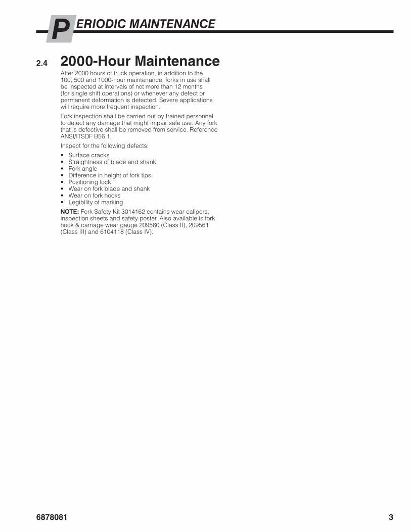
1 Determine the amount of platen tip to remove as follows: Position the new tip section over the damaged tip, and establish the correct overall faceplate-to-platen tip length. Scribe a grind line as shown.
NOTE: If unsure of the correct platen length, contact Cascade with the attachment's serial number.
2 Remove the platens as described in Section 4.6-1.
3 At a suitable distance from the grind line, remove the damaged tip by sawing, oxy-fuel torch, or arc gouging. If torch or arc process is used, allow enough distance from the grind line so the heat-affected zone can be removed to unaffected base metal.
4 Grind the platen and new tip section as shown. Remove all paint, carbon particles or other contaminants from around the repair area prior to welding.
5 Align the new replacement tip section with the platen. Clamp both parts securely to a welding table, or similar strongback device. Do all welding in the flat (1F) position using the following weld process:
• WELD METHOD A (recommended) – FCAW (Flux-Cored Arc Welding). Attach ground wire to platen. Weld using AWS E110T5-K3 1/16 in. (1.6 mm) or 5/64 in. (2 mm) diameter wire with 100% CO² shielding gas at 35-50 CFH. Set welding amps per manufacturer’s recommendations with polarity D.C.R.P.
• WELD METHOD B (optional) – SMAW (Shielded Metal Arc Welding). Attach ground wire to platen. Weld using E-11018-M low hydrogen 1/8 in. (3.2 mm) or 5/32 in. (4 mm) diameter electrodes. Set welding amps per manufacturer’s recommendations with polarity D.C.R.P. Do not use electrodes exposed to moisture without first re-drying them at 200° F (75° C) for 2 hours.
6 Preheat both parts to 70° F (21° C) minimum, and tackweld the new tip to the platen. Add runoff tabs as shown to eliminate starts and stops on parent metal. Clean tack welds and inspect for cracks.
1
4
New Tip Sections
60 degree total angle
60 degree total angle
0–1/8 in.(0–3.2 mm)
0–1/8 in.(0–3.2 mm)
Platen Thickness
Platen Length (faceplate-to-tip)
Grind Line
WARNING: Cascade Corporation recommends that a qualified or certified welder experienced in this type of repair be used for best quality.
4.6-3 Platen Tip RepairThe following procedure describes platen tip removal and replacement using service kit 6812420, 6813479, and 6813480.
Kit No. Platen Tine Width
681242068134796813480
3 in. and 7 in. (Qty. 2 each)3 in. (Qty. 2)7 in. (Qty 2)
PP0273.eps
6
New Tip Section
Runoff Tabs (each side)

6878081 27
ERVICES
PP0299.eps
PP1860.ai
7 Oven preheat platen to 150°–250° F (66°–121° C). Do not exceed 450° F (232° C). Monitor and maintain preheat and interpass temperatures at locations shown using suitable temperature-indicating devices.
CAUTION: If localized preheat technique is used, preheat must extend fully through base metal thickness, and to a distance of 3 in. (7.5 cm.) on each side of the weld.
8 Clamp and deposit root pass welds using a stringer bead technique. Do not exceed a bead width of 5/16 in. (8 mm). Start and stop all welds on runoff tabs.
9 Rotate platen to opposite side. Backgrind previous root pass to remove all slag. Clamp and deposit additional stringer root pass welds, assuring 100% full penetration weld.
10 Clean welds and inspect for cracks. Continue rotating, clamping and welding until joint is entirely filled. Maintain interpass temperature for each pass. Visually inspect each pass.
11 Slow-cool platen to ambient (room) temperature using an insulating blanket.
12 Remove runoff tabs by sawing or grinding and grind all welds flat with platen surface. Finish-sand to a minimum surface roughness of 250. Make all grinding and sanding marks parallel with the platen length.
13 Nondestructive test (NDT) weld area for defects. No undercutting, voids or other defects allowed. Reinstall the platens on the Attachment and check for proper tip alignment. Refer to Section 4.6-2.
8,9
12Grind and sand welds flat with platen surface
All grinding/sanding marks parallel with platen length
Root Pass Welds
.30 in. (8 mm)
4.6-3 Platen Tip Repair (continued)

687808128
ERVICES4.7 Sequence Valve4.7-1 Valve Removal
1 Disconnect, tag and plug the hoses from the valve fittings.
2 Remove the capscrews securing the valve to the mounting bracket. For reassembly, tighten the capscrews to a torque of 15 ft.-lbs. (20 Nm).
3 For installation, reverse the above procedure with the following exception:
• Service the valve, as required. Refer to Section 4.7-2.
4.7-2 Valve Service1 Remove the valve from the attachment as described in
Section 4.7-1.
2 Remove fittings, plugs and cartridges.
3 Clean all parts with clean solvent. Remove any burrs or sharp edges with emery cloth
4 For reassembly, reverse the above procedures except as follows:
• Install new O-rings and back-up rings on the cartridges.
• Lubricate the cartridges with petroleum jelly prior to reassembly.
• Tighten cartridges to a torque of:
Shuttle Valve – 5 ft.-lbs. (7 Nm)Check Valve – 14 ft.-lbs. (19 Nm)Sequence Cartridge – 25 ft.-lbs. (35 Nm)
WARNING: Before removing any hoses, relieve pressure in the hydraulic system. With the truck off, open the truck auxiliary control valve(s) several times in both directions.
PP2336.eps
1
2
Sequence Valve Cartridge
Check Valve
Shuttle Valve
Fitting
Plug
RC2494.epsGA0202.illGA0203.eps
Sequence Valve Cartridge
O-RingsO-Ring O-Rings
Back-Up RingsBack-Up Rings Back-Up Ring
Check ValveShuttle Valve
Reference: 6060537 R2

6878081 29
ERVICES4.7-3 Valve Adjustment
The platens should position at the end of the sideshift stroke. Adjust as follows:
• If the attachment is simultaneously sideshifting and platen positioning, turn the sequence cartridge screw clockwise (CW) in 1/4 turn increments.
• If the attachment is not sequencing to platen positioning at the end of sideshift stroke, turn the sequence cartridge screw counterclockwise (CCW) in 1/4 turn increments.
PP2017.eps
Adjust Sequence Valve Cartridge

687808130
ERVICES
PP2354.epsPP2355.eps
4.8 Radio Frequency Valve4.8-1 Valve Removal
1 Disconnect, tag and plug the hoses and tubes from the valve fittings.
2 Remove the valve cover. For reassembly, tighten capscrews to a torque of 15 ft.-lbs. (20 Nm).
3 If servicing the valve, continue to Step 4. Otherwise, proceed to Step 7.
4 Disconnect the receiver plugs from the battery and solenoid.
5 Remove the battery from the battery clip.
6 Remove the battery clip, receiver clip and receiver from the valve.
7 Remove the capscrews securing the valve to the mounting bracket. For reassembly, tighten the capscrews to a torque of 15 ft.-lbs. (20 Nm).
8 For installation, reverse the above procedure with the following exception:
• Service the valve, as required. Refer to Section 4.8-2.
WARNING: Before removing any hoses, relieve pressure in the hydraulic system. With the truck off, open the truck auxiliary control valve(s) several times in both directions.
PP2351.eps
11 2
4
456
6
6
7
Battery Clip
Receiver
Receiver Clip

6878081 31
ERVICES4.8-2 Valve Service
1 Remove the valve from the attachment as described in Section 4.8-1.
2 Remove fittings, plugs and cartridges.
3 Clean all parts with clean solvent. Remove any burrs or sharp edges with emery cloth.
4 For reassembly, reverse the above procedures except as follows:
• Install new O-rings and back-up rings on the cartridges.
• Lubricate the cartridges with petroleum jelly prior to reassembly.
• Tighten cartridges to a torque of:
Shuttle Valve – 5 ft.-lbs. (7 Nm)Check Valve – 5 ft.-lbs. (7 Nm)Solenoid Cartridge – 20 ft.-lbs. (27 Nm)Solenoid Nut – 5 ft.-lbs. (7 Nm)Directional Cartridge – 27 ft.-lbs. (36 Nm)
PP2352.eps
GA0432.eps
GA0203.epsGA0468.eps6069787 (Hydraforce, PD10-44-0-NS-110)6069792 (Hydraforce, PD10-45-0-NS-110)
GA0469.eps
220627 (Hydraforce, SV08-40-0-N-0)6054451 (Hydraforce, 4301871)Solenoid Valve Cartridge
Directional Valve Cartridge
Check Valve
Shuttle Valve
O-Rings
O-Rings O-Ring
O-Ring
Back-Up Rings
Back-Up Rings
Back-Up Rings
Back-Up Ring
Solenoid Valve Cartridge
Coil
Check Valve
Shuttle Valve
Directional Valve Cartridge
Fitting
Fitting
Fitting
Plug
Plug
Reference: 6070947 R2

687808132
ERVICES
PP2342.eps
4.9 Solenoid4.9-1 Coil Service
1 Disconnect the wires and diode from the coil terminals.
2 Remove the end cover capscrews and remove the end cover and coil. Note the position of the coil terminals.
3 Install the new coil and end cover. Verify that the terminals are positioned correctly.
4 For reassembly, reverse the above procedures except as follows:
• Refer to electrical schematic, below, for correct wire and diode installation.
4.9-2 Valve Service• Check the plunger within the valve body for freedom
of movement. Press end button on coil to assure that valve is not jammed or damaged. If problems are found, replace solenoid valve as a complete assembly.
Two Function (One Button Control Knob)
7.5 AmpFuse
WhiteKnobButton Black
Diode
18 Gauge Wire1/4 in. Terminals
SolenoidValve
7.5 AmpFuse White Black
User Supplied Wire
Diode
Three Function (Two Button Control Knob)
7.5 AmpFuse
WhiteBlack
Diodes
SolenoidValves
Green
7.5 AmpFuse
White
Black
Green
User Supplied Wire
Diode
RC0204.eps
32
4
Coil
Solenoid Valve
6878081
PECIFICATIONSS
33
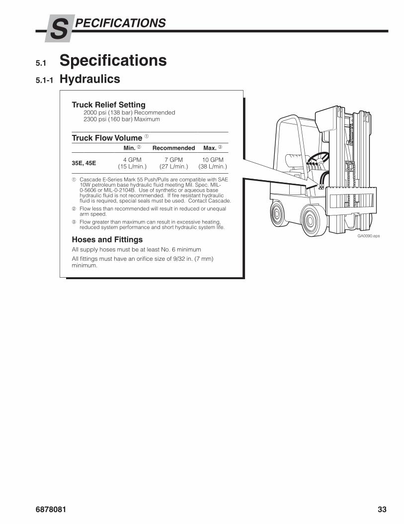
5.1 Specifications5.1-1 Hydraulics
GA0090.eps
Truck Relief Setting2000 psi (138 bar) Recommended2300 psi (160 bar) Maximum
Truck Flow Volume ➀
Min. ➁ Recommended Max. ➂
35E, 45E 4 GPM(15 L/min.)
7 GPM(27 L/min.)
10 GPM(38 L/min.)
➀ Cascade E-Series Mark 55 Push/Pulls are compatible with SAE 10W petroleum base hydraulic fluid meeting Mil. Spec. MIL-0-5606 or MIL-0-2104B. Use of synthetic or aqueous base hydraulic fluid is not recommended. If fire resistant hydraulic fluid is required, special seals must be used. Contact Cascade.
➁ Flow less than recommended will result in reduced or unequal arm speed.
➂ Flow greater than maximum can result in excessive heating, reduced system performance and short hydraulic system life.
Hoses and FittingsAll supply hoses must be at least No. 6 minimum
All fittings must have an orifice size of 9/32 in. (7 mm) minimum.

6878081
PECIFICATIONSS
34
GA0389.eps
A
5.1-3 Truck Carriage
Carriage Mount Dimension (A) ITA (ISO)
Minimum Maximum
Class IIClass III
14.94 in. (380.0 mm)18.68 in. (474.5 mm)
15.00 in. (381.0 mm)18.74 in. (476.0 mm)
GA0126.eps
5.1-2 Auxiliary Valve FunctionsCheck for compliance with ANSI/ITSDF (ISO) standards:
GA0082.eps
Hoist Up
TIlt Forward
Tilt Back
Hoist Down
One Auxiliary ValveThree Solenoids
A
Sideshift LeftOR
Push ◆(Faceplate Extend, Grippers Up)
ORPlatens Apart ◆
B
Sideshift RightOR
Pull ◆(Faceplate Retract, Grippers Down)
ORPlatens Together ◆
◆ Press solenoid switch
Two Auxiliary ValvesTwo Solenoids OR Radio Frequency Sequence Valve
A Sideshift Left Sideshift Left ANDPlatens Apart
B Sideshift Right Sideshift Right AND Platens Together
C
Push(Faceplate Extend,
Grippers Up)OR
Platens Apart ◆
Push(Faceplate Extend,
Grippers Up)
D
Pull(Faceplate Retract,
Grippers Down)OR
Platens Together ◆
Pull (Faceplate Retract,
Grippers Down)
◆ Press solenoid switch
A
CA
BDBHoist Up
TIlt Forward
Tilt Back
Hoist Down

6878081
PECIFICATIONSS
35
PP2347.eps
5.1-4 Torque ValuesFastener torque values for E-Series Mark 55 Push/Pull attachments are shown in the table below in both US and Metric units. All torque values are also called out in each specific service procedure throughout this manual.
NOTE: All fasteners have a torque value range of ±10% of stated value.
NOTE: For additional torque values related to the faceplate, arm mechanism, and their components, refer to the E-Series Push/Pull and Load Push Service Manual, Part No. 686455.
Manuals are available at www.cascorp.com under the support tab, "Technical Support Manuals" link.
Ref. Fastener(s) Size Ft.-lbs. Nm
1 Platen Hook Capscrews M20 515 700
2 Bolt-On Lower Hook Capscrews M16 120 165
3 Quick-Disconnect Lower Hook Capscrews M16 52 70
4 Sideshift Mount Capscrews M12 75 100
5 Sequence Valve M8 15 20
6 Solenoid Valve Capscrews M6 5 8
7 Radio Frequency Valve Capscrews M8 15 20
8 Mounting Bracket Capscrews M8 15 20
9 Valve Cover Capscrews M8 15 20
10 Cylinder Seal Carrier – 120 165
PP2345.eps
2
5
7
1 10
3
68
4
PP2346.eps
8
8PP2348.eps
Sequence Valve
Radio Frequency Valve
c© Cascade Corporation 2016 06-2016 Part Number 6878081
Do you have questions you need answered right now? Call your nearest Cascade Service Department.Visit us online at www.cascorp.com
AMERICASCascade CorporationU.S. Headquarters2201 NE 201stFairview, OR 97024-9718Tel: 800-CASCADE (227-2233)Fax: 888-329-8207
Cascade Canada Inc.5570 Timberlea Blvd.Mississauga, OntarioCanada L4W-4M6Tel: 905-629-7777Fax: 905-629-7785
Cascade do BrasilPraça Salvador Rosa,131/141-Jordanópolis, São Bernardo do Campo - SPCEP 09891-430Tel: 55-13-2105-8800Fax: 55-13-2105-8899
EUROPE-AFRICACascade Italia S.R.L.European HeadquartersVia Dell’Artigianato 137030 Vago di Lavagno (VR) ItalyTel: 39-045-8989111Fax: 39-045-8989160
Cascade (Africa) Pty. Ltd.PO Box 625, Isando 160060A Steel RoadSparton, Kempton ParkSouth AfricaTel: 27-11-975-9240Fax: 27-11-394-1147
ASIA-PACIFICCascade Japan Ltd.2-23, 2-Chome,Kukuchi NishimachiAmagasaki, Hyogo Japan, 661-0978Tel: 81-6-6420-9771Fax: 81-6-6420-9777
Cascade Korea121B 9L Namdong Ind. Complex, 691-8 Gojan-DongNamdong-KuInchon, KoreaTel: +82-32-821-2051Fax: +82-32-821-2055
Cascade-XiamenNo. 668 Yangguang Rd. Xinyang Industrial ZoneHaicang, Xiamen CityFujian ProvinceP.R. China 361026Tel: 86-592-651-2500Fax: 86-592-651-2571
Cascade India Material Handling Private LimitedNo 34, Global Trade Centre 1/1 Rambaugh ColonyLal Bahadur Shastri Road, Navi Peth, Pune 411 030(Maharashtra) IndiaPhone: +91 020 2432 5490Fax: +91 020 2433 0881
Cascade Australia Pty. Ltd.1445 Ipswich RoadRocklea, QLD 4107AustraliaTel: 1-800-227-223Fax: +61 7 3373-7333
Cascade New Zealand15 Ra Ora DriveEast Tamaki, AucklandNew ZealandTel: +64-9-273-9136Fax: +64-9-273-9137
Sunstream IndustriesPte. Ltd.18 Tuas South Street 5Singapore 637796Tel: +65-6795-7555Fax: +65-6863-1368