copeland-scroll-compressors-for-heat-pump-applications ...
39
Copeland ™ Scroll Compressors for Heat Pump Applications with R410A ZH04K1P to ZH19K1P ZHI05K1P to ZHI46K1P Application Guidelines
-
Upload
khangminh22 -
Category
Documents
-
view
0 -
download
0
Transcript of copeland-scroll-compressors-for-heat-pump-applications ...
Copeland™ Scroll Compressorsfor Heat Pump Applications with R410AZH04K1P to ZH19K1PZHI05K1P to ZHI46K1P
Application Guidelines
AGL_HP_ST_ZHK1P_EN_Rev00
About these guidelines ............................................................................................ 1
1 Safety instructions ........................................................................................ 1
1.1 Icon explanation ............................................................................................... 1
1.2 Safety statements............................................................................................. 1
1.3 General instructions .......................................................................................... 2
2 Product description ...................................................................................... 3
2.1 Compressor range............................................................................................ 3
2.2 Nomenclature .................................................................................................. 3
2.3 Application range ............................................................................................. 4
2.3.1 Qualified refrigerants and oils ................................................................... 4
2.3.2 Application limits .................................................................................... 4
2.4 Dimensions ..................................................................................................... 6
3 Installation..................................................................................................... 8
3.1 Compressor handling ........................................................................................ 8
3.1.1 Transport and storage ............................................................................. 8
3.1.2 Positioning and securing.......................................................................... 8
3.1.3 Installation location ................................................................................. 8
3.1.4 Mounting parts ....................................................................................... 9
3.2 Brazing procedure ............................................................................................ 9
3.3 Pressure safety controls ...................................................................................10
3.3.1 High-pressure protection ........................................................................10
3.3.2 Low-pressure protection .........................................................................10
3.4 Crankcase heaters ..........................................................................................11
3.5 Soft starters ....................................................................................................12
3.6 Discharge gas temperature protection ................................................................12
3.6.1 Excessive discharge gas temperatures .....................................................14
3.7 Screens .........................................................................................................14
3.8 Mufflers..........................................................................................................14
3.9 Reversing valves .............................................................................................14
3.10 Sound and vibration .........................................................................................15
3.11 Compressor oil return, oil balancing and f loodback tests........................................15
3.12 Suction line accumulator...................................................................................16
4 Electrical connection .................................................................................. 17
4.1 General recommendations ................................................................................17
4.2 Electrical installation ........................................................................................17
4.2.1 Wiring diagrams ....................................................................................17
4.2.2 Terminal box.........................................................................................19
4.2.3 Motor winding .......................................................................................21
4.3 Motor insulation...............................................................................................21
4.4 Motor protection ..............................................................................................21
AGL_HP_ST_ZHK1P_EN_Rev00
4.4.1 Internal line break motor protection ..........................................................21
4.4.2 External protection with Kriwan................................................................21
4.5 Kriwan protector functional check and failure detection..........................................22
4.5.1 Checking the connection ........................................................................22
4.5.2 Checking the compressor thermistor chain ................................................22
4.5.3 Checking the protection module...............................................................22
4.6 High-potential testing .......................................................................................23
5 Start-up & operation.................................................................................... 24
5.1 Strength pressure test ......................................................................................24
5.1.1 Compressor strength-pressure test ..........................................................24
5.1.2 System strength-pressure test .................................................................24
5.2 Compressor tightness test ................................................................................24
5.3 Preliminary checks – Pre-starting .......................................................................25
5.4 Charging procedure .........................................................................................25
5.5 Initial start-up ..................................................................................................25
5.6 Rotation direction ............................................................................................26
5.7 Starting sound ................................................................................................26
5.8 Deep vacuum operation ...................................................................................26
5.9 Shell temperature ............................................................................................26
5.10 Pumpdown cycle .............................................................................................26
5.11 Pump-out cycle ...............................................................................................27
5.12 Minimum run time ............................................................................................27
5.13 Shut-off sound ................................................................................................27
5.14 Supply frequency and voltage ...........................................................................27
5.15 Oil level..........................................................................................................28
5.16 Oil stub ..........................................................................................................28
6 Maintenance & repair .................................................................................. 29
6.1 Exchanging the refrigerant ................................................................................29
6.2 Rotalock valves...............................................................................................29
6.3 Disassembling system components....................................................................29
6.4 Replacing a compressor ...................................................................................30
6.4.1 Compressor replacement........................................................................30
6.4.2 Start-up of a new or replacement compressor ............................................30
6.5 Lubrication and oil removal ...............................................................................30
6.6 Oil additives....................................................................................................31
7 Troubleshooting .......................................................................................... 32
8 Dismantling & disposal ............................................................................... 35
9 References .................................................................................................. 35
DISCLAIMER........................................................................................................... 35
AGL_HP_ST_ZHK1P_EN_Rev00 1
About these guidelines
The purpose of these guidelines is to provide guidance in the applicat ion of Copeland™ scroll compressors in users’ systems. It is intended to answer the questions raised while designing, assembling and operating a system with these products.
Besides the support they provide, the instructions listed herein are also critical for the proper and safe functioning of the compressors. The performance and reliability of the product may be impacted if the product is not used according to these guidelines or is misused.
These application guidelines cover stationary applications only. For mobile applicat ions, p lease contact the Application Engineering department at Emerson as other considerations may apply.
1 Safety instructions
Copeland scroll compressors are manufactured according to the latest European and US safety standards. Particular emphasis has been placed on the user’s safety.
These compressors are intended for installation in systems in accordance with the European Machinery Directive MD 2006/42/EC. They may be put to service only if they have been installed in these systems according to instructions and conform to the corresponding provisions of legislation. For relevant standards please refer to the Manufacturer’s Declaration, available on request.
These instructions should be retained throughout the lifetime of the compressor.
You are strongly advised to follow these safety instructions.
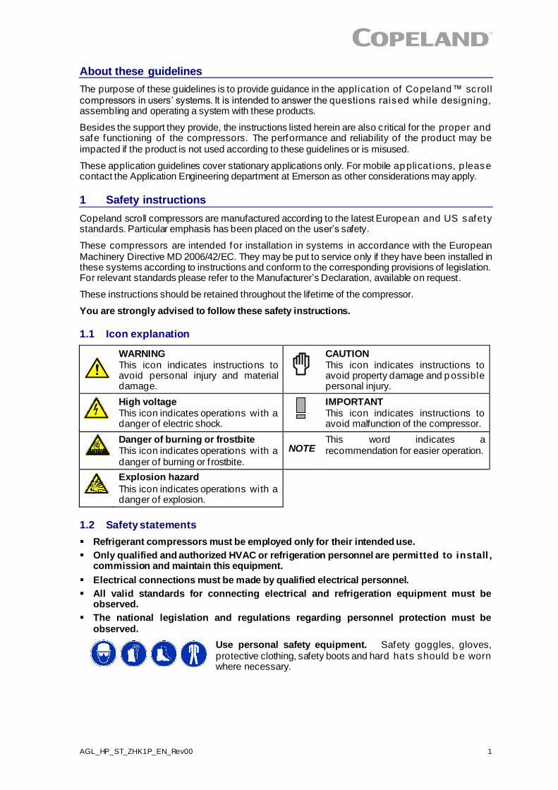
1.1 Icon explanation
WARNING This icon indicates instructions to avoid personal injury and material damage.
CAUTION This icon indicates instructions to avoid property damage and possible personal injury.
High voltage This icon indicates operations with a danger of electric shock.
IMPORTANT This icon indicates instructions to avoid malfunction of the compressor.
Danger of burning or frostbite This icon indicates operations with a danger of burning or f rostbite.
NOTE
This word indicates a recommendation for easier operation.
Explosion hazard
This icon indicates operations with a danger of explosion.
1.2 Safety statements
▪ Refrigerant compressors must be employed only for their intended use.
▪ Only qualified and authorized HVAC or refrigeration personnel are permitted to install , commission and maintain this equipment.
▪ Electrical connections must be made by qualified electrical personnel.
▪ All valid standards for connecting electrical and refrigeration equipment must be observed.
▪ The national legislation and regulations regarding personnel protection must be observed.
Use personal safety equipment. Safety goggles, gloves, protective clothing, safety boots and hard hats should be worn where necessary.
2 AGL_HP_ST_ZHK1P_EN_Rev00
1.3 General instructions
WARNING System breakdown! Personal injuries! Never install a system in the f ield and leave it unattended when it has no charge, a holding charge, or with the service valves closed without electrically locking out the system. System breakdown! Personal injuries! Only approved ref rigerants and ref rigeration oils must be used.
WARNING Pressurized system! Serious personal injuries and/or system breakdown! The system contains refrigerant and oil under p ressure. The mixture of air and oil at high temperature can lead to an explosion (Diesel ef fect). Avoid operating with air. Never install a system in the field and leave it unat tended when it has no charge, a holding charge, or with the service valves closed witho ut electrically locking out the system. Only approved refrigerants and refrigeration oils must be used. Remove ref rigerant from both high- and low-pressure sides with a suitable recovery unit before removing compressor.
WARNING High shell temperature! Burning! Do not touch the compressor until it has cooled down. Ensure that other materials in the area of the compressor do not come into contact with it. Lock and mark accessible sections.
CAUTION Overheating! Bearing damage! Do not operate compressors without ref rigerant charge or without being connected to the system.
CAUTION Contact with refrigerant oil! Material damage! POE lubricant must be handled carefully and the proper protective equipment (gloves, eye protection, etc.) must be used at all times. POE must not come into contact with any surface or material that it might damage, including without limitation, certain polymers, eg, PVC/CPVC and polycarbonate.
IMPORTANT Transit damage! Compressor malfunction! Use original packaging. Avoid collisions and tilting.
AGL_HP_ST_ZHK1P_EN_Rev00 3
2 Product description
2.1 Compressor range
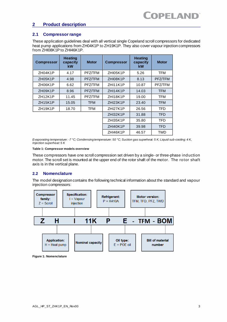
These application guidelines deal with all vertical single Copeland scroll compressors for dedicated heat pump applications from ZH04K1P to ZH19K1P. They also cover vapour injection compressors f rom ZHI08K1P to ZHI46K1P.
Compressor Heating capacity
kW Motor Compressor
Heating capacity
kW Motor
ZH04K1P 4.17 PFZ/TFM ZHI05K1P 5.26 TFM
ZH05K1P 4.98 PFZ/TFM ZHI08K1P 8.13 PFZ/TFM
ZH06K1P 6.62 PFZ/TFM ZHI11K1P 10.87 PFZ/TFM
ZH09K1P 8.96 PFZ/TFM ZHI14K1P 14.03 TFM
ZH12K1P 11.45 PFZ/TFM ZHI18K1P 19.00 TFM
ZH15K1P 15.05 TFM ZHI23K1P 23.40 TFM
ZH19K1P 18.70 TFM ZHI27K1P 26.56 TFD
ZHI32K1P 31.88 TFD
ZHI35K1P 35.80 TFD
ZHI40K1P 39.98 TFD
ZHI46K1P 46.57 TWD
Evaporating temperature: -7 °C; Condensing temperature: 50 °C; Suction gas superheat: 5 K; Liquid sub-cooling: 4 K, Injection superheat: 5 K
Table 1: Compressor models overview
These compressors have one scroll compression set driven by a single- or three-phase induction motor. The scroll set is mounted at the upper end of the rotor shaft of the motor. The ro tor shaf t axis is in the vertical plane.
2.2 Nomenclature
The model designation contains the following technical information about the standard and vapour injection compressors:
Figure 1: Nomenclature
4 AGL_HP_ST_ZHK1P_EN_Rev00
2.3 Application range
2.3.1 Qualified refrigerants and oils
Oil recharge values can be taken from Copeland scroll compressors brochures or Copeland Select sof tware available at www.climate.emerson.com/en-gb.
Compressors ZH04K1P to ZH19K1P ZHI05K1P to ZHI46K1P
Qualified refrigerants R410A
Copeland brand products standard oil
Emkarate RL 32 3MAF
Servicing oil Emkarate RL 32 3MAF
Table 2: Qualified refrigerant and oil
2.3.2 Application limits
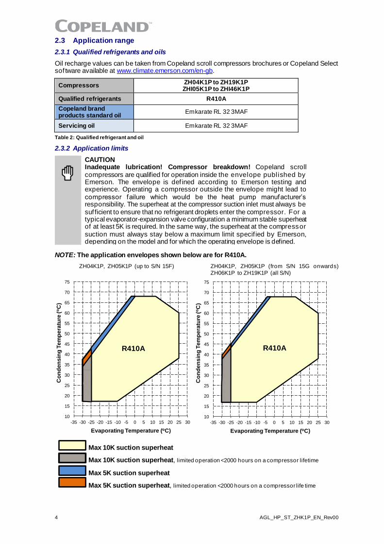
CAUTION Inadequate lubrication! Compressor breakdown! Copeland scroll compressors are qualified for operation inside the envelope published by Emerson. The envelope is def ined according to Emerson testing and experience. Operating a compressor outside the envelope might lead to compressor failure which would be the heat pump manufacturer’s responsibility. The superheat at the compressor suction inlet must always be suf ficient to ensure that no refrigerant droplets enter the compressor. For a typical evaporator-expansion valve configuration a minimum stable superheat of at least 5K is required. In the same way, the superheat at the compressor suction must always stay below a maximum limit specif ied by Emerson, depending on the model and for which the operating envelope is defined.
NOTE: The application envelopes shown below are for R410A.
ZH04K1P, ZH05K1P (up to S/N 15F) ZH04K1P, ZH05K1P (from S/N 15G onwards)
ZH06K1P to ZH19K1P (all S/N)
10
15
20
25
30
35
40
45
50
55
60
65
70
75
-35 -30 -25 -20 -15 -10 -5 0 5 10 15 20 25 30
Co
nd
en
sin
g T
em
pe
ratu
re (
oC
)
Evaporating Temperature (oC)
R410A
10
15
20
25
30
35
40
45
50
55
60
65
70
75
-35 -30 -25 -20 -15 -10 -5 0 5 10 15 20 25 30
Co
nd
en
sin
g T
em
pe
ratu
re (
oC
)
Evaporating Temperature (oC)
R410A
Max 10K suction superheat
Max 10K suction superheat, limited operation <2000 hours on a compressor lifetime
Max 5K suction superheat
Max 5K suction superheat, limited operation <2000 hours on a compressor life time
AGL_HP_ST_ZHK1P_EN_Rev00 5
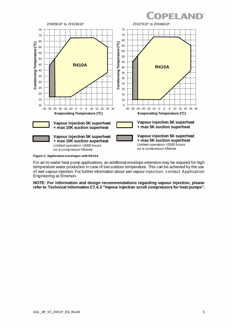
ZHI05K1P to ZHI23K1P ZHI27K1P to ZHI46K1P
Figure 2: Application envelopes with R410A
For air-to-water heat pump applications, an additional envelope extension may be required for high temperature water production in case of low outdoor temperature. This can be achieved by the use of wet vapour injection. For further information about wet vapour injec tion, contact Applicat ion Engineering at Emerson.
NOTE: For information and design recommendations regarding vapour injection, please refer to Technical Information C7.4.3 "Vapour injection scroll compressors for heat pumps".
10
15
20
25
30
35
40
45
50
55
60
65
70
75
-35 -30 -25 -20 -15 -10 -5 0 5 10 15 20 25 30
Co
nd
en
sin
g T
em
pe
ratu
re (
oC
)
Evaporating Temperature (oC)
R410A
5
10
15
20
25
30
35
40
45
50
55
60
65
70
75
-35 -30 -25 -20 -15 -10 -5 0 5 10 15 20 25 30
Co
nd
en
sin
g T
em
pe
ratu
re (
oC
)
Evaporating Temperature (oC)
R410A
Vapour injection 5K superheat + max 10K suction superheat Vapour injection 5K superheat + max 10K suction superheat Limited operation <2000 hours
on a compressor lifetime
Vapour injection 5K superheat + max 5K suction superheat Vapour injection 5K superheat + max 5K suction superheat Limited operation <2000 hours
on a compressor lifetime
6 AGL_HP_ST_ZHK1P_EN_Rev00
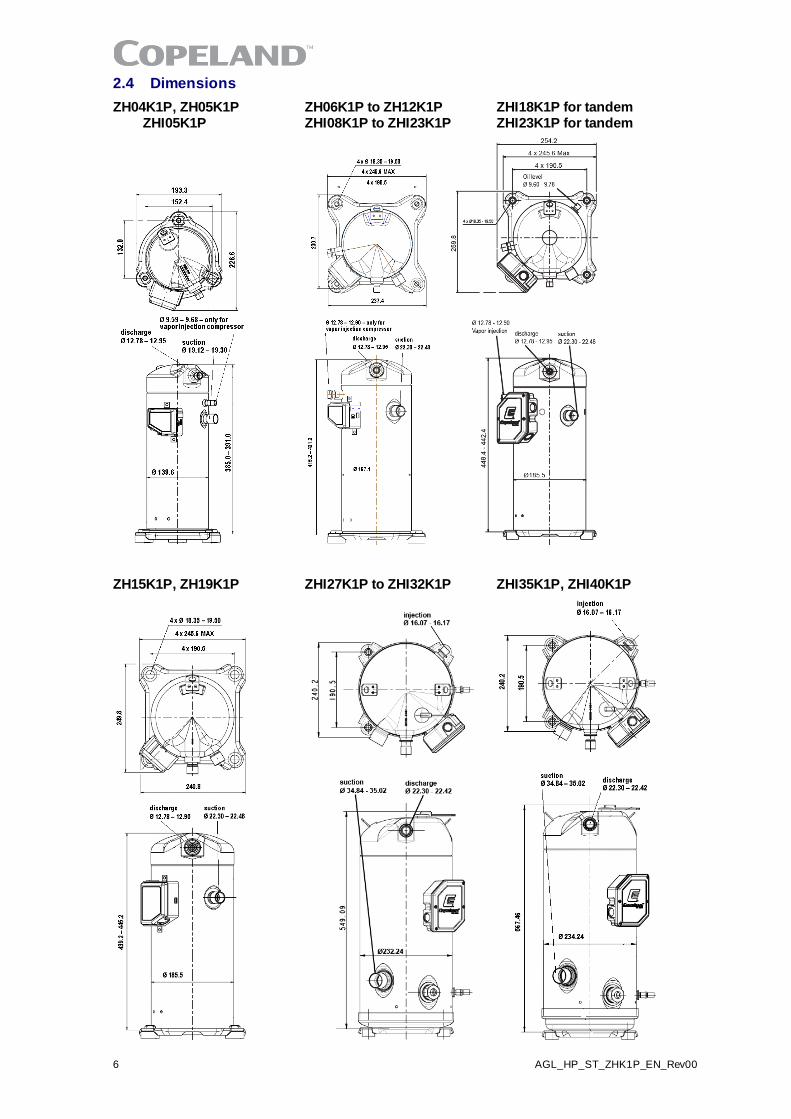
2.4 Dimensions
ZH04K1P, ZH05K1P ZH06K1P to ZH12K1P ZHI18K1P for tandem ZHI05K1P ZHI08K1P to ZHI23K1P ZHI23K1P for tandem
ZH15K1P, ZH19K1P ZHI27K1P to ZHI32K1P ZHI35K1P, ZHI40K1P
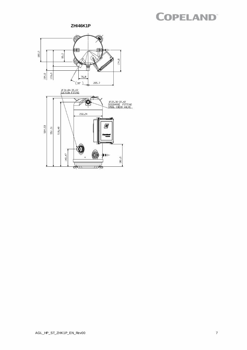
AGL_HP_ST_ZHK1P_EN_Rev00 7
ZHI46K1P

8 AGL_HP_ST_ZHK1P_EN_Rev00
3 Installation
WARNING High pressure! Injury to skin and eyes possible! Be careful when opening connections on a pressurized item.
3.1 Compressor handling
3.1.1 Transport and storage
WARNING Risk of collapse! Personal injuries! Move compressors only with appropriate mechanical or handling equipment according to weight. Keep in the upright position. Respect stacking loads according to Figure 3. Check the tilting stability and if needed take action to ensure the s tabili ty of the stacked loads. Do not stack single boxes on top of each other. Keep the packaging dry at all times.
Respect the maximum number of identical packages which may be s tacked on one another, where "n" is the limiting number:
▪ Transport: n = 1 ▪ Storage: n = 2
Figure 3: Maximum stacking loads for transport and storage
The compressor tilt angle should not be more than 30° during transport and hand ling. This wil l prevent oil from exiting through the suction stub. A tilt angle of maximum 45° is allowed for a very short time. Tilting the compressor more than 45° might affect its lubrication at start -up.
The suction stub on compressor models ZHI27K1P to ZHI46K1P is located at low level. Oil might f low through the suction stub and get trapped in the system. To avoid this, Emerson s trongly recommends mounting the suction piping turning vertically upward f rom the compressor connection. This will ensure that the oil gets back into the oil sump even when tilting at 30°.
3.1.2 Positioning and securing
IMPORTANT Handling damage! Compressor malfunction! Only use the lif ting eyes whenever the compressor requires positioning. Using discharge o r suction connections for lifting may cause damage or leaks.
The compressor should be kept vertical during handling.
The discharge connection plug should be removed first before pulling the suction connection plug to allow the dry air pressure inside the compressor to escape. Pulling the plugs in this sequence prevents oil mist from coating the suction tube making brazing difficult. The copper -coated s teel suction tube should be cleaned before brazing.
The plugs must be removed as late as possible before brazing so that the air humidity does no t af fect the oil characteristics
As oil might spill out of the suction connection located low on the shell, the suction connection plug must be left in place until the compressor is set into the unit.
No object, eg, a swaging tool should be inserted deeper than 51 mm into the suct ion tube as it might damage the suction screen and motor.
3.1.3 Installation location
Scroll compressors are capable of operating correctly with compressor am bient humidity within 30 % to 95 % and at altitudes up to 1000 meters. For correct operation the compressor ambient air temperatures have to be within -40 to 60 °C and the compressor PS and TS have to be respected at all times during operation and at a standstill.
Ensure the compressors are installed on a solid level base. For single compressor application, the compressor tilt angle during operation should not be more than 15° to allow adequate lubrication.
AGL_HP_ST_ZHK1P_EN_Rev00 9
For multiple compressor parallel configurations, the compressors must be positioned completely vertically on a totally horizontal surface or rail.
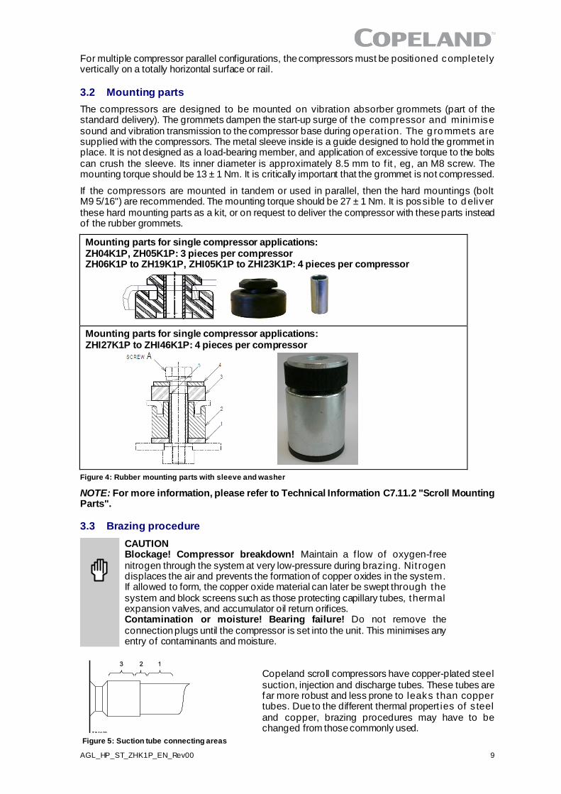
3.2 Mounting parts
The compressors are designed to be mounted on vibration absorber grommets (part of the standard delivery). The grommets dampen the start-up surge of the compressor and minimise sound and vibration transmission to the compressor base during operat ion. The g rommets are supplied with the compressors. The metal sleeve inside is a guide designed to hold the grommet in place. It is not designed as a load-bearing member, and application of excessive torque to the bolts can crush the sleeve. Its inner diameter is approximately 8.5 mm to f it , eg, an M8 screw. The mounting torque should be 13 ± 1 Nm. It is critically important that the grommet is not compressed.
If the compressors are mounted in tandem or used in parallel, then the hard mountings (bolt M9 5/16") are recommended. The mounting torque should be 27 ± 1 Nm. It is possible to deliver these hard mounting parts as a kit, or on request to deliver the compressor with these parts instead of the rubber grommets.
Mounting parts for single compressor applications: ZH04K1P, ZH05K1P: 3 pieces per compressor ZH06K1P to ZH19K1P, ZHI05K1P to ZHI23K1P: 4 pieces per compressor
Mounting parts for single compressor applications: ZHI27K1P to ZHI46K1P: 4 pieces per compressor
Figure 4: Rubber mounting parts with sleeve and washer
NOTE: For more information, please refer to Technical Information C7.11.2 "Scroll Mounting Parts".
3.3 Brazing procedure
CAUTION Blockage! Compressor breakdown! Maintain a f low of oxygen-f ree nitrogen through the system at very low-pressure during brazing. Nit rogen displaces the air and prevents the formation of copper oxides in the system. If allowed to form, the copper oxide material can later be swept through the system and block screens such as those protecting capillary tubes, thermal expansion valves, and accumulator oil return orifices. Contamination or moisture! Bearing failure! Do not remove the connection plugs until the compressor is set into the unit. This minimises any entry of contaminants and moisture.
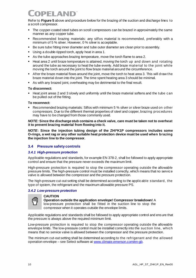
Copeland scroll compressors have copper-plated steel suction, injection and discharge tubes. These tubes are far more robust and less prone to leaks than copper tubes. Due to the different thermal propert ies of s teel and copper, brazing procedures may have to be changed from those commonly used.
Figure 5: Suction tube connecting areas
10 AGL_HP_ST_ZHK1P_EN_Rev00
Refer to Figure 5 above and procedure below for the brazing of the suction and discharge lines to a scroll compressor.
▪ The copper-coated steel tubes on scroll compressors can be brazed in approximately the same manner as any copper tube.
▪ Recommended brazing materials: any silfos material is recommended, preferably with a minimum of 5 % silver. However, 0 % silver is acceptable.
▪ Be sure tube f itting inner diameter and tube outer diameter are clean prior to assembly.
▪ Using a double-tipped torch, apply heat in area 1.
▪ As the tube approaches brazing temperature, move the torch flame to area 2.
▪ Heat area 2 until braze temperature is attained, moving the torch up and down and rotating around the tube as necessary to heat the tube evenly. Add braze material to the joint while moving the torch around the joint to flow braze material around the circumference.
▪ Af ter the braze material flows around the joint, move the torch to heat area 3. This will d raw the braze material down into the joint. The time spent heating area 3 should be minimal.
▪ As with any brazed joint, overheating may be detrimental to the final result.
To disconnect:
▪ Heat joint areas 2 and 3 slowly and uniformly until the braze material softens and the tube can be pulled out of the fitting.
To reconnect:
▪ Recommended brazing materials: Silfos with minimum 5 % silver or silver braze used on o ther compressors. Due to the different thermal properties of steel and copper, brazing procedures may have to be changed from those commonly used.
NOTE: Since the discharge stub contains a check valve, care must be taken not to overheat it to prevent brazing material from flowing into it.
NOTE: Since the injection tubing design of the ZHI*K1P compressors includes some O-rings, a wet rag or any other suitable heat protection device must be used when brazing the injection line to the compressor.
3.4 Pressure safety controls
3.4.1 High-pressure protection
Applicable regulations and standards, for example EN 378-2, shall be followed to apply appropriate control and ensure that the pressure never exceeds the maximum limit.
High-pressure protection is required to stop the compressor operating outside the allowable pressure limits. The high-pressure control must be installed correctly, which means that no service valve is allowed between the compressor and the pressure protection.
The high-pressure cut-out setting shall be determined according to the applicable s tandard, the type of system, the refrigerant and the maximum allowable pressure PS.
3.4.2 Low-pressure protection
CAUTION Operation outside the application envelope! Compressor breakdown! A low-pressure protection shall be f itted in the suction line to stop the compressor when it operates outside the envelope limits.
Applicable regulations and standards shall be followed to apply appropriate control and ensure that the pressure is always above the required minimum limit.
Low-pressure protection is required to stop the compressor operating outside the allowable envelope limits. The low-pressure control must be installed correctly into the suction l ine, which means that no service valve is allowed between the compressor and the pressure protection.
The minimum cut-out setting shall be determined according to the ref rigerant and the allowed operation envelope – see Select software at www.climate.emerson.com/en-gb.
AGL_HP_ST_ZHK1P_EN_Rev00 11
3.5 Crankcase heaters
CAUTION Overheating and burnout! Compressor damage! Never apply power to the crankcase heater in free air, before the crankcase heater is instal led on the compressor or when it is not in complete contact with the compressor shell.
IMPORTANT Oil dilution! Bearing malfunction! Turn the crankcase heater on 12 hours before starting the compressor.
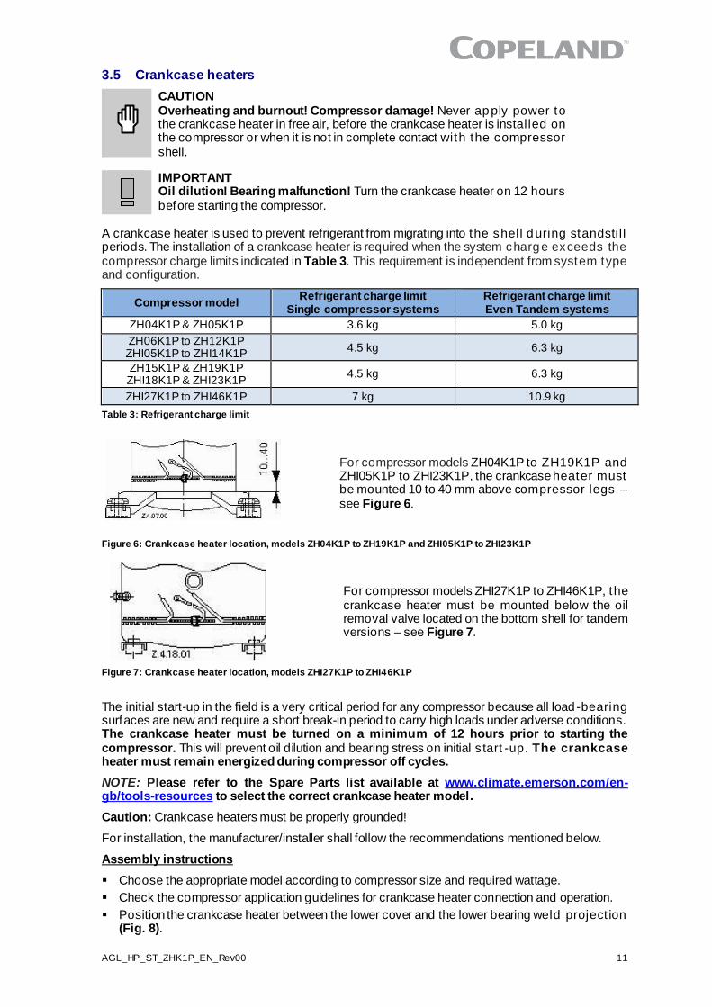
A crankcase heater is used to prevent refrigerant from migrating into the shell during standsti l l periods. The installation of a crankcase heater is required when the system charge exceeds the compressor charge limits indicated in Table 3. This requirement is independent from system type and configuration.
Compressor model Refrigerant charge limit
Single compressor systems Refrigerant charge limit Even Tandem systems
ZH04K1P & ZH05K1P 3.6 kg 5.0 kg
ZH06K1P to ZH12K1P ZHI05K1P to ZHI14K1P
4.5 kg 6.3 kg
ZH15K1P & ZH19K1P ZHI18K1P & ZHI23K1P
4.5 kg 6.3 kg
ZHI27K1P to ZHI46K1P 7 kg 10.9 kg
Table 3: Refrigerant charge limit
For compressor models ZH04K1P to ZH19K1P and ZHI05K1P to ZHI23K1P, the crankcase heater must be mounted 10 to 40 mm above compressor legs – see Figure 6.
Figure 6: Crankcase heater location, models ZH04K1P to ZH19K1P and ZHI05K1P to ZHI23K1P
For compressor models ZHI27K1P to ZHI46K1P, the crankcase heater must be mounted below the oil removal valve located on the bottom shell for tandem versions – see Figure 7.
Figure 7: Crankcase heater location, models ZHI27K1P to ZHI46K1P
The initial start-up in the field is a very critical period for any compressor because all load-bearing surfaces are new and require a short break-in period to carry high loads under adverse conditions. The crankcase heater must be turned on a minimum of 12 hours prior to starting the compressor. This will prevent oil dilution and bearing stress on initial s tart -up. The crankcase heater must remain energized during compressor off cycles.
NOTE: Please refer to the Spare Parts list available at www.climate.emerson.com/en-gb/tools-resources to select the correct crankcase heater model.
Caution: Crankcase heaters must be properly grounded!
For installation, the manufacturer/installer shall follow the recommendations mentioned below.
Assembly instructions
▪ Choose the appropriate model according to compressor size and required wattage.
▪ Check the compressor application guidelines for crankcase heater connection and operation.
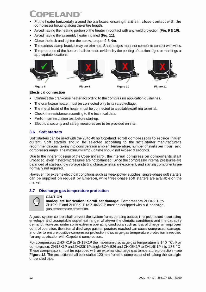
▪ Position the crankcase heater between the lower cover and the lower bearing weld project ion (Fig. 8).
12 AGL_HP_ST_ZHK1P_EN_Rev00
▪ Fit the heater horizontally around the crankcase, ensuring that it is in c lose contact with the compressor housing along the entire length.
▪ Avoid having the heating portion of the heater in contact with any weld projection (Fig. 9 & 10).
▪ Avoid having the assembly heater inclined (Fig. 11).
▪ Close the lock and tighten the screw, torque: 2-3 Nm.
▪ The excess clamp bracket may be trimmed. Sharp edges must not come into contact with wires.
▪ The presence of the heater shall be made evident by the posting of caution signs or markings at appropriate locations.
Figure 8 Figure 9 Figure 10 Figure 11
Electrical connection
▪ Connect the crankcase heater according to the compressor application guidelines.
▪ The crankcase heater must be connected only to its rated voltage.
▪ The metal braid of the heater must be connected to a suitable earthing terminal.
▪ Check the resistance according to the technical data.
▪ Perform an insulation test before start-up.
▪ Electrical security and safety measures are to be provided on site.
3.6 Soft starters
Soft starters can be used with the 20 to 40 hp Copeland scroll compressors to reduce inrush current. Sof t starters should be selected according to the sof t starter manufacturer's recommendations, taking into consideration ambient temperature, number of starts per hour, and compressor amps. The maximum ramp-up time should not exceed 3 seconds.
Due to the inherent design of the Copeland scroll, the internal compression components start unloaded, even if system pressures are not balanced. Since the compressor internal pressures are balanced at start-up, low voltage starting characteristics are excellent, and starting components are normally not required.
However, for extreme electrical conditions such as weak power supplies, single-phase soft starters can be supplied on request by Emerson, while three-phase sof t starters are available on the market.
3.7 Discharge gas temperature protection
CAUTION Inadequate lubrication! Scroll set damage! Compressors ZH04K1P to ZH19K1P and ZHI05K1P to ZHI46K1P must be equipped with a d ischarge gas temperature protection.
A good system control shall prevent the system from operating outside the published operat ing envelope and acceptable superheat range, whatever the climatic conditions and the capacit y demand. However, under some extreme operating conditions such as loss of charge o r improper control operation, the internal discharge gas temperature reached can cause compressor damage. In order to ensure positive compressor protection, discharge gas temperature protection is required for any application with Copeland compressors.
For compressors ZH04K1P to ZH19K1P the maximum discharge gas temperature is 140 °C. Fo r compressors ZHI18K1P and ZHI23K1P single BOM 526 and ZHI05K1P to ZHI14K1P it is 135 °C. These compressors must be equipped with an external discharge gas temperature protection – see Figure 12. The protection shall be installed 120 mm from the compressor shell, along the st raight or bended pipe.
AGL_HP_ST_ZHK1P_EN_Rev00 13
Figure 12: Sketch of discharge gas temperature protection for compressors with external sensor
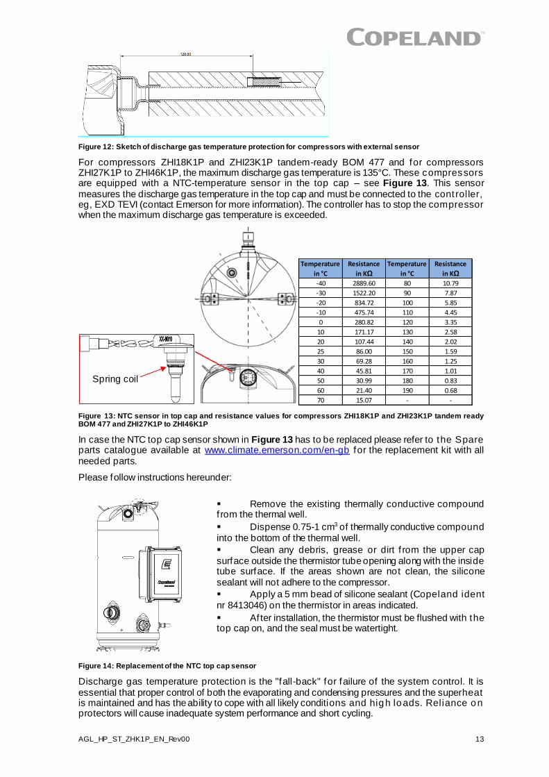
For compressors ZHI18K1P and ZHI23K1P tandem-ready BOM 477 and for compressors ZHI27K1P to ZHI46K1P, the maximum discharge gas temperature is 135°C. These compressors are equipped with a NTC-temperature sensor in the top cap – see Figure 13. This sensor measures the discharge gas temperature in the top cap and must be connected to the control ler, eg, EXD TEVI (contact Emerson for more information). The controller has to stop the compressor when the maximum discharge gas temperature is exceeded.
Figure 13: NTC sensor in top cap and resistance values for compressors ZHI18K1P and ZHI23K1P tandem ready BOM 477 and ZHI27K1P to ZHI46K1P
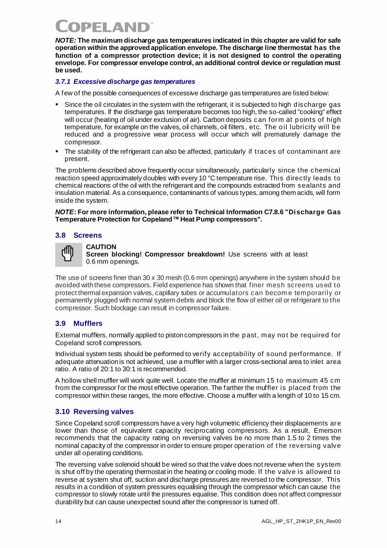
In case the NTC top cap sensor shown in Figure 13 has to be replaced please refer to the Spare parts catalogue available at www.climate.emerson.com/en-gb for the replacement kit with all needed parts.
Please follow instructions hereunder:
▪ Remove the existing thermally conductive compound f rom the thermal well.
▪ Dispense 0.75-1 cm3 of thermally conductive compound into the bottom of the thermal well.
▪ Clean any debris, grease or dirt f rom the upper cap surface outside the thermistor tube opening along with the inside tube surface. If the areas shown are not clean, the silicone sealant will not adhere to the compressor.
▪ Apply a 5 mm bead of silicone sealant (Copeland ident nr 8413046) on the thermistor in areas indicated.
▪ Af ter installation, the thermistor must be flushed with the top cap on, and the seal must be watertight.
Figure 14: Replacement of the NTC top cap sensor
Discharge gas temperature protection is the "fall-back" for failure of the system control. It is essential that proper control of both the evaporating and condensing pressures and the superheat is maintained and has the ability to cope with all likely conditions and high loads. Reliance on protectors will cause inadequate system performance and short cycling.
Temperature
in °C
Resistance
in KΩ
Temperature
in °C
Resistance
in KΩ
-40 2889.60 80 10.79
-30 1522.20 90 7.87
-20 834.72 100 5.85
-10 475.74 110 4.45
0 280.82 120 3.35
10 171.17 130 2.58
20 107.44 140 2.02
25 86.00 150 1.59
30 69.28 160 1.25
40 45.81 170 1.01
50 30.99 180 0.83
60 21.40 190 0.68
70 15.07 - -
Spring coil
14 AGL_HP_ST_ZHK1P_EN_Rev00
NOTE: The maximum discharge gas temperatures indicated in this chapter are valid for safe operation within the approved application envelope. The discharge line thermostat has the function of a compressor protection device; it is not designed to control the operating envelope. For compressor envelope control, an additional control device or regulation must be used.
3.7.1 Excessive discharge gas temperatures
A few of the possible consequences of excessive discharge gas temperatures are listed below:
▪ Since the oil circulates in the system with the refrigerant, it is subjected to high d ischarge gas temperatures. If the discharge gas temperature becomes too high, the so-called "cooking" effect will occur (heating of oil under exclusion of air). Carbon deposits can form at points of high temperature, for example on the valves, oil channels, oil filters , etc. The o il lubricity wil l be reduced and a progressive wear process will occur which will prematurely damage the compressor.
▪ The stability of the ref rigerant can also be affected, particularly if t races of contaminant are present.
The problems described above frequently occur simultaneously, particularly since the chemical reaction speed approximately doubles with every 10 °C temperature rise. This d irec tly leads to chemical reactions of the oil with the refrigerant and the compounds extracted from sealants and insulation material. As a consequence, contaminants of various types, among them acids, will form inside the system.
NOTE: For more information, please refer to Technical Information C7.8.6 "Discharge Gas Temperature Protection for Copeland™ Heat Pump compressors".
3.8 Screens
CAUTION Screen blocking! Compressor breakdown! Use screens with at least 0.6 mm openings.
The use of screens finer than 30 x 30 mesh (0.6 mm openings) anywhere in the system should be avoided with these compressors. Field experience has shown that f iner mesh screens used to protect thermal expansion valves, capillary tubes or accumulators can becom e temporari ly or permanently plugged with normal system debris and block the flow of either oil or ref rigerant to the compressor. Such blockage can result in compressor failure.
3.9 Mufflers
External mufflers, normally applied to piston compressors in the past , may no t be required for Copeland scroll compressors.
Individual system tests should be performed to verify acceptabil i ty of sound performance. If adequate attenuation is not achieved, use a muffler with a larger cross-sectional area to inlet area ratio. A ratio of 20:1 to 30:1 is recommended.
A hollow shell muffler will work quite well. Locate the muffler at minimum 15 to maximum 45 cm f rom the compressor for the most effective operation. The farther the muffler is placed f rom the compressor within these ranges, the more effective. Choose a muffler with a length of 10 to 15 cm.
3.10 Reversing valves
Since Copeland scroll compressors have a very high volumetric efficiency their displacements are lower than those of equivalent capacity reciprocating compressors. As a result, Emerson recommends that the capacity rating on reversing valves be no more than 1.5 to 2 times the nominal capacity of the compressor in order to ensure proper operat ion of t he reversing valve under all operating conditions.
The reversing valve solenoid should be wired so that the valve does not reverse when the system is shut off by the operating thermostat in the heating or cooling mode. If the valve is al lowed to reverse at system shut off, suction and discharge pressures are reversed to the compressor. This results in a condition of system pressures equalising through the compressor which can cause the compressor to slowly rotate until the pressures equalise. This condition does not affect compressor durability but can cause unexpected sound after the compressor is turned off.
AGL_HP_ST_ZHK1P_EN_Rev00 15
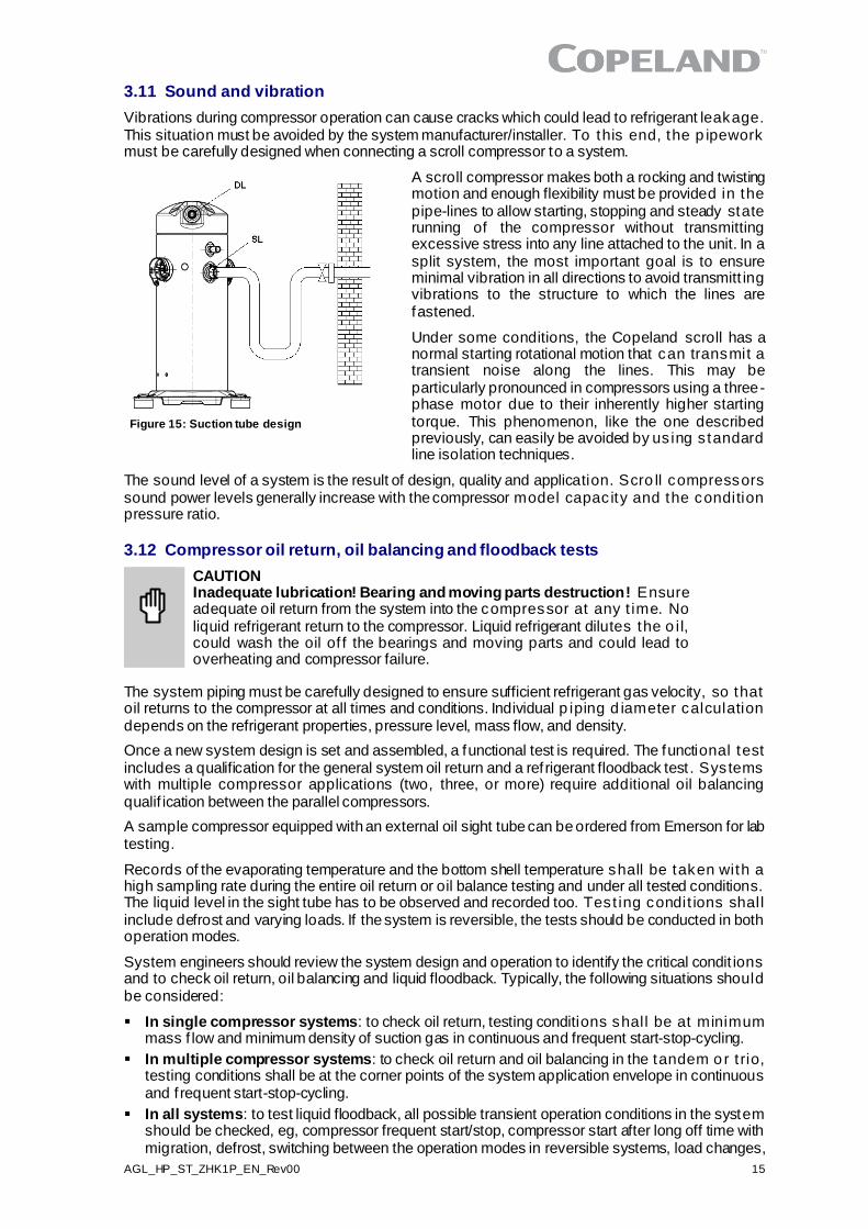
Figure 15: Suction tube design
3.11 Sound and vibration
Vibrations during compressor operation can cause cracks which could lead to refrigerant leakage. This situation must be avoided by the system manufacturer/installer. To this end, the p ipework must be carefully designed when connecting a scroll compressor to a system.
A scroll compressor makes both a rocking and twisting motion and enough flexibility must be provided in the pipe-lines to allow starting, stopping and steady state running of the compressor without transmitting excessive stress into any line attached to the unit. In a split system, the most important goal is to ensure minimal vibration in all directions to avoid transmitt ing vibrations to the structure to which the lines are fastened.
Under some conditions, the Copeland scroll has a normal starting rotational motion that can transmit a transient noise along the lines. This may be particularly pronounced in compressors using a three-phase motor due to their inherently higher starting torque. This phenomenon, like the one described previously, can easily be avoided by us ing s tandard line isolation techniques.
The sound level of a system is the result of design, quality and application. Scro ll compressors sound power levels generally increase with the compressor model capac ity and the condition pressure ratio.
3.12 Compressor oil return, oil balancing and floodback tests
CAUTION Inadequate lubrication! Bearing and moving parts destruction! Ensure adequate oil return from the system into the compressor at any t ime. No liquid refrigerant return to the compressor. Liquid refrigerant dilutes the o il, could wash the oil of f the bearings and moving parts and could lead to overheating and compressor failure.
The system piping must be carefully designed to ensure sufficient refrigerant gas velocity, so that oil returns to the compressor at all times and conditions. Individual p iping d iameter calculation depends on the refrigerant properties, pressure level, mass flow, and density.
Once a new system design is set and assembled, a functional test is required. The functional test includes a qualification for the general system oil return and a ref rigerant floodback test . Systems with multiple compressor applications (two, three, or more) require additional oil balancing qualif ication between the parallel compressors.
A sample compressor equipped with an external oil sight tube can be ordered from Emerson for lab testing.
Records of the evaporating temperature and the bottom shell temperature shall be taken with a high sampling rate during the entire oil return or oil balance testing and under all tested conditions. The liquid level in the sight tube has to be observed and recorded too. Test ing condit ions shall include defrost and varying loads. If the system is reversible, the tests should be conducted in both operation modes.
System engineers should review the system design and operation to identify the critical condit ions and to check oil return, oil balancing and liquid floodback. Typically, the following situations should be considered:
▪ In single compressor systems: to check oil return, testing conditions shall be at minimum mass f low and minimum density of suction gas in continuous and frequent start-stop-cycling.
▪ In multiple compressor systems: to check oil return and oil balancing in the tandem o r t rio, testing conditions shall be at the corner points of the system application envelope in continuous and f requent start-stop-cycling.
▪ In all systems: to test liquid floodback, all possible transient operation conditions in the system should be checked, eg, compressor frequent start/stop, compressor start after long off time with migration, defrost, switching between the operation modes in reversible systems, load changes,
16 AGL_HP_ST_ZHK1P_EN_Rev00
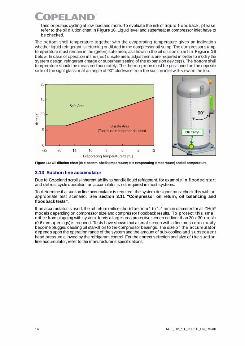
fans or pumps cycling at low load and more. To evaluate the risk of l iquid f loodback, p lease refer to the oil dilution chart in Figure 16. Liquid level and superheat at compressor inlet have to be checked.
The bottom shell temperature together with the evaporating temperature gives an indication whether liquid refrigerant is returning or diluted in the compressor oil sump. The compressor sump temperature must remain in the (green) safe area, as shown in the oil dilution chart in Figure 16 below. In case of operation in the (red) unsafe area, adjustments are required in order to modify the system design, refrigerant charge or superheat setting of the expansion device(s). The bottom shell temperature should be measured accurately. The thermo-probe must be positioned on the opposite side of the sight glass or at an angle of 90° clockwise from the suction inlet with view on the top.
Figure 16: Oil dilution chart (tb = bottom shell temperature; te = evaporating temperature) and oil temperature
3.13 Suction line accumulator
Due to Copeland scroll’s inherent ability to handle liquid refrigerant, for example in f looded start and defrost cycle operation, an accumulator is not required in most systems.
To determine if a suction line accumulator is required, the system designer must check this with an appropriate test scenario. See section 3.11 "Compressor oil return, oil balancing and floodback tests".
If an accumulator is used, the oil-return orifice should be from 1 to 1.4 mm in diameter for all ZH(I)* models depending on compressor size and compressor floodback results. To protect this small orif ice from plugging with system debris a large-area protective screen no finer than 30 x 30 mesh (0.6 mm openings) is required. Tests have shown that a small screen with a fine mesh can easily become plugged causing oil starvation to the compressor bearings. The size o f the accumulator depends upon the operating range of the system and the amount of sub-cooling and subsequent head pressure allowed by the refrigerant control. For the correct selection and size of the suct ion line accumulator, refer to the manufacturer’s specifications.
AGL_HP_ST_ZHK1P_EN_Rev00 17
4 Electrical connection
4.1 General recommendations
The compressor terminal box has a wiring diagram on the inside of its cover. Before connecting the compressor, ensure the supply voltage, the phases and the frequency match the nameplate data.
4.2 Electrical installation
4.2.1 Wiring diagrams
The recommended wiring diagrams are shown in figures hereunder.
NOTE: Emerson recommends using a contactor K2 for the safety chain in order to comply with EN 60335.
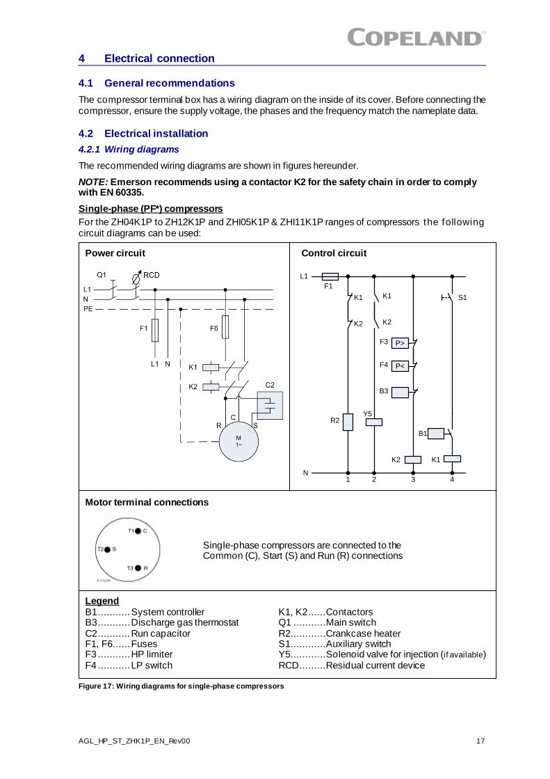
Single-phase (PF*) compressors
For the ZH04K1P to ZH12K1P and ZHI05K1P & ZHI11K1P ranges of compressors the following circuit diagrams can be used:
Power circuit Control circuit
L1
K1
K2
K1
K2
S1
P>
P<
F3
F4
B3
K2
R2
N1 2 3 4
Y5
B1
K1
B1
F1
Motor terminal connections
Single-phase compressors are connected to the Common (C), Start (S) and Run (R) connections
Legend B1 ........... System controller K1, K2 ......Contactors B3 ........... Discharge gas thermostat Q1 ...........Main switch C2 ........... Run capacitor R2............Crankcase heater F1, F6...... Fuses S1............Auxiliary switch F3 ........... HP limiter Y5............Solenoid valve for injection (if available) F4 ........... LP switch RCD.........Residual current device
Figure 17: Wiring diagrams for single-phase compressors
18 AGL_HP_ST_ZHK1P_EN_Rev00
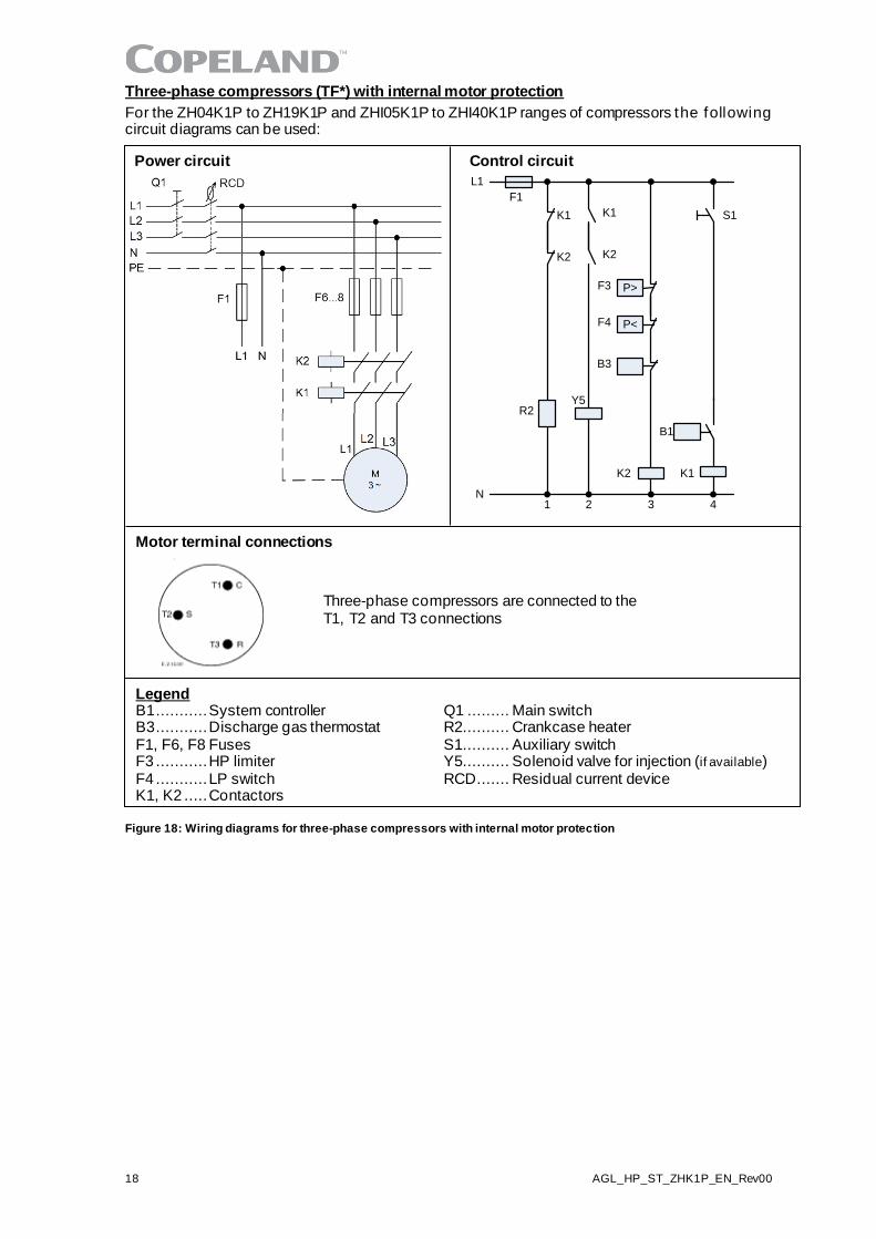
Three-phase compressors (TF*) with internal motor protection
For the ZH04K1P to ZH19K1P and ZHI05K1P to ZHI40K1P ranges of compressors the following circuit diagrams can be used:
Power circuit Control circuit
L1
K1
K2
K1
K2
S1
P>
P<
F3
F4
B3
K2
R2
N1 2 3 4
Y5
B1
K1
B1
F1
Motor terminal connections
Three-phase compressors are connected to the T1, T2 and T3 connections
Legend B1 ........... System controller Q1 ......... Main switch B3 ........... Discharge gas thermostat R2.......... Crankcase heater F1, F6, F8 Fuses S1.......... Auxiliary switch F3 ........... HP limiter Y5.......... Solenoid valve for injection (if available) F4 ........... LP switch RCD....... Residual current device K1, K2 ..... Contactors
Figure 18: Wiring diagrams for three-phase compressors with internal motor protection
AGL_HP_ST_ZHK1P_EN_Rev00 19
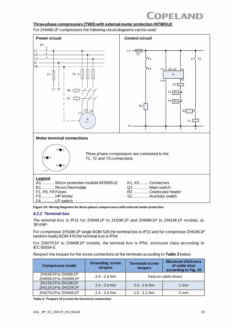
Three-phase compressors (TWD) with external motor protection INT69SU2
For ZHI46K1P compressors the following circuit diagrams can be used:
Power circuit Control circuit
L1
K1
K2
S1
P>
P<
F3
F4
K2
R2
N1 3 4
B1
K1
B1
F1
A1
T1/L
T2/N
S1 S2 M1
M2
2
Motor terminal connections
Three-phase compressors are connected to the T1, T2 and T3 connections
Legend A1 ........... Motor protection module INT69SU2 K1, K2 ....... Contactors B1 ........... Room thermostat Q1............. Main switch F1, F6, F8 Fuses R2 ............. Crankcase heater F3 ........... HP limiter S1 ............. Auxiliary switch F4 ........... LP switch
Figure 19: Wiring diagrams for three-phase compressors with external motor protection
4.2.2 Terminal box
The terminal box is IP21 for ZH04K1P to ZH19K1P and ZHI08K1P to ZHI14K1P models, ie, TF*/PF*.
For compressor ZHI18K1P single BOM 526 the terminal box is IP21 and for compressor ZHI18K1P tandem-ready BOM 476 the terminal box is IP54.
For ZHI27K1P to ZHI40K1P models, the terminal box is IP54, enclosure class according to IEC 60034-5.
Respect the torques for the screw connections at the terminals according to Table 3 below:
Compressor model Grounding screw
torques Terminals screw
torques
Maximum thickness of cable shoe
according to Fig. 20 ZH04K1P to ZH09K1P ZHI05K1P to ZHI08K1P
2.4 - 2.6 Nm Fast-on cable shoes
ZH12K1P to ZH19K1P ZHI11K1P to ZHI23K1P
2.4 - 2.6 Nm 2.4 - 2.6 Nm 1 mm
ZHI27K1P to ZHI46K1P 2.4 - 2.6 Nm 1.5 - 2.1 Nm 2 mm
Table 4: Torques of screws for electrical connection
20 AGL_HP_ST_ZHK1P_EN_Rev00
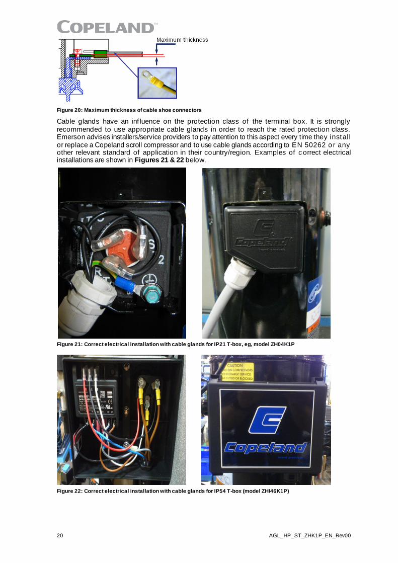
Figure 20: Maximum thickness of cable shoe connectors
Cable glands have an inf luence on the protection class of the terminal box. It is strongly recommended to use appropriate cable glands in order to reach the rated protection class. Emerson advises installers/service providers to pay attention to this aspect every time they instal l or replace a Copeland scroll compressor and to use cable glands according to EN 50262 o r any other relevant standard of application in their country/region. Examples of c orrect electrical installations are shown in Figures 21 & 22 below.
Figure 21: Correct electrical installation with cable glands for IP21 T-box, eg, model ZH04K1P
Figure 22: Correct electrical installation with cable glands for IP54 T-box (model ZHI46K1P)
AGL_HP_ST_ZHK1P_EN_Rev00 21
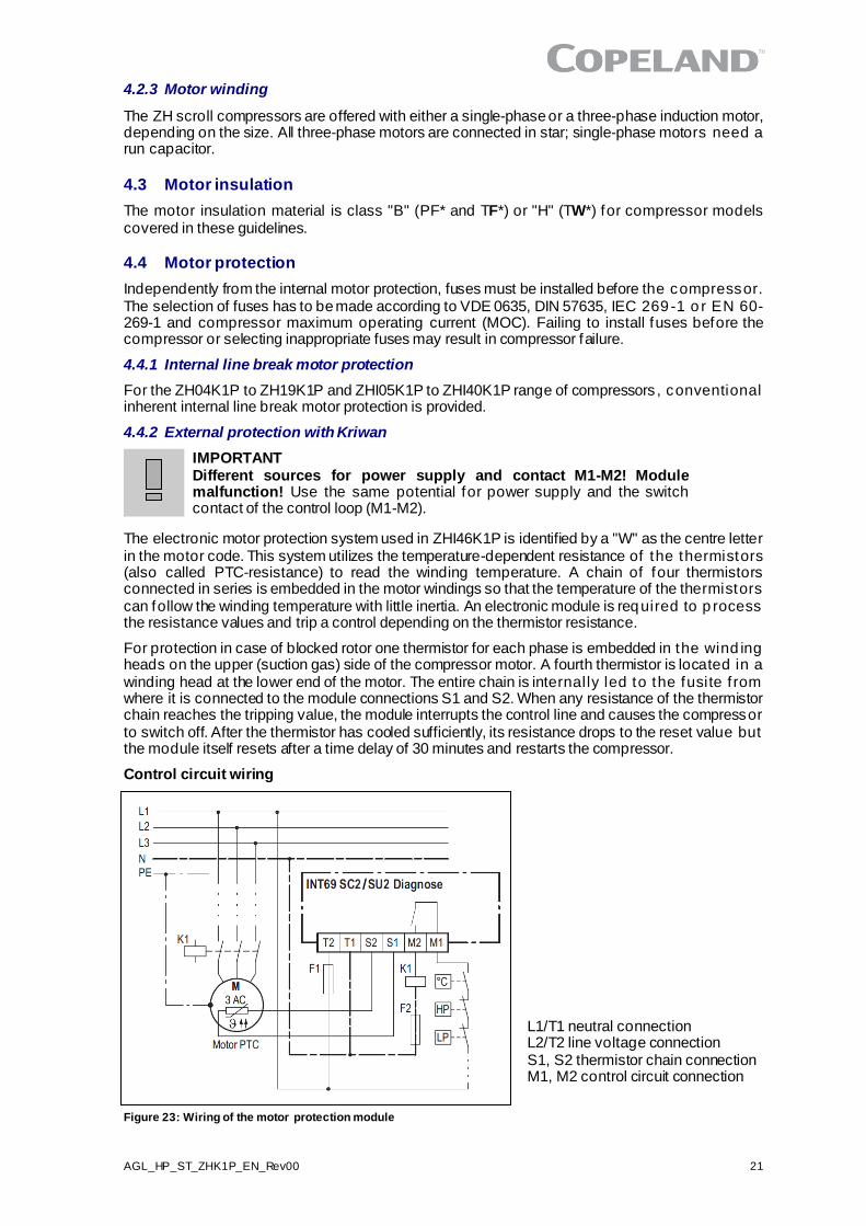
L1/T1 neutral connection L2/T2 line voltage connection S1, S2 thermistor chain connection M1, M2 control circuit connection
4.2.3 Motor winding
The ZH scroll compressors are offered with either a single-phase or a three-phase induction motor, depending on the size. All three-phase motors are connected in star; single-phase motors need a run capacitor.
4.3 Motor insulation
The motor insulation material is class "B" (PF* and TF*) or "H" (TW*) for compressor models covered in these guidelines.
4.4 Motor protection
Independently from the internal motor protection, fuses must be installed before the compressor. The selection of fuses has to be made according to VDE 0635, DIN 57635, IEC 269 -1 o r EN 60-269-1 and compressor maximum operating current (MOC). Failing to install fuses before the compressor or selecting inappropriate fuses may result in compressor failure.
4.4.1 Internal line break motor protection
For the ZH04K1P to ZH19K1P and ZHI05K1P to ZHI40K1P range of compressors , conventional inherent internal line break motor protection is provided.
4.4.2 External protection with Kriwan
IMPORTANT Different sources for power supply and contact M1-M2! Module malfunction! Use the same potential for power supply and the switch contact of the control loop (M1-M2).
The electronic motor protection system used in ZHI46K1P is identified by a "W" as the centre letter in the motor code. This system utilizes the temperature-dependent resistance of the thermistors (also called PTC-resistance) to read the winding temperature. A chain of four thermistors connected in series is embedded in the motor windings so that the temperature of the thermistors can follow the winding temperature with little inertia. An electronic module is required to p rocess the resistance values and trip a control depending on the thermistor resistance.
For protection in case of blocked rotor one thermistor for each phase is embedded in the wind ing heads on the upper (suction gas) side of the compressor motor. A fourth thermistor is located in a winding head at the lower end of the motor. The entire chain is internally led to the fusite f rom where it is connected to the module connections S1 and S2. When any resistance of the thermistor chain reaches the tripping value, the module interrupts the control line and causes the compressor to switch off. After the thermistor has cooled sufficiently, its resistance drops to the reset value but the module itself resets after a time delay of 30 minutes and restarts the compressor.
Control circuit wiring
Figure 23: Wiring of the motor protection module
22 AGL_HP_ST_ZHK1P_EN_Rev00
Supply voltage: Dual voltage 115-230 V AC 50 Hz, -15 %...+10 %, 3 VA
120-240 V AC 60 Hz, -15 %...+10 %, 3 VA
Supply voltage 24 V AC 50/60 Hz, -15 %...+10 %, 3 VA
24 V DC 20 %, 2 W
Ambient temperature range -30…+70 °C
R25, total < 1,8k
Trip resistance 4.50k Ω ± 20 %
Reset time delay type 1 / type 2 30 min 5 min / 60 min 5 min
Reset of running time Power interruption / mains failure for approx. 5 sec
Short circuit monitoring system Typically < 30 Ω
Protection class according to EN 60529 IP00
Weight Approximately 200 g
Mounting Screw in or snap in
Housing material PA66 GF25 FR
Table 5: Protection module specifications INT69SU2
4.5 Kriwan protector functional check and failure detection
WARNING Conductor cables! Electrical shock hazard! Shut off power supply before and between each test.
Prior to start-up of the fully connected compressor a functional check shall be carried out:
▪ Disconnect one terminal either S1 or S2 of the protection module. If the compres sor is now switched on, the motor should not start (simulation of an open thermistor chain).
▪ Reconnect the disconnected thermistor line. If the compressor is now switched on, the motor must start.
If the motor does not start up during the functional check, this indicates a disturbance in operation. The following steps should be followed:
4.5.1 Checking the connection
▪ Check the connection of the thermistor leads in the terminal box and at the protect ion module for possible loose connections or cable breakage.
If there is neither loose connection nor cable breakage the resistance of the thermistor chain must be checked.
4.5.2 Checking the compressor thermistor chain
Caution: Use maximum measuring voltage of 3V!
The thermistor leads at terminals S1 and S2 of the module shall be disconnected and the resistance measured between the leads. The resistance must be between 150 Ω and 1250 Ω.
▪ If the thermistor chain has a higher resistance (2750 Ω or higher), the motor temperature is s ti l l too high and it must be allowed to cool. Then measure again.
▪ If the resistance is below 30 Ω, the compressor has to be exchanged due to shorted sensor circuit.
▪ An inf inite value indicates an open sensor circuit and the compressor has to be replaced.
If no defect is detected in the thermistor chain the module must be checked.
4.5.3 Checking the protection module
The control connections at M1 and M2 have to be removed and the switching conditions must be checked by an ohmmeter or signal buzzer:
▪ Simulation of a short circuit in the thermistor chain (0 Ω): Bridge the already disconnected thermistor terminals S1 and S2 and switch on the voltage supply; the relay must switch on then of f again after a short period; connection established then interrupted between terminals M1 and M2.
AGL_HP_ST_ZHK1P_EN_Rev00 23
▪ Simulation of an open thermistor chain (∞ Ω): Remove the jumper used for the short -circuit simulation and switch on the voltage supply; the relay remains switched of f ; no connect ion between terminals M1 and M2.
If one of the above conditions is not met, the module is defective and has to be exchanged.
NOTE: The function of the module should be tested each time the fuse in the control circuit breaks the power supply. This ensures the contacts did not stick.
4.6 High-potential testing
WARNING Conductor cables! Electrical shock hazard! Shut off power supply before high-potential testing.
CAUTION Internal arcing! Motor destruction! Do not carry out high-voltage or insulation tests if the compressor housing is under vacuum.
Emerson subjects all scroll compressors to a high-voltage test after final assembly . Each motor phase winding is tested, according to EN 0530 or VDE 0530 part 1, at a d if ferent ial voltage of 1000 V plus twice the nominal voltage. Since high-voltage tests lead to premature ageing of the winding insulation additional tests of that nature are not recommended.
If it has to be done for any reason, a lower voltage must be used. Disconnect all electronic devices, eg, motor protection module, fan speed control, etc prior to testing.
24 AGL_HP_ST_ZHK1P_EN_Rev00
5 Start-up & operation
WARNING Diesel effect! Compressor destruction! The mixture of air and oil at high temperature can lead to an explosion. Avoid operating with air.
IMPORTANT Oil dilution! Bearing malfunction! It is important to ensure that new compressors are not subjected to liquid abuse. Turn the crankcase heater on 12 hours before starting the compressor.
5.1 Strength pressure test
WARNING High pressure! Personal injuries! Consider personal safety requirements and refer to test pressures prior to test.
IMPORTANT System contamination! Bearing malfunction! Use only d ry nit rogen for pressure testing. DO NOT USE other industrial gases.
5.1.1 Compressor strength-pressure test
The compressor has been strength-pressure tested in the Emerson factory . Theref ore, i t is not necessary for the system manufacturer/installer to strength-pressure test the compressor again.
Scroll compressors are divided into two pressure zones. The compressor high-side and low-s ide maximum allowable pressures PS have to be respected at all times.
5.1.2 System strength-pressure test
A strength-pressure test of individual sections of the entire system is p ermitted. Once the compressor is isolated, the rest of the system can be tested with the required pressure values.
The strength-pressure test can also be conducted with the compressor connected, but in that case the two pressure zones of the scroll compressor need to be respected:
▪ System high-pressure section:
o Def ine the system high-side PS ≤ compressor high-side PS.
o Isolate the high- and low-pressure sections of the system by c losing va lves, solenoid valves, expansion valves or by other means.
o Use the internal check valve of the compressor on the discharge side or add an external check valve. To protect the compressor internal check valve, observe a maximum pressure delta of ≤ 40 bar between the high-pressure side and the low-pressure side.
o Activate the check valve with a fast pressure increase. Once the check valve is act ivated, the pressure increase can be slowed down.
o At this stage the system test pressure of 1.1 x system high-side PS can be applied for a short time.
o During the system test, make sure the pressure inside the compressor does not exceed the maximum PS value, which corresponds to the compressor low-pressure PS.
▪ System low-pressure section:
o Def ine the system low-side PS ≤ compressor low-side PS.
o The system test pressure of 1.1 x system low-side PS can be applied for a short time.
5.2 Compressor tightness test
WARNING High pressure! Personal injuries! Consider personal safety requirements and refer to test pressures prior to test.
IMPORTANT System contamination! Bearing malfunction! Use only dry inert gases, for example nitrogen, for leak testing. DO NOT USE other industrial gases.
The compressor has been leak-pressure tested in the Emerson factory.
AGL_HP_ST_ZHK1P_EN_Rev00 25
All compressors get a factory holding charge of dry air (about 1 to 2.5 bar, relative pressure). An intact holding charge serves as a proof of quality against penetrating moisture.
When removing plugs from the compressor, the plugs may pop out due to p ressure and oil can spurt.
Any later modification to compressor connections can have an impact on the compressor tightness. Always leak-pressure test the compressor after opening or modifying the connections.
Never add ref rigerant to the test gas (as leak indicator).
5.3 Preliminary checks – Pre-starting
Discuss details of the installation with the installer. If possible, obtain drawings, wiring diagrams, etc. It is ideal to use a check-list but always check the following:
▪ Visual check of the electrics, wiring, fuses etc.
▪ Visual check of the plant for leaks, loose fittings such as TXV bulbs etc.
▪ Compressor oil level
▪ Calibration of HP & LP switches and any pressure actuated valves
▪ Check setting and operation of all safety features and protection devices
▪ All valves in the correct running position
▪ Pressure and compound gauges fitted
▪ Correctly charged with refrigerant
▪ Compressor electrical isolator location & position
5.4 Charging procedure
CAUTION Low suction pressure operation! Compressor damage! Do not operate with a restricted suction. Do not operate with the low-pressure limiter bridged. Do not operate compressor at pressures that are not allowed by the operating envelope. Allowing the suction pressure to drop below the envelope l imit for more than a few seconds may overheat scrolls and cause early drive bearing and moving parts damage.
Prior to charging or re-charging, the refrigerant system must be leak- and pressure-tes ted with appropriate purging gas.
Ensure that the system is grounded prior to charging with refrigerant.
The system shall be liquid-charged through the liquid-receiver shut-off valve or through a valve in the liquid line. The use of a filter dryer in the charging line is highly recommended. Systems shall be liquid-charged on both the high and low sides simultaneously to ensure a positive ref rigerant pressure is present in the compressor before it runs. The majority of the charge shall be placed in the high side of the system to prevent bearing washout during first-time start on the assembly line.
Extreme care shall be taken not to overfill the system with refrigerant.
5.5 Initial start-up
CAUTION High discharge pressure operation! Compressor damage! Do not use compressor to test opening setpoint of high-pressure cut-out. Internal parts are susceptible to damage before they have had several hours of normal running in.
Liquid and high-pressure loads could be detrimental to new bearings. It is therefore important to ensure that new compressors are not subjected to liquid abuse and high-pressure run tests. It is not good practice to use the compressor to test the high-pressure switch function on the production line. Switch function can be tested with nitrogen prior to installation and wiring can be checked by
disconnecting the high-pressure switch during the run test.
26 AGL_HP_ST_ZHK1P_EN_Rev00
5.6 Rotation direction
Scroll compressors, like several other types of compressors, will only compress in one rotational direction. Direction of rotation is not an issue with single-phase compressors since they will always start and run in the proper direction. All three-phase compressors wil l ro tate in either direct ion depending upon the phasing of the power. Since there is a 50-50 chance of connect ing power in such a way as to cause rotation in the reverse direction, it is important to include notices and instructions in appropriate locations on the equipment to ensure proper rotation dir ection when the system is installed and operated.
Observing that suction pressure drops and discharge pressure rises when the compressor is energized allows verification of proper rotation direction. There is no negative impact on durabil ity caused by operating three-phase Copeland scroll compressors in the reversed direction for a short period of time (under one hour) but oil may be lost. Oil loss can be prevented during reverse rotation if the tubing is routed at least 15 cm above the compressor. Af ter several minutes of operation in reverse, the compressor's protection system will trip due to high motor temperature. The operator will notice a lack of cooling. However, if allowed to repeatedly res tart and run in reverse without correcting the situation, the compressor will be permanently damaged.
All three-phase scroll compressors are identically wired internally. Theref ore, once the correct phasing is determined for a specific system or installation, connecting properly phased power leads to the identified compressor terminals will ensure proper rotation direction.
5.7 Starting sound
During the very brief start-up, a clicking sound resulting from the initial contacting of the spirals is audible – it is normal. Due to the design of the Copeland scroll compressors, the internal compression components always start unloaded even if system pressures are not balanced. In addition, since internal compressor pressures are always balanced at start-up, low-voltage starting characteristics are excellent for Copeland scroll compressors.
5.8 Deep vacuum operation
CAUTION Vacuum operation! Compressor damage! Copeland scroll compressors should never be used to evacuate refrigeration or air-conditioning systems. Operating scroll compressors in deep vacuum could damage internal motor parts and lead to unacceptable high temperatures in the compressor housing.
The scroll compressor can be used to pump down refrigerant in a unit as long as the pressures remain within the operating envelope. Low suction pressures will result in overheating of the scrolls and permanent damage to the compressor drive bearing.
5.9 Shell temperature
The top shell and discharge line can briefly but repeatedly reach temperatures above 177°C if th e compressor cycles on its internal protection devices. This only happens under rare circumstances and can be caused by the failure of system components such as the condenser or evaporator fan or loss of charge and depends upon the type of expansion control. Care must be taken to ensure that wiring or other materials that could be damaged by these temperatures do not touch the shell.
5.10 Pumpdown cycle
CAUTION Vacuum operation! Compressor damage! Compressor operation outside the operating envelope is not allowed.
A pumpdown cycle to control refrigerant migration may have to be used for several reasons, for example when the compressor is located outdoors without any housing so that cold air b lowing over the compressor makes the crankcase heater ineffective.
If a pumpdown cycle is used, a separate external check valve must be added . The scroll discharge check valve is designed to stop extended reverse rotation and prevent high-pressure gas f rom leaking rapidly into the low side after shut-off. The check valve might in some cases leak more than reciprocating compressor discharge reeds, normally used with pumpdown, causing the scro ll compressor to recycle more frequently. Repeated short cycling of this nature can result in a low oil
AGL_HP_ST_ZHK1P_EN_Rev00 27
situation and consequent damage to the compressor. The hysteresis of the low-pressure control dif ferential has to be reviewed since a relatively large volume of gas will re-expand f rom the high side of the compressor into the low side after shutdown.
For pressure control setting, never set the low-pressure limiter to shut off outside of the operating envelope. To prevent the compressor from running into problems during such faults as loss of charge or partial blockage, the low-pressure limiter should not be set lower than the minimum suction pressure allowed by the operating envelope.
5.11 Pump-out cycle
A pump-out cycle has been successfully used by some manufacturers of large rooftop units. Af ter an extended off period, a typical pump-out cycle will energize the compressor for up to one second followed by an off time of 5 to 20 seconds. This cycle is usually repeated a second time, the third time the compressor stays on for the cooling cycle.
5.12 Minimum run time
Emerson recommends a maximum of 10 starts per hour. There is no minimum of f t ime because scroll compressors start unloaded, even if the system has unbalanced pressures. The most critical consideration is the minimum run time required to return oil to the compressor af ter s tart -up. To establish the minimum run time, a sample compressor equipped with an external oil sight g lass is available f rom Emerson. The minimum on time becomes the time required for oil lost during compressor start-up to return to the compressor sump and to restore a minimal o il level that wil l ensure oil pick-up through the crankshaft. Cycling the compressor for a shorter period than this, for instance to maintain very tight temperature control, will result in progressive loss of oil and damage to the compressor.
5.13 Shut-off sound
Scroll compressors incorporate a device that minimizes reverse rotation. The residual momentary reversal of the scrolls at shut-off will cause a clicking sound, but it is entirely normal and has no ef fect on compressor durability.
5.14 Supply frequency and voltage
There is no general release of standard Copeland scroll compressors for use with variable speed AC drives. There are numerous issues that must be taken into account when applying scroll compressors with variable speed, including system design, inverter selection, and operating envelopes at various conditions. Only frequencies from 50 Hz to 60 Hz are acceptable. Operation outside this frequency range is possible but should not be done without specif ic Applicat ion Engineering review. The voltage must vary proportionally to the frequency.
If the inverter can only deliver a maximum voltage of 400 V, the amps will increase when the speed is above 50 Hz, and this may give rise to nuisance tripping if operation is near the maximum power limit and/or compressor discharge temperature limit.
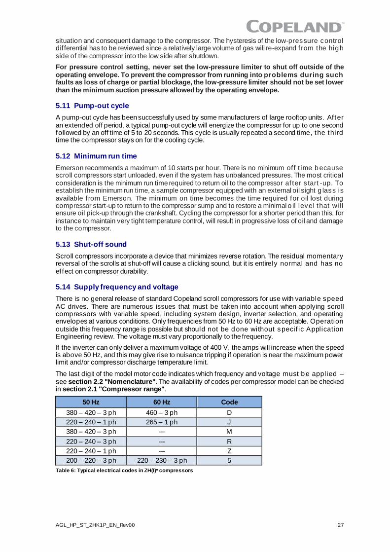
The last digit of the model motor code indicates which frequency and voltage must be applied – see section 2.2 "Nomenclature". The availability of codes per compressor model can be checked in section 2.1 "Compressor range".
50 Hz 60 Hz Code
380 – 420 – 3 ph 460 – 3 ph D
220 – 240 – 1 ph 265 – 1 ph J
380 – 420 – 3 ph --- M
220 – 240 – 3 ph --- R
220 – 240 – 1 ph --- Z
200 – 220 – 3 ph 220 – 230 – 3 ph 5
Table 6: Typical electrical codes in ZH(I)* compressors
28 AGL_HP_ST_ZHK1P_EN_Rev00
5.15 Oil level
During the system development, adequate oil return in any operation should be checked whatever the compressor model. For this purpose, sample compressors equipped with sight tubes can be ordered from Emerson. Oil return check test recommendations are also available on demand f rom Application Engineering.
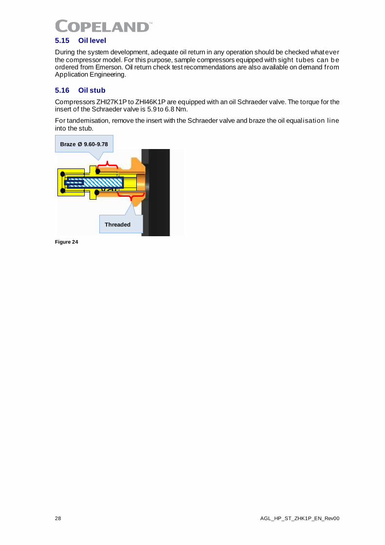
5.16 Oil stub
Compressors ZHI27K1P to ZHI46K1P are equipped with an oil Schraeder valve. The torque for the insert of the Schraeder valve is 5.9 to 6.8 Nm.
For tandemisation, remove the insert with the Schraeder valve and braze the oil equalisation l ine into the stub.
Figure 24
Valve
Threaded
Braze Ø 9.60-9.78
AGL_HP_ST_ZHK1P_EN_Rev00 29
6 Maintenance & repair
WARNING Conductor cables! Electrical shock! Follow the lockout/tag out procedure and the national regulations before carrying out any maintenance or serv ice work on the system. Use compressor with grounded system only. Screwed electrical connections must be used in all applications. Refer to original equipment wiring diagrams. Electrical connections must be made by qualified electrical personnel.
6.1 Exchanging the refrigerant
CAUTION Low suction pressure operation! Compressor damage! Do no t operate with a restricted suction. Do not operate with the low-pressure limiter bridged. Do not operate compressor at pressures that are not allowed by the operating envelope. Allowing the suction pressure to drop below the envelope limit for more than a few seconds may overheat scrolls and cause early drive bearing and moving parts damage.
For qualified refrigerants and oils, see section 3.6.1.
It is not necessary to replace the refrigerant unless contamination, for example due to an error such as topping up the system with a non-condensable gas or incorrect refrigerant , is suspected. To verify correct refrigerant composition, a sample can be taken for chemical analysis. A check can be made during shutdown by comparing the refrigerant temperature and p ressure us ing prec is ion measurements at a location in the system where liquid and vapour phases are present and when the temperatures have stabilised.
6.2 Rotalock valves
Rotalock valves should be periodically re-torqued to ensure that leak tightness is maintained.
6.3 Disassembling system components
When disassembling system components please follow the main steps described hereunder:
1. Recover ref rigerant and evacuate system using a recovery unit and vacuum pump. All the ref rigerant shall be recovered to avoid significant release.
2. Flush system with inert gas (dry nitrogen). Compressed air or oxygen shall no t be used for purging refrigerant systems.
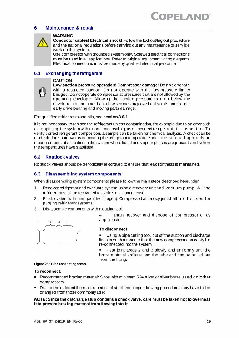
3. Disassemble components with a cutting tool.
4. Drain, recover and dispose of compressor oil as appropriate.
To disconnect:
▪ Using a pipe cutting tool, cut off the suction and discharge lines in such a manner that the new compressor can easily be re-connected into the system.
▪ Heat joint areas 2 and 3 slowly and uniformly until the braze material sof tens and the tube end can be pulled out f rom the fitting.
To reconnect:
▪ Recommended brazing material: Silfos with minimum 5 % silver or silver braze used on o ther compressors.
▪ Due to the different thermal properties of steel and copper, brazing procedures may have to be changed from those commonly used.
NOTE: Since the discharge stub contains a check valve, care must be taken not to overheat it to prevent brazing material from flowing into it.
Figure 25: Tube connecting areas
30 AGL_HP_ST_ZHK1P_EN_Rev00
6.4 Replacing a compressor
CAUTION Inadequate lubrication! Bearing destruction! For systems with a ref rigerant accumulator, exchange the accumulator af ter replacing a compressor with a burned-out motor. The accumulator oil return orif ice or screen may be plugged with debris or may become plugged. This will result in starvation of oil to the new compressor and a second failure. Remove ref rigerant and oil completely from the replaced compressor.
6.4.1 Compressor replacement
In the case of a motor burnout, the majority of contaminated oil will be removed with the compressor. The rest of the oil is cleaned through the use of suction and liquid line filter dryers. A 100 % activated alumina suction line f ilter dryer is recommended but must be removed af ter 72 hours. When a single compressor or tandem is exchanged in the field, it is possible that a major portion of the oil may still be in the system. While this may not af fect the reliability of the replacement compressor, the extra oil will add to rotor drag and increase power usage.
6.4.2 Start-up of a new or replacement compressor
Rapid charging only on the suction side of a scroll-equipped system can occas ionally result in a temporary no-start condition for the compressor. The reason for this is that, if the f lanks of the scrolls happen to be in a sealed position, rapid pressurisation of the low s ide without opposing high-side pressure can cause the scrolls to seal axially. As a result, until the pressures eventually equalise, the scrolls can be held tightly together preventing rotation. The best way to avoid this situation is to charge on both the high and low sides simultaneously at a rate which does not result in axial loading of the scrolls.
A minimum suction pressure specified in the published operating envelope must be maintained during charging. Allowing the suction pressure to drop below that value may overheat the scrolls and cause early drive bearing and moving parts damage. Never install a system in the f ield and leave it unattended when it has no charge, a holding charge, or with the service valves c losed without securely electrically locking out the system. This will prevent unauthorised personnel f rom accidentally operating the system and potentially ruining the compressor by operating with no ref rigerant. Do not start the compressor while the system is in a deep vacuum. Internal arcing may occur when a scroll compressor is started in a vacuum causing burnout of the internal lead connections.
6.5 Lubrication and oil removal
CAUTION Chemical reaction! Compressor destruction! Do not mix up ester oils with mineral oil and/or alkyl benzene when used with chlorine-f ree (HFC) ref rigerants.
The compressor is supplied with an initial oil charge. The standard oil charge for use with ref rigerant R410A is a polyolester (POE) lubricant Emkarate RL 32 3MAF. In the field the oil level could be topped up with Mobil EAL Arctic 22 CC if 3MAF is no t available. See nameplate for original oil charge shown in litres. A field recharge is from 0.05 to 0.1 litre less.
One disadvantage of POE is that it is far more hygroscopic than mineral oil – see Figure 25. Only brief exposure to ambient air is needed for POE to absorb suf f icient moisture to make it unacceptable for use in a ref rigeration system. Since POE holds moisture more readily than mineral oil it is more difficult to remove it through the use of vacuum. Compressors supplied by Emerson contain oil with low moisture content, and it may rise during the system assembling process. Therefore it is recommended that a properly sized f ilter dryer is installed in all POE systems. This will maintain the moisture level in the oil to less than 50 ppm. If oil is charged into a system, it is recommended to use POE with a moisture content no higher than 50 ppm.
If the moisture content of the oil in a ref rigeration system reaches unacceptably high levels, corrosion and copper plating may occur. The system should be evacuated down to 0.3 mbar o r lower. If there is uncertainty as to the moisture content in the system, an o il sample should be taken and tested for moisture. Sight glass/moisture indicators currently available can be used with the HFC refrigerants and lubricants; however, the moisture indicator will just show the moisture content of the refrigerant. The actual moisture level of POE would be higher than the s ight g lass indicates. This is due to the high hygroscopicity of the POE oil. To determine the actual moisture content of the lubricant, samples have to be taken from the system and analysed.
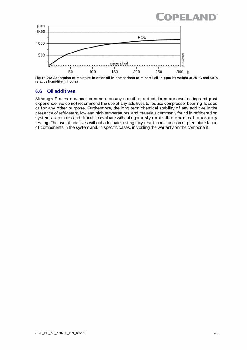
AGL_HP_ST_ZHK1P_EN_Rev00 31
Figure 26: Absorption of moisture in ester oil in comparison to mineral oil in ppm by weight at 25 °C and 50 % relative humidity (h=hours)
6.6 Oil additives
Although Emerson cannot comment on any specif ic product, f rom our own testing and past experience, we do not recommend the use of any additives to reduce compressor bearing losses or for any other purpose. Furthermore, the long term chemical stability of any additive in the presence of refrigerant, low and high temperatures, and materials commonly found in refrigerat ion systems is complex and difficult to evaluate without rigorously controlled chemical laboratory testing. The use of additives without adequate testing may result in malfunction or premature failure of components in the system and, in specific cases, in voiding the warranty on the component.
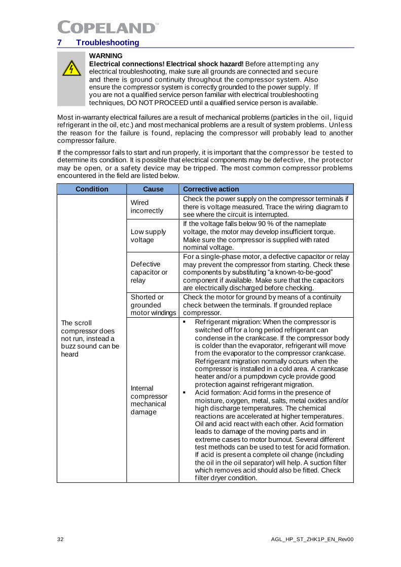
32 AGL_HP_ST_ZHK1P_EN_Rev00
7 Troubleshooting
WARNING Electrical connections! Electrical shock hazard! Before at tempt ing any electrical troubleshooting, make sure all grounds are connected and secure and there is ground continuity throughout the compressor system. Also ensure the compressor system is correctly grounded to the power supply. If you are not a qualified service person familiar with electrical troubleshooting techniques, DO NOT PROCEED until a qualified service person is available.
Most in-warranty electrical failures are a result of mechanical problems (particles in the oil , l iquid ref rigerant in the oil, etc.) and most mechanical problems are a result of system problems. Unless the reason for the failure is found, replacing the compressor will probably lead to another compressor failure.
If the compressor fails to start and run properly, it is important that the compressor be tested to determine its condition. It is possible that electrical components may be defective, the protector may be open, or a safety device may be tripped. The most common compressor problems encountered in the field are listed below.
Condition Cause Corrective action
The scroll compressor does not run, instead a buzz sound can be heard
Wired incorrectly
Check the power supply on the compressor terminals if there is voltage measured. Trace the wiring diagram to see where the circuit is interrupted.
Low supply voltage
If the voltage falls below 90 % of the nameplate voltage, the motor may develop insufficient torque. Make sure the compressor is supplied with rated nominal voltage.
Defective capacitor or relay
For a single-phase motor, a defective capacitor or relay may prevent the compressor from starting. Check these components by substituting “a known-to-be-good” component if available. Make sure that the capacitors are electrically discharged before checking.
Shorted or grounded motor windings
Check the motor for ground by means of a continuity check between the terminals. If grounded replace compressor.
Internal compressor mechanical damage
▪ Refrigerant migration: When the compressor is switched off for a long period refrigerant can condense in the crankcase. If the compressor body is colder than the evaporator, refrigerant will move f rom the evaporator to the compressor crankcase. Refrigerant migration normally occurs when the compressor is installed in a cold area. A crankcase heater and/or a pumpdown cycle provide good protection against refrigerant migration.
▪ Acid formation: Acid forms in the presence of moisture, oxygen, metal, salts, metal oxides and/or high discharge temperatures. The chemical reactions are accelerated at higher temperatures. Oil and acid react with each other. Acid formation leads to damage of the moving parts and in extreme cases to motor burnout. Several different test methods can be used to test for acid formation. If acid is present a complete oil change (including the oil in the oil separator) will help. A suction filter which removes acid should also be fitted. Check f ilter dryer condition.
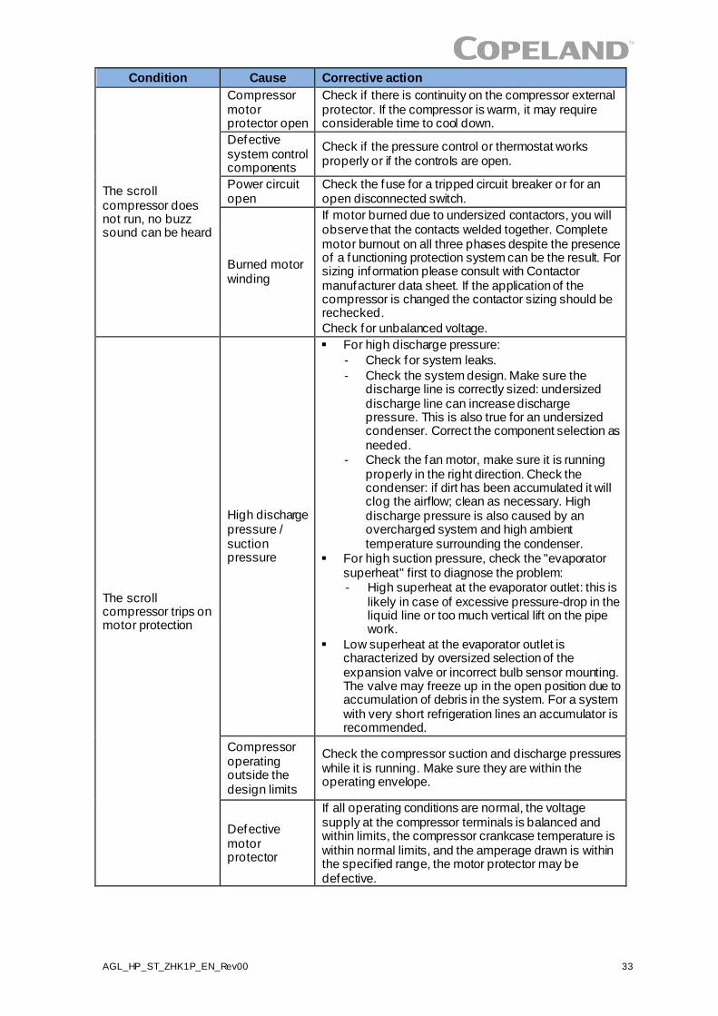
AGL_HP_ST_ZHK1P_EN_Rev00 33
Condition Cause Corrective action
The scroll compressor does not run, no buzz sound can be heard
Compressor motor protector open
Check if there is continuity on the compressor external protector. If the compressor is warm, it may require considerable time to cool down.
Defective system control components
Check if the pressure control or thermostat works properly or if the controls are open.
Power circuit open
Check the fuse for a tripped circuit breaker or for an open disconnected switch.
Burned motor winding
If motor burned due to undersized contactors, you will observe that the contacts welded together. Complete motor burnout on all three phases despite the presence of a functioning protection system can be the result. For sizing information please consult with Contactor manufacturer data sheet. If the application of the compressor is changed the contactor sizing should be rechecked.
Check for unbalanced voltage.
The scroll compressor trips on motor protection
High discharge pressure / suction pressure
▪ For high discharge pressure:
- Check for system leaks.
- Check the system design. Make sure the discharge line is correctly sized: undersized discharge line can increase discharge pressure. This is also true for an undersized condenser. Correct the component selection as needed.
- Check the fan motor, make sure it is running properly in the right direction. Check the condenser: if dirt has been accumulated it will clog the airflow; clean as necessary. High discharge pressure is also caused by an overcharged system and high ambient temperature surrounding the condenser.
▪ For high suction pressure, check the "evaporator superheat" first to diagnose the problem: - High superheat at the evaporator outlet: this is
likely in case of excessive pressure-drop in the liquid line or too much vertical lift on the pipe work.
▪ Low superheat at the evaporator outlet is characterized by oversized selection of the expansion valve or incorrect bulb sensor mounting. The valve may freeze up in the open position due to accumulation of debris in the system. For a system with very short refrigeration lines an accumulator is recommended.
Compressor operating outside the design limits
Check the compressor suction and discharge pressures while it is running. Make sure they are within the operating envelope.
Defective motor protector
If all operating conditions are normal, the voltage supply at the compressor terminals is balanced and within limits, the compressor crankcase temperature is within normal limits, and the amperage drawn is within the specified range, the motor protector may be defective.
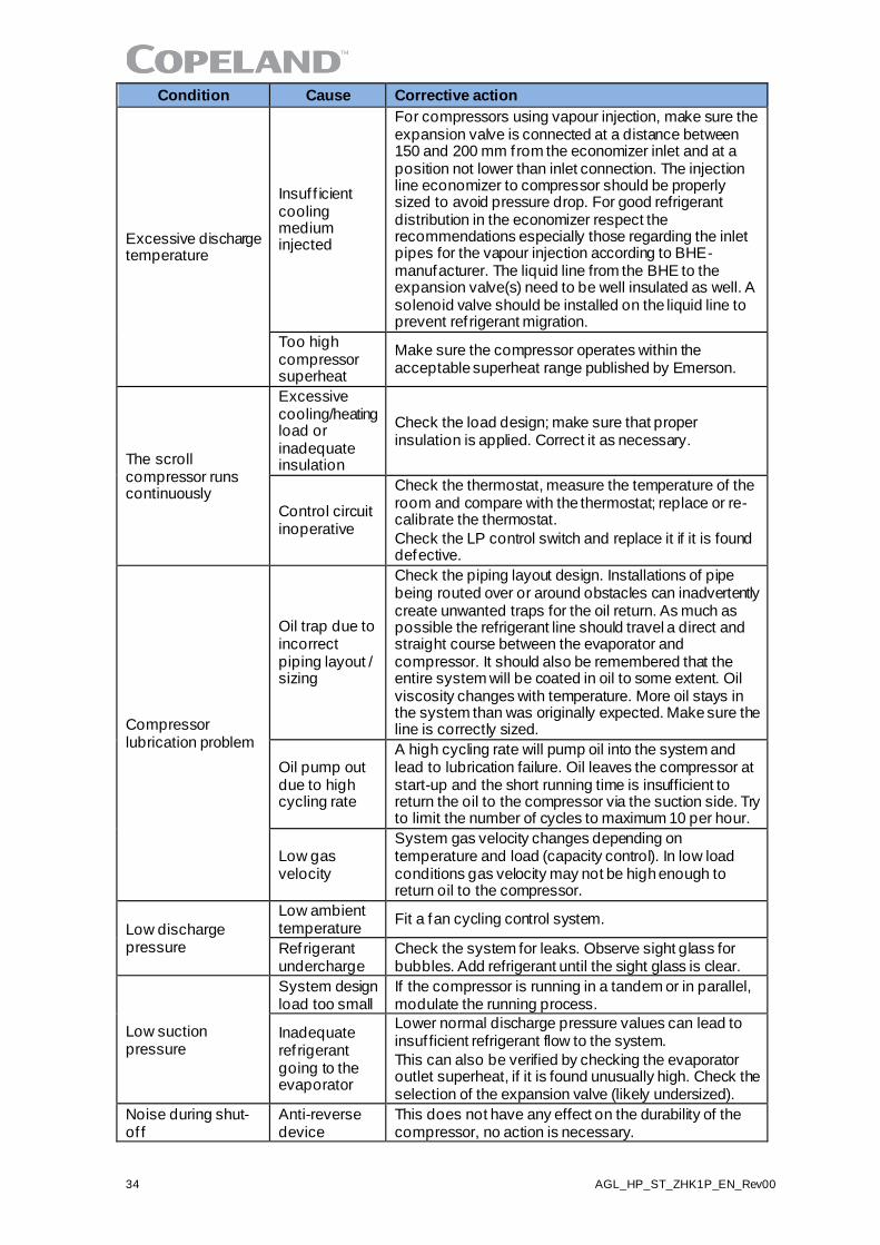
34 AGL_HP_ST_ZHK1P_EN_Rev00
Condition Cause Corrective action
Excessive discharge temperature
Insuf f icient cooling medium injected
For compressors using vapour injection, make sure the expansion valve is connected at a distance between 150 and 200 mm from the economizer inlet and at a position not lower than inlet connection. The injection line economizer to compressor should be properly sized to avoid pressure drop. For good refrigerant distribution in the economizer respect the recommendations especially those regarding the inlet pipes for the vapour injection according to BHE-manufacturer. The liquid line from the BHE to the expansion valve(s) need to be well insulated as well. A solenoid valve should be installed on the liquid line to prevent ref rigerant migration.
Too high compressor superheat
Make sure the compressor operates within the acceptable superheat range published by Emerson.
The scroll compressor runs continuously
Excessive cooling/heating load or inadequate insulation
Check the load design; make sure that proper insulation is applied. Correct it as necessary.
Control circuit inoperative
Check the thermostat, measure the temperature of the room and compare with the thermostat; replace or re-calibrate the thermostat.
Check the LP control switch and replace it if it is found defective.
Compressor lubrication problem
Oil trap due to incorrect piping layout / sizing
Check the piping layout design. Installations of pipe being routed over or around obstacles can inadvertently create unwanted traps for the oil return. As much as possible the refrigerant line should travel a direct and straight course between the evaporator and compressor. It should also be remembered that the entire system will be coated in oil to some extent. Oil viscosity changes with temperature. More oil stays in the system than was originally expected. Make sure the line is correctly sized.
Oil pump out due to high cycling rate
A high cycling rate will pump oil into the system and lead to lubrication failure. Oil leaves the compressor at start-up and the short running time is insufficient to return the oil to the compressor via the suction side. Try to limit the number of cycles to maximum 10 per hour.
Low gas velocity
System gas velocity changes depending on temperature and load (capacity control). In low load conditions gas velocity may not be high enough to return oil to the compressor.
Low discharge pressure
Low ambient temperature
Fit a fan cycling control system.
Refrigerant undercharge
Check the system for leaks. Observe sight glass for bubbles. Add refrigerant until the sight glass is clear.
Low suction pressure
System design load too small
If the compressor is running in a tandem or in parallel, modulate the running process.
Inadequate ref rigerant going to the evaporator
Lower normal discharge pressure values can lead to insuf ficient refrigerant flow to the system.
This can also be verified by checking the evaporator outlet superheat, if it is found unusually high. Check the selection of the expansion valve (likely undersized).
Noise during shut-of f
Anti-reverse device
This does not have any effect on the durability of the compressor, no action is necessary.
AGL_HP_ST_ZHK1P_EN_Rev00 35
8 Dismantling & disposal
Removing oil and refrigerant:
▪ Do not disperse in the environment. ▪ Use the correct equipment and method of removal. ▪ Dispose of oil and refrigerant in accordance with national legislation and regulations.
Dispose of compressor in accordance with national legislation and regulations.
9 References
Please visit www.climate.emerson.com/en-gb for free download of Application Guidelines and Technical Information. Performance and technical data: The latest version of Copeland Select sof tware with performance data and technical data is available from the webpage www.climate.emerson.com/en-gb. Spare parts and accessories:
An online version of the Emerson spare parts and accessories software is available f rom the webpage www.climate.emerson.com/en-gb/tools-resources.
DISCLAIMER
1. The contents of this publication are presented for informational purposes only and are not to be construed as warranties or guarantees, express or implied, regarding the products or services described herein or their use or applicability.
2. Emerson Climate Technologies GmbH and/or its af f iliates (collectively "Emerson"), as applicable, reserve the right to modify the design or specifications of such products at any time without notice.
3. Emerson does not assume responsibility for the selection, use or maintenance of any product . Responsibility for proper selection, use and maintenance of any Emerson p roduct remains solely with the purchaser or end user.
4. Emerson does not assume responsibility for possible typographic erro rs contained in this publication.
AGL_
HP_
ST_Z
HK1
P_EN
_Rev
00
BENELUXJosephinastraat 19NL-6462 EL KerkradeTel: +31 45 535 06 73Fax: +31 45 535 06 [email protected]
UK & IRELANDUnit 17, Theale Lakes Business ParkReading, Berkshire RG7 4GB Tel: +44 1189 83 80 00Fax: +44 1189 83 80 [email protected]
BALKANSelska cesta 93HR-10 000 ZagrebTel: +385 1 560 38 75Fax: +385 1 560 38 79
GERMANY, AUSTRIA & SWITZERLANDTheo-Mack Str. 3DE-63477 MaintalTel: +49 6109 605 90Fax: +49 6109 60 59 [email protected]
SWEDEN, DENMARK, NORWAY & FINLANDPascalstr. 65DE-52076 AachenTel: +49 2408 929 0Fax: +49 2408 929 [email protected]
FRANCE, GREECE & MAGHREB8, Allée du Moulin BergerFR-69134 Ecully Cédex, Technoparc - CS 90220Tel: +33 4 78 66 85 70Fax: +33 4 78 66 85 [email protected]
EASTERN EUROPE & TURKEYPascalstr. 65DE-52076 AachenTel: +49 2408 929 0Fax: +49 2408 929 [email protected]
ROMANIA & BULGARIAParcul Industrial Tetarom 2 Emerson Nr. 4 400641 Cluj-NapocaTel: +40 374 13 23 50Fax: +40 374 13 28 [email protected]
ITALYVia Ramazzotti, 26IT-21047 Saronno (VA)Tel: +39 02 96 17 81Fax: +39 02 96 17 88 [email protected]
POLANDul. Konstruktorska 13PL-02673 WarsawTel: +48 22 458 92 05Fax: +48 22 458 92 [email protected]
MIDDLE EAST & AFRICAPO Box 26382Jebel Ali Free Zone - South, Dubai - UAETel: +971 4 811 81 00Fax: +971 4 886 54 [email protected]
ASIA PACIFICSuite 2503-8, 25/F., Exchange Tower33 Wang Chiu Road, Kowloon BayKowloon , Hong KongTel: +852 2866 3108Fax: +852 2520 6227
CZECH REPUBLICHajkova 22 CZ - 133 00 Prague Tel: +420 733 161 651Fax: +420 271 035 [email protected]
SPAIN & PORTUGALC/ Pujades, 51-55 Box 53ES-08005 BarcelonaTel: +34 93 412 37 [email protected]
RUSSIA & CISDubininskaya 53, bld. 5, 4th floorRU-115054, MoscowTel: +7 499 403 64 [email protected]
For more details, see www.climate.emerson.com/en-gb
The Emerson logo is a trademark and service mark of Emerson Electric Co. Emerson Climate Technologies Inc. is a subsidiary of Emerson Electric Co.Copeland is a registered trademark and Copeland Scroll is a trademark of Emerson Climate Technologies Inc.. All other trademarks are property of their respective owners.Emerson Climate Technologies GmbH shall not be liable for errors in the stated capacities, dimensions, etc., as well as typographic errors. Products, specifications, designs and technical data contained in this document are subject to modification by us without prior notice. Illustrations are not binding.
© 2019 Emerson Climate Technologies, Inc.
Emerson Commercial & Residential SolutionsEmerson Climate Technologies GmbH - Pascalstrasse 65 - 52076 Aachen, GermanyTel. +49 (0) 2408 929 0 - Fax: +49 (0) 2408 929 570 - Internet: www.climate.emerson.com/en-gb
Connect with us: facebook.com/EmersonCommercialResidentialSolutions