TURBINES AND COMPRESSORS BHEL, HYDERABAD
94
` Annexure-A to purchase specification TC54367 R06 TURBINES AND COMPRESSORS BHEL, HYDERABAD Page 1 of 1 Rev. No. Revisions Prepared: Reviewed: Approved Date 00 Issue ANSHUL Sunil B J Prafulla 24.03.2022 COPYRIGHT AND CONFIDENTIAL The information on this document is the property of BHARAT HEAVY ELECTRICALS LIMITED. It must not be used directly or indirectly in any way detrimental to the interest of the company. TD-106-1 Rev. 5 Form No. Ref. Doc. COMP. FILE NAME TC 5 4362-R00 PRICE SCHEDULE Enquiry ref. No: Date: Offer ref no. Date: Sl. No Description 1 Set =? Qty Unit Price 01 Oil Centrifuge Assy consists of a) OIL PURF. SKID 2400LPH-COMP SS-DCS Mat code TC9754367450 --- 10 Nos b) TERMINAL PLATE FOR ALL OPU MOTORS Mat code TC9754367469 10 Set c) BEARINGS DE & NDE ALL OPU MTR Mat Code TC9754367302 Vendor specific 20 Set d) SPARE IE2 MTR FOR CENTRIFUGE AND PUMP Mat code TC9754367280 2 motors 20 Set e) Cooling Fan for all OPU motors Mat code: TC9754367361 20 Set f) End shield cover for all OPU motors Mat code: TC9754367191 20 Set 02 Type test of one no of Oil Purification unit as per approved test procedure 2 No. NOTE: 1. Only Sl. No 01, 02 is to be considered for price evaluation 2. Any additional requirements, which are essential for proper functioning of Oil Centrifuge but not indicated in specification, are included in the main offer. Vendor’s Signature Vendor’s Company seal
-
Upload
khangminh22 -
Category
Documents
-
view
3 -
download
0
Transcript of TURBINES AND COMPRESSORS BHEL, HYDERABAD

`
Annexure-A to purchase specification TC54367 R06
TURBINES AND COMPRESSORS
BHEL, HYDERABAD Page 1 of 1
Rev. No. Revisions Prepared: Reviewed: Approved Date
00 Issue ANSHUL Sunil B J Prafulla 24.03.2022
CO
PY
RIG
HT
AN
D C
ON
FID
EN
TIA
L
Th
e in
form
atio
n o
n t
his
docum
ent
is the p
ropert
y o
f B
HA
RA
T H
EA
VY
ELE
CT
RIC
ALS
LIM
ITE
D.
It m
ust
not
be u
sed d
irectly o
r in
directly in
any w
ay d
etr
ime
nt a
l to
the in
tere
st of th
e c
om
pany.
TD
-106-1
R
ev.
5
Fo
rm N
o.
Ref.
Doc.
C
OM
P. F
ILE
NA
ME
TC
5 4
362-R
00
PRICE SCHEDULE Enquiry ref. No: Date: Offer ref no. Date:
Sl.
No Description
1 Set =? Qty Unit Price
01 Oil Centrifuge Assy consists of
a) OIL PURF. SKID 2400LPH-COMP SS-DCS Mat code TC9754367450
--- 10 Nos
b) TERMINAL PLATE FOR ALL OPU MOTORS
Mat code TC9754367469 10 Set
c) BEARINGS DE & NDE ALL OPU MTR
Mat Code TC9754367302 Vendor
specific
20 Set
d) SPARE IE2 MTR FOR CENTRIFUGE AND PUMP
Mat code TC9754367280 2 motors 20 Set
e) Cooling Fan for all OPU motors
Mat code: TC9754367361
20 Set
f) End shield cover for all OPU motors
Mat code: TC9754367191
20 Set
02 Type test of one no of Oil Purification unit as per approved test
procedure
2 No.
NOTE:
1. Only Sl. No 01, 02 is to be considered for price evaluation
2. Any additional requirements, which are essential for proper functioning of Oil Centrifuge but not
indicated in specification, are included in the main offer.
Vendor’s Signature Vendor’s Company seal

15) Redundant feeder for power shall be provided.Clean oil and dirty oil pump are provided for TDBFP purifier
SHEET 2 OF 4 REV 04
28.01.19
28.01.19
28.01.19
28.01.19

WRITE UP ON OIL PURIFICATION SYSTEM
Page 1
Ref: Purification oil system P&I Diagram 9962-110-PVM-F-003
FUNCTIONFUNCTIONFUNCTIONFUNCTION
During the course of operation lube oil circulated in the system may contain particles/sediments and
moisture content from the gland seal. The sediment and moisture can hamper the condition of
turbine bearings. To maintain the quality of oil circulated in the system for lubrication of bearings
conditioning has to be carried out one shift a day.
The system shall remove moisture from the oil (1.5% by volume) so that the oil at the outlet of
purifying system does not contain any free moisture. . All suspended particles shall be removed down
to maintain the impurities within permissible limits conforming to grade 15/12 as per ISO 4406
when oil temp is 65°C. This will be demonstrated with inlet oil quality confirming to code 21/18 as
per ISO: 4406. Moisture less than 500 ppm for an inlet ppm of 15000.
SYSTEM DESCIPTIONSYSTEM DESCIPTIONSYSTEM DESCIPTIONSYSTEM DESCIPTION
The oil purification unit will handle turbine oil (Servo prime 46 of IOC make). The oil purifier will
be located on the ground floor below the oil level in the Turbine oil tank. The purification process
will operate on a by-pass system, handling complete oil of the lube oil system of TDBFP & will be
working one shift a day(8 Hrs) while the turbine is running. A dirty oil pump (having capacity 10%
higher than purifying unit) will draw the lubricating oil from the Turbine oil tank & send it to the
centrifuge through the oil heater . Similarly one clean oil pump (having capacity 10% higher than
purifying unit) will deliver the purified oil back to the turbine oil tank through the polishing filter.
Main parts of Oil Purification unitMain parts of Oil Purification unitMain parts of Oil Purification unitMain parts of Oil Purification unit
Centrifuge Bowl
A suitable vertical centrifuge made of high grade stainless steel will carry out primary separation of
the impurities in the lubrication oil. Heavier phase discharge from the centrifuge (Mainly water) will
go to waste through a small tank, level of which may be utilized for signalizing flooding of centrifuge
due to loss of water seal or due to clogging in the heavy phase drain pipe or in the event of excessive
water in the oil.
Oil Heater
Turbine oil will be heated up to the necessary centrifuging temperature by passing it through an
electric heater located immediately upstream of the centrifuge. The heater will be indirect type, in
which the electric immersion heater elements are used to heat a batch of water, which in turn heats
the oil passing through the coils immersed in this bath. Heater will be cut in steps.

WRITE UP ON OIL PURIFICATION SYSTEM
Page 2
Feed and Booster Pump
The pumps shall be of positive displacement type complete with necessarily relief valves at the
discharge. Each pump shall be having capacity 10% higher than the purifying unit capacity. The
motor shall be sized 1.25 times of shaft BKW of the pump & centrifuge.
Polishing Filter
The purified oil coming out of the centrifuge bowl shall pass through a polishing filter capable of
handling the required output before returning it to the turbine oil tank. This filter shall eliminate all
suspended solids down to maintain the impurities within permissible limits conforming to grade
15/12 as per ISO 4406 when oil temperature is 65°C.
Interconnecting pipes and valves
All pipes and valves will be of Stainless steel material.
CONTROLS, INSTRUMENTATION AND PANELS:
The oil purification plant shall be complete with all the instruments and controls, for efficient
operation of the plant. The various instruments, control lamps, enunciators etc will be brought to a
control panel on a common skid mounting. The panel will be complete with all wiring tubing and the
various instruments and switches will be displaced on it in a neat manner.
The following interlocks are provided in the panel
1) Liquid seal breakage alarm / trip
2) High oil & heater temperature alarm / heater trip
3) Centrifuge and booster pump motor over load trip
4) Low oil temperature alarm
5) Low heater water level alarm / heater trip
6) Open Bowl/separator Cover
7) Polishing filter choke-up alarm trip
As per the standard practice, necessary provision shall be provided in control panel to enable off
control of Oil purification unit through DCS/control room.

1
a) Name, address, e-mail id, contact no.etc. of manufacturer of enquiry item
i Application: Lube Oil System
ii) Proven track Record of equipment:
Enquiry item shall be identical and similar in terms of flow, Operating pressure, Mechanical
Design, Materials etc as compared to at least TWO unit of the proposed model designed,
engineered, manufactured, tested and supplied from the proposed manufacturing plant in the
last TEN years and the reference unit shall have completed ONE year of satisfactory operation at
site as on bid due date.
iii) All the facilities reqired for manufacturing and testing of Enquiry Item as per applicable
standards shall be available with manufacturer.
iv) Vendor shall furnish the details of Service after Sale facilities available in India with references of
executed project.
Spare shall be readily available at propretary suppliers/ distributors in India.
4
5
6
7
BHEL RequirementVendor’s
ConfirmationDeviation, if any Remarks
PRE-QUALIFICATION CRITERIA
All the suppliers need to submit this document i.e. titled pre-qualification criteria and
furnish required information along with offer.
Enquiry Items of Lube Oil System
S.No.
2
b) Name, address, e-mail id, contact no.etc. of authourised agency / trading house quoting on
behalf of manufacturer
In case offer is received from authourised agency / trading house, the following requirements
shall be full filled.
i) Valid letter of authorisation and copy of agreement to be enclosed with offer.
ii) The offer shall be either from the authorised agency or from the manufacturer directly. In
case of BHEL receiving offer from both, then offer from manufaturer will only be considered.
Offer from an unauthorised agency / entity on behalf of any vendor shall be summarily rejected.
iii) Name, address, e-mail id, contact no.etc. of entity on whom order to be released in case of L1
shall be clearly indicated.
3 Supplier to confirm/provide the following criteria/documents for evaluation of offer.
(a) The supplier should have the proven experience in manufacturing and supply of offered model as
per enquiry requirement.
All the above criteria 3(a) (i) to 3(a) (iv) must be combinedly met by the vendor against a single supply
reference.
(b) The supplier meeting all the above criteria as per clause 3 (a), shall furnish details of such supplies
in the annexure II (Proven Track Record). Suppliers shall furnish up to 03 numbers of latest customer
reference details.
Note : Details furnished in any other format shall not be considered.
All the documents shall be furnished only in English. Documents furnished in other langauges will not
be considered for further evaluation.
(c) BHEL reserves the right to cross verify with the above such customers including overseas
customers with a copy to the supplier and satisfy itself with reference to the claims of the supplier. If
the information furnished by the supplier is not found satisfactory, the offer will be technically
rejected.
Vendors to submit their bid in 2 - part system i.e.
Part-I shall consists of Pre-Qualification Criteria along with the required documents and Techno-
Commercial Bid.Vendor shall submit duly filled supplier questionarie.
Part-II shall consists of Price Bid. Offers failing to meet prequalification part will not be considered for
further evaluation.
(d) 1. vendor details, i.e. name, address, BHEL/EIL/IOCL/Consulatnt/ Customer enlistment
letter.
2. One PTR of compressor to be provided by BHEL indicating that the items have been
procured from proposed vendors and supply has been completed. PTR shall include
the following minimum:
- Approved GAD and BOM indicating item details and vendor details.
- Unpriced PO copy issued by BHEL to the vendors for the listed items.
- IRN copy of compressor.The vendors should furnish the detailed process of manufacturing and testing procedures along with
the offer.
List of BHEL qualified bidders shall be forwarded to BHEL's End Customer for their review and
approval. The list finalized by BHEL's End Customer shall be final and binding.
BHEL team may carry out vendor evaluation/assesment(incase of a new vendor)by a visit to vendor
works for qualifying /rejecting the technical bid based on the findings of the visit.
Page 1 of 1 Vendor's Signature with Seal
PRODUCT STANDARD INDUSTRIAL TURBINES & COMPRESSORS
TC 54367
Rev. No. : 06
Page 1 of 34
CO
PY
RIG
HT
AN
D C
ON
FID
EN
TIA
L
Th
e in
form
atio
n o
n t
his
do
cum
ent
is t
he
pro
per
ty o
f B
HA
RA
T H
EA
VY
EL
EC
TR
ICA
LS
LIM
ITE
D.
It m
ust
no
t b
e u
sed
dir
ectl
y o
r in
dir
ectl
y i
n a
ny
way
det
rim
enta
l to
th
e in
tere
st o
f th
e co
mp
any
.
TD
-10
6. –
2
Rev
. N
o.
: 5
Fo
rm N
o.
:
TURBINE OIL PURIFICATION PLANT
FIXED TYPE FOR BFPDT
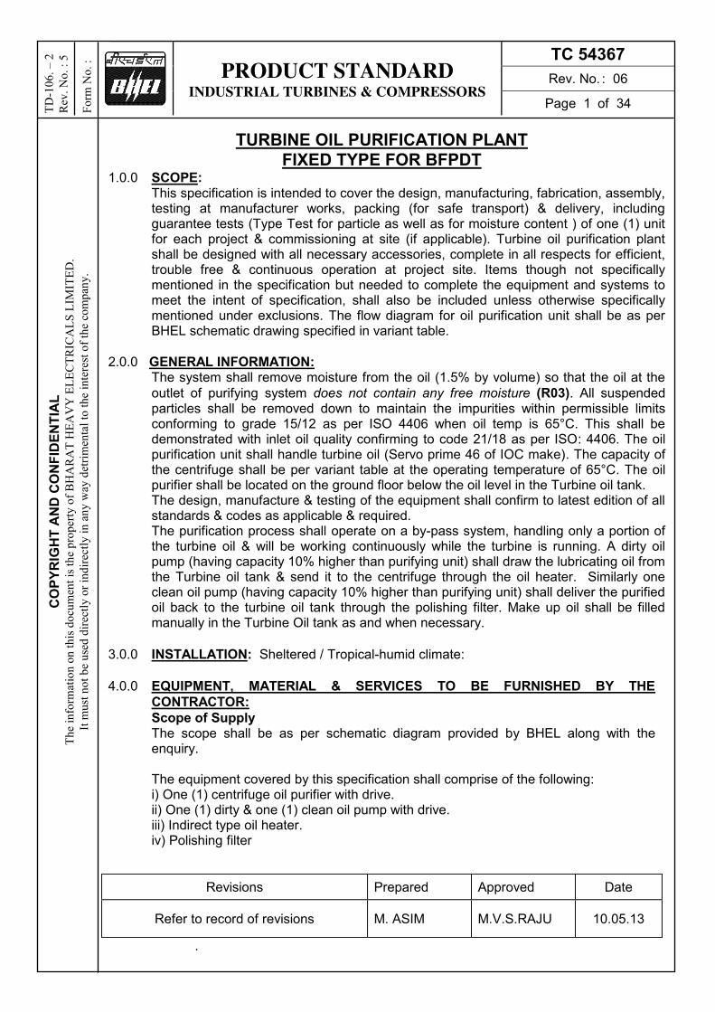
1.0.0 SCOPE: This specification is intended to cover the design, manufacturing, fabrication, assembly, testing at manufacturer works, packing (for safe transport) & delivery, including guarantee tests (Type Test for particle as well as for moisture content ) of one (1) unit for each project & commissioning at site (if applicable). Turbine oil purification plant shall be designed with all necessary accessories, complete in all respects for efficient, trouble free & continuous operation at project site. Items though not specifically mentioned in the specification but needed to complete the equipment and systems to meet the intent of specification, shall also be included unless otherwise specifically mentioned under exclusions. The flow diagram for oil purification unit shall be as per BHEL schematic drawing specified in variant table.
2.0.0 GENERAL INFORMATION: The system shall remove moisture from the oil (1.5% by volume) so that the oil at the
outlet of purifying system does not contain any free moisture (R03). All suspended particles shall be removed down to maintain the impurities within permissible limits conforming to grade 15/12 as per ISO 4406 when oil temp is 65°C. This shall be demonstrated with inlet oil quality confirming to code 21/18 as per ISO: 4406. The oil purification unit shall handle turbine oil (Servo prime 46 of IOC make). The capacity of the centrifuge shall be per variant table at the operating temperature of 65°C. The oil purifier shall be located on the ground floor below the oil level in the Turbine oil tank. The design, manufacture & testing of the equipment shall confirm to latest edition of all standards & codes as applicable & required. The purification process shall operate on a by-pass system, handling only a portion of the turbine oil & will be working continuously while the turbine is running. A dirty oil pump (having capacity 10% higher than purifying unit) shall draw the lubricating oil from the Turbine oil tank & send it to the centrifuge through the oil heater. Similarly one clean oil pump (having capacity 10% higher than purifying unit) shall deliver the purified oil back to the turbine oil tank through the polishing filter. Make up oil shall be filled manually in the Turbine Oil tank as and when necessary.
3.0.0 INSTALLATION: Sheltered / Tropical-humid climate:
4.0.0 EQUIPMENT, MATERIAL & SERVICES TO BE FURNISHED BY THE
CONTRACTOR:
Scope of Supply The scope shall be as per schematic diagram provided by BHEL along with the enquiry.
The equipment covered by this specification shall comprise of the following:
i) One (1) centrifuge oil purifier with drive. ii) One (1) dirty & one (1) clean oil pump with drive. iii) Indirect type oil heater. iv) Polishing filter
.
Revisions Prepared Approved Date
Refer to record of revisions M. ASIM M.V.S.RAJU 10.05.13

PRODUCT STANDARD INDUSTRIAL TURBINES & COMPRESSORS
TC 54367
Rev. No. : 06
Page 2 of 34
CO
PY
RIG
HT
AN
D C
ON
FID
EN
TIA
L
Th
e in
form
atio
n o
n t
his
do
cum
ent
is t
he
pro
per
ty o
f B
HA
RA
T H
EA
VY
EL
EC
TR
ICA
LS
LIM
ITE
D.
It m
ust
no
t b
e u
sed
dir
ectl
y o
r in
dir
ectl
y i
n a
ny
way
det
rim
enta
l to
th
e in
tere
st o
f th
e co
mp
any
.
TD
-10
6. –
2
Rev
. N
o.
: 5
Fo
rm N
o.
:
v) All controls, instruments, control wiring, power cables inside the plant including the control panel.
vi) Common fabricated base plate for entire plant with anchor bolts, sleeves, parts to be embedded in concrete. However, the owner as per the requirement of the contractor shall furnish equipment foundation.
vii) Armored cable 1.5 mm2 x 3 core with plug socket of 20 M length viii) Suitable lifting and handling arrangement for the centrifuge, filter, tank, pumps
etc. ix) One set of special erection & maintenance tools. (List of erection and maintenance
tools to be furnished by supplier at offer stage) x) Commissioning spares (List of Commissioning spares to be furnished by supplier
at offer stage) xi) First Fill of Consumable, Oils and Lubricants (List of Consumable, oils & lubricants
to be furnished by supplier at offer stage) xii) Loose supply items which are supplied along with purification unit with proper
identification. xiii) Foundation items for fixing the purification unit. (Anchor bolts, sleeves etc.) xiv) One spare filter element for polishing filter. xv) Two nos. of spare flat belt. xvi) Spare 1 set of Gasket & O-rings as applicable. xvii) Conversion spare from purifier to clarifier.
4.1.0 SPARE PARTS: Complete list of spare parts recommended by the manufacturer for Three years operation with itemized list and quantity shall be submitted with the proposal for the total system. List of spare parts along with their drawing and catalogues and procedure for ordering spares shall be listed in O& M manuals.
4.2.0 COMMISSIONING (if Applicable): Vendor to quote commissioning charges along with offer. The rate should be per day basis.
5.0.0 DESIGN & CONSTRUCTION::
General: The design, manufacture & testing of the equipment shall conform to latest edition of all standards & codes, as applicable & required. All the pressure piping shall be designed & constructed in accordance with ANSI standard B 31.1 for Pressure piping. The material shall be SS300 series. Each line size is to be specified in schematic diagram provided by vendor. Line size calculations shall be furnished for our review. All materials issued shall be new & of tested quality & first class in all respects.
5.1.0 CENTRIFUGE:
1) A suitable vertical centrifuge shall carry out primary separation of the impurities in the lubrication oil. The centrifuge bowl shall be of separator type having ample size to give the required optimum performance. It shall be vapor tight type construction to prevent oil fumes of vapors from escaping into turbine room. Heavier phase discharge from the centrifuge (Mainly water) shall go to waste through a small tank, level of which may be utilized for signalizing flooding of centrifuge due to loss of water seal or due to clogging in the heavy phase drain pipe or in the event of excessive water in the oil.

PRODUCT STANDARD INDUSTRIAL TURBINES & COMPRESSORS
TC 54367
Rev. No. : 06
Page 3 of 34
CO
PY
RIG
HT
AN
D C
ON
FID
EN
TIA
L
Th
e in
form
atio
n o
n t
his
do
cum
ent
is t
he
pro
per
ty o
f B
HA
RA
T H
EA
VY
EL
EC
TR
ICA
LS
LIM
ITE
D.
It m
ust
no
t b
e u
sed
dir
ectl
y o
r in
dir
ectl
y i
n a
ny
way
det
rim
enta
l to
th
e in
tere
st o
f th
e co
mp
any
.
TD
-10
6. –
2
Rev
. N
o.
: 5
Fo
rm N
o.
:
2) The rotating assembly of the centrifuge unit shall be carefully balanced to minimize unbalance and shaft vibration while operating at the rated speed. The centrifuge bearings shall be designed for at least 25000 Hrs of continuous operation. All influent lubricating oil contact parts of the purifier shall be made of high grade stainless steel AISI-316 or equivalent. The bowl shall be assembled and dispatched. Sufficient care to be taken to avoid any transit damage to the bowl assembly.
3) Centrifuge shall be assembled as a single unit and shall be ready to use. The inlet & outlet connection with counter flanges shall be as per ANSI B16.5 and the size is in-line with the schematic diagram provided by BHEL along with enquiry.
4) Centrifuge shall be supplied as purifier assembly.
5) Conversion spare from purifier to clarifier is part of equipment & should be supplied along with centrifuge unit.
5.2.0 OIL HEATER:
1) Turbine oil shall be heated up to the necessary centrifuging temperature by passing it through an electric heater located immediately upstream of the centrifuge. The heater shall be indirect type, in which the electric immersion heater elements are used to heat a batch of water, which in turn heats the oil passing through the coils immersed in this bath. Heater shall be cut in cut off type. The oil shall be heated to 65°C in one pass through heater (Min temp at inlet of
heater 35°C) (R03)
2) The heating elements shall be readily accessible for inspection and easily removable for maintenance or replacement.
5.3.0 DIRTY AND CLEAN OIL PUMPS: The pumps shall be of positive displacement type complete with necessarily relief valves at the discharge. Each pump shall be having capacity 10% higher than the purifying unit capacity. The motor shall be sized 1.25 times of shaft BKW of the pump & centrifuge, and the motor rating shall be considered as per IS 325. Suction temp. of fluid handled : 65oC (Normal Operation) -Oil Viscosity 18 cst
: 10oC (During starting)- Oil Viscosity 280 cst Suction head : Atmospheric (Flooded suction)
The design of the pumps shall be as per standards of "Hydraulic Institute of USA" or approved equivalent. The materials for various components shall be as recommended in the standard. The casing and base plate shall be of cast iron construction, the rotor and shaft shall be of carbon steel. High tensile steel bolts and
nuts shall be used for the casing.(R03)
5.4.0 POLISHING FILTER:
1) The purified oil coming out of the centrifuge shall pass through a polishing filter capable of handling the required output before returning it to the turbine oil tank. This filter shall eliminate all suspended solids down to maintain the impurities within permissible limits conforming to grade 15/12 as per ISO 4406 when oil temperature is 65°C. Vapor cloud in the oil by stripping action. It shall not
however remove any rust inhibitor or oxidation inhibitor in the process.
The particles size rating at outlet of filter shall not be more than 3 microns. Furnish
beta efficiency of filter element. (R03)
2) One spare filter element shall be provided along with oil purification unit.
3) The filter vessel shall be designed for the maximum working pressure and fabricated in accordance with the ASME code for unfiltered pressure vessel. It

PRODUCT STANDARD INDUSTRIAL TURBINES & COMPRESSORS
TC 54367
Rev. No. : 06
Page 4 of 34
CO
PY
RIG
HT
AN
D C
ON
FID
EN
TIA
L
Th
e in
form
atio
n o
n t
his
do
cum
ent
is t
he
pro
per
ty o
f B
HA
RA
T H
EA
VY
EL
EC
TR
ICA
LS
LIM
ITE
D.
It m
ust
no
t b
e u
sed
dir
ectl
y o
r in
dir
ectl
y i
n a
ny
way
det
rim
enta
l to
th
e in
tere
st o
f th
e co
mp
any
.
TD
-10
6. –
2
Rev
. N
o.
: 5
Fo
rm N
o.
:
shall be provided with a small relief valve to protect from over pressure due to thermal expansion etc.
Interconnecting pipes and valves (R03) All relief valves shall be provided with hand levers to permit manual operation. Strainers with stainless steel elements shall be provided. Screen (R04) Opening area shall be at least four times the pipe cross-sectional area. Material of construction of interconnecting piping shall be complete Stainless steel.
MOC of valve material shall be as per material code description in variant table.(R06)
5.5.0 DRIVE MOTOR: General specification for the Electrical drive motor shall be as per BHEL specification
TC54368 for IE2 motor and TC54373 for IE3 motor (R01) or as per specification mentioned in enquiry.
5.6.0 CONTROLS, INSTRUMENTATION AND PANELS: 1) The oil purification plant shall be complete with all the instruments and controls, for
efficient operation of the plant. The various instruments, control lamps, enunciators etc shall be brought to a control panel on a common skid mounting. The panel shall be complete with all wiring tubing and the various instruments and switches shall be displaced on it in a neat manner. The make of the instruments shall be as per Customer/ BHEL “A” class approved vendor directory. Vendor shall select the sub-vendors strictly as per clause 13.00 of this specification. However, project specific vendor list is final.
2) The following interlocking arrangement shall be provided.
i) The inlet valve to the centrifuge unit shall be solenoid operated and shall be interlocked with a level switch on the anti flood tank. In the event of the flooding of the centrifuge the interlock shall operate to close the inlet solenoid valve automatically and the same time to trip the motor of the pumping unit and centrifuge. Flooding of the centrifuge may be caused by any one of the following malfunctions. 1. Loss of water seal of centrifuge causing over flow of oil to the anti flood tank. 2. Presence of excessive water in the oil, which may cause insufficient
separation of oil. This can be sensed by a rise in water level in the anti flood tank.
3. Clogging of the heavy phase drain pipe and possible over flow of water to the light Phase section. This can also be sensed from a raise in anti flood tank water level.
ii) In case the centrifuge drive is belt operated, a belt failure limit switch shall be
provided which will initiate closing of the inlet solenoid valve and tripping of the centrifuge and pump motors in the event of belt failure.
iii) The heating element of the heater shall be switched off in the event of low water level in the heater.
iv) Two numbers of thermostats are to be mounted on the oil piping downstream of each electric heater. The thermostats shall operate in its differential temperature for suitable for best separation. Dirty and clean oil pump trip due to over load and flooding of centrifuge shall also be provided.
v) Prevention mechanism shall be made to prevent mixing of oil in water line

PRODUCT STANDARD INDUSTRIAL TURBINES & COMPRESSORS
TC 54367
Rev. No. : 06
Page 5 of 34
CO
PY
RIG
HT
AN
D C
ON
FID
EN
TIA
L
Th
e in
form
atio
n o
n t
his
do
cum
ent
is t
he
pro
per
ty o
f B
HA
RA
T H
EA
VY
EL
EC
TR
ICA
LS
LIM
ITE
D.
It m
ust
no
t b
e u
sed
dir
ectl
y o
r in
dir
ectl
y i
n a
ny
way
det
rim
enta
l to
th
e in
tere
st o
f th
e co
mp
any
.
TD
-10
6. –
2
Rev
. N
o.
: 5
Fo
rm N
o.
:
vi) The system of annunciating the loss of water seal, plugging of polishing filter, over load trip of centrifuge drive and over load trip of electric heaters shall be provided with a visual alarm as well.
vii) The heater circuit shall be interlocked with pump motor circuits to shut off the
heaters when the pumps are not being operated. (R03) viii) The following interlocks are provided in the panel
1) Liquid seal breakage alarm / trip 2) High oil & heater temperature alarm / heater trip 3) Centrifuge and booster pump motor over load trip 4) Low oil temperature alarm 5) Low heater water level alarm / heater trip 6) Open Bowl/separator Cover 7) Polishing filter choke-up alarm trip Necessary provision shall be provided in control panel to enable on-off control of Oil purification unit through DCS/control room. Parameter like oil temp display, anti-flood tank level high, filter choking and feed pump on shall be
provided from DCS.(R06)
Refer attached C&I customer specification. Annex 1
3) Power Supplies: Redundant power packs/ supplies for powering the control systems.
4) Electric Power Supply System: 1. Sets of Microprocessor based modular 24VDC power supply system shall be
used for powering the control systems including its network devices. 2. Supplier shall provide power supply distribution panes / cabinets for sub-
distribution of Main UPS/ utility feeders on as required basis. The power supply distribution box shall included change over circuitry switch fuse units, MCBs. Terminal blocks etc. suitable for application.
3. The control system shall perform all functions such as auto / manual operation
of valves, pumps, drives, local / remote selection of operation, status indication, annunciation, interlock and protection of pumps/ drives etc. For successful implementation of the same, the contractor shall furnish all the required details / drawing /data / information like list of drives to be controlled, write-ups for controls, interlock and protection of supplier's equipment, recommended control loops.
4. Supplier shall provide all necessary assistance for proper commissioning of his equipment.
5) Supplier should note that he has to supply system complete in all respect with all software, hardware, accessories, interfacing equipment required etc. whether specifically stated herein or not, to make the system operation and fully meeting the functional, parametric, hardware, software, interfacing, quality assurance & testing requirement within the quoted price.
6) Spare capacity for the system:
10% redundancy of all the binary outputs for drives in functional group. 10% redundancy of CLCS drives in functional group shall be provided.

PRODUCT STANDARD INDUSTRIAL TURBINES & COMPRESSORS
TC 54367
Rev. No. : 06
Page 6 of 34
CO
PY
RIG
HT
AN
D C
ON
FID
EN
TIA
L
Th
e in
form
atio
n o
n t
his
do
cum
ent
is t
he
pro
per
ty o
f B
HA
RA
T H
EA
VY
EL
EC
TR
ICA
LS
LIM
ITE
D.
It m
ust
no
t b
e u
sed
dir
ectl
y o
r in
dir
ectl
y i
n a
ny
way
det
rim
enta
l to
th
e in
tere
st o
f th
e co
mp
any
.
TD
-10
6. –
2
Rev
. N
o.
: 5
Fo
rm N
o.
:
7) Measuring Instrument: 1. Pressure gauge:
All pressure gauges shall be glycerin filled. Dial Size shall be min 150 mm. Shall be provided with 3-way manifold for PG and 5-way manifold for DPG.(R04)
2. Temperature Indicator
Mercury in steel dial thermometer Dial Size shall be min 150 mm. Over range test pressure shall be 1.5 times the max design pr at 38 deg C
Control Panels (R03)
General
a) All panels shall be furnished complete with integral piping, internal wiring, convenience outlets, internal lighting, grounding, ventilation, space heating, vibration isolating pads and other accessories. b) Unless otherwise specified cable entry for panels shall be through bottom via gland plate. Fireproof seal shall be used to seal the bottom to prevent entry of dust. c) Panels shall be constructed from steel sheet reinforced as required to provide true surface and adequate support for devices mounted thereon. Thickness of the steel plate shall conform to the requirements of UL 50 or equivalent standard. Panels and cabinets shall be of adequate strength to support mounted components during shipment and to support a concentrated load of 100 Kilograms on their top after erection. d) Panel shall have eyebolt on top for lifting. e) Mounting, wiring, powering of all items to be mounted / installed on desks irrespective of the source of procurement shall fall in the scope of erection of Bidder, this shall include free issue items furnished by Owner. f). Control Supply health indication to be provided. g). 10% spare terminal shall be provided in the panel. h). Panel & door material / thickness: 2 mm- CRCA. i). Gland Plate Material & Thickness- CRCA- 3mm. j). Door lock shall be CAM lock type. k). Bus bar material: Aluminum, 25x10. l) Ammeter and voltmeter shall be provided in power supply.
Surface Preparation and Painting
Sheet metal exterior steel surfaces shall be sand blasted, ground smooth and painted as specified below:
a) Suitable filler shall be applied to all pits, blemishes and voids in the surface. The filler shall be sanded so that surfaces are level and flat; corners are smooth and even. Exposed raw metal edges shall be ground burr-free. The entire surface shall be blast clean to remove rust and scale. Oil, grease and salts etc. shall be removed from by one or more solvent cleaning methods prior to blasting.
b) Two spray coats of epoxy primer surface shall be applied to all exterior and interior
surfaces,

PRODUCT STANDARD INDUSTRIAL TURBINES & COMPRESSORS
TC 54367
Rev. No. : 06
Page 7 of 34
CO
PY
RIG
HT
AN
D C
ON
FID
EN
TIA
L
Th
e in
form
atio
n o
n t
his
do
cum
ent
is t
he
pro
per
ty o
f B
HA
RA
T H
EA
VY
EL
EC
TR
ICA
LS
LIM
ITE
D.
It m
ust
no
t b
e u
sed
dir
ectl
y o
r in
dir
ectl
y i
n a
ny
way
det
rim
enta
l to
th
e in
tere
st o
f th
e co
mp
any
.
TD
-10
6. –
2
Rev
. N
o.
: 5
Fo
rm N
o.
:
each coat of primer surface shall be of dry film thickness of 1.5 mil. A minimum of two spray coats of final finish colour (Catalysed epoxy or polyurethane) shall be applied to all surface of dry film thickness 2.0 Mil. The finish colours for exterior and interior surfaces shall conform to the following shades:
i) Exterior: Opaline green shade 275 of IS: 5 or equivalent international code. ii) Interior - Brilliant White. c) Paint films, which show sags, cheeks, blisters, teardrops, fat edges or other painting
imperfections shall not be acceptable.
Wiring
Wiring within the panels shall conform to NEC standards and shall be factory installed and tested at the works. All interior wiring shall be installed neatly. Features shall not be limited to the following: a) All spare contacts of relays, switches and push buttons shall be wired up to the terminal
blocks.
b) Each wire shall be identified at both ends with wire designation as per approved wiring diagram. Heat shrinkable type ferrules with indelible computerized print shall be used with cross- identification. c) Wire termination shall be made with insulated sleeve and crimping type lugs. All external connections shall be made with one wire per terminal. Wire shall not be spliced or tapped between terminals.Open-ended terminal lugs shall not be used. d) Internal wiring shall be terminated uniformly on one side of the terminal block leaving the other
side available for termination of outgoing cables.
e) Common connections shall be limited to two wires per terminal.
f) Wiring to door mounted devices shall be provided with multi-strand wires of (49 strands minimum) adequate loop lengths of hinge-wire so that multiple door openings will not cause fatigue to the conductor.
g) Wire shall be multistranded annealed flexible high purity copper conductor with heat resistant
FRLS PVC insulation and shall pass vertical flame test per IPCEAS-1981. h) Wire sizes used for internal wiring shall not be lower than the followings :
Control wiring (switches, pushbuttons etc.) : 1.5 Sq.mm Power supply/receptacle/illumination wiring : 2.5 sq. mm or higher as per Load 4-20mA DC current and low voltage signal upto 48V DC : 0.5 Sq. mm
All switchgears, MCCs, DBC, panels, modules, local starters and bush buttons shall have
prominent engraved identification plates. b). Local push button station shall have metal enclosure of die cast aluminum or roller sheet of 1.6
mm thickness & shall be of DOP IP55. Push buttons shall be of latch type with mushroom knobs.
c). All non current carrying metal works of boards/ panels shall be effectively bonded to earth bus of galvanized steel, extending throughout the switch board/ MCC/ DB. Positive earthing shall be maintained for all positions of chassis and breaker frame.
d). Control circuits shall operate at suitable voltage of 110 V AC or 220 V DC / 110 V DC. Necessary control supply transformers having primary and secondary fuses shall be provided for each MCC, 2x100% per bus section.

PRODUCT STANDARD INDUSTRIAL TURBINES & COMPRESSORS
TC 54367
Rev. No. : 06
Page 8 of 34
CO
PY
RIG
HT
AN
D C
ON
FID
EN
TIA
L
Th
e in
form
atio
n o
n t
his
do
cum
ent
is t
he
pro
per
ty o
f B
HA
RA
T H
EA
VY
EL
EC
TR
ICA
LS
LIM
ITE
D.
It m
ust
no
t b
e u
sed
dir
ectl
y o
r in
dir
ectl
y i
n a
ny
way
det
rim
enta
l to
th
e in
tere
st o
f th
e co
mp
any
.
TD
-10
6. –
2
Rev
. N
o.
: 5
Fo
rm N
o.
:
5.7.0 MATERIALS OF CONSTRUCTION (MOC):
S.N. Item Description MOC
1 Centrifuge bowl & body
12% Chrome steel- AISI316
2 Disc Stack, gravity disck, distributor & top discharge
AISI 316
3 Heater element Nichrome
4 Heater sheeting 12 % Chrome steel
5 Heater bath Carbon steel with silver heat resistant paint.
6 Cast iron components IS 210 Grade 20 or equivalent
7 Insulation Glass wool
8 Tanks Mild steel as per IS 2062 or equivalent
9 Heater tubes in tank Stainless steel AISI 304
10 Instruments As per Annexure II
6.0.0 First Fill of Consumable, Oils and Lubricants: All the first fill and one year's topping requirement of consumable such as grease, oil, lubricants, servo fluids, gases and essential chemical etc. which will be required to put the equipment covered under the scope of specifications, into successful commissioning / initial operation. Suitable standard lubricants as available in India are desired. Efforts should be made to limit the variety of lubricants to minimum.
7.0.0 Noise: Max noise level shall not be more than 85 db A. when measured (min 6 points around each equipment) at 1.0 m horizontally from the nearest surface of any equipment/ machine and at a height of 1.5 m above the floor level.
8.0.0 INSPECTION AND TESTING AT MANUFACTURER’S SHOP: 1) All materials used for manufacture of the equipment covered under this
specification shall be of tested quality. Relevant test certificates shall be made available to the purchaser before the final shop inspection. In case the correlating test certificates are not available, the supplier shall arrange to carry out necessary tests as required by the code at his own cost.
2) The pressure vessels shall be hydro statically tested at not less than 1 ½ times
design pressure prior to painting and lining. The pressure vessels shall be kept pressurized for at least 30 min. at this test pressure and shall be demonstrated to be free from visible leaks.
3) The performance of the complete assembly oil purifier unit shall be tested at the
manufacturer’s works in the presence of purchaser’s representative. The performance test procedure shall be reviewed by customer & approved by purchaser.
4) The capacity of oil purification unit to be shown during inspection at 65° C.

PRODUCT STANDARD INDUSTRIAL TURBINES & COMPRESSORS
TC 54367
Rev. No. : 06
Page 9 of 34
CO
PY
RIG
HT
AN
D C
ON
FID
EN
TIA
L
Th
e in
form
atio
n o
n t
his
do
cum
ent
is t
he
pro
per
ty o
f B
HA
RA
T H
EA
VY
EL
EC
TR
ICA
LS
LIM
ITE
D.
It m
ust
no
t b
e u
sed
dir
ectl
y o
r in
dir
ectl
y i
n a
ny
way
det
rim
enta
l to
th
e in
tere
st o
f th
e co
mp
any
.
TD
-10
6. –
2
Rev
. N
o.
: 5
Fo
rm N
o.
:
5) The Inspection shall be carried out as per the BHEL / Customer (NTPC) approved vendor quality plan.
9.0.0 PROTECTION AND PRESERVATIVE COATING REQUIREMENTS:
1) Painting shall be as per NTPC approved painting schedule. 2) All coated surfaces shall be protected against abrasion impact, discoloration any
other damages. All exposed threaded portions shall be suitably protected with either metallic or a nonmetallic protection device. All ends of all valves and piping and conduit equipment connections shall be properly sealed with suitable devices to protect them from damage The parts which are likely to get rusted due to exposure to whether, should also be properly treated and protected in a suitable manner. All primers / paints / coatings shall take into account the hot humid, corrosive & alkaline, subsoil or over ground environment as the case may be. Preservative shop coating:
3) All exposed metallic surfaces subject to corrosion shall be protected by shop application of suitable coatings. All surfaces that will not be easily accessible after the shop assembly shall be treated before hand and protected for the life of the equipment. All surfaces shall be thoroughly cleaned of all mill scales, oxides and other coatings and pre heated in the shop. The surfaces that are to be finish painted after installation or require corrosion protection until installation, shall be shop painted with at least two coats of primer.
4) All other steel surfaces which are not to be painted shall be coated with suitable dust preventive compound subject to the approval of Customer / BHEL. All piping shall be cleaned after shop assembly by shot blasting or other means approved by the customer / BHEL. Lube oil piping shall be pickled.
5) The Painting of all electrical equipment shall be epoxy based with suitable additives. The thickness of finish coat shall be minimum 50 micron (with minimum total DFT of 100 micron). However in case electrostatic process of painting is offered fir any electrical equipment; minimum paint thickness of 50 micron shall be acceptable for finish coat.
6) Cleaning and painting procedure for entire oil purification system. The painting shall be RAL 9002 (Grey).
10.0.0 RATING PLATES Each item of Oil purification unit shall have permanently attached to it in a conspicuous position, a rating plate of non-corrosive material upon which shall be engraved manufacturer’s name, equipment, type or serial number together with details of the ratings, service/conditions under which the item of plant in question has been designed to operate, and such diagram plates as may be required. The nameplates or labels shall be white non-hygroscopic material with engraved black lettering.
11.0.0 DOCUMENTATION: 1) The list of engineering data would be a comprehensive one including all engineering data / drawings / information for all brought out items and manufacturing items
2) All the drawings/ documents submitted by the vendor during detailed engineering
stage shall be stamped “For Approval” or “For Information” prior to submission.

PRODUCT STANDARD INDUSTRIAL TURBINES & COMPRESSORS
TC 54367
Rev. No. : 06
Page 10 of 34
CO
PY
RIG
HT
AN
D C
ON
FID
EN
TIA
L
Th
e in
form
atio
n o
n t
his
do
cum
ent
is t
he
pro
per
ty o
f B
HA
RA
T H
EA
VY
EL
EC
TR
ICA
LS
LIM
ITE
D.
It m
ust
no
t b
e u
sed
dir
ectl
y o
r in
dir
ectl
y i
n a
ny
way
det
rim
enta
l to
th
e in
tere
st o
f th
e co
mp
any
.
TD
-10
6. –
2
Rev
. N
o.
: 5
Fo
rm N
o.
:
3) After the approval of the drawing, further work by the vendor shall be in strict accordance with these approved drawings and no deviations shall be permitted without the written approval of customer.
4) All manufacturing, fabrication and execution of work in connection with the
equipment / system. Prior to the approval of the drawings. Shall be at the vendor’s risk. The vendor is expected not to make any changes in the design of the equipment / system, once they are approved by customer. However, if some changes are necessitated in the design of equipment / system at a later date. The vendor may do so, but such changes shall promptly be brought to the notice of customer indicating the reasons for the change and get the revised drawing approved again in strict conformance to the provisions of the technical specification. The no of copies / prints/CD/manuals to be furnished as follows:
- Drawings, Data sheets, Design calculations for Information / approval ….. 3 prints & 1 CD - Final Drawings, Data sheets, Design calculations for Information / approval …. 5 prints & 1 CD - Performance and functional guarantee test reports …. 8 prints & 1 CD O&M manual with project drawings, data sheets, performance and functional guarantee test reports. 10 Prints & 1 CD
11.1.0 DRAWINGS, DATA TO BE FURNISHED: Following drawings & data are to be submitted with proposal: 1) The offer cannot be considered without submission of these documents. Vendor
has to categorically state that his offer is confirming compliances to this specification in Toto.
2) Preliminary outline drawing indicating principal dimensions and weights of the equipment offered & location of pipe connections.
3) Preliminary foundation drawing indicating loading data. 4) Flow diagram 5) Schematic diagram of the electrical connections. 6) Complete descriptive illustrated literature including manufacturer's name, size &
description of the various equipments bought out sub deliveries. 7) Vendor has to submit the oil purification system data sheet as per clause
12.00.00 of this specification 8) Quality plan
11.2.0 Drawings and data to be furnished after receipt of order for approval by purchaser
within two weeks of letter of intent.
1. Certified foundation drawings indicating loading data (Static & dynamic) for the assembly in order to enable the purchaser to design the concrete foundation as per manufacturer’s requirements (GA with NTPC Drawing No.).
2. Flow Diagram (having NTPC drawing no.)- indicating the pressure temperature and flow at various junctions such as before and after heaters, solenoid valves, before and after centrifuge, feed & discharge pump.
3. Control Panel drawing (having NTPC Drawing no.) 4. Technical Data Sheet (TDS) as per annexure II having NTPC Drawing No. 5. All Motors data sheets, Speed torque characteristic curve of motor and
performance curve of motors. 6. Type test procedure- As per annexure 1. 7. TYPE TEST REPORT 8. Data sheet & Catalogue of all instruments highlighting the offered model no.

PRODUCT STANDARD INDUSTRIAL TURBINES & COMPRESSORS
TC 54367
Rev. No. : 06
Page 11 of 34
CO
PY
RIG
HT
AN
D C
ON
FID
EN
TIA
L
Th
e in
form
atio
n o
n t
his
do
cum
ent
is t
he
pro
per
ty o
f B
HA
RA
T H
EA
VY
EL
EC
TR
ICA
LS
LIM
ITE
D.
It m
ust
no
t b
e u
sed
dir
ectl
y o
r in
dir
ectl
y i
n a
ny
way
det
rim
enta
l to
th
e in
tere
st o
f th
e co
mp
any
.
TD
-10
6. –
2
Rev
. N
o.
: 5
Fo
rm N
o.
:
9. Write up indicating function of all components/ operating control philosophy of the system
10. Data sheet & write-up describing operating / control philosophy and function of all the components and system
11. Part list indicating details of material construction of main parts along with their ASTM equivalent
12. List of all tripping condition with tripping set point. 13. Regulating ring size with respect to different oil densities. 14. Instrument schedule to be submitted 15. Supplier shall provide KKS codes for all instrument and drives in the scope of
work. 16. Cross sectional drawings showing the construction of centrifuge, pump, filters
etc. 17. Logic diagrams, Electric schematic instrumentation list with bill of materials &
probable sub vendors shall also be submitted. 18. Cleaning and painting procedure adopted by vendor. 19. Before dispatch clearance is requested all test reports, Inspection reports,
material certificates, performance test reports etc., to be furnished.
12.00.00 DATA SHEET:
The following data sheet of Oil purification plant to be filled and sent along with offer
12.01.00 GUARANTEED PERFORMANCE DATA:
12.01.01 Unit oil purification plant : 12.01.02 Rated capacity in LPH : 12.01.03 Guaranteed size of solids in the oil purified oil at the
outlet of the polishing filter at rated capacity in microns. Specify also the maximum water content in %
12.01.04 Guaranteed size of solids in the oil purified oil at the outlet of centrifuge but ahead of the polishing filter at rated capacity in microns. Specify also the maximum water content in %
12.01.05 Guaranteed % of oil drained through heavy phase drain
12.01.06 Maximum permissible delivery pressure at the outlet of the polishing filter in Kg/cm2(g)
12.01.07 Centrifuge temperature in Deg Cent
12.02.00 OIL PUMPS:
12.02.01 Number of pumps
12.02.02 Capacity in LPM
12.02.03 Total head in Kg/cm2(g)
12.02.04 Maximum permissible suction lift at rated capacity in

PRODUCT STANDARD INDUSTRIAL TURBINES & COMPRESSORS
TC 54367
Rev. No. : 06
Page 12 of 34
CO
PY
RIG
HT
AN
D C
ON
FID
EN
TIA
L
Th
e in
form
atio
n o
n t
his
do
cum
ent
is t
he
pro
per
ty o
f B
HA
RA
T H
EA
VY
EL
EC
TR
ICA
LS
LIM
ITE
D.
It m
ust
no
t b
e u
sed
dir
ectl
y o
r in
dir
ectl
y i
n a
ny
way
det
rim
enta
l to
th
e in
tere
st o
f th
e co
mp
any
.
TD
-10
6. –
2
Rev
. N
o.
: 5
Fo
rm N
o.
:
MLC
12.02.05 Pump speed in RPM
12.02.06 Power required at the rated operating conditions in KW
12.02.07 Efficiency of the pumps at the operating conditions
12.03.00 TECHNICAL PARTICULARS:
12.03.01 Centrifuge:
12.03.01.1 Manufacturer
12.03.01.2 Type and model number
12.03.01.3 Codes / Standards followed for design and manufacture of the unit
12.03.01.4 Bowl capacity in Lts
12.03.01.5 Bowl diameter in mm
12.03.01.6 Speed of Centrifuge in RPM
12.03.01.7 Vapour tight assembly
12.03.01.8 Type of transmission from drive motor to centrifuge
12.03.01.9 Bearings
12.0
12.03.01.9.1
Type and number
12.03.01.9.2 Type of lubrication needed
12.03.01.9.3 Make and model number
12.03.01.10 Method of balancing and its standard
12.03.01.11 Heavy phase drain through anti-flood tank
12.03.01.12 Method of signaling loss of water seal in centrifuge
and/or excessive water in oil and/or chocking of heavy phase drain pipe

PRODUCT STANDARD INDUSTRIAL TURBINES & COMPRESSORS
TC 54367
Rev. No. : 06
Page 13 of 34
CO
PY
RIG
HT
AN
D C
ON
FID
EN
TIA
L
Th
e in
form
atio
n o
n t
his
do
cum
ent
is t
he
pro
per
ty o
f B
HA
RA
T H
EA
VY
EL
EC
TR
ICA
LS
LIM
ITE
D.
It m
ust
no
t b
e u
sed
dir
ectl
y o
r in
dir
ectl
y i
n a
ny
way
det
rim
enta
l to
th
e in
tere
st o
f th
e co
mp
any
.
TD
-10
6. –
2
Rev
. N
o.
: 5
Fo
rm N
o.
:
12.03.01.13 Weight of the rotating assembly in Kgs.
12.03.01.14 Power required at the rated operating condition in KW
Time gap after pump trip
12.04.00 OIL HEATER:
12.04.01 Manufacturer 12.04.02 Type & model number 12.04.03 Rated capacity in LPH.
12.04.04 WATER BATH:
12.04.04.01 Dimensions in mm
12.04.04.02 Water content in Liters
12.04.04.03 Provision of Gauge glass
12.04.04.04 Type of insulation and its standard
12.04.05 Heating elements:
12.04.05.01 Number of elements and KW rating per each element
12.04.05.02 Material and type of construction of the heating elements
12.04.05.03 Power supply, Voltage, Phase & Frequency
12.04.05.04 Provision of metallic sheeting
12.04.05.05 Provision of Ceramic terminal blocks
12.04.05.06 Number of Thermostats and out “in” and out “out” temperature of each thermostat
12.04.05.07 Cutting in and cutting out contacts of thermostat rated at
12.04.05.08 Type and number of parallel paths of oil heating coil

PRODUCT STANDARD INDUSTRIAL TURBINES & COMPRESSORS
TC 54367
Rev. No. : 06
Page 14 of 34
CO
PY
RIG
HT
AN
D C
ON
FID
EN
TIA
L
Th
e in
form
atio
n o
n t
his
do
cum
ent
is t
he
pro
per
ty o
f B
HA
RA
T H
EA
VY
EL
EC
TR
ICA
LS
LIM
ITE
D.
It m
ust
no
t b
e u
sed
dir
ectl
y o
r in
dir
ectl
y i
n a
ny
way
det
rim
enta
l to
th
e in
tere
st o
f th
e co
mp
any
.
TD
-10
6. –
2
Rev
. N
o.
: 5
Fo
rm N
o.
:
12.04.05.09 Total heating surface area in Sq. M of oil heating coil
12.05.00 OIL PUMPS:
12.05.01 Manufacturer
12.05.02 Type & model number
12.05.03 Size of suction in mm
12.05.04 Size of discharge in mm
12.05.05 Relief valve (At pump discharge) set pressure in Kg/cm2(g)
12.05.06 Type of transmission between motor shaft and pump shaft
12.06.00 POLISHING FILTER:
12.06.01 Manufacturer
12.06.02 Type & model number
12.06.03 Rated capacity in LPH
12.06.04 Normal pressure drop at rated capacity in Kg/cm2(g)
12.06.05 Maximum pressure drop at rated capacity in Kg/cm2(g)
12.06.06 Filter surface area in M2
12.06.07 Filtering elements:
12.06.07.01 Type
12.06.07.02 Material
12.06.07.03 Reusable after cleaning
12.06.08 Filter vessel:
12.06.08.01 Outer diameter in mm
12.06.08.02 Height in mm
12.06.08.03 Plate thickness in mm

PRODUCT STANDARD INDUSTRIAL TURBINES & COMPRESSORS
TC 54367
Rev. No. : 06
Page 15 of 34
CO
PY
RIG
HT
AN
D C
ON
FID
EN
TIA
L
Th
e in
form
atio
n o
n t
his
do
cum
ent
is t
he
pro
per
ty o
f B
HA
RA
T H
EA
VY
EL
EC
TR
ICA
LS
LIM
ITE
D.
It m
ust
no
t b
e u
sed
dir
ectl
y o
r in
dir
ectl
y i
n a
ny
way
det
rim
enta
l to
th
e in
tere
st o
f th
e co
mp
any
.
TD
-10
6. –
2
Rev
. N
o.
: 5
Fo
rm N
o.
:
12.06.08.04 Provision of relief valve
12.06.08.05 Design pressure in Kg/cm2(g)
12.07.00 Drive motors:
The motor data sheet to be filled & submitted as specified in motor specificationTC54191
12.07.01 Manufacturer
12.07.02 Nameplate rating
12.07.03 Speed in RPM
12.07.04 Insulation class
12.07.05 Enclosure (IP)
Paint shall for Motors RAL 5012 (Blue) for indoor and outdoor appplication
12.08.00 Material of construction (Specify Grade / Code / Std etc.
12.08.01 Centrifuge bowl and internals
12.08.02 Centrifuge frame and cover
12.08.03 Centrifuge shaft
12.08.04 Heating element
12.08.05 Element sheathing
12.08.06 Heater bath
12.08.07 Oil heating coil
12.08.08 Oil tanks
12.09.00 Weights and dimensions:
12.09.01 Weight of the complete oil purification plant in Kgs
12.09.02 Weight of the polishing filter in Kgs
PRODUCT STANDARD INDUSTRIAL TURBINES & COMPRESSORS
TC 54367
Rev. No. : 06
Page 16 of 34
CO
PY
RIG
HT
AN
D C
ON
FID
EN
TIA
L
Th
e in
form
atio
n o
n t
his
do
cum
ent
is t
he
pro
per
ty o
f B
HA
RA
T H
EA
VY
EL
EC
TR
ICA
LS
LIM
ITE
D.
It m
ust
no
t b
e u
sed
dir
ectl
y o
r in
dir
ectl
y i
n a
ny
way
det
rim
enta
l to
th
e in
tere
st o
f th
e co
mp
any
.
TD
-10
6. –
2
Rev
. N
o.
: 5
Fo
rm N
o.
:
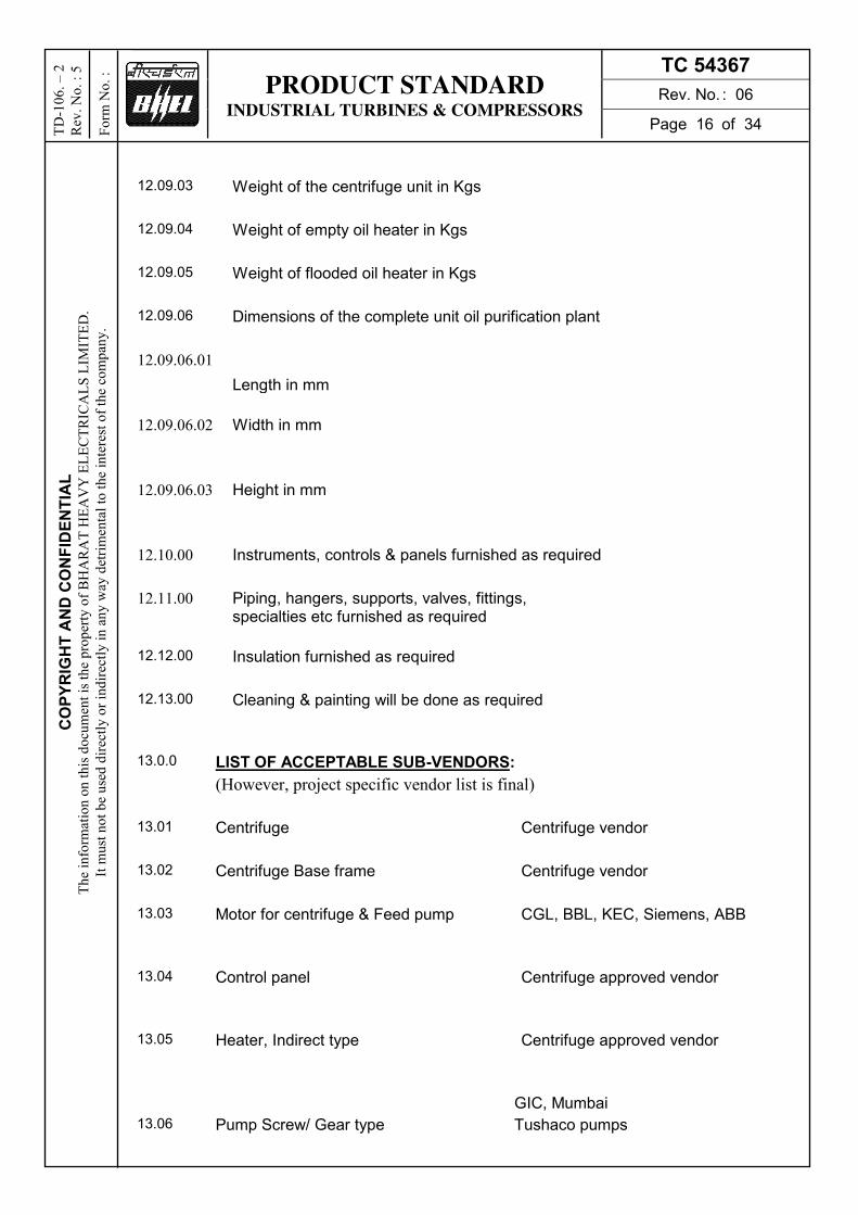
12.09.03 Weight of the centrifuge unit in Kgs
12.09.04 Weight of empty oil heater in Kgs
12.09.05 Weight of flooded oil heater in Kgs
12.09.06 Dimensions of the complete unit oil purification plant
12.09.06.01
Length in mm
12.09.06.02 Width in mm
12.09.06.03 Height in mm
12.10.00 Instruments, controls & panels furnished as required
12.11.00 Piping, hangers, supports, valves, fittings, specialties etc furnished as required
12.12.00 Insulation furnished as required
12.13.00 Cleaning & painting will be done as required
13.0.0 LIST OF ACCEPTABLE SUB-VENDORS:
(However, project specific vendor list is final)
13.01 Centrifuge Centrifuge vendor
13.02 Centrifuge Base frame Centrifuge vendor
13.03 Motor for centrifuge & Feed pump CGL, BBL, KEC, Siemens, ABB
13.04 Control panel Centrifuge approved vendor
13.05 Heater, Indirect type Centrifuge approved vendor
GIC, Mumbai
13.06 Pump Screw/ Gear type Tushaco pumps

PRODUCT STANDARD INDUSTRIAL TURBINES & COMPRESSORS
TC 54367
Rev. No. : 06
Page 17 of 34
CO
PY
RIG
HT
AN
D C
ON
FID
EN
TIA
L
Th
e in
form
atio
n o
n t
his
do
cum
ent
is t
he
pro
per
ty o
f B
HA
RA
T H
EA
VY
EL
EC
TR
ICA
LS
LIM
ITE
D.
It m
ust
no
t b
e u
sed
dir
ectl
y o
r in
dir
ectl
y i
n a
ny
way
det
rim
enta
l to
th
e in
tere
st o
f th
e co
mp
any
.
TD
-10
6. –
2
Rev
. N
o.
: 5
Fo
rm N
o.
:
Allweiler, Germany
IMO, Sweden/USA
Lestritz, Germany
13.07 Polishing filter Fairey arlon, holland
Pall India pvt.Ltd
EPE, Germany
13.08 Anti-flood tank Centrifuge approved vendor
13.09 Pressure Gauge/ Differential pressure gauge
BALIGA Chennai Budenberg UK ASHCROFT USA/Germany WIKA Germany / PUNE Wise Control Korea Nagano Keiki Japan H Guru South India Bangalore AN Instrument Kolkata GIC (gauge Bourdon) Panvel Manometer Mumbai Goa Thermostatic Goa GLUCK Mumbai Switzer Chennai (only for DP Gauge) PTCI Kolkata Waree Vapi Forbes Marshall Hyderabad Ashcroft Gandhinagar H Guru Rishra / Muzaffarpur Gauge Bourdon (GIC)
13.10 Differential pressure switch ITT BARTON,USA
Herion, Germany
SOR, USA
Dresser, USA
Gauge Bourdon (GIC) Panvel
Delta, UK
Switzer, Chennai
Ashcroft Ghandinagar Barksdale Germany Indfoss, Ghaziabad
13.11 Thermocouple, RTD & Thermo well Heraus Sensor Germany WISE Control Korea Tempsens Udaipur Pyroelectric Goa Datriv Instrumentation & electrical Mumbai Minco USA OKAZAKI Japan Yamari Japan

PRODUCT STANDARD INDUSTRIAL TURBINES & COMPRESSORS
TC 54367
Rev. No. : 06
Page 18 of 34
CO
PY
RIG
HT
AN
D C
ON
FID
EN
TIA
L
Th
e in
form
atio
n o
n t
his
do
cum
ent
is t
he
pro
per
ty o
f B
HA
RA
T H
EA
VY
EL
EC
TR
ICA
LS
LIM
ITE
D.
It m
ust
no
t b
e u
sed
dir
ectl
y o
r in
dir
ectl
y i
n a
ny
way
det
rim
enta
l to
th
e in
tere
st o
f th
e co
mp
any
.
TD
-10
6. –
2
Rev
. N
o.
: 5
Fo
rm N
o.
:
ABB (SENSYCON) Germany Emerson (Rose Mount) Germany GIC (Thermal instrument) Savantwadi
13.12 Temperature Gauge
Budenberg UK DRESSOR (ASHROFT) USA / Germany Wika Germany / Pune Wise Control Korea Nagano Keiki Japan H Guru South India Banglore AN. Instrument Kolkata NUOVA FIMA Italy Goa Thermostatic Goa GIC (Goa Instrument) Goa PTCI Kolkata Waree Vapi Ashcroft Gandhinagar Forbes Marshall Hyderabad H Guru Rishea/ Muzaffarpur
13.13 Temperature transmitter EMARSON- USA/ Pawane Yokogawa- Japan Moore- USA FULI ELECTRIC- JAPAN ABB Germany/ Faridabad
13.14 Temperature switch
Ashcroft Gandinagar SOR USA DRESSOR (Aschroft) USA/ Germany ITT Barton USA DELTA CONTROLS UK Switzer Chennai Indfos Ghaziabad Trafag Ranipet Gauge Bourdon (GIC) Panvel
13.15 Strainer Y-type JNM, Skilt
13.16 Flow Glass Sigma, Technoflow
13.17 Check valve Flowline, Expert
13.18 Regulating globe valve BDK or equvalent
13.19 Needle valve ASCO or equivalent
13.20
Globe valve
Centrifuge approved vendor
13.21 Rota meter
IEPL Hyderabad TRAC Hyderabad PLACKA Chennai EUREKA Pune Scientific Devices Mumbai

PRODUCT STANDARD INDUSTRIAL TURBINES & COMPRESSORS
TC 54367
Rev. No. : 06
Page 19 of 34
CO
PY
RIG
HT
AN
D C
ON
FID
EN
TIA
L
Th
e in
form
atio
n o
n t
his
do
cum
ent
is t
he
pro
per
ty o
f B
HA
RA
T H
EA
VY
EL
EC
TR
ICA
LS
LIM
ITE
D.
It m
ust
no
t b
e u
sed
dir
ectl
y o
r in
dir
ectl
y i
n a
ny
way
det
rim
enta
l to
th
e in
tere
st o
f th
e co
mp
any
.
TD
-10
6. –
2
Rev
. N
o.
: 5
Fo
rm N
o.
:
Flow Star Faridabad Tokoyo Keiso Japan Small Chemtrol Mumbai
13.21 Solenoid valve: Technoflow Rotex Vadodra Avcon Mumbai Harion Germany IMI Norgen Germany Jafferson Argentina Asco Chennai/ USA
13.22 Ball valve BDK, Audco
13.23 Level switch (float/ displacer type)
Endress & Houser Aurangabad Magnetrol Belgium Levcon Kolkata SBEM Pune Chemtrols samil Mumbai Sigma Industries Mumbai D K Instrument Kolkata Pune Techtrol Pune V Automat New Delhi Waree Wapi Level State UK
13.24 PLC System
GE Intellegent Plateforms Bangalore ABB Bangalore Schneider Nasik Rockwell Sahibabad Siemens Nasik
13.25 Impulse Pipes & tubes:
Sumitomo/ Kawasaki/ Nippon Japan TPS Technitube Germany Veluric & manessmann Germany BHEL Tirchy Trouvay & Cauvin France Heavy Metals Ahmedabad Jindal SAW India ISMT Ahmadnagar Sandvik
13.26 Compression Fittings
Parker USA Precision Mumbai DK Tech Korea HY LOK Korea Astech Mumbai Swagelock USA Panam Mumabi
13.27 Instrument Valve: BHEL Trichy DK Tech Korea HY LOK Korea Excel Hydro Mumbai Instrumentation Ltd. Palghat Swagelock USA

PRODUCT STANDARD INDUSTRIAL TURBINES & COMPRESSORS
TC 54367
Rev. No. : 06
Page 20 of 34
CO
PY
RIG
HT
AN
D C
ON
FID
EN
TIA
L
Th
e in
form
atio
n o
n t
his
do
cum
ent
is t
he
pro
per
ty o
f B
HA
RA
T H
EA
VY
EL
EC
TR
ICA
LS
LIM
ITE
D.
It m
ust
no
t b
e u
sed
dir
ectl
y o
r in
dir
ectl
y i
n a
ny
way
det
rim
enta
l to
th
e in
tere
st o
f th
e co
mp
any
.
TD
-10
6. –
2
Rev
. N
o.
: 5
Fo
rm N
o.
:
HP Valves & Fitting Chennai Vikas Mumbai Hydair Lonawala Lonavala Aura INC New Delhi Baldota Mumbai
13.28 Instrument Cable:
Paramount Khuskhera Polycab Pawane Delton Faridabad KEI Bhiwadi Elkey telelinks Faridabad Cords Bhiwadi Reliance Bangalore Nicco Kolkata TEW & C USA Habla Cables Sweden Kerpen cables Germany Lapp cables Germany Thermo Electra BV Netherland Universal Cable Satna
14.0.0 TEST & GUARANTEE CERTIFICATES
14.0.1 TEST CERTIFICATES: 3 Copies of the manufacturers test certificates for performance of oil purification unit shall be supplied for each item of the consignment quoting BHEL standard number, purchase order number and manufacturer’s identification serial number.
14.0.2 GUARANTEE CERTIFICATES: A guarantee certificate for 24 months of trouble free performance from the date of shipment or 18 months from the date of commissioning whichever is earlier shall be supplied. If any mal performance or defects occur during the warrantee period, the vendor shall make all necessary alteration, repairs or replacement free of cost.
15.0.0 PACKING: The entire unit shall be properly packed to withstand mechanical damage and rust during transit. The packing shall be seaworthy packing.
16.0.0 MARKING: The manufacturer’s serial number and year of manufacture shall be marked at suitable locations viz Name plate A tag bearing the relevant 12 digit material code shall be attached for each item.
The name plate of the oil purification unit shall contain the following information
- Manufacturer’s name or trade mark & serial number - Capacity of the centrifuge
- Pump discharge pressure
- Performance guarantee figures of moisture content and solid particles
Similar name plate to be provided for other items like Electric heater, polishing filter, oil pumps, electrical motors, Anti flood tank etc. All the Instruments are to be properly tagged for easy identification
17.0.0 Enclosed:
1. Annexure –I (Type test procedure)
2. Annexure- II (Technical Data Sheet)
3. Annexure- III (Technical Deviation Sheet)

P
RO
DU
CT
ST
AN
DA
RD
IN
DU
ST
RIA
L T
UR
BIN
ES
& C
OM
PR
ES
SO
RS
TC
54
36
7
Re
v. N
o. : 0
6
Pa
ge
21
of 3
4
COPYRIGHT AND CONFIDENTIAL The information on this document is the property of BHARAT HEAVY ELECTRICALS LIMITED.
It must not be used directly or indirectly in any way detrimental to the interest of the company.
TD-106. – 2
Rev. No. : 5
Form No. :
4. A
nn
exu
re –
IV ( C
he
ck lis
t)
5. A
nn
exu
re- V
(Pric
e s
ch
ed
ule
)

PRODUCT STANDARD INDUSTRIAL TURBINES & COMPRESSORS
TC 54367
Rev. No. : 06
Page 22 of 34
CO
PY
RIG
HT
AN
D C
ON
FID
EN
TIA
L
Th
e in
form
atio
n o
n t
his
do
cum
ent
is t
he
pro
per
ty o
f B
HA
RA
T H
EA
VY
EL
EC
TR
ICA
LS
LIM
ITE
D.
It m
ust
no
t b
e u
sed
dir
ectl
y o
r in
dir
ectl
y i
n a
ny
way
det
rim
enta
l to
th
e in
tere
st o
f th
e co
mp
any
.
TD
-10
6. –
2
Rev
. N
o.
: 5
Fo
rm N
o.
:
18.0.0 Variant Table:
Var No. Description Model No. Material Code
01 OIL PURIFICATION UNIT 2400 LPH AS PER 2308000030-00
MMB305 – Alfa Laval OTC 5-91-067
TC9754367019
02 SP SET OF GASKETS FOR 2400LPH OPU TC9754367027 03 SP SET OF "O" RINGS FOR 2400LPH OPU TC9754367035 04 SP SET OF BRGS FOR 2400LPH OPU TC9754367043 05 SP SET OF PF FILT CART FOR 2400LPH OPU TC9754367051 06 SP DRIVE BELT FOR 2400LPH OPU TC9754367060 07 SP FEED & DISCH PUMP ROTOR 2400LPH OPU TC9754367078 08 SP SET OF GLAND COVER,PKG&SHFT SLV OPU TC9754367086 09 SP SET OF FRICTION PAD SCRU 2400LPH OPU TC9754367094 10 SP SET OF SPRINGS FOR 2400LPH OPU TC9754367108
11 SP BREAK PLUG FOR 2400LPH OPU TC9754367116 12 SPARE GLASS FOR 2400LPH OPU TC9754367124 13 SPARE BOWL DISC FOR 2400LPH OPU TC9754367132 14 SPARE SET OF SHEAR COUP FEED PUMP OPU TC9754367140 15 SP SET OF CONTROL PANEL SPARES FOR OPU TC9754367159 16 SP DE BRG FOR OPU DRIVE MOTOR TC9754367167 17 SP NDE BRG FOR OPU DRIVE MOTOR TC9754367175 18 SP COOLING FAN FOR OPU DRIVE MOTOR TC9754367183 19 SP END SHIELD COVER FOR OPU MOTOR
BRGS TC9754367191
20 SP TERMINAL BOX FOR OPU DRIVE MOTOR TC9754367205 21 OIL CENTRIFUGE(FIXED)2400LPH IE2 MOTOR
Ref TC54368 for IE2 TC9754367213
22 IE3 MOTOR FOR CENTRIFUGE AND PUMP TC9754367221 23 BEARNG IE3 MOTR FOR CENTRIFUGE AND
PUMP Ref TC54373 for IE3 Mtr TC9754367230
24 SPACE HEATR IE3 MOTR CENTRIFUGE & PUMP Ref TC54373 for IE3 Mtr
TC9754367248
25 COOLING FAN IE3 MOTR CENTRIFUGE & PUMP Ref TC54373 for IE3 Mtr
TC9754367256
26 OPU FIXED 2400 LPH IE3 MOTOR (Valve body CS internal SS & SS pipe)
TC9754367264
27 SPR FOR applicable IE2 MTR for OPU AS PER TBLE 1
TC9754367272
28 SPARE IE2 MTR FOR CENTRIFUGE AND PUMP Ref TC54368 for IE2
TC9754367280
29 Spare bearing,o-ring,gasket and filters TC9754367299

PRODUCT STANDARD INDUSTRIAL TURBINES & COMPRESSORS
TC 54367
Rev. No. : 06
Page 23 of 34
CO
PY
RIG
HT
AN
D C
ON
FID
EN
TIA
L
Th
e in
form
atio
n o
n t
his
do
cum
ent
is t
he
pro
per
ty o
f B
HA
RA
T H
EA
VY
EL
EC
TR
ICA
LS
LIM
ITE
D.
It m
ust
no
t b
e u
sed
dir
ectl
y o
r in
dir
ectl
y i
n a
ny
way
det
rim
enta
l to
th
e in
tere
st o
f th
e co
mp
any
.
TD
-10
6. –
2
Rev
. N
o.
: 5
Fo
rm N
o.
:
Table No 1
S.No Material description Quantity
1 Bearings 1
2 Cooling fan 1
3 Motor terminal block plates 1
4 Complete set of couplings 1
RECORD OF REVISIONS
Rev. No. Date Revision Details Revised By Approved By
00 10.05.2013 First Issue
01 13.02.15 Motor requirement and Variant no up to 28 added
02 09.04.15 Table No 1 and 2 added
03 16.11.16 Revision marked as R03 ANSHUL SUNIL J
04 22.06.17 Revision marked as R04 ANSHUL SUNIL J
05 27.11.17 Revision marked as R05 ANSHUL SUNIL J
06 13.12.17 Variant no 42 added. Marked as R06 ANSHUL SUNIL J
30 BEARINGS DE & NDE ALL OPU MTR TC9754367302 31 COOLING FAN FOR ALL OPU MTR TC9754367310 32 TERMINAL BLOCK FOR ALL OPU MOTOR TC9754367329 33 SET OF COUPLING ALL OPU MOTOR TC9754367337 35 DE & NDE BEARING OPU IE3 MOTOR TC9754367353 36 COOLING FAN FOR OPU IE3 MOTOR TC9754367361 37 TERMINAL BLOCK OPU IE3 MOTOR TC9754367370 38 OPU FOR GSECL WANAKBORI,IE2 MOTOR TC9754367388 39 OPU SKID,2400LPH, IE3 MTR, (COMPLETE
Valve and Pipe SS) TC9754367396
40 ALL APP.INSTRUMENT FOR OPU(10% QTY) TC9754367400 41 Pressure Gauge (10% or2 nos of each type) TC9754367418 42 OPU-2400 LPH, IE2 MOTOR, COMPLETE SS TC9754367426 43 OPU-2400 LPH, IE3 MOTOR, COMPLETE
SS-FLAMEPROOF-Refer Annex VI
TC9754367434
44 OIL PURF. SKID 2400LPH-SELF CLEAN TC9754367442 45 OIL PURF. SKID 2400LPH-COMP SS-DCS TC9754367450 46 TERMINAL PLATE FOR ALL OPU MOTORS TC9754367469 47 48 49 50

PRODUCT STANDARD INDUSTRIAL TURBINES & COMPRESSORS
TC 54367
Rev. No. : 06
Page 24 of 34
CO
PY
RIG
HT
AN
D C
ON
FID
EN
TIA
L
Th
e in
form
atio
n o
n t
his
do
cum
ent
is t
he
pro
per
ty o
f B
HA
RA
T H
EA
VY
EL
EC
TR
ICA
LS
LIM
ITE
D.
It m
ust
no
t b
e u
sed
dir
ectl
y o
r in
dir
ectl
y i
n a
ny
way
det
rim
enta
l to
th
e in
tere
st o
f th
e co
mp
any
.
TD
-10
6. –
2
Rev
. N
o.
: 5
Fo
rm N
o.
:
Annexure 1 (type test procedure for partlicle test)
Objective: Type test procedure is to determine the efficency of particulate seperation in offered Centriuge (Disc) with and without polishing filter at outlet of centrifuge
2. Desired Cleanliness level:
Centrifuge / centrifuge + polishing filter module inlet oil quality- 21/18 as per ISO 4406
Centrifuge / centrifuge + polishing filter module outlet oil quality- 15/12 as per ISO 4406
The sample tesing at lab will be as per approved ISO 4406-1999 procedure either by Microscopic Method or by Automatic particle counter.
3. Standard to be used:
ISO 4406: 1999 (E). This internation standard specifies the codes to be used in defining the solid particle in the fluid used in a given hydraulic fluid power system.
4. Oil to be used: ISO VG 46
5. References:
The following normative documents contains provision which, through reference in this text constitute provision of this international standard.
- ISO 11500-1997, hydraulic fluid power- determination of particulate contamination by automatic counting used the light extinction principle.
-ISO 4407:1991, Hydraulic fluid power- Fluid contamination- determincatio of particulate contamination by the counting method using micoscope
6. Procedure for test at NTPC approved Lab (CMTI: Banglore, or equivalent)
a) Start the centrifue and wait till it attains full speed and oil attains temp. of 65 deg C.
b) start the feed( Clean Oil- Purified to ISO class better than 15/12 after sampling before test) and set the centrifuge for desired capacity and temperature.
c) Add particulate matter (contamination) in tank. (add approx. 1/4 kg of particles in 100 lts. Of oil) and test this sample for information.
d) start the feed through the centrifuge and bypassing the polishing filter.
e) Collect samples from centrifuge inlet sampling point after one minute of mixing dirt and collect sample at outlet of centrfiuge immediately after collecteing inlet sample.
f) now pass the outlet oil through the polishing filtre and collect sample at outlet of polishing filter.
g) Stop centrifuge after collection of sample.
h) place the outlet drum at inlet of centrifuge and repear the above process from 4 to 7 for up to 3-4 passed or till
no further reduction of ISO class o outlet oil.
7. Sample Collection
use ultra clean bottle collected from laboratory.

PRODUCT STANDARD INDUSTRIAL TURBINES & COMPRESSORS
TC 54367
Rev. No. : 06
Page 25 of 34
CO
PY
RIG
HT
AN
D C
ON
FID
EN
TIA
L
Th
e in
form
atio
n o
n t
his
do
cum
ent
is t
he
pro
per
ty o
f B
HA
RA
T H
EA
VY
EL
EC
TR
ICA
LS
LIM
ITE
D.
It m
ust
no
t b
e u
sed
dir
ectl
y o
r in
dir
ectl
y i
n a
ny
way
det
rim
enta
l to
th
e in
tere
st o
f th
e co
mp
any
.
TD
-10
6. –
2
Rev
. N
o.
: 5
Fo
rm N
o.
:
once the oil is collected in the bottle, close the cap immediately, this will help to avoid settling of atmospheric
particles in the oil sample.
Seal the sample bottle in presence of all party.
8. Acceptance Criteria:
During sample test, inlet oil quality shall be inferior or equal to ISO 4406 class 21/18 and outlet oil qualtiy shall
be superior or equal to ISO 4406 class 15/12
LOG SHEET FOR MEASUREMENT OF PARTICULTE MATTER
Centrfiuge Model No.
design Flow: @ 65 deg C
Machine Sl. No.

PRODUCT STANDARD INDUSTRIAL TURBINES & COMPRESSORS
TC 54367
Rev. No. : 06
Page 26 of 34
CO
PY
RIG
HT
AN
D C
ON
FID
EN
TIA
L
Th
e in
form
atio
n o
n t
his
do
cum
ent
is t
he
pro
per
ty o
f B
HA
RA
T H
EA
VY
EL
EC
TR
ICA
LS
LIM
ITE
D.
It m
ust
no
t b
e u
sed
dir
ectl
y o
r in
dir
ectl
y i
n a
ny
way
det
rim
enta
l to
th
e in
tere
st o
f th
e co
mp
any
.
TD
-10
6. –
2
Rev
. N
o.
: 5
Fo
rm N
o.
:
Annexure-II
Customer :
Project :
BHEL PO No. :
NTPC Drawing No. :
1.0 Number of Units offered ( BFP Drive Turbine )
2.0 Location Indoor
2.2 Type of operation Purifier
2.3 Max. Hydraulic capacity (for turbine oil)
2.4 Recommended through put for best
Performances (for turbine oil)
2.5 Speed Centrifuge Motor RPM ____, Bowl
Speed RPM _____.
2.6 Particle size distribution in terms of ISO
Ration in purified oil at centrifuge system outlet
After single pass ISO 4406 Class 15/12 from initial
21/18
2.7 Particle size in purified oil at outlet All particle above 5µm size will be
of polishing filter removed
2.8 Water content in purified oil at outlet Free Water level in treated oil :
Max.
of centrifuge. 0.05% (Provided 1.5% water at
inlet)
2.9 Water contact in purification oil 0.05% Volume/volume
at outlet of polishing filter
2.10 OIL TEMPERATURES
2.10.1 Inlet to electric heater 650 C (Max), 100 C (Min)
2.10.2 Outlet from electric heater 650 C
2.11 Water temperature in the heater tank 900 C (not to excess 900 C)
2.12 Bearings 1. Nos.
2. Type Ball Bearing
3. Manufacturer

PRODUCT STANDARD INDUSTRIAL TURBINES & COMPRESSORS
TC 54367
Rev. No. : 06
Page 27 of 34
CO
PY
RIG
HT
AN
D C
ON
FID
EN
TIA
L
Th
e in
form
atio
n o
n t
his
do
cum
ent
is t
he
pro
per
ty o
f B
HA
RA
T H
EA
VY
EL
EC
TR
ICA
LS
LIM
ITE
D.
It m
ust
no
t b
e u
sed
dir
ectl
y o
r in
dir
ectl
y i
n a
ny
way
det
rim
enta
l to
th
e in
tere
st o
f th
e co
mp
any
.
TD
-10
6. –
2
Rev
. N
o.
: 5
Fo
rm N
o.
:
2.13 Solid holding capacity of the bowl
3.0 CONSTRUCTION FEATURE OF CENTRIFUGE
3.1 Automatic tripping of all electric motor
on actuation of anti-flood device
3.2 Clearing of centrifuge bowl Manual
3.3 Type of centrifuge drive Belt Drive
3.4 If centrifuge is belt driven automatic
Tripping of all electric motors on belt failure Separation trip
4.0 MATERIALS OF CONSTRUCTION OF
CENTRIFUGE (INDICATE STANDARDS) – ASTM Standards
4.1 Frame
4.2 Hood
4.3 Main Bowl Parts:
i) Bowl Bottom
ii) Bowl Top
iii) Disk
iv) Thread Ring
v) Lower Centripetal Pump Chamber Cover
vi) Spindle
5.0 DESIGN/CONSTRUCTION FEATURES
OF ELECTRIC HEATER (H01.01 – pos. no. 23)
5.1 Heater Details
5.1.1 Quantity
5.1.2 Kilowatts
5.1.3 Voltage Volts (AC) 415V ± 10%
5.1.4 Frequency 50 Hz
5.1.5 Phase 3
5.2 i) Number of on thermostats __
Or
Pt – 100 Points on oil line (Pt-100, L = 150 mm, ø = 6 mm)
ii) Range 0 - 1990 C for oil temp. Control
5.3 Heater control thermostat setting 0 - 1200 C for water temp. Control

PRODUCT STANDARD INDUSTRIAL TURBINES & COMPRESSORS
TC 54367
Rev. No. : 06
Page 28 of 34
CO
PY
RIG
HT
AN
D C
ON
FID
EN
TIA
L
Th
e in
form
atio
n o
n t
his
do
cum
ent
is t
he
pro
per
ty o
f B
HA
RA
T H
EA
VY
EL
EC
TR
ICA
LS
LIM
ITE
D.
It m
ust
no
t b
e u
sed
dir
ectl
y o
r in
dir
ectl
y i
n a
ny
way
det
rim
enta
l to
th
e in
tere
st o
f th
e co
mp
any
.
TD
-10
6. –
2
Rev
. N
o.
: 5
Fo
rm N
o.
:
5.4 i) Rating of thermostat contacts
5.5 Heater tube
5.5.1 Material SS304
5.5.2 Type ___
5.5.3 Length ___
5.5.4 outside Diameter ___
5.5.5 Tube wall thickness ___
5.6 Surface load of heater ___
5.7 Tube Sheets
5.7.1 Material SS304
5.7.2 Number ___
5.7.3 Thickness ___
5.8 Tube bundle type ___
5.9 Capacity of heater tank ___
6.0 FEED PUMP
6.1 Quantity 1 (one) No.
6.2 Model No. ___
6.3 Type Positive displacement (Gear type)
6.4 Capacity (10% excess capacity)
6.5 Speed 1440 RPM
6.6 Discharge Pressure __ kg / cm2 (g)
6.7 Relief valve setting __ kg / cm2
6.8 Max. allowable pump working pressure __ kg / cm2 (g)
6.9 Connections
a) Inlet __ NB
b) Outlet __ NB
6.10 Material
Flange ASTM ____
Cover ASTM ____
Shaft ASTM ____
Body ASTM ____

PRODUCT STANDARD INDUSTRIAL TURBINES & COMPRESSORS
TC 54367
Rev. No. : 06
Page 29 of 34
CO
PY
RIG
HT
AN
D C
ON
FID
EN
TIA
L
Th
e in
form
atio
n o
n t
his
do
cum
ent
is t
he
pro
per
ty o
f B
HA
RA
T H
EA
VY
EL
EC
TR
ICA
LS
LIM
ITE
D.
It m
ust
no
t b
e u
sed
dir
ectl
y o
r in
dir
ectl
y i
n a
ny
way
det
rim
enta
l to
th
e in
tere
st o
f th
e co
mp
any
.
TD
-10
6. –
2
Rev
. N
o.
: 5
Fo
rm N
o.
:
Bush ASTM ____
6.11 Drive (AC Motor) Main Centrifuge Motor
6.12 Motor rating __kW (Main Centrifuge Motor)
6.13 Bearing ___
6.14 HP rated capacity for feed pump ___hp
7.0 Booster DISCHARGE PUMP
7.1 Quantity 1 (one) No.
7.2 Model No. ___
7.3 Type Positive displacement (Gear type)
7.4 Capacity (10% excess capacity)
7.5 Speed 1450 rpm
7.6 Discharge Pressure __ kg / km2 (g)
7.7 Relief valve setting __ kg / km2
7.8 Max. allowable pump working pressure __ kg / km2 (g)
7.9 Connections
a) Inlet __ NB
b) Outlet __ NB
7.10 Material
Flange ASTM____
Cover ASTM____
Shaft ASTM____
Body ASTM____
Bush ASTM____
7.11 Motor rating __kW
7.12 Bearing
7.13 HP rated capacity __ hp
8.0 INSTRUMENTS
8.1 PRESSURE GAUGES
a) Type Bourdon Type

PRODUCT STANDARD INDUSTRIAL TURBINES & COMPRESSORS
TC 54367
Rev. No. : 06
Page 30 of 34
CO
PY
RIG
HT
AN
D C
ON
FID
EN
TIA
L
Th
e in
form
atio
n o
n t
his
do
cum
ent
is t
he
pro
per
ty o
f B
HA
RA
T H
EA
VY
EL
EC
TR
ICA
LS
LIM
ITE
D.
It m
ust
no
t b
e u
sed
dir
ectl
y o
r in
dir
ectl
y i
n a
ny
way
det
rim
enta
l to
th
e in
tere
st o
f th
e co
mp
any
.
TD
-10
6. –
2
Rev
. N
o.
: 5
Fo
rm N
o.
:
b) Number __ Nos.
c) Location - -
Dial Size : 150 mm
Over Range : 150%
Protection : IP 55
Connection : ½” NPT(M)
d) Range 0-6kg/cm2 and -1 to (+) 5 kg km2
e) Accuracy ± 1% FSD
f) Body Material Die Cast Aluminium
g) Scale Liner 2700 (arc graduated in
metric)
i) Zero/Span adjustment provided
i) Window Shatterproof glass
k) Model No .
j) Manufacturer
8.2 TEMPERATURE INDICATORS
a) Type Mercury in steel Dial
Thermometer.
b) Number __ Nos.
c) Location __
Dial Size : 150 mm
Over Range : 125%
Protection : IP 65
d) Range 0 to 1000 C
e) Accuracy ± 1% FSD
f) Body Material Die Cast Aluminum
g) Sensing Material Mercury in steel
h) Scale Liner 2700 (arc graduated in metric)
i) Over Range 150% FSD
j) Zero/Span adjustment provided
k) SS thermowell provided

PRODUCT STANDARD INDUSTRIAL TURBINES & COMPRESSORS
TC 54367
Rev. No. : 06
Page 31 of 34
CO
PY
RIG
HT
AN
D C
ON
FID
EN
TIA
L
Th
e in
form
atio
n o
n t
his
do
cum
ent
is t
he
pro
per
ty o
f B
HA
RA
T H
EA
VY
EL
EC
TR
ICA
LS
LIM
ITE
D.
It m
ust
no
t b
e u
sed
dir
ectl
y o
r in
dir
ectl
y i
n a
ny
way
det
rim
enta
l to
th
e in
tere
st o
f th
e co
mp
any
.
TD
-10
6. –
2
Rev
. N
o.
: 5
Fo
rm N
o.
:
l) Manufacturer
j) Window Shatterproof glass.
h) Model No.
.
i) Thermowel
.
j) Thermowel Process connection: ¾” NPT M
8.3 FLOW GLASS (FG1, FG2 - pos. no 10)
a) Type Glass tube
b) Accuracy N.A
c) Location
d) Connections, type & size __ NB
e) Model No. __
f) Manufacturer __
9.0 LEVEL SWITCH
a) Number _ No.
b) Type Vertical Mounting Type Float
Switch
c) Location
e) Model No.
f) Manufacturer
g) No. of contacts & contact rating
10.0 INDICATING TYPE DIFFERENTIAL PRESSURE GAUGE/SWITCH
(ACROSS POLISHING FILTER)
a) Number 1 No.
b) Type Dial Type
c) Location ACROSS POLISHING FILTER
d) Model No.
e) Manufacturer
f) No. of contacts & contact rating
11.0 POLISHING FILTER

PRODUCT STANDARD INDUSTRIAL TURBINES & COMPRESSORS
TC 54367
Rev. No. : 06
Page 32 of 34
CO
PY
RIG
HT
AN
D C
ON
FID
EN
TIA
L
Th
e in
form
atio
n o
n t
his
do
cum
ent
is t
he
pro
per
ty o
f B
HA
RA
T H
EA
VY
EL
EC
TR
ICA
LS
LIM
ITE
D.
It m
ust
no
t b
e u
sed
dir
ectl
y o
r in
dir
ectl
y i
n a
ny
way
det
rim
enta
l to
th
e in
tere
st o
f th
e co
mp
any
.
TD
-10
6. –
2
Rev
. N
o.
: 5
Fo
rm N
o.
:
a) Number 01 No.
b) Location After Booster Pump.
c) Model No .
d) Make
12.0 Ball Valves
a) Size __ NB
b) End connection
c) Body Material A 216 GR WCB
d) Internals SS 316
e) Make
13.0 Ball Valve
a) Size __ NB
b) End connection Treaded.
c) Body Material A216 GR WCB
d) Internals SS316
e) Make

PRODUCT STANDARD INDUSTRIAL TURBINES & COMPRESSORS
TC 54367
Rev. No. : 06
Page 33 of 34
CO
PY
RIG
HT
AN
D C
ON
FID
EN
TIA
L
Th
e in
form
atio
n o
n t
his
do
cum
ent
is t
he
pro
per
ty o
f B
HA
RA
T H
EA
VY
EL
EC
TR
ICA
LS
LIM
ITE
D.
It m
ust
no
t b
e u
sed
dir
ectl
y o
r in
dir
ectl
y i
n a
ny
way
det
rim
enta
l to
th
e in
tere
st o
f th
e co
mp
any
.
TD
-10
6. –
2
Rev
. N
o.
: 5
Fo
rm N
o.
:
Annexure-III
Technical Deviation Sheet (TDS Sheet):
S.No Spec No Description of Spec Deviation Reason
Vendor’s Signature
Vendor’s Company seal

PRODUCT STANDARD INDUSTRIAL TURBINES & COMPRESSORS
TC 54367
Rev. No. : 06
Page 34 of 34
CO
PY
RIG
HT
AN
D C
ON
FID
EN
TIA
L
Th
e in
form
atio
n o
n t
his
do
cum
ent
is t
he
pro
per
ty o
f B
HA
RA
T H
EA
VY
EL
EC
TR
ICA
LS
LIM
ITE
D.
It m
ust
no
t b
e u
sed
dir
ectl
y o
r in
dir
ectl
y i
n a
ny
way
det
rim
enta
l to
th
e in
tere
st o
f th
e co
mp
any
.
TD
-10
6. –
2
Rev
. N
o.
: 5
Fo
rm N
o.
:
Annexure-IV
Check List (TO BE FILLED BY THE VENDOR AND SUBMITTED ALONG WITH THE OFFER WITH
OUT WHICH OFFER WILL NOT BE CONSIDERED)
S.No. Description Vendor’s Confirmation (Yes/No)
1 Compliance for BHEL specification TC54367
2
Compliance for the sub-vendors list indicated as per BHEL
specification. For the items, which are not covered in the list or vendors
not indicated, vendor has to procure from their standard sub-vendors.
Vendor to confirm compliance for the same.
3
Vendor shall confirm that the bill of material furnished along with offer
is only indicative and the final BOM, which shall be furnished during
detailed Engineering (after order placement) for the approval of BHEL.
The additional items, if any required at later stage for complying BHEL
specification or for the satisfactory working of the equipment shall be
supplied by vendor without any price/delivery implications.
4
Price Schedule as per Annexure- III enclosed.
Also, signed filled copy of Price schedule ( without prices) enclosed
with technical offer
5 Filled up equipment data sheet
6 Proven Track Record
7
Recommended commissioning spares during commissioning operation.
These are to be clearly specified in the offer & the price is to be
included in the equipment price
8
Recommended spares for three years of normal operation: list for all
the items with item wise prices. The offer shall be valid for one year
after placement of order and these shall be ordered as required later.
9 Any additional requirements which are essential for proper functioning
of the equipment included in the offer.
a)
Vendor’s Signature
Vendor’s Company seal

P
RO
DU
CT
ST
AN
DA
RD
IN
DU
ST
RIA
L T
UR
BIN
ES
& C
OM
PR
ES
SO
RS
TC
54
36
7
Re
v. N
o. : 0
6
Pa
ge
35
of 3
4
COPYRIGHT AND CONFIDENTIAL The information on this document is the property of BHARAT HEAVY ELECTRICALS LIMITED.
It must not be used directly or indirectly in any way detrimental to the interest of the company.
TD-106. – 2
Rev. No. : 5
Form No. :
An
nex
ure
-VI
Pro
jec
t- UP
RV
UN
L P
AN
KI 1
X6
60
MW
V
OL
-V (I &
C)-In
strum
entatio
n sp
ec V
OL
-V (I &
C)-lo
cal con
trol p
anel

PRODUCT STANDARD INDUSTRIAL TURBINES & COMPRESSORS
TC 54373
CO
PY
RIG
HT
AN
D C
ON
FID
EN
TIA
L
The i
nfo
rmat
ion o
n t
his
do
cum
en
t is
th
e p
ropert
y o
f B
HA
RA
T H
EA
VY
EL
EC
TR
ICA
LS
LIM
ITE
D.
It m
ust
no
t b
e u
sed
dir
ectl
y o
r in
dir
ectl
y i
n a
ny w
ay d
etr
imenta
l to
the i
nte
rest
of
the c
om
pany
.
TD
-10
6
2
Rev.
No.:
5
Fo
rm N
o.
:
SQUIRREL CAGE INDUCTION MOTORS IE-3 (Premium
Efficiency Class)
(For BFP Drive Turbine)
1. SCOPE:
This standard specifies the requirements of the 3-phase medium voltage squirrel cage
Induction motors used for driving Centrifugal / Screw / Gear pumps of lube oil
systems of Industrial Turbo sets and BFP drives.
2. TECHNICAL REQUIREMENTS:
2.1 General:
The squirrel cage induction motors shall be of horizontal foot mounted (B3) type or
Vertical flange mounted (V1) type construction as per enquiry suitable for bi-
directional rotation. Unless otherwise specified the motors are of type IP55 enclosure
(as per IS: 4691 & IEC60034-05 (S1).
motors shall be suitable for 100% humid (at 40 deg C), salty tropical conditions and
highly polluted environment.
2.2 Design Standards:
The motors shall conform to relevant latest amendments of National and International
Codes and standards, especially the Indian Statutory Regulations.
Performance : IS 325 & IS 8789 & IEC:60034
Dimensions : IS 1231 / IS 2223
Enclosure and protection : IS 4691 / IEC:60034-05
Tropicalizing treatment : IS 3202
Energy Efficient motors : IS 12615 / IEC:60034-30
Method of Cooling : IS 6362 / (Equivalent IEC: 60034 Std.)
2.3 Design and Constructional Features:
2.3.1 Motors shall work satisfactorily for following supply conditions:
Variation of supply voltage from rated voltage : 10%
Variation of supply frequency from rated frequency : + 3% to - 5%
Combined voltage and frequency variation : 10%
2.3.2 The Voltage level of motors shall be as follows: (unless otherwise specified)
Up to 200 kW: 3 Phase 415V AC
2.3.3 Rated frequency: 50 Hz
2.3.4 The ambient temperature is 50 C and an altitude not exceeding 1000 meters above
mean sea level shall be taken into consideration unless otherwise specified.

PRODUCT STANDARD INDUSTRIAL TURBINES & COMPRESSORS
TC 54373
CO
PY
RIG
HT
AN
D C
ON
FID
EN
TIA
L
The i
nfo
rmat
ion o
n t
his
do
cum
en
t is
th
e p
ropert
y o
f B
HA
RA
T H
EA
VY
EL
EC
TR
ICA
LS
LIM
ITE
D.
It m
ust
no
t b
e u
sed
dir
ectl
y o
r in
dir
ectl
y i
n a
ny w
ay d
etr
imenta
l to
the i
nte
rest
of
the c
om
pany
.
TD
-10
6
2
Rev.
No.:
5
Fo
rm N
o.
:
2.3.5 TEMPERATURE RISE 70 C by resistance method for both thermal class 130(B) &
155(F) insulation.
2.3.6 Continuous duty LT motors up to 160 KW Output rating (at 50 C ambient
temperatures), shall be Energy Efficient motors, Efficiency class of Premium efficiency
(IE3) as per IEC: 60034-30 unless otherwise specified.
2.3.7 Winding and Insulation shall be Non-hygroscopic, oil resistant, and flame resistant.
2.3.8 Motor body shall have two earthing points on opposite sides.
2.3.9 All motors shall be so designed that maximum inrush currents and locked rotor and
pullout torque developed by them at extreme voltage and frequency variations do not
endanger the motor and driven equipment.
2.3.10 The motors shall be suitable for bus transfer schemes provided on the 11kV, 3.3 kV
/415V systems without any injurious effect on its life.
2.3.11 The starting time of the motor shall be less than 3 secs.
2.312 The motor shall be totally enclosed fan cooled (TEFC) unless otherwise specified.
2.4 Performance:
2.4.1 Motor shall be suitable for DOL starting.
2.4.2 The motor shall be capable of start & operating satisfactorily at full load for 5
minutes without injurious heating with 75% rated voltage at motor terminal.
2.4.3 Accelerating torque at any speed with the lowest permissible starting voltage shall be
at least 10% motor full load torque. Starting torque should not be less than 120% of
FLT. The pullout torque at the rated voltage shall be not less than 205% of the full
load torque with no negative tolerance. Unless otherwise agreed, the pullout torque
shall not exceed 300% of the rated load torque.
2.4.4 Fault capacity of the system to which motor is connected is about 45 kA RMS 1
second.
2.4.5 Noise level for all the motors shall be limited to 85dB (A) at distance of 1 m as per
IS12065 (latest) /IEC60034.
2.4.6 Vibration shall be limited within the limits prescribed in IS: 12075 / IEC 60034-14.
Motors shall withstand vibrations produced by driven equipment.
2.4.7 The spacing between gland plate & center of terminal stud shall be as per Table-1.
2.4.8 For motors with starting time up to 20 secs. at minimum permissible voltage during
starting, the locked rotor withstand time under hot condition at highest voltage limit
shall be at least 2.5 secs. more than starting time.
2.4.9 The ratio of locked rotor KVA at rated voltage to rated KW shall not exceed the
following (without any further tolerance)
a) Below 110 kW: 10.0
(b) From 110 kW & up to 200 kW: 9.0
Motors and EPB located in hazardous areas shall have flame proof enclosures
conforming to IS: 2148 as detailed below

PRODUCT STANDARD INDUSTRIAL TURBINES & COMPRESSORS
TC 54373
CO
PY
RIG
HT
AN
D C
ON
FID
EN
TIA
L
The i
nfo
rmat
ion o
n t
his
do
cum
en
t is
th
e p
ropert
y o
f B
HA
RA
T H
EA
VY
EL
EC
TR
ICA
LS
LIM
ITE
D.
It m
ust
no
t b
e u
sed
dir
ectl
y o
r in
dir
ectl
y i
n a
ny w
ay d
etr
imenta
l to
the i
nte
rest
of
the c
om
pany
.
TD
-10
6
2
Rev.
No.:
5
Fo
rm N
o.
:
(a) Fuel oil area: Group IIB
2.4.11 The starting voltage requirement shall be 85% for motors below 110KW rating and
80% from 110KW to 200KW.
2.5 ACCESSORIES:
Terminals and Terminal box:
2.5.1 All the six terminals should be brought out on the terminal block, which shall be
provided with connecting strips and shall amply be rated.
2.5.2 The terminal box shall be capable of being turned through 360 degrees in steps of
90 degrees and location is to be midway on right hand side when viewed from
coupling end.
2.5.3 The terminals shall be clearly marked R.Y.B.
2.5.4 The terminal box shall be furnished completely with nickel coated brass double
compression glands for termination.
2.5.5 Grounding pads shall be as per relevant standards.
2.5.6 The degree of protection shall be IP55 as per IS4601 & IEC60034-05
2.6 Suitable single phase AC (240 V) space heaters shall be provided on motors rated
30KW and above to maintain windings in dry condition when motor is standstill.
Space heaters shall be wired up to separate terminal box complete with removable
gland plate and suitable terminals & glands for connections of cable & temperature
detectors, bearing temperature indicators and moisture detectors terminals, Neutral CT
terminals shall also be provided.
2.7 Lower capacity motors (less than 30kW) where separate Anti condensation heaters
are not provided, two phases of the winding will be subjected to 240V AC, 50HZ
supply continuously whenever the motor is switched off to avoid any ingress of
moisture. The supplier in the offer in this regard shall bring out any limitations. For LV
Motors: Two point five (2.5) mm2, two (2) core copper conductor PVC insulated,
armoured & FRLS PVC sheathed heavy duty 650/1100 V grade cable to IS: 1554 Part-I).
2.8 RATING PLATES
A rating plate of non-
name, Motor type, Motor model, Serial no. of motor, Rating, Voltage, Speed in RPM,
Type of duty, Full load current in Amps, type of protection and efficiency class (IE3 /
IE4).
These rating plates shall be of White non-hygroscopic material with engraved black
lettering.
Stainless steel name plate as per IS 325 (Latest) /IEC 60034 (latest).
2.9 PROTECTION AND PRESERVATIVE COATING REQUIREMENTS:

PRODUCT STANDARD INDUSTRIAL TURBINES & COMPRESSORS
TC 54373
CO
PY
RIG
HT
AN
D C
ON
FID
EN
TIA
L
The i
nfo
rmat
ion o
n t
his
do
cum
en
t is
th
e p
ropert
y o
f B
HA
RA
T H
EA
VY
EL
EC
TR
ICA
LS
LIM
ITE
D.
It m
ust
no
t b
e u
sed
dir
ectl
y o
r in
dir
ectl
y i
n a
ny w
ay d
etr
imenta
l to
the i
nte
rest
of
the c
om
pany
.
TD
-10
6
2
Rev.
No.:
5
Fo
rm N
o.
:
2.9.1 All coated surfaces shall be protected against abrasion impact, discoloration any
other damages. All exposed threaded portions shall be suitably protected with either
metallic or a nonmetallic protection device. The shaft ends of motor shall be properly
sealed with suitable devices to protect them from damage. The parts which are likely
to get rusted due to exposure to whether, should also be properly treated and
protected in a suitable manner. All primers / paints / coatings shall take into account
the hot humid, corrosive & alkaline, subsoil or over ground environment as the case
may be.
2.9.2 Preservative shop coating:
All exposed metallic surfaces subject to corrosion shall be protected by shop
application of suitable coatings. All surfaces that will not be easily accessible after
the shop assembly shall be treated before-hand and protected for the life of the
equipment. All surfaces shall be thoroughly cleaned of all mill scales, oxides and
other coatings and pre heated in the shop. The surfaces that are to be finish painted
after installation or require corrosion protection until installation, shall be shop painted
with at least two coats of primer.
All other steel surfaces which are not to be painted shall be coated with suitable
dust preventive compound subject to the approval of Customer / BHEL.
2.10 PAINT AND FINISH
Motor external parts shall be finished and painted to produce a neat and durable
surface, which would prevent rusting, and corrosion. The equipment shall be
thoroughly degreased, all rust, sharp edges and scale removed and treated with one
coat of primer and finished with two coats of RAL 5012 blue paint unless otherwise
specified.
Material shall be properly packed to withstand mechanical damage and rust during
transit.
2.11 The motor winding shall be tropicalized. The windings shall preferably be vacuum
impregnated. Alternately the winding shall be suitably varnished, baked and treated
with epoxy gel for operating satisfactorily in humid and corrosive atmospheres.
2.12 Cooling fan hub shall be threaded for withdrawing.
2.13 Drain plug shall be provided at the bottom of the starter frame.
2.14 The following cable sizes shall be considered for selecting suitable cable glands,
unless otherwise specified.
Up to 3.7 KW - 3C x 2.5 mm2 multi stand cu. conductor armored cable.
Above 3.7 KW up to 11KW - 3C x 10 mm2 Multi stand Al. conductor, Armored cable
Above 11 KW up to 26KW - 3C x 25 mm2 Multi stand Al. conductor, Armored cable.
Above 26 KW up to 37KW - 3Cx50 mm2 Multi stand Al. conductor, Armored cable.
Above 37 KW up to 55KW - 3Cx95 mm2 Multi stand Al. conductor, Armored cable.
Above 55 KW up to 75KW - 3Cx150 mm2 Multi stand Al. conductor, Armored cable.

PRODUCT STANDARD INDUSTRIAL TURBINES & COMPRESSORS
TC 54373
CO
PY
RIG
HT
AN
D C
ON
FID
EN
TIA
L
The i
nfo
rmat
ion o
n t
his
do
cum
en
t is
th
e p
ropert
y o
f B
HA
RA
T H
EA
VY
EL
EC
TR
ICA
LS
LIM
ITE
D.
It m
ust
no
t b
e u
sed
dir
ectl
y o
r in
dir
ectl
y i
n a
ny w
ay d
etr
imenta
l to
the i
nte
rest
of
the c
om
pany
.
TD
-10
6
2
Rev.
No.:
5
Fo
rm N
o.
:
Above 75 KW up to 150KW -2x 3Cx185 mm2 Multi stand Al. conductor, Armored
cable.
insulated, colour
coded, laid up, FRLS PVC type ST2 sheathed, GI wire /strip armoured, FRLS PVC
type-ST2 jacketed overall, 650 / 1100V grade, heavy-duty cable as per IS:1554 Part-I).
For space heater 2Cx6 mm2 Aluminum conductor, Armored cable
Special sizes if any will be as per our enquiry.
For NTPC:
90 kW AC motor: 1x3C x 150sq mm
2.15 Bearing & Lubrication:
Motors shall have greased lubricated ball or roller bearings. In all cases, the bearings
shall be chosen to provide a minimum life of 5 Years (40000 hours) at rated
operating conditions. Unless otherwise specified the bearings shall be adequate to
absorb axial thrust produced by the motor itself or due to shaft expansion. Vertical
motors shall be provided with thrust bearings suitable for the load imposed by the
driven equipment. In cases such as pumps for hot liquids where the driven machine
operates at high temperatures, a shaft-mounted fan shall cool bearings. This shall
ensure efficient ventilation of the bearing and disperse the heat transmitted from the
driven object by conduction or convection. For motors operating in hazardous areas
fans shall be of an anti-static non-sparking material.
Bearings shall be capable of grease injection from outside without removal of covers
with motors in the running conditions. The bearing boxes shall be provided with
necessary features to prevent loss of grease or entry of dust or moisture e.g.
labyrinth seal. Where grease nipples are provided, these shall be associated, where
necessary with appropriately located relief devices, which ensure passage of grease
through the bearing. Pre-lubricated sealed bearings may be considered provided full
guarantee is given for 4 to 5 years of trouble free service without the necessity of
re-lubrication.
2.16 Cooling system:
All motors shall be self-ventilated, fan cooled (TEFC). Fans shall be corrosion
resistant or appropriately protected. They shall be suitable for motor rotation in either
direction without affecting the performance of the motor. If this is not possible for
large outputs, it shall be possible to reserve the fan without effecting the balancing of
the motor.
Motor shall be capable of 5 equal spaced cold starts per hour under normal
conditions, 3 starts in quick succession from cold condition and two hot start in
succession with motor initially at normal running condition.
2.17 ROTOR:

PRODUCT STANDARD INDUSTRIAL TURBINES & COMPRESSORS
TC 54373
CO
PY
RIG
HT
AN
D C
ON
FID
EN
TIA
L
The i
nfo
rmat
ion o
n t
his
do
cum
en
t is
th
e p
ropert
y o
f B
HA
RA
T H
EA
VY
EL
EC
TR
ICA
LS
LIM
ITE
D.
It m
ust
no
t b
e u
sed
dir
ectl
y o
r in
dir
ectl
y i
n a
ny w
ay d
etr
imenta
l to
the i
nte
rest
of
the c
om
pany
.
TD
-10
6
2
Rev.
No.:
5
Fo
rm N
o.
:
The rotor shall be of squirrel cage type, dynamically balanced to provide a
low vibration level and long service life of the bearings. The accepted values
of peak-to-peak vibration amplitudes for a motor at rated voltage and speed
on a machined surface bedplate with the motor leveled and with a half-key or
coupling fitted shall not exceed those given in IS-12075 (latest).
2.18 Grounding
General- Two (2) grounding terminals one (1) on either side at the bottom
suitable for connecting mild steel/GI flat/GI wire grounding conductor, size of
grounding conductor shall be decided during detailed engineering.
LV Motors-At each earthing point, two (2) drilled and tapped holes with
hexagonal head bolts, plain washers, spring washers and tinned lugs (for
motors upto 5.5 KW) for size of conductor specified shall be provided.
3. TESTS CERTIFICATE:
3 copies of performance test certificate of motor shall be supplied for each item of
the consignment quoting BHEL Standard number, purchase order number and
l number.
4. GUARANTEE CERTIFICATE:
4.1 A guarantee certificate for 24 months of trouble free performance from the date of
shipment or 18 months from the date of commissioning whichever is earlier shall be
supplied.
4.2 If any mal-performance or defects occur during the guarantee period, the vendor shall
make all necessary alteration, repairs and replacement free of charge.
5. SCOPE OF SUPPLY:
5.1 Main Supply
5.1.1 Motor with suitable double compression cable glands, lugs and along with shaft keys.
5.1.2 Space heater & RTD for motors with separate terminal box of rating 30 KW and
above.
5.2 1 Set of commissioning spares (DE &NDE Bearings) items- Separate Purchase
Requisitions is raised if required.
5.3 3 years Normal Operational spares (optional price shall be quoted for validity of 2
years) - Separate Purchase Requisitions will be raised as and when required.
5.3.1 Terminal Box.
5.3.2 Cooling Fan with End shield Cover
5.3.3 DE and NDE side Bearings
6. TESTS:

PRODUCT STANDARD INDUSTRIAL TURBINES & COMPRESSORS
TC 54373
CO
PY
RIG
HT
AN
D C
ON
FID
EN
TIA
L
The i
nfo
rmat
ion o
n t
his
do
cum
en
t is
th
e p
ropert
y o
f B
HA
RA
T H
EA
VY
EL
EC
TR
ICA
LS
LIM
ITE
D.
It m
ust
no
t b
e u
sed
dir
ectl
y o
r in
dir
ectl
y i
n a
ny w
ay d
etr
imenta
l to
the i
nte
rest
of
the c
om
pany
.
TD
-10
6
2
Rev.
No.:
5
Fo
rm N
o.
:
6.1 Each motor shall be Routine tested in accordance with IEC 60034-2 latest in
Type test of similar frame size motor to be produced at the time of inspection. Tests
on completely assembled motor shall be carried out in the presence of BHEL /
Customer representative. The results shall be tabulated and signed by both vendor
and BHEL / Customer representatives. Though the motors shall be accepted on the
absolve the vendor from liability regarding the proper functioning of motor coupled
to the driven equipment at BHEL works or at sites.
6.2 LT Motors supplied shall be of type tested design. During detailed engineering, the
contractor shall submit for Owner's approval the reports of all the type tests as listed
in this specification and carried out within last eight (8) years.
6.3 These reports should be for the test conducted on the equipment similar to those
proposed to be supplied under this contract and the test(s) should have been either
conducted at an independent laboratory or should have been witnessed by a client.
However if the contractor is not able to submit report of the type test(s) conducted
within last eight (8) years from the date of ordering, or in the case of type test
report(s) are not found to be meeting the specification requirements, the contractor
shall conduct all such tests under this contract at no additional cost to the owner
either at third party lab or in presence of client/owners representative and submit the
reports for approval.
1. Type tests
i. No load saturation and loss curves up to approximately 115% of rated voltage.
ii. Momentary overload test.
iii. Temperature rise test at rated conditions. During heat run test, bearing temp.,
winding temp., core temp., coolant flow and its temperature shall also be
measured. In case the temperature rise test is carried at load other than rated
load, specific approval for the test method and procedure is required to be
obtained. Wherever ETD's are provided, the temperature shall be measured by
ETD's also for the record purpose.iv. Surge withstand test on the sample coil after
placing it in stator core at (4U + 5 KV) and with at least five impulse of 1.2/50 micro
sec. wave, for HV motors only,where U is the line to line voltage in kV.
v. Surge-withstand test with 0.3/3 micro sec. wave on each type of 6.6/11 kV
motor coils with at least five such impulses, followed by one minute power
frequency high voltage test on turn to turn insulation, after cutting the coil and
bringing out the turns suitably. The power frequency test voltage shall be
decided during detailed engineering.
vi. Dimensions (for motors covered by IS 1231:1974 and IS 2223:1983 only).
vii. Measurement of resistance of windings of stator and wound rotor.
viii. Reduced voltage running up test at no load (for squirrel cage motors up to 37kw

PRODUCT STANDARD INDUSTRIAL TURBINES & COMPRESSORS
TC 54373
CO
PY
RIG
HT
AN
D C
ON
FID
EN
TIA
L
The i
nfo
rmat
ion o
n t
his
do
cum
en
t is
th
e p
ropert
y o
f B
HA
RA
T H
EA
VY
EL
EC
TR
ICA
LS
LIM
ITE
D.
It m
ust
no
t b
e u
sed
dir
ectl
y o
r in
dir
ectl
y i
n a
ny w
ay d
etr
imenta
l to
the i
nte
rest
of
the c
om
pany
.
TD
-10
6
2
Rev.
No.:
5
Fo
rm N
o.
:
only).
ix. Full load test to determine efficiency, power factor and slip.
x. Insulation resistance test.
xi. Test for vibration severity of motor.
xii. Test for noise levels of motor.
xiii. Test for degree of protection by enclosure.
xiv. Temperature rise test at limiting values of voltage and frequency variations.
xv. Over speed test.
2. Routine Tests
The following shall constitute the routine tests.
i. Insulation resistance test
ii. Measurement of resistance of windings of stator and wound rotor.
iii. No load test
iv. Locked rotor readings of voltage, current and power input at a suitable reduced
voltage
v. Reduced voltage running up test ( for squirrel cage motor) vi. Open circuit voltage
ratio of stator and rotor windings (for slip ring motors);rotor;
vii. High voltage test
7. DOCUMENTATION:
7.1 All the drawings/ documents submitted by the vendor during detailed engineering
After the approval of the drawing, further work by the vendor shall be in strict
accordance with these approved drawings and no deviations shall be permitted
without the written approval of customer.
7.2 All manufacturing, fabrication and execution of work in connection with the equipment
make any changes in the design of the approval of the drawings equipment, once
they are approved by customer. However, if some changes are necessitated in the
design of equipment at a later date, the vendor may do so, but such changes shall
promptly be brought to the notice of customer indicating the reasons for the change
and get the revised drawing approved again in strict conformance to the provisions of
the technical specification.
7.3 LIST OF TESTS FOR WHICH REPORTS HAVE TO BE SUBMITTED
All the motors shall be tested in accordance of IEC 60034-2
The following type test reports shall be submitted for each type and rating of

PRODUCT STANDARD INDUSTRIAL TURBINES & COMPRESSORS
TC 54373
CO
PY
RIG
HT
AN
D C
ON
FID
EN
TIA
L
The i
nfo
rmat
ion o
n t
his
do
cum
en
t is
th
e p
ropert
y o
f B
HA
RA
T H
EA
VY
EL
EC
TR
ICA
LS
LIM
ITE
D.
It m
ust
no
t b
e u
sed
dir
ectl
y o
r in
dir
ectl
y i
n a
ny w
ay d
etr
imenta
l to
the i
nte
rest
of
the c
om
pany
.
TD
-10
6
2
Rev.
No.:
5
Fo
rm N
o.
:
LT motor of above 50 KW only
1. Measurement of resistance of windings of stator and wound rotor.
2. No load test at rated voltage to determine input current power and speed
3. Open circuit voltage ratio of wound rotor motors (in case of Slip ring motors)
4. Full load test to determine efficiency power factor and slip.
5. Temperature rise test.
6. Momentary excess torque test.
7. High voltage test.
8. Test for vibration severity of motor.
9. Test for noise levels of motor (Shall be limited to 85 dB (A) until otherwise
specified)
10. Test for degree of protection
11. Over - speed test.
12. Type test reports for motors located in fuel oil area having flame proof
enclosures as per IS 2148 / IEC 60079-1.
All acceptance and routine tests as per the specification and relevant standards shall
be carried out. Charges for these shall be deemed to be included in the equipment
basic price.
The type test reports once approved for any projects shall be treated as reference.
For subsequent projects of NTPC, an endorsement sheet will be furnished by the
shall be highlighted on the endorsement sheet.
7.4 NUMBER OF DOCUMENTS TO BE SUBMITTED:-
Drawings, Data sheets, Curves
Prints.
O&M manual with project drawings, data sheets, performance and functional
guarantee test reports
8. DRAWINGS, DATA TO BE FURNISHED
8.1 Documents to be sent along with offer (2 copies)
(Without following data, offers will not be considered)
8.1.1 The descriptive leaflets / catalogues giving full sectional details of the item.
8.1.2 Motor Overall dimensional drawing along with terminal box details.
8.1.3 Motor cross-sectional drawing showing spare part details.
8.1.4 Filled in motor data sheets as per NTPC format (Page 12 to 15)
8.1.5 Characteristics curve of motor.
8.1.6 Speed torque characteristic curve of motor along with GD2 Value.
8.1.7 Quality plan
8.1.8 Type test Certificates of similar frame size

PRODUCT STANDARD INDUSTRIAL TURBINES & COMPRESSORS
TC 54373
CO
PY
RIG
HT
AN
D C
ON
FID
EN
TIA
L
The i
nfo
rmat
ion o
n t
his
do
cum
en
t is
th
e p
ropert
y o
f B
HA
RA
T H
EA
VY
EL
EC
TR
ICA
LS
LIM
ITE
D.
It m
ust
no
t b
e u
sed
dir
ectl
y o
r in
dir
ectl
y i
n a
ny w
ay d
etr
imenta
l to
the i
nte
rest
of
the c
om
pany
.
TD
-10
6
2
Rev.
No.:
5
Fo
rm N
o.
:
8.2 DOCUMENTS TO BE SENT AFTER PLACEMENT OF ORDER FOR APPROVAL
(3 Hard Copies + 1 Soft copy)
8.2.1 Motor Overall dimensional drawing along with terminal box details.
8.2.2 Motor cross-sectional drawing showing spare part details.
8.2.3 Filled in motor data sheets as per NTPC format (Page 12 to 15)
8.2.4 Characteristics curve of motor
8.2.5 Speed torque characteristic curve of motor along with GD2 value
8.2.6 Quality plan
8.2.7 Type test Certificates of similar frame size
8.3 DOCUMENT TO BE SUBMITTED AFTER FINAL APPROVAL
8.3.1 Material test certificates.
8.3.2 Guarantee certificates
8.3.3 Motor Overall dimensional drawing.
8.3.4 Filled in motor data sheets.
8.3.4 Quality plan.
8.3.7 Type test report
8.4 DOCUMENT TO BE SUBMITTED ALONG WITH CONSIGNMENT
8.3.1 Material test certificates.
8.3.2 Performance test certificates & Performance curve.
8.3.3 Guarantee certificates
8.3.4 Motor Overall dimensional drawing.
8.3.5 Filled in motor data sheets.
8.3.6 Quality plan.
8.3.7 Type test reports
8.3.8 O&M Manual
9. SPECIAL NOTES:
9.1 Final documents shall be furnished in CD for using in MS word, AutoCAD & PDF.
9.2 Before forwarding the drawings and documents, vendor shall ensure that the following
information is properly entered in each drawing.
9.2.1 Name of the equipment
9.2.2 Equipment tag number
9.2.3 Name of the project
9.2.4 Client / Customer
9.2.5 Drawing / Document title
9.2.6 Drawing / Document number.
9.2.7 Revision and date.
9.2.8 hall be marked at suitable location.
9.2.9 A tag number bearing the relevant 12 digit material code shall be attached for each
item.

PRODUCT STANDARD INDUSTRIAL TURBINES & COMPRESSORS
TC 54373
CO
PY
RIG
HT
AN
D C
ON
FID
EN
TIA
L
The i
nfo
rmat
ion o
n t
his
do
cum
en
t is
th
e p
ropert
y o
f B
HA
RA
T H
EA
VY
EL
EC
TR
ICA
LS
LIM
ITE
D.
It m
ust
no
t b
e u
sed
dir
ectl
y o
r in
dir
ectl
y i
n a
ny w
ay d
etr
imenta
l to
the i
nte
rest
of
the c
om
pany
.
TD
-10
6
2
Rev.
No.:
5
Fo
rm N
o.
:
10. REFERENCE
IS 325: THREE-PHASE INDUCTION MOTORS
IS 8789: Values of performance characteristics for three-phase induction motors(up
to 37 kw)
IEC:60034: Rotating electrical machines
IS 1231: Dimensions of Three-phase Foot-mounted Induction Motors
IS 2223: Dimensions of flange mounted ac induction motors
IS 4691: Degrees of protection provided by enclosure for rotating electrical machinery
IS 3202: Code of practice for climate proofing of electrical equipment
IS 12615, Energy Efficient Induction Motors - Three Phase Squirrel Cage
IEC:60034-30: Rotating electrical machines - Part 30: Efficiency classes of single-
speed, three-phase, cage-induction motors (IE-code)
IS 6362: Designation of methods of cooling of rotating electrical machines
11. TABLE 1:
DIMENSIONS OF TERMINAL BOXES FOR LV MOTORS:
S.N. Motor MCR in KW Minimum distance between centre of
stud and gland plate in mm
1 UP to 3 KW As per manufacturer's practice.
2 Above 3 KW - up to 7 KW 85
3 Above 7 KW - up to 13 KW 115
4 Above 13 KW - up to 24 KW 167
5 Above 24 KW - up to 37 KW 196
6 Above 37 KW - up to 55 KW 249
7 Above 55 KW - up to 90 KW 277
8 Above 90 KW - up to 125 KW 331
9 Above 125 KW-up to 200 KW 203
PHASE TO PHASE/ PHASE TO EARTH AIR CLEARANCE:
NOTE: Minimum inter-phase and phase-earth air clearances for LT motors with lugs
installed shall be as follows:
S.N. Motor MCR in KW Clearance
1 UP to 110 KW 10mm
2 Above 110 KW and up to 150 KW 12.5mm
3 Above 150 KW 19mm
12. DATA SHEET (NTPC FORMAT):
DE-1 LT MOTORS

PRODUCT STANDARD INDUSTRIAL TURBINES & COMPRESSORS
TC 54373
CO
PY
RIG
HT
AN
D C
ON
FID
EN
TIA
L
The i
nfo
rmat
ion o
n t
his
do
cum
en
t is
th
e p
ropert
y o
f B
HA
RA
T H
EA
VY
EL
EC
TR
ICA
LS
LIM
ITE
D.
It m
ust
no
t b
e u
sed
dir
ectl
y o
r in
dir
ectl
y i
n a
ny w
ay d
etr
imenta
l to
the i
nte
rest
of
the c
om
pany
.
TD
-10
6
2
Rev.
No.:
5
Fo
rm N
o.
:
A. GENERAL
1. Manufacturer & Country of origin.
2. Equipment driven by motor
3. Motor type
4. Quantity
B. DESIGN AND PERFORMANCE DATA
1. Frame size
2. Type of duty S1
3. Type of enclosure /Method of cooling/ Degree of protection
4. Applicable standard to which motor generally conforms
5. Efficiency class as per IS 12615 (latest) / IEC 60034-30 (latest) IE3 (default)
6. (a)Whether motor is flame proof Yes/No
(b)If yes, the gas group to which it conforms as per IS:2148
7. Type of mounting
8. Direction of rotation as viewed from DE END Bi-directional
9. Standard continuous rating at 40 deg. C ambient temperature as
per Indian Standard (KW)
10. Deaerated rating for specified normal condition i.e. 50 deg. C
ambient temperature (KW)
11. Maximum continuous load demand of driven equipment in KW
12. Rated Voltage (volts) 415
13. Permissible variation of :
a. Voltage (Volts) ±10
b. Frequency (Hz) ±5
c. Combined voltage and frequency ±10
14. Rated speed at rated voltage and frequency(RPM)
15. At rated Voltage and frequency:
a. Full load current
b. No load current
16. Power Factor at
a. 100% load
b. NO load
c. Starting.
17. Efficiency at rated voltage and frequency,
a.100% load
b. 75% load

PRODUCT STANDARD INDUSTRIAL TURBINES & COMPRESSORS
TC 54373
CO
PY
RIG
HT
AN
D C
ON
FID
EN
TIA
L
The i
nfo
rmat
ion o
n t
his
do
cum
en
t is
th
e p
ropert
y o
f B
HA
RA
T H
EA
VY
EL
EC
TR
ICA
LS
LIM
ITE
D.
It m
ust
no
t b
e u
sed
dir
ectl
y o
r in
dir
ectl
y i
n a
ny w
ay d
etr
imenta
l to
the i
nte
rest
of
the c
om
pany
.
TD
-10
6
2
Rev.
No.:
5
Fo
rm N
o.
:
c. 50% load
18. Starting current (amps) at
a. 100 % voltage
b. 85% voltage
c. 80% voltage
19. Minimum permissible starting Voltage (Volts)
20. Starting time with minimum permissible voltage
a. Without driven equipment coupled
b. With driven equipment coupled
21. Safe stall time with 100% and 110% of rated voltage
a. From hot condition
b. From cold condition
22. Torques :
a. Starting torque at min. permissible voltage (kg-mtr.)
b. Pull up torque at rated voltage.
c. Pull out torque
d. Min accelerating torque (kg-m) available at lowest permissible
starting voltage
e. Rated torque (kg-m)
23. Stator winding resistance per phase (ohms at 20 Deg.C.)
24. GD2 value of motors
25. No of permissible successive starts when motor is in hot
26. Locked Rotor KVA Input
27. Locked Rotor KVA/KW
28. Vibration limit :Velocity (mm/s)
29. Noise level limit (dBA)
C. CONSTRUCTIONAL FEATURES
1. Stator winding insulation
a. Class & Type

PRODUCT STANDARD INDUSTRIAL TURBINES & COMPRESSORS
TC 54373
CO
PY
RIG
HT
AN
D C
ON
FID
EN
TIA
L
The i
nfo
rmat
ion o
n t
his
do
cum
en
t is
th
e p
ropert
y o
f B
HA
RA
T H
EA
VY
EL
EC
TR
ICA
LS
LIM
ITE
D.
It m
ust
no
t b
e u
sed
dir
ectl
y o
r in
dir
ectl
y i
n a
ny w
ay d
etr
imenta
l to
the i
nte
rest
of
the c
om
pany
.
TD
-10
6
2
Rev.
No.:
5
Fo
rm N
o.
:
b. Winding Insulation Process
c. Tropicalised (Yes/No) Yes
d. Temperature rise over specified maximum ambient
temperature of 50 deg C
e. Method of temperature measurement
f. Stator winding connection
2. Main Terminal Box
a. Type
b. Location(viewed from NDE side)
c. Entry of cables(bottom/side)
d. Recommended cable size
(To be matched with cable size envisaged by owner)
e. Fault level (MVA),Fault level duration(sec) 50kA RMS
for 0.25 sec
f. Cable glands & lugs details (shall be suitable for power cable)
3. Type of DE/NDE Bearing
4. Motor Paint shade RAL5012(Blue
)
5. Weight of
a. Motor stator (KG)
b. Motor Rotor (KG)
c. Total weight (KG)
D. List of accessories.
1. Space Heaters (Nos./Power in watts/supply voltage)
2. Terminal Box for Space Heater (Yes/No) yes
3. Speed switch (Yes/No)
No of contacts and contact ratings of speed switch
4. Insulation of bearing (Yes/No)
5. Noise reducer(Yes/No)
6. Grounding pads
i) No and size on motor body
ii) Nos on terminal Box
7. Any other fitments
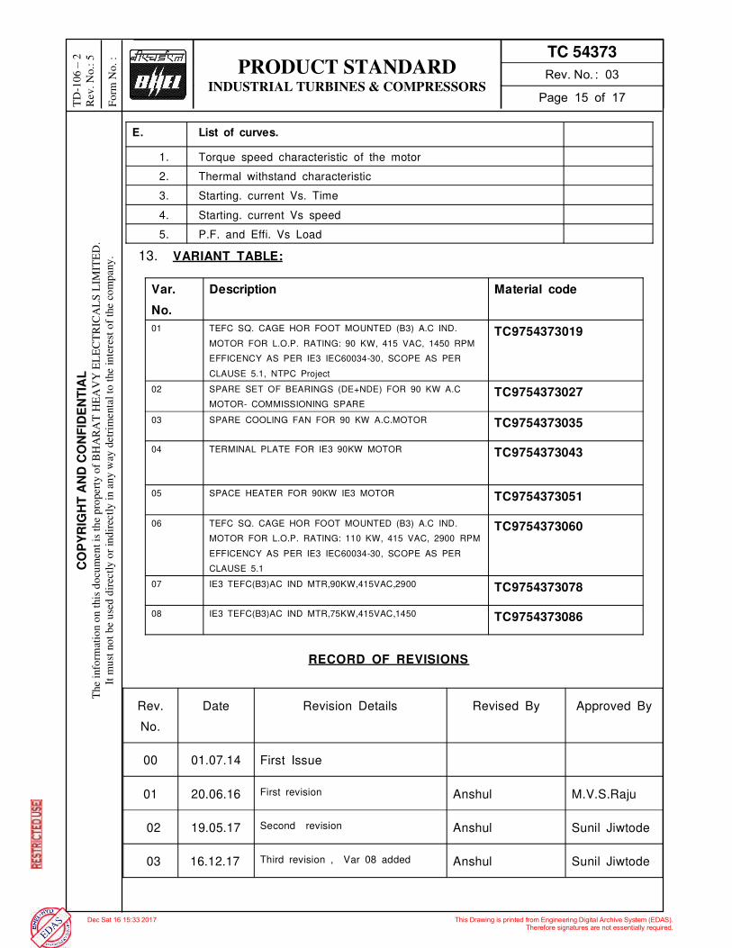
PRODUCT STANDARD INDUSTRIAL TURBINES & COMPRESSORS
TC 54373
CO
PY
RIG
HT
AN
D C
ON
FID
EN
TIA
L
The i
nfo
rmat
ion o
n t
his
do
cum
en
t is
th
e p
ropert
y o
f B
HA
RA
T H
EA
VY
EL
EC
TR
ICA
LS
LIM
ITE
D.
It m
ust
no
t b
e u
sed
dir
ectl
y o
r in
dir
ectl
y i
n a
ny w
ay d
etr
imenta
l to
the i
nte
rest
of
the c
om
pany
.
TD
-10
6
2
Rev.
No.:
5
Fo
rm N
o.
:
E. List of curves.
1. Torque speed characteristic of the motor
2. Thermal withstand characteristic
3. Starting. current Vs. Time
4. Starting. current Vs speed
5. P.F. and Effi. Vs Load
13. VARIANT TABLE:
Var.
No.
Description Material code
01 TEFC SQ. CAGE HOR FOOT MOUNTED (B3) A.C IND.
MOTOR FOR L.O.P. RATING: 90 KW, 415 VAC, 1450 RPM
EFFICENCY AS PER IE3 IEC60034-30, SCOPE AS PER
CLAUSE 5.1, NTPC Project
TC9754373019
02 SPARE SET OF BEARINGS (DE+NDE) FOR 90 KW A.C
MOTOR- COMMISSIONING SPARE
TC9754373027
03 SPARE COOLING FAN FOR 90 KW A.C.MOTOR TC9754373035
04 TERMINAL PLATE FOR IE3 90KW MOTOR TC9754373043
05 SPACE HEATER FOR 90KW IE3 MOTOR TC9754373051
06 TEFC SQ. CAGE HOR FOOT MOUNTED (B3) A.C IND.
MOTOR FOR L.O.P. RATING: 110 KW, 415 VAC, 2900 RPM
EFFICENCY AS PER IE3 IEC60034-30, SCOPE AS PER
CLAUSE 5.1
TC9754373060
07 IE3 TEFC(B3)AC IND MTR,90KW,415VAC,2900 TC9754373078
08 IE3 TEFC(B3)AC IND MTR,75KW,415VAC,1450 TC9754373086
RECORD OF REVISIONS
Rev.
No.
Date Revision Details Revised By Approved By
00 01.07.14 First Issue
01 20.06.16 First revision Anshul M.V.S.Raju
02 19.05.17 Second revision Anshul Sunil Jiwtode
03 16.12.17 Third revision , Var 08 added Anshul Sunil Jiwtode
PRODUCT STANDARD INDUSTRIAL TURBINES & COMPRESSORS
TC 54373
CO
PY
RIG
HT
AN
D C
ON
FID
EN
TIA
L
The i
nfo
rmat
ion o
n t
his
do
cum
en
t is
th
e p
ropert
y o
f B
HA
RA
T H
EA
VY
EL
EC
TR
ICA
LS
LIM
ITE
D.
It m
ust
no
t b
e u
sed
dir
ectl
y o
r in
dir
ectl
y i
n a
ny w
ay d
etr
imenta
l to
the i
nte
rest
of
the c
om
pany
.
TD
-10
6
2
Rev.
No.:
5
Fo
rm N
o.
:

Digitally signed by soumyajitmukherjeeDate: 2020.08.17 18:20:27 ISTReason: CAT ILocation: NTPCEOC
Signature Not Verified

PROJECTPROJECTPROJECTPROJECT- 1X660 MW PANKI THERMAL POWER EXTENSION PROJECT
DOC NODOC NODOC NODOC NO – 9962-001-HY-110-PVM-W-026
TITLETITLETITLETITLE- TYPE TEST PROCEDURE OF LUBE OIL PURIFICATION SYSTEM FOR TDBFP
S.No. Customer Comment BHEL reply dtd 08.05.2020
1 The comment was to tell that according to diagram submitted, S2 point is before polishing filter whereas . BHEL
to check and correct.
Noted and revised in document.
2 Please inform about the time till which module is run in
recirculation mode? There is no definite time period because practically we need to add
dirt in small stages in such way we achieve/ create inlet condition of
21/18 class as per ISO 4406 as explained next step of point no. 3 of
type test procedure.
3 S2 or S3?? S3
4 Please check with the attached setup diagram. Revised doc attached
Note: The test procedure is a standard document followed since last 10 years. Request to accept the same.

TYPE TEST PROCEDURE FOR ALFA LAVAL DISC BOWL CENTRIFUGE
1. Objective:
To measure effectiveness of centrifuge / separator w.r.t. reduction of solid contaminants from
mineral oil.
Type Test for solid particle reduction size shall be carried out on Model MMB 305 centrifuge.
2. Scope:
Centrifuge is used for various grades of Turbine lube oils like ISO VG 32, 46, 57, 68 in power
plants. The capacity of centrifuge depends on its viscosity at separation temperature.
2.1 Oil Grade: Type test for particle size shall be conducted with ISO VG 46 oil.
2.2 Location: Type test will be conducted by CMTI, Bangalore @ Alfa Laval India
Private Limited, Dapodi , Pune Factory .
2.3 Desired cleanliness level for particle size:
Centrifuge inlet oil quality - 21/18 as per ISO 4406
Centrifuge outlet oil quality after Centrifuge - 15/12 as per ISO 4406 in one pass.
The samples testing will be as per ISO4406-1999 procedure by Automatic particle counter.
Sample testing starts only after calibrating the instruments as per NAS 0 cleanliness level.
For calibration of automatic particle size counter ISO 11171:1999, Hydraulic fluid power
calibration of automatic particle size counters for liquids shall be used.
2.4 Standard followed for particle size measurement:
ISO 4406: 1999(E). This International standard specifies the code to be used in defining of
solid particles in the fluid used in a given hydraulic fluid power system.
3. Procedure for Particle Size Measurement Test:
Assemble the centrifuge bowl in purifier mode.
Set up of the module is made as per attached schematic flow diagram (SMN-0241 R1)
Oil temperature will be maintained at 65 Deg C.
Start the feed (Fresh /clean oil) and wait till it reaches full speed. & set the purifier for desired capacity -2400 LPH of ISOVG 46 & temp 65
Start the module initially in recirculation mode (fresh oil is circulated back to dirty oil tank).
Add particulate matter (contamination) in dirty oil tank to achieve contamination level of
21/18 as per ISO 4406 by ensuring proper mixing of the particulate matter (contamination).
Which can be checked through automatic particle counter.

Once above-mentioned condition achieves, the module is ready for the Type test.
The oil flow (capacity) is checked using measuring flask. Desired capacity is measured by
collecting the oil in a jar of 5 ltrs. And time taken to fill this jar. At least three readings are
taken to adjust the capacity. The capacity is adjusted by flow adjusting inlet valve.
Collect samples from centrifuge inlet sampling point after one minute of mixing dirt and
collect sample at outlet after two minute of mixing dirt
The samples should be checked for its contamination using CMTI instruments (Automatic
particle counter) which are made available at the type test venue. All the sample readings
are recorded as per the
Log Sheet below.
Stop the centrifuge after collection of samples.
4. Sample collection:
Use ultra clean bottles.
Samples will be collected after proper rinsing of clean bottles with respective oil.
Once the oil is collected in the bottle, close the cap immediately, this will help to avoid
settling of atmospheric particles in the oil sample.
Samples will be collected at 2 points.
Dirty Oil Sample @ Centrifuge Inlet (Sample point S1)
Clean Oil Sample @ Centrifuge Outlet i.e. after polishing filter (Sample point S3)
Valid Calibration certificates of all measuring instruments (/Temperature/Particle count
measurement etc.) shall be made available at the time of Type Test.
5. ACCEPTANCE CRITERIA FOR PARTICLE SIZE REDUCTION:
During sample test, Inlet oil quality shall be inferior or equal to ISO 4406 class 21/18 and
Cleaned oil outlet quality at outlet of Centrifuge(i.e. after polishing filter) shall be superior or
equal to ISO 4406 class 15/12 in one pass.
6. Capacity will measured during testing –
Desired Capacity is measured by collecting the oil jar of 5 Lit & time taken to fill this jar, At
least three readings are taken to adjust the capacity. The capacity is adjusted by flow
adjusting inlet valve
LOG SHEET FOR MEASUREMENT OF PARTICULATE MATTER

Centrifuge Model no.-
Design Flow -
Oil Grade –
Tank Capacity -
Machine Sr.No. -
Temperature -
Total weight of solid particles added of different
sizes to achieve dirty oil particle size class 21/18 -
Sr
No
Date Time Flow
M3/hr
or LPH
Temp
Deg C
Dirt
added at
time
Sample
Collection
time
Contamination Level as per
ISO 4406
Dirty oil at
inlet of
centrifuge
(S1)
Clean oil at
outlet of
Centrifuge
(i.e. After
Polishing
filter)
(S3)
(NTPC) (BHEL/TPIA) (CMTI) (Alfa Laval)
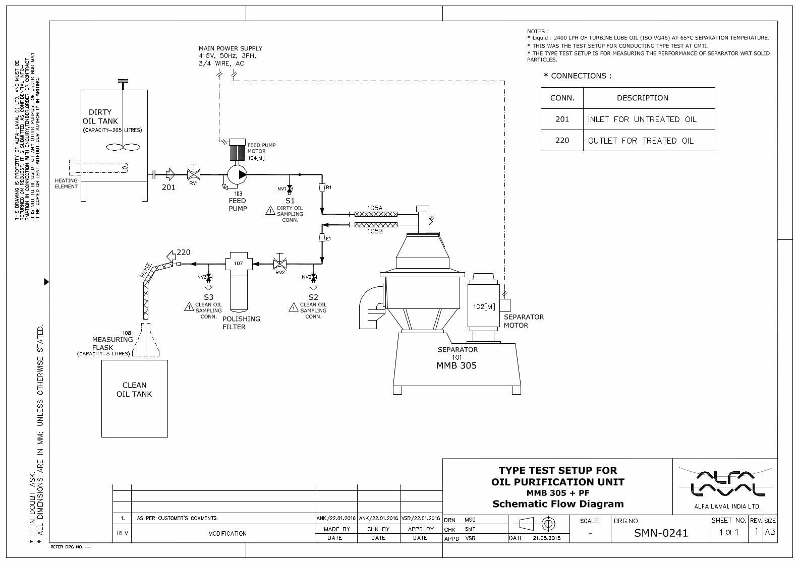

Reference numberISO 4406:1999(E)
© ISO 1999
INTERNATIONALSTANDARD
ISO4406
Second edition1999-12-01
Hydraulic fluid power — Fluids — Methodfor coding the level of contamination bysolid particles
Transmissions hydrauliques — Fluides — Méthode de codification duniveau de pollution particulaire solide
Licensed to ALFA LAVAL/BRUCE HAYISO Store order #: 510916/Downloaded: 2002-08-27Single user licence only, copying and networking prohibited

ISO 4406:1999(E)
PDF disclaimer
This PDF file may contain embedded typefaces. In accordance with Adobe's licensing policy, this file may be printed or viewed but shall notbe edited unless the typefaces which are embedded are licensed to and installed on the computer performing the editing. In downloading thisfile, parties accept therein the responsibility of not infringing Adobe's licensing policy. The ISO Central Secretariat accepts no liability in thisarea.
Adobe is a trademark of Adobe Systems Incorporated.
Details of the software products used to create this PDF file can be found in the General Info relative to the file; the PDF-creation parameterswere optimized for printing. Every care has been taken to ensure that the file is suitable for use by ISO member bodies. In the unlikely eventthat a problem relating to it is found, please inform the Central Secretariat at the address given below.
© ISO 1999
All rights reserved. Unless otherwise specified, no part of this publication may be reproduced or utilized in any form or by any means, electronicor mechanical, including photocopying and microfilm, without permission in writing from either ISO at the address below or ISO's member bodyin the country of the requester.
ISO copyright officeCase postale 56 � CH-1211 Geneva 20Tel. + 41 22 749 01 11Fax + 41 22 734 10 79E-mail [email protected] www.iso.ch
Printed in Switzerland
ii © ISO 1999 – All rights reserved
Licensed to ALFA LAVAL/BRUCE HAYISO Store order #: 510916/Downloaded: 2002-08-27Single user licence only, copying and networking prohibited

ISO 4406:1999(E)
© ISO 1999 – All rights reserved iii
Foreword
ISO (the International Organization for Standardization) is a worldwide federation of national standards bodies (ISOmember bodies). The work of preparing International Standards is normally carried out through ISO technicalcommittees. Each member body interested in a subject for which a technical committee has been established hasthe right to be represented on that committee. International organizations, governmental and non-governmental, inliaison with ISO, also take part in the work. ISO collaborates closely with the International ElectrotechnicalCommission (IEC) on all matters of electrotechnical standardization.
International Standards are drafted in accordance with the rules given in the ISO/IEC Directives, Part 3.
Draft International Standards adopted by the technical committees are circulated to the member bodies for voting.Publication as an International Standard requires approval by at least 75 % of the member bodies casting a vote.
International Standard ISO 4406 was prepared by Technical Committee ISO/TC 131, Fluid power systems,Subcommittee SC 6, Contamination control and hydraulic fluids.
This second edition cancels and replaces the first edition (ISO 4406:1987), which has been technically revised. Thenew edition introduces a three-part code for contamination levels measured with automatic particle counterscalibrated in accordance with ISO 11171. It also introduces equivalent particle sizes for such counters, based oncalibration with NIST standard reference material SRM 2806.
The particle sizes to be reported for measurement by using a microscope, W5 µm and W15 µm, are unchanged
from those specified in ISO 4406:1987.
Defining the automatic particle counter code sizes in this way validates direct comparison of measurements madein accordance with this standard using either measurement method, or between such measurements and datarecords based on ISO 4406:1987.
Annex A forms a normative part of this International Standard.
Licensed to ALFA LAVAL/BRUCE HAYISO Store order #: 510916/Downloaded: 2002-08-27Single user licence only, copying and networking prohibited

ISO 4406:1999(E)
iv © ISO 1999 – All rights reserved
Introduction
In hydraulic fluid power systems, power is transmitted and controlled through a liquid under pressure within anenclosed circuit. Solid-particle contaminant is always present in the hydraulic fluid, and the amount needs to bedetermined because the contaminant may cause serious problems.
Licensed to ALFA LAVAL/BRUCE HAYISO Store order #: 510916/Downloaded: 2002-08-27Single user licence only, copying and networking prohibited

INTERNATIONAL STANDARD ISO 4406:1999(E)
© ISO 1999 – All rights reserved 1
Hydraulic fluid power — Fluids — Method for coding thelevel of contamination by solid particles
1 Scope
This International Standard specifies the code to be used in defining the quantity of solid particles in the fluid usedin a given hydraulic fluid power system.
2 Normative references
The following normative documents contain provisions which, through reference in this text, constitute provisions ofthis International Standard. For dated references, subsequent amendments to, or revisions of, any of thesepublications do not apply. However, parties to agreements based on this International Standard are encouraged toinvestigate the possibility of applying the most recent editions of the normative documents indicated below. Forundated references, the latest edition of the normative document referred to applies. Members of ISO and IECmaintain registers of currently valid International Standards.
ISO 4407:1991, Hydraulic fluid power — Fluid contamination — Determination of particulate contamination by thecounting method using a microscope.
ISO 11171:1999, Hydraulic fluid power — Calibration of automatic particle counters for liquids.
ISO 11500:1997, Hydraulic fluid power — Determination of particulate contamination by automatic counting usingthe light extinction principle.
3 Code definition
3.1 General
The purpose of this code is to simplify the reporting of particle count data by converting the numbers of particlesinto broad classes or codes, where an increase in one code is generally a doubling of the contamination level.
The original code in accordance with ISO 4406:1987 stated the reporting at two sizes, W5 µm and W15 µm, but thesizes in this revision have been changed to account for the use of a different calibration standard for opticalautomatic particle counters. The reported sizes are W4 µm(c), W6 µm(c) and W14 µm(c), the last two of thesebeing equivalent to the 5 µm and 15 µm particle sizes obtained using the ISO 4402:1991 method of calibratingautomatic particle counters. ISO 4402:1991 has been replaced by ISO 11171:1999. Throughout this InternationalStandard, the use of µm(c) means that particle size measurements are carried out using an automatic particlecounter which has been calibrated in accordance with ISO 11171.
Measurement of particles using an optical microscope as specified in ISO 4407:1991 establishes the size of aparticle as being equal to its longest dimension, whereas an automatic particle counter derives the size of anequivalent particle from its cross-sectional area, a value different in most cases from that determined using amicroscope. The particle sizes to be reported for measurement by microscope, W5 µm and W15 µm, areunchanged from those specified in ISO 4406:1987.
Licensed to ALFA LAVAL/BRUCE HAYISO Store order #: 510916/Downloaded: 2002-08-27Single user licence only, copying and networking prohibited

ISO 4406:1999(E)
2 © ISO 1999 – All rights reserved
CAUTION — Particle counts are affected by a variety of factors. These factors include procurement ofsample, particle counting accuracy, and the sample container, where used, and its cleanliness. Proper careshould be taken during sample procurement to ensure that the sample obtained is representative of thefluid circulation in the system.
3.2 Basis of code
The code for contamination levels using automatic particle counters comprises three scale numbers, which permitthe differentiation of the dimension and the distribution of the particles as follows:
� the first scale number represents the number of particles equal to or larger than 4 µm(c) per millilitre of fluid;
� the second scale number represents the number of particles equal to or larger than 6 µm(c) per millilitre of fluid;
� the third scale number represents the number of particles equal to or larger than 14 µm(c) per millilitre of fluid.
The code for microscope counting comprises two scale numbers using 5 µm and 15 µm.
3.3 Allocation of scale numbers
3.3.1 The scale numbers are allocated according to the number of particles counted per millilitre of the fluidsample (see Table 1).
3.3.2 A step ratio of generally two, as given between the upper and lower limits for the number of particles permillilitre in Table 1, has been adopted to keep the number of scale numbers within a reasonable limit and to ensurethat each step is meaningful.
3.4 Determination of code using automatic particle counter analysis
3.4.1 Counting shall be undertaken in accordance with ISO 11500 or another recognised method, using anautomatic particle counter calibrated to ISO 11171.
3.4.2 A scale number shall be allocated to the number of particles equal to or larger than 4 µm(c).
3.4.3 A second scale number shall be allocated to the number of particles equal to or larger than 6 µm(c).
3.4.4 A third scale number shall be allocated to the number of particles equal to or larger than 14 µm(c).
3.4.5 The three numbers shall be written one after the other and separated by oblique strokes (slashes).
EXAMPLE A code of 22/18/13 signifies that there are more than 20 000 and up to and including 40 000 particles equal toor larger than 4 µm(c), more than 1 300 and up to and including 2 500 particles equal to or larger than 6 µm(c) and more than 40and up to and including 80 particles equal to or larger than 14 µm(c) in 1 ml of a given fluid sample.
3.4.6 When applicable, include either a "*" (too numerous to count) or a "—" (no requirement to count) notationwhen reporting the scale number.
EXAMPLE 1 */19/14 means that this sample has too many particles equal to or larger than 4 µm(c) to count.
EXAMPLE 2 —/19/14 means that there was no requirement to count particles equal to or larger than 4 µm(c).
Licensed to ALFA LAVAL/BRUCE HAYISO Store order #: 510916/Downloaded: 2002-08-27Single user licence only, copying and networking prohibited

ISO 4406:1999(E)
© ISO 1999 – All rights reserved 3
Table 1 — Allocation of scale numbers
Number of particles per millilitre Scale number
More than Up to and including
2 500 000 �28
1 300 000 2 500 000 28
640 000 1 300 000 27
320 000 640 000 26
160 000 320 000 25
80 000 160 000 24
40 000 80 000 23
20 000 40 000 22
10 000 20 000 21
5 000 10 000 20
2 500 5 000 19
1 300 2 500 18
640 1 300 17
320 640 16
160 320 15
80 160 14
40 80 13
20 40 12
10 20 11
5 10 10
2,5 5 9
1,3 2,5 8
0,64 1,3 7
0,32 0,64 6
0,16 0,32 5
0,08 0,16 4
0,04 0,08 3
0,02 0,04 2
0,01 0,02 1
0,00 0,01 0
NOTE Reproducibility below scale number 8 is affected by the actual number of particles counted in the fluid sample.Raw counts should be more than 20 particles. If this is not possible, then refer to 3.4.7.
3.4.7 When the raw data in one of the size ranges results in a particle count of fewer than 20 particles, the scale
number for that size range shall be labelled with the symbol W.
EXAMPLE A code of 14/12/W7 signifies that there are more than 80 and up to and including 160 particles equal to orlarger than 4 µm(c) per millilitre and more than 20 and up to and including 40 particles equal to or larger than 6 µm(c) permillilitre. The third part of the code, W 7, indicates that there are more than 0,64 and up to and including 1,3 particles equal to orlarger than 14 µm(c) per millilitre, but less than 20 particles were counted, which lowers statistical confidence. Because of thislower confidence, the 14 µm(c) part of the code could actually be higher than 7, indicating a particle count more than1,3 particles per millilitre.
Licensed to ALFA LAVAL/BRUCE HAYISO Store order #: 510916/Downloaded: 2002-08-27Single user licence only, copying and networking prohibited

ISO 4406:1999(E)
4 © ISO 1999 – All rights reserved
3.5 Determination of code using microscope sizing
3.5.1 Counting shall be undertaken in accordance with ISO 4407.
3.5.2 A scale number shall be allocated to the number of particles equal to or larger than 5 µm.
3.5.3 A second scale number shall be allocated to the number of particles equal to or larger than 15 µm.
3.5.4 In order to relate to counts obtained with an automatic particle counter, the code shall be stated in three-part form with the first part given as a "—", e.g. —/18/13.
4 Identification statement (reference to this International Standard)
Use the following statement in test reports, catalogues and sales literature when electing to comply with thisInternational Standard:
"Solid contaminant code conforms to ISO 4406:1999, Hydraulic fluid power — Fluids — Method for coding the levelof contamination by solid particles."
Licensed to ALFA LAVAL/BRUCE HAYISO Store order #: 510916/Downloaded: 2002-08-27Single user licence only, copying and networking prohibited

ISO 4406:1999(E)
© ISO 1999 – All rights reserved 5
Annex A(normative)
Graphical presentation of the code number
For automatic particle counter analysis, the contaminant code is determined by allocating a first scale number tothe total number of particles equal to or larger than 4 µm(c), allocating a second scale number to the total numberof particles equal to or larger than 6 µm(c) and allocating a third scale number to the total number of particles equalto or larger than 14 µm(c), and then writing these three numbers one after another separated by oblique strokes(slashes). For an example, see 22/18/13 in Figure A.1. For analysis by microscope, use a "—" in place of the firstscale number and allocate the second and third numbers based on the counts at 5 µm and 15 µm, respectively.
Interpolation is acceptable, extrapolation is not permissible.
Licensed to ALFA LAVAL/BRUCE HAYISO Store order #: 510916/Downloaded: 2002-08-27Single user licence only, copying and networking prohibited

ISO 4406:1999(E)
6 © ISO 1999 – All rights reserved
NOTE Quote scale number at 4 �m(c), 6 �m(c) and 14 �m(c) levels for automatic particle counters, and at 5 �m and15 �m for microscope counting.
Figure A.1
Licensed to ALFA LAVAL/BRUCE HAYISO Store order #: 510916/Downloaded: 2002-08-27Single user licence only, copying and networking prohibited

ISO 4406:1999(E)
© ISO 1999 – All rights reserved 7
Bibliography
[1] ISO 4021:1992, Hydraulic fluid power — Particulate contamination analysis — Extraction of fluid samplesfrom lines of an operating system.
Licensed to ALFA LAVAL/BRUCE HAYISO Store order #: 510916/Downloaded: 2002-08-27Single user licence only, copying and networking prohibited

ISO 4406:1999(E)
ICS 23.100.60; 75.120
Price based on 7 pages
© ISO 1999 – All rights reserved
Licensed to ALFA LAVAL/BRUCE HAYISO Store order #: 510916/Downloaded: 2002-08-27Single user licence only, copying and networking prohibited

Digitally signed by soumyajitmukherjeeDate: 2020.06.01 09:14:32 ISTReason: CAT ILocation: NTPCEOC
Signature Not Verified

PROJECTPROJECTPROJECTPROJECT- 1X660 MW PANKI THERMAL POWER EXTENSION PROJECT
DOC NODOC NODOC NODOC NO – HY-DG-4-31101-20221
TITLETITLETITLETITLE- P&ID OF LUBE OIL PURIFICATION SYSTEM FOR TDBFP
S.No. Customer Comment BHEL Reply
A comments repeated.BHEL/Alfa to discuss the same with NTPC-C&I before submission of next revision.
Noted. Discussion completed.
1. Flow meter is to be provided for safe operation and monitoring by the operator. 2. The flow meter has been provided in all previous projects.
Noted. Flowmeter is incorporated in the revised document.
C How to ensure that separator capacity is 20% of total charge.to explain how this value of 2400LPH has arrived?
Tank charge capacity is 11500 lts (As per spec requirement of 5 min
retention time- Ch 2, Sec 2 clause 7.7.8.a). Considering 20% of the total
charge capacity OPU is sized as 2400LPH.
D What is the tripping value of oil & water for heaters to trip??
Tripping value of oil is 75°C and for Water is 90°C. All this parameters
are settable and can be set as per the site ambient temperature.
E As per spec Oil temp should not go above 65 degrees, then why alarm is being generated at higher values.
All the points shown in the write up are settable points and can be
altered based on the site ambient condition. As per the Alfa Laval
guideline, the separation temperature is 65°C. The tripping for oil high
temp is 10°C over the separation temperature.
The only point, is that machine will have best separation efficiency at
65°C. Rest everything can be set as per ambient temperature.

CONTROL PANEL
220
201
HD
PO
LIS
HIN
G
FIL
TER
INDIRECT HEATER
WD
371
TD
MMB 305
221
116
206
FEED PUMP
EXPANDER / REDUCER :
R1 :
R2 :
E1 :
E2 :
Spec. No. : TC 54367 Rev.5
Material code : TC9754367450
NOTES :
* Liquid :
* Painting :
* WATER FOR SEALING :
Pressure :
Total Hardness :
pH-Value : >
Salinity :
* WATER FOR HEATER :
Type :
Quantity :
:
* INTER CONNECTING PIPES CONFORMING TO ASTM A312, TP 304, SCH40, SEAMLESS.
*
*
*
*
*
*
CONNECTIONS :
201 :
202 :
220 :
206 :
371 :
TD :
WD
HD
BD
S1, S2
SAMPLING
CONN. - 15NB
HOSE CONN.
MAIN SUPPLY :
CUSTOMER : BHARAT HEAVY ELECTRICALS LTD, HYDERABAD.
PROJECT : 1X660MW UPRVUNL PANKI-(MPA1063)
P.O. No. : B719A00494 Dtd. 02.11.2019
SM
J6H
42761-0
1
OIL PURIFICATION UNIT,MMB305 + 48kW INDIRECT HEATER + FM + PF + LSA
P & I Diagram +Part ListSUPPLY LIMITS
perm
itte
d b
y A
lfa L
aval. A
lfa L
aval w
ill e
nfo
rce its
rig
hts
rela
ted t
o t
his
docum
ent
to t
he f
ulle
st
exte
nt
of
the law
, in
clu
din
g t
he s
eekin
g o
f crim
inal pro
secution.
record
ing,
or
oth
erw
ise),
or
for
any p
urp
ose,
without
the e
xpre
ssed
perm
issio
n o
f A
lfa L
aval. N
or
may it
be u
sed in a
ny o
ther
way o
r fo
r any o
ther
purp
ose t
han e
xpre
ssly
any r
ights
rela
ted t
o t
his
docum
ent,
no p
art
of
this
docum
ent
may b
e c
opie
d,
repro
duced o
r tr
ansm
itte
d in a
ny f
orm
or
by a
ny m
eans (
ele
ctr
onic
, m
echanic
al, p
hoto
copyin
g,
This
docum
ent
and its
conte
nts
is o
wned b
y A
lfa L
aval A
B (
publ.)
or
its a
ffili
ate
s a
nd p
rote
cte
d b
y law
s g
overn
ing inte
llectu
al pro
pert
y a
nd t
here
to r
ela
ted r
ights
. W
ithout
limitin
g
Alfa Laval India Pvt. Limited
ISO
A2_L P
AP
ER
TE
MP
LA
TE
NO
.:-Q
MJ00001-0
126/R
3
RE
FE
RE
NC
E D
RA
WIN
G N
O.-
202
M
REFER DRG NO. :-
S1
SAMPLING
CONN. - 15NB
HOSE CONN.
S2
OIL QUALITY LOP SYSTEM :-
FLOW
METER
Lube Oil P&ID System- 9962-110-PVM-F-003 (For conn 201 and 220) Data sheet of Purification unit- 9962-110-PVM-Y-025 Equipment Foundation- 9962-110-PVC-V-012 GAD of Purification - 9962-110-PVM-B-024 Wiring and control Panel Drg- 9962-110-PVM-B-027

Document No. :
SMJD6H42897-01
OIL PURIFICATION UNIT, STATIONARY
MMB305 + 48KW INDIRECT HEATER + FM + PF +
LSA
PARTS LIST
Date Sheet No.
Alfa Laval India Private
Limited
06.04.2020 1 of 5
Prepared By MSG Rev. Size
Checked By VSB Customer :- BHARAT HEAVY ELECTRICALS LTD, HYDERABAD.
2 A4 Approved By VSB
Project : - 1 x 660MW UPRVUNL PANKI-(MPA1063).
P.O. No. : B719A00494 Dtd. 02.11.2019
Spec. No. : TC 54367 Rev.5
Material code : TC9754367450
Reference Drawing No. : SMJ6H42897‐01 For Schematic Flow Diagram. Template No. : SMND‐0172, Rev. : 0
I. No. Tag No. Qty Name Make Model / Part No. Technical Data
1 100 1 BASE FRAME ALIPL SMJ6H42897-05 STATIONARY TYPE, CARBON STEEL FABRICATION,
IS:2062.
2 101 1 STRAINER FORBES MARSHALL /
TRIVENI 25NB SOCKET WELD CONN, SS, `Y' TYPE, MESH 12, SS
SCREEN.
3 R1
102 1 FEED PUMP TUSHACO RT 40HBCI3LNJ INLET/OUTLET: 1"BSP CONN., GEAR PUMP, HORIZANTAL MOUNTING, CAPACITY:2640LPH.
BODEY: IS 210 GR.FG 260, SHAFT: EN 10084 20 MnCr5
4
103[M] 1 FEED PUMP MOTOR
CROMPTON GREAVES/ BHARAT BIJLEE/ ABB / SIEMENS
0.75kW, 4 POLE, 415V±10%, 50Hz±5%, 3PH, IP55, B3, IE3, STD TEFC, SQ CAGE, AC INDUCTION TYPE, AS PER BHEL SPEC NO. TC 54373
5 105 1 OIL HEATER ALIPL 48KWIDH
SMJ6H42761-06 INDIRECT TYPE, Rating : 48kW, 415V, 3PH, 50HZ, AC, SUPPLY WITH SS TUBES.
6 R1
107 1 SEPARATOR ALIPL MMB305 S-11 CENTRIFUGAL TYPE, SOLID RETAINING , SPECIFICATION : 88115201050150
FRAME: CI EN 1561,BOWL: SS Alloy, EN 10088, steel no 1.4462,DISKS: SS316, ASTM A480M,SPINDLE: Steel EN 10083‐3
7
108[M] 1 SEP. MOTOR CROMPTON GREAVES/ BHARAT BIJLEE/ ABB / SIEMENS
3.7kW, 2 POLE, 415V±10%, 50Hz±5%, V&F 10%, 3PH, IP55, V1, INSLN.CL.`F', TEMP. RISE LIMITED TO CL.`B', 50°C AMB. TEMP., IE3, STD TEFC, SQ.CAGE, AC INDUCTION TYPE, AS PER BHEL SPEC NO. TC 54373

Document No. :
SMJD6H42897-01
OIL PURIFICATION UNIT, STATIONARY
MMB305 + 48KW INDIRECT HEATER + FM + PF +
LSA
PARTS LIST
Date Sheet No.
Alfa Laval India Private
Limited
06.04.2020 2 of 5
Prepared By MSG Rev. Size
Checked By VSB Customer :- BHARAT HEAVY ELECTRICALS LTD, HYDERABAD.
2 A4 Approved By VSB
Project : - 1 x 660MW UPRVUNL PANKI-(MPA1063).
P.O. No. : B719A00494 Dtd. 02.11.2019
Spec. No. : TC 54367 Rev.5
Material code : TC9754367450
Reference Drawing No. : SMJ6H42897‐01 For Schematic Flow Diagram. Template No. : SMND‐0172, Rev. : 0
I. No. Tag No. Qty Name Make Model / Part No. Technical Data
8 109 1 ANTIFLOOD
TANK ALIPL SEJB192-106 Capacity : 20 LTRS (APPROX.), CARBON STEEL
FABRICATION, IS:2062.
9 115 1 CONTROL PANEL ALIPL SMJ6H42897-03 INPUT SUPPLY 415V, 3PH, 50HZ.
10 RV1
1 REGULATING VALVE
L&T/BDK 25NB SOCKET WELD CONN., SS304, GLOBE TYPE.
11 FG1-2 2 FLOW GLASS TECHNOFLOW/SIGM
A 25NB FLANGED CONN., CLASS 150, SS304.
12
PG1 1 PRESSURE GAUGE
GIC / WIKA LFBSPG-V-150-S4S-S6S-S6S-S4S-T15NTM-(-1 to 5)-BAR-GLY
1/2"NPT(M) CONN., RANGE : -1 TO +5Kg/cm², SS CASE, DIAL 150mm, BOTTOM CONN., GLYCERINE FILLED, BOURDON TUBE TYPE, WEATHER PROOF.
13
PG2-4 3 PRESSURE GAUGE
GIC / WIKA LFBSPG-V-150-S4S-S6S-S6S-S4S-T15NTM-(0 to 6)-BAR-GLY
1/2"NPT(M) CONN., RANGE : 0 TO +6Kg/cm², SS CASE, DIAL 150mm, BOTTOM CONN., GLYCERINE FILLED, BOURDON TUBE TYPE, WEATHER PROOF.
14 GV1-GV4 4 GAUGE
ISOLATION VALVE
GIC 2 VALVE MANIFOLD- ½"NPT(F) CONN., SS304 BODY & INTERNALS, Model: G2VM2.
15 CV1 1 CHECK VALVE EXPERT 25NB FLANGED CONN., CLASS 150, NON SLAM TYPE,
BODY ASTM A351, Gr.CF8M, DISC AISI316.
16 R2 BV1-BV8, BV13-BV15
11 BALL VALVE L&T/ MICROFINISH / BDK
25NB SOCKET WELD CONN., SS304

Document No. :
SMJD6H42897-01
OIL PURIFICATION UNIT, STATIONARY
MMB305 + 48KW INDIRECT HEATER + FM + PF +
LSA
PARTS LIST
Date Sheet No.
Alfa Laval India Private
Limited
06.04.2020 3 of 5
Prepared By MSG Rev. Size
Checked By VSB Customer :- BHARAT HEAVY ELECTRICALS LTD, HYDERABAD.
2 A4 Approved By VSB
Project : - 1 x 660MW UPRVUNL PANKI-(MPA1063).
P.O. No. : B719A00494 Dtd. 02.11.2019
Spec. No. : TC 54367 Rev.5
Material code : TC9754367450
Reference Drawing No. : SMJ6H42897‐01 For Schematic Flow Diagram. Template No. : SMND‐0172, Rev. : 0
I. No. Tag No. Qty Name Make Model / Part No. Technical Data
17 SV1 1 SOLENOID
VALVE ASCO WPTE210 B154
220V/50Hz 1"BSP CONN., 2/2 WAY DIRECT ACTING TYPE, NC, BRASS, 220VAC,50Hz, IP55
18
TH1,TH3 2 THERMOMETER GIC / WIKA
BDT-V-150-S4S-S06-200MM-S4S-T15NTM-(0 TO 120)-DGC-TW TW-BT01-S4S-28-16-07-T15NTF-T15NTM-100-50-4-0
RIGID STEM TYPE WITH SS THERMOWELL, DIAL ∅150, 1/2" NPT(M) CONN., RANGE : 0°-120°C, WEATHERPROOF, DIRECT BOTTOM ENTRY.
19 BV9-BV11 3 BALL VALVE L&T/MICROFINISH/
BDK 3/4"BSP CONN., SS304
20 BV12 1 BALL VALVE L&T/ MICROFINISH /
BDK 3/4" BSP CONN., SS304.
-PART OF INDIRECT HEATER.
21
LS1-2 2 LEVEL SWITCH PUNE TECHTROL /SBEM
MODEL : FPS‐JN2B2SRWW /137 EA
27F SF-S000-
MAGNET FLOAT SWITCH, HORIZONTAL MOUNTED STD FLOAT ASSY, SS FLOAT, 2 SPDT
22 NV1-NV2 2 SAMPLING
NEEDLE VALVE GIC / FLUCON NEEDLE TYPE, 1/2"NPT(MxF) CONN., SS304
23 TT1, TT2 2 TEMPERATURE
SENSOR RADIX/GIC 1/2"NPT(M) CONN., SIMPLEX, 3 WIRE, HEAD TYPE, ACF
HEAD, L=150mm, ∅6.25mm, WITH THERMOWELL.
24 110A-B 2 OIL HOSE A L I P L Art. No. : 1762012-
80 FLEXIBLE TYPE, 3/4" BSP x 1" BSP CONN., SS BRAIDED, L=600mm FOR OIL IN/OUT.
25 114 1 WATER HOSE A L I P L Art. No. : 1763910- FLEXIBLE TYPE, 1/2" BSP x 3/4" BSP CONN.,

Document No. :
SMJD6H42897-01
OIL PURIFICATION UNIT, STATIONARY
MMB305 + 48KW INDIRECT HEATER + FM + PF +
LSA
PARTS LIST
Date Sheet No.
Alfa Laval India Private
Limited
06.04.2020 4 of 5
Prepared By MSG Rev. Size
Checked By VSB Customer :- BHARAT HEAVY ELECTRICALS LTD, HYDERABAD.
2 A4 Approved By VSB
Project : - 1 x 660MW UPRVUNL PANKI-(MPA1063).
P.O. No. : B719A00494 Dtd. 02.11.2019
Spec. No. : TC 54367 Rev.5
Material code : TC9754367450
Reference Drawing No. : SMJ6H42897‐01 For Schematic Flow Diagram. Template No. : SMND‐0172, Rev. : 0
I. No. Tag No. Qty Name Make Model / Part No. Technical Data
01 SS BRAIDED, L=1500mm FOR SEAL WATER.
26 116 1 VALVE ASSY FOR
WATER SEAL A L I P L Art. No. :
1763875-80 3/4" BSP CONN., , PART OF CENTRIFUGE.
27 117 1 HOSE FOR
HEAVY PHASE(WATER)
A L I P L ∅76, FLEXIBLE TYPE RUBBER PIPE.
28
TH2 1 THERMOMETER GIC / WIKA BDT-C-150-S4S-S06-200MM-S4S-T15NTM-(0 TO 120)-DGC-TW TW-BT01-S4S-28-16-07-T15NTF-T15NTM-100-50-4-0
RIGID STEM TYPE WITH SS THERMOWELL, DIAL ∅150, 1/2" NPT(M) CONN., RANGE : 0°-120°C, WEATHERPROOF, DIRECT BACK ENTRY.
29
* 4 FOUNDATION BOLTS WITH NUTS & WASHERS
A L I P L LOOSE SUPPLY - M12 x 300Lg.
30 GV6-GV7 2 GAUGE
ISOLATION VALVE
GIC / FLUCON NIDDLE TYPE, 1/4""NPT(MxM) CONN., SS304
31 R1
113 1 POLISHING FILTER
EPE 40-LE-0030-H3XL-A-
00-07-0-R0-P-00
Simplex Inline Filter with Bypass valve . Filtration Grade: 3
Microns (Absolute) , Connection: 1.1/2” BSPF,
Filer Bowl: Carbon Steel, Filter Head: Aluminium , Filter

Document No. :
SMJD6H42897-01
OIL PURIFICATION UNIT, STATIONARY
MMB305 + 48KW INDIRECT HEATER + FM + PF +
LSA
PARTS LIST
Date Sheet No.
Alfa Laval India Private
Limited
06.04.2020 5 of 5
Prepared By MSG Rev. Size
Checked By VSB Customer :- BHARAT HEAVY ELECTRICALS LTD, HYDERABAD.
2 A4 Approved By VSB
Project : - 1 x 660MW UPRVUNL PANKI-(MPA1063).
P.O. No. : B719A00494 Dtd. 02.11.2019
Spec. No. : TC 54367 Rev.5
Material code : TC9754367450
Reference Drawing No. : SMJ6H42897‐01 For Schematic Flow Diagram. Template No. : SMND‐0172, Rev. : 0
I. No. Tag No. Qty Name Make Model / Part No. Technical Data
Element: Micro Glass Fibre (Disposable), Seals: Nitrile
32 DPG + DPS 1 DIFFER.PRESSU
RE INDICATOR + SWITCH
SWITZER 120-B07-S-4-0B-2-W-C-A-Z-0
1/4" NPT(F) CONN., DIAL-150mm, 2 SPDT, RANGE: 0-2.5 bar
33 * 1 SEP. MOUNTING
STAND A L I P L SEN006561-3 CARBON STEEL FABRICATION, IS:2062.
34 * 1 FEED PUMP
MOUNTING STAND
A L I P L SEN006097-2 CARBON STEEL FABRICATION, IS:2062.
35 R2 FM 1 FLOW METER EUREKA SSVF-PG-14(M) 25NB FLANGED CONN., CLASS 150, GLASS TUBE
ROTAMETER TYPE, RANGE : 300-3000 LPH,
REVISION TABLE:
Rev.No. Revision Comments Date Created By Checked By Approved By
0 AS PER CUSTOMER COMMENTS SEPARATE PART LIST DOCUMENT PREPARED. 06.04.2020 MSG ANK VSB
1 AS PER CUSTOMER COMMENTS /AS MARKED - R1 22.04.2020 MSG ANK VSB
2 AS PER CUSTOMER COMMENTS FLOW METER & BALL VALVE ADDED. 18.05.2020 MSG ANK VSB

MMB +I DH (H1+H2=H3) + LSA_PF Page 1 of 8
Operational Write up of Separator Controller
OIL PURIFICATION SYSTEM :
MMB Separator + In Direct Heater (H1+H2+H3) + LSA +PF
SELEC Flexys Panel TX4
ESC F12 HELP F1/1 F2/2 F3/3
F11 ENTER F13 F4/4 F5/5 F6/6
SHIFT F14 F10/0 F7/7 F8/8 F9/9
TEST ACCEPT RESET
HOME
OIL: 030 deg C
WATER : 030 deg C
HOURS: 0
1. Specifications:
a) Compact PLC with Built in HMI b) Display : LCD backlight , 4 line x 16 character c) Digital inputs (DC PNP- 6-30VDC) : 18 nos d) Digital outputs (relay, 5A@230VAC) : 8 nos e) Analog inputs : 4 nos f) Number of keys: 18 g) Pre-programmed & Pre-configured , user friendly editing for temp set points. h) Input supply: 90-270 VAC i) Size : 99x99x100 , Cutout :92x92
2. Digital Inputs:
Digital Input
Description
I0 Separator Motor OverloadI1 Liquid Seal Broken
I2 Separator Motor F/B I3 Not applicable
1.I0 Low water Level in Heaters1.I1 Heater-I F/B 1.I2 Heater-II F/B

MMB +I DH (H1+H2=H3) + LSA_PF Page 2 of 8
Digital Input
Description
1.I3 Heater-III F/B
1.I4 Not applicable
1.I5 Feed Pump Motor Overload
1.I6 Feed Pump Motor F/B 1.I7 Emergency Stop 1.I8 Not applicable
1.I9 Filter Choke
1.I10 Not applicable
1.I11 Not applicable
1.I12 Not applicable
1.I13 Not applicable
Normal condition = Input closed
Abnormal condition = input open
3. RTD Inputs:
RTD Input Description I0+ / I0- / R30 Oil Temp TT1
I1+ / I1- / R31 Water Temp TT2 I2+ / I2- / R32 not connected I3+ / I3- / R33 not connected
4. Digital Outputs:
5. Keys :
Function / number : F1/1 to F9/9 & F10/0
F11: Move left, F13: Move right,
F12: Move Up, F14: Move down
Digital Output
Description
R0 Separator Motor R1 Heater-I R2 Heater-II R3 Heater-III R4 Not applicable R5 Feed Pump Motor R6 Buzzer R7 Fault

MMB +I DH (H1+H2=H3) + LSA_PF Page 3 of 8
6. Below Faults are monitored & displayed :
a) Separator Motor Overload b) Feed Pump Motor overload c) Separator Motor F/B Failure d) Feed Pump Motor F/B Failure e) Liquid Seal Broken f) Polishing Filter Choke g) Low water Level in Heaters h) Heater – I F/B Failure i) Heater – II F/B Failure j) Heater –III F/B Failure k) Low oil temp - LOT l) High oil temp – HOT m) High Water temp – HWT n) Emergency Stop o) Sensor break
7. Interlocks :
SR NO
CONDITION / ALARM ACTION
1 Separator Motor Overload Separator Motor OFF2 Liquid Seal Broken Separator Motor OFF3 Feed Pump Motor Overload Feed Pump Motor OFF4 Separator Motor OFF Feed Pump Motor OFF5 High Oil Temp Heaters OFF
6 High Water Temp Heaters OFF7 Oil temp > set temp Of Heater-I Heater-I OFF8 Oil temp > set temp Of Heater-II Heater-II OFF9 Oil temp > set temp Of Heater-III Heater-III OFF10 Motor / Heater Feedback Fail Corresponding Equipment OFF 11 Emergency Stop All Motors/ Heaters OFF12 Running Hours > Cleaning timer Separator Motor OFF
13 Separator Motor OFF /Feed Pump Motor OFF
Solenoid valve OFF
14 Polishing Filter Choke Separator Motor OFF

MMB +I DH (H1+H2=H3) + LSA_PF Page 4 of 8
8. Alarms :
a. Press F7 to Test the Buzzer / Alarm lamp. b. In the event of any Alarm , Alarm will be displayed on display, for example
such as
Se pa ra tor Motor ove rloa d
ACK: Y/ N Y
c. Press “ Enter “ key to accept the Alarm message. d. Press “ F8 “ key to silence the Buzzer, rectify the fault . e. Press “ F9 “ key to reset the Alarms . if alarm still present – the Buzzer will
sound again. Press “ F8” key to silence the Buzzer. After fault removal- Press F9 to reset the fault.
f. If more than one alarm is present or you need to see accepted alarm , Press F11 to see alarm history . Press F11 repeatedly to come out from alarm history.
F11: ALARM PRESENT
F7: TEST
F8: ACC EPT HO O TER
F9: RESET O FF
g. Press “ F12/F14 “ key to go to desired pages.
9. Following pages will be displayed on controller display :
Press “ F12/F14 “ key to go to desired pages.
a) Home > Oil temperature -TT1,TT2 & Running hours:
HO ME
O IL: - - - - de g C
WATER : - - - - de g C
HO URS: - - - -

MMB +I DH (H1+H2=H3) + LSA_PF Page 5 of 8
b) Temp set points- Alarms:
HO T LO T
75.0 40.0
EHWT
80.0
c) Temp set points- Heater stages :
H1 H2
62.0 59.0
H3 H4
56.0 0.0
d) Separator Motor :
SEPARATO R MO TO R
F1: START
F4: STO P
STATUS : O FF
e) Feed Pump Motor :
FEED PUMP MO TO R
F2: START
F5: STO P
STATUS : O FF
f) Heater:
HEATER
F3: START
F6: STO P
Comma nd : O FF
g) Heater – ON/OFF Status:
HEATER STATUS
H1 : O FF H2 : O FF
H3 : O FF H4 : O FF

MMB +I DH (H1+H2=H3) + LSA_PF Page 6 of 8
h) Alarm :
F11: ALARM PRESENT
F7: TEST
F8: ACC EPT HO O TER
F9: RESET O FF
i) Cleaning timer :
CLEANING TIMER
SETTING : 100 Hr
REMAINING TIME:
100 Hr
j) Input / Output Status : Input/output status can be seen by pressing F13 for more than 3 sec on Home page
10. Settings :
Check all set points . If any set point is required to be change - then proceed as below: a) Go to Home page . Press “Shift + F14” keys. b) All set points will be displayed one by one. c) To change the value press “ Shift + F10” keys . Existing set value will flash. Press
the required number key to input the new value. d) Press “Enter “key to store the new value. e) Press “ F14” to go next set point. f) Ensure that all new set values are correctly displayed on set point pages. g) As a general guide line ,
High water temp can be set at temp + 90 deg C
High oil temp can be set at Separation temp + 10 deg C
Low oil temp = ( Separation temp - 15 deg C )
Heater –I set point ( Separation temp – 3 deg C )
Heater –II set point ( Separation temp – 6 deg C )
Heater –III set point ( Separation temp – 9 deg C )
h) Cleaning timer is provided in the controller. Set the same as per requirement. At the end of the set time Separator will be shut down with alarm. To reset cleaning timer : switch Off the Separator Motor . Go to cleaning timer setting page , Press "shift +F4" " 0" will be shown ‐ which indicates that timer has reset to 0 , whatever time has elapsed same will be reset to 0
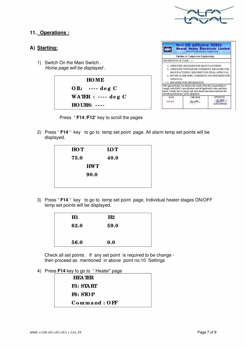
MMB +I DH (H1+H2=H3) + LSA_PF Page 7 of 8
11. Operations :
A) Starting:
1) Switch On the Main Switch . Home page will be displayed .
HO ME
O IL: - - - - de g C
WATER : - - - - de g C
HO URS: - - - -
Press “ F14 /F12“ key to scroll the pages
2) Press “ F14 “ key to go to temp set point page. All alarm temp set points will be displayed.
HO T LO T
75.0 40.0
HWT
90.0
3) Press “ F14 “ key to go to temp set point page. Individual heater stages ON/OFF temp set points will be displayed.
H1 H2
62.0 59.0
56.0 0.0
Check all set points . If any set point is required to be change - then proceed as mentioned in above point no:10 Settings
4) Press F14 key to go to “ Heater” page
HEATER
F3: START
F6: STO P
Comma nd : O FF

MMB +I DH (H1+H2=H3) + LSA_PF Page 8 of 8
Press “F3” to switch on the heaters. Command Status on display will changed to ON.
Heater stages will be made on/off automatically depending on set point & actual oil temp.
To see the individual heater stage status – Press F14 to go to Heater status page.
5) Press F14 key to go to “ Separator Motor” page
SEPARATO R MO TO R
F1: START
F4: STO P
STATUS : O FF
Press “F1” to start the separator motor. Separator Motor Status on display will changed to ON
Wait for full speed of the bowl , normally it takes 2-3 minutes to attains the full bowl speed. Provide water to establish liquid seal .
Close water after liquid seal is established.
6) Press F14 key to go to “ Feed Pump Motor” page
FEED PUMP MO TO R
F2: START
F5: STO P
STATUS : O FF
Press F2 to start the feed pump motor. Feed Pump Motor Status on display will changed to ON
Open oil inlet to separator B) Stopping:
a) Press “ F14/F12 “ key to scroll the pages b) Go to “ Heater “ page . Press “F6 “ to switch off the heater. c) Press “ F12 “ key to go to “ Feed Pump Motor” page d) Press “F5 “ to switch off the “Feed Pump Motor” e) Press “ F12 “ key to go to “ Separator Motor” page f) Press “F4 “ to switch off the Separator Motor. g) Close oil inlet valve. h) Switch OFF the Main Switch .
‐‐‐‐‐‐‐‐‐‐‐ ‐‐‐‐‐‐‐‐‐‐‐‐‐‐‐‐‐‐‐‐‐‐ End ‐‐‐‐‐‐‐‐‐‐‐‐‐‐‐‐‐‐‐‐‐‐‐‐‐‐‐‐‐‐‐‐‐‐‐‐‐‐‐‐‐‐‐‐‐‐‐‐‐‐ ‐‐‐‐‐‐‐

BHEL RAMACHANDRAPURAM HYDERABAD
STANDARD MANUFACTURING QUALITY PLAN QP. NO.:HYQA/STD QP/TC/1213/07
PRODUCT: OIL PURIFICATION UNIT BHEL SPEC: TC54216, TC54217, TC54367, TC54014, TC54017
REV NO: 02 DATE: 31.12.2015
PAGE 1 OF 4
SL NO
COMPONENTS CHARACTERISTICS CLASS TYPE OF CHECK
QUANTUM OF CHECK
REFERENCE DOCUMENT
ACCEPTANCE NORMS
FORMAT OF RECORD
*
D
AGENCY REMARKS
P W V
LEGEND: WPS – WELDING PROCESS SPECIFICATION PQR – WELDING PROCESS QUALIFICATION RECORD WPQ – WELDING PROCESS QUALIFICATION P: - PERFORM, W: - WITNESS , V: - VERFICATION, IR – INSPECTION REPORT TR – TEST REPORT T.C. - TEST CERTIFICATE 1: - BHEL /NOMMNATED INSPECTION AGENCY 2: - MANUFACTURER / VENDOR/SUB CONTRACTOR
* D: RECORDS IDENTIFIED WITH TICK (�) SHALL BE ESSENTIALLY INCLUDED IN QA
DOCUMENTATION.
PREPARED BY
Sachin Katiyar Engineer / QA
APPROVED BY
K.S.N.MURTHY
AGM / QA
1 2 3 4 5 6 7 8 9 10 11 12 13 14
1.0 RAW MATERIALS & BOUGHT OUT ITEMS
1.01 Base Plate Chemical Mechanical
Major Review 100% BHEL Spec/ Approved Drawing /
Data Sheet TC √ 2 1
1.02
Centrifuge Bowl Chemical Mechanical
Major Review 100% BHEL Spec/ Approved Drawing /
Data Sheet TC/COC √ 2 1
Bowl Balancing Balancing Test Major Review 100% BHEL Spec/ Approved Drawing /
Data Sheet TC/COC √ 2 1
Bowl Spindle UT Major Review 100% BHEL Spec/ Approved Drawing /
Data Sheet TC/COC √ 2 1
1.03 Control Wiring & Power Cables
Material Functional
Major Review 100% BHEL Spec/ Approved Drawing /
Data Sheet TC √ 2 1
1.04 Filters Material Functional
Major Review 100% BHEL Spec/ Approved Drawing /
Data Sheet TC √ 2 1
1.05 Pressure Piping Mechanical Chemical properties
Major Review 100% BHEL Spec/ Approved Drawing /
Data Sheet TC √ 2 1
1.06 Indirect type oil heater
Functional Major Review 100% BHEL Spec/ Approved Drawing /
Data Sheet TC √ 2 1
1.07 Instruments Calibration Performance
Major Measurement 100% BHEL Spec/ Approved Drawing /
Data Sheet TC √ 2 1
1.08 Strainer Visual inspection Major Visual 100% BHEL Spec/ Approved Drawing /
Data Sheet TC √ 2 1
1.09 Valves Performance & accuracy
Major Visual 100% BHEL Spec/ Approved Drawing /
Data Sheet TC √ 2 1
1.10 Flexible hose Visual inspection Major Visual 100% BHEL Spec/ Approved Drawing /
Data Sheet TC √ 2 1
1.11 Pumps with AC Motor
Routine test Major Mechanical 100% BHEL Spec/ Approved Drawing
/ Data Sheet
TC √ 2 1
Type test Minor Elect. test Sample TC √ 2 1
Flame proof-ness Major Elect. test Type test TC √ 2 1

BHEL RAMACHANDRAPURAM HYDERABAD
STANDARD MANUFACTURING QUALITY PLAN QP. NO.:HYQA/STD QP/TC/1213/07
PRODUCT: OIL PURIFICATION UNIT BHEL SPEC: TC54216, TC54217, TC54367, TC54014, TC54017
REV NO: 02 DATE: 31.12.2015
PAGE 2 OF 4
SL NO
COMPONENTS CHARACTERISTICS CLASS TYPE OF CHECK
QUANTUM OF CHECK
REFERENCE DOCUMENT
ACCEPTANCE NORMS
FORMAT OF RECORD
*
D
AGENCY REMARKS
P W V
LEGEND: WPS – WELDING PROCESS SPECIFICATION PQR – WELDING PROCESS QUALIFICATION RECORD WPQ – WELDING PROCESS QUALIFICATION P: - PERFORM, W: - WITNESS , V: - VERFICATION, IR – INSPECTION REPORT TR – TEST REPORT T.C. - TEST CERTIFICATE 1: - BHEL /NOMMNATED INSPECTION AGENCY 2: - MANUFACTURER / VENDOR/SUB CONTRACTOR
* D: RECORDS IDENTIFIED WITH TICK (�) SHALL BE ESSENTIALLY INCLUDED IN QA
DOCUMENTATION.
PREPARED BY
Sachin Katiyar Engineer / QA
APPROVED BY
K.S.N.MURTHY
AGM / QA
1.12 Drive Motor
Routine test Major Elect. test 100%
BHEL Spec/ Approved Drawing / Data Sheet
TC √ 2 1
Type test Minor Elect. test Sample TC √ 2 1
Energy Efficiency Major Type Tests Sample TC √ 2 1
Flame proof-ness Major Elect. test Type test TC √ 2 1
2.0 IN PROCESS CONTROL / INSPECTION
2.1 Fabrication / Welding
WPS, PQR review Major Verification 100% BHEL Spec/ Approved Drawing / Data Sheet
TC √ 2 1
DP Test Major NDT 100% TC √ 2 1
2.2 Assembly Dimensions Major Measurement 100% BHEL Spec/ Approved Drawing /
Data Sheet
TC √ 2 1
Completeness Major Visual 100% TC √ 2 1
2.3 Piping Butt weld / Fillet weld Major
RT / DT
100% BHEL Spec/ Approved Drawing / Data Sheet
TC √ 2 1
Hydro Test Major Mechanical 100% TC √ 2 1
2.4 Controls & Panel
Dimension Minor Measurement 100%
BHEL Spec/ Approved Drawing / Data Sheet
IR √ 2 1
Interlock & sequential operation
Major Simualtion 100% IR √ 2 1
Insulation resistance before & after HV
Major Megger test 100% IR √ 2 1
HV test Major HV test 100% IR √ 2 1
Bill of Material Minor Visual 100% IR 2 1
Flame proof-ness Major Electrical test Type test TC √ 2 1
3.0 FINAL ASSEMBLY, INSPECTION & TESTING
3.1 Dimension and general layout of system
Dimension & layout Completeness Lifting Arrangement
Minor Measurement &
visual check 100%
BHEL Spec/ Approved Drawing / Data Sheet
I.R √ 2 1
3.2 Assembly Hydro test (without centrifuge)
Criti-cal
Pressure Test 100% Approved Test Procedure / Appd
Drg & BHEL Spec IR √ 2 1
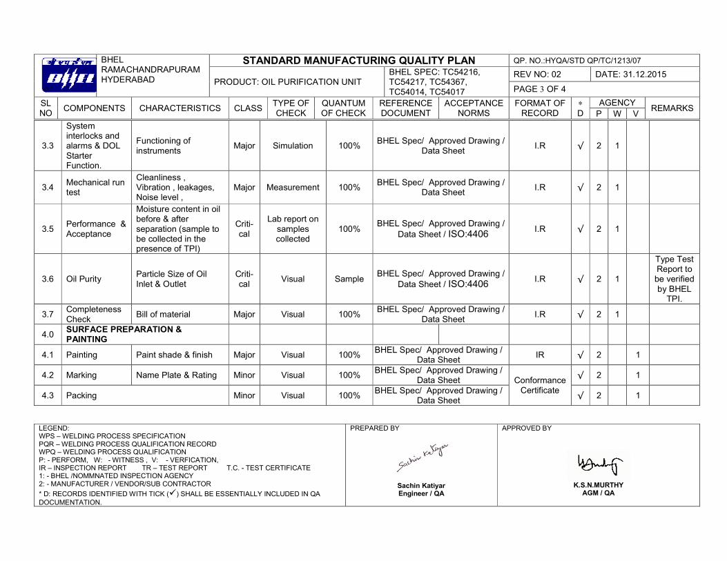
BHEL RAMACHANDRAPURAM HYDERABAD
STANDARD MANUFACTURING QUALITY PLAN QP. NO.:HYQA/STD QP/TC/1213/07
PRODUCT: OIL PURIFICATION UNIT BHEL SPEC: TC54216, TC54217, TC54367, TC54014, TC54017
REV NO: 02 DATE: 31.12.2015
PAGE 3 OF 4
SL NO
COMPONENTS CHARACTERISTICS CLASS TYPE OF CHECK
QUANTUM OF CHECK
REFERENCE DOCUMENT
ACCEPTANCE NORMS
FORMAT OF RECORD
*
D
AGENCY REMARKS
P W V
LEGEND: WPS – WELDING PROCESS SPECIFICATION PQR – WELDING PROCESS QUALIFICATION RECORD WPQ – WELDING PROCESS QUALIFICATION P: - PERFORM, W: - WITNESS , V: - VERFICATION, IR – INSPECTION REPORT TR – TEST REPORT T.C. - TEST CERTIFICATE 1: - BHEL /NOMMNATED INSPECTION AGENCY 2: - MANUFACTURER / VENDOR/SUB CONTRACTOR
* D: RECORDS IDENTIFIED WITH TICK (�) SHALL BE ESSENTIALLY INCLUDED IN QA
DOCUMENTATION.
PREPARED BY
Sachin Katiyar Engineer / QA
APPROVED BY
K.S.N.MURTHY
AGM / QA
3.3
System interlocks and alarms & DOL Starter Function.
Functioning of instruments
Major Simulation 100% BHEL Spec/ Approved Drawing /
Data Sheet I.R √ 2 1
3.4 Mechanical run test
Cleanliness , Vibration , leakages, Noise level ,
Major Measurement 100% BHEL Spec/ Approved Drawing /
Data Sheet I.R √ 2 1
3.5 Performance & Acceptance
Moisture content in oil before & after separation (sample to be collected in the presence of TPI)
Criti-cal
Lab report on samples collected
100% BHEL Spec/ Approved Drawing /
Data Sheet / ISO:4406 I.R √ 2 1
3.6 Oil Purity Particle Size of Oil Inlet & Outlet
Criti-cal
Visual Sample BHEL Spec/ Approved Drawing /
Data Sheet / ISO:4406 I.R √ 2 1
Type Test Report to be verified by BHEL
TPI.
3.7 Completeness Check
Bill of material Major Visual 100% BHEL Spec/ Approved Drawing /
Data Sheet I.R √ 2 1
4.0 SURFACE PREPARATION & PAINTING
4.1 Painting Paint shade & finish Major Visual 100% BHEL Spec/ Approved Drawing /
Data Sheet IR √ 2 1
4.2 Marking Name Plate & Rating Minor Visual 100% BHEL Spec/ Approved Drawing /
Data Sheet Conformance Certificate
√ 2 1
4.3 Packing Minor Visual 100% BHEL Spec/ Approved Drawing /
Data Sheet √ 2 1

BHEL RAMACHANDRAPURAM HYDERABAD
STANDARD MANUFACTURING QUALITY PLAN QP. NO.:HYQA/STD QP/TC/1213/07
PRODUCT: OIL PURIFICATION UNIT BHEL SPEC: TC54216, TC54217, TC54367, TC54014, TC54017
REV NO: 02 DATE: 31.12.2015
PAGE 4 OF 4
SL NO
COMPONENTS CHARACTERISTICS CLASS TYPE OF CHECK
QUANTUM OF CHECK
REFERENCE DOCUMENT
ACCEPTANCE NORMS
FORMAT OF RECORD
*
D
AGENCY REMARKS
P W V
LEGEND: WPS – WELDING PROCESS SPECIFICATION PQR – WELDING PROCESS QUALIFICATION RECORD WPQ – WELDING PROCESS QUALIFICATION P: - PERFORM, W: - WITNESS , V: - VERFICATION, IR – INSPECTION REPORT TR – TEST REPORT T.C. - TEST CERTIFICATE 1: - BHEL /NOMMNATED INSPECTION AGENCY 2: - MANUFACTURER / VENDOR/SUB CONTRACTOR
* D: RECORDS IDENTIFIED WITH TICK (�) SHALL BE ESSENTIALLY INCLUDED IN QA
DOCUMENTATION.
PREPARED BY
Sachin Katiyar Engineer / QA
APPROVED BY
K.S.N.MURTHY
AGM / QA
NOTE:
1. This QP should be read along with BHEL Spec, approved drawings, data sheet, BOM and PO. 2. Latest revisions of specification / drawings as per P.O., approved drawings & bill of materials are applicable. 3. Any other tests/ checks indicated in specification, P.O., or drawing & any additional checks envisaged by BHEL/TPI to ensure workmanship, finish,
aesthetics, etc. shall also be conducted and witnessed/verified by BHEL /TPI / customer as required. 4. All test certificates/ reports reviewed and certified by BHEL/TPI shall be submitted to BHEL as documentation package. 5. Drawing / Data Sheet shall prevail over Quality Plan in case of any contradiction between Quality Plan and Drawing / Data Sheet. 6. Any project / customer specific requirement, like QP approval & Customer/Consultant Inspection, which shall be notified have to be fulfilled by
the vendor at the time of execution of order. 7. This QP shall not be applicable to the orders for which QP approval & Inspection by customer/consultant is required. 8. This SQP is not applicable for vendors supplying this item for the first time to BHEL. 9. Requirement of carrying out the type tests and other tests shall be as per BHEL spec/ approved drawing. 10. All type test reports submitted shall not be older than 3 years from date of purchase order.