
Part 1: Hydraulic Turbines - UNIDO
34
Technical Guidelines for the Development of Small Hydropower Plants UNITS Part 1: Hydraulic Turbines SHP/TG 003-1: 2019
-
Upload
khangminh22 -
Category
Documents
-
view
4 -
download
0
Transcript of Part 1: Hydraulic Turbines - UNIDO

Technical Guidelines for the Development of Small Hydropower PlantsUNITS
Part 1: Hydraulic Turbines
SHP/TG 003-1: 2019

D I S C L A I M E R
This document has been produced without formal United Nations editing. The designations and the presentation of the material in this document do not imply the expression of any opinion whatsoever on the part of the Secretariat of the United Nations Industrial Development Organization (UNIDO) concerning the legal status of any country, territory, city or area of its authorities, or concerning the delimitation of its frontiers or boundaries, or its economic system or degree of development. Designations such as “developed”, “industrialized” and “developing” are intended for statistical convenience and do not necessarily express a judgement about the stage reached by a particular country or area in the development process. Mention of company names or commercial products does not constitute an endorsement by UNIDO. Although great care has been taken to maintain the accuracy of information herein, neither UNIDO nor its Member States assume any responsibility for consequences which may arise from the use of the material. This document may be freely quoted or reprinted but acknowledgement is requested.
© 2019 UNIDO / INSHP- All rights reserved

Technical Guidelines for the Development of Small Hydropower PlantsUNITS
Part 1: Hydraulic Turbines
SHP/TG 003-1: 2019

Technical Guidelines for the Development of Small Hydropower Plants – Units
SHP/TG 003-1: 2019IV
ACKNOWLEDGEMENTSThe technical guidelines (TGs) are the result of a collaborative effort between the United Nations Industrial Development Organization (UNIDO) and the International Network on Small Hydro Power (INSHP). About 80 international experts and 40 international agencies were involved in the document’s preparation and peer review, and they provided concrete comments and suggestions to make the TGs professional and applicable.
UNIDO and the INSHP highly appreciate the contributions provided during the development of these guidelines and in particular those delivered by the following international organizations:
- The Common Market for Eastern and Southern Africa(COMESA)
- The Global Network of Regional Sustainable Energy Centres (GN-SEC), particularly the ECOWAS Centre for Renewable Energy and Energy Efficiency (ECREEE), the East African Centre for Renewable Energy and Energy Efficiency (EACREEE), the Pacific Centre for Renewable Energy and Energy Efficiency (PCREEE) and the Caribbean Centre for Renewable Energy and Energy Efficiency (CCREEE).
The Chinese government has facilitated the finalization of these guidelines and was of great importance to its completion.
The development of these guidelines benefited greatly from the valuable inputs, review and constructive comments as well as contributions received from Mr. Adnan Ahmed Shawky Atwa, Mr. Adoyi John Ochigbo, Mr. Arun Kumar, Mr. Atul Sarthak, Mr. Bassey Edet Nkposong, Mr. Bernardo Calzadilla-Sarmiento, Ms. Chang Fangyuan, Mr. Chen Changju, Ms. Chen Hongying , Mr. Chen Xiaodong, Ms. Chen Yan, Ms. Chen Yueqing, Ms. Cheng Xialei, Ms. Chileshe Kapaya Matantilo, Ms. Chileshe Mpundu Kapwepwe, Mr. Deogratias Kamweya, Mr. Dolwin Khan, Mr. Dong Guofeng, Mr. Ejaz Hussain Butt, Ms. Eva Kremere, Ms. Fang Lin, Mr. Fu Liangliang, Mr. Garaio Donald Gafiye, Mr. Guei Guillaume Fulbert Kouhie, Mr. Guo Chenguang, Mr. Guo Hongyou, Mr. Harold John Annegam, Ms. Hou Ling, Mr. Hu Jianwei, Ms. Hu Xiaobo, Mr. Hu Yunchu, Mr. Huang Haiyang, Mr. Huang Zhengmin, Ms. Januka Gyawali, Mr. Jing Songkun, Mr. K. M. Dharesan Unnithan, Mr. Kipyego Cheluget, Mr. Kolade Esan, Mr. Lamyser Castellanos Rigoberto, Mr. Li Zhiwu, Ms. Li Hui, Mr. Li Xiaoyong, Ms. Li Jingjing, Ms. Li Sa, Mr. Li Zhenggui, Ms. Liang Hong, Mr. Liang Yong, Mr. Lin Xuxin, Mr. Liu Deyou, Mr. Liu Heng, Mr. Louis Philippe Jacques Tavernier, Ms. Lu Xiaoyan, Mr. Lv Jianping, Mr. Manuel Mattiat, Mr. Martin Lugmayr, Mr. Mohamedain Seif Elnasr, Mr. Mundia Simainga, Mr. Mukayi Musarurwa, Mr. Olumide Taiwo Alade, Mr. Ou Chuanqi, Ms. Pan Meiting, Mr. Pan Weiping, Mr. Ralf Steffen Kaeser, Mr. Rudolf Hüpfl, Mr. Rui Jun, Mr. Rao Dayi, Mr. Sandeep Kher, Mr. Sergio Armando Trelles Jasso, Mr. Sindiso Ngwenga, Mr. Sidney Kilmete, Ms. Sitraka Zarasoa Rakotomahefa, Mr. Shang Zhihong, Mr. Shen Cunke, Mr. Shi Rongqing, Ms. Sanja Komadina, Mr. Tareq Emtairah, Mr. Tokihiko Fujimoto, Mr. Tovoniaina Ramanantsoa Andriampaniry, Mr. Tan Xiangqing, Mr. Tong Leyi, Mr. Wang Xinliang, Mr. Wang Fuyun, Mr. Wei Jianghui, Mr. Wu Cong, Ms. Xie Lihua, Mr. Xiong Ji, Ms. Xu Jie, Ms. Xu Xiaoyan, Mr. Xu Wei, Mr. Yohane Mukabe, Mr. Yan Wenjiao, Mr. Yang Weijun, Ms. Yan Li, Mr. Yao Shenghong, Mr. Zeng Jingnian, Mr. Zhao Guojun, Mr. Zhang Min, Mr. Zhang Liansheng, Mr. Zhang Zhenzhong, Mr. Zhang Xiaowen, Ms. Zhang Yingnan, Mr. Zheng Liang, Mr. Zheng Xiongwei, Mr. Zheng Yu, Mr. Zhou Shuhua, Ms. Zhu Mingjuan.
Further recommendations and suggestions for application for the update would be highly welcome.

SHP/TG 003-1: 2019
Part 1: Hydraulic Turbines
V
Table of ContentsForeword V
Introduction VI
1 Scope 1
2 Normative references 1
3 Terms and definitions 1
4 Service environment conditions 2
5 Technical requirements 25.1 General requirements 25.2 Operating stress and safety factor 35.3 General requirements for the structural design and materials 55.4 Specific requirements for different types of hydraulic turbines 65.5 Hydraulic performance guarantee in the steady state 85.6 Guarantee of the cavitation, cavitation pitting and abrasion 85.7 Steady operation range of the hydraulic turbine 95.8 Vibration 95.9 Maximum transient speed and maximum/minimum transient pressure 95.10 Water leakage of the guide vanes or the nozzle 105.11 Noise 105.12 Reliability index 10
6 Supply scope and spare parts 106.1 Supply scope 106.2 Spare parts 11
7 Technical documents 11
8 Inspection and acceptance 128.1 Factory inspection and tests 128.2 Acceptance tests 16
9 Nameplate, packing, transportation and storage 159.1 Nameplate 169.2 Packing and transportation 179.3 Storage 17
10 Installation, operation and maintenance 1810.1 Installation and commissioning 1810.2 Operation and maintenance 18
11 Quality guarantee period 18
Appendix A (Normative) Reaction turbine efficiency step-up formula 19
Appendix B (Normative) Efficiency step-up formula of the impulse type turbine 21
Appendix C (Normative) List of spare parts for the hydraulic turbine 24

Technical Guidelines for the Development of Small Hydropower Plants – Units
SHP/TG 003-1: 2019VI
ForewordThe United Nations Industrial Development Organization (UNIDO) is a specialized agency under the United Nations system to promote globally inclusive and sustainable industrial development (ISID). The relevance of ISID as an integrated approach to all three pillars of sustainable development is recognized by the 2030 Agenda for Sustainable Development and the related Sustainable Development Goals (SDGs), which will frame United Nations and country efforts towards sustainable development in the next fifteen years. UNIDO’s mandate for ISID covers the need to support the creation of sustainable energy systems as energy is essential to economic and social development and to improving quality of life. International concern and debate over energy have grown increasingly over the past two decades, with the issues of poverty alleviation, environmental risks and climate change now taking centre stage.
INSHP (International Network on Small Hydro Power) is an international coordinating and promoting organization for the global development of small hydropower (SHP), which is established on the basis of voluntary participation of regional, subregional and national focal points, relevant institutions, utilities and companies, and has social benefit as its major objective. INSHP aims at the promotion of global SHP development through triangle technical and economic cooperation among developing countries, developed countries and international organizations, in order to supply rural areas in developing countries with environmentally sound, affordable and adequate energy, which will lead to the increase of employment opportunities, improvement of ecological environments, poverty alleviation, improvement of local living and cultural standards and economic development.
UNIDO and INSHP have been cooperating on the World Small Hydropower Development Report since year 2010. From the reports, SHP demand and development worldwide were not matched. One of the development barriers in most countries is lack of technologies. UNIDO, in cooperation with INSHP, through global expert cooperation, and based on successful development experiences, decided to develop the SHP TGs to meet demand from Member States.
These TGs were drafted in accordance with the editorial rules of the ISO/IEC Directives, Part 2 (see www.iso.org/directives).
Attention is drawn to the possibility that some of the elements of these TGs may be subject to patent rights. UNIDO and INSHP shall not be held responsible for identifying any such patent rights.

SHP/TG 003-1: 2019
Part 1: Hydraulic Turbines
VII
IntroductionSmall Hydropower (SHP) is increasingly recognized as an important renewable energy solution to the challenge of electrifying remote rural areas. However, while most countries in Europe, North and South America, and China have high degrees of installed capacity, the potential of SHP in many developing countries remains untapped and is hindered by a number of factors including the lack of globally agreed good practices or standards for SHP development.
These Technical Guidelines for the Development of Small Hydropower Plants (TGs) will address the current limitations of the regulations applied to technical guidelines for SHP Plants by applying the expertise and best practices that exist across the globe. It is intended for countries to utilize these agreed upon Guidelines to support their current policy, technology and ecosystems. Countries that have limited institutional and technical capacities, will be able to enhance their knowledge base in developing SHP plants, thereby attracting more investment in SHP projects, encouraging favourable policies and subsequently assisting in economic development at a national level. These TGs will be valuable for all countries, but especially allow for the sharing of experience and best practices between countries that have limited technical know-how.
The TGs can be used as the principles and basis for the planning, design, construction and management of SHP plants up to 30MW.
• The Terms and Definitions in the TGs specify the professional technical terms and definitions commonly used for SHP Plants.
• The Design Guidelines provide guidelines for basic requirements, methodology and procedure in terms of site selection, hydrology, geology, project layout, configurations, energy calculations, hydraulics, electromechanical equipment selection, construction, project cost estimates, economic appraisal, financing, social and environmental assessments—with the ultimate goal of achieving the best design solutions.
• Units Guidelines specify the technical requirements on SHP turbines, generators, hydro turbine governing systems, excitation systems, main valves as well as monitoring, control, protection and DC power supply systems.
• The Construction Guidelines can be used as the guiding technical documents for the construction of SHP projects.
• The Management Guidelines provide technical guidance for the management, operation and maintenance, technical renovation and project acceptance of SHP projects.

Technical Guidelines for the Development of Small Hydropower Plants – Units
SHP/TG 003-1: 2019VIII
Technical Guidelines for the Development of Small Hydropower Plants UNITS
Part 1: Hydraulic Turbines

SHP/TG 003-1: 2019
Part 1: Hydraulic Turbines
1
1 ScopeThis Part of the Units Guidelines specifies the technical requirements, main component structure and material requirements, the supply scope, spare parts, technical documents as well as the basic requirements for inspection and acceptance, packing, transportation, storage, installation, testing, commissioning, contractual performance testing, operation and maintenance for SHP hydraulic turbines.
This document is applicable to the SHP hydraulic turbines with the unit capacity is less than 10MW; for Francis and Pelton turbines, the nominal runner diameter is less than 1.0m; for axial-flow, diagonal and tubular turbines, the nominal runner diameter is less than 3.3m.
2 Normative referencesThe following documents are referred to in the text in such a way that some or all of their content constitutes requirements of this document. For dated references, only the edition cited applies. For undated references, the latest edition of the referenced document (including any amendments) applies.
ISO 780 Packaging -- Distribution packaging -- Graphical symbols for handling and storage of packages
ISO 1940-1 Mechanical vibration -- Balance quality requirements for rotors in a constant (rigid) state -- Part 1: Specification and verification of balance tolerances
ISO 10816-5 Mechanical vibration -- Evaluation of machine vibration by measurements on non-rotating parts -- Part 5: Machine sets in hydraulic power generating and pumping plants
IEC 60193 Hydraulic turbine, storage pumps and pump-turbines- Model acceptance tests
IEC 60308 Hydraulic turbine - Testing of control systems
IEC 60545 Guide for commissioning, operation and maintenance of hydraulic turbines
IEC 60609-1 Hydraulic turbines, storage pumps and pump-turbines - Cavitation pitting evaluation - Part 1: Evaluation in reaction turbines, storage pumps and pump-turbines
IEC 60609-2 Cavitation pitting evaluation in hydraulic turbines, storage pumps and pump-turbines- Part 2: Evaluation in Pelton turbine
IEC 60994 Guide for field measurement of vibrations and pulsations in hydraulic machines (turbines, storage pumps and pump-turbine
IEC 61116 Electromechanical equipment guide for small hydroelectric installations
IEC TR 61364 Nomenclature for hydroelectric power plant machinery
IEC 62006 Hydraulic machines-Acceptance tests of small hydro turbines
CCH-70-3 Steel Castings for Hydraulic Machines
3 Terms and definitionsFor the purposes of this document, the terms and definitions given in IEC TR 61364 apply.

Technical Guidelines for the Development of Small Hydropower Plants – Units
SHP/TG 003-1: 20192
4 Service environment conditionsOperating condition for the hydraulic turbines specified as per this document is for general water quality situations. When the water contains a small amount of sediment or the wear strength is not high, it can be deemed to be the general water quality. When the water contains obvious chemically corrosive substances, sediment or other solids, or the gas content exceeds the general water quality, it shall be separately determined by the supplier and the user through mutual negotiation.
5 Technical requirements
5.1 General requirements5.1.1 The main parameters of the hydraulic turbines shall be selected in accordance with the basic parameters and characteristics of the hydropower stations for the design of the hydraulic turbines so as to ensure that the turbines operate safely, reliably, stably and efficiently. The turbine runner selected should undergo the model test and be accompanied by relatively complete test data; the turbine prototype and the model efficiency conversion shall be carried out according to Appendices A and B, and the correction by workmanship and for irregular parts shall be considered.
5.1.2 The structural design of the hydraulic turbine shall meet the arrangement requirement for the powerhouse of the hydropower station, with consideration given to the relationship among the generator, governor and main valve, and shall be convenient for routine inspection and overhaul; the transportation conditions shall comply with the actual situation of the hydropower station.
5.1.3 The safety margin shall be reserved for the calculation of the structural strength, and the components of the turbine shall be free from any resonance and harmful deformation under various working conditions including load rejection.
5.1.4 The passage components of the turbine shall comply with the prototype requirements of IEC 60193.
5.1.5 The runner and the flywheel shall be subjected to the static balancing test and shall comply with the requirements of grade G6.3 in the standard ISO 1940-1.
5.1.6 When the turbine is operating under various conditions, the maximum temperature of the guide bearing metal shell lubricated by thin oil shall not exceed 70°C, and the maximum oil temperature shall not exceed 65°C; the maximum temperature of elastic metallic-plastic bearing shell shall not exceed 55°C and the maximum oil temperature shall not exceed 50°C.
5.1.7 The highest point of the outlet section of the reaction turbine draft tube shall have a submerged depth not less than 300mm.
5.1.8 The components of the turbine and its accessories to be subject to pressure testing shall be tested with the test pressure in the factory.
a)With regard to the strength hydrostatic test, the test pressure shall be 1.5 times the design pressure (including the pressure rise) but the minimum pressure shall not be less than 0.4MPa. The test pressure shall be maintained for 15 minutes. The pressure parts shall be free from abnormal phenomena like harmful deformation and leakage. The hydrostatic tests for the metal spiral case of the reaction turbine and the water distribution pipe of the impulse turbine may be carried out according to the contract requirements;

SHP/TG 003-1: 2019
Part 1: Hydraulic Turbines
3
b) With regard to the pressure-tight test, the test pressure shall be 1.25 times the actual working pressure, the pressure shall be maintained for 30 minutes and there shall be no leakage;
c) With regard to the leak test, the test pressure shall be the actual operating pressure, the pressure shall be maintained for 8 hours and there shall be no leakage;
d)The test pressure for the cooler should be 2 times the actual operating pressure but shall not be less than 0.4MPa. The pressure shall be maintained for 60 minutes and there shall be no leakage.
5.1.9 The automatic components and the hydro turbine governing system shall satisfy the start-up, normal operation, normal shutdown and emergency shutdown requirements of the unit, and be fitted with the necessary detection protector and signal transmitting devices to send signals or to shut down the machine in a timely manner when the unit encounters an abnormal situation.
5.2 Operating stress and safety factor5.2.1 The operating stress of all the components shall not exceed the allowable stress specified. Under normal operating conditions, the stress on the cross-section calculated by the typical formula shall not be more than the allowable stress specified in Table 1; under special operating conditions, the stress on the cross-section calculated by the typical formula shall not be greater than 2/3 of the yield limit of the material.
5.2.2 With regards to the parts and components subject to shearing and twisting moment, the maximum shearing stress shall not exceed 21MPa for the cast iron, and shall not exceed 70% of the allowable tensile stress for other ferrous metals. The maximum shearing stress of the spindle and the guide vane stem shall not exceed 60% of the allowable stress.
5.2.3 When pre-stress is required, the parts like bolts, screws and connecting rods shall be subject to the pre-stress treatment and the pre-stress of the parts shall not exceed 7/8 of the yield strength of the material. The load of the bolts shall not be less than 2 times the design load of the connected part.
Table 1 - Allowable stress of the components under normal operating conditionsUnit: Mpa
Name of materialsAllowable stress
Tensile stress Pressure stress
Grey pig iron U.T.S/10 70
Carbon cast steel and alloy cast steel U.T.S/5 or Y.S/3 U.T.S/5 or Y.S/3
Carbon steel forging Y.S/3 Y.S/3
Carbon steel plate for the main stressed member U.T.S/4 U.T.S/4
High strength steel plate for the heavily stressed member Y.S/3 Y.S/3
Other materials U.T.S/5 or Y.S/3 U.T.S/5 or Y.S/3
NOTE 1 U.T.S refers to the ultimate tensile strength;NOTE 2 Y.S refers to the yielding strength.

Technical Guidelines for the Development of Small Hydropower Plants – Units
SHP/TG 003-1: 20194
5.2.4 With regard to the stress analysis results obtained with the finite element method, the local stress value may exceed the aforesaid allowable stress value. Under normal operating conditions, the maximum stress shall not exceed 2/3 of the yield strength of the material. Under special operating conditions, the maximum stress shall not exceed the yield strength of the material.
5.2.5 The maximum stress on the components of the runner shall not exceed 1/5 of the yield limit of the material when the runner blades of the Francis turbine and Kaplan turbine are operating normally under the expected maximum load conditions, and shall not exceed 2/5 of the yield limit of the material at the maximum runaway speed. The maximum stress on the components of the runner shall not exceed 1/18 of the yield limit of the material and the fatigue strength shall be checked when the impulse runner is operating normally under the expected maximum load conditions.
5.2.6 The maximum combined stress Smax of the spindle [see formula (1)] shall not exceed 1/4 of the material’s yield limit.
( )1
2 2 2max 3S S T= + ............................................................................. (1)
where
S the sum of the axial stress and the bending stress arising from the hydraulic power, dynamic load and static load;
T the twisting shearing stress under the maximum power of the hydraulic turbine.
The maximum stress that incorporates the maximum combined stress Smax calculated by the formula (1) and the stress concentration shall not exceed 2/5 of the yield limit of the material, and the twisting shearing stress of the spindle shall not exceed 42MPa at the maximum output of the hydraulic turbine. The spindle of the tubular turbine with transverse shaft shall be subject to the fatigue strength check.
5.3 General requirements for the structural design and materials5.3.1 The structural design of the turbine shall be convenient for installation, maintenance and dismantling. The damageable parts shall be convenient for inspection and replacement, and the main structural components shall have sufficient strength and rigidity under all the expected conditions.
5.3.2 The structural design of the turbine shall ensure that the following parts could be replaced when the main components like the generator rotor, stator, turbine runner and main shaft are not removed:
a) Guide bearing shell/pads, cooler and the turbine shaft gland sealing element;
b) Sealing elements and piston rings of the turbine servomotor, the water distributor drive components and the protecting components of the reaction turbine; sealing elements for the Kaplan turbine blades;
c) Tail water bend, guide bearing shell and cooler, sealing element for the turbine shaft, water distributor drive component and the protecting components of the horizontal-shaft turbine;
d) Nozzle and deflector of the impulse turbine.
5.3.3 The standard parts of the turbine shall be universal and the spare parts shall be exchangeable.
5.3.4 The water distributor of the reaction turbine shall be fitted with the guide vane fracture protector and the guide vane maximum opening limiter. The guide vane protector shall be able to automatically send the alarm.
SHP/TG 003-1: 2019
Part 1: Hydraulic Turbines
5
5.3.5 The axial clearance of the vertical turbine shall ensure that the rotating part could be lifted to the expected height when the generator rotor is jacked up against the stator.
5.3.6 The head cover of the reaction turbine shall be fitted with reliable drainage facilities; the water level control and signal devices used for drainage shall be reliable.
5.3.7 The turbine shall be fitted with the runaway prevention facility. The turbine can run continuously for 5 min at the highest runaway speed, and the rotating parts of the turbine shall be free from harmful deformation.
5.3.8 The top of the spiral case inlet section behind the main valve of the vertical turbine shall be fitted with reliable automatic air compensation and discharge devices.
5.3.9 The man-door shall be set in the draft tube of the Francis turbine, the axial flow turbine, the tubular turbine and the turbine with a runner diameter of 1.4m or more; the diameter of the man-door should not be less than 500mm. The water test valve shall be set below the man-door.
5.3.10 The materials of the turbine components shall have good fatigue resistance, cavitation resistance, wear resistance and corrosion resistance adaptive to the water quality conditions of the hydro power station. The turbine runner and other cavitation-prone and wearing components shall be made of cavitation resistant and anti-wearing materials or the necessary protective measures shall be taken. When the protective measure of stainless steel overlaying is used, the thickness of the stainless steel after processing shall not be less than 2mm.
5.3.11 The important welds of the main components of the turbine shall be subjected to 100% ultrasonic non-destructive flaw inspection; the components with high stress or the suspicious positions may be reviewed by radiographic or ultrasonic diffraction inspection.
5.4 Specific requirements for different types of hydraulic turbines
5.4.1 Francis turbine
5.4.1.1 The turbine runner shall have sufficient strength and rigidity, and the cast-weld structure should be adopted; the blades may be cast or forged. The blade section should be processed by using the numerical control method.
5.4.1.2 The number of runner blades shall be the same as in the model, the passage surface shall be smooth and the profile of the runner surface shall be similar to the model.
5.4.1.3 The runner shall be made of materials with cavitation resistance, wearing resistance and good welding performance. The runner may be all stainless steel or be assembled and welded with the stainless steel blades and the alloy steel upper canopy and bottom ring.
5.4.1.4 The spiral case shall meet the following requirements:
a) If the transportation conditions permit, the bottom ring and the metal spiral case shall be welded or cast into one integral part by the manufacturer and shall be transported to the hydro power station as a whole. If the dimension of the metal spiral case exceeds the transportation requirement, it shall be divided into several sections. The sections shall be temporarily pre-assembled on the manufacturer’s premises for matching and then transported in parts to the construction site of the hydro power station for assembling. The anti-deformation measures shall be taken in the transportation process.

Technical Guidelines for the Development of Small Hydropower Plants – Units
SHP/TG 003-1: 20196
b) The strength design of the metal spiral case of the turbine with the vertical shaft shall ensure that the metal spiral case could bear the stress produced by the maximum pressure (including the water hammer pressure) generated under the maximum water head without consideration given to the combined stress of the concrete.
c) The spiral case and the bottom ring of the turbine with horizontal shaft shall be welded (or cast) into one integral part on the manufacturer’s premise, and the top shall be fitted with the air exhausting device.
d) The passage surface of the assembled metal spiral case shall be smooth and shall be subject to non-destructive flaw inspection or the hydraulic test according to the provisions.
5.4.1.5 The Francis turbine may be fitted with the natural air supply device for reducing vibration or the forced air supply system shall be fitted.
5.4.2 Axial flow turbine
5.4.2.1 The runner blade section of the turbine should be machined by using the numerical control method; the number of blades shall be the same as in the model, the passage surface shall be smooth and the profile of the runner surface shall be similar to the model.
5.4.2.2 The runner shall be made of the materials with cavitation resistance, wearing resistance and good welding performance. The runner blade and chokes of the runner chamber should be made of stainless steel.
5.4.2.3 The sealing elements for the runner blade of the movable propeller turbine should be made of oil resistant and pressure-resistant material. The runner and the runner blade should be lifted with special tools; the lifting holes should not be drilled on the blades.
5.4.2.4 The inner surface of the runner chamber of the propeller turbine shall be a spherical structure or a semi-spherical structure; the runner chamber of the fixed blade propeller turbine unit may be a cylindrical structure; the man-door shall be set on the appropriate position of the runner chamber or the draft tube.
5.4.2.5 The operating mechanism of the runner blades shall be flexible. The combination device shall be accurate and reliable. Water is prohibited from entering the runner hub oil-supply chamber through the runner seal.
5.4.2.6 The fixed blade propeller turbine may be fitted with the natural air supply device for reducing vibration or the forced air supply system shall be provided.
5.4.2.7 The axial flow turbine shall be fitted with the protective measures against upward thrust.
5.4.3 Tubular turbine
5.4.3.1 When the runner is of cantilever construction, the influence of the shaft deflection shall be taken into account.
5.4.3.2 The operating mechanism of the runner blades shall be flexible. The combination device shall be accurate and reliable. Water is prohibited from entering the runner hub oil-supply chamber through the runner seal.
5.4.3.3 The joining surfaces of inner and outer guide rings shall be applied with sealant or fitted with sealing strips.
5.4.3.4 The creeping flange shall be set behind the runner chamber of the tubular turbine and the expansion length shall not be less than 10mm.
5.4.3.5 Heavy-hammer runaway prevention protector shall be fitted for the bulb tubular turbine.

SHP/TG 003-1: 2019
Part 1: Hydraulic Turbines
7
5.4.3.6 The manhole shall be established on the top of inlet pipe of the shaft-extension type tubular turbine near the bulb body for installing, removing and maintaining the components in the bulb body.
5.4.4 Pelton turbine and turgo turbine
5.4.4.1 The abrasion-prone positions and the needles, nozzles, deflectors and runner shall be made of cavitation resistant and wearing resistant material.
5.4.4.2 The runner shall be designed employing the mono-block cast or cast-weld structure or solid forging with the necessary thermal treatment and provisions for flaw detection. During the operation period, the user shall periodically inspect the cracks on the water bucket. The first inspection of the water bucket shall be done within 500hours of operation.
5.4.4.3 Sound insulation or noise reduction measures shall be taken on the enclosure.
5.4.4.4 In the event of unit load rejection, the deflector shall automatically and rapidly deflect the water so as to prevent the runaway of the unit.
5.4.4.5 The Pelton turbine may be fitted with the reverse brake nozzle according to the needs.
5.4.4.6 The discharging head and the aeration height shall meet the safe and stable operation requirements of the turbine so as to prevent its efficiency from being influenced.
5.4.4.7 The enclosure shall have sufficient strength and rigidity, and have relatively good anti-vibration performance.
5.4.4.8 The inlet pipe and nozzle assembly shall be subject to hydraulic testing.
5.4.5 Cross-flow turbine
5.4.5.1 The runner shall be safe and reliable, designed as per the fatigue strength, have sufficient strength and rigidity and be free from cracks.
5.4.5.2 The gulp valve for adjusting the water level in the draft tube shall be installed on the rack.
5.4.5.3 If the water distributor is manually and electrically controlled, the reliable limit switch shall be set. The electrical machine shall be fitted with the overload protector and the reliable manual/electrical switching device to ensure that the electrical machine could be switched off in manual operation mode.
5.4.5.4 The discharging head shall ensure that the turbine operates safely and stably and that its efficiency is not influenced.
5.5 Hydraulic performance guarantee in the steady state
5.5.1 Power guarantee of the hydraulic turbine
The rated power of the hydraulic turbine under the rated water head and the power under maximum water head, weighted average water head, minimum water head and other particular water head shall be guaranteed.
5.5.2 Efficiency guarantee of the hydraulic turbine
The optimal efficiency of the hydraulic turbine, the weighted average efficiency within the scope of the operating water heads and the efficiency at other particular operating points shall be guaranteed.

Technical Guidelines for the Development of Small Hydropower Plants – Units
SHP/TG 003-1: 20198
5.5.3 Maximum runaway speed guarantee of the hydraulic turbine
The maximum runaway speed of the turbine shall ensure:
a) The Francis turbine and the fixed blade propeller turbine shall take the runaway speed produced under maximum water head and the maximum opening of the guide vanes; in particular cases, this shall be agreed by the supplier and the user through negotiation;
b) The impulse turbine shall take the runaway speed produced under maximum water head and the maximum opening of the nozzle;
c) The Kaplan turbine shall take the maximum runaway speed produced within the scope of the operating water heads under the coordinated operating conditions (on cam) of the guide vanes and the runner blades of the turbine. Under special conditions, as agreed by both the supplier and the demander, it can be considered that the maximum runaway speed can be ensured within the operation water head range under the condition that the combined relationship is broken.
5.6 Guarantee of the cavitation, cavitation pitting and abrasion5.6.1 The cavitation performance of the turbine shall be guaranteed.
5.6.2 The cavitation pitting damage guarantee of the reaction turbine shall meet the provisions of IEC 60609-1 under the general water quality condition. The cavitation pitting damage guarantee of the impulse turbine shall meet the provisions of IEC 60609-2 under the general water quality condition. The operating records shall be kept by the user within the guarantee period, and shall at least contain the data on water head, power, operating time and the corresponding tailwater level.
5.6.3 When the sediment concentration is relatively high in the passageway, the abrasion of the turbine components may be determined according to the flow rate through the unit, the sediment concentration, sediment characteristics and operating conditions of the hydro power station, and agreed by the supplier and the user through negotiation.
5.7 Steady operation range of the hydraulic turbine5.7.1 Under no-load condition, the turbine shall be able to operate stably.
5.7.2 Within the scope of the specified maximum and minimum water head, the turbine shall operate stably within the power range listed in Table 2.
Table 2 - Guaranteed power scope
Type of hydraulic turbine Guaranteed power range of the unit under corresponding water head (%)
Francis turbine (45 to 100)
Fixed blade propeller turbine (75 to 100)
Kaplan turbine (35 to 100)
Impulse turbine (25 to 100)
NOTE For the Francis turbine, if excessive vibration occurs in the guaranteed operating range the suitable measures shall be taken to prevent vibrations.

SHP/TG 003-1: 2019
Part 1: Hydraulic Turbines
9
5.8 Vibration5.8.1 Under the various operating conditions (including load shedding), the components of the turbine shall not produce resonance or harmful deformation.
5.8.2 Within the guaranteed stable operating range, the vibration of the turbine shall be evaluated in accordance with ISO 10816-5. The measurement method shall be subject to IEC 60994.
5.8.3 Under normal operating conditions, the relative vibration (swing) of the shaft shall not exceed 75% of the total clearance of the bearing.
5.8.4 The critical speed of the unit shaft-bearing system of the hydro turbine generator unit shall be determined through calculation by the supplier of the turbine and the generator. The first-order critical speed of the unit shaft-bearing system shall not be less than 120% of the maximum runaway speed.
5.9 Maximum transient speed and maximum/minimum transient pressureWhen the unit is shedding load fully or partially, the pressure rise in the spiral case, the pressure reduction in the draft tube and the turbine speed rise shall not exceed the design values.
5.10 Water leakage of the guide vanes or the nozzle5.10.1 Under rated water head, the water leakage of the new cylindrical guide apparatus shall not be greater than 3‰ of the rated flow of the hydraulic turbine. The water leakage of the new tapered guide apparatus shall not be greater than 4‰ of the rated flow of the hydraulic turbine.
5.10.2 The new nozzle of the impulse turbine shall be free from water leakage when it is fully closed.
5.11 NoiseWhen the turbine is running normally, the noise measured at the position 1m away the floor of the turbine pit shall not be more than 90dB (A), the noise measured at the position 1m away from the man-door of the draft tube shall not be more than 95dB (A), the noise measured at the position 1m away from the impulse turbine enclosure shall not be more than 90dB (A) and the noise measured at the position within a 1m scope around the runner chamber of the tubular turbine shall not be more than 90dB (A).
5.12 Reliability indexUnder the general water quality condition, the turbine shall have the following reliability indices:
a) The availability shall not be less than 99%;
b) The average life of the turbine shall not be less than 35 years.
6 Supply scope and spare parts
6.1 Supply scope6.1.1 Hydraulic turbine: From the flange disk connected to the generator shaft, including the runner, turbine

Technical Guidelines for the Development of Small Hydropower Plants – Units
SHP/TG 003-1: 201910
shaft, bearing, shaft seal, enclosure, stand ring (tubular seat), runner chamber, guide apparatus, metal spiral case and inlet section, pit liner, draft tube cone, drainage installation and other supporting equipment;
The turbine with horizontal shaft also shall include the inlet elbow, flange, flywheel and flywheel guard and brake; the impulse turbine shall include the distribution pipe, enclosure, nozzle, needle, needle travel mechanism and defector.
6.1.2 Pressure diversion equipment: The junction pipe from the tail end of the penstock of the hydro power station to the spiral case inlet of the turbine, the adjuster of the steel pipe, its flange, connecting bolts, expansion joint and the connecting flange of the expansion joint shall be determined by the supplier and the user through negotiation.
6.1.3 Hydraulic monitoring instrument and the automatic components: Including the instruments and relevant panel cabinets for monitoring the pressure, temperature and vacuum of the turbine and its auxiliary equipment during the operation; the differential pressure signal meter, liquid level signal meter, liquid-flow annunciator or flow transmitter, temperature annunciator, hydraulic components, pneumatic components on oil, air and water pipelines for satisfying the demands of automatic control; the remote annunciator, speed measuring device and various transmitters specified in the order contract signed by the supplier and the user; and the connecting cables (to the terminal box of the turbine pit) between the components in the turbine pit and the equipment. Specific automatic requirements shall be decided by the supplier and the user through negotiation.
6.1.4 Pipelines and the fittings: The oil pipes, air pipes, water pipes, connectors and brackets between individual devices in the complete set of equipment. For the incomplete set of equipment of the reaction turbine with vertical shaft, the pipelines and fittings shall be supplied to the first pair of flanges or the servomotor flange of the equipment, and the flanges shall be provided in pairs. For the incomplete set of equipment of the tubular turbine, the pipelines and fittings shall be supplied on the position 1m to the man-door or the servomotor flange of the turbine, and the flanges shall be provided in pairs.
6.1.5 Dedicated tools and special tools for installation and overhaul shall be provided.
6.2 Spare partsThe items and the quantity of spare parts for the turbine shall be subject to the provisions of Tables C1, C2, C3 and C4 in Appendix C, or shall be regulated in the contract by both parties.
7 Technical documentsThe supplier shall submit the necessary technical documents to the user; the contents, quantity and delivery time shall be determined by the supplier and the user through negotiation. The attached technical documents include the following contents:
a) Arrangement diagrams of the turbine and its auxiliary equipment, the foundation drawing and drawing of the embedded parts, the dimensions of the largest parts and the weight of the heaviest parts.
b) General assembly drawing of the turbine, single line drawing of the spiral case and the draft tube, assembly drawing of the turbine components, and the arrangement diagram of the pipelines of the turbine and its auxiliary equipment.
c) Modelled combined characteristic curve and the performance curve of the turbine and the relationship curve between the guide vane opening or the turn angle or the nozzle opening and the servomotor stroke.
SHP/TG 003-1: 2019
Part 1: Hydraulic Turbines
11
d) Drawings and data on the assembly and arrangement of the turbine and its auxiliary equipment
e) Installation and layout diagrams of the control cabinets and automatic equipment for control and monitoring including automatic the operation diagram of the turbine, oil, air and water system diagrams, and the schedule of the turbine measuring instruments.
f) Installation, operation and maintenance manuals for the turbine and the auxiliary equipment, inspection and test reports, guarantee certificates and packing list.
8 Inspection and acceptance
8.1 Factory inspection and tests8.1.1 The user may participate in the following inspections and tests in the manufacturing process for the main components of the turbine:
a) Inspection and testing of the physical dimensions, runner blade profile, machining precision, surface roughness and interchangeability of the main components;
b) The inspection of the alignment of the turbine shaft with the generator shaft after combined reaming of the holes for the coupling bolts. The inspection of the alignment of the shafts shall be implemented by the generator manufacturer if the turbine and the generator are manufactured by different manufacturers;
c) Assembly and static balance testing of the runner;
d) Hydraulic testing and seal test of the pressure-bearing members;
e) The important welds of the main components of the turbine shall be subjected to 100% ultrasonic non-destructive flaw inspection. The components with high stress or the suspicious positions may be reviewed by radiographic inspection;
f) Inspection of the water passage components according to the prototype requirements of IEC 60193;
g) Inspection of the pre-assembly of the guide apparatus of the reaction turbine and inspection of the guide vane clearances;
h) Hydrostatic test of the metal spiral case of the reaction turbine and the distribution pipes of the impulse turbine; to be performed as required.
8.1.2 All the components of the turbine shall be inspected and/or tested according to the drawing requirements. The qualified suppliers shall be evaluated for the procurement of the standard parts.
8.1.3 The flanged joint surfaces of the equipment shall be smooth and burr-free. The joint gap shall be inspected with a 0.05mm feeler gauge, and the gap shall not be passed through; local gaps are acceptable and when they are inspected with a 0.10mm feeler gauge, the depth shall not exceed 1/3 of the width of the joint surface and the total length shall not exceed 20% of the perimeter; there shall be no gap around the assembling bolts and pins.
8.1.4 Attention shall be paid to the matching marks when assembling the components. When multiple units are being installed, each unit shall be assembled with components having the marks of same series. The components or measuring points of the same kind shall be numbered in the assembling record. With regard to the fixed components, the components shall be numbered clockwise (viewed from the turbine generator’s terminal, similarly hereinafter) from +Y.
Technical Guidelines for the Development of Small Hydropower Plants – Units
SHP/TG 003-1: 201912
8.1.5 When the equipment container is subjected to the kerosene leakage test, it shall last at least 4hrs and the container shall not leak. After the leakage test, the container should not usually be disassembled again.
8.1.6 The components of the turbine shall be subjected to surface pre-treatment and painting protection in the supplier’s factory according to the requirements of the design drawing; the components (including the welds applied on the construction site of the hydropower station) to be coated with the finishing coat on the construction site of the hydro power station shall be painted according to the design requirements; its coating shall be uniform and free from any bubbles and wrinkles, and the colour shall be uniform.
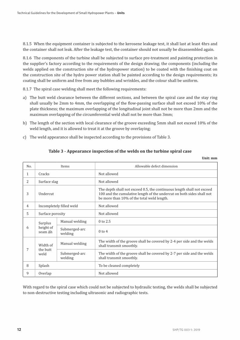
8.1.7 The spiral case welding shall meet the following requirements:
a) The butt weld clearance between the different sections, and between the spiral case and the stay ring shall usually be 2mm to 4mm, the overlapping of the flow-passing surface shall not exceed 10% of the plate thickness; the maximum overlapping of the longitudinal joint shall not be more than 2mm and the maximum overlapping of the circumferential weld shall not be more than 3mm;
b) The length of the section with local clearance of the groove exceeding 5mm shall not exceed 10% of the weld length, and it is allowed to treat it at the groove by overlaying;
c) The weld appearance shall be inspected according to the provisions of Table 3.
Table 3 - Appearance inspection of the welds on the turbine spiral caseUnit: mm
No. Items Allowable defect dimension
1 Cracks Not allowed
2 Surface slag Not allowed
3 Undercut The depth shall not exceed 0.5, the continuous length shall not exceed 100 and the cumulative length of the undercut on both sides shall not be more than 10% of the total weld length.
4 Incompletely filled weld Not allowed
5 Surface porosity Not allowed
6Surplus height of seam Δh
Manual welding 0 to 2.5
Submerged-arc welding 0 to 4
7Width of the butt weld
Manual welding The width of the groove shall be covered by 2-4 per side and the welds shall transmit smoothly.
Submerged-arc welding
The width of the groove shall be covered by 2-7 per side and the welds shall transmit smoothly.
8 Splash To be cleaned completely
9 Overlap Not allowed
With regard to the spiral case which could not be subjected to hydraulic testing, the welds shall be subjected to non-destructive testing including ultrasonic and radiographic tests.

SHP/TG 003-1: 2019
Part 1: Hydraulic Turbines
13
8.1.8 The static balancing test of the runner shall meet the following requirements:
a) The static balance stand shall be concentric to the runner, the deviation shall not be more than 0.07mm and the horizontal deviation of the support shall not be more than 0.02mm/m;
b) When the steel ball, runner plate type balance method is used, the sensitivity of the static balance stand shall meet the requirements of Table 4:
Table 4 - Distance from the sphere centre of the turbine runner to the centre of gravity of the runner
Unit: mm
Runner mass t/(kg) Maximum distance Minimum distance
t<5000 40 20
5000≤t<10,000 50 30
10,000≤t<50,000 60 40
8.1.9 The operation test and the hydraulic test of the Kaplan turbine runner shall be carried out according to the following requirements:
a) The quality of test oil shall meet the standard and the oil temperature shall not be less than 5°C;
b) The maximum leakage test pressure shall be maintained for 16hrs;
c) During the test, the operating blade shall be opened and closed by full travel (2-3) times per hour;
d) The shaft-runner joint shall not leak; the oil leakage limit of the single blade sealing device with or without the test pressure imposed shall not exceed 5mL/h;
e) The runner servomotor shall act stably; the minimum oil pressure for opening and closing shall not usually exceed 15% of the rated operating pressure;
f) The curve of the relationship between the runner servomotor travel and the blade rotating angle shall be prepared.
8.1.10 The sealing clearances shall meet the requirements of Table 5, Table 6 and Table 7:

Technical Guidelines for the Development of Small Hydropower Plants – Units
SHP/TG 003-1: 201914
Table 5 - Unilateral clearance between the Francis turbine runner and the heat cover and bottom ring (Seal Ring), and between the axial flow turbine/bulb turbine blade and
the runner chamberUnit: mm
Runner diameter D1/(mm)Clearance value
H≤35/(m) 35<H≤100/(m) H>100/(m) Allowable Deviation Value
Francis turbine
D1≤420 0.5 0.4 0.4 ±0.1
420<D1≤840 0.6 0.6 0.4 ±0.1
840<D1≤1200 (0.04-0.08)%D1
D1>1200 (0.04-0.07)%D1
Axial flow turbine/bulb
turbine
D1≤1000 (0.08-0.135)%D1
1000<D1≤2000 (0.07-0.125)%D1
D1>2000 (0.05-0.1)%D1
Table 6 - Total clearance (2A) between the turbine guide vane top/bottom and the head cover and bottom ring
Unit: mm
Runner diameter D1/(mm)
Clearance Value A
b0/D1≥0.35 b0/D1≥0.25 b0/D1≥0.2 b0/D1≥0.12 b0/D1≥0.1
D1≤420 0.20-0.50 0.15-0.35 0.10-0.28 0.06-0.22 0.05-0.20
420<D1≤840 0.25-0.60 0.18-0.45 0.12-0.35 0.08-0.28 0.06-0.23
D1>840 0.30-0.75 0.22-0.55 0.15-0.40 0.12-0.35 0.10-0.30
NOTE 1 If not listed in the table, the total clearance between the upper and lower end surfaces of the guide vane may take (0.1-0.2)% of the guide vane height (b0).NOTE 2 When the upper and lower end surfaces of the guide vane are fitted with the sealing device, they shall meet the drawing requirement.
Table 7 - Clearance of the vertical surface when the turbine guide vane is fully closedUnit: mm
b0/D1 b0/D1≥0.35 0.35>b0/D1>0.2 b0/D1≤0.2
Allowable local clearance 0.15 0.10 0.08
NOTE 1 When the guide vane is closed fully, the local clearance no greater than the value given in the above table is acceptable within 1/4 of the guide vane height. When inspecting the rest section with a 0.05mm feeler gauge, the gauge shall not pass through the clearance.NOTE 2 When the vertical surface of the guide vane is fitted with the sealing device, its clearance shall not be more than 0.15mm and after the sealing strip is installed, there shall be no clearance on the vertical surface.NOTW 3 The allowable local clearance on the vertical surface of the tubular vane shall not exceed 0.25mm maximum and its length shall not exceed 25% of the guide vane height.

SHP/TG 003-1: 2019
Part 1: Hydraulic Turbines
15
8.1.11 Turbine guide bearing shell shall meet the following requirements:
a) The surface of the rubber bearing shell shall be level, free from cracks and uncoating defects; the Babbitt metal bearing shell shall be free from porosity, cracks, hard spot and uncoating; the roughness of the bearing shell surface shall be less than 0.8μm;
b) The rubber bearing shell and the metal cylindrical bearing shell shall be pre-assembled on the shaft, and the total clearance shall meet the design requirement. Both the difference between the maximum and minimum total clearances on each end and the difference between the total clearance of the upper and lower ends on the same orientation shall not be more than 10% of the measured average total clearance;
c) When the metal cylindrical bearing shell meets the requirements of a) and b), it may not be ground further; whether the split bearing shell needs to be ground shall be determined according to the design requirement;
d) After the bearing shell is ground, the contact of the bearing shell shall be uniform. There shall be at least (2-3) contact points per square centimetre; the local non-contact area per bearing shell shall not be more than 5% per position, and the total surface area shall not exceed 15% of the total surface area of the bearing shell.
8.1.12 The bearing shall meet the following requirements:
a) The bearing oil tank shall not leak oil, and shall be subjected to the kerosene leak test according to 8.1.5;
b) The bearing cooler shall be subjected to hydraulic testing.
8.1.13 Before assembling, 0.05MPa compressed air shall be fed into the air shroud ring for leak testing in the water, and the shroud ring shall not leak air.
8.1.14 When the impulse turbine is pre-assembled on the supplier’s premises, the deviation between the inlet centreline of the inlet pipe and the axis of the unit shall not be more than ±0.2% of the inlet diameter. The split enclosure shall meet the requirements of 8.1.3; the flanged joint surfaces without seals or without gaskets shall be applied with the sealant. With regard to the vertical unit, the elevations of the nozzle flanges on the enclosure shall be consistent, and the elevation difference shall not be more than 1mm; the flange perpendicularity shall not be more than 0.3mm/m; the distance to the datum line of the coordinates of the unit shall meet the design requirement.
8.1.15 The nozzle and the servomotor of the impulse turbine shall be subjected to hydraulic testing in the supplier’s factory. After the nozzle and the servomotor are assembled, the actions of the needle and the servomotor shall be smooth at 16% rated pressure. When the rated pressure oil is fed into the closing cavity of the servomotor, there shall be no clearance between the needle head and the nozzle exit. When the servomotor of the needle is the built-in servomotor, it is necessary to inspect the oil leakage and the water leakage in the oil-water mixture discharge cavity; there shall be no leakage.
8.1.16 The assembling of the nozzles shall meet the following requirements:
a) The centreline of nozzle shall be at a tangent to the runner pitch circle, the radial error shall not be more than ±0.2%D1 (D1 is the pitch circle diameter of the runner), and the axial error of the water jet and the bucket plane shall not be more than ±0.5%W (W refers to the maximum inside width of the water bucket); when the aforesaid error is less than ±1mm, it shall take ±1mm;
b) The deviation of the deflector centre and the nozzle centre shall not usually be more than 4mm;
c) The deviation of the compression length of the buffer spring from the design value shall not be more than ±1mm;

Technical Guidelines for the Development of Small Hydropower Plants – Units
SHP/TG 003-1: 201916
d) The synchronism deviation of the needle travel of the nozzles shall not be more than 2% of the design travel;
e) The axial and radial deviation of the centreline of the reverse brake nozzle shall not be more than ±5mm.
8.2 Acceptance testsThe hydraulic performance acceptance test of the turbine shall meet the requirements of IEC 62006. The full load operation duration should be continuous for 72hrs. After the acceptance tests, the preliminary acceptance certificates shall be signed by the user and the supplier, the commercial operation shall be launched and the performance guarantee period shall start from then. After the performance guarantee period of the turbine expires, and the technical guarantees satisfy the requirements in the order contract signed by both parties, the final acceptance certificate shall be signed by the user.
9 Nameplate, packing, transportation and storage
9.1 Nameplate9.1.1 The materials and engraving method of the nameplates shall ensure that its text is not obliterated during the entire service period, and the following information shall be marked:
a) Name, model and product No.;
b) Maximum water head, rated water head and minimum water head;
c) Rated flow;
d) Maximum power and rated power;
e) Rated speed and runaway speed;
f) Name of the manufacturer and date of production.
9.2 Packing and transportation9.2.1 The turbine components and the spare parts within the supply scope shall pass the inspection by the manufacturer before being delivered, and shall be accompanied by the relevant documents proving the product compliance.
9.2.2 The packing size and weight of the turbine components shall satisfy the transportation conditions from the supplier’s factory to the hydro power station.
9.2.3 The packing and transportation of the turbine components and its auxiliary equipment shall meet the provisions of ISO 780, and the rain-proof, damp-proof, vibration-proof, mould-proof, anti-freezing and salt-spray resistance measures shall be taken according to the different requirements and transportation modes of the equipment.
9.2.4 The packing case shall contain the product qualification certificate, technical documents and drawings. The names and the quantities listed in the packing list shall be consistent with the material objects in the case and the drawing number. The packing list shall be put into the antiseptic box (bag) in the case.

SHP/TG 003-1: 2019
Part 1: Hydraulic Turbines
17
9.3 Storage9.3.1 The machined components of the turbine, and the spare parts and auxiliary equipment must be properly kept, and shall not be stacked without permission.
9.3.2 The machined parts of the turbine shall be protected from dampness and rain, and shall not be exposed to the sun and rain after they are delivered to the construction site of the hydro power station and unpacked.
9.3.3 The rubber, plastic and nylon parts shall be protected from direct sunlight, and shall not be placed at a place within a 1.5m scope around the oven or other heating device. The rubber shall be protected from being polluted by oils. The rubber products and the fillings shall be stored in a dry and ventilated warehouse.
9.3.4 The electronic, electrical and automatic components (devices) or instruments shall be stored in the warehouse with a temperature of –5°C to 40°C, relative humidity of no more than 90%, and free from acid, alkali, salt or corrosive/explosive gases, electromagnetic field, dust and rain/snow erosion.
9.3.5 The supplier shall guarantee that the products are free from corrosion, mildew-growing, damages or accuracy reduction arising from improper packing under normal storage, transportation and lifting conditions within one year from the date of delivery to the acceptance on the construction site of the hydro power station.
10 Installation, operation and maintenance
10.1 Installation and commissioning10.1.1 The installation and commissioning of the turbine shall comply with the requirements of IEC 61116 and IEC 62006.
10.1.2 The sundry materials in the diversion system and the water conductor components of the turbine shall be thoroughly cleaned to prevent the sundry materials from damaging the turbine before the water is filled into the diversion system of the hydro power station for the first time.
10.1.3 Before commissioning, the oil system shall be cleaned repeatedly with the oil, and then filled with the new oil specified by the design for the commissioning.
10.2 Operation and maintenanceThe operation of the turbine shall comply with the provisions of IEC 60545 and the operation and maintenance manual provided by the supplier.
11 Quality guarantee periodUnder the premise that the product is stored, installed and used properly, the product quality guarantee period shall be one year after the date on which the 72 hour trial operation is completed, or two years after the delivery date of the last batch of goods, whichever comes earlier. If the equipment gets damaged or is unable to function properly due to the manufacturing quality during the quality guarantee period, the supplier shall repair or replace it free of charge.

Technical Guidelines for the Development of Small Hydropower Plants – Units
SHP/TG 003-1: 201918
Appendix A (Normative)
Reaction turbine efficiency step-up formulaA.1 Method 1:
Francis type:
( ) ( )[ ]2011 .pmmax DDK= ....................................................(A.1)
Axial-flow type:
( ) ( ) ( )[ ]102070701 .pm
.pmmax HHDD..K= ...............................(A.2)
where
ηm optimum efficiency of the model turbine;
K coefficient, K = 0.5~0.7 (minimum value for the renovation unit; maximum value for the new unit);
Dm nominal diameter of the model turbine wheel, m;
Dp nominal diameter of the prototype turbine wheel, m;
Hm test head of the model turbine, m;
Hp water head of the prototype turbine, m.
A.2 Method 2:
Reaction turbine efficiency step-up formula recommended by IEC 60193:
0.160.16
e e
e e
uref urefh ref
um up
R RR R
=
.....................................................(A.3)
0.16
e
e
1
1hoptm
ref
uref ref
uoptm ref
R VR V
=
+
...............................................................(A.4)
where
h modification value for the model efficiency being converted to the prototype efficiency;
ref modification value for the nominal value being converted to the prototype efficiency;
Reuref standard Reynolds number;
Reum count point model Reynolds number;

SHP/TG 003-1: 2019
Part 1: Hydraulic Turbines
19
Reup count point prototype Reynolds number;
Reuoptm model optimal efficiency point Reynolds number;
hoptm model optimal efficiency;
Vref standard loss distribution coefficient (0.8 for the axial-flow Kaplan turbine, Deriaz turbine, and tubular Kaplan turbine; 0.7 for the Francis turbine, fixed blade propeller turbine, Kaplan propeller turbine, fixed blade of the Deriaz turbine, and the tubular fixed blade propeller turbine).
A.3 Method 3:
The following formula is recommended for the existing model test curves and the model test data marked with the Reynolds number and the water temperature:
[ 0.16Re(1 ) 1 ( ) ]
Remh hoptm
umupV=
...............................................(A.5)
m optm refV V V= = ..........................................................................(A.6)
67 10eum eurefR R= = ....................................................................(A.7)
where
Vm model loss distribution coefficient (0.8 for the axial-flow Kaplan turbine, Deriaz turbine, and tubular Kaplan turbine; 0.7 for the Francis fixed blade propeller turbine, propeller turbine, fixed blade of Deriaz turbine, and the tubular fixed blade propeller turbine);
Voptm oss distribution coefficient of the model optimal efficiency point.

Technical Guidelines for the Development of Small Hydropower Plants – Units
SHP/TG 003-1: 201920
Appendix B (Normative)
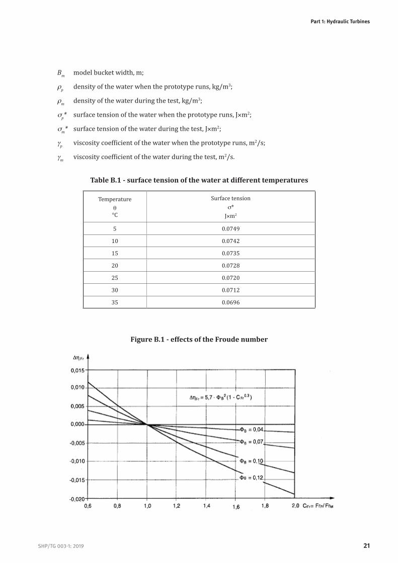
Efficiency step-up formula of the impulse type turbine Reh hp hm Fr we= = + + .................................................. (B.1)
( ) ( )2
Re863.0222
115.7 1 1.95 10 10
h hp hm
weB Fr
BB
CCC
=
= + + ...................(B.2)
where
( )1
2 20
4
2p
B
p p p
Q
g H BZ=
.......................................................... (B.3)
1 11 2 22
rp p P m mFr
rm m m p p
F g H B gCF g H B g
= =
........................................... (B.4)
11 1 1 22 2 2 *
*ep p P p p m
weem m m m m p
W g H BC
W g H B= =
.............................. (B.5)
12
Reep p P p m
em m m m p
R g H BC
R g H B= =
....................................................(B.6)
where
FB discharge coefficient;
Qp prototype flow, m3/s;
Z0 number of nozzles;
gp field acceleration of gravity for the power station;
gm ab acceleration of gravity;
Hp prototype water head, m;
Hm prototype test water head, m;
Bp prototype bucket width, m;
SHP/TG 003-1: 2019
Part 1: Hydraulic Turbines
21
Bm model bucket width, m;
rp density of the water when the prototype runs, kg/m3;
rm density of the water during the test, kg/m3;
sp* surface tension of the water when the prototype runs, J×m2;
sm* surface tension of the water during the test, J×m2;
gp viscosity coefficient of the water when the prototype runs, m2/s;
gm viscosity coefficient of the water during the test, m2/s.
Table B.1 - surface tension of the water at different temperatures
Temperature q°C
Surface tensions*
J×m2
5 0.0749
10 0.0742
15 0.0735
20 0.0728
25 0.0720
30 0.0712
35 0.0696
Figure B.1 - effects of the Froude number

Technical Guidelines for the Development of Small Hydropower Plants – Units
SHP/TG 003-1: 201922
Figure B.2 - effects of the Weber number
Figure B.3 - effects of the Reynolds number

SHP/TG 003-1: 2019
Part 1: Hydraulic Turbines
23
Appendix C (Normative)
List of spare parts for the hydraulic turbine
Table A.1 - Spare parts for the Francis turbine
Unit: set
No. Name of the spare partQuantity
Remarks1-2 Units 3-4
UnitsOver 5 Units
1 Upper, middle and lower journal bushes of the guide vanes 1/2 1 2
2 Seal ring of the guide vanes One set per turbine
3 Split key of the guide vanes 1/3 1/2 1
4 Shear pin of the guide vanes (breaking bolt) 1/2 1 2
5 Connecting link bushes of the guide vane 1/4 1/2 1
6 Sealing element for the operating seal of the turbine shaft One set per turbine
7 Sealing element for the maintenance seal of the turbine shaft One set per turbine
8 Servomotor piston ring or piston sealing element 1 1 2
9 Seal ring for fixing the servomotor 1 1 2
10 Springs 1 1 2
11 Turbine guide bearing shell 1 1 2
12 Thrust bearing shell 1 1 2 Only limited to the horizontal type unit
13 Brake block 1 1 2 Only limited to the horizontal type unit

Technical Guidelines for the Development of Small Hydropower Plants – Units
SHP/TG 003-1: 201924
Table A.2 - Spare parts for the axial flow turbineUnit: set
No. Name of the spare partQuantity
Remarks1-2 Units 3-4
UnitsOver 5 Units
1 Upper, middle and lower journal bushings of the guide vanes 1/2 1 2
2 Seal ring of the guide vanes One set per turbine
3 Split key of the guide vanes 1/3 1/2 1
4 Shear pin of the guide vanes (breaking bolt) 1/2 1 2
5 Connecting link bushings of the guide vane 1/4 1/2 1
6 Sealing element for the operating seal of the turbine shaft One set per turbine
7 Sealing element for the maintenance seal of the turbine shaft One set per turbine
8 Servomotor piston ring or piston sealing element 1 1 2
9 Seal ring for the fixing of the servomotor 1 1 2
10 Springs 1 1 2
11 Seal for the runner blades One set per turbine
12 Shaft sleeve of the receptacle 2 2 3
13 Floating bearing shell of receptacle 2 2 3

SHP/TG 003-1: 2019
Part 1: Hydraulic Turbines
25
Table A.3 - Spare parts for the tubular turbineUnit: set
No. Name of the spare partQuantity
Remarks1-2 Units 3-4
UnitsOver 5 Units
1 Upper and lower journal bushings of the guide vane 1/2 1 2
2 Seal ring of the guide vane One set per turbine
3 Split key of the guide vane 1/3 1/2 1
4 Protector of the guide vane 1/2 1 2
5 Connecting link bushes of the guide vane 1/4 1/2 1
6 Sealing element for the operating seal of the turbine shaft One set per turbine
7 Sealing element for the maintenance seal of the turbine shaft One set per turbine
8 Servomotor piston ring or piston sealing element 1 set 1set 2 sets
9 Seal ring for the fixing of the servomotor 1 1 2
10 Springs 1 1 2
11 Seal ring for the runner blade One set per turbine
12 Shaft sleeve of the receptacle 2 2 3
13 Floating bearing shell of the receptacle 2 2 3
14 Turbine Guide bearing shell 1 1 2
15 Thrust bearing shell 1 1 2Only limited to the bulb turbine unit
Table A.4 - Spare parts for the impulse turbine
Unit: set
No. Name of the spare partQuantity
Remarks1-2 Units 3-4
UnitsOver 5 Units
1 Sealing element of the needle rod One set per turbine
2 Backing ring of the nozzle One set per turbine
3 Shaft sleeve of the needle rod 1 2 3
4 Servomotor piston ring or piston sealing element One set per turbine
5 Seal ring for the fixing of the servomotor One set per turbine
6 Deflector blade 1
7 Guide bearing shell or anti-friction bearing 1

Vienna International CentreP.O. Box 300 · 1400 Vienna · Austria Tel.: (+43-1) 26026-oE-mail: [email protected]
INTERNATIONAL NETWORK ON SMALL HYDROPOWER
136 Nanshan RoadHangzhou * 310002 * P.R.ChinaTel.: (86-571)87132793E-mail: [email protected]