The Development of a Frost-Less Heat Pump
12
The Development of a Frost-Less Heat Pump V. C. Mei, R. E. Domitrovic, and F. C. Chen, Oak Ridge National Laboratory J. K. Kilpatrick, Tennessee Valley Authority ABSTRACT There are two major concerns associated with heat pump applications in heating season operation. One is that periodic defrosting is required when the ambient temperature is below 40˚F, and the other is the “cold blow” effect (delivery of air at less than body temperature) that compromises indoor thermal comfort. Conventional defrosting by cycle reversing has an inherent energy penalty because it absorbs heat from the indoor air during the defrosting period. A new frost-less heat pump technology has been developed at Oak Ridge National Laboratory. If a moderate amount of heat is added to the refrigerant stream in the accumulator, the suction pressure can be raised by several pounds and the suction temperature by several degrees. As a result, frost accumulation on the outdoor coil is retarded. Most of the heat added to the accumulator will be delivered to the indoors in the form of a higher heat pump supply air temperature, reducing the cold blow effect. The frequency of defrosting cycles can be drastically reduced, by a factor of five (5) in the Knoxville, Tennessee area. The new technology also includes a new energy-efficient defrosting scheme. In the case of cycle reversing, defrosting is needed when the ambient temperature is below 32˚F. A moderate amount of heat added to the accumulator will not retard frost accumulation effectively. With the new defrosting method, the indoor fan is not energized during the defrosting period. Two-phase refrigerant flowing through the indoor coil remains two-phase as it enters the accumulator; it then boils as a result of the heat added to the accumulator, or the accumulator functions as the evaporator. An obvious advantage is that the heat pump will not produce cold air during the defrosting period. Energy consumption for defrosting is modest, around 1 kW, compared with an average of 7–10 kW for resistant heating coil during conventional defrosting. Laboratory experiments indicated that the new frostless concept saves energy, a projected 12% in the Knoxville area compared with baseline test data. The new heat pump design concept can be implemented cost-effectively. This paper presents the new concept and test data. Introduction The heat pump is an efficient system for both heating and cooling. Although it behaves like an air-conditioning system for summer cooling operation, winter operation requires periodic coil defrosting if the ambient temperature is below 40˚F. Cycle-reverse defrosting is the most common method used to defrost the outdoor coil. The reverse-cycle method is inefficient because it takes heat from the indoor air to defrost the outdoor coil, resulting in a power surge because a 7- to 10-kW resistance-heating element is energized to make up for the heat lost. In addition, every time the cycle is reversed, the heat pump suffers Residential Buildings: Technologies, Design, Performance Analysis, and Building Industry Trends - 1.183
-
Upload
khangminh22 -
Category
Documents
-
view
2 -
download
0
Transcript of The Development of a Frost-Less Heat Pump

The Development of a Frost-Less Heat Pump
V. C. Mei, R. E. Domitrovic, and F. C. Chen, Oak Ridge National Laboratory J. K. Kilpatrick, Tennessee Valley Authority
ABSTRACT
There are two major concerns associated with heat pump applications in heating season operation. One is that periodic defrosting is required when the ambient temperature is below 40˚F, and the other is the “cold blow” effect (delivery of air at less than body temperature) that compromises indoor thermal comfort. Conventional defrosting by cycle reversing has an inherent energy penalty because it absorbs heat from the indoor air during the defrosting period.
A new frost-less heat pump technology has been developed at Oak Ridge National Laboratory. If a moderate amount of heat is added to the refrigerant stream in the accumulator, the suction pressure can be raised by several pounds and the suction temperature by several degrees. As a result, frost accumulation on the outdoor coil is retarded. Most of the heat added to the accumulator will be delivered to the indoors in the form of a higher heat pump supply air temperature, reducing the cold blow effect. The frequency of defrosting cycles can be drastically reduced, by a factor of five (5) in the Knoxville, Tennessee area.
The new technology also includes a new energy-efficient defrosting scheme. In the case of cycle reversing, defrosting is needed when the ambient temperature is below 32˚F. A moderate amount of heat added to the accumulator will not retard frost accumulation effectively. With the new defrosting method, the indoor fan is not energized during the defrosting period. Two-phase refrigerant flowing through the indoor coil remains two-phase as it enters the accumulator; it then boils as a result of the heat added to the accumulator, or the accumulator functions as the evaporator. An obvious advantage is that the heat pump will not produce cold air during the defrosting period. Energy consumption for defrosting is modest, around 1 kW, compared with an average of 7–10 kW for resistant heating coil during conventional defrosting.
Laboratory experiments indicated that the new frostless concept saves energy, a projected 12% in the Knoxville area compared with baseline test data. The new heat pump design concept can be implemented cost-effectively. This paper presents the new concept and test data.
Introduction
The heat pump is an efficient system for both heating and cooling. Although it behaves like an air-conditioning system for summer cooling operation, winter operation requires periodic coil defrosting if the ambient temperature is below 40˚F. Cycle-reverse defrosting is the most common method used to defrost the outdoor coil. The reverse-cycle method is inefficient because it takes heat from the indoor air to defrost the outdoor coil, resulting in a power surge because a 7- to 10-kW resistance-heating element is energized to make up for the heat lost. In addition, every time the cycle is reversed, the heat pump suffers
Residential Buildings: Technologies, Design, Performance Analysis, and Building Industry Trends - 1.183

pressure and thermal shocks. Further, the perception of “cold blow”1 will be even more severe during the defrosting period. It is obvious that heat pump manufacturers must improve coil frost management and defrosting technique, as well as alleviates the cold blow effect and improve energy efficiency.
The industry made a previous effort to tackle the heat pump thermal comfort issue by increasing the supply air temperature to above 105˚F. However, at the end of the project, the participants reached a conclusion that the cost was too high to achieve the targeted goal.
In the area of coil frost management, much work has been reported in heat pump frosting and defrosting performance (Miller 1989) (Kondepudi and O’Neal 1987, 1989) (Nutter and O’Neal 1996). Work was also reported on shortening the defrosting cycle by adding heat to the accumulator during the defrosting period (Nutter and O’Neal 1996). However, there is practically no reported work discussing the possibility of reducing the number of defrosting cycles by retarding frost on the outdoor coil. In addition, heat pump manufacturers have generally practiced cycle-reversing defrosting, and no effort has been made in recent years to improve the current defrosting technology.
Oak Ridge National Laboratory (ORNL) has derived a new heat pump design (Chen et al. 1998) that addresses all the aforementioned problems. ORNL, under the sponsorship of the U.S. Department of Energy (DOE) and the Tennessee Valley Authority (TVA), has developed a new frost management method and a defrosting concept called “frost-less” technology.
Two heat pumps were modified with the new frost-less feature and were tested in a two-room environmental chamber at various simulated outdoor temperatures. The results indicated that frost-less operation was as expected that it retarded frost accumulation on the outdoor coil significantly. The new defrosting concept was also tested and worked as expected. The defrosting time was almost identical to that of the conventional defrosting method, and only about 1 to 1.2 kW of power was input to the accumulator. Compared with conventional defrosting technology, which energizes a 7- to 10-kW resistance heating element during the defrosting period, the new defrosting technology is much more energy-efficient, and it does not take heat from indoor air.
Frost-Less Heat Pump Concept
Experimental results showed that if the outdoor coil temperature is above 27˚F, there will be practically no frost accumulation on the outdoor coil when the ambient temperature is in the range of 32 to 41˚F, which is the range at which frost is most likely to accumulate. If a moderate amount of heat is added to the accumulator during winter heating-mode operation (Figure 1), the outdoor coil temperature can be increased to around 27˚F. Frost formation on the coil will then be retarded because of the elevated coil temperature. However, most of the heat added to the accumulator will be delivered to the inside of the house as higher-temperature supply air, through more efficient compressor operation with higher suction pressure and mass flow rate.
It should be noted that “frost-less” is not “frost-free.” If the heat pump is operated over a long time at low ambient temperatures, frost will accumulate on the outdoor coil even with heat added to the accumulator. When the ambient temperature is outside the range of 32 1 Cold blow occurs because the temperature of the supply air from a heat pump is often lower than the human skin temperature and thus induces a cold feeling when the supply air is in contact with the body.
1.184

to 41˚F, the heater in the accumulator will be turned off, because above 41˚F the coil temperature will be warm enough to prevent frost formation, and below 32˚F, the moisture content of the air will be too low for heavy frost accumulation on the coil.
10
24
22
2012 18
1818
18
14
21
23
16
25
26
27
Figure 1. Refrigerant-Side Schematic
17
29
28
35
30
40
Because the heating capacity is higher with the frost-less system, the heat pump should cycle off before a defrosting cycle is initiated. It is estimated that the frost-less heat pump has the potential to reduce the defrosting cycle by a factor of five (5) in the Knoxville, Tennessee area, based on bin temperature calculation under typical load balance conditions.
New Defrosting Technology
Cycle reversing is the standard heat pump defrosting method. Some heat pumps use a hot-gas bypass to mix hot gas with the expanded refrigerant to defrost the coil.2 This method has the advantage of not requiring cycle reversal, with the attendant reversal of high- and low-pressure coils of the system and the sudden surging of liquid into the accumulator and compressor. On the other hand, reduced heat transfer, longer defrost cycles may result, with a corresponding loss of efficiency.
The heat pump tested was equipped with the standard timer and refrigerant temperature sensor for defrosting. The timer was originally set for 60-minute defrosting. It was re-set for 90-minute defrosting for this study, because a more frequent defrost cycle would tip the energy efficiency to favor the frost-less technology. During the defrosting period, heat is taken from the indoors to defrost the outdoor coil, resulting in the sensation of cold blow even with the indoor resistance heating coil fully energized.
The frost-less concept retards frost accumulation on the outdoor coil and increases the heating capacity, thus potentially reducing the number of cycle reversals for defrosting. However, when the ambient temperature is below 32˚F, the heaters in the accumulator are
2 Janitrol “Specifications – Series 38/39” (Tech. Bulletin published by Janitrol, 1976).
Residential Buildings: Technologies, Design, Performance Analysis, and Building Industry Trends - 1.185

shut off in heating mode operation because adding a modest amount of heat to the accumulator would not retard frost accumulation on the outdoor coil. Eventually, a cycle-reversing defrosting period will be needed.
However, during the cycle-reversing defrosting period, the indoor blower will be shut off. Liquid refrigerant passing the indoor expansion device will be two-phase throughout the indoor coil without absorbing heat from the house. The two-phase refrigerant will flow to the accumulator, and the heater in the accumulator will be energized during the defrosting period. In other words, the accumulator takes over the function of the evaporator where the refrigerant is evaporated to provide vapor to the compressor for outdoor coil defrosting.
This design allows cycle reversing defrosting but without an indoor cold air draft and without the indoor resistance heaters being energized. The advantages of this defrosting scheme are
1. Cold blow is eliminated during the defrosting period because the indoor blower is shut off.
2 Defrosting is very efficient because the accumulator is close to the outdoor coil where the heat lost is at a minimum. Heat input to the accumulator will be in the order of 1 kW, while the conventional defrosting method requires 7 to 10 kW to energize the indoor resistance heating elements.
3. The power consumption by the indoor blower motor is avoided.
Resistanceheaters
To variac
Accumulator
Figure 2. Accumulator with Heaters
Experimental Setup
A 2-ton split heat pump was selected for the test because it was considered the most popular model in the TVA region. Figure 1 shows the refrigerant-side schematic, Figure 2 the accumulator-heater assembly, and Figure 3 the air-side schematic. The setup measures both the air-side and refrigerant-side performance. Pressure transducers and thermocouples were used for pressure and temperature measurements. However, air-side measurements were adopted because refrigerant-side mass flow rate measurement would not be accurate during transient operating periods, such as the start and the end of the defrost cycle.
1.186

Figure 3. Air-Side Schematic
Inlet airtemperaturethermopiles, drybulband wet bulb
Outlet air temperaturethermopiles, dry bulband wet bulb
Indoorcoil
Honeycombsection
Air in
Air out
The indoor blower motor was wired so that during the cycle-reversing defrosting period for frost-less operation, the motor would not be energized. Power measurements for the compressor and condenser fan motor, indoor blower motor, and resistance heating elements were recorded separately by power transducers. From the measured data, elements such as the heat pump heating capacity, supply air temperature, power consumption, and system COP, could be calculated. A description of the test setup is as follow.
Air-Side
Heat pump indoor unit inlet and outlet air dry and wet bulb temperature measurement with thermocouple piles. Outdoor dry bulb temperature and wet bulb temperature measurement with thermocouples.Indoor air volumetric flow rate measurement with a micromanometer.
Refrigerant-Side
Pressure measurement with pressure transducers: compressor inlet and outlet, condenser (indoor coil) outlet, and suction before accumulator. Temperature measurement with thermocouples: compressor inlet and outlet, condenser (indoor coil) outlet, before expansion device (on outdoor coil), after expansion device, before and after accumulator. Refrigerant volumetric flow rate measurement with a turbinemeter located just before the expansion device (on the outdoor coil).
Power
Compressor and condenser fan power, indoor blower motor power, and resistance heater power inside the accumulator were measured.
Residential Buildings: Technologies, Design, Performance Analysis, and Building Industry Trends - 1.187

Test Procedures
Frost-less operation. In this study, a 2-ton cooling heat pump with an SEER of 10.0 was tested extensively for baseline and frost-less operation over an outdoor temperature range of 33 to 41˚F at 75% relative humidity.
Baseline tests were performed first. After the heat pump went through a few frosting and defrosting cycles at a specified ambient temperature, with the normal 60-minute cycle readjusted to a 90-minute cycle, the heaters in the accumulator were turned on for frost-less operation. The heat pump was operated continuously with the heaters on until frost finally accumulated on the outdoor coil. Tests were performed at simulated outdoor temperatures of 41, 39, 37, 35, and 33˚F, all at 75% relative humidity.
Test of new defrosting method. The heat pump was operated with a simulated outdoor ambient temperature of below 30˚F to allow frost to accumulate on the outdoor coil without energizing the heaters. Once the heat pump called for defrosting, after 90 minutes of operation, the heat pump cycle was reversed, the heaters in the accumulator were energized, and the indoor blower motor was turned off. The two-phase refrigerant flowed past the indoor coil without being evaporated. The accumulator served as the evaporator during the defrosting period. The amount of power input to the accumulator, 1 to 1.4 kW, was recorded, and the outdoor coil temperatures were measured. The test data were then compared with the baseline defrosting test data.
Test Results and Discussions
Based on a comparison of the test data for the two operations, it shows that the frost-less concept provided a higher average supply air temperature, 4 to 6˚F over that of baseline operation. The supply air temperatures during frost-less operation were also very stable, while the supply air temperature during baseline operation varied over the operating cycle. The indoor thermal comfort was thus greatly improved.
Figures 4a to 4c show the coil frost accumulation over 90 minutes of operation at 39˚F ambient and 75% RH. It is evident that the coil was almost covered with frost at the end of 90 minutes of operation. However, when the heaters in the accumulator were energized (Figures 5a to 5c), the same heat pump had little or no frost on the outdoor coil. Figures 6 and 7 show the heat pump supply air temperature and heating capacity comparisons between baseline and frost-less operation. It is clear that frost-less operation provided higher and more-stable air supply air temperature and heating capacity.
1.188

Fig. 4a. Baseline, 20 min. Fig. 4b. Baseline, 40 min. Fig. 4c. Baseline, 60 min.
Fig. 5a. Frost-less, 20 min. Fig. 5b. Frost-less, 40 min. Fig. 5c. Frost-less, 60 min.
Operating condition: 39°F and 75% RH.
Figure 6. Capacity Comparison Between Baseline and Frost-Less oOperation at 35F and 75% RH
-5000
0
5000
10000
15000
20000
25000
1 12 23 34 45 56 67 78 89 100
111
122
133
144
155
166
177
188
Time (minutes)
Cap
acity
(Btu
/hr)
Baseline CapacityHeating Capacity
Residential Buildings: Technologies, Design, Performance Analysis, and Building Industry Trends - 1.189
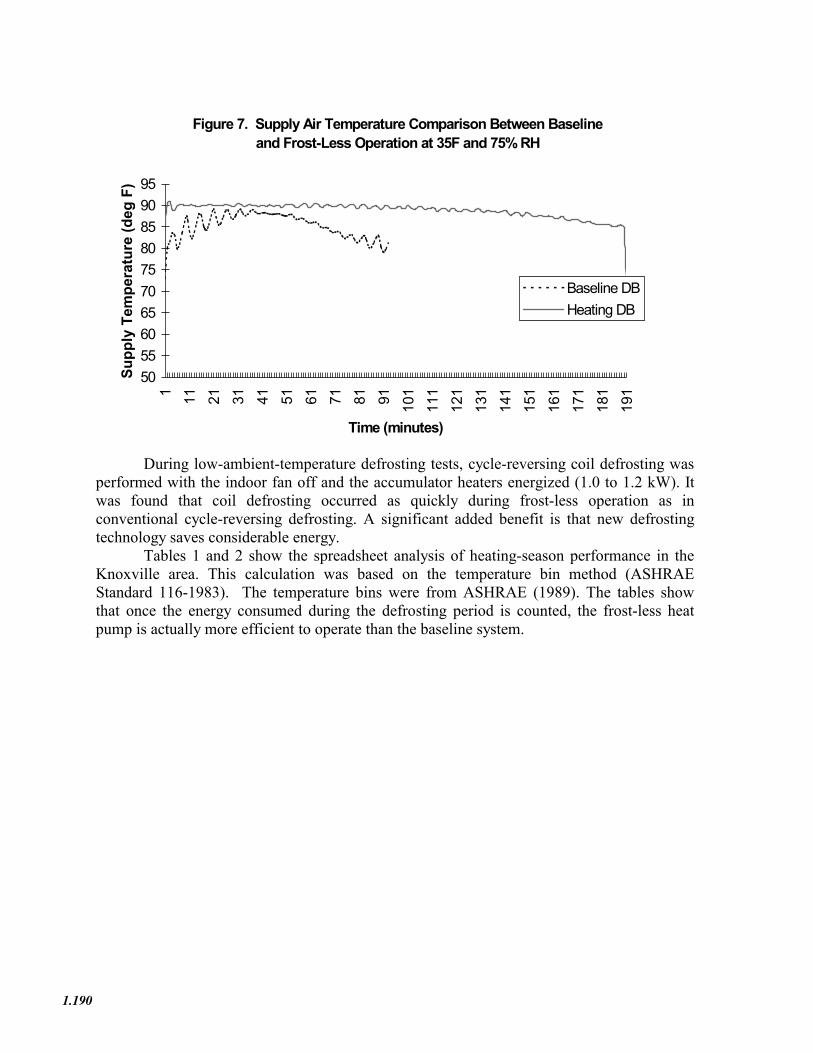
Figure 7. Supply Air Temperature Comparison Between Baseline aand Frost-Less Operation at 35F and 75% RH
50556065707580859095
1 11 21 31 41 51 61 71 81 91 101
111
121
131
141
151
161
171
181
191
Time (minutes)
Supp
ly T
empe
ratu
re (d
eg F
)
Baseline DBHeating DB
During low-ambient-temperature defrosting tests, cycle-reversing coil defrosting was performed with the indoor fan off and the accumulator heaters energized (1.0 to 1.2 kW). It was found that coil defrosting occurred as quickly during frost-less operation as in conventional cycle-reversing defrosting. A significant added benefit is that new defrosting technology saves considerable energy.
Tables 1 and 2 show the spreadsheet analysis of heating-season performance in the Knoxville area. This calculation was based on the temperature bin method (ASHRAE Standard 116-1983). The temperature bins were from ASHRAE (1989). The tables show that once the energy consumed during the defrosting period is counted, the frost-less heat pump is actually more efficient to operate than the baseline system.
1.190

Table 1. Baseline Heat Pump Performance with Coil Defrosting Energy Included
Table 2. Frostless Heat Pump
A B C D E F G H I J K L M N O-------- -------- -------- -------- -------- -------- -------- -------- -------- -------- -------- -------- -------- -------- --------
SEASONAL BTUH ODT HEAT HP HP HP PARTIAL RESIST BTUHDEFROSTODT HEATING LOSS DIFF LOSS CAP INPUT LOAD LOAD RUN HP HEAT RES.HT LOSS KWHBIN HOURS /DEG65-ODT) BTUH BTUH KW FACTOR FACTOR TIME KWH KW KWH /YEAR /YEAR62 746 642 3 1,925 28,305 2.250 0.068 0.767 9% 148.83 0.00 0.00 1,43657 675 642 8 5,133 26,500 2.199 0.194 0.798 24% 360.12 0.00 0.00 3,46552 672 642 13 8,342 24,752 2.148 0.337 0.834 40% 583.11 0.00 0.00 5,60647 689 642 18 11,550 23,060 2.098 0.501 0.875 57% 827.24 0.00 0.00 7,95842 648 642 23 14,758 21,432 2.050 0.689 0.922 75% 991.97 0.00 0.00 9,56337 590 642 28 17,967 22,742 3.024 0.790 0.948 83% 1,487.62 0.00 0.00 10,60032 456 642 33 21,175 16,261 1.815 1.000 1.000 100% 827.64 1.44 656.54 9,656 50.6727 217 642 38 24,383 13,976 1.742 1.000 1.000 100% 378.01 3.05 661.70 5,291 24.1122 101 642 43 27,592 15,486 1.862 1.000 1.000 100% 188.06 3.55 358.24 2,787 11.2217 41 642 48 30,800 14,144 1.817 1.000 1.000 100% 74.50 4.88 200.09 1,263 4.5612 21 642 53 34,008 12,874 1.773 1.000 1.000 100% 37.23 6.19 130.04 714 2.33
7 7 642 58 37,217 11,635 1.729 1.000 1.000 100% 12.10 7.50 52.47 261 0.782 2 642 63 40,425 10,467 1.687 1.000 1.000 100% 3.37 8.78 17.56 81 0.22
Totals = 5,920 2,077 58,680 94
Outdoor Design Temperature = 17 deg. F HSPF = Sum N / ((Sum K+Sum M+Sum O))Design Heating Load Requirement = 30,800 Btuh HSPF = 7.25
Balance Point Outdoor Temperature = 35 deg. F
Notes:1) Frostless HP defrost is assumed a 1 KW resistance heating coil inside the accumulator on for 10 minutes. Every 90 minutes defrost onc2) Knoxville weather data
A B C D E F G H I J K L M N O-------- -------- -------- -------- -------- -------- -------- -------- -------- -------- -------- -------- -------- -------- --------
SEASONAL BTUH ODT HEAT HP HP HP PARTIAL RESIST BTUHDEFROSTODT HEATING LOSS DIFF LOSS CAP INPUT LOAD LOAD RUN HP HEAT RES.HT LOSS KWHBIN HOURS /DEG (65-ODT) BTUH BTUH KW FACTOR FACTOR TIME KWH KW KWH /YEAR /YEAR62 746 642 3 1,925 28,305 2.250 0.068 0.767 9% 148.83 0.00 0.00 1,436 57 675 642 8 5,133 26,500 2.199 0.194 0.798 24% 360.12 0.00 0.00 3,465 52 672 642 13 8,342 24,752 2.148 0.337 0.834 40% 583.11 0.00 0.00 5,606 47 689 642 18 11,550 23,060 2.098 0.501 0.875 57% 827.24 0.00 0.00 7,958 42 648 642 23 14,758 21,432 2.050 0.689 0.922 75% 991.97 0.00 0.00 9,563 37 590 642 28 17,967 18,546 1.887 0.969 0.992 98% 1,087.04 0.00 0.00 10,600 655.5632 456 642 33 21,175 18,343 1.954 1.000 1.000 100% 891.02 0.83 378.37 9,656 506.6727 217 642 38 24,383 16,885 1.908 1.000 1.000 100% 414.04 2.20 476.75 5,291 241.1122 101 642 43 27,592 15,486 1.862 1.000 1.000 100% 188.06 3.55 358.24 2,787 112.2217 41 642 48 30,800 14,144 1.817 1.000 1.000 100% 74.50 4.88 200.09 1,263 45.5612 21 642 53 34,008 12,874 1.773 1.000 1.000 100% 37.23 6.19 130.04 714 23.33
7 7 642 58 37,217 11,635 1.729 1.000 1.000 100% 12.10 7.50 52.47 261 7.782 2 642 63 40,425 10,467 1.687 1.000 1.000 100% 3.37 8.78 17.56 81 2.22
Totals = 5,619 1,614 58,680 1,594
Outdoor Design Temperature = 17 deg. F HSPF = Sum N / ((Sum K+Sum M+Sum O))Design Heating Load Requirement = 30,800 Btuh HSPF = 6.65
Balance Point Outdoor Temperature = 35 deg. F
Notes:1) Baseline HP defrost is assumed a 10 KW resistance heating coil on for 10 minutes. Every 90 minutes defrost once.2) Knoxville weather data
Residential Buildings: Technologies, Design, Performance Analysis, and Building Industry Trends - 1.191

Conclusions
A 2-ton heat pump was modified for both baseline and frost-less operation. A new defrosting method was also tested. The test data showed that both concepts (frost-less operation and defrosting) worked as expected. The following conclusions can be summarized from the tests:
1. Adding a moderate amount of heat to the accumulator during the winter heating season will significantly retard frost accumulation on the outdoor coil in the ambient temperature range from 32 to 40˚F. However, when the ambient temperature drops below 32˚F, adding a moderate amount of heat will not prevent frost accumulation on the outdoor coil, and thus the heat input to the accumulator should be suspended. Heat hould be added to the accumulator only when the ambient temperature is in the 41 to 32˚F temperature range in which frost is most likely to accumulate on the coil. Heat should also be added to the accumulator during defrosting periods, during which the indoor blower is off.
2. Most of the heat added to the accumulator to retard frost accumulation was delivered to the indoors via a higher heat pump supply-air temperature because of higher compressor suction pressure. Indoor thermal comfort was improved because the heat pump supply air temperature was elevated by 4 to 6˚F. In addition, since frost accumulation on outdoor coil was greatly reduced, the supply air temperature was very stable for frost-less operation, while baseline operation showed a big swing in supply air temperature.
3. A moderate amount of heat supplied to the accumulator during the cycle-reversing defrosting period made the accumulator the de facto evaporator with an internal heat source. No heat was taken from the indoor air because the indoor blower was off during the defrosting period.
4. If the amount of heat used for defrosting is considered, frost-less operation out-performed baseline operation by providing improved indoor thermal comfort and a higher HSPF.
The frost-less concept is simple, efficient, and potentially low-cost. It improves indoor thermal comfort even during defrosting cycles. It can potentially eliminate the need for cycle-reversing defrosting by a factor of five (5) in the Knoxville region and thus can increase the reliability of the heat pump. Indoor thermal comfort and efficiency have always been the major concerns of heat pump manufacturers, and this technology addresses both concerns in a simple, cost-effective manner.
Acknowledgments
This project was co-sponsored by the Tennessee Valley Authority and the U.S. Department of Energy. Oak Ridge National Laboratory is managed by UT-Battelle, LLC, under contract DE-AC05-00OR22725 with the U.S. Department of Energy.
1.192

References
ASHRAE 1989. Fundamentals Handbook 1989, “Weather Data,” p. 28.11., American Society of Heating, Refrigerating and Air-Conditioning Engineers, Atlanta.
ASHRAE 1983. Methods of Testing for Seasonal Efficiency of Unitary Air-Conditioners and Heat Pumps, Standard 116-1983, American Society of Heating, Refrigerating and Air-Conditioning Engineers, Atlanta.
Chen, F. C., et al. 1998. “Heat Pump Having Improved Defrost System,” U.S. Patent 5845502.
Kondepudi, S. N. and D. L. O'Neal 1987. “The Effects of Frost Growth on Extended Surface Heat Exchanger Performance: A Review,” ASHRAE Trans., Vol. 93, pt. 2, American Society of Heating, Refrigerating and Air-Conditioning Engineers.
Kondepudi, S. N. and D. L. O'Neal 1989. “Effect of Frost Growth on the Performance of Louvered finned Tube,” International J. of Refrigeration, 12, pp. 151–158, May.
Mei, V. C., et al. 1996. :Experimental Study of a Liquid Over-Feeding Window Air Conditioner,” ASHRAE Trans. Vol. 92, Pt. 1, American Society of Heating, Refrigerating and Air-Conditioning Engineers.
Miller, W. A., 1989. Laboratory Study of the Dynamic Losses of a Single Speed, Split System Air-to-Air Heat Pump Having Tube and Plate Fin Heat Exchangers, ORNL/CON-253, Oak Ridge National Laboratory, August.
Nutter, D. W., and D. L. O’Neal 1996. “Shortening the Defrost Cycle Time with Active Enhancement within the Suction-Line Accumulator of an Air-Source Heat Pump,” Symposium AES-Vol. 36, pp. 59–68, ASME International Mechanical Engineering Congress and Exposition, Nov. 17–22, 1996, Atlanta.
Residential Buildings: Technologies, Design, Performance Analysis, and Building Industry Trends - 1.193

1.194