PUMP USER MANUAL - UPRENT
42
www.uprent.eu PUMPING AND ENERGY SOLUTIONS PUMP USER MANUAL
-
Upload
khangminh22 -
Category
Documents
-
view
0 -
download
0
Transcript of PUMP USER MANUAL - UPRENT

www.uprent.eu
P U M P I N G A N D E N E R G Y S O L U T I O N S
PUMPUSERMANUAL
Diesel centrifugal pump in silenced canopy
Technical specification:
Intended use Sewerage and drainage water pumping
Make / Type BBA / BA150E
Maximal flow 460 m3 / h, see curve
Maximal head 27 mwc, see curve
Maximal suction lift 8,5m
Suction connection 6’’
Discharge connection 6’’
Free passage Up to 80mm
Dimensions L x W x H 2270mm x 1050mm x 1533mm
Weight 1600kg
Engine Diesel engine
Engine brand / Type Perkins / 404D-22
Engine power / rpm 22kW / 1500 rpm
Fuel tank 300 liter
Maximal fuel consumption 6 l/h
Level control 2x floating switches
Vacuumpump capacity 50 m3/h
GPS Equipped with GPS


1
User manual
BA 150E

2
Contents 1 Description, application and working principle ............................................................................... 4
1.1 Description .................................................................................................................................. 4
1.2 Construction ................................................................................................................................ 4
1.3 Working principle of the vacuum system ................................................................................ 4
1.4 Intended use ................................................................................................................................ 5
1.5 Unintended use ........................................................................................................................... 6
2 Specification and dimensions ........................................................................................................... 7
3 Performance curve ............................................................................................................................. 9
4 Safety instruction.............................................................................................................................. 10
4.1 Warning stickers ....................................................................................................................... 10
5 Lifting instructions BA150E pump unit .......................................................................................... 12
5.1 Moving the pump unit with a forklift ....................................................................................... 13
6 Pump unit installation ...................................................................................................................... 14
6.1 Outdoor use ............................................................................................................................... 15
6.2 Indoor use .................................................................................................................................. 16
7 Daily maintenance of the pump ....................................................................................................... 17
7.1 Engine oil level check .............................................................................................................. 18
7.2 Check the water trap ................................................................................................................ 18
7.3 Priming the fuel system ........................................................................................................... 19
7.4 Fuel level check ........................................................................................................................ 20
7.5 Floating switches ...................................................................................................................... 20
7.6 Cooling level check .................................................................................................................. 21
8 Control panel LC20 ........................................................................................................................... 23
8.1 Selection switch ........................................................................................................................ 23
9 Control panel (old type) ................................................................................................................... 24
9.1 Selection switch (old type) ...................................................................................................... 24
10 Pump unit preparation for starting ............................................................................................. 25
11 Starting (manual New type) ......................................................................................................... 26
11.1 Stopping (manual new type) .................................................................................................... 27
12 Starting (auto new type) ............................................................................................................... 28
12.1 Stopping (auto new type) ......................................................................................................... 30
13 Starting (manual old type) ........................................................................................................... 31
13.1 Stopping (manual old type) ..................................................................................................... 32
14 Starting (auto old type) ................................................................................................................ 33

3
14.1 Stopping (auto old type) .......................................................................................................... 35
15 Draining the pump when there is danger of freezing ................................................................ 36
16 Troubleshooting ............................................................................................................................ 37
4
1 Description, application and working principle
1.1 Description
WARNING: This manual is intended to give Important Information that must be followed during Storage, Transportation, Installation, Operation and Maintenance of the Pump-Set. We therefore recommend that this manual is read carefully before the Pump-Set is put into operation. To prevent damage being caused by inappropriate or incorrect use, or by being used outside the normal operating parameters of the Pump-set, the Instructions in this manual must be followed. Failure to do so may lead to damage to or premature failure of the
Pump-set and may cause Injury. Any such actions will invalidate the warranty.
The BA series of pumps, with their large solids handling capacity and good wear resistance, are perfect for
pumping both clean and partially polluted liquids.
The solids handling capacity is specified on the data sheet that accompanies the pump unit. The pumps are fitted with a half open or closed impeller and a wear plate or wear ring which can be
replaced quickly. Because few moving parts come into contact with the liquid, the pump is subject to
minimal wear.
The design includes large cleaning covers so the pump can be cleaned internally.
The design of the pump shaft seal is dependent on the application. The standard configuration includes oil
cooling of the pump shaft seal. This characteristic is indicated by a code in the type designation.
The data sheet that accompanies the pump includes all data for the pump or pump unit.
Before the pump or pump unit is connected, an assessment must always be made to determine whether
it is suitable for the intended application.
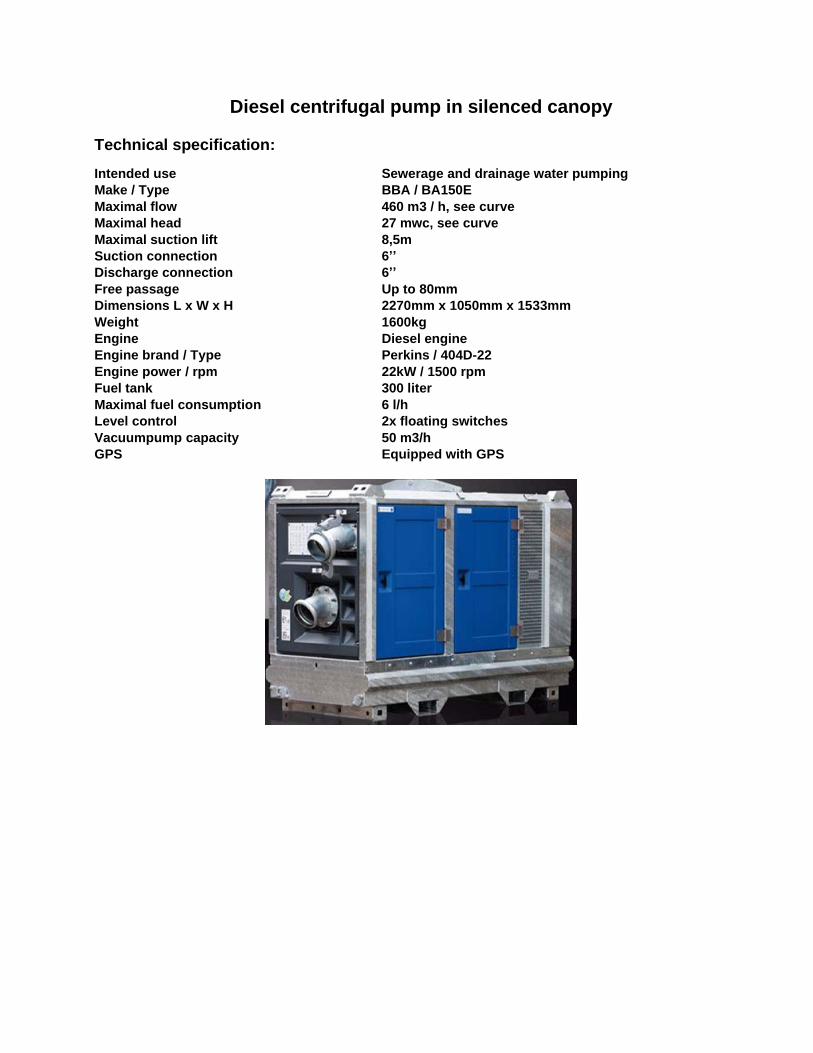
1.2 Construction
The pump consists of the following main components:
1. Suction side 2. Float chamber
3. Pressure side
4. Cleaning cover
5. Vacuum pump
6. Drive shaft
7. Pump housing
8. Vacuum pump drive
9. Cleaning cover
10. Cleaning cover
11. Non-return valve
1.3 Working principle of the vacuum system

5
The BA dry-prime centrifugal pump distinguishes itself from the normal-priming centrifugal pump through
the inclusion of a separate vacuum pump. The vacuum pump is usually driven by the drive shaft via a belt.
In special cases the vacuum pump is driven by a separate drive system, such as an electric or hydraulic
drive unit. The vacuum pump draws the air out of the suction line and pump housing via a float chamber.
To ensure that vacuum develops in the suction line and the pump housing, a non-return valve is present on
the pressure side of the pump.
Once sufficient vacuum has developed, the pump housing fills itself with liquid and the pump begins moving
the liquid.
WARNING
To prevent damage to the pump it is important that the pump does not run dry for more
than five minutes.
The designation ‘self-priming centrifugal pump’ indicates that the pump housing does not have to be filled
before the pump is started, which is a big advantage.
The drawing below is an exploded-view of a BA dry-prime centrifugal pump. The arrows indicate the flow
of the liquid and air through the pump housing.
Air: bubbles; liquid: dark arrow
1.4 Intended use
– The BA series pump is suitable for pumping viscous liquids up to 50 mm²/s (cSt).
– The maximum liquid temperature is 70 °C (158 °F), which depends in part on the materials used in the
pump as well as the liquid, operating pressure and pump position.

6
The pump set is designed to pump the following:
• Surface Water
• Drainage Water
• Diluted Sewage Waste
• Undiluted Sewage Water
• Storm Water
• Solids Laden Water
• Slurry and Viscous Liquids
Note
The BA series is not designed for food processing but can be used for such applications if they are not
subject to any special hygiene standards.
The materials used in the selected pump version must in all cases be checked in advance for their suitability
for the concerned foodstuff.
1.5 Unintended use
– It is not permitted to use the pump for pumping flammable and/or explosive substances.
– It is not permitted to deploy a standard pump or pump unit in an environment in which there is a
danger of fire and/or explosion.
– It is not permitted to deploy a standard pump or pump unit in an ATEX environment.
– Use the pump only for those applications listed on the pump specification sheet.
– It is not permitted to use the pump for any application and/or field of activity other than that for
which the pump was originally specified and installed without written permission from BBA
Pumps.
WARNING
BBA Pumps is not responsible for incorrect use and/or application of the pump.

7
2 Specification and dimensions
Standard technical specification BBA auto prime pump Pump type............................BA150E D285 Canopy type......................... M10-23 Max. flow..............................460 m3/hour Max. head............................27 mwc Dimensions L x W x H ......... 2270 x 1050 x 1533 mm Dry weight…………………..1600 kg Fuel tank .............................. PE net 300 ltr Fuel tank autonomy ............. 50 hours (at 1500 rpm BEP) Fuel tank cap ....................... 100mm Basic frame .......................... Hot dip galvanised Additional ............................. Fitted with oil-water separator Impeller type ........................Semi-open impeller Solids handling ....................80 mm Pump casing........................Cast iron GG20 Impeller................................Chrome Moly 42CrM04 Self-cleaning wear plate ......Chrome Moly 42CrM04 (cutter slots) Pump shaft...........................C45 Shaft seal.............................Mechanical seal Seal faces ............................Tung/Sic Seal rubber ..........................Viton Engine Engine brand ....................... Perkins Engine type .......................... 404D-22 Flywheel power .................... 22 kW (30 Hp) Max. engine speed .............. 1500 RPM Fuel consumption ................ 234 g/kWh Displacement ....................... 2.2 l Number of cylinders ............. 4 Cooling system .................... Water cooled Exhaust emission EU .......... Stage IIIA Exhaust emission US .......... Tier 4i

8

9
3 Performance curve

10
4 Safety instruction
This manual contains warning and safety symbols. Do not ignore the instructions. They are provided for the benefit of your health and safety and to prevent damage to the environment and the pump unit.
DANGER
When the danger symbol with the text DANGER is shown, it is accompanied by
information that is of great importance for the safety of everyone concerned.
Ignoring the information can result in injury (possibly severe) or even death.
WARNING
When the warning symbol with the text WARNING is shown, it is accompanied by
information that is of great importance for everyone concerned with the pump unit.
Ignoring the information can result in injury or damage (possibly severe) to the pump unit.
The pump unit conforms to the European Machinery Directive. However, this does not exclude the possibility of accidents if used incorrectly. Use of the pump for an application and/or deployment of the pump in an environment other than defined at the time of purchase is strictly prohibited and can result in a hazardous situation. This is particularly true for corrosive, toxic or other hazardous liquids. The pump unit may only be installed, operated and maintained by persons who have received appropriate training and are aware of the associated dangers. The installer, operator and maintenance personnel must comply with the local safety regulations. The company management is responsible for ensuring that all work is performed by qualified personnel in a safe manner. It is not permitted to make changes to the pump unit without written permission from BBA Pumps. If any changes are made to the pump without the written permission of BBA Pumps, BBA Pumps
disclaims all liability. Hearing protection must be worn if the noise emission level exceeds 85 dB(A).
Ensure that hot/cold and rotating parts of the pump are shielded adequately to prevent unintentional contact.
It is not permitted to start the pump if such guards are missing or damaged.
The company management must ensure that everyone who works with/on the pump unit is aware of the type of liquid that is being pumped. These persons must know what measures are to be taken in the event of leakage. Dispose of any liquids that have leaked, in a responsible manner. Observe local regulations
Never allow the pump unit to run with a blocked discharge line. The heat build-up could lead to an
explosion
4.1 Warning stickers
Warning stickers are applied to the pump unit as applicable to the specific version. Make sure these symbols are and remain clearly legible

11
A
Label for the transport of hazardous materials (hazardous goods) in accordance with the safety standard for the transport of hazardous goods. The UN 1202 class 3 placard indicates the presence of gas oil, diesel fuel or light heating oil.
B
Diesel is hazardous to the environment, with substantial remediation costs if it leaks into a drain, waterway or the ground.
C
Caution: hot surface
D
Caution: crushing danger
E
Oil
F
Hazardous or irritating substances
G
General hazard
H
Danger: high voltage
I
Danger: magnetic field
J
Wear hearing protection
K
Instructions for use
L
Dispose of in an environmentally responsible manner at the end of the product's useful life.

12
5 Lifting instructions BA150E pump unit
DANGER
Never walk under a raised load. This can result in a life-threatening situation.
WARNING
Always disconnect all external connections before moving the pump unit.
WARNING
Neither the lifting eye on the engine nor the lifting eye of the (bare shaft) pump may
be used for transport of the pump unit.
WARNING
Lifting forces must be as vertical as possible; the maximum lifting angle is 15°.
Pump unit in enclosure
There is a lifting eye located on the top of the enclosure. Only lift the unit from this lifting eye.
WARNING
If the pump unit is installed on a swampy or muddy surface, the installation
may be ‘stuck’ to the ground.
13
DANGER
NEVER move or lift the pump unit by the angle profiles on top of the enclosure or
stacking frame.
DANGER
The standard lifting eyes on BBA pump units, both in low-noise enclosure and open
frame, are NOT designed to lift the additional weight of trailers or other components. It
is strictly forbidden to use the standard lifting provision to lift or move the pump units
with a higher total weight than stated in the specification sheets. This can result in a life-threatening situation.
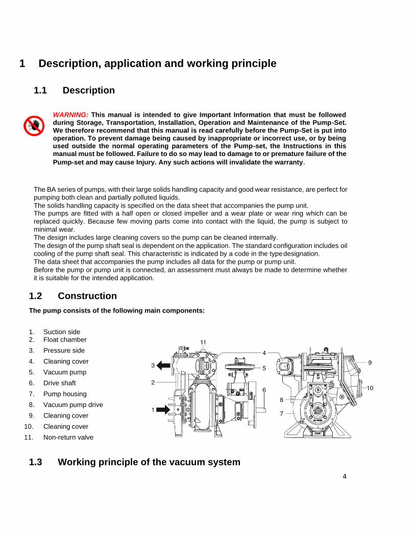
5.1 Moving the pump unit with a forklift
Forklift pockets (if present) can be used for moving the pump unit with a forklift. The forks of the forklift must be inserted into these pockets to lift the pump unit.
WARNING
Use certified lifting equipment with an adequate lifting capacity and always lift from
directly above. Lifting from an angle can lead to dangerous situations.
Lifting work may only be performed by appropriately authorised personnel.
Because many different versions of the pump unit are available, only general
instructions are provided. See the specification sheet for the particular pump unit for
the weight and dimensions.
14
6 Pump unit installation
Placement – general
WARNING
Failure to follow the guidelines for the placement and installation of the pump unit can result
in danger to the user and/or severe damage to the pump or pump unit.
BBA Pumps is not responsible for accidents and damage that result from failure to follow the guidelines in
this manual. Such use results in forfeiture of the right to assert any warranty or damage compensation
claims
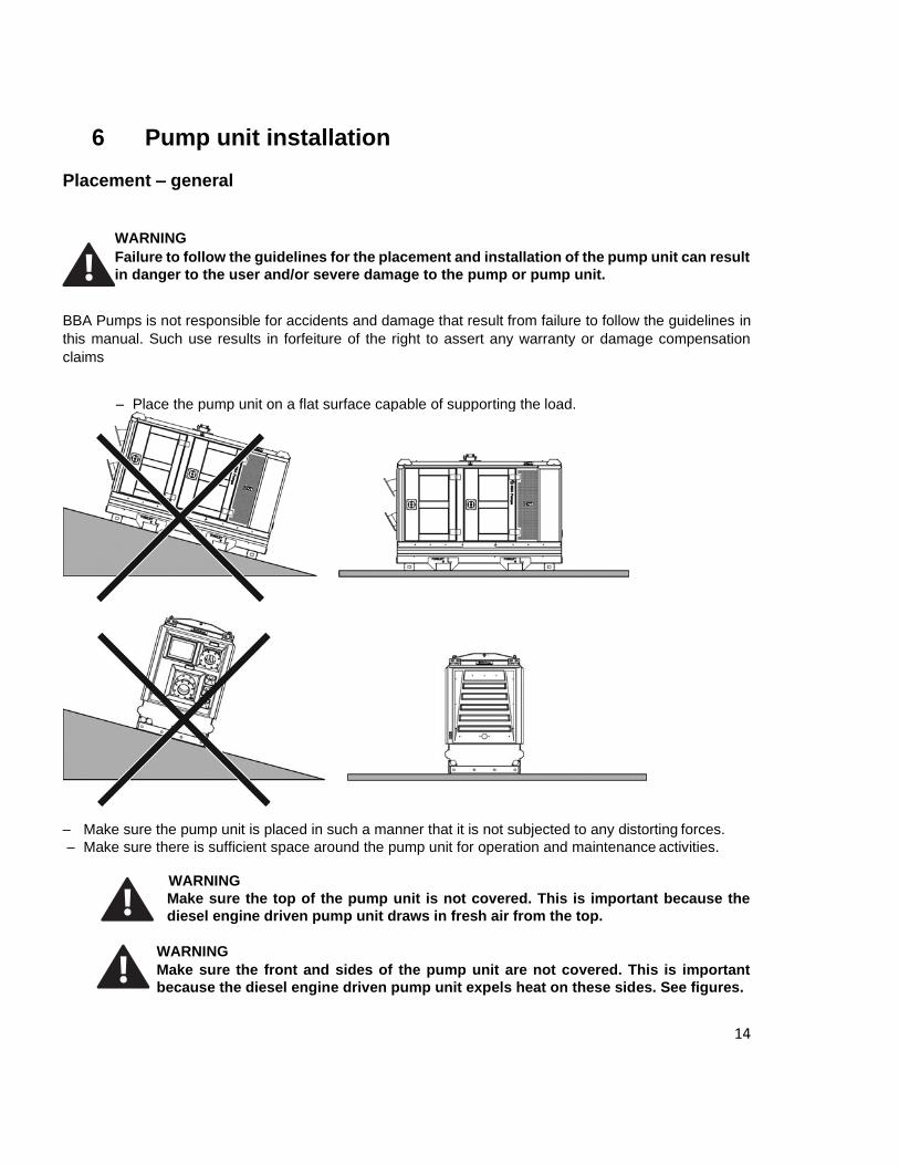
– Place the pump unit on a flat surface capable of supporting the load.
– Make sure the pump unit is placed in such a manner that it is not subjected to any distorting forces.
– Make sure there is sufficient space around the pump unit for operation and maintenance activities.
WARNING
Make sure the top of the pump unit is not covered. This is important because the
diesel engine driven pump unit draws in fresh air from the top.
WARNING
Make sure the front and sides of the pump unit are not covered. This is important
because the diesel engine driven pump unit expels heat on these sides. See figures.
15
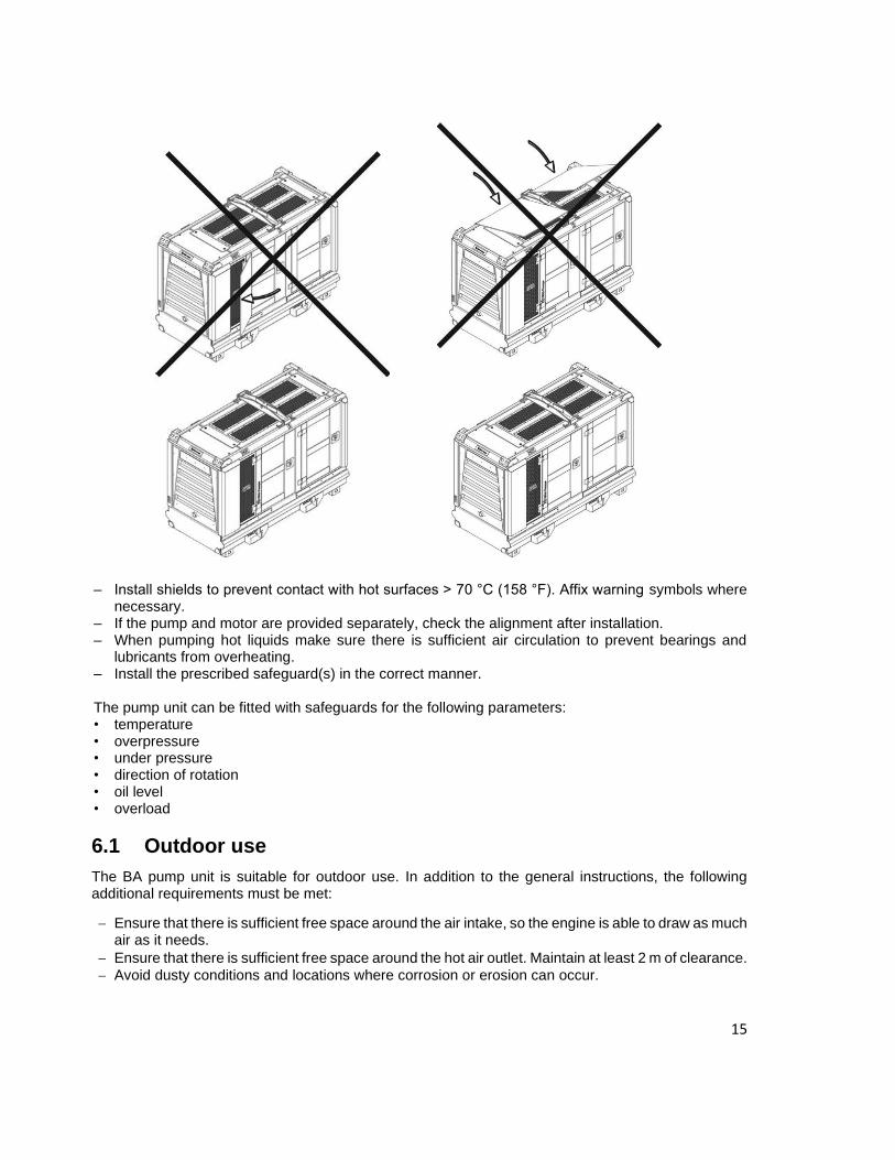
– Install shields to prevent contact with hot surfaces > 70 °C (158 °F). Affix warning symbols where necessary.
– If the pump and motor are provided separately, check the alignment after installation. – When pumping hot liquids make sure there is sufficient air circulation to prevent bearings and
lubricants from overheating. – Install the prescribed safeguard(s) in the correct manner.
The pump unit can be fitted with safeguards for the following parameters: • temperature • overpressure • under pressure • direction of rotation • oil level • overload
6.1 Outdoor use
The BA pump unit is suitable for outdoor use. In addition to the general instructions, the following additional requirements must be met:
− Ensure that there is sufficient free space around the air intake, so the engine is able to draw as much air as it needs.
− Ensure that there is sufficient free space around the hot air outlet. Maintain at least 2 m of clearance.
− Avoid dusty conditions and locations where corrosion or erosion can occur.

16
6.2 Indoor use
In addition to the general instructions, the following additional requirements must be met:
− Ensure that the area has adequate ventilation.
− Make sure the exhaust gases are discharged outdoors.
− Ensure that there is sufficient free space around the air intake, so the engine is able to draw as much air as it needs.
− Prevent high ambient temperature and humidity. Avoid dusty conditions and locations where
corrosion or erosion can occur.

17
7 Daily maintenance of the pump
Note Perform daily maintenance pump must be switched off. The sight glasses must be at least half filled and oil may not be discolored.
1. Check the oil level in the vacuum pump (1) and supply if necessary.
2. Check the oil level and clarity of the oil in the pumps seal chamber (2). If the oil is not clear but white, its means that the oil contains water. Drain this mixture, check the seal and fill the seal chamber with fresh oil.
3. Check oil level of pump bearings (3) and supply if necessary.
4. Check the oil level of the engine and supply if necessary.
5. Check the engine cooling level.
6. Check the level of the fuel in the fuel tank and supply if necessary.
7. Check whether all panels of the casing have been mounted.
8. Check whether the set is set up securely.
9. Check whether the drain valve below the pump housing is closed.
10. Check whether all connections of suction and delivery lines are tightened securely.
WARNING Hot oil and components can cause personal injury. Do not allow hot oil or hot components to contact the skin.

18
7.1 Engine oil level check
WARNING Hot oil and components can cause personal injury. Do not allow hot oil or hot components to contact the skin.
Note Perform this maintenance engine must be stopped.
1. The engine must be in horizontal position before adding oil or checking the oil level.
2. Pull out dipstick (1) and add engine oil of the correct specification and viscosity up to the’’max’’ mark on the dipstick.
3. Remove the oil filler cap (2) and add oil, if necessary. Clean the oil filler cap. Install back the oil filler cap
7.2 Check the water trap
The intervals at which you should check the water trap depend entirely on the amount of water in the fuel
and the care taken when refueling.
- Unscrew the bottom (2) of the water trap (1) about 2-3 turns.
- Capture the draining water and fuel in a transparent (glass) vessel. Since water has a greater
specific gravity than diesel fuel, the water emerges before the diesel fuel. The two substances separate
at a clearly visible line.
- As soon as only diesel emerges from the opening, the bottom of the water separator (2) can be
tightened again.

19
7.3 Priming the fuel system
WARNING
Always check fuel level in fuel tank. Don’t start the pump when fuel is running
low. In this case air can get in fuel system.
Prime the fuel system before starting the engine for the first time, after the fuel tank has been drained
completely or after replacement of the fuel filter(s).
1. Make sure there is sufficient fuel in fuel tank.
2. Visually inspect the fuel lines for routing and leakage.
3. Open the bleeder screw (3). 4. Squeeze the manual pump (4) to pump the fuel, repeat this until fuel exits the bleeder screw (3). 5. Close the bleeder screw (3). 6. Dispose of the discharged fuel.
20
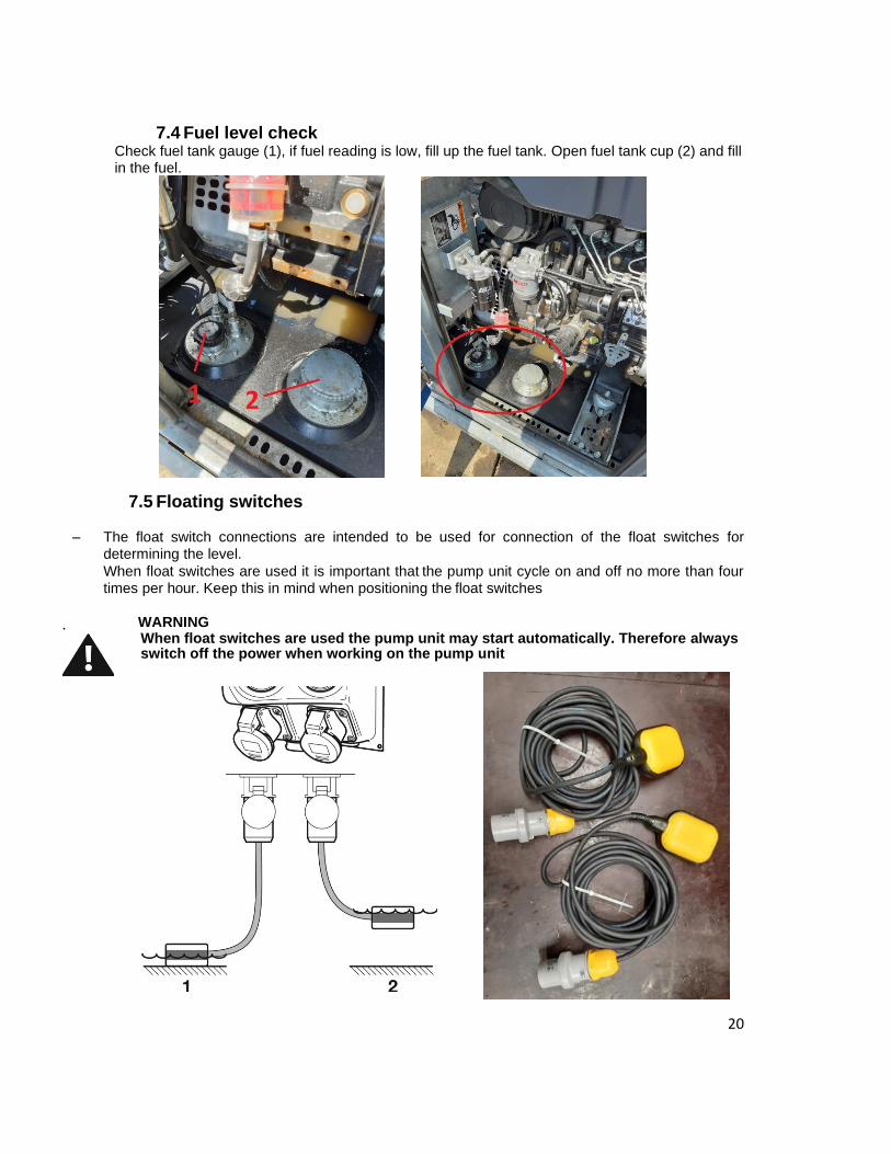
7.4 Fuel level check Check fuel tank gauge (1), if fuel reading is low, fill up the fuel tank. Open fuel tank cup (2) and fill in the fuel.
7.5 Floating switches
– The float switch connections are intended to be used for connection of the float switches for determining the level.
When float switches are used it is important that the pump unit cycle on and off no more than four times per hour. Keep this in mind when positioning the float switches
.
WARNING When float switches are used the pump unit may start automatically. Therefore always switch off the power when working on the pump unit

21
7.6 Cooling level check
7.6.1 Open the cover top of canopy (1)
7.6.2 Open cooling radiator cup (2)
.
WARNING Perform this action engine must be switched off and cooled down. Hot coolant steam can harmfully burn the skin.
22
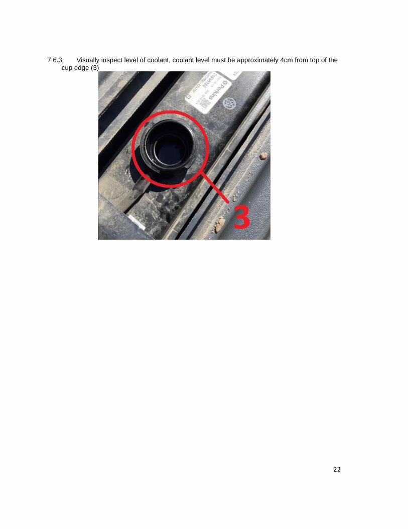
7.6.3 Visually inspect level of coolant, coolant level must be approximately 4cm from top of the cup edge (3)

23
8 Control panel LC20
1. Auto standby LED (green)
2. Glow plug LED (yellow)
3. Oil pressure LED (red)
4. Temperature LED (yellow)
5. Selection switch
6. Hour counter
7. RPM meter
8. Float switch connection ‘low liquid level’
9. Float switch connection ‘high liquid level’
Note The hour counter (6) indicates how long the
pump has been in service. This hour reading
is also important for determining when the
pump unit requires maintenance.
The RPM meter (7) shows the speed of the
combustion engine. This speed can be
adjusted as desired via the speed regulator.
8.1 Selection switch
The selection switch has four positions: (1) Pump unit is switched off (1).
(2) Pump unit is switched on manually (2)
This means that the pump unit will run continuously. To prevent damage to the pump it is important that the pump can draw sufficient liquid
(3) Starting pump unit (3). (4) The pump unit is set to ‘auto start’ (4)*
This means that the pump unit will switch itself on at certain times. The activation parameters can be
set by the user by means of the two float switches.
If the pump is running in ‘auto start’ mode, the float switches must be connected to the control panel.
24
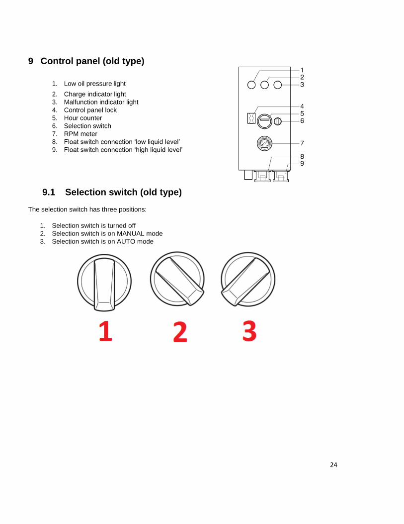
9 Control panel (old type)
1. Low oil pressure light
2. Charge indicator light
3. Malfunction indicator light
4. Control panel lock
5. Hour counter
6. Selection switch
7. RPM meter
8. Float switch connection ‘low liquid level’
9. Float switch connection ‘high liquid level’
9.1 Selection switch (old type) The selection switch has three positions:
1. Selection switch is turned off
2. Selection switch is on MANUAL mode
3. Selection switch is on AUTO mode

25
10 Pump unit preparation for starting 1. Check the oil levels of the vacuum pump bearings, pump seal and pump bearings.
2. If applicable, the pump is now pre-heated to an adequate temperature (whether it is necessary to
pre-heat the pump depends on the pumped liquid and the ambient conditions).
3. When barrier fluid is used, check: whether barrier fluid is present, has the correct pressure and can
circulate freely.
4. Completely open the suction and pressure shut-off valves.
5. In the case of a bypass line, open the shut-off valve in the bypass line.
6. If present: check whether the non-return valve is closed.
7. Check engine oil level
8. Check the engine cooling level
9. Check whether the direction of rotation of the pump matches that of the engine

26
11 Starting (manual New type)
1. Check the pump type (type plate) and the characteristics of the pump unit, such as: rpm, operating pressure, power consumption, operating temperature, direction of rotation, etc.
2. Check whether the pump unit is placed in accordance with the instructions. Pay particular attention to
the area around the pump unit. Make sure the pump unit can draw adequate fresh air.
3. Check whether the prescribed safety provisions are in place.
4. Connect the hoses
5. Perform daily maintenance 6. Make sure there is sufficient fuel in the fuel tank.
7. Bleed the fuel system, if necessary
8. Perform the general steps for starting the pump
9. Switch on earth switch (1).
10. Turn the switch on the control panel to right (2). The oil pressure and battery charging lamp must light
on. If the glow plug LED (yellow) is on, the system is being preheated. When the LED goes out the
engine can be started.
11. Turn the switch on START position (3). Engine must start.

27
WARNING If vibration occurs during starting, stop the pump immediately and eliminate the cause before starting again.
11.1 Stopping (manual new type)
1. Turn the switch on the control panel to position (1).
2. Observe whether the system comes to a gradual, smooth stop.
3. When you suspect that the liquid is beginning to freeze, drain the pump while the medium is still in the liquid state.
4. Switch off earth switch (1)

28
12 Starting (auto new type)
1. Check the pump type (type plate) and the characteristics of the pump unit, such as: rpm, operating pressure, power consumption, operating temperature, direction of rotation, etc.
2. Check whether the pump unit is placed in accordance with the instructions. Pay particular attention to
the area around the pump unit. Make sure the pump unit can draw adequate fresh air.
3. Check whether the prescribed safety provisions are in place.
4. Connect the hoses
5. Perform daily maintenance 6. Make sure there is sufficient fuel in the fuel tank.
7. Bleed the fuel system, if necessary
8. Perform the general steps for starting the pump
9. Connect and install both float switches through canopy holes (1 and 2)
10. Set the minimum float switch in minimum level and maximum float switch to maximum level.

29
11. Close the earth switch (1),
12. Turn the switch on the control panel to the left (4). The Auto standby LED (green) light is coming on.
Pump is ready.
WARNING If vibration occurs during starting, stop the pump immediately and eliminate the cause before starting again.
Note When float switches are used it is important that the pump unit cycle on and off no more than
four times per hour.
DANGER When float switches are used the pump unit may start automatically. Therefore
always switch off the power when working on the pump unit

30
12.1 Stopping (auto new type)
1. Turn the switch on the control panel to position (1). Observe whether the pump unit comes to a gradual, smooth stop.
2. Observe whether the system comes to a gradual, smooth stop.
3. When you suspect that the liquid is beginning to freeze, drain the pump while the medium is still in the liquid state.
4. Switch off earth switch (1)

31
13 Starting (manual old type) 1. Check the pump type (type plate) and the characteristics of the pump unit, such as: rpm, operating
pressure, power consumption, operating temperature, direction of rotation, etc.
2. Check whether the pump unit is placed in accordance with the instructions. Pay particular attention
to the area around the pump unit. Make sure the pump unit can draw adequate fresh air.
3. Check whether the prescribed safety provisions are in place.
4. Connect the hoses
5. Perform daily maintenance
6. Make sure there is sufficient fuel in the fuel tank.
7. Bleed the fuel system, if necessary
8. Perform the general steps for starting the pump
9. Close the earth switch (2).
10. Turn the switch on the control panel to left (2). Pump is switched on

32
13.1 Stopping (manual old type)
1. Turn the switch on the control panel to position (1)
2. Observe whether the system comes to a gradual, smooth stop.
3. When you suspect that the liquid is beginning to freeze, drain the pump while the medium is still in the liquid state.
4. Switch off earth switch (2)
WARNING If vibration occurs during starting, stop the pump immediately and eliminate the cause before starting again.

33
14 Starting (auto old type) 1. Check the pump type (type plate) and the characteristics of the pump unit, such as: rpm,
operating pressure, power consumption, operating temperature, direction of rotation, etc.
2. Check whether the pump unit is placed in accordance with the instructions. Pay particular
attention to the area around the pump unit. Make sure the pump unit can draw adequate fresh air.
3. Check whether the prescribed safety provisions are in place.
4. Connect the hoses
5. Perform daily maintenance
6. Make sure there is sufficient fuel in the fuel tank.
7. Bleed the fuel system, if necessary
8. Perform the general steps for starting the pump
9. Connect and install both float switches through canopy holes (1 and 2)
10 Set the minimum float switch in minimum level and maximum float switch to maximum level.

34
12. Close the earth switch (1)
12. Turn the switch on the control panel to the right (3). Pump is switched on.
WARNING If vibration occurs during starting, stop the pump immediately and eliminate the cause before starting again.
Note When float switches are used it is important that the pump unit cycle on and off no more than four
times per hour.
DANGER When float switches are used the pump unit may start automatically. Therefore
always switch off the power when working on the pump unit
35
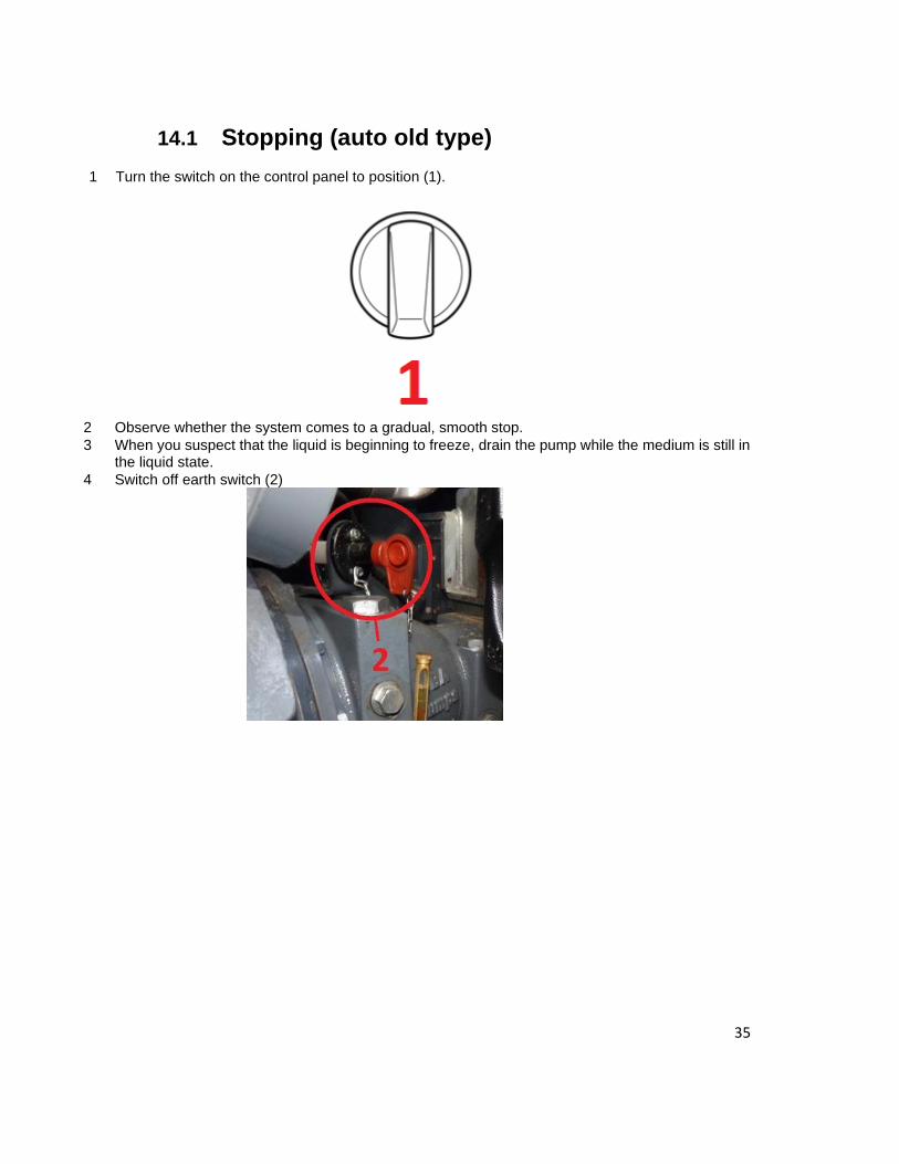
14.1 Stopping (auto old type)
1 Turn the switch on the control panel to position (1).
2 Observe whether the system comes to a gradual, smooth stop.
3 When you suspect that the liquid is beginning to freeze, drain the pump while the medium is still in the liquid state.
4 Switch off earth switch (2)

36
15 Draining the pump when there is danger of freezing
WARNING
If there is a danger of freezing, a pump used to pump a liquid that may freeze must be
drained (while at a standstill).
1. Turn off the engine and open canopy draining ports (covers / plugs) (1). 2. Make sure the canopy draining ports (covers / plugs) (1) are not clogged with solids, clean
them if clogged.
3. Open valves (covers / plugs) (2,3,4), make sure they are not clogged, clean them if clogged, and drain water.
4. Close all valves (ports / covers / plugs) after complete water drainage.

37
16 Troubleshooting
WARNING In the event of a malfunction or abnormal operation, shut off the pump or pump
unit immediately to prevent a dangerous situation and/or damage (possibly
severe) to the pump or pump unit.
Inform to responsible persons. Determine the cause of the malfunction.
Resolve the problem before restarting the pump
Problem Cause Possible solution
Pump does not
deliver any liquid
Incorrect direction of rotation Reverse direction of rotation
Vacuum pump does not draw a vacuum Inspect vacuum pump
Gas or air is released from the liquid Ensure that the liquid flows more slowly/
smoothly
Air pockets form in the suction line Eliminate air entrapment to the extent
possible
Inlet of the suction pipe is insufficiently
submerged
Submerge the suction line more deeply
Foreign object in the impeller Clean impeller
Insufficient lubrication Lubricate
Manometric suction height undercalculated Place pump higher, if possible
Otherwise: use a different type of pump
The suction height is too great or there is
too little difference between the geometric
height and the vapour tension of the liquid
(NPSH too low)
Place pump at a lower height
Otherwise: use a different type of pump
The suction pipe is clogged Clean
The pressure pipe is clogged Clean
There is a leak in the suction pipe Eliminate leak
Problem Cause Possible solution
Pump provides
insufficient
capacity
The operating speed is too low Increase speed
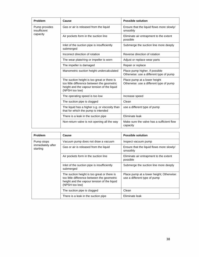
38
Problem Cause Possible solution
Pump provides
insufficient
capacity
Gas or air is released from the liquid Ensure that the liquid flows more slowly/
smoothly
Air pockets form in the suction line Eliminate air entrapment to the extent
possible
Inlet of the suction pipe is insufficiently
submerged
Submerge the suction line more deeply
Incorrect direction of rotation Reverse direction of rotation
The wear plate/ring or impeller is worn Adjust or replace wear parts
The impeller is damaged Repair or replace
Manometric suction height undercalculated Place pump higher, if possible
Otherwise: use a different type of pump
The suction height is too great or there is
too little difference between the geometric
height and the vapour tension of the liquid
(NPSH too low)
Place pump at a lower height
Otherwise: use a different type of pump
The operating speed is too low Increase speed
The suction pipe is clogged Clean
The liquid has a higher s.g. or viscosity than
that for which the pump is intended
use a different type of pump
There is a leak in the suction pipe Eliminate leak
Non-return valve is not opening all the way Make sure the valve has a sufficient flow
capacity
Problem Cause Possible solution
Pump stops
immediately after
starting
Vacuum pump does not draw a vacuum Inspect vacuum pump
Gas or air is released from the liquid Ensure that the liquid flows more slowly/
smoothly
Air pockets form in the suction line Eliminate air entrapment to the extent
possible
Inlet of the suction pipe is insufficiently
submerged
Submerge the suction line more deeply
The suction height is too great or there is
too little difference between the geometric
height and the vapour tension of the liquid
(NPSH too low)
Place pump at a lower height; Otherwise:
use a different type of pump
The suction pipe is clogged Clean
There is a leak in the suction pipe Eliminate leak

39
Problem Cause Possible solution
Pump is
demanding
abnormal amount
of power
Incorrect direction of rotation Reverse direction of rotation
Foreign object in the impeller Clean impeller
The shafts are not in alignment with one
another
Align unit
The shaft is bent Replace shaft
Rotating parts are rubbing against
stationary parts
Adjust everything and align if necessary
The wear plates/ring or impeller is/are worn Adjust or replace wear parts
The impeller is damaged Repair or replace
The seal is not installed properly Install properly; replace seal if necessary.
Inadequate lubrication or insufficient
lubricant in the bearing housing, possibly as
a result of a leak; can be identified by higher
than normal temperature
Follow good service plan
In this application the pump is not
functioning in the intended range
Make changes to the piping system, if
possible
Otherwise: use a different type of pump
The liquid has a higher s.g. or viscosity than
that for which the pump is intended
Change temperature of liquid, if possible.
Otherwise: use a different type of pump
WARNING
If appear some pump defect and cannot find fault immediately contact
Uprent technical department.