Repair Manual - General Pump
45
MKS Repair Manual Ref 300699 Rev D 02-20 General Pump is a member of the Interpump Group MKS55A-MKS60A-MKS65A MKS40A-MKS45A-MKS50A
-
Upload
khangminh22 -
Category
Documents
-
view
3 -
download
0
Transcript of Repair Manual - General Pump

MKSRepair Manual
Ref 300699 Rev D02-20
General Pump is amember of the Interpump Group
MKS55A-MKS60A-MKS65A
MKS40A-MKS45A-MKS50A

GENERAL PUMP A member of the Interpump Group MKS SERIES
Page 2
INDEX
1. INTRODUCTION . . . . . . . . . . . . . . . . . . . . . . . . . . . . . . . . . . . . . . . . . . . . . . . . . . Page 3
2. REPAIR INSTRUCTIONS . . . . . . . . . . . . . . . . . . . . . . . . . . . . . . . . . . . . . . . . . . . Page 3 2 .1 Crank Mechanism Repair . . . . . . . . . . . . . . . . . . . . . . . . . . . . . . . . . . . . . . . . . Page 3 2 .1 .1 Crank Mechanism Disassembly . . . . . . . . . . . . . . . . . . . . . . . . . . . . . Page 4 2 .1 .2 Crank Mechanism Assembly . . . . . . . . . . . . . . . . . . . . . . . . . . . . . . . Page 13 2 .1 .3 Refurbishing the Crank Mechanism . . . . . . . . . . . . . . . . . . . . . . . . . . Page 23 2 .2 Fluid End Repair . . . . . . . . . . . . . . . . . . . . . . . . . . . . . . . . . . . . . . . . . . . . . . . Page 24 2 .2 .1 Head Disassembly - Valve Units . . . . . . . . . . . . . . . . . . . . . . . . . . . . Page 24 2 .2 .2 Head Assembly - Valve Units . . . . . . . . . . . . . . . . . . . . . . . . . . . . . . . Page 27 2 .2 .3 Disassembling the Plunger Unit - Supports - Seals . . . . . . . . . . . . . . Page 33 2 .2 .4 Assembly of the Plunger Unit - Suports - Seals . . . . . . . . . . . . . . . . . Page 36 2 .2 .5 Manifold Refurbishment . . . . . . . . . . . . . . . . . . . . . . . . . . . . . . . . . . . Page 41 3. SCREW CALIBRATION . . . . . . . . . . . . . . . . . . . . . . . . . . . . . . . . . . . . . . . . . . . . Page 43
4. REPAIR TOOLS . . . . . . . . . . . . . . . . . . . . . . . . . . . . . . . . . . . . . . . . . . . . . . . . . . Page 44
5. MAINTENANCE LOG . . . . . . . . . . . . . . . . . . . . . . . . . . . . . . . . . . . . . . . . . . . . . . Page 45
Ref 300699 Rev D02-20

1. INTRODUCTIONThis manual describes the instructions for Repairing MKS Series pumps, and must be carefully read andunderstood before performing any repair intervention on the pump . Correct use and adequate maintenance is fundamental for the pump’s regular operation and long wear . General Pump declines any responsibility for damage caused by the misuse or the non-observance of the instructions described in this manual .
2. REPAIR INSTRUCTIONS
2.1 Crank Mechanism RepairCrank mechanism repair operations must be carried out after draining the oil from the crankcase . To drainthe oil, remove the oil refill cap 1, Fig . 1, and then the draining plug (2, fig . 1) .
Exhausted oil must be collected in an appropriate receptacle and disposed of in designated locations . In absolutely no case may it be disposed of in the environment .
Page 3
GENERAL PUMP A member of the Interpump Group MKS SERIES
Ref 300699 Rev D02-20

Page 4
2.1.1 Crank Mechanism DisassemblyThe correct sequence is the following
Completely drain the oil from the pump, then remove the key from the shaft (1, fig .2) .
Unscrew the reducer flange fastening screws (1, fig . 3) and remove the flange from the shaft .
On the opposite side, unfasten the screws (1, fig . 4) and then remove the bearing cover .
GENERAL PUMP A member of the Interpump Group MKS SERIES
Ref 300699 Rev D02-20
Page 5
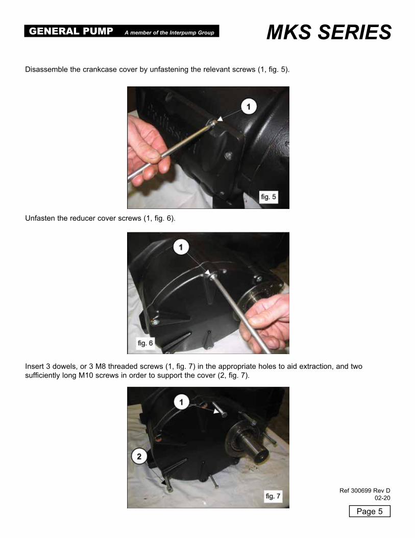
Unfasten the reducer cover screws (1, fig . 6) .
Insert 3 dowels, or 3 M8 threaded screws (1, fig . 7) in the appropriate holes to aid extraction, and two sufficiently long M10 screws in order to support the cover (2, fig . 7) .
Disassemble the crankcase cover by unfastening the relevant screws (1, fig . 5) .
GENERAL PUMP A member of the Interpump Group MKS SERIES
Ref 300699 Rev D02-20

Page 6
Screw on the 3 threaded screws (1, fig . 8) and simultaneously, using the appropriate tool (p/n F27516700),hammer on the tool itself so that the bearing remains on the pinion when extracting the cover (1, fig . 9) .
When this operation is complete, remove the reducer cover and then slip off the bearing from the pinion .Remove the screws that fasten the ring gear stopper (1, fig . 10), and remove the stopper itself (1, fig . 11) .
Remove the ring gear (1, fig . 12) . If necessary, use a slide hammer applying it to the 2 M8 holes (2, fig . 12) .
GENERAL PUMP A member of the Interpump Group MKS SERIES
Ref 300699 Rev D02-20

Page 7
Remove the pinion by using a slide hammer applying it to the M14 hole (1, fig . 14) .
Lift the safety washer key (1, fig . 15)
Remove the key from the shaft (1, fig . 13) .
GENERAL PUMP A member of the Interpump Group MKS SERIES
Ref 300699 Rev D02-20
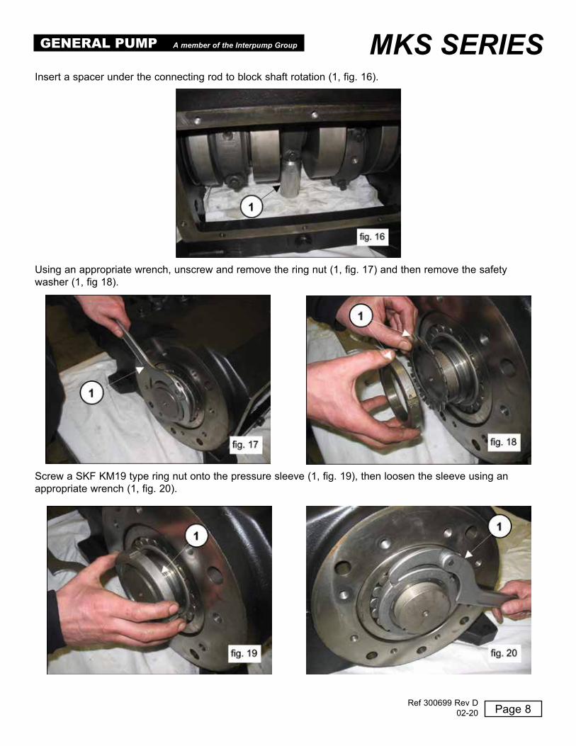
Insert a spacer under the connecting rod to block shaft rotation (1, fig . 16) .
Using an appropriate wrench, unscrew and remove the ring nut (1, fig . 17) and then remove the safetywasher (1, fig 18) .
Screw a SKF KM19 type ring nut onto the pressure sleeve (1, fig . 19), then loosen the sleeve using anappropriate wrench (1, fig . 20) .
Page 8
GENERAL PUMP A member of the Interpump Group MKS SERIES
Ref 300699 Rev D02-20
Page 9
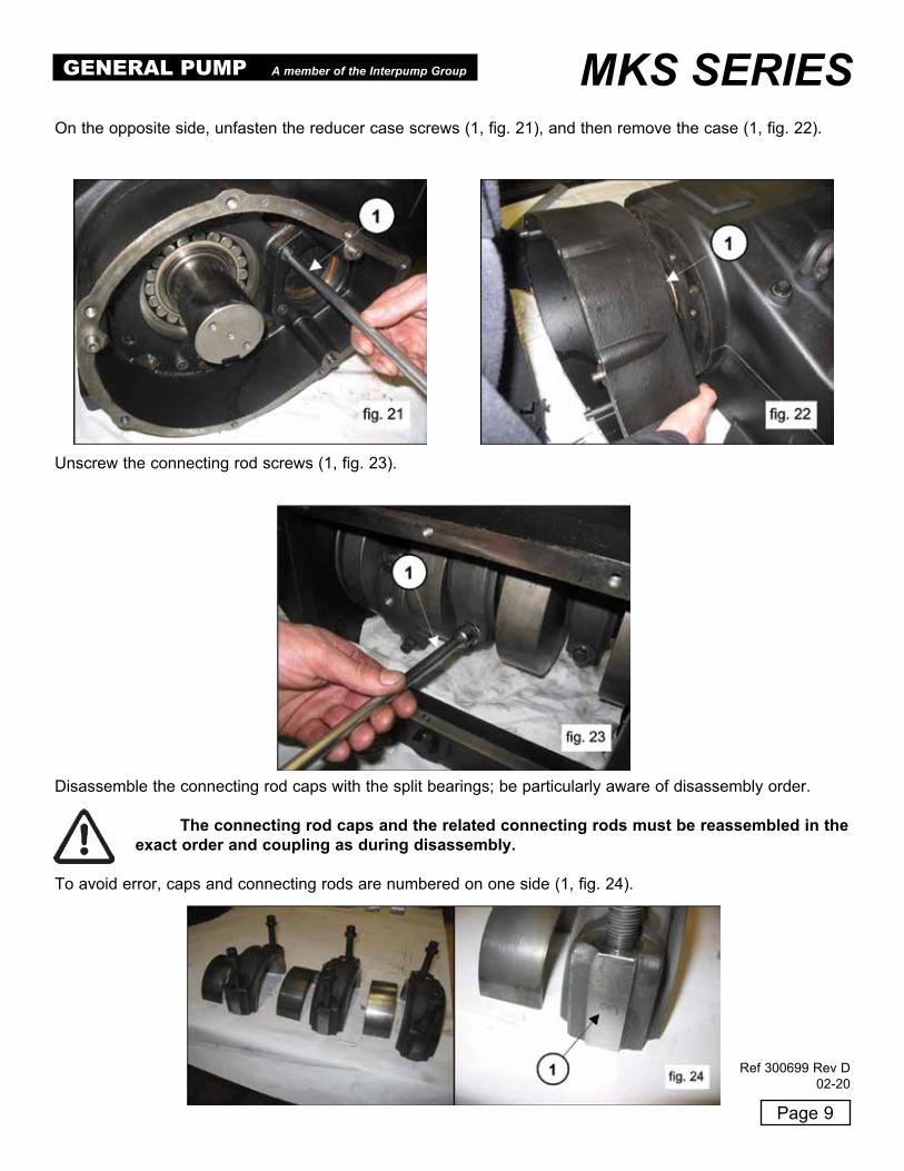
On the opposite side, unfasten the reducer case screws (1, fig . 21), and then remove the case (1, fig . 22) .
Unscrew the connecting rod screws (1, fig . 23) .
Disassemble the connecting rod caps with the split bearings; be particularly aware of disassembly order .
The connecting rod caps and the related connecting rods must be reassembled in the exact order and coupling as during disassembly.
To avoid error, caps and connecting rods are numbered on one side (1, fig . 24) .
GENERAL PUMP A member of the Interpump Group MKS SERIES
Ref 300699 Rev D02-20

Page 10
Remove the pressure sleeve (1, fig . 26) .
Remove the upper split bearing of the connecting rods (1, fig . 27) .
Push the connecting rods forward in the direction of the hydraulic side in order to push out the crankshaft .Use the appropriate tool (p/n F27566200) to facilitate this operation (1, fig . 25)
GENERAL PUMP A member of the Interpump Group MKS SERIES
Ref 300699 Rev D02-20

Remove the crankshaft with the help of a hammer on the PTO side (1, fig . 28) . Remove the shaft and the bearing (1, fig . 29) .
If the replacement of one or more connecting rods or plunger guides is necessary, please operate as follows:Unfasten the screws of the tool (p/n F27566200 to unlock the connecting rods (1, fig . 31) and thereforeextract the connecting rod-plunger guide units from the opening behind the crankcase (1, fig . 32) .
On the opposite side, extract the bearing (1, fig . 30)
Page 11
GENERAL PUMP A member of the Interpump Group MKS SERIES
Ref 300699 Rev D02-20

Couple the connecting rods with the previously disassembled caps; be sure to respect numbering (1, fig . 33) .
Remove the pin (1, fig . 35) and then remove the connecting rod (1, fig . 36) .
Remove the two seeger rings that block the plunger pin by using the appropriate tool (1, fig . 34) .
Page 12
GENERAL PUMP A member of the Interpump Group MKS SERIES
Ref 300699 Rev D02-20

To separate the rod from the plunger guide, unfasten the M10 hexagonal-head screws using a size 17 socketwrench (1, fig . 37) .
2.1.2 Crank Mechanism AssemblyProceed with assembly by inverting the precedure indicated in paragraph 2 .1 .1 .The correct sequence is the following:
Connect the rod to the plunger guideInsert the Ø5 pin in the appropriate hole on the plunger guide (1, fig . 38) and connect the rod to the plungerguide using M10 x 35 screws (1, fig . 39) .
Page 13
GENERAL PUMP A member of the Interpump Group MKS SERIES
Ref 300699 Rev D02-20

Block the rod using a clamp, and proceed with calibration using a torque wrench (1, fig . 40) as indicatedin paragraph 3 . “SCREW CALIBRATION”
Insert the connecting rod in the plunger guide (1, fig . 36) and then insert the pin (1, fig . 35) . Apply thetwo seeger rings using the correct tool (1, fig . 34) .
Make sure that conrods, plunger guides and wrist pins can move freely after being assembled together.
Separate the caps from the connecting rod; correct coupling is guaranteed by the numbering on the side(1, fig . 33) .
After verifying the perfect cleaning of the crankcase, insert the connecting rod-plunger guide unit inside thecylinders of the crankcase (1, fig . 32) .
The insertion of the connecting rod-plunger guide unit inside crankcase must be done by positioning the connecting rods with the numbering visible from above.
Block the three units using the correct tool, p/n F27566200(1, fig 31) .
Pre-assemble the bearing, PTO side, on the shaft (1, fig . 41) and assemble the bearing on the oppositeside on the crankcase (1, fig . 42) .
The bearing in fig. 42 has a tapered internal ring. Verify that the taper goes from the outside towards the inside in order to allow the subsequent insertion of the sleeve.
Page 14
GENERAL PUMP A member of the Interpump Group MKS SERIES
Ref 300699 Rev D02-20

Insert the shaft (1, fig . 29) until the pre-assembled bearing is aligned with the edge of the crankcase(1, fig . 43) .
Manually insert the pressure sleeve to maintain the shaft alignment (1, fig . 44) .
Assemble the reducer case (1, fig . 45) and the related gasket (2, fig 45) using the 6 M12 x 40 screws (1, fig . 46), the 2 M12 x 50 screws (1, fig . 47) and the Ø 12 Grower washers (2, fig . 46 and fig . 47) .Calibrate the screws with a torque wrench (1, fig . 48) as indicated in paragraph 3 . “SCREW CALIBRATION”
Page 15
GENERAL PUMP A member of the Interpump Group MKS SERIES
Ref 300699 Rev D02-20

Page 16
Completely insert the pressure sleeve on the shaft from the opposite side of the PTO (1, fig . 49 and fig . 50) .
Pressure sleeve insertion must be done without oil or lubricants.
Insert the sleeve until the external surface (tapered) couples perfectly with the inside of the bearing . During insertion, be sure that the bearing remains in contact with the shaft shoulder .
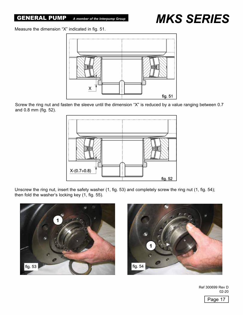
Measure the dimension “X” indicated in fig . 51 .
GENERAL PUMP A member of the Interpump Group MKS SERIES
Ref 300699 Rev D02-20
Page 17
Screw the ring nut and fasten the sleeve until the dimension “X” is reduced by a value ranging between 0 .7and 0 .8 mm (fig . 52) .
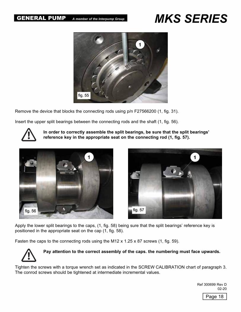
Unscrew the ring nut, insert the safety washer (1, fig . 53) and completely screw the ring nut (1, fig . 54);then fold the washer’s locking key (1, fig . 55) .
Measure the dimension “X” indicated in fig . 51 .
MKS SERIESGENERAL PUMP A member of the Interpump Group MKS SERIES
Ref 300699 Rev D02-20
Page 18
Remove the device that blocks the connecting rods using p/n F27566200 (1, fig . 31) .
Insert the upper split bearings between the connecting rods and the shaft (1, fig . 56) .
In order to correctly assemble the split bearings, be sure that the split bearings’ reference key in the appropriate seat on the connecting rod (1, fig. 57).
Apply the lower split bearings to the caps, (1, fig . 58) being sure that the split bearings’ reference key ispositioned in the appropriate seat on the cap (1, fig . 58) .
Fasten the caps to the connecting rods using the M12 x 1 .25 x 87 screws (1, fig . 59) .
Pay attention to the correct assembly of the caps. the numbering must face upwards.
Tighten the screws with a torque wrench set as indicated in the SCREW CALIBRATION chart of paragraph 3 . The conrod screws should be tightened at intermediate incremental values .
GENERAL PUMP A member of the Interpump Group MKS SERIES
Ref 300699 Rev D02-20

Page 19
Once tightened on the crankshaft, make sure that conrods still have axial right-left endplay.
Preassemble the bearing on the pinion (1, fig . 60) and fully insert the pinion in the seat on the reducercase (1, fig . 61) by using a hammer .
Apply the 22 x 14 x 100 key in the seat on the shaft (1, fig . 62) and insert the ring gear on the shaft .Fasten the ring gear stopper (1, fig . 63) using the 2 M10 x 25 screws (2, fig . 63) .Calibrate the screws with the torque wrench as indicated in paragraph 3 . “SCREW CALIBRATION”
GENERAL PUMP A member of the Interpump Group MKS SERIES
Ref 300699 Rev D02-20
Page 20
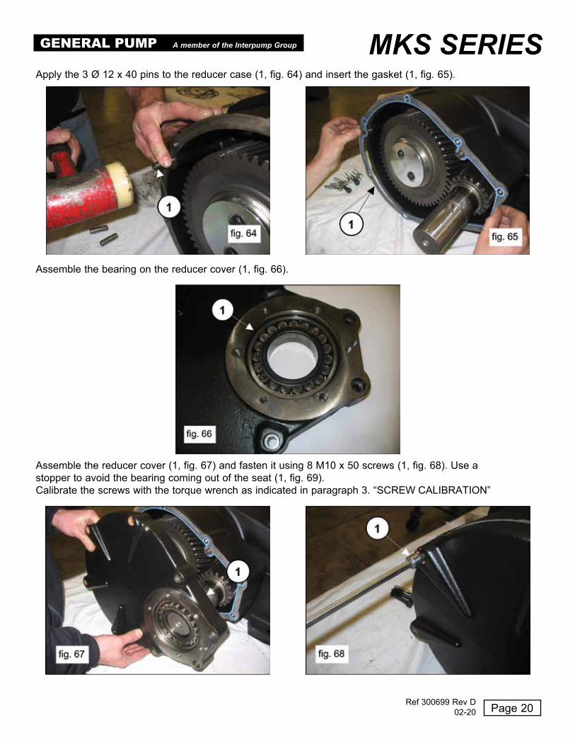
Assemble the bearing on the reducer cover (1, fig . 66) .
Assemble the reducer cover (1, fig . 67) and fasten it using 8 M10 x 50 screws (1, fig . 68) . Use astopper to avoid the bearing coming out of the seat (1, fig . 69) .Calibrate the screws with the torque wrench as indicated in paragraph 3 . “SCREW CALIBRATION”
Apply the 3 Ø 12 x 40 pins to the reducer case (1, fig . 64) and insert the gasket (1, fig . 65) .
GENERAL PUMP A member of the Interpump Group MKS SERIES
Ref 300699 Rev D02-20

Page 21
Insert the oil seal inside the reducer flange using the proper tools, p/n F27515900 and F27548200 (1, fig . 70) .Before proceeding with oil seal assembly, verify the conditions of the sealing lip . If replacement is necessary,position the new ring as indicated in fig . 71 .
If the shaft presents diameter wear corresponding to the sealing lip, to avoid the need for grinding it’s possible to position the ring as indicated in fig. 71.
Apply the reducer flange with it’s gasket to the reducer case (1, fig . 72) and fasten it using 3 M8 x 18screws (1, fig . 73) .
To avoid damaging the oil seal, pay particular attention when inserting the flange on the pinion.
Calibrate the screws with the torque wrench as indicated in paragraph 3 . “SCREW CALIBRATION”
GENERAL PUMP A member of the Interpump Group MKS SERIES
Ref 300699 Rev D02-20

Page 22
Insert the key 16 x 10 x 90 in the pinion .
Insert the O-ring in the rear cover (1 . fig . 74) and fasten it to the crankcase using 10 M8 x 18 screws(1, fig . 75) .Calibrate the screws with the torque wrench as indicated in paragraph 3 . “SCREW CALIBRATION”
Assemble the bearing cover (and related gasket) (1, fig . 76) using 8 M12 x 30 screws (1, fig . 77) .Calibrate the screws with the torque wrench as indicated in paragraph 3 . “SCREW CALIBRATION”
GENERAL PUMP A member of the Interpump Group MKS SERIES
Ref 300699 Rev D02-20

Page 23
Complete the assembly of the crank mechanism by applying the plugs and lifting eyebolts with therelated sealing O-ring .
Fill the crankcase with oil as indicated in the use and maintenance manual, paragraph 7 .4 .
2.1.3 Refurbishing the crank mechanism
TABLE UNDERSIZED DIAMETERS FOR CRANKSHAFT AND CONROD BUSHINGS
Max. Undersize(mm)
Upper halfbushing
p/n
Lower halfbushing p/n
Crank pin grinding measures
(mm)
0 .25 F90931100 F90930100 Ø 92 .75 0/-0 .03Roughness Ra 0 .4 Rt 3 .5
0 .50 F90931200 F90930200 Ø 92 .50 0/-0 .03Roughness Ra 0 .4 Rt 3 .5
TABLE OVERSIZED DIAMETERS FOR CRANKCASE CYLINDER BORES AND PLUNGER GUIDES
Max. oversize(mm) Plunger guide p/n
Crank pin grinding measures
(mm)
1 .00 F74050243 Ø 81 H6 + 0 .22/0Roughness Ra 0 .8 Rt 6
GENERAL PUMP A member of the Interpump Group MKS SERIES
Ref 300699 Rev D02-20

Page 24
2.2 Fluid End Repair
2.2.1 Head Disassembly - Valve UnitsThe head requires preventive maintenance as indicated in the use and maintenance manual . Interventions may be limited to valve inspection, or replacement as needed . To extract the valve units operate as follows:
Unfasten the 8 M16 x 55 screws of the valve cover (1, fig . 78) and remove the cover (1, fig . 79) .
Remove the spring (1, fig . 81) .
Extract the valve plug using a slide hammer applied to the M10 hole of the valve plug (1, fig . 80) .
GENERAL PUMP A member of the Interpump Group MKS SERIES
Ref 300699 Rev D02-20
Page 25
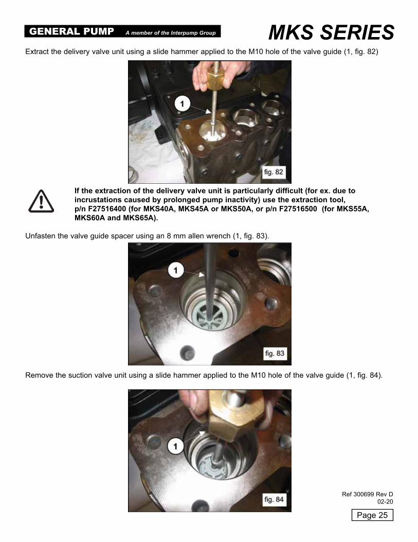
Extract the delivery valve unit using a slide hammer applied to the M10 hole of the valve guide (1, fig . 82)
If the extraction of the delivery valve unit is particularly difficult (for ex. due to incrustations caused by prolonged pump inactivity) use the extraction tool, p/n F27516400 (for MKS40A, MKS45A or MKS50A, or p/n F27516500 (for MKS55A, MKS60A and MKS65A).
Unfasten the valve guide spacer using an 8 mm allen wrench (1, fig . 83) .
Remove the suction valve unit using a slide hammer applied to the M10 hole of the valve guide (1, fig . 84) .
GENERAL PUMP A member of the Interpump Group MKS SERIES
Ref 300699 Rev D02-20

Page 26
Disassemble the suction and delivery valve units by screwing on an M10 screw long enough to act on thevalve and extract the valve guide from the valve seat (1, fig . 87) .
If the extraction of the of the suction valve unit is particularly difficult (for ex. due to incrustations caused by prolonged pump inactivity) use the extraction tool p/n F27516200 (for MKS40A, MKS45A, MKS50A) or p/n F27516300 (for MKS55A, MKS60A and MKS65A) (1, fig. 85) and act as indicated.
Unscrew the valve opening device using a 30 mm wrench (1, fig . 86) .
GENERAL PUMP A member of the Interpump Group MKS SERIES
Ref 300699 Rev D02-20
Page 27
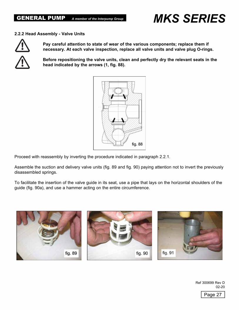
2.2.2 Head Assembly - Valve Units
Pay careful attention to state of wear of the various components; replace them if necessary. At each valve inspection, replace all valve units and valve plug O-rings.
Before repositioning the valve units, clean and perfectly dry the relevant seats in the head indicated by the arrows (1, fig. 88).
Proceed with reassembly by inverting the procedure indicated in paragraph 2 .2 .1 .
Assemble the suction and delivery valve units (fig . 89 and fig . 90) paying attention not to invert the previouslydisassembled springs .
To facilitate the insertion of the valve guide in its seat, use a pipe that lays on the horizontal shoulders of theguide (fig . 90a), and use a hammer acting on the entire circumference .
GENERAL PUMP A member of the Interpump Group MKS SERIES
Ref 300699 Rev D02-20

Page 28
Proceed with the insertion of the valve units (suction and delivery) into the head, paying attention to the correct insertion sequence of the O-rings and anti-extrusion rings.
The correct assembly sequence of the valve units in the head is the following:Insert the anti-extrusion ring, exploded view item 4 from Owner’s Manual (1, fig . 92) .
Insert the O-ring, exploded view item 5 from Owner’s Manual (1, fig . 93) .
GENERAL PUMP A member of the Interpump Group MKS SERIES
Ref 300699 Rev D02-20

Page 29
Be sure that the O-ring and the anti-extrusion ring are perfectly fit into their seats . Insert the suction valveunit together with the spacer (1, fig . 94) . The valve unit must be fully inserted, as shown in 1, fig . 95 .
Mount the O-ring, exploded view item 5 from Owner’s Manual (1, fig . 96) and the anti-extrusion ring, exploded view item 15 from Owner’s Manual (2, fig . 96) on the delivery valve seat .
Insert the delivery valve unit (1, fig . 97) . The valve unit must be fully inserted as shown in 1, fig . 98 .
GENERAL PUMP A member of the Interpump Group MKS SERIES
Ref 300699 Rev D02-20
Page 30
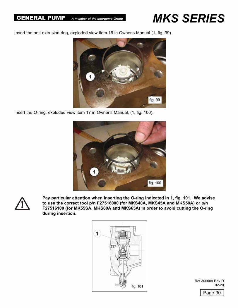
Insert the anti-extrusion ring, exploded view item 16 in Owner’s Manual (1, fig . 99) .
Pay particular attention when inserting the O-ring indicated in 1, fig. 101. We advise to use the correct tool p/n F27516000 (for MKS40A, MKS45A and MKS50A) or p/n F27516100 (for MK55SA, MKS60A and MKS65A) in order to avoid cutting the O-ring during insertion.
Insert the O-ring, exploded view item 17 in Owner’s Manual, (1, fig . 100) .
GENERAL PUMP A member of the Interpump Group MKS SERIES
Ref 300699 Rev D02-20

Page 31
Insert the valve seat ring (1, fig 102) and the spring (1, fig . 103) .
Assemble the O-ring, exploded view item 17 in Owner’s Manual, (1, fig . 104) and the anti-extrusion ring,exploded view item 21 in Owner’s Manual (2, fig . 104) on the delivery valve plug .
Insert the valve plug complete with O-rings and anti-extrusion ring .
After assembling the valve unit and the valve plug, apply the valve cover (1, fig . 105) and screw on the8 M16 x 55 screws (1, fig . 106) .
GENERAL PUMP A member of the Interpump Group MKS SERIES
Ref 300699 Rev D02-20
Page 32
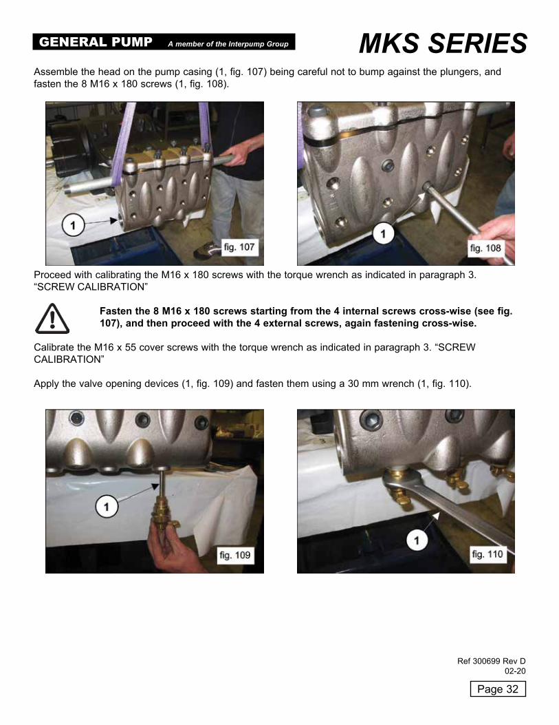
Assemble the head on the pump casing (1, fig . 107) being careful not to bump against the plungers, andfasten the 8 M16 x 180 screws (1, fig . 108) .
Proceed with calibrating the M16 x 180 screws with the torque wrench as indicated in paragraph 3 .“SCREW CALIBRATION”
Fasten the 8 M16 x 180 screws starting from the 4 internal screws cross-wise (see fig. 107), and then proceed with the 4 external screws, again fastening cross-wise.
Calibrate the M16 x 55 cover screws with the torque wrench as indicated in paragraph 3 . “SCREW CALIBRATION”
Apply the valve opening devices (1, fig . 109) and fasten them using a 30 mm wrench (1, fig . 110) .
GENERAL PUMP A member of the Interpump Group MKS SERIES
Ref 300699 Rev D02-20

Page 33
2.2.3 Disassembling the Plunger Unit - Supports - SealsThe plunger unit requires a periodical inspection as indicated in the preventive maintenance table of the Owner’s Manual . Interventions only require visual inspections of the draining from the hole in the lower cover . In case of anomolies/oscillations on the delivery pressure gauge, or leaking from the drain hole, proceed with seal inspection and replacement if necessary . Operate as follows to extract the plunger units:
To access the plunger unit, unscrew the M16 x 180 screws and disassemble the head .
Remove the head with great care in order to avoid bumping against the plungers.
Disassemble the plungers by unfastening the screws (1, fig . 111) .Remove the plunger from the packing support and check that there are no scratches, or signs of wear orcavitation .
Remove the upper inspection cover by unscrewing the 4 fastening screws (1, fig . 112) .
GENERAL PUMP A member of the Interpump Group MKS SERIES
Ref 300699 Rev D02-20
Page 34
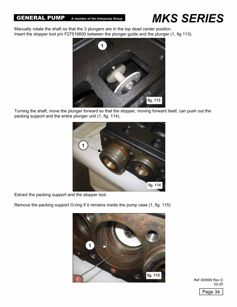
Manually rotate the shaft so that the 3 plungers are in the top dead center position .Insert the stopper tool p/n F27516600 between the plunger guide and the plunger (1, fig 113) .
Turning the shaft, move the plunger forward so that the stopper, moving forward itself, can push out thepacking support and the entire plunger unit (1, fig . 114) .
Extract the packing support and the stopper tool .
Remove the packing support O-ring if it remains inside the pump case (1, fig . 115)
GENERAL PUMP A member of the Interpump Group MKS SERIES
Ref 300699 Rev D02-20

Page 35
Remove the wiper rings from the plunger guides (1, fig . 116) .
If replacement of the plunger guide oil seal is needed, disassemble the oil seal cover by operating as follows:Unfasten the two screws of the oil seal cover (1, fig . 117) .
Extract the oil seal cover by screwing a threaded M5 bar or screw into the correct holes on the cover(1 fig . 118); extract the oil seal cover from the pump unit (1, fig . 119) .
GENERAL PUMP A member of the Interpump Group MKS SERIES
Ref 300699 Rev D02-20

Separate the packing support from the liner (1, fig . 121) to access the pressure packings (1, fig 122) .
To remove the low pressure packing, use a shim or another tool that doesn’t damage the seat of the packingsupport (1, fig . 123) .
Page 36
Replace the oil seal (1, fig . 120) and the external O-ring (2, fig . 120) .
GENERAL PUMP A member of the Interpump Group MKS SERIES
Ref 300699 Rev D02-20

Replace the pressure packings by applying a small amount of silicone grease to the lips, being careful not to damage them when inserting the liner. At each disassembly, the pressure packings must always be replaced together with all the O-rings.
Insert the low pressure packings in the packing support (1, fig 124), being careful that the sealing lips arefacing frontwards (toward the head) .
Assemble the head ring (1, fig . 125), the high pressure packing (1, fig . 126) and the restop ring(1, fig . 127) .
Page 37
Couple the packing support to the liner (1, fig . 128) .
2.2.4 Assembly of the Plunger Unit - Support - SealsProceed with reassembly by inverting the disassembly procedure indicated in paragraph 2 .2 .3 .
GENERAL PUMP A member of the Interpump Group MKS SERIES
Ref 300699 Rev D02-20

Page 38
Position the O-ring (1, fig . 130) in its seat on the oil seal cover, and insert the assembled unit inside thecrankcase in the correct space (1, fig . 131) .
Perfectly insert the cover into its seat (1, fig . 132) being careful not to damage the oil seal lip . Fasten theoil seal cover with 2 M6 x 14 screws (1, fig . 133) .
Calibrate the screws using a torque wrench as indicated in paragraph 3 . “SCREW CALIBRATION”
Insert the oil seal in its cover (1, fig . 129) using a stopper p/n F27910900 .
GENERAL PUMP A member of the Interpump Group MKS SERIES
Ref 300699 Rev D02-20

Page 39
Insert the 14 x 2 O-ring in its correct seat on the plunger bolt (1, fig . 136) .
Assemble the plungers on their respective guides (1, fig . 137) and fasten them as in 1, fig . 138) .
Calibrate the screws using the torque wrench as indicated in paragraph 3 . “SCREW CALIBRATION”
Position the wiper complete with its O-ring in its seat on the plunger guide (1, fig . 134 and fig . 135) .
GENERAL PUMP A member of the Interpump Group MKS SERIES
Ref 300699 Rev D02-20

Page 40
Be sure that the liner-support unit is correctly positioned in its seat (1, fig . 141) .
Assemble the liner’s front O-ring (1, fig . 142) and the O-ring of the recirculation hole (1, fig . 143) .
Insert the O-ring inside the pump case (1, fig . 139), followed by the previously assembled liner-packingsupport unit (complete with the O-ring), (1, fig . 140) .
GENERAL PUMP A member of the Interpump Group MKS SERIES
Ref 300699 Rev D02-20

Calibrate the screws with the torque wrench as indicated in paragraph 3 . “SCREW CALIBRATION”
Insert the O-ring on the inspection covers (1, fig . 144) and mount the covers using 4 + 4 M6 x 14 screws(1, fig . 145) .
2.2.5 Manifold RefurbishmentManifold cavitation damages around the three cylinder bores can be fixed by re-tooling the damaged boresto a larger diameter (see fig . 146 for MKS40A, 45A-50A and fig . 148 for MKS55A-60A-65A) .
Page 41
GENERAL PUMP A member of the Interpump Group MKS SERIES
Ref 300699 Rev D02-20

Page 42
After re-tooling, three steel bushings designed to restore the original bores have to be driven in the manifoldalong with relevant O-rings and anti-extrusion rings as shown in fig . 148 and 149 .
1 . 3 pcs . x p/n F74215156 bushings MKS40A-45A-50A
2 . 6 pcs . x p/n F90525880 anti-extrusion rings
3 . 6 pcs . x p/n F90410200 O-rings
1 . 3 pcs . x p/n F74215056 bushings MKS55A-60A-65A
2 . 6 pcs . x p/n F90528500 anti-extrusion rings
3 . 6 pcs . x p/n F90412900 O-rings
GENERAL PUMP A member of the Interpump Group MKS SERIES
Ref 300699 Rev D02-20
Page 43
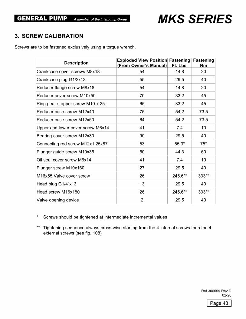
3. SCREW CALIBRATION Screws are to be fastened exclusively using a torque wrench .
Description Exploded View Position(From Owner’s Manual)
FasteningFt. Lbs.
FasteningNm
Crankcase cover screws M8x18 54 14 .8 20
Crankcase plug G1/2x13 55 29 .5 40
Reducer flange screw M8x18 54 14 .8 20
Reducer cover screw M10x50 70 33 .2 45
Ring gear stopper screw M10 x 25 65 33 .2 45
Reducer case screw M12x40 75 54 .2 73 .5
Reducer case screw M12x50 64 54 .2 73 .5
Upper and lower cover screw M6x14 41 7 .4 10
Bearing cover screw M12x30 90 29 .5 40
Connecting rod screw M12x1 .25x87 53 55 .3* 75*
Plunger guide screw M10x35 50 44 .3 60
Oil seal cover screw M6x14 41 7 .4 10
Plunger screw M10x160 27 29 .5 40
M16x55 Valve cover screw 26 245 .6** 333**
Head plug G1/4”x13 13 29 .5 40
Head screw M16x180 26 245 .6** 333**
Valve opening device 2 29 .5 40
* Screws should be tightened at intermediate incremental values
** Tightening sequence always cross-wise starting from the 4 internal screws then the 4 external screws (see fig . 108)
GENERAL PUMP A member of the Interpump Group MKS SERIES
Ref 300699 Rev D02-20

Page 44
4. REPAIR TOOLS
Pump maintenance may be carried out using simple tools for assembling and disassem-bling components .The following tools are available:
For Assembly:
KIT For Assembly: • Plunger guide oil seal . . . . . . . . . . . . . . . . . . . . . . . . . . . . . . . . . . . . . . . . . . . . . .F27910900 • Pinion oil seal . . . . . . . . . . . . . . . . . . . . . . . . . . . . . . . . . . . . . . . . . . . . . . . . . . . .F27515900 & F27548200 B • Delivery valve O-ring seat (MK40A, MK45A, MK50A) . . . . . . . . . . . . . . . . . . . . . F27516000 A • Delivery valve O-ring seat (MK55A, MK60A, MK65A) . . . . . . . . . . . . . . . . . . . . . F27516100 KIT For Disassembly: B • Suction valve seat (MK40A, MK45A, MK50A) . . . . . . . . . . . . . . . . . . . . . . . . . . . F27516200 A • Suction valve seat (MK55A, MK60A, MK65A) . . . . . . . . . . . . . . . . . . . . . . . . . . . F27516300 A/B • Slide hammer . . . . . . . . . . . . . . . . . . . . . . . . . . . . . . . . . . . . . . . . . . . . . . . . . . .F27516400 . . . . . . . . . . . . . . . . . . . . . . . . . . . . . . . . . . . . . . . . . . . . . . . . . . . . . . . . . . . . . . C • Liner + packings support unit . . . . . . . . . . . . . . . . . . . . . . . . . . . . . . . . . . . . . . . . F27516600 • Reducer cover . . . . . . . . . . . . . . . . . . . . . . . . . . . . . . . . . . . . . . . . . . . . . . . . . . .F27516700 • Shaft (connecting rod blocking) . . . . . . . . . . . . . . . . . . . . . . . . . . . . . . . . . . . . . . F27566200 A/B • 10 mm threaded bushing . . . . . . . . . . . . . . . . . . . . . . . . . . . . . . . . . . . . . . . . . . . 800049
RECOMMENDED REPAIR KITS
FKITMKVLP - MK55A, MK60A, MK65A Valve removal / Installation Tool Kit A Includes: F27516100 Valve O-ring install . . . . . . . . . . . . . . . . . . . . . . . . . . . Qty . 1 F27516300 F27513400 handle + F27627800 seat pusher . . . . . . . . . . . Qty . 1 F27516400 Slide hammer . . . . . . . . . . . . . . . . . . . . . . . . . . . . . . . . . . . . . . . . . . . . . . . . . . . . . . . . . . . . .Qty . 1 800049 10 mm threaded bushing . . . . . . . . . . . . . . . . . . . . . . . . . . . . . . . . . . . . . . . . . . . Qty . 1 FKITMKVHP - MK40A, MK45A, MK50A Valve Removal / Installation Tool Kit B Includes: F27516000 Outlet valve O-ring assembly tool . . . . . . . . . . . . . . . Qty . 1 F27516200 F27513400 handle + F27627700 seat pusher . . . . . . Qty . 1 F27516400 Slide hammer . . . . . . . . . . . . . . . . . . . . . . . . . . . . . . .Qty . 1 800049 10 mm threaded bushing . . . . . . . . . . . . . . . . . . . . . . Qty . 1
F27516600 - Cylinder Removal Tool with Handle - MK - Tool Kit C
GENERAL PUMP A member of the Interpump Group MKS SERIES
Ref 300699 Rev D02-20

Page 45
MAINTENANCE LOG
OIL CHANGE
GREASE
PACKINGREPLACEMENT
PLUNGER REPLACEMENT
VALVE REPLACEMENT
HOURS & DATE
GP Companies, Inc .1174 Northland Drive
Mendota Heights, MN 55120Phone:651 .686 .2199 Fax: 800 .535 .1745
www .generalpump .com email: sales@gpcompanies .com
GENERAL PUMP A member of the Interpump Group MKS SERIES
Ref 300699 Rev D02-20