Variable displacement pump A10VSO
16
Industrial Hydraulics Electric Drives and Controls Linear Motion and Assembly Technologies Pneumatics Service Automation Mobile Hydraulics Variable displacement pump A10VSO Size 18 Series 31 Nominal pressure 280 bar Peak pressure 350 bar Contents Ordering code 2 Hydraulic fluid 3 Technical data 4 Installation notes, noise characteristics 5 Unit dimensions size 18, PA12 6 Unit dimensions size 18, UC62 7 Pressure controller DR 8 Pressure controller, remote controlled DRG 9 Pressure flow controller DFR / DFR1 10 Unit dimensions DFR / DFR1 11 Pressure and flow controller, electronic DFE1 12 Unit dimensions DFE1 13 Through drive, unit dimensions combination pumps 14 Unit dimensions through drives K01 and K52 15 RE 92 712/02.94 1/16 Replaces: 01.91 open circuit Features – Variable displacement axial piston pump A10VSO in swashplate construction is designed for hydrostatic transmissions in open circuits. – It can be used in mobile and industrial applications. – Flow is proportional to the drive speed and the displacement. By adjusting the position of the swashplate it is possible to steplessly vary the flow. – ISO or SAE mounting flange – SAE flanged connections with metric or UNC fixing threads – 2 case drain ports – Good suction characteristics – Permissible continuous operating pressure 280 bar – Low noise level – Long service life – Axial and radial loading of drive shaft possible – Low specific weight – Short control times – Through drive for multi-circuit system possible A10VSO size 28 ... 140 see RE 92711
-
Upload
khangminh22 -
Category
Documents
-
view
1 -
download
0
Transcript of Variable displacement pump A10VSO

IndustrialHydraulics
Electric Drivesand Controls
Linear Motion andAssembly Technologies Pneumatics
ServiceAutomation
MobileHydraulics
Variable displacement pump A10VSO
Size 18
Series 31
Nominal pressure 280 bar
Peak pressure 350 bar
Contents
Ordering code 2
Hydraulic fluid 3
Technical data 4
Installation notes, noise characteristics 5
Unit dimensions size 18, PA12 6
Unit dimensions size 18, UC62 7
Pressure controller DR 8
Pressure controller, remote controlled DRG 9
Pressure flow controller DFR / DFR1 10
Unit dimensions DFR / DFR1 11
Pressure and flow controller, electronic DFE1 12
Unit dimensions DFE1 13
Through drive, unit dimensions combination pumps 14
Unit dimensions through drives K01 and K52 15
RE 92 712/02.94 1/16Replaces: 01.91
open circuit
Features
– Variable displacement axial piston pump A10VSO in
swashplate construction is designed for hydrostatic
transmissions in open circuits.
– It can be used in mobile and industrial applications.
– Flow is proportional to the drive speed and the
displacement. By adjusting the position of the swashplate
it is possible to steplessly vary the flow.
– ISO or SAE mounting flange
– SAE flanged connections
with metric or UNC fixing threads
– 2 case drain ports
– Good suction characteristics
– Permissible continuous operating pressure 280 bar
– Low noise level
– Long service life
– Axial and radial loading of drive shaft possible
– Low specific weight
– Short control times
– Through drive for multi-circuit system possible
A10VSO size 28 ... 140
see RE 92711

2/16 Bosch Rexroth AG | Mobile Hydraulics A10VSO | RE 92 712/02.94
Seals
Perbunan (shaft sealing ring in Viton)
Viton
Shaft end DIN SAE
Parallel with key DIN 6885 �
Parallel with key 19-1 (SAE A-B) �
Splined 19-4 (SAE A-B, 3/4") �
Splined 16-4 (SAE A, 5/8", not suitable for through drive) �
Mounting flange ISO 2-hole �
SAE 2-hole �
Service line connections
Pressure port B SAE ports on opposite sides Suction port S metric fixing threads
Pressure port B SAE ports on opposite sides Suction port S UNC fixing threads
Through drive
Without through drive
With through drive for building on axial piston unit or gear pump
Mounting flange Shaft/coupling for mounting:
82-2 (SAE A) Splined shaft 16-4 (SAE A; 5/8") G2
82-2 (SAE A) Splined shaft 19-4 (SAE A-B; 3/4") A10VSO 18
Hydraulic fluid
Mineral oil (without short code)
Axial piston unit
Swashplate design, variable, industrial range Nominal pressure 280 bar, peak pressure 350 bar
Mode of operation
Pump, open circuit
Size
Flow Vg max (cm3) 18
Control device
Pressure controller DR �
DR G �
remote controlled
Pressure and flow controller DFR �
DFR 1 �
X-channel plugged
Pressure and flow controller, electronic DFE1 �
Ordering code
O
A10VS
Series
Direction of Rotation
Viewed on drive shaft clockwise
anti-clockwise
31
L
R
A10VS O 18 / 31 –
V
P
P
K
S
U
A
C
prefered programwith short delivery timestype list see page 15
DFE1
DFR1
DFR
DR
DRG
N00
K52
K01
12
62
� = available
�� = in preparation– = not available

RE 92 712/02.94 | A10VSO Mobile Hydraulics | Bosch Rexroth AG 3/16
Druckflüssigkeitstemperaturbereich
Temperatur t (° C)
Visk
ositä
t ν (m
m2 /s
)
νopt
tmin = – 25° C tmax = + 90° C
– 25° – 10° 10°
20°
30° 50° 70° 90°
- 20° 0° 40° 60° 80° 100°1000
36
16
10
1000600400
200
1008060
40
2015
10
VG 22VG 32VG 46VG 68VG 100
Notes on hydraulic fluid selection
In order to select the correct fluid it is necessary to know the
operating temperature in the tank (open loop) in relation to the
ambient temperature.
The hydraulic fluid should be selected so that within the
operating temperature range the operating viscosity lies within
the optimum range (νopt) - see shaded area of selection diagram.
We recommend that the highest possible viscosity range should
be chosen in each case.
Example: At an ambient temperature of X° C the operating
temperature in the tank is 60°C. Within the operating viscosity
range (νopt; shaded area) this corresponds to viscosity classes
VG 46 or VG 68. VG 68 should be selected.
Important: The case drain oil temperature is influenced by
pressure and pump speed and is always higher than the tank
temperature. However, at no point in the installation may the
temperature exceed 90° C.
Please consult us if compliance with the above conditions is not
possible due to extreme operating parameters or high ambient
temperatures.
Fluid filtration
Correct functioning of the unit calls for a minimum level of
cleanliness
to NAS, 1638 class 9
to SAE, ASTM, AIA or
to ISO/DIS 4406 18/15
This can be achieved, for example, using filter element
type ...D 020...(see RE 31278).
This gives a filter quotient of
β20 ≥ 100.
Hydraulic fluidFor detailed information on the range of fluids and their
application conditions please see our data sheets RE 90220
(mineral oil), RE 90221 (environmentally acceptable hydraulic
fluids) and RE 90223 (HF hydraulic fluids). When operating with
environmentally acceptable hydraulic fluids and HF fluids it may
be necessary to consider certain modifications to the technical
data; please contact our technical department. Operation with
Skydrol hydraulic fluid strictly subject to consultation.
Operating viscosity range
In the interests of ensuring optimum efficiency and service life we
recommend that the operating viscosity (at operating
temperature) is selected from within the range
νopt = opt. operating viscosity 16...36 mm2/s
with reference to the tank temperature (open circuits).
Viscosity limits
The following values apply in respect of viscosity limits:
νmin = 10 mm2/s
short-term at maximum permissible drain temperature
of 90° C.
νmax = 1000 mm2/s
Temperature range (cf: selection diagram)
tmin = – 25° Ctmax = + 90° C
Selection diagram
Mechanical flow limitingMechanical flow limiting on the version without through driveit is standard, it is not possible with through drive
Qmax : Setting range Vg max to 50% Vg max
Combination pumps
1. If a second Brueninghaus pump is fitted in the factory, both ordering codes should be joined with "+" .
Typical order format: A10VSO 18DFR/31R-PSC62K52 + A10VSO 18DFR/31R-PSC62N00
2. If a gear pump is fitted in the factory please consult us (RE 90139 in preparation).
Fluid temperature range
Vis
cosi
ty v
(m
m2 /
s)
Temperature t (°C)

4/16 Bosch Rexroth AG | Mobile Hydraulics A10VSO | RE 92 712/02.94
Through flow directionS to B.
Case drain pressureMaximum permissible pressure of case drain fluid (at port L, L1):Maximum 0.5 bar higher than inlet pressure at port S,but nohigher than 2 bar absolute.
Technical data(suitable for operation on mineral oil;for water based fluids see RE 90223 andenvironmentally acceptable fluids see RE 90221)
Operating pressure range - Inlet sideAbsolute pressure at port Spabs min 0,8 barpabs max 30 bar
Operating pressure range - Outlet sidePressure at port BNominal pressure pN 280 barPeak pressure pmax 350 bar(Pressure information to DIN 24312)Applications at intermittent operating pressures of up to 315 barat 10% duty are permissible.
Determination of inlet pressure pabs at suction port S orreduction in output flow for increasing speed
Determination of sizeVg • n • ηv
Flow Q = [L/min] 1000
1,59 • Vg • ∆ pDrive torque M = [Nm]
100 • ηmh
2π • M • n M • n Q • ∆ pDrive capacity P = = = [kW]
60000 9549 600 • ηt
Vg = geometric displacement [cm3] per revolution
∆ p = Differential pressure [bar]n = Speed [rpm]ηv = Volumetric efficiencyηmh = Mechanical hydraulic efficiencyηt = Overall efficiency (ηt = ηv • ηmh)
Max.power(∆p = 280 bar)
Permissible shaft loadingMax. permissible axial force
1) These values are valid for an absolute pressure of 1 bar at suction port S.By reducing the output flow or increasing the input pressurethe speed can be increased as shown in the diagram.
2) For higher radial forces please consult us.
Inle
t pre
ssur
e p ab
s [ba
r] ➝
Spe
ed n
/nm
ax ➝
Application of
forces± Fax
Fq
X
X/2 X/2
1,2
1,1
1,0
0,9
1,6
1,4
1,2
Displacement Vg/Vg max
0,7 0,8 0,9 1,0
1,0
0,9
0,8
Table of values (theoretical values, rounded off without taking into consideration ηmh and ηv)
Size 18
Displacement Vg max cm3 18
Max. speed1) at Vg max no max rpm 3300
Max. permissible velocity (speed limit) no max zul rpm 3900
on increase in inlet pressure pabs or Vg < Vg max
Max. flow at no max Qo max L/min 59,4
at nE = 1500 rpm L/min 27
at no max Po max kW 27,7
at nE = 1500 rpm kW 12,6
Max. torque (∆p = 280 bar) at Vg max Mmax Nm 80,1
Torque (∆p = 100 bar) at Vg max M Nm 28,6
Moment of inertia about drive axis J kgm2 0,00093
Fill capacity L 0,4
Weight without (oil fill) m kg 12
Fax max N 700
Max. permissible radial force 2) Fq max N 350

RE 92 712/02.94 | A10VSO Mobile Hydraulics | Bosch Rexroth AG 5/16
Installation notesThe installation position is optional. The pump housing must be filled with hydraulic fluid during commissioning and stay full when
operating. In order to ensure the lowest possible noise values all connections (suction, pressure and drain connections) must
be flexible.
Avoid a non-return valve in the drain line. In exceptional cases this may be permissible, but only after prior consultation with us.
Size 18
For detailed installation notes and commissioning information see RE 90400 (in prep.)
Characteristic curves for pump with pressure controller DRNoise levelsMeasured in an anechoic chamberDistance from microphone to pump = 1 mMeasuring error: ± 2 dB (A)(Fluid: ISO VG 46 DIN 51519, t = 50° C)
Qmax
Qzero
Qmax
Qzero
74
72
70
68
66
64
62
60
58
560 50 100 150 200 250 280
Drive power and output flow(Fluid:Hydraulic oil ISO VG 46 DIN 51519, t = 50° C)
Size 18– – – – n = 1500 rpm
n = 3300 rpm
0 50 100 150 200 250 280
80
60
40
20
0
302520151050
PQ maxQ
PQ zero
n = 3000 rpm
n = 1500 rpm
Noi
se le
vel L
A [d
B(A
)] ➝
Operating pressure p [bar] ➝
Flow
Q [L
/min
] ➝
Operating pressure p [bar] ➝
Driv
e po
wer
P [k
W] ➝

6/16 Bosch Rexroth AG | Mobile Hydraulics A10VSO | RE 92 712/02.94
Unit dimensions size 18ISO version with keyed shaft PA12,Through drive version N00 (without through drive)not including control
B Pressure port SAE 3/4" (Standard pressure series)S Suction port SAE 1" (Standard pressure series)L/L1 Case drain ports M16x1,5 (L1 plugged at factory)
mech. displacement limiter
View W View V
Before finalising your design, please request a certified drawing.All rights reserved, subject to revision
L
L1
W
V
S B
M1017 tief
M1017 tief
2 hole flange
17 deep 17 deep
RE 92 712/02.94 | A10VSO Mobile Hydraulics | Bosch Rexroth AG 7/16
ø 3
/4"
22
30
38
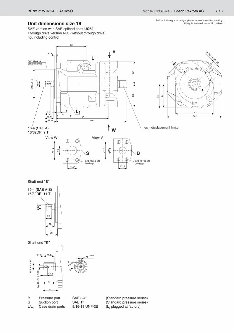
B Pressure port SAE 3/4" (Standard pressure series)S Suction port SAE 1" (Standard pressure series)L/L1 Case drain ports 9/16-18 UNF-2B (L1 plugged at factory)
Unit dimensions size 18SAE version with SAE splined shaft UC62,Through drive version N00 (without through drive)not including control
Shaft end "S"
Shaft end "K"
19-4 (SAE A-B)16/32DP; 11 T
Before finalising your design, please request a certified drawing.All rights reserved, subject to revision
L
L1
S B
W
V
mech. displacement limiter16-4 (SAE A)16/32DP; 9 T
View W View V
2 hole flange
20 deep 20 deep
8/16 Bosch Rexroth AG | Mobile Hydraulics A10VSO | RE 92 712/02.94
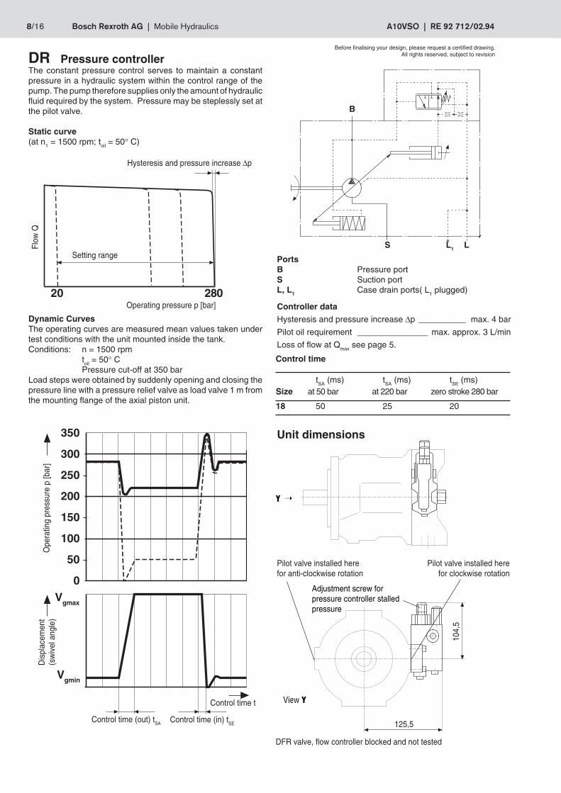
DR Pressure controllerThe constant pressure control serves to maintain a constantpressure in a hydraulic system within the control range of thepump. The pump therefore supplies only the amount of hydraulicfluid required by the system. Pressure may be steplessly set atthe pilot valve.
Static curve(at n1 = 1500 rpm; toil = 50° C)
Dynamic CurvesThe operating curves are measured mean values taken undertest conditions with the unit mounted inside the tank.Conditions: n = 1500 rpm
toil = 50° CPressure cut-off at 350 bar
Load steps were obtained by suddenly opening and closing thepressure line with a pressure relief valve as load valve 1 m fromthe mounting flange of the axial piston unit.
Control time
tSA (ms) tSA (ms) tSE (ms)Size at 50 bar at 220 bar zero stroke 280 bar
18 50 25 20
Setting range
Dis
plac
emen
t(s
wiv
el a
ngle
)
Control time (in) tSEControl time (out) tSA
DFR valve, flow controller blocked and not tested
PortsB Pressure portS Suction portL, L1 Case drain ports( L1 plugged)
Controller data
Hysteresis and pressure increase ∆p __________ max. 4 bar
Pilot oil requirement _______________ max. approx. 3 L/min
Loss of flow at Qmax see page 5.
Pilot valve installed here Pilot valve installed herefor anti-clockwise rotation for clockwise rotation
Adjustment screw forpressure controller stalledpressure
Unit dimensions
125,5
104,
5
View Y
Y
Hysteresis and pressure increase ∆p
Flow
Q
Control time t
➝
Ope
ratin
g pr
essu
re p
[bar
]
Operating pressure p [bar]
Before finalising your design, please request a certified drawing.All rights reserved, subject to revision
20 280
350
300
250
200
150
100
50
0Vgmax
Vgmin
B
S LL1

RE 92 712/02.94 | A10VSO Mobile Hydraulics | Bosch Rexroth AG 9/16
Pilot valve installed here Pilot valve installedhere for anti-clockwise rotation for clockwise rotation
DRG Pressure controller, remotecontrolledFunction and equipment as for DR.
A pressure relief valve can be connected here at port X. This isnot included in the items supplied for the DRG control
The standard setting for differential pressure at the pilot valve is20 bar. The amount of pilot oil required is approx. 1.5 L/min. If adifferent setting is required (range 10-22 bar) please indicate inclear text.
We recommend the following as a separate pressure relief valve:DBDH 6 (hydraulic) to RE 25402,DBEC-3X (electrical) to RE 29142 orDBETR -SO 381 w. nozzle ø 0.8 in P (electrical) to RE 29166.
Max. line length should not exceed 2 m.
Static curve(at n1 = 1500 rpm; toil = 50° C)
Setting range
Hysteresis and pressure increase ∆p
Flow
QNot included insupply
Unit dimensions
PortsB Pressure portS Suction portL, L1 Case drain ports ( L1 plugged)X Pilot pressure port
Size A1 A2 A3 A4 A5 Port X
18ISO 104,5 125,5 109 40 109 M14x1,5;12 deep
18SAE 104,5 125,5 109 40 130 7/16-20 UNF-2B;10 deep
A1
A2
A3
A4
A5 (ISO)
A5 (SAE)
X
X
View Y
Y
Operating pressure p [bar]
➝
Threadedconnection
7/16-20 UNF-2BController data
Hysteresis and pressure increase ∆p __________ max. 4 bar
Pilot oil requirement __________________ approx. 4.5 L/min
Loss of flow at Qmax see page 5.
Before finalising your design, please request a certified drawing.All rights reserved, subject to revision
Adjustment screw formaximum pressure cut-off
Adjustment screw fordifferential pressure
20 280

10/16 Bosch Rexroth AG | Mobile Hydraulics A10VSO | RE 92 712/02.94
∆Q (s
ee ta
ble)
Static curve at variable speed
Flow
Q
Speed n
Control time t
Dynamic flow control curveThe curves are mean values measured under test conditions,pump in tank
Control time (in) tSE
Control time
tSA (ms) tSA (ms) tSE (ms)Size stand by-280 bar 280 bar-stand by 50 bar-stand by
18 40 15 40
ConnectionsB Pressure portS Suction portL, L1 Case drain ports ( L1 plugged)X Pilot pressure port
Differential pressure ∆p:Adjustable between 10 and 22 bar (higher values on request).Standard setting: 14 bar. If another setting is required pleasestate in clear text.When pressure is relieved on port X to tank a stalled pressureof p = 18 ± 2 bar ("stand by") is set.
Controller dataMax. flow deviation (hysteresis and increase)measured at drive speed n = 1500 rpm
Size 18∆Qmax L/min 0,9
Hysteresis and pressure increase ∆p __________ max. 5 bar
Pilot oil requirement DFR ______ max. approx. 3 ... 4,5 L/min
Pilot oil requirement DFR1 __________ max. approx. 3 L/min
Loss of flow at at Qmax see page 5.
Flow
Q
Control time (out) tSA
Hysteresis and pressure ∆p
∆Q (s
ee ta
ble)
Plugged onDFR 1
Operating pressure p [bar]
Not includedin supply
Dis
plac
emen
t Vg %
➝
Load
pre
ssur
e [b
ar]
➝Adjustment range
DFR/DFR1 Pressure - Flow controller
In addition to operation of the pressure controller it is alsopossible to set the pump flow by means of differential pressureat the actuator (e.g. an orifice).In model DFR1 the X port is plugged.
Static curve(at n1 = 1500 rpm, toil = 50° C)
20 280
100
75
50
25
0
350
300280250
200
150
100
5018
L1 LS
B
X
(stand by)

RE 92 712/02.94 | A10VSO Mobile Hydraulics | Bosch Rexroth AG 11/16
Size A1 A2 A3 A4 A5 Port X
18ISO 104,5 125,5 109 40 109 M14x1,5;12 deep
18SAE 104,5 125,5 109 40 130 7/16-20 UNF-2B;10 deep
Unit dimensions
A5 (SAE)
A5 (ISO)
X
A1
X
A4
A2
A3
Pilot valve installed here Pilot valve installed herefor anti-clockwise rotation for clockwise rotation
Adjustment screw forpressure controller stalled pressureThreaded
connection7/16-20 UNF-2B
Adjustment screwfor flow controller
differential pressure
Before finalising your design, please request a certified drawing.All rights reserved, subject to revision

12/16 Bosch Rexroth AG | Mobile Hydraulics A10VSO | RE 92 712/02.94
100
012 280
B
S L1 L
1.1
1.2
1
US
50 ms
40
120
20
60
80
100
140psoll
pist
160
0
50 ms
40
120
20
60
80
100
140
psoll
pist
0
160
Control data
Hysteresis < 1% of Vg max
Repeatability < 1%
Pilot oil requirement max. approx. 2.5 L/min
Loss of flow at Qmax see Page 5.
DFE1 Pressure and flow controller,electronic
Pressure and flow to the pump are controlled by an electricallyoperated proportional valve. Flow control is via the variablepump swivel angle wthout compensation for drive speedvariations (e.g. due to the diesel motor). Pump pressure andpump position are signalled via a pressure sensor and inductivepositional transducer to the amplifier card which is required tooperate the closed loop control.
DFE1 model pump is suitable for operation with analogueamplifier card VT 5041.The amplifier card and the pressure sensor should be orderedseparately.
For safety reasons an additional pressure relief valve should beinstalled in addition to the pump pressure controller. This is tosafeguard the maximum permissible operating pressure.
For further information and some typical applications seeRE 67016 and RE 98090.
Static curves
Flow
Q [%
] ➝
End of control PortsB Pressure portS Suction portL, L1 Case drain ports ( L1 plugged)
Components1 A10VSO with hydraulic setting device1.1 Proportional valve1.2 Inductive positional transducerPressure sensor and control electronics are loose items(please order separately to RE 67016)
Pressure stepped signal value 120 bar – 40 barDFE1 45 with compression oil volume (5L)
Operating pressure p [bar] ➝
Dynamic curves
Pressure stepped signal value e.g. 40 bar – 120 barDFE1 45 with compression oil volume (5L)
Ope
ratin
g pr
essu
re p
[bar
] ➝
Control time ➝
Ope
ratin
g pr
essu
re p
[bar
] ➝
Control time ➝
comm.
act.
comm.
act.

RE 92 712/02.94 | A10VSO Mobile Hydraulics | Bosch Rexroth AG 13/16
Unit dimensionsDFE1 pressure and flow controller, electronic
Pilot valve installed here Pilot valve installed herefor anti-clockwise rotation for clockwise rotation
Size A1 A2 A3 A4 A5 A6
18 97 106,5 118 158 63 216
Before finalising your design, please request a certified drawing.All rights reserved, subject to revision

14/16 Bosch Rexroth AG | Mobile Hydraulics A10VSO | RE 92 712/02.94
l1
l2
l3
m1 m2 m3
A1
A2
A3
A4
Size 18
Max. permitted. total through drive torque at shaft "S", Pump 1(Pump 1 + Pump 2) MGes max Nm 80
MD1max Nm 80
MD2max Nm 0
MD1max Nm 0
MD2max Nm 80
m1, m2 [kg] Weight of pumpl1, l2 [mm] Centre to centre spacing
Mm = (m1 x l1 + m2 x l2 + m3 x l3) • [Nm]
Size 18
Permitted bending moment Mm zul Nm 50
Weight m kg 12Centre to centre spacing l1 mm 90
Permitted through drive torque
Through drive
The A10VSO axial piston unit can be supplied with through drivein accordance with the coding on page 3.The type of through drive is determined by the coding (KXX).
The following are included in the supply:Hub, fixing screws, seal and, if required, an intermediateflange.
Combination pumpsBy building on other pumps mutually independent circuits can bemade available for use.1. If the combination pump consists of 2 Brueninghaus
units and if these are to be supplied assembledthen the two ordering codes should be joined with "+".Typical order:A10VSO 18 DR/31 R–PSC12K52 +A10VSO 18 DR/31 R–PSC12N00
2. If a gear- or radial piston pump is to be fitted at thefactory please consult us.
1102
1
2
21
Permitted bending moment
Unit dimensions: combination pumps A10VSO + A10VSO
Main p. A10VSO 18 A10VSO 28 A10VSO 45 A10VSO 71 A10VSO 100 A10VSO 1402nd pump A2 A3 A4 A1 A2 A3 A4 A1 A2 A3 A4 A1 A2 A3 A4 A1 A2 A3 A4 A1 A2 A3 A4
A10VSO 18 164 204 349 399 164 204 349 399 184 229 374 424 217 267 412 462 275 338 483 533 275 350 495 545
See RE 92711
Permitted.through
drive torque.
Permitted.through
drive torque.
Before finalising your design, please request a certified drawing.All rights reserved, subject to revision
MGes
MD1 MD2
totalMGes
MD1 MD2
total

RE 92 712/02.94 | A10VSO Mobile Hydraulics | Bosch Rexroth AG 15/16
A2
A3
A4
A5
A7A6
A8
A9
45 o
nur K 01
Built-on A10VSO 18Order code K01 or K52
Size A2 A3 A4 A5 A6 A7 A8 A9
K01 182 10 9 43,3 M10;16 deep spline SAE A, 5/8"; 16/32DP; 9T Ø 82,55 106,5
K52 182 10 9 43,3 M10;16 deep spline SAE A-B, 3/4"; 16/32DP; 11T Ø 82,55 106,5
up to pump mounting surface
prefered program (short delivery times)
Ident.-Nr. Type
947666 A10VSO 18 DFR /31L-PSC62N00
940520 A10VSO 18 DFR /31R-PPA12N00
945178 A10VSO 18 DFR1 /31R-PPA12N00
942503 A10VSO 18 DR /31R-PPA12N00
Before finalising your design, please request a certified drawing.All rights reserved, subject to revision
K01 only

16/16 Bosch Rexroth AG | Mobile Hydraulics A10VSO | RE 92 712/02.94
Brueninghaus Hydromatik GmbH
Plant Horb
An den Kelterwiesen 14
72160 Horb, Germany
Tel. +49 (0) 74 51-92-0
Fax +49 (0) 74 51-82 21
www.boschrexroth.com/brm
© 2002 by Brueninghaus Hydromatik GmbH, 72160 Horb
All rights reserved. No part of this document may be reproduced or
stored, processed, duplicated or circulated using electronic systems, in
any form or by any means, without the prior written authorization of
Brueninghaus Hydromatik GmbH. Violations shall give rise to claims for
damages.
The data specified above only serve to describe the product. They do not
indicate any specific condition or suitability for a certain application. The
information provided does not release the user from the obligation of own
judgement and veification. It must be remembered that our products are
subject to natural wear and ageing.