V Series Infusion Pump User Manual - NIVAS
48
V Series Infusion Pump User Manual Version 1.0 Sino Medical-Device Technology Co., Ltd
-
Upload
khangminh22 -
Category
Documents
-
view
2 -
download
0
Transcript of V Series Infusion Pump User Manual - NIVAS

V Series
Infusion Pump
User Manual
Version 1.0
Sino Medical-Device Technology Co., Ltd
Declarations:
The information contained in this manual is based on the experiences and knowledge acquired by
Sino Medical-Device Technology Co., Ltd. (Hereinafter referred to as Sinomdt) from the product
field.
Sinomdt is convinced that the information provided in this manual is accurate and reliable. But,
we could not make any guarantees for the contents of this manual. As this manual is only used to
provide the guidance for the use, operation and maintenance of infusion pump, Sinomdt shall not
assume liability for the property damages or personal injuries caused by the citations of the contents of
this manual for other purposes.
This manual copyright is owned by Sinomdt, and no reproduction or dissemination of its content
and information is allowed without the prior written permission of Sinomdt.
The contents of this manual are subject to change without notice due to product upgrades or design
improvements.
Before the installation and application of V series infusion pump, please read this manual
carefully.
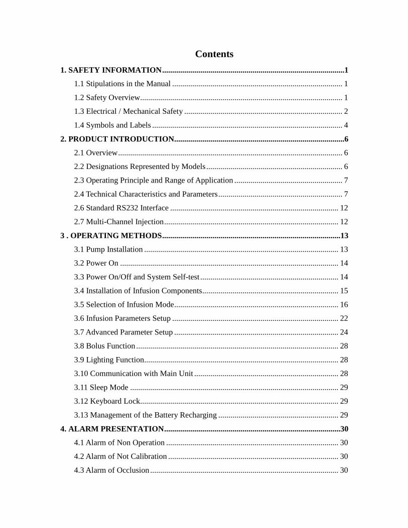
Contents 1. SAFETY INFORMATION ...........................................................................................1
1.1 Stipulations in the Manual ..................................................................................... 1
1.2 Safety Overview..................................................................................................... 1
1.3 Electrical / Mechanical Safety ............................................................................... 2
1.4 Symbols and Labels ............................................................................................... 4
2. PRODUCT INTRODUCTION .....................................................................................6
2.1 Overview ................................................................................................................ 6
2.2 Designations Represented by Models .................................................................... 6
2.3 Operating Principle and Range of Application ...................................................... 7
2.4 Technical Characteristics and Parameters .............................................................. 7
2.6 Standard RS232 Interface .................................................................................... 12
2.7 Multi-Channel Injection ....................................................................................... 12
3 . OPERATING METHODS .........................................................................................13
3.1 Pump Installation ................................................................................................. 13
3.2 Power On ............................................................................................................. 14
3.3 Power On/Off and System Self-test ..................................................................... 14
3.4 Installation of Infusion Components .................................................................... 15
3.5 Selection of Infusion Mode .................................................................................. 16
3.6 Infusion Parameters Setup ................................................................................... 22
3.7 Advanced Parameter Setup .................................................................................. 24
3.8 Bolus Function ..................................................................................................... 28
3.9 Lighting Function................................................................................................. 28
3.10 Communication with Main Unit ........................................................................ 28
3.11 Sleep Mode ........................................................................................................ 29
3.12 Keyboard Lock................................................................................................... 29
3.13 Management of the Battery Recharging ............................................................ 29
4. ALARM PRESENTATION ........................................................................................30
4.1 Alarm of Non Operation ...................................................................................... 30
4.2 Alarm of Not Calibration ..................................................................................... 30
4.3 Alarm of Occlusion .............................................................................................. 30

4.4 Alarm of Bubble ................................................................................................... 30
4.5 Alarm of Door Open ............................................................................................ 30
4.6 Alarm of Infusion Finish ...................................................................................... 31
4.7 Alarm of KVO Completion .................................................................................. 31
4.8 Alarm of Drip Sensor Abnormality ...................................................................... 31
4.9 Alarm of Power Supply Breakdown .................................................................... 31
4.10 Alarm of Low Voltage Battery ........................................................................... 31
4.11 Alarm of Battery Running-out ........................................................................... 31
4.12 Alarm of System Error ....................................................................................... 32
4.13 Alarm Level ....................................................................................................... 32
4.14 Alarm Volume .................................................................................................... 32
5. ANALYSIS OF MALFUNCTION AND TROUBLESHOOTING .........................34
6. MAINTENANCE .........................................................................................................35
7. NATURES OF INFUSION .........................................................................................36
7.1 Natures of Rate Accuracy .................................................................................... 36
7.2 Response to Occlusion ......................................................................................... 37
8.EMC ............................................................................................................................39
9. STANDARD CONFIGURATION .............................................................................43
10. RELEVANT INFORMATION ................................................................................44
1
1. Safety Information
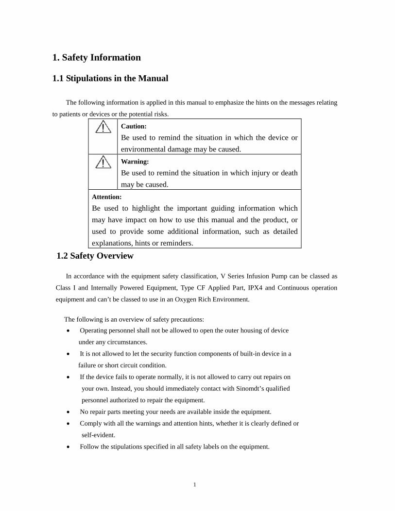
1.1 Stipulations in the Manual
The following information is applied in this manual to emphasize the hints on the messages relating
to patients or devices or the potential risks.
Caution:
Be used to remind the situation in which the device or environmental damage may be caused.
Warning:
Be used to remind the situation in which injury or death may be caused.
Attention:
Be used to highlight the important guiding information which may have impact on how to use this manual and the product, or used to provide some additional information, such as detailed explanations, hints or reminders.
1.2 Safety Overview
In accordance with the equipment safety classification, V Series Infusion Pump can be classed as
Class I and Internally Powered Equipment, Type CF Applied Part, IPX4 and Continuous operation
equipment and can’t be classed to use in an Oxygen Rich Environment.
The following is an overview of safety precautions: • Operating personnel shall not be allowed to open the outer housing of device
under any circumstances.
• It is not allowed to let the security function components of built-in device in a
failure or short circuit condition.
• If the device fails to operate normally, it is not allowed to carry out repairs on
your own. Instead, you should immediately contact with Sinomdt’s qualified
personnel authorized to repair the equipment.
• No repair parts meeting your needs are available inside the equipment.
• Comply with all the warnings and attention hints, whether it is clearly defined or
self-evident.
• Follow the stipulations specified in all safety labels on the equipment.
2
1.3 Electrical / Mechanical Safety
Only those well-trained and qualified maintenance personnel authorized by the Sinomdt can open
the outer housing of device and replace the electrical and mechanical components. Otherwise, problems
of device safety may be caused.
The V series pump complies with standard EN 60601-1 and EN60601-2-24. The following is an overview of warning message:
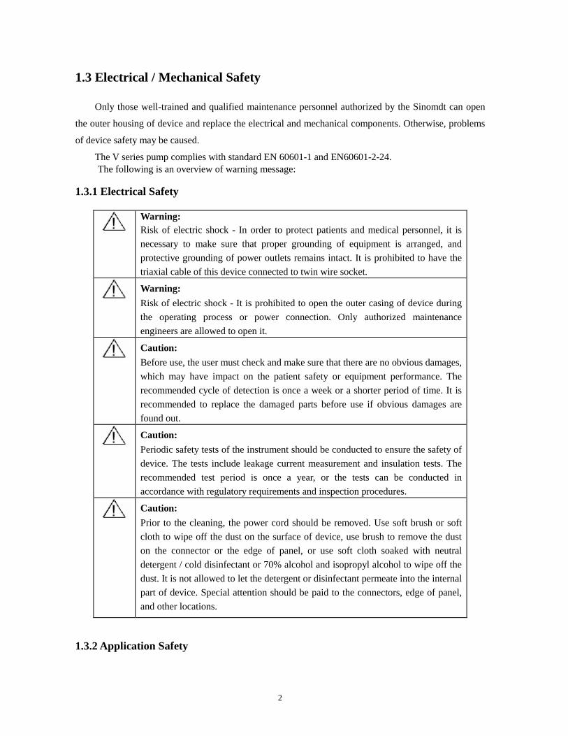
1.3.1 Electrical Safety
Warning: Risk of electric shock - In order to protect patients and medical personnel, it is necessary to make sure that proper grounding of equipment is arranged, and protective grounding of power outlets remains intact. It is prohibited to have the triaxial cable of this device connected to twin wire socket.
Warning: Risk of electric shock - It is prohibited to open the outer casing of device during the operating process or power connection. Only authorized maintenance engineers are allowed to open it.
Caution: Before use, the user must check and make sure that there are no obvious damages, which may have impact on the patient safety or equipment performance. The recommended cycle of detection is once a week or a shorter period of time. It is recommended to replace the damaged parts before use if obvious damages are found out.
Caution: Periodic safety tests of the instrument should be conducted to ensure the safety of device. The tests include leakage current measurement and insulation tests. The recommended test period is once a year, or the tests can be conducted in accordance with regulatory requirements and inspection procedures.
Caution: Prior to the cleaning, the power cord should be removed. Use soft brush or soft cloth to wipe off the dust on the surface of device, use brush to remove the dust on the connector or the edge of panel, or use soft cloth soaked with neutral detergent / cold disinfectant or 70% alcohol and isopropyl alcohol to wipe off the dust. It is not allowed to let the detergent or disinfectant permeate into the internal part of device. Special attention should be paid to the connectors, edge of panel, and other locations.
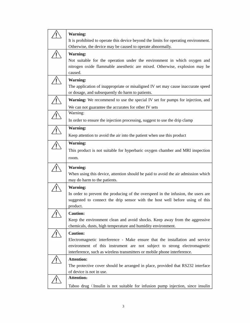
1.3.2 Application Safety
3
Warning: It is prohibited to operate this device beyond the limits for operating environment. Otherwise, the device may be caused to operate abnormally.
Warning: Not suitable for the operation under the environment in which oxygen and nitrogen oxide flammable anesthetic are mixed. Otherwise, explosion may be caused.
Warning: The application of inappropriate or misaligned IV set may cause inaccurate speed or dosage, and subsequently do harm to patients.
Warning: We recommend to use the special IV set for pumps for injection, and
We can not guarantee the accurates for other IV sets
Warning:
In order to ensure the injection processing, suggest to use the drip clamp
Warning:
Keep attention to avoid the air into the patient when use this product
Warning:
This product is not suitable for hyperbaric oxygen chamber and MRI inspection
room.
Warning: When using this device, attention should be paid to avoid the air admission which may do harm to the patients.
Warning: In order to prevent the producing of the overspeed in the infusion, the users are suggested to connect the drip sensor with the host well before using of this product.
Caution: Keep the environment clean and avoid shocks. Keep away from the aggressive chemicals, dusts, high temperature and humidity environment.
Caution: Electromagnetic interference - Make ensure that the installation and service environment of this instrument are not subject to strong electromagnetic interference, such as wireless transmitters or mobile phone interference.
Attention: The protective cover should be arranged in place, provided that RS232 interface of device is not in use.
Attention:
Taboo drug(Insulin is not suitable for infusion pump injection, since insulin
4
should be kept at a low temperature. Insulin should be injected quickly after leaving the low temperature environment).
Attention: The IV set should fit with the National relative sanitation and quality standard for
disposable goods; do not crossed use; after using the disposable IV set, the
operator should deal with it as the medical rubbish
Attention: Please use the power line, battery from Sinomdt, otherwise will possibly lead to
irregular injection
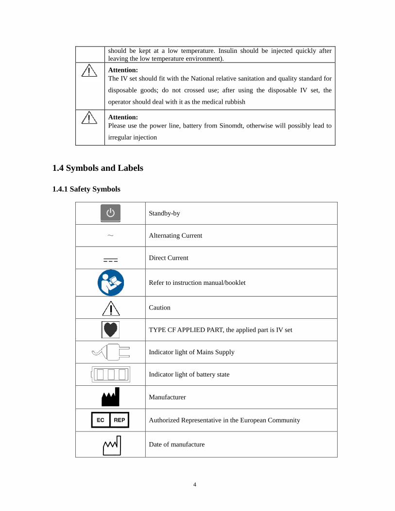
1.4 Symbols and Labels
1.4.1 Safety Symbols
Standby-by
~ Alternating Current
Direct Current
Refer to instruction manual/booklet
Caution
TYPE CF APPLIED PART, the applied part is IV set
Indicator light of Mains Supply
Indicator light of battery state
Manufacturer
Authorized Representative in the European Community
Date of manufacture
5
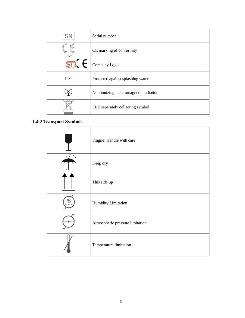
Serial number
0123 CE marking of conformity
Company Logo
IPX4 Protected against splashing water
Non ionizing electromagnetic radiation
EEE separately collecting symbol
1.4.2 Transport Symbols
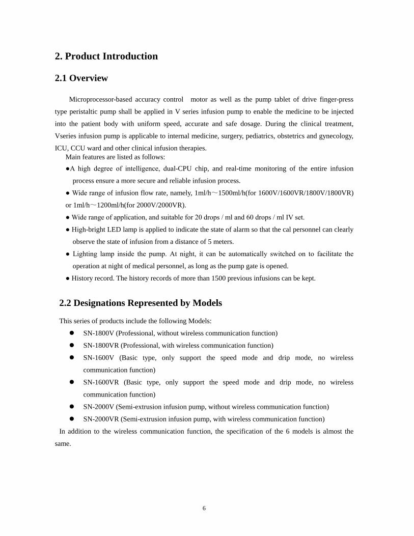
Fragile: Handle with care
Keep dry
This side up
Humidity Limitation
Atmospheric pressure limitation
Temperature limitation
6
2. Product Introduction
2.1 Overview
Microprocessor-based accuracy control motor as well as the pump tablet of drive finger-press
type peristaltic pump shall be applied in V series infusion pump to enable the medicine to be injected
into the patient body with uniform speed, accurate and safe dosage. During the clinical treatment,
Vseries infusion pump is applicable to internal medicine, surgery, pediatrics, obstetrics and gynecology,
ICU, CCU ward and other clinical infusion therapies. Main features are listed as follows: ●A high degree of intelligence, dual-CPU chip, and real-time monitoring of the entire infusion
process ensure a more secure and reliable infusion process.
● Wide range of infusion flow rate, namely, 1ml/h~1500ml/h(for 1600V/1600VR/1800V/1800VR)
or 1ml/h~1200ml/h(for 2000V/2000VR).
● Wide range of application, and suitable for 20 drops / ml and 60 drops / ml IV set.
● High-bright LED lamp is applied to indicate the state of alarm so that the cal personnel can clearly
observe the state of infusion from a distance of 5 meters.
● Lighting lamp inside the pump. At night, it can be automatically switched on to facilitate the
operation at night of medical personnel, as long as the pump gate is opened.
● History record. The history records of more than 1500 previous infusions can be kept.
2.2 Designations Represented by Models
This series of products include the following Models:
SN-1800V (Professional, without wireless communication function)
SN-1800VR (Professional, with wireless communication function)
SN-1600V (Basic type, only support the speed mode and drip mode, no wireless
communication function)
SN-1600VR (Basic type, only support the speed mode and drip mode, no wireless
communication function)
SN-2000V (Semi-extrusion infusion pump, without wireless communication function)
SN-2000VR (Semi-extrusion infusion pump, with wireless communication function)
In addition to the wireless communication function, the specification of the 6 models is almost the
same.
7
2.3 Operating Principle and Range of Application
2.3.1 Operating Principle The pump, falling into the category of volumetric type pump, is composed of finger-press type
peristaltic pump, control system, and operation display system. The finger-press type peristaltic pump
comprises motor, tape handler, peristaltic cam, wiggle cam, extrusion pump tablet, and press plate. At
the time of operation, the micro processing chip controls the rotation of motor, and drive the peristaltic
shaft to rotate after the deceleration of tape handler. The peristaltic shaft drives the peristaltic cam to
rotate, enabling extrusion pump tablets to conduct regular up and down movement under the extrusion
of cam. The extrusion pump tablets alternatively extrude the infusion tube mounted between the press
plate and extrusion tablet, and subsequently push the liquid medicine to move forward. The control
system, consisting of dual-CPU chip, motor control module and so on, is applied to accurately control
the flow rate of infusion and monitor the infusion status so that the safe and reliable infusion process can
be guaranteed in the entire process. The operation display system, consisting of LCM, control panel, etc,
is applied to realize the man-machine interaction and facilitate the operation of medical staffs.
2.3.2 Expected Purpose V series infusion pump is adapted to the hospital department of internal medicine, surgery,
pediatrics, obstetrics and Gynecology, ICU, CCU room and other clinical infusion therapy.This product
should operated by qualified workers in hospital.
2.3.3 Expected Suitable Object Used for the drugs injection for adult, pediatric, neonatal, etc., used in Infusion therapy.
2.3.4 Expected User The doctor, nurse or trained qualified medical staff in the hospital.
2.3.5 Taboo 1600V/1600VR/1800V/1800VR:
Taboo drugs: insulin is not suitable for infusion pump injection.
This product is strictly prohibited for blood transfusion.
2000V/2000VR:
None.
2.4 Technical Characteristics and Parameters 2.4.1 Rate Range of Adjustment 1ml/h - 1500ml/h(for 1600V/1600VR/1800V/1800VR)
1ml/h - 1200ml/h(for 2000V/2000VR)
When the speed is at 1-99.9 ml/h, the flow rate of infusion increases by 0.1 ml; When the speed is
above 100 ml/h, the flow rate of infusion increases by 1 ml/h.
8
Measuring equipment calibration unit: ml/h
2.4.2 Accuracy
Flow rate accuracy: less than ± 5%
2.4.3 Purge Rate
200ml/h~1000ml/h,Adjustable
2.4.4 Delivery Search 0.1ml ~ 9999ml,
Below 100ml, the accuracy is 0.1ml. Above 100ml, the accuracy is 1ml
2.4.5 Delivery Limit
0.1ml~9999ml, Adjust step 0.1ml. Above 100ml,the step is 1ml
2.4.6 Occlusion Alarm Level
Infusion pump obstruction pressure's setting range is 100mmHg~900mmHg(13.3kPa~120kPa),
Adjustable ten level, error is ± 50mmHg or ± 25% (6.6kpa), the bigger should be taken.
2.4.7 Bubble Detector Ultrasonic detection method, bubble above 25ul can detected.
2.4.8 KVO Rate 0.5~5ml/h, Adjustable, the default value is 2ml/h
2.4.9 History Record This series products can store more than 1500 historical records.
Automatic record key operations and event information after system booting , including infusion start
time, accumulation, flow rate, state,etc..
2.4.10 Alarm In order to ensure the safety of infusion, this series products with the following warning or
reminding function:
over time, not calibration, occlusion, bubble, door open, finish, KVO completion, drip sensor
abnormality, power supply breakdown, under voltage battery, battery running-out, system error.
Detailed information see "Alarm Presentation"
2.4.11 Power Power supply voltage: A.C. 100V - 240V D.C. 12V
Power frequency: 50/60Hz
Battery voltage: DC 12V
Battery working time: under full charge condition, Equipment can work more than 8 hours with a speed
of 25ml/h
Maximum power: 28VA
9
2.4.12 Environment Working environment:
Temperature: 5 ~ 40 ℃
Humidity: 20% ~ 90%
Atmospheric pressure: 86kpa~106kpa
Transportation and storage condition:
Temperature: -20~+55℃
Humidity: ≤ 95%
2.4.13 Dimension
129mm×130mm×215mm
2.4.14 Net Weight
1.8kg
2.4.15 Supported Brand The infusion pump can record 12 different manufacturers' IV sets, 10 drops/ml,15 drops/ml , 18
drops/ml, 20 drops/ml and 60 drops/ml included. the 12 manufacturers were: U_1、U_2、U_3、U_4、
U_5、U_6、U_7、U_8、U_9、U_10、U_11、U_12, "U_XX" number of IV set should pass the calibration
function, then the corresponding IV set can be use.
Warning: If the IV set without calibration, it may lead to inaccurate infusion. User choose IV set should get CE certificate, or get the allow for accessing into local medical equipment market.
2.5 External Appearance & Structure
The main unit of infusion pump mainly consists of the outer casing, pump gate, operating panel,
peristaltic pump, and drip sensor. Its external appearance and structure is shown in below Figure:
10
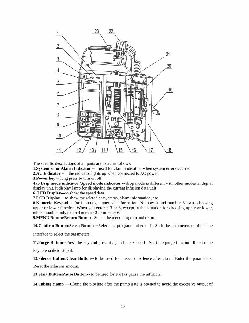
The specific descriptions of all parts are listed as follows: 1.System error Alarm Indicator -- used for alarm indication when system error occurred 2.AC Indicator -- the indicator lights up when connected to AC power, 3.Power key -- long press to turn on/off 4./5 Drip mode indicator /Speed mode indicator -- drop mode is different with other modes in digital display unit, it display lamp for displaying the current infusion data unit 6. LED Display—to show the speed data. 7.LCD Display -- to show the related data, status, alarm information, etc.. 8.Numeric Keypad -- for inputting numerical information, Number 3 and number 6 owns choosing upper or lower function. When you entered 3 or 6, except in the situation for choosing upper or lower, other situation only entered number 3 or number 6. 9.MENU Button/Return Button –Select the menu program and return .
10.Confirm Button/Select Button---Select the program and enter it; Shift the parameters on the some
interface to select the parameters.
11.Purge Button--Press the key and press it again for 5 seconds, Start the purge function. Release the
key to enable to stop it.
12.Silence Button/Clear Button--To be used for buzzer on-silence after alarm; Enter the parameters,
Reset the infusion amount.
13.Start Button/Pause Button--To be used for start or pause the infusion.
14.Tubing clamp —Clamp the pipeline after the pump gate is opened to avoid the excessive output of
11
liquid medicine.
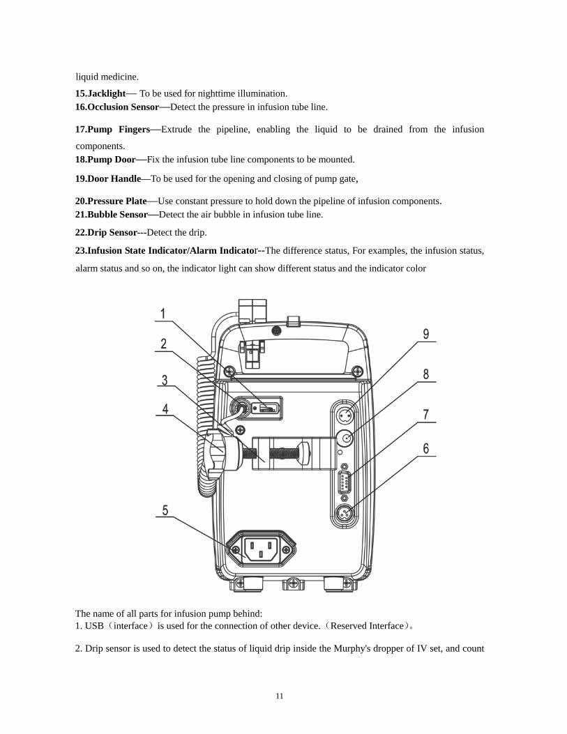
15.Jacklight— To be used for nighttime illumination. 16.Occlusion Sensor—Detect the pressure in infusion tube line.
17.Pump Fingers—Extrude the pipeline, enabling the liquid to be drained from the infusion
components. 18.Pump Door—Fix the infusion tube line components to be mounted.
19.Door Handle—To be used for the opening and closing of pump gate,
20.Pressure Plate—Use constant pressure to hold down the pipeline of infusion components. 21.Bubble Sensor—Detect the air bubble in infusion tube line. 22.Drip Sensor---Detect the drip.
23.Infusion State Indicator/Alarm Indicator--The difference status, For examples, the infusion status,
alarm status and so on, the indicator light can show different status and the indicator color
The name of all parts for infusion pump behind: 1. USB(interface)is used for the connection of other device.(Reserved Interface)。
2. Drip sensor is used to detect the status of liquid drip inside the Murphy's dropper of IV set, and count
12
the liquid drips splashed into the Murphy's dropper. 3. The fixation clamp is used for fixing infusion pump onto the infusion stand or bedstead.
4. Fixation handle--Rotating and adjusting the fixation which it is lock or release 5. Power supply interface is used for the connection of AC power supply.
6. DC 15V power output interface is used for output DC15V power supply.
7. RS232 interface is used for external communications.
8. DC12V Power input interface is used for the connection of 12v external DC power supply.
9. Calling nurse interface is used for the connection of nurse-calling system.
2.6 Standard RS232 Interface
The pump has a standard RS232 interface and it is communicated each other. RS232 connected line is asked to use shielded wire an it should be accord with the standard request of information technique and safe standard for IEC60950-1. For more detailed information, Please ask our company to the RS232 interface agreement. The device must be connected with the specified equipment. 2.7 Multi-Channel Injection
It is recommended that the infusion device use a one-way valve under using multi-channel injection. If there is no one-way value in the infusion tube, and it happened to be able to detect the block for the patient and it can lead to the drug corner. After release the block, the drug corner will inject the patient with unknown speed. It is very dangerous to the patient.
13
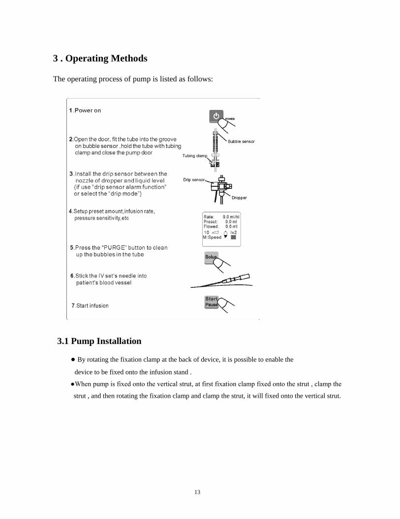
3 . Operating Methods
The operating process of pump is listed as follows:
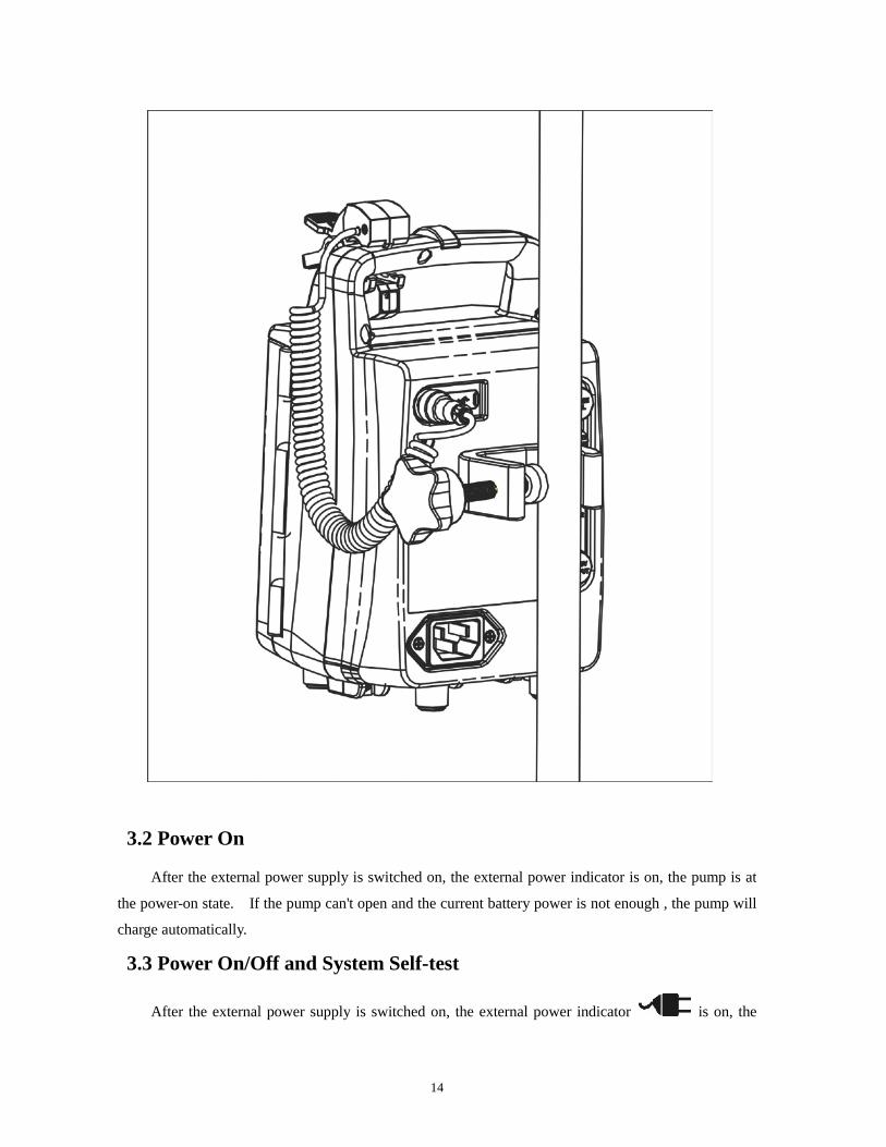
3.1 Pump Installation
● By rotating the fixation clamp at the back of device, it is possible to enable the
device to be fixed onto the infusion stand .
●When pump is fixed onto the vertical strut, at first fixation clamp fixed onto the strut , clamp the
strut , and then rotating the fixation clamp and clamp the strut, it will fixed onto the vertical strut.
14
3.2 Power On
After the external power supply is switched on, the external power indicator is on, the pump is at
the power-on state. If the pump can't open and the current battery power is not enough , the pump will
charge automatically.
3.3 Power On/Off and System Self-test
After the external power supply is switched on, the external power indicator is on, the
15
pump is at the power-on state. At this moment, press the key for 1 second to enable the start-up
of device. Under the premise that the internal battery is used, the battery indicates the current battery
power after the power switch is pressed to enable the start-up of device.
The system starts to conduct self-test after the start-up of device. At this moment, the buzzing
sound will be given out, the indicator and alarm light will bright up according to priority, and the pump
will automatically check each of the functions (Note: All keys will be tested during the self-test process.
In order to avoid an alarm for key error, please do not press any key). If there is no error message on
the main interface of LCD screen after the self-test, that means the pump works normally. At the
moment, the device is in standby state, The pump will give out alarm if the system is in abnormal
condition. For this regard, please refer to the description of alarm.
After the external power supply is switched on, Press the key for seconds to enable switch off
device. Under infusion status, Press to stop infusion, Press the key for seconds to enable switched off device. After power off, the data stored in the memory chip is not lost due to power off.
3.4 Installation of Infusion Components
Make the infusion components ready. Hang the IV bottle (or bag) onto the IV stand (Note: the
infusion bottle or bag should be placed 20cm ~ 80cm higher than the patient’s heart), open the package
of IV set components, and close the roller clamp of IV set. After the infusion components are properly
connected, use your hands to extrude the Murphy's dropper of IV set, and enable it to be filled with
liquid (An appropriate filling amount is one third of the Murphy's dropper). Open the roller clamp, fill
the infusion tube with infusion liquid to exhaust the air bubble, and then close the roller clamp.
Properly install the infusion tube. Lift up the pump handle, open the door, start the installation
from up to down, smoothly insert the tube into the pipe clamp, bubble sensor, and tubing clamp
according to priority . After the pipeline installation is finalized, it is possible to lift up the door handle,
ensure that the pulling hook of door handle has fastened the door locking pin, successively press down
the latch handle and close the pump door. At this moment, the surface of door handle should be in
parallel with the pump.
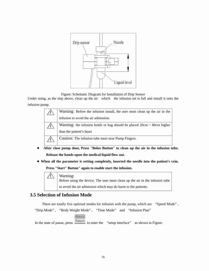
If you select the “drip mode” or enable the “drip sensor alarm function” , the drip sensor
should be installed. Have the drip sensor installed between the top of Murphy's dropper nozzle and
liquid level and try to keep the Murphy's dropper in the vertical position so that the drip sensor can
accurately detect the status of the liquid drip inside the Murphy's dropper (see Figure ).
16
Figure: Schematic Diagram for Installation of Drip Sensor
Under using, as the step above, clean up the air which the infusion set is full and install it onto the
infusion pump.
Warning: Before the infusion install, the user must clean up the air in the
infusion to avoid the air admission.
Warning: the infusion bottle or bag should be placed 20cm ~ 80cm higher
than the patient’s heart
Caution: The infusion tube must near Pump Fingers.
● After close pump door, Press "Bolus Button" to clean up the air in the infusion tube.
Release the hands upon the medical liquid flow out. ● When all the parameter is setting completely, inserted the needle into the patient's vein.
Press "Start" Button" again to enable start the infusion.
Warning: Before using the device, The user must clean up the air in the infusion tube
to avoid the air admission which may do harm to the patients.
3.5 Selection of Infusion Mode
There are totally five optional modes for infusion with the pump, which are “Speed Mode” ,
“Drip Mode” , “Body Weight Mode” , “Time Mode” and “Infusion Plan”
In the state of pause, press to enter the “setup interface” as shown in Figure:
17
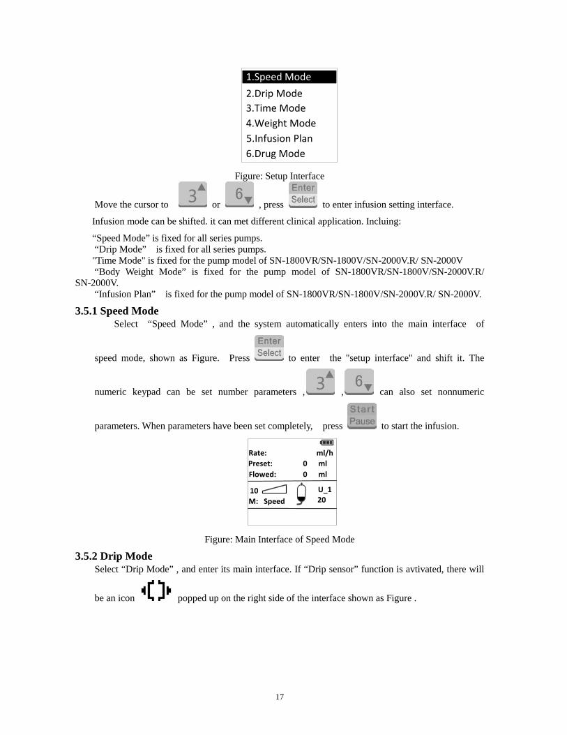
1.Speed Mode2.Drip Mode3.Time Mode4.Weight Mode5.Infusion Plan6.Drug Mode
Figure: Setup Interface
Move the cursor to or , press to enter infusion setting interface.
Infusion mode can be shifted. it can met different clinical application. Incluing:
“Speed Mode” is fixed for all series pumps. “Drip Mode” is fixed for all series pumps. "Time Mode" is fixed for the pump model of SN-1800VR/SN-1800V/SN-2000V.R/ SN-2000V
“Body Weight Mode” is fixed for the pump model of SN-1800VR/SN-1800V/SN-2000V.R/ SN-2000V.
“Infusion Plan” is fixed for the pump model of SN-1800VR/SN-1800V/SN-2000V.R/ SN-2000V.
3.5.1 Speed Mode Select “Speed Mode” , and the system automatically enters into the main interface of
speed mode, shown as Figure. Press to enter the "setup interface" and shift it. The
numeric keypad can be set number parameters , , can also set nonnumeric
parameters. When parameters have been set completely, press to start the infusion.
Rate:Preset:Flowed:
10M: Speed
U_120
ml/hmlml
10000
Figure: Main Interface of Speed Mode
3.5.2 Drip Mode Select “Drip Mode” , and enter its main interface. If “Drip sensor” function is avtivated, there will
be an icon popped up on the right side of the interface shown as Figure .
18
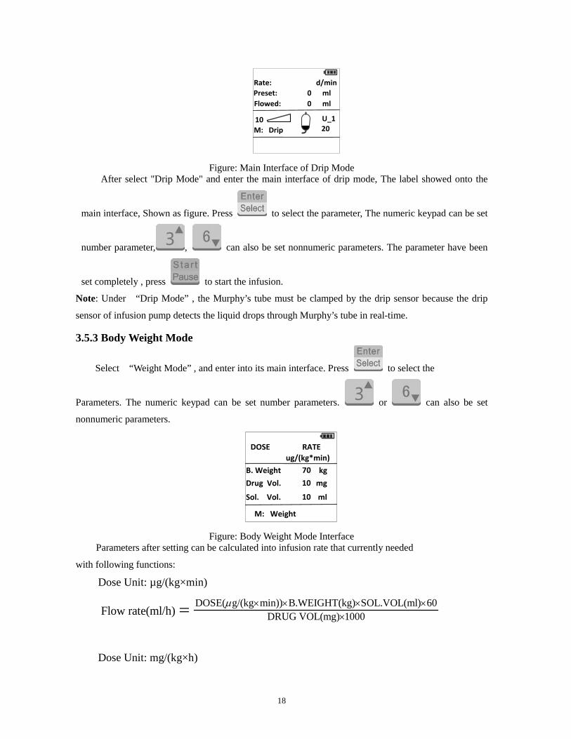
Rate:Preset:Flowed:
10M: Drip
U_120
d/minmlml
10000
Figure: Main Interface of Drip Mode
After select "Drip Mode" and enter the main interface of drip mode, The label showed onto the
main interface, Shown as figure. Press to select the parameter, The numeric keypad can be set
number parameter, , can also be set nonnumeric parameters. The parameter have been
set completely , press to start the infusion.
Note: Under “Drip Mode” , the Murphy’s tube must be clamped by the drip sensor because the drip
sensor of infusion pump detects the liquid drops through Murphy’s tube in real-time.
3.5.3 Body Weight Mode
Select “Weight Mode” , and enter into its main interface. Press to select the
Parameters. The numeric keypad can be set number parameters. or can also be set
nonnumeric parameters.
DOSE7
B. Weight kg70
RATEug/(kg*min)
Sol. Vol. ml10
Drug Vol. mg10
M: Weight
Figure: Body Weight Mode Interface Parameters after setting can be calculated into infusion rate that currently needed
with following functions:
Dose Unit: µg/(kg×min)
DOSE( g/(kg min)) B.WEIGHT(kg) SOL.VOL(ml)DRUG VOL(mg) 100
00
6Flow rate(ml/h)
µ × × × ××=
Dose Unit: mg/(kg×h)
19
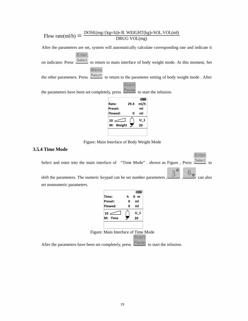
DOSE( )) B. WEIGHT(kg)mg/(kg hDRUG VOL(mg)
SOL.VOL(ml)Flow rate(ml/h)
× × ×=
After the parameters are set, system will automatically calculate corresponding rate and indicate it
on indicator. Press to return to main interface of body weight mode. At this moment, Set
the other parameters. Press to return to the parameter setting of body weight mode . After
the parameters have been set completely, press to start the infusion.
Rate:Preset:Flowed:
10M: Weight
U_120
ml/hmlml
29.400
Figure: Main Interface of Body Weight Mode
3.5.4 Time Mode
Select and enter into the main interface of “Time Mode” . shown as Figure , Press to
shift the parameters. The numeric keypad can be set number parameters , , can also
set nonnumeric parameters.
Time:Preset:Flowed:
10M: Time
U_120
hmlml
100
0 m
Figure: Main Interface of Time Mode
After the parameters have been set completely, press to start the infusion.
20
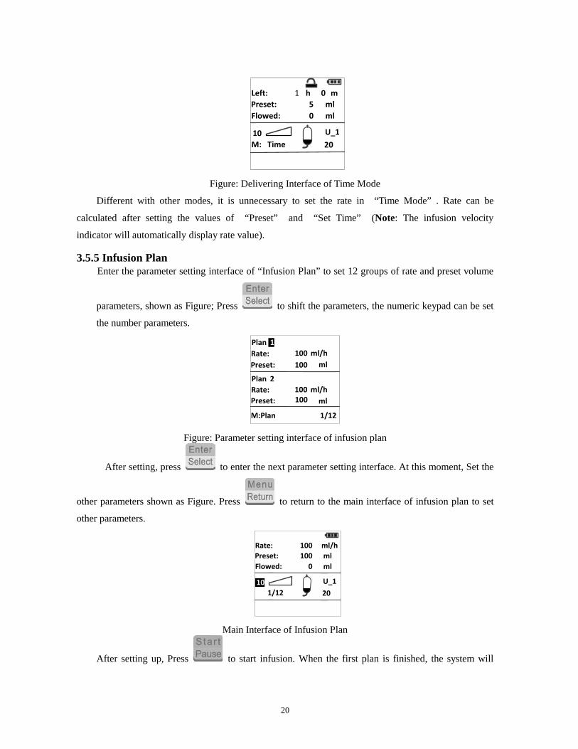
Left:Preset:Flowed:
10M: Time
U_120
hmlml
150
0 m
Delivering
Figure: Delivering Interface of Time Mode
Different with other modes, it is unnecessary to set the rate in “Time Mode” . Rate can be
calculated after setting the values of “Preset” and “Set Time” (Note: The infusion velocity
indicator will automatically display rate value).
3.5.5 Infusion Plan Enter the parameter setting interface of “Infusion Plan” to set 12 groups of rate and preset volume
parameters, shown as Figure; Press to shift the parameters, the numeric keypad can be set
the number parameters.
M:Plan
Plan
Plan
Rate:Preset:
Rate:Preset:
ml/h100ml100
ml/h100ml100
1/12
1
2
Figure: Parameter setting interface of infusion plan
After setting, press to enter the next parameter setting interface. At this moment, Set the
other parameters shown as Figure. Press to return to the main interface of infusion plan to set
other parameters.
Rate:Preset:Flowed:
101/12
U_120
ml/hmlml
100100
0
Main Interface of Infusion Plan
After setting up, Press to start infusion. When the first plan is finished, the system will

21
automatically shift to the next plan to continue infusion until all plans are finished.
Rate:Preset:Flowed:
101/12
U_120
ml/hmlml
100100
0
Delivering
.
Delivering Interface of Infusion Plan
3.5.6 Drug Library Enter the parameter setting interface of “Drug Mode” to choose drug name shown as Figure:
1 Caspofungin 70mg2 C e f e P I M E 1 G M / 5 0 m l3 C e f e P I M E 1 G M / 1 0 0 m l4 A t r a c u r m 5 0 0 m c g / m l
Main Interface of Drug Mode
Press to check Upper Hard Limit (UHL), Upper Soft Limit (USL), Lower Soft Limit (LSL)
and Lower Hard Limit (LHL).
C a s p o f u n g i n 7 0 m g
UHL: 250
USL: 250
LSL: 0
LHL: 0
Limit parameters of Drug Mode
Press to enter the "setup interface" and shift it. The numeric keypad can be set number
parameters , , can also set nonnumeric parameters. When parameters have been set
completely, press to start the infusion.

22
Rate:Preset:Flowed:
10M: Drug
U_120
ml/hmlml
1000
0
3.6 Infusion Parameters Setup
3.6.1 Infusion Rate Setup Default position of cursor is on rate setup after turning-on, shown as Figure, use numeric keypad to
set up the value.
Rate:Preset:Flowed:
10M: Speed
U_120
ml/hmlml
10000
Infusion Rate Setup Note: the rate unit of d/min can be only used under “Drip Mode”. See Clause 3.5.2 for detailed
introduction to “Drip Mode”.
In the state of running, press number keys to change the value, and press to
confirm the new value, then pump will run under the new rate.
3.6.2 Preset Volume Setup Move the cursor to “Preset”, shown as Figure, Use numeric keypad to set up the value. Below
100mL is accurate to 0.1mL,over 100mL is accurate to 1mL.
Rate:Preset:Flowed:
10M: Speed
U_120
ml/hmlml0
100100
Preset Volume Setup The default value of “Preset” is 0 after turning-on. The infusion process will last until no liquid
is left if the preset volume keeps unaltered (preset volume is 0).
Note: Ensure the value of Preset Volume is smaller than/equal to the actual amount of the liquid in
the infusion bottle (or infusion bag).
23
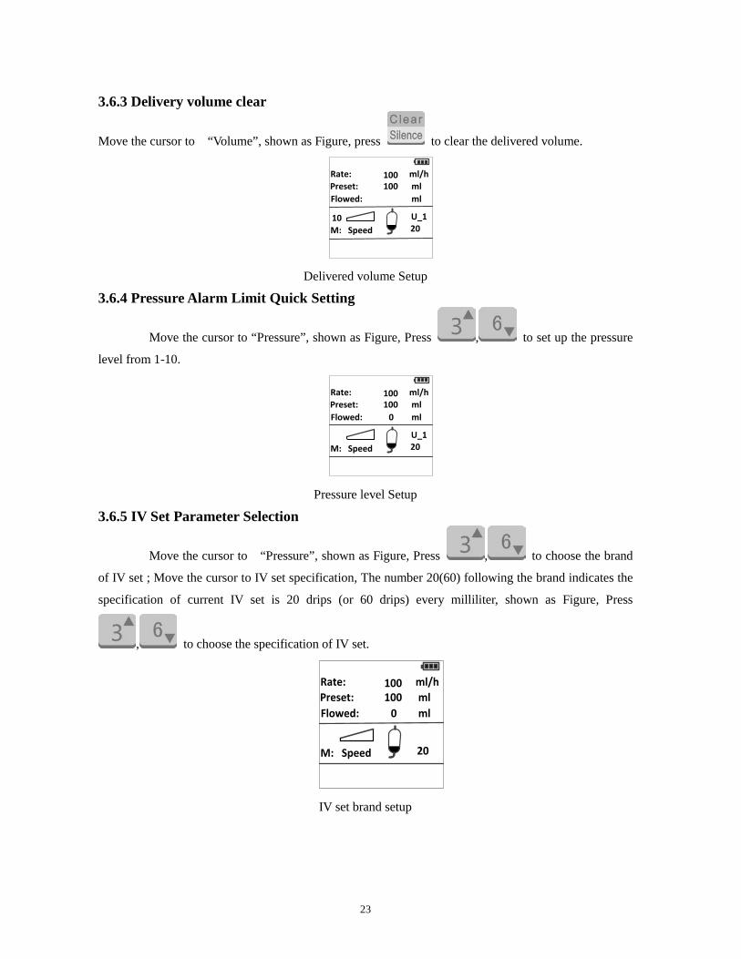
3.6.3 Delivery volume clear
Move the cursor to “Volume”, shown as Figure, press to clear the delivered volume.
Rate:Preset:Flowed:
10M: Speed
U_120
ml/hmlml
100
0100
Delivered volume Setup
3.6.4 Pressure Alarm Limit Quick Setting
Move the cursor to “Pressure”, shown as Figure, Press , to set up the pressure
level from 1-10.
Rate:Preset:Flowed: 0
M: SpeedU_120
ml/hmlml
100
10
100
Pressure level Setup
3.6.5 IV Set Parameter Selection
Move the cursor to “Pressure”, shown as Figure, Press , to choose the brand
of IV set ; Move the cursor to IV set specification, The number 20(60) following the brand indicates the
specification of current IV set is 20 drips (or 60 drips) every milliliter, shown as Figure, Press
, to choose the specification of IV set.
Rate:Preset:Flowed: 0
M: Speed 20
ml/hmlml
100
U_1
100
IV set brand setup
24
Rate:Preset:Flowed: 0
M: Speed
ml/hmlml
100
20
100
U_1
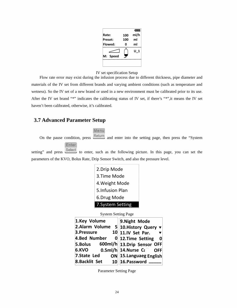
IV set specification Setup Flow rate error may exist during the infusion process due to different thickness, pipe diameter and
materials of the IV set from different brands and varying ambient conditions (such as temperature and
wetness). So the IV set of a new brand or used in a new environment must be calibrated prior to its use.
After the IV set brand “*” indicates the calibrating status of IV set, if there’s “*”,it means the IV set
haven’t been calibrated, otherwise, it’s calibrated.
3.7 Advanced Parameter Setup
On the pause condition, press and enter into the setting page, then press the “System
setting” and press to enter, such as the following picture. In this page, you can set the
parameters of the KVO, Bolus Rate, Drip Sensor Switch, and also the pressure level.
7.System Setting
2.Drip Mode3.Time Mode4.Weight Mode5.Infusion Plan6.Drug Mode
System Setting Page
7.State Led6.KVO5.Bolus4.Bed Number3.Pressure2.Alarm Volume1.Key Volume ON
510
0600ml/h0.5ml/h
ON8.Backlit Set 10
15.Languaeg14.Nurse Call13.Drip Sensor12.Time Setting 11.IV Set Par. 10.History Query9.Night Mode
0OFFOFF
English16.Password _____
Parameter Setting Page
25
3.7.1 Keypad Tone Setup Once on the page of parameter setting, when the Cursor stop at the keypad’s sound, and press
or to switch on or off the keypad sound.
3.7.2 Alarm Tone Volume Setup
Press , put the cursor onto the alarm sound volume, and press or to adjust the alarm sound volume level, there are total 10 levels(1-10) which can be adjustable.
3.7.3 Pressure Alarm Limit Setup
Press , and put the cursor onto the Occlusion Level, then press or to
adjust the Occlusion level, there are total ten levels which can be adjustable. The relative occlusion
parameter is as follows: the range of the occlusion lever is 100mmHg~900mmHg(13.3kPa~120kPa),
ten levels to be adjustable, and the Error is ±50mmHg (6.6kpa)or ±25%, which is greater.
3.7.4 Bed Number Setup Press , and put the cursor onto the Bed No, then input the Bed number with the Numeric
keypad, the number is from 1 to 255.
3.7.5 Bolus Rate Setup
Press , and put the cursor onto the Bolus rate setting, then input the bolus rate with the Numeric keypad.
Purge rate is from 5-1000ml/h; stepping is 1ml/h.
3.7.6 KVO Rate Setup
Press , and put the cursor onto the KVO rate setting, then input the KVO rate with the Numeric keypad. So that once the injection is finished, the pump will go into KVO mode instantly.
Range of KVO rate is from 0.5-5ml/h; stepping is 0.1ml/h.
3.7.7 Operating Light Switch Setup
Press , and put the cursor onto the Operation Switch setting, and press or to switch on or off the Operating Light Switch.
3.7.8 Background Light
Press , put the cursor onto Backlight setting, and press or to adjust background light, the number is from 0 to 10.
3.7.9 Night mode
Press , put the cursor onto the Night Mode, and press or , Select between
26
and , when it is on ,Press , enter into the page of Night mode. In night mode,
press or to set switch ON or OFF; Press Numeric keypad to set Time Start and Time
End (Attention: time difference must be more than one hour); Press or to set Alarm Volume from 1 to 10 and Background light from 0 to 10.
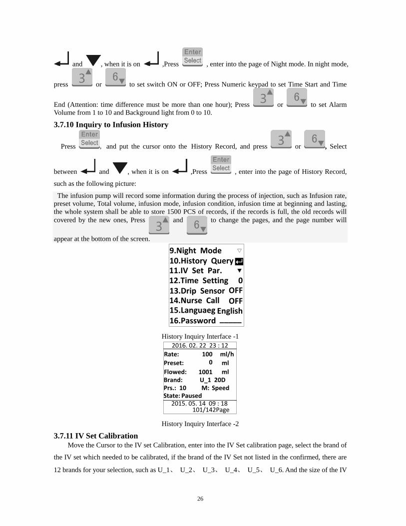
3.7.10 Inquiry to Infusion History
Press , and put the cursor onto the History Record, and press or , Select
between and , when it is on ,Press , enter into the page of History Record,
such as the following picture:
The infusion pump will record some information during the process of injection, such as Infusion rate, preset volume, Total volume, infusion mode, infusion condition, infusion time at beginning and lasting, the whole system shall be able to store 1500 PCS of records, if the records is full, the old records will covered by the new ones, Press and to change the pages, and the page number will
appear at the bottom of the screen.
15.Languaeg14.Nurse Call13.Drip Sensor12.Time Setting 11.IV Set Par. 10.History Query9.Night Mode
0OFFOFF
English16.Password _____
History Inquiry Interface -1
Rate:2016. 02. 22 23 : 12
Preset:Flowed:
ml/hmlml
100
10010
Brand: U_1 20DPrs.: 10State: Paused
2015. 05. 14 09 : 18101/142Page
M: Speed
History Inquiry Interface -2
3.7.11 IV Set Calibration Move the Cursor to the IV set Calibration, enter into the IV Set calibration page, select the brand of
the IV set which needed to be calibrated, if the brand of the IV Set not listed in the confirmed, there are
12 brands for your selection, such as U_1、 U_2、 U_3、 U_4、 U_5、 U_6. And the size of the IV

27
set should be 10 drop/ml, 15 drop/ml, 18 drop/ml, 20 drop/ml and 60drop/ml, use the confirmed
parameter in the system for the testing, please see the following:
Before IV Calibration, please get rid of the air bubble in the tube, put the out-put part of the IV tube
into the testing cup. Press and begin the IV set calibration. When the liquid volume reach the
desired one, press to stop the testing, if the testing is successful, there will appear “Testing
Over” at the screen. After that the system shall calculate the relative calibration number. And if the Error
is too big, there will appear “Re-calibrate”.
To ensure the accuracy of the calibration, please return to the main page, set the rate at 200ml/h,
and Preset volume at 10ml for the testing to check whether you get your required mount of the liquid 10
ml in the testing cup.
Brand:Spec.:T. Rate:T. Vol:Calib. Value:
U_120200 ml/h10 ml
***
d/ml
Testing
IV Set calibration page Attention: If there appear “*” on the back of IV set brand, that means the current used IV Set has not
been calibrated, and if there appear U01, that means the current used IV set has already been calibrated.
Attention: If one hospital used the same brand of IV set, it is more convenient for the IV Set calibration.
That is, when you calibrate the IV set in one unit of the infusion pump, and record the calibration
number, and when you calibrate the same IV set to another unit of infusion pump, you just input the
calibration number to the infusion pump, after that the calibration is ok.
3.7.12 Time Setup Move the Cursor to the time setting, and set your required time, details is as the following:
Date:2016 - 02 - 14Time:
10 : 10
Time setup Interface Once enter into this page, you can set the local time and the date as you require with the numeric
28
keypad and the button , and press to confirm your set pareameter.
3.7.13 Drip Sensor Switch Setup
Move the Cursor to the “Drip sensor switch setup”, press and to set the switch.
When the injection is under “Speed mode” “Time mode” and “Body Weight Mode”, as well as “Infusion
Plan” the use can also be able to use this drop sensor, which can check in time whether the whole
process of the injection is right or not, at the same time the sensor switch must be connected to the
Moufi Tube
When the function of drip sensor alarm is working or the infusion mode is “drip mode”, there will
appear on the top of the main page.
Note: In Order to ensure the safety of the Injection, suggest use this “Drip Sensor alarm function ”
3.7.14 Nurse Call Setup
Move the Cursor to the “Nurse call setup”, and press and to set the switch ON or
OFF.
3.7.15 Language Setup
Move the Cursor to the “Language setup” and press and to choose the applicable
language. There are 13 languages including Chinese, English, Italian, Russian, Portuguese, Spanish ,
German, Slovak, Bulgaria, Hungarian, Greek, French and Czech.
3.8 Bolus Function
Purge function (Bolus function) can be performed both in the state of Pause and in the infusion
process. The purge dosage generated in the state of Pause is not accumulated to the infusion amount,
while the purge dosage in the infusion process is accumulated.
Press , and then press it again within 5s and hold it to start purge.
3.9 Lighting Function
At night(or the light is very dim in the room), once you open the door, the light inside of the pump
will be on automatically, which shall enhance the convenience of the operation.
3.10 Communication with Main Unit
By connecting to the main unit for communication, the transfusion pump system can realize the

29
data transfer with the main unit. As for that, SN-1600V and SN-1800V can utilize standard RS232
interface to communicate with the main unit.SN-1800VR and SN-1600VR support wireless mode and
can also use RS232 interface to communicate with the main unit.
Notes: standard RS232 interface can be used for two-way communication where shielding cable is
required and the device being connected shall comply with the requirements of IEC60950-1 Safety of
Information Technology Equipment. For more information, please ask salesman from Sinomdt for
RS232 Interface Protocol. Device being connected must be the one specified by Sinomdt.
3.11 Sleep Mode
In the pause state, press 2 seconds, the pump turn into sleep mode. Press any key
except , the pump returns work mode.
3.12 Keyboard Lock
In the delivering state, press 2 seconds, the pump keyboard is locked. Press , the
keyboard is unlocked.
3.13 Management of the Battery Recharging
3.13.1 Battery Type of the battery:A1
Appearance of the battery: There should be no deformation, leakage and other defects
Discharging voltage limited:10V.
Normal working voltage above 12V:
The rechargeable battery inside the pump should be examined upon its time length of charging and
discharging every three months to prevent work failure caused by run-out of battery energy when it
works relying on battery. Battery’s rated discharging time is 8 hours, yet under a damaged or
incomplete-charged condition, the time length the battery supports the pump service is not certain.
It should have 12 continuous hours for charging in turn-off condition prior to its first use. If long time
standing by, the pump should be charged every 3 months to prevent inset battery from getting useless
because of auto-discharging. Promptly connect the pump with AC power supply for charging or turn off
the pump when alarming the energy run-out, otherwise energy run-out may do harm to the battery.
Ineffective battery should be taken to the place designated by environment protection sections, or sent
30
back to our company for unified disposal to prevent environment pollution.
3.13.2 Recharging Battery recharging of Sinomdt pump is both available at both turn-off and turn-on condition, stop
recharging once full. During the process of battery recharging, firstly at constant current charging and
then constant voltage charging, switch to trickle recharging close to saturation, stop recharging once full.
4. Alarm Presentation
4.1 Alarm of Non Operation
Alarm turns on when no operation proceeds after the device starts up or service suspends for 2
minutes, meanwhile the LCD will display “Time Out” ; the alarm sound can be removed by pressing the
“SLIENCE” button.
4.2 Alarm of Not Calibration
If the pump doesn’t run with unaligned infusion apparatus after pressing the “START” button, the
main interface will display “NOT CALIBRATED”.
The troubleshooting method: replace with an aligned infusion apparatus, or enter the calibration
interface to align the infusion apparatus; for details of aligning infusion apparatus please refer to Section
3.7.9.
4.3 Alarm of Occlusion
In the course of infusion, when the pressure inside the infusion tube arrives at the set limit value,
alarm turns on with sound and light, and the LCD will display “Occl”, then pumps automatically stops
working and releases the excessive dosage caused by occlusion; pressing silence button can remove the
alarm sound.
Exclusion: examine if the infusion tube line twists or ties together.
4.4 Alarm of Bubble
In the course of service, ultra-sound air bubble sensor detects the bubble, then alarm turns on with
light and sound; the LCD will display “Bubb” ; the pump automatically stops work; pressing the Silence
button can remove the alarm sound.
Exclusion: clean up the bubble inside the infusion tube and insert the infusion tube into the bottom
of the bubble sensor.
4.5 Alarm of Door Open
If the pump door is open when the pump is running, there will be an alarm with sound and light, t
31
the LCD will display “Open” , and the pump will auto stop working. You can press the silence button to
remove the alarm sound.
Exclusion: check if the pump gate is closed properly.
4.6 Alarm of Infusion Finish
Upon the completion of the setting volume of infusion, the system will automatically enter the
KVO (keep vein open) meanwhile with the audible and visible alarm; the LCD will display “Finish” and
“KVO” . The alarm sound can be removed; 2 minutes later the alarm works again; press “PAUSE” to
suspend the infusion process.
Note: once in KVO mode, KVO rate will appear on the LED. If the current rate is above KVO rate,
the infusion rate will be as preset KVO rate, otherwise will be as the preset infusion rate.
4.7 Alarm of KVO Completion
In the KVO mode, pump stops working with audible and visible alarm when the output dosage
reaches 6ml. the panel shows “KVO FINISHED”; the alarm sound is not removable.
Note: Infusion dosage of KVO will be counted into the accumulative dosage.
4.8 Alarm of Drip Sensor Abnormality
This alarm is only available when the drip sensor is used in rate mode or the drip mode is selected.
If any abnormality is detected by the system, there will be an alarm with sound and light and t the LCD
will display “Drop Error”. You can press the silence button to remove the alarm sound.
Note: Check if the installation drip folder is abnormal or not, or whether bottle is empty or not
4.9 Alarm of Power Supply Breakdown
Power supply switches on; if without outside power supply connection or with electrical cord
disconnecting in the course of service, pump will give off intermittent alarm sound,. There will be note
on the LCD to indicate the net electricity is off. Pressing the silence button and the alarm sound can be
removed.
4.10 Alarm of Low Voltage Battery
When the battery is low, light flickers (one grid flickers), pump will give off intermittent
alarm sound; this sound can be removed by pressing the silence button; 2 minutes later it alarms again.
Meanwhile, the pump can sustain the service for 30 minutes longer at the rate of 25 ml/h.
4.11 Alarm of Battery Running-out
When the battery runs out of energy (at the flow rate of 25 ml/h, only able to last for 3 minutes), the
32
pump stops working. Light flickers , with lasting noise of alarming, which is not removable.
4.12 Alarm of System Error
Error operation or machine breakdown turns on the alarm noise and the “SysErr” lamp at the alarm
indicator, with the main interface displaying the error code (the reason for the error lists as follows);
here requires to re-start the device; if re-start the device, but the system remains alarming errors, please
contact the post-sale service department.
4.13 Alarm Level
“Occlusion” “Bubble”, “Door Open”, “Drip Sensor Abnormality”, “System Error”, “Infusion
Finish”, “Door Open” these alarms have been with highest priority; other alarms with lowest priority.
4.14 Alarm Volume
Sound pressure of Alarm is from 45dB to 85dB.
Warning:
Warning: IV set to be used must be precisely calibrated, otherwise phenomenon as
inaccuracy of the flow rate, occlusion pressure, error alert, will happen. As for
designated infusion Set , we only recognize its external structural size, and the index
as biochemical, physical, and metering shall acquire verification and certification by
relative supervision departments.
Warning: Suggest use the IV set specially for the infusion pump, other wise can not
assure the injection accuracy
Warning: tube line of IV set will act poor rebounding performance or even have
leakages after a while of usage; thus after 6 hours’ continuous work, the infusion
pump shall be turned off and have the tube lines in slight motions in order to assure
no extrusion unto the tube lines between the pump tablet and the pressing plate。
Warning: when reinstalling the infusion tube, infusion tubes that have been
extruded shall not be located at the position of air bubble sensor, otherwise it can
cause error alert about air bubbles in the tubes.
Warning: the roller clamp of infusion apparatus should be located onto the tube
lines between the infusion pump and the patient when installing the infusion IV set
Warning: air bubbles in tube lines between the pump and the patient cannot be
detected; it has to be excluded manually.
Warning: do not press hard the stress point of pressure sensor; otherwise, the press
33
sensor will get damaged.
Warning: the pump should not be operated by patient’s family members, in case
incorrect operation brings about dangers to patients.
Warning: the rechargeable battery inside the pump should be examined upon its
time length of charging and discharging every three months to prevent work failure
caused by run-out of battery energy when it works relying on battery. Battery’s rated
discharging time is 8 hours, yet under a damaged or incomplete-charged condition,
the time length the battery supports the pump service is not certain.
Warning: ineffective battery should be taken to the place designated by
environment protection sections, or sent back to our company for unified disposal to
prevent environment pollution. Properly handle the parts off the apparatus when
repaired or when the apparatus’s service life becomes due in order to avoid
environment pollution.
Warning: Used under the regular care of the nurse or other medical Persons
Warning: the IV set to be used with the pump must get the Medical Registration or
CE. And also the IV set have to be calibrated before first using, otherwise
inaccuracy will occur
34
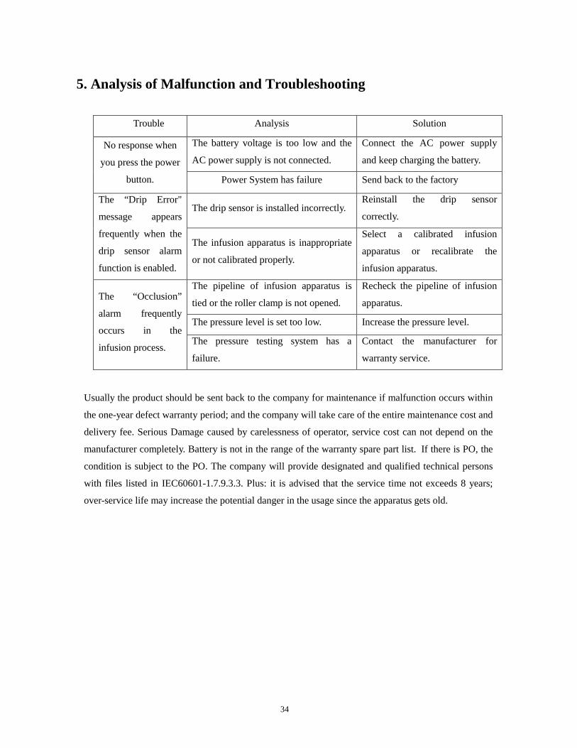
5. Analysis of Malfunction and Troubleshooting
Trouble Analysis Solution
No response when
you press the power
button.
The battery voltage is too low and the
AC power supply is not connected.
Connect the AC power supply
and keep charging the battery.
Power System has failure Send back to the factory
The “Drip Error"
message appears
frequently when the
drip sensor alarm
function is enabled.
The drip sensor is installed incorrectly. Reinstall the drip sensor
correctly.
The infusion apparatus is inappropriate
or not calibrated properly.
Select a calibrated infusion
apparatus or recalibrate the
infusion apparatus.
The “Occlusion”
alarm frequently
occurs in the
infusion process.
The pipeline of infusion apparatus is
tied or the roller clamp is not opened.
Recheck the pipeline of infusion
apparatus.
The pressure level is set too low. Increase the pressure level.
The pressure testing system has a
failure.
Contact the manufacturer for
warranty service.
Usually the product should be sent back to the company for maintenance if malfunction occurs within
the one-year defect warranty period; and the company will take care of the entire maintenance cost and
delivery fee. Serious Damage caused by carelessness of operator, service cost can not depend on the
manufacturer completely. Battery is not in the range of the warranty spare part list. If there is PO, the
condition is subject to the PO. The company will provide designated and qualified technical persons
with files listed in IEC60601-1.7.9.3.3. Plus: it is advised that the service time not exceeds 8 years;
over-service life may increase the potential danger in the usage since the apparatus gets old.
35
6. Maintenance
● The pump should be regularly cleansed with clean wet cloth and appropriate amount of detergent,
then cleansed with clean wet cloth upon the external surface, and finally with clean cloth to dry the
surface and put on the dry shelf.
●When battery is low, the pump will give off intermittent alarm; please charge the pump timely or
connect the pump with AC power supply; when the battery runs out of energy, pump will stop
work with audible and visible alarm; please turn off the device immediately or connect with AC
power supply to continue the service.。The charging method: in the state of turn-off, connect the
pump with AC power supply; once the AC electrical indicator lamp lights up, the pump are in the
charging state.
Note: recharge 12 hours continuously in the state of turn-off
●With long time standby, the pump should be charged every 3 months to prevent the inset battery
from getting useless because of auto-discharging.
●Alarm system should be checked every year referring to “4. Alarm presentation”.
Note: LED lamp and text are applied to indicate the state of alarm at the front of the pump, so the user
should face the pump to operate the pump when alarms occur.
●With long time standby, the pump should be examined upon the charging and discharging of the
battery in case of black out condition when the inset battery is needed yet out of work; if the
battery is found malfunction with charging, please contact our company to replace with new
rechargeable battery unit. Battery replacement should be operated by authorized personnel. The
replacing way is: loosen off the behind screws, open the behind lid, take away the lead plug, and
then loosen off the battery box’ s screws, take away the old battery, and replace with the new one,
then plug the battery lead plug into the socket, and finally fix the screws.
36
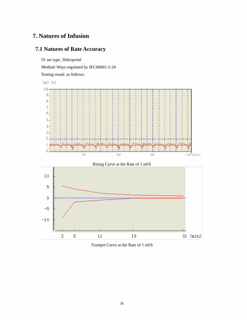
7. Natures of Infusion
7.1 Natures of Rate Accuracy
IV set type: 20drops/ml
Method: Ways regulated by IEC60601-2-24
Testing result: as follows:
Rising Curve at the Rate of 1 ml/h
Trumpet Curve at the Rate of 1 ml/h

37
Rising Curve at the Rate of 25 ml/h
Trumpet Curve at the Rate of 25 ml/h
Warning:
The above testing result is the one used by the IV set 20 drop/ml,. So that
there will be some small difference if used other brand of IV Set for the
testing
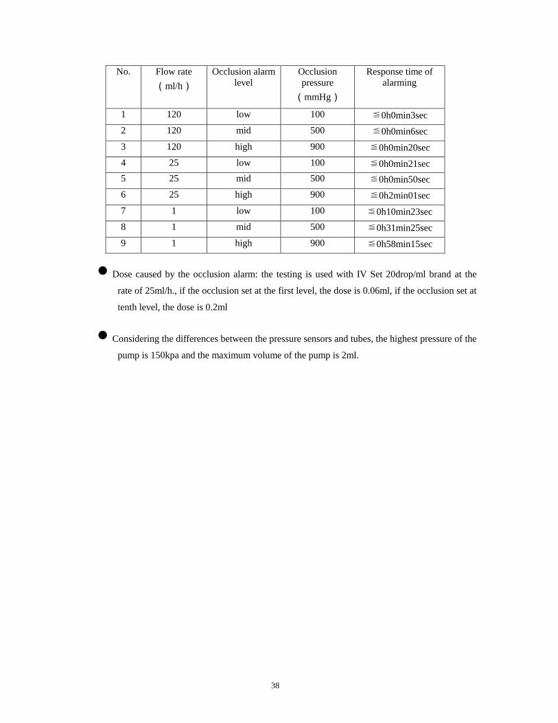
7.2 Response to Occlusion
● The occlusion alarm time is a main indicator of the nature of response to occlusion. In this test,
use 20 d/ml apparatus; the following data only present the results of the test about the infusion
apparatus used in the test.
Note: The response time of occlusion alarm is subject to the infusion rate, infusion apparatus
brand, pressure level, etc.
38
No. Flow rate(ml/h)
Occlusion alarm level
Occlusion pressure
(mmHg)
Response time of alarming
1 120 low 100 ≦0h0min3sec 2 120 mid 500 ≦0h0min6sec 3 120 high 900 ≦0h0min20sec 4 25 low 100 ≦0h0min21sec 5 25 mid 500 ≦0h0min50sec 6 25 high 900 ≦0h2min01sec 7 1 low 100 ≦0h10min23sec 8 1 mid 500 ≦0h31min25sec 9 1 high 900 ≦0h58min15sec
• Dose caused by the occlusion alarm: the testing is used with IV Set 20drop/ml brand at the
rate of 25ml/h., if the occlusion set at the first level, the dose is 0.06ml, if the occlusion set at
tenth level, the dose is 0.2ml
• Considering the differences between the pressure sensors and tubes, the highest pressure of the
pump is 150kpa and the maximum volume of the pump is 2ml.
39
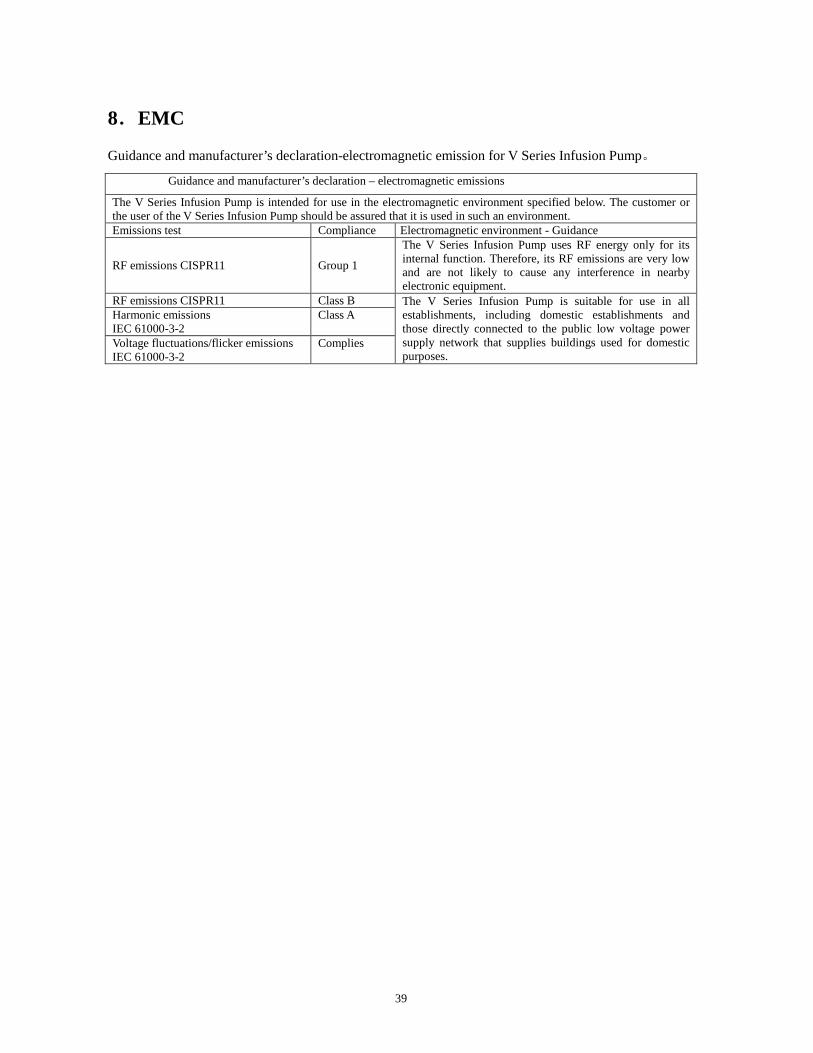
8.EMC
Guidance and manufacturer’s declaration-electromagnetic emission for V Series Infusion Pump。
Guidance and manufacturer’s declaration – electromagnetic emissions
The V Series Infusion Pump is intended for use in the electromagnetic environment specified below. The customer or the user of the V Series Infusion Pump should be assured that it is used in such an environment. Emissions test Compliance Electromagnetic environment - Guidance
RF emissions CISPR11 Group 1
The V Series Infusion Pump uses RF energy only for its internal function. Therefore, its RF emissions are very low and are not likely to cause any interference in nearby electronic equipment.
RF emissions CISPR11 Class B The V Series Infusion Pump is suitable for use in all establishments, including domestic establishments and those directly connected to the public low voltage power supply network that supplies buildings used for domestic purposes.
Harmonic emissions IEC 61000-3-2
Class A
Voltage fluctuations/flicker emissions IEC 61000-3-2
Complies
40
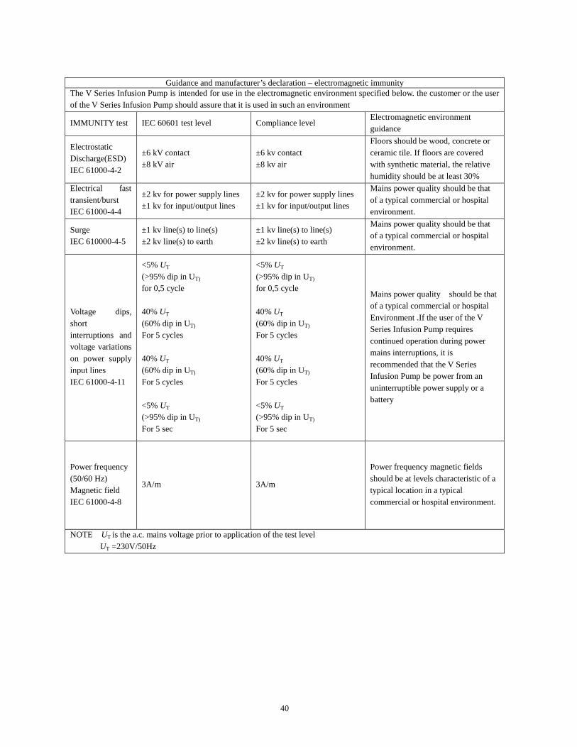
Guidance and manufacturer’s declaration – electromagnetic immunity
The V Series Infusion Pump is intended for use in the electromagnetic environment specified below. the customer or the user of the V Series Infusion Pump should assure that it is used in such an environment
IMMUNITY test IEC 60601 test level Compliance level Electromagnetic environment guidance
Electrostatic Discharge(ESD) IEC 61000-4-2
±6 kV contact ±8 kV air
±6 kv contact ±8 kv air
Floors should be wood, concrete or ceramic tile. If floors are covered with synthetic material, the relative humidity should be at least 30%
Electrical fast transient/burst IEC 61000-4-4
±2 kv for power supply lines ±1 kv for input/output lines
±2 kv for power supply lines ±1 kv for input/output lines
Mains power quality should be that of a typical commercial or hospital environment.
Surge IEC 610000-4-5
±1 kv line(s) to line(s) ±2 kv line(s) to earth
±1 kv line(s) to line(s) ±2 kv line(s) to earth
Mains power quality should be that of a typical commercial or hospital environment.
Voltage dips, short interruptions and voltage variations on power supply input lines IEC 61000-4-11
<5% UT (>95% dip in UT)
for 0,5 cycle
40% UT (60% dip in UT)
For 5 cycles 40% UT (60% dip in UT)
For 5 cycles <5% UT (>95% dip in UT)
For 5 sec
<5% UT (>95% dip in UT)
for 0,5 cycle
40% UT (60% dip in UT)
For 5 cycles 40% UT (60% dip in UT)
For 5 cycles <5% UT (>95% dip in UT)
For 5 sec
Mains power quality should be that of a typical commercial or hospital Environment .If the user of the V Series Infusion Pump requires continued operation during power mains interruptions, it is recommended that the V Series Infusion Pump be power from an uninterruptible power supply or a battery
Power frequency (50/60 Hz) Magnetic field IEC 61000-4-8
3A/m 3A/m
Power frequency magnetic fields should be at levels characteristic of a typical location in a typical commercial or hospital environment.
NOTE UT is the a.c. mains voltage prior to application of the test level UT =230V/50Hz
41
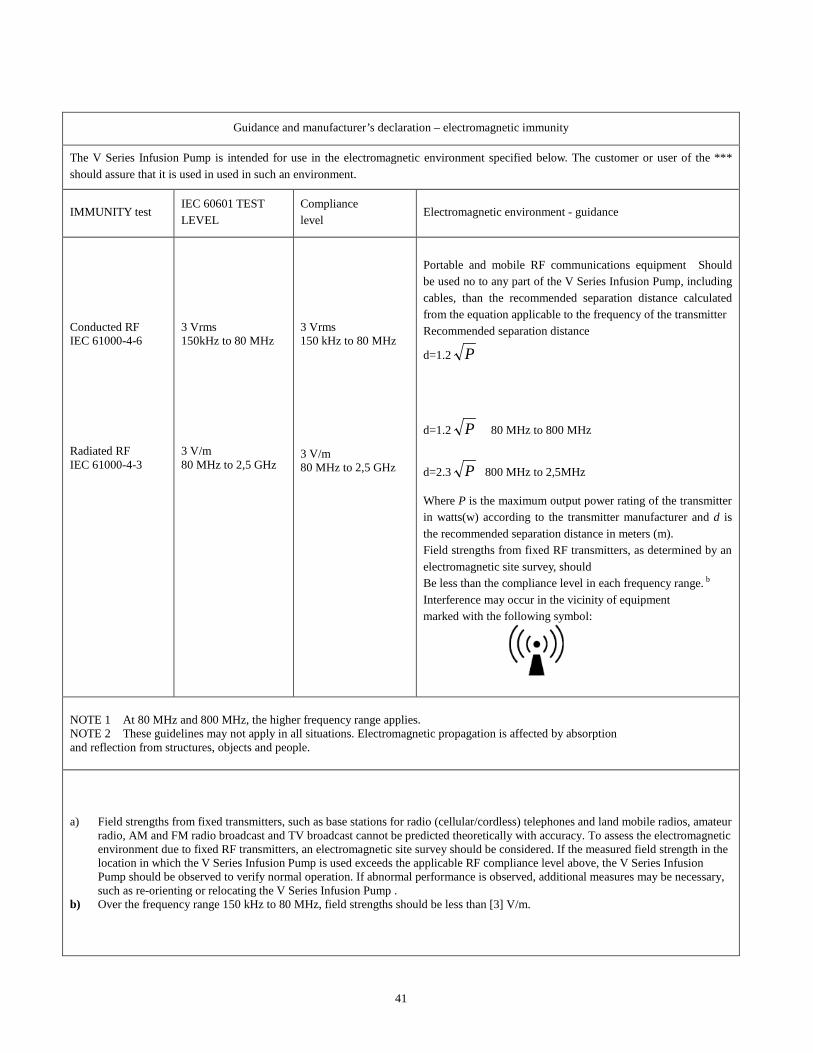
Guidance and manufacturer’s declaration – electromagnetic immunity
The V Series Infusion Pump is intended for use in the electromagnetic environment specified below. The customer or user of the *** should assure that it is used in used in such an environment.
IMMUNITY test IEC 60601 TEST LEVEL
Compliance level
Electromagnetic environment - guidance
Conducted RF IEC 61000-4-6 Radiated RF IEC 61000-4-3
3 Vrms 150kHz to 80 MHz 3 V/m 80 MHz to 2,5 GHz
3 Vrms 150 kHz to 80 MHz 3 V/m 80 MHz to 2,5 GHz
Portable and mobile RF communications equipment Should be used no to any part of the V Series Infusion Pump, including cables, than the recommended separation distance calculated from the equation applicable to the frequency of the transmitter Recommended separation distance
d=1.2 P
d=1.2 P 80 MHz to 800 MHz
d=2.3 P 800 MHz to 2,5MHz Where P is the maximum output power rating of the transmitter in watts(w) according to the transmitter manufacturer and d is the recommended separation distance in meters (m). Field strengths from fixed RF transmitters, as determined by an electromagnetic site survey, should Be less than the compliance level in each frequency range. b Interference may occur in the vicinity of equipment marked with the following symbol:
NOTE 1 At 80 MHz and 800 MHz, the higher frequency range applies. NOTE 2 These guidelines may not apply in all situations. Electromagnetic propagation is affected by absorption and reflection from structures, objects and people.
a) Field strengths from fixed transmitters, such as base stations for radio (cellular/cordless) telephones and land mobile radios, amateur radio, AM and FM radio broadcast and TV broadcast cannot be predicted theoretically with accuracy. To assess the electromagnetic environment due to fixed RF transmitters, an electromagnetic site survey should be considered. If the measured field strength in the location in which the V Series Infusion Pump is used exceeds the applicable RF compliance level above, the V Series Infusion Pump should be observed to verify normal operation. If abnormal performance is observed, additional measures may be necessary, such as re-orienting or relocating the V Series Infusion Pump .
b) Over the frequency range 150 kHz to 80 MHz, field strengths should be less than [3] V/m.
42
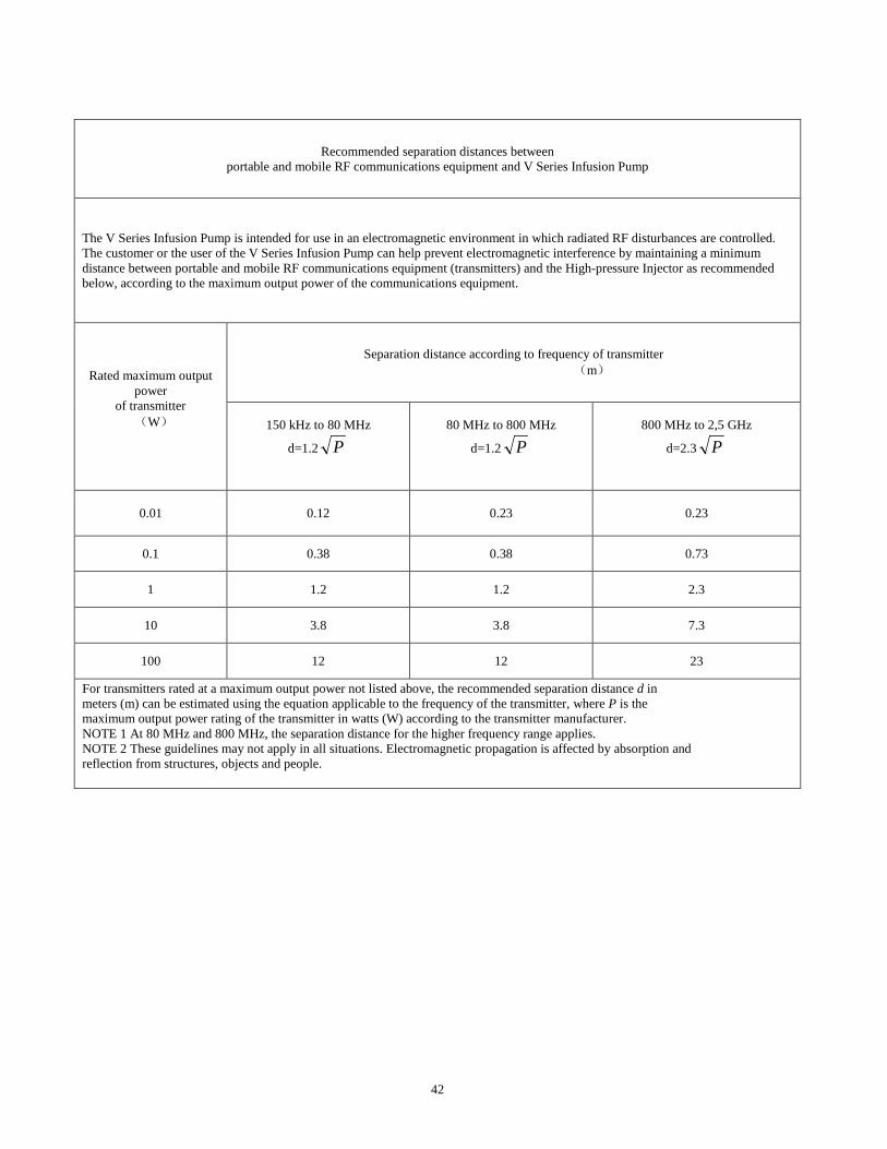
Recommended separation distances between portable and mobile RF communications equipment and V Series Infusion Pump
The V Series Infusion Pump is intended for use in an electromagnetic environment in which radiated RF disturbances are controlled. The customer or the user of the V Series Infusion Pump can help prevent electromagnetic interference by maintaining a minimum distance between portable and mobile RF communications equipment (transmitters) and the High-pressure Injector as recommended below, according to the maximum output power of the communications equipment.
Rated maximum output power
of transmitter (W)
Separation distance according to frequency of transmitter (m)
150 kHz to 80 MHz
d=1.2 P
80 MHz to 800 MHz
d=1.2 P
800 MHz to 2,5 GHz
d=2.3 P
0.01 0.12 0.23 0.23
0.1 0.38 0.38 0.73
1 1.2 1.2 2.3
10 3.8 3.8 7.3
100 12 12 23
For transmitters rated at a maximum output power not listed above, the recommended separation distance d in meters (m) can be estimated using the equation applicable to the frequency of the transmitter, where P is the maximum output power rating of the transmitter in watts (W) according to the transmitter manufacturer. NOTE 1 At 80 MHz and 800 MHz, the separation distance for the higher frequency range applies. NOTE 2 These guidelines may not apply in all situations. Electromagnetic propagation is affected by absorption and reflection from structures, objects and people.

43
9. Standard Configuration
● Infusion Pump 1 PCS
● Power line 1 PCS
● User manual 1 PCS
● Certificate of conformity 1 PCS
● Warranty card 1 PCS
44
10. Relevant Information
Manufacturer: Sino Medical-Device Technology Co., Ltd.
Add: 6th Floor, Building 15, No.1008, Songbai Road, Nanshan District, Shenzhen, P.R. China
Zip: 518055
Tel: (86) 755- 86142996 Fax: (86) 755- 86142985
Website: www.Sinomdt.com
Email: [email protected]
EC Representative: Shanghai International Holding Corp. GmbH (Europe)
Add:Eiffestrasse 80, 20537 Hamburg, Germany
Tel: +49-40-2513175
Fax: +49-40-255726
E-mail: [email protected]