STREAMLINE HIGH PRESSURE WATERJET PUMP ...
159
STREAMLINE HIGH PRESSURE WATERJET PUMP Operation and Service Manual STREAMLINE SL-V 30S Classic STREAMLINE SL-V 50S Classic 400 V / 3 / 50 Hz Language: English Including: Maintenance DVD Intensifier Date: 03-2008 Satus: Rev. 3 CPN: DOC00091 KMT GmbH KMT Waterjet Systems • www.kmtgroup.com
-
Upload
khangminh22 -
Category
Documents
-
view
0 -
download
0
Transcript of STREAMLINE HIGH PRESSURE WATERJET PUMP ...

STREAMLINE HIGH PRESSURE WATERJET PUMP
Operation and Service Manual
STREAMLINE SL-V 30S Classic STREAMLINE SL-V 50S Classic 400 V / 3 / 50 Hz
Language: English Including: Maintenance DVD Intensifier Date: 03-2008 Satus: Rev. 3 CPN: DOC00091
KMT GmbH KMT Waterjet Systems • www.kmtgroup.com

DOC00091 03-2008/Rev 03
STREAMLINE SL-V
OPERATION and SERVICE MANUAL
Notice
This document contains subject matter in which KMT Waterjet Systems has proprietary rights. Recipients of this document shall not duplicate, use, or disclose information contained herein, in whole or in part, for other than the purpose for which this manual was provided.
KMT Waterjet believes the information described in this manual to be accurate and reliable. Much care has been taken in its preparation; however, the Company cannot accept any responsibility, financial or otherwise, for any consequences arising out of the use of this material. The information contained herein is subject to change, and revisions may be issued to advise of such changes and/or additions
KMT GmbH 2008
KMT GmbH • KMT Waterjet Systems Waterjet Cutting Technology Auf der Laukert 11 61231 Bad Nauheim, Germany
Tel.: +49-6032-997-0 Fax: +49-6032-997-270
E-Mail: [email protected] Homepage: www.kmtgroup.com

Table of Contents
DOC00091 03-2008/Rev 03 2
Table of Contents
1 SECTION 1 INTRODUCTION ....................................................................................... 1-1
1.1 Overview ..................................................................................................................................... 1-1 Intended Use ............................................................................................................................... 1-1 Product Code .............................................................................................................................. 1-2
1.2 Performance Features and Options .............................................................................................. 1-2 1.3 Operational Overview .................................................................................................................. 1-4
Low Pressure Water System ......................................................................................................... 1-4 Recirculation System .................................................................................................................... 1-4 Hydraulic System ......................................................................................................................... 1-5 High Pressure Water System ........................................................................................................ 1-5 Operating System ........................................................................................................................ 1-6
1.4 Safety .......................................................................................................................................... 1-6 Danger Areas .............................................................................................................................. 1-7 Lockout/Tagout Procedure .......................................................................................................... 1-7 Warning Labels ........................................................................................................................... 1-8 Integrated Safety Systems ......................................................................................................... 1-10 Emergency Medical Treatment .................................................................................................. 1-11
1.5 Worldwide Product Support ...................................................................................................... 1-12 1.6 Spare Parts ................................................................................................................................ 1-12 1.7 Manual Organization ................................................................................................................. 1-12 1.8 Equipment and Service Manual Questionnaire ........................................................................... 1-13
2 SECTION 2 INSTALLATION ........................................................................................ 2-1
2.1 Overview ..................................................................................................................................... 2-1 2.2 Installation Summary ................................................................................................................... 2-1 2.3 Site Requirements ....................................................................................................................... 2-2
Transporting ................................................................................................................................ 2-3 2.4 Power Requirements ................................................................................................................... 2-3 2.5 Service Connections .................................................................................................................... 2-4
Hydraulic Oil ................................................................................................................................ 2-6 Cooling Water ............................................................................................................................. 2-6 Cutting Water ............................................................................................................................. 2-6 Drain ........................................................................................................................................... 2-7 Plant Air ...................................................................................................................................... 2-7
2.6 Flow Requirements ...................................................................................................................... 2-7 2.7 High Pressure Piping .................................................................................................................... 2-8
Measurements and Dimensions ................................................................................................... 2-8 Hand Coning ............................................................................................................................. 2-10 Power Coning ........................................................................................................................... 2-11 Hand Threading ........................................................................................................................ 2-12 Power Threading ....................................................................................................................... 2-12
2.8 High Pressure Connections ........................................................................................................ 2-13 Standard Connections ............................................................................................................... 2-13 Anti-Vibration Connections ....................................................................................................... 2-14
2.9 Commissioning ......................................................................................................................... 2-15 2.10 Decommissioning ...................................................................................................................... 2-18
3 SECTION 3 MAINTENANCE ........................................................................................ 3-1
3.1 Overview ..................................................................................................................................... 3-1 3.2 Maintenance ............................................................................................................................... 3-1
Daily Inspection ........................................................................................................................... 3-1 Periodic Maintenance .................................................................................................................. 3-1 High Pressure System Maintenance ............................................................................................. 3-2
3.3 Maintenance Precautions ............................................................................................................ 3-3

Table of Contents
DOC00091 03-2008/Rev 03 3
4 SECTION 4 OPERATION ............................................................................................. 4-1
Overview ..................................................................................................................................... 4-1 Startup Sequence ........................................................................................................................ 4-1 Startup after Motor Stop ............................................................................................................. 4-2 Startup after Emergency Stop ...................................................................................................... 4-2 Elements of the PLC (Programmable Logic Controller) ................................................................. 4-3 Explanation of the Display ........................................................................................................... 4-3 Using the Arrow Keys .................................................................................................................. 4-3 Info, Clear and Enter Keys ........................................................................................................... 4-4 Function Keys F1 to F4 ................................................................................................................ 4-4
4.1 System Display (View 1) ............................................................................................................... 4-7 Setting the Temperature Display to °C or °F ................................................................................ 4-7
4.2 Display of Operating Hours and Strokes Topwork 1 (View 2) ....................................................... 4-8 Displaying production hours and strokes for pressure intensifier 1 ............................................... 4-8 Resetting the Operating Hours and Strokes ................................................................................. 4-8
4.3 Stop Positioning for Changing the Seal (View 3) .......................................................................... 4-9 4.4 Display of Operating Hours for “Topwork 1” ............................................................................ 4-10
Number of Strokes for “Topwork 1” ......................................................................................... 4-10 4.5 Print Setting with (optional) Proportion Valve (View 5) .............................................................. 4-11
Entering Your Password ............................................................................................................ 4-12 Pressure Settings ....................................................................................................................... 4-13
4.6 Setting the Time Period for Automatic Pump Shutoff (View 6) ................................................... 4-14 4.7 Display for “Right Strokes/Left Strokes in Milliseconds” (View 7) ............................................... 4-15 4.8 Number of “Right Strokes/Left Strokes per Minute” (View 8) .................................................... 4-16 4.9 Number of “Overall Strokes per Minute” (View 9) ..................................................................... 4-17 4.10 Capacity in Percent (View 10) .................................................................................................... 4-18
Setting the Capacity in Percent for Topwork 1 .......................................................................... 4-19 Setting the Volume Display in l/min or gal/min .......................................................................... 4-20
4.11 Display of Voltage on the Proportional Valve, Optional (View 11) .............................................. 4-20 4.12 Parametering for Options (View 12) .......................................................................................... 4-20
Resetting the Parameter for installed oil-air-radiator .................................................................. 4-21 4.13 Setting Language, Date and Time (View 13) .............................................................................. 4-23
Setting the Language ................................................................................................................ 4-23 Entering Date and Time ............................................................................................................. 4-24
4.14 Brightness Setting in the Text Display (View 14) ........................................................................ 4-26 4.15 Fault Report .............................................................................................................................. 4-26
5 SECTION 5 LOW PRESSURE WATER SYSTEM ........................................................... 5-1
5.1 Overview ..................................................................................................................................... 5-1 5.2 Cutting Water Supply .................................................................................................................. 5-2 5.3 Operation .................................................................................................................................... 5-2 5.4 Service and Maintenance Procedures ........................................................................................... 5-4
Filter Assembly and Strainer Maintenance ................................................................................... 5-4 Booster Pump Adjustment ........................................................................................................... 5-6
6 SECTION 6 RECIRCULATION SYSTEM ....................................................................... 6-1
6.1 Overview ..................................................................................................................................... 6-1 6.2 Operation .................................................................................................................................... 6-2
Oil-to-Water Heat Exchanger ....................................................................................................... 6-2 Air-to-Oil Heat Exchanger ............................................................................................................ 6-4
6.3 Service and Maintenance Procedures ........................................................................................... 6-4 Hydraulic Oil Maintenance .......................................................................................................... 6-5 Oil Filter Maintenance ................................................................................................................. 6-7 Operating Temperature Adjustment ............................................................................................ 6-7
7 SECTION 7 HYDRAULIC SYSTEM .............................................................................. 7-1

Table of Contents
DOC00091 03-2008/Rev 03 4
7.1 Overview ..................................................................................................................................... 7-1 7.2 Optional System Components ..................................................................................................... 7-2 7.3 Operation .................................................................................................................................... 7-2 7.4 Service and Maintenance Procedures ........................................................................................... 7-4
Hydraulic Operating Pressure ....................................................................................................... 7-4 Motor Maintenance .................................................................................................................... 7-6 Flexible Coupling Replacement .................................................................................................... 7-6 Hydraulic Compensator Maintenance .......................................................................................... 7-8
8 SECTION 8 ELECTRICAL SYSTEM ............................................................................... 8-1
8.1 Overview ..................................................................................................................................... 8-1 8.2 Optional System Components ..................................................................................................... 8-1 8.3 Operation .................................................................................................................................... 8-2
Sensors and Solenoids ................................................................................................................. 8-4 8.4 Service and Maintenance Procedures ........................................................................................... 8-8
Proximity Switch Maintenance ..................................................................................................... 8-8
9 SECTION 9 HIGH PRESSURE WATER SYSTEM .......................................................... 9-1
9.1 Overview ..................................................................................................................................... 9-1 9.2 Operation .................................................................................................................................... 9-2 9.3 System Components ................................................................................................................... 9-4 9.4 Service and Maintenance Overview ............................................................................................. 9-6
Torque Specifications .................................................................................................................. 9-7 Specialized Maintenance Tools .................................................................................................... 9-9
9.5 High and Low Pressure Water Piping ......................................................................................... 9-10 9.6 High Pressure Cylinder Assembly ............................................................................................... 9-10
High Pressure Cylinder Assembly Removal ................................................................................. 9-10 High Pressure Cylinder Assembly Installation ............................................................................. 9-12 High Pressure Cylinder Maintenance ......................................................................................... 9-13
9.7 Hard Seal End Caps ................................................................................................................... 9-14 Hard Seal End Cap Removal ...................................................................................................... 9-14 Hard Seal End Cap Installation ................................................................................................... 9-15
9.8 Sealing Head ............................................................................................................................. 9-16 High Pressure Discharge Check Valve ........................................................................................ 9-17 Low Pressure Inlet Check Valve ................................................................................................. 9-18 Sealing Head Maintenance ........................................................................................................ 9-19
9.9 High Pressure Seal Assembly ..................................................................................................... 9-20 9.10 Hydraulic Piston and Plungers .................................................................................................... 9-23
Hydraulic Piston and Plunger Removal ....................................................................................... 9-23 Piston Bushings and Seal Assembly ............................................................................................ 9-25 Plunger Maintenance ................................................................................................................ 9-26 Hydraulic Piston and Plunger Installation ................................................................................... 9-27
9.11 Hydraulic Cylinder Maintenance ................................................................................................ 9-28 9.12 High Pressure Attenuator .......................................................................................................... 9-28 9.13 High Pressure Dump Valve ........................................................................................................ 9-28
Pneumatic Control Valve ........................................................................................................... 9-30 Pneumatic Actuator ................................................................................................................... 9-34
9.14 Weep Holes ............................................................................................................................... 9-35
10 SECTION 10 TROUBLESHOOTING ........................................................................... 10-1
10.1 Overview ................................................................................................................................... 10-1 10.2 Troubleshooting Guide .............................................................................................................. 10-2
11 SECTION 11 SPECIFICATIONS .................................................................................. 11-1
11.1 Overview ................................................................................................................................... 11-1 11.2 Installation Specifications .......................................................................................................... 11-1

Table of Contents
DOC00091 03-2008/Rev 03 5
11.3 Water Specifications .................................................................................................................. 11-2 Water Quality Standards............................................................................................................ 11-3
11.4 Electrical Specifications .............................................................................................................. 11-6 11.5 Hydraulic and High Pressure Water System Specifications .......................................................... 11-6
Orifice Capacity ......................................................................................................................... 11-7 Torque Specifications ................................................................................................................ 11-9
DOC00091 03-2008/Rev 03 1-1
1 SECTION 1
INTRODUCTION
1.1 Overview
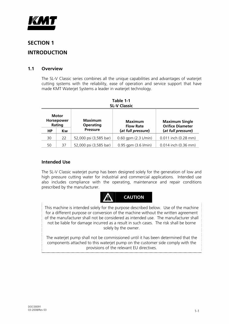
The SL-V Classic series combines all the unique capabilities and advantages of waterjet cutting systems with the reliability, ease of operation and service support that have made KMT Waterjet Systems a leader in waterjet technology.
Table 1-1 SL-V Classic
Motor Horsepower
Rating
Maximum Operating Pressure
Maximum Flow Rate
(at full pressure)
Maximum Single Orifice Diameter (at full pressure) HP Kw
30 22 52,000 psi (3,585 bar) 0.60 gpm (2.3 L/min) 0.011 inch (0.28 mm)
50 37 52,000 psi (3,585 bar) 0.95 gpm (3.6 l/min) 0.014 inch (0.36 mm)
Intended Use
The SL-V Classic waterjet pump has been designed solely for the generation of low and high pressure cutting water for industrial and commercial applications. Intended use also includes compliance with the operating, maintenance and repair conditions prescribed by the manufacturer.
CAUTION
This machine is intended solely for the purpose described below. Use of the machine for a different purpose or conversion of the machine without the written agreement of the manufacturer shall not be considered as intended use. The manufacturer shall
not be liable for damage incurred as a result in such cases. The risk shall be borne solely by the owner.
The waterjet pump shall not be commissioned until it has been determined that the components attached to this waterjet pump on the customer side comply with the
provisions of the relevant EU directives.

Section 1 Introduction
DOC00091 03-2008/Rev 03 1-2
CAUTION
The owner of the system shall procure and deploy the materials/media used and handled for normal operation of the system. Proper handling and the associated risks
are the sole responsibility of the owner.
The owner must provide warnings and disposal information. Please observe the material safety data sheets from the respective material and media manufacturers.
Product Code
The information in this operations manual applies only to this pump, the type code for which is specified on the title page. The type code and serial number are located on the nameplate on the top right-hand side of the pump, next to the pressure intensifier.
For all queries, it is important to specify the correct pump type and system number so the query can be processed as quickly and efficiently as possible.
Figure 1-1: Nameplate
1.2 Performance Features and Options
The SL-V Classic series is designed with the same convenience and ease of access for maintenance and service you have come to expect from KMT Waterjet. The hydraulic cylinder head simply bolts to the hydraulic cylinder; each high pressure assembly can be removed and serviced independently, and the hydraulic seal cartridge can be quickly replaced as a single unit.
The robust performance and standard features are the result of aggressive development and decades of experience.
• Continuous operation at 52,000 psi (3,585 bar).
Section 1 Introduction
DOC00091 03-2008/Rev 03 1-3
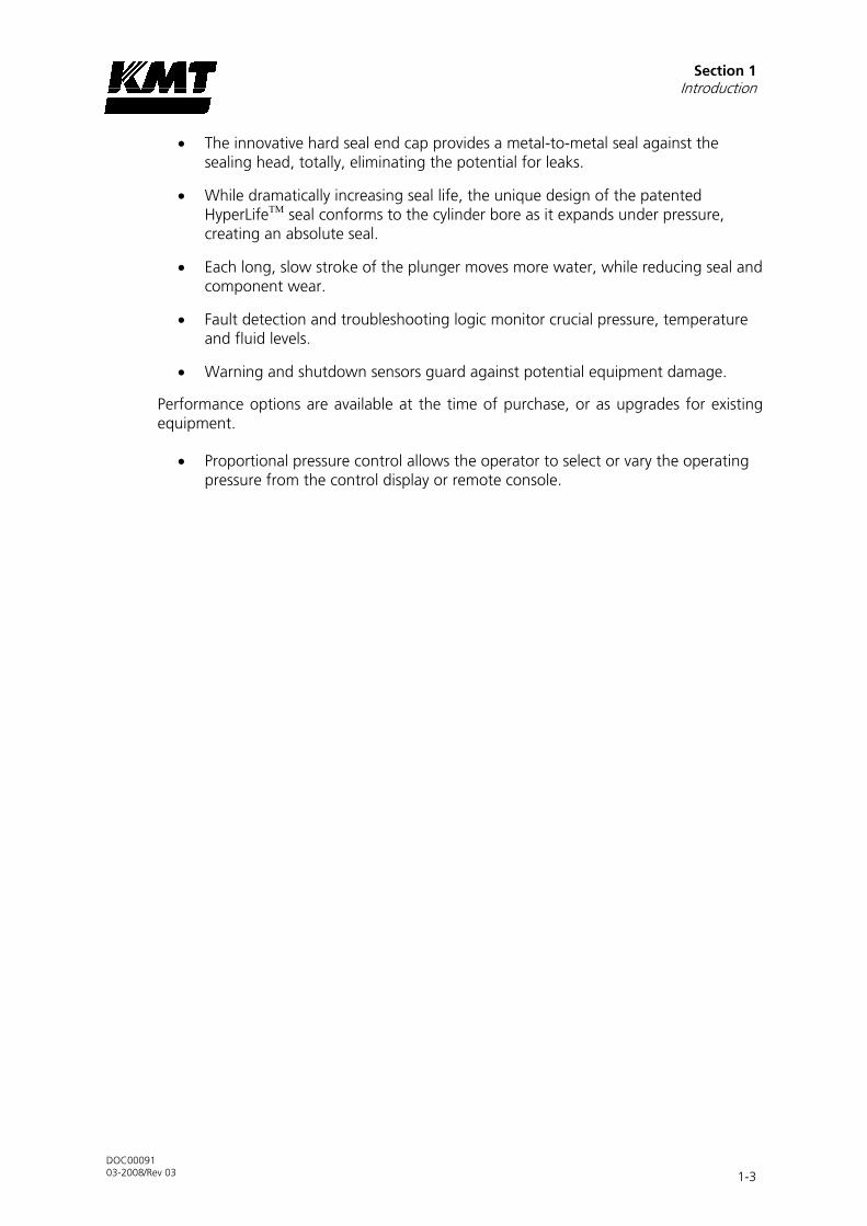
• The innovative hard seal end cap provides a metal-to-metal seal against the sealing head, totally, eliminating the potential for leaks.
• While dramatically increasing seal life, the unique design of the patented HyperLifeTM seal conforms to the cylinder bore as it expands under pressure, creating an absolute seal.
• Each long, slow stroke of the plunger moves more water, while reducing seal and component wear.
• Fault detection and troubleshooting logic monitor crucial pressure, temperature and fluid levels.
• Warning and shutdown sensors guard against potential equipment damage.
Performance options are available at the time of purchase, or as upgrades for existing equipment.
• Proportional pressure control allows the operator to select or vary the operating pressure from the control display or remote console.

Section 1 Introduction
DOC00091 03-2008/Rev 03 1-4
1.3 Operational Overview
The following provides a brief overview of the function and primary components associated with the individual systems. A detailed discussion of each system is provided in Sections 4 through 9. Equipment specifications are provided in Section 11, Specifications.
Low Pressure Water System
The low pressure water system supplies the cutting water flow to the intensifier. Major system components include the water filter assembly and the booster pump.
Figure 1-2: System Components
A Hydraulic System B Recirculation System C Low Pressure Water System
1 Electric Motor 4 Recirculation Pump 8 Booster Pump
2 Hydraulic Pump 5 Oil Filter Assembly 9 Water Filter Assembly
3 Hydraulic Manifold 6 Hydraulic Oil Reservoir
7 Oil-to-Water Heat Exchanger
Recirculation System
The recirculation system is a cooling and filtration system that provides properly conditioned oil to the main hydraulic system. Major system components include the recirculation pump, heat exchanger, oil filter assembly and the hydraulic oil reservoir. The pump is equipped with an oil-to-water heat exchanger, or with an external oil-to-air heat exchanger.

Section 1 Introduction
DOC00091 03-2008/Rev 03 1-5
Hydraulic System
The hydraulic system supplies the intensifier with the hydraulic oil required to produce high pressure water. Major system components include the electric motor, hydraulic pump, and the 4-way directional control valve mounted on the hydraulic manifold.
High Pressure Water System
The high pressure water system is the heart of the waterjet system. Water is pressurized and continuously delivered to the cutting head. As water passes through a tiny hole in the orifice, water pressure is converted to water velocity capable of cutting many materials, with exact precision.
The major components include the high pressure cylinder assemblies, hydraulic cylinder assembly, hydraulic piston, attenuator and the safety dump valve.
Figure 1-3: High Pressure System Components
1 High Pressure Cylinder Assembly 4 Safety Dump Valve
2 Hydraulic Piston 5 Attenuator
3 Hydraulic Cylinder Assembly

Section 1 Introduction
DOC00091 03-2008/Rev 03 1-6
Operating System
A programmable logic controller (PLC) provides basic intensifier shift control and monitors out of limit conditions. Operator interface is through the text operator panel.
Figure 1-4: Text Operator Panel
MI4 – 110 – KC1
• GB SLV 50 C xcV1.0
•
0:00:00 hours
info
• strokes/min. 0
• 0 °C
•
F 1
• F 2
• F 3
• F 4 clear
enter
1.4 Safety
The high pressure waterjet cutting system is a high energy cutting tool capable of cutting many dense or strong materials. Do not touch or be exposed to high pressure water. High pressure water will penetrate all parts of the human body. The liquid stream and the material ejected by the extreme pressure can result in severe injury.
All personnel operating, servicing or working near the waterjet cutting equipment shall adhere to the following safety precautions, as well as the applicable plant safety precautions.
• Only trained, qualified personnel shall service and maintain the equipment.
• The operator shall practice and promote safety at all times to avoid potential injury and unnecessary downtime.
• Responsibilities for machine operation must be clearly defined and complied with to ensure there is no confusion regarding competence in the area of safety.
• Ensure that the work area around the equipment is clean and free of debris and oil spills.
•
Wear safety glasses and ear protection when operating or working near the equipment.

Section 1 Introduction
DOC00091 03-2008/Rev 03 1-7
• The owner is obliged to operate the machine only when it is in perfect condition.
• The operator is obliged to report any changes to the machine that affect safety to the owner immediately.
Danger Areas
A minimum clearance of 36 inches (914 mm) should be provided on all sides of the machine to facilitate maintenance. During maintenance and repair work, the danger area extends one meter around the system. The swivel angle of the control cabinet doors when open must be taken into account. Keep the area around the system free of objects.
Lockout/Tagout Procedure
This lockout/tagout procedure is designed to protect all employees from injuries caused by the unexpected energizing or startup of the machine, or the release of stored energy during service and maintenance.
This is accomplished with energy isolating devices that prevent the transmission or release of energy. An energy source is any source of electrical, mechanical, hydraulic, pneumatic, chemical, thermal, or other energy source that could cause injury to personnel.
A lockout device utilizes a lock and key to hold an energy isolating device in the safe position and prevents the machine from being energized. A tagout device is a prominent warning device that can be securely attached to the machine warning personnel not to operate the energy isolating device. This procedure requires the combination of a lockout device and a tagout device.
The lockout/tagout procedure applies to any employee who operates and/or performs service or maintenance on the machine. Before any maintenance or repairs are performed, the machine shall be isolated, and rendered inoperative as follows.
1. Shut down the machine by pressing the F1 key and open the high pressure cutting water valve to bleed the water and hydraulic pressure from the system.
or
Press the emergency stop button to shut down the machine. Control power to the intensifier will be turned off, the pump will stop and the high pressure water will be released through the safety dump valve.
2. Disconnect, lockout and tag the main, customer supplied, power source.
3. Lockout and tag the circuit breaker/disconnect on the electrical enclosure door.
4. Close, lockout and tag the manual shutoff valves for all service connections; cutting water in, cooling water in and out or hydraulic oil in and out, and air.

Section 1 Introduction
DOC00091 03-2008/Rev 03 1-8
Warning Labels
Warning labels are posted on the machine to indicate potential hazards. The operator and service personnel shall pay particular attention to these warning labels. Figure 1-5, Warning Labels, illustrates the location of the warning labels. Table 1-2 describes the necessary precautions and provides the part number required to order replacement labels.
Figure 1-5: Warning Labels
Table 1-2 Warning Label Precautions
1
The electrical enclosure and motor junction box can present an electrical shock hazard. Always
disconnect and lockout the main power before opening the enclosure.
Always disconnect and lockout the main power and the circuit breaker/disconnect on the electrical enclosure door before performing any type of
maintenance P/N 05114962
2
The surface of high pressure water and hydraulic components becomes hot during normal operation. Failed, or failing components, can become extremely
hot during operation.
Warnings labels are placed on both side panels and on the back panel.
P/N 05114970

Section 1 Introduction
DOC00091 03-2008/Rev 03 1-9
Table 1-2 Warning Label Precautions
3
Ensure that all protective guards, shields or covers are in place on the equipment at all times. Never
operate the pump with the guards removed.
Warnings labels are placed on both side panels and on the back panel.
P/N 80082209
4
High pressure water and/or hydraulic pressure remains in the system even when the pump has
been shut off. All pressure can be safely bled from the system by opening the high pressure cutting
water valve for a few seconds after shutting off the pump.
Pressing the EMERGENCY STOP button turns the control power to the intensifier off, stops the pump
and bleeds the high pressure water through the safety dump valve.
Depressurization of the high pressure system creates a loud hissing sound when the dump valve opens.
The sound fades quickly as the pressure drops.
P/N 05098017
5
All personnel involved in the installation, operation and/or service of the intensifier must carefully read,
understand and follow the procedures in this manual to avoid creating unsafe conditions, risking
damage to the equipment, or personal injury.
P/N 20415794

Section 1 Introduction
DOC00091 03-2008/Rev 03 1-10
Safety precautions and warnings for specific procedures are emphasized throughout this manual as illustrated in the following examples. These precautions must be reviewed and understood by operating and maintenance personnel prior to installing, operating or servicing the machine. Adherence to all Warnings, Cautions and Notes is essential to safe and efficient service and operation.
WARNING
Warnings emphasize operating or service procedures, or conditions that can result in serious personal injury or death.
CAUTION
Cautions emphasize operating or service procedures, or conditions that can result in equipment damage or impairment of system operation.
NOTE
Notes provide additional information that can expedite or improve operating or service procedures.
Integrated Safety Systems
A function test must be performed on the integrated safety devices at regular intervals.
Table 1-2 Function Test Intervals
Safety System Interval
Power Switch Weekly
Emergency Stop Button Weekly
The power switch is located at the front on the control cabinet and connects/disconnects the machine to/from the main power supply. The switch must be secured by means of a padlock to prevent the machine from being switched on by unauthorized personnel. When pressed, the power switch must switch the machine off and exhaust the pressure, see pressure dump valve.
The emergency stop button is located at the front on the control cabinet, next to the controller. The emergency stop button stops the machine when pressed. The emergency stop button can be unlatched by pulling or turning it to the right.

Section 1 Introduction
DOC00091 03-2008/Rev 03 1-11
When the safety dump valve is opened, water escapes through the drain connection. The pump is un-pressurized when the high pressure gauge displays “0” bar or when no water escapes when the cutting valve is opened.
WARNING
These operating instructions are part of the system and must be available to operating personnel at all times. The safety instructions provided must be observed.
Switching off or changing the method of operation of the safety devices is strictly forbidden.
Comprehensive fault detection and troubleshooting logic are built into the programmable logic controller (PLC) to monitor crucial pressure, temperature and fluid levels. Warning and shutdown sensors guard against potential injury and equipment damage. See Section 8, Electrical System, for a additional information regarding sensors and solenoids.
KMT Waterjet Systems trains operation and maintenance personnel at the installation site of the machine. If you have any questions, or you are unsure about anything, please contact KMT Waterjet Systems.
Emergency Medical Treatment
An emergency medical card is included in the binder of this manual. This information should be used to aid in the treatment of a waterjet injury. Additional cards may be obtained by contacting KMT Waterjet Systems using the address or telephone number shown on the card.
Medical Alert This card is to be carried by personnel working with high pressure waterjet
equipment. Obtain medical treatment immediately for ANY high pressure waterjet
injuries.
KMT Waterjet Systems 635 West 12th Street
Baxter Springs, KS 66713 (620) 856-2151
This person has been working with water jetting at pressures to 55,000 psi (374MPa, 3740 bar, 3867 Kg/cm2) with a jet velocity of 3,000 fps (914 mps). Foreign material (sand) may have been injected with water. Unusual infections with microaerophilic organisms occurring at
lower temperatures have been reported, such as gram negative pathogens as are found in
sewage. Bacterial swabs and blood cultures may therefore be helpful. This injury must be treated as an acute surgical emergency and be evaluated
by a qualified surgeon. Circulation may be compromised, therefore, DO NOT APPLY HEAT
TO INJURED PART. For first aid: (1) Elevate injured part (2) Antibiotics (3) Keep injured
person NPO.

Section 1 Introduction
DOC00091 03-2008/Rev 03 1-12
1.5 Worldwide Product Support
The KMT Waterjet Customer Service Department is available to answer your questions regarding equipment installation and service. Technical assistance is available by phone and on-site support is available on request.
On-site technical assistance is available during equipment installation and startup. Additionally, technical support for service and maintenance issues and training of operators and maintenance personnel is available. Periodic training sessions are also conducted at KMT Waterjet designated locations.
Contact the KMT Waterjet Customer Service Department for additional information.
USA Europe
KMT Waterjet Systems 635 West 12th Street Baxter Springs, KS 66713 USA
KMT GmbH • KMT Waterjet Systems Wasserstrahl-Schneidetechnik Auf der Laukert 11 D-61231 Bad Nauheim Germany
Customer Service Manager Technical Manager
Phone: (620) 856-2151 Fax: (620) 856-5050 Email: [email protected]
Phone: +49-6032-997-117 Fax: +49-6032-997-270 Email: [email protected]
Spare Part Manager
Phone: +49-6032-997-119 Fax: +49-6032-997-271 Email: [email protected]
1.6 Spare Parts
KMT Waterjet maintains a well-stocked Spare Parts Department, staffed by trained, knowledgeable personnel. If required, emergency shipment is available. Contact the Customer Service Department to order spare parts, or for additional information.
1.7 Manual Organization
This manual contains operating and maintenance procedures for the SL-V Classic. Information is organized as follows:
• Section 1, Introduction, provides an overview of equipment features and options, a brief operational overview, details regarding safety issues and contact information for product support.
• Section 2, Installation, details installation requirements and procedures. Systematic guidelines for commissioning the intensifier are also provided.

Section 1 Introduction
DOC00091 03-2008/Rev 03 1-13
• Section 3, Maintenance, highlights routine and preventive maintenance requirements. Precautions associated with high pressure cutting equipment are also reviewed.
• Section 4, Operation, explains the control functions and the display panel.
• Sections 5 through 9 are specific to each individual system. Each section contains a detailed description of the principles of operation and the function of each system. Routine maintenance procedures associated with the system are also detailed.
• Section 10, Troubleshooting, is a comprehensive guide containing the information required to diagnose problems and repair the machine.
• Section 11, Specifications, contains a comprehensive list of equipment specifications; a detailed discussion of water quality standards and treatment guidelines; as well as horsepower requirements for various orifice sizes.
• Section 12, Parts List, contains part numbers, descriptions and drawings to facilitate the ordering of replacement parts.
1.8 Equipment and Service Manual Questionnaire
We are interested in your impression of the KMT Waterjet System recently installed at your location. Your comments and recommendations will aid us in our continuing goal to improve our products, and make our technical information more useful to our customers.
At your convenience, please take a few minutes to complete the following questionnaire, and return it to the applicable Customer Service Department listed above.

DOC00091 03-2008/Rev 03 1
Equipment and Service Manual Questionnaire
1. General Appearance
Was the unit received in good condition? Yes No
Comments:
Is the unit a convenient size? Yes No
2. Controls
Are the controls user friendly? Yes No
Is the unit easy to operate? Yes No
Comments:
3. Performance
Does the unit perform smoothly and meet your expectations? Yes No
Does the unit run quietly? Yes No
Comments:
4. Did the installation and startup go smoothly? Yes No
Comments:
5. What features do you consider the most significant?
Quiet operation
Appearance
Performance/Operation
Repair/Maintenance
Other
6. What areas could be improved?
Appearance
Performance
Serviceability
Other

Equipment and Service Manual Questionnaire
DOC00091 03-2008/Rev 03 2
7. Manual Organization
Does the Table of Contents help you find topics easily? Yes No
Comments:
Is the information well organized? Yes No
Comments:
Is the page layout suitable for the material being presented? Yes No
Comments:
8. Graphics
Are the illustrations suitable for the material being presented? Yes No
Comments:
9. Text
Does the information adequately explain how to operate and service the equipment?
Yes No
Comments:
Are there paragraphs or procedures you feel need clarification? Please identify them by page number and add your comments.
Yes No
Comments:
Is there anything you would add or delete to make the manual more useful?
Yes No
Comments:
Is there any information that should receive more emphasis? Yes No
Comments:
Name Title
Company Date
Address

DOC00091 03-2008/Rev 03 2-1
2 SECTION 2
INSTALLATION
2.1 Overview
Installation and commissioning requirements and procedures are detailed in this section. These procedures require a thorough understanding of the individual components and systems, safety issues, and the overall operation of the intensifier.
All personnel involved in the installation, operation and/or service of the intensifier must carefully review this manual prior to installing and commissioning the machine.
The Technical Service Department at KMT Waterjet Systems is available to assist in the installation and commissioning process. Service and repair training for maintenance personnel is also available.
2.2 Installation Summary
The following summary lists the procedures required for the installation and commissioning of the intensifier system. Details and requirements for each item are discussed in this section.
• Upon receipt, the machine must be uncrated and moved into position on a level surface.
• Properly sized power drops with fused disconnects must be installed.
• A pneumatic drop with a manual shutoff valve and regulator for the air connection must be installed.
• Plumbing and manual shutoff valves for the inlet and outlet cutting water, inlet and outlet cooling water or hydraulic oil, depending on the type of heat exchanger utilized, must be installed.
Incoming source water must meet specific water quality standards, flow rates and pressure requirements. It may be necessary to install water conditioning and/or pressure boosting equipment to meet these water purity and pressure requirements.
• Drain water plumbing must be suitably located and installed for the proper disposal of wastewater.
• High pressure tubing runs from the intensifier to the cutting station must be installed with the appropriate mountings, support brackets and hardware.
• Wiring must be installed and connected between the intensifier and the cutting station control system.
• The machine must be commissioned and tested.

Section 2 Installation
DOC00091 03-2008/Rev 03 2-2
2.3 Site Requirements
The intensifier must be installed indoors where air borne dust and contaminants are minimal. The ambient temperature should be between 40° F (5° C) and 104° F (40° C), with a maximum relative humidity of 95%.
Refer to Table 2-1, Equipment Dimensions and Weight, to establish a suitable installation site. A minimum clearance of 36 inches (914 mm) should be provided on all sides of the machine to facilitate service.
Figure 2-1: Equipment Dimensions
Table 2-1 Equipment Dimensions and Weight
(1) Length (2) Width (3) Height Weight
30 HP 68.0” (1,727 mm) 36.00” (914 mm) 47.38” (1,203 mm) 1,800 lbs (816 kg)
50 HP 68.0” (1,727 mm) 36.00” (914 mm) 47.38” (1,203 mm) 2,600 lbs (1,179 kg)

Section 2 Installation
DOC00091 03-2008/Rev 03 2-3
Transporting
The weight of the machine is not evenly distributed from one end to the other, particularly on the larger horsepower models. Do not attempt to lift the machine from either end. Note the warnings stamped on the crate. The center of gravity is clearly identified on the sides of the crate. The forklift should be positioned accordingly.
When the machine has been removed from the crate, note the position of the fork pockets on the bottom of the machine. The pockets are positioned in relationship to the center of gravity to balance the weight on the forklift.
Figure 2-2: Fork Pockets
1 Fork Pockets
If the machine will be installed in an overhead location, a forklift or crane can be used to position the pump. Heavy straps or chains, properly rated for the weight requirements, should be placed through each fork pocket, and wrapped around the sides of the machine so they meet on the top. The straps can then be attached to a crane or forklift to lift the machine.
CAUTION
The machine must be lifted from the bottom. Do not attempt to lift the machine from the intensifier.
2.4 Power Requirements
Power supplied to the pump and wiring for remote control must comply with local, regional and national electrical codes. Service voltage and ampacity must meet the requirements of the specific model. Voltage fluctuations in excess of +/- 10 percent of nominal voltage may damage the machine and void the warranty. Refer to Table 2-2, Ampacity and Power Voltage Requirements.

Section 2 Installation
DOC00091 03-2008/Rev 03 2-4
Table 2-2 Ampacity and Power Voltage Requirements
Power Voltage Motor Horsepower Ampacity
208/3/60 30 80/125
230/3/60 30 76/100
400/3/50 30 43/60
415/3/50 30 43/60
460/3/60 30 38/50
575/3/60 30 32/40
200/3/50-60 50 132/175
208/3/50-60 50 128/175
230/3/60 50 116/150
380/3/50 50 69/100
400/3/50 50 66/100
415/3/50 50 64/100
460/3/60 50 58/80
575/3/60 50 52/70
Refer to 2.9, Commissioning, for correct motor rotation.
2.5 Service Connections
Intensifiers equipped with an oil-to-water heat exchanger require two incoming water sources, cooling water and cutting water; two drain lines, cooling water and wastewater; a high pressure discharge line, and an air supply line.
Intensifiers equipped with an external air-to-oil heat exchanger require an incoming cutting water source, both an incoming and discharge hydraulic oil line, a drain line for wastewater, a high pressure discharge line, and an air supply line.
All service connections are made on the rear bulkhead of the machine as shown in Figure 2-3, Service Connections. Table 2-3 lists the fittings required for each interface connection. All piping must comply with local, regional and national codes.
With the exception of the wastewater drain line, manual shutoff valves should be installed for all connections. To facilitate service, the valves should be located as close as practical to the interface connection.
CAUTION
Thoroughly purge all supply plumbing prior to connection to remove any residue that could contaminate the system.

Section 2 Installation
DOC00091 03-2008/Rev 03 2-5
Figure 2-3: Service Connections
Table 2-3 Service Connections
Connection Height
A Drain 1/2” NPT Connection 191 mm
B Cutting Water In 1/2” NPT Connection 267 mm
C Hydraulic Oil Out Cooling Water Out
3/4” NPTF Connection 1/2” NPT Connection
343 mm
D Hydraulic Oil In Cooling Water In
3/4” NPTF Connection 1/2” NPT Connection
419 mm
E Plant Air 1/4” NPT Connection 715 mm
F Cutting Water Out 9/16” HP Connection 820 mm

Section 2 Installation
DOC00091 03-2008/Rev 03 2-6
Hydraulic Oil
If the machine is equipped with an external air-to-oil heat exchanger, the recirculation pump pulls oil from the reservoir and sends it to the external air-to-oil heat exchanger. Oil exits through the 3/4-inch connection on the rear bulkhead. The cooled oil returns through the 3/4-inch inlet connection, passes through the filter element and returns to the reservoir.
Cooling Water
If the machine is equipped with an oil-to-water heat exchanger, inlet cooling water flows through the heat exchanger in the hydraulic system to control heat buildup in the hydraulic oil. The cooling water is then discharged through the cooling water out port to either the drain or routed to a customer supplied water chiller.
Cooling water supply piping must be sized to meet the flow and pressure requirements of the specific equipment. If municipal or well water is used for cooling, ensure the supply flow and pressure meet the requirements in Section 11, Specifications.
If a facility-wide chilled water system is used for cooling, ensure there is a minimum of 35 psi (2.4 bar) pressure differential between the facility supply and discharge plumbing. Installation of an in-line pressure boosting pump may be necessary to provide adequate cooling flow.
Cutting Water
Inlet cutting water is filtered and routed to the intensifier where it is pressurized and delivered to the cutting head. The cutting water supply must meet the minimum water quality standards outlined in Section 11, Specifications. Poor water quality will drastically shorten component life.
Cutting water supply piping must be sized to meet the flow and pressure requirements listed in Section 11, Specifications. Only PVC, copper or rubber piping should be used between the cutting water source and the machine.
The inlet water must be maintained at a minimum pressure of 35 psi (2.4 bar) at all times. If the facility water pressure is below, or can fall below 35 psi (2.4 bar), a water pressure booster pump is required.
NOTE
The machine will not start if inlet cutting water pressure is below 30 psi (2 bar).

Section 2 Installation
DOC00091 03-2008/Rev 03 2-7
Drain
Cutting water released through the safety dump valve when the emergency stop button is initiated is discharged from the drain port. The discharge is considered wastewater and must be piped to an appropriate location, i.e. a sewer line. The volume of water released will be minimal and does not require high pressure plumbing, however, piping must comply with local, regional and national codes.
Plant Air
The facility compressed air connection should provide clean, dry air regulated to 85 psi (5.9 bar). Air usage is minimal, normally less than 1 scf/m.
2.6 Flow Requirements
Figure 2-4, Pressure Drop Values, illustrates the pressure drop for four different pipe sizes. The graph can be used to calculate the minimum source water pressure.
1. Enter the graph at the required GPM and note the pressure drop figures for the different pipe sizes.
2. Multiply the pressure drop (PSI/FT) by the length in feet of each pipe size used from the water source to the intensifier. Add the values together for a total pressure drop value.
3. Add 30 to the total pressure drop to determine the minimum flowing, source water pressure required to provide adequate supply to the intensifier.
Cutting water and cooling water capacity should be calculated separately. Note that the cutting water requirements represent instantaneous, not average, demand. The machine will not start if the inlet cutting water pressure drops below 30 psi (2 bar).
Figure 2-4: Pressure Drop Values
Pipe Sizing
00.05
0.10.15
0.20.25
0.30.35
0.40.45
0 1 2 3 4 5 6 7 8 9 10 11 12 13 14 15 16 17 18 19 20
Required GPM
Pres
sure
dro
p (P
SI/F
T)
1/2" ID
3/4" ID
1" ID
1-1/4" ID

Section 2 Installation
DOC00091 03-2008/Rev 03 2-8
2.7 High Pressure Piping
High pressure piping is used to transport high pressure cutting water from the machine to the cutting station. High pressure piping and fittings must be properly rated and sized. When transporting high pressure water over long distances, tubing and fittings with an outside diameter of 9/16-inch are recommended. The large tubing size reduces vibration, strain and motion; as well as reducing pressure drop and pulsation.
WARNING
High pressure tubing and fittings must be rated for 52,000 psi (3,585 bar). Failure to use properly rated components may result in component failure causing equipment
damage, personal injury or death.
High pressure tubing lengths must be coned and threaded prior to installation. KMT Waterjet provides both hand and power tools for coning and threading high pressure tubing. Tool descriptions and part numbers are provided in Table 2-4.
Table 2-4 Coning and Threading Tools
Part Number
Hand Tools Power Tools
1/4” Coning Tool 80386 05109897
3/8” Coning Tool 80387 05109889
9/16” Coning Tool 80141 05109871
1/4” Threading Tool 80388 05122742
3/8” Threading Tool 80389 05120258
9/16” Threading Tool 80145 05122759
1/4” Tube Vise 05108782
3/8” Tube Vise 05108790
9/16” Tube Vise 05108774
Measurements and Dimensions
Tubing must be cut to the proper length, both ends of the tubing must then be coned, threaded and deburred.
To determine the tube length, measure the distance between the fittings, and add two times the engagement allowance shown in Table 2-5. Table 2-6 lists the required cone and thread dimensions illustrated in Figure 2-6.

Section 2 Installation
DOC00091 03-2008/Rev 03 2-9
Figure 2-5: Tube Length
Table 2-5 Engagement Allowance (EA)
1/4” Tubing 0.49” (12.4 mm)
3/8” Tubing 0.68” (17.3 mm)
9/16” Tubing 0.86” (21.8 mm)
Tube Length = Length + 2(EA)
Figure 2-6: Cone and Thread Dimensions
Table 2-6 Cone and Thread Dimensions
Tube OD
Tube ID
D (Maximum)
L (Maximum)
Thread UNF-LH
1/4” (6.35 mm) 0.083” (2.11 mm) 0.125” (3.2 mm) 0.562” (14.3 mm) 1/4” - 28
3/8” (9.52 mm) 0.125” (3.18 mm 0.219” (5.6 mm) 0.750” (19.1 mm) 3/8” - 24
9/16” (14.29 mm) 0.188” (4.78 mm) 0.281” (7.1 mm) 0.938” (23.8 mm) 9/16” - 18
L

Section 2 Installation
DOC00091 03-2008/Rev 03 2-10
Hand Coning
Figure 2-7: Hand Coning Tool
1 Housing 5 Access Window
2 Gland Nut 6 Feed Nut
3 Tubing 7 Cutter Handle
4 Collet 8 Cutting Blades
1. Place the body of the coning tool in a vise allowing adequate clearance for the rotation of the cutter handle. Position the tool so the cutter handle is elevated slightly so the lubricant will flow to the cutting blades.
2. Turn the feed nut counter-clockwise to retract the cutting blades past the access window.
3. Loosen the gland nut and insert the tubing through the collet. The end of the tubing should just make contact with the cutting blades. Loosely tighten the gland nut to slightly grip the tubing.
4. Turn the feed nut counter-clockwise 1/4 turn to retract the cutting blades away from the tubing, and tighten the gland nut with a wrench.
5. Apply a liberal amount of cutting oil to the exposed end of the tubing, the cutting blades and through the lubrication channel at the cutter handle.
Apply cutting oil frequently and liberally throughout the cutting operation. A medium weight cutting oil with high sulfur content is recommended.
6. Turn the feed nut clockwise until the cutting blades contact the end of the tubing.
7. In a smooth, continuous motion, turn the cutter handle in a clockwise direction. Simultaneously turn the feed nut in a clockwise direction to establish a constant feed. Do not remove too much material at once; the cutting blades should make light, uninterrupted cuts.

Section 2 Installation
DOC00091 03-2008/Rev 03 2-11
NOTE
Before interrupting the cut, back the cutter blades away from the tubing. Use compressed air or a small brush to remove the accumulation of chips from the
blades and the tubing throughout the coning operation.
8. Continue the operation until the feed nut bottoms on the housing. Turn the cutter handle several more rotations to face-off the end of the cone.
9. Retract the cutter blades, loosen the gland nut and remove the tubing. Inspect the cone for surface finish and completeness.
NOTE
Clean the machining chips from the blade and from the collet before coning the next tube.
Power Coning
1. Secure the tubing in a tube vise. No more than the recommended length of tubing should extend beyond the face of the vice. See Table 2-7, Recommended Extension Length.
2. Mount the coning tool in a 3/8-inch or 1/2-inch, variable speed power drill. Apply cutting oil to the end of the tube and slide the coning tool on the tubing.
3. Apply steady pressure against the end of the tubing while the cone is being cut.
Apply cutting oil frequently and liberally throughout the cutting operation. A medium weight cutting oil with high sulfur content is recommended.
4. The tool will stop cutting when the tube angle and facing is complete.
NOTE
Clean the machining chips from the blade and body of the tool before coning the next tube.
Table 2-7 Recommended Extension Length
1/4” Tubing 1.25-1.50” (31.8-38.1 mm)
3/8” Tubing 1.25-1.50” (31.8-38.1 mm)
9/16” Tubing 1.75-2.00” (44.5-50.8 mm)

Section 2 Installation
DOC00091 03-2008/Rev 03 2-12
Hand Threading
1. Secure the coned tubing in a tube vise. No more than the recommended length of tubing should extend beyond the face of the vice. See Table 2-7, Recommended Extension Length.
2. Apply cutting oil to the end of the tube and slide the threading tool on the tubing.
3. Grip the handles of the tool firmly, apply steady pressure and turn the tool counter-clockwise. Approximately every half turn, reverse direction to break off and remove the chips.
Apply cutting oil frequently and liberally throughout the cutting operation. A medium weight cutting oil with high sulfur content is recommended.
4. Continue threading until the proper thread length is reached, see Table 2-6, Column L. Remove the tool from the end of the tubing.
NOTE
Clean the machining chips from the die and body of the tool before threading the next tube.
Power Threading
1. Secure the coned tubing in a tube vise. No more than the recommended length of tubing should extend beyond the face of the vice. See Table 2-7, Recommended Extension Length.
2. Mount the threading tool in a 3/8-inch or 1/2-inch, variable speed power drill. Apply cutting oil to the end of the tube and slide the threading tool on the tubing.
3. Make sure the drill is set to turn counter-clockwise. Apply steady pressure against the end of the tubing while the threads are being cut.
Apply cutting oil frequently and liberally throughout the cutting operation. A medium weight cutting oil with high sulfur content is recommended.
4. Continue threading until the proper thread length is reached, see Table 2-6, Column L. Reverse the direction of the drill and remove the threading tool.
NOTE
Clean the machining chips from the die and body of the tool before threading the next tube.

Section 2 Installation
DOC00091 03-2008/Rev 03 2-13
2.8 High Pressure Connections
When installing high pressure discharge piping it is essential that all burrs be carefully removed and the tubing sections purged with clean compressed air prior to assembly.
High pressure piping must be installed without torsional or bending stresses and proper supports and guides must be provided. Torsional stress will cause premature component failure.
Pure Goop anti-seize compound must be applied to the threads and contact surfaces of all stainless steel components prior to assembly. Failure to lubricate components with Pure Goop will result in galling, rendering the components useless.
CAUTION
Do not use any other anti-seize compound. Apply Pure Goop only to stainless steel components.
Standard Connections
Standard connections are used for general applications where internal pressure is the only load on the tubing.
Figure 2-8: Standard High Pressure Connections
1 Gland Nut 3 Collar
2 Tubing 4 Exposed Threads
1. Deburr the tubing ID and thoroughly clean the tubing threads.
2. Slip the gland nut onto the tubing.
3. Screw the collar onto the threaded end of the tubing leaving one to two threads exposed on the tubing between the collar and the coned tubing.
4. Apply Pure Goop to the male threads on the gland nut and insert the tubing into the connection. Engage the gland nut and tighten finger tight.
5. Tighten the gland nut to the torque specifications in Table 2-8.

Section 2 Installation
DOC00091 03-2008/Rev 03 2-14
WARNING
Proper piping supports and guides must be provided. End connections will not support the tubing load alone.
Table 2-8 Torque Specifications
High Pressure Connections
1/4” Tubing 25 ft-lb (34 Nm)
3/8” Tubing 50 ft-lb (68 Nm)
9/16” Tubing 110 ft-lb (149 Nm)
Anti-Vibration Connections
The bending stresses resulting from excessive vibration or shock on the threaded area of the tubing can cause premature failure at the back of the thread. When tubing will be subjected to vibration, rotation and movement, anti-vibration connections must be used. The anti-vibration collet gland transfers the stress to the unthreaded section of the tubing, and the gripping action of the collet strengthens the entire assembly.
Figure 2-9: Anti-Vibration Connections
1 Tubing 4 Collet
2 Gland Nut 5 Exposed Threads
3 Collar
1. Deburr the tubing ID and thoroughly clean the tubing threads.
2. Slip the gland nut and the collet onto the tubing.
3. Screw the collar onto the threaded end of the tubing leaving one to two threads exposed on the tubing between the collar and the coned tubing.

Section 2 Installation
DOC00091 03-2008/Rev 03 2-15
4. Apply Pure Goop to the male threads on the gland nut and insert the tubing into the connection. Engage the gland nut and tighten finger tight.
5. Tighten the gland nut to the torque specifications in Table 2-8.
When a flexible whip is used to allow cutting nozzle movement, anti-vibration fittings and proper supports and guides must be provided to prevent failures from non-water related stresses. The whip will only flex in a single plane without being subjected to torsional stress. The use of high pressure swivels is strongly recommended.
2.9 Commissioning
When the machine has been positioned, all service connections installed, and the high pressure plumbing has been installed to the cutting area, the machine is ready to be commissioned.
The following procedure is used for the initial startup and testing of the machine.
1. Check all areas in and around the pump for foreign objects and debris. Remove all tools, parts, etc. from the area.
2. Check the hydraulic fluid level. The hydraulic system is pre-filled prior to shipping. If the hydraulic fluid is low or empty due to leakage during transit, the system must be filled. Follow the instructions and specifications in Section 6, Recirculation System.
3. Open the shutoff valves on the service connections and check for leaks.
4. Check the connection between the customer supplied, main power disconnect and the circuit breaker/disconnect on the enclosure door. Close the enclosure door and turn the control power on.
5. To activate the text operator panel, make sure the EMERGENCY STOP button is not activated and press the POWER ON button. The control panel will go through a series of diagnostics, and the Run Screen will display. Refer to Section 4, Operation, for additional information regarding control panel functions.

Section 2 Installation
DOC00091 03-2008/Rev 03 2-16
1 Red light flashes to signal an alarm condition 4 Emergency Stop
2 Green light flashes at startup and remains on during operation
5 Local/Remote Switch
3 Power On Button 6 Text Operator Panel
6. Press the F3 key to select low pressure operation.
MI4 – 110 – KC1
• GB SLV 50 C xcV1.0
•
0:00:00 hours
info
• strokes/min. 0
• 0 °C
•
F 1
• F 2
• F 3
• F 4 clear
enter
7. To avoid a sudden increase in pressure, it is necessary to adjust the high pressure setting. The high pressure adjustment is made at the high pressure control valve on the hydraulic manifold. Refer to Section 7, Hydraulic System, for additional information.
Loosen the locking nut on the high pressure control valve by turning counter-clockwise. Turn the high pressure control valve counter-clockwise, decreasing the pressure to the lowest setting.

Section 2 Installation
DOC00091 03-2008/Rev 03 2-17
Hydraulic Manifold
1 Hydraulic Pressure Gauge
2 High Pressure Control Valve
If the machine is equipped with proportional pressure control, the high pressure adjustment is made from the text operator panel. Refer to Section 4, Operation, for additional information.
8. Check the motor rotation. Press the F2 key and observe the pressure gauge on the hydraulic manifold. If the motor rotation is correct, pressure will begin to build in just a few seconds. If the rotation is not correct, the gauge will not move.
If the motor shaft is rotating in the wrong direction, press the F2 key and turn the control power off by pressing the EMERGENCY STOP button.
The electrical power phase must be reversed to any two motor leads. The leads can be reversed at the disconnect/circuit breaker on the enclosure door, or at the main power disconnect.
CAUTION
Do not allow the motor to run backward. Incorrect motor rotation will result in damage to the hydraulic pump.
9. Press the F1 key to start the motor. The dump valve will open for a short time to allow trapped air to bleed from the high pressure cylinders. Run the machine and check for any leaks in the plumbing, or around the high pressure cylinders.
If leaks are detected, stop the machine and correct any problems.
10. Observe the pressure gauge on the low pressure water outlet manifold to ensure the inlet cutting water pressure is between 90-120 psi (6-8 bar). If not, the booster pump pressure must be adjusted. Refer to Section 5, Low Pressure Water System, for additional information.

Section 2 Installation
DOC00091 03-2008/Rev 03 2-18
NOTE
An automatic shutdown will occur if the inlet cutting water pressure falls below 60 psi (4 bar).
Remove the acorn nut on the side of the booster pump and use a flat blade screwdriver to turn the adjustment screw. Turn the screw clockwise to increase the pressure or counter-clockwise to decrease the pressure.
Booster Pump
1 Acorn Nut
11. Check the safety circuits by pushing the EMERGENCY STOP button in and verifying that the power goes off. If applicable, check all remote start and emergency stop functions.
12. Press the F3 key on the text operator panel to select high pressure operation. Increase the high pressure setting in gradual increments, checking for leaks at each interval. Continue increasing the pressure until the operating pressure is reached.
The high pressure setting is increased by turning the high pressure control valve on the hydraulic manifold clockwise.
It is strongly recommended that the high pressure plumbing be purged under high pressure operating conditions, using a large, inexpensive orifice. Contamination will be released when the tubing expands under pressure. Early orifice failures could be experienced if the piping is not adequately purged.
2.10 Decommissioning
All local regulations must be adhered to when the intensifier is decommissioned and taken out of service for any reason.

DOC00091 03-2008/Rev 03 3-1
3 SECTION 3
MAINTENANCE
3.1 Overview
The SL-V Classic series has been designed to fail safely. Systems fail gradually; seals and connections begin to leak slowly through specially designed weep holes. Water or oil dripping from a weep hole indicates internal seals or valves are beginning to fail, a warning that maintenance will be required.
The comprehensive fault detection and troubleshooting logic built into the programmable logic controller (PLC) monitors crucial pressure, temperature and fluid levels. Warning and shutdown sensors guard against potential injury and equipment damage.
3.2 Maintenance
The waterjet system has been designed for ease of maintenance and long, reliable operation. In order to keep the equipment in optimum operating condition, routine and preventive maintenance is essential. Detailed maintenance and procedures for specific systems are provided in subsequent sections of this manual.
Daily Inspection
The following inspection procedures should be performed each day. If problems are detected, they should be remedied before placing the machine in service.
• Prior to startup, inspect the area around the machine, the high pressure piping and connections for indications of leaks.
• Make sure there is no maintenance work in process.
• Check the hydraulic oil level.
• As the machine is started and water pressure increases, listen for unusual sounds.
• Check for water or oil leakage.
• Check the condition of the water filter and the oil filter.
Periodic Maintenance
A number of factors can contribute to component failure; poor water quality, operating conditions, or improper maintenance procedures. Maintaining a service log can be a useful method of tracking component life and maintenance trends. Analyzing service intervals will assist in preparing a preventive maintenance schedule tailored to your specific application and production requirements. Periodic maintenance, at regularly scheduled intervals, will minimize unscheduled downtime and premature component failure.

Section 3 Maintenance
DOC00091 03-2008/Rev 03 3-2
Improper assembly can lead to the premature failure of components. Maintenance procedures must be followed carefully; components must be properly cleaned prior to assembly and tightened to the correct torque specifications.
• Maintain a clean, dust and dirt free work area for maintenance.
• Use only clean, dry air and clean, filtered solvent when flushing parts.
• Use lint free cloths for cleaning.
• Use extreme care when aligning close tolerance parts for assembly. Do not force the parts together. If parts bind during assembly, they must be disassembled and re-aligned.
• Use only original KMT Waterjet replacement parts for consistent performance and reliability; and to protect equipment warranty.
To avoid unsafe conditions and the risk of equipment damage, operating personnel and service technicians must carefully read and follow the procedures in this manual.
High Pressure System Maintenance
The high pressure system is conveniently mounted on a drip pan. All service components are readily accessible, and can be removed from the unit easily for maintenance and service.
• High pressure fittings, valves and tubing must be rated for 52,000 psi (3,585 bar). Failure to use properly rated components may result in component failure, equipment damage and personal injury.
• Do not over-torque fittings to stop leakage.
• Ensure all components are clean, free of burrs, metal particles, dirt and dust prior to assembly.
After servicing high pressure components the high pressure water system must be thoroughly flushed to remove any debris or contaminates.
1. Operate the intensifier for a short period with the nozzle valve open and the orifice removed.
2. Turn the intensifier off and install an orifice.
3. Turn the machine on and increase the operating pressure in gradual increments. Check all high pressure connections for leaks.

Section 3 Maintenance
DOC00091 03-2008/Rev 03 3-3
Many components are lubricated prior to assembly. Table 3-1 lists the recommended lubricants and their applications. Substitutions are not recommended.
Table 3-1 Lubrication Specifications
Description Application Part Number
Pure Goop Stainless steel threads 49864887
FML-2 Grease O-rings, backup rings, bearing rings, seal components
49865603
JL-M Grease Non-stainless steel threads 49865595
3.3 Maintenance Precautions
Make sure all safety devices are operational. Each device should be checked on a specified schedule. If the device does not function, it must be replaced before operating the machine.
Check the EMERGENCY STOP button. The normal operating position is pulled out. Turn the power on and activate the emergency stop button by pushing it in to verify the power goes off and the safety dump valve opens to bleed the high pressure from the system.
Before performing any maintenance on the equipment, take the system out of service and make sure the controls are properly locked and marked. Never perform any maintenance on the equipment without making sure the main control power is locked out in the OFF position.
• Never service or maintain the equipment while it is operating.
• All high pressure leaks must be repaired immediately. Press the EMERGENCY STOP button to turn the control power off and bleed off the high pressure water from the intensifier before performing maintenance.
• Never service or maintain any high pressure component, or loosen any high pressure fitting when it is pressurized. Press the EMERGENCY STOP button to turn the control power off and bleed off the high pressure water from the intensifier before servicing.
• If leakage occurs at a sealing surface, high pressure water is released through weep holes. If a pressurized fitting is loosened, a jet of high pressure water will exit the nearest weep hole with possible hazardous results.
• If the machine is equipped with an optional top cover, steam or fog inside the cover is an indication of a high pressure leak. All high pressure leaks must be repaired immediately. Press the EMERGENCY STOP button to turn the control power off and bleed off the high pressure water from the intensifier before lifting the cover.
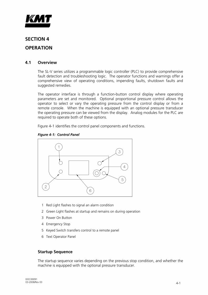
DOC00091 03-2008/Rev 03 4-1
4 SECTION 4
OPERATION
4.1 Overview
The SL-V series utilizes a programmable logic controller (PLC) to provide comprehensive fault detection and troubleshooting logic. The operator functions and warnings offer a comprehensive view of operating conditions, impending faults, shutdown faults and suggested remedies.
The operator interface is through a function-button control display where operating parameters are set and monitored. Optional proportional pressure control allows the operator to select or vary the operating pressure from the control display or from a remote console. When the machine is equipped with an optional pressure transducer the operating pressure can be viewed from the display. Analog modules for the PLC are required to operate both of these options.
Figure 4-1 identifies the control panel components and functions.
Figure 4-1: Control Panel
1 Red Light flashes to signal an alarm condition
2 Green Light flashes at startup and remains on during operation
3 Power On Button
4 Emergency Stop
5 Keyed Switch transfers control to a remote panel
6 Text Operator Panel
Startup Sequence
The startup sequence varies depending on the previous stop condition, and whether the machine is equipped with the optional pressure transducer.

Section 4 Operation
DOC00091 03-2008/Rev 03 4-2
Startup after Motor Stop
After a normal motor stop the safety dump valve will be closed and high pressure will be present in the intensifier. Press the F1 KEY on the Text Operator Panel to start the motor. The machine will be held in low pressure for six strokes, it then goes to high pressure or remains in low pressure, depending on the previous pressure setting on the Text Operator Panel.
If the machine is equipped with a pressure transducer and pressure is not allowed to bleed, the startup sequence is the same as above.
Startup after Emergency Stop
After an emergency stop the safety dump valve will be open and high pressure released in the intensifier. The dump valve will close after six strokes.
Pull the e-stop button out and push the Power On button to activate the control display. Press the F1 KEY on the Text Operator Panel to start the motor. The machine will be held in low pressure for 6 strokes to allow trapped air to bleed from the high pressure cylinders. It then goes to high pressure or remains in low pressure, depending on the previous pressure setting on the Text Operator Panel.

Section 4 Operation
DOC00091 03-2008/Rev 03 4-3
Elements of the PLC (Programmable Logic Controller)
Figure 4-2: PLC
1 = RS232/485-Communication Interface to MI4
3 = RUN LED; operation = continuous light grün, Not ready = flashing green SF-LED; continuous light red = error message 2 = Set button+ Selector switch
Explanation of the Display
MI4 – 110 – KC1
• View window
•
Line 2
info
• Line 3
• Line 4
•
F 1
• F 2
• F 3
• F 4 clear
enter
The four-digit display window is located in the center of the operating panel. It displays actual information and values are entered into it.
Using the Arrow Keys
You can use the arrow keys to control the views and the lines.
• Changing to a Different Line

Section 4 Operation
DOC00091 03-2008/Rev 03 4-4
You can use the vertical and arrow keys to scroll up and down the entries in order to access the next line entries or the previous ones.
• Changing to a Different View
The display has over 14 different views that can be accessed by pressing the horizontal arrow keys or .
• Switching Over to the System Display (View 1)
Press the “Clear” key to return to the system display (View 1).
Info, Clear and Enter Keys
• Info Key
In View 1, pressing the info key calls up the KMT Waterjet Systems contact information such as address, telephone number, fax, Web site address as well as PLC and MI4 versions.
• Clear Key
Go to View 1 (systems display) Reset alarm Cancel entry Open water supply shutoff valve
• Enter Key
Function 1: Activates enter function Function 2: Confirms pre-selected entries
Function Keys F1 to F4
• F1 Key
ON/OFF pump operation
LED ON = Pump in operation (only when Hydraulic oil temperature = >20°C / 68°F)
LED OFF = Pump off
• F2 Key
ON/OFF Pump recirculation
LED ON = Pump recirculation ON
LED OFF = Pump recirculation OFF

Section 4 Operation
DOC00091 03-2008/Rev 03 4-5
Recirculation turns off automatically after 10 minutes or by reaching an oil-temperature = >25°C / 68°F.
By starting Recirculation with an oil-temperature = >25°C / 68°F recirculation program runs the 10 minutes operation time.
LED flashes = oil temperature < 20° / 68°F. Demand starting recirculation.
F3 Key
Low pressure – high pressure
LED ON = high pressure
LED OFF = low pressure
When switched from low pressure to high pressure with an oil temperature less than 25 °C/77 °F, the LED key F3 flashes and the pump remains in low-pressure operation.
When switched from low pressure to high pressure with an oil temperature greater than or equal to 25 °C/77 °F, the pump switches to high-pressure operation. The LED key F3 flashes continuously.
NOTE
If high-pressure operation is preselected, the pump switches to high-pressure operation automatically as soon as the hydraulic oil temperature equals or is greater than
25 °C/77 °F.
• F4 Key
Function 1: Start Password entry

Section 4 Operation
DOC00091 03-2008/Rev 03 4-6
Symbols and LEDs
Table 4-2 Symbols and LEDs
Symbol Name Color Status Function
Alarm red
Off Alarm not active
On Alarm active
Blinking Alarm (confirmation required)
com green On No communication error
Blinking Communication error
– green – Programmable with Macro Editor
run Green
Off Hardware error
On o.k.
– red
Off Hardware o.k.
On Hardware error
Blinking Performance low
Green Off No key pressed
On Key pressed

Section 4 Operation
DOC00091 03-2008/Rev 03 4-7
4.2 System Display (View 1)
This view displays the pump version, the software version for the MI4 display, the operating hours, strokes per minute and Oil-Temperature in °C or °F.
Setting the Temperature Display to °C or °F
To switch between temperature units, press the arrow key.
MI4 – 110 – KC1
• GB SLV 50 C xcV1.0
•
0:00:00 hours
info
• strokes/min. 0
• 0 °C
•
F 1
• F 2
• F 3
• F 4 clear
enter
NOTE
To switch to a different line, press the or arrow keys.

Section 4 Operation
DOC00091 03-2008/Rev 03 4-8
4.3 Display of Operating Hours and Strokes Topwork 1 (View 2)
The production hours and strokes of the pressure intensifier are displayed and reset in this view.
Displaying production hours and strokes for pressure intensifier 1
This function may be performed when the pump is running.
To display the production hours press and hold down the “Info” key for at least 1 second. The symbol “<” will appear for the left and the symbol “>” for the right side of the pressure intensifier. The four pieces of information shown below will be displayed one after the other for 5 seconds.
1. Display of production hours and strokes of pressure intensifier 1
MI4 – 110 – KC1
• productionhours
•
topwork 1
info
• > 0:00:00 hours
• strokes 0
•
F 1
• F 2
• F 3
• F 4 clear
enter
Resetting the Operating Hours and Strokes
To be able to perform the functions in this chapter the pump must not be operating.
Select the the left or right high pressure cylinder and press the “Clear” key for five seconds until the topwork’s operating hours and strokes have been reset to 0:00:00. Releasing the “clear” key automatically returns you to View 1 (systems display).
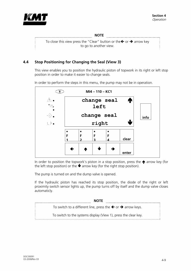
Section 4 Operation
DOC00091 03-2008/Rev 03 4-9
NOTE
To close this view press the “Clear” button or the or arrow key to go to another view.
4.4 Stop Positioning for Changing the Seal (View 3)
This view enables you to position the hydraulic piston of topwork in its right or left stop position in order to make it easier to change seals.
In order to perform the steps in this menu, the pump may not be in operation.
MI4 – 110 – KC1
• change seal
•
left
info
• change seal
• right
•
F 1
• F 2
• F 3
• F 4 clear
enter
In order to position the topwork's piston in a stop position, press the arrow key (for the left stop position) or the arrow key (for the right stop position).
The pump is turned on and the dump valve is opened.
If the hydraulic piston has reached its stop position, the diode of the right or left proximity switch sensor lights up, the pump turns off by itself and the dump valve closes automaticly.
NOTE
To switch to a different line, press the or arrow keys.
To switch to the systems display (View 1), press the clear key.

Section 4 Operation
DOC00091 03-2008/Rev 03 4-10
4.5 Display of Operating Hours and strokes for “Topwork 1”
This number indicates the overall operating hours of topwork 1.
Number of Strokes for “Topwork 1”
The number next to “strokes” indicates how often topwork 2 was operated from one side to the other side.
MI4 – 110 – KC1
• topwork 1
•
0:00:00 hours
info
c• strokes 0
•
•
F 1
• F 2
• F 3
• F 4 clear
enter
NOTE
To switch to a different line, press the or arrow keys.

Section 4 Operation
DOC00091 03-2008/Rev 03 4-11
4.6 Print Setting with (optional) Proportional Valve (View 5)
This view enables you to set the maximum and minimum pressure (rest pressure). Pressure can be defined in either bar or psi. The maximum adjustable pressure appears in line 5 of the view which becomes visible by pressing the arrow key.
NOTE
If, in the lines for “max. bar” and “max. psi” or “min. bar” and “min. psi,” values for both pressure units are simultaneously entered, all values are automatically reset to “0”
because the controller is then not able to recognize which entries should be valid.
MI4 – 110 – KC1
• pressure 0bar
•
pressure 0bar
info
• pressure 0psi • pressure 0psi
•
F 1
• F 2
• F 3
• F 4 clear
enter
If the maximum value for “bar” or “psi” listed in line 5 is either exceeded or not reached when entering the max. or min. pressure, the following key values are automatically entered:
• For the max. “bar,” the value is taken from line 5 and for the “min.,” the value “800” (bar) is used.
• For the max. “psi,” the value is taken from line 5 and for the “min.,” the value “12000” (psi) is used.
Should the topwork be equipped with a pressure recorder (optional), the recorder provides the current actual value of the impending high pressure within a closed loop control system. The selected maximum pressure is then readjusted with an accuracy of approx. ±10 bar in which case the resting pressure displayed in line 5 is not exceeded.
By pressing the or arrow keys, the separate lines can be selected.

Section 4 Operation
DOC00091 03-2008/Rev 03 4-12
Before entering data, type in your password
Press the “F4” button. PASSWORD: _ appears on the display.
Press the arrow key 4 times. PASSWORD: 0 appears on the display.
Press the “Enter” key.
MI4 – 110 – KC1
• 3585bar 52000psi
•
proportional valve 0
info
• bar = psi : 14.5038
• psi = bar x 14,5038
•
F 1
• F 2
• F 3
• F 4 clear
enter
NOTE
If no proportional valve has not been fitted in the pump then there should be a “0” in line 6. Otherwise, the low pressure-high pressure switch will no longer
function.
If a proportional valve has been fitted then line 6 should read “Proprtional valve 1” for the low pressure-high pressure change-over to function.
Entering Your Password
1. Press the “F4” button. PASSWORD: _ appears on the display.
2. Press the arrow key 4 times. PASSWORD: 0 appears on the display.
3. Press the “Enter” key.
NOTE
If it takes longer than five minutes after entering your password to press the keys, the password is deactivated.

Section 4 Operation
DOC00091 03-2008/Rev 03 4-13
Pressure Settings
1. Press the “Enter” key. Pressure 0bar appears on the display.
NOTE
By pressing the or arrow keys, the separate lines can be selected.
2. Press the “Enter” key once to confirm the selected line.
3. To enter the first digit, press the or arrow keys down until the desired value appears.
4. To preselect the decade, press the arrow key. To select the desired number, press the or arrow keys until the desired value appears.
5. Proceed with setting the rest of the digits according to point 4.
6. Press the “Enter” key once in order to confirm the data entered.
NOTE
To switch to a different line, press the or arrow keys.
To switch to the systems display (View 1), press the clear key.
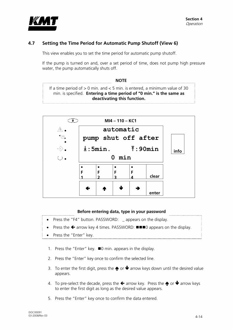
Section 4 Operation
DOC00091 03-2008/Rev 03 4-14
4.7 Setting the Time Period for Automatic Pump Shutoff (View 6)
This view enables you to set the time period for automatic pump shutoff.
If the pump is turned on and, over a set period of time, does not pump high pressure water, the pump automatically shuts off.
NOTE
If a time period of > 0 min. and < 5 min. is entered, a minimum value of 30 min. is specified. Entering a time period of “0 min.” is the same as
deactivating this function.
MI4 – 110 – KC1
• automatic
•
pump shut off after
info
• :5min. :90min • 0 min
• F 1
• F 2
• F 3
• F 4 clear
enter
Before entering data, type in your password
• Press the “F4” button. PASSWORD: _ appears on the display.
• Press the arrow key 4 times. PASSWORD: 0 appears on the display.
• Press the “Enter” key.
1. Press the “Enter” key. 0 min. appears in the display.
2. Press the “Enter” key once to confirm the selected line.
3. To enter the first digit, press the or arrow keys down until the desired value appears.
4. To pre-select the decade, press the arrow key. Press the or arrow keys to enter the first digit as long as the desired value appears.
5. Press the “Enter” key once to confirm the data entered.

Section 4 Operation
DOC00091 03-2008/Rev 03 4-15
4.8 Display for “Right Strokes/Left Strokes in Milliseconds” (View 7)
This view indicates the times that topwork 1’s hydraulic piston requires in order to go from the left to the right stop position or from the right to the left stop position. The times are displayed in milliseconds.
MI4 – 110 – KC1
• strokes in msec
•
topwork 1
info
• 0 0 •
•
F 1
• F 2
• F 3
• F 4 clear
enter
NOTE
To switch to a different line, press the or arrow keys.
To switch to the systems display (View 1), press the clear key.
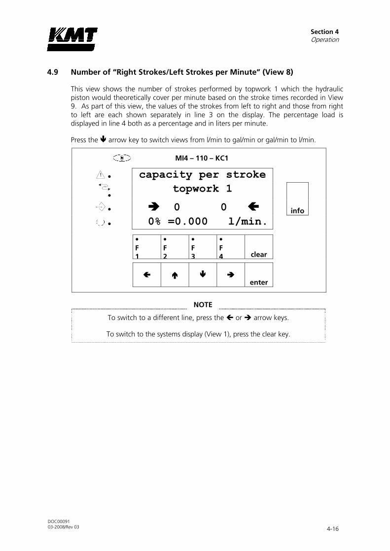
Section 4 Operation
DOC00091 03-2008/Rev 03 4-16
4.9 Number of “Right Strokes/Left Strokes per Minute” (View 8)
This view shows the number of strokes performed by topwork 1 which the hydraulic piston would theoretically cover per minute based on the stroke times recorded in View 9. As part of this view, the values of the strokes from left to right and those from right to left are each shown separately in line 3 on the display. The percentage load is displayed in line 4 both as a percentage and in liters per minute.
Press the arrow key to switch views from l/min to gal/min or gal/min to l/min.
MI4 – 110 – KC1
• capacity per stroke
•
topwork 1
info
• 0 0 • 0% =0.000 l/min.
• F 1
• F 2
• F 3
• F 4 clear
enter
NOTE
To switch to a different line, press the or arrow keys.
To switch to the systems display (View 1), press the clear key.

Section 4 Operation
DOC00091 03-2008/Rev 03 4-17
4.10 Number of “Overall Strokes per Minute” (View 9)
This view indicates the number of strokes from topwork 1 that the hydraulic piston actually performs per minute based on the number of direction changes.
MI4 – 110 – KC1
• strokes per min
•
topwork 1
info
• 0
•
•
F 1
• F 2
• F 3
• F 4 clear
enter
NOTE
To switch to a different line, press the or arrow keys.
To switch to the systems display (View 1), press the clear key.

Section 4 Operation
DOC00091 03-2008/Rev 03 4-18
4.11 Capacity in Percent (View 10)
This view displays the percentage capacity of topwork 1 in % and l/min. or % and gal.(US)/min. and it also enables you to adjust these settings.
The display shows the following information:
1. The third line displays the current capacity in % and l/min. or % and gal.(US)/min. The display is updated in 60 second intervals.
2. The upper capacity limit is defined in the fourth line.
Assessing the capacity:
If, for example, an upper limit of 80% is defined, an alarm is generally issued if capacity falls 5 percent points below this value (=75%).
If the upper limit of 80% is achieved or exceeded, the pump turns off as soon as it has reached or exceeded this upper limit 10 times during current operation.
NOTE
The upper limit can be set between 10% and 120%. If a value of <10% is entered, a default value of 120% is assigned.
Example:
SL-V 50HP = 100% = 54 strokes/min. = 1111 ms pro stroke = 3.7093 l/min. = 0.98 gal.(US)/min.
Shut-off due to overstroke set to 80%: 80% = 43.2 strokes/min. = 1389 ms per stroke = 2.9674 l/min. = 0.7863 gal.(US)/min.
Alarm: 75% = 40.5 strokes/min. = 1302 ms per stroke = 2.78154 l/min. = 0.7320 gal. (US)/min.
Shut-off due to overstroke: If the time per stroke is lesser than (or equal to) 1389ms or 80%, the pump is shut off as soon as this time has been achieved or gone below for the tenth time after turning on the pump. When turning on the pump again, the internal counter automatically resets the value to zero.

Section 4 Operation
DOC00091 03-2008/Rev 03 4-19
MI4 – 110 – KC1
• capacity
•
topwork 1
info
• 0% = 0.000 l/min
• 120% = 4.451 l/min
•
F 1
• F 2
• F 3
• F 4 clear
enter
Setting the Capacity in Percent for Topwork 1
Before entering data, type in your password
• Press the “F4” button. PASSWORD: _ appears on the display.
• Press the arrow key 4 times. PASSWORD: 0 appears on the display.
• Press the “Enter” key.
1. Press the “Enter” key. 0% appears on the display.
2. Press the “Enter” key once to confirm the selected line.
3. To enter the first digit, press the or arrow keys down until the desired value appears.
4. To pre-select the tenth digit, press the arrow key. To select the desired number, press the or arrow keys down until the desired value appears.
5. Proceed with setting the rest of the digits according to point 4.
6. Press the “Enter” key to confirm the data entered.

Section 4 Operation
DOC00091 03-2008/Rev 03 4-20
Setting the Volume Display in l/min or gal/min
To switch the display from l/min to gal/min or gal/min to l/min, press the arrow key.
NOTE
To switch to a different line, press the or arrow keys.
To switch to the systems display (View 1), press the clear key.
4.12 Display of Voltage on the Proportional Valve, Optional (View 11)
This view displays the current setpoint of the control voltage (0 – 10 V) for the proportional valve.
MI4 – 110 – KC1
• voltage on the
•
proportional valve
info
•
• 0.000 V
•
F 1
• F 2
• F 3
• F 4 clear
enter
NOTE
To switch to a different line, press the or arrow keys.
To switch to the systems display (View 1), press the clear key.
4.13 Parametering for Options (View 12)
In this view, the following parameterizations can be displayed and adjusted:
• the setpoint value
• Resetting installed Oil-air-radiator

Section 4 Operation
DOC00091 03-2008/Rev 03 4-21
Before entering data, type in your password
• Press the “F4” button. PASSWORD: _ appears on the display.
• Press the arrow key 4 times. PASSWORD: 0 appears on the display.
• Press the “Enter” key.
1. Press the or arrow key down until the “Setpoint value” is displayed.
MI4 – 110 – KC1
• setpoint value 0
•
0 = from local
info
• or from remote
• 1 = always local
•
F 1
• F 2
• F 3
• F 4 clear
enter
2. Press the “Enter” key. Setpoint value appears on the display.
3. Press the “Enter” key once to confirm the selected line.
4. To enter the first digit, press the or arrow keys down until the desired value appears.
5. Press the “Enter” key once to confirm the data entered.
Resetting the Parameter for installed oil-air-radiator
The “oil-air-radiator installed” window enables to reset the availability of an oil-air-radiator.
Before entering data, type in your password
• Press the “F4” button. PASSWORD: _ appears on the display.
• Press the arrow key 4 times. PASSWORD: 0 appears on the display.
• Press the “Enter” key.

Section 4 Operation
DOC00091 03-2008/Rev 03 4-22
1. Press the or arrow key down until the “oil-air-radiator installed” is displayed.
MI4 – 110 – KC1
• oil-air-radiator
•
installed
info
• reset 0
• --------------------
•
F 1
• F 2
• F 3
• F 4 clear
enter
2. Press the “Enter” key “reset 0”appears on the display.
3. Press the “Enter” key once to confirm the selected line.
4. To enter the first digit, press the or arrow keys down until the desired value appears.
5. Press the “Enter” key once to confirm the data entered.
6. As soon the value “reset 0” appears again, the availability of the oil-air-radiator is reset.

Section 4 Operation
DOC00091 03-2008/Rev 03 4-23
4.14 Setting Language, Date and Time (View 13)
This view window enables you to set the language, date and time.
MI4 – 110 – KC1
• 01-01-08
•
English
info
• 12:00:00
•
•
F 1
• F 2
• F 3
• F 4 clear
enter
Setting the Language
1. Press the or arrow keys to set the language.

Section 4 Operation
DOC00091 03-2008/Rev 03 4-24
Entering Date and Time
Before entering data, type in your password
• Press the “F4” button. PASSWORD: _ appears on the display.
• Press the arrow key 4 times. PASSWORD: 0 appears on the display.
• Press the “Enter” key.
1. Press and hold down the “Enter” key again until you are able to see the below illustrated entry in the display.
MI4 – 110 – KC1
• PGS ALM EVT PSW CFG
•
TIM ACC SYS EXT
info
•
•
•
F 1
• F 2
• F 3
• F 4 clear
enter
2. Press the arrow key twice until you get to “TIM.”
3. Press the “Enter” key. The following appears on the display, for example:
MI4 – 110 – KC1
• DATE 19-07-04
•
TIME 10:42:53
info
•
•
•
F 1
• F 2
• F 3
• F 4 clear
enter

Section 4 Operation
DOC00091 03-2008/Rev 03 4-25
NOTE
If the date 0-01-95 appears in the display, wait approx. 1.5 minutes until the display has automatically switched to a different date.
If “97” appears after the automatic switch, you first have to change the year.
1. Press the “Enter” key twice.
2. Press the key until the desired year appears. Make sure that the year that appears does not jump back. (Jumps back every 20 seconds)
3. Press the “Clear” key once to confirm the data entered.
4. Repeat steps 4, 5 and 6.
5. To enter the day (19), press the or arrow keys.
6. Press the “Enter” key once to confirm the data entered.
7. To enter the month (07), press the or arrow keys.
8. Press the “Enter” key once to confirm the data entered.
9. To enter the year (04), press the or arrow keys.
10. Press the “Enter” key once to confirm the data entered.
11. To enter the hour (10), press the or arrow keys.
12. Press the “Enter” key once to confirm the data entered.
13. To enter the minute (42), press the or arrow keys.
14. Press the “clear” key once to confirm all of the data entered.
NOTE
The seconds may not be changed because otherwise synchronization between the display and the PLC does not take place.
NOTE
To switch to a different line, press the or arrow keys.
To switch to the systems display (View 1), press the clear key.

Section 4 Operation
DOC00091 03-2008/Rev 03 4-26
4.15 Brightness Setting in the Text Display (View 14)
This view window enables you to adjust the brightness of the text display.
MI4 – 110 – KC1
• Brighter
•
<- Display ->
info
• Darker •
•
F 1
• F 2
• F 3
• F 4 clear
enter
1. Press the or arrow keys to adjust the brightness.
NOTE
To switch to a different line, press the or arrow keys.
To switch to the systems display (View 1), press the clear key.
4.16 Fault Report
In case of fault reports please follow the instruction on the screen.
If a fault is active you can quit the fault message text and go to View 1 (Operating display) by pressing the “Clear” button. The fault itself will remain active. The fault message will appear again if you press the “Info” button in any view or after three minutes have elapsed.
For technical help the customer service is available to customers.
Europa: Head of Engineering KMT GmbH • KMT Waterjet Systems Auf der Laukert 11 D-61231 Bad Nauheim
Tel.: +49-6032-997-117 Fax: +49-6032-997-270 E-Mail: [email protected]

DOC00091 03-2008/Rev 03 5-1
5 SECTION 5
LOW PRESSURE WATER SYSTEM
5.1 Overview
The low pressure water system, cutting water supply circuit, supplies the intensifier with the required cutting water flow and pressure. System components include the inlet water solenoid valve, strainer, low pressure filter assembly and the booster pump. Pressure and temperature switches, connected to the PLC, monitor out of tolerance conditions in the cutting water circuit and provide automatic shutdown protection.
Figure 5-1: Cutting Water Supply Circuit
1 Sealing Heads 7 Check Valve 12 Cutting Water Supply Gauge
2 Air Bleed Valve 8 Orifice 13 Inlet Water Solenoid Valve
3 Filter Assembly 9 Relief Valve 14 Strainer
4 Temperature Switch 10 Booster Pump 15 Cutting Water In
5 30 psi (2 bar) Pressure Switch 11 Booster Pressure Gauge 16 Drain
6 60 psi (4 bar) Pressure Switch
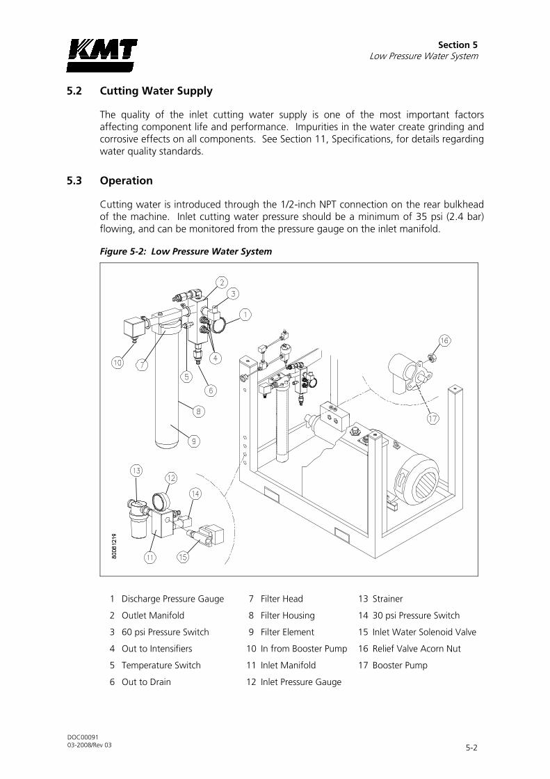
Section 5 Low Pressure Water System
DOC00091 03-2008/Rev 03 5-2
5.2 Cutting Water Supply
The quality of the inlet cutting water supply is one of the most important factors affecting component life and performance. Impurities in the water create grinding and corrosive effects on all components. See Section 11, Specifications, for details regarding water quality standards.
5.3 Operation
Cutting water is introduced through the 1/2-inch NPT connection on the rear bulkhead of the machine. Inlet cutting water pressure should be a minimum of 35 psi (2.4 bar) flowing, and can be monitored from the pressure gauge on the inlet manifold.
Figure 5-2: Low Pressure Water System
1 Discharge Pressure Gauge 7 Filter Head 13 Strainer
2 Outlet Manifold 8 Filter Housing 14 30 psi Pressure Switch
3 60 psi Pressure Switch 9 Filter Element 15 Inlet Water Solenoid Valve
4 Out to Intensifiers 10 In from Booster Pump 16 Relief Valve Acorn Nut
5 Temperature Switch 11 Inlet Manifold 17 Booster Pump
6 Out to Drain 12 Inlet Pressure Gauge

Section 5 Low Pressure Water System
DOC00091 03-2008/Rev 03 5-3
Cutting water enters through the normally closed, inlet water solenoid valve. When the control power is turned on, the solenoid valve opens and allows water to flow through the valve. The inlet water is monitored by a 30 psi pressure switch mounted on the inlet manifold. If the pressure drops below 30 psi (2 bar) the switch activates an automatic shutdown circuit in the PLC and the machine will not start.
NOTE
The machine will not start if inlet cutting water pressure is below 30 psi (2 bar).
If a shutdown occurs due to an overstrike condition, the inlet solenoid valve automatically closes to prevent water waste due to an external leak. Additionally, the valve automatically closes after five minutes of inactivity when the water reset function is enabled at the control panel.
Cutting water then passes through a strainer to remove debris before the water enters the booster pump. The booster pump increases the pressure to 120 psi (8 bar) to ensure proper supply to the intensifier assembly.
Pressurized water passes through the filter assembly where debris is removed to prevent contaminates from damaging the check valves and seals in the intensifier. The filter assembly consists of a filter head, housing and a 10 micron absolute filter. A bleed valve on the top of the filter head is used to release air inside the housing.
As the water enters the outlet manifold, the discharge pressure is monitored by a 60 psi pressure switch. An automatic shutdown will occur if the pressure is below 60 psi (4 bar).
If the discharge pressure exceeds 125 psi (8.6 bar) a relief valve opens allowing water to exit through the 1/2-inch drain connection on the rear bulkhead. It is still possible to operate the machine; however, excess water will continue to be released through the drain.
Discharge pressure is displayed on the pressure gauge mounted on the outlet manifold. The gauge should read approximately 120 psi (8 bar) while the machine is idling. When it strokes, the pressure drop should be no greater than 30 psi (2 bar). The water pressure range should remain between 90-120 psi (6-8 bar) during operation.
NOTE
While the intensifier assembly reverses direction, the boosted pressure will fluctuate slightly above and below the normal setting.
A relief valve built into the filter assembly prevents excessive discharge pressure and typically operates when the machine is in a deadhead condition. The booster pump is factory set to deliver 120 psi (8 bar) with an inlet pressure of 58 psi (4 bar). The pump may require adjustment to satisfy system requirements.
A temperature switch, mounted on the outlet manifold, monitors the discharge temperature. If the temperature exceeds 128° F (53° C), the switch activates an automatic shutdown circuit in the PLC that stops the main motor. The temperature switch prevents booster pump overheating due to lack of water or long deadhead

Section 5 Low Pressure Water System
DOC00091 03-2008/Rev 03 5-4
conditions. To reduce overheating during a deadhead condition, water is re-circulated through the orifice and check valve, and routed back through the strainer to the booster pump inlet.
From the manifold, cutting water is routed to the sealing head inlet check valves on each end of the intensifier.
5.4 Service and Maintenance Procedures
To ensure water quality and supply to the high pressure system, the filter element, strainer and booster pump will require routine servicing and maintenance. The procedures for servicing these components are detailed below.
NOTE
Refer to Section 12, Parts List for a complete listing of replacement parts and part numbers.
Filter Assembly and Strainer Maintenance
The life of the filter element is directly related to the quality of the inlet water. The condition of the filter element can be monitored by observing the pressure gauge on the inlet manifold. Document the pressure reading when the filter element is new. The element should be replaced when the pressure drops to 15 psi (1 bar) below the original value. When the filter element is replaced, the strainer should also be cleaned.
The following procedure is used to replace the filter element and clean the strainer.
Figure 5-3: Filter Element
1 Filter Head
2 Filter Element
3 Housing

Section 5 Low Pressure Water System
DOC00091 03-2008/Rev 03 5-5
1. Turn the cutting water supply off.
2. Press the red bleed valve on the filter head to release any pressure trapped inside the housing.
3. Use a filter wrench to unscrew the housing and remove the old element.
4. Install the new element and use the filter wrench to replace the housing.
Figure 5-4: Strainer
1 Strainer Head
2 Strainer Body
5. Unscrew and remove the strainer body. Remove and clean the mesh liner.
6. Ensure the gasket is properly positioned in the body, install the liner and screw the strainer body into the strainer head, hand tighten.
7. Turn the cutting water supply on.
8. Press the red bleed valve to remove any air inside the housing.
9. Start the machine and verify satisfactory pressure readings.

Section 5 Low Pressure Water System
DOC00091 03-2008/Rev 03 5-6
Booster Pump Adjustment
If the discharge pressure from the booster pump stays below 90 psi (6 bar), the relief valve on the booster pump should be adjusted.
Figure 5-5: Booster Pump
1 Acorn Nut
1. Turn the cutting water supply on.
2. Start the machine and initiate normal, shifting operation.
3. Observe the discharge pressure from the booster pump. If the pressure stays below 90 psi (6 bar), continue with Step 4.
4. Stop the intensifier and remove the acorn nut on the side of the pump to access the adjustment screw.
5. Use a flat screwdriver and turn the adjustment screw clockwise to increase the discharge pressure or counter-clockwise to decrease the pressure.
CAUTION
If the adjustment screw is turned too far out (counter-clockwise) an internal spring and relief will fall down inside the pump. If this occurs, the pump must be removed
and the parts must be reinstalled to avoid component damage.
6. Replace the acorn nut, resume normal operation and observe the booster discharge pressure. Peak pressure should be in the range of 90 to 120 psi (6 to 8 bar). If it is not, repeat the adjustment procedure.

DOC00091 03-2008/Rev 03 6-1
6 SECTION 6
RECIRCULATION SYSTEM
6.1 Overview
The oil recirculation circuit is a cooling and filtration system that provides properly conditioned oil to the main hydraulic system. Hydraulic oil is maintained at the proper operating temperature and condition by continuous recirculation.
System components include the recirculation pump, heat exchanger, oil filter assembly and the hydraulic oil reservoir. A temperature/low level switch, connected to the PLC, monitors temperature and oil level conditions in the hydraulic oil reservoir and provides automatic shutdown protection.
Figure 6-1: Oil Recirculation Circuit with Air-to-Oil Heat Exchanger
1 Pressure Gauge 5 Bypass Relief Valve
2 Heat Exchanger 6 Hydraulic Oil In
3 Recirculation Pump 7 Hydraulic Oil Out
4 Oil Filter Assembly 8 Hydraulic Oil Reservoir

Section 6 Recirculation System
DOC00091 03-2008/Rev 03 6-2
Figure 6-2: Oil Recirculation Circuit with Oil-to-Water Heat Exchanger
1 Pressure Gauge 6 Water Out to Drain
2 Heat Exchanger 7 Cooling Water In
3 Recirculation Pump 8 Water Modulating Valve
4 Oil Filter Assembly 9 Hydraulic Oil Reservoir
5 Bypass Relief Valve
6.2 Operation
The standard SL-V Classic is equipped with either an oil-to-water heat exchanger, or an external air-to-oil heat exchanger. Bulkhead connections are configured for inlet and outlet cooling water, or for hydraulic oil in and out.
Oil-to-Water Heat Exchanger
Cooling water is introduced through the 1/2-inch NPT connection on the rear bulkhead of the machine where the water modulating valve regulates the cooling flow to the heat exchanger. The valve is factory set, but may require adjustment to maintain the operating oil temperature at 115° F (46° C). Oil temperature can be visually monitored from a dual scale level/temperature sight gauge on the side of the hydraulic oil reservoir.

Section 6 Recirculation System
DOC00091 03-2008/Rev 03 6-3
Figure 6-2: Recirculation System Components
1 Temperature/Low Level Switch 7 Case Drain
2 Hydraulic Oil Reservoir 8 Pressure Gauge
3 Recirculation Pump 9 Filter Head
4 Air Breather 10 Oil Fill Port
5 Level/Temperature Sight Gauge 11 Filter Element
6 Oil-to-Water Heat Exchanger 12 Water Modulating Valve
The recirculation pump pulls oil from the reservoir and sends it to the heat exchanger. The oil-to-water heat exchanger controls heat build-up in the hydraulic oil. The plate style design allows cooling water and oil to flow side by side through alternating plates.
The cooled oil then passes through the filter element and returns to the reservoir. The cooling water either is discharged to the 1/2-inch NPT drain on the rear bulkhead or is routed to a customer supplied water chiller.
The hydraulic oil filter assembly consists of the filter head, a filter element, pressure gauge, bypass relief valve and the oil fill port. The filter element should be changed when the gauge reads 30 psi (2.1 bar) at normal operating temperature.
If the element is not replaced, and fills with debris, the bypass relief in the filter head will open to prevent over pressurization. The relief valve opens at 50 psi (3.4 bar). When the valve opens, the oil bypasses the filter and unfiltered oil is allowed to return to the reservoir.
The temperature/low level switch monitors the oil temperature and level in the reservoir. An automatic shutdown will occur if the operating oil temperature exceeds 144° F (62° C). An automatic shutdown will also occur if the oil level falls below 21 gal (80 L).

Section 6 Recirculation System
DOC00091 03-2008/Rev 03 6-4
NOTE
To conserve water usage it is recommended that the cooling water be shut off at the end of the day. A sensor bulb from the modulating valve is submerged in the
reservoir. Even when the control power is off, the valve will remain open, allowing water to flow until the oil is cooled.
Air-to-Oil Heat Exchanger
The recirculation pump pulls oil from the reservoir and sends it to the external air-to-oil heat exchanger. Oil exits through the 3/4-inch NPTF connection on the rear bulkhead.
The cooled oil returns through the 3/4-inch inlet connection, passes through the filter element and returns to the reservoir.
Figure 6-3: Oil-to-Air Operation
1 Temperature/Low Level Switch 7 Pressure Gauge
2 Hydraulic Oil Reservoir 8 Filter Head
3 Recirculation Pump 9 Oil Fill Port
4 Air Breather 10 Filter Element
5 Level/Temperature Sight Gauge 11 Out to Heat Exchanger
6 Case Drain 12 In from Heat Exchanger
6.3 Service and Maintenance Procedures
To ensure the supply of properly conditioned oil to the main hydraulic system, the components will require routine servicing and maintenance. The procedures for servicing these components are detailed below.

Section 6 Recirculation System
DOC00091 03-2008/Rev 03 6-5
NOTE
Refer to Section 12, Parts List for a complete listing of replacement parts and part numbers.
Hydraulic Oil Maintenance
The hydraulic oil should be replaced after 3,000 hours or one year of service, whichever comes first. The oil should be replaced sooner if a fluid sample indicates contamination that cannot be rectified by filtering.
An air breather and filter is located on the top of the reservoir. The air breather prevents dirt from being sucked into the reservoir when the oil level drops, and allows air to escape when the level rises. The air breather must not be used as a fill point. Oil must only be added at the fill port on the filter head and removed at the drain valve.
CAUTION
Do not attempt to fill the reservoir from the air breather. The oil will not be filtered and will not conform to the cleanliness requirements of the system.
Figure 6-3: Hydraulic Reservoir
1 Breather
2 Oil Fill Port
3 Drain Valve

Section 6 Recirculation System
DOC00091 03-2008/Rev 03 6-6
WARNING
Severe injury can result if the machine is not properly locked out. Observe electrical Lock Out/Tag Out procedures before performing maintenance.
Ensure all pressure is relieved or blocked from the hydraulic and high pressure circuits before performing maintenance.
1. Drain the oil reservoir by connecting the inlet hose from an oil transfer pump to the drain valve on the reservoir.
2. Open the shut off valve on the drain and pump the used oil out to a container.
3. Close the shut off valve and remove the inlet hose from the drain valve.
NOTE
Typically, oil from a new drum does not meet the cleanliness requirements of the hydraulic system. For this reason, it is important to use the oil transfer pump that will
force oil through the return filter into the reservoir.
4. Remove the cap from the fill port on the oil filter.
5. Connect the discharge hose from the oil transfer pump to the fill port and pump the fresh oil into the reservoir.
CAUTION
To ensure cleanliness, the oil fill port must be used to pump oil into the reservoir. Filling at this point guarantees the hydraulic oil will pass through the oil filter before
entering the reservoir.
6. Check the oil sight gauge on the reservoir to ensure proper fill level.
7. Remove the hose from the case drain on the main hydraulic pump to make sure the pump case fills with oil. With the hose removed, head pressure from the reservoir will force oil into the pump case.
CAUTION
Oil in the pump case provides internal lubrication for the main hydraulic pump. Failure to the fill the pump case with oil will allow air to become trapped inside,
damaging the pump.
8. Disconnect the discharge hose from the fill port and replace the fill port cap.

Section 6 Recirculation System
DOC00091 03-2008/Rev 03 6-7
9. Follow the initial startup sequence in Section 4, Operation, to ensure the system is filled with oil.
10. Check the sight gauge again and follow the same procedure to add additional oil if necessary.
Oil Filter Maintenance
If the filter element is not properly serviced and is allowed to fill with debris, the oil will be forced through the relief valve, bypassing the filter. The bypass relief valve opens at 50 psi (3.4 bar).
The filter element must be replaced when the pressure gauge reading is 30 psi (2.1 bar) or greater during normal operating conditions. Normal operating conditions indicate the machine is running and the oil temperature has reached 115° F (46° C).
Figure 6-4: Oil Filter Assembly
1 Filter Head
2 Filter Element
3 Pressure Gauge
1. Use a filter wrench to unscrew the filter element from the filter head.
2. Lubricate the gasket on the new element with fresh oil.
3. Use the filter wrench to screw the new element onto the filter head.
4. Start the machine and check for leaks.
Operating Temperature Adjustment
If the machine is equipped with an oil-to-water heat exchanger, the cooling water flow to the heat exchanger is regulated by the water modulating valve, a manually adjusted, thermostatic control valve. The valve is factory set to maintain the operating oil temperature at 115° F (46° C). It is adjusted by increasing or decreasing the spring tension on the valve.

Section 6 Recirculation System
DOC00091 03-2008/Rev 03 6-8
Figure 6-5: Water Modulating Valve
1. Locate the adjusting knob, a screwdriver slot on the top of the valve.
2. Use a flat screwdriver and turn counter-clockwise to compress the spring, slowing water flow and increasing temperature. Or; turn clockwise to reduce spring tension, increasing water flow and decreasing the temperature.
3. Monitor the sight gauge on the side of the reservoir until the adjusted temperature can be determined. It will take some time for the temperature in the oil reservoir to change.
4. Repeat steps 2 and 3 if necessary.

DOC00091 03-2008/Rev 03 7-1
7 SECTION 7
HYDRAULIC SYSTEM
7.1 Overview
The main hydraulic power circuit supplies the intensifier assembly with the hydraulic oil required to produce high pressure water. High pressure cutting water is generated from the oil pressure in the hydraulic cylinder.
System components include the electric motor, hydraulic pump, 4-way directional control valve and the hydraulic manifold. The manifold houses the high and low pressure control valves, hydraulic gauge, solenoid valve and the main system relief valve. The system relief valve monitors hydraulic oil pressure and provides system protection by limiting excess pressure.
Figure 7-1: Main Hydraulic Power Circuit
1 Intensifier 6 Electric Motor
2 Directional Control Valve 7 Hydraulic Gauge
3 High Pressure Control Valve 8 Hydraulic Manifold
4 Low Pressure Control Valve 9 Main Relief Valve
5 Solenoid Valve 10 Hydraulic Pump

Section 7 Hydraulic System
DOC00091 03-2008/Rev 03 7-2
7.2 Optional System Components
Optional proportional pressure control enhances the standard high and low pressure selection by allowing the operator to select or vary the hydraulic operating pressure from the control panel or from a remote console. From the control panel the high pressure can be set as a percentage, from 0% to 100%. An electronically controlled hydraulic cartridge valve receives a signal from the PLC and automatically makes the operator selected adjustments.
As proportional pressure controls hydraulic oil pressure, it also determines cutting water pressure based on the intensification ratio.
7.3 Operation
The electric motor drives three pumps mounted in tandem; the main hydraulic pump, the recirculation pump and the booster pump. The motor drives the variable displacement, pressure compensated hydraulic pump by means of a flexible coupling.
Hydraulic fluid from the reservoir is drawn into the inlet, low pressure side of the hydraulic pump. Oil delivered to the pump should be maintained at 110-115° F (43-46° C). Hydraulic fluid then enters the bottom of the manifold through an internal anti-rotation check valve. After a shutdown, the anti-rotation check valve prevents the pump from running backwards.
Figure 7-2: Hydraulic System Components
1 Electric Motor 7 Main System Relief Valve
2 Hydraulic Pump 8 Directional Control Valve
3 Case Drain 9 Low Pressure Control Valve
4 High/Low Limit Compensators 10 High Pressure Control Valve
5 Hydraulic Manifold 11 2-Way Solenoid Valve
6 Hydraulic Reference Gauge

Section 7 Hydraulic System
DOC00091 03-2008/Rev 03 7-3
The main system relief valve provides system protection by monitoring the oil pressure entering the manifold. If the hydraulic pressure exceeds 2,973 psi (205 bar), the valve opens to limit the pressure. The valve is factory calibrated and is not serviceable. A drain line from the valve prevents oil from collecting behind the relief valve to ensure a constant pressure under all operating conditions.
The hydraulic system operates at high or low pressure settings up to the maximum flow capacity of the hydraulic pump. The high and low limit compensators mounted on the pump regulate the flow of hydraulic fluid to maintain constant operating pressures. Operating pressures are set and adjusted at the high and low pressure control valves on the manifold.
If the machine is equipped with proportional pressure control, low pressure is adjusted at the manifold, and the high pressure setting is made from the control panel or a remote console.
CAUTION
The high and low limit compensators regulate the flow of hydraulic fluid to the system by controlling the angle of the swashplate. If the oil is not properly
maintained, the compensators can become blocked with debris. As a result, pump control will be lost and you will not be able to create hydraulic oil pressure.
The normally closed, two pressure solenoid valve is controlled by the operator’s selection of high or low pressure. The valve is closed while operating in high pressure and is open during low pressure operation. A light on the solenoid indicates low pressure operation.
At startup, hydraulic pressure is automatically switched to low, limiting torque demand. After 20 seconds, hydraulic pressure automatically returns to the previously selected pressure setting.
A reference gauge on the top of the manifold displays hydraulic pressure to the intensifiers. When the intensifier shifts, it is normal for the pressure to quickly fall and then rise again.
The 4-way directional control valve directs pressurized oil to one end of the hydraulic cylinder and returns fluid to the reservoir from the opposite end, causing the intensifier to stroke. The movement is controlled hydraulically by a pilot valve that is electronically operated by two solenoids, energized by the PLC. Indicators light up as each solenoid is energized.
The directional control valve sends flow to the hydraulic cylinder in one direction until the hydraulic piston activates the proximity switch at the end of the stroke. The activated switch sends a signal to the PLC to reverse the direction of flow. The piston then moves in the opposite direction until it activates the proximity switch at the opposite end of the stroke.

Section 7 Hydraulic System
DOC00091 03-2008/Rev 03 7-4
7.4 Service and Maintenance Procedures
The extreme duty cycles demanded of the hydraulic system make routine inspection and maintenance acutely important. Leaks must be detected and remedied as soon as possible.
The operating pressure settings must be checked daily, and the electric motor must be inspected at regular intervals. It is also possible for the flexible coupling to fail and require replacement. The procedures for servicing these components are detailed below.
NOTE
Refer to Section 12, Parts List for a complete listing of replacement parts and part numbers.
Hydraulic Operating Pressure
Hydraulic operating pressure settings should be checked daily and adjusted as necessary. High and low operating pressure on standard machines is adjusted at the high and low pressure control valves per the specifications in Table 7-1.
For machines equipped with proportional pressure control, high pressure adjustments are made from the control panel. If equipped with proportional pressure, the following specifications and the low pressure adjustment procedure are used to make low pressure adjustments.
NOTE
The F3 key on the control panel must be set to high pressure to enable the PROPORTIONAL PRESSURE control.
Table 7-1 Hydraulic Operating Pressure Limits
Adjustment Pressure Limits
Increase Decrease Minimum Maximum
High Pressure Clockwise Counter-clockwise
290 psi (20 bar) 2,567 psi (205 bar)
Low Pressure Clockwise Counter-clockwise
290 psi (20 bar) 1,500 psi (103 bar)

Section 7 Hydraulic System
DOC00091 03-2008/Rev 03 7-5
Figure 7-3: High Pressure Control Valve
1 High Pressure Control Valve
1. Check the operating pressure to determine if adjustment is necessary.
2. If high pressure adjustment is required, loosen the locking thumbscrew on the high pressure control valve by turning counter-clockwise.
3. Turn the knob on the control valve clockwise to increase operating pressure, or turn the knob counter-clockwise to decrease pressure.
4. Tighten the locking nut and verify the high pressure setting.
Figure 7-4: Low Pressure Control Valve
1 Low Pressure Control Valve
1. Check the operating pressure to determine if adjustment is necessary.
2. If low pressure adjustment is required, loosen the locking nut on the low pressure control valve by turning counter-clockwise.
3. Turn the hex clockwise to increase operating pressure. Or; turn the hex counter-clockwise to decrease pressure.
4. Tighten the locking nut and verify the low pressure setting.

Section 7 Hydraulic System
DOC00091 03-2008/Rev 03 7-6
Motor Maintenance
The motor should be inspected at regular intervals, approximately every 500 hours of operation or every three months, whichever occurs first. Keep the motor clean and the ventilation openings clear.
NOTE
Motor bearings are sealed for life and require no periodic mainjtenance.
Flexible Coupling Replacement
When the flexible coupling fails, the pump shaft will not turn and pressure will not be created. Typically, failure will be sudden, without any warning signs.
Figure 7-5: Coupling Components
1 Coupling Half, Motor Shaft 4 Coupling Half, C-Spline
2 Flexible Coupling 5 Hydraulic Pump Shaft
3 Flange 6 Vibration Isolation Mount
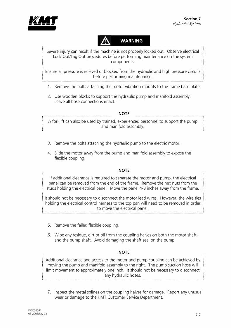
Section 7 Hydraulic System
DOC00091 03-2008/Rev 03 7-7
WARNING
Severe injury can result if the machine is not properly locked out. Observe electrical Lock Out/Tag Out procedures before performing maintenance on the system
components.
Ensure all pressure is relieved or blocked from the hydraulic and high pressure circuits before performing maintenance.
1. Remove the bolts attaching the motor vibration mounts to the frame base plate.
2. Use wooden blocks to support the hydraulic pump and manifold assembly. Leave all hose connections intact.
NOTE
A forklift can also be used by trained, experienced personnel to support the pump and manifold assembly.
3. Remove the bolts attaching the hydraulic pump to the electric motor.
4. Slide the motor away from the pump and manifold assembly to expose the flexible coupling.
NOTE
If additional clearance is required to separate the motor and pump, the electrical panel can be removed from the end of the frame. Remove the hex nuts from the
studs holding the electrical panel. Move the panel 4-8 inches away from the frame.
It should not be necessary to disconnect the motor lead wires. However, the wire ties holding the electrical control harness to the top pan will need to be removed in order
to move the electrical panel.
5. Remove the failed flexible coupling.
6. Wipe any residue, dirt or oil from the coupling halves on both the motor shaft, and the pump shaft. Avoid damaging the shaft seal on the pump.
NOTE
Additional clearance and access to the motor and pump coupling can be achieved by moving the pump and manifold assembly to the right. The pump suction hose will
limit movement to approximately one inch. It should not be necessary to disconnect any hydraulic hoses.
7. Inspect the metal splines on the coupling halves for damage. Report any unusual wear or damage to the KMT Customer Service Department.

Section 7 Hydraulic System
DOC00091 03-2008/Rev 03 7-8
8. Inspect the shaft cavity for the presence of hydraulic oil or evidence of hydraulic leaks. If a hydraulic leak is detected, the shaft seal must be replaced.
9. Install the new flexible coupling over the coupling half on the motor shaft, aligning the splines. The internal ring or snap ring keeps the coupling centered between the motor and pump shafts.
10. Move the motor and pump assembly together to re-engage the flexible coupling with the coupling half on the pump shaft. You may need to turn the motor shaft to align the splines with the pump shaft. When the motor and pump are rejoined, the coupling should have a small amount of end clearance to allow the coupling to float.
11. Attach the pump to the motor by reinstalling the bolts, and remove the wooden blocks.
12. Reinstall the vibration mounts to the frame base plate.
13. Reinstall the electrical panel to the end of the frame, if necessary.
14. Start the motor and apply full high pressure water pressure. Note any unusual sounds from the motor or pump assembly.
Hydraulic Compensator Maintenance
The high and low limit compensators regulate the flow of hydraulic fluid to the system. The compensators can become blocked with debris resulting in loss of pump control.
Figure 7-6: Hydraulic Compensator Components
1 Spool 4 Spring Collar
2 Spring Cup 5 Plug Nut
3 Springs 6 Sealing Cap
1 2
3 4 5 6

Section 7 Hydraulic System
DOC00091 03-2008/Rev 03 7-9
WARNING
Severe injury can result if the machine is not properly locked out. Observe electrical Lock Out/Tag Out procedures before performing maintenance on the system
components.
Ensure all pressure is relieved or blocked from the hydraulic and high pressure circuits before performing maintenance.
1. Remove the hydraulic hose from the low limit compensator.
2. Remove the four socket screws that attach the compensators to the pump.
3. Remove the compensators and then remove the three plugs and o-rings on the back of the housing.
1 O-Ring 4 Plug
2 Orifice 5 Low Limit Compensator
3 O-Ring 6 High Limit Compensator
4. Disassemble the compensators one at a time by first removing the hexagon sealing cap.
5. Loosen the lock nut, and then remove the plug nut.
6. Disassemble the plug by removing the spring collar, springs, spring cup and spool.
7. Clean the housing and all components with clean fluid and carefully dry with air.
8. Check and clean the small internal passages in the spools.
4
6
2
3
5 1

Section 7 Hydraulic System
DOC00091 03-2008/Rev 03 7-10
9. Check and clean the orifices in both spools.
10. Assemble in the reverse order, ensuring that the screw slot on the orifice is aligned with the long axis of the body.
CAUTION
When the compensators are removed, the machine loses adjustment. The compensators must be reset before operation can begin.
11. Start the machine and select the low pressure operating mode on the display panel.
12. Deadhead the machine.
1 Hydraulic Reference Gauge 4 High Limit Compensator
2 High Pressure Control Valve 5 Low Limit Compensator
3 Low Pressure Control Valve
13. Set the high and low pressure control valves on the hydraulic manifold to the minimum setting by turning them counter-clockwise.
If the machine is equipped with proportional pressure control, adjust the high pressure setting on the Pressure Control Screen.
14. Set the compensators to the minimum setting by turning the adjusting screws counter-clockwise.

Section 7 Hydraulic System
DOC00091 03-2008/Rev 03 7-11
15. Select high pressure operating mode on the display panel and set the high pressure control valve on the hydraulic manifold to the maximum setting by turning the knob clockwise.
If the machine is equipped with proportional pressure control, adjust the high pressure setting on the control panel.
16. Turn the adjusting screw on the high limit compensator clockwise until the hydraulic reference gauge reads 2,600 psi (179 bar).
17. Select low pressure operating mode on the display panel and turn the adjusting screw on the low limit compensator clockwise until the reference gauge reads 290 psi (20 bar). Lock the adjustment screw in place.
18. Select high pressure operating mode on the display panel and turn the knob on the high pressure control valve counter-clockwise until the reference gauge reads 2,000 psi (138 bar).
If the machine is equipped with proportional pressure control, adjust the high pressure setting on the control panel.
19. Open the high pressure water control valve, allowing water to flow. Set the desired high operating pressure by adjusting the high pressure control valve.
If the machine is equipped with proportional pressure control, select the high operating pressure on the control panel.
20. While the machine is running and high pressure water is flowing, select low pressure operating mode. Set the desired low operating pressure by adjusting the low pressure control valve.

DOC00091 03-2008/Rev 03 8-1
8 SECTION 8
ELECTRICAL SYSTEM
8.1 Overview
The SL-V Classic series is equipped with integral motor starter and control circuitry, enclosed in the electrical panel. The operator controls the machine primarily through a function-button control panel that communicates with the programmable logic controller (PLC). A series of sensors provide automatic shutdown logic and diagnostics.
Major system components include the electric motor, control panel, high voltage and control components, and the wiring harness that connects the sensors and solenoid valves to the PLC.
8.2 Optional System Components
The following system option is available at the time of purchase, or as an upgrade kit for existing equipment.
• Proportional pressure control allows the operator to select or vary the hydraulic operating pressure from the control panel or from a remote console.
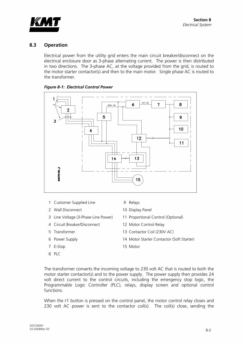
Section 8 Electrical System
DOC00091 03-2008/Rev 03 8-2
8.3 Operation
Electrical power from the utility grid enters the main circuit breaker/disconnect on the electrical enclosure door as 3-phase alternating current. The power is then distributed in two directions. The 3-phase AC, at the voltage provided from the grid, is routed to the motor starter contactor(s) and then to the main motor. Single phase AC is routed to the transformer.
Figure 8-1: Electrical Control Power
1 Customer Supplied Line 9 Relays
2 Wall Disconnect 10 Display Panel
3 Line Voltage (3-Phase Line Power) 11 Proportional Control (Optional)
4 Circuit Breaker/Disconnect 12 Motor Control Relay
5 Transformer 13 Contactor Coil (230V AC)
6 Power Supply 14 Motor Starter Contactor (Soft Starter)
7 E-Stop 15 Motor
8 PLC
The transformer converts the incoming voltage to 230 volt AC that is routed to both the motor starter contactor(s) and to the power supply. The power supply then provides 24 volt direct current to the control circuits, including the emergency stop logic, the Programmable Logic Controller (PLC), relays, display screen and optional control functions.
When the F1 button is pressed on the control panel, the motor control relay closes and 230 volt AC power is sent to the contactor coil(s). The coil(s) close, sending the

Section 8 Electrical System
DOC00091 03-2008/Rev 03 8-3
incoming power to the motor. When the F1 button is pressed again, the motor control relay opens, disconnecting power to the contactor coil(s), stopping the motor.
The motor starter contactors are solenoid operated by 230 volt AC control power. The contactors are arranged in a Soft Starter configuration. Soft Starters are used to start the motor slowly, minimizing the initial current draw.
Figure 8-2: Soft Starter Configuration
The circuit breaker/door disconnect provides the primary over current protection for the machine. All power is automatically disconnected from the machine when the main disconnect on the enclosure door is opened. However, power is still present on the input side of the circuit breaker/door disconnect. The only way to isolate all power to the machine is to turn the customer installed main power disconnect off.
Figure 8-3: Electrical Enclosure Door
1 Circuit Breaker/Disconnect

Section 8 Electrical System
DOC00091 03-2008/Rev 03 8-4
NOTE
See Section 2, Installation, regarding specifications for the customer installed main power disconnect.
Sensors and Solenoids
Warning and shutdown sensors monitor operating conditions, and electronically operated solenoids provide basic intensifier shift control. The harness cable connects these sensors and solenoids to the PLC, see Figure 8-5, Electrical Harness.
Figure 8-4: Sensors and Solenoids
1 Water Inlet Valve (5Y9) 7 2-Pressure Solenoid (4Y5)
2 Booster Temperature Switch (3S1) 8 Proximity Switch
3 Inlet Water Pressure Switch (3S10) Intensifier 1, Right (3S6)
4 Booster Outlet Pressure Switch (3S9) Intensifier 1, Left (3S5)
5 Oil Level/Temp Switch (3S2/3) 9 Safety Dump Valve (5Y8)
6 4-Way Directional Control Valve 10 Proportional Pressure Control (Optional)
Solenoid A (4Y1)
Solenoid B (4Y2)

Section 8 Electrical System
DOC00091 03-2008/Rev 03 8-5
Table 8-1 Sensors and Solenoids
Component
Function
Inlet Water Solenoid Valve
1 The normally closed, inlet water solenoid valve is located at the service bulkhead. When the control power is turned on, the valve opens and allows low pressure cutting water to enter. The solenoid valve functions as a safeguard by closing if a leak is detected anywhere in the system, or if the system is idle for an extended period.
The operator can adjust the idle closing time from 5 to 60 minutes. The function can also be disabled so the valve stays open whenever the control power is on.
Low Pressure Water Filter Assembly
2 The 30 psi pressure switch, mounted on the inlet manifold, monitors the inlet cutting water. If the pressure drops below 30 psi (2 bar) the switch activates an automatic shutdown circuit, protecting the booster pump from damage due to insufficient water supply pressure.
3 A temperature switch monitors the temperature of the cutting water from the booster pump. If the temperature exceeds 128° F (53° C), the switch activates an automatic shutdown circuit in the PLC. The temperature switch prevents booster pump overheating due to lack of water or long deadhead conditions.
4 To ensure adequate water pressure and supply to the intensifiers, the discharge pressure is monitored by a 60 psi pressure switch. An automatic shutdown occurs if the pressure is below 60 psi (4 bar).

Section 8 Electrical System
DOC00091 03-2008/Rev 03 8-6
Table 8-1 Sensors and Solenoids
Component
Function
Hydraulic Reservoir
5 The temperature/low level switch monitors the oil temperature and level in the reservoir. Although the float switch and the temperature switch are combined in a single unit, the two switches function independently.
If the operating oil temperature exceeds 144° F (62° C) an automatic shutdown occurs. If the hydraulic fluid level falls below specifications, a low oil level shutdown occurs.
Hydraulic Manifold
6 The 4-way directional control valve shifts the hydraulics back and forth to the intensifier. A shift valve directs pressurized oil to one end the hydraulic cylinder and returns fluid to the reservoir from the opposite end, causing the intensifier to stroke. The movement is controlled hydraulically by a pilot valve that is electronically operated by two solenoids, energized by the PLC. As power is directed from one solenoid to the other, LEDs are alternately illuminated.
7 When either high or low pressure is selected, a normally closed, solenoid valve is activated. The valve remains closed while operating in high pressure and is held open during low pressure operation. An illuminated LED on the solenoid indicates low pressure operation.

Section 8 Electrical System
DOC00091 03-2008/Rev 03 8-7
Table 8-1 Sensors and Solenoids
Component
Function
Hydraulic Cylinder
8 As pressurized hydraulic oil is sent to one side of the hydraulic cylinder, it pushes against the piston, moving it in one direction until it activates the proximity switch at the end of the stroke. The hydraulic flow is then sent to the opposite side of the cylinder, and the piston reverses direction until it activates the proximity switch at the opposite end of the stroke.
The green light on the proximity switch indicates there is power to the switch. The light turns red when the switch is activated. The proximity switches are magnetically activated by the presence of the metallic surface of the piston. When the switch is activated, it sends a signal to the PLC to change the flow of the directional control valve and reverse direction.
High Pressure Safety Dump Valve
9 The safety dump valve releases the stored pressure in the intensifier and high pressure delivery lines. The high pressure dump valve assembly includes a normally open high pressure water valve and a solenoid operated air valve.
The normally open pneumatic dump valve is held closed by air pressure. When the air supply is interrupted from an emergency stop, the valve opens and allows water to flow through the valve. Pressure is released in the intensifier and the high pressure water stream exits through the drain.
Proportional Pressure Control
10 Optional proportional pressure control allows the operator to select or vary the hydraulic operating pressure from the control panel or from a remote console. An electronically controlled hydraulic cartridge valve, mounted on the hydraulic manifold, receives a signal from the PLC and automatically makes the operator selected adjustments.

Section 8 Electrical System
DOC00091 03-2008/Rev 03 8-8
Figure 8-5: Electrical Harness
8.4 Service and Maintenance Procedures
Electrical components require minimal service. The proximity switches on the hydraulic cylinder may require replacement.
NOTE
Refer to Section 12, Parts List for a complete listing of replacement parts and part numbers.
Proximity Switch Maintenance
A proximity switch has failed and needs to be replaced if the LEDs do not change state, indicating they are not sensing the piston, or if an LED flashes continuously.
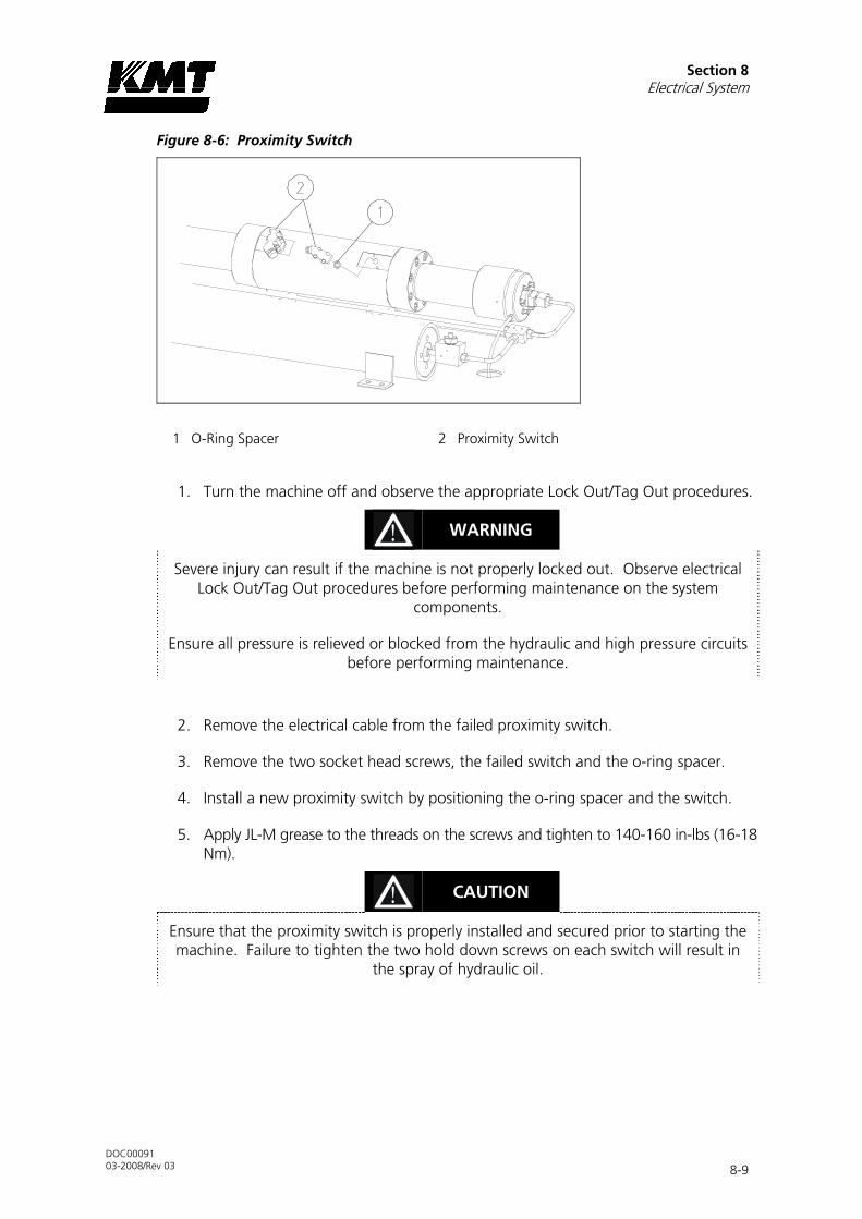
Section 8 Electrical System
DOC00091 03-2008/Rev 03 8-9
Figure 8-6: Proximity Switch
1 O-Ring Spacer 2 Proximity Switch
1. Turn the machine off and observe the appropriate Lock Out/Tag Out procedures.
WARNING
Severe injury can result if the machine is not properly locked out. Observe electrical Lock Out/Tag Out procedures before performing maintenance on the system
components.
Ensure all pressure is relieved or blocked from the hydraulic and high pressure circuits before performing maintenance.
2. Remove the electrical cable from the failed proximity switch.
3. Remove the two socket head screws, the failed switch and the o-ring spacer.
4. Install a new proximity switch by positioning the o-ring spacer and the switch.
5. Apply JL-M grease to the threads on the screws and tighten to 140-160 in-lbs (16-18 Nm).
CAUTION
Ensure that the proximity switch is properly installed and secured prior to starting the machine. Failure to tighten the two hold down screws on each switch will result in
the spray of hydraulic oil.
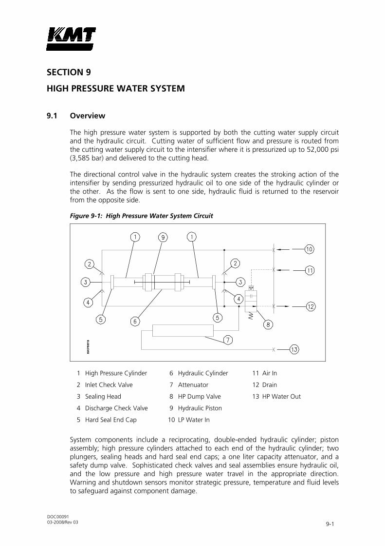
DOC00091 03-2008/Rev 03 9-1
9 SECTION 9
HIGH PRESSURE WATER SYSTEM
9.1 Overview
The high pressure water system is supported by both the cutting water supply circuit and the hydraulic circuit. Cutting water of sufficient flow and pressure is routed from the cutting water supply circuit to the intensifier where it is pressurized up to 52,000 psi (3,585 bar) and delivered to the cutting head.
The directional control valve in the hydraulic system creates the stroking action of the intensifier by sending pressurized hydraulic oil to one side of the hydraulic cylinder or the other. As the flow is sent to one side, hydraulic fluid is returned to the reservoir from the opposite side.
Figure 9-1: High Pressure Water System Circuit
1 High Pressure Cylinder 6 Hydraulic Cylinder 11 Air In
2 Inlet Check Valve 7 Attenuator 12 Drain
3 Sealing Head 8 HP Dump Valve 13 HP Water Out
4 Discharge Check Valve 9 Hydraulic Piston
5 Hard Seal End Cap 10 LP Water In
System components include a reciprocating, double-ended hydraulic cylinder; piston assembly; high pressure cylinders attached to each end of the hydraulic cylinder; two plungers, sealing heads and hard seal end caps; a one liter capacity attenuator, and a safety dump valve. Sophisticated check valves and seal assemblies ensure hydraulic oil, and the low pressure and high pressure water travel in the appropriate direction. Warning and shutdown sensors monitor strategic pressure, temperature and fluid levels to safeguard against component damage.

Section 9 High Pressure Water System
DOC00091 03-2008/Rev 03 9-2
9.2 Operation
The directional control valve sends pressurized hydraulic oil to one side of the hydraulic cylinder. The pressurized oil pushes against the piston, moving it in one direction until it activates the proximity switch at the end of the stroke. The hydraulic flow is then sent to the opposite side of the cylinder, and the piston reverses direction until it activates the proximity switch at the opposite end of the stroke.
The green light on the proximity switch indicates there is power to the switch. The light turns red when the switch is activated. The proximity switches are magnetically activated by the presence of the metallic surface of the piston. When the switch is activated, it sends a signal to the PLC to change the flow of the directional control valve and reverse direction.
As the pressurized oil pushes the piston in one direction, the plunger on that end extends and displaces the water in the high pressure cylinder, increasing the pressure up to 52,000 psi (3,585 bar). When the piston reverses direction, the plunger retracts and the plunger in the opposite high pressure cylinder extends.
Figure 9-2: High Pressure Cylinder
1 Inlet Check Valve 6 Inlet Water Passage 11 Hydraulic Cylinder
2 Sealing Head 7 Extended Plunger 12 Retracted Plunger
3 Discharge Check Valve 8 High Pressure Cylinder 13 Hydraulic Piston
4 Outlet Water Passage 9 Stem Mount
5 Inlet Water Port 10 Hydraulic Oil In
Low pressure water is routed through the inlet water ports to the inlet passages in the sealing heads. When the plunger retracts, the inlet check valve opens to allow water to enter the high pressure cylinder. When the plunger extends to create high pressure water, the inlet valve closes to seal the inlet passage and the discharge check valve opens to allow the high pressure water to exit the cylinder. As the plunger retracts, the discharge check valve is closed.

Section 9 High Pressure Water System
DOC00091 03-2008/Rev 03 9-3
Figure 9-3: High Pressure Water System
1 High Pressure Cylinder 7 Out to Cutting ‘Head
2 Hydraulic Cylinder 8 Out to Drain
3 Hydraulic Cylinder Head 9 Hard Seal End Cap
4 Out to Attenuator 10 Proximity Switch
5 Attenuator 11 Inlet Water Port
6 Safety Dump Valve
The intensifier is a reciprocating pump. As the piston and plungers move from one side to the other, high pressure water exits one side of the intensifier as low pressure water refills the opposite side.
The high pressure water is then routed to the attenuator. The attenuator acts as a shock absorber to dampen pressure fluctuations and ensure a steady and consistent supply of water. From the attenuator, the high pressure water exits to the cutting head.
The safety dump valve releases the stored pressure in the intensifier and high pressure delivery lines when the power is turned off. The high pressure dump valve assembly includes a normally open high pressure water valve and an electrically controlled air valve.
The normally open pneumatic dump valve is held closed by air pressure. When the air supply is interrupted from an emergency stop, the valve opens and allows water to flow through the valve. Pressure is released in the intensifier and the high pressure water stream exits through the drain.

Section 9 High Pressure Water System
DOC00091 03-2008/Rev 03 9-4
9.3 System Components
The following figures illustrate the individual high pressure water system components.
Figure 9-4: High Pressure Cylinder Assembly
1 High Pressure Seal Assembly 5 Sealing Head Spacer
2 High Pressure Cylinder 6 Hard Seal End Cap
3 Cylinder Liner 7 O-Ring
4 Sealing Head 8 Jackbolt

Section 9 High Pressure Water System
DOC00091 03-2008/Rev 03 9-5
Figure 9-5: Hydraulic Cylinder Assembly
1 Proximity Switch, Socket Head Screws 7 Bushing Retainer Flange
2 O-Ring Spacer 8 Hydraulic Seal Cartridge
3 O-Ring 9 Hydraulic Cylinder Head
4 Backup Ring 10 Stem Mount
5 Socket Head Screw 11 Hydraulic Cylinder
6 Retaining Ring

Section 9 High Pressure Water System
DOC00091 03-2008/Rev 03 9-6
Figure 9-6: Hydraulic Piston
1 High Pressure Cylinder Assembly 4 Retaining Ring
2 Hydraulic Piston 5 Plunger
3 Retainer Nut
9.4 Service and Maintenance Overview
Never perform any type of maintenance on the high pressure water system while it is pressurized. Never attempt to tighten a leaking high pressure or hydraulic fitting while the machine is operating. Always turn the power off and bleed the high pressure water before servicing. Pressing the emergency stop button turns the control power off to the intensifier, and bleeds high pressure water through the dump valve.
Improper assembly can lead to the premature failure of components. Maintenance procedures must be followed carefully; components must be properly cleaned prior to assembly and tightened to the correct torque specifications.
Some high pressure components are not serviceable at the customer level, others require precise refinishing. KMT Waterjet Systems offers maintenance and refinishing services for these components.
NOTE
Refer to Section 12, Parts List for a complete listing of replacement parts and part numbers.

Section 9 High Pressure Water System
DOC00091 03-2008/Rev 03 9-7
Torque Specifications
Table 9-1, Torque Specifications, details the torque specifications and tightening sequences for the high pressure components and connections.
Table 9-1 Torque Specifications
High Pressure Water System
Hard Seal End Cap
Jackbolts 5 (7/16”) each
1st Stage Hand Tight
2nd Stage 20 ft-lbs (27 Nm) In Sequence*
3rd Stage 32-35 ft-lbs (43-47 Nm)** In Sequence
4th Stage 32-35 ft-lbs (43-47 Nm) Clockwise Pattern From Bolt 1 to Bolt 4
Socket Wrench Size 3/8 inch
5-Bolt Crossing Pattern
* Note: In Sequence: 1, 2, 3, 4, 5.
** Note: A maximum torque of 38 ft-lbs (51 Nm) is etched on the hard seal end cap. This represents the maximum allowable torque, not the recommended torque.
Hydraulic Cylinder Head
Socket Head Screws 8 (14M) each
Torque 75-80 ft-lbs (102-108 Nm)
Hex Key M12

Section 9 High Pressure Water System
DOC00091 03-2008/Rev 03 9-8
Table 9-1 Torque Specifications
High Pressure Water System
Proximity Switch
Socket Head Screws 2 (M6) each
Torque 140-160 in-lbs (16-18 Nm)
Hex Key M5
Stem Mount
Socket Head Screws 4 (M10) each
Torque 60-65 ft-lbs (80-88 Nm)
Hex Key M8
Sealing Head
Discharge Gland Nut 130 ft-lbs (176 Nm)
Poppet Retainer 25-30 in-lbs (2.8-3.4 Nm)
3/8” Inlet Gland Nut 50 ft-lbs (68 Nm)
Pneumatic Control Valve
3/8-inch HP Inlet Gland Nut 50 ft-lbs (68 Nm)
1/4-inch Outlet to Drain 25 ft-lbs (34 Nm)
Pneumatic Actuator 5 ft-lbs (7 Nm)
9/16”-1/4” HP Adapter 50 ft-lbs (68 Nm)

Section 9 High Pressure Water System
DOC00091 03-2008/Rev 03 9-9
Specialized Maintenance Tools
KMT Waterjet has designed tools to facilitate the removal and installation of specialized system components. These tools are illustrated in Figure 9-7, Specialized Maintenance Tools, and part numbers are provided in Table 9-2.
Figure 9-7: Specialized Maintenance Tools
1 Plunger Removal Tool 5 Seal Removal Tool Stand
2 Vee Block Cradle 6 Plug
3 Cylinder Wrench 7 Gland Fitting
4 End Cap Wrench (5 Bolt) 8 Seal Removal Tool
Table 9-2 Specialized Maintenance Tools
High Pressure Water System
Part Number
Plunger Removal Tool 05004924
Vee Block Cradle 20438361
Plug 49864655 (3/8”)
Gland Fitting 49864598 (3/8”)
Seal Removal Tool 10148674
End Cap Wrench (5 Bolt) 80088354
Cylinder Wrench 05066139
Seal Removal Tool Stand 05149802

Section 9 High Pressure Water System
DOC00091 03-2008/Rev 03 9-10
9.5 High and Low Pressure Water Piping
Before performing any maintenance on the high pressure components, it is necessary to remove the high and low pressure water piping. The following procedure should be used to remove and install the piping.
WARNING
Severe injury can result if the machine is not properly locked out. Observe electrical Lock Out/Tag Out procedures before performing maintenance on the high pressure
system components.
Ensure all pressure is relieved or blocked from the hydraulic and high pressure circuits before performing maintenance.
1. Turn the cutting water supply off.
2. Loosen and remove the high pressure gland fitting connected to the discharge high pressure check valve. Move the tubing to clear the work area.
3. Loosen and remove the low pressure piping connected to the inlet water port on the hard seal end cap.
4. When the required maintenance has been completed and the components reassembled, connect the low pressure water piping to the inlet water port on the hard seal end cap.
5. Apply Pure Goop to the threads on the high pressure gland fitting. Before installing the high pressure fitting, ensure proper collar position, 1 to 1-1/2 threads should be exposed. Install and tighten the fitting to the torque specifications in Table 9-1.
6. Turn the cutting water supply on and check for low pressure leaks.
7. Remove the cutting orifice and start the machine. Operate in low pressure mode to flush the high pressure passages.
8. Install the orifice and operate at high pressure to check for leaks.
9.6 High Pressure Cylinder Assembly
KMT Waterjet recommends removing the high pressure cylinder, sealing head and end cap as an assembly for servicing the plunger, high pressure seals, hydraulic piston and seal cartridge. Removing the jackbolts in the hard seal end cap is not recommended except to service the inlet check valve and cone seat on the sealing head.
High Pressure Cylinder Assembly Removal
Prior to removing electrical power or any high or low pressure piping, bring the hydraulic piston in the left or right stop position to facilitate maintenance. The plunger will extend in the selected direction, allowing full exposure when the unit is disassembled. Refer to Section 4, Operation.

Section 9 High Pressure Water System
DOC00091 03-2008/Rev 03 9-11
1. Turn the machine off and observe the appropriate Lock Out/Tag Out procedures.
WARNING
Severe injury can result if the machine is not properly locked out. Observe electrical Lock Out/Tag Out procedures before proceeding.
Ensure all pressure is relieved or blocked from the hydraulic and high pressure circuits before proceeding.
2. Disconnect the high and low pressure water piping, following the procedure, High and Low Pressure Water Piping.
NOTE
Prior to removal, verify that the alignment marks on the high pressure cylinder and on the hydraulic cylinder head are aligned. If not, check the condition of the retaining
ring and the bushing retainer flange after the cylinder assembly is removed.
CAUTION
Due to the weight of the cylinder assembly, adequate support must be provided to prevent damage to the plunger or seals during removal and installation. See Figure 9-
7, Specialized Maintenance Tools for tools available to support the high pressure assembly for this procedure.
3. Position the vee block cradle tool under the cylinder assembly. Unthread and remove the assembly from the hydraulic cylinder head and plunger. The assembly can be rotated with the cylinder wrench or by hand.

Section 9 High Pressure Water System
DOC00091 03-2008/Rev 03 9-12
Figure 9-8: High Pressure Cylinder Assembly Removal and Installation
1 High Pressure Cylinder Assembly 3 Cylinder Wrench
2 Vee Block Cradle
NOTE
If thread or metal surface galling is detected during removal, galled surfaces and threads must be filed, sanded and lubricated prior to reassembly. See the procedure,
High Pressure Cylinder Maintenance.
High Pressure Cylinder Assembly Installation
1. Verify that the high pressure cylinder threads and alignment surfaces are adequately cleaned and lubricated with Pure Goop, and that the threads have been sanded and dressed if galling was encountered during removal.
2. Verify that the high pressure seal assembly, packing follower and cylinder liner are correctly installed. Align the cylinder assembly with the plunger and the hydraulic cylinder head, using the cradle tool to support the weight. Carefully push and lift the assembly into position until the threads are ready to engage.
3. Thread the cylinder assembly into the hydraulic cylinder head.
Section 9 High Pressure Water System
DOC00091 03-2008/Rev 03 9-13
NOTE
If galling occurs during threading, remove the high pressure cylinder assembly and inspect the mating surfaces and threads. Repair surfaces, thoroughly clean, lubricate
and thread the cylinder assembly into the hydraulic cylinder head.
NOTE
An alignment mark is located on the hydraulic cylinder head under the KMT logo. To ensure the high pressure cylinder is properly tightened and fully seated in the
hydraulic cylinder head, it is recommended that a corresponding mark be placed on the high pressure cylinder after installation. Periodically inspect the cylinder for
movement. If movement is detected, re-tighten the assembly.
4. Connect the high and low pressure water piping, following the procedure, High and Low Pressure Water Piping.
5. Start the machine in low pressure mode to flush air from the high pressure components and to check for obvious leaks. After 5-10 minutes, switch to high pressure operation and check for leaks.
If leaks are detected, turn the machine off and remedy the problem. When the problem has been remedied, repeat the startup procedure, moving from low to high pressure soon after the intensifier starts pumping water. There is no further need to flush air from the system.
High Pressure Cylinder Maintenance
The plunger seal area in the high pressure cylinder bore should be inspected and cleaned each time the high pressure seal assembly is replaced.
1. Clean the sealing area on the inside diameter of the high pressure cylinder and inspect the bore for rings, scratches, pits, residue or other potential leak paths.
Seal material or residue can build up, forming a ring. Running a fingernail across the buildup will cause it to appear as a surface flaw. Grooves or ridges are typically seal debris buildup rather than marks on the inside diameter wall of the cylinder.
2. Polish the inside diameter of the cylinder where the seal will locate with 600-grit wet/dry sandpaper. Hold the sandpaper on the end of your finger and move in a cylindrical wiping motion. Polish in a circumferential motion only. Do not polish or drag the sandpaper along the length of the cylinder.
3. Clean the residue from the inside diameter of the cylinder and re-inspect for surface defects.

Section 9 High Pressure Water System
DOC00091 03-2008/Rev 03 9-14
NOTE
The ends of the high pressure cylinder show a 'step' where the inner sleeve extends slightly beyond the outer sleeve. This is normal and does not indicate a flaw in the
cylinder.
9.7 Hard Seal End Caps
KMT Waterjet recommends loosening the jackbolts and removing the hard seal end caps (HSEC) only to service the inlet check valve and the cone seat on the sealing head.
Hard Seal End Cap Removal
Prior to removing electrical power or any high or low pressure piping, bring the hydraulic piston in the left or right stop position to facilitate maintenance. The plunger will extend in the selected direction, allowing full exposure when the unit is disassembled. Refer to Section 4, Operation.
1. Turn the machine off and observe the appropriate Lock Out/Tag Out procedures.
WARNING
Severe injury can result if the machine is not properly locked out. Observe electrical Lock Out/Tag Out procedures before proceeding.
Ensure all pressure is relieved or blocked from the hydraulic and high pressure circuits before proceeding.
2. Disconnect the high and low pressure water piping, following the procedure, High and Low Pressure Water Piping.
3. Loosen the jackbolts in the hard seal end cap.
4. Unscrew and remove the HSEC from the high pressure cylinder.
5. Remove the sealing head. The sealing head may be removed with the HSEC or after the end cap has been removed.
6. Verify the removal of the white plastic sealing head spacer used to position the sealing head relative to the high pressure cylinder. The bushing may come out with the sealing head. If not, the bushing must be removed from the cylinder bore prior to reinstalling the sealing head to avoid pushing it farther into the bore.
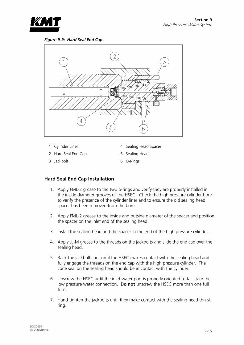
Section 9 High Pressure Water System
DOC00091 03-2008/Rev 03 9-15
Figure 9-9: Hard Seal End Cap
1 Cylinder Liner 4 Sealing Head Spacer
2 Hard Seal End Cap 5 Sealing Head
3 Jackbolt 6 O-Rings
Hard Seal End Cap Installation
1. Apply FML-2 grease to the two o-rings and verify they are properly installed in the inside diameter grooves of the HSEC. Check the high pressure cylinder bore to verify the presence of the cylinder liner and to ensure the old sealing head spacer has been removed from the bore.
2. Apply FML-2 grease to the inside and outside diameter of the spacer and position the spacer on the inlet end of the sealing head.
3. Install the sealing head and the spacer in the end of the high pressure cylinder.
4. Apply JL-M grease to the threads on the jackbolts and slide the end cap over the sealing head.
5. Back the jackbolts out until the HSEC makes contact with the sealing head and fully engage the threads on the end cap with the high pressure cylinder. The cone seal on the sealing head should be in contact with the cylinder.
6. Unscrew the HSEC until the inlet water port is properly oriented to facilitate the low pressure water connection. Do not unscrew the HSEC more than one full turn.
7. Hand-tighten the jackbolts until they make contact with the sealing head thrust ring.

Section 9 High Pressure Water System
DOC00091 03-2008/Rev 03 9-16
8. Tighten the jackbolts following the tightening sequence and torque specifications in Table 9-1.
9. Connect the high and low pressure water piping and turn the low pressure water supply on.
10. Start the machine in low pressure mode to flush air from the high pressure components and to check for obvious leaks. After 5-10 minutes, switch to high pressure operation and check for leaks.
If leaks are detected, turn the machine off and remedy the problem. When the problem has been remedied, repeat the start up procedure.
9.8 Sealing Head
The sealing head is sealed to the outboard end of the high pressure cylinder by a 45-degree metal-to-metal compression seal. The pre-loading jackbolts in the hard seal end cap hold the sealing head against the end of the cylinder.
The inlet and discharge check valves in the sealing head ensure the low pressure and high pressure water only travels in one direction.
Figure 9-10: Sealing Head
1 Discharge Check Valve 4 High Pressure Cylinder
2 Inlet Check Valve 5 Hard Seal End Cap
3 Sealing Head 6 Jackbolt

Section 9 High Pressure Water System
DOC00091 03-2008/Rev 03 9-17
High Pressure Discharge Check Valve
The high pressure discharge checks valves should be serviced on a regular, preventive maintenance schedule. Service is recommended every 1,500 hours. The discharge check valve can be serviced with the sealing head either installed or removed from the high pressure cylinder.
1. Turn the machine off and observe the appropriate Lock Out/Tag Out procedures.
WARNING
Severe injury can result if the machine is not properly locked out. Observe electrical Lock Out/Tag Out procedures before proceeding.
Ensure all pressure is relieved or blocked from the hydraulic and high pressure circuits before proceeding.
2. Disconnect the high pressure water piping, following the procedure, High and Low Pressure Water Piping.
3. Use a pair of wrenches to remove the gland nut. The poppet pin, spring and poppet check valve will normally remain in the gland nut when it is removed. If necessary, remove the components from the gland nut.
Figure 9-11: High Pressure Discharge Check Valve
1 Gland Nut 5 Seat
2 Poppet Pin 6 Sealing Head
3 Compression Spring 7 Sealing Head Cone Ring
4 Poppet Check Valve, Discharge
4. Use a magnet to remove the seat from the sealing head.
5. Inspect the poppet pin for wear and replace the pin if worn.

Section 9 High Pressure Water System
DOC00091 03-2008/Rev 03 9-18
6. Inspect both faces of the seat for damage or cracking. A cracked or damaged seat must be replaced. The seat can be installed with either face toward the poppet valve. If one face is worn, but the opposite is not, the seat can be reversed, placing the new surface toward the poppet valve. A slight burr at the hole edge identifies the used side of the seat. If both faces are worn, the seat must be replaced.
NOTE
The seat, spring and poppet valve should be replaced as a set. If one component requires replacement, replace all components.
7. Apply a thin film of Pure Goop to the face of the seat opposite the poppet valve and install the seat into the sealing head. If the existing seat is reused, install the seat with the new surface facing the poppet valve.
8. Install the poppet pin and the spring, with the larger end of the spring facing the poppet valve, and then install the poppet valve into the gland nut.
9. Apply Pure Goop to the sealing face and the threads on the gland nut and thread the gland nut into the sealing head. Hand tighten until there is a 0.20 inch (5 mm) gap between the gland nut and the sealing head. No threads should show. If the gap exceeds 0.20 inch (5 mm), the poppet or seat has slipped out of position. The parts must be removed, inspected and re-assembled.
10. Use a crowfoot/torque wrench combination and tighten the gland nut to the torque specifications in Table 9-1.
Low Pressure Inlet Check Valve
The hard seal end cap must be removed to service the inlet check valve. Follow the procedure, Hard Seal End Cap Removal. When the end cap has been removed, proceed with Step 1 below.
Figure 9-12: Low Pressure Inlet Check Valve
1 Poppet Check Valve, Inlet 3 Poppet Retainer
2 Compression Spring

Section 9 High Pressure Water System
DOC00091 03-2008/Rev 03 9-19
1. Use a 1/2-inch flat blade screwdriver to remove the poppet retainer from the sealing head.
2. Inspect the sealing head for scratches or wear on the cone ring contact surface, and on the poppet valve contact surface. If defects are detected, the surfaces must be refinished. See the procedure, Sealing Head Maintenance.
3. Inspect both faces on the inlet poppet valve. The poppet valve can be installed with either face toward the sealing head. If one face is worn, but the opposite is not, the poppet can be reversed, placing the best surface toward the sealing head. If both faces are worn, the poppet valve must be replaced.
4. Assemble the spring and the poppet valve on the poppet retainer. Apply a small amount of Loctite 222 to the poppet retainer threads only. Do not get any Loctite on the poppet or any other surfaces on the inlet check valve.
5. Use the flat blade screwdriver to tighten the poppet retainer. Tighten the poppet retainer to the torque specifications in Table 9-1.
6. Inspect the assembled unit to ensure the poppet moves freely, the spring is fully guided on the poppet retainer, the spring end is 90 degrees from the screwdriver slot on the retainer and the poppet retainer is seated against the sealing head.
Sealing Head Maintenance
The sealing head should be inspected for scratches or wear on the cone ring contact surface, and on the poppet valve contact surface. If defects are detected, the surfaces must be refinished. The sealing head can be returned to KMT Waterjet for refinishing.
1. Polish the 45-degree surface on the cone ring to achieve a smooth finish. You should not be able to feel any grooves or machine tool marks when you run a fingernail across the surface.
2. Inspect the inlet poppet valve sealing surface for pits, scratches or jetting erosion. If necessary, refinish the surface.
Place a piece of 1/4-1/2” thick plate glass, not window glass, on a sturdy table to provide an absolutely, flat surface. Place a piece of 400-grit wet/dry sandpaper on the glass. Use even, deliberate strokes, rotating the sealing head approximately 10-15 degrees after each stroke. Polish the sealing head until it is smooth. Be careful not to cause additional damage by tilting or tipping the part while polishing.
3. When the sealing head is flat and smooth, perform a final polish with 600-grit wet/dry sandpaper. A mirror finish is required.

Section 9 High Pressure Water System
DOC00091 03-2008/Rev 03 9-20
9.9 High Pressure Seal Assembly
The following procedure should be used to replace the high pressure seal assembly.
Figure 9-13: High Pressure Seal Assembly
1 U-Cup Seal W/Cantilever Spring Seal Orientation
2 Backup Ring 6 Hydraulic Piston
3 Packing Follower 7 Seal Head
4 Plunger
5 Red Surfaces
Prior to removing electrical power or any high or low pressure piping, bring the hydraulic piston in the left or right stop position to facilitate maintenance. The plunger will extend in the selected direction, allowing full exposure when the unit is disassembled. Refer to Section 4, Operation.
1. Turn the machine off and observe the appropriate Lock Out/Tag Out procedures.
WARNING
Severe injury can result if the machine is not properly locked out. Observe electrical Lock Out/Tag Out procedures before proceeding.
Ensure all pressure is relieved or blocked from the hydraulic and high pressure circuits before proceeding.

Section 9 High Pressure Water System
DOC00091 03-2008/Rev 03 9-21
2. Disconnect the high and low pressure water piping, following the procedure, High and Low Pressure Water Piping.
3. Remove the high pressure cylinder assembly, following the procedure, High Pressure Cylinder Assembly Removal.
Figure 9-14: High Pressure Seal Removal
1 High Pressure Cylinder Assembly 4 Discharge Gland Nut
2 Plug/Gland Fitting 5 Seal Removal Tool
3 Seal Removal Tool Stand 6 Plunger
4. Thread the high pressure plug and gland fitting into the discharge gland nut on the sealing head and hand tighten.
5. Position the cylinder assembly upright in the seal removal tool stand. If a tool stand is not available, position the cylinder on a platform of wooden blocks. Rest the outside edges of the end cap on the platform.
6. Fill the cylinder with water and slide the seal removal tool or a used plunger into the bronze packing follower to ensure a good seal for the removal of the seal assembly.
7. Place a shop towel around the plunger to avoid splash back. Use a dead blow hammer to drive the removal tool or plunger into the cylinder until the seal components move up and out of the cylinder.

Section 9 High Pressure Water System
DOC00091 03-2008/Rev 03 9-22
8. Remove the cylinder liner from the bore and inspect for possible heat or wear damage, or for debris. If cracks or brittleness are detected on the tabs on the ends of the liner, the liner must be replaced.
9. Feel approximately one inch into the cylinder bore for obvious ridges or grooves.
10. Inspect the plunger surface for flaws. Rotate the plunger 360 degrees by hand while viewing light reflection on the surface to detect any dullness, streaks, pits or other defects. Run a fingernail perpendicular to the direction of the suspected flaws to determine the severity of defects. Depending on the seal life achieved with the removed seal assembly, make a judgment regarding plunger and/or cylinder replacement.
11. Lightly coat the new seal components with FML grease and install the new components on the plunger. Ensure the proper orientation of the backup rings as illustrated in Figure 9-13, High Pressure Seal Assembly.
The cantilever spring inside the U-cup seal can easily be distorted. Verify that the spring, lips and cavity appear uniform prior to installation.
12. Slide the cylinder liner over the plunger.
13. Install the high pressure cylinder assembly into the hydraulic cylinder head, following the procedure, High Pressure Cylinder Assembly Installation.
14. Reconnect the high and low pressure water piping and turn the low pressure water supply on.

Section 9 High Pressure Water System
DOC00091 03-2008/Rev 03 9-23
9.10 Hydraulic Piston and Plungers
Two hydraulic bushings provide wear contact between the piston and the inside diameter of the hydraulic cylinder. On each end of the piston, a retainer nut and a retaining ring hold the plungers in position.
Figure 9-17: Hydraulic Piston Components
1 Ram Piston 4 Piston Seal Assembly
2 Retainer Nut 5 Piston Bushing
3 Retaining Ring 6 Plunger
Hydraulic Piston and Plunger Removal
The following procedure is used to remove the hydraulic piston and plungers. It is only necessary to remove the components from one end of the intensifier.
Prior to removing electrical power or any high or low pressure piping, bring the hydraulic piston in the left or right stop position to facilitate maintenance. The plunger will extend in the selected direction, allowing full exposure when the unit is disassembled. Refer to Section 4, Operation.
1. Turn the machine off and observe the appropriate Lock Out/Tag Out procedures.

Section 9 High Pressure Water System
DOC00091 03-2008/Rev 03 9-24
WARNING
Severe injury can result if the machine is not properly locked out. Observe electrical Lock Out/Tag Out procedures before proceeding.
Ensure all pressure is relieved or blocked from the hydraulic and high pressure circuits before proceeding.
2. Disconnect the high and low pressure water piping following the procedure, High and Low Pressure Water Piping.
3. Remove the high pressure cylinder assembly following the procedure, High Pressure Cylinder Assembly Removal.
Figure 9-18: Hydraulic Piston Removal
1 O-Ring Spacer 7 Backup Ring
2 Proximity Switches 8 Hydraulic Cylinder Head
3 Hydraulic Cylinder 9 Socket Head Screw
4 Hydraulic Piston 10 Hydraulic Seal Cartridge
5 Plunger 11 Bushing Retainer Flange
6 O-Ring 12 Retaining Ring

Section 9 High Pressure Water System
DOC00091 03-2008/Rev 03 9-25
4. Remove the proximity switch to prevent interference and to allow the hydraulic oil to drain back to the reservoir, minimizing oil spillage. It will take approximately five minutes for the oil to drain.
5. Remove the retaining ring, bushing retainer flange and the hydraulic cartridge seal.
6. Loosen and remove the socket head screws in the hydraulic cylinder head.
7. Remove the hydraulic cylinder head with the o-ring and backup ring. The mounting flat for the proximity switch provides a small lip for loosening the cylinder head.
8. Grasp the plunger firmly and pull the piston out of the hydraulic cylinder.
9. Place the piston in a vice and remove the retaining ring on each end of the piston.
10. Unthread and remove the retainer nuts, and remove the plungers.
Piston Bushings and Seal Assembly
1. Use a brass, dull-edged blade made from brass or similar soft metal material to remove the two bushings and the two-piece seal assembly.
NOTE
Do not scratch the surfaces of the piston seal groove. Scratches on the sides or bottom of the groove can result in hydraulic leaks.
2. Inspect the bottom of the seal grooves for marks, scratches and residue buildup. Clean and/or repair the groove surfaces as required.
3. Apply FML-2 grease to the new piston bushings and install the bushings.
4. The piston seal assembly consists of a seal ring and an o-ring. Apply FML-2 grease to the both rings. Use the brass, dull-edged blade to install the o-ring, ensuring the ring is not twisted after installation. Slide the outer, seal ring over the metal edges and ease it into position over the inner, o-ring.

Section 9 High Pressure Water System
DOC00091 03-2008/Rev 03 9-26
Figure 9-19: Piston Bushings and Seal Assembly
1 Piston Bushing 3 O-Ring, Inner Ring
2 Seal Ring, Outer Ring
Plunger Maintenance
Plunger surfaces can become streaked with longitudinal scratches or flaws, and discolored or dull in appearance. If any of these conditions become severe, the high pressure seal assembly and possibly the hydraulic cartridge seal will leak.
Accumulation of debris on the surface of the plunger can be removed by polishing with 600-grit sandpaper. However, plunger surface flaws usually cannot be repaired on site. The plunger can be returned to KMT Waterjet for reconditioning.
Figure 9-20: Plunger
1 Plunger 3 Button Chamfer
2 Plunger Button

Section 9 High Pressure Water System
DOC00091 03-2008/Rev 03 9-27
Hydraulic Piston and Plunger Installation
1. Position the plunger in the plunger socket on the piston.
2. Apply a small amount of Loctite 222, or similar thread locker, to the threads on the retainer nut. Tighten the retainer nut against the piston finger tight.
3. Install the retaining ring into the cavity of the plunger socket.
Figure 9-21: Plunger Installation
1 Hydraulic Piston 3 Retainer Nut
2 Plunger 4 Retaining Ring
4. Repeat steps 1-3 to install the second plunger.
5. Ensure that the hydraulic cylinder bore is free of grit or contamination.
6. Lubricate the piston bushings and seal assembly, and lightly lubricate 2-3 inches of the cylinder bore with FML-2 grease.
7. Install the piston into the hydraulic cylinder bore, spearing the plunger through the hydraulic cartridge seal in the opposite end of the hydraulic cylinder.
8. Verify that the o-ring and backup ring are properly positioned in the groove on the hydraulic cylinder head, and that they are sufficiently lubricated with FML-2 grease.
9. Position the cylinder head in the end of the hydraulic cylinder. Apply JL-M grease to the threads on the socket head screws. Install the screws in the hydraulic cylinder head and tighten, following the torque specifications in Table 9-1.

Section 9 High Pressure Water System
DOC00091 03-2008/Rev 03 9-28
10. Verify that the plunger moves freely when handled. If it feels tight, there may be residue buildup in the pocket or the pocket depth may be insufficient.
11. Replace the hydraulic cartridge seal, bushing retainer flange and retaining ring in the hydraulic cylinder head.
12. Replace the proximity switch by positioning the o-ring spacer and the switch. Apply JL-M grease to the threads on the socket head screws and tighten, following the torque specifications in Table 9-1.
CAUTION
Ensure that the proximity switch is properly installed and secured prior to starting the motor. Failure to tighten the two hold down screws on the switch will result in the
spray of hydraulic oil.
13. Install the high pressure cylinder assembly into the hydraulic cylinder head, following the procedure, High Pressure Cylinder Assembly Installation.
14. Connect the high and low pressure water piping, and turn the low pressure water supply on.
9.11 Hydraulic Cylinder Maintenance
The inside diameter surface of the hydraulic cylinder should be inspected for wear grooves and surface finish whenever the hydraulic cylinder heads are removed. Excessive grooving is indicative of piston seal wear.
9.12 High Pressure Attenuator
The high pressure attenuator is not serviceable at the customer level. KMT Waterjet Systems tests the seals in the attenuator at pressures exceeding normal operating pressure, making disassembly difficult. If the attenuator develops a high pressure water leak, it should be replaced. The failed attenuator should be returned to KMT Waterjet for servicing or replacement.
9.13 High Pressure Dump Valve
The high pressure dump valve assembly includes a normally open high pressure water valve and a solenoid operated air valve. The following procedure is recommended for servicing the high pressure dump valve. Failure to follow this procedure will cause damage to the stem, valve seat, or both.

Section 9 High Pressure Water System
DOC00091 03-2008/Rev 03 9-29
WARNING
The high pressure dump valve is a safety device designed to instantly release high pressure in the system. Proper maintenance is imperative to prevent potential
personal injury.
Figure 9-22: High Pressure Dump Valve
1 Signal from PLC 8 Pneumatic Control Valve
2 Solenoid Valve 9 Control Air In
3 Water In 10 Adapter Cone
4 High Pressure Gland and Collar 11 9/16” Adapter
5 High Pressure M/F Adapter 12 Collar
6 Out to Drain 13 1/4” Gland Nut
7 Valve Body
Figure 9-23, Pneumatic Valve Seal Tools, illustrates the special seal tools recommended for this procedure.

Section 9 High Pressure Water System
DOC00091 03-2008/Rev 03 9-30
Figure 9-23: Pneumatic Valve Seal Tools
1 Seal Installation Tool (05103882) 3 Seal Push Tool (05103890)
2 Seal Positioning Tool (05067350) Seal Tool Kit (05141759)
Pneumatic Control Valve
For reliable operation, it is recommended that the valve seat, seal assembly, brass backup ring and stem always be replaced at the same time. The stainless steel backup ring can be reused.
WARNING
Severe injury can result if the machine is not properly locked out. Observe electrical Lock Out/Tag Out procedures before proceeding.
Ensure all pressure is relieved or blocked from the hydraulic and high pressure circuits before proceeding.
1. Turn the air supply off.
2. Remove the air supply hose, and the electrical connection to the solenoid valve.
3. Loosen and remove the high pressure gland connection and the drain connection.
4. Remove the valve and actuator assembly from the machine.
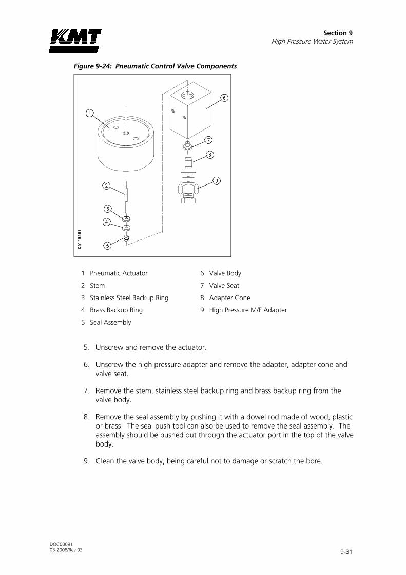
Section 9 High Pressure Water System
DOC00091 03-2008/Rev 03 9-31
Figure 9-24: Pneumatic Control Valve Components
1 Pneumatic Actuator 6 Valve Body
2 Stem 7 Valve Seat
3 Stainless Steel Backup Ring 8 Adapter Cone
4 Brass Backup Ring 9 High Pressure M/F Adapter
5 Seal Assembly
5. Unscrew and remove the actuator.
6. Unscrew the high pressure adapter and remove the adapter, adapter cone and valve seat.
7. Remove the stem, stainless steel backup ring and brass backup ring from the valve body.
8. Remove the seal assembly by pushing it with a dowel rod made of wood, plastic or brass. The seal push tool can also be used to remove the seal assembly. The assembly should be pushed out through the actuator port in the top of the valve body.
9. Clean the valve body, being careful not to damage or scratch the bore.

Section 9 High Pressure Water System
DOC00091 03-2008/Rev 03 9-32
Figure 9-25: Valve Seal Installation
1 Pneumatic Actuator 5 High Pressure M/F Adapter
2 Seal 6 Seal Positioning Tool
3 Valve Body 7 Seal Installation Tool
4 Adapter Cone 8 Seal Push Tool
10. To replace the seal assembly, first remove the brass wedge ring. Lubricate a new seal and o-ring with FML-2 food grade grease. Insert the seal and o-ring into the seal installation tool, inserting the tapered end of the seal first.
Figure 9-26: Seal Assembly
1 Seal 3 Brass Wedge Ring
2 O-Ring
11. Place the seal positioning tool into the opposite end of the valve body, using the high pressure adapter to hold the positioning tool. With the seal in position, place the seal installation tool into the mating cavity of the valve body.
12. Hold the positioning tool in place and use the seal push tool to push the seal into the bore of the valve body until the shoulder of the push tool contacts the seal installation tool.
13. Remove the push tool, installation tool and positioning tool.

Section 9 High Pressure Water System
DOC00091 03-2008/Rev 03 9-33
14. Place the brass wedge ring, thick end first, onto the seal push tool and use it as a guide to position the wedge ring onto the seal. Remove the push tool and ease the wedge ring lightly onto the seal with the tip of your finger.
15. Install the existing stainless steel backup ring and a new brass backup ring on a new stem. The vee groove on the stainless steel backup ring should face toward the brass backup ring. The small OD of the brass backup ring should face toward the seal assembly. See Figure 9-24, Pneumatic Control Valve Components.
16. Insert the assembly into the top of the valve body so the stem enters the ID of the seal assembly.
17. Apply anti-seize compound to the threads of the actuator and carefully thread it into the valve body, guiding the stem head into the hole in the actuator. Turn the actuator clockwise until resistance is felt. Reverse the actuator 1/4 turn, and give it a quick spin clockwise to seat it. Hand tighten only, 5 ft-lbs (7 Nm).
18. Apply anti-seize compound to all surfaces, except the ID, of a new valve seat. Install the seat into the valve body, inserting the small OD first.
19. Apply anti-seize compound to the threads on the high pressure adapter, and on the back side of the adapter cone. Position the adapter cone in the adapter, install the adapter and torque to 50 ft-lbs (68 Nm).
20. Replace the 1/4-inch drain gland nut and collar and torque to 25 ft-lbs (34 Nm).
21. Apply anti-seize compound to the threads on the 3/8-inch high pressure gland fitting. Install the collar and the gland fitting and torque to 50 ft-lbs (68 Nm).
22. Install the air supply hose and the electrical connection to the solenoid valve. Turn the air pressure to the actuator on and test the valve for leaks and proper operation.

Section 9 High Pressure Water System
DOC00091 03-2008/Rev 03 9-34
Pneumatic Actuator
The following procedure is used to service the pneumatic actuator.
Figure 9-27: Pneumatic Actuator
1 Cylinder Head Normally Open Actuator - Air Pressure to Close
2 O-Ring 8 Cylinder Head
3 O-Ring 9 Piston
4 Piston 10 O-Ring
5 O-Ring 11 O-Ring
6 Pneumatic Cylinder 12 Pneumatic Cylinder
7 Control Air 1/8 Female NPT
1. Unscrew and remove the cylinder head. Remove the piston from the cylinder.
2. Remove the o-ring on the cylinder head. Apply FML-2 grease to a new o-ring and install.
3. Remove the two o-rings on the piston. Apply FML-2 grease to two new o-rings and install.
4. Install the piston in the pneumatic cylinder. Apply anti-seize compound to the threads on the cylinder head and screw it into the pneumatic cylinder.

Section 9 High Pressure Water System
DOC00091 03-2008/Rev 03 9-35
9.14 Weep Holes
High pressure seals and connections fail gradually and begin leaking slowly. Weep holes are located at every threaded high pressure connection to provide a vent for internal leaks. Water or oil dripping from a weep hole indicates one or more internal components are beginning to fail.
Table 9-3 lists the location of the weep hole, the possible source of the leak and the corrective action required.
Table 9-3 Weep Holes
High Pressure Water System
Location Indication Comments
Hydraulic Cylinder Head
Hydraulic oil leaking from the weep hole
Failed hydraulic cartridge seal
Replace the cartridge seal. If the leak persists, check the plunger for linear scratches or scoring.
Water leaking from the weep hole on the cylinder head flange
Failed high pressure seal assembly
Replace the high pressure seal assembly.
Damaged plunger Check the plunger for longitudinal scratches or flaws. If detected, replace the plunger or return to KMT for evaluation.
Seal material buildup on plunger
Polish the plunger surface following the procedure, Plunger Maintenance.
Damaged high pressure cylinder
Check for scratches, grooves or material buildup on the inside diameter of the cylinder. If detected, polish the bore following the procedure, High Pressure Cylinder Maintenance.
Check the inside diameter of the cylinder for expansion where the high pressure seal assembly is located. If detected, replace the cylinder.
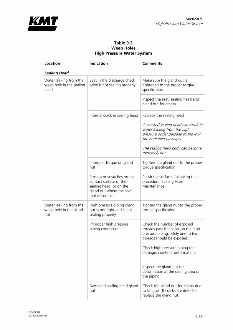
Section 9 High Pressure Water System
DOC00091 03-2008/Rev 03 9-36
Table 9-3 Weep Holes
High Pressure Water System
Location Indication Comments
Sealing Head
Water leaking from the weep hole in the sealing head
Seat in the discharge check valve is not sealing properly
Make sure the gland nut is tightened to the proper torque specification.
Inspect the seat, sealing head and gland nut for cracks.
Internal crack in sealing head Replace the sealing head
A cracked sealing head can result in water leaking from the high pressure outlet passage to the low pressure inlet passages.
The sealing head body can become extremely hot.
Improper torque on gland nut
Tighten the gland nut to the proper torque specification.
Erosion or scratches on the contact surface of the sealing head, or on the gland nut where the seat makes contact
Polish the surfaces following the procedure, Sealing Head Maintenance.
Water leaking from the weep hole in the gland nut
High pressure piping gland nut is not tight and is not sealing properly
Tighten the gland nut to the proper torque specification.
Improper high pressure piping connection
Check the number of exposed threads past the collar on the high pressure piping. Only one to two threads should be exposed.
Check high pressure piping for damage, cracks or deformation.
Inspect the gland nut for deformation at the sealing area of the piping.
Damaged sealing head gland nut
Check the gland nut for cracks due to fatigue. If cracks are detected, replace the gland nut.

Section 9 High Pressure Water System
DOC00091 03-2008/Rev 03 9-37
Table 9-3 Weep Holes
High Pressure Water System
Location Indication Comments
Hard Seal End Cap
Water leaking from the weep holes in the hard seal end cap
Damaged high pressure cylinder
Check for scratches, grooves or material buildup on the inside diameter of the high pressure cylinder. If detected, polish the bore following the procedure, High Pressure Cylinder Maintenance.
External crack in sealing head
Replace the sealing head.
Damaged sealing head Check for scratches or grooves on the 45-degree surface of the sealing head. If detected, polish the surface following the procedure, Sealing Head Maintenance.
Improper torque on jackbolts Re-torque the jackbolts to the proper torque specification.

DOC00091 03-2008/Rev 03 10-1
10 SECTION 10
TROUBLESHOOTING
10.1 Overview
The troubleshooting guide will help identify the probable cause of a system malfunction and assist in providing corrective action. The following symptoms are discussed in this section:
1. High boosted water temperature
2. Booster pump pressure drop is greater than 30 psi (2 bar) during stroke condition
3. Outlet booster pump pressure is falling below 60 psi (4 bar)
4. Inlet water flow is poor and the filter housing is not filling completely
5. Water is leaking around the bleed valve on the filter head
6. High oil temperature resulting in shutdown
7. Low oil level resulting in shutdown
8. Restricted or no cooling flow
9. Hydraulic pressure but no high pressure water pressure
10. No hydraulic oil pressure
11. Pump shaft will not turn
12. Pump will not start
13. Console display and lights do not illuminate
14. Pump quits running
15. No control power
16. Red light on operator’s console is flashing
17. Abnormal fluctuations in high pressure water signal
18. Hot surfaces on the high pressure cylinder components
19. Low cutting water supply pressure
20. Low cutting water pressure
21. Hydraulic oil leaking from the weep hole in the hydraulic cylinder head
22. Water leaking from the weep hole on the hydraulic cylinder head flange
23. Water leaking from the weep hole in the sealing head
24. Water leaking from the weep hole in the sealing head gland nut
25. Water leaking from the weep holes in the hard seal end cap

Section 10 Troubleshooting
DOC00091 03-2008/Rev 03 10-2
10.2 Troubleshooting Guide
Listen to the machine and observe it in operation. Learn to recognize the normal sounds and operating conditions of the system. Carefully define the symptom of the problem. Locate the symptom on the troubleshooting guide that most closely corresponds to the problem.
If the symptoms in the guide do not correspond to the malfunction, or if the problem is not resolved by the recommended corrective action, contact the KMT Customer Service Department for assistance.
SL-V Series Troubleshooting Guide
Malfunction Indication Comments
1. High boosted water temperature
Orifice is blocked with debris
Long deadhead condition
Insufficient water supply
2. Booster pump pressure drop is greater than 30 psi (2 bar) during stroke condition
Inlet water pressure or flow is low
Filter element is dirty and needs to be replaced
Booster pump is starting to fail
If the pressure consistently drops below 60 psi (4 bar) the pump will need to be replaced.
3. Outlet booster pump pressure is falling below 60 psi (4 bar)
Inlet water pressure is low
Filter element is dirty and needs to be replaced
Booster pump needs to be adjusted
Booster pump should be adjusted to 120 psi (8 bar) when deadheaded.
4. Inlet water flow is poor and the filter housing is not filling completely
Pipe sizing for inlet cutting water should be checked for pressure and flow
Cutting water supply will be lacking capacity or flow.
5. Water is leaking around the bleed valve on the filter head
O-ring that closes the passage has deteriorated
A small o-ring under the valve can deteriorate causing the passage to remain open. The o-ring can be replaced by removing the screw and spring on the underneath side.

Section 10 Troubleshooting
DOC00091 03-2008/Rev 03 10-3
SL-V Series Troubleshooting Guide
Malfunction Indication Comments
6. High oil temperature resulting in shutdown
Cooling water flow is restricted
Check cooling water source for proper temperature and flow rate.
Water modulating valve is stuck
Replace the valve.
Scale build up in the heat exchanger has restricted the flow
The heat exchanger will need to be flushed or replaced.
7. Low oil level resulting in shutdown
Check the level gauge.
Check for hydraulic leaks.
8. Restricted or no cooling flow
Check cooling water flow to and from the heat exchanger
The water pressure differential across the heat exchanger requires a minimum of 35 psi (2.4 bar) for flow through the exchanger.See Section 4, Operation.
9. Hydraulic pressure but no high pressure water pressure
Proximity switch failure From the control panel, jog the intensifier left and right and verify that the red light comes on at both proximity switches.
I/O relay failure From the control panel, jog the intensifier left and right and verify that the green light comes on at both directional valve solenoids.
See Section 4, Operation.
Coil failure on the directional control valve
Check the coils on the directional valve with a volt meter to verify if they are good or bad.
PLC failure If there are inputs from the proximity switches, but no outputs, contact the KMT Customer Service Department for a logic review and verification of PLC failure.

Section 10 Troubleshooting
DOC00091 03-2008/Rev 03 10-4
SL-V Series Troubleshooting Guide
Malfunction Indication Comments
10. No hydraulic oil pressure The high and low limit compensators on the hydraulic pump are blocked with debris and are not controlling the swashplate
Disassemble the compensators, clean and inspect the components following the maintenance procedure in Section 7, Hydraulic System.
11. Pump shaft will not turn The flexible coupling has failed
Replace the flexible coupling.
12. Pump will not start Emergency stop button is depressed
Pull the E-STOP button out.
Check all remote E-STOP buttons.
Main power is disconnected Check the main power and verify that the main power disconnect is on.
Control power has been interrupted
Check the power supply circuit for a tripped breaker.
Check the input and output of the 24 volt DC power supply.
A protection fault has been activated
Check the display panel for fault messages.
Motor overload relay has been tripped
Identify the source of the overload and remedy the problem. Reset the overload relay.
Inlet water valve is turned off
Press the RESET button on the Run Screen to reset the water valve.
13. Console display and lights do not illuminate
Emergency stop button is depressed
Pull the E-STOP button out.
Check all remote E-STOP buttons.
Main power is disconnected Check the main power and verify that the main power disconnect is on.
Control power is not available
Check the power supply circuit for a tripped breaker.
Check the input and output of the 24 volt DC power supply.

Section 10 Troubleshooting
DOC00091 03-2008/Rev 03 10-5
SL-V Series Troubleshooting Guide
Malfunction Indication Comments
14. Pump quits running Unsafe operation has been detected
Check the display panel for fault messages.
Electrical power has been interrupted
Check the power supply circuit for a tripped breaker.
Check the input and output of the 24 volt DC power supply.
Verify that power is available at the main power source.
Motor overload relay has been tripped
Identify the source of the overload and remedy the problem. Reset the overload relay.
15. No control power Circuit breaker has been tripped
Check the input and output of the 24 volt DC power supply.
Power supply fault Check the input and output voltages at the power supply.
Emergency stop button is depressed
Pull the E-STOP button out.
Check all remote E-STOP buttons.
Master control relay is not energized
Verify that the contactor coil is pulling in on the master control relay.
Contact set failure on the master control relay
Verify that the contact sets on the master control relay are changing states when the relay is energized.
16. Red light on operator’s console is flashing
An alarm condition has occurred
Check the display panel for fault messages.
Refer to Section 4, Operation, for additional information regarding warning and alarm conditions and recovery procedures.
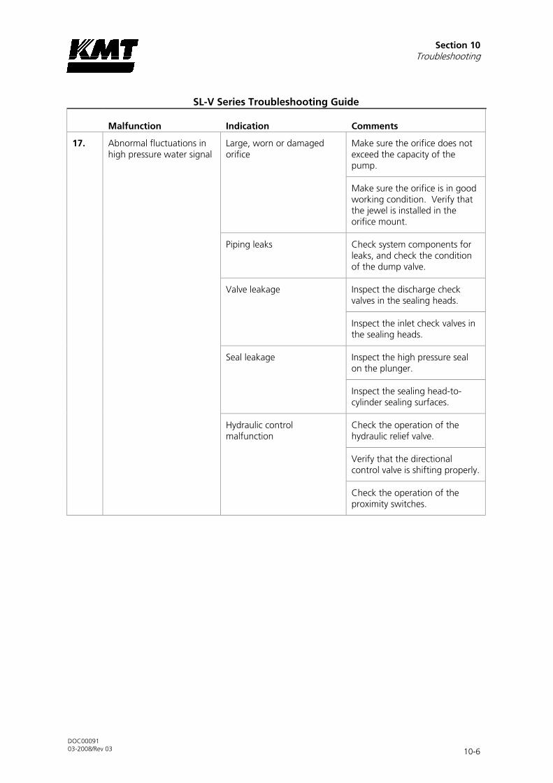
Section 10 Troubleshooting
DOC00091 03-2008/Rev 03 10-6
SL-V Series Troubleshooting Guide
Malfunction Indication Comments
17. Abnormal fluctuations in high pressure water signal
Large, worn or damaged orifice
Make sure the orifice does not exceed the capacity of the pump.
Make sure the orifice is in good working condition. Verify that the jewel is installed in the orifice mount.
Piping leaks Check system components for leaks, and check the condition of the dump valve.
Valve leakage Inspect the discharge check valves in the sealing heads.
Inspect the inlet check valves in the sealing heads.
Seal leakage Inspect the high pressure seal on the plunger.
Inspect the sealing head-to-cylinder sealing surfaces.
Hydraulic control malfunction
Check the operation of the hydraulic relief valve.
Verify that the directional control valve is shifting properly.
Check the operation of the proximity switches.

Section 10 Troubleshooting
DOC00091 03-2008/Rev 03 10-7
SL-V Series Troubleshooting Guide
Malfunction Indication Comments
18. Hot surfaces on the high pressure cylinder components
Leaking discharge check valve
Inspect the condition of the seat, poppet valve, spring, poppet pin and sealing head surface on the discharge end of the sealing heads.
Leaking inlet check valve Inspect the condition of the poppet valve, poppet retainer and the spring, if applicable, on the inlet end of the sealing heads.
Damaged sealing head Check the cone flange surface of the sealing head for scratches or mechanical damage and replace if necessary.
Damaged high pressure cylinder
Check the high pressure cylinder for cracks.
19. Low cutting water supply pressure
Restricted water supply Check cutting water supply flow and pressure.
Clogged water filter Check the condition of the low pressure water filter and replace the filter element if necessary.
Trapped air Bleed the air from the cutting water plumbing.
20. Low cutting water pressure
Low hydraulic pressure setting
If operating in low pressure, switch to high pressure operation and check the hydraulic pressure setting.
Not applicable when the machine is equipped with the optional proportional pressure control.
Collapsed element in the high pressure line filter
Check the element in the high pressure line filter.
21. Hydraulic oil leaking from the weep hole in the hydraulic cylinder head
Failed hydraulic cartridge seal
Replace the cartridge seal. If the leak persists, check the plunger for linear scratches or scoring.

Section 10 Troubleshooting
DOC00091 03-2008/Rev 03 10-8
SL-V Series Troubleshooting Guide
Malfunction Indication Comments
22. Water leaking from the weep hole on the hydraulic cylinder head flange
Failed high pressure seal assembly
Replace the high pressure seal assembly.
Damaged plunger Check the plunger for longitudinal scratches or flaws. If detected, replace the plunger or return to KMT Waterjet for evaluation.
Seal material buildup on plunger
Polish the plunger surface following the procedure, Plunger Maintenance, detailed in Section 9, High Pressure Water System.
Damaged high pressure cylinder
Check for scratches, grooves or material buildup on the inside diameter of the cylinder. If detected, polish the bore following the procedure, High Pressure Cylinder Maintenance, detailed in Section 9, High Pressure Water System.
Check the inside diameter of the cylinder for expansion where the high pressure seal assembly is located. If detected, replace the cylinder.
23. Water leaking from the weep hole in the sealing head
Seat in the discharge check valve is not sealing properly
Make sure the gland nut is tightened to the proper torque specification.
Inspect the seat, sealing head and gland nut for cracks.
Internal crack in sealing head
Replace the sealing head.
A cracked sealing head can result in water leaking from the high pressure outlet passage to the low pressure inlet passages The sealing head body can become extremely hot.
Improper torque on gland nut
Tighten the gland nut to the proper torque specification.

Section 10 Troubleshooting
DOC00091 03-2008/Rev 03 10-9
SL-V Series Troubleshooting Guide
Malfunction Indication Comments
Erosion or scratches on the contact surface of the sealing head, or on the gland nut where the seat makes contact
Polish the surfaces following the procedure, Sealing Head Maintenance, detailed in Section 9, High Pressure Water System.
24. Water leaking from the weep hole in the sealing head gland nut
High pressure piping gland nut is not tight and is not sealing properly
Tighten the gland nut to the proper torque specification.
Improper high pressure piping connection
Check the number of exposed threads past the collar on the high pressure piping. Only one to two threads should be exposed.
Check high pressure piping for damage, cracks or deformation.
Inspect the gland nut for deformation at the sealing area of the piping.
Damaged sealing head gland nut
Check the gland nut for cracks due to fatigue. If cracks are detected, replace the gland nut.
25. Water leaking from the weep holes in the hard seal end cap
Damaged high pressure cylinder
Check for scratches, grooves or material buildup on the inside diameter of the high pressure cylinder. If detected, polish the bore following the procedure, High Pressure Cylinder Maintenance, detailed in Section 9, High Pressure Water System.
External crack in sealing head
Replace the sealing head.
Damaged sealing head Check for scratches or grooves on the 45-degree surface of the sealing head. If detected, polish the surface following the procedure, Sealing Head Maintenance, detailed in Section 9, High Pressure Water System.

Section 10 Troubleshooting
DOC00091 03-2008/Rev 03 10-10
SL-V Series Troubleshooting Guide
Malfunction Indication Comments
Improper torque on jackbolts
Re-torque the jackbolts to the proper torque specification.

DOC00091 03-2008/Rev 03 11-1
11 SECTION 11
SPECIFICATIONS
11.1 Overview
Comprehensive listings of specifications for the SL-V Classic are provided in this section.
Table 11-1 SL-V Classic
Model
Motor Horsepower Rating
HP
Kw
SL-V 30 Classic 30 22
SL-V 50 Classic 50 37
11.2 Installation Specifications
Environment
Installation location Indoors
Air borne dust/contaminants Minimal
Ambient temperature
Minimum storage 36° F (2° C)
Minimum operating 40° F (5° C)
Maximum operating 104° F (40° C)
Maximum relative humidity* (at maximum operating temperature)
95%
*Note: When the relative humidity is above 50%, the oil in the reservoir should be checked frequently for water content.
Sound Level
Sound level [dB(A)] 80.0
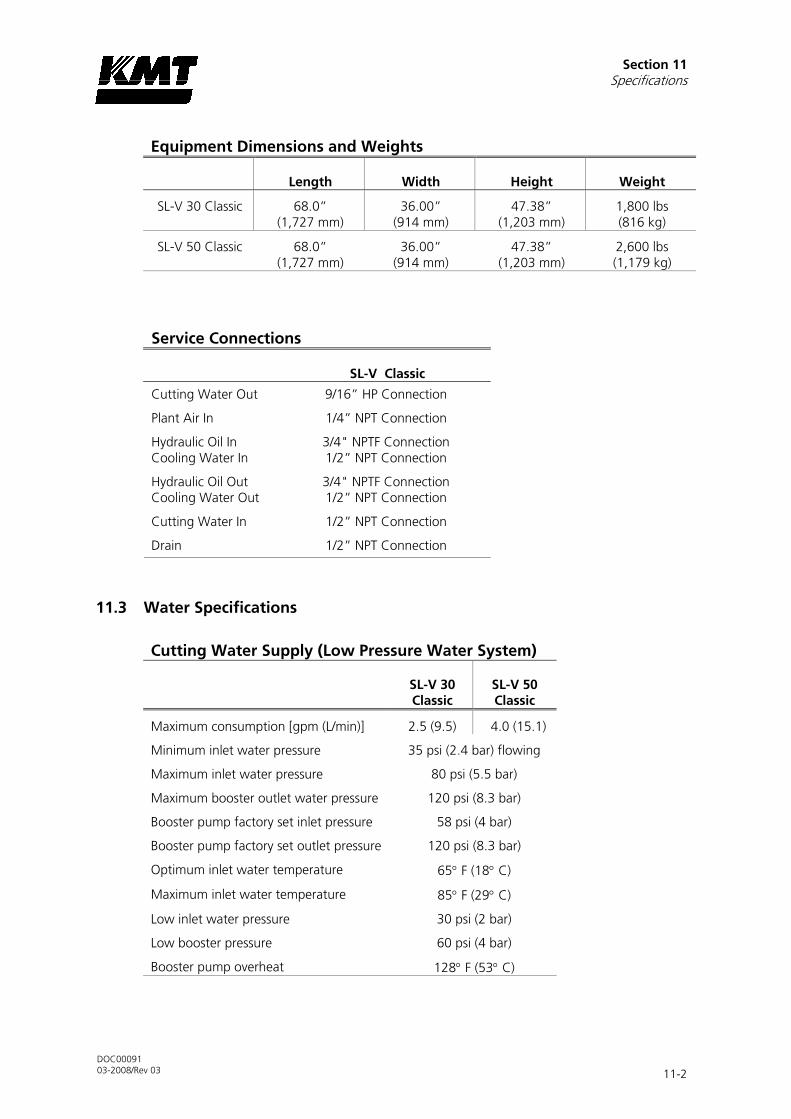
Section 11 Specifications
DOC00091 03-2008/Rev 03 11-2
Equipment Dimensions and Weights
Length Width Height Weight
SL-V 30 Classic 68.0” (1,727 mm)
36.00” (914 mm)
47.38” (1,203 mm)
1,800 lbs (816 kg)
SL-V 50 Classic 68.0” (1,727 mm)
36.00” (914 mm)
47.38” (1,203 mm)
2,600 lbs (1,179 kg)
Service Connections
SL-V Classic
Cutting Water Out 9/16” HP Connection
Plant Air In 1/4” NPT Connection
Hydraulic Oil In Cooling Water In
3/4" NPTF Connection 1/2” NPT Connection
Hydraulic Oil Out Cooling Water Out
3/4" NPTF Connection 1/2” NPT Connection
Cutting Water In 1/2” NPT Connection
Drain 1/2” NPT Connection
11.3 Water Specifications
Cutting Water Supply (Low Pressure Water System)
SL-V 30 Classic
SL-V 50 Classic
Maximum consumption [gpm (L/min)] 2.5 (9.5) 4.0 (15.1)
Minimum inlet water pressure 35 psi (2.4 bar) flowing
Maximum inlet water pressure 80 psi (5.5 bar)
Maximum booster outlet water pressure 120 psi (8.3 bar)
Booster pump factory set inlet pressure 58 psi (4 bar)
Booster pump factory set outlet pressure 120 psi (8.3 bar)
Optimum inlet water temperature 65° F (18° C)
Maximum inlet water temperature 85° F (29° C)
Low inlet water pressure 30 psi (2 bar)
Low booster pressure 60 psi (4 bar)
Booster pump overheat 128° F (53° C)

Section 11 Specifications
DOC00091 03-2008/Rev 03 11-3
Recirculation System
SL-V 30 SL-V 50
Maximum consumption [gpm l/min)] 2.5 (9.5) 3.0 gpm (11.4)
Total heat rejection 5.3 HP 4.0 kW 8.6 HP 6.4 kW
Reservoir capacity 38 gal (144 L)
Low oil level shutdown 30 gal (114 L)
Minimum operating oil temperature 60° F (15° C)
Optimum operating oil temperature 115° F (46° C)
Hot oil shutdown (maximum operating oil temperature) 144° F (62° C)
Minimum inlet cooling water pressure 35 psi (2.4 bar)
Maximum inlet cooling water pressure 100 psi (6.9 bar)
Oil filtration rating (Beta filtration rating) β10≥100*
Fluid cleanliness rating (ISO fluid cleanliness rating)) 17/14**
Nominal recirculation pressure 30 psi (2 bar)
Recommended oil type
General service Mobil #DTE Heavy Medium, No. 05022702
Conoco Hydroclear TM multi-purpose R&O
Food service AMOCO #FG68EL
* Note: For each particle per milliliter downstream of the filer greater than 10 microns, there are 100 particles per milliliter larger than 10 microns upstream of the filter.
**Note: Indicates ISO 4406 range numbers for maximum permissible number of particles per milliliter, greater than 5 and 15 microns.
17 <1,300 particles per milliliter, >5 microns
14 <160 particles per milliliter, >15 microns
Water Quality Standards
The quality of the inlet cutting water supply is one of the most important factors affecting component life and performance. Water treatment requirements can be determined by a water analysis.
The cutting water supply must meet the following standards. A high concentration of dissolved solids, especially calcium, silica and chlorides will affect high pressure component life.

Section 11 Specifications
DOC00091 03-2008/Rev 03 11-4
Table 11-2 Water Quality Standards
Constituent (mg/l)
Minimum Requirement
Better
Best
Alkalinity 50 25 10
Calcium 25 5 0.5
Carbon Dioxide 0 0 0
Chloride 100 15 1
Free Chlorine 1 1 0.05
Iron 0.2 0.1 0.01
Magnesium as Mg 0.5 0.1 0.1
Manganese as Mn 0.1 0.1 0.1
Nitrate 25 25 10
Oxygen 2 1 0.1
Silica 15 10 1
Sodium 50 10 1
Sulfate 25 25 1
TDS* 200 100 5**
Electrical Conductivity 290 154 45**
Total Hardness 15 10 1
pH 6.5-8.5 6.5-8.5 6.5-8.5
Turbidity (NTU) 5 5 1
* Note: Total dissolved solids
**Note: Do not reduce the TDS beyond this amount or the water will be too aggressive.

Section 11 Specifications
DOC00091 03-2008/Rev 03 11-5
Table 11-3 Water Impurities
Constituent
Chemical Formula
Comments
Alkalinity Bicarbonate (HCO3) Carbonate (CO3) Hydrate (OH), expressed as CaCO3
Acid neutralizing capacity of water. Foaming and carryover of solids, causes embrittlement of steel, can produce CO2, a source of corrosion.
Calcium Ca When dissolved makes water hard; contributes to the formation of scale.
Carbon Dioxide CO2 Causes corrosion
Chloride Cl Adds to solid content and increases corrosive character of water; in relative percentage presence with oxygen induces stress corrosion cracking.
Free Chlorine Cl2 Oxidizing agent; can attack elastomeric seals and damage reverse osmosis (RO) membranes.
Iron Fe++ (ferrous) Fe+++ (ferric)
Discolors water or precipitation; source of scale and erosion.
Magnesium as Mg When dissolved makes water hard; contributes to the formation of scale.
Manganese as Mn Mn++ Discolors water or precipitation; source of scale and erosion.
Nitrate NO3 Adds to solid content; effect is not generally significant industrially.
Oxygen O2 Causes corrosion
Silica SiO2 Causes scale
Sodium Na Found naturally; introduced to water in the ion exchange water softening process.
Sulfate SO4 Adds to solid content; combines with calcium to form calcium sulfate scale.
TDS Measure of the total amount of dissolved matter in water.
Total Hardness CaCO3 Sum of all hardness constituents in water; typically expressed as their equivalent concentration of calcium carbonate; primarily due to calcium and magnesium in solution, but may include small amounts of metal. Carbonate hardness is usually due to magnesium and calcium bicarbonate; non-carbonate hardness is due to sulfates and chlorides.
pH Intensity of the acidic or alkaline solids in water; pH scale runs from 0, highly acidic, to 14, highly basic; with 7 being neutral.
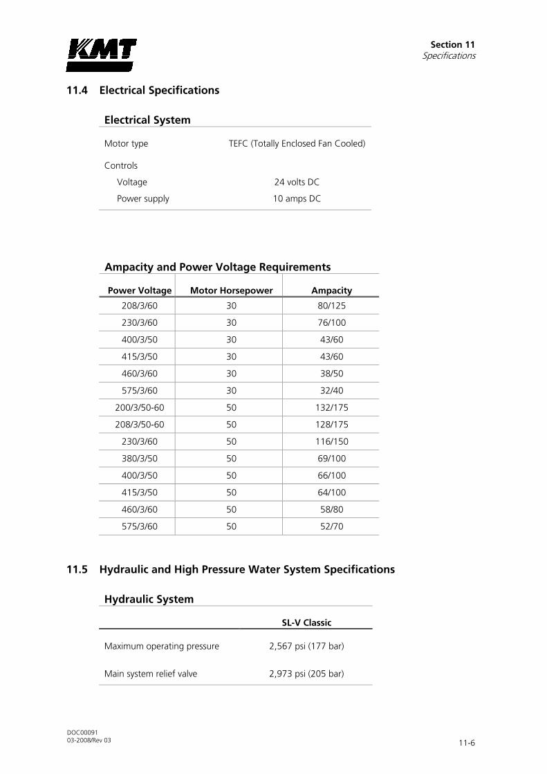
Section 11 Specifications
DOC00091 03-2008/Rev 03 11-6
11.4 Electrical Specifications
Electrical System
Motor type TEFC (Totally Enclosed Fan Cooled)
Controls
Voltage 24 volts DC
Power supply 10 amps DC
Ampacity and Power Voltage Requirements
Power Voltage Motor Horsepower Ampacity
208/3/60 30 80/125
230/3/60 30 76/100
400/3/50 30 43/60
415/3/50 30 43/60
460/3/60 30 38/50
575/3/60 30 32/40
200/3/50-60 50 132/175
208/3/50-60 50 128/175
230/3/60 50 116/150
380/3/50 50 69/100
400/3/50 50 66/100
415/3/50 50 64/100
460/3/60 50 58/80
575/3/60 50 52/70
11.5 Hydraulic and High Pressure Water System Specifications
Hydraulic System
SL-V Classic
Maximum operating pressure 2,567 psi (177 bar)
Main system relief valve 2,973 psi (205 bar)

Section 11 Specifications
DOC00091 03-2008/Rev 03 11-7
High Pressure Water System
30 HP 50 HP
Maximum flow rate [gpm (l/min)]
52,000 psi (3,585 bar) .60 (2.3) 1.0 (3.8)
Plunger diameter [inches (mm)] 0.875 (22)
Piston diameter [inches (mm)] 4.03 (102.4)
Intensification ratio 20:1
Minimum outlet pressure 5,000 psi (500 bar)
Maximum outlet pressure 52,000 psi (3,585 bar)
Pneumatic Control Valve
Maximum water pressure 60,000 psi (4,137 bar)
Minimum air pressure 85 psi (5.9 bar)
Maximum air pressure 100 psi (6.9 bar)
Maximum flow rate 1.0 cfm (0.028) m3/min
Orifice Capacity
The following tables provide horsepower requirements for some of the more popular orifices.
Table 11-4 Single Orifice Diameter
Model
Motor Horsepower
Rating
Maximum Operating Pressure
Maximum Single Orifice Diameter (at full pressure)
HP Kw
SL-V 30 Classic 30 22 52,000 psi (3,585 bar)
0.011 inch (0.279 mm)
SL-V 50 Classic 50 37 52,000 psi (3,585 bar)
0.014 inch (0.356 mm)

Section 11 Specifications
DOC00091 03-2008/Rev 03 11-8
Table 11-5 Horsepower Requirements
Orifice Size inches (mm)
45,000 psi (3,103 bar)
50,000 psi (3,447 bar)
52,000 psi (3,585 bar)
0.003 (0.08) 1.7 2.0 2.1
0.004 (0.10) 3.0 3.5 3.7
0.005 (0.12) 4.6 5.4 5.7
0.006 (0.15) 6.7 7.8 8.3
0.007 (0.17) 9.1 10.6 11.3
0.008 (0.20) 11.8 13.9 14.7
0.009 (0.23) 15.0 17.5 18.6
0.010 (0.25) 18.5 21.6 23.0
0.011 (0.28) 22.4 26.2 27.8
0.012 (0.30) 26.6 31.2 33.1
0.013 (0.33) 31.2 36.6 38.8
0.014 (0.36) 36.2 42.4 45.0
0.015 (0.38) 41.6 48.7 51.7
0.016 (0.41) 47.3 55.4 58.8
The horsepower requirements for operating multiple orifices are determined by adding the requirements in Table 11-5 for each orifice. Examples are shown below.
Orifice Size inches (mm)
Number of Orifices
Operating Pressure
Calculation
Total Horsepower
0.008 (0.20) 2 52,000 2 x 14.7 29.4
0.012 (0.31) 0.009 (0.23)
1 1
50,000 31.2 + 17.5 48.7
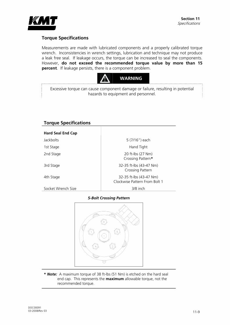
Section 11 Specifications
DOC00091 03-2008/Rev 03 11-9
Torque Specifications
Measurements are made with lubricated components and a properly calibrated torque wrench. Inconsistencies in wrench settings, lubrication and technique may not produce a leak free seal. If leakage occurs, the torque can be increased to seal the components. However, do not exceed the recommended torque value by more than 15 percent. If leakage persists, there is a component problem.
WARNING
Excessive torque can cause component damage or failure, resulting in potential hazards to equipment and personnel.
Torque Specifications
Hard Seal End Cap
Jackbolts 5 (7/16”) each
1st Stage Hand Tight
2nd Stage 20 ft-lbs (27 Nm) Crossing Pattern*
3rd Stage 32-35 ft-lbs (43-47 Nm) Crossing Pattern
4th Stage 32-35 ft-lbs (43-47 Nm) Clockwise Pattern From Bolt 1
Socket Wrench Size 3/8 inch
5-Bolt Crossing Pattern
* Note: A maximum torque of 38 ft-lbs (51 Nm) is etched on the hard seal end cap. This represents the maximum allowable torque, not the recommended torque.

Section 11 Specifications
DOC00091 03-2008/Rev 03 11-10
Torque Specifications
Hydraulic Cylinder Head
Socket Head Screws 8 (14M) each
Torque 75-80 ft-lbs (102-108 Nm)
Hex Key M12
Proximity Switch
Socket Head Screws 2 (M6) each
Torque 140-160 in-lbs (16-18 Nm)
Hex Key M5
Stem Mount
Socket Head Screws 4 (M10) each
Torque 60-65 ft-lbs (80-88 Nm)
Hex Key M8
Sealing Head
Discharge Gland Nut 130 ft-lbs (176 Nm)
Poppet Retainer 25-30 in-lbs (2.8-3.4 Nm)
3/8” Inlet Gland Nut 50 ft-lbs (68 Nm)
Pneumatic Control Valve
3/8-inch HP Inlet Gland Nut 50 ft-lbs (68 Nm)
1/4-inch Outlet to Drain 25 ft-lbs (34 Nm)
Pneumatic Actuator 5 ft-lbs (7 Nm)
9/16”-1/4” HP Adapter 50 ft-lbs (68 Nm)
High Pressure Fittings
1/4-inch Gland Nut 25 ft-lb (34 Nm)
3/8-inch Gland Nut 50 ft-lb (68 Nm)
9/16-inch Gland Nut 110 ft-lb (149 Nm)