SK Pump Solution Guide
98
www.controltechniques.com User Guide SK Pump Software for Commander SK Part Number: SSK-0000-0001 Issue Number: 5
-
Upload
khangminh22 -
Category
Documents
-
view
0 -
download
0
Transcript of SK Pump Solution Guide

www.controltechniques.com
User Guide
SK Pump
Software for Commander SK
Part Number: SSK-0000-0001Issue Number: 5

Safety InformationPersons supervising and performing the electrical installation or maintenance of a Drive and/or an external Option Unit must be suitably qualified and competent in these duties. They should be given the opportunity to study and if necessary to discuss this User Guide before work is started.
The voltages present in the Drive and external Option Units are capable of inflicting a severe electric shock and may be lethal. The Stop function of the Drive does not remove dangerous voltages from the terminals of the Drive and external Option Unit. Mains supplies should be removed before any servicing work is performed.
The installation instructions should be adhered to. Any questions or doubt should be referred to the supplier of the equipment. It is the responsibility of the owner or user to ensure that the installation of the Drive and external Option Unit, and the way in which they are operated and maintained complies with the requirements of the National Electrical Code and any additional state or local codes.
The Drive software may incorporate an optional Auto-start facility. In order to prevent the risk of injury to personnel working on or near the motor or its driven equipment and to prevent potential damage to equipment, users and operators, all necessary precautions must be taken if operating the Drive in this mode.
The Stop and Start inputs of the Drive should not be relied upon to ensure safety of personnel. If a safety hazard could exist from unexpected starting of the Drive, an interlock should be installed to prevent the motor being inadvertently started.
General InformationThe manufacturer accepts no liability for any consequences resulting from inappropriate, negligent or incorrect installation or adjustment of the optional operating parameters of the equipment or from mismatching the variable speed drive (Drive) with the motor.
The contents of this guide are believed to be correct at the time of printing. In the interests of a commitment to a policy of continuous development and improvement, the manufacturer reserves the right to change the specification of the product or its performance, or the contents of this guide, without notice.
All rights reserved. No parts of this guide may be reproduced or transmitted in any form or by any means, electrical or mechanical including photocopying, recording or by an information storage or retrieval system, without permission in writing from the publisher.
Copyright © 2011, 2012
Control Techniques Americas LLC

Content
1 Introduction........................................................................... 11.1 Who Should Read This Manual?.................................................................... 11.2 Application Overview...................................................................................... 11.2.1 Pump Mode 1 (Pressure Switch Start / Flow Switch Stop)............................................. 21.2.2 Pump Mode 2 (Pressure Transducer Start / Flow Switch Stop) ..................................... 21.2.3 Pump Mode 3 (Pressure Transducer Start/Stop) ........................................................... 3
2 Ordering Codes .................................................................... 52.1 Pump Drive Only ............................................................................................ 52.2 Pump Drive with a SM-I/O Lite Option Module............................................... 52.3 Programmed LogicStick and SmartStick........................................................ 52.4 How To Order................................................................................................. 62.4.1 Commander SK-P includes: ........................................................................................... 62.4.2 Commander SK-PL includes: ......................................................................................... 62.4.3 LogicStick-P includes...................................................................................................... 62.4.4 LogicStick-PL includes....................................................................................................6
3 Feature Set ............................................................................ 73.1 Operating Modes............................................................................................ 73.2 Operating Mode Options ................................................................................ 73.2.1 Off ................................................................................................................................... 73.2.2 Terminals ........................................................................................................................73.2.3 Keypad-AUTO 3.2.4 Keypad-AUTO-HAND 3.3 Start/Stop and Control Modes ........................................................................ 83.3.1 Pump Mode 1 - Pressure Switch and Flow Switch ......................................................... 83.3.2 Pump Mode 2 - Pressure Transducer and Flow Switch ................................................. 83.3.3 Pump Mode 3 - Pressure Transducer Only .................................................................... 83.4 Software Operating Features ......................................................................... 83.4.1 Pressure PID .................................................................................................................. 83.4.2 Sleep/Wake .................................................................................................................... 83.4.3 No Suction Detection/Dry Well ....................................................................................... 83.4.4 Transducer Loss Detection............................................................................................. 83.4.5 High Pressure Detect.....................................................................................................93.4.6 Low Pressure Detect ...................................................................................................... 93.4.7 Start Delay ...................................................................................................................... 93.4.8 Stop Delay ...................................................................................................................... 93.4.9 Automatic Fault Reset .................................................................................................... 93.4.10 No Flow Detection ........................................................................................................93.4.11 Multiple Setpoint Selection ......................................................................................... 103.4.12 Pipe Fill ....................................................................................................................... 10
4 Mechanical Installation ...................................................... 114.1 Option Modules Installation .......................................................................... 114.2 SmartStick Installation.................................................................................. 124.3 Installation of LogicStick............................................................................... 14
5 Electrical Installation.......................................................... 155.1 Control.......................................................................................................... 155.1.1 Commander SK Control Terminal Connections............................................................ 155.1.2 SM-I/O Lite Option Module ........................................................................................... 165.1.3 Commander SK RS485 Port......................................................................................... 175.1.4 Typical System Wiring Diagram.................................................................................... 185.1.5 Pump Mode 1 (Pressure Switch Start / Flow Switch Stop)........................................... 19
SK Pump Solutions Software User Guide for Commander SK iIssue Number: 5 www.controltechniques.com
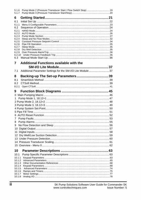
5.1.6 Pump Mode 2 (Pressure Transducer Start / Flow Switch Stop) ...................................195.1.7 Pump Mode 3 (Pressure Transducer Start/Stop)..........................................................20
6 Getting Started....................................................................216.1 Initial Set Up ................................................................................................. 226.1.1 Menu 0 Configurable Parameters .................................................................................236.2 Sequence of Operation................................................................................. 246.2.1 HAND Mode..................................................................................................................246.2.2 AUTO Mode ..................................................................................................................266.2.3 Pump Mode Section......................................................................................................276.2.4 Sleep and No Flow Modes............................................................................................326.2.5 Constant Pressure Setpoint Control .............................................................................346.2.6 Pipe Fill Operation ........................................................................................................356.2.7 Sleep Mode...................................................................................................................356.2.8 Dry Well Detection ........................................................................................................356.2.9 Over Pressure Alarm/Trip .............................................................................................366.2.10 Under Pressure Feedback Trip...................................................................................366.3 Manual Mode Start Up.................................................................................. 36
7 Additional Functions available with the SM-I/O Lite Module.....................................................37
7.1 Additional Parameter Settings for the SM-I/O Lite Module ........................... 37
8 Backing-up The Set-up Parameters..................................398.1 SmartStick Method ....................................................................................... 398.2 CTSoft Method.............................................................................................. 398.2.1 Open CTSoft .................................................................................................................41
9 Function Block Diagrams ..................................................450 Main Pumping Macro ........................................................................................ 461 Pump Mode 1, 18.12=1 ................................................................................... 472 Pump Mode 2, 18.12=2 ..................................................................................... 483 Pump Mode 3, 18.12=3 ..................................................................................... 494 Pump System Set-Point..................................................................................... 505 Pipe Fill Time ..................................................................................................... 516 AUTO Reset Function....................................................................................... 527 Pump Faults..................................................................................................... 538 Pump Alarms ................................................................................................... 559 No Flow Detection and Sleep .......................................................................... 5610 Digital Output .................................................................................................. 5711 Digital Inputs.................................................................................................... 5812 Dry Well/Low Suction Detection...................................................................... 5913 Under Pressure Detection............................................................................... 6014 Pressure Transducer Scaling.......................................................................... 6115 Overview - Menu 0.......................................................................................... 62
10 Parameter Descriptions ...................................................6310.1 Pump Specific Parameter Descriptions ...................................................... 6310.1.1 Keypad Parameters ....................................................................................................6310.1.2 Advanced Parameters ................................................................................................6510.1.3 Other Documentation References ..............................................................................6810.1.4 Keypad Parameters ....................................................................................................6810.1.5 Advanced Parameters ...............................................................................................7410.1.6 Ramps and Timers......................................................................................................7510.1.7 Motor Settings.............................................................................................................7710.1.8 Analog I/O ...................................................................................................................78
ii SK Pump Solutions Software User Guide for Commander SKwww.controltechniques.com Issue Number: 5
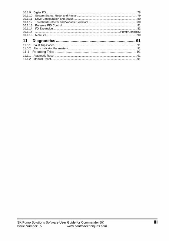
10.1.9 Digital I/O.................................................................................................................... 7810.1.10 System Status, Reset and Restart............................................................................ 7910.1.11 Drive Configuration and Status................................................................................. 8010.1.12 Threshold Detector and Variable Selectors .............................................................. 8010.1.13 Pressure PID Control................................................................................................ 8110.1.14 I/O Expansion ...........................................................................................................8210.1.15 ............................................................................................................Pump Control8310.1.16 Menu 21.................................................................................................................... 90
11 Diagnostics ....................................................................... 9111.0.1 Fault Trip Codes .........................................................................................................9111.0.2 Alarm Indicator Parameters ........................................................................................ 9111.1 Resetting Trips ........................................................................................... 9111.1.1 Automatic Reset ......................................................................................................... 9111.1.2 Manual Reset.............................................................................................................. 91
SK Pump Solutions Software User Guide for Commander SK iiiIssue Number: 5 www.controltechniques.com

iv SK Pump Solutions Software User Guide for Commander SKwww.controltechniques.com Issue Number: 5

1 Introduction1.1 Who Should Read This Manual?This manual is intended to assist the user in commissioning the application software and should be read in conjunction with the documentation that is supplied with the drive and other associated hardware. The safety systems that are required to prevent risk of injury to persons operating or maintaining the machine are not included in this manual. The user must be familiar with and able to implement the required safety systems. This manual assumes that the user is familiar with relevant Control Techniques products and understands the requirements for the application.
If you do not feel confident of the above, then you should contact your local Control Techniques drive center or distributor to obtain assistance or service.
1.2 Application OverviewThe SK Pumping Solutions drive is an effective and versatile control system for maintaining constant pressure or flow in a single pump configuration. An embedded controller in the motor drive eliminates the need for an external PLC saving cost, space, and programming time. The system consists of a Commander SK variable frequency motor drive with a SmartStick containing pump drive parameters, a LogicStick programmed with the pump solutions software, and an optional SM-I/O Lite module. The optional I/O module provides an additional 4 digital inputs for control purposes and 1 programmable relay output for status monitoring. See Section 5 Electrical Installation on page 15 for details.
The flexibility of the SK Pump drive allows the user to operate and run the pump from the built-in keypad without the need to interface with other control equipment. If additional functionality is desired I/O terminals may be utilized, including definable output status relays.
Pressure feedback can be provided via either a 4-20 mA analog signal or a pressure switch. The system will control based on pressure feedback alone or in conjunction with a flow switch.
All models of the Commander SK drive are available with the Pumping Solutions control software.
Only drive sizes B and above may have the optional SM-I/O Lite module installed.NOTE
SK Pump Solutions Software User Guide for Commander SK 1Issue Number: 5 www.controltechniques.com

1.2.1 Pump Mode 1 (Pressure Switch Start / Flow Switch Stop)
In this mode, the pump starts automatically when low pressure is detected by the Pressure switch. The pump will then run at maximum speed. The pressure rises and the Pressure switch opens. If demand reduces (e.g. reduced flow due to valve closing) the pressure will increase and the Flow switch would close indicating a no-flow condition. At this point (no flow detection), the pump automatically stops after a adjustable time delay. This cycle is repeated when the pressure reduces to the low set level.
1.2.2 Pump Mode 2 (Pressure Transducer Start / Flow Switch Stop)
In this mode, the pump starts automatically after a adjustable start delay when a low pressure condition is detected (the transducer signal is below the Low Pressure setpoint threshold). Initially, a pipe fill operation is performed to remove air bubbles if enabled (then a constant pressure setpoint PID control regulates the system pressure to the setpoint). The pump control adjusts the motor speed in order to satisfy the demand and maintain constant pressure at the setpoint value. At maximum demand, the pump speed will be at maximum and whereas at low demand the motor speed drops to the minimum speed limit. If the demand goes even further below the system Flow switch will close indicating a no-flow condition. At this point (no flow detection), the pump automatically stops after a time delay.
Flow SwitchOpens with Flow
Water Pump
WaterSupply
Pressure SwitchOpens with Pressure
Flow
Flow Switchopens with flow
Water Pump
WaterSupply
Pressure Transducer4-20 mA / 0-10 Vdc
Flow
2 SK Pump Solutions Software User Guide for Commander SKwww.controltechniques.com Issue Number: 5

1.2.3 Pump Mode 3 (Pressure Transducer Start/Stop)
In this mode, the pump starts automatically with a start delay when a low pressure condition is detected (Pressure Transducer signal goes below Low Pressure setpoint threshold). Initially, a pipe fill operation is performed to remove air bubbles if enabled. A constant pressure setpoint PID control then regulates the system pressure to the setpoint. The pump control adjusts the motor speed in order to satisfy the demand and maintain pressure constant at the set value. At maximum demand the pump speed will be at maximum speed and at low demand the motor speed drops to the minimum speed limit. The pump automatically stops after a time when a “No Flow” or “Sleep” condition is detected by the pump control system logic.
Flow
Water PumpWaterSupply
Pressure Trnasducer4-20 mA / 0-10 Vdc
SK Pump Solutions Software User Guide for Commander SK 3Issue Number: 5 www.controltechniques.com

4 SK Pump Solutions Software User Guide for Commander SKwww.controltechniques.com Issue Number: 5
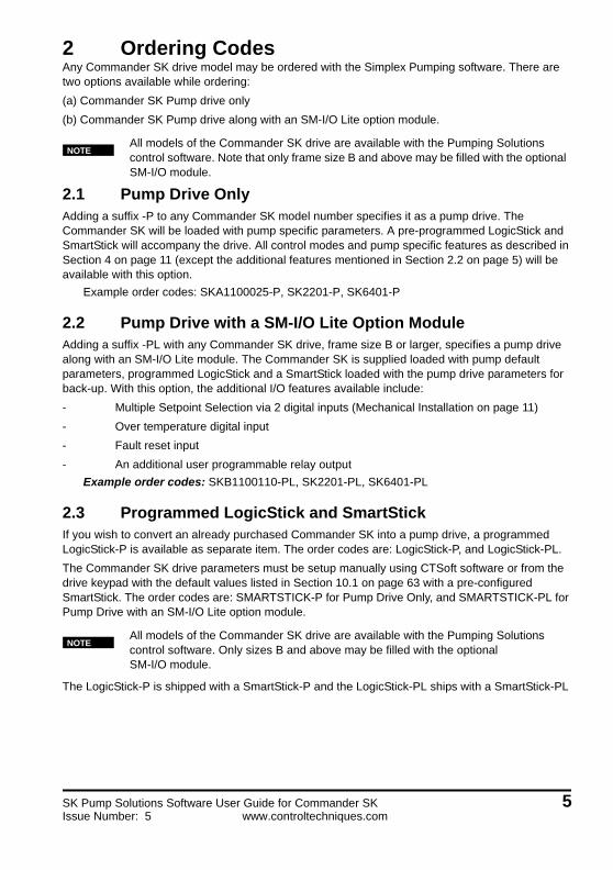
2 Ordering CodesAny Commander SK drive model may be ordered with the Simplex Pumping software. There are two options available while ordering:
(a) Commander SK Pump drive only
(b) Commander SK Pump drive along with an SM-I/O Lite option module.
2.1 Pump Drive OnlyAdding a suffix -P to any Commander SK model number specifies it as a pump drive. The Commander SK will be loaded with pump specific parameters. A pre-programmed LogicStick and SmartStick will accompany the drive. All control modes and pump specific features as described in Section 4 on page 11 (except the additional features mentioned in Section 2.2 on page 5) will be available with this option.
Example order codes: SKA1100025-P, SK2201-P, SK6401-P
2.2 Pump Drive with a SM-I/O Lite Option ModuleAdding a suffix -PL with any Commander SK drive, frame size B or larger, specifies a pump drive along with an SM-I/O Lite module. The Commander SK is supplied loaded with pump default parameters, programmed LogicStick and a SmartStick loaded with the pump drive parameters for back-up. With this option, the additional I/O features available include:
- Multiple Setpoint Selection via 2 digital inputs (Mechanical Installation on page 11)
- Over temperature digital input
- Fault reset input
- An additional user programmable relay output
Example order codes: SKB1100110-PL, SK2201-PL, SK6401-PL
2.3 Programmed LogicStick and SmartStickIf you wish to convert an already purchased Commander SK into a pump drive, a programmed LogicStick-P is available as separate item. The order codes are: LogicStick-P, and LogicStick-PL.
The Commander SK drive parameters must be setup manually using CTSoft software or from the drive keypad with the default values listed in Section 10.1 on page 63 with a pre-configured SmartStick. The order codes are: SMARTSTICK-P for Pump Drive Only, and SMARTSTICK-PL for Pump Drive with an SM-I/O Lite option module.
The LogicStick-P is shipped with a SmartStick-P and the LogicStick-PL ships with a SmartStick-PL
All models of the Commander SK drive are available with the Pumping Solutions control software. Note that only frame size B and above may be filled with the optional SM-I/O module.
All models of the Commander SK drive are available with the Pumping Solutions control software. Only sizes B and above may be filled with the optional SM-I/O module.
NOTE
NOTE
SK Pump Solutions Software User Guide for Commander SK 5Issue Number: 5 www.controltechniques.com

2.4 How To OrderSK Pump Solutions can be ordered 4 ways:
1. Add a -P to the Commander SK drive order code2. Add a -PL to the Commander SK drive order code (frame size B and above)3. Order a LOGICSTICK-P4. Order a LOGICSTICK-PL
2.4.1 Commander SK-P includes:• A programmed Commander SK-P containing the default drive parameters for the Pump
configuration.
• A LOGICSTICK containing the Pump software.
• A SMARTSTICK-P containing the default drive parameters for the Pump configuration. This is provided as a back up to restore drive parameter defaults.
2.4.2 Commander SK-PL includes:• A LOGICSTICK containing the Pump software.
• A SMARTSTICK-P containing the default drive parameters for the Pump configuration. This is provided as a back up to restore drive parameter defaults.
• SM-I/O LITE option module (frame size B and above) parameters
2.4.3 LogicStick-P includes• A LOGICSTICK containing the Pump software.
• A SMARTSTICK-P containing the default drive parameters for the Pump configuration.
2.4.4 LogicStick-PL includes• A LOGICSTICK containing the Pump software.
• A SMARTSTICK-PL containing the default drive parameters for the Pump configuration including the SM-I/O Lite option module parameters.
6 SK Pump Solutions Software User Guide for Commander SKwww.controltechniques.com Issue Number: 5
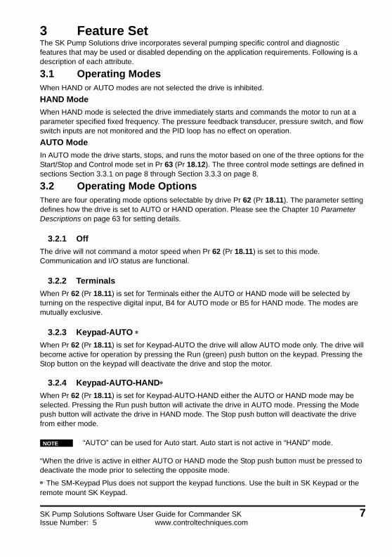
3 Feature SetThe SK Pump Solutions drive incorporates several pumping specific control and diagnostic features that may be used or disabled depending on the application requirements. Following is a description of each attribute.
3.1 Operating ModesWhen HAND or AUTO modes are not selected the drive is inhibited.
HAND Mode
When HAND mode is selected the drive immediately starts and commands the motor to run at a parameter specified fixed frequency. The pressure feedback transducer, pressure switch, and flow switch inputs are not monitored and the PID loop has no effect on operation.
AUTO Mode
In AUTO mode the drive starts, stops, and runs the motor based on one of the three options for the Start/Stop and Control mode set in Pr 63 (Pr 18.12). The three control mode settings are defined in sections Section 3.3.1 on page 8 through Section 3.3.3 on page 8.
3.2 Operating Mode OptionsThere are four operating mode options selectable by drive Pr 62 (Pr 18.11). The parameter setting defines how the drive is set to AUTO or HAND operation. Please see the Chapter 10 Parameter Descriptions on page 63 for setting details.
3.2.1 Off
The drive will not command a motor speed when Pr 62 (Pr 18.11) is set to this mode. Communication and I/O status are functional.
3.2.2 Terminals
When Pr 62 (Pr 18.11) is set for Terminals either the AUTO or HAND mode will be selected by turning on the respective digital input, B4 for AUTO mode or B5 for HAND mode. The modes are mutually exclusive.
3.2.3 Keypad-AUTO When Pr 62 (Pr 18.11) is set for Keypad-AUTO the drive will allow AUTO mode only. The drive will become active for operation by pressing the Run (green) push button on the keypad. Pressing the Stop button on the keypad will deactivate the drive and stop the motor.
3.2.4 Keypad-AUTO-HANDWhen Pr 62 (Pr 18.11) is set for Keypad-AUTO-HAND either the AUTO or HAND mode may be selected. Pressing the Run push button will activate the drive in AUTO mode. Pressing the Mode push button will activate the drive in HAND mode. The Stop push button will deactivate the drive from either mode.
“When the drive is active in either AUTO or HAND mode the Stop push button must be pressed to deactivate the mode prior to selecting the opposite mode.
The SM-Keypad Plus does not support the keypad functions. Use the built in SK Keypad or the remote mount SK Keypad.
“AUTO” can be used for Auto start. Auto start is not active in “HAND” mode.NOTE
SK Pump Solutions Software User Guide for Commander SK 7Issue Number: 5 www.controltechniques.com

3.3 Start/Stop and Control ModesThere are three modes available to control the pressure and flow in the system depending on the type of feedback devices. Pr 63 (Pr 18.12) defines the mode to be used.
3.3.1 Pump Mode 1 - Pressure Switch and Flow Switch
The drive will become active and ramp up to maximum frequency when the Pressure Switch input turns on indicating low pressure. The drive remains active until either a Stop command is initiated or the system detects no flow from the Flow Switch input.
3.3.2 Pump Mode 2 - Pressure Transducer and Flow Switch
The drive will start the pump motor when the pressure transducer feedback value is below the Low Set-Point value in Pr 64 (Pr 18.13). The drive remains active until either a Stop command is initiated or the system detects no flow from the Flow Switch input.
3.3.3 Pump Mode 3 - Pressure Transducer Only
The drive will start the pump motor when the pressure transducer feedback value is below the Low Set-Point value in Pr 64 (Pr 18.13). The drive will run until a Stop command is initiated or a no flow situation is detected.
3.4 Software Operating Features
3.4.1 Pressure PID
In Pump Modes 2 and 3 the system water pressure is maintained by the drive using an adjustable gain PID control loop with a 4-20 mA pressure transducer as feedback. The user will enter the pressure setpoint in PSI units with 0.1 resolution and a range of 0-1000. The feedback transducer can be scaled using Pr 65 (Pr 18.23).
3.4.2 Sleep/Wake
In Pump Mode 3 only and during times of low demand it may be desired to stop the pump motor and enter a "sleep" situation. When the pressure drops the system will "wake" and resume pressure control. This feature may be used or disabled by setting Pr 67 (Pr 1.24) and Pr 2.17. If the motor frequency falls below the setting of Pr 67 (Pr 1.24) for the time specified in Pr 2.17 the system will initiate sleep. Setting Pr 67 (Pr 1.24) to 0 disables the sleep function.
3.4.3 No Suction Detection/Dry Well
While the motor is running at maximum speed the system will monitor the current load on the drive and determine if the pump is empty by comparing it to the normal running load as set in a Pr 2.26. If the motor load is below the setting for an amount of time specified in Pr 2.24 the system will reduce the speed or generate either an alarm or fault as selected by the user.
3.4.4 Transducer Loss Detection
The system will monitor the 4-20 mA pressure transducer and if the signal is below 4 mA the system will act as follows depending on a user setting in Pr 8.17: Option 1- the system will generate a trip, Option 2- the system will run at a fixed speed as specified by the user in Pr 1.27.
8 SK Pump Solutions Software User Guide for Commander SKwww.controltechniques.com Issue Number: 5

3.4.5 High Pressure Detect
There are separate parameters available for setting a high pressure warning alarm limit and a high pressure fault limit. If the actual system pressure exceeds the alarm setting in Pr 18.20 a digital output will be set. If the pressure exceeds the fault setting in Pr 18.21 the system will generate a trip. Setting parameter to 0 disables the function.
3.4.6 Low Pressure Detect
The system pressure is monitored while the drive is running at maximum speed. If the pressure is lower than the Main Setpoint for the amount of time specified by the user in Pr 2.16 the system will generate a trip. Setting parameter to 0 disables the function. An alternative option is by setting 18.50 =1, the user can specify a low pressure threshold set in Pr 18.14.
3.4.7 Start Delay
In Pump Mode 1 the system will delay starting the pump motor until the Pressure Switch input has been on for the specified amount of time set in Pr 2.13. In Pump Modes 2 and 3 the system will delay starting the pump until the pressure feedback falls below the Low Setpoint setting for the amount of time specified in Pr 2.13. If the transducer signal level rises above the Low Setpoint value or the Pressure Switch input turns off, the timer will reset and the pump will not start. Setting parameter to 0 disables the Start Delay.
3.4.8 Stop Delay
In Pump Modes 1 and 2 the system will delay stopping the drive until the Flow Switch input has been closed for a time specified in Pr 2.14. If the flow switch opens during this delay the timer will reset and the drive will remain active. Setting parameter to 0 disables the Stop Delay. Note: on Pump Mode 3 the stop delay is not used in this mode.
3.4.9 Automatic Fault Reset
The system has the capability of automatically resetting trip conditions. A setting in Pr 10.34 allows the user to specify the number of reset attempts from 0 to 5 times. A setting of 0 disables the function. Pr 10.35 defines the time delay between the trip and the auto reset attempt. If the number of accumulated reset attempts reaches the value in Pr 10.34 no further reset attempts will be made. The reset attempt accumulation counter is reset to zero if no faults occur for 5 minutes, or if a manual reset is performed.
3.4.10 No Flow Detection
In Pump Mode 3 only and while running in AUTO mode the system monitors the speed of the motor and compares it to the setting in Pr 68 (Pr 1.26) including the bandwidth set in Pr 1.23. If the motor speed is lower for the period of time in Pr 2.23, the system will begin the No Flow Detection sequence. First, the pressure setpoint will be decremented by the amount of PSI set in Pr 18.27. After a stabilizing time set in Pr 2.18 the pressure feedback will be monitored to determine if the pressure followed the lower setpoint. If it did, the original setpoint will be restored. If not, a no flow situation is present and the system will initiate sleep.
The start/stop times should be set to reduce over cycling on the pump, when there is a low power and pressure condition.
NOTE
SK Pump Solutions Software User Guide for Commander SK 9Issue Number: 5 www.controltechniques.com

3.4.11 Multiple Setpoint Selection
The system can store 4 separate pressure setpoints. Any of the 4 can be selected as the active setpoint via a binary pattern on two digital inputs on the SM-I/O Lite module. If neither of the inputs is turned on, the main setpoint value in Pr 66 (Pr 18.30) is selected.
3.4.12 Pipe Fill
The Pipe Fill feature gives the user an option of bypassing the PID loop and running the motor at maximum speed for a specified amount of time when the drive starts running in automatic pump modes 2 or 3. When the timer has expired the drive will begin PID control. Setting a time value in Pr 2.15 will activate the feature, while a setting of 0 disables it. The No Flow, Under Pressure, and Dry Well detection will not be activated until the Pipe Fill timer has elapsed.
Use caution when activating this feature. The pressure transducer is ignored which may cause an over pressure condition if the time value is too long. When using this feature it is highly recommended to enable the over pressure fault detection.WARNING
10 SK Pump Solutions Software User Guide for Commander SKwww.controltechniques.com Issue Number: 5
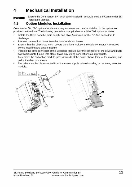
4 Mechanical Installation
4.1 Option Modules InstallationCommander SK ‘SM’ option modules are truly universal and can be installed to the option slot provided on the drive. The following procedure is applicable for all the ‘SM’ option modules:
• Isolate the Drive from the main supply and allow 5 minutes for the DC Bus capacitors to discharge.
• Remove the terminal cover from the drive as shown below.• Ensure that the plastic tab which covers the drive’s Solutions Module connector is removed
before installing any option module.• Position the drive connector of the Solutions Module over the connector of the drive and push
downwards until it locks into place. Make any wiring connections as appropriate.• To remove the SM option module, press inwards at the points shown (side of the module) and
pull in the direction shown.• The drive must be disconnected from the mains supply before installing or removing an option
module.
Ensure the Commander SK is correctly installed in accordance to the Commander SK Installation Manual.
NOTE
Pz1 0.4 N m (3.5 lb in)
SK Pump Solutions Software User Guide for Commander SK 11Issue Number: 5 www.controltechniques.com

4.2 SmartStick InstallationThe SmartStick is a memory option (flash drive) that stores a complete parameter set for the Commander SK.
1. Install the SmartStick into the drive SmartStick/LogicStick option slot with the copper tabs to the left.
The SmartStick is a parameter storage memory option that can be used to:
• Upload a parameter set from the drive
• Store a parameter set from the drive
• Automatically download a parameter set to the drive upon start-up
• Transfer a parameter set between drives
no: no action
rEAd: program the drive with the content of the SmartStick
Prog: program the SmartStick with the current drive settings
boot: SmartStick becomes read only. The contents of the SmartStick will be copied to the drive every time the drive is powered up.
No Function Range Defaults Type
28 Parameter cloning no,rEad, Prog, boot no RW
12 SK Pump Solutions Software User Guide for Commander SKwww.controltechniques.com Issue Number: 5

Parameter cloning is initiated by pressing the MODE key on exit from parameter edit mode after Pr 28 has been set to rEAd, Prog or boot.
Before setting boot mode, the current drive settings must be stored in the SmartStick be using Prog mode, otherwise the drive will trip on C.Acc at power-up.
If parameter cloning is enabled when no SmartStick is installed in the drive, the drive will trip on CAcc.
The SmartStick can be used to copy parameters between drives of different ratings. Certain drive dependant parameters will be stored on the SmartStick but will not be copied to the cloned drive.The drive will trip on C.rtg when being written to by a cloned parameter set of a different drive rating.The drive dependant parameters are: Pr 06 Motor rated current, Pr 08 Motor rated voltage, Pr 09 Motor power factor and Pr 37 Maximum switching frequency.
NOTE
M
NOTE
NOTE
SK Pump Solutions Software User Guide for Commander SK 13Issue Number: 5 www.controltechniques.com

4.3 Installation of LogicStickThe LogicStick is a memory option that stores a PLC ladder logic program to be executed onboard the drive.
1. Remove cover.2. Install the LogicStick into the drive SmartStick/LogicStick option slot with the copper tabs to the
left.3. Press the LogicStick Guard into the LogicStick slot in the front cover as shown; do not press
fully into position.4. Install the terminal cover to the drive in the normal manner.
The LogicStick may be inserted and removed from the drive while the power remains on. However, the drive will trip C.Acc (read / write fail) if the LogicStick is removed while it is being read/programmed during parameter cloning/transfer or the PLC ladder program is running.
1 2 3
NOTE
14 SK Pump Solutions Software User Guide for Commander SKwww.controltechniques.com Issue Number: 5
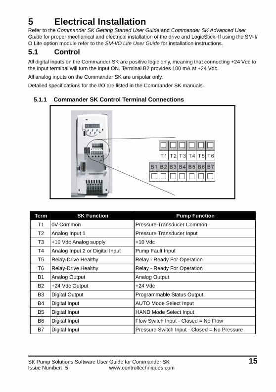
5 Electrical InstallationRefer to the Commander SK Getting Started User Guide and Commander SK Advanced User Guide for proper mechanical and electrical installation of the drive and LogicStick. If using the SM-I/O Lite option module refer to the SM-I/O Lite User Guide for installation instructions.
5.1 ControlAll digital inputs on the Commander SK are positive logic only, meaning that connecting +24 Vdc to the input terminal will turn the input ON. Terminal B2 provides 100 mA at +24 Vdc.
All analog inputs on the Commander SK are unipolar only.
Detailed specifications for the I/O are listed in the Commander SK manuals.
5.1.1 Commander SK Control Terminal Connections
Term SK Function Pump Function
T1 0V Common Pressure Transducer Common
T2 Analog Input 1 Pressure Transducer Input
T3 +10 Vdc Analog supply +10 Vdc
T4 Analog Input 2 or Digital Input Pump Fault Input
T5 Relay-Drive Healthy Relay - Ready For Operation
T6 Relay-Drive Healthy Relay - Ready For Operation
B1 Analog Output Analog Output
B2 +24 Vdc Output +24 Vdc
B3 Digital Output Programmable Status Output
B4 Digital Input AUTO Mode Select Input
B5 Digital Input HAND Mode Select Input
B6 Digital Input Flow Switch Input - Closed = No Flow
B7 Digital Input Pressure Switch Input - Closed = No Pressure
T1 T2 T3 T4 T5 T6
B1 B2 B3 B4 B5 B6 B7
SK Pump Solutions Software User Guide for Commander SK 15Issue Number: 5 www.controltechniques.com

5.1.2 SM-I/O Lite Option Module
Term SK Function Pump Function
PL1
1 0V common 0 V
2 Analog Input Over Temperature Switch Input - Close to Trip
3 Analog Output Analog Output
4 +24 Vdc +24 Vdc
5 Digital Input 1 Multi Setpoint Select 1 Input
6 Digital Input 2 Multi Setpoint Select 2 Input
7 Digital Input 3 Fault Reset Input - Close to Reset
8 Encoder B\
9 Encoder A
10 Encoder A\
11 0V common (analog) 0V common (analog)
12 Encoder +5 V
PL2
21 Relay 1 Relay - Alarm
22 Not Connected
23 Relay 2 Relay - Alarm
PL1 PL2
16 SK Pump Solutions Software User Guide for Commander SKwww.controltechniques.com Issue Number: 5
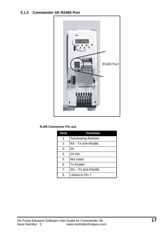
5.1.3 Commander SK RS485 Port
RJ45 Connector Pin out
Term Function
1 Terminating Resistor
2 RX - TX EIA-RS485
3 0V
4 24 Vdc
5 Not Used
6 Tx Enable
7 /Rx - /Tx EIA-RS485
8 Linked to Pin 7
RS485 Port
SK Pump Solutions Software User Guide for Commander SK 17Issue Number: 5 www.controltechniques.com
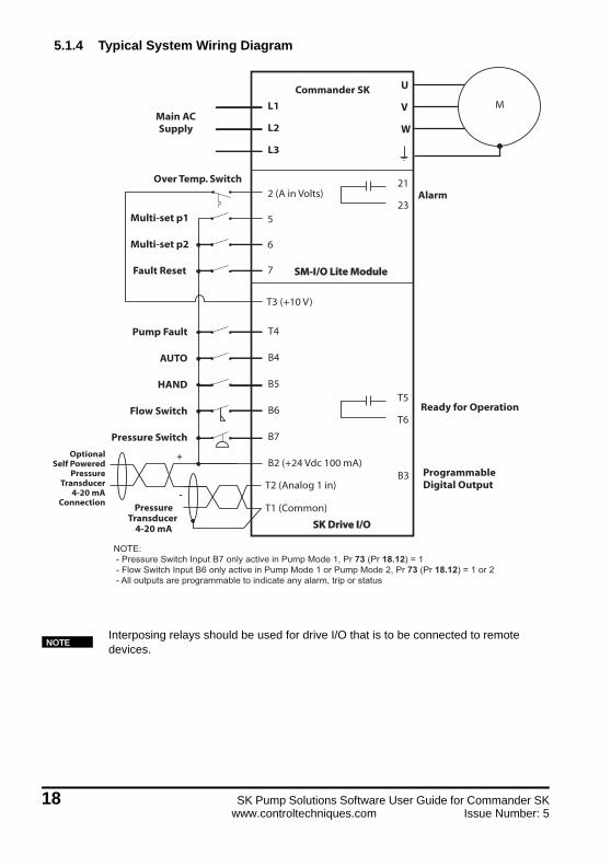
5.1.4 Typical System Wiring Diagram
Interposing relays should be used for drive I/O that is to be connected to remote devices.
M
Alarm
U
V
W
21
23
T5
T6
L1
L2
L3
2 (A in Volts)
5
6
7
T3 (+10 V)
Main ACSupply
Over Temp. Switch
Multi-set p1
Multi-set p2
Fault Reset
Pump Fault
AUTO
HAND
Flow Switch
Pressure Switch
T4
B4
B5
B6
B7
B2 (+24 Vdc 100 mA)
Ready for Operation
ProgrammableDigital Output
B3
SK Drive I/OSK Drive I/O
SM-I/O Lite ModuleSM-I/O Lite Module
Commander SK
T2 (Analog 1 in)
T1 (Common)PressureTransducer
4-20 mA
OptionalSelf Powered
PressureTransducer
4-20 mAConnection
NOTE: - Pressure Switch Input B7 only active in Pump Mode 1, Pr 73 (Pr 18.12) = 1 - Flow Switch Input B6 only active in Pump Mode 1 or Pump Mode 2, Pr 73 (Pr 18.12) = 1 or 2 - All outputs are programmable to indicate any alarm, trip or status
+
-
NOTE
18 SK Pump Solutions Software User Guide for Commander SKwww.controltechniques.com Issue Number: 5

5.1.5 Pump Mode 1 (Pressure Switch Start / Flow Switch Stop)
This mode is selected by setting Pr 73 (Pr 18.12) = 1. In this mode, the pump starts automatically when low pressure is detected by the Pressure Switch. The pump will then run at maximum speed which is set in Pr 1.06. The pressure should rise and the Pressure Switch should open. If demand reduces, e.g. reduced flow due to valve closing, the pressure will increase and the Flow Switch (terminal B6) would close indicating a no-flow condition. At this point (no flow detection), the pump automatically stops after a adjustable time delay (Pr 2.14). This cycle is repeated when the pressure reduces to the low set level.
5.1.6 Pump Mode 2 (Pressure Transducer Start / Flow Switch Stop)
This mode is selected by setting Pr 73 (Pr 18.12 = 2) In this mode, the pump starts automatically with a start delay (Pr 2.13) when a low pressure condition is detected. The Pressure transducer signal Pr 71 (Pr 18.02) goes below the Low Pressure setpoint threshold (Pr 18.13). Initially, a pipe fill operation is performed to remove air bubbles if enabled. Then a constant pressure setpoint PID control regulates the system pressure to the setpoint. The pump control adjusts the motor speed in order to satisfy the demand and maintain pressure constant at the setpoint value. At maximum demand, the pump speed will be at maximum and at low demand the motor speed drops to minimum speed limit. If the demand goes even further below, the system Flow switch will close indicating a no-flow condition. At this point (no flow detection), the pump automatically stops after a adjustable time delay (Pr 2.14).
Flow SwitchOpens with Flow
Water Pump
WaterSupply
Pressure SwitchOpens with Pressure
Flow
Flow Switchopens with flow
Water Pump
WaterSupply
Pressure Transducer4-20 mA / 0-10 Vdc
Flow
SK Pump Solutions Software User Guide for Commander SK 19Issue Number: 5 www.controltechniques.com

5.1.7 Pump Mode 3 (Pressure Transducer Start/Stop)
In this mode, the pump starts automatically with a start delay when a low pressure condition is detected (Pressure Transducer signal does below Low Pressure setpoint threshold). Initially, a pipe fill operation is performed to remove are bubbles if enabled. A constant pressure setpoint PID control then regulates the system pressure to the setpoint. The pump control adjusts the motor speed in order to satisfy the demand and maintain pressure constant at the set value. At maximum demand the pump speed will be at maximum speed and at low demand the motor speed drops to minimum speed limit. The pump automatically stops after a time when a “No Flow” or “Sleep” condition is detected by the pump control system logic.
Flow
Water PumpWaterSupply
Pressure Trnasducer4-20 mA / 0-10 Vdc
20 SK Pump Solutions Software User Guide for Commander SKwww.controltechniques.com Issue Number: 5

6 Getting StartedSeveral parameters must be set prior to running the Pump Solutions drive system. The drive may be commissioned by entering parameters with any of the following methods:
1. Use the drive's standard keypad. This method requires the use of Pr 71 to Pr 80 in order to gain access to all of the required settings. Set the parameter numbers whose values need to be changed in Pr 71 to Pr 80 and change the parameter value in Pr 61 to Pr 70. For example to set Pr 18.23 = 2000, set Pr 75 = 18.23 and Pr 65 = 2000. Once all setup parameters are entered, change the values of Pr 71 to Pr 80 back to the default setting shown in Section 6.1.1 on page 23. For more information on mapping, refer to Commander SK Getting Started Guide.
2. Connecting an SM-Keypad Plus to the standard RTU serial port. This LCD keypad provides direct access to all menus and parameters.
3. A personal computer with CTSoft drive configuration software and a CT communication cable connected to the standard RTU serial port. Cable order code is CT-USB-CABLE.
It is highly recommended to first become familiar with the commissioning method selected before proceeding to the set up steps in Section 6.1 on page 22.
SK Pump Solutions Software User Guide for Commander SK 21Issue Number: 5 www.controltechniques.com

2
6.1 Initial Set UpEnsure that all digital inputs are off before applying power to the drive or changing any parameters.
Follow the steps below for the initial setting of the drive:
1. The SK Pump Solutions drive is shipped from the factory with the default pump parameters loaded. Apply power to the drive and verify that the pump specific parameter values match the default settings listed in Section 10 on page 63.
2. The pump parameters can also be programmed using a SMARTSTICK-P or SMARTSTICK-PL:a Insert the SMARTSTICK into the SmartStick/LogicStick option slot
b Set Pr 28 = Read
c Press the RESET button on the drive keypad
d If the drive trips with ‘c.rtg’ code; the motor current rating needs to be set
e Press the RESET button again to clear the trip
3. Enter the motor data information from the motor data plate:a Motor rated current in Pr 06
b Motor rated voltage in Pr 08
c Motor rated power factor in Pr 09 (if unknown leave at default of 85)
4. Enter motor rated full load RPM Pr 07 to a value of 0. This will ensure no slip compensation is enabled.
5. Ensure the pump program is running by setting Pr 59 (11.47) = 1.6. Scale the pressure transducer feedback signal connected to Commander SK analog input
terminal T1 & T2. Set the minimum and maximum pressure values with Pr 18.22 and Pr 18.23 respectively. This applies to Pump modes 2 and 3 only.
7. The remainder of the parameter settings is application specific. The following sections in this chapter describe the parameter setup necessary for a particular feature.
There are many other parameters available in the Commander SK drive and information on those can be obtained from the Commander SK Advanced User Guide.
NOTE
2 SK Pump Solutions Software User Guide for Commander SKwww.controltechniques.com Issue Number: 5

6.1.1 Menu 0 Configurable Parameters
For ease of operation, the following 10 Menu 0 parameters are configured in the pump program:
The above setup allows the following pump parameters to be viewed and setup from the base drive keypad Menu 0.
See Diagram 15 Overview - Menu 0 on page 62 for more Menu 0 information
Parameter Description Mapped Parameter
71 Pr 61 Set-up 18.02
72 Pr 62 Set-up 18.11
73 Pr 63 Set-up 18.12
74 Pr 64 Set-up 18.13
75 Pr 65 Set-up 18.23
76 Pr 66 Set-up 18.30
77 Pr 67 Set-up 1.24
78 Pr 68 Set-up 1.26
79 Pr 69 Set-up 14.10
80 Pr 70 Set-up 14.11
Parameter Description Type Default Units
61 Pressure Feedback Value (Pr 18.02) RO 0 0.1 PSI
62 Pumping Macro Select (Pr 18.11) RW 0 -
63 Start / Stop Control Modes (Pr 18.12) RW 3 -
64 Low Setpoint (Pr 18.13) RW 0 0.1 PSI
65 Maximum Feedback Scaling (Pr 18.23) RW 1450 0.1 PSI
66 Main Setpoint (Pr 18.30) RW 0 0.1 PSI
67 Minimum Sleep Speed/Freq (Pr 1.24) RW 0 Hz
68 No Flow RPM (Freq) Setpoint (Pr 1.26) RW 0 Hz
69 PID Proportional Gain (Pr 14.10) RW 1 -
70 PID Integral Gain (Pr 14.11) RW 0.5 -
SK Pump Solutions Software User Guide for Commander SK 23Issue Number: 5 www.controltechniques.com

6.2 Sequence of OperationThe simplex pumping operation has 2 main control modes, HAND and AUTO. These modes can be selected from drive terminals or keypad or both as selected by 'Operation Mode' Pr 62 (Pr 18.11).
When HAND or AUTO mode is not selected the Pump drive is Inhibited/Off. The keypad displays ‘inh’ in this condition.
6.2.1 HAND Mode
This mode is mostly used for maintenance. The HAND mode can be selected from either the drive terminals or from the drive keypad. Relevant setup parameters for this mode are shown in the table below:
6.2.1.1 From Drive Terminalsa Set the Pumping Macro Select Pr 62 (Pr 18.11) = 1 (Terminals).
b Close the 'HAND' switch (drive terminals B2 and B5). The drive runs in HAND mode.
c Opening the 'HAND' switch will disable HAND mode and stop the drive.
6.2.1.2 From Drive Keypad:a Set the Pumping Macro Select Pr 62 (Pr 18.11) = 3 (AUTO + HAND).
b Press the keypad 'M' button to enable the HAND mode and run the motor
c Press the keypad 'STOP' button to disable the HAND mode and stop the motor
In HAND mode, the drive will run the motor at the set speed determined by the frequency reference as set in Pr 18 (Pr 1.21)
SK Parameter Description Section Units Range Default
18 (1.21)HAND Mode Speed (Frequency)
Setpoint6.2.1.1 Hz +/- 1500.0 0
62 (18.11) Pumping Macro Select 6.2.1.2 +/- 32767 0 0 (off)
B2 24 Vdc
B5
B6
B7
HAND Run
Flow Switch
Pressure Switch
24 SK Pump Solutions Software User Guide for Commander SKwww.controltechniques.com Issue Number: 5
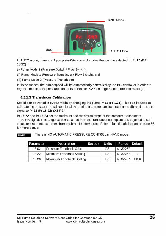
.
In AUTO mode, there are 3 pump start/stop control modes that can be selected by Pr 73 (PR 18.12):
(i) Pump Mode 1 (Pressure Switch / Flow Switch),
(ii) Pump Mode 2 (Pressure Transducer / Flow Switch), and
(iii) Pump Mode 3 (Pressure Transducer)
In these modes, the pump speed will be automatically controlled by the PID controller in order to regulate the setpoint pressure control (see Section 6.2.5 on page 34 for more information).
6.2.1.3 Transducer Calibration
Speed can be varied in HAND mode by changing the pump Pr 18 (Pr 1.21). This can be used to calibrate the pressure transducer signal by running at a speed and comparing a calibrated pressure signal to Pr 61 (Pr 18.02) (0.1 PSI).
Pr 18.22 and Pr 18.23 set the minimum and maximum range of the pressure transducers 4-20 mA signal. This range can be obtained from the transducer nameplate and adjusted to suit actual pressure measurement from calibrated meter/gauge. Refer to functional diagram on page 56 for more details.
There is NO AUTOMATIC PRESSURE CONTROL in HAND mode.
Parameter Description Section Units Range Default
18.02 Pressure Feedback Value PSI +/- 32767
18.22 Minimum Feedback Scaling PSI +/- 32767 0
18.23 Maximum Feedback Scaling PSI +/- 32767 1450
Stop
Hand Mode
Auto ModeAUTO Mode
HAND Mode
Stop
NOTE
SK Pump Solutions Software User Guide for Commander SK 25Issue Number: 5 www.controltechniques.com

6.2.2 AUTO Mode
Setpoint PID pressure control is functional only in AUTO mode. The AUTO mode can be initiated from either the drive terminals or from the drive keypad. In AUTO mode, the pump start/stop sequence is automatically controlled based on the pump mode selected (refer to Section 6.2.3.1 on page 27, Section 6.2.3.2 on page 28 & Section 6.2.3.3 on page 30). Relevant setup parameters for AUTO mode are shown in the table below:
Parameter Description Section Units Range Default
20 (1.23) No Flow Frequency Bandwidth 6.2.3.3 Hz +/-1500.0 15
21 (1.24) Minimum Sleep Frequency* 6.2.7 Hz +/-1500.0 0
1.25 Max Freq. Bandwidth 6.2.8 Hz +/-1500.0 1
78 (1.26) No Flow Frequency Setpoint 6.2.3.3 Hz +/-1500.0 0
1.27Feedback Loss Frequency
Reference6.2.5.4 Hz +/-1500.0
2.13 Start Delay Time 6.2.3.1 / 6.2.3.2 / 6.2.3.3 sec 0-3200.0 0
2.14 Stop Delay Time 6.2.3.1 / 6.2.3.2 / 6.2.3.3 sec 0-3200.0 5
2.15 Pipe Fill Time 6.2.6 sec 0-3200.0 0
2.16 Under Pressure Detect Time* 6.2.10 sec 0-3200.0 0
2.17 Sleep Start Time 6.2.7 sec 0-3200.0 0
2.18 Stabilize Delay 6.2.3.3 sec 0-3200.0 2
2.23 Constant Frequency Time 6.2.3.3 sec 0-3200.0 5
2.24 Dry Well Detection Time* 6.2.8 sec 0-3200.0 0
2.26 Torque Low Load Point 6.2.8 0.10% 0-3200.0 0
2.27 Frequency Dec. Low Suction 6.2.8 0.10% 0-3200.0 0
69 (14.10) Proportional Gain 6.2.5.2 Gain 0-4.000 1
70 (14.11) Integral Gain 6.2.5.2 sec 0-4.000 0.5
62 (18.11) Pumping Macro Select 6.2.1.1 / 6.2.1.2 +/-32767 0
63 (18.12) Start/Stop Control Modes 6.2.3.1 / 6.2.3.2 / 6.2.3.3 +/-32767 3
64 (18.13) Low Setpoint 6.2.3.2 / 6.2.3.3 0.1 PSI +/-32767 0
18.15 Setpoint Bandwidth 6.2.10 0.1 PSI +/-32767 5
18.17 Transducer Loss Action* 6.2.5.4 0.1 PSI +/-32767 1
18.18 Dry Well Selection Mode 6.2.8 0.1 PSI +/-32767 2
18.20 Over Pressure Alarm Level* 6.2.9 0.1 PSI +/-32767 0
18.21 Over Pressure Fault Level* 6.2.9 0.1 PSI +/-32767 0
18.22 Minimum Feedback Scaling 6.1 0.1 PSI +/-32767 0
75 (18.23) Maximum Feedback Scaling 6.1 0.1 PSI +/-32767 1450
18.24 Alternate Setpoint 1 6.2.5.1 0.1 PSI +/-32767 0
18.25 Alternate Setpoint 2 6.2.5.1 0.1 PSI +/-32767 0
18.26 Alternate Setpoint 3 6.2.5.1 0.1 PSI +/-32767 0
76 (18.30) Main Setpoint 6.2.5.1 0.1 PSI +/-32767 0
26 SK Pump Solutions Software User Guide for Commander SKwww.controltechniques.com Issue Number: 5

6.2.3 Pump Mode Section
6.2.3.1 Pump Mode 1 (Pressure Switch Start / Flow Switch Stop)
This mode is selected by setting Pr 63 (Pr 18.12) = 1. Press Pressure Switch (Start) and Flow Switch (Stop) control.
In this mode the pump will run based on the two switch inputs:
The Flow Switch (B6) and the Pressure Switch (B7).
When the drive is placed in the AUTO mode, the display will switch from "ih" (inhibited) to "rd" (ready).
• At this point the pump will stay idle until the Pressure Switch closes (low PSI indicator) for a period of time set by Pr 2.13 (in seconds).
• Once the drive starts, it will ramp up to the maximum speed as set by Pr 02 (Pr 1.06) and stay there even if the Pressure Switch opens.
• The pump will continue to run until the Flow Switch closes (no flow indicator) for a period of time set by Pr 2.14 (in seconds).
Parameter # Default Setting Function
2.13 0 sec Start Delay Time
2.14 0 sec Stop Delay Time
02 (1.06) 60 Hz Motor Max Frequency
Flow SwitchOpens with Flow
Water Pump
WaterSupply
Pressure SwitchOpens with Pressure
Flow
B2
B6
B7
Flow Switch
Pressure Switch
SK Pump Solutions Software User Guide for Commander SK 27Issue Number: 5 www.controltechniques.com
2
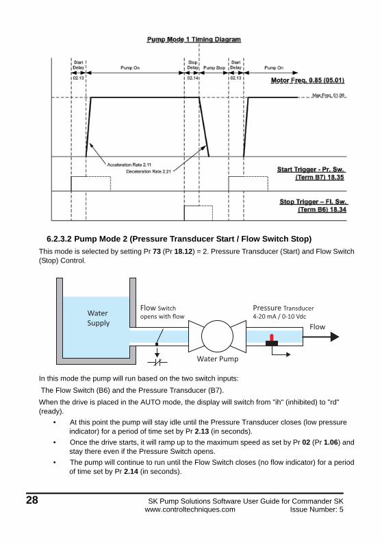
6.2.3.2 Pump Mode 2 (Pressure Transducer Start / Flow Switch Stop)
This mode is selected by setting Pr 73 (Pr 18.12) = 2. Pressure Transducer (Start) and Flow Switch (Stop) Control.
In this mode the pump will run based on the two switch inputs:
The Flow Switch (B6) and the Pressure Transducer (B7).
When the drive is placed in the AUTO mode, the display will switch from "ih" (inhibited) to "rd" (ready).
• At this point the pump will stay idle until the Pressure Transducer closes (low pressure indicator) for a period of time set by Pr 2.13 (in seconds).
• Once the drive starts, it will ramp up to the maximum speed as set by Pr 02 (Pr 1.06) and stay there even if the Pressure Switch opens.
• The pump will continue to run until the Flow Switch closes (no flow indicator) for a period of time set by Pr 2.14 (in seconds).
Flow Switchopens with flow
Water Pump
WaterSupply
Pressure Transducer4-20 mA / 0-10 Vdc
Flow
8 SK Pump Solutions Software User Guide for Commander SKwww.controltechniques.com Issue Number: 5

Care should be taken when setting the time since too long of a time could over pressure the system
Parameter # Default Setting Function
2.13 5 sec Start Delay Time
2.14 0 sec Stop Delay Time
64 (18.13) 0 sec Min Pressure Threshold
2.15 0 sec Pipe Fill Time
02 (1.06) 60 Hz Motor Max Frequency
NOTE
Self Powered 4-20 millampsPressure Transducer
(+)
(-)
External Powered 4-20 millampsPressure Transducer
(+)
(-)
Flow Switch
OR
B6
T1
T2
B2
SK Pump Solutions Software User Guide for Commander SK 29Issue Number: 5 www.controltechniques.com

6.2.3.3 Pump Mode 3 (Pressure Transducer Only Control)
This mode is selected by setting Pr 73 (Pr 18.12) = 3. Pressure Transducer Start/Stop Control.
Set Point Pressure 18.04
Set Point Bandwidth 18.15
Start Delay
02.13
Min.Freq. 01.07
Max.Freq. 01.06
Stop Delay
02.14
Presure Feedback 0.61 (18.02)
Motor Freq. 0.85 (05.01)
Acceleration Rate 2.11Deceleration Rate 2.21
Pump Mode 2 Timing Diagram
Pipe Fill
02.15
Start Delay
02.13
Constant Pressure Control StopPipe Fill
02.15
Constant Pressure Control
Stop Trigger – Fl. Sw. (Term B6) 18.34
Start Trigger - Pr. FB 0.61 (18.02) < Low Pr.
Threshold (18.13)
Low Pr. Threshold 18.13
Flow
Water PumpWaterSupply
Pressure Trnasducer4-20 mA / 0-10 Vdc
30 SK Pump Solutions Software User Guide for Commander SKwww.controltechniques.com Issue Number: 5

• In this mode of operation, the pump will start when the system pressure as measured by the transducer, Pr 61 (Pr 18.02) falls below the minimum pressure threshold Pr 64 (Pr 18.13) after a time delay, Pr 2.13.
• The pump will continue to run until the No Flow condition is detected or a Sleep Mode occurs due to a lack of demand in the system.
• Also in this mode, a Pipe Fill Time function can be added. The time is set by Pr 2.15 and the pump speed is set by the maximum speed Pr 02 (Pr 1.06). This function is to fill the empty pipe an remove any air bubbles.
• Sleep operation is detailed in the following section 6.2.4.
Care should be taken when setting the pipe fit time since too long of a time could over pressure the system
Parameter # Default Setting Function
2.13 5 sec Start Delay Time
2.14 5 sec Stop Delay Timea
a. Based on Sleep or No Flow
64 (18.13) 0 sec Min Pressure Threshold
2.15 0 sec Pipe Fill Time
02 (1.06) 60 Hz Motor Max Frequency
NOTE
B2
T2
T1
Self Powered 4-20 millampsPressure Transducer
(+)
(-)
External Powered 4-20 millampsPressure Transducer
(+)
(-)
OR
SK Pump Solutions Software User Guide for Commander SK 31Issue Number: 5 www.controltechniques.com

The timing sequence diagram for pump mode 3 shown below is with 'Sleep' stop trigger logic,
6.2.4 Sleep and No Flow Modes
“Sleep Mode” is enabled by setting the Minimum Sleep Frequency, Pr 67 (Pr 1.24) to a non-zero value and a Sleep Time Delay in Pr 2.17. This function will put the drive into a ready “rd” state if the motor frequency drops below the minimum Sleep Frequency Pr 67 (Pr 1.24) must be set higher than the Minimum Frequency Pr 01 (Pr 2.07).
“No Flow” is enabled by setting the No Flow Frequency Setpoint, Pr 68 (Pr 1.26) to a non-zero value and a Duration Time in Pr 2.23. There is also a Frequency Bandwidth setting, Pr 1.23 and Stabilizing Time Delay set by Pr 2.18.This function will put the drive into a “rd” state if the motor frequency drops below the No flow Frequency setpoint for a period of time set in Pr 2.17. The No Flow Frequency Setpoint must be set higher than the Minimum Frequency Pr 01 (Pr 2.07),
Set Point Pressure 18.04
Set Point Bandwidth 18.15
Start Delay
02.13
Min.Freq. 01.07
Max.Freq. 01.06
Stop Delay
02.14
Presure Feedback 0.61 (18.02)
Motor Freq. 0.85 (05.01)
Acceleration Rate 2.11
Deceleration Rate 2.21
Pump Mode 3 Timing Diagram(Stop Logic shown for Sleep Mode)
Pipe Fill
02.15
Start Delay
02.13
Constant Pressure Control StopPipe Fill
02.15
Constant Pressure Control
Stop Trigger – No Flow / Sleep Mode
Start/Wake Trigger - Pr. FB 0.61 (18.02) < Low Pr.
Threshold (18.13)
Low Pr. Threshold 18.13
Sleep Threshold 01.24 (Set >= Min Freq 01.07)
32 SK Pump Solutions Software User Guide for Commander SKwww.controltechniques.com Issue Number: 5

and the frequency bandwidth setting (Pr 1.23) must be greater than Pr 1.26 (NO Flow Fre-quency Setpoint) - Pr 1.07 (Minimum Speed).
Normally Sleep or No Flow would be used, not both.
Sleep Setup(Mode 3 only)
Normally Sleep or No Flow would be used, not both.
No Flow Setup(Mode 3 only)
Sleep logic: This condition is detected in Pump Mode 3 when the actual motor frequency goes below the Minimum Sleep Frequency Threshold Pr 67 (1.24). The pump will stop after a time delay set by Pr 2.17. The parameter setting requirements for 'Sleep' condition detection is:
Minimum Sleep Frequency Pr 67 (Pr 1.24) >= Minimum Frequency Pr 01 (Pr 1.07)
“No flow” detection logic: This condition is detected in Pump Mode 3 when the actual motor frequency (Pr 5.01) goes below the 'No Flow Frequency Setpoint' Pr 68 (1.26) and stays within a frequency bandwidth (+/- Window) set by Pr 1.23 for a time period (Pr 2.23). There will be a stabilizing time delay as specified by Pr 2.18. The parameter setting requirements for proper operation of 'No Flow' detection are:
No Flow Frequency Setpoint Pr 1.27 >= Minimum Frequency Pr 01 (Pr 1.07)
Bandwidth Pr 1.23 >= (Pr 1.27 - Pr 01)
Parameter # DefaultSetting
ExampleSetting(pump)
Function
67 (1.24) 0 Hz 20 Hz Minimum Sleep Frequency
2.17 0 sec 15 sec Sleep Time Delay
01(1.07) 0 Hz 15 Hz Minimum Speed Parameter
Parameter # Default Setting
ExampleSetting(pump)
Function
68 (1.26) 0 Hz 20 Hz No Flow Frequency Setpoint
2.23 0 sec 15 sec Duration Time
1.23 0 Hz 6 Hz Frequency Bandwidth
2.18 0 sec 15 sec Stabilizing Time Delay
01 (1.07) 0 Hz 15 Hz Minimum Frequency Parameter
SK Pump Solutions Software User Guide for Commander SK 33Issue Number: 5 www.controltechniques.com

6.2.5 Constant Pressure Setpoint Control
6.2.5.1 Pressure Setpoint Selection
The Pump System Setpoint (Pr 18.04) sets the PID reference input for the pressure control system. The default setpoint is Pr 76 (Pr 18.30) however, if multiple pressure setpoints are necessary, this can be achieved by adding an SM-I/O Lite module and using digital inputs T5 and T6 as shown in table below. These setpoint pressure must be less than the maximum rated value (Pr 75 (Pr 18.23)).
6.2.5.2 PID Pressure Control
The built in PID Controller within the pump drive regulates the pump pressure depending on the setpoint. The proportional Pr 69 (Pr 14.10) and Integral Pr 70 (Pr 14.11) gains may require adjusting to obtain the response required, however the default values are suitable for most systems.
6.2.5.3 Transducer Calibration
The SK Pump program must know the pressure range of the transducer. The minimum and maximum pressure is entered in the parameters listed below. Pr 7.05 (sets up analog input #1 (T2) for a 4-20 mA or 0 Vdc to 10 Vdc signal.
.
Example: For a transducer rated at 200 psi maximum, enter 200 x 10 = 2000 into Pr 18.23 (as well as any other pressure parameter).
6.2.5.4 Transducer Loss (4-20 mA only)
In case of transducer feedback loss, one of the following actions is taken by the pump control system based upon the setting of Pr 18.17.
0 = Disabled (Ignore fault)
1 = Fault Drive (Trip Code t081)
2 = Run at Fixed Speed set in Pr 1.27)
Terminal 5 Terminal 6 Pump System Set-Point
Open Open Main Set
Closed Open Set-Point 1 (Pr 18.24)
Open Closed Set-Point 2 (Pr 18.25)
Closed Closed Set-Point 3 (Pr 18.26)
The units entered in ALL of pressure registers is the value in psi x10 since the units are tenths of a pound
Parameter # Default Setting Function
61 (18.02) 0000 psi Pressure Feedback Value
65 (8.23) 0000 psi Maximum Pressure Feedback
18.22 0000 psi Minimum Pressure Feedback
NOTE
34 SK Pump Solutions Software User Guide for Commander SKwww.controltechniques.com Issue Number: 5
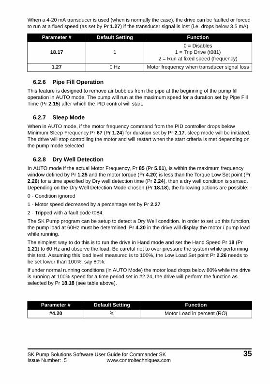
When a 4-20 mA transducer is used (when is normally the case), the drive can be faulted or forced to run at a fixed speed (as set by Pr 1.27) if the transducer signal is lost (i.e. drops below 3.5 mA).
6.2.6 Pipe Fill Operation
This feature is designed to remove air bubbles from the pipe at the beginning of the pump fill operation in AUTO mode. The pump will run at the maximum speed for a duration set by Pipe Fill Time (Pr 2.15) after which the PID control will start.
6.2.7 Sleep Mode
When in AUTO mode, if the motor frequency command from the PID controller drops below Minimum Sleep Frequency Pr 67 (Pr 1.24) for duration set by Pr 2.17, sleep mode will be initiated. The drive will stop controlling the motor and will restart when the start criteria is met depending on the pump mode selected
6.2.8 Dry Well Detection
In AUTO mode if the actual Motor Frequency, Pr 85 (Pr 5.01), is within the maximum frequency window defined by Pr 1.25 and the motor torque (Pr 4.20) is less than the Torque Low Set point (Pr 2.26) for a time specified by Dry well detection time (Pr 2.24), then a dry well condition is sensed. Depending on the Dry Well Detection Mode chosen (Pr 18.18), the following actions are possible:
0 - Condition ignored
1 - Motor speed decreased by a percentage set by Pr 2.27
2 - Tripped with a fault code t084.
The SK Pump program can be setup to detect a Dry Well condition. In order to set up this function, the pump load at 60Hz must be determined. Pr 4.20 in the drive will display the motor / pump load while running.
The simplest way to do this is to run the drive in Hand mode and set the Hand Speed Pr 18 (Pr 1.21) to 60 Hz and observe the load. Be careful not to over pressure the system while performing this test. Assuming this load level measured is to 100%, the Low Load Set point Pr 2.26 needs to be set lower than 100%, say 80%.
If under normal running conditions (in AUTO Mode) the motor load drops below 80% while the drive is running at 100% speed for a time period set in #2.24, the drive will perform the function as selected by Pr 18.18 (see table above).
Parameter # Default Setting Function
18.17 10 = Disables
1 = Trip Drive (t081)2 = Run at fixed speed (frequency)
1.27 0 Hz Motor frequency when transducer signal loss
Parameter # Default Setting Function
#4.20 % Motor Load in percent (RO)
SK Pump Solutions Software User Guide for Commander SK 35Issue Number: 5 www.controltechniques.com

6.2.9 Over Pressure Alarm/Trip
In AUTO mode the drive can detect two over pressure levels. The first (set by Pr 18.20) is used to set an alarm if the pressure stays at 95% of that level (a flag is set, Pr 18.41) which can be used for a digital output or relay output to indicate this alarm.
The second, set by Pr 18.21, will cause the drive to trip, displaying a t082 code on the drive display.
6.2.10 Under Pressure Feedback Trip
When the pressure Pr 61 (Pr 18.02) is below the setpoint bandwidth (Pr 18.15) and the motor frequency is within maximum frequency bandwidth (01.06 - 1.25) for a duration more than Under Pressure Detect Time (Pr 2.16), the pump drive is tripped and indicates trip code t083.
There are 2 configurations available:
Pr 18.50 = 0 System Set Point Bandwidth
Pr 18.50 = 1 Under Pressure Setpoint
When the pressure Pr 61 (Pr 18.02) is below the under pressure setpoint (Pr 18.14) and the motor frequency is within the maximum frequency bandwidth (1.06 - 1.25), for a duration more than Under Pressure Detect Time (Pr 2.16), the pump drive is tripped with a trip code t083.
6.3 Manual Mode Start UpUpon selecting manual mode the pump will run at a fixed speed specified in Pr 18 until the Hand input is removed (in terminal mode) or the stop button is pressed (in keypad mode).
1. Ensure the pump is ready for operation.2. Enter the desired motor frequency in Pr 183. If Pr 62 (Pr 18.11) is set to 1 (terminals) closing the Hand input will start the pump. Removing
the input will stop the pump motor.
If Pr 62 (Pr 18.11) is set to 3 (Keypad AUTO + HAND) pressing the M button on the keypad will start the pump.
Press the Stop (red) button to stop the pump.
#2.26 0% Motor Load at Full pump Speed
#2.24 0 sec Detection Time
#18.18 0
0 = Alarm1 = Decrease pump speed
(by % in Pr 2.27)2 = Fault the Drive
Parameter # Default Setting Function
#18.20 0% Over Pressure Alarm Setting
#18.41 0 Flag parameter for Alarm
#18.21 0% Over Pressure Trip Setting
36 SK Pump Solutions Software User Guide for Commander SKwww.controltechniques.com Issue Number: 5
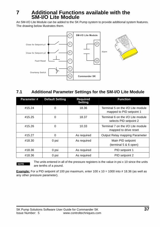
7 Additional Functions available with the SM-I/O Lite Module
An SM-I/O Lite Module can be added to the SK Pump system to provide additional system features. The drawing below illustrates them.
7.1 Additional Parameter Settings for the SM-I/O Lite Module
Example: For a PID setpoint of 100 psi maximum, enter 100 x 10 = 1000 into # 18.36 (as well as any other pressure parameter).
Parameter # Default Setting RequiredSetting
Function
#15.24 0 18.36 Terminal 5 on the I/O Lite module mapped to PID setpoint 1
#15.25 0 18.37 Terminal 6 on the I/O Lite module selects PID setpoint 2
#15.26 0 10.33 Terminal 7 on the I/O Lite module mapped to drive reset
#15.27 0 As required Output Relay mapping Parameter
#18.30 0 psi As required Main PID setpoint (terminal 5 & 6 open)
#18.36 0 psi As required PID setpoint 1
#18.36 0 psi As required PID setpoint 2
The units entered in all of the pressure registers is the value in psi x 10 since the units are tenths of a pound.
Alarm
Close for Setpoint p1
Close for Setpoint p2
Fault Reset
Overtemp Switch
21
22
5
7
T3
6
2
4 SM-I/O Lite Module
Commander SK
NOTE
SK Pump Solutions Software User Guide for Commander SK 37Issue Number: 5 www.controltechniques.com

38 SK Pump Solutions Software User Guide for Commander SKwww.controltechniques.com Issue Number: 5
8 Backing-up The Set-up ParametersAfter you have succeeded in setting up the SK Pump to your satisfaction, this setup data defines the essence of the application and allows the drive to perform as it was intended per your application. Should it become necessary to replace a drive, without this critical data, the drive would be unable to perform as it was originally intended.
8.1 SmartStick MethodA SmartStick is included with the Commander SK Pump which contains a default set of pump parameters depending on the -P or -PL suffix (the SmartStick-P and SmartStick-PL can be purchased separately). The data on this stick has been made "read-only" (boot mode) so it can always be used to get back to a factory default pump parameters if need be. In order to return the SK Pump drive back to factory settings you would first reset the drive to defaults (Pr 29 set to "usa", then push the stop / reset button), Pr 29 should revert back to "no" when the process is complete. Now power down the drive, insert the SmartStick then power the drive back up. The parameters will load automatically. Once this is complete, power down the drive and insert the LogicStick and power up the drive. Press the stop reset button once power up is complete. If you have an older SmartStick you may need to set Pr 28 to "read" then press the mode button (Pr 28 should revert back to "no").
The drive will now have all of the required default parameter settings. The program can now be set up for the application. Make sure the LogicStick program is running - Pr 59 = 1 and Pr 60 = 2.
8.2 CTSoft MethodThe use of CTSoft can make programming the SK Pump a simple task. Included with the SK Pump drive system, a dvd which not only contains the Commander SK Pump manual but also a parameter file which can be used to reset the drive back to default SK Pump parameters (Master SK Pump File with IO_ descriptions.par). This file can be used to download to any size drive and also contains enhanced descriptions of SK Pump parameters.
Control Techniques will be able to provide you with a replacement drive but we will not have the “recipe” (data) that was specific for your application. Therefore, it is imperative that the OEM, System Integrator, Field Engineer or Installer back up this critical information and leave a copy with the End User following the commissioning process. Failure to do so can result in unnecessary machine downtime.
NOTE
SK Pump Solutions Software User Guide for Commander SK 39Issue Number: 5 www.controltechniques.com

The procedure to restore parameters will be demonstrated in the following pages.
40 SK Pump Solutions Software User Guide for Commander SKwww.controltechniques.com Issue Number: 5

8.2.1 Open CTSoft
Select Work with a drive option button and then select the Commander SK
Select Detect Drive Configuration
SK Pump Solutions Software User Guide for Commander SK 41Issue Number: 5 www.controltechniques.com

If your communications are good the screen above should appear, click OK.
Under the File drop down menu, select the Master SK Pump file on the CD-ROM and click open. This file is also available on our web site if you do not have the CD-ROM or to check for an updated version.
42 SK Pump Solutions Software User Guide for Commander SKwww.controltechniques.com Issue Number: 5
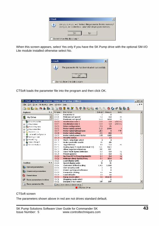
When this screen appears, select Yes only if you have the SK Pump drive with the optional SM-I/O Lite module installed otherwise select No.
CTSoft loads the parameter file into the program and then click OK.
CTSoft screen
The parameters shown above in red are not drives standard default.
SK Pump Solutions Software User Guide for Commander SK 43Issue Number: 5 www.controltechniques.com

At this point, up load the parameters from the drive, this action will correct the file in CTSoft to match the actual drive (since the Generic file on the CD-ROM does not contain the drive voltage and current rating).
Click Yes, CTSoft will go online, upload the parameters, then go off line.
Once the upload is complete, save the parameter file using "save parameter file…" in the File menu giving it a unique name.
Now click on the red square at the bottom of the CTSoft screen to go online with the drive.
The SK Pump drive system can now be customized for the pump requirements (starting at page 22 - after entering in the pump motor current rating). Don't forget to save your file when you are done.
The differences from the drives standard defaults are shown in red. The descriptions are also different from the files default descriptions to match the Pump functions for the program.
NOTE
Click the upload in the Icon Bar at the top
44 SK Pump Solutions Software User Guide for Commander SKwww.controltechniques.com Issue Number: 5
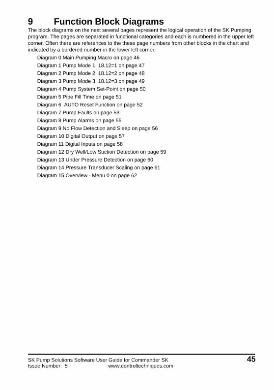
9 Function Block DiagramsThe block diagrams on the next several pages represent the logical operation of the SK Pumping program. The pages are separated in functional categories and each is numbered in the upper left corner. Often there are references to the these page numbers from other blocks in the chart and indicated by a bordered number in the lower left corner.
Diagram 0 Main Pumping Macro on page 46
Diagram 1 Pump Mode 1, 18.12=1 on page 47
Diagram 2 Pump Mode 2, 18.12=2 on page 48
Diagram 3 Pump Mode 3, 18.12=3 on page 49
Diagram 4 Pump System Set-Point on page 50
Diagram 5 Pipe Fill Time on page 51
Diagram 6 AUTO Reset Function on page 52
Diagram 7 Pump Faults on page 53
Diagram 8 Pump Alarms on page 55
Diagram 9 No Flow Detection and Sleep on page 56
Diagram 10 Digital Output on page 57
Diagram 11 Digital Inputs on page 58
Diagram 12 Dry Well/Low Suction Detection on page 59
Diagram 13 Under Pressure Detection on page 60
Diagram 14 Pressure Transducer Scaling on page 61
Diagram 15 Overview - Menu 0 on page 62
SK Pump Solutions Software User Guide for Commander SK 45Issue Number: 5 www.controltechniques.com

���
���
������
� � ����������
����
���
����
��
� ��
���
���
���
����
���
�� �
����
���
���
����
���
����
��
��
��
��� !
��
��������������
�
�� �� ��
���� ����
����
�� �� �
!��" ��#$
��%����#����&�
�
'���(������
)����*+
�,��
�����
)-�
���'�����)��
����)��
����
���
������������'�
�-����'�)�..
����
���
���..,������-
��/
�������
)��
�����
.���
���-��,
����
�
�����0��
��1����
�.�����
�
� ���������&
�2��
�������
"
���
�#
$� %
&�'�(
�)$
�#$
� %&
&2��
������&
"
���
��
� ��
�%
�'�(�
)$�#
$� %
&
32��
������3
"
���
��
� ��
�%
-��
����
����
����
����
)��
���
*+�
� ��
*�
���
���
�4����
� �����
+5�667���4�7����8��4954��
- ����� �� ����:�6�#����
� � ��������&�2��%�5 ������
,)�
� )
�#�
% ��
��
�#
)��
)��
��
%
�
+�$� � #
� �
)�#
�%
���
��#
)��
)��
��
%
+�$� �
����
�� 6 *-�
� ��
*�
����
�� 6
0 Main Pumping Macro
46 SK Pump Solutions Software User Guide for Commander SKwww.controltechniques.com Issue Number: 5

PUM
P M
OD
E 1
18.
12 =
11
PRES
SUR
E SW
ITC
HTe
rmin
al B
7 an
d B
2
FLO
W S
WIT
CH
Term
inal
B6
and
B2
STA
RT
DEL
AY T
IME
Par
amet
er 0
2.13
Ran
ge: 0
- 32
00.0
sec
.D
efau
lt: 0
.0 s
ec.
STO
P D
ELAY
TIM
EP
aram
eter
02.
14R
ange
: 0 -
3200
.0 s
ec.
Def
ault:
5.0
sec
.
STA
RT
SYST
EM
STO
PSY
STEM
MA
X FR
EQ S
ET-P
OIN
TP
aram
eter
01.
06R
ange
: 0 –
150
0.0H
zD
efau
lt: 6
0Hz
DR
IVE
OU
TPU
TM
NO
TE: S
ET P
AR
AM
ETER
18.
30 T
O IT
S M
AX
PAR
AM
ETER
VA
LUE,
(327
67) T
O E
NSU
RE
MA
X SP
EED
OF
PUM
P IS
AC
HIE
VED
1 Pump Mode 1, 18.12=1
SK Pump Solutions Software User Guide for Commander SK 47Issue Number: 5 www.controltechniques.com

2 Pump Mode 2, 18.12=2
PUM
P M
OD
E 2
18.
12 =
22
FLO
W S
WIT
CH
Term
inal
B6
and
B2
STA
RT
DEL
AY T
IME
Par
amet
er 0
2.13
Ran
ge: 0
- 32
00.0
sec
.D
efau
lt: 0
.0 s
ec.
STO
P D
ELAY
TIM
EP
aram
eter
02.
14R
ange
: 0 -
3200
.0 s
ec.
Def
ault:
5.0
sec
.
STA
RT
SYST
EM
STO
PSY
STEM
PID
CO
NTR
OL
14.1
0 =
P14
.11
= I
14
.12
= D
SYST
EM S
ET-P
OIN
T
4
DR
IVE
OU
TPU
TM
LOW
SET
-PO
INT
Par
amet
er 1
8.13
Ran
ge: 0
- 10
00.0
PS
ID
efau
lt: 0
PS
I
PUM
P A
LAR
MS
8
PRES
SUR
E FB
K
PIPE
FIL
L
5
DIG
ITA
L O
UTP
UTS
10
PUM
P FA
ULT
S
7
PRES
SUR
E FB
K
1414
48 SK Pump Solutions Software User Guide for Commander SKwww.controltechniques.com Issue Number: 5
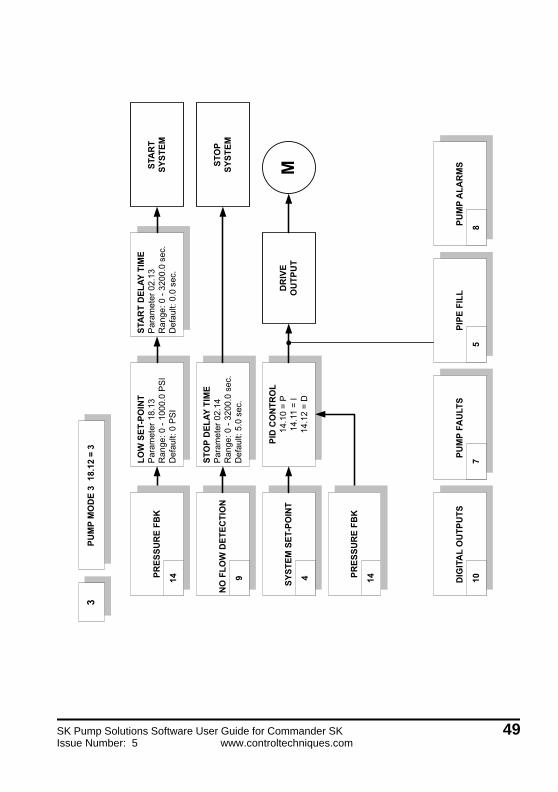
��������3����&23
3
�!.�
)���
�����
;
�������.
�,����
"��
�
��
�.��
/�
0!��
�1���
��.�
��%
.�
���
� !��
.���
%.
������.
�,����
"��
�
��
�.�-
/�
0!��
�1���
��.�
��%
.�
���
� !�+
.���
%.
�����
�,��
��
����
�,��
��
�������
�.
�-.�
����
"�-
.���
��2��
��-
.���
���
�,��
�����
<����
=
���'�
����
��
�
.�)���
<����
"��
�
��
3.��
/�
0!��
�1���
��.�
�"#2
��
��� !
���"
#2
�����.�
���
�
����
����!>
+
����
!�..
?
������.����
���
��
����!�
�.��
@
����
����!>
+
�=�=
3 Pump Mode 3, 18.12=3
SK Pump Solutions Software User Guide for Commander SK 49Issue Number: 5 www.controltechniques.com

������.
�+�4�
5�����
�#,
12'�
�6�
�
�����,
����
���
<����
=
������
A����
"�
��
��
3.��
/�
0!��
�1���
��.�
�"#
2�
���
� !��
�"#
2
������.
�+��6�:��1�
5�����
�#,
12'�
�6�
�
���A��
���
"�
��
��
3.�-
/�
0!��
�1���
��.�
�"#
2�
���
� !��
�"#
2
������.
�+�����1�
5��6�:��
�#,
12'�
�6�
�
���A��
��&
"�
��
��
3.�+
/�
0!��
�1���
��.�
�"#
2�
���
� !��
�"#
2
������.
�+��6�:��1�
5��6�:��
�#,
12'�
�6�
�
���A��
��3
"�
��
��
3.�5
/�
0!��
�1���
��.�
�"#
2�
���
� !��
�"#
2
�,��
����
�<��
��
��.�
����
�,��
�����
<����
"�
��
��
3.�-
/�
0!��
1���
�.��
"#
2.
�"
7�
86�
#7
�
�"
7�
�"
7�
�"
7�
86�
#7
�
86�
#7
�8
6�#
7�
������
<����
���<��
��&
���<��
��3
���<��
��=
�3.�
9�3
.�5
������.���
��
��
�(�?
������.
�������
��
����-
��>.�
4 Pump System Set-Point
50 SK Pump Solutions Software User Guide for Commander SKwww.controltechniques.com Issue Number: 5

����
!�..����
?
�,��
����
��
��
����
���
�&�
�3
����
!�..����
"��
�
��.�+
/� 0
!���1
��+.��
�%.
����
� !����
%.�
�����
�:��
�!&��
?B�
���!
��C�
��,
��
��/D��
��(E
�����/
����
�&��
?
>��������
���
.
,
5 Pipe Fill Time
SK Pump Solutions Software User Guide for Commander SK 51Issue Number: 5 www.controltechniques.com

����
���
�������
"�
��
��
�.�-
/�
0!��
�1�+
��
��� !
�+��
����
:��
����
���
��������
"�
��
��
�.�+
/�
0!��
�1��+
.���
%.
��
��� !
����
�%.
���
����
:��
����
���
��!�����
(
�66����
�����:
���
��!�
�.�
!��.�
�,��
��� F�� �
�
7���
%��:� ��:�� #4��
6 AUTO Reset Function
52 SK Pump Solutions Software User Guide for Commander SKwww.controltechniques.com Issue Number: 5
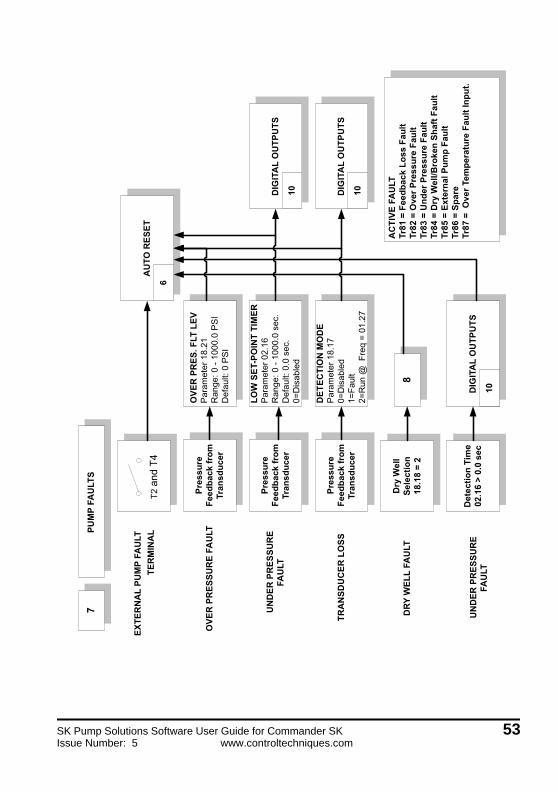
����!�
�.��
@
����
���
����
�� �
��-
������.
�'�
�����
�!.�.�'
"�
��
��
3.��
/�
0!��
�1���
��.�
�"#
2�
���
� !��
�"#
2
���:: ��
!���7 #G%���
�� �:� #��
�/��
��.��
��!�
�.�
�'�
�����
����!�
�.�
���
���������
"�
��
��
3.�9
���
���:
��
��(�
��
��/
� �;
��(
<���
��.�
9
���:: ��
!���7 #G%���
�� �:� #��
�����
����
.���
.�)���
<���������
"�
��
��
�.�5
/�
0!��
�1���
��.�
��%
.�
���
� !��
.���
%.�
���
���:
��
���:: ��
!���7 #G%���
�� �:� #��
����
����
����
!��.�
������.����
���
������.����
���
�� ��
��$)�66
��6�#����
�����2&
��,
)�.
.!�
�.�
�
(
����#��������
�&��(B���:�#
����
����
����
!��.�
������.����
���
��
����'�
!��.�
����2!���7 #G.�::! 6�
���&2�����
��:: ��! 6�
���32��������:: ��! 6�
���=2��$)�660>
��G���4
%�! 6�
���?2�F���� 6�
��! 6�
���(2�� ��
���@2�
������
��� � ��! 6���� ��
7 Pump Faults
SK Pump Solutions Software User Guide for Commander SK 53Issue Number: 5 www.controltechniques.com

����!�
�.��
@
����
���
����
�� �
���
������.
�'�
����
�����
���
(
����'�
!��.�
����2!���7 #G.�::! 6�
���&2�����
��:: ��! 6�
���32��������:: ��! 6�
���=2��$)�660>
��G���4
%�! 6�
���?2�F���� 6�
��! 6�
���(2�� ��
���@2�
������
��� � ��! 6���� ��
54 SK Pump Solutions Software User Guide for Commander SKwww.controltechniques.com Issue Number: 5

�����.�
���
�
�'�
�����
��.�
.�'
"�
��
��
3.��
/�
0!��
�1���
��.�
�"#
2�
���
� !��
�"#
2
� ���!!.���6
-$:����:�:�:?H
>�6�5
���&�
���:: ��
!���7 #G%���
�� �:� #��
�'�
�����
����)����
������.����
���
��
��,
)�.
.��
.�����
����
�����2�
��,
)�.
.�.�
��
������ 6�6 ��
8 Pump Alarms
SK Pump Solutions Software User Guide for Commander SK 55Issue Number: 5 www.controltechniques.com

�!.�
)���
�����
���.
���
; �,��
������
������
����
�!��C
�!6�5
-I��
�<�����
"�
��
��
�.�5
/�
0!��
�=���
.�5�
��
��� !
�5�.
���
>
���:� ��!��"����
"�
��
��
�.��
/�
0!��
�1���
�.��
�%.
��
��� !
�+.�
��%
.
�!6�5
-I> ��5
���4
"�
��
��
�.��
/�
0!��
�1+��
��>
��
��� !
��+�
�>
���<�
������#������
"�
��
��
3.�9
/�
0!��
�1���
��.�
�"#
2�
���
� !��
.��"
#2
�� 7�6�I���6 $
"�
��
��
�.�3
/�
0!��
�1���
�.��
�%.
��
��� !
��.�
��%
.
���<�
����> ��5
���4
"�
��
��
3.�+
/�
0!��
�1��.
��"
#2
��
��� !
��.+
�"#
2
�!.�
)���
����
������ ���6���
�6�������� �
!��"
"�
��
��
�.�-
/�
0!��
�=���
.�5�
��
��� !
����
>��
���
�:�
�
� F�!��"�> ��5
���4
"�
��
��
�.�+
/�
0!��
�1��.
���
>�
���
� !��
.���
>
������� �� �!��"
"�
��
��
�.�9
/�
0!��
�=��
�.�5
��
��� !
��.�
��>
�>�
?���
.�5
�>�
$� &
� �*
� �$
�� &
��.
��@
���
�7
A��
����
.��
B�
B�
B�
�)
�)
�)
(�
:�%C
�$
� &�
�#
1�)�
�
:� �
$��
&�
�3.�
+@
�)
��:�������<�����
�6����� ������
"�
��
��
�.�9
/�
0!��
�1���
����
%.
��
��� !
����
%.
�����-IJ��&=
2��"
��
��
(�
:�%C
�D�#
�)
� �
*�
�$��
&
�)
B�
�3.�
��D�
�3.�
3��3
.�+
B�
9 No Flow Detection and Sleep
56 SK Pump Solutions Software User Guide for Commander SKwww.controltechniques.com Issue Number: 5

������.����
���
*!��������
�����
���
EEEK
EEE
��
����
��
EEE�K
EEE
EEEK
EEE
�:���
�6�#� 76�
����!�
�.�
����
��
EEE�K
EEE
EEEK
EEE
�:���
�6�#� 76�
�����
����
.���
����
��
EEE�K
EEE
EEEK
EEE
�:���
�6�#� 76�
�����
<����
����
��
EEE�K
EEE
EEEK
EEE
�:���
�6�#� 76�
�'�
�����
����
)����
����
��
EEE�K
EEE
EEEK
EEE
�:���
�6�#� 76�
���
�,!�
�
���
���
��
����
��
EEE�K
EEE
EEEK
EEE
��,
)�.
.!�
�.� ��
����
�� �
��
������
�%)
��0�
�:�
�� �
�%�
�:
����
�0
�� )
�� �
���0
� ���)
� ��
.�/
�
��)�
8)�
��
��#
���
��F
���
�
����
��
EEE�K
EEE
EEEK
EEE
����
����
����
!��.�
"��
�
��
�.��
"��
�
��
3.--
"��
�
��
3.-�
"��
�
��
3.-�
"��
�
��
3.-�
"��
�
��
3.-5
"��
�
��
3.-G
10 Digital Output
SK Pump Solutions Software User Guide for Commander SK 57Issue Number: 5 www.controltechniques.com

������.���
����
����!�
�.�
�-
��.���
��<����
�+D��<�0�.���E
��.���
��<����
�5D��<�0�.���E
-������
*+
����
����
*-
@ = =� �
���'����
���9
D��<�0�.���E
����
�����)
���-
*9
!.�)�)���-
*5
�'�
����
�����
���
��D��<�0�.���E
@�
"�
��
��
3.�3
"�
��
��
3.�5
"�
��
��
3.�9
"�
��
��
3.�+
"�
��
��
3.�G
"�
��
��
3.�-
"�
��
��
�.��
"�
��
��
3.��
"�
��
��
3.��
11 Digital Inputs
58 SK Pump Solutions Software User Guide for Commander SKwww.controltechniques.com Issue Number: 5

DRY
WEL
L / L
OW
SU
CTI
ON
DET
ECTI
ON
0%25
%50
%75
%10
0%
SPEE
D
TOR
QU
E200%
02.2
6
Low
Loa
d Po
int
Par
amet
er 0
2.26
Ran
ge: 0
- 20
0%D
efau
lt: 0
%.
12
0%
DRY
WEL
L D
ETEC
TIO
N
SELE
CTI
ON
MO
DE
P
aram
eter
18.
18D
efau
lt: 2
0=A
larm
1=D
ecre
ase
Spe
ed %
by
2.27
2=Fa
ult
Dry
Wel
l D
etec
tion
DET
ECTI
ON
TIM
EP
aram
eter
02.
24R
ange
: 0 -
3200
.0 s
ec.
Def
ault:
0.0
sec
.0=
Dis
able
d
Set-P
oint
Dec
rem
ent
Par
amet
er 0
2.27
Ran
ge: 0
- 10
.0 %
Def
ault:
1.0
%
NO
TE:
This
func
tion
dete
cts
a lo
w lo
ad o
n th
e m
otor
whe
n ru
nnin
g at
max
imum
spe
ed in
dica
ting
a dr
y o
r unl
oade
d pu
mp.
To
set:
1. R
un fu
lly lo
aded
pum
p at
max
imum
spe
ed a
nd re
cord
ave
rage
val
ue in
par
amet
er 4
.20
2. S
et p
aram
eter
2.2
6 to
a v
alue
low
er th
an th
e re
cord
ed v
alue
in 4
.20
and
high
er th
an a
n un
load
ed p
ump.
- Dry
wel
l/ Lo
w S
uctio
n h
as a
hig
her p
riorit
y th
en fl
ow/n
o-flo
w d
etec
tion
- Dry
wel
l/ Lo
w S
uctio
n h
as a
hig
her p
riorit
y th
en fe
edba
ck lo
ss @
fixe
d sp
eed
18.1
7=2
Mot
or L
oad
Perc
enta
geP
aram
eter
04.
20R
ange
: 0 -
200%
Rea
d O
nly
4.20
< 2
.26 Ye
s
No
12 Dry Well/Low Suction Detection
SK Pump Solutions Software User Guide for Commander SK 59Issue Number: 5 www.controltechniques.com

����
����
�������
�����
�3
�,��
������
.�5���<�������������
"�
��
��
�.�5
/�
0!��
�1���
�.��
�%.
��
��� !
����
%.��
����
:��
�
!��.����'�
� F�!��"�> ��5
���4
"�
��
��
�.�+
/�
0!��
�1��.
�5�
���
� !��
.���
>
"
���
�(:
C�?�
#
1")�
��
�� �(
<.
�D�
�.�5
=��.
�+��
���
�7
A��
����
.�5
����
����
����>��+�
����
��������:: ����
6�#�
"�
��
��
3.+�
/�
0!��
�1��
��
��� !
��
��������:: ����
6�#�2�
#
1�)�
��
�#��
�
�#
1�)�
��
3.�-
��=�*
� �$
�� &
���3.
�+��
��������:: ����
6�#�2�
#
1�)�
��
�� �
�"
��
��
#
1�)�
���
3.�-
��
�3.�
����
"
���
�(
�:�
%C
13 Under Pressure Detection
60 SK Pump Solutions Software User Guide for Commander SKwww.controltechniques.com Issue Number: 5

����
������
���
����
��
�.��
�=
����
������
����
��
� ��
����
� ��
��
=<&�����L� 6
���.�����
"�
��
��
3.��
/�
0!��
=���
�.��
"#
2�
���
� !��
�"#
2
���.����/�
"�
��
��
3.��
/�
0!��
=���
�.��
"#
2�
���
� !��
-+.�
�"#
2
����
����!>
+"
���
��3.
��/
� 0
!��1�
���.
��"
#2.
!�.���
"�
��
��
�.�+
/�
0!��
=GG.
GG�
��
��� !
����
�3.�
�
�3.�
�
#�0
���/
� 0
#%����"#2�/� 0
-��
���
�
14 Pressure Transducer Scaling
SK Pump Solutions Software User Guide for Commander SK 61Issue Number: 5 www.controltechniques.com
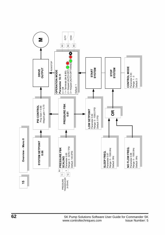
����
����!>
+
���.��
"�
��
��
.5+
/�
0!��
�1���
95.9
�"#
2�
���
� !��
-+.�
"#
2
�������5=��� �
�?
�.��
�!�
�C�
"�
��
��
.59
/�
0!��
�1��+
��.�
�>
��
��� !
���
>
�����
�,��
��
����
�,��
��
�������
�.�
")
��F
�� �
���.
5G2
0
���0
�� �
���.
9���
�,��
�����
����
��((
���'�
����
��
�
.�)���
����
"�
��
��
.5-
/�
0!��
�1���
��.�
�"#
2�
���
� !��
�"#
2
����
����!>
+��(�
�!.�
)!��C
�"
���
��.5
3/
� 0
!���1�
�+��
.��
>�
���
� !��
�>
��
*-
*+
*�
��
��
��
��
���
���
������
� � ����������
����
���
����
��
� ��
���*
-�4
�*+�
����
��
����
���
��1�
((�
����
��
����
���
��1�
((1�
��
��
��
��� !
��
�
�� ��
"/
7#
#�
/7
��/
��
#�
�8
7/
�-1�
���
�
�H �
����
�.����
"�
��
��
.5�
/�
0!��
�1��
��
��� !
��
/�
�'#
��"
15 Overview - Menu 0
62 SK Pump Solutions Software User Guide for Commander SKwww.controltechniques.com Issue Number: 5

10 Parameter Descriptions10.1 Pump Specific Parameter DescriptionsMany of the Commander SK parameters have different functionality than standard when used in the Pump Solution mode. If not listed in the table below the functionality is standard as listed in the Commander SK Getting Started Guide and Commander SK Advanced User Guide.
10.1.1 Keypad Parameters
Pr Description Type Units Range Default
01 Minimum Set Speed RW Hz 0-1500 0
02 Maximum Set Speed RW Hz 0-1500 60
03 Acceleration Rate RW s/100Hz 0-3200 1.0
04 Deceleration Rate RW s/100Hz 0-3200 1.0
05 Drive Configuration RW - -Pr
(Preset)
06 Motor Rated Current RW Amps - 0
07 Motor Rated RPM RW RPM 0-9999 0
08 Motor Rated Voltage RW Volts - -
09 Motor Power Factor RW - 0-1.00 0.85
10 Security Status RW - - L3
11 Start/Stop Logic Select RW 0-6 0
16 Analog 1 Input Mode RW - - 4
18 HAND Mode Speed RW Hz +/-1500.0 0
20 No Flow RPM (Freq) Bandwidth RW Hz +/-1500.0 15
21 Minimum Sleep Speed/Freq RW Hz +/-1500.0 0
41 Voltage Mode Select RW - -FD
(Fixed)
59 PLC Ladder Program Enable RW - - Run/Clip
60 PLC Ladder Program Status RO - - V
61 Pressure Feedback (Pr 18.02) RO 0.1 PSI +/-32767 -
62 Pumping Macro (Pr 18.11) RW - +/-32767 0 (Off)
63 Start/Stop Control Modes (Pr 18.12) RW - +/-32767 3 (PT)
64 Low Pressure setpoint (Pr 18.13) RW 0.1 PSI +/-32767 0
65 Maximum Pressure Scaling (Pr 18.23) RW 0.1 PSI +/-32767 1450
66 Main Pressure setpoint (Pr 18.30) RW 0.1 PSI +/-32767 0
67 Minimum Sleep Frequency (Pr 1.24) RW Hz +/-1500.0 0
68 No Flow Frequency (Pr 1.26) RW Hz +/-1500.0 0
69 Proportional Gain (Pr 14.10) RW Gain 0-4.000 1
70 Integral Time (Pr 14.11) RW sec 0-4.000 0.5
SK Pump Solutions Software User Guide for Commander SK 63Issue Number: 5 www.controltechniques.com
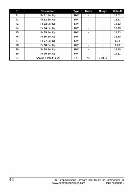
71 Pr 61 Set Up RW - - 18.02
72 Pr 62 Set Up RW - - 18.11
73 Pr 63 Set Up RW - - 18.12
74 Pr 64 Set Up RW - - 18.13
75 Pr 65 Set Up RW - - 18.23
76 Pr 66 Set Up RW - - 18.30
77 Pr 67 Set Up RW - - 1.24
78 Pr 68 Set Up RW - - 1.26
79 Pr 69 Set Up RW - - 14.10
80 Pr 70 Set Up RW - - 14.11
94 Analog 1 Input Level RO % 0-100.0 -
Pr Description Type Units Range Default
64 SK Pump Solutions Software User Guide for Commander SKwww.controltechniques.com Issue Number: 5
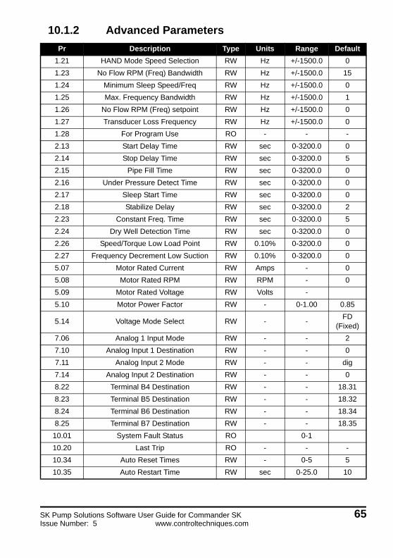
10.1.2 Advanced Parameters
Pr Description Type Units Range Default
1.21 HAND Mode Speed Selection RW Hz +/-1500.0 0
1.23 No Flow RPM (Freq) Bandwidth RW Hz +/-1500.0 15
1.24 Minimum Sleep Speed/Freq RW Hz +/-1500.0 0
1.25 Max. Frequency Bandwidth RW Hz +/-1500.0 1
1.26 No Flow RPM (Freq) setpoint RW Hz +/-1500.0 0
1.27 Transducer Loss Frequency RW Hz +/-1500.0 0
1.28 For Program Use RO - - -
2.13 Start Delay Time RW sec 0-3200.0 0
2.14 Stop Delay Time RW sec 0-3200.0 5
2.15 Pipe Fill Time RW sec 0-3200.0 0
2.16 Under Pressure Detect Time RW sec 0-3200.0 0
2.17 Sleep Start Time RW sec 0-3200.0 0
2.18 Stabilize Delay RW sec 0-3200.0 2
2.23 Constant Freq. Time RW sec 0-3200.0 5
2.24 Dry Well Detection Time RW sec 0-3200.0 0
2.26 Speed/Torque Low Load Point RW 0.10% 0-3200.0 0
2.27 Frequency Decrement Low Suction RW 0.10% 0-3200.0 0
5.07 Motor Rated Current RW Amps - 0
5.08 Motor Rated RPM RW RPM - 0
5.09 Motor Rated Voltage RW Volts -
5.10 Motor Power Factor RW - 0-1.00 0.85
5.14 Voltage Mode Select RW - -FD
(Fixed)
7.06 Analog 1 Input Mode RW - - 2
7.10 Analog Input 1 Destination RW - - 0
7.11 Analog Input 2 Mode RW - - dig
7.14 Analog Input 2 Destination RW - - 0
8.22 Terminal B4 Destination RW - - 18.31
8.23 Terminal B5 Destination RW - - 18.32
8.24 Terminal B6 Destination RW - - 18.34
8.25 Terminal B7 Destination RW - - 18.35
10.01 System Fault Status RO 0-1
10.20 Last Trip RO - - -
10.34 Auto Reset Times RW - 0-5 5
10.35 Auto Restart Time RW sec 0-25.0 10
SK Pump Solutions Software User Guide for Commander SK 65Issue Number: 5 www.controltechniques.com

11.27 Drive Configuration RW - -Pr
(Preset)
11.44 Security Status RW - - L3
11.47 PLC Ladder Program Enable RW - - Run/Clip
12.03 Threshold Detector 1 Source RW - - 15.40
12.04 Threshold Detector 1 Level RW % 0-100.0 10
12.07 Threshold Detector 1 Destination RW - - 18.39
12.08 Variable Selector 1 Source 1 RW - - 7.01
12.10 Variable Selector 1 Mode RW - - 6
12.15 Pressure Transducer Filter RW sec 0-99.99 0
14.02 PID Main Reference Source RW - - 18.29
14.03 PID Reference Source RW - - 18.05
14.04 PID Feedback Source RW - - 12.12
14.10 Proportional Gain RW Gain 0-4.000 1
14.11 Integral Time RW sec 0-4.000 0.5
14.12 Differential Rate RW d/dt 0-4.000 0
14.14 PID Lower Limit RW % +/-100.0 0
14.16 PID Output Destination RW - - 1.36
15.24 Terminal T5 Destination RW - - -
15.25 Terminal T6 Destination RW - - -
15.26 Terminal T7 Destination RW - - -
15.27 Terminal T21/T23 Relay Source RW - - -
15.38 Analog Input T2 mode RW - Volt
18.01 For Program Use (NV) RO - +/-32767 -
18.02 Pressure Feedback Value RO 0.1 PSI +/-32767 -
18.03 PID Error RO 0.1 PSI +/-32767 -
18.04 Selected Setpoint Value RO 0.1 PSI +/-32767 -
18.05 Scaled Setpoint for PID RO P.U. +/-32767 -
18.06 For Program Use RO - +/-32767 -
18.07 For Program Use RO - +/-32767 -
18.08 Final Setpoint with Inc & Dec RO 0.1 PSI +/-32767 -
18.09 For Program Use RO - +/-32767 -
18.10 For Program Use RO - +/-32767 -
18.11 Pumping Macro Select RW - +/-32767 0 (Off)
18.12 Start/Stop & Control Modes RW - +/-32767 3 (PT)
18.13 Low Setpoint RW 0.1 PSI +/-32767 0
18.14 Under Pressure Setpoint RW 0.1 PSI +/-32767 0
18.15 Setpoint Bandwidth RW 0.1 PSI +/-32767 5
Pr Description Type Units Range Default
66 SK Pump Solutions Software User Guide for Commander SKwww.controltechniques.com Issue Number: 5
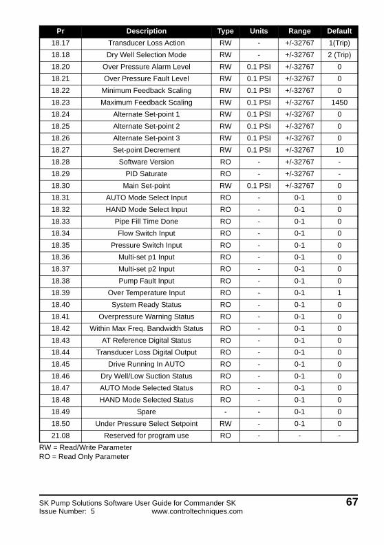
RW = Read/Write ParameterRO = Read Only Parameter
18.17 Transducer Loss Action RW - +/-32767 1(Trip)
18.18 Dry Well Selection Mode RW - +/-32767 2 (Trip)
18.20 Over Pressure Alarm Level RW 0.1 PSI +/-32767 0
18.21 Over Pressure Fault Level RW 0.1 PSI +/-32767 0
18.22 Minimum Feedback Scaling RW 0.1 PSI +/-32767 0
18.23 Maximum Feedback Scaling RW 0.1 PSI +/-32767 1450
18.24 Alternate Set-point 1 RW 0.1 PSI +/-32767 0
18.25 Alternate Set-point 2 RW 0.1 PSI +/-32767 0
18.26 Alternate Set-point 3 RW 0.1 PSI +/-32767 0
18.27 Set-point Decrement RW 0.1 PSI +/-32767 10
18.28 Software Version RO - +/-32767 -
18.29 PID Saturate RO - +/-32767 -
18.30 Main Set-point RW 0.1 PSI +/-32767 0
18.31 AUTO Mode Select Input RO - 0-1 0
18.32 HAND Mode Select Input RO - 0-1 0
18.33 Pipe Fill Time Done RO - 0-1 0
18.34 Flow Switch Input RO - 0-1 0
18.35 Pressure Switch Input RO - 0-1 0
18.36 Multi-set p1 Input RO - 0-1 0
18.37 Multi-set p2 Input RO - 0-1 0
18.38 Pump Fault Input RO - 0-1 0
18.39 Over Temperature Input RO - 0-1 1
18.40 System Ready Status RO - 0-1 0
18.41 Overpressure Warning Status RO - 0-1 0
18.42 Within Max Freq. Bandwidth Status RO - 0-1 0
18.43 AT Reference Digital Status RO - 0-1 0
18.44 Transducer Loss Digital Output RO - 0-1 0
18.45 Drive Running In AUTO RO - 0-1 0
18.46 Dry Well/Low Suction Status RO - 0-1 0
18.47 AUTO Mode Selected Status RO - 0-1 0
18.48 HAND Mode Selected Status RO - 0-1 0
18.49 Spare - - 0-1 0
18.50 Under Pressure Select Setpoint RW - 0-1 0
21.08 Reserved for program use RO - - -
Pr Description Type Units Range Default
SK Pump Solutions Software User Guide for Commander SK 67Issue Number: 5 www.controltechniques.com

10.1.3 Other Documentation References
10.1.4 Keypad Parameters
Sets the minimum frequency that the drive will run at when a run command is issued.Setting Pr02 to a lower value will override this setting.
This is the maximum frequency that the drive will run at regardless if the setpoint frequency is set higher.
Defines the acceleration rate of the motor in seconds per 100 Hz. Too high of a setting will result in a slow responding PID loop and may cause other time sensitive diagnostic routines issues.
Defines the deceleration rate of the motor in seconds per 100Hz. Too high of a setting will result in a slow responding PID loop and may cause other time sensitive diagnostic routines issues.
Sets the drive configuration mode i.e. the reference source location for the drive and I/O configuration. Always set this to Preset (Pr).
Manual Description CT Part Number
Commander SK Getting Started Guide 0472-0000-XX
Commander SK Advanced User Guide 0447-0002-XX
Pr Function Range Units Default Type
01 Minimum Set Speed 0 - 1500 Hz 0 RW
Pr Function Range Units Default Type
02 Maximum Set Speed 0 - 1500.0 Hz 60.0 RW
Pr Function Range Units Default Type
03 Acceleration Rate 0 - 3200.0 s/100 Hz 1 RW
Pr Function Range Units Default Type
04 Deceleration Rate 0 - 3200.0 s/100 Hz 1 RW
Pr Function Range Units Default Type
05 Drive Configuration Pr RW
If this parameter is changed many other parameters will automatically change as a result. Therefore, set this to Pr and perform a drive reset prior to setting any other parameters.
CAUTION
68 SK Pump Solutions Software User Guide for Commander SKwww.controltechniques.com Issue Number: 5

Defines the full load Amps of the motor rating. Enter the motor nameplate value in Amps.
Set to zero the disable slip compensation.
Enter the rated motor voltage at base speed.
Enter the motor power factor. If unknown leave at default or perform a rotating auto-tune.
This setting defines the level of security for menu 0 through the keypad.
Pr Function Range Units Default Type
06 Motor Rated Current0 to Drive Rated
CurrentAmps 0 RW
Pr Function Range Units Default Type
07 Motor Rated RPM 0-9999 RPM 0 RW
Pr Function Range Units Default Type
08 Motor Rated Voltage0 -240 V, 0 - 480 V, 0 - 575 V, 0 - 690 V
Volts
230, 460, 575, 690
depending on drive model
RW
Pr Function Range Units Default Type
09 Motor Power Factor 0 -1 0.85 RW
Pr Function Range Units Default Type
10 Security Status L1, L2, L3, LoC L3 RW
Value Level Access Permitted
0 L1 Only the first ten parameters can be accessed
1 L2 Parameters up to 60 can be accessed
2 L3 Parameters up to 95 can be accessed
3 LoCLock security, so that the security code must be entered before a parameter can be edited and set security status to L1
SK Pump Solutions Software User Guide for Commander SK 69Issue Number: 5 www.controltechniques.com
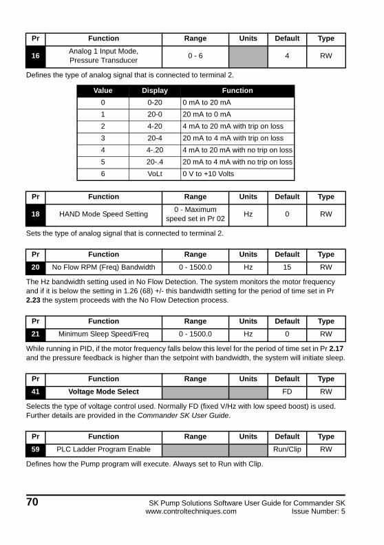
Defines the type of analog signal that is connected to terminal 2.
Sets the type of analog signal that is connected to terminal 2.
The Hz bandwidth setting used in No Flow Detection. The system monitors the motor frequency and if it is below the setting in 1.26 (68) +/- this bandwidth setting for the period of time set in Pr 2.23 the system proceeds with the No Flow Detection process.
While running in PID, if the motor frequency falls below this level for the period of time set in Pr 2.17 and the pressure feedback is higher than the setpoint with bandwidth, the system will initiate sleep.
Selects the type of voltage control used. Normally FD (fixed V/Hz with low speed boost) is used. Further details are provided in the Commander SK User Guide.
Defines how the Pump program will execute. Always set to Run with Clip.
Pr Function Range Units Default Type
16Analog 1 Input Mode, Pressure Transducer
0 - 6 4 RW
Value Display Function
0 0-20 0 mA to 20 mA
1 20-0 20 mA to 0 mA
2 4-20 4 mA to 20 mA with trip on loss
3 20-4 20 mA to 4 mA with trip on loss
4 4-.20 4 mA to 20 mA with no trip on loss
5 20-.4 20 mA to 4 mA with no trip on loss
6 VoLt 0 V to +10 Volts
Pr Function Range Units Default Type
18 HAND Mode Speed Setting0 - Maximum
speed set in Pr 02Hz 0 RW
Pr Function Range Units Default Type
20 No Flow RPM (Freq) Bandwidth 0 - 1500.0 Hz 15 RW
Pr Function Range Units Default Type
21 Minimum Sleep Speed/Freq 0 - 1500.0 Hz 0 RW
Pr Function Range Units Default Type
41 Voltage Mode Select FD RW
Pr Function Range Units Default Type
59 PLC Ladder Program Enable Run/Clip RW
70 SK Pump Solutions Software User Guide for Commander SKwww.controltechniques.com Issue Number: 5

Indicates the status of the Pump program execution. Under normal running conditions a 2 is displayed.
Indicates the scaled pressure feedback PSI
Defines the Operation Mode of the Pump system.
0 = Off
1 = Terminals
2 = Keypad, Automatic Only
3 = Keypad, Automatic and Hand.
This parameter sets the Start/Stop modes of the drive.
1 = Pressure Switch/Flow Switch. The drive will start when the feedback pressure switch closes and runs until a stop command is given or a no flow detection is made from the No Flow switch input.
2 = Pressure Transducer/Flow Switch. The drive will start when the feedback pressure transducer level is below the Low Setpoint (Pr 18.13), and runs until a stop command is given or a no flow detection is made from the No Flow switch input.
3 = Pressure Transducer. The drive will start when the feedback pressure transducer level is below the Low Setpoint (Pr 18.13), and runs until a stop command is given or a No Flow detection is made (see No Flow diagram for details).
Pr Function Range Units Default Type
60 PLC Ladder Program Status RO
Value Description
-nPLC ladder program caused a drive trip due to an error condition while running rung n. Note that the rung number is shown on the display as a
negative number
0 LogicStick is installed with no PLC ladder program
1 LogicStick is installed, PLC ladder program is installed but stopped
2 LogicStick is installed, PLC ladder program is installed and running
3 LogicStick is not installed
Pr Function Range Units Default Type
61 Pressure Feedback Value ± 32767 0.1 PSI RO
Pr Function Range Units Default Type
62 Pumping Macro Select ± 32767 0 RW
Pr Function Range Units Default Type
63 Start/Stop & Control Mode ± 32767 3 RW
SK Pump Solutions Software User Guide for Commander SK 71Issue Number: 5 www.controltechniques.com
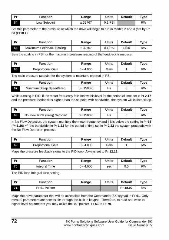
Set this parameter to the pressure at which the drive will begin to run in Modes 2 and 3 (set by Pr 63 (Pr18.12.
Sets the scaling in PSI for the maximum pressure reading of the feedback transducer
The main pressure setpoint for the system to maintain, entered in PSI.
While running in PID, if the motor frequency falls below this level for the period of time set in Pr 2.17 and the pressure feedback is higher than the setpoint with bandwidth, the system will initiate sleep.
In No Flow Detection, the system monitors the motor frequency and if it is below the setting in Pr 68 (Pr 1.26) +/- the bandwidth in Pr 1.23 for the period of time set in Pr 2.23 the system proceeds with the No Flow Detection process.
Maps the pressure feedback signal to the PID loop. Always set to Pr 12.12.
The PID loop Integral time setting.
Maps the drive parameter that will be accessible from the Commander SK keypad in Pr 61. Only menu 0 parameters are accessible through the built in keypad. Therefore, to read and write to higher level parameters you may utilize the 10 "pointer" Pr 61 to Pr 70.
Pr Function Range Units Default Type
64 Low Setpoint ± 32767 0.1 PSI RW
Pr Function Range Units Default Type
65 Maximum Feedback Scaling ± 32767 0.1 PSI 1450 RW
Pr Function Range Units Default Type
66 Proportional Gain 0 - 4.000 Gain 1 RW
Pr Function Range Units Default Type
67 Minimum Sleep Speed/Freq 0 - 1500.0 Hz 0 RW
Pr Function Range Units Default Type
68 No Flow RPM (Freq) Setpoint 0 - 1500.0 Hz 0 RW
Pr Function Range Units Default Type
69 Proportional Gain 0 - 4.000 Gain 1 RW
Pr Function Range Units Default Type
70 Integral Time 0 - 4.000 sec 0.5 RW
Pr Function Range Units Default Type
71 Pr 61 Pointer Pr 18.02 RW
72 SK Pump Solutions Software User Guide for Commander SKwww.controltechniques.com Issue Number: 5
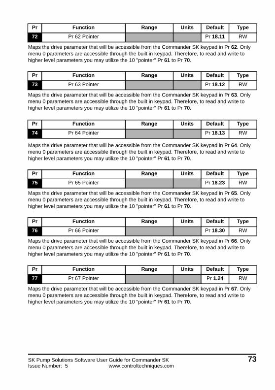
Maps the drive parameter that will be accessible from the Commander SK keypad in Pr 62. Only menu 0 parameters are accessible through the built in keypad. Therefore, to read and write to higher level parameters you may utilize the 10 "pointer" Pr 61 to Pr 70.
Maps the drive parameter that will be accessible from the Commander SK keypad in Pr 63. Only menu 0 parameters are accessible through the built in keypad. Therefore, to read and write to higher level parameters you may utilize the 10 "pointer" Pr 61 to Pr 70.
Maps the drive parameter that will be accessible from the Commander SK keypad in Pr 64. Only menu 0 parameters are accessible through the built in keypad. Therefore, to read and write to higher level parameters you may utilize the 10 "pointer" Pr 61 to Pr 70.
Maps the drive parameter that will be accessible from the Commander SK keypad in Pr 65. Only menu 0 parameters are accessible through the built in keypad. Therefore, to read and write to higher level parameters you may utilize the 10 "pointer" Pr 61 to Pr 70.
Maps the drive parameter that will be accessible from the Commander SK keypad in Pr 66. Only menu 0 parameters are accessible through the built in keypad. Therefore, to read and write to higher level parameters you may utilize the 10 "pointer" Pr 61 to Pr 70.
Maps the drive parameter that will be accessible from the Commander SK keypad in Pr 67. Only menu 0 parameters are accessible through the built in keypad. Therefore, to read and write to higher level parameters you may utilize the 10 "pointer" Pr 61 to Pr 70.
Pr Function Range Units Default Type
72 Pr 62 Pointer Pr 18.11 RW
Pr Function Range Units Default Type
73 Pr 63 Pointer Pr 18.12 RW
Pr Function Range Units Default Type
74 Pr 64 Pointer Pr 18.13 RW
Pr Function Range Units Default Type
75 Pr 65 Pointer Pr 18.23 RW
Pr Function Range Units Default Type
76 Pr 66 Pointer Pr 18.30 RW
Pr Function Range Units Default Type
77 Pr 67 Pointer Pr 1.24 RW
SK Pump Solutions Software User Guide for Commander SK 73Issue Number: 5 www.controltechniques.com

Maps the drive parameter that will be accessible from the Commander SK keypad in Pr 68. Only menu 0 parameters are accessible through the built in keypad. Therefore, to read and write to higher level parameters you may utilize the 10 "pointer" Pr 61 to Pr 70.
Maps the drive parameter that will be accessible from the Commander SK keypad in Pr 69. Only menu 0 parameters are accessible through the built in keypad. Therefore, to read and write to higher level parameters you may utilize the 10 "pointer" Pr 61 to Pr 70.
Maps the drive parameter that will be accessible from the Commander SK keypad in Pr 70. Only menu 0 parameters are accessible through the built in keypad. Therefore, to read and write to higher level parameters you may utilize the 10 "pointer" Pr 61 to Pr 70.
The level of the pressure transducer feedback analog input signal. The value is in % where 20 mA = 100%
10.1.5 Advanced Parameters
Sets the fixed frequency that the motor will run when running in HAND Mode.
The Hz bandwidth setting used in No Flow Detection. The system monitors the motor frequency and if it is below the setting in Pr 68 (Pr 1.26) +/- this bandwidth setting for the period of time set in Pr 2.23 the system proceeds with the No Flow Detection process.
Pr Function Range Units Default Type
78 Pr 68 Pointer Pr 1.26 RW
Pr Function Range Units Default Type
79 Pr 69 Pointer Pr 14.10 RW
Pr Function Range Units Default Type
80 Pr 70 Pointer Pr 14.11 RW
Pr Function Range Units Default Type
94Analog 1 Input Level,
Pressure Transducer Feedback0 -100 % RO
Menu 1 through Menu 21 are only accessible via CTSoft or the SM Keypad Plus.
Pr Function Range Units Default Type
1.21 HAND Mode Speed Setting0 to Maximum
Speed set in Pr 02Hz 0 RW
Pr Function Range Units Default Type
1.23 No Flow RPM (Freq) Bandwidth 0 - 1500.0 Hz 15 RW
NOTE
74 SK Pump Solutions Software User Guide for Commander SKwww.controltechniques.com Issue Number: 5

While running in PID, if the motor frequency falls below this level for the period of time set in Pr 2.17 and the pressure feedback is higher than the setpoint with bandwidth, the system will initiate sleep.
Sets the bandwidth of Pr 1.06 for determining when the drive is operating at maximum frequency. The system uses this during Under Pressure and Low Suction detection.
In No Flow Detection, the system monitors the motor frequency and if it is below the setting in Pr 68 (Pr 1.26) +/- the bandwidth in Pr 1.23 for the period of time set in Pr 2.23 the system proceeds with the No Flow Detection process.
Set the running frequency when transducer loss is detection Pr 18.17 is set to 2.
10.1.6 Ramps and Timers
The system will delay activating the drive for a specified amount of time after the pressure transducer falls below the Low Setpoint or the Pressure Switch input turns on. If the transducer signal level rises above the Low Set-Point value or the Pressure Switch input turns off the timer will reset and the drive will remain inactive.
In Pump Modes 1 and 2 the system will delay stopping the drive for a specified amount of time after the Flow Switch has closed. If the Flow Switch opens during this delay the timer will reset and the drive will remain active.
Pr Function Range Units Default Type
1.24 Minimum Sleep Speed/Freq 0 - 1500.0 Hz 0 RW
Pr Function Range Units Default Type
1.25 Max Frequency Bandwidth 0 - 1500.0 Hz 1 RW
Pr Function Range Units Default Type
1.26 No Flow RPM (Freq) Setpoint 0 - 1500.0 Hz 0 RW
Pr Function Range Units Default Type
1.27 Transducer Loss Frequency 0 - 1500.0 Hz 0 RW
Pr Function Range Units Default Type
1.28 For Program Use RO
Pr Function Range Units Default Type
2.13 Start Delay Time 0 - 3200.0 sec 0 RW
Pr Function Range Units Default Type
2.14 Stop Delay Time 0 - 3200.0 sec 5 RW
SK Pump Solutions Software User Guide for Commander SK 75Issue Number: 5 www.controltechniques.com
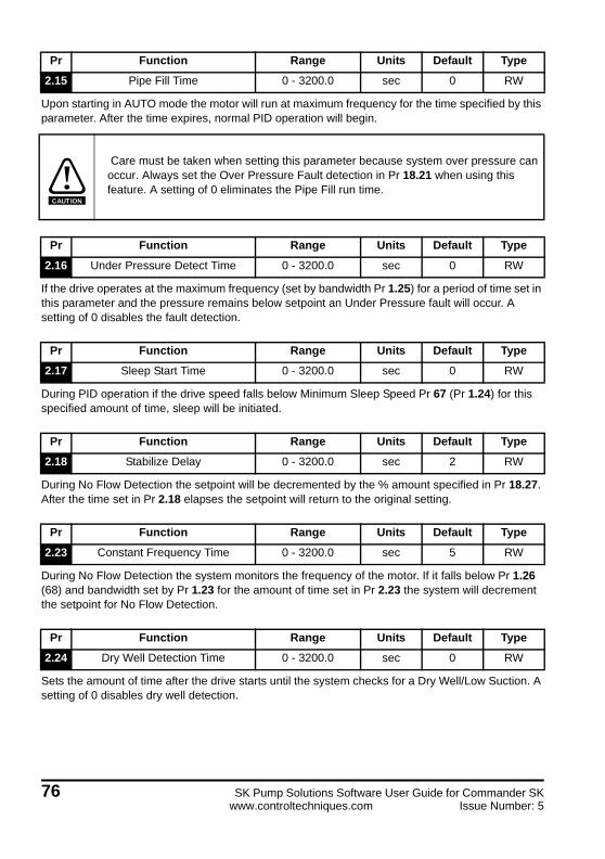
Upon starting in AUTO mode the motor will run at maximum frequency for the time specified by this parameter. After the time expires, normal PID operation will begin.
If the drive operates at the maximum frequency (set by bandwidth Pr 1.25) for a period of time set in this parameter and the pressure remains below setpoint an Under Pressure fault will occur. A setting of 0 disables the fault detection.
During PID operation if the drive speed falls below Minimum Sleep Speed Pr 67 (Pr 1.24) for this specified amount of time, sleep will be initiated.
During No Flow Detection the setpoint will be decremented by the % amount specified in Pr 18.27. After the time set in Pr 2.18 elapses the setpoint will return to the original setting.
During No Flow Detection the system monitors the frequency of the motor. If it falls below Pr 1.26 (68) and bandwidth set by Pr 1.23 for the amount of time set in Pr 2.23 the system will decrement the setpoint for No Flow Detection.
Sets the amount of time after the drive starts until the system checks for a Dry Well/Low Suction. A setting of 0 disables dry well detection.
Pr Function Range Units Default Type
2.15 Pipe Fill Time 0 - 3200.0 sec 0 RW
Care must be taken when setting this parameter because system over pressure can occur. Always set the Over Pressure Fault detection in Pr 18.21 when using this feature. A setting of 0 eliminates the Pipe Fill run time.
Pr Function Range Units Default Type
2.16 Under Pressure Detect Time 0 - 3200.0 sec 0 RW
Pr Function Range Units Default Type
2.17 Sleep Start Time 0 - 3200.0 sec 0 RW
Pr Function Range Units Default Type
2.18 Stabilize Delay 0 - 3200.0 sec 2 RW
Pr Function Range Units Default Type
2.23 Constant Frequency Time 0 - 3200.0 sec 5 RW
Pr Function Range Units Default Type
2.24 Dry Well Detection Time 0 - 3200.0 sec 0 RW
CAUTION
76 SK Pump Solutions Software User Guide for Commander SKwww.controltechniques.com Issue Number: 5
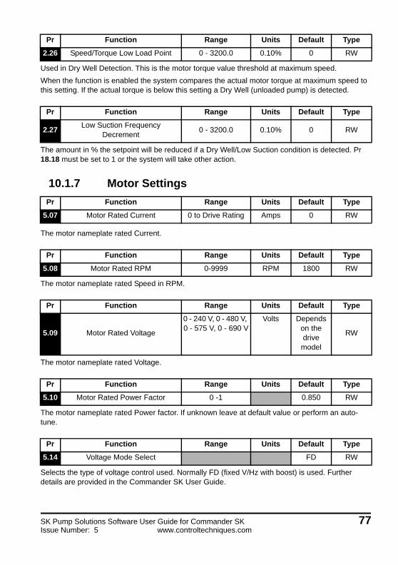
Used in Dry Well Detection. This is the motor torque value threshold at maximum speed.
When the function is enabled the system compares the actual motor torque at maximum speed to this setting. If the actual torque is below this setting a Dry Well (unloaded pump) is detected.
The amount in % the setpoint will be reduced if a Dry Well/Low Suction condition is detected. Pr 18.18 must be set to 1 or the system will take other action.
10.1.7 Motor Settings
The motor nameplate rated Current.
The motor nameplate rated Speed in RPM.
The motor nameplate rated Voltage.
The motor nameplate rated Power factor. If unknown leave at default value or perform an auto-tune.
Selects the type of voltage control used. Normally FD (fixed V/Hz with boost) is used. Further details are provided in the Commander SK User Guide.
Pr Function Range Units Default Type
2.26 Speed/Torque Low Load Point 0 - 3200.0 0.10% 0 RW
Pr Function Range Units Default Type
2.27Low Suction Frequency
Decrement 0 - 3200.0 0.10% 0 RW
Pr Function Range Units Default Type
5.07 Motor Rated Current 0 to Drive Rating Amps 0 RW
Pr Function Range Units Default Type
5.08 Motor Rated RPM 0-9999 RPM 1800 RW
Pr Function Range Units Default Type
5.09 Motor Rated Voltage
0 - 240 V, 0 - 480 V, 0 - 575 V, 0 - 690 V
Volts Depends on the drive
model
RW
Pr Function Range Units Default Type
5.10 Motor Rated Power Factor 0 -1 0.850 RW
Pr Function Range Units Default Type
5.14 Voltage Mode Select FD RW
SK Pump Solutions Software User Guide for Commander SK 77Issue Number: 5 www.controltechniques.com
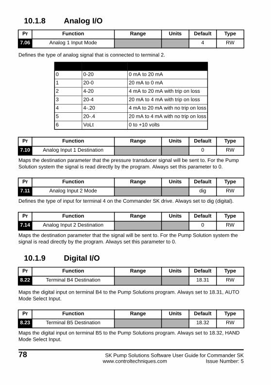
10.1.8 Analog I/O
Defines the type of analog signal that is connected to terminal 2.
Maps the destination parameter that the pressure transducer signal will be sent to. For the Pump Solution system the signal is read directly by the program. Always set this parameter to 0.
Defines the type of input for terminal 4 on the Commander SK drive. Always set to dig (digital).
Maps the destination parameter that the signal will be sent to. For the Pump Solution system the signal is read directly by the program. Always set this parameter to 0.
10.1.9 Digital I/O
Maps the digital input on terminal B4 to the Pump Solutions program. Always set to 18.31, AUTO Mode Select Input.
Maps the digital input on terminal B5 to the Pump Solutions program. Always set to 18.32, HAND Mode Select Input.
Pr Function Range Units Default Type
7.06 Analog 1 Input Mode 4 RW
Value Display Function
0 0-20 0 mA to 20 mA
1 20-0 20 mA to 0 mA
2 4-20 4 mA to 20 mA with trip on loss
3 20-4 20 mA to 4 mA with trip on loss
4 4-.20 4 mA to 20 mA with no trip on loss
5 20-.4 20 mA to 4 mA with no trip on loss
6 VoLt 0 to +10 volts
Pr Function Range Units Default Type
7.10 Analog Input 1 Destination 0 RW
Pr Function Range Units Default Type
7.11 Analog Input 2 Mode dig RW
Pr Function Range Units Default Type
7.14 Analog Input 2 Destination 0 RW
Pr Function Range Units Default Type
8.22 Terminal B4 Destination 18.31 RW
Pr Function Range Units Default Type
8.23 Terminal B5 Destination 18.32 RW
78 SK Pump Solutions Software User Guide for Commander SKwww.controltechniques.com Issue Number: 5

Maps the digital input on terminal B6 to the Pump Solutions program. Always set to 18.34, Flow Switch Input.
Maps the digital input on terminal B7 to the Pump Solutions program. Always set to 18.35, Pressure Switch Input.
10.1.10 System Status, Reset and Restart
Indicates a system fault when = 1.
Indicates the trip code for the most recent drive fault.
Defines the number of times the drive will attempt to automatically reset a fault.
Defines the amount of time in between automatic fault reset attempts.
Pr Function Range Units Default Type
8.24 Terminal B6 Destination 18.34 RW
Pr Function Range Units Default Type
8.25 Terminal B7 Destination 18.35 RW
Pr Function Range Units Default Type
10.01 System Status 0 - 1 RO
Pr Function Range Units Default Type
10.20 Last Trip RO
Pr Function Range Units Default Type
10.33 Drive Reset OFF(0) or ON(1) OFF(0) RW
Pr Function Range Units Default Type
10.34 Auto Reset Times 0 - 5 5 RW
Pr Function Range Units Default Type
10.35 Auto Restart Times 0 - 25.0 sec 10 RW
SK Pump Solutions Software User Guide for Commander SK 79Issue Number: 5 www.controltechniques.com
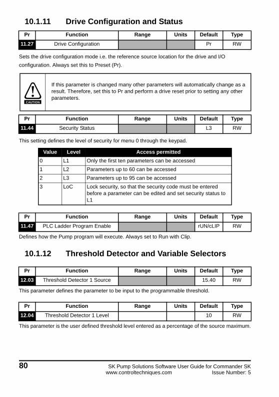
10.1.11 Drive Configuration and Status
Sets the drive configuration mode i.e. the reference source location for the drive and I/O
configuration. Always set this to Preset (Pr).
This setting defines the level of security for menu 0 through the keypad.
Defines how the Pump program will execute. Always set to Run with Clip.
10.1.12 Threshold Detector and Variable Selectors
This parameter defines the parameter to be input to the programmable threshold.
This parameter is the user defined threshold level entered as a percentage of the source maximum.
Pr Function Range Units Default Type
11.27 Drive Configuration Pr RW
If this parameter is changed many other parameters will automatically change as a result. Therefore, set this to Pr and perform a drive reset prior to setting any other parameters.
Pr Function Range Units Default Type
11.44 Security Status L3 RW
Value Level Access permitted
0 L1 Only the first ten parameters can be accessed
1 L2 Parameters up to 60 can be accessed
2 L3 Parameters up to 95 can be accessed
3 LoC Lock security, so that the security code must be entered before a parameter can be edited and set security status to L1
Pr Function Range Units Default Type
11.47 PLC Ladder Program Enable rUN/cLIP RW
Pr Function Range Units Default Type
12.03 Threshold Detector 1 Source 15.40 RW
Pr Function Range Units Default Type
12.04 Threshold Detector 1 Level 10 RW
CAUTION
80 SK Pump Solutions Software User Guide for Commander SKwww.controltechniques.com Issue Number: 5
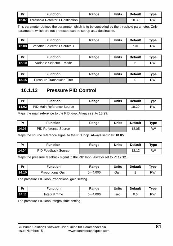
This parameter defines the parameter which is to be controlled by the threshold parameter. Only parameters which are not protected can be set up as a destination.
10.1.13 Pressure PID Control
Maps the main reference to the PID loop. Always set to 18.29.
Maps the source reference signal to the PID loop. Always set to Pr 18.05.
Maps the pressure feedback signal to the PID loop. Always set to Pr 12.12.
The pressure PID loop Proportional gain setting.
The pressure PID loop Integral time setting.
Pr Function Range Units Default Type
12.07 Threshold Detector 1 Destination 18.39 RW
Pr Function Range Units Default Type
12.08 Variable Selector 1 Source 1 7.01 RW
Pr Function Range Units Default Type
12.10 Variable Selector 1 Mode 6 RW
Pr Function Range Units Default Type
12.15 Pressure Transducer Filter 0 RW
Pr Function Range Units Default Type
14.02 PID Main Reference Source 18.29 RW
Pr Function Range Units Default Type
14.03 PID Reference Source 18.05 RW
Pr Function Range Units Default Type
14.04 PID Feedback Source 12.12 RW
Pr Function Range Units Default Type
14.10 Proportional Gain 0 - 4.000 Gain 1 RW
Pr Function Range Units Default Type
14.11 Integral Time 0 - 4.000 sec 0.5 RW
SK Pump Solutions Software User Guide for Commander SK 81Issue Number: 5 www.controltechniques.com

The pressure PID loop Differential rate setting.
The low limit for the pressure PID loop output.
Maps the output of the pressure PID loop to the drive speed reference signal. Always set to 1.36.
10.1.14 I/O Expansion
These parameters are used to set up the SM-I/O Lite module.
Maps digital input terminal 5 of the SM-I/O Lite module. Always set to 18.36.
Maps digital input terminal 6 of the SM-I/O Lite module. Always set to 18.37.
Maps digital input terminal 7 of the SM-I/O Lite module. Always set to 10.33.
Maps the output relay of the SM-I/O Lite module to the signal of choice.
Defines the type of input for terminal 2 of the SM-I/O Lite module. Always set to Volt.
Pr Function Range Units Default Type
14.12 Differental Rate 0 - 4.000 d/dt 0 RW
Pr Function Range Units Default Type
14.14 PID Lower Limit 0 RW
Pr Function Range Units Default Type
14.16 PID Output Destination 1.36 RW
Pr Function Range Units Default Type
15.24 Terminal T5 Destination 18.36 RW
Pr Function Range Units Default Type
15.25 Terminal T6 Destination 18.37 RW
Pr Function Range Units Default Type
15.26 Terminal T7 Destination 10.33 RW
Pr Function Range Units Default Type
15.27 Terminal T21/T23 Relay Source RW
Pr Function Range Units Default Type
15.38 Analog Input T2 mode Volt RW
82 SK Pump Solutions Software User Guide for Commander SKwww.controltechniques.com Issue Number: 5
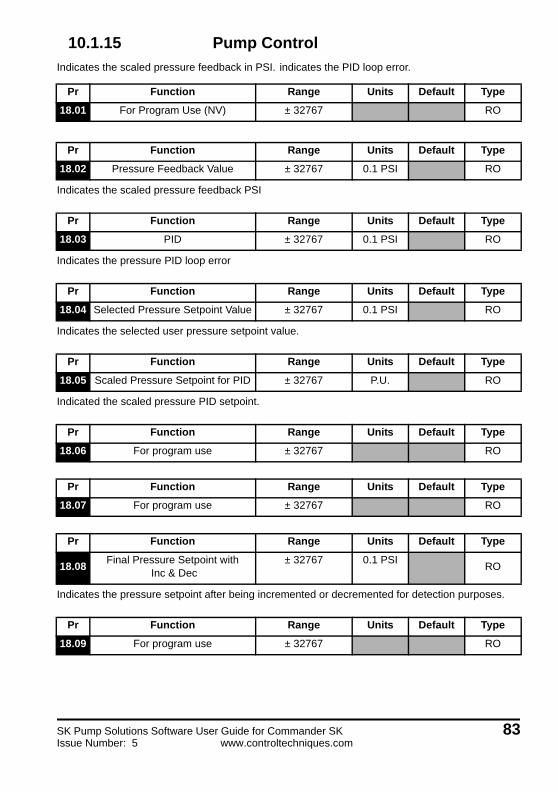
10.1.15 Pump Control
Indicates the scaled pressure feedback in PSI. indicates the PID loop error.
Indicates the scaled pressure feedback PSI
Indicates the pressure PID loop error
Indicates the selected user pressure setpoint value.
Indicated the scaled pressure PID setpoint.
Indicates the pressure setpoint after being incremented or decremented for detection purposes.
Pr Function Range Units Default Type
18.01 For Program Use (NV) ± 32767 RO
Pr Function Range Units Default Type
18.02 Pressure Feedback Value ± 32767 0.1 PSI RO
Pr Function Range Units Default Type
18.03 PID ± 32767 0.1 PSI RO
Pr Function Range Units Default Type
18.04 Selected Pressure Setpoint Value ± 32767 0.1 PSI RO
Pr Function Range Units Default Type
18.05 Scaled Pressure Setpoint for PID ± 32767 P.U. RO
Pr Function Range Units Default Type
18.06 For program use ± 32767 RO
Pr Function Range Units Default Type
18.07 For program use ± 32767 RO
Pr Function Range Units Default Type
18.08Final Pressure Setpoint with
Inc & Dec± 32767 0.1 PSI
RO
Pr Function Range Units Default Type
18.09 For program use ± 32767 RO
SK Pump Solutions Software User Guide for Commander SK 83Issue Number: 5 www.controltechniques.com
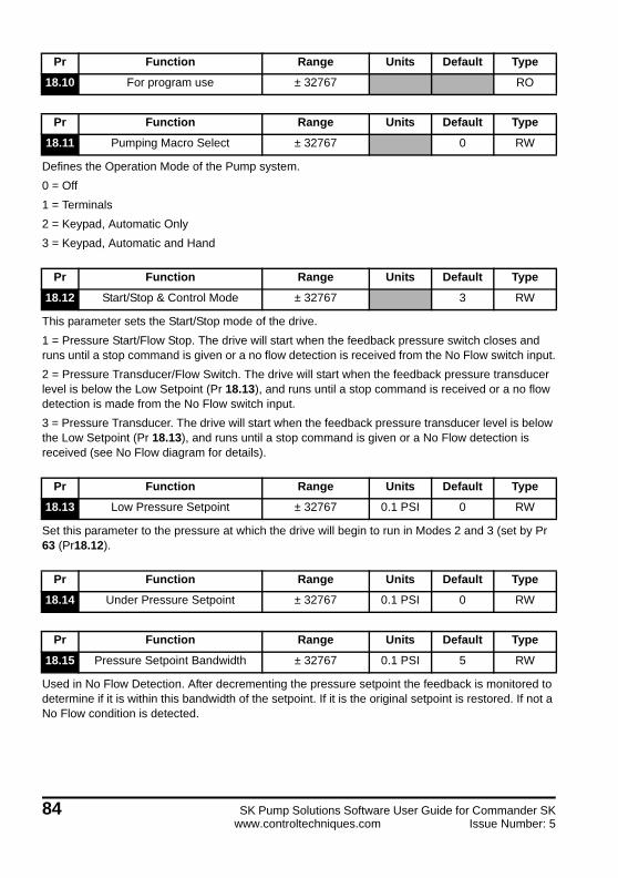
Defines the Operation Mode of the Pump system.
0 = Off
1 = Terminals
2 = Keypad, Automatic Only
3 = Keypad, Automatic and Hand
This parameter sets the Start/Stop mode of the drive.
1 = Pressure Start/Flow Stop. The drive will start when the feedback pressure switch closes and runs until a stop command is given or a no flow detection is received from the No Flow switch input.
2 = Pressure Transducer/Flow Switch. The drive will start when the feedback pressure transducer level is below the Low Setpoint (Pr 18.13), and runs until a stop command is received or a no flow detection is made from the No Flow switch input.
3 = Pressure Transducer. The drive will start when the feedback pressure transducer level is below the Low Setpoint (Pr 18.13), and runs until a stop command is given or a No Flow detection is received (see No Flow diagram for details).
Set this parameter to the pressure at which the drive will begin to run in Modes 2 and 3 (set by Pr 63 (Pr18.12).
Used in No Flow Detection. After decrementing the pressure setpoint the feedback is monitored to determine if it is within this bandwidth of the setpoint. If it is the original setpoint is restored. If not a No Flow condition is detected.
Pr Function Range Units Default Type
18.10 For program use ± 32767 RO
Pr Function Range Units Default Type
18.11 Pumping Macro Select ± 32767 0 RW
Pr Function Range Units Default Type
18.12 Start/Stop & Control Mode ± 32767 3 RW
Pr Function Range Units Default Type
18.13 Low Pressure Setpoint ± 32767 0.1 PSI 0 RW
Pr Function Range Units Default Type
18.14 Under Pressure Setpoint ± 32767 0.1 PSI 0 RW
Pr Function Range Units Default Type
18.15 Pressure Setpoint Bandwidth ± 32767 0.1 PSI 5 RW
84 SK Pump Solutions Software User Guide for Commander SKwww.controltechniques.com Issue Number: 5

Sets the action taken in the event of a transducer signal loss.
0 = Disabled
1 = Fault Drive
2 = Run at a fixed speed set by Pr 1.21
Sets the action taken in the event of a Dry Well Detection.
0 = Alarm
1 = Decrease Speed
2 = Fault
If the pressure feedback signal rises above this setting the Over Pressure Alarm digital output will turn on.
If the pressure feedback exceeds this setting the drive will fault and trip code 82 will be indicated.
Sets the scaling in PSI for the minimum pressure reading of the feedback transducer.
Sets the scaling in PSI for the maximum pressure reading of the feedback transducer.
This is the Alternative 1 PSI setpoint for the system. If the optional SM-I/O Lite module is installed, 3 alternative setpoints may be selected with digital inputs.
Main Setpoint = Terminal 5 and 6 open
Pr Function Range Units Default Type
18.17 Transducer Loss Action ± 32767 1 RW
Pr Function Range Units Default Type
18.18 Dry Well Detection Model ± 32767 2
Pr Function Range Units Default Type
18.20 Over Pressure Alarm Level ± 32767 0.1 PSI 0 RW
Pr Function Range Units Default Type
18.21 Over Pressure Fault Level ± 32767 0.1 PSI 0 RW
Pr Function Range Units Default Type
18.22Minimum Pressure Feedback
Scaling± 32767 0.1.PSI 0
RW
Pr Function Range Units Default Type
18.23Maximum Pressure Feedback
Scaling± 32767 0.1 PSI 1450
RW
Pr Function Range Units Default Type
18.24 Alternate Pressure Setpoint 1 ± 32767 0.1 PSI 0 RW
SK Pump Solutions Software User Guide for Commander SK 85Issue Number: 5 www.controltechniques.com

Setpoint 1 = Terminal 5 closed, 6 open
Setpoint 2 = Terminal 5 open, 6 closed
Setpoint 3 = Terminal 5 and 6 closed
This is the Alternative 2 PSI setpoint for the system. If the optional SM-I/O Lite module is installed, 3 alternative setpoints may be selected with digital inputs.
Main Setpoint = Terminal 5 and 6 open
Setpoint 1 = Terminal 5 closed, 6 open
Setpoint 2 = Terminal 5 open, 6 closed
Setpoint 3 = Terminal 5 and 6 closed
This is the Alternative 3 PSI setpoint for the system. If the optional SM-I/O Lite module is installed, 3 alternative setpoints may be selected with digital inputs.
Main Setpoint = Terminal 5 and 6 open
Setpoint 1 = Terminal 5 closed, 6 open
Setpoint 2 = Terminal 5 open, 6 closed
Setpoint 3 = Terminal 5 and 6 closed
While operating in PID the drive monitors the motor frequency. If the frequency falls below the setpoint (1.26 (68)) with bandwidth (1.23) for the time period specified (2.23) the setpoint will be decremented by this percentage as a step toward detecting no flow.
Indicates the Pump Solutions program version number.
Used in the Pipe Fill feature for saturating the PID loop. Is set to 32767 during pipe filling time and is set to 0 during normal PID operation.
Pr Function Range Units Default Type
18.25 Alternate Setpoint 2 ± 32767 0.1 PSI 0 RW
Pr Function Range Units Default Type
18.26 Alternate Setpoint 3 ± 32767 0.1 PSI 0 RW
Pr Function Range Units Default Type
18.27 Setpoint Decrement ± 32767 0.1 PSI 10 RW
Pr Function Range Units Default Type
18.27 Software Version ± 32767 RO
Pr Function Range Units Default Type
18.29 PID Saturate ± 32767 RO
Pr Function Range Units Default Type
18.30 Main Setpoint ± 32767 0.1 PSI 0 RW
86 SK Pump Solutions Software User Guide for Commander SKwww.controltechniques.com Issue Number: 5

The main pressure setpoint for the system to maintain, entered in PSI.
SK Pump Solutions Software User Guide for Commander SK 87Issue Number: 5 www.controltechniques.com
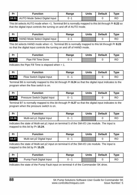
This bit selects AUTO mode when =1. Terminal B4 is normally mapped to this bit through Pr 8.22 so that the digital input controls the turning on and off of AUTO mode.
This bit selects HAND mode when =1. Terminal B5 is normally mapped to this bit through Pr 8.23 so that the digital input controls the turning on and off of HAND mode.
Indicates the Pipe Fill Time is elapsed when = 1.
Terminal B6 is normally mapped to this bit through Pr 8.24 so that the digital input indicates to the program when the flow switch is on.
Terminal B7 is normally mapped to this bit through Pr 8.27 so that the digital input indicates to the program when the pressure switch is on.
Indicates the state of Multi-set p1 input on terminal 5 of the SM-I/O Lite module. The input is mapped to this bit by Pr 15.24.
Indicates the state of Multi-set p2 input on terminal 6 of the SM-I/O Lite module. The input is mapped to this bit by Pr 15.25.
Indicates the state of the Pump Fault input on terminal 4 of the Commander SK drive.
Pr Function Range Units Default Type
18.31 AUTO Mode Select Digital Input 0 -1 0 RO
Pr Function Range Units Default Type
18.32 HAND Mode Select Digital Input 0 -1 0 RO
Pr Function Range Units Default Type
18.33 Pipe Fill Time Done 0 -1 0 RO
Pr Function Range Units Default Type
18.34 Flow Switch Digital Input 0 - 1 0 RO
Pr Function Range Units Default Type
18.35 Pressure Switch Digital Input 0 - 1 0 RO
Pr Function Range Units Default Type
18.36 Multi-set p1 Digital Input 0 - 1 0 RO
Pr Function Range Units Default Type
18.37 Multi-set p2 Digital Input 0 - 1 0 RO
Pr Function Range Units Default Type
18.38 Pump Fault Digital Input 0 - 1 0 RO
88 SK Pump Solutions Software User Guide for Commander SKwww.controltechniques.com Issue Number: 5

Indicates the state of the Over Temp. input on terminal 2 of the SM-I/O Lite module.
Indicates the system is ready to run (no faults) when = 1. Can be used as the source parameter for any output.
Indicates an over pressure warning when = 1. Can be used as the source parameter for any output.
Indicates the drive is running within the bandwidth setting of the maximum frequency when = 1. Can be used as the source parameter for any output.
Indicates the system is running at the reference (setpoint) speed when = 1. Can be used as the source parameter for any output.
Indicates a feedback transducer signal loss when = 1. Can be used as the source parameter for any output.
Indicates the system is running and in AUTO mode when = 1. Can be used as the source parameter for any output.
Pr Function Range Units Default Type
18.39 Over Temperature Digital Input 0 - 1 0 RO
Pr Function Range Units Default Type
18.40 System Ready Digital Status 0 - 1 0 RO
Pr Function Range Units Default Type
18.41Over Pressure Warning Digital
Status0 - 1 0 RO
Pr Function Range Units Default Type
18.42Within Max. Frequency Bandwidth
Status0 - 1 0 RO
Pr Function Range Units Default Type
18.43At Reference Digital Output
Status0 - 1 0 RO
Pr Function Range Units Default Type
18.44Transducer Loss Digital Output
Status0 - 1 0 RO
Pr Function Range Units Default Type
18.45 Drive Running is AUTO Status 0 - 1 0 RO
SK Pump Solutions Software User Guide for Commander SK 89Issue Number: 5 www.controltechniques.com

Indicates the system has detected a Dry Well condition when = 1. Can be used as the source parameter for any output.
Indicates the system is in AUTO Mode when =1.
Indicates the system is in HAND Mode when =1.
This parameter selects the source for the under pressure setpoint. =0.
10.1.16 Menu 21
Pr Function Range Units Default Type
18.46Dry Well/Low Suction Output
Status0 - 1 0 RO
Pr Function Range Units Default Type
18.47 AUTO Mode Selected Status 0 - 1 0 RO
Pr Function Range Units Default Type
18.48 HAND Mode Selected Status 0 - 1 0 RO
Pr Function Range Units Default Type
18.49 Spare 0 - 1 0
Pr Function Range Units Default Type
18.50 Spare 0 - 1 0
Pr Function Range Units Default Type
21.08 Reserved for program use RO
90 SK Pump Solutions Software User Guide for Commander SKwww.controltechniques.com Issue Number: 5
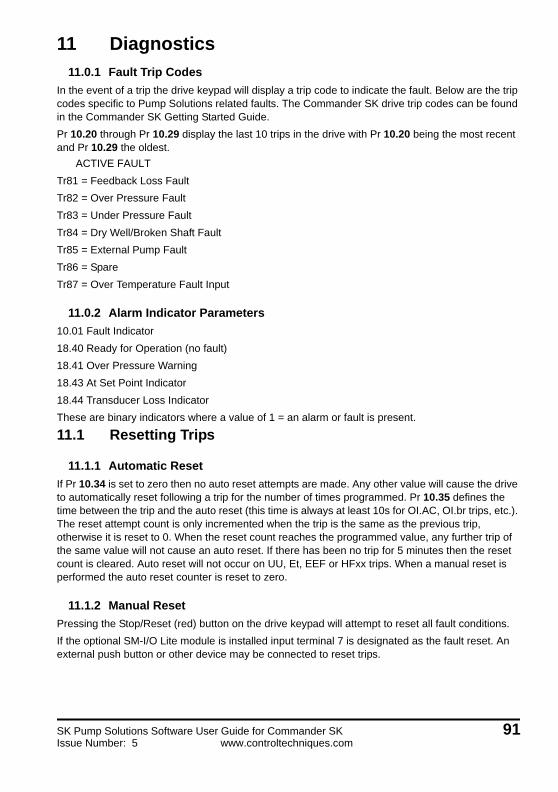
11 Diagnostics
11.0.1 Fault Trip Codes
In the event of a trip the drive keypad will display a trip code to indicate the fault. Below are the trip codes specific to Pump Solutions related faults. The Commander SK drive trip codes can be found in the Commander SK Getting Started Guide.
Pr 10.20 through Pr 10.29 display the last 10 trips in the drive with Pr 10.20 being the most recent and Pr 10.29 the oldest.
ACTIVE FAULT
Tr81 = Feedback Loss Fault
Tr82 = Over Pressure Fault
Tr83 = Under Pressure Fault
Tr84 = Dry Well/Broken Shaft Fault
Tr85 = External Pump Fault
Tr86 = Spare
Tr87 = Over Temperature Fault Input
11.0.2 Alarm Indicator Parameters
10.01 Fault Indicator
18.40 Ready for Operation (no fault)
18.41 Over Pressure Warning
18.43 At Set Point Indicator
18.44 Transducer Loss Indicator
These are binary indicators where a value of 1 = an alarm or fault is present.
11.1 Resetting Trips
11.1.1 Automatic Reset
If Pr 10.34 is set to zero then no auto reset attempts are made. Any other value will cause the drive to automatically reset following a trip for the number of times programmed. Pr 10.35 defines the time between the trip and the auto reset (this time is always at least 10s for OI.AC, OI.br trips, etc.). The reset attempt count is only incremented when the trip is the same as the previous trip, otherwise it is reset to 0. When the reset count reaches the programmed value, any further trip of the same value will not cause an auto reset. If there has been no trip for 5 minutes then the reset count is cleared. Auto reset will not occur on UU, Et, EEF or HFxx trips. When a manual reset is performed the auto reset counter is reset to zero.
11.1.2 Manual Reset
Pressing the Stop/Reset (red) button on the drive keypad will attempt to reset all fault conditions.
If the optional SM-I/O Lite module is installed input terminal 7 is designated as the fault reset. An external push button or other device may be connected to reset trips.
SK Pump Solutions Software User Guide for Commander SK 91Issue Number: 5 www.controltechniques.com

For more information about Control Techniques products and services, call (800) 893-2321 or contact our website at www.controltechniques.com.Control Techniques Americas LLCDivision of Emerson7078 Shady Oak RoadEden Prairie, Minnesota 55344U.S.A.Customer Service
Phone: (952) 995-8000 or (800) 893-2321Fax: (952) 995-8129
Technical SupportPhone: (952) 995-8033 or (800) 893-2321Fax (952) 9995-8020


![jflif{sk|ltj]bg - ADBL](https://static.fdokumen.com/doc/165x107/631b1bb6e422e895e602b689/jflifskltjbg-adbl.jpg)