Aquavar Intelligent Pump Controller - Xylem
300
INSTRUCTION MANUAL IM318 Aquavar Intelligent Pump Controller
-
Upload
khangminh22 -
Category
Documents
-
view
0 -
download
0
Transcript of Aquavar Intelligent Pump Controller - Xylem
INSTRUCTION MANUALIM318
Aquavar Intelligent PumpController


Table of Contents
1 Introduction and Safety..............................................................................................................51.1 Introduction.......................................................................................................................... 51.2 Safety..................................................................................................................................... 5
1.2.1 Safety message levels...................................................................................................51.2.2 Qualified personnel......................................................................................................61.2.3 Safety precautions........................................................................................................ 6
1.3 User safety.............................................................................................................................81.3.1 Wash the skin and eyes................................................................................................9
1.4 Protecting the environment................................................................................................9
2 Transportation and Storage....................................................................................................112.1 Examine the delivery......................................................................................................... 11
2.1.1 Examine the package.................................................................................................112.1.2 Examine the unit......................................................................................................... 11
2.2 System lifting...................................................................................................................... 112.3 Transportation guidelines.................................................................................................11
2.3.1 Precautions.................................................................................................................. 112.4 Storage guidelines.............................................................................................................12
3 Product Description................................................................................................................. 133.1 Product overview............................................................................................................... 13
3.1.1 Conformity, approvals and certifications.................................................................133.1.2 Abbreviations and standards.................................................................................... 13
3.2 Motor thermal protection................................................................................................. 143.3 Dimensions......................................................................................................................... 19
3.3.1 Frame sizes A2–A5, B1–B4, C1–C4........................................................................... 193.3.2 Frame sizes D1–D4, D5, D7....................................................................................... 21
3.4 Frame size description...................................................................................................... 283.5 Internal frequency converter controller functions......................................................... 31
4 Mechanical Installation............................................................................................................ 324.1 Pre-installation....................................................................................................................32
4.1.1 Installation site checklist............................................................................................ 324.1.2 Frequency converter and motor pre-installation check list...................................32
4.2 General considerations.....................................................................................................324.2.1 Tools needed.............................................................................................................. 324.2.2 Space............................................................................................................................334.2.3 Wire access..................................................................................................................33
4.3 How to get started............................................................................................................. 334.4 Installation requirements.................................................................................................. 34
4.4.1 Lifting............................................................................................................................344.4.2 Cooling.........................................................................................................................354.4.3 Mounting......................................................................................................................354.4.4 Terminal and connection...........................................................................................364.4.5 Gland/Conduit entry IP21 (NEMA 1) and IP54 (NEMA12)....................................394.4.6 NEMA-3R cover kit......................................................................................................394.4.7 Install the top plate.....................................................................................................404.4.8 Install the gland plate.................................................................................................404.4.9 Install the NEMA 3R cover......................................................................................... 424.4.10 Piping connections...................................................................................................434.4.11 Diaphragm tank, pressure relief valve, and discharge piping............................44
Table of Contents
Aquavar Intelligent Pump Controller INSTRUCTION MANUAL 1

4.4.12 Diaphragm tank, system pressure..........................................................................444.4.13 Installing the pressure sensor................................................................................. 444.4.14 Underwater connection........................................................................................... 44
5 Electrical Installation................................................................................................................ 465.1 Precautions......................................................................................................................... 46
5.1.1 Earth (grounding) requirements...............................................................................475.1.2 Using GFCIs (RCDs)....................................................................................................47
5.2 Basic electrical connection............................................................................................... 485.3 Motor connection.............................................................................................................. 49
5.3.1 Motor connection for A2 and A3..............................................................................515.3.2 Motor connection for A4 and A5..............................................................................525.3.3 Motor connection for B1 and B2.............................................................................. 525.3.4 Shielding against electrical noise............................................................................. 53
5.4 Power connection.............................................................................................................. 535.4.1 Cable and fusing.........................................................................................................535.4.2 Shielding of cables..................................................................................................... 555.4.3 Cable-length and cross-section................................................................................ 565.4.4 Switching frequency...................................................................................................56
5.5 Power and control wiring for unshielded cables........................................................... 595.6 Grounding.......................................................................................................................... 605.7 Extra protection (RCD)...................................................................................................... 615.8 Torque.................................................................................................................................615.9 Shielded cables..................................................................................................................615.10 Control wiring.................................................................................................................. 615.11 Control wiring access......................................................................................................615.12 Control terminal types.................................................................................................... 625.13 Wiring to control terminals.............................................................................................65
5.13.1 Unplug terminal connectors................................................................................... 655.13.2 Control terminal connections................................................................................. 655.13.3 Analog input configuration..................................................................................... 665.13.4 Control terminal functions.......................................................................................675.13.5 Analog input 53........................................................................................................ 675.13.6 Using screened control cables............................................................................... 675.13.7 Serial communication.............................................................................................. 68
5.14 Common terminal wiring configurations......................................................................695.14.1 Relay wiring............................................................................................................... 695.14.2 Pump protect............................................................................................................ 695.14.3 Configuring an additional transducer feedback.................................................. 715.14.4 Speed control through an analog input................................................................ 725.14.5 Control from external PLC/BMS through communications port........................ 74
5.15 Local control panel..........................................................................................................755.15.1 Controller status....................................................................................................... 765.15.2 LCP Parameters.........................................................................................................795.15.3 Menu keys..................................................................................................................805.15.4 Navigation keys.........................................................................................................805.15.5 Operation keys..........................................................................................................815.15.6 Status lights............................................................................................................... 825.15.7 Parameter backup.................................................................................................... 825.15.8 Factory Reset/Initialization...................................................................................... 83
6 MCO301 Programmable API..................................................................................................846.1 Overview............................................................................................................................. 846.2 Safety................................................................................................................................... 856.3 Basic installation instructions for Option A or Option B cards.....................................856.4 Installation instructions for additional enclosure sizes..................................................86
6.4.1 Enclosure Sizes A2, A3, B3, and B4..........................................................................86
Table of Contents
2 Aquavar Intelligent Pump Controller INSTRUCTION MANUAL

6.4.2 Enclosure Sizes A5, B1, B2, C, D...............................................................................876.5 Wiring the MCO301 Programmable API........................................................................ 88
6.5.1 Option A wiring...........................................................................................................886.5.2 Option B wiring...........................................................................................................90
6.6 Shielding for MCO301 Programmable API....................................................................916.6.1 Single ground shielding............................................................................................ 916.6.2 Multiple ground shielding......................................................................................... 92
6.7 Troubleshooting the MCO301.........................................................................................936.8 Group 19 parameter descriptions................................................................................... 94
7 Operation................................................................................................................................ 1047.1 Pre-start procedure......................................................................................................... 1047.2 Pre-startup inspections................................................................................................... 1057.3 Start-up procedure..........................................................................................................1057.4 Programming the controller...........................................................................................106
7.4.1 Quick Menus............................................................................................................. 1087.4.2 My Personal Menu....................................................................................................1087.4.3 Start-Up Genie (Smart Setup)..................................................................................1137.4.4 Main menu.................................................................................................................118
7.5 Setup and commissioning..............................................................................................1197.5.1 Start-Up Genie (Smart Setup) setup.......................................................................1197.5.2 Main Menu setup......................................................................................................1227.5.3 Motor setup...............................................................................................................1267.5.4 Application setup..................................................................................................... 1297.5.5 Single Pump Control setup..................................................................................... 1317.5.6 Multipump Control setup........................................................................................ 1477.5.7 Speed Control setup................................................................................................1527.5.8 Follower Control setup............................................................................................ 1557.5.9 Test Run Mode setup............................................................................................... 1587.5.10 Multipump setup.................................................................................................... 1607.5.11 Feedback setup......................................................................................................1807.5.12 Setpoint setup.........................................................................................................1887.5.13 Pipe Fill Function setup......................................................................................... 1927.5.14 Flow Compensation setup.................................................................................... 1957.5.15 Pump Protection setup.......................................................................................... 1987.5.16 Bypass setup........................................................................................................... 2157.5.17 Digital Input setup..................................................................................................2187.5.18 Relay and Analog Output setup...........................................................................2237.5.19 Communication setup........................................................................................... 2267.5.20 Maintenance........................................................................................................... 2287.5.21 System start-up....................................................................................................... 228
8 Warnings and alarms............................................................................................................. 2308.1 Warning and alarm types............................................................................................... 2308.2 Warning and alarm displays...........................................................................................2308.3 Warnings and alarms...................................................................................................... 240
9 Troubleshooting.....................................................................................................................2499.1 Start up and operation troubleshooting.......................................................................249
10 Technical Specification....................................................................................................... 25210.1 Power-dependent specifications.................................................................................25210.2 General technical data..................................................................................................26110.3 Fuses and circuit breakers............................................................................................267
10.3.1 NEC (NFPA 70) compliance.................................................................................. 26710.3.2 CE compliance........................................................................................................26910.3.3 UL compliance........................................................................................................ 271
Table of Contents
Aquavar Intelligent Pump Controller INSTRUCTION MANUAL 3

10.4 Tightening torques........................................................................................................27710.5 Wire sizing charts.......................................................................................................... 278
10.5.1 VFD input wire sizing............................................................................................. 27910.5.2 VFD output wire sizing...........................................................................................283
10.6 Parameter list................................................................................................................. 287
11 Product Warranty.................................................................................................................292
Table of Contents
4 Aquavar Intelligent Pump Controller INSTRUCTION MANUAL

1 Introduction and Safety1.1 IntroductionPurpose of this manual
The purpose of this manual is to provide necessary information for:
• Installation• Operation• Maintenance
CAUTION:
Read this manual carefully before installing and using the product. Improper use of theproduct can cause personal injury and damage to property, and may void the warranty.
NOTICE:
Save this manual for future reference, and keep it readily available at the location of theunit.
1.2 SafetyWARNING:
• The operator must be aware of safety precautions to prevent physical injury.• Operating, installing, or maintaining the unit in any way that is not covered in this
manual could cause death, serious personal injury, or damage to the equipment. Thisincludes any modification to the equipment or use of parts not provided by Xylem. Ifthere is a question regarding the intended use of the equipment, please contact aXylem representative before proceeding.
• Do not change the service application without the approval of an authorized Xylemrepresentative.
CAUTION:
You must observe the instructions contained in this manual. Failure to do so could resultin physical injury, damage, or delays.
1.2.1 Safety message levels
About safety messages
It is extremely important that you read, understand, and follow the safety messages andregulations carefully before handling the product. They are published to help preventthese hazards:
• Personal accidents and health problems• Damage to the product• Product malfunction
Definitions
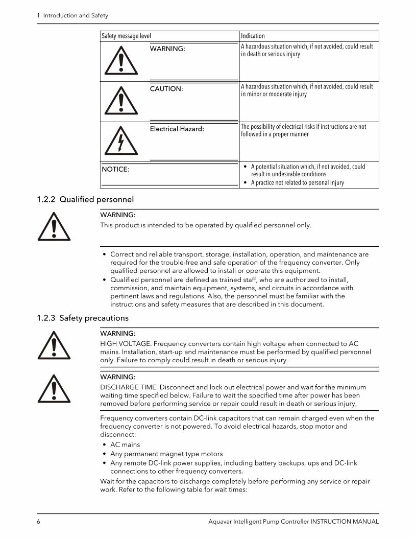
Safety message level Indication
DANGER:
A hazardous situation which, if not avoided, will result indeath or serious injury
1 Introduction and Safety
Aquavar Intelligent Pump Controller INSTRUCTION MANUAL 5
Safety message level Indication
WARNING:
A hazardous situation which, if not avoided, could resultin death or serious injury
CAUTION:
A hazardous situation which, if not avoided, could resultin minor or moderate injury
Electrical Hazard:
The possibility of electrical risks if instructions are notfollowed in a proper manner
NOTICE:
• A potential situation which, if not avoided, couldresult in undesirable conditions
• A practice not related to personal injury
1.2.2 Qualified personnel
WARNING:
This product is intended to be operated by qualified personnel only.
• Correct and reliable transport, storage, installation, operation, and maintenance arerequired for the trouble-free and safe operation of the frequency converter. Onlyqualified personnel are allowed to install or operate this equipment.
• Qualified personnel are defined as trained staff, who are authorized to install,commission, and maintain equipment, systems, and circuits in accordance withpertinent laws and regulations. Also, the personnel must be familiar with theinstructions and safety measures that are described in this document.
1.2.3 Safety precautions
WARNING:
HIGH VOLTAGE. Frequency converters contain high voltage when connected to ACmains. Installation, start-up and maintenance must be performed by qualified personnelonly. Failure to comply could result in death or serious injury.
WARNING:
DISCHARGE TIME. Disconnect and lock out electrical power and wait for the minimumwaiting time specified below. Failure to wait the specified time after power has beenremoved before performing service or repair could result in death or serious injury.
Frequency converters contain DC-link capacitors that can remain charged even when thefrequency converter is not powered. To avoid electrical hazards, stop motor anddisconnect:
• AC mains• Any permanent magnet type motors• Any remote DC-link power supplies, including battery backups, ups and DC-link
connections to other frequency converters.
Wait for the capacitors to discharge completely before performing any service or repairwork. Refer to the following table for wait times:
1 Introduction and Safety
6 Aquavar Intelligent Pump Controller INSTRUCTION MANUAL

Voltage (V) Power range Minimum waiting time(min)hp kW
200-240 1.5–5 1.1-3.7 4
200-240 7.5-60 5.5-45 15
380-480 1.5-10 1.1-7.5 4
380-480 15-125 11-90 15
380–480 150–350 90-315 20
380–480 450–600 315-450 40
525-690 1.5-10 1.1-7.5 4
525-690 1.5-10 1.1-7.5 7
525-690 15-125 11-90 15
525–690 75– 350 55-315 20
525–690 350–600 315-450 30
High voltage may be present even when the warning LED indicator lights are off.
WARNING:
LEAKAGE CURRENT HAZARD. Follow national and local codes regarding protectiveearthing of equipment with a leakage current > 3.5 mA. Frequency converter technologyimplies high frequency switching at high power. This will generate a leakage current in theearth connection. A fault current in the frequency converter at the output power terminalsmight contain a DC component which can charge the filter capacitors and cause atransient earth current. The earth leakage current depends on various systemconfigurations including RFI filtering, screened motor cables, and frequency converterpower. Failure to ground the drive properly could result in death or serious injury.
EN/EC61800–5–1 (Power Drive System Product standard) requires special care if theleakage current exceeds 3.5 mA. Earth grounding must be reinforced in one of thefollowing ways:
• Earth ground wire of at least 8 AWG or 10 mm2.• Two separate earth ground wires both complying with the dimensioning rules.
See EN60364–5–54 section 543.7 for further information.
WARNING:
UNINTENDED START. When the frequency converter is connected to AC mains, the motormay start at any time. The frequency converter, motor, and any driven equipment must bein operational readiness. Failure to comply could result in death, serious injury,equipment, or property damage.
To prevent unintended motor start:
• Press [Off/Reset] on the LCP, before programming parameters.• Disconnect the frequency converter from mains.• The frequency converter, motor, and any driven equipment must be fully wired and
assembled when the frequency converter is connected to AC mains, DC power supply,or load sharing.
WARNING:
UNINTENDED START. WINDMILLING! Unintended rotation of permanent magnet motorscauses a risk of personal injury and equipment damage. Ensure permanent magnetmotors are blocked to prevent unintended rotation.
1 Introduction and Safety
Aquavar Intelligent Pump Controller INSTRUCTION MANUAL 7

WARNING:
EQUIPMENT HAZARD. Rotating shafts and electrical equipment can be hazardous. Allelectrical work must conform to national and local electrical codes. Installation, start-up,and maintenance must be performed by trained and qualified personnel. Wear safetyglasses whenever working on electric control or rotating equipment. Failure to followthese guidelines could result in death or serious injury.
WARNING:
Only use original spare parts to replace any worn or faulty components. The use ofunsuitable spare parts may cause malfunctions, damage, and injuries as well as void theguarantee.
WARNING:
This product can expose you to chemicals including Lead, which is known to the State ofCalifornia to cause cancer and birth defects or other reproductive harm. For moreinformation go to: www.P65Warnings.ca.gov.
CAUTION:
INTERNAL FAILURE HAZARD. Risk of personal injury when the frequency converter is notproperly closed. Before applying power, ensure all safety covers are in place and securelyfastened.
CAUTION:
Before using the Genie, set DI18 to Stop (terminal 18 open) to prevent the unit fromstarting the motor. Keep terminal 18 open to avoid an unintended motor rotation. Applythe Start signal to the controller only when pump operation is desired.
1.3 User safetyGeneral safety rules
These safety rules apply:
• Always keep the work area clean.• Pay attention to the risks presented by gas and vapors in the work area.• Avoid all electrical dangers. Pay attention to the risks of electric shock or arc flash
hazards.• Always bear in mind the risk of drowning, electrical accidents, and burn injuries.
Safety equipment
Use safety equipment according to the company regulations. Use this safety equipmentwithin the work area:
• Hard hat• Safety goggles, preferably with side shields• Protective shoes• Protective gloves• Gas mask• Hearing protection• First-aid kit• Safety devices
NOTICE:
Never operate a unit unless safety devices are installed. Also see specific informationabout safety devices in other chapters of this manual.
1 Introduction and Safety
8 Aquavar Intelligent Pump Controller INSTRUCTION MANUAL

Electrical connections
Electrical connections must be made by certified electricians in compliance with allinternational, national, state, and local regulations. For more information aboutrequirements, see sections dealing specifically with electrical connections.
Precautions before work
Observe these safety precautions before you work with the product or are in connectionwith the product:
• Provide a suitable barrier around the work area, for example, a guard rail.• Make sure that all safety guards are in place and secure.• Make sure that you have a clear path of retreat.• Make sure that the product cannot roll or fall over and injure people or damage
property.• Make sure that the lifting equipment is in good condition.• Use a lifting harness, a safety line, and a breathing device as required.• Allow all system and pump components to cool before you handle them.• Make sure that the product has been thoroughly cleaned.• Disconnect and lock out power before you service the pump.• Check the explosion risk before you weld or use electric hand tools.
Precautions during work
Observe these safety precautions when you work with the product or are in connectionwith the product:
• Never work alone.• Always wear protective clothing and hand protection.• Stay clear of suspended loads.• Always lift the product by its lifting device.• Beware of the risk of a sudden start if the product is used with an automatic level
control.• Beware of the starting jerk, which can be powerful.• Rinse the components in water after you disassemble the pump.• Do not exceed the maximum working pressure of the pump.• Do not open any vent or drain valve or remove any plugs while the system is
pressurized. Make sure that the pump is isolated from the system and that pressure isrelieved before you disassemble the pump, remove plugs, or disconnect piping.
• Never operate a pump without a properly installed coupling guard.
1.3.1 Wash the skin and eyesFollow these procedures for chemicals or hazardous fluids that have come into contactwith your eyes or your skin:
Condition Action
Chemicals or hazardous fluids ineyes
1. Hold your eyelids apart forcibly with your fingers.2. Rinse the eyes with eyewash or running water for at least 15 minutes.3. Seek medical attention.
Chemicals or hazardous fluids onskin
1. Remove contaminated clothing.2. Wash the skin with soap and water for at least 1 minute.3. Seek medical attention, if necessary.
1.4 Protecting the environmentEmissions and waste disposal
Observe the local regulations and codes regarding:
1 Introduction and Safety
Aquavar Intelligent Pump Controller INSTRUCTION MANUAL 9
• Reporting of emissions to the appropriate authorities• Sorting, recycling and disposal of solid or liquid waste• Clean-up of spills
Exceptional sites
CAUTION: Radiation Hazard
Do NOT send the product to Xylem if it has been exposed to nuclear radiation, unlessXylem has been informed and appropriate actions have been agreed upon.
Recycling guidelines
Always follow local laws and regulations regarding recycling.
Waste and emissions guidelines
Do not dispose of equipment containing electricalcomponents together with domestic waste.Collect it separately in accordance with local andcurrently valid legislation.
1 Introduction and Safety
10 Aquavar Intelligent Pump Controller INSTRUCTION MANUAL

2 Transportation and Storage2.1 Examine the delivery2.1.1 Examine the package
1. Examine the package for damaged or missing items upon delivery.
2. Record any damaged or missing items on the receipt and freight bill.
3. If anything is out of order, then file a claim with the shipping company.
If the product has been picked up at a distributor, make a claim directly to thedistributor.
2.1.2 Examine the unit1. Remove packing materials from the product.
Dispose of all packing materials in accordance with local regulations.
2. To determine whether any parts have been damaged or are missing, examine theproduct.
3. If applicable, unfasten the product by removing any screws, bolts, or straps.
Use care around nails and straps.
4. If there is any issue, then contact a sales representative.
2.2 System liftingWARNING:
Assembled units and their components are heavy. Failure to properly lift and support thisequipment can result in serious physical injury and/or equipment damage. Lift equipmentonly at the specifically identified lifting points. Lifting devices such as eyebolts, slings, andspreaders must be rated, selected, and used for the entire load being lifted.
WARNING: Crush Hazard
Always lift the unit by its designated lifting points.Use suitable lifting equipment and ensure that the product is properly harnessed.Wear personal protective equipment.Stay clear of cables and suspended loads.
2.3 Transportation guidelines2.3.1 Precautions
DANGER: Crush Hazard
Moving parts can entangle or crush. Always disconnect and lock out power beforeservicing to prevent unexpected startup. Failure to do so could result in death or seriousinjury.
2 Transportation and Storage
Aquavar Intelligent Pump Controller INSTRUCTION MANUAL 11

2.4 Storage guidelinesStorage location
The product must be stored in a covered and dry location free from heat, dirt, andvibrations.
NOTICE:
Protect the product against humidity, heat sources, and mechanical damage.
NOTICE:
Do not place heavy weights on the packed product.
2 Transportation and Storage
12 Aquavar Intelligent Pump Controller INSTRUCTION MANUAL

3 Product Description3.1 Product overview
WARNING:
CALIFORNIA PROPOSITION 65 WARNING. See Safety precautions on page 6 for details ofthe safety precaution for California Proposition 65 Warning.
A frequency converter is an electronic motor controller that converts AC mains input intoDC and then into a variable voltage, variable frequency output waveform. The following isa list of functions of the frequency converter:
• Regulates the frequency and voltage to control the motor speed or torque.• Varies the speed of the motor in response to system feedback, such as changing
temperature or pressure for controlling fan, compressor, or pump motors.• Regulates the motor by responding to remote commands from external controls.• Monitors the system and motor status.• Issues warnings or alarms for fault conditions.• Starts and stops the motor.• Optimizes energy efficiency.
Operation and monitoring functions are available as status indications to an outsidecontrol system or serial communication network.
3.1.1 Conformity, approvals and certifications
Conformity Approvals and certifications
The unit complies with UL 508C thermal memory retention requirements.
3.1.2 Abbreviations and standards
Abbreviation Term SI unit I-P unit
a Acceleration m/s2 ft/s2
AWG American wire gauge
Auto Tune Automatic Motor Tuning
°C Celsius
I Current A Amp
ILIM Current limit
Joule Energy J = N·m ft-lb, Btu
°F Fahrenheit
FC Adjustable Frequency Drive
f Frequency Hz Hz
kHz Kilohertz kHz kHz
LCP Local Control Panel
mA Milliampere
ms millisecond
min Minute
MCT Motion Control Tool
3 Product Description
Aquavar Intelligent Pump Controller INSTRUCTION MANUAL 13

Abbreviation Term SI unit I-P unit
M-TYPE Motor Type Dependent
Nm Newton meters in-lbs
IM,N Nominal motor current
FM,N Nominal motor frequency
PM,N Nominal motor power
UM,N Nominal motor voltage
par. Parameter
PELV Protective Extra Low Voltage
Watt Power W Btu/hr, hp
Pascal Pressure Pa = N/m2 psi, psf, ft of water
IINV Rated Inverter OutputCurrent
RPM Revolutions per minute
SR Size related
T Temperature C F
t Time s s, hr
TLIM Torque limit
U Voltage V V
ELCB Earth Leakage CircuitBreaker
EMC ElectromagneticCompatibility
ETR Electronic Thermal Relay
GFCI Ground Fault CircuitInterrupter
RCD Residual Current Device
IPC Intelligent Pump Controller
PLC Programmable LogicController
3.2 Motor thermal protectionMotor Thermal Protection can be implemented using various techniques: PTC sensor inmotor windings, mechanical thermal switch, (Klixon type) or Electronic Thermal Relay(ETR).
Protection against motor overheating comes from [1-90] Motor Thermal Protection. If theETR function is desired, set [1-90] Motor Thermal Protection to data value [4] ETR trip(default value) or data value [3] ETR warning.
NOTICE: The ETR function is initialized at 1.16 x rated motor current and rated motorfrequency. The ETR function provides class 20 motor overload protection in accordancewith the NEC.
Motor Thermal Protection prevents the motor from overheating. The ETR function is anelectronic feature that simulates a bimetal relay that is based on internal measurements.The characteristic is shown in the following figure.
3 Product Description
14 Aquavar Intelligent Pump Controller INSTRUCTION MANUAL

Figure 1: The characteristics of ETR function
The X-axis shows the ratio between Imotor actual and Imotor nominal. The Y-axis shows thetime in seconds before the ETR cuts off and trips the frequency converter. The curvesshow the characteristic nominal speed, at twice the nominal speed and at 20% of thenominal speed. The curve shows that at lower speed the ETR cuts off at lower heat due toless cooling of the motor. In that way, the motor is protected from overheating even at lowspeed. The ETR function calculates the motor temperature that is based on actual currentand speed. The calculated temperature is visible as a readout parameter in [16-18] MotorThermal in the frequency converter.
Motor Thermal Protection can also be achieved using an external thermistor. Set [1-90]Motor Thermal Protection to data value [2] Thermistor trip or data value [1] Thermistorwarning. Set [1-93] Thermistor Source to the input to which the thermistor is connected.Refer to the examples below for wiring details.
The thermistor cut-out value is >3kΩ. Integrate a thermistor (PTC sensor) in the motor forwinding protection.
Figure 2: The characteristics of Thermistor resistant
The following examples show various ways to connect the PTC/Thermistor to the drive.
• Using a digital input and the 24 V as a power supply.
– Parameter set-up:
– Set [1-90] Motor Thermal Protection to Thermistor Trip [2]– Set [1-93] Thermistor Source to Digital Input 19 [4]
3 Product Description
Aquavar Intelligent Pump Controller INSTRUCTION MANUAL 15

Figure 3: ON/OFF with a digital input and the 24 V as a power supply
• Using a digital input and the 10 V as a power supply.
– Parameter set-up:
– Set [1-90] Motor Thermal Protection to Thermistor Trip [2]– Set [1-93] Thermistor Source to Digital Input 19 [4]
3 Product Description
16 Aquavar Intelligent Pump Controller INSTRUCTION MANUAL

Figure 4: ON/OFF with a digital input and the 10 V as a power supply
• Using an analog input and 10 V as a power supply
– Parameter set-up:
– Set [1-90] Motor Thermal Protection to Thermistor Trip [2]– Set [1-93] Thermistor Source to Analog Input 54 [2]. Do not use Analog Input 54
as any other feedback or reference source. Be sure to configure the analoginput configuration switches properly.
3 Product Description
Aquavar Intelligent Pump Controller INSTRUCTION MANUAL 17
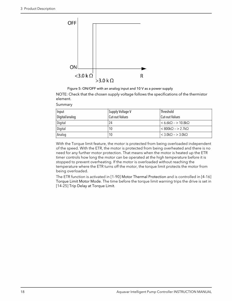
Figure 5: ON/OFF with an analog input and 10 V as a power supply
NOTE: Check that the chosen supply voltage follows the specifications of the thermistorelement.
Summary
InputDigital/analog
Supply Voltage VCut-out Values
ThresholdCut-out Values
Digital 24 < 6.6kΩ — > 10.8kΩ
Digital 10 < 800kΩ — > 2.7kΩ
Analog 10 < 3.0kΩ — > 3.0kΩ
With the Torque limit feature, the motor is protected from being overloaded independentof the speed. With the ETR, the motor is protected from being overheated and there is noneed for any further motor protection. That means when the motor is heated up the ETRtimer controls how long the motor can be operated at the high temperature before it isstopped to prevent overheating. If the motor is overloaded without reaching thetemperature where the ETR turns off the motor, the torque limit protects the motor frombeing overloaded.
The ETR function is activated in [1-90] Motor Thermal Protection and is controlled in [4-16]Torque Limit Motor Mode. The time before the torque limit warning trips the drive is set in[14-25] Trip Delay at Torque Limit.
3 Product Description
18 Aquavar Intelligent Pump Controller INSTRUCTION MANUAL

3.3 Dimensions3.3.1 Frame sizes A2–A5, B1–B4, C1–C4
A2 A3 A4 A5 B1 B2
B3 B4 C1 C2 C3 C4
Top and bottom mounting holes
Top and bottom mounting holes (B4+C3+C4 only)
IP20/21* IP55/66TYPE 12/4X
IP55/66TYPE 3R/12/4X
IP21/55/66 IP21/55/66
IP20/21* IP20/21* IP21/55/66 IP21/55/66 IP20/21* IP20/21*
IP20/21*TYPE 1/3R/12/4XOPEN/TYPE 1
OPEN/TYPE 1 OPEN/TYPE 1TYPE 1/3R/12/4X
e
f
a
Table 1: Mechanical dimensions
Frame size A2 A3 A4 A5 B1 B2 B3 B4 C1 C2 C3 C4
Single-Phase Rated Power hp [kW]
3 Product Description
Aquavar Intelligent Pump Controller INSTRUCTION MANUAL 19

Frame size A2 A3 A4 A5 B1 B2 B3 B4 C1 C2 C3 C4
200–240 V 1.5[1.1]
2-7.5[1.5-5.
5]
10[7.5]
20 [15] 30[22]
Three-Phase Rated Power hp [kW]
200–240 V 1.5–3 [1.1-2.2] 4–5 [3-3.7] 1.5–3[1.1-2.
2]
1.5–5[1.1-3.
7]
7.5–15[5.5-11
]
20 [15] 7.5-15[5.5-11
]
20–25[15-18]
25–40[18-30]
50–60[37-45]
30–40[22-30]
50–60[37-45]
380–480/500 V 1.5–5 [1.1-4] 7.5–10 [5.5-7.5] 1.5–5[1.1-4]
1.5–10[1.1-7.
5]
15–25[11-18]
30–40[22-30]
15–25[11-18]
30–50[22-37]
50–75[37-55]
100–125
[75-90]
60–75[45-55]
100–125
[75-90]
525–600 V 1.5–10 [1.1-7.5] 1.5–10[1.1-7.
5]
15–25[11-18]
15–40[11-30]
15–25[11-18]
30–50[22-37]
50–75[37-55]
50–125
[37-90]
60–75[45-55]
100–125
[75-90]
525–690 V 15-22[11-30]
50-125[37-90]
Enclosure Rating
IP Rating IP20 IP21 IP20 IP21 IP55IP66
IP55IP66
IP21IP55IP66
IP21IP55IP66
IP20 IP20 IP21IP55IP66
IP21IP55IP66
IP20 IP20
UL Type OPEN 1 OPEN 1 124X
3R124X
3R124X
3R124X
OPEN OPEN 3R124X
3R124X
OPEN OPEN
Height in (mm)
Height withde-couplingplate forfieldbuscables
A 14.72(374)
- 14.72(374)
- - - - - 16.54(420)
23.43(595)
- - 24.8(630)
31.5(800)
Height ofbackplate
A 10.55(268)
14.76(375)
10.55(268)
14.76(375)
15.35(390)
16.54(420)
18.90(480)
25.59(650)
15.71(399)
20.47(520)
26.77(680)
30.31(770)
21.65(550)
25.98(660)
Distancebetweenmountingholes
a 10.12(257)
13.78(350)
10.12(257)
13.78(350)
15.79(401)
15.83(402)
17.87(454)
24.57(624)
14.96(380)
19.49(495)
25.51(648)
29.09(739)
20.51(521)
24.84(631)
Width in (mm)
Width ofbackplate
B 3.54(90)
3.54(90)
5.12(130)
5.12(130)
7.87(200)
9.53(242)
9.53(242)
9.53(242)
6.50(165)
9.10(23 0)
12.13(308)
14.57(370)
12.13(308)
14.57(370)
Width ofbackplatewith one Coption
B 5.12(130)
5.12(130)
6.70(170)
6.70(170)
- 9.53(242)
9.53(242)
9.53(242)
8.07(205)
9.10(230)
12.13(308)
14.57(370)
12.13(308)
14.57(370)
Width ofbackplatewith 2 Coptions
B 5.91(150)
5.91(150)
7.48(190)
7.48(190)
- 9.53(242)
9.53(242)
9.53(242)
8.86(225)
9.10(230)
12.13(308)
14.57(370)
12.13(308)
14.57(370)
Distancebetweenmountingholes
b 2.76(70)
2.76(70)
4.33(110)
4.33(110)
6.73(171)
8.46(215)
8.27(210)
8.27(210)
5.51(140)
7.87(200)
10.71(272)
13.15(334)
10.63(270)
12.99(330)
IP Rating IP20 IP21 IP20 IP21 IP55IP66
IP55IP66
IP21IP55IP66
IP21IP55IP66
IP20 IP20 IP21IP55IP66
IP21IP55IP66
IP20 IP20
3 Product Description
20 Aquavar Intelligent Pump Controller INSTRUCTION MANUAL

Frame size A2 A3 A4 A5 B1 B2 B3 B4 C1 C2 C3 C4
Depth in (mm)
Without A/BOption Card*
C 8.07(205)
8.15(207)
8.07(205)
8.15(207)
6.89(175)
7.87(200)
10.24(260)
10.24(260)
9.80(249)
9.53(242)
12.20(310)
13.19(335)
13.11(333)
13.11(333)
With A/BOption Card*
C 8.66(220)
8.74(222)
8.66(220)
8.74(222)
6.89(175)
7.87(200)
10.24(260)
10.24(260)
10.31(262)
9.53(242)
12.20(310)
13.19(335)
13.11(333)
13.11(333)
Screw holes in (mm)
c 0.31(8)
0.31(8)
0.31(8)
0.31(8)
0.32(8.2)
0.32(8.2)
0.47(12)
0.47(12)
0.31(8)
- 0.47(12)
0.47(12)
- -
d 0.43(11)
0.43(11)
0.43(11)
0.43(11)
0.47(12)
0.47(12)
0.75(19)
0.75(19)
0.47(12)
- 0.75(19)
0.75(19)
- -
e 0.22(5.5)
0.22(5.5)
0.22(5.5)
0.22(5.5)
0.26(6.5)
0.26(6.5)
0.35(9)
0.35(9)
0.27(6.8)
0.33(8.5)
0.35(9)
0.35(9)
0.33(8.5)
0.33(8.5)
f 0.35(9)
0.35(9)
0.26(6.5)
0.26(6.5)
0.24(6)
0.35(9)
0.35(9)
0.35(9)
0.31(7.9)
0.59(15)
0.39(9.8)
0.39(9.8)
0.67(17)
0.67(17)
Max. weight — lb(kg)
10.8(4.9)
11.7(5.3)
14.6(6.6)
15.4(7)
21.4(9.7)
29.8(13.5)/
31.3(14.2)
50.7(23)
59.5(27)
26.5(12)
51.8(23.5)
99.2(45)
143.3(65)
77.2(35)
110.2(50)
3.3.2 Frame sizes D1–D4, D5, D7NOTICE: dimensions in the following drawings are in mm (in.).
99(3.9)
674(26.5)
164(6.5)
507(20.0)
844(33.2)
561(22.1)
82(3.2)
378(14.9)
148(5.8)
20(0.8)
18(0.71)
901(35.5) 844
(33.2)
123(4.8)
78(3.1)
246(9.7)
325(12.8)
180(7.1)
200(7.9)
200(7.9)
656(25.8)
130(5.1)
12
34
Figure 6: D1 enclosure, cabinet mount
1. Ceiling2. Minimum 225 (8.9) airspace outlet3. Minimum 225 (8.9) airspace inlet4. Floor
Please note airflow directions
3 Product Description
Aquavar Intelligent Pump Controller INSTRUCTION MANUAL 21

335(13.2) 140
(5.5)
189(7.4)
330(13.0)
336(13.23)
586(23.1)
916(36.1)
1877(73.9)
1556(61.3)
468(18.4)
Figure 7: Exterior dimensions for D1h with NEMA 3R Kit (9K715)
12
34
96(3.8)
879(34.6)
211(8.3)
623(24.5)
1050(41.3)
718(28.3)
378(14.9)142(5.6)
18(0.7)20
(0.8)
148(5.8)
1107(43.6)
1051(41.4)
107(4.2)
420(16.5)
280(11.0)
346(13.6)
213(8.4)
320(12.6)
271(10.7)
857(33.7)
130(5.1)
Figure 8: D2 enclosure, cabinet mount
1. Ceiling2. Minimum 225 (8.9) airspace outlet3. Minimum 225 (8.9) airspace inlet4. Floor
Please note airflow directions
3 Product Description
22 Aquavar Intelligent Pump Controller INSTRUCTION MANUAL

586(23.0)
189(7.4)
1122(44.2)
1074(42.3)
763(30.0)
468(18.4)
425(16.7)
431(17.0)
430(16.9)
280(11.0)
Figure 9: Exterior dimensions for D2h with NEMA 3R Kit (9K716)
909(35.81)
61(2.4)
660(26.0)
39(1.5)
128(5.0)
495(19.5)
844(33.2)
375(14.8)
82(3.2)
18(0.7)20
(0.8)
148(5.8)
889(35.0)
844(33.2)
122.5(4.8)77.5(3.1) 200
(7.9)
250(9.8)180(7.1)
130(5.1)
200(7.9)
656(25.8)
12
34
Figure 10: D3 enclosure, cabinet mount
1. Ceiling2. Minimum 225 (8.9) airspace outlet3. Minimum 225 (8.9) airspace inlet4. Floor
Please note airflow directions
3 Product Description
Aquavar Intelligent Pump Controller INSTRUCTION MANUAL 23

1
3
2
4
271(10.7)
857(33.7)
130(5.1)
320(12.6)
350(13.8)280
(11.0)
1122(44.2)
1096(43.1)
1051(41.4)
107(4.2)213(8.4)
375(14.8)
142(5.6)
39(1.5) 18
(0.7)
20(0.8)
148(5.8)
1050(41.3)
176(6.9)
59(2.3)
868(34.2)
611(24.1)
Figure 11: D4 enclosure, cabinet mount
1. Ceiling2. Minimum 225 (8.9) airspace outlet3. Minimum 225 (8.9) airspace inlet4. Floor
Please note airflow directions
1107(43.6)
149(5.9)
733(28.9)
1277(50.3)
381(15)
115(4.5)
23(0.9)
161(6.3)
325 (12.8)306 (12.1)
180(7.1)
276 (10.9)
123(4.8)
78(3.1)200(7.9)
1324(52.1)
1276(50.2)
123(4.8)
78(3.1)200(7.9)
130(5.1)
1111(43.7)
130(5.1)
220(8.7)
200(7.9)
12
34
5
433(17)
670(26.4)
218(8.6)
Figure 12: D5 Enclosure
1. Ceiling2. Minimum 225 (8.9) airspace outlet3. Minimum 225 (8.9) airspace inlet4. Floor5. Heatsink access panel
Please note airflow directions
3 Product Description
24 Aquavar Intelligent Pump Controller INSTRUCTION MANUAL

1754(69.1)
209(8.2)
1282(50.5)
386(15.2)
156(6.2)
23(0.9)
Ø25(11)
1931(76)
161(6.3)
420 (16.5)411 (16.2)
280(11)
374 (14.7)
130(5.1)107
(4.2)213(8.4)320
(12.6)
1978(77.9)
1953(76.9)
107(4.2)213(8.4)320
(12.6)
1760(69.3)
130(5.1)
668(26.3)
1 2
591(23)
316(12)
1168(46)
3
1730.5(68)
468(18)
23(1)
271(11)4
2X Ø11(0)
1536.5(61)
Figure 13: D7 Enclosure
1. Ceiling2. Minimum 225 (8.9) airspace outlet3. Heatsink access panel4. Wall mounting holes
Please note airflow directions
Table 2: Mechanical dimensions and rated power for D1, D2, D3, D4
Frame size D1 D2 D3 D4
Normal overload rated power 110% overloadtorque
150–250 hp (110–160kW) at 400 V
150-200 hp (132–160kW) at 690 V (525–
690 V)
300–450 hp (200–315kW) at 400 V
250-350 hp (200-315kW) at 690 V (525–
690 V)
150–250 hp (110–160kW) at 400 V (380–
480 V)150-200 hp (132-160kW) at 690 V (525-690
V)
300–450 hp (200–315kW) at 400 V
250–400 hp (200–400kW) at 690 V (525–
690 V)
Enclosure protection IP 21/54 00
NEMA Type 1/Type 12 Chassis
Shipping Dimensionin. (mm)
Height 23.11 (587)
Width 39.25 (997) 46.06 (1170) 39.25 (997) 46.06 (1170)
Depth 18.11 (460) 21.06 (535) 18.11 (460) 21.06 (535)
Drive dimensionin. (mm)
Height 35.5 (901) 41.7 (1060) 35.8 (909) 44.2 (1122)
Width 12.8 (325) 16.54 (420) 9.8 (250) 13.8 (350)
Depth 15.0 (381) 14.76 (375)
Max. Weight lbs (kg) 137 (62) 125 (276) 137 (62) 125 (276)
3 Product Description
Aquavar Intelligent Pump Controller INSTRUCTION MANUAL 25

Frame Size D1 D2 D3 D4
Enclosure protection IP 21/54 00
NEMA Type 1 / Type 12 Chassis
Normal overload rated power — 110% overloadtorque
150–250 hp (110–160kW) at 400 V (380–
480 V)150-200 hp (132–160
kW) at 400 V (380–480 V)
300–450 hp (200–315kW) at 400 V
250-350 hp (200-315kW) at 690 V (525–
690 V)
150–250 hp (110–160kW) at 400 V (380–
480 V)150-200 hp (132-160kW) at 690 V (525-690
V)
300–450 hp (200–315kW) at 400 V
250–400 hp (200–400kW) at 690 V (525–
690 V)
Table 3: Mechanical dimensions and rated power for D5, D7
Frame size D5 D7
Normal overload rated power 110% overload torque 150–250 hp (110–160 kW) at 400V (380–480 V)
150-200 hp (132-160 kW) at 690V (525-690 V)
300–450 hp (200–315 kW) at 400V
250–400 hp (200–400 kW) at 690V (525–690 V)
Enclosure protection IP 21/54 21/54
NEMA Type 1/Type 12 Type 1/Type 12
Shipping dimensionsin. (mm)
Height 25.98 (660)
Width 71.65 (1820) 97.24 (2470)
Depth 20.08 (510) 23.23 (590)
Drive dimensionsin. (mm)
Height 52.13 (1324) 77.87 (1978)
Width 12.8 (325) 16.54 (420)
Depth 15 (381) 15.2 (386)
Max. Weight lbs (kg) 218 (99) 408 (185)
3 Product Description
26 Aquavar Intelligent Pump Controller INSTRUCTION MANUAL

Frame size D5 D7
Enclosure protection IP 21/54
NEMA Type 1/Type 12
Normal overload rated power — 110% overload torque 150–250 hp (110–160 kW) at 400V (380–480 V)
150-200 hp (132-160 kW) at 690V (525-690 V)
300–450 hp (200–315 kW) at 400V
250–400 hp (200–400 kW) at 690V (525–690 V)
NOTE:
• The typical power loss is at nominal load conditions and expected to be within ±15%(tolerance relates to variety in voltage and cable conditions).
• The losses are based on the default switching frequency. The losses increasesignificantly at higher switching frequencies.
• D5h-D7h frames for IP21 and IP54 are based upon D1h and D2h ratings added withthe options cabinet for disconnect and fuse respectively, shown in the following table.
• The NEMA 3R cover kit is for D1h and D2h enclosure.
Table 4: D5h-D8h frames
Frame size Description Max. weight, kg (lbs)
D5h D1h ratings+disconnect and/or brake chopper 166 (366)
D7h D2h ratings+disconnect and/or brake chopper 200 (441)
3 Product Description
Aquavar Intelligent Pump Controller INSTRUCTION MANUAL 27

3.4 Frame size description
Figure 14: Exploded view of Frame Size A
1 LCP 10 Motor output terminals 96 (U), 98 (W)
2 RS-485 serial bus connector (+68, 69) 11 Relay 2 (01, 02, 03)
3 Analog I/O connector 12 Relay 1 (04, 05, 06)
4 LCP input plug 13 Brake (-81, +82) and load sharing (-88, +89) terminals
5 Analog switch A54 14 Mains input terminals 91 (L1), 92 (L2), 93 (L3)
6 Cable strain relief/PE ground 15 USB connector
7 Decoupling plate 16 Serial bus terminal switch
8 Grounding clamp (PE) 17 Digital I/O and 24 V power supply
9 Shielded cable grounding clamp and strain relief 18 Control cable cover plate
3 Product Description
28 Aquavar Intelligent Pump Controller INSTRUCTION MANUAL

Figure 15: Exploded view of Frame Sizes B and C, IP55, IP66 UL Type 3R, 12 and 4X
1 LCP 11 Relay 2 (04, 05, 06)
2 Cover 12 Lifting ring
3 RS-485 serial bus connector 13 Mounting slot
4 Digital I/O and 24 V power supply 14 Grounding clamp (PE)
5 Analog I/O connector 15 Cable strain relief / PE ground
6 Cable strain relief/PE ground 16 Brake terminal (-81, +82)
7 USB connector 17 Load sharing terminal (DC bus) (-88, +89)
8 Serial bus terminal switch 18 Motor output terminals 96 (U), 97 (V), 98 (W)
9 Analog switch A54 19 Mains input terminals 91 (L1), 92 (L2), 93 (L3)
10 Relay 1 (01, 02, 03)
3 Product Description
Aquavar Intelligent Pump Controller INSTRUCTION MANUAL 29

1011
1
15 14
12
13(IP 21/54
NEMA 1/12)13 (IP 20/Chassis)
89
16
Figure 16: D1 Interior components
9
8
7
4
1
6
2
53
10
11
Figure 17: Close-up view: LCP and control functions
1 LCP
2 RS-485 serial bus connector
3 Digital I/O and 24 V power supply
4 Analog I/O connector
5 USB connector
6 Serial bus terminal switch
7 Analog switch A54
8 Relay 1 (01, 02, 03)
9 Re;ay 2 (04, 05, 06)
10 Lifting ring
11 Mounting slot
12 Cable clamp (PE)
13 Ground
14 Motor output terminals 96 (U), 97 (V), 98 (W)
15 Line power input terminals 91 (L1), 92 (L2), 93 (L3)
16 TB5 (IP21/54 only). Terminal block for anti-condensationheater.
For location of TB6 (terminal block for contactor), see Terminal Locations: D5h-D8h.
3 Product Description
30 Aquavar Intelligent Pump Controller INSTRUCTION MANUAL

3.5 Internal frequency converter controller functions
1 2 34
5
6
M
7
8
Figure 18: Frequency converter block diagram
Area Title Functions
1 Mains input Three-phase AC mains power supply to thefrequency converter
2 Rectifier The rectifier bridge converts the AC input to DCcurrent to supply inverter power.
3 DC bus Intermediate DC-bus circuit handles the DCcurrent
4 DC reactors • Filter the intermediate DC circuit voltage• Proveide line transient protection• Reduce RMS current• Raise the power factor reflected back to
the line• Reduce harmonics on the AC input
5 Capacitor bank • Stores the DC power• Provides ride-through protection for short
power losses
6 Inverter Converts the DC into a controlled PWM ACwaveform for a controlled variable output tothe motor.
7 Output to motor Regulated three-phase output power to themotor
8 Control circuitry • Input power, internal processing, output,and motor current are monitored toprovide efficient operation and control.
• User interface and external commands aremonitored and performed.
• Status output and control can be provided.
3 Product Description
Aquavar Intelligent Pump Controller INSTRUCTION MANUAL 31
4 Mechanical Installation4.1 Pre-installation4.1.1 Installation site checklist
• The frequency converter relies on the ambient air for cooling. Observe the limitationson ambient air temperature for optimal operation.
• Ensure that the installation location has sufficient support strength to mount thefrequency converter.
• Keep the manual, drawings, and diagrams accessible for detailed installation andoperation instructions. It is important that the manual is available for equipmentoperators.
• Locate equipment as near to the motor as possible. Keep motor cables as short aspossible. Check the motor characteristics for actual tolerances.
– For installations with long motor cables use the output filter option to protect themotor.
• Ensure that the ingress protection rating of the frequency converter is suitable for theinstallation environment. IP55 (Type 3R/12) or IP66 (Type 4X) enclosures may benecessary.
CAUTION:
Ingress protection. IP54, IP55 (Type 3R/12) and IP66 (Type 4X) ratingscan only be guaranteed if the unit is properly closed.
– Ensure all cable glands and unused holes for glands are properlysealed.
– Ensure that the unit cover is properly closed.
Device damage through contamination. Do not leave the frequencyconverter uncovered.
4.1.2 Frequency converter and motor pre-installation check list• Compare the model number of the unit on the nameplate to what was ordered to
verify the proper equipment.• Ensure each of the following are rated for same voltage:
– Mains (power)– Frequency converter– Motor
• Ensure that the frequency converter output current rating is equal to or greater thanmotor service factor current for peak motor performance.
– Motor size and frequency converter power must match for proper overloadprotection.
– If frequency converter rating is less than motor, full motor output cannot beachieved.
4.2 General considerations4.2.1 Tools needed
To perform the mechanical installation, the following tools are needed:
• Drill with 0.39 or 0.47 in (10 or 12 mm) drill.• Tape measure• Wrench with relevant metric sockets (0.28–0.67 in (7–17 mm))• Extensions to wrench
4 Mechanical Installation
32 Aquavar Intelligent Pump Controller INSTRUCTION MANUAL

• Sheet metal punch for conduits or cable connectors in IP 21/NEMA 1 and IP 54 units• Lifting bar to lift the unit (rod or tube max. Ø1 in (25 mm), able to lift minimum 880 lbs
(400 kg).• Crane or other lifting aid to place the frequency converter in position.
4.2.2 SpaceEnsure proper space above and below the frequency converter to allow airflow and cableaccess. In addition, space in front of the unit must be considered to allow the panel doorto be opened.
399(15.7)
526(20.7)
≤105, 0°
Figure 19: Space in front of IP21/IP54 enclosure type, frame size D1 and D2
4.2.3 Wire accessEnsure that proper cable access is present including the necessary bending allowance. Asthe IP00 enclosure is open to the bottom, cables must be fixed to the back panel of theenclosure where the frequency converter is mounted, for example, by using cable clamps.
NOTICE:
All cable lugs/shoes must mount within the width of the terminal bus bar.
4.3 How to get startedThe frequency converter is designed for a quick installation and is electromagneticcompatibility (EMC) compliant. Follow the steps that are described below.
CAUTION:
Read this manual carefully before installing and using the product. Improper use of theproduct can cause personal injury and damage to property, and may void the warranty.
Mechanical installation
• Mechanical mounting
Electrical installation
• Connection to Line and Protecting Ground• Motor connection and cables• Fuses and circuit breakers• Control terminals cables
Quick Setup
• Local control panel, LCP• Automatic Motor Adaptation, AMA• Programming
Frame size depends on the enclosure type, power range, and AC linevoltage.
4 Mechanical Installation
Aquavar Intelligent Pump Controller INSTRUCTION MANUAL 33
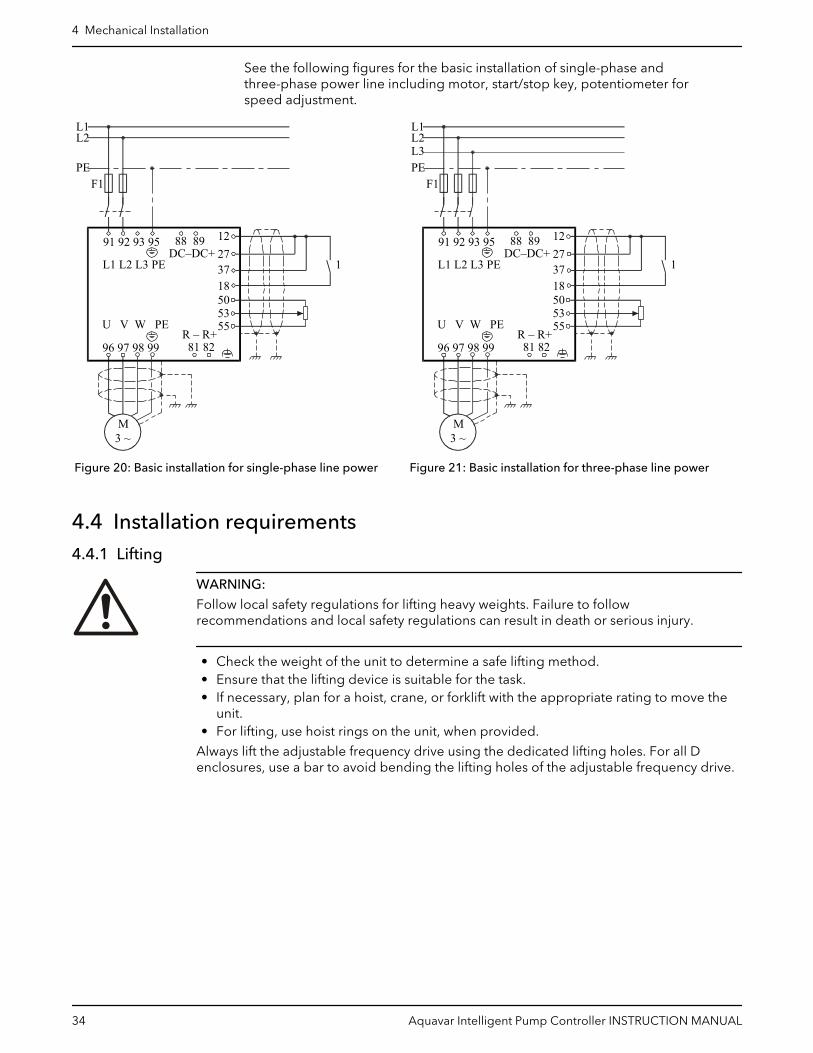
See the following figures for the basic installation of single-phase andthree-phase power line including motor, start/stop key, potentiometer forspeed adjustment.
L1L2
PEF1
1L1 L2 L3 PE
91 92 93 95 88 89DC–DC+
12273718505355
R – R+81 8296 97 98 99
U V W PE
M3 ~
Figure 20: Basic installation for single-phase line power
L1L2L3PE
F1
1L1 L2 L3 PE
91 92 93 95 88 89DC–DC+
12273718505355
R – R+81 8296 97 98 99
U V W PE
M3 ~
Figure 21: Basic installation for three-phase line power
4.4 Installation requirements4.4.1 Lifting
WARNING:
Follow local safety regulations for lifting heavy weights. Failure to followrecommendations and local safety regulations can result in death or serious injury.
• Check the weight of the unit to determine a safe lifting method.• Ensure that the lifting device is suitable for the task.• If necessary, plan for a hoist, crane, or forklift with the appropriate rating to move the
unit.• For lifting, use hoist rings on the unit, when provided.
Always lift the adjustable frequency drive using the dedicated lifting holes. For all Denclosures, use a bar to avoid bending the lifting holes of the adjustable frequency drive.
4 Mechanical Installation
34 Aquavar Intelligent Pump Controller INSTRUCTION MANUAL

Figure 22: Recommended lifting method, frame size D
NOTICE:
The lifting bar must be able to handle the weight of the adjustable frequency drive. SeeMechanical Dimensions for the weight of the different frame sizes. Maximum diameter forbar is 1 in (2.5 cm). The angle from the top of the drive to the lifting cable should be 60°Cor greater.
4.4.2 Cooling• To provide cooling airflow, mount the unit to a solid flat surface or to the optional back
plate.• Top and bottom clearance for air cooling must be provided. Generally, 100–225 mm
(4–10 in) is required.
a
b
Enclosure A2–A5 B1–B4 C1, C3 C2, C4
a/b 100 mm (3.9 in) 200 mm (7.9 in) 200 mm (7.9 in) 225 mm (8.9 in)
• Improper mounting can result in overheating and reduced performance.• Derating for temperatures starting between 40°C (104°F) and 50°C (122°F) and
elevation 1000 m (3300 ft) above sea level must be considered.
4.4.3 Mounting• Mount the unit vertically.• The frequency converter allows side by side installation.
4 Mechanical Installation
Aquavar Intelligent Pump Controller INSTRUCTION MANUAL 35

• Ensure that the strength of the mounting location will support the unit weight.• Mount the unit to a solid flat surface or to the optional back plate to provide cooling
airflow.
A
Figure 23: Mounting with back plate
A Properly installed back plate
1
Figure 24: Mounting with railings
1 Back plate1
4.4.4 Terminal and connectionTake the following terminal positions into consideration when you design for cableaccess.
Be aware that the power cables are heavy and hard to bend. Give thought to the optimumposition of the adjustable frequency drive for ensuring easy installation of the cables.
Note: IP20 Chassis is for D3h and D4h, and 3R is for D1h and D2h only.
Terminal locations — D enclosures
0(0.0)
272(10.7)
192(7.6)
80(3.1)
0(0.0)
0(0.0)
33(1.3)
62(2.4)
101(4.0)
140(5.5)
163(6.4)
185(7.3)
224(8.8)
263(10.4)
293(11.5)
86(3.4)
B
A
R T V
S U W
BA
244(9.6)
0(0.0)
1
3
56
4
2
Figure 25: Terminal locations — D1h
1. Section A-A Mains terminal2. Section B-B Motor terminals3. Mains terminal4. Motor terminal5. 3X M8X20 stud with nut6. Ground
1 Back plate is needed when mounted on railings.
4 Mechanical Installation
36 Aquavar Intelligent Pump Controller INSTRUCTION MANUAL

1
3 4
2
0(0.0)
0(0.0)
0(0.0)
323(12.7)
284(11.2)
56 160
(6.3)135(5.3)7
42(1.7)
68(2.7)
126(5.0)
184(7.2)
245.8(9.7)
299.8(12)
378(14.9)
354(13.9)
203(8.0)
R T V
S U W
255(10.0)
0(0.0)
BA
Figure 26: Terminal locations — D2h
1. Section A-A Mains terminal2. Section B-B Motor terminals3. Mains terminal4. Motor terminal5. 4X M10X20 stud with nut6. 2X Ground7. 2X Ground
1
3
4
2
5
0(0.0)
272(10.7)
0(0.0)
188(7.4)
0(0.0)
83(3.3)
290(11.4)
244(9.6)
292(11.5)
152(6.0)
217(8.5)
B
A
BA
0(0.0)
62(2.4)
145(5.7)
223(8.8)
22(0.9)
101(4.0)
184(7.2)
R T V
S U W
Figure 27: Terminal locations — D3h
1. Section A-A Mains terminal2. Section B-B Motor terminals and brake / regen terminals3. Mains terminal4. Brake / regen terminals5. Motor terminal
4 Mechanical Installation
Aquavar Intelligent Pump Controller INSTRUCTION MANUAL 37
1
3
42
5
0(0.0)
284(11.2)
0(0.0)
319(12.6)
0(0.0)
200(7.9)
306(12.1)
255(10.0)
237(9.3)
293(11.5)
376(14.8)
BA
BA
0(0.0)
91(3.6)
211(8.3)
319(12.6)
33(1.3)
149(5.8)
265(10.4)
R T V
S U W
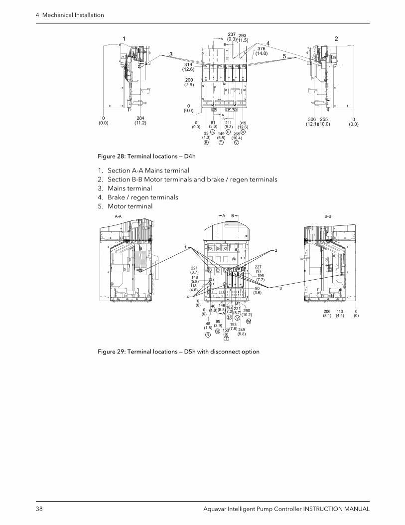
Figure 28: Terminal locations — D4h
1. Section A-A Mains terminal2. Section B-B Motor terminals and brake / regen terminals3. Mains terminal4. Brake / regen terminals5. Motor terminal
RS
T
U VW
A-A B-BA B
12
3
221(8.7)148(5.8)118(4.6)
0(0)
0(0) 0
(0)
227(9)196(7.7)
90(3.6)
45(1.8)
46(1.8)
99(3.9)
146(5.8)
A182(7.2)
221(8.7)
B
153(6)
193(7.6) 249
(9.8)
260(10.2)
206(8.1)
113(4.4)
4
Figure 29: Terminal locations — D5h with disconnect option
4 Mechanical Installation
38 Aquavar Intelligent Pump Controller INSTRUCTION MANUAL

B
B
A
A
412(16.2)
B-BA-A
RS
T
U
V
W
1
2
3
4
0(0)
119(4.7)
276(10.9)
0(0)
372(14.7)
545(21.4)515
(20.3)
395(15.6)
0(0)
49(1.9)
95(3.7)
66(2.6)
151(5.9)
131(5.1)
195.5(8)
292(11.5)
238(9.4)
0(0)
346(13.6)
368(14.5)
Figure 30: Terminal locations — D7h with disconnect option
1. Mains terminals2. Brake terminals3. Motor terminals4. Earth/Ground terminals
4.4.5 Gland/Conduit entry IP21 (NEMA 1) and IP54 (NEMA12)Cables are connected through the gland plate from the bottom. Remove the plate andplan where to place the entry for the glands or conduits.
Prepare holes in the marked area in below illustration.
NOTICE:
The gland plate must be fitted to the frequency converter to ensure the specifiedprotection degree, as well as ensuring proper cooling of the unit. If the gland plate is notmounted, the frequency converter may trip on Alarm 69, Pwr. Card Temp.
4.4.6 NEMA-3R cover kitThe NEMA 3R cover kit is designed for D1h and D2h enclosure sizes for the followingapplications:
• This kit adds a cover to the outside vents of the frequency converter and providesNEMA 3R compliant protection against weather and hosed water. The kit is used onlywith frequency converters that have the enclosure Code C-N3R.
The NEMA 3R kit contains the following parts:
• Top plate (1)• Gland plate with attached gasket (1)• NEMA 3R cover (1)• Adhesive label (1)• 3–sectioned plastic bag containing:
– For top plate, lifting eyelets (2) and screws (6) without captive washers.– For gland plate, screws (6) for D1h or (8) for D2h. The screws have captive washers.– For NEMA 3R cover, screws (6) with captive washers.
4 Mechanical Installation
Aquavar Intelligent Pump Controller INSTRUCTION MANUAL 39

4.4.7 Install the top plate
1
2 3
Figure 31: Installing NEMA 3R Top Plate
1. Top plate2. Eye bolt3. Screw without captive washer
1. Remove the four (4) screws along the back side of the top vent opening.
2. Place the top plate over the top vent opening.
3. Secure the top plate with the six (6) screws without captive washers provided in thebag. Torque to 2.3 Nm (20 in/lbs).
4. If lifting eyebolts are needed for the application, remove the plated eyebolts that camewith the unit and replace with the stainless steel eyebolts provided in the bag.
NOTICE:
UL NEMA 3R RATING
Eyebolts are not required to meet UL NEMA 3R rating.
4.4.8 Install the gland plate1. Remove the existing gland plate and gasket from the bottom of the frequency
converter by removing 6 screws (T25) from the D1h or 8 screws (T25) from the D2h.
2. Make sure that the flange on the frequency converter is smooth and clean inpreparation for the new gasket.
3. Place the new gland plate over the opening, with the gasket side facing the opening.
4. Secure the new gland plate to the frequency converter using the provided screws withcaptive washers (6) for D1h or (8) for the D2h. Torque to 2.3 Nm (20 in/lbs).
4 Mechanical Installation
40 Aquavar Intelligent Pump Controller INSTRUCTION MANUAL

1
23
Figure 32: Removing Gland Plate
3 2
1
Figure 33: Installing NEMA 3R Gland Plate
1. Gasket2. Screw with captive washer3. Gland plate
4 Mechanical Installation
Aquavar Intelligent Pump Controller INSTRUCTION MANUAL 41

4.4.9 Install the NEMA 3R cover
1
2
43
Figure 34: Installing NEMA 3R Cover
1. Screw without captive washer2. NEMA 3R sticker3. NEMA 3R cover4. Screws to remove for taking off the NEMA 3R cover
1. Set the NEMA 3R cover over the top of the frequency converter. Align the NEMA 3Rcover with the screw holes on the top mounting plate and the screw holes on the sideof the unit.
2. Using the 6 screws provided in the bag, loosely secure the cover to the frequencyconverter.
3. Torque all 6 screws to 2.3 Nm (20 in/lbs).
4. Apply adhesive label to the cover.
To remove the NEMA 3R cover after it has been installed, remove the front 2 screws onthe bottom of the unit. The cover can be removed after the other 4 screws are loosenedsince the cover has slotted screw openings.
4.4.9.1 Calculating Nominal Current when Using a NEMA 3R CoverThe nominal current of a frequency converter with the NEMA 3R cover is 88% of its currentrating. For example, in a N315 standard IP21 frequency converter, the nominal outputcurrent at 460/480V in nominal overload mode is 588 A. With the NEMA 3R cover, thenormal overload current is 0.88 x 588 = 517.4 A. The same calculation is used to calculatethe nominal current for the high overload mode.
4.4.9.2 Derating For Ambient Temperature When Using A NEMA 3R CoverUsing the NEMA 3R cover kit requires derating due to higher ambient temperatureswithin the enclosure. Using SFAVM (stator flux asynchronous vector modulation) givesgreater switching control, but generates more heat than using 60°AVM (asynchronous
4 Mechanical Installation
42 Aquavar Intelligent Pump Controller INSTRUCTION MANUAL

vector modulation). SFAVM switches throughout the entire cycle, where 60° AVM onlyswitches 2/3 of the time.
The maximum switching frequency is 16 kHZ for 60° AVM and 10 kHz for SFAVM. Thediscrete switching frequencies are shown in the following figure.
Table 5: Switching patterns
50˚C
52˚C
110
60
100
70
80
90
1 2 3 4 5 6 7 8 9
A
B
Figure 35: 60° AVM, High Overload HO, 150%
50˚C
52˚C
100
50
70
80
90
1 2 3 4 5 9
A
B
60
45˚C
6 7 8
Figure 36: 60° AVM, Normal Overload HO, 110%
50˚C
52˚C
110
50
100
70
80
90
1 2 3 4 5 6
A
B
60
45˚C
Figure 37: SFAVM, High Overload HO, 150%
50˚C
52˚C
110
50
100
70
80
90
1 2 3 4 5 6
A
B
60
45˚C
40˚C
Figure 38: SFAVM, Normal Overload HO, 110%
A % of drive output, nominal HO current
B FSW (KHZ)
4.4.10 Piping connections
NOTICE:
All plumbing work must be performed by a qualified technician. Always follow all local,state and provincial codes.
A proper installation requires a pressure relief valve, a diaphragm tank, a 1/4” female NPTthreaded fitting for the pressure sensor, and properly sized pipe. Piping should be nosmaller than pump discharge and/or suction connections. Piping should be kept as shortas possible. Avoid the use of unnecessary fittings to minimize friction losses.
CAUTION:
Use pipes suited to the maximum working pressure of the pump. Failure to do so cancause the system to rupture, with the risk of injury.
All joints must be airtight. Use PTFE tape or another type of pressure sealant to sealthreaded connections. Please be careful when using thread sealant as any excess thatgets inside the pipe may plug the pressure sensor.
Galvanized fittings or pipe should never be connected directly to the stainless steeldischarge head or casing as galvanic corrosion may occur. Barb type connectors shouldalways be double clamped.
4 Mechanical Installation
Aquavar Intelligent Pump Controller INSTRUCTION MANUAL 43
WARNING:
Do not install any valves (except check valves), flow control devices or filters between thepressure transducer and the pump. It is allowable to run branches off the pipe betweenthe pump and transducer as long as no flow restricting devices are between the pumpand transducer.
4.4.11 Diaphragm tank, pressure relief valve, and discharge pipingUse only “pre-charged” tanks on this system. Do not use galvanized tanks. Select an areathat is always above 34°F (1.1°C) in which to install the tank, pressure sensor, and pressurerelief valve. If this is an area where a water leak or pressure relief valve blow-off maydamage property, connect a drain line to the pressure relief valve. Run the drain line fromthe pressure relief valve to a suitable drain or to an area where water will not damageproperty.
4.4.12 Diaphragm tank, system pressureA diaphragm tank (not included) is used to cushion the pressure system during start-upand shut-down. It should be sized to at least 20% of the total capacity of your pump. Forexample: If your pump is sized for 100 GPM (0.38 m3/min) then size your tank for at least20 gallon (75.71 Liters) total volume, not draw down. Pre-charge your bladder tank to 15–20 PSI (1–1.4 Bar) below your system pressure. The controller is pre-set for 50 PSI (3.4 Bar)at the factory. Therefore a 30–35 PSI (2.1–2.4 Bar) pre-charge in your tank would berequired. Use the higher tank pre-charge setting if the system drifts over 5 PSI (.34 Bar) ata constant flow rate. NOTE: Pre-charge your tank before filling with water.
CAUTION:
Exceeding the working pressure of the tank can cause the tank to rupture or explode.
4.4.13 Installing the pressure sensor
The pressure sensor requires a 1/4” FNPT fitting for installation. Install the pressure sensorwith the electrical connector pointing up to avoid clogging the pressure port with debris.Install the pressure sensor in a straight run of pipe away from elbows or turbulence. Foroptimum pressure control install the pressure sensor in the same straight run of pipe asthe pressure tank. Ensure the pressure sensor is within 10 feet (3 m) of the pressure tank.Installing the pressure sensor far away from the pressure tank may result in pressureoscillations. Do not install the pressure sensor in a location where freezing can occur. Afrozen pipe can cause damage to the pressure sensor.
4.4.14 Underwater connection
When using submersible motors, a waterproof connection is required between the dropcable and motor leads. The underwater connection where the drop cable connects to themotor wires must be made using a waterproof heat shrink kit or with equivalentwaterproof connection kit. When using a waterproof shrink kit to make the connection:
1. Strip the wires 1/2” and place the heat shrink tubes over the wires.2. Connect the wires using the crimps.3. Shrink the tubes over the crimps by heating from the center outward.
– The sealant in the tube will flow over the ends making a watertight seal.– If a heat shrink tube is burnt or split, the connection will need to be remade.
Vinyl electrical tape is not acceptable for underwater splices when using variable speeddrives. There is a high potential for leakage to ground through taped joints.
4 Mechanical Installation
44 Aquavar Intelligent Pump Controller INSTRUCTION MANUAL

CAUTION:
Failure to use a waterproof heat shrink kit will void the warranty.
Before installing the motor in the well, the drop cable must be connected to the motorwires. Refer to the wire size chart when selecting wire size for the drop cable.
4 Mechanical Installation
Aquavar Intelligent Pump Controller INSTRUCTION MANUAL 45
5 Electrical Installation5.1 Precautions
Electrical Hazard:
• Branch circuit protection required. Provide branch circuit protection in accordancewith the electrical regulations locally in force.
• Motor control equipment and electronic controls are connected to hazardous linevoltages. Extreme care should be taken to protect against electrical hazard.
• Proper protective grounding of the equipment must be established. Ground currentsare higher than 3.5 mA.
• A dedicated ground wire is required.
WARNING:
EQUIPMENT HAZARD. See section 1.2.3 Safety precautions on page 6 for details of thesafety precaution for Equipment Hazard.
NOTICE:
WIRING ISOLATION. Run input power, motor wiring and control wiring in three separatemetallic conduits or use separated shielded cable for high frequency noise isolation.Failure to isolate power, motor and control wiring could result in less than optimumfrequency converter and associated equipment performance.
For your safety comply with the following requirements:
• Electronic control equipment is connected to hazardous mains voltage. Extreme careshould be taken to protect against electrical hazards when applying power to the unit.
• Run motor cable from multiple frequency converters separately. Induced voltage cancharge equipment capacitors even with the equipment turned off and locked.
Overload and equipment protection:
• An electronically activated function within the frequency converter provides overloadprotection in the motor. The overload calculates the level of increase to activate timingfor the trip (controller output stop) function. The higher the current draw, the quickerthe trip response. The overload provides Class 20 motor protection. See Warnings andalarms on page 240 for details on the trip function.
• All frequency converters must be provided with short-circuit and over-currentprotection. Input fusing and/or circuit breaker are required to provide this protection.If not factory supplied, fuses must be provided by the installer as part of installations.See Fuses and circuit breakers on page 267 for details.
5 Electrical Installation
46 Aquavar Intelligent Pump Controller INSTRUCTION MANUAL

Figure 39: Frequency converter fuses
Item Description
1 Fuses
2 Ground
Wire type and ratings:
• All wiring must comply with local and national regulations regarding cross section andambient temperature requirements.
• It is recommended the all power connections be made with a minimum 75°C ratedcopper wire.
• See Power-dependent specifications on page 252 for recommended wire sizes.
5.1.1 Earth (grounding) requirements
WARNING:
For operator safety, it is important to ground the frequency converter properly inaccordance with national and local electrical codes as well as instructions contained withinthis document. Ground currents are higher than 3.5 mA. Failure to ground the frequencyconverter properly could result in death or serious injury.
NOTICE:
It is the responsibility of the user or certified electrical installer to ensure correctgrounding (earthing) of the equipment in accordance with national and local electricalcodes and standards.
• Follow all local and national electrical codes to ground electrical equipment properly.• Proper protective grounding for equipment with ground currents higher the 3.5 mA
must be established. Refer to the Leakage Current Hazard in section 1.2.3 Safetyprecautions on page 6 for details of the safety precaution of Leakage Current Hazard.
• A dedicated ground wire is required for input power, motor power and control wiring.• Use the clamps provided with the equipment for proper ground connections.• Do not ground one frequency converter to another in a “daisy chain” fashion.• Keep the ground wire connections as short as possible.• Using high-strand wire to reduce electrical noise is recommended.• Follow motor manufacturer wiring requirements.
5.1.2 Using GFCIs (RCDs)Where Ground Fault Circuit Interrupters (GFCIs) and Residual Current Devices (RCDs),also know as Earth Leakage Circuit Breakers (ELCDs), are used, comply with the following:
5 Electrical Installation
Aquavar Intelligent Pump Controller INSTRUCTION MANUAL 47
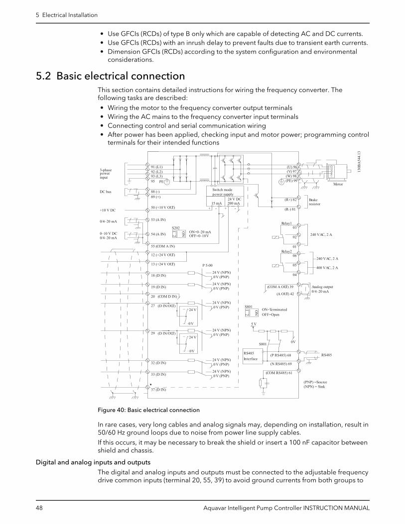
• Use GFCIs (RCDs) of type B only which are capable of detecting AC and DC currents.• Use GFCIs (RCDs) with an inrush delay to prevent faults due to transient earth currents.• Dimension GFCIs (RCDs) according to the system configuration and environmental
considerations.
5.2 Basic electrical connectionThis section contains detailed instructions for wiring the frequency converter. Thefollowing tasks are described:
• Wiring the motor to the frequency converter output terminals• Wiring the AC mains to the frequency converter input terminals• Connecting control and serial communication wiring• After power has been applied, checking input and motor power; programming control
terminals for their intended functions
*
91 (L1)92 (L2)93 (L3)
PE
88 (-)89 (+)
50 (+10 V OUT)
53 (A IN)
54 (A IN)
55 (COM A IN)
0/4–20 mA
12 (+24 V OUT)
13 (+24 V OUT)
18 (D IN)
20 (COM D IN)
15 mA 200 mA
(U) 96(V) 97
(W) 98(PE) 99
(COM A OUT) 39
(A OUT) 42 0/4–20 mA
03 0–10 V DC
+10 V DC
0/4–20 mA
240 V AC, 2 A
24 V DC
02
01
05
04
06240 V AC, 2 A
24 V (NPN) 0 V (PNP)
0 V (PNP)24 V (NPN)
19 (D IN)
24 V (NPN) 0 V (PNP)27
24 V
0 V
(D IN/OUT)
0 V (PNP)24 V (NPN)
(D IN/OUT)
0 V
24 V29
24 V (NPN) 0 V (PNP)
0 V (PNP)24 V (NPN)
33 (D IN)
32 (D IN)
ON2
1S202ON=0–20 mAOFF=0–10 V
95
400 V AC, 2 AP 5-00
(R+) 82
(R-) 81
37 (D IN)
+ - + -
130B
A54
4.13
(P RS485) 68
(N RS485) 69
(COM RS485) 61
0V
5 V
S801
RS485RS485
21 O
N
S801
3-phasepowerinput
DC bus Switch modepower supply
Motor
Analog output
Interface
Relay1
Relay2
ON=TerminatedOFF=Open
Brakeresistor
(NPN) = Sink(PNP) = Source
Figure 40: Basic electrical connection
In rare cases, very long cables and analog signals may, depending on installation, result in50/60 Hz ground loops due to noise from power line supply cables.
If this occurs, it may be necessary to break the shield or insert a 100 nF capacitor betweenshield and chassis.
Digital and analog inputs and outputs
The digital and analog inputs and outputs must be connected to the adjustable frequencydrive common inputs (terminal 20, 55, 39) to avoid ground currents from both groups to
5 Electrical Installation
48 Aquavar Intelligent Pump Controller INSTRUCTION MANUAL

affect other groups. For example, switching on the digital input may disturb the analoginput signal.
Figure 41: Input polarity of control terminals
Note: To comply with EMC emission specifications, shielded/armored cables arerecommended. If an unshielded/unarmored cable is used, see Power and control wiringfor unshielded cables on page 59.
Connect the wires as described in the Instruction Manual for the adjustable frequencydrive. Remember to connect the shields in a proper way to ensure optimum electricalimmunity.
5.3 Motor connectionWARNING:
INDUCED VOLTAGE. Run output motor cables from multiple frequency convertersseparately. Induced voltage from output motor cables run together can chargeequipment capacitors even with the equipment turned off and locked out. Failure to runoutput motor cables separately could result in death or serious injury.
Be sure the following are adhered to:
• For maximum wire sizes, see Power-dependent specifications on page 252.• Comply with local and national electrical codes• Motor wiring knockouts or access panels are provided at the base of
IP21
(Type 1) and higher units• Do not install power factor correction capacitors between the frequency converter and
the motor• Do not wire a starting or pole-changing device between the frequency converter and
the motor• Connect the 3–phase motor wiring to terminals 96 (U), 97 (V), and 98 (W)• Ground the cable in accordance with grounding instructions provided• Torque terminals in accordance with the information provided in Tightening torques
on page 277• Follow motor manufacturer wiring requirements
5 Electrical Installation
Aquavar Intelligent Pump Controller INSTRUCTION MANUAL 49
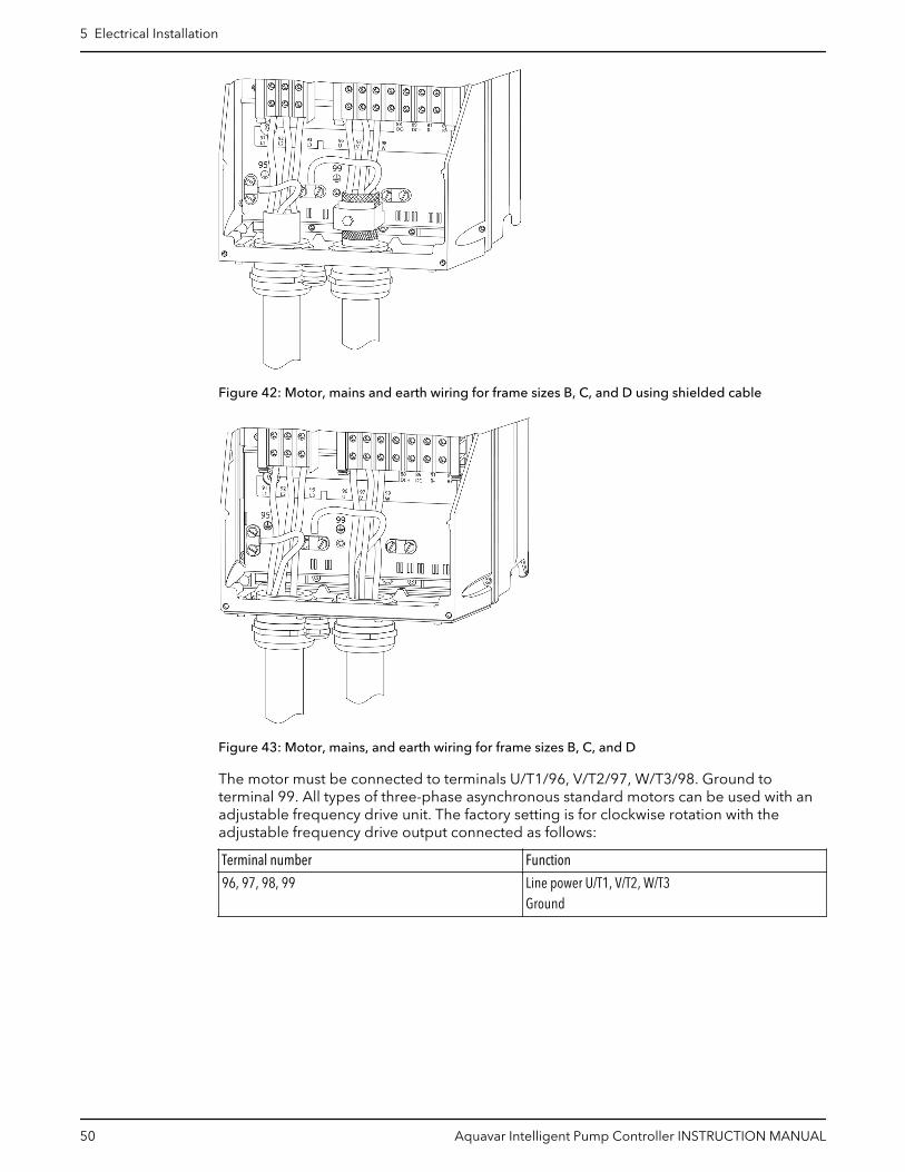
Figure 42: Motor, mains and earth wiring for frame sizes B, C, and D using shielded cable
Figure 43: Motor, mains, and earth wiring for frame sizes B, C, and D
The motor must be connected to terminals U/T1/96, V/T2/97, W/T3/98. Ground toterminal 99. All types of three-phase asynchronous standard motors can be used with anadjustable frequency drive unit. The factory setting is for clockwise rotation with theadjustable frequency drive output connected as follows:
Terminal number Function
96, 97, 98, 99 Line power U/T1, V/T2, W/T3Ground
5 Electrical Installation
50 Aquavar Intelligent Pump Controller INSTRUCTION MANUAL

Figure 44: Motor connections
• Terminal U/T1/96 connected to U-phase• Terminal V/T2/97 connected to V-phase• Terminal W/T3/98 connected to W-phase
The direction of rotation can be changed by switching two phases in the motor cable orby changing the setting of [4–10] Motor Speed Direction. Motor Rotation Check can beperformed by using [1–28] Motor Rotation Check and following the steps that are shownin the display.
Output junction box requirements
The length, minimum 8 ft (2.5 m), and quantity of cables must be equal from each invertermodule to the common terminal in the junction box.
• NOTE: If the retrofit application requires unequal amounts of wires per phase, consultthe factory for requirements and documentation or use the top/bottom entry sidecabinet option.
5.3.1 Motor connection for A2 and A3
Follow these drawings step by step for connecting the motor to the frequency converter.
1. Connect the motor earthwire to terminal 99, place motor U, V and W wires in plug andtighten.
2. Mount cable clamp to ensure 360° connection between chassis and screen, note theouter insulation of the motor cable is removed under the clamp.
5 Electrical Installation
Aquavar Intelligent Pump Controller INSTRUCTION MANUAL 51
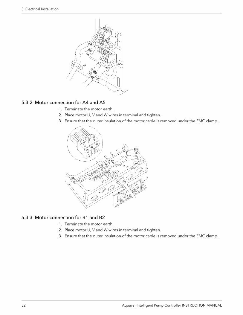
5.3.2 Motor connection for A4 and A51. Terminate the motor earth.
2. Place motor U, V and W wires in terminal and tighten.
3. Ensure that the outer insulation of the motor cable is removed under the EMC clamp.
5.3.3 Motor connection for B1 and B21. Terminate the motor earth.
2. Place motor U, V and W wires in terminal and tighten.
3. Ensure that the outer insulation of the motor cable is removed under the EMC clamp.
5 Electrical Installation
52 Aquavar Intelligent Pump Controller INSTRUCTION MANUAL
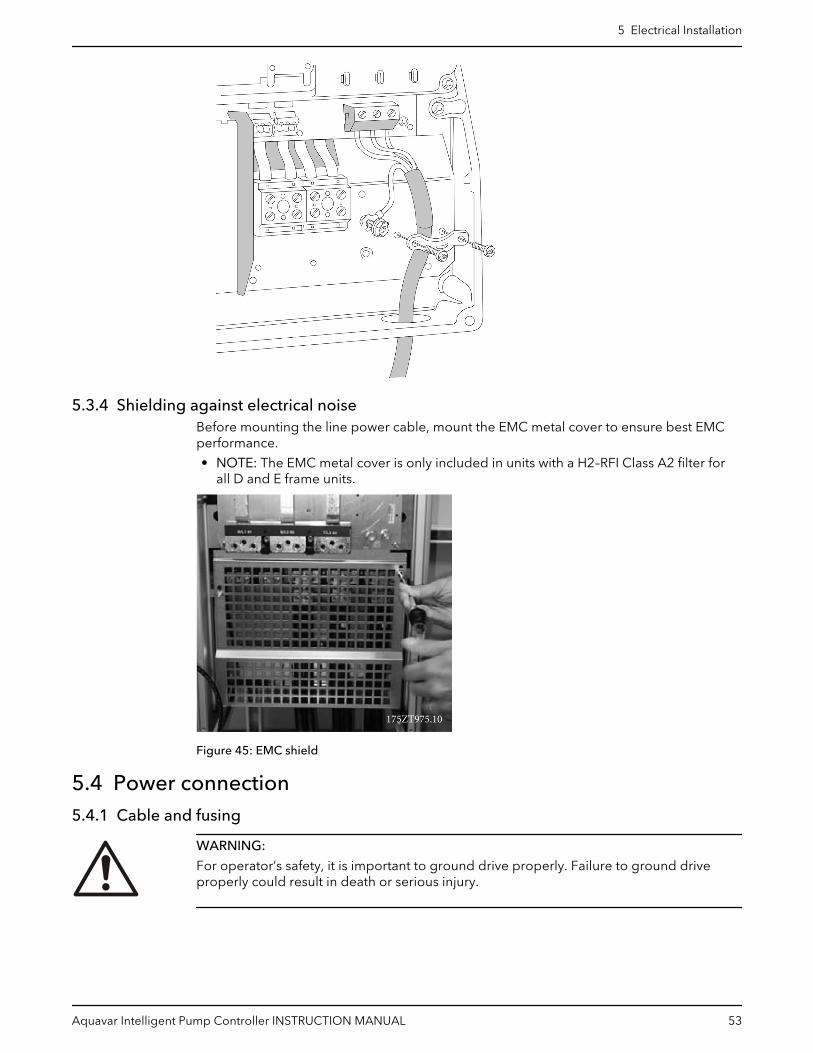
5.3.4 Shielding against electrical noiseBefore mounting the line power cable, mount the EMC metal cover to ensure best EMCperformance.
• NOTE: The EMC metal cover is only included in units with a H2–RFI Class A2 filter forall D and E frame units.
Figure 45: EMC shield
5.4 Power connection5.4.1 Cable and fusing
WARNING:
For operator’s safety, it is important to ground drive properly. Failure to ground driveproperly could result in death or serious injury.
5 Electrical Installation
Aquavar Intelligent Pump Controller INSTRUCTION MANUAL 53

NOTICE:
It is the responsibility of the user or certified electrical installer to ensure correctgrounding (earthing) of the equipment in accordance with national and local electricalcodes and standards.
NOTICE:
All cabling must comply with national and local regulations on cable cross-sections andambient temperature. UL applications require 167°F (75°C) copper conductors arethermally acceptable for the adjustable frequency drive to use in non-UL applications.
The power cable connections are situated as shown below. Dimensioning of cable cross-section must be done in accordance with the current rating and local regulations. See Technical Specification on page 252 for details.
For protection of the adjustable frequency drive, recommended fuses and/or circuitbreaker must be used or the unit must be with built-in fuses. Recommended fuses can beseen in the tables of Fuses and circuit breakers on page 267. Always ensure that properfusing is done according to local regulations.
The AC line input connections are fitted to the line power switch if this is included.
Requirements:
1. Grounding: see Earth (grounding) requirements on page 47 and Grounding on page60 for correct grounding.
2. Ensure that the input power source for the controller is locked in the off position.3. Connect metalized conduit to the controller.4. Route the power wiring through the conduit.5. Input power connections:
– Single-phase drive: Connect the input power wires to terminals labeled L1, L2 onthe input side of the disconnect and (Ground).
91 (L1)92 (L2)93 (L3)95 PE
Figure 46: Power input wiring for single-phase drive
– Three-phase drive: Connect the input power wires to terminals labeled L1, L2, L3on the input side of the disconnect and (Ground).
91 (L1)92 (L2)93 (L3)95 PE
Figure 47: Power input wiring for three-phase drive
5 Electrical Installation
54 Aquavar Intelligent Pump Controller INSTRUCTION MANUAL

• Depending on the configuration of the equipment, input power will be connected tothe mains input terminals or the input disconnect.
• Ground the cable in accordance with grounding instructions in Earth (Grounding)Requirements.
• All frequency converters may be used with an isolated input source as well as withground reference power lines. When supplied from an isolated mains source (IT mainsor floating delta) or TT/TN-S mains with a grounded leg (grounded delta), set 14-50RFI Filter to OFF. When off, the internal RFI filter capacitors between the chassis andthe intermediate circuit are isolated to avoid damage to the intermediate circuit and toreduce earth capacity currents in accordance with IEC 61800-3.
NOTICE:
To comply with EMC emission specifications, shielded/armored cables arerecommended. If an unshielded/unarmored cable is used, see Power and control wiringfor unshielded cables on page 59.
Table 6: EMC categories
Unit size hp [kW] Power Supply Classification by categories based onIEC 61800-3
1.5-60 [1.1-45] 3 x 200-240 V C1(*)
1.5-125 [1.1-90] 3 x 380-480 V C1(*)
(*) max cable length 164 feet (50 m)
Contact Xylem for information on other sizes and power supply.
NOTICE:
No external EMC filters are required to make the product compliant with the limit valuesof each category reported in the table above.
See Technical Specification on page 252 for correct dimensioning of motor cable cross-section and length.
5.4.2 Shielding of cablesAvoid installation with twisted shield ends (pigtails). They spoil the shielding effect athigher frequencies. If it is necessary to break the shield to install a motor isolator or motorcontactor, the shield must be continued at the lowest possible HF impedence.
Connect the motor cable shield to both the de-coupling plate of the adjustable frequencydrive and to the metal housing of the motor.
Make the shield connections with the largest possible surface area (cable clamp). This isdone by using the supplied installation devices within the adjustable frequency drive.
5 Electrical Installation
Aquavar Intelligent Pump Controller INSTRUCTION MANUAL 55

5.4.3 Cable-length and cross-sectionThe adjustable frequency drive has been EMC tested with a given length of cable. Keepthe motor cable as short as possible to reduce the noise level and leakage currents.
5.4.4 Switching frequencyWhen adjustable frequency drives are used together with sine-wave filters to reduce theacoustic noise from a motor, the switching frequency must be set according to theinstructions in par. [14–01] Switching Frequency.
Terminalnumber
96 97 98 99 Description
U V W PE1) Motor voltage 0–100% of AC line voltage.3 wires out of motor
U1W2
V1U2
W1V2
PE1) Delta-connected6 wires
U1 V1 W1 PE1) Star-connected U2, V2, W2U2, V2 and W2 to be interconnected separately
1) Protected ground connection
Note: In motors without phase insulation paper or other insulation reinforcement suitablefor operation with voltage supply (such as an adjustable frequency drive), fit a sine-wavefilter on the output of the adjustable frequency drive.
Figure 48: Motor connections
5 Electrical Installation
56 Aquavar Intelligent Pump Controller INSTRUCTION MANUAL
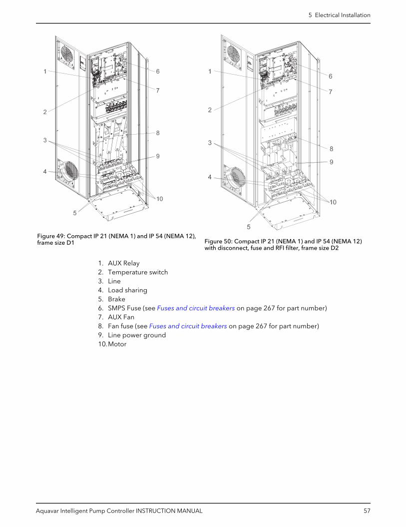
Figure 49: Compact IP 21 (NEMA 1) and IP 54 (NEMA 12),frame size D1 Figure 50: Compact IP 21 (NEMA 1) and IP 54 (NEMA 12)
with disconnect, fuse and RFI filter, frame size D2
1. AUX Relay2. Temperature switch3. Line4. Load sharing5. Brake6. SMPS Fuse (see Fuses and circuit breakers on page 267 for part number)7. AUX Fan8. Fan fuse (see Fuses and circuit breakers on page 267 for part number)9. Line power ground10.Motor
5 Electrical Installation
Aquavar Intelligent Pump Controller INSTRUCTION MANUAL 57

Figure 51: Compact IP 00 (chassis), frame size D3Figure 52: Compact IP 00 (chassis) with disconnect, fuseand RFI filter, frame size D4
1. AUX Relay2. Temperature switch3. Line4. Load sharing5. Brake6. SMPS Fuse (see Fuses and circuit breakers on page 267 for part number)7. AUX Fan8. Fan fuse (see Fuses and circuit breakers on page 267 for part number)9. Line power ground10.Motor
5 Electrical Installation
58 Aquavar Intelligent Pump Controller INSTRUCTION MANUAL

Figure 53: Position of ground terminals IP00, frame sizes D
Figure 54: Position of ground terminals IP21 (NEMA type 1) and IP54 (NEMA type 12)
D2 and D4 shown as examples. D1 and D3 are equivalent.
5.5 Power and control wiring for unshielded cablesElectrical Hazard:
Induced Voltage
• Run motor cables from multiple drives separately. Induced voltage from output motorcables run together can change equipment capacitors even with the equipmentturned off and locked out. Failure to run output cables separately could result in deathor serious injury.
5 Electrical Installation
Aquavar Intelligent Pump Controller INSTRUCTION MANUAL 59

NOTICE:
Run drive input power, motor wiring, and control wiring in three separate metallicconduits or raceways for high frequency noise isolation. Failure to isolate power, motor,and control wiring could result in less than optimum controller and associated equipmentperformance.
Because the power wiring carries high frequency electrical pulses, it is important thatinput power and motor power are run in separate conduit. If the incoming power wiring isrun in the same conduit as the motor wiring, these pulses can couple electrical noise backonto the building power grid. Control wiring should always be isolated from the highvoltage power wiring.
When shielded/armored cable is not used, at least three separate conduits must beconnected to the panel option (see figure below).
• Power wiring into the enclosure• Power wiring from the enclosure to the motor• Control wiring
Figure 55: Power and control wiring connection
5.6 GroundingThe following basic issues need to be considered when installing an adjustable frequencydrive, so as to obtain electromagnetic compatibility (EMC).
• Safety, grounding: Please note that the adjustable frequency drive has a high leakagecurrent and must be grounded appropriately for safety reasons. Always follow localsafety regulations.
• High-frequency grounding: Keep the ground wire connections as short as possible.
Connect the different ground systems at the lowest possible conductor impedance. Thelowest possible conductor impedance is obtained by keeping the conductor as short aspossible and by using the greatest possible surface area.
The metal cabinets of the different devices are mounted on the cabinet rear plate usingthe lowest possible HF impedance. This prevents having different HF voltages for theindividual devices and prevents the risk of radio interference currents running inconnection cables that may be used between the devices, as radio interference isreduced.
In order to obtain a low HF impedance, use the fastening bolts of the devices as HFconnections to the rear plate. It is necessary to remove insulating paint and the like fromthe fastening points.
5 Electrical Installation
60 Aquavar Intelligent Pump Controller INSTRUCTION MANUAL

5.7 Extra protection (RCD)Earth Leakage Circuit Breaker (ELCB) relays, multiple protective grounding or groundingcan be used as extra protection, provided that local safety regulations are complied with.
In the case of a ground fault, a DC component may develop in the fault current.
If ELCB relays are used, local regulations must be observed. Relays must be suitable forprotection of 3–phase equipment with a bridge rectifier and for a brief discharge onpower-up.
See also the section Special Conditions in the VFD Design Guide FC102.
5.8 TorqueWhen tightening all electrical connections, it is very important to tighten with the correcttorque. Too low or too high torque results in a bad electrical connection. Use a torquewrench to ensure correct torque.
See Tightening torques on page 277 for details.
5.9 Shielded cablesIt is important that shielded and armored cables are connected properly to ensure highEMC immunity and low emissions.
Connection can be made by either cable connectors or clamps:
• EMC cable connectors: Generally available cable connectors can be used to ensure anoptimum EMC connection.
• EMC cable clamp: Clamps allowing for easy connection are supplied with theadjustable frequency drive.
5.10 Control wiringMake sure that the following are adhered to:
• Run input power and control wiring in separate metallic conduits or raceways for highfrequency isolation. Failure to isolate power, motor, and control wiring could result inless than optimum drive and associated equipment performance.
• Use control wiring rated for 600 V for 480 V and 600 V drives and 300 V for 200–240 Vdrives.
• Isolate control wiring from high power components in the frequency converter.• If the frequency converter is connected to a thermistor, for Protective Extra Low
Voltage (PELV) isolation, optional thermistor control wiring must be reinforced/doubleinsulated. A 24 V DC supply voltage is recommended.
5.11 Control wiring access• Remove access cover plate with a screwdriver.
5 Electrical Installation
Aquavar Intelligent Pump Controller INSTRUCTION MANUAL 61

Figure 56: Control wiring access for A2, A3, B3, B4, C3, and C4 enclosures
• Remove front cover by loosening attaching screws.
130B
T334
.10
Figure 57: Control wiring access for A4, A5, B1, B2, C1, and C2 enclosures
5.12 Control terminal types
1
432
130B
B921
.12
130B
B931
.11
12 13 18 19 27 29 32 33 20 37
39696861 42 50 53 54 55
1
32
Figure 58: Control terminal locations
• Connector 1 provides four programmable digital inputs terminals, two additionaldigital terminals programmable as either input or output, a 24 V DC terminal supplyvoltage, and a common for optional customer supplied 24 V DC voltage.
• Connector 2 terminals (+)68 and (-)69 are for an RS-485 serial communicationsconnection.
• Connector 3 provides two analog inputs, one analog output, 10 V DC supply voltage,and commons for the inputs and output.
• Connector 4 is a USB port available for use with the frequency converter.
5 Electrical Installation
62 Aquavar Intelligent Pump Controller INSTRUCTION MANUAL
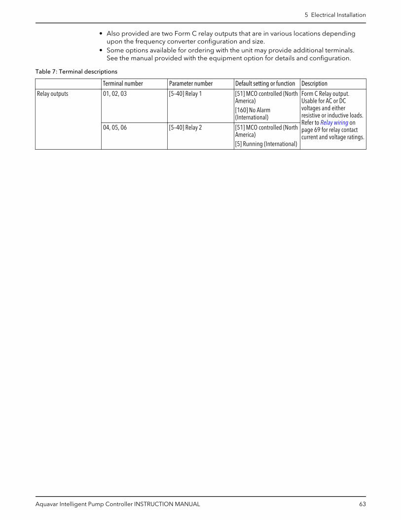
• Also provided are two Form C relay outputs that are in various locations dependingupon the frequency converter configuration and size.
• Some options available for ordering with the unit may provide additional terminals.See the manual provided with the equipment option for details and configuration.
Table 7: Terminal descriptions
Terminal number Parameter number Default setting or function Description
Relay outputs 01, 02, 03 [5–40] Relay 1 [51] MCO controlled (NorthAmerica)[160] No Alarm(International)
Form C Relay output.Usable for AC or DCvoltages and eitherresistive or inductive loads.Refer to Relay wiring onpage 69 for relay contactcurrent and voltage ratings.
04, 05, 06 [5–40] Relay 2 [51] MCO controlled (NorthAmerica)[5] Running (International)
5 Electrical Installation
Aquavar Intelligent Pump Controller INSTRUCTION MANUAL 63

Terminal number Parameter number Default setting or function Description
Digital I/O 12, 13 – +24V DC 24V DC supply voltage.Maximum output current is200mA total for all 24Vloads. Usable for digitalinputs and externaltransducers.
18 [5–10] [8] Start Start/Stop digital inputsignal for the drive.Connect input to 24V tostart. Open the input tostop. This is a requiredconnection.
19 [5–11] [0] No Operation Unused digital input. Thisinput can be configured foruse as a Pump Protect/External Interlock Warningor Alarm Input. See Pumpprotect on page 69 toenable the Warning orAlarm associated with thisinput.
27 [5–12] [0] No Operation Unused digital input. Thisinput can be configured foruse as a Pump Protect/External Interlock Warningor Alarm Input. See Pumpprotect on page 69 toenable the Warning orAlarm associated with thisinput.
29 [5–13] [75] MCO Specific Selectable for digital inputthat is configured for use asa High Suction Cutoutwarning/alarm signal.Refer to Pump protect onpage 69 for details.
32 [5–14] [1] Reset Digital input. Configuredfor use as a Reset for theNo Water/Loss of PrimeRestart function. Refer to Pump protect on page 69for details.
33 [5–15] [75] MCO Specific Digital input. Configuredfor use as a Setpoint 1/Setpoint 2 select (SP1/SP2).
20 – Common Common for digital inputsand reference for 24Vsupply
5 Electrical Installation
64 Aquavar Intelligent Pump Controller INSTRUCTION MANUAL
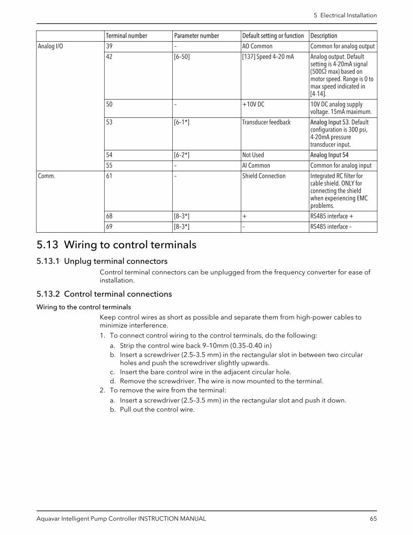
Terminal number Parameter number Default setting or function Description
Analog I/O 39 – AO Common Common for analog output
42 [6–50] [137] Speed 4–20 mA Analog output. Defaultsetting is 4-20mA signal(500Ω max) based onmotor speed. Range is 0 tomax speed indicated in[4-14].
50 – +10V DC 10V DC analog supplyvoltage. 15mA maximum.
53 [6–1*] Transducer feedback Analog Input 53. Defaultconfiguration is 300 psi,4-20mA pressuretransducer input.
54 [6–2*] Not Used Analog Input 54
55 – AI Common Common for analog input
Comm. 61 – Shield Connection Integrated RC filter forcable shield. ONLY forconnecting the shieldwhen experiencing EMCproblems.
68 [8–3*] + RS485 interface +
69 [8–3*] – RS485 interface –
5.13 Wiring to control terminals5.13.1 Unplug terminal connectors
Control terminal connectors can be unplugged from the frequency converter for ease ofinstallation.
5.13.2 Control terminal connections
Wiring to the control terminals
Keep control wires as short as possible and separate them from high-power cables tominimize interference.
1. To connect control wiring to the control terminals, do the following:
a. Strip the control wire back 9–10mm (0.35–0.40 in)b. Insert a screwdriver (2.5–3.5 mm) in the rectangular slot in between two circular
holes and push the screwdriver slightly upwards.c. Insert the bare control wire in the adjacent circular hole.d. Remove the screwdriver. The wire is now mounted to the terminal.
2. To remove the wire from the terminal:
a. Insert a screwdriver (2.5–3.5 mm) in the rectangular slot and push it down.b. Pull out the control wire.
5 Electrical Installation
Aquavar Intelligent Pump Controller INSTRUCTION MANUAL 65
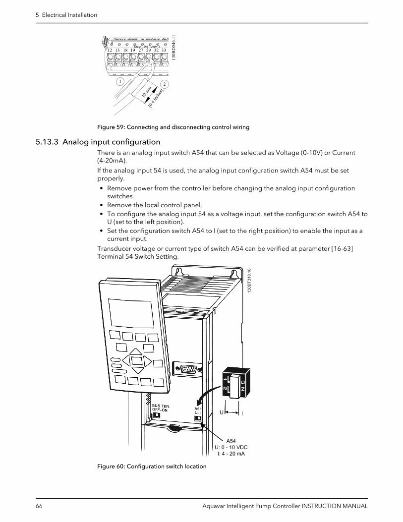
130B
D54
6.11
21
10 m
m[0
.4 inc
hes]
12 13 18 19 27 29 32 33
Figure 59: Connecting and disconnecting control wiring
5.13.3 Analog input configurationThere is an analog input switch A54 that can be selected as Voltage (0-10V) or Current(4-20mA).
If the analog input 54 is used, the analog input configuration switch A54 must be setproperly.
• Remove power from the controller before changing the analog input configurationswitches.
• Remove the local control panel.• To configure the analog input 54 as a voltage input, set the configuration switch A54 to
U (set to the left position).• Set the configuration switch A54 to I (set to the right position) to enable the input as a
current input.
Transducer voltage or current type of switch A54 can be verified at parameter [16-63]Terminal 54 Switch Setting.
A54U: 0 - 10 VDCI: 4 - 20 mA
130B
T310
.10
U I
Figure 60: Configuration switch location
5 Electrical Installation
66 Aquavar Intelligent Pump Controller INSTRUCTION MANUAL
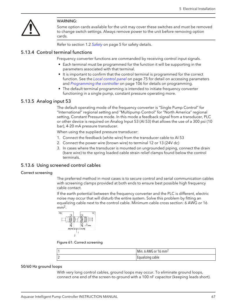
WARNING:
Some option cards available for the unit may cover these switches and must be removedto change switch settings. Always remove power to the unit before removing optioncards.
Refer to section 1.2 Safety on page 5 for safety details.
5.13.4 Control terminal functionsFrequency converter functions are commanded by receiving control input signals.
• Each terminal must be programmed for the function it will be supporting in theparameters associated with that terminal.
• It is important to confirm that the control terminal is programmed for the correctfunction. See the Local control panel on page 75 for detail on accessing parametersand Programming the controller on page 106 for details on programming.
• The default terminal programming is intended to initiate frequency converterfunctioning in a single pump, constant pressure operating more.
5.13.5 Analog input 53The default operating mode of the frequency converter is “Single Pump Control” for“International” regional setting and “Multipump Control” for “North America” regionalsetting, Constant Pressure mode. In this mode a feedback signal from a transducer, PLCor other device is required on Analog Input 53 (AI 53) that allows the use of a 300 psi (10bar), 4-20 mA pressure transducer.
When using the supplied pressure transducer:
1. Connect the feedback (white wire) from the transducer cable to AI 532. Connect the power wire (brown wire) to terminal 12 or 13 (24V dc)3. In cases where the transducer is mounted on ungrounded piping, connect the drain
(bare wire) to the spring loaded cable strain relief clamps found below the controlterminals.
5.13.6 Using screened control cables
Correct screening
The preferred method in most cases is to secure control and serial communication cableswith screening clamps provided at both ends to ensure best possible high frequencycable contact.
If the earth potential between the frequency converter and the PLC is different, electricnoise may occur that will disturb the entire system. Solve this problem by fitting anequalizing cable next to the control cable. Minimum cable cross section: 6 AWG or 16mm2.
Figure 61: Correct screening
1 Min. 6 AWG or 16 mm2
2 Equalizing cable
50/60 Hz ground loops
With very long control cables, ground loops may occur. To eliminate ground loops,connect one end of the screen-to-ground with a 100 nF capacitor (keeping leads short).
5 Electrical Installation
Aquavar Intelligent Pump Controller INSTRUCTION MANUAL 67

Figure 62: 50/60 Hz ground loops
Avoid EMC noise on serial communication
This terminal is connected to earth via an internal RC link. Use twisted-pair cables toreduce interference between conductors.
Figure 63: Twisted-pair cables
1 Min. 6 AWG or 16 mm2
2 Equalizing cable
Alternatively, the connection to terminal 61 can be omitted:
Figure 64: Twisted-pair cables without terminal 61
1 Min. 6 AWG or 16 mm2
2 Equalizing cable
5.13.7 Serial communicationRS-485 is two-wire bus interface compatible with multi-drop network topology. Forexample, nodes can be connected as a bus, or via drop cables from a common trunk line.A total of 32 nodes can be connected to one network segment. Repeaters divide networksegments. Note that each repeater functions as a node within the segment in which it isinstalled. Each node connected within a given network must have a unique node address,across all segments. Terminate each segment at both ends, using either the terminationswitch (BUS TER./S801) of the frequency converters or a biased termination resistornetwork. Always use screened twisted pair (STP) cable for bus cabling, and always followgood common installation practice.
Low-impedence ground (earth) connection of the screen at every node is important,including at high frequencies. Thus, connect a large surface of the screen to ground(earth) , for example with a cable clamp or a conductive cable gland. It may be necessaryto apply potential-equalizing cables to maintain the same ground (earth) potentialthroughout the network. Particularly in installations with long cables.
To prevent impedence mismatch, always use the same type of cable throughout the entirenetwork. When connecting a motor to the frequency converter, always use screenedmotor cable.
Table 8: Cable information
Cable Screened twisted pair (STP)
Impedence 120 Ω
5 Electrical Installation
68 Aquavar Intelligent Pump Controller INSTRUCTION MANUAL

Cable Screened twisted pair (STP)
Max. cable length [m] 1200 including drop lines500 station-to-station
5.14 Common terminal wiring configurations5.14.1 Relay wiring
Each controller has two programmable form C relay outputs. The relay terminals arelocated in various locations on the controller depending on the frame size. For defaultsettings see Table 7: Terminal descriptions on page 63.
Figure 65: Relay terminal wiring
Table 9: Relay terminal ratings
Programmable relay outputs 2
Relay 01 Terminal number 1–3 (break), 1–2 (make)
Maximum terminal load (AC-1)1 on 1–3 (NC), 1–2 (NO) (Resistive load) 240 V AC, 2A
Maximum terminal load (AC-15)1 (Inductive load @ cosφ 0.4) 240 V AC, 0.2A
Maximum terminal load (DC-1)1 on 1–2 (NO), 1–3 (NC) (Resistive load) 60 V DC, 1A
Maximum terminal load (DC-13)1 (Inductive load) 24 V DC, 0.1A
Relay 02 Terminal number 4–6 (break), 4–5 (make)
Maximum terminal load (AC-2)1 on 4–5 (NO) (resistive load)2,3 400 V AC, 2A
Maximum terminal load (AC-15)1 (Inductive load @ cosφ 0.4) 240 V AC, 0.2A
Maximum terminal load (DC-1)1 on 4–5 (NO) (Resistive load) 80 V DC, 2A
Maximum terminal load (DC-13)1 on 4–5 (NO) (Inductive load) 24 V DC, 0.1A
Maximum terminal load (AC-1)1 on 4–6 (NC) (Resistive load) 240 V AC, 2A
Maximum terminal load (AC-15)1 on 4–6 (NC) (Inductive load @ cosφ0.4)
240 V AC, 0.2A
Maximum terminal load (DC-1)1 on 4–6 (NC) (Resistive load) 50 V DC, 2A
Maximum terminal load (DC-13)1 on 4–6 (NC) (Inductive load) 24 V DC, 0.1A
Minimum terminal load on 1–3 (NC), 1–2 (NO), 4–6 (NC), 4–5 (NO) 24 V DC 10mA, 24 V AC 20mA
Environment according to EN 60664–1 overvoltage category III/pollution degree 2
5.14.2 Pump protectA Pump Protect function can be used to turn off the controller and issue an alarm 60(Pump Protect (North America)/External Interlock (International)) when system pressures,temperatures, levels, etc. are outside of the normal operating range for the system. ThePump Protect function can be configured on digital input 19, 27 and 29. These inputs canbe controlled by an external device such as a suction pressure switch, an over pressure
5 Electrical Installation
Aquavar Intelligent Pump Controller INSTRUCTION MANUAL 69

switch, a temperature switch, a differential pressure switch, etc. The device chosen shouldbe normally closed. The [22-00] Pump Protect Delay parameter can be configured todelay the onset of the Pump Protect (North America)/External Interlock (International)Alarm to prevent nuisance tripping. When the input is disconnected from the 24V supply,the delay timer will start. If the input remains disconnected for the time indicated in[22-00]Pump Protect Delay, the controller stops the motor and issues Alarm 60 Protect(North America)/External Interlock (International). If a Pump Protect/External InterlockAlarm is issued, the controller will attempt to restart if the [14-20] Reset Mode parameterand the [14-21] Automatic Restart Time parameter are set to allow automatic restarting.To prevent an automatic restart set the [14-20] Reset Mode to Manual Reset. Note that the[14-20] Reset Mode parameter affects all other Alarms that are not listed as a Trip LockAlarm. Refer to Warnings and alarms on page 240 for details.
NOTE: This function can be enabled using the Start-Up Genie (Smart Setup).
[51] MCO controlled1
Figure 66: Connections for adding Pump Protect
Table 10: Parameter settings for enabling a Pump Protect/External Interlock Alarm on DI19
Parameter number Parameter description Set to
[5–11]* Terminal 19 Digital Input Pump Protect (North America)/External Interlock (International)
[22–00] Pump Protect Delay Set to the desired delay time. If set to10 seconds, the Pump Protect/External Interlock Alarm will beissued 10 seconds after the input isdisconnected from 24V. The inputmust remain disconnected for theentire delay time for the alarm to beissued.
[14–20] Reset Mode Set to the desired number ofautomatic resets. If a fault occursmore than this setting, a manualreset is required. Set to Manual Resetif no resets are allowed. Defaultsetting is: Automatic reset x 3.
[14–21] Automatic Restart Time This is the time between when analarm/warning is issued and whenthe controller attempts the nextrestart. Default setting is 30 seconds.
* To configure DI 27, set [5–12] to Pump Protect , and to configure DI 29, also set [5-13] toPump Protect (North America)/External Interlock (International).
5 Electrical Installation
70 Aquavar Intelligent Pump Controller INSTRUCTION MANUAL

5.14.3 Configuring an additional transducer feedbackAn additional transducer can be added to the system to work with closed loop control orfor external monitoring. The additional transducer can be either a voltage output orcurrent output transducer. The additional transducer can be added to the unused analoginput (AI 53 for current type only or AI 54 for current type or voltage type). The wiringbelow shows the required connections for an additional transducer on AI 54.
A common use of two pressure transducer feedback signals is to take the differencebetween the signals to create a differential pressure transducer. To implement adifferential pressure transducer with 2 pressure transducers, set [20-20] FeedbackFunction to Difference. The controller will calculate the feedback value as[20-03]Feedback 2 Source – [20-00]Feedback 1 Source. Be sure to set all unusedfeedback sources to No Function (parameters [20-00], [20-03] or [20-06]). The parameterlisting that follows shows how to configure the additional transducer.
• Analog inputs can be configured using the Start-Up Genie (Smart Setup).• Be sure to properly set the analog input configuration switch prior to using the analog
input. Refer to Analog input configuration on page 66 for details.
Figure 67: Connections for adding 4–20 mA transducer feedback to AI 53
Figure 68: Connections for adding 0–10 V transducer feedback to AI 54
NOTE: Refer to Analog input configuration on page 66 for details of setting the DIP switchA54.
In order to set up the controller for closed loop control based on the feedback from anexternal transducer, set the following parameters:
Table 11: Parameter settings to enable an additional transducer on AI 53
Parameter Number Parameter Description Set To
[6-14]* Terminal 53 Low Ref./Feedb.Value Minimum transducer feedback value.For example, for a 0-300psitransducer, set to 0.
[6-15]* Terminal 53 High Ref./Feedb.Value Maximum transducer feedback value.For example, for a 300psi transducer,set to 300.
[6-17]* Terminal 53 Sensor Fault (NorthAmerica) / Live Zero (International)
Enabled
5 Electrical Installation
Aquavar Intelligent Pump Controller INSTRUCTION MANUAL 71

Parameter Number Parameter Description Set To
[20-03] Feedback 2 Source Analog Input 53*
[20-05] Feedback 2 Source Unit Units for the second feedback source.For a differential pressure transducer,use the same units as found in[20-02], psi is default
[20-12] Reference/Feedback Unit Select as appropriate for application.For example, set to psi when usingpressure feedback.
[20-13] Minimum Reference/Feedb. Minimum transducer feedback value.For example, for a 0-300psitransducer, set to 0.
[20-14] Maximum Reference/Feedb. Maximum transducer feedback value.For example, for a 300psi transducer,set to 300.
* To use AI 54 configure parameters [6-24], [6-25], [6-27] and [20-03] for Analog Input 54.
Table 12: Parameter settings for an additional transducer used for monitoring
Parameter number Description Set to
[0-24] Display Line 3 Large Ext. 1 Feedback [Unit]
[21-14] Ext.1 Feedback Source Analog Input 54*
[21-10] Ext.1 Ref./Feedback Unit Select as appropriate for application.For example, set to psi when using apressure transducer.
[21-11] Ext.1 Minimum Reference Minimum transducer feedback value.For example, for a 0-300psitransducer, set to 0 psi.
[21-12] Ext.1 Maximum ReferenceExt. 1 Maximum Reference
Maximum transducer feedbackvalue. For example, for a 300 psi DPtransducer, set to 300 psi.
[6-24]* Terminal 54 Low Ref./Feedb.Value Minimum transducer feedback value.For example, for a 0-300 psitransducer, set to 0.
[6-25]* Terminal 54 High Ref./Feedb.Value Maximum transducer feedbackvalue. For example, for a 300 psitransducer, set to 300.
[6-27]* Terminal 54 Sensor Fault (NorthAmerica) / Live Zero (International)
Disabled
* To use AI 53, configure parameters [6-14], [6-15], [6-17] and set [21-14] to Analog Input53.
5.14.4 Speed control through an analog inputThe controller can be configured for speed control through an analog input. Thecontrolling source can be either an external control device such as a PLC, BMS (buildingmanagement system) or potentiometer. The output from the external control device canbe either a voltage or current output signal. Be sure to set the analog input configurationswitches based on the type of output signal. The diagrams below show the connectionsfor an external speed command.
• Speed control mode can be configured using the Start-Up Genie (Smart Setup).
5 Electrical Installation
72 Aquavar Intelligent Pump Controller INSTRUCTION MANUAL

Figure 69: Connections for speed control with external potentiometer on AI 54
Figure 70: Connections for speed control over current signal from PLC or BMS
Figure 71: Connections for speed control over voltage signal from PLC or BMS
Table 13: Parameter settings for speed control from external potentiometer, PLC or BMS
Parameter number Description Set to
[1-00] Configuration Mode Open Loop
[3-02] Minimum Reference Set to value corresponding to desiredspeed at the minimum reference
[3-03] Maximum Reference Set to value corresponding to desiredspeed at the maximum reference
[3-10.0] – [3-10.7] Preset Reference 0
[3-15] Reference 1 Source Analog Input 53
[3-16] Reference 2 Source No function
[3-17] Reference 3 Source No function
[5-10] Terminal 18 Digital Input Start
[6-12] Terminal 53 Low Current 4 mA
[6-13] Terminal 53 High Current 20 mA
[6-14] Terminal 53 Low Ref./Feedb.Value Set to value corresponding to thecommanded speed at the low current.
5 Electrical Installation
Aquavar Intelligent Pump Controller INSTRUCTION MANUAL 73

Parameter number Description Set to
[6-15] Terminal 53 High Ref./Feedb.Value Set to value corresponding to thecommanded speed at the highcurrent.
[6-17] Terminal 53 Sensor Fault (NorthAmerica) / Live Zero (International)
Disabled
[19-00] Configuration Mode External Reference
[19-40] All Zones Failure Function Off
[20-00] Feedback 1 Source Analog Input 53
NOTE: For speed control over voltage signal (DIP switch 54).
• Wire 0-10V signal to terminal #54.• Set switch A54 = U (left position).• Set [3-15] Reference 1 Source = [20-00] Feedback 1 Source = Analog Input 54.• Set [6-20] Terminal 54 Low Voltage = 0 V and [6-21] Terminal 54 High Voltage = 10 V.• Set [6-24] Terminal 54 Low Ref./Feedb.Value to value corresponding to the command
speed at the low voltage and [6-25] Terminal 54 High Ref./Feedb.Value to valuecorresponding to the command speed at the high voltage.
• Set [6-27] Terminal 54 Sensor Fault (North America) / Live Zero (International) toDisable.
5.14.5 Control from external PLC/BMS through communications portBy selecting option [0] External Reference in [19-00] Configuration Mode, a BMS or PLCcan be connected to the control through the communications port. In this configuration,the BMS or PLC can control the drive by overriding the setpoint, supplying the processvariable or by providing a speed command to the drive. Control cables must be braidedscreened/shielded and the screen must be connected by means of a cable clamp at thecontroller and at the BMS/PLC. Refer to Using screened control cables section for detailson installing shielded/screened cables. The parameter list in the table below showsparameters used to configure communication for two common protocols, Modbus RTUand BACnet. The parameter list in the second table below shows parameters thatdetermine the control source for certain drive functions. Use these parameters todetermine whether digital inputs or the BMS/PLC has control of the function.
Figure 72: Connections for external control source connected through comm. port
Table 14: Parameter settings for Modbus RTU and BACnet protocols
Parameter Number Parameter Description Protocol
Modbus RTU BACnet
[8-02] Control Source FC Port FC Port
[8-30] Protocol Modbus RTU BACnet
[8-31] Address 1 1
[8-32] Baud Rate 19200 9600
5 Electrical Installation
74 Aquavar Intelligent Pump Controller INSTRUCTION MANUAL

Parameter Number Parameter Description Protocol
Modbus RTU BACnet
[8-33] Parity / Stop Bits Even Parity, 1 Stop bit No Parity, 1 Stop bit
[8-34] Estimated Cycle Time 0 ms 0 ms
[8-35] Minimum Response Delay 10 ms 10 ms
[8-36] Maximum Response Delay 5000 ms 5000 ms
[8-37] Maximum Inter-Char Delay 0.86 ms 25 ms
Table 15: Parameters determining control source for controller functions
Parameter number Description Set to
[8-01] Control Site Determines the location of the control source.Set to Digital and ctrl.word to use both serialbus and digital input control. Set to Digitalonly to use only the digital inputs. Set toControlword only to use only the serial bus.
[8-50] Coasting Select Determines the control location of the coasting(stop) function. Set to Digital input to use adigital input only. Set to Bus to use only theserial bus only. Set to Logic AND to use theserial bus AND a digital input. Set to Logic ORto use the serial bus OR a digital input.
[8-53] Start Select Determines the control location of the start command. Set to Digital input to use a digitalinput only. Set to Bus to use only the serial busonly. Set to Logic AND to use the serial busAND a digital input. Set to Logic OR to use theserial bus OR a digital input.
[8-55] Set-up Select* Determines the control location of the set-upselection function. Set to Digital input to use adigital input only. Set to Bus to use only theserial bus only. Set to Logic AND to use theserial bus AND a digital input. Set to Logic ORto use the serial bus OR a digital input.
[8-56] Preset Reference Select* Determines the control location of the presetreference selection function. Set to Digitalinput to use a digital input only. Set to Bus touse only the serial bus only. Set to Logic ANDto use the serial bus AND a digital input. Set toLogic OR to use the serial bus OR a digitalinput.
* The Set-up Select and Preset Reference Select functions are used to control other pre-configured functions in the controller. To avoid interfering with these functions, it isrecommended to control this function via digital inputs.
5.15 Local control panelThe controller is equipped with a local control panel (LCP). The LCP combines the statusscreen and keypad found on the front of the controller. The LCP is the user interface to thecontroller. The LCP allows the user to perform various functions such as:
• Start, stop and control speed with the keypad when in local/Hand mode• View and display the status of the controller, pump and system• Provides access to all parameters and start up functions• Manually reset the controller after a fault
5 Electrical Installation
Aquavar Intelligent Pump Controller INSTRUCTION MANUAL 75

Figure 73: Default configuration
1. Controller Status2. Motor hp / kW (Parameter [0-20])3. Motor Frequency (Parameter [0-21])4. Motor Current (Parameter [0-22])5. Feedback/Actual Pressure or process variable (Parameter [0-23])6. Setpoint (Parameter [0-24])7. Menu keys8. Navigation keys9. Operation keys10.Status lights
The parameters shown are the factory default settings. To display other values, modifyparameters [0-20], [0-21], [0-22], [0-23], or [0-24].
5.15.1 Controller statusThe controller status line shows operational information about the controller.
The first word in the status line shows the Operation Mode. The table below defines theOperation Mode status.
Off The controller does not react to any control signal until[Auto On] is pressed.
Auto On The controller is controlled from the control terminaland/or the serial communication.
5 Electrical Installation
76 Aquavar Intelligent Pump Controller INSTRUCTION MANUAL
Hand On The controller can be controlled by the navigation keys onthe LCP. Stop commands, reset, reversing, DC brake, andother signals applied to the control terminals canoverride local control.
The second word in the status line shows the Reference Site.
Remote The speed reference is given from external signals, serialcommunication, or internal preset references.
Local The controller converter uses [Hand On] control orreference values from the LCP.
The third word in the status line shows the Operation Status.
AC Brake AC Brake was selected in [2–10] Brake Function. The ACbrake over-magnetizes the motor to achieve a controlledslow down.
AMA finish OK Automatic motor adaptation (AMA) was carried outsuccessfully.
AMA ready AMA is ready to start. Press [Hand On] to start.
AMA running AMA process is in progress.
Braking The brake chopper is in operation. Generative energy isabsorbed by the brake resistor.
Braking max. The brake chopper is in operation. The power limit for thebrake resistor defined in [2–12] Brake Power Limit (kW)has been reached.
Coast • Coast inverse was selected as a function for a digitalinput (parameter group [5–1]* Digital Inputs). Thecorresponding terminal is not connected.
• Coast activated by serial communication.
Ctrl. Ramp-down Control Ramp-down was selected in [14–10] MainsFailure.• The mains voltage is below the value set in [14–11]
Mains Voltage at Mains Fault• The controller ramps down the motor using a
controlled ramp down
Current high The controller output current is above the limit set in [4–51] Warning Current High.
Current Low The controller output current is below the limit set in [4–52] Warning Speed Low.
DC Hold DC hold is selected in [1–80] Function at Stop and a stopcommand is active. The motor is held by a DC current setin [2–00] DC Hold/Preheat Current.
DC Stop The motor is held with a DC current ([2–01] DC BrakeCurrent) for a specified time ([2–02] DC Braking Time).• DC Brake is activated in [2–03] DC Brake Cut In
Speed [RPM] and a Stop command is active.• DC Brake (inverse) is selected as a function for a
digital input (parameter group [5–1]* Digital Inputs).The corresponding terminal is not active.
• The DC Brake is activated via serial communication.
Feedback high The sum of all feedbacks is above the feedback limit setin [4–57] Warning Feedback High.
Feedback low The sum of all actives is below the feedback limit set in[4–56] Warning Feedback Low.
5 Electrical Installation
Aquavar Intelligent Pump Controller INSTRUCTION MANUAL 77

Freeze output The remote reference is active, which holds the presentspeed.• Freeze output was selected as a function for a digital
input (parameter group [5–1]* Digital Inputs). Thecorresponding terminal is active. Speed control isonly possible via the terminal functions Speed Upand Speed Down.
• Hold ramp is activated via serial communication.
Freeze output request A freeze output command has been given, but the motorwill remain stopped until a run permissive signal isreceived.
Freeze Reference Freeze Reference was chosen as a function for a digitalinput (parameter group [5–1]* Digital Inputs). Thiscorresponding terminal is active. The controller saves theactual reference. Changing the reference is now onlypossible via terminal functions Speed Up and SpeedDown.
Jog request A jog command has been given, but the motor will bestopped until a run permissive signal is received via adigital input.
Jogging The motor is running as programmed in [3–19] JogSpeed [RPM].• Jog was selected as function for a digital input
(parameter group [5–1]* Digital Inputs). Thecorresponding terminal (e.g. Terminal 29) is active.
• The Jog Function is activated via the serialcommunication.
• The Jog function was selected as a reaction for amonitoring function (e.g. No signal). The monitoringfunction is active.
Motor check In [1–80] Function at Stop, Motor Check was selected. Astop command is active. To ensure that a motor isconnected to the controller, a permanent test current isapplied to the motor.
OVC control Overvoltage control was activated in [2–17] Over-voltageControl, [2] Enabled. The connected motor is supplyingthe controller with generative energy. The overvoltagecontrol adjusts the V/Hz ratio to run the motor incontrolled mode and to prevent the controller fromtripping.
PowerUnit Off (For controllers with an external 24 V power supplyinstalled only.) Mains supply to the controller is removed,but the control card is supplied by the external 24 V.
Protection md Protection mode is active. The unit has detected a criticalstatus (an overcurrent or overvoltage).• To avoid tripping, switching frequency is reduced to
4 kHz.• If possible, protection mode ends after
approximately 10 s• Protection mode can be restricted in [14–26] Trip
Delay at Inverter Fault
5 Electrical Installation
78 Aquavar Intelligent Pump Controller INSTRUCTION MANUAL
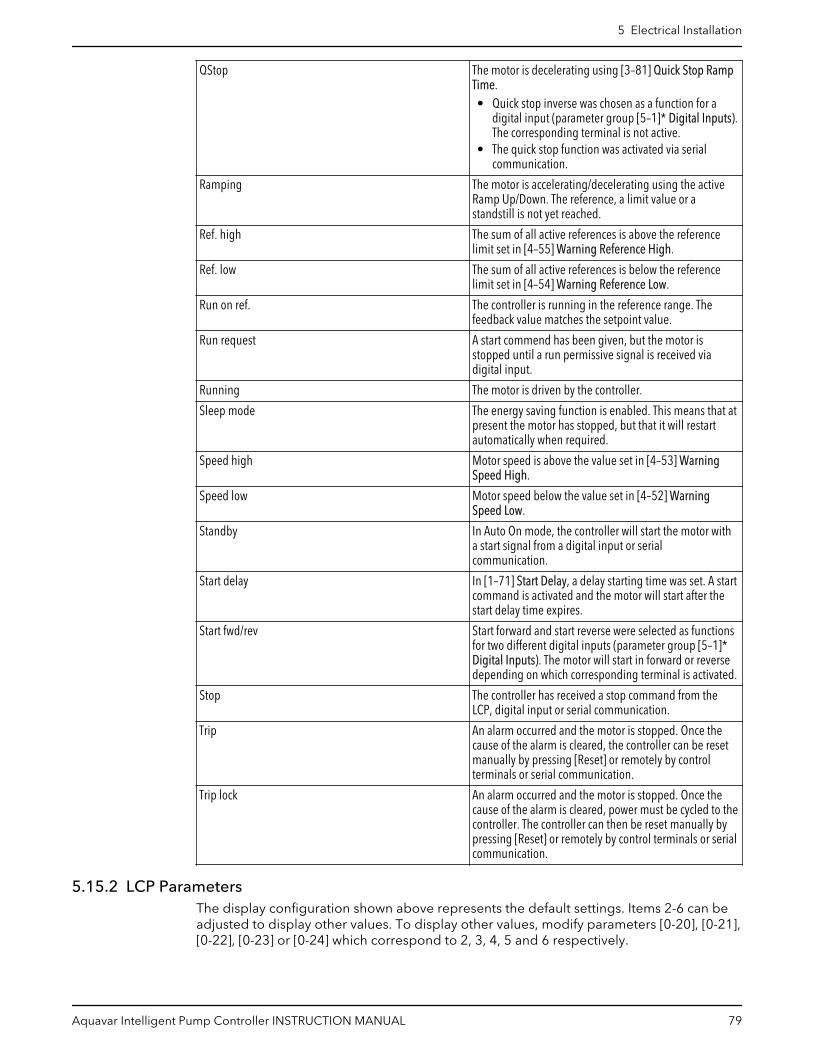
QStop The motor is decelerating using [3–81] Quick Stop RampTime.• Quick stop inverse was chosen as a function for a
digital input (parameter group [5–1]* Digital Inputs).The corresponding terminal is not active.
• The quick stop function was activated via serialcommunication.
Ramping The motor is accelerating/decelerating using the activeRamp Up/Down. The reference, a limit value or astandstill is not yet reached.
Ref. high The sum of all active references is above the referencelimit set in [4–55] Warning Reference High.
Ref. low The sum of all active references is below the referencelimit set in [4–54] Warning Reference Low.
Run on ref. The controller is running in the reference range. Thefeedback value matches the setpoint value.
Run request A start commend has been given, but the motor isstopped until a run permissive signal is received viadigital input.
Running The motor is driven by the controller.
Sleep mode The energy saving function is enabled. This means that atpresent the motor has stopped, but that it will restartautomatically when required.
Speed high Motor speed is above the value set in [4–53] WarningSpeed High.
Speed low Motor speed below the value set in [4–52] WarningSpeed Low.
Standby In Auto On mode, the controller will start the motor witha start signal from a digital input or serialcommunication.
Start delay In [1–71] Start Delay, a delay starting time was set. A startcommand is activated and the motor will start after thestart delay time expires.
Start fwd/rev Start forward and start reverse were selected as functionsfor two different digital inputs (parameter group [5–1]*Digital Inputs). The motor will start in forward or reversedepending on which corresponding terminal is activated.
Stop The controller has received a stop command from theLCP, digital input or serial communication.
Trip An alarm occurred and the motor is stopped. Once thecause of the alarm is cleared, the controller can be resetmanually by pressing [Reset] or remotely by controlterminals or serial communication.
Trip lock An alarm occurred and the motor is stopped. Once thecause of the alarm is cleared, power must be cycled to thecontroller. The controller can then be reset manually bypressing [Reset] or remotely by control terminals or serialcommunication.
5.15.2 LCP ParametersThe display configuration shown above represents the default settings. Items 2-6 can beadjusted to display other values. To display other values, modify parameters [0-20], [0-21],[0-22], [0-23] or [0-24] which correspond to 2, 3, 4, 5 and 6 respectively.
5 Electrical Installation
Aquavar Intelligent Pump Controller INSTRUCTION MANUAL 79
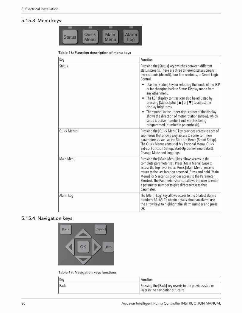
5.15.3 Menu keys
Table 16: Function description of menu keys
Key Function
Status Pressing the [Status] key switches between differentstatus screens. There are three different status screens;five readouts (default), four line readouts, or Smart LogicControl.• Use the [Status] key for selecting the mode of the LCP
or for changing back to Status Display mode fromany other menu.
• The LCP display contrast can also be adjusted bypressing [Status] plus [▲] or [▼] to adjust thedisplay brightness.
• The symbol in the upper-right corner of the displayshows the direction of motor rotation (arrow), whichsetup is active (number) and which is beingprogrammed (number in parenthesis).
Quick Menus Pressing the [Quick Menu] key provides access to a set ofsubmenus that allows easy access to some commonparameters as well as the Start-Up Genie (Smart Setup).The Quick Menus consist of My Personal Menu, QuickSet-up, Function Set-up, Start-Up Genie (Smart Start),Change Made and Loggings.
Main Menu Pressing the [Main Menu] key allows access to thecomplete parameter set. Press [Main Menu] twice toaccess the top-level index. Press [Main Menu] once toreturn to the last location accessed. Press and hold [MainMenu] for 5 seconds provides access to the ParameterShortcut. The Parameter shortcut allows the user to entera parameter number to give direct access to thatparameter.
Alarm Log The [Alarm Log] key allows access to the 5 latest alarmsnumbers A1–A5. To obtain details about an alarm, usethe arrow keys to highlight the alarm number and pressOK.
5.15.4 Navigation keys
Table 17: Navigation keys functions
Key Function
Back Pressing the [Back] key reverts to the previous step orlayer in the navigation structure.
5 Electrical Installation
80 Aquavar Intelligent Pump Controller INSTRUCTION MANUAL

Key Function
Cancel Pressing the [cancel] button will cancel the last change orcommand as long as the display has not been changed.
Info Pressing the [Info] button will display information abouta command, parameter, or function in any displaywindow. [Info] provides detailed information whenneeded. Exit the Info mode by pressing either [Info],[Back], or [Cancel].
OK [OK] is used for choosing a parameter marked by thecursor and for enabling the change of a parameter.
Arrows The four navigation arrows are used to navigate betweenthe different choices available in [Quick Menu], [MainMenu] and Alarm Log]. Use these keys to move thecursor.
Table 18: Indicator lights functions
Light Indicator Function
Green ON The ON light activates when thecontroller receives power from mainsvoltage, a DC bus terminal, or anexternal 24 V supply.
Yellow WARN When warning conditions are met,the yellow WARN light comes on andtext appears in the display areaidentifying the problem.
Red ALARM A fault condition causes the red alarmlight to flash and an alarm text isdisplayed/
5.15.5 Operation keys
Table 19: Operation keys functions
Hand On The [Hand On] key enables control of the drive via theLCP interface. Pressing [Hand On] also starts the motorand the speed can be manually adjusted using the arrowkeys. The [Hand On] key can be enabled or disabled viaparameter [0–40] [Hand on] Key on LCP. If [Hand On] isactive the drive can be stopped by:• Start signal on DI 18• The [Off] button• Stop command from serial communication
Off Pressing the [Off] key will stop the motor. The [Off] keycan be enabled or disabled via parameter [0–41] [Off]Key on LCP. If no external stop function is selected andthe [Off] key is disabled, the motor can only be stoppedby disconnecting the mains supply.
5 Electrical Installation
Aquavar Intelligent Pump Controller INSTRUCTION MANUAL 81

Auto On Pressing the [Auto On] key enables the drive to becontrolled via the control terminals and/or serialcommunication. When a start signal is applied on thecontrol terminals and/or serial communication, the drivewill start. This key can be enabled or disabled via [0–42][Auto on] Key on LCP.
Reset The [Reset] key is used for resetting the controller after analarm (trip). The key can be enabled or disabled viaparameter [0–43] [Reset] Key on LCP.
5.15.6 Status lights
If certain threshold values are exceeded, the alarm and/or Warning (Warn.) LED will turnon. If an alarm or warning is active, a status or alarm text will appear on the control panel.
• Yellow Warn. LED: Indicates a warning is active.• Red Flashing Alarm LED: Indicates an alarm is active.
The On LED is activated when the controller receives power.
• Green On LED: Control section is powered and working.
5.15.7 Parameter backupParameter settings are stored internally in the controller. The parameters can beuploaded to the LCP for backup or to easily transfer the parameter settings from onecontroller to another controller. A factory reset/initialization does not change the datastored in the LCP.
WARNING:
Parameter group [0-5]* Copy/Save does not function on the parameter group 19-**Application Parameters. Do not use the parameter group [0-5]* Copy/Save to copy orsave parameters if the controller has the MCO301 Programmable API option cardinstalled.
To upload parameters (except the parameter group [19-**] Application Parameters) to theLCP follow the following procedure:
1. Press [Off] to stop the motor before uploading data.2. Press [Main Menu] to enter the parameter list.3. Select [0-**] Operation / Display, press [OK].4. Use the down arrow to scroll to [0-5*] Copy/Save, press [OK] to enter the submenu.5. Press [OK] to enable editing of parameter [0-50] LCP Copy.6. Use the up or down arrows to scroll to ALL to Copy, press [OK] to select.7. The progress bar will show the status of the process.8. Press [Status] to return to the main status screen.9. Press [Auto On] or [Hand On] to resume previous operating mode.
To download parameters (except the parameter group [19-**] Application Parameters) tothe controller from the LCP follow the procedure below.
1. Press [Off] to stop the motor before uploading data.2. Press [Main Menu] to enter the parameter list.
5 Electrical Installation
82 Aquavar Intelligent Pump Controller INSTRUCTION MANUAL

3. Select [0-**]Operation / Display, press [OK].4. Use the down arrow to scroll to [0-5*] Copy/Save, press [OK] to enter the submenu.5. Press [OK] to enable editing of parameter [0-50] LCP Copy.6. To copy all data from the LCP, including size dependent data, use the up or down
arrows to scroll to All from LCP, press [OK] to select. To copy all size independent data,scroll to Size indep. from LCP, press [OK] to select.
7. The progress bar will show the status of the process.8. Press [Status] to return to the main status screen.9. Press [Auto On] or [Hand On] to resume previous operating mode.
5.15.8 Factory Reset/Initialization
CAUTION:
Before performing the Reset/Initialization, keep the terminal 18 open to avoid anunintended motor rotation.
A factory reset or an initialization can be performed to restore the controller back todefault settings. There are multiple ways to perform this function.
Parameter [14-22] Operation Mode can be used to perform the factory reset function.Using this method does not change controller data such as operating hours, serialcommunication selections, fault log, alarm log, and other monitoring functions. Toperform the reset through parameter 14-22 perform the following steps.
1. Press [Main Menu] to enter the parameter list.2. Use the up and down arrows to scroll to [14-**] Special Functions, press [OK].3. Use the up and down arrows to scroll to [14-2*] Reset Functions, press [OK].4. Use the up and down arrows to scroll to [14-22] Operation Mode, press [OK].5. Press [OK] to enable modification of the parameter.6. Use the up and down arrows to scroll to Initialization, press [OK].7. Remove input power from the unit and wait for the LCP to turn off.8. Apply power to the unit. The reset is performed at power up.9. Alarm 80 Drive Initialized to Default Value will be displayed.10.Press [Reset] to return to operation mode.
Another way to perform the factory reset or initialization is to issue a 3 finger reset. Theprocess is described below.
1. Remove power from the unit and wait for the LCP to turn off.2. Press and hold [Status], [Main Menu], and [OK] at the same time. While holding down
the buttons, apply power to the unit.
5 Electrical Installation
Aquavar Intelligent Pump Controller INSTRUCTION MANUAL 83
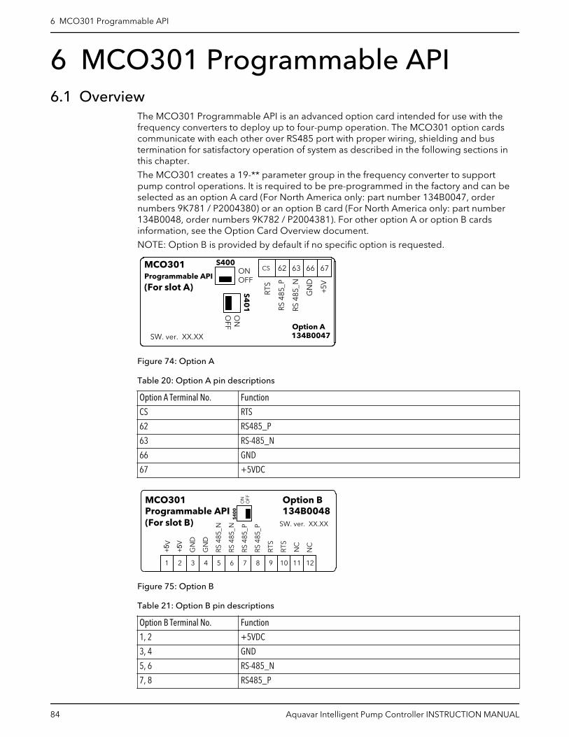
6 MCO301 Programmable API6.1 Overview
The MCO301 Programmable API is an advanced option card intended for use with thefrequency converters to deploy up to four-pump operation. The MCO301 option cardscommunicate with each other over RS485 port with proper wiring, shielding and bustermination for satisfactory operation of system as described in the following sections inthis chapter.
The MCO301 creates a 19-** parameter group in the frequency converter to supportpump control operations. It is required to be pre-programmed in the factory and can beselected as an option A card (For North America only: part number 134B0047, ordernumbers 9K781 / P2004380) or an option B card (For North America only: part number134B0048, order numbers 9K782 / P2004381). For other option A or option B cardsinformation, see the Option Card Overview document.
NOTE: Option B is provided by default if no specific option is requested.
MCO301Programmable API
(For slot A)
SW. ver. XX.XX
S400ONOFF
S40
1O
NO
FF
CS 62 63 66 67
GN
D
RTS
RS48
5_N
+5V
RS48
5_P
134B0047Option A
Figure 74: Option A
Table 20: Option A pin descriptions
Option A Terminal No. Function
CS RTS
62 RS485_P
63 RS-485_N
66 GND
67 +5VDC
SW. ver. XX.XX
12111091 2 3 4 5 6 7 8
RS48
5_N
+5V
GN
D
RS48
5_P
RTS
NC
+5V
GN
D
RS48
5_N
RS48
5_P
RTS
NC
S40
0
NO
FF
OMCO301Programmable API(For slot B)
Option B134B0048
Figure 75: Option B
Table 21: Option B pin descriptions
Option B Terminal No. Function
1, 2 +5VDC
3, 4 GND
5, 6 RS-485_N
7, 8 RS485_P
6 MCO301 Programmable API
84 Aquavar Intelligent Pump Controller INSTRUCTION MANUAL
Option B Terminal No. Function
9, 10 RTS
11, 12 NC
6.2 SafetyWARNING:
Refer to section 1.2 Safety on page 5 for safety details.
Electrical Hazard:
See section 5.2 Basic electrical connection on page 48 in the Electrical Installation chapter.
Be sure that the following are adhered to:
• The mains supply to the frequency converter must be disconnected whenever repairwork is to be carried out. Check that the mains supply has been disconnected and thatthe necessary time has elapsed before removing motor and mains supply plugs.
• The [OFF] button on the control panel of the frequency converter does not disconnectthe mains supply and consequently it must not be used as a safety switch.
• The equipment must be properly earthed, the user must be protected against supplyvoltage and the motor must be protected against overload in accordance withapplicable national and local regulations.
• The earth leakage current exceeds 3.5 mA.• Protection against motor overload is not included in the factory setting. If this function
is desired, set par. [1-90] Motor Thermal Protection to data value ETR trip 1 [4] or datavalue ETR warning 1 [3].
• Do not remove the plugs for the motor and mains supply while the frequencyconverter is connected to mains. Check that the mains supply has been disconnectedand that the necessary time has elapsed before removing motor and mains plugs.
• Please note that the frequency converter has more voltage sources than L1, L2 and L3,when load sharing (linking of DC intermediate circuit) or external 24 V DC are installed.Check that all voltage sources have been disconnected and that the necessary timehas elapsed before commencing repair work.
6.3 Basic installation instructions for Option A or Option B cards1. Remove the LCP panel from the frequency converter.2. Remove the frame located beneath.3. For the Option A card, push the right connector with the cable terminal facing up into
slot A of the control card. For the Option B card, push the connector with the cableterminal facing down into slot B of the control card. The cable up position is frequentlymost suitable when several frequency converters are installed side by side in a rack, asthis position permits shorter cable lengths.
4. Push the LCP frame for the frequency converter into position.5. Install the LCP panel.6. Attach cable.7. Fasten the cable in position by using cable holders. The frequency converter top
surface has pre-drilled threaded holes for attaching the cable holders to the unit.
6 MCO301 Programmable API
Aquavar Intelligent Pump Controller INSTRUCTION MANUAL 85

1
2
Figure 76: Slot A and Slot B locations
1. Slot A2. Slot B
1
23
Figure 77: Installation of Option A Card
1. Option A2. Drive terminals3. LCP frame
1
2
3
Figure 78: Installation of Option B Card
1. Drive terminals2. Option B3. LCP frame
6.4 Installation instructions for additional enclosure sizes6.4.1 Enclosure Sizes A2, A3, B3, and B4
1. Remove the LCP (local control panel), the terminal cover, and the LCP frame from thefrequency converter.
2. Fit the Option A card into slot A or Option B card into slot B.
6 MCO301 Programmable API
86 Aquavar Intelligent Pump Controller INSTRUCTION MANUAL

3. Connect the control cables and relieve the cable. See Wiring the MCO301Programmable API on page 88 and Shielding for MCO301 Programmable API onpage 91 for details about wiring.
4. Remove the knock-out in the extended LCP frame (supplied).5. Fit the extended LCP frame and terminal cover on the frequency converter.6. Fit the LCP or blind cover in the extended LCP frame.7. installation in enclosure sizes A2, A3, B3, and B4
1
2
3
4
5
130B
E183
.10
Figure 79: Installation enclosure sizes A2, A3, B3, B4
1 LCP
2 LCP frame
3 Slot B
4 Option B
5 Terminal cover
6.4.2 Enclosure Sizes A5, B1, B2, C, D1. Remove the LCP (local control panel) and the LCP cradle.2. Fit the Option A card into slot A or Option B card into slot B.3. Connect the control cables and relieve the cable. See Wiring the MCO301
Programmable API on page 88 and Shielding for MCO301 Programmable API onpage 91 for details about wiring.
4. Fit the cradle on the frequency converter.5. Fit the LCP in the cradle.
6 MCO301 Programmable API
Aquavar Intelligent Pump Controller INSTRUCTION MANUAL 87
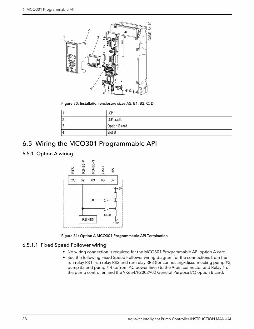
1
2
3
4
130B
E184
.10
Figure 80: Installation enclosure sizes A5, B1, B2, C, D
1 LCP
2 LCP cradle
3 Option B card
4 Slot B
6.5 Wiring the MCO301 Programmable API6.5.1 Option A wiring
RTS
RS4
85-P
RS4
85-N
GN
D
+5V
+5V
S400
0VRS-485
CS 62 63 66 67
Figure 81: Option A MCO301 Programmable API Termination
6.5.1.1 Fixed Speed Follower wiring• No wiring connection is required for the MCO301 Programmable API option A card.• See the following Fixed Speed Follower wiring diagram for the connections from the
run relay RR1, run relay RR2 and run relay RR3 (for connecting/disconnecting pump #2,pump #3 and pump # 4 to/from AC power lines) to the 9-pin connector and Relay 1 ofthe pump controller, and the 9K654/P2002902 General Purpose I/O option B card.
6 MCO301 Programmable API
88 Aquavar Intelligent Pump Controller INSTRUCTION MANUAL

Figure 82: Fixed Speed Follower wiring diagram
6.5.1.2 Fixed Master Synchronous or Fixed Master Multi Control Option A wiringDaisy chain terminal numbers 62 (RS485-P) and 63 (RS485-N) of the MCO301Programmable API option card to terminal numbers 68 (+) and 69 (-) of the RS-485 serialcommunications connectors (see Control terminal types on page 62) of the othercontrollers, respectively.
6 MCO301 Programmable API
Aquavar Intelligent Pump Controller INSTRUCTION MANUAL 89

RTS
RS4
85-P
RS4
85-N
GN
D
+5V
CS 62 63 66 67
61 6968 61 6968 61 6968
SHIELD
Figure 83: Fixed Master Synchronous or Fixed Master Multi Control option A wiring diagram
6.5.1.3 Multi Master Synchronous or Multi Master Multi Control Option A wiringDaisy chain the same terminal number 62 (RS485-P) with terminal number 62 (RS485-P),and terminal number 63 (RS485-N) with terminal number 63 (RS485-N) from the firstMCO301 Programmable API option card to the last one.
SHIELD
CS 62 63 66 67 CS 62 63 66 67 CS 62 63 66 67
RTS
RS4
85-P
RS4
85-N
GN
D+5
V
RTS
RS4
85-P
RS4
85-N
GN
D+5
V
RTS
RS4
85-P
RS4
85-N
GN
D+5
V
Figure 84: Multi Master Synchronous or Multi Master Multi Control Option A wiring diagram
6.5.2 Option B wiring
RTS
RS4
85-P
RS4
85-N
GN
D
+5V
S400
0V
RS-485
1
RTS NC
NC
RS4
85-P
RS4
85-N
GN
D
+5V
2 3 4 5 6 7 8 9 10 11 12
Figure 85: Option B MCO301 Programmable API Termination
NOTE: Two terminals that have the same names are shorted.
6 MCO301 Programmable API
90 Aquavar Intelligent Pump Controller INSTRUCTION MANUAL

6.5.2.1 Fixed Master Synchronous or Fixed Master Multi Control Option B wiringDaisy chain terminal numbers 5 (RS485-N) and 7 (RS485-P) of the MCO301Programmable API option card to terminal numbers 69 (-) and 68 (+) of the RS-485 serialcommunications connectors (see Control terminal types on page 62) of the othercontrollers, respectively.
NOTE: Two pairs of terminal numbers 5 & 6, and 7 & 8 that have the same name areshorted. They can be used separately for a daisy-chain wiring.
RTS
RS4
85-P
RS4
85-N
GN
D
+5V
1
61 6968 61 6968 61 6968
SHIELD
+5V
GN
D
RS4
85-N
RS4
85-P RTS NC
NC
2 3 4 5 6 7 8 9 10 11 12
Figure 86: Fixed Master Synchronous or Fixed Master Multi Control Option B wiring diagram
6.5.2.2 Multi Master Synchronous or Multi Master Multi Control Option B wiringDaisy chain the same terminal number 5 (RS485-N) with terminal number 5 (RS485-N),and terminal number 7 (RS485-P) with terminal number 7 (RS485-P) from the firstMCO301 Programmable API option card to the last one.
Two pairs of terminal numbers 5 & 6, and 7 & 8 that have the same name are shorted.They can be used separately for a daisy-chain wiring.
SHIELD
RTS
RS4
85-P
RS4
85-N
GN
D
+5V
RTS N
CN
C
RS4
85-P
RS4
85-N
GN
D
+5V
RTS
RS4
85-P
RS4
85-N
GN
D
+5V
RTS N
CN
C
RS4
85-P
RS4
85-N
GN
D
+5V
RTS
RS4
85-P
RS4
85-N
GN
D
+5V
RTS N
CN
C
RS4
85-P
RS4
85-N
GN
D
+5V
1 2 3 4 5 6 7 8 9 10 1112 1 2 3 4 5 6 7 8 9 10 1112 1 2 3 4 5 6 7 8 9 10 1112
Figure 87: Multi Master Synchronous or Multi Master Multi Control Option B wiring diagram
6.6 Shielding for MCO301 Programmable APIWARNING:
EMC WARNING: Ensure compliance with relevant national and local regulations, forexample in protective earth connection.
For installing the communication cables, two different strategies can be followed, Singleground of shield and Multiple ground of shield. Each strategy has both advantages anddisadvantages. See the following Single Ground Shielding and Multiple Ground Shieldingsections.
6.6.1 Single ground shieldingThe single ground shield is specified in the ANSI/ASHRAE 135-1995 standard. Thesolution benefits by having only one ground connection of the shield, by doing so thepossibility for ground loop of equalizing current is heavily reduced. In these systems the
6 MCO301 Programmable API
Aquavar Intelligent Pump Controller INSTRUCTION MANUAL 91

shield of the communication cables has to be isolated from ground at all station, exceptone. At each station the shield from the two cables has to be connected with each other,and isolated from ground. The best solution for this has been proven to be the use ofshrink tubes. The single ground shielding is a good approach where the system uses longcommunication cables. If two buildings have to be connected over the samecommunication cable, the use of fiber optic has to be considered. This will prevent that alightning stroke will be carried from one building to another, and problem with differencein earth potential can be neglected.
Figure 88: Single ground shielding installation for MCO301 programmable API
6.6.2 Multiple ground shieldingIf the distance between the individual drives is limited, connecting the screen to ground atboth ends of the bus cable is recommended. This ensures the maximum protection fromEMC noise. Connecting the screen at each end requires that each MCO301Programmable API device has the same earth potential or else an equalizing current flowsin the screen of the cable and causes disturbance and poor performance of the system.Low impedance to ground connection of the screen can be achieved by connecting thesurface of the screen to ground, by means of a cable clamp or a conductive cable gland.Where this is not possible, the screen can be isolated from the chassis of the drive by useof shrink-tubing. It must be pointed out that the routing of the MCO301 programmableAPI cable must be established with a maximum distance to other cables such as mains,motor cable, etc.
6 MCO301 Programmable API
92 Aquavar Intelligent Pump Controller INSTRUCTION MANUAL
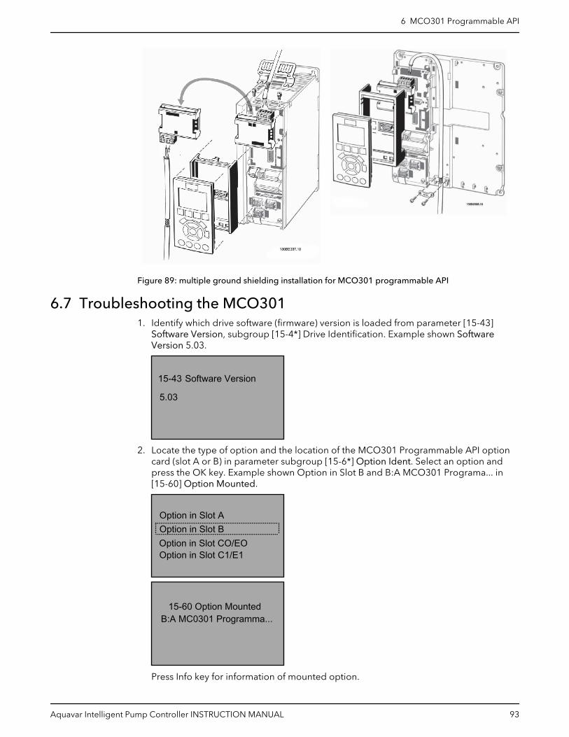
Figure 89: multiple ground shielding installation for MCO301 programmable API
6.7 Troubleshooting the MCO3011. Identify which drive software (firmware) version is loaded from parameter [15-43]
Software Version, subgroup [15-4*] Drive Identification. Example shown SoftwareVersion 5.03.
Software Version
5.03
15-43
2. Locate the type of option and the location of the MCO301 Programmable API optioncard (slot A or B) in parameter subgroup [15-6*] Option Ident. Select an option andpress the OK key. Example shown Option in Slot B and B:A MCO301 Programa... in[15-60] Option Mounted.
Option in Slot CO/EOOption in Slot C1/E1
Option in Slot BOption in Slot A
15-60 Option Mounted B:A MC0301 Programma...
Press Info key for information of mounted option.
6 MCO301 Programmable API
Aquavar Intelligent Pump Controller INSTRUCTION MANUAL 93
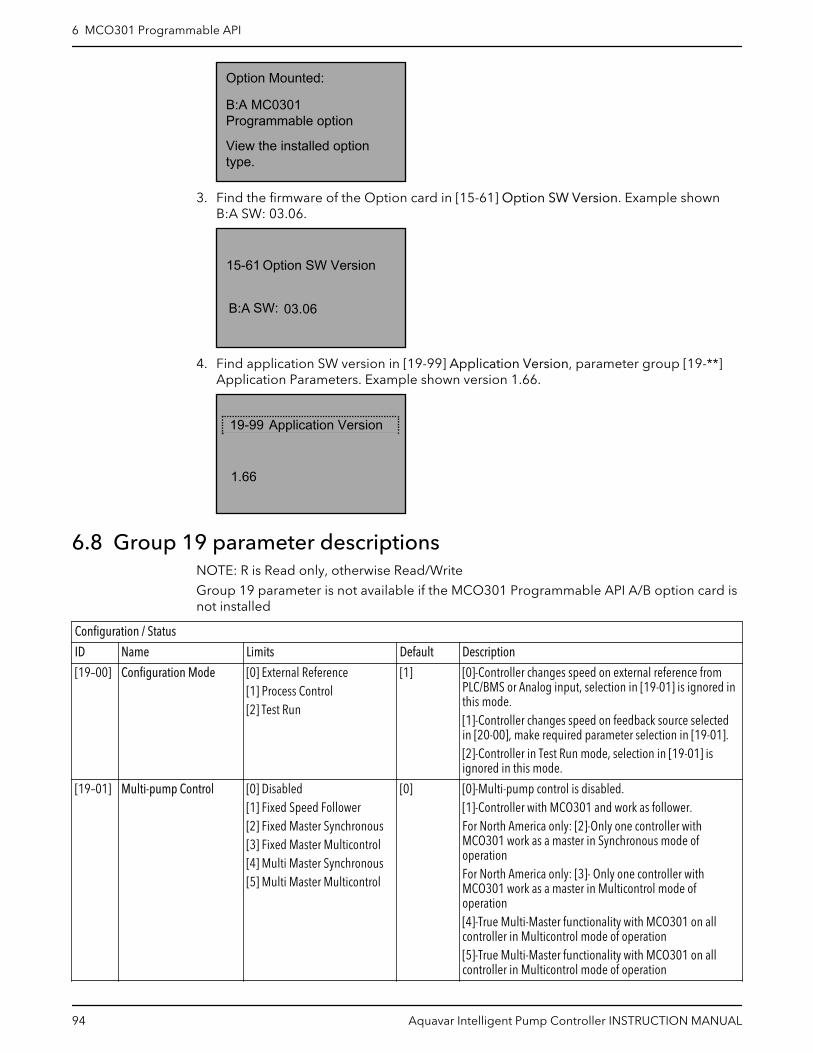
B:A MC0301 Programmable option
View the installed option type.
Option Mounted:
3. Find the firmware of the Option card in [15-61] Option SW Version. Example shownB:A SW: 03.06.
03.06
Option SW Version
B:A SW:
15-61
4. Find application SW version in [19-99] Application Version, parameter group [19-**]Application Parameters. Example shown version 1.66.
1.66
19-99 Application Version
6.8 Group 19 parameter descriptionsNOTE: R is Read only, otherwise Read/Write
Group 19 parameter is not available if the MCO301 Programmable API A/B option card isnot installed
Configuration / Status
ID Name Limits Default Description
[19–00] Configuration Mode [0] External Reference[1] Process Control[2] Test Run
[1] [0]-Controller changes speed on external reference fromPLC/BMS or Analog input, selection in [19-01] is ignored inthis mode.[1]-Controller changes speed on feedback source selectedin [20-00], make required parameter selection in [19-01].[2]-Controller in Test Run mode, selection in [19-01] isignored in this mode.
[19–01] Multi-pump Control [0] Disabled[1] Fixed Speed Follower[2] Fixed Master Synchronous[3] Fixed Master Multicontrol[4] Multi Master Synchronous[5] Multi Master Multicontrol
[0] [0]-Multi-pump control is disabled.[1]-Controller with MCO301 and work as follower.For North America only: [2]-Only one controller withMCO301 work as a master in Synchronous mode ofoperationFor North America only: [3]- Only one controller withMCO301 work as a master in Multicontrol mode ofoperation[4]-True Multi-Master functionality with MCO301 on allcontroller in Multicontrol mode of operation[5]-True Multi-Master functionality with MCO301 on allcontroller in Multicontrol mode of operation
6 MCO301 Programmable API
94 Aquavar Intelligent Pump Controller INSTRUCTION MANUAL
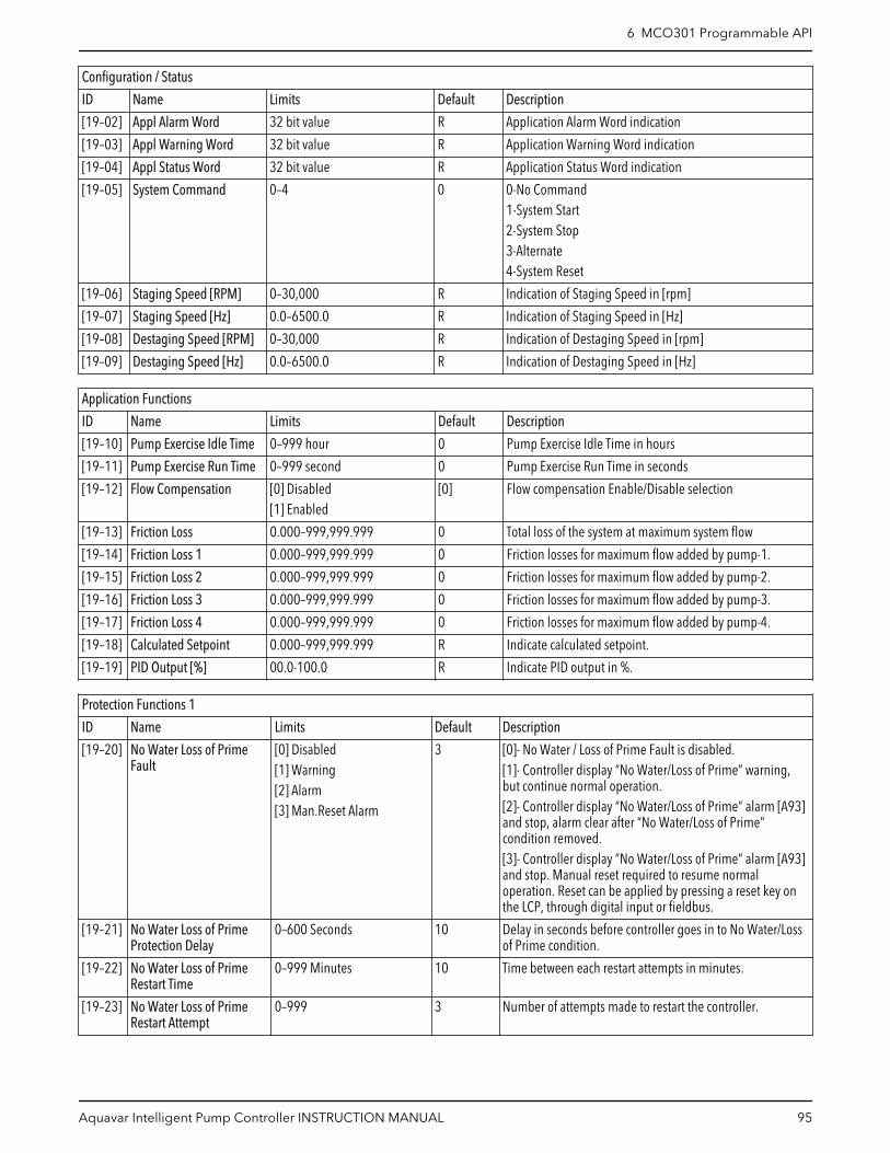
Configuration / Status
ID Name Limits Default Description
[19–02] Appl Alarm Word 32 bit value R Application Alarm Word indication
[19–03] Appl Warning Word 32 bit value R Application Warning Word indication
[19–04] Appl Status Word 32 bit value R Application Status Word indication
[19–05] System Command 0–4 0 0-No Command1-System Start2-System Stop3-Alternate4-System Reset
[19–06] Staging Speed [RPM] 0–30,000 R Indication of Staging Speed in [rpm]
[19–07] Staging Speed [Hz] 0.0–6500.0 R Indication of Staging Speed in [Hz]
[19–08] Destaging Speed [RPM] 0–30,000 R Indication of Destaging Speed in [rpm]
[19–09] Destaging Speed [Hz] 0.0–6500.0 R Indication of Destaging Speed in [Hz]
Application Functions
ID Name Limits Default Description
[19–10] Pump Exercise Idle Time 0–999 hour 0 Pump Exercise Idle Time in hours
[19–11] Pump Exercise Run Time 0–999 second 0 Pump Exercise Run Time in seconds
[19–12] Flow Compensation [0] Disabled[1] Enabled
[0] Flow compensation Enable/Disable selection
[19–13] Friction Loss 0.000–999,999.999 0 Total loss of the system at maximum system flow
[19–14] Friction Loss 1 0.000–999,999.999 0 Friction losses for maximum flow added by pump-1.
[19–15] Friction Loss 2 0.000–999,999.999 0 Friction losses for maximum flow added by pump-2.
[19–16] Friction Loss 3 0.000–999,999.999 0 Friction losses for maximum flow added by pump-3.
[19–17] Friction Loss 4 0.000–999,999.999 0 Friction losses for maximum flow added by pump-4.
[19–18] Calculated Setpoint 0.000–999,999.999 R Indicate calculated setpoint.
[19–19] PID Output [%] 00.0-100.0 R Indicate PID output in %.
Protection Functions 1
ID Name Limits Default Description
[19–20] No Water Loss of PrimeFault
[0] Disabled[1] Warning[2] Alarm[3] Man.Reset Alarm
3 [0]- No Water / Loss of Prime Fault is disabled.[1]- Controller display “No Water/Loss of Prime” warning,but continue normal operation.[2]- Controller display “No Water/Loss of Prime” alarm [A93]and stop, alarm clear after “No Water/Loss of Prime”condition removed.[3]- Controller display “No Water/Loss of Prime” alarm [A93]and stop. Manual reset required to resume normaloperation. Reset can be applied by pressing a reset key onthe LCP, through digital input or fieldbus.
[19–21] No Water Loss of PrimeProtection Delay
0–600 Seconds 10 Delay in seconds before controller goes in to No Water/Lossof Prime condition.
[19–22] No Water Loss of PrimeRestart Time
0–999 Minutes 10 Time between each restart attempts in minutes.
[19–23] No Water Loss of PrimeRestart Attempt
0–999 3 Number of attempts made to restart the controller.
6 MCO301 Programmable API
Aquavar Intelligent Pump Controller INSTRUCTION MANUAL 95

Protection Functions 1
ID Name Limits Default Description
[19–24] No Flow Shutdown [0] Disabled[1] Enabled
1 [0]- Sleep Mode and Flow Check functions is disabled.[1]- Sleep Mode and Flow Check functions is enabled,controller enter sleep mode and stop when a No Flowcondition is detected.
[19–25] No Flow Restart Difference 0.000–999,999.999 5.000 No Flow Restart Difference sets the pressure drop allowed inabsolute units of feedback/setpoint for the pressure (Pset)before canceling the sleep mode.
[19–26] High System Fault [0] Disabled[1] Warning[2] Alarm[3] Man.Reset Alarm[4] Alarm TripLock
[0] [0]- High System Cut-out Function is disabled.[1]-Controller display “High System” warning, but continuenormal operation.[2]-Controller display “High System” alarm and coast allpumps to stop. System attempts resets as per set in 19-48 &19-49, then requires manual reset after that.[3]-Controller display “High System” alarm and coast allpumps to stop. Manual reset event require to resumenormal operation. Reset can be applied by pressing a resetkey on the LCP, through digital input or fieldbus.[4]-Controller display “High System” alarm and coast allpumps to stop. System Power Cycle is required to clear thealarm.
[19–27] High System Limit 0.000–999,999.999 0 System pressure upper threshold value, if feedback pressuregoes above this, system generates Alarm/Warning asselected in [19-26] after the delay mentioned in [19-28].
[19–28] High System Delay 0–999 Seconds 0 When System pressure goes above “High System Limit”mentioned in [19-27], Controller wait for this time beforeasserting Alarm/Warning
[19–29] Suction Feedback 0.000–999,999.999 R Indicates Suction Feedback.
Protection Functions 2
ID Name Limits Default Description
[19–30] Suction Input [0] Not Set[1] Analog input 53[2] Analog input 54[7] Analog input X30/11[8] Analog input X30/12[9] Analog input X42/1[10] Analog input X42/3[11] Analog input X42/5[100] Bus Feedback 1[101] Bus Feedback 2[102] Bus Feedback 3
[0] Select the available source of suction input, this isapplicable to master drive only.
[19–31] Cascade Pump Status 32 bit Value R Cascade Pump Status Word indication. See Note #1 for[19-31] Cascade Pump Status below this 19 parametergroup table.
6 MCO301 Programmable API
96 Aquavar Intelligent Pump Controller INSTRUCTION MANUAL

Protection Functions 2
ID Name Limits Default Description
[19–32] Low Suction Fault [0] Disabled[1] Warning[2] Alarm[3] Man.Reset Alarm
[0] [0]- Low Suction Fault is disabled.[1]-Controller display “Low Suction” warning, but continuenormal operation.[2]-Controller display “Low Suction” alarm and coast allpumps to stop, alarm clears after “Low Suction” conditionremoved[3]-Controller display “Low Suction” alarm and coast allpumps to stop. Manual reset event require to resumenormal operation. Reset can be applied by pressing a resetkey on the LCP, through digital input or fieldbus.
[19–33] Low Suction Cut-out 0.000–999,999.999 0 Suction pressure lower/cut-out threshold value, if suctionpressure goes below this value, system generates Alarm/Warning as selected in [19-32] after the delay mentionedin [19-34].
[19–34] Low Suction Delay 0–999 Seconds 0 When Suction pressure goes below “Low Suction Cut-out”mentioned in [19-33], Controller wait for this time beforeasserting Alarm/Warning
[19–35] Low Suction Restart Limit 0.000–999,999.999 0 Controller comes out of “Low Suction” condition whenfeedback value rises above “Low Suction Restart”
[19–36] High Suction Fault [0] Disabled[1] Warning[2] Alarm[3] Man.Reset Alarm
[0] [0]- High Suction Fault is disabled.[1]-Controller display “High Suction” warning, but continuenormal operation.[2]-Controller display “High Suction” alarm and coast allpumps to stop, alarm clears after “High Suction” conditionremoved[3]-Controller display “High Suction” alarm and coast allpumps to stop. Manual reset event require to resumenormal operation. Reset can be applied by pressing a resetkey on the LCP, through digital input or fieldbus.
[19–37] High Suction Cut-out 0.000–999,999.999 0 Suction pressure higher threshold value, if suction pressuregoes above this value, system generates Alarm/Warning asselected in [19-36] after the delay mentioned in [19-38].
[19–38] High Suction Delay 0–999 Seconds 0 When Suction pressure goes above “High Suction Fault”mentioned in [19-37], controller waits for this time beforeasserting Alarm/Warning
[19–39] High Suction Restart Limit 0.000–999,999.999 0 Controller comes out of “High Suction” condition whenfeedback value goes below “High Suction Restart Limit”
6 MCO301 Programmable API
Aquavar Intelligent Pump Controller INSTRUCTION MANUAL 97

Protection Functions 3
ID Name Limits Default Description
[19–40] All Zones Failure Function [0] Off[2] Stop[3] Constant Speed[4] Stop and Trip
2 [0]– All Zone Failure monitoring is disabled.[2]– The controller stops all pumps in the system. The “AllZone Failure” warning displays on LCP. Controllerresumes normal operation when any of the zone sensorsrecovers.[3]– The controller runs a number of pumps defined by[19-42] All Zones Failure Number of Pumps at the speeddefined by parameters [19-42] All Zones Failure Speed[RPM] or [19-43] All Zones Failure Speed [Hz]. The “AllZone Failure” warning displays on LCP. Controllerresumes normal operation when any of the zone sensorsrecovers.[4]– The controller stop all pumps in the system. The “AllZone Failure” alarm display on LCP. Manual Reset eventrequired to resume normal operation. Reset can beapplied by pressing a reset key on the LCP, through digitalinput or fieldbus.
[19–41] All Zones Failure Numberof Pumps
1–4 1 All zone failure occurs when all pressure feedback signalsare lost (i.e. drop below 2 mA). During this condition, apredefined number of pumps runs at a predefined speed.This parameter sets the number of pumps and [19-42] or[19-43] determines the speed.
[19–42] All Zones Failure Speed[RPM]
0 - 30,000 RPM 0 All zone failure speed in rpm
[19–43] All Zones Failure Speed[Hz]
0.0 - 6500.0 Hz 0 All zone failure speed in Hz
[19–44] Zone Status 32 bit value R Indicate zone status word. See Note #2 for [19-44] ZoneStatus below this 19 parameter group table.
[19–45] Low System Fault [0] Disabled[1] Warning[2] Alarm[3] Man.Reset Alarm[4] Alarm TripLock
[0] [0]- Low System Fault is disabled.[1]-Controller display “Low System” warning, but continuenormal operation.[2]-Controller display “Low System” alarm and coast allpumps to stop. System attempts resets as per set in[19-48] & [19-49], then requires manual reset after that.[3]-Controller display “Low System” alarm and coast allpumps to stop. Manual reset event require to resumenormal operation. Reset can be applied by pressing areset key on the LCP, via digital input or fieldbus.[4]-Controller display “Low System” alarm and coast allpumps to stop. System Power Cycle is required to clear thealarm.
[19–46] Low System Limit 0.000–999,999.999 0 System pressure lower threshold value, if feedbackpressure goes below this, system generates Alarm/Warning as selected in [19-45] after the delay mentionedin [19-47].
[19–47] Low System Delay 0–999 Seconds 0 When System pressure goes below “Low System Cut-outThreshold” mentioned in [19-46], Controller wait for thistime before asserting Alarm/Warning
[19–48] System Restart Time 0–999 seconds 0 Time between each restart attempts in seconds, applicableto “Low System Cut-out Function”, “High System Cut-outFunction” and "Underpressure".
[19–49] System Restart Attempts 1–5 1 Number of attempts made to restart the controller,applicable to Low System Fault, “High System Fault” and"Underpressure"
6 MCO301 Programmable API
98 Aquavar Intelligent Pump Controller INSTRUCTION MANUAL

Multi-Pump Functions
ID Name Limits Default Description
[19–50] Number of Pumps 2–4 2 Total number of pumps in the system
[19–51] Standby Pumps 0–2 0 Total number of standby pumps in the system
[19–52] Alternation Function [0] Disabled[1] On Run Time[2] On Clock Time
2 [0]- Automatic alternation is disabled.[1]- The lead pump functionality transferred to the nextavailable pump by pump’s address[2]- The lead pump functionality transferred to the pumpwith the least running hours
[19–53] Alternation Time Interval 0–999 hours 24 This determines the number of hours of pump operationbefore pump alternation occurs. When the pumps aremanually alternated using the right or left arrow keys onthe Local Control Panel, this timer is reset.
[19–54] Pump Status 32 bit value R Pump status of Advance pump controller. See the Note #3for [19-54] Pump Status below this 19 parameter grouptable.
[19–55] Lead Pump 1–4 R Indicate current lead pump number used by the controllerfor sequential staging and destaging in Multi-Master/Fixed-Master configuration.
[19–56] Pump Address 1–4 1 Pump address in Multi-Master/Fixed-Masterconfiguration, it must be unique for all controller insystem.
[19–57] Timed Destage 0–999 Minutes 0 Destage time in minutes, this parameter Allows todestage pumps when PV destaging fails to detect drop inthe demand
[19–58] Bypass Drives Fail 0–4 0 When the total number of controllers fail because of non-pump related alarms, rises to or above the numberdefined by this parameter, Bypass operation starts
[19–59] Bypass Run Pumps 0–4 0 When Bypass Operation is started, application put thenumber of controllers into bypass mode as defined by parthis parameter or the maximum number available,whichever is less
PV Staging
ID Name Limits Default Description
[19–60] Stage Speed 0–100 % 95 When controller reaches this percentage of maximumspeed, the controller start a timer, set in [19-61]. After thistimer expires, the controller stage on another pump.
[19–61] Stage Proof Time 0–999 Seconds 30 After controller reaches the speed percentage set in[19-60], this timer starts. After this timer expires thecontroller stage on next available pump in system
[19–62] Stabilization Time 0–999 Seconds 60 After a pump has been staged on, the speed that thesystem reaches after this timer expires is used to calculatethe de-stage speed.
[19–63] Destage Percentage 0–100 % 80 After Controller staged on, the controller waits until thestage stabilization proof timer expires. It then calculatesthe de-stage speed by multiplying the pump speed by thevalue in this parameter. The controller de-stages a pumpwhen the system speed reaches this value.
[19–64] Destage Proof Time 0–999 Seconds 30 After the controller drops speed below the calculateddestaging speed set at [19- 08] (RPM) or [19-09] (Hz), thetimer starts. After the timer expires the controller destagesthe last pump in the system.
6 MCO301 Programmable API
Aquavar Intelligent Pump Controller INSTRUCTION MANUAL 99
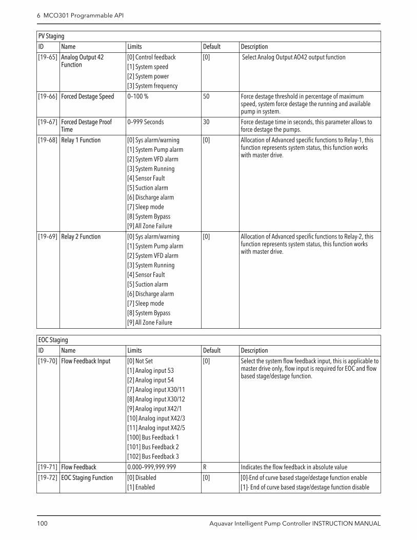
PV Staging
ID Name Limits Default Description
[19–65] Analog Output 42Function
[0] Control feedback[1] System speed[2] System power[3] System frequency
[0] Select Analog Output AO42 output function
[19–66] Forced Destage Speed 0–100 % 50 Force destage threshold in percentage of maximumspeed, system force destage the running and availablepump in system.
[19–67] Forced Destage ProofTime
0–999 Seconds 30 Force destage time in seconds, this parameter allows toforce destage the pumps.
[19–68] Relay 1 Function [0] Sys alarm/warning[1] System Pump alarm[2] System VFD alarm[3] System Running[4] Sensor Fault[5] Suction alarm[6] Discharge alarm[7] Sleep mode[8] System Bypass[9] All Zone Failure
[0] Allocation of Advanced specific functions to Relay-1, thisfunction represents system status, this function workswith master drive.
[19–69] Relay 2 Function [0] Sys alarm/warning[1] System Pump alarm[2] System VFD alarm[3] System Running[4] Sensor Fault[5] Suction alarm[6] Discharge alarm[7] Sleep mode[8] System Bypass[9] All Zone Failure
[0] Allocation of Advanced specific functions to Relay-2, thisfunction represents system status, this function workswith master drive.
EOC Staging
ID Name Limits Default Description
[19–70] Flow Feedback Input [0] Not Set[1] Analog input 53[2] Analog input 54[7] Analog input X30/11[8] Analog input X30/12[9] Analog input X42/1[10] Analog input X42/3[11] Analog input X42/5[100] Bus Feedback 1[101] Bus Feedback 2[102] Bus Feedback 3
[0] Select the system flow feedback input, this is applicable tomaster drive only, flow input is required for EOC and flowbased stage/destage function.
[19–71] Flow Feedback 0.000–999,999.999 R Indicates the flow feedback in absolute value
[19–72] EOC Staging Function [0] Disabled[1] Enabled
[0] [0]-End of curve based stage/destage function enable[1]- End of curve based stage/destage function disable
6 MCO301 Programmable API
100 Aquavar Intelligent Pump Controller INSTRUCTION MANUAL

EOC Staging
ID Name Limits Default Description
[19–73] Max.Pump Flow 0.000–999,999.999 This is used to initiate end-of-curve staging on of anadditional pump. This represents the maximum flow perpump at the end of the pump curve.
[19–74] EOC Stage Percentage 0–100 % 80 This represents the percentage of [19-73] Max.PumpFlow, when the flow per pump is greater than this valuetimes the pump speed in percent, the controller begin tostage on an additional pump.
[19–75] EOC Stage Proof Time 0–999 Seconds 30 After the feedback signal from the flow meter indicatesthat the flow per pump is greater than the expected flow,this timer starts. The expected flow is calculated by theproduct of the maximum flow from the pump times thepercent of output speed If the condition continues untilthe timer expires, an additional pump staged on.
[19–76] EOC Destage Percentage 0–100 % 45 This represents the percentage of [19-73] Max.PumpFlow, when the flow per pump is less than this valuetimes the pump speed in percent, the controller destage apump
[19–77] EOC Destage Proof Time 0–999 Seconds 30 After the controller calculates that end of curve destagingis required, this timer starts. If the condition continuesuntil the timer expires, a pump destage
[19–78] Flow Destage Value 0.000–999,999.999 0 If the flow per pump measured by the flow meter is lessthan this value, the controller initiate the process ofdestaging a pump, regardless of the pressure feedback.
[19–79] Flow Destage Proof Time 0–999 Seconds 0 When the controller initiates a flow destage, this timerstart. If the condition continues until the timer expires apump destage.
Appl Closed Loop
ID Name Limits Default Description
[19–80] Feedback 4 Source [0] No Function[1] Analog input 53[2] Analog input 54[7] Analog input X30/11[8] Analog input X30/12[9] Analog input X42/1[10] Analog input X42/3[11] Analog input X42/5[100] Bus Feedback 1[101] Bus Feedback 2[102] Bus Feedback 3
[0] Select the feedback-4 input, this is applicable to masterdrive only, any unused feedback must be set to “NoFunction” in Feedback Source parameters by the user.
[19–81] Feedback 4 0.000–999,999.999 R Indicates Feedback 4 value in absolute unit.
[19–82] Control Feedback 0.000–999,999.1000 R Indicates feedback value currently controlling the systemin absolute unit
[19–83] Setpoint 4 0.000–999,999.999 0 Setpoint 4 value in absolute unit, system consider valuein this parameter based on selection in [20-20] –Feedback Function.
[19–84] Alternate Setpoint 1 0.000–999,999.999 0 Alternate Setpoint 1 value, switch between alternatesetpoint by applying signal on digital input-33, require toset [5-15] DI-33 to [75] MCO Specific
[19–85] Alternate Setpoint 2 0.000–999,999.999 0 Alternate Setpoint 2 value, switch between alternatesetpoint by applying signal on digital input-33, require toset [5-15] DI-33 to [75] MCO Specific
6 MCO301 Programmable API
Aquavar Intelligent Pump Controller INSTRUCTION MANUAL 101

Appl Closed Loop
ID Name Limits Default Description
[19–86] Alternate Setpoint 3 0.000–999,999.999 0 Alternate Setpoint 3 value, switch between alternatesetpoint by applying signal on digital input-33, require toset [5-15] DI-33 to [75] MCO Specific
[19–87] Alternate Setpoint 4 0.000–999,999.999 0 Alternate Setpoint 4 value, switch between alternatesetpoint by applying signal on digital input-33, require toset [5-15] DI-33 to [75] MCO Specific
[19–88] Control Zone 1–4 R Indicates control zone of system
[19–89] Control Setpoint 0.000–999,999.999 R Indicates control setpoint of system
[19–90] Pipe Fill Function [0] Disabled[1] Enabled
[0] [0]- Disabled[1]- Enabled, Pipe Fill Function run only once whencontroller is powered up (application is initialized) andstarted (is put into “Auto On” mode and is permitted torun)
[19–91] Triggered Pressure 0.000–999,999.999 0 Pipe Fill Function achieve this pressure before it passcontrol to system PID
[19–92] Speed Step 0.0–100.0 % 0 Pipe Fill Function increase the system speed by thispercentage of maximum speed.
[19–93] Steady Time 0.000–999,999.999 Secs 0 Steady Time defines the time for which system pressuremust remain stable within dead band defined by [19-94].
[19–94] Dead Band 0.000–999,999.999 0 System pressure must remain within this band for timespecified in [19-93] before Pipe Fill Function increasespeed by step size
[19–95] Pipe Fill Max Pump 0–4 0 Maximum number of pumps can be staged in Pipe FillFunction.
[19–96] System Speed [Hz] 0.0–6500.0 Hz R Indicates system speed in Hz
[19–97] Priming Delay 0–999 Seconds 0 Ensure proper system priming before protection isenabled. When controller is powered it starts the primingproof timer defined by this parameter
[19–98] System kW 0–2147483647 kW R Indicates system power in kW.
[19–99] Application Version 0-999.99 R Application Version number, indicates the applicationsoftware version installed in system.
Note #1 for [19-31] Cascade Pump Status:
• Cascade Pump Status will be updated only when system operates in Fixed SpeedFollower Mode, Cascade Status is 32-bit hexadecimal value with pump at index 1 dataat MSB and pump at index 4 data at LSB, where only one pump runs on variable speedand other will run at fixed speed.
Bit Description
00 - 07 Status of Fixed Speed Pump 3
08 - 15 Status of Fixed Speed Pump 2
16 - 23 Status of Fixed Speed Pump 1
24 - 31 Status of Variable Speed Pump
• Pump status of Variable Speed remains as per [19-54] Pump Status and the followingtable shows status for each of three fixed speed Pump designations:
Bit Bit = 0 Bit = 1
0 Pump is not Running Pump Running
1 Pump is not Fail (Default) Pump Fail
2 Not a Lead Pump Lead Pump
6 MCO301 Programmable API
102 Aquavar Intelligent Pump Controller INSTRUCTION MANUAL
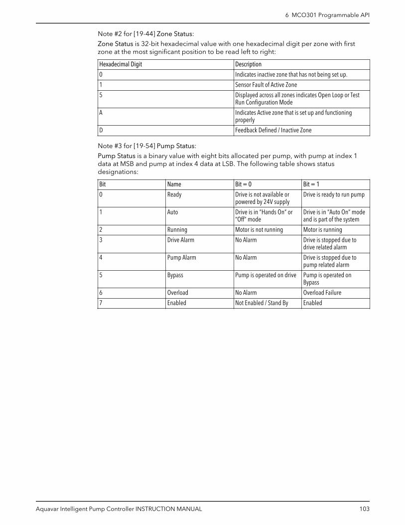
Note #2 for [19-44] Zone Status:
Zone Status is 32-bit hexadecimal value with one hexadecimal digit per zone with firstzone at the most significant position to be read left to right:
Hexadecimal Digit Description
0 Indicates inactive zone that has not being set up.
1 Sensor Fault of Active Zone
5 Displayed across all zones indicates Open Loop or TestRun Configuration Mode
A Indicates Active zone that is set up and functioningproperly
D Feedback Defined / Inactive Zone
Note #3 for [19-54] Pump Status:
Pump Status is a binary value with eight bits allocated per pump, with pump at index 1data at MSB and pump at index 4 data at LSB. The following table shows statusdesignations:
Bit Name Bit = 0 Bit = 1
0 Ready Drive is not available orpowered by 24V supply
Drive is ready to run pump
1 Auto Drive is in “Hands On” or“Off” mode
Drive is in “Auto On” modeand is part of the system
2 Running Motor is not running Motor is running
3 Drive Alarm No Alarm Drive is stopped due todrive related alarm
4 Pump Alarm No Alarm Drive is stopped due topump related alarm
5 Bypass Pump is operated on drive Pump is operated onBypass
6 Overload No Alarm Overload Failure
7 Enabled Not Enabled / Stand By Enabled
6 MCO301 Programmable API
Aquavar Intelligent Pump Controller INSTRUCTION MANUAL 103

7 Operation7.1 Pre-start procedure
Electrical Hazard:
If input and output connections have been connected improperly, there is potential forhigh voltage on these terminals. If power leads for multiple motors are improperly run insame conduit, there is potential for leakage current to charge capacitors within thefrequency converter, even when disconnected from mains input. For initial start up, makeno assumptions about power components. Follow pre-start procedures. Failure to followpre-start procedures could result in personal injury or damage to equipment.
1. Make sure the input power to unit is OFF and locked out per OSHA requirements forNorth America or local regulation for International. Do not rely on panel disconnectswitches.
2. Condition Action
Single-phasedrive
Use an AC voltmeter to verify that there is no voltage on input terminals L1 and L2, and fromthese terminals to ground, and output terminals T1, T2, and T3, phase-to-phase, and phase toground for one phase power supply.
Three-phasedrive
Use an AC voltmeter to verify that there is no voltage on input terminals L1, L2, and L3,phase-to-phase and phase-to-ground and output terminals T1, T2, and T3, phase-to-phase,and phase-to-ground for three phase power supply.
3. Use an ohmmeter to confirm continuity of the motor by measuring T1–T2, T2–T3, andT3–T1.
4. Condition Action
Single-phase drive Use an ohmmeter to confirm open on input by measuring L1 and L2 for one phase powersupply.
Three-phase drive Use an ohmmeter to confirm open on input by measuring L1–L2, L2–L3, and L3–L1 for threephase power supply.
If an isolation transformer is between the power source and panel, continuity will bepresent. In this case, visually confirm that motor and power leads are not reversed.
5. Inspect the controller for loose connections on terminals.
6. Check for proper ground: controller to main building distribution ground, and tomotor ground.
7. Confirm control connections are terminated per connection diagrams that aresupplied with the equipment.
8. Check for external devices between drive and motor.
It is recommended that no devices be installed between the motor and drive.
9. Record motor nameplate data; power, voltage, full load amps (FLA), and RPM. Ensurethe nameplate data matches the drive ratings.
10.Confirm that incoming power matches drive label voltage and motor nameplatevoltage.
11.For multiple winding motors, motors must be wired on run winding Delta, not Y-startwinding.
7 Operation
104 Aquavar Intelligent Pump Controller INSTRUCTION MANUAL
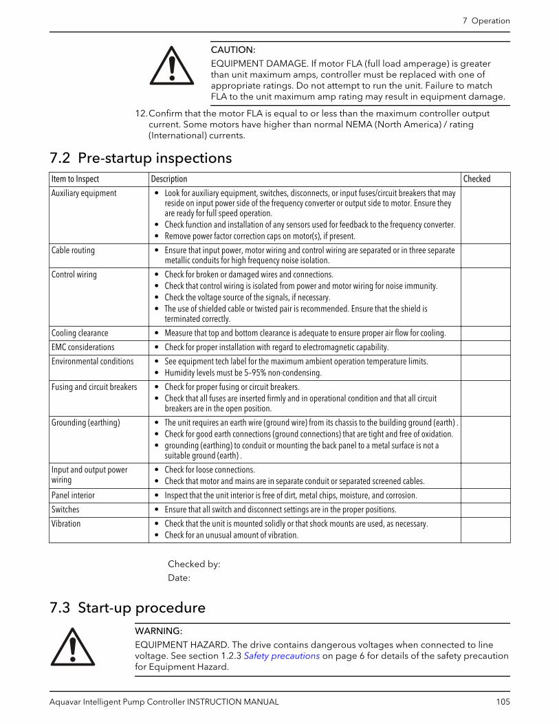
CAUTION:
EQUIPMENT DAMAGE. If motor FLA (full load amperage) is greaterthan unit maximum amps, controller must be replaced with one ofappropriate ratings. Do not attempt to run the unit. Failure to matchFLA to the unit maximum amp rating may result in equipment damage.
12.Confirm that the motor FLA is equal to or less than the maximum controller outputcurrent. Some motors have higher than normal NEMA (North America) / rating(International) currents.
7.2 Pre-startup inspectionsItem to Inspect Description Checked
Auxiliary equipment • Look for auxiliary equipment, switches, disconnects, or input fuses/circuit breakers that mayreside on input power side of the frequency converter or output side to motor. Ensure theyare ready for full speed operation.
• Check function and installation of any sensors used for feedback to the frequency converter.• Remove power factor correction caps on motor(s), if present.
Cable routing • Ensure that input power, motor wiring and control wiring are separated or in three separatemetallic conduits for high frequency noise isolation.
Control wiring • Check for broken or damaged wires and connections.• Check that control wiring is isolated from power and motor wiring for noise immunity.• Check the voltage source of the signals, if necessary.• The use of shielded cable or twisted pair is recommended. Ensure that the shield is
terminated correctly.
Cooling clearance • Measure that top and bottom clearance is adequate to ensure proper air flow for cooling.
EMC considerations • Check for proper installation with regard to electromagnetic capability.
Environmental conditions • See equipment tech label for the maximum ambient operation temperature limits.• Humidity levels must be 5–95% non-condensing.
Fusing and circuit breakers • Check for proper fusing or circuit breakers.• Check that all fuses are inserted firmly and in operational condition and that all circuit
breakers are in the open position.
Grounding (earthing) • The unit requires an earth wire (ground wire) from its chassis to the building ground (earth) .• Check for good earth connections (ground connections) that are tight and free of oxidation.• grounding (earthing) to conduit or mounting the back panel to a metal surface is not a
suitable ground (earth) .
Input and output powerwiring
• Check for loose connections.• Check that motor and mains are in separate conduit or separated screened cables.
Panel interior • Inspect that the unit interior is free of dirt, metal chips, moisture, and corrosion.
Switches • Ensure that all switch and disconnect settings are in the proper positions.
Vibration • Check that the unit is mounted solidly or that shock mounts are used, as necessary.• Check for an unusual amount of vibration.
Checked by:
Date:
7.3 Start-up procedureWARNING:
EQUIPMENT HAZARD. The drive contains dangerous voltages when connected to linevoltage. See section 1.2.3 Safety precautions on page 6 for details of the safety precautionfor Equipment Hazard.
7 Operation
Aquavar Intelligent Pump Controller INSTRUCTION MANUAL 105

WARNING:
• HIGH VOLTAGE. See section 1.2.3 Safety precautions on page 6 for details of thesafety precaution for High Voltage.
• DISCHARGE TIME. See section 1.2.3 Safety precautions on page 6 for details of thesafety precaution for Discharge Time.
• LEAKAGE CURRENT. See section 1.2.3 Safety precautions on page 6 for details of thesafety precaution for Leakage Current Hazard.
• UNINTENDED START. See section 1.2.3 Safety precautions on page 6 for details of thesafety precaution of Unintended Start.
• INTERNAL FAILURE HAZARD. Refer to section 1.2.3 Safety precautions on page 6 fordetails of the safety precaution for Internal Failure Hazard.
• WINDMILLING. See section 1.2.3 Safety precautions on page 6 for details of the safetyprecaution for Windmilling.
1. Perform pre-start procedure.
2. Ensure that all operator devices are in the OFF position.
3. Keep the built-in disconnect switch in the OFF position. Apply voltage to the unit. DONOT operate drive now.
4. Condition Action
Single-phase drive Not applicable
Three-phase drive Confirm input line voltage is balanced within 3% for three phase drive. If it is not, correctinput voltage imbalance before proceeding. Repeat this procedure after voltage correction,when applicable.
5. Confirm that the wiring matches the installation diagram that is supplied with the unit.
6. Ensure control wiring matches the installation application.
7. Turn the built-in disconnect to the ON position.
7.4 Programming the controllerCAUTION:
See section 1.2.3 Safety precautions on page 6 for details of the safety precaution beforeusing the Genie.
The following CAUTION screen is displayed after a reinitialization or after selecting Q4Start-Up Genie (North America regional setting) or Q4 Smart Start (International regionalsetting).
CAUTION: Beforeproceeding, set DI 18 toStop (terminal 18 open)to prevent the unit from
starting the motor.[OK]
The controller can be programmed by using either the Start-Up Genie for the NorthAmerica regional setting or Smart Setup for International regional setting, Quick Menusmode or the Main Menu mode. The Main Menu mode allows access to all parameters. Tomodify a parameter or make a selection in the Start-Up Genie (Smart Setup), enter theQuick Menus mode or the Main Menu mode by following the procedure below:
• To enter the Quick Menus mode, press [Quick Menu]
7 Operation
106 Aquavar Intelligent Pump Controller INSTRUCTION MANUAL

Start-Up GenieFunction SetupsQuick Setup02
0304
My Personal Menu01Quick Menus
• To enter the Main Menu mode, press [Main Menu]
Reference and Ramps3-**2-** Brakes1-** Load and Motor0-** Operation/DisplayMain Menu
• The Start-Up Genie (Smart Setup) will begin automatically after the first power up or itcan be rerun by selecting Start-Up Genie for the North America regional setting orSmart Start for the International regional setting under Quick Menus.
• Select the desired selection in the Start-Up Genie (Smart Setup) or parameter group inMain Menu by using the up and down arrows.
• Press [OK] to enter the sub-menu or selected parameter group.• Once in the sub-menu or parameter group, use the up and down arrows to highlight
the desired parameter. Press [OK] to select the parameter and enable editing.• To edit the parameter use the up and down arrows to scroll through the parameter
settings or selections. For numeric values with more than one digit, use the left andright keys to select the position within the number. The highlighted area can bemodified by using the up and down arrows.
• Press [OK] to accept and save or [Cancel] to disregard the change.
Array parameters allow the modification of a group of parameters through one parameteraddress. An example of an array parameter is [5-40] Function Relay. This parameter allowsconfiguration of the 2 programmable relays included with the controller. To modify anarray parameter follow the procedure below:
• Enter the Main Menu as previously described.• Use the up and down arrows to scroll to [5-**] Digital In/Out. Press [OK] to enter the
parameter group.• Use the up and down arrows to scroll to [5-4*] Relays. Press [OK] to enter the
parameter sub-group. The screen is shown below.
Relay 1Relay 2
5-40160 No alarm
Function Relay
– To edit Relay 1, use the up and down arrowsto highlight Relay 1 and press [OK] to selectRelay 1.
– Press [OK] again to enable editing of Relay 1.– Use the up and down arrows to select the
desired relay function.– Press [OK] to save the selection.– Use the up and down arrows to select the
[5-41] On Delay, Relay or [5-42] Off Delay,Relay. Repeat the steps above to edit theseparameters.
– Press [BACK] to return to the Relays screenand repeat the above steps to edit thefunction for Relay 2.
– Press [Main Menu] to return to the MainMenu.
7 Operation
Aquavar Intelligent Pump Controller INSTRUCTION MANUAL 107

7.4.1 Quick MenusThe Quick Menus mode contains various sub-menus that allow quick and easy access tocommon parameters. There are 6 sub-menus under Quick Menus. The 6 sub-menus areshown in the table below.
Table 22: Quick Menus
Sub-menu Sub-menu Group Name Description
Q1 My Personal Menu Contains parameters commonly usedto configure pump applications.
Q2 Quick Setup Contains parameters commonly usedto configure the controller.
Q3 Function Setups Provides quick access to parameterscommonly required for HVACapplications.
Q4 Start-Up Genie (North America)Smart Start (International)
Guides the user to configure thecontroller for various applications.
Q5 Changes Made Shows the last 10 changedparameters, changes since factorydefaults and input assignments.
Q6 Loggings Displays graph line readouts of theLCP parameters. To change displayedLCP parameters use parameters 0–20to 0–24.
7.4.2 My Personal MenuMy Personal Menu (Q1) has been configured at the factory to contain 20 parameterscommonly used in pumping applications. Use My Personal Menu to change parameterswhile the system is running, such as changing Setpoint.
NOTE: Per the factory default setting, the active setup is Setup 1 for all applications. Theparameters found in My Personal Menu are shown below.
7.4.2.1 My personal menu — North America parameters
Parameter number Parameter Name Default Value Parameter Description
[20-21] Setpoint 1 • Booster: 50 [Unit]• HVAC: 15 [Unit]
Process Setpoint 1. Thecontroller will adjust speedto maintain this value.
[20-00] Feedback 1 Source Analog Input 53 Feedback source for the PIDcontroller, transducer inputsource.Note: DIP switch 54: set to I(right position) for currentinput type or set to U (leftposition) for voltage inputtype.
[20-12] Reference/Feedback Unit • Pressure Control: psi• Flow Control: GPM• Level Control: ft
Unit used for the FeedbackSource, prior to applyingthe feedback conversion.
[22-20] Low Power Auto Set-up Off Start of auto set-up of powerdata for no-flow powertuning.
7 Operation
108 Aquavar Intelligent Pump Controller INSTRUCTION MANUAL

Parameter number Parameter Name Default Value Parameter Description
[20-84] On Reference Bandwidth 0% When the differencebetween the feedback andthe setpoint reference isless than the value of thisparameter, the drive willrun on Ramp 2.
[3-41] Ramp 1 Ramp Up Time 10.0 s Ramp up time (0 to fullspeed). Increasing this timewill produce a lower rampup.
[3-42] Ramp 1 Ramp Down Time 5.0 s Ramp down time (fullspeed to 0). Increasing thistime will produce a slowerramp down.
[20-93] PID Proportional Gain 5.0 Proportional correction gainfor PID controller.Increasing this value willproduce a faster systemresponse. CAUTION:Increasing this value toohigh can make the systemunstable and producesevere oscillations.
[20-94] PID Integral Time 3.3 s Integration time for the PIDcontroller.Increasing this value willproduce a slower systemresponse. CAUTION:Decreasing this value toolow can make the systemunstable and producesevere oscillations.
[19-12] Flow Compensation Disabled This parameter is used forenabling or disabling theflow-compensated setpointoperation.
[19-60] Stage Speed 95% When a variable speedpump reaches thispercentage of maximumspeed, the controller willstart a timer, set in [19-61].After this timer expires, thecontroller will stage onanother available pump.
[19-63] Destage Percentage 80% After a pump is staged on,the controller waits until thestage stabilization prooftimer expires. It thencalculates the de-stagespeed by multiplying thepump speed by the value inthis parameter. Thecontroller will de-stage apump when the systemspeed stays below thisvalue for de-stage prooftime.
7 Operation
Aquavar Intelligent Pump Controller INSTRUCTION MANUAL 109
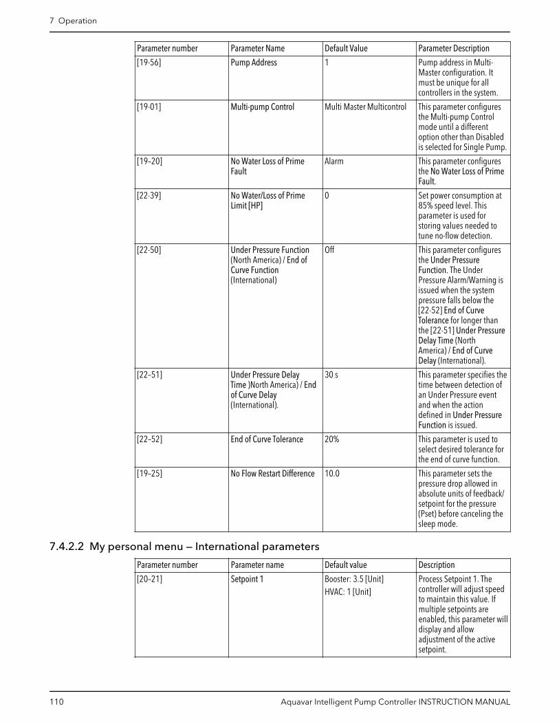
Parameter number Parameter Name Default Value Parameter Description
[19-56] Pump Address 1 Pump address in Multi-Master configuration. Itmust be unique for allcontrollers in the system.
[19-01] Multi-pump Control Multi Master Multicontrol This parameter configuresthe Multi-pump Controlmode until a differentoption other than Disabledis selected for Single Pump.
[19–20] No Water Loss of PrimeFault
Alarm This parameter configuresthe No Water Loss of PrimeFault.
[22-39] No Water/Loss of PrimeLimit [HP]
0 Set power consumption at85% speed level. Thisparameter is used forstoring values needed totune no-flow detection.
[22-50] Under Pressure Function(North America) / End ofCurve Function(International)
Off This parameter configuresthe Under PressureFunction. The UnderPressure Alarm/Warning isissued when the systempressure falls below the[22-52] End of CurveTolerance for longer thanthe [22-51] Under PressureDelay Time (NorthAmerica) / End of CurveDelay (International).
[22–51] Under Pressure DelayTime )North America) / Endof Curve Delay(International).
30 s This parameter specifies thetime between detection ofan Under Pressure eventand when the actiondefined in Under PressureFunction is issued.
[22–52] End of Curve Tolerance 20% This parameter is used toselect desired tolerance forthe end of curve function.
[19–25] No Flow Restart Difference 10.0 This parameter sets thepressure drop allowed inabsolute units of feedback/setpoint for the pressure(Pset) before canceling thesleep mode.
7.4.2.2 My personal menu — International parameters
Parameter number Parameter name Default value Description
[20–21] Setpoint 1 Booster: 3.5 [Unit]HVAC: 1 [Unit]
Process Setpoint 1. Thecontroller will adjust speedto maintain this value. Ifmultiple setpoints areenabled, this parameter willdisplay and allowadjustment of the activesetpoint.
7 Operation
110 Aquavar Intelligent Pump Controller INSTRUCTION MANUAL

Parameter number Parameter name Default value Description
[19–18] Calculated Setpoint Booster: 3.5 [Unit]HVAC: 1 [Unit]
This parameter indicates acalculated setpoint.
[19–25] No Flow Restart Difference 0.2 This parameter sets thepressure drop allowed inabsolute units of feedback/setpoint for the pressure(Pset) before canceling thesleep mode.
[19–12] Flow Compensation Disabled This parameter is used forenabling or disabling theflow-compensated setpointoperation.
[19–13] Friction Loss 0 This parameter calculatesthe total loss of the systemat the maximum systemflow.
[20–84] On Reference Bandwidth 20% The On ReferenceBandwidth is calculated as apercentage of the setpointreference. When thedifference between thefeedback and the setpointreference is less than thevalue of this parameter,drive will run on Ramp 2.
[3–41] Ramp 1 Ramp Up Time 4s Ramp up time (0 to fullspeed). Increasing this timewill produce a slower rampup.
[3–42] Ramp 1 Ramp Down Time 4s Ramp down time (fullspeed to 0). Increasing thistime will produce a slowerramp down.
[3–51] Ramp 2 Ramp Up Time 70s Ramp up time (0 to fullspeed). Increasing this timewill produce a slower rampup.
[3–52] Ramp 2 Ramp Down Time 70s Ramp down time (fullspeed to 0). Increasing thistime will produce a slowerramp down.
[19–60] Stage Speed 95% When the controller reachesthis percentage ofmaximum speed, thecontroller starts a timer setin [19-61]. After this timerexpires, the controller willstage on another pump.
7 Operation
Aquavar Intelligent Pump Controller INSTRUCTION MANUAL 111

Parameter number Parameter name Default value Description
[19–63] Destage Percentage 40% After a pump is staged on,the controller waits until thestage stabilization prooftimer expires. It thencalculates the de-stagespeed by multiplying thepump speed by the value inthis parameter. Thecontroller will de-stage apump when the systemspeed stays below thisvalue for destage prooftime.
[20–12] Reference/Feedback Unit bar Unit used for the FeedbackSource, prior to applyingthe feedback conversion.
[20–14] Maximum Reference/Feedb.
300 This setting determines thehighest value obtainable bysumming all referencesources for closed loopoperation.
[22–20] Low Power Auto Set-up Off This is the start of auto set-up of power data for no-flowpower tuning.
[19–20] No Water Loss of PrimeFault
Disabled This parameter configuresthe No Water Loss of PrimeFault. Set this value to Man.Reset Alarm in order toutilize the No Water/Loss ofPrime Restart Function. (areyou saying about autorestart function? If yes, thenit has to set as Alarm. If setto Man. Rest Alarm it has tobe manually reset by theuser)
[19–21] No Water Loss of PrimeProtection Delay
10s Delay in seconds beforecontroller goes in to NoWater/Loss of Primecondition.
[22–50] End of Curve Function Off This parameter configuresthe End of Curve Function.The End of Curve Alarm/Warning is issued when thesystem pressure falls belowthe [22-52] End of CurveTolerance for longer thanthe [22-51] End of CurveDelay.
[22–51] End of Curve Delay 30 This parameter specifies thetime between detection ofan End of Curve event andwhen the action defined inEnd of Curve Function isissued.
7 Operation
112 Aquavar Intelligent Pump Controller INSTRUCTION MANUAL
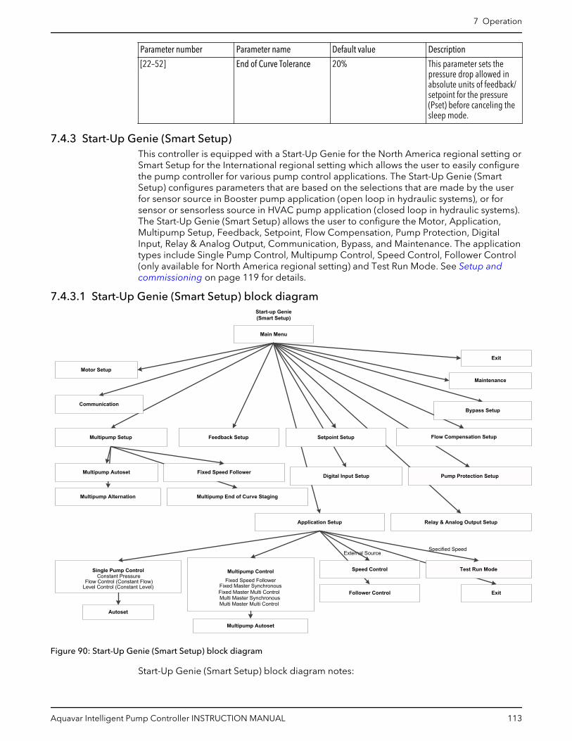
Parameter number Parameter name Default value Description
[22–52] End of Curve Tolerance 20% This parameter sets thepressure drop allowed inabsolute units of feedback/setpoint for the pressure(Pset) before canceling thesleep mode.
7.4.3 Start-Up Genie (Smart Setup)This controller is equipped with a Start-Up Genie for the North America regional setting orSmart Setup for the International regional setting which allows the user to easily configurethe pump controller for various pump control applications. The Start-Up Genie (SmartSetup) configures parameters that are based on the selections that are made by the userfor sensor source in Booster pump application (open loop in hydraulic systems), or forsensor or sensorless source in HVAC pump application (closed loop in hydraulic systems).The Start-Up Genie (Smart Setup) allows the user to configure the Motor, Application,Multipump Setup, Feedback, Setpoint, Flow Compensation, Pump Protection, DigitalInput, Relay & Analog Output, Communication, Bypass, and Maintenance. The applicationtypes include Single Pump Control, Multipump Control, Speed Control, Follower Control(only available for North America regional setting) and Test Run Mode. See Setup andcommissioning on page 119 for details.
7.4.3.1 Start-Up Genie (Smart Setup) block diagram
Autoset
Main Menu
Communication
Motor Setup
Application Setup
Feedback Setup
Pump Protection Setup
Setpoint Setup Flow Compensation Setup
Bypass Setup
Relay & Analog Output Setup
Single Pump Control Multipump Control Speed Control Test Run Mode
Multipump Setup
Specified SpeedExternal Source
Multipump Autoset Fixed Speed Follower
Multipump Alternation Multipump End of Curve Staging
Digital Input Setup
Fixed Speed FollowerConstant Pressure
Fixed Master Multi ControlMulti Master SynchronousMulti Master Multi Control
Fixed Master SynchronousFlow Control (Constant Flow)
Level Control (Constant Level)
Start-up Genie(Smart Setup)
Maintenance
Exit
Follower Control Exit
Multipump Autoset
Figure 90: Start-Up Genie (Smart Setup) block diagram
Start-Up Genie (Smart Setup) block diagram notes:
7 Operation
Aquavar Intelligent Pump Controller INSTRUCTION MANUAL 113
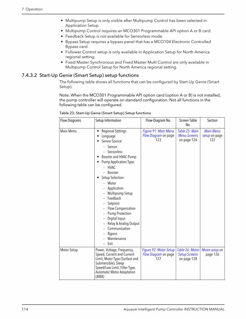
• Multipump Setup is only visible after Multipump Control has been selected inApplication Setup.
• Multipump Control requires an MCO301 Programmable API option A or B card.• Feedback Setup is not available for Sensorless mode.• Bypass Setup requires a bypass panel that has a MCO104 Electronic Controlled
Bypass card.• Follower Control setup is only available in Application Setup for North America
regional setting.• Fixed Master Synchronous and Fixed Master Multi Control are only available in
Multipump Control Setup for North America regional setting.
7.4.3.2 Start-Up Genie (Smart Setup) setup functionsThe following table shows all functions that can be configured by Start-Up Genie (SmartSetup).
Note: When the MCO301 Programmable API option card (option A or B) is not installed,the pump controller will operate on standard configuration. Not all functions in thefollowing table can be configured.
Table 23: Start-Up Genie (Smart Setup) Setup functions
Flow Diagrams Setup Information Flow-Diagram No. Screen TableNo.
Section
Main Menu • Regional Settings• Language• Sensor Source:
– Sensor– Sensorless
• Booster and HVAC Pump• Pump Application Type:
– HVAC– Booster
• Setup Selection:– Motor– Application– Multipump Setup– Feedback– Setpoint– Flow Compensation– Pump Protection– Digital Input– Relay & Analog Output– Communication– Bypass– Maintenance– Exit
Figure 91: Main MenuFlow Diagram on page
123
Table 25: MainMenu Screenson page 124
Main Menusetup on page
122
Motor Setup Power, Voltage, Frequency,Speed, Current and CurrentLimit, Motor Type (Surface andSubmersible), SleepSpeed/Low Limit, Filter Type,Automatic Motor Adaptation(AMA)
Figure 92: Motor SetupFlow Diagram on page
127
Table 26: MotorSetup Screenson page 128
Motor setup onpage 126
7 Operation
114 Aquavar Intelligent Pump Controller INSTRUCTION MANUAL

Flow Diagrams Setup Information Flow-Diagram No. Screen TableNo.
Section
Application Setup • Operating Mode:– Single Pump Control– Multipump Control– Speed Control– Test Run Mode– Exit
Figure 93: ApplicationSetup Flow Diagram on
page 130
Table 28:Application
Setup Screenson page 131
Applicationsetup on page
129
Single Pump ControlSetup
Pump Application Type:• Booster:
– Constant Pressure– Flow Control– Level Control
• HVAC:– Constant Pressure– Flow Control
Units, Tank Fill/Empty, RampTime
Figure 95: Single PumpControl Flow Diagram
on page 134
Table 31:Single PumpControl Setup
Screens onpage 135
Single PumpControl setupon page 131
Autoset Setpoint 1, Autoset forConstant Pressure, FlowControl and Level Control
Figure 96: Autoset FlowDiagram on page 143
Table 34:Autoset Screens
on page 144
Autoset onpage 138
Multipump ControlSetup
• Fixed Speed Follower• Fixed Master Synchronous• Fixed Master Multi Control• Multi Master Synchronous• Multi Master Multi Control
Figure 97: MultipumpControl Flow Diagram
on page 148
Table 35:Multipump
Control Screenson page 148
MultipumpControl setupon page 147
Speed Control Setup Speed Reference Source,Terminal 53 and 54 Low/HighRef./Feedb. Values, Min/MaxSpeed Reference
Figure 98: SpeedControl Setup Flow
Diagram on page 153
Table 36: SpeedControl Setup
Screens onpage 153
Speed Controlsetup on page
152
Follower Control Setup • IPC Follower Control• PLC Follower Control
Figure 100: FollowerControl Flow Diagram
on page 156
Table 37:Follower
Control SetupScreens onpage 157
FollowerControl setupon page 155
Test Run Mode Setup Test Run Speed and Ramp Time Figure 101: Test RunMode Flow Diagram on
page 159
Table 38: TestRun Mode
Setup Screenson page 159
Test Run Modesetup on page
158
Multipump Setup Number of Pumps/StandbyPumps, Digital Output Pin 6 &7/Controls Pump 1 & 2, Relay 1controls Pump 3, Staging/Destaging Threshold/Delay,Forced Destaging Threshold/Delay, Timed Destage/Delay
Figure 102: MultipumpSetup Flow Diagram on
page 160
Table 39:Multipump
Setup Screenson page 161
Multipumpsetup on page
160
Multipump Autoset Setpoint 1, Constant Pressure,Flow Control and Level Control
Figure 103: MultipumpAutoset Flow Diagram
on page 169
Table 42:Multipump
Autoset ScreensTable on page
170
MultipumpAutoset onpage 163
Fixed Speed FollowerSetup
Staging Bandwidth, StageProof Time, Destage ProofTime, Fixed Speed Bandwidth
Figure 104: FixedSpeed Follower Flow
Diagram on page 173
Table 43: FixedSpeed Follower
Screens onpage 174
Fixed SpeedFollower setupon page 173
7 Operation
Aquavar Intelligent Pump Controller INSTRUCTION MANUAL 115
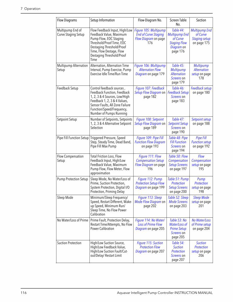
Flow Diagrams Setup Information Flow-Diagram No. Screen TableNo.
Section
Multipump End ofCurve Staging Setup
Flow Feedback Input, High/LowFeedback Value, MaximumPump Flow, EOC StagingThreshold/Proof Time, EOCDestaging Threshold/ProofTime, Flow Destage, FlowDestaging Threshold/ProofTime
Figure 105: MultipumpEnd of Curve Staging
Flow Diagram on page176
Table 44:Multipump End
of CurveStaging FlowDiagram onpage 176
Multipump Endof Curve
Staging setupon page 175
Multipump AlternationSetup
Alternation, Alternation TimeInterval, Pump Exercise, PumpExercise Idle Time/Run Time
Figure 106: MultipumpAlternation Flow
Diagram on page 179
Table 45:MultipumpAlternationScreens onpage 179
MultipumpAlternation
setup on page178
Feedback Setup Control feedback sources ,Feedback Function, Feedback1, 2, 3 & 4 Sources, Low/HighFeedback 1, 2, 3 & 4 Values,Sensor Faults, All Zone FailureFunction/Speed/Frequency,Number of Pumps Running
Figure 107: FeedbackSetup Flow Diagram on
page 182
Table 46:Feedback Setup
Screens onpage 183
Feedback setupon page 180
Setpoint Setup Number of Setpoints, Setpoints1, 2, 3 & 4 Alternative SetpointSelection
Figure 108: SetpointSetup Flow Diagram on
page 189
Table 47:Setpoint Setup
Screens onpage 190
Setpoint setupon page 188
Pipe Fill Function Setup Triggered Pressure, SpeedStep, Steady Time, Dead Band,Pipe Fill Max Pump
Figure 109: Pipe FillFunction Flow Diagram
on page 193
Table 48: PipeFill FunctionScreens onpage 194
Pipe FillFunction setupon page 192
Flow CompensationSetup
Total Friction Loss, FlowFeedback Input, High/LowFeedback Value, MaximumPump Flow, Flow Meter, Flowapproximation
Figure 111: FlowCompensation Setup
Flow Diagram on page196
Table 50: FlowCompensationSetup Screenson page 197
FlowCompensationsetup on page
195
Pump Protection Setup Sleep Mode, No Water/Loss ofPrime, Suction Protection,System Protection, Digital I/OProtection, Priming Delay
Figure 112: PumpProtection Setup FlowDiagram on page 199
Table 51: PumpProtection
Setup Screenson page 200
PumpProtection
setup on page198
Sleep Mode Minimum/Sleep Frequency/Speed, Restart Different, Wake-up Speed, Minimum Run/Sleep Time, No Flow PowerCalibration
Figure 113: SleepMode Flow Diagram on
page 202
Table 52: SleepMode Screenson page 203
Sleep Modesetup on page
201
No Water/Loss of Prime Prime Fault, Protection Delay,Restart Time/Attempts, No FlowPower Calibration
Figure 114: No Water/Loss of Prime Flow
Diagram on page 205
Table 53: NoWater/Loss ofPrime SetupScreens onpage 205
No Water/Lossof Prime setupon page 204
Suction Protection High/Low Suction Source,High/Low Feedback Value,High/Low Suction Fault/Cut-out/Delay/ Restart Limit
Figure 115: SuctionProtection Flow
Diagram on page 207
Table 54:Suction
ProtectionScreens onpage 207
SuctionProtection
setup on page206
7 Operation
116 Aquavar Intelligent Pump Controller INSTRUCTION MANUAL

Flow Diagrams Setup Information Flow-Diagram No. Screen TableNo.
Section
Digital SuctionProtection
Low Suction Protection throughDigital Input 27, Low SuctionCut-out Delay, High SuctionProtection through DigitalInput 29, High Suction Cut-outDelay
Figure 116: DigitalSuction Protection FlowDiagram on page 209
Table 55:Digital Suction
ProtectionScreens onpage 209
Digital SuctionProtection
setup on page208
System Protection Under Pressure Function/Delay/Difference, Low SystemCut-out/Limit/Delay, HighSystem Cut-out/Limit/Delay,System Restart Time/Attempts
Figure 117: SystemProtection Flow
Diagram on page 211
Table 56:System
ProtectionScreens onpage 211
SystemProtection
setup on page210
Digital I/O Protection Pump Protection throughDigital Input 19, 27 & 29,Pump Protect Delay
Figure 118: Digital I/OProtection Setup FlowDiagram on page 213
Table 57:Digital I/OProtection
Setup Screenson page 214
Digital I/OProtection
setup on page213
Bypass Setup Bypass Function/Drives Fail/Pumps Running
Figure 119: BypassSetup Flow Diagram on
page 217
Table 58:Bypass Setup
Screens onpage 217
Bypass setupon page 215
Digital Input Setup Terminals Digital Input 19/ 27/29/32/33
Figure 120: DigitalInput Setup Flow
Diagram on page 221
Table 61:Digital Input
Setup Screenson page 222
Digital Inputsetup on page
218
Relay & Analog OutputSetup
Relay 1/Relay 2 Function ,Terminal 42 Current Setting/Output Function, Terminal,Terminal 42 Output MinScale/Max Scale
Figure 121: Relay &Analog Output Setup
Flow Diagram on page225
Table 64: Relay& Analog
Output SetupScreens onpage 225
Analog Outputon page 224
Communication Setup Modbus RTU/BACnet, Address,Baud Rate, Parity/Stop Bits,BACnet Device Instance
Figure 122:Communication SetupFlow Diagram on page
226
Table 65:CommunicationSetup Screenson page 227
Communicationsetup on page
226
Maintenance Reset running hours Figure 123:Maintenance Flow
Diagram on page 228
Table 66:MaintenanceSetup Screenson page 228
Maintenanceon page 228
7.4.3.3 Start-Up Genie (Smart Setup) flow-diagram symbolsFlow diagrams and detailed screen tables are provided in each setup function for step-by-step accessing the Start-Up Genie (Smart Setup) configuration. The following shapes andconnector symbols are used for the flow diagrams.
Starting or ending Start-Up Genie (Smart Setup) configurations.
Flow direction from a screen to the next screen or to branching.
20Start-Up Genie (Smart Setup) function. The number in the circleindicates the function number for connecting different flow diagramstogether.
7 Operation
Aquavar Intelligent Pump Controller INSTRUCTION MANUAL 117
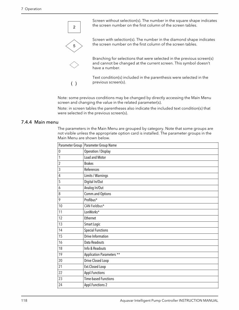
2Screen without selection(s). The number in the square shape indicatesthe screen number on the first column of the screen tables.
5Screen with selection(s). The number in the diamond shape indicatesthe screen number on the first column of the screen tables.
Branching for selections that were selected in the previous screen(s)and cannot be changed at the current screen. This symbol doesn’thave a number.
( )Text condition(s) included in the parenthesis were selected in theprevious screen(s).
Note: some previous conditions may be changed by directly accessing the Main Menuscreen and changing the value in the related parameter(s).
Note: in screen tables the parentheses also indicate the included text condition(s) thatwere selected in the previous screen(s).
7.4.4 Main menuThe parameters in the Main Menu are grouped by category. Note that some groups arenot visible unless the appropriate option card is installed. The parameter groups in theMain Menu are shown below.
Parameter Group Parameter Group Name
0 Operation / Display
1 Load and Motor
2 Brakes
3 References
4 Limits / Warnings
5 Digital In/Out
6 Analog In/Out
8 Comm.and Options
9 Profibus*
10 CAN Fieldbus*
11 LonWorks*
12 Ethernet
13 Smart Logic
14 Special Functions
15 Drive Information
16 Data Readouts
18 Info & Readouts
19 Application Parameters **
20 Drive Closed Loop
21 Ext.Closed Loop
22 Appl.Functions
23 Time-based Functions
24 Appl.Functions 2
7 Operation
118 Aquavar Intelligent Pump Controller INSTRUCTION MANUAL

Parameter Group Parameter Group Name
25 Cascade ControllerConstant Slave Controller
26 Analog I/O Option
31 Bypass Option***
* Appropriate option card must be installed.
** MCO301 Programmable API A/B option card is installed and functioning.
*** Bypass panel that has a MCO104 Electronic Controlled Bypass card installed andfunctioning is required.
Refer to the appendix for a complete parameter list.
7.5 Setup and commissioning7.5.1 Start-Up Genie (Smart Setup) setup
CAUTION:
When a Start (Closed) signal is present on DI18, the controller can start the pump/motorat any time without warning. Set DI18 to Stop (Open) or press the [Off] operation keybefore using the Start-Up Genie (Smart Setup). Apply the Start signal to the controller onlywhen pump/motor operation is desired.
The Start-Up Genie (Smart Setup) provides a fast and easy method for configuring thecontroller for various pump applications. The Navigation keys are used to make selectionsand the [Info] button can be pressed at any time while in the Start-Up Genie (Smart Setup)to retrieve additional information about the current screen or parameter.
To navigate through the Start-Up Genie (Smart Setup), press [OK] to enable editing of ascreen or parameter. Use the up and down arrows to highlight the desired selection thenpress [OK] to confirm the selection. Next use the down arrow to save the parameter andnavigate to the next screen. The up arrow transitions to the previous screen. If the screenshows the desired setting is already selected for a particular parameter or function, simplyuse the down arrow to proceed to the next screen.
NOTE: Be sure to press the down arrow key to save the parameter after confirming theselection. This ensures all associated parameter settings and background calculations areperformed and saved properly. After pressing the down arrow to save the parameter theStart-Up Genie (Smart Setup) may be slow to respond as these settings and calculationsare performed.
Press [Cancel] to exit parameter editing without saving or to change a saved parameter orselection back to the previously saved while still in the current screen. Pressing [Back] willalso exit parameter editing without saving. To exit the Start-Up Genie (Smart Setup) at anytime, first exit parameter editing then press [Back] then [OK].
The arrows shown in the lower right hand corner of the LCP indicate the options fornavigation. When an up arrow is displayed, pressing the up arrow will transition to theprevious screen. When a down arrow is displayed, pressing the down arrow will transitionto the next screen. When both an up and down arrow are displayed then pressing the uparrow will transition to the previous screen and pressing the down arrow will transition tothe next screen.
NOTE: Ensure the controller is set to Stop (DI 18 Open) and is set to Setup 1 prior torunning the Start-Up Genie (Smart Setup).
The Start-Up Genie (Smart Setup) starts automatically the first time the controller has beenpowered in the field or if the Start-Up Genie (Smart Setup) has not been used previouslyor after a factory reset or an initialization. The Start-Up Genie (Smart Setup) can be startedat any time by accessing the Quick Menus screen by pressing [Quick Menu] then using the
7 Operation
Aquavar Intelligent Pump Controller INSTRUCTION MANUAL 119

up and down arrows to highlight Q4 Start-Up Genie for North America regional setting orQ4 Smart Start for International regional setting.
Start-Up Genie Q4
Quick SetupQ2 Function Setups Q3
My Personal MenuQ1Quick Menus
Press [OK] to enter the Start-Up Genie (Smart Setup).
The first menu requires the user to set the region. To select a region, press [OK] to enableparameter editing. Use the up and down arrows to highlight the North America orInternational regional setting then press [OK] to save the selection.
• A Start-Up Genie text is displayed for the North America region setting or a SmartSetup text is displayed for the International region setting on the top left line of theLCP screen for general information through out the setting of Start-Up Genie (SmartSetup) configuration.
Regional SettingsNorth America
Next use the down arrow to proceed to the next section.
The second menu requires the user to set the language.
LanguageEnglish US
The next screen is the Sensor Source screen for the user to select Sensor or Sensorlesssource if the sensorless data have been pre-programmed at the factory.
Sensor SourceSensorless
Note:
• Sensor mode is a default mode. The Sensor Source screen is not displayed if thesensorless data have not been detected.
• Sensorless information can be found in the parameter group [20-6*] Sensorless.
The next screen will be the Pump Application Type for the user to select Booster or HVACpump application type if the sensor source is Sensor.
7 Operation
120 Aquavar Intelligent Pump Controller INSTRUCTION MANUAL
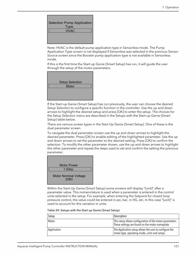
Selection Pump ApplicationType HVAC
Note: HVAC is the default pump application type in Sensorless mode. The PumpApplication Type screen is not displayed if Sensorless was selected in the previous SensorSource screen since the Booster pump application type is not available in Sensorlessmode.
If this is the first time the Start-up Genie (Smart Setup) has run, it will guide the userthrough the setup of the motor parameters.
Setup SelectionMotor
If the Start-up Genie (Smart Setup) has run previously, the user can choose the desiredSetup Selection to configure a specific function in the controller. Use the up and downarrows to highlight the desired setup and press [OK] to enter the setup. The choices forthe Setup Selection menu are described in the Setups with the Start-up Genie (SmartSetup) table below.
There are various screen types in the Start-Up Genie (Smart Setup). One of these is thedual parameter screen.
To navigate the dual parameter screen use the up and down arrows to highlight thedesired parameter. Press [OK] to enable editing of the highlighted parameter. Use the upand down arrows to set the parameter to the desired setting. Press [OK] to confirm theselection. To modify the other parameter shown, use the up and down arrows to highlightthe other parameter and repeat the steps used to set and confirm the setting the previousparameter.
Motor Power
208VMotor Nominal Voltage
1.50hp
Within the Start-Up Genie (Smart Setup) some screens will display “[unit]” after aparameter value. This nomenclature is used when a parameter is entered in the controlunits selected in the setup. For example, when entering the Setpoint for closed looppressure control, the value could be entered in psi, bar, in HG, etc. In this case “[unit]” isused to account for this variation in units.
Table 24: Setups with the Start-up Genie (Smart Setup)
Setup Description
Motor This setup allows configuration of the motor parameters.These settings are found on the motor nameplate.
Application The Application setup allows the user to configure themotor type, operating mode, units and ramps.
7 Operation
Aquavar Intelligent Pump Controller INSTRUCTION MANUAL 121

Setup Description
Multipump Setup This setup configures the controller to operate up to 4multi pumps using up to 4 MCO301 Programmable APIoption cards.
Feedback This setup allows configuration of up to 3 feedbacksources. The feedbacks can be taken in to the controllerthrough analog inputs or communications.Note: The Feedback setup is not available for sensorlesssource.
Setpoint This setup allows configuration of up to 2 setpoints. Ifmultiple setpoints are used, the setpoint is selected byusing DI 33.
Flow Compensation This setup configures the Flow Compensation functionwhich can automatically adjust the system setpoint tooffset the affect of friction loss in the system.
Pump Protection This setup configures Sleep Mode, No Water/Loss ofPrime, Digital I/O Protection, Suction Protection andSystem Protection functions. NOTE: This setup is onlyvisible after the Multipump Control setup underApplication operating mode has been selected andinvisble again after the Multipump Control setup hasbeen de-selected.
Digital Input This setup allows configuration of the digital inputs.
Relay and Analog Output This setup allows configuration of the relay and analogoutputs.
Communication This setup configures the on board fieldbuscommunications.
Bypass This setup allows the bypass panel to connect the motorto the drive or to the power line. NOTE: The Bypassselection is only available with a Bypass panel.
Maintenance This setup allows the running hours counter to be reset.
7.5.2 Main Menu setupThe Main Menu setup configures the Start-Up Genie (Smart Setup) setup that was runbefore, or was not run before or after a factory reset/initialization.
7 Operation
122 Aquavar Intelligent Pump Controller INSTRUCTION MANUAL

20
20
1
Motor Setup
50 160 180 200 260 280 300 390130 410
9
Setup Selection
Main Menu
12
Exit
Exit
600
6
12
Complete
12
see notes
Regional Setting
Language selection
End of Setup
2
3Sensor Source Sensor
Sensorless
(No)
(Yes)
(Sensorless data detected?)
4
Start-Up Genie(Smart Setup)
Pump Application
(Setup not run before)HVAC
Booster
(Setup run before)
Go to default Status screen
Figure 91: Main Menu Flow Diagram
Main Menu flow diagram notes:
20: Motor Setup
50: Application Setup
130: Feedback Setup (not available in Sensorless mode)
160: Setpoint Setup
180: Flow Compensation Setup
200: Pump Protection Setup
260: Digital Input Setup
280: Relay & Analog Output Setup
300: Communication Setup (not available in Test Run mode)
390: Maintenance
410: Multipump Setup (only available after Multipump Control operating mode wasselected)
600: Bypass Setup (only available with a Bypass panel)
7 Operation
Aquavar Intelligent Pump Controller INSTRUCTION MANUAL 123

Table 25: Main Menu Screens
Screen IDNo.
Screen Selection Parameters SetupInformation
Screen Information
1
Regional SettingsNorth America
[North America][International]
• (Setup not runbefore): [22-00] =20s, [22-36] = 1500RPM (All Setup),[22-37] = 50 Hz (AllSetup), [5-10] =MCO Specific, [0-24]= 1989, [5-12] = NoOperation, [3-04] =External/Preset.
• (Setup run before):[22-00] = 20 seconly if [22-00] < 1sec.
• North America: Set[0-03] = NorthAmerica, [0-02] =Hz , [3-03] = 60 Hzif Setup not runbefore.
• International: Set[0-03] =International.
Continue to screen ID #2.
2
LanguageEnglish US
• North America:[English US]
[French][Spanish]
• International[English][German][French][Danish][Spanish][Italian]
[Swedish][Dutch]
[Chinese][Finnish]
[Portuguese][Slovenian]
[Korean][Turkish][Czech][Polish]
[Russian]
Note: The language canbe changed in [0-01]Language.
• (Sensorless data isdetected): continueto screen ID #3.
• (Sensorless data isnot detected):
– (Setup not runbefore):continue to theMotor SetupScreens table.
– (Setup runbefore):continue toscreen ID #6.
7 Operation
124 Aquavar Intelligent Pump Controller INSTRUCTION MANUAL
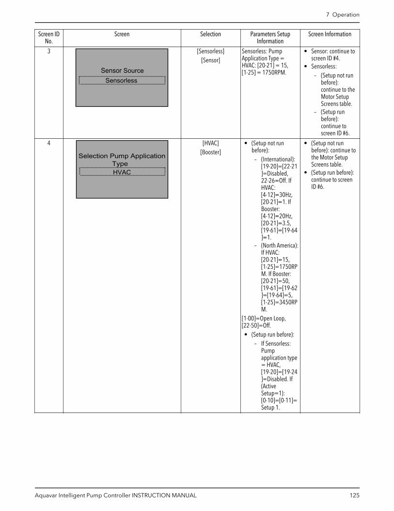
Screen IDNo.
Screen Selection Parameters SetupInformation
Screen Information
3
Sensor SourceSensorless
[Sensorless][Sensor]
Sensorless: PumpApplication Type =HVAC: [20-21] = 15,[1-25] = 1750RPM.
• Sensor: continue toscreen ID #4.
• Sensorless:– (Setup not run
before):continue to theMotor SetupScreens table.
– (Setup runbefore):continue toscreen ID #6.
4
Selection Pump ApplicationType HVAC
[HVAC][Booster]
• (Setup not runbefore):
– (International):[19-20]=[22-21]=Disabled,22-26=Off. IfHVAC:[4-12]=30Hz,[20-21]=1. IfBooster:[4-12]=20Hz,[20-21]=3.5,[19-61]=[19-64]=1.
– (North America):If HVAC:[20-21]=15,[1-25]=1750RPM. If Booster:[20-21]=50,[19-61]=[19-62]=[19-64]=5,[1-25]=3450RPM.
[1-00]=Open Loop,[22-50]=Off.• (Setup run before):
– If Sensorless:Pumpapplication type= HVAC,[19-20]=[19-24]=Disabled. If(ActiveSetup=1):[0-10]=[0-11]=Setup 1.
• (Setup not runbefore): continue tothe Motor SetupScreens table.
• (Setup run before):continue to screenID #6.
7 Operation
Aquavar Intelligent Pump Controller INSTRUCTION MANUAL 125

Screen IDNo.
Screen Selection Parameters SetupInformation
Screen Information
6
Setup SelectionApplication
[Motor][Application]
[Multipump Setup][Feedback][Setpoint]
[Flow Compensation][Pump Protection]
[Digital Input][Relay & Analog Output]
[Communication][Maintenance]
[Bypass][Exit]
• Exit: continue toscreen ID #12.
• Other selections:continue to theselected SetupSelection Screenstable.
NOTE:• Multipump Setup is
only visible afterMultipump Controlhas been selected inApplication Setup.
• Bypass is onlyvisible for a Bypasspanel.
12
Start-Up Genie CompletePress [OK] to Exit
[OK] OK: The default Statusscreen is displayed.
7.5.3 Motor setupThe motor data required to complete the Motor Setup can be found on the motornameplate. The Start-Up Genie (Smart Setup) will prompt the user for Motor Power (kW orhp), Motor Nominal Voltage, Motor Nominal Frequency (Hz), Motor Nominal Speed(RPM), Motor Current (FLA) and Current Limit (only for Booster mode). The [1–80] Functionat Stop will be set to Coast and [1–82] Min Speed for Function at Stop [Hz] to 10 Hz forboth Booster and HVAC pump application types.
1. If a Booster pump application was selected, Current Limit (%) can be set as apercentage of the Motor Current (FLA). For example, if the Motor Current (FLA)indicated on the motor nameplate is 10A and the Motor Service Factor Current (SFA) is11.5A, enter 115% for Current Limit (%). Be sure to correctly set the Motor Current(FLA) and Current Limit. These parameters configure the motor overload protectionfeature.
– If a Submersible motor is selected, the controller is configured to have a 30 Hzminimum speed at [4-12] Sleep Frequency/Low Limit [Hz] (North America), rampfrom stop to 29 Hz in 1 second ([1-78] Compressor Start Max Speed [Hz] = 29 Hzand [3-82] Starting Ramp Up Time = 1s, and [14-01] Switching Frequency is set to2KHz.
– If a Surface motor is selected, select the Sleep Speed/Low Limit for configuringparameter [4-11] Motor Speed Low Limit [RPM] (International) or [4-12] SleepFrequency/Low Limit [Hz] (North America). The [1-78] Compressor Start Max Speed[Hz] is inactive and [3-82] Starting Ramp Up Time is set at 3s, and [14-01] SwitchingFrequency is set at 5KHz.
– Next select a type for the Filter Type. Parameter [14-55] Output Filter will be set atNo Filter for None, Reactor, Dv/Dt or HVAC, and Sine Wave Filter Fixed for SineWave. Parameter [14-01] Switching Frequency will be set at 4 kHz for Reactor,Dv/Dt or HVAC, and at 5 kHz for Sine Wave.
2. If an HVAC pump application was selected, the Current Limit (%) and Motor Type arenot available for setting. For the North America regional setting, the controller is
7 Operation
126 Aquavar Intelligent Pump Controller INSTRUCTION MANUAL
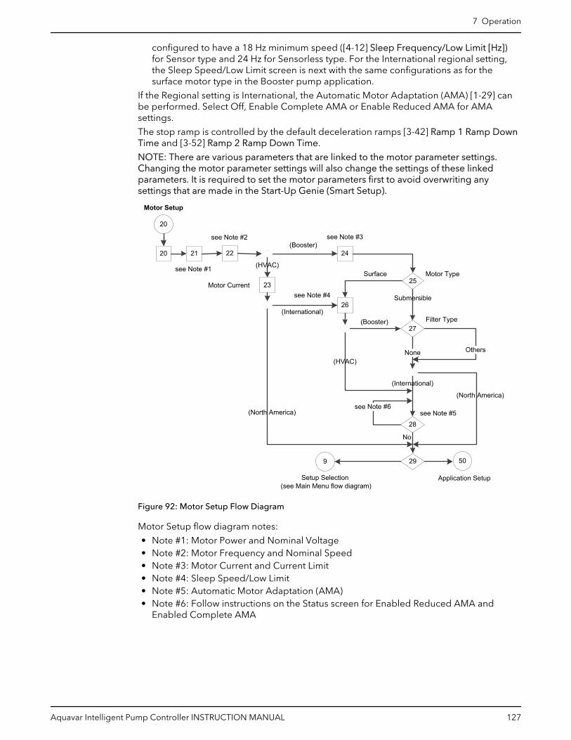
configured to have a 18 Hz minimum speed ([4-12] Sleep Frequency/Low Limit [Hz])for Sensor type and 24 Hz for Sensorless type. For the International regional setting,the Sleep Speed/Low Limit screen is next with the same configurations as for thesurface motor type in the Booster pump application.
If the Regional setting is International, the Automatic Motor Adaptation (AMA) [1-29] canbe performed. Select Off, Enable Complete AMA or Enable Reduced AMA for AMAsettings.
The stop ramp is controlled by the default deceleration ramps [3-42] Ramp 1 Ramp DownTime and [3-52] Ramp 2 Ramp Down Time.
NOTE: There are various parameters that are linked to the motor parameter settings.Changing the motor parameter settings will also change the settings of these linkedparameters. It is required to set the motor parameters first to avoid overwriting anysettings that are made in the Start-Up Genie (Smart Setup).
20 21 24
23 25
50
Application Setup
20
Motor Setup
22
9
Motor Type
see Note #2
see Note #4
27
None
Filter Type
(Booster)
(HVAC)
Submersible
Surface
Setup Selection(see Main Menu flow diagram)
Others
see Note #3
(North America)
(International)
29
see Note #5
26
(HVAC)
(Booster)
Motor Current
28
see Note #6
No
see Note #1
(International)
(North America)
Figure 92: Motor Setup Flow Diagram
Motor Setup flow diagram notes:
• Note #1: Motor Power and Nominal Voltage• Note #2: Motor Frequency and Nominal Speed• Note #3: Motor Current and Current Limit• Note #4: Sleep Speed/Low Limit• Note #5: Automatic Motor Adaptation (AMA)• Note #6: Follow instructions on the Status screen for Enabled Reduced AMA and
Enabled Complete AMA
7 Operation
Aquavar Intelligent Pump Controller INSTRUCTION MANUAL 127

Table 26: Motor Setup Screens
20Motor Setup
Screen IDNo.
Screens Selections [Parameters] SetupInformation
Screen Information
20
Setup SelectionMotor
The Motor setup isrequired to becompletely configured atthe first time of runningStart-Up Genie (SmartSetup) setup or after afactory reset or aninitialization.
21
Motor Power
208VMotor Nominal Voltage
1.50hp
_____ [kW/hp]_____ V
kW: [1-20] = first entryhp: [1-21] = first entry[1-22] = second entry.
Continue to screen ID#22.
22
60HzMotor Nominal Speed
1704RPM
Motor Frequency
_____ Hz_____ RPM
[1-23] = first entry.[1-25] = second entry.[3-03] & [4-14] = [1-23][22-37] = [1-23] * 0.85.[1-80] = Coast[1-82] = 10 Hz[22-33] = 4.14 x 0.5
• (HVAC): continue toscreen ID #23.
• (Booster): continueto screen ID #24.
23
Motor Current5.48A
______ A [1-24] = entry.[3-82] = 3 s.[1-78] = 0 Hz[14-01] = 5 kHz(HVAC): [14-55] = NoFilter• Sensor: [4-12] =
18 Hz• Sensorless: [4-12] =
24 Hz
• (International):continue to screen ID#26.
• (North America):continue to screen ID#29.
Note: This screen is onlydisplayed in the HVACpump application.
24
110.0%Current Limit
Motor Current5.48A
______ A______%
[1-24] = first entry.[4-18] = second entry.[22-39] = [1-21] * [4-18]* 0.46,[22-35] = [22*39] *([22-33] / [4-14]) ^3.
Continue to screen ID#25.Note: This screen is onlydisplayed in the Boosterpump application.
25
Motor TypeSurface
[Submersible][Surface]
• Submersible:[4-12] = 30 Hz[1-78] = 29 Hz[3-82] = 1 s[14-01] = 2 kHz
• Surface: continue toscreen ID #26.
• Submersible:continue to screen ID#27.
7 Operation
128 Aquavar Intelligent Pump Controller INSTRUCTION MANUAL

20Motor Setup
Screen IDNo.
Screens Selections [Parameters] SetupInformation
Screen Information
26
Sleep Speed / Low Limit18.0Hz
_____ [RPM/Hz] Rpm: [4–11] = entryHz: [4-12] = entry[1-78] = 0 Hz[3-82] = 3 s[14-01] = 5 kHz
• (Booster): continueto screen ID #27.
• (HVAC): continue toscreen ID #28.
27
Dv/DtFilter Type
[None][Reactor][Dv/Dt]
[Sine wave]
• None: [14-55] = NoFilter
• Sine wave: [14-55]= Sine Wave FilterFixed, [14-01] =5 kHz
• Reactor or Dv/Dt:[14-55] = No Filter,[14-01] = 4 kHz
• (International):Continue to screenID #29.
• (North America):Continue to screenID #30.
28 [RPM/Hz] Rpm: [4–11] = entryHz: [4-12] = entry[1-78] = 0 Hz[3-82] = 3 s[14-01] = 5 kHz[14-55] = No Filter
See the above screen ID#27.
29
Off
Automatic MotorAdaption (AMA)
[Off][Enable Complete AMA][Enable Reduced AMA]
• Off: continue toscreen ID #29.
• Others: followinstructions on theStatus screen.
30
Yes
[Yes][No]
• Yes: continue to theApplication SetupScreens table.
• No: return to theSetup Selectionscreen ID #6 in theMain Menu Screenstable.
7.5.4 Application setupThe next menu set is the Application setup which will allow selection and configuration ofthe application type and control response. Select the application type by first selecting theOperating Mode. Selecting the Operating Mode will configure specific parameters toconfigure the selected mode.
Note: If the Operating Mode is changed, any changes made to configure the previouslyconfigured Operating Mode will be overwritten.
The Operating Mode can be set to Single Pump Control, Multipump Control, SpeedControl, Follower Control, or Test Run Mode.
NOTE:
7 Operation
Aquavar Intelligent Pump Controller INSTRUCTION MANUAL 129

• Setup 1 is the active setup for all operating modes.• Multipump Control is the default value for the North America regional setting and
Single Pump control is the default value for the International regional setting.• Follower Control is only available for the North America regional setting.
The various Operating Modes are defined below.
Table 27: Operating modes
Operating Mode Description
Single Pump Control This mode is the default Operating Mode. Use this modefor constant pressure, flow or level applications that usesone controller operating a single pump. Parameters[19-56] and [8-31] should be set at 1 in single pumpmode.
Multipump Control This mode requires up to four MCO301 ProgrammableAPI option cards installed to the controllers to configure asystem that has one master with up to three followers, ormultipimp applications. There will always be one masterat one time. All pumps can run synchronously orconfigured multiple application.Note: Multipump Control selection is only available whena MCO301 Programmable API option cards is installedand functioning.
Speed Control This mode configures the controller to accept a speedcommand through an analog input, pulse input orextended PI loop [21–**]. A start signal on DI 18 [5–10] isrequired.
Follower Control This mode configures the controller to be operated as IPCFollower Control or PLC Follower Control.
Test Run Mode Test Run Mode allows the controller to be configured torun the pump at specified speed for a specified amountof time. The action will be started by a digital input (DI18).
15
Application Setup
50
54 55 56 58
9
5 Operating Mode Setup Selection(see Main Menu flow diagram)
Single Pump Control
Multipump Control
Speed Control
Test Run Mode
57
Follower Control
Figure 93: Application Setup Flow Diagram
7 Operation
130 Aquavar Intelligent Pump Controller INSTRUCTION MANUAL

Table 28: Application Setup Screens
50Application Setup
Screen IDNo.
Screens Selections Parameters SetupInformation
Screen Information
50
ApplicationSetup Selection
The Application setup isrecommended to becompletely configured forthe first time of runningStart-Up Genie (SmartSetup) setup or after afactory reset or aninitialization.
51Operating Mode
CHANGING OPERATINGMODE WILL OVERWRITE
CURRENT SETUP!Single Pump Control
[Single Pump Control][Multipump Control]
[Speed Control][Follower Control][Test Run Mode]
[Exit]
If (Old) Operating Mode= selection: [5-10]=[75]MCO Specific.If Selection = MultipumpControl: [19-01] = [5]Multi Master MulCtl.
• Exit: continue to theSetup Selection inMain Menu Screenstable.
• Continue to thescreens table of theselected OperatingMode.
7.5.5 Single Pump Control setupThe Single Pump Control is the default operating mode for the International regionalsetting. Use this mode for Constant Pressure, Flow Control (Constant Flow), or LevelControl (Constant Level) applications that use one controller operating a single pump.
• The Application Type screen allows selection of the type of control. For Booster pumpapplication select either Constant Pressure, Flow Control or Level Control for the NorthAmerica regional setting, or Constant Pressure, Constant Flow or Constant Level forInternational regional setting. For HVAC pump application, select either ConstantPressure or Flow Control for the North America region or Constant Pressure orConstant Flow for the International region. Level Control (Constant Level) is notavailable in HVAC pump application. Sensorless mode is not available in Boosterpump application.
• Select the appropriate units for the application.• Select whether the application is a Tank Fill or Tank Empty application.
• In a ‘Fill’ application the pump will speed up when the level in the tank drops belowthe setpoint level.
• In an ‘Empty’ application the pump will speed up when the level in the tank is abovesetpoint level.
• The [20-81] PID Normal / Inverse Control parameter is set to Inverse for the ‘Empty’application and to Normal for the ‘Fill’ application.
If Booster mode is the pump application, the ramp times for North America orInternational regional setting are selected next. Select from either a Fast, Medium or Slowramp.
Acceleration ramps are set in [3-41] Ramp 1 Ramp Up Time. Deceleration ramps are set in[3-42] Ramp 1 Ramp Down Time.
Table 29: Ramp Time values for North America Region
ParametersLevel Control Constant Pressure/Flow Control
Slow Medium Fast Slow Medium Fast
[3-41] Ramp 1Ramp Up Time
80 secs 40 secs 20 secs 20 secs 10 secs 5 secs
7 Operation
Aquavar Intelligent Pump Controller INSTRUCTION MANUAL 131

ParametersLevel Control Constant Pressure/Flow Control
Slow Medium Fast Slow Medium Fast
[3-42] Ramp 1Ramp DownTime
80 secs 40 secs 20 secs 10 secs 5 secs 3 secs
[3-51] Ramp 2Ramp Up Time
90 secs 90 secs 90 secs 70 secs 70 secs 70 secs
[3-52] Ramp 2Ramp DownTime
90 secs 90 secs 90 secs 70 secs 70 secs 70 secs
Table 30: Ramp Time values for International Region
ParametersConstant Level Constant Pressure/Constant Flow
Slow Medium Fast Slow Medium Fast
[3-41] Ramp 1Ramp Up Time
16 secs 12 secs 8 secs 8 secs 6 secs 4 secs
[3-42] Ramp 1Ramp DownTime
16 secs 12 secs 8 secs 8 secs 6 secs 4 secs
[3-51] Ramp 2Ramp Up Time
90 secs 90 secs 90 secs 70 secs 70 secs 70 secs
[3-52] Ramp 2Ramp DownTime
90 secs 90 secs 90 secs 70 secs 70 secs 70 secs
In Sensorless mode, ramp time selection is not available. 10 seconds are set by the Start-up Genie (Smart Setup) for both acceleration and deceleration Ramp 1 time in bothSensor and Sensorless modes.
The Regulation Band is the next screen if the [Regional Setting] = International and PumpApplication Type = Booster.
• Regulation Band (International only): a percentage of the required value, centered onit. When the read pressure is close to the required value, inside the regulation band,the system uses slow ramps. Outside the regulation band the system uses fast ramps.See the Regulation band information in the below Ramp Control description.
• Ramp Control description (International only): System control uses fixed ramps toregulate system variable to follow setpoint as described below.
• Ramps can be set to one of the preset values:
– Slow: big pump size– Medium: medium pump size– Fast: small pump size
Ramp time
Booster HVAC
Ramp 1 Ramp 2 Ramp 1 Ramp 2
Up Down Up Down Up Down Up Down
Fast 4 4 70 70 8 8 90 90
Medium 6 6 70 70 12 12 90 90
Fast 8 8 70 70 16 16 90 90
The ramp is expressed in seconds and represents the time needed for the motor to gofrom 0 Hz to the maximum frequency, or from maximum frequency to 0 Hz.
Ramp 1 (up or down) is always used below minimum frequency/sleep frequency andwhen feedback value is outside the regulation band.
Ramp 2 (up or down) is used when feedback value is inside the regulation band.
7 Operation
132 Aquavar Intelligent Pump Controller INSTRUCTION MANUAL

The motor control will use the ramp-up (1 or 2) till the feedback value reaches the upperlimit of the regulation band. Once the upper limit is reached, the motor control will usethe ramp-down (1 or 2) till the feedback value reaches the lower limit of the regulationband.
Parameter Description
3–41 Ramp 1 Ramp Up Time
3–42 Ramp 1 Ramp Down Time
3–51 Ramp 2 Ramp Up Time
3–52 Ramp 2 Ramp Down Time
Figure 94: Chart
1. Setpoint2. Control feedback (actual value)3. Regulation band4. Sleep delay5. Sleep frequency6. Output frequency7. Regulating with Ramp 2 Up and Ramp 2 Down (slow ramps)
7 Operation
Aquavar Intelligent Pump Controller INSTRUCTION MANUAL 133

see Note #2
see Note #1
66
64
(Constant Pressure) 65 (Yes)
69
No
70
340
Feedback Setup
Multipump Setup
62
130
Single Pump Control
(Booster)
(HVAC)
410
54
60
(Sensorless)
9
55
Multipump Control
67
(No)
Yes
(Sensorless)
Yes
63 Tank Fill/Empty
Units
Units
see Note #4
Autoset
71
Setup Selection(see Main Menu flow diagram)
No (Sensor)
No
160
Setpoint Setup
Yes
61
(Sensor)
(Constant Pressure)
see Note #1
Application Type
Application Type
(Booster)
(HVAC)
see Note #3(No)
(International)
68(Yes)
Figure 95: Single Pump Control Flow Diagram
Single Pump Control flow diagram notes:
1. Note #1:
– North America: (Flow Control)– International: (Constant Flow)
2. Note #2:
– North America: (Level Control)– International: (Constant Level)
3. Note #3:
– (North America or International)4. Note #4: Ramp Time
– Slow, Medium or Fast for Level Control (Constant Level), or Constant Pressure/FlowControl (Constant Flow)
7 Operation
134 Aquavar Intelligent Pump Controller INSTRUCTION MANUAL

Table 31: Single Pump Control Setup Screens
54Single Pump Control Setup
Screen IDNo.
Screens Selections Parameters SetupInformation
Screen Information
60Operating Mode
CHANGING OPERATINGMODE WILL OVERWRITE
CURRENT SETUP!Single Pump Control
[19-01] = Disabled,[19-00] = [1] ProcessControl, [19-50] =[19-56] = [25-20] =[25-22] = 1, [0-24] =1989, [0-21] =Frequency, [0-22] =Motor current, [0-23] =Feedback [Unit].• (North America):
[0-20] = Power [hp]• (International): [0-20]
= Power [kW]
(Pump application type):• (Booster): continue to
screen ID #61.• (HVAC): continue to
screen ID #62.
61
Application TypeLevel Control
• North America– [Constant
Pressure]– [Flow Control]– [Level Control]
• International– [Constant
Pressure]– [Constant Flow]– [Constant Level]
Note: Level Control(Constant Level) is onlyavailable for Boosterpump application mode.
• Level Control(Constant Level):[20-93] = 3s &[20-94] = 10s.
• Flow Control(Constant Flow) &Constant Pressure:[20-93] = 5s and[20-94] = 3.3s.
• These applicationtypes are available forthe Booster pumpapplication.
• Application Type:– Level Control
(Constant Level):continue toscreen ID #63.
– Flow Control(Constant Flow):continue toscreen ID #64.
– ConstantPressure:continue toscreen ID #65.
7 Operation
Aquavar Intelligent Pump Controller INSTRUCTION MANUAL 135

54Single Pump Control Setup
Screen IDNo.
Screens Selections Parameters SetupInformation
Screen Information
62
Application TypeConstant Pressure
• North America– [Constant
Pressure]– [Flow Control]
• International– [Constant
Pressure]– [Constant Flow]
• (Sensor): [20-93] =5s; [20-94] = 3.3s.
• (Sensorless): [20-03]= [20-06] = NoFunction; [20-20] =Minimum; [6-17] =Disabled; [20-13] =0; [3-41] = [3-42] =10s.
– ConstantPressure: [20-00]= SensorlessPressure; [20-02]= [20-12] = PSI;[20-60] = GPM;[6-15] = 300;[20-14] = 300PSI.
– Flow Control(Constant Flow):[20-00] =Sensorless Flow;[20-02] =[20-12] = GPM;[20-60] = PSI;[6-15] = 4000;[20-14] = 4000GPM
• These applicationtypes are available forthe HVAC pumpapplication.
• (Sensor):– Flow Control
(Constant Flow):continue toscreen ID #64.
– ConstantPressure:continue toscreen ID #65.
• (Sensorless):– (Single Pump
Control):continue toscreen ID #68.
– (MultipumpControl):continue to theMultipumpSetup Screenstable.
63
Level control unitsft
[ft][in WG][ft WG]
[m][m WG]
[20-02] = [20-05] =[20-08] = [20-12] =selection
Continue to screen ID#66.
64
Flow control unitsGPM
[GPM][gal/s]
[gal/min][gal/h][CFM][ft3/s]
[ft3/min][ft3/h][m3/h]
[20-02] = [20-05] =[20-08] = [20-12] =selection[20-81] = Normal(HVAC): [3-41] = [3-42] =10s
• (Booster): continue toscreen ID #67
• (HVAC):– If (Multipump
Control):continue to theMultipumpSetup Screenstable.
– Else: continue toscreen ID #68.
7 Operation
136 Aquavar Intelligent Pump Controller INSTRUCTION MANUAL

54Single Pump Control Setup
Screen IDNo.
Screens Selections Parameters SetupInformation
Screen Information
65
Pressure control unitspsi
[psi][lb/in2][in Hg][mbar][bar][Pa]
[kPa][mm Hg]
See the above screen ID#64.
See the above screen ID#64.
66
Tank Fill or Tank EmptyApplication
Fill
[Fill][Empty]
• Fill: [20-81] =Normal
• Empty: [20-81] =Inverse
See the above screen ID#64.
67
Ramp TimeFast
[Fast][Medium]
[Slow]
(North America): see Table 29: Ramp Timevalues for North AmericaRegion on page 131.(International): see Table30: Ramp Time values forInternational Region onpage 132.
• This screen is onlyavailable for Boosterpump applicationtype.
• (North America): if(Multipump Control)then continue to theMultipump SetupScreens table, elsecontinue to screen ID#69.
• (International):continue to screen ID#68.
68
20%Regulation Band
____ % [20-84] = entry • If (MultipumpControl): continue tothe Multipump SetupScreens table.
• Else: continue toscreen ID #69.
Note: only forInternational regionalsetting and Boostermode. See the RegulationBand description in Single Pump Controlsetup on page 131.
7 Operation
Aquavar Intelligent Pump Controller INSTRUCTION MANUAL 137
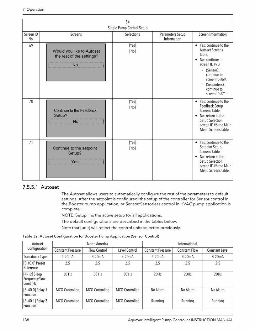
54Single Pump Control Setup
Screen IDNo.
Screens Selections Parameters SetupInformation
Screen Information
69Would you like to Autosetthe rest of the settings?
No
[Yes][No]
• Yes: continue to theAutoset Screenstable.
• No: continue toscreen ID #70.
– (Sensor):continue toscreen ID #69.
– (Sensorless):continue toscreen ID #71.
70
Continue to the FeedbackSetup?
No
[Yes][No]
• Yes: continue to theFeedback SetupScreens Table.
• No: return to theSetup Selectionscreen ID #6 the MainMenu Screens table.
71Continue to the setpoint
Setup?
Yes
[Yes][No]
• Yes: continue to theSetpoint SetupScreens Table.
• No: return to theSetup Selectionscreen ID #6 the MainMenu Screens table.
7.5.5.1 AutosetThe Autoset allows users to automatically configure the rest of the parameters to defaultsettings. After the setpoint is configured, the setup of the controller for Sensor control inthe Booster pump application, or Sensor/Sensorless control in HVAC pump application iscomplete.
NOTE: Setup 1 is the active setup for all applications.
The default configurations are described in the tables below.
Note that [unit] will reflect the control units selected previously.
Table 32: Autoset Configuration for Booster Pump Application (Sensor Control)
AutosetConfiguration
North America International
Constant Pressure Flow Control Level Control Constant Pressure Constant Flow Constant Level
Transducer Type 4-20mA 4-20mA 4-20mA 4-20mA 4-20mA 4-20mA
[3-10.0] PresetReference
2.5 2.5 2.5 2.5 2.5 2.5
[4–12] SleepFrequency/LowLimit [Hz]
30 Hz 30 Hz 30 Hz 20Hz 20Hz 20Hz
[5–40.0] Relay 1Function
MCO Controlled MCO Controlled MCO Controlled No Alarm No Alarm No Alarm
[5–40.1] Relay 2Function
MCO Controlled MCO Controlled MCO Controlled Running Running Running
7 Operation
138 Aquavar Intelligent Pump Controller INSTRUCTION MANUAL

AutosetConfiguration
North America International
Constant Pressure Flow Control Level Control Constant Pressure Constant Flow Constant Level
[6–15] Terminal 53High Ref./Feedb.Value
300 [unit] 4000 [unit] 300 [unit] 10 [unit] 100 [unit] 10 [unit]
[6–17] Terminal 53Sensor Fault (NorthAmerica) / LiveZero(International)
Disabled Disabled Disabled Disabled Disabled Disabled
[6–27] Terminal 54Sensor Fault (NorthAmerica) / LiveZero(International)
Disabled Disabled Disabled Disabled Disabled Disabled
[13-20.0] SLController Timer
10 Min 10 Min 10 Min 30 secs 30 secs 30 secs
[14-20] ResetMode
Manual Reset Manual Reset Manual Reset Manual Reset Manual Reset Manual Reset
[19-10] PumpExercise Idle Time
0 0 0 100 100 100
[19-11] PumpExercise Run Time
NA NA NA 10 10 10
[19-12] FlowCompensation
Disabled Disabled Disabled Disabled Disabled Disabled
[19–20] No WaterLoss of Prime Fault
Alarm Alarm Alarm Disabled Disabled Disabled
[19–21] No WaterLoss of PrimeProtection Delay
60 60 60 60 60 60
[19–22] No WaterLoss of PrimeRestart Time
10 min. 10 min. 10 min. 10 min. 10 min. 10 min.
[19–23] No WaterLoss of PrimeRestart Attempt
3 3 3 3 3 3
[19-24] No FlowShutdown
Enabled Disabled Enabled Enabled Disabled Enabled
[19–25] No FlowRestart Difference
10 10 10 NA NA NA
[19-26] HighSystem Fault
Disabled Disabled Disabled Disabled Disabled Disabled
[19-27] HighSystem Limit
100 100 100 10 100 10
[19-28] HighSystem Delay
3 3 3 3 3 3
[19-32] LowSuction Fault
Disabled Disabled Disabled Disabled Disabled Disabled
[19-36] HighSuction Fault
Disabled Disabled Disabled Disabled Disabled Disabled
[19-40] All ZonesFailure Function
Stop Stop Stop Stop and Trip Stop and Trip Stop and Trip
[19-45] LowSystem Fault
Disabled Disabled Disabled Disabled Disabled Disabled
7 Operation
Aquavar Intelligent Pump Controller INSTRUCTION MANUAL 139
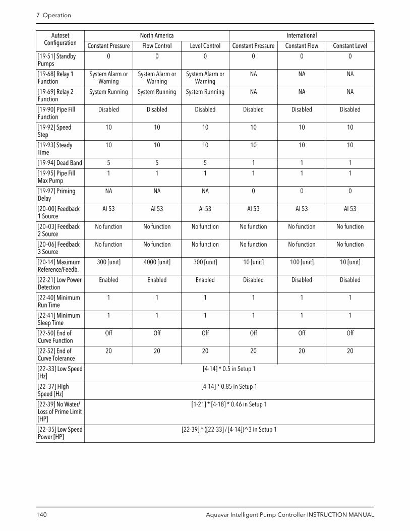
AutosetConfiguration
North America International
Constant Pressure Flow Control Level Control Constant Pressure Constant Flow Constant Level
[19-51] StandbyPumps
0 0 0 0 0 0
[19-68] Relay 1Function
System Alarm orWarning
System Alarm orWarning
System Alarm orWarning
NA NA NA
[19-69] Relay 2Function
System Running System Running System Running NA NA NA
[19-90] Pipe FillFunction
Disabled Disabled Disabled Disabled Disabled Disabled
[19-92] SpeedStep
10 10 10 10 10 10
[19-93] SteadyTime
10 10 10 10 10 10
[19-94] Dead Band 5 5 5 1 1 1
[19-95] Pipe FillMax Pump
1 1 1 1 1 1
[19-97] PrimingDelay
NA NA NA 0 0 0
[20–00] Feedback1 Source
AI 53 AI 53 AI 53 AI 53 AI 53 AI 53
[20–03] Feedback2 Source
No function No function No function No function No function No function
[20–06] Feedback3 Source
No function No function No function No function No function No function
[20-14] MaximumReference/Feedb.
300 [unit] 4000 [unit] 300 [unit] 10 [unit] 100 [unit] 10 [unit]
[22-21] Low PowerDetection
Enabled Enabled Enabled Disabled Disabled Disabled
[22-40] MinimumRun Time
1 1 1 1 1 1
[22-41] MinimumSleep Time
1 1 1 1 1 1
[22-50] End ofCurve Function
Off Off Off Off Off Off
[22-52] End ofCurve Tolerance
20 20 20 20 20 20
[22–33] Low Speed[Hz]
[4-14] * 0.5 in Setup 1
[22–37] HighSpeed [Hz]
[4-14] * 0.85 in Setup 1
[22-39] No Water/Loss of Prime Limit[HP]
[1-21] * [4-18] * 0.46 in Setup 1
[22–35] Low SpeedPower [HP]
[22-39] * ([22-33] / [4-14])^3 in Setup 1
7 Operation
140 Aquavar Intelligent Pump Controller INSTRUCTION MANUAL

Table 33: Autoset Configuration for HVAC Pump Application (Sensor and Sensorless Control)
AutosetConfiguration
North America International
Sensor Sensorless Sensor Sensorless
ConstantPressure
Flow Control ConstantPressure
Flow Control ConstantPressure
Constant Flow ConstantPressure
Constant Flow
TransducerType
4-20mA 4-20mA SensorlessControl
SensorlessControl
4-20mA 4-20mA SensorlessControl
SensorlessControl
[4–12] SleepFrequency/Low Limit [Hz]
18 Hz 18 Hz 24 Hz 24 Hz 30 Hz 30 Hz 30 Hz 30 Hz
[5–40.0] Relay1 Function
MCOControlled
MCOControlled
MCOControlled
MCOControlled
No Alarm No Alarm No Alarm No Alarm
[5–40.1] Relay2 Function
MCOControlled
MCOControlled
MCOControlled
MCOControlled
Running Running Running Running
[6–15]Terminal 53High Ref./Feedb.Value
300 [unit] 4000 [unit] 36 [unit] 4000 [unit] 10 [unit] 100 [unit] 10 [unit] 100 [unit]
[6–17]Terminal 53Sensor Fault(NorthAmerica) / LiveZero(International)
Disabled Disabled Disabled Disabled Disabled Disabled Disabled Disabled
[6–27]Terminal 54Sensor Fault(NorthAmerica) / LiveZero(International)
Disabled Disabled Disabled Disabled Disabled Disabled Disabled Disabled
[14-20] ResetMode
Manual Reset Manual Reset AutomaticReset x 3
AutomaticReset x 3
Manual Reset Manual Reset AutomaticReset x 3
AutomaticReset x 3
[19-10] PumpExercise IdleTime
0 0 0 0 100 100 100 100
[19-11] PumpExercise RunTime
NA NA NA NA 10 10 10 10
[19-12] FlowCompensation
Disabled Disabled Disabled Disabled Disabled Disabled Disabled Disabled
[19–20] NoWater Loss ofPrime Fault
Disabled Disabled Disabled Disabled Disabled Disabled Disabled Disabled
[19-24] NoFlowShutdown
Disabled Disabled Disabled Disabled Disabled Disabled Disabled Disabled
[19-26] HighSystem Fault
Disabled Disabled Disabled Disabled Disabled Disabled Disabled Disabled
[19-27] HighSystem Limit
100 100 100 100 10 100 10 100
[19-28] HighSystem Delay
3 3 3 3 3 3 3 3
7 Operation
Aquavar Intelligent Pump Controller INSTRUCTION MANUAL 141

AutosetConfiguration
North America International
Sensor Sensorless Sensor Sensorless
ConstantPressure
Flow Control ConstantPressure
Flow Control ConstantPressure
Constant Flow ConstantPressure
Constant Flow
[19-32] LowSuction Fault
Disabled Disabled Disabled Disabled Disabled Disabled Disabled Disabled
[19-36] HighSuction Fault
Disabled Disabled Disabled Disabled Disabled Disabled Disabled Disabled
[19-40] AllZones FailureFunction
Stop Stop Stop Stop Stop Stop Stop Stop
[19-45] LowSystem Fault
Disabled Disabled Disabled Disabled Disabled Disabled Disabled Disabled
[19-51]StandbyPumps
0 0 0 0 0 0 0 0
[19-68] Relay1 Function
System Alarmor Warning
System Alarmor Warning
System Alarmor Warning
System Alarmor Warning
NA NA NA NA
[19-69] Relay2 Function
SystemRunning
SystemRunning
SystemRunning
SystemRunning
NA NA NA NA
[19-72] EOCStagingFunction
Disabled Disabled Disabled Disabled Disabled Disabled Disabled Disabled
[19-90] PipeFill Function
Disabled Disabled Disabled Disabled Disabled Disabled Disabled Disabled
[19-92] SpeedStep
10 10 10 10 10 10 10 10
[19-93] SteadyTime
10 10 10 10 10 10 10 10
[19-94] DeadBand
5 5 5 5 1 1 1 1
[19-95] PipeFill Max Pump
1 1 1 1 1 1 1 1
[19-97]Priming Delay
NA NA NA NA 0 0 0 0
[20–00]Feedback 1Source
AI 53 AI 53 SensorlessPressure
SensorlessFlow
AI 53 AI 53 SensorlessPressure
SensorlessFlow
[20–03]Feedback 2Source
No function No function No function No function No function No function No function No function
[20–06]Feedback 3Source
No function No function No function No function No function No function No function No function
[20-14]MaximumReference/Feedb.
300 [unit] 4000 [unit] 300 [unit] 4000 [unit] 10 [unit] 100 [unit] 10 [unit] 100 [unit]
[22-21] LowPowerDetection
Enabled Enabled Enabled Enabled Disabled Disabled Disabled Disabled
[22-50] End ofCurveFunction
Off Off Off Off Off Off Off Off
7 Operation
142 Aquavar Intelligent Pump Controller INSTRUCTION MANUAL

AutosetConfiguration
North America International
Sensor Sensorless Sensor Sensorless
ConstantPressure
Flow Control ConstantPressure
Flow Control ConstantPressure
Constant Flow ConstantPressure
Constant Flow
[22-52] End ofCurveTolerance
20 20 20 20 20 20 20 20
Autoset
(Booster)
342
344 345 346
348
(HVAC)
350349
340
12
341 343 347
(Sensor)
352
354353
351
see Note #1see Note #2 see Note #1
(Sensorless)
Exit(see Main Menu flow diagram)
see Note #1
(Constant Pressure)
(Constant Pressure) (Constant Pressure)(Flow Control)
(Level Control) (Flow Control) (Flow Control)
Figure 96: Autoset Flow Diagram
Notes:
1. Note #1:
– North America: (Flow Control)– International: (Constant Flow)
2. Note #2:
– North America: (Level Control)– International: (Constant Level)
7 Operation
Aquavar Intelligent Pump Controller INSTRUCTION MANUAL 143
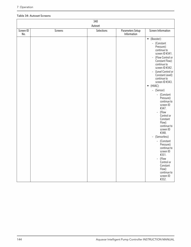
Table 34: Autoset Screens
340Autoset
Screen IDNo.
Screens Selections Parameters SetupInformation
Screen Information
• (Booster) :– (Constant
Pressure):continue toscreen ID #341.
– (Flow Control orConstant Flow):continue toscreen ID #342.
– (Level Control orConstant Level):continue toscreen ID #343.
• (HVAC):– (Sensor)
– (ConstantPressure):continue toscreen ID#347.
– (FlowControl orConstantFlow):continue toscreen ID#348.
– (Sensorless)– (Constant
Pressure):continue toscreen ID#351.
– (FlowControl orConstantFlow):continue toscreen ID#352.
7 Operation
144 Aquavar Intelligent Pump Controller INSTRUCTION MANUAL

340Autoset
Screen IDNo.
Screens Selections Parameters SetupInformation
Screen Information
341, 342,343, 347,348, 351,
352 Setpoint 115.000psi
____ [unit] • Screen ID #341:– continue to
screen ID #344.• Screen ID #342:
– continue toscreen ID #345
• Screen ID #343:– continue to
screen ID #346• Screen ID #347:
– continue toscreen ID #349
• Screen ID #348:– continue to
screen ID #350• Screen ID #351:
– continue toscreen ID #353
• Screen ID #352– continue to
screen ID #354
344 North America: Constant Pressure with 300 [unit],4-20mA sensor on AI 53, Sleep Frequency = 30Hz,
Restart Difference = 10 [unit], No Water/Loss ofPrime fault is enabled, Restart Time = 10 mins.
International: See Notes below the table
[OK] See the ConstantPressure parameterssetup information forNorth America orInternational in Table 32:Autoset Configuration forBooster PumpApplication (SensorControl) on page 138.
OK: continue to Exit inthe Main Menu Screentable.
345 North America: Flow Control with 4000 [unit],4-20mA sensor on AI 53, Sleep Mode = Disabled,
No Water/Loss of Prime fault is enabled, RestartTime = 10 mins.
International: See Notes below the table
[OK] See the Flow Control(North America) orConstant Flow(International)parameters setupinformation inTable 32:Autoset Configuration forBooster PumpApplication (SensorControl) on page 138.
OK: continue to Exit inthe Main Menu Screentable.
346 North America: Level Control with 300 [unit],4-20mA sensor on AI 53, Sleep Frequency = 30Hz,
Restart Difference = 10 [unit], No Water/Loss ofPrime fault is enabled, Restart Time = 10 mins.
International: See Notes below the table
[OK] See the Level Control(North America) orConstant Level(International)parameters setupinformation in Table 32:Autoset Configuration forBooster PumpApplication (SensorControl) on page 138.
OK: continue to Exit inthe Main Menu Screentable.
7 Operation
Aquavar Intelligent Pump Controller INSTRUCTION MANUAL 145

340Autoset
Screen IDNo.
Screens Selections Parameters SetupInformation
Screen Information
349 North America:
Constant Pressure with 36 [unit], 4-20mA sensor on AI 53, Sleep Mode =Disabled,No Water/Loss
of Prime fault isdisabled[OK]
International: See Notes below the table
[OK] See the ConstantPressure parameterssetup information forSensor Control, NorthAmerica or Internationalin Table 33: AutosetConfiguration for HVACPump Application(Sensor and SensorlessControl) on page 141.
OK: continue to Exit inthe Main Menu Screentable.
350 North America:
Flow Control with 4000 [unit],4-20mA sensor on
AI 53, Sleep Mode =Disabled, No Water/Loss
of Prime fault isdisabled.[OK]
International: See Notes below the table
[OK] See the Flow Control(North America) orConstant Flow(International)parameters setupinformation for SensorControl in Table 33:Autoset Configuration forHVAC Pump Application(Sensor and SensorlessControl) on page 141.
OK: continue to Exit inthe Main Menu Screentable.
353 North America:
Constant Pressure with 300 [unit],sensorless Control in closed loop
application[OK]
International: See Notes below the table
[OK] See the ConstantPressure parameterssetup information for ,Sensorless Control,North America orInternational in Table 33:Autoset Configuration forHVAC Pump Application(Sensor and SensorlessControl) on page 141.
OK: continue to Exit inthe Main Menu Screentable.
354 North America:
Flow Control with 4000[unit],sensorless Controlin closed loop application.
[OK]
International: See Notes below the table
[OK] See the Flow Control(North America) orConstant Flow(International),parameters setupinformation forSensorless Control in Table 33: AutosetConfiguration for HVACPump Application(Sensor and SensorlessControl) on page 141.
OK: continue to Exit inthe Main Menu Screentable.
Notes:
Screens #344, #349 and #353 will be displayed as below:
7 Operation
146 Aquavar Intelligent Pump Controller INSTRUCTION MANUAL

Constant Pressure Default Values Loaded
(See IOM)[OK]
Screens #345, #350 and #354 will be displayed as below:
Constant Flow Default Values Loaded (See IOM).
[OK]
Screen #346 will be displayed as below:
Constant Level Default Values Loaded (See IOM).
[OK]
7.5.6 Multipump Control setupThe Multipump Control configures the controllers for operation in a system with up to fourpumps via [19-01] Multi-pump Control with the following modes:
• [0] Disabled – Multi-pump control is disabled. Drive will assume single pumpfunctionality.
• [1] Fixed Spd Follower (Fixed Speed Follower): only one controller with an MCO301Programmable API option card is required. Run relays are required for the otherfollower pumps to run at full speed.
– Note: a MCB101 General Purpose I/O board is required. See Fixed Speed Followerwiring on page 88.
• [2] Fixed Master Synch (Fixed Master Synchronous): only the fixed master controllerrequires an MCO301 Programmable API option card. The fixed master controller runsits pump at a variable speed and the other active follower pumps at the same speed ofthe master pump. The Fix Master Synch setup is only available for the North Americaregional setting.
• [3] Fixed Master MulCtl (Fixed Master Multicontrol): only the fixed master controllerrequires an MCO301 Programmable API option card. The fixed master controller runsthe last staged pump at a variable speed and the other active follower pumps at fullspeed. The Fix Master MulCtl setup is only available for the North America regionalsetting.
• [4] Multi Master Synch (Multi Master Synchronous): MCO301 Programmable APIoption cards are required for all controllers. Any controller can take control as a masterthat runs the master pump at a variable speed and the other active follower pumps atthe speed of the master.
• [5] Multi Master MulCtl (Multi-Master Multicontrol): MCO301 Programmable APIoption cards are required for all controllers. Any controller can take control as a masterthat runs the lastly staged pump at a variable speed and the other active followerpumps at full speed.
7 Operation
Aquavar Intelligent Pump Controller INSTRUCTION MANUAL 147

Ramp time values: see Table 29: Ramp Time values for North America Region on page 131for North America region, and Table 30: Ramp Time values for International Region onpage 132 and Ramps Control description inSingle Pump Control setup on page 131.
55
Multipump Control
402
54
Single Pump Control
400
Pump Address
401see Note #3
see Note #2
see Note #1
Figure 97: Multipump Control Flow Diagram
Multi Control flow diagram notes:
Note #1:
• (North America):
– Fixed Spd Follower– Fixed Master Synch– Fixed Master MulCtl– Multi Master Synch– Multi Master MulCtl
• (International):
– Fixed Spd Follower– Multi Master Synch– Multi Master MulCtl
Note #2:
• (Fixed Speed Follower)• (Fixed Master Synch)• (Fixed Master MulCtrl)
Note #3:
• (Multi Master Synch)• (Multi Master MulCtrl)
Table 35: Multipump Control Screens
55Multi-pump Control
400
CHANGING OPERATINGMODE WILL OVERWRITE
CURRENT SETUP!
Operating Mode
Multipump Control
Continue to screen ID#401.
7 Operation
148 Aquavar Intelligent Pump Controller INSTRUCTION MANUAL
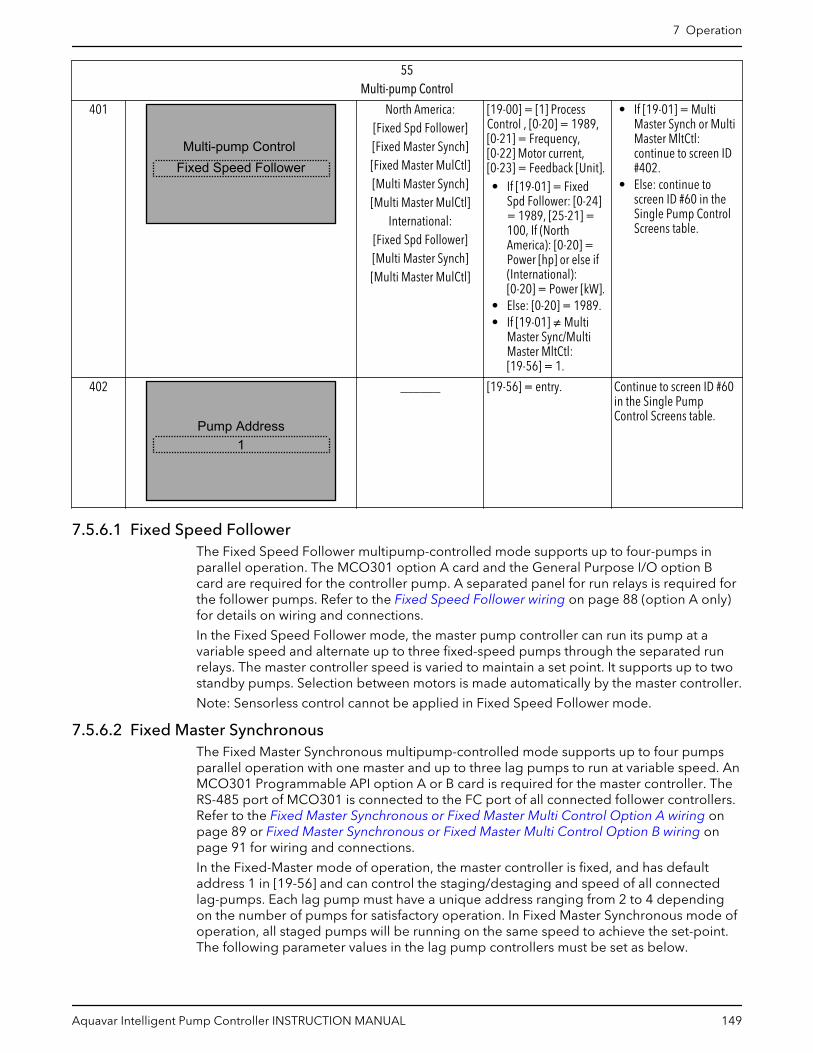
55Multi-pump Control
401
Multi-pump ControlFixed Speed Follower
North America:[Fixed Spd Follower][Fixed Master Synch][Fixed Master MulCtl][Multi Master Synch][Multi Master MulCtl]
International:[Fixed Spd Follower][Multi Master Synch][Multi Master MulCtl]
[19-00] = [1] ProcessControl , [0-20] = 1989,[0-21] = Frequency,[0-22] Motor current,[0-23] = Feedback [Unit].• If [19-01] = Fixed
Spd Follower: [0-24]= 1989, [25-21] =100, If (NorthAmerica): [0-20] =Power [hp] or else if(International):[0-20] = Power [kW].
• Else: [0-20] = 1989.• If [19-01] ≠ Multi
Master Sync/MultiMaster MltCtl:[19-56] = 1.
• If [19-01] = MultiMaster Synch or MultiMaster MltCtl:continue to screen ID#402.
• Else: continue toscreen ID #60 in theSingle Pump ControlScreens table.
402
Pump Address1
______ [19-56] = entry. Continue to screen ID #60in the Single PumpControl Screens table.
7.5.6.1 Fixed Speed FollowerThe Fixed Speed Follower multipump-controlled mode supports up to four-pumps inparallel operation. The MCO301 option A card and the General Purpose I/O option Bcard are required for the controller pump. A separated panel for run relays is required forthe follower pumps. Refer to the Fixed Speed Follower wiring on page 88 (option A only)for details on wiring and connections.
In the Fixed Speed Follower mode, the master pump controller can run its pump at avariable speed and alternate up to three fixed-speed pumps through the separated runrelays. The master controller speed is varied to maintain a set point. It supports up to twostandby pumps. Selection between motors is made automatically by the master controller.
Note: Sensorless control cannot be applied in Fixed Speed Follower mode.
7.5.6.2 Fixed Master SynchronousThe Fixed Master Synchronous multipump-controlled mode supports up to four pumpsparallel operation with one master and up to three lag pumps to run at variable speed. AnMCO301 Programmable API option A or B card is required for the master controller. TheRS-485 port of MCO301 is connected to the FC port of all connected follower controllers.Refer to the Fixed Master Synchronous or Fixed Master Multi Control Option A wiring onpage 89 or Fixed Master Synchronous or Fixed Master Multi Control Option B wiring onpage 91 for wiring and connections.
In the Fixed-Master mode of operation, the master controller is fixed, and has defaultaddress 1 in [19-56] and can control the staging/destaging and speed of all connectedlag-pumps. Each lag pump must have a unique address ranging from 2 to 4 dependingon the number of pumps for satisfactory operation. In Fixed Master Synchronous mode ofoperation, all staged pumps will be running on the same speed to achieve the set-point.The following parameter values in the lag pump controllers must be set as below.
7 Operation
Aquavar Intelligent Pump Controller INSTRUCTION MANUAL 149
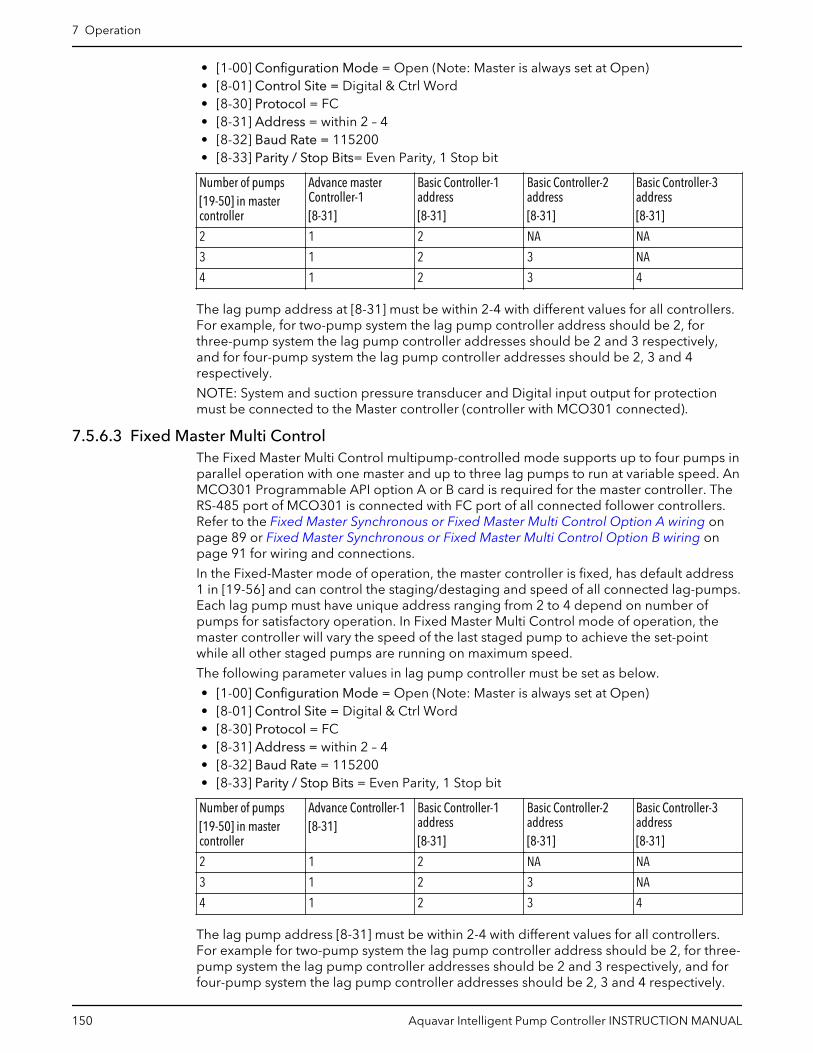
• [1-00] Configuration Mode = Open (Note: Master is always set at Open)• [8-01] Control Site = Digital & Ctrl Word• [8-30] Protocol = FC• [8-31] Address = within 2 – 4• [8-32] Baud Rate = 115200• [8-33] Parity / Stop Bits= Even Parity, 1 Stop bit
Number of pumps[19-50] in mastercontroller
Advance masterController-1[8-31]
Basic Controller-1address[8-31]
Basic Controller-2address[8-31]
Basic Controller-3address[8-31]
2 1 2 NA NA
3 1 2 3 NA
4 1 2 3 4
The lag pump address at [8-31] must be within 2-4 with different values for all controllers.For example, for two-pump system the lag pump controller address should be 2, forthree-pump system the lag pump controller addresses should be 2 and 3 respectively,and for four-pump system the lag pump controller addresses should be 2, 3 and 4respectively.
NOTE: System and suction pressure transducer and Digital input output for protectionmust be connected to the Master controller (controller with MCO301 connected).
7.5.6.3 Fixed Master Multi ControlThe Fixed Master Multi Control multipump-controlled mode supports up to four pumps inparallel operation with one master and up to three lag pumps to run at variable speed. AnMCO301 Programmable API option A or B card is required for the master controller. TheRS-485 port of MCO301 is connected with FC port of all connected follower controllers.Refer to the Fixed Master Synchronous or Fixed Master Multi Control Option A wiring onpage 89 or Fixed Master Synchronous or Fixed Master Multi Control Option B wiring onpage 91 for wiring and connections.
In the Fixed-Master mode of operation, the master controller is fixed, has default address1 in [19-56] and can control the staging/destaging and speed of all connected lag-pumps.Each lag pump must have unique address ranging from 2 to 4 depend on number ofpumps for satisfactory operation. In Fixed Master Multi Control mode of operation, themaster controller will vary the speed of the last staged pump to achieve the set-pointwhile all other staged pumps are running on maximum speed.
The following parameter values in lag pump controller must be set as below.
• [1-00] Configuration Mode = Open (Note: Master is always set at Open)• [8-01] Control Site = Digital & Ctrl Word• [8-30] Protocol = FC• [8-31] Address = within 2 – 4• [8-32] Baud Rate = 115200• [8-33] Parity / Stop Bits = Even Parity, 1 Stop bit
Number of pumps[19-50] in mastercontroller
Advance Controller-1[8-31]
Basic Controller-1address[8-31]
Basic Controller-2address[8-31]
Basic Controller-3address[8-31]
2 1 2 NA NA
3 1 2 3 NA
4 1 2 3 4
The lag pump address [8-31] must be within 2-4 with different values for all controllers.For example for two-pump system the lag pump controller address should be 2, for three-pump system the lag pump controller addresses should be 2 and 3 respectively, and forfour-pump system the lag pump controller addresses should be 2, 3 and 4 respectively.
7 Operation
150 Aquavar Intelligent Pump Controller INSTRUCTION MANUAL

NOTE: System and suction pressure transducer and Digital input output for protectionmust be connected to Master controller (controller with MCO301 connected)
7.5.6.4 Multi Master SynchronousThe Multi Master Synchronous multipump-controlled mode supports up to four pumps inparallel operation. In Multi-Master operation, all controllers can work as the mastercontroller. Upon failure of any working master the next pump in the sequence takes overas the master and the system keeps running until the last healthy pump plus controller arein system. An MCO301 Programmable API option A or B card is required for eachcontroller. The MCO301 RS-485 port of all controllers is connected in daisy chain. Refer tothe Multi Master Synchronous or Multi Master Multi Control Option A wiring on page 90 or Multi Master Synchronous or Multi Master Multi Control Option B wiring on page 91 forwiring and connections.
In Multi-Master mode of operation, the master controller controls the staging/destagingand speed of all connected lag pumps. Each controller must have a unique addressranging from 1 to 4 depending on the number of pumps for satisfactory operation. InMulti Master Synchronous mode of operation all staged pumps will be running on thesame speed to achieve the set-point.
WARNING:
If the system is required to be completely stopped during the operation, all pumps in thesystem are required to put in the Off mode by pressing the Off key (Off LED will be On)for stopping all pumps. Without doing so, any pump that is stopping but still in the AutoOn mode (Auto On LED is On) may start or re-start running at any time due to the specificMulti Master Synchronous operation.
The following parameter value in lag pump controller must be set as below.
• [19–56] Pump Address = within 2 – 4
Number of pumps[19-50] in mastercontroller
Advance Controller-1[19–56]
Advance Controller-2address[19–56]
Advance Controller-3address[19–56]
Advance Controller-4address[19–56]
2 1 2 NA NA
3 1 2 3 NA
4 1 2 3 4
All controller address ([19-56]) must be within 2-4 with different values for all controllers.For example for two-pump system the lag pump controller address should be 2, for three-pump system the lag pump controller addresses should be 2 and 3 respectively, and forfour-pumps system the lag pump controller addresses should be 2, 3 and 4 respectively.
NOTE: System & suction pressure transducer and Digital input output for protection mustbe connected to all controllers.
7.5.6.5 Multi Master Multi ControlAdvanced Multi Master Multi Control is an embedded pump control mode of operation,and supports up to four pumps in parallel operation. In Multi-Master operation allcontrollers can work as a master controller. Upon failure of any working master. The nextpump in sequence will take up as the master and the system keeps running until the lasthealthy pump in the system. An MCO301 Programmable API option A or B card isrequired for each controller. The MCO301 RS-485 port of all controllers is connected indaisy chain. Refer to the Multi Master Synchronous or Multi Master Multi Control Option Awiring on page 90 or Multi Master Synchronous or Multi Master Multi Control Option Bwiring on page 91 for wiring and connections.
In Multi-Master mode of operation, the master controller controls the staging/destagingand speed of all connected lag-pumps. Each controller must have unique address rangingfrom 1 to 4 depending on number of pumps for satisfactory operation. In Multi Master
7 Operation
Aquavar Intelligent Pump Controller INSTRUCTION MANUAL 151

Multi Control mode of operation, the last staged pump will be running on variable speedto achieve the set-point while all other staged pumps are running on maximum speed.
WARNING:
If the system is required to be completely stopped during the operation, all pumps in thesystem are required to put in the Off mode by pressing the Off key (Off LED will be On)for stopping all pumps. Without doing so, any pump that is stopping but still in the AutoOn mode (Auto On LED is On) may start or re-start running at any time due to the specificMulti Master Multi Control operation.
The following parameter value in lag pump controllers must be set as below.
• [19-56] Pump Address = within 2 – 4
Number of pumps[19-50] in mastercontroller
Advance Controller-1address[19-56]
Advance Controller-2address[19-56]
Advance Controller-3address[19-56]
Advance Controller-4address[19-56]
2 1 2 NA NA
3 1 2 3 NA
4 1 2 3 4
All lag pump controller addresses ([19-56]) must be within 2-4 with different values for allcontrollers. For example for two-pumps system the lag pump controller address shouldbe 2, for three- pump system the lag pump controller addresses should be 2 and 3respectively, and for four-pump system the lag pump controller addresses should be 2, 3and 4 respectively.
NOTE: System and suction pressure transducer and Digital input output for protectionmust be connected to all controllers.
7.5.7 Speed Control setupSpeed Control Mode allows the speed to be controlled by an external device such as aPLC or BMS. A start signal on DI 18 is required to start and stop the pump.
To configure Speed Control mode first select the speed reference source. Select thespeed reference source as either an analog input or Fieldbus Reference. When using theanalog inputs be sure to set the analog input configuration switches to the appropriatefeedback type switch A54 which can be configured to both voltage type or current type.Refer to the Analog input configuration in the Control terminal connections section fordetails on setting the analog input configuration switches. Refer to the Common TerminalWiring Configurations section in this manual for detail on wiring external devices to theanalog inputs.
Next set the minimum and maximum reference/feedback values. The [6-14] Terminal 53Low Ref./Feedb.Value is the speed value that corresponds with the low current (0 or 4mAfor current references) or low voltage (0V for voltage references) that will be applied tothe analog input. The [6–15] Terminal 53 High Ref./Feedb.Value is the speed value thatcorresponds with the high current (20mA for current references) or high voltage (AI 54 isrequired to configure to voltage type for 10V voltage references) that will be applied tothe analog input. For example, if the application uses a 4-20 mA reference signal on AI 53and the pump is required to operate from 30Hz to 60Hz, set [6-14] Terminal 53 Low Ref./Feedb.Value to 30 and [6–15]Terminal 53 High Ref./Feedb.Value to 60.
The minimum and maximum speed reference values are set next. These values are theminimum and maximum speed settings for the application. These settings will limit thecontrollable speed range of the pump. The speed range will be limited to the [3–02]Minimum Reference as the low speed limit and [3–03] Maximum Reference as the highspeed limit. Using the example above, set the [3–02] Minimum Reference to 30Hz and the[3–03] Maximum Reference to 60Hz.
Note: The Reference/Feedback and Speed Reference values may be displayed incorrectlyin the Speed Control mode due to the values that were changed in the other modes.
7 Operation
152 Aquavar Intelligent Pump Controller INSTRUCTION MANUAL

Update and verify the Reference/Feedback and Speed Reference values on the screenbefore proceeding to the next screen.
115
117
118(AI 54)
119
114
(AI 53)
120
Speed Control
56
56
No Function
200Yes
121
NoPump Protection Setup
12
see Note #1
Reference/Feedback
Exit(see Main Menu flow diagram)
116
Complete
see Note #3see Note #2
Figure 98: Speed Control Setup Flow Diagram
Speed Control Setup flow diagram notes:
• Note #1: Speed Reference Source selection screen.• Note #2: AI 53 or AI 54 was selected condition.• Note #3: Min/Max Speed Reference dual parameter screen.
Table 36: Speed Control Setup Screens
56Speed Control Setup
Screen IDNo.
Screens Selections Parameters SetupInformation
Screen Information
56
Speed Control
Operating ModeCHANGING OPERATINGMODE WILL OVERWRITE
CURRENT SETUP!
• Speed Control Modeallows the speed tobe controlled by anexternal device.
• Continue to screen ID#114.
114 Speed control allows the speed to be controlledby an external source. A Start Signal on DI 18 is
needed to start and stop the pump.
[OK] Continue to screen ID#115.
7 Operation
Aquavar Intelligent Pump Controller INSTRUCTION MANUAL 153

56Speed Control Setup
Screen IDNo.
Screens Selections Parameters SetupInformation
Screen Information
115
No FunctionSpeed Reference Source
[ No function][Analog Input 53][Analog Input 54]
[Fieldbus Reference]
[3-15]=[20-00]=selection (=No Function ifFieldbus Reference wasselected), [0-20]=Power[hp],[0-21]=MotorCurrent,[0-22]=Power [kw],[0-23]=Frequency,[0-24]=Reference [%],[3-16]=[3-17]= Nofunction, [3-10] (all)=0,[5-10]=Start,[13-90.9]=False,[19-00]=[0] ExternalReference, [19-40]=Off.
• No Function &Fieldbus Reference:continue to screen ID#119.
• Others: continue toscreen ID #116.
116 Be sure to configure the DIP switch 54 under thekeypad to match the feedback type. Set I for
current (mA) and U for voltage feedback.Do NOT change DIP switch position while drive is
powered up.
[OK] • AI 53 feedback:continue to screen ID#117.
• AI 54 feedback:continue to screen ID#118.
117
Terminal 53 High Ref./-Feedb.Value
60.000
0.000
Terminal 53 Low Ref./-Feedb.Value
________
[6-14] = first entry.[6-15] = second entry.[6-17] = Disabled.
Continue to screen ID#119.
118
Terminal 54 High Ref./-Feedb.Value
60.000
0.000
Terminal 54 Low Ref./-Feedb.Value
________
[6-24] = first entry.[6-25] = second entry.[6-27] = Disabled.
Continue to screen ID#119.
119
Max Speed Reference60.000Hz
0.000HzMin Speed Reference
_____Hz_____Hz
[3-02] = first entry[3-03] = second entry[0-20] = Power [hp][0-21] = Motor current[0-22] = Power [kW][0-23] = Frequency[0-24] = Reference [Unit][3-04] = External/Preset
Continue to screen ID#120.
7 Operation
154 Aquavar Intelligent Pump Controller INSTRUCTION MANUAL
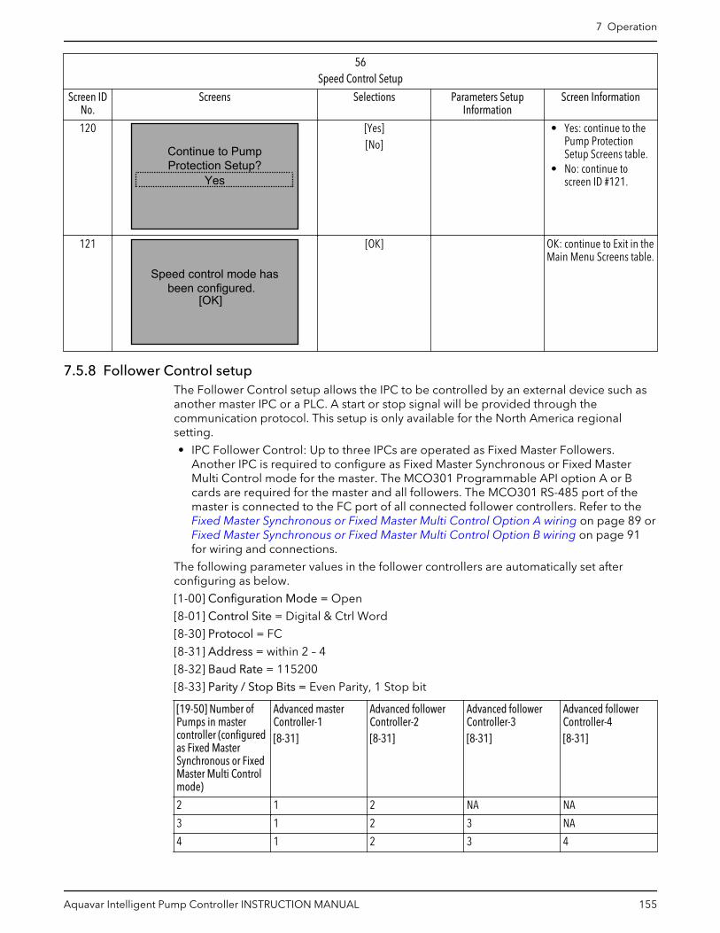
56Speed Control Setup
Screen IDNo.
Screens Selections Parameters SetupInformation
Screen Information
120
Continue to PumpProtection Setup?
Yes
[Yes][No]
• Yes: continue to thePump ProtectionSetup Screens table.
• No: continue toscreen ID #121.
121
[OK]
Speed control mode hasbeen configured.
[OK] OK: continue to Exit in theMain Menu Screens table.
7.5.8 Follower Control setupThe Follower Control setup allows the IPC to be controlled by an external device such asanother master IPC or a PLC. A start or stop signal will be provided through thecommunication protocol. This setup is only available for the North America regionalsetting.
• IPC Follower Control: Up to three IPCs are operated as Fixed Master Followers.Another IPC is required to configure as Fixed Master Synchronous or Fixed MasterMulti Control mode for the master. The MCO301 Programmable API option A or Bcards are required for the master and all followers. The MCO301 RS-485 port of themaster is connected to the FC port of all connected follower controllers. Refer to the Fixed Master Synchronous or Fixed Master Multi Control Option A wiring on page 89 or Fixed Master Synchronous or Fixed Master Multi Control Option B wiring on page 91for wiring and connections.
The following parameter values in the follower controllers are automatically set afterconfiguring as below.
[1-00] Configuration Mode = Open
[8-01] Control Site = Digital & Ctrl Word
[8-30] Protocol = FC
[8-31] Address = within 2 – 4
[8-32] Baud Rate = 115200
[8-33] Parity / Stop Bits = Even Parity, 1 Stop bit
[19-50] Number ofPumps in mastercontroller (configuredas Fixed MasterSynchronous or FixedMaster Multi Controlmode)
Advanced masterController-1[8-31]
Advanced followerController-2[8-31]
Advanced followerController-3[8-31]
Advanced followerController-4[8-31]
2 1 2 NA NA
3 1 2 3 NA
4 1 2 3 4
7 Operation
Aquavar Intelligent Pump Controller INSTRUCTION MANUAL 155

All follower address ([8-31]) must be within 2-4 with different values for all followercontrollers. Minimum and Maximum Reference are required to set for speed.
• PLC Follower Control: Up to three IPCs can be operated as PLC Followers. A PLC thatcan communicate and control the IPCs is required. The MCO301 Programmable APIoption A or B cards are required for all followers. The RS-485 port of the PLC isconnected to the FC port of all connected follower controllers. See the below PLCFollower Control wiring diagram.
RS4
85-P
RS4
85-N
PLC61 6968 61 6968 61 6968
SHIELD
Figure 99: PLC Follower Control wiring diagram
The following parameter values in the follower controllers are automatically set afterconfiguring as below.
[1-00] Configuration Mode = Open
[8-01] Control Site = Digital & Ctrl Word
[8-30] Protocol = Modbus RTU
[8-31] Address = within 1 – 3
[8-32] Baud Rate = 9600
[8-33] Parity / Stop Bits = No Parity, 1 Stop bit
Advanced follower Controller-1[8-31]
Advanced follower Controller-2[8-31]
Advanced follower Controller-3[8-31]
1 NA NA
1 2 NA
1 2 3
All follower address ([8-31]) must be within 1-3 with different values for all followercontrollers.
702
705
701
Follower Control
58 700
12
Exit(see Main Menu flow diagram)
706
703
see Note #1
see Note #2
707704
see Note #3
see Note #4
see Note #5
Pump Address
see Note #6
Figure 100: Follower Control Flow Diagram
7 Operation
156 Aquavar Intelligent Pump Controller INSTRUCTION MANUAL

Follower Control flow diagram notes:
• Note #1: Mode of Operation• Note #2: IPC Follower Control• Note #3: PLC Follower Control• Note #4: (IPC Follower Control)• Note #5: (PLC Follower Control)• Note #6: Min/Max Speed Reference
Table 37: Follower Control Setup Screens
58Follower Control Setup
Screen IDNo.
Screens Selections Parameters SetupInformation
Screen Information
700
Follower Control
Operating Mode CHANGINGOPERATING MODE WILLOVERWRITE CURRENT
SETUP!
• The Follower Controlsetup is onlyavailable for NorthAmerica regionalsetting.
• Continue to screen ID#701.
701
IPC Follower ControlMode of Operation
[IPC Follower Control][PLC Follower Control]
[19-40] = Off[19-00] = ExternalReference Mode
• IPC Follower Control:continue to screen ID#702.
• PLC Follower Control:continue to screen ID#703.
702
[OK]
Drive will be used as Fixed Master Follower
Control
[0-20]=Power [hp],[0-21]=Frequency,[0-22]=Motor Current,[0-23]=Reference [%],[3-15]=No Function,[5-10]=No Operation,[8-30]=FC,[8-32]=115200 Baud,[20-00]=No Function,[1390.5]=[1390.8]=[1390.9]= False, [8-02]=FCPort in Setup1 & Setup 2,[8-04]=Select Setup 2 inSetup 1&2, [8-53]=LogicOR in Setup1,[8-53]=Digital Input inSetup 2.
Continue to screen ID#704.
703
[OK]
Drive will be used as PLC Follower Control
[5-10]=No Operation,[8-02]=FC Port,[8-30]=Modbus RTU,[8-32]=9600 Baud,[8-33]=No Parity, 1 Stopbit, [20-00]=No Function,[1390.5]=[1390.8]=[1390.9]=False.
Continue to screen ID#704.
7 Operation
Aquavar Intelligent Pump Controller INSTRUCTION MANUAL 157

58Follower Control Setup
Screen IDNo.
Screens Selections Parameters SetupInformation
Screen Information
704
Pump Address1
______ [8- 31] = Entry • (IPC FollowerControl): continue toscreen ID #705.
• (PLC FollowerControl): continue toscreen ID #707.
705
Max Speed Reference60.000Hz
0.000HzMin Speed Reference
___ Hz___ Hz
[3-02] = 1st entry[3-03] = 2nd entry
Continue to screen ID#706.
706
[OK]
Fixed Master FollowerControl Configured
[OK] OK: Continue to Exit inthe Main Menu Screentable.
707
[OK]
PLC Follower Control has been configured
[OK] OK: Continue to Exit inthe Main Menu Screentable.
7.5.9 Test Run Mode setupTest Run Mode allows the controller to perform a test which will ramp the pump at aspecified speed in order to perform a test on the system and pump/motor. Test RunMode is triggered to start based on the state of DI 18. When DI 18 is closed, the test willbegin. When DI 18 is open, test run mode will stop. To configure Test Run Mode set thetest run speed and test run ramp time. The Test Run Speed is the speed that the controllerwill ramp the pump to. The Test Run Ramp Time is the ramp used to reach the Test RunSpeed. This ramp is the time to ramp from stop (0 RPM) and the rated motor speed. TheTest Run Ramp Time applies to both acceleration and deceleration in Test Run Mode.
7 Operation
158 Aquavar Intelligent Pump Controller INSTRUCTION MANUAL
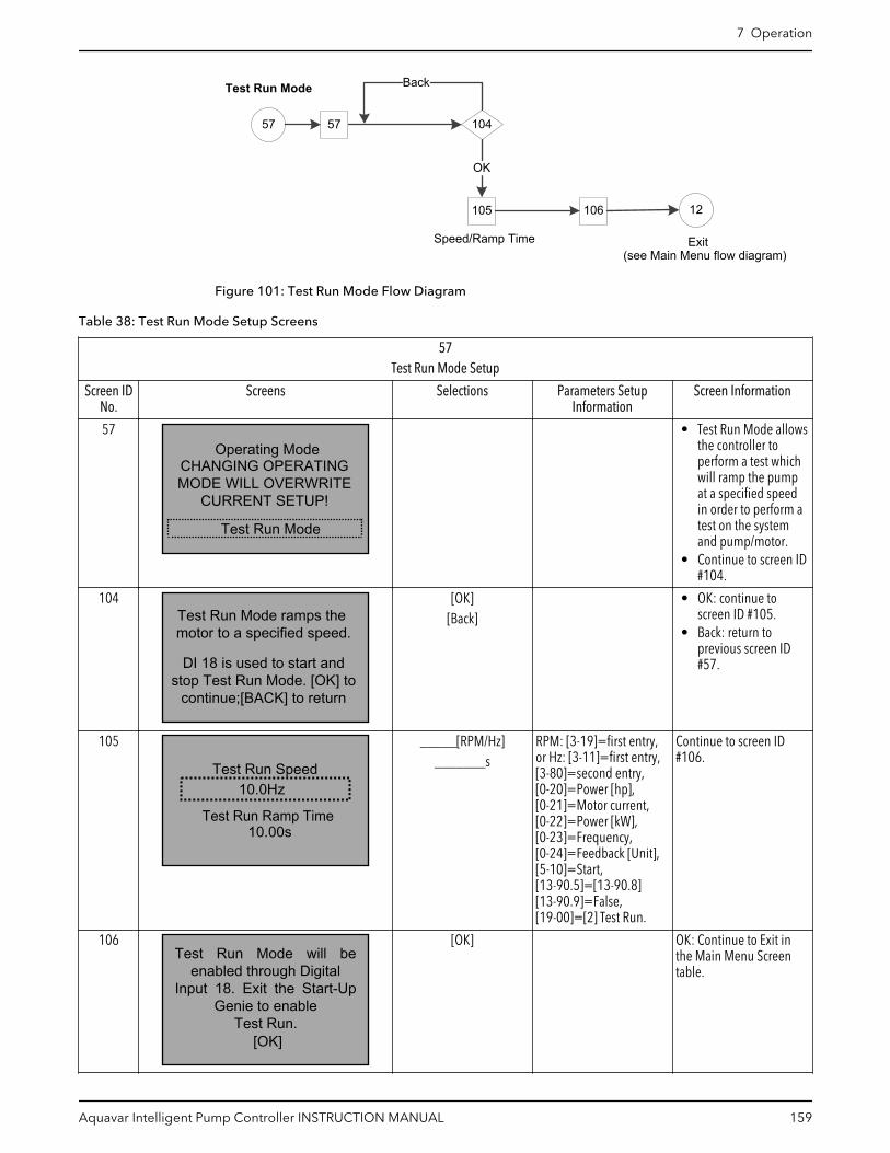
105 106
104
OK
Test Run Mode
57 57
12
Back
Exit(see Main Menu flow diagram)
Speed/Ramp Time
Figure 101: Test Run Mode Flow Diagram
Table 38: Test Run Mode Setup Screens
57Test Run Mode Setup
Screen IDNo.
Screens Selections Parameters SetupInformation
Screen Information
57Operating Mode
CHANGING OPERATINGMODE WILL OVERWRITE
CURRENT SETUP!
Test Run Mode
• Test Run Mode allowsthe controller toperform a test whichwill ramp the pumpat a specified speedin order to perform atest on the systemand pump/motor.
• Continue to screen ID#104.
104
DI 18 is used to start and stop Test Run Mode. [OK] to
continue;[BACK] to return
Test Run Mode ramps the motor to a specified speed.
[OK][Back]
• OK: continue toscreen ID #105.
• Back: return toprevious screen ID#57.
105
10.00s
10.0HzTest Run Speed
Test Run Ramp Time
_____[RPM/Hz]_______s
RPM: [3-19]=first entry,or Hz: [3-11]=first entry,[3-80]=second entry,[0-20]=Power [hp],[0-21]=Motor current,[0-22]=Power [kW],[0-23]=Frequency,[0-24]=Feedback [Unit],[5-10]=Start,[13-90.5]=[13-90.8][13-90.9]=False,[19-00]=[2] Test Run.
Continue to screen ID#106.
106
[OK]
Test Run Mode will be enabled through Digital
Input 18. Exit the Start-Up Genie to enable
Test Run.
[OK] OK: Continue to Exit inthe Main Menu Screentable.
7 Operation
Aquavar Intelligent Pump Controller INSTRUCTION MANUAL 159
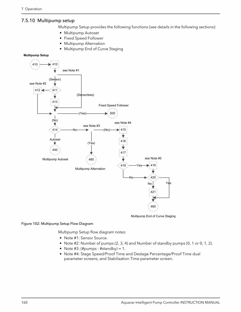
7.5.10 Multipump setupMultipump Setup provides the following functions (see details in the following sections):
• Multipump Autoset• Fixed Speed Follower• Multipump Alternation• Multipump End of Curve Staging
(Yes)
(No)
Multipump Setup
410
Multipump End of Curve Staging
413
412
414
440
Autoset
418
No
480
(Yes)
415(No)
416
419
No
421
420
460
Multipump Autoset
Multipump Alternation
410
see Note #1
411
417
500
Fixed Speed Follower
Yes
see Note #5
see Note #3see Note #4
(Sensorless)
(Sensor)see Note #2
YesNo
Figure 102: Multipump Setup Flow Diagram
Multipump Setup flow diagram notes:
• Note #1: Sensor Source.• Note #2: Number of pumps (2, 3, 4) and Number of standby pumps (0, 1 or 0, 1, 2).• Note #3: (#pumps - #standby) = 1.• Note #4: Stage Speed/Proof Time and Destage Percentage/Proof Time dual
parameter screens, and Stabilization Time parameter screen.
7 Operation
160 Aquavar Intelligent Pump Controller INSTRUCTION MANUAL

Table 39: Multipump Setup Screens
410Multipump Setup
Screen IDNo.
Screen Selections Parameters SetupInformation
Screen Information
410
Setup SelectionMultipump Setup
The Multipump Setup canbe configured for up to 4pumps. Multipump Setupselection is only visibleafter the MultipumpControl was selected inthe Application operatingmode.
411
Number of Pumps2
[2,3,4] [19-50] = selection. • Less than 4 pumps:continue to screen ID#412.
• 4 pumps: continue toscreen ID #413.
412
Number of standby pumps1
[0, 1] [19-51] = selection. • Fixed SpeedFollower: continue tothe Fixed SpeedFollower Screenstable.
• Not Fixed SpeedFollower: continue toscreen ID #414.
413
Number of standby pumps2
[0, 1, 2] [19-51] = selection. • Fixed SpeedFollower: continue tothe Fixed SpeedFollower Screenstable.
• Not Fixed SpeedFollower: continue toscreen ID #414.
414
Yes
Would you like to Autosetthe rest of the settings?
[Yes][No]
• Yes: continue to theFixed Speed FollowerScreens table.
• No:– (Number of
pumps - Numberof standby = 1):continue to theMultipumpAlternationScreens table.
– (Number ofpumps - Numberof standby ≠ 1):continue toscreen ID #415.
7 Operation
Aquavar Intelligent Pump Controller INSTRUCTION MANUAL 161
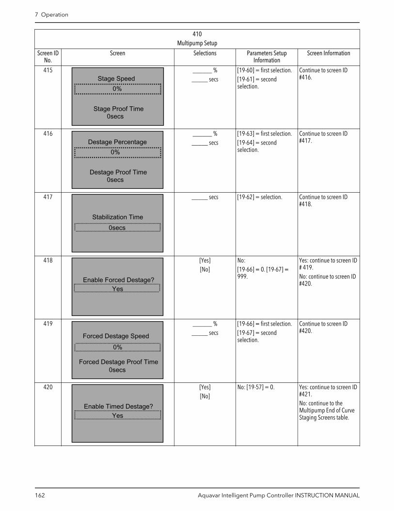
410Multipump Setup
Screen IDNo.
Screen Selections Parameters SetupInformation
Screen Information
415
0secs
Stage Speed
Stage Proof Time
0%
______ %_____ secs
[19-60] = first selection.[19-61] = secondselection.
Continue to screen ID#416.
416
0secs
Destage Percentage
Destage Proof Time
0%
______ %_____ secs
[19-63] = first selection.[19-64] = secondselection.
Continue to screen ID#417.
417
Stabilization Time0secs
_____ secs [19-62] = selection. Continue to screen ID#418.
418
Enable Forced Destage?Yes
[Yes][No]
No:[19-66] = 0. [19-67] =999.
Yes: continue to screen ID# 419.No: continue to screen ID#420.
419
Forced Destage Speed0%
Forced Destage Proof Time0secs
______ %_____ secs
[19-66] = first selection.[19-67] = secondselection.
Continue to screen ID#420.
420
Enable Timed Destage?Yes
[Yes][No]
No: [19-57] = 0. Yes: continue to screen ID#421.No: continue to theMultipump End of CurveStaging Screens table.
7 Operation
162 Aquavar Intelligent Pump Controller INSTRUCTION MANUAL

410Multipump Setup
Screen IDNo.
Screen Selections Parameters SetupInformation
Screen Information
421
Timed Destage0mins
_____ mins [19-57] = selection. Continue to theMultipump End of CurveStaging Screens table.
7.5.10.1 Multipump AutosetThe Multipump Autoset allows the user to automatically configure the rest of theparameters to default settings. After the setpoint is configured, the setup of the controlleris complete for Sensor control in the Booster pump application, or for Sensor/Sensorlesscontrol in HVAC pump application.
NOTE: Setup 1 is the active setup for all applications.
The default configurations are described in the following tables. Note that [unit] willreflect the control units selected previously.
NOTE: Only one standby pump is allowed in the Sensorless mode.
Table 40: Multipump Autoset Configuration for Booster Pump Application (Sensor Control)
MultipumpAutoset
Configuration
North America International
Constant Pressure Flow Control Level Control Constant Pressure Constant Flow Constant Level
Transducer Type 4-20mA 4-20mA 4-20mA 4-20mA 4-20mA 4-20mA
[3-10.0] PresetReference
2.5 2.5 2.5 2.5 2.5 2.5
[4–12] SleepFrequency/LowLimit [Hz]
30 Hz 30 Hz 30 Hz 20 Hz 20 Hz 20 Hz
[5-40.0] Relay 1Function
MCO Controlled MCO Controlled MCO Controlled No Alarm No Alarm No Alarm
[5-40.1] Relay 2Function
MCO Controlled MCO Controlled MCO Controlled Running Running Running
[6–15] Terminal 53High Ref./Feedb.Value
300 [unit] 4000 [unit] 300 [unit] 10 [unit] 100 [unit] 10 [unit]
[6–17] Terminal 53Sensor Fault(North America) /Live Zero(International)
Disabled Disabled Disabled Disabled Disabled Disabled
[6–27] Terminal 54Sensor Fault(North America) /Live Zero(International)
Disabled Disabled Disabled Disabled Disabled Disabled
[13-20.0] SLController Timer
10 Min 10 Min 10 Min 30 secs 30 secs 30 secs
[14-20] ResetMode
Manual Reset Manual Reset Manual Reset Manual Reset Manual Reset Manual Reset
7 Operation
Aquavar Intelligent Pump Controller INSTRUCTION MANUAL 163

MultipumpAutoset
Configuration
North America International
Constant Pressure Flow Control Level Control Constant Pressure Constant Flow Constant Level
[19-10] PumpExercise Idle Time
0 0 0 100 100 100
[19-11] PumpExercise Run Time
NA NA NA 10 10 10
[19-12] FlowCompensation
Disabled Disabled Disabled Disabled Disabled Disabled
[19–20] No WaterLoss of Prime Fault
Alarm Alarm Alarm Disabled Disabled Disabled
[19–21] No WaterLoss of PrimeProtection Delay
60 60 60 60 60 60
[19–22] No WaterLoss of PrimeRestart Time
10 min. 10 min. 10 min. 10 min. 10 min. 10 min.
[19–23] No WaterLoss of PrimeRestart Attempt
3 3 3 3 3 3
[19-24] No FlowShutdown
Enabled Disabled Enabled Enabled Disabled Enabled
[19–25] No FlowRestart Difference
10 10 10 NA NA NA
[19-26] HighSystem Fault
Disabled Disabled Disabled Disabled Disabled Disabled
[19-27] HighSystem Limit
100 100 100 10 100 10
[19-28] HighSystem Delay
3 3 3 3 3 3
[19-32] LowSuction Fault
Disabled Disabled Disabled Disabled Disabled Disabled
[19-36] HighSuction Fault
Disabled Disabled Disabled Disabled Disabled Disabled
[19-40] All ZonesFailure Function
Stop Stop Stop Stop Stop Stop
[19-45] LowSystem Fault
Disabled Disabled Disabled Disabled Disabled Disabled
[19-51] StandbyPumps
0 0 0 0 0 0
[19-52] AlternationFunction
On Run Time On Run Time On Run Time On Run Time On Run Time On Run Time
[19-53] AlternationTime Interval
24 hrs. 24 hrs. 24 hrs. 24 hrs. 24 hrs. 24 hrs.
[19-57] TimedDestage
0 0 0 0 0 0
[19-60] StageSpeed
95 95 95 95 95 95
[19-61] StageProof Time
5 5 5 1 1 1
[19-62]Stabilization Time
5 5 5 1 1 1
7 Operation
164 Aquavar Intelligent Pump Controller INSTRUCTION MANUAL

MultipumpAutoset
Configuration
North America International
Constant Pressure Flow Control Level Control Constant Pressure Constant Flow Constant Level
[19-63] DestagePercentage
80 80 80 40 40 40
[19-64] DestageProof Time
5 5 5 1 1 1
[19-66] ForcedDestage Speed
0 0 0 0 0 0
[19-67] ForcedDestage ProofTime
30 30 30 30 30 30
[19-68] Relay 1Function
System Alarm orWarning
System Alarm orWarning
System Alarm orWarning
NA NA NA
[19-69] Relay 2Function
System Running System Running System Running NA NA NA
[19-72] EOCStaging Function
Disabled Disabled Disabled Disabled Disabled Disabled
[19-74] EOC StagePercentage
80 80 80 80 80 80
[19-75] EOC StageProof Time
30 30 30 30 30 30
[19-76] EOCDestagePercentage
45 45 45 45 45 45
[19-77] EOCDestage ProofTime
30 30 30 30 30 30
[19-90] Pipe FillFunction
Disabled Disabled Disabled Disabled Disabled Disabled
[19-92] SpeedStep
10 10 10 10 10 10
[19-93] SteadyTime
10 10 10 10 10 10
[19-94] Dead Band 5 5 5 1 1 1
[19-95] Pipe FillMax Pump
1 1 1 1 1 1
[19-97] PrimingDelay
NA NA NA 0 0 0
[20–00] Feedback1 Source
AI 53 AI 53 AI 53 AI 53 AI 53 AI 53
[20–03] Feedback2 Source
No function No function No function No function No function No function
[20–06] Feedback3 Source
No function No function No function No function No function No function
[20-14] MaximumReference/Feedb.
300 [unit] 4000 [unit] 300 [unit] 10 [unit] 100 [unit] 10 [unit]
[22-21] Low PowerDetection
Enabled Enabled Enabled Disabled Disabled Disabled
[22-40] MinimumRun Time
1 1 1 1 1 1
[22-41] MinimumSleep Time
1 1 1 1 1 1
7 Operation
Aquavar Intelligent Pump Controller INSTRUCTION MANUAL 165

MultipumpAutoset
Configuration
North America International
Constant Pressure Flow Control Level Control Constant Pressure Constant Flow Constant Level
[22-50] End ofCurve Function
Off Off Off Off Off Off
[22-52] End ofCurve Tolerance
20 20 20 20 20 20
[22–33] Low Speed[Hz]
[4-14] * 0.5 in Setup 1
[22–37] HighSpeed [Hz]
[4-14] * 0.85 in Setup 1
[22-39] No Water/Loss of Prime Limit[HP]
[1-21] * [4-18] * 0.46 in Setup 1
[22–35] Low SpeedPower [HP]
[22-39] * ([22-33] / [4-14])^3 in Setup 1
Table 41: Multipump Autoset Configuration for HVAC Pump Application (Sensor and Sensorless Control)
MultipumpAutoset
Configuration
North America International
Sensor Sensorless Sensor Sensorless
ConstantPressure
Flow Control ConstantPressure
Flow Control ConstantPressure
Constant Flow ConstantPressure
Constant Flow
TransducerType
4-20mA 4-20mA SensorlessControl
SensorlessControl
4-20mA 4-20mA SensorlessControl
SensorlessControl
[4–12] SleepFrequency/Low Limit [Hz]
18 Hz 18 Hz 24 Hz 24 Hz 30 Hz 30 Hz 30 Hz 30 Hz
[5-40.0] Relay1 Function
MCOControlled
MCOControlled
MCOControlled
MCOControlled
No Alarm No Alarm No Alarm No Alarm
[5-40.1] Relay2 Function
MCOControlled
MCOControlled
MCOControlled
MCOControlled
Running Running Running Running
[6–15]Terminal 53High Ref./Feedb.Value
36 [unit] 4000 [unit] 300 [unit] 4000 [unit] 10 [unit] 100 [unit] 10 [unit] 100 [unit]
[6–17]Terminal 53Sensor Fault(NorthAmerica) / LiveZero(International)
Disabled Disabled Disabled Disabled Disabled Disabled Disabled Disabled
[6–27]Terminal 54Sensor Fault(NorthAmerica) / LiveZero(International)
Disabled Disabled Disabled Disabled Disabled Disabled Disabled Disabled
[14-20] ResetMode
Manual Reset Manual Reset AutomaticReset x 3
AutomaticReset x 3
Manual Reset Manual Reset AutomaticReset x 3
AutomaticReset x 3
[19-10] PumpExercise IdleTime
0 0 0 0 100 100 100 100
7 Operation
166 Aquavar Intelligent Pump Controller INSTRUCTION MANUAL

MultipumpAutoset
Configuration
North America International
Sensor Sensorless Sensor Sensorless
ConstantPressure
Flow Control ConstantPressure
Flow Control ConstantPressure
Constant Flow ConstantPressure
Constant Flow
[19-11] PumpExercise RunTime
NA NA NA NA 10 10 10 10
[19-12] FlowCompensation
Disabled Disabled Disabled Disabled Disabled Disabled Disabled Disabled
[19–20] NoWater Loss ofPrime Fault
Disabled Disabled Disabled Disabled Disabled Disabled Disabled Disabled
[19-24] NoFlowShutdown
Disabled Disabled Disabled Disabled Disabled Disabled Disabled Disabled
[19-26] HighSystem Fault
Disabled Disabled Disabled Disabled Disabled Disabled Disabled Disabled
[19-27] HighSystem Limit
100 100 100 100 10 100 10 100
[19-28] HighSystem Delay
3 3 3 3 3 3 3 3
[19-32] LowSuction Fault
Disabled Disabled Disabled Disabled Disabled Disabled Disabled Disabled
[19-36] HighSuction Fault
Disabled Disabled Disabled Disabled Disabled Disabled Disabled Disabled
[19-40] AllZones FailureFunction
Stop Stop Stop Stop Stop Stop Stop Stop
[19-45] LowSystem Fault
Disabled Disabled Disabled Disabled Disabled Disabled Disabled Disabled
[19-50]Number ofPumps
NA NA 2 2 NA NA 2 2
[19-51]StandbyPumps
0 0 1 1 0 0 1 1
[19-52]AlternationFunction
On Run Time On Run Time On Run Time On Run Time On Run Time On Run Time On Run Time On Run Time
[19-53]AlternationTime Interval
24 hrs. 24 hrs. 24 hrs. 24 hrs. 24 hrs. 24 hrs. 24 hrs. 24 hrs.
[19-57] TimedDestage
0 0 NA NA 0 0 NA NA
[19-60] StageSpeed
95 95 NA NA 95 95 NA NA
[19-61] StageProof Time
30 30 NA NA 1 1 NA NA
[19-62]StabilizationTime
60 60 NA NA 1 1 NA NA
[19-63]DestagePercentage
80 80 NA NA 40 40 NA NA
7 Operation
Aquavar Intelligent Pump Controller INSTRUCTION MANUAL 167
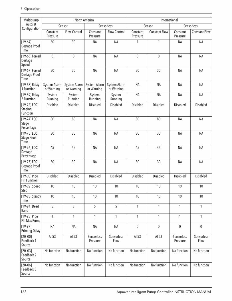
MultipumpAutoset
Configuration
North America International
Sensor Sensorless Sensor Sensorless
ConstantPressure
Flow Control ConstantPressure
Flow Control ConstantPressure
Constant Flow ConstantPressure
Constant Flow
[19-64]Destage ProofTime
30 30 NA NA 1 1 NA NA
[19-66] ForcedDestageSpeed
0 0 NA NA 0 0 NA NA
[19-67] ForcedDestage ProofTime
30 30 NA NA 30 30 NA NA
[19-68] Relay1 Function
System Alarmor Warning
System Alarmor Warning
System Alarmor Warning
System Alarmor Warning
NA NA NA NA
[19-69] Relay2 Function
SystemRunning
SystemRunning
SystemRunning
SystemRunning
NA NA NA NA
[19-72] EOCStagingFunction
Disabled Disabled Disabled Disabled Disabled Disabled Disabled Disabled
[19-74] EOCStagePercentage
80 80 NA NA 80 80 NA NA
[19-75] EOCStage ProofTime
30 30 NA NA 30 30 NA NA
[19-76] EOCDestagePercentage
45 45 NA NA 45 45 NA NA
[19-77] EOCDestage ProofTime
30 30 NA NA 30 30 NA NA
[19-90] PipeFill Function
Disabled Disabled Disabled Disabled Disabled Disabled Disabled Disabled
[19-92] SpeedStep
10 10 10 10 10 10 10 10
[19-93] SteadyTime
10 10 10 10 10 10 10 10
[19-94] DeadBand
5 5 5 5 1 1 1 1
[19-95] PipeFill Max Pump
1 1 1 1 1 1 1 1
[19-97]Priming Delay
NA NA NA NA 0 0 0 0
[20–00]Feedback 1Source
AI 53 AI 53 SensorlessPressure
SensorlessFlow
AI 53 AI 53 SensorlessPressure
SensorlessFlow
[20–03]Feedback 2Source
No function No function No function No function No function No function No function No function
[20–06]Feedback 3Source
No function No function No function No function No function No function No function No function
7 Operation
168 Aquavar Intelligent Pump Controller INSTRUCTION MANUAL

MultipumpAutoset
Configuration
North America International
Sensor Sensorless Sensor Sensorless
ConstantPressure
Flow Control ConstantPressure
Flow Control ConstantPressure
Constant Flow ConstantPressure
Constant Flow
[20-14]MaximumReference/Feedb.
300 [unit] 4000 [unit] 300 [unit] 4000 [unit] 10 [unit] 100 [unit] 10 [unit] 100 [unit]
[22-21] LowPowerDetection
Enabled Enabled Enabled Enabled Disabled Disabled Disabled Disabled
[22-50] End ofCurveFunction
Off Off Off Off Off Off Off Off
[22-52] End ofCurveTolerance
20 20 20 20 20 20 20 20
Multipump Autoset
(Booster)
442
444 445 446
448
(HVAC)
450449
440
12
441 443 447
(Sensor)
452
454453
451
(Constant Pressure)(Flow Control) (Constant Pressure) (Constant Pressure)
(Sensorless)
Exit(see Main Menu flow diagram)
(Level Control)
see Note #1 see Note #1see Note #1see Note #2
(Flow Control) (Flow Control)
Figure 103: Multipump Autoset Flow Diagram
Notes:
• Note #1:
– North America: (Flow Control)– International: (Constant Flow)
• Note #2:
– North America: (Level Control)– International: (Constant Level)
7 Operation
Aquavar Intelligent Pump Controller INSTRUCTION MANUAL 169

Table 42: Multipump Autoset Screens Table
440Multipump Autoset
Screen IDNo.
Screens Selections Parameters SetupInformation
Screen Information
• (Booster) :– (Constant
Pressure):continue toscreen ID #441.
– (Flow Control orConstant Flow):continue toscreen ID #442.
– (Level Control orConstant Level):continue toscreen ID #443.
• (HVAC):– (Sensor)
– (ConstantPressure):continue toscreen ID#447.
– (FlowControl orConstantFlow):continue toscreen ID#448.
– (Sensorless)– (Constant
Pressure):continue toscreen ID#451.
– (FlowControl orConstantFlow):continue toscreen ID#452.
– (Sensorless)– (Constant
Pressure):continue toscreen ID#451.
– (FlowControl orConstantFlow):continue toscreen ID#452.
7 Operation
170 Aquavar Intelligent Pump Controller INSTRUCTION MANUAL
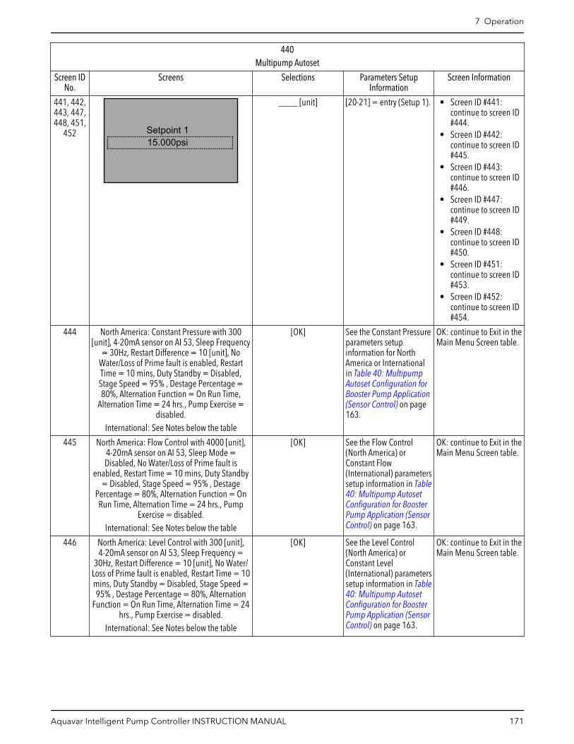
440Multipump Autoset
Screen IDNo.
Screens Selections Parameters SetupInformation
Screen Information
441, 442,443, 447,448, 451,
452 Setpoint 115.000psi
____ [unit] [20-21] = entry (Setup 1). • Screen ID #441:continue to screen ID#444.
• Screen ID #442:continue to screen ID#445.
• Screen ID #443:continue to screen ID#446.
• Screen ID #447:continue to screen ID#449.
• Screen ID #448:continue to screen ID#450.
• Screen ID #451:continue to screen ID#453.
• Screen ID #452:continue to screen ID#454.
444 North America: Constant Pressure with 300[unit], 4-20mA sensor on AI 53, Sleep Frequency
= 30Hz, Restart Difference = 10 [unit], NoWater/Loss of Prime fault is enabled, RestartTime = 10 mins, Duty Standby = Disabled,Stage Speed = 95% , Destage Percentage =80%, Alternation Function = On Run Time,
Alternation Time = 24 hrs., Pump Exercise =disabled.
International: See Notes below the table
[OK] See the Constant Pressureparameters setupinformation for NorthAmerica or Internationalin Table 40: MultipumpAutoset Configuration forBooster Pump Application(Sensor Control) on page163.
OK: continue to Exit in theMain Menu Screen table.
445 North America: Flow Control with 4000 [unit],4-20mA sensor on AI 53, Sleep Mode =Disabled, No Water/Loss of Prime fault is
enabled, Restart Time = 10 mins, Duty Standby= Disabled, Stage Speed = 95% , Destage
Percentage = 80%, Alternation Function = OnRun Time, Alternation Time = 24 hrs., Pump
Exercise = disabled.International: See Notes below the table
[OK] See the Flow Control(North America) orConstant Flow(International) parameterssetup information in Table40: Multipump AutosetConfiguration for BoosterPump Application (SensorControl) on page 163.
OK: continue to Exit in theMain Menu Screen table.
446 North America: Level Control with 300 [unit],4-20mA sensor on AI 53, Sleep Frequency =
30Hz, Restart Difference = 10 [unit], No Water/Loss of Prime fault is enabled, Restart Time = 10mins, Duty Standby = Disabled, Stage Speed =95% , Destage Percentage = 80%, Alternation
Function = On Run Time, Alternation Time = 24hrs., Pump Exercise = disabled.
International: See Notes below the table
[OK] See the Level Control(North America) orConstant Level(International) parameterssetup information in Table40: Multipump AutosetConfiguration for BoosterPump Application (SensorControl) on page 163.
OK: continue to Exit in theMain Menu Screen table.
7 Operation
Aquavar Intelligent Pump Controller INSTRUCTION MANUAL 171

440Multipump Autoset
Screen IDNo.
Screens Selections Parameters SetupInformation
Screen Information
449 North America: Constant Pressure with 36 [unit],4-20mA sensor on AI 53, Sleep Mode =Disabled, No Water/Loss of Prime fault is
disabled, Duty Standby = Disabled, StageSpeed = 95% , Destage Percentage = 80%,
Alternation Function = On Run Time, AlternationTime = 24 hrs., Pump Exercise = disabled.
International: See Notes below the table
[OK] See the Constant Pressureparameters setupinformation for SensorControl, North America orInternational in the above Table 41: MultipumpAutoset Configuration forHVAC Pump Application(Sensor and SensorlessControl) on page 166.
OK: continue to Exit in theMain Menu Screen table.
450 North America: Flow Control with 4000 [unit],4-20mA sensor on AI 53, Sleep Mode =Disabled, No Water/Loss of Prime fault is
disabled, Duty Standby = Disabled, StageSpeed = 95% , Destage Percentage = 80%,
Alternation Function = On Run Time, AlternationTime = 24 hrs., Pump Exercise = disabled.
International: See Notes below the table
[OK] See the above FlowControl (North America) orConstant Flow(International) parameterssetup information forSensor Control in Table41: Multipump AutosetConfiguration for HVACPump Application (Sensorand Sensorless Control)on page 166.
OK: continue to Exit in theMain Menu Screen table.
453 North America:
Constant Pressure with 300 [unit],sensorless Control in closed loop
application[OK]
International: See Notes below the table
[OK] See the Constant Pressureparameters setupinformation for SensorlessControl, North America orInternational in Table 41:Multipump AutosetConfiguration for HVACPump Application (Sensorand Sensorless Control)on page 166.
OK: continue to Exit in theMain Menu Screen table.
454 North America:
Flow Control with 4000[unit],sensorless Controlin closed loop application.
[OK]
International: See Notes below the table
[OK] See the Flow Control(North America) orConstant Flow(International) parameterssetup information forSensorless Control Table41: Multipump AutosetConfiguration for HVACPump Application (Sensorand Sensorless Control)on page 166.
OK: continue to Exit in theMain Menu Screen table.
Notes:
Screens #444, #449 and #453 will be displayed as the following:
Constant Pressure Default Values Loaded
(See IOM)[OK]
Screens #445, #450 and #454 will be displayed as the following:
7 Operation
172 Aquavar Intelligent Pump Controller INSTRUCTION MANUAL

Constant Flow Default Values Loaded (See IOM).
[OK]
Screens #446 will be displayed as the following:
Constant Level Default Values Loaded (See IOM).
[OK]
7.5.10.2 Fixed Speed Follower setupRefer to the Fixed Speed Follower information in the Multipump Control setup on page147 for the description, wiring and connections.
504
505 506
340
Fixed Speed Follower
Multipump Alternation
501
(2 pumps)
502
(3 pumps)
503
500
507 480
Yes
No
Autoset
(4 pumps)
see Note #1
see Note #3
see Note #2
Figure 104: Fixed Speed Follower Flow Diagram
Fixed Speed Follower flow diagram notes:
• Note #1: (Parameter [19-50] Number of Pumps = 2/3/4?)• Note #2: Information screens for 2, 3 or 4 pumps.• Note #3: Staging Bandwidth, Stage/Destage Proof Time and Fixed Speed Bandwidth
parameter screens.
7 Operation
Aquavar Intelligent Pump Controller INSTRUCTION MANUAL 173

Table 43: Fixed Speed Follower Screens
500Fixed Speed Follower
Screen IDNo.
Screens Selections Parameters SetupInformation
ScreenInformation
If [19-50] = 2:[5-32] = MCOControlled.• If [19-50] =
3: [5-33] =MCOControlled
• If [19-50] =4: [5-33] =540.0 =MCOControlled.
[19-50] =• 2: continue
to screen ID#501.
• 3: continueto screen ID#502.
• 4: continueto screen ID#503.
501
[OK]
Digital Output Pin 6Controls Fixed Speed
Pump 1
[OK] Continue toscreen ID #504.
502Digital Output Pin 6
Controls Fixed SpeedPump 1, Digital OutputPin 7 Controls Fixed
Speed Pump 2[OK]
[OK] Continue toscreen ID #504.
503 “Digital Output Pin 6 Controls Fixed Speed Pump 1, Digital Output Pin 7Controls Fixed Speed Pump 2, Relay 1 Controls Fixed Speed Pump 3”
[OK] Continue toscreen ID #504.
504
10%Staging Bandwidth
____ % [15-20] = entry. Continue toscreen ID #505.
505
30secs
Destage Proof Time30secs
Stage Proof Time
____ s____ s
[19-61] = firstentry.[19-64] = secondentry.
Continue toscreen ID #506.
7 Operation
174 Aquavar Intelligent Pump Controller INSTRUCTION MANUAL

500Fixed Speed Follower
Screen IDNo.
Screens Selections Parameters SetupInformation
ScreenInformation
506
10%Fixed Speed Bandwidth
% [25-22] = entry. Continue toscreen ID #507.
507
Yes
Would you like to Autosetthe rest of the settings?
[Yes][No]
Yes: continue tothe AutosetScreens Table.No: continue tothe MultipumpAlternationScreens table.
7.5.10.3 Multipump End of Curve Staging setupEOC (End-of-Curve) protection means protection from having the control curve drop offthe pump curve. This leads to cavitation and is highly undesirable. If the flow meterdetects that flow has exceeded a programmed value depending upon the number ofpumps operating, then it should stage on another pump as possible to overflow thesystem. This causes the 2-way valves in the system to begin to close which forces thecontrol curve left back onto the pump curve where cavitation ceases. If the control curvecannot be got back onto the pump curve, the controller exports a warning after a timedelay has elapsed, but continues to operate.
NOTE: A flow meter input is required for flow measurement in the correct units and forend-of-curve protection.
7 Operation
Aquavar Intelligent Pump Controller INSTRUCTION MANUAL 175
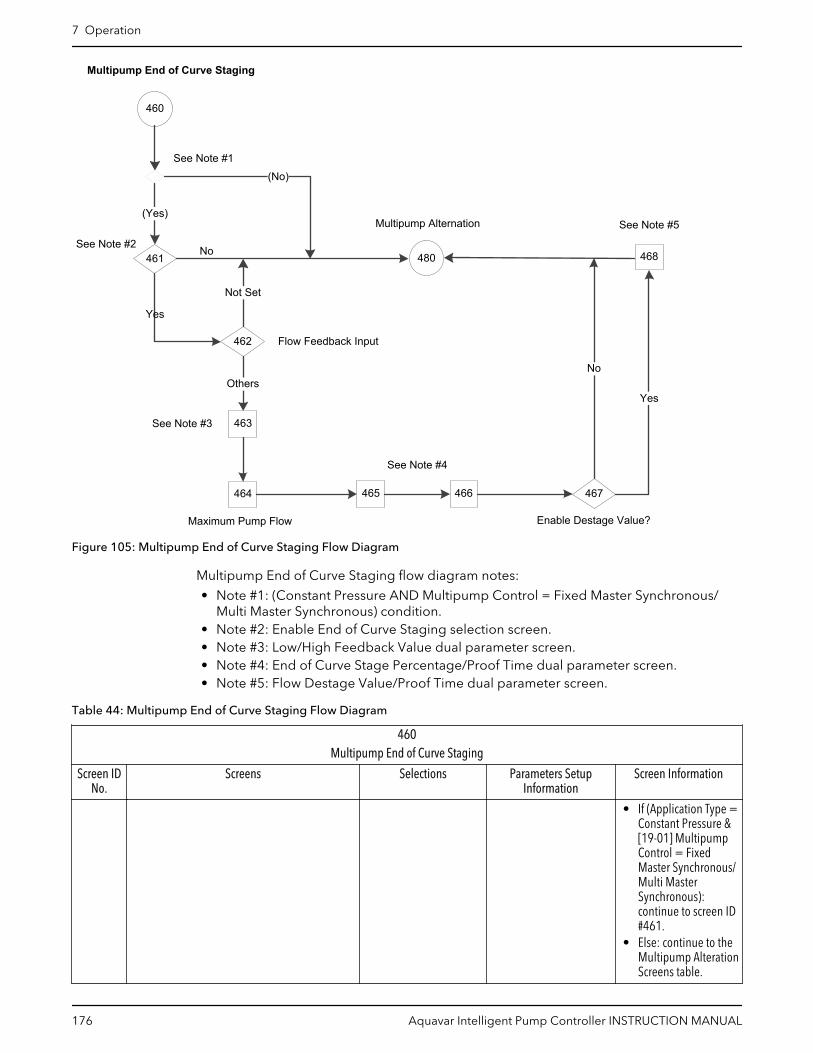
460
461
(Yes)
463
Others
480
Not Set
(No)
No
Multipump Alternation
464 465 466
468
467
Yes
No
Flow Feedback Input462
See Note #3
Maximum Pump Flow
See Note #2
Multipump End of Curve Staging
See Note #1
Yes
See Note #5
See Note #4
Enable Destage Value?
Figure 105: Multipump End of Curve Staging Flow Diagram
Multipump End of Curve Staging flow diagram notes:
• Note #1: (Constant Pressure AND Multipump Control = Fixed Master Synchronous/Multi Master Synchronous) condition.
• Note #2: Enable End of Curve Staging selection screen.• Note #3: Low/High Feedback Value dual parameter screen.• Note #4: End of Curve Stage Percentage/Proof Time dual parameter screen.• Note #5: Flow Destage Value/Proof Time dual parameter screen.
Table 44: Multipump End of Curve Staging Flow Diagram
460Multipump End of Curve Staging
Screen IDNo.
Screens Selections Parameters SetupInformation
Screen Information
• If (Application Type =Constant Pressure &[19-01] MultipumpControl = FixedMaster Synchronous/Multi MasterSynchronous):continue to screen ID#461.
• Else: continue to theMultipump AlterationScreens table.
7 Operation
176 Aquavar Intelligent Pump Controller INSTRUCTION MANUAL

460Multipump End of Curve Staging
Screen IDNo.
Screens Selections Parameters SetupInformation
Screen Information
461
Enable End of CurveStaging?
Yes
[Yes][No]
• Yes: continue toscreen ID #462.
• No: continue to theMultipump AlterationScreens table.
462
Flow Feedback InputNot Set
[Not Set][Analog Input 53][Analog Input 54]
[Analog Input X30/11][Analog Input X30/12][Analog Input X42/1][Analog Input X42/3][Analog Input X42/5]
[19-70] = selection.• If [19-70] = [0] Not
Set: [19-72] = [0]Disabled.
• If [19-70] = [0] NotSet: [19-72] = [0]Disabled.
• If [19-70] = [0] NotSet: continue to theMultipump AlterationScreens table.
• Else: continue toscreen ID #463.
463
60.000
Low Feedback Value0.000
High Feedback Value
____ [Unit]____ [Unit]
[19-72] = Enabled Continue to screen ID#464.
464
0.000Max. Pump Flow
_____ [19-73] = selection. Continue to screen ID#465.
465EOC Stage Percentage
EOC Stage Proof Time0secs
0%
____ %____ secs
[19-74] = first selection.[19-75] = secondselection.
Continue to screen ID#466.
466EOC Destage Percentage
EOC Destage Proof Time0secs
0%
____ %____ secs
[19-76] = first selection.[19-77] = secondselection.
Continue to screen ID#467.
7 Operation
Aquavar Intelligent Pump Controller INSTRUCTION MANUAL 177
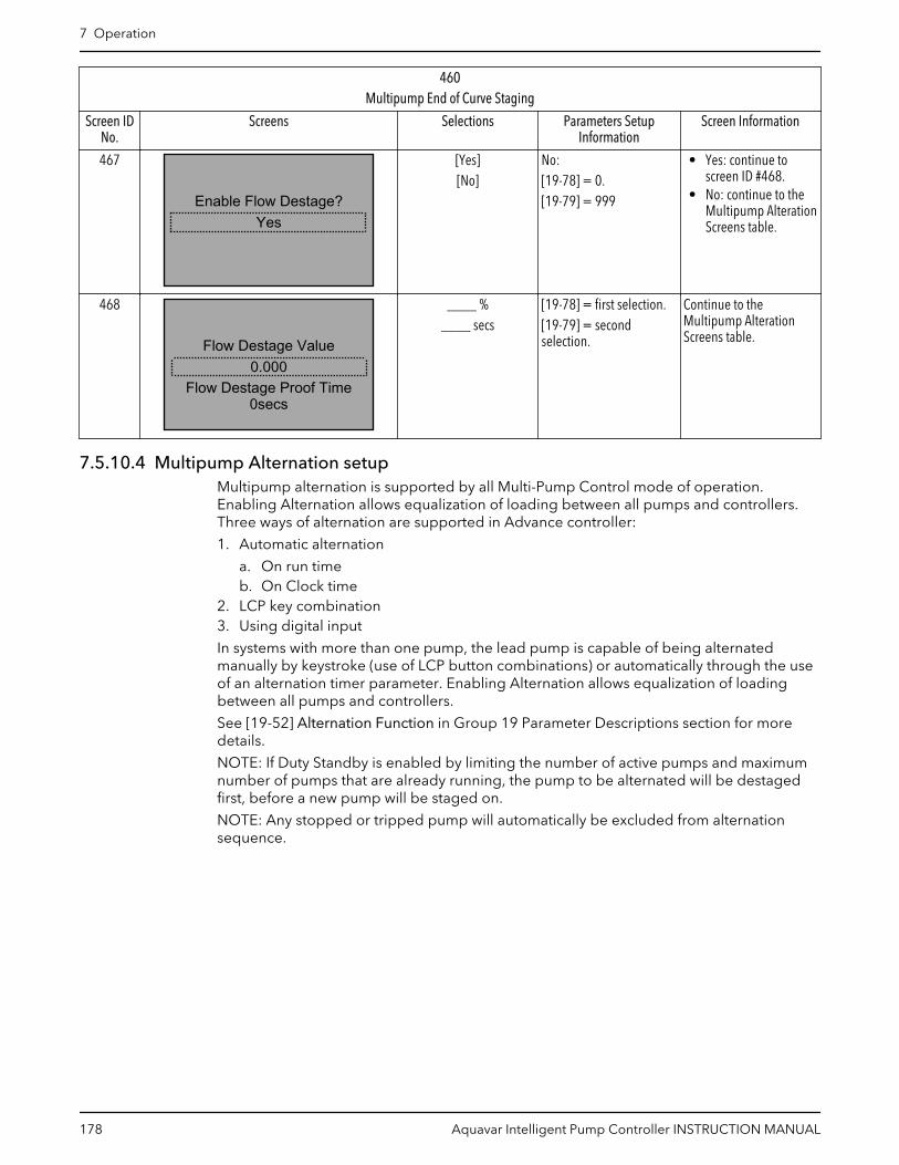
460Multipump End of Curve Staging
Screen IDNo.
Screens Selections Parameters SetupInformation
Screen Information
467
YesEnable Flow Destage?
[Yes][No]
No:[19-78] = 0.[19-79] = 999
• Yes: continue toscreen ID #468.
• No: continue to theMultipump AlterationScreens table.
468
0.000
0secsFlow Destage Proof Time
Flow Destage Value
____ %____ secs
[19-78] = first selection.[19-79] = secondselection.
Continue to theMultipump AlterationScreens table.
7.5.10.4 Multipump Alternation setupMultipump alternation is supported by all Multi-Pump Control mode of operation.Enabling Alternation allows equalization of loading between all pumps and controllers.Three ways of alternation are supported in Advance controller:
1. Automatic alternation
a. On run timeb. On Clock time
2. LCP key combination3. Using digital input
In systems with more than one pump, the lead pump is capable of being alternatedmanually by keystroke (use of LCP button combinations) or automatically through the useof an alternation timer parameter. Enabling Alternation allows equalization of loadingbetween all pumps and controllers.
See [19-52] Alternation Function in Group 19 Parameter Descriptions section for moredetails.
NOTE: If Duty Standby is enabled by limiting the number of active pumps and maximumnumber of pumps that are already running, the pump to be alternated will be destagedfirst, before a new pump will be staged on.
NOTE: Any stopped or tripped pump will automatically be excluded from alternationsequence.
7 Operation
178 Aquavar Intelligent Pump Controller INSTRUCTION MANUAL

480
Multipump Alternation
(Yes)
483see Note #3
Disable
(No)
Feedback Setup
485
486
Others
130
9
No
Yes
484
Enable
Yes
No
(Fixed Speed Follower?)
(HVAC)
(Booster)
Setup Selection
481 482
(see Main Menu flow diagram)
Pump Exercise Idle Time/Run TimePump Exercise
see Note #1 see Note #2
487
(Sensorless) (Sensor)
160 Yes
No
Setpoint Setup
Figure 106: Multipump Alternation Flow Diagram
Multipump Alternation flow diagram notes:
• Note #1: Fixed Speed Follower condition.• Note #2: Alternation Function selection screens.• Note #3: Alternation Time Interval parameter screen.• Note #4: Pump Exercise Idle Time/Run Time dual parameter screen.
Table 45: Multipump Alternation Screens
480Multipump Alternation
Screen IDNo.
Screens Selections Parameter SetupInformation
Screen Information
• If (Fixed SpeedFollower): continueto screen ID #481.
• Else: continue toscreen ID #482.
7 Operation
Aquavar Intelligent Pump Controller INSTRUCTION MANUAL 179

480Multipump Alternation
Screen IDNo.
Screens Selections Parameter SetupInformation
Screen Information
481
Alternation FunctionDisabled
[Disabled][On Clock Time]
[19-52] = selection([19-52] selection listexcept On Run Time)If [19-52] = Disable &(HVAC):[19-10] = [19-11] = 0.
• If [19-52] =Disabled:
• (Booster) continue toscreen ID #484.
• (HVAC): continue toscreen ID #486.
• Else: continue toscreen ID #483.
482
Alternation FunctionDisabled
[Disabled][On Run Time]
[On Clock Time]
[19-52] = selection. See the above screen ID#481.
483
Alt Time lnt0hours
____ hours [19-53] = selection.If (HVAC):[19-10] = [19-11] = 0.
• (Booster): continue toscreen ID #484.
• (HVAC): continue toscreen ID #486.
484
Enable Pump Exercise?Yes
[Yes][No]
No: [19-10] = [19-11] =0.
• Yes: continue toscreen ID #485.
• No: continue toscreen ID #486.
485
Pump Exe Run Time0secs
Pump Exe Idle Time0hours
____ hours____ secs
[19-10] = first selection.[19-11] = secondselection.
Continue to screen ID#486.
486
Continue to the FeedbackSetup?
No
[Yes][No]
• Yes: continue to theFeedback SetupScreens table.
• No: continue to theSetup Selectionscreen ID #6 in theMain Menu Screenstable.
7.5.11 Feedback setupFeedback setup function is not available for sensorless source. For sensor source, thecontroller can utilize up to 4 feedback sources using the onboard IO: 2 of these sources
7 Operation
180 Aquavar Intelligent Pump Controller INSTRUCTION MANUAL

can be configured for the analog inputs (AI 53 and AI 54), the other 2 can be set to busfeedbacks which can be set through the onboard fieldbus communications.
1Control feedback sources
When using analog inputs be sure to set the analog input configuration switches to theappropriate feedback type. Refer to the Analog Input Configuration (switch A54) sectionfor details on setting the analog input configuration switches. Refer to the CommonTerminal Wiring Configurations section in this manual for detail on wiring external devicesto the analog inputs.
In the Booster Pump Application Type, [20-20] Feedback Function is always set toMinimum value if only one feedback source is selected. If multiple feedback sources areselected, the Feedback Function can be configured from the list of [20-20] FeedbackFunction (excluding multi-zone multi-setpoint).
In the HVAC Pump Application Type, [20-20]Feedback Function is always set to MultiSetpoint Min value if the regional setting was North America. If the regional setting wasInternational, [20-20]Feedback Function is always set to Minimum value if only onefeedback source is selected; if multiple feedback sources are selected, the FeedbackFunction can be configured from the list of [20-20]Feedback Function.
The Feedback Function determines how the multiple feedbacks will be used to controlthe system.
[20–20] Feedback Function
Sum The sum of all feedbacks will be in the feedback to thecontroller.
Difference The difference between Feedback 2 and Feedback 1 willbe the feedback to the controller. This setting iscommonly used to configure a differential pressuresignal using 2 separate transducers. NOTE This selectionis only valid with Feedback 1 and Feedback 2. Feedback 3is not used with this selection.
Average The average of all feedback will be the feedback to thecontroller.
Minimum The lowest feedback will be the feedback to thecontroller.
Maximum The highest feedback will be the feedback to thecontroller.
The minimum and maximum values for each feedback source must be configured toproperly scale the input. For example, for a 0-300 psi transducer, set the Low Feedback 1Value to 0 psi and the High Feedback 1 Value to 300 psi.
After configuring all setpoints, the type of alarm for sensor fault can be set for eachfeedback.
In HVAC pump application, the All Zone Failure Function (AZF Function) screen displaysfor selecting Off, Stop, Stop and Trip or Constant Speed.
In Booster pump application type, the Sensor Fault Function displays for selecting Off,Stop or Stop and Trip. Constant Speed is not available in Booster type.
[6-17] Terminal 53 Sensor Fault (North America) / Live Zero (International) for AnalogInput 53 and Parameter [6-27] Terminal 54 Sensor Fault (North America) / Live Zero(International) for Analog Input 54 are required to set to Disable for the sensor fault to
7 Operation
Aquavar Intelligent Pump Controller INSTRUCTION MANUAL 181
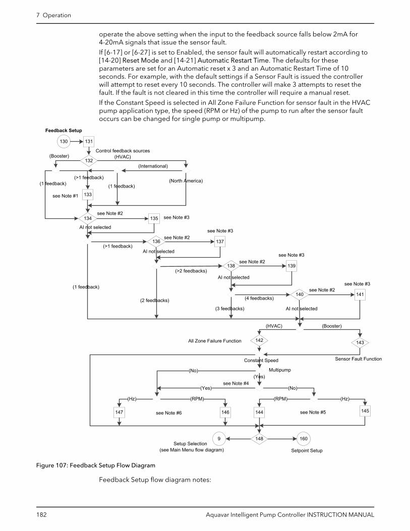
operate the above setting when the input to the feedback source falls below 2mA for4-20mA signals that issue the sensor fault.
If [6-17] or [6-27] is set to Enabled, the sensor fault will automatically restart according to[14-20] Reset Mode and [14-21] Automatic Restart Time. The defaults for theseparameters are set for an Automatic reset x 3 and an Automatic Restart Time of 10seconds. For example, with the default settings if a Sensor Fault is issued the controllerwill attempt to reset every 10 seconds. The controller will make 3 attempts to reset thefault. If the fault is not cleared in this time the controller will require a manual reset.
If the Constant Speed is selected in All Zone Failure Function for sensor fault in the HVACpump application type, the speed (RPM or Hz) of the pump to run after the sensor faultoccurs can be changed for single pump or multipump.
Setpoint Setup
160148
135
132
130
133
134
137136
Feedback Setup
140
AI not selected(>1 feedback)
(1 feedback)
AI not selected
138 139
(4 feedbacks)141
(No)
(Hz)
144 145
Constant Speed
(RPM)
146
9
147
(No)
(RPM)(Hz)
AI not selected
Control feedback sources
All Zone Failure Function
Sensor Fault Function
142 143
Multipump
(Booster) (HVAC)
(2 feedbacks)
(3 feedbacks)
(HVAC) (Booster)
(>2 feedbacks)
AI not selected
131
Setup Selection(see Main Menu flow diagram)
(Yes)
see Note #2
see Note #2
see Note #2
see Note #2see Note #3
see Note #3
see Note #3
see Note #3
see Note #5see Note #6
(>1 feedback)(1 feedback) (1 feedback)
(North America)
(International)
see Note #1
(Yes)see Note #4
Figure 107: Feedback Setup Flow Diagram
Feedback Setup flow diagram notes:
7 Operation
182 Aquavar Intelligent Pump Controller INSTRUCTION MANUAL

• Note #1: Feedback Function.• Note #2: Feedback 1/2/3/4.• Note #3: & High Feedback 1/2/3/4 Value.• Note #4: (#pump - #standby) > 1.• Note #5: Number of Pumps Running and All Zones Failure Speed (RPM/Hz).• Note #6: All Zones Failure Speed (RPM/Hz).
Table 46: Feedback Setup Screens
130Feedback Setup
Screen IDNo.
Screens Selections Parameters SetupInformation
Screen Information
131
Setup SelectionFeedback
• The controller canutilize up to 4feedback sourcesusing the onboard IO.
• Feedback Setup is notavailable forSensorless mode.
• Continue to screen ID#132.
132
Control feedback sources4
[1, 2, 3 or 4] • (Booster): If #feedbacks = 1:[20-20] = Minimum
• (HVAC):– (North America):
[20-20] = MultiSetpoint Min.
– (International): If# feedback = 1:[20-20] =Minimum
• (Booster & # feedback>1) or (HVAC &International & #feedback > 1):continue to screen ID#133.
• (Booster & # feedback= 1) or (HVAC &International & #feedback > 1):continue to screen ID# 134.
133
Feedback FunctionMinimum
• (Booster & # feedback= 1):
– [Sum]– [Difference]– [Average]– [Minimum]– [Maximum]
• (HVAC & International& # feedback = 1):
– [Sum]– [Difference]– [Average]– [Minimum]– [Maximum]– [Multi Setpoint
Min]– [Multi Setpoint
Max]
Continue to screen ID#134.
7 Operation
Aquavar Intelligent Pump Controller INSTRUCTION MANUAL 183
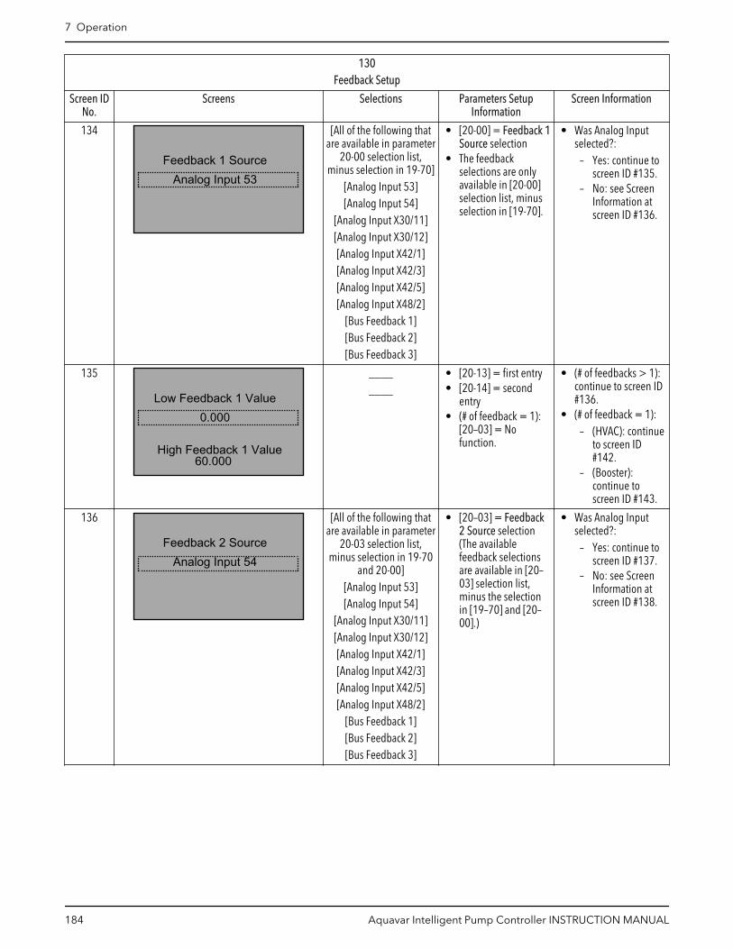
130Feedback Setup
Screen IDNo.
Screens Selections Parameters SetupInformation
Screen Information
134
Feedback 1 SourceAnalog Input 53
[All of the following thatare available in parameter
20-00 selection list,minus selection in 19-70]
[Analog Input 53][Analog Input 54]
[Analog Input X30/11][Analog Input X30/12][Analog Input X42/1][Analog Input X42/3][Analog Input X42/5][Analog Input X48/2]
[Bus Feedback 1][Bus Feedback 2][Bus Feedback 3]
• [20-00] = Feedback 1Source selection
• The feedbackselections are onlyavailable in [20-00]selection list, minusselection in [19-70].
• Was Analog Inputselected?:
– Yes: continue toscreen ID #135.
– No: see ScreenInformation atscreen ID #136.
135
Low Feedback 1 Value
High Feedback 1 Value
0.000
60.000
________
• [20-13] = first entry• [20-14] = second
entry• (# of feedback = 1):
[20–03] = Nofunction.
• (# of feedbacks > 1):continue to screen ID#136.
• (# of feedback = 1):– (HVAC): continue
to screen ID#142.
– (Booster):continue toscreen ID #143.
136
Feedback 2 SourceAnalog Input 54
[All of the following thatare available in parameter
20-03 selection list,minus selection in 19-70
and 20-00][Analog Input 53][Analog Input 54]
[Analog Input X30/11][Analog Input X30/12][Analog Input X42/1][Analog Input X42/3][Analog Input X42/5][Analog Input X48/2]
[Bus Feedback 1][Bus Feedback 2][Bus Feedback 3]
• [20–03] = Feedback2 Source selection(The availablefeedback selectionsare available in [20–03] selection list,minus the selectionin [19–70] and [20–00].)
• Was Analog Inputselected?:
– Yes: continue toscreen ID #137.
– No: see ScreenInformation atscreen ID #138.
7 Operation
184 Aquavar Intelligent Pump Controller INSTRUCTION MANUAL

130Feedback Setup
Screen IDNo.
Screens Selections Parameters SetupInformation
Screen Information
137
Low Feedback 2 Value
High Feedback 2 Value
0.000
300.000
________
• [20–13] = first entry.[20–14] = secondentry.
• (# of feedback = 2):[20–03] = Nofunction.
• (# of feedbacks > 2):continue to screen ID#138.
• (# of feedback = 2):– (HVAC): continue
to screen ID#142.
– (Booster):continue toscreen ID #143.
138
Feedback 3 SourceBus Feedback 1
[All of the following thatare available in parameter
20-06 selection list,minus selection in 19-70,
20-00 and 20-03][Analog Input 53][Analog Input 54]
[Analog Input X30/11][Analog Input X30/12][Analog Input X42/1][Analog Input X42/3][Analog Input X42/5][Analog Input X48/2]
[Bus Feedback 1][Bus Feedback 2][Bus Feedback 3]
• [20-06] = selection(The availableselections areavailable in [20-06]selection list, minusthe selections in [19–70], [20–00] and [20–03].)
• Was Analog Inputselected?:
– Yes: continue toscreen ID #139.
– No: continue tothe output ofscreen ID #141.
139
Low Feedback 3 Value
High Feedback 3 Value
0.000
300.000
_____ [Unit]_____ [Unit]
• [20–13] = first entry.[20–14] = secondentry.
• (# of feedback = 3):[20–03] = Nofunction.
• (# of feedback ≠ 3):continue to screen ID#140.
• (# of feedback = 3):– (HVAC): continue
to screen ID#142.
7 Operation
Aquavar Intelligent Pump Controller INSTRUCTION MANUAL 185

130Feedback Setup
Screen IDNo.
Screens Selections Parameters SetupInformation
Screen Information
140
Feedback 4 SourceBus Feedback 2
[All of the following thatare available in [19-80]
selection list, minusselection in [19-70],[20-00], [20-03] and
[20-06]][Analog Input 53][Analog Input 54]
[Analog Input X30/11][Analog Input X30/12][Analog Input X42/1][Analog Input X42/3][Analog Input X42/5][Analog Input X48/2]
[Bus Feedback 1][Bus Feedback 2][Bus Feedback 3]
• [19-80] = selection• The available
selections areavailable in [19–80]selection list, minusthe selections in [19–70], [20–00], [20–03]and [20–06].
• Was Analog Inputselected?:
– Yes: continue toscreen ID #141.
– No: continue tothe output ofscreen ID #142.
141
60.000
Low Feedback 4 Value0.000
High Feedback 4 Value
_____ [Unit]_____ [Unit]
• [20–13] = first entry.[20–14] = secondentry.
• (HVAC): continue toscreen ID #142.
• (Booster): continue toscreen ID #143.
7 Operation
186 Aquavar Intelligent Pump Controller INSTRUCTION MANUAL

130Feedback Setup
Screen IDNo.
Screens Selections Parameters SetupInformation
Screen Information
142
Constant SpeedAZF Function
[Off][Stop]
[Constant Speed][Stop and Trip]
[19–40] = selection • Constant Speed:– (Multipump and
#running pumps≠ 1 and MotorSpeed Unit =RPM): continueto screen ID #144.
– (Multipump and#running pumps≠ 1 and MotorSpeed Unit =HZ): continue toscreen ID # 145.
– (Single pumpand #runningpump = 1 andMotor SpeedUnit = RPM):continue toscreen ID # 146.
– (Single pumpand #runningpump = 1 andMotor SpeedUnit = HZ):continue toscreen ID # 147.
• Not Constant Speed:continue to screen ID#148.
143
Sensor Fault FunctionConstant Speed
[Off][Stop]
[Stop and Trip]
[19–40] = selection See the above screen ID#142.
144
0 RPM
Number of Pumps Runni...1
AZF Speed [RPM]
[1, 2, 3 or 4][RPM]
[19–41] = first selection[19–42] = secondselection
Continue to screen ID#148.
7 Operation
Aquavar Intelligent Pump Controller INSTRUCTION MANUAL 187

130Feedback Setup
Screen IDNo.
Screens Selections Parameters SetupInformation
Screen Information
145
0.0Hz
Numbe of Pumps Runni...1
AZF Speed [Hz]
[1, 2, 3 or 4]_____ [Hz]
[19–41] = first selection[19–42] = secondselection
Continue to screen ID#148.
146
AZF Speed [RPM]0RPM
_____ [RPM] Continue to screen ID#148.
147
AZF Speed [Hz]0.0Hz
_____ [Hz] Continue to screen ID#148.
148Continue to the setpoint
Setup?
Yes
[Yes][No]
• Yes: continue to theSetpoint SetupScreens table.
• No: return to theSetup Selectionscreen ID #6 in Main-Menu Screens table.
7.5.12 Setpoint setupThe Setpoint setup can be configured for up to two setpoints from [20-21] and [19-84] forthe Booster pump application type. For the HVAC pump application type, the number ofsetpoints is based on the number of feedbacks selected in the Feedback setup andcannot be changed in the Setpoint setup. Four setpoints can be selected from [20-21],[20-22], [20-23] and [19-83], and four alternate setpoints can be selected from [19-84],[19-85], [19-86] and [19-87].
Setpoint 2 in the Booster pump application or alternative setpoints in the HVAC pumpapplication will be selected through digital input 33 by setting [5-15] Terminal 33 DigitalInput to MCO Specific.
7 Operation
188 Aquavar Intelligent Pump Controller INSTRUCTION MANUAL
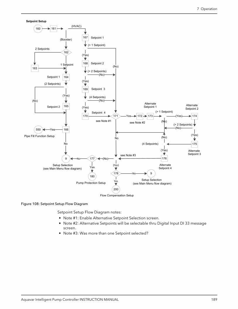
160 161
Setpoint 3
Setpoint Setup
Setpoint 2
(Booster)
164
163
165
(Yes)
166
(No)
550
9
Setup Selection
Pipe Fill Function Setup
Yes
No
167
(HVAC)
168
(Yes)
169
(Yes)
171170
(Yes)
172 173 174
175
(No)
(No)
(No)
Yes (Yes)
(Yes)
176
(Yes)
(> 1 Setpoint)
No
see Note #1
(No)
(No)
(No)
200
Pump Protection Setup
162
1 Setpoint
Setpoint 1
Setpoint 2
Setpoint 1
Setpoint 4
2 Setpoints
(see Main Menu flow diagram)
AlternateSetpoint 1 Alternate
Setpoint 2
AlternateSetpoint 3
AlternateSetpoint 4
(> 1 Setpoint)
(> 2 Setpoints)
(4 Setpoints)
(> 2 Setpoints)
(4 Setpoints)
(2 Setpoints)
(No)
180
Flow Compensation Setup
Yes
9
Setup Selection(see Main Menu flow diagram)
see Note #3
see Note #2
177
178
(Yes)
No
No
Yes
Figure 108: Setpoint Setup Flow Diagram
Setpoint Setup Flow Diagram notes:
• Note #1: Enable Alternative Setpoint Selection screen.• Note #2: Alternative Setpoints will be selectable thru Digital Input DI 33 message
screen.• Note #3: Was more than one Setpoint selected?
7 Operation
Aquavar Intelligent Pump Controller INSTRUCTION MANUAL 189
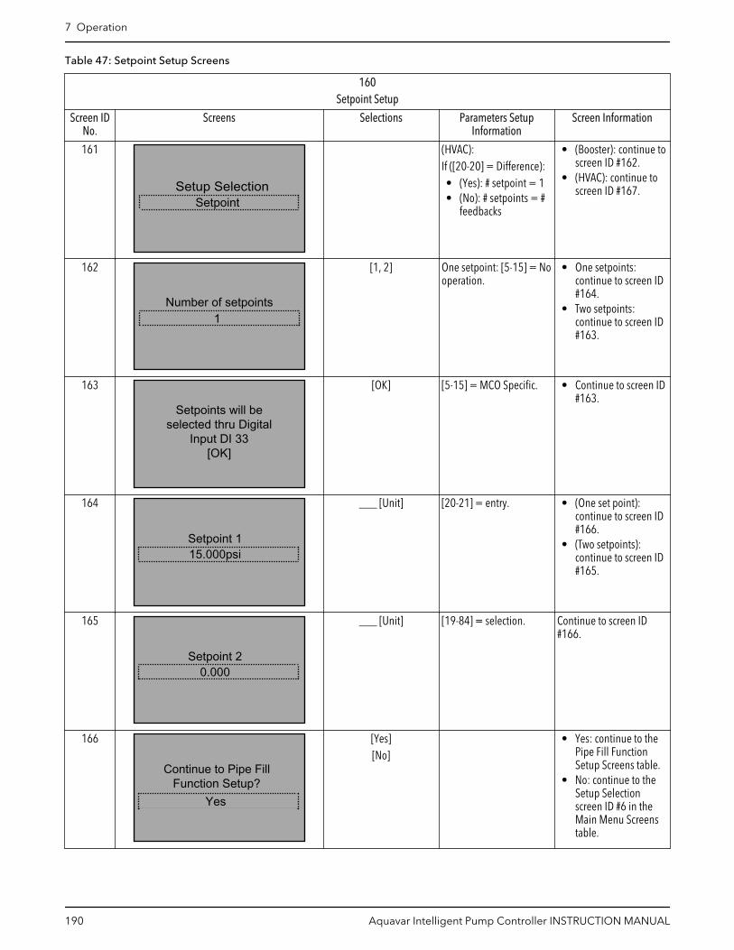
Table 47: Setpoint Setup Screens
160Setpoint Setup
Screen IDNo.
Screens Selections Parameters SetupInformation
Screen Information
161
SetpointSetup Selection
(HVAC):If ([20-20] = Difference):• (Yes): # setpoint = 1• (No): # setpoints = #
feedbacks
• (Booster): continue toscreen ID #162.
• (HVAC): continue toscreen ID #167.
162
Number of setpoints1
[1, 2] One setpoint: [5-15] = Nooperation.
• One setpoints:continue to screen ID#164.
• Two setpoints:continue to screen ID#163.
163
Setpoints will beselected thru Digital
Input DI 33[OK]
[OK] [5-15] = MCO Specific. • Continue to screen ID#163.
164
Setpoint 115.000psi
___ [Unit] [20-21] = entry. • (One set point):continue to screen ID#166.
• (Two setpoints):continue to screen ID#165.
165
Setpoint 20.000
___ [Unit] [19-84] = selection. Continue to screen ID#166.
166
Continue to Pipe FillFunction Setup?
Yes
[Yes][No]
• Yes: continue to thePipe Fill FunctionSetup Screens table.
• No: continue to theSetup Selectionscreen ID #6 in theMain Menu Screenstable.
7 Operation
190 Aquavar Intelligent Pump Controller INSTRUCTION MANUAL

160Setpoint Setup
Screen IDNo.
Screens Selections Parameters SetupInformation
Screen Information
167
Setpoint 115.000psi
___ [Unit] [20-21] = entry. • (One set point):continue to screen ID#171.
• (Two setpoints):continue to screen ID#168.
168
Setpoint 20.000
___ [Unit] [2-22] = selection. • (Two setpoints):continue to screen ID#171.
• (More than twosetpoints): continueto screen ID #169.
169
Setpoint 30.000psi
___ [Unit] [20-23] = entry in Setup1
• (Three setpoints):continue to screen ID#171.
• (More than threesetpoints): continueto screen ID #170.
170
Setpoint 40.000
___ [Unit] [19-83] = entry. Continue to screen ID#171.
171
Enable Alternative SetpointSelection?
Yes
[Yes][No]
No: [5-15] = Nooperation.
• Yes: continue toscreen ID #172.
• No:– If (Number of
Setpoints > 1):continue toscreen ID #177.
– Else: continue toscreen ID #178.
172
Alternative Setpoints will be selectable thru Digital Input DI 33 [OK]
[OK] [5-15] = MCO Specific. Continue to screen ID#173.
7 Operation
Aquavar Intelligent Pump Controller INSTRUCTION MANUAL 191
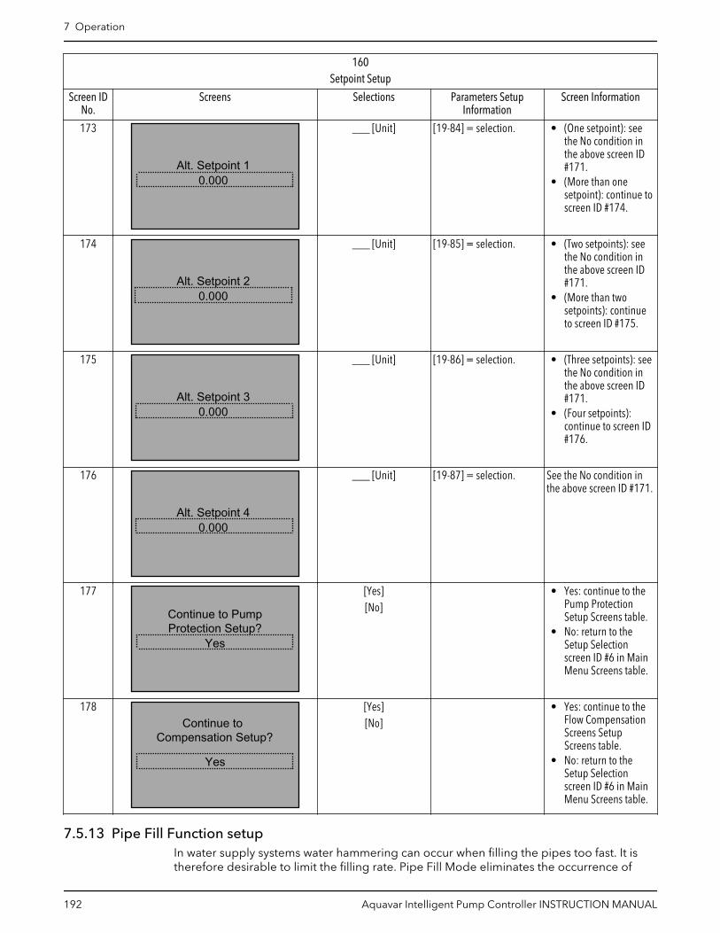
160Setpoint Setup
Screen IDNo.
Screens Selections Parameters SetupInformation
Screen Information
173
Alt. Setpoint 10.000
___ [Unit] [19-84] = selection. • (One setpoint): seethe No condition inthe above screen ID#171.
• (More than onesetpoint): continue toscreen ID #174.
174
Alt. Setpoint 20.000
___ [Unit] [19-85] = selection. • (Two setpoints): seethe No condition inthe above screen ID#171.
• (More than twosetpoints): continueto screen ID #175.
175
Alt. Setpoint 30.000
___ [Unit] [19-86] = selection. • (Three setpoints): seethe No condition inthe above screen ID#171.
• (Four setpoints):continue to screen ID#176.
176
Alt. Setpoint 40.000
___ [Unit] [19-87] = selection. See the No condition inthe above screen ID #171.
177
Continue to PumpProtection Setup?
Yes
[Yes][No]
• Yes: continue to thePump ProtectionSetup Screens table.
• No: return to theSetup Selectionscreen ID #6 in MainMenu Screens table.
178Continue to
Compensation Setup?
Yes
[Yes][No]
• Yes: continue to theFlow CompensationScreens SetupScreens table.
• No: return to theSetup Selectionscreen ID #6 in MainMenu Screens table.
7.5.13 Pipe Fill Function setupIn water supply systems water hammering can occur when filling the pipes too fast. It istherefore desirable to limit the filling rate. Pipe Fill Mode eliminates the occurrence of
7 Operation
192 Aquavar Intelligent Pump Controller INSTRUCTION MANUAL
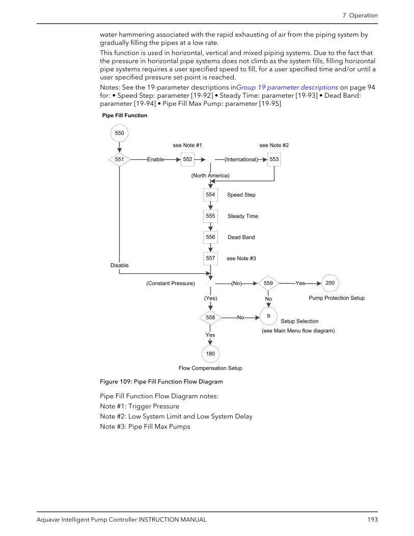
water hammering associated with the rapid exhausting of air from the piping system bygradually filling the pipes at a low rate.
This function is used in horizontal, vertical and mixed piping systems. Due to the fact thatthe pressure in horizontal pipe systems does not climb as the system fills, filling horizontalpipe systems requires a user specified speed to fill, for a user specified time and/or until auser specified pressure set-point is reached.
Notes: See the 19-parameter descriptions inGroup 19 parameter descriptions on page 94for: • Speed Step: parameter [19-92] • Steady Time: parameter [19-93] • Dead Band:parameter [19-94] • Pipe Fill Max Pump: parameter [19-95]
550
551 552Enable
554
(North America)
555
556
557
(Yes)
(No)
Dead Band
558
559
9
180
Yes
No
200
Setup Selection
(see Main Menu flow diagram)
Pump Protection Setup
(Constant Pressure)
Pipe Fill Function
Flow Compensation Setup
see Note #1
Yes
Disable
No
Speed Step
Steady Time
553(International)
see Note #2
see Note #3
Figure 109: Pipe Fill Function Flow Diagram
Pipe Fill Function Flow Diagram notes:
Note #1: Trigger Pressure
Note #2: Low System Limit and Low System Delay
Note #3: Pipe Fill Max Pumps
7 Operation
Aquavar Intelligent Pump Controller INSTRUCTION MANUAL 193

Table 48: Pipe Fill Function Screens
550Pipe Fill Function
Screen IDNo.
Screens Selections Parameters SetupInformation
Screen Information
551
EnablePipe Fill Function
[Enabled][Disabled]
• Enabled: [19-90] =Enable.
• Disabled: [19-90] =Disable.
• Enabled: continue toscreen ID #552.
• Disabled:– (Application type
= ConstantPressure):continue toscreen ID #557.
– (Application type≠ ConstantPressure):continue toscreen ID #558.
552
0.000Triggered Pressure
___ [Unit] [19-91] = selection.If (International):• (Low System
Fault=Disabled):[19-45]=ManualReset Alarm,[19-47]=30 sec,[19-48]=600 sec,[19-49]=1.
• (Low SystemFault=Enabled):[19-46]=[19-91].
(North America): continueto screen ID #554.(International): continueto screen ID #553.
553
30secsLow System Delay
Low System Limit0.00
Low System Limit _____[Unit]
Low System Delay _____secs
[19-46]=selection 1[19-47]=selection 2
Continue to screenID#554.
554
0%Speed Step
___ % [19-92] = selection. Continue to screen ID#555.
555
0secsSteady Time
___ sec [19-93] = selection. Continue to screen ID#556.
7 Operation
194 Aquavar Intelligent Pump Controller INSTRUCTION MANUAL
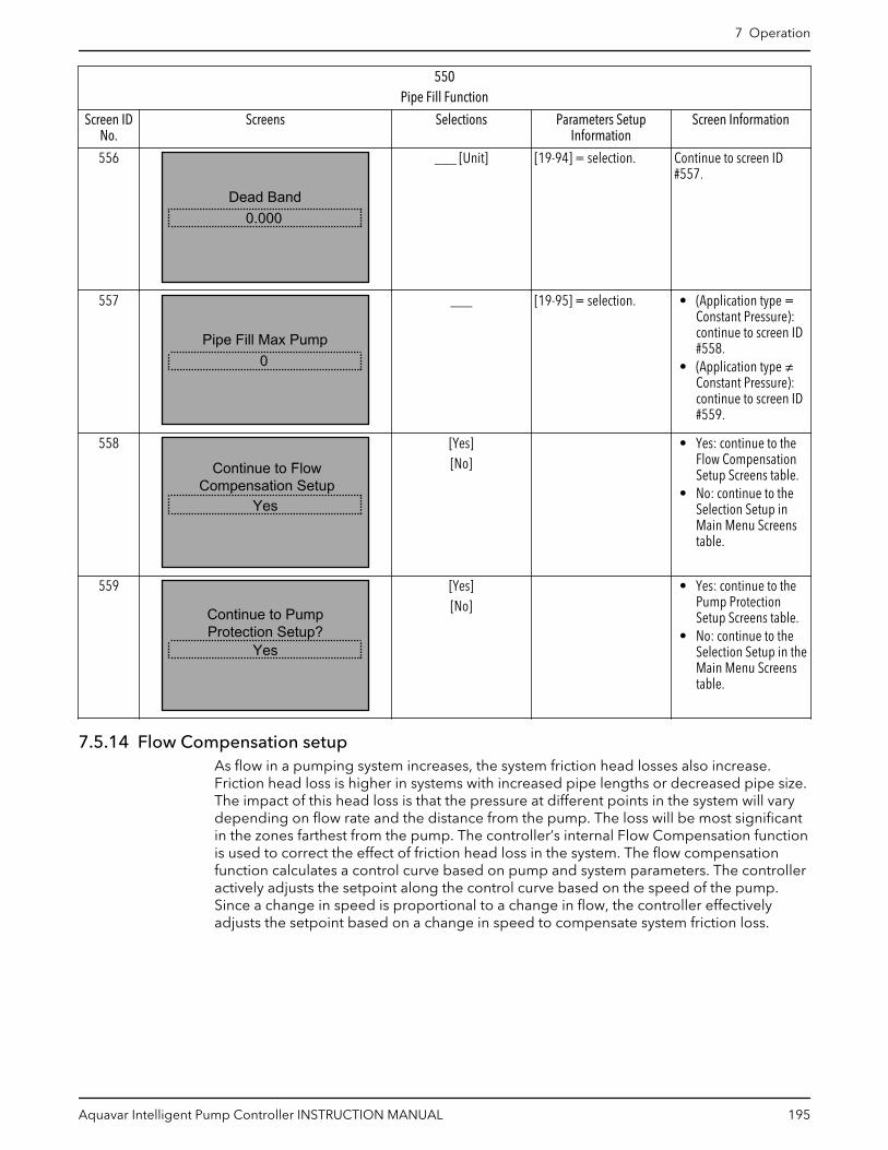
550Pipe Fill Function
Screen IDNo.
Screens Selections Parameters SetupInformation
Screen Information
556
0.000Dead Band
___ [Unit] [19-94] = selection. Continue to screen ID#557.
557
0Pipe Fill Max Pump
___ [19-95] = selection. • (Application type =Constant Pressure):continue to screen ID#558.
• (Application type ≠Constant Pressure):continue to screen ID#559.
558
Yes
Continue to FlowCompensation Setup
[Yes][No]
• Yes: continue to theFlow CompensationSetup Screens table.
• No: continue to theSelection Setup inMain Menu Screenstable.
559
Continue to PumpProtection Setup?
Yes
[Yes][No]
• Yes: continue to thePump ProtectionSetup Screens table.
• No: continue to theSelection Setup in theMain Menu Screenstable.
7.5.14 Flow Compensation setupAs flow in a pumping system increases, the system friction head losses also increase.Friction head loss is higher in systems with increased pipe lengths or decreased pipe size.The impact of this head loss is that the pressure at different points in the system will varydepending on flow rate and the distance from the pump. The loss will be most significantin the zones farthest from the pump. The controller’s internal Flow Compensation functionis used to correct the effect of friction head loss in the system. The flow compensationfunction calculates a control curve based on pump and system parameters. The controlleractively adjusts the setpoint along the control curve based on the speed of the pump.Since a change in speed is proportional to a change in flow, the controller effectivelyadjusts the setpoint based on a change in speed to compensate system friction loss.
7 Operation
Aquavar Intelligent Pump Controller INSTRUCTION MANUAL 195

Figure 110: Flow Compensation Curve
NOTE: Setpoint in the above Flow Compensation Curve is the maximum control setpoint,will correspond to the controlling setpoint.
Table 49: Flow Compensation Parameters Setup
Parameter Number Description Set to
[19-12] Flow Compensation Enabled
[19-13] Friction Loss 0.000 - 999,999.999
[19-14] Friction Loss 1 0.000 - 999,999.999
[19-15] Friction Loss 2 0.000 - 999,999.999
[19-16] Friction Loss 3 0.000 - 999,999.999
Flow Compensation Setup
180
Low/High
Maximum Pump Flow
181
182
Enable
Total Friction Loss(Not Set) 188184Others 185
186
Not Set
187
Disable
(Others)
200Yes
9
Setup Selection
NoFlow Feedback Input
Flow meter Flow approximation
183
Pump Protection Setup
(see Main Menu flow diagram)
Feedback Values
Flow Compensation?
Figure 111: Flow Compensation Setup Flow Diagram
7 Operation
196 Aquavar Intelligent Pump Controller INSTRUCTION MANUAL

Table 50: Flow Compensation Setup Screens
180Flow Compensation Setup
Screen IDNo.
Screens Selections Parameters SetupInformation
Screen Information
181
EnabledFlow Compensation
[Enable][Disable]
• Enable: [19-12] =Enable.
• Disable: [19-12] =Disable.
• Enable: continue toscreen ID #182.
• Disable: continue toscreen ID #188.
182
0.000[unit]Total Friction Loss
___ [Unit] [19-13] = selection. [19-70] = Not Set:• Yes: continue to
screen ID #183.• No: continue to
screen ID #186.
183
Flow Feedback InputNot Set
[Not Set][Analog Input 53][Analog Input 54]
[Analog Input X30/11][Analog Input X30/12][Analog Input X42/1][Analog Input X42/3][Analog Input X42/5]
[19-13] = selection.Note: All of the selectionsare available in [19-70].
[19-70] = Not Set:• Yes: continue to
screen ID #187.• No: continue to
screen ID #184.
184
60.000
Low Feedback Value0.000
High Feedback Value
_____ [Unit]_____ [Unit]
Continue to screen ID#185.
185
0.000Max. Pump Flow
____ [19-73] = selection. Continue to screen ID#188.
186
[OK]
Flow meter will be usedfor compensation.
[OK] Continue to screen ID#188.
7 Operation
Aquavar Intelligent Pump Controller INSTRUCTION MANUAL 197
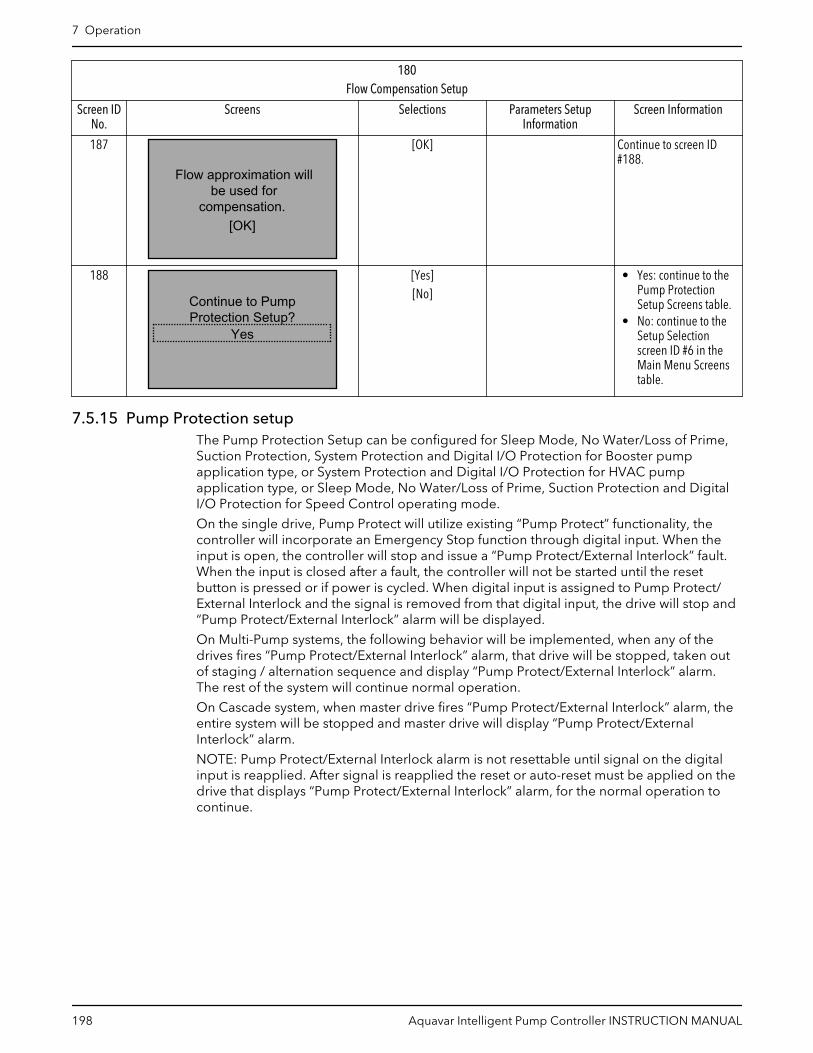
180Flow Compensation Setup
Screen IDNo.
Screens Selections Parameters SetupInformation
Screen Information
187
[OK]
Flow approximation willbe used for
compensation.
[OK] Continue to screen ID#188.
188
Continue to PumpProtection Setup?
Yes
[Yes][No]
• Yes: continue to thePump ProtectionSetup Screens table.
• No: continue to theSetup Selectionscreen ID #6 in theMain Menu Screenstable.
7.5.15 Pump Protection setupThe Pump Protection Setup can be configured for Sleep Mode, No Water/Loss of Prime,Suction Protection, System Protection and Digital I/O Protection for Booster pumpapplication type, or System Protection and Digital I/O Protection for HVAC pumpapplication type, or Sleep Mode, No Water/Loss of Prime, Suction Protection and DigitalI/O Protection for Speed Control operating mode.
On the single drive, Pump Protect will utilize existing “Pump Protect” functionality, thecontroller will incorporate an Emergency Stop function through digital input. When theinput is open, the controller will stop and issue a “Pump Protect/External Interlock” fault.When the input is closed after a fault, the controller will not be started until the resetbutton is pressed or if power is cycled. When digital input is assigned to Pump Protect/External Interlock and the signal is removed from that digital input, the drive will stop and“Pump Protect/External Interlock” alarm will be displayed.
On Multi-Pump systems, the following behavior will be implemented, when any of thedrives fires “Pump Protect/External Interlock” alarm, that drive will be stopped, taken outof staging / alternation sequence and display “Pump Protect/External Interlock” alarm.The rest of the system will continue normal operation.
On Cascade system, when master drive fires “Pump Protect/External Interlock” alarm, theentire system will be stopped and master drive will display “Pump Protect/ExternalInterlock” alarm.
NOTE: Pump Protect/External Interlock alarm is not resettable until signal on the digitalinput is reapplied. After signal is reapplied the reset or auto-reset must be applied on thedrive that displays “Pump Protect/External Interlock” alarm, for the normal operation tocontinue.
7 Operation
198 Aquavar Intelligent Pump Controller INSTRUCTION MANUAL

200
200
202
201
System Protection
210 Sleep Mode(Booster)
230
570
No Water/Loss of Prime
240Suction Protection
Digital I/O Protection 590
(HVAC)
(Speed Control)
(No)
Priming Delay
(Yes)
see Note #2
600
(Yes)
Bypass Setup
(No)260 Yes
Digital Input Setup
Pump Protection Setup
(see Main Menu flow diagram)
(Speed Control)
(Booster)
No
9
Setup Selection
see Note #1
Figure 112: Pump Protection Setup Flow Diagram
Pump Protection Setup flow diagram notes:
• Note #1: (Parameters [19-20] & [19-45] = Disabled & [22-50] = Off?)• Note #2: Bypass Panel is detected and functioning
7 Operation
Aquavar Intelligent Pump Controller INSTRUCTION MANUAL 199

Table 51: Pump Protection Setup Screens
200Pump Protection Setup
Screen IDNo.
Screens Selections Parameters SetupInformation
Screen Information
200
Setup SelectionPump Protection
(Not Speed Control):• (Booster & Flow
Control)– [19-24] = [0]
Disabled, [22-23]= Off.
• (HVAC): [19-24] =[19-20] = [19-32] =[19-36] = [0]Disabled, [22-23] =Off, [19-30] = [0] NotSet.
• (Not Speed Control):– (Booster):
continue to theSleep Mode, NoWater/Loss ofPrime, SuctionProtection,SystemProtection,Digital I/OProtection SetupScreens tablesrespectively.
– (HVAC): continueto the SystemProtection andDigital I/OProtection SetupScreens tablesrespectively.
• (Speed Control):continue to the SleepMode, No Water/Lossof Prime, SuctionProtection, andDigital I/O ProtectionSetup Screens tablesrespectively.
• ([19-20] = [19-45] =[0] Disabled and[22-50] = [0] Off):
– (Yes): continue tothe output ofscreen ID #201 toverify if a Bypassdrive is available.
– (No): continue toscreen ID #201.
([19-20] = [19-45] = [0]Disabled and [22-50] =[0] Off):• (Yes): continue to the
output of screen ID#201 to verify if aBypass panel isavailable.
• (No): continue toscreen ID #201.
7 Operation
200 Aquavar Intelligent Pump Controller INSTRUCTION MANUAL

200Pump Protection Setup
Screen IDNo.
Screens Selections Parameters SetupInformation
Screen Information
201
Priming Delay0secs
______sec [19-97] = entry. If a Bypass panel wasdetected and functioning:• Yes: continue to the
Bypass Setup Screenstable.
• No: continue toscreen ID #202.
202
Continue to Digital InputSetup?Yes
[Yes][No]
• Yes: continue to theDigital Input SetupScreens table.
• No: continue to theSetup Selectionscreen ID #6 in theMain Menu Screenstable.
7.5.15.1 Sleep Mode setupSleep Mode protects the pump by turning off the pump in cases where there is no flow inthe system. Sleep mode is only available in Booster and Speed Control operating modesand can be enabled or disabled at the [19–24] No Flow Shutdown. If Sleep Mode isdisabled the pump will not turn off during a no flow condition if no other control devicesare present to turn the pump off. The [4–12] Sleep Frequency/Low Limit [Hz] (NorthAmerica) and [22–24] Sleep Delay (North America) and No-Flow Delay (International) areset first depending on the Operating Mode, Speed Control (RPM/Hz) or other modes. The[4–11] Motor Speed Low Limit [RPM] or [4–12] Sleep Frequency/Low Limit [Hz] is thefrequency that the pump has to reach or fall below in order to enter sleep mode. TheSleep Frequency is also the minimum frequency. The Sleep Delay is the amount of timethe pump speed must be at or below the Sleep Frequency in order to enter Sleep Mode.Use this parameter to prevent the pump from entering sleep mode too soon.
For Speed Control operating mode, [22–42] Wake-up Speed [RPM] or [22–43] Wake-upSpeed [Hz] can be changed.
For the other operating modes, the [19–25] No Flow Restart Difference is the differencebetween the setpoint and the actual value that will cause the pump to restart (wake up)from sleep mode. This value is entered as an absolute value. For example, if the setpointis 50 psi and an absolute value 5.000 No Flow Restart Difference is entered, the pump willrestart from sleep mode after the system pressure drops 5 psi below the set pressure (45psi). If multiple setpoints are used then a Restart Difference is the same for all setpoints.
The [22–40] Minimum Run Time and [22–41] Minimum Sleep Time can be used to preventrapid cycling. The [22–40] Minimum Run Time forces the pump to stay on and not entersleep mode until the pump runs for the time entered in [22–40] Minimum Run Time. The[22–41] Minimum Sleep Time forces the pump to stay in sleep mode (turned off) for thetime entered in [22–41] Minimum Sleep Time.
7 Operation
Aquavar Intelligent Pump Controller INSTRUCTION MANUAL 201

210
Disable
No Water/Loss of Prime
Sleep Mode
211 Enable 212
see Note #1
213(No)
214
(Yes) 215
216
217
Wake-up Speed
218
230
Sleep Mode
(RPM)
(Hz)
(Hz)
(RPM)
see Note #2
see Note #3 see Note #4
see Note #6 219
see Note #5
(Speed Control)
(No)
(Yes)
Figure 113: Sleep Mode Flow Diagram
Sleep Mode flow diagram notes:
• Note #1: Minimum/Sleep Frequency (Hz)/Speed (RPM) and Sleep Delay dualparameter screens.
• Note #2: (Operating mode = Speed Control?) condition.• Note #3: No Flow Restart Difference parameter screen.• Note #4: Minimum Run Time/Sleep Time dual parameter screen.• Note #5: Flow Check Window & Time.• Note #6: Enabling Sleep Mode information.
7 Operation
202 Aquavar Intelligent Pump Controller INSTRUCTION MANUAL

Table 52: Sleep Mode Screens
210Sleep Mode
Screen IDNo.
Screens Selections Parameters SetupInformation
Screen Information
211
Sleep ModeEnable
[Enable][Disable]
• Disable: [19-24] =[22-21] = [22-22] =[0] Disabled, [22-23]= [0] Off.
• Enable:– (North America):
[22-21]=Enabled. If (SpeedControl):[19-24]=[0]Disabled,[22-22]=Disabled, [22-23]=SleepMode. Else[19-24]=[1]Enabled,[22-22]=Disabled, [22-23]=Off.
– (International): If(Speed Control):[19-24]=[0]Disabled,[22-22]=Enabled, [22-23]=SleepMode. Else[19-24]=[1]Enabled,[22-22]=Disabled, [22-23]=Off.
• Enable:– ([0-02] = Hz):
continue toscreen ID #212.
– ([0-02] = RPM):continue toscreen ID #213.
• Disable: see screen ID#218.
212
Minimum/Sleep Frequen18.0Hz
Sleep Delay3s
______ [Hz]______s
[4-12] = first entry.[22-24] = second entry.
• (Speed Control):– ([0-02] = Hz):
continue toscreen ID #215.
– ([0-02] = RPM):continue toscreen ID #216.
• (Not Speed Control):continue to screen ID#214.
213
Minimum/Sleep Speed540RPM
Sleep Delay3s
______ [RPM]______s
[4-11] = first entry.[22-24] = second entry.
Continue to the output ofscreen ID #212 to checkthe operating mode.
7 Operation
Aquavar Intelligent Pump Controller INSTRUCTION MANUAL 203

210Sleep Mode
Screen IDNo.
Screens Selections Parameters SetupInformation
Screen Information
214
0.000No Flow Restart Difference
_____ [19-25] = entry. Continue to screen ID#217.
215
Wake-up Speed
30.0Hz
_____ [Hz] [22-43] = entry. Continue to screen ID#217.
216
Wake-up Speed [Hz]
900RPM
_____ [RPM] [22-42] = entry. Continue to screen ID#217.
217
Minimum Run Time10s
Minimum Sleep time10s
______s______s
[22-40] = first entry.[22-41] = second entry.
• (Not Speed Control):continue to screen ID#218.
• (Speed Control):continue to screen ID#219.
218
0.00%Flow Check Window
Flow Check Time10mins
______ %______ mins
[3-10.0] = first entry[13-20.0] = second entry* 60,000
Continue to screen ID #219.
219 “To enable Sleep Mode based on powerconsumption, No Flow Power Calibration must
be run on all pumps in the system.”
[OK] Continue to the No Water/Loss of Prime SetupScreens table.
7.5.15.2 No Water/Loss of Prime setupThe No Water/Loss of Prime function is used to protect the pump against running dryand/or loss of prime. The function works by monitoring power at full speed andcomparing the actual power to a preset limit. If the actual power falls below this presetlimit for a specified amount of time, the No Water/Loss of Prime alarm is issued. If the NoWater/Loss of Prime function is disabled, the pump will not be protected against runningdry and/or loss of prime.
7 Operation
204 Aquavar Intelligent Pump Controller INSTRUCTION MANUAL

The [22–39] No Water/Loss of Prime Limit [HP] (North America) / [22-38] High SpeedPower [kW] (International) is the no flow power value that corresponds to the speedentered in [22–37] High Speed [Hz]. The No Flow Power Calibration Set-up automaticallyenters 85% of the [4–14] Motor Speed High Limit [Hz] in [22–37] High Speed [Hz].
When the pump is running at full speed and the actual power consumed by the pump isless than or equal to this value for a specified amount of time, the No Water/Loss of Primealarm is issued. It is recommended to set this value by performing the No Flow PowerCalibration Setup.
230
Suction Protection
Disabled
240
No Water/Loss of Prime
231 234233Others (Yes) 235See Note #1
(No)
See Note #3
See Note #4
232
See Note #2
Figure 114: No Water/Loss of Prime Flow Diagram
No Water/Loss of Prime flow diagram notes:
• Note #1: No Water/Loss of Prime Fault selection screen.• Note #2: Run the No Flow Power Calibration Setup selection screen and No Water/
Loss of Prime Protection Delay parameter screen.• Note #3: (No Water Loss of Prime Fault) condition.• Note #4: No Water Loss of Prime Restart Time/Attemps dual parameter screen and
enabling No Water Loss of Prime functionality information.
Table 53: No Water/Loss of Prime Setup Screens
230No Water/Loss of Prime Setup
Screen IDNo.
Screens Selections Parameters SetupInformation
Screen Information
231
No Water/Loss of PrimeFault
Warning
[Disabled] (0)[Warning] (1)
[Alarm] (2)[Man. Reset Alarm] (3)
[19-20] = selection. • Disabled: continue toscreen ID #235.
• Others: continue toscreen ID #232.
232
Off
Run the No Flow PowerCalibration Setup?
[Yes][No]
Yes: [22-21] = Enabled.After Low Power AutoSetup was run, [8-13] =return screen, [22-20] =Enabled.
Continue to screen ID#233.
7 Operation
Aquavar Intelligent Pump Controller INSTRUCTION MANUAL 205

230No Water/Loss of Prime Setup
Screen IDNo.
Screens Selections Parameters SetupInformation
Screen Information
233
No Water/Loss of PrimeProtection Delay
0secs
______s [19-21] = entry. ([19-20] = [2] Alarm):• (Yes): continue to
screen ID #234.• (No): continue to
screen ID #235.
234
NWLP Restart Attempts
10mins
3
NWLP Restart Time
______secs______
[19-22] = first entry.[19-23] = second entry.
Continue to screen ID#235.
235 “To enable No Water / Loss of Primefunctionality, No Flow Power Calibration must
be run on all pumps in the system.”
[OK] Continue to the SuctionProtection Screens table.
7.5.15.3 Suction Protection setupThe Suction Protection provides the choice to select action against the High suction / Lowsuction condition at the suction area. A transducer must be connected at suction area tomeasure live pressure of suction inlet.
• Low Suction Cut-out provides protection from running pump dry using a suctionpressure transducer. This feature works in conjunction with No Water/Loss of Primeprotection which determines dry pump state based on power consumption.
• High Suction Cut-out provides protection from running pump when there is sufficientsuction pressure to meet system pressure requirements.
7 Operation
206 Aquavar Intelligent Pump Controller INSTRUCTION MANUAL

240
Suction Protection
241
242
Others
Digital Suction Protectionsee Note #1
250Not Set
244243 245
Restart Limit
Disable
247
246
High Suction
248
Others
Low Suction
Cut-out/Delay
Restart Limit
Disabled
570 590(Speed Control)(Booster)
System Protection Digital I/O Protection
Others
Cut-out/DelayLow Suction
(Manual Reset Alarm)
Fault
(Manual Reset Alarm)
High Suction
High Suction
FaultLow Suction
see Note #2
Figure 115: Suction Protection Flow Diagram
Suction Protection flow diagram notes:
• Note #1: Suction Input selection screen.• Note #2: Low/High Feedback Value dual selection screen.
Table 54: Suction Protection Screens
240Suction Protection
Screen IDNo.
Screens Selections Parameters SetupInformation
Screen Information
241
Analog input 54Suction Input
[Not Set][Analog Input 53][Analog Input 54]
[Analog Input X30/11][Analog Input X30/12][Analog Input X42/1][Analog Input X42/3][Analog Input X42/5]
[19-30] = selection.Note: The selections areavailable in [19-30]selection list, minusselection in [19-70],[20-00], [20-03], [20-06],[19-80].
• Not Set: continue tothe Digital SuctionProtection SetupScreens table.
• Other selections:continue to screen ID#242.
242
300.000
Low Feedback Value0.000
High Feedback Value
_____ [Unit]_____ [Unit]
• Selected low-feedback value [6-14]or [6-24] or [6-34] or[6-44] or [26-14] or[26-34] = first entry.
• Selected high-feedback value [6-25]or [6-35] or [6-45] or[26-15] or [26-25] or[26-35] = secondentry.
Continue to screen ID#243.
7 Operation
Aquavar Intelligent Pump Controller INSTRUCTION MANUAL 207

240Suction Protection
Screen IDNo.
Screens Selections Parameters SetupInformation
Screen Information
243
Low Suction FaultAlarm
[Disabled] (0)[Warning] (1)
[Alarm] (2)[Man. Reset Alarm] (3)
[19-32] = selection. • Disabled: continue toscreen ID #246.
• Other selections:continue to screen ID#244.
244
0secs
Low Suction Cut-out0.000
Low Suction Delay
_____ [Unit]_____ secs
[19-33] = first entry.[19-34] = second entry.
• (Low Suction Cut-out= Man Reset Alarm):
– (Yes): continue toscreen ID #246.
– (No): continue toscreen ID #245.
245
Low Suction Restart Limit0.000
_____ [Unit] [19-35] = entry. Continue to screen ID#246.
246
High Suction FaultAlarm
[Disabled] (0)[Warning] (1)
[Alarm] (2)[Man. Reset Alarm] (3)
[19-36] = selection. • Disabled: see screenID #248.
• Other selections:continue to screen ID#247.
247
High Suction Cut-out
0secs
0.000High Suction Delay
_____ [Unit]_____ secs
[19-37] = first entry.[19-38] = second entry.
(High Suction Cut-out =Man. Reset Alarm):• (Yes): return to Suction
Protection in thePump ProtectionSetup Screens table.
248
High Suction Restart Limit0.000
_____ [Unit] [19-39] = entry. • (Booster and HVAC):continue to theSystem ProtectionSetup Screens table.
• (Speed Control):continue to the DigitalI/O Protection Screenstable.
7.5.15.4 Digital Suction Protection setupThe Digital Suction Protection setup allows the user to set up suction related protectionthrough the external digital input. If these suction protections are assigned through the
7 Operation
208 Aquavar Intelligent Pump Controller INSTRUCTION MANUAL

digital inputs then a Low suction protection action must apply to the digital pin 27 onlyand a High suction protection action must apply to the digital input pin 29 only.
250
Digital Suction Protection
251 252Others
254
570
591
(Booster)
Low Suction
High Section
Digital I/O Protection
System Protection Setup
253
Disabled
Disabled
Others
(Speed Control)
Cut-out Delay
Cut-out Delay
see Note #1
see Note #2
Figure 116: Digital Suction Protection Flow Diagram
Digital Suction Protection flow diagram notes:
• Note #1: Setup Low Suction Protection Through Digital Input 27 selection screen.• Note #2: Setup High Suction Protection Through Digital Input 29 selection screen.
Table 55: Digital Suction Protection Screens
250Digital Suction Protection
Screen IDNo.
Screens Selections Parameters SetupInformation
Screen Information
251
Setup Low SuctionProtection Through Digital
Input 27?
Warning
[Disabled] (0)[Warning] (1)
[Alarm] (2)[Man. Reset Alarm] (3)
• [19-32] = selection.– Disabled: [5-12]
= No Operation.– Other selections:
[5-01] = Input,– [5-12] = [75]
MCO Specific.
• Disabled: continue toscreen ID #253.
• Other selections:continue to screen ID#252.
252
Low Suction Cut-out Delay0secs
_____ secs [19-34] = entry. Continue to screen ID#253.
253
Setup High SuctionProtection Through Digital
Input 29?Warning
[Disabled] (0)[Warning] (1)
[Alarm] (2)[Man. Reset Alarm] (3)
• [19-36] = selection.– Disabled: [5-13]
= No operation.– Other selections:
[5-02] = Input,[5-13] = MCOSpecific.
• Disabled: see screenID #254.
• Other selections:continue to screen ID#254.
7 Operation
Aquavar Intelligent Pump Controller INSTRUCTION MANUAL 209
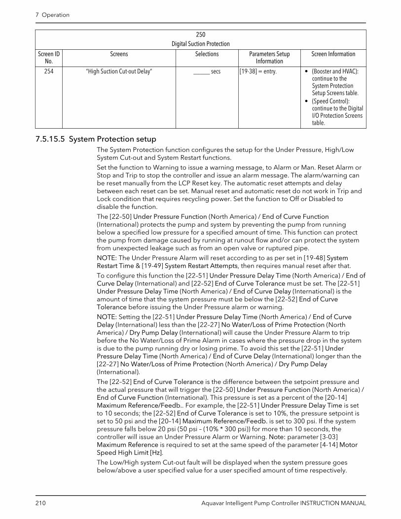
250Digital Suction Protection
Screen IDNo.
Screens Selections Parameters SetupInformation
Screen Information
254 “High Suction Cut-out Delay” _____ secs [19-38] = entry. • (Booster and HVAC):continue to theSystem ProtectionSetup Screens table.
• (Speed Control):continue to the DigitalI/O Protection Screenstable.
7.5.15.5 System Protection setupThe System Protection function configures the setup for the Under Pressure, High/LowSystem Cut-out and System Restart functions.
Set the function to Warning to issue a warning message, to Alarm or Man. Reset Alarm orStop and Trip to stop the controller and issue an alarm message. The alarm/warning canbe reset manually from the LCP Reset key. The automatic reset attempts and delaybetween each reset can be set. Manual reset and automatic reset do not work in Trip andLock condition that requires recycling power. Set the function to Off or Disabled todisable the function.
The [22–50] Under Pressure Function (North America) / End of Curve Function(International) protects the pump and system by preventing the pump from runningbelow a specified low pressure for a specified amount of time. This function can protectthe pump from damage caused by running at runout flow and/or can protect the systemfrom unexpected leakage such as from an open valve or ruptured pipe.
NOTE: The Under Pressure Alarm will reset according to as per set in [19-48] SystemRestart Time & [19-49] System Restart Attempts, then requires manual reset after that.
To configure this function the [22–51] Under Pressure Delay Time (North America) / End ofCurve Delay (International) and [22–52] End of Curve Tolerance must be set. The [22–51]Under Pressure Delay Time (North America) / End of Curve Delay (International) is theamount of time that the system pressure must be below the [22–52] End of CurveTolerance before issuing the Under Pressure alarm or warning.
NOTE: Setting the [22–51] Under Pressure Delay Time (North America) / End of CurveDelay (International) less than the [22–27] No Water/Loss of Prime Protection (NorthAmerica) / Dry Pump Delay (International) will cause the Under Pressure Alarm to tripbefore the No Water/Loss of Prime Alarm in cases where the pressure drop in the systemis due to the pump running dry or losing prime. To avoid this set the [22–51] UnderPressure Delay Time (North America) / End of Curve Delay (International) longer than the[22–27] No Water/Loss of Prime Protection (North America) / Dry Pump Delay(International).
The [22–52] End of Curve Tolerance is the difference between the setpoint pressure andthe actual pressure that will trigger the [22–50] Under Pressure Function (North America) /End of Curve Function (International). This pressure is set as a percent of the [20–14]Maximum Reference/Feedb.. For example, the [22–51] Under Pressure Delay Time is setto 10 seconds; the [22–52] End of Curve Tolerance is set to 10%, the pressure setpoint isset to 50 psi and the [20–14] Maximum Reference/Feedb. is set to 300 psi. If the systempressure falls below 20 psi (50 psi – (10% * 300 psi)) for more than 10 seconds, thecontroller will issue an Under Pressure Alarm or Warning. Note: parameter [3-03]Maximum Reference is required to set at the same speed of the parameter [4-14] MotorSpeed High Limit [Hz].
The Low/High system Cut-out fault will be displayed when the system pressure goesbelow/above a user specified value for a user specified amount of time respectively.
7 Operation
210 Aquavar Intelligent Pump Controller INSTRUCTION MANUAL
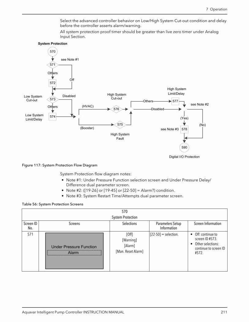
Select the advanced controller behavior on Low/High System Cut-out condition and delaybefore the controller asserts alarm/warning.
All system protection proof timer should be greater than live zero timer under AnalogInput Section.
570
System Protection
571
572Off
573
574
578575
576
High System
Disabled
590
Digital I/O Protection
Others
(Yes)
see Note #2
(No)
Cut-out
Low SystemLimit/Delay
Disabled
Others
Low System
(HVAC)
(Booster)
Fault
Cut-out
High System
High SystemLimit/Delay
see Note #1
see Note #3
577
Others
Figure 117: System Protection Flow Diagram
System Protection flow diagram notes:
• Note #1: Under Pressure Function selection screen and Under Pressure Delay/Difference dual parameter screen.
• Note #2: ([19-26] or [19-45] or [22-50] = Alarm?) condition.• Note #3: System Restart Time/Attempts dual parameter screen.
Table 56: System Protection Screens
570System Protection
Screen IDNo.
Screens Selections Parameters SetupInformation
Screen Information
571
Under Pressure FunctionAlarm
[Off][Warning]
[Alarm][Man. Reset Alarm]
[22-50] = selection. • Off: continue toscreen ID #573.
• Other selections:continue to screen ID#572.
7 Operation
Aquavar Intelligent Pump Controller INSTRUCTION MANUAL 211

570System Protection
Screen IDNo.
Screens Selections Parameters SetupInformation
Screen Information
572
Under Pressure Delay
10.0%Under Pressure Diff.
30s
______ s_____ %
[22-51] = first entry.[22-52] = second entry.
Continue to screen ID#573.
573
Low System Cut-outAlarm Triplook
[Disabled] (0)[Warning] (1)
[Alarm] (2)[Man. Reset Alarm] (3)
[19-45] = selection. • Disabled: continue tothe output of screenID #547 for checkingpump applicationtype selection.
• Other selections:continue to screen ID#574.
574
Low System Limit0.000
0secsLow System Delay
_____ [Unit]_____ secs
• [19-46] = first entry.• [19-47] = second
entry.
• (Booster): continue toscreen ID #575.
• (HVAC): continue toscreen ID #576.
575
Alarm TripLockHigh System Fault
[0] [Disabled][1] [Warning]
[2] [Alarm][3] [Man. Reset Alarm]
[19-26] = selection. • Disabled: continue tothe output of screenID #577 for checkingalarm setups.
• Other selections:continue to screen ID#577.
576
High System Cut-outDisable
[0] [Disabled][1] [Enabled]
• Disabled: [19-26] =[0] Disabled.
• Enabled: [19-26] =[4] Alarm TripLock.
• Disabled: continue tothe output of screenID #577 for checkingalarm setups.
• Enabled: continue toscreen ID #577.
577
High System Limit
0secsHigh System Delay
0.000
_____ [Unit]_____ secs
• [19-27] = firstselection.
• [19-28] = secondselection.
([19-26] = [19-45] =[22-50] = Alarm):• (Yes): continue to
screen ID #578.• (No): see screen ID
#578.
7 Operation
212 Aquavar Intelligent Pump Controller INSTRUCTION MANUAL

570System Protection
Screen IDNo.
Screens Selections Parameters SetupInformation
Screen Information
578
System Restart Time
0System Restart Attempts
0secs
______secs______
• [19-48] = firstselection.
• [19-49] = secondselection.
Continue to the Digital I/OProtection Setup Screenstable.
7.5.15.6 Digital I/O Protection setupThe Digital I/O Protection setup activates the pump protection using external digital input.This digital input signal is indicating a fault condition external to the adjustable frequencydrive. A “Pump Protect” has commanded the adjustable frequency drive to trip. The alarmcan be reset using a digital input or the [RESET] key if the cause for the Protect/ExternalInterlock has been removed.
590
591
Pump Protect Delay
593
590597
Digital I/O Protection
594 595 596
YesFixed Speed Follower
See Note #5
No
592
(MCO Specific)
3 pumps2 pumps
No
(No)
(Yes)
See Note #1 (MCO Specific)
4 pumps
See Note #2
See Note #3
See Note #4
Figure 118: Digital I/O Protection Setup Flow Diagram
Digital I/O Protection Setup flow diagram notes:
• Note #1:
– Setup Pump Protection Through Digital Input 19 selection screen.– (Terminal 27 Digital Input = MCO Specific) condition.– Setup Pump Protection Through Digital Input 27 selection screen.
• Note #2:
– (Terminal 29 Digital Input = MCO Specific?) condition.– Setup Pump Protection Through Digital Input 29 selection screen.
• Note #3: Setup pump protection for 2, 3 and 4 pumps through digital inputsinformation screen.
• Note #4: Pump Protect Delay parameter screen.
7 Operation
Aquavar Intelligent Pump Controller INSTRUCTION MANUAL 213
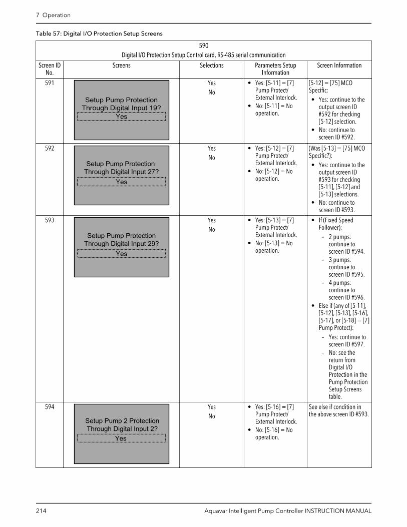
Table 57: Digital I/O Protection Setup Screens
590Digital I/O Protection Setup Control card, RS-485 serial communication
Screen IDNo.
Screens Selections Parameters SetupInformation
Screen Information
591
Yes
Setup Pump ProtectionThrough Digital Input 19?
YesNo
• Yes: [5-11] = [7]Pump Protect/External Interlock.
• No: [5-11] = Nooperation.
[5-12] = [75] MCOSpecific:• Yes: continue to the
output screen ID#592 for checking[5-12] selection.
• No: continue toscreen ID #592.
592
Yes
Setup Pump ProtectionThrough Digital Input 27?
YesNo
• Yes: [5-12] = [7]Pump Protect/External Interlock.
• No: [5-12] = Nooperation.
(Was [5-13] = [75] MCOSpecific?):• Yes: continue to the
output screen ID#593 for checking[5-11], [5-12] and[5-13] selections.
• No: continue toscreen ID #593.
593
Yes
Setup Pump ProtectionThrough Digital Input 29?
YesNo
• Yes: [5-13] = [7]Pump Protect/External Interlock.
• No: [5-13] = Nooperation.
• If (Fixed SpeedFollower):
– 2 pumps:continue toscreen ID #594.
– 3 pumps:continue toscreen ID #595.
– 4 pumps:continue toscreen ID #596.
• Else if (any of [5-11],[5-12], [5-13], [5-16],[5-17], or [5-18] = [7]Pump Protect):
– Yes: continue toscreen ID #597.
– No: see thereturn fromDigital I/OProtection in thePump ProtectionSetup Screenstable.
594
Yes
Setup Pump 2 ProtectionThrough Digital Input 2?
YesNo
• Yes: [5-16] = [7]Pump Protect/External Interlock.
• No: [5-16] = Nooperation.
See else if condition inthe above screen ID #593.
7 Operation
214 Aquavar Intelligent Pump Controller INSTRUCTION MANUAL

590Digital I/O Protection Setup Control card, RS-485 serial communication
Screen IDNo.
Screens Selections Parameters SetupInformation
Screen Information
595
Yes
Setup Pump 2 and Pump 3Protection
Through Digital Input 2 andDigital Input 3?
YesNo
• Yes: [5-16] = [5-17]= [7] Pump Protect/External Interlock.
• No: [5-16] = [5-17]= No operation.
See else if condition inthe above screen ID #593.
596
Yes
Setup Pump 2 ,Pump 3 andPump 4 Protection
Through Digital Input 2 DigitalInput 3 and Digital Input 4?
YesNo
• Yes: [5-16] = [5-17]= [5-18] = [7] PumpProtect/ExternalInterlock.
• No: [5-16] = [5-17]= [5-18] = Nooperation.
See else if condition inthe above screen ID #593.
597
0sPump Protect Delay
_____ S [22-00] = entry. Return to the PumpProtection Setup Screentable for checking NoWater/Loss of Prime Fault& Low System Fault & Endof Curve Function beforecontinuing to screen ID#201.
7.5.16 Bypass setupThe Start-Up Genie (Smart Setup) can be configured for Disabled, Automatic and digital,Automatic only, and Digital Input only. For a bypass panel to connect the motor to thedrive or to the power line, isolate the drive’s output from the power line or provide a timedelay before going to bypass (not available for Lowara).
Each Drive Mode or Manual/Auto Bypass Mode has a specific symbol displayed on thetop right line of the bypass LCP screen when it is activated:
•
Drive Mode:
The motor is connected to and controlled by the drive.
•
Manual/Auto Bypass Mode:
The motor operates at full speed across the line when a run command is present.
7 Operation
Aquavar Intelligent Pump Controller INSTRUCTION MANUAL 215

BypassSymbol
Off/Reset key
Drive/Bypass key
Pressing Drive Bypass key on the bypass LCP when the drive is in Drive Mode will showthe Bypass and Drive Mode options on screen:
Press [Cancel] to stay to inDrive Mode.
Press [OK] to change toBypass Mode.
Pressing Drive Bypass key on the bypass LCP when the drive is in Bypass Mode will showthe Drive Mode and Bypass Mode options on screen:
Press [Cancel] to stay to inBypass Mode
Press [OK] to change toDrive Mode.
• In Automatic and Digital configuration mode and Automatic only configuration mode,the bypass operation will be activated when any of the drive-related alarm is occurred.The number of bypass drives can be set through Start-Up Genie (Smart Setup) or
7 Operation
216 Aquavar Intelligent Pump Controller INSTRUCTION MANUAL

[19-59] Bypass Run Pumps on the failure of the number of drives set in [19-58] BypassDrives Fail.
• In Digital Input only configuration mode, the Digital Input 32 is used for setting thenumber of pumps in [19-59] Bypass Run Pumps for bypass mode in remote area.
600
600
601
6049
Digital Input Setup
Bypass Setup
260
Setup Selection
602
603
YesNo
Bypass Pumps Running
Bypass Driver Fails/
(see Main Menu flow diagram)
Automatic OnlyAutomatic & Digital
Digital Input Only
Disabled
Bypass Pumps Running
Figure 119: Bypass Setup Flow Diagram
Table 58: Bypass Setup Screens
240Bypass Setup
Screen IDNo.
Screens Selections Parameters SetupInformation
Screen Information
600
Setup SelectionBypass
• The Bypass SetupSelection is onlyavailable when aBypass panel isdetected andfunctioning.
• Continue to screen ID#601.
601
Automatic OnlyBypass Function
[Disabled][Automatic and digital]
[Automatic only][Digital Input only]
• Disabled: [19-58] =[19-59] = 0, [31-01]= 5 sec, [31-02] = 0sec.
• If ([5-14] = [75] MCOSpecific): [5-14] = Nooperation
• Disabled: continue toscreen ID #604.
• Automatic and digitalor Automatic only:continue to screen ID#602.
• Digital Input only:continue to screen ID#603.
7 Operation
Aquavar Intelligent Pump Controller INSTRUCTION MANUAL 217

240Bypass Setup
Screen IDNo.
Screens Selections Parameters SetupInformation
Screen Information
602
1
2Bypass Drive Fail
Bypass Pumps Running
[1 - 4][1 - 4]
[19-58] = first selection[19-59] = secondselection[31-01] = 5 sec, [31-02]= 0 sec.• (Automatic only):
[5-14] = Nooperation.
• (Automatic anddigital): [5-14] = [75]MCO Specific.
Continue to screen ID#604.
603
1Bypass Pumps Running
[1 - 4] • [19-59] = selection• [19-58] = 0• [5-14] = [75] MCO
Specific, [31-01] = 5sec, [31-02] = 0 sec.
Screen Information:Continue to screen ID#604.
604
Continue to Digital InputSetup?
No
[Yes][No]
• Yes: continue to theDigital Input SetupScreens table.
• No: return to theSetup Selectionscreen ID #6 in theMain-Menu Screenstable.
7.5.17 Digital Input setupAny unused digital input can be configured as part of the Digital Input Setup. A list of thedigital inputs and their associated functions are shown below. The default function of adigital input can change based on the Operating Mode selected. Digital Input 18 isutilized as a Start function for all operating modes. This input has a dedicated function andcannot be configured in the Digital Input Setup.
NOTICE:
Only selections from the following list should be available for digital inputs in this section(if those selections are available for particular input). If previously selected value is not onthe list, it should be reset to No Operation.
Table 59: Digital Input Selection List
[0] No operation
[1] Reset
[2] Coast inverse
[3] Coast and reset inverse
[5] DC brake inverse
[6] Stop inverse
[8] Start
[9] Latched start
7 Operation
218 Aquavar Intelligent Pump Controller INSTRUCTION MANUAL
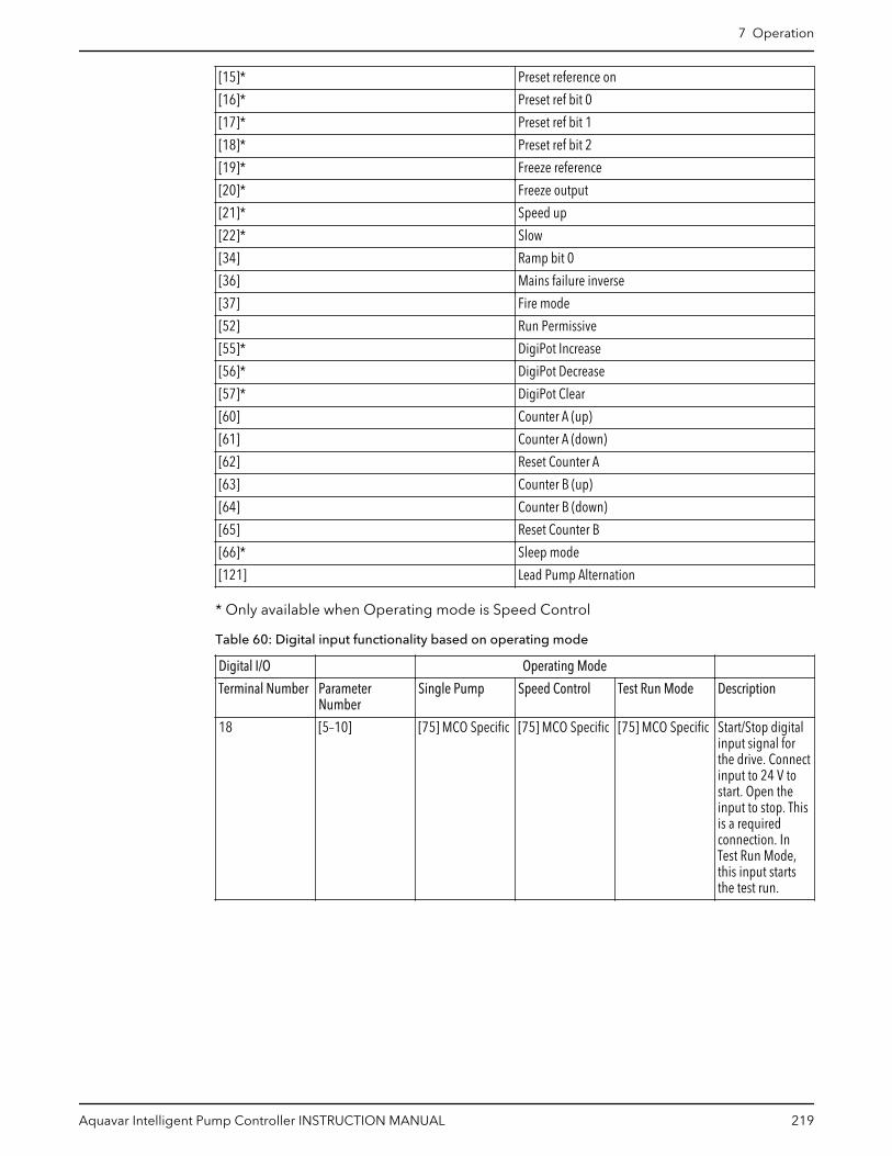
[15]* Preset reference on
[16]* Preset ref bit 0
[17]* Preset ref bit 1
[18]* Preset ref bit 2
[19]* Freeze reference
[20]* Freeze output
[21]* Speed up
[22]* Slow
[34] Ramp bit 0
[36] Mains failure inverse
[37] Fire mode
[52] Run Permissive
[55]* DigiPot Increase
[56]* DigiPot Decrease
[57]* DigiPot Clear
[60] Counter A (up)
[61] Counter A (down)
[62] Reset Counter A
[63] Counter B (up)
[64] Counter B (down)
[65] Reset Counter B
[66]* Sleep mode
[121] Lead Pump Alternation
* Only available when Operating mode is Speed Control
Table 60: Digital input functionality based on operating mode
Digital I/O Operating Mode
Terminal Number ParameterNumber
Single Pump Speed Control Test Run Mode Description
18 [5–10] [75] MCO Specific [75] MCO Specific [75] MCO Specific Start/Stop digitalinput signal forthe drive. Connectinput to 24 V tostart. Open theinput to stop. Thisis a requiredconnection. InTest Run Mode,this input startsthe test run.
7 Operation
Aquavar Intelligent Pump Controller INSTRUCTION MANUAL 219

Digital I/O Operating Mode
Terminal Number ParameterNumber
Single Pump Speed Control Test Run Mode Description
19 [5–11] [0] No Operation [0] No Operation [0] No Operation This input can beconfigured for useas a PumpProtect/ExternalInterlock Warningor Alarm Input.Refer to the Digital I/OProtection setupon page 213 toenable theWarning or Alarmassociated withthe input.
27 [5–12] [0] No Operation [0] No Operation [0] No Operation This input can beconfigured for useas a PumpProtect/ExternalInterlock Warningor Alarm input.Refer to the Digital I/OProtection setupon page 213 toenable theWarning or Alarmassociated withthis input.
29 [5–13]/[5–31] [63] Comparator3
[0] No Operation [0] No Operation Selectable fordigital input oroutput. This inputcan be configuredfor use as a PumpProtect/ExternalInterlock Warningor Alarm input.Refer to the Digital I/OProtection setupon page 213 fordetails.
32 [5–14] [1] Restart [0] No Operation [0] No Operation Configured forBypass Automaticand Digitaldetection. Refer tothe Bypass setupon page 215 fordetails.
33 [5–15] [0] No Operation [0] No Operation [0] No Operation Digital input.Configured foruse as a Setpoint /Alternativesetpoints select.
20 — Common Common Common Common fordigital inputs andreference for 24 Vsupply
7 Operation
220 Aquavar Intelligent Pump Controller INSTRUCTION MANUAL

Digital input functionality based on operating mode:
Note: - If any of the below Digital Input pins assigned to [75] MCO Specific, Advancedcontroller will use only listed below function. (see the attached document).
9
Relay & Analog Output Setup
Digital Input Setup
260
(Yes)
(Yes)
No
(No)
280 Yes
DI 19
262
DI 27
DI 29263
No operation
265
DI 32
DI 33
Setup Selection
261(No)
No operation
(No)
264
266
(No)
260
(see Main Menu flow diagram)
(Yes)
(Yes)
(see Note #1)
(see Note #3)
Yes
No
(see Note #2)
see Note #4
see Note #5
Figure 120: Digital Input Setup Flow Diagram
Digital Input Setup flow diagram notes:
• Note #1: (Terminal 19 Digital Input = Pump Protect/External Interlock?) condition.• Note #2: (Terminal 27 Digital Input = Pump Protect/External Interlock or MCO
Specific?) condition.• Note #3: (Terminal 29 Digital Input = Pump Protect/External Interlock or MCO
Specific?) condition.• Note #4: (Terminal 32 Digital Input = MCO Specific?) condition.• Note #5: (Terminal 33 Digital Input = MCO Specific?) condition.
7 Operation
Aquavar Intelligent Pump Controller INSTRUCTION MANUAL 221
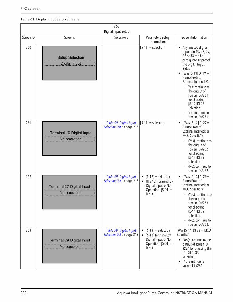
Table 61: Digital Input Setup Screens
260Digital Input Setup
Screen ID Screens Selections Parameters SetupInformation
Screen Information
260
Digital InputSetup Selection
[5-11] = selection. • Any unused digitalinput pin 19, 27, 29,32 or 33 can beconfigured as part ofthe Digital InputSetup.
• (Was [5-11] DI 19 =Pump Protect/External Interlock?):
– Yes: continue tothe output ofscreen ID #261for checking[5-12] DI 27selection
– No: continue toscreen ID #261.
261
No operationTerminal 19 Digital Input
Table 59: Digital InputSelection List on page 218
[5-11] = selection • ( Was [5-12] DI 27=Pump Protect/External Interlock orMCO Specific?):
– (Yes): continue tothe output ofscreen ID #262for checking[5-13] DI 29selection.
– (No): continue toscreen ID #262.
262
No operationTerminal 27 Digital Input
Table 59: Digital InputSelection List on page 218
• [5-12] = selection• If [5-12] Terminal 27
Digital Input ≠ NoOperation: [5-01] =Input.
• ( Was [5-13] DI 29=Pump Protect/External Interlock orMCO Specific?):
– (Yes): continue tothe output ofscreen ID #263for checking[5-14] DI 32selection.
– (No): continue toscreen ID #263.
263
No operationTerminal 29 Digital Input
Table 59: Digital InputSelection List on page 218
• [5-13] = selection• [5-13] Terminal 29
Digital Input ≠ NoOperation: [5-01] =Input.
(Was [5-14] DI 32 = MCOSpecific?):• (Yes): continue to the
output of screen ID#264 for checking the[5-15] DI 33selection.
• (No) continue toscreen ID #264.
7 Operation
222 Aquavar Intelligent Pump Controller INSTRUCTION MANUAL

260Digital Input Setup
Screen ID Screens Selections Parameters SetupInformation
Screen Information
264 “Terminal 32 Digital Input” Table 59: Digital InputSelection List on page 218
[5-14] = selection • (Was [5-15] DI 33 =MCO specific?):
– (Yes): continue toscreen ID #266.
– (No): continue toscreen ID #265.
265
No operationTerminal 33 Digital Input
Table 59: Digital InputSelection List on page 218
[5-15] = selection Continue to screen ID#266.
266
Yes
Continue to Relay andAnalog Output Setup?
[Yes][No]
• Yes: continue to theRelay & Output SetupScreens table.
• No: return to theSetup Selectionscreen ID #6 in theMain Menu
7.5.18 Relay and Analog Output setupThe Relay and Analog Output Setup allows configuration of the onboard relays andanalog output signal.
7.5.18.1 Relay functionTo configure the relay set the relay function. The relay function configures when the relaywill change state. For example, when set to ‘No Alarm’, the relay will change state from theinactive to the active state when no alarms exist in the system. In the inactive state COM =NC and in the active state COM = NO.
Table 62: Relays selection list
Selection Parameters [540.1] and [540.2]Values
Parameters [19–68] and [19–69]Values
No operation [0] No operation
System hydraulic alarm [51] MCO Controlled [1] System Pump alarm
System electric alarm [51] MCO Controlled [2] System VFD alarm
System warning [51] MCO Controlled [0] Sys alarm or warning
System running [51] MCO Controlled [3] System running
Sensor Fault [51] MCO Controlled [4] Sensor Fault
Suction alarm [51] MCO Controlled [5] Suction alarm
Discharge alarm [51] MCO Controlled [6] Discharge alarm
Sleep mode [51] MCO Controlled [7] Sleep mode
System Bypass [51] MCO Controlled [8] System Bypass
All Zone Failure [51] MCO Controlled [9] All Zone Failure
Pump running [5] Running
7 Operation
Aquavar Intelligent Pump Controller INSTRUCTION MANUAL 223
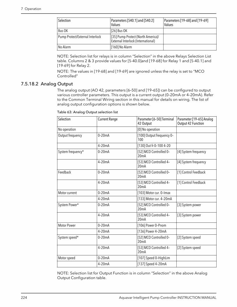
Selection Parameters [540.1] and [540.2]Values
Parameters [19–68] and [19–69]Values
Bus OK [26] Bus OK
Pump Protect/External Interlock [35] Pump Protect (North America)/External Interlock (International)
No Alarm [160] No Alarm
NOTE: Selection list for relays is in column “Selection” in the above Relays Selection Listtable. Columns 2 & 3 provide values for [5-40.0]and [19-68] for Relay 1 and [5-40.1] and[19-69] for Relay 2.
NOTE: The values in [19-68] and [19-69] are ignored unless the relay is set to “MCOControlled”
7.5.18.2 Analog OutputThe analog output (AO 42, parameters [6–50] and [19–65]) can be configured to outputvarious controller parameters. This output is a current output (0–20mA or 4–20mA). Referto the Common Terminal Wiring section in this manual for details on wiring. The list ofanalog output configuration options is shown below.
Table 63: Analog Output selection list
Selection Current Range Parameter [6–50] Terminal42 Output
Parameter [19–65] AnalogOutput 42 Function
No operation [0] No operation
Output frequency 0–20mA [100] Output frequency 0–100
4–20mA [130] Out fr 0–100 4–20
System frequency* 0–20mA [52] MCO Controlled 0–20mA
[4] System frequency
4–20mA [53] MCO Controlled 4–20mA
[4] System frequency
Feedback 0–20mA [52] MCO Controlled 0–20mA
[1] Control Feedback
4–20mA [53] MCO Controlled 4–20mA
[1] Control Feedback
Motor current 0–20mA [103] Motor cur. 0–Imax
4–20mA [133] Motor cur. 4–20mA
System Power* 0–20mA [52] MCO Controlled 0–20mA
[3] System power
4–20mA [53] MCO Controlled 4–20mA
[3] System power
Motor Power 0–20mA [106] Power 0–Pnom
4–20mA [136] Power 4–20mA
System speed* 0–20mA [52] MCO Controlled 0–20mA
[2] System speed
4–20mA [53] MCO Controlled 4–20mA
[2] System speed
Motor speed 0–20mA [107] Speed 0–HighLim
4–20mA [137] Speed 4–20mA
NOTE: Selection list for Output Function is in column “Selection” in the above AnalogOutput Configuration table.
7 Operation
224 Aquavar Intelligent Pump Controller INSTRUCTION MANUAL

NOTE: The selections marked with asterisk should be only available if Multipump is set to“Yes”. Columns 2 & 3 provide values for parameters [6-50] and [19-65]. Values inparameter [19-65] are ignored unless AO is set to “MCO Controlled”.
280 280
Relay and Analog Output Setup
281
Communication Setup
282
283
284
300
9No
Yes
Relay 1&2 Function
Terminal 42 Output
Setup Selection(see Main Menu flow diagram)
Min/Max Scale
Setting/Function
Figure 121: Relay & Analog Output Setup Flow Diagram
Table 64: Relay & Analog Output Setup Screens
280Relay & Analog Output Setup
Screen IDNo.
Screens Selections Parameters SetupInformation
Screen Information
280
Relay & Analog OutputSetup Selection
Continue to screen ID#281.
281
Sleep Mode
Pump running
Relay 2 Function
Relay 1 Function[Selection List][Selection List]
Note: see table in thissection to set parameters.
Continue to screen ID#282.
282
No Operation
4-20mA
Terminal 42 Output Fun...
Terminal 42 O/P Setting[List][List]
Note: see table in thissection to set parameters.
Continue to screen ID#283.
7 Operation
Aquavar Intelligent Pump Controller INSTRUCTION MANUAL 225
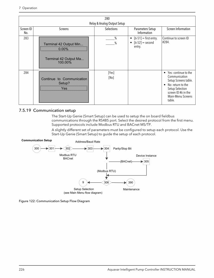
280Relay & Analog Output Setup
Screen IDNo.
Screens Selections Parameters SetupInformation
Screen Information
283
100.00%
0.00%
Terminal 42 Output Ma...
Terminal 42 Output Min..._____%_____%
• [6-51] = first entry.• [6-52] = second
entry.
Continue to screen ID#284.
284
Yes
Continue to CommunicationSetup?
[Yes][No]
• Yes: continue to theCommunicationSetup Screens table.
• No: return to theSetup Selectionscreen ID #6 in theMain-Menu Screenstable.
7.5.19 Communication setupThe Start-Up Genie (Smart Setup) can be used to setup the on board fieldbuscommunications through the RS485 port. Select the desired protocol from the first menu.Supported protocols include Modbus RTU and BACnet MS/TP.
A slightly different set of parameters must be configured to setup each protocol. Use theStart-Up Genie (Smart Setup) to guide the setup of each protocol.
Communication Setup
300 301
305(BACnet)
(Modbus RTU)
9
302 303 304
Modbus RTUBACnet
Address/Baud Rate
Parity/Stop Bit
Device Instance
Setup Selection(see Main Menu flow diagram)
306 390
Maintenance
Figure 122: Communication Setup Flow Diagram
7 Operation
226 Aquavar Intelligent Pump Controller INSTRUCTION MANUAL

Table 65: Communication Setup Screens
300Communication Setup
Screen IDNo.
Screens Selections Parameters SetupInformation
Screen Information
301
CommunicationSetup Selection
302
Modbus RTUProtocol
[Modbus RTU][BACnet]
[8-30] = entry Continue to screen ID#303.
303
1
Baud Rate9600 Baud
Address
__________ Baud
[8-31] = first entry[8-32] = second entry[8-32] = second entry(9600 is default forModbus, 38400 is defaultfor BACNet).
Continue to screen ID#304.Note: In Fixed Masterconfiguration, baud rateof follower drive/pumpshould always be 115200and protocol should beFC.
304
Even Parity,1 Stop BitParity / Stop Bits
_____ Parity, _____Bit (“Even Parity, 1 Stop Bit“ is default for Modbus,“No Parity, 1 Stop Bit” isdefault for BACnet).
• (BACnet): continue toscreen ID #305.
• (Modbus RTU):continue to screen ID#306.
305
1BACnet Device Instance
_____ [8-70] = entry Return to the SetupSelection screen ID #6 inthe Main-Menu Screenstable.
306
YesContinue to Maintenance?
[Yes][No]
• Yes: continue to theMaintenance SetupScreens table.
• No: return to theSetup Selectionscreen screen ID #6the Main-MenuScreens table.
7 Operation
Aquavar Intelligent Pump Controller INSTRUCTION MANUAL 227

7.5.20 MaintenanceThe Maintenance setup can reset the running hours. Select Do not Reset or Reset Counterfor [15-07] Reset Running Hours Counter when the Reset Running Hours screen displays.
390 9
Setup Selection(see Main Menu flow diagram)
MaintenanceSee Note #1
391390
Figure 123: Maintenance Flow Diagram
Note #1: Reset Running Hours Counters
Table 66: Maintenance Setup Screens
390Maintenance Setup
Screen IDNo.
Screens Selections Parameters SetInformation
Screen Information
390
MaintenanceSetup Selection
Continue to screen ID#391.
391
Do Not Rest
Reset Running HoursCounter
[Do not reset][Reset counter]
Continue to the SetupSelection screen ID #6 inthe Main Menu Screenstable.
7.5.21 System start-up
The procedure in this section requires user wiring and application programming to becompleted. Application set-up examples are intended to help with this task. Other aids toapplication set-up are listed in 1.2 Additional Resources. The following procedure isrecommended after application set-up by the user is completed.
NOTICE:
MOTOR START. Ensure that the motor, system and any attached equipment is ready forstart.
1. Press [Auto On].
2. Ensure that external control function are properly wired to the frequency converterand all programming is completed.
3. Apply an external run command.
4. Adjust the speed reference throughout the speed range.
7 Operation
228 Aquavar Intelligent Pump Controller INSTRUCTION MANUAL

5. Remove the external run command.
6. Note any problems.
If warning or alarms occur, see Warnings and Alarms section for details ontroubleshooting.
7 Operation
Aquavar Intelligent Pump Controller INSTRUCTION MANUAL 229

8 Warnings and alarms8.1 Warning and alarm typesWarnings
A warning is issued when an alarm condition is impending or when an abnormaloperating condition is present and may result in the frequency converter issuing an alarm.A warning clears by itself when the abnormal condition is removed.
Alarms
An alarm is issued when the frequency converter is tripped, that is, the frequencyconverter suspends operation to prevent frequency converter or system damage.Depending on settings the motor will ramp or coast to stop. The frequency converterlogic will continue to operate and monitor the frequency converter status. After the faultcondition is remedied, the frequency converter can be reset. It will be ready to startoperation again.
A trip can be reset in any of 4 ways:
• Press [Reset] on the LCP• Digital reset input command• Serial communication reset input command• Auto reset
An alarm that causes the frequency converter to trip-lock requires that input power iscycled. Depending on settings the motor will ramp or coast to stop. The frequencyconverter logic will continue to operate and monitor the frequency converter status.Remove input power to the frequency converter and correct the cause of the fault, thenrestore power. This action puts the frequency converter into a trip condition as describedabove and may be reset in any of those 4 ways.
8.2 Warning and alarm displays
Figure 124: Warning display
An alarm or trip-lock alarm will flash along with the alarm number.
Figure 125: Alarm display
In addition to the text and alarm code on the frequency converter LCP, there are threestatus indicator lights.
8 Warnings and alarms
230 Aquavar Intelligent Pump Controller INSTRUCTION MANUAL

Figure 126: Status indicator lights
Table 67: Status indicator lights explanations
Warning LED Alarm LED
Warning On Off
Alarm Off On (Flashing)
Trip-Lock On On (Flashing)
Warnings/Alarm messages
A warning or an alarm is signaled by the relevant LED on the front of the frequencyconverter and indicated by a code on the display.
A warning remains active until its cause is no longer present. Under certain circumstances,operation of the motor may still be continued. Warning messages may be critical, but arenot necessarily so.
In the event of an alarm, the frequency converter trips. Reset the alarm to resumeoperation once the cause has been rectified.
Three ways to reset:
• Press [Reset].• Via a digital input with the “Reset” function.• Via serial communication/optional fieldbus.
NOTE: After a manual reset pressing [Reset], press [Auto On] to restart the motor.
If an alarm can't be reset, the reason may be that its cause has not been rectified, or thealarm is trip-locked.
Alarms that are trip-locked offer additional protection, meaning that the mains supplymust be switched off before the alarm can be reset. After being switched back on, thefrequency converter is no longer blocked and can be reset as described above once thecause has been rectified.
Alarms that are not trip-locked can also be reset using the automatic reset function in [14–20] Reset Mode (Warning: Automatic wake-up is possible).
In some cases a warning will occur before an alarm is issued. This is possible, for instance,in [1–90] Motor Thermal Protection. After an alarm or trip, the motor continues to rampdown or coast, and the alarm and warning flash. Once the problem has been rectified,only the alarm continues flashing until the frequency converter is reset.
NOTE: No missing motor phase detection (numbers 30–32) and no stall detection is activewhen [1–10] Motor Construction is set to [1] PM non salient SPM.
8 Warnings and alarms
Aquavar Intelligent Pump Controller INSTRUCTION MANUAL 231

The following table defines whether a warning is issued before an alarm, and whether thealarm trips the unit or trip locks the unit.
Table 68: Alarm/Warning code list
Number Description Warning Alarm/Trip Alarm/Trip Lock Parameter Reference
1 10 volts low X
2 Sensor Fault (X) (X) [6–01] Sensor FaultTimeout Function
3 No motor (X) [1–80] Function atStop
4 Input Phase Loss (X) (X) (X) [14–12] Function atMainsImbalanceFunction atSensor Fault
5 DC link voltage high X
6 DC link voltage low X
7 DC overvoltage X X
8 DC undervoltage X X
9 Inverter overloaded X X
10 Motor ETR over-temperature
(X) (X) [1–90] MotorTemperature
11 Motor thermistor overtemperature
(X) (X) [1–90] MotorTemperature
12 Torque limit X X
13 Over current X X X
14 Ground/earth fault X X
15 Hardware mismatch X X
16 Short circuit X X
17 Control word timeout (X) (X) [8–04] ControlTimeout Function
18 Start Failed X [1–77] CompressorStart Max Speed[RPM], [1–79]Compressor Start MaxTime to Trip, [1–03]Torque Characteristics
20 Temp. Input Error
21 Param error
22 Hoist Mech. Brake (X) (X) Parameter group 2–2*
23 Internal fans X
24 External fans X
25 Brake resistor short-circuited
X
26 Brake resistor powerlimit
(X) (X) [2–13] Brake PowerMonitoring
27 Brake chopper short-circuited
X X
28 Brake check (X) (X) [2–15] Brake Check
29 Heatsink temp X X X
8 Warnings and alarms
232 Aquavar Intelligent Pump Controller INSTRUCTION MANUAL

Number Description Warning Alarm/Trip Alarm/Trip Lock Parameter Reference
30 Motor phase Umissing
(X) (X) (X) [4–58] Missing MotorPhase Function
31 Motor phase Vmissing
(X) (X) (X) [4–58] Missing MotorPhase Function
32 Motor phase Wmissing
(X) (X) (X) [4–58] Missing MotorPhase Function
33 Inrush fault X X
34 Fieldbuscommunication fault
X X
35 Option fault
36 Mains failure X X
37 Phase imbalance (Notapplicable for singlephase drives).
X
38 Internal fault X X
39 Heatsink sensor X X
40 Overload of DigitalOutput Terminal 27
(X) [5–00] Digital I/Omode, [5–01]Terminal 27 Mode
41 Overload of DigitalOutput Terminal 29
(X) [5–00] Digital I/Omode, [5–02]Terminal 29 Mode
42 Ovrld X30/6–7 (X)
43 Ext. Supply (option)
45 Earth Fault 2 X X
46 Pwr. card supply X X
47 24 V supply low X X X
48 1.8 V supply low X X
49 Speed limit X [1–86] Trip Speed Low[RPM]
50 AMA calibration failed X
51 AMA check Unom andInom
X
52 AMA low Inom X
53 AMA motor too big X
54 AMA motor too small X
55 AMA parameter out ofrange
X
56 AMA interrupted byuser
X
57 AMA time-out X
58 AMA internal fault X X
59 Current limit X
60 Pump Protect (NorthAmerica)/ExternalInterlock(International)
X X
8 Warnings and alarms
Aquavar Intelligent Pump Controller INSTRUCTION MANUAL 233

Number Description Warning Alarm/Trip Alarm/Trip Lock Parameter Reference
61 Feedback Error (X) (X) [4–30] MotorFeedback LossFunction
62 Output Frequency atMaximum Limit
X
63 Mechanical Brake Low (X) [2–20] Release BrakeCurrent
64 Voltage Limit X
65 Control Board Over-temperature
X X X
66 Heat sink TemperatureLow
X
67 Option Configurationhas changed
X
68 Safe Stop (X) (X)1) [5–19] Terminal 37Safe Stop
69 pwr. Card Temp X X
70 Illegal FCconfiguration
X
71 PTC 1 Safe Stop
72 Dangerous failure
73 Safe Stop Auto Restart (X) (X) [5–19] Terminal 37Safe Stop
74 PTC Thermistor X
75 Illegal Profile Sel. X
76 Power Unit Setup X
77 Reduced power mode X [14–59] ActualNumber of InverterUnits
78 Tracking Error (X) (X) [4–34] Tracking ErrorFunction
79 Illegal PS config X X
80 Drive initialized toDefault value
X
81 CSIV corrupt X
82 CSIV parameter error X
83 Illegal OptionCombination
X
84 No Safety Option X
85 Dang fail PB
86 Dang fail DI
88 Option Detection X
89 Mechanical BrakeSliding
Z
90 Feedback Monitor (X) (X) [17–61] FeedbackSignal Monitoring
91 Analog input 54wrong settings
X 5202
8 Warnings and alarms
234 Aquavar Intelligent Pump Controller INSTRUCTION MANUAL

Number Description Warning Alarm/Trip Alarm/Trip Lock Parameter Reference
92 No Flow X X [22–2]* No-FlowDetection
93 No Water/Loss ofPrime (North America)Dry Pump(International)
X X [22–2]* No-FlowDetection
94 Under pressure X X [22–5]*
95 Broken Belt X X [22–6]*
96 Start Delayed X [22–7]*
97 Stop Delayed X [22–7]*
98 Clock Fault X [0–7]* Clock Settings
102 Too many CAN objects
103 Illegal axis num.
104 Mixing fans
105 Error not reset
106 HOME not done
107 Home vel zero
108 Position error
109 Index not found
110 Unknown cmd.
111 SW end limit
112 Unknown param
113 FC not enabled
114 Too many loops
115 Par. save failed
116 Param. memory
117 Progr. memory
118 Reset by CPU
119 User abort.
121 No more SDOchannels
125 HW end limit
149 Too many inter.
150 No ext. 24 V
151 GOSUB > limit
152 Return @ limit
154 D.out overload
155 LINK failed
156 Illegal double arg.
160 Internal Intr. error
162 Memory error
163 ATEX ETRcur.lim.warning
X
164 ATEX ETRcur.lim.alarm
X
8 Warnings and alarms
Aquavar Intelligent Pump Controller INSTRUCTION MANUAL 235

Number Description Warning Alarm/Trip Alarm/Trip Lock Parameter Reference
165 ATEX ETRfreq.lim.warning
X
166 ATEX ETRfreq.lim.alarm
X
201 Fire M was Active
202 Fire M LimitsExceeded
203 Missing Motor
204 Locked Rotor
243 Brake IGBT X X
244 Heatsink temp X X X
245 Heatsink sensor X X
246 Pwr. card supply
247 Pwr. card temp X X
248 Illegal PS config X X
250 New spare parts X
251 New Type Code X X
(X) Dependent on parameter1) Cannot be Auto reset via 14–20 Reset Mode
A trip is the action following an alarm. The trip coasts the motor and is reset by pressing[Reset] or by a digital input (parameter group 5–1* Digital Inputs [1]). The origin event thatcaused the alarm cannot damage the frequency converter or cause dangerous conditions.A trip lock is an action when an alarm occurs, which could damage the frequencyconverter or connected parts. A trip lock situation can only be reset by a power cycling.
Table 69: LED indication
Warning Yellow
Alarm Flashing red
Trip locked Yellow and red
The following table defines the alarm words, warning words and extended status wordsthat can be read out via serial bus or optional fieldbus for diagnostics, or through 16–94Ext. Status Word.
Table 70: Description of Alarm word, Warning word and Extended Status word
Bit Hex Dec Alarm word Alarm word 2 Warning word Warning word2
ExtendedStatus word
ExtendedStatus word 2
Alarm Word Extended Status Word
0 00000001 1 Brake Check(A28)
ServiceTrip,read/write
Brake Check(W28)
StartDelayed
Ramping Off
1 00000002 2 Pwr.card temp(A69)
ServiceTrip,(reserved)
Pwr.card temp(A69)
StopDelayed
AMA Running Hand/Auto
8 Warnings and alarms
236 Aquavar Intelligent Pump Controller INSTRUCTION MANUAL

Bit Hex Dec Alarm word Alarm word 2 Warning word Warning word2
ExtendedStatus word
ExtendedStatus word 2
Alarm Word Extended Status Word
2 00000004 4 Ground/EarthFault (A14)
ServiceTrip,Typecade/sparepart
Ground/EarthFault (W14)
reserved Start CW/CCWstart_possibleis active, whenthe DIselections [12]OR [13] areactive and therequesteddirectionmatches thereference sign
Profibus OFF1active
3 00000008 8 Ctrl.CardTemp (A65)
ServiceTrip,(reserved)
Ctrl.CardTemp (W65)
reserved Slow Downslow downcommandactive, e.g. viaCTW bit 11 oeDI
Profibus OFF2active
4 00000010 16 Ctrl. Word TO(A17)
ServiceTrip,(reserved)
Ctrl. Word TO(W17)
Catch Upcatch upcomandactive, e.g. viaCTW bit 12 orDI
Profibus OFF3active
5 00000020 32 Over Current(A13)
reserved Over Current(W13)
reserved FeedbackHighfeedback > 4–57
Relay 123active
6 00000040 64 Torque Limit(12)
reserved Torque Limit(W12)
reserved Feedback Lowfeedback < 4–56
StartPrevented
7 00000080 128 Motor Th Over(A11)
reserved Motor Th Over(W11)
reserved OutputCurrent Highcurrent > 4–51
Control Ready
8 00000100 256 Motor ETROver (A10)
reserved Motor ETROver (W10)
reserved OutputCurrent Lowcurrent < 4–50
Drive Ready
9 00000200 512 InverterOverld. (A9)
DischargeHigh
OnverterOverld (W9)
DischargeHigh
Output FreqHighspeed > 4–53
Quick Stop
10 000000400 1024 DC under Volt(A8)
Start Failed SC under Volt(W8)
Multi-motorunderload
Output FreqLowspeed < 4–52
DC Brake
11 00000080 2048 DC over Volt(A7)
Speed Limit SC over Volt(W7)
Multi-motorOverload
Brake CheckOKbrake test NOTok
Stop
8 Warnings and alarms
Aquavar Intelligent Pump Controller INSTRUCTION MANUAL 237

Bit Hex Dec Alarm word Alarm word 2 Warning word Warning word2
ExtendedStatus word
ExtendedStatus word 2
Alarm Word Extended Status Word
12 00001000 4096 Short Circuit(A16)
Pump Protect(NorthAmerica)/ExternalInterlock(International)
DC VoltageLow (W6)
Compress orInterlock
Braking MaxBrakePower >BrakePowerLimit (2–12)
Stand by
13 00002000 8192 Inrush Fault(A33)
Illegal OptionCombi.
DC VoltageHigh (W5)
MechanicalBrake Sliding
Braking Freeze OutputRequest
14 00004000 16384 Input PhaseLoss (A4)
No SafetyOption
Mains ph. Loss(W4)
Safe OptionWarning
Out of SpeedRange
Freeze Output
15 00008000 32768 AMA not OK reserved No Motor(W3)
Auto DCBraking
OVC Active Jog Request
16 00010000 65536 Sensor Fault(A2)
reserved Sensor Fault(W2)
AC Brake Jog
17 00020000 131072 Internal Fault(A38)
KTY error 10V Low (W1) KTY Warn PasswordTimelocknumber ofallowedpasswordtrialsexceeded -timelockactive
Start Request
18 00040000 262144 BrakeOverload(A26)
Fans error BrakeOverload(W26)
Fans Warn PasswordProtection 0–61 =ALL_NO_ACCESS ORBUS_NO_ACCESS ORBUS_READONLY
Start
19 00080000 524288 U phase Loss(A30)
ECB error Brake Resistor(W25)
ECB Warn ReferenceHighreference > 4–55
Start Applied
20 00100000 1048576 V phase Loss(AA31)
reserved Brake IGBT(W27)
reserved Reference Lowreference < 4–54
Start delay
21 00200000 2097152 W phase Loss(A32)
reserved Speed Limit(W49)
RESERVED LocalReferencereference site= REMOTE >auto onpressed &active
Sleep
22 00400000 4194304 Fieldbus Fault(A34)
reserved Fieldbus Fault(W34)
reserved Protectionmodenotification
Sleep Boost
23 00800000 8388608 24 V SupplyLow (A47)
reserved 24V SupplyLow (W47)
reserved Unused Running
24 01000000 16777216 Mains Failure(A36)
reserved Mains Failure(W36)
reserved Unused Drive Bypass
8 Warnings and alarms
238 Aquavar Intelligent Pump Controller INSTRUCTION MANUAL
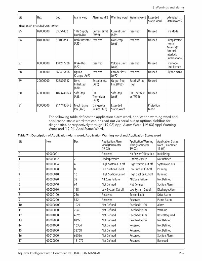
Bit Hex Dec Alarm word Alarm word 2 Warning word Warning word2
ExtendedStatus word
ExtendedStatus word 2
Alarm Word Extended Status Word
25 02000000 33554432 1.8V SupplyLow (A48)
Current Limit(W59)
Current Limit(A59)
reserved Unused Fire Mode
26 04000000 67108864 Brake Resistor(A25)
reserved Low Temp(W66)
reserved Unused Pump Protect(NorthAmerica)/ExternalInterlock(International)
27 08000000 134217728 Brake IGBT(A27)
reserved Voltage Limit(W64)
reserved Unused FiremodeLimit Exceed
28 10000000 268435456 OptionChange (A67)
reserved Encoder loss(W90)
reserved Unused FlyStart active
29 20000000 536870912 DriveInitialized(A80)
Encoder loss(A90)
Output freq.lim. (W62)
BackEMF tooHigh
Unused
30 40000000 1073741824 Safe Stop(A68)
PTCThermistor(A74)
Safe Stop(W68)
PTC Thermistor (W74)
Unused
31 80000000 2147483648 Mech. brakelow (A63)
Dangerousfailure (A72)
ExtendedStatus Word
ProtectionMode
The following table defines the application alarm word, application warning word andapplication status word that can be read out via serial bus or optional fieldbus fordiagnostics, or respectively through [19-02] Appl Alarm Word, [19-03] Appl WarningWord and [19-04] Appl Status Word.
Table 71: Description of Application Alarm word, Application Warning word and Application Status word
Bit Hex Dec Application Alarmword (Parameter19-02)
Application Warningword (Parameter19-03)
Application Statusword (Parameter19-04)
0 00000001 1 Reserved No Power Calibration Initializing
1 00000002 2 Underpressure Underpressure Not Defined
2 00000004 4 High System Cut-off High System Cut-off System can run
3 00000008 8 Low Suction Cut-off Low Suction Cut-off Priming
4 00000010 16 High Suction Cut-off High Suction Cut-off Running
5 00000020 32 All Zone Failure All Zone Failure Not Defined
6 00000040 64 Not Defined Not Defined Suction Alarm
7 00000080 128 Low System Cut-off Low System Cut-off Discharge Alarm
8 00000100 256 Reserved Sensor Fault Drive Alarm
9 00000200 512 Reserved Reserved Pump Alarm
10 000000400 1024 Not Defined Feedback 1 Fail Alarm
11 00000080 2048 Not Defined Feedback 2 Fail Warning
12 00001000 4096 Not Defined Feedback 3 Fail Reset Required
13 00002000 8192 Not Defined Feedback 4 Fail Not Defined
14 00004000 16384 Not Defined Reserved Not Defined
15 00008000 32768 Not Defined Reserved Not Defined
16 00010000 65536 Not Defined Reserved Suction Alarm
17 00020000 131072 Not Defined Reserved Reserved
8 Warnings and alarms
Aquavar Intelligent Pump Controller INSTRUCTION MANUAL 239

Bit Hex Dec Application Alarmword (Parameter19-02)
Application Warningword (Parameter19-03)
Application Statusword (Parameter19-04)
18 00040000 262144 Not Defined Reserved Reserved
19 00080000 524288 Not Defined Reserved Reserved
20 00100000 1048576 Not Defined Suction Feedback Fail Reserved
21 00200000 2097152 Not Defined Reserved Reserved
22 00400000 4194304 Not Defined Reserved Reserved
23 00800000 8388608 Not Defined Reserved Reserved
24 01000000 16777216 Not Defined Reserved Operating Mode:0
25 02000000 33554432 Not Defined Reserved Operating Mode:1
26 04000000 67108864 Not Defined Reserved Operating Mode:2
27 08000000 134217728 Not Defined Reserved Operating Mode:3
28 10000000 268435456 Not Defined Flow Feedback Fail System Status:0
29 20000000 536870912 Not Defined Reserved System Status:1
30 40000000 1073741824 Not Defined Not Defined System Status:2
31 80000000 2147483648 Not Defined Not Defined System Status:3
8.3 Warnings and alarmsTable 72: Warnings and alarms
Warning/Alarm Description Cause Remedy
1 — 10 V low The control card voltage is below10 V from terminal 50.
A short in a connectedpotentiometer or improper wiringof the potentiometer.
Remove the wiring from terminal50. If the warning clears, theproblem is with the customerwiring.
2 — Sensor FaultNote: this warning/alarm is notavailable when the MCO301Programmable API option card isinstalled and functioning.
This warning or alarm will onlyappear if programmed by the userin [6–01] Sensor Fault TimeoutFunction. The signal on one of theanalog inputs is less than 50% ofthe minimum value that isprogrammed for that input.
Broken wiring or faulty devicesending the signal.
Check the connections on all theanalog input terminals. Controlcard terminals 53 and 54 forsignals, terminal 55 common.General Purpose I/O Option Cardterminals 11 and 12 for signals,terminal 10 common. Analog I/OOption Card terminals 1, 3, 5 forsignals, terminals 2, 4, 6 common.Check that the frequency converterprogramming and switch settingsmatch the analog signal type.Perform Input Terminal Signal Test
4 — Input phase loss A phase is missing on the supplyside, or the mains voltageimbalance is too high. Thismessage also appears for a fault inthe input rectifier on the frequencyconverter. Options areprogrammed at [14–12] Functionat Mains Imbalance (notapplicable for single-phasedrives).
Check the supply voltage andsupply currents to the frequencyconverter.
5 — DC link voltage high The intermediate circuit voltage(DC) is higher than the highvoltage warning limit.
The limit is dependent on thefrequency converter voltagerating. The frequency converter isstill active.
8 Warnings and alarms
240 Aquavar Intelligent Pump Controller INSTRUCTION MANUAL

Warning/Alarm Description Cause Remedy
6 — DC link voltage low The intermediate circuit voltage(DC) is lower than the low voltagewarning limit.
The limit is dependent on thefrequency converter voltagerating. The frequency converter isstill active.
7 — DC overvoltage If the intermediate circuit voltageexceeds the limit, the frequencyconverter trips after a time.
Connect a brake resistorExtend a ramp timeChange the ramp typeActivate functions in [2–10] BrakeFunctionIncrease [14–26] Trip Delay atInverter Fault
8 — DC under voltage If the intermediate circuit voltage(DC) drops below the undervoltage limit, the frequencyconverter checks if a 24 VDCbackup supply is connected.
If no 24 VDC backup supply isconnected, the frequencyconverter trips after a fixed timedelay. The time delay varies withunit size.
Check that the supply voltagematches the frequency convertervoltage.Perform input voltage testPerform soft charge and rectifiercircuit test.
9 — Inverter overloaded The frequency converter is aboutto cut-out because of an overload(too high current for too long). Thecounter for electronic, thermalinverter protection gives a warningat 98% and trips at 100% whilegiving an alarm. The frequencyconverter cannot be reset until thecounter is below 90%.
The fault is that the frequencyconverter is overloaded by morethan 100% for too long.
Compare the output currentshown on the LCP with thefrequency converter rated current.Compare the output currentshown on the LCP with themeasured motor current.Display the Thermal Drive Load onthe LCP and
10 — Motor overload temperature According to the electronicthermal protection (ETR), themotor is too hot. Select whetherthe frequency converter gives awarning or an alarm when thecounter reaches 100% in [1–90]Motor Thermal Protection.
The fault occurs when the motor isoverloaded by more than 100% fortoo long.
Check for motor overheating.Check if the motor is mechanicallyoverloaded.Check that the motor current set in[1–24] Motor Current is correct.
11 — Motor thermistor over temp The thermistor might bedisconnected. Select whether thefrequency converter gives awarning or an alarm in [1–90]Motor Thermal Protection.
Check for motor overheating.Check if the motor is mechanicallyoverloaded.When using terminal 54, checkthat the thermistor is connectedcorrectly between terminal 54(analog voltage input) andterminal 50 (+10 V supply) andthat the terminal switch for 54 isset for voltage. Check [1–93]Thermistor Source selects terminal54.When using digital inputs 18 or19, check that the thermistor isconnected correctly betweeneither terminal 18 or 19 (digitalinput PNP only) and terminal 50.Check [1–93] Thermistor Sourceselects terminal 18 or 19.
8 Warnings and alarms
Aquavar Intelligent Pump Controller INSTRUCTION MANUAL 241

Warning/Alarm Description Cause Remedy
12 — Torque limit The torque has exceeded the valuein [4–16] Torque Limit MotorMode or the value in [4–17]Torque Limit Generator Mode.[14–25] Trip Delay at Torque Limitcan change this from a warningonly condition to a warningfollowed by an alarm.
If the motor torque limit isexceeded during ramp up, extendthe ramp up time.If the generator torque limit isexceeded during ramp down,extend the ramp down time.If torque limit occurs whilerunning, possibly increase thetorque limit. Be sure the systemcan operate safely at a highertorque.Check the application for excessivecurrent draw on the motor.
13 — Over current The inverter peak current limit(approximately 200% of the ratedcurrent) is exceeded. The warninglasts about 1.5 seconds, then thefrequency converter trips andissues an alarm. This fault may becaused by shock loading or fastacceleration with high inertialoads. If extended mechanicalbrake control is selected, trip canbe reset externally.
Remove power and check if themotor can be turned.Check that the motor size matchesthe frequency converter.Check parameters [1–20] through[1–25] for correct motor data.
14 — Ground/Earth fault There is current from the outputphases to ground, either in thecable between the frequencyconverter and the motor or in themotor itself.
Remove power to the frequencyconverter and repair the earthfault.Check for ground faults in themotor by measuring the resistanceto ground of the motor leads andthe motor megohmmeter.
15 — Hardware mismatch A fitted option is not operationalwith the present control boardhardware or software.
Record the value of the followingparameters and contact yourXylem supplier:• [15–40] FC Type• [15–41] Power Section• [15–42] Voltage• [15–43] Software Version• [15–45] Actual Typecode
String• [15–49] SW ID Control Card• [15–50] SW ID Power Card• [15–60] Option Mounted• [15–61] Option SW Version
16 — Short circuit There is a short circuit in the motoror motor wiring.
Remove power to the frequencyconverter and repair the shortcircuit.
17 — Control word timeout There is no communication to thefrequency converter.The warning will only be activewhen [8–04] Control TimeoutFunction is NOT set to [0] OFF.
If [8–04] Control Timeout Functionis set to Stop and Trip, a warningappears and the frequencyconverter ramps down until itstops then displays an alarm.
Check connections on the seriescommunication cable.Increase [8–03] Control TimeoutTimeCheck operation of thecommunication equipmentVerify proper installation based onEMC requirements.
8 Warnings and alarms
242 Aquavar Intelligent Pump Controller INSTRUCTION MANUAL

Warning/Alarm Description Cause Remedy
18 — Start failed The speed has not been able toexceed [1–77] Compressor StartMax Speed [RPM] during startwithin the allowed time. (set in [1–79] Compressor Start Max Time toTrip.
This may be caused by a blockedmotor.
23 — Internal fan fault The fan warning function checks ifthe fan is running. The fanwarning can be disabled on [14–53] Fan Monitor.
Check for proper fan operation.Cycle power to the frequencyconverter and check that the fanoperates briefly at startup.Check the sensors on the heatsinkand control card.
24 — External fan fault The fan warning function checks ifthe fan is running. The fanwarning can be disabled on [14–53] Fan Monitor.
Check for proper fan operation.Cycle power to the frequencyconverter and check that the fanoperates briefly at startup.Check the sensors on the heatsinkand control card.
25 — Brake resistor short circuit The brake resistor is monitoredduring operation. If a short circuitoccurs, the brake function isdisabled and the warning appears.The frequency converter is stilloperational but without the brakefunction.
Remove power to the frequencyconverter and replace the brakeresistor (see [2–15] Brake Check).
26 — Brake resistor power limit The power transmitted to thebrake resistor is calculated as amean value over the last 120seconds of run time. Thecalculation is based on theintermediate circuit voltage andthe brake resistance value set in[2–16] AC brake Max.Current.
The warning is active when thedissipated braking is higher than90% of the brake resistancepower.If Trip [2] is selected in [2–13]Brake Power Monitoring, thefrequency converter will trip whenthe dissipated braking powerreaches 100%.
27 — Brake chopper fault The brake transistor is monitoredduring operation and if a shortcircuit occurs, the brake function isdisabled and a warning is issued.
The frequency converter is stilloperational but, since the braketransistor has short-circuited,substantial power is transmitted tothe brake resistor, even if it isinactive.
Remove power to the frequencyconverter and remove the brakeresistor.
28 — Brake check failed The brake resistor is not connectedor not working.
Check [2–15] Brake Check.
29 — Heatsink temp The maximum temperature of theheatsink has been exceeded. Thetemperature fault will not resetuntil the temperature falls belowthe reset heatsink temperature.The trip and reset points are basedon the frequency converter powersize.
Check for the following conditions:• Ambient temperature too
high.• Motor cable too long.• Incorrect airflow clearance
above and below thefrequency converter.
• Blocked airflow around thefrequency converter.
• Damaged heatsink fan.• Dirty heatsink.
30 — Motor phase U missing Motor phase U between thefrequency converter and the motoris missing.
Remove power from the frequencyconverter and check motor phaseU.
8 Warnings and alarms
Aquavar Intelligent Pump Controller INSTRUCTION MANUAL 243

Warning/Alarm Description Cause Remedy
31 — Motor phase V missing Motor phase V between thefrequency converter and the motoris missing.
Remove power from the frequencyconverter and check motor phaseV.
32 — Motor phase W missing Motor phase W between thefrequency converter and the motoris missing.
Remove power from the frequencyconverter and check motor phaseW.
33 — Inrush fault Too many power-ups haveoccurred within a short timeperiod.
Let the unit cool to operatingtemperature.
34 — Fieldbus communicationfault
Communication between thefieldbus and the communicationoption card is not operating.
36 — Mains failure This warning/alarm is only active ifthe supply voltage to thefrequency converter is lost and[14–10] Mains Failure is NOT set to[0] No Function.
Check the fuses to the frequencyconverter and mains power supplyto the unit.
38 — Internal fault When an internal fault occurs, acode number defined in the tablebelow is displayed.
Cycle power to the frequencyconverter.Check that the option is properlyinstalled.Check for loose or missing wiring.It may be necessary to contact yourXylem supplier or servicedepartment. Note the codenumber for furthertroubleshooting directions.
39 — Heatsink sensor No feedback from the heatsinktemperature sensor.
The signal from the IGBT Thermalsensor is not available on thepower card. The problem could beon the power card, on the gatedrive card, or the ribbon cablebetween the power card and gatedrive card.
40 — Overload of digital outputterminal 27
Check the load connected toterminal 27 or remove short-circuitconnection.Check [5–00] Digital I/O mode and[5–01] Terminal 27 Mode.
41 — Overload of digital outputterminal 29
Check the load connected toterminal 29 or remove short-circuitconnection.Check [5–00] Digital I/O mode and[5–02] Terminal 29 Mode.
42 — Overload of digital output onX30/6 or overload of digital outputon X30/7
For X30/6, check the loadconnected to X30/6 or removeshort-circuit connection. Check [5–32] Term X30/6 Digi Out (MCB101).For X30/7, check the loadconnected to X30/77 or removeshort-circuit connection. Check [5–33] Term X30/7 Digi Out (MCB101).
8 Warnings and alarms
244 Aquavar Intelligent Pump Controller INSTRUCTION MANUAL
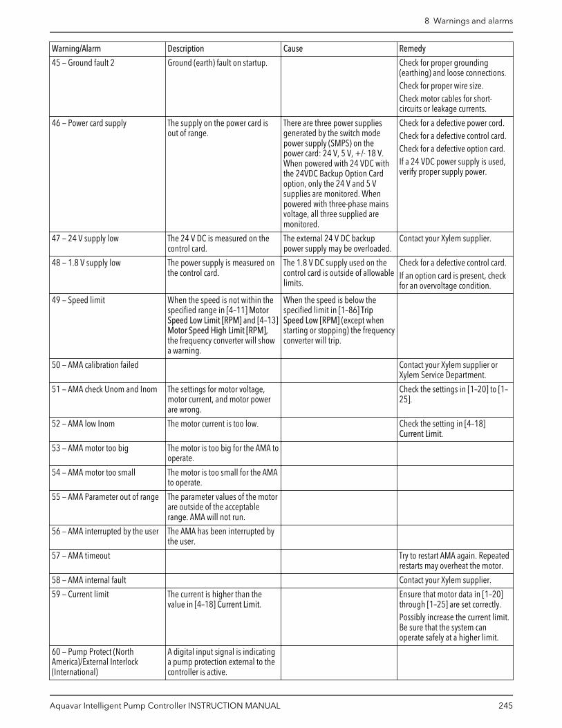
Warning/Alarm Description Cause Remedy
45 — Ground fault 2 Ground (earth) fault on startup. Check for proper grounding(earthing) and loose connections.Check for proper wire size.Check motor cables for short-circuits or leakage currents.
46 — Power card supply The supply on the power card isout of range.
There are three power suppliesgenerated by the switch modepower supply (SMPS) on thepower card: 24 V, 5 V, +/- 18 V.When powered with 24 VDC withthe 24VDC Backup Option Cardoption, only the 24 V and 5 Vsupplies are monitored. Whenpowered with three-phase mainsvoltage, all three supplied aremonitored.
Check for a defective power cord.Check for a defective control card.Check for a defective option card.If a 24 VDC power supply is used,verify proper supply power.
47 — 24 V supply low The 24 V DC is measured on thecontrol card.
The external 24 V DC backuppower supply may be overloaded.
Contact your Xylem supplier.
48 — 1.8 V supply low The power supply is measured onthe control card.
The 1.8 V DC supply used on thecontrol card is outside of allowablelimits.
Check for a defective control card.If an option card is present, checkfor an overvoltage condition.
49 — Speed limit When the speed is not within thespecified range in [4–11] MotorSpeed Low Limit [RPM] and [4–13]Motor Speed High Limit [RPM],the frequency converter will showa warning.
When the speed is below thespecified limit in [1–86] TripSpeed Low [RPM] (except whenstarting or stopping) the frequencyconverter will trip.
50 — AMA calibration failed Contact your Xylem supplier orXylem Service Department.
51 — AMA check Unom and Inom The settings for motor voltage,motor current, and motor powerare wrong.
Check the settings in [1–20] to [1–25].
52 — AMA low Inom The motor current is too low. Check the setting in [4–18]Current Limit.
53 — AMA motor too big The motor is too big for the AMA tooperate.
54 — AMA motor too small The motor is too small for the AMAto operate.
55 — AMA Parameter out of range The parameter values of the motorare outside of the acceptablerange. AMA will not run.
56 — AMA interrupted by the user The AMA has been interrupted bythe user.
57 — AMA timeout Try to restart AMA again. Repeatedrestarts may overheat the motor.
58 — AMA internal fault Contact your Xylem supplier.
59 — Current limit The current is higher than thevalue in [4–18] Current Limit.
Ensure that motor data in [1–20]through [1–25] are set correctly.Possibly increase the current limit.Be sure that the system canoperate safely at a higher limit.
60 — Pump Protect (NorthAmerica)/External Interlock(International)
A digital input signal is indicatinga pump protection external to thecontroller is active.
8 Warnings and alarms
Aquavar Intelligent Pump Controller INSTRUCTION MANUAL 245
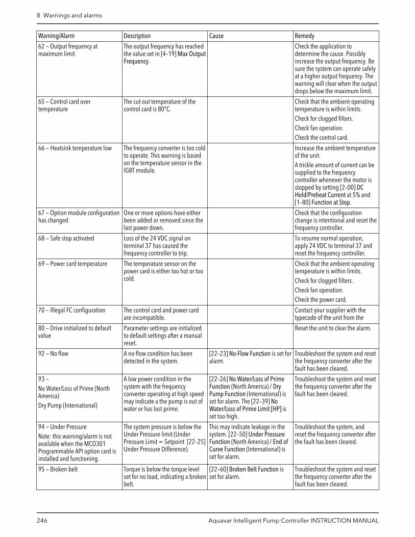
Warning/Alarm Description Cause Remedy
62 — Output frequency atmaximum limit
The output frequency has reachedthe value set in [4–19] Max OutputFrequency.
Check the application todetermine the cause. Possiblyincrease the output frequency. Besure the system can operate safelyat a higher output frequency. Thewarning will clear when the outputdrops below the maximum limit.
65 — Control card overtemperature
The cut-out temperature of thecontrol card is 80°C.
Check that the ambient operatingtemperature is within limits.Check for clogged filters.Check fan operation.Check the control card.
66 — Heatsink temperature low The frequency converter is too coldto operate. This warning is basedon the temperature sensor in theIGBT module.
Increase the ambient temperatureof the unit.A trickle amount of current can besupplied to the frequencycontroller whenever the motor isstopped by setting [2–00] DCHold/Preheat Current at 5% and[1–80] Function at Stop.
67 — Option module configurationhas changed
One or more options have eitherbeen added or removed since thelast power down.
Check that the configurationchange is intentional and reset thefrequency controller.
68 — Safe stop activated Loss of the 24 VDC signal onterminal 37 has caused thefrequency controller to trip.
To resume normal operation,apply 24 VDC to terminal 37 andreset the frequency controller.
69 — Power card temperature The temperature sensor on thepower card is either too hot or toocold.
Check that the ambient operatingtemperature is within limits.Check for clogged filters.Check fan operation.Check the power card.
70 — Illegal FC configuration The control card and power cardare incompatible.
Contact your supplier with thetypecode of the unit from the
80 — Drive initialized to defaultvalue
Parameter settings are initializedto default settings after a manualreset.
Reset the unit to clear the alarm.
92 — No flow A no-flow condition has beendetected in the system.
[22–23] No-Flow Function is set foralarm.
Troubleshoot the system and resetthe frequency converter after thefault has been cleared.
93 —No Water/Loss of Prime (NorthAmerica)Dry Pump (International)
A low power condition in thesystem with the frequencyconverter operating at high speedmay indicate a the pump is out ofwater or has lost prime.
[22–26] No Water/Loss of PrimeFunction (North America) / DryPump Function (International) isset for alarm. The [22–39] NoWater/Loss of Prime Limit [HP] isset too high.
Troubleshoot the system and resetthe frequency converter after thefault has been cleared.
94 — Under PressureNote: this warning/alarm is notavailable when the MCO301Programmable API option card isinstalled and functioning.
The system pressure is below theUnder Pressure limit (UnderPressure Limit = Setpoint [22–25]Under Pressure Difference).
This may indicate leakage in thesystem. [22–50] Under PressureFunction (North America) / End ofCurve Function (International) isset for alarm.
Troubleshoot the system, andreset the frequency converter afterthe fault has been cleared.
95 — Broken belt Torque is below the torque levelset for no load, indicating a brokenbelt.
[22–60] Broken Belt Function isset for alarm.
Troubleshoot the system and resetthe frequency converter after thefault has been cleared.
8 Warnings and alarms
246 Aquavar Intelligent Pump Controller INSTRUCTION MANUAL

Warning/Alarm Description Cause Remedy
96 — Start delayed Motor start has been delayed dueto short-cycle protection.
[22–76] Interval Between Starts isenabled.
Troubleshoot the system and resetthe frequency converter after thefault has been cleared.
97 — Stop delayed Stopping the motor has beendelayed due to short cycleprotection.
[22–76] Interval Between Starts isenabled.
Troubleshoot the system and resetthe frequency converter after thefault has been cleared.
98 — Clock fault Time is not set or the RTC clock hasfailed.
Reset the clock in [0–70] Date andTime.
200 — Fire mode This indicates the frequencycontroller is operating in firemode.
Cycle power to the unit to removethe warning. See the fire modedata in the alarm log on thecontroller.
201 — Fire mode was active This indicates the frequencycontroller had entered fire mode.
Cycle power to the unit to removethe warning. See the fire modedata in the alarm log on thecontroller.
202 — Fire mode limits exceeded While operating in fire mode oneor more alarm conditions has beenignored which would normally tripthe unit.
Operating in this condition voidsunit warranty.
Cycle power to the unit to removethe warning. See the fire modedata in the alarm log on thecontroller.
203 — Missing motor With a frequency converteroperating multi-motors, an under-load condition was detected.
This could indicate a missingmotor.
Inspect the system for properoperation.
204 — Locked rotor With a frequency converteroperating multi-motors, anoverload condition was detected.
This could indicate a locked rotor. Inspect the motor for properoperation.
250 — New spare part A component in the frequencyconverter has been replaced.
Reset the frequency converter fornormal operation.
251 — New typecode A component in the frequencyconverter has been replaced andthe typecode changed.
Reset the frequency converter fornormal operation.
Table 73: Application warnings and alarms
Warning/Alarm Description Cause Remedy
A500_NO_CALIBRATION No Calibration warning occurswhen there is No PowerCalibration has been done forvariable frequency drive.
Power calibrate the system bydoing Auto power calibrationusing [22-20] No Flow PowerCalibration (North America)/LowPower Auto Set-up (International).
A501_UNDERPRESSURE Feedback is lower than the setpoint.
This may indicate leakage in theSystem. Parameter [22–50] UnderPressure Function (NorthAmerica) /End of Curve Delay(International) is set for alarm.
Troubleshoot the system, andreset the frequency converter afterthe fault has been cleared.
A502_HIGH_SYSTEM The system pressure is above the[19-27] High System Limit.
High System Alarm may damagethe system if it is not meant tosustain such high pressure
Troubleshoot the system, andreset the frequency converter afterthe fault has been cleared.
A503_LOW_SUCTION The Suction pressure is below the[19-33] Low Suction Cut-out.
Low Suction Cut-out providesprotection from running pump dryusing a suction sensor.
Troubleshoot the system, andreset the frequency converter afterthe fault has been cleared.
A504_HIGH_SUCTION The Suction pressure is above the[19-37] High Suction Cut-out.
High Suction Cut-out providesprotection from running pumpwhen there is sufficient suctionpressure to meet system pressurerequirements.
Troubleshoot the system, andreset the frequency converter afterthe fault has been cleared.
8 Warnings and alarms
Aquavar Intelligent Pump Controller INSTRUCTION MANUAL 247
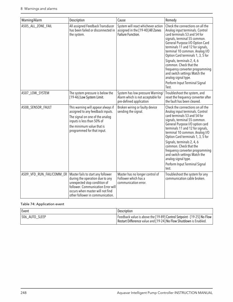
Warning/Alarm Description Cause Remedy
A505_ALL_ZONE_FAIL All assigned Feedback Transducerhas been failed or disconnected inthe system.
System will react whichever actionassigned in the [19-40] All ZonesFailure Function.
Check the connections on all theAnalog input terminals. Controlcard terminals 53 and 54 forsignals, terminal 55 common.General Purpose I/O Option Cardterminals 11 and 12 for signals,terminal 10 common. Analog I/OOption Card terminals 1, 3, 5 forSignals, terminals 2, 4, 6common. Check that thefrequency converter programmingand switch settings Match theanalog signal type.Perform Input Terminal SignalTest.
A507_LOW_SYSTEM The system pressure is below the[19-46] Low System Limit.
System has low pressure Warning/Alarm which is not acceptable forpre-defined application
Troubleshoot the system, andreset the frequency converter afterthe fault has been cleared.
A508_SENSOR_FAULT This warning will appear always ifassigned to any feedback inputs.The signal on one of the analoginputs is less than 50% ofthe minimum value that isprogrammed for that input.
Broken wiring or faulty devicesending the signal.
Check the connections on all theAnalog input terminals. Controlcard terminals 53 and 54 forsignals, terminal 55 common.General Purpose I/O option cardterminals 11 and 12 for signals,terminal 10 common. Analog I/OOption Card terminals 1, 3, 5 forSignals, terminals 2, 4, 6common. Check that thefrequency converter programmingand switch settings Match theanalog signal type.Perform Input Terminal Signaltest.
A509_VFD_RUN_FAIL/COMM_ER Master fails to start any followerduring the operation due to anyunexpected stop condition offollower. Communication Error willoccurs when master will not findother follower in communication.
Master has no longer control ofFollower which has acommunication error.
Troubleshoot the system for anycommunication cable broken.
Table 74: Application event
Event Description
506_AUTO_SLEEP Feedback value is above the [19-89] Control Setpoint - [19-25] No FlowRestart Difference value and [19-24] No Flow Shutdown is Enabled.
8 Warnings and alarms
248 Aquavar Intelligent Pump Controller INSTRUCTION MANUAL

9 Troubleshooting9.1 Start up and operation troubleshootingTable 75: Troubleshooting
Symptom Possible cause Test Solution
Display dark/No function
Missing or open fuses or circuitbreaker tripped
See Pre-startup inspections tablein this manual.
Check the input power source
No power to the LCP Check the LCP cable for properconnection or damage
Replace the faulty LCP orconnection cable
Shortcut on control voltage(terminal 12 or 50) or at controlterminals
Check the 24 V control voltagesupply for terminals 12/13 to 20-39 or 10 V supply for terminals 50to 55
Wire the terminals properly
Wrong LCP Use only LCP #9K651.
Wrong contrast setting Press [status] + [▲]/[▼] to adjustthe contrast
Display (LCP) is defective Test using a different LCP Replace the faulty LCP orconnection cable
Internal voltage supply fault orSMPS is defective
Contact supplier
Intermittent display Overloaded power supply (SMPS)due to improper control wiring orfault within the frequencyconverter
To rule out a problem in thecontrol wiring, disconnect allcontrol wiring by removing theterminal blocks.
If the display stays lit, then theproblem is in the control wiring.Check the wiring for shorts orincorrect connections. If thedisplay continues to cut out, followthe procedure for display dark.
Motor not running
Service switch open or missingmotor connection
Check if the motor is connectedand the connection is notinterrupted (by a service switch orother device)
Connect the motor and check theservice switch
No mains power with 24 V DCoption card
If the display is functioning but nooutput, check that mains power isapplied to the frequency converter
Apply mains power to run the unit
LCP Stop Check if [Off] has been pressed Press [Auto On] or [Hand On](depending on operation mode) torun the motor
Missing start signal (Standby) Check 5–10 Terminal 18 DigitalInput for correct setting forterminal 18 (use default setting)
Apply a valid start signal to startthe motor
Motor coast signal active(Coasting)
Check 5–12 Coast inv. for correctsetting for terminal 27 (usedefault setting)
Apply 24 V on terminal 27 orprogram this terminal to Nooperation
Wrong reference signal source Check reference signals: Local,remote or bus reference? Presetreference active? Terminalconnection correct? Scaling ofterminals correct? Referencesignal available?
Program correct settings. Check 3–13 Reference Site. Set presetreference active in parametergroup 3–1* References. Check forcorrect wiring. Check scaling orterminals. Check reference signal.
9 Troubleshooting
Aquavar Intelligent Pump Controller INSTRUCTION MANUAL 249
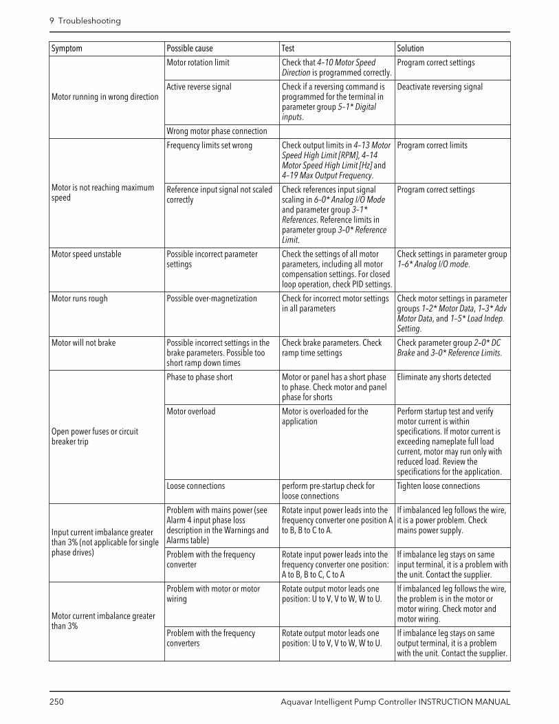
Symptom Possible cause Test Solution
Motor running in wrong direction
Motor rotation limit Check that 4–10 Motor SpeedDirection is programmed correctly.
Program correct settings
Active reverse signal Check if a reversing command isprogrammed for the terminal inparameter group 5–1* Digitalinputs.
Deactivate reversing signal
Wrong motor phase connection
Motor is not reaching maximumspeed
Frequency limits set wrong Check output limits in 4–13 MotorSpeed High Limit [RPM], 4–14Motor Speed High Limit [Hz] and4–19 Max Output Frequency.
Program correct limits
Reference input signal not scaledcorrectly
Check references input signalscaling in 6–0* Analog I/O Modeand parameter group 3–1*References. Reference limits inparameter group 3–0* ReferenceLimit.
Program correct settings
Motor speed unstable Possible incorrect parametersettings
Check the settings of all motorparameters, including all motorcompensation settings. For closedloop operation, check PID settings.
Check settings in parameter group1–6* Analog I/O mode.
Motor runs rough Possible over-magnetization Check for incorrect motor settingsin all parameters
Check motor settings in parametergroups 1–2* Motor Data, 1–3* AdvMotor Data, and 1–5* Load Indep.Setting.
Motor will not brake Possible incorrect settings in thebrake parameters. Possible tooshort ramp down times
Check brake parameters. Checkramp time settings
Check parameter group 2–0* DCBrake and 3–0* Reference Limits.
Open power fuses or circuitbreaker trip
Phase to phase short Motor or panel has a short phaseto phase. Check motor and panelphase for shorts
Eliminate any shorts detected
Motor overload Motor is overloaded for theapplication
Perform startup test and verifymotor current is withinspecifications. If motor current isexceeding nameplate full loadcurrent, motor may run only withreduced load. Review thespecifications for the application.
Loose connections perform pre-startup check forloose connections
Tighten loose connections
Input current imbalance greaterthan 3% (not applicable for singlephase drives)
Problem with mains power (seeAlarm 4 input phase lossdescription in the Warnings andAlarms table)
Rotate input power leads into thefrequency converter one position Ato B, B to C to A.
If imbalanced leg follows the wire,it is a power problem. Checkmains power supply.
Problem with the frequencyconverter
Rotate input power leads into thefrequency converter one position:A to B, B to C, C to A
If imbalance leg stays on sameinput terminal, it is a problem withthe unit. Contact the supplier.
Motor current imbalance greaterthan 3%
Problem with motor or motorwiring
Rotate output motor leads oneposition: U to V, V to W, W to U.
If imbalanced leg follows the wire,the problem is in the motor ormotor wiring. Check motor andmotor wiring.
Problem with the frequencyconverters
Rotate output motor leads oneposition: U to V, V to W, W to U.
If imbalance leg stays on sameoutput terminal, it is a problemwith the unit. Contact the supplier.
9 Troubleshooting
250 Aquavar Intelligent Pump Controller INSTRUCTION MANUAL

Symptom Possible cause Test Solution
Acoustic noise or vibration (forexample, a pump impeller blademakes noise or vibrations atcertain frequencies)
Resonances, for example, in themotor/pump system
Bypass critical frequencies byusing parameters in parametergroup 4–6* Speed Bypass
Check if noise and/or vibrationhave been reduced to anacceptable limit
Turn off over-modulation in 14–03Overmodulation
Change switching pattern andfrequency in parameter group 14–0* Inverter Switching
Increase Resonance Dampening in1–64 Resonance Dampening
9 Troubleshooting
Aquavar Intelligent Pump Controller INSTRUCTION MANUAL 251
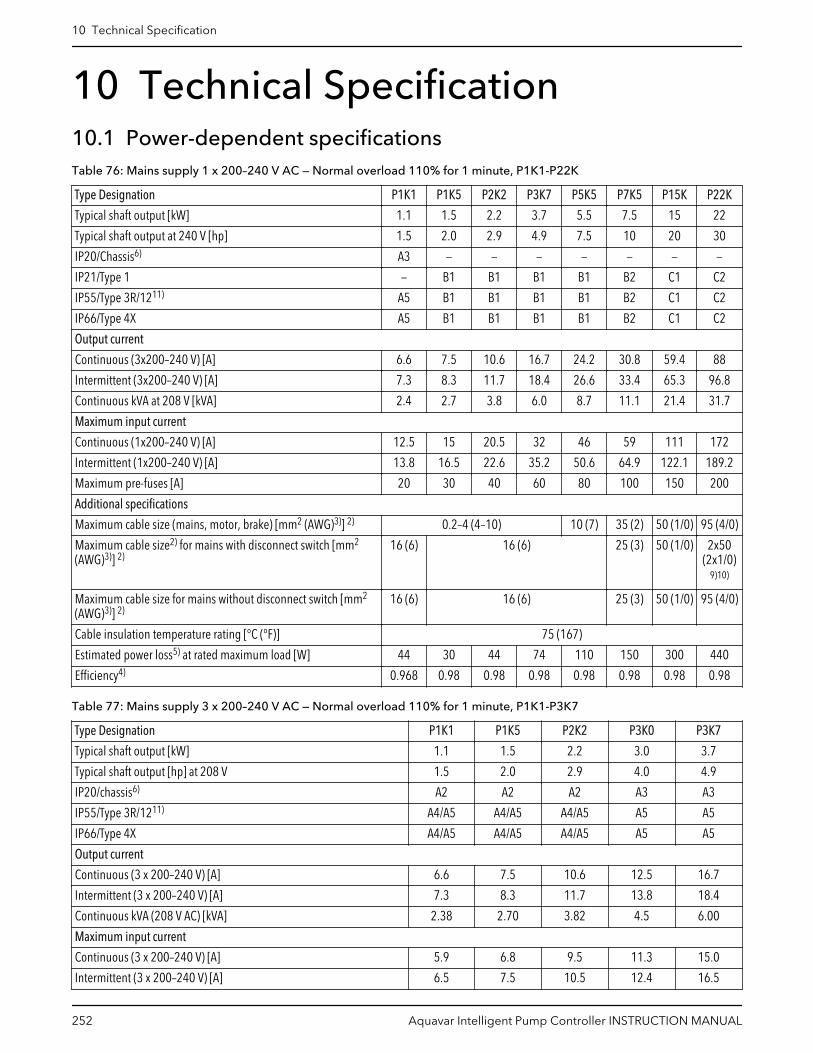
10 Technical Specification10.1 Power-dependent specificationsTable 76: Mains supply 1 x 200–240 V AC — Normal overload 110% for 1 minute, P1K1-P22K
Type Designation P1K1 P1K5 P2K2 P3K7 P5K5 P7K5 P15K P22K
Typical shaft output [kW] 1.1 1.5 2.2 3.7 5.5 7.5 15 22
Typical shaft output at 240 V [hp] 1.5 2.0 2.9 4.9 7.5 10 20 30
IP20/Chassis6) A3 — — — — — — —
IP21/Type 1 — B1 B1 B1 B1 B2 C1 C2
IP55/Type 3R/1211) A5 B1 B1 B1 B1 B2 C1 C2
IP66/Type 4X A5 B1 B1 B1 B1 B2 C1 C2
Output current
Continuous (3x200–240 V) [A] 6.6 7.5 10.6 16.7 24.2 30.8 59.4 88
Intermittent (3x200–240 V) [A] 7.3 8.3 11.7 18.4 26.6 33.4 65.3 96.8
Continuous kVA at 208 V [kVA] 2.4 2.7 3.8 6.0 8.7 11.1 21.4 31.7
Maximum input current
Continuous (1x200–240 V) [A] 12.5 15 20.5 32 46 59 111 172
Intermittent (1x200–240 V) [A] 13.8 16.5 22.6 35.2 50.6 64.9 122.1 189.2
Maximum pre-fuses [A] 20 30 40 60 80 100 150 200
Additional specifications
Maximum cable size (mains, motor, brake) [mm2 (AWG)3)] 2) 0.2–4 (4–10) 10 (7) 35 (2) 50 (1/0) 95 (4/0)
Maximum cable size2) for mains with disconnect switch [mm2
(AWG)3)] 2)16 (6) 16 (6) 25 (3) 50 (1/0) 2x50
(2x1/0)9)10)
Maximum cable size for mains without disconnect switch [mm2
(AWG)3)] 2)16 (6) 16 (6) 25 (3) 50 (1/0) 95 (4/0)
Cable insulation temperature rating [°C (°F)] 75 (167)
Estimated power loss5) at rated maximum load [W] 44 30 44 74 110 150 300 440
Efficiency4) 0.968 0.98 0.98 0.98 0.98 0.98 0.98 0.98
Table 77: Mains supply 3 x 200–240 V AC — Normal overload 110% for 1 minute, P1K1-P3K7
Type Designation P1K1 P1K5 P2K2 P3K0 P3K7
Typical shaft output [kW] 1.1 1.5 2.2 3.0 3.7
Typical shaft output [hp] at 208 V 1.5 2.0 2.9 4.0 4.9
IP20/chassis6) A2 A2 A2 A3 A3
IP55/Type 3R/1211) A4/A5 A4/A5 A4/A5 A5 A5
IP66/Type 4X A4/A5 A4/A5 A4/A5 A5 A5
Output current
Continuous (3 x 200–240 V) [A] 6.6 7.5 10.6 12.5 16.7
Intermittent (3 x 200–240 V) [A] 7.3 8.3 11.7 13.8 18.4
Continuous kVA (208 V AC) [kVA] 2.38 2.70 3.82 4.5 6.00
Maximum input current
Continuous (3 x 200–240 V) [A] 5.9 6.8 9.5 11.3 15.0
Intermittent (3 x 200–240 V) [A] 6.5 7.5 10.5 12.4 16.5
10 Technical Specification
252 Aquavar Intelligent Pump Controller INSTRUCTION MANUAL

Type Designation P1K1 P1K5 P2K2 P3K0 P3K7
Additional specifications
Estimated power loss at rated maximum load [W]5) 63 82 116 155 185
IP20/Chassis, IP21/Type 1 maximum cable size8) (mains, motor, brake,and load sharing) [mm2 (AWG)3)] 2)
4, 4, 4 (12, 12, 12)(Minimum 0.2 (24))
IP55/Type 3R/12, IP66/Type 4X maximum cable size8) (mains, motor,brake, and load sharing) [mm2 (AWG)3)] 2)
4, 4, 4 (12, 12, 12)
Maximum cable size with disconnect8) [mm2 (AWG)3)] 2) 6, 4, 4 (10, 12, 12)
Efficiency4) 0.96 0.96 0.96 0.96 0.96
Table 78: Mains supply 3 x 200–240 V AC — Normal overload 110% for 1 minute, P5K5-18K
Type Designation P5K5 P7K5 P11K P15K P18K
Typical shaft output [kW] 5.5 7.5 11 15 18.5
Typical shaft output [hp] at 208 V 7.5 10 15 20 25
IP20/chassis7) B3 B3 B3 B4 B4
IP21/Type 1 B1 B1 B1 B2 C1
IP55/Type 3R/1211) B1 B1 B1 B2 C1
IP66/Type 4X B1 B1 B1 B2 C1
Output current
Continuous (3 x 200–240 V) [A] 24.2 30.8 46.2 59.4 74.8
Intermittent (3 x 200–240 V) [A] 26.6 33.9 50.8 65.3 82.3
Continuous KVA (208 V VA) [kVA] 8.7 11.1 16.6 21.4 26.9
Maximum input current
Continuous (3 x 200–240 V) [A] 22.0 28.0 42.0 54.0 68.0
Intermittent (3 x 200–240 V) [A] 24.2 30.8 46.2 59.4 74.8
Additional specifications
Estimated power loss at rated maximum load [W]5) 269 310 447 602 737
IP20/Chassis maximum cable size8) (mains, brake, motor, and loadsharing) [mm2 (AWG)3)] 2)
10, 10 (8,8–) 35,-,- (2,-,-) 35 (2) 50 (1)
IIP21/Type 1, IP55/Type 3R/12, IP66/Type 4X maximum cable size8)
(mains, motor) [mm2 (AWG)3)] 2) 10, 10 (8, 8–)35, 25, 25
(2, 4, 4)50 (1)
IP21/Type 1, IP55/Type 3R/12, IP66/Type 4X maximum cable size8)
(brake, load sharing) [mm2 (AWG)3)] 2) 16, 10, 16 (6, 8, 6) 35,-,- (2,-,-) 50 (1)
Efficiency4) 0.96 0.96 0.96 0.96 0.96
Table 79: Mains supply 3 x 200–240 V AC — Normal overload 110% for 1 minute, P22K-P45K
Type Designation P22K P30K P37K P45K
Typical shaft output [kW] 22 30 37 45
Typical shaft output [hp] at 208 V 30 40 50 60
IP20/chassis7) C3 C3 C4 C4
IP21/Type 1 C1 C1 C2 C2
IP55/Type 3R/1211) C1 C1 C2 C2
IP66/Type 4X C1 C1 C2 C2
Output current
Continuous (3 x 200–240 V) [A] 88.0 115 143 170
Intermittent (3 x 200–240 V) [A] 96.8 127 157 187
10 Technical Specification
Aquavar Intelligent Pump Controller INSTRUCTION MANUAL 253
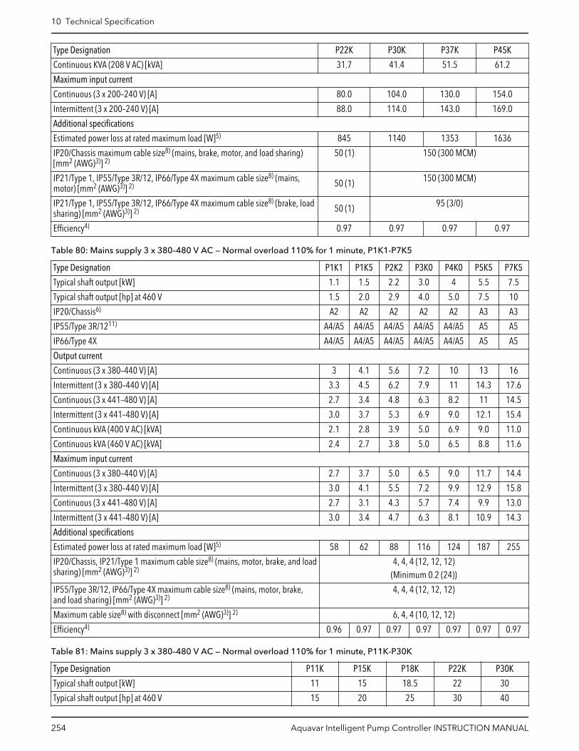
Type Designation P22K P30K P37K P45K
Continuous KVA (208 V AC) [kVA] 31.7 41.4 51.5 61.2
Maximum input current
Continuous (3 x 200–240 V) [A] 80.0 104.0 130.0 154.0
Intermittent (3 x 200–240 V) [A] 88.0 114.0 143.0 169.0
Additional specifications
Estimated power loss at rated maximum load [W]5) 845 1140 1353 1636
IP20/Chassis maximum cable size8) (mains, brake, motor, and load sharing)[mm2 (AWG)3)] 2)
50 (1) 150 (300 MCM)
IP21/Type 1, IP55/Type 3R/12, IP66/Type 4X maximum cable size8) (mains,motor) [mm2 (AWG)3)] 2) 50 (1) 150 (300 MCM)
IP21/Type 1, IP55/Type 3R/12, IP66/Type 4X maximum cable size8) (brake, loadsharing) [mm2 (AWG)3)] 2) 50 (1) 95 (3/0)
Efficiency4) 0.97 0.97 0.97 0.97
Table 80: Mains supply 3 x 380–480 V AC — Normal overload 110% for 1 minute, P1K1-P7K5
Type Designation P1K1 P1K5 P2K2 P3K0 P4K0 P5K5 P7K5
Typical shaft output [kW] 1.1 1.5 2.2 3.0 4 5.5 7.5
Typical shaft output [hp] at 460 V 1.5 2.0 2.9 4.0 5.0 7.5 10
IP20/Chassis6) A2 A2 A2 A2 A2 A3 A3
IP55/Type 3R/1211) A4/A5 A4/A5 A4/A5 A4/A5 A4/A5 A5 A5
IP66/Type 4X A4/A5 A4/A5 A4/A5 A4/A5 A4/A5 A5 A5
Output current
Continuous (3 x 380–440 V) [A] 3 4.1 5.6 7.2 10 13 16
Intermittent (3 x 380–440 V) [A] 3.3 4.5 6.2 7.9 11 14.3 17.6
Continuous (3 x 441–480 V) [A] 2.7 3.4 4.8 6.3 8.2 11 14.5
Intermittent (3 x 441–480 V) [A] 3.0 3.7 5.3 6.9 9.0 12.1 15.4
Continuous kVA (400 V AC) [kVA] 2.1 2.8 3.9 5.0 6.9 9.0 11.0
Continuous kVA (460 V AC) [kVA] 2.4 2.7 3.8 5.0 6.5 8.8 11.6
Maximum input current
Continuous (3 x 380–440 V) [A] 2.7 3.7 5.0 6.5 9.0 11.7 14.4
Intermittent (3 x 380–440 V) [A] 3.0 4.1 5.5 7.2 9.9 12.9 15.8
Continuous (3 x 441–480 V) [A] 2.7 3.1 4.3 5.7 7.4 9.9 13.0
Intermittent (3 x 441–480 V) [A] 3.0 3.4 4.7 6.3 8.1 10.9 14.3
Additional specifications
Estimated power loss at rated maximum load [W]5) 58 62 88 116 124 187 255
IP20/Chassis, IP21/Type 1 maximum cable size8) (mains, motor, brake, and loadsharing) [mm2 (AWG)3)] 2)
4, 4, 4 (12, 12, 12)(Minimum 0.2 (24))
IP55/Type 3R/12, IP66/Type 4X maximum cable size8) (mains, motor, brake,and load sharing) [mm2 (AWG)3)] 2)
4, 4, 4 (12, 12, 12)
Maximum cable size8) with disconnect [mm2 (AWG)3)] 2) 6, 4, 4 (10, 12, 12)
Efficiency4) 0.96 0.97 0.97 0.97 0.97 0.97 0.97
Table 81: Mains supply 3 x 380–480 V AC — Normal overload 110% for 1 minute, P11K-P30K
Type Designation P11K P15K P18K P22K P30K
Typical shaft output [kW] 11 15 18.5 22 30
Typical shaft output [hp] at 460 V 15 20 25 30 40
10 Technical Specification
254 Aquavar Intelligent Pump Controller INSTRUCTION MANUAL

Type Designation P11K P15K P18K P22K P30K
IP20/chassis7) B3 B3 B3 B4 B4
IP21/Type 1 B1 B1 B1 B2 B2
IP55/Type 3R/1211) B1 B1 B1 B2 B2
IP66/Type 4X B1 B1 B1 B2 B2
Output current
Continuous (3 x 380–439 V) [A] 24 32 37.5 44 61
Intermittent (3 x 380–439 V) [A] 26.4 35.2 41.3 48.4 67.1
Continuous (3 x 440–480) [A] 21 27 34 40 52
Intermittent (3 x 440–480 V) [A] 23.1 29.7 37.4 44 61.6
Continuous kVA (400 V AC) [kVA] 16.6 22.2 26 30.5 42.3
Continuous kVA (460 V AC) [kVA] 16.7 21.5 27.1 31.9 41.4
Maximum input current
Continuous (3 x 380–439 V) [A] 22 29 34 40 55
Intermittent (3 x 380–439 V) [A] 24.2 31.9 37.4 44 60.5
Continuous (3 x 440–480 V) [A] 19 25 31 36 47
Intermittent (3 x 440–480 V) [A] 20.9 27.5 34.1 39.6 51.7
Additional specifications
Estimated power loss at rated maximum load [W]5) 278 392 465 525 698
IP20/Chassis maximum cable size8) (mains, motor, and load sharing)[mm2 (AWG)3)] 2)
16, 10,- (8, 8,-) 35,-,- (2,-,-) 35 (2)
IP21/Type 1, IP55/Type 3R/12, IP66/Type 4X maximum cable size8)
(mains, motor) [mm2 (AWG)3)] 2)10, 10, 16 (6, 8, 6) 35, 25, 25 (2, 4, 4) 50 (1)
IP21/Type 1, IP55/Type 3R/12, IP66/Type 4X maximum cable size8)
(brake, load sharing) [mm2 (AWG)3)] 2)10, 10,- (8, 8,-) 35,-,- (2,-,-) 50 (1)
With mains disconnect switch included [mm2 (AWG)3)] 2) 16 (6)
Efficiency4) 0.98 0.98 0.98 0.98 0.98
Table 82: Mains supply 3 x 380–480 V AC — Normal overload 110% for 1 minute, P37K-P90K
Type Designation P37K P45K P55K P75K P90K
Typical shaft output [kW] 37 45 55 75 90
Typical shaft output [hp] at 460 V 50 60 75 100 125
IP20/Chassis7) B4 C3 C3 C4 C4
IP21/Type 1 C1 C1 C1 C2 C2
IP55/Type 3R/1211) C1 C1 C1 C2 C2
IP66/Type 4X C1 C1 C1 C2 C2
Output current
Continuous (3 x 380–439 V) [A] 73 90 106 147 177
Intermittent (3 x 380–439 V) [A] 80.3 99 117 162 195
Continuous (3 x 440–480 V) [A] 65 80 105 130 160
Intermittent (3 x 440–480 V) [A] 71.5 88 116 143 176
Continuous kVA (400 V AC) [kVA] 50.6 62.4 73.4 102 123
Continuous kVA (460 V AC) [kVA] 51.8 63.7 83.7 104 128
Maximum input current
Continuous (3 x 380–439 V) [A] 66 82 96 133 161
Intermittent (3 x 380–439 V) [A] 72.6 90.2 106 146 177
10 Technical Specification
Aquavar Intelligent Pump Controller INSTRUCTION MANUAL 255

Type Designation P37K P45K P55K P75K P90K
Continuous (3 x 440–480 V) [A] 59 73 95 118 145
Intermittent (3 x 440–480 V) [A] 64.9 80.3 105 130 160
Additional specifications
Estimated power loss at rated maximum load [A]5) 739 843 1083 1384 1474
IP20/Chassis maximum cable size (mains, brake, motor, and loadsharing) [mm2 (AWG)3)] 2)
50 (1) 150 (300 MCM)
IP21/Type 1, IP55/Type 3R/12, IP66/Type 4X maximum cable size(mains, motor) [mm2 (AWG)3)] 2)
150 (300 MCM)
IP21/Type 1, IP55/Type 3R/12, IP66/Type 4X maximum cable size(brake, load sharing) [mm2 (AWG)3)] 2)
95 (3/0)
With mains disconnect switch included [mm2 (AWG)3)] 2) 35 (2) 35 (2) 35 (2) 70 (3/0) 185(kcmil350)
Efficiency4) 0.98 0.98 0.98 0.98 0.98
Table 83: Mains supply 3 x 525–600 V AC - Normal overload 110% for 1 minute, P1K1-P7K5
Type Designation P1K1 P1K5 P2K2 P3K0 P3K7 P4K0 P5K5 P7K5
Typical shaft output [kW] 1.1 1.5 2.2 3.0 3.7 4.0 5.5 7.5
Typical shaft output [hp] 1.5 2.0 2.9 4.0 5.0 5.5 7.5 10
IP20/Chassis6)7) A3 A3 A3 A3 A2 A3 A3 A3
IP21/Type 1 A3 A3 A3 A3 A2 A3 A3 A3
IP55/Type 3R/1211) A5 A5 A5 A5 A5 A5 A5 A5
IP66/Type 4X A5 A5 A5 A5 A5 A5 A5 A5
Output current
Continuous (3 x 525–550 V) [A] 2.6 2.9 4.1 5.2 — 6.4 9.5 11.5
Intermittent (3 x 525–550 V) [A] 2.9 3.2 4.5 5.7 — 7.0 10.5 12.7
Continuous (3 x 525–600 V) [A] 2.4 2.7 3.9 4.9 — 6.1 9.0 11.0
Intermittent (3 x 525–600 V) [A] 2.6 3.0 4.3 5.4 — 6.7 9.9 12.1
Continuous kVA (525 V AC) [kVA] 2.5 2.8 3.9 5.0 — 6.1 9.0 11.0
Continuous kVA (575 V AC) [kVA] 2.4 2.7 3.9 4.9 — 6.1 9.0 11.0
Maximum input current
Continuous (3 x 525–600 V) [A] 2.4 2.7 4.1 5.2 — 5.8 8.6 10.4
Intermittent (3 x 525–600 V) [A] 2.7 3.0 4.5 5.2 — 6.4 9.5 11.5
Additional specifications
Estimated power loss at rated maximum load [W]5) 50 65 92 122 — 145 195 261
IP20/Chassis maximum cable size8) (mains, motor, brake, and load sharing)[mm2 (AWG)3)] 2)
4, 4, 4 (12, 12, 12)(Minimum 0.2 (24))
IP21/Type 1, IP55/Type 3R/12, IP66/Type 4X maximum cable size8) (mains,motor, brake, and load sharing) [mm2 (AWG)3)] 2)
4, 4, 4 (12, 12, 12)(Minimum 0.2 (24))
Maximum cable size8) with disconnect [mm2 (AWG)3)] 2) 6, 4, 4 (12, 12 ,12)
Mains disconnect switch included [mm2 (AWG)3)] 2): 4 (12)
Efficiency4) 0.97 0.97 0.97 0.97 — 0.97 0.97 0.97
Table 84: Mains supply 3 x 525–600 V AC - Normal overload 110% for 1 minute, P11K-P90K
Type Designation P11K P15K P18K P22K P30K P37K P45K P55K P75K P90K
Typical shaft output [kW] 11 15 18.5 22 30 37 45 55 75 90
Typical shaft output [hp] 15 20 25 30 40 50 60 75 100 125
10 Technical Specification
256 Aquavar Intelligent Pump Controller INSTRUCTION MANUAL

Type Designation P11K P15K P18K P22K P30K P37K P45K P55K P75K P90K
IP20/Chassis B3 B3 B3 B4 B4 B4 C3 C3 C4 C4
IP21/Type 1 B1 B1 B1 B2 B2 C1 C1 C1 C2 C2
IP55/Type 3R/1211) B1 B1 B1 B2 B2 C1 C1 C1 C2 C2
IP66/Type 4X B1 B1 B1 B2 B2 C1 C1 C1 C2 C2
Output current
Continuous (3 x 525–550 V) [A] 19 23 28 36 43 54 65 87 105 137
Intermittent (3 x 525–550 V) [A] 21 25 31 40 47 59 72 96 116 151
Continuous (3 x 525–600 V) [A] 18 22 27 34 41 52 62 83 100 131
Intermittent (3 x 525–600 V) [A] 20 24 30 37 45 57 68 91 110 144
Continuous kVA (525 V AC) [kVA] 18.1 21.9 26.7 34.3 41 51.4 61.9 82.9 100 130.5
Continuous kVA (575 V AC) [kVA] 17.9 21.9 26.9 33.9 40.8 51.8 61.7 82.7 99.6 130.5
Maximum input current
Continuous (3 x 525–600 V) [A] 17.2 20.9 25.4 32.7 39 49 59 78.9 95.3 124.3
Intermittent (3 x 525–600 V) [A] 19 23 28 36 43 54 65 87 105 137
Additional specifications
Estimated power loss at rated maximum load [W]5) 300 400 475 525 700 750 850 1100 1400 1500
IP20/Chassis maximum cable size8) (mains, brake, and loadsharing) [mm2 (AWG)3)] 2)
10, 10, - (8,8, -)
35, -, - (2, -, -) 50,-,- (1,-,-) 150 (300 MCM)
IP21, IP55, IP66 maximum cable size8) (mains, brake, and loadsharing) [mm2 (AWG)3)] 2)
16, 10, 10 (6,8, 8)
35,-,-(2,-,-) 50,-,- (1,-,-) 95 (4/0)
IP21, IP55, IP66 maximum cable cross-section (motor) [mm2
(AWG)]10, 10, - (8,
8,-)35, 25, 25 (2,
4, 4)50,-,- (1,-,-) 150 (300 MCM)
Maximum cable size8) with disconnect [mm2 (AWG)3)] 2) 16, 10, 10 (6, 8, 8) 50, 35, 35 (1, 2, 2) 95,70,70
(3/0,2/0,2/0)
185, 150,120 (350
MCM, 300MCM, 4/0)
Mains disconnect switch included [mm2 (AWG)3)] 2) 16 (6) 35 (2) 70(3/0)
185(kcmil350)
Efficiency4) 0.98 0.98 0.98 0.98 0.98 0.98 0.98 0.98 0.98 0.98
Table 85: Mains supply 3x525–690 V AC - Normal overload 110% for 1 minute, P1K1-P7K5
Type Designation P1K1 P1K5 P2K2 P3K0 P4K0 P5K5 P7K5
Typical shaft output [kW] 1.1 1.5 2.2 3.0 4.0 5.5 7.5
Typical shaft output [hp] 1.5 2.0 3.0 4.0 5.5 7.5 10
Enclosure IP20 (only) A3 A3 A3 A3 A3 A3 A3
Output current
Continuous (3 x 525–550 V) [A] 2.1 2.7 3.9 4.9 6.1 9.0 11
Intermittent (3 x 525–550 V) [A] 3.4 4.3 6.2 7.8 9.8 14.4 17.6
Continuous kVA (3x551–690 V) [kVA] 1.6 2.2 3.2 4.5 5.5 7.5 10
Intermittent kVA (3x551–690 V) [kVA] 2.6 3.5 5.1 7.2 8.8 12 16
Continuous kVA (525 V AC) [kVA] 1.9 2.5 3.5 4.5 5.5 8.2 10
Intermittent kVA (690 V AC) [kVA] 1.9 2.6 3.8 5.4 6.6 9.0 12
Maximum input current
Continuous (3x525–550 V) [A] 1.9 2.4 3.5 4.4 5.5 8.0 10
10 Technical Specification
Aquavar Intelligent Pump Controller INSTRUCTION MANUAL 257

Type Designation P1K1 P1K5 P2K2 P3K0 P4K0 P5K5 P7K5
Intermittent (3x525–550 V) [A] 3.0 3.9 5.6 7.1 8.8 13 16
Continuous kVA (3x551–690 V) [kVA] 1.4 2.0 2.9 4.0 4.9 6.7 9.0
Intermittent kVA (3x551–690 V) [kVA] 2.3 3.2 4.6 6.5 7.9 10.8 14.4
Additional specifications
Estimated power loss at rated maximum load [W]5) 44 60 88 120 160 220 300
Maximum cable cross-section (mains, motor, brake, and load sharing) [mm2
(AWG)]6, 4, 4 (10, 12, 12)
(minimum 0.2 (24))
Maximum cable cross-section with disconnect 6, 4, 4 (10, 12, 12)
Efficiency4) 0.96 0.96 0.96 0.96 0.96 0.96 0.96
Table 86: Mains supply 3x525–690 V AC - Normal overload 110% for 1 minute, P11K-P30K
Type Designation P11K P15K P18K P22K P30K
High/Normal Load NO NO NO NO NO
Typical shaft output at 550 V [kW] 7.5 11 15 18.5 22
Typical shaft output at 690 V [kW] 11 15 18.5 22 30
Typical shaft output [hp] 15 20 25 30 40
IP20/Chassis B4 B4 B4 B4 B4
IP21/NEMA 1 B2 B2 B2 B2 B2
IP55/NEMA 12 B2 B2 B2 B2 B2
Output current
Continuous (3 x 525–550 V) [A] 14 19 23 28 36
Intermittent (60 s overload) (3x525–550 V) [A] 22.4 20.9 25.3 30.8 39.6
Continuous (3 x 551–690 V) [A] 13 18 22 27 34
Intermittent (60 s overload) (3x551–690 V) [A] 20.8 19.8 24.2 29.7 37.4
Continuous kVA (550 V AC) [kVA] 13.3 18.1 21.9 26.7 34.3
Continuous kVA (690 V AC) [kVA] 15.5 21.5 26.3 32.3 40.6
Maximum input current
Continuous (at 550 V) [A] 15 19.5 24 29 36
Intermittent (60 s overload) (at 550 V) [A] 23.2 21.5 26.4 31.9 39.6
Continuous (at 690 V) [A] 14.5 19.5 24 29 36
Intermittent (60 s overload) (at 690 V) [A] 23.2 21.5 26.4 31.9 39.6
Maximum pre-fuses2) [A] 63 63 63 80 100
Additional specifications
Estimated power loss at rated maximum load [W]5) 150 220 300 370 440
Maximum cable cross-section (mains, motor, load sharing, and brake)[mm2 (AWG)]
35, 25, 25 (2, 4, 4)
Maximum cable size with mains disconnect [mm2]/(AWG)2) 16, 10, 10 (6, 8, 8)
Efficiency4) 0.98 0.98 0.98 0.98 0.98
Table 87: Mains supply 3x525–690 V AC - Normal overload 110% for 1 minute, P37K-P90K
Type Designation P37K P45K P55K P75K P90K
High/Normal Load NO NO NO NO NO
Typical shaft output at 550 V [kW] 30 37 45 55 75
Typical shaft output at 690 V [kW] 37 45 55 75 90
Typical shaft output at 575 V [hp] 50 60 75 100 125
10 Technical Specification
258 Aquavar Intelligent Pump Controller INSTRUCTION MANUAL

Type Designation P37K P45K P55K P75K P90K
IP20/Chassis B4 C3 C3 D3h D3h
IP21/NEMA 1 C2 C2 C2 C2 C2
IP55/NEMA 12 C2 C2 C2 C2 C2
Output current
Continuous (3 x 525–550 V) [A] 43 54 65 87 105
Intermittent (60 s overload) (3x525–550 V) [A] 47.3 59.4 71.5 95.7 115.5
Continuous (3 x 551–690 V) [A] 41 52 62 83 100
Intermittent (60 s overload) (3x551–690 V) [A] 45.1 57.2 68.2 91.3 110
Continuous kVA (550 V AC) [kVA] 41 51.4 61.9 82.9 100
Continuous kVA (690 V AC) [kVA] 49 62.1 74.1 99.2 119.5
Maximum input current
Continuous (at 550 V) [A] 49 59 71 87 99
Intermittent (60 s overload) (at 550 V) [A] 53.9 64.9 78.1 95.7 108.9
Continuous (at 690 V) [A] 48 58 70 86 94.3
Intermittent (60 s overload) (at 690 V) [A] 52.8 63.8 77 94.6 112.7
Maximum pre-fuses2) [A] 125 160 160 160 —
Additional specifications
Estimated power loss at rated maximum load [W] 740 900 1100 1500 1800
Maximum cable cross-section (mains and motor) [mm2 (AWG)] 150 (300 MCM)
Maximum cable cross-section (load sharing and brake) [mm2 (AWG)] 95 (3/0)
Maximum cable size with mains disconnect [mm2]/(AWG)2) 95, 70, 70 (3/0, 2/0, 2/0) 185, 150, 120 (350MCM, 300 MCM, 4/0)
Efficiency4) 0.98 0.98 0.98 0.98 0.98
Table 88: Main supply 3 x 380–480 V AC — N110–N315
Type Designation N110 N132 N160 N200 N250 N315
Normal Load* NO NO NO NO NO NO
Typical shaft output at 400 V [kW] 110 132 160 200 250 315
Typical shaft output at 460 V [hp] 150 200 250 300 350 450
Typical shaft output at 480 V [kW] 132 160 200 250 315 355
Enclosure IP21 (Type 1)/IP55 (Type 12) D1h D1h D1h D2h D2h D7h
Enclosure IP54 D1h D1h D1h D2h D2h D2h
Enclosure IP20 D3h D3h D3h D4h D4h D4h
Output current
Continuous at 400 V) [A] 212 260 315 395 480 588
Intermittent (60 sec overload) (at 400 V) [A] 233 286 347 435 528 647
Continuous (at 460/480 V) [A] 190 240 302 361 443 535
Intermittent (60 sec overload) (at 460/480 V) [A] 209 264 332 397 487 588
Continuous KVA (at 400 V) [KVA] 147 180 218 274 333 407
Continuous KVA (at 460 V) [KVA] 151 191 241 288 353 426
Maximum input current
Continuous (at 400 V) [A] 204 251 304 381 463 567
Continuous (at 460/480V) [A] 183 231 291 348 427 516
10 Technical Specification
Aquavar Intelligent Pump Controller INSTRUCTION MANUAL 259

Type Designation N110 N132 N160 N200 N250 N315
Maximum cable size, line power motor, brake and load share [mm2
(AWG2)]2 x 95
(2 x 3/0)2 x 185
2 x 350 mcm)
Maximum external mains fuses [A]2) 315 350 400 550 630 800
Estimated power loss5) at rated maximum load [W]4), 400 V [W] 2555 2949 3764 4109 5129 6663
Estimated power loss5) at rated maximum load [W]4), 460 V [W] 2257 2719 3612 3561 4558 5703
Weight, enclosure IP21, IP54 [kg (lb)] 62 (137) 125 (276)
Weight, enclosure IP00 [kg (lb)] 62 (137) 125 (276)
Efficiency4) 0.98
Output frequency 0–590 Hz
Heatsink Overtemp. trip [°C (°F)] 110°C (230°F)
Power card ambient trip [°C (°F)] 75°C (167°F)
*Normal overload = 110% current for 60s
Table 89: Supply 3 x 525–690 V AC
Type Designation N110 N132 N160 N200 N250 N315 N400
Normal Load* NO NO NO NO NO NO NO
Typical shaft output at 550 V [kW] 90 110 132 160 200 250 315
Typical shaft output at 575 V [hp] 125 150 200 250 300 350 400
Typical shaft output at 690 V [kW] 110 132 160 200 250 315 400
Enclosure IP21 (Type 1)/IP55 (Type 12) D5h D5h D5h D7h D7h D7h D7h
Enclosure IP54 D1h D1h D1h D2h D2h D2h D2h
Enclosure IP54 (Type 3R) D3h D3h D3h D4h D4h D4h D4h
Output current
Continuous at 550 V) [A] 137 162 201 253 303 360 418
Intermittent (60 sec overload) (at 550 V) [A] 151 178 221 278 333 396 460
Continuous (at 575/690 V) [A] 131 155 192 242 290 344 400
Intermittent (60 sec overload) (at 575/690 V) [A] 144 171 211 266 319 378 440
Continuous KVA (at 550 V) [KVA] 131 154 191 241 289 343 398
Continuous KVA (at 550 V) [KVA] 130 154 191 241 289 343 398
Continuous KVA (at 690 V) [KVA] 157 185 229 289 347 311 478
Maximum input current
Continuous (at 550 V) [A] 130 158 198 245 289 343 398
Continuous (at 575 V) [A] 124 151 189 234 289 343 398
Continuous (at 690 V) [A] 128 155 197 240 347 411 478
Maximum cable size, mains motor, brake and load share [mm2
(AWG2)]2 x 95
(2 x 3/0)2 x 185
2 x 350 mcm)
Maximum external pre-fuses [A]2) 315 315 350 350 400 500 550
Estimated power loss5) at rated maximum load [W]4), 600 V 1739 2099 2646 3071 3719 4460 5023
Estimated power loss5) at rated maximum load [W]4), 690 V 1796 2165 2738 3172 3848 4610 5150
Weight, enclosure IP21, IP54 [kg (lb)] 62 (137) 125 (276)
Weight, enclosure IP00 [kg (lb) 62 (137) 125 (276)
Efficiency4) 0.98
Output frequency 0–590 Hz
Heatsink Overtemp. trip 110°C (230°F)
10 Technical Specification
260 Aquavar Intelligent Pump Controller INSTRUCTION MANUAL
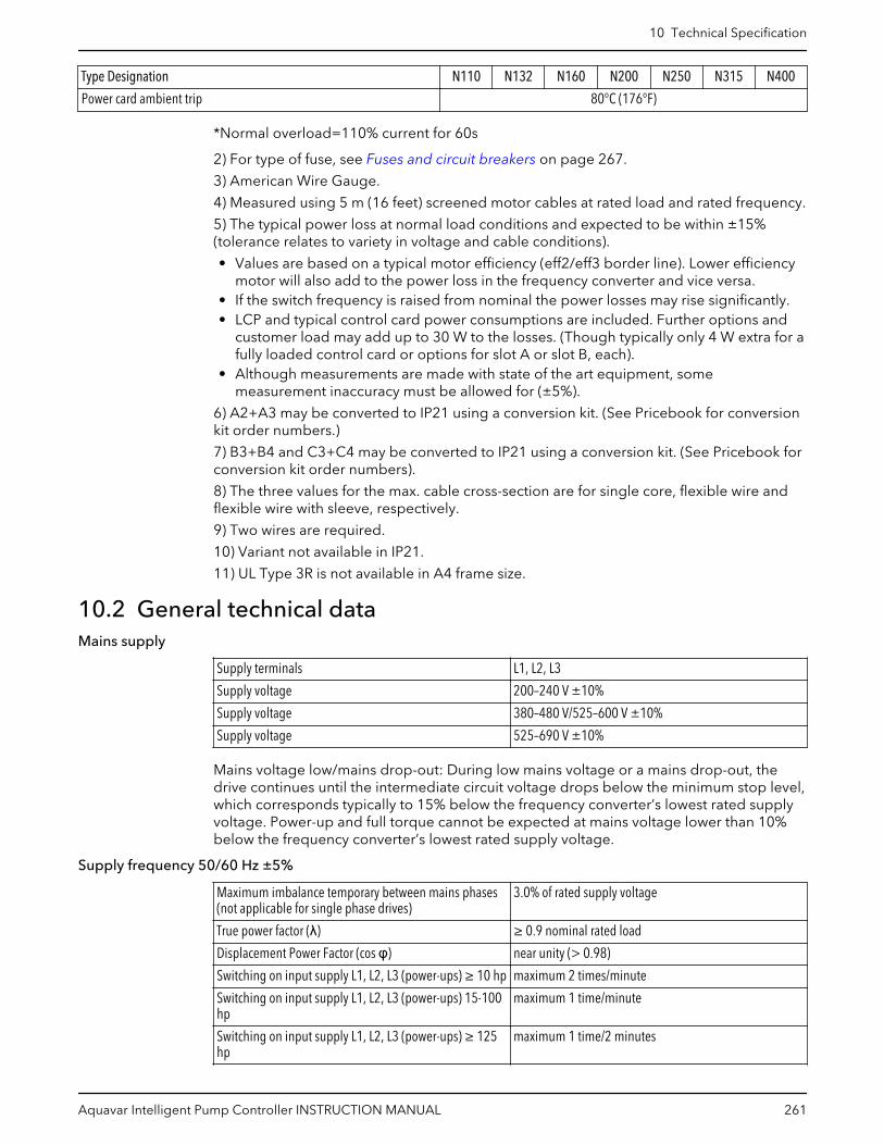
Type Designation N110 N132 N160 N200 N250 N315 N400
Power card ambient trip 80°C (176°F)
*Normal overload=110% current for 60s
2) For type of fuse, see Fuses and circuit breakers on page 267.
3) American Wire Gauge.
4) Measured using 5 m (16 feet) screened motor cables at rated load and rated frequency.
5) The typical power loss at normal load conditions and expected to be within ±15%(tolerance relates to variety in voltage and cable conditions).
• Values are based on a typical motor efficiency (eff2/eff3 border line). Lower efficiencymotor will also add to the power loss in the frequency converter and vice versa.
• If the switch frequency is raised from nominal the power losses may rise significantly.• LCP and typical control card power consumptions are included. Further options and
customer load may add up to 30 W to the losses. (Though typically only 4 W extra for afully loaded control card or options for slot A or slot B, each).
• Although measurements are made with state of the art equipment, somemeasurement inaccuracy must be allowed for (±5%).
6) A2+A3 may be converted to IP21 using a conversion kit. (See Pricebook for conversionkit order numbers.)
7) B3+B4 and C3+C4 may be converted to IP21 using a conversion kit. (See Pricebook forconversion kit order numbers).
8) The three values for the max. cable cross-section are for single core, flexible wire andflexible wire with sleeve, respectively.
9) Two wires are required.
10) Variant not available in IP21.
11) UL Type 3R is not available in A4 frame size.
10.2 General technical dataMains supply
Supply terminals L1, L2, L3
Supply voltage 200–240 V ±10%
Supply voltage 380–480 V/525–600 V ±10%
Supply voltage 525–690 V ±10%
Mains voltage low/mains drop-out: During low mains voltage or a mains drop-out, thedrive continues until the intermediate circuit voltage drops below the minimum stop level,which corresponds typically to 15% below the frequency converter’s lowest rated supplyvoltage. Power-up and full torque cannot be expected at mains voltage lower than 10%below the frequency converter’s lowest rated supply voltage.
Supply frequency 50/60 Hz ±5%
Maximum imbalance temporary between mains phases(not applicable for single phase drives)
3.0% of rated supply voltage
True power factor (λ) ≥ 0.9 nominal rated load
Displacement Power Factor (cos φ) near unity (> 0.98)
Switching on input supply L1, L2, L3 (power-ups) ≥ 10 hp maximum 2 times/minute
Switching on input supply L1, L2, L3 (power-ups) 15-100hp
maximum 1 time/minute
Switching on input supply L1, L2, L3 (power-ups) ≥ 125hp
maximum 1 time/2 minutes
10 Technical Specification
Aquavar Intelligent Pump Controller INSTRUCTION MANUAL 261

Environment according to EN60664–1 overvoltage category III/pollutin degree 2
The unit is suitable for use on a circuit capable of delivering not more than 100,000 RMSsymmetrical Amperes, 240/500/600/690 V maximum.
Motor output (U, V, W)
Output voltage 0–100% of supply voltage
Output frequency 0–590 Hz
Output frequency (110–250 kW) 0–5901) Hz
Switching on output Unlimited
Ramp times 1–3600 s
1) Voltage and power dependent
Torque characteristics
Starting torque (constant torque) maximum 110% for 60 s1)
Starting torque maximum 135% up to 0.5 s1)
Overload torque (constant torque) maximum 110% for 60 s1)
Starting torque (variable torque) maximum 110% for 60 s1)
Overload torque (variable torque) maximum 110% for 60 s
Torque rise time in VVCplus (independent of fsw) 10 ms
1) Percentage relates to the nominal torque.2) The torque response time depends on application and load but as a general rule, thetorque step from 0 to reference is 4–5 x torque rise time.
Cable lengths and cross sections for control cables1)
Maximum motor cable length, screened 492 ft (150m)
Maximum motor cable length, unscreened 984 ft (300m)
Maximum cross-section to control terminals, flexible/rigid wire without cable end-sleeves
0.0023 in2 (1.5 mm2)/16 AWG (2x0.75 mm2)
Maximum cross-section to control terminals, flexible wirewith cable end-sleeves
0.0016 in2 (1 mm2)/18 AWG
Maximum cross-section to control terminals, flexible wirewith cable end-sleeves with collar
.0008 in2 (0.5 mm2)/20 AWG
Maximum cross section to control terminals 0.00039 in2 (0.25 mm2)
1) For power cables, see Power Dependent Specifications.
Digital inputs
Programmable digital inputs 4 (6)1)
Terminal number 18, 19, 271), 291), 32, 33
Logic PNP or NPN
Voltage level 0–24 V DC
Voltage level, logic ‘0’ PNP <5 V DC
Voltage level l, logic ‘1’ PNP >10 V DC
Voltage level, logic ‘0’ NPN2) >19 V DC
Voltage level, logic ‘1’ NPN2) <14 V DC
Maximum voltage on input 28 V DC
Pulse frequency range 0–110 kHZ
10 Technical Specification
262 Aquavar Intelligent Pump Controller INSTRUCTION MANUAL

(Duty cycle) Min. pulse width 4.5 ms
Input resistance, Ri Approximately 4 kΩ
Analog inputs
Number of analog inputs 2
Terminal number 53, 54
Modes Voltage or current
Mode select Switch A54
Voltage mode Switch A54 = U (left position)
Voltage level 0 V to 10 V (scaleable)
Input resistance Ri Approximately 10 kΩ
Maximum voltage ±20 V
Current mode Switch A54 = I (right position)
Current level 0/4 to 20 mA (scaleable)
Input resistance Ri Approximately 200Ω
Maximum current 30 mA
Resolution for analog inputs 10 bit (+ sign)
Accuracy of analog inputs Maximum error 0.5% of full scale
Bandwidth 20 Hz/100 Hz
The analog inputs are galvanically isolated from the supply voltage (PELV) and other high-voltage terminals.
12
34
5
9
10
11
7
68
1. +24 V2. 183. 374. Functional isolation5. RS4856. Control7. PELV isolation8. High voltage9. Mains10.Motor11.DC-Bus
Figure 127: PELV isolation
Pulse
Programmable pulse 2/1
Terminal number pulse 291), 332) / 333)
Maximum frequency at terminal 29, 33 110 kHZ (push-pull driven)
Maximum frequency at terminal 29, 33 5 kHZ (open collector)
Minimum frequency at terminal 29, 33 4 Hz
Voltage level See Digital Inputs in the General Technical Data section.
Maximum voltage on input 28 V DC
10 Technical Specification
Aquavar Intelligent Pump Controller INSTRUCTION MANUAL 263

Input resistance, Ri Approximately 4kΩ
Pulse input accuracy (0.1–1 kHZ) Maximum error: 0.1% of full scale
Encoder input accuracy (1–11 kHZ) Maximum error: 0.05% of full scale
The pulse and encoder inputs (terminals 29, 32, 33) are galvanically isolated from thesupply voltage (PELV) and other high-voltage terminals.1) only2) Pulse inputs are 29 and 33
Analog output
Number of programmable analog outputs 1
Terminal number 42
Current range at analog output 0/4–20 mA
Maximum load GND — analog output 500 Ω
Accuracy on analog output Maximum error: 0.5% of full scale
Resolution on analog output 12 bit
The analog output is galvanically isolated from the supply voltage (PELV) and other high-voltage terminals.
Control card, RS-485 serial communication
Terminal number 68 (P, TX+, RX+), 69 (N, TX-, RX-)
Terminal number 61 Common for terminals 68 and 69
The RS-485 serial communication circuit is functionally separated from other centralcircuits and galvanically isolated from the supply-voltage (PELV).
Digital output
Programmable digital/pulse outputs 2
Terminal number 27, 291)
Voltage level at digital/frequency output 0–24 V
Maximum output current (sink or source) 40 mA
Maximum load at frequency output 1 kΩ
Maximum capacitive load at frequency output 10 nF
Minimum output frequency at frequency output 0 Hz
Maximum output frequency at frequency output 32 kHZ
Accuracy of frequency output Maximum error: 0.1% of full scale
Resolution of frequency outputs 12 bit
The digital output is galvanically isolated from the supply voltage (PELV) and other high-voltage terminals.1) Terminal 27 and 29 can also be programmed as input.
Control card, 24 V DC output
Terminal number 12, 13
Output voltage 24 V +1, 3 V
Maximum load 200 mA
The 24 V DC supply is galvanically isolated from the supply voltage (PELV), but has thesame potential as the analog and digital inputs and outputs.
10 Technical Specification
264 Aquavar Intelligent Pump Controller INSTRUCTION MANUAL

Relay outputs
Programmable relay outputs all kW: 2
Relay 01 terminal number 13 (break), 12 (make)
Maximum terminal load (AC-1)1) on 13 (NC), 12 (NO)(resistive load)
240 V AV, 2 A
Maximum terminal load (AC-15)1) (inductive load @ cosϕ0.4)
240 V AC, 0.2 A
Maximum terminal load (DC-1)1) on 12 (NO), 13 (NC)(resistive load)
60 V DC, 1 A
Maximum terminal load (DC-13)1) (inductive load) 24 V DC, 0.1 A
Relay 02 (only) terminal number 4–6 (break), 4–5 (make)
Maximum terminal load (AC-1)1) on 45 (NO) (resistiveload)2)3) overvoltage category II
400 V AC, 2 A
Maximum terminal load (AC-15)1) on 45 (NO) (inductiveload @ cosϕ 0.4)
240 V AC, 0.2 A
Maximum terminal load (DC-1)1) on 45 (NO) (resistiveload)
80 V DC, 2 A
Maximum terminal load (DC-13)1) on 45 (NO) (inductiveload)
24 V DC, 0.1 A
Maximum terminal load (AC-1)1) on 46 (NC) (resistiveload)
240 V AC, 2 A
Maximum terminal load (AC-15)1) on 46 (NC) (inductiveload @ cosϕ 0.4)
240 V AC, 0.2 A
Maximum terminal load (DC-1)1) on 46 (NC) (resistiveload)
50 V DC, 2 A
Maximum terminal load (DC-13)1) on 46 (NC) (inductiveload)
24 V DC, 0.1 A
Minimum terminal load on 13 (NC), 12 (NO), 46 (NC), 45(NO)
24 V DC 10 mA, 24 V AC 20 mA
Environment according to EN 60664–1 overvoltage category III/pollution degree 2
1) IEC 60947 part 4 and 5
The relay contacts are galvanically isolated from the rest of the circuit by reinforcedisolation (PELV).2) Overvoltage category II3) UL applications 300 V AC 2A
Control card, 10 V DC output
Terminal number 50
Output voltage 10.5 V ±0.5 V
Maximum load 15 mA
The 10 V DC supply is galvanically isolated from the supply voltage (PELV) and other high-voltage terminals.
Control characteristics
Resolution of output frequency at 0–590 Hz ± 0.003 Hz
Repeat accuracy of Precise start/stop (terminals 18, 19) ≤± 0.1 ms
System response time (terminals 18, 19, 27, 29, 32, 33) ≤ 2 ms
Speed control range (open loop) 1:100 of synchronous speed
Speed control range (closed loop) 1:1000 of synchronous speed
10 Technical Specification
Aquavar Intelligent Pump Controller INSTRUCTION MANUAL 265

Speed accuracy (open loop) 30–4000 rpm: error ±8 rpm
Speed accuracy (closed loop), depending on resolution offeedback device
0–6000 rpm: error ±0.15 rpm
All control characteristics are based on a 4–pole asynchronous motor
Environment
Enclosure IP Rating IP20/Chassis, IP21/Type 1, IP55/Type 3R/12, IP66/Type4X
Vibration test 1.0 g
Maximum relative humidity 5% – 93% (IEC 72133) Class 3K3 (non-condensing)during operation
Aggressive environment (IEC 60068243) H2S test class Kd
Ambient temperature Maximum 50°C (24hour average maximum 45°C)
Minimum ambient temperature during full-scaleoperation
0°C
Minimum ambient temperature at reduced performance 10°C
Temperature during storage/transport 25 to +65/70°C
Maximum altitude above sea level without derating 1000 m
EMC standards, Emission EN 61800–3, EN 61000–6–3/4, EN 55011
EMC standards, immunity EN 61800–3, EN 61000–6–1/2, EN 61000–4–2, EN61000–4–3, EN 61000–4–4, EN 61000–4–5, EN 61000–4–6
1) Only for ≤ 3.7 kW (200-240 and to 400-480 V), ≤ 7.5 kW (200-240 and to 400-480 V)2) As enclosure kit for ≤ 3.7 kW (200-240 and to 400-480 V), ≤ 7.5 kW (200-240 and to400-480 V)
Control card performance
Scan interval 1 ms
Control card, USB serial communication
USB standard 1.1 (full speed)
USB plug USB type B “device” plug
Connection to PC is carried out via a standard host/device USB cable.
The USB connection is galvanically isolated from the supply voltage (PELV) and otherhigh-voltage terminals.
The USB ground connection is not galvanically isolated from protection earth. Use only anisolated laptop as PC connection to the USB connector on the frequency converter.
Protection and features
• Electronic thermal motor protection against overload.• Temperature monitoring of the heatsink ensures that the frequency converter trips if
the temperature reaches a predefined level. An overload temperature cannot be resetuntil the temperature of the heatsink is below the values stated in the tables on thefollowing pages (Guideline — these temperatures may vary for different power sizes,frame sizes, enclosure ratings, etc.)
• The frequency converter is protected against short-circuits on motor terminals U, V, W.• If mains phase is missing, the frequency converter trips a warning (depending on the
load).
10 Technical Specification
266 Aquavar Intelligent Pump Controller INSTRUCTION MANUAL

• Monitoring of the intermediate circuit voltage ensures that the frequency convertertrips if the intermediate circuit voltage is too low or too high.
• The frequency converter constantly checks for critical levels of internal temperature,load current, high voltage on the intermediate circuit and low motor speeds. As aresponse to a critical level, the frequency converter can adjust the switching frequencyand/or change the switching pattern in order to ensure the performance of thefrequency converter.
10.3 Fuses and circuit breakersUse recommended fuses and/or circuit breakers on the supply side as protection in caseof component breakdown inside the adjustable frequency drive (first fault).
NOTICE:
Use of fuses on the supply side is mandatory for IEC 60364 (CE) and NEC 2009 (UL)compliant installations.
Recommendations
• Fuses of the type gG• Circuit breakers of Eaton types. For other circuit breaker types, ensure that the energy
into the adjustable frequency drive is equal to or lower than the energy provided byEaton types.
Use of recommended fuses and circuit breakers ensures possible damage to theadjustable frequency drive is limited to damages inside the unit.
The fuses below are suitable for use on a circuit capable of delivering 100,000 Arms(symmetrical), depending on the adjustable frequency drive voltage rating. With theproper fusing the adjustable frequency drive Short Circuit Current Rating (SCCR) is100,000 Arms.
10.3.1 NEC (NFPA 70) compliance
Table 90: Mains supply 1x200–240 V AC - Single Phase
Power (hp [kW]) Maximum input current, continuous(at 1x200–240 V AC)
NEC fuse size
1.5 [1.1] 12.5 15
2 [1.5] 15 20
3 [2.2] 20.5 25
5 [3.7] 32 40
7.5 [5.5] 46 60
10 [7.5] 59 80
20 [15] 111 150
30 [22] 172 200
Table 91: Line power supply 3x200–240 V AC - Three Phase
Power (hp [kW]) Maximum input current, continuous(at 3x200–240 V AC)
NEC fuse size
1.5 [1.1] 5.9 10
2 [1.5] 6.8 10
3 [2.2] 9.5 15
5 [3.7] 15 20
7.5 [5.5] 22 30
10 [7.5] 28 35
10 Technical Specification
Aquavar Intelligent Pump Controller INSTRUCTION MANUAL 267
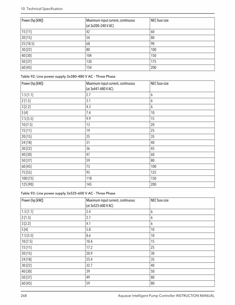
Power (hp [kW]) Maximum input current, continuous(at 3x200–240 V AC)
NEC fuse size
15 [11] 42 60
20 [15] 54 80
25 [18.5] 68 90
30 [22] 80 100
40 [30] 104 150
50 [37] 130 175
60 [45] 154 200
Table 92: Line power supply 3x380–480 V AC - Three Phase
Power (hp [kW]) Maximum input current, continuous(at 3x441-480 V AC)
NEC fuse size
1.5 [1.1] 2.7 6
2 [1.5] 3.1 6
3 [2.2] 4.3 6
5 [4] 7.4 10
7.5 [5.5] 9.9 15
10 [7.5] 13 20
15 [11] 19 25
20 [15] 25 35
24 [18] 31 40
30 [22] 36 45
40 [30] 47 60
50 [37] 59 80
60 [45] 73 100
75 [55] 95 125
100 [75] 118 150
125 [90] 145 200
Table 93: Line power supply 3x525–600 V AC - Three Phase
Power (hp [kW]) Maximum input current, continuous(at 3x525-600 V AC)
NEC fuse size
1.5 [1.1] 2.4 6
2 [1.5] 2.7 6
3 [2.2] 4.1 6
5 [4] 5.8 10
7.5 [5.5] 8.6 10
10 [7.5] 10.4 15
15 [11] 17.2 25
20 [15] 20.9 30
24 [18] 25.4 35
30 [22] 32.7 40
40 [30] 39 50
50 [37] 49 80
60 [45] 59 80
10 Technical Specification
268 Aquavar Intelligent Pump Controller INSTRUCTION MANUAL

Power (hp [kW]) Maximum input current, continuous(at 3x525-600 V AC)
NEC fuse size
75 [55] 78.9 100
100 [75] 95.3 125
125 [90] 124.3 175
10.3.2 CE compliance
Table 94: 200-240 V, Enclosure Types A, B, C
Enclosure type Power (hp [kW]) Recommended fusesize
Recommended max.fuse size
Recommended circuitbreaker (Eaton)
Max. trip level [A]
A2 1.5-3 [1.1-2.2] gG-10 (1.5-2 [1.1-1.5])gG-16 (3 [2.2])
gG-25 PKZM0-25 25
A3 4-5 [3.0-3.7] gG-16 (4 [3])gG-20 (5 [3.7])
gG-32 PKZM0-25 25
B3 7.5-15 [5.5-11] gG-25 (7.5-10[5.5-7.5])gG-32 (15 [11])
gG-63 PKZM4-50 50
B4 20-24 [15-18] gG-50 (20 [15])gG-63 (25 [18])
gG-125 NZMB1-A100 100
C3 30-40 [22-30] gG-80 (30 [22])aR-125 (40 [30])
gG-150 (30 [22])aR-160 (40 [30])
NZMB2-A200 150
C4 50-60 [37-45] aR-160 (50 [37])aR-200 (60 [45])
aR-200 (50 [37])aR-250 (60 [45])
NZMB2-A250 250
A4 1.5-3 [1.1-2.2] gG-10 (1.5-2 [1.1-1.5])gG-16 (3 [2.2])
gG-32 PKZM0-25 25
A5 0.34-5 [0.25-3.7] gG-10 (0.34-2[0.25-1.5])gG-16 (3-4 [2.2-3])gG-20 (5 [3.7])
gG-32 PKZM0-25 25
B1 7.5-15 [5.5-11] gG-25 (7.5 [5.5])gG-32 (10-15[7.5-11])
gG-80 PKZM4-63 63
B2 20 [15] gG-50 gG-100 NZMB1-A100 100
C1 24-40 [18-30] gG-63 (25 [18.5])gG-80 (30 [22])gG-100 (40 [30])
gG-160 (25-30[18.5-22])aR-160 (40 [30])
NZMB2-A200 160
C2 50-60 [37-45] aR-160 (50 [37])aR-200 (60 [45])
aR-200 (50 [37])aR-250 (60 [45])
NZMB2-A250 250
Table 95: 380V-480V, Enclosure Types A, B and C
Enclosure type Power (hp [kW]) Recommended fusesize
Recommended max.fuse size
Recommended circuitbreaker (Eaton)
Max. trip level [A]
A2 1.5-5 [1.1-4.0] gG-10 (1.5-4 [1.1-3])gG-16 (5 [4])
gG-25 PKZM0-25 25
A3 7.5-10 [5.5-7.5] gG-16 gG-32 PKZM0-25 25
B3 15-24 [11-18] gG-40 gG-63 PKZM4-5O 50
10 Technical Specification
Aquavar Intelligent Pump Controller INSTRUCTION MANUAL 269

Enclosure type Power (hp [kW]) Recommended fusesize
Recommended max.fuse size
Recommended circuitbreaker (Eaton)
Max. trip level [A]
B4 30-50 [22-37] gG-50 (30 [22])gG-63 (40 [30])gG-80 (50 [37])
gG-125 NZMB1-A100 100
C3 60-75 [45-55] gG-100 (60 [45])gG-160 (75 [55])
gG-150 (60 [45])gG-160 (75 [55])
NZMB2-A200 150
C4 100-125 [75-90] aR-200 (100 [75])aR-250 (125 [90])
aR-250 NZMB2-A250 250
A4 1.5-5 [1.1-4] gG-10 (1.5-4 [1.1-3])gG-16 (5 [4])
gG-32 PKZM0-25 25
A5 1.5-10 [1.1-7.5] gG-10 (1.5-4 [1.1-3])gG-16 (5-10 [4-7.5])
gG-32 PKZM0-25 25
B1 15-25 [11-18.5] gG-40 gG-80 PKZM4-63 63
B2 30-40 [22-30] gG-50 (30 [22])gG-63 (40 [30])
gG-100 NZMB1-A100 100
C1 50-75 [37-55] gG-80 (50 [37])gG-100 (60 [45])gG-160 (75 [55])
gG-160 NZMB2-A200 160
C2 100-125 [75-90] aR-200 (100 [75])aR-250 (125 [90])
aR-250 NZMB2-A250 250
Table 96: 525-600 V, Enclosure Types A, B and C
Enclosure type Power (hp [kW]) Recommended fusesize
Recommended max.fuse size
Recommended circuitbreaker (Eaton)
Max. trip level [A]
A3 5.5 [7.5-10] gG-10 (7.5 [5.5])gG-16 (10 [7.5])
gG-32 PKZM0-25 25
B3 15-24 [11-18] gG-25 (15 [11])gG-32 (20-25 [15-18])
gG-63 PKZM4-50 50
B4 30-50 [22-37] gG-40 (30 [22])gG-50 (40 [30])gG-63 (50 [37])
gG-125 NZMB1-A100 100
C3 60-75 [45-55] gG-63 (60 [45])gG-100 (75 [55])
gG-150 NZMB2-A200 150
C4 100-125 [75-90] aR-160 (100 [75])aR-200 (125 [90])
aR-250 NZMB2-A250 250
A5 1.5-10 [1.1-7.5] gG-10 (1.5-7.5[1.1-5.5])gG-16 (10 [7.5])
gG-32 PKZM0-25 25
B1 15-24 [11-18] gG-25 (15 [11])gG-32 (20 [15])gG-40 (25 [18.5])
gG-80 PKZM4-63 63
B2 30-40 [22-30] gG-50 (30 [22])gG-63 (40 [30])
gG-100 NZMB1-A100 100
C1 50-75 [37-55] gG-63 (50 [37])gG-100 (60 [45])aR-160 (75 [55])
gG-160 (50-60[37-45])aR-250 (75 [55])
NZMB2-A200 160
10 Technical Specification
270 Aquavar Intelligent Pump Controller INSTRUCTION MANUAL

Enclosure type Power (hp [kW]) Recommended fusesize
Recommended max.fuse size
Recommended circuitbreaker (Eaton)
Max. trip level [A]
C2 100-125 [75-90] aR-200 (100-125[75-90])
aR-250 NZMB2-A250 250
Table 97: 525-690 V, Enclosure Types A, B and C
Enclosure type Power (hp [kW]) Recommended fusesize
Recommended max.fuse size
Recommended circuitbreaker (Eaton)
Max. trip level [A]
A3 1.5 [1.1]2 [1.5]3 [2.2]4 [3]5 [4]7.5 [5.5]10 [7.5]
gG-6gG-6gG-6gG-10gG-10gG-16gG-16
gG-25gG-25gG-25gG-25gG-25gG-25gG-25
PKZM0-16 16
B2/B4 15 [11]20 [15]24 [18]30 [22]
gG-25 (15 [11])gG-32 (20 [15])gG-32 (24 [18])gG-40 (30 [22])
gG-63 - -
B4/C2 40 [30] gG-63 (40 [30]) gG-80 (40 [30])
C2/C3 50 [37]60 [45]
gG-63 (50 [37])gG-80 (60 [45])
gG-100 (50 [37])gG-125 (60 [45])
- -
C2 75 [55]100 [75]
gG-100 (75 [55])gG-125 (100 [75])
gG-160 (75-100[55-75])
- -
10.3.3 UL compliance
Table 98: 1 x 200–240 V, Enclosure Types A, B, and C
Recommended maximum fuse
Power (hp[kW])
Max.prefusesize [A]
Bussmann SIBA Littel-fuse Ferraz-Shawmut
JFHR2 RK1 J T CC CC CC RK1 RK1 CC RK1 J
1.5 [1.1] 15 FWX-15 KTN-15 JKS-15 JJN-15 FNQ-R-15
KTK-R-15
LP-CC-15
5017906–016
KLN-R15 ATM-R15
A2K-15R
HSJ15
2 [1.5] 20 FWX-20 KTN-R20 JKS-20 JJN-20 FNQ-R-20
KTK-R-20
LP-CC-20
5017906–020
KLN-R20 ATM-R20
A2K-20R
HSJ20
3 [2.2] 30* FWX-30 KTN-R30 JKS-30 JJN-30 FNQ-R-30
KTK-R-30
LP-CC-30
5012406–032
KLN-R30 ATM-R30
A2K-30R
HSJ30
5 [3.7] 50 FWX-50 KTN-R50 JKS-50 JJN-50 5014006–050
KLN-R50 — A2K-50R
HSJ50
7.5 [5.5] 60** FWX-60 KTN-R60 JKS-60 JJN-60 5014006–050
KLN-R60 — A2K-60R
HSJ60
10 [7.5] 80 FWX-80 KTN-R80 JKS-80 JJN-80 5014006–080
KLN-R80 — A2K-80R
HSJ80
20 [15] 150 FWX-150
KTN-R150
JKS-150 JJN-150 2028220–150
KLN-R150 A2K-150R
HSJ150
30 [22] 200 FWX-200
KTN-R200
JKS-200 JJN-200 2028220–200
KLN-R200 A2K-200R
HSJ200
* Siba allowed up to 32 A; ** Siba allowed up to 63A
10 Technical Specification
Aquavar Intelligent Pump Controller INSTRUCTION MANUAL 271
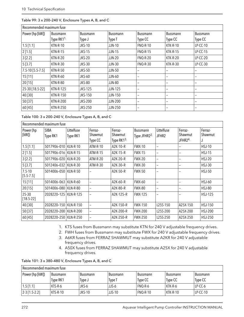
Table 99: 3 x 200–240 V, Enclosure Types A, B, and C
Recommended maximum fuse
Power (hp [kW]) BussmannType RK11.
BussmannType J
BussmannType T
BussmannType CC
BussmannType CC
BussmannType CC
1.5 [1.1] KTN-R-10 JKS-10 JJN-10 FNQ-R-10 KTK-R-10 LP-CC-10
2 [1.5] KTN-R-15 JKS-15 JJN-15 FNQ-R-15 KTK-R-15 LP-CC-15
3 [2.2] KTN-R-20 JKS-20 JJN-20 FNQ-R-20 KTK-R-20 LP-CC-20
5 [3.7] KTN-R-30 JKS-30 JJN-30 FNQ-R-30 KTK-R-30 LP-CC-30
7.5-10 [5.5-7.5] KTN-R-50 JKS-50 JJN-50 — — —
15 [11] KTN-R-60 JKS-60 JJN-60 — — —
20 [15] KTN-R-80 JKS-80 JJN-80 — — —
25-30 [18.5-22] KTN-R-125 JKS-125 JJN-125 — — —
40 [30] KTN-R-150 JKS-150 JJN-150 — — —
50 [37] KTN-R-200 JKS-200 JJN-200 — — —
60 [45] KTN-R-250 JKS-250 JJN-250 — — —
Table 100: 3 x 200–240 V, Enclosure Types A, B, and C
Recommended maximum fuse
Power (hp[kW])
SIBAType RK1
LittelfuseType RK1
Ferraz-ShawmutType CC
Ferraz-ShawmutType RK13.
BussmannType JFHR22.
LittelfuseJFHR2
Ferraz-ShawmutJFHR24.
Ferraz-ShawmutJ
1.5 [1.1] 5017906–010 KLN-R-10 ATM-R-10 A2K-10–R FWX-10 — — HSJ-10
2 [1.5] 5017906–016 KLN-R-15 ATM-R-15 A2K-15–R FWX-15 — — HSJ-15
3 [2.2] 5017906–020 KLN-R-20 ATM-R-20 A2K-20–R FWX-20 — — HSJ-20
5 [3.7] 5012406–032 KLN-R-30 ATM-R-30 A2K-30–R FWX-30 — — HSJ-30
7.5-10[5.5-7.5]
5014006–050 KLN-R-50 — A2K-50–R FWX-50 — — HSJ-50
15 [11] 5014006–063 KLN-R-60 — A2K-60–R FWX-60 — — HSJ-60
20 [15] 5014006–080 KLN-R-80 — A2K-80–R FWX-80 — — HSJ-80
25-30[18.5-22]
2028220–125 KLN-R-125 — A2K-125–R FWX-125 — — HSJ-125
40 [30] 2028220–150 KLN-R-150 — A2K-150–R FWX-150 L25S-150 A25X-150 HSJ-150
50 [37] 2028220–200 KLN-R-200 — A2K-200–R FWX-200 L25S-200 A25X-200 HSJ-200
60 [45] 2028220–250 KLN-R-250 — A2K-250–R FWX-250 L25S-250 A25X-250 HSJ-250
1. KTS fuses from Bussmann may substitute KTN for 240 V adjustable frequency drives.2. FWH fuses from Bussmann may substitute FWX for 240 V adjustable frequency drives.3. A6KR fuses from FERRAZ SHAWMUT may substitute A2KR for 240 V adjustable
frequency drives.4. A50X fuses from FERRAZ SHAWMUT may substitute A25X for 240 V adjustable
frequency drives.
Table 101: 3 x 380–480 V, Enclosure Types A, B, and C
Recommended maximum fuse
Power (hp [kW]) BussmannType RK1
BussmannType J
BussmannType T
BussmannType CC
BussmannType CC
BussmannType CC
1.5 [1.1] KTS-R-6 JKS-6 JJS-6 FNQ-R-6 KTK-R-6 LP-CC-6
2-3 [1.5-2.2] KTS-R-10 JKS-10 JJS-10 FNQ-R-10 KTK-R-10 LP-CC-10
10 Technical Specification
272 Aquavar Intelligent Pump Controller INSTRUCTION MANUAL

Recommended maximum fuse
Power (hp [kW]) BussmannType RK1
BussmannType J
BussmannType T
BussmannType CC
BussmannType CC
BussmannType CC
5 [4] KTS-R-20 JKS-20 JJS-20 FNQ-R-20 KTK-R-20 LP-CC-20
7.5 [5.5] KTS-R-25 JKS-25 JJS-25 FNQ-R-25 KTK-R-25 LP-CC-25
10 [7.5] KTS-R-30 JKS-30 JJS-30 FNQ-R-30 KTK-R-30 LP-CC-30
15-20 [11-15] KTS-R-40 JKS-40 JJS-40 — — —
24 [18] KTS-R-50 JKS-50 JJS-50 — — —
30 [22] KTS-R-60 JKS-60 JJS-60 — — —
40 [30] KTS-R-80 JKS-80 JJS-80 — — —
50 [37] KTS-R-100 JKS-100 JJS-100 — — —
60 [45] KTS-R-125 JKS-125 JJS-125 — — —
75 [55] KTS-R-150 JKS-150 JJS-150 — — —
100 [75] KTS-R-200 JKS-200 JJS-200 — — —
125 [90] KTS-R-250 JKS-250 JJS-250 — — —
Table 102: 3 x 380–480 V, Enclosure Types A, B, and C
Recommended maximum fuse
Power (hp[kW])
SIBAType RK1
LittelfuseType RK1
Ferraz-ShawmutType CC
Ferraz-ShawmutType RK1
BussmannJFHR2
Ferraz-ShawmutJ
Ferraz-ShawmutJFHR21.
LittelfuseJFHR2
1.5 [1.1] 5017906–006 KLS-R-6 ATM-R-6 A6K-10–6 FWH-6 HSJ-6 — —
2-3 [1.5-2.2] 5017906–010 KLS-R-10 ATM-R-10 A6K-10–R FWH-10 HSJ-10 — —
5 [4] 5017906–020 KLS-R-10 ATM-R-20 A6K-20–R FWH-20 HSJ-20 — —
7.5 [5.5] 5017906–025 KLS-R-25 ATM-R-25 A6K-25–R FWH-25 HSJ-25 — —
10 [7.5] 5012406–032 KLS-R-30 ATM-R-30 A6K-30–R FWH-30 HSJ-30 — —
15-20 [11-15] 5014006–040 KLS-R-40 — A6K-40–R FWH-40 HSJ-40 — —
24 [18] 5014006–050 KLS-R-50 — A6K-50–R FWH-50 HSJ-50 — —
30 [22] 5014006–063 KLS-R-60 — A6K-60–R FWH-60 HSJ-60 — —
40 [30] 2028220–100 KLS-R-80 — A6K-80–R FWH-80 HSJ-80 — —
50 [37] 2028220–125 KLS-R-100 — A6K-100–R FWH-100 HSJ-100 — —
60 [45] 2028220–125 KLS-R-125 — A6K-125–R FWH-125 HSJ-125 — —
75 [55] 2028220–160 KLS-R-150 — A6K-150–R FWH-150 HSJ-150 — —
100 [75] 2028220–200 KLS-R-200 — A6K-200–R FWH-200 HSJ-200 A50–P-225 L50–S-225
125 [90] 2028220–250 KLS-R-250 — A6K-250–R FWH-250 HSJ-250 A50–P-250 L50–S-250
1. Ferraz-Shawmut A50QS may substitute A50P fuses.
Table 103: 3 x 525–600 V, Enclosure Types A, B, and C
Recommended maximum fuse
Power (hp[kW])
BussmannType RK1
BussmannType J
BussmannType T
BussmannType CC
BussmannType CC
BussmannType CC
SIBAType RK1
LittelfuseType RK1
Ferraz-ShawmutType RK1
Ferraz-ShawmutJ
1.5 [1.1] KTS-R-5 JKS-5 JJS-6 FNQ-R-5 KTK-R-5 LP-CC-5 5017906–005
KLS-R-005 A6K-5–R HSJ-6
2-3[1.5-2.2]
KTS-R-10 JKS-10 JJS-10 FNQ-R-10 KTK-R-10 LP-CC-10 5017906–010
KLS-R-010 A6K-10–R HSJ-10
10 Technical Specification
Aquavar Intelligent Pump Controller INSTRUCTION MANUAL 273

Recommended maximum fuse
Power (hp[kW])
BussmannType RK1
BussmannType J
BussmannType T
BussmannType CC
BussmannType CC
BussmannType CC
SIBAType RK1
LittelfuseType RK1
Ferraz-ShawmutType RK1
Ferraz-ShawmutJ
5 [4] KTS-R-20 JKS-20 JJS-20 FNQ-R-20 KTK-R-20 LP-CC-20 5017906–020
KLS-R-020 A6K-20–R HSJ-20
7.5 [5.5] KTS-R-25 JKS-25 JJS-25 FNQ-R-25 KTK-R-25 LP-CC-25 5017906–025
KLS-R-025 A6K-25–R HSJ-25
10 [7.5] KTS-R-30 JKS-30 JJS-30 FNQ-R-30 KTK-R-30 LP-CC-30 5017906–030
KLS-R-030 A6K-30–R HSJ-30
15-20[11-15]
KTS-R-35 JKS-35 JJS-35 — — — 5014006–040
KLS-R-035 A6K-35–R HSJ-35
24 [18] KTS-R-45 JKS-45 JJS-45 — — — 5014006–050
KLS-R-045 A6K-45–R HSJ-45
30 [22] KTS-R-50 JKS-50 JJS-50 — — — 5014006–050
KLS-R-050 A6K-50–R HSJ-50
40 [30] KTS-R-60 JKS-50 JJS-60 — — — 5014006–063
KLS-R-060 A6K-60–R HSJ-60
50 [37] KTS-R-80 JKS-80 JJS-80 — — — 5014006–080
KLS-R-075 A6K-80–R HSJ-80
60 [45] KTS-R-100 JKS-100 JJS-100 — — — 5014006–100
KLS-R-100 A6K-100–R HSJ-100
75 [55] KTS-R-125 JKS-125 JJS-125 — — — 2028220–125
KLS-125 A6K-125–R HSJ-125
100 [75] KTS-R-150 JKS-150 JJS-150 — — — 2028220–150
KLS-150 A6K-150–R HSJ-150
125 [90] KTS-R-175 JKS-175 JJS-175 — — — 2028220–200
KLS-175 A6K-175–R HSJ-175
Table 104: 3 x 525-690 V, Enclosure Types A, B and C
Recommended maximum fuse
Power (hp [kW]) BussmannType RK1
BussmannType J
BussmannType T
BussmannType CC
BussmannType CC
BussmannType CC
1.5 [1.1] KTS-R-5 JKS-5 JJS-6 FNQ-R-5 KTK-R-5 LP-CC-5
2-3 [1.5-2.2] KTS-R-10 JKS-10 JJS-10 FNQ-R-10 KTK-R-10 LP-CC10
4 [3] KTS-R-15 JKS-15 JJS-15 FNQ-R-15 KTK-R-15 LP-CC-15
5 [4] KTS-R-20 JKS-20 JJS-20 FNQ-R-20 KTK-R-20 LP-CC-20
7.5 [5.5] KTS-R-25 JKS-25 JJS-25 FNQ-R-25 KTK-R-25 LP-CC-25
10 [7.5] KTS-R-30 JKS-30 JJS-30 FNQ-R-30 KTK-R-30 LP-CC-30
15-20 [11-15] KTS-R-35 JKS-35 JJS-35 — — —
24 [18] KTS-R-45 JKS-45 JJS-45 — — —
30 [22] KTS-R-50 JKS-50 JJS-50 — — —
40 [30] KTS-R-60 JKS-60 JJS-60 — — —
50 [37] KTS-R-80 JKS-80 JJS-80 — — —
60 [45] KTS-R-100 JKS-100 JJS-100 — — —
75 [55] KTS-R-125 JKS-125 JJS-125 — — —
100 [75] KTS-R-150 JKS-150 JJS-150 — — —
125 [90] KTS-R-175 JKS-175 JJS-175 — — —
10 Technical Specification
274 Aquavar Intelligent Pump Controller INSTRUCTION MANUAL

Table 105: 3 x 525-690 V, Enclosure Types B and C
Recommended maximum fuse
Power (hp[kW])
Maximumprefuse
BussmannE52273RK1/JDDZ
BussmannE4273J/JDDZ
BussmannE4273T/JDDZ
SIBAE180276RK1/JDDZ
LittelfuseP81895RK1/JDDZ
Ferraz-ShawmutE163267/E2137RK1/JDDZ
Ferraz-ShawmutE2137J/HSJ
15-20 [11-15] 30 A KTS-R-30 JKS-30 JKJS-30 5017906-030 KLS-R-030 A6K-30–R HST-30
25 [18.5] 45 A KTS-R-45 JKS-45 JKJS-45 5014006-050 KLS-R-045 A6K-45–R HST-45
40 [30] 60 A KTS-R-60 JKS-60 JKJS-60 5014006-063 KLS-R-060 A6K-60–R HST-60
50 [37] 80 A KTS-R-80 JKS-80 JKJS-80 5014006-080 KLS-R-075 A6K-80–R HST-80
60 [45] 90 A KTS-R-90 JKS-90 JKJS-90 5014006-100 KLS-R-090 A6K-90–R HST-90
75 [55] 100 A KTS-R-100 JKS-100 JKJS-100 5014006-100 KLS-R-100 A6K-100–R HST-100
100 [75] 125 A KTS-R-125 JKS-125 JKJS-125 202822-125 KLS-R-150 A6K-125–R HST-125
125 [90] 150 A KTS-R-150 JKS-150 JKJS-150 202822-150 KLS-R-175 A6K-150–R HST-150
Non-UL compliance
If UL/cUL is not to be complied with, we recommend using the following fuses, which willensure compliance with EN50178:
Table 106: Non-UL compliance, recommended line fuses
N110K–N315 380–500 V type aR
N75K–N400 525–690 V type aR
UL compliance
The fuses below are suitable for use on a circuit capable of delivering 100,000 Arms(symmetrical), depending on the drive voltage rating. With the proper fusing, the driveShort Circuit Current Rating (SCCR) is 100,000 Arms.
Table 107: Frame size D, line fuses, 380–480 V
Size/Type
Fuse options
BussmannPN
LittelfusePN
LittelfusePN
BussmannPN
SIBAPN
Ferraz-ShawmutPN
Ferraz-ShawmutPN(Europe)
Ferraz-ShawmutPN(NorthAmerica)
N110 170M2619 LA50QS300-4 L50S-300 FWH-300A 20 61031.315
A50QS300-4 6,9URD31D08A0315
A070URD31KI0315
N132 170M2620 LA50QS350-4 L50S-350 FWH-350A 20 61031.350
A50QS350-4 6,9URD31D08A0350
A070URD31KI0350
N160 170M2621 LA50QS400-4 L50S-400 FWH-400A 20 61031.400
A50QS400-4 6,9URD31D08A0400
A070URD31KI0400
N200 170M4015 LA50QS500-4 L50S-500 FWH-500A 20 61031.550
A50QS500-4 6,9URD31D08A0550
A070URD31KI0550
N250 170M4016 LA50QS600-4 L50S-600 FWH-600A 20 61031.630
A50QS600-4 6,9URD31D08A0630
A070URD31KI0630
N315 170M4017 LA50QS800-4 L50S-800 FWH-800A 20 61031.800
A50QS800-4 6,9URD31D08A0800
A070URD31KI0800
10 Technical Specification
Aquavar Intelligent Pump Controller INSTRUCTION MANUAL 275

* 170M fuses from Bussmann shown use the /80 visual indicator; TN/80 Type T, /110 orTN/110 Type T indicator fuses of the same size and amperage may be substituted forexternal use.
** Any minimum 500 V UL listed fuse with associated current rating may be used to meetUL requirements.
Table 108: Frame size D, 525–690 V
Size/TypeFuse options
Bussmann PN SIBA PN Ferraz-Shawmut EuropeanPN
Ferraz-Shawmut NorthAmerican PN
N110 170M2619 20 610 31.315 6,9URD31D08A0315 A070URD31KI0315
N132 170M2619 20 610 31.315 6,9URD31D08A0315 A070URD31KI0315
N200 170M4015 20 620 31.550 6,9URD32D08A0550 A070URD32KI0550
N250 170M4015 20 620 31.550 6,9URD32D08A0550 A070URD32KI0550
N315 170M4015 20 620 31.550 6,9URD32D08A0550 A070URD32KI0550
N400 170M4015 20 620 31.550 6,9URD32D08A0550 A070URD32KI0550
* 170M fuses from Bussmann shown use the /80 visual indicator; TN/80 Type T, /110 orTN/110 Type T indicator fuses of the same size and amperage may be substituted forexternal use.
Suitable for use on a circuit capable of delivering not more than 100,000 rms symmetricalamperes, 500/600/690 Volts maximum when protected by the above fuses.
Supplementary fuses
Table 109: SMPS fuse
Frame size Bussmann PN* Rating
D KTK-4 4A, 600 V
Table 110: Fan fuses
Size/Type Bussmann PN* LittelFuse Rating
P315, 380–480 V KTK-4 4A, 600 V
P450, 525–690 V KTK-4 4A, 600 V
P355-P450, 380–480 V KLK-15 15A, 600 V
Line power disconnectors
Frame size Power and voltage Type
D1/D3 1500–1750 380–480 V & 1500–2000 525–690 V
ABB OETL-NF200A OR OT200U12–91
D2/D4 2000–3000 380–480 V AND 2500–5000 525–690 V
ABB OETL-NF400A OR OT400U12–91
NEC (NFPA 70) Compliance
Table 111: Line power supply 3 x 380–480 V AC — Three Phase
Size/Type Power (hp [kW])
Continuous (at 3x380 V AC) Continuous (at 3x480 V AC)
Maximum inputcurrent
125% ofmaximum inputcurrent
NEC Fuse Size Maximum inputcurrent
125% ofmaximum inputcurrent
NEC Fuse Size
N110 150 [110] 204 255 300 183 228.75 250
N132 200 [132] 251 313.75 350 231 288.75 300
N160 250 [160] 304 380 400 291 363.75 400
10 Technical Specification
276 Aquavar Intelligent Pump Controller INSTRUCTION MANUAL

Size/Type Power (hp [kW])
Continuous (at 3x380 V AC) Continuous (at 3x480 V AC)
Maximum inputcurrent
125% ofmaximum inputcurrent
NEC Fuse Size Maximum inputcurrent
125% ofmaximum inputcurrent
NEC Fuse Size
N200 300 [200] 381 476.25 500 348 435 450
N250 350 [250] 463 578.75 600 427 533.75 600
N315 450 [315] 567 708.75 800 516 645 700
P355 500 [355] 634 792.5 800 569 711.25 800
P400 550 [400] 718 897.5 1000 653 816.25 1000
P450 600 [450] 771 963.75 1000 704 880 1000
Table 112: Line power supply 3 x 525–690 V AC — Three Phase
Size/Type Power (hp[kW])
Continuous (at 3x550 V AC) Continuous (at 3x575 V AC) Continuous (at 3x690 V AC)
Maximuminputcurrent
125% ofmaximuminputcurrent
NEC FuseSize
Maximuminputcurrent
125% ofmaximuminputcurrent
NEC FuseSize
Maximuminputcurrent
125% ofmaximuminputcurrent
NEC FuseSize
N110 125 [110] 130 162.5 175 124 155 175 128 160 175
N132 150 [132] 158 197.5 200 151 188.75 200 155 193.75 200
N160 200 [160] 198 247.5 250 189 236.25 250 197 246.25 250
N200 250 [200] 245 306.25 350 234 292.5 300 240 300 300
N250 300 [250] 289 361.25 400 289 361.25 400 347 433.75 450
N315 350 [315] 343 428.75 450 343 428.75 450 411 513.75 600
N400 400 [400] 398 497.5 500 398 497.5 500 478 597.5 600
10.4 Tightening torquesTable 113: Tightening torques for covers in Nm (in-lbs)
Frame IP20 Open IP21/Type 1 IP55/Type 3R/12 IP66/Type 4X
A3/A4/A5 — — 2 (18) 2 (18)
B1/B2 — * 2.2 (19) 2.2 (19)
C1/C2/C3/C4 — * 2.2 (19) 2.2 (19)
* No screws to tighten— Does not exist
Table 114: Tightening torques of terminals for frame sizes A2, A4, A5, B1-B4, C1-C4
Power (hp [kW]) Torque Nm (in-lbs)
Enclosure 208–230 V 380–460 V 575 V 525–600 V Mains Motor DCconnection
Brake Earth Relay
A2 1.5–3[1.1-2.2]
1.5–5[1.1-4]
1.8 (16) 1.8 (16) 1.8 (16) 1.8 (16) 3 (27) 0.6 (5.3)
A4 1.5–3[1.1-2.2]
1.5–5[1.1-4]
1.8 (16) 1.8 (16) 1.8 (16) 1.8 (16) 3 (27) 0.6 (5.3)
A5 1.5 [1.1] 1.5–10 [1.17.5]
1.5–10[1.1-7.5]
1.8 (16) 1.8 (16) 1.8 (16) 1.8 (16) 3 (27) 0.6 (5.3)
B1 7.5–15[5.5-11]
15–25[11-18]
15–25[11-18]
1.8 (16) 1.8 (16) 1.5 (13) 1.5 (13) 3 (27) 0.6 (5.3)
B2 20 [15] 30–40[22-30]
30–40[22-30]
15–40[11-30]
4.5 (40) 4.5 (40) 3.7 (33) 3.7 (33) 3 (27) 0.6 (5.3)
10 Technical Specification
Aquavar Intelligent Pump Controller INSTRUCTION MANUAL 277

Power (hp [kW]) Torque Nm (in-lbs)
Enclosure 208–230 V 380–460 V 575 V 525–600 V Mains Motor DCconnection
Brake Earth Relay
B3 7.5–15[5.5-11]
15–25[11-18]
15–25[11-18]
1.8 (15.9) 1.8 (15.9) 1.8 (15.9) 1.8 (15.9) 3 (27) 0.6 (5.3)
B4 20–25[15-18]
30–50[22-37]
30–50[22-37]
15–50[11-37]
4.5 (40) 4.5 (40) 4.5 (40) 4.5 (40) 3 (27) 0.6 (5.3)
C1 25–40[18-30]
50–75[37-55]
50–75[37-55]
10 (89) 10 (89) 10 (89) 10 (89) 3 (27) 0.6 (5.3)
C2 50–60[37-45]
100–125[75-90]
100–125[75-90]
50–120[37-90]
14(124)/24(212)1)
14(124)/24(212)1)
14 (124) 14 (124) 3 (27) 0.6 (5.3)
C3 60–75[45-55]
60–75[45-55]
60–70[45-55]
10 (89) 10 (89) 10 (89) 10 (89) 3 (27) 0.6 (5.3)
C4 50–75[37-55]
100–125[75-90]
100–125[75-90]
14/241) 14/241) 14 (124) 14 (124) 3 (27) 0.6 (5.3)
1) For different cable dimensions x/y, where x ≤ 0.14725 in2 (95 mm2) and y ≥ 0.14725 in2 (95 mm2).
Table 115: Tightening torques of terminals for frame sizes D1-D4
Frame size Terminal Torque Bolt size
D1, D2, D3 and D4 Line power motor 19 Nm (168 in-lbs) M10
Load sharing Brake 9.5 Nm (84 in-lbs) M8
Apply the correct torque when tightening fasteners in the locations that are listed in thefollowing table. Too low or too high torque when fastening an electrical connectionresults in a bad electrical connection. To ensure correct torque, use a torque wrench.
Table 116: Fastener torque ratings
Location Bolt size Torque [Nm (in-lb)]
Mains terminals M10/M12 19 (168)/37 (335)
Motor terminals M10/M12 19 (168)/37 (335)
Ground terminals M8/M10 9.6 (84)/19.1 (169)
Brake terminals M8 9.6 (84)
Load sharing terminals M10/M12 19 (168)/37 (335)
Relay terminals _ 0.5 (4)
Door/panel cover M5 2.3 (20)
Gland plate M5 2.3 (20)
Heat sink access panel M5 3.9 (35)
Serial communication cover M5 2.3 (20)
10.5 Wire sizing chartsNOTE: For North America only.
WARNING:
All wiring must comply with local and national regulations regarding cross section andambient temperature requirements.
10 Technical Specification
278 Aquavar Intelligent Pump Controller INSTRUCTION MANUAL

10.5.1 VFD input wire sizingM
axim
um A
llow
able
Con
duct
or L
engt
h (4
5˚C
Am
bien
t, 5%
dro
p)
Con
duct
or S
ize
for 7
5˚C
Rat
ed W
ire (S
ingl
e-In
sula
ted
Con
duct
or in
Fre
e A
ir. L
engt
hs in
Bol
d R
equi
re 9
0˚C
Rat
ed W
ire)
Con
trol
ler R
atin
gs
Freq
uenc
y Pow
er(h
p [k
W])
Inpu
t 14
12
10
8
6 4
3 2
1 1/
0 2/
0 3/
0 4/
0 25
0 30
0 35
0 40
0 50
0 60
0 75
0 10
00
C
onve
rter
C
urre
nt
1K1
1.
5 [1
.1]
12
.5
166
264
421
667
1037
16
54
2079
26
26
3308
1K5
2
[1.5
]
15
138
220
351
556
864
1378
17
33
2188
27
56
3479
2K2
3
[2.2
]20
.5
16
1 25
7 40
7 63
3 10
08
1268
16
01
2017
25
46
3212
3K7
5
[3.7
]32
260
405
646
812
1026
12
92
1631
20
58
2597
32
72
3863
5K5
7.
5 [5
.5]
46
28
2 44
9 56
5 71
3 89
9 11
35
1431
18
07
2277
26
88
3226
37
71
7K
5
10 [7
.5]
59
350
440
556
701
885
1116
14
09
1775
20
95
2515
29
40
3362
15K
20
[15]
111
470
593
749
943
1114
13
37
1563
17
87
2223
26
80
3354
22K
30
[22]
172
609
719
863
1009
11
53
1435
17
30
2165
28
70
1K
1
1.5
[1.1
]5.
9 35
2 55
9 89
2 14
12
2198
35
04
1K
5
2 [1
.5]
6.8
305
485
774
1226
19
07
3040
38
22
2K
2
3 [2
.2]
9.
5 21
8 34
7 55
4 87
7 13
65
2176
27
36
3455
3K7
5
[3.7
]15
13
8 22
0 35
1 55
6 86
4 13
78
1733
21
88
2756
34
79
5K
5
7.5
[5.5
]22
23
9 37
9 58
9 94
0 11
81
1492
18
79
2372
29
93
3778
7K5
10
[7.5
]28
298
463
738
928
1172
14
77
1864
23
52
2969
37
40
11
K
15 [1
1]42
30
9 49
2 61
9 78
1 98
4 12
43
1568
19
79
2493
29
44
3534
15K
20
[15]
54
38
3 48
1 60
8 76
6 96
6 12
19
1539
19
39
2289
27
48
3213
36
73
18
K
25 [1
8]68
38
2 48
3 60
8 76
7 96
8 12
22
1540
18
18
2183
25
51
2917
36
29
22
K
30 [2
2]80
410
517
652
823
1039
13
09
1545
18
55
2169
24
79
3085
37
19
30
K
40 [3
0]10
4
39
8 50
2 63
3 79
9 10
07
1189
14
27
1668
19
07
2373
28
61
3580
37K
50
[37]
130
506
639
806
951
1142
13
35
1526
18
98
2289
28
64
3797
45K
60
[45]
154
54
0 68
0 80
3 96
4 11
27
1288
16
02
1932
24
18
3205
1K1
1.
5 [1
.1]
2.7
1536
24
44
3898
1K5
2
[1.5
]3.
711
21
1783
28
44
2K
2
3 [2
.2]
583
0 13
20
2105
33
33
4K
5
[4]
946
1 73
3 11
69
1852
28
82
5K
5
7.5
[5.5
]11
.735
5 56
4 89
9 14
25
2217
35
34
7K
5
10 [7
.5]
14.4
288
458
731
1157
18
01
2871
36
09
11
K
15 [1
1]22
478
758
1179
18
79
2363
29
84
3759
15K
20
[15]
29
575
894
1426
17
92
2263
28
51
3599
18K
25
[18]
34
490
763
1216
15
29
1931
24
32
3070
38
73
22
K
30 [2
2]40
648
1034
12
99
1641
20
67
2609
32
92
30
K
40 [3
0]55
75
2 94
5 11
93
1503
18
98
2394
30
23
3808
37K
50
[37]
66
626
788
995
1253
15
81
1995
25
19
3173
37
46
45
K
60 [4
5]82
80
0 10
08
1273
16
06
2027
25
54
3015
36
20
55
K
75 [5
5]96
861
1087
13
72
1732
21
82
2576
30
92
3614
75K
10
0 [7
5]13
3
99
0 12
50
1575
18
59
2232
26
09
2983
37
11
90
K
125
[90]
161
1301
15
36
1844
21
55
2464
30
66
3696
1x200-240V 3x200-240V 3x380-480VLine
Po
wer
Supp
ly
Figure 128: Input - Single-Insulated Conductor 1x200-240V, 3x200-240V, 3x380-480V - 1K1-90K
10 Technical Specification
Aquavar Intelligent Pump Controller INSTRUCTION MANUAL 279
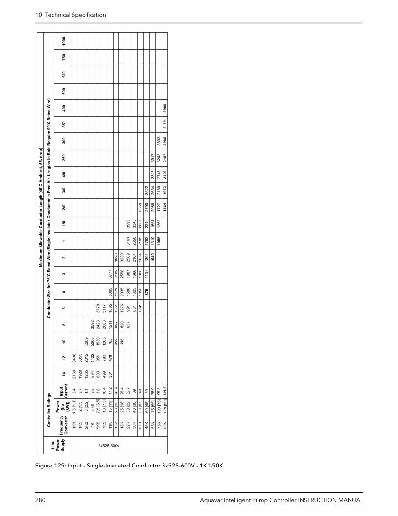
M
axim
um A
llow
able
Con
duct
or L
engt
h (4
5˚C
Am
bien
t, 5%
dro
p)
Con
duct
or S
ize
for 7
5˚C
Rat
ed W
ire (S
ingl
e-In
sula
ted
Con
duct
or in
Fre
e A
ir. L
engt
hs in
Bol
d R
equi
re 9
0˚C
Rat
ed W
ire)
Con
trol
ler R
atin
gs
Fr
eque
ncy
In
put
14
12
10
8 6
4 3
2 1
1/0
2/0
3/0
4/0
250
300
350
400
500
600
750
1000
Con
vert
er
Cur
rent
1K1
1.
5 [1
.1]
2.
4 21
60
3436
1K5
2
[1.5
]2.
7 19
20
3055
2K2
3
[2.2
]4.
1 12
65
2012
32
094K
5
[4]
5.8
894
1422
22
68
3592
5K5
7.
5 [5
.5]
8.6
603
959
1530
24
23
7K
5
10 [7
.5]
10.4
49
9 79
3 12
65
2003
31
17
11K
15
[11]
17.2
30
1 47
9 76
5 12
11
1885
30
05
3777
15
K
20 [1
5]20
.9
629
997
1551
24
73
3109
39
2618
K
25 [1
8]25
.4
518
820
1276
20
35
2558
32
3022
K
30 [2
2]32
.7
63
7 99
1 15
80
1987
25
09
3161
39
9030
K
40 [3
0]39
83
1 13
25
1666
21
04
2650
33
4537
K
50 [3
7]49
66
2 10
55
1326
16
74
2109
26
63
3359
45K
60
[45]
59 78.9
95.3
124.
3
876
1101
13
9110
40
1752
1310
1085
22
1116
5413
69
27
9020
8617
2713
24
35
2226
3421
8016
72
3x525-600VLine
Po
wer
Supp
ly
55K
75 [5
5]75
K10
0 [7
5]90
K12
5 [9
0]
3770
3318
2747
2106
3917
3243
2487
3893
2985
3489
3989
Pow
er(h
p [k
W])
Figure 129: Input - Single-Insulated Conductor 3x525-600V - 1K1-90K
10 Technical Specification
280 Aquavar Intelligent Pump Controller INSTRUCTION MANUAL
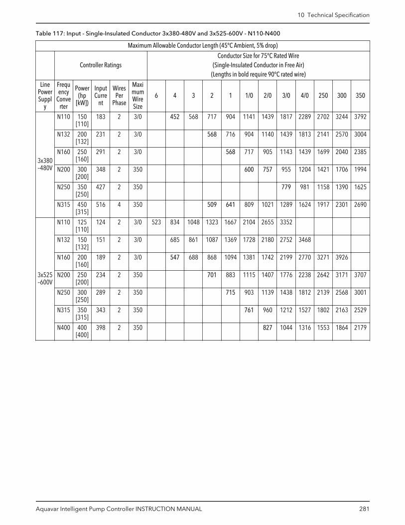
Table 117: Input - Single-Insulated Conductor 3x380-480V and 3x525-600V - N110-N400
Maximum Allowable Conductor Length (45°C Ambient, 5% drop)
Controller RatingsConductor Size for 75°C Rated Wire
(Single-Insulated Conductor in Free Air)(Lengths in bold require 90°C rated wire)
LinePowerSuppl
y
Frequency
Converter
Power(hp
[kW])
InputCurre
nt
WiresPer
Phase
MaximumWireSize
6 4 3 2 1 1/0 2/0 3/0 4/0 250 300 350
3x380–480V
N110 150[110]
183 2 3/0 452 568 717 904 1141 1439 1817 2289 2702 3244 3792
N132 200[132]
231 2 3/0 568 716 904 1140 1439 1813 2141 2570 3004
N160 250[160]
291 2 3/0 568 717 905 1143 1439 1699 2040 2385
N200 300[200]
348 2 350 600 757 955 1204 1421 1706 1994
N250 350[250]
427 2 350 779 981 1158 1390 1625
N315 450[315]
516 4 350 509 641 809 1021 1289 1624 1917 2301 2690
3x525–600V
N110 125[110]
124 2 3/0 523 834 1048 1323 1667 2104 2655 3352
N132 150[132]
151 2 3/0 685 861 1087 1369 1728 2180 2752 3468
N160 200[160]
189 2 3/0 547 688 868 1094 1381 1742 2199 2770 3271 3926
N200 250[200]
234 2 350 701 883 1115 1407 1776 2238 2642 3171 3707
N250 300[250]
289 2 350 715 903 1139 1438 1812 2139 2568 3001
N315 350[315]
343 2 350 761 960 1212 1527 1802 2163 2529
N400 400[400]
398 2 350 827 1044 1316 1553 1864 2179
10 Technical Specification
Aquavar Intelligent Pump Controller INSTRUCTION MANUAL 281

Table 118: Input - 3 Current Carrying Conductors in Cable 3x380-480V and 3x525-600V - N110-N400
Maximum Allowable Conductor Length (45°C Ambient, 5% drop)
Controller RatingsConductor Size for 75°C Rated Wire
(3 Current Carrying Conductors in Cable, Raceway or Directly Buried)(Lengths in Bold Require 90°C Rated Wire)
LinePowerSupply
Frequency
Converter
Power(hp
[kW])
InputCurren
t
Wiresper
Phase
Maximum
WireSize
4 3 2 1 1/0 2/0 3/0 4/0 250 300 350
3x380–480V
N110 150[110]
183 2 3/0 904 1141 1439 1817 2289 2702 3244 3792
N132 200[132]
231 2 3/0 904 1140 1439 1813 2141 2570 3004
N160 250[160]
291 2 3/0 1143 1439 1699 2040 2385
N200 300[200]
348 2 350 1204 1421 1706 1994
N250 350[250]
427 2 350 1390 1625
N315 450[315]
516 4 350 1021 1289 1624 1917 2301 2690
3x525–600V
N110 125[110]
124 2 3/0 834 1048 1323 1667 2104 2655 3352
N132 150[132]
151 2 3/0 861 1087 1369 1728 2180 2752 3468
N160 200[160]
189 2 3/0 1094 1381 1742 2199 2770 3271 3926
N200 250[200]
234 2 350 1115 1407 1776 2238 2642 3171 3707
N250 300[250]
289 2 350 1438 1812 2139 2568 3001
N315 350[315]
343 2 350 1527 1802 2163 2529
N400 400[400]
398 2 350 1553 1864 2179
10 Technical Specification
282 Aquavar Intelligent Pump Controller INSTRUCTION MANUAL
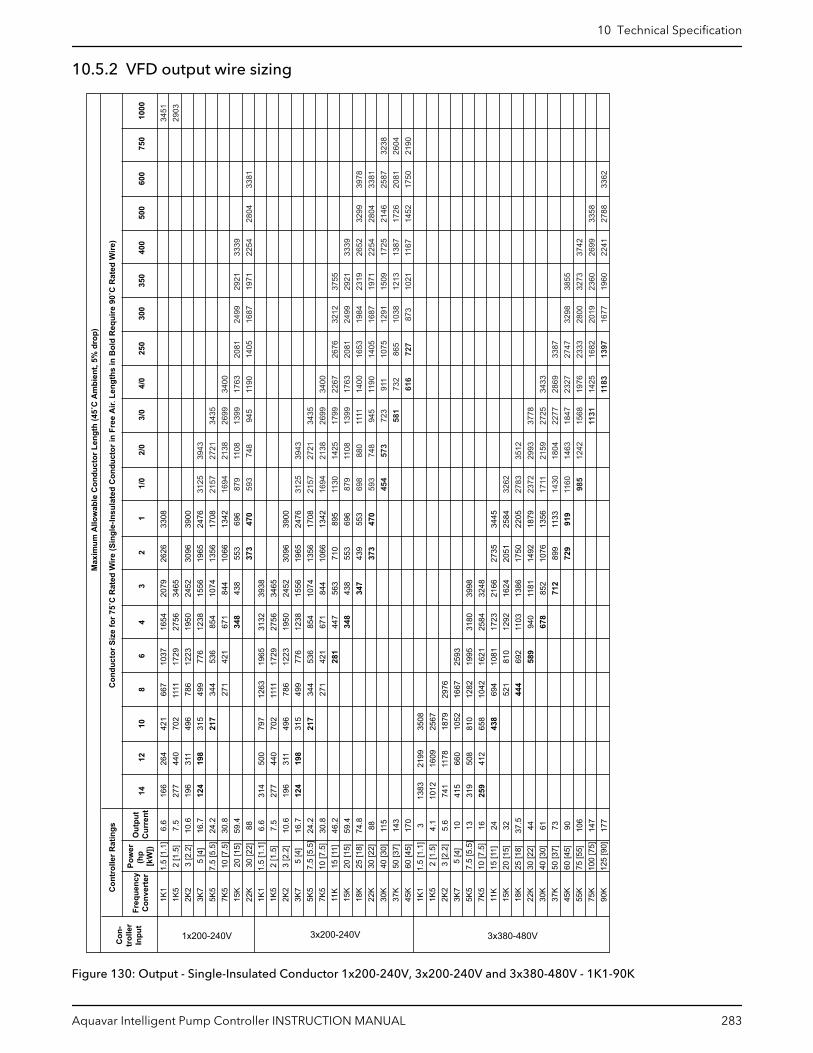
10.5.2 VFD output wire sizing
M
axim
um A
llow
able
Con
duct
or L
engt
h (4
5˚C
Am
bien
t, 5%
dro
p)
Con
duct
or S
ize
for 7
5˚C
Rat
ed W
ire (S
ingl
e-In
sula
ted
Con
duct
or in
Fre
e A
ir. L
engt
hs in
Bol
d R
equi
re 9
0˚C
Rat
ed W
ire)
Con
trol
ler R
atin
gs
Fr
eque
ncy Po
wer
(hp
[kW
]) O
utpu
t 14
12
10
8
6 4
3 2
1 1/
0 2/
0 3/
0 4/
0 25
0 30
0 35
0 40
0 50
0 60
0 75
0 10
00
C
onve
rter
C
urre
nt
1K1
1.5
[1.1
]6.
67.
510
.616
.724
.230
.859
.488 6.
67.
510
.616
.724
.230
.846
.259
.474
.888 11
514
317
0 3 4.1
5.6
10 13 16 24 32 37.5
44 61 73 90 106
147
177
16
627
719
612
4 31
427
719
612
4 13
8310
1274
141
531
925
9 26
444
031
119
8 50
044
031
119
8 21
9916
0911
7866
050
841
2
42
170
249
631
521
7 79
770
249
631
521
7 35
0825
6718
7910
5281
065
843
8
667
1111
786
499
344
271
1263
1111
786
499
344
271
2976
1667
1282
1042
694
521
444
1037
1729
1223
776
536
421
1965
1729
1223
776
536
421
281
2593
1995
1621
1081
810
692
589
16
5427
5619
5012
3885
467
134
8 31
3227
5619
5012
3885
467
144
734
8
3180
2584
1723
1292
1103
940
678
20
7934
6524
5215
5610
7484
443
8 39
3834
6524
5215
5610
7484
456
343
834
7
3998
3248
2166
1624
1386
1181
852
712
26
26
3096
1965
1356
1066
553
373
3096
1965
1356
1066
710
553
439
373
2735
2051
1750
1492
1076
899
729
3308
3900
2476
1708
1342
696
470
3900
2476
1708
1342
895
696
553
470
3445
2584
2205
1879
1356
1133
919
1K5
2 [1
.5]
2K2
3 [2
.2]
3125
2157
1694
879
593
3125
2157
1694
1130
879
698
593
454
3262
2783
2372
1711
1430
1160
985
39
4327
2121
3811
0874
8
3943
2721
2138
1425
1108
880
748
573
3512
2993
2159
1804
1463
1242
3K7
5 [4
]
34
3526
9913
9994
5
3435
2699
1799
1399
1111
945
723
581
3778
2725
2277
1847
1568
1131
3400
1763
1190
3400
2267
1763
1400
1190
911
732
616
3433
2869
2327
1976
1425
1183
2081
1405
2676
2081
1653
1405
1075
865
727
3387
2747
2333
1682
1397
5K5
7.5
[5.5
]
2499
1687
3212
2499
1984
1687
1291
1038
873
3298
2800
2019
1677
2921
1971
3755
2921
2319
1971
1509
1213
1021
3855
3273
2360
1960
7K5
10 [7
.5]
33
3922
54
3339
2652
2254
1725
1387
1167
3742
2699
2241
15K
20 [1
5]
28
04
3299
2804
2146
1726
1452
3358
2788
33
81
3978
3381
2587
2081
1750
3362
3238
2604
2190
22K
30 [2
2]
3451
2903
1K1
1.5
[1.1
]
1K5
2 [1
.5]
2K2
3 [2
.2]
3K7
5 [4
]
5K5
7.5
[5.5
]
7K5
10 [7
.5]
11K
15 [1
1]
15K
20 [1
5]
18K
25 [1
8]
22K
30 [2
2]
30K
40 [3
0]
37K
50 [3
7]
45K
60 [4
5]
1K1
1.5
[1.1
]
1K5
2 [1
.5]
2K2
3 [2
.2]
3K7
5 [4
]
5K5
7.5
[5.5
]
7K5
10 [7
.5]
11K
15 [1
1]
15K
20
[15]
18K
25
[18]
22K
30
[22]
30K
40
[30]
37K
50
[37]
45K
60
[45]
55K
75
[55]
75K
10
0 [7
5]
90
K
125
[90]
1x200-240V 3x200-240V 3x380-480VCon
-tr
olle
rIn
put
Figure 130: Output - Single-Insulated Conductor 1x200-240V, 3x200-240V and 3x380-480V - 1K1-90K
10 Technical Specification
Aquavar Intelligent Pump Controller INSTRUCTION MANUAL 283
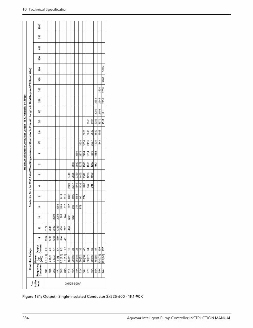
M
axim
um A
llow
able
Con
duct
or L
engt
h (4
5˚C
Am
bien
t, 5%
dro
p)
Con
duct
or S
ize
for 7
5˚C
Rat
ed W
ire (S
ingl
e-In
sula
ted
Con
duct
or in
Fre
e A
ir. L
engt
hs in
Bol
d R
equi
re 9
0˚C
Rat
ed W
ire)
Con
trol
ler R
atin
gs
Fr
eque
ncy Po
wer
(hp
[kW
]) O
utpu
t 14
12
10
8
6 4
3 2
1 1/
0 2/
0 3/
0 4/
0 25
0 30
0 35
0 40
0 50
0 60
0 75
0 10
00
C
onve
rter
C
urre
nt
1K1
2.
62.
94.
16.
49.
511
.5 19 23 28 36 43 54 65 87 105
137
19
9417
8812
6581
054
645
1 31
7228
4420
1212
8986
871
743
4
3209
2055
1385
1144
692
572
3255
2193
1812
1097
906
744
579
3412
2819
1706
1409
1158
901
754
2720
2247
1846
1436
1202
957
795
3419
2825
2320
1805
1511
1203
1000
3567
2930
2279
1908
1519
1262
943
3691
2871
2404
1914
1590
1188
1K5
2K2
3624
3034
2416
2007
1500
1243
3828
3048
2532
1892
1568
4K
3848
3197
2388
1979
1517
3009
2493
1911
3553
2944
2256
5K5
3534
2708
3166
7K5
3619
11K
15K
18K
22K
30K
37K
45K
1.5
[1.1
]2
[1.5
]3
[2.2
]5
[4]
7.5
[5.5
]10
[7.5
]15
[11]
20 [1
5]25
[18]
30 [2
2]40
[30]
50 [3
7]60
[45]
55K
75 [5
5]75
K10
0 [7
5]90
K12
5 [9
0]
3x525-600VCon
-tr
olle
rIn
put
Figure 131: Output - Single-Insulated Conductor 3x525-600 - 1K1-90K
10 Technical Specification
284 Aquavar Intelligent Pump Controller INSTRUCTION MANUAL

Table 119: Output - Single-Insulated Conductor 3x380-480V and 3x525-600V - N110-N400
Maximum Allowable Conductor Length (45°C Ambient, 5% drop)
Controller RatingsConductor Size for 75°C Rated Wire
(Single-Insulated Conductor in Free Air)(Lengths in Bold Require 90°C Rated Wire)
LinePowerSuppl
y
Frequency
Converter
Power(hp
[kW])
Output
Current
WiresPer
Phase
MaximumWireSize
6 4 3 2 1 1/0 2/0 3/0 4/0 250 300 350
3x380–480V
N110 150[110]
190 2 3/0 435 547 691 870 1099 1386 1750 2205 2603 3125 3652
N132 200[132]
240 2 3/0 547 689 870 1097 1385 1745 2061 2474 2891
N160 250[160]
302 2 3/0 548 691 872 1101 1387 1637 1966 2298
N200 300[200]
361 2 350 578 730 921 1160 1370 1644 1922
N250 350[250]
443 2 350 751 946 1116 1340 1566
N315 400[315]
535 4 350 618 780 985 1243 1566 1849 2219 2594
3x525–600V
N110 125[110]
131 2 3/0 495 789 992 1253 1578 1992 2513 3173 3997
N132 150[132]
155 2 3/0 667 838 1059 1334 1683 2124 2681 3378 3988
N160 200[160]
192 2 3/0 538 677 855 1077 1359 1715 2165 2727 3220 3865
N200 250[200]
242 2 350 678 854 1078 1360 1717 2164 2554 3066 3584
N250 300[250]
290 2 350 713 900 1135 1433 1806 2132 2559 2991
N315 350[315]
344 2 350 759 957 1208 1522 1797 2157 2522
N400 400[400]
400 2 350 823 1039 1309 1545 1855 2169
10 Technical Specification
Aquavar Intelligent Pump Controller INSTRUCTION MANUAL 285
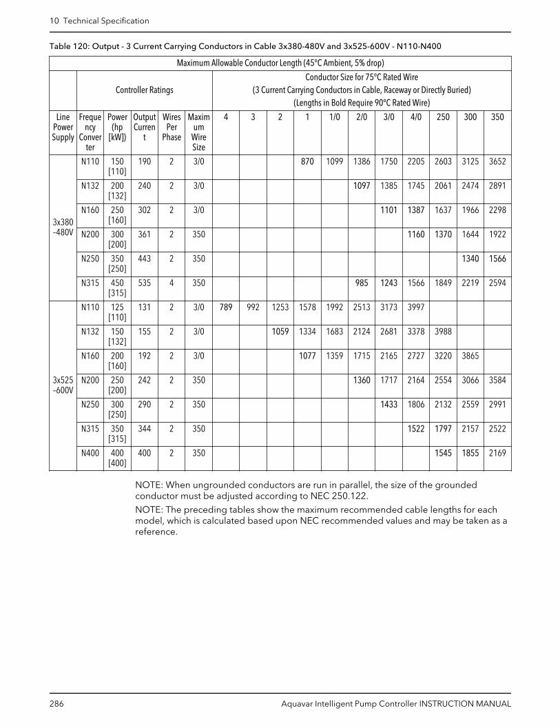
Table 120: Output - 3 Current Carrying Conductors in Cable 3x380-480V and 3x525-600V - N110-N400
Maximum Allowable Conductor Length (45°C Ambient, 5% drop)
Controller RatingsConductor Size for 75°C Rated Wire
(3 Current Carrying Conductors in Cable, Raceway or Directly Buried)(Lengths in Bold Require 90°C Rated Wire)
LinePowerSupply
Frequency
Converter
Power(hp
[kW])
OutputCurren
t
WiresPer
Phase
Maximum
WireSize
4 3 2 1 1/0 2/0 3/0 4/0 250 300 350
3x380–480V
N110 150[110]
190 2 3/0 870 1099 1386 1750 2205 2603 3125 3652
N132 200[132]
240 2 3/0 1097 1385 1745 2061 2474 2891
N160 250[160]
302 2 3/0 1101 1387 1637 1966 2298
N200 300[200]
361 2 350 1160 1370 1644 1922
N250 350[250]
443 2 350 1340 1566
N315 450[315]
535 4 350 985 1243 1566 1849 2219 2594
3x525–600V
N110 125[110]
131 2 3/0 789 992 1253 1578 1992 2513 3173 3997
N132 150[132]
155 2 3/0 1059 1334 1683 2124 2681 3378 3988
N160 200[160]
192 2 3/0 1077 1359 1715 2165 2727 3220 3865
N200 250[200]
242 2 350 1360 1717 2164 2554 3066 3584
N250 300[250]
290 2 350 1433 1806 2132 2559 2991
N315 350[315]
344 2 350 1522 1797 2157 2522
N400 400[400]
400 2 350 1545 1855 2169
NOTE: When ungrounded conductors are run in parallel, the size of the groundedconductor must be adjusted according to NEC 250.122.
NOTE: The preceding tables show the maximum recommended cable lengths for eachmodel, which is calculated based upon NEC recommended values and may be taken as areference.
10 Technical Specification
286 Aquavar Intelligent Pump Controller INSTRUCTION MANUAL

10.6 Parameter list0-
**
Ope
ratio
n / D
ispl
ay0-
0*
Bas
ic S
ettin
gs0-
01
Lang
uage
0-02
M
otor
Spe
ed U
nit
0-03
R
egio
nal S
ettin
gs0-
04
Ope
ratin
g St
ate
at P
ower
-up
0-05
Lo
cal M
ode
Uni
t0-
1*
Set-u
p O
pera
tions
0-10
Ac
tive
Set-u
p0-
11
Prog
ram
min
g Se
t-up
0-12
Th
is S
et-u
p Li
nked
to0-
13
Rea
dout
: Lin
ked
Set-u
ps0-
14
Rea
dout
: Pro
g. S
et-u
ps /
Cha
nnel
0-2*
LC
P D
ispl
ay0-
20
Dis
play
Lin
e 1.
1 Sm
all
0-21
D
ispl
ay L
ine
1.2
Smal
l0-
22
Dis
play
Lin
e 1.
3 Sm
all
0-23
D
ispl
ay L
ine
2 La
rge
0-24
D
ispl
ay L
ine
3 La
rge
0-25
M
y Pe
rson
al M
enu
0-3*
LC
P C
usto
m R
eado
ut0-
30
Cus
tom
Rea
dout
Uni
t0-
31
Cus
tom
Rea
dout
Min
Val
ue0-
32
Cus
tom
Rea
dout
Max
Val
ue0-
37
Dis
play
Tex
t 10-
38
Dis
play
Tex
t 20-
39
Dis
play
Tex
t 30-
4*
LCP
Key
pad
0-40
[H
and
on] K
ey o
n LC
P0-
41
[Off]
Key
on
LCP
0-42
[A
uto
on] K
ey o
n LC
P0-
43
[Res
et] K
ey o
n LC
P0-
44
[Off/
Res
et] K
ey o
n LC
P0-
45
[Driv
e By
pass
] Key
on
LCP
0-5*
C
opy/
Save
0-50
LC
P C
opy
0-51
Se
t-up
Cop
y0-
6*
Pass
wor
d0-
60
Mai
n M
enu
Pass
wor
d0-
61
Acce
ss to
Mai
n M
enu
w/o
Pas
swor
d0-
65
Pers
onal
Men
u Pa
ssw
ord
0-66
Ac
cess
to P
erso
nal M
enu
w/o
Pas
swor
d0-
67
Bus
Acce
ss P
assw
ord
0-7*
C
lock
Set
tings
0-70
D
ate
and
Tim
e0-
71
Dat
e Fo
rmat
0-72
Ti
me
Form
at0-
74
DST
/Sum
mer
time
0-76
D
ST/S
umm
ertim
e St
art
0-77
D
ST/S
umm
ertim
e En
d0-
79
Clo
ck F
ault
0-81
W
orki
ng D
ays
0-82
Ad
ditio
nal W
orki
ng D
ays
0-83
Ad
ditio
nal N
on-W
orki
ng D
ays
0-89
D
ate
and
Tim
e R
eado
ut
1-**
Load
and
Mot
or1-
0*
G
ener
al S
ettin
gs1-
00
C
onfig
urat
ion
Mod
e1-
03
Torq
ue C
hara
cter
istic
s1-
06
Clo
ckw
ise
Dire
ctio
n1-
1*
Mot
or S
elec
tion
1-10
M
otor
Con
stru
ctio
n1-
1*
VVC
+ PM
1-14
D
ampi
ng G
ain
1-15
Lo
w S
peed
Filt
er T
ime
Con
st.
1-16
H
igh
Spee
d Fi
lter T
ime
Con
st.
1-17
Vo
ltage
filte
r tim
e co
nst.
1-2*
M
otor
Dat
a1-
20
Mot
or P
ower
[kW
]1-
21
Mot
or P
ower
[HP]
1-22
M
otor
Vol
tage
1-23
M
otor
Fre
quen
cy1-
24
Mot
or C
urre
nt1-
25
Mot
or N
omin
al S
peed
1-26
M
otor
Con
t. R
ated
Tor
que
1-28
M
otor
Rot
atio
n C
heck
1-29
Au
tom
atic
Mot
or A
dapt
atio
n (A
MA)
1-3*
A
dv. M
otor
Dat
a1-
30
Stat
or R
esis
tanc
e (R
s)1-
31
Rot
or R
esis
tanc
e (R
r)1-
35
Mai
n R
eact
ance
(Xh)
1-36
Iro
n Lo
ss R
esis
tanc
e (R
fe)
1-37
d-
axis
Indu
ctan
ce (L
d)1-
39
Mot
or P
oles
1-40
Ba
ck E
MF
at 1
000
RPM
1-46
Po
sitio
n D
etec
tion
Gai
n1-
5*
Load
Inde
p. S
ettin
g1-
50
Mot
or M
agne
tisat
ion
at Z
ero
Spee
d1-
51
Min
Spe
ed N
orm
al M
agne
tisin
g [R
PM]
1-52
M
in S
peed
Nor
mal
Mag
netis
ing
[Hz]
1-58
Fl
ysta
rt Te
st P
ulse
s C
urre
nt1-
59
Flys
tart
Test
Pul
ses
Freq
uenc
y1-
6*
Load
Dep
en. S
ettin
g1-
60
Low
Spe
ed L
oad
Com
pens
atio
n1-
61
Hig
h Sp
eed
Load
Com
pens
atio
n1-
62
Slip
Com
pens
atio
n1-
63
Slip
Com
pens
atio
n Ti
me
Con
stan
t1-
64
Res
onan
ce D
ampe
ning
1-65
R
eson
ance
Dam
peni
ng T
ime
Con
stan
t1-
66
Min
. Cur
rent
at L
ow S
peed
1-7*
St
art A
djus
tmen
ts1-
70
PM S
tart
Mod
e1-
71
Star
t Del
ay1-
72
Star
t Fun
ctio
n1-
73
Flyi
ng S
tart
1-77
C
ompr
esso
r Sta
rt M
ax S
peed
[RPM
]1-
78
Com
pres
sor S
tart
Max
Spe
ed [H
z]1-
79
Com
pres
sor S
tart
Max
Tim
e to
Trip
1-8*
St
op A
djus
tmen
ts1-
80
Func
tion
at S
top
1-81
M
in S
peed
for F
unct
ion
at S
top
[RPM
]1-
82
Min
Spe
ed fo
r Fun
ctio
n at
Sto
p [H
z]1-
86
Trip
Spe
ed L
ow [R
PM]
1-87
Tr
ip S
peed
Low
[Hz]
1-9*
M
otor
Tem
pera
ture
1-90
M
otor
The
rmal
Pro
tect
ion
1-91
M
otor
Ext
erna
l Fan
1-93
Th
erm
isto
r Sou
rce
2-**
B
rake
s2-
0*
DC
-Bra
ke2-
00
DC
Hol
d/Pr
ehea
t Cur
rent
2-01
D
C B
rake
Cur
rent
2-02
D
C B
raki
ng T
ime
2-03
D
C B
rake
Cut
In S
peed
[RPM
]2-
04
DC
Bra
ke C
ut In
Spe
ed [H
z]2-
06
Park
ing
Cur
rent
2-07
Pa
rkin
g Ti
me
2-1*
B
rake
Ene
rgy
Func
t.2-
10
Brak
e Fu
nctio
n2-
11
Brak
e R
esis
tor (
ohm
)2-
12
Brak
e Po
wer
Lim
it (k
W)
2-13
Br
ake
Pow
er M
onito
ring
2-15
Br
ake
Che
ck2-
16
AC b
rake
Max
. Cur
rent
2-17
O
ver-v
olta
ge C
ontro
l3-
**
Ref
eren
ce /
Ram
ps3-
0*
Ref
eren
ce L
imits
3-02
M
inim
um R
efer
ence
3-03
M
axim
um R
efer
ence
3-04
R
efer
ence
Fun
ctio
n3-
1*
Ref
eren
ces
3-10
Pr
eset
Ref
eren
ce3-
11
Jog
Spee
d [H
z]3-
13
Ref
eren
ce S
ite3-
14
Pres
et R
elat
ive
Ref
eren
ce3-
15
Ref
eren
ce 1
Sou
rce
3-16
R
efer
ence
2 S
ourc
e3-
17
Ref
eren
ce 3
Sou
rce
3-19
Jo
g Sp
eed
[RPM
]3-
4*
Ram
p 1
3-41
R
amp
1 R
amp
Up
Tim
e3-
42
Ram
p 1
Ram
p D
own
Tim
e3-
5*
Ram
p 2
3-51
R
amp
2 R
amp
Up
Tim
e3-
52
Ram
p 2
Ram
p D
own
Tim
e3-
8*
Oth
er R
amps
3-80
Jo
g R
amp
Tim
e3-
81
Qui
ck S
top
Ram
p Ti
me
3-82
St
artin
g R
amp
Up
Tim
e3-
9*
Dig
ital P
ot.M
eter
3-90
St
ep S
ize
3-91
R
amp
Tim
e3-
92
Pow
er R
esto
re3-
93
Max
imum
Lim
it3-
94
Min
imum
Lim
it3-
95
Ram
p D
elay
4-**
Li
mits
/ W
arni
ngs
4-1*
M
otor
Lim
its4-
10
Mot
or S
peed
Dire
ctio
n4-
11
Mot
or S
peed
Low
Lim
it [R
PM]
4-12
Sl
eep
Freq
uenc
y/Lo
w L
imit
[Hz]
4-13
M
otor
Spe
ed H
igh
Lim
it [R
PM]
4-14
M
otor
Spe
ed H
igh
Lim
it [H
z]4-
16
Torq
ue L
imit
Mot
or M
ode
4-17
To
rque
Lim
it G
ener
ator
Mod
e4-
18
Cur
rent
Lim
it4-
19
Max
Out
put F
requ
ency
4-5*
A
dj. W
arni
ngs
4-50
W
arni
ng C
urre
nt L
ow4-
51
War
ning
Cur
rent
Hig
h4-
52
War
ning
Spe
ed L
ow4-
53
War
ning
Spe
ed H
igh
4-54
W
arni
ng R
efer
ence
Low
4-55
W
arni
ng R
efer
ence
Hig
h4-
56
War
ning
Fee
dbac
k Lo
w4-
57
War
ning
Fee
dbac
k H
igh
4-58
M
issi
ng M
otor
Pha
se F
unct
ion
4-6*
Sp
eed
Byp
ass
4-60
By
pass
Spe
ed F
rom
[RPM
]4-
61
Bypa
ss S
peed
Fro
m [H
z]4-
62
Bypa
ss S
peed
To
[RPM
]4-
63
Bypa
ss S
peed
To
[Hz]
4-64
Se
mi-A
uto
Bypa
ss S
et-u
p5-
**
Dig
ital I
n/O
ut5-
0*
Dig
ital I
/O m
ode
5-00
D
igita
l I/O
Mod
e5-
01
Term
inal
27
Mod
e5-
02
Term
inal
29
Mod
e5-
1*
Dig
ital I
nput
s5-
10
Term
inal
18
Dig
ital I
nput
5-11
Te
rmin
al 1
9 D
igita
l Inp
ut5-
12
Term
inal
27
Dig
ital I
nput
5-13
Te
rmin
al 2
9 D
igita
l Inp
ut5-
14
Term
inal
32
Dig
ital I
nput
5-15
Te
rmin
al 3
3 D
igita
l Inp
ut5-
16
Term
inal
X30
/2 D
igita
l Inp
ut5-
17
Term
inal
X30
/3 D
igita
l Inp
ut5-
18
Term
inal
X30
/4 D
igita
l Inp
ut5-
19
Term
inal
37
Safe
Sto
p5-
3*
Dig
ital O
utpu
ts5-
30
Term
inal
27
Dig
ital O
utpu
t5-
31
Term
inal
29
Dig
ital O
utpu
t5-
32
Term
X30
/6 D
igi O
ut (M
CB
101)
5-33
Te
rm X
30/7
Dig
i Out
(MC
B 10
1)5-
4*
Rel
ays
5-40
Fu
nctio
n R
elay
5-41
O
n D
elay
, Rel
ay5-
42
Off
Del
ay, R
elay
5-5*
Pu
lse
Inpu
t5-
50
Term
. 29
Low
Fre
quen
cy5-
51
Term
. 29
Hig
h Fr
eque
ncy
5-52
Te
rm. 2
9 Lo
w R
ef./F
eedb
. Val
ue5-
53
Term
. 29
Hig
h R
ef./F
eedb
. Val
ue5-
54
Puls
e Fi
lter T
ime
Con
stan
t #29
5-55
Te
rm. 3
3 Lo
w F
requ
ency
5-56
Te
rm. 3
3 H
igh
Freq
uenc
y5-
57
Term
. 33
Low
Ref
./Fee
db. V
alue
5-58
Te
rm. 3
3 H
igh
Ref
./Fee
db. V
alue
5-59
Pu
lse
Filte
r Tim
e C
onst
ant #
335-
6*
Puls
e O
utpu
t5-
60
Term
inal
27
Puls
e O
utpu
t Var
iabl
e5-
62
Puls
e O
utpu
t Max
Fre
q #2
75-
63
Term
inal
29
Puls
e O
utpu
t Var
iabl
e5-
65
Puls
e O
utpu
t Max
Fre
q #2
95-
66
Term
inal
X30
/6 P
ulse
Out
put V
aria
ble
5-68
Pu
lse
Out
put M
ax F
req
#X30
/65-
8*
I/O O
ptio
ns5-
80
AHF
Cap
Rec
onne
ct D
elay
5-9*
B
us C
ontr
olle
d5-
90
Dig
ital &
Rel
ay B
us C
ontro
l5-
93
Puls
e O
ut #
27 B
us C
ontro
l5-
94
Puls
e O
ut #
27 T
imeo
ut P
rese
t5-
95
Puls
e O
ut #
29 B
us C
ontro
l5-
96
Puls
e O
ut #
29 T
imeo
ut P
rese
t5-
97
Puls
e O
ut #
X30/
6 Bu
s C
ontro
l5-
98
Puls
e O
ut #
X30/
6 Ti
meo
ut P
rese
t6-
**
Ana
log
In/O
ut6-
0*
Ana
log
I/O M
ode
6-00
Se
nsor
Fau
lt Ti
meo
ut T
ime
(Nor
th A
mer
ica)
6-01
Se
nsor
Fau
lt Ti
meo
ut F
unct
ion
(Nor
th A
mer
ica)
6-02
Fi
re M
ode
Sens
or F
ault
Tim
eout
Fun
ctio
n (N
orth
Am
eric
a)
6-1*
A
nalo
g In
put 5
36-
10
Term
inal
53
Low
Vol
tage
6-11
Te
rmin
al 5
3 H
igh
Volta
ge6-
12
Term
inal
53
Low
Cur
rent
6-13
Te
rmin
al 5
3 H
igh
Cur
rent
6-14
Te
rmin
al 5
3 Lo
w R
ef./F
eedb
. Val
ue6-
15
Term
inal
53
Hig
h R
ef./F
eedb
. Val
ue6-
16
Term
inal
53
Filte
r Tim
e C
onst
ant
6-17
Te
rmin
al 5
3 Se
nsor
Fau
lt (N
orth
Am
eric
a)
6-2*
A
nalo
g In
put 5
46-
20
Term
inal
54
Low
Vol
tage
6-21
Te
rmin
al 5
4 H
igh
Volta
ge6-
22
Term
inal
54
Low
Cur
rent
6-23
Te
rmin
al 5
4 H
igh
Cur
rent
6-24
Te
rmin
al 5
4 Lo
w R
ef./F
eedb
. Val
ue6-
25
Term
inal
54
Hig
h R
ef./F
eedb
. Val
ue6-
26
Term
inal
54
Filte
r Tim
e C
onst
ant
6-27
Te
rmin
al 5
4 Se
nsor
Fau
lt (N
orth
Am
eric
a)
6-3*
A
nalo
g In
put X
30/1
16-
30
Term
inal
X30
/11
Low
Vol
tage
6-31
Te
rmin
al X
30/1
1 H
igh
Volta
ge6-
34
Term
. X30
/11
Low
Ref
./Fee
db. V
alue
6-35
Te
rm. X
30/1
1 H
igh
Ref
./Fee
db. V
alue
6-36
Te
rm. X
30/1
1 Fi
lter T
ime
Con
stan
t6-
37
Term
. X30
/11
Sens
or F
ault
6-4*
A
nalo
g In
put X
30/1
26-
40
Term
inal
X30
/12
Low
Vol
tage
0-15
R
eado
ut: a
ctua
l set
up
0-27
D
ispl
ay M
ode
0-28
LC
P St
ep S
ize
0-29
LC
P R
amp
1-94
AT
EX E
TR c
ur.li
m. s
peed
redu
ctio
n1-
98
ATEX
ETR
inte
rpol
. poi
nts
freq.
1-99
AT
EX E
TR in
terp
ol p
oint
s cu
rrent
4-59
M
otor
Che
ck A
t Sta
rt
6-00
Li
ve Z
ero
Tim
eout
Tim
e (In
tern
atio
nal)
6-01
Li
ve Z
ero
Tim
eout
Fun
ctio
n (In
tern
atio
nal)
6-02
Fi
re M
ode
Live
Zer
o Ti
meo
ut F
unct
ion
(Inte
rnat
iona
l)
6-17
Te
rmin
al 5
3 Li
ve Z
ero
(Inte
rnat
iona
l)
6-27
Te
rmin
al 5
4 Li
ve Z
ero
(Inte
rnat
iona
l)
10 Technical Specification
Aquavar Intelligent Pump Controller INSTRUCTION MANUAL 287

6-63
Te
rmin
al X
30/8
Out
put B
us C
ontro
l6-
64
Term
inal
X30
/8 O
utpu
t Tim
eout
Pre
set
8-**
C
omm
. and
Opt
ions
8-0*
G
ener
al S
ettin
gs8-
01
Con
trol S
ite8-
02
Con
trol S
ourc
e8-
03
Con
trol T
imeo
ut T
ime
8-04
C
ontro
l Tim
eout
Fun
ctio
n8-
05
End-
of-T
imeo
ut F
unct
ion
8-06
R
eset
Con
trol T
imeo
ut8-
07
Dia
gnos
is T
rigge
r8-
08
Rea
dout
Filt
erin
g8-
09
Com
mun
icat
ion
Cha
rset
8-1*
C
ontr
ol S
ettin
gs8-
10
Con
trol P
rofil
e8-
13
Con
figur
able
Sta
tus
Wor
d ST
W8-
3*
FC P
ort S
ettin
gs8-
30
Prot
ocol
8-31
Ad
dres
s8-
32
Baud
Rat
e8-
33
Parit
y / S
top
Bits
8-34
Es
timat
ed c
ycle
tim
e8-
35
Min
imum
Res
pons
e D
elay
8-36
M
axim
um R
espo
nse
Del
ay8-
37
Max
imum
Inte
r-Cha
r Del
ay8-
4*
FC M
C p
roto
col s
et8-
40
Tele
gram
Sel
ectio
n8-
42
PCD
Writ
e C
onfig
urat
ion
8-43
PC
D R
ead
Con
figur
atio
n8-
5*
Dig
ital/B
us8-
50
Coa
stin
g Se
lect
8-52
D
C B
rake
Sel
ect
8-53
St
art S
elec
t8-
54
Rev
ersi
ng S
elec
t8-
55
Set-u
p Se
lect
8-56
Pr
eset
Ref
eren
ce S
elec
t8-
7*
BA
Cne
t8-
70
BAC
net D
evic
e In
stan
ce8-
72
MS/
TP M
ax M
aste
rs8-
73
MS/
TP M
ax In
fo F
ram
es8-
74
"I-Am
" Ser
vice
8-75
In
itial
isat
ion
Pass
wor
d8-
8*
FC P
ort D
iagn
ostic
s
8-80
Bu
s M
essa
ge C
ount
8-81
Bu
s Er
ror C
ount
8-82
Sl
ave
Mes
sage
s R
cvd
8-83
Sl
ave
Erro
r Cou
nt8-
84
Slav
e M
essa
ges
Sent
8-85
Sl
ave
Tim
eout
Erro
rs8-
89
Dia
gnos
tics
Cou
nt8-
9*
Bus
Jog
/ Fe
edba
ck8-
90
Bus
Jog
1 Sp
eed
8-91
Bu
s Jo
g 2
Spee
d8-
94
Bus
Feed
back
18-
95
Bus
Feed
back
28-
96
Bus
Feed
back
39-
**
Prof
ibus
9-00
Se
tpoi
nt9-
07
Actu
al V
alue
9-15
PC
D W
rite
Con
figur
atio
n9-
16
PCD
Rea
d C
onfig
urat
ion
9-18
N
ode
Addr
ess
9-22
Te
legr
am S
elec
tion
9-23
Pa
ram
eter
s fo
r Sig
nals
9-27
Pa
ram
eter
Edi
t9-
28
Proc
ess
Con
trol
9-44
Fa
ult M
essa
ge C
ount
er9-
45
Faul
t Cod
e9-
47
Faul
t Num
ber
9-52
Fa
ult S
ituat
ion
Cou
nter
9-53
Pr
ofib
us W
arni
ng W
ord
9-63
Ac
tual
Bau
d R
ate
9-64
D
evic
e Id
entif
icat
ion
9-65
Pr
ofile
Num
ber
9-67
C
ontro
l Wor
d 1
9-68
St
atus
Wor
d 1
9-71
Pr
ofib
us S
ave
Dat
a Va
lues
9-72
Pr
ofib
usD
riveR
eset
9-75
D
O Id
entif
icat
ion
9-80
D
efin
ed P
aram
eter
s (1
)9-
81
Def
ined
Par
amet
ers
(2)
9-82
D
efin
ed P
aram
eter
s (3
)9-
83
Def
ined
Par
amet
ers
(4)
9-84
D
efin
ed P
aram
eter
s (5
)9-
90
Cha
nged
Par
amet
ers
(1)
9-91
C
hang
ed P
aram
eter
s (2
)9-
92
Cha
nged
Par
amet
ers
(3)
9-93
C
hang
ed P
aram
eter
s (4
)9-
94
Cha
nged
Par
amet
ers
(5)
9-99
Pr
ofib
us R
evis
ion
Cou
nter
11-*
* L
onW
orks
11-0
* L
onW
orks
ID11
-00
Neu
ron
ID11
-1*
LO
N F
unct
ions
11-1
0 D
rive
Prof
ile11
-15
LON
War
ning
Wor
d11
-17
XIF
Rev
isio
n11
-18
LonW
orks
Rev
isio
n11
-2*
LO
N P
aram
. Acc
ess
11-2
1 S
tore
Dat
a Va
lues
12-*
* Et
hern
et12
-0*
IP S
ettin
gs
12-0
0 IP
Add
ress
Ass
ignm
ent
12-0
1 IP
Add
ress
12-0
2 S
ubne
t Mas
k12
-03
Def
ault
Gat
eway
12-0
4 D
HC
P Se
rver
12-0
5 Le
ase
Expi
res
12-0
6 N
ame
Serv
ers
12-0
7 D
omai
n N
ame
12-0
8 H
ost N
ame
12-0
9 P
hysi
cal A
ddre
ss12
-1*
Ethe
rnet
Lin
k Pa
ram
eter
s12
-10
Link
Sta
tus
12-1
1 Li
nk D
urat
ion
12-1
2 A
uto
Neg
otia
tion
12-1
3 Li
nk S
peed
12-1
4 Li
nk D
uple
x12
-2*
Proc
ess
Dat
a12
-20
Con
trol I
nsta
nce
12-2
1 P
roce
ss D
ata
Con
fig W
rite
12-2
2 P
roce
ss D
ata
Con
fig R
ead
12-2
7 P
rimar
y M
aste
r12
-28
Sto
re D
ata
Valu
es12
-29
Sto
re A
lway
s12
-3*
Ethe
rNet
/IP12
-30
War
ning
Par
amet
er12
-31
Net
Ref
eren
ce12
-32
Net
Con
trol
12-3
3 C
IP R
evis
ion
12-3
4 C
IP P
rodu
ct C
ode
12-3
5 E
DS
Para
met
er12
-37
CO
S In
hibi
t Tim
er12
-38
CO
S Fi
lter
12-4
* M
odbu
s TC
P12
-40
Sta
tus
Para
met
er12
-41
Sla
ve M
essa
ge C
ount
12-4
2 S
lave
Exc
eptio
n M
essa
ge C
ount
12-8
* O
ther
Eth
erne
t Ser
vice
s12
-80
FTP
Ser
ver
12-8
1 H
TTP
Serv
er12
-82
SM
TP S
ervi
ce12
-89
Tran
spar
ent S
ocke
t Cha
nnel
Por
t12
-9*
Adv
ance
d Et
hern
et S
ervi
ces
12-9
0 C
able
Dia
gnos
tic12
-91
Aut
o C
ross
Ove
r12
-92
IGM
P Sn
oopi
ng12
-93
Cab
le E
rror L
engt
h12
-94
Bro
adca
st S
torm
Pro
tect
ion
12-9
5 B
road
cast
Sto
rm F
ilter
12-9
6 P
ort C
onfig
12-9
8 In
terfa
ce C
ount
ers
12-9
9 M
edia
Cou
nter
s13
-**
Smar
t Log
ic13
-0*
SLC
Set
tings
13-0
0 S
L C
ontro
ller M
ode
13-0
1 S
tart
Even
t13
-02
Sto
p Ev
ent
13-0
3 R
eset
SLC
13-1
* C
ompa
rato
rs13
-10
Com
para
tor O
pera
nd
13-1
1 C
ompa
rato
r Ope
rato
r13
-12
Com
para
tor V
alue
13-2
* Ti
mer
s13
-20
SL
Con
trolle
r Tim
er13
-4*
Logi
c R
ules
13-4
0 Lo
gic
Rul
e Bo
olea
n 1
13-4
1 Lo
gic
Rul
e O
pera
tor 1
13-4
2 Lo
gic
Rul
e Bo
olea
n 2
13-4
3 Lo
gic
Rul
e O
pera
tor 2
13-4
4 Lo
gic
Rul
e Bo
olea
n 3
13-5
* St
ates
13-5
1 S
L C
ontro
ller E
vent
13-5
2 S
L C
ontro
ller A
ctio
n13
-9* U
ser D
efin
ed A
lert
s13
-90
Aler
t Trig
ger
13-9
1 Al
ert A
ctio
n13
-92
Aler
t Tex
t13
-9* U
ser D
efin
ed R
eado
uts
13-9
7 Al
ert A
larm
Wor
d13
-98
Aler
t War
ning
Wor
d13
-99
Aler
t Sta
tus
Wor
d14
-**
Spec
ial F
unct
ions
14-0
* In
vert
er S
witc
hing
14-0
0 S
witc
hing
Pat
tern
14-0
1 S
witc
hing
Fre
quen
cy14
-03
Ove
rmod
ulat
ion
14-0
4 P
WM
Ran
dom
14-1
* M
ains
On/
Off
14-1
0 M
ains
Fai
lure
14-1
1 M
ains
Vol
tage
at M
ains
Fau
lt14
-12
Fun
ctio
n at
Mai
ns Im
bala
nce
14-1
6 Ki
n. B
acku
p G
ain
14-2
* R
eset
Fun
ctio
ns14
-20
Res
et M
ode
14-2
1 A
utom
atic
Res
tart
Tim
e14
-22
Ope
ratio
n M
ode
14-2
3 Ty
peco
de S
ettin
g14
-25
Trip
Del
ay a
t Tor
que
Lim
it14
-26
Trip
Del
ay a
t Inv
erte
r Fau
lt14
-28
Pro
duct
ion
Setti
ngs
14-2
9 S
ervi
ce C
ode
14-3
* C
urre
nt L
imit
Ctr
l.14
-30
Cur
rent
Lim
Ctrl
, Pro
porti
onal
Gai
n14
-31
Cur
rent
Lim
Ctrl
, Int
egra
tion
Tim
e14
-32
Cur
rent
Lim
Ctrl
, Filt
er T
ime
14-4
* En
ergy
Opt
imis
ing
14-4
0 V
T Le
vel
14-4
1 A
EO M
inim
um M
agne
tisat
ion
14-4
2 M
inim
um A
EO F
requ
ency
14-4
3 M
otor
Cos
phi
14-5
* En
viro
nmen
t14
-50
RFI
Filt
er14
-51
DC
Lin
k C
ompe
nsat
ion
14-5
2 F
an C
ontro
l14
-53
Fan
Mon
itor
14-5
5 O
utpu
t Filt
er14
-59
Act
ual N
umbe
r of I
nver
ter U
nits
14-6
* A
uto
Der
ate
14-6
0 F
unct
ion
at O
ver T
empe
ratu
re
14-6
1 F
unct
ion
at In
verte
r Ove
rload
14-6
2 In
v. O
verlo
ad D
erat
e C
urre
nt14
-8* O
ptio
ns14
-89
Opt
ion
Det
ectio
n14
-9*
Faul
t Set
tings
14-9
0 F
ault
Leve
l15
-**
Driv
e In
form
atio
n15
-0*
Ope
ratin
g D
ata
15-0
0 O
pera
ting
hour
s15
-01
Run
ning
Hou
rs15
-02
kWh
Cou
nter
15-0
3 P
ower
Up'
s15
-04
Ove
r Tem
p's
15-0
5 O
ver V
olt's
15-0
6 R
eset
kW
h C
ount
er15
-07
Res
et R
unni
ng H
ours
Cou
nter
15-0
8 N
umbe
r of S
tarts
15-1
* D
ata
Log
Setti
ngs
15-1
0 Lo
ggin
g So
urce
15-1
1 Lo
ggin
g In
terv
al15
-12
Trig
ger E
vent
15-1
3 Lo
ggin
g M
ode
15-1
4 S
ampl
es B
efor
e Tr
igge
r15
-2*
His
toric
Log
15-2
0 H
isto
ric L
og: E
vent
15-2
1 H
isto
ric L
og: V
alue
15-2
2 H
isto
ric L
og: T
ime
15-2
3 H
isto
ric lo
g: D
ate
and
Tim
e15
-3*
Ala
rm L
og15
-30
Ala
rm L
og: E
rror C
ode
15-3
1 A
larm
Log
: Val
ue15
-32
Ala
rm L
og: T
ime
15-3
3 A
larm
Log
: Dat
e an
d Ti
me
15-4
* D
rive
Iden
tific
atio
n15
-40
FC
Typ
e15
-41
Pow
er S
ectio
n15
-42
Vol
tage
15-4
3 S
oftw
are
Vers
ion
15-4
4 O
rder
ed T
ypec
ode
Strin
g15
-45
Act
ual T
ypec
ode
Strin
g15
-46
Fre
quen
cy C
onve
rter O
rder
ing
No
15-4
7 P
ower
Car
d O
rder
ing
No
15-4
8 LC
P Id
No
15-4
9 S
W ID
Con
trol C
ard
15-5
0 S
W ID
Pow
er C
ard
15-5
1 F
requ
ency
Con
verte
r Ser
ial N
umbe
r15
-53
Pow
er C
ard
Seria
l Num
ber
15-5
5 V
endo
r UR
L15
-56
Ven
dor N
ame
15-5
9 C
SIV
File
nam
e15
-6*
Opt
ion
Iden
t15
-60
Opt
ion
Mou
nted
15-6
1 O
ptio
n SW
Ver
sion
15-6
2 O
ptio
n O
rder
ing
No
15-6
3 O
ptio
n Se
rial N
o15
-70
Opt
ion
in S
lot A
15-7
1 S
lot A
Opt
ion
SW V
ersi
on15
-72
Opt
ion
in S
lot B
15-7
3 S
lot B
Opt
ion
SW V
ersi
on
6-41
Te
rmin
al X
30/1
2 H
igh
Volta
ge6-
44
Term
. X30
/12
Low
Ref
./Fee
db. V
alue
6-45
Te
rm. X
30/1
2 H
igh
Ref
./Fee
db. V
alue
6-46
Te
rm. X
30/1
2 Fi
lter T
ime
Con
stan
t6-
47
Term
. X30
/12
Sens
or F
ault
6-5*
A
nalo
g O
utpu
t 42
6-50
Te
rmin
al 4
2 O
utpu
t6-
51
Term
inal
42
Out
put M
in S
cale
6-52
Te
rmin
al 4
2 O
utpu
t Max
Sca
le6-
53
Term
inal
42
Out
put B
us C
ontro
l6-
54
Term
inal
42
Out
put T
imeo
ut P
rese
t6-
55
Anal
og O
utpu
t Filt
er6-
6*
Ana
log
Out
put X
30/8
6-60
Te
rmin
al X
30/8
Out
put
6-61
Te
rmin
al X
30/8
Min
. Sca
le6-
62
Term
inal
X30
/8 M
ax. S
cale
10 Technical Specification
288 Aquavar Intelligent Pump Controller INSTRUCTION MANUAL

16-2
2 To
rque
[%]
16-2
6 P
ower
Filt
ered
[kW
]16
-27
Pow
er F
ilter
ed [h
p]16
-3*
Driv
e St
atus
16-3
0 D
C L
ink
Volta
ge16
-32
Bra
ke E
nerg
y /s
16-3
3 B
rake
Ene
rgy
/2 m
in16
-34
Hea
tsin
k Te
mp.
16-3
5 In
verte
r The
rmal
16-3
6 In
v. N
om. C
urre
nt16
-37
Inv.
Max
. Cur
rent
16-3
8 S
L C
ontro
ller S
tate
16-3
9 C
ontro
l Car
d Te
mp.
16-4
0 Lo
ggin
g Bu
ffer F
ull
16-4
1 Lo
ggin
g Bu
ffer F
ull
16-4
3 Ti
med
Act
ions
Sta
tus
16-4
9 C
urre
nt F
ault
Sour
ce16
-5*
Ref
. & F
eedb
.16
-50
Ext
erna
l Ref
eren
ce16
-52
Fee
dbac
k[U
nit]
16-5
3 D
igi P
ot R
efer
ence
16-5
4 F
eedb
ack
1 [U
nit]
16-5
5 F
eedb
ack
2 [U
nit]
16-5
6 F
eedb
ack
3 [U
nit]
16-5
8 P
ID O
utpu
t [%
]
16-6
* In
puts
& O
utpu
ts
16-6
0 D
igita
l Inp
ut16
-61
Term
inal
53
Switc
h Se
tting
16-6
2 An
alog
Inpu
t 53
16-6
3 Te
rmin
al 5
4 Sw
itch
Setti
ng16
-64
Anal
og In
put 5
416
-65
Anal
og O
utpu
t 42
[mA]
16-6
6 D
igita
l Out
put [
bin]
16-6
7 Pu
lse
Inpu
t #29
[Hz]
16-6
8 Pu
lse
Inpu
t #33
[Hz]
16-6
9 Pu
lse
Out
put #
27 [H
z]16
-70
Puls
e O
utpu
t #29
[Hz]
16-7
1 R
elay
Out
put [
bin]
16-7
2 C
ount
er A
16-7
3 C
ount
er B
16-7
5 An
alog
In X
30/1
116
-76
Anal
og In
X30
/12
16-7
7 An
alog
Out
X30
/8 [m
A]16
-8*
Fiel
dbus
& F
C P
ort
16-8
0 Fi
eldb
us C
TW 1
16-8
2 Fi
eldb
us R
EF 1
16-8
4 C
omm
. Opt
ion
STW
16-8
5 FC
Por
t CTW
116
-86
FC P
ort R
EF 1
16-9
* D
iagn
osis
Rea
dout
s16
-90
Alar
m W
ord
16-9
1 Al
arm
Wor
d 2
16-9
2 W
arni
ng W
ord
16-9
3 W
arni
ng W
ord
216
-94
Ext.
Stat
us W
ord
16-9
5 Ex
t. St
atus
Wor
d 2
16-9
6 M
aint
enan
ce W
ord
18-*
*
Info
& R
eado
uts
18-0
* M
aint
enan
ce L
og18
-00
Mai
nten
ance
Log
: Ite
m18
-01
Mai
nten
ance
Log
: Act
ion
18-0
2 M
aint
enan
ce L
og: T
ime
18-0
3 M
aint
enan
ce L
og: D
ate
and
Tim
e18
-1*
Fire
Mod
e Lo
g18
-10
Fire
Mod
e Lo
g:Ev
ent
18-1
1 F
ire M
ode
Log:
Tim
e18
-12
Fire
Mod
e Lo
g: D
ate
and
Tim
e18
-3*
Inpu
ts &
Out
puts
18-3
0 A
nalo
g In
put X
42/1
18-3
1 A
nalo
g In
put X
42/3
18-3
2 A
nalo
g In
put X
42/5
18-3
3 A
nalo
g O
ut X
42/7
[V]
18-3
4 A
nalo
g O
ut X
42/9
[V]
18-3
5 A
nalo
g O
ut X
42/1
1 [V
]18
-36
Ana
log
Inpu
t X48
/2 [m
A]18
-37
Tem
p. In
put X
48/4
18-3
8 Te
mp.
Inpu
t X48
/718
-39
Tem
p. In
put X
48/1
018
-5*
Ref
. & F
eedb
.18
-50
Sen
sorle
ss R
eado
ut [u
nit]
19-*
* App
licat
ion
Para
met
ers
19-0
0 C
onfig
urat
ion
Mod
e19
-01
Mul
ti-pu
mp
cont
rol
19-0
2 Ap
pl A
larm
Wor
d
19-0
3
Appl
War
ning
Wor
d19
-04
Appl
Sta
tus
Wor
d19
-05
Syst
em C
omm
and
19-0
6
Stag
ing
Spee
d [R
PM]
19-0
7
Stag
ing
Spee
d [H
z]19
-08
Des
tagi
ng S
peed
[RPM
]19
-09
Des
tagi
ng S
peed
[Hz]
19-1
0
Pum
p Ex
erci
se Id
le T
ime
19-1
1
Pum
p Ex
erci
se R
un T
ime
19-1
2
Flow
Com
pens
atio
n19
-13
Fric
tion
Loss
19-1
4
Fric
tion
Loss
119
-15
Fric
tion
Loss
219
-16
Fric
tion
Loss
319
-17
Fric
tion
Loss
419
-18
Cal
cula
ted
Setp
oint
19-1
9
PID
Out
put[%
]19
-20
No
Wat
er L
oss
of P
rime
Faul
t19
-21
No
Wat
er L
oss
of P
rime
Prot
ectio
n D
elay
19-2
2
No
Wat
er L
oss
of P
rime
Res
tart
Tim
e19
-23
No
Wat
er L
oss
of P
rime
Res
tart
Atte
mpt
19-2
4
No
Flow
Shu
tdow
n19
-25
No
Flow
Res
tart
Diff
eren
ce19
-26
Hig
h Sy
stem
Fau
lt19
-27
Hig
h Sy
stem
Lim
it19
-28
Hig
h Sy
stem
Del
ay19
-29
Suct
ion
Feed
back
19-3
0
Suct
ion
Inpu
t19
-31
Cas
cade
Pum
p St
atus
19-3
2
Low
Suc
tion
Faul
t19
-33
Low
Suc
tion
Cut
-out
19-3
4
Low
Suc
tion
Del
ay19
-35
Low
Suc
tion
Res
tart
Lim
it19
-36
Hig
h Su
ctio
n Fa
ult
19-3
7 H
igh
Suct
ion
Cut
-out
19-3
8 H
igh
Suct
ion
Del
ay19
-39
Hig
h Su
ctio
n R
esta
rt Li
mit
19-4
0 Al
l Zon
es F
ailu
re F
unct
ion
19-4
1 Al
l Zon
es F
ailu
re N
umbe
r of P
umps
19-4
2 Al
l Zon
es F
ailu
re S
peed
[RPM
]19
-43
All Z
ones
Fai
lure
Spe
ed [H
z]19
-44
Zone
Sta
tus
19-4
5 Lo
w S
yste
m F
ault
19-4
6 Lo
w S
yste
m L
imit
19-4
7 Lo
w S
yste
m D
elay
19-4
8 Sy
stem
Res
tart
Tim
e19
-49
Syst
em R
esta
rt At
tem
pts
19-5
0 N
umbe
r of P
umps
19-5
1 St
andb
y Pu
mps
19-5
2 Al
tern
atio
n Fu
nctio
n19
-53
Alte
rnat
ion
Tim
e In
terv
al19
-54
Pum
p St
atus
19-5
5 Le
ad P
ump
19-5
6 Pu
mp
Addr
ess
19-5
7 Ti
med
Des
tage
19-5
8 By
pass
Driv
es F
ail
19-5
9 By
pass
Run
Pum
ps19
-60
Stag
e Sp
eed
19-6
1 St
age
Proo
f Tim
e
19-6
2
Stab
ilizat
ion
Tim
e19
-63
Des
tage
Per
cent
age
19-6
4
Des
tage
Pro
of T
ime
19-6
5
Anal
og O
utpu
t 42
Func
tion
19-6
6
Forc
ed D
esta
ge S
peed
19-6
7
Forc
ed D
esta
ge P
roof
Tim
e19
-68
Rel
ay 1
Fun
ctio
n19
-69
Rel
ay 2
Fun
ctio
n19
-70
Flow
Fee
dbac
k In
put
19-7
1
Flow
Fee
dbac
k19
-72
EOC
Sta
ging
Fun
ctio
n19
-73
Max
. Pum
p Fl
ow19
-74
EOC
Sta
ge P
erce
ntag
e19
-75
EOC
Sta
ge P
roof
Tim
e19
-76
EOC
Des
tage
Per
cent
age
19-7
7
EOC
Des
tage
Pro
of T
ime
19-7
8
Flow
Des
tage
Val
ue19
-79
Flow
Des
tage
Pro
of T
ime
19-8
0
Feed
back
4 S
ourc
e19
-81
Feed
back
419
-82
Con
trol F
eedb
ack
19-8
3
Setp
oint
419
-84
Alte
rnat
e Se
tpoi
nt 1
19-8
5
Alte
rnat
e Se
tpoi
nt 2
19-8
6
Alte
rnat
e Se
tpoi
nt 3
19-8
7
Alte
rnat
e Se
tpoi
nt 4
19-8
8
Con
trol Z
one
19-8
9
Con
trol S
etpo
int
19-9
0
Pipe
Fill
Func
tion
19-9
1
Trig
gere
d Pr
essu
re19
-92
Spee
d St
ep19
-93
Stea
dy T
ime
19-9
4
Dea
d Ba
nd19
-95
Pipe
Fill
Max
Pum
p19
-96
Syst
em S
peed
[Hz]
19-9
7 Pr
imin
g D
elay
19-9
8 Sy
stem
kW
19-9
9 Ap
plic
atio
n Ve
rsio
n20
-**
Driv
e C
lose
d Lo
op20
-0*
Feed
back
20-0
0 F
eedb
ack
1 So
urce
20-0
1 F
eedb
ack
1 C
onve
rsio
n20
-02
Fee
dbac
k 1
Sour
ce U
nit
20-0
3 F
eedb
ack
2 So
urce
20-0
4 F
eedb
ack
2 C
onve
rsio
n20
-05
Fee
dbac
k 2
Sour
ce U
nit
20-0
6 F
eedb
ack
3 So
urce
20-0
7 F
eedb
ack
3 C
onve
rsio
n20
-08
Fee
dbac
k 3
Sour
ce U
nit
20-1
2 R
efer
ence
/Fee
dbac
k U
nit
20-1
3 M
inim
um R
efer
ence
/Fee
db.
20-1
4 M
axim
um R
efer
ence
/Fee
db.
20-2
* Fe
edba
ck/S
etpo
int
20-2
0 F
eedb
ack
Func
tion
20-2
1 S
etpo
int 1
20-2
2 S
etpo
int 2
20-2
3 S
etpo
int 3
20-3
* Fe
edb.
Adv
. Con
v.20
-30
Ref
riger
ant
20-3
1
Use
r Def
ined
Ref
riger
ant A
120
-32
U
ser D
efin
ed R
efrig
eran
t A2
20-3
3
Use
r Def
ined
Ref
riger
ant A
320
-34
D
uct 1
Are
a [m
2]20
-35
D
uct 1
Are
a [in
2]20
-36
D
uct 2
Are
a [m
2]20
-37
D
uct 2
Are
a [in
2]20
-38
Ai
r Den
sity
Fac
tor [
%]
20-6
*
Sens
orle
ss20
-60
Se
nsor
less
Uni
t20
-69
Se
nsor
less
Info
rmat
ion
20-7
*
PID
Aut
otun
ing
20-7
0
Clo
sed
Loop
Typ
e20
-71
PI
D P
erfo
rman
ce20
-72
PI
D O
utpu
t Cha
nge
20-7
3
Min
imum
Fee
dbac
k Le
vel
20-7
4
Max
imum
Fee
dbac
k Le
vel
20-7
9
PID
Aut
otun
ing
20-8
*
PID
Bas
ic S
ettin
gs20
-81
PI
D N
orm
al/ I
nver
se C
ontro
l20
-82
PI
D S
tart
Spee
d [R
PM]
20-8
3
PID
Sta
rt Sp
eed
[Hz]
20-8
4
On
Ref
eren
ce B
andw
idth
20-9
*
PID
Con
trol
ler
20-9
1
PID
Ant
i Win
dup
20-9
3
PID
Pro
porti
onal
Gai
n20
-94
PI
D In
tegr
al T
ime
20-9
5
PID
Diff
eren
tiatio
n Ti
me
20-9
6
PID
Diff
. Gai
n Li
mit
21-*
*
Ext.
Clo
sed
Loop
21-0
*
Ext.
CL
Aut
otun
ing
21-0
0
Clo
sed
Loop
Typ
e21
-01
PI
D P
erfo
rman
ce21
-02
PI
D O
utpu
t Cha
nge
21-0
3 M
inim
um F
eedb
ack
Leve
l21
-04
Max
imum
Fee
dbac
k Le
vel
21-0
9 P
ID A
utot
unin
g21
-1*
Ext.
CL
1 R
ef./F
b.21
-10
Ext
. 1 R
ef./F
eedb
ack
Uni
t21
-11
Ext
. 1 M
inim
um R
efer
ence
21-1
2 E
xt. 1
Max
imum
Ref
eren
ce21
-13
Ext
. 1 R
efer
ence
Sou
rce
21-1
4 E
xt. 1
Fee
dbac
k So
urce
21-1
5 E
xt. 1
Set
poin
t21
-17
Ext
. 1 R
efer
ence
[Uni
t]21
-18
Ext
. 1 F
eedb
ack
[Uni
t]21
-19
Ext
. 1 O
utpu
t [%
]21
-2*
Ext.
CL
1 PI
D21
-20
Ext
. 1 N
orm
al/In
vers
e C
ontro
l21
-21
Ext
. 1 P
ropo
rtion
al G
ain
21-2
2 E
xt. 1
Inte
gral
Tim
e21
-23
Ext
. 1 D
iffer
enta
tion
Tim
e21
-24
Ext
. 1 D
if. G
ain
Lim
it
21-3
* Ex
t. C
L 2
Ref
./Fb.
21-3
0 E
xt. 2
Ref
./Fee
dbac
k U
nit
21-3
1 E
xt. 2
Min
imum
Ref
eren
ce21
-32
Ext
. 2 M
axim
um R
efer
ence
21-3
3 E
xt. 2
Ref
eren
ce S
ourc
e
15-8
* O
pera
ting
Dat
a II
15-8
0 F
an R
unni
ng H
ours
15-8
1 P
rese
t Fan
Run
ning
Hou
rs15
-9*
Para
met
er In
fo15
-92
Def
ined
Par
amet
ers
15-9
3 M
odifi
ed P
aram
eter
s15
-98
Driv
e Id
entif
icat
ion
15-9
9 P
aram
eter
Met
adat
a16
-**
Dat
a R
eado
uts
16-0
* G
ener
al S
tatu
s16
-00
Con
trol W
ord
16-0
1 R
efer
ence
[Uni
t]16
-02
Ref
eren
ce [%
]16
-03
Sta
tus
Wor
d16
-05
Mai
n Ac
tual
Val
ue [%
]16
-09
Cus
tom
Rea
dout
16-1
* M
otor
Sta
tus
16-1
0 P
ower
[kW
]16
-11
Pow
er [h
p]16
-12
Mot
or V
olta
ge16
-13
Fre
quen
cy16
-14
Mot
or c
urre
nt16
-15
Fre
quen
cy [%
]16
-16
Torq
ue [N
m]
16-1
7 S
peed
[RPM
]16
-18
Mot
or T
herm
al16
-20
Mot
or A
ngle
16-2
3 M
otor
Sha
ft Po
wer
[kW
]16
-24
Cal
ibra
ted
Stat
or R
esis
tanc
e
16-4
5 M
otor
Pha
se U
Cur
rent
16-4
6 M
otor
Pha
se V
Cur
rent
16-4
7 M
otor
Pha
se W
Cur
rent
16-5
9 Ad
just
ed S
etpo
int
18-5
7 Ai
r Pre
ssur
e to
Flo
w A
ir Fl
ow21
-26
Ext.
1 O
n R
efer
ence
Ban
dwid
th
10 Technical Specification
Aquavar Intelligent Pump Controller INSTRUCTION MANUAL 289

22-2
3 N
o-Fl
ow F
unct
ion
22-2
4 S
leep
Del
ay (N
orth
Am
eric
a)
22-2
6 N
o W
ater
/Los
s of
Prim
e Fu
nctio
n (N
.A)
22-2
7 N
o W
ater
/Los
s of
Prim
e Pr
otec
tion
(N.A
.)
22-3
* N
o-Fl
ow P
ower
Tun
ing
22-3
0 N
o-Fl
ow P
ower
22-3
1 P
ower
Cor
rect
ion
Fact
or22
-32
Low
Spe
ed [R
PM]
22-3
3 Lo
w S
peed
[Hz]
22-3
4 Lo
w S
peed
Pow
er [k
W]
22-3
5 Lo
w S
peed
Pow
er [H
P]22
-36
Hig
h Sp
eed
[RPM
]
22-3
7 H
igh
Spee
d [H
z]22
-38
Hig
h Sp
eed
Pow
er [k
W]
22-3
9 N
o W
ater
/Los
s of
Prim
e Li
mit
[HP]
22-4
* Sl
eep
Mod
e22
-40
Min
imum
Run
Tim
e22
-41
Min
imum
Sle
ep T
ime
22-4
2 W
ake-
up S
peed
[RPM
]22
-43
Wak
e-up
Spe
ed [H
z]22
-44
Wak
e-up
Ref
./FB
Diff
eren
ce22
-45
Setp
oint
Boo
st22
-46
Max
imum
Boo
st T
ime
22-5
* U
nder
Pre
ssur
e (N
orth
Am
eric
a)
22-5
0 U
nder
Pre
ssur
e Fu
nctio
n (N
.A.)
22-5
1 U
nder
Pre
ssur
e D
elay
Tim
e (N
orth
Am
eric
a)
22-5
2En
d of
Cur
ve T
oler
ance
22-6
* B
roke
n B
elt D
etec
tion
22-6
0 Br
oken
Bel
t Fun
ctio
n22
-61
Brok
en B
elt T
orqu
e22
-62
Brok
en B
elt D
elay
22-7
* Sh
ort C
ycle
Pro
tect
ion
22-7
5 Sh
ort C
ycle
Pro
tect
ion
22-7
6 In
terv
al b
etw
een
Star
ts22
-77
Min
imum
Run
Tim
e22
-78
Min
imum
Run
Tim
e O
verri
de22
-79
Min
imum
Run
Tim
e O
verri
de V
alue
22-8
* Fl
ow C
ompe
nsat
ion
22-8
0 Fl
ow C
ompe
nsat
ion
22-8
1 Sq
uare
-line
ar C
urve
App
roxi
mat
ion
22-8
2 W
ork
Poin
t Cal
cula
tion
22-8
3 Sp
eed
at N
o-Fl
ow [R
PM]
22-8
4 Sp
eed
at N
o-Fl
ow [H
z]22
-85
Spee
d at
Des
ign
Poin
t [R
PM]
22-8
6 Sp
eed
at D
esig
n Po
int [
Hz]
22-8
7 Pr
essu
re a
t No-
Flow
Spe
ed22
-88
Pres
sure
at R
ated
Spe
ed22
-89
Flow
at D
esig
n Po
int
22-9
0 Fl
ow a
t Rat
ed S
peed
23-*
* Ti
me-
base
d Fu
nctio
ns23
-0*
Tim
ed A
ctio
ns23
-00
ON
Tim
e23
-01
O
N A
ctio
n23
-02
OFF
Tim
e23
-03
OFF
Act
ion
23-0
4 O
ccur
renc
e23
-0*
Tim
ed A
ctio
ns S
ettin
gs23
-08
Tim
ed A
ctio
ns M
ode
23-0
9 Ti
med
Act
ions
Rea
ctiv
atio
n
23-1
* M
aint
enan
ce23
-10
Mai
nten
ance
Item
23-1
1 M
aint
enan
ce A
ctio
n23
-12
Mai
nten
ance
Tim
e Ba
se23
-13
Mai
nten
ance
Tim
e In
terv
al23
-14
Mai
nten
ance
Dat
e an
d Ti
me
23-1
* M
aint
enan
ce R
eset
23-1
5 R
eset
Mai
nten
ance
Wor
d
23-1
6
Mai
nten
ance
Tex
t23
-5*
En
ergy
Log
23-5
0 En
ergy
Log
Res
olut
ion
23-5
1 Pe
riod
Star
t23
-53
Ener
gy L
og23
-54
Res
et E
nerg
y Lo
g23
-6*
Tren
ding
23-6
0 Tr
end
Varia
ble
23-6
1 C
ontin
uous
Bin
Dat
a23
-62
Tim
ed B
in D
ata
23-6
3 Ti
med
Per
iod
Star
t23
-64
Tim
ed P
erio
d St
op23
-65
Min
imum
Bin
Val
ue23
-66
Res
et C
ontin
uous
Bin
Dat
a23
-67
Res
et T
imed
Bin
Dat
a23
-8*
Payb
ack
Cou
nter
23-8
0 Po
wer
Ref
eren
ce F
acto
r23
-81
Ener
gy C
ost
23-8
2 In
vest
men
t23
-83
Ener
gy S
avin
gs23
-84
Cos
t Sav
ings
24-*
* A
ppl.
Func
tions
224
-0*
Fire
Mod
e24
-00
Fire
Mod
e Fu
nctio
n24
-01
Fire
Mod
e C
onfig
urat
ion
24-0
2 Fi
re M
ode
Uni
t24
-03
Fire
Mod
e M
in R
efer
ence
24-0
4 Fi
re M
ode
Max
Ref
eren
ce24
-05
Fire
Mod
e Pr
eset
Ref
eren
ce24
-06
Fire
Mod
e R
efer
ence
Sou
rce
24-0
7 Fi
re M
ode
Feed
back
Sou
rce
24-0
9 Fi
re M
ode
Alar
m H
andl
ing
24-1
* D
rive
Byp
ass
24-1
0 D
rive
Bypa
ss F
unct
ion
24-1
1 D
rive
Bypa
ss D
elay
Tim
e24
-9*
Mul
ti-M
otor
Fun
ct.
24-9
0 M
issi
ng M
otor
Fun
ctio
n24
-91
Mis
sing
Mot
or C
oeffi
cien
t 124
-92
Mis
sing
Mot
or C
oeffi
cien
t 224
-93
Mis
sing
Mot
or C
oeffi
cien
t 324
-94
Mis
sing
Mot
or C
oeffi
cien
t 424
-95
Lock
ed R
otor
Fun
ctio
n24
-96
Lock
ed R
otor
Coe
ffici
ent 1
24-9
7 Lo
cked
Rot
or C
oeffi
cien
t 224
-98
Lock
ed R
otor
Coe
ffici
ent 3
24-9
9 Lo
cked
Rot
or C
oeffi
cien
t 425
-**
Con
stan
t Sla
ve C
ontr
olle
r25
-0*
Syst
em S
ettin
gs25
-00
Cas
cade
Con
trolle
r25
-02
Mot
or S
tart
25-0
4 R
un T
ime
Equa
lizat
ion
25-0
5 F
ixed
Lea
d Pu
mp
25-0
6 N
umbe
r of P
umps
25-2
* B
andw
idth
Set
tings
25-2
0 S
tagi
ng B
andw
idth
25-2
1 O
verri
de B
andw
idth
25-2
2 F
ixed
Spe
ed B
andw
idth
25-2
3 S
BW S
tagi
ng D
elay
25-2
4 S
BW D
esta
ging
Del
ay
25-2
5 O
BW T
ime
25-2
6
Des
tage
At N
o-Fl
ow25
-27
St
age
Func
tion
25-2
8
Stag
e Fu
nctio
n Ti
me
25-2
9
Des
tage
Fun
ctio
n25
-30
D
esta
ge F
unct
ion
Tim
e25
-4*
St
agin
g Se
tting
s25
-40
R
amp
Dow
n D
elay
25-4
1
Ram
p U
p D
elay
25-4
2
Stag
ing
Thre
shol
d25
-43
D
esta
ging
Thr
esho
ld25
-44
St
agin
g Sp
eed
[RPM
]25
-45
St
agin
g Sp
eed
[Hz]
25-4
6
Des
tagi
ng S
peed
[RPM
]25
-47
D
esta
ging
Spe
ed [H
z]25
-5*
A
ltern
atio
n Se
tting
s25
-50
Le
ad P
ump
Alte
rnat
ion
25-5
1
Alte
rnat
ion
Even
t25
-52
Al
tern
atio
n Ti
me
Inte
rval
25-5
3
Alte
rnat
ion
Tim
er V
alue
25-5
4
Alte
rnat
ion
Pred
efin
ed T
ime
25-5
5
Alte
rnat
e if
Load
< 5
0%25
-56
St
agin
g M
ode
at A
ltern
atio
n25
-58
R
un N
ext P
ump
Del
ay25
-59
R
un o
n M
ains
Del
ay25
-8*
St
atus
25-8
0
Cas
cade
Sta
tus
25-8
1
Pum
p St
atus
25-8
2
Lead
Pum
p25
-83
R
elay
Sta
tus
25-8
4
Pum
p O
N T
ime
25-8
5
Rel
ay O
N T
ime
25-8
6
Res
et R
elay
Cou
nter
s25
-9*
Se
rvic
e25
-90
Pu
mp
Inte
rlock
25-9
1
Man
ual A
ltern
atio
n26
-**
A
nalo
g I/O
Opt
ion
26-0
*
Ana
log
I/O M
ode
26-0
0
Term
inal
X42
/1 M
ode
26-0
1
Term
inal
X42
/3 M
ode
26-0
2
Term
inal
X42
/5 M
ode
26-1
*
Ana
log
Inpu
t X42
/126
-10
Te
rmin
al X
42/1
Low
Vol
tage
26-1
1
Term
inal
X42
/1 H
igh
Volta
ge26
-14
Term
. X42
/1 L
ow R
ef./F
eedb
. Val
ue26
-15
Term
. X42
/1 H
igh
Ref
./Fee
db. V
alue
26-1
6 Te
rm. X
42/1
Filt
er T
ime
Con
stan
t26
-17
Term
. X42
/1 S
enso
r Fau
lt26
-2*
Ana
log
Inpu
t X42
/326
-20
Term
inal
X42
/3 L
ow V
olta
ge26
-21
Term
inal
X42
/3 H
igh
Volta
ge26
-24
Term
. X42
/3 L
ow R
ef./F
eedb
. Val
ue26
-25
Term
. X42
/3 H
igh
Ref
./Fee
db. V
alue
26-2
6 Te
rm. X
42/3
Filt
er T
ime
Con
stan
t26
-27
Term
. X42
/3 S
enso
r Fau
lt26
-3*
Ana
log
Inpu
t X42
/526
-30
Term
inal
X42
/5 L
ow V
olta
ge26
-31
Term
inal
X42
/5 H
igh
Volta
ge26
-34
Term
. X42
/5 L
ow R
ef./F
eedb
. Val
ue
26-3
5 Te
rm. X
42/5
Hig
h R
ef./F
eedb
. Val
ue26
-36
Te
rm. X
42/5
Filt
er T
ime
Con
stan
t26
-37
Term
. X42
/5 S
enso
r Fau
lt26
-4*
Ana
log
Out
X42
/726
-40
Term
inal
X42
/7 O
utpu
t26
-41
Term
inal
X42
/7 M
in. S
cale
26-4
2 Te
rmin
al X
42/7
Max
. Sca
le26
-43
Term
inal
X42
/7 B
us C
ontro
l26
-44
Term
inal
X42
/7 T
imeo
ut P
rese
t26
-5*
Ana
log
Out
X42
/926
-50
Term
inal
X42
/9 O
utpu
t26
-51
Term
inal
X42
/9 M
in. S
cale
26-5
2 Te
rmin
al X
42/9
Max
. Sca
le26
-53
Term
inal
X42
/9 B
us C
ontro
l26
-54
Term
inal
X42
/9 T
imeo
ut P
rese
t26
-6*
Ana
log
Out
X42
/11
26-6
0 Te
rmin
al X
42/1
1 O
utpu
t26
-61
Term
inal
X42
/11
Min
. Sca
le26
-62
Term
inal
X42
/11
Max
. Sca
le26
-63
Term
inal
X42
/11
Bus
Con
trol
26-6
4 Te
rmin
al X
42/1
1 Ti
meo
ut P
rese
t30
-**
Spec
ial F
eatu
res
30-2
* A
dv. S
tart
Adj
ust
30-2
2 Lo
cked
Rot
or D
etec
tion
30-2
3 Lo
cked
Rot
or D
etec
tion
Tim
e [s
]31
-**
Byp
ass
Opt
ion
31-0
0 By
pass
Mod
e31
-01
Bypa
ss S
tart
Tim
e D
elay
31-0
2 By
pass
Trip
Tim
e D
elay
31-0
3 Te
st M
ode
Activ
atio
n31
-10
Bypa
ss S
tatu
s W
ord
31-1
1 By
pass
Run
ning
Hou
rs31
-19
Rem
ote
Bypa
ss A
ctiv
atio
n
35-*
* Se
nsor
Inpu
t Opt
ion
35-0
* Te
mp.
Inpu
t Mod
e35
-00
Term
. X48
/4 T
empe
ratu
re U
nit
22-2
2 Lo
w S
peed
Det
ectio
n
22-2
4 N
o-Fl
ow D
elay
(Int
erna
tiona
l)
22-2
6 D
ry P
ump
Func
tion
(Inte
rnat
iona
l)
22-2
7 D
ry P
ump
Del
ay (I
nter
natio
nal)
22-5
0 En
d of
Cur
ve F
unct
ion
(Inte
rnat
iona
l)
22-5
1 En
d of
Cur
ve D
elay
(Int
erna
tiona
l)
22-2
1 Lo
w P
ower
Det
ectio
n
21-3
4
Ext.
2 Fe
edba
ck S
ourc
e21
-35
Ex
t. 2
Setp
oint
21-3
7
Ext.
2 R
efer
ence
[Uni
t]21
-38
Ex
t. 2
Feed
back
[Uni
t]21
-39
Ex
t. 2
Out
put [
%]
21-4
*
Ext.
CL
2 PI
D21
-40
Ex
t. 2
Nor
mal
/Inve
rse
Con
trol
21-4
1
Ext.
2 Pr
opor
tiona
l Gai
n21
-42
Ex
t. 2
Inte
gral
Tim
e21
-43
Ex
t. 2
Diff
eren
tatio
n Ti
me
21-4
4
Ext.
2 D
if. G
ain
Lim
it
21-5
*
Ext.
CL
3 R
ef./F
b.21
-50
Ex
t. 3
Ref
./Fee
dbac
k U
nit
21-5
1
Ext.
3 M
inim
um R
efer
ence
21-5
2
Ext.
3 M
axim
um R
efer
ence
21-5
3
Ext.
3 R
efer
ence
Sou
rce
21-5
4
Ext.
3 Fe
edba
ck S
ourc
e21
-55
Ex
t. 3
Setp
oint
21-5
7
Ext.
3 R
efer
ence
[Uni
t]21
-58
Ex
t. 3
Feed
back
[Uni
t]21
-59
Ex
t. 3
Out
put [
%]
21-6
*
Ext.
CL
3 PI
D21
-60
Ex
t. 3
Nor
mal
/Inve
rse
Con
trol
21-6
1
Ext.
3 Pr
opor
tiona
l Gai
n21
-62
Ex
t. 3
Inte
gral
Tim
e21
-63
Ex
t. 3
Diff
eren
tatio
n Ti
me
21-6
4
Ext.
3 D
if. G
ain
Lim
it
22-*
*
App
l. Fu
nctio
ns22
-0*
M
isce
llane
ous
22-0
0
Pum
p Pr
otec
t Del
ay (N
orth
Am
eric
a)
22-0
1
Pow
er F
ilter
Tim
e
22-2
*
No-
Flow
Det
ectio
n22
-20
No
Flo
w Po
wer C
alib
ratio
n (N
orth
Am
erica
)22
-20
Lo
w P
ower
Aut
o Se
t-up
(Inte
rnat
iona
l)
22-0
0 Ex
tern
al In
terlo
ck D
elay
(Int
erna
tiona
l)
21-4
6 Ex
t. 2
On
Ref
eren
ce B
andw
idth
21-6
6 Ex
t. 3
On
Ref
eren
ce B
andw
idth
22-1
* A
ir Pr
es. T
o Fl
ow
22
-13
Air P
ress
ure
to F
low
Fan
flow
uni
t22
-12
Air P
ress
ure
to F
low
Air
dens
ity
22-1
0
Air P
ress
ure
to F
low
Sign
al s
ourc
e22
-11
Ai
r Pre
ssur
e to
Flo
w F
an k
-fact
or
23-1
0 M
aint
enan
ce It
em
34-*
* M
CO
Dat
a R
eado
uts
34-0
* PC
D W
rite
Par.
34-0
1 PC
D 1
Writ
e to
MC
O34
-02
PCD
2 W
rite
to M
CO
34-0
3 PC
D 3
Writ
e to
MC
O34
-04
PCD
4 W
rite
to M
CO
34-0
5 PC
D 5
Writ
e to
MC
O34
-06
PCD
6 W
rite
to M
CO
34-0
7 PC
D 7
Writ
e to
MC
O34
-08
PCD
8 W
rite
to M
CO
34-0
9 PC
D 9
Writ
e to
MC
O34
-10
PCD
10
Writ
e to
MC
O34
-2*
PCD
Rea
d Pa
r. 34
-21
PCD
1 R
ead
from
MC
O34
-22
PCD
2 R
ead
from
MC
O34
-23
PCD
3 R
ead
from
MC
O34
-24
PCD
4 R
ead
from
MC
O34
-25
PCD
5 R
ead
from
MC
O34
-26
PCD
6 R
ead
from
MC
O34
-27
PCD
7 R
ead
from
MC
O34
-28
PCD
8 R
ead
from
MC
O34
-29
PCD
9 R
ead
from
MC
O34
-30
PCD
10
Rea
d fro
m M
CO
22-5
* En
d of
Cur
ve (I
nter
natio
nal)
10 Technical Specification
290 Aquavar Intelligent Pump Controller INSTRUCTION MANUAL
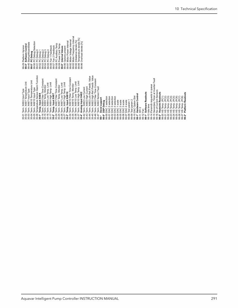
99-9
0
Opt
ions
pre
sent
99-9
1
Mot
or P
ower
Inte
rnal
99-9
2
Mot
or V
olta
ge In
tern
al99
-93
M
otor
Fre
quen
cy In
tern
al99
-94
Im
bala
nce
dera
te [%
]99
-95
Te
mpe
ratu
re d
erat
e [%
]99
-96
O
verlo
ad d
erat
e [%
]
99-5
5
PC D
ebug
499
-56
Fa
n 1
Feed
back
99-5
7
Fan
2 Fe
edba
ck99
-58
PC
Aux
iliary
Tem
p99
-59
Po
wer
Car
d Te
mp.
99-9
*
Inte
rnal
Val
ues
99-5
4 PC
Deb
ug 3
35-0
2 Te
rm. X
48/7
Tem
pera
ture
Uni
t35
-03
Term
. X48
/7 In
put T
ype
35-0
4 Te
rm. X
48/1
0 Te
mpe
ratu
re U
nit
35-0
5 Te
rm. X
48/1
0 In
put T
ype
35-0
6 Te
mpe
ratu
re S
enso
r Ala
rm F
unct
ion
35-1
* Te
mp.
Inpu
t X48
/435
-14
Term
. X48
/4 F
ilter
Tim
e C
onst
ant
35-1
5 Te
rm. X
48/4
Tem
p. M
onito
r35
-16
Term
. X48
/4 L
ow T
emp.
Lim
it35
-17
Term
. X48
/4 H
igh
Tem
p. L
imit
35-2
* Te
mp.
Inpu
t X48
/735
-24
Term
. X48
/7 F
ilter
Tim
e C
onst
ant
35-2
5 Te
rm. X
48/7
Tem
p. M
onito
r35
-26
Term
. X48
/7 L
ow T
emp.
Lim
it35
-27
Term
. X48
/7 H
igh
Tem
p. L
imit
35-3
* Te
mp.
Inpu
t X48
/10
35-3
4 Te
rm. X
48/1
0 Fi
lter T
ime
Con
stan
t35
-35
Term
. X48
/10
Tem
p. M
onito
r35
-36
Term
. X48
/10
Low
Tem
p. L
imit
35-3
7 Te
rm. X
48/1
0 H
igh
Tem
p. L
imit
35-4
* A
nalo
g In
put X
48/2
35-4
2 Te
rm. X
48/2
Low
Cur
rent
35-4
3 Te
rm. X
48/2
Hig
h C
urre
nt35
-44
Term
. X48
/2 L
ow R
ef./F
eedb
. Val
ue35
-45
Term
. X48
/2 H
igh
Ref
./Fee
db. V
alue
35-4
6 Te
rm. X
48/2
Filt
er T
ime
Con
stan
t35
-47
Term
. X48
/2 S
enso
r Fau
lt99
-*
Dev
el s
uppo
rt99
-0*
DSP
Deb
ug99
-00
DAC
1 s
elec
tion
99-0
1 D
AC 2
sel
ectio
n99
-02
DAC
3 s
elec
tion
99-0
3 D
AC 4
sel
ectio
n99
-04
DAC
1 s
cale
99-0
5 D
AC 2
sca
le99
-06
DAC
3 s
cale
99-0
7 D
AC 4
sca
le99
-08
Test
par
am 1
99-0
9 Te
st p
aram
299
-10
DAC
Opt
ion
Slot
99-1
* H
ardw
are
Con
trol
99-1
1 R
FI 2
99-1
2 Fa
n99
-1*
Softw
are
Rea
dout
s99
-13
Idle
tim
e99
-14
Para
mdb
requ
ests
in q
ueue
99-1
5 Se
cond
ary
Tim
er a
t Inv
erte
r Fau
lt99
-16
No
of C
urre
nt S
enso
rs99
-2*
Hea
tsin
k R
eado
uts
99-2
0 H
S Te
mp.
(PC
1)99
-21
HS
Tem
p. (P
C2)
99-2
2 H
S Te
mp.
(PC
3)99
-23
HS
Tem
p. (P
C4)
99-2
4 H
S Te
mp.
(PC
5)99
-25
HS
Tem
p. (P
C6)
99-2
6 H
S Te
mp.
(PC
7)99
-27
HS
Tem
p. (P
C8)
99-2
* Pl
atfo
rm R
eado
uts
99-2
9 Pl
atfo
rm V
ersi
on99
-4*
So
ftwar
e C
ontr
ol99
-40
St
artu
pWiz
ardS
tate
99-5
*
PC D
ebug
99-5
0
PC D
ebug
Sel
ectio
n99
-51
PC
Deb
ug 0
99-5
2
PC D
ebug
199
-53
PC
Deb
ug 2
35-0
1 Te
rm. X
48/4
Inpu
t Typ
e
10 Technical Specification
Aquavar Intelligent Pump Controller INSTRUCTION MANUAL 291

11 Product WarrantyFor Bell & Gossett and CentriPro
Commercial warranty
Warranty. For goods sold to commercial buyers, Seller warrants the goods sold to Buyerhereunder (with the exception of membranes, seals, gaskets, elastomer materials,coatings and other "wear parts" or consumables all of which are not warranted except asotherwise provided in the quotation or sales form) will be (i) be built in accordance withthe specifications referred to in the quotation or sales form, if such specifications areexpressly made a part of this Agreement, and (ii) free from defects in material andworkmanship for a period of thirty-six (36) months from the date of installation or forty-two(42) months from the date of shipment (which date of shipment shall not be greater thanndythirty (30) days after receipt of notice that the goods are ready to ship), whichever shalloccur first, unless a longer period is specified in the product documentation (the“Warranty”).
Except as otherwise required by law, Seller shall, at its option and at no cost to Buyer,either repair or replace any product which fails to conform with the Warranty providedBuyer gives written notice to Seller of any defects in material or workmanship within ten(10) days of the date when any defects or non-conformance are first manifest. Undereither repair or replacement option, Seller shall not be obligated to remove or pay for theremoval of the defective product or install or pay for the installation of the replaced orrepaired product and Buyer shall be responsible for all other costs, including, but notlimited to, service costs, shipping fees and expenses. Seller shall have sole discretion as tothe method or means of repair or replacement. Buyer’s failure to comply with Seller’srepair or replacement directions shall terminate Seller’s obligations under this Warrantyand render the Warranty void. Any parts repaired or replaced under the Warranty arewarranted only for the balance of the warranty period on the parts that were repaired orreplaced. Seller shall have no warranty obligations to Buyer with respect to any product orparts of a product that have been: (a) repaired by third parties other than Seller or withoutSeller’s written approval; (b) subject to misuse, misapplication, neglect, alteration,accident, or physical damage; (c) used in a manner contrary to Seller’s instructions forinstallation, operation and maintenance; (d) damaged from ordinary wear and tear,corrosion, or chemical attack; (e) damaged due to abnormal conditions, vibration, failureto properly prime, or operation without flow; (f) damaged due to a defective powersupply or improper electrical protection; or (g) damaged resulting from the use ofaccessory equipment not sold or approved by Seller. In any case of products notmanufactured by Seller, there is no warranty from Seller; however, Seller will extend toBuyer any warranty received from Seller’s supplier of such products.
THE FOREGOING WARRANTY IS EXCLUSIVE AND IN LIEU OF ANY AND ALL OTHEREXPRESS OR IMPLIED WARRANTIES, GUARANTEES, CONDITIONS OR TERMS OFWHATEVER NATURE RELATING TO THE GOODS PROVIDED HEREUNDER, INCLUDINGWITHOUT LIMITATION ANY IMPLIED WARRANTIES OF MERCHANTABILITY ANDFITNESS FOR A PARTICULAR PURPOSE, WHICH ARE HEREBY EXPRESSLY DISCLAIMEDAND EXCLUDED. EXCEPT AS OTHERWISE REQUIRED BY LAW, BUYER’S EXCLUSIVEREMEDY AND SELLER’S AGGREGATE LIABILITY FOR BREACH OF ANY OF THEFOREGOING WARRANTIES ARE LIMITED TO REPAIRING OR REPLACING THE PRODUCTAND SHALL IN ALL CASES BE LIMITED TO THE AMOUNT PAID BY THE BUYER FOR THEDEFECTIVE PRODUCT. IN NO EVENT SHALL SELLER BE LIABLE FOR ANY OTHER FORMOF DAMAGES, WHETHER DIRECT, INDIRECT, LIQUIDATED, INCIDENTAL,CONSEQUENTIAL, PUNITIVE, EXEMPLARY OR SPECIAL DAMAGES, INCLUDING BUTNOT LIMITED TO LOSS OF PROFIT, LOSS OF ANTICIPATED SAVINGS OR REVENUE,LOSS OF INCOME, LOSS OF BUSINESS, LOSS OF PRODUCTION, LOSS OFOPPORTUNITY OR LOSS OF REPUTATION.
11 Product Warranty
292 Aquavar Intelligent Pump Controller INSTRUCTION MANUAL
Limited consumer warranty
Warranty. For goods sold for personal, family or household purposes, Seller warrants thegoods purchased hereunder (with the exception of membranes, seals, gaskets, elastomermaterials, coatings and other "wear parts" or consumables all of which are not warrantedexcept as otherwise provided in the quotation or sales form) will be free from defects inmaterial and workmanship for a period of thirty-six (36) months from the date ofinstallation or forty-two (42) months from the product date code, whichever shall occurfirst, unless a longer period is provided by law or is specified in the productdocumentation (the “Warranty”).
Except as otherwise required by law, Seller shall, at its option and at no cost to Buyer,either repair or replace any product which fails to conform with the Warranty providedBuyer gives written notice to Seller of any defects in material or workmanship within ten(10) days of the date when any defects or non-conformance are first manifest. Undereither repair or replacement option, Seller shall not be obligated to remove or pay for theremoval of the defective product or install or pay for the installation of the replaced orrepaired product and Buyer shall be responsible for all other costs, including, but notlimited to, service costs, shipping fees and expenses. Seller shall have sole discretion as tothe method or means of repair or replacement. Buyer’s failure to comply with Seller’srepair or replacement directions shall terminate Seller’s obligations under this Warrantyand render this Warranty void. Any parts repaired or replaced under the Warranty arewarranted only for the balance of the warranty period on the parts that were repaired orreplaced. The Warranty is conditioned on Buyer giving written notice to Seller of anydefects in material or workmanship of warranted goods within ten (10) days of the datewhen any defects are first manifest.
Seller shall have no warranty obligations to Buyer with respect to any product or parts of aproduct that have been: (a) repaired by third parties other than Seller or without Seller’swritten approval; (b) subject to misuse, misapplication, neglect, alteration, accident, orphysical damage; (c) used in a manner contrary to Seller’s instructions for installation,operation and maintenance; (d) damaged from ordinary wear and tear, corrosion, orchemical attack; (e) damaged due to abnormal conditions, vibration, failure to properlyprime, or operation without flow; (f) damaged due to a defective power supply orimproper electrical protection; or (g) damaged resulting from the use of accessoryequipment not sold or approved by Seller. In any case of products not manufactured bySeller, there is no warranty from Seller; however, Seller will extend to Buyer any warrantyreceived from Seller’s supplier of such products.
THE FOREGOING WARRANTY IS PROVIDED IN PLACE OF ALL OTHER EXPRESSWARRANTIES. ALL IMPLIED WARRANTIES, INCLUDING BUT NOT LIMITED TO THEIMPLIED WARRANTIES OF MERCHANTABILITY AND FITNESS FOR A PARTICULARPURPOSE, ARE LIMITED TO THIRTY-SIX (36) MONTHS FROM THE DATE OFINSTALLATION OR FORTY-TWO (42) MONTHS FROM THE PRODUCT DATE CODE ,WHICHEVER SHALL OCCUR FIRST. EXCEPT AS OTHERWISE REQUIRED BY LAW, BUYER’SEXCLUSIVE REMEDY AND SELLER’S AGGREGATE LIABILITY FOR BREACH OF ANY OFTHE FOREGOING WARRANTIES ARE LIMITED TO REPAIRING OR REPLACING THEPRODUCT AND SHALL IN ALL CASES BE LIMITED TO THE AMOUNT PAID BY THE BUYERFOR THE DEFECTIVE PRODUCT. IN NO EVENT SHALL SELLER BE LIABLE FOR ANYOTHER FORM OF DAMAGES, WHETHER DIRECT, INDIRECT, LIQUIDATED, INCIDENTAL,CONSEQUENTIAL, PUNITIVE, EXEMPLARY OR SPECIAL DAMAGES, INCLUDING BUTNOT LIMITED TO LOSS OF PROFIT, LOSS OF ANTICIPATED SAVINGS OR REVENUE,LOSS OF INCOME, LOSS OF BUSINESS, LOSS OF PRODUCTION, LOSS OFOPPORTUNITY OR LOSS OF REPUTATION.
Some states do not allow limitations on how long an implied warranty lasts, so the abovelimitation may not apply to you. Some states do not allow the exclusion or limitation ofincidental or consequential damages, so the above exclusions may not apply to you. Thiswarranty gives you specific legal rights, and you may also have other rights which mayvary from state to state.
11 Product Warranty
Aquavar Intelligent Pump Controller INSTRUCTION MANUAL 293

To make a warranty claim, check first with the dealer from whom you purchased theproduct or visit www.xyleminc.com for the name and location of the nearest dealerproviding warranty service.
For Lowara
For Lowara only: for information about warranty, see the sales contract.
11 Product Warranty
294 Aquavar Intelligent Pump Controller INSTRUCTION MANUAL


Xylem |’zīləm|
1) The tissue in plants that brings water upward from the roots;2) a leading global water technology company.
We’re a global team unified in a common purpose: creating advancedtechnology solutions to the world’s water challenges. Developing newtechnologies that will improve the way water is used, conserved, and re-used inthe future is central to our work. Our products and services move, treat, analyze,monitor and return water to the environment, in public utility, industrial,residential and commercial building services settings. Xylem also provides aleading portfolio of smart metering, network technologies and advancedanalytics solutions for water, electric and gas utilities. In more than 150 countries,we have strong, long-standing relationships with customers who know us for ourpowerful combination of leading product brands and applications expertise witha strong focus on developing comprehensive, sustainable solutions.
For more information on how Xylem can help you, go to www.xylem.com
Xylem Inc.2881 East Bayard St. Ext., Suite A Seneca Falls, NY 13148USATel: (866) 325-4210Fax: (888) 322-5877www.xylem.com/centripro
Visit our Web site for the latest version of this documentand more information
The original instruction is in English. All non-Englishinstructions are translations of the original instruction.
© 2020 Xylem Inc
CentriPro is a trademark of Xylem Inc or one of itssubsidiaries.
IM318_Rev 1_February 2020_en-US_Aquavar Intelligent Pump Controller