Emotionally Intelligent Leadership: An Integrative, Process ...
Upload
khangminh22Category
view
0download
0
INTELLIGENT TANKSENSORSITS 60 FOR DIESEL FUELSITS 65 FOR HYDRAULIC- AND ENGINE OILSWith E1 type approval
NO MECHANICAL MOVING PARTS ROBUST DESIGN FOR HEAVY DUTY APPLICATIONS PRECISE INDICATION OF MEDIUM LEVEL PRECISE INDICATION OF THE MEDIUM TEMPERATURE LINEAR OUTPUT SIGNAL EVEN WITH NON LINEAR TANK GEOMETRY
MIN OR MAX SWITCHING POINT INTEGRATED
ISO 9001CertifiedQuality Management System
www.tuv-sud.com/ms-cert
ISO 14001Certified EnvironmentalManagement System
www.tuv-sud.com/ms-cert

2 www.bedia.com

3www.bedia.com
CONTENT
The company 4
Tough ambient conditions 6
All hydraulic and engine oils are measurable 7
Flexibility and Compatibility 8
Tank geometry adaption 9
Integrated second output 10
Output 11
Technical data 12
Instructions for determining parameters 14
Connectors and Designs 29
Order number overview 32
Parameter sheet 35

4 www.bedia.com
BEDIAThe company
As a high performance and innovative company BEDIA deve-
lopes, produces and distributes well thought out solutions for
level and temperature monitoring.
We have been concentrating our skills in the domain of meas-
uring filling levels and temperatures under extreme operating
conditions. We are able to offer customized solutions to the
specific requirements of our clients for small to large series.
In doing so we are combining tried and tested technolo-
gies with innovative product ideas. Our expertise and flex-
ibility are well demonstrated in the developement of customer
specific solutions.
One thing that all our products have in common is the nonexist-
ence of moving or adjustable parts; our parts are not subject
to mechanical interference and exhibit exceptional operational
reliability.
Since 1986 BEDIA Motorentechnik is a valued partner of nu-
merous manufacturers of agricultural and construction ma-
chinery, compressors, engines, power train control systems and
utility vehicles.
The high quality requirements of our world wide operating cus-
tomers are our motivation for the constant improvement of our
products and processes. The stable customer relationships of
many years standing express the high quality of our products
and the satisfaction of our customers.
We hope you will get a comprehensive overview of our prod-
ucts from this catalog. Please feel free to contact us, we will be
happy to assist you with our advice and experience.
Measuring with system and passion

5www.bedia.com
Company history at a glance
Our products at a glance
capacitive level sensors for a versatile range of applications: · CLS 20/25 for railway applications tested according to DIN EN 50155
· CLS 40/45 for off- and onroad applications with E1-type approval of the KBA
· CLS 50/55 for maritime applications with approvals of the classification societies
intelligent, analog tank sensors for fuels and oils
intelligent, analog hot wire sensors for monitoring oil sump fill levels
temperature sensors
mechanical temperature switches
electronic temperature switches
electronic temperature sensors
DC/DC converters
We are certified in accordance with ISO 9001:2015 and ISO 14001:2015.
Relocation of BEDIA Motorentechnik and BEDIA Kabel to the new corporate building in Altdorf in the indus-trial park near the A6. 2
009
2005
Reorganization of BEDIA Motorentechnik GmbH into BEDIA Motorentechnik GmbH & Co. KG, preparation and the transfer of business administration to Holger Schultheis.
1994 Transfer of the Sensor Systems and Water Treatment
business unit from BEDIA Maschinenfabrik to BEDIA Motorentechnik.
Foundation of BEDIA Motorentechnik in Leinburg. Core focus business with vehicle wiring cables and delivery of sensor parts for the Bedia Maschinenfabrik in Bonn.
1986
Spin-off of the new BEDIA Kabel business unit from BEDIA Motorentechnik GmbH & Co. KG into BEDIA Kabel GmbH & Co. KG.2
006
Sale of the water treatment business unit to Aqua-Concept GmbH.2
000
Takeover of the production for sensors from the business entit E-T-A in Altdorf2
008
Foundation of BEDIA Sensors USA in Austin, Texas
2012
30th company anniversary
2016
currently about 140 employees
2020

6 www.bedia.com
TOUGH AMBIENT CONDITIONS
Mechanics
The tank sensor ITS 60/ITS 65 is characterized by a particularly stable, but light mechanical system
specifically designed for “Heavy Duty Applications”.
The mounting flange and measurement tube are constructed from die cast aluminium.
This design permits the insertion of tank sensors up to 1200 mm in length,
without additional support on the tank floor.
The flange hole distribution is compatible with commercially used tank sensors. This means that this system can be
used without expensive conversions.
The capacitive measurement principle permits measurement of levels without mechanical
moving parts. This increases stability and operating safety considerably.
Die cast aluminium

7www.bedia.com
ALL HYDRAULIC AND ENGINE OILS ARE MEASURABLE
The ITS65 level measuring system is based on a capacitive measurement principle. A capacitor is formed by an electrically
conducting plate and an aluminium tube. Depending on the level, the remaining air volume between the measurement
electrodes varies. The resulting capacitive change is detected and processed by the microcontroller.
Additionally, the ITS65 offers measurement of the medium temperature through a sensor element posi-
tioned at the tip of the sensor.
Measurement principle
Capacitance measurement
„Capacitive is not always capacitive!”
Er = 1
V
V
Er = 1
V
V
electrical field
With capacitive level measurement, the variation in permittivity of different media is an important aspect. Conventional
capacitive sensors can therefore measure only one particular medium type correctly. This can lead to a measurement inac-
curacy of up to 50%, e.g. due to aging or change of the medium.
Our sensor is equipped with a proprietary sensor structure. This permits automatic calibration of the
medium, which is to be measured. This calibration occurs at levels as low as 50%.
The conductivity of the medium due to the existence of traces of water is compensated over a wide range by an integrated
microprocessor by means of several plausibility checks.
Air r = 1
Oil r > 1
ЗЗ
ЗЗ

8 www.bedia.com
FLEXIBILITY AND COMPATIBILITY
1
2
3
4
5
0 10 % 20 % 30 % 40 % 50 % 60 % 70 % 80 % 90 % 100 %
Output signal [v]
Immersion depth
Freely selectable range for the output
The intelligent electronic integrated in the tank sensors offers a variety of processing and output options such as e.g.:
PWM SIGNALS (DIGITAL OR RESISTANCE EMULATION FOR COMMERCIAL ANALOG MEASUREMENT INSTRUMENTS)
VOLTAGE OUTPUT
CURRENT LOOP
CAN INTERFACE (ON REQUEST)
The measurement range, which can be programmed according to customer requirements, lies between 20 mm below the
seal edge and 10 mm from the sensor end.
Evaluation and signal processing
Example of use

9www.bedia.com
Using a microcontroller not only permits linear tank geometries to be taken into account with the ITS 60 / ITS 65 tank sen-
sor, but a variety of tank geometries to be correctly evaluated by programming up to 15 reference points.
Example of use
Output signal [v]
Immersion depth
Adaption to tank geometry using 15 reference points.
TANK GEOMETRY ADAPTION

10 www.bedia.com
INTEGRATED SECOND OUTPUT
Immersion depth
Freely selectable switchpoint as MIN or MAX version, plus selectable switch hysteresis and switch lag
An additional feature of the ITS is its freely configurable second output.
1. This output can be individually configured as either minimum or maximum switching point of the medium level. Further-
more, the switching point, the delay action and the switching hysteresis are programmable. A typical application of the
switching point would be a refuelling facility with an automatic pump deactivation
2. On the ITS 65 the second output can alternatively be used as an analogue temperature output to determine the medium
temperature within a range from –50 to +150 °C. The output type (analogue output voltage, current loop or PWM sig-
nal) in that case is of the same type as the level output
Level switch
Uout [v]
Temperature [°C]
analogue temperature output(ITS 65 only)
Free selectable range for the analogue temperature output
AUS
EIN
0 10 % 20 % 30 % 40 % 50 % 60 % 70 % 80% 90 % 100 %
Output signal
on
off

11www.bedia.com
OUTPUT
The analogue outputs are available as voltage output, as PWM output or as current loop.
Output types
Analogue outputs
The switching output is available as a lowside
switch or a highside switch.
The switching output is short-circuit
protected and suitable for 500 mA.
With inductive loads, a freewheeling diode must
be connected in parallel to the load.
Switching output
Voltage
output:
PWM
signal:
1
t
Other signal types available on request.
t
t
Current
output:
Lowside Highside
Signal types
U
U
I

12 www.bedia.com
TECHNICAL DATA
Technical dataMeasure principle: r – compensated level measurement
medium temperature measurement from –50 °C to 150 °C (ITS 65 only)
Supply voltage: 12 V DC/24 V DC (–25%/+50%)
Reverse connection protection: Between supply voltage plus and minus
Measurable mediums: ITS 60: all diesel fuels
ITS 65: Oil mediums with an r 1,8 ... 6
Sensor outputs: Voltage output, PWM, Current loop, CAN
All outputs are short circuit protected
Signal Characteristics:: Range as per customer requirements
Tank geometry: Linear or as per customer requirements
Level switch- or Temperature output requirement: Switching point as defined by the customer
(within the measuring range)
MIN or MAX function
Hysteresis as defined by the customer
Delay time as defined by the customer
Low side switching upto 500mA and short circuit proof
Temperature output (analogue) –50 °C to 150 °C
Measurement deviation: +/– 3% referenced to the measurement range and value
Temperature: +/– 2 °C
Installation position: Vertical without support +/– 15° or ask for details
Pressure resistance: 5 bar
Environmental protection of flange: IP 69K according to DIN 40050
Environmental protection of connector: Depending on version, up to IP69K according to DIN 40050
Operating temperature: ITS 60: –40 °C to 85 °C ITS 65: –40 °C to 125 °C
Medium temperature: ITS 60: –40 °C to 85 °C ITS 65: –50 °C to 150 °C
Storage temperature: ITS 60: –50 °C to 85 °C ITS 65: –50 °C to 125 °C
El. connection: 3- or 4-wire cable; plug as per customer requirement
(standard: bayonet according to ISO 15170)
ЗЗ
ЗЗ

13www.bedia.com
TECHNICAL DATA
Technical dataMechanical connection: 5-hole flange (standard)
6-hole flange
G 2“ screw-in flange
Marking: Laser inscription
(manufacturer, manufacturer number, customer part number,
serial number, date: week/year )
Sensor length: As per customer requirements from 200 mm to 2300 mm
EMC*: Conducted emissions test according to CISPR 25
Measurement of radiated field strength according to CISPR 25
ESD test according to EN 61000-4-2 and ISO TR 10605
Immunity test according to ISO 11 452
Immunity test according to ISO EN 61000-4-6
Immunity test according to ISO EN 61000-4-5
Transient immunity test with test pulse 5 (load dump) according to ISO 7637-2
Voltage variations according to IEC 60092-504
Voltage interruptions according to IEC 60092-504
Vibratory resistance*: Sine-Vibration according to DIN IEC 68-2-6/ -27
Shock resistance*: Shock test according to DIN IEC 68-2-6/ -27
Environmental test*: Thermal shock test according to EN 60068-2
Temperature cycling examination according to EN 60068-2
Salt spray examination according to EN 60068-2
Type of protection examination IP 67 and IP 69K according DIN 40050 part 9
Flange material: GD-AlSi10Mg (Nr. 239) DIN 1725
Profile material: AlMgSi0, 5 F22 DIN 1725
* These tests were performed according to the standards of construction machinery and commercial vehicle industry
A complete test report is available on request.

14 www.bedia.com
INSTRUCTIONS FOR DETERMINING PARAMETERS
To be able to provide you with a quote or a finished sample, we will require various details from you. Because of the
numerous options that our sensor can offer, we are particularly dependent on your co-operation.
The following table provides definitions for the terms used, together with an example for the parameterisation of a sensor.
A dimensioned drawing is attached with all parameters listed.
All measurements are given in [mm] from the seal edge.
Please enter your data on page 35, and complete the entry with your personal information and the required number of
pieces per year. To receive a quote or request a sample, please fax this page to the fax number provided.
If you require any assistance with the completion of this form, please get in touch with us.

15www.bedia.com
This number
can be found
in the data
sheet.
Structure of the parameter sheet
Designation of the
parameter.
Describes the values
or value ranges
avail able for this
para meter.
Important notes and additional informa-
tion for this parameter.
Parameter
designation
Possible values Note
1
Mechanic
Mounting flange » 5-hole flange
(standard), diameter
of pitch circle =
54 mm
» 6-hole flange,
diameter of pitch
circle = 80 mm
» G 2“ screw-in flange
The screw-in flange consists of a sensor
with a 5-hole flange and an adapter.
The sensor and adapter are supplied
pre-mounted (see drawing).
Section Parameter
designation
Possible values Note
2 Standard sensor
pipe length
» Minimum length :
200 mm
» Maximum length :
2300 mm
The sensor pipe, which is open to the
bottom needs no guidance and must not
rest on the base of the tank so that the
medium to be measured can circulate
within the sensor pipe. The sensor pipe
should end near the intake point. This
ensures that the sensor is not standing in
condensation water.
Example for the parameterisation of a sensor for the tank and description depicted on page 9.
A 5-hole flange was selected for the example tank.
A length of 490 mm was selected for the example tank. This length results from the position of the intake fitting. The sensor pipe ends with the intake point.
Section
INSTRUCTIONS FOR DETERMINING PARAMETERS

16 www.bedia.com
3 Electrical
connection
» Bayonet cap
ISO 15170
(standard)
» Cable with open end
» Customer specified
connector
The electrical connection of the sensor
is preferably implemented via a 4-wire
cable with a bayonet connector ISO
15170 of protection class IP 69K. Other
connectors can be installed on request.
Section Parameter
designation
Possible values Note
Cable length » Minimum length :
100 mm
» Standard length
800 mm
» Other lengths
on request.
A bayonet cap ISO 15170 was selected for the example sensor.
A length of 800 mm was selected for the example sensor.
INSTRUCTIONS FOR DETERMINING PARAMETERS

17www.bedia.com
INSTRUCTIONS FOR DETERMINING PARAMETERS
4 Analogue output
signal
Sensor not immersed/
measurement start
* Voltage 0 - 5 V
* Voltage 0 - 10 V
(only with 24 V
supply)
* Current 4 - 20 mA
* PWM 0 - 100%
Sensor immersed /
measurement end
* Voltage 0 - 5 V
* Voltage 0 - 10 V
(only with 24 V
supply)
* Current 4 - 20 mA
* PWM 0 - 100%
The output signal consists of an ana-
logue start and analogue end. If the
given start value is smaller than the end
value, the sensor is programmed nor-
mally. If the start value is large than the
end value, then the signal is automati-
cally inverted. If an analogue instrument
is used, the output values can be given
in % of the desired display value on the
scale. In this case, a suitable display in-
strument must be provided as a sample.
Level output
Section Parameter
designation
Possible values Note
The following output signal was selected for the example sensor:Analogue start: 0.5 V Analogue end: 4.5 VThis signal is not inverted.

18 www.bedia.com
4 Output type The voltage output actively outputs
the level/volume applicable voltage. A
Pull Up/constant current is not required.
The output can be loaded with 2 mA.
The frequency of the PWM output is
1000 Hz. A modulation range of
0 % to 100 % is possible.
The analog current output supplies
current equivalent to the measured level.
The current range is from
4 - 20 mA.
Section Parameter
designation
Possible values Note
» Voltage output:
» PWM output:
» Current output:
Output selected for this example: voltage output.
INSTRUCTIONS FOR DETERMINING PARAMETERS

19www.bedia.com
INSTRUCTIONS FOR DETERMINING PARAMETERS
5 Analogue
temperature output
Analogue tempera-
ture output
* Voltage 0 - 5 V
* Voltage 0 - 10 V
(only with 24 V
supply)
* Current 4 - 20 mA
* PWM 0 - 100%
Temperature measur-
ing range
–50 °C ... 150 °C
For measuring the medium’s tempera-
ture, a range within the threshold values
can be freely selected.
An analogue output voltage can be
generated for this temperature range.
The type of output (analogue voltage,
current loop or PWM) is then always the
same as for the level output.
Analogue temperature output (ITS 65 only)
Section Parameter
designation
Possible values Note
Uout [v]
Temperature [°C]
Analogue temperature output

20 www.bedia.com
INSTRUCTIONS FOR DETERMINING PARAMETERS
6 Switching point » Switching point range
» See dimensioned
drawing
» Switching point
in [mm]
The sensor is equipped with one switch-
ing output. When actuated, a minus
potential is switched through the output.
The distance of the switching point is
measured from the seal edge and is
freely selectable within the switching
point range (see drawing).
Level switch output
Section Parameter
designation
Possible values Note
A switching point of 400 mm was selected for the example sensor.

21www.bedia.com
INSTRUCTIONS FOR DETERMINING PARAMETERS
Function of
switching point
» Function:
Minimum
» Function:
Maximum
The switching output is optional and
can be set as a minimum switch (e.g. as
a low fuel warning) or as a maximum
switch (e.g. to switch off a filling system).
Section Parameter
designation
Possible values Note
Switching delay » Switching delay
range
0 sec to 240 sec
» Delay in [sec]
A switching delay can be selected for
the switch output. The switching output
is then switched with the specified time
(t) delay. For a low fuel indicator, a
delay time of 7 sec prevents the indica-
tor from constantly triggering when the
medium sloshes around. A delay time
of 0 sec is recommended for overfilling
(MAX- switching point) as this will ensure
a prompt switch-off. Depending on the
system, extremely fast level changes
(fuelling up) can still occur and therefore
the switching output may switch with
appr. 2 sec delay.
A minimum switch was selected for the example sensor.
A switching delay of 7 sec was selected for the example sensor (typical MIN).
medium
no medium
minimum
switching
maximum
switching
switch delayt
switch delayt

22 www.bedia.com
INSTRUCTIONS FOR DETERMINING PARAMETERS
Reset hysteresis» The switch-off
point must lie
within the swit-
ching point range.
» Switch-off point in
[mm]
The medium must under/overshoot
a specific switch-off point before the
switching output is reseted to its output
condition. The position of the switch-off
point is given to the switching point.
Section Parameter
designation
Possible values Note
A reset hysteresis of 0 mm was selected for the example sensor.

23www.bedia.com
INSTRUCTIONS FOR DETERMINING PARAMETERS
7 Measurement
range/Geometry
adaptation
» Position from
seal edge
Data in [mm]
This parameter is used to specify the
positions of the measurement range
start and measurement range end.
Where necessary, several geometry
points can also be specified (see exam-
ple). In total, 15 connection points can
be defined. At least two points must
be defined to specify the measurement
range. If the analogue output shall be
proportional to the tank volume, the
setting points can be given in [V], [mA]
or in [% PWM].
Section Parameter
designation
Possible values Note
Geometry adaption
Volume [l]
Position from seal edge [mm]
Diagram for the example tank

24 www.bedia.com
INSTRUCTIONS FOR DETERMINING PARAMETERS
As the output signal of the example sensor is to be proportional to the contents of the tank
the following connection points are defined:
The output value “analogue start” is always given with the first setting point and the “analogue end” value
is always given with the last setting point. If the signal is not to be given in proportion to the level but e.g.
proportional to the actual content, additional setting points must be provided. Up to 15 setting points can be
given.
Connection point
1
2
3
Position from seal edge
480 mm
200 mm
20 mm
Output value
0,50 V
3,59 V
4,50 V

25www.bedia.com
Example tank
INSTRUCTIONS FOR DETERMINING PARAMETERS
26 www.bedia.com
Example
X ( 1 : 1 )X
F E D C B A
E D C B A
12
43
67
23
Das Urheberrecht an dieser Zeichnung gehört uns. Vervielfältigung, Überlassung, Zugänglichkeit oder Mitteilung des Inhalts, auch auszugsweise, an Dritte ist nicht gestattet. Die Zeichnung darf ohne unsere Zustimmung, zu einem anderen Zweck als sie dem Empfänger anvertraut wird, nicht benutzt werden. Zuwiderhandlung verpflichtet zu Schadenersatz. Alle Rechte, für den Fall einer Patenterteilung, Gebrauchsmustereintrag oder anderer Schutzrechte, sind uns vorbehalten.
BEDIA Motorentechnik GmbH & Co.KG, Altdorf bei Nürnberg
The copyright to this drawing belongs to us. No duplication or transfer to, providing access to or communicating to any third parties is allowed of its contents or excerpts thereof. This drawing may not be used without our approval for any purpose other than that for which it has been entrusted to the recipient. Any non-compliance shall obligate the violator to compensate for damages. In case any patent is issued or a utility model is registered, or in caseof any other industrial property rights, all such rights must be reserved for us.
41
5
Zust. / rev.
Änderung/m
odification D
atum/date
Nam
e/Geprüft
checked by
Erstellt /created byG
eprüft /checked by
Zul. Abw
eichung /adm
issible toleranceO
berfläche /surface
Position /
positionM
enge /am
ountM
aßstab /scale
Benennung / description
Zeichnungsnumm
er / drawing num
ber
Dimensional drawing 5-hole
ITS-60 tank sensor09.04.2013
MödererS
aß09.04.2013
1/1
with 5-hole-flange
1:1
Nam
e / name
Datum
/ date
Blatt / sheet
Format /
Size
A3
Maßeinheit /
dimension unitin [m
m]
20
25
19
cable length39,7Ø
4
54
65
30
68°80°
68°
72°
5x Ø5,6 conical (Ø
6,4)
sensor pipe length
36°
35Ø
132 4
10available sw
itching point range
available measuring range
1 = positive (+)2 = negative (-)3 = level output4 = sw
itching output
10
10
INSTRUCTIONS FOR DETERMINING PARAMETERS

27www.bedia.com
INSTRUCTIONS FOR DETERMINING PARAMETERS
Example
X ( 1 : 1 )X
F E D C B A
E D C B A
12
43
67
23
Das Urheberrecht an dieser Zeichnung gehört uns. Vervielfältigung, Überlassung, Zugänglichkeit oder Mitteilung des Inhalts, auch auszugsweise, an Dritte ist nicht gestattet. Die Zeichnung darf ohne unsere Zustimmung, zu einem anderen Zweck als sie dem Empfänger anvertraut wird, nicht benutzt werden. Zuwiderhandlung verpflichtet zu Schadenersatz. Alle Rechte, für den Fall einer Patenterteilung, Gebrauchsmustereintrag oder anderer Schutzrechte, sind uns vorbehalten.
BEDIA Motorentechnik GmbH & Co.KG, Altdorf bei Nürnberg
The copyright to this drawing belongs to us. No duplication or transfer to, providing access to or communicating to any third parties is allowed of its contents or excerpts thereof. This drawing may not be used without our approval for any purpose other than that for which it has been entrusted to the recipient. Any non-compliance shall obligate the violator to compensate for damages. In case any patent is issued or a utility model is registered, or in caseof any other industrial property rights, all such rights must be reserved for us.
41
5
Zust. / rev.
Änderung/m
odification D
atum/date
Nam
e/Geprüft
checked by
Erstellt /created byG
eprüft /checked by
Zul. Abw
eichung /adm
issible toleranceO
berfläche /surface
Position /
positionM
enge /am
ountM
aßstab /scale
Benennung / description
Zeichnungsnumm
er / drawing num
ber
Dimensional drawing 6-hole
ITS-60 tank sensor09.04.2013
MödererS
aß09.04.2013
1/1
with 6-hole-flange
1:1
Nam
e / name
Datum
/ date
Blatt / sheet
Format /
Size
A3
Maßeinheit /
dimension unitin [m
m]
15
25
14
cable length41,6Ø
4
96
30
sensor pipe length
35Ø
132 4
10available sw
itching point range
available measuring range
1 = positive (+)2 = negative (-)3 = level output4 = sw
itching output
10
10
5
7
6x
30°
60°6x
(=360°)
50
80

28 www.bedia.com
INSTRUCTIONS FOR DETERMINING PARAMETERS
Example
X ( 1 : 1 )X
F E D C B A
E D C B A
12
43
67
23
Das Urheberrecht an dieser Zeichnung gehört uns. Vervielfältigung, Überlassung, Zugänglichkeit oder Mitteilung des Inhalts, auch auszugsweise, an Dritte ist nicht gestattet. Die Zeichnung darf ohne unsere Zustimmung, zu einem anderen Zweck als sie dem Empfänger anvertraut wird, nicht benutzt werden. Zuwiderhandlung verpflichtet zu Schadenersatz. Alle Rechte, für den Fall einer Patenterteilung, Gebrauchsmustereintrag oder anderer Schutzrechte, sind uns vorbehalten.
BEDIA Motorentechnik GmbH & Co.KG, Altdorf bei Nürnberg
The copyright to this drawing belongs to us. No duplication or transfer to, providing access to or communicating to any third parties is allowed of its contents or excerpts thereof. This drawing may not be used without our approval for any purpose other than that for which it has been entrusted to the recipient. Any non-compliance shall obligate the violator to compensate for damages. In case any patent is issued or a utility model is registered, or in caseof any other industrial property rights, all such rights must be reserved for us.
41
5
Zust. / rev.
Änderung/m
odification D
atum/date
Nam
e/Geprüft
checked by
Erstellt /created byG
eprüft /checked by
Zul. Abw
eichung /adm
issible toleranceO
berfläche /surface
Position /
positionM
enge /am
ountM
aßstab /scale
Benennung / description
Zeichnungsnumm
er / drawing num
ber
Dimensional drawing adapter G2"
ITS-60 tank sensor09.04.2013
MödererS
aß09.04.2013
1/1
with G2" screw in flange
1:1
Nam
e / name
Datum
/ date
Blatt / sheet
Format /
Size
A3
Maßeinheit /
dimension unitin [m
m]
30
25
10
cable length
54
65
30
68°
80°68°
72°
sensor pipe length
36°
35Ø
132 4
10available switching point range
available measuring range
1 = positive (+)2 = negative (-)3 = level output4 = sw
itching output
10
10
25
G 2"
75
5x hexagon sockethead screwD
IN912-A2 M
5x30
65(HEX )
65HEX

29www.bedia.com
CONNECTORS AND DESIGNS
5-hole flange cable with bayonet according ISO 15170 overmolded
» Order number overview at page 32
5-hole flange cable with DEUTSCH DT04-4P
» Order number overview at page 32
5-hole flange cable with connector AMPSEAL 16 4-pole
5-hole flange cable with SUPERSEAL
5-hole flange cable with SUPERSEAL
5-hole flange cable with Packard overmolded
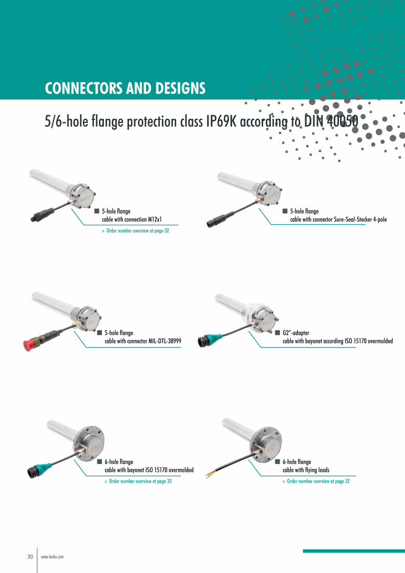
5/6-hole flange protection class IP69K according to DIN 40050
30 www.bedia.com
5-hole flange cable with connection M12x1
» Order number overview at page 32
5-hole flange cable with connector Sure-Seal-Stecker 4-pole
CONNECTORS AND DESIGNS
5/6-hole flange protection class IP69K according to DIN 40050
5-hole flange cable with connector MIL-DTL-38999
G2“-adapter cable with bayonet according ISO 15170 overmolded
6-hole flange cable with bayonet ISO 15170 overmolded
» Order number overview at page 32
6-hole flange cable with flying leads
» Order number overview at page 32

31www.bedia.com
CONNECTORS AND DESIGNS
5/6-hole flange protection class IP69K according to DIN 40050
5-hole flange with connector DIN EN 175 301-803-A
5-hole flange with connector M12x1
5-hole flange with connector MIL-C-26482 series 2 - 4-pole

32 www.bedia.com
200 0.0V-5.0V 800 2* 600 502240 0V-5V 6000 1* 600 430250 0V-5V 800 2* 600 183250 0.45V-5V 500 1* 600 257250 0V-5V 2000 1* 600 437265 0.5V-3.3V 900 1* 600 422270 0V-5V 800 2* 600 471285 0.5V-4.5V MIN 250 300 1* 600 115290 0.5V-4.5V 200 2* 600 255300 0V-5V 800 2* 600 240300 0.5V-4.5V MIN 250 800 1* 600 306340 0.5V-10V MIN 279 800 2* 600 291350 0.5V-10V MIN 288 800 2* 600 292357 0.5V-4.5V MIN 180 300 1* 600 227360 0.5V-10V MIN 297 800 2* 600 293370 0V-5V MAX 30 800 2* 600 057370 0V-10V MIN 360 3000 1* 600 202370 1V-9V 100 3* 600 413380 0.5V-4.5V 200 2* 600 191382 0.5V-4.5V MIN 350 300 1* 600 226390 0V-10V MIN 350 800 2* 600 223390 0.5V-4.5V MIN 304 800 2* 600 417400 0V-5V 2000 1* 600 213400 0.5V-10V MIN 333 800 2* 600 294400 0V-5V 6000 1* 600 435410 0V-10V MIN 370 800 2* 600 224460 0V-10V MIN 415 800 2* 600 222480 0.5V-10V 3000 1* 600 160480 0V-10V MIN 430 800 2* 600 221480 0.5V-10V MIN 405 800 2* 600 295500 0.5V-4.5V MIN 470 200 4* 600 034500 0.5V-4.5V 600 3* 600 395500 0V-5V 6000 1* 600 431530 0V-10V 1000 1* 600 086536 0.5V-4.5V 300 1* 600 149540 0.5V-10V MIN 459 800 2* 600 297540 0V-10V MIN 480 10000 1* 600 359550 0.5V-10V MIN 468 800 2* 600 296550 0V-5V 6000 1* 600 432567 0.5V-4.5V MIN 354 300 1* 600 228570 0V-5V 500 2* 600 275575 0V-10V MIN 555 3000 1* 600 494
1* Cable with flying leads 2* Cable with bayonet according to ISO 15170 overmoulded
3* Cable with connector M12x1 4* Cable with Deutsch connector DT04-4P
Order number
Cable connection type
Cable length mm
Switching point
from the seal edge
Function of switching
point
Level output
Sensor pipe length mm
ORDER NUMBER OVERVIEW
ITS 60 with voltage output
33www.bedia.com
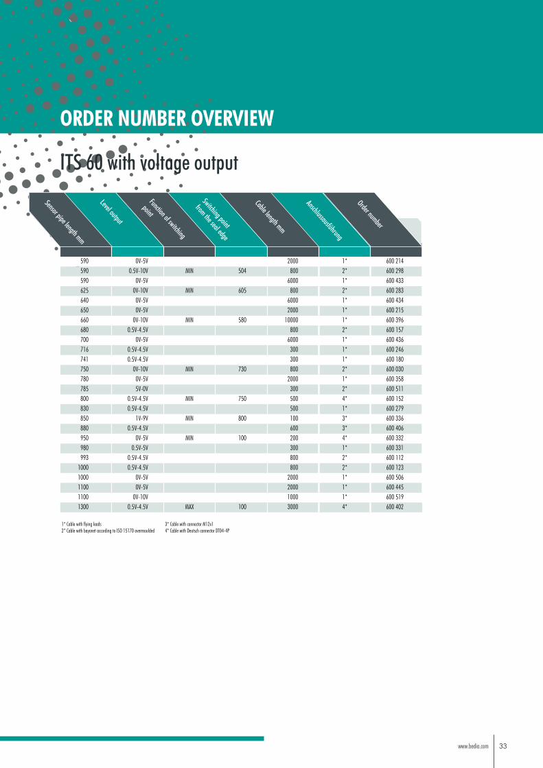
ORDER NUMBER OVERVIEW
ITS 60 with voltage output
590 0V-5V 2000 1* 600 214590 0.5V-10V MIN 504 800 2* 600 298590 0V-5V 6000 1* 600 433625 0V-10V MIN 605 800 2* 600 283640 0V-5V 6000 1* 600 434650 0V-5V 2000 1* 600 215660 0V-10V MIN 580 10000 1* 600 396680 0.5V-4.5V 800 2* 600 157700 0V-5V 6000 1* 600 436716 0.5V-4.5V 300 1* 600 246741 0.5V-4.5V 300 1* 600 180750 0V-10V MIN 730 800 2* 600 030780 0V-5V 2000 1* 600 358785 5V-0V 300 2* 600 511800 0.5V-4.5V MIN 750 500 4* 600 152830 0.5V-4.5V 500 1* 600 279850 1V-9V MIN 800 100 3* 600 336880 0.5V-4.5V 600 3* 600 406950 0V-5V MIN 100 200 4* 600 332980 0.5V-5V 300 1* 600 331993 0.5V-4.5V 800 2* 600 112
1000 0.5V-4.5V 800 2* 600 1231000 0V-5V 2000 1* 600 5061100 0V-5V 2000 1* 600 4451100 0V-10V 1000 1* 600 5191300 0.5V-4.5V MAX 100 3000 4* 600 402
1* Cable with flying leads 2* Cable with bayonet according to ISO 15170 overmoulded
3* Cable with connector M12x1 4* Cable with Deutsch connector DT04-4P
Order number
Anschlussausführung
Cable length mm
Switching point
from the seal edge
Function of switching
point
Level output
Sensor pipe length mm

34 www.bedia.com
ORDER NUMBER OVERVIEW
260 4.0mA-20mA MIN 180 2000 1* 600 510340 4.0mA-20mA 500 4* 600 245400 4.0mA-20mA 500 4* 600 193400 4.0mA-20mA 150 3* 600 518450 4.0mA-20mA 100 2* 600 238530 4.0mA-20mA 100 2* 600 716900 4.0mA-20mA MIN 760 2000 1* 600 312
1* Cable with flying leads 2* Cable with bayonet according to ISO 15170 overmoulded
3* Cable with connector M12x1 4* Cable with Deutsch connector DT04-4P
Order number
Anschlussausführung
Cable length mm
Switching point
from the seal edge
Function of switching
point
Level output
Sensor pipe length mm
ITS 60 with current loop output 4 mA - 20 mA
35www.bedia.com
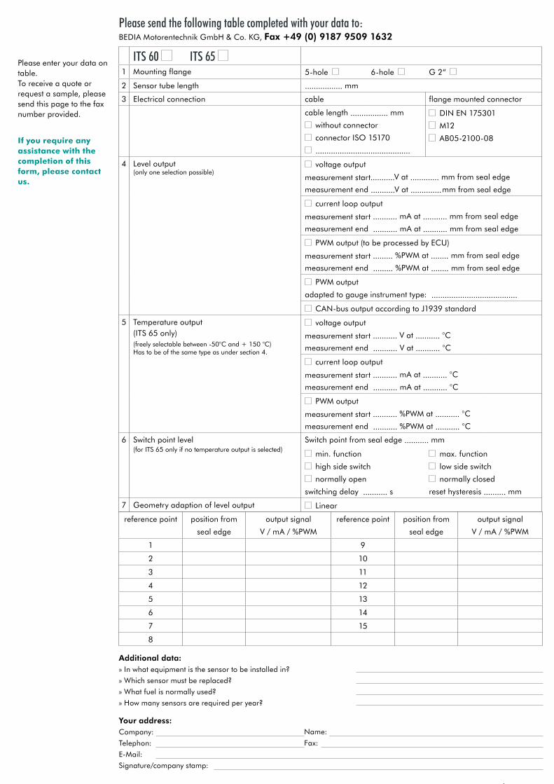
Please enter your data on table. To receive a quote or request a sample, please send this page to the fax number provided.
If you require any assistance with the completion of this form, please contact us.
ITS 60 ITS 65 1 Mounting flange 5-hole 6-hole G 2“
2 Sensor tube length ................. mm
3 Electrical connection cable flange mounted connector
cable length ................. mm
without connector
connector ISO 15170
...........................................
DIN EN 175301
M12
AB05-2100-08
4 Level output(only one selection possible)
voltage output
measurement start...........V at ............. mm from seal edge
measurement end ...........V at .............. mm from seal edge
current loop output
measurement start ........... mA at ........... mm from seal edge
measurement end ........... mA at ........... mm from seal edge
PWM output (to be processed by ECU)
measurement start ......... %PWM at ........ mm from seal edge
measurement end ......... %PWM at ........ mm from seal edge
PWM output
adapted to gauge instrument type: .......................................
CAN-bus output according to J1939 standard
5 Temperature output(ITS 65 only)(freely selectable between -50°C and + 150 °C)Has to be of the same type as under section 4.
voltage output
measurement start ........... V at ........... °C
measurement end ........... V at ........... °C
current loop output
measurement start ........... mA at ........... °C
measurement end ........... mA at ........... °C
PWM output
measurement start ........... %PWM at ........... °C
measurement end ........... %PWM at ........... °C
6 Switch point level(for ITS 65 only if no temperature output is selected)
Switch point from seal edge ........... mm
min. function
high side switch
normally open
switching delay ........... s
max. function
low side switch
normally closed
reset hysteresis .......... mm
7 Geometry adaption of level output Linear
reference point position from
seal edge
output signal
V / mA / %PWM
reference point position from
seal edge
output signal
V / mA / %PWM
1 9
2 10
3 11
4 12
5 13
6 14
7 15
8
Please send the following table completed with your data to: BEDIA Motorentechnik GmbH & Co. KG, Fax +49 (0) 9187 9509 1632
Additional data:» In what equipment is the sensor to be installed in?
» Which sensor must be replaced?
» What fuel is normally used?
» How many sensors are required per year?
Your address:Company:
Telephon:
E-Mail:
Signature/company stamp:
Fax:
Name:

Rev. 13/2019 - EN
454 013
rege
s-au
ge.d
e |
BED
-19
/03_
ITS
60/6
5_EN
BEDIA Motorentechnik GmbH & Co. KGIm Erlet 1D-90518 Altdorf bei Nürnberg
Phone +49 (0) 9187 9509 632Fax +49 (0) 9187 9509 1632
Copyright © 2022 FDOKUMEN