User manual - Jablotron
30
User manual
-
Upload
khangminh22 -
Category
Documents
-
view
0 -
download
0
Transcript of User manual - Jablotron

User manual
MLJ57205 - EN user manual - desky.indd 1 20.9.2014 12:23:18

1
1. INTRODUCTION 3
2. OPERATING THE JABLOTRON 100 SYSTEM 3
2.1 Keypad code authorization 4
2.2 Using the system keypad 6
2.2.1 Using the segment keypads 6
2.2.1.1 Alarm Setting 9
2.2.1.2 Alarm Unsetting 9
2.2.1.3 Duress Access Control 10
2.2.1.4 Partial Alarm Setting 10
2.2.1.5 Terminating a triggered alarm 11
2.2.1.6 Section control from the keypad’s display menu 11
2.2.2 Using the JA-110E and JA-150E system keypads 12
2.2.2.1 Alarm Setting 14
2.2.2.2 Alarm Unsetting 15
2.2.2.3 Partial Alarm Setting 15
2.2.2.4 Duress Access Control 16
2.2.2.5 Terminating a triggered alarm 16
2.2.2.6 Section control by authorization 17
2.2.2.7 Section control from the keypad’s menu 17
2.3 Operating the system with a keyfob 17
2.4 Operating the system using a computer and a USB cable (JA-100-Link) 18
2.5 Operating the system using the voice menu 18
2.6 Operating the system via the MyJABLOTRON web interface 18
2.7 Operating the system using the MyJABLOTRON smartphone app 19
2.8 Operating the system using SMS commands 19
2.9 Operating the system remotely using a computer (JA-100-Link) 20
2.10 PG outputs control via… 20
3. BLOCKING / DISABLING THE SYSTEM 21
3.1 Blocking users 21
3.2 Blocking detectors 21
3.3 Disabling Timers 21
4. CUSTOMIZING THE SYSTEM 22
4.1 Changing a user access code 22
4.2 Changing, deleting or adding an RFID card/tag 22
4.3 Changing a username or phone number 22
4.4 Adding / deleting a user 22
4.5 Calendar events set up 22
TABLE OF CONTENTS

2
5. EVENT HISTORY 23
5.1 Using the LCD keypad 23
5.2 Using the JA-100-Link software and a computer 23
5.3 Logging into MyJABLOTRON (web/smartphone) 23
6. WHAT IS THE MyJABLOTRON WEB INTERFACE? 23
7. PERIODICAL MAINTENANCE 23
8. TECHNICAL SPECIFICATIONS 24
9. GLOSSARY OF TERMS 25

31. INTRODUCTION
Thank you for choosing the JABLOTRON 100 security system. This system is a unique flexible indoor solution for commercial and home security that offers the use of both wired and wireless devices.
The JABLOTRON 100 is very easy to control. Simplicity of control consists of two steps, authorization with a code or a RFID tag followed by pressing an individual keypad segments with assigned function on a keypad. It is possible to use a reversed method when the “Default” system profile is enabled. Press a segment button first and then authorize. The control segments use a simple traffic light logic which everyone can understand. The number of segments can be promptly adapted to requirements of premises. The JABLOTRON 100 series offers a wide range of detectors with timeless design. It can be operated from anywhere owing to complete remote control access. The JA-100-Link software (Windows XP and higher), the MyJABLOTRON web interface and the MyJABLOTRON application for smart phones allow you to control, program and monitor the system remotely.
The JABLOTRON 100 is designed for up to 300 users and it can be divided into 15 individual sections. Up to 120 detectors can be connected and the system offers up to 32 multi-purpose programmable outputs (e.g. home automation).
The security system can be controlled in a number of different ways. To unset the alarm, authorization in the form of user identification is always required. The system detects the identity of the users and allows them to operate those parts of the system which they have been assigned to control. You can choose from different ways of setting with or without authorization. When Standard authorization type is used, you don’t have to authorize yourself because it is possible to set the system just by pressing the right segment button on a keypad. The user name, date, and time are recorded and stored in the system‘s memory every time the system is accessed. This information is available indefinitely. Any user can also cancel a triggered alarm (stop sirens from sounding) just by authorization in any part of the system (depending on their access rights). However, that does not automatically unset the system (unless the system’s default setting is changed).
Note: Depending on the configuration of the installation and system settings, some of the options described below may not be available. Consult the configuration of the installation with your service technician.
Users and Their Access Rights
CODE AUTHORIZATION
TYPE DESCRIPTION
ARC code This code has the highest level of authorization to configure the system’s behaviour and is exclusively allowed to perform the system unblock after a triggered alarm. It can enter Service mode, access all tabs with options including ARC communication to which it can deny access to a Service technician (Service code). As long as the “Administrator-restricted Service/ARC right” parameter remains unchecked, the ARC code can control all sections and PG outputs used in the system. This code enables to add more Admini-strators and other users with a lower level of authorization assign them with codes, RFID tags and cards. It also has a permission to erase alarm and tamper alarm memory. The number of ARC codes is limited only by remaining capacity of the control panel.
Service code (Service)
It can enter Service mode and configure the system’s behaviour. It has access to all tabs with options including ARC communication unless the access is limited by the ARC technician. As long as the “Administrator-restricted Service/ARC right” parameter remains unchecked, the Service code can control all sections and PG outputs used in the system. It can create users with ARC permission, other Service technicians, Administrators and other users with a lower level of authorization and assign them with access codes, RFID tags and cards. The number of Service codes is limited only by remaining capacity of the control panel. By the factory defaults, the code is 0*1010 and it cannot be erased.
Administrator(Main)
This code has always full access to all sections and is authorized to control all PG outputs. The Administrator can create other Administrator and other codes with a lower level of authorization and assign them with access to sections and PG outputs, access codes, RFID chips and cards. Has permission to erase the alarm memory. There can be only one main Administrator code which can’t be erased. When “Administrator-restricted Service / ARC right” is enabled, the administrator code must be authorized to confirm access for ARC and Service technicians. By the factory defaults, the code is 1*1234.
2. OPERATING THE JABLOTRON 100 SYSTEM

4
2.1 KEYPAD CODE AUTHORIZATION
Authorization with a user code is done by typing a valid code into a keypad or with an RFID tag.
It is possible to use 4, 6 or 8-digit codes in the system.
The system can be configured to be used with or without prefix codes.
Code with a prefix: nnn*ccccMeaning:
nnn is the prefix, which is number of the user’s position (0 to 300)* is a separator (* key)cccc is a 4, 6, or 8-digit code. Allowed codes… from 0000 to 99999999
Default control panel code Administrator: 1*1234; 1*123456; 1*12345678;
WARNING: The main Administrator code must start with the prefix 1, The main Service code starts with the prefix 0
Prefix can be disabled for systems with a small number of users. Type of the code can be changed only by an installation technician.
Code without a prefix: ccccMeaning:
cccc cccc is a 4, 6 or 8-digit code. Allowed codes… from 0000 to 99999999
Default control panel code Administrator: 1234; 123456; 12345678;
2. OPERATING THE JABLOTRON 100 SYSTEM
CODE AUTHORIZATION
TYPE DESCRIPTION
Administrator(Other)
Has access to sections selected by the main Administrator to which the other Administrator can add new users with the same or lower level of authorization to control sections and PG outputs, assign them with access codes, RFID tags and cards. Has permission to erase the alarm memory in assigned sections. When “Administrator-restricted Service/ARC right” is enabled, the administrator code must be authorized as to confirm access for ARC and Service technicians. The number of Administrator codes (other) is limited only by remaining capacity of the control panel. There is no code set by the factory defaults.
User This code has access to sections and PG control rights assigned by an Administrator. Users can add/ delete their RFID tags and access cards and change their own telephone numbers. It has permission to erase the alarm memory in assigned sections. Users can change their codes provided that the system uses Codes with prefixes. Selected users may have their access to sections limited by a schedule. The number of User codes is limited only by remaining capacity of the control panel. There is no code set by the factory defaults.
Set This code is allowed only to set a designated section and is allowed to control (ON/OFF) PG outputs which require authorization. Users with this level of authorization are not allowed to change their code and are not allowed to erase the alarm memory. The number of Set codes is limited only by remaining capacity of the control panel. There is no code set by the factory defaults.
PG only Allows the user to control programmable outputs with authorization only. This applies to both switching on and off. Users with this level of authorization are not allowed to change their code and are not allowed to erase the alarm memory. The number of PG only codes is limited only by remaining capacity of the control panel. There is no code set by the factory defaults.
Panic This code is allowed only to trigger Panic alarm. A user of this code is not allowed to change it or erase the alarm memory. The number of Panic codes is limited only by remaining capacity of the control panel. There is no code set by the factory defaults.
Guard Code This is a code for a security agency. This level of authorization allows to set the whole system. However the guard code can unset the system only during alarm or after it expired as long as the alarm memory is still active. A user of this code is not allowed to change it or erase the alarm memory. The number of Guard codes is limited only by remaining capacity of the control panel. There is no code set by the factory defaults.
Unblocking code This code is designated to unblock the system after System blocking by alarm. A user of this code is not allowed to change it or erase the alarm memory. The number of Unblocking codes is limited only by remaining capacity of the control panel. There is no code set by the factory defaults.

5
The security of access codes, contactless RFID devices and remote controlsA control panel enables each user to be assigned with one 4, 6 or 8-digit code and up to two RFID tags
for system authorization. User authorization is required during each operation via keypad, voice menu, a computer, web or mobile apps. Code length affects number of possible combinations and therefore code security.
The number of code combinations depends on the configuration:
Ways to improve protection against guessing the valid code:
a Using a code with more digits (6 or 8-digit codes)
a More advanced types of authorization, such as “Card confirmation with a code“ or “Double authorization”.
Control panel parameters
4 DIGITS 6 DIGITS 8 DIGITS
Using„Code with a prefix“
= 104 = (10.000) = 106 = (1.000.000) = 108 = (100.000.000)
„Code with a prefix“ and „Duress access control“ both disabled
= 104 – (Number of users – 1) = 106 – (Number of users – 1) = 108 – (Number of users – 1)
„Code with a prefix“ disabled; „Duress access control“ enabled
≤ 104 – ((Number of users – 1) * 3) ≤ 106 – ((Number of users – 1) * 3) ≤ 108 – ((Number of users – 1) * 3)
Using only an RFID card with a range of 14 characters (6 constant + 8 variable)
= 108 = (100.000.000) = 108 = (100.000.000) = 108 = (100.000.000)
„Code with a prefix“ and „Card confirmation with a code“ both enabled
= ( 108 * 104 ) = 1012 = (1.000.000.000.000)
= ( 108 * 106 ) = 1014 = (100.000.000.000.000)
= ( 108 * 108 ) = 1016 = (1.000.000.000.000.000)
„Code with a prefix“ disabled; „Card con-firmation with a code“ enabled
= 108
* (104 – (Number of users – 1))
= 108 * (106 – (Number of users – 1))
= 108
* (108 – (Number of users – 1))
2. OPERATING THE JABLOTRON 100 SYSTEM

6 2. OPERATING THE JABLOTRON 100 SYSTEM
Continuous yellowPARTIALLY SET
Access moduleCARD READER / KEYPAD
Continuous redSET / ON
Flashes redALARM /
ALARM MEMORY
Ways of operating the JABLOTRON 100
On-site:
a System keypad
a System keyfob
a Computer using a USB cable and the JA-100-Link software
Remotely:
a Telephone using the voice menu
a Computer, via the MyJABLOTRON web interface
a MyJABLOTRON smartphone application
a Mobile – via SMS
a Computer, via the internet using the JA-100-Link software
a Dialling-in from an authorized telephone number
(only for operating programmable outputs)
Flashes redALARM / ALARM MEMORY
Continuous greenEVERYTHING OK
Flashes greenCONTROL
Continuous yellowFAULT
Flashes yellow
UNSUCCESSFUL
SETTING
Continuous greenUNSET / OFF
Flashes greenENTRY DELAY
2.2 USING THE SYSTEM KEYPAD
2.2.1 USING THE SEGMENT KEYPADSJABLOTRON 100 system may be controlled by a variety of access modules which let you not just control
but also display statuses of individual segments. The system can be operated directly (setting or unsetting the system and other automation functions) using two-button segments on the keypad. The segment buttons are clearly labelled and coloured (using traffic light logic) so that each segment’s status is distinctly indicated. A segment can also be used to indicate a status (e.g. opened garage door) or to control various automated devices (for example heating or window shutters). The maximum number of segments is 20 for one access module. A segment can also be set up to call for help in an emergency (medical or panic alarm).

7
The various types of access modules and their combinations:
When unsetting the alarm using the segment buttons, user authorization is always required. When setting the alarm and controlling automated processes using the segment buttons, user authorization is optional for each segment.
A user can be authorized by entering their assigned code or using their RFID card/tag. Each user can have one code and up to two RFID chips (cards or tags).
Recommended contactless chips: JABLOTRON 100, Oasis and Azor or other third-party chips compatible with 125 kHZ EM Unique standard. If higher security is required the alarm system can be set up to use confirmed authorization using RFID chips and codes (optional).
If the users want to control multiple segments simultaneously, he must authorize himself and then press segments of the particular sections subsequently. This way the user can unset for example the house and the garage within one single authorization.
2. OPERATING THE JABLOTRON 100 SYSTEM
RFID Card readerallows control of the system using segments and user authorization using contactless method (RFID card/tag).
Keypad with a card readerthe user can control the system using segments and authorization, either by entering a code or the contactless me-thod (RFID card/tag), or a combination of both for higher security.
Keypad with display and card readerthe user can control the system using segments and authorization, using either a code, the contactless method (RFID card/tag), both code and card/tag for higher security, or by authorizing and using the options avai-lable on the keypad’s LCD display.
The keypad authorization code can consist of up to eleven digits: a prefix (one to three digits), an asterisk * (which separates the prefix and main code), and a 4,6 or 8-digit code depending on configuration (for example : 123*12345678, or 1*12345678). All users can change their own codes which follow the prefix. The code can be changed from the LCD keypad, the JA-100-Link software (Windows XP and higher) or MyJABLOTRON app.
The prefix can be omitted for premises with a smaller number of users. In this case only a code is required (4,6 or 8-digit code depending on configuration). These codes can be changed only by the system administrator or a service technician.

8
Structure and description of the internal LCD keypad menu
2. OPERATING THE JABLOTRON 100 SYSTEM
Cancel warning indication
Section Control
Event memory
Setting prevented
Faults in system
Bypassed detectors
System status
Settings
Display setting
Allows you to cancel alarm/unsuccessful setting indication in all sections to which the user has
access rights
Allows you to control the system‘s sections to which the user has access rights and are enabled
in the internal settings.
Displays a detailed list of the event memory.
Shows a list of triggered detectors preventing setting the system, provided this option is
activated in the control panel configuration.
Displays a list of all detectors indicating system faults from sections
to which the user has access rights.
Displays a list of all blocked detectors in sections to which a user has access rights.
Shows system status (list of triggered detectors, triggered tamper
contacts, low batteries, bypassing, etc.).
Allows editing of users and devices (only when USB is disconnected).
Allows adjustment of keypad backlight intensity and display contrast.
Administrator or User authorization by the code
or RFID tag/card
9
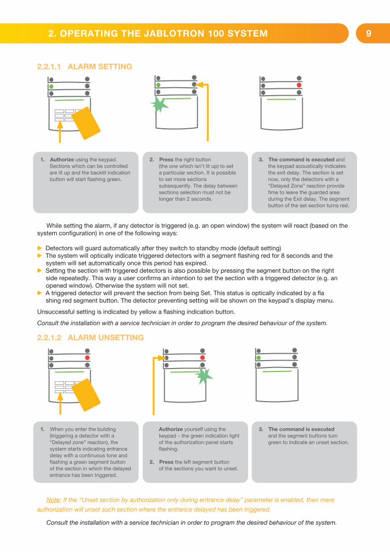
2.2.1.1 ALARM SETTING
While setting the alarm, if any detector is triggered (e.g. an open window) the system will react (based on the system configuration) in one of the following ways:
a Detectors will guard automatically after they switch to standby mode (default setting)a The system will optically indicate triggered detectors with a segment flashing red for 8 seconds and the system will set automatically once this period has expired. a Setting the section with triggered detectors is also possible by pressing the segment button on the right side repeatedly. This way a user confirms an intention to set the section with a triggered detector (e.g. an opened window). Otherwise the system will not set.a A triggered detector will prevent the section from being Set. This status is optically indicated by a fla shing red segment button. The detector preventing setting will be shown on the keypad’s display menu.
Unsuccessful setting is indicated by yellow a flashing indication button.
Consult the installation with a service technician in order to program the desired behaviour of the system.
2.2.1.2 ALARM UNSETTING
Note: If the “Unset section by authorization only during entrance delay” parameter is enabled, then mere
authorization will unset such section where the entrance delayed has been triggered.
Consult the installation with a service technician in order to program the desired behaviour of the system.
1. Authorize using the keypad. Sections which can be controlled are lit up and the backlit indication button will start flashing green.
2. Press the right button (the one which isn’t lit up) to set a particular section. It is possible to set more sections subsequently. The delay between sections selection must not be longer than 2 seconds.
3. The command is executed and the keypad acoustically indicates the exit delay. The section is set now, only the detectors with a “Delayed Zone” reaction provide time to leave the guarded area during the Exit delay. The segment button of the set section turns red.
1. When you enter the building (triggering a detector with a “Delayed zone” reaction), the system starts indicating entrance delay with a continuous tone and flashing a green segment button of the section in which the delayed entrance has been triggered.
Authorize yourself using the keypad – the green indication light of the authorization panel starts flashing.
2. Press the left segment button of the sections you want to unset.
3. The command is executed and the segment buttons turn green to indicate an unset section.
2. OPERATING THE JABLOTRON 100 SYSTEM

10
2.2.1.3 DURESS ACCESS CONTROL
Provides unsetting of the system in a special mode. The system seemingly unsets, however it triggers a silent panic alarm, which is reported to selected users (including ARC).
Unsetting under duress is executed by adding 1 to the last number in a valid code. Contact your service technician if you want to use this feature.
Example for a code with the prefix:
Valid code: 2*9999 Code for unsetting under duress: 2*9990
Example for a code without the prefix:
Valid code: 9999 Code for unsetting under duress: 9990
2.2.1.4 PARTIAL ALARM SETTING
The system can also be configured to be partially set which allows guarding only by certain detectors in a section. Example: At night, it is possible to set the door and window detectors only, while motion detectors inside a house do not react to anything.
To set the entire premises in which partial setting is enabled, the button to set the system has to be pressed twice. After the button is pressed once it flashes yellow, after it is pressed a second time it flashes red.
If the system is partially set already – showing a continuous yellow light – the entire system can be fully set by authorization and pressing the yellow button. Once the button is pressed, the system will be fully set and the button turns red.
Partial setting can be configured in a way that authorization is not required.
1. Authorize yourself using the keypad (enter a code or hold a card or a tag up to the read-er). The green backlit indication button will start flashing.
2. Press the right segment button of the selected section.
3. The command is executed and the segment button turns permanently yellow to indicate a partially set section.
2. OPERATING THE JABLOTRON 100 SYSTEM

11
2.2.1.5 TERMINATING A TRIGGERED ALARM
A triggered alarm in progress is indicated by a rapidly flashing red segment button and a backlit indication button. You need to authorize yourself using the keypad in order to terminate the alarm. The section remains set, a rapidly flashing red segment button indicates the alarm memory. Indication will keep on flashing even after the system has been unset.
If the alarm memory indication was activated during your absence, search for the cause of the alarm in the event history and be very careful when entering and checking the premises or wait until the security agency arrives (provided your system is connected to an Alarm Receiving Centre).
The segment alarm memory indication remains on until the system is set once again. Alternatively, it can be cancelled by unsetting the system one more time. Alarm indication can be also cancelled from a keypad with an LCD display in the Main menu – Cancel warning indication.
Indication of a triggered tamper alarm can be terminated only by a Service technician.
Note: When using the “Default” system profile, it is possible to first select a particular action by pressing a segment button and then confirm it by authorization using the keypad.
Terminating an alarm using a remote control will also unset the corresponding section.
2.2.1.6 SECTION CONTROL FROM THE KEYPAD’S DISPLAY MENU
Statuses of sections are displayed in the left top part of the display. A fully set section is shown by a number in a rectangle filled with black colour. A partially set section is depicted by a framed number.
Control from the keypad menu:
a Authorization by a valid code or an RFID chip
a Enter the menu by pressing ENTER
a Section Control → ENTER
a Select the desired section using arrows
a Pressing ENTER repeatedly will change between section statuses
(partially set / set / unset)
a Press ESC to exit the menu
1. Authorize yourself using the keypad (enter a code, hold a tag up to the reader).
2. Press the left segment button of the section in which the alarm has been triggered.
3. Unsetting is finished and sirens are silenced. The green flashing button indicates un-setting of the particu-lar section. The red flashing light indicates alarm memory.
4. Authorize yourself and press the green button again to cancel the alarm memory indication.
5. The segment indicates the unset section with a continuously lit up green button.
2. OPERATING THE JABLOTRON 100 SYSTEM

12
2.2.2 USING THE JA-110E AND JA-150E SYSTEM KEYPADS
Statuses of individual sections are indicated by status indicators A, B, C, D above the LCD display and by the functions buttons. The control panel can be operated directly (setting or unsetting the alarm and other automation functions) using function buttons on the keypad. The function buttons and the status indicators A, B, C, D are colourfully backlit in order to clearly indicate the section status.
a GREEN – Unseta YELLOW – Partially Unseta RED – Set
Authorization can be done by entering an access code on the keypad or using an RFID card/tag assigned to a particular user. Each user can have one code and one RFID chip (a card or a tag).
If the users want to control multiple sections simultaneously, they must authorize themselves and then press function buttons of the particular sections subsequently. This way the users can unset all sections (for example the house and the garage) within one single authorization.
Status indicatorsA, B, C, D
LCD display
Function buttonsA, B, C, D
System indicator
The keypad and the RFID reader
2. OPERATING THE JABLOTRON 100 SYSTEM

13
Cancel warning indication
Section Control
Event memory
Setting prevented
System status
Settings
Display setting
Allows you to cancel alarm/unsuccessful setting indication in all sections to which the user has
access rights
Allows you to control the system‘s sections to which the user has access rights and are
enabled in the internal settings.
Displays a detailed list of the event memory.
Shows a list of triggered detectors preventing setting the system, provided this option
is activated in the control panel configuration.
Bypassed detectors
Displays a list of all blocked detectors in sections to which a user has access rights.
Faults in system
Displays a list of all detectors indicating system faults from sections to which
the user has access rights.
Shows system status (list of triggered detectors, triggered tamper contacts, low batteries,
bypassing, etc.).
Allows editing of users and devices (only when USB is disconnected).
Allows adjustment of keypad backlight intensity and display contrast.
Administrator or User authorization
by the code or RFID tag/card
2. OPERATING THE JABLOTRON 100 SYSTEM
Structure and description of the internal LCD keypad menu
14
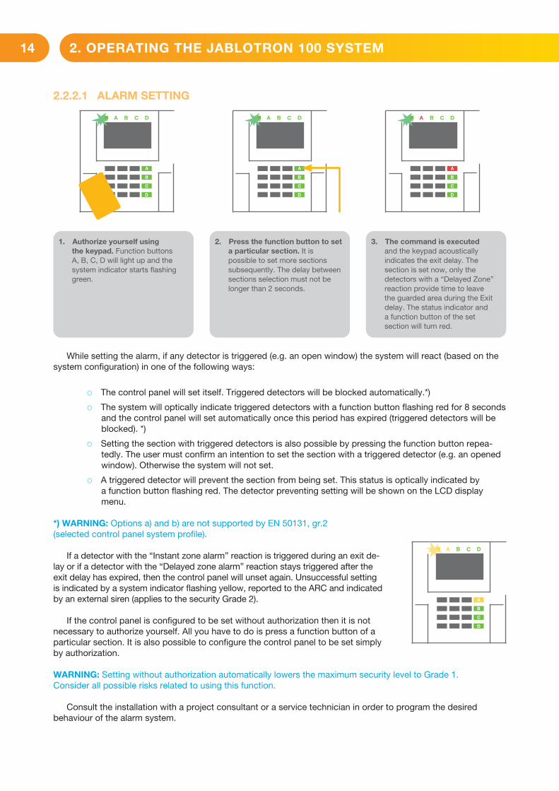
2.2.2.1 ALARM SETTING
While setting the alarm, if any detector is triggered (e.g. an open window) the system will react (based on the system configuration) in one of the following ways:
o The control panel will set itself. Triggered detectors will be blocked automatically.*)
o The system will optically indicate triggered detectors with a function button flashing red for 8 seconds and the control panel will set automatically once this period has expired (triggered detectors will be blocked). *)
o Setting the section with triggered detectors is also possible by pressing the function button repea-tedly. The user must confirm an intention to set the section with a triggered detector (e.g. an opened window). Otherwise the system will not set.
o A triggered detector will prevent the section from being set. This status is optically indicated by a function button flashing red. The detector preventing setting will be shown on the LCD display menu.
*) WARNING: Options a) and b) are not supported by EN 50131, gr.2 (selected control panel system profile).
If a detector with the “Instant zone alarm” reaction is triggered during an exit de-lay or if a detector with the “Delayed zone alarm” reaction stays triggered after the exit delay has expired, then the control panel will unset again. Unsuccessful setting is indicated by a system indicator flashing yellow, reported to the ARC and indicated by an external siren (applies to the security Grade 2).
If the control panel is configured to be set without authorization then it is not necessary to authorize yourself. All you have to do is press a function button of a particular section. It is also possible to configure the control panel to be set simply by authorization.
WARNING: Setting without authorization automatically lowers the maximum security level to Grade 1. Consider all possible risks related to using this function.
Consult the installation with a project consultant or a service technician in order to program the desired behaviour of the alarm system.
1. Authorize yourself usingthe keypad. Function buttons A, B, C, D will light up and the system indicator starts flashing green.
2. Press the function button to set a particular section. It is possible to set more sections subsequently. The delay between sections selection must not be longer than 2 seconds.
3. The command is executed and the keypad acoustically indicates the exit delay. The section is set now, only the detectors with a “Delayed Zone” reaction provide time to leave the guarded area during the Exit delay. The status indicator and a function button of the set section will turn red.
2. OPERATING THE JABLOTRON 100 SYSTEM

15
2.2.2.2 ALARM UNSETTING
Note: If the “Unset section by authorization only during entrance delay” parameter is enabled, then mere autho-rization will unset a section where the entrance delayed has been triggered. This option should be used with caution when using multiple sections.
Consult the installation with a service technician in order to program the desired behaviour of the system.
2.2.2.3 PARTIAL ALARM SETTING
WARNING: This is an additional function of the alarm system.
The system can also be configured to be partially set which allows guarding only by certain detectors in a section.
Example: At night, it is possible to set the door and window detectors only, while selected motion detectors will not trigger the alarm when somebody moves inside the section.
1. When you enter the building (triggering a detector with a “Delayed zone” reaction), the system starts indicating an entrance delay with a continuous tone, the system indicator and a function button, both flashing red, of the section in which the delayed entrance has been triggered.
2. Authorize yourself using the keypad – the system indicator will start flashing green.
3. Press the function buttons of the sections you want to unset.
4. The command is executed.The function buttons and the system indicator turn green to indicate unset sections.
1. Authorize yourself using the keypad (enter a code or hold an RFID card or tag up to the reader). The system indicator button will start flashing green.
2. Press the function button of the selected section.
3. The command is executed and the function button turns permanently yellow to indicate a partially set section.
2. OPERATING THE JABLOTRON 100 SYSTEM

16
To set the entire premises in which partial setting is enabled, hold down the button to set the control panel for 2 seconds or press it twice. After the button is pressed once it shows continuous yellow light, after it is pressed a second time it shows continuous red light.
If the system is partially set already – the function button shows a continuous yellow light – the entire system can be fully set by authorization and pressing the yellow button for a longer time. Once the button is pressed, the system will be fully set and the button turns red.
Partial setting can be configured in a way that authorization is not required.In order to unset the control panel when it is partially set, press the yellow button. The control panel will unset
and the button turns green.
2.2.2.4 DURESS ACCESS CONTROL
Provides unsetting of the control panel in a special mode. The system seemingly unsets, however it triggers a silent panic alarm, which is reported to selected users (including ARC).
Unsetting under duress is executed by adding 1 to the last number in a valid code. Contact your service technician if you want to use this feature.
Example:Valid code: 9999 Code for unsetting under duress: 9990
2.2.2.5 TERMINATING A TRIGGERED ALARM
A triggered alarm in progress is indicated by the status indicator and the function button rapidly flashing red. You need to authorize yourself using the keypad in order to terminate the alarm. The section remains set, a rapidly flashing red function button indicates the alarm memory. Indication will continue flashing even after the system has been unset.
WARNING: If the alarm memory indication was activated during your absence, always enter the building with caution, search for the cause of the alarm in the event history and be very careful when checking the premises or wait until the security agency arrives (provided your system is connected to an Alarm Receiving Centre).
The alarm memory indication remains on until the system is set once again. Alternatively, it can be also cancelled from the keypad menu: Main menu – Cancel warning indication.Indication of a triggered tamper alarm can be terminated only by a Service technician and Administrator.
Note: When using the “Default” system profile, it is possible to select a particular action by pressing a function button first and then confirm it by authorization using the keypad.
Terminating an alarm using a remote control will also unset the corresponding section.
1. Authorize yourself using the keypad (enter a code or hold a tag up to the reader).
2. Press the function button of the section in which the alarm has been triggered.
3. Unsetting is finished and sirens are silenced. Rapidly alternately flashing function buttons (green/red) and the status indicators indicate the alarm memory.
2. OPERATING THE JABLOTRON 100 SYSTEM

17
2.2.2.6 SECTION CONTROL BY AUTHORIZATION
The service technician can configure the control panel to be controlled just by authorization. This way the status of all sections can change by authorization on a keypad (by typing an access code or using an RFID chip).
2.2.2.7 SECTION CONTROL FROM THE KEYPAD’S MENU
Control from the keypad menu:
o Authorize yourself using a valid code or an RFID chip
o Enter the menu by pressing ENTER
o Section Control → ENTER
o Select the desired section using arrows
o Pressing ENTER repeatedly will change between section statuses
(partially set / set / unset)
Partial setting:
Fully set:
o Press ESC to exit the menu.
1
1
2.3 OPERATING THE SYSTEM WITH A KEYFOB
Keyfobs must be enrolled into the system by the installer. The keyfob can be linked to specific users, which will prevent SMS text message notification to the user who is interacting with the system at the moment (if notification parameters are set up in this way). The keyfob can provide either bi-directional communication, confirming the execution of a command with a coloured indicator light, or one-way without any confirmation. Keyfobs control and indicate battery status and are equipped with optical and acoustic indication.
Bi-directional keyfobThe button functions are differentiated by lock icons. The closed lock icon sets
programmed sections; the opened lock icon unsets them. Correct command execution is confirmed by an LED light; unsetting – green, setting – red. A communication fault (out of the control panel’s range) is indicated by a yellow LED light flashing once. The buttons with symbols of full and empty circles can control another section. Buttons of the keyfob can also be configured to control PG outputs in different modes: the first button switches on/ the second switches off, each button can have an individual function when impulse or change functions are used. For more functions, it is possible to press two buttons at the same time. This way a 4-button keyfob can have up to 6 individual functions or one PG status output (e.g. turn the lights on and off), alternatively two PG outputs (e.g. a garage door and door lock).
If the system is configured to Set after confirmation (chapter 2.2.1.1) the detector will indicate unsuccessful setting with a green LED light if a device is triggered. It is necessary to confirm setting by pressing the lock button again. A set section will be confirmed by a red LED light.
The keyfob buttons can be blocked to prevent accidental pressing. A command will be sent out when a button is pressed repeatedly.
A low battery is indicated acoustically (with 3 beeps) and optically with a yellow flashing LED after pressing a button.
For more information, consult configuration of the remote control with your service technician.
2. OPERATING THE JABLOTRON 100 SYSTEM

18
One-way keyfobsOne-way keyfobs send a signal every time a button is pressed without receiving feedback from the control
panel. Sending a signal is confirmed only by a short flash of the red LED and alternatively with a beep.
The button functions are differentiated by lock icons. The closed lock icon sets programmed sections; the opened lock icon unsets them. The buttons with symbols of full and empty circles can control another section or one status PG output (e.g. to turn the lights on and off) or two PG outputs (e.g. a garage door and door lock).
A low battery is indicated by a red LED and acoustically (3 fast beeps).
2.4 OPERATING THE SYSTEM USING A COMPUTER AND A USB CABLE (JA-100-LINK)
The JABLOTRON 100 can be operated locally or remotely (see chapter 2.9) using a computer and installed JA-100-Link software (Windows XP and higher), which can be used for user management (add/remove users, change their level of authorization, phone numbers, codes, card/tags, etc.).
The JA-100-link software is available for local connection with a control panel. It is located on the system’s security drive (FLEXI_CFG/ja-100-link), which will appear after the control panel is connected to a PC via USB.
It is possible to set / unset the system using icons on the lower bar of the program or with the “Status” buttons in the “Section” tab. If a keypad with at least one controllable segment is used with the system, then it is possible to set/unset the system in the JA-100-Link software using an on-screen virtual keypad (click on “Keypad“ in the main menu).
WARNING: When the system is controlled via PC, it doesn’t check for triggered devices while setting. This may lead to setting with a triggered device. Be careful when you control the system this way!
2.5 OPERATING THE SYSTEM USING THE VOICE MENU
The system can be controlled from a mobile phone or land line through a simple voice menu, which guides the user through a series of options in the preconfigured language. To access the voice menu, you just dial the alarm system’s phone number.
Access to the voice menu can be enabled either to all telephone numbers without restrictions or alternatively only to authorized phone numbers stored in the control panel. Depending on the configuration, authorization by entering a valid code on a phone keypad may be required. When the user enters the menu, the system will give an update of the current status of all sections assigned to the user. The caller then can control these sections, either individually or collectively, using phone keypad and available menu options.
The system default is set up to answer incoming calls after three rings (approximately 15 seconds).
2.6 OPERATING THE SYSTEM VIA THE MyJABLOTRON WEB INTERFACE
The JABLOTRON 100 system can be easily and conveniently operated using your computer via the internet and the MyJABLOTRON web interface, which is accessible from www.myjablotron.com. For more information about this web interface please see the chapter 6.
2. OPERATING THE JABLOTRON 100 SYSTEM

19
MyJABLOTRONDepending on your country or region, a web account in MyJABLOTRON can be set
up by an authorized JABLOTRON partner. The login name is the user‘s e-mail address. The password for the first log in will be sent to this address. The password can be changed anytime in the user settings.
Once logged into the account, the system will display all active devices which can be monitored or controlled.
The “Overview“ menu includes “Section”, and “Automation (PG)” tabs. Depending on the type of detectors used, the menu may also include tabs like “Thermostats and thermometers”, “Meters” “History” and “Gallery”.
Tabs:
a Sections – enables you to view and operate all sections in the system.a Keypads – enables you to view all virtual keypads the way they are installed
in the premises. It is possible to control them by clicking on a segment just like pressing a segment button on the real keypad. You will be asked you to enter an authorization code upon the first request to control the system. While you are logged in, subsequent actions will not require repeated authorization.
a Automation (PG) – enables you to view all programmable system outputs. a Thermostats and thermometers – allows you to view the current temperatures
and history graphs from a list of used thermostats and thermometers. Depending on the configuration, it is possible to regulate temperature in the building.
a Meters – an overview of all installed meters (electricity, gas and water). a Gallery – enables you to take snapshots with any installed camera verification devices, or look at past photos
and video sequences taken by these devices.
The bottom of the home page has an overview of the most recent system events.
MyJABLOTRON offers free notifications (via SMS, e-mail, or push notifications) for selected system section events, programmable outputs, thermometers or meters. These notifications can be set up in the “Settings“ menu.
Each system can have only one main user with Administrator rights (owner). This user has the right to share a whole building or its selected parts (single sections, PG outputs, photo verification and measuring devices) with other users whose MyJABLOTRON accounts will be created automatically after the system sharing is configured. If a user already has a MyJABLOTRON account, the shared installation will appear in the user’s dashboard as another active device. Notification of shared access will be sent, along with the password, to the e-mail address (login name) of the new user.
2.7 OPERATING THE SYSTEM USING THE MYJABLOTRON SMARTPHONE APP
If the user account is created in the MyJABLOTRON web interface (see previous chapter), the alarm system can be monitored and controlled remotely using MyJABLOTRON app for smart phones running either on Android and iPhone. The application can be downloaded free of charge after logging into MyJABLOTRON, or from Google Play, AppStore, etc.
Login credentials for MyJABLOTRON smart phone app are identical to those for the MyJABLOTRON web interface.
2.8 OPERATING THE SYSTEM USING SMS COMMANDS
SMS commands can control Individual sections and programmable outputs just like keypad segment buttons. The form of text message to operate the system is: CODE_COMMAND. The actual commands are predefined (SET/UNSET) with an additional numeric parameter which identifies a specific section.
One SMS can control multiple sections at the same time. In this case, added numbers in the command define sections.
2. OPERATING THE JABLOTRON 100 SYSTEM

20
Example of an SMS command used to set sections 2 and 4 and user code 22222222_ SET_2_4
The underscore “_” sign stands for a space between words.
The commands to control the programmable outputs can be programmed by a system installer. For example, you may choose SHUTTERS DOWN as your command to close the shutters on your windows. It is also possible to configure the system not to require a code before a command. In such case the command is simply automatically identified when the system recognizes the user’s phone number from which the SMS was sent. Configuration is done by a service technician.
2.9 OPERATING THE SYSTEM REMOTELY USING A COMPUTER (JA-100-LINK)
The JABLOTRON 100 system can be operated both remotely and locally on-site (see chapter 2.4) by installing the JA-100-Link software (Windows XP and higher) on your computer which can also manage users (change codes, cards / tags, and phone numbers).
To operate the system remotely, the program must be downloaded from the “Downloads” section of the www.jablotron.com website or it can be found in the control panel’s SD card. The registration code of the security system (a 14 digit code) and the telephone number of its SIM card is required to connect to the system remotely the first time. Remote access is initiated by clicking on “Internet“ in the main menu.
It is possible to set / unset the system using icons on the lower bar of the program or with the “Status” buttons in the “Section” tab. If a keypad with at least one controllable segment is used in the system, then it is possible to set/unset the system in JA-100-Link using an on-screen virtual keypad (click on “Keypad“ in the main menu).
WARNING: When the system is controlled via PC, it will not prevent setting with a triggered device. Be careful when you control the system this way!
2.10 PG OUTPUTS CONTROL VIA…
Keypad segmentA PG output switches on by pressing a button on the right side of the segment and switches off
by pressing the button on the left side. If the output is configured as a pulse output, it is switched off according to the preset time.
PG control may or may not be stored in the control panel’s event memory. Configuration is done by a service technician.
Authorization is/isn’t demanded based on the system configuration.
User keypad authorizationIt is possible to activate a PG output just by user authorization (entering a code or using an RIFD tag).
The PG output must be configured to activate from a designated keypad.
Remote controlBy pressing an assigned button of a remote control. Bi-directional remote controls confirm activation of PG
outputs with an LED indicator.
Dialling-inEach telephone number stored in the system (one user can have one telephone number) can control
it just by dialling-in (i.e. without establishing a call). Dialling-in consists of dialling the phone number of the SIM card used in the security system and hanging up before the system answers the call. By default, the system will answer the call after the third ring (approximately 15 seconds).
2. OPERATING THE JABLOTRON 100 SYSTEM

21
SMS messageSending an SMS can switch on/off a particular PG. Authorization is/isn’t demanded based on the system
configuration.
Example: CODE_CONFIGURED TEXT (“_” character = space)
MyJABLOTRON websiteBy clicking on ON/OFF in the Automation (PG) tab.
My JABLOTRON smartphone appBy tapping on ON/OFF in the Automation (PG) tab.
3.1 BLOCKING USERS
Any user can be temporarily blocked (e.g. when a user loses a card/tag or his access code is revealed). When user’s access is blocked their ID code or card/tag will no longer be accepted by the system. The users will also not receive any text message alerts or voice reports to their phone.
Only the system administrator or service technician can block a user. One method of taking away access rights is by choosing Settings / Users / User / Bypass and selecting “Yes” on the LCD keypad. Another option is to locally or remotely block a user through the JA-100-Link software (Windows XP and higher) by clicking on the user in the Settings / Users / User blocking column.
A blocked (disabled) user will be marked with a red circle until the blocking is cancelled.
3.2 BLOCKING DETECTORS
A detector can be temporarily blocked in a similar way a user can be disabled. A detector is blocked when its activation is temporarily not desirable (for example a motion detector in a room with a pet or disable a siren sounding). The system still performs diagnostics of tamper contacts and sends service events however the alarm function is deactivated.
Only the system administrator or service technician can block a detector. It can be achieved by choosing Settings / Devices / Bypass and selecting Yes on the LCD keypad. Another option is to use the JA-100-Link software by clicking on the detector in the Settings / Diagnostics / Disabled column. A blocked detector is marked with a yellow circle until it is turned back on using the same procedure. A device can be also blocked from MyJABLOTRON smartphone app.
3.3 DISABLING TIMERS
To temporarily disable automated scheduled events in the system, a timer can be disabled. Disabling a scheduled event (e.g. unsetting the system from night guarding at a predetermined time) will prevent execution of that event (e.g. while on vacation).
A timer can be disabled locally or remotely through the JA-100-Link software by clicking on the section in the Settings / Calendar / Blocked column. A disabled timer is marked with a red circle until it is turned back on using the same procedure.
2. OPERATING THE JABLOTRON 100 SYSTEM
3. BLOCKING/ DISABLING THE SYSTEM

22
4.1 CHANGING USER ACCESS CODE
If the system is set up with prefix codes, individual users can be allowed to change their codes from the LCD menu on the keypad. The code can be changed after authorization by selecting Settings / Users /User / Code. To input a new code you must enter edit mode (the code will start to flash) by pressing Enter, enter the new code and confirm by pressing Enter again. After completing the changes they must be confirmed by choosing Save when the system prompts you with “Save Settings?”
If the system is set up without prefixed codes, only the system administrator and the service technician can change the security codes. The system administrator can make changes from both the LCD keypad menu the JA-100-Link software and MyJABLOTRON smartphone app.
4.2 CHANGING, DELETING OR ADDING AN RFID CARD/TAG
If the system is set up with prefixed codes, users can add, change or delete their RFID tags or cards from the LCD menu on the keypad. These changes are done after authorization by selecting Settings / Users / User / Access card 1 (or 2). To enter a new RFID card/tag, you must enter edit mode (access card 1 or 2 will start to flash) by pressing Enter. Then The RFID card/tag must be placed on to the reader or the serial number must be manually entered. After confirming by pressing Enter again, the RFID card/tag is added. To delete an access card enter “0” into the serial number field. After the changes are complete the change must be saved by selecting Save when the system prompts with “Save Settings?”.
The system administrator and the service technician can add, change and delete RFID cards/tags from both the LCD keypad menu and the JA-100-Link software.
4.3 CHANGING A USERNAME OR PHONE NUMBER
If the system is set up with prefix codes, users can add, change or delete their telephone numbers or change their name from the LCD menu on the keypad. This can be done after authorization by selecting Settings / Users / User / Phone. The user must be in edit mode to make changes. This is done by pressing Enter. After making the changes, they must be confirmed by pressing Enter again. To delete a phone number enter “0” into the phone number field. After the changes are complete the change must be saved by selecting Save when the system prompts with “Save Settings?”
The system administrator and the service technician can add, modify or delete a user‘s phone number or change a user‘s name from both the LCD keypad menu and the JA-100-Link software.
4.4 ADDING / DELETING A USER
Only the system administrator or service technician can add new users to the system (or delete them). New users can be added to the system (or deleted from it) only through the JA-100-Link software, or the F-Link software in the case of a technician.
When creating a new user, it is necessary to assign him with access permissions (rights), sections the user may operate, programmable outputs he may control, and what type of authorization will be required.
4.5 CALENDAR EVENTS SET UP
It is possible to configure up to 20 calendar events (unsetting / setting / partial setting, controlling or blocking PG outputs). A single calendar event may combine several actions at the same time. For example, you can Set selected sections, switch on a PG output and block another PG, all at once.
Timers can be set up via the JA-100-Link software in the Calendar tab.
4. CUSTOMIZING THE SYSTEM

23
The security system stores all performed operations and events (setting, unsetting, alarms, faults, messages sent to users and ARCs) in the micro SD card in the system’s control panel. Each entry includes the date, time (start and end), and source (cause / origin) of the event.
The different ways of browsing through the system’s event history:
5.1 USING THE LCD KEYPAD
Accessing the event history using the keypad requires user authorization. Once authorized, the available options (based on user permissions) are displayed by choosing Event Memory. Records can be viewed using arrows.
5.2 USING THE JA-100-LINK SOFTWARE AND A COMPUTER
The system memory can be browsed using the JA-100-Link software (Windows XP and higher). Events can be downloaded from the control panel in small (about 1,200 events) or larger (about 4,000 events) batches. The events can be filtered in detail, colour-coded for easier orientation, or saved into a file in a computer.
5.3 LOGGING INTO MYJABLOTRON (WEB/SMARTPHONE)
All system events can be viewed after logging in the MyJABLOTRON web/smartphone interface. The account shows history in a range which corresponds with the user’s permissions.
The MyJABLOTRON web interface is a unique service that allows on-line
access to JABLOTRON devices. It allows end-users to monitor and control
the system.
The MyJABLOTRON web interface allows users to:a View the current system status.
a Set/unset the entire system or a part of it.
a Control programmable outputs.
a View the event history.
a Send reports to selected users via text messaging,
e-mail or push notifications
a Capture images from photo verification devices (640 x 480 px) and browse
through them in the Photo gallery tab or directly in Recent events
a Monitor current temperature or energy consumption, including a history
overview on graphic charts.
a And other useful features.
a It is necessary to have regular and timely maintenance checks performed in order to secure reliable functioning of the system. Most of the maintenance is carried out by an installation company at least once a year during periodical maintenance inspections.
a User maintenance consists of keeping the individual devices clean.
a Some devices may require testing (fire detectors, for example). Please, contact your service technician.
5. EVENT HISTORY
6. WHAT IS THE MYJABLOTRON WEB INTERFACE?
7. PERIODICAL MAINTENANCE

24
JABLOTRON ALARMS a.s. hereby declares that these control panels JA-101K, JA-101K(-LAN)(3G) a JA-106K(-3G) meet the basic requirements and other relevant provisions of the Directive no. 2014/53/EU, 2014/35/EU, 2014/30/EU and 2011/65/EU. You will find the original Declaration of Conformity at www.jablotron.com, section Downloads.
Note: Disposing of this product correctly will help save valuable resources and prevent any potential negative effects on human health and the environment, which could otherwise arise from inappropriate waste handling. Please return the product to the dealer or contact your local authority for further details of your nearest designated collection point.
8. TECHNICAL SPECIFICATIONS
Parametr JA-101K (-LAN) (-LAN3G) JA-106K (-3G)
Control panel power supply
~ 230 V/50 Hz, max. 0.1 A with T200 mA fuse ~ 110 V to 120 V/60 Hz, max. 0.2 A, with T400 mA fuse protection class II
~ 230 V / 50 Hz, max. 0.2 A, with T400 mA fuse protection class II
Back-up battery 12 V; 2.6 Ah 12 V; 7 to 18 Ah
Maximum battery charging time
72 h 72 h
BUS voltage (red-black) 12.0 to 13.8 V 12.0 to 13.8 V
Max. continuous consumption from the control panel
400 mA permanently (1000 mA for 5 minutes)
1200 mA permanently, valid for each BUS output (2000 mA for 10 minutes)
Max. continuous consumption for backing up 12 hours
JA-101K - battery 2,6 Ah JA-106K – battery 18 Ah
Without GSM communicator
LAN – OFF – 123 mA LAN – ON – 78 mA
Without GSM communicator
LAN – OFF – 1150 mA LAN – ON – 1105 mA
With GSM communicator
LAN – OFF – 103 mA LAN – ON – 58 mA
With GSM communicator
LAN – OFF – 1130 mA LAN – ON – 1085 mA
Max. continuous consumption for backing up 24 hours
Without GSM communicator
LAN – OFF – 37 mA LAN – ON – Not possible
Without GSM communicator
LAN – OFF – 550 mA LAN – ON – 505 mA
With GSM communicator
LAN – OFF – 17 mA LAN – ON – Not possible
With GSM communicator
LAN – OFF – 530 mA LAN – ON – 485 mA
Max. number of devices
50 120
LAN communicator Ethernet interface (LAN versions only) Ethernet interface
Dimensions (mm) 258 x 214 x 77 357 x 297 x 105
Weight 1250 g 2500 g
Reaction to invalid code entry
Alarm after 10 wrong code entries
Event history approx. 7 million latest events, incl. date and time
Power supply unit type A (EN 50131-6)T 031 note: In case of a main power failure is the system backed up for 24 hours and at the same time is a failure report sent to the ARC.
GSM communicator 850 / 900 / 1800 / 1900 MHz
3G GSM communicator 2100 MHz
Environmental class class II, indoor general according to EN 50131-1
Operational temperature range
-10 °C to +40 °C, relative humidity 75 %
Classification Security grade 2 according to EN 50131-1, EN 50131-3, EN 50131-6, EN50131-10, EN 50131-5-3, EN 50136-1, EN 50136-2
Operating frequency (with the JA-11xR module)
868.1 MHz
Radio emissions ETSI EN 300 220-2 (module R), ETSI EN 301 419-1, ETSI EN 301 511 (GSM)
EMC EN 50130-4 ed. 2, EN 55022 ed. 3, ETSI EN 301 489-7
Safety EN 60950-1
Operational conditions ERC REC 70-03, ERC DEC (98) 20
Certification body TREZOR TEST: (JA-101K, JA-101K-LAN, JA-106K), ANPI: INCERT T014(A) (JA-101K, JA-106K)
Caller’s identification ETSI EN 300 089

25
BUS / Wireless DevicesThe main hub of the security system is its control panel. It can communicate with all devices in two ways:
using the BUS, i.e. using data cables within the guarded premises or part thereof; or wirelessly using radio communication. BUS devices are powered by the control panel. Wireless devices require batteries whose longevity depends on intensity of use. Some of the wireless devices are supplied by 250V from the electric grid.
Control SegmentThis is the control and signalling part of the access module (keypad). A segment contains a description
of its function and has two backlit buttons – a green one on the left and a red or yellow one on the right. A segment is used to easily and clearly operate a part of the system and simultaneously display its status using the colour indicators (green when unset, red when set, and yellow when partially set). The number of segments and their function are determined by the service technician.
RFID Card / TagThe RFID card/tag allows the user to operate the system and is used for contactless authorization by simply
placing the card/tag on to the keypad reader. It replaces or complements numerical code entries. The RFID card can be carried in a wallet. The RFID tag can be attached to a key ring.
SectionThe alarm system can be divided into several smaller, independently functioning parts, called sections.
Each section can have its assigned detectors, keypads, as well as sirens, users and their telephone numbers. There can be up to 15 sections per system.
Programmable Outputs PGThe security system can be used to switch on/off or control other electrical devices or appliances. This is
done using programmable outputs that can be controlled by the user (via text messages, using the keypad, etc.) or can be automated based on the system status (following the system status, alarm status, faults, etc.).
Home AutomationIn addition to providing an intruder alarm system, the JABLOTRON 100 offers a number of other features.
Among the most popular functions are: electrical door locks, automated light switches using motion detectors, and the remote control of appliances (electrical heating, garage doors, gates, entry barriers, etc.).
Panic AlarmWhen a user is in danger and in need of urgent assistance, the panic alarm can be triggered. The panic
alarm can be set up as a designated segment on the keypad, a special code, a panic button, or as a specific combination of buttons on a keyfob. If connected to a security centre, triggering the panic alarm creates an immediate response (vehicle dispatch) that cannot be cancelled by phone.
Security Centre, ARCAn Alarm Receiving Centre, a continuously manned security agency (24/7/365), is able to immediately react
to information received from the guarded premises and respond with an appropriate action or proceed according to internal rules.
9. GLOSSARY OF TERMS
For questions and further information contact your installer.
MLJ57110_JL

26 NOTES:

27NOTES

28 NOTES:

www.jablotron.comwww.jablotron.com8 595614 114110
MLJ57205 - EN user manual - desky.indd 1 20.9.2014 12:23:18