Deployment and Installation Guide for Cisco Virtualization ...
Upload
khangminh22Category
view
0download
0
Cisco DNA Center Second-Generation Appliance Installation Guide,Release 1.3First Published: 2019-05-31
Last Modified: 2020-02-05
Americas HeadquartersCisco Systems, Inc.170 West Tasman DriveSan Jose, CA 95134-1706USAhttp://www.cisco.comTel: 408 526-4000
800 553-NETS (6387)Fax: 408 527-0883

THE SPECIFICATIONS AND INFORMATION REGARDING THE PRODUCTS IN THIS MANUAL ARE SUBJECT TO CHANGE WITHOUT NOTICE. ALL STATEMENTS,INFORMATION, AND RECOMMENDATIONS IN THIS MANUAL ARE BELIEVED TO BE ACCURATE BUT ARE PRESENTED WITHOUT WARRANTY OF ANY KIND,EXPRESS OR IMPLIED. USERS MUST TAKE FULL RESPONSIBILITY FOR THEIR APPLICATION OF ANY PRODUCTS.
THE SOFTWARE LICENSE AND LIMITED WARRANTY FOR THE ACCOMPANYING PRODUCT ARE SET FORTH IN THE INFORMATION PACKET THAT SHIPPED WITHTHE PRODUCT AND ARE INCORPORATED HEREIN BY THIS REFERENCE. IF YOU ARE UNABLE TO LOCATE THE SOFTWARE LICENSE OR LIMITED WARRANTY,CONTACT YOUR CISCO REPRESENTATIVE FOR A COPY.
The Cisco implementation of TCP header compression is an adaptation of a program developed by the University of California, Berkeley (UCB) as part of UCB's public domain version ofthe UNIX operating system. All rights reserved. Copyright © 1981, Regents of the University of California.
NOTWITHSTANDING ANY OTHERWARRANTY HEREIN, ALL DOCUMENT FILES AND SOFTWARE OF THESE SUPPLIERS ARE PROVIDED “AS IS" WITH ALL FAULTS.CISCO AND THE ABOVE-NAMED SUPPLIERS DISCLAIM ALL WARRANTIES, EXPRESSED OR IMPLIED, INCLUDING, WITHOUT LIMITATION, THOSE OFMERCHANTABILITY, FITNESS FOR A PARTICULAR PURPOSE AND NONINFRINGEMENT OR ARISING FROM A COURSE OF DEALING, USAGE, OR TRADE PRACTICE.
IN NO EVENT SHALL CISCO OR ITS SUPPLIERS BE LIABLE FOR ANY INDIRECT, SPECIAL, CONSEQUENTIAL, OR INCIDENTAL DAMAGES, INCLUDING, WITHOUTLIMITATION, LOST PROFITS OR LOSS OR DAMAGE TO DATA ARISING OUT OF THE USE OR INABILITY TO USE THIS MANUAL, EVEN IF CISCO OR ITS SUPPLIERSHAVE BEEN ADVISED OF THE POSSIBILITY OF SUCH DAMAGES.
Any Internet Protocol (IP) addresses and phone numbers used in this document are not intended to be actual addresses and phone numbers. Any examples, command display output, networktopology diagrams, and other figures included in the document are shown for illustrative purposes only. Any use of actual IP addresses or phone numbers in illustrative content is unintentionaland coincidental.
All printed copies and duplicate soft copies of this document are considered uncontrolled. See the current online version for the latest version.
Cisco has more than 200 offices worldwide. Addresses and phone numbers are listed on the Cisco website at www.cisco.com/go/offices.
Cisco and the Cisco logo are trademarks or registered trademarks of Cisco and/or its affiliates in the U.S. and other countries. To view a list of Cisco trademarks, go to this URL: www.cisco.comgo trademarks. Third-party trademarks mentioned are the property of their respective owners. The use of the word partner does not imply a partnership relationship between Cisco and anyother company. (1721R)
© 2019 Cisco Systems, Inc. All rights reserved.

C O N T E N T S
Review the Cisco DNA Center Appliance Features 1C H A P T E R 1
Appliance Hardware Specifications 1
Front and Rear Panels 4
Physical Specifications 17
Environmental Specifications 18
Power Specifications 19
Plan the Deployment 21C H A P T E R 2
Planning Workflow 21
Cisco DNA Center and Cisco Software-Defined Access 22
Interface Cable Connections 22
Required IP Addresses and Subnets 27
Interface Names and Wizard Configuration Order 30
Required Internet URLs and Fully Qualified Domain Names 31
Provide Secure Access to the Internet 33
Required Network Ports 34
Required Ports and Protocols for Cisco Software-Defined Access 36
Required Configuration Information 44
Required First-Time Setup Information 45
Install the Appliance 47C H A P T E R 3
Appliance Installation Workflow 47
Unpack and Inspect the Appliance 48
Review the Installation Warnings and Guidelines 48
Review the Rack Requirements 51
Connect and Power On the Appliance 51
Cisco DNA Center Second-Generation Appliance Installation Guide, Release 1.3iii

Check the LEDs 51
Prepare the Appliance for Configuration 55C H A P T E R 4
Preparation for Appliance Configuration Overview 55
Enable Browser Access to Cisco Integrated Management Controller 55
Execute Preconfiguration Checks 60
Disable the Network Interface Card 62
Reimage the Appliance 68
Verify the Cisco DNA Center ISO Image 68
Create a Bootable USB Drive 69
Using Etcher 69
Using the Linux CLI 70
Using the Mac CLI 71
Install the Cisco DNA Center ISO Image 71
Configure the Appliance 73C H A P T E R 5
Appliance Configuration Overview 73
Configure the Primary Node Using the Maglev Wizard 73
Configure Add-On Nodes Using the Maglev Wizard 87
Upgrade to the Latest Cisco DNA Center Release 102
Complete First-Time Setup 103C H A P T E R 6
First-Time Setup Workflow 103
Compatible Browsers 104
Log In for the First Time 104
Integrate Cisco ISE with Cisco DNA Center 106
Configure Authentication and Policy Servers 109
Configure SNMP Properties 111
Troubleshoot the Deployment 113C H A P T E R 7
Troubleshooting Tasks 113
Log Out 113
Reconfigure the Appliance Using the Configuration Wizard 114
Power-Cycle the Appliance 115
Cisco DNA Center Second-Generation Appliance Installation Guide, Release 1.3iv
Contents

Using the Cisco IMC GUI 116
Using SSH 116
Review High Availability Cluster Deployment Scenarios 119A P P E N D I X A
New HA Deployment 119
Existing HA Deployment of the Primary Node with Standard Interface Configurations 120
Existing HA Deployment of Primary Node with Nonstandard Interface Configurations 120
Redistribute Services 121
Additional HA Deployment Considerations 121
Telemetry 121
Wireless Controller 122
Cisco DNA Center Second-Generation Appliance Installation Guide, Release 1.3v
Contents

Cisco DNA Center Second-Generation Appliance Installation Guide, Release 1.3vi
Contents

C H A P T E R 1Review the Cisco DNA Center ApplianceFeatures
• Appliance Hardware Specifications, on page 1• Front and Rear Panels, on page 4• Physical Specifications, on page 17• Environmental Specifications, on page 18• Power Specifications, on page 19
Appliance Hardware SpecificationsCisco supplies Cisco Digital Network Architecture (DNA) Center in the form of a rack-mountable, physicalappliance. The second generation Cisco DNA Center appliance consists of either a Cisco Unified ComputingSystem (UCS) C220 M5 small form-factor (SFF) chassis or Cisco UCS C480 M5 chassis, both with theaddition of one Intel X710-DA2 network interface card (NIC) and one Intel X710-DA4 NIC. Four versionsof the second generation appliance are available:
• 44 core appliance: Cisco part number DN2-HW-APL
• 44 core upgrade appliance: Cisco part number DN2-HW-APL-U
This is the relevant part number if you are upgrading from a first generation 44 core appliance (Ciscopart number DN1-HW-APL).
• 56 core appliance: Cisco part number DN2-HW-APL-L
• 112 core appliance: Cisco part number DN2-HW-APL-XL
The Cisco DNA Center software image is preinstalled on these appliances, but must be configured for use.
The following tables summarize the appliance's hardware specifications.
Table 1: 44 Core Cisco DNA Center Appliance Hardware Specifications
DescriptionFeature
One rack-unit (1RU) chassis.Chassis
Two 22-core Intel Xeon Gold 6152 2.1 GHz processorsProcessors
Cisco DNA Center Second-Generation Appliance Installation Guide, Release 1.31

DescriptionFeature
Eight 32 GB DDR4 2666 MHz registered DIMMs (RDIMMs)Memory
• 2 x 480 GB in RAID 1
• 2 x 1.9 TB in RAID 1
• 6 x 1.9 TB in RAID 10
Storage
• RAID 1 on slots 1 through 4
• RAID 10 on slots 5 through 10
Disk Management (RAID)
Supported connectors:
• Two 10-Gbps Ethernet ports on the Intel X710-DA2 NIC
• One 1-Gbps RJ-45 management port (Marvell 88E6176)
• Two 10GBase-T LOM ports (Intel X550 controller embedded on themotherboard)
The following connectors are available but not typically used in the day-to-dayoperation of Cisco DNA Center:
• One RS-232 serial port (RJ-45 connector)
• One VGA (DB-15) connector
• Two USB 3.0 connectors
• One front-panel KVMconnector that is usedwith the KVMcable, which providestwo USB 2.0, one VGA (DB-15), and one serial port (RS-232) RJ-45 connector.
Note that the Intel X710-DA4 NIC, which provides four 10-Gbps Ethernet ports, hasbeen disabled in this release of Cisco DNA Center and will be enabled in a futurerelease of the product.
Network and Management I/O
Two 770 W AC power supplies.
Redundant as 1+1.
Power
Seven hot-swappable fan modules for front-to-rear cooling.Cooling
Video Graphics Array (VGA) video resolution up to 1920 x 1200, 16 bpp at 60 Hz,and up to 512 MB of video memory (8 MB is allocated by default).
Video
Table 2: 56 Core Cisco DNA Center Appliance Hardware Specifications
DescriptionFeature
One rack-unit (1RU) chassis.Chassis
Two 28-core Intel Xeon Platinum 8180 2.5 GHz processorsProcessors
Cisco DNA Center Second-Generation Appliance Installation Guide, Release 1.32
Review the Cisco DNA Center Appliance FeaturesAppliance Hardware Specifications

DescriptionFeature
Twelve 32 GB DDR4 2666 MHz RDIMMsMemory
• 2 x 480 GB in RAID 1
• 2 x 1.9 TB in RAID 1
• 6 x 1.9 TB in RAID 10
Storage
• RAID 1 on slots 1 through 4
• RAID 10 on slots 5 through 10
Disk Management (RAID)
Supported connectors:
• Two 10-Gbps Ethernet ports on the Intel X710-DA2 NIC
• One 1-Gbps RJ-45 management port (Marvell 88E6176)
• Two 10GBase-T LOM ports (Intel X550 controller embedded on themotherboard)
The following connectors are available but not typically used in the day-to-dayoperation of Cisco DNA Center:
• One RS-232 serial port (RJ-45 connector)
• One VGA (DB-15) connector
• Two USB 3.0 connectors
• One front-panel KVMconnector that is usedwith the KVMcable, which providestwo USB 2.0, one VGA (DB-15), and one serial port (RS-232) RJ-45 connector.
Note that the Intel X710-DA4 NIC, which provides four 10-Gbps Ethernet ports, hasbeen disabled in this release of Cisco DNA Center and will be enabled in a futurerelease of the product.
Network and Management I/O
Two 770 W AC power supplies.
Redundant as 1+1.
Power
Seven hot-swappable fan modules for front-to-rear cooling.Cooling
Video Graphics Array (VGA) video resolution up to 1920 x 1200, 16 bpp at 60 Hz,and up to 512 MB of video memory (8 MB is allocated by default).
Video
Table 3: 112 Core Cisco DNA Center Appliance Hardware Specifications
DescriptionFeature
Four rack-unit (4RU) chassis.Chassis
Two CPU modules, each with two 28-core Intel Xeon Platinum 8176 2.1 GHzprocessors
Processors
Cisco DNA Center Second-Generation Appliance Installation Guide, Release 1.33
Review the Cisco DNA Center Appliance FeaturesAppliance Hardware Specifications

DescriptionFeature
Twenty-four 32 GB DDR4 2666 MHz RDIMMsMemory
• 2 x 480 GB in RAID 1
• 2 x 3.8 TB in RAID 1
• 16 x 1.9 TB in RAID 10
Storage
• RAID 1 on drive bays 1 and 2
• RAID 10 on slots 3 through 18
• RAID 1 on drive bays 19 and 20
Disk Management (RAID)
Supported connectors:
• Two 10 Gbps Ethernet ports on the Intel X710-DA2 NIC
• Two 10 Base-T Gbps Ethernet ports
• One Gigabit Ethernet management port
The following connectors are available but not typically used in the day-to-dayoperation of Cisco DNA Center:
• One RS-232 serial port (RJ-45 connector)
• One VGA (DB-15) connector
• Three USB 3.0 connectors
• One front-panel KVMconnector that is usedwith the KVMcable, which providestwo USB 2.0, one VGA (DB-15), and one serial port (RS-232) RJ-45 connector.
Note that the Intel X710-DA4 NIC, which provides four 10-Gbps Ethernet ports, hasbeen disabled in this release of Cisco DNA Center and will be enabled in a futurerelease of the product.
Network and Management I/O
Four 1600 W AC power supplies.
Redundant as 3+1 (must be configured via the Cisco Integrated ManagementController).
Power
Four hot-swappable fan modules with two fans in each for front-to-rear cooling.Cooling
VGA video resolution up to 1600 x1200, 16 bpp at 60 Hz, and up to 256MB of videomemory.
Video
Front and Rear PanelsThe following figures and tables describe the front and rear panels of the Cisco DNA Center appliance.
Cisco DNA Center Second-Generation Appliance Installation Guide, Release 1.34
Review the Cisco DNA Center Appliance FeaturesFront and Rear Panels

Figure 1: 44 and 56 Core Appliance Front Panel
DescriptionComponent
A total of 10 drives are available on the appliance:
• Two 480 GB SAS SSD (in slots 1 and 2).
• Eight 1.9 TB SATA SSD (in slots 3 through 10).
Each installed drive has a fault LED and an activity LED.
When the drive fault LED is:
• Off: The drive is operating properly.
• Amber: The drive has failed.
• Amber, blinking: The drive is rebuilding.
When the drive activity LED is:
• Off: There is no drive in the sled (no access, no fault).
• Green: The drive is ready.
• Green, blinking: The drive is reading or writing data.
1
Power button/power status LED. When the LED is:
• Off: There is no AC power to the appliance.
• Amber: The appliance is in standby power mode. Power is supplied only to the CiscoIntegrated Management Controller (CIMC) and some motherboard functions.
• Green: The appliance is in main power mode. Power is supplied to all the servercomponents.
2
Cisco DNA Center Second-Generation Appliance Installation Guide, Release 1.35
Review the Cisco DNA Center Appliance FeaturesFront and Rear Panels

DescriptionComponent
Unit identification button and LED. When the LED is:
• Off: Unit identification is inactive.
• Blue: Unit identification is active.
3
System status LED. When the LED is:
• Green: The appliance is running in a normal operating condition.
• Green, blinking: The appliance is performing system initialization and memorychecks.
• Amber, steady: The appliance is in a degraded operational state, which may be dueto one or more of the following causes:
• Power supply redundancy is lost.
• CPUs are mismatched.
• At least one CPU is faulty.
• At least one DIMM is faulty.
• At least one drive in a RAID configuration failed.
• Amber, 2 blinks: There is a major fault with the system board.
• Amber, 3 blinks: There is a major fault with the memory DIMMs.
• Amber, 4 blinks: There is a major fault with the CPUs.
4
Power supply status LED. When the LED is:
• Green: All power supplies are operating normally.
• Amber, steady: One or more power supplies are in a degraded operational state.
• Amber, blinking: One or more power supplies are in a critical fault state.
5
Fan status LED. When the LED is:
• Green: All fan modules are operating properly.
• Amber, steady: One fan module has failed.
• Amber, blinking: Critical fault, two or more fan modules have failed.
6
Network link activity LED. When the LED is:
• Off: The Ethernet link is idle.
• Green, blinking: One or more Ethernet LOM ports are link-active, with activity.
• Green: One or more Ethernet LOM ports are link-active, but there is no activity.
7
Cisco DNA Center Second-Generation Appliance Installation Guide, Release 1.36
Review the Cisco DNA Center Appliance FeaturesFront and Rear Panels

DescriptionComponent
Temperature status LED. When the LED is:
• Green: The appliance is operating at normal temperature.
• Amber, steady: One or more temperature sensors have exceeded a warning threshold.
• Amber, blinking: One or more temperature sensors have exceeded a critical threshold.
8
Pull-out asset tag.9
KVM connector. Used with a KVM cable that provides two USB 2.0, one VGA, and oneserial connector.
10
Figure 2: 112 Core Appliance Front Panel
DescriptionComponent
Power button/power status LED. When the LED is:
• Off: There is no AC power to the appliance.
• Amber: The appliance is in standby power mode. Power is supplied only to the CIMCand some motherboard functions.
• Green: The appliance is in main power mode. Power is supplied to all the servercomponents.
1
Unit identification button and LED. When the LED is:
• Off: Unit identification is inactive.
• Blue: Unit identification is active.
2
Cisco DNA Center Second-Generation Appliance Installation Guide, Release 1.37
Review the Cisco DNA Center Appliance FeaturesFront and Rear Panels

DescriptionComponent
System status LED. When the LED is:
• Green: The appliance is running in a normal operating condition.
• Amber, steady: The appliance is in a degraded operational state, which may be dueto one or more of the following causes:
• Power supply redundancy is lost.
• CPUs are mismatched.
• At least one CPU is faulty.
• At least one DIMM is faulty.
• At least one drive in a RAID configuration failed.
• Amber, blinking: The appliance is in a critical fault state, which may be due to oneor more of the following causes:
• Boot failure
• Fatal processor and/or bus error detected
• Over-temperature condition
3
Fan status LED. When the LED is:
• Green: All fan modules are operating properly.
• Amber, steady: Fan modules are in a degraded state. One fan module has a fault.
• Amber, blinking: Two or more fan modules have faults.
4
Temperature status LED. When the LED is:
• Green: The appliance is operating at normal temperature. No error conditions detected.
• Amber, steady: One or more temperature sensors have exceeded a warning threshold.
• Amber, blinking: One or more temperature sensors have exceeded a criticalnon-recoverable threshold.
5
Power supply status LED. When the LED is:
• Green: All power supplies are operating normally.
• Amber, steady: One or more power supplies are in a degraded operational state.
• Amber, blinking: One or more power supplies are in a critical fault state.
6
Cisco DNA Center Second-Generation Appliance Installation Guide, Release 1.38
Review the Cisco DNA Center Appliance FeaturesFront and Rear Panels

DescriptionComponent
Network link activity LED. When the LED is:
• Off: The Ethernet LOM port link is idle.
• Green: One or more Ethernet LOM ports are link-active, but there is no activity.
• Green, blinking: One or more Ethernet LOM ports are link-active, with activity.
7
A total of 20 drives are available on the appliance:
• Two 480 GB SATA SSD (in drive bays 1 and 2).
• Sixteen 1.9 TB SATA SSD (in slots 3 through 18).
• Two 3.8 TB SATA SSD (in drive bays 19 and 20).
Drive bays 21 through 24 are not used by the appliance.Note
Each installed drive has a fault LED and an activity LED.
When the drive fault LED is:
• Off: The drive is operating properly.
• Amber: The drive has failed.
• Amber, blinking: The drive is rebuilding.
When the drive activity LED is:
• Off: There is no drive in the sled (no access, no fault).
• Green: The drive is ready.
• Green, blinking: The drive is reading or writing data.
8
KVM connector. Used with a KVM cable that provides two USB 2.0, one VGA, and oneserial connector.
9
Pull-out asset tag.10
CPU module bay 1.11
CPU module bay 2.12
Figure 3: 44 and 56 Core Appliance Rear Panel
Cisco DNA Center Second-Generation Appliance Installation Guide, Release 1.39
Review the Cisco DNA Center Appliance FeaturesFront and Rear Panels
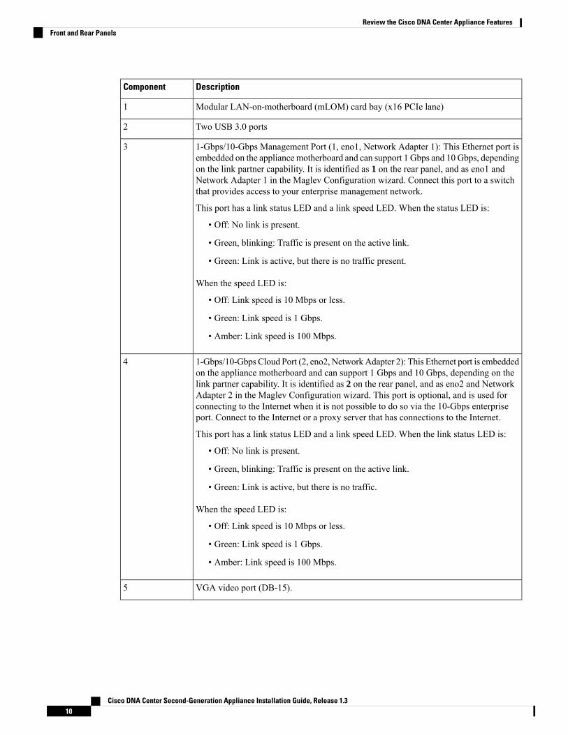
DescriptionComponent
Modular LAN-on-motherboard (mLOM) card bay (x16 PCIe lane)1
Two USB 3.0 ports2
1-Gbps/10-Gbps Management Port (1, eno1, Network Adapter 1): This Ethernet port isembedded on the appliancemotherboard and can support 1 Gbps and 10 Gbps, dependingon the link partner capability. It is identified as 1 on the rear panel, and as eno1 andNetwork Adapter 1 in the Maglev Configuration wizard. Connect this port to a switchthat provides access to your enterprise management network.
This port has a link status LED and a link speed LED. When the status LED is:
• Off: No link is present.
• Green, blinking: Traffic is present on the active link.
• Green: Link is active, but there is no traffic present.
When the speed LED is:
• Off: Link speed is 10 Mbps or less.
• Green: Link speed is 1 Gbps.
• Amber: Link speed is 100 Mbps.
3
1-Gbps/10-Gbps Cloud Port (2, eno2, NetworkAdapter 2): This Ethernet port is embeddedon the appliance motherboard and can support 1 Gbps and 10 Gbps, depending on thelink partner capability. It is identified as 2 on the rear panel, and as eno2 and NetworkAdapter 2 in the Maglev Configuration wizard. This port is optional, and is used forconnecting to the Internet when it is not possible to do so via the 10-Gbps enterpriseport. Connect to the Internet or a proxy server that has connections to the Internet.
This port has a link status LED and a link speed LED. When the link status LED is:
• Off: No link is present.
• Green, blinking: Traffic is present on the active link.
• Green: Link is active, but there is no traffic.
When the speed LED is:
• Off: Link speed is 10 Mbps or less.
• Green: Link speed is 1 Gbps.
• Amber: Link speed is 100 Mbps.
4
VGA video port (DB-15).5
Cisco DNA Center Second-Generation Appliance Installation Guide, Release 1.310
Review the Cisco DNA Center Appliance FeaturesFront and Rear Panels

DescriptionComponent
1-Gbps CIMC Port: This is the embedded port to the right of the VGA video port andto the left of the RJ45 serial port. It is assigned an IP address when you enable browseraccess to the appliance's CIMC GUI (see Enable Browser Access to Cisco IntegratedManagement Controller). This port is reserved for out-of-band management of theappliance chassis and software. Connect this port to a switch that provides access to yourenterprise management network.
This port has a link status LED and a link speed LED. When the link status LED is:
• Off: No link is present.
• Green, blinking: Traffic is present on the active link.
• Green: Link is active, but there is no traffic present.
When the speed LED is:
• Off: Link speed is 10 Mbps or less.
• Green: Link speed is 1 Gbps.
• Amber: Link speed is 100 Mbps.
6
Serial port (RJ-45 connector)7
Rear unit identification button and LED8
Power supplies (up to two: redundant as 1+1). Each power supply has a power supplyfault LED and an AC power LED.
When the fault LED is:
• Off: The power supply is operating normally.
• Amber, blinking: An event warning threshold has been reached, but the powersupply continues to operate.
• Amber, solid: A critical fault threshold has been reached, causing the power supplyto shut down (for example, a fan failure or an over-temperature condition).
When the AC Power LED is:
• Off: There is no AC power to the power supply.
• Green, solid: AC power is OK, DC output is OK.
• Green, blinking: AC power is OK, DC output is not enabled.
For more details, see Power Specifications.
9
Cisco DNA Center Second-Generation Appliance Installation Guide, Release 1.311
Review the Cisco DNA Center Appliance FeaturesFront and Rear Panels

DescriptionComponent
Intel X710-DA4 network interface card (NIC), which is located in the appliance's PCIeriser 2/slot 2. Note that this card has been disabled in this release of Cisco DNA Centerand will be enabled in a future release of the product.
If this card is enabled in your appliance, you must disable it. If you do notdisable the card, your appliance will contain four extra interfaces, which couldnegatively affect your configuration. To disable the card, see Disable theNetwork Interface Card, on page 62.
Important
10
10-Gbps Cluster Port (enp94s0f1, Network Adapter 4): This is the right-hand 10-Gbpsport on the Intel X710-DA2 NIC in the appliance PCIe riser 1/slot 1. It is identified asenp94s0f1 and Network Adapter 4 in the Maglev Configuration wizard. Connect thisport to a switch with connections to the other nodes in the cluster.
This port has a link status (ACT) LED and a link speed (LINK) LED.
When the link status LED is:
• Off: No link is present.
• Green, blinking: Traffic is present on the active link.
• Green: Link is active, but there is no traffic present.
When the link speed LED is:
• Off: Link speed is 100 Mbps or less.
• Green: Link speed is 10 Gbps.
• Amber: Link speed is 1 Gbps.
Although capable of operating at lower speeds, the enterprise and cluster portsare intended to operate at 10 Gbps only.
Note
11
Cisco DNA Center Second-Generation Appliance Installation Guide, Release 1.312
Review the Cisco DNA Center Appliance FeaturesFront and Rear Panels

DescriptionComponent
10-Gbps Enterprise Port (enp94s0f0, Network Adapter 3): This is the left-hand 10-Gbpsport on the Intel X710-DA2 NIC in the appliance PCIe riser 1/slot 1. It is identified asenp94s0f0 and Network Adapter 3 in the Maglev Configuration wizard. Connect thisport to a switch with connections to the enterprise network.
This port has a link status (ACT) LED and a link speed (LINK) LED.
When the link status LED is:
• Off: No link is present.
• Green, blinking: Traffic is present on the active link.
• Green: Link is active, but there is no traffic present.
When the speed LED is:
• Off: Link speed is 100 Mbps or less.
• Green: Link speed is 10 Gbps.
• Amber: Link speed is 1 Gbps.
Although capable of operating at lower speeds, the enterprise and cluster portsare intended to operate at 10 Gbps only.
Note
12
Threaded holes for dual-hole grounding lug.13
Figure 4: 112 Core Appliance Rear Panel
Cisco DNA Center Second-Generation Appliance Installation Guide, Release 1.313
Review the Cisco DNA Center Appliance FeaturesFront and Rear Panels

Figure 5: 112 Core Appliance Rear Panel Slots
DescriptionComponent
Serial port COM 1 (DB-9 connector)1
VGA video port (DB-15 connector)2
Not used at this time3
1-Gbps/10-Gbps Management Port (1, enp53s0f0, Network Adapter 1): This Ethernetport is embedded on the appliance motherboard and can support 1 Gbps and 10 Gbps,depending on the link partner capability. It is identified as 1 on the rear panel, and asenp53s0f0 and Network Adapter 1 in the Maglev Configuration wizard. Connect thisport to a switch that provides access to your enterprise management network.
This port has a link status LED and a link speed LED. When the status LED is:
• Off: No link is present.
• Green, blinking: Traffic is present on the active link.
• Green: Link is active, but there is no traffic present.
When the speed LED is:
• Off: Link speed is 10 Mbps or less.
• Green: Link speed is 1 Gbps.
• Amber: Link speed is 100 Mbps.
4
Cisco DNA Center Second-Generation Appliance Installation Guide, Release 1.314
Review the Cisco DNA Center Appliance FeaturesFront and Rear Panels

DescriptionComponent
1-Gbps/10-Gbps Cloud Port (2, enp53s0f1, Network Adapter 2): This Ethernet port isembedded on the appliancemotherboard and can support 1 Gbps and 10 Gbps, dependingon the link partner capability. It is identified as 2 on the rear panel, and as enp53s0f1and Network Adapter 2 in the Maglev Configuration wizard. This port is optional, andis used for connecting to the Internet when it is not possible to do so via the 10-Gbpsenterprise port. Connect to the Internet or a proxy server that has connections to theInternet.
This port has a link status LED and a link speed LED. When the link status LED is:
• Off: No link is present.
• Green, blinking: Traffic is present on the active link.
• Green: Link is active, but there is no traffic.
When the speed LED is:
• Off: Link speed is 10 Mbps or less.
• Green: Link speed is 1 Gbps.
• Amber: Link speed is 100 Mbps.
5
1-Gbps CIMC Port: This is the 10/100/1000 Ethernet dedicated management port(Base-T), which is located to the right of the Management port. It is identified as 3 onthe rear panel. This port is assigned an IP address when you enable browser access tothe appliance's CIMCGUI (see Enable Browser Access to Cisco IntegratedManagementController). It is reserved for out-of-band management of the appliance chassis andsoftware. Connect this port to a switch that provides access to your enterprise managementnetwork.
This port has a link status LED and a link speed LED. When the link status LED is:
• Off: No link is present.
• Green, blinking: Traffic is present on the active link.
• Green: Link is active, but there is no traffic present.
When the speed LED is:
• Off: Link speed is 10 Mbps or less.
• Green: Link speed is 1 Gbps.
• Amber: Link speed is 100 Mbps.
6
Rear identification button/LED7
Three USB 3.0 ports8
Power supplies 1 – 4: hot-swappable and redundant as 3+1 (configured in CIMC)
See Power Specifications for more information.
9
Cisco DNA Center Second-Generation Appliance Installation Guide, Release 1.315
Review the Cisco DNA Center Appliance FeaturesFront and Rear Panels

DescriptionComponent
Threaded holes for dual-hole grounding lug.10
Intel X710-DA4 network interface card (NIC), which is located in the appliance's PCIeriser 2/slot 12. Note that this card has been disabled in this release of Cisco DNA Centerand will be enabled in a future release of the product.
If this card is enabled in your appliance, you must disable it. If you do notdisable the card, your appliance will contain four extra interfaces, which couldnegatively affect your configuration. To disable the card, see Disable theNetwork Interface Card, on page 62.
Important
11
10-Gbps Cluster Port (enp69s0f1, Network Adapter 4): This is the bottom 10-Gbps porton the Intel X710-DA2 NIC that resides in the appliance's PCIe slot 9. It is identified asenp69s0f1 and Network Adapter 4 in the Maglev Configuration wizard. Connect thisport to a switch with connections to the other nodes in the cluster.
This port has a link status (ACT) LED and a link speed (LINK) LED.
When the link status LED is:
• Off: No link is present.
• Green, blinking: Traffic is present on the active link.
• Green: Link is active, but there is no traffic present.
When the link speed LED is:
• Off: Link speed is 100 Mbps or less.
• Green: Link speed is 10 Gbps.
• Amber: Link speed is 1 Gbps.
Although capable of operating at lower speeds, the enterprise and cluster portsare intended to operate at 10 Gbps only.
Note
12
Cisco DNA Center Second-Generation Appliance Installation Guide, Release 1.316
Review the Cisco DNA Center Appliance FeaturesFront and Rear Panels

DescriptionComponent
10-Gbps Enterprise Port (enp69s0f0, Network Adapter 3): This is the top 10-Gbps porton the Intel X710-DA2 NIC that resides in the appliance's PCIe slot 9. It is identified asenp69s0f0 and Network Adapter 3 in the Maglev Configuration wizard. Connect thisport to a switch with connections to the enterprise network.
This port has a link status (ACT) LED and a link speed (LINK) LED.
When the link status LED is:
• Off: No link is present.
• Green, blinking: Traffic is present on the active link.
• Green: Link is active, but there is no traffic present.
When the speed LED is:
• Off: Link speed is 100 Mbps or less.
• Green: Link speed is 10 Gbps.
• Amber: Link speed is 1 Gbps.
Although capable of operating at lower speeds, the enterprise and cluster portsare intended to operate at 10 Gbps only.
Note
13
Physical SpecificationsThe following table lists the physical specifications for the appliance. Unless indicated, the specificationsapply to the 44, 56, and 112 core appliances.
Table 4: Physical Specifications
SpecificationDescription
44 and 56 core appliance: 1.7 in. (4.32 cm)
112 core appliance: 6.9 in. (17.6 cm)
Height
44 and 56 core appliance:
• Without handles: 16.9 in. (43.0 cm)
• Including handles: 19.0 in. (48.3 cm)
112 core appliance: 19.0 in. (48.3 cm)
Width
44 and 56 core appliance:
• Without handles: 29.8 in. (75.6 cm)
• Including handles: 30.98 in. (78.7 cm)
112 core appliance: 32.7 in. (83.1 cm)
Depth (length)
Cisco DNA Center Second-Generation Appliance Installation Guide, Release 1.317
Review the Cisco DNA Center Appliance FeaturesPhysical Specifications

SpecificationDescription
3 in. (76 mm)Front Clearance
1 in. (25 mm)Side Clearance
6 in. (152 mm)Rear Clearance
44 and 56 core appliance: 37.5 lb. (17.0 kg)
112 core appliance: 146 lb. (66.2 Kg)
Maximum weight (fully loaded chassis)
Environmental SpecificationsThe following table lists the environmental specifications for the Cisco DNA Center appliance. Unlessindicated, the specifications apply to the 44, 56, and 112 core appliances.
Table 5: Environmental Specifications
SpecificationDescription
41 to 95°F (5 to 35°C)
Derate the maximum temperature by 1°C for every1000 ft. (305 meters) of altitude above sea level.
Temperature, operating
–40 to 149°F (–40 to 65°C)Temperature, nonoperating (when the appliance isstored or transported)
10 to 90%, noncondensing at 82°F (28°C)Humidity (RH), operating
5 to 93% at 82°F (28°C)Humidity (RH), nonoperating (when the appliance isstored or transported)
0 to 10,000 ft. (0 to 3,048 m)Altitude, operating
0 to 40,000 ft. (0 to 12,192 m)Altitude, nonoperating (when the appliance is storedor transported)
44 and 56 core appliance: 5.5
112 core appliance:
• Minimum configuration: 7.08
• Typical configuration: 7.67
• Maximum configuration: 8.24
Sound power level, measure A-weighted per ISO7779LwAd (Bels), operation at 73°F (23°C)
Cisco DNA Center Second-Generation Appliance Installation Guide, Release 1.318
Review the Cisco DNA Center Appliance FeaturesEnvironmental Specifications

SpecificationDescription
44 and 56 core appliance: 40
112 core appliance:
• Minimum configuration: 57.6
• Typical configuration: 63.5
• Maximum configuration: 70.5
Sound pressure level, measure A-weighted perISO7779 LpAm (dBA), Operation at 73°F (23°C)
Power SpecificationsThe specifications for the power supplies provided with the Cisco DNA Center appliance are listed in thetable below. The 44 and 56 core appliance ships with two 770 W power supplies (Cisco part numberUCSC-PSU1-770W) and the 112 core appliance ships with four 1600 W AC power supplies (Cisco partnumber UCSC-PSU1-1600W). Unless indicated, the specifications apply to both power supplies.
Table 6: AC Power Supply Specifications
SpecificationDescription
770 W:
• Nominal range: 100–120 VAC, 200–240 VAC
• Range: 90–132 VAC, 180–264 VAC
1600 W:
• Nominal range: 200–240 VAC
• Range: 180–264 VAC
AC input voltage
Nominal range: 50 to 60 Hz
(Range: 47–63 Hz)
AC input frequency
770 W:
• 9.5 A at 100 VAC
• 4.5 A at 208 VAC
1600 W: 9.5 A at 200 VAC
Maximum AC input current
770 W: 950 VA at 100 VAC
1600 W: 1250 VA at 200 VAC
Maximum input volt-amperes
770 W: 100–120 VAC
1600 W: 200–240 VAC
Maximum output power per PSU
Cisco DNA Center Second-Generation Appliance Installation Guide, Release 1.319
Review the Cisco DNA Center Appliance FeaturesPower Specifications

SpecificationDescription
770 W: 15 A at 35° C
1600 W: 30 A at 35° C
Maximum inrush current
770 W: 12 ms
1600 W: 80 ms at
Maximum hold-up time
12 VDCPower supply output voltage
12 VDCPower supply standby voltage
Climate Savers Platinum Efficiency (80Plus Platinumcertified)
Efficiency rating
RSP2Form factor
IEC320 C14Input connector
You can get more specific power information for the exact configuration of your appliance by using the CiscoUCS Power Calculator: http://ucspowercalc.cisco.com
Note
Cisco DNA Center Second-Generation Appliance Installation Guide, Release 1.320
Review the Cisco DNA Center Appliance FeaturesPower Specifications

C H A P T E R 2Plan the Deployment
• Planning Workflow, on page 21• Cisco DNA Center and Cisco Software-Defined Access, on page 22• Interface Cable Connections, on page 22• Required IP Addresses and Subnets, on page 27• Required Internet URLs and Fully Qualified Domain Names, on page 31• Provide Secure Access to the Internet, on page 33• Required Network Ports, on page 34• Required Ports and Protocols for Cisco Software-Defined Access, on page 36• Required Configuration Information, on page 44• Required First-Time Setup Information, on page 45
Planning WorkflowYou must perform the following planning and information-gathering tasks before attempting to install,configure, and set up your Cisco DNA Center appliance. After you complete these tasks, you can continueby physically installing your appliance in the data center.
For more information, see Cisco DNA Center and Cisco Software-Defined Access.Note
1. Review the recommended cabling and switching requirements for standalone and cluster installations.For more information, see Interface Cable Connections.
2. Gather the IP addressing, subnetting, and other IP traffic information that you will apply during applianceconfiguration. For more information, see Required IP Addresses and Subnets.
3. Prepare a solution for the required access to web-based resources. For more information, see RequiredInternet URLs and Fully Qualified Domain Names and Provide Secure Access to the Internet.
4. Reconfigure your firewalls and security policies for Cisco DNA Center traffic. For more information, seeRequired Network Ports. If you are using Cisco DNA Center to manage a Cisco Software-DefinedAccess(SD-Access) network, also see Required Ports and Protocols for Cisco Software-Defined Access.
5. Gather the additional information used during appliance configuration and first-time setup. For moreinformation, see Required Configuration Information and Required First-Time Setup Information.
Cisco DNA Center Second-Generation Appliance Installation Guide, Release 1.321

Cisco DNA Center and Cisco Software-Defined AccessYou can use Cisco DNA Center to manage any type of network, including networks that employ the CiscoSD-Access fabric architecture. Cisco SD-Access transforms conventional networks into intent-based networks,where business logic becomes a physical part of the network, making it easy to automate day-to-day taskssuch as configuration, provisioning, and troubleshooting. The Cisco SD-Access solution reduces the timetaken to adapt the network to business needs, improves issue resolutions, and reduces security-breach impacts.
A complete discussion of the Cisco SD-Access solution is outside the scope of this guide. Network architectsand administrators planning to implement a Cisco SD-Access fabric architecture for use with Cisco DNACenter can find additional information and guidance from the following resources:
• For more information on how Cisco DNA Center leverages Cisco SD-Access to automate solutions thatare not possible with normal networking approaches and techniques, see Software Defined Access:Enabling Intent-Based Networking.
• For guidance in using Cisco SD-Access access segmentation to enhance network security, see theSoftware-Defined Access Segmentation Design Guide.
• For guidance on deploying SDAwith Cisco DNA Center, see the Software-Defined Access DeploymentGuide.
• For more information on the digital network architecture that is the foundation of Cisco DNA Centerand the Cisco SD-Access solution, and the roles that other Cisco and third-party products and solutionsplay in this innovative architecture, see the Cisco DNA Design Zone.
Interface Cable ConnectionsConnect the ports on the appliance to switches providing the following types of network access. At a minimum,you must configure the Enterprise and Cluster port interfaces, as they are required for Cisco DNA Centerfunctionality.
The interface name assigned to ports on 44, 56, and 112 core appliances differ. Whenever two interface namesare provided, the first applies to both 44 and 56 core appliances and the second applies to 112 core appliances.
Note
• (Optional) 1-Gbps/10-Gbps Management Port (1, eno1/enp53s0f0, Network Adapter 1): This port(labeled 1 on the rear panel) provides access to the Cisco DNA Center GUI, allowing users to use thesoftware on the appliance. Connect this port to a switch with connections to your enterprise managementnetwork, and configure one IP address with a subnet mask for the port.
• (Optional) 1-Gbps/10-Gbps Cloud Port (eno2/enp53s0f1, Network Adapter 2): This port, labeled 2on the rear panel, is optional. Use it only if you cannot connect the appliance to the Internet (includingto your Internet proxy server) using the 10-Gbps enterprise port (enp94s0f0/enp69s0f0, Network Adapter3). If you need to use the cloud port, connect it to a switch with connections to your Internet proxy serverand configure one IP address with subnet mask for the port.
• (Required) 10-Gbps Enterprise Port (enp94s0f0/enp69s0f0, Network Adapter 3): The purpose ofthis port is to enable Cisco DNA Center to communicate with and manage your network. Connect this
Cisco DNA Center Second-Generation Appliance Installation Guide, Release 1.322
Plan the DeploymentCisco DNA Center and Cisco Software-Defined Access

port to a switch with connections to the enterprise network and configure one IP address with subnetmask for the port.
• On the 44 and 56 core appliance, this is the left-hand port on the Intel X710-DA2 NIC that residesin the appliance's PCIe slot 1.
• On the 112 core appliance, this is the top 10-Gbps port on the Intel X710-DA2 NIC that resides inthe appliance's PCIe slot 12.
• (Required) 10-Gbps Cluster Port (enp94s0f1/enp69s0f1, Network Adapter 4): The purpose of thisport is to enable communications among the primary and add-on nodes in a cluster. Connect this port toa switch with connections to the other nodes in the cluster and configure one IP address with subnet maskfor the port.
• On the 44 and 56 core appliance, this is the right-hand port on the Intel X710-DA2 NIC that residesin the appliance's PCIe slot 1.
• On the 112 core appliance, this is the bottom 10-Gbps port on the Intel X710-DA2 NIC that residesin the appliance's PCIe slot 12.
During appliance configuration, the Maglev Configuration wizard does not let you proceed until youassign the Cluster Link option to an interface.We recommend that you designate port enp94s0f1/enp69s0f1as the Cluster Link. Be aware, however, that the interface marked as the Cluster Link cannot be changedafter configuration completes. Later, if you must change the interface marked as the Cluster Link, youare required to reconfigure the appliance. With this in mind, we recommend that you set up the ClusterPort with an IP address, so as to allow for expansion to a three-node cluster in the future. Also, makesure that the cluster link interface is connected to a switch port and is in the UP state.
For a description of the tasks you need to complete in order to reimage your CiscoDNA Center appliance, see Reimage the Appliance.
Note
• (Optional, but strongly recommended) 1-Gbps CIMC Port: This port provides browser access to theCisco Integrated Management Controller (CIMC) out-of-band appliance management interface and itsGUI. Its purpose is to allow you to manage the appliance and its hardware. Connect this port to a switchwith connections to your enterprise management network and configure an IP address with a subnet maskfor the port.
The following figures show the recommended connections for a single-node Cisco DNA Center cluster:
Cisco DNA Center Second-Generation Appliance Installation Guide, Release 1.323
Plan the DeploymentInterface Cable Connections
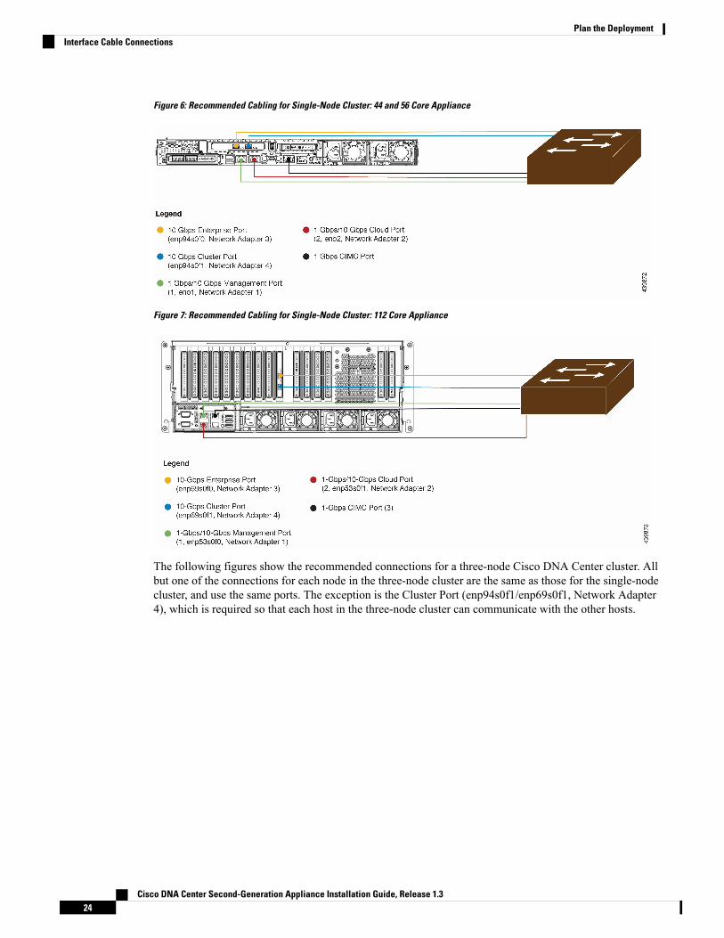
Figure 6: Recommended Cabling for Single-Node Cluster: 44 and 56 Core Appliance
Figure 7: Recommended Cabling for Single-Node Cluster: 112 Core Appliance
The following figures show the recommended connections for a three-node Cisco DNA Center cluster. Allbut one of the connections for each node in the three-node cluster are the same as those for the single-nodecluster, and use the same ports. The exception is the Cluster Port (enp94s0f1/enp69s0f1, Network Adapter4), which is required so that each host in the three-node cluster can communicate with the other hosts.
Cisco DNA Center Second-Generation Appliance Installation Guide, Release 1.324
Plan the DeploymentInterface Cable Connections

Figure 8: Recommended Cabling for Three-Node Cluster: 44 and 56 Core Appliance
Cisco DNA Center Second-Generation Appliance Installation Guide, Release 1.325
Plan the DeploymentInterface Cable Connections

Figure 9: Recommended Cabling for Three-Node Cluster: 112 Core Appliance
For more details on each of the ports, see the rear panel diagram and accompanying descriptions for yourchassis in Front and Rear Panels.
Multinode cluster deployments require all the member nodes to be in the same network and at the same site.The appliance does not support distribution of nodes across multiple networks or sites.
Note
When cabling the 10-Gbps enterprise and cluster ports, note that the ports support only the following mediatypes:
• SFP-10G-SR (Short range, MMF)
• SFP-10G-SR-S (Short range, MMF)
• SFP-10G-LR (Long range, SMF)
Cisco DNA Center Second-Generation Appliance Installation Guide, Release 1.326
Plan the DeploymentInterface Cable Connections

• SFP-H10GB-CU1M (Twinax cable, passive, 1 Meter)
• SFP-H10GB-CU3M (Twinax cable, passive, 3 Meters)
• SFP-H10GB-CU5M (Twinax cable, passive, 5 Meters)
• SFP-H10GB-ACU7M (Twinax cable, active, 7 Meters)
Required IP Addresses and SubnetsBefore beginning the installation, you must ensure that your network has sufficient IP addresses available toassign to each of the appliance ports that you plan on using. Depending on whether you are installing theappliance as a single-node cluster or as a primary or add-on node in a three-node cluster, you will need thefollowing appliance port (NIC) addresses:
• Enterprise Port Address (Required): One IP address with subnet mask.
• Cluster Port Address (Required): One IP address with subnet mask.
• Management Port Address (Optional): One IP address with subnet mask.
• Cloud Port Address (Optional): One IP address with subnet mask. This is an optional port, used onlywhen you cannot connect to the cloud using the Enterprise port. You do not need an IP address for theCloud port unless you must use it for this purpose.
• CIMC Port Address (Optional, but strongly recommended): One IP address with subnet mask.
All of the IP addresses called for in these requirements must be valid IPv4 addresses with valid IPv4 netmasks.Ensure that the addresses and their corresponding subnets do not overlap. Service communication issues canresult if they do.
Note
You will also need the following additional IP addresses and dedicated IP subnets, which are prompted forand applied during configuration of the appliance:
• Cluster Virtual IP Addresses: One virtual IP (VIP) address per configured network interface per cluster.This requirement applies to three-node clusters and single-node clusters that are likely to be convertedinto a three-node cluster in the future. You must supply a VIP for each network interface you configure.Each VIP should be from the same subnet as the IP address of the corresponding configured interface.There are four interfaces on each appliance: Enterprise, Cluster, Management, and Cloud. At a minimum,you must configure the Enterprise and Cluster port interfaces, as they are required for Cisco DNACenterfunctionality. An interface is considered configured if you supply an IP for that interface, along with asubnet mask and one or more associated gateways or static routes. If you skip an interface entirely duringconfiguration, that interface is considered as not configured.
Note the following:
• If you have a single-node setup and do not plan to convert it into a three-node cluster in the future,you are not required to specify a VIP address. However, if you decide to do so, you must specify aVIP address for every configured network interface (just as you would for a three-node cluster).
• If the intracluster link for a single-node cluster goes down, then the VIP addresses associated withtheManagement and Enterprise interfaces will also go down.When this happens, Cisco DNACenter
Cisco DNA Center Second-Generation Appliance Installation Guide, Release 1.327
Plan the DeploymentRequired IP Addresses and Subnets

is unusable until the intracluster link is restored (because the Software ImageManagement (SWIM)and Cisco Identity Services Engine (ISE) integration will not be operational and Cisco DNAAssurance data will not be displayed because information cannot be gathered from Network DataPlatform (NDP) collectors).
• Default Gateway IP Address: The IP address for your network's preferred default gateway. If no otherroutes match the traffic, traffic will be routed through this IP address. Typically, you should assign thedefault gateway to the interface in your network configuration that accesses the internet. For informationon security considerations to keep in mind when deploying Cisco DNA Center, see the Cisco DigitalNetwork Architecture Center Security Best Practices Guide.
• DNS Server IP Addresses: The IP address for one or more of your network's preferred Domain NameSystem (DNS) servers. During configuration, you can specify multiple DNS server IP addresses andnetmasks by entering them as a space-separated list.
• (Optional) Static Route Addresses: The IP addresses, subnet masks, and gateways for one or morestatic routes. During configuration, you can specify multiple static-route IP addresses, netmasks, andgateways by entering them as a space-separated list.
You can set one or more static routes for an interface on the appliance. You should supply static routeswhen you want to route traffic in a specific direction other than the default gateway. Each of the interfaceswith static routes will be set as the device the traffic will be routed through in the IP route commandtable. For this reason, it is important to match the static route directions with the interface though whichthe traffic will be sent.
Static routes are not recommended in network device routing tables such as those used by switches androuters. Dynamic routing protocols are better for this. However, you should add static routes whereneeded, to allow the appliance access to particular parts of the network that can be reached no other way.
• NTP Server IP Addresses: The DNS-resolvable hostname or IP address for at least one Network TimeProtocol (NTP) server.
During configuration, you can specify multiple NTP server IPs/masks or hostnames by entering them asa space-separated list. For a production deployment, we recommend that you configure a minimum ofthree NTP servers.
Specify these NTP servers during preflight hardware synchronization, and again during the configurationof the software on each appliance in the cluster. Time synchronization is critical to the accuracy of dataand the coordination of processing across a multihost cluster. Before deploying the appliance in aproduction environment, make sure that the time on the appliance system clock is current and that theNTP servers you specified are keeping accurate time. If you are planning to integrate the appliance withISE, you should also ensure that ISE is synchronizing with the same NTP servers as the appliance.
• Services Subnet: Identifies a dedicated IP subnet for the appliance to use in managing and getting IPsfor communications among its internal application services, such as Cisco DNA Assurance, inventorycollection, and so on. The dedicated IPv4 Services subnet must not conflict with or overlap any othersubnet used by the Cisco DNA Center internal network or an external network. The minimum size ofthe subnet is 21 bits. The IPv4 Services subnet must conform with the IETF RFC 1918 and RFC 6598specifications for private networks, which support the following address ranges:
• 10.0.0.0/8
• 172.16.0.0/12
• 192.168.0.0/16
Cisco DNA Center Second-Generation Appliance Installation Guide, Release 1.328
Plan the DeploymentRequired IP Addresses and Subnets

• 100.64.0.0/10
For details, see RFC 1918, Address Allocation for Private Internets, and RFC 6598, IANA-ReservedIPv4 Prefix for Shared Address Space.
• Ensure that you specify a valid CIDR subnet. Otherwise, incorrect bits willbe present in the 172.17.1.0/20 and 172.17.61.0/20 subnets.
• After configuration of your Cisco DNA Center appliance is completed, youcannot assign a different subnet without first reimaging the appliance (seeReimage the Appliance for more information).
Important
• Cluster Services Subnet: Identifies a dedicated IP subnet for the appliance to use in managing andgetting IP addresses for communications among its infrastructure services, such as database access, themessage bus, and so on. The dedicated IPv4 Cluster Services subnet must not conflict with or overlapany other subnet used by the Cisco DNA Center internal network or an external network. The minimumsize of the subnet is 21 bits. The IPv4 Cluster Services subnet must conform with the IETF RFC 1918and RFC 6598 specifications for private networks, which support the following address ranges:
• 10.0.0.0/8
• 172.16.0.0/12
• 192.168.0.0/16
• 100.64.0.0/10
For details, see RFC 1918, Address Allocation for Private Internets, and RFC 6598, IANA-ReservedIPv4 Prefix for Shared Address Space.
If you were to specify 10.10.10.0/21 as your Services subnet, you could also specify a Cluster Servicessubnet of 10.0.8.0/21 since these two subnets do not overlap. Also note that the configuration wizarddetects overlaps (if any) between these subnets and prompts you to correct the overlap.
• Ensure that you specify a valid CIDR subnet. Otherwise, incorrect bits willbe present in the 172.17.1.0/20 and 172.17.61.0/20 subnets.
• After configuration of your Cisco DNA Center appliance is completed, youcannot assign a different subnet without first reimaging the appliance (seeReimage the Appliance for more information).
Important
The recommended total IP address space for the two Services and Cluster Services subnets contains 4,096addresses, broken down into two /21 subnets of 2,048 addresses each. The two /21 subnets must not overlap.The Cisco DNA Center internal services require a dedicated set of IP addresses to operate (a Cisco DNACenter microservice architecture requirement). To accommodate this requirement, you must allocate twodedicated subnets for each Cisco DNA Center system.
One reason the appliance requires this amount of address space is to maintain system performance. Becauseit uses internal routing and tunneling technologies for east-west (inter-node) communications, using overlappingaddress spaces forces the appliance to run Virtual Routing and Forwarding (VRF) FIBs internally. This leads
Cisco DNA Center Second-Generation Appliance Installation Guide, Release 1.329
Plan the DeploymentRequired IP Addresses and Subnets

to multiple encaps and decaps for packets going from one service to another, causing high internal latency ata very low level, with cascading impacts at higher layers.
Another reason is the CiscoDNACenter Kubernetes-based service containerization architecture. Each applianceuses the IP addresses in this space for each Kubernetes K8 node. Multiple nodes can make up a single service.Currently, Cisco DNA Center supports more than 100 services, each requiring several IP addresses, and newfeatures and corresponding services being added all the time. The address space requirement is purposely keptlarge at the start to ensure that Cisco can add new services and features without running out of IP addressesor requiring customers to reallocate contiguous address spaces simply to upgrade their systems.
The services supported over these subnets are also enabled at Layer 3. The Cluster Services space, in particular,carries data between application and infrastructure services, and is heavily used.
The RFC 1918 and RFC 6598 requirement is because of the requirement by Cisco DNA Center to downloadpackages and updates from the cloud. If the selected IP ranges do not conform with RFC 1918 and RFC 6598,this can quickly lead to problems with public IP overlaps.
Interface Names and Wizard Configuration OrderInterface names and the order in which these interfaces are configured in the Maglev Configuration wizarddiffer between the first and second generation Cisco DNA Center appliance, as illustrated in the followingtable. Refer to these Cisco part numbers to determine whether you have a first or second generation appliance:
• First generation 44 core appliance: DN1-HW-APL
• Second generation:
• 44 core appliance: DN2-HW-APL
• 44 core upgrade appliance: DN2-HW-APL-U
• 56 core appliance: DN2-HW-APL-L
• 112 core appliance: DN2-HW-APL-XL
Table 7: Interface Names and Wizard Configuration Order
Configuration Order in theMaglev ConfigurationWizard
Interface NameCisco DNA CenterAppliance Type
Function
Network Adapter #2enp1s0f0First generationManagement: Allowsyou to access the CiscoDNA Center GUI fromyour managementnetwork.
Network Adapter #1• 44 and 56 coreappliance: eno1
• 112 core appliance:enp53s0f0
Second generation
Cisco DNA Center Second-Generation Appliance Installation Guide, Release 1.330
Plan the DeploymentInterface Names and Wizard Configuration Order

Configuration Order in theMaglev ConfigurationWizard
Interface NameCisco DNA CenterAppliance Type
Function
Network Adapter #3enp1s0f1First generationCloud: Provides internetaccess when anotherinterface is not availablefor this purpose.
Network Adapter #2• 44 and 56 coreappliance: eno2
• 112 core appliance:enp53s0f1
Second generation
Network Adapter #4enp9s0First generationEnterprise: Links theappliance to yourenterprise network. Network Adapter #3• 44 and 56 core
appliance:enp94s0f0
• 112 core appliance:enp69s0f0
Second generation
Network Adapter #1enp10s0First generationCluster: Links theappliance to your clusternodes. Network Adapter #4• 44 and 56 core
appliance:enp94s0f1
• 112 core appliance:enp69s0f1
Second generation
Required Internet URLs and Fully Qualified Domain NamesThe appliance requires secure access to the following table of URLs and Fully Qualified Domain Names(FQDNs).
The table describes the features that make use of each URL and FQDN. You must configure either yournetwork firewall or a proxy server so that IP traffic can travel to and from the appliance and these resources.If you cannot provide this access for any listed URL and FQDN, the associated features will be impaired orinoperable.
For more on requirements for proxy access to the internet, see Provide Secure Access to the Internet.
Cisco DNA Center Second-Generation Appliance Installation Guide, Release 1.331
Plan the DeploymentRequired Internet URLs and Fully Qualified Domain Names

Table 8: Required URLs and FQDN Access
...Cisco DNA Center must access these URLs and FQDNsIn order to...
Recommended: *.ciscoconnectdna.com:4431
Customers who want to avoid wildcards can specify theseURLs instead:
• https://www.ciscoconnectdna.com
• https://cdn.ciscoconnectdna.com
• https://registry.ciscoconnectdna.com
• https://registry-cdn.ciscoconnectdna.com
Download updates to the system and applicationpackage software, submit user feedback to theproduct team.
https://*.ciscoconnectdna.com/*Cisco DNA Center update package
https://apx.cisco.com
https://cloudsso.cisco.com/as/token.oauth2
https://*.cisco.com/*
Smart Account and SWIM software downloads
https://dnacenter.uservoice.comUser feedback
Recommended: *.meraki.com:443
Customers who want to avoid wildcards can specify theseURLs instead:
• dashboard.meraki.com:443
• api.meraki.com:443
• n63.meraki.com:443
Integrate with Cisco Meraki.
Cisco DNA Center Second-Generation Appliance Installation Guide, Release 1.332
Plan the DeploymentRequired Internet URLs and Fully Qualified Domain Names

...Cisco DNA Center must access these URLs and FQDNsIn order to...
*.cisco.com:443
Customers who want to avoid wildcards can specify theseURLs instead:
• software.cisco.com
• cloudsso.cisco.com
• cloudsso1.cisco.com
• cloudsso2.cisco.com
• apiconsole.cisco.com
• api.cisco.com
• apx.cisco.com
• sso.cisco.com
• apmx-prod1-vip.cisco.com
• apmx-prod2-vip.cisco.com
• tools.cisco.com
Integrate with Cisco.com and Cisco SmartLicensing.
• www.mapbox.com
• *.tiles.mapbox.com/* :443. For a proxy, thedestination is *.tiles.mapbox.com/*
Render accurate information in site and locationmaps.
1 Cisco owns and maintains ciscoconnectdna.com and its subdomains. The Cisco Connect DNAinfrastructure meets Cisco Security and Trust guidelines and undergoes continuous security testing.This infrastructure is robust, with built-in load balancing and automation capabilities, and is monitoredand maintained by a cloud operations team to ensure 24x7x365 availability.
Provide Secure Access to the InternetBy default, the appliance is configured to access the internet in order to download software updates, licenses,and device software, as well as provide up-to-date map information, user feedback, and so on. Providinginternet connections for these purposes is a mandatory requirement.
Using an HTTPS proxy server is a reliable way to access remote URLs securely. We recommend that youuse an HTTPS proxy server to provide the appliance with the access it needs to the URLs listed in RequiredInternet URLs and Fully Qualified Domain Names. During appliance installation, you are prompted to enterthe URL and port number of the proxy server you want to use for this purpose, along with the proxy's logincredentials (if the proxy requires them).
As of this release, the appliance supports communication with proxy servers over HTTP only. You can placethe HTTPS proxy server anywhere within your network. The proxy server communicates with the internetusing HTTPS, while the appliance communicates with the proxy server via HTTP. Therefore, we recommendthat you specify the proxy's HTTP port when configuring the proxy during appliance configuration.
Cisco DNA Center Second-Generation Appliance Installation Guide, Release 1.333
Plan the DeploymentProvide Secure Access to the Internet

If you need to change the proxy setting after configuration, you can do so using the GUI.
Required Network PortsThe following two tables list the well-known network service ports that the appliance uses. You must ensurethat these ports are open for traffic flows to and from the appliance, whether you open them using firewallsettings or a proxy gateway.
Additional ports, protocols, and types of traffic must be accommodated if you are deploying the appliance ina network that employs SDA infrastructure. For details, see Required Ports and Protocols for CiscoSoftware-Defined Access.
For information on security considerations when deploying Cisco DNACenter, see the Cisco Digital NetworkArchitecture Center Security Best Practices Guide.
Note
Table 9: Ports: Incoming Traffic
Protocol (TCP or UDP)Permitted TrafficPort Number
TCPHTTP80
TCP and UDPNFS (used for Assurance backups)111
UDPNTP123
UDPSNMP162
TCPHTTPS443
TCP and UDPNFS (used for Assurance backups)2049
TCPSSH2222
TCP and UDPNFS (used for Assurance backups)20048
TCP and UDPNFS (used for Assurance backups)32767
Table 10: Ports: Outgoing Traffic
Protocol (TCP or UDP)Permitted TrafficPort Number
TCPSSH (to the network devices andCisco ISE)
22
TCPTelnet (to the network devices)23
UDPDNS53
Cisco DNA Center Second-Generation Appliance Installation Guide, Release 1.334
Plan the DeploymentRequired Network Ports

Protocol (TCP or UDP)Permitted TrafficPort Number
TCPPort 80 can be used for an outgoingproxy configuration.
Additionally, other common ports(such as 8080) can also be usedwhen a proxy is being configuredby the Configuration wizard (if aproxy is already in use for yournetwork).
To access Cisco-supportedcertificates and trust pools,configure your network to allowoutgoing IP traffic from theappliance to the Cisco addresses at:
https://www.cisco.com/security/pki/
80
UDPNTP123
UDPSNMP agent161
TCPHTTPS443
TCPISE XMP for PxGrid5222
TCPISE ERS API traffic9060
The following table lists the ports that permit incoming IP traffic to the appliance:
Table 11: Ports: IP Traffic
Traffic TypePort NumberProtocol (TCP or UDP)
SSH22TCP
SSH2222TCP
HTTP80TCP
HTTPS443TCP
bootps67UDP
NTP123UDP
SNMP162UDP
Cisco DNA Center Second-Generation Appliance Installation Guide, Release 1.335
Plan the DeploymentRequired Network Ports

Additionally, you can configure your network to allow outgoing IP traffic from the appliance to the Ciscoaddresses at: https://www.cisco.com/security/pki/. The appliance uses the IP addresses listed at the aboveURL to access Cisco-supported certificates and trust pools.
Note
Required Ports and Protocols for Cisco Software-DefinedAccess
This topic details the ports, protocols, and types of traffic native to a typical Cisco SD-Access fabric deploymentthat is similar to the one shown in the following figure.
Cisco DNA Center Second-Generation Appliance Installation Guide, Release 1.336
Plan the DeploymentRequired Ports and Protocols for Cisco Software-Defined Access

Figure 10: Cisco SD-Access Fabric Infrastructure
If you have implemented Cisco SD-Access in your network, use the information in the following tables toplan firewall and security policies that secure your Cisco SD-Access infrastructure properly while providingCisco DNA Center with the access it requires to automate your network management.
Table 12: Cisco DNA Center Traffic
DescriptionDestinationDestinationPort
SourceSourcePort2
From Cisco DNA Center to DNS serverDNS ServerUDP 53Cisco DNACenter
Any
From Cisco DNA Center to fabricswitches' loopbacks for SSH
Fabric underlayTCP 22Cisco DNACenter
Any
Cisco DNA Center Second-Generation Appliance Installation Guide, Release 1.337
Plan the DeploymentRequired Ports and Protocols for Cisco Software-Defined Access

From Cisco DNA Center to fabricswitches' loopbacks for TELNET
Fabric underlayTCP 23Cisco DNACenter
Any
From Cisco DNA Center to fabricswitches' loopbacks for SNMP devicediscovery
Fabric underlayUDP 161Cisco DNACenter
Any
From Cisco DNA Center to fabricswitches' loopbacks for SNMP devicediscovery
Fabric underlayICMPCisco DNACenter
ICMP
From Cisco DNA Center to fabricswitches for software upgrades (also tothe internet if there is no proxy)
Fabric underlayTCP 443Cisco DNACenter
Any
From Cisco DNA Center to fabricswitches for Plug and Play (PnP) (alsoto the internet if there is no proxy)
Fabric underlayTCP 80Cisco DNACenter
Any
From Cisco DNA Center to fabricswitches for Netconf (Cisco SD-Accessembedded wireless)
Fabric underlayTCP 830Cisco DNACenter
Any
From Cisco DNA Center to fabricswitches for the initial period duringLAN automation
Fabric underlayUDP 123Cisco DNACenter
UDP 123
From Cisco DNA Center to NTP serverNTP ServerUDP 123Cisco DNACenter
Any
From Cisco DNA Center to CiscoWireless Controller
Cisco WirelessController
TCP 22, UDP161
Cisco DNACenter
Any
From Cisco DNA Center to CiscoWireless Controller
Cisco WirelessController
ICMPCisco DNACenter
ICMP
From Cisco DNA Center to an AP as asensor and active sensor (Cisco Aironet1800S)
APTCP 80, TCP443
Cisco DNACenter
Any
Used for receiving traffic statistics andpacket capture data used by the CiscoDNA Assurance Intelligent Capture(gRPC) feature.
Cisco DNACenter
TCP 32626APAny
2 Cluster, PKI, SFTP server, and proxy port traffic are not included in this table.
Table 13: Internet Connectivity Traffic
DescriptionDestinationDestinationPort
SourceSourcePort
Download Cisco DNACenter package updates
registry.ciscoconnectdna.comTCP 443Cisco DNA CenterAny
Cisco DNA Center Second-Generation Appliance Installation Guide, Release 1.338
Plan the DeploymentRequired Ports and Protocols for Cisco Software-Defined Access

Download Cisco DNACenter package updates
www.ciscoconnectdna.comTCP 443Cisco DNA CenterAny
Download Cisco DNACenter package updates
registry-cdn.ciscoconnectdna.comTCP 443Cisco DNA CenterAny
Download Cisco DNACenter package updates
cdn.ciscoconnectdna.comTCP 443Cisco DNA CenterAny
Download device softwaresoftware.cisco.comTCP 443Cisco DNA CenterAny
Validate Cisco.com andSmart Account credentials
cloudsso.cisco.comTCP 443Cisco DNA CenterAny
Validate Cisco.com andSmart Account credentials
cloudsso1.cisco.comTCP 443Cisco DNA CenterAny
Validate Cisco.com andSmart Account credentials
cloudsso2.cisco.comTCP 443Cisco DNA CenterAny
CSSMSmart LicensingAPIapiconsole.cisco.comTCP 443Cisco DNA CenterAny
CCO and Smart Licensingsso.cisco.comTCP 443Cisco DNA CenterAny
CCO and Smart Licensingapi.cisco.comTCP 443Cisco DNA CenterAny
CCO and Smart Licensingapx.cisco.comTCP 443Cisco DNA CenterAny
Meraki integrationdashboard.meraki.comTCP 443Cisco DNA CenterAny
Meraki integrationapi.meraki.comTCP 443Cisco DNA CenterAny
Meraki integrationn63.meraki.comTCP 443Cisco DNA CenterAny
User feedback submissiondnacenter.uservoice.comTCP 443Cisco DNA CenterAny
Render maps in the browser(for access through proxy;the destination is*.tiles.mapbox.com/*)
*.tiles.mapbox.comTCP 443Cisco DNA CenterAdmin Client
Any
Maps and Cisco WirelessController country codeidentification
www.mapbox.comTCP 443Cisco DNA CenterAny
Table 14: Cisco Software-Defined Access Fabric Underlay Traffic
DescriptionDestinationDestination PortSourceSourcePort3
From fabric switches and routers tothe DHCP server for DHCP Relaypackets initiated by the fabric edgenodes.
DHCP serverUDP 67Fabricunderlay
UDP 68
From fabric switch and routerloopback IPs to Cisco DNA Centerfor PnP
Cisco DNACenter
TCP 80Fabricunderlay
Any
Cisco DNA Center Second-Generation Appliance Installation Guide, Release 1.339
Plan the DeploymentRequired Ports and Protocols for Cisco Software-Defined Access

From fabric switch and routerloopback IPs to Cisco DNA Centerfor image upgrade
Cisco DNACenter
TCP 443Fabricunderlay
Any
From fabric switch and routerloopback IPs to Cisco DNA Centerfor SNMP Traps
Cisco DNACenter
UDP 162Fabricunderlay
Any
From fabric switches and routers toCisco DNA Assurance
Cisco DNACenter
UDP 514Fabricunderlay
Any
From fabric routers to Cisco DNACenter for NetFlow
Cisco DNACenter
UDP 6007Fabricunderlay
Any
From fabric switches to Cisco DNACenter; used when doing LANautomation
Cisco DNACenter
UDP 123Fabricunderlay
Any
From fabric switch and routerloopbacks to Cisco DNA Center forSNMP: device discovery
Cisco DNACenter
ICMPFabricunderlay
ICMP
From fabric switch and routerloopbacks to Cisco DNA Center forSNMP: Device Discovery
Cisco DNACenter
AnyFabricunderlay
UDP 161
From fabric switches and routers toDNS server for name resolution
DNS ServerUDP 53Fabricunderlay
Any
LISP-encapsulated control messagesFabric Routersand Switches
TCP and UDP 4342Fabricunderlay
TCP andUDP 4342
LISP control-plane communicationsFabric Routersand Switches
AnyFabricunderlay
TCP andUDP 4342
Fabric-encapsulated data packets(VXLAN-GPO)
Fabric Routersand Switches
UDP 4789Fabricunderlay
Any
From fabric switch and routerloopback IPs to ISE for RADIUS
ISEUDP1645/1646/1812/1813
Fabricunderlay
Any
From fabric switches and routers toISE for troubleshooting
ISEICMPFabricunderlay
ICMP
From fabric switches to ISE forcare-of address (CoA)
ISEAnyFabricunderlay
UDP1700/3799
From fabric switch and routerloopback IPs to the NTP server
NTP ServerUDP 123Fabricunderlay
Any
From control-plane loopback IP toCisco Wireless Controller forFabric-enabled wireless
Cisco WirelessController
UDP and TCP4342/4343
control-planeAny
3 Border routing protocol, SPAN, profiling, and telemetry traffic are not included in this table.
Cisco DNA Center Second-Generation Appliance Installation Guide, Release 1.340
Plan the DeploymentRequired Ports and Protocols for Cisco Software-Defined Access

Table 15: Cisco Wireless Controller Traffic
DescriptionDestinationDestinationPort
SourceSource Port
From Cisco Wireless Controllerto an AP subnet for CAPWAP
AP IP PoolAnyCisco WirelessController
UDP5246/5247/5248
From Cisco Wireless Controllerto APs allowing ping fortroubleshooting
AP IP PoolICMPCisco WirelessController
ICMP
From Cisco Wireless Controllerto an AP subnet for CAPWAP
AP IP PoolUDP69/5246/5247TCP 22
Cisco WirelessController
Any
From Cisco Wireless Controllerto control-plane loopback IP
Control planeUDP and TCP4342/4343
Cisco WirelessController
Any
From Cisco Wireless Controllerto Cisco DNA Center for devicediscovery
Cisco DNACenter
TCP 32222Cisco WirelessController
Any
From Cisco Wireless Controllerto Cisco DNA Center for SNMP
Cisco DNACenter
AnyCisco WirelessController
UDP 161
From Cisco Wireless Controllerto Cisco DNA Center for SNMPtraps
Cisco DNACenter
UDP 162Cisco WirelessController
Any
From Cisco Wireless Controllerto Cisco MSE and SpectrumExpert for NMSP
Cisco MobilityServices Engine(MSE) and CiscoSpectrum Expert
TCP 16113Cisco WirelessController
Any
From Cisco Wireless Controllerto allow ping for troubleshooting
Cisco DNACenter
ICMPCisco WirelessController
ICMP
Database server HA (QoS)Cisco DNACenter
TCP 1315HA serverAny
HA database portsCisco DNACenter
TCP1316–1320
HA serverAny
HA web server's health monitorport
Cisco DNACenter
TCP 8082HA web serverAny
Syslog (optional)Cisco WirelessController
UDP 514Cisco WirelessController andvarious syslog servers
Any
From Cisco Wireless Controllerto DNS server
DNS ServerUDP 53Cisco WirelessController
Any
From Cisco Wireless Controllerto ISE for Guest SSID webauthorization
ISETCP 443Cisco WirelessController
Any
Cisco DNA Center Second-Generation Appliance Installation Guide, Release 1.341
Plan the DeploymentRequired Ports and Protocols for Cisco Software-Defined Access

From Cisco Wireless Controllerto ISE for RADIUSauthentication
ISEUDP1645,1812
Cisco WirelessController
Any
From Cisco Wireless Controllerto ISE for RADIUS accounting
ISEUDP 1646,1813
Cisco WirelessController
Any
From Cisco Wireless Controllerto ISE for RADIUS CoA
ISEUDP 1700,3799
Cisco WirelessController
Any
From Cisco Wireless Controllerto ISE ICMP for troubleshooting
ISEICMPCisco WirelessController
ICMP
From Cisco Wireless Controllerto NTP server
NTP serverUDP 123Cisco WirelessController
Any
Table 16: Fabric-Enabled Wireless AP IP Pool Traffic
DescriptionDestinationDestination PortSourceSourcePort
From an AP IP pool to DHCP server.DHCP serverUDP 67AP IPPool
UDP 68
From an AP IP pool to ICMP fortroubleshooting.
DHCP serverICMPAP IPPool
ICMP
Syslog—Destination configurable.Default is 255.255.255.255.
Various514AP IPPool
Any
From an AP IP pool to Cisco WirelessController for CAPWAP.
Cisco WirelessController
UDP69/5246/5247/5248
AP IPPool
Any
From an AP IP pool to Cisco WirelessController, allowing ping fortroubleshooting.
Cisco WirelessController
ICMPAP IPPool
ICMP
Table 17: ISE Traffic
DescriptionDestinationDestinationPort
SourceSource Port4
From ISE to border node for SGTExchange Protocol (SXP)
BorderTCP 64999ISEAny
From ISE to syslog server (CiscoDNA Center)
Cisco DNA CenterUDP 514ISEAny
From ISE to fabric switches androuters for RADIUS and authorization
Fabric underlayAnyISEUDP1645/1646/1812/1813
From ISE to fabric switch and routerloopback IPs for CoA
Fabric underlayUDP1700/3799
ISEAny
From ISE to fabric switches fortroubleshooting
Fabric underlayICMPISEICMP
From ISE to NTP serverNTP ServerUDP 123ISEAny
Cisco DNA Center Second-Generation Appliance Installation Guide, Release 1.342
Plan the DeploymentRequired Ports and Protocols for Cisco Software-Defined Access

From ISE to CiscoWireless Controllerfor RADIUS
Cisco WirelessController
AnyISEUDP1812/1645/1813/1646
From ISE to CiscoWireless Controllerfor troubleshooting
Cisco WirelessController
ICMPISEICMP
4 Note: High availability and profiling traffic are not included in this table.
Table 18: DHCP Server Traffic
DescriptionDestinationDestinationPort
SourceSourcePort
From DHCP server to fabric APsAP IP PoolUDP 68DHCPserver
UDP 67
ICMP for troubleshooting: Fabric to DHCPAP IP PoolICMPDHCPserver
ICMP
From DHCP to fabric switches and routersFabricunderlay
UDP 68DHCPserver
UDP 67
ICMP for troubleshooting: Fabric to DHCPFabricunderlay
ICMPDHCPserver
ICMP
From DHCP server to fabric switches androuters
User IP PoolUDP 68DHCPserver
UDP 67
ICMP for troubleshooting: User to DHCPUser IP PoolICMPDHCPserver
ICMP
Table 19: NTP Server Traffic
DescriptionDestinationDestinationPort
SourceSourcePort
From NTP server to ISEISEAnyNTPServer
UDP 123
FromNTP server to Cisco DNACenterCisco DNA CenterAnyNTPServer
UDP 123
From NTP server to fabric switch androuter loopback
Fabric underlayAnyNTPServer
UDP 123
From NTP server to Cisco WirelessController
Cisco WirelessController
AnyNTPServer
UDP 123
Table 20: DNS Traffic
DescriptionDestinationDestinationPort
SourceSourcePort
From DNS server to fabric switchesFabric underlayAnyDNSServer
UDP 53
Cisco DNA Center Second-Generation Appliance Installation Guide, Release 1.343
Plan the DeploymentRequired Ports and Protocols for Cisco Software-Defined Access

From DNS server to Cisco WirelessController
Cisco WirelessController
AnyDNSServer
UDP 53
Required Configuration InformationDuring appliance configuration, you will be prompted for the following information, in addition to the RequiredIP Addresses and Subnets:
• Linux User Name: This is maglev. This user name is the same on all the appliances in a cluster,including the primary node and add-on nodes, and cannot be changed.
• Linux Password: Identifies the password for the Linux user name maglev. This password ensuressecure access to each appliance using the Linux command line. If required, you can assign a differentLinux password for each maglev Linux user name on each appliance in a cluster.
You must create the Linux password because there is no default. The password must meet the followingrequirements:
• Minimum length of eight characters.
• Should not contain a tab or a line break.
• Contains characters from at least three of the following categories:
• Upper case alphabets
• Lower case alphabets
• Numerals
• Special characters (for example, ! or #)
The Linux password is encrypted and hashed in the Cisco DNA Center database. If you are deploying amultinode cluster, you will also be prompted to enter the primary node's Linux password on each of theadd-on nodes.
• Password Generation Seed (Optional): Instead of creating Linux password, you can enter a seed phraseand click Generate Password. The Maglev Configuration wizard generates a random and securepassword using this seed phrase. You can further edit the generated password by using theAuto GeneratedPassword field.
• Administrator Passphrase: Identifies the password used for web access to Cisco DNA Center in acluster. This is the password for the superuser account admin, which you use to log in to Cisco DNACenter for the first time (see Log In for the First Time). You are prompted to change this password whenyou log in for the first time.
You must create this password because there is no default. The Administrator Passphrase must meet thesame requirements as the Linux password, described earlier.
• CIMC User Password: Identifies the password used for access to the CIMC GUI. The factory defaultis password, but you are prompted to change it when you first set up CIMC for access using a webbrowser (see Enable Browser Access to Cisco Integrated Management Controller).
The CIMC user password must meet the same requirements as the Linux password described earlier. Itcan be changed back to password only by a reset to factory defaults.
Cisco DNA Center Second-Generation Appliance Installation Guide, Release 1.344
Plan the DeploymentRequired Configuration Information

• Primary Node IP Address: Required only when you are installing add-on nodes in a cluster. This is theIP address of the cluster port on the primary node (see Interface Cable Connections).
Required First-Time Setup InformationAfter you have configured your appliances, log in to Cisco DNA Center and complete the essential setuptasks. During this first-time setup, you should have the following information:
• New Admin Superuser Password: You will be prompted to enter a new password for the Cisco DNACenter admin super user. Resetting the super user password enhances operational security. This isespecially important if, for example, the enterprise staff who installed and configured the Cisco DNACenter appliance is not a Cisco DNA Center user or administrator.
• Cisco.com Credentials: The Cisco.com user ID and password that your organization uses to registersoftware downloads and receive system communications through email.
• Cisco Smart Account Credentials: The Cisco.com Smart Account user ID and password yourorganization uses for managing your device and software licenses.
• IP Address Manager URL and Credentials: The host name, URL, admin user name, and adminpassword of the third-party IP address manager (IPAM) server you plan to use with Cisco DNA Center.This release supports InfoBlox and Bluecat.
• Proxy URL, Port, and Credentials: The URL (host name or IP address), port number, user name, anduser password of the proxy server you plan to use with Cisco DNA Center in order to get updates to theCisco DNA Center software, manage device licenses, and retrieve other downloadable content.
• Cisco DNA Center Users: User names, passwords, and privilege settings for the newCisco DNACenterusers you will be creating. We recommend that you always use one of these new user accounts for allyour normal Cisco DNA Center operations. Avoid using the admin super user account for activities,except reconfiguring Cisco DNACenter and operations where super user privileges are explicitly required.
For details about how to launch and respond to the first-time setup wizard that prompts you for this information,see Log In for the First Time.
You will also need the following information to complete the remaining setup tasks, which can be done afteryour first login:
• Authorization and Policy Server Information: If you are using Cisco ISE as your authentication andpolicy server, you will need the same information listed in the previous bullet, plus the ISE CLI username, CLI password, server FQDN, a subscriber name (such as cdnac), the ISE SSH key (optional), theprotocol choice (RADIUS or TACACS), the authentication port, the accounting port, and retry andtimeout settings.
• Authorization and Policy Server Information: If you are using Cisco ISE as your authentication andpolicy server, you will need the same information as for the ISE integration above, plus the ISE CLI username, CLI password, server FQDN, a subscriber name (such as cdnac), the ISE SSH key (optional), theprotocol choice (RADIUS or TACACS), the authentication port, the accounting port, and retry andtimeout settings.
If you are using an authorization and policy server that is not Cisco ISE, you will need the server's IPaddress, protocol choice (RADIUS or TACACS), authentication port, accounting port, and retry andtimeout settings.
Cisco DNA Center Second-Generation Appliance Installation Guide, Release 1.345
Plan the DeploymentRequired First-Time Setup Information

This information is required to integrate Cisco DNA Center with your chosen authentication and policyserver, as explained in Configure Authentication and Policy Servers.
• SNMP Retry and Timeout Values: This is required to set up device polling andmonitoring, as explainedin Configure SNMP Properties.
Cisco DNA Center Second-Generation Appliance Installation Guide, Release 1.346
Plan the DeploymentRequired First-Time Setup Information

C H A P T E R 3Install the Appliance
• Appliance Installation Workflow, on page 47• Unpack and Inspect the Appliance, on page 48• Review the Installation Warnings and Guidelines, on page 48• Review the Rack Requirements, on page 51• Connect and Power On the Appliance, on page 51• Check the LEDs, on page 51
Appliance Installation WorkflowComplete the following tasks to physically install your Cisco DNA Center appliance. Complete these tasksfor each appliance you want to install. Be sure to install all of the appliances before configuring the first,primary node.
1. Review and address the deployment planning requirements, including gathering the information you needto provide during configuration and setup (as described in the following topics):
• Cisco DNA Center and Cisco Software-Defined Access
• Interface Cable Connections
• Required IP Addresses and Subnets, on page 27
• Required Internet URLs and Fully Qualified Domain Names
• Provide Secure Access to the Internet
• Required Network Ports
• Required Configuration Information
• Required First-Time Setup Information
2. Review the appliance's features and specifications:
• Appliance Hardware Specifications
• Front and Rear Panels
• Physical Specifications
• Environmental Specifications
Cisco DNA Center Second-Generation Appliance Installation Guide, Release 1.347

• Power Specifications
3. Unpack the appliance: Unpack and Inspect the Appliance
4. Review the operational warnings and guidelines about the appliance: Review the Installation Warningsand Guidelines
5. Install the appliance in a rack: Review the Rack Requirements
6. Connect power to the appliance and power it on: Connect and Power On the Appliance
7. Check the front-panel and back-panel LEDs to ensure that the appliance is functional: Check the LEDs
After you have completed all of these tasks successfully, continue with the steps described in Preparation forAppliance Configuration Overview.
Unpack and Inspect the Appliance
When handling internal appliance components, wear an ESD strap and handle modules by the carrier edgesonly.
Caution
Step 1 Remove the appliance from its cardboard container and save all the packaging material (in case the appliance requiresshipping in the future).
Step 2 Compare the shipment with the equipment list provided by your customer service representative. Verify that you haveall the items.
Step 3 Check for damage and report discrepancies or damage, if any, to your customer service representative immediately. Havethe following information ready:
• Invoice number of the shipper (see the packing slip)
• Model and serial number of the damaged unit
• Description of damage
• Effect of damage on the installation
Review the Installation Warnings and Guidelines
Before you install, operate, or service a server, review the Regulatory Compliance and Safety Information forCisco UCS C-Series Servers for important safety information.
Note
Cisco DNA Center Second-Generation Appliance Installation Guide, Release 1.348
Install the ApplianceUnpack and Inspect the Appliance

IMPORTANT SAFETY INSTRUCTIONS
This warning symbol means danger. You are in a situation that could cause bodily injury. Before youwork on any equipment, be aware of the hazards involved with electrical circuitry and be familiar withstandard practices for preventing accidents. Use the statement number provided at the end of eachwarning to locate its translation in the translated safety warnings that accompanied this device.
Statement 1071
Warning
To prevent the system from overheating, do not operate it in an area that exceeds the maximumrecommended ambient temperature of: 95°F (35°C).
Statement 1047
Warning
The plug-socket combination must be accessible at all times, because it serves as the main disconnectingdevice.
Statement 1019
Warning
This product relies on the building’s installation for short-circuit (overcurrent) protection. Ensure thatthe protective device is rated not greater than: 250 V, 15 A. Statement 1005
Warning
Installation of the equipment must comply with local and national electrical codes.
Statement 1074
Warning
This unit is intended for installation in restricted access areas. A restricted access area can be accessedonly through the use of a special tool, lock, and key, or other means of security.
Statement 1017
Warning
The following four warnings are specific to the 112 core appliance:
This equipment must be grounded. Never defeat the ground conductor or operate the equipment in theabsence of a suitably installed ground conductor. Contact the appropriate electrical inspection authorityor an electrician if you are uncertain that suitable grounding is available.
Statement 1024
Warning
Cisco DNA Center Second-Generation Appliance Installation Guide, Release 1.349
Install the ApplianceReview the Installation Warnings and Guidelines
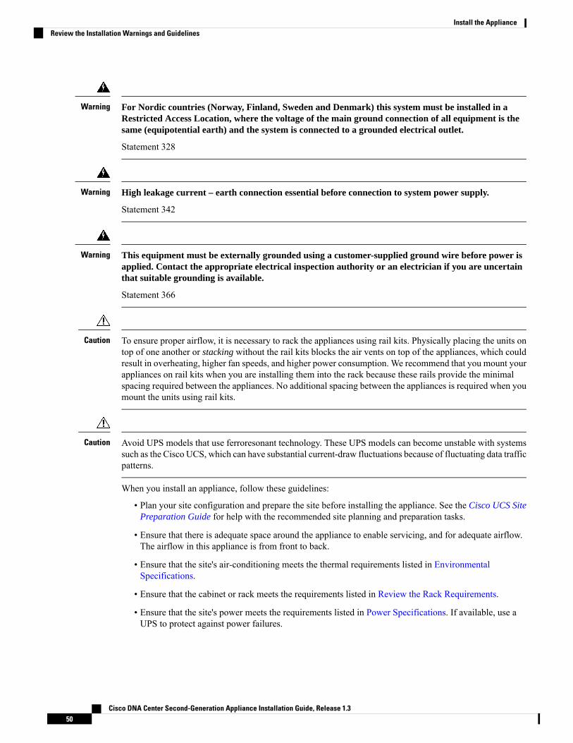
For Nordic countries (Norway, Finland, Sweden and Denmark) this system must be installed in aRestricted Access Location, where the voltage of the main ground connection of all equipment is thesame (equipotential earth) and the system is connected to a grounded electrical outlet.
Statement 328
Warning
High leakage current – earth connection essential before connection to system power supply.
Statement 342
Warning
This equipment must be externally grounded using a customer-supplied ground wire before power isapplied. Contact the appropriate electrical inspection authority or an electrician if you are uncertainthat suitable grounding is available.
Statement 366
Warning
To ensure proper airflow, it is necessary to rack the appliances using rail kits. Physically placing the units ontop of one another or stacking without the rail kits blocks the air vents on top of the appliances, which couldresult in overheating, higher fan speeds, and higher power consumption. We recommend that you mount yourappliances on rail kits when you are installing them into the rack because these rails provide the minimalspacing required between the appliances. No additional spacing between the appliances is required when youmount the units using rail kits.
Caution
Avoid UPS models that use ferroresonant technology. These UPS models can become unstable with systemssuch as the Cisco UCS, which can have substantial current-draw fluctuations because of fluctuating data trafficpatterns.
Caution
When you install an appliance, follow these guidelines:
• Plan your site configuration and prepare the site before installing the appliance. See the Cisco UCS SitePreparation Guide for help with the recommended site planning and preparation tasks.
• Ensure that there is adequate space around the appliance to enable servicing, and for adequate airflow.The airflow in this appliance is from front to back.
• Ensure that the site's air-conditioning meets the thermal requirements listed in EnvironmentalSpecifications.
• Ensure that the cabinet or rack meets the requirements listed in Review the Rack Requirements.
• Ensure that the site's power meets the requirements listed in Power Specifications. If available, use aUPS to protect against power failures.
Cisco DNA Center Second-Generation Appliance Installation Guide, Release 1.350
Install the ApplianceReview the Installation Warnings and Guidelines

Review the Rack RequirementsFor proper operation, the rack in which you install the appliance must meet the following requirements:
• A standard 19-in. (48.3-cm) wide, four-post EIA rack, with mounting posts that conform to Englishuniversal hole spacing, per section 1 of ANSI/EIA-310-D-1992.
• The rack post holes can be square 0.38-in. (9.6 mm), round 0.28-in. (7.1 mm), #12-24 UNC, or #10-32UNC when you use the supplied slide rails.
• The minimum vertical rack space per server must be:
• For the 44 and 56 core appliance, one RU, which equals 1.75 in. (44.45 mm).
• For the 112 core appliance, four RUs, which equals 7.0 in. (177.8 mm).
Connect and Power On the ApplianceThis section describes how to power on the appliance and check that it is functional.
Step 1 Attach the supplied power cord to each power supply in the appliance and then attach the power cords to a grounded ACpower outlet. See Power Specifications for details.
Wait for approximately two minutes to let the appliance boot into standby power mode during the first boot up.
The Power Status LED indicates the appliance's power status:
• Off: There is no AC power present in the appliance.
• Amber: The appliance is in standby power mode. Power is supplied only to the CIMC and some motherboardfunctions.
• Green: The appliance is in main power mode. Power is supplied to all the appliance components.
For more information on these and other appliance LEDs, see Front and Rear Panels.
Step 2 Connect a USB keyboard and VGAmonitor to the server, using the supplied KVM cable connected to the KVM connectoron the front panel. Alternatively, you can use the VGA and USB ports on the rear panel. You can only connect to oneVGA interface at a time.
Check the LEDsAfter you have powered up the appliance, check the state of the front-panel and rear-panel LEDs and buttonsto ensure it is functioning.
The following illustrations show the LEDs for a functional appliance after physical installation and firstpower-up and before configuration.
Cisco DNA Center Second-Generation Appliance Installation Guide, Release 1.351
Install the ApplianceReview the Rack Requirements

Figure 11: 44 and 56 Core Appliance Front Panel LEDs
Desired Status IndicatorLED
• Drive Fault LEDs: Off
• Drive Activity LEDs: Green
1
Power Status: Green2
Unit identification: Off3
System Status: Green4
Power Supply Status: Green5
Fan Status: Green6
Network Link Activity: Off7
Temperature Status: Green8
Cisco DNA Center Second-Generation Appliance Installation Guide, Release 1.352
Install the ApplianceCheck the LEDs
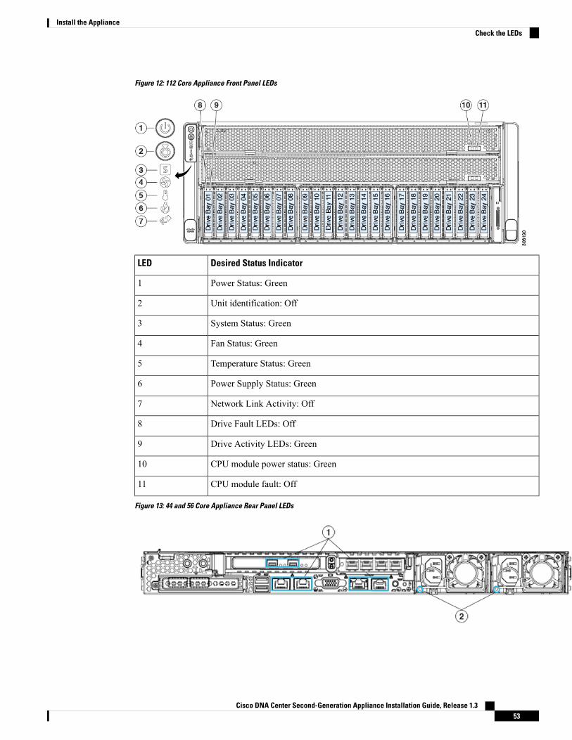
Figure 12: 112 Core Appliance Front Panel LEDs
Desired Status IndicatorLED
Power Status: Green1
Unit identification: Off2
System Status: Green3
Fan Status: Green4
Temperature Status: Green5
Power Supply Status: Green6
Network Link Activity: Off7
Drive Fault LEDs: Off8
Drive Activity LEDs: Green9
CPU module power status: Green10
CPU module fault: Off11
Figure 13: 44 and 56 Core Appliance Rear Panel LEDs
Cisco DNA Center Second-Generation Appliance Installation Guide, Release 1.353
Install the ApplianceCheck the LEDs

Desired Status IndicatorLED
At initial power-up, all ports should have their Link Status and Link Speed LEDs showingas Off.
After network settings are configured and tested using the Maglev Configuration wizard(see Configure the Primary Node Using the Maglev Wizard and Configure Add-OnNodes Using the Maglev Wizard), the Link Status and Link Speed LEDs for all cabledports should be Green. All uncabled port LEDs should be unchanged.
1
AC Power Supply Status LEDs: Green2
Figure 14: 112 Core Appliance Rear Panel LEDs
Desired Status IndicatorLED
At initial power-up, all ports should have their Link Status and Link Speed LEDs showingas Off.
After network settings are configured and tested using the Maglev Configuration wizard(see Configure the Primary Node Using the Maglev Wizard and Configure Add-OnNodes Using the Maglev Wizard), the Link Status and Link Speed LEDs for all cabledports should be Green. All uncabled port LEDs should be unchanged.
1
AC Power Supply Status LEDs: Green2
If you see LEDs with colors other than those shown above, you may have a problem condition. See Front andRear Panels for details on the likely causes of the status. Be sure to correct any problem conditions beforeproceeding to configure the appliance.
Cisco DNA Center Second-Generation Appliance Installation Guide, Release 1.354
Install the ApplianceCheck the LEDs

C H A P T E R 4Prepare the Appliance for Configuration
• Preparation for Appliance Configuration Overview, on page 55• Enable Browser Access to Cisco Integrated Management Controller, on page 55• Execute Preconfiguration Checks, on page 60• Disable the Network Interface Card, on page 62• Reimage the Appliance, on page 68
Preparation for Appliance Configuration OverviewBefore you can successfully configure your Cisco DNA Center appliance, first complete the following tasks:
1. Enable browser access to the appliance's Cisco IMC (see Enable Browser Access to Cisco IntegratedManagement Controller).
2. Use Cisco IMC to check and adjust important hardware and switch settings (see Execute PreconfigurationChecks).
3. If the Intel X710-DA4 network interface card (NIC) that shipped with your appliance is currently enabled,you need to disable it (see Disable the Network Interface Card, on page 62).
4. Cisco DNA Center software is preinstalled on your appliance, but you may need to reinstall the softwarein certain situations (such as before you change the current cluster link configuration). If this is the case,you must also complete the tasks described in Reimage the Appliance.
If you do not need to reimage your appliance, proceed to Appliance Configuration Overview.Note
Enable Browser Access to Cisco Integrated ManagementController
After installing the appliance, as described in Appliance InstallationWorkflow, use the Cisco IMC configurationutility to assign an IP address and gateway to the appliance's CIMC port. This gives you access to the CiscoIMC GUI, which you should use to configure the appliance.
Cisco DNA Center Second-Generation Appliance Installation Guide, Release 1.355

After you complete the Cisco IMC setup, log in to Cisco IMC and run the tasks listed in ExecutePreconfiguration Checks to ensure correct configuration.
To help ensure the security of your deployment, Cisco IMC prompts you to change the Cisco IMC user'sdefault password when you boot the appliance for the first time. To change the Cisco IMC user passwordlater, use the Cisco IMC GUI, as follows:
1. Choose > Admin > User Management > Local User Management.
2. Click ID 1, and then Modify User.
3. Enter the new password in the Change Password field, and then click Save.
Tip
Step 1 Access the appliance console by attaching either of the following:
• A KVM cable to the KVM connector on the appliance's front panel (component 11 on the front panel illustratedin Front and Rear Panels)
• A keyboard andmonitor to the USB and VGA ports on the appliance's rear panel (components 2 and 5, respectively,on the rear panel illustrated in Front and Rear Panels).
Step 2 Make sure that the appliance's power cord is plugged in and the power is on.Step 3 Press the Power button on the front panel to boot the appliance.
The Cisco IMC configuration utility boot screen should be displayed, as shown below.
Step 4 As soon as the boot screen is displayed, press F8 to perform Cisco IMC configuration.
The CIMC configuration utility displays the CIMC User Details screen, as shown below.
Cisco DNA Center Second-Generation Appliance Installation Guide, Release 1.356
Prepare the Appliance for ConfigurationEnable Browser Access to Cisco Integrated Management Controller
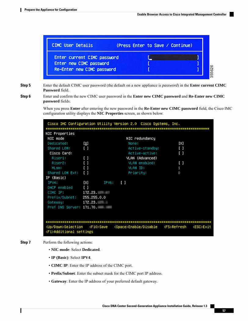
Step 5 Enter the default CIMC user password (the default on a new appliance is password) in the Enter current CIMCPassword field.
Step 6 Enter and confirm the new CIMC user password in the Enter new CIMC password and Re-Enter new CIMCpassword fields.
When you press Enter after entering the new password in the Re-Enter new CIMC password field, the Cisco IMCconfiguration utility displays the NIC Properties screen, as shown below.
Step 7 Perform the following actions:
• NIC mode: Select Dedicated.
• IP (Basic): Select IPV4.
• CIMC IP: Enter the IP address of the CIMC port.
• Prefix/Subnet: Enter the subnet mask for the CIMC port IP address.
• Gateway: Enter the IP address of your preferred default gateway.
Cisco DNA Center Second-Generation Appliance Installation Guide, Release 1.357
Prepare the Appliance for ConfigurationEnable Browser Access to Cisco Integrated Management Controller

• Pref DNS Server: Enter the IP address of your preferred DNS server.
• NIC Redundancy: Select None.
Step 8 Press F1 to specify Additional settings.
The Cisco IMC configuration utility displays the Common Properties screen, as shown below.
Step 9 Perform the following actions:
• Hostname: Enter a hostname for CIMC on this appliance.
• Dynamic DNS: Uncheck the check box to disable this feature.
• Factory Defaults: Uncheck the check box to disable this feature.
• Default User (Basic): Leave these fields blank.
• Port Properties: Enter new settings or accept the defaults shown in these fields.
• Port Profiles: Uncheck the check box to disable this feature.
Step 10 Press F10 to save the settings.Step 11 Press Escape to exit and reboot the appliance.Step 12 After the settings are saved and the appliance finishes rebooting, open a compatible browser on a client machine with
access to the subnet on which the appliance is installed, and enter the following URL:
https://CIMC_ip_address, where CIMC_ip_address is the Cisco IMC port IP address that you entered inStep 7.
Cisco DNA Center Second-Generation Appliance Installation Guide, Release 1.358
Prepare the Appliance for ConfigurationEnable Browser Access to Cisco Integrated Management Controller
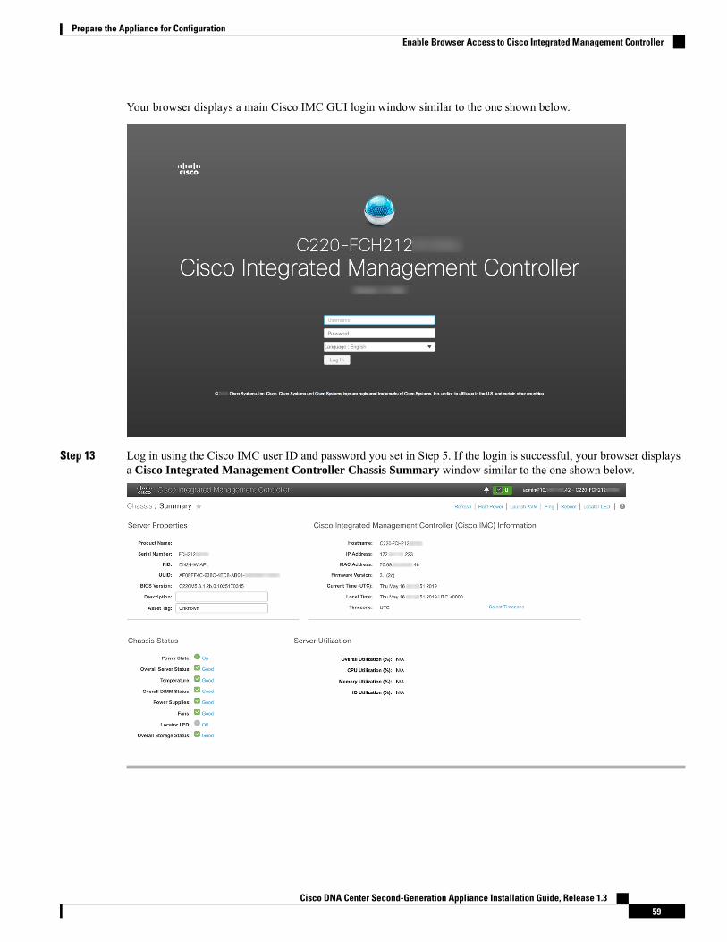
Your browser displays a main Cisco IMC GUI login window similar to the one shown below.
Step 13 Log in using the Cisco IMC user ID and password you set in Step 5. If the login is successful, your browser displaysa Cisco Integrated Management Controller Chassis Summary window similar to the one shown below.
Cisco DNA Center Second-Generation Appliance Installation Guide, Release 1.359
Prepare the Appliance for ConfigurationEnable Browser Access to Cisco Integrated Management Controller

Execute Preconfiguration ChecksAfter installing the appliance (as described in Appliance Installation Workflow) and setting up access to theCisco IMC GUI (as described in Enable Browser Access to Cisco Integrated Management Controller), useCisco IMC to perform the following preconfiguration tasks, which help ensure correct configuration anddeployment:
1. Synchronize the appliance hardware with the Network Time Protocol (NTP) servers you use to manageyour network. These must be the same NTP servers whose hostnames or IPs you gathered for use whenplanning your implementation, as explained in Required IP Addresses and Subnets. This is a critical taskthat ensures that your Cisco DNA Center data is synchronized properly across the network.
2. Reconfigure the switches connected to the 10-Gbps appliance ports to support higher throughput settings.
Step 1 Login to the appliance's CIMC using the CIMC IP address, user ID and password you set in Enable Browser Access toCisco IntegratedManagement Controller. If login is successful, your browser displays theCisco Integrated ManagementController Chassis Summary window, as shown below.
Step 2 Synchronize the appliance hardware with the Network Time Protocol (NTP) servers you use to manage your network,as follows:a) With the Chassis Summary window displayed, click the icon to display the CIMC menu.b) From the CIMC menu, select Admin > Networking > NTP Setting. CIMC displays the NTP Setting tab.c) Make sure the NTP Enabled box is checked, then enter up to four NTP server host names or addresses in the four
numbered Server fields, as in the example shown below.
Cisco DNA Center Second-Generation Appliance Installation Guide, Release 1.360
Prepare the Appliance for ConfigurationExecute Preconfiguration Checks

d) When you are finished, click Save Changes. Cisco IMC will validate your entries, then begin to synchronize thetime on the appliance hardware with the time on the NTP servers.
Unlike the previous generation of Cisco DNA Center appliances, second generation appliances do not usea virtual interface card (VIC). You do not need to configure the network interface card (NIC) that comesinstalled on your second generation appliance to support high throughput in Cisco IMC, as this is alreadyenabled by default.
Note
Step 3 Next, reconfigure your switches to match the high-throughput settings on the appliance, as follows:a) Using a Secure Shell (SSH) client, login to the switch to be configured and enter EXEC mode at the switch prompt.b) Enter the following series of commands to configure the switch port:
MySwitch#Config terminalMySwitch(config)#interface tengigabitethernet 1/1/3MySwitch(config-if)#switchport mode accessMySwitch(config-if)#switchport access vlan 99MySwitch(config-if)#speed autoMySwitch(config-if)#duplex fullMySwitch(config-if)#mtu 1500MySwitch(config-if)#no shutMySwitch(config-if)#endMySwitch(config)#copy running-config startup-config
These commands are examples only.Note
The switch port on Cisco DNA Center second generation appliances must be set to access mode in orderto function properly. Trunk mode is not supported, as it is on first generation appliances.
Important
c) Run the command show interface tengigabitethernet portID and verify that the port is connected and running,and has the correct MTU, duplex, and link type settings in the command output. For example:MySwitch#show interface tengigabitethernet 1/1/3TenGigabitEthernet1/1/3 is up, line protocol is up (connected)Hardware is Ten Gigabit Ethernet, address is XXXe.310.8000 (bia XXX.310.8000)
Cisco DNA Center Second-Generation Appliance Installation Guide, Release 1.361
Prepare the Appliance for ConfigurationExecute Preconfiguration Checks

MTU 1500 bytes, BW 10000000 Kbit/sec, DLY 10 usec,reliability 255/255, txload 1/255, rxload 1/255
Encapsulation ARPA, loopback not setKeepalive not setFull-duplex, 10GB/s, link type is auto, media type is SFP-10Gbase-SR
d) Run the command show run interface tengigabitethernet portID to configure the switch ports where the cablesfrom the Intel X710-DA2 NIC ports are connected. For example:MySwitch#show run interface tengigabitethernet 1/1/3Building configuration...Current configuration : 129 bytes! interface TenGigabitEthernet1/1/3switchport access vlan 99ip device tracking maximum 10end
MySwitch#
e) Run the command show mac address-table interface tengigabitethernet portID and verify theMAC addressfrom the command output. For example:MySwitch#show mac address-table interface tengigabitethernet 1/1/3
Mac Address Table––––––––––––––––––––––––––––––––––––––––––--Vlan Mac Address Type Ports––-- ––––––––––- –––- –––--99 XXXe.3161.1000 DYNAMIC Te1/1/3Total Mac Addresses for this criterion: 1
MySwitch#
What to do next
When this task is complete, do one of the following:
• If you need to reinstall Cisco DNA Center software before you configure your appliance, see Reimagethe Appliance.
• If you are ready to configure your appliance, proceed to Appliance Configuration Overview.
Disable the Network Interface CardIf your appliance ships with the Intel X710-DA4 network interface card (NIC) enabled, you must disable itby completing the following procedure. If you do not disable the card, your appliance will contain four extrainterfaces, which could negatively affect your configuration.
Step 1 Confirm that you have a Cisco DNA Center appliance and that it has the Intel X710-DA4 NIC installed.a) Log in to the appliance's Cisco IMC.b) In the Summary window's Server Properties area, confirm that the following values are set:
• PID: DN2-HW-APL for a 44 core appliance,DN2-HW-APL-L for a 56 core appliance, or DN2-HW-APL-XLfor a 112 core appliance (see the following example).
Cisco DNA Center Second-Generation Appliance Installation Guide, Release 1.362
Prepare the Appliance for ConfigurationDisable the Network Interface Card

• BIOS Version: This value should start with either C220M5 for a 44 and 56 core appliance or C480M5 for a112 core appliance (see the following example).
c) Choose > Chassis > Inventory > Network Adapters.d) In the Network Adapters table, confirm that the Intel X710-DA4 Quad Port network adapter is listed for one of the
following slots:
• For a 44 or 56 core appliance, Slot 2.
• For a 112 core appliance, Slot 12 (see the following example).
Step 2 Confirm that the your appliance's PCIe card is disabled:
a) Choose > Compute.
The BIOS > Configure BIOS > I/O tab opens.
b) Set the following parameters to Disabled, then click Save:
• For a 44 or 56 core appliance, PCIe Slot 2 OptionROM and PCIe Slot 2 Link Speed.
• For a 112 core appliance,PCIe Slot 12 OptionROM andPCIe Slot 12 Link Speed (see the following example).
Cisco DNA Center Second-Generation Appliance Installation Guide, Release 1.363
Prepare the Appliance for ConfigurationDisable the Network Interface Card

c) Do one of the following:
• If you were able to set these two parameters to Disabled for your appliance, reboot your appliance and thenproceed with its configuration. You do not need to complete the rest of this procedure.
• If you have a 112 core appliance and only see one of these parameters displayed in the I/O tab, proceed to Step3 and complete the rest of this procedure.
Step 3 Boot into your appliance's BIOS:a) From Cisco IMC, start a KVM session.b) Power cycle the appliance by clicking the Host Power link and then choosing Power Cycle.c) During startup, press the F2 key as soon as you see the following screen to boot into your appliance's BIOS and open
the Aptio Setup Utility.
Cisco DNA Center Second-Generation Appliance Installation Guide, Release 1.364
Prepare the Appliance for ConfigurationDisable the Network Interface Card

Step 4 Disable the PCIe card:a) From the Aptio Setup Utility's Main tab, open the Advanced tab and then choose LOM and PCIe Slots
Configuration.
b) In the LOM and PCIe Slots Configuration tab, choose PCIE Link Speed Configuration.
Cisco DNA Center Second-Generation Appliance Installation Guide, Release 1.365
Prepare the Appliance for ConfigurationDisable the Network Interface Card

c) In the PCIE Link Speed Configuration tab, scroll down to PCIE SlotID: 12's Link Enable option and then pressEnter.
d) Choose Disable, then press ENTER.
Your screen should look like the following example:
Cisco DNA Center Second-Generation Appliance Installation Guide, Release 1.366
Prepare the Appliance for ConfigurationDisable the Network Interface Card

e) Press the ESC key twice to return to the main BIOS menu, then open the Save & Exit tab.f) Choose the Save Changes and Reset option, then press Enter.
Cisco DNA Center Second-Generation Appliance Installation Guide, Release 1.367
Prepare the Appliance for ConfigurationDisable the Network Interface Card

Your appliance reboots and opens the configuration wizard. Proceed with the configuration of your appliance.
After you have disabled your appliance's NIC, if you reset your appliance to the default settings in Cisco
IMC ( >Admin >Utilities >Reset to factory Default), you will need to complete this procedure again.
Important
Reimage the ApplianceSituations may arise that require you to reimage your Cisco DNA Center appliance, such as recovering froma backup or changing your cluster link configuration. To do so, complete the following procedure.
Step 1 Download the Cisco DNA Center ISO image and verify that it is a genuine Cisco image.
See Verify the Cisco DNA Center ISO Image.
Step 2 Create a bootable USB drive that contains the Cisco DNA Center ISO image.
See Create a Bootable USB Drive.
Step 3 Reinstall Cisco DNA Center onto your appliance.
See Install the Cisco DNA Center ISO Image.
Verify the Cisco DNA Center ISO ImagePrior to deploying Cisco DNA Center, we strongly advise you to verify that the ISO image you downloadedis a genuine Cisco image.
Before you begin
Obtain the location of the Cisco DNA Center ISO image (either via email or contact with the Cisco supportteam).
Step 1 Download the Cisco DNA Center ISO image (.iso) from the location specified by Cisco.Step 2 Download the Cisco public key (cisco_image_verification_key.pub) for signature verification from the location specified
by Cisco.Step 3 Download the secure hash algorithm (SHA512) checksum file for the ISO image from the location specified by Cisco.Step 4 Obtain the ISO image's signature file (.sig) from Cisco support via email or by download from the secure Cisco website
(if available).Step 5 (Optional) Perform a SHA verification to determine whether the ISO image was corrupted due to a partial download.
Run one of the following commands (depending upon your operating system):
• On a Linux system: sha512sum ISO-image-filename
• On a Mac system: shasum -a 512 ISO-image-filename
Cisco DNA Center Second-Generation Appliance Installation Guide, Release 1.368
Prepare the Appliance for ConfigurationReimage the Appliance

Microsoft Windows does not include a built-in checksum utility, but you can use the certutil tool:certutil -hashfile <filename> sha256 | md5
For example:certutil -hashfile D:\Customers\FINALIZE.BIN sha256
On Windows, you can also use the Windows PowerShell to generate the digest. For example:PS C:\Users\Administrator> Get-FileHash -Path D:\Customers\FINALIZE.BINAlgorithm Hash PathSHA256 B84B6FFD898A370A605476AC7EC94429B445312A5EEDB96166370E99F2838CB5 D:\Customers\FINALIZE.BIN
Compare the output of the command you run to the SHA512 checksum file that you downloaded. If the command outputdoes not match, download the ISO image again and run the appropriate command a second time. If the output still doesnot match, contact Cisco support.
Step 6 Verify that the ISO image is genuine and from Cisco by verifying its signature:
openssl dgst -sha512 -verify cisco_image_verification_key.pub -signature signature-filename ISO-image-filename
This command will work in both MAC and Linux environments. For Windows, you need to download andinstall OpenSSL (available here) if you have not already done so.
Note
If the ISO image is genuine, then running this command should result in a Verified OK message. If this message failsto appear, then do not install the ISO image and contact Cisco support.
Step 7 After confirming you have downloaded a Cisco ISO image, create a bootable USB drive that contains the Cisco DNACenter ISO image. See Create a Bootable USB Drive.
Create a Bootable USB DriveComplete one of the following procedures to create a bootable USB drive from which you can install theCisco DNA Center ISO image.
Before you begin:
• Download and verify your copy of the Cisco DNA Center ISO image. See Verify the Cisco DNA CenterISO Image.
• Confirm that the USB flash drive you are using has a capacity of at least 32 GB.
Using Etcher
Step 1 Download and install Etcher (version 1.3.1 or later), an open-source freeware utility that allows you to create a bootableUSB drive on your laptop or desktop.
Linux, macOS, and Windows versions of Etcher are currently available. You can download a copy athttps://www.balena.io/etcher/.
Only use the Windows version of Etcher on machines running Windows 10, as there are known compatibilityissues with older versions of Windows.
Note
Step 2 From the machine on which you installed Etcher, connect a USB drive and then start Etcher.
Cisco DNA Center Second-Generation Appliance Installation Guide, Release 1.369
Prepare the Appliance for ConfigurationCreate a Bootable USB Drive
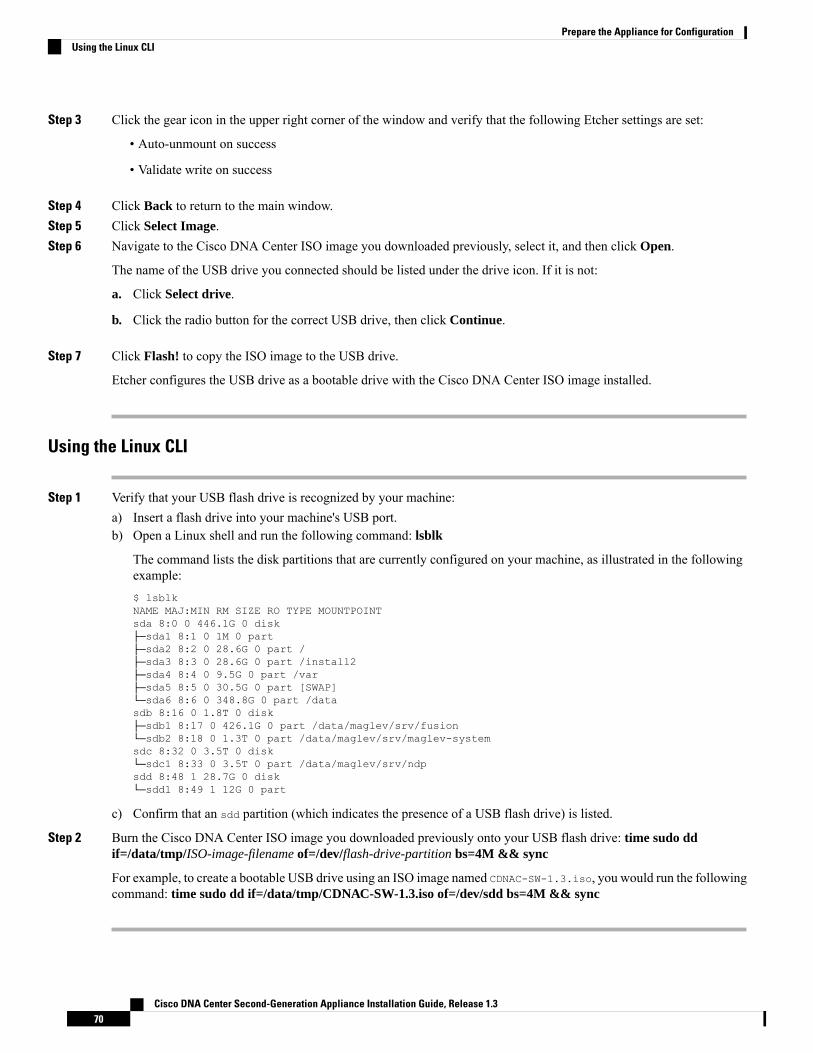
Step 3 Click the gear icon in the upper right corner of the window and verify that the following Etcher settings are set:
• Auto-unmount on success
• Validate write on success
Step 4 Click Back to return to the main window.Step 5 Click Select Image.Step 6 Navigate to the Cisco DNA Center ISO image you downloaded previously, select it, and then click Open.
The name of the USB drive you connected should be listed under the drive icon. If it is not:
a. Click Select drive.
b. Click the radio button for the correct USB drive, then click Continue.
Step 7 Click Flash! to copy the ISO image to the USB drive.
Etcher configures the USB drive as a bootable drive with the Cisco DNA Center ISO image installed.
Using the Linux CLI
Step 1 Verify that your USB flash drive is recognized by your machine:a) Insert a flash drive into your machine's USB port.b) Open a Linux shell and run the following command: lsblk
The command lists the disk partitions that are currently configured on your machine, as illustrated in the followingexample:$ lsblkNAME MAJ:MIN RM SIZE RO TYPE MOUNTPOINTsda 8:0 0 446.1G 0 disk├─sda1 8:1 0 1M 0 part├─sda2 8:2 0 28.6G 0 part /├─sda3 8:3 0 28.6G 0 part /install2├─sda4 8:4 0 9.5G 0 part /var├─sda5 8:5 0 30.5G 0 part [SWAP]└─sda6 8:6 0 348.8G 0 part /datasdb 8:16 0 1.8T 0 disk├─sdb1 8:17 0 426.1G 0 part /data/maglev/srv/fusion└─sdb2 8:18 0 1.3T 0 part /data/maglev/srv/maglev-systemsdc 8:32 0 3.5T 0 disk└─sdc1 8:33 0 3.5T 0 part /data/maglev/srv/ndpsdd 8:48 1 28.7G 0 disk└─sdd1 8:49 1 12G 0 part
c) Confirm that an sdd partition (which indicates the presence of a USB flash drive) is listed.
Step 2 Burn the Cisco DNA Center ISO image you downloaded previously onto your USB flash drive: time sudo ddif=/data/tmp/ISO-image-filename of=/dev/flash-drive-partition bs=4M && sync
For example, to create a bootable USB drive using an ISO image named CDNAC-SW-1.3.iso, you would run the followingcommand: time sudo dd if=/data/tmp/CDNAC-SW-1.3.iso of=/dev/sdd bs=4M && sync
Cisco DNA Center Second-Generation Appliance Installation Guide, Release 1.370
Prepare the Appliance for ConfigurationUsing the Linux CLI

Using the Mac CLI
Step 1 Determine the disk partition associated with your USB flash drive:a) Open a Terminal window and run the following command: diskutil list
The command lists the disk partitions that are currently configured on your machine.
b) Insert a flash drive into your machine's USB port and run the diskutil list command a second time.
The partition that was not listed the first time you ran this command corresponds to your flash drive. For example,let's assume that your flash drive's partition is /dev/disk2.
Step 2 Unmount the flash drive's partition: diskutil unmountDisk flash-drive-partition
Continuing our example, you would enter diskutil unmountDisk /dev/disk2
Step 3 Using the Cisco DNA Center ISO image you downloaded previously, create a disk image: hdiutil convert -formatUDRW -o Cisco-DNA-Center-version ISO-image-filename
Continuing our example, let's assume that you are working with a Cisco DNA Center 1.3 ISO image namedCDNAC-SW-1.3.iso. You would run the following command, which creates a macOS disk image named CDNAC-1.3.dmg:hdiutil convert -format UDRW -o CDNAC-1.3 CDNAC-SW-1.3.iso
Ensure that the ISO image does not reside on a Box partition.Important
Step 4 Create a bootable USB drive: sudo dd if=macOS-disk-image-filename of=flash-drive-partition bs=1m
Continuing our example, you would run the following command: sudo dd if=CDNAC-1.3.dmg of=/dev/disk2 bs=1m
The ISO image is about 18 GB in size, so this can take around an hour to complete.
Install the Cisco DNA Center ISO ImageComplete the following procedure to install the Cisco DNA Center ISO image onto your appliance.
Before you begin
Create the bootable USB drive from which you will install the Cisco DNA Center ISO image. See Create aBootable USB Drive.
Step 1 Connect the bootable USB drive with the Cisco DNA Center ISO image to the appliance.Step 2 Log into CIMC and start a KVM session.Step 3 Power on or power cycle the appliance:
• Choose Power > Power On System if the appliance is not currently running.
• Choose Power > Power Cycle System (cold boot) if the appliance is already running.
Step 4 In the resulting pop-up window, click Yes to acknowledge that you are about to execute a server control action.
Cisco DNA Center Second-Generation Appliance Installation Guide, Release 1.371
Prepare the Appliance for ConfigurationUsing the Mac CLI

Step 5 When the Cisco logo appears, either press the F6 key or choose Macros > User Defined Macros > F6 from the KVMmenu.
The boot device selection menu appears.
Step 6 Select your USB drive and then press Enter.Step 7 In the GNU GRUB bootloader window, choose Manufacture Cisco DNA appliance and then press Enter.
The bootloader will automatically boot the Maglev Installer instead if you do not make a selection within 30seconds. Ensure that you make your selection before then.
Note
When installation of the Cisco DNACenter ISO image completes, the installer reboots and opens theMaglev Configurationwizard's welcome screen. Depending on whether you are going to configure a primary or secondary cluster node, proceedto Step 4 in either Configure the Primary Node Using the Maglev Wizard or Configure Add-On Nodes Using the MaglevWizard.
Cisco DNA Center Second-Generation Appliance Installation Guide, Release 1.372
Prepare the Appliance for ConfigurationInstall the Cisco DNA Center ISO Image

C H A P T E R 5Configure the Appliance
• Appliance Configuration Overview, on page 73• Configure the Primary Node Using the Maglev Wizard, on page 73• Configure Add-On Nodes Using the Maglev Wizard, on page 87• Upgrade to the Latest Cisco DNA Center Release, on page 102
Appliance Configuration OverviewYou can deploy the appliance in your network in one of the following two modes:
• Standalone: As a single node offering all the functions. This option is usually preferred for initial or testdeployments and in smaller network environments.
• Cluster: As a node that belongs to a three-node cluster. In this mode, all the services and data are sharedamong the hosts. This is the preferred option for large deployments.
If you choose the Standalone mode for your initial deployment, you can add more appliances later to form acluster. When configuring the standalone host, ensure that it is set it up as the first, or primary, node in thecluster.
If you choose the Cluster mode for your initial deployment, be sure to finish configuring the primary nodebefore configuring the add-on nodes.
To proceed, complete the following tasks:
1. Launch theMaglev Configuration wizard fromCisco IMC and configure the primary node in your cluster.See Configure the Primary Node Using the Maglev Wizard.
2. If you have installed three appliances and want to add the second and third nodes to your cluster, seeConfigure Add-On Nodes Using the Maglev Wizard.
Configure the Primary Node Using the Maglev WizardPerform the following steps to configure the first installed appliance as the primary node. You must alwaysconfigure the first appliance as the primary node, whether it will operate standalone or as part of a cluster.
If you are configuring the installed appliance as an add-on node for an existing cluster that already has aprimary node, follow the steps in Configure Add-On Nodes Using the Maglev Wizard instead.
Cisco DNA Center Second-Generation Appliance Installation Guide, Release 1.373

Ensure that all of the IP addresses you enter while completing this procedure are valid IPv4 addresses withvalid IPv4 netmasks. Also make sure that the addresses and their corresponding subnets do not overlap. Servicecommunication issues can result if they do.
Note
Before you begin
Ensure that you:
• Collected all of the information called for in Required IP Addresses and Subnets and RequiredConfiguration Information.
• Installed the first appliance as described in Appliance Installation Workflow.
• Configured Cisco IMC browser access on the primary node, as described in Enable Browser Access toCisco Integrated Management Controller.
• Checked that the primary node appliance's ports and the switches it uses are properly configured, asdescribed in Execute Preconfiguration Checks.
• Are using a browser that is compatible with Cisco IMC and Cisco DNA Center. For a list of compatiblebrowsers, see the Release Notes for the version of Cisco DNA Center you are installing.
• Enabled ICMP on the firewall between Cisco DNA Center and the DNS server you will specify in Step7 of the following procedure. The Maglev Configuration wizard uses Ping to verify the DNS server youspecify. This ping can be blocked if there is a firewall between Cisco DNA Center and the DNS serverand ICMP is not enabled on that firewall.When this happens, you will not be able to complete the wizard.
Step 1 Point your browser to the Cisco IMC IP address you set during the Cisco IMC GUI configuration you performed, andlogin to the Cisco IMC GUI as the Cisco IMC user (see Enable Browser Access to Cisco Integrated ManagementController).After successful login, the appliance displays the Cisco Integrated Management Controller Chassis Summarywindow, with a blue link menu at the upper right, as shown below.
Step 2 From the blue link menu, choose Launch KVM and then select either Java based KVM or HTML based KVM. Ifyou select the Java-based KVM, you will need to launch the Java startup file from your browser or file manager inorder to view the KVM console in its own window. If you select the HMTL-based KVM, it will launch the KVMconsole in a separate browser window or tab automatically.
Cisco DNA Center Second-Generation Appliance Installation Guide, Release 1.374
Configure the ApplianceConfigure the Primary Node Using the Maglev Wizard

Irrespective of the KVM type you choose, use the KVM console to monitor the progress of the configuration andrespond to Maglev Configuration wizard prompts.
Step 3 With the KVM displayed, reboot the appliance by making one of the following selections:a) In the main Cisco IMC GUI browser window: Choose Host Power > Power Cycle. Then switch to the KVM
console to continue.b) In the KVM console: Choose Power > Power Cycle System (cold boot).
If asked to confirm your choice to reboot the appliance, click OK.
After displaying reboot messages, the KVM console displays theMaglev Configuration wizard welcome screen, shownbelow.
Step 4 Choose Start a Cisco DNA Center Cluster to begin configuring the primary node.
The wizard discovers all of the ports on the appliance and presents them to you one by one, in separate screens, in thefollowing order:
a. 1Gbps/10Gbps Management Port (1, eno1/enp53s0f0, Network Adapter #1)
b. 1Gbps/10Gbps Cloud Port (eno2/enp53s0f1, Network Adapter #2)
c. 10Gbps Enterprise Port (enp94s0f0/enp69s0f0, Network Adapter #3)
d. 10Gbps Cluster Port (enp94s0f1/enp69s0f1, Network Adapter #4)
Cisco DNA Center Second-Generation Appliance Installation Guide, Release 1.375
Configure the ApplianceConfigure the Primary Node Using the Maglev Wizard

The interface names assigned to ports on 44, 56, and 112 core appliances differ. Whenever two interfacenames are provided in this procedure, the first applies to both 44 and 56 core appliances and the secondapplies to 112 core appliances.
Note
If the wizard fails to display either or both of the Enterprise and Cluster ports during the course of configuration, theseports may be non-functional or disabled. These 10Gbps ports are required for Cisco DNA Center functionality. If youdiscover they are non-functional, choose cancel to exit the configuration immediately. Be sure you have completed allof the steps provided in Execute Preconfiguration Checks before resuming configuration or contacting the CiscoTechnical Assistance Center (TAC).
Step 5 The wizard discovers the 1Gbps/10Gbps Management Port (1, eno1/enp53s0f0) first and presents it as NETWORKADAPTER #1. As explained in Interface Cable Connections, this port is used to access the Cisco DNA Center GUIfrom your management network. Apply the host IP address, netmask, and other values appropriate for this purpose (seeRequired IP Addresses and Subnets and Required Configuration Information for the values to enter).
Enter configuration values for NETWORK ADAPTER #1 as shown in the table below.
Table 21: Primary Node Entries for Network Adapter #1: 1Gbps/10Gbps Management Port (eno1/enp53s0f0)
Enter the IP address for the Management Port. This isrequired only if you are using this port to access the CiscoDNA Center GUI from your management network;otherwise, you can leave it blank.
Host IP address
Enter the netmask for the port's IP address. This is requiredif you enter an IP address.
Netmask
Cisco DNA Center Second-Generation Appliance Installation Guide, Release 1.376
Configure the ApplianceConfigure the Primary Node Using the Maglev Wizard

Enter a default gateway IP address to use for the port. Thisis usually required on the Enterprise Port only.
Default Gateway IP address
Enter the IP address of the preferred DNS server. Ifentering multiple DNS servers, separate the IP addressesin the list with spaces.
Important • For NTP, ensure port 123 (UDP) is openbetween Cisco DNACenter and your NTPserver.
• For each appliance in your cluster,configure a maximum of three DNSservers. Problems can occur if youconfigure more than three DNS servers foran appliance.
DNS Servers
Enter one or more static routes in the following format,separated by spaces: <network>/<netmask>/<gateway>.
Static Routes
Leave this field blank. It is required on the Cluster Portonly.
Cluster Link
Reserved for future use. Leave this field blank.Configure IPv6 Address
When you are finished entering configuration values, enter next>> to proceed. After entering next>>, the wizardvalidates the values you entered and issues an error message if any are incorrect. If you receive an error message, checkthat the value you entered is correct, then re-enter it. If needed, select <<back to re-enter it.
Step 6 After successful validation of the Management Port values you entered, the wizard presents the 1Gbps/10Gbps CloudPort (2, eno2/enp53s0f1) as NETWORK ADAPTER #2. As explained in Interface Cable Connections, this is anoptional port used to link the appliance to the Internet when you cannot do so through the 10Gbps Enterprise Port(enp94s0f0/enp69s0f0). Apply the host IP address, netmask, and other values appropriate for this purpose (see RequiredIP Addresses and Subnets and Required Configuration Information for the values to enter).
Cisco DNA Center Second-Generation Appliance Installation Guide, Release 1.377
Configure the ApplianceConfigure the Primary Node Using the Maglev Wizard

Enter configuration values for NETWORK ADAPTER #2 as shown in the table below.
Table 22: Primary Node Entries for Network Adapter #2: 1Gbps/10Gbps Cloud Port (eno2/enp53s0f1)
Enter the IP address for the Cloud Port. This is requiredonly if you are using the Cloud Port for internet connection;otherwise, you can leave it blank.
Host IP address
Enter the netmask for the port's IP address. This is requiredif you enter an IP address.
Netmask
Enter a default gateway IP address to use for the CloudPort. This is usually required on the Enterprise Port only.
Default Gateway IP address
Enter the IP address of the preferred DNS server. Ifentering multiple DNS servers, separate the IP addressesin the list with spaces.
For each appliance in your cluster, configure amaximum of three DNS servers. Problems canoccur if you configure more than three DNSservers for an appliance.
Important
DNS Servers
Enter one or more static routes in the following format,separated by spaces: <network>/<netmask>/<gateway>.This is usually required on the Management Port only.
Static Routes
Cisco DNA Center Second-Generation Appliance Installation Guide, Release 1.378
Configure the ApplianceConfigure the Primary Node Using the Maglev Wizard

Leave this field blank. It is required on the Cluster Portonly.
Cluster Link
Reserved for future use. Leave this field blank.Configure IPv6 Address
When you are finished, enter next>> to proceed. Correct any validation errors as you did in previous screens.
Step 7 After successful validation of the Cloud Port values you entered, the wizard presents the 10Gbps Enterprise Port(enp94s0f0/enp69s0f0) asNETWORK ADAPTER #3. As explained in Interface Cable Connections, this is a requiredport used to link the appliance to the enterprise network. Apply the host IP address, netmask, and other values appropriatefor this purpose, (see Required IP Addresses and Subnets and Required Configuration Information for the values toenter).
Enter configuration values for NETWORK ADAPTER #3 as shown in the table below.
Table 23: Primary Node Entries for Network Adapter #3: 10Gbps Enterprise Port (enp94s0f0/enp69s0f0)
Enter the IP address for the Enterprise Port. This isrequired.
Host IP address
Enter the netmask for the port's IP address. This is required.Netmask
Enter a default gateway IP address to use for the port. Thisis required.
Default Gateway IP address
Cisco DNA Center Second-Generation Appliance Installation Guide, Release 1.379
Configure the ApplianceConfigure the Primary Node Using the Maglev Wizard
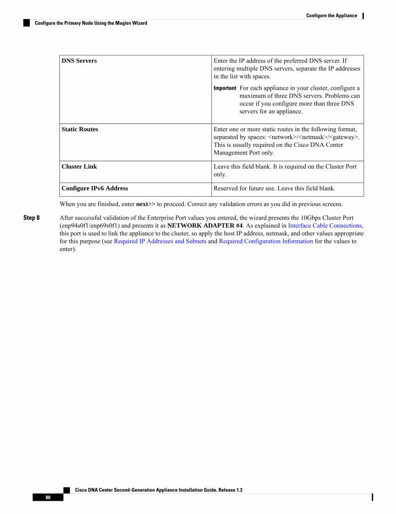
Enter the IP address of the preferred DNS server. Ifentering multiple DNS servers, separate the IP addressesin the list with spaces.
For each appliance in your cluster, configure amaximum of three DNS servers. Problems canoccur if you configure more than three DNSservers for an appliance.
Important
DNS Servers
Enter one or more static routes in the following format,separated by spaces: <network>/<netmask>/<gateway>.This is usually required on the Cisco DNA CenterManagement Port only.
Static Routes
Leave this field blank. It is required on the Cluster Portonly.
Cluster Link
Reserved for future use. Leave this field blank.Configure IPv6 Address
When you are finished, enter next>> to proceed. Correct any validation errors as you did in previous screens.
Step 8 After successful validation of the Enterprise Port values you entered, the wizard presents the 10Gbps Cluster Port(enp94s0f1/enp69s0f1) and presents it as NETWORK ADAPTER #4. As explained in Interface Cable Connections,this port is used to link the appliance to the cluster, so apply the host IP address, netmask, and other values appropriatefor this purpose (see Required IP Addresses and Subnets and Required Configuration Information for the values toenter).
Cisco DNA Center Second-Generation Appliance Installation Guide, Release 1.380
Configure the ApplianceConfigure the Primary Node Using the Maglev Wizard

Enter configuration values for NETWORK ADAPTER #4 as shown in the table below.
Table 24: Primary Node Entries for Network Adapter #4: 10Gbps Cluster Port (enp94s0f1/enp69s0f1)
Enter the IP address for the Cluster Port. This is required.Note that you cannot change the address of the ClusterPort later.
Host IP address
Enter the netmask for the port's IP address. This is required.Netmask
Enter a default gateway IP address to use for the port. Thisis usually required on the Enterprise Port only.
Default Gateway IP address
Enter the IP address of the preferred DNS server. Ifentering multiple DNS servers, separate the IP addressesin the list with spaces.
For each appliance in your cluster, configure amaximum of three DNS servers. Problems canoccur if you configure more than three DNSservers for an appliance.
Important
DNS Servers
Enter one or more static routes in the following format,separated by spaces: <network>/<netmask>/<gateway>.This is usually required on the Management Port only.
Static Routes
Cisco DNA Center Second-Generation Appliance Installation Guide, Release 1.381
Configure the ApplianceConfigure the Primary Node Using the Maglev Wizard

Select the checkbox to indicate that this port will be thelink to a Cisco DNA Center cluster. This is required onthe Cluster Port only.
Cluster Link
Reserved for future use. Leave this field blank.Configure IPv6 Address
When you are finished, enter next>> to proceed. Correct any validation errors as you did in previous screens. Thewizard will validate and apply your network adapter configurations.
Step 9 Once network adapter configuration is complete, the wizard will prompt you to enter configuration values for theNETWORK PROXY you are using, as shown below.
Enter configuration values for the NETWORK PROXY as shown in the table below.
Table 25: Primary Node Entries for Network Proxy
Enter the URL or host name of an HTTPS network proxyused to access the Internet.
Connection from Cisco DNA Center to theHTTPS proxy is supported only via HTTP inthis release.
Note
HTTPS Proxy
Enter the user name used to access the network proxy. Ifno proxy login is required, leave this field blank.
HTTPS Proxy Username
Cisco DNA Center Second-Generation Appliance Installation Guide, Release 1.382
Configure the ApplianceConfigure the Primary Node Using the Maglev Wizard

Enter the password used to access the network proxy. Ifno proxy login is required, leave this field blank.
HTTPS Proxy Password
When you are finished, enter next>> to proceed. Correct any validation errors as you did in previous screens.
Step 10 Once network proxy configuration is complete, the wizard will prompt you to enter virtual IP addresses for the primarynode, in MAGLEV CLUSTER DETAILS, as shown below.
Enter a space-separated list of the virtual IP addresses used for traffic between the cluster and your network. This isrequired for both three-node clusters and single-node clusters that will be converted into a three-node cluster in thefuture. If you have a single-node cluster setup and plan to stick with it, skip this step and proceed to Step 11.
You must enter one virtual IP address for each configured network interface. You will not be able to completethe wizard unless you do so. These addresses are tied to the cluster link's status, which must be in the UPstate.
Important
You also have the option to specify the fully qualified domain name (FQDN) for your cluster. Cisco DNA Center usesthis domain name to do the following:
• It uses this hostname to access your cluster’s web interface and the Representational State Transfer (REST) APIsused by devices in the enterprise network that Cisco DNA Center manages.
• In the Subject Alternative Name (SAN) field of Cisco DNA Center certificates, it uses the FQDN to the definethe Plug and Play server that should be used for device provisioning.
When you are finished, enter next>> to proceed. Correct any validation errors as you did in previous screens.
Cisco DNA Center Second-Generation Appliance Installation Guide, Release 1.383
Configure the ApplianceConfigure the Primary Node Using the Maglev Wizard

Step 11 Once the virtual IP addresses are entered, the wizard will prompt you to enter values forUSER ACCOUNT SETTINGS,as shown below.
Enter values for USER ACCOUNT SETTINGS as shown in the table below.
Table 26: Primary Node Entries for User Account Settings
Enter a Linux password for the maglev user.Linux Password
Confirm the Linux password by entering it a second time.Re-enter Linux Password
If you do not want to create the Linux Password yourself,enter a seed phrase in this field and then press <GeneratePassword> to generate the password.
Password Generation Seed
(Optional) The seed phrase appears as part of a randomand secure password. If desired, you can either use thispassword "as is", or you can further edit this auto-generatedpassword.
Press <Use Generated Password> to save the password.
Auto Generated Password
Enter a password for the default admin superuser, used tolog in to Cisco DNA Center for the first time.
Administrator Passphrase
Confirm the administrator passphrase by entering it asecond time.
Re-enter Administrator Passphrase
Cisco DNA Center Second-Generation Appliance Installation Guide, Release 1.384
Configure the ApplianceConfigure the Primary Node Using the Maglev Wizard

When you are finished, enter next>> to proceed. Correct any validation errors as you did in previous screens.
Step 12 Once user account details are entered, the wizard will prompt you to enter values for NTP SERVER SETTINGS, asshown below.
Enter one or more NTP server addresses or hostnames, separated by spaces. At least one NTP address or hostname isrequired. For a production deployment, Cisco recommends that you configure a minimum of three NTP servers.
When you are finished, enter next>> to proceed. Correct any validation errors as you did in previous screens. Thewizard will validate and apply your NTP server configuration.
Step 13 Once you have specified NTP servers, the wizard will prompt you to enter values for MAGLEV ADVANCEDSETTINGS, as shown below.
Cisco DNA Center Second-Generation Appliance Installation Guide, Release 1.385
Configure the ApplianceConfigure the Primary Node Using the Maglev Wizard

Enter configuration values for MAGLEV ADVANCED SETTINGS as shown in the table below.
Table 27: Primary Node Entries for Maglev Advanced Settings
Enter a dedicated IP subnet for Cisco DNA Center to usein managing its own services.
Services Subnet
Enter a dedicated IP subnet for Cisco DNA Center to usein managing its clustering services.
Cluster Services Subnet
When you are finished, enter next>> to proceed. Correct any validation errors as you did in previous screens.
Step 14 When you are finished entering Maglev advanced settings, a final message appears stating that the wizard is now readyto proceed with applying the configuration, as shown below.
Cisco DNA Center Second-Generation Appliance Installation Guide, Release 1.386
Configure the ApplianceConfigure the Primary Node Using the Maglev Wizard

Enter proceed>> to complete the configuration.
The host will reboot automatically and display messages on the KVM console as it applies your settings and brings upservices. This process can take several hours. You can monitor its progress via the KVM console.
At the end of the configuration process, the appliance power-cycles again, then displays a CONFIGURATIONSUCCEEDED! message.
What to do next
When this task is complete:
• If you are deploying this appliance in standalone mode only, continue by performing first-time setup:First-Time Setup Workflow.
• If you are deploying this appliance as the primary node in a cluster, configure the second and thirdinstalled appliances in the cluster: Configure Add-On Nodes Using the Maglev Wizard.
Configure Add-On Nodes Using the Maglev WizardPerform the steps in this procedure to configure the second and third appliances in the cluster.
Cisco DNA Center Second-Generation Appliance Installation Guide, Release 1.387
Configure the ApplianceConfigure Add-On Nodes Using the Maglev Wizard

In order to build a three-node cluster, the same version of the System package must be installed on your threeCisco DNA Center appliances. Otherwise, unexpected behavior and possible downtime can occur.
Important
Ensure that all of the IP addresses you enter while completing this procedure are valid IPv4 addresses withvalid IPv4 netmasks. Also make sure that the addresses and their corresponding subnets do not overlap. Servicecommunication issues can result if they do.
Note
When joining each new add-on node to the cluster, you must specify the first host in the cluster as the primarynode. Note the following when joining add-on nodes to a cluster:
• Before adding a new node to the cluster, be sure that all installed packages are deployed on the primarynode. You can check this by using Secure Shell to log in to the primary node's Cisco DNA CenterManagement port as the Linux User (maglev) and then running the command maglev package status.All installed packages should appear in the command output as DEPLOYED. In the following example, theapplication-policy, sd-access, sensor-assurance and sensor-automation packages were not installed, sothey are the only packages whose status is NOT_DEPLOYED. Your package status should look similar tothis before configuring an add-on node.$ ssh [email protected] -p 2222The authenticity of host '[172.29.131.14]:2222 ([172.29.131.14]:2222)' can't beestablished.ECDSA key fingerprint is SHA256:scye+2ll6NFHAkOZDs0cNLHBR75j1KV3ZXIKuUaiadk.Are you sure you want to continue connecting (yes/no)? yesWarning: Permanently added '[172.29.131.14]:2222' (ECDSA) to the list of known hosts.Welcome to the Maglev [email protected]'s password:
Welcome to the Maglev Appliance
System information as of Thu Dec 20 03:07:13 UTC 2018
System load: 4.08 IP address for enp94s0f0: 17.192.1.14Usage of /: 59.8% of 28.03GB IP address for enp94s0f1: 192.192.192.14Memory usage: 21% IP address for eno1: 172.29.131.14Swap usage: 0% IP address for docker0: 169.254.0.1Processes: 831 IP address for tun10: 10.60.3.0Users logged in: 0
To run a command as administrator (user "root"), use "sudo <command>".See "man sudo_root" for details.
[Thu Dec 20 03:07:13 UTC] [email protected]$ maglev package status[administration] password for 'admin':
maglev-1 [main - https://kong-frontend.maglev-system.svc.cluster.local:443]
NAME DEPLOYED AVAILABLE STATUS-----------------------------------------------------------------------------------application-policy - 2.1.10.170000 NOT_DEPLOYEDassurance 1.0.5.686 1.1.8.1440 DEPLOYEDautomation-core 2.1.8.60044 2.1.12.60011 DEPLOYEDbase-provision-core 2.1.8.60044 2.1.12.60016 DEPLOYEDcommand-runner 2.1.8.60044 2.1.9.60029 DEPLOYEDdevice-onboarding 2.1.8.60044 2.1.12.60016 DEPLOYED
Cisco DNA Center Second-Generation Appliance Installation Guide, Release 1.388
Configure the ApplianceConfigure Add-On Nodes Using the Maglev Wizard

image-management 2.1.8.60044 2.1.12.60011 DEPLOYEDncp-system 2.1.8.60044 2.1.9.60029 DEPLOYEDndp-base-analytics 1.0.7.878 1.0.7.908 DEPLOYEDndp-platform 1.0.7.829 1.0.7.866 DEPLOYEDndp-ui 1.0.7.956 1.0.7.975 DEPLOYEDnetwork-visibility 2.1.8.60044 2.1.12.60016 DEPLOYEDpath-trace 2.1.8.60044 2.1.12.60016 DEPLOYEDsd-access - 2.1.12.60016 NOT_DEPLOYEDsensor-assurance - 1.1.5.40 NOT_DEPLOYEDsensor-automation - 2.1.9.60029 NOT_DEPLOYEDsystem 1.0.4.807 1.0.4.855 DEPLOYED
• Be sure to join only a single node to the cluster at a time. Do not attempt to add multiple nodes at thesame time, as doing so will result in unpredictable behavior.
• Expect some service downtime during the cluster attachment process for each add-on node. Services willneed to be redistributed across the nodes and the cluster will be down for periods of time during thatprocess.
Before you begin
Ensure that you:
• Configured the first appliance in the cluster, following the steps in Configure the Primary Node Usingthe Maglev Wizard.
• Collected all of the information called for in Required IP Addresses and Subnets and RequiredConfiguration Information.
• Installed the second and third appliances as described in Appliance Installation Workflow.
• Have done the following:
1. Ran the maglev package status command on the first appliance.
You can also access this information from the Cisco DNA Center home page by clicking the Help
icon ( ) and choosing About > Show Packages.
2. Contacted the Cisco TAC, gave them the output of this command, and asked them to point you tothe ISO that you should install on your second and third appliances.
• Configured Cisco IMC browser access on both add-on appliances as described in Enable Browser Accessto Cisco Integrated Management Controller.
• Checked that both add-on node appliances' ports and the switches they use are properly configured, asdescribed in Execute Preconfiguration Checks.
• Are using a compatible browser. For a list of compatible browsers, see the Release Notes for the versionof Cisco DNA Center you are installing.
• Enabled ICMP on the firewall between Cisco DNA Center and the DNS server you will specify in Step7 of the following procedure. The Maglev Configuration wizard uses Ping to verify the DNS server youspecify. This ping can be blocked if there is a firewall between Cisco DNA Center and the DNS serverand ICMP is not enabled on that firewall.When this happens, you will not be able to complete the wizard.
Cisco DNA Center Second-Generation Appliance Installation Guide, Release 1.389
Configure the ApplianceConfigure Add-On Nodes Using the Maglev Wizard

Step 1 Point your browser to the Cisco IMC IP address you set during the Cisco IMC GUI configuration you performed, andlog in to the Cisco IMC GUI as the Cisco IMC user (see Enable Browser Access to Cisco Integrated ManagementController).After successful login, the appliance displays the Cisco Integrated Management Controller Chassis Summarywindow, with a blue link menu at the upper right, as shown below.
Step 2 From the blue link menu, choose Launch KVM and then select either Java based KVM or HTML based KVM. Ifyou select the Java-based KVM, you will need to launch the Java startup file from your browser or file manager inorder to view the KVM console in its own window. If you select the HMTL-based KVM, it will launch the KVMconsole in a separate browser window or tab automatically.
Irrespective of the KVM type you choose, use the KVM console to monitor the progress of the configuration andrespond to Maglev Configuration wizard prompts.
Step 3 With the KVM displayed, reboot the appliance by making one of the following selections:a) In the main Cisco IMC GUI browser window: Choose Host Power > Power Cycle. Then switch to the KVM
console to continue.b) In the KVM console: Choose Power > Power Cycle System (cold boot).
If asked to confirm your choice to reboot the appliance, click OK.
After displaying reboot messages, the KVM console displays theMaglev Configuration wizard welcome screen, shownbelow.
Cisco DNA Center Second-Generation Appliance Installation Guide, Release 1.390
Configure the ApplianceConfigure Add-On Nodes Using the Maglev Wizard
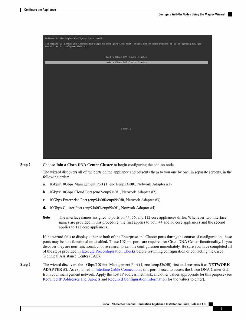
Step 4 Choose Join a Cisco DNA Center Cluster to begin configuring the add-on node.
The wizard discovers all of the ports on the appliance and presents them to you one by one, in separate screens, in thefollowing order:
a. 1Gbps/10Gbps Management Port (1, eno1/enp53s0f0, Network Adapter #1)
b. 1Gbps/10Gbps Cloud Port (eno2/enp53s0f1, Network Adapter #2)
c. 10Gbps Enterprise Port (enp94s0f0/enp69s0f0, Network Adapter #3)
d. 10Gbps Cluster Port (enp94s0f1/enp69s0f1, Network Adapter #4)
The interface names assigned to ports on 44, 56, and 112 core appliances differ. Whenever two interfacenames are provided in this procedure, the first applies to both 44 and 56 core appliances and the secondapplies to 112 core appliances.
Note
If the wizard fails to display either or both of the Enterprise and Cluster ports during the course of configuration, theseports may be non-functional or disabled. These 10Gbps ports are required for Cisco DNA Center functionality. If youdiscover they are non-functional, choose cancel to exit the configuration immediately. Be sure you have completed allof the steps provided in Execute Preconfiguration Checks before resuming configuration or contacting the CiscoTechnical Assistance Center (TAC).
Step 5 The wizard discovers the 1Gbps/10Gbps Management Port (1, eno1/enp53s0f0) first and presents it as NETWORKADAPTER #1. As explained in Interface Cable Connections, this port is used to access the Cisco DNA Center GUIfrom your management network. Apply the host IP address, netmask, and other values appropriate for this purpose (seeRequired IP Addresses and Subnets and Required Configuration Information for the values to enter).
Cisco DNA Center Second-Generation Appliance Installation Guide, Release 1.391
Configure the ApplianceConfigure Add-On Nodes Using the Maglev Wizard
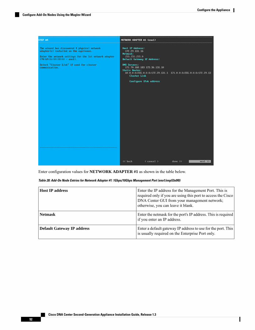
Enter configuration values for NETWORK ADAPTER #1 as shown in the table below.
Table 28: Add-On Node Entries for Network Adapter #1: 1Gbps/10Gbps Management Port (eno1/enp53s0f0)
Enter the IP address for the Management Port. This isrequired only if you are using this port to access the CiscoDNA Center GUI from your management network;otherwise, you can leave it blank.
Host IP address
Enter the netmask for the port's IP address. This is requiredif you enter an IP address.
Netmask
Enter a default gateway IP address to use for the port. Thisis usually required on the Enterprise Port only.
Default Gateway IP address
Cisco DNA Center Second-Generation Appliance Installation Guide, Release 1.392
Configure the ApplianceConfigure Add-On Nodes Using the Maglev Wizard

Enter the IP address of the preferred DNS server. Ifentering multiple DNS servers, separate the IP addressesin the list with spaces.
Important • For NTP, ensure port 123 (UDP) is openbetween Cisco DNACenter and your NTPserver.
• For each appliance in your cluster,configure a maximum of three DNSservers. Problems can occur if youconfigure more than three DNS servers foran appliance.
DNS Servers
Enter one or more static routes in the following format,separated by spaces: <network>/<netmask>/<gateway>.
Static Routes
Leave this field blank. It is required on the Cluster Portonly.
Cluster Link
Reserved for future use. Leave this field blank.Configure IPv6 Address
When you are finished entering configuration values, enter next>> to proceed. After entering next>>, the wizardvalidates the values you entered and issues an error message if any are incorrect. If you receive an error message, checkthat the value you entered is correct, then re-enter it. If needed, select <<back to re-enter it.
Step 6 After successful validation of the Management Port values you entered, the wizard presents the 1Gbps/10Gbps CloudPort (2, eno2/enp53s0f1) as NETWORK ADAPTER #2. As explained in Interface Cable Connections, this is anoptional port used to link the appliance to the Internet when you cannot do so through the 10Gbps Enterprise Port(enp94s0f0/enp69s0f0). Apply the host IP address, netmask, and other values appropriate for this purpose (see RequiredIP Addresses and Subnets and Required Configuration Information for the values to enter).
Cisco DNA Center Second-Generation Appliance Installation Guide, Release 1.393
Configure the ApplianceConfigure Add-On Nodes Using the Maglev Wizard

Enter configuration values for NETWORK ADAPTER #2 as shown in the table below.
Table 29: Add-On Node Entries for Network Adapter #2: 1Gbps/10Gbps Cloud Port (eno2/enp53s0f1)
Enter the IP address for the Cloud Port. This is requiredonly if you are using the Cloud Port for internet connection;otherwise, you can leave it blank.
Host IP address
Enter the netmask for the port's IP address. This is requiredif you enter an IP address.
Netmask
Enter a default gateway IP address to use for the CloudPort. This is usually required on the Enterprise Port only.
Default Gateway IP address
Enter the IP address of the preferred DNS server. Ifentering multiple DNS servers, separate the IP addressesin the list with spaces.
For each appliance in your cluster, configure amaximum of three DNS servers. Problems canoccur if you configure more than three DNSservers for an appliance.
Important
DNS Servers
Enter one or more static routes in the following format,separated by spaces: <network>/<netmask>/<gateway>.This is usually required on the Management Port only.
Static Routes
Cisco DNA Center Second-Generation Appliance Installation Guide, Release 1.394
Configure the ApplianceConfigure Add-On Nodes Using the Maglev Wizard

Leave this field blank. It is required on the Cluster Portonly.
Cluster Link
Reserved for future use. Leave this field blank.Configure IPv6 Address
When you are finished, enter next>> to proceed. Correct any validation errors as you did in previous screens.
Step 7 After successful validation of the Cloud Port values you entered, the wizard presents the 10Gbps Enterprise Port(enp94s0f0/enp69s0f0) asNETWORK ADAPTER #3. As explained in Interface Cable Connections, this is a requiredport used to link the appliance to the enterprise network. Apply the host IP address, netmask, and other values appropriatefor this purpose (see Required IP Addresses and Subnets and Required Configuration Information for the values toenter).
Enter configuration values for NETWORK ADAPTER #3 as shown in the table below.
Table 30: Add-On Node Entries for Network Adapter #3: 10Gbps Enterprise Port (enp94s0f0/enp69s0f0)
Enter the IP address for the Enterprise Port. This isrequired.
Host IP address
Enter the netmask for the port's IP address. This is required.Netmask
Enter a default gateway IP address to use for the port. Thisis required.
Default Gateway IP address
Cisco DNA Center Second-Generation Appliance Installation Guide, Release 1.395
Configure the ApplianceConfigure Add-On Nodes Using the Maglev Wizard

Enter the IP address of the preferred DNS server. Ifentering multiple DNS servers, separate the IP addressesin the list with spaces.
For each appliance in your cluster, configure amaximum of three DNS servers. Problems canoccur if you configure more than three DNSservers for an appliance.
Important
DNS Servers
Enter one or more static routes in the following format,separated by spaces: <network>/<netmask>/<gateway>.This is usually required on the Cisco DNA CenterManagement Port only.
Static Routes
Leave this field blank. It is required on the Cluster Portonly.
Cluster Link
Reserved for future use. Leave this field blank.Configure IPv6 Address
When you are finished, enter next>> to proceed. Correct any validation errors as you did in previous screens.
Step 8 After successful validation of the Enterprise Port values you entered, the wizard presents the 10Gbps Cluster Port(enp94s0f1/enp69s0f1) and presents it as NETWORK ADAPTER #4. As explained in Interface Cable Connections,this port is used to link the appliance to the cluster, so apply the host IP address, netmask, and other values appropriatefor this purpose (see Required IP Addresses and Subnets and Required Configuration Information for the values toenter).
Cisco DNA Center Second-Generation Appliance Installation Guide, Release 1.396
Configure the ApplianceConfigure Add-On Nodes Using the Maglev Wizard

Enter configuration values for NETWORK ADAPTER #4 as shown in the table below.
Table 31: Add-On Node Entries for Network Adapter #4: 10Gbps Cluster Port (enp94s0f1/enp69s0f1)
Enter the IP address for the Cluster Port. This is required.Note that you cannot change the address of the ClusterPort later.
Host IP address
Enter the netmask for the port's IP address. This is required.Netmask
Enter a default gateway IP address to use for the port. Thisis usually required on the Enterprise Port only.
Default Gateway IP address
Enter the IP address of the preferred DNS server. Ifentering multiple DNS servers, separate the IP addressesin the list with spaces.
For each appliance in your cluster, configure amaximum of three DNS servers. Problems canoccur if you configure more than three DNSservers for an appliance.
Important
DNS Servers
Enter one or more static routes in the following format,separated by spaces: <network>/<netmask>/<gateway>.This is usually required on the Management Port only.
Static Routes
Cisco DNA Center Second-Generation Appliance Installation Guide, Release 1.397
Configure the ApplianceConfigure Add-On Nodes Using the Maglev Wizard

Select the checkbox to indicate that this port will be thelink to a cluster. This is required on the Cluster Port only.
Cluster Link
Reserved for future use. Leave this field blank.Configure IPv6 Address
When you are finished, enter next>> to proceed. Correct any validation errors as you did in previous screens.
Step 9 Once network adapter configuration is complete, the wizard will prompt you to enter configuration values for theNETWORK PROXY you are using, as shown below.
Enter configuration values for the NETWORK PROXY as shown in the table below.
Table 32: Add-On Node Entries for Network Proxy
Enter the URL or host name of an HTTPS network proxyused to access the Internet.
Connection from Cisco DNA Center to theHTTPS proxy is supported only via HTTP inthis release.
Note
HTTPS Proxy
Enter the user name used to access the network proxy. Ifno proxy login is required, leave this field blank.
HTTPS Proxy Username
Enter the password used to access the network proxy. Ifno proxy login is required, leave this field blank.
HTTPS Proxy Password
Cisco DNA Center Second-Generation Appliance Installation Guide, Release 1.398
Configure the ApplianceConfigure Add-On Nodes Using the Maglev Wizard

When you are finished, enter next>> to proceed. Correct any validation errors as you did in previous screens.
Step 10 Once network proxy configuration is complete, the wizard will prompt you to identify the Cluster Port on the primarynode, and primary node login details, in MAGLEV CLUSTER DETAILS, as shown below.
Enter values for MAGLEV CLUSTER DETAILS as shown in the table below.
Table 33: Add-On Node Entries for Maglev Cluster Details
Enter the IP address of the Cluster Port on the primarynode in the cluster. If you have followed recommendationsfor port assignment, this will be the IP address ofenp94s0f1, Network Adapter #4 on the primary node.
Maglev Node
Enter maglev.Username
Enter the Linux Password you configured on the primarynode.
Password
When you are finished, enter next>> to proceed. Correct any validation errors as you did in previous screens.
Step 11 OnceMaglev Cluster Details are entered, the wizard will prompt you to enter values forUSER ACCOUNT SETTINGSfor this add-on node, as shown below.
Cisco DNA Center Second-Generation Appliance Installation Guide, Release 1.399
Configure the ApplianceConfigure Add-On Nodes Using the Maglev Wizard

Enter values for USER ACCOUNT SETTINGS as shown in the table below.
Table 34: Add-On Node Entries for User Account Settings
Enter a Linux password for the maglev user.Linux Password
Confirm the Linux password by entering it a second time.Re-enter Linux Password
If you do not want to create the Linux Password yourself,enter a seed phrase in this field and then press <GeneratePassword> to generate the password.
Password Generation Seed
(Optional) The seed phrase appears as part of a randomand secure password. If desired, you can either use thispassword "as is", or you can further edit this auto-generatedpassword.
Press <Use Generated Password> to save the password.
Auto Generated Password
Enter a password for the default admin superuser, used tolog in to Cisco DNA Center for the first time.
Administrator Passphrase
Confirm the administrator passphrase by entering it asecond time.
Re-enter Administrator Passphrase
When you are finished, enter next>> to proceed. Correct any validation errors as you did in previous screens.
Cisco DNA Center Second-Generation Appliance Installation Guide, Release 1.3100
Configure the ApplianceConfigure Add-On Nodes Using the Maglev Wizard
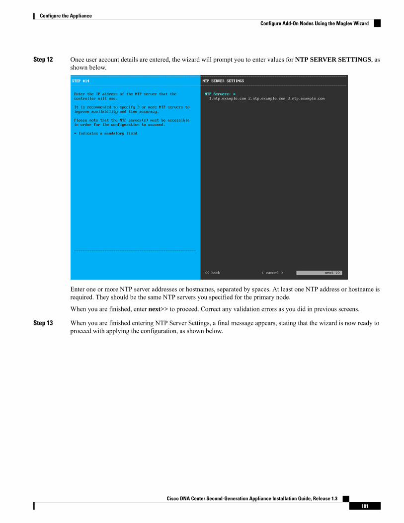
Step 12 Once user account details are entered, the wizard will prompt you to enter values for NTP SERVER SETTINGS, asshown below.
Enter one or more NTP server addresses or hostnames, separated by spaces. At least one NTP address or hostname isrequired. They should be the same NTP servers you specified for the primary node.
When you are finished, enter next>> to proceed. Correct any validation errors as you did in previous screens.
Step 13 When you are finished entering NTP Server Settings, a final message appears, stating that the wizard is now ready toproceed with applying the configuration, as shown below.
Cisco DNA Center Second-Generation Appliance Installation Guide, Release 1.3101
Configure the ApplianceConfigure Add-On Nodes Using the Maglev Wizard

Enter proceed>> to complete the configuration.
The host will reboot automatically and display messages on the KVM console as it applies your settings and brings upservices. This process can take several hours. You can monitor its progress via the KVM console.
At the end of the configuration process, the appliance power-cycles again, then displays a CONFIGURATIONSUCCEEDED! message.
What to do next
When this task is complete:
• If you have an additional appliance to deploy as the third and final node in the cluster, repeat this procedure.
• If you are finished adding hosts to the cluster, continue by performing first-time setup: First-Time SetupWorkflow.
Upgrade to the Latest Cisco DNA Center ReleaseFor information about upgrading your current release of Cisco DNA Center, see the Cisco Digital NetworkArchitecture Center Upgrade Guide.
Cisco DNA Center Second-Generation Appliance Installation Guide, Release 1.3102
Configure the ApplianceUpgrade to the Latest Cisco DNA Center Release

C H A P T E R 6Complete First-Time Setup
• First-Time Setup Workflow, on page 103• Compatible Browsers, on page 104• Log In for the First Time, on page 104• Integrate Cisco ISE with Cisco DNA Center, on page 106• Configure Authentication and Policy Servers, on page 109• Configure SNMP Properties, on page 111
First-Time Setup WorkflowAfter you finish configuring all of the Cisco DNACenter appliances you have installed, perform the followingtasks to prepare Cisco DNA Center for production use.
For the parameter information you need to complete this work, see Required First-Time Setup Information.Note
1. Make sure that you are accessing Cisco DNA Center using a compatible browser.
For a list of compatible browsers, see the Release Notes document for the version of Cisco DNA Centeryou are installing.
2. Log in to the Cisco DNACenter GUI as an administrator for the first time. During this first administrativelogin, you will be prompted to:
a. Provide a new password for the admin superuser.
b. Enter the cisco.com username and password your organization uses to download software images andreceive email communications from Cisco.
c. Enter the cisco.com username and password your organization uses to manage its Smart Accountlicenses.
d. Configure the IP address manager (IPAM) server you plan to use with Cisco DNA Center.
For details on these tasks, see Log In for the First Time.
3. If you are planning to use Cisco DNA Center with Cisco Identity Services Engine (ISE), make sure thetwo are properly integrated: Integrate Cisco ISE with Cisco DNA Center.
Cisco DNA Center Second-Generation Appliance Installation Guide, Release 1.3103

4. Connect Cisco DNA Center with your policy and AAA server (including ISE): Configure Authenticationand Policy Servers.
5. Configure the basic SNMP retry and polling parameters: Configure SNMP Properties.
6. Redistribute services among your cluster nodes to optimize high availability (HA) operation: RedistributeServices
7. After you are finished with the first-time setup: Log Out.
Compatible BrowsersThe Cisco DNA Center GUI is compatible with the following HTTPS-enabled browsers:
• Google Chrome: Version 62.0 or later.
• Mozilla Firefox: Version 54.0 or later.
We recommend that the client systems you use to log in to Cisco DNACenter be equipped with 64-bit operatingsystems and browsers.
Log In for the First TimeAfter you have installed and configured the Cisco DNA Center appliance, you can log in to its GUI. Use acompatible, HTTPS-enabled browser when accessing Cisco DNA Center.
When you log in for the first time as the admin superuser (with the username admin and theSUPER-ADMIN-ROLE assigned), you are asked to complete a first-time setup wizard that helps you enhancesystem security and complete the essential setup tasks. Although you can skip each of the steps in the wizard,we recommend that you complete all of them as indicated, so that your system is ready for use as soon aspossible.
You should also create new Cisco DNA Center users. We recommend that you create at least one additionaluser account to be used for daily operations, and that this user account have the NETWORK-ADMIN-ROLE.
Before you begin
To log in to Cisco DNA Center and complete the first-time setup wizard, you will need:
• The admin superuser username and password you specified when following the steps in Configure thePrimary Node Using the Maglev Wizard.
• The requisite information, as described in Required First-Time Setup Information.
Step 1 After the Cisco DNA Center appliance reboot is completed, launch your browser.Step 2 Enter the host IP address to access the Cisco DNA Center GUI, using HTTPS:// and the IP address of the Cisco DNA
Center GUI that was displayed at the end of the configuration process.
After entering the IP address, one of the following messages appears (depending on the browser you are using):
• Google Chrome: Your connection is not private
Cisco DNA Center Second-Generation Appliance Installation Guide, Release 1.3104
Complete First-Time SetupCompatible Browsers

• Mozilla Firefox: Warning: Potential Security Risk Ahead
Step 3 Ignore the message and click Advanced.
A message stating that the site’s security certificate is not trusted appears. This message appears because the controlleruses a self-signed certificate. For information on how Cisco DNA Center uses certificates, see the "Certificate andPrivate Key Support" section in the Cisco Digital Network Architecture Center Administrator Guide.
Step 4 Ignore the message and click the link at the bottom of the window.
The Cisco DNA Center Login window appears.
Step 5 In the Login window, enter the admin's username (admin) and password that you set when you configured Cisco DNACenter, then click Log In.
The Reset Login window appears.
Step 6 Enter the old password, enter and confirm a new password for the admin superuser, and then click Save.
The Enter Cisco.com ID window appears.
Step 7 Enter the username and password for the cisco.com user, then click Next.
If the cisco.com user login does not match any known Cisco Smart Account user login, the Smart Account windowappears.
Step 8 If the Smart Account window appears, enter the username and password for your organization's Smart Account, orclick the corresponding link to open a new Smart Account. After you are finished, click Next.
The IP Address Manager window appears.
Step 9 If your organization uses an external IP address manager (IPAM), do the following and then click Next:
• Enter your IPAM server's name and URL.
• Enter the username and password required for server access.
• Choose your IPAM provider (such as Infoblox).
• Choose the specific view of IP addresses available in the IPAM server database that you want Cisco DNA Centerto use.
The Enter Proxy Server window appears.
Step 10 Enter the proxy server information your organization will use, then click Next:
• Include the server username and password if your proxy server requires a login.
• To validate this information before proceeding (recommended), ensure that the Validate Settings check box ischecked.
The software EULA window appears.
Step 11 Click Next to accept the software End User License Agreement and continue.
The Ready to go! window appears.
Step 12 Click any of the links in this window, or click Go to System 360 to display the System 360 dashboard and start usingCisco DNA Center.
Cisco DNA Center Second-Generation Appliance Installation Guide, Release 1.3105
Complete First-Time SetupLog In for the First Time

We recommend that you click the User Management link to display the User Management window. Then click Addto begin adding new Cisco DNA Center users. After you have entered the new user's name and password, and selectedthe user's role, click Save to create the new user. Repeat this as needed until you have added all the new users for yourinitial deployment. Be sure to create at least one user with the NETWORK-ADMIN-ROLE.
What to do next
Complete other administrative setup tasks, in any order:
• Integrate Cisco ISE with Cisco DNA Center
• Configure Authentication and Policy Servers
• Configure SNMP Properties
Integrate Cisco ISE with Cisco DNA CenterThis release of Cisco DNA Center provides a mechanism to create a trusted communications link with CiscoISE and permits Cisco DNA Center to share data with Cisco ISE in a secure manner. After Cisco ISE isregistered with Cisco DNA Center, any device that Cisco DNA Center discovers, along with relevantconfiguration and other data, is pushed to Cisco ISE. Users can use Cisco DNA Center to discover devicesand then apply both Cisco DNA Center and Cisco ISE functions to them because these devices are exposedin both applications. Cisco DNA Center and Cisco ISE devices are all uniquely identified by their devicenames.
As soon as they are provisioned and belong to a particular site in the Cisco DNA Center site hierarchy, CiscoDNA Center devices are pushed to Cisco ISE. Any updates to a Cisco DNA Center device (such as changesto IP address, SNMP or CLI credentials, Cisco ISE shared secret, and so on) will flow to the correspondingdevice instance on Cisco ISE automatically. Note that Cisco DNA Center devices are pushed to Cisco ISEonly when these devices are associated with a particular site where Cisco ISE is configured as its AAA server.
Before you begin
Before attempting to integrate Cisco ISE with Cisco DNA Center, ensure that you have met the followingprerequisites:
• You have deployed one or more Cisco ISE version 2.3 (and later) hosts on your network. For informationon installing Cisco ISE, see the Cisco Identity Services Engine Install and Upgrade guides for version2.3 and later.
• If you have a standalone Cisco ISE deployment, you must integrate with the Cisco ISE node and enablethe pxGrid service and External RESTful Services (ERS) on that node.
Cisco ISE 2.4 and later supports pxGrid 2.0 as well as pxGrid 1.0. AlthoughpxGrid 2.0 allows up to four pxGrid nodes in the Cisco ISE deployment, CiscoDNA Center releases earlier than 2.2.1.x do not support more than two pxGridnodes.
Note
Cisco DNA Center Second-Generation Appliance Installation Guide, Release 1.3106
Complete First-Time SetupIntegrate Cisco ISE with Cisco DNA Center

• If you have a distributed Cisco ISE deployment:
• You must integrate Cisco DNA Center with the Cisco ISE admin node, the primary PolicyAdministration node (PAN), and enable ERS on the primary PAN. You must also enable ERS inyour secondary PAN. In the case of a primary PAN failover in Cisco ISE, if ERS is not enabled inthe secondary PAN, the secondary PAN is not available to Cisco DNA Center. As a result, theconnection between Cisco DNA Center and Cisco ISE is affected.
As a best practice, use ERS through the PAN. But for backup, enable ERS onthe Policy Service nodes (PSNs).
Note
• As with single-node deployments, you must enable the pxGrid service on one of the Cisco ISEnodes within the distributed deployment. Although you can choose to do so, you do not have toenable pxGrid on the PAN. You can enable pxGrid on any of the other Cisco ISE nodes in yourdistributed deployment.
• The PSNs you configure in Cisco ISE to handle TrustSec/SD Access content and PACs must alsobe defined in Work Centers > Trustsec > Trustsec Servers > Trustsec AAA Servers. For moreinformation, see the Segmentation document in the Administrator Workflow for your release ofCisco ISE.
• You have enabled communication between Cisco DNA Center and Cisco ISE on the following ports:22, 443, 5222, 8910, and 9060.
• The Cisco ISE host on which pxGrid is enabled must be reachable from Cisco DNA Center on the IPaddress of the Cisco ISE eth0 interface.
• The Cisco ISE node can reach the fabric underlay network via the appliance's NIC.
• The Cisco ISE admin node certificate must contain the Cisco ISE IP address or FQDN in either thecertificate subject name or the Subject Alternative Name (SAN).
• The Cisco DNA Center system certificate must list both the Cisco DNA Center appliance IP address andFQDN in the SAN field.
For Cisco ISE 2.4 Patch 13, 2.6 Patch 7, and 2.7 Patch 3, if you are using theCisco ISE default self-signed certificate as the pxGrid certificate, Cisco ISEmightreject that certificate after applying those patches. This is because the olderversions of that certificate have the Netscape Cert Type extension specified asthe SSL server, which now fails (because a client certificate is required).
This issue does not occur in Cisco ISE 3.0 and later. For details and a suggestedworkaround, see the Cisco ISE Release Notes.
Note
For more information about configuring Cisco ISE for Cisco DNA Center, see Integration with Cisco DNACenter in the Cisco ISE Administrators Guide.
Step 1 Enable the Cisco ISE pxGrid service and ERS:
Cisco DNA Center Second-Generation Appliance Installation Guide, Release 1.3107
Complete First-Time SetupIntegrate Cisco ISE with Cisco DNA Center
a) Log in to the Cisco ISE primary policy administration node.b) Choose Administration > System > Deployment.
The Deployment Nodes window opens.
c) Click the hostname of the Cisco ISE node on which you want to enable pxGrid services.
In a distributed deployment, this can be any Cisco ISE node in the deployment.
The Edit Node window opens, with the General Settings tab selected by default.
d) Ensure that the pxGrid check box is checked, then click Save.e) Choose Administration > System > Settings.f) From the left navigation pane, click ERS Settings to open the ERS Settings window.g) Click the Enable ERS for Read/Write radio button, then click OK in the notification prompt.h) Click Save.
Step 2 Add the Cisco ISE node to Cisco DNA Center as a AAA server:a) Log in to the Cisco DNA Center GUI.b) Click the Menu icon ( ) and choose System > System 360.c) In the Identity Services Engine (ISE) pane, click the Configure link.d) From the Authentication and Policy Servers window, click Add and choose ISE from the drop-down list.e) Complete the following tasks in the Add AAA/ISE server slide-in pane:
• In the Server IP Address field, enter the Cisco ISE management IP address.
• Enter the Shared Secret used to secure communications between your network devices and Cisco ISE.
• In the Username and Password fields, enter the corresponding Cisco ISE admin credentials.
• Enter the FQDN for the Cisco ISE node.
• (Optional) Enter the virtual IP address of the load balancer behind which the Cisco ISE PSNs are located. Ifyou have multiple policy service node farms behind different load balancers, you can enter a maximum of sixvirtual IP addresses.
f) Click Add.
The first time integration with Cisco ISE is initiated, you will see a notification that the certificate from Cisco ISE is notyet trusted.
• You can view the certificate to see the details.
• Choose Accept to trust the certificate and continue with the integration process. If you do not wish to trust thecertificate and terminate the integration process, choose Decline.
After the integration completes successfully, a confirmation message is displayed.
If any problem is encountered in the integration process, a message is shown with details of the problem. An option toedit or retry is shown where possible.
• If the error message says that the Cisco ISE Admin credentials are invalid, click Edit and re-enter the correctinformation.
• If errors are found with certificates in the integration process, you must delete the Cisco ISE server entry and restartthe integration from the beginning after the certificate issue has been resolved.
Cisco DNA Center Second-Generation Appliance Installation Guide, Release 1.3108
Complete First-Time SetupIntegrate Cisco ISE with Cisco DNA Center

Step 3 Verify that Cisco DNA Center is connected to Cisco ISE, and that the Cisco ISE SGT groups and devices are beingpushed to Cisco DNA Center:a) Log in to the Cisco DNA Center GUI.b) Click the Menu icon ( ) and choose System > System 360.c) In the Identity Services Engine (ISE) pane, click the Update link.d) From the Authentication and Policy Servers window, verify that the status of the Cisco ISE AAA server is still
Active.
Step 4 Verify that Cisco ISE is connected to Cisco DNA Center and that the connection has subscribers:a) Log in to the Cisco ISE nodes that are shown as pxGrid servers in the Cisco Identity Services Engine (ISE) Deployment
window.b) Choose Administration > pxGrid Services and click the Web Clients tab.
You should see two pxGrid clients in the list with the IP address of the Cisco DNA Center server.
Configure Authentication and Policy ServersCisco DNA Center uses AAA servers for user authentication and Cisco ISE for both user authentication andaccess control. Use this procedure to configure AAA servers, including Cisco ISE.
Before you begin
• If you are using Cisco ISE to perform both policy and AAA functions, make sure that Cisco DNACenterand Cisco ISE are integrated as described in Integrate Cisco ISE with Cisco DNA Center.
• If you are using another product (not Cisco ISE) to perform AAA functions, make sure that you do thefollowing:
• Register Cisco DNA Center with the AAA server, and define the shared secret on both the AAAserver and Cisco DNA Center.
• Define an attribute name for Cisco DNA Center on the AAA server.
• For a Cisco DNA Center multihost cluster configuration, define all the individual host IP addressesand the virtual IP address for the multihost cluster on the AAA server.
Step 1 From the Cisco DNACenter home page, choose > System Settings > Settings >Authentication and Policy Servers.
Step 2 Click .Step 3 Configure the primary AAA server by providing the following information:
• Server IP Address: IP address of the AAA server.
• Shared Secret: Key for device authentications. The shared secret can be up to 128 characters in length.
Step 4 To configure an AAA server (except Cisco ISE), leave the Cisco ISE Server slider in the Off position and proceed toStep 5.
Cisco DNA Center Second-Generation Appliance Installation Guide, Release 1.3109
Complete First-Time SetupConfigure Authentication and Policy Servers

To configure a Cisco ISE server, click the Cisco ISE server slider to move it to the On position and enter informationin the following fields:
• Username—Name that is used to log in to Cisco ISE CLI.
This user must be a Super Admin.Note
• Password—Password for the Cisco ISE CLI username.
• FQDN—FQDN of the Cisco ISE server.
• We recommend that you copy the FQDN that is defined in Cisco ISE (Administration >Deployment > Deployment Nodes > List) and paste it directly into this field.
• The FQDN that you enter must match the FQDN, CommonName (CN), or Subject Alternative Name(SAN) defined in the Cisco ISE certificate.
Note
The FQDN consists of two parts, a hostname and a domain name, in the following format:
hostname.domainname.com.
For example, the FQDN for a Cisco ISE server might be ise.cisco.com.
• Subscriber Name—Unique text string that identifies a pxGrid client registering for Cisco ISE pxGrid services; forexample, acme. The subscriber name is used during Cisco DNA Center-to-Cisco ISE integration.
• (Optional) SSH Key—Diffie-Hellman-Group14-SHA1 SSH key used to connect to Cisco ISE.
• (Optional) Virtual IP Address(es)—Virtual IP address of the load balancer behind which the Cisco ISE policyservice nodes are located. If you have multiple policy service node farms behind different load balancers, you canenter a maximum of six virtual IP addresses.
If the status of the configured ISE server is "FAILED" due to password change, click Retry, and update thepassword to resync the ISE connectivity.
Note
Step 5 Click View Advanced Settings and configure the settings:
The settings you need to configure will vary, depending on the protocol you set for the server.Note
• Protocol: RADIUS is set by default, but you can choose TACACS instead or choose both protocols.
If you do not choose TACACS for Cisco ISE servers, it will not be available when you configure CiscoISE nodes.
Attention
• Authentication Port: Port used by RADIUS to relay authentication messages to the AAA server. The default isUDP port 1812.
• Accounting Port: Port used by RADIUS to relay important events to the AAA server. The information in theseevents is used for security and billing purposes. The default UDP port is 1813.
• Port: Port used by TACACS to communicate with the AAA server. The default port is 49.
• Retries: Number of times that Cisco DNA Center attempts to connect with the AAA server before abandoning theattempt to connect. The default number of attempts is 3.
• Timeout: Length of time the device waits for the AAA server to respond before abandoning the attempt to connect.The default timeout is 4 seconds.
Cisco DNA Center Second-Generation Appliance Installation Guide, Release 1.3110
Complete First-Time SetupConfigure Authentication and Policy Servers

Step 6 Click Apply.Step 7 To add a secondary server, repeat Step 2 through Step 6.
Configure SNMP PropertiesYou can configure the retry and timeout values for SNMP.
Before you begin
Only a user with SUPER-ADMIN-ROLE permissions can perform this procedure. For more information, seethe Cisco DNA Center Administrator Guide.
Step 1 From the Cisco DNA Center home page, click the gear icon ( ) and then choose System Settings > Settings > SNMPProperties.
Step 2 Configure the following fields:
• Retries: Number of attempts allowed to connect to the device. Valid values are from 1 to 3. The default is 3.
• Timeout (in Seconds): Number of seconds Cisco DNA Center waits for when trying to establish a connection witha device before timing out. Valid values are from 1 to 300 seconds, in intervals of 5 seconds. The default is 5 seconds.
Step 3 Click Apply.
To return to the default settings, click Revert to Defaults.Note
Cisco DNA Center Second-Generation Appliance Installation Guide, Release 1.3111
Complete First-Time SetupConfigure SNMP Properties

Cisco DNA Center Second-Generation Appliance Installation Guide, Release 1.3112
Complete First-Time SetupConfigure SNMP Properties

C H A P T E R 7Troubleshoot the Deployment
• Troubleshooting Tasks, on page 113• Log Out, on page 113• Reconfigure the Appliance Using the Configuration Wizard, on page 114• Power-Cycle the Appliance, on page 115
Troubleshooting TasksWhen troubleshooting issues with the appliance's configuration, you will normally perform the followingtasks:
1. If you are currently using the Cisco DNA Center GUI: Log Out.
2. To reconfigure the appliance's hardware, log in to and use the CIMC GUI, as explained in Steps 12 and13 of Enable Browser Access to Cisco Integrated Management Controller.
3. To change the appliance configuration, launch and use the Maglev Configuration wizard, as explained inReconfigure the Appliance Using the Configuration Wizard.
4. Power-cycle the appliance so that your changes are active: Power-Cycle the Appliance, on page 115.
For more information about the appliance's network adapters, see the Managing Adapters section of the CiscoUCS C-Series Servers Integrated Management Controller CLI Configuration Guide, Release 3.1. As notedelsewhere, never attempt to manage the appliance hardware through the Linux CLI. Use only the CIMC GUIor the Maglev Configuration wizard to change appliance settings.
Log OutFollow the steps below to log out of the Cisco DNA Center GUI.
For security reasons, we recommend that you log out after you complete a work session. If you do not logout yourself, you will be logged out automatically after 30 minutes of inactivity.
Step 1 Click .Step 2 Click Sign out.
Cisco DNA Center Second-Generation Appliance Installation Guide, Release 1.3113

This ends your session and logs you out.
Reconfigure the Appliance Using the Configuration WizardTo reconfigure an appliance, you must use the Configuration wizard to update the appliance settings. Youcannot use the Linux CLI to do this. The normal Linux administration procedures that you might use to updateconfiguration settings on a standard Linux server will not work and should not be attempted.
After the appliance is configured, you cannot use the Configuration wizard to change all of the appliancesettings. Changes are restricted to the following settings only:
• Host IP address of the appliance
• DNS server IP addresses
• Default gateway IP address
• NTP server IP addresses
• Cluster Virtual IP address
• Static routes
• Proxy server IP address
• Maglev user password
• Admin user password
Before you begin
Youwill need the Linux user name (maglev) and password that are currently configured on the target appliance.
Step 1 Point your browser to the Cisco IMC IP address you set during the Cisco IMC GUI configuration you performed, andlog in to the Cisco IMC GUI as the Cisco IMC user (see Enable Browser Access to Cisco Integrated ManagementController).After successful login, the appliance displays theCisco Integrated Management Controller Chassis Summarywindow,with a hyperlinked menu at the top of the window, as shown below.
Cisco DNA Center Second-Generation Appliance Installation Guide, Release 1.3114
Troubleshoot the DeploymentReconfigure the Appliance Using the Configuration Wizard

Step 2 From the hyperlinked menu, choose Launch KVM and then select either Java based KVM or HTML based KVM. Ifyou select Java-based KVM, you will need to launch the Java startup file from your browser or file manager in orderto view the KVM console in its own window. If you select HMTL-based KVM, it launches the KVM console in aseparate window or tab automatically.
Irrespective of the KVM type you choose, use the KVM console to monitor the progress of the configuration and respondto the Maglev Configuration wizard prompts.
Step 3 When prompted, enter the Linux password.Step 4 Enter the following command to access the Configuration wizard.
sudo maglev-config update
If you are prompted for the Linux password, enter it again.
Step 5 The Configuration wizard presents an abbreviated version of the same series of screens shown in, for example, ConfigureAdd-On Nodes Using the Maglev Wizard. Make changes to the settings presented, if required. After you finish makingchanges on each screen, choose [Next], as needed, to proceed through the Configuration wizard.
Step 6 At the end of the configuration process, a message appears, stating that the Configuration wizard is now ready to applyyour changes. The following options are available:
• [back]: Review and verify your changes.
• [cancel]: Discard your changes and exit the Configuration wizard.
• [proceed]: Save your changes and begin applying them.
Choose proceed>> to complete the installation. The Configuration wizard applies the changes you made.
At the end of the configuration process, a CONFIGURATION SUCCEEDED! message appears.
What to do next
Ensure your changes are applied and active by power-cycling the appliance. See Power-Cycle the Appliance,on page 115.
If you have updated the DNS Server IP addresses, we recommend that you perform a cold boot whenpower-cycling the appliance. This ensures that your DNS changes are applied.
Note
Power-Cycle the ApplianceComplete one of the following procedures on your Cisco DNA Center appliance to either halt it or performa warm restart. You can halt the appliance before you make hardware repairs, or you can initiate a warmrestart after you have corrected software issues.
Cisco DNA Center Second-Generation Appliance Installation Guide, Release 1.3115
Troubleshoot the DeploymentPower-Cycle the Appliance
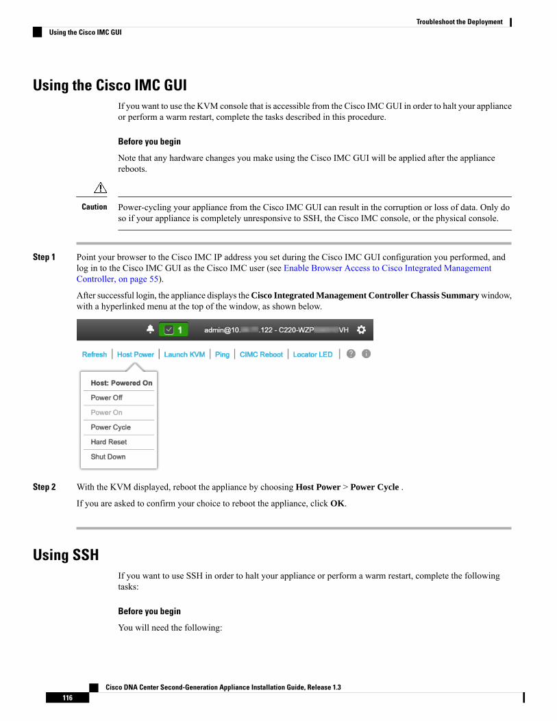
Using the Cisco IMC GUIIf you want to use the KVM console that is accessible from the Cisco IMCGUI in order to halt your applianceor perform a warm restart, complete the tasks described in this procedure.
Before you begin
Note that any hardware changes you make using the Cisco IMC GUI will be applied after the appliancereboots.
Power-cycling your appliance from the Cisco IMC GUI can result in the corruption or loss of data. Only doso if your appliance is completely unresponsive to SSH, the Cisco IMC console, or the physical console.
Caution
Step 1 Point your browser to the Cisco IMC IP address you set during the Cisco IMC GUI configuration you performed, andlog in to the Cisco IMC GUI as the Cisco IMC user (see Enable Browser Access to Cisco Integrated ManagementController, on page 55).
After successful login, the appliance displays theCisco Integrated Management Controller Chassis Summarywindow,with a hyperlinked menu at the top of the window, as shown below.
Step 2 With the KVM displayed, reboot the appliance by choosing Host Power > Power Cycle .
If you are asked to confirm your choice to reboot the appliance, click OK.
Using SSHIf you want to use SSH in order to halt your appliance or perform a warm restart, complete the followingtasks:
Before you begin
You will need the following:
Cisco DNA Center Second-Generation Appliance Installation Guide, Release 1.3116
Troubleshoot the DeploymentUsing the Cisco IMC GUI

• Secure Shell (SSH) client software.
• The IP address that you configured for the 10-Gbps Enterprise port on the appliance that needsreconfiguration. Log in to the appliance at this address, on port 2222.
To identify the Enterprise port, see the rear-panel figures in Front and Rear Panels, on page 4.
• The Linux user name (maglev) and the password that is currently configured on the target appliance.
Step 1 Using a Secure Shell (SSH) client, log in to the IP address of the Enterprise port of the appliance that needs to bereconfigured, on port 2222:
ssh maglev@Enterprise-port's-IP-address -p 2222
Step 2 When prompted, enter the Linux password.Step 3 Enter the command that is appropriate for the task you want to perform:
• To halt the appliance, enter: sudo shutdown -h now
• To initiate a warm restart, enter: sudo shutdown -r now
If you are prompted for the Linux password, enter it again.
Step 4 Review the command output that is displayed as the host shuts down.Step 5 If you halted your appliance, power up the Maglev root process by turning the appliance back on, using the front-panel
power button.
Cisco DNA Center Second-Generation Appliance Installation Guide, Release 1.3117
Troubleshoot the DeploymentUsing SSH

Cisco DNA Center Second-Generation Appliance Installation Guide, Release 1.3118
Troubleshoot the DeploymentUsing SSH

A P P E N D I X AReview High Availability Cluster DeploymentScenarios
Cisco DNA Center's implementation of high availability (HA) is described in the Cisco Digital NetworkArchitecture Center High Availability Guide. We recommend that you first review this information and thendetermine whether you want to deploy HA in your production environment. If you choose to do so, completethe following tasks:
1. Complete the deployment procedure that is appropriate for your network:
• New HA Deployment
• Existing HA Deployment of the Primary Node with Standard Interface Configurations
• Existing HA Deployment of Primary Node with Nonstandard Interface Configurations
2. Redistribute Services among your cluster nodes.
3. See Additional HADeployment Considerations andmake any additional configurations that are necessary.
• New HA Deployment, on page 119• Existing HA Deployment of the Primary Node with Standard Interface Configurations, on page 120• Existing HA Deployment of Primary Node with Nonstandard Interface Configurations, on page 120• Redistribute Services, on page 121• Additional HA Deployment Considerations, on page 121
New HA DeploymentTo install a brand new HA cluster, complete the following steps:
Step 1 Configure the first installed appliance as the primary node.
See Configure the Primary Node Using the Maglev Wizard.
Step 2 Configure the second and third appliances in the cluster.
See Configure Add-On Nodes Using the Maglev Wizard.
Cisco DNA Center Second-Generation Appliance Installation Guide, Release 1.3119

Existing HA Deployment of the Primary Node with StandardInterface Configurations
To deploy an existing HA cluster, where the primary node uses the required interface cable configurations,complete the following steps.
Step 1 Upgrade the primary node to Cisco DNA Center 1.3.
For information about upgrading your current release of Cisco DNA Center, see Cisco Digital Network ArchitectureCenter Upgrade Guide.
Step 2 Confirm that you are using the required interface cable configurations on the primary node.
See Interface Cable Connections.
Step 3 Update the virtual IP address (if the virtual IP address is not yet added).
See Reconfigure the Appliance Using the Configuration Wizard.
Step 4 Configure the second and third appliances in the cluster.
See Configure Add-On Nodes Using the Maglev Wizard.
Step 5 Enter the following command to check the GlusterFS size:
sudo du -h /data/maglev/srv/maglev-system/glusterfs/mnt/bricks/default_brick/ | tail -1 | awk '{print $1}'
If the GlusterFS file system size is larger than 150 GB, complete the steps described in Existing HA Deployment ofPrimary Node with Nonstandard Interface Configurations.
Existing HA Deployment of Primary Node with NonstandardInterface Configurations
To deploy an existing HA cluster where the primary node uses nonstandard interface configurations, completethe following steps.
Step 1 Upgrade the primary node to Cisco DNA Center 1.3.
For information about upgrading your current release of Cisco DNA Center, see the Cisco DNA Center Upgrade Guide.
Step 2 Create a backup of the remote repository.
See the "Backup and Restore" chapter in the Cisco DNA Center Administrator Guide.
Step 3 Reimage the primary node with the required interface cable configuration.
See Interface Cable Connections and Install the Cisco DNACenter ISO Image.Make sure that the VIP has been configuredcorrectly on the primary node.
Cisco DNA Center Second-Generation Appliance Installation Guide, Release 1.3120
Review High Availability Cluster Deployment ScenariosExisting HA Deployment of the Primary Node with Standard Interface Configurations

Step 4 On the primary node, install the same set of packages that you selected during the backup.Step 5 Using the backup file that you created in Step 2, restore the remote repository's data.Step 6 Configure the second and third appliances in the cluster.
See Configure Add-On Nodes Using the Maglev Wizard.
Redistribute ServicesCisco DNA Center's implementation of HA is described in the Cisco Digital Network Architecture CenterHigh Availability Guide. We recommend that you first review this information and then determine whetheryou want to deploy HA in your production environment. If you choose to do so, optimize HA operation byredistributing the services among your cluster nodes:
1. Click and then choose System Settings.
The System 360 tab is displayed by default.
2. In the Hosts area, click Enable Service Distribution.
After you clickEnable Service Distribution, Cisco DNACenter enters into maintenancemode. In this mode,Cisco DNA Center is unavailable until the redistribution of services is completed. You should take this intoaccount when scheduling an HA deployment.
Cisco DNACenter goes into maintenancemode every time you restore the database, perform a system upgrade(not a package upgrade), and enable a service redistribution for HA (as described above).
Note
Additional HA Deployment ConsiderationsFor an existing HA deployment, the following additional configurations must be made.
For information about known HA bugs and workarounds, see “Open Bugs—HA" in the Release Notes forCisco Digital Network Architecture Center.
Note
TelemetryIf you enabled telemetry for a device (without enabling the VIP), complete the following steps:
Step 1 Use the maglev-config update command to update the cluster VIP.Step 2 Disable telemetry on the device:
a. From the Cisco DNA Center home page, choose Network Telemetry from the Tools area.
Cisco DNA Center Second-Generation Appliance Installation Guide, Release 1.3121
Review High Availability Cluster Deployment ScenariosRedistribute Services

The Network Telemetry window appears.
b. Click the Site View tab.
c. Check the check box of the device on which you want to disable telemetry, and then choose Actions > DisableTelemetry.
Step 3 Reenable telemetry using the profile associated with the device previously.
Wireless ControllerYou must update the wireless controllers in your network with the new VIP of Cisco DNA Center.
Cisco DNA Center Second-Generation Appliance Installation Guide, Release 1.3122
Review High Availability Cluster Deployment ScenariosWireless Controller
Copyright © 2022 FDOKUMEN