Workload Optimization Manager 3.1.0 Installation Guide - Cisco
Upload
khangminh22Category
view
4download
0
Cisco HyperFlex Systems Installation Guide for VMware ESXi, Release3.0First Published: 2018-04-13
Last Modified: 2020-05-05
Americas HeadquartersCisco Systems, Inc.170 West Tasman DriveSan Jose, CA 95134-1706USAhttp://www.cisco.comTel: 408 526-4000
800 553-NETS (6387)Fax: 408 527-0883

THE SPECIFICATIONS AND INFORMATION REGARDING THE PRODUCTS IN THIS MANUAL ARE SUBJECT TO CHANGE WITHOUT NOTICE. ALL STATEMENTS,INFORMATION, AND RECOMMENDATIONS IN THIS MANUAL ARE BELIEVED TO BE ACCURATE BUT ARE PRESENTED WITHOUT WARRANTY OF ANY KIND,EXPRESS OR IMPLIED. USERS MUST TAKE FULL RESPONSIBILITY FOR THEIR APPLICATION OF ANY PRODUCTS.
THE SOFTWARE LICENSE AND LIMITED WARRANTY FOR THE ACCOMPANYING PRODUCT ARE SET FORTH IN THE INFORMATION PACKET THAT SHIPPED WITHTHE PRODUCT AND ARE INCORPORATED HEREIN BY THIS REFERENCE. IF YOU ARE UNABLE TO LOCATE THE SOFTWARE LICENSE OR LIMITED WARRANTY,CONTACT YOUR CISCO REPRESENTATIVE FOR A COPY.
The Cisco implementation of TCP header compression is an adaptation of a program developed by the University of California, Berkeley (UCB) as part of UCB's public domain version ofthe UNIX operating system. All rights reserved. Copyright © 1981, Regents of the University of California.
NOTWITHSTANDING ANY OTHERWARRANTY HEREIN, ALL DOCUMENT FILES AND SOFTWARE OF THESE SUPPLIERS ARE PROVIDED “AS IS" WITH ALL FAULTS.CISCO AND THE ABOVE-NAMED SUPPLIERS DISCLAIM ALL WARRANTIES, EXPRESSED OR IMPLIED, INCLUDING, WITHOUT LIMITATION, THOSE OFMERCHANTABILITY, FITNESS FOR A PARTICULAR PURPOSE AND NONINFRINGEMENT OR ARISING FROM A COURSE OF DEALING, USAGE, OR TRADE PRACTICE.
IN NO EVENT SHALL CISCO OR ITS SUPPLIERS BE LIABLE FOR ANY INDIRECT, SPECIAL, CONSEQUENTIAL, OR INCIDENTAL DAMAGES, INCLUDING, WITHOUTLIMITATION, LOST PROFITS OR LOSS OR DAMAGE TO DATA ARISING OUT OF THE USE OR INABILITY TO USE THIS MANUAL, EVEN IF CISCO OR ITS SUPPLIERSHAVE BEEN ADVISED OF THE POSSIBILITY OF SUCH DAMAGES.
Any Internet Protocol (IP) addresses and phone numbers used in this document are not intended to be actual addresses and phone numbers. Any examples, command display output, networktopology diagrams, and other figures included in the document are shown for illustrative purposes only. Any use of actual IP addresses or phone numbers in illustrative content is unintentionaland coincidental.
All printed copies and duplicate soft copies of this document are considered uncontrolled. See the current online version for the latest version.
Cisco has more than 200 offices worldwide. Addresses and phone numbers are listed on the Cisco website at www.cisco.com/go/offices.
Cisco and the Cisco logo are trademarks or registered trademarks of Cisco and/or its affiliates in the U.S. and other countries. To view a list of Cisco trademarks, go to this URL:https://www.cisco.com/c/en/us/about/legal/trademarks.html. Third-party trademarks mentioned are the property of their respective owners. The use of the word partner does not imply apartnership relationship between Cisco and any other company. (1721R)
© 2018–2020 Cisco Systems, Inc. All rights reserved.

C O N T E N T S
HyperFlex Deferred Releases 1C H A P T E R 1
HyperFlex Deferred Releases 1
Overview 3C H A P T E R 2
Cisco HyperFlex HX-Series System 3
Cisco HyperFlex HX-Series System Components 3
Cisco HyperFlex HX-Series System Configuration Options 4
Cisco HyperFlex HX-Series System Management Components 6
Cisco HyperFlex Connect User Interface and Online Help 7
Dashboard Page 9
Operational Status Dialog Box 10
Resiliency Health Dialog Box 11
Installation Prerequisites 13C H A P T E R 3
Required Hardware Cables 13
Host Requirements 14
Disk Requirements 14
Port Requirements 16
HyperFlex External Connections 17
Fabric Interconnect Uplink Provisioning 17
Network Settings 20
VLAN and vSwitch Requirements 21
Cisco UCS Requirements 22
Hypervisor Requirements 23
Storage Cluster Requirements 23
vCenter Configuration Requirements 25
Cisco HyperFlex Systems Installation Guide for VMware ESXi, Release 3.0iii

System Services Requirements 26
CPU Resource Reservation for Controller VMs 28
Memory Resource Reservation for Controller VMs 28
Auto Support Requirements 29
Single Sign On Requirements 29
Install Cisco HyperFlex Systems Servers 31C H A P T E R 4
Rack Cisco HyperFlex Nodes 31
Setting Up the Fabric Interconnects 32
Configuring the Primary Fabric Interconnect Using Cisco UCS Manager GUI 33
Configuring the Secondary Fabric Interconnect Using Cisco UCS Manager GUI 35
Configure the Primary Fabric Interconnect Using CLI 36
Configure the Subordinate Fabric Interconnect Using CLI 37
Verify Console Setup 38
Connecting HX-Series Servers to Cisco UCS Fabric Interconnects 39
Overview 39
Connecting Converged Nodes to the Fabric Interconnect 40
Physical Connectivity Illustrations for Direct Connect Mode Cluster Setup 41
Connecting Compute-Only Nodes to the Fabric Interconnect 42
Configure Cisco HyperFlex Systems 43C H A P T E R 5
Installation Workflow 43
Deploy HX Data Platform Installer OVA Using vSphere Web Client 44
Deploy the HX Data Platform Installer OVA with a Static IP Address 46
Configure Syslog 47
Configure and Deploy Your HyperFlex Cluster 48
Common Task Steps used In HyperFlex GUI 48
Associate HyperFlex Servers 49
Configure UCS Manager 50
Configure Hypervisor 53
Configure IP Addresses 54
Configure Your HyperFlex Cluster 56
Installation of HyperFlex Nodes with GPUs 59
HX Data Platform Installer Navigation Aid Buttons 59
Cisco HyperFlex Systems Installation Guide for VMware ESXi, Release 3.0iv
Contents

Warnings and Error Messages 60
Configure Licensing with HyperFlex Data Platform 61C H A P T E R 6
Smart Licensing and HyperFlex 61
License Management for Connected Environments 64
Registering a Cluster with Smart Software Licensing through a Controller VM 64
Deregistering a Cluster from Smart Licensing 65
Renewing Smart Licensing Authorization 66
Post Cluster Configuration Tasks 67C H A P T E R 7
Post Cluster Configuration Guidelines 67
Enabling PCI Passthrough for a Network Device on a Host 67
Run Post-Installation Script 68
Changing ESXi Host Root Password 69
Changing Storage Controller Password 70
Access the HX Data Platform Plugin through vSphere 71
Add Datastores in the Storage Cluster 71
Set HA Heartbeat 72
Auto Support and Smart Call Home for HyperFlex 72
Configuring Auto Support Using HX Connect 73
Configuring Notification Settings Using CLI 74
Configuring Smart Call Home for Data Collection 75
Replication Pairing 77
Adding Private VLAN 78
About Private VLANs 78
Configuring a Private VLAN on a VM Network without Existing VMs 79
Configuring Private VLAN on ESX Hosts 79
Configuring a Private VLAN on a VM Network with Existing VMs 79
Deleting VMNICs on the vSphere Standard Switch 79
Creating vSphere Distributed Switch 80
Creating Private VLANs on vSphere Distributed Switch 80
Set Private VLAN in Distributed Port Group 81
Distributed Virtual Switches and Cisco Nexus 1000v 81
Hosting vCenter on the HX Data Platform 83
Cisco HyperFlex Systems Installation Guide for VMware ESXi, Release 3.0v
Contents

Deploying AMD GPUs 83
Setting Up Multiple HX Clusters 85C H A P T E R 8
Setting Up Multiple Clusters 85
Expand Cisco HyperFlex System Clusters 87C H A P T E R 9
Cluster Expansion Guidelines 87
ESXi Installation Guidelines 88
Prerequisites When Creating a Mixed M4/M5 Cluster 88
Steps During Mixed Cluster Expansion 88
Prerequisites for Adding a Converged (HX220c/HX240c) Node 89
Preparing a Converged Node 90
Adding a Converged Node to an Existing Cluster 90
Prerequisites for Adding a Compute-Only Node 98
Preparing a Compute-Only Node 99
Verify the HX Data Platform Installer 100
Apply an HX Profile on a Compute-only Node Using UCS Manager 100
Install VMware ESXi on Compute Nodes 100
Adding a Compute-Only Node to an Existing Cluster 101
Resolving Failure of Cluster Expansion 107
Enabling Logical Availability Zones 108
Requirements and Limitations for Logical Availability Zones 109
Expanding Cluster with Nodes Lesser than Zones 111
Set Up Clusters with Mixed CPUs 113C H A P T E R 1 0
Overview 113
Prerequisites for Using Mixed CPUs 113
CPU Compatibility with EVC Mode 114
Enable Enhanced vMotion Compatibility (EVC) on an Existing Cluster 114
Adding Newer Generation Servers to Uniform Clusters 114
Adding Mixed or Older Generation Servers to Existing Clusters 115
Cisco HyperFlex Systems Customized Installation Method 117C H A P T E R 1 1
Overview 117
Cisco HyperFlex Systems Installation Guide for VMware ESXi, Release 3.0vi
Contents

Installation and Configuration Workflow for Non Pre-Configured Cisco HyperFlex Systems 117
Installing VMware ESXi 118
Configure vMedia and Boot Policies Through Cisco UCS Manager 119
Opening a Remote KVM Console 120
Rebooting Servers 120
Undo vMedia and Boot Policy Changes 120
Cisco HyperFlex Systems Installation Guide for VMware ESXi, Release 3.0vii
Contents

Cisco HyperFlex Systems Installation Guide for VMware ESXi, Release 3.0viii
Contents

C H A P T E R 1HyperFlex Deferred Releases
• HyperFlex Deferred Releases, on page 1
HyperFlex Deferred ReleasesCisco HyperFlex Data Platform releases 3.0(1a), 3.0(1b), 3.0(1c), 3.0(1d), 3.0(1e), 3.0(1h) are no longeravailable for download. It is recommended that you upgrade to the latest release – 3.0(1i). For more information,see Software Deferral Notice for CSCvm97558.
Cisco HyperFlex Systems Installation Guide for VMware ESXi, Release 3.01

Cisco HyperFlex Systems Installation Guide for VMware ESXi, Release 3.02
HyperFlex Deferred ReleasesHyperFlex Deferred Releases

C H A P T E R 2Overview
This chapter provides an overview of the components in Cisco HyperFlex Systems:
• Cisco HyperFlex HX-Series System, on page 3• Cisco HyperFlex HX-Series System Components, on page 3• Cisco HyperFlex HX-Series System Configuration Options, on page 4• Cisco HyperFlex HX-Series System Management Components, on page 6• Cisco HyperFlex Connect User Interface and Online Help, on page 7
Cisco HyperFlex HX-Series SystemCisco HyperFlex HX-Series System provides a fully contained, virtual server platform that combines all threelayers of compute, storage, and network with the powerful Cisco HX Data Platform software tool resultingin a single point of connectivity for simplified management. Cisco HyperFlex HX-Series System is a modularsystem designed to scale out by addingHXnodes under a single UCSmanagement domain. The hyperconvergedsystem provides a unified pool of resources based on your workload needs.
Cisco HyperFlex HX-Series System Components• Cisco HX-Series Server—You can use any of the following servers to configure the Cisco HyperFlexSystem:
• Converged nodes—All Flash: Cisco HyperFlex HXAF240c M5, HXAF220c M5, HXAF240c M4,and HXAF220c M4.
• Converged nodes—Hybrid: Cisco HyperFlex HX240cM5, HX220cM5, HX240cM4, andHX220cM4.
• Compute-only—Cisco B200 M3/M4, B260 M4, B420 M4, B460 M4, B480 M5, C240 M3/M4,C220 M3/M4, C480 M5, C460 M4, B200 M5, C220 M5, and C240 M5.
• Cisco HX Data Platform—The HX Data Platform consists of the following components:
• Cisco HX Data Platform Installer: Download this installer to a server connected to the storagecluster. The HX Data Platform Installer configures the service profiles and policies within CiscoUCS Manager, deploys the controller VMs, installs the software, creates the storage cluster, andupdates the VMware vCenter plug-in.
Cisco HyperFlex Systems Installation Guide for VMware ESXi, Release 3.03

• Storage Controller VM: Using the HX Data Platform Installer, installs the storage controller VMon each converged node in the managed storage cluster.
• Cisco HX Data Platform Plug-in: This integratedVMware vSphere interfacemonitors andmanagesthe storage in your storage cluster.
• Cisco UCS Fabric Interconnects (FI)
Fabric Interconnects provide both network connectivity and management capabilities to any attachedCisco HX-Series Server.
FI that were purchased and deployed as part of the Cisco HyperFlex System are also referred to as anHX FI Domain in this document. The following Fabric Interconnects are supported:
• Cisco UCS 6200 Series Fabric Interconnects
• Cisco UCS 6300 Series Fabric Interconnects
• Cisco Nexus Switches
Cisco Nexus switches deliver high-density, configurable ports for flexible access deployment andmigration.
Figure 1: Cisco HyperFlex HX-Series System Component Details
Cisco HyperFlex HX-Series System Configuration OptionsThe Cisco HyperFlex HX-Series System offers flexible and scalable options to expand storage and computecapabilities in your environment. To add more storage capabilities to your Cisco HyperFlex System, yousimply add a Cisco HX-Series Server.
Cisco HyperFlex Systems Installation Guide for VMware ESXi, Release 3.04
OverviewCisco HyperFlex HX-Series System Configuration Options

An HX Cluster is a group of HX-Series Servers. Each HX-Series Server in the cluster is referred to as a HXnode or a Host.
Note
You can configure a HX Cluster in any of the ways, as shown in the following images:
Configuration Options for a HX Cluster
Figure 2: Cisco HyperFlex Hybrid M5 Configurations
Figure 3: Cisco HyperFlex Hybrid M4 Configurations
Cisco HyperFlex Systems Installation Guide for VMware ESXi, Release 3.05
OverviewCisco HyperFlex HX-Series System Configuration Options

Figure 4: Cisco HyperFlex All Flash M5 Configurations
Figure 5: Cisco HyperFlex All Flash M4 Configurations
Cisco HyperFlex HX-Series System Management ComponentsThe Cisco HyperFlex HX-Series System is managed using the following Cisco software components:
Cisco UCS Manager
Cisco UCS Manager is embedded software that resides on a pair of Fabric Interconnects providing completeconfiguration and management capabilities for Cisco HX-Series Server. The most common way to accessUCS Manager is to use a web browser to open the GUI. UCS Manager supports role-based access control.
The configuration information is replicated between two Cisco UCS Fabric Interconnects (FI) providing ahigh-availability solution. If one FI becomes unavailable, the other takes over.
A key benefit of UCS Manager is the concept of Stateless Computing. Each node in an HX Cluster has noset configuration. MAC addresses, UUIDs, firmware, and BIOS settings, for example, are all configured onUCSManager in a Service Profile and applied uniformly to all the HX-Series servers. This enables consistentconfiguration and ease of reuse. A new Service Profile can be applied within a matter of minutes.
Cisco HyperFlex Systems Installation Guide for VMware ESXi, Release 3.06
OverviewCisco HyperFlex HX-Series System Management Components

Cisco HX Data Platform
Cisco HX Data Platform is a hyperconverged software appliance that transforms Cisco servers into a singlepool of compute and storage resources. It eliminates the need for network storage and tightly integrates withVMware vSphere and its existing management application to provide a seamless data management experience.In addition, native compression and deduplication reduce storage space occupied by the VMs.
HX Data Platform is installed on a virtualized platform, such as vSphere. It manages the storage for yourvirtual machines, applications, and data. During installation, you specify the Cisco HyperFlex HX Clustername, and HX Data Platform creates a hyperconverged storage cluster on each of the nodes. As your storageneeds increase and you add nodes to the HX Cluster, HX Data Platform balances the storage across theadditional resources.
VMware vCenter Management
Cisco HyperFlex System has VMware vCenter-based management. The vCenter Server is a data centermanagement server application developed to monitor virtualized environments. The HXData Platform is alsoaccessed from the preconfigured vCenter Server to perform all storage tasks. vCenter supports key sharedstorage features like VMware vMotion, DRS, HA, and vSphere replication. More scalable, native HX DataPlatform snapshots and clones replace VMware snapshots and cloning capability.
You must have a vCenter installed on a separate server to access HX Data Platform. vCenter is accessedthrough the vSphere Client, which is installed on the administrator's laptop or PC.
Cisco HyperFlex Connect User Interface and Online HelpCisco HyperFlex Connect (HX Connect) provides a user interface to Cisco HyperFlex. It is divided into twomain sections, a Navigation pane on the left and a Work pane on the right.
To perform most actions in HX Connect, you must have administrative privileges.Important
Table 1: Header Icons
DescriptionNameIcon
Toggles between the full-size Navigation pane and the icon-only, hover-overNavigation pane.
Menu
Displays a list of user initiated actions; for example, datastore created, diskremoved.
Use Clear All to remove all of the messages and hide the Messages icon.
Messages
Accesses Support, Notification, and Cloud Management settings. Youcan also access the Support Bundle page.
Settings
Displays an alarm count of your current errors or warnings. If there areboth errors and warnings, the count shows the number of errors.
For more detailed alarm information, see the Alarms page.
Alarms
Cisco HyperFlex Systems Installation Guide for VMware ESXi, Release 3.07
OverviewCisco HyperFlex Connect User Interface and Online Help

DescriptionNameIcon
Opens the context-sensitive HX Connect Online Help file.Help
Accesses your configurations, such as timeout settings, and log out.
User Settings is visible only to administrators.
User
Accesses more detailed data about that element.Information
To access the online help for:
• A particular page in the user interface, click Help in the header.
• A dialog box, click Help in that dialog box.
• A wizard, click Help in that wizard.
Table Header Common Fields
Several tables in HXConnect provide one or more of the following three fields that affect the content displayedin the table.
Essential InformationUI Element
The table automatically refreshes for dynamic updates to the HXCluster.The timestamp indicates the last time the table was refreshed.
Click the circular icon to refresh the content now.
Refresh field and icon
Display in the table only list items that match the entered filter text. Theitems listed in the current page of the table below are automaticallyfiltered. Nested tables are not filtered.
Type in the selection text in the Filter field.
To empty the Filter field, click the x.
To export content from other pages in the table, scroll to the bottom,click through the page numbers, and apply the filter.
Filter field
Save a copy of the current page of table data. The table content isdownloaded to the local machine in the selected file type. If the listeditems are filtered, the filtered subset list is exported.
Click the down arrow to select an export file type. The file type optionsare: cvs, xls, and doc.
To export content from other pages in the table, scroll to the bottom,click through the page numbers, and apply the export.
Export menu
Cisco HyperFlex Systems Installation Guide for VMware ESXi, Release 3.08
OverviewCisco HyperFlex Connect User Interface and Online Help

Dashboard Page
If you are a read-only user, you may not see all of the options available in the Help. To perform most actionsin HyperFlex (HX) Connect, you must have administrative privileges.
Important
Displays a status summary of your HX storage cluster. This is the first page that you see when you log in toCisco HyperFlex Connect.
Essential InformationUI Element
Provides the functional status of the HX storage cluster and applicationperformance.
Click Information ( ) to access the HX storage cluster name andstatus data.
Operational Status section
Displays the following link when you log into the HX storage clusterfor the first time or till the HX storage cluster license is registered:
Cluster License not registered link—Appears when the HX storagecluster is not registered. To register a cluster license, click this link andprovide product instance registration token in the Smart SoftwareLicensing Product Registration screen. For more information on howto get a product instance registration token, refer the Registering aCluster with Smart Licensing section in the Cisco HyperFlex SystemsInstallation Guide for Microsoft Hyper-V.
Cluster License Status section
Provides the data health status and ability of the HX storage cluster totolerate failures.
Click Information ( ) to access the resiliency status, and replicationand failure data.
Resiliency Health section
Displays a breakdown of the total storage versus how much storage isused or free.
Also displays the storage optimization, compression-savings, anddeduplication percentages based on the data stored in the cluster.
Capacity section
Displays the number of nodes in the HX storage cluster, and the divisionof converged versus compute nodes. Hovering over a node icon displaysthat node's name, IP address, node type, and an interactive display ofdisks with access to capacity, usage, serial number, and disk type data.
Nodes section
Displays an HX storage cluster performance snapshot for a configurableamount of time, showing IOPS, throughput, and latency data.
For full details, see Performance Page.
Performance section
System date and time for the cluster.Cluster Time field
Cisco HyperFlex Systems Installation Guide for VMware ESXi, Release 3.09
OverviewDashboard Page

Table Header Common Fields
Several tables in HXConnect provide one or more of the following three fields that affect the content displayedin the table.
Essential InformationUI Element
The table automatically refreshes for dynamic updates to the HXCluster.The timestamp indicates the last time the table was refreshed.
Click the circular icon to refresh the content now.
Refresh field and icon
Display in the table only list items that match the entered filter text. Theitems listed in the current page of the table below are automaticallyfiltered. Nested tables are not filtered.
Type in the selection text in the Filter field.
To empty the Filter field, click the x.
To export content from other pages in the table, scroll to the bottom,click through the page numbers, and apply the filter.
Filter field
Save a copy of the current page of table data. The table content isdownloaded to the local machine in the selected file type. If the listeditems are filtered, the filtered subset list is exported.
Click the down arrow to select an export file type. The file type optionsare: cvs, xls, and doc.
To export content from other pages in the table, scroll to the bottom,click through the page numbers, and apply the export.
Export menu
Operational Status Dialog BoxProvides the functional status of the HX storage cluster and application performance.
Essential InformationUI Element
Name of this HX storage cluster.Cluster Name field
• Online—Cluster is ready.
• Offline—Cluster is not ready.
• Read Only—Cluster cannot accept write transactions, but cancontinue to display static cluster information.
• Out of space—Either the entire cluster is out of space or one ormore disks are out of space. In both cases, the cluster cannot acceptwrite transactions, but can continue to display static clusterinformation.
Cluster Status field
• Available
• Not supported
Alternatively, Yes and No can be used.
Data-at-rest encryption capablefield
Cisco HyperFlex Systems Installation Guide for VMware ESXi, Release 3.010
OverviewOperational Status Dialog Box

Essential InformationUI Element
Displays the number of messages to explain what is contributing to thecurrent status.
Reason to view drop-down list
Click Close.
Resiliency Health Dialog BoxProvides the data health status and ability of the HX storage cluster to tolerate failures.
DescriptionName
• Healthy—Cluster is healthy with respect to data and availability.
• Warning—Either data or cluster availability is being adverselyaffected.
• Unknown—Transitional state while the cluster is coming online.
Color coding and icons are used to indicate various status states. Clickan icon to display additional information.
Resiliency Status field
• CompliantData Replication Compliancefield
Displays the number of redundant data replicas across the HX storagecluster.
Data Replication Factor field
Displays the number of node disruptions the HX storage cluster canhandle.
Number of node failures tolerablefield
Displays the number of persistent device disruptions the HX storagecluster can handle.
Number of Persistent Devicefailures tolerable field
Displays the number of cache device disruptions the HX storage clustercan handle.
Number of Caching Devicefailures tolerable field
Displays the number of messages to explain what is contributing to thecurrent status.
Reason to view drop-down list
Click Close.
Cisco HyperFlex Systems Installation Guide for VMware ESXi, Release 3.011
OverviewResiliency Health Dialog Box

Cisco HyperFlex Systems Installation Guide for VMware ESXi, Release 3.012
OverviewResiliency Health Dialog Box

C H A P T E R 3Installation Prerequisites
• Required Hardware Cables, on page 13• Host Requirements, on page 14• Disk Requirements, on page 14• Port Requirements, on page 16• HyperFlex External Connections, on page 17• Fabric Interconnect Uplink Provisioning, on page 17• Network Settings, on page 20• VLAN and vSwitch Requirements, on page 21• Cisco UCS Requirements, on page 22• Hypervisor Requirements, on page 23• Storage Cluster Requirements, on page 23• vCenter Configuration Requirements, on page 25• System Services Requirements, on page 26• CPU Resource Reservation for Controller VMs, on page 28• Memory Resource Reservation for Controller VMs, on page 28• Auto Support Requirements, on page 29• Single Sign On Requirements, on page 29
Required Hardware Cables• Use at least two 10-Gb Small Form-Factor Pluggable (SFP) cables per server when using the 6200 seriesFI.
Use at least two 40-GbE QSFP cables per server when using the 6300 series FI.
• Ensure that the Fabric Interconnect console cable (CAB-CONSOLE-RJ45) has an RJ-45 connector onone end and a DB9 connector on the other. This cable is used to connect into the RS-232 consoleconnection on a laptop.
• Ensure that the standard power cords have an IEC C13 connector on the end that plugs into the powersupplies. Make sure that the optional jumper power cords have an IEC C13 connector on the end thatplugs into the power supplies and an IEC C14 connector on the end that plugs into an IEC C13 outletreceptacle.
For further details, see the Cisco UCS 6300 Series Fabric Interconnect Hardware Guide.
Cisco HyperFlex Systems Installation Guide for VMware ESXi, Release 3.013

• The KVM cable provides a connection for the Cisco HX-Series Servers into the system. It has a DB9serial connector, a VGA connector for a monitor, and dual USB 2.0 ports for a keyboard and mouse.With this cable, you can create a direct connection to the operating system and the BIOS running on thesystem.
This same KVM cable is used for both UCS rack mount and blade servers.Note
For further details on cables and ordering information forM4 orM5 servers, see the respective Cisco HyperFlexHX-Series Models and Cisco UCS B200 Blade Server Installation and Service Note.
Host RequirementsA Cisco HyperFlex cluster contains a minimum of three converged HyperFlex nodes. There is an option ofadding compute-only nodes to provide additional compute power if there is no need for extra storage. Eachserver in a HyperFlex cluster is also referred as a HyperFlex node. Make sure that each node has the followingsettings installed and configured before you deploy the storage cluster.
For further information, refer to the Cisco HX240c/220c HyperFlex Node Installation Guides.
Ensure that the following host requirements are met.
• Use the same VLAN IDs for all the servers (node or hosts) in the cluster.
• Use the same administrator login credentials for all the ESXi servers across the storage cluster.
• Keep SSH enabled on all ESXi hosts.
• Configure DNS and NTP on all servers.
• Install and configure VMware vSphere.
• VIC and NIC Support: For details, see the CiscoHyperFlex Systems—Networking Topologies document.
Disk RequirementsThe disk requirements vary between converged nodes and compute-only nodes. To increase the availableCPU and memory capacity, you can expand the existing cluster with compute-only nodes as needed. Thesecompute-only nodes provide no increase to storage performance or storage capacity.
Alternatively, adding converged nodes increase storage performance and storage capacity alongside CPU andmemory resources.
Servers with only Solid-State Disks (SSDs) are All-Flash servers. Servers with both SSDs and Hard DiskDrives (HDDs) are hybrid servers.
The following applies to all the disks in a HyperFlex cluster:
• All the disks in the storage cluster must have the same amount of storage capacity. All the nodes in thestorage cluster must have the same number of disks.
• All SSDs must support TRIM and have TRIM enabled.
Cisco HyperFlex Systems Installation Guide for VMware ESXi, Release 3.014
Installation PrerequisitesHost Requirements

• AllHDDs can be either SATA or SAS type. All SAS disks in the storage cluster must be in a pass-throughmode.
• Disk partitions must be removed from SSDs and HDDs. Disks with partitions are ignored and not addedto your HX storage cluster.
• Optionally, you can remove or backup existing data on disks. All existing data on a provided disk isoverwritten.
New factory servers are shipped with appropriate disk partition settings. Do notremove disk partitions from new factory servers.
Note
• Only the disks ordered directly from Cisco are supported.
• On servers with Self Encrypting Drives (SED), both the cache and persistent storage (capacity) drivesmust be SED capable. These servers support Data at Rest Encryption (DARE).
In addition to the disks listed in the table below, all M4 converged nodes have 2 x 64-GB SD FlexFlash cardsin a mirrored configuration with ESX installed. All M5 converged nodes have M.2 SATA SSD with ESXiinstalled.
Do not mix storage disks type or storage size on a server or across the storage cluster. Mixing storage disktypes is not supported.
• When replacing cache or persistent disks, always use the same type and size as the original disk.
• Do not mix any of the persistent drives. Use all HDD or SSD and the same size drives in a server.
• Do not mix hybrid and All-Flash cache drive types. Use the hybrid cache device on hybrid servers andAll-Flash cache devices on All-Flash servers.
• Do not mix encrypted and non-encrypted drive types. Use SED hybrid or SEDAll-Flash drives. On SEDservers, both the cache and persistent drives must be SED type.
• All nodes must use same size and quantity of SSDs. Do not mix SSD types.
Note
Please refer to the corresponding server model spec sheet for details of drives capacities and number of drivessupported on the different servers.
For information on compatible PIDs when performing an expansion of existing cluster, please refer to theCisco HyperFlex Drive Compatibility document.
Compute-Only Nodes
The following table lists the supported compute-only node configurations for compute-only functions. Storageon compute-only nodes is not included in the cache or capacity of storage clusters.
Cisco HyperFlex Systems Installation Guide for VMware ESXi, Release 3.015
Installation PrerequisitesDisk Requirements

When adding compute nodes to your HyperFlex cluster, the compute-only service profile template automaticallyconfigures it for booting from an SD card. If you are using another form of boot media, update the local diskconfiguration policy. See the Cisco UCS Manager Server Management Guide for server-related policies.
Note
Supported Methods for Booting ESXiSupported Compute-Only Node Servers
Choose any method.
Ensure that only one form of boot media isexposed to the server for ESXi installation.Post install, you may add in additional local orremote disks.
USB boot is not supported for HXCompute-only nodes.
Important
• SD Cards in a mirrored configuration with ESXiinstalled.
• Local drive HDD or SSD.
• SAN boot.
• M.2 SATA SSD Drive.
• Cisco B200 M3/M4/M5
• B260 M4
• B420 M4
• B460 M4
• C240 M3/M4/M5
• C220 M3/M4/M5
• C460 M4
• C480 M5
• B480 M5
Port RequirementsIf your network is behind a firewall, in addition to the standard port requirements, VMware recommends portsfor VMware ESXi and VMware vCenter.
• CIP-M is for the cluster management IP.
• SCVM is the management IP for the controller VM.
• ESXi is the management IP for the hypervisor.
The comprehensive list of ports required for component communication for the HyperFlex solution is locatedin Appendix A of the HX Data Platform Security Hardening Guide
If you do not have standard configurations and need different port settings, refer to Table C-5 Port LiteralValues for customizing your environment.
Tip
Cisco HyperFlex Systems Installation Guide for VMware ESXi, Release 3.016
Installation PrerequisitesPort Requirements

HyperFlex External ConnectionsEssential InformationIP Address/ FQDN/
Ports/VersionDescriptionExternal Connection
All device connectorsmust properly resolvesvc.intersight.com andallow outbound-initiatedHTTPS connections onport 443. The current HXInstaller supports the useof an HTTP proxy.
The IP addresses of ESXimanagement must bereachable from CiscoUCSManager over all theports that are listed asbeing needed frominstaller to ESXimanagement, to ensuredeployment of ESXimanagement from CiscoIntersight.
For more information, seethe Network ConnectivityRequirements section ofthe Intersight Help Center.
HTTPS Port Number: 443
1.0.5-2084 or later(Auto-upgraded by CiscoIntersight)
Supported HX systemsare connected to CiscoIntersight through adevice connector that isembedded in themanagement controller ofeach system.
Intersight DeviceConnector
Enabling Auto Support isstrongly recommendedbecause it provideshistorical hardwarecounters that are valuablein diagnosing futurehardware issues, such asa drive failure for a node.
SMTP Port Number: 25Auto Support (ASUP) isthe alert notificationservice provided throughHX Data Platform.
Auto Support
Fabric Interconnect Uplink ProvisioningPrior to setting up the HyperFlex cluster, plan the upstream bandwidth capacity for optimal network trafficmanagement. This ensures that the flow is in steady state, even if there is a component failure or a partialnetwork outage.
By default, the hx-vm-network vSwitch is configured asactive/active. All other vSwitches are configuredas active/standby.
Cisco HyperFlex Systems Installation Guide for VMware ESXi, Release 3.017
Installation PrerequisitesHyperFlex External Connections

For clusters running Catalyst switches upstream to the FI's, set the best effort Quality of Service (QOS) MTUto 9216 (located in LAN > LAN Cloud > QoS System Class), otherwise failover will fail.
Note
Figure 6: HyperFlex Data Platform Connectivity for a Single Host
Set the default vSwitch NIC teaming policy and failover policy to yes to ensure that all management, vMotion,and storage traffic are locally forwarded to the fabric interconnects to keep the flow in steady state. WhenvNIC-a fails, ESXi computes the load balancing and all the virtual ports are repinned to vNIC-b.When vNIC-acomes back online, repinning does apply and virtual ports are rebalanced across vNIC-a and vNIC-b. Thisreduces the latency and bandwidth utilization upstream of the Cisco UCS fabric interconnects.
Cisco HyperFlex Systems Installation Guide for VMware ESXi, Release 3.018
Installation PrerequisitesFabric Interconnect Uplink Provisioning

Figure 7: Traffic Flow in Steady State
In case one or more server links fail, for instance, if Host 1 loses connectivity to Fabric A while Host 2 losesconnectivity to Fabric B, the traffic must go through the upstream switches. Therefore, the uplink networkbandwidth usage increases, and you must add more uplinks.
Figure 8: Traffic Flow During Link Failure
Cisco HyperFlex Systems Installation Guide for VMware ESXi, Release 3.019
Installation PrerequisitesFabric Interconnect Uplink Provisioning

When you have uplinks from a fabric interconnect to two different upstream switches, you encounter acondition called Disjoint Layer 2 (DJL2) on the FI. This is known to happen on the FI on End Host Modeand if the DJL2 is not configured properly.
To deploy the DJL2 properly, refer to the Cisco UCS 6300 Series Fabric Interconnect Hardware Guide—DeployLayer 2 Disjoint Networks Upstream in End Host Mode white paper.
Note
Network Settings
All IP addresses must be IPv4. HyperFlex does not support IPv6 addresses.Important
Best Practices
• Must use different subnets and VLANs for each network.
• Directly attach each host to a Cisco UCS fabric interconnect using a 10-Gbps cable.
• Do not use VLAN 1 which is the default VLAN as it can cause networking issues, especially if DisjointLayer 2 configuration is used.
• Installer sets the VLANs as non-native by default. Ensure to configure the upstream switches toaccommodate the non-native VLANs.
• Uplinks from the UCS Fabric Interconnects to all top of rack switch ports must configure spanning treein edge trunk or portfast edge mode depending on the vendor and model of the switch. This extraconfiguration ensures that when links flap or change state, they do not transition through unnecessaryspanning tree states and incur an extra delay before traffic forwarding begins. Failure to properly configureFI uplinks in portfast edge mode may result in network and cluster outages during failure scenarios andduring infrastructure upgrades that leverage the highly available network design native to HyperFlex.
• FI facing ports need to have Port-fast, spanning-tree port type edge trunk, or similar spanning treeconfiguration that immediately put ports into forwarding mode.
Each ESXi host needs the following networks.
• Management traffic network—From the vCenter, handles the hypervisor (ESXi server) management,and storage cluster management.
• Data traffic network—Handles the hypervisor and storage data traffic.
• vMotion network
• VM network
There are four vSwitches, each carrying a different network.
• vswitch-hx-inband-mgmt—Used for ESXi management and storage controller management.
• vswitch-hx-storage-data—Used for ESXi storage data and HX Data Platform replication.
Cisco HyperFlex Systems Installation Guide for VMware ESXi, Release 3.020
Installation PrerequisitesNetwork Settings

These two vSwitches are further divided in two port groups with assigned static IP addresses to handletraffic between the storage cluster and the ESXi host.
• vswitch-hx-vmotion—Used for VM and storage vMotion.
This vSwitch, has one port group for management, defined through vSphere that connects to all the hostsin the vCenter cluster.
• vswitch-hx-vm-network—Used for VM data traffic.
You can add or remove VLANs on the corresponding vNIC templates in Cisco UCS Manager. SeeManaging VLANs in Cisco UCS Manager and Managing vNIC templates in Cisco UCS Manager forthe detailed steps. To create port groups on the vSwitch, refer to Adding Virtual Port Groups to VMwareStandard vSwitch.
1. The Cisco HX Data Platform Installer automatically creates the vSwitches.
2. The following services in vSphere must be enabled after the HyperFlex storage cluster is created.
• DRS (Optional, if licensed)
• vMotion
• High Availability
Note
VLAN and vSwitch RequirementsProvide at least three VLAN IDs. All VLANs must be configured on the fabric interconnects during theinstallation.
DescriptionVLAN Type
Must use different subnets and VLANs for each of the following networks.Note
VLAN Name: <user-defined> (for example"hx-inband-mgmt")
VLAN ID: <user-defined>
VLAN ESXi and HyperFlex Management Traffic
VLAN Name: <user-defined> (for example,"hx-storage-data")
VLAN ID: <user-defined>
VLAN HyperFlex Storage Data
VLAN Name: <user-defined> (forexample,"hx-vmotion")
VLAN ID: <user-defined>
VLAN VM vMotion
Cisco HyperFlex Systems Installation Guide for VMware ESXi, Release 3.021
Installation PrerequisitesVLAN and vSwitch Requirements

DescriptionVLAN Type
VLAN VM Network: <user-defined> (for example,"hx-vm-network")
VLAN ID: <user-defined>
VLAN VM Network
The VLAN tagging with External Switch VLAN Tagging (EST) and vSwitch settings are applied using UCSManager profiles. The HX Data Platform Installer, simplifies this process.
• Do not use VLAN 1 which is the default VLAN as it can cause networking issues, especially if DisjointLayer 2 configuration is used. Use a different VLAN other than VLAN 1.
Installer sets the VLANs as non-native by default. Configure the upstream switches to accommodate thenon-native VLANs.
• Inband Management is not supported on VLAN 2 or VLAN 3.
Note
Cisco UCS RequirementsProvide the listed content for the UCS Fabric Interconnect and UCS Manager when prompted.
Cisco UCS Fabric Interconnect Requirements
Essential InformationUI Element
Provide the switch type and connection type (SFP +Twin Ax or Optic).
Uplink Switch Model
<IP address>.Fabric Interconnect Cluster IP address
<IP address>.FI-A IP Address
<IP address>.FI-B IP Address
Check 00:00:00 MAC address pool.MAC Address Pool
KVM IP pool. A minimum of 4 IP addresses.IP Blocks
For example, 255.255.0.0.Subnet mask
For example, 10.193.0.1.Default Gateway
Cisco UCS Manager Requirements
Essential InformationUI Element
Hostname or IP address.UCS Manager Host Name
<admin username>User Name
Cisco HyperFlex Systems Installation Guide for VMware ESXi, Release 3.022
Installation PrerequisitesCisco UCS Requirements

Essential InformationUI Element
<admin username>Password
Hypervisor RequirementsEnter the IP address from the range of addresses that are available to the ESXi servers on the storagemanagement network or storage data network through vCenter. Provide static IP addresses for all networkaddresses.
• Data and Management networks must be on different subnets.
• IP addresses cannot be changed after the storage cluster is created. Contact Cisco TAC for assistance.
• Though, not required by itself, if you are specifying DNS names, enable IP addresses forward and reverseDNS lookup.
• The installer IP address must be reachable from the management subnet used by the hypervisor and thestorage controller VMs. The installer appliance must run on the ESXi host or on a VMware workstationthat is not a part of the cluster to be installed.
Note
Data Network IP AddressesManagement Network IP Addresses
Storage ControllerHypervisorStorage ControllerHypervisor
<IP Address ><IP Address ><IP Address ><IP Address >
<IP Address ><IP Address ><IP Address ><IP Address >
<IP Address ><IP Address ><IP Address ><IP Address >
<IP Address ><IP Address ><IP Address ><IP Address >
VLAN_IDVLAN TagVLAN_IDVLAN Tag
Subnet MaskSubnet Mask
Default GatewayDefault Gateway
Installer Appliance IP Addresses
<IP Address ><IP Address >
Storage Cluster RequirementsStorage cluster is a component of the Cisco HXData Platformwhich reduces storage complexity by providinga single datastore that is easily provisioned in the vSphere Web Client. Data is fully distributed across disksin all the servers that are in the storage cluster, to leverage controller resources and provide high availability.
Cisco HyperFlex Systems Installation Guide for VMware ESXi, Release 3.023
Installation PrerequisitesHypervisor Requirements
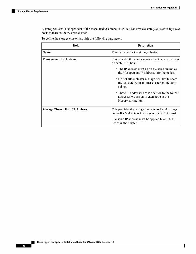
A storage cluster is independent of the associated vCenter cluster. You can create a storage cluster using ESXihosts that are in the vCenter cluster.
To define the storage cluster, provide the following parameters.
DescriptionField
Enter a name for the storage cluster.Name
This provides the storagemanagement network, accesson each ESXi host.
• The IP address must be on the same subnet asthe Management IP addresses for the nodes.
• Do not allow cluster management IPs to sharethe last octet with another cluster on the samesubnet.
• These IP addresses are in addition to the four IPaddresses we assign to each node in theHypervisor section.
Management IP Address
This provides the storage data network and storagecontroller VM network, access on each ESXi host.
The same IP address must be applied to all ESXinodes in the cluster.
Storage Cluster Data IP Address
Cisco HyperFlex Systems Installation Guide for VMware ESXi, Release 3.024
Installation PrerequisitesStorage Cluster Requirements

DescriptionField
Data Replication Factor defines the number ofredundant replicas of your data across the storagecluster.
This is set during HX Data Platform installation andcannot be changed.
Choose a Data Replication Factor. The choices are:
• Data Replication Factor3—Areplication factorof three is highly recommended for allenvironments except HyperFlex Edge. Areplication factor of two has a lower level ofavailability and resiliency. The risk of outagedue to component or node failures should bemitigated by having active and regular backups.
This is the recommended option.Attention
• Data Replication Factor 2—Keep tworedundant replicas of the data. This consumesless storage resources, but reduces your dataprotection in the event of simultaneous node ordisk failure.
If nodes or disks in the storage cluster fail, thecluster's ability to function is affected. If morethan one node fails or one node and disk(s) on adifferent node fail, it is called a simultaneousfailure.
Data Replication Factor
vCenter Configuration RequirementsProvide administrator level account and password for vCenter. Ensure that you have an existing vCenterserver. Ensure that the following vSphere services are operational.
• Enable Dynamic Resource Scheduler (DRS) [Optional, enable if licensed].
• Enable vMotion.
• Enable High availability (HA) [Required to define failover capacity and for expanding the datastoreheartbeat].
• User VMs must be version 9 or later [Required to use HX Data Platform, Native Snapshots, andReadyClones].
DescriptionField
Enter your current vCenter server web address.
For example, http://<IP address>.
vCenter Server
Cisco HyperFlex Systems Installation Guide for VMware ESXi, Release 3.025
Installation PrerequisitesvCenter Configuration Requirements

DescriptionField
Enter <admin username>.User Name
Enter <admin password>.Password
Enter the required name for the vCenter datacenter.Datacenter Name
An existing datacenter object can be used.If the datacenter doesn't exist in vCenter,it will be created.
Note
Enter the required name for the vCenter cluster. Thecluster must contain aminimum of three ESXi servers.
Cluster Name
System Services RequirementsBefore installing Cisco HX Data Platform, ensure that the following network connections and services areoperational.
• DNS server
DNS servers should reside outside of the HX storage cluster. Nested DNS serverscan cause a cluster to not start after entire cluster is shutdown, such as during DCpower loss.
Caution
• NTP server
NTP servers should reside outside of the HX storage cluster. Nested NTP serverscan cause a cluster to not start after entire cluster is shutdown, such as during DCpower loss.
Caution
Cisco HyperFlex Systems Installation Guide for VMware ESXi, Release 3.026
Installation PrerequisitesSystem Services Requirements

• Before configuring the storage cluster, manually verify that the NTP serveris working and providing a reliable source for the time.
• Use the same NTP server for all nodes (both converged and compute) andall storage controller VMs.
• The NTP server must be stable, continuous (for the lifetime of the cluster),and reachable through a static IP address.
• If you are using Active Directory as an NTP server, please make sure thatthe NTP server is setup according to Microsoft best practices. For moreinformation, see Windows Time Service Tools and Settings. Please notethat if the NTP server is not set correctly, time sync may not work, and youmay need to fix the time sync on the client-side. For more information, seeSynchronizing ESXi/ESX time with a Microsoft Domain Controller.
Note
• Time Zone
Essential InformationField
<IP address>
DNS server address is required if you are using hostnames while installing theHyperFlex Data Platform.
Note • If you do not have a DNS server, do not enter a hostname underSystem Services in the Cluster Configuration page of theHX Data Platform Installer. Use only IP addresses.
• To provide more than one DNS servers address, separate theaddress with a comma. Check carefully to ensure that DNSserver addresses are entered correctly.
DNS Server(s)
<IP address>
NTP server is used for clock synchronization between:
• Storage controller VM
• ESXi hosts
• vCenter server
Static IP address for an NTP server is required to ensure clocksynchronization between the storage controller VM, ESXi hosts,and vCenter server.
Important
During installation, this information is propagated to all the storage controllerVMs and corresponding hosts. The servers are automatically synchronized onstorage cluster startup.
NTP Server(s)
(A reliable NTP server isrequired)
Cisco HyperFlex Systems Installation Guide for VMware ESXi, Release 3.027
Installation PrerequisitesSystem Services Requirements

Essential InformationField
<your time zone>
Select a time zone for the storage controller VMs. It is used to determine whento take scheduled snapshots.
All the VMs must be in the same time zone.Note
Time Zone
CPU Resource Reservation for Controller VMsAs the storage controller VMs provide critical functionality for the HyperFlex Data Platform, the HX DataPlatform Installer configures CPU resource reservations for the controller VMs. This reservation guaranteesthat the controller VMs have the minimum required CPU resources. This is useful in situations where thephysical CPU resources of the ESXi hypervisor host are heavily consumed by the guest VMs. The followingtable details the CPU resource reservation for storage controller VMs.
LimitReservationSharesNumber of VM CPUProduct ID
Unlimited10,800 MHzLow12HXAF220c-M5SN(All NVMe 220)
Unlimited10,800 MHzLow16With HX BoostMode enabled:
HXAF220c-M5SN
Unlimited10,800 MHzLow12With HX BoostMode enabled:
HXAF220c-M4/M5
HXAF240c-M4/M5SX
Unlimited10,800 MHzLow8All Other Models
Memory Resource Reservation for Controller VMsThe following table details the memory resource reservations for the storage controller VMs.
Reserve All Guest MemoryAmount of Guest MemoryServer Model
Yes48 GBHX220c-M4/M5
HX-E-220M5SX
Yes48 GBHXAF220C-M4
Yes48 GB
56 GB for configurations with 7.6TB SSDs (SED and non-SED)
HXAF220C-M5
HXAF-E-220M5SX
Cisco HyperFlex Systems Installation Guide for VMware ESXi, Release 3.028
Installation PrerequisitesCPU Resource Reservation for Controller VMs

Reserve All Guest MemoryAmount of Guest MemoryServer Model
Yes72 GBHX240c-M4/M5SX
Yes72 GB
84 GB for configurations with 7.6TB SSDs (SED and non-SED)
HXAF240c-M4/M5SX
Yes78 GBHX240C-M5L
• C240 Rack Server delivers outstanding levels of expandability and performance in a two rack-unit (2RU)form-factor.
• C220 Server delivers expandability in a one rack-unit (1RU) form-factor.
Auto Support RequirementsAuto Support (ASUP) is the alert notification service provided through HXData Platform. If you enable AutoSupport, notifications are sent from HXData Platform to designated email addresses or email aliases that youwant to receive the notifications.
To configure Auto Support, you need the following information:
Auto Support
Check this box during HX storage cluster creation.Enable AutoSupport check box
<IP address>
SMTP mail server must be configured in your network to enable Auto Support. Usedfor handling email sent from all the storage controller VM IP addresses.
Only unauthenticated SMTP is supported for ASUP.Note
Mail Server
Email address to use for sending Auto Support notifications.
Mail Sender
List of email addresses or email aliases to receive Auto Support notifications.ASUP Recipient
Enabling Auto Support is strongly recommended because it provides historical hardware counters that arevaluable in diagnosing future hardware issues, such as drive failure for a node.
Note
Single Sign On RequirementsThe SSO URL is provided by vCenter. If it is not directly reachable from the controller VM, then configurethe location explicitly using Installer Advanced Settings.
Cisco HyperFlex Systems Installation Guide for VMware ESXi, Release 3.029
Installation PrerequisitesAuto Support Requirements

Single Sign On (SSO)
SSO URL can be found in vCenter at vCenter Server > Manage >Advanced Settings, key config.vpxd.sso.sts.uri
SSO Server URL
Cisco HyperFlex Systems Installation Guide for VMware ESXi, Release 3.030
Installation PrerequisitesSingle Sign On Requirements

C H A P T E R 4Install Cisco HyperFlex Systems Servers
This chapter describes how to install the physical components for setting up a HyperFlex cluster:
• Rack Cisco HyperFlex Nodes, on page 31• Setting Up the Fabric Interconnects, on page 32• Connecting HX-Series Servers to Cisco UCS Fabric Interconnects, on page 39• Overview, on page 39
Rack Cisco HyperFlex NodesFor details on the HyperFlex cluster and node limits, see Cisco HX Data Platform Storage ClusterSpecifications in the latest version of the Release Notes for Cisco HX Data Platform.
For UCS C-Series integration guidelines, see the Cisco UCS C-Series Server Integration with Cisco UCSManager Configuration Guide for your release.
For details on the installation of Cisco HyperFlex nodes, refer to respective links from the following table:
ReferenceType of Node To Be Installed
Converged Nodes
Cisco HyperFlex HX220c M4/M5 Node InstallationGuides
HyperFlex HX220c M4/M5 Nodes
Cisco HyperFlex HX240c M4/M5 Node InstallationGuides
HyperFlex HX240c M4/M5 Nodes
Compute-only Nodes
CiscoUCSB200M3/M4/M5Blade Server Installationand Service Note
Cisco UCS B200 M3/M4/M5 Nodes
Cisco UCS B260 M4 and B460 M4 Blade ServerInstallation and Service Note for Servers with E7 v4CPUs
Cisco UCS B260 M4 and B460 M4 Blade ServerInstallation and Service Note for Servers with E7 v3and E7 v2 CPUs
Cisco UCS B260 M4 Nodes, B460 M4 Nodes
Cisco HyperFlex Systems Installation Guide for VMware ESXi, Release 3.031

ReferenceType of Node To Be Installed
Cisco UCS B420 M4 Blade Server Installation andService Note
Cisco UCS B420 M4 Nodes
Cisco UCS B480 M5 Blade Server Installation andService Note
Cisco UCS B480 M5 Nodes
Cisco UCS C240 M3/M4/M5 Server Installation andService Guide
Cisco UCS C240 M3/M4/M5 Rack Nodes
Cisco UCS C220 M3/M4/M5 Server Installation andService Guide
Cisco UCS C220 M3/M4/M5 Rack Nodes
Cisco UCS C480 M5 Server Installation and ServiceGuide
Cisco UCS C480 M5 Nodes
Cisco UCS 460 M4 Server Installation and ServiceGuide
Cisco UCS C460 M4 Nodes
Setting Up the Fabric InterconnectsConfigure a redundant pair of fabric interconnects for high availability as follows:
1. Connect the two fabric interconnects directly using Ethernet cables between the L1 and L2 high availabilityports.
2. Connect Port L1 on fabric interconnect A to port L1 on fabric interconnect B, and Port L2 on fabricinterconnect A to port L2 on fabric interconnect B.
This allows both the fabric interconnects to continuously monitor the status of each other.
Verify and obtain the following information before connecting the fabric interconnects.
DescriptionItem
• Console port for the first fabric interconnect must bephysically connected to a computer or console server.
• Management Ethernet port (mgmt0) must be connectedto an external hub, switch, or router.
• L1 ports on both the fabric interconnects must be directlyconnected to each other.
• L2 ports on both the fabric interconnects must be directlyconnected to each other.
Verify the physical connections of the fabricinterconnects.
Cisco HyperFlex Systems Installation Guide for VMware ESXi, Release 3.032
Install Cisco HyperFlex Systems ServersSetting Up the Fabric Interconnects

DescriptionItem
• 9600 baud
• 8 data bits
• No parity
• 1 stop bit
Verify console port parameters on thecomputer terminal.
Collect the following information for initial setup:
• System name
• Password for admin account
• Three static IP addresses
• Subnet mask for three static IP addresses
• Default gateway IP address
• DNS server IP address
• Domain name for the system
Obtain information for initial setup.
Both fabric interconnects must go through the same setup process. Set up the primary fabric interconnect andenable for cluster configuration. When you use the same process to set up the secondary fabric interconnect,it detects the first fabric interconnect as a peer.
Configuring the Primary Fabric Interconnect Using Cisco UCS Manager GUISpecify the following three IP addresses in the same subnet before you begin the configuration.
• Management Port IP address for the primary fabric interconnect, FI A.
• Management Port IP address for the secondary fabric interconnect, FI B.
• IP address of the HyperFlex Cluster.
Configure the Primary Fabric Interconnect using the Cisco UCS Manager GUI as follows:
Step 1 Connect to the console port. See Cisco 6300 Series Fabric Interconnect Hardware Installation Guide for more details.Step 2 Power on the fabric interconnect. You will see the Power On self-test message as the fabric interconnect boots.Step 3 At the installation method prompt, enter gui.Step 4 If the system cannot access the DHCP server, you will be prompted to enter the following information:
• IPv4 address for the management port on the fabric interconnect.
• IPv4 subnet mask for the management port on the fabric interconnect.
• IPv4 for the default gateway assigned to the fabric interconnect.
All IP addresses must be IPv4. HyperFlex does not support IPv6 addresses.Important
Cisco HyperFlex Systems Installation Guide for VMware ESXi, Release 3.033
Install Cisco HyperFlex Systems ServersConfiguring the Primary Fabric Interconnect Using Cisco UCS Manager GUI

Step 5 Copy the web link from the prompt into a web browser and navigate to the Cisco UCS Manager launch page.Step 6 Select Express Setup.Step 7 Select Initial Setup and click Submit.Step 8 In the Cluster and Fabric Setup area, complete the following fields:
DescriptionName
Select the enable cluster option.Enable Cluster option
Select Fabric A.Fabric Setup option
Enter the IPv4 address that Cisco UCS Manager will use.Cluster IP Address field
Step 9 In the System Setup area, complete the following fields:
DescriptionField
The name assigned to the Cisco UCS domain.System Name field
The password used for the admin account on the fabricinterconnect.
Choose a strong password that meets the guidelines forCisco UCSManager passwords. This password cannot beblank.
Admin Password field
The password used for the admin account on the fabricinterconnect.
Confirm Admin Password field
The static IP address for the management port on the fabricinterconnect.
Mgmt IP Address field
The IP subnet mask for the management port on the fabricinterconnect.
Mgmt IP Netmask field
The IP address for the default gateway assigned to themanagement port on the fabric interconnect.
Default Gateway field
The IP address for the DNS server assigned to themanagement port on the fabric interconnect.
DNS Server IP field
The name of the domain in which the fabric interconnectresides.
Domain name field
Step 10 Click Submit.A page displays the results of your setup operations.
Cisco HyperFlex Systems Installation Guide for VMware ESXi, Release 3.034
Install Cisco HyperFlex Systems ServersConfiguring the Primary Fabric Interconnect Using Cisco UCS Manager GUI

Configuring the Secondary Fabric Interconnect Using Cisco UCS Manager GUIMake sure that the console port of the secondary fabric interconnect is physically connected to a computer ora console server. Ensure that you know the password for the admin account on the primary fabric interconnectthat you configured earlier.
Step 1 Connect to the console port. See Cisco 6300 Series Fabric Interconnect Hardware Installation Guide for more details.Step 2 Power on the fabric interconnect. You will see the Power On self-test message as the fabric interconnect boots.Step 3 At the installation method prompt, enter gui.Step 4 If the system cannot access the DHCP server, you will be prompted to enter the following information:
• IPv4 address for the management port on the fabric interconnect.
• IPv4 subnet mask for the management port on the fabric interconnect.
• IPv4 address for the default gateway assigned to the fabric interconnect.
Both the fabric interconnects must be assigned the same management interface address type during setup.Note
Step 5 Copy the web link from the prompt into a web browser and go to the Cisco UCS Manager GUI launch page.Step 6 Copy the web link from the prompt into a web browser and navigate to the Cisco UCS Manager launch page.Step 7 Select Express Setup.Step 8 Select Initial Setup and click Submit.
The fabric interconnect should detect the configuration information for the first fabric interconnect.
Step 9 In the Cluster and Fabric Setup area, complete the following fields:
DescriptionName
Select the enable cluster option.Enable Cluster option
Select Fabric B.Fabric Setup option
Step 10 In the System Setup area, enter the password for the Admin account into the Admin Password of Master field. TheManager Initial Setup Area is displayed.
Step 11 In the Manager Initial Setup area, the field that is displayed depends on whether you configured the first fabricinterconnect with an IPv4 management address. Complete the field that is appropriate for your configuration as follows:
DescriptionField
Enter an IPv4 address for theMgmt0 interface on the localfabric interconnect.
Peer FI is IPv4 Cluster enabled. Please provide localFI Mgmt0 IPv4 address field
Step 12 Click Submit.A page displays the results of your setup operations.
Cisco HyperFlex Systems Installation Guide for VMware ESXi, Release 3.035
Install Cisco HyperFlex Systems ServersConfiguring the Secondary Fabric Interconnect Using Cisco UCS Manager GUI

Configure the Primary Fabric Interconnect Using CLI
Step 1 Connect to the console port.Step 2 Power on the fabric interconnect.
You will see the power-on self-test messages as the fabric interconnect boots.Step 3 When the unconfigured system boots, it prompts you for the setup method to be used. Enter console to continue the
initial setup using the console CLI.Step 4 Enter setup to continue as an initial system setup.Step 5 Enter y to confirm that you want to continue the initial setup.Step 6 Enter the password for the admin account.Step 7 To confirm, re-enter the password for the admin account.Step 8 Enter yes to continue the initial setup for a cluster configuration.Step 9 Enter the fabric interconnect fabric (either A or B ).Step 10 Enter the system name.Step 11 Enter the IPv4 address for the management port of the fabric interconnect.
You will be prompted to enter an IPv4 subnet mask.
Step 12 Enter the IPv4 subnet mask, then press Enter.
You are prompted for an IPv4 address for the default gateway, depending on the address type you entered for themanagement port of the fabric interconnect.
Step 13 Enter the IPv4 address of the default gateway.Step 14 Enter yes if you want to specify the IP address for the DNS server, or no if you do not.Step 15 (Optional) Enter the IPv4 address for the DNS server.
The address type must be the same as the address type of the management port of the fabric interconnect.
Step 16 Enter yes if you want to specify the default domain name, or no if you do not.Step 17 (Optional) Enter the default domain name.Step 18 Review the setup summary and enter yes to save and apply the settings, or enter no to go through the Setup wizard
again to change some of the settings.
If you choose to go through the Setup wizard again, it provides the values you previously entered, and the values appearin brackets. To accept previously entered values, press Enter.
Example
The following example sets up the first fabric interconnect for a cluster configuration using theconsole and IPv4 management addresses:
Enter the installation method (console/gui)? consoleEnter the setup mode (restore from backup or initial setup) [restore/setup]? setupYou have chosen to setup a new switch. Continue? (y/n): yEnter the password for "admin": adminpassword%958Confirm the password for "admin": adminpassword%958Do you want to create a new cluster on this switch (select 'no' for standalone setup or if
Cisco HyperFlex Systems Installation Guide for VMware ESXi, Release 3.036
Install Cisco HyperFlex Systems ServersConfigure the Primary Fabric Interconnect Using CLI

you want this switch to be added to an existing cluster)? (yes/no) [n]: yesEnter the switch fabric (A/B): AEnter the system name: fooMgmt0 IPv4 address: 192.168.10.10Mgmt0 IPv4 netmask: 255.255.255.0IPv4 address of the default gateway: 192.168.10.1Virtual IPv4 address: 192.168.10.12Configure the DNS Server IPv4 address? (yes/no) [n]: yesDNS IPv4 address: 20.10.20.10
Configure the default domain name? (yes/no) [n]: yesDefault domain name: domainname.com
Join centralized management environment (UCS Central)? (yes/no) [n]: noFollowing configurations will be applied:Switch Fabric=ASystem Name=fooManagement IP Address=192.168.10.10Management IP Netmask=255.255.255.0Default Gateway=192.168.10.1Cluster Enabled=yesVirtual Ip Address=192.168.10.12DNS Server=20.10.20.10Domain Name=domainname.com
Apply and save the configuration (select 'no' if you want to re-enter)? (yes/no): yes
Configure the Subordinate Fabric Interconnect Using CLIThis procedure describes setting up the second fabric interconnect using the IPv4 address for the managementport.
When adding a new Fabric Interconnect to an existing High Availability cluster, for example, during a newinstall or when replacing a Fabric Interconnect, the new device will not be able to log into the cluster as longas the authentication method is set to remote. To successfully add a new Fabric Interconnect to the cluster,the authentication method must be temporarily set to local and the local admin credentials of the primaryFabric Interconnect must be used.
Note
Step 1 Connect to the console port.Step 2 Power up the fabric interconnect.
You will see the power-on self-test messages as the fabric interconnect boots.Step 3 When the unconfigured system boots, it prompts you for the setup method to be used. Enter console to continue the
initial setup using the console CLI.
The fabric interconnect should detect the peer fabric interconnect in the cluster. If it does not, check the physicalconnections between the L1 and L2 ports, and verify that the peer fabric interconnect has been enabled for acluster configuration.
Note
Step 4 Enter y to add the subordinate fabric interconnect to the cluster.Step 5 Enter the admin password of the peer fabric interconnect.Step 6 Enter the IP address for the management port on the subordinate fabric interconnect.Step 7 Review the setup summary and enter yes to save and apply the settings, or enter no to go through the Setup wizard
again to change some of the settings.
Cisco HyperFlex Systems Installation Guide for VMware ESXi, Release 3.037
Install Cisco HyperFlex Systems ServersConfigure the Subordinate Fabric Interconnect Using CLI

If you choose to go through the Setup wizard again, it provides the values you previously entered, and the values appearin brackets. To accept previously entered values, press Enter.
Example
The following example sets up the second fabric interconnect for a cluster configuration using theconsole and the IPv4 address of the peer:Enter the installation method (console/gui)? consoleInstaller has detected the presence of a peer Fabric interconnect. This Fabric interconnectwill be added to the cluster. Continue (y/n) ? yEnter the admin password of the peer Fabric Interconnect: adminpassword%958Peer Fabric interconnect Mgmt0 IPv4 Address: 192.168.10.11Apply and save the configuration (select 'no' if you want to re-enter)? (yes/no): yes
Verify Console SetupYou can verify that both fabric interconnect configurations are complete by logging in to the fabric interconnectthrough SSH.
Use the following commands to verify the cluster status using Cisco UCS Manager CLI.
Table 2:
Sample OutputPurposeCommand
The following example displaysthat both fabric interconnects are inthe Up state, HA is in the Readystate, fabric interconnect A has theprimary role, and fabricinterconnect B has the subordinaterole.UCS-A# show cluster stateCluster Id:0x4432f72a371511de-0xb97c000de1b1ada4
A: UP, PRIMARYB: UP,SUBORDINATE HA READY
Displays the operational state andleadership role for both fabricinterconnects in a high availabilitycluster.
show cluster state
Cisco HyperFlex Systems Installation Guide for VMware ESXi, Release 3.038
Install Cisco HyperFlex Systems ServersVerify Console Setup

Sample OutputPurposeCommand
The following example shows howto view the extended state of acluster.UCSC# show clusterextended-state0x2e95deacbd0f11e2-0x8ff35147e84f3de2Starttime: Thu May 16 06:54:222013Last election time: ThuMay 16 16:29:28 2015SystemManagementViewing the Cluster StateA: UP, PRIMARYB: UP, SUBORDINATE
A: memb state UP, lead statePRIMARY, mgmt services state:UPB: memb state UP, lead stateSUBORDINATE,mgmt services state: UPheartbeat state PRIMARY_OKHA READYDetailed state of the deviceselected for HA quorum data:Device 1007, serial:a66b4c20-8692-11df-bd63-1b72ef3ac801,state: activeDevice 1010, serial:00e3e6d0-8693-11df-9e10-0f4428357744,state: activeDevice 1012, serial:1d8922c8-8693-11df-9133-89fa154e3fa1,state: active
Displays extended details about thecluster state and typically usedwhen troubleshooting issues.
show cluster extended-state
Connecting HX-Series Servers to Cisco UCS FabricInterconnects
OverviewThe Cisco HX220c and HX240c Servers connect directly to the fabric interconnects. The direct connectionenables Cisco UCS Manager to manage the HX-Series servers using a single cable for both managementtraffic and data traffic.
After connecting the server with the fabric interconnect, when the server is discovered, update the C-Seriessoftware bundle available for Cisco UCS Manager using the UCS Manager configuration form.
Note
Cisco HyperFlex Systems Installation Guide for VMware ESXi, Release 3.039
Install Cisco HyperFlex Systems ServersConnecting HX-Series Servers to Cisco UCS Fabric Interconnects

When you use direct connect mode, all Cisco UCS managed adapters must be connected to the server portson the fabric interconnects. Make sure that the HX servers have the recommended firmware as listed in theRequirements Chapter. If not, use Cisco UCS Manager to update the firmware.
Note the following UCS configuration limits:
• Cisco HX-specific UCS configuration limit: HX M4 servers are incompatible with 1227 VIC and6332-16UP fabric interconnects.
• General Cisco UCS configuration limits: see the Cisco UCS 6200, 6332 and 6324 Series ConfigurationLimits for Cisco UCS Manager.
Note
Connecting Converged Nodes to the Fabric InterconnectThis topic describes how to physically add converged nodes for creating a HX cluster or adding to an existingHX cluster.
Before you begin
• Set the CIMC server to factory default settings before integrating with Cisco UCS Manager.
• Do not connect dedicated CIMC ports to the network for integrated nodes. Doing so causes the serverto not be discovered in Cisco UCSManager. If the server is not discovered, reset CIMC to factory settingsfor each server.
• If there is no forseeable future need to connect FC Storage, only use ports 1-16.
• Cisco UCS FI 63xx and 64xx only support configuring ports 1-6 as FC ports. If there is a future need toconnect FC Storage, convert ports 1-6 to FC.
The conversion may disrupt the HX deployment.Note
Important
• Before you connect the CIMC server, make sure a Cisco VIC 1227 is installed in the PCIe slot 2 of anHXc240, or Riser 1 slot 1 for an HXc220 for integration with Cisco UCS Manager. If the card is notinstalled in the correct slot, you cannot enable direct connect management for the server.
• Complete the physical cabling of servers to the fabric interconnects, and configure the ports as serverports.
Step 1 Install the HX server in the rack. See Rack Cisco HyperFlex Nodes, on page 31 for more details.Step 2 Configure the server ports on the fabric interconnect.
a) Connect a 10-Gb SFP+ cable from one port on the server to fabric interconnect A. You can use any port on fabricinterconnect A, but the port must be enabled for server traffic.
Cisco HyperFlex Systems Installation Guide for VMware ESXi, Release 3.040
Install Cisco HyperFlex Systems ServersConnecting Converged Nodes to the Fabric Interconnect

Connect one cable from the VIC to the fabric interconnect for one card. Do not connect both ports to the same fabricinterconnect.
b) Configure that port on FI-A as a server port. For the detailed steps, refer to the Configuring Port Modes for a 6248Fabric Interconnect section of the Cisco UCS Manager Network Management Guide.
c) Connect 10-Gb SFP+ cable from the other port on the server to FI B. You can use any port on FI B, but the port mustbe enabled for server traffic.
Do not mix SFP+ types on an uplink. If you do, you will get Discovery Failed errors.Note
d) Configure that port on FI-B as a server port. For the detailed steps, refer to the Configuring Port Modes for a 6248Fabric Interconnect section of the Cisco UCS Manager Network Management Guide.
Step 3 Attach a power cord to each power supply in your node, and to a grounded AC power outlet. During initial boot up, waitfor approximately two minutes to let the node boot in standby power.
a. When powered up, the server is discovered by the fabric interconnects. You can monitor node discoveryin UCS Manager.
b. Verify the node's power status by looking at the node Power Status LED on the front panel. A node is inthe standby power mode when the LED is amber.
Note
Step 4 Repeat steps one through four to connect the remaining HX-Series servers to the HyperFlex cluster.
Physical Connectivity Illustrations for Direct Connect Mode Cluster SetupThe following images shows a sample of direct connect mode physical connectivity for C-Series Rack-MountServer with Cisco UCS Domain, Cisco UCS Manager, release 3.1 or later. This image shows the cablingconfiguration for Cisco UCS Manager integration with a C-Series Rack-Mount Server. The paths shown ingold carry both management traffic and data traffic.
Figure 9: Direct Connect Cabling Configuration
Cisco HyperFlex Systems Installation Guide for VMware ESXi, Release 3.041
Install Cisco HyperFlex Systems ServersPhysical Connectivity Illustrations for Direct Connect Mode Cluster Setup
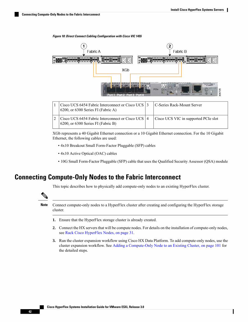
Figure 10: Direct Connect Cabling Configuration with Cisco VIC 1455
C-Series Rack-Mount Server3Cisco UCS 6454 Fabric Interconnect or Cisco UCS6200, or 6300 Series FI (Fabric A)
1
Cisco UCS VIC in supported PCIe slot4Cisco UCS 6454 Fabric Interconnect or Cisco UCS6200, or 6300 Series FI (Fabric B)
2
XGb represents a 40 Gigabit Ethernet connection or a 10 Gigabit Ethernet connection. For the 10 GigabitEthernet, the following cables are used:
• 4x10 Breakout Small Form-Factor Pluggable (SFP) cables
• 4x10 Active Optical (OAC) cables
• 10G Small Form-Factor Pluggable (SFP) cable that uses the Qualified Security Assessor (QSA) module
Connecting Compute-Only Nodes to the Fabric InterconnectThis topic describes how to physically add compute-only nodes to an existing HyperFlex cluster.
Connect compute-only nodes to a HyperFlex cluster after creating and configuring the HyperFlex storagecluster.
Note
1. Ensure that the HyperFlex storage cluster is already created.
2. Connect the HX servers that will be compute nodes. For details on the installation of compute-only nodes,see Rack Cisco HyperFlex Nodes, on page 31.
3. Run the cluster expansion workflow using Cisco HX Data Platform. To add compute-only nodes, use thecluster expansion workflow. See Adding a Compute-Only Node to an Existing Cluster, on page 101 forthe detailed steps.
Cisco HyperFlex Systems Installation Guide for VMware ESXi, Release 3.042
Install Cisco HyperFlex Systems ServersConnecting Compute-Only Nodes to the Fabric Interconnect

C H A P T E R 5Configure Cisco HyperFlex Systems
This chapter describes how to configure the components of the Cisco HyperFlex Systems:
• Installation Workflow, on page 43• Deploy HX Data Platform Installer OVA Using vSphere Web Client, on page 44• Deploy the HX Data Platform Installer OVA with a Static IP Address, on page 46• Configure Syslog , on page 47• Configure and Deploy Your HyperFlex Cluster, on page 48• Installation of HyperFlex Nodes with GPUs, on page 59• HX Data Platform Installer Navigation Aid Buttons, on page 59• Warnings and Error Messages, on page 60
Installation Workflow
If the HyperFlex cluster nodes were part of any other HyperFlex cluster before (or not factory shipped), followthe node cleanup procedure before starting the cluster deployment. For more information , see HyperFlexCustomer Cleanup Guides for FI and Edge.
Note
The following installation workflow summarizes the steps involved in creating a Standard Cluster, using theHX Data Platform Installer.
Follow this workflow during installation:
1. Deploy the HX Data Platform Installer OVA using the vSphere Web Client. If your hypervisor wizarddefaults to DHCP for assigning IP addresses to new VMs, deploy the HX Data Platform Installer OVA
Cisco HyperFlex Systems Installation Guide for VMware ESXi, Release 3.043

with a static IP address. See Deploy HX Data Platform Installer OVA Using vSphere Web Client, on page44 or Deploy the HX Data Platform Installer OVA with a Static IP Address, on page 46 for moreinformation.
2. Configure syslog to send all logging information to a centralized syslog repository. See Configure Syslog, on page 47 for more information.
3. Enter UCS Manager, vCenter, and Hypervisor credentials.
4. Configure server ports and associate HyperFlex servers. See Associate HyperFlex Servers, on page 49formore information.
5. Configure VLAN, MAC Pool, 'hx-ext-mgmt' IPPool for Out-of-Band CIMC, iSCSi Storage, and FCStorage. See Configure UCS Manager, on page 50 for more information.
6. Configure the Hypervisor. See Configure Hypervisor, on page 53 for more information.
7. Configure the IP addresses. See Configure IP Addresses, on page 54 for more information.
8. Configure and deploy the Hyperflex cluster. See Configure Your HyperFlex Cluster, on page 56 for moreinformation.
Deploy HX Data Platform Installer OVA Using vSphere WebClient
In addition to installing the HX Data Platform on an ESXi host, you may also deploy the HX Data PlatformInstaller on either VMware Workstation, VMware Fusion, or Virtual Box.
• Connect to vCenter to deploy the OVA file and provide the IP address properties. Deploying directlyfrom an ESXi host will not allow you to set the values correctly.
• Do not deploy the HX Data Platform Installer to an ESXi server that is going to be a node in the CiscoHX Storage Cluster.
Note
Step 1 Locate and download the HX Data Platform Installer OVA from Download Software. Download the HX Data PlatformInstaller to a node that is on the storage management network, which will be used for the HX Data Platform storagecluster.
Step 2 Deploy the HXData Platform Installer using VMware hypervisor, to create a HXData Platform Installer virtual machine.
Use a version of the virtualization platform that supports virtual hardware version 10.0 or greater.Note
vSphere is a system requirement. You can use either vSphere thick client, vSphere thin client, or vSphere Web Client.To deploy the HX Data Platform Installer, you can also use VMware Workstation, VMware Fusion, or VirtualBox.
a) Open a virtual machine hypervisor, such as vSphere, VirtualBox, Workstation, or Fusion.b) Select the node where you want to deploy the HX Data Platform Installer.
Cisco HyperFlex Systems Installation Guide for VMware ESXi, Release 3.044
Configure Cisco HyperFlex SystemsDeploy HX Data Platform Installer OVA Using vSphere Web Client
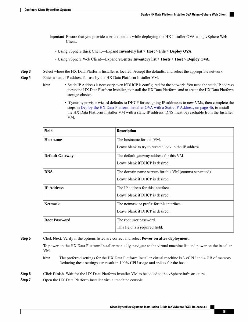
Ensure that you provide user credentials while deploying the HX Installer OVA using vSphere WebClient.
Important
• Using vSphere thick Client—Expand Inventory list > Host > File > Deploy OVA.
• Using vSphere Web Client—Expand vCenter Inventory list > Hosts > Host > Deploy OVA.
Step 3 Select where the HX Data Platform Installer is located. Accept the defaults, and select the appropriate network.Step 4 Enter a static IP address for use by the HX Data Platform Installer VM.
• Static IP Address is necessary even if DHCP is configured for the network. You need the static IP addressto run the HXData Platform Installer, to install the HXData Platform, and to create the HXData Platformstorage cluster.
• If your hypervisor wizard defaults to DHCP for assigning IP addresses to new VMs, then complete thesteps in Deploy the HX Data Platform Installer OVA with a Static IP Address, on page 46, to installthe HX Data Platform Installer VM with a static IP address. DNS must be reachable from the InstallerVM.
Note
DescriptionField
The hostname for this VM.
Leave blank to try to reverse lookup the IP address.
Hostname
The default gateway address for this VM.
Leave blank if DHCP is desired.
Default Gateway
The domain name servers for this VM (comma separated).
Leave blank if DHCP is desired.
DNS
The IP address for this interface.
Leave blank if DHCP is desired.
IP Address
The netmask or prefix for this interface.
Leave blank if DHCP is desired.
Netmask
The root user password.
This field is a required field.
Root Password
Step 5 Click Next. Verify if the options listed are correct and select Power on after deployment.
To power on the HX Data Platform Installer manually, navigate to the virtual machine list and power on the installerVM.
The preferred settings for the HX Data Platform Installer virtual machine is 3 vCPU and 4 GB of memory.Reducing these settings can result in 100% CPU usage and spikes for the host.
Note
Step 6 Click Finish. Wait for the HX Data Platform Installer VM to be added to the vSphere infrastructure.Step 7 Open the HX Data Platform Installer virtual machine console.
Cisco HyperFlex Systems Installation Guide for VMware ESXi, Release 3.045
Configure Cisco HyperFlex SystemsDeploy HX Data Platform Installer OVA Using vSphere Web Client

The initial console display lists the HX Data Platform Installer virtual machine IP address.Data Platform Installer.*******************************************You can start the installation by visitingthe following URL:http://192.168.10.210*******************************************Cisco-HX-Data-Platform-Installer login:
Step 8 Use the URL to log in to the HX Data Platform Installer.Example:http://192.168.10.210
Step 9 Accept the self-signed certificate.Step 10 Log in using the username root and the password you provided as part of the OVA deployment.
Deploy the HX Data Platform Installer OVA with a Static IPAddress
If your hypervisor wizard defaults to DHCP for assigning IP addresses to new VMs, deploy the HX DataPlatform Installer using the following steps:
Step 1 Install the VMware OVF Tool 4.1 or later on a node that is on the storage management network that will be used for theHX Data Platform storage cluster. See OVF Tool Documentation for more details.
Step 2 Locate and download HX Data Platform installer OVA from Download Software on the node where VMware OVF wasinstalled.
Step 3 Deploy the downloaded HX Data Platform installer OVA, using the ovftool command. For example:root@server:/tmp/test_ova# ovftool --noSSLVerify --diskMode=thin--acceptAllEulas=true --powerOn --skipManifestCheck --X:injectOvfEnv--datastore=qa-048-ssd1 --name=rfsi_static_test1 --network='VM Network'--prop:hx.3gateway.Cisco_HX_Installer_Appliance=10.64.8.1--prop:hx.4DNS.Cisco_HX_Installer_Appliance=10.64.1.8--prop:hx.5domain.Cisco_HX_Installer_Appliance=cisco--prop:hx.6NTP.Cisco_HX_Installer_Appliance=10.64.8.5--prop:hx.1ip0.Cisco_HX_Installer_Appliance=10.64.8.36--prop:hx.2netmask0.Cisco_HX_Installer_Appliance=255.255.248.0--prop:hx.7root_password.Cisco_HX_Installer_Appliance=mypassword/opt/ovf/rfsi_test/Cisco-HX-Data-Platform-Installer-v1.7.1-14786.ovavi://root:password@esx_server
The command deploys the HX Data Platform installer, powers on the HX Data Platform installer VM, and configuresthe provided static IP address. A sample of processing response:Opening OVA source:/opt/ovf/rfsi_test/Cisco-HX-Data-Platform-Installer-v1.7.1-14786.ovaOpening VI target: vi://root@esx_server:443/Deploying to VI: vi://root@esx_server:443/Transfer CompletedPowering on VM: rfsi_static_testTask CompletedCompleted successfully
Cisco HyperFlex Systems Installation Guide for VMware ESXi, Release 3.046
Configure Cisco HyperFlex SystemsDeploy the HX Data Platform Installer OVA with a Static IP Address

DNS must be reachable from the Installer VM. The required command options for the static IP address to be configuredsuccessfully are:
DescriptionCommand
To power on the HX Data Platform installer VM after itis deployed.
powerOn
To insert the static IP properties onto the HX DataPlatform installer VM.
X:injectOvfEnv
Specify the appropriate gateway IP address.prop:hx.3gateway.Cisco_HX_Installer_Appliance=10.64.8.1
Specify the appropriate DNS IP address.prop:hx.4DNS.Cisco_HX_Installer_Appliance=10.64.1.8
Specify the appropriate domain.prop:hx.5domain.Cisco_HX_Installer_Appliance=cisco
Specify the appropriate NTP IP address.prop:hx.6NTP.Cisco_HX_Installer_Appliance=10.64.8.5
Specify the appropriate installer static IP address.prop:hx.1ip0.Cisco_HX_Installer_Appliance=10.64.8.36
Specify the appropriate netmask address.prop:hx.2netmask0.Cisco_HX_Installer_Appliance=255.255.248.0
Specify the root user password.prop:hx.7root_password.Cisco_HX_Installer_Appliance=mypassword
The source address of the HX Data Platform installerOVA.
/opt/ovf/rfsi_test/Cisco-HX-Data-Platform-Installer-v1.7.1-14786.ova
The destination ESX server where the HXData Platforminstaller VM is installed. Include the appropriate ESXserver root login credentials.
vi://root:password@esx_server
Configure SyslogIt is best practice to send all logging information to a centralized syslog repository.
In general, configuring audit log export using syslog is recommended if long term retention of audit log isrequired. Specifically for HX220c nodes and compute-only nodes booting from SD card, configuring syslogis required for persistent logging. If you do not configure the syslog server, audit logs are overwritten becauseof the log rotation policy.
Attention
Cisco HyperFlex Systems Installation Guide for VMware ESXi, Release 3.047
Configure Cisco HyperFlex SystemsConfigure Syslog

You can not select an NFS datastore as a destination for the persistent scratch location on ESXi. If you selectthe HX datastore for the persistent scratch location, it will be removed after the ESXi host reloads.
For all M5 servers, M.2 boot SSD is automatically selected for use as scratch. This is configured out of thebox on any new install.
For HX240M4 (non-SED), Intel SSD is used for persistent logs/scratch (same applies on 220M5/240M5, buton a different local SSD).
For HX220M4 and HX240M4 (SED), there is no location to store the scratch partition. So, the only optionis to use syslog for persistent logging over the network.
Note
Step 1 Verify that the syslog server is up and running and TCP/UDP ports are open to receive logs from ESXi servers.Step 2 SSH to the ESXi shell and execute the following commands.
a) esxcli system syslog config set --loghost='udp://remote-syslog-server-ip'b) esxcli system syslog reloadc) esxcli network firewall ruleset set -r syslog -e trued) esxcli network firewall refresh
Step 3 Repeat steps 1 and 2 for all ESXi hosts in the cluster.Step 4 At the remote syslog server, verify if the logs are being received in the designated directory.
Configure and Deploy Your HyperFlex Cluster
Common Task Steps used In HyperFlex GUI
SUMMARY STEPS
1. Log in to the HX Data Platform Installer with root user credentials. For first time log in, you will beprompted to change the default password set in the factory.
2. In the Change factory default password screen, complete the following fields, and click ChangePassword & Login.
DETAILED STEPS
Step 1 Log in to the HX Data Platform Installer with root user credentials. For first time log in, you will be prompted to changethe default password set in the factory.a) In a browser, enter the URL for the VM where HX Data Platform Installer was installed.b) Enter the following login credentials.
• Username: root
• Password: Cisco123
Cisco HyperFlex Systems Installation Guide for VMware ESXi, Release 3.048
Configure Cisco HyperFlex SystemsConfigure and Deploy Your HyperFlex Cluster

c) Read the EULA, select the I accept the terms and conditions checkbox, and click Login.
Step 2 In the Change factory default password screen, complete the following fields, and click Change Password & Login.
DescriptionField
Enter a new hypervisor password.New password
Re-enter the new hypervisor password.Re-enter new password
Associate HyperFlex ServersOn the Server Selection page, the Configuration pane on the right displays a detailed list of the Credentialsused. The Server Selection page displays a list of unassociated HX servers under the Unassociated tab, andthe list of discovered servers under the Associated tab.
DescriptionField
Turn on to locate a server.Locator LED
Name assigned to the server.Server Name
• Inaccessible—Status
Displays the server model.Model
Displays the serial number of the server.Serial
• Associated
• Unassociated
Assoc State
Service profile assigned to the server.
Editing the HyperFlex Service Profiletemplates is not recommended.
Note
Service Profile [Only for Associated Servers]
• Launch KVM Console—Choose this option tolaunch the KVM Console directly from the HXData Platform Installer.
• Disassociate Server—Choose this option toremove a service profile from that server.
Actions
Before you begin
Ensure that you completed entering UCS Manager, vCenter, and Hypervisor credentials.
Cisco HyperFlex Systems Installation Guide for VMware ESXi, Release 3.049
Configure Cisco HyperFlex SystemsAssociate HyperFlex Servers

Step 1 Click the Configure Server Ports button to discover any new HX nodes. In the Configure Server Ports dialog box,list all ports to be configured as server ports. Click Configure.
Typically, the server ports are configured in Cisco UCS Manager before you start the configuration.Note
Step 2 Select the servers under the Unassociated tab to include in the HyperFlex cluster.
If HX servers do not appear in this list, check Cisco UCS Manager and ensure that they have been discovered.
If there are no unassociated servers, the following error message is displayed:No unassociated servers found. Login to UCS Manager and ensure server ports are enabled.
Note
Step 3 Click Continue to configure UCS Manager. See Configure UCS Manager, on page 50.
Configure UCS ManagerOn the UCSM Configuration page, you can configure VLAN, MAC Pool, 'hx-ext-mgmt' IP Pool for CIMC,iSCSi Storage, and FC Storage.
Before you begin
Associate servers to the HyperFlex cluster. See Associate HyperFlex Servers, on page 49.
Step 1 In the VLAN Configuration section, complete the following fields:
Use separate subnet and VLANs for each of the following networks.Note
DescriptionField
VLAN for Hypervisor and HyperFlex management
hx-inband-mgmtVLAN Name
Default—3091VLAN ID
VLAN for HyperFlex storage traffic
hx-storage-dataVLAN Name
Default—3092VLAN ID
VLAN for VM vMotion
hx-vmotionVLAN Name
Default—3093VLAN ID
VLAN for VM Network
vm-networkVLAN Name
Cisco HyperFlex Systems Installation Guide for VMware ESXi, Release 3.050
Configure Cisco HyperFlex SystemsConfigure UCS Manager

DescriptionField
Default—3094
A comma-separated list of guest VLANs.
VLAN ID(s)
Step 2 In the MAC Pool section, configure MAC Pool Prefix by adding in two more hex characters (0-F).
Select a prefix that is not used with any other MAC address pool across all UCS domains.Note
Example:00:25:B5:A0:
Step 3 In the 'hx-ext-mgmt' IP Pool for CIMC section, complete the following fields:
DescriptionField
The range of management IP addresses assigned to theCIMC for each HyperFlex server. The IP addresses arespecified as a range, and multiple blocks of IPs may bespecified as a comma-separated list. Ensure you have atleast one unique IP per server in the cluster. When selectingto use out-of-band, this range must fall into the same IPsubnet used on the mgmt0 interfaces on the FabricInterconnects.
For example, 10.193.211.124-127, 10.193.211.158-163.
IP Blocks
Specify the subnet mask for the IP range provided above.
For example, 255.255.0.0.
Subnet Mask
Enter the Gateway IP address.
For example, 10.193.0.1.
Gateway
The management IP addresses used to access the CIMC on a server can be either:
• Out of band: The CIMC management traffic traverses the Fabric Interconnect through the limited bandwidthmanagement interface, mgmt0, on the Fabric Interconnect. This option is most commonly used and shares the sameVLAN as the Fabric Interconnect management VLAN.
• In-band: The CIMC management traffic traverses the Fabric Interconnect through the uplink ports of the FabricInterconnect. The bandwidth available for management traffic in this case would be equivalent to the FabricInterconnect uplink bandwidth. If you are using the In-band option, the Cisco HyperFlex installer will create adedicated VLAN for the CIMCmanagement communication. This option is useful when large files such as aWindowsServer installation ISO must be mounted to the CIMC for OS installation. This option is only available in theHyperFlex installer VM and is not available for deployments through Intersight.
Step 4 Select either Out of band or In-band based on the type of connection you want to use for CIMC management access.If you select In-band, provide the VLAN ID for the management VLAN. Make sure to create the CIMC managementVLAN in the upstream switch for seamless connectivity.
Step 5 If you want to add external storage, configure iSCSI Storage by completing the following fields:
Cisco HyperFlex Systems Installation Guide for VMware ESXi, Release 3.051
Configure Cisco HyperFlex SystemsConfigure UCS Manager

DescriptionField
Select to configure iSCSI storage.Enable iSCSI Storage check box
Name of the VLAN associated with the iSCSI vNIC, onthe primary Fabric Interconnect (FI-A).
VLAN A Name
ID of the VLAN associated with the iSCSI vNIC, on theprimary Fabric Interconnect (FI-A).
VLAN A ID
Name of the VLAN associated with the iSCSI vNIC, onthe subordinate Fabric Interconnect (FI-B).
VLAN B Name
ID of the VLAN associated with the iSCSI vNIC, on thesubordinate Fabric Interconnect (FI-A).
VLAN B ID
Step 6 If you want to add external storage, configure FC Storage by completing the following fields:
DescriptionField
Select to enable FC Storage.Enable FC Storage check box
AWWNpool that contains bothWWnode names andWWport names. For each Fabric Interconnect, a WWxN poolis created for WWPN and WWNN.
WWxN Pool
The name of the VSAN for the primary Fabric Interconnect(FI-A).
Default—hx-ext-storage-fc-a.
VSAN A Name
The unique identifier assigned to the network for theprimary Fabric Interconnect (FI-A).
Do not enter VSAN IDs that are currently usedon the UCS or HyperFlex system. If you enteran existing VSAN ID in the installer whichutilizes UCS zoning, zoning will be disabled inyour existing environment for that VSAN ID.
Caution
VSAN A ID
The name of the VSAN for the subordinate FabricInterconnect (FI-B).
Default—hx-ext-storage-fc-b.
VSAN B Name
The unique identifier assigned to the network for thesubordinate Fabric Interconnect (FI-B).
Do not enter VSAN IDs that are currently usedon the UCS or HyperFlex system. If you enteran existing VSAN ID in the installer whichutilizes UCS zoning, zoning will be disabled inyour existing environment for that VSAN ID.
Caution
VSAN B ID
Cisco HyperFlex Systems Installation Guide for VMware ESXi, Release 3.052
Configure Cisco HyperFlex SystemsConfigure UCS Manager

Step 7 In the Advanced section, do the following:
DescriptionField
Select the UCS firmware version to associate with the HXservers from the drop-down list. The UCS firmware versionmust match the UCSM version. See the latest Cisco HXData Platform Release Notes for more details.
For example, 3.2(1d).
UCS Server Firmware Version
Specify a user-defined name. The HyperFlex cluster nameis applied to a group of HX Servers in a given cluster. TheHyperFlex cluster name adds a label to service profiles foreasier identification.
HyperFlex Cluster Name
Specify a unique Org Name to ensure isolation of theHyperFlex environment from the rest of the UCS domain.
Org Name
Step 8 Click Continue to configure the Hypervisor. See Configure Hypervisor, on page 53.
Configure Hypervisor
Review the VLAN, MAC pool, and IP address pool information on the Hypervisor Configuration page, inthe Configuration pane. These VLAN IDs may be changed by your environment. By default, the HX DataPlatform Installer sets the VLANs as non-native. You must configure the upstream switches to accommodatethe non-native VLANs by appropriately applying a trunk configuration.
Note
You can skip configuring Hypervisor in case of a reinstall, if ESXi networking has been completed.Attention
Before you begin
Configure VLAN, MAC Pool, and 'hx-ext-mgmt' IP Pool for Out-of-Band CIMC. If you are adding externalstorage, configure iSCSI Storage and FC Storage. Select the UCS Server Firmware Version and assign a namefor the HyperFlex cluster. See Configure UCS Manager, on page 50.
Step 1 In the Configure Common Hypervisor Settings section, complete the following fields:
DescriptionField
Set the subnet mask to the appropriate level to limit andcontrol IP addresses.
For example, 255.255.0.0.
Subnet Mask
Cisco HyperFlex Systems Installation Guide for VMware ESXi, Release 3.053
Configure Cisco HyperFlex SystemsConfigure Hypervisor

DescriptionField
IP address of gateway.
For example, 10.193.0.1.
Gateway
IP address for the DNS Server.
Note • If you do not have a DNS server, do notenter a hostname in any of the fields on theCluster Configuration page of the HXData Platform Installer. Use only static IPaddresses and hostnames for all ESXi hosts.
• If you are providing more than one DNSserver, check carefully to ensure that bothDNS servers are correctly entered, separatedby a comma.
DNS Server(s)
Step 2 On the Hypervisor Settings section, select Make IP Addresses and Hostnames Sequential to make the IP addressessequential. Complete the following fields:
You can rearrange the servers using drag and drop.Note
DescriptionField
Name assigned to the server.Name
Turn on to locate a server.Locator LED
Displays the serial number of the server.Serial
Input static IP addresses and hostnames for all ESXi hosts.Static IP Address
Do not leave the hostname fields empty.Hostname
Step 3 Click Continue to configure IP Addresses. See Configure IP Addresses, on page 54.
Configure IP Addresses
Before you begin
Ensure that you completed configuring Hypervisor on the Hypervisor Configuration page. See ConfigureHypervisor, on page 53.
Step 1 On the IP Addresses page, select Make IP Addresses Sequential to make the IP Addresses sequential.Step 2 When you enter IP addresses in the first row for Hypervisor, Storage Controller (Management) and Hypervisor, Storage
Controller (Data) columns, the HXData Platform Installer incrementally autofills the node information for the remaining
Cisco HyperFlex Systems Installation Guide for VMware ESXi, Release 3.054
Configure Cisco HyperFlex SystemsConfigure IP Addresses

nodes. The minimum number of nodes in the storage cluster is three. If you have more nodes, use the Add button toprovide the address information.
Compute-only nodes can be added only after the storage cluster is created.Note
For each HX node, enter the Hypervisor, Storage Controller, Management, and Data IP addresses. For the IP addresses,specify if the network belongs to the Data Network or the Management Network.
DescriptionField
Enter the static IP address that handles the Hypervisormanagement network connection between the ESXi hostand the storage cluster.
Management Hypervisor
Enter the static IP address that handles the storage controllerVM management network connection between the storagecontroller VM and the storage cluster.
Management Storage Controller
Enter the static IP address that handles the Hypervisor datanetwork connection between the ESXi host and the storagecluster.
Data Hypervisor
Enter the static IP address that handles the storage controllerVM data network connection between the storage controllerVM and the storage cluster.
Data Storage Controller
Step 3 The IP address provided here are applied to one node in the storage cluster. In the event the node becomes unavailablethe affected IP address is moved to another node in the storage cluster. All nodes must have a port configured to acceptthese IP addresses.
Provide the following IP addresses:
DescriptionField
Enter the management network IP address for the HX DataPlatform storage cluster.
Management Cluster Data IP Address
Enter the IP address of data network for the HX DataPlatform storage cluster.
Data Cluster Data IP Address
Enter the subnet information for your VLAN and vSwitches.
Provide the management network value. For example,255.255.255.0.
Management Subnet Mask
Provide the network value for the data network. Forexample, 255.255.255.0.
Data Subnet Mask
Provide the network value for your management network.For example, 10.193.0.1.
Management Gateway
Provide the network value for your data network. Forexample, 10.193.0.1.
Data Gateway
Cisco HyperFlex Systems Installation Guide for VMware ESXi, Release 3.055
Configure Cisco HyperFlex SystemsConfigure IP Addresses

Step 4 Click Continue to configure the HyperFlex cluster. See Configure Your HyperFlex Cluster, on page 56.
Configure Your HyperFlex ClusterOn theCluster Configuration page, for the Cisco HX Storage Cluster complete the following fields to begindeploying the HyperFlex cluster.
Before you begin
Ensure that you completed configuring IP addresses on the IP Addresses page. See Configure IP Addresses,on page 54.
Step 1 In the Cisco HX Cluster section, complete the following fields:
DescriptionField
Specify a name for the HX Data Platform storage cluster.Cluster Name
Specify the number of redundant replicas of your data acrossthe storage cluster. Set the replication factor to either 2 or3 redundant replicas.
• For hybrid servers (servers that contain SSD andHDDs), the default value is 3.
• For flash servers (servers that contain only SSDs),select either 2 or 3.
• A replication factor of three is highly recommendedfor all environments except HyperFlex Edge. Areplication factor of two has a lower level ofavailability and resiliency. The risk of outage due tocomponent or node failures should be mitigated byhaving active and regular backups.
Replication Factor
Step 2 In the Controller VM section, create a new password for the Administrative User of the HyperFlex cluster.
A default administrator username and password is applied to the controller VMs. The VMs are installed on all convergedand compute-only nodes.
• You cannot change the name of the controller VM or the controller VM’s datastore.
• Use the same password for all controller VMs. The use of different passwords is not supported.
• Provide a complex password that includes 1 uppercase character, 1 lowercase character, 1 digit, 1 specialcharacter, and a minimum of 10 characters in total.
• You can provide a user-defined password for the controller VMs and for the HX cluster to be created. Forpassword character and format limitations, see the section on Guidelines for HX Data Platform SpecialCharacters in the Cisco HX Data Platform Management Guide.
Important
Cisco HyperFlex Systems Installation Guide for VMware ESXi, Release 3.056
Configure Cisco HyperFlex SystemsConfigure Your HyperFlex Cluster

Step 3 In the vCenter Configuration section, complete the following fields:
DescriptionField
Enter the vCenter datacenter name for the Cisco HyperFlexcluster.
vCenter Datacenter Name
Enter the vCenter cluster name.vCenter Cluster Name
Step 4 In the System Services section, complete the following fields:
A comma-separated list of IP addresses of each DNS server.DNS Server(s)
A comma-separated list of IP addresses of each NTP server.
All hosts must use the same NTP server, forclock synchronization between services runningon the storage controller VMs and ESXi hosts.
Note
NTP Server(s)
DNS FQDN or IP address.DNS Domain Name
The local time zone for the controller VM, to determinewhen to take scheduled snapshots. Scheduled nativesnapshot actions are based on this setting.
Time Zone
Step 5 In theConnected Services section, selectEnable Connected Services to enable Auto Support and IntersightManagement.
DescriptionField
Enables Auto Support and Intersight management. Log onto HX Connect to configure these services or selectivelyturn them On or Off.
Enable Connected Services (Recommended)
Email address where SR notifications are sent whentriggered by Auto Support.
Send service ticket notifications to
Step 6 In the Advanced Configuration section, do the following:
DescriptionField
Check to set the MTU size for the storage data network onthe host vSwitches and vNICs, and each storage controllerVM.
The default value is 9000.
To set yourMTU size to a value other than 9000,contact Cisco TAC.
Note
Jumbo frames
Enable Jumbo Frames
Cisco HyperFlex Systems Installation Guide for VMware ESXi, Release 3.057
Configure Cisco HyperFlex SystemsConfigure Your HyperFlex Cluster

DescriptionField
Check to remove all existing data and partitions from allnodes added to the storage cluster for manually preparedservers. Select this option to delete existing data andpartitions. You must backup any data that should beretained.
Do not select this option for factory preparedsystems. The disk partitions on factory preparedsystems are properly configured.
Attention
Disk Partitions
Clean up Disk Partitions
Check for VDI only environments.
To change the VDI settings after the storagecluster is created, shut down or move theresources, make the changes (described in thesteps below), then restart the cluster.
Note
The HyperFlex cluster by default is configured to beperformance tuned for VSI workloads.
You may change this performance customization byperforming the following steps on your HyperFlex DataPlatform cluster. To change the HyperFlex cluster fromVDI to VSI workloads (and vice versa):
WARNING: Amaintenance window is required as this willcause data to be unavailable while the cluster is offline.
a. Shut down the cluster (stcli cluster shutdown).
b. Edit the storfs.cfg in all the controller VMs to modifythe workloadType to Vsi or Vdi.
c. Start the cluster (stcli cluster start) to enable thetune changes after the cluster is created.
Virtual Desktop (VDI)
This information is only required if the SSO URL is notreachable.
Do not use this field. It is used for legacydeployments.
You can locate the SSO URL in vCenter bynavigating to vCenter Server > Manage >Advanced Settings > keyconfig.vpxd.sso.sts.uri.
Note
(Optional) vCenter Single-Sign-On Server
Step 7 Click Start to begin deploying the HyperFlex cluster. The Progress page displays the progress of various configurationtasks.
Cisco HyperFlex Systems Installation Guide for VMware ESXi, Release 3.058
Configure Cisco HyperFlex SystemsConfigure Your HyperFlex Cluster

Do not skip validation warnings.
See the Warnings section for more details.
Caution
What to do next
• Some validation errors require you to go back and re-enter a parameter (for example, an invalid ESXipassword, incorrect NTP server, bad SSO server, or other incorrect input). Click Re-enter Values toreturn to the Cluster Configuration page and resolve the issue.
• When complete, the HyperFlex servers are installed and configured. The deployed cluster status showsas Online and Healthy.
• Click Launch HyperFlex Connect to create datastores and manage your cluster.
Installation of HyperFlex Nodes with GPUsA specific BIOS policy change is required when installing HyperFlex nodes with GPUs. All supported GPUcards require enablement of BIOS setting that allows greater than 4 GB of Memory Mapped I/O (MMIO).For more information, see Requirement for All Supported GPUs.
Installing GPU After the HyperFlex Cluster Is Created
If the GPUs are installed after a cluster is created, then the service profile associated with the servers must bemodified to have the BIOS policy setting enabled.
Enable the BIOS Setting as detailed in Cisco UCS Manager Controlled Server. Set Memory Mapped I/Oabove 4 GB config to Enabled as specified in step 3.
Installing GPU Before the HyperFlex Cluster Is Created
If the GPU card is installed before the cluster is created, then during cluster creation, select the Advancedworkflow.
1. On the HXData Platform Installer page, select I know what I’m doing, let me customize my workflow.
2. Check Run UCS Manager Configuration and click Continue.
This creates the necessary service profiles for the HyperFlex nodes.
3. Enable the BIOS Setting as detailed in Cisco UCS Manager Controlled Server. Set Memory Mapped I/Oabove 4 GB config to Enabled as specified in step 3.
4. Go back to the Advanced workflow on the HX Data Platform Installer page to continue with Run ESXConfiguration, Deploy HX Software, and Create HX Cluster to complete cluster creation.
HX Data Platform Installer Navigation Aid Buttons• Export Configuration—Click the down arrow icon to download a JSON configuration file.
Cisco HyperFlex Systems Installation Guide for VMware ESXi, Release 3.059
Configure Cisco HyperFlex SystemsInstallation of HyperFlex Nodes with GPUs

• Workflow Info—Hover over the information icon to view the current workflow. For HyperFlex clustercreation, the workflow info is Create Workflow = Esx.
• Tech Support—Click the question mark icon to view details related to the HyperFlex Data Platformsoftware version. Click Create New Bundle to create a Tech Support Bundle for Cisco TAC.
• Save Changes—Click the circle icon to save changes made to the HyperFlex cluster configurationparameters.
• Settings—Click the gear icon to Start Over or Log Out.
Warnings and Error Messages• UCSM configuration and Hypervisor configuration succeeded, but deployment or cluster creationfails—Click Settings Icon > Start Over. Select I know what I'm doing, let me customize my workflowto start the cluster configuration from the point where the failure occurred.
• IP Address screen shows as blank when you go back to re-enter values—Add the IP addresses manually.Click Add Server for the number of servers in your cluster and re-input all of the IP addresses on thispage.
• Server reachability issues are seen observed when DNS is not properly configured on the Installer VM(SSO Error)—Edit the SSO field manually and either substitute IP address in place of FQDN ortroubleshoot and remediate the DNS configuration.
• Ensure that a matching Cisco UCSManager version to Cisco HyperFlex version is selected when creatinganother cluster—If a matching version is not selected, manually enter the correct version.
For the current compatibility matrix, refer to the Software Versions table in the latest Release Notes forCisco HX Data Platform.
Cisco HyperFlex Systems Installation Guide for VMware ESXi, Release 3.060
Configure Cisco HyperFlex SystemsWarnings and Error Messages

C H A P T E R 6Configure Licensing with HyperFlex DataPlatform
• Smart Licensing and HyperFlex, on page 61• License Management for Connected Environments, on page 64
Smart Licensing and HyperFlexOverview
Cisco Smart Software Licensing (Smart Licensing) is an intelligent software license management system thatautomates time-consuming, manual licensing tasks, such as procuring, deploying, and managing licensesacross your entire organization. It provides visibility into your license ownership and consumption so youknow what you own and how you are using it.
Smart Licensing introduces company-wide license pooling. Server-based licenses, or smart licenses, are notnode-locked to devices so they can be used on any compatible device owned by your company. Using virtualaccounts to organize licenses and product instances for your company into logical entities, for example, bybusiness unit, product type, or IT group, makes it easy to transfer devices and licenses across virtual accounts.
The Smart Licensing feature integrates with Cisco HyperFlex and is automatically enabled as soon as youcreate an HX storage cluster. For your HX storage cluster to start reporting license consumption, you mustregister it with Cisco Smart Software Manager (SSM) through your Cisco Smart Account. A Smart Accountis a cloud-based repository that provides full visibility and access control to Cisco software licenses andproduct instances across your company. Registration is valid for one year.
Registration enables HyperFlex to be identified to a Smart Account and allows license usage to be reportedto Cisco Smart Software Manager or Smart Software Manager satellite. After registration, HyperFlex reportslicense usage to Cisco Smart Software Manager or Smart Software Manager satellite with the current licensestatus. See the following License Status section for details.
You will need to open ports 80 and 443 to tools.cisco.com for all HyperFlex management IPs in orderfor this to work.
Note
Cisco HyperFlex Systems Installation Guide for VMware ESXi, Release 3.061

After you register your HX storage cluster, communicationmessages are signed by a certificate used to identifyHyperFlex to Cisco Smart Software Manager or Smart Software Manager satellite. HyperFlex automaticallysends the following requests:
• A renew registration request every six months. In case the automatic registration renewal does not occur,use the stcli license renew id command to manually renew.
• A renew authorization request every 30 days is required by Smart Licensing. In case the automaticauthorization renewal does not occur, use the stcli license renew auth command to manually renew.You need to manually renew Smart Licensing authorization only if connectivity is not available whenrenewal is attempted or your renewal time is outside of your connectivity window.
• A renew authorization request is also sent to Cisco Smart Software Manager or Smart Software Managersatellite whenever license consumption changes. This authorization is valid for 90 days. If HyperFlexdoesn't contact Cisco Smart Software Manager or Smart Software Manager satellite for 90 days to renewits authorization, licenses consumed by HyperFlex are reclaimed and put back in the pool.
License Status
System FunctionalityVerify StatusDescriptionRegistrationStatus
No impact on features orfunctionality.
To verify the status orcheck the remaining timeleft in the evaluationperiod, run #stcli
license show all.Result:Mode = Eval &Remainingperiod(Number ofDays:Hours:Minutes)
Smart Licensing is enabled butyour HX storage cluster is notregistered to Cisco Smart SoftwareManager or Smart SoftwareManager satellite and in a 90-dayevaluation period.
EvaluationMode
No impact on features orfunctionality.
• Generates syslogmessage.
• Generates anEvaluation Expiredalarm in the HXConnect UI.
To verify the status, run#stcli license show
all.Result:Mode = EvaluationExpired
Smart Licensing is enabled butyour HX storage cluster is notregistered to Cisco Smart SoftwareManager or Smart SoftwareManager satellite. Your license isin the Initial Unidentified state andnot considered out of compliance.
EvaluationExpired
——Smart Licensing is enabled andyour HX storage cluster isregistered to Cisco Smart SoftwareManager or Smart SoftwareManager satellite. You areconsuming less licenses than youown.
In Compliance
Cisco HyperFlex Systems Installation Guide for VMware ESXi, Release 3.062
Configure Licensing with HyperFlex Data PlatformSmart Licensing and HyperFlex

System FunctionalityVerify StatusDescriptionRegistrationStatus
No impact on features orfunctionality.
• Generates syslogmessage.
• Generates an Out ofCompliance alarm inthe HX Connect UIat cluster level.
The Out ofCompliance statebreaches theintellectualproperty EULAand the licensemust bepurchased/renewedin order tocontinue receivingsupport.
Note
To verify the status, run#stcli license show
all.Result:Mode = Out ofCompliance
You are consuming more licensesthan you own.
Cisco will neverinterfere with orshutdown a customernetwork when a deviceis out of compliance.
Important
• Out of Compliance at InitialRegistration state—SmartLicensing is enabled and yourHX storage cluster isregistered to Cisco SmartSoftware Manager or SmartSoftware Manager Satellitebut after initial registrationyou do not have enoughlicenses.
• Out of Compliance afterInitial state or after beingin-compliance for someperiod— Smart Licensing isenabled and your HX storagecluster is registered to CiscoSmart Software Manager orSmart Software ManagerSatellite but you no longerhave enough licenses.
Out ofCompliance
No impact on features orfunctionality.
• Generates syslogmessage.
• No event or alarm onHX Connect.
• Cisco SmartSoftware Managerportal displays flagsand notifications.
To verify the status, run#stcli license show
status.Result:Mode = AuthorizationExpired
Smart Licensing is enabled andyour HX storage cluster isregistered to Cisco Smart SoftwareManager or Smart SoftwareManager satellite but has notcommunicated to Cisco SmartSoftware Manager or SmartSoftware Manager satellite formore than 90 days.
AuthorizationExpired
Cisco HyperFlex Systems Installation Guide for VMware ESXi, Release 3.063
Configure Licensing with HyperFlex Data PlatformSmart Licensing and HyperFlex

System FunctionalityVerify StatusDescriptionRegistrationStatus
Behavior is mostlycontrolled by the CiscoSmart Software Managerserver.
This status isapplicable onlyif the HXstorage clustercontainsrestrictedfunctionality.
Note
—Smart Licensing is enabled andyour HX storage cluster isregistered to Cisco Smart SoftwareManager or Smart SoftwareManager satellite but cannotregister to use Export Control.
Export ControlFlag Set to "NotAllowed"
• Generates syslogmessage.
• No event or alarm onHX Connect.
• Cisco SmartSoftware Managerportal displays flagsand notifications.
To verify the status, run#stcli license show
status.Result:Mode: ID CertificateExpired
To clear all conditions andreturn to In Compliancestatus, run the followingcommand:#stcli license renew<auth>/<id>
Smart Licensing is enabled andyour HX storage cluster isregistered to Cisco Smart SoftwareManager or Smart SoftwareManager satellite but your IDcertificate has not renewed formore than six months. Your licenseis in the Subsequent Unidentifiedstate and is considered out ofcompliance.
ID CertificateExpired
License Management for Connected EnvironmentsTo manage your licenses for connected environments, proceed as follows:
Registering a Cluster with Smart Software Licensing through a Controller VMThis section covers the alternate method for registering a cluster with Smart Software Licensing.
Step 1 Log in to a controller VM.Step 2 Confirm that your HX storage cluster is in Smart Licensing mode.
# stcli license show status
Feedback should show Smart Licensing is ENABLED, Status: UNREGISTERED, and the amount of time left duringthe 90-day evaluation period (in days, hours, minutes, and seconds). The Smart Licensing evaluation period starts whenthe HX storage cluster begins using the licensing feature and is not renewable. When the evaluation period expires, theSmart Agent sends a notification.
Step 3 Register your HX storage cluster, where idtoken-string is the New ID Token from Cisco Smart Software Manager orSmart Software Manager satellite.
Cisco HyperFlex Systems Installation Guide for VMware ESXi, Release 3.064
Configure Licensing with HyperFlex Data PlatformLicense Management for Connected Environments

# stcli license register --idtoken idtoken-string
Step 4 Confirm that your HX storage cluster is registered.# stcli license show summary
Alternatively, you can confirm that your HX storage cluster is registered inCisco Smart Software Manager > Inventory >Product Instances.
Example:root@SpringpathController8OIW1HJOKW:~# stcli license show summary
Smart Licensing is ENABLED
Registration:Status: REGISTEREDSmart Account: Corp X HyperFlex LicenseVirtual Account: west-regionLast Renewal Attempt: NoneNext Renewal Attempt: Aug 1 17:47:06 2017 PDT
License Authorization:Status: AUTHORIZEDLast Communication Attempt: SUCCEEDEDNext Communication Attempt: Mar 4 16:47:11 2017 PST
License Usage:License Entitlement Tag
Count Status
------------------------------------------------------------------------------------------------------------------------------
Cisco Vendor String XYZregid.2016-11.com.cisco.HX-SP-DP-S001,1.0_1c06ca12-18f2-47bd-bcea-518ab1fd4520 3 InCompliance
Deregistering a Cluster from Smart LicensingYou deregister an HX storage cluster when you want to release the licenses back into the pool to be used byanother HX storage cluster or to remove Cisco Smart SoftwareManager registration; for example, if you wantto decommission a cluster. After the HX storage cluster is deregistered, HyperFlex runs in evaluation mode,if any evaluation period remains. If not, HyperFlex is in evaluation expired status. Deregistering a cluster thatis in an expired evaluation state, does not impact the cluster production data.
The Smart Agent contacts the licensing cloud and unregisters itself. All Smart Licensing entitlements andcertificates on the platform are removed. All certificates and registration information on the trusted store areremoved. The Smart Agent can unregister even if it is unable to communicate with Cisco to deregister. If youneed to use Smart Licensing again, reregister your HX storage cluster. See Registering a Cluster with SmartSoftware Licensing through a Controller VM, on page 64.
Before you begin
• Verify that your HX storage cluster is registered with Smart Licensing using the following command:# stcli license show status
Cisco HyperFlex Systems Installation Guide for VMware ESXi, Release 3.065
Configure Licensing with HyperFlex Data PlatformDeregistering a Cluster from Smart Licensing

Step 1 Log in to a controller VM.Step 2 Deregister your HX storage cluster from Smart Licensing.
# stcli license deregister
Step 3 Confirm that your HX storage cluster is deregistered.# stcli license show summary
Renewing Smart Licensing Authorization
Before you begin
• Verify that your HX storage cluster is registered with Smart Licensing using the following command:# stcli license show status
Step 1 Log in to a controller VM.Step 2 Renew the Smart Licensing authorization using the following commands:
# stcli license renew id
# stcli license renew auth
Step 3 Confirm that the HX storage cluster is renewed and authorized.# stcli license show summary
Cisco HyperFlex Systems Installation Guide for VMware ESXi, Release 3.066
Configure Licensing with HyperFlex Data PlatformRenewing Smart Licensing Authorization

C H A P T E R 7Post Cluster Configuration Tasks
• Post Cluster Configuration Guidelines, on page 67• Enabling PCI Passthrough for a Network Device on a Host, on page 67• Run Post-Installation Script, on page 68• Changing ESXi Host Root Password, on page 69• Changing Storage Controller Password, on page 70• Access the HX Data Platform Plugin through vSphere, on page 71• Add Datastores in the Storage Cluster, on page 71• Set HA Heartbeat, on page 72• Auto Support and Smart Call Home for HyperFlex, on page 72• Replication Pairing, on page 77• Adding Private VLAN, on page 78• Distributed Virtual Switches and Cisco Nexus 1000v, on page 81• Hosting vCenter on the HX Data Platform, on page 83• Deploying AMD GPUs, on page 83
Post Cluster Configuration Guidelines
• Keep SSH enabled on all ESXi hosts. This is required for the following Cisco HyperFlex post clusterconfiguration operations.
• Do not change these pre-configured values without approval from Cisco.
Important
Enabling PCI Passthrough for a Network Device on a HostPassthrough devices provide the means to more efficiently use resources and improve performance in yourenvironment. Enabling PCI passthrough allows a VM to use a host device as if the device were directlyattached to the VM.
The following procedure describes how to configure a network device (such as NVIDIA GPUs) for PCIpassthrough on an ESXi host.
Cisco HyperFlex Systems Installation Guide for VMware ESXi, Release 3.067

Step 1 In vSphere Client, browse to the ESXi host in the Navigator panel.Step 2 Enter HX maintenance mode on the node that has the GPUs installed. To enter maintenance mode, right click on the
node > Cisco HX Maintenance Mode > Enter HX Maintenance Mode
Step 3 In a new browser window, login directly to the ESXi node.Step 4 Click Manage.Step 5 Under the Hardware tab, click PCI Devices. A list of available passthrough devices appears.Step 6 Select PCI device you want to enable for passthrough. Click Toggle passthrough.Step 7 Reboot the host to make the PCI device available for use.Step 8 When the reboot completes, ensure that the node is not in maintenance mode.Step 9 Log in to vCenter Server.Step 10 Locate the VM, right click and select elect Edit Settings.Step 11 From the New device drop-down, select PCI Device, and click Add.Step 12 Click the passthrough device to use (example: NVIDIA GPU) and click OK.Step 13 Log in to the ESXi host and open the virtual machine configuration file (.vmx) in a text editor.
cd /vmfs/volumes/[datastore_name]/[vm_name]vi [vmname].vmx
Step 14 Add the following lines, save, and exit the text editor.
# pciPassthru.64bitMMIOSizeGB = "64"# Firmware = "efi"# pciPassthru.use64bitMMIO = "TRUE"
Run Post-Installation ScriptTo complete the post-installation tasks, you can run the post-installation script.
• Ensure that you run hx_post_install and confirm network operation immediately following the deploymentof the HyperFlex System.
Important
1. Use an SSH client to connect to cluster virtual IP using admin login.
2. Type hx_post_install and hit Enter.
3. Set the post-install script parameters as specified in the following table:
If you run into any post-install script issues, set the post-install script parameters manually.Note
Cisco HyperFlex Systems Installation Guide for VMware ESXi, Release 3.068
Post Cluster Configuration TasksRun Post-Installation Script

DescriptionParameter
Enables vSphere High Availability (HA) featureper best practice.
Enable HA/DRS on cluster?
Suppresses the SSH and shell warnings in thevCenter.
Disable SSH warning?
Configure vMotion interfaces per best practice.Requires IP address and VLAN ID input.
Add vMotion interfaces
Add additional guest VLANs to Cisco UCSManager and within ESXi on all cluster hosts.
Add VM network VLANs
4. Correct network errors reported, if any.
Sample Post-Install Script: Option 1. New/Existing Cluster
Sample Post-Install Script: Option 3. Generate Certificate
Sample Network Errors
Host: esx-hx-5.cpoc-rtp.cisco.comNo errors found
Host: esx-hx-6.cpoc-rtp.clsco.comNo errors found
Host: esx-hx-l.cpoc-rtp.cisco.comNo errors found
Host: esx-hx-2.cpoc-rtp.cisco.comNo errors found
controller VM clocks:stctlVM-FCH1946V34Y - 2016-09-16 22:34:04stCtlVM-FCH1946V23M - 2016-09-16 22:34:04stctIVM-FCH1951V2TT - 2016-09-16 22:34:04stctlVM-FCH2004VINS - 2016-09-16 22:34:04
Cluster:Version - 1.8.1a-19499Model - HX220C-M4SHealth - HEALTHYAccess policy - LENIENTASUP enabled - FalseSMTP server - smtp.cisco.com
Changing ESXi Host Root PasswordYou can change the default ESXi password for the following scenarios:
• During creation of a standard and stretch cluster (supports only converged nodes)
• During expansion of a standard cluster (supports both converged or compute node expansion)
Cisco HyperFlex Systems Installation Guide for VMware ESXi, Release 3.069
Post Cluster Configuration TasksChanging ESXi Host Root Password

• During Edge cluster creation
In the above cases, the ESXi root password is secured as soon as installation is complete. In the event asubsequent password change is required, the procedure outlined below may be used after installation tomanually change the root password.
Note
As the ESXi comes up with the factory default password, you should change the password for security reasons.To change the default ESXi root password post-installation, do the following.
If you have forgotten the ESXi root password, for password recovery please contact Cisco TAC.Note
Step 1 Log in to the ESXi host service control using SSH.Step 2 Acquire root privileges.
su -
Step 3 Enter the current root password.Step 4 Change the root password.
passwd root
Step 5 Enter the new password, and press Enter. Enter the password a second time for confirmation.
If the password entered the second time does not match, you must start over.Note
Changing Storage Controller PasswordTo reset the HyperFlex storage controller password post-installation, do the following.
Step 1 Log in to a storage controller VM.Step 2 Change the Cisco HyperFlex storage controller password.
# stcli security password set
This command applies the change to all the controller VMs in the storage cluster.
If you add new compute nodes and try to reset the cluster password using the stcli security passwordset command, the converged nodes get updated, but the compute nodes may still have the default password.To change the compute node password, use the following procedure.
Note
To change the password on compute nodes:
a. Vmotion all the user VMs off the ESXi hosts.
Cisco HyperFlex Systems Installation Guide for VMware ESXi, Release 3.070
Post Cluster Configuration TasksChanging Storage Controller Password

b. Launch the storage controller VM console from vCenter and log in as the root user.
c. Run the passwd command to change the password.
d. Log out and re-login to confirm that the password changed successfully.
e. Run the stcli node add -f command to add the node back into the cluster.
Step 3 Type in the new password.Step 4 Press Enter.
Access the HX Data Platform Plugin through vSphereTo manage your storage cluster through a GUI, launch the vSphere Web Client. You access your storagecluster through the vSphere Web Client and HX Data Platform plug-in.
Step 1 From the HX Data Platform installer, after installation is completed, on the Summary page, click Launch vSphere WebClient.
Step 2 Display the login page, click Login to vSphere Web Client and enter your vSphere credentials.Step 3 View the HX Data Platform plug-in.
From the vSphere Web Client Navigator, select vCenter Inventory Lists > Cisco HyperFlex Systems > Cisco HXData Platform.
Add Datastores in the Storage ClusterA new HyperFlex cluster has no default datastores configured for virtual machine storage, so the datastoresmust be created using VMware vSphere Web Client.
A minimum of two datastores is recommended for high availability.Note
Step 1 From the vSphere Web Client Navigator, Global Inventory Lists expand Cisco HyperFlex Systems > Cisco HX DataPlatform > cluster > Manage > Datastores.
Step 2 Click the Create Datastore icon.Step 3 Enter a Name for the datastore. The vSphere Web Client enforces a 42 character limit for the datastore name. Assign
each datastore a unique name.Step 4 Specify the Size for the datastore. Choose GB or TB from the drop-down list. Click OK.Step 5 Click the Refresh button to display your new datastore.
Cisco HyperFlex Systems Installation Guide for VMware ESXi, Release 3.071
Post Cluster Configuration TasksAccess the HX Data Platform Plugin through vSphere

Step 6 Click the Hosts tab to see the Mount Status of the new datastore.
Set HA HeartbeatUnder the vSphere HA settings, ensure that you set the Datastore for Heartbeating option to allow selectingany datastore from the list of available datastores.
Step 1 Login to vSphere.Step 2 Verify DRS is enabled.
From vSphere Home > Hosts and Clusters > cluster > ConfigureServices. Click vSphere DRS.
Step 3 Select the Edit button. Click vSphere HA. Click Edit.Step 4 Select Turn on vSphere HA if it is not selected.Step 5 Expand Admission Control > Define Failover capacity by > Cluster resource percentage from the drop-down menu.
You may use the default value or enable Override calculated failover capacity and enter a percentage.Step 6 ExpandHeartbeat Datastores and selectUse datastore only from the specified list. Select which datastores to include.Step 7 Click OK.
Auto Support and Smart Call Home for HyperFlexYou can configure the HX storage cluster to send automated email notifications regarding documented events.You can use the data collected in the notifications to help troubleshoot issues in your HX storage cluster.
Auto Support (ASUP) and Smart Call Home (SCH) support the use of a proxy server. You can enable the useof a proxy server and configure proxy settings for both using HX Connect.
Note
Auto Support (ASUP)
Auto Support is the alert notification service provided through HXData Platform. If you enable Auto Support,notifications are sent from HX Data Platform to designated email addresses or email aliases that you want toreceive the notifications. Typically, Auto Support is configured during HX storage cluster creation byconfiguring the SMTP mail server and adding email recipients.
Only unauthenticated SMTP is supported for ASUP.Note
If the Enable Auto Support check box was not selected during configuration, Auto Support can be enabledpost-cluster creation using the following methods:
Cisco HyperFlex Systems Installation Guide for VMware ESXi, Release 3.072
Post Cluster Configuration TasksSet HA Heartbeat

Associated TopicPost-Cluster ASUP Configuration Method
Configuring Auto Support Using HX Connect, onpage 73
HX Connect user interface
Configuring Notification Settings Using CLI, on page74
Command Line Interface (CLI)
Cisco HyperFlex Support REST APIs on CiscoDevNet.
REST APIs
Auto Support can also be used to connect your HX storage cluster to monitoring tools.
Smart Call Home (SCH)
Smart Call Home is an automated support capability that monitors your HX storage clusters and then flagsissues and initiates resolution before your business operations are affected. This results in higher networkavailability and increased operational efficiency.
Call Home is a product feature embedded in the operating system of Cisco devices that detects and notifiesthe user of a variety of fault conditions and critical system events. Smart Call Home adds automation andconvenience features to enhance basic Call Home functionality. After Smart Call Home is enabled, Call Homemessages/alerts are sent to Smart Call Home.
Smart Call Home is included with many Cisco service contracts and includes:
• Automated, around-the-clock device monitoring, proactive diagnostics, real-time email alerts, serviceticket notifications, and remediation recommendations.
• Proactivemessaging sent to your designated contacts by capturing and processing Call Home diagnosticsand inventory alarms. These email messages contain links to the Smart Call Home portal and the TACcase if one was automatically created.
• Expedited support from the Cisco Technical Assistance Center (TAC). With Smart Call Home, if an alertis critical enough, a TAC case is automatically generated and routed to the appropriate support teamthrough https, with debug and other CLI output attached.
• Customized status reports and performance analysis.
• Web-based access to: all Call Home messages, diagnostics, and recommendations for remediation in oneplace; TAC case status; and up-to-date inventory and configuration information for all Call Home devices.
To ensure automatic communication among your HX storage cluster, you, and Support, see Configuring SmartCall Home for Data Collection, on page 75.
Configuring Auto Support Using HX ConnectTypically, Auto Support (ASUP) is configured during HX storage cluster creation. If it was not, you canenable it post cluster creation using the HX Connect user interface.
Step 1 Log in to HX Connect.Step 2 In the banner, click Edit settings (gear icon) > Auto Support Settings and fill in the following fields.
Cisco HyperFlex Systems Installation Guide for VMware ESXi, Release 3.073
Post Cluster Configuration TasksConfiguring Auto Support Using HX Connect

Essential InformationUI Element
Configures Call home for this HX storage cluster by enabling:
• Data delivery to Cisco TAC for analysis.
• Notifications from Support as part of proactive support.
Enable Auto Support (Recommended)check box
Enter the email address that you want to receive the notifications.Send service ticket notifications to field
End user usage agreement. The check box must be checked to use theAuto-Support feature.
Terms and Conditions check box
• Web Proxy Server url
• Port
• Username
• Password
Use Proxy Server check box
Step 3 Click OK.Step 4 In the banner, click Edit settings (gear icon) > Notifications Settings and fill in the following fields.
Essential InformationUI Element
If checked, fill in the following fields:
• Mail Server Address
• From Address—Enter the email address used to identify your HX storagecluster in Support service tickets, and as the sender for Auto Supportnotifications. Support information is currently not sent to this email address.
• Recipient List (Comma separated)
Send email notifications for alarmscheck box
Step 5 Click OK.
Configuring Notification Settings Using CLIUse the following procedure to configure and verify that you are set up to receive alarm notifications fromyour HX storage cluster.
Only unauthenticated SMTP is supported for ASUP.Note
Step 1 Log in to a storage controller VM in your HX storage cluster using ssh.Step 2 Configure the SMTP mail server, then verify the configuration.
Cisco HyperFlex Systems Installation Guide for VMware ESXi, Release 3.074
Post Cluster Configuration TasksConfiguring Notification Settings Using CLI

Email address used by the SMTP mail server to send email notifications to designated recipients.
Syntax: stcli services smtp set [-h] --smtp SMTPSERVER --fromaddress FROMADDRESS
Example:# stcli services smtp set --smtp mailhost.eng.mycompany.com --fromaddress [email protected]# stcli services smtp show
Step 3 Enable ASUP notifications.# stcli services asup enable
Step 4 Add recipient email addresses, then verify the configuration.
List of email addresses or email aliases to receive email notifications. Separate multiple emails with a space.
Syntax: stcli services asup recipients add --recipients RECIPIENTS
Example:# stcli services asup recipients add --recipients [email protected] [email protected]# stcli services asup show
Step 5 From the controller VM that owns the eth1:0 IP address for the HX storage cluster, send a test ASUP notification to youremail.# sendasup -t
To determine the node that owns the eth1:0 IP address, log in to each storage controller VM in your HX storage clusterusing ssh and run the ifconfig command. Running the sendasup command from any other node does not return anyoutput and tests are not received by recipients.
Step 6 Configure your email server to allow email to be sent from the IP address of all the storage controller VMs.
Configuring Smart Call Home for Data CollectionData collection is enabled by default but, you can opt-out (disable) during installation. You can also enabledata collection post cluster creation. During an upgrade, Smart Call Home enablement is determined by yourlegacy configuration. For example, if stcli services asup show as enabled, Smart Call Home is enabledon upgrade.
Data collection about your HX storage cluster is forwarded to Cisco TAC through https. If you have a firewallinstalled, configuring a proxy server for Smart Call Home is completed after cluster creation.
Smart Call Home does not support the use of a proxy server in deployments where outgoing connections froman HX cluster require to go through a proxy server.
Note
In HyperFlex Data Platform release 2.5(1.a), Smart Call Home Service Request (SR) generation does not usea proxy server.
Note
Using Smart Call Home requires the following:
Cisco HyperFlex Systems Installation Guide for VMware ESXi, Release 3.075
Post Cluster Configuration TasksConfiguring Smart Call Home for Data Collection

• A Cisco.com ID associated with a corresponding Cisco Unified Computing Support Service or CiscoUnified Computing Mission Critical Support Service contract for your company.
• Cisco Unified Computing Support Service or Cisco Unified ComputingMission Critical Support Servicefor the device to be registered.
Step 1 Log in to a storage controller VM in your HX storage cluster.Step 2 Register your HX storage cluster with Support.
Registering your HX storage cluster adds identification to the collected data and automatically enables Smart Call Home.To register your HX storage cluster, you need to specify an email address. After registration, this email address receivessupport notifications whenever there is an issue and a TAC service request is generated.
Syntax:stcli services sch set [-h] --email EMAILADDRESS
Example:# stcli services sch set --email [email protected]
Step 3 Verify data flow from your HX storage cluster to Support is operational.
Operational data flow ensures that pertinent information is readily available to help Support troubleshoot any issues thatmight arise.
--all option runs the commands on all the nodes in the HX cluster.# asupcli [--all] ping
Contact Support if you receive the following error:root@ucs-stctlvm-554-1:/tmp# asupcli post --type alert/bin/sh: 1: ansible: not foundFailed to post - not enough arguments for format stringroot@ucs-stctlvm-554-1:/tmp#
Step 4 (Optional) Configure a proxy server to enable Smart Call Home access through port 443.
If your HX storage cluster is behind a firewall, after cluster creation, you must configure the Smart Call Home proxyserver. Support collects data at the url: https://diag.hyperflex.io:443 endpoint.
a. Clear any existing registration email and proxy settings.# stcli services sch clear
b. Set the proxy and registration email.
Syntax:
stcli services sch set [-h] --email EMAILADDRESS [--proxy-url PROXYURL] [--proxy-port PROXYPORT][--proxy-user PROXYUSER] [--portal-url PORTALURL] [--enable-proxy ENABLEPROXY]
Syntax Description DescriptionRequired or OptionalOption
Add an email address for someone to receive emailfrom Cisco support. Recommendation is to use adistribution list or alias.
Required.--email EMAILADDRESS
Cisco HyperFlex Systems Installation Guide for VMware ESXi, Release 3.076
Post Cluster Configuration TasksConfiguring Smart Call Home for Data Collection

DescriptionRequired or OptionalOption
Explicitly enable or disable use of proxy.Optional.--enable-proxyENABLEPROXY
Specify an alternative Smart Call Home portal URL, ifapplicable.
Optional.--portal-url PORTALURL
Specify the HTTP or HTTPS proxyURL, if applicable.Optional.--proxy-url PROXYURL
Specify the HTTP or HTTPS proxy port, if applicable.Optional.--proxy-port PROXYPORT
Specify the HTTP or HTTPS proxy user, if applicable.
Specify the HTTP or HTTPS proxy password, whenprompted.
Optional.--proxy-user PROXYUSER
Example:# stcli services sch set--email [email protected] www.company.com--proxy-port 443--proxy-user admin--proxy-password adminpassword
c. Ping to verify the proxy server is working and data can flow from your HX storage cluster to the Support location.# asupcli [--all] ping
--all option runs the command on all the nodes in the HX cluster.
Step 5 Verify Smart Call Home is enabled.
When Smart Call Home configuration is set, it is automatically enabled.# stcli services sch show
Step 6 Enable Auto Support (ASUP) notifications.
Typically, Auto Support (ASUP) is configured during HX storage cluster creation. If it was not, you can enable it postcluster creation using HX Connect or CLI.
If Smart Call Home is disabled, enable it manually.# stcli services sch enable
Replication PairingCreating a replication cluster pair is a pre-requisite for setting up VMs for replication. The replication networkand at least one datastore must be configured prior to creating the replication pair.
By pairing cluster 1 with cluster 2, you are specifying that all VMs on cluster 1 that are explicitly set up forreplication can replicate to cluster 2, and that all VMs on cluster 2 that are explicitly set up for replication canreplicate to cluster 1.
Cisco HyperFlex Systems Installation Guide for VMware ESXi, Release 3.077
Post Cluster Configuration TasksReplication Pairing

By pairing a datastore A on cluster 1 with a datastore B on cluster 2, you are specifying that for any VM oncluster 1 that is set up for replication, if it has files in datastore A, those files will be replicated to datastore Bon cluster 2. Similarly, for any VM on cluster 2 that is set up for replication, if it has files in datastore B, thosefiles will be replicated to datastore A on cluster 1.
Pairing is strictly 1-to-1. A cluster can be paired with no more than one other cluster. A datastore on a pairedcluster, can be paired with no more than one datastore on the other cluster.
For the detailed procedure on creating, editing, and deleting replication pairs, see the Cisco HyperFlex SystemsAdministration Guide.
Adding Private VLAN
About Private VLANsA private VLAN partitions the Layer 2 broadcast domain of a VLAN into subdomains, allowing you to isolatethe ports on the switch from each other. A subdomain consists of a primary VLAN and one or more secondaryVLANs. A private VLAN domain has only one primary VLAN. Each port in a private VLAN domain is amember of the primary VLAN, and the primary VLAN is the entire private VLAN domain.
Understanding Private VLAN Ports
Table 3: Types of Private VLAN Ports
DescriptionVLAN Port
Belongs to the primary VLAN. Can communicate with all interfaces thatbelong to those secondary VLANs that are associated to the promiscuousport and associated with the primary VLAN. Those interfaces include thecommunity and isolated host ports. All packets from the secondary VLANsgo through this VLAN.
Promiscuous Primary VLAN
Host port that belongs to an isolated secondary VLAN. This port hascomplete isolation from other ports within the same private VLAN domain,except that it can communicate with associated promiscuous ports.
Isolated Secondary VLAN
Host port that belongs to a community secondary VLAN. Community portscommunicate with other ports in the same community VLAN and withassociated promiscuous ports.
Community Secondary VLAN
Following HX deployment, a VM network uses a regular VLAN by default. To use a Private VLAN for theVM network, see the following sections:
• Configuring a Private VLAN on a VM Network without Existing VMs, on page 79.
• Configuring a Private VLAN on a VM Network with Existing VMs, on page 79.
Cisco HyperFlex Systems Installation Guide for VMware ESXi, Release 3.078
Post Cluster Configuration TasksAdding Private VLAN

Configuring a Private VLAN on a VM Network without Existing VMs
Step 1 To configure a private VLAN on Cisco UCS Manager, see the Cisco UCS Manager Network Management Guide.Step 2 To configure a private VLAN on the upstream switch, see the Cisco Nexus 9000 Series NX-OS Layer 2 Switching
Configuration Guide.Step 3 To configure a private VLAN on ESX hosts, see Configuring Private VLAN on ESX Hosts, on page 79.
Configuring Private VLAN on ESX HostsTo configure private VLANs on the ESX hosts do the following:
Step 1 Delete VMNICs on the vSphere Standard Switches from the VMware vSphere Client.Step 2 Create new vSphere Distributed Switch with the VMNICs deleted from the previous step.Step 3 Create promiscuous, isolated, and community VLAN.
Configuring a Private VLAN on a VM Network with Existing VMs
Step 1 To configure a private VLAN on Cisco UCS Manager, see the Cisco UCS Manager Network Management Guide.Step 2 To configure a private VLAN on the upstream switch, see the Cisco Nexus 9000 Series NX-OS Layer 2 Switching
Configuration Guide.Step 3 To configure a private VLAN on ESX hosts, see Configuring Private VLAN on ESX Hosts, on page 79Step 4 Migrate VMs from vSphere standard switch to the newly created vSphere distributed switch.
a) Right-click the vCenter Virtual Machine and click Migrate Virtual Machine Networking.b) Choose source network and destination network from the drop-down list.c) Click Next.d) Select the Virtual Machines that you want to migrate.e) Click Finish.
Step 5 Change network connection of the network adapter on the VMs to private VLAN.a) Right-click the vCenter Virtual Machine and click Edit Settings.b) Under the Hardware tab, select the network adapter you want to modify.c) Select the Network Connection you want to use from the Network Label drop-down list.d) Click OK.
Deleting VMNICs on the vSphere Standard Switch
Step 1 Log on to VMware vSphere Client.Step 2 Select Home > Hosts and Clusters.
Cisco HyperFlex Systems Installation Guide for VMware ESXi, Release 3.079
Post Cluster Configuration TasksConfiguring a Private VLAN on a VM Network without Existing VMs

Step 3 Select the ESX host from which you want to delete the VMNIC.Step 4 Open the Configuration tab.Step 5 Click Networking.Step 6 Select the switch you wish to remove a VMNIC from.Step 7 Click the Manage the physical adapters connected to the selected switch button.Step 8 Select the vminc you want to delete and click Remove.Step 9 Confirm your selection by clicking Yes.Step 10 Click Close.
Creating vSphere Distributed Switch
Step 1 Log on to the VMware vSphere Client.Step 2 Select Home > Networking.Step 3 Right click on the cluster Distributed Switch > New Distributed Switch.Step 4 In the Name and Location dialog box, enter a name for the distributed switch.Step 5 In the Select Version dialog box, select the distributed switch version that correlates to your version and configuration
requirements.Step 6 Click Next.Step 7 In the Edit Settings dialog box, specify the following:
• Number of uplink ports
• Enable Network I/O Control.
• Create a default port group should be checked.
• Enter the default port group name in the Port Group Name box.
Step 8 Click Next.Step 9 Review the settings in the Ready to complete dialog box.Step 10 Click Finish.
Creating Private VLANs on vSphere Distributed Switch
Step 1 From the VMware vSphere Client, select Inventory > Networking.Step 2 Right-click on the dvSwitch.Step 3 Click Edit Settings.Step 4 Select the Private VLAN tab.Step 5 On the Primary private VLAN ID tab, enter a private VLAN ID.
Step 6 On the Secondary private VLAN ID tab, enter a private VLAN ID.Step 7 Select the type of VLAN from the Type drop-down list. Valid values include:
Cisco HyperFlex Systems Installation Guide for VMware ESXi, Release 3.080
Post Cluster Configuration TasksCreating vSphere Distributed Switch

• Isolated
• Community
• Promiscuous (Default)
Step 8 Click OK.
Set Private VLAN in Distributed Port Group
Before you begin
Create Private VLAN on the vSphere Distribute Switch.
Step 1 Right click dvPortGroup under dvSwitch, and click Edit Settings.Step 2 Click Policies > VLAN.Step 3 Select Private VLAN, from the VLAN type drop-down list.Step 4 From the Private VLAN Entry drop-down list, select the type of private VLAN. It can be one of the following:
• Isolated
• Community
Community private VLAN is recommended.
Promiscuous ports are not supported
Note
Step 5 Click OK.
Distributed Virtual Switches and Cisco Nexus 1000vConsiderations when Deploying Distributed Switches
Cisco HyperFlex Systems Installation Guide for VMware ESXi, Release 3.081
Post Cluster Configuration TasksSet Private VLAN in Distributed Port Group

• Using Distributed Virtual Switches (DVS) or Cisco Nexus 1000v (NK1v) is an optional and not a requiredstep.
• DVS for your vMotion network is available only if your environment has Enterprise Plus License forvSphere.
• You can use only one of the two switches at a given time.
• There may be a potential conflict between the Quality of Service (QoS) policy for HyperFlex and Nexus1000v. Make sure that the QoS classes for N1Kv are set as per the HyperFlex policy. See Creating aQoS Policy, in the Network and Storage Management Guide.
• If you choose to deploy N1Kv switch, apply the settings as described, so that the traffic between theHyperFlex hosts flows locally on the FIs in a steady state. If not configured accurately, it could lead toa situation where most traffic will go through the upstream switches leading to latency. In order to avoidthat scenario, ensure that the Storage Controller, Management Network, and vMotion port groups areconfigured with active/standby and failover enabled.
1. Set the link status for theNetwork Control Policy using UCSManager. For details, see the "ConfiguringNetwork Control Policy" section in the Cisco UCS Manager GUI Configuration Guide.
2. Set the vSwitch properties in vCenter.
a. Set the Network Failure Detection to Link Status only.
b. Set Failback to Yes. For details, see the "Configuring the VM-FEX for VMware" section in the CiscoUCS Manager VM-FEX for VMware Configuration guide
Note
Distributed switches ensure that each node is using the same configuration. It helps prioritize traffic and allowsother network streams to utilize available bandwidth when no vMotion traffic is active.
The HyperFlex (HX) Data Platform can use Distributed Virtual Switch (DVS) Networks for non-HyperFlexdependent networks.
These non-HX dependent networks include:
• VMware vMotion networks
• VMware applications networks
The HX Data Platform has dependency that the following networks use standard vSwitches.
• vswitch-hx-inband-mgmt: Storage Controller Management Network
• vswitch-hx-inband-mgmt: Management Network
• vswitch-hx-storage-data: Storage Hypervisor Data Network
• vswitch-hx-storage-data: Storage Controller Data Network
During HX Data Platform installation, all the networks are configured with standard vSwitch networks. Afterthe storage cluster is configured, the non-HX dependent networks can be migrated to DVS networks. Forexample:
• vswitch-hx-vm-network: VM Network
Cisco HyperFlex Systems Installation Guide for VMware ESXi, Release 3.082
Post Cluster Configuration TasksDistributed Virtual Switches and Cisco Nexus 1000v

• vmotion: vmotion pg
For further details on how to migrate the vMotion Network to Distributed Virtual Switches, please see theMigrating vMotion Networks to Distributed Virtual Switches (DVS) or Cisco Nexus 1000v (N1Kv) in theNetwork and Storage Management Guide.
Hosting vCenter on the HX Data PlatformDeployment of vCenter on the HyperFlex cluster is supported with some constraints. See the How to DeployvCenter on the HX Data Platform TechNote for more details.
Deploying AMD GPUsAMD FirePro S7150 series GPUs are supported in HX240c M5 nodes. These graphic accelerators enablehighly secure, high performance, and cost-effective VDI deployments. Follow the steps below to deploy AMDGPUs in HyperFlex.
Step InstructionsActionStep
Requirement For All Supported GPUs:Memory-Mapped I/O Greater than 4 GB
For the service profiles attached to the servers modifythe BIOS policy.
1
GPU Card InstallationInstall the GPU card in the servers.2
—Power on the servers, and ensure that the GPUs arevisible in the Cisco UCS Manager inventory for theservers.
3
Download the inventory list from CiscoSoftware Downloads that includes thelatest driver ISO for C-series standalonefirmware / software version bundle 3.1(3)for AMD on VMware ESXi .
Install the vSphere Installation Bundle (VIB) for theAMD GPU card and reboot.
4
Specifying Eligible Virtual MachinesCreate a Win10 VM on the cluster with the VMconfiguration.
5
Using the MxGPU Setup ScriptOn each ESXi hosts run the MxGPU.sh script toconfigure the GPUs and to create virtual functionsfrom the GPU.
6
—Assign the virtual functions (VFs) created in theprevious step to the Win10 VMs.
7
Cisco HyperFlex Systems Installation Guide for VMware ESXi, Release 3.083
Post Cluster Configuration TasksHosting vCenter on the HX Data Platform

Cisco HyperFlex Systems Installation Guide for VMware ESXi, Release 3.084
Post Cluster Configuration TasksDeploying AMD GPUs

C H A P T E R 8Setting Up Multiple HX Clusters
• Setting Up Multiple Clusters, on page 85
Setting Up Multiple ClustersMultiple HyperFlex clusters may coexist under the same UCS domain (pair of fabric interconnects). Thefollowing guidelines should be followed to ensure smooth ongoing operations for all equipment connectedto the domain.
Having HX clusters with two different HX versions on the same UCSM domain is a supported configurationas long as the UCSM infrastructure release supports the needed server firmware bundles. HXDP versions aremapped to UCSM server firmware bundles per the release notes. The version of UCSM infrastructure isindependent.
Note
Recommendations
• The number of Compute-only nodes must be less than or equal to the number of converged nodes whenusing the standard HXDP license. The enterprise HXDP licenses allows a maximum 2:1 ratio of computeto converged nodes.
• To create a newHyperFlex cluster, ensure that all the requirements listed in Chapter 2 are met. In addition,follow the process as outlined in Chapter 4.
• Use the HX Data Platform Installer for the deployment.
• All nodes in an HX cluster should reference the same policies and service profiles.
Editing the HyperFlex Service Profile templates is not recommended.Note
• Assign a unique name for each HX cluster.
• Each HX cluster will be created in a unique sub-org as part of installation. Do not modify this hierarchyas it ensures unique policies are created per cluster.
• Each cluster should use a unique storage data VLAN to keep all storage traffic isolated. Reuse of thisVLAN across multiple clusters is highly discouraged.
Cisco HyperFlex Systems Installation Guide for VMware ESXi, Release 3.085

• When reusing VLANs (e.g. management and guest traffic VLANs), create a new unique VLAN namefor each VLAN even if it already exists in UCSM. This will ensure no disruption to other clusters andservers in that domain.
• Ensure that you select the compatible Cisco UCS Manager and Cisco HyperFlex versions.
For the latest compatibility matrix, refer to the Software Versions table in the latest Release Notes forCisco HX Data Platform.
• Ensure that you clear browser cache before setting up a second cluster on a different vCenter using thesame Cisco HX Data Platform Installer. This avoids issues such as caching the older cluster's IP addresswhich could result in deployment failure.
You may need to add more uplink ports depending on your traffic.Note
It is possible to use the sameVLANs across multiple clusters connected to the same pair of Fabric Interconnects,for example - Management, vMotion and VM guest VLANs. This is possible as long as you do not overlapIPs. It is, however, recommended to keep the HX storage VLANs different per cluster to ensure storage trafficis secure and isolated. If deciding to reuse the storage VLAN against best practices, be extremely vigilant toavoid duplicate IPs. A duplicate IP can disrupt existing storage traffic on another cluster.
Note
Step 1 Log in to the HX Data Platform Installer.Step 2 Follow the Create Cluster workflow for a standard cluster to create additional clusters. See Configure Cisco HyperFlex
Systems, on page 43 for more details.
Cisco HyperFlex Systems Installation Guide for VMware ESXi, Release 3.086
Setting Up Multiple HX ClustersSetting Up Multiple Clusters

C H A P T E R 9Expand Cisco HyperFlex System Clusters
• Cluster Expansion Guidelines, on page 87• Prerequisites When Creating a Mixed M4/M5 Cluster, on page 88• Steps During Mixed Cluster Expansion, on page 88• Prerequisites for Adding a Converged (HX220c/HX240c) Node, on page 89• Preparing a Converged Node, on page 90• Adding a Converged Node to an Existing Cluster, on page 90• Prerequisites for Adding a Compute-Only Node, on page 98• Preparing a Compute-Only Node, on page 99• Adding a Compute-Only Node to an Existing Cluster, on page 101• Resolving Failure of Cluster Expansion, on page 107• Enabling Logical Availability Zones, on page 108
Cluster Expansion Guidelines• If you have replication configured, put replication in pause mode before performing upgrade, expansionor cluster maintenance. After the upgrade, expansion or cluster maintenance is completed, then resumereplication. Perform the pause and resume on any cluster that has replication configured to or from thislocal cluster.
• If you are using RESTful APIs to perform cluster expansion, sometimes the task may take longer thanexpected.
• ESXi installation is supported on SD cards forM4 converged nodes andM.2 SATASSD forM5 convergednodes. For compute-only nodes, ESXi installation is supported for SD Cards, SAN boot, front SSD/HDD,or single M.2 SSD (using UCS-MSTOR-M2 controller). Installing ESXi on USB Flash is not supportedfor compute-only nodes
• You must click on the discovered cluster to proceed with expanding a standard ESX cluster in a 3.5.x orearlier release. Not doing so results in errors.
• Use only Admin credentials for the Controller VM during expansion work flow. Using any othercredentials other than Admin may cause the expansion to fail.
• In the event you see an error about unsupported drives or catalog upgrade, see the Compatibility Catalog.
Cisco HyperFlex Systems Installation Guide for VMware ESXi, Release 3.087

ESXi Installation Guidelines1. Modify boot policy for compute node.
Tomodify the template and boot policy for HyperFlex Stretched Cluster compute only node onM5 server:
a. Clone the template.
b. Uncheck the Flex flash from local boot policy, if the compute M5 node does not have flash cards.
c. Add the SAN boot with proper WWPN to the boot order.
2. Start the DPI expansion workflow.
3. When prompted, install ESXi using an ISO image.
4. Return to the DPI expansion workflow and complete the ESXi installation workflow.
If the Hypervisor configuration fails with the SOL logging failure message, access the installer CLI throughSSH with root and default password and configure the ESXi hypervisor. Then, run the advanced installer andcheck the HX Storage Software and Expand Cluster check boxes to proceed with the ESXi installationprocess.
Note
Prerequisites When Creating a Mixed M4/M5 ClusterThe following tasks should be performed prior to beginning cluster expansion in a mixed cluster:
• Hypercheck Health Check Utility—Cisco recommends running this proactive health check utility onyour HyperFlex cluster prior to upgrade. These checks provide early visibility into any areas that mayneed attention andwill help ensure a seamless upgrade experience. For more information, see the HyperflexHealth & Pre-Upgrade Check Tool TechNote for full instructions on how to install and run Hypercheck.
• Upgrade UCS Manager to 3.2(1d) or later.
• Upgrade the existing HX cluster fully to 2.6(1a) or later.
• Download and deploy the matching 2.6(1a) or later HX Data Platform Installer to run the expansionworkflow.
• Upgrade existing M4 server firmware to the latest 3.2(1) patch release.
• Upgrade vCenter to 6.5 or later. Without vCenter 6.5, Broadwell EVC mode cannot be enabled. OnlyvCenter upgrade is required. ESXi can remain on an older version subject to the VMware softwareinteroperability matrix. Proceeding with EVCmode off is not supported and will cause operational issuesin the future.
Steps During Mixed Cluster Expansion• During the validation steps, before expansion begins, an EVC check is performed. Follow the displayedguidance to manually enable EVC mode on the existing cluster at this time.
Cisco HyperFlex Systems Installation Guide for VMware ESXi, Release 3.088
Expand Cisco HyperFlex System ClustersESXi Installation Guidelines

Failure to enable EVC at the time of the warning will require a complete shutdownof the storage cluster and all associated VMs at a later point in time. Do not skipthis warning.
Caution
• Perform the EVC mode configuration in vCenter and then retry the validation.
• Cluster expansion will then validate a second time and then continue with the expansion.
Prerequisites for Adding a Converged (HX220c/HX240c) NodeA converged node can be added to a HyperFlex cluster after cluster creation. The storage on a converged nodeis automatically added to the cluster's storage capacity.
Before you start adding a converged node to an existing storage cluster, make sure that the followingprerequisites are met.
• Ensure that the storage cluster state is healthy.
• Ensure that the new node meets the system requirements listed under InstallationPrerequisites, including network and disk requirements.
• Ensure that the new node uses the same configuration as the other nodes in the storage cluster. Thisincludes VLAN IDs and switch types (whether vSwitches), VLAN tagging with External Switch VLANTagging (EST), VLAN tagging with Virtual Switch Tagging (VST), or Virtual Distributed Switch.
If the storage cluster is in an out of space condition, when you add a new node,the system automatically rebalances the storage cluster. This is in addition to therebalancing that is performed every 24 hours.
Note
• Ensure that the node you add is of the same model (HX220 or HX240) type (Hybrid or All Flash), anddisk configuration (SED or non-SED). In addition, ensure that the number of capacity disks matches theexisting cluster nodes.
• To add a node that has a different CPU family from what is already in use in the HyperFlex cluster,enable EVC. For more details, see the Setting up Clusters with Mixed CPUs section in theCisco HyperFlexSystems Installation Guide for VMware ESXi.
• Ensure that the software version on the node matches the Cisco HX Data Platform version, the ESXiversion, and the vCenter version. To identify the software version, go to the Storage Cluster Summarytab in vCenter and check the HX Data Platform version in the top section. Upgrade if necessary.
If you upgraded the cluster, you must download and install a new installer VM,that matches the current version of HXDP running on the cluster.
Note
• Ensure that the new node has at least one valid DNS and NTP server configured.
Cisco HyperFlex Systems Installation Guide for VMware ESXi, Release 3.089
Expand Cisco HyperFlex System ClustersPrerequisites for Adding a Converged (HX220c/HX240c) Node
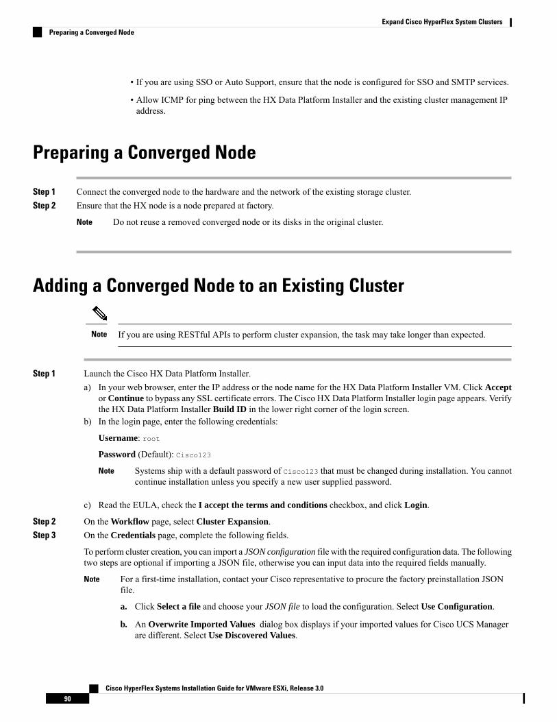
• If you are using SSO or Auto Support, ensure that the node is configured for SSO and SMTP services.
• Allow ICMP for ping between the HX Data Platform Installer and the existing cluster management IPaddress.
Preparing a Converged Node
Step 1 Connect the converged node to the hardware and the network of the existing storage cluster.Step 2 Ensure that the HX node is a node prepared at factory.
Do not reuse a removed converged node or its disks in the original cluster.Note
Adding a Converged Node to an Existing Cluster
If you are using RESTful APIs to perform cluster expansion, the task may take longer than expected.Note
Step 1 Launch the Cisco HX Data Platform Installer.a) In your web browser, enter the IP address or the node name for the HX Data Platform Installer VM. Click Accept
or Continue to bypass any SSL certificate errors. The Cisco HX Data Platform Installer login page appears. Verifythe HX Data Platform Installer Build ID in the lower right corner of the login screen.
b) In the login page, enter the following credentials:
Username: root
Password (Default): Cisco123
Systems ship with a default password of Cisco123 that must be changed during installation. You cannotcontinue installation unless you specify a new user supplied password.
Note
c) Read the EULA, check the I accept the terms and conditions checkbox, and click Login.
Step 2 On the Workflow page, select Cluster Expansion.Step 3 On the Credentials page, complete the following fields.
To perform cluster creation, you can import a JSON configuration file with the required configuration data. The followingtwo steps are optional if importing a JSON file, otherwise you can input data into the required fields manually.
For a first-time installation, contact your Cisco representative to procure the factory preinstallation JSONfile.
a. Click Select a file and choose your JSON file to load the configuration. Select Use Configuration.
b. An Overwrite Imported Values dialog box displays if your imported values for Cisco UCS Managerare different. Select Use Discovered Values.
Note
Cisco HyperFlex Systems Installation Guide for VMware ESXi, Release 3.090
Expand Cisco HyperFlex System ClustersPreparing a Converged Node

DescriptionField
UCS Manager Credentials
UCS Manager FQDN or IP address.
For example, 10.193.211.120.
UCS Manager Host Name
<admin> username.User Name
<admin> password.Password
vCenter Credentials
vCenter server FQDN or IP address.
For example, 10.193.211.120.
Note • A vCenter server is required before thecluster can be made operational.
• The vCenter address and credentials musthave root level administrator permissionsto the vCenter.
• vCenter server input is optional if you arebuilding a nested vCenter. See the NestedvCenter TechNote for more details.
vCenter Server
<admin> username.
For example, [email protected].
User Name
<root> password.Admin Password
Hypervisor Credentials
<admin> username.
This is root for factory nodes.
Admin User Name
<root> password.
Default password is Cisco123 for factory nodes.
Systems ship with a default password ofCisco123 that must be changed duringinstallation. You cannot continue installationunless you specify a new user suppliedpassword.
Note
Admin Password
Step 4 Click Continue. A Cluster Expand Configuration page is displayed. Select the HX Cluster that you want to expand.
If the HX cluster to be expanded is not found, or if loading the cluster takes time, enter the IP of the Cluster ManagementAddress in the Management IP Address field.
Cisco HyperFlex Systems Installation Guide for VMware ESXi, Release 3.091
Expand Cisco HyperFlex System ClustersAdding a Converged Node to an Existing Cluster

Step 5 The Server Selection page displays a list of unassociated HX servers under the Unassociated tab, and the list ofdiscovered servers under theAssociated tab. Select the servers under theUnassociated tab to include in the HyperFlexcluster.
If HX servers do not appear in this list, check Cisco UCS Manager and ensure that they have been discovered.
For each server you can use the Actions drop-down list to set the following:
• Launch KVM Console—Choose this option to launch the KVM Console directly from the HX Data PlatformInstaller.
• Disassociate Server—Choose this option to remove a service profile from that server.
If there are no unassociated servers, the following error message is displayed:No unassociated servers found. Please login to UCS Manager and ensure server ports areenabled.
Note
TheConfigure Server Ports button allows you to discover any newHX nodes. Typically, the server ports are configuredin Cisco UCS Manager before you start the configuration.
Step 6 Click Continue. The UCSM Configuration page appears.
If you imported a JSON file at the beginning, the Credentials page should be populated with the requiredconfiguration data from the preexisting HX cluster. This information must match your existing clusterconfiguration.
Note
Step 7 In the UCSM Configuration page, complete the following fields for each network.
DescriptionField
VLAN Configuration
Use separate subnet and VLANs for each of the following networks.Note
VLAN for Hypervisor and HyperFlex management
Name: hx-inband-mgmt
Default VLAN ID: 3091
VLAN Name
VLAN ID
VLAN for HyperFlex storage traffic
Name: hx-storage-data
Default VLAN ID: 3092
VLAN Name
VLAN ID
VLAN for VM vMotion
Name: hx-vmotion
Default VLAN ID: 3093
VLAN Name
VLAN ID
VLAN for VM Network
Cisco HyperFlex Systems Installation Guide for VMware ESXi, Release 3.092
Expand Cisco HyperFlex System ClustersAdding a Converged Node to an Existing Cluster

DescriptionField
Name: vm-network
Default VLAN ID: 3094
A comma-separated list of guest VLANs.
VLAN Name
VLAN ID(s)
MAC Pool
Configure MAC Pool prefix by adding in two more hexcharacters (0-F).
For example, 00:25:B5:A0.
MAC Pool Prefix
'hx-ext-mgmt' IP Pool for Out-of-Band CIMC
The range of IP addresses designated for the HyperFlexnodes. This can be a comma-separated list of values forthe guest VLANs.
For example, 10.193.211.124-127, 10.193.211.158-163
IP Blocks
Set the subnet to the appropriate level to limit and controlIP addresses.
For example, 255.255.0.0.
Subnet Mask
IP address.
For example, 10.193.0.1.
Gateway
iSCSI Storage
This must be configured upfront if you want to use external storage at any point in the future.Note
Check to configure iSCSI storage.Enable iSCSI Storage checkbox
Name of the VLAN associated with the iSCSI vNIC, onthe primary fabric interconnect (FI-A).
VLAN A Name
ID of the VLAN associated with the iSCSI vNIC, on theprimary fabric interconnect (FI-A).
VLAN A ID
Name of the VLAN associated with the iSCSI vNIC, onthe subordinate fabric interconnect (FI-B).
VLAN B Name
ID of the VLAN associated with the iSCSI vNIC, on thesubordinate fabric interconnect (FI-A).
VLAN B ID
FC Storage
This must be configured upfront if you want to use external storage at any point in the future.Note
Check to enable FC Storage.Enable FC Storage checkbox
Cisco HyperFlex Systems Installation Guide for VMware ESXi, Release 3.093
Expand Cisco HyperFlex System ClustersAdding a Converged Node to an Existing Cluster

DescriptionField
AWWN pool that contains both WW node names andWW port names. For each fabric interconnect, a WWxNpool is created for WWPN and WWNN.
WWxN Pool
The name of the VSAN for the primary fabric interconnect(FI-A). By default, this is set to hx-ext-storage-fc-a.
VSAN A Name
The unique identifier assigned to the network for theprimary fabric interconnect (FI-A).
Do not enter VSAN IDs that are currently usedon the UCS or HyperFlex system. If you enteran existing VSAN ID in the installer whichutilizes UCS zoning, zoning will be disabled inyour existing environment for that VSAN ID.
Caution
VSAN A ID
The name of the VSAN for the subordinate fabricinterconnect (FI-B). By default, this is set tohx-ext-storage-fc-b.
VSAN B Name
The unique identifier assigned to the network for thesubordinate fabric interconnect (FI-B).
Do not enter VSAN IDs that are currently usedon the UCS or HyperFlex system. If you enteran existing VSAN ID in the installer whichutilizes UCS zoning, zoning will be disabled inyour existing environment for that VSAN ID.
Caution
VSAN B ID
Advanced
Select the UCS firmware version to associate with the HXservers from the drop-down list. TheUCS firmware versionmust match the UCSM version. See the latest Cisco HXData Platform Release Notes for more details.
For example, 3.2(1d).
UCS Firmware Version
The name applied to a group of HX Servers in a givencluster. This is a user-defined name. The HyperFlex clustername adds a label to service profiles for easieridentification.
HyperFlex Cluster Name
Displays a unique Org Name of the cluster, that ensuresisolation of the HyperFlex environment from the rest ofthe UCS domain.
Org Name
Review the VLAN, MAC pool, and IP address pool information in the Configuration pane. These VLANIDs might be changed by your environment. By default, the Installer sets the VLANs as non-native. Youmust configure the upstream switches to accommodate the non-native VLANs by appropriately applying atrunk configuration.
Note
Cisco HyperFlex Systems Installation Guide for VMware ESXi, Release 3.094
Expand Cisco HyperFlex System ClustersAdding a Converged Node to an Existing Cluster

Step 8 Click Continue. The Hypervisor Configuration page appears. Complete the following fields:
You can skip the completion of the fields described in this step in case of a reinstall, and if ESXi networkinghas been completed.
Attention
DescriptionField
Configure Common Hypervisor Settings
Set the subnet mask to the appropriate level to limit andcontrol IP addresses.
For example, 255.255.0.0.
Subnet Mask
IP address of gateway.
For example, 10.193.0.1.
Gateway
IP address for the DNS Server.
If you do not have a DNS server, do not enter a hostnamein any of the fields on the Cluster Configuration page ofthe HXData Platform installer. Use only static IP addressesand hostnames for all ESXi hosts.
If you are providing more than one DNS server,check carefully to ensure that both DNS serversare correctly entered, separated by a comma.
Note
DNS Server(s)
Hypervisor Settings
Ensure to select Make IP Addresses and Hostnames Sequential, to make the IP addresses sequential.
You can rearrange the servers using drag and drop.Note
Server name.Name
Serial number of the server.Serial
Input static IP addresses and hostnames for all ESXi hosts.Static IP Address
Do not leave the hostname fields empty.Hostname
Step 9 Click Continue. The IP Addresses page appears. You can add more compute or converged servers, by clicking AddCompute Server or Add Converged Server.
Ensure to select Make IP Addresses Sequential, to make the IP addresses sequential. For the IP addresses, specify ifthe network should belong to Data Network or Management Network.
For each HX node, complete the following fields for Hypervisor Management and Data IP addresses.
DescriptionField
Enter the static IP address that handles the Hypervisormanagement network connection between the ESXi hostand the storage cluster.
Management Hypervisor
Cisco HyperFlex Systems Installation Guide for VMware ESXi, Release 3.095
Expand Cisco HyperFlex System ClustersAdding a Converged Node to an Existing Cluster

DescriptionField
Enter the static IP address that handles the HX DataPlatform storage controller VM management networkconnection between the storage controller VM and thestorage cluster.
Management Storage Controller
Enter the static IP address that handles the Hypervisor datanetwork connection between the ESXi host and the storagecluster.
Data Hypervisor
Enter the static IP address that handles the HX DataPlatform storage controller VM data network connectionbetween the storage controller VM and the storage cluster.
Data Storage Controller
When you enter IP addresses in the first row for Hypervisor (Management), Storage Controller VM (Management),Hypervisor (Data), and Storage Controller VM (Data) columns, the HXData Platform Installer applies an incrementalauto-fill to the node information for the rest of the nodes. The minimum number of nodes in the storage cluster isthree. If you have more nodes, use the Add button to provide the address information.
Compute-only nodes can be added only after the storage cluster is created.Note
Adefault administrator username and password are appliedto the controller VMs. The VMs are installed on allconverged and compute-only nodes.
Important • You cannot change the name of thecontroller VM or the controller VM’sdatastore.
• Use the same password for all controllerVMs. The use of different passwords isnot supported.
• Provide a complex password that includes1 uppercase character, 1 digit, 1 specialcharacter, and a minimum of 10 charactersin total.
• You can provide a user-defined passwordfor the controller VMs and for the HXcluster to be created. For passwordcharacter and format limitations, see thesection on Guidelines for HX DataPlatform Special Characters in the CiscoHX Data Platform Management Guide.
Controller VM Password
Advanced Configuration
Cisco HyperFlex Systems Installation Guide for VMware ESXi, Release 3.096
Expand Cisco HyperFlex System ClustersAdding a Converged Node to an Existing Cluster

DescriptionField
Check to set the MTU size for the storage data networkon the host vSwitches and vNICs, and each storagecontroller VM.
The default value is 9000.
To set your MTU size to a value other than9000, contact Cisco TAC.
Note
Jumbo frames
Enable Jumbo Frames checkbox
Check to remove all existing data and partitions from allnodes added to the storage cluster. You must backup anydata that should be retained.
Do not select this option for factory preparedsystems. The disk partitions on factory preparedsystems are properly configured. For manuallyprepared servers, select this option to deleteexisting data and partitions.
Important
Disk Partitions
Clean up Disk Partitions checkbox
Step 10 Click Start. A Progress page displays the progress of various configuration tasks.
If the vCenter cluster has EVC enabled, the deploy process fails with a message: The host needs tobe manually added to vCenter. To successfully perform the deploy action, do the following:
• Log in to the ESXi host to be added in vSphere Client.
• Power off the controller VM.
• Add the host to the vCenter cluster in vSphere Web Client.
• In the HX Data Platform Installer, click Retry Deploy.
Note
Step 11 When cluster expansion is complete, click Launch HyperFlex Connect to start managing your storage cluster.
When you add a node to an existing storage cluster, the cluster continues to have the same HA resiliency asthe original storage cluster until auto-rebalancing takes place at the scheduled time.
Rebalancing is typically scheduled during a 24-hour period, either 2 hours after a node fails or if the storagecluster is out of space.
Note
To rebalance the storage cluster before the scheduled time, perform the following steps to manually initiate rebalancestorage cluster command.
a. From a storage cluster controller VM command line, run the # stcli rebalance start --force command:
b. To monitor rebalance status, run the # stcli rebalance status command.
Step 12 Create the required VM Network port groups and vMotion vmkernel interfaces using HyperFlex hx_post_install
script or manually to match the other nodes in the cluster.a) SSH to HyperFlex cluster management IP.b) Log in as the admin user.c) Run the hx_post_install command.
Cisco HyperFlex Systems Installation Guide for VMware ESXi, Release 3.097
Expand Cisco HyperFlex System ClustersAdding a Converged Node to an Existing Cluster

d) Follow the on-screen instructions, starting with vMotion and VM network creation. The other configuration stepsare optional.
Step 13 After the new nodes are added to the storage cluster the High Availability (HA) services are reset so that HA canrecognize the added nodes.a) Log in to vCenter.b) In the vSphere Web Client, navigate to the Host: Home > vCenter > Inventory Lists > Hosts and Clusters >
vCenter > Server > Datacenter > Cluster > Hostc) Select the new node.d) Right-click and select Reconfigure for vSphere HA.
Prerequisites for Adding a Compute-Only NodeA compute-only node can be added to a HyperFlex cluster, after cluster creation. It is added to provide extracompute resources. The Cisco UCS server does not need to have any caching or persistent drives as they donot contribute any storage capacity to the cluster.
Before you start adding a compute-only node, make sure that the following prerequisites are met.
• Ensure that the storage cluster state is healthy.
• Ensure that the new nodemeets the compute-only system requirements listed in Installation Prerequisites,including network and disk requirements.
• Install ESXi hypervisor after service profile association.
• Ensure that the new node uses the same configuration as the other nodes in the storage cluster. Thisincludes VLAN IDs and switch types (whether vSwitches), VLAN tagging with External Switch VLANTagging (EST), VLAN tagging with Virtual Switch Tagging (VST), or Virtual Distributed Switch.
If the storage cluster is in an out of space condition, when you add a new node,the system automatically rebalances the storage cluster. This is in addition to therebalancing that is performed every 24 hours.
Note
• Enable EVC if the new node to be added has a different CPU family than what is already used in the HXcluster. For more details, see the Setting up Clusters with Mixed CPUs section in the Cisco HyperFlexSystems Installation Guide for VMware ESXi.
• Ensure that the software version on the node matches the Cisco HX Data Platform version, the ESXiversion, and the vCenter version. To identify the software version, go to the Storage Cluster Summarytab in vCenter and check the HX Data Platform version in the top section. Upgrade if necessary.
• Ensure that the new node has at least one valid DNS and NTP server configured.
• If you are using SSO or Auto Support, ensure that the node is configured for SSO and SMTP services.
• ESXi installation is supported on SD cards forM4 converged nodes andM.2 SATASSD forM5 convergednodes. For compute-only nodes, ESXi installation is supported for SD Cards, SAN boot, front SSD/HDD,or single M.2 SSD (using UCS-MSTOR-M2 controller). Installing ESXi on USB Flash is not supportedfor compute-only nodes.
Cisco HyperFlex Systems Installation Guide for VMware ESXi, Release 3.098
Expand Cisco HyperFlex System ClustersPrerequisites for Adding a Compute-Only Node

• Compute-only nodes are deployed with automatic detection and configuration of disk and boot policiesbased on the boot hardware.
Starting with HXData Platform version 4.5(1a) and later, compute-only nodes are deployedwith automaticdetection and configuration of disk and boot policies based on the inventoried boot hardware. Userscannot directly select the UCSM policies. Instead, the boot device is automatically determined based onthe first acceptable boot media discovered in the server. The tables below show the priority order for M4and M5 generation servers. Reading from top to bottom, the first entry that is a match based on theinventoried hardware are selected automatically during cluster expansion. For example, when expandingwith a B200 compute node with a single M.2 boot SSD, the second rule in the table below is a matchand used for SPT association.
If the server is booted using a mechanism not listed (such a SAN boot), the catch-all policy of anyld isselected and administrators may subsequently modify the UCSM policies and profiles as needed to bootthe server.
Priority for M5
Number of disksBoot DeviceSPT NamePriority
2M.2 Raidcompute-nodes-m5-m2r11
1PCH/Non-RAID M.2compute-nodes-m5-m2pch2
2FlexFlashcompute-nodes-m5-sd3
2MegaRAIDcompute-nodes-m5-ldr14
1FlexFlashcompute-nodes-m5-sd5
AnyAny other configcompute-nodes-m5-anyld6
Priority for M4
Number of disksBoot DeviceSPT NamePriority
1 or 2FlexFlashcompute-nodes-m5-sd1
AnyAny other configcompute-nodes-m5-anyld2
Preparing a Compute-Only Node
Step 1 Ensure that the server is a supported HX server and meets the requirements. For more details, see the Host Requirementssection in the Cisco HyperFlex Systems Installation Guide for VMware ESXi.
Step 2 Log in to Cisco UCS Manager.a) Open a browser and enter the Cisco UCS Manager address for the fabric interconnect of the storage cluster network.b) Click the Launch UCS Manager button.c) If prompted, download, install, and accept Java.d) Log in with administrator credentials.
Cisco HyperFlex Systems Installation Guide for VMware ESXi, Release 3.099
Expand Cisco HyperFlex System ClustersPreparing a Compute-Only Node

Username: admin
Password: <admin password>
Step 3 Locate the server to ensure that the server has been added to the same FI domain as the storage cluster and is an approvedcompute-onlymodel. Check the latest Release Notes for Cisco HXData Platform for a full list of compatible Compute-onlynodes.
Verify the HX Data Platform Installer
Step 1 Verify that the HX Data Platform installer is installed on a node that can communicate with all the nodes in the storagecluster and compute nodes that are being added to the storage cluster.
Step 2 If the HX Data Platform installer is not installed, see Deploy the HX Data Platform Installer.
Apply an HX Profile on a Compute-only Node Using UCS ManagerIn Cisco UCSManager the network policies are grouped into an HX profile. The HX installer handles automaticservice profile association for compute-only nodes. Manual association is not required.
Once install beings, you should monitor compute-only node service profile association in UCS Manager. Wait until theserver is fully associated before continuing on to install ESXi.
Install VMware ESXi on Compute Nodes
Install VMware ESXi on each compute-only node.
Install a Cisco HX Data Platform supported version of ESXi. See the Cisco HyperFlex Data Platform ReleaseNotes for a list of supported ESXi versions.
If the compute only node already has ESXi installed, it must be re-imaged with the Cisco HX Custom image.
Important
Before you begin
Ensure the required hardware and network settings are met. For more details, see the Installation Prerequisitessection in the Cisco HyperFlex Systems Installation Guide for VMware ESXi. Ensure the service profiles inthe previous step have finished associating.
Step 1 Download the HX Custom Image for ESXi from the Cisco.com download site for Cisco HyperFlex. See DownloadSoftware.
Select a networked location that can be accessed through Cisco UCS Manager.
Cisco HyperFlex Systems Installation Guide for VMware ESXi, Release 3.0100
Expand Cisco HyperFlex System ClustersVerify the HX Data Platform Installer

Step 2 Log in to Cisco UCS Manager.Step 3 Log in to the KVM console of the server through Cisco UCS Manager.
a) In the Navigation Pane, click Servers > Service Profiles > Sub-Organizations > hx-cluster.b) Right click the hx-cluster and choose KVM Console.
Step 4 Copy the HX-Vmware.iso image to the KVM path for the compute server.
Example:
HX-Vmware-ESXi-60U3-5050593-Cisco-Custom-6.0.3.1.iso
Step 5 From the KVM console session, select Virtual Media > Map CD/DVD and mount the HX Custom Image for ESXiimage. If you do not see the Map CD/DVD option, first activate virtual devices.a) Select Virtual Media > Activate Virtual Devices.
This opens in a pop-up window.
b) Click Accept the session > Apply.
Step 6 From the Map CD/DVD option, map to the location of the HX-Vmware.iso file.a) Select the HX-Vmware.iso file.b) Select Map Device.
There is a check mark indicating that the file is on a mapped location, once the process is complete. The mappedfile's full name includes the ESXi build ID.
Step 7 Reset the compute server.a) Click the Reset button on the KVM console. Click OK to confirm.b) Select Power Cycle. Click OK.
Step 8 Change the boot path to point to the HX-Vmware.iso file.a) Press F6.b) From the Enter boot selection menu, use the arrow keys to highlight the Cisco vKVM-Mapped vDVD1.22 option.c) Press Enter to select.
This launches the ESXi installer bootloader. Select one of the three compute-only node options based on desiredboot type: SD Card, Local Disk, or Remote Disk. Type in yes (all lowercase) to confirm selection. The rest of theinstallation is automated. ESXi will reboot several times. It is normal to see warnings that automatically dismissafter a short wait period. Wait for the ESXi DCUI to fully appear, signaling the end of installation.
Step 9 Repeat steps 3 to 8 for each Cisco HyperFlex server.Step 10 Once ESXi is fully installed, click continue. Then click Retry Hypervisor Configuration to complete the rest of the
cluster expansion.
Adding a Compute-Only Node to an Existing ClusterTo add a HyperFlex compute-only node to an existing HyperFlex system cluster, complete the followingsteps.
Cisco HyperFlex Systems Installation Guide for VMware ESXi, Release 3.0101
Expand Cisco HyperFlex System ClustersAdding a Compute-Only Node to an Existing Cluster

If you are using RESTful APIs to perform cluster expansion, sometimes the taskmay take longer than expected.Note
After you add a compute-only node to an existing cluster, you must manually configure the vmk2 interfacefor vmotion.
Note
Step 1 Launch the Cisco HX Data Platform Installer.a) In your web browser, enter the IP address or the node name for the HX Data Platform Installer VM. Click Accept
or Continue to bypass any SSL certificate errors. The Cisco HX Data Platform Installer login page appears. Verifythe HX Data Platform Installer Build ID in the lower right corner of the login screen.
b) In the login page, enter the following credentials:
Username: root
Password (Default): Cisco123
Systems ship with a default password of Cisco123 that must be changed during installation. You cannotcontinue installation unless you specify a new user supplied password.
Note
c) Read the EULA, check the I accept the terms and conditions checkbox, and click Login.
Step 2 On the Workflow page, select Cluster Expansion.Step 3 On the Credentials page, complete the following fields.
To perform cluster creation, you can import a JSON configuration file with the required configuration data. The followingtwo steps are optional if importing a JSON file, otherwise you can input data into the required fields manually.
For a first-time installation, contact your Cisco representative to procure the factory preinstallation JSONfile.
a. Click Select a file and choose your JSON file to load the configuration. Select Use Configuration.
b. An Overwrite Imported Values dialog box displays if your imported values for Cisco UCS Managerare different. Select Use Discovered Values.
Note
DescriptionField
UCS Manager Credentials
UCS Manager FQDN or IP address.
For example, 10.193.211.120.
UCS Manager Host Name
<admin> username.User Name
<admin> password.Password
vCenter Credentials
Cisco HyperFlex Systems Installation Guide for VMware ESXi, Release 3.0102
Expand Cisco HyperFlex System ClustersAdding a Compute-Only Node to an Existing Cluster

DescriptionField
vCenter server FQDN or IP address.
For example, 10.193.211.120.
Note • A vCenter server is required before thecluster can be made operational.
• The vCenter address and credentials musthave root level administrator permissionsto the vCenter.
• vCenter server input is optional if you arebuilding a nested vCenter. See the NestedvCenter TechNote for more details.
vCenter Server
<admin> username.
For example, [email protected].
User Name
<root> password.Admin Password
Hypervisor Credentials
<admin> username.
This is root for factory nodes.
Admin User Name
<root> password.
Default password is Cisco123 for factory nodes.
Systems ship with a default password ofCisco123 that must be changed duringinstallation. You cannot continue installationunless you specify a new user suppliedpassword.
Note
Admin Password
Step 4 Click Continue. A Cluster Expand Configuration page is displayed. Select the HX Cluster that you want to expand.
If the HX cluster to be expanded is not found, or if loading the cluster takes time, enter the IP of the Cluster ManagementAddress in the Management IP Address field.
Step 5 Click Continue. A Server Selection page is displayed. On the Server Selection page, the Associated tab lists all theHX servers that are already connected. Do not select them. On the Unassociated tab, select the servers you wish toadd to the cluster.
Step 6 Click Continue. A UCS Manager Configuration page is displayed.
• If you imported a JSON file at the beginning, the fields should be populated with the requiredconfiguration data from the pre-existing HX cluster. If the server to add into the cluster is not associated,select them and click Continue.
• This information must match your existing cluster configuration. Ensure that you use the proper settingson this page.
Note
Cisco HyperFlex Systems Installation Guide for VMware ESXi, Release 3.0103
Expand Cisco HyperFlex System ClustersAdding a Compute-Only Node to an Existing Cluster

Enter the following information for each network:
InformationField
VLAN for ESXi and HyperFlex management
Name: hx-inband-mgmt
Default VLAN ID: 3091
VLAN Name
VLAN ID
VLAN for HyperFlex Storage traffic
Name: hx-storage-data
Default VLAN ID: 3092
VLAN Name
VLAN ID
VLAN for VM vMotion
Name: hx-vmotion
Default VLAN ID: 3093
VLAN Name
VLAN ID
VLAN for VM Network
Name: hx-vm-network
Default VLAN ID: 3094
VLAN Name
VLAN ID
MAC Pool
For example, 00:25:B5:99 (99 is default and can be set asper the user environment).
MAC Pool Prefix
hx-ext-mgmt IP Pool for Out-of-Band CIMC
The range of IP addresses designated for the HyperFlexnodes. This can be a comma-separated list of values forthe guest VLANs.
For example, 10.193.211.124-127, 10.193.211.158-163,255.255.255.0.
Enter IP address of gateway. For example, 10.193.0.1.
IP Blocks
Set the subnet to the appropriate level to limit and controlIP addresses.
For example, 255.255.0.0.
Subnet
IP address.
For example, 10.193.0.1.
Default gateway
Advanced
Cisco HyperFlex Systems Installation Guide for VMware ESXi, Release 3.0104
Expand Cisco HyperFlex System ClustersAdding a Compute-Only Node to an Existing Cluster

InformationField
Select the UCS firmware version to associate with the HXservers from the drop-down list. TheUCS firmware versionmust match the UCSM version. See the latest Cisco HXData Platform Release Notes for more details.
For example, 3.2(1d).
UCS Firmware version
The name applied to a group of HX Servers in a givencluster. This is a user-defined name. The HyperFlex clustername adds a label to service profiles for easieridentification.
HyperFlex Cluster Name
Review the VLAN, MAC pool, and IP address pool information in the Configuration pane. These VLANIDs might be changed by your environment. By default, the Installer sets the VLANs as non-native. Youmust configure the upstream switches to accommodate the non-native VLANs by appropriately applying atrunk configuration.
Note
Step 7 Click Continue. The Hypervisor Configuration page appears. Complete the following fields:
You can skip the completion of the fields described in this step in case of a reinstall, and if ESXi networkinghas been completed.
Attention
DescriptionField
Configure Common Hypervisor Settings
Set the subnet mask to the appropriate level to limit andcontrol IP addresses.
For example, 255.255.0.0.
Subnet Mask
IP address of gateway.
For example, 10.193.0.1.
Gateway
IP address for the DNS Server.
If you do not have a DNS server, do not enter a hostnamein any of the fields on the Cluster Configuration page ofthe HXData Platform installer. Use only static IP addressesand hostnames for all ESXi hosts.
If you are providing more than one DNS server,check carefully to ensure that both DNS serversare correctly entered, separated by a comma.
Note
DNS Server(s)
Hypervisor Settings
Ensure to select Make IP Addresses and Hostnames Sequential, to make the IP addresses sequential.
You can rearrange the servers using drag and drop.Note
Server name.Name
Cisco HyperFlex Systems Installation Guide for VMware ESXi, Release 3.0105
Expand Cisco HyperFlex System ClustersAdding a Compute-Only Node to an Existing Cluster

DescriptionField
Serial number of the server.Serial
Input static IP addresses and hostnames for all ESXi hosts.Static IP Address
Do not leave the hostname fields empty.Hostname
Step 8 Click Continue. An IP Addresses page is displayed. Click Add Compute-only Node to add a new node.If you are adding more than one compute-only node, select Make IP Addresses Sequential.
InformationField
Enter the static IP address that handles the Hypervisormanagement network connection between the ESXi hostand storage cluster.
Management Hypervisor
None.Management Storage Controller
Enter the static IP address that handles the Hypervisor datanetwork connection between the ESXi host and the storagecluster.
Data Hypervisor
None.Data Storage Controller
Enter the default Admin username and password that wereapplied to controller VMs when they were installed on theexisting HX Cluster.
The name of the controller VM cannot bechanged. Use the existing cluster password.
Note
Controller VM
Step 9 Click Start. A Progress page displays the progress of various configuration tasks.
By default no user intervention is required if you are booting from FlexFlash (SD Card). However, if youare setting up your compute-only node to boot from a local disk, complete the following steps in Cisco UCSManager:
Note
a. Click the service profile created by the HX Data Platform Installer.
For example, blade-1(HX_Cluster_Name).
b. On the General tab, click Unbind from the Template.
c. In the working pane, click the Storage tab. Click the Local Disk Configuration Policy sub tab.
d. In the Actions area, selectChange Local Disk Configuration Policy >Create Local Disk Configuration Policy.
e. Under Create Local Disk Configuration Policy, enter a name for the policy, and keep the rest as default. ClickOk.
f. In the Change Local Disk Configuration Policy Actions area, select the newly created local disk configurationpolicy from the drop-down list. Click Ok.
Cisco HyperFlex Systems Installation Guide for VMware ESXi, Release 3.0106
Expand Cisco HyperFlex System ClustersAdding a Compute-Only Node to an Existing Cluster

g. Now, go back to the HX Data Platform Installer UI and click Continue, and then click Retry UCSM
Configuration.
If the vCenter cluster has EVC enabled, the deploy process fails, The host needs to bemanually added to vCenter. To successfully perform the deploy action, do the following:
Note
a) Log in to the ESXi host to be added in vSphere Client.b) Power off the controller VM.c) Add the host to the vCenter cluster in vSphere Web Client.d) In the HX installer, click Retry Deploy.
Step 10 When installation is complete, start managing your storage cluster by clicking Launch HyperFlex Connect.Step 11 After the new nodes are added to the storage cluster, HA services are reset so that HA is able to recognize the added
nodes.a) Log on to VMware vSphere Client.b) Select Home > Hosts and Clusters > Datacenter > Cluster > Host.c) Select the new node.d) Right-click and select Reconfigure for vSphere HA.
Step 12 After adding compute-only nodes to an existing cluster, you must manually configure the vmk2 interface for vmotion.
Resolving Failure of Cluster ExpansionIf you receive an error dialog box and the storage cluster expansion doesn't complete, proceed with theresolution options listed below:
Step 1 Edit Configuration - Returns you to the Cluster Configuration page. You fix the issues listed in the validation page.
Cisco HyperFlex Systems Installation Guide for VMware ESXi, Release 3.0107
Expand Cisco HyperFlex System ClustersResolving Failure of Cluster Expansion

Step 2 Start Over - Allows you to reverse the settings you applied by clearing progress table entries and you are returned tothe Cluster Configuration page to restart a new deployment. See Technical Assistance Center (TAC).
Step 3 Continue - Adds the node to the storage cluster in spite of the failure generating errors. See Technical Assistance Center(TAC).
Select the Continue button only if you understand the failures and are willing to accept the possibility ofunpredictable behavior.
Note
For more information about cleaning up a node for the purposes of redeploying HyperFlex, see the HyperFlex CustomerCleanup Guides for FI and Edge.
Enabling Logical Availability ZonesOnce you have successfully configured your HyperFlex cluster, refer to the commands below to enable ordisable Logical Availability Zones (LAZ).
Please be advised to wait for at least 10 seconds between successive invocations of LAZ disable and, LAZenable operations in that order.
In case of fresh cluster installation, for best results, it is recommended that LAZ is enabled during clustercreation.
Important
DescriptionCommand
Checks if zones are enabled.stcli cluster get-zone
Disables zones.stcli cluster set-zone --zone 0
(Recommended) Enables and creates zones (defaultnumber of zones)
Important • A cluster created without zoningenabled, will become zone compliantonly after enabling zoning andsuccessful completion of rebalance.
• Youmust execute the rebalance startcommand after you enable and createzones.
• Triggering rebalance activity mayinvolve large scale data movementsacross several nodes in the clusterwhich may decrease the IOperformance in the cluster.
stcli cluster set-zone --zone 1
stcli rebalance start
Cisco HyperFlex Systems Installation Guide for VMware ESXi, Release 3.0108
Expand Cisco HyperFlex System ClustersEnabling Logical Availability Zones

DescriptionCommand
Enables zones and creates a specific number of zones.
You must execute the rebalance startcommand after you enable and createzones.
Important
stcli cluster set-zone --zone 1 --numzones<integer-value>
stcli rebalance start
Requirements and Limitations for Logical Availability ZonesLogical Availability Zones (LAZ) are subject to the following requirements and limitations:
• Only HyperFlex clusters with 8 nodes or more can be configured with Logical Availability Zones duringthe installation process.
• Logical Availability Zones can be enabled during the HyperFlex cluster installation, or it can be enabledusing the command line interface at a later time. It is recommended to enable this feature duringinstallation, in order to avoid a large migration and reorganization of data across the cluster, which wouldbe necessary to comply with the data distribution rules if LAZ is turned on in a cluster already containingdata.
• The number of zones can be manually specified as 3, 4, 5, or you can allow the installer to automaticallychoose, which is the recommended setting. When you let the installer decide the number of zones, thenumber of zones is decided based on the number of nodes in the cluster.
Here is a mapping table of number of nodes and resultant number of zones, with the assumption of RFas 3:
No. of Zones in the clusterNo. of Hyperconverged Nodes in the cluster
48
39
510
311
312
313
714
315
416
317
318
319
420
Cisco HyperFlex Systems Installation Guide for VMware ESXi, Release 3.0109
Expand Cisco HyperFlex System ClustersRequirements and Limitations for Logical Availability Zones

No. of Zones in the clusterNo. of Hyperconverged Nodes in the cluster
321
1122
323
324
525
1326
327
428
329
330
331
432
You can view the LAZ status and check which node is in which zone, by accessing HyperFlex Connect> System information and HyperFlex Connect > Dashboard respectively.
Also, you can view the LAZ details through CLI by running the following command:stcli cluster get-zone
zones:----------------------------------------pNodes:
----------------------------------------state: readyname: 10.10.18.61----------------------------------------state: readyname: 10.10.18.59----------------------------------------
zoneId: 0000000057eebaab:0000000000000003numNodes: 2----------------------------------------pNodes:
----------------------------------------state: readyname: 10.10.18.64----------------------------------------state: readyname: 10.10.18.65----------------------------------------
zoneId: 0000000057eebaab:0000000000000001numNodes: 2----------------------------------------pNodes:
----------------------------------------state: readyname: 10.10.18.60
Cisco HyperFlex Systems Installation Guide for VMware ESXi, Release 3.0110
Expand Cisco HyperFlex System ClustersRequirements and Limitations for Logical Availability Zones
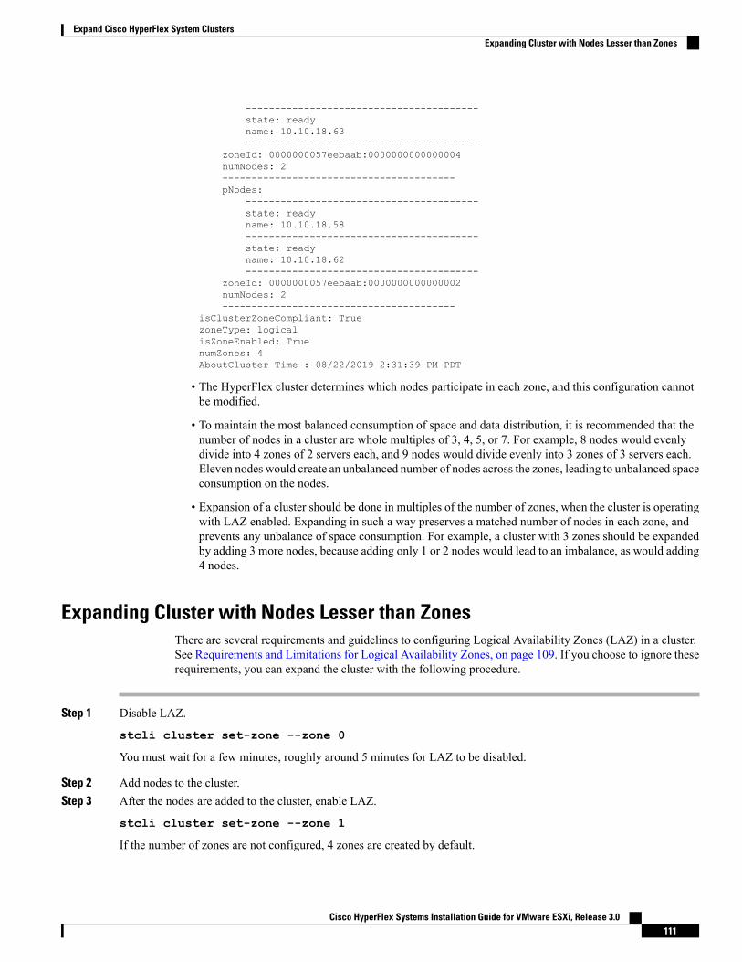
----------------------------------------state: readyname: 10.10.18.63----------------------------------------
zoneId: 0000000057eebaab:0000000000000004numNodes: 2----------------------------------------pNodes:
----------------------------------------state: readyname: 10.10.18.58----------------------------------------state: readyname: 10.10.18.62----------------------------------------
zoneId: 0000000057eebaab:0000000000000002numNodes: 2----------------------------------------
isClusterZoneCompliant: TruezoneType: logicalisZoneEnabled: TruenumZones: 4AboutCluster Time : 08/22/2019 2:31:39 PM PDT
• The HyperFlex cluster determines which nodes participate in each zone, and this configuration cannotbe modified.
• To maintain the most balanced consumption of space and data distribution, it is recommended that thenumber of nodes in a cluster are whole multiples of 3, 4, 5, or 7. For example, 8 nodes would evenlydivide into 4 zones of 2 servers each, and 9 nodes would divide evenly into 3 zones of 3 servers each.Eleven nodes would create an unbalanced number of nodes across the zones, leading to unbalanced spaceconsumption on the nodes.
• Expansion of a cluster should be done in multiples of the number of zones, when the cluster is operatingwith LAZ enabled. Expanding in such a way preserves a matched number of nodes in each zone, andprevents any unbalance of space consumption. For example, a cluster with 3 zones should be expandedby adding 3 more nodes, because adding only 1 or 2 nodes would lead to an imbalance, as would adding4 nodes.
Expanding Cluster with Nodes Lesser than ZonesThere are several requirements and guidelines to configuring Logical Availability Zones (LAZ) in a cluster.See Requirements and Limitations for Logical Availability Zones, on page 109. If you choose to ignore theserequirements, you can expand the cluster with the following procedure.
Step 1 Disable LAZ.
stcli cluster set-zone --zone 0
You must wait for a few minutes, roughly around 5 minutes for LAZ to be disabled.
Step 2 Add nodes to the cluster.Step 3 After the nodes are added to the cluster, enable LAZ.
stcli cluster set-zone --zone 1
If the number of zones are not configured, 4 zones are created by default.
Cisco HyperFlex Systems Installation Guide for VMware ESXi, Release 3.0111
Expand Cisco HyperFlex System ClustersExpanding Cluster with Nodes Lesser than Zones

Step 4 Initiate rebalancing in the cluster.
stcli rebalance start
• Rebalancing of nodes may decrease the performance of the cluster by about 30% to 40%.
• The time taken to rebalance the nodes in the cluster depends on the cluster size and the data within thecluster. You can use the stcli rebalance status command to review the progress of the rebalancing activity.
Note
Step 5 Review the cluster configuration and determine if the cluster is zone compliant.
stcli cluster get-zone
Cisco HyperFlex Systems Installation Guide for VMware ESXi, Release 3.0112
Expand Cisco HyperFlex System ClustersExpanding Cluster with Nodes Lesser than Zones

C H A P T E R 10Set Up Clusters with Mixed CPUs
This chapter describes how to add HX nodes with different Intel CPU versions on the same FI.
• Overview, on page 113• Prerequisites for Using Mixed CPUs, on page 113• CPU Compatibility with EVC Mode, on page 114• Enable Enhanced vMotion Compatibility (EVC) on an Existing Cluster, on page 114
OverviewHyperFlex supports Intel v3 and Intel v4 CPUs on the same fabric interconnect. Enable VMware EnhancedvMotion Compatibility (EVC) to migrate virtual machines between Intel v3 and Intel v4 CPUs. After EVCis enabled, all hosts in the HyperFlex cluster are configured to give them a baseline with features of the lowermodel of CPU. Identical CPU features are exposed to virtual machines regardless of which host they arerunning on, so virtual machines can be migrated between hosts in a HyperFlex cluster. This ensures CPUcompatibility for vMotion even if the hosts have different underlying hardware.
Prerequisites for Using Mixed CPUs• You can only use CPUs from a single vendor in an EVC-enabled cluster. You cannot add a host from adifferent vendor into an EVC-enabled cluster.
• When enabling EVC for a cluster with Intel processors of the Xeon E3 or Xeon E5 family that havedifferent revision numbers (v2, v3, or v4), an EVC baseline is required.
• Enable advanced virtualization CPU features in the BIOS if they are available. Otherwise it can causeproblems in enabling EVC, as EVC compatibility checks may fail to detect the features that are expectedto be present for a particular CPU.
• Migration of virtual machines using vMotion may fail, even if they are within an EVC cluster under thefollowing scenarios:
• When a host is not connected to a vCenter Server system.
• When a host is not configured for vMotion.
• If the virtual machine does not reside on storage shared by the source and destination hosts.
Cisco HyperFlex Systems Installation Guide for VMware ESXi, Release 3.0113

CPU Compatibility with EVC ModeTo determine the Enhanced vMotion Compatibility (EVC) modes compatible with your CPU, search theVMware Compatibility Guide. Search for the server model or CPU family, and click the entry in the CPUSeries column to display the compatible EVC modes.
Finding the Current EVC Mode for a Host
Each EVC mode corresponds closely to the features available in processors with the same name.
Using vSphere Web Client
1. From the vSphere Web Client Navigator, select Hosts and Clusters > HX Cluster > Summary. TheSummary tab indicates whether EVC is enabled, and displays the current EVC mode for the host.
2. Click the blue icon next to the EVC mode to display a list of all the supported EVC modes for the host.
Using VMware Shared Utilities Tool
VMware provides a free CPU identification utility that displays the compatible EVC modes, in addition toother CPU features. You can download this utility and boot the host from the ISO image from Shared Utilities.
Enable Enhanced vMotion Compatibility (EVC) on an ExistingCluster
Enable EVC to ensure that migration with vMotion is possible between hosts in the cluster. EVC mode isrequired when mixing different CPU families within the same HyperFlex cluster. Once EVCmode is enabled,only hosts that meet the minimum requirements of the configured EVC mode may be added to the cluster.EVC mode can be enabled, even during cluster expansion without disruption.
• EVC is disabled by default. It can be enabled in the cluster settings under VMware EVC.
• This is not an HX Data Platform constraint but rather a VMware limitation. For further details, refer tothe VMware KB article EVC and CPU Compatibility FAQ (1005764).
Note
There are two paths to consider, uniform clusters that you want to add newer generation servers to, and existingclusters with mixed generations of servers.
Adding Newer Generation Servers to Uniform ClustersIf the cluster is currently uniform and you want to add newer generation servers to the cluster, you can enableEVC online and without disruption by selecting the current generation EVC mode in VC. Then proceednormally with expansion (converged or compute only). It is imperative the EVC mode is set before anyexpansion is attempted.
To enable EVC mode on a uniform cluster prior to performing a cluster expansion, perform the followingsteps:
Cisco HyperFlex Systems Installation Guide for VMware ESXi, Release 3.0114
Set Up Clusters with Mixed CPUsCPU Compatibility with EVC Mode

Step 1 Enable Enhanced vMotion Compatibility (EVC) in the HX cluster.a) From the vSphere Web Client Navigator, select Hosts and Cluster > Datacenter > HX Cluster.b) Select the cluster for which you want to enable EVC. In the Work pane, click the Manage or Configure tab. Select
VMware EVC.c) Click the Edit button and select the desired EVC mode. Click Ok.
Step 2 Proceed with compute only or converged node expansion using the HyperFlex installer.
Adding Mixed or Older Generation Servers to Existing ClustersThe cluster already has mixed generations of servers OR you wish to add older generation servers to an existingcluster (compute only nodes).
These steps should be followed if EVC mode was not enabled during the cluster expansion workflow withnewer nodes.
Note
To add an older generation server to an existing cluster perform the following steps:
Step 1 Ensure that the HyperFlex cluster is healthy, and all the nodes are online before you start.
• Using vSphere Web Client
From the vSphere Web Client Navigator, select Home > Global Inventory Lists > Cisco HyperFlex Systems >Cisco HX Data Platform > HX Cluster > Summary.
Example response:Operational Status: OnlineResiliency Status: Healthy
• Using the Controller VM
In the controller VM, run the command # stcli cluster info.
Example response:healthstate: healthystate: online
Step 2 Power off all non-storage controller virtual machines.Step 3 Log in to one storage controller VM and execute the command stcli cluster shutdown. Wait until the execution is
complete.Step 4 Shut down all the storage controller VMs.
a) From the vSphereWeb Client Navigator, selectVMs and Templates > vCenter server >Datacenter >Discoveredvirtual machine > Virtual Machines > controller_vm.
b) Right-click the controller_vm or from the Actions menu, select Power > Shut Down Guest OS.
Step 5 Put each HX host in maintenance mode.a) From the vSphere Web Client Navigator, select Hosts and Cluster > Datacenter > HX Cluster > node.
Cisco HyperFlex Systems Installation Guide for VMware ESXi, Release 3.0115
Set Up Clusters with Mixed CPUsAdding Mixed or Older Generation Servers to Existing Clusters

b) Right-click the node and select Maintenance Mode > Enter Maintenance Mode.
Do not use the Cisco HX Maintenance Mode menu for this operation.Note
Step 6 Enable Enhanced vMotion Compatibility (EVC) in the HX cluster.a) From the vSphere Web Client Navigator, select Hosts and Cluster > Datacenter > HX Cluster.b) Select the cluster for which you want to enable EVC. In the Work pane, click the Manage or Configure tab. Select
VMware EVC.c) Click the Edit button and select the desired EVC mode. Click Ok.
Step 7 Exit maintenance mode.a) From the vSphere Web Client Navigator, select Hosts and Cluster > Datacenter > HX Cluster > node.b) Right-click the node and select Maintenance Mode > Exit Maintenance Mode.
Do not use the Cisco HX Maintenance Mode menu for this operation.Note
Step 8 The controller VMs should automatically power on after the host exists maintenance mode. If the controller VMs donot power on automatically, do the following:a) From the vSphere Web Client Navigator, select VMs and Templates > vCenter server > Datacenter > ESXi
Agents > Virtual Machines > controller_vm.b) Right-click the controller_vm or from the Actions menu. Select Power > Power On or Power > Power ON.
Step 9 Make sure all controller VMs are fully booted. Then, log in to one of the controller VMs, and run the command stclicluster start.
Step 10 Make sure that all datastores are mounted from vCenter HX plug-in and ensure that the cluster is healthy.Step 11 Start the user VMs.Step 12 Proceed with compute only expansion using the HyperFlex installer.
Cisco HyperFlex Systems Installation Guide for VMware ESXi, Release 3.0116
Set Up Clusters with Mixed CPUsAdding Mixed or Older Generation Servers to Existing Clusters

C H A P T E R 11Cisco HyperFlex Systems Customized InstallationMethod
• Overview, on page 117• Installation and Configuration Workflow for Non Pre-Configured Cisco HyperFlex Systems, on page117
• Installing VMware ESXi, on page 118
OverviewThis chapter describes the process for manually preparing the HyperFlex servers, before moving to theinstallation steps. This customized installation method can be used during the following scenarios:
• Adding a compute-only node to the HyperFlex cluster.
• Redeploying your Cisco HyperFlex System.
The tasks to perform are essentially the same as for deploying pre-configured HyperFlex Systems. The newtask specific to non pre-configured systems is, installing VMware ESXi.
InstallationandConfigurationWorkflowforNonPre-ConfiguredCisco HyperFlex Systems
Before you begin
Review the installation and configuration requirements for Cisco HyperFlex Systems. See InstallationPrerequisites for more details.
Step 1 Clean up the existing environment by deleting the cluster in vCenter. Remove the vCenter MOB entries, UCS Managerservice profiles, and VLANs in Cisco UCS.
Step 2 Download the Cisco HyperFlex Data Platform Installer OVA file from Download Software.
Example:
Cisco-HX-Data-Platform-Installer-v2.5.1b-26284.ova
Cisco HyperFlex Systems Installation Guide for VMware ESXi, Release 3.0117

Step 3 Launch the Cisco HX Data Platform Installer and sign-in.a) Select Customized Workflow.b) Select Run UCS Manager configuration to configure UCS service profiles. Follow the steps as described in
Configuring Cisco UCS Manager and HX Data Platform section of the Cisco HyperFlex Systems Installation Guidefor VMware ESXi.
Step 4 Perform a fresh ESXi installation using the vMedia method.
Using Dynamic Host Configuration Protocol (DHCP) for automatic IP address assignment in not recommended.By default, the HX Data Platform Installer assigns static IP addresses to the ESXi servers. If you are usingDHCP, configure the networking in the ESXi manually with the proper VLANs.
Note
Step 5 Launch the Cisco HX Data Platform Installer again.a) Select Customized Workflow.b) Select Run ESX Configuration, Deploy HX Software, and Create HX Cluster.
Ensure that you select Delete Existing Partitions in the wizard.
Installing VMware ESXiThe servers must have a supported version of VMware ESXi. See the latest Release notes for Cisco HX DataPlatform for a list of supported ESXi versions.
Install ESXi on each HX server.Important
Download the VMware ESXi image from the CiscoHyperFlexData PlatformDownload Software page. Select a networkedlocation that can be accessed through Cisco UCS Manager.
The HX custom ISO is based on the Cisco custom ESXi release.
For example,
HX-Vmware-ESXi-60U2-4192238-Cisco-Custom-6.0.2.3.iso
.
What to do next
• Configure vMedia and Boot Policies through Cisco UCS Manager.
• Open a remote KVM console.
• Reboot the servers to begin installation.
• Undo vMedia and Boot Policy changes through Cisco UCS Manager.
Cisco HyperFlex Systems Installation Guide for VMware ESXi, Release 3.0118
Cisco HyperFlex Systems Customized Installation MethodInstalling VMware ESXi

Configure vMedia and Boot Policies Through Cisco UCS ManagerTo configure the Cisco UCS vMedia and Boot Policies, complete the following steps:
Before you begin
Log in to Cisco HX Data Platform Installer. Run the Create Cluster workflow for standard cluster. up toCisco UCS Manager configuration.
Create a cluster with name as Temporary, so it is easier to identify it during service profile disassociationfrom the server.
Note
Step 1 In Cisco UCS Manager, click the Servers tab in the Navigation Pane.Step 2 Expand Servers > Policies > root > Sub-Organizations > hx-cluster > vMedia Policies
Step 3 Click vMedia Policy HyperFlex.Step 4 In the configuration pane, click Create vMedia Mount.Step 5 Enter a name for the mount, for example: ESX.Step 6 Select the CDD option.Step 7 Select the HTTP as the protocol.Step 8 Enter the IP Address of the HyperFlex installer VM, for example: 192.168.10.210.Step 9 Select None as the Image Variable Name.Step 10 Enter HX-Vmware-ESXi-6.0.0-3380124-Custom-Cisco-6.0.1.2.iso as the Remote File.Step 11 Enter /images/ as the Remote Path.Step 12 Click Save Changes, and click OK.Step 13 In the Configuration Pane, select Servers > Service Profile Templates > root > Sub-Organizations > hx-cluster >
Service Template hx-nodes
Step 14 Click the vMedia Policy tab.Step 15 Click Modify vMedia Policy.Step 16 Choose the HyperFlex vMedia Policy from the drop-down selection, and click OK twice.Step 17 Select Servers > Policies > root > Sub-Organizations > hx-cluster > Boot Policy HyperFlex.Step 18 In the Navigation Pane, expand the section titled CIMC Mounted vMedia.Step 19 Click the entry labeled Add CIMC Mounted CD/DVD.Step 20 Select the CIMC Mounted CD/DVD entry in the Boot Order list, and click the Move Up button until the CIMC
Mounted CD/DVD entry is listed first.Step 21 Click Save Changes, and click OK.
What to do next
Delete the Sub-Organization Temporary.
Cisco HyperFlex Systems Installation Guide for VMware ESXi, Release 3.0119
Cisco HyperFlex Systems Customized Installation MethodConfigure vMedia and Boot Policies Through Cisco UCS Manager

Opening a Remote KVM ConsoleTo monitor the progress of one or more servers, it is advisable to open a remote KVM console session towatch the installation.
To open the KVM console, complete the following steps:
Step 1 In Cisco UCS Manager, click Servers in the Navigation pane.Step 2 Expand Servers > Service Profiles > Root > Sub-Organizations > hx-cluster > rack-unit-number.Step 3 In the Work pane, click the General tab.Step 4 In the Actions area, click KVM Console.Step 5 Click Continue to any security alerts that appear. The remote KVM Console window appears shortly and shows the
server’s local console output.Step 6 Repeat Steps 2-4 for any additional servers whose KVM Console you wish to monitor during the installation.
Rebooting ServersReboot the servers to begin the installation after modifying the vMedia policy, boot policy, and service profiletemplate.
To reboot servers, complete the following steps:
Before you begin
Open a remote KVM Console sessions to monitor the progress of rebooting servers.
Step 1 In Cisco UCS Manager, click Servers in the Navigation pane.Step 2 Expand Equipment > Rack Mounts > Servers.Step 3 In the Work pane, click the first server to be rebooted, then shift+click the last server to be rebooted, selecting them
all.Step 4 Right-click the mouse, and click Reset.Step 5 Click OK.Step 6 Select Power Cycle and click OK.
Now, the servers that you are monitoring in the KVM console windows immediately reboot, then boot from the remotevMedia mount, and install the Cisco customized ESXi ISO. If there are any error messages, they can be safely ignored.
Undo vMedia and Boot Policy ChangesTo prevent the servers from going into a boot loop, constantly booting from the installation ISO file, undothe changes to the boot policy.
Cisco HyperFlex Systems Installation Guide for VMware ESXi, Release 3.0120
Cisco HyperFlex Systems Customized Installation MethodOpening a Remote KVM Console

Before you begin
Ensure that all the servers have booted from the remote vMedia file and have begun their installation process.
Step 1 In Cisco UCS Manager, click Servers in the Navigation pane.Step 2 Expand Servers > Policies >Root > Sub-Organizations > hx-cluster_name > Boot Policies >Boot Policy HyperFlex
.Step 3 In the Work pane, click the General tab.Step 4 In the Actions area, click CIMC Mounted CD/DVD.Step 5 Select the CIMC Mounted CD/DVD entry in the Boot Order list, and click Delete.Step 6 Click Save Changes, and click OK.
What to do next
New Node
If you are adding a new node, never used before in the cluster, expand the HX cluster. See Cluster ExpansionGuidelines for more details.
Reinstalling an Existing Node
If this node was part of the cluster in the past and was reimaged to fix something, contact Cisco TAC forguidance.
Cisco HyperFlex Systems Installation Guide for VMware ESXi, Release 3.0121
Cisco HyperFlex Systems Customized Installation MethodUndo vMedia and Boot Policy Changes

Cisco HyperFlex Systems Installation Guide for VMware ESXi, Release 3.0122
Cisco HyperFlex Systems Customized Installation MethodUndo vMedia and Boot Policy Changes
Copyright © 2022 FDOKUMEN