VMware SD-WAN Administration Guide
465
VMware SD-WAN Administration Guide VMware SD-WAN 3.4
-
Upload
khangminh22 -
Category
Documents
-
view
6 -
download
0
Transcript of VMware SD-WAN Administration Guide

VMware SD-WAN Administration Guide
VMware SD-WAN 3.4

You can find the most up-to-date technical documentation on the VMware website at:
https://docs.vmware.com/
VMware, Inc.3401 Hillview Ave.Palo Alto, CA 94304www.vmware.com
Copyright ©
2020 VMware, Inc. All rights reserved. Copyright and trademark information.
VMware SD-WAN Administration Guide
VMware, Inc. 2

Contents
1 About VMware SD-WAN Administration Guide 10
2 What's New 11
3 Overview 13Solution Components 14
Capabilities 15
Tunnel Overhead and MTU 17
Network Topologies 21
Branch Site Topologies 22
Roles and Privilege Levels 27
User Role Matrix 28
Key Concepts 31
Supported Browsers 36
Supported Modems 36
4 User Agreement 37
5 Log in to VMware SD-WAN Orchestrator Using SSO for Enterprise User 38
6 Monitor Enterprises 39Monitor Navigation Panel 39
Network Overview 39
Monitor Edges 42
Overview Tab 43
QoE Tab 44
Transport Tab 47
Applications Tab 49
Sources Tab 50
Destinations Tab 51
Business Priority Tab 53
System Tab 54
Flow Stats Rollups and Retention 55
Monitor Network Services 57
Monitor Routing 58
PIM Neighbors View 59
Monitor Alerts 59
Monitor Events 60
VMware, Inc. 3

Auto Rollback to the Last Known Good Configuration 61
Supported VMware SD-WAN Edge Events for Syslogs 61
Monitor Reports 69
7 Configure Segments 71
8 Configure Network Services 73About Edge Clustering 74
How Edge Clustering Works 75
Configure Edge Clustering 81
Troubleshooting Edge Clustering 83
Configure a Non VMware SD-WAN Site 84
VPN Workflow 89
Configure Check Point 93
Configure the Check Point CloudGuard Connect 93
Configure Check Point as Non VMware SD-WAN Site on SD-WAN Orchestrator 93
Configure Zscaler 96
Create and Configure a Non VMware SD-WAN Site 96
Associate NVS to a Configuration Profile 98
Configure Zscaler 99
Configure Business Priority Rules 102
Configure Amazon Web Services 104
Obtain Amazon Web Services Configuration Details 104
Create and Configure a Non VMware SD-WAN Site 105
Configure Cloud Security Services 108
Overview of Cloud Security Services 108
Configure Cloud Security Services 108
Add and Configure a Cloud Security Provider 109
Configure Cloud Security Services for Profiles 110
Configure Cloud Security Services for Edges 112
Monitor Cloud Security Services 114
Edges Screen 114
Network Services Screen 114
Configure DNS Services 115
Configure Netflow Settings 116
Private Network Names 118
Configure Private Networks 118
Delete a Private Network Name 118
Configure Authentication Services 119
9 Configure Profiles 120
VMware SD-WAN Administration Guide
VMware, Inc. 4

Create a Profile 120
Modify a Profile 122
Profile Overview Screen 122
Network to Segment Migration 122
Edge Upgrade from 2.X to 3.X Prerequisites 122
Best Practices for Upgrading Edges Deployed as Hub and Spoke 123
Best Practices for Upgrading Edges Deployed in HA 123
Migrate Network to Segment 123
Configure Local Credentials 127
Add Credentials 128
10 Configure a Profile Device 129Configure a Device 129
Assign Segments in Profile 130
Configure Authentication Settings 132
Configure DNS Settings 132
Configure Netflow Settings at the Profile Level 133
Configure Syslog Settings at Profile Level 135
Syslog Message Format for Firewall Logs 137
Configure Cloud VPN 140
Cloud VPN Overview 140
Configure Branch to Non VMware SD-WAN Site VPNs 144
Configure a Tunnel Between a Branch and a SD-WAN Hubs VPN 145
Configure Branch to Branch VPN 154
Configure Multicast Settings 155
Configure Multicast Settings at the Interface Level 156
Configure VLAN for Profiles 159
Configure the Management IP Address 161
Configure Device Settings 162
Configure Interface Settings 176
Configure Wi-Fi Radio Settings 184
Configure SNMP Settings for Profiles 184
Configure Visibility Mode 186
Assign Partner Gateways 187
Assign Controllers 190
11 Configure Profile Business Policy 192Create Business Policy Rules 193
Configure Match Source 200
Configure Match Destination 200
Configure Match Application 201
VMware SD-WAN Administration Guide
VMware, Inc. 5

Configure Action Priority 202
Configure Action Network Service 202
Configure Link Steering Modes 203
Configure Policy-based NAT 209
Configure Action Service Class 210
Overlay QoS CoS Mapping 210
Tunnel Shaper for Service Providers with Partner Gateway 211
12 Configure Firewall 214Configure Firewall for Profiles 215
Configure Firewall for Edges 216
Configure Firewall Rule 222
Configure Edge Access 225
Troubleshooting Firewall 226
13 Provision an Edge 227Provision a New Edge 227
Activate Edges 230
Activate Edges Using Zero Touch Provisioning (Tech Preview) 230
Activate Edges Using Email 231
Send an Activation Email 231
Activate an Edge Device 232
SD-WAN Edges 233
Reset Edges to Factory Settings 235
14 Edge Overview Tab 237
15 Configure an Edge Device 245Configure DSL Settings 247
Configure Netflow Settings at the Edge Level 249
Configure Syslog Settings at Edge Level 250
Configure Static Route Settings 252
Configure ICMP Probes/Responders 252
Configure VRRP Settings 253
Monitor VRRP Events 256
Edge Cloud VPN 257
Configure VLAN for Edges 257
Configure Device Settings 260
Configure DHCP Server on Routed Interfaces 261
High Availability (HA) 262
Enabling RADIUS on a Routed Interface 262
VMware SD-WAN Administration Guide
VMware, Inc. 6

Configure Edge LAN Overrides 263
Configure Edge WAN Overrides 264
Configure Edge WAN Overlay Settings 264
Configure MPLS CoS 274
SD-WAN Service Reachability via MPLS 276
Configure SNMP Settings for Edges 280
Configure Wi-Fi Radio Overrides 282
Security VNFs 283
Configure VNF Management Service 285
Configure Security VNF 290
Define Mapping Segments with Service VLANs 294
Configure VLAN with VNF Insertion 294
Monitor VNF for an Edge 296
VNF Events 297
Configure VNF Alerts 298
Configure Edge Business Policy 299
Configure Edge Activation 300
LAN-side NAT Rules at Edge Level 301
16 Object Groups 310Configure Address Groups 310
Configure Port Groups 311
Configure Business Policies with Object Groups 312
Configure Firewall Rules with Object Groups 314
17 Site Configurations 317Data Center Configurations 318
Configure Branch and Hub 318
18 Configure Dynamic Routing with OSPF or BGP 330Enable OSPF 330
Route Filters 333
Enable BGP 334
OSPF/BGP Redistribution 339
Overlay Flow Control 340
Configure Global Routing Preferences 341
Configure Subnets 342
19 Configure Alerts 345
20 Testing and Troubleshooting 350
VMware SD-WAN Administration Guide
VMware, Inc. 7

Remote Diagnostics 351
Remote Diagnostics Tests 352
Remote Actions 371
Diagnostic Bundles 372
Request Packet Capture 373
Request Diagnostic Bundle 374
Download Bundle 375
Delete Bundle 376
21 Enterprise Administration 377System Settings 377
Configure Enterprise Information 377
Configure Enterprise Authentication 380
Overview of Single Sign On 381
Configure Single Sign On for Enterprise User 381
Configure an IDP for Single Sign On 384
Manage Admin Users 404
Create New Admin User 405
Configure Admin Users 406
Edge Licensing 408
22 Configure SD-WAN Edge High Availability 410Overview of SD-WAN Edge HA 410
Prerequisites 411
High Availability Options 411
HA Option 1: Standard HA 411
HA Option 2: Enhanced HA 415
Split-Brain Condition 416
Split-Brain Detection and Prevention 416
Failure Scenarios 417
Support for BGP Over HA Link 417
Selection Criteria to Determine Active and Standby Status 418
VLAN-tagged Traffic Over HA Link 418
Configure HA 419
Enable High Availability (HA) 419
Wait for SD-WAN Edge to Assume Active 420
Connect the Standby SD-WAN Edge to the Active Edge 420
Connect LAN and WAN Interfaces on Standby SD-WAN Edge 420
HA Event Details 421
Deploying HA on VMware ESXi 421
VMware SD-WAN Administration Guide
VMware, Inc. 8

23 VMware Virtual Edge Deployment 426Deployment Prerequisites for VMware Virtual Edge 426
Special Considerations for VMware Virtual Edge deployment 427
Cloud-init Creation 428
Install VMware Virtual Edge 430
Enable SR-IOV on KVM 431
Install Virtual Edge on KVM 433
Enable SR-IOV on VMware 437
Install Virtual Edge on VMware ESXi 438
24 Azure Virtual WAN SD-WAN Gateway Automation 444Azure Virtual WAN SD-WAN Gateway Automation Overview 444
Prerequisite Azure Configuration 445
Register SD-WAN Orchestrator Application 445
Assign the SD-WAN Orchestrator Application to Contributor Role 447
Register a Resource Provider 448
Create a Client Secret 450
Configure Azure Virtual WAN for Branch-to-Azure VPN Connectivity 451
Create a Resource Group 451
Create a Virtual WAN 453
Create a Virtual Hub 454
Create a Virtual Network 456
Create a Virtual Connection between VNet and Hub 458
Configure SD-WAN Orchestrator for Branch-to-Azure VPN Connectivity 459
Configure an IaaS Subscription Network Service 459
Configure a Microsoft Azure Non VMware SD-WAN Site 460
Associate a Non VMware SD-WAN Site to a Profile 462
Edit a VPN Site 463
Synchronize VPN Configuration 464
Delete a Non VMware SD-WAN Site 464
VMware SD-WAN Administration Guide
VMware, Inc. 9

About VMware SD-WAN Administration Guide 1The VMware SD-WAN™ (formerly known as VMware SD-WAN™ by VeloCloud®) Administration Guide provides information about VMware SD-WAN Orchestrator and the core VMware configuration settings, including how to configure and manage Network, Network Services, Edges, Profiles, and Customers who use the SD-WAN Orchestrator.
Intended Audience
This guide is intended for network administrators, network analysts, and IT administrators responsible for deploying, monitoring and managing Enterprise branch network.
Beginning with Release 4.4.0, VMware SD-WAN is offered as part of VMware SASE. To access SASE documentation for Cloud Web Security and Secure Access, along with Release Notes for version 4.4.0 and later, see VMware SASE.
VMware, Inc. 10

What's New 2What's New in Version 3.4.1
Feature Description
Support for Private Segment
Used for traffic flows that require limited visibility in order to address end user privacy requirements. See Chapter 7 Configure Segments.
Syslog Firewall Logging Enhancement
With All Segments option enabled, allows the Syslog collector to receive firewall logs from all the segments. Also, the firewall log message is enhanced with new message fields. See Configure Syslog Settings at Profile Level.
MPLS CoS Enhancement
While configuring MPLS CoS, you can enforce strict IP precedence to combine the Classes of Service into less number of classes in the network of your Service Provider. See Configure MPLS CoS.
What's New in Version 3.4
Feature Description
Conditional Backhaul With Conditional Backhaul enabled, the edge will be able to failover Internet bound traffic (Direct Internet traffic and Cloud Security Traffic via IPsec) to MPLS links whenever there is no public Internet links available. See Configure Edge Clustering and Configure Action Network Service.
Configure DSL Settings
Support is available for Metanoia xDSL SFP module (MT 5311), a highly integrated SFP bridged modem, which provides a pluggable SFP compliant interface to upgrade existing DSL IAD or home Gateway devices to higher bandwidth services. See Configure DSL Settings.
Edge Clustering Updates
For updated information about Edge Clustering and how it works, see the following sections: About Edge Clustering, How Edge Clustering Works.
Edge Custom Info Allows Standard Admin and Super User of Enterprise/MSP/Operator roles (users who have UPDATE_EDGE privilege) to add or update Custom Information for an edge. See Provision a New Edge.
Edge Wi-Fi Improvements
At the edge-level, based on the edge model and the country configured for the Edge, allows selection of a radio band and channel supported for the Edge. See Configure Wi-Fi Radio Overrides.
Enhanced MPLS CoS While configuring MPLS CoS, there is an enhancement in mapping the DSCP tags. You should map DSCP tags of same IP precedence to the same class of service. See Configure MPLS CoS.
VMware, Inc. 11
Feature Description
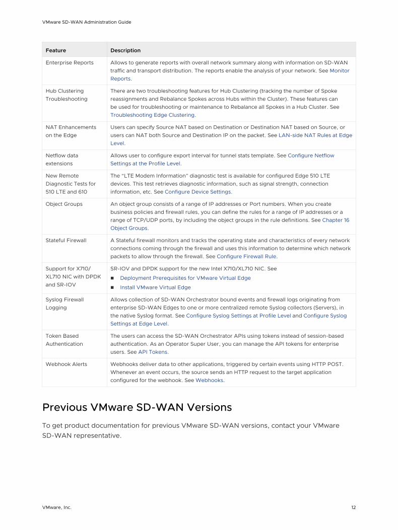
Enterprise Reports Allows to generate reports with overall network summary along with information on SD-WAN traffic and transport distribution. The reports enable the analysis of your network. See Monitor Reports.
Hub Clustering Troubleshooting
There are two troubleshooting features for Hub Clustering (tracking the number of Spoke reassignments and Rebalance Spokes across Hubs within the Cluster). These features can be used for troubleshooting or maintenance to Rebalance all Spokes in a Hub Cluster. See Troubleshooting Edge Clustering.
NAT Enhancements on the Edge
Users can specify Source NAT based on Destination or Destination NAT based on Source, or users can NAT both Source and Destination IP on the packet. See LAN-side NAT Rules at Edge Level.
Netflow data extensions
Allows user to configure export interval for tunnel stats template. See Configure Netflow Settings at the Profile Level.
New Remote Diagnostic Tests for 510 LTE and 610
The “LTE Modem Information” diagnostic test is available for configured Edge 510 LTE devices. This test retrieves diagnostic information, such as signal strength, connection information, etc. See Configure Device Settings.
Object Groups An object group consists of a range of IP addresses or Port numbers. When you create business policies and firewall rules, you can define the rules for a range of IP addresses or a range of TCP/UDP ports, by including the object groups in the rule definitions. See Chapter 16 Object Groups.
Stateful Firewall A Stateful firewall monitors and tracks the operating state and characteristics of every network connections coming through the firewall and uses this information to determine which network packets to allow through the firewall. See Configure Firewall Rule.
Support for X710/XL710 NIC with DPDK and SR-IOV
SR-IOV and DPDK support for the new Intel X710/XL710 NIC. See
n Deployment Prerequisites for VMware Virtual Edge
n Install VMware Virtual Edge
Syslog Firewall Logging
Allows collection of SD-WAN Orchestrator bound events and firewall logs originating from enterprise SD-WAN Edges to one or more centralized remote Syslog collectors (Servers), in the native Syslog format. See Configure Syslog Settings at Profile Level and Configure Syslog Settings at Edge Level.
Token Based Authentication
The users can access the SD-WAN Orchestrator APIs using tokens instead of session-based authentication. As an Operator Super User, you can manage the API tokens for enterprise users. See API Tokens.
Webhook Alerts Webhooks deliver data to other applications, triggered by certain events using HTTP POST. Whenever an event occurs, the source sends an HTTP request to the target application configured for the webhook. See Webhooks.
Previous VMware SD-WAN Versions
To get product documentation for previous VMware SD-WAN versions, contact your VMware SD-WAN representative.
VMware SD-WAN Administration Guide
VMware, Inc. 12

Overview 3VMware SD-WAN is a cloud network service solution enabling sites to quickly deploy Enterprise grade access to legacy and cloud applications over both private networks and Internet broadband.
Cloud-delivered Software-defined WAN assures enterprises the cloud application performance over Internet and hybrid WAN, while simplifying deployments and reducing costs.
The following figure shows the VMware SD-WAN solution components. The components are described in more detail in the following sections.
SD-WAN Edge
Orchestrator
Enterprise DC
Hybrid Cloud
Enterprise Data CenterBranch Site
Internet Cloud
Gateway
Cloud DCSaaS
Enterprise DC
SD-WAN Edge
PRIVATE/ MPLS
To become familiar with the basic configuration and Edge activation, see Activate Edges.
This chapter includes the following topics:
n Solution Components
VMware, Inc. 13

n Capabilities
n Tunnel Overhead and MTU
n Network Topologies
n Branch Site Topologies
n Roles and Privilege Levels
n User Role Matrix
n Key Concepts
n Supported Browsers
n Supported Modems
Solution Components
This section describes VMware solution components.
VMware SD-WAN Edge
A thin “Edge” that is zero IT touch provisioned from the cloud for secured, optimized connectivity to your apps and virtualized services. The SD-WAN Edges are zero-touch, enterprise-class devices or virtual software that provide secure and optimized connectivity to private, public and hybrid applications; compute; and virtualized services. SD-WAN Edges perform deep application recognition, application and per-packet steering, on-demand remediation performance metrics and end-to-end quality of service (QoS) in addition to hosting Virtual Network Function (VNF) services. An Edge pair can be deployed to provide High Availability (HA). Edges can be deployed in branches, large sites and data centers. All other network infrastructure is provided on-demand in the cloud.
VMware SD-WAN Orchestrator
The VMware SD-WAN Orchestrator provides centralized enterprise-wide configuration and real-time monitoring, as well as orchestrates the data flow into and through the SD-WAN overlay network. Additionally, it provides the one-click provisioning of virtual services across Edges, in centralized and regional enterprise service hubs and in the cloud.
VMware SD-WAN Gateways
VMware SD-WAN network consists of gateways deployed at top tier network points-of-presence and cloud data centers around the world, providing SD-WAN services to the doorstep of SaaS, IaaS and cloud network services, as well as access to private backbones. Multi-tenant, virtual Gateways are deployed both by VMware SD-WAN transit and cloud service provider partners. The gateways provide the advantage of an on-demand, scalable and redundant cloud network for optimized paths to cloud destinations as well as zero-installation applications.
VMware SD-WAN Administration Guide
VMware, Inc. 14

Capabilities
This section describes VMware SD-WAN capabilities.
Dynamic Multi-path Optimization
VMware Dynamic Multi-path Optimization is comprised of automatic link monitoring, dynamic link steering and on-demand remediation.
Link Steering and Remediation
Dynamic, application aware per-packet link steering is performed automatically based on the business priority of the application, embedded knowledge of network requirements of the application, and the real-time capacity and performance of each link. On-demand mitigation of individual link degradation through forward error correction, jitter buffering and negative acknowledgment proxy also protects the performance of priority and network sensitive applications. Both the dynamic per-packet link steering and on-demand mitigation combine to deliver robust, sub-second blocked and limited protection to improve application availability, performance and end user experience.
Cloud VPN
Cloud VPN is a 1-click, site-to-site, VPNC-compliant, IPSec VPN to connect VMware and Non VMware SD-WAN Sites while delivering real-time status and the health of the sites. The Cloud VPN establishes dynamic edge-to-edge communication for all branches based on service level objectives and application performance. Cloud VPN also delivers secure connectivity across all branches with PKI scalable key management. New branches join the VPN network automatically with access to all resources in other branches, enterprise data centers, and 3rd party data centers, like Amazon AWS.
Multi-source Inbound QoS
VMware classifies 3000+ applications enabling smart control. Out-of-the-box defaults set the multi-source inbound Quality of Service (QoS) parameters for different application types with IT required only to establish application priority. Knowledge of network requirements for different application types, automatic link capacity measurements and dynamic flow monitoring enables automation of QoS configurations and bandwidth allocations.
Firewall
VMware delivers stateful and context-aware (application, user, device) integrated application aware firewall with granular control of sub-applications, support for protocol-hopping applications – such as Skype and other peer-to-peer applications (e.g., disable Skype video and chat, but allow Skype audio). The secure firewall service is user- and device OS-aware with the ability to separate voice, video, data, and compliance traffic. Policies for BYOD devices (such as Apple iOS, Android, Windows, and Mac OS) on the corporate network are easily controlled.
VMware SD-WAN Administration Guide
VMware, Inc. 15

Network Service Insertion
The VMware Solution supports a platform to host multiple virtualized network functions to eliminate single-function appliances and reduce branch IT complexity. VMware service-chains traffic from the branch to both cloud-based and enterprise regional hub services, with assured performance, security, and manageability. Branches leverage consolidated security and network services, including those from partners like Zscaler and Websense. Using a simple click-to-enable interface, services can be inserted in the cloud and on-premise with application specific policies.
Activation
SD-WAN Edge appliances automatically authenticate, connect, and receive configuration instructions once they are connected to the Internet in a zero-touch deployment. They deliver a highly available deployment with SD-WAN Edge redundancy protocol and integrate with the existing network with support for OSPF routing protocol and benefit from dynamic learning and automation.
Overlay Flow Control
The SD-WAN Edge learns routes from adjacent routers through OSPF and BGP. It sends the learned routes to the Gateway/Controller. The Gateway/Controller acts like a route reflector and sends the learned routes to other SD-WAN Edges. The Overlay Flow Control (OFC) enables enterprise-wide route visibility and control for ease of programming and for full and partial overlay.
OSPF
VMware supports inbound/outbound filters to OSPF neighbors, OE1/OE2 route types, MD5 authentication. Routes learned through OSPF will be automatically redistributed to the controller hosted in the cloud or on-premise.
BGP
VMware supports inbound/outbound filters and the filter can be set to Deny, or optionally adding/changing the BGP attribute to influence the path selection, i.e. RFC 1998 community, MED, AS-Path prepend, and local preference.
Segmentation
Network segmentation is an important feature for both enterprises and service providers. In the most basic form, segmentation provides network isolation for management and security reasons. Most common forms of segmentation are VLANs for L2 and VRFs for L3.
Typical Use Cases for Segmentation:
n Line of Business Separation: Engineering, HR etc. for Security/Audit
n User Data Separation: Guest, PCI, Corporate traffic separation
VMware SD-WAN Administration Guide
VMware, Inc. 16

n Enterprise uses overlapping IP addresses in different VRFs
However, the legacy approach is limited to a single box or two physically connected devices. To extend the functionality, segmentation information must be carried across the network.
VMware enables end-to-end segmentation. When the packet traverses through the Edge, the Segment ID is added to the packet and is forwarded to the Hub and cloud Gateway, allowing network service isolation from the Edge to the cloud and data center. This provides the ability to group prefixes into a unique routing table, making the business policy segment aware.
Routing
In Dynamic Routing, SD-WAN Edge learns routes from adjacent routers through OSPF or BGP. The SD-WAN Orchestrator maintains all the dynamically learned routes in a global routing table called the Overlay Flow Control. The Overlay Flow Control allows management of dynamic routes in the case of "Overlay Flow Control sync" and "change in Inbound/Outbound filtering configuration." The change in inbound filtering for a prefix from IGNORE to LEARN would fetch the prefix from the Overlay Flow Control and install into the Unified routing table.
For more information, see Chapter 18 Configure Dynamic Routing with OSPF or BGP.
Business Policy Framework
Quality of Service (QoS), resource allocations, link/path steering, and error correction are automatically applied based on business policies and application priorities. Orchestrate traffic based on transport groups defined by private and public links, policy definition, and link characteristics.
Tunnel Overhead and MTU
VMware, like any overlay, imposes additional overhead on traffic that traverses the network. This section first describes the overhead added in a traditional IPsec network and how it compares with VMware, which is followed by an explanation of how this added overhead relates to MTU and packet fragmentation behaviors in the network.
IPsec Tunnel Overhead
In a traditional IPsec network, traffic is usually carried in an IPsec tunnel between endpoints. A standard IPsec tunnel scenario (AES 128-bit encryption using ESP [Encapsulating Security Payload]) when encrypting traffic, results in multiple types of overhead as follows:
n Padding
n AES encrypts data in 16-byte blocks, referred to as "block" size.
n If the body of a packet is smaller than or indivisible by block size, it is padded to match the block size.
n Examples:
n A 1-byte packet will become 16-bytes with 15-bytes of padding.
VMware SD-WAN Administration Guide
VMware, Inc. 17

n A 1400-byte packet will become 1408-bytes with 8-bytes of padding.
n A 64-byte packet does not require any padding.
n IPsec headers and trailers:
n UDP header for NAT Traversal (NAT-T).
n IP header for IPsec tunnel mode.
n ESP header and trailer.
Element Size in Bytes
IP Header 20
UDP Header 8
IPsec Sequence Number 4
IPsec SPI 4
Initialization Vector 16
Padding 0 – 15
Padding Length 1
Next Header 1
Authentication Data 12
Total 66-81
Note The examples provided assume at least one device is behind a NAT device. If no NAT is used, then IPsec overhead is 20-bytes less, as NAT-T is not required. There is no change to the behavior of VMware regardless of whether NAT is present or not (NAT-T is always enabled).
VMware Tunnel Overhead
In order to support Dynamic Multipath Optimization™ (DMPO), VMware encapsulates packets in a protocol called the VeloCloud Multipath Protocol (VCMP). VCMP adds 31-bytes of overhead for user packets to support resequencing, error correction, network analysis, and network segmentation within a single tunnel. VCMP operates on an IANA-registered port of UDP 2426. To ensure consistent behavior in all potential scenarios (unencrypted, encrypted and behind a NAT, encrypted but not behind a NAT), VCMP is encrypted using transport mode IPsec and forces NAT-T to be true with a special NAT-T port of 2426.
VMware SD-WAN Administration Guide
VMware, Inc. 18
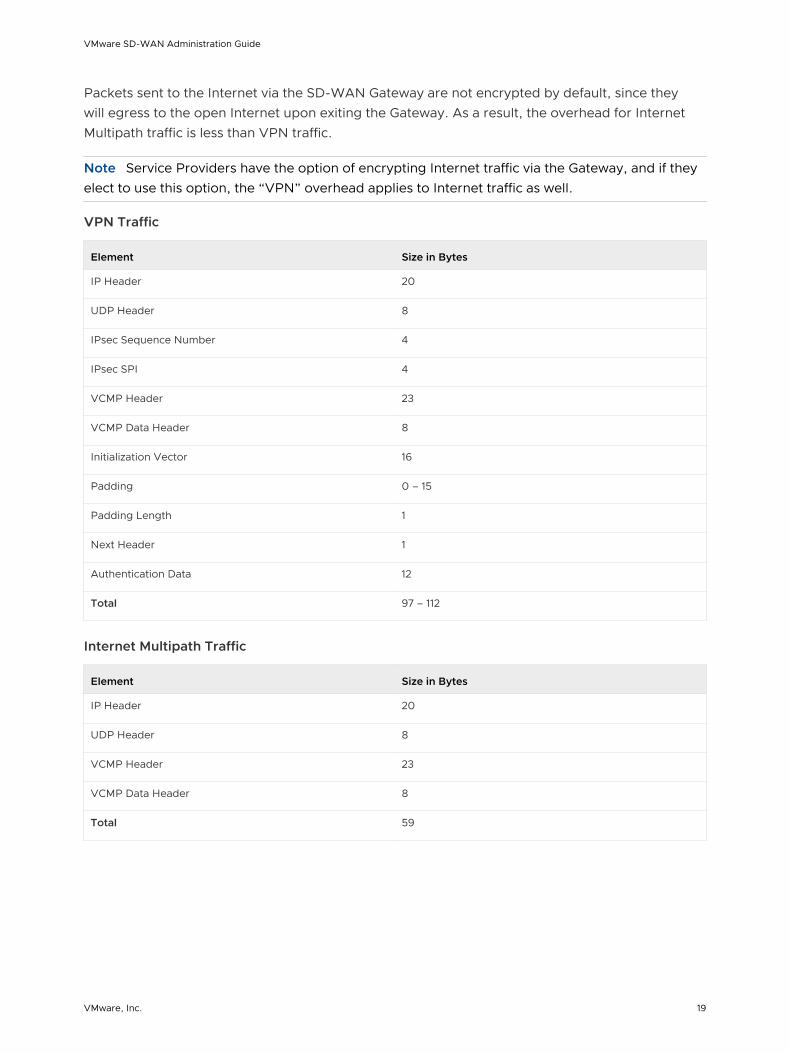
Packets sent to the Internet via the SD-WAN Gateway are not encrypted by default, since they will egress to the open Internet upon exiting the Gateway. As a result, the overhead for Internet Multipath traffic is less than VPN traffic.
Note Service Providers have the option of encrypting Internet traffic via the Gateway, and if they elect to use this option, the “VPN” overhead applies to Internet traffic as well.
VPN Traffic
Element Size in Bytes
IP Header 20
UDP Header 8
IPsec Sequence Number 4
IPsec SPI 4
VCMP Header 23
VCMP Data Header 8
Initialization Vector 16
Padding 0 – 15
Padding Length 1
Next Header 1
Authentication Data 12
Total 97 – 112
Internet Multipath Traffic
Element Size in Bytes
IP Header 20
UDP Header 8
VCMP Header 23
VCMP Data Header 8
Total 59
VMware SD-WAN Administration Guide
VMware, Inc. 19

Path MTU Discovery
After it is determined how much overhead will be applied, the SD-WAN Edge must discover the maximum permissible MTU in order to calculate the effective MTU for customer packets. To find the maximum permissible MTU, the Edge performs Path MTU Discovery:
n For public Internet WAN links:
n Path MTU discovery is performed to all Gateways.
n The MTU for all tunnels will be set to the minimum MTU discovered.
n For private WAN links:
n Path MTU discovery is performed to all other Edges in the customer network.
n The MTU for each tunnel is set based on the results of Path MTU discovery.
The Edge will first attempt RFC 1191 Path MTU discovery, where a packet of the current known link MTU (Default: 1500 bytes) is sent to the peer with the "Don’t Fragment" (DF) bit set in the IP header. If this packet is received on the remote Edge or Gateway, an acknowledgement packet of the same size is returned to the Edge. If the packet cannot reach the remote Edge or Gateway due to MTU constraints, the intermediate device is expected to send an ICMP destination unreachable (fragmentation needed) message. When the Edge receives the ICMP unreachable message, it will validate the message (to ensure the MTU value reported is sane) and once validated, adjust the MTU. The process then repeats until the MTU is discovered.
In some cases (e.g. USB LTE dongles), the intermediate device will not send an ICMP unreachable message even if the packet is too large. If RFC 1191 fails (the Edge did not receive an acknowledgement or ICMP unreachable), it will fall back to RFC 4821 Packetization Layer Path MTU Discovery. The Edge will attempt to perform a binary search to discover the MTU.
When an MTU is discovered for a peer, all tunnels to this peer are set to the same MTU. That means that if an Edge has one link with an MTU of 1400 bytes and one link with an MTU of 1500 bytes, all tunnels will have an MTU of 1400 bytes. This ensures that packets can be sent on any tunnel at any time using the same MTU. We refer to this as the Effective Edge MTU. Based on the destination (VPN or Internet Multipath) the overhead outlined above is subtracted to compute the Effective Packet MTU. For Direct Internet or other underlay traffic, the overhead is 0 bytes, and because link failover is not required, the effective Packet MTU is identical to the discovered WAN Link MTU.
Note VMware RFC 4821 Packetization Layer Path MTU Discovery will measure MTU to a minimum of 1300 bytes. If your MTU is less than 1300 bytes, you must manually configure the MTU.
VPN Traffic and MTU
Now that the SD-WAN Edge has discovered the MTU and calculated the overheads, an effective MTU can be computed for client traffic. The Edge will attempt to enforce this MTU as efficiently as possible for the various potential types of traffic received.
TCP Traffic
VMware SD-WAN Administration Guide
VMware, Inc. 20

The Edge automatically performs TCP MSS (Maximum Segment Size) adjustment for TCP packets received. As SYN and SYN|ACK packets traverse the Edge, the MSS is rewritten based on the Effective Packet MTU.
Non-TCP Traffic without DF bit set
If the packet is larger than the Effective Packet MTU, the Edge automatically performs IP fragmentation as per RFC 791.
Non-TCP Traffic with DF bit set
If the packet is larger than the Effective Packet MTU:
n The first time a packet is received for this flow (IP 5-tuple), the Edge drops the packet and sends an ICMP Destination unreachable (fragmentation needed) as per RFC 791.
n If subsequent packets are received for the same flow which are still too large, these packets are fragmented into multiple VCMP packets and reassembled transparently before handoff at the remote end.
Network Topologies
This section describes network topologies for branches and data centers.
Branches to Private Third Party (VPN)
Customers with a private data center or cloud data center often want a way to include it in their network without having to define a tunnel from each individual branch office site to the data center. By defining the site as a Non VMware SD-WAN Site, a single tunnel will be built from the nearest SD-WAN Gateway to the customer’s existing router or firewall. All the SD-WAN Edges that need to talk to the site will connect to the same SD-WAN Gateway to forward packets across the tunnel, simplifying the overall network configuration and new site bring up.
SD-WAN Edges
SD-WAN Gateway
Enterprise DC
VMware simplifies the branch deployment and delivers enterprise great application performance or public/private link for cloud and/or on-premise applications.
VMware SD-WAN Administration Guide
VMware, Inc. 21

Branch Site Topologies
The VMware service defines two or more different branch topologies designated as Bronze, Silver, and Gold. In addition, pairs of SD-WAN Edges can be configured in a High Availability (HA) configuration at a branch location.
Bronze Site Topology
The Bronze topology represents a typical small site deployment where there are one or two WAN links connected to the public internet. In the Bronze topology, there is no MPLS connection and there is no L3 switch on the LAN-side of the SD-WAN Edge. The following figure shows an overview of the Bronze topology.
Internet
Internet1
Internet2
Silver Site Topology
The Silver topology represents a site that also has an MPLS connection, in addition to one or more public Internet links. There are two variants of this topology.
The first variant is a single L3 switch with one or more public internet links and a MPLS link, which is terminated on a CE and is accessible through the L3 switch. In this case, the SD-WAN Edge goes between the L3 switch and Internet (replacing existing firewall/router).
Internet
MPLS
The second variant includes MPLS and Internet routers deployed using HSRP with an L2 switch on the LAN side. In this case, the SD-WAN Edge replaces the L2 switch.
VMware SD-WAN Administration Guide
VMware, Inc. 22

Internet
MPLS
Gold Site Topology
The Gold topology is a typical large branch site topology. The topology includes active/active L3 switches which communicate routes using OSPF or BGP, one or more public internet links and a MPLS link which is terminated on a CE router that is also talking to OSPF or BGP and is accessible through the L3 switches.
SD-WAN Edge
L3 L3
LAN LAN
MPLS Internet
A key differentiation point here is a single WAN link is accessible via two routed interfaces. To support this, a virtual IP address is provisioned inside the edge and can be advertised over OSPF, BGP, or statically routed to the interfaces.
VMware SD-WAN Administration Guide
VMware, Inc. 23

Internet
MPLS
High Availability (HA) Configuration
The following figure provides a conceptual overview of the VMware High Availability configuration using two SD-WAN Edges, one active and one standby.
Failover link
W1
L2
L1 L1
L2
W1W2 W2
ISP1 ISP2
Active Standby
Connecting the L1 ports on each edge is used to establish a failover link. The standby SD-WAN Edge blocks all ports except the L1 port for the failover link.
On-premise Topology
The on-premise topology consists of two hubs and multiple branches, with or without SD-WAN Edge. Each hub has hybrid WAN connectivity. There are several branch types.
Note The Gold Site is not currently in the scope of this release and will be added at a later time.
The MPLS network runs BGP and peers with all the CE routers. At Hub 1, Hub 2, and Silver 1 sites, the L3 switch runs OSPF, or BGP with the CE router and firewall (in case of hub sites).
VMware SD-WAN Administration Guide
VMware, Inc. 24

Gold Site Dual L3
Switches (2.1 only)
Silver Site Single L2/L3
Switch
Legacy Site MPLS with
VPN backup
WAN Headend
To Core switch (Campus/DC)
Existing VPN hub
Bronze Site Single/dual
Internet
Internet
SaaS
Internet
MPLS
MPLS
In some cases, there may be redundant data centers which advertise the same subnets with different costs. In this scenario, both data centers can be configured as edge-to-edge VPN hubs. Since all edges connect directly to each hub, the hubs in fact also connect directly to each other. Based on route cost, traffic is steered to the preferred active data center.
VMware SD-WAN Administration Guide
VMware, Inc. 25
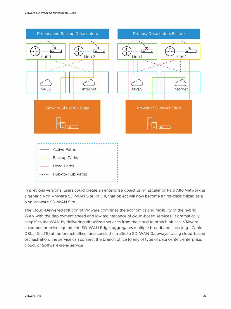
Hub 1
MPLS Internet
VMware SD-WAN Edge
Hub 2
Primary and Backup Datacenters
Hub 1
MPLS Internet
VMware SD-WAN Edge
Hub 2
Active Paths
Backup Paths
Dead Paths
Hub-to-Hub Paths
Primary Datacenters Failure
In previous versions, users could create an enterprise object using Zscaler or Palo Alto Network as a generic Non VMware SD-WAN Site. In 3.4, that object will now become a first-class citizen as a Non VMware SD-WAN Site.
The Cloud-Delivered solution of VMware combines the economics and flexibility of the hybrid WAN with the deployment speed and low maintenance of cloud-based services. It dramatically simplifies the WAN by delivering virtualized services from the cloud to branch offices. VMware customer-premise equipment, SD-WAN Edge, aggregates multiple broadband links (e.g., Cable, DSL, 4G-LTE) at the branch office, and sends the traffic to SD-WAN Gateways. Using cloud-based orchestration, the service can connect the branch office to any of type of data center: enterprise, cloud, or Software-as-a-Service.
VMware SD-WAN Administration Guide
VMware, Inc. 26

SD-WAN Edge is a compact, thin Edge device that is zero-IT-touch provisioned from the cloud for secure, optimized connectivity to applications and data. A cluster of gateways is deployed globally at top-tier cloud data centers to provide scalable and on-demand cloud network services. Working with the Edge, the cluster delivers dynamic, multi-path optimization so multiple, ordinary broadband links appear as a single, high bandwidth link. Orchestrator management provides centralized configuration, real-time monitoring, and one-click provisioning of virtual services.
Roles and Privilege Levels
VMware has pre-defined roles with different set of privileges.
n IT Administrator (or Administrator)
n Site Contact at each site where an SD-WAN Edge device is deployed
n IT Operator (or Operator)
n IT Partner (or Partner)
Administrator
The Administrator configures, monitors, and administers the VMware service operation. There are three Administrator roles:
Administrator Role Description
Enterprise Standard Admin Can perform all configuration and monitoring tasks.
Enterprise Superuser Can perform the same tasks as an Enterprise Standard Admin and can also create additional users with the Enterprise Standard Admin, Enterprise MSP, and Customer Support role.
Enterprise Support Can perform configuration review and monitoring tasks but cannot view user identifiable application statistics and can only view configuration information.
Note An Administrator should be thoroughly familiar with networking concepts, web applications, and requirements and procedures for the Enterprise.
Site Contact
The Site Contact is responsible for SD-WAN Edge physical installation and activation with the VMware service. The Site Contact is a non-IT person who has the ability to receive an email and perform the instructions in the email for Edge activation.
Operator
The Operator can perform all of the tasks that an Administrator can perform, plus additional operator-specific tasks – such as create and manage customers, Cloud Edges, and Gateways. There are four Operator roles:
VMware SD-WAN Administration Guide
VMware, Inc. 27

Operator Role Description
Standard Operator Can perform all configuration and monitoring tasks.
Superuser Operator Can view and create additional users with the Operator roles.
Business Specialist Operator Can create and manage customer accounts.
Customer Support Operator Can monitor Edges and activity.
An Operator should be thoroughly familiar with networking concepts, web applications, and requirements and procedures for the Enterprise.
Partner
The Partner can perform all of the tasks that an Administrator can perform, along with additional Partner specific tasks – such as creating and managing customers. There are four Partner roles:
Partner Role Description
Standard Admin Can perform all configuration and monitoring tasks.
Superuser Can view and create additional users with the Partner roles.
Business Specialist Can perform configuration and monitoring tasks but cannot view user identifiable application statistics.
Customer Support Can perform configuration review and monitoring tasks but cannot view user identifiable application statistics and can only view configuration information.
A Partner should be thoroughly familiar with networking concepts, web applications, and requirements and procedures for the Enterprise.
User Role Matrix
This section describes feature access according to VMware user roles.
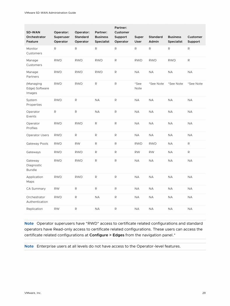
Operator-level SD-WAN Orchestrator Features User Role Matrix
The following table lists the Operator-level user roles that have access to the SD-WAN Orchestrator features.
n R: Read
n W: Write (Modify/Edit)
n D: Delete
n NA: No Access
VMware SD-WAN Administration Guide
VMware, Inc. 28
SD-WAN Orchestrator Feature
Operator: Superuser Operator
Operator: Standard Operator
Partner: Business Specialist
Partner: Customer Support Operator
Super User
Standard Admin
Business Specialist
Customer Support
Monitor Customers
R R R R R R R R
Manage Customers
RWD RWD RWD R RWD RWD RWD R
Manage Partners
RWD RWD RWD R NA NA NA NA
(Managing Edge) Software Images
RWD RWD R R *See Note
*See Note *See Note *See Note
System Properties
RWD R NA R NA NA NA NA
Operator Events
R R NA R NA NA NA NA
Operator Profiles
RWD RWD R R NA NA NA NA
Operator Users RWD R R R NA NA NA NA
Gateway Pools RWD RW R R RWD RWD NA R
Gateways RWD RWD R R RW RW NA R
Gateway Diagnostic Bundle
RWD RWD R R NA NA NA NA
Application Maps
RWD RWD R R NA NA NA NA
CA Summary RW R R R NA NA NA NA
Orchestrator Authentication
RWD R NA R NA NA NA NA
Replication RW R NA R NA NA NA NA
Note Operator superusers have "RWD" access to certificate related configurations and standard operators have Read-only access to certificate related configurations. These users can access the certificate related configurations at Configure > Edges from the navigation panel.*
Note Enterprise users at all levels do not have access to the Operator-level features.
VMware SD-WAN Administration Guide
VMware, Inc. 29

Partner-level SD-WAN Orchestrator Features User Role Matrix
The following table lists the Partner-level user roles that have access to the SD-WAN Orchestrator features.
n R: Read
n W: Write (Modify/Edit)
n D: Delete
n NA: No Access
SD-WAN Orchestrator Feature Partner: Superuser
Partner: Standard Admin Business Specialist CustomerSupport
Monitor Customers R R R R
Manage Customers RWD RWD RWD R
Events R R NA R
Admins RWD R NA R
Overview R R R R
Settings RW R R R
Gateway Pools RW RWD NA R
Gateways RW RW NA R
Enterprise-level SD-WAN Orchestrator Features User Role Matrix
The following table lists the Enterprise-level user roles that have access to the SD-WAN Orchestrator features.
n R: Read
n W: Write (Modify/Edit)
n D: Delete
n NA: No Access
SD-WAN Orchestrator FeatureEnterprise: Super User
Enterprise: Standard Admin
Customer Support Read Only
Monitor > Edges R R R R
Monitor > Network Services R R R R
Monitor > Routing R R R NA
Monitor > Alerts R R R NA
Monitor > Events R R R NA
VMware SD-WAN Administration Guide
VMware, Inc. 30

SD-WAN Orchestrator FeatureEnterprise: Super User
Enterprise: Standard Admin
Customer Support Read Only
Configure > Edges RWD RWD R NA
Configure > Profiles RWD RWD R NA
Configure > Networks RWD RWD R NA
Configure > Segments RWD RWD R NA
Configure > Overlay
Flow Control
RWD RWD R NA
Configure > Network Services RWD RWD R NA
Configure > Alerts & Notifications RW RW R NA
Test & Troubleshoot > Remote Diagnostics
RW RW RW NA
Test & Troubleshoot > Remote Actions RW RW RW NA
Test & Troubleshoot > Packet Capture RW RW RW NA
Administration > System Settings RW RW RW NA
Administration > Administrators RW R R NA
Note Operator users have complete access to the SD-WAN Orchestrator features.
Key Concepts
This section describes the key concepts and the core configurations of SD-WAN Orchestrator.
Configurations
The VMware service has four core configurations that have a hierarchical relationship. Create these configurations in the SD-WAN Orchestrator.
The following table provides an overview of the configurations.
Configuration Description
Network Defines basic network configurations, such as IP addressing and VLANs. Networks can be designated as Corporate or Guest and there can be multiple definitions for each network.
Network Services Define several common services used by the VMware Service, such as BackHaul Sites, Cloud VPN Hubs, Non VMware SD-WAN Sites, Cloud Proxy Services, DNS services, and Authentication Services.
VMware SD-WAN Administration Guide
VMware, Inc. 31

Configuration Description
Profile Defines a template configuration that can be applied to multiple Edges. A Profile is configured by selecting a Network and Network Services. A profile can be applied to one or more Edge models and defines the settings for the LAN, Internet, Wireless LAN, and WAN Edge Interfaces. Profiles can also provide settings for Wi-Fi Radio, SNMP, Netflow, Business Policies and Firewall configuration.
Edge Configurations provide a complete group of settings that can be downloaded to an Edge device. The Edge configuration is a composite of settings from a selected Profile, a selected Network, and Network Services. An Edge configuration can also override settings or add ordered policies to those defined in the Profile, Network, and Network Services.
The following image shows a detailed overview of the relationships and configuration settings of multiple Edges, Profiles, Networks, and Network Services.
Profile
Overview• Networks• Services
Business Policy
Firewall
Device• Networks• Cloud VPN• Device• WiFi
• DNS• Authentication• SNMP• Network Flow Network Services
Service 2Service 1 ...
Edges
Edge 1
...
Edge x
Edges
Edge 1
...
Edge y
Edges
Edge 1
...
Edge z
Profile 1 Profile 2 Profile 3 ...
Edge
Overview• Profile• Contact & Location
Business Policy
Firewall
Device• Networks• HA• Cloud VPN• Device• Static Routes• WiFi
• ICMP Probes• ICMP Responders• DNS• Authentication• SNMP• Netflow
Network 1Networks Network 2 ...
Network
Corporate (1-N)
Guest (1-N)
Network Services
Backhaul Sites
Cloud VPN Hubs
Non-VMware SD-WAN Sites
Cloud Proxy
DNS
Authentication
A single Profile can be assigned to multiple Edges. An individual Network configuration can be used in more than one Profile. Network Services configurations are used in all Profiles.
Networks
Networks are standard configurations that define network address spaces and VLAN assignments for Edges. You can configure the following network types:
n Corporate or trusted networks, which can be configured with either overlapping addresses or non-overlapping addresses.
n Guest or untrusted networks, which always use overlapping addresses.
VMware SD-WAN Administration Guide
VMware, Inc. 32

You can define multiple Corporate and Guest Networks, and assign VLANs to both the Networks.
With overlapping addresses, all Edges that use the Network have the same address space. Overlapping addresses are associated with non-VPN configurations.
With non-overlapping addresses, an address space is divided into blocks of an equal number of addresses. Non-overlapping addresses are associated with VPN configurations. The address blocks are assigned to Edges that use the Network so that each Edge has a unique set of addresses. Non-overlapping addresses are required for Edge-to-Edge and Edge -to- Non VMware SD-WAN Site VPN communication. The VMware configuration creates the required information to access an Enterprise Data Center Gateway for VPN access. An administrator for the Enterprise Data Center Gateway uses the IPSec configuration information generated during Non VMware SD-WAN Site VPN configuration to configure the VPN tunnel to the Non VMware SD-WAN Site.
The following image shows unique IP address blocks from a Network configuration being assigned to SD-WAN Edges.
VMware SD-WAN Administration Guide
VMware, Inc. 33

Enterprise Data Center
VMware SD-WAN Edge 2
VMware SD-WAN Network Configuration
Non-overlapping IP Addresses
Block 1 Block 2 Block n...
IPsec Configuration
VPN
VMwareSD-WAN
by VeloCloudEnterprise
DC Gateway
VMware SD-WAN Orchestrator Cloud Management
VMware SD-WAN Edge 1
Note When using non-overlapping addresses, the SD-WAN Orchestrator automatically allocates the blocks of addresses to the Edges. The allocation happens based on the maximum number of Edges that might use the network configuration.
Network Services
You can define your Enterprise Network Services and use them across all the Profiles. This includes services for Authentication, Cloud Proxy, Non VMware SD-WAN Sites, and DNS. The defined Network Services are used only when they are assigned to a Profile.
Profiles
A profile is a named configuration that defines a list of VLANs, Cloud VPN settings, wired and wireless Interface Settings, and Network Services such as DNS Settings, Authentication Settings, Cloud Proxy Settings, and VPN connections to Non VMware SD-WAN Sites. You can define a standard configuration for one or more SD-WAN Edges using the profiles.
VMware SD-WAN Administration Guide
VMware, Inc. 34

Profiles provide Cloud VPN settings for Edges configured for VPN. The Cloud VPN Settings can enable or disable Edge-to-Edge and Edge-to- Non VMware SD-WAN Site VPN connections.
Profiles can also define rules and configuration for the Business Policies and Firewall settings.
Edges
You can assign a profile to an Edge and the Edge derives most of the configuration from the Profile.
You can use most of the settings defined in a Profile, Network, or Network Services without modification in an Edge configuration. However, you can override the settings for the Edge configuration elements to tailor an Edge for a specific scenario. This includes settings for Interfaces, Wi-Fi Radio Settings, DNS, Authentication, Business Policy, and Firewall.
In addition, you can configure an Edge to augment settings that are not present in Profile or Network configuration. This includes Subnet Addressing, Static Route settings, and Inbound Firewall Rules for Port Forwarding and 1:1 NAT.
Orchestrator Configuration Workflow
VMware supports multiple configuration scenarios. The following table lists some of the common scenarios:
Scenario Description
SaaS Used for Edges that do not require VPN connections between Edges, to a Non VMware SD-WAN Site, or to a VMware SD-WAN Site. The workflow assumes the addressing for the Corporate Network using overlapping addresses.
Non VMware SD-WAN Site via VPN
Used for Edges that require VPN connections to a Non VMware SD-WAN Site such as Amazon Web Services, Zscaler, Cisco ISR, or ASR 1000 Series. The workflow assumes the addressing for the Corporate Network using non-overlapping addresses and the Non VMware SD-WAN Sites are defined in the profile.
VMware SD-WAN Site VPN
Used for Edges that require VPN connections to a VMware SD-WAN Site such as an Edge Hub or a Cloud VPN Hub. The workflow assumes the addressing for the Corporate Network using non-overlapping addresses and the VMware SD-WAN Sites are defined in the profile.
For each scenario, perform the configurations in the SD-WAN Orchestrator in the following order:
Step 1: Network
Step 2: Network Services
Step 3: Profile
Step 4: Edge
The following table provides a high-level outline of the Quick Start configuration for each of the workflows. You can use the preconfigured Network, Network Services, and Profile configurations for Quick Start Configurations. For VPN configurations modify the existing VPN Profile and configure the VMware SD-WAN Site or Non VMware SD-WAN Site. The final step is to create a new Edge and activate it.
VMware SD-WAN Administration Guide
VMware, Inc. 35
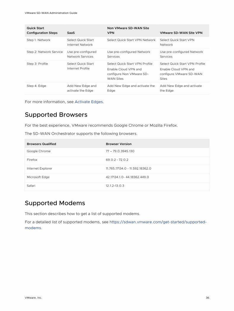
Quick Start Configuration Steps SaaS
Non VMware SD-WAN Site VPN VMware SD-WAN Site VPN
Step 1: Network Select Quick Start Internet Network
Select Quick Start VPN Network Select Quick Start VPN Network
Step 2: Network Service Use pre-configured Network Services
Use pre-configured Network Services
Use pre-configured Network Services
Step 3: Profile Select Quick Start Internet Profile
Select Quick Start VPN Profile
Enable Cloud VPN and configure Non VMware SD-WAN Sites
Select Quick Start VPN Profile
Enable Cloud VPN and configure VMware SD-WAN Sites
Step 4: Edge Add New Edge and activate the Edge
Add New Edge and activate the Edge
Add New Edge and activate the Edge
For more information, see Activate Edges.
Supported Browsers
For the best experience, VMware recommends Google Chrome or Mozilla Firefox.
The SD-WAN Orchestrator supports the following browsers.
Browsers Qualified Browser Version
Google Chrome 77 – 79.0.3945.130
Firefox 69.0.2 - 72.0.2
Internet Explorer 11.765.17134.0 - 11.592.18362.0
Microsoft Edge 42.17134.1.0- 44.18362.449.0
Safari 12.1.2-13.0.3
Supported Modems
This section describes how to get a list of supported modems.
For a detailed list of supported modems, see https://sdwan.vmware.com/get-started/supported-modems.
VMware SD-WAN Administration Guide
VMware, Inc. 36

User Agreement 4An Enterprise Superuser or Partner Superuser might see a user agreement upon logging into the SD-WAN Orchestrator. The user must accept the agreement to get access to the SD-WAN Orchestrator. If the user does not accept the agreement, he or she will be automatically logged out.
VMware, Inc. 37

Log in to VMware SD-WAN Orchestrator Using SSO for Enterprise User
5Describes how to log in to VMware SD-WAN Orchestrator using Single Sign On (SSO) as an Enterprise user.
To login into SD-WAN Orchestrator using SSO as an Enterprise user:
Prerequisites
n Ensure you have configured SSO authentication in SD-WAN Orchestrator. For more information, see Configure Single Sign On for Enterprise User.
n Ensure you have set up roles, users, and OIDC application for SSO in your preferred IDPs. For more information, see Configure an IDP for Single Sign On.
Procedure
1 In a web browser, launch a SD-WAN Orchestrator application as Enterprise user.
The VMware SD-WAN Orchestrator screen appears.
2 Click Sign In With Your Identity Provider.
3 In the Enter your Organization Domain text box, enter the domain name used for the SSO configuration and click Sign In.
The IDP configured for SSO will authenticate the user and redirect the user to the configured SD-WAN Orchestrator URL.
Note Once the users log in to the SD-WAN Orchestrator using SSO, they will not be allowed to login again as native users.
VMware, Inc. 38
Monitor Enterprises 6The SD-WAN Orchestrator provides monitoring functionality that enables you to observe various performance and operational characteristics of VMware SD-WAN Edges. Monitoring functionality is accessible in Monitor area of the navigation panel.
This chapter includes the following topics:
n Monitor Navigation Panel
n Network Overview
n Monitor Edges
n Monitor Network Services
n Monitor Routing
n Monitor Alerts
n Monitor Events
n Monitor Reports
Monitor Navigation Panel
The following monitoring capabilities are displayed under Monitor in the navigation panel.
n Network Overview
n Monitor Edges
n Monitor Network Services
n Monitor Routing
n Monitor Alerts
n Monitor Events
Network Overview
The Network Overview feature helps to monitor networks by checking the Edge and Link (activated Edge) status summary. Clicking Monitor > Network Overview in the navigation panel opens the Network Overview screen, which provides a visual summary about the enterprises
VMware, Inc. 39
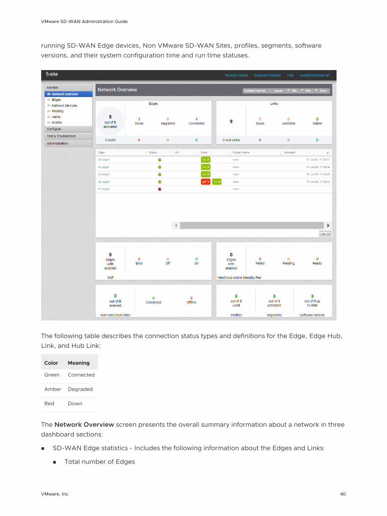
running SD-WAN Edge devices, Non VMware SD-WAN Sites, profiles, segments, software versions, and their system configuration time and run time statuses.
The following table describes the connection status types and definitions for the Edge, Edge Hub, Link, and Hub Link:
Color Meaning
Green Connected
Amber Degraded
Red Down
The Network Overview screen presents the overall summary information about a network in three dashboard sections:
n SD-WAN Edge statistics - Includes the following information about the Edges and Links:
n Total number of Edges
VMware SD-WAN Administration Guide
VMware, Inc. 40

n Total number of Edge Hubs
n Total number of Links
n Total number of Hub Links
n Count of Edges/Edge Hubs (Connected, Degraded, and Down)
n Count of Link/Hub Links (Stable, Unstable, and Down)
n Summary dashboard table - Includes a table that displays top ten Edges, or Edge Hubs, or Links, or Hub Links sorted by last contact time, based on the selected filter criteria in the SD-WAN Edge statistics section.
n Non-Edge statistics - Includes the following non-edge related information:
n Total number of Virtual Network Functions (VNFs)-enabled Edges
n Count of VNFs-enabled Edges (Error, On, and Off)
n Total number of VMware Active Standby Pair-enabled Edges
n Count of VMware Active Standby Pair-enabled Edges (Failed, Pending, and Ready)
n Total number of enabled Non VMware SD-WAN Sites
n Count of Non VMware SD-WAN Sites (Connected and Offline)
n Count of used Profiles out of the total number of Profiles configured for the Enterprise.
n Count of activated Segments out of the total number of Segments configured for the Enterprise.
n Count of Edges with up-to-date Software version out of the total number of Edges configured for the Enterprise.
Note The minimum supported edge version is 2.4.0. You can change the target edge version against which the edges will be compared by using the system property product.edge.version.minimumSupported.
You can also get detailed information on a specific item in the Network Overview screen by clicking the link on the respective item or metric. For example, clicking the Edge link in the summary dashboard table takes you to the Edge detail dashboard for the selected Edge.
You can configure the refresh time interval for the information displayed in the Network Overview dashboard screen to one of the following options:
n pause
n 30s
n 60s
n 5min
VMware SD-WAN Administration Guide
VMware, Inc. 41

Monitor Edges
You can monitor the status of Edges and view the details of each Edge like the WAN links, top applications used by the Edges, usage data through the network sources and traffic destinations, business priority of network traffic, system information, details of Gateways connected to the Edge, and so on.
To monitor the Edge details:
1 In the Enterprise portal, click Monitor > Edges.
2 The Edges page displays the Edges associated with the Enterprise.
The page displays the following details of Edges:
n Table of edges – Lists all edges provisioned in the network.
n Search – Enter a term to search for s specific detail. Click the drop-down arrow to filter the view by specific criteria.
n Cols – Click to show or hide the columns. By default, Edge and Status information are displayed.
n Reset – Click to reset the view to default settings.
n Refresh – Click to refresh the details displayed with the most current data.
n Export – Click to export all data to a file, in CSV format.
Click the link to an Edge to view the details pertaining to the selected Edge. Click the relevant tabs to view the corresponding information. Each tab displays a drop-down list at the top which allows you to select a specific time period. The tab displays the details for the selected duration.
For each Edge, you can view the following details:
n Overview Tab
n QoE Tab
VMware SD-WAN Administration Guide
VMware, Inc. 42
n Transport Tab
n Applications Tab
n Sources Tab
n Destinations Tab
n Business Priority Tab
n System Tab
Overview Tab
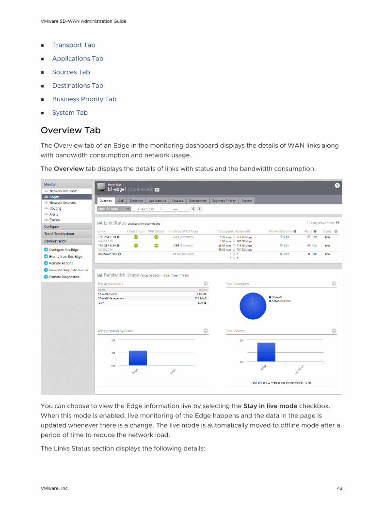
The Overview tab of an Edge in the monitoring dashboard displays the details of WAN links along with bandwidth consumption and network usage.
The Overview tab displays the details of links with status and the bandwidth consumption.
You can choose to view the Edge information live by selecting the Stay in live mode checkbox. When this mode is enabled, live monitoring of the Edge happens and the data in the page is updated whenever there is a change. The live mode is automatically moved to offline mode after a period of time to reduce the network load.
The Links Status section displays the following details:
VMware SD-WAN Administration Guide
VMware, Inc. 43
Option Description
Links The Interface and WAN links of the selected Edge
Cloud Status Connectivity status of the Link to the Gateway.
VPN Status Connectivity status of the Link IPsec tunnel to the Gateway.
Interface (WAN Type) The Interface connected to the Link.
Throughput Total bytes in a given direction divided by the total time. The total time is the periodicity of statistics uploaded from the Edge. By default, the periodicity in the Orchestrator is 5 minutes.
Bandwidth The maximum rate of data transfer across a given path. Displays both the upstream and downstream bandwidth details.
Pre-Notifications Allows to enable or disable the alerts sent to the Operator. Click Edit to modify the notification settings.
Alerts Allows to enable or disable the alerts sent to the Enterprise Customer. Click Edit to modify the notification settings.
Signal Information on signal strength.
Latency Time taken for a packet to get across the network, from source to destination. Displays both the upstream and downstream Latency details.
Jitter Variation in the delay of received packets caused by network congestion or route changes. Displays both the upstream and downstream Jitter details.
Packet loss Packet loss happens when one or more packets fail to reach the intended destination. A lost packet is calculated when a path sequence number is missed and does not arrive within the re-sequencing window. A “very late” packet is counted as a lost packet.
The Bandwidth Usage section displays graphical representation of bandwidth and network usage of the following: Applications, Categories, Operating Systems, and Sources of the Edges. Click the Arrow in each panel to navigate to the corresponding tab and view more details.
Hover the mouse on the graphs to view more details.
QoE Tab
The VMware Quality of Experience (QoE) tab shows the Quality Score for different applications. The Quality score rates an application's quality of experience that a network can deliver for a period of time.
Click the Monitor > Edges > QoE tab to view the following details.
VMware SD-WAN Administration Guide
VMware, Inc. 44

Traffic Type
There are three different traffic types that you can monitor (Voice, Video, and Transactional) in the QoE tab. You can hover over a WAN network link, or the aggregate link to display a summary of Latency, Jitter, and Packet Loss.
Quality Score
The Quality Score rates an application's quality of experience that a network can deliver for a given time frame. Some examples of applications are: video, voice, and transactional. QoE rating options are shown in the table below.
Rating Color Rating Option Definition
Green Good All metrics are better than the objective thresholds. Application SLA met/exceeded.
Yellow Fair Some or all metrics are between the objective and maximum values. Application SLA is partially met.
Red Poor Some or all metrics have reached or exceeded the maximum value. Application SLA is not met.
QoE Example
The following images show examples of QoE with before and after voice traffic scenario problems and how VMware solved them. The red numbers in the following images represent the scenario numbers in the table.
VMware SD-WAN Administration Guide
VMware, Inc. 45

QoE Example Table
Scenario Issue VMware Solution
1 MPLS is down Link steering
2 Packet loss Forward error correction
3 MPLS is down; Jitter on Comcast Link steering and jitter buffering
Scenario 1 and 2: Link Steering and Forward Error Correction Solution Example
VMware SD-WAN Administration Guide
VMware, Inc. 46

Scenario 3: Link Steering and Jitter Buffering Solution Example
Transport Tab
You can monitor the WAN links connected to a specific Edge along with the status, interface details, and other metrics.
At any point of time, you can view which Link or Transport Group is used for the traffic and how much data is sent in the Monitor > Edges > Transport tab.
When you click the Transport tab, Links is screen is displayed by default. The screen displays Sent and Received data for your links. The links associated with an Edge are displayed in at the bottom of the screen under the Link column, along with the status for Cloud and VPN, WAN Interface, Application details, and details of Bytes.
Hover the mouse on the graphs to view more details.
At the top of the page, you can choose a specific time period to view the details of links used for the selected duration.
Click Transport Groups to view the links grouped into one of the following categories: Public Wired, Public Wireless, or Private Wired.
VMware SD-WAN Administration Guide
VMware, Inc. 47

You can choose to view the information live by clicking the Start Live Monitoring option. When this mode is enabled, you can view live monitoring of the links and the transport groups. Live monitoring is useful for conducting active testing and calculating Average Throughput. It is also beneficial for troubleshooting security compliance and for monitoring how traffic policies are being leveraged in real time.
In the Live Monitoring screen, select the Show TCP/UDP Details checkbox to view protocol level link usage details.
By default the Scale Y-axis evenly checkbox is enabled. This option synchronizes the Y-axis between the charts. If required, you can disable this option.
Choose the metrics from the drop-down to view the details related to the selected parameter. The bottom panel displays the details of the selected metrics for the links or the transport groups.
Click the arrow prior to the link name or the transport group to view the break-up details. To view drill-down reports with more details, click the links displayed in the metrics column.
The following image shows a detailed report of transport groups with top applications.
VMware SD-WAN Administration Guide
VMware, Inc. 48

Applications Tab
You can monitor the network usage of applications or application categories used by a specific Edge.
Click the Monitor > Edges > Applications tab to view the following:
At the top of the page, you can choose a specific time period to view the details of applications used for the selected duration.
Click Categories to view similar applications grouped into categories.
Hover the mouse on the graphs to view more details.
Choose the metrics from the drop-down to view the details related to the selected parameter.
VMware SD-WAN Administration Guide
VMware, Inc. 49

By default the Scale Y-axis evenly checkbox is enabled. This option synchronizes the Y-axis between the charts. If required, you can disable this option.
The bottom panel displays the details of the selected metrics for the applications or categories.
To view drill-down reports with more details, click the links displayed in the metrics column.
The following image shows a detailed report of top applications.
Sources Tab
You can monitor the network usage of devices and operating systems for a specific Edge.
Click Monitor > Edges > Sources to view the following:
VMware SD-WAN Administration Guide
VMware, Inc. 50

At the top of the page, you can choose a specific time period to view the details of clients used for the selected duration.
Click Operating Systems to view the report based on the Operating Systems used in the devices.
Choose the metrics from the drop-down to view the details related to the selected parameter.
By default the Scale Y-axis evenly checkbox is enabled. This option synchronizes the Y-axis between the charts. If required, you can disable this option.
Hover the mouse on the graphs to view more details.
The bottom panel displays the details of the selected metrics for the devices or operating systems.
To view drill-down reports with more details, click the links displayed in the metrics column.
The following image shows a detailed report of top clients.
Click the arrows displayed next to Top Applications to navigate to the Applications tab.
Destinations Tab
You can monitor the network usage data of the destinations of the network traffic.
Click the Monitor > Edges > Destinations tab to view the following:
VMware SD-WAN Administration Guide
VMware, Inc. 51

At the top of the page, you can choose a specific time period to view the details of destinations used for the selected duration.
You can view the report of Destinations by Domain, FQDN, or IP address. Click the relevant type to view the corresponding information.
Hover the mouse on the graphs to view more details.
Choose the metrics from the drop-down to view the details related to the selected parameter.
By default the Scale Y-axis evenly checkbox is enabled. This option synchronizes the Y-axis between the charts. If required, you can disable this option.
The bottom panel displays the details of the selected metrics for the destinations by the selected type.
To view drill-down reports with more details, click the links displayed in the metrics column.
The following image shows a detailed report of top domains.
VMware SD-WAN Administration Guide
VMware, Inc. 52

Click the arrows displayed next to Top Applications to navigate to the Applications tab.
Business Priority Tab
You can monitor the Business policy characteristics according to the priority and the associated network usage data for a specific Edge.
Click Monitor > Edges > Business Priority tab, to view the following:
At the top of the page, you can choose a specific time period to view the details of the priorities for the selected duration.
Choose the metrics from the drop-down to view the details related to the selected parameter.
VMware SD-WAN Administration Guide
VMware, Inc. 53
By default the Scale Y-axis evenly checkbox is enabled. This option synchronizes the Y-axis between the charts. If required, you can disable this option.
Hover the mouse on the graphs to view more details.
The bottom panel displays the details of the selected metrics for the business priorities.
System Tab
You can view the detailed network usage by the system for a specific Edge.
To view the details of system information:
Procedure
1 In the Enterprise portal, click Monitor > Edges.
2 Click the link to an Edge and click the System tab.
Results
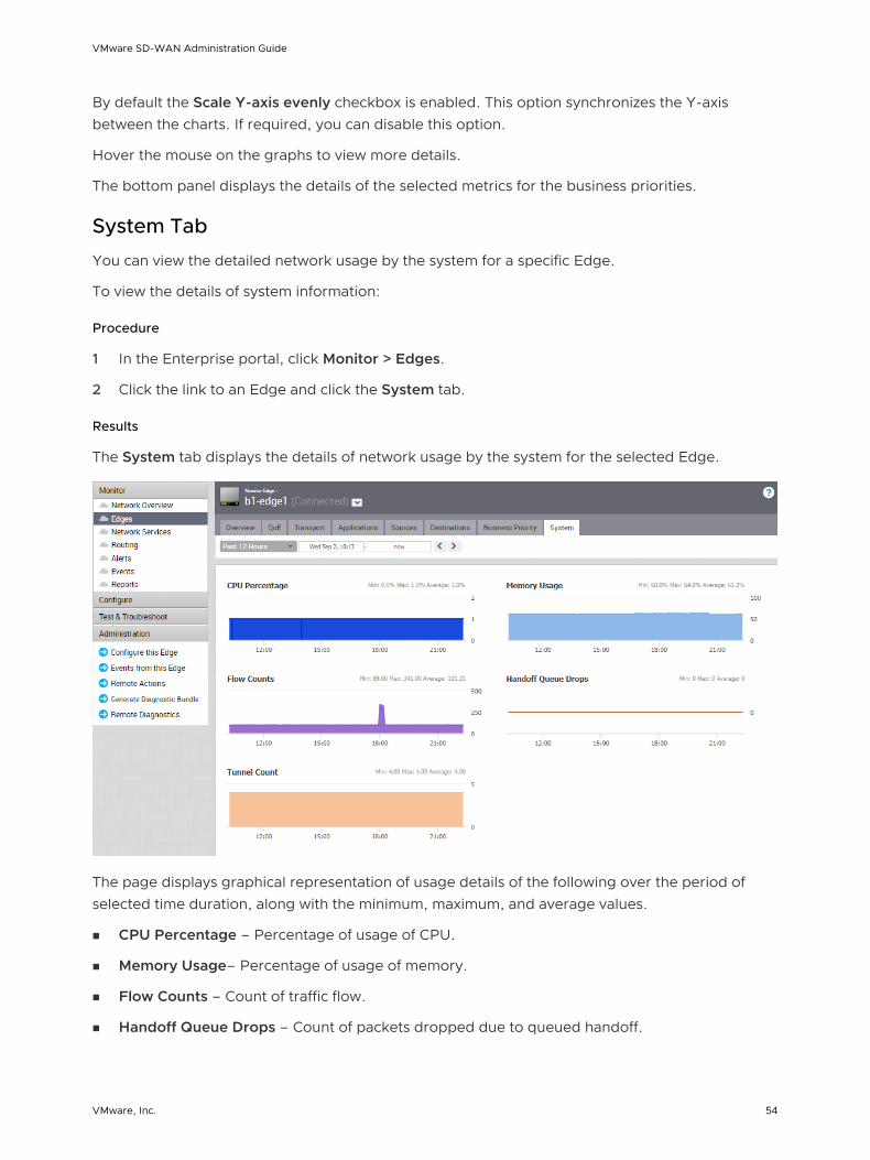
The System tab displays the details of network usage by the system for the selected Edge.
The page displays graphical representation of usage details of the following over the period of selected time duration, along with the minimum, maximum, and average values.
n CPU Percentage – Percentage of usage of CPU.
n Memory Usage– Percentage of usage of memory.
n Flow Counts – Count of traffic flow.
n Handoff Queue Drops – Count of packets dropped due to queued handoff.
VMware SD-WAN Administration Guide
VMware, Inc. 54

n Tunnel Count – Count of tunnel sessions.
Hover the mouse on the graphs to view more details.
Flow Stats Rollups and Retention
In 3.3.0 release, the SD-WAN Orchestrator stores only flow statistics with high resolution to provide visibility and troubleshooting capability. Starting from 3.3.2 release, SD-WAN Orchestrator supports retention of flow stats for upto one year by rolling up flow stats for every edge on a daily basis. Currently, the daily flow stats rollups is supported only for on-prem customers.
Aggregating Flow Statistics
The SD-WAN Orchestrator currently aggregates flow statistics from a higher resolution (every 5 minutes) to a ready-to-use form at a low resolution (every 24 hours). The following tables summarize the flow stats rollup and retention support information.
Table 6-1. Flow Stats Rollup Support
Resolution Rollup Pre 3.3.0 Rollup Post 3.3.0 Rollup Post 3.3.2
High 5 minutes 5 minutes 5 minutes
Medium 2 hours Deprecated Not Supported
Low 8 hours Deprecated 24 hours
Table 6-2. Flow Stats Retention Support
ResolutionRetention Pre 3.3.0
Retention Post 3.3.0 for OnPrem
Retention Post 3.3.0 for Hosted
Retention Post 3.3.2 for OnPrem
Retention Post 3.3.2 for Hosted
High 6-10 weeks 14 days (Default), 31 days (Maximum)
14 days 14 days 14 days
Medium 10 -14 weeks Deprecated Deprecated Deprecated Deprecated
Low Upto 1 year Deprecated Deprecated Upto 1 year Deprecated
Frequently Asked Questions
n How to enable flow stats daily rollups post a 3.3.2 upgrade?
To enable flow stats daily rollups, set the flowStats.daily.rollup.enabled system property to
true.
n What is the maximum number of flows that are rolled up per edge per day?
By default, a maximum of one million flows are rolled up per edge per day. This averages out to approximately 3500 flows per 5-minute push. You can modify the number of flows that are rolled up per edge per day, by using the flowStats.daily.rollup.flowLimit system
property.
VMware SD-WAN Administration Guide
VMware, Inc. 55
n Are hub flows rolled up?
By default, rolling up of hub flows is disabled. You can enable hub flows by using the flowStats.daily.rollup.edgeflowLimit system property, which takes a key-value pair of
<edgeId>:<numFlows>. You can view high resolution hub flows upto 15 days only.
n Is the flow stats retention policy configurable?
The retention policy for rolled up stats is configurable on the SD-WAN Orchestrator using the retentionWeeks.flowStats.daily system property. The rolled-up flow stats retention can be
configured to persist anywhere between 1 and 52 weeks.
n Will the UI be able to query flowstats for more than 15 days after enabling rollups?
No. Rolling up flowstats for longer retention is separated from actually being able to query those flowstats. You can set the number of days you want to query the flows by using the session.options.maxFlowstatsRetentionDays system property.
n Will there be side effects from a data perspective after turning on this feature?
Although, no side effects are observed on aggregated results, time-series graphs on the SD-WAN Orchestrator UI would have a loss in fidelity due to displaying of rolled up series stats.
n What are the side effects from a system load perspective?
Since rolling up daily flowstats aggregates results from the full resolution table and stores it separately, the system load (CPU/load average) is bound to increase due to the additional processing required by MySQL for aggregating the results.
n What would be the impact to storage requirements for on-premise deployments?
Since rolling up daily flowstats aggregates results from the high resolution table and stores it separately, VMware anticipates the need for the on-premise customers to plan their storage requirements to accommodate rolled up stats. On an average, rolled up flows will consume 1/8th of the space required for high resolution stats; however, this is strongly dependent on the uniqueness of daily flows sent by the edge. In any case, the storage space consumption growth of rolled up flows will be at a much lower rate than the high resolution statistics. For customers that start off with smaller volume drive, VMware recommends using logical volumes so the storage capacity can be grown as the Edges increase.
Changing the Retention Period
High resolution flow stats retention can be configured to persist anywhere between 1 and 31 days. With the 3.3.0 release, the configuration granularity of the high-resolution flow stats retention has been changed from months to days. Operators can change the retention period by creating a system property. To create a system property to change the retention period, follow the steps below.
1 From the SD-WAN Orchestrator navigation panel, click System Properties.
2 In the System Properties screen, click the New System Properties button.
VMware SD-WAN Administration Guide
VMware, Inc. 56
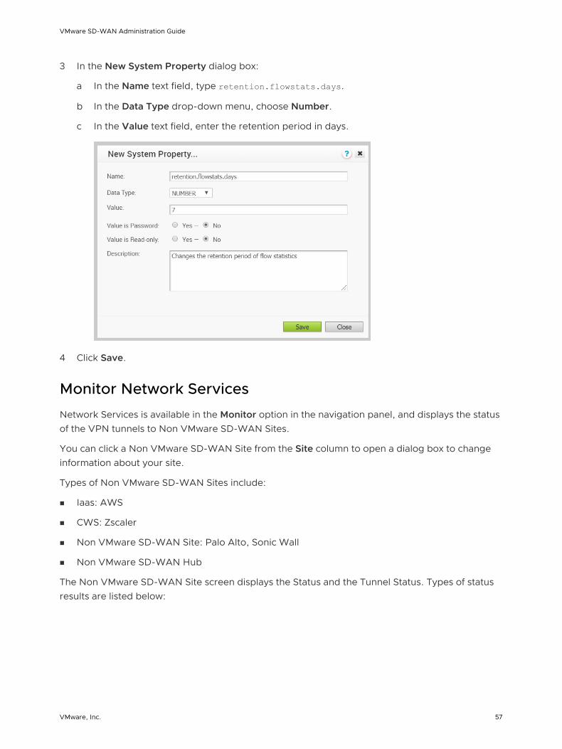
3 In the New System Property dialog box:
a In the Name text field, type retention.flowstats.days.
b In the Data Type drop-down menu, choose Number.
c In the Value text field, enter the retention period in days.
4 Click Save.
Monitor Network Services
Network Services is available in the Monitor option in the navigation panel, and displays the status of the VPN tunnels to Non VMware SD-WAN Sites.
You can click a Non VMware SD-WAN Site from the Site column to open a dialog box to change information about your site.
Types of Non VMware SD-WAN Sites include:
n Iaas: AWS
n CWS: Zscaler
n Non VMware SD-WAN Site: Palo Alto, Sonic Wall
n Non VMware SD-WAN Hub
The Non VMware SD-WAN Site screen displays the Status and the Tunnel Status. Types of status results are listed below:
VMware SD-WAN Administration Guide
VMware, Inc. 57

Color Meaning
Green Connected
Red Offline/ Disconnected
Gray Not Enabled
Monitor Routing
The Routing feature ( Monitor > Routing > Multicast tab) displays Multicast Group and Multicast Edge information.
VMware SD-WAN Administration Guide
VMware, Inc. 58

PIM Neighbors View
The following figure shows the PIM neighbors of the selected Edge (per segment), the interface where the PIM neighbor was discovered, the neighbor IP address, and time stamps.
Monitor Alerts
SD-WAN Orchestrator provides an alert function to notify one or more Enterprise Administrators (or other support users) when a problem occurs. You can access this functionality by clicking Alerts under Monitor in the navigation panel.
You can send Alerts when a SD-WAN Edge goes offline or comes back online, a WAN link goes down, a VPN tunnel goes down, or when an Edge HA failover occurs. A delay for sending the alert after it is detected can be entered for each of the alert types. You can configure alerts in Configure > Alerts and Notifications.
VMware SD-WAN Administration Guide
VMware, Inc. 59
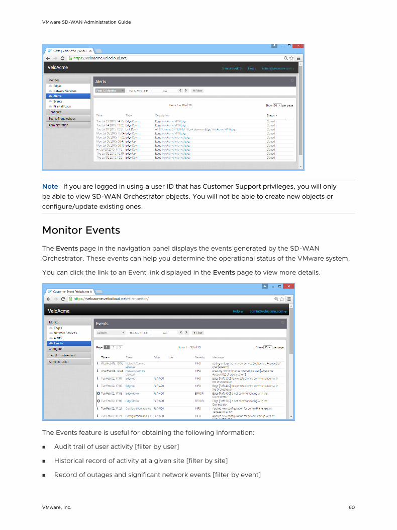
Note If you are logged in using a user ID that has Customer Support privileges, you will only be able to view SD-WAN Orchestrator objects. You will not be able to create new objects or configure/update existing ones.
Monitor Events
The Events page in the navigation panel displays the events generated by the SD-WAN Orchestrator. These events can help you determine the operational status of the VMware system.
You can click the link to an Event link displayed in the Events page to view more details.
The Events feature is useful for obtaining the following information:
n Audit trail of user activity [filter by user]
n Historical record of activity at a given site [filter by site]
n Record of outages and significant network events [filter by event]
VMware SD-WAN Administration Guide
VMware, Inc. 60

n Analysis of degraded ISP performance [filter by time period]
Auto Rollback to the Last Known Good Configuration
If an Administrator changes device configurations that cause the Edge to disconnect from the Orchestrator, the Administrator will get an Edge Down alert. Once the Edge detects that it cannot reach the SD-WAN Orchestrator, it will rollback to the last known configuration and generate an event on the Orchestrator titled, “bad configuration.”
The rollback time, which is the time necessary to detect a bad configuration and apply the previous known “good” configuration for a standalone Edge, is between 5-6 minutes. For HA Edges, the rollback time is between 10-12 minutes.
Note This feature rolls back only Edge-level device settings. If the configuration is pushed from the Profile that causes multiple Edges to go offline from the Orchestrator, the Edges will log “Bad Configuration” events and roll back to the last known good configuration individually. IMPORTANT: The Administrator is responsible for fixing the Profile accordingly. the Profile configuration will not roll back automatically.
Supported VMware SD-WAN Edge Events for Syslogs
The following table describes all the possible VMware SD-WAN Edge events that could be exported to syslog collectors.
Events Severity Description
BW_UNMEASURABLE ALERT Generated by a SD-WAN Edge when the path bandwidth is unmeasurable.
EDGE_BIOS_UPDATE_FAILED ERROR Generated by 12-upgrade-bios.sh script when SD-WAN Edge BIOS is updated.
EDGE_BIOS_UPDATED INFO Generated by 12-upgrade-bios.sh script when SD-WAN Edge BIOS update failed.
EDGE_CONSOLE_LOGIN INFO Generated by a SD-WAN Edge during login via console port.
EDGE_DEACTIVATED WARNING Generated when a SD-WAN Edge has all its configuration cleared and is not associated with a customer site. The software build remains unchanged.
EDGE_DHCP_BAD_OPTION WARNING Generated when the SD-WAN Edge is configured with an invalid DHCP option.
VMware SD-WAN Administration Guide
VMware, Inc. 61

Events Severity Description
EDGE_DISK_IO_ERROR WARNING Generated by a SD-WAN Edge when the Disk IO error has occurred during upgrade/downgrade.
EDGE_DISK_READONLY CRITICAL Generated by a SD-WAN Edge when a Disk turns to read-only mode.
EDGE_DNSMASQ_FAILED ERROR Generated when Dnsmasq service failed.
EDGE_DOT1X_SERVICE_DISABLED WARNING, CRITICAL Generated by vc_procmon when the SD-WAN Edge 802.1x service is disabled.
EDGE_DOT1X_SERVICE_FAILED ERROR Generated by vc_procmon when the SD-WAN Edge 802.1x service failed.
EDGE_HARD_RESET WARNING Generated when user has initiated SD-WAN Edge hard reset.
EDGE_HEALTH_ALERT EMERGENCY Generated by the SD-WAN Edge when the data plane is unable to allocate necessary resources for packet processing.
EDGE_INTERFACE_DOWN INFO Generated by hotplug scripts when the interface is down.
EDGE_INTERFACE_UP INFO Generated by hotplug scripts when the interface is up.
EDGE_KERNEL_PANIC ALERT Generated by a SD-WAN Edge when the Edge operating system has encountered a critical exception and must reboot the Edge to recover. An Edge reboot is disruptive to customer traffic for 2-3 minutes while the Edge completes the reboot.
EDGE_L2_LOOP_DETECTED ERROR Generated when SD-WAN EdgeL2 loop is detected.
EDGE_LED_SERVICE_DISABLED WARNING, CRITICAL Generated by vc_procmon when the SD-WAN Edge LED service is disabled.
EDGE_LED_SERVICE_FAILED ERROR Generated by vc_procmon when the SD-WAN Edge LED service failed.
EDGE_LOCALUI_LOGIN INFO Generated when LOCAL UI login is successful for a user.
VMware SD-WAN Administration Guide
VMware, Inc. 62

Events Severity Description
EDGE_MEMORY_USAGE_ERROR ERROR Generated by a SD-WAN Edge when the Resource Monitor process detects Edge memory utilization has exceeded defined thresholds and reaches 70% threshold. The Resource Monitor waits for 90 seconds to allow the edged process to recover from a possible temporary spike in memory usage. If memory usage persists at a 70% or higher level for more than 90 seconds, the Edge will generate this error message and send this event to the Orchestrator.
EDGE_MEMORY_USAGE_WARNING WARNING Generated by a SD-WAN Edge when the Resource Monitor process detects Edge memory utilization is 50% or more of the available memory. This event will be sent to the Orchestrator every 60 minutes until the memory usage drops under the 50% threshold.
EDGE_MGD_SERVICE_DISABLED CRITICAL, WARNING Generated by vc_procmon when mgd is unable to start or disabled for too many failures.
EDGE_MGD_SERVICE_FAILED ERROR Generated by vc_procmon when the mgd service failed.
EDGE_NEW_DEVICE INFO Generated when a new DHCP client is identified by processing the DHCP request.
EDGE_NEW_USER INFO Generated when a new client user is added.
EDGE_OSPF_NSM INFO Generated by the SD-WAN Edge when the OSPF Neighbor state Machine (NSM) state occurred.
EDGE_REBOOTING WARNING Generated when a user has initiated SD-WAN Edge reboot.
EDGE_RESTARTING WARNING Generated when a user has initiated SD-WAN Edge service restart.
EDGE_SERVICE_DISABLED WARNING Generated when the SD-WAN Edge data plane service is disabled.
EDGE_SERVICE_ENABLED WARNING Generated when the SD-WAN Edge data plane service is enabled.
EDGE_SERVICE_FAILED ERROR Generated when the SD-WAN Edge data plane service failed.
EDGE_SHUTTING_DOWN WARNING Generated when a SD-WAN Edge is shutting down.
VMware SD-WAN Administration Guide
VMware, Inc. 63

Events Severity Description
EDGE_STARTUP INFO Generated when a SD-WAN Edge is running in mgmt-only mode.
EDGE_SSH_LOGI INFO Generated by a SD-WAN Edge during login via SSH protocol.
EDGE_TUNNEL_CAP_WARNING WARNING Generated when a SD-WAN Edge has reached its maximum tunnel capacity.
EDGE_VNFD_SERVICE_DISABLED WARNING, CRITICAL Generated by vc_procmon when the Edge VNFD service is disabled.
EDGE_VNFD_SERVICE_FAILED ERROR Generated by vc_procmon when the Edge VNFD service failed.
FLOOD_ATTACK_DETECTED INFO Generated when a malicious host floods the SD-WAN Edge with new connections.
HA_FAILED INFO HA Peer State Unknown -Generated when the Standby Edge has not sent a heartbeat response and only one of the two HA Edges is communicating with the Orchestrator and Gateways.
HA_GOING_ACTIVE INFO An HA failover. Generated when the Active High Availability (HA) Edge has been marked as down and the Standby is brought up to be the Active.
HA_INTF_STATE_CHANGED ALERT Generated when the HA Interface state is changed to Active.
HA_READY INFO Generated when both the Active and Standby Edges are up and synchronized.
HA_STANDBY_ACTIVATED INFO Generated when the HA Standby Edge has accepted the activation key, downloaded its configuration, and updated its software build.
HA_TERMINATED INFO Generated when HA has been disabled on a SD-WAN Edge.
INVALID_JSON CRITICAL Generated when a SD-WAN Edge received an invalid response from MGD.
IP_SLA_PROBE Up = INFO, Down = ALERT Generated when an IP ICMP Probe state change.
IP_SLA_RESPONDER Up = INFO, Down = ALERT Generated when an IP ICMP Responder state change.
LINK_ALIVE INFO Generated when a WAN link is no longer DEAD.
LINK_DEAD ALERT Generated when all tunnels established on the WAN link have received no packets for at least seven seconds.
VMware SD-WAN Administration Guide
VMware, Inc. 64
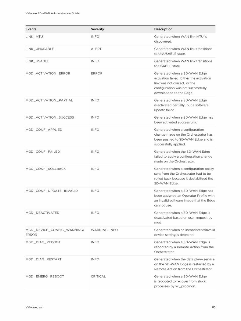
Events Severity Description
LINK_MTU INFO Generated when WAN link MTU is discovered.
LINK_UNUSABLE ALERT Generated when WAN link transitions to UNUSABLE state.
LINK_USABLE INFO Generated when WAN link transitions to USABLE state.
MGD_ACTIVATION_ERROR ERROR Generated when a SD-WAN Edge activation failed. Either the activation link was not correct, or the configuration was not successfully downloaded to the Edge.
MGD_ACTIVATION_PARTIAL INFO Generated when a SD-WAN Edge is activated partially, but a software update failed.
MGD_ACTIVATION_SUCCESS INFO Generated when a SD-WAN Edge has been activated successfully.
MGD_CONF_APPLIED INFO Generated when a configuration change made on the Orchestrator has been pushed to SD-WAN Edge and is successfully applied.
MGD_CONF_FAILED INFO Generated when the SD-WAN Edge failed to apply a configuration change made on the Orchestrator.
MGD_CONF_ROLLBACK INFO Generated when a configuration policy sent from the Orchestrator had to be rolled back because it destabilized the SD-WAN Edge.
MGD_CONF_UPDATE_INVALID INFO Generated when a SD-WAN Edge has been assigned an Operator Profile with an invalid software image that the Edge cannot use.
MGD_DEACTIVATED INFO Generated when a SD-WAN Edge is deactivated based on user request by mgd.
MGD_DEVICE_CONFIG_WARNING/ERROR
WARNING, INFO Generated when an inconsistent/invalid device setting is detected.
MGD_DIAG_REBOOT INFO Generated when a SD-WAN Edge is rebooted by a Remote Action from the Orchestrator.
MGD_DIAG_RESTART INFO Generated when the data plane service on the SD-WAN Edge is restarted by a Remote Action from the Orchestrator.
MGD_EMERG_REBOOT CRITICAL Generated when a SD-WAN Edge is rebooted to recover from stuck processes by vc_procmon.
VMware SD-WAN Administration Guide
VMware, Inc. 65

Events Severity Description
MGD_ENTER_LIVE_MODE DEBUG Generated when the management service on a SD-WAN Edge is entering the LIVE mode.
MGD_EXIT_LIVE_MODE DEBUG Generated when the management service on a SD-WAN Edge is exiting the LIVE mode.
MGD_EXITING INFO Generated when the management service on a SD-WAN Edge is shutting down for a restart.
MGD_EXTEND_LIVE_MODE DEBUG Generated by a SD-WAN Edge when Live mode is extended.
MGD_FLOW_STATS_PUSH_FAILED DEBUG Generated by a SD-WAN Edge when Flow stats pushed to Orchestrator failed.
MGD_FLOW_STATS_PUSH_SUCCEEDED
DEBUG Generated by a SD-WAN Edge when Flow stats pushed to Orchestrator succeeded.
MGD_FLOW_STATS_QUEUED INFO Generated by a SD-WAN Edge when Flow stats pushed to Orchestrator is queued.
MGD_HARD_RESET INFO Generated when a SD-WAN Edge is restored to its factory-default software and configuration.
MGD_HEALTH_STATS_PUSH_FAILED
DEBUG Generated by a SD-WAN Edge when Health stats pushed to Orchestrator failed.
MGD_HEALTH_STATS_PUSH_SUCCEEDED
DEBUG Generated by a SD-WAN Edge when Health stats pushed to Orchestrator succeeded.
MGD_HEALTH_STATS_QUEUED INFO Generated by a SD-WAN Edge when Health stats pushed to Orchestrator is queued.
MGD_HEARTBEAT INFO Generated by a SD-WAN Edge when Heartbeat is generated to Orchestrator.
MGD_HEARTBEAT_FAILURE INFO Generated by a SD-WAN Edge when generated Heartbeat to Orchestrator failed.
MGD_HEARTBEAT_SUCCESS INFO Generated by a SD-WAN Edge when generated Heartbeat to Orchestrator succeeded.
MGD_INVALID_VCO_ADDRESS WARNING Generated when an invalid address for Orchestrator was sent in a management plane policy update and was ignored.
VMware SD-WAN Administration Guide
VMware, Inc. 66
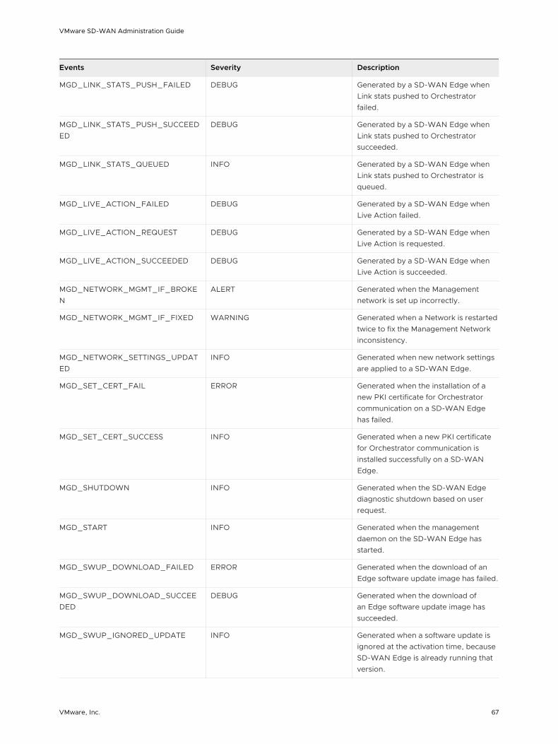
Events Severity Description
MGD_LINK_STATS_PUSH_FAILED DEBUG Generated by a SD-WAN Edge when Link stats pushed to Orchestrator failed.
MGD_LINK_STATS_PUSH_SUCCEEDED
DEBUG Generated by a SD-WAN Edge when Link stats pushed to Orchestrator succeeded.
MGD_LINK_STATS_QUEUED INFO Generated by a SD-WAN Edge when Link stats pushed to Orchestrator is queued.
MGD_LIVE_ACTION_FAILED DEBUG Generated by a SD-WAN Edge when Live Action failed.
MGD_LIVE_ACTION_REQUEST DEBUG Generated by a SD-WAN Edge when Live Action is requested.
MGD_LIVE_ACTION_SUCCEEDED DEBUG Generated by a SD-WAN Edge when Live Action is succeeded.
MGD_NETWORK_MGMT_IF_BROKEN
ALERT Generated when the Management network is set up incorrectly.
MGD_NETWORK_MGMT_IF_FIXED WARNING Generated when a Network is restarted twice to fix the Management Network inconsistency.
MGD_NETWORK_SETTINGS_UPDATED
INFO Generated when new network settings are applied to a SD-WAN Edge.
MGD_SET_CERT_FAIL ERROR Generated when the installation of a new PKI certificate for Orchestrator communication on a SD-WAN Edge has failed.
MGD_SET_CERT_SUCCESS INFO Generated when a new PKI certificate for Orchestrator communication is installed successfully on a SD-WAN Edge.
MGD_SHUTDOWN INFO Generated when the SD-WAN Edge diagnostic shutdown based on user request.
MGD_START INFO Generated when the management daemon on the SD-WAN Edge has started.
MGD_SWUP_DOWNLOAD_FAILED ERROR Generated when the download of an Edge software update image has failed.
MGD_SWUP_DOWNLOAD_SUCCEEDED
DEBUG Generated when the download of an Edge software update image has succeeded.
MGD_SWUP_IGNORED_UPDATE INFO Generated when a software update is ignored at the activation time, because SD-WAN Edge is already running that version.
VMware SD-WAN Administration Guide
VMware, Inc. 67
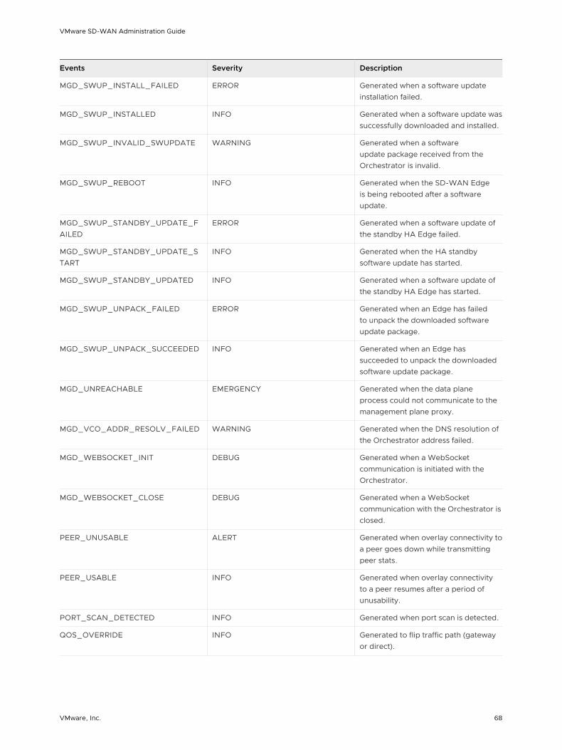
Events Severity Description
MGD_SWUP_INSTALL_FAILED ERROR Generated when a software update installation failed.
MGD_SWUP_INSTALLED INFO Generated when a software update was successfully downloaded and installed.
MGD_SWUP_INVALID_SWUPDATE WARNING Generated when a software update package received from the Orchestrator is invalid.
MGD_SWUP_REBOOT INFO Generated when the SD-WAN Edge is being rebooted after a software update.
MGD_SWUP_STANDBY_UPDATE_FAILED
ERROR Generated when a software update of the standby HA Edge failed.
MGD_SWUP_STANDBY_UPDATE_START
INFO Generated when the HA standby software update has started.
MGD_SWUP_STANDBY_UPDATED INFO Generated when a software update of the standby HA Edge has started.
MGD_SWUP_UNPACK_FAILED ERROR Generated when an Edge has failed to unpack the downloaded software update package.
MGD_SWUP_UNPACK_SUCCEEDED INFO Generated when an Edge has succeeded to unpack the downloaded software update package.
MGD_UNREACHABLE EMERGENCY Generated when the data plane process could not communicate to the management plane proxy.
MGD_VCO_ADDR_RESOLV_FAILED WARNING Generated when the DNS resolution of the Orchestrator address failed.
MGD_WEBSOCKET_INIT DEBUG Generated when a WebSocket communication is initiated with the Orchestrator.
MGD_WEBSOCKET_CLOSE DEBUG Generated when a WebSocket communication with the Orchestrator is closed.
PEER_UNUSABLE ALERT Generated when overlay connectivity to a peer goes down while transmitting peer stats.
PEER_USABLE INFO Generated when overlay connectivity to a peer resumes after a period of unusability.
PORT_SCAN_DETECTED INFO Generated when port scan is detected.
QOS_OVERRIDE INFO Generated to flip traffic path (gateway or direct).
VMware SD-WAN Administration Guide
VMware, Inc. 68

Events Severity Description
SLOW_START_CAP_MET NOTICE Generated when the Bandwidth measurement slow-start cap limit is exceeded. It will be done in Burst mode
VPN_DATACENTER_STATUS INFO, ERROR Generated when a VPN Tunnel state change.
VRRP_FAIL_INFO INFO Generated when VRRP failed.
VRRP_INTO_MASTER_STATE INFO Generated when VRRP get into Master state.
VRRP_OUT_OF_MASTER_STATE INFO Generated when VRRP get out of Master state.
Monitor Reports
The Monitoring dashboard in the Enterprise portal allows to generate reports with overall network summary along with information on SD-WAN traffic and transport distribution. The reports enable the analysis of your network.
Note The reports focus on descriptive analytics and cannot be used for troubleshooting purposes. In addition, these reports are not dashboards that reflect the real-time data from the network.
In the Enterprise portal, click Monitor > Reports.
To create a new report:
1 In the Reports window, click New Report .
2 In the New Report window, enter a descriptive name for the report and choose the start and end dates.
3 Click Create.
Note You can generate a report only for a duration of 14 days and for a maximum of 600 Edges. The report generation times out after 3 hours. The Reports table retains only the latest 10 reports at a time.
VMware SD-WAN Administration Guide
VMware, Inc. 69

The Status of the report generation is displayed in the window. Once completed, you can download the report by clicking the Completed link.
The Download Report window provides the following options:
You can download the report as a PDF that provides an overall summary of the traffic and transport distribution, represented as a pie chart. This report also provides the list of top 10 applications by the traffic and transport type.
You can choose to download the reports by transport or traffic distribution, as a CSV file.
n The transport distribution report displays the details of time, transport type, applications, name and description of the edges, and the bytes sent and received.
n The traffic distribution report displays the details of time, flow path, applications, name and description of the edges, and the bytes sent and received.
VMware SD-WAN Administration Guide
VMware, Inc. 70

Configure Segments 7Segmentation is the process of dividing the network into logical sub-networks called Segments by using isolation techniques on a forwarding device such as a switch, router, or firewall. Network segmentation is important when traffic from different organizations and/or data types must be isolated.
In the segment-aware topology, different Virtual Private Network (VPN) profiles can be enabled for each segment. For example, Guest traffic can be backhauled to remote data center firewall services, Voice media can flow direct from Branch-to-Branch based on dynamic tunnels, and the PCI segment can backhaul traffic to the data center to exit out of the PCI network.
Note You can configure a maximum of 16 Segments per enterprise customer.
To configure a new segment for an enterprise, perform the following steps:
1 From the SD-WAN Orchestrator navigation panel, go to Configure > Segments. The Segments page for the selected enterprise appears.
2 Click the + button and enter the following details to configure a new segment.
Field Description
Segment Name The name of the segment (up to 256 characters).
Description The description of the segment (up to 256 characters).
VMware, Inc. 71
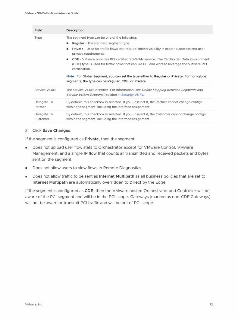
Field Description
Type The segment type can be one of the following:
n Regular - The standard segment type.
n Private - Used for traffic flows that require limited visibility in order to address end user privacy requirements.
n CDE - VMware provides PCI certified SD-WAN service. The Cardholder Data Environment (CDE) type is used for traffic flows that require PCI and want to leverage the VMware PCI certification.
Note For Global Segment, you can set the type either to Regular or Private. For non-global segments, the type can be Regular, CDE, or Private.
Service VLAN The service VLAN identifier. For information, see Define Mapping between Segments and Service VLANs (Optional) section in Security VNFs.
Delegate To Partner
By default, this checkbox is selected. If you unselect it, the Partner cannot change configs within the segment, including the interface assignment.
Delegate To Customer
By default, this checkbox is selected. If you unselect it, the Customer cannot change configs within the segment, including the interface assignment.
3 Click Save Changes.
If the segment is configured as Private, then the segment:
n Does not upload user flow stats to Orchestrator except for VMware Control, VMware Management, and a single IP flow that counts all transmitted and received packets and bytes sent on the segment.
n Does not allow users to view flows in Remote Diagnostics.
n Does not allow traffic to be sent as Internet Multipath as all business policies that are set to Internet Multipath are automatically overridden to Direct by the Edge.
If the segment is configured as CDE, then the VMware hosted Orchestrator and Controller will be aware of the PCI segment and will be in the PCI scope. Gateways (marked as non-CDE Gateways) will not be aware or transmit PCI traffic and will be out of PCI scope.
VMware SD-WAN Administration Guide
VMware, Inc. 72

Configure Network Services 8As an enterprise user, SD-WAN Orchestrator allows you to configure network services from Configure > Network Services.
Note If you are logged in using a user ID that has Customer Support privileges, you will only be able to view SD-WAN Orchestrator objects. You will not be able to create new objects or configure/update existing ones.
You can configure the following Network Services:
n Edge Cluster
n Non-VeloCloud Sites
n Cloud Security Service
n VNFs
n VNF Licenses
n DNS Services
n Netflow Settings
n Private Network Names
n Authentication Services
Note Configuring Network Services are optional and can be configured in any order.
VMware, Inc. 73
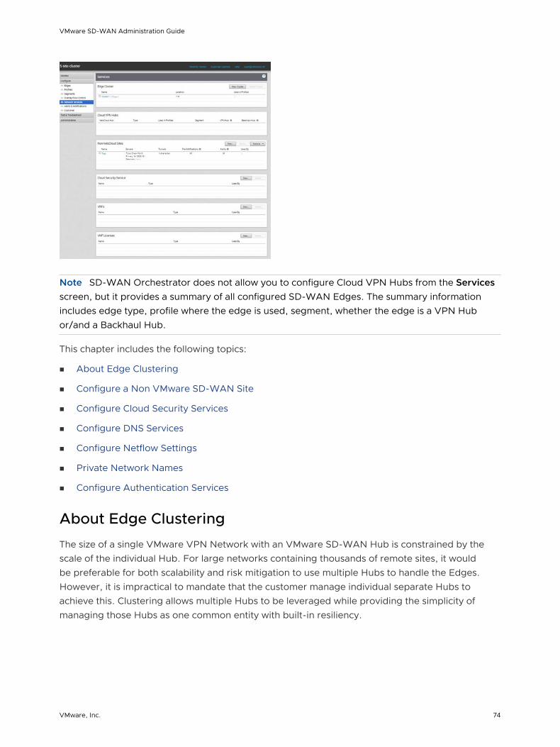
Note SD-WAN Orchestrator does not allow you to configure Cloud VPN Hubs from the Services screen, but it provides a summary of all configured SD-WAN Edges. The summary information includes edge type, profile where the edge is used, segment, whether the edge is a VPN Hub or/and a Backhaul Hub.
This chapter includes the following topics:
n About Edge Clustering
n Configure a Non VMware SD-WAN Site
n Configure Cloud Security Services
n Configure DNS Services
n Configure Netflow Settings
n Private Network Names
n Configure Authentication Services
About Edge Clustering
The size of a single VMware VPN Network with an VMware SD-WAN Hub is constrained by the scale of the individual Hub. For large networks containing thousands of remote sites, it would be preferable for both scalability and risk mitigation to use multiple Hubs to handle the Edges. However, it is impractical to mandate that the customer manage individual separate Hubs to achieve this. Clustering allows multiple Hubs to be leveraged while providing the simplicity of managing those Hubs as one common entity with built-in resiliency.
VMware SD-WAN Administration Guide
VMware, Inc. 74

SD-WAN Edge Clustering addresses the issue of SD-WAN Hub scale because it can be used to easily expand the tunnel capacity of the Hub dynamically by creating a logical cluster of Edges. Edge Clustering also provides resiliency via the Active/Active High Availability (HA) topology that a cluster of SD-WAN Edges would provide. A cluster is functionally treated as an individual Hub from the perspective of other Edges.
The Hubs in a VMware Cluster can be either physical or Virtual Edges. If they are virtual, they may exist on a single hypervisor or across multiple hypervisors.
Each Edge in a cluster periodically reports usage and load stats to the SD-WAN Gateway. The load value is calculated based on Edge CPU and memory utilization along with the number of tunnels connected to the Hub as a percentage of the Edge model’s tunnel capacity. The Hubs within the cluster do not directly communicate nor exchange state information. Typically, Edge Clusters are deployed as Hubs in data centers.
Note Theoretically, Edge Clustering could be used to horizontally scale other vectors, such as throughput. However, the current Edge Clustering implementation has been specifically designed and tested to scale at tunnel capacity only.
How Edge Clustering Works
This section provides an in-depth overview of how the SD-WAN Edge Clustering functionality works.
The following are important concepts that describe the SD-WAN Edge Clustering functionality:
n Edge Clustering can be used on Hubs as follows:
n To allow greater tunnel capacity for a Hub than an individual Edge serving as a Hub can provide.
n To distribute the remote Spoke Edges among multiple Hubs and reduce the impact of any incident that may occur.
n Cluster Score is a mathematical calculation of the overall utilization of the system as follows:
The three measured utilization factors are CPU usage, memory usage, and tunnel capacity.
n Each measure of utilization is treated as a percentage out of a maximum of 100%.
n Tunnel capacity is based on the rated capacity for a given hardware model or Virtual Edge configuration.
n All three utilization percentages are averaged to arrive at an integer-based Cluster Score (1-100).
n While throughput is not directly considered, CPU and memory usage indirectly reflect throughput and flow volume on a given Hub.
n For example, on an Edge 2000:
n CPU usage = 20%
n Memory usage = 30%
VMware SD-WAN Administration Guide
VMware, Inc. 75
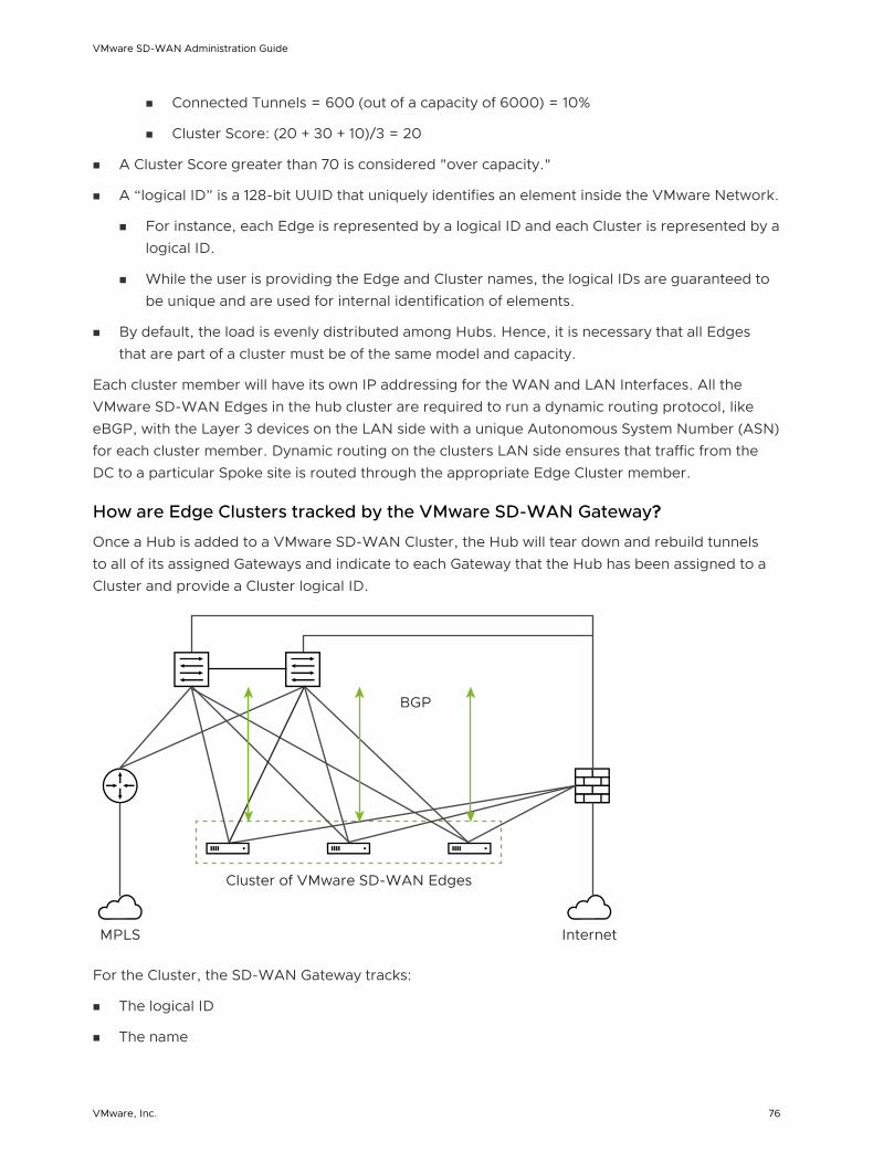
n Connected Tunnels = 600 (out of a capacity of 6000) = 10%
n Cluster Score: (20 + 30 + 10)/3 = 20
n A Cluster Score greater than 70 is considered "over capacity."
n A “logical ID” is a 128-bit UUID that uniquely identifies an element inside the VMware Network.
n For instance, each Edge is represented by a logical ID and each Cluster is represented by a logical ID.
n While the user is providing the Edge and Cluster names, the logical IDs are guaranteed to be unique and are used for internal identification of elements.
n By default, the load is evenly distributed among Hubs. Hence, it is necessary that all Edges that are part of a cluster must be of the same model and capacity.
Each cluster member will have its own IP addressing for the WAN and LAN Interfaces. All the VMware SD-WAN Edges in the hub cluster are required to run a dynamic routing protocol, like eBGP, with the Layer 3 devices on the LAN side with a unique Autonomous System Number (ASN) for each cluster member. Dynamic routing on the clusters LAN side ensures that traffic from the DC to a particular Spoke site is routed through the appropriate Edge Cluster member.
How are Edge Clusters tracked by the VMware SD-WAN Gateway?
Once a Hub is added to a VMware SD-WAN Cluster, the Hub will tear down and rebuild tunnels to all of its assigned Gateways and indicate to each Gateway that the Hub has been assigned to a Cluster and provide a Cluster logical ID.
InternetMPLS
Cluster of VMware SD-WAN Edges
BGP
For the Cluster, the SD-WAN Gateway tracks:
n The logical ID
n The name
VMware SD-WAN Administration Guide
VMware, Inc. 76

n Whether Auto Rebalance is enabled
n A list of Hub objects for members of the Cluster
For each Hub object in the Cluster, the Gateway tracks:
n The logical ID
n The name
n A set of statistics, updated every 30 seconds via a periodic message sent from the Hub to each assigned Gateway, including:
n Current CPU usage of the Hub
n Current memory usage of the Hub
n Current tunnel count on the Hub
n Current BGP route count on the Hub
n The current computed Cluster Score based on the formula provided above.
A Hub is removed from the list of Hub objects when the Gateway has not received any packets from the Hub Edge for more than seven seconds.
How are Edges assigned to a specific Hub in a Cluster?
In a traditional Hub and Spoke topology, the SD-WAN Orchestrator provides the Edge with the logical ID of the Hub to which it must be connected. The Edge asks its assigned Gateways for connectivity information for that Hub logical ID—i.e. IP addresses and ports, which the Edge will use to connect to that Hub.
From the Edge’s perspective, this behavior is identical when connecting to a Cluster. The Orchestrator informs the Edge that the logical ID of the Hub it should connect to is the Cluster logical ID rather than the individual Hub logical ID. The Edge follows the same procedure of sending a Hub connection request to the Gateways and expects connectivity information in response.
VMware SD-WAN Administration Guide
VMware, Inc. 77
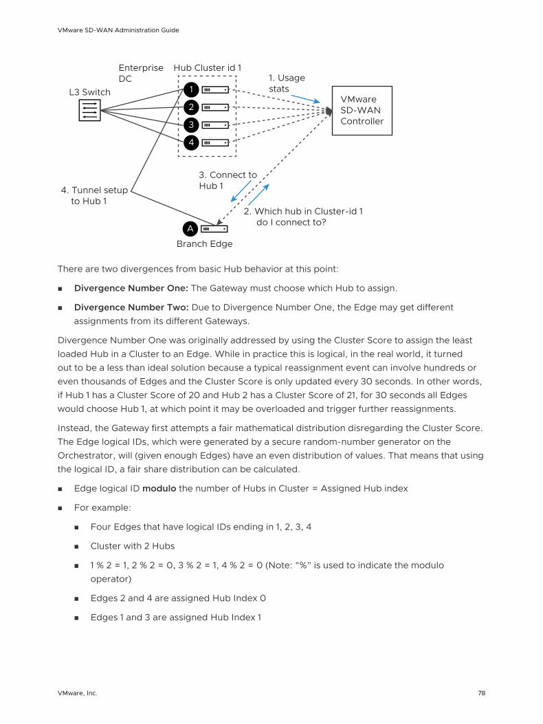
1
2
3
4
Hub Cluster id 1
VMware SD-WAN Controller
A
1. UsagestatsL3 Switch
EnterpriseDC
3. Connect to Hub 14. Tunnel setup
to Hub 1
Branch Edge
2. Which hub in Cluster-id 1 do I connect to?
There are two divergences from basic Hub behavior at this point:
n Divergence Number One: The Gateway must choose which Hub to assign.
n Divergence Number Two: Due to Divergence Number One, the Edge may get different assignments from its different Gateways.
Divergence Number One was originally addressed by using the Cluster Score to assign the least loaded Hub in a Cluster to an Edge. While in practice this is logical, in the real world, it turned out to be a less than ideal solution because a typical reassignment event can involve hundreds or even thousands of Edges and the Cluster Score is only updated every 30 seconds. In other words, if Hub 1 has a Cluster Score of 20 and Hub 2 has a Cluster Score of 21, for 30 seconds all Edges would choose Hub 1, at which point it may be overloaded and trigger further reassignments.
Instead, the Gateway first attempts a fair mathematical distribution disregarding the Cluster Score. The Edge logical IDs, which were generated by a secure random-number generator on the Orchestrator, will (given enough Edges) have an even distribution of values. That means that using the logical ID, a fair share distribution can be calculated.
n Edge logical ID modulo the number of Hubs in Cluster = Assigned Hub index
n For example:
n Four Edges that have logical IDs ending in 1, 2, 3, 4
n Cluster with 2 Hubs
n 1 % 2 = 1, 2 % 2 = 0, 3 % 2 = 1, 4 % 2 = 0 (Note: "%” is used to indicate the modulo operator)
n Edges 2 and 4 are assigned Hub Index 0
n Edges 1 and 3 are assigned Hub Index 1
VMware SD-WAN Administration Guide
VMware, Inc. 78

EdgesHub Cluster1
2
3
4
0
1
This is more consistent than a round-robin type assignment because it means that Edges will tend to be assigned the same Hub each time, which makes assignment and troubleshooting more predictive.
Note When a Hub restarts (e.g. due to maintenance or failure), it will be disconnected from the Gateway and removed from the Cluster. This means that Edges will always be evenly distributed following all Edges restarting (due to the above described logic), but will be unevenly distributed following any Hub event that causes it to lose connectivity.
What happens when a Hub exceeds its maximum allowed tunnel capacity?
The Edge assignment logic will attempt to evenly distribute the Edges between all available Hubs. However, after an event (like restart) on the Hub, the Edge distribution will no longer be even.
Note Generally, the Gateway tries at initial assignment to evenly distributed Edges among Hubs, an uneven distribution is not considered an invalid state. If the assignments are uneven but no individual Hub exceeds 70% tunnel capacity, the assignment is considered valid.
Due to such an event on the Hub (or adding additional Edges to the network), Clusters might reach a point where an individual Hub has exceeded 70% of its permitted tunnel capacity. If this happens, and at least one other Hub is at less than 70% tunnel capacity, then fair share redistribution is performed automatically regardless of whether rebalancing is enabled on the Orchestrator. Most Edges will retain their existing assignment due to the predictive mathematical assignment using logical IDs, and the Edges that have been assigned to other Hubs due to failovers or previous utilization rebalancing will be rebalanced to ensure the Cluster is returned to an even distribution automatically.
What happens when a Hub exceeds its maximum allowed Cluster Score?
Unlike tunnel percentage (a direct measure of capacity), which can be acted upon immediately, the Cluster Score is only updated every 30 seconds and the Gateway cannot automatically calculate what the adjusted Cluster Score will be after making an Edge reassignment. In the Cluster configuration, an Auto Rebalance parameter is provided to indicate whether the Gateway should dynamically attempt to shift the Edge load for each Hub as needed.
If Auto Rebalance is deactivated and a Hub exceeds a 70 Cluster Score (but not 70% tunnel capacity), then no action is taken.
VMware SD-WAN Administration Guide
VMware, Inc. 79

If Auto Rebalance is enabled and one or more Hubs exceed a 70 Cluster Score, the Gateway will reassign one Edge per minute to the Hub with the lowest current Cluster Score until all Hubs are below 70 or there are no more reassignments possible.
Note Auto Rebalance is deactivated by default.
What happens when two VMware SD-WAN Gateways give different Hub assignments?
As is the nature of a distributed control plane, each Gateway is making an individual determination of the Cluster assignment. In most cases, Gateways will use the same mathematical formula and thus arrive at the same assignment for all Edges. However, in cases like Cluster Score-based rebalancing this cannot be assured.
If an Edge is not currently connected to a Hub in a Cluster, it will accept the assignment from any Gateway that responds. This ensures that Edges are never left unassigned in a scenario where some Gateways are down and others are up.
If an Edge is connected to a Hub in a Cluster and it gets a message indicating it should choose an alternate Hub, this message is processed in order of “Gateway Preference.” For instance, if the Super Gateway is connected, the Edge will only accept reassignments from the Super Gateway. Conflicting assignments requested by other Gateways will be ignored. Similarly, if the Super Gateway is not connected, the Edge would only accept reassignments from the Alternate Super Gateway. For Partner Gateways (where no Super Gateways exist), the Gateway Preference is based on the order of configured Partner Gateways for that specific Edge.
Note When using Partner Gateways, the same Gateways must be assigned to both the Hubs in a Cluster and the Spoke Edges, otherwise a scenario may arise where a Spoke Edge is not able to receive Hub assignments because the Spoke Edge is connected to a Gateway that is not also connected to the Hubs in a Cluster.
What happens when a VMware SD-WAN Gateway goes down?
When a SD-WAN Gateway goes down, Edges may be reassigned if the most preferred Gateway was the one that went down, and the next most preferred Gateway provided a different assignment. For instance, the Super Gateway assigned Hub A to this Edge while the Alternate Super Gateway assigned Hub B to the same Edge.
The Super Gateway going down will trigger the Edge to fail over to Hub B, since the Alternate Super Gateway is now the most preferred Gateway for connectivity information.
When the Super Gateway recovers, the Edge will again request a Hub assignment from this Gateway. In order to prevent the Edge switching back to Hub A again in the scenario above, the Hub assignment request includes the currently assigned Hub (if there is one). When the Gateway processes the assignment request, if the Edge is currently assigned a Hub in the Cluster and
VMware SD-WAN Administration Guide
VMware, Inc. 80

that Hub has a Cluster Score less than 70, the Gateway updates its local assignment to match the existing assignment without going through its assignment logic. This ensures that the Super Gateway, on recovery, will assign the currently connected Hub and prevent a gratuitous failover for its assigned Edges.
What happens if a Hub in a Cluster loses its dynamic routes?
As noted above, the Hubs report to the SD-WAN Gateway the number of dynamic routes they have learned via BGP every 30 seconds. If routes are lost for only one Hub in a Cluster, either because they are erroneously retracted or the BGP neighborship fails, the SD-WAN Gateway will failover Spoke Edges to another Hub in the Cluster that has an intact routing table.
As the updates are sent every 30 seconds, the route count is based on the moment in time when the update is sent to the SD-WAN Gateway. The SD-WAN Gateway rebalancing logic occurs every 60 seconds, meaning that users can expect failover to take 30-60 seconds in the unlikely event of total loss of a LAN-side BGP neighbor. To ensure that all Hubs have a chance to update the Gateways again following such an event, rebalancing is limited to a maximum of once per 120 seconds. This means that users can expect failover to take 120 seconds for a second successive failure.
How to configure Routing on Cluster Hubs?
As the Gateway can instruct the spokes to connect to any member Hub of the Cluster, the routing configuration should be mirrored on all the Hubs. For example, if the spokes must reach a BGP prefix 192.168.2.1 behind the Hubs, all the Hubs in the cluster should advertise 192.168.2.1 with the exact same route attributes.
BGP uplink community tags should be used in the cluster deployment. Configure the cluster nodes to set the uplink community tag when redistributing routes to BGP peers.
What happens if a Hub in a Cluster fails?
The SD-WAN Gateway will wait for tunnels to be declared dead (7 seconds) before failing over Spoke Edges. This means that users can expect failover to take 7-10 seconds (depending on RTT) when an SD-WAN Hub or all its associated WAN links fail.
Configure Edge Clustering
You can configure Edge clusters by following the steps in this section.
1 To access the Edge Cluster area, go to Configure > Network Services.
2 To add new Cluster:
a From the Edge Cluster area, click the New Cluster button.
VMware SD-WAN Administration Guide
VMware, Inc. 81

b In the Edge Cluster dialog box, enter the name and description in the appropriate text boxes.
c Enable Auto Rebalance if needed (this feature is not enabled by default).
Note If this option is enabled, when an individual Edge in a Hub Cluster exceeds a Cluster Score of 70, Spokes will Rebalance at the rate of one Spoke per minute until the Cluster Score is reduced to below 70. When a Spoke Edge is reassigned to a different Hub, the Spoke Edge's VPN tunnels will disconnect and there may be up to 6-10 seconds of downtime. If all of the Hubs in a Cluster exceed a 70 Cluster Score, no rebalancing will be performed. For more information about the Cluster Score, refer to the section titled, How Edge Clustering Works.
d In the Available Edges section, select an Edge and move it to the Edges In Cluster section, by using the > button.
e Click Save Changes. The configured Edge Cluster will appear under Available Edges & Clusters area of the Manage Cloud VPN Hubs screen for the selected profile.
Note Edges used as a Hub or in Hub Clusters, or configured as an Active/Standby HA pair are not displayed in the Available Edges list area.
VMware SD-WAN Administration Guide
VMware, Inc. 82

3 From the Manage Cloud VPN Hubs screen, you can configure an Edge Cluster and an individual Edge simultaneously as Hubs in a branch profile. Once Edges are assigned to a Cluster, they cannot be assigned as individual Hubs. Choose an Edge Cluster as a Hub in the Branch Profile.
4 In order to configure Branch to Branch VPN using Hubs that are also Edge Clusters, you would first select a Hub from the Hubs area, and then move it to the Branch to Branch VPN Hubs area.
5 Hub Clusters can also be configured as Internet Backhaul Hubs in the Business Policy configuration by first selecting a Hub from the Hubs area and then moving it to the Backhaul Hubs area.
6 To enable Conditional Backhaul, select the Enable Conditional BackHaul checkbox. With Conditional Backhaul (CBH) enabled, the Edge will be able to failover Internet-bound traffic (Direct Internet traffic, Internet via SD-WAN Gateway and Cloud Security Traffic via IPsec) to MPLS links whenever there is no Public Internet links available. When Conditional Backhaul is enabled, by default all Business Policy rules at the branch level are subject to failover traffic through Conditional Backhaul. You can exclude traffic from Conditional Backhaul based on certain requirements for selected policies by disabling this feature at the selected business policy level. For more information, see Conditional Backhaul.
Note It is mandatory to run a dynamic routing protocol, like eBGP, on the LAN side of the clusters.
Troubleshooting Edge Clustering
This section describes the troubleshooting enhancements for Edge Clustering.
VMware SD-WAN Administration Guide
VMware, Inc. 83

Overview
Edge Clustering includes a troubleshooting feature to rebalance VMware SD-WAN Spoke Edges within a Cluster. The rebalancing of the Spokes can be performed on any of the Hubs within the Cluster. There are two methods to rebalance Spokes:
n Evenly rebalance Spokes across all the Hubs in the Cluster.
n Exclude one Hub and rebalance the Spokes across the remaining Hubs in the Cluster.
Rebalancing Spokes on the Hub Using the VMware SD-WAN Orchestrator
An administrator may rebalance Spokes in a Cluster via Remote Diagnostics on the VMware SD-WAN Orchestrator. When an SD-WAN Edge is deployed as a Hub in a Cluster, a new Remote Diagnostics option will appear named Rebalance Hub Cluster, which offers users two choices.
Redistribute Spokes in Hub Cluster
n This option will attempt to evenly re-distribute Spoke Edges among all Hub Edges in the Cluster.
Redistribute Spokes excluding this Hub
n This option will attempt to evenly re-distribute Spokes among Hubs in the Cluster, excluding the Hub Edge from which a user is running the Redistribute Spokes utility.
n This option can be used for troubleshooting or maintenance to remove all Spokes from this Hub Edge.
Shown below is an image of the Remote Diagnostics section of the Hub.
Note Rebalancing Spokes will cause a brief traffic interruption when the Spoke is moved to a different Hub in the Cluster. Therefore, it is highly recommended to use this troubleshooting mechanism during a maintenance window.
Configure a Non VMware SD-WAN Site
VMware supports the following Non VMware SD-WAN Site configurations:
n Check Point
n Cisco ASA
n Cisco ISR
n Generic IKEv2 Router (Route Based VPN)
VMware SD-WAN Administration Guide
VMware, Inc. 84

n Microsoft Azure Virtual Hub
n Palo Alto
n SonicWALL
n Zscaler
n Generic IKEv1 Router (Route Based VPN)
n Generic Firewall (Policy Based VPN)
Note VMware now supports both Generic IKEv1 Router (Route Based VPN) and Generic IKEv2 Router (Route Based VPN) Non VMware SD-WAN Site Configurations.
Cisco ASA
Cisco ASA is another common third party configuration. Instructions on how to configure with Cisco ASA in the SD-WAN Orchestrator are listed below.
To configure via Cisco ASA:
1 Go to Configure > Network Services.
2 In the Non-VeloCloud Sites area, click the New button.
The New Non-VeloCloud Site dialog box appears.
3 In the New Non-VeloCloud Site dialog box:
a In the Name text box, enter the name for the Non VMware SD-WAN Site.
b From the Type drop-down menu, select Cisco ASA.
c Enter the IP address for the Primary VPN Gateway, and click Next. .
Your Non VMware SD-WAN Site is created, and a dialog box for your Non VMware SD-WAN Site appears.
VMware SD-WAN Administration Guide
VMware, Inc. 85

4 In the dialog box for your Non VMware SD-WAN Site:
a To configure tunnel settings for the Non VMware SD-WAN Site’s Primary VPN Gateway, click the Advanced button located at the bottom of the dialog box.
b In the Primary VPN Gateway area, you can configure the following tunnel settings:
Field Description
PSK The Pre-Shared Key (PSK), which is the security key for authentication across the tunnel. The Orchestrator generates a PSK by default. If you want to use your own PSK or password then you can enter it in the textbox.
Encryption Select either AES 128 or AES 256 as the algorithm to encrypt data. The default value is AES 128.
VMware SD-WAN Administration Guide
VMware, Inc. 86

Field Description
DH Group Select the Diffie-Hellman (DH) Group algorithm to be used when exchanging a pre-shared key. The DH Group sets the strength of the algorithm in bits. The default value is 2.
PFS Select the Perfect Forward Secrecy (PFS) level for additional security. The default value is 2.
Note The Secondary VPN Gateway are not supported for the Cisco ASA network service type.
Note For Cisco ASA Non VMware SD-WAN Site, by default, the local authentication ID value used is SD-WAN Gateway Interface Local IP.
c Select the Redundant VeloCloud Cloud VPN checkbox to add redundant tunnels for each VPN Gateway.
Any changes made to Encryption, DH Group, or PFS of Primary VPN Gateway will also be applied to the redundant VPN tunnels, if configured. After modifying the tunnel settings of the Primary VPN Gateway, save the changes and then click View IKE/IPSec Template to view the updated tunnel configuration.
d Click the Update location link to set the location for the configured Non VMware SD-WAN Site. The latitude and longitude details are used to determine the best Edge or Gateway to connect to in the network.
e Under Site Subnets, you can add subnets for the Non VMware SD-WAN Site by clicking the + button.
f Use Custom Source Subnets to override the source subnets routed to this VPN device. Normally, source subnets are derived from the edge LAN subnets routed to this device.
g Check the Enable Tunnel(s) checkbox once you are ready to initiate the tunnel from the SD-WAN Gateway to the Cisco ASA VPN gateways.
h Click Save Changes.
Cisco ISR
Cisco ISR is one of the more common third party configurations. Instructions on how to configure with Cisco ISR in the SD-WAN Orchestrator are listed below.
To configure via Cisco ISR:
1 Go to Configure > Network Services.
2 In the Non-VeloCloud Sites area, click the New button.
The New Non-VeloCloud Site dialog box appears.
VMware SD-WAN Administration Guide
VMware, Inc. 87
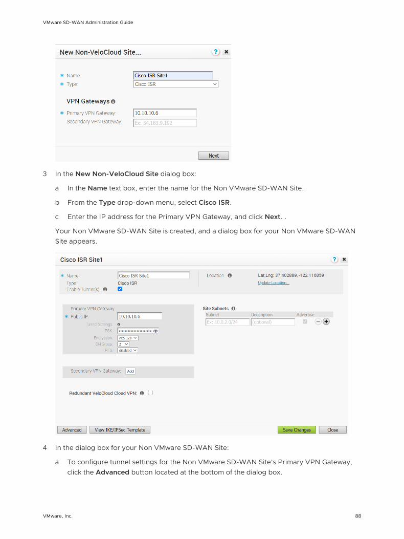
3 In the New Non-VeloCloud Site dialog box:
a In the Name text box, enter the name for the Non VMware SD-WAN Site.
b From the Type drop-down menu, select Cisco ISR.
c Enter the IP address for the Primary VPN Gateway, and click Next. .
Your Non VMware SD-WAN Site is created, and a dialog box for your Non VMware SD-WAN Site appears.
4 In the dialog box for your Non VMware SD-WAN Site:
a To configure tunnel settings for the Non VMware SD-WAN Site’s Primary VPN Gateway, click the Advanced button located at the bottom of the dialog box.
VMware SD-WAN Administration Guide
VMware, Inc. 88

b Configure tunnel settings such as PSK, Encryption, DH Group, and PFS by referring to the above table.
c If you want to create a Secondary VPN Gateway for this site, then click the Add button next to Secondary VPN Gateway. In the pop-up window, enter the IP address of the Secondary VPN Gateway and click Save Changes.
The Secondary VPN Gateway will be created immediately for this site and will provision a VMware VPN tunnel to this Gateway.
Note For Cisco ISR Non VMware SD-WAN Site, by default, the local authentication ID value used is SD-WAN Gateway Interface Local IP.
d Select the Redundant VeloCloud Cloud VPN checkbox to add redundant tunnels for each VPN Gateway.
e Under Site Subnets, you can add subnets for the Non VMware SD-WAN Site by clicking the + button.
f Check the Enable Tunnel(s) checkbox once you are ready to initiate the tunnel from the SD-WAN Gateway to the Cisco ISR VPN gateways.
g Click Save Changes.
Microsoft Azure Virtual Hub
Microsoft Azure Virtual Hub is one of the more common third party configurations. For instructions on how to configure a Non VMware SD-WAN Site of type Microsoft Azure Virtual Hub in SD-WAN Orchestrator, see Configure a Microsoft Azure Non VMware SD-WAN Site.
VPN Workflow
This is an optional service that allows you to create VPN tunnel configurations to access one or more Non VMware SD-WAN Sites. The VMware provides the configuration required to create the tunnel(s) – including creating IKE IPSec configuration and generating a pre-shared key.
Overview
The following figure shows an overview of the VPN tunnels that can be created between the VMware and a Non VMware SD-WAN Site.
VMware SD-WAN Administration Guide
VMware, Inc. 89

Cloud Gateways Enterprise DC
Enterprise DC
Enterprise DC
Cloud Gateways
Cloud Gateways
Cloud Gateways
Enterprise DC
Enterprise DC
SD-WAN Edge
VMware SD-WAN Administration Guide
VMware, Inc. 90

Note It is required that an IP address be specified for a Primary VPN Gateway at the Non VMware SD-WAN Site. The IP address is used to form a Primary VPN Tunnel between a SD-WAN Gateway and the Primary VPN Gateway.
Optionally, an IP address can be specified for a Secondary VPN Gateway to form a Secondary VPN Tunnel between a SD-WAN Gateway and the Secondary VPN Gateway. Using Advanced Settings, Redundant VPN Tunnels can be specified for any VPN tunnels you create.
Add Non VMware SD-WAN Site VPN Gateway
Enter a Name and choose a gateway Type. Specify the IP address for the Primary VPN Gateway and, optionally, specify an IP address for a Secondary VPN Gateway.
Configure Non VMware SD-WAN Site Subnets
Once you have created a Non VMware SD-WAN Site configuration, you can add site subnets and configure tunnel settings.
Click the Advanced Settings button to enter additional subnet parameters, VPN Gateway parameters, and to add Redundant VPN tunnel(s).
VMware SD-WAN Administration Guide
VMware, Inc. 91
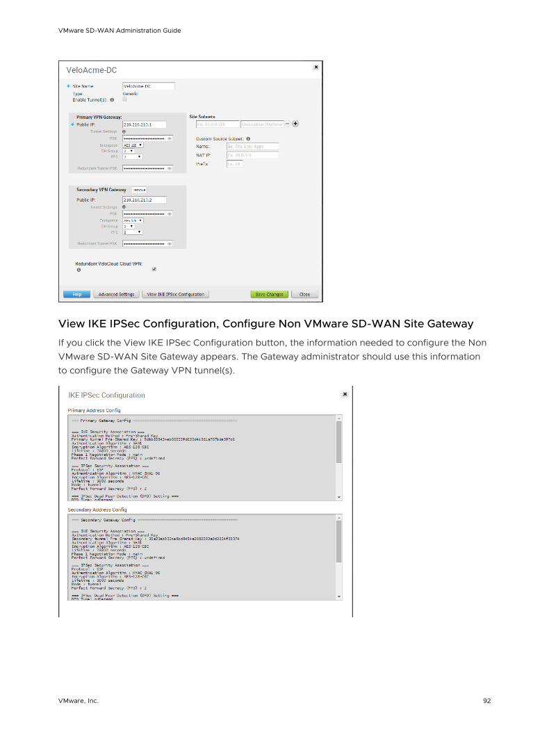
View IKE IPSec Configuration, Configure Non VMware SD-WAN Site Gateway
If you click the View IKE IPSec Configuration button, the information needed to configure the Non VMware SD-WAN Site Gateway appears. The Gateway administrator should use this information to configure the Gateway VPN tunnel(s).
VMware SD-WAN Administration Guide
VMware, Inc. 92

Enable IPSec Tunnel
The Non VMware SD-WAN Site VPN tunnel is initially disabled. You must enable the tunnel(s) after the Non VMware SD-WAN Site Gateway has been configured and before first use of the Edge-to- Non VMware SD-WAN Site VPN.
Configure Check Point
The SD-WAN Gateway connects to the Check Point CloudGuard service using IKEv1/IPsec. There are two steps to configure Check Point: Configuring the Checkpoint CloudGuard service and Configuring Checkpoint on the SD-WAN Orchestrator. You will perform the first step on the Check Point Infinity Portal and the second step on the SD-WAN Orchestrator.
Click the links for the following sections below to complete the instructions to configure Check Point.
Step 1:Configure the Check Point CloudGuard Connect
Step 2: Configure Check Point as Non VMware SD-WAN Site on SD-WAN Orchestrator
Prerequisites
You must have an active Check Point account and login credentials to access Check Point's Infinity Portal.
Configure the Check Point CloudGuard Connect
Instructions on how to configure the Check Point CloudGuard Service.
You must have an active Check Point account and login credentials to access Check Point's Infinity Portal.
Procedure
1 To configure the Check Point CloudGuard service, login to Check Point’s Infinity Portal at (https://portal.checkpoint.com/).
2 Once logged in, create a site at Check Point's Infinity Portal via the following link: https://sc1.checkpoint.com/documents/integrations/VeloCloud/check-point-VeloCloud-integration.html
After you create a site at Check Point's Infinity Portal, Configure Check Point as Non VMware SD-WAN Site on SD-WAN Orchestrator
Configure Check Point as Non VMware SD-WAN Site on SD-WAN Orchestrator
After you create a site at Check Point's Infinity Portal, configure Check Point as the Non VMware SD-WAN Site on the SD-WAN Orchestrator.
After you create a site at Check Point's Infinity Portal, complete the steps below:
Procedure
1 From the SD-WAN Orchestrator, go to Configure > Network Services
VMware SD-WAN Administration Guide
VMware, Inc. 93
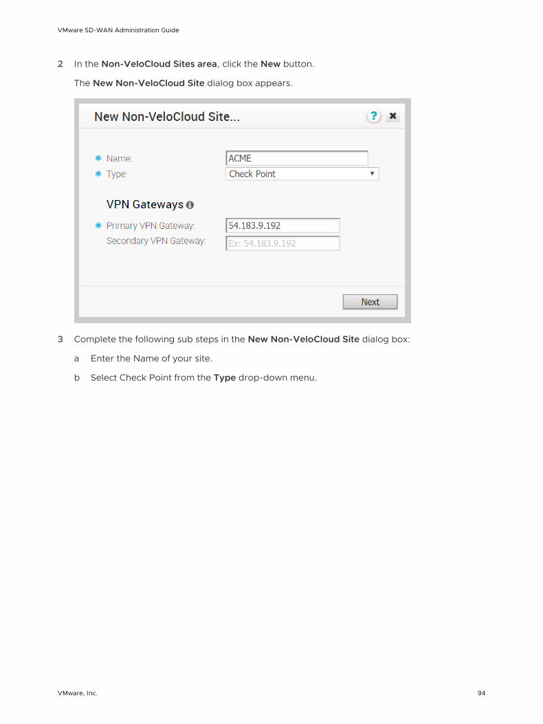
2 In the Non-VeloCloud Sites area, click the New button.
The New Non-VeloCloud Site dialog box appears.
3 Complete the following sub steps in the New Non-VeloCloud Site dialog box:
a Enter the Name of your site.
b Select Check Point from the Type drop-down menu.
VMware SD-WAN Administration Guide
VMware, Inc. 94

c Type in the Primary VPN Gateway (and the Secondary VPN Gateway if necessary).
d Click Next.
A dialog box for your Non VMware SD-WAN Site appears. (image below).
Note To configure tunnel settings to the Non VMware SD-WAN Site’s Primary VPN Gateway, click the Advanced button located at the bottom of the dialog box. Any changes made to Encryption, DH Group, or PFS will also be applied to the redundant tunnel configuration. After saving your changes, update the site's primary VPN Gateway device. Click on the "View IKE/IPSec Template" button for details.
4 In the Primary VPN Gateway area, enter the following:
a PSK: Enter the Pre-Shared Key that was configured on the Check Point infinity portal. Do not configure redundant IPsec tunnels (keep the checkbox for Redundant VeloCloud Cloud VPN unchecked).
b Encryption: The Encryption should be set to the same algorithm that was configured on the checkpoint infinity portal.
c DH Group: The DH group should be set to the same value that was configured on the checkpoint infinity portal.
d For the purposes of this specific Check Point configuration, choose disabled from PFS drop-down menu.
5 To add a Secondary VPN Gateway click the Add button. Clicking the Save Changes button will immediately create the Secondary VPN Gateway for this site and provision a VMware VPN tunnel to this Gateway.
Note For Checkpoint Non VMware SD-WAN Site, by default, the local authentication ID value used is SD-WAN Gateway Interface Public IP.
VMware SD-WAN Administration Guide
VMware, Inc. 95
6 As mentioned in Step 4a above, leave the Redundant VeloCloud Cloud VPN checkbox unchecked.
7 For the purposes of the Check Point configuration, choose Default from the Local Auth Id drop-down menu.
8 For the purposes of the Check Point configuration, check the Disable Site Subnets checkbox.
9 Click Save Changes.
10 Check the Enable Tunnel(s) checkbox once you are ready to initiate the tunnel from the SD-WAN Gateway to the Check Point CloudGuard VPN gateways.
Configure Zscaler
The Zscaler configuration includes four major steps. You must perform all four steps to complete this configuration.
The first three major steps include setting up a VPN IPSec tunnel gateway between VMware and Zscaler, and the last step requires that you set up business rules. Complete the following configuration steps:
1 Create and Configure a Non VMware SD-WAN Site.
2 Add a Non VMware SD-WAN Site to the Configuration Profile.
3 Zscaler Configuration: Create an account, add VPN credentials, add a location.
4 Configure Business Priority Rules.
Note You will perform Step 1, Step 2, and Step 4 in the SD-WAN Orchestrator. You will perform Step 3 at the Zscaler site.
Create and Configure a Non VMware SD-WAN Site
To create and configure a Non VMware SD-WAN Site:
1 From the navigation panel click Configure > Network Services.
The Services screen appears.
2 In the Non-VeloCloud Sites area, click the New button.
The New Non-VeloCloud Site dialog box appears.
VMware SD-WAN Administration Guide
VMware, Inc. 96

3 In the New Non-VeloCloud Site dialog box:
a In the Name text box, enter the name for the Non VMware SD-WAN Site.
b From the Type drop-down menu, select Zscaler.
c Enter the IP address for the Primary VPN Gateway (and the Secondary VPN Gateway if necessary), and click Next. A Non VMware SD-WAN Site of type Zscaler is created and a dialog box for your Non VMware SD-WAN Site appears.
VMware SD-WAN Administration Guide
VMware, Inc. 97
4 In the dialog box for your Non VMware SD-WAN Site:
a To configure tunnel settings for the Non VMware SD-WAN Site’s Primary VPN Gateway, click the Advanced button.
b In the Primary VPN Gateway area, under Tunnel Settings, you can configure the Pre-Shared Key (PSK), which is the security key for authentication across the tunnel. The Orchestrator generates a PSK by default. If you want to use your own PSK or password then you can enter it in the textbox.
c If you want to create a Secondary VPN Gateway for this site, then click the Add button next to Secondary VPN Gateway. In the pop-up window, enter the IP address of the Secondary VPN Gateway and click Save Changes. The Secondary VPN Gateway will be created immediately for this site and will provision a VMware VPN tunnel to this Gateway.
d Select the Redundant VeloCloud Cloud VPN checkbox to add redundant tunnels for each VPN Gateway. Any changes made to PSK of Primary VPN Gateway will also be applied to the redundant VPN tunnels, if configured. After modifying the tunnel settings of the Primary VPN Gateway, save the changes and then click View IKE/IPSec Template to view the updated tunnel configuration.
e Click the Update location link to set the location for the configured Non VMware SD-WAN Site. The latitude and longitude details are used to determine the best Edge or Gateway to connect to in the network.
f Local authentication ID defines the format and identification of the local gateway. From the Local Auth Id drop-down menu, choose from the following types and enter a value that you determine:
n FQDN - The Fully Qualified Domain Name or hostname. For example, google.com.
n User FQDN - The User Fully Qualified Domain Name in the form of email address. For example, [email protected].
n IPv4 - The IP address used to communicate with the local gateway.
Note For Zscaler Non VMware SD-WAN Site, it is recommended to use FQDN or User FQDN as the local authentication ID.
Copy the Local authentication details and PSK password. (You will need this information when you set up your VPN Credentials in your Zscaler account).
g Check the Enable Tunnel(s) checkbox once you are ready to initiate the tunnel from the SD-WAN Gateway to the Zscaler VPN gateways.
h Click Save Changes.
Associate NVS to a Configuration Profile
To associate a NVS to a configuration profile:
1 From the navigation panel click Configure > Profiles.
VMware SD-WAN Administration Guide
VMware, Inc. 98

2 In the Configure Profiles screen, click the Devices icon to the right of your profile. (For multiple Edges, use the drop-down menu to select your Edge, then click the Device tab).
3 From the Cloud VPN area, click the symbol, and choose your Non VMware SD-WAN Site from the drop-down menu.
Note You can also create a new Non VMware SD-WAN Site from the Cloud VPN area. After you click the symbol, choose New Non-VeloCloud Site from the drop-down menu.
4 Click Save Changes.
Configure Zscaler
This section describes Zscaler configuration.
Complete the following these steps on the Zscaler website. From there, you will create a Zscaler account, add VPN credentials, and add a location.
1 From the Zscaler website, create a Zscaler web security account.
VMware SD-WAN Administration Guide
VMware, Inc. 99
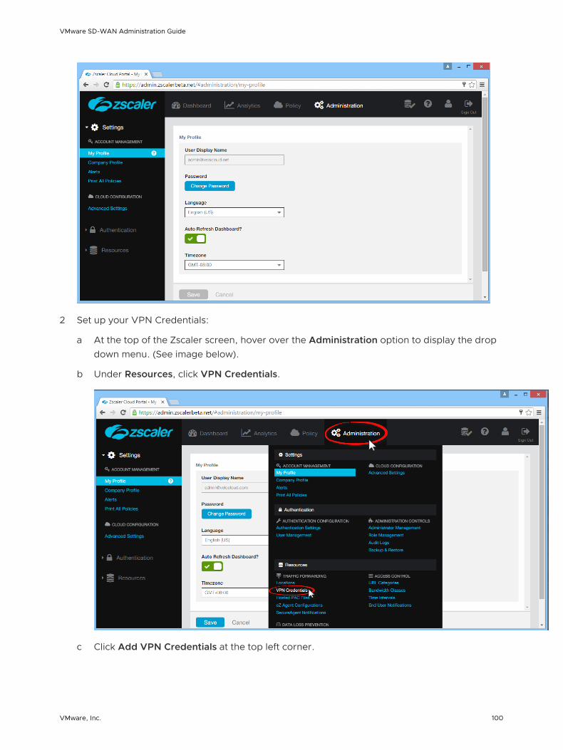
2 Set up your VPN Credentials:
a At the top of the Zscaler screen, hover over the Administration option to display the drop down menu. (See image below).
b Under Resources, click VPN Credentials.
c Click Add VPN Credentials at the top left corner.
VMware SD-WAN Administration Guide
VMware, Inc. 100

d From the Add VPN Credential dialog box:
1 Choose FQDN as the Authentication Type.
2 Type the User ID and Pre-Shared Key (PSK). You obtained this information from your Non VMware SD-WAN Site's dialog box in the SD-WAN Orchestrator.
3 If necessary, type in any comments in the Comments section.
4 Click Save.
3 Assign a location:
a At the top of the Zscaler screen, hover over the Administration option to display the drop-down menu.
b Under Resources, click Locations.
c Click Add Location at the top left corner.
d In the Add Location dialog box (see image below):
1 Complete the text boxes in the Location area (Name, Country, State/Province, Time Zone).
2 Choose None from the Public IP Addresses drop-down menu.
3 In the VPN Credentials drop-down menu, select the credential you just created. (See image below).
4 Click Done.
5 Click Save.
VMware SD-WAN Administration Guide
VMware, Inc. 101

Configure Business Priority Rules
Define the business policy in your SD-WAN Orchestrator to determine web security screening.
1 From the navigation panel in the SD-WAN Orchestrator, go to Configure > Edges.
2 In the Edges screen, click the Bus. Policy icon for your Edge.
3 Click the New Rule button.
a In the Rule dialog box:
1 Type in a name for the rule in the Rule Name textbox.
2 In the Destination area of the Match section, choose your options. (Example options are shown below):
a Click the Define button.
b Choose Internet.
c Choose TCP from the Protocol drop-down menu.
d Type your port in the Ports text box. The image below shows an example using the port 80 option. VMware recommends using port 80 or port 443. See note at the end of this section for more information.
VMware SD-WAN Administration Guide
VMware, Inc. 102

3 In the Action area, choose your options. (Example options are shown below):
a For Priority, choose Normal.
b For Network Service, click Internet Backhaul and choose your Non VMware SD-WAN Site from the drop down menu.
c For Link Steering, choose an option (for example, by Service Group).
d For Service Class, choose Transactional.
b Click OK.
Note VMware recommends business policy rules to Backhaul web traffic, specifically port 80 and 443. You can send all Internet traffic to Backhaul Zscaler. An image example using port 443 is shown below.
VMware SD-WAN Administration Guide
VMware, Inc. 103

Configure Amazon Web Services
VMware supports Amazon Web Services (AWS) configuration in Non VMware SD-WAN Site.
Configure the Amazon Web Services (AWS) as follows:
1 Obtain Public IP, Inside IP, and PSK details from the Amazon Web Services website.
2 Enter the details you obtained from the AWS website into the Non-VMware Network Service in the VMware Orchestrator.
To configure using Amazon Web Services, complete the instructions in the following section.
Obtain Amazon Web Services Configuration Details
This section describes how to obtain Amazon Web Services configuration details.
VMware SD-WAN Administration Guide
VMware, Inc. 104

When using Amazon Web Services for your configurations, refer to the instructions in Amazon's documentation (Amazon Virtual Private Cloud Network Administrator Guide), which can be found at: http://awsdocs.s3.amazonaws.com/VPC/latest/vpc-nag.pdf. Reference the following section, "Example: Generic Customer Gateway without Border Gateway" on page 79 for specific configuration instructions.
1 From Amazon's Web Services, create VPC and VPN Connections. (See section above for the link on how to access the Amazon Web Services to complete this step).
2 Make note of the SD-WAN Gateways associated with the enterprise account in the SD-WAN Orchestrator that might be needed to create a virtual private gateway in the Amazon Web Services.
3 Make a note of the Public IP, Inside IP and PSK details associated with the Virtual Private Gateway. You will enter this information in the SD-WAN Orchestrator when you create a Non VMware SD-WAN Site.
Create and Configure a Non VMware SD-WAN Site
After you obtain Public IP, Inside IP, and PSK information from the Amazon Web Services (AWS) website, you can configure a Non VMware SD-WAN Site.
To configure a Non VMware SD-WAN Site:
1 Go to Configure > Network Services.
2 In the Non-VeloCloud Sites area, click the New button.
3 In the New Non-VeloCloud Site dialog box:
a Enter the name of your site.
b Select Generic IKEv1 Router (Route Based VPN) or Generic IKEv2 Router (Route Based VPN) from the Type drop-down menu.
c Type in the Primary VPN Gateway (and the Secondary VPN Gateway if necessary).
d Click Next.
VMware SD-WAN Administration Guide
VMware, Inc. 105

A route-based Non VMware SD-WAN Site is created and a dialog box for your Non VMware SD-WAN Site appears.
4 To configure tunnel settings for the Non VMware SD-WAN Site’s Primary VPN Gateway, click the Advanced button.
VMware SD-WAN Administration Guide
VMware, Inc. 106

5 In the Primary VPN Gateway area, you can configure the following tunnel settings:
Field Description
PSK The Pre-Shared Key (PSK), which is the security key for authentication across the tunnel. The Orchestrator generates a PSK by default. If you want to use your own PSK or password then you can enter it in the textbox.
Encryption Select either AES 128 or AES 256 as the algorithm to encrypt data. The default value is AES 128.
DH Group Select the Diffie-Hellman (DH) Group algorithm to be used when exchanging a pre-shared key. The DH Group sets the strength of the algorithm in bits. The default value is 2.
PFS Select the Perfect Forward Secrecy (PFS) level for additional security. The default value is 2.
6 If you want to create a Secondary VPN Gateway for this site, then click the Add button next to Secondary VPN Gateway. In the pop-up window, enter the IP address of the Secondary VPN Gateway and click Save Changes.
The Secondary VPN Gateway will be created immediately for this site and will provision a VMware VPN tunnel to this Gateway.
7 Select the Redundant VeloCloud Cloud VPN checkbox to add redundant tunnels for each VPN Gateway.
Any changes made to Encryption, DH Group, or PFS of Primary VPN Gateway will also be applied to the redundant VPN tunnels, if configured. After modifying the tunnel settings of the Primary VPN Gateway, save the changes and then click View IKE/IPSec Template to view the updated tunnel configuration.
8 Click the Update location link to set the location for the configured Non VMware SD-WAN Site. The latitude and longitude details are used to determine the best Edge or Gateway to connect to in the network.
9 Local authentication ID defines the format and identification of the local gateway. From the Local Auth Id drop-down menu, choose from the following types and enter a value that you determine:
n FQDN - The Fully Qualified Domain Name or hostname. For example, google.com.
n User FQDN - The User Fully Qualified Domain Name in the form of email address. For example, [email protected].
n IPv4 - The IP address used to communicate with the local gateway.
Note For Generic route based VPN, if the user do not specify a value, Default is used as the local authentication ID. The default local authentication ID value will be the SD-WAN Gateway Interface Public IP.
VMware SD-WAN Administration Guide
VMware, Inc. 107

10 Under Site Subnets, you can add subnets for the Non VMware SD-WAN Site by clicking the + button. If you do not need subnets for the site, select the Disable Site Subnets checkbox.
11 Check the Enable Tunnel(s) checkbox once you are ready to initiate the tunnel from the SD-WAN Gateway to the Generic Router VPN gateways.
12 Click Save Changes.
Configure Cloud Security Services
Cloud Security Service is a cloud-hosted security offering (such as firewalls, URL filtering, etc.) that protects an Enterprise’s branch and/or data center. The following sections describe how to define and configure a cloud security service instance and how to establish a secure tunnel directly from the Edge to the cloud security service.
Overview of Cloud Security Services
This section provides an overview of Cloud Security Services.
Currently, the connectivity from a branch Edge to a cloud service or a Non VMware SD-WAN Site is established through the SD-WAN Gateway. In this model, the SD-WAN Gateway aggregates traffic from multiple branch Edges and securely forwards the traffic to the Non VMware SD-WAN Site.
You can also configure the branch Edge to establish a tunnel direct to the cloud service pop. This option has the following advantages:
n You can save link bandwidth costs by offloading non-enterprise traffic to the internet.
n By redirecting the Internet traffic to a cloud security service, you can ensure that the branch sites are protected from malicious traffic.
n Simplified configuration.
This document describes how to define and configure a cloud security service instance and establish a secure tunnel directly from the Edge to the cloud security service. The configuration is divided into three parts:
n Configure Cloud Security Services
n Configure Cloud Security Services for Profiles
n Configure Cloud Security Services for Edges
Configure Cloud Security Services
You can configure the cloud security services from the Network Services window.
In the Enterprise portal, navigate to Configure > Network Services. For establishing a secured tunnel to cloud security service sites from the Edge, you can define the service instance in the Cloud Security Service area.
VMware SD-WAN Administration Guide
VMware, Inc. 108

Add and Configure a Cloud Security Provider
The cloud security service establishes a secure tunnel from an Edge to the cloud security service sites. This ensures secured traffic flow to the cloud security services.
1 In the Customer panel, click Configure > Network Services.
2 In the Cloud Security Service panel, click New.
3 In the New Cloud Security Provider dialog box, select the Service Type for the cloud service.
4 Enter a descriptive name next to Service Name.
5 Enter the IP Address for Primary Point-of-Presence/Server and Secondary Point-of-Presence/Server.
Note If you have selected Zscaler Cloud Security Service as Service Type and planning to assign a GRE tunnel, it is recommended to enter only IP address as Point-of-Presence and not the hostname, as GRE does not support hostnames.
6 To save your configuration, click Add.
VMware SD-WAN Administration Guide
VMware, Inc. 109

Note You must configure the tunnel attributes for each Edge. See the Configure Cloud Security Services for Edges section.
Configure Cloud Security Services for Profiles
You must enable cloud security to establish a secured tunnel from an Edge to cloud security service sites. This enables the secured traffic being redirected to third party cloud security sites.
Before you begin:
n Ensure that you have access permission to configure network services.
n Ensure that your SD-WAN Orchestrator has version 3.3.x or above.
n You should have Cloud security service gateway endpoint IPs and FQDN credentials configured in the third party CSS.
1 In the Enterprise portal, click Configure > Profiles.
2 Click the Device Icon next to a profile, or click the link to the profile, and then click the Device tab.
3 In the Cloud Security section, switch the dial from the Off position to the On position.
4 Configure the following settings:
Option Description
Cloud Security Service Select a cloud security service from the drop-down menu. You can also click New Cloud Security Service from the drop-down to create a new service type.
Tunneling Protocol This option is available only for Zscaler cloud security service. Choose either IPsec or GRE. By default, IPsec is selected.
VMware SD-WAN Administration Guide
VMware, Inc. 110

Option Description
Hash Select the Hash function as SHA 1 or SHA 256 from the drop-down. By default, SHA 1 is selected.
Note VMware does not support MD5 and it is recommended not to choose MD5 as the Hash function.
Encryption Select the Encryption algorithm as AES 128 or AES 256 from the drop-down. By default, None is selected.
Key Exchange Protocol This option is not available for Symantec cloud security service.
Select the key exchange method as IKEv1 or IKEv2. By default, IKEv2 is selected.
5 Click Save Changes.
When you enable Cloud Security Service and configure the settings in a profile, the setting is automatically applied to the Edges that are associated with the profile. If required, you can override the configuration for a specific Edge. See Configure Cloud Security Services for Edges.
For the profiles created with cloud security service enabled and configured prior to 3.3.1 release, you can choose to redirect the traffic as follows:
n Redirect only web traffic to Cloud Security Service
n Redirect all internet bound traffic to Cloud Security Service
n Redirect traffic based on Business Policy Settings – This option is available only from release 3.3.1. If you choose this option, then the other two options are no longer available.
Note For the new profiles that you create for release 3.3.1 or later, by default, the traffic is redirected as per the Business Policy settings.
You can create a rule in the business policy to redirect the traffic to cloud security service.
1 In the Business Policy tab of the profile, create a new rule by clicking New Rule or, from the Actions drop-down menu, choose New.
The Configure Rule dialog box appears.
2 Enter a unique name for the Rule Name.
3 In the Action area, click the Internet Backhaul button and choose Cloud Security Service.
VMware SD-WAN Administration Guide
VMware, Inc. 111

4 Click OK.
The new rule appears in the Business Policy screen.
Configure Cloud Security Services for Edges
When you have assigned a profile to an Edge, the device automatically inherits the cloud security service associated with the profile. You can override the settings to modify the attributes for each Edge.
1 In the Enterprise portal, click Configure > Edges.
2 In the Cloud Security Service section, the cloud security service parameters of the associated profile are displayed. Select Enable Edge Override, to modify the attributes. For more information on the attributes, see Configure Cloud Security Services for Profiles.
VMware SD-WAN Administration Guide
VMware, Inc. 112

Apart from the existing attributes, you can configure the following additional parameters for an Edge:
n FQDN – Enter the Fully Qualified Domain Name for an IPsec protocol.
n PSK – Enter the Pre-shared Key for an IPsec protocol.
Note The above options are not available for Symantec cloud security service.
If you choose the GRE tunneling protocol for Zscaler cloud security service, add the GRE tunnel parameters.
1 Click Add Tunnel.
2 In the Add Tunnel window, configure the following:
Option Description
WAN Links Select the WAN interface to be used as source by the GRE tunnel.
Tunnel Source Public IP Choose the IP address to be used as a public IP address by the Tunnel. You can either choose the WAN Link IP or Custom WAN IP. If you choose Custom WAN IP, enter the IP address to be used as public IP.
Primary Router IP/Mask Enter the primary IP address of Router.
Secondary Router IP/Mask Enter the secondary IP address of Router.
Primary ZEN IP/Mask Enter the primary IP address of Internal Zscaler Public Service Edge.
Secondary ZEN IP/Mask Enter the secondary IP address of Internal Zscaler Public Service Edge.
Note The Router IP/Mask and ZEN IP/Mask are provided by Zscaler.
3 Click OK and the tunnel details are displayed in the Cloud Security Services section.
Click Save Changes in the Edges window to save the modified settings.
For the profiles created with cloud security service enabled and configured prior to 3.3.1 release, you can choose to redirect the traffic as follows:
n Redirect only web traffic to Cloud Security Service
VMware SD-WAN Administration Guide
VMware, Inc. 113

n Redirect all internet bound traffic to Cloud Security Service
n Redirect traffic based on Business Policy Settings – This option is available only from release 3.3.1. If you choose this option, then the other two options are no longer available.
Note For the new profiles that you create for release 3.3.1 or later, by default, the traffic is redirected as per the Business Policy settings.
You can create a rule in the business policy to associate the cloud security service.
1 In the Business Policy tab of the Edge, create a new rule by clicking New Rule or, from the Actions drop-down menu, choose New Rule.
The Configure Rule dialog box appears.
2 Enter a unique name for the Rule Name.
3 In the Action area, click the Internet Backhaul button and choose Cloud Security Service.
4 Click OK.
The new rule appears in the Business Policy screen.
Monitor Cloud Security Services
There are two places you can monitor cloud security services from the navigation panel, the Edges screen ( Monitor > Edges) and the Network Services screen ( Monitor > Network Services) screens. The following sections provide more information.
Edges Screen
To monitor your cloud services from the Edges screen, go to Monitor > Edges. This view displays the number of tunnels that are up and the number of tunnels that are down.
Network Services Screen
To monitor your cloud security services from the Network Services screen, go to Monitor > Network Services > Cloud Security Tunnel State.
VMware SD-WAN Administration Guide
VMware, Inc. 114

The Edge Status column in the Cloud Security Tunnel State area displays how many Edges are fully connected and disconnected.
Status Column
The Status column shows the overall connectivity state of the specific Cloud Security Service. If all Edges are fully connected, the color of the icon will be green. If some Edges are connected, while some are disconnected, the color of the icon will be yellow. If all Edges are disconnected, the color of the icon will be red.
Events
To view the Events for the Cloud Security Service, click the Events link in the Cloud Security Service Sites area.
Configure DNS Services
This is an optional service that allows you to create a configuration for DNS.
The DNS Service can be for a public DNS service or a private DNS service provided by your company. A Primary Server and Backup Server can be specified. The service is preconfigured to use Google and Open DNS servers.
VMware SD-WAN Administration Guide
VMware, Inc. 115

The following figure shows a sample configuration for a Public DNS.
For a private service, you can also specify one or more Private Domains.
Configure Netflow Settings
In an Enterprise network, Netflow monitors traffic flowing through SD-WAN Edges and exports Internet Protocol Flow Information eXport (IPFIX) information directly from SD-WAN Edges to one or more Netflow collectors. The SD-WAN Orchestrator allows you to configure Netflow collectors and filters as network services at the profile, edge, and segment level. You can configure a maximum of two collectors per segment and eight collectors per profile and edge. Also, you can configure a maximum of 16 filters per collector.
Procedure
1 From the SD-WAN Orchestrator, go to Configure > Network Services.
The Services page appears.
VMware SD-WAN Administration Guide
VMware, Inc. 116
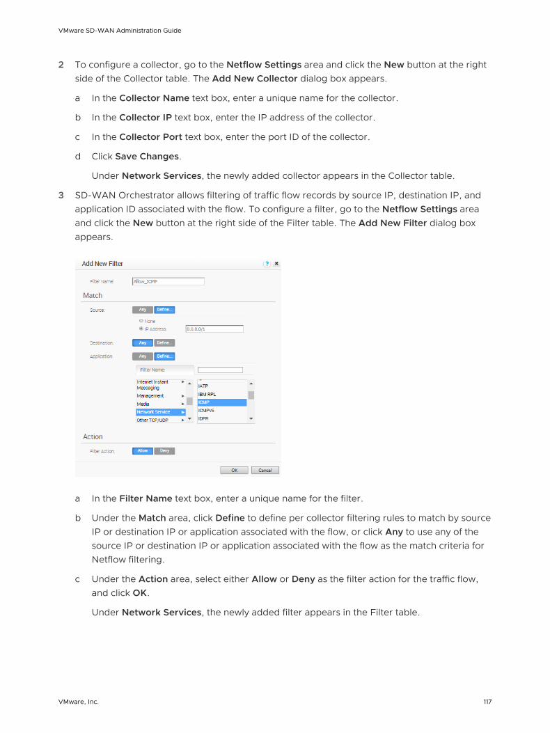
2 To configure a collector, go to the Netflow Settings area and click the New button at the right side of the Collector table. The Add New Collector dialog box appears.
a In the Collector Name text box, enter a unique name for the collector.
b In the Collector IP text box, enter the IP address of the collector.
c In the Collector Port text box, enter the port ID of the collector.
d Click Save Changes.
Under Network Services, the newly added collector appears in the Collector table.
3 SD-WAN Orchestrator allows filtering of traffic flow records by source IP, destination IP, and application ID associated with the flow. To configure a filter, go to the Netflow Settings area and click the New button at the right side of the Filter table. The Add New Filter dialog box appears.
a In the Filter Name text box, enter a unique name for the filter.
b Under the Match area, click Define to define per collector filtering rules to match by source IP or destination IP or application associated with the flow, or click Any to use any of the source IP or destination IP or application associated with the flow as the match criteria for Netflow filtering.
c Under the Action area, select either Allow or Deny as the filter action for the traffic flow, and click OK.
Under Network Services, the newly added filter appears in the Filter table.
VMware SD-WAN Administration Guide
VMware, Inc. 117

Results
At the profile and edge level, the configured collectors and filters appears as a list under the Netflow Settings area in the Device tab.
n While configuring a profile or edge, you can either select a collector and filter from the available list or add a new collector and a filter. For steps, see Configure Netflow Settings at the Profile Level.
n To override Netflow settings at the Edge level, see Configure Netflow Settings at the Edge Level.
Private Network Names
You can define multiple private networks and assign them to individual private WAN overlays.
Configure Private Networks
To configure private networks:
1 From the SD-WAN Orchestrator navigation panel, go to Configure > Network Services.
2 In the Private Network Names area, click the New button.
3 In New Private Network Name dialog box, enter a unique name in the appropriate text box.
4 Click Save Changes.
The private network name appears in the Private Network Name area.
Delete a Private Network Name
Only private network names that are not used by an Edge device can be deleted.
To delete a private network name not used by an Edge device:
1 Select the name by clicking the name's checkbox, and then click the Delete button.
2 In the Confirm Deletion dialog box, click OK.
You can select private link tags when you define a User Defined Overlay. See section titled, " Select a Private Network Name."
VMware SD-WAN Administration Guide
VMware, Inc. 118

Configure Authentication Services
Authentication Services is an optional configuration. If your organization uses a service for authentication or accounting, you can create a Network Service that specifies the IP address and ports for the service. This is a part of the 802.1x configuration process, which is configured in the profile.
The following figure shows an example configuration.
VMware SD-WAN Administration Guide
VMware, Inc. 119

Configure Profiles 9Profiles provide a composite of the configurations created in Networks and Network Services. It also adds configuration for Business Policy and Firewall rules.
Note If you are logged in using a user ID that has Customer Support privileges, you will only be able to view SD-WAN Orchestrator objects. You will not be able to create new objects or configure/update existing ones.
Profiles have four tab pages: Profile Overview, Device, Business Policy, and Firewall.
This chapter includes the following topics:
n Create a Profile
n Modify a Profile
n Profile Overview Screen
n Network to Segment Migration
n Configure Local Credentials
Create a Profile
After a new installation, the SD-WAN Orchestrator has the following predefined Profiles: Internet Profile, VPN Profile, and as of the 3.0 release, Segment-based profiles.
Note With the Segmentation feature introduced in the 3.0 release, Edges running the software prior to 3.0 could have a Network-based Configuration or a Segmentation-based Configuration. **Because of this transition, you must migrate/convert the Network-based profile to the Segment-based profile.
The following steps are typically followed when creating a new Profile:
1 Create a Profile
2 Configure Device
a Select Network
b Assign Authentication/DNS
c Configure Interface Settings
VMware, Inc. 120
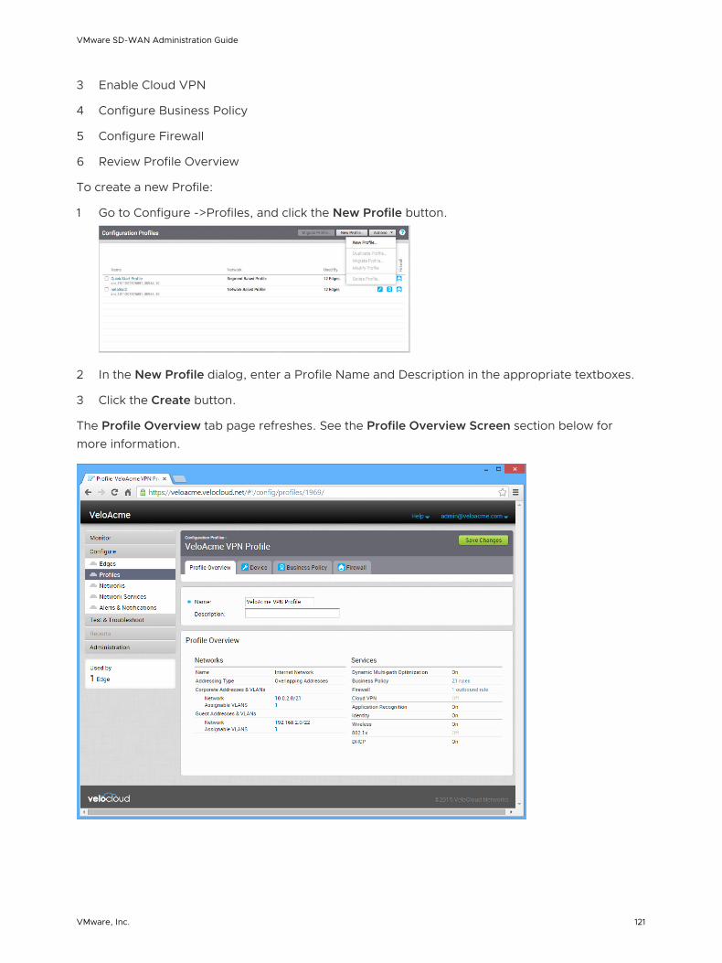
3 Enable Cloud VPN
4 Configure Business Policy
5 Configure Firewall
6 Review Profile Overview
To create a new Profile:
1 Go to Configure ->Profiles, and click the New Profile button.
2 In the New Profile dialog, enter a Profile Name and Description in the appropriate textboxes.
3 Click the Create button.
The Profile Overview tab page refreshes. See the Profile Overview Screen section below for more information.
VMware SD-WAN Administration Guide
VMware, Inc. 121

Modify a Profile
Enterprise Admins can also manually assign a profile to an Edge.
One scenario in which this is necessary is for Edge Staging Profiles. In this case, the Edge gets activated against the staging profile by default due to push activation. Enterprise Admins must manually assign a final production profile to the Edge. See Provision an Edge in Assign a Profile (Change a Profile) for instructions on how to manually assign Profiles.
Profile Overview Screen
The Profile Overview screen provides a quick summary of all Networks and Services that are defined in the profile.
The overview is divided into two categories:
Category Description
Networks Has the name of the Network configuration used, the type of addressing, and the Network addresses and VLANs assigned to the Corporate and Guest networks.
Services Has a summary of the services provided by the VMware system.
After all settings have been entered for the Profile Device, Business Policy, and Firewall tab screens, the Profile Overview screen should reflect the configurations you have performed.
Network to Segment Migration
In the 3.2 release, the Profile Migration feature was introduced to help simplify the workflow to upgrade Edges from Network-based Profiles to Segment-based Profiles. This document provides the workflow and details on how to upgrade a 2.X Edge with a Network-based Profile to 3.X with a Segment-based profile.
Edge Upgrade from 2.X to 3.X Prerequisites
To upgrade from version 2.X to 3.X, the following prerequisites are required for the Edge:
n Upgrading to 3.X is supported from versions 2.4 and 2.5.
n Make sure the SD-WAN Orchestrator and SD-WAN Gateway are the same version or a higher version than the Edge.
VMware SD-WAN Administration Guide
VMware, Inc. 122

Best Practices for Upgrading Edges Deployed as Hub and Spoke
While performing upgrades for Edges deployed in Hub and Spoke configurations:
n The Edges configured as a Hub should be upgraded to 3.X before upgrading the Edges configured as Spokes.
n Tunnel formation will not occur if the Hub is in a 3.X based profile and all the Spokes are running in a 2.X based profile.
n In order to overcome the above-mentioned restriction, each Spoke profile should have at least one Spoke running in the 3.2.1 based profile.
Best Practices for Upgrading Edges Deployed in HA
Normal software upgrade steps are applicable for customers who are upgrading a pair of High Availability Edges to Release 3.3.x or earlier (e.g. 3.3.2 P2). However, customers who are upgrading Edges deployed in HA to the Release 3.4.x branch or later are required to perform an intermediate upgrade to 3.3.x prior to upgrading their HA Edges to the desired 3.4.x or later release. Upgrading a single, standalone Edge directly from a 2.x Release to a 3.4.x or later release is supported with no known issues.
Migrate Network to Segment
This section describes network to segment migration.
Before You Begin
n Prior to upgrading an Edge, make sure the SD-WAN Orchestrator and SD-WAN Gateway are the same version or a higher version than the Edge.
Note Because 3.X Edges only understand Segment-based Profiles, the 3.2 image update will get pushed out to the Edge only if the Edge has a Segmented Profile assigned. Once a Segment-based Profile is assigned to an Edge, it cannot be reassigned to a Network-based Profile. The transition from a Network-based Profile to a Segment-based Profile is supported, but a Segment-based Profile to a Network-based Profile is not supported.
n Ensure Segmentation is enabled before migrating a profile.
Note By default, Segmentation is enabled.
Step 1: Create a Non-global Segment for Allocating a Guest Network
Because guest networks are created by default in a Network-based profile, you must create a non-global segment to map the guest networks to a separate segment during migration.
1 From the SD-WAN Orchestrator, go to Configure > Segments. The Segments screen appears. Note that the Global Segment cannot be deleted.
VMware SD-WAN Administration Guide
VMware, Inc. 123
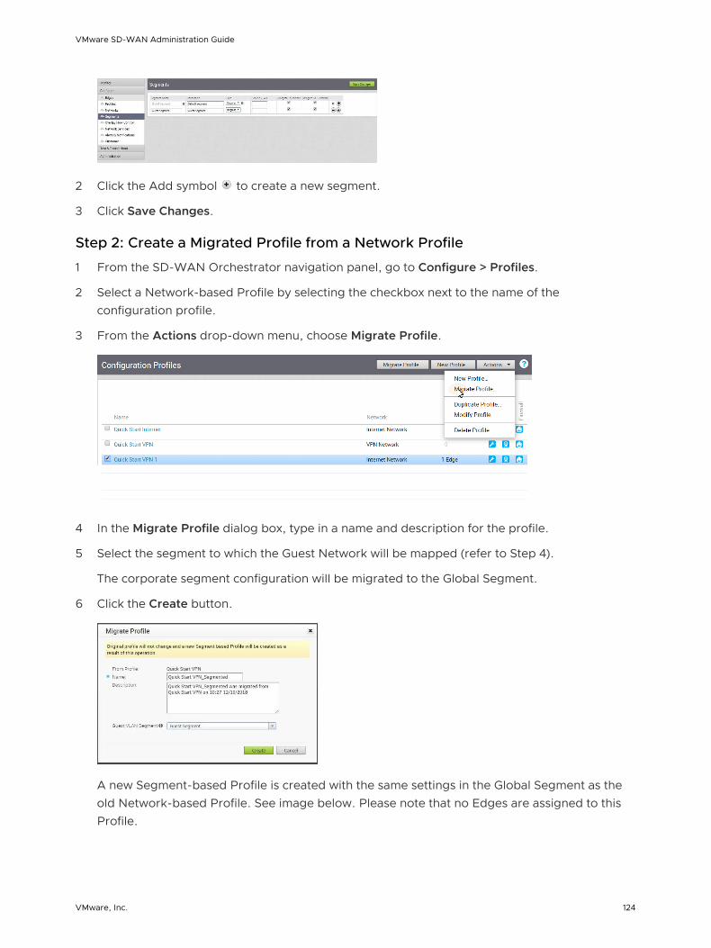
2 Click the Add symbol to create a new segment.
3 Click Save Changes.
Step 2: Create a Migrated Profile from a Network Profile
1 From the SD-WAN Orchestrator navigation panel, go to Configure > Profiles.
2 Select a Network-based Profile by selecting the checkbox next to the name of the configuration profile.
3 From the Actions drop-down menu, choose Migrate Profile.
4 In the Migrate Profile dialog box, type in a name and description for the profile.
5 Select the segment to which the Guest Network will be mapped (refer to Step 4).
The corporate segment configuration will be migrated to the Global Segment.
6 Click the Create button.
A new Segment-based Profile is created with the same settings in the Global Segment as the old Network-based Profile. See image below. Please note that no Edges are assigned to this Profile.
VMware SD-WAN Administration Guide
VMware, Inc. 124

Step 3: Assign Migrated Profile to Edges (See IMPORTANT NOTE Below)
During this step, no configuration updates will be pushed out to the Edge while the Edge reported software image is < 3.0. Edges in this state are essentially ‘configuration frozen’ until a 3.X image is provisioned to them.
To assign a segment-based profile to a network-based Edge:
1 Go to Configure > Edges in the navigation panel of the SD-WAN Orchestrator.
2 In the Edges screen, select the Edge you want to assign a Segment Profile to.
3 In the Edge Overview tab, go to the Profile area.
4 From the Profile drop-down menu, choose a Segment Based Profile.
The segment-based profile will be applied only after the Edge is upgraded to 3.2.X.
Note There are two additional steps to migrate a profile, 'Create a New Operator Profile with a 3.2 Edge Image' and 'Assign the Segment-based Operator Profile to the Edges.' Enterprise Admin users at all levels do not have access to these additional steps and must contact their Operator. Their Operator must create a new Operator Profile with a 3.X Image and assign the Operator profile to the Enterprise usage. After assigning the 3.X based Operator profile and segmented profile, the Edge will receive a software image update. Contact your Operator for more information.
Note The next step, "Create a New Operator Profile with a 3.2 Edge Image" is an Operator-level only step that must be completed before a profile can be migrated. Partners do not have access to the features for this step and must contact their Operators.
VMware SD-WAN Administration Guide
VMware, Inc. 125

Step 4: Create a New Operator Profile with a 3.2 Edge Image (Operator-level Only Step)
Operators must create a new Operator profile with a 3.2 Edge image before a profile can be migrated. Enterprise and Partner level users do not have access to the features in this step.
Step 5 is an Operator-level only step. Your Operator must create a new Operator Profile with a 3.2 Edge Image.
1 From the SD-WAN Orchestrator, choose Operator Profiles. See image below.
2 From the Operator Profile screen, click the New Profile button.
3 In the New Operator Profile dialog box:
a Type in a Name and Description for the profile.
b In the Configuration Type drop-down menu, choose Segment Based.
c Click the Create button.
4 In the newly created Operator Profile screen, go to the Software Version area.
5 In the Software Version area, choose a software version from the Version drop-down menu. (See image below).
6 Click the Save Changes button at the top of the SD-WAN Orchestrator screen.
VMware SD-WAN Administration Guide
VMware, Inc. 126

Step 6: Assign the Segment-based Operator Profile to the Edges
An Important Note has been added to this step for the 3.3.0 software release (see note below).
Note Operators and Partners can assign software images, but Enterprise Admins at all levels do not have access to this feature.
The Edge with the Segmented Profile will receive a software image update via the Operator Profile. This can be accomplished either by switching the Operator Profile for the customer or assigning a new Operator Profile to selected Edges. The steps below describe how to assign a new Operator Profile to a selected Edge.
Note It is recommended that you perform the profile assignment to one Edge first and validate that the Edge is working correctly before you proceed to the other Edges. The first Edge that you assign a profile to will be classified as a Hub (because Hubs must be migrated before spokes).
To Assign a new Operator Profile:
1 From the SD-WAN Orchestrator navigation panel, go to Configure > Edges.
2 In the Edges screen, select the Edge(s) you want to assign an Operator Profile to.
3 From the Actions drop-down menu, choose Assign Operator Profile or Assign Software Image.(NOTE: Only Operator Superusers will see Assign Operator Profile from the Actions drop-down menu, all other users with access to this feature will see Assign Software Image from the Actions drop-down menu).
4 From the appropriate dialog box ( Assign Operator Profile dialog box or Assign Software Image dialog box), choose the Segment-based Operator Profile that was created in Step 3. ( NOTE: If necessary, assign the Operator Profile to a Customer or Partner).
5 Click the Update button.
After this operation, Edge(s) will receive the 3.2 software image update, and after the image update process is complete, Edge(s) will begin communicating with the SD-WAN Orchestrator.
Configure Local Credentials
You can change the local credentials at the Profile level from the Configure > Profiles > Profile Overview tab. When the credentials are updated, they will be sent to all Edges that use the Profile as an Edge action.
VMware SD-WAN Administration Guide
VMware, Inc. 127

Add Credentials
This section describes how to add credentials.
Click the View button to open the Local Configuration Credentials dialog box. Type in a User name and a Password, and then click the Submit button.
VMware SD-WAN Administration Guide
VMware, Inc. 128

Configure a Profile Device 10This section describes how to configure a profile device.
Note If you are logged in using a user ID with Customer Support privileges, you will only be able to view SD-WAN Orchestrator objects. You will not be able to create new objects or configure/update existing ones.
VMware provides device settings using the Device tab ( Configure > Profiles > Device Tab) in a profile. The Device Settings tab is used to assign segments, create VLANs, configure interfaces, configure DNS settings, Configure Authentication Settings. For more information about Segmentation, see Chapter 7 Configure Segments.
This chapter includes the following topics:
n Configure a Device
Configure a Device
Device configuration allows you to assign segments to a Profile and configure Interfaces to be associated with a Profile.
For segment aware profiles, there are two sections on the UI:
Configuration Type Description
Segment-aware configurations
Configure Segments area of the Device tab screen. Customers can choose the segment from the drop-down menu, select the segment, and then the configuration for that segment will display in the Configure Segments area.
Common configurations The lower part of the Device tab screen. Features and configurations that apply to multiple segments, which include VLAN configs, Device Settings, Wi-Fi and Multi-source QoS.
VMware, Inc. 129
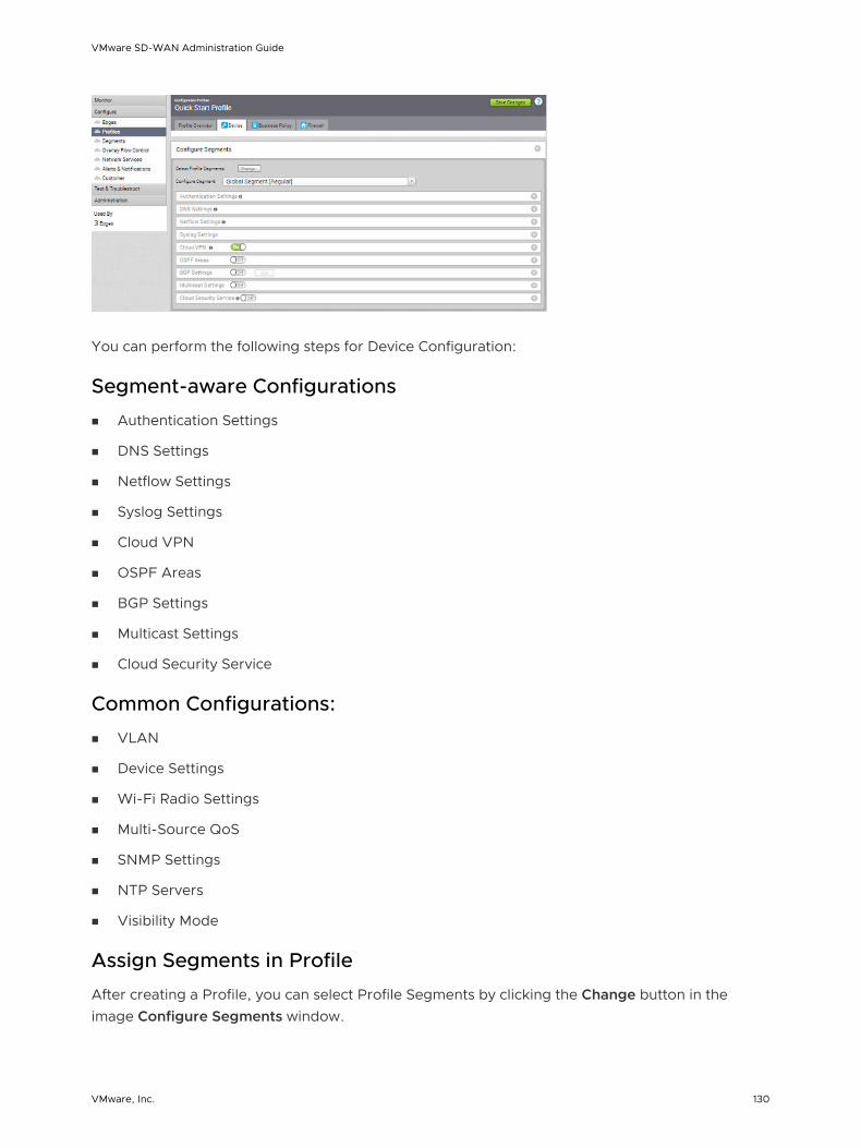
You can perform the following steps for Device Configuration:
Segment-aware Configurations
n Authentication Settings
n DNS Settings
n Netflow Settings
n Syslog Settings
n Cloud VPN
n OSPF Areas
n BGP Settings
n Multicast Settings
n Cloud Security Service
Common Configurations:
n VLAN
n Device Settings
n Wi-Fi Radio Settings
n Multi-Source QoS
n SNMP Settings
n NTP Servers
n Visibility Mode
Assign Segments in Profile
After creating a Profile, you can select Profile Segments by clicking the Change button in the image Configure Segments window.
VMware SD-WAN Administration Guide
VMware, Inc. 130

Clicking the Change button opens the Select Segments dialog box.
In this dialog box, you can select the Segments that you want to include in your profile. Segments with a lock symbol next to them indicate that the Segment is in use within a profile, and it cannot be removed. Segments available for use will be displayed on the left side of the dialog under All Segments.
After you have selected a Segment, you can configure your Segment through the Configure Segment drop-down menu. All Segments available for configuration are listed in the Configure Segment drop-down menu. If a Segment is assigned to a VLAN or interface, it will display the VLAN ID and the Edge models associated with it.
When you choose a Segment to configure from the Configure Segment drop-down menu, depending upon the Segment’s options, the settings associated that Segment display in the Configure Segments area.
VMware SD-WAN Administration Guide
VMware, Inc. 131

Configure Authentication Settings
The Device Authentication Settings allow you to specify which Network Services DNS Service to use.
Configure DNS Settings
The DNS Settings can be used to configure conditional DNS forwarding through a private DNS service and to specify a public DNS service to be used for querying purpose.
To configure the DNS settings:
1 In the Enterprise portal, click Configure > Profiles.
2 Click the Device Icon next to a profile, or click the link to the profile, and then click the Device tab.
3 In the Device tab, configure the following in the DNS Settings section:
n Conditional DNS Forwarding – Select a private DNS service from the drop-down list to forward the DNS requests related to the domain name. You can also choose the New Private DNS Service to create a new private DNS service.
n Public DNS – Select a public DNS service from the drop-down list to be used for querying the domain names. You can also choose the New DNS Service to create a new public DNS service.
Note The public DNS service is enabled on a VLAN or a routed interface only if the DHCP service is enabled on that VLAN or routed interface. For instructions, see Configure DHCP Server on Routed Interfaces.
For more information on creating new DNS service, see Configure DNS Services.
VMware SD-WAN Administration Guide
VMware, Inc. 132

4 In the Device tab, click Save Changes.
Note The global segment configuration for DNS applies to all the customer-created segments. The source IP is the Management IP configured in the Configure VLAN section. See Configure VLAN for Profiles.
Configure Netflow Settings at the Profile Level
As an enterprise Administrator, you can configure Netflow settings at the Profile level.
Procedure
1 From the SD-WAN Orchestrator, go to Configure > Profiles.
The Configuration Profiles page appears.
2 Select a profile you want to configure Netflow settings and click the icon under the Device column.
The Device Setting page for the selected profile appears.
3 From the Configure Segment drop-down menu, select a profile segment to configure Netflow settings.
4 Go to the Netflow Settings area and configure the following details.
a Select the Netflow Enabled checkbox.
SD-WAN Orchestrator supports IP Flow Information Export (IPFIX) protocol version 10.
b From the Collector drop-down menu, select an existing Netflow collector to export IPFIX information directly from SD-WAN Edges, or click New Collector to configure a new Netflow collector.
For more information about how to add a new collector, see Configure Netflow Settings.
Note You can configure a maximum of two collectors per segment and eight collectors per profile by clicking the + button. When the number of configured collectors reaches the maximum allowable limit, the + button will be disabled.
VMware SD-WAN Administration Guide
VMware, Inc. 133
c From the Filter drop-down menu, select an existing Netflow filter for the traffic flows from SD-WAN Edges, or click New Filter to configure a new Netflow filter.
For more information about how to add a new filter, see Configure Netflow Settings.
Note You can configure a maximum of 16 filters per collector by clicking the + button. However, the 'Allow All' filtering rule is added implicitly at the end of the defined filter list, per collector.
d Enable the Allow All checkbox corresponding to a collector to allow all segment flows to that collector.
e Under Intervals, configure the following Netflow export intervals:
n Flow Stats - Export interval for flow stats template, which exports flow statistics to the collector. By default netflow records of this template is exported every 60 seconds. The allowable export interval range is from 60 seconds to 300 seconds.
n FlowLink Stats - Export interval for flow link stats template, which exports flow statistics per link to the collector. By default netflow records of this template is exported every 60 seconds. The allowable export interval range is from 60 seconds to 300 seconds.
n VRF Table - Export interval for VRF option template, which exports segment related information to collector. The default export interval is 300 seconds. The allowable export interval range is from 60 seconds to 300 seconds.
n Application Table - Export interval for Application option template, which exports application information to the collector. The default export interval is 300 seconds. The allowable export interval range is from 60 seconds to 300 seconds.
n Interface Table - Export interval for Interface option template, which exports interface information to collector. The default export interval is 300 seconds. The allowable export interval range is from 60 seconds to 300 seconds.
n Link Table - Export interval for Link option template, which exports link information to the collector. The default export interval is 300 seconds. The allowable export interval range is from 60 seconds to 300 seconds.
n Tunnel Stats - Export interval for tunnel stats template. By default the statistics of the active tunnels in the edge are exported every 60 seconds. The allowable export interval range is from 60 seconds to 300 seconds.
Note In an Enterprise, you can configure the Netflow intervals for each template only on the Global segment. The configured Netflow export interval is applicable for all collectors of all segments on an edge.
5 Click Save Changes.
VMware SD-WAN Administration Guide
VMware, Inc. 134

Configure Syslog Settings at Profile Level
In an Enterprise network, SD-WAN Orchestrator supports collection of SD-WAN Orchestrator bound events and firewall logs originating from enterprise SD-WAN Edges to one or more centralized remote Syslog collectors (Servers), in the native Syslog format. For the Syslog collector to receive SD-WAN Orchestrator bound events and firewall logs from the configured edges in an Enterprise, at the profile level, configure Syslog collector details per segment in the SD-WAN Orchestrator by performing the steps on this procedure.
Prerequisites
n Ensure that Cloud Virtual Private Network (branch-to-branch VPN settings) is configured for the SD-WAN Edge (from where the SD-WAN Orchestrator bound events are originating) to establish a path between the SD-WAN Edge and the Syslog collectors. For more information, see Configure Cloud VPN.
Procedure
1 From the SD-WAN Orchestrator, go to Configure > Profiles.
The Configuration Profiles page appears.
2 Select a profile you want to configure Syslog settings and click the icon under the Device column.
The Device Settings page for the selected profile appears.
3 From the Configure Segment drop-down menu, select a profile segment to configure syslog settings. By default, Global Segment [Regular] is selected.
4 Go to the Syslog Settings area and configure the following details.
a From the Facility Code drop-down menu, select a Syslog standard value that maps to how your Syslog server uses the facility field to manage messages for all the events from SD-WAN Edges. The allowed values are from local0 through local7.
Note The Facility Code field is configurable only for the Global Segment, even if the Syslog settings is enabled or not for the profile. The other segments will inherit the facility code value from the Global segment.
b Select the Syslog Enabled checkbox.
c In the IP text box, enter the destination IP address of the Syslog collector.
d From the Protocol drop-down menu, select either TCP or UDP as the Syslog protocol.
e In the Port text box, enter the port number of the Syslog collector. The default value is 514.
f As Edge interfaces are not available at the Profile level, the Source Interface field is set to Auto. The Edge automatically selects an interface with 'Advertise' field set as the source interface.
VMware SD-WAN Administration Guide
VMware, Inc. 135

g From the Roles drop-down menu, select one of the following:
n EDGE EVENT
n FIREWALL EVENT
n EDGE AND FIREWALL EVENT
h From the Syslog Level drop-down menu, select the Syslog severity level that need to be configured. For example, If CRITICAL is configured, the SD-WAN Edge will send all the events which are set as either critical or alert or emergency.
Note By default, firewall event logs are forwarded with Syslog severity level INFO.
The allowed Syslog severity levels are:
n EMERGENCY
n ALERT
n CRITICAL
n ERROR
n WARNING
n NOTICE
n INFO
n DEBUG
i Optionally, in the Tag textbox, enter a tag for the syslog. The syslog tag can be used to differentiate the various types of events at the Syslog Collector. The maximum allowed character length is 32, delimited by period.
j When configuring a Syslog collector with FIREWALL EVENT or EDGE AND FIREWALL EVENT role, select the All Segments checkbox if want the Syslog collector to receive firewall logs from all the segments. If the checkbox is disabled, the Syslog collector will receive firewall logs only from that particular Segment in which the collector is configured.
Note When the role is EDGE EVENT, the Syslog collector configured in any segment will receive Edge event logs by default.
5 Click the + button to add another Syslog collector or else click Save Changes. The remote syslog collector is configured in SD-WAN Orchestrator.
Note You can configure a maximum of two Syslog collectors per segment and 10 Syslog collectors per Edge. When the number of configured collectors reaches the maximum allowable limit, the + button will be disabled.
VMware SD-WAN Administration Guide
VMware, Inc. 136
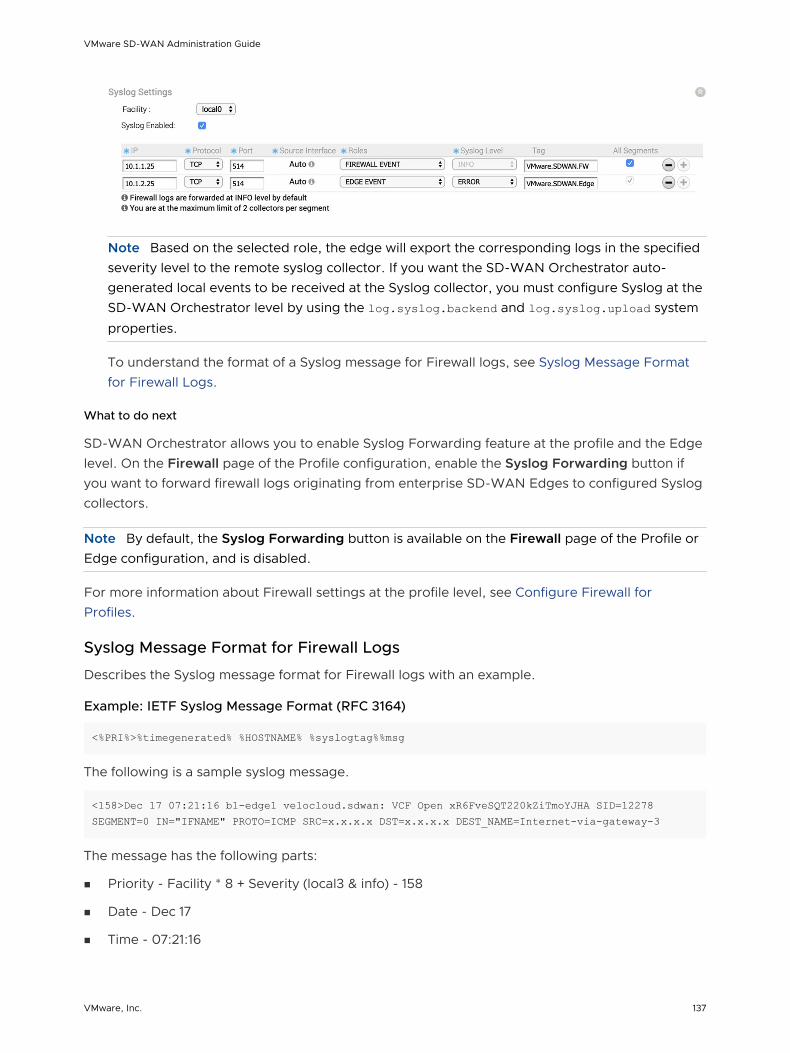
Note Based on the selected role, the edge will export the corresponding logs in the specified severity level to the remote syslog collector. If you want the SD-WAN Orchestrator auto-generated local events to be received at the Syslog collector, you must configure Syslog at the SD-WAN Orchestrator level by using the log.syslog.backend and log.syslog.upload system
properties.
To understand the format of a Syslog message for Firewall logs, see Syslog Message Format for Firewall Logs.
What to do next
SD-WAN Orchestrator allows you to enable Syslog Forwarding feature at the profile and the Edge level. On the Firewall page of the Profile configuration, enable the Syslog Forwarding button if you want to forward firewall logs originating from enterprise SD-WAN Edges to configured Syslog collectors.
Note By default, the Syslog Forwarding button is available on the Firewall page of the Profile or Edge configuration, and is disabled.
For more information about Firewall settings at the profile level, see Configure Firewall for Profiles.
Syslog Message Format for Firewall Logs
Describes the Syslog message format for Firewall logs with an example.
Example: IETF Syslog Message Format (RFC 3164)
<%PRI%>%timegenerated% %HOSTNAME% %syslogtag%%msg
The following is a sample syslog message.
<158>Dec 17 07:21:16 b1-edge1 velocloud.sdwan: VCF Open xR6FveSQT220kZiTmoYJHA SID=12278 SEGMENT=0 IN="IFNAME" PROTO=ICMP SRC=x.x.x.x DST=x.x.x.x DEST_NAME=Internet-via-gateway-3
The message has the following parts:
n Priority - Facility * 8 + Severity (local3 & info) - 158
n Date - Dec 17
n Time - 07:21:16
VMware SD-WAN Administration Guide
VMware, Inc. 137

n Host Name - b1-edge1
n Syslog Tag - velocloud.sdwan
n Message - VCF Open xR6FveSQT220kZiTmoYJHA SID=12278 SEGMENT=0 IN="IFNAME" PROTO=ICMP SRC=x.x.x.x DST=x.x.x.x DEST_NAME=Internet-via-gateway-3
VMware supports the following Firewall log messages:
n With Stateful Firewall enabled:
n Open - The traffic flow session has started.
n Close - The traffic flow session has ended due to session timeout or the session is flushed through the Orchestrator.
n Deny - If the session matches the Deny rule, the Deny log message will appear and the packet will be dropped. In the case TCP, Reset will be sent to the Source.
n Update - For all the ongoing sessions, the Update log message will appear if the firewall rule is either added or modified through Orchestrator.
n With Stateful Firewall disabled:
n Allow
n Deny
Table 10-1. Firewall Log Message Fields
Field Description
SID The unique identification number applied to each session.
SVLAN The VLAN ID of the Source device.
DVLAN The VLAN ID of the Destination device.
SEGMENT The segment to which the session belongs to. The allowable range is from 0 through 255.
IN The name of the interface on which the first packet of the session was received. In the case of overlay received packets, this field will contain VPN. For any other packets (received through underlay), this field will display the name of the interface in the edge.
PROTO The type of IP protocol used by the session. The possible values are TCP, UDP, GRE, ESP, and ICMP.
SRC The source IP address of the session in dotted decimal notation.
DST The destination IP address of the session in dotted decimal notation.
SPT The source port number of the session. This field is applicable only if the underlaying transport is UDP/TCP.
DPT The destination port number of the session. This field is applicable only if the underlaying transport is UDP/TCP.
VMware SD-WAN Administration Guide
VMware, Inc. 138

Table 10-1. Firewall Log Message Fields (continued)
Field Description
DEST_NAME The name of the remote-end device of the session. The possible values are:
n CSS-Backhaul - For traffic which is destined to Cloud Security Service from edge.
n Internet-via-<egress-iface-name> - For Cloud traffic going directly from edge using business policy.
n Internet-BH-via-<backhaul hub name> - For Cloud-bound traffic going to Internet through Backhaul hub using business policy.
n <Remote edge name>-via-Hub - For VPN traffic flowing through Hub.
n <Remote edge name>-via-DE2E - For VPN traffic flowing between the edges through direct VCMP tunnel.
n <Remote edge name>-via-Gateway - For VPN traffic flowing through Cloud gateway.
n NVS-via-<gateway name> - For Non VMware SD-WAN Site traffic flowing through Cloud gateway.
n Internet-via-<gateway name> - For Internet traffic flowing through Cloud gateway.
NAT_SRC The source IP address used for source natting the direct Internet traffic.
NAT_SPT The source port used for patting the direct Internet traffic.
APPLICATION The Application name to which the session was classified by DPI Engine. This field is available only for Close log messages.
BYTES_SENT The amount of data sent in bytes in the session. This field is available only for Close log messages.
BYTES_RECEIVED The amount of data received in bytes in the session. This field is available only for Close log messages.
DURATION_SECS The duration for which the session has been active. This field is available only for Close log messages.
REASON The reason for closure or denial of the session. The possible values are:
n State Violation
n Reset
n Purged
n Aged-out
n Fin-Received
n RST-Received
n Error
This field is available for Close and Deny log messages.
VMware SD-WAN Administration Guide
VMware, Inc. 139

Configure Cloud VPN
At the profile level, SD-WAN Orchestrator allows you to configure Cloud Virtual Private Network (VPN). To initiate and respond to VPN connection requests, you must enable Cloud VPN. You can configure the Cloud VPN from the Configure > Profiles > Device page.
On enabling Cloud VPN for a profile, you can configure the following Cloud VPN types:
n Configure Branch to Non VMware SD-WAN Site VPNs
n Configure a Tunnel Between a Branch and a SD-WAN Hubs VPN
n Configure Branch to Branch VPN
Note Cloud VPN should be configured per Segment.
For topology and use cases, see Cloud VPN Overview.
Cloud VPN Overview
The Cloud Virtual Private Network (VPN) enables a VPNC-compliant IPSec VPN connection that connects VMware and Non VMware SD-WAN Sites. It also indicates the health of the sites (up or down status) and delivers real-time status of the sites.
Cloud VPN supports the following traffic flows:
n Branch to Non VMware SD-WAN Site
n Branch to SD-WAN Hub
n Branch to Branch VPN
The following figure represents all three branches of the Cloud VPN. The numbers in the image represent each branch and correspond to the descriptions in the table that follows.
VMware SD-WAN Administration Guide
VMware, Inc. 140

SD-WAN Gateway 1
Zscaler Iaas
SD-WAN Gateway 1
Branch
HUB
1
2
3
5 4
NVC
NVC 2
Branch
Number (from above image) Description
Non VMware SD-WAN Site
Branch to SD-WAN Hub
Branch to Branch VPN
Branch to Non VMware SD-WAN Site
Branch to Non VMware SD-WAN Site
Branch to Non VMware SD-WAN Site
Branch to Non VMware SD-WAN Site supports the following configurations:
n Connect to Customer Data Center with Existing Firewall VPN Router
n Iaas
n Connect to CWS (Zscaler)
VMware SD-WAN Administration Guide
VMware, Inc. 141

Connect to Customer Data Center with Existing Firewall VPN Router
A VPN connection between the VMware Gateway and the data center firewall (any VPN router) provides connectivity between branches (with SD-WAN Edges installed) and Non VMware SD-WAN Sites, resulting in ease of insertion, in other words, no customer Data Center installation is required.
The following figure shows a VPN configuration:
SD-WAN Gateway
SD-WAN Gateway
Branch1
2
3
NVC
NVC 2
Branch
Number (from above image) Description
Primary tunnel
Redundant tunnel
Secondary VPN Gateway
VMware supports VPN connectivity to the following third-party firewalls:
n Cisco ASA
n Cisco ISR
n PaloAlto
n SonicWall
n Generic Router (Router Based VPN)
n Generic Firewall (Policy Based VPN)
For information on how to configure a Branch to Non VMware SD-WAN Site see Configure a Non VMware SD-WAN Site.
VMware SD-WAN Administration Guide
VMware, Inc. 142

Iaas
When configuring with Amazon Web Services (AWS), use the Generic Firewall (Policy Based VPN) option in the Non VMware SD-WAN Site dialog box.
Configuring with a third party can benefit you in the following ways:
n Eliminates mesh
n Cost
n Performance
VMware Cloud VPN is simple to set up (global networks of SD-WAN Gateways eliminates mesh tunnel requirement to VPCs), has a centralized policy to control branch VPC access, assures performance, and secures connectivity as compared to traditional WAN to VPC.
For information on how to configure using Amazon Web Services (AWS), see the Configure Amazon Web Services section.
Connect to CWS (Zscaler)
Zscaler Web Security provides security, visibility, and control. Delivered in the cloud, Zscaler provides web security with features that include threat protection, real-time analytics, and forensics.
Configuring using Zscaler provides the following benefits:
n Performance: Direct to Zscaler (Zscaler via Gateway)
n Managing proxy is complex: Enables simple click policy aware Zscaler
Branch to SD-WAN Hub
The SD-WAN Hub is an Edge deployed in Data Centers for branches to access Data Center resources. You must set up your SD-WAN Hub in the SD-WAN Orchestrator. The SD-WAN Orchestrator notifies all the SD-WAN Edges about the Hubs, and the SD-WAN Edges build secure overlay multi-path tunnel to the Hubs.
The following figure shows how both Active-Standby and Active-Active are supported.
Primary Hub Edge
Primary path, higher preference
Secondary Hub Edge
Branch to SD-WAN Hubs
Enable:
SD-WAN Hubs
1 DC1-VCE
2 DC2-VCE
Branch to SD-WAN Hubs
Enable:
SD-WAN Hubs
1 DC1-VCE
2 DC2-VCE
Branch to SD-WAN Hubs
Enable:
SD-WAN Hubs
1 DC2-VCE
2 DC1-VCE
Region 1 Hub Edge
Region 2 Hub Edge
VMware SD-WAN Administration Guide
VMware, Inc. 143

Branch to Branch VPN
Branch to Branch VPN supports configurations for establishing a VPN connection between branches for improved performance and scalability.
Branch to Branch VPN supports two configurations:
n Cloud Gateways
n SD-WAN Hubs for VPN
The following figure shows Branch to Branch traffic flows for both Cloud Gateway and a SD-WAN Hub.
Initial traffic
After dynamic E2E is up
Branch to Branch VPN
Enable:
Use Cloud Gateways:
Dynamic B2B VPN:
Branch to Branch VPN
Enable:
Use Cloud Gateways:
SD-WAN Hubs Modify...
1 DC1-VCE
Use SD-WAN Hubs for VPN:
Dynamic B2B VPN:
You can also enable Dynamic Branch to Branch VPN for both Cloud Gateways and Hubs.
You can access the 1-click Cloud VPN feature in the SD-WAN Orchestrator from Configure > Profiles > Device Tab in the Cloud VPN area.
Note For step-by-step instructions to configure Cloud VPN, see Configure Cloud VPN.
Configure Branch to Non VMware SD-WAN Site VPNs
Configure branch to Non VMware SD-WAN Site VPNs to establish VPN connection between a branch and a Non VMware SD-WAN Site
Procedure
1 From the SD-WAN Orchestrator, go to Configure > Profiles.
The Configuration Profiles page appears.
2 Select a profile you want to configure Cloud VPN and click the icon under the Device column.
The Device Settings page for the selected profile appears.
3 Go to Cloud VPN area and enable Cloud VPN by turning the toggle button to On.
4 To configure a Branch to Non VMware SD-WAN Site, under Branch to Non-VeloCloud Site, select the Enable checkbox.
VMware SD-WAN Administration Guide
VMware, Inc. 144

5 From the drop-down menu, select a Non VMware SD-WAN Site to establish VPN connection. Click the + (plus) button to add additional Non VMware SD-WAN Sites.
6 You can also create VPN connections by selecting the New Non-VeloCloud Site from the drop-down menu. The New Non-VeloCloud Site dialog appears.
a In the Name textbox, enter the name for the Non VMware SD-WAN Site.
b From the Type drop-down menu, select a Non VMware SD-WAN Site.
c In the Primary VPN Gateway textbox, enter the IP address that you want to configure as the primary VPN gateway for the selected Non VMware SD-WAN Site.
d Click Next. A new Non VMware SD-WAN Site will be created and gets added to the Non VMware SD-WAN Site drop-down menu.
For more information about configuring a Non VMware SD-WAN Site, see Configure a Non VMware SD-WAN Site.
7 Click Save Changes.
Note The Branch to Non VMware SD-WAN Site VPN should not be enabled until the gateway for the Enterprise Data Center is configured by the Enterprise Data Center Administrator and the Data Center VPN Tunnel is enabled.
Configure a Tunnel Between a Branch and a SD-WAN Hubs VPN
Configure Branch to SD-WAN Hubs VPN to establish VPN connection between branch and hubs.
Procedure
1 From the SD-WAN Orchestrator, go to Configure > Profiles.
The Configuration Profiles page appears.
2 Select a profile you want to configure Cloud VPN and click the icon under the Device column.
The Device Settings page for the selected profile appears.
3 Go to Cloud VPN area and enable Cloud VPN by turning the toggle button to On.
4 To configure Branch to SD-WAN Hubs, under Branch to Hubs, select the Enable checkbox.
VMware SD-WAN Administration Guide
VMware, Inc. 145

5 Click the Select Hubs link. The Manage Cloud VPN Hubs page for the selected profile appears.
6 From Available Edges & Clusters, you can select and configure the edges to act as SD-WAN Hubs, or Backhaul Hubs, or Branch to Branch VPN Hubs in the branch profile, using the > or < arrows.
Note An edge cluster and an individual edge can be simultaneously configured as Hubs in a branch profile. Once edges are assigned to a cluster, they cannot be assigned as individual Hubs.
Note Branch to Branch VPN using Hubs functions the same regardless of whether the Hubs are Clusters or individual Edges. In order to configure Branch to Branch VPN using Hubs that are also Edge Clusters, you can select a Hub from the Hubs area and move it to the Branch to Branch VPN Hubs area. It is recommended to select the Auto Select VPN Hub checkbox so that the edge will select the best hub for establishing the Branch to Branch VPN Hubs connection.
7 To enable Conditional Backhaul, select the Enable Conditional BackHaul checkbox.
With Conditional Backhaul (CBH) enabled, the Edge will be able to failover Internet-bound traffic (Direct Internet traffic, Internet via SD-WAN Gateway and Cloud Security Traffic via IPsec) to MPLS links whenever there is no Public Internet links available. When Conditional Backhaul is enabled, by default all Business Policy rules at the branch level are subject to failover traffic through Conditional Backhaul. You can exclude traffic from Conditional Backhaul based on certain requirements for selected policies by disabling this feature at the selected business policy level. For more information, see Conditional Backhaul.
8 Click Save Changes.
VMware SD-WAN Administration Guide
VMware, Inc. 146

Conditional Backhaul
Conditional Backhaul (CBH) is a feature designed for Hybrid SD-WAN branch deployments that have at least one Public and one Private link. Whenever there is a Public Internet link failure on a VMware SD-WAN Edge, tunnels to VMware SD-WAN Gateway, Cloud Security Service (CSS), and Direct breakout to Internet are not established. In this scenario, the Conditional Backhaul feature, if enabled, will make use of the connectivity through Private links to designated Backhaul Hubs, giving the SD-WAN Edge the ability to failover Internet-bound traffic over Private overlays to the Hub and provide reachability to Internet destinations.
Whenever Public Internet link fails and Conditional Backhaul is enabled, the Edge can failover the following Internet-bound traffic types:
1 Direct to Internet
2 Internet via SD-WAN Gateway
3 Cloud Security Service traffic
Behavioral Characteristics of Conditional Backhaul
n When Conditional Backhaul is enabled, by default all Business Policy rules at the branch level are subject to failover traffic through CBH. You can exclude traffic from Conditional Backhaul based on certain requirements for selected policies by disabling this feature at the selected business policy level.
n Conditional Backhaul will not affect existing flows that are being backhauled to a Hub already if the Public link(s) goes down. The existing flows will still forward data using the same Hub.
n If a branch location has backup Public links, the backup Public link will take precedence over CBH. Only if the primary and backup links are all inoperable then the CBH gets triggered and uses the Private link.
n If a Private link is acting as backup, traffic will fail over to Private link using CBH feature when active Public link fails and Private backup link becomes Active.
n In order for the feature to work, both Branches and Conditional Backhaul Hubs need to have the same Private Network name assigned to their Private links. (The Private tunnel will not come up otherwise.)
Operational Flow
Under normal operations, the Public link is UP and Internet-bound traffic will flow normally either Direct or via SD-WAN Gateway as per the Business Policies configured.
VMware SD-WAN Administration Guide
VMware, Inc. 147

Internet
MPLS HUBBranch
When the Public Internet link goes DOWN, or the SD-WAN Overlay path goes to QUIET state (no packets received from Gateway after 7 heartbeats), the Internet-bound traffic is dynamically backhauled to the Hub.
VMware SD-WAN Administration Guide
VMware, Inc. 148

Internet
MPLS HUBBranch
The Business Policy configured on the Hub will determine how this traffic is forwarded once it reaches the hub. The options are:
n Direct from Hub
n Hub to Gateway and then breakout from the Gateway
When the Public Internet link comes back, CBH will attempt to move the flows back to the Public link. To avoid an unstable link causing traffic to flap between the Public and Private links, CBH has a default 30 seconds holdoff timer. After the holdoff timer is reached, flows will be failed back to the Public Internet link.
.
VMware SD-WAN Administration Guide
VMware, Inc. 149

Internet
MPLS HUBBranch
Configuring Conditional Backhaul
At the Profile level, in order to configure Conditional Backhaul, you should enable Cloud VPN and then establish VPN connection between Branch and SD-WAN Hubs by performing the following steps:
1 From the SD-WAN Orchestrator, go to Configure > Profiles. The Configuration Profiles page appears.
2 Select a profile you want to configure Cloud VPN and click the icon under the Device column. The Device Settings page for the selected profile appears.
3 From the Configure Segment drop-down menu, select a profile segment to configure Conditional Backhaul. By default, Global Segment [Regular] is selected.
Note The Conditional Backhaul feature is Segment aware and therefore must be enabled at each Segment where it is intended to work.
4 Go to Cloud VPN area and enable Cloud VPN by turning the toggle button to On.
5 To configure Branch to SD-WAN Hubs, under Branch to Hubs, select the Enable checkbox.
6 Click the Select Hubs link. The Manage Cloud VPN Hubs page for the selected profile appears.
VMware SD-WAN Administration Guide
VMware, Inc. 150

From Hubs area, select the Hubs to act as Backhaul Hubs and move them to Backhaul Hubs area by using the > arrow.
7 To enable Conditional Backhaul, select the Enable Conditional BackHaul checkbox.
With Conditional Backhaul enabled, the Edge will be able to failover Internet-bound traffic (Direct Internet traffic, Internet via SD-WAN Gateway and Cloud Security Traffic via IPsec) to MPLS links whenever there is no Public Internet links available. Conditional Backhaul when enabled will apply for all Business Policies by default. If you want to exclude traffic from Conditional Backhaul based on certain requirements, you can disable Conditional Backhaul for selected policies to exclude selected traffic from this behavior by selecting the Disable Conditional Backhaul checkbox in the Action area of the Configure Rule screen for the selected business policy.
VMware SD-WAN Administration Guide
VMware, Inc. 151

Note n Conditional Backhaul and SD-WAN Reachability can work together in the same Edge. Both
Conditional Backhaul and SD-WAN reachability support failover of Cloud-bound Gateway traffic to MPLS when Public Internet is down on the Edge. If Conditional Backhaul is enabled and there is no path to Gateway and there is a path to hub via MPLS then both direct and Gateway bound traffic apply Conditional Backhaul. For more information about SD-WAN reachability, see SD-WAN Service Reachability via MPLS.
n When there are multiple candidate hubs, Conditional Backhaul will use the first hub in the list unless the hub has lost connectivity to Gateway.
8 Click Save Changes.
Troubleshooting Conditional Backhaul
Consider a user with the following two Business Policy rules created at the Branch level.
VMware SD-WAN Administration Guide
VMware, Inc. 152

You can check if the constant pings to each of these destination IP addresses are active for the branch by running the List Active Flows command from the Remote Diagnostics section.
If extreme packet loss occurs in the Public link of the Branch and the link is down then the same flows toggle to Internet Backhaul at the Branch.
Note that the business policy on the hub determines how the hub forwards the traffic. As the Hub has no specific rule for these flows, they are categorized as default traffic. For this scenario, a Business Policy rule can be created at the Hub level to match the desired IPs or Subnet ranges to define how flows from a specific Branch are handled in the event of CBH becomes operational.
VMware SD-WAN Administration Guide
VMware, Inc. 153

Configure Branch to Branch VPN
Configure Branch to Branch VPN to establish a VPN connection between branches.
Procedure
1 In the Enterprise portal, click Configure > Profiles.
The Configuration Profiles page appears.
2 Select a profile you want to configure Cloud VPN and click the icon under the Device column.
The Device Settings page for the selected profile appears.
3 Go to Cloud VPN area and enable Cloud VPN by turning the toggle button to On.
4 To configure a Branch to Branch VPN, under Branch to Branch VPN, select the Enable checkbox.
Branch to Branch VPN supports two configurations for establishing a VPN connection between branches:
Configuration Description
Using SD-WAN Gateway In this option, the closest gateway is used to establish VPN connections between Edges. The SD-WAN Gateway may have traffic from other users.
Using SD-WAN Hub In this option, one or more Edges are selected to act as hubs that can establish VPN connections between branches. The hub will be your asset and will only have your corporate data on it, improving overall security.
5 To enable profile isolation, select the Isolate Profile checkbox.
If profile isolation is enabled, then the edges within the profile will not learn routes from other edges outside the profile via the SD-WAN Overlay.
You can enable Dynamic Branch To Branch VPN to all edges or to edges within a Profile. On selecting the Enabled checkbox, by default the dynamic branch to branch VPN is configured for all edges. To configure dynamic Branch to Branch VPN by profile, make sure the Isolate Profile checkbox is unselected.
Note When Profile Isolation is enabled, Dynamic Branch To Branch VPN can only be enabled to edges within Profile.
VMware SD-WAN Administration Guide
VMware, Inc. 154

When you enable Dynamic Branch to Branch VPN, the first packet goes through the Cloud Gateway (or the Hub). If the initiating Edge determines that traffic can be routed through a secure overlay multi-path tunnel, and if Dynamic Branch to Branch VPN is enabled, then a direct tunnel is created between the branches.
Once the tunnel is established, traffic begins to flow over the secure overlay multi-path tunnel between the branches. After 180 seconds of traffic silence (forward or reverse from either side of the branches), the initiating edge tears down the tunnel.
6 Click Save Changes.
Configure Multicast Settings
Multicast provides an efficient way to send data to an interested set of receivers to only one copy of data from the source, by letting the intermediate multicast-routers in the network replicate packets to reach multiple receivers based on a group subscription.
Multicast clients use the Internet Group Management Protocol (IGMP) to propagate membership information from hosts to Multicast enabled routers and PIM to propagate group membership information to Multicast servers via Multicast routers.
Multicast support includes:
n Multicast support on both overlay and underlay
n Protocol-Independent Multicast - Sparse Mode (PIM-SM) on SD-WAN Edge
n Internet Group Management Protocol (IGMP) version 2 on SD-WAN Edge
n Static Rendezvous Point (RP) configuration, where RP is enabled on a 3rd party router.
Configure Multicast Globally
There are two steps to enable and configure Multicast (globally and at the interface level), in which both can be overridden at the Edge Level. The steps below provide instructions on how to enable the Multicast globally.
To configure Multicast globally:
1 From Configure > Profile > Devices, go to the Multicast Settings area.
2 If the Multicast Settings button is in the Off position, click the Off button to turn On Multicast Settings.
The RP Selection is set to Static by default.
VMware SD-WAN Administration Guide
VMware, Inc. 155
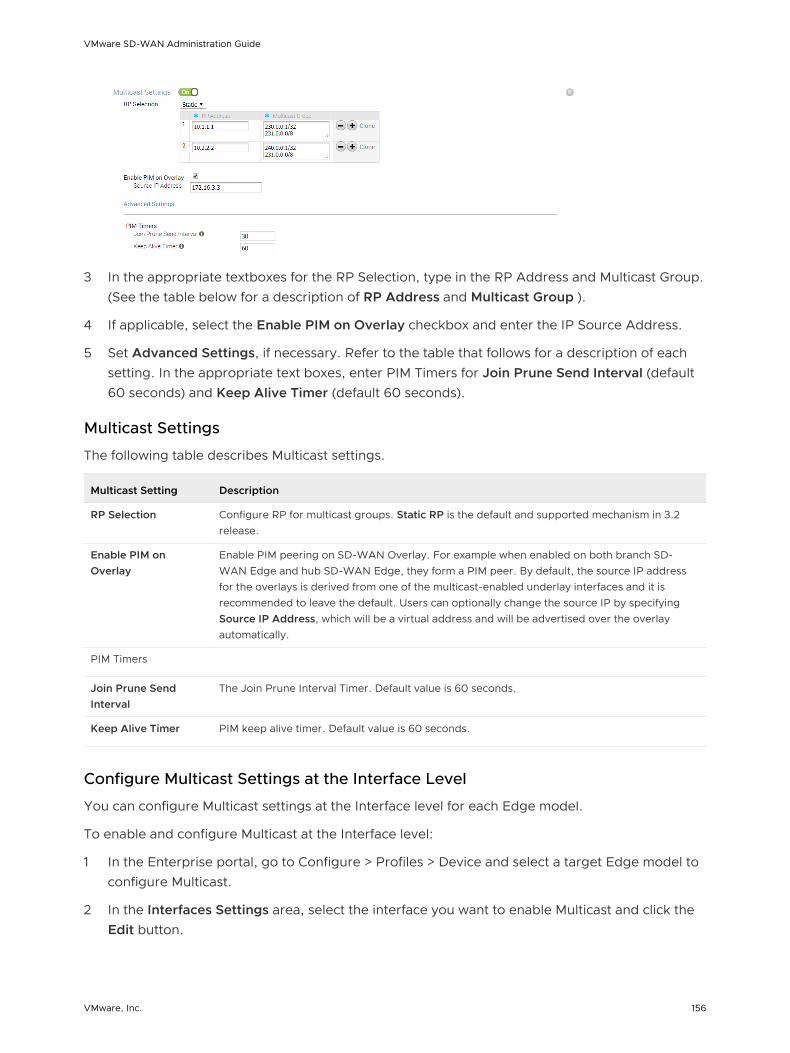
3 In the appropriate textboxes for the RP Selection, type in the RP Address and Multicast Group. (See the table below for a description of RP Address and Multicast Group ).
4 If applicable, select the Enable PIM on Overlay checkbox and enter the IP Source Address.
5 Set Advanced Settings, if necessary. Refer to the table that follows for a description of each setting. In the appropriate text boxes, enter PIM Timers for Join Prune Send Interval (default 60 seconds) and Keep Alive Timer (default 60 seconds).
Multicast Settings
The following table describes Multicast settings.
Multicast Setting Description
RP Selection Configure RP for multicast groups. Static RP is the default and supported mechanism in 3.2 release.
Enable PIM on Overlay
Enable PIM peering on SD-WAN Overlay. For example when enabled on both branch SD-WAN Edge and hub SD-WAN Edge, they form a PIM peer. By default, the source IP address for the overlays is derived from one of the multicast-enabled underlay interfaces and it is recommended to leave the default. Users can optionally change the source IP by specifying Source IP Address, which will be a virtual address and will be advertised over the overlay automatically.
PIM Timers
Join Prune Send Interval
The Join Prune Interval Timer. Default value is 60 seconds.
Keep Alive Timer PIM keep alive timer. Default value is 60 seconds.
Configure Multicast Settings at the Interface Level
You can configure Multicast settings at the Interface level for each Edge model.
To enable and configure Multicast at the Interface level:
1 In the Enterprise portal, go to Configure > Profiles > Device and select a target Edge model to configure Multicast.
2 In the Interfaces Settings area, select the interface you want to enable Multicast and click the Edit button.
VMware SD-WAN Administration Guide
VMware, Inc. 156

3 In the Interface dialog box of the selected Edge:
a The Interface Enabled checkbox is enabled by default. If required, you can disable the Interface. When disabled, the Interface is not available for any communication.
b In the Capability drop-down menu, choose Routed to be able to use the Multicast settings. By default, the option Switched is selected for the Switch Port.
c In the Addressing Type drop-down menu, choose either DHCP, PPPoE, or Static.
d If applicable, select the WAN Overlay checkbox. By default, this option is enabled with Auto-Detect Overlay. You can choose the User Defined Overlay and configure the Overlay settings. For more information, see Configure Edge WAN Overlay Settings.
e If applicable, select the OSPF checkbox.
f In the Multicast section:
1 If applicable, select the IGMP checkbox and select the only available option IGMP v2.
2 If applicable, select the PIM checkbox and select the only available option PIM SM.
3 Click the toggle advanced multicast settings link to set IGMP and PIM Timers.
n PIM Hello Timer - The default value is 30 seconds and the allowable range is 1 through 180 seconds.
VMware SD-WAN Administration Guide
VMware, Inc. 157

n IGMP Host Query Interval: The default value is 125 seconds and the allowable range is 1 through 1800.
n IGMP Max Query Response Value: The default value is 100 deciseconds and the allowable range is 10 through 250 deciseconds.
g You must disable WAN Overlay to configure RADIUS Authentication. Select the checkbox to enable RADIUS Authentication on the Interface and add the MAC addresses that should not be forwarded to RADIUS for re-authentication. For more information, see Enabling RADIUS on a Routed Interface .
h If applicable, select the following checkboxes:
n Advertise - Select the checkbox to advertise the Interface to other branches in the network.
n ICMP Echo Response - Select the checkbox to enable the Interface to respond to ICMP echo messages. You can disable this option for the Interface, for security purposes.
n NAT Direct Traffic - Select the checkbox to apply NAT to the network traffic sent from the Interface.
n Underlay Accounting - This option is enabled by default. If a private WAN overlay is defined on the Interface, all underlay traffic traversing the interface will be counted against the measured rate of the WAN link to prevent over-subscription. If you do not want this behavior (for example, while using one-arm deployments), disable the option.
n Trusted Source - Select the checkbox to set the Interface as a trusted source.
i From the Reverse Path Forwarding drop-down menu, select one of the following options from the drop-down list:
n Disabled – Allows incoming traffic even if there is no matching route in the route table.
n Specific – This option is selected by default, even when the Trusted Source option is disabled. The incoming traffic should match a specific return route on the incoming interface. If a specific match is not found, then the incoming packet is dropped. This is a commonly used mode on interfaces configured with public overlays and NAT.
n Loose – The incoming traffic should match any route(Connected/Static/Routed) in the routing table. This allows asymmetrical routing and is commonly used on interfaces that are configured without next hop.
Note You can choose an option for Reverse Path Forwarding (RPF) only when you have enabled Trusted Source. RPF defaults to Specific mode when Trusted Source is disabled.
j In the L2 Settings area, the Autonegotiate checkbox is enabled by default. The Auto-negotiation allows the port to communicate with the device on the other end of the link to determine the optimal duplex mode and speed for the connection.
VMware SD-WAN Administration Guide
VMware, Inc. 158

k If Autonegotiate is unselected, enter the following details:
n Speed - This option is available only when Autonegotiate is disabled. Select the speed that the port has to communicate with other links. By default, 100 Mbps is selected.
n Duplex - This option is available only when Autonegotiate is disabled. Select the mode of the connection as Full duplex or Half duplex. By default, Full duplex is selected.
n MTU - The default MTU size for frames received and sent on all switch interfaces is 1500 bytes. You can change the MTU size for an Interface.
l Click Update to save the settings.
Note Go to Monitor > Routing > Multicast tab, to view Multicast routing information. See Monitor Routing for more information.
Configure VLAN for Profiles
As an enterprise Administrator, you can configure a VLAN at the Profile level.
To add a new VLAN at the Profile level, perform the following steps:
1 From the SD-WAN Orchestrator, go to Configure > Profiles. The Configuration Profiles page appears.
2 Select a Profile to configure a VLAN and click the icon under the Device column. The Device Setting page for the selected Profile appears.
3 Go to the Configure VLAN area, click Add VLAN.
VMware SD-WAN Administration Guide
VMware, Inc. 159

4 In the VLAN dialog box, configure the following details:
a From the Segment drop-down menu, select a Profile segment to configure VLAN.
b In the VLAN Name text box, enter a unique name for the VLAN.
c In the VLAN Id text box, enter a unique identifier for the VLAN.
d Select the Assign Overlapping Subnets checkbox if you want to assign the same subnet for the VLAN to every Edges in the Profile. Enabling this checkbox will allow you to define a subnet to be used for every Edges in the Profile, by using the Edge LAN IP Address and Cidr Prefix fields. The Network address will be automatically set based on the subnet mask and CIDR value.
Note If you want to assign different subnets to every Edges (for example, for VPN networks), do not enable the Assign Overlapping Subnets checkbox at the Profile level, however you can configure the subnets on each Edges individually.
e Select the Advertise checkbox to advertise the VLAN to other branches in the network.
f Select the ICMP Echo Response checkbox to enable the VLAN to respond to ICMP echo messages.
g Select the VNF Insertion checkbox to enable Edges Virtual Network Function (VNF) insertion.
Note VNF insertion requires that the selected segment have a Service VLAN. For more information about VNF, see Security VNFs.
h If the Multicast feature is enabled for the selected segment then you can configure Multicast settings by enabling IGMP and PIM checkboxes.
VMware SD-WAN Administration Guide
VMware, Inc. 160
i Under the DHCP area, choose one of the following as the DHCP type:
n Enabled - Enables DHCP with the Edges as the DHCP server. When choosing this option, you must provide the following details:
n DHCP Start - Enter a valid IP address available within a subnet as the DHCP start IP.
n Num Addresses - Enter the number of IP addresses available on a subnet in the DHCP Server.
n Lease Time - From the drop-down menu, select the period of time the VLAN is allowed to use an IP address dynamically assigned by the DHCP Server.
Also, you can add one or more DHCP options, where you specify pre-defined options or add custom options.
n Relay - Enables DHCP with the DHCP Relay Agent installed at a remote location. If you choose this option, you can specify the IP address of one or more Relay Agents.
n Disabled - Disables DHCP.
j Configure OSPF settings if the OSPF feature is enabled for the selected segment.
5 Click Add VLAN. The VLAN is configured for the Profile. You can change the VLAN settings by clicking the Edit link under Actions column.
For Configuring VLANs at the Edge level, see Configure VLAN for Edges.
Configure the Management IP Address
You can configure the Management IP address at the Profile-level and choose to override it at the Edge-level.
Starting from release 3.4, the Edges do not use the Management IP address to source traffic to Orchestrator. Instead, the Edges will choose the first "up and advertised" interface on a segment to initiate traffic. If no such LAN interfaces are found, traffic will egress directly to the Internet using a NAT-enabled WAN link. Currently, if you are sending traffic sourced from the Management IP through VPN in the global segment and do not have any up and advertised LAN interfaces in the global segment, you will experience reachability issues when you upgrade your Edges and Orchestrator to release 3.4. Contact VMware Customer Support to restore the pre-3.4 behavior so that you can continue to use Management IP address to source traffic.
VMware SD-WAN Administration Guide
VMware, Inc. 161

The following are the various scenarios when you can use the Management IP address, provided your Edge and Orchestrator versions are 3.3 or lower:
n It is used to source the management traffic from Edges to Orchestrator. In this scenario, you can either use the default Management IP address (192.168.1.1) or an IP address of your choice that you configure at the Profile-level so that all Edges attached to the Profile use the same IP address to source the traffic to the Orchestrator.
Note You can choose to ignore the Management IP configuration, if you have NAT Direct enabled on the WAN ports or if the traffic from the Edges is routed to the Orchestrator through a Gateway.
n If you choose to configure services such as DNS, NTP, Netflow, BGP and so on, you must override the Management IP address configuration at the Edge-level so that each Edge has a unique IP address that can be used as the source address for these services.
n It is also used as the destination IP address for diagnostic tests when configured at the Edge-level.
To configure the Management IP address for a Profile:
1 In the Enterprise portal, go to Configure > Profiles.
2 Either click the Device icon next to the Profile for which you want to configure the Management IP address, or click the link to the Profile, and then go to the Device tab.
3 In the Device page, scroll down to the Management IP section, and enter the required Management IP address.
4 Click Save Changes.
You can choose to override the Management IP address configuration for an Edge:
1 In the Enterprise portal, go to Configure > Edges.
2 Either click the Device icon next to the Edge for which you want to override the Management IP address configuration, or click the link to the Edge, and then go to the Device tab.
3 In the Device page, scroll down to the Management IP section, and select the Enable Edge Override check box.
4 Enter the required Management IP address.
5 Click Save Changes.
Configure Device Settings
Device Settings allows you configure the Interface Settings for one or more Edge models in a profile.
Depending on the Edge Model, each interface can be a Switch Port (LAN) interface or a Routed (WAN) Interface. Depending on the Branch Model, a connection port is a dedicated LAN or WAN port, or ports can be configured to be either a LAN or WAN port. Branch ports can be Ethernet or SFP ports. Some Edge models may also support wireless LAN interfaces.
VMware SD-WAN Administration Guide
VMware, Inc. 162
It is assumed that a single public WAN link is attached to a single interface that only serves WAN traffic. If no WAN link is configured for a routed interface that is WAN capable, it is assumed that a single public WAN link should be automatically discovered. If one is discovered, it will be reported to the SD-WAN Orchestrator. This auto-discovered WAN link can then be modified via the SD-WAN Orchestrator and the new configuration pushed back to the branch.
Note n If the routed Interface is enabled with the WAN overlay and attached with a WAN link, then
the interface will be available for all Segments.
n If an interface is configured as PPPoE, it will only support a single auto-discovered WAN link. Additional links cannot be assigned to the interface.
If the link should not or cannot be auto-discovered, it must be explicitly configured. There are multiple supported configurations in which auto-discovery will not be possible, including:
n Private WAN links
n Multiple WAN links on a single interface. Example: A Datacenter Hub with 2 MPLS connections
n A single WAN link reachable over multiple interfaces. Example: for an active-active HA topology
Links that are auto-discovered are always public links. User-defined links can be public or private, and will have different configuration options based on which type is selected.
Note Even for auto-discovered links, overriding the parameters that are automatically detected -- such as service provider and bandwidth – can be overridden by the Edge configuration.
Public WAN Links
Public WAN links are any traditional link providing access to the public internet such as Cable, DSL, etc. No peer configuration is required for public WAN links. They will automatically connect to the SD-WAN Gateway, which will handle the dissemination of information needed for peer connectivity.
Private (MPLS) WAN Links
Private WAN links belong to a private network and can only connect to other WAN links within the same private network. Because there can be multiple MPLS networks, within a single enterprise, for example, the user must identify which links belong to which network. The SD-WAN Gateway will use this information to distribute connectivity information for the WAN links.
You may choose to treat MPLS links as a single link. However, to differentiate between different MPLS classes of service, multiple WAN links can be defined that map to different MPLS classes of service by assigning each WAN link a different DSCP tag.
VMware SD-WAN Administration Guide
VMware, Inc. 163

Additionally, you may decide to define a static SLA for a private WAN link. This will eliminate the need for peers to exchange path statistics and reduce the bandwidth consumption on a link. Since probe interval influences how quickly the device can fail over, it’s not clear whether a static SLA definition should reduce the probe interval automatically.
Device Settings
The following screen captures illustrate the top-level user interface for the SD-WAN Edge 500, SD-WAN Edge 1000, and introducing SD-WAN Edge 610 for the 3.4 release. The following table describes the major features of the UI (the numbers in the table correspond to the numbers in the subsequent screen captures).
Actions you can perform on the network interface, such as Edit or Delete.
The Interface name. This name matches the Edge port label on the Edge device or is predetermined for wireless LANs.
The list of Switch Ports with a summary of some of their settings (such as Access or Trunk mode and the VLANs for the interface). Switch Ports are highlighted with a light yellow background.
The list of Routed Interfaces with a summary of their settings (such as the addressing type and if the interface was auto-detected or has an Auto Detected or User Defined WAN overlay). Routed Interfaces are highlighted with a light blue background.
The list of Wireless Interfaces (if available on the Edge device). You can add additional wireless networks by clicking the Add Wi-Fi SSID button. Wireless Interfaces are highlighted with a light gray background.
n You can add additional wireless networks by clicking the Add Wi-Fi SSID button. Wireless Interfaces are highlighted with a light gray background.
n You can add sub interfaces by clicking the Add Sub Interfaces button. Sub interfaces are displayed with "SIF" next to the interface.
n You can add secondary IPs by clicking the Add Secondary IP button. Secondary IPs are displayed with 'SIP" next to the interface.
The 3.4 release introduces Edge 610.
VMware SD-WAN Administration Guide
VMware, Inc. 164

For the 3.4 release, a new routed interface (CELL1) is added, if users choose Edge 510-LTE as the model, will be displayed in the Interface Settings area (see image below).
By clicking the Edit link, as shown in the image above, users can edit the Cell Settings section. (See image below).
VMware SD-WAN Administration Guide
VMware, Inc. 165

Note 510 LTE Modern Information Diagnostic Test: For the 3.4 release, if the Edge 510 LTE device is configured, the “LTE Modem Information” diagnostic test will be available. The LTE Modern Information diagnostic test will retrieve diagnostic information, such as signal strength, connection information, etc. For information on how to run a diagnostic test, see section titled, Remote Diagnostics
VMware SD-WAN Administration Guide
VMware, Inc. 166

Sub Interfaces and Secondary IPs
Adding a Sub Interface
When you add a sub interface to a routed interface, the sub interface gets a subset of the configuration options provided to the parent interface.
1 Click the Add Sub Interface button.
2 Select an Interface from the drop-down menu and the Sub Interface ID in the text box as shown in the Select Interface dialog below.
3 Click Next.
4 In the Sub Interface dialog box, choose your Addressing Type ( DHCP or Static).
a If you choose the Addressing Type DHCP, the Enable VLAN Tagging checkbox is selected by default and the Sub Interface ID you chose in the previous dialog displays in the text box.
b If you choose the Addressing Type Static, you have the option of enabling VLAN by selecting the Enable VLAN Tagging check box. The Sub Interface ID you chose in the previous dialog displays in the text box.
VMware SD-WAN Administration Guide
VMware, Inc. 167

5 Check NAT Direct Traffic checkbox if necessary.
6 Click the Update button.
The Interface column refreshes, showing the newly created sub interface.
Adding a Secondary IP Address
1 Click the Add Secondary IP button.
2 Select an Interface from the drop-down menu and the Sub Interface ID in the text box as shown in the Select Interface dialog below. Note the Sub Interface type is Secondary IP.
3 Click Next.
4 In the Secondary IP dialog box, choose your Addressing Type ( DHCP or Static).
5 In the Secondary IP dialog box, choose your Addressing Type ( DHCP or Static).
6 Click the Update button.
The Interface column refreshes, showing the newly created Secondary IP (see the Interface Settings image below).
VMware SD-WAN Administration Guide
VMware, Inc. 168

User-defined WAN Overlay Use Cases
The scenarios wherein this configuration is useful are outlined first, followed by a specification of the configuration itself.
1 Use Case 1: Two WAN links connected to an L2 Switch – Consider the traditional data center topology where the SD-WAN Edge is connected to an L2 switch in the DMZ that is connected to multiple firewalls, each connected to a different upstream WAN link.
Internet
DSL
SD-WAN Edge
10.0.0.1
10.0.0.2
L2 Switch
10.0.0.3
In this topology, the VMware interface has likely been configured with FW1 as the next hop. However, in order to use the DSL link, it must be provisioned with an alternate next hop to which packets should be forwarded, because FW1 cannot reach the DSL. When defining the DSL link, the user must configure a custom next hop IP address as the IP address of FW2 to ensure that packets can reach the DSL modem. Additionally, the user must configure a custom source IP address for this WAN link to allow the edge to identify return interfaces. The final configuration becomes similar to the following figure:
Internet
DSL
SD-WAN Edge
L2 Switch
The following paragraph describes how the final configuration is defined.
n The interface is defined with IP address 10.0.0.1 and next hop 10.0.0.2. Because more than one WAN link is attached to the interface, the links are set to “user defined.”
VMware SD-WAN Administration Guide
VMware, Inc. 169

n The Cable link is defined and inherits the IP address of 10.0.0.1 and next hop of 10.0.0.2. No changes are required. When a packet needs to be sent out the cable link, it is sourced from 10.0.0.1 and forwarded to the device that responds to ARP for 10.0.0.2 (FW1). Return packets are destined for 10.0.0.1 and identified as having arrived on the cable link.
n The DSL link is defined, and because it is the second WAN link, the SD-WAN Orchestrator flags the IP address and next hop as mandatory configuration items. The user specifies a custom virtual IP (e.g. 10.0.0.4) for the source IP and 10.0.0.3 for the next hop. When a packet needs to be sent out the DSL link, it is sourced from 10.0.0.4 and forwarded to the device that responds to the ARP for 10.0.0.3 (FW2). Return packets are destined for 10.0.0.4 and identified as having arrived on the DSL link.
2 Case 2: Two WAN links connected to an L3 switch/router: Alternatively, the upstream device may be an L3 switch or a router. In this case, the next hop device is the same (the switch) for both WAN links, rather than different (the firewalls) in the previous example. Often this is leveraged when the firewall sits on the LAN side of the SD-WAN Edge.
Internet
DSL
SD-WAN Edge
L3 Switch
In this topology, policy-based routing will be used to steer packets to the appropriate WAN link. This steering may be performed by the IP address or by the VLAN tag, so we support both options.
Steering by IP: If the L3 device is capable of policy-based routing by source IP address, then both devices may reside on the same VLAN. In this case, the only configuration required is a custom source IP to differentiate the devices.
Internet
DSL
SD-WAN Edge
10.0.0.3
10.0.0.1
10.0.0.2
L3 Switch
VMware SD-WAN Administration Guide
VMware, Inc. 170
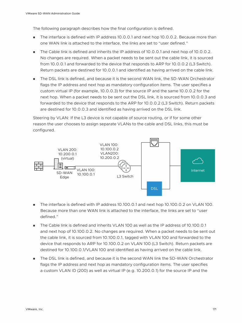
The following paragraph describes how the final configuration is defined.
n The interface is defined with IP address 10.0.0.1 and next hop 10.0.0.2. Because more than one WAN link is attached to the interface, the links are set to “user defined.”
n The Cable link is defined and inherits the IP address of 10.0.0.1 and next hop of 10.0.0.2. No changes are required. When a packet needs to be sent out the cable link, it is sourced from 10.0.0.1 and forwarded to the device that responds to ARP for 10.0.0.2 (L3 Switch). Return packets are destined for 10.0.0.1 and identified as having arrived on the cable link.
n The DSL link is defined, and because it is the second WAN link, the SD-WAN Orchestrator flags the IP address and next hop as mandatory configuration items. The user specifies a custom virtual IP (for example, 10.0.0.3) for the source IP and the same 10.0.0.2 for the next hop. When a packet needs to be sent out the DSL link, it is sourced from 10.0.0.3 and forwarded to the device that responds to the ARP for 10.0.0.2 (L3 Switch). Return packets are destined for 10.0.0.3 and identified as having arrived on the DSL link.
Steering by VLAN: If the L3 device is not capable of source routing, or if for some other reason the user chooses to assign separate VLANs to the cable and DSL links, this must be configured.
Internet
DSL
SD-WAN Edge
VLAN 200: 10.200.0.1
(virtual)
VLAN 100: 10.100.0.1
VLAN 100: 10.100.0.2 VLAN200: 10.200.0.2
L3 Switch
n The interface is defined with IP address 10.100.0.1 and next hop 10.100.0.2 on VLAN 100. Because more than one WAN link is attached to the interface, the links are set to “user defined.”
n The Cable link is defined and inherits VLAN 100 as well as the IP address of 10.100.0.1 and next hop of 10.100.0.2. No changes are required. When a packet needs to be sent out the cable link, it is sourced from 10.100.0.1, tagged with VLAN 100 and forwarded to the device that responds to ARP for 10.100.0.2 on VLAN 100 (L3 Switch). Return packets are destined for 10.100.0.1/VLAN 100 and identified as having arrived on the cable link.
n The DSL link is defined, and because it is the second WAN link the SD-WAN Orchestrator flags the IP address and next hop as mandatory configuration items. The user specifies a custom VLAN ID (200) as well as virtual IP (e.g. 10.200.0.1) for the source IP and the
VMware SD-WAN Administration Guide
VMware, Inc. 171
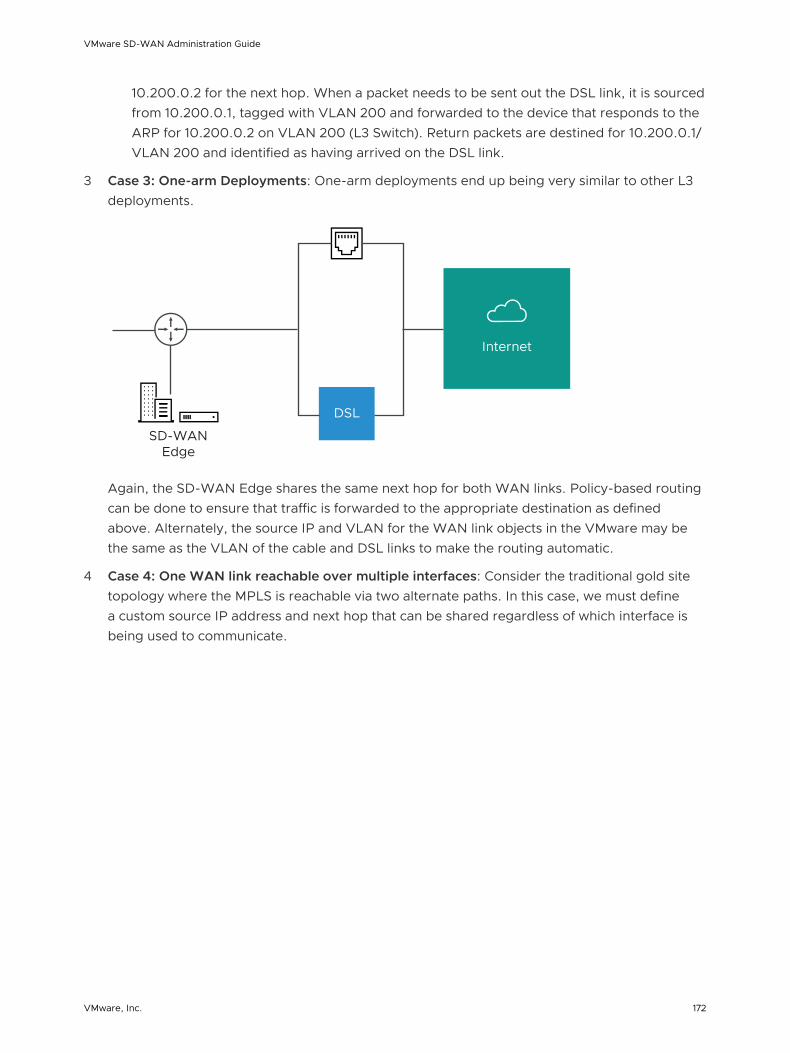
10.200.0.2 for the next hop. When a packet needs to be sent out the DSL link, it is sourced from 10.200.0.1, tagged with VLAN 200 and forwarded to the device that responds to the ARP for 10.200.0.2 on VLAN 200 (L3 Switch). Return packets are destined for 10.200.0.1/VLAN 200 and identified as having arrived on the DSL link.
3 Case 3: One-arm Deployments: One-arm deployments end up being very similar to other L3 deployments.
Internet
DSL
SD-WAN Edge
Again, the SD-WAN Edge shares the same next hop for both WAN links. Policy-based routing can be done to ensure that traffic is forwarded to the appropriate destination as defined above. Alternately, the source IP and VLAN for the WAN link objects in the VMware may be the same as the VLAN of the cable and DSL links to make the routing automatic.
4 Case 4: One WAN link reachable over multiple interfaces: Consider the traditional gold site topology where the MPLS is reachable via two alternate paths. In this case, we must define a custom source IP address and next hop that can be shared regardless of which interface is being used to communicate.
VMware SD-WAN Administration Guide
VMware, Inc. 172

SD-WAN Edge169.254.0.2
(virtual) 169.254.0.1 (virtual)
10.10.0.1
10.20.0.2
10.20.0.2
10.20.0.2
L3 L3
LAN LAN
MPLS Internet
n GE1 is defined with IP address 10.10.0.1 and next hop 10.10.0.2
n GE2 is defined with IP address 10.20.0.1 and next hop 10.20.0.2
n The MPLS is defined and set as reachable via either interface. This makes the source IP and next hop IP address mandatory with no defaults.
n The source IP and destination are defined, which can be used for communication irrespective of the interface being used. When a packet needs to be sent out the MPLS link, it is sourced from 169.254.0.1, tagged with the configured VLAN and forwarded to the device that responds to ARP for 169.254.0.2 on the configured VLAN (CE Router). Return packets are destined for 169.254.0.1 and identified as having arrived on the MPLS link.
Note If OSPF or BGP is not enabled, you may need to configure a transit VLAN that is the same on both switches to enable reachability of this virtual IP.
Interface Configuration
Clicking the Edit link presents a dialog for updating the settings for a specific interface. The following sections provide a short description for the various dialogs that are presented for the Edge model and interface types.
VMware SD-WAN Administration Guide
VMware, Inc. 173

Edge 500 LAN Access
The following shows the parameters for an Edge 500 LAN interface configured as an Access Port. You can choose a VLAN for the port and select L2 Settings for Autonegotiate (selected by default), Speed, Duplex type, and MTU size (default 1500).
Edge 500 LAN Trunk
The following shows the parameters for an Edge 500 LAN interface configured as a Trunk Port. You can choose VLANs for the port, how Untagged VLAN data is handled (routed to a specific VLAN or Dropped) and select L2 Settings for Autonegotiate (selected by default), Speed, Duplex type, and MTU size (default 1500).
Edge 1000 LAN Access
The following shows the parameters for an Edge 1000 LAN interface configured as a Switched Access Port. You can choose a VLAN for the port and select L2 Settings for Autonegotiate (selected by default), Speed, Duplex type, and MTU size (default 1500).
VMware SD-WAN Administration Guide
VMware, Inc. 174

Edge 1000 LAN Trunk
The following shows the parameters for an Edge 1000 LAN interface configured as a Trunk Port. You can choose VLANs for the port, how Untagged VLAN data is handled (routed to a specific VLAN or Dropped) and select L2 Settings for Autonegotiate (selected by default), Speed, Duplex type, and MTU size (default 1500).
Edge 500 WAN
The following shows the parameters for an Edge 500 WAN interface with Capability= Routed. You can choose Addressing Type (DHCP, PPPoE, or static), a WAN Overlay (Auto-detect or User Defined), enable OSPF, enable NAT Direct Traffic, and select L2 Settings for Autonegotiate (selected by default), Speed, Duplex type, and MTU size (default 1500).
Note The port can also be configured as a Switched interface.
Edge 1000 WAN
The following shows the parameters for an Edge 1000 WAN interface with Capability= Routed. You can choose Addressing Type (DHCP, PPPoE, or static), a WAN Overlay (Auto-detect or User Defined), enable OSPF, enable NAT Direct Traffic, and select L2 Settings for Autonegotiate (selected by default), Speed, Duplex type, and MTU size (default 1500).
Note The port can also be configured as a Switched interface.
VMware SD-WAN Administration Guide
VMware, Inc. 175

Edge 500 WLAN
Initially, two Wi-Fi networks are defined for the SD-WAN Edge 500; one as a Corporate network and one as a Guest network that is initially disabled. Additional wireless networks can be defined, each with a specific VLAN, SSID, and security configuration.
Security for Wi-Fi Connections
Security for your Wi-Fi connections can be one of three types:
Type Description
Open No security is enforced.
WPA2 / Personal A password is used to authenticate a user.
WPA2 / Enterprise A Radius server is used to authenticate a user. In this scenario, a Radius Server must be configured in Network Services and the Radius Server must be selected in the Profile Authentication Settings on the Device page. The default settings for Security can also be overridden on the Edge Device page.
Configure Interface Settings
You can configure the Interface settings for each Edge model. Each Interface on an Edge can be a Switch Port (LAN) or a Routed (WAN) Interface.
The Interface Settings options vary based on the Edge model. For more information on different Edge models and deployments, see Configure Device Settings.
Procedure
1 In the Enterprise portal, click Configure > Profiles.
VMware SD-WAN Administration Guide
VMware, Inc. 176

2 Click the Device Icon next to a profile, or click the link to the profile, and then click the Device tab.
3 Scroll down to the Device Settings section, which displays the existing Edge models in the Enterprise.
4 Click the DOWN arrow next to an Edge model to view the Interface Settings for the Edge.
The Interface Settings section displays the existing interfaces available in the selected Edge model.
5 Click the Edit option for an Interface to view and modify the settings.
VMware SD-WAN Administration Guide
VMware, Inc. 177

6 The following image shows the Switch Port settings of an Interface.
You can modify the existing settings as follows:
Option Description
Interface Enabled This option is enabled by default. If required, you can disable the Interface. When disabled, the Interface is not available for any communication.
Capability For a Switch Port, the option Switched is selected by default. You can choose to convert the port to a routed Interface by selecting the option Routed from the drop-down list.
Mode Select the mode of the port as Access or Trunk port.
VLANs For an Access port, select an existing VLAN from the drop-down list.
For a Trunk port, you can select multiple VLANs and select an untagged VLAN.
L2 Settings
Autonegotiate This option is enabled by default. When enabled, Auto negotiation allows the port to communicate with the device on the other end of the link to determine the optimal duplex mode and speed for the connection.
Speed This option is available only when Autonegotiate is disabled. Select the speed that the port has to communicate with other links. By default, 100 Mbps is selected.
Duplex This option is available only when Autonegotiate is disabled. Select the mode of the connection as Full duplex or Half duplex. By default, Full duplex is selected.
MTU The default MTU size for frames received and sent on all switch interfaces is 1500 bytes. You can change the MTU size for an Interface.
Click Update to save the settings.
VMware SD-WAN Administration Guide
VMware, Inc. 178

7 The following image shows the Routed Interface settings.
You can modify the existing settings as follows:
Option Description
Interface Enabled This option is enabled by default. If required, you can disable the Interface. When disabled, the Interface is not available for any communication.
Capability For a Routed Interface, the option Routed is selected by default. You can choose to convert the Interface to a Switch Port by selecting the option Switched from the drop-down list.
Segments By default, the configuration settings are applicable to all the segments.
Addressing Type By default, DHCP is selected, which assigns an IP address dynamically. If you select Static or PPPoE, you should configure the addressing details for each Edge.
WAN Overlay By default, this option is enabled with Auto-Detect Overlay. You can choose the User Defined Overlay and configure the Overlay settings. For more information, see Configure Edge WAN Overlay Settings.
VMware SD-WAN Administration Guide
VMware, Inc. 179
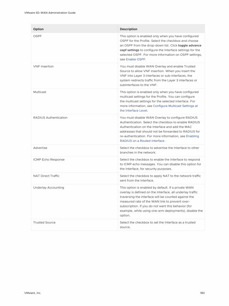
Option Description
OSPF This option is enabled only when you have configured OSPF for the Profile. Select the checkbox and choose an OSPF from the drop-down list. Click toggle advance ospf settings to configure the Interface settings for the selected OSPF. For more information on OSPF settings, see Enable OSPF.
VNF Insertion You must disable WAN Overlay and enable Trusted Source to allow VNF insertion. When you insert the VNF into Layer 3 interfaces or sub-interfaces, the system redirects traffic from the Layer 3 interfaces or subinterfaces to the VNF.
Multicast This option is enabled only when you have configured multicast settings for the Profile. You can configure the multicast settings for the selected Interface. For more information, see Configure Multicast Settings at the Interface Level.
RADIUS Authentication You must disable WAN Overlay to configure RADIUS Authentication. Select the checkbox to enable RADIUS Authentication on the Interface and add the MAC addresses that should not be forwarded to RADIUS for re-authentication. For more information, see Enabling RADIUS on a Routed Interface .
Advertise Select the checkbox to advertise the Interface to other branches in the network.
ICMP Echo Response Select the checkbox to enable the Interface to respond to ICMP echo messages. You can disable this option for the Interface, for security purposes.
NAT Direct Traffic Select the checkbox to apply NAT to the network traffic sent from the Interface.
Underlay Accounting This option is enabled by default. If a private WAN overlay is defined on the Interface, all underlay traffic traversing the interface will be counted against the measured rate of the WAN link to prevent over-subscription. If you do not want this behavior (for example, while using one-arm deployments), disable the option.
Trusted Source Select the checkbox to set the Interface as a trusted source.
VMware SD-WAN Administration Guide
VMware, Inc. 180

Option Description
Reverse Path Forwarding You can choose an option for Reverse Path Forwarding only when you have enabled Trusted Source. This option allows traffic on the interface only if return traffic can be forwarded on the same interface. This helps to prevent traffic from unknown sources (malicious traffic) on an enterprise network. If the incoming source is unknown, then the packet is dropped at ingress without creating flows. Select one of the following options from the drop-down list:
n Disabled – Allows incoming traffic even if there is no matching route in the route table.
n Specific – This option is selected by default. The incoming traffic should match a specific return route on the incoming interface. If a specific match is not found, then the incoming packet is dropped. This is a commonly used mode on interfaces configured with public overlays and NAT.
n Loose – The incoming traffic should match any route(Connected/Static/Routed) in the routing table. This allows asymmetrical routing and is commonly used on interfaces that are configured without next hop.
VLAN Enter a VLAN ID for the Interface to support VLAN tagging over the port. This option is not available if you have chosen the Addressing Type as DHCP.
L2 Settings
Autonegotiate This option is enabled by default. When enabled, Auto negotiation allows the port to communicate with the device on the other end of the link to determine the optimal duplex mode and speed for the connection.
Speed This option is available only when Autonegotiate is disabled. Select the speed that the port has to communicate with other links. By default, 100 Mbps is selected.
Duplex This option is available only when Autonegotiate is disabled. Select the mode of the connection as Full duplex or Half duplex. By default, Full duplex is selected.
MTU The default MTU size for frames received and sent on all routed interfaces is 1500 bytes. You can change the MTU size for an Interface.
SFP Settings – This option is available only for Edge models that support SFP ports.
SFP Module By default, Standard is selected. You can select DSL as the module to use the SFP port with higher bandwidth services.
VMware SD-WAN Administration Guide
VMware, Inc. 181

Option Description
DSL Settings – The option to configure Digital Subscriber Line (DSL) settings is available when you select the SFP module as DSL.
Mode Choose the DSL mode from the following options:
n VDSL2 – This option is selected by default. Very-high-bit-rate digital subscriber line (VDSL) technology provides faster data transmission. The VDSL lines connect service provider networks and customer sites to provide high bandwidth applications over a single connection.
When you choose VDSL2, select the Profile from the drop-down list. Profile is a list of pre-configured VDSL2 settings. The following profiles are supported: 17a and 30a.
n ADSL2/2+ – Asymmetric digital subscriber line (ADSL) technology is part of the xDSL family and is used to transport high-bandwidth data. ADSL2 improves the data rate and reach performance, diagnostics, standby mode, and interoperability of ADSL modems. ADSL2+ doubles the possible downstream data bandwidth.
If you choose ADSL2/2+, configure the following settings:
n PVC – A permanent virtual circuit (PVC) is a software-defined logical connection in a network such as a frame relay network. Choose a PVC number from the drop-down list. The range is from 0 to 7.
n VPI – Virtual Path Identifier (VPI) is used to identify the path to route the packet of information. Enter the VPI number, ranging from 0 to 255.
n VCI – Virtual Channel Identifier (VCI) defines the fixed channel on which the packet of information should be sent. Enter the VCI number, ranging from 35 to 65535.
n PVC VLAN – Set up a VLAN to run over PVCs on the ATM module. Enter the VLAN ID, ranging from 1 to 4094.
VMware SD-WAN Administration Guide
VMware, Inc. 182

8 Some of the Edge models support Wireless LAN. The following image shows WLAN Interface settings.
You can modify the settings as follows:
Option Description
Interface Enabled This option is enabled by default. If required, you can disable the Interface. When disabled, the Interface is not available for any communication.
VLAN Choose the VLAN to be used by the Interface.
SSID Enter the wireless network name.
Select the Broadcast checkbox to broadcast the SSID name to the surrounding devices.
Security Select the type of security for the Wi-Fi connection, from the drop-down list. The following options are available:
n Open – No security is enforced.
n WPA2 / Personal – A password is required for authentication. Enter the password in the Passphrase field.
n WPA2 / Enterprise – A RADIUS server is used for authentication. You should have already configured a RADIUS server and selected it for the Profile and Edge.
To configure a RADIUS server, see Configure Authentication Services.
To select the RADIUS server for a Profile, see Configure Authentication Settings.
What to do next
When you configure the Interface Settings for a Profile, the settings are automatically applied to the Edges that are associated with the profile. If required, you can override the configuration for a specific Edge as follows:
1 In the Enterprise portal, click Configure > Edges.
VMware SD-WAN Administration Guide
VMware, Inc. 183

2 Click the Device Icon next to an Edge, or click the link to an Edge and then click the Device tab.
3 In the Device tab, scroll down to the Interface Settings section, which displays the interfaces available in the selected Edge.
4 Click the Edit option for an Interface to view and modify the settings.
5 Select the Override Interface checkbox to modify the configuration settings for the selected Interface.
Configure Wi-Fi Radio Settings
At the profile level, you can enable/disable WI-FI Radio and configure the band of radio frequencies.
Procedure
1 In the Enterprise portal, click Configure > Profiles.
The Configuration Profiles page appears.
2 Select a profile you want to configure WI-FI Radio settings and click the icon under the Device column.
The Device Settings page for the selected profile appears.
3 In the WI-FI Radio Settings area, by default, the Radio Enabled checkbox is enabled and Channel is set to Automatic.
4 Select the radio band. It can be 2.4 GHz or 5 GHz.
5 Click Save Changes.
At the Edge level, you can override the WI-FI Radio settings specified in the Profile by selecting the Enable Edge Override checkbox. For more information, see Configure Wi-Fi Radio Overrides.
Configure SNMP Settings for Profiles
SNMP is a commonly used protocol for network monitoring and MIB is a database associated with SNMP to manage entities. SNMP can be enabled by selecting the desired SNMP version as described in the steps below.
VMware SD-WAN Administration Guide
VMware, Inc. 184

Before you begin:
n To download the SD-WAN Edge MIB: go to the Remote Diagnostic screen (Test & Troubleshooting > Remote Diagnostics) and run MIB for SD-WAN Edge. Copy and paste results onto your local machine.
n Install all MIBs required by VELOCLOUD-EDGE-MIB on the client host, including SNMPv2-SMI, SNMPv2-CONF, SNMPv2-TC, INET-ADDRESS-MIB, IF-MIB, UUID-TC-MIB, and VELOCLOUD-MIB. All the above-mentioned MIBs are available on the Remote Diagnostics page.
Supported MIBs
n SNMP MIB-2 System
n SNMP MIB-2 Interfaces
n VELOCLOUD-EDGE-MIB
n HOST-RESOURCES-MIB, from RFC 1514
Procedure to Configure SNMP Settings at Profile Level:
1 Obtain the VELOCLOUD-EDGE-MIB from Remote Diagnostic.
2 Install all MIBs required by VELOCLOUD-EDGE-MIB. (See "Before you begin" for more information.
3 From the SD-WAN Orchestrator, go to Configure > Profiles.
The Configuration Profiles screen appears.
4 Select a profile you want to configure SNMP settings for, and click the Device icon under the Device column.
The Configuration Profiles screen for the selected Profile appears.
5 Scroll down to the SNMP Settings area. You can choose between two versions, v2c or v3.
6 For a SNMP v2c Config follow the steps below:
a Check the v2c checkbox.
b Type in a Port in the Port textbox. The default setting is 161.
c In the Community textbox, type in a word or sequence of numbers that will act as a 'password' that will allow you access to the SNMP agent.
d For Allowed IPs:
n Check the Any checkbox to allow any IP to access the SNMP agent.
n To restrict access to the SNMP agent, uncheck the Any checkbox and enter the IP address(es) that will be allowed access to the SNMP agent.
VMware SD-WAN Administration Guide
VMware, Inc. 185

7 For a SNMP v3 Config, which provides added security support follow the steps below:
a Type in a port in the Port textbox. 161 is the default setting.
b Type in a user name and password in the appropriate textboxes.
c Check the Privacy checkbox if you want your packet transfer encrypted.
d If you have checked the Privacy checkbox, choose DES or AES from the Algorithm drop-down menu.
8 Configure Firewall Settings. After you have configured SNMP Settings, go to Firewall settings (Configure >Profiles > Firewall) to configure the Firewall settings that will enable your SNMP settings.
Note SNMP interface monitoring is supported on DPDK enabled interfaces for 3.3.0 and later releases.
Configure Visibility Mode
This section describes how to configure Visibility mode.
About Visibility Mode
Even though tracking by MAC Address is ideal (providing a global unique identifier), there’s a lack of visibility when an L3 switch is located between the client and the Edge because the switch MAC is known to the Edge, not the device MAC. Therefore, two tracking modes (MAC Address and now IP Address) are available. When tracking by MAC address is not possible, IP address will be used instead.
Choosing Visibility Mode
To choose a Visibility Mode, go to Configure > Profile > Devices tab. Select one of the following:
n Visibility by MAC address
n Visibility by IP address
VMware SD-WAN Administration Guide
VMware, Inc. 186

Considerations for Using Visibility Mode
Keep in mind the following when choosing a Visibility mode:
n If Visibility by MAC address is selected:
n Clients are behind L2 SW
n Client MAC, IP and Hostname (if applicable) will appear
n Stats are collected based on MAC
n If Visibility by IP address is selected:
n Clients are behind L3 SW
n SW MAC, Client IP and Hostname (if applicable) will appear
n Stats are collected based on IP
Assign Partner Gateways
In order for customers to be able to use partner gateways, your Operator must select the Enable Partner Handoff check box for the Gateway to enable this feature. If this feature is available to you, will see the Partner Gateway Assignment area in the Configure > Profiles > Device tab screen.
Note The Partner Gateway Assignment feature has been enhanced to also support segment-based configurations. Multiple Partner Gateways can be configured on the Profile level and/or overridden on the Edge level.
Select Gateways
To complete this section, you must have this feature enabled. See your Operator for more information.
If there are no Gateways listed in the Gateway Handoff Assignment area:
1 Click the Select Gateways link to select Partner Gateways.
VMware SD-WAN Administration Guide
VMware, Inc. 187

2 In the Select Partner Gateways for Global Segment dialog box, select an available Partner Gateway from the Available Partner Gateway area and move it (using the appropriate arrow) to the Selected Partner Gateway area.
Note that only Gateways configured as a Partner Handoff Gateway will be visible in the Available Partner Gateways area. If there are other Gateways not configured as a Partner Handoff Gateway, the following message will appear in the dialog box: There is one other Gateway in the Gateway Pool that is not configured as a Partner Handoff Gateway.
Selecting CDE Gateways
In normal scenarios, the PCI traffic runs between customer branch and the Data Center where the PCI traffic is handoff to the PCI network and the Gateways are out of PCI scope. (The Operator can configure the Gateway to exclude PCI Segment by unchecking the CDE role).
In certain scenarios where Gateways can have a handoff to the PCI network and in the PCI scope, the Operator can enable CDE role for the Partner Gateways and these Gateways (CDE Gateways) will be available for the user to assign in the PCI Segments (CDE Type).
To complete this section, you must have this feature enabled. See your Operator for more information.
Assign a CDE Gateway
To assign a CDE Gateway:
1 From the Configure Segments window, click the Select Profile Segments Change button.
2 In the Select Segments dialog box, move the available CDE segment from the Available Segments area (using the appropriate arrow) to the Within This Profile area.
VMware SD-WAN Administration Guide
VMware, Inc. 188

3 In the Gateway Handoff Assignment area, click the Select Gateways link.
4 In the Select Partner Gateways for cde seg dialog box, select an available CDE Partner Gateway (from the Available Partner Gateways area) and move it to the Selected Partner Gateways area.
5 Click the Update button.
The Gateway Handoff Assignment area refreshes with the selected Gateways.
Note As indicated in the Select Partner Gateways for cde seg dialog box, only CDE gateways can be selected for the segment.
Considerations When Assigning Partner Gateways:
Consider the following notes when assigning Partner Gateways:
n Partner Gateways can be assigned at the Profile or Edge level.
n More than two Partner Gateways can be assigned to an Edge (up to 16).
VMware SD-WAN Administration Guide
VMware, Inc. 189

n Partner Gateways can be assigned per Segment.
Note If you do not see the Gateway Handoff Assignment area displayed in the Configure Segments window, contact your Operator to enable this feature.
Assign Controllers
The SD-WAN Gateway is enabled for supporting both the data and control plane. In the 3.2 release, VMware introduces a Controller-only feature (Controller Gateway Assignment).
There are multiple use cases which require the SD-WAN Gateway to operate as a Controller only (that is, to remove the data plane capabilities). Additionally, this will enable the Gateway to scale differently, as resources typically dedicated for packet processing can be shifted to support control plane processing. This will enable, for instance, a higher number of concurrent tunnels to be supported on a Controller than on a traditional Gateway. See the following section for a typical use case.
Use Case: Dynamic Branch-to-Branch via Different Partner Gateways
In this scenario, Edge 1 (E1) and Edge 2 (E2) as shown in the image belong to the same enterprise in the Orchestrator. However, they connect to different Partner Gateways (typically due to being in different regions). Therefore, Dynamic Branch-to-Branch is not possible between E1 and E2, but by leveraging the Controller, this is possible.
Initial Traffic Flow
As shown in the image below, when E1 and E2 attempt to communicate directly, the traffic flow begins by traversing the private network as it would in previous versions of the code. Simultaneously, the Edges will also notify the Controller that they are communicating and request a direct connection.
Dynamic Tunnel
The Controller signals to the Edges to create the dynamic tunnel by providing E1 connectivity information to E2 and vice versa. The traffic flow moves seamlessly to the new dynamic tunnel if and when it is established.
VMware SD-WAN Administration Guide
VMware, Inc. 190

Configuring a Gateway as a Controller
In order for customers to be able to use partner gateways, your Operator must select the Enable Partner Handoff check box for the Gateway to enable this feature. If this feature is available to you, you will see the Controller Assignment area in the Configure > Profiles > Device tab screen.
Note At least one Gateway in the Gateway Pool should be a "Controller Only" Gateway.
1 Go to Configure > Profiles > Device tab.
2 Scroll down to the Controller Assignment area.
3 In the Controller Assignment area, click the Select Gateways link.
4 In the Select Controllers for Global Segment dialog, move controllers from the Available area
to the Selected area.
5 Click Update.
The Controller Assignment area refreshes.
VMware SD-WAN Administration Guide
VMware, Inc. 191

Configure Profile Business Policy 11VMware provides an enhanced Quality of Service feature called Business Policy. This feature is defined using the Business Policy tab in a Profile or at the Edge override level.
Note If you are logged in using a user ID that has Customer Support privileges, you will only be able to view SD-WAN Orchestrator objects. You will not be able to create new objects or configure/update existing ones.
Based on the business policy configuration, VMware examines the traffic being used, identifies the Application behavior, the business service objective required for a given app (High, Med, or Low), and the Edge WAN Link conditions. Based on this, the Business Policy optimizes Application behavior driving queuing, bandwidth utilization, link steering, and the mitigation of network errors.
The screen capture below shows some of the Business Policy rules. A number of rules are predefined and you can add your own rules to customize your network operation. Rules are listed in order of highest precedence. Network traffic is managed by identifying its characteristics then matching the characteristics to the rule with the highest precedence.
As shown in the image below, Business Policy Rules are now Segment aware. All Segments available for configuration are listed in the Configure Segment drop-down menu.
When you choose a Segment to configure from the Configure Segment drop-down menu, the settings and options associated with that Segment appear in the Configure Segments area. Global Segment [Regular] is the default segment.
For more information about Segmentation, see Chapter 7 Configure Segments and Chapter 10 Configure a Profile Device.
VMware, Inc. 192

Note You can move your configured rules up or down in the list of rules to establish precedence by hovering over the numeric value at the left side of the rule and moving the rule up or down. If you hover over the right side of a rule, click the – (minus) sign next to the rule to remove it from the list or the + (plus) sign to add a new rule.
This chapter includes the following topics:
n Create Business Policy Rules
Create Business Policy Rules
SD-WAN Orchestrator allows you to configure business policy rules at the Profile and Edge levels. Operators, Partners, and Admins of all levels can create a business policy. The business policy matches parameters such as IP addresses, ports, VLAN IDs, interfaces, domain names, protocols, operating system, object groups, applications, and DSCP tags. When a data packet matches the match conditions, the associated action or actions are taken. If a packet matches no parameters, then a default action is taken on the packet.
Before you begin: Know the IP Addresses of your devices and understand the implications of setting a wildcard mask.
To create a business policy:
1 From the SD-WAN Orchestrator, go to Configure > Profiles > Business Policy.
2 Under Business Policy area, click New Rule. The Configure Rule dialog box appears.
VMware SD-WAN Administration Guide
VMware, Inc. 193

3 In the Rule Name box, enter a unique name for the rule.
VMware SD-WAN Administration Guide
VMware, Inc. 194

4 Under the Match area, configure the match conditions for the traffic flow. The option you choose may change the fields in the dialog box:
Settings Description
Source Allows to specify match criteria for the source traffic. Select any of the following options:
n Any - Matches all source traffic, by default.
n Object Group - Allows you to select a combination of address group and port group to be matched for the source. For more information, see Chapter 16 Object Groups and Configure Business Policies with Object Groups.
Note If the selected address group contains any domain names, then they would be ignored when matching for the source.
n Define - Allows you to define the matching criteria for the source traffic from a specific VLAN, Interface, IP Address, Port, or Operating System. Select one of the following options, by default, None is selected:
n VLAN - Matches traffic from the specified VLAN, selected from the drop-down menu.
n Interface - Matches traffic from the specified interface, selected from the drop-down menu.
Note If an interface cannot be selected, then the interface is either disabled or not assigned to this segment.
n IP Address - Matches traffic from the specified IP address. Along with the IP address, you can specify one of the following options to match the source traffic:
n CIDR prefix - Choose this option if you want the network defined as a CIDR value (for example: 172.10.0.0 /16).
n Subnet mask - Choose this option if you want the network defined based on a Subnet mask (for example, 172.10.0.0 255.255.0.0).
n Wildcard mask - Choose this option if you want the ability to narrow the enforcement of a policy to a set of devices across different IP subnets that share a matching host IP address value. The Wildcard mask matches an IP or a set of IP addresses based on the inverted Subnet mask. A '0' within the binary value of the mask means the value is fixed and a '1' within the binary value of the mask means the value is wild (can be 1 or 0). For example, a Wildcard mask of 0.0.0.255 (binary equivalent
VMware SD-WAN Administration Guide
VMware, Inc. 195
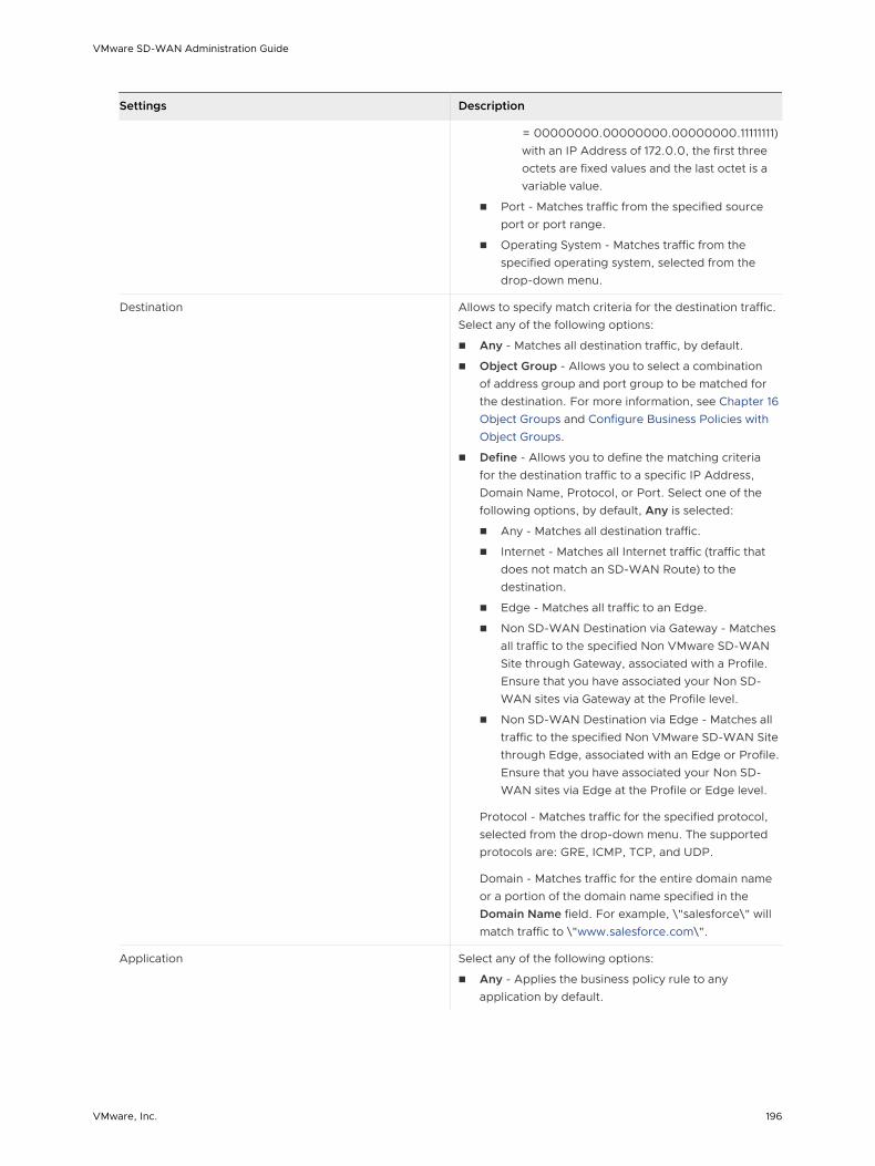
Settings Description
= 00000000.00000000.00000000.11111111) with an IP Address of 172.0.0, the first three octets are fixed values and the last octet is a variable value.
n Port - Matches traffic from the specified source port or port range.
n Operating System - Matches traffic from the specified operating system, selected from the drop-down menu.
Destination Allows to specify match criteria for the destination traffic. Select any of the following options:
n Any - Matches all destination traffic, by default.
n Object Group - Allows you to select a combination of address group and port group to be matched for the destination. For more information, see Chapter 16 Object Groups and Configure Business Policies with Object Groups.
n Define - Allows you to define the matching criteria for the destination traffic to a specific IP Address, Domain Name, Protocol, or Port. Select one of the following options, by default, Any is selected:
n Any - Matches all destination traffic.
n Internet - Matches all Internet traffic (traffic that does not match an SD-WAN Route) to the destination.
n Edge - Matches all traffic to an Edge.
n Non SD-WAN Destination via Gateway - Matches all traffic to the specified Non VMware SD-WAN Site through Gateway, associated with a Profile. Ensure that you have associated your Non SD-WAN sites via Gateway at the Profile level.
n Non SD-WAN Destination via Edge - Matches all traffic to the specified Non VMware SD-WAN Site through Edge, associated with an Edge or Profile. Ensure that you have associated your Non SD-WAN sites via Edge at the Profile or Edge level.
Protocol - Matches traffic for the specified protocol, selected from the drop-down menu. The supported protocols are: GRE, ICMP, TCP, and UDP.
Domain - Matches traffic for the entire domain name or a portion of the domain name specified in the Domain Name field. For example, \"salesforce\" will match traffic to \"www.salesforce.com\".
Application Select any of the following options:
n Any - Applies the business policy rule to any application by default.
VMware SD-WAN Administration Guide
VMware, Inc. 196

Settings Description
n Define - Allows to select a specific application to apply the business policy rule. In addition, a DSCP value can be specified to match traffic coming in with a preset DSCP/TOS tag.
Note When creating a business policy rule matching an application only, to apply the Network Service Action for such application, the Edge might need to use DPI (Deep Packet Inspection) Engine. Generally, the DPI will not be able to determine the application based on the first packet. The DPI Engine usually needs the first 5-10 packets in the flow to identify the application. For only the first packets received, traffic might take a different path, i.e. 'Direct' instead of 'Multipath' or 'Internet Backhaul' depending on the business policy configuration.
Depending on your Match choices, some Actions may not be available.
VMware SD-WAN Administration Guide
VMware, Inc. 197

5 Under the Action area, configure the actions for the rule:
Settings Description
Priority Designate the priority of the rule as one of the following:
n High
n Normal
n Low
Select the Rate Limit checkbox to set limits for inbound and outbound traffic directions.
Network Service Set the Network Service to one of the following options:
n Direct - Sends the traffic out of the WAN circuit directly to the destination, bypassing the SD-WAN Gateway.
Note The Edge by default prefers a secure route over a business policy. In practice this means the Edge will forward traffic via Multipath (Branch to Branch or Cloud via Gateway, depending on the route) even if a business policy is configured to send that traffic via the Direct path if the Edge has received either secure default routes or more specific secure routes from the Partner Gateway or another Edge.
n Multi-Path - Sends the traffic from one SD-WAN Edge to another SD-WAN Edge.
n Internet Backhaul - This network service is enabled only if the Destination is set as Internet.
Note The Internet Backhaul Network Service will only apply to Internet traffic (WAN traffic destined to network prefixes that do not match a known local route or VPN route).
For information about these options, see Configure Action Network Service.
If Conditional Backhaul is enabled at the profile level, by default it will apply for all Business Policies configured for that profile. You can disable conditional backhaul for selected policies to exclude selected traffic (Direct, Multi-Path, and CSS) from this behavior by selecting the disable conditional backhaul checkbox.
For more information about how to enable and troubleshoot the Conditional Backhaul feature, see Conditional Backhaul.
VMware SD-WAN Administration Guide
VMware, Inc. 198

Settings Description
Link Steering Select one of the following link steering modes:
n Auto - By default, all applications are set to automatic Link Steering mode. When an application is in the automatic Link Steering mode, the DMPO automatically chooses the best links based on the application type and automatically enables on-demand remediation when necessary. Enter an Inner Packet DSCP Tag from the drop-down menu and an Outer Packet DSCP Tag from the drop-down menu.
n Transport Group - Specify any one of the following transport group options in the steering policy so that the same Business Policy configuration can be applied across different device types or locations, which may have completely different WAN carriers and WAN interfaces:
n Public Wired
n Public Wireless
n Private Wired
n Interface - Link steering is tied to a physical interface and will be used primarily for routing purposes.
Note This option is only allowed at the Edge override level.
n WAN Link - Allows to define policy rules based on specific private links. For this option, the interface configuration is separate and distinct from the WAN link configuration. You will be able to select a WAN link that was either manually configured or auto-discovered.
Note This option is only allowed at the Edge override level.
For more information about the link steering modes and DSCP, DSCP marking for both Underlay and Overlay traffic, see Configure Link Steering Modes.
NAT Disable or Enable NAT. For more information, see Configure Policy-based NAT.
Service Class Select one of the following Service Class options:
n Real-time
n Transactional
n Bulk
Note This option is only for a custom application.
VMware Apps/Categories fall in one of these categories.
6 Click OK. The business policy rule is created for the selected profile and it appears under the Business Policy area of the Profile Business Policy page.
Related Information: Overlay QoS CoS Mapping
VMware SD-WAN Administration Guide
VMware, Inc. 199

Configure Match Source
This section describes the Match Source, Destination, and Application selections in more detail. For each of the Match selections, Any is used to designate any traffic from a source, destination, or application.
If the Match Source Define option is chosen, the source traffic can be narrowed to a specific VLAN, an IP Address, a Port, an Operating System or any combination of selections.
Configure Match Destination
If the Match Destination Define option is chosen, specify additional parameters to identify traffic destination.
The destination can be first narrowed to a type (Any, Internet, Edge, or Non VMware SD-WAN Site). See the table below for a description of the above-mentioned traffic destinations.
Option Description
Any All traffic regardless of destination or routing.
Internet Traffic that does not match an SD-WAN Route.
Edge Traffic designated for another site in the network. Sites such as these would use a SD-WAN Edge.
Non-VeloCloud Site Sites that do not use a SD-WAN Edge, but that have a route inside the network. A Non VMware SD-WAN Site is configured in Configure > Network Services.
The destination can then be further defined by specifying an IP Address, Hostname, Protocol (GRE, ICMP, TCP, or UDP), and a port.
Match Destination options are particularly useful if the same traffic match pattern needs to be assigned different QoS values depending on the route taken. As an example, you may want to assign a higher priority to traffic destined to a VMware SD-WAN Site versus regular cloud-based internet traffic. This can be easily achieved using the Destination configuration value.
VMware SD-WAN Administration Guide
VMware, Inc. 200

Configure Match Application
If the Match Application Define option is chosen, applications can be chosen first by category then by specific application. In addition, a DSCP value can be specified to match traffic coming in with a preset DSCP/TOS tag.
The following sections describe the Action Priority, Network Service, Link Steering, NAT, and Service class selections in more detail.
Note Depending on your Match choices, some Actions may not be available. For example, if All Applications is chosen, Network Service and Link Actions are grayed out and are not available for selection. In a similar manner, if a Destination of type Internet or an Application of type Routable Apps is chosen for a VPN profile, an additional Network Service option, Internet Backhaul, becomes available.
VMware SD-WAN Administration Guide
VMware, Inc. 201

Configure Action Priority
The Action Priority parameter allows traffic to be categorized as High, Normal, or Low. A percentage Rate Limit can also be applied in both the Outbound and Inbound direction.
Configure Action Network Service
While creating or updating a Business Policy rule and action, you can set the Network Service to Direct, Multi-Path, and Internet Backhaul.
Direct
Sends the traffic out of the WAN circuit directly to the destination, bypassing the SD-WAN Gateway. NAT is applied to the traffic if the NAT Direct Traffic checkbox is enabled on the Interface Settings under the Device tab. When you configure NAT Direct, consider the following limitations.
n NAT must hit traffic in edge routing table with Next Hop as either Cloud VPN or Cloud Gateway.
n NAT works for traffic to public IP addresses only, even if Business Policy allows to configure private IP addresses as destination.
Multi-Path
Sends the traffic from one SD-WAN Edge to another SD-WAN Edge.
Internet Backhaul
While configuring the business policy rule match criteria, if you define the Destination as Internet, then the Internet Backhaul network service will be enabled.
Note The Internet Backhaul Network Service will only apply to Internet traffic (WAN traffic destined to network prefixes that do not match a known local route or VPN route).
When the Internet Backhaul is selected, you need to select one of the following:
n Backhaul Hubs
n Non-VeloCloud Site
n Cloud Security Service
You should be able to configure multiple VMware SD-WAN Sites for backhaul to support the redundancy that is inherently built into the Non VMware SD-WAN Site connection, but keep a consistent behavior of service unavailability leading to traffic being dropped.
VMware SD-WAN Administration Guide
VMware, Inc. 202
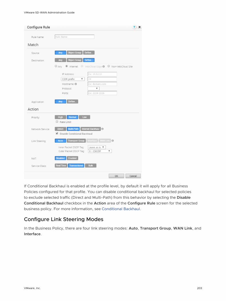
If Conditional Backhaul is enabled at the profile level, by default it will apply for all Business Policies configured for that profile. You can disable conditional backhaul for selected policies to exclude selected traffic (Direct and Multi-Path) from this behavior by selecting the Disable Conditional Backhaul checkbox in the Action area of the Configure Rule screen for the selected business policy. For more information, see Conditional Backhaul.
Configure Link Steering Modes
In the Business Policy, there are four link steering modes: Auto, Transport Group, WAN Link, and Interface.
VMware SD-WAN Administration Guide
VMware, Inc. 203

Link Selection: Auto
By default, all applications are given the automatic Link steering mode. This means the DMPO automatically picks the best links based on the application type and automatically enables on-demand remediation when necessary. There are four possible combinations of Link Steering and On-demand Remediation for Internet applications. As mentioned earlier, traffic within the Enterprise (VPN) always goes through the DMPO tunnels, hence it always receives the benefits of on-demand remediation.
Scenario Expected DMPO Behavior
At least one link satisfies the SLA for the application.
Choose the best available link.
Single link with packet loss exceeding the SLA for the application.
Enable FEC for the real-time applications sent on this link.
Two links with loss on only one link. Enable FEC on both links.
Multiple links with loss on multiple links.
Enable FEC on two best links.
Two links but one link appears unstable, i.e. missing three consecutive heartbeats.
Mark link un-usable and steer the flow to the next best available link.
Both Jitter and Loss on both links. Enable FEC on both links and enable Jitter buffer on the receiving side. Jitter buffer is enabled when Jitter is greater than 7 ms for voice and greater than 5 ms for video.
The sending DMPO endpoint notifies the receiving DMPO endpoint to enable Jitter buffer. The receiving DMPO endpoint will buffer up to 10 packets or 200 ms of traffic, whichever happens first. The receiving DMPO endpoint uses the original time stamp embedded in the DMPO header to calculate the flow rate to use in de-jitter buffer. If the flow is not sent at a constant rate, the Jitter buffering is disabled.
Link Steering by Transport Group
A Transport Group represents WAN links bundled together based on similar characteristics and functionality. Defining a Transport Group allows business abstraction so that a similar policy can apply across different Hardware types.
Different locations may have different WAN transports (e.g. WAN carrier name, WAN interface name); DMPO uses the concept of Transport Group to abstract the underlying WAN carriers and interfaces from the Business Policy configuration. The Business Policy configuration can specify the transport group (Public Wired, Public Wireless or Private Wired) in the steering policy so that the same Business Policy configuration can be applied across different device types or
VMware SD-WAN Administration Guide
VMware, Inc. 204

locations, which may have completely different WAN carriers and WAN interfaces. When the DMPO performs the WAN link discovery, it also assigns the transport group to the WAN link. This is the most desirable option for specifying the links in the Business Policy because it eliminates the need for IT administrators to know the type of physical connectivity or the WAN carrier.
If you choose the Preferred option, the Error Correct Before Steering checkbox displays.
If you select the Error Correct Before Steering checkbox, the Loss% variable textbox displays. When you define a loss percentage (4% for example), the Edge will continue to use the selected link or transport group and apply error correction until loss reaches 4%, which is when it will steer traffic to another path. When the Error Correct Before Steering checkbox is unchecked, the Edge will start steering traffic away if the loss for the link exceed the application SLA - i.e. Real-time application SLA is 0.3% by default. If you disable this checkbox, the application will steer before Error Correction occurs.
Note This option is allowed at both the Edge Override level and Profile level.
Link Steering by Interface
For this option, the link steering is tied to a physical interface. Link steering by interface will be used primarily for routing purposes. However, even though it logically should only be used for routing traffic directly from the VMware SD-WAN Site, if the rule specified has a Network Service requiring Internet Multi-path benefits, it will pick a single WAN link connected to the interface.
If you choose the Preferred option, the Error Correct Before Steering checkbox displays. If you check the box is checked, an additional Loss% variable will become available. When the option is disabled, the Edge will start steering traffic away if the loss for the link exceed the application SLA - i.e. Real-Time application SLA is 0.3% by default. When “Error Correct Before Steering” is
VMware SD-WAN Administration Guide
VMware, Inc. 205
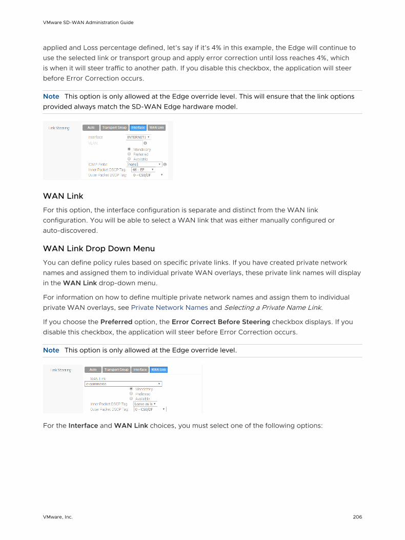
applied and Loss percentage defined, let’s say if it’s 4% in this example, the Edge will continue to use the selected link or transport group and apply error correction until loss reaches 4%, which is when it will steer traffic to another path. If you disable this checkbox, the application will steer before Error Correction occurs.
Note This option is only allowed at the Edge override level. This will ensure that the link options provided always match the SD-WAN Edge hardware model.
WAN Link
For this option, the interface configuration is separate and distinct from the WAN link configuration. You will be able to select a WAN link that was either manually configured or auto-discovered.
WAN Link Drop Down Menu
You can define policy rules based on specific private links. If you have created private network names and assigned them to individual private WAN overlays, these private link names will display in the WAN Link drop-down menu.
For information on how to define multiple private network names and assign them to individual private WAN overlays, see Private Network Names and Selecting a Private Name Link.
If you choose the Preferred option, the Error Correct Before Steering checkbox displays. If you disable this checkbox, the application will steer before Error Correction occurs.
Note This option is only allowed at the Edge override level.
For the Interface and WAN Link choices, you must select one of the following options:
VMware SD-WAN Administration Guide
VMware, Inc. 206

Option Description
Mandatory Indicates that traffic will be sent over the WAN link or link Service-group specified. If the link specified (or all links within the chosen service group) is inactive or if a Multi-path gateway route is unavailable, the corresponding packet will be dropped.
Preferred Indicates that traffic should preferably be sent over the WAN link or link Service-group specified. If the link specified (or all links within the chosen service group) is inactive, or if the Multi-path gateway route chosen is unstable, or if the link Service Level Objective (SLO) is not being met, the corresponding packet will be steered on the next best available link. If the preferred link becomes available again, traffic will be steered back to the preferred link.
Available Indicates that traffic should preferably be sent over the WAN link or link Service-group specified as long as it is available (irrespective of link SLO). If the link specified (or all links within chosen service group) are not available, or if the selected Multi-path gateway route is unavailable, the corresponding packet will be steered to the next best available link. If the preferred link becomes available again, traffic will be steered back to the available link.
Link Steering: DSCP Marking for Underlay and Overlay Traffic Overview
VMware supports DSCP remarking of packets forwarded by the Edge to the Underlay. The SD-WAN Edge can re-mark underlay traffic forwarded on a WAN link as long as Underlay Accounting is enabled on the interface. DSCP re-marking is enabled in the Business Policy configuration in the Link Steering area. See Create Business Policy Rules . In the example image shown below (assuming the Edge is connected to MPLS with both underlay and overlay traffic forwarded MPLS), if the traffic matches the network prefix 172.16.0.0/12, the Edge will re-mark the underlay packets with a DSCP value of 16 or CS2 and ignore the Outer Packet DSCP Tag field. For overlay traffic sent toward MPLS matching the same business policy, the DSCP value for the outer header will be set to the Outer Packet DSCP tag.
VMware SD-WAN Administration Guide
VMware, Inc. 207

Link Steering: DSCP Marking for Underlay Traffic Use Case
Edges that are connected to MPLS normally mark DSCP on the packet before sending to the PE for the SP to treat the packet according to the SLA. Underlay Accounting must be enabled on the WAN interface for DSCP marking on Underlay traffic via Business Policy to take effect.
Linking Steering: Underlay DSCP Configuration
1 Verify that Underlay Accounting is enabled for WAN Overlay by default in the SD-WAN Orchestrator (Configure > Edge Devices >Device Settings area).
2 From the SD-WAN Orchestrator, go to Configure> Edges>Business Policy.
3 From the Business Policy screen, click an existing rule or click the New Rule button to create a new rule.
4 In the Action section, go to the Link Steering area.
5 Click one of the following as applicable: Auto, Transport Group, Interface, or WAN Link.
6 Configure Match criteria for the underlay traffic and configure Inner Packet DSCP Tag.
Linking Steering: Overlay DSCP Configuration
1 Verify that Underlay Accounting is enabled for WAN Overlay by default in the SD-WAN Orchestrator (Configure> Edge Devices > Device Settings area).
2 From the SD-WAN Orchestrator, go to Configure > Edges > Business Policy.
3 From the Business Policy screen, click an existing rule or click the New Rule button to create a new rule.
4 In the Action section, go to the Link Steering area.
5 Click one of the following as applicable: Auto, Transport Group, Interface, or WAN Link.
VMware SD-WAN Administration Guide
VMware, Inc. 208

6 Configure Match criteria for the Overlay traffic and configure Inner Packet DSCP Tag and Outer Packet DSCP Tag.
Configure Policy-based NAT
You can configure Policy-based NAT for both Source and Destination. The NAT can be applied to either Non VMware SD-WAN Site traffic or Partner Gateway Handoff traffic using Multi-path. When configuring NAT, you must define which traffic to NAT and the action you want to perform. There are two types of NAT configuration: Many to One and One-to-One.
Accessing NAT
You can access the NAT feature from Configure > Profiles > Business Policy tab, then click the New Rule button. The NAT feature is located under the Action area.
Many-to-One NAT Configuration
In this configuration, you can NAT the traffic's source or destination IP originated from the hosts behind the edge to a different unique source or destination IP address. For example, the user can source NAT all the flows destined to a host or server in the Data Center, which is behind the Partner Gateway with a unique IP address, even though they are originated from different hosts behind an Edge.
The following figure shows an example of the Many to One configuration. In this example, all the traffic originating from the hosts that are connected to VLAN 100 - Corporate 2 (behind the Edge destined to an Internet host or a host behind the DC) will get source NAT with the IP address 72.4.3.1.
VMware SD-WAN Administration Guide
VMware, Inc. 209

One-to-One NAT Configuration
In this configuration, the Branch Edge will NAT a single local IP address of a host or server to another global IP address. If the host in the Non VMware SD-WAN Site or Data Center sends traffic to the global IP address (configured as the Source NAT IP address in the One-to-One NAT configuration), the SD-WAN Gateway will forward that traffic to the local IP address of the host or server in the Branch.
Configure Action Service Class
The Service Class parameter can be set to Real Time (time-sensitive traffic), Transactional, or Bulk. This option is only for a custom application. VMware Apps/Categories belong to one of these categories.
Overlay QoS CoS Mapping
A Traffic Class is defined with a combination of Priority (High, Normal, or Low) and Service Class (Real-Time, Transactional, or Bulk) resulting into a 3x3 matrix with nine Traffic Classes. You can map Application/Category and scheduler weight onto these Traffic Classes. All applications within a Traffic Class will be applied with the aggregate QoS treatment, including Scheduling and Policing.
All applications in a given Traffic Class have a guaranteed minimum aggregate bandwidth during congestion based on scheduler weight (or percentage of bandwidth). When there is no congestion, the applications are allowed into the maximum aggregated bandwidth. A Policer can be applied to cap the bandwidth for all the applications in a given Traffic Class. See the image below for a default of the Application/Category and Traffic Class Mapping.
The Business Policy contains the out-of-the-box Smart Defaults functionality that maps more than 2,500 applications to Traffic Classes. You can use application-aware QoS without having to define policy. Each Traffic Class is assigned a default weight in the Scheduler, and these parameters can be changed in the Business Policy. Below are the default values for the 3x3 matrix with nine Traffic Classes. See the image below for default of the Weight and Traffic Class Mapping.
VMware SD-WAN Administration Guide
VMware, Inc. 210

Example:
In this example, a customer has 90 Mbps Internet link and 10 Mbps MPLS on the Edge and the aggregate Bandwidth is 100 Mbps. Based on the default weight and Traffic Class mapping above, all applications that map to Business Collaboration will have a guaranteed bandwidth of 35 Mbps, and all applications that map to Email will have a guaranteed bandwidth of 15 Mbps. Note that business policies can be defined for an entire category like Business Collaborations, applications (e.g. Skype for Business), and more granular sub-applications (e.g. Skype File Transfer, Skype Audio, and Skype Video).
Configure Overlay QoS CoS Mapping
Note The SD-WAN Traffic Class and Weight Mapping feature is editable only if it is enabled by your Operator. To gain access to this feature, see your Operator for more information.
To enable Overlay QoS CoS Mapping:
1 Go to Configure > Profiles.
2 Click the link of the appropriate configuration profile.
3 Click the Business Policy tab.
4 In the SD-WAN Traffic Class and Weight Mapping area, type in numerical values for Real Time, Transactional, and/or Bulk as necessary.
5 Check the Policing checkbox for a Service Class if necessary.
Tunnel Shaper for Service Providers with Partner Gateway
This section describes the Tunnel Shaper for Service Providers with the Partner Gateway.
VMware SD-WAN Administration Guide
VMware, Inc. 211

Service Providers may offer SD-WAN services at a lower capacity compared to the aggregated capacity of WAN links at the local branch. For example, customers may have purchased a broadband link from another vendor and SP offering SD-WAN services, and hosting VMware Partner Gateway has no control over the underlay broadband link. In such situations, in order to ensure that the SD-WAN service capacity is being honored and to avoid congestion towards Partner Gateway, a Service Provider can enable the DMPO Tunnel Shaper between the tunnel and the Partner Gateway.
Tunnel Shaper Example
DIRECT INTERNET
PARTNERSD-WAN Edge
Internet
VCMPMPLS Partner
Gateway
xMBPS
Consider a SD-WAN Edge with two WAN links, 20 Mbps Internet and 20 Mbps MPLS, using a 35 Mbps SD-WAN service offered from a Service Provider (SP). In this case, the bandwidth of SD-WAN service (35 Mbps) is lower than the aggregated bandwidth of the WAN links (40 Mbps). To ensure that the traffic towards the Partner Gateway does not exceed 35 Mbps (displayed as "X" in the image above), the Service Provider can place a Tunnel Shaper on the DMPO tunnel.
Configure Rate-Limit Tunnel Traffic
Note The Rate-Limit Tunnel Traffic feature is editable only if it is enabled by your Operator. To gain access to this feature, see your Operator for more information.
To enable Rate-Limit Tunnel Traffic:
1 Go to Configure > Profiles from the navigation panel.
2 Click the link of the appropriate configuration profile.
3 Click the Business Policy tab.
4 In the SD-WAN Overlay Rate Limit area, check the Rate-Limit Tunnel Traffic check box. (See image below).
5 Select either the Percent or Rate (Mbps) radial buttons.
6 In the Limit text box, type in a numerical limit to the Tunnel Traffic.
7 Click Save Changes.
VMware SD-WAN Administration Guide
VMware, Inc. 212

VMware SD-WAN Administration Guide
VMware, Inc. 213

Configure Firewall 12A firewall is a network security device that monitors incoming and outgoing network traffic and decides whether to allow or block specific traffic based on a defined set of security rules. SD-WAN Orchestrator supports configuration of stateless and stateful firewalls for profiles and edges.
A Stateful firewall monitors and tracks the operating state and characteristics of every network connections coming through the firewall and uses this information to determine which network packets to allow through the firewall. The Stateful firewalls build a state table and use this table to allow only returning traffic from connections currently listed in the state table. After a connection is removed from the state table, no traffic from the external device of this connection is permitted.
The Stateful firewall feature provides the following benefits:
n Prevent attacks such as denial of service (DoS) and spoofing
n More robust logging
n Improved network security
Note By default, the Stateful Firewall feature is enabled for an enterprise. SD-WAN Orchestrator allows the enterprise user to enable or disable the Stateful Firewall feature at the profile and edge level from the respective Firewall page. To disable the Stateful Firewall feature for an enterprise, contact an Operator with Super User permission.
Note Asymmetric routing is not supported in Stateful Firewall enabled edges.
Note By default, the Syslog Forwarding feature is disabled for an enterprise. To collect firewall logs originating from enterprise SD-WAN Edges to one or more centralized remote Syslog collectors (Servers), an enterprise user must enable this feature at the enterprise level. For steps on how to configure Syslog collector details per segment in the SD-WAN Orchestrator, see Configure Syslog Settings at Profile Level.
To configure firewall settings at the profile and edge level, see:
n Configure Firewall for Profiles
n Configure Firewall for Edges
This chapter includes the following topics:
n Configure Firewall for Profiles
VMware, Inc. 214

n Configure Firewall for Edges
n Configure Firewall Rule
n Configure Edge Access
n Troubleshooting Firewall
Configure Firewall for Profiles
As an enterprise administrator, you can configure firewall rules, edge access information, and enable or disable firewall status and logs, using the Firewall tab in the Profile Configuration dialog.
Firewall Profiles are Segment aware. All Segments available for the configuration are listed in the Configure Segment drop-down menu. When you select a Segment to configure from the Configure Segment drop-down menu, the settings and options associated with that Segment appear in the Configure Segments area. Global Segment [Regular] is the default Segment.
For more information about Segmentation, see Chapter 7 Configure Segments.
VMware SD-WAN Administration Guide
VMware, Inc. 215

The firewall configuration at the profile level includes:
n Enabling Syslog Forwarding. By default, the Syslog Forwarding feature is disabled for an enterprise. To collect SD-WAN Orchestrator bound events and firewall logs originating from enterprise SD-WAN Edges to one or more centralized remote Syslog collectors (Servers), an enterprise user must enable this feature at the enterprise level. For steps on how to configure Syslog collector details per segment in the SD-WAN Orchestrator, see Configure Syslog Settings at Profile Level.
n Enabling Stateful Firewall at the Profile and Edge level. By default, the Stateful Firewall feature is enabled for an enterprise. To disable the Stateful Firewall feature for an enterprise, contact an Operator with Super User permission.
n Configure Firewall Rule.
n Configure Edge Access
Note You can disable the Firewall function for profiles by turning the Firewall Status to OFF.
Related Links
n Configure Firewall for Edges
n Troubleshooting Firewall
Configure Firewall for Edges
All the edges inherit the firewall rules and edge access configurations from the associated Profile. Under the Firewall tab of the Edge Configuration dialog, you can view all the inherited firewall rules in the Rule From Profile area. Optionally, at the edge-level, you can also override the Profile Firewall rules and edge access configuration.
VMware SD-WAN Administration Guide
VMware, Inc. 216

As an Enterprise Administrator, you can configure Port Forwarding and 1:1 NAT firewall rules individually for each edge by following the instructions on this page.
Port Forwarding and 1:1 NAT Firewall Rules
Note You can configure Port Forwarding and 1:1 NAT rules individually only at the Edge Level.
Port Forwarding and 1:1 NAT firewall rules gives Internet clients access to servers connected to an Edge LAN interface. Access can be made available through either Port Forwarding Rules or 1:1 NAT (Network Address Translation) rules.
Port Forwarding Rules
Port forwarding rules enable you to configure rules to redirect traffic from a specific WAN port to a device (LAN IP/ LAN Port) within the local subnet. Optionally, you can also restrict the inbound traffic by an IP or a subnet. Port forwarding rules can be configured with the Outside IP which is on the same subnet of the WAN IP. It can also translate outside IP addresses in different subnets than the WAN interface address if the ISP routes traffic for the subnet towards the SD-WAN Edge.
To configure a port forwarding rule, provide the following details.
1 In the Name text box, enter a name (optional) for the rule.
2 From the Protocol drop-down menu, select either TCP or UDP as the protocol for port forwarding.
3 From the Interface drop-down menu, select the interface for the inbound traffic.
4 In the Outside IP text box, enter the IP address using which the host (application) can be accessed from the outside network.
VMware SD-WAN Administration Guide
VMware, Inc. 217
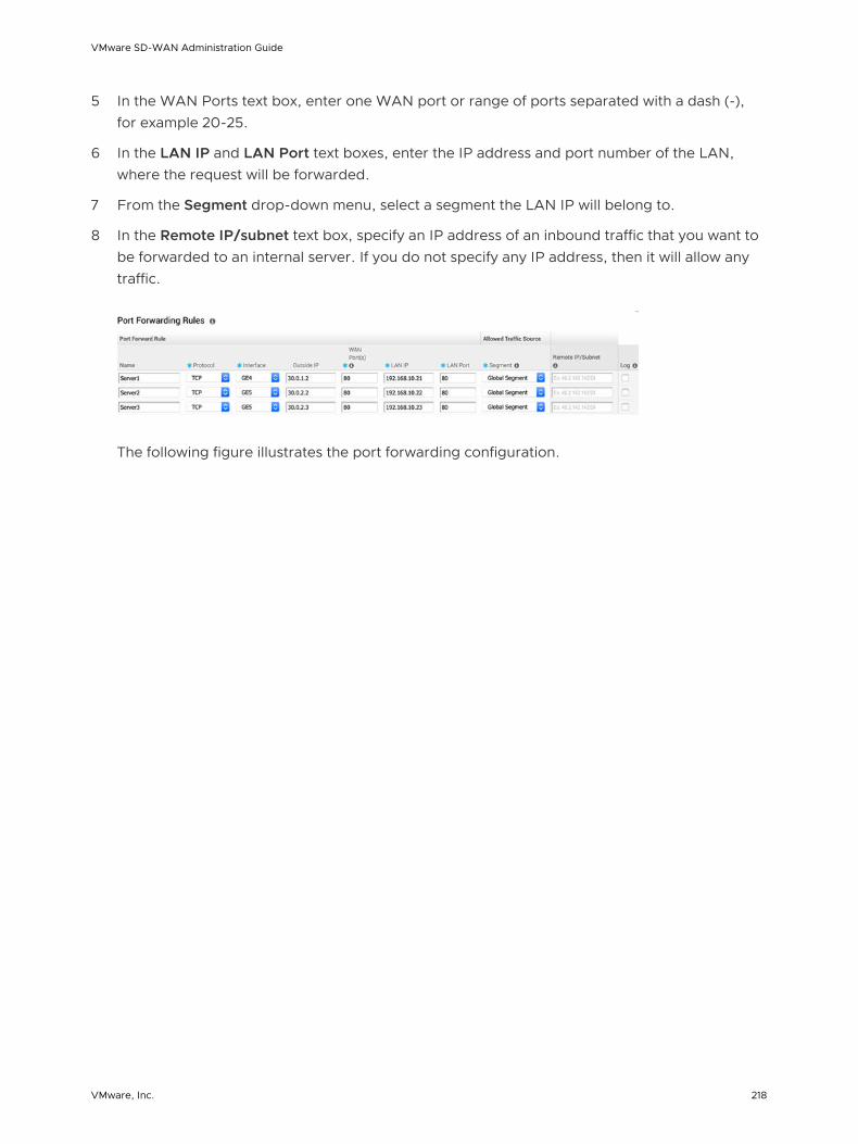
5 In the WAN Ports text box, enter one WAN port or range of ports separated with a dash (-), for example 20-25.
6 In the LAN IP and LAN Port text boxes, enter the IP address and port number of the LAN, where the request will be forwarded.
7 From the Segment drop-down menu, select a segment the LAN IP will belong to.
8 In the Remote IP/subnet text box, specify an IP address of an inbound traffic that you want to be forwarded to an internal server. If you do not specify any IP address, then it will allow any traffic.
The following figure illustrates the port forwarding configuration.
VMware SD-WAN Administration Guide
VMware, Inc. 218

PC-A
ISP 1 ISP 2
Destination: Internet1IP Address, Port 80
Destination: Internet2IP Address, Port 80
Destination: Internet2IP Address, Port 80
PC-B PC-C
Internet1 Internet2
SD-WAN EdgeLAN
L2 Switch
PC-CPort 80
PC-BPort 80
PC-APort 80
Server1192.168.10.21
Server2192.168.10.22
Server3192.168.10.23
VMware SD-WAN Administration Guide
VMware, Inc. 219

1:1 NAT Settings
These are used to map an Outside IP address supported by the SD-WAN Edge to a server connected to an Edge LAN interface (for example, a web server or a mail server). It can also translate outside IP addresses in different subnets than the WAN interface address if the ISP routes traffic for the subnet towards the SD-WAN Edge. Each mapping is between one IP address outside the firewall for a specific WAN interface and one LAN IP address inside the firewall. Within each mapping, you can specify which ports will be forwarded to the inside IP address. The '+' icon on the right can be used to add additional 1:1 NAT settings.
To configure a 1:1 NAT rule, provide the following details.
1 In the Name text box, enter a name for the rule.
2 In the Outside IP text box, enter the IP address with which the host can be accessed from an outside network.
3 From the Interface drop-down menu, select the WAN interface where the Outside IP address will be bound.
4 In the Inside (LAN) IP text box, enter the actual IP (LAN) address of the host.
5 From the Segment drop-down menu, select a segment the LAN IP will belong to.
6 Select the Outbound Traffic checkbox, if you want to allow the Outbound traffic that comes to the edge from Internet to the LAN Client to pass over the firewall connection.
7 Enter the Allowed Traffic Source (Protocol, Ports, Remote IP/Subnet) details for the mapping in the respective fields.
The following figure illustrates the 1:1 NAT configuration.
VMware SD-WAN Administration Guide
VMware, Inc. 220

PC-A
ISP 1 ISP 2
Destination: Internet110.10.1.14, Port 80
Destination: Internet210.10.1.15, Port 80
Destination: Internet210.10.1.16, Port 25
PC-B PC-C
Internet1 Internet2
SD-WAN EdgeLAN
L2 Switch
PC-CPort 25
PC-BPort 80
PC-APort 80
Server1192.168.10.21
Server2192.168.10.22
Server3192.168.10.23
VMware SD-WAN Administration Guide
VMware, Inc. 221

Configure Edge Overrides
Optionally, at the edge level, you can override the inherited profile firewall rules. To override firewall rules at the Edge level, click New Rule under Firewall Rules, and follow the steps in Configure Firewall Rule. The override rules will appear in the Edge Overrides area. The Edge override rules will take priority over the inherited profile rules for the Edge. Any Firewall override match value that is the same as any Profile Firewall rule will override that Profile rule.
Configure Edge Access Overrides
Optionally, at the edge level, you can also override the edge access configuration. To override edge access, select the Enable Edge Override checkbox in the Edge Access area of the Edge Firewall page. For more information, see Configure Edge Access.
Related Links
n Configure Firewall for Profiles
n Configure Syslog Settings at Edge Level
n Troubleshooting Firewall
Configure Firewall Rule
SD-WAN Orchestrator allows you to configure Firewall rules at the Profile and Edge levels to allow, drop, reject, or skip inbound and outbound traffic. The firewall uses the parameters such as source IP address/port, destination IP address/port, applications, application categories, and DSCP tags to create firewall rules.
To configure a firewall rule with stateful firewall-enabled at the profile level, perform the steps on this procedure.
Procedure
1 From the SD-WAN Orchestrator, go to Configure > Profiles > Firewall.
2 Enable Stateful Firewall for the selected profile.
VMware SD-WAN Administration Guide
VMware, Inc. 222

3 Under Firewall Rules area, click New Rule. The Configure Rule dialog box appears.
4 In the Rule Name box, enter a unique name for the rule.
VMware SD-WAN Administration Guide
VMware, Inc. 223

5 Under the Match area, configure the match conditions for the rule:
Settings Description
Source Allows to specify the source for packets. Select any of the following options:
n Any - Allows all source addresses by default.
n Object Group - Allows you to select a combination of address group and port group.
n Define - Allows you to define the source traffic to a specific VLAN, IP Address, MAC Address, or Port. For IP address, choose one of the three options:
n CIDR prefix - Choose this option if you want the network defined as a CIDR value (for example: 172.10.0.0 /16).
n Subnet mask - Choose this option if you want the network defined based on a Subnet mask (for example, 172.10.0.0 255.255.0.0).
n Wildcard mask - Choose this option if you want the ability to narrow the enforcement of a policy to a set of devices across different IP subnets that share a matching host IP address value. The Wildcard mask matches an IP or a set of IP addresses based on the inverted Subnet mask. A '0' within the binary value of the mask means the value is fixed and a '1' within the binary value of the mask means the value is wild (can be 1 or 0). For example, a Wildcard mask of 0.0.0.255 (binary equivalent = 00000000.00000000.00000000.11111111) with an IP Address of 172.0.0, the first three octets are fixed values and the last octet is a variable value.
Destination Allows to specify the destination for packets. Select any of the following options:
n Any - Allows all destination addresses by default.
n Object Group - Allows you to select a combination of address group and port group. For more information about Object Group, see Chapter 16 Object Groups.
n Define - Allows you to define the destination traffic to a specific VLAN, IP Address, MAC Address, or Port. For IP address, choose one of the three options: CIDR prefix, Subnet mask, or Wildcard mask.
Application Allows to specify the applications to apply the firewall rule. Select any of the following options:
n Any - Applies the firewall rule to any application by default.
n Define - Allows you to select a specific application.
VMware SD-WAN Administration Guide
VMware, Inc. 224
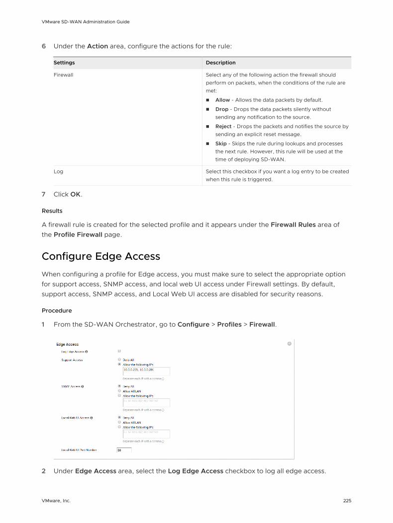
6 Under the Action area, configure the actions for the rule:
Settings Description
Firewall Select any of the following action the firewall should perform on packets, when the conditions of the rule are met:
n Allow - Allows the data packets by default.
n Drop - Drops the data packets silently without sending any notification to the source.
n Reject - Drops the packets and notifies the source by sending an explicit reset message.
n Skip - Skips the rule during lookups and processes the next rule. However, this rule will be used at the time of deploying SD-WAN.
Log Select this checkbox if you want a log entry to be created when this rule is triggered.
7 Click OK.
Results
A firewall rule is created for the selected profile and it appears under the Firewall Rules area of the Profile Firewall page.
Configure Edge Access
When configuring a profile for Edge access, you must make sure to select the appropriate option for support access, SNMP access, and local web UI access under Firewall settings. By default, support access, SNMP access, and Local Web UI access are disabled for security reasons.
Procedure
1 From the SD-WAN Orchestrator, go to Configure > Profiles > Firewall.
2 Under Edge Access area, select the Log Edge Access checkbox to log all edge access.
VMware SD-WAN Administration Guide
VMware, Inc. 225

3 For Support Access, select Allow the following IPs option and explicitly specify the IP addresses from where you can SSH into this edge.
4 For SNMP Access from routed interface/WAN, choose Allow All LAN or Allow the following IPs option if the SNMP servers are in the LAN.
5 For Local Web UI Access from routed interface/WAN, choose Allow All LAN or Allow the following IPs.
6 In the Local Web UI Port Number text box, enter the port number of the local web UI.
7 Click Save Changes.
Results
What to do next
If you want to override the edge access settings for a specific edge, use Enable Edge Override option available on the Edge Firewall page. For related information, see Configure Firewall for Edges
Troubleshooting Firewall
You can collect the firewall diagnostic logs by running the remote diagnostic tests on an Edge.
The following remote diagnostic tests are used to obtain firewall diagnostic information:
n List Active Firewall Sessions - Lists active sessions in the firewall as shown in the following screenshot.
n Flush Firewall Sessions - Resets established sessions from the firewall.
For more information about how to run remote diagnostics on an Edge, see Remote Diagnostics.
VMware SD-WAN Administration Guide
VMware, Inc. 226

Provision an Edge 13This section describes how to provision an Edge.
This chapter includes the following topics:
n Provision a New Edge
n Activate Edges
n SD-WAN Edges
Provision a New Edge
Enterprise Admins can provision a single Edge or multiple Edges, such as assigning a Profile configuration to an Edge or changing other Edge specific parameters. You must create a configuration for every Edge you will deploy to a specific site.
You can provision a new edge from the Edges screen by performing the following steps:
Procedure
1 In the Enterprise portal, click Configure > Edges.
VMware, Inc. 227

2 In the Edges screen, click New Edge at the top-right corner of the screen.
The Provision New Edge dialog box appears.
3 In the Name textbox, enter a unique name for the Edge.
4 From the Model drop-down menu, select an Edge model.
Note Starting from the 3.4 release, Edge 510-LTE is supported and can be provisioned.
5 From the Profile drop-down menu, select a profile to be assigned to the Edge.
n If an Edge Staging Profile is displayed as an option due to push activation, this profile is used by a newly assigned Edge, but has not been configured with a production Profile.
n If a customer has a Network-based Operator Profile, then the customer can only provision Network-based Edges. In addition, if a customer has a Segment-based Operator Profile, then the customer can only provision Segment-based Edges. (For more information about Profile migration see, Network to Segment Migration. For more information about how to create a new profile, see the Chapter 9 Configure Profiles section titled, Create a Profile).
6 From the Authentication drop-down menu, select one of the following options: Certificate Disabled, Certificate Optional, and Certificate Required for certificate-based authentication.
7 In the Custom Info textbox, enter custom information associated with the edge
. Customer information must not exceed 255 characters.
Note Super User and Standard Admin users of Enterprise/MSP/Operator roles (with UPDATE_EDGE privilege) can add or update the Custom Info for an edge.
VMware SD-WAN Administration Guide
VMware, Inc. 228

8 To apply High Availability (HA), select the High Availability checkbox. (Edges can be installed as a single standalone device or paired with another Edge to provide High Availability (HA) support. For more information about HA, see the High Availability Options section).
9 In the Serial Number textbox, enter the serial number of the Edge . If specified, the serial number must match the serial number of the Edge that will be activated.
10 In the Contact Name and Contact Email textboxes, enter the name and email address of the site contact for the Edge.
11 Click the Set Location link to set the location of the Edge.
12 Click Create.
Results
The Edge gets provisioned with an activation key.
Note The activation key expires in one month if the Edge device is not activated against it. For information on how to activate an Edge see the Configure Edge Activation section in the Edge Activation Quick Start Guide.
What to do next
After you click Create, the Edge Overview screen appears showing the Edge activation key at the top of the screen. To see an overview of the Edge you just created, or to make any changes to it, see the Chapter 14 Edge Overview Tab section.
After you have provisioned the edge, you can perform the following actions using the Actions drop-down menu:
n New Edge - Creates a new edge.
n Local Credentials - Assign local configuration credentials for the selected edge.
n Delete Edge - Deletes the selected edges.
n Assign Profile - Change the profile for the selected edges.
n Assign Operator Profile - Change the Operator profile.
Note This option is available only for Operator users.
n Update Pre-notifications - Enable or disable edge alert notifications for Operators.
n Edge Licensing - - Assign a license type to a selected edge.
Note Superuser Administrators and Standard Administrators can assign a license type to an edge.
n Update Customer Alerts - Enable or disable edge alert notifications for Customers.
VMware SD-WAN Administration Guide
VMware, Inc. 229

n Rebalance Gateways - Rebalance SD-WAN hosted Gateways across the Enterprise edge.
Note This option is available only for Operator users.
For more information, see the SD-WAN Edges.
Edge Troubleshooting
For the 3.4 release, if you configure the Edge 510 LTE device, you can run the “LTE Modem Information” diagnostic test. The LTE Modem Information diagnostic test will retrieve diagnostic information, such as signal strength, connection information, etc. For information on how to run a diagnostic test, see section titled, Remote Diagnostics
Activate Edges
The VMware solution supports two methods of SD-WAN Edge deployment and activation: Zero Touch Provisioning and Email.
Activity Email (Office Admin Activates)Zero Touch Provisioning (Central NOC Activates)
No IT Visit Required
No Pre-staging Required
No Security Risk if Box Is Lost
No Site-by-site Link Profile Needed
No Device Tracking Needed
Requires Email to Office Admin
Requires Knowledge of Device to Site
Activate Edges Using Zero Touch Provisioning (Tech Preview)
In this method, the SD-WAN Edge is activated without the requirement for an office admin to click an activation link.
Following are some scenarios that require you to activate SD-WAN Edge using the Zero Touch Provisioning method:
n When a Service Provider outsources the physical installation of devices at a site—in most instances, just to connect cables and power. The person who installs the device may neither be an employee of the end customer nor of the Service Provider.
n When the person at the remote site is unable to connect a laptop/tablet/ phone to the SD-WAN Edge, and therefore cannot use an email or cannot click an activation code/URL.
For details about how to activate your Edges using the Zero Touch Provisioning method, contact VMware Customer Support.
VMware SD-WAN Administration Guide
VMware, Inc. 230

Activate Edges Using Email
In this method, the SD-WAN Edge is shipped to the customer site with a factory-default configuration. Prior to activation, the SD-WAN Edge contains no configuration or credentials to connect to the enterprise network.
Complete the following tasks to activate the SD-WAN Edge using Email:
1 Send an Activation Email.
The administrator initiates the activation process by sending an activation procedure email to the person that will install the Edge, typically a Site Contact.
2 Activate the Edge Device.
The individual following the instructions in the activation procedure email will activate the Edge device.
Complete the following instructions for the Edge activation process.
Send an Activation Email
The process of activating the Edge begins with the initiation of an activation procedure email that is sent to the Site Contact by the IT Admin.
To send the activation procedure email:
1 Go to Configure > Edges from the Orchestrator.
2 Select the Edge you want to activate. The Edge Overview Tab window appears.
3 As an optional step, in the Properties area, enter the serial number of the Edge that will be activated in the Serial Number text field. Serial numbers are case sensitive, so make sure that “VC” is capitalized.
Note This step is optional. However, if specified, the serial number must match the activated Edge.
4 Click the Send Activation Email button to send the activation email to the Site Contact.
5 The Send Activation Email pop-up window appears. It describes the steps for the Site Contact to complete to activate the Edge device.
VMware SD-WAN Administration Guide
VMware, Inc. 231

Note For the 3.4 release, if an Edge 510 LTE device has been configured, the Activation email will contain Cellular Settings (e.g. SIM PIN, Network, APN, Username).
6 Click the Send button to send the activation procedure email to the Site Contact.
Note If you configure the Edge 510 LTE device, you can run the “LTE Modem Information” diagnostic test for troubleshooting purposes. The LTE Modem Information diagnostic test will retrieve diagnostic information, such as signal strength, connection information, etc. For information on how to run a diagnostic test, see section titled, Remote Diagnostics.
Activate an Edge Device
The Site Contact performs the steps outlined in the Edge activation procedure email.
In general, the Site Contact completes the following steps:
1 Connect your Edge device to power and insert any Internet cables or USB modems.
2 Find and connect to the Wi-Fi network that looks like velocloud- followed by three more
letters/numbers (for example,velocloud-01c) with the password vcsecret.
3 Click the hyperlink in the email to activate the Edge.
Note Refer the Wi-Fi SSID from the box. The default Wi-Fi is vc-wifi.
VMware SD-WAN Administration Guide
VMware, Inc. 232

The Edge activation email might provide specific instructions for connecting WAN cables and USB modems, connecting devices to the LAN connections, and connecting additional networking devices to the Edge. It might also provide instructions for using one or more Wi-Fi connections.
During the Edge activation, the activation status screen appears.
The Edge will download the configuration and software from the SD-WAN Orchestrator. The Edge will be activated successfully and will be ready for service. Once an Edge has been activated, it will be “useable” for routing network traffic. In addition, more advanced functions such as monitoring, testing, and troubleshooting will be enabled.
SD-WAN Edges
The SD-WAN Edges Configuration screen lists all the provisioned edges in an Enterprise network and also allows you to provision a new edge by clicking the New Edge button on the top right-hand corner of the screen. You can also select an edge from here and perform various actions such as change local credential, delete edge. assign profile, assign operator profile, enable pre-notification and so on using the Actions drop-down menu.
The Enterprise Edges Identification table below provides details for each field and button displayed on this screen.
Note If you are logged in using a user ID that has Customer Support privileges, you will only be able to view SD-WAN Orchestrator objects. You will not be able to create new objects or configure/update existing ones.
Enterprise Edges Screen Identification Table
Most of the column headers have a sorting feature that lists items in the column in alphabetical order, numerical order, or by type. (The Device, Biz Policy, Firewall, Alerts, and Operator Alerts columns do not have this feature). Click the column headers that have this feature to sort the list.
Option Description
Edge Displays the name of the Edge. Click the Edge column header to sort the Edge list in alphabetical order. The Edge name is also a link; click the link to open the Chapter 14 Edge Overview Tab screen. Select the checkbox next to the name of the Edge to select the Edge.
Certificates Displays an Edge’s current and expired certificates. Click the View link next to the number of certificates for more information.
VMware SD-WAN Administration Guide
VMware, Inc. 233

Option Description
Profile Lists the Profile assigned to the Edge. The Profile name is also a link; clicking the link opens the Profile Overview Screen Tab screen. NOTE: If an Edge Staging Profile is displayed due to push activation , this profile is used by a newly assigned Edge, but has not been configured with a production Profile. Enterprise Admins must manually assign a Profile to these Edges. See section titled, Assign a Profile (Change a Profile) for instructions on how to manually assign a profile to an Edge.
Operator Profile This column is visible to only Operators. The Operator Profile is the template assigned to the customer the moment the customer is created by the Operators. It includes the software image, application maps, Gateway selection, and the management settings of the Edge. Operator-level Admins can change the Operator Profile for specific Edges. Enterprise Admins have read-only access. The Operator Profile name is also a link; clicking the link opens the Operator Profiles screen.
HA Selecting the HA checkbox enables the Active Standby HA option.
Device Displays a blue icon if Edge specific configurations have been configured. Displays a gray icon to indicate that all settings (if any) have been inherited from the Profile. To navigate to the Device settings screen, click the icon in the Device column, and then click the Device tab.
Biz Policy Displays a blue icon if Business Policy rules have been configured. Displays a gray icon to indicate that all rules (if any) have been inherited from the Profile. To navigate to the Business Policy screen, click the icon in the Biz Policy column and then click the Business Policy tab.
Firewall Displays a blue icon if Firewall rules have been configured. Displays a gray icon to indicate that all rules (if any) have been inherited from the Profile.
Displays a red line across the icon if the Firewall is disabled. When the Firewall is disabled, it indicates that it has been turned off in an Edge's profile configuration. To turn the Firewall on, go the profile configuration ( Configure > Profiles > Firewall tab).
To navigate to the Firewall screen, click the icon in the Firewall column and then click the Firewall tab.
Alerts If Customer alerts are enabled for the Edge, the Alerts checkbox will be checked in this column. Click the name of the Edge in the Edge column to open the Chapter 14 Edge Overview Tab to enable or disable Customer alerts.
Operator Alerts If Operator alerts are enabled for the Edge, the Operator Alerts checkbox will be checked in this column. Click the name of the Edge in the Edge column to open the Chapter 14 Edge Overview Tab to enable or disable Operator alerts.
Software Version
The software version of the Edge will display in this column.
Factory Software Version
When the Edge is shipped from the factory, it is shipped with a default software version.
Build Number Displays the build number of an activated Edge.
Model Displays the model type of the Edge.
Serial Number Displays the serial number of the Edge. Assigning a serial number to an Edge is optional. If a serial number is not assigned to the Edge, this field will be blank.
Created Displays the date and time the Edge was provisioned.
Activated Displays the date and time the Edge was activated.
Last Contact The last date and time the Edge communicated with the SD-WAN Orchestrator.
VMware SD-WAN Administration Guide
VMware, Inc. 234
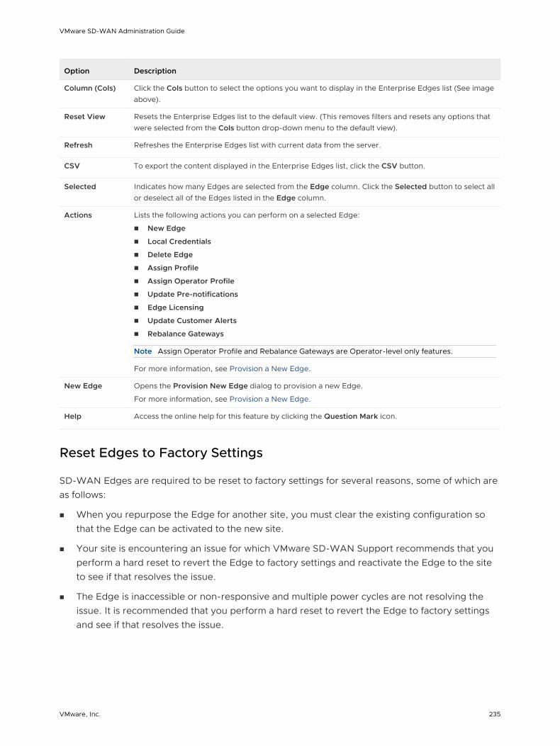
Option Description
Column (Cols) Click the Cols button to select the options you want to display in the Enterprise Edges list (See image above).
Reset View Resets the Enterprise Edges list to the default view. (This removes filters and resets any options that were selected from the Cols button drop-down menu to the default view).
Refresh Refreshes the Enterprise Edges list with current data from the server.
CSV To export the content displayed in the Enterprise Edges list, click the CSV button.
Selected Indicates how many Edges are selected from the Edge column. Click the Selected button to select all or deselect all of the Edges listed in the Edge column.
Actions Lists the following actions you can perform on a selected Edge:
n New Edge
n Local Credentials
n Delete Edge
n Assign Profile
n Assign Operator Profile
n Update Pre-notifications
n Edge Licensing
n Update Customer Alerts
n Rebalance Gateways
Note Assign Operator Profile and Rebalance Gateways are Operator-level only features.
For more information, see Provision a New Edge.
New Edge Opens the Provision New Edge dialog to provision a new Edge.
For more information, see Provision a New Edge.
Help Access the online help for this feature by clicking the Question Mark icon.
Reset Edges to Factory Settings
SD-WAN Edges are required to be reset to factory settings for several reasons, some of which are as follows:
n When you repurpose the Edge for another site, you must clear the existing configuration so that the Edge can be activated to the new site.
n Your site is encountering an issue for which VMware SD-WAN Support recommends that you perform a hard reset to revert the Edge to factory settings and reactivate the Edge to the site to see if that resolves the issue.
n The Edge is inaccessible or non-responsive and multiple power cycles are not resolving the issue. It is recommended that you perform a hard reset to revert the Edge to factory settings and see if that resolves the issue.
VMware SD-WAN Administration Guide
VMware, Inc. 235
You can reset an Edge to factory settings using one of the following methods:
n Soft Reset or Deactivation—The Edge is deactivated and all the existing configuration that the Edge is using is completely removed. The Edge now uses the original factory configuration. However, the Edge software is not affected and it retains the software version it had prior to the soft reset. A soft reset Edge can be reactivated to another site or to the same site.
n Hard Reset—The Edge is fully reset to factory settings, that is the Edge is not only deactivated and uses the factory configuration, but the Edge software is also changed to the factory software version. The Edge is effectively as it was when it was shipped from the factory.
If you reset an Edge that is actively used at a site, you will completely lose the client device connectivity at the site until you either reactivate the same Edge at the site or activate another Edge at the site.
For instructions on how to reset an Edge to factory settings, see How to Factory Reset a VMware SD-WAN Edge.
VMware SD-WAN Administration Guide
VMware, Inc. 236
Edge Overview Tab 14The Edge Overview tab provides Edge-specific property information such as name, description, custom information, profile associated with the edge, name and email address of the site contact for the Edge. From the Edge Overview tab, you can send an edge activation email, enable alerts for a specific Edge, make changes to certain properties, assign a different profile to a selected edge, set edge location, update edge contact and location information, and request RMA Reactivation.
To access the Edge Overview Tab:
1 On the navigation panel of SD-WAN Orchestrator, go to Configure > Edges.
2 In the Enterprise Edge screen, select and click an Edge to open the Edge Overview Tab.
VMware, Inc. 237

On the Edge Overview Tab:
n To enable alerts for a specific Edge, or send an Edge activation email, see the Edge Overview Properties and Initiate Edge Activation sections.
n To see an overview of the Edge overrides from a specific profile, or if you need to change to a different profile, see the Edge Profile section.
n To change the contact, location, or the shipping address of an Edge, see the Edge Contact & Location section.
n To request RMA Reactivation, see the RMA Reactivation section.
The following sections provide detailed descriptions of each area of the Edge Overview Tab.
Edge Overview Properties
In the Properties area, you can initiate the Edge activation process by sending an Edge activation email, and you can also view and change certain properties of a selected Edge. The Edge status, activation date, and software version also display in this area.
The following table describes the Field in the Properties area.
VMware SD-WAN Administration Guide
VMware, Inc. 238

Field/Checkbox Description
Name Displays the unique name of the Edge at the customer level. If you change the name of the Edge, remember to click the Save Changes button.
Description Enables you to provide information about the Edge. If you make updates to the Edge description, remember to click the Save Changes button.
Note This is the only location where a description of the Edge is displayed.
Custom Info Displays the custom information associated with the edge.
Enable Pre-Notifications checkbox
This checkbox is enabled by default after the Edge has been provisioned.
For Operators to receive alerts, the Enable Pre-Notifications checkbox must be checked, and alerts must be selected and enabled via email, SMS, or SNMP Traps at Configure > Alerts & Notifications.
In addition to receiving an email, SMS, or SNMP Trap, Alerts can also be viewed on the Alerts screen at Monitor > Alerts. Uncheck this checkbox to disable alert notifications for Operators for the selected Edge.
Enable Alerts checkbox
This checkbox is enabled by default after the Edge has been provisioned.
For Customers to receive Edge Device alerts, the Enable Alerts checkbox must be checked, and alerts must be selected and enabled via email, SMS, or SNMP Traps at Configure > Alerts & Notifications.
In addition to receiving an email, SMS, or SNMP Trap, Alerts can also be viewed on the Alerts screen at Monitor > Alerts. Uncheck this checkbox to disable alerts for the selected Edge.
Authentication Mode
There are three options for the Authentication Mode (Certificate Disabled, Certificate Optional, and Certificate Required).
n Certificate Disabled (default): If Certificate Disabled is selected as an option, the Edge will use a pre-shared key mode of authentication.
n Certificate Optional: If Certificate Optional is selected as an option, the Edge will use either the PKI certificate or the Pre-shared key (depending upon which certificate the other Edge or Gateway is using).
Note The Operator must enable PKI at Configure > Customer.
n Certificate Required: Once the Edge obtains a valid certificate, Certificate Required becomes available as an option in the drop-down menu. If the Certificate Required option is selected, the Edge will use the PKI certificate as the mode of authentication.
Note The Operator must enable PKI at Configure > Customer.
License The License drop-down menu displays available license types that can be assigned to an Edge.
Note Standard Administrator Superusers and Standard Administrators can assign and monitor Edge license types that have been assigned to them.
View Certificate If the Edge has a valid certificate, the View link displays. Click the View link to view, export, or revoke the certificate.
Status Displays the following status options: Pending, Activated, and Reactivation Pending.
n Pending: The Edge has not been activated.
n Activated: The Edge has been activated.
n Reactivation Pending: If the Request Reactivation button is clicked, the status will change to Reactivation Pending. This status update does not change the Edge’s function, it only indicates that a new or replacement Edge can be activated with the existing configuration.
Activated Displays the date and time the Edge was activated.
VMware SD-WAN Administration Guide
VMware, Inc. 239

Field/Checkbox Description
Software Version Displays the software version and build number of the Edge.
Local Credentials Displays the credentials for the local UI. The default credentials are username: admin password: admin123 (case sensitive). Click the View button to change the credentials.
Serial Number If the Edge is in the Pending state, the Serial Number text field displays. Entering the serial number is optional, but if specified, the serial number must match the serial number of the Edge that will be activated.
Activation Key If the Edge is in the Pending state, the Edge Activation Key displays. The activation key is only valid for one month. After one month, the key will expire, and a warning message will display underneath the activation key. You can generate a new key by clicking the Generate New Activation Key button located below the warning message.
See the Expired RMA Activation Key section for more information.
Send Activation Email
When the Send Activation Email button is clicked, an email with activation instructions is sent to the Site Contact.
Initiate Edge Activation
Once the Edge configuration is saved, an activation key is assigned. In the Properties area, click the Send Activation Email button to initiate the Edge activation process. Clicking the Send Activation Email button does not activate the Edge; it only initiates the activation process by sending an email to the Site Contact with instructions on how to activate the Edge device.
After clicking the Send Activation Email button, a pop-up window displays the email that will be sent to the Site Contact. Instructions are provided in the email for the Site Contact to connect and activate the Edge hardware. For more information on how to activate an Edge, see the Edge Activation Quick Start Guide in the online help. For information about Pull Activation and Push Activation, see Zero Touch Provisioning.
Edge Profile
The Profile drop-down menu displays a list of profiles that can be assigned to a specific Edge. When switching to a different profile on the Edge, all relevant configurations will be changed except for any Edge override configurations. Overwritten configurations are displayed in the Profile area.
Note Edge overwritten configurations will not be changed when switching to a different profile.
Note If an Edge Staging Profile is displayed as an option due to push activation, it is a newly assigned Edge that has not been configured by a production Profile. Enterprise Admins must manually assign a Profile to those Edges by choosing a new profile from the Profile drop-down menu.
VMware SD-WAN Administration Guide
VMware, Inc. 240
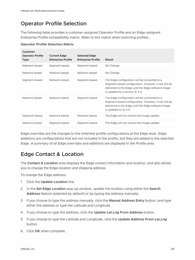
Operator Profile Selection
The following table provides a customer-assigned Operator Profile and an Edge-assigned Enterprise Profile compatibility matrix. Refer to this matrix when switching profiles.
Operator Profile Selection Matrix
Customer Operator Profile Type
Current Edge Enterprise Profile
Selected Edge Enterprise Profile Result
Segment-based Segment-based Segment-based No Change
Network-based Network-based Network-based No Change
Segment-based Network-based Segment-based The Edge configuration will be converted to a Segment-based configuration. However, it will not be delivered to the Edge until the Edge software image is updated to a version ≧ 3.0.
Network-based Network-based Segment-based The Edge configuration will be converted to a Segment-based configuration. However, it will not be delivered to the Edge until the Edge software image is updated to ≧ 3.0.
Segment-based Network-based Network-based The Edge will not receive the image update.
Network-based Segment-based Segment-based The Edge will not receive the image update.
Edge overrides are the changes to the inherited profile configurations at the Edge level. Edge additions are configurations that are not included in the profile, but they are added to the selected Edge. A summary of all Edge overrides and additions are displayed in the Profile area
Edge Contact & Location
The Contact & Location area displays the Edge contact information and location, and also allows you to change the Edge location and shipping address.
To change the Edge address:
1 Click the Update Location link.
2 In the Set Edge Location pop-up window, update the location using either the Search Address feature (selected by default) or by typing the address manually.
3 If you choose to type the address manually, click the Manual Address Entry button, and type either the address or type the Latitude and Longitude.
4 If you choose to type the address, click the Update Lat,Lng From Address button.
5 If you choose to type the Latitude and Longitude, click the Update Address From Lat,Lng button.
6 Click OK when complete.
VMware SD-WAN Administration Guide
VMware, Inc. 241

If the shipping address is different from the Edge location, unselect the Same as above checkbox for the shipping address, then type in the shipping contact in the appropriate text field.
To change the Edge shipping location:
1 Click the Set Location link.
2 In the Edge Shipping Location pop-up window, update the shipping location using either the Search Address feature (selected by default) or by typing the address manually.
3 If you choose to type the address manually, click the Manual Address Entry button, type the address, and then click the Update Location on Map button.
4 Click OK.
RMA Reactivation
You can initiate an Edge RMA reactivation request from the Edge Overview Tab in the following scenarios:
n Replace an edge due to a malfunction
n Upgrade an edge hardware model
To complete the RMA reactivation process:
1 From the Orchestrator, go to Configure > Edges.
2 Select the Edge you want to reactivate.
3 In the Edge Overview Tab, scroll down to the bottom of the screen to the RMA Reactivation area. Expand the area by clicking the gray arrow located on the upper, right side.
4 Click the Request Reactivation button. This step generates a new activation key and places the Edge status in Reactivation Pending mode.
Note The reactivation key is only valid for one month from the time when the reactivation request was made.
5 If you need to cancel the activation request for any reason, click the Cancel Reactivation Request button. The Edge status changes from Reactivation Pending to Activated.
6 If the activation key has expired (the key is valid for one month), you will need to generate a new activation key. For more information, see Expired RMA Activation Key section.
7 As an optional step, you can enter the serial number of the Edge that will be activated in the RMA Serial Number text field.
Note Serial numbers are case sensitive. Activation will fail if the serial number doesn’t match the Edge that will be activated.
VMware SD-WAN Administration Guide
VMware, Inc. 242

8 The RMA Model drop-down menu displays the selected Edge by default. If you are reactivating a different Edge model, select the Edge model that will be activated from the RMA Model drop-down menu.
Note Activation will fail if the selected Edge model doesn’t match the Edge that will be activated.
9 If you entered a serial number or chose a model from the RMA Model drop-down menu, click the Update button.
10 Click the Send Activation Email button. The Send Activation Email pop-up window appears.
11 Click the Send button to send the activation procedure email to the Site Contact. This email will include the same information displayed in the Send Activation Email pop-up window.
The remaining instructions provide steps for activating the replacement Edge device.
VMware SD-WAN Administration Guide
VMware, Inc. 243

12 Disconnect the old Edge from the power and network.
13 Connect the new Edge to the power and network. Make sure the Edge is connected to the Internet.
14 Follow the activation procedures you received via email.
Note Be sure to click the activation link in the email to activate the Edge.
The Edge will download the configuration and software from the SD-WAN Orchestrator. The new Edge will be activated successfully and will be ready for service.
Expired RMA Activation Key
The RMA Activation Key is valid for one month from the time the reactivation request was made. If the RMA Activation Key has expired, a warning message displays in the RMA Reactivation area of the SD-WAN Orchestrator. You can either cancel the reactivation request (by clicking the Cancel Reactivation Request button) or generate a new key. Follow the instructions below to generate a new key after the one-month expiration date.
To generate a new RMA Activation Key:
1 Click the Generate New Activation Key button.
2 In the Generate New Activation Key dialog box, specify the number of days you would like the key to be active.
3 Click Submit.
4 Follow the RMA Reactivation Steps to complete the RMA reactivation process.
VMware SD-WAN Administration Guide
VMware, Inc. 244

Configure an Edge Device 15Configuration overrides can be made to some settings that were assigned to an Edge. In most cases, an override must first be enabled then changes can be made.
Overrides can be made to Interfaces, DNS, and Authentication. In addition override rules can be added to existing Business Policy and Firewall rules. Override rules have precedence over all other rules defined for Business Policy or Firewall.
Note Edge overrides enable Edge specific edits to the displayed settings, and discontinue further automatic updates from the configuration Profile. You can simply disable the override and go back to automatic updates any time.
The sections below describe the areas in the Configure > Edges > Device tab screen.
Some areas are Segment-aware.
VMware, Inc. 245
Segment-aware Configurations:
n Authentication Settings
n DNS Settings
n Netflow Settings
n Syslog Settings
n Static Route Settings
n ICMP Probes
n ICMP Responders
n VRRP Settings
n Cloud VPN
n OSPF Areas
n BGP Settings
n Multicast Settings
n Cloud Security Service
Common Configurations:
n High Availability
n VLAN
n Device Settings
n WAN Settings
n Multi-Source QoS
n SNMP Settings
n NTP Servers
n Visibility Mode
Note For information about OSPF and BGP, see the Chapter 18 Configure Dynamic Routing with OSPF or BGP section.
This chapter includes the following topics:
n Configure DSL Settings
n Configure Netflow Settings at the Edge Level
n Configure Syslog Settings at Edge Level
n Configure Static Route Settings
VMware SD-WAN Administration Guide
VMware, Inc. 246

n Configure ICMP Probes/Responders
n Configure VRRP Settings
n Edge Cloud VPN
n Configure VLAN for Edges
n Configure Device Settings
n Configure SNMP Settings for Edges
n Configure Wi-Fi Radio Overrides
n Security VNFs
n Configure Edge Business Policy
n Configure Edge Activation
n LAN-side NAT Rules at Edge Level
Configure DSL Settings
Support is available for Metanoia xDSL SFP module (MT 5311). It is a highly integrated SFP bridged modem, which provides a pluggable SFP compliant interface to upgrade existing DSL IAD or home Gateway devices to higher bandwidth services.
The Metanoia xDSL SFP module (MT 5311) can be plugged into Edge 610 device SFP slot and used in ADSL2+/VDSL2 mode. This module must be procured by the user. Configuring DSL is only available for the 610 Edge device.
Configuring SFP
Click the SFP interface that the specific DSL module is plugged into. When the SFP is plugged in, the slot name will display as SFP1 and SFP2.
VMware SD-WAN Administration Guide
VMware, Inc. 247

To Configure SFP:
1 Click the Edit link in the Actions column, as shown in the image above.
The Interface SFP1 dialog for the Edge device (Edge 610 in this example) appears as shown in the image below.
2 The Override Interface checkbox must be checked to configure DSL Settings.
3 Check the Interface Enabled checkbox.
4 In the SFP Settings area, there are two options available from the drop-down menu, Standard and DSL. Choose DSL as the SFP Module as shown in the image below.
VMware SD-WAN Administration Guide
VMware, Inc. 248
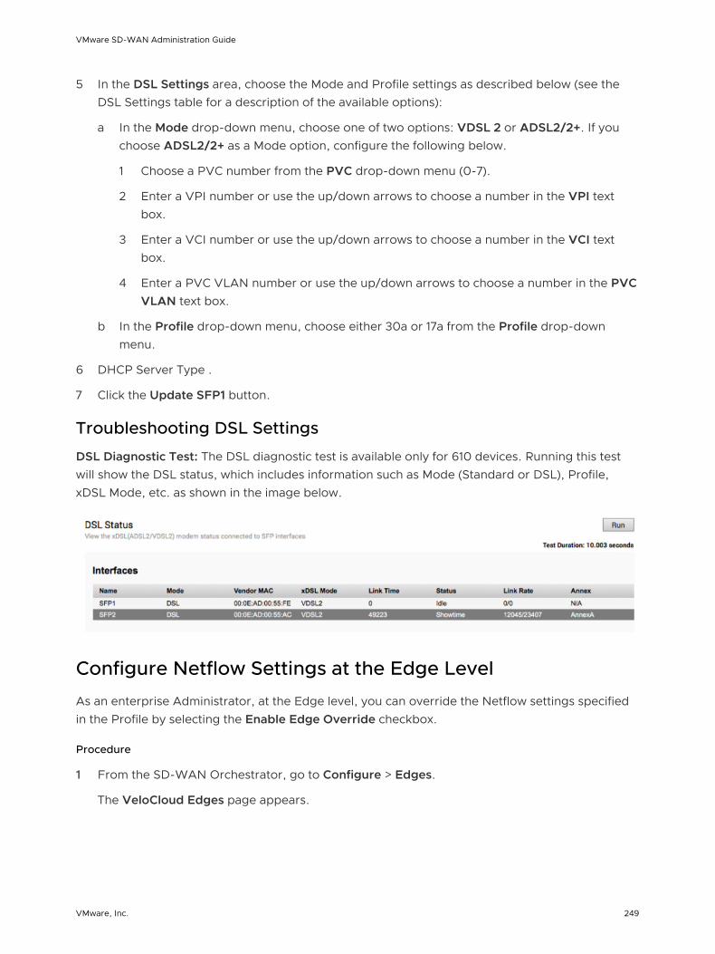
5 In the DSL Settings area, choose the Mode and Profile settings as described below (see the DSL Settings table for a description of the available options):
a In the Mode drop-down menu, choose one of two options: VDSL 2 or ADSL2/2+. If you choose ADSL2/2+ as a Mode option, configure the following below.
1 Choose a PVC number from the PVC drop-down menu (0-7).
2 Enter a VPI number or use the up/down arrows to choose a number in the VPI text box.
3 Enter a VCI number or use the up/down arrows to choose a number in the VCI text box.
4 Enter a PVC VLAN number or use the up/down arrows to choose a number in the PVC VLAN text box.
b In the Profile drop-down menu, choose either 30a or 17a from the Profile drop-down menu.
6 DHCP Server Type .
7 Click the Update SFP1 button.
Troubleshooting DSL Settings
DSL Diagnostic Test: The DSL diagnostic test is available only for 610 devices. Running this test will show the DSL status, which includes information such as Mode (Standard or DSL), Profile, xDSL Mode, etc. as shown in the image below.
Configure Netflow Settings at the Edge Level
As an enterprise Administrator, at the Edge level, you can override the Netflow settings specified in the Profile by selecting the Enable Edge Override checkbox.
Procedure
1 From the SD-WAN Orchestrator, go to Configure > Edges.
The VeloCloud Edges page appears.
VMware SD-WAN Administration Guide
VMware, Inc. 249

2 Select an Edge you want to override Netflow settings and click the icon under the Device column.
The Device Setting page for the selected Edge appears.
3 From the Configure Segment drop-down menu, select a profile segment to configure Netflow settings.
4 Go to the Netflow Settings area and select the Enable Edge Override checkbox.
At the edge level, the Observation ID field is auto-populated with 8 bits segment ID and 24 bits edge ID and it cannot be edited. The Observation ID is unique to an Exporting Process per segment per enterprise.
5 Override the collector, filter, and Netflow export interval information specified in the Profile by referring to the Step 4 in Configure Netflow Settings at the Profile Level.
6 From the Source Interface drop-down menu, select an Edge interface configured in the segment as the source interface, to choose the source IP for the NetFlow packets.
Note Make sure you manually select the Edge’s LAN interface (VLAN/Routed/Sub-Interface) with 'Advertise' flag enabled as the source interface. If none is selected, the Edge automatically selects a LAN interface (VLAN/Routed/Sub-Interface) which is ‘UP’ and 'Advertise' enabled from the corresponding segment as the source interface for that collector. If the Edge doesn’t have interfaces which is ‘UP’ and 'Advertise' enabled, then the source interface will not be chosen and the Netflow packets will not be generated.
7 Click Save Changes.
Configure Syslog Settings at Edge Level
In an Enterprise network, SD-WAN Orchestrator supports collection of SD-WAN Orchestrator bound events and firewall logs originating from enterprise SD-WAN Edges to one or more centralized remote syslog collectors (Servers), in native syslog format. At the Edge level, you can override the syslog settings specified in the Profile by selecting the Enable Edge Override checkbox.
VMware SD-WAN Administration Guide
VMware, Inc. 250

To override the Syslog settings at the Edge level, perform the following steps.
Prerequisites
n Ensure that Cloud VPN (branch-to-branch VPN settings) is configured for the SD-WAN Edge (from where the SD-WAN Orchestrator bound events are originating) to establish a path between the SD-WAN Edge and the Syslog collectors. For more information, see Configure Cloud VPN.
Procedure
1 From the SD-WAN Orchestrator, go to Configure > Edges.
The SD-WAN Edges page appears.
2 Select an Edge you want to override Syslog settings and click the icon under the Device column.
The Device Settings page for the selected Edge appears.
3 From the Configure Segment drop-down menu, select a profile segment to configure syslog settings. By default, Global Segment [Regular] is selected.
4 Go to the Syslog Settings area and select the Enable Edge Override checkbox.
5 From the Source Interface drop-down menu, select one of the Edge interface configured in the segment as the source interface.
6 Override the other syslog settings specified in the Profile associated with the Edge by following the Step 4 in Configure Syslog Settings at Profile Level.
7 Click the + button to add another Syslog collector or else click Save Changes. The syslog settings for the edge will be overridden.
Note You can configure a maximum of two Syslog collectors per segment and 10 Syslog collectors per Edge. When the number of configured collectors reaches the maximum allowable limit, the + button will be disabled.
Note Based on the selected role, the edge exports the corresponding logs in the specified severity level to the remote syslog collector. If you want the SD-WAN Orchestrator auto-generated local events to be received at the Syslog collector, you must configure Syslog at the SD-WAN Orchestrator level by using the log.syslog.backend and log.syslog.upload system
properties.
VMware SD-WAN Administration Guide
VMware, Inc. 251

To understand the format of a Syslog message for Firewall logs, see Syslog Message Format for Firewall Logs.
What to do next
On the Firewall page of the Edge configuration, enable the Syslog Forwarding button if you want to forward firewall logs originating from enterprise SD-WAN Edges to configured Syslog collectors.
Note By default, the Syslog Forwarding button is available on the Firewall page of the Profile or Edge configuration, and is disabled.
For more information about Firewall settings at the Edge level, see Configure Firewall for Edges.
Configure Static Route Settings
Static Route Settings are useful for special cases in which static routes are needed for existing network attached devices (such as printers). You can add additional Static Route Settings (plus '+' icon) or delete Static Route Settings (minus -icon) located to the right of the dialog box.
For details about the settings in the dialog box, refer to the table that follows.
To specify the Static Route Settings:
1 Enter the subnet for the route.
2 Enter the IP address for the route.
3 Select the WAN interface where the Static Route will be bound.
4 Select the Broadcast checkbox to advertise this route over VPN and allow other Edges in the network to have access to this resource.
5 Optionally, add a description for the route.
Configure ICMP Probes/Responders
ICMP handlers may be needed to enable integration with an external router that is performing dynamic routing functionality and needs stateful information about route reachability through VMware. The Device Settings area provides sections for specifying ICMP Probes and Responders.
ICMP Probes can be specified settings for Name, VLAN Tagging (none, 802.1q, 802.1ad, QinQ (0x8100), or QinQ (0x9100)), C-Tags, S-Tags, Source/Destination/Next Hop IPs, Frequency to send ping requests, and Threshold the value for number of missed pings that will cause route to be marked unreachable.
VMware SD-WAN Administration Guide
VMware, Inc. 252

ICMP Responders can be specified settings for Name, IP Address, and Mode ( Conditional or Always).
n Always: Edge always responds to ICMP Probes.
n Conditional: Edge only responds to ICMP Probes when the SD-WAN Overlay is up.
Configure VRRP Settings
You can configure Virtual Router Redundancy Protocol (VRRP) on an Edge to enable next-hop redundancy in the SD-WAN Orchestrator network by peering with third-party CE router. You can configure an Edge to be a primary VRRP device and pair the device with a third-party router.
The following illustration shows a network configured with VRRP:
LAN
MPLS MPLS Internet
OR
L2
MPLS Internet
L2VRRP
VCMP TunnelLAN
Prerequisites
Consider the following guidelines before configuring VRRP:
n You can enable VRRP only between the SD-WAN Edge and third party router connected to the same subnet through an L2 switch.
n You can add only one SD-WAN Edge to the VRRP HA group in a branch.
n You cannot enable both Active-Standby HA and VRRP HA at the same time.
n VRRP is supported on primary routed port, sub-interface, and VLAN interfaces.
n SD-WAN Edge must be configured as the primary VRRP device, by setting higher priority, in order to steer the traffic through SD-WAN.
VMware SD-WAN Administration Guide
VMware, Inc. 253
n If the SD-WAN Edge is configured as the DHCP server, then virtual IP addresses are set as the default Gateway address for the clients. When you use a separate DHCP server relay for the LAN, then the admin must configure the VRRP virtual IP address as the default Gateway address.
n When DHCP server is enabled in both the SD-WAN Edge and third-party router, then split the DHCP pool between the Edge and third party router, to avoid the overlapping of IP addresses.
n VRRP is not supported on an interface enabled with WAN Overlay, that is on the WAN link. If you want to use the same link for LAN, then create a sub-interface and configure VRRP on the sub-interface.
n You can configure only one VRRP group in a broadcast domain in a VLAN. You cannot add additional VRRP group for the secondary IP addresses.
n Do not add WI-FI link to the VRRP enabled VLAN. As the link failure would never happen, the SD-WAN Edge always remains as the primary device.
Procedure
1 In the Enterprise portal, click Configure > Edges.
2 Either click the Device Icon corresponding to the Edge, or click the Edge and then click the Device tab.
3 In the Device tab, select the VRRP with Third-Party Router checkbox under High Availability.
VMware SD-WAN Administration Guide
VMware, Inc. 254

4 In the VRRP Settings, configure the following:
a VRID – Enter the VRRP group ID. The range is from 1 to 255.
b Interface – Select a physical or VLAN Interface from the list. The VRRP is configured on the selected Interface.
c Virtual IP – Enter a virtual IP address to identify the VRRP pair. Ensure that the virtual IP address is not the same as the IP address of the Edge Interface or the third-party router.
d Advertise Interval – Enter the time interval with which the primary VRRP device sends VRRP advertisement packets to other members in the VRRP group.
e Priority – To configure the Edge as primary VRRP device, enter a value that exceeds the priority value of the third party router. The default is 100.
f Preempt Delay – Select the checkbox so that SD-WAN Edge can preempt the third-party router which is currently the primary device, after the specified preempt delay.
5 Click Save Changes.
Results
In a branch network VLAN, if the Edge goes down, then the clients behind the VLAN are redirected through the backup router.
VMware SD-WAN Administration Guide
VMware, Inc. 255

The SD-WAN Edge that acts as a primary VRRP device becomes the default Gateway for the subnet.
If the SD-WAN Edge loses connectivity with all the SD-WAN Edge/Controllers, then the VRRP priority gets reduced to 10 and the SD-WAN Edge withdraws the routes learned from the SD-WAN Edge and routes in the remote Edges as well. This results in the third-party router to become the primary device and take over the traffic.
SD-WAN Edge automatically tracks overlay failure to the SD-WAN Edge. When all the overlay paths to the SD-WAN Edge are lost, the VRRP priority of the SD-WAN Edge is reduced to 10.
When the Edge gets into the VRRP backup mode, the Edge drops any packets that go through the virtual MAC. When the path is UP, the Edge becomes the primary VRRP device again, provided the preemption mode is enabled.
When VRRP is configured on a routed interface, the interface is used for local LAN access and can failover to the backup router.
VRRP is not supported on a routed interface enabled with WAN Overlay. In such cases, a subinterface, sharing the same physical interface, must be configured for local LAN access to support VRRP.
When LAN interface is down, VRRP instance would go to INIT state, and then the SD-WAN Edge sends the route withdrawal request to the SD-WAN Edge/Controller and all the remote SD-WAN Edge remove those routes. This behavior is applicable for the static routes added to the VRRP enabled interface as well.
If the private overlay is present with the SD-WAN Edge peer Hub, then the route is not removed from the Hub, and can cause asymmetric routing. For example, when SD-WAN spoke Edge loses connectivity with public gateway, the third-party router forwards the packets from the LAN to the SD-WAN Hub Edge. The Hub sends the return packets to the SD-WAN spoke Edge instead of the third-party router. As a workaround, enable the SD-WAN Reachable functionality, so that the SD-WAN Edge is reachable on private overlay and remains as the primary VRRP device. As the Internet traffic is also steered through the private link over the overlay through the SD-WAN Edge, there might be some limitation on the performance or throughput.
The conditional backhaul option is used to steer the Internet traffic through the Hub. However, in VRRP-enabled SD-WAN Edge, when public overlay goes down the Edge becomes Backup. So the conditional backhaul feature cannot be utilized on a VRRP-enabled Edge.
Monitor VRRP Events
You can monitor the events related to changes in VRRP configuration.
In the enterprise portal, click Monitor > Events.
To view the events related to VRRP, you can use the filter option. Click the drop-down arrow next to the Search option and choose to filter by the Event column. The following events are available for VRRP:
n VRRP HA updated to master
VMware SD-WAN Administration Guide
VMware, Inc. 256

n VRRP HA updated out of master
n VRRP Failed
The following image shows some of the VRRP events.
You can also view the events in the new Orchestrator UI.
Click Open New Orchestrator UI and then click Launch New Orchestrator UI in the pop-up window. The UI opens in a new tab displaying the monitoring options. Click Events. Click the Filter Icon in the Search option to filter the VRRP events.
Edge Cloud VPN
The Edge Cloud VPN settings are inherited from the Profile selected for the Edge and can be reviewed in the Edge Device tab. Changes to Cloud VPN settings can be made only in the associated Profile.
Configure VLAN for Edges
At an Edge level, you can add a new VLAN or update the existing VLAN settings inherited from the associated Profile. While configuring a new VLAN at the Edge level, SD-WAN Orchestrator allows you to configure additional Edge-specific VLAN settings such as Fixed IP addresses, LAN interfaces, and Service Set Identifier (SSID) of Wi-Fi interfaces.
VMware SD-WAN Administration Guide
VMware, Inc. 257

To configure VLAN settings at the Edge level, perform the following steps:
1 From the SD-WAN Orchestrator, go to Configure > Edges. The SD-WAN Edges page appears.
2 Select an Edge to configure a VLAN and click the icon under the Device column. The Device Setting page for the selected Profile appears.
3 To add a new VLAN, go to the Configure VLAN area and click Add VLAN.
4 In the VLAN dialog box, configure the following details:
a From the Segment drop-down menu, select a Profile segment to configure VLAN.
b In the VLAN Name text box, enter a unique name for the VLAN.
c In the VLAN Id text box, enter a unique identifier for the VLAN.
d The Assign Overlapping Subnets field that allows LAN IP Addressing is managed from the assigned Profile of this Edge. When Assign Overlapping Subnets is checked, the values for Edge LAN IP Address, Cidr Prefix, and DHCP are inherited from the associated Profile and become read-only. The Network address will be automatically set based on the subnet mask and CIDR value.
e Select the Advertise checkbox to advertise the VLAN to other branches in the network.
f Select the ICMP Echo Response checkbox to enable the VLAN to respond to ICMP echo messages.
g Select the VNF Insertion checkbox to enable Edge Virtual Network Function (VNF) insertion.
Note VNF insertion requires that the selected segment have a Service VLAN. For more information about VNF, see Security VNFs.
VMware SD-WAN Administration Guide
VMware, Inc. 258

h In Fixed IPs field, enter fixed IP addresses tied to specific MAC Addresses for the VLAN.
i Configure LAN interfaces and Wi-Fi SSIDs for the VLAN.
j If the Multicast feature is enabled for the selected segment then you can configure Multicast settings by enabling IGMP and PIM checkboxes.
k Under the DHCP area, choose one of the following as the DHCP type:
n Enabled - Enables DHCP with the Edge as the DHCP server. When choosing this option, you must provide the following details:
n DHCP Start - Enter a valid IP address available within a subnet as the DHCP start IP.
n Num Addresses - Enter the number of IP addresses available on a subnet in the DHCP Server.
n Lease Time - From the drop-down menu, select the period of time the VLAN is allowed to use an IP address dynamically assigned by the DHCP Server.
Also, you can add one or more DHCP options, where you specify pre-defined options or add custom options.
n Relay - Enables DHCP with the DHCP Relay Agent installed at a remote location. If you choose this option, you can specify the IP address of one or more Relay Agents.
n Disabled - Disables DHCP.
l Configure OSPF settings if the OSPF feature is enabled for the selected segment.
m Click Add VLAN.
5 To update the VLAN settings inherited from the Profile, under the Actions column, click the Edit link corresponding to the VLAN. The VLAN dialog box appears.
VMware SD-WAN Administration Guide
VMware, Inc. 259

6 Click the Enable Edge Override checkboxes to override the VLAN settings inherited from the Profile.
Note You will not be able to override the Profile VLAN name and ID.
For Configuring VLANs at the Profile level, see Configure VLAN for Profiles.
Configure Device Settings
The Edge Device Settings screen provides the ability to do the following tasks:
n Set VLAN Settings
n Override Syslog Settings
n Override Profile Interface Settings
n Add a User Defined WAN Overlay
n Configure NAT for overlapping Network
VMware SD-WAN Administration Guide
VMware, Inc. 260
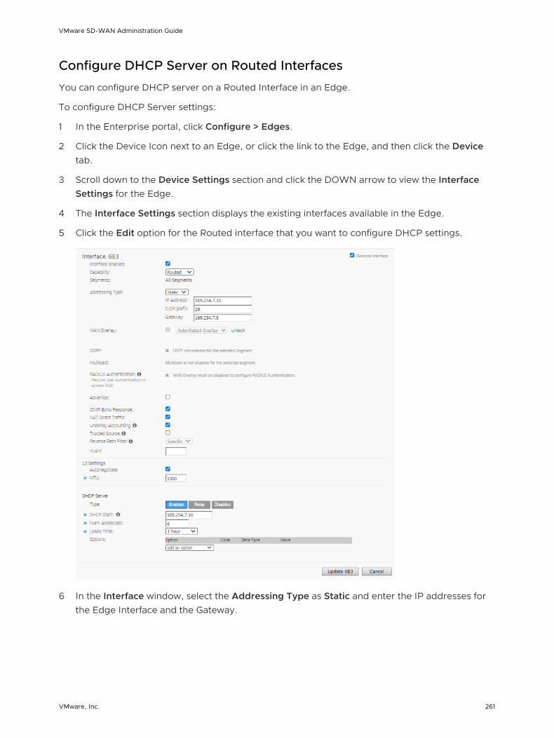
Configure DHCP Server on Routed Interfaces
You can configure DHCP server on a Routed Interface in an Edge.
To configure DHCP Server settings:
1 In the Enterprise portal, click Configure > Edges.
2 Click the Device Icon next to an Edge, or click the link to the Edge, and then click the Device tab.
3 Scroll down to the Device Settings section and click the DOWN arrow to view the Interface Settings for the Edge.
4 The Interface Settings section displays the existing interfaces available in the Edge.
5 Click the Edit option for the Routed interface that you want to configure DHCP settings.
6 In the Interface window, select the Addressing Type as Static and enter the IP addresses for the Edge Interface and the Gateway.
VMware SD-WAN Administration Guide
VMware, Inc. 261

7 In the DHCP Server section, choose one of the following DHCP settings:
n Enabled – Enables DHCP with the Edge as the DHCP server. Configure the following details:
n DHCP Start – Enter a valid IP address available within the subnet.
n Num. Addresses – Enter the number of IP addresses available on a subnet in the DHCP Server.
n Lease Time – Select the period of time from the drop-down list. This is the duration the VLAN is allowed to use an IP address dynamically assigned by the DHCP Server.
n Options – Add pre-defined or custom DHCP options from the drop-down list. The DHCP option is a network service passed to the clients from the DHCP server. For a custom option, enter the code, data type, and value.
n Relay – Enables DHCP with the DHCP Relay Agent installed at a remote location. If you choose this option, configure the following:
n Relay Agent IP(s) – Specify the IP address of Relay Agent. Click the Plus(+) Icon to add more IP addresses.
n Disabled – Disables DHCP.
For more information on other options in the Interface Settings window, see Configure Interface Settings.
Note See Tunnel Overhead and MTU for more information.
High Availability (HA)
Enable High Availability (HA) for the Edge here.
For more information about the setup and configuration of HA, see HA Configuration.
Enabling RADIUS on a Routed Interface
RADIUS can be enabled on any interface that can be configured as a routed interface. See the section below for step-by-step instructions.
Requirements
n A RADIUS server must be configured and added to the Edge. This is perfomed on the Configure -> Network Services screen in the VMware SD-WAN Orchestrator.
VMware SD-WAN Administration Guide
VMware, Inc. 262

n RADIUS may be enabled on any interface that can be configured as a routed interface. This includes the interfaces for any Edge model, except for the LAN 1-8 ports on Edge models 500/520/540.
Note RADIUS enabled interfaces do not use DPDK.
Enabling RADIUS on a Routed Interface
1 Go to Configure->Device on the VMware SD-WAN Orchestrator, click Edit for the interface you want to enable RADIUS authentication.
2 Configure the Capability parameter as Routed.
3 Disable the WAN Overlay by unchecking the box.
4 Enable RADIUS Authentication by checking that box.
5 Configure the allowed list of devices that are pre-authenticated and should not be forwarded to RADIUS for re-authentication. You can add devices by individual MAC addresses (e.g. 8c:ae:4c:fd:67:d5) and by OUI (Organizationally Unique Identifier [e.g. 8c:ae:4c:00:00:00]).
Note The interface will use the server that has already been assigned to the Edge (i.e. two interfaces cannot use two different RADIUS servers).
Configure Edge LAN Overrides
The LAN settings specified in the Profile can be overridden by selecting the Override Interface check box.
See Chapter 10 Configure a Profile Device for LAN interface configuration parameters.
VMware SD-WAN Administration Guide
VMware, Inc. 263

Configure Edge WAN Overrides
The WAN settings specified in the Profile can be overridden by selecting the Override Interface checkbox.
See Chapter 10 Configure a Profile Device for LAN interface configuration parameters.
Configure Edge WAN Overlay Settings
The WAN settings enables you to add or modify a User-Defined WAN Overlay.
A user-defined overlay needs to be attached to an interface that has been configured ahead of time for WAN overlay. You can configure any one of the following Overlays:
n Private Overlay: This is required on a private network where you want to have the Edge build overlay VCMP tunnels directly between private IP addresses assigned to each Edge on the private network
n Public Overlay: This is useful when you want to set a custom VLAN or source IP address and Gateway address for the VCMP tunnels, to reach VMware SD-WAN Gateways over the Internet, as determined by the SD-WAN Orchestrator.
VMware SD-WAN Administration Guide
VMware, Inc. 264

You can also modify or delete an existing auto-detected WAN Overlay that has been detected on a routed interface. An auto-detected overlay is available only when the Edge has successfully made a VCMP tunnel over a routed interface configured with WAN Overlay to Gateways designated by the SD-WAN Orchestrator.
Note The WAN overlays listed under WAN Settings will persist even after an interface is down or not in use and can be deleted when they are no longer required.
Procedure
1 In the SD-WAN Orchestrator portal, click Configure > Edges.
2 In the Edges page, either click the device Icon next to an Edge or click the link to the Edge and click the Device tab.
3 Scroll down to WAN Settings.
4 For an existing auto-detected or user-defined WAN Overlay, click Edit to modify the settings.
5 To create a new Public or Private overlay, click Add User Defined WAN Overlay.
6 In the User Defined WAN Overlay window, choose the Link Type from the following available options:
n Public overlay is used over the Internet where SD-WAN cloud Gateways, that are on the Internet, are reachable. The user-defined overlay must be attached to an Interface. The public overlay instructs the Edge to assign primary and secondary gateways over the interface it is attached, to help determine the outside global NAT address. This outside global address is reported to the Orchestrator so that all the other Edges use this outside global address, if configured to build VCMP tunnels to the currently selected Edge.
Note By default, all routed interfaces will attempt to Auto Detect, that is build VCMP tunnels to, pre-assigned cloud Gateways over the Internet. If the attempt is successful, an Auto Detect Public overlay is created. A User Defined Public overlay is only needed if your Internet service requires a VLAN tag or you want to use a different public IP address from the one that the Edge has learned through DHCP on the public facing interface.
n Private overlay is used on private networks such as an MPLS network or point-to-point link. A private overlay is attached to an interface like any user defined overlay and assumes that the IP address on the interface it is attached is routable for all other Edges on the same private network. This means that there is no NAT on the WAN side of the interface. When you attach a private overlay to an interface, the Edge advises the Orchestrator that the IP address on the interface should be used for any remote Edges configured to build tunnels to it.
VMware SD-WAN Administration Guide
VMware, Inc. 265

The following tables describe the Overlay settings:
Table 15-1. Settings common for Public and Private Overlay
Option Description
Name Enter a descriptive name for the public or private link. You can reference this name while choosing a WAN link in a Business Policy. See Configure Link Steering Modes.
Pre-Notification Alerts Sends alerts related to the Overlay network to the Operator. Ensure that you have enabled the Link alerts in the Configure > Alerts & Notifications page to receive the alerts.
Alerts Sends alerts related to the Overlay network to the Customer. Ensure that you have enabled the Link alerts in the Configure > Alerts & Notifications page to receive the alerts.
Interfaces Select one or more routed interfaces from the update selection drop-down list, and the current user-defined overlay is attached to the selected interface. The list consists of Routed Interfaces with the WAN Overlay enabled and set to User Defined Overlay.
Table 15-2. Public Overlay Settings
Option Description
Public IP Address Displays the discovered public IP address for a public Overlay. This field is populated once the outside global NAT address is discovered using the Gateway method.
The following image shows an example of Settings for Public Overlay:
VMware SD-WAN Administration Guide
VMware, Inc. 266

Table 15-3. Private Overlay Settings
Option Description
SD-WAN Service Reachable When creating a private overlay and attaching it to a private WAN like MPLS network, you may also be able to reach the internet over the same WAN, usually through a firewall in the data center. In this case, it is recommended to enable SD-WAN Service Reachable as it provides the following:
n A secondary path to the internet for access to internet hosted SD-WAN Gateways. This is used if all the direct links to the internet from this Edge fail.
n A secondary path to the Orchestrator, when all the direct links to the internet from this Edge fail. The management IP address the Edge uses to communicate must be routable within MPLS, otherwise NAT Direct would need to be checked on the private interface for the Orchestrator traffic to come back properly.
Note The SD-WAN Edge always prefers the VCMP tunnel created over a local internet link (short path), compared to the VCMP tunnel created over the private network using a remote firewall to the internet (long path).
Note Per-packet or round-robin load balancing will not be performed between the short and long paths.
In a site with no direct public internet access, the SD-WAN Service Reachable option allows the private WAN to be used for private site-to-site VCMP tunnels and as a path to communicate with an internet hosted VMware service.
Public SD-WAN Addresses When you select the SD-WAN Service Reachable checkbox, a list of public IP addresses of SD-WAN Gateways and SD-WAN Orchestrator is displayed, which may need to be advertised across the private network, if a default route has not been already advertised across the same private network from the firewall.
Some IP addresses in the list, such as Gateways, may change over time.
The following image shows an example of Settings for Private Overlay:
VMware SD-WAN Administration Guide
VMware, Inc. 267

Table 15-4. Optional Configuration
Option Description
Source IP Address This is the raw socket source IP address used for VCMP tunnel packets that originate from the interface to which the current overlay is attached.
Source IP address does not have to be pre-configured anywhere but must be routable to and from the selected interface.
Next-Hop IP Address Enter the next hop IP address to which the packets, which come from the raw socket source IP address specified in the Source IP Address field, are to be routed.
Custom VLAN Select the checkbox to enable custom VLAN and enter the VLAN ID. The range is 2 to 4094.
This option applies the VLAN tag to the packets originated from the Source IP Address of a VCMP tunnel from the interface to which the current overlay is attached.
802.1P Setting Sets 802.1p PCP bits on frames leaving the interface to which the current overlay is attached. This setting is only available for a specific VLAN. PCP priority values are a 3-digit binary number. The range is from 000 to 111 and default is 000.
This checkbox is available only when the system property session.options.enable8021PConfiguration must be set to True. By default, this value is False.
If this option is not available for you, contact the VMware support of your operations team to enable the setting.
Click Advanced to configure the following settings:
VMware SD-WAN Administration Guide
VMware, Inc. 268

Table 15-5. Advanced Settings common for Public and Private Overlay
Option Description
Bandwidth Measurement Choose a method to measure the bandwidth from the following options:
n Measure Bandwidth (Slow Start): When measuring the default bandwidth reports incorrect results, it may be due to ISP throttling. To overcome this behavior, choose this option for a sustained slow burst of UDP traffic followed by a larger burst.
n Measure Bandwidth (Burst Mode): Choose this option to perform short bursts of UDP traffic to an SD-WAN Gateway for public links or to the peer for private links, to assess the bandwidth of the link.
n Do Not Measure (define manually): Choose this option to configure the bandwidth manually. This is recommended for the Hub sites because:
a Hub sites can usually only measure against remote branches which have slower links than the hub.
b If a hub Edge fails and is using a dynamic bandwidth measurement mode, it may add delay in the hub Edge coming back online while it re-measures the available bandwidth.
Upstream Bandwidth Enter the upstream bandwidth in Mbps. This option is available only when you choose Do Not Measure (define manually).
Downstream Bandwidth Enter the downstream bandwidth in Mbps. This option is available only when you choose Do Not Measure (define manually).
Dynamic Bandwidth Adjustment Dynamic Bandwidth Adjustment attempts to dynamically adjust the available link bandwidth based on packet loss and intended for use with Wireless broadband services where bandwidth can suddenly decrease.
Note This option works only for WAN links with no latent loss, so it is possible to misinterpret routine packet loss as congestion and in some cases lead to WAN links with unrelated packet loss having their available bandwidth dropped to 2 Mbps.
Note This configuration is not recommended for Edges with software release 3.3.x or earlier. You can configure this option for Edges with release 3.4 or later.
VMware SD-WAN Administration Guide
VMware, Inc. 269

Table 15-5. Advanced Settings common for Public and Private Overlay (continued)
Option Description
Use as Backup Only This option puts the interface that this WAN Overlay is attached to into backup mode. This means that the VCMP tunnels are torn down and the interface is only to be used when tunnels are re-established and when all other paths from this Edge are down.
Only one interface on an Edge can be put into backup mode. When enabled, the interface will be displayed in Monitor > Edges page as Cloud Status: standby.
Note Use this option to reduce user data and SD-WAN performance measurement bandwidth consumption on a 4G or LTE service. Failover times will be slower however, compared to a link that is not in backup mode and where business policy is used to reduce bandwidth consumption. Do not use this feature if the Edge is used as a hub or is part of a cluster.
MTU The SD-WAN Edge performs path MTU discovery and the discovered MTU value is updated in this field. Most wired networks support 1500 Bytes while 4G networks supporting VoLTE typically only allow up to 1358 Bytes.
It is not recommended to set the MTU below 1300 Bytes as it may introduce framing overhead. There is no need to set MTU unless path MTU discovery has failed.
You can find if the MTU is large from the Remote Diagnostics > List Paths page, as the VCMP tunnels (paths) for the interface never become stable and repeatedly reach an UNUSABLE state with greater than 25% packet loss.
As the MTU slowly increases during bandwidth testing on each path, if the configured MTU is greater than the network MTU, all packets greater than the network MTU are dropped, causing severe packet loss on the path.
For more information, see Tunnel Overhead and MTU.
Overhead Bytes Enter a value for the Overhead bandwidth in bytes. This is an option to indicate the additional L2 framing overhead that exists in the WAN path.
When you configure the Overhead Bytes, the bytes are additionally accounted for by the QoS schedular for each packet, in addition to the actual packet length. This ensures that the link bandwidth is not oversubscribed due to any upstream L2-framing overhead.
VMware SD-WAN Administration Guide
VMware, Inc. 270

Table 15-6. Advanced Settings for Public Overlay
Option Description
UDP Hole Punching If a Branch to Branch SD-WAN overlay is required and branch Edges are deployed behind NAT devices, that is NAT device is WAN side of the Edge, the direct VCMP tunnel on UDP/2426 will not likely come up if the NAT devices have not been configured to allow incoming VCMP tunnels on UDP port 2426 from other Edges.
Use Branch to Branch VPN to enable branch to branch tunnels. See Configure Branch to Branch VPN and Edge Cloud VPN.
Use Remote Diagnostics > List Paths to check that one Edge has built a tunnel to another Edge.
UDP hole punching attempts to work around NAT devices blocking incoming connections. However, this technique is not applicable in all scenarios or with all types of NATs, as NAT operating characteristics are not standardized.
Enabling UDP hole punching on an Edge overlay interface, instructs all remote Edges to use the discovered NAT public IP and NAT dynamic source port discovered through SD-WAN Gateway as destination IP and destination port for creating a VCMP tunnel to this Edge overlay interface.
Note Before enabling UDP hole punching, configure the branch NAT device to allow UDP/2426 inbound with port forwarding to the Edge private IP address or put the NAT device, which is usually a router or modem, into bridge mode. Use UDP hole punching only as a last resort as it will not work with firewalls, symmetric NAT devices, 4G/LTE networks due to CGNAT, and most modern NAT devices.
UDP hole punching may introduce additional connectivity issues as remote sites try to use the new UDP dynamic port for VCMP tunnels.
Type When configuring a business policy for an Edge, you can choose the Link Steering to prefer a Transport Group as: Public Wired, Public Wireless or Private Wired. See Configure Link Steering Modes.
Choose Wired or Wireless, to put the overlay into a public wired or wireless transport group.
The following image shows Advanced settings for a Public Overlay:
VMware SD-WAN Administration Guide
VMware, Inc. 271

Table 15-7. Advanced Settings for Private Overlay
Option Description
Private Network Name If you have more than one private network and want to differentiate between them to ensure that the Edges try to tunnel only to Edges on the same private network then define a Private Network Name and attach the Overlay to it. This prevents tunneling to Edges on a different private network they cannot reach. In addition, configure the Edges in other locations on this private network to use the same private network name.
For example:
Edge1 GE1 is attached to private network A. Use private network A for the private overlay attached to GE1.
Edge1 GE2 is attached to private network B. Use private network B for the private overlay attached to GE2.
Repeat the same attachment and naming for Edge2.
When you enable branch to branch or when Edge2 is a hub site:
n Edge1 GE1 attempts to connect to Edge2 GE1 and not GE2.
n Edge1 GE2 attempts to connect to Edge2 GE2 and not GE1.
Configure Static SLA Forces the overlay to assume that the SLA parameters being set are the actual SLA values for the path. No dynamic measurement of packet loss, latency or jitter will be done on this overlay. The QoE report use these values for its Green/Yellow/Red coloring against thresholds.
Note Static SLA configuration is not supported from release 3.4. It is recommended not to use this option, as dynamic measurement of packet loss, latency and jitter will provide a better outcome.
VMware SD-WAN Administration Guide
VMware, Inc. 272

Table 15-7. Advanced Settings for Private Overlay (continued)
Option Description
Configure Class of Service SD-WAN Edges can prioritize traffic and provide a 3x3 QoS class matrix over both Internet and Private networks alike. However, some MPLS networks include their own quality of service (QoS) classes, each with specific characteristics such as rate guarantees, rate limits, packet loss probability etc.
This option allows the Edge to understand the private network QoS bandwidth available and policing for the private Overlay on a specific interface.
Note Outer DSCP tags must be set in business policy per application/rule and in this feature, each Class of Service line is matching on those DSCP tags set in the business policy.
After you select this checkbox, configure the following:
n Class of Service: Enter a descriptive name for the class of service. You can reference this name while choosing a WAN link in a Business Policy. See Configure Link Steering Modes.
n DSCP Tags: Class of service will match on the DSCP tags defined here. DSCP tags are assigned to each application using business policy.
n Bandwidth: Percentage of interface transmit/upload bandwidth available for this class as determined by the private network QoS class bandwidth guaranteed.
n Policing: This option monitors the bandwidth used by the traffic flow in the class of service and when the traffic exceeds the bandwidth, it rate-limits the traffic.
n Default Class: If the traffic does not fall under any of the defined classes, the traffic is associated with the default CoS.
For more information on class of service, see Configure MPLS CoS.
Strict IP precedence This checkbox is available when you select the Configure Class of Service checkbox.
When you enable this option, 8 VCMP sub-paths corresponding to the 8 IP precedence bits are created. Use this option when you want to combine the Classes of Service into less number of classes in the network of your Service Provider.
By default, this option is disabled and the VCMP sub-paths are created for the exact number of classes of service that are configured. The grouping is not applied.
The following image shows Advanced settings for a Private Overlay:
VMware SD-WAN Administration Guide
VMware, Inc. 273

7 Click Update Link to save the settings.
Configure MPLS CoS
You can manage traffic by defining Class of Service (CoS) in a private WAN link. You can group similar types of traffic as a class. The CoS treats each class with its level of service priority.
For each Edge consisting of private WAN links, you can define the CoS.
1 In the Enterprise portal, click Configure > Edges.
2 Either click the Device Icon next to an Edge or click the link to the Edge and click the Device tab.
3 In the WAN Settings section, click Add User Defined WAN Overlay and choose the Link Type as Private.
4 You can also define the CoS for an existing private link by clicking Edit.
5 In the WAN Overlay settings, click Advanced and select the Configure Class of Service checkbox. When you enable this option, the following settings appear and configure them appropriately. You can click the Plus (+) icon to add multiple class of services.
n Strict IP precedence: Select this checkbox to enforce strict IP precedence.
When you enable this option, 8 VCMP sub-paths corresponding to the 8 IP precedence bits are created. Use this option when you want to combine the Classes of Service into less number of classes in the network of your Service Provider.
By default, this option is disabled and the VCMP sub-paths are created for the exact number of classes of service that are configured. The grouping is not applied.
VMware SD-WAN Administration Guide
VMware, Inc. 274

n Class of Service: Enter a descriptive name for the class of service. The name can be a combination of alphanumeric and special characters.
n DSCP Tags: Click Set to assign DSCP tags to the class of service. You can select multiple DSCP tags from the available list.
Note You should map DSCP tags of same IP precedence to the same class of service. A CoS queue can be an aggregate of many classes but DSCP values of same class cannot be part of multiple class queues.
For example, the following set of DSCP tags cannot be spread across multiple queues:
n CS1 and AF11 to AF14
n CS2 and AF21 to AF24
n CS3 and AF31 to AF34
n CS4 and AF41 to AF44
n Bandwidth: Enter a value in percentage for the traffic designated to the CoS. This value allocates a weight to the class. The incoming traffic is processed based on the associated weight. If you have multiple class of services, the total value of the bandwidth should add up to 100.
n Policing: Select the checkbox to enable the class-based policing. This option monitors the bandwidth used by the traffic flow in the class of service and when the traffic exceeds the bandwidth, it polices the traffic.
n Default Class: Click to set the corresponding class of service as default. If the incoming traffic does not fall under any of the defined classes, the traffic is associated with the default CoS.
6 Click Update Link to save the settings.
The following example shows multiple class of services with different set of DSCP tags.
Class of Service Description DSCP Tags Policing
CoS1 Voice CS5, EF Enabled
CoS2 Video AF41, CS4 Disabled
CoS3 File Transfer AF21, CS2 Disabled
VMware SD-WAN Administration Guide
VMware, Inc. 275

For more information on the WAN Overlay Settings, see Configure Edge WAN Overlay Settings.
SD-WAN Service Reachability via MPLS
An Edge with only Private MPLS links can reach the Orchestrator and Gateways located in public cloud, by using the SD-WAN Service Reachable option.
In a site with no direct public internet access, the SD-WAN Service Reachable option allows the private WAN to be used for private site-to-site VCMP tunnels and as a path to communicate with an internet hosted VMware service.
For hybrid environments that have MPLS-only links or require failover to MPLS links, you can enable the SD-WAN Service Reachable option.
MPLS-only Sites
VMware supports private WAN deployments with a hosted VMware service for customers with hybrid environments who deploy in sites with only a private WAN link.
In a site with no public overlays, the private WAN can be used as the primary means of communication with the VMware service, including the following:
n Enabled SD-WAN service reachability through private link
n Enabled NTP override using private NTP servers
The following image shows a Regional Hub with Internet connection and SD-WAN Edge with only MPLS connection.
VMware SD-WAN Administration Guide
VMware, Inc. 276

MPLSBranch
Edge
MPLS-onlySite
LAN
Hub Edge
Regional Hub Site
LAN
SD-WANOrchestrator
Internet
CloudGateway
SD-WAN Edge connects to SD-WAN Orchestrator via a Regional Hub
SD-WAN Edge connects to SD-WAN Gateway via a Regional Hub
SD-WAN Gateway informs the SD-WAN Edge private IP of the Hub, and IPsec is established between the SD-WAN Edge and the Hub
The traffic from the SD-WAN Edge with MPLS-only links is routed to the Orchestrator and Gateway through a Regional Hub, which is able to break out to the public cloud. SD-WAN Service Reachable option allows the Edge to remain online and manageable from the Orchestrator, and allows public internet connectivity through the Gateway irrespective of whether or not there is public link connectivity.
Dynamic Failover via MPLS
If all the public Internet links fail, you can failover critical Internet traffic to a private WAN link. The following image illustrates Resiliency of SD-WAN Orchestrator and Non VMware SD-WAN Site, Zscaler.
VMware SD-WAN Administration Guide
VMware, Inc. 277

MPLS
Branch Edge
LAN
Hub Edge
Regional Hub Site
LAN
Internet
CloudGateway
Example SD-WAN Orchestrator Resiliency
SD-WAN Orchestrator connectivity is via Internet
If Internet fails, SD-WAN Orchestratoris connected via MPLS
Zscaler
VMware SD-WAN
SD-WANOrchestrator
Example Zscaler Resiliency
Zscaler Non VMware SD-WAN Site connectivity is via Internet
If public link fails, Zscaleris connected via MPLS
VMware SD-WAN Administration Guide
VMware, Inc. 278
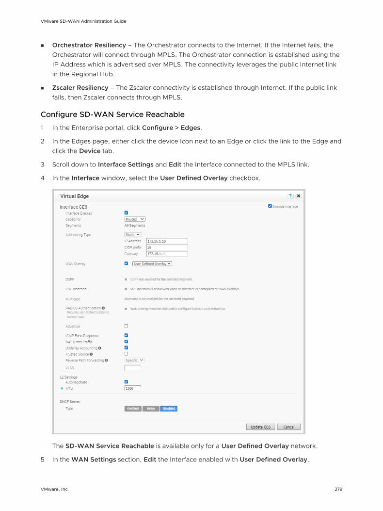
n Orchestrator Resiliency – The Orchestrator connects to the Internet. If the Internet fails, the Orchestrator will connect through MPLS. The Orchestrator connection is established using the IP Address which is advertised over MPLS. The connectivity leverages the public Internet link in the Regional Hub.
n Zscaler Resiliency – The Zscaler connectivity is established through Internet. If the public link fails, then Zscaler connects through MPLS.
Configure SD-WAN Service Reachable
1 In the Enterprise portal, click Configure > Edges.
2 In the Edges page, either click the device Icon next to an Edge or click the link to the Edge and click the Device tab.
3 Scroll down to Interface Settings and Edit the Interface connected to the MPLS link.
4 In the Interface window, select the User Defined Overlay checkbox.
The SD-WAN Service Reachable is available only for a User Defined Overlay network.
5 In the WAN Settings section, Edit the Interface enabled with User Defined Overlay.
VMware SD-WAN Administration Guide
VMware, Inc. 279

6 In the User Defined WAN Overlay window, select the SD-WAN Service Reachable checkbox to deploy sites which only have a private WAN link and/or enable the capability to failover critical Internet traffic to a private WAN link.
When you select the SD-WAN Service Reachable checkbox, a list of public IP addresses of SD-WAN Gateways and SD-WAN Orchestrator is displayed, which may need to be advertised across the private network, if a default route has not been already advertised across the same private network from the firewall.
7 Configure other options as required and click Update Link to save the settings.
For more information on other options in the WAN Overlay window, see Configure Edge WAN Overlay Settings.
Configure SNMP Settings for Edges
SNMP is a commonly used protocol for network monitoring and MIB is a database associated with SNMP to manage entities. SNMP can be enabled by selecting the desired SNMP version as described in the steps below. At the Edge Level, you can override the SNMP settings specified in the Profile by selecting the Enable Edge Override checkbox.
Note SD-WAN Edges do not generate SNMP traps. If there is a failure at the Edge level, the Edge reports the failure in the form of events to SD-WAN Orchestrator, which in turn generates traps based on the alerts configured for the received events.
Before you begin:
n To download the SD-WAN Edge MIB: go to the Remote Diagnostic screen (Test & Troubleshooting > Remote Diagnostics) and run MIB for SD-WAN Edge. Copy and paste results onto your local machine.
n Install all MIBs required by VELOCLOUD-EDGE-MIB on the client host, including SNMPv2-SMI, SNMPv2-CONF, SNMPv2-TC, INET-ADDRESS-MIB, IF-MIB, UUID-TC-MIB, and VELOCLOUD-MIB. All the above-mentioned MIBs are available on the Remote Diagnostics page.
VMware SD-WAN Administration Guide
VMware, Inc. 280

About this task: At the Edge level, you can override the SNMP settings specified in the Profile by selecting the Enable Edge Override checkbox. The Edge Override option enables Edge specific edits to the displayed settings, and discontinues further automatic updates from the configuration profile for this module. For ongoing consistency and ease of updates, it is recommended to set configurations at the Profile rather than Edge exception level.
Supported MIBs
n SNMP MIB-2 System
n SNMP MIB-2 Interfaces
n VELOCLOUD-EDGE-MIB
n HOST-RESOURCES-MIB, from RFC 1514
Procedure to Configure SNMP Settings at Edge Level:
1 Obtain the VELOCLOUD-EDGE-MIB on the Remote Diagnostic screen of the SD-WAN Orchestrator.
2 Install all MIBs required by VELOCLOUD-EDGE-MIB.
3 From the SD-WAN Orchestrator, go to Configure > Edges.
4 Select an Edge you want to configure SNMP settings for, and click the Device icon under the Device column.
The Configuration Edges screen for the selected Edge appears.
5 Scroll down to the SNMP Settings area and check the Enable Edge Override checkbox. You can choose between two versions, v2c or v3.
6 For a SNMP v2c config follow the steps below:
a Check the v2c checkbox.
b Type in a Port in the Port textbox. The default setting is 161.
c In the Community textbox, type in a word or sequence of numbers that will act as a 'password' that will allow you access to the SNMP agent.
d For Allowed IPs:
n Check the Any checkbox to allow any IP to access the SNMP agent.
n To restrict access to the SNMP agent, uncheck the Any checkbox and enter the IP address(es) that will be allowed access to the SNMP agent.
VMware SD-WAN Administration Guide
VMware, Inc. 281

7 For a SNMP v3 config, which provides added security support follow the steps below:
a Type in a port in the Port textbox. 161 is the default setting.
b Type in a user name and password in the appropriate textboxes.
c Check the Privacy checkbox if you want your packet transfer encrypted.
d If you have checked the Privacy checkbox, choose DES or AES from the Algorithm drop-down menu.
8 Configure Firewall Settings. After you have configured SNMP Settings, go to Firewall settings (Configure >Profiles > Firewall) to configure the Firewall settings that will enable your SNMP settings.
Note SNMP interface monitoring is supported on DPDK enabled interfaces for 3.3.0 and later releases.
Configure Wi-Fi Radio Overrides
At the Edge level, you can override the WI-FI Radio settings specified in the Profile by selecting the Enable Edge Override checkbox. Based on the Edge model and the country configured for the Edge, WI-FI Radio settings allow you to select a radio band and channel supported for the Edge.
To override the WI-FI Radio settings at the Edge level, perform the following steps.
Prerequisites
n Before configuring the WI-FI radio band and channel for the Edge, it is important to set the correct country of operation for the Wi-fi radio, to conform to local requirements for Wi-fi transmission. Ensure that the correct country of operation for this edge is set in the Contact & Location section of the Edge Overview configuration page. The address is populated automatically after the Edge is activated; however, you can override the address manually, if needed.
Note The country should be specified using the 2-character ISO 3166-1-alpha-2 notation (for example, US, DE, IN, and so on.)
Procedure
1 From the SD-WAN Orchestrator, go to Configure > Edges.
VMware SD-WAN Administration Guide
VMware, Inc. 282

2 Select an Edge you want to override WI-FI Radio settings and click the icon under the Device column.
The Device Setting page for the selected Edge appears.
3 In the Configure Segment drop-down menu, by default, Global Segment [Regular] is selected. If needed, you can select a different profile segment from the drop-down menu.
4 Go to the WI-FI Radio Settings area and select the Enable Edge Override checkbox.
5 Select a radio band from the Band of radio frequencies supported for the Edge.
6 From the Channel drop-down menu, select a radio channel supported for the Edge.
Note The Band and Channel selectors display only the supported radio bands and channels for the configured location of the Edge.
7 If you want to change the location of the Edge, click Go to Edge Overview to change edge location. The Edge Overview page for the selected Edge appears.
a Under Contact & Location area, click the Update Location link to set the Edge location and click Save Changes.
8 Click Save Changes. The WI-FI Radio settings are overridden for the selected Edge.
Note If a country is not set for the edge or the country is invalid, then the radio Band is set to 2.4 GHz and Channel is set to Automatic.
Security VNFs
Virtual network functions (VNFs) are individual network services, such as routers and firewalls, running as software-only virtual machine (VM) instances on generic hardware. For example, a routing VNF implements all the functions of a router but runs in a software-only form, alone or along with other VNFs, on generic hardware. VNFs are administered and orchestrated within the NFV architecture.
VMware SD-WAN Administration Guide
VMware, Inc. 283

The virtualization of both NFV and VNF denotes that network functions are implemented in a generalized manner independent of the underlying hardware. VNFs can run in any VM environment in the branch office, cloud, or data center. This architecture allows you to:
n Insert network services in an optimal location to provide appropriate security. For example, insert a VNF firewall in an Internet-connected branch office rather than incur the inefficiency of an MPLS link to hairpin traffic through a distant data center to be firewalled.
n Optimize application performance. Traffic can follow the most direct route between the user and the cloud application using a VNF for security or traffic prioritization. In a VM environment, several VNFs may run simultaneously, isolated from each other, and can be independently changed or upgraded.
The following tables list the third-party firewalls supported by VMware along with the support matrix:
Table 15-8. Palo Alto Networks Firewall – Support Matrix
VMware SD-WAN Edge Platform Edge 520v Edge 840 Edge 620 Edge 640 Edge 680
Recommended VM Series Firewall Models
VM-50 Lite VM-100 VM-50 Lite VM-100 VM-100
Number of vCPUs available for VM-Series Firewall
2 2 2 2 2
Memory available for VNF
4.5 GB 6.5 GB 4.5 GB 6.5 GB 6.5 GB
Storage space available on Edge for VNF
64 GB 120 GB 64 GB 120 GB 120 GB
VMware software version
Release 3.2.0 or later
Release 3.2.0 or later
Release 3.4.3 or later
Release 3.4.3 or later
Release 3.4.3 or later
Panorama version
Release 8.0.5 or later
Release 8.0.5 or later
Release 8.0.5 or later
Release 8.0.5 or later
Release 8.0.5 or later
Table 15-9. Check Point Firewall – Support Matrix
VMware SD-WAN Edge Platform Edge 520v Edge 840 Edge 620 Edge 640 Edge 680
Memory available for VNF
2 GB 4 GB 2 GB 4 GB 4 GB
Number of vCPUs available for VNF
2 2 2 2 2
Storage available on Edge for VNF
64 GB 100 GB 120 GB 120 GB 120 GB
VMware SD-WAN Administration Guide
VMware, Inc. 284

Table 15-9. Check Point Firewall – Support Matrix (continued)
VMware SD-WAN Edge Platform Edge 520v Edge 840 Edge 620 Edge 640 Edge 680
Maximum Throughput of SD-WAN and Checkpoint VNF
100 Mbps 550 Mbps 100 Mbps 350 Mbps 500 Mbps
VMware software version
Release 3.3.2 or later
Release 3.3.2 or later
Release 3.4.3 or later
Release 3.4.3 or later
Release 3.4.3 or later
Checkpoint VNF OS version
Release R77.20 or later
Release R77.20 or later
Release R77.20 or later
Release R77.20 or later
Release R77.20 or later
Checkpoint manager software version
Release 80.30 or later
Release 80.30 or later
Release 80.30 or later
Release 80.30 or later
Release 80.30 or later
Table 15-10. Fortinet Firewall – Support Matrix
VMware SD-WAN Edge Platform Edge 520v Edge 840
Recommended VM Series Firewall Models
VM00, VM01 VM00, VM01, VM02
Memory available for VNF 2 GB 4 GB
Number of vCPUs available for VNF 2 2
Storage available on Edge for VNF 64 GB 100 GB
Maximum Throughput of SD-WAN and FortiGate VNF
100 Mbps 500 Mbps
VMware software version Release 3.3.1 or later Release 3.3.1 or later
FortiOS version Release 6.0 and 6.2.0 Release 6.0 and 6.2.0
You can deploy and forward traffic through VNF on an SD-WAN Edge.
Configure VNF Management Service
VMware supports third-party firewalls that can be used as VNF to pass traffic through Edges.
Choose the third-party firewall and configure the settings accordingly. You may need to configure additional settings in the third-party firewall as well. Refer to the deployment guides of the corresponding third-party firewall for the additional configurations.
VMware SD-WAN Administration Guide
VMware, Inc. 285

For the VNF Types Check Point Firewall and Fortinet Firewall configure the VNF Image by using the System Property edge.vnf.extraImageInfos. You must be an Operator user to configure the system property. If you do not have the Operator role access, contact your Operator to configure the VNF Image.
Note You must provide the correct checksum value in the system property. The Edge computes the checksum of the downloaded VNF image and compares the value with the one available in the system property. The Edge deploys the VNF only when both the checksum values are the same.
Procedure
1 In the Enterprise portal, click Configure > Network Services.
2 In the Services page, scroll down to the VNFs section and click New.
3 In the VNF Service Management Configuration window, enter a descriptive name for the security VNF service and select a VNF Type from the drop-down list.
VMware SD-WAN Administration Guide
VMware, Inc. 286
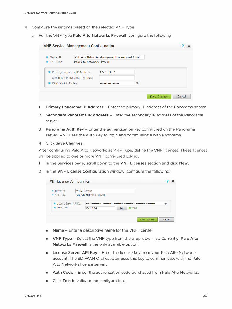
4 Configure the settings based on the selected VNF Type.
a For the VNF Type Palo Alto Networks Firewall, configure the following:
1 Primary Panorama IP Address – Enter the primary IP address of the Panorama server.
2 Secondary Panorama IP Address – Enter the secondary IP address of the Panorama server.
3 Panorama Auth Key – Enter the authentication key configured on the Panorama server. VNF uses the Auth Key to login and communicate with Panorama.
4 Click Save Changes.
After configuring Palo Alto Networks as VNF Type, define the VNF licenses. These licenses will be applied to one or more VNF configured Edges.
1 In the Services page, scroll down to the VNF Licenses section and click New.
2 In the VNF License Configuration window, configure the following:
n Name – Enter a descriptive name for the VNF license.
n VNF Type – Select the VNF type from the drop-down list. Currently, Palo Alto Networks Firewall is the only available option.
n License Server API Key – Enter the license key from your Palo Alto Networks account. The SD-WAN Orchestrator uses this key to communicate with the Palo Alto Networks license server.
n Auth Code – Enter the authorization code purchased from Palo Alto Networks.
n Click Test to validate the configuration.
VMware SD-WAN Administration Guide
VMware, Inc. 287

3 Click Save Changes.
You can apply the VNF licenses while configuring Palo Alto Networks Firewall as a VNF Type on Edges.
Note If you want to remove the deployment of Palo Alto Networks Firewall configuration from a VNF type, ensure that you have deactivated the VNF License of Palo Alto Networks before removing the configuration.
b For the VNF Type Check Point Firewall, configure the following:
1 Primary Check Point Mgmt Server IP – Enter the Check Point Smart Console IP address that will connect to the Check Point Firewall.
2 SIC Key for Mgmt Server Access – Enter the password used to register the VNF to the Check Point Smart Console.
3 Admin Password – Enter the administrator password.
4 VNF Image Location – Enter the image location from where the SD-WAN Orchestrator will download the VNF image.
5 Image Version – Select a version of the Check Point VNF image from the drop-down list. The image version is derived from the system property edge.vnf.extraImageInfos.
6 File Checksum Type – Specifies the method used to validate the VNF image and is automatically populated after you select an image version.
7 File Checksum – Specifies the checksum used to validate the VNF image and is automatically populated after you select an image version. The checksum value is derived from the system property edge.vnf.extraImageInfos.
8 Download Type – Choose the type of the image. For https, enter the username and password. For s3, enter the AccessKeyid and SecretAccessKey.
VMware SD-WAN Administration Guide
VMware, Inc. 288
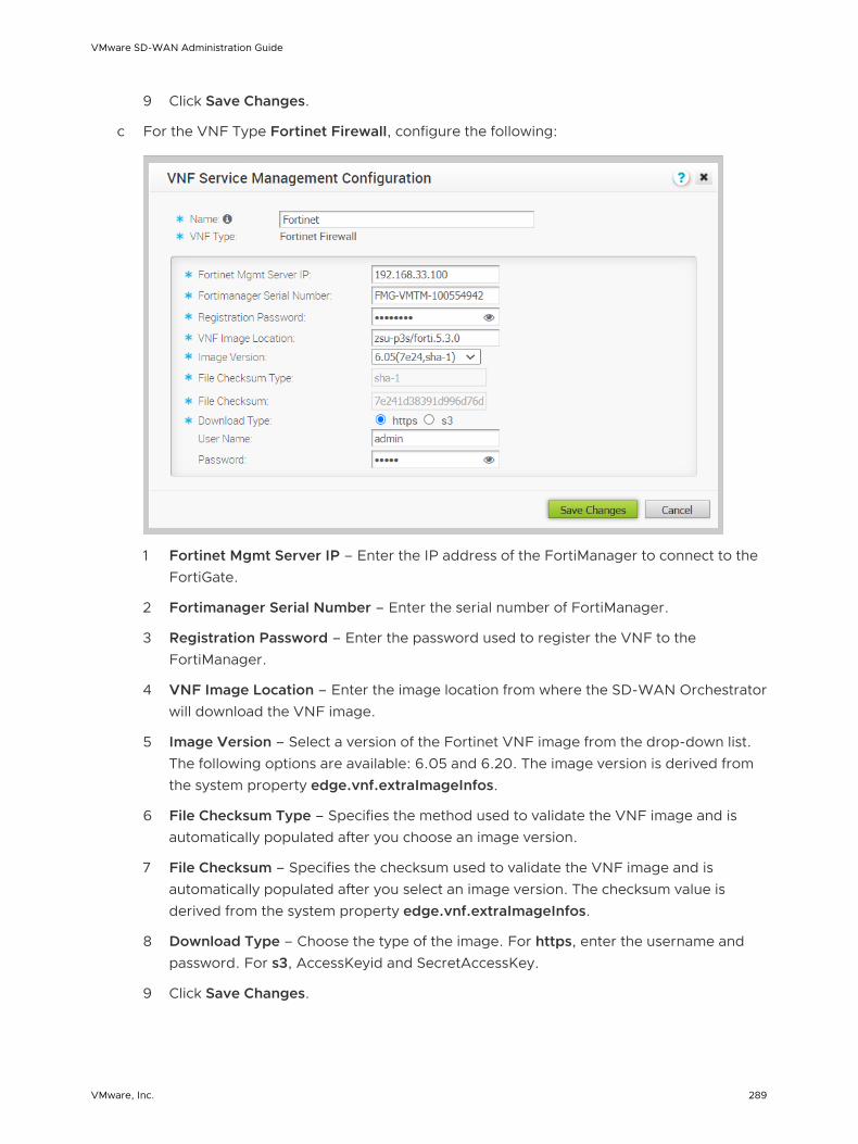
9 Click Save Changes.
c For the VNF Type Fortinet Firewall, configure the following:
1 Fortinet Mgmt Server IP – Enter the IP address of the FortiManager to connect to the FortiGate.
2 Fortimanager Serial Number – Enter the serial number of FortiManager.
3 Registration Password – Enter the password used to register the VNF to the FortiManager.
4 VNF Image Location – Enter the image location from where the SD-WAN Orchestrator will download the VNF image.
5 Image Version – Select a version of the Fortinet VNF image from the drop-down list. The following options are available: 6.05 and 6.20. The image version is derived from the system property edge.vnf.extraImageInfos.
6 File Checksum Type – Specifies the method used to validate the VNF image and is automatically populated after you choose an image version.
7 File Checksum – Specifies the checksum used to validate the VNF image and is automatically populated after you select an image version. The checksum value is derived from the system property edge.vnf.extraImageInfos.
8 Download Type – Choose the type of the image. For https, enter the username and password. For s3, AccessKeyid and SecretAccessKey.
9 Click Save Changes.
VMware SD-WAN Administration Guide
VMware, Inc. 289

Results
The VNFs section displays the created VNF services. The following image shows an example of VNF Type as Check Point Firewall.
What to do next
You can configure security VNF for an Edge to direct the traffic through the VNF management services. See Configure Security VNF.
Configure Security VNF
You can deploy and forward traffic through VNF on the SD-WAN Edge, using third-party firewalls.
Only an Operator can enable the Security VNF configuration. If the Security VNF option is not available for you, contact your Operator.
Prerequisites
Ensure that you have the following:
n SD-WAN Orchestrator and activated SD-WAN Edge running software versions that support deploying a specific security VNF. For more information on the supported software versions and Edge platforms, refer to the Support Matrix in Security VNFs.
n VNF Manager add on license.
n Configured VNF Management service. For more information, see Configure VNF Management Service.
Procedure
1 In the Enterprise portal, click Configure > Edges.
2 In the Edges page, either click the Device Icon next to an Edge or click the link to an Edge and click the Device tab.
3 In the Device tab, scroll down to the Security VNF section and click Edit.
4 In the Edge VNF Configuration window, check the Deploy checkbox.
5 Configure the following in VM Configuration:
a VLAN – Choose a VLAN, to be used for the VNF management, from the drop-down list.
b VM-1 IP – Enter the IP address of the VM and ensure that the IP address is in the subnet range of the chosen VLAN.
VMware SD-WAN Administration Guide
VMware, Inc. 290

c VM-1 Hostname – Enter a name for the VM host.
d Deployment State – Choose one of the following options:
n Image Downloaded and Powered On – This option powers up the VM after building the firewall VNF on the Edge. The traffic transits the VNF only when this option is chosen, which requires at least one VLAN or routed interface be configured for VNF insertion.
n Image Downloaded and Powered Off – This option keeps the VM powered down after building the firewall VNF on the Edge. Do not select this option if you intend to send traffic through the VNF.
VMware SD-WAN Administration Guide
VMware, Inc. 291
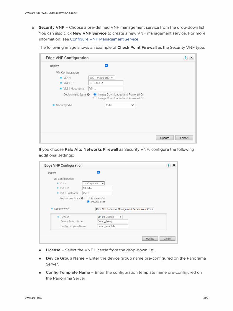
e Security VNF – Choose a pre-defined VNF management service from the drop-down list. You can also click New VNF Service to create a new VNF management service. For more information, see Configure VNF Management Service.
The following image shows an example of Check Point Firewall as the Security VNF type.
If you choose Palo Alto Networks Firewall as Security VNF, configure the following additional settings:
n License – Select the VNF License from the drop-down list.
n Device Group Name – Enter the device group name pre-configured on the Panorama Server.
n Config Template Name – Enter the configuration template name pre-configured on the Panorama Server.
VMware SD-WAN Administration Guide
VMware, Inc. 292

Note If you want to remove the deployment of Palo Alto Networks Firewall configuration from a VNF type, ensure that you have deactivated the VNF License of Palo Alto Networks before removing the configuration.
If you choose Fortinet Firewall, configure the following additional settings:
n Inspection Mode – Choose one of the following modes:
n Proxy – This option is selected by default. Proxy-based inspection involves buffering traffic and examining the data as a whole for analysis.
n Flow – Flow-based inspection examines the traffic data as it passes through the FortiGate unit without any buffering.
n License – Drag and drop the VM License.
f Click Update.
Results
The configuration details are displayed in the Security VNF section.
VMware SD-WAN Administration Guide
VMware, Inc. 293

What to do next
If you want to redirect multiple traffic segments to the VNF, define mapping between Segments and service VLANs. See Define Mapping Segments with Service VLANs
You can insert the security VNF into both the VLAN as well as routed interface to redirect the traffic from the VLAN or the routed interface to the VNF. See Configure VLAN with VNF Insertion.
Define Mapping Segments with Service VLANs
When you want to redirect multiple traffic segments to the security VNF, define mapping between Segments and service VLANs.
To map the segments with the service VLANs:
Procedure
1 In the Enterprise portal, click Configure > Segments.
2 In the Segments page, enter the Service VLAN ID for each segment.
3 Click Save Changes.
Results
The segment in which the VNF is inserted is assigned with a unique VLAN ID. The Firewall policy on the VNF is defined using these VLAN IDs. The traffic from VLANs and interfaces within these segments is tagged with the VLAN ID allocated for the specified segment.
What to do next
Insert the security VNF into a service VLAN or routed interface to redirect the traffic from the VLAN or the routed interface to the VNF. See Configure VLAN with VNF Insertion.
Configure VLAN with VNF Insertion
You can insert the security VNF into both the VLAN as well as routed interface.
Prerequisites
Ensure that you have created a security VNF and configured the settings. See Configure Security VNF.
VMware SD-WAN Administration Guide
VMware, Inc. 294

Map the segments with service VLANs to enable VNF insertion into the VLANs. See Define Mapping Segments with Service VLANs.
Procedure
1 In the Enterprise portal, click Configure > Edges.
2 In the Edges page, either click the Device Icon next to an Edge or click the link to an Edge and click the Device tab.
3 In the Device tab, scroll down to the Configure VLAN section.
4 Click the Edit link of the VLAN to which you want to insert the VNF.
5 In the VLAN window, select the VNF Insertion checkbox to insert the VNF into VLAN. This option redirects traffic from a specific VLAN to the VNF.
6 Click Update VLAN.
Results
The Configure VLAN section displays the status of the VNF insertion.
VMware SD-WAN Administration Guide
VMware, Inc. 295
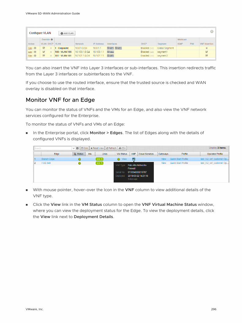
You can also insert the VNF into Layer 3 interfaces or sub-interfaces. This insertion redirects traffic from the Layer 3 interfaces or subinterfaces to the VNF.
If you choose to use the routed interface, ensure that the trusted source is checked and WAN overlay is disabled on that interface.
Monitor VNF for an Edge
You can monitor the status of VNFs and the VMs for an Edge, and also view the VNF network services configured for the Enterprise.
To monitor the status of VNFs and VMs of an Edge:
n In the Enterprise portal, click Monitor > Edges. The list of Edges along with the details of configured VNFs is displayed.
n With mouse pointer, hover-over the Icon in the VNF column to view additional details of the VNF type.
n Click the View link in the VM Status column to open the VNF Virtual Machine Status window, where you can view the deployment status for the Edge. To view the deployment details, click the View link next to Deployment Details.
VMware SD-WAN Administration Guide
VMware, Inc. 296

To monitor the status of VNFs and VMs:
n In the Enterprise portal, click Monitor > Network Services. The list of Edges along with the details of configured VNFs is displayed.
VNF Events
You can view the events when the VNF VM is deployed, when there is a change in the VNF VM configuration, and when a VNF insertion is enabled in a VLAN.
In the enterprise portal, click Monitor > Events.
To view the events related to VNF, you can use the filter option. Click the drop-down arrow next to the Search option and choose to filter either by the Event or by the Message column.
The following events occur when there is a change in the VNF configuration:
n VNF VM config changed
n VNF VM deleted
n VNF VM deployed
n VNF VM error
n vnf image download event
The following events occur when VNF insertion is enabled or disabled in a VLAN or routed Interface.
n VNF insertion disabled
VMware SD-WAN Administration Guide
VMware, Inc. 297

n VNF insertion enabled
The following image shows some of the VNF events.
Configure VNF Alerts
You can configure to receive alerts and notifications related to the VNF events.
In the Enterprise portal, click Configure > Alerts & Notifications. In the Alert Configuration page, you can select the Alert Types.
VMware SD-WAN Administration Guide
VMware, Inc. 298

To receive alerts for VNF events, select the following Alert Types:
n Edge VNF Virtual Machine Deployment – Receive an alert when there is a change in the Edge VNF virtual machine deployment state.
n Edge VNF Insertion – Receive an alert when there is a change in the Edge VNF deployment state.
n Edge VNF Image Download Event – Receive an alert when there is a change in the Edge VNF image download state.
You can view the alert notifications in the Monitor > Alerts page.
To view the alerts related to VNF, you can use the filter option. Click the drop-down arrow next to the Search option and choose to filter by the Type.
The following image shows some of the VNF alerts.
You can also view the alerts in the new Orchestrator UI.
Click Launch New Orchestrator UI in the pop-up window. The UI opens in a new tab displaying the monitoring options. Click Alerts. Click the Filter Icon in the Search option to filter the VNF alerts.
Configure Edge Business Policy
This section describes how to configure the Edge Business Policy.
Configure Edge Business Policy
The Edge Firewall primarily uses rules from the assigned Profile. Overriding Profile Business Policy rules at the Edge is an optional step.
VMware SD-WAN Administration Guide
VMware, Inc. 299

Business Policy Override Rules
At the Edge, Business Policy Rules from the assigned Profile can be overridden using the Edge Business Policy dialog shown below. Any Business Policy override match value that is the same as any Profile Business Policy rule, will override that Profile rule. You can create override rules in the same way as you create Profile rules (see Chapter 11 Configure Profile Business Policy).
As shown in the image below, Business Policy is Segment aware. All Segments available for configuration are listed in the Configure Segment drop-down menu.
When you choose a Segment to configure from the Configure Segment drop down, the settings and options associated with that Segment display in the Configure Segments area. Global Segment [Regular] is the default Segment.
For more information about Segmentation, see Chapter 7 Configure Segments and Configure Edge Device.
Configure Edge Activation
This section describes how to initiate Edge activation.
Once an Edge configuration has been saved, it is assigned an activation key. Edge activation begins by clicking the Send Activation Email link on the Edge Overview Tab.
VMware SD-WAN Administration Guide
VMware, Inc. 300
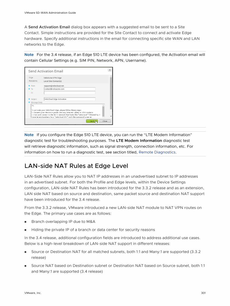
A Send Activation Email dialog box appears with a suggested email to be sent to a Site Contact. Simple instructions are provided for the Site Contact to connect and activate Edge hardware. Specify additional instructions in the email for connecting specific site WAN and LAN networks to the Edge.
Note For the 3.4 release, if an Edge 510 LTE device has been configured, the Activation email will contain Cellular Settings (e.g. SIM PIN, Network, APN, Username).
Note If you configure the Edge 510 LTE device, you can run the “LTE Modem Information” diagnostic test for troubleshooting purposes. The LTE Modem Information diagnostic test will retrieve diagnostic information, such as signal strength, connection information, etc. For information on how to run a diagnostic test, see section titled, Remote Diagnostics.
LAN-side NAT Rules at Edge Level
LAN-Side NAT Rules allow you to NAT IP addresses in an unadvertised subnet to IP addresses in an advertised subnet. For both the Profile and Edge levels, within the Device Settings configuration, LAN-side NAT Rules has been introduced for the 3.3.2 release and as an extension, LAN side NAT based on source and destination, same packet source and destination NAT support have been introduced for the 3.4 release.
From the 3.3.2 release, VMware introduced a new LAN-side NAT module to NAT VPN routes on the Edge. The primary use cases are as follows:
n Branch overlapping IP due to M&A
n Hiding the private IP of a branch or data center for security reasons
In the 3.4 release, additional configuration fields are introduced to address additional use cases. Below is a high-level breakdown of LAN-side NAT support in different releases:
n Source or Destination NAT for all matched subnets, both 1:1 and Many:1 are supported (3.3.2 release)
n Source NAT based on Destination subnet or Destination NAT based on Source subnet, both 1:1 and Many:1 are supported (3.4 release)
VMware SD-WAN Administration Guide
VMware, Inc. 301

n Source NAT and Destination 1:1 NAT on the same packet (3.4 release)
Note n LAN-side NAT supports traffic over VCMP tunnel. It does not support underlay traffic.
n Support for "Many:1" and "1:1" (e.g. /24 to /24) Source and Destination NAT.
n If multiple rules are configured, only the first matched rule is executed.
n LAN-side NAT is done before route or flow lookup. To match traffic in the business profile, users must use the NATed IP.
n By default, NATed IP are not advertised from the Edge. Therefore, make sure to add the Static Route for the NATed IP and advertise to the Overlay.
n Configurations in 3.3.2 will be carried over, no need to reconfigure upon 3.4 upgrade.
LAN-side NAT (3.3.2 Release)
Use Case Number One: "Many:1 Source NAT"
In this scenario, a third-party has assigned multiple non-overlapping subnets to a customer's site. The server in the customer's data center recognizes traffic from this third-party by a single IP address at any given site.
The configuration required for Use Case Number One for Version 3.3.2: New rule: LAN-side NAT 192.168.1.0/24 -> 172.16.24.4/32
As shown in the image below, because the NAT rule is a single IP, TCP and UDP traffic will be PAT'd. Therefore, in this example, 192.168.1.50 becomes 172.16.24.4 with an ephemeral source port for TCP/UDP traffic, ICMP traffic becomes 172.16.24.4 with a custom ICMP ID for reverse lookup, and all other traffic will be dropped.
VMware SD-WAN Administration Guide
VMware, Inc. 302

Use Case Number Two: "1:1 Source NAT"
In this scenario, the LAN subnet is 192.168.1.0/24. However, this is an overlapping subnet with other sites. A unique subnet of equal size, 172.16.24.0/24 has been assigned to use for VPN communication at this site. Traffic from the PC must be NAT'd on the Edge prior to the route lookup, otherwise the source route will match 192.168.1.0/24 which is not advertised from this Edge and traffic will drop.
The configuration required for Use Case Number Two: New rule: LAN-side NAT 192.168.1.0/24 -> 172.16.24.0/24
Because the subnets match in size, all bits matching the subnet mask will be NAT'd. Therefore, in the image below example, 192.168.1.50 becomes 172.16.24.50.
LAN-side NAT Based on Source or Destination (3.4 Release)
The 3.4 release introduces LAN-side NAT based on Source/Destination support as part of a single rule, in which you can enable NAT only for a subset of traffic based on Source or Destination subnets. See the following use cases for this enhancement below.
Use Case Number One: "Perform SNAT or DNAT with Source or Destination as Match Criteria"
In the illustration example below, the branch should NAT the source IP 10.4.1.1 to 10.200.1.245 only for the traffic destined to 100.1.1.0/24. Similarly, at the DC, the destination IP 100.1.1.9 should be NATed to 10.1.10.9 only if the traffic is received from source 10.200.1.0/24.
VMware SD-WAN Administration Guide
VMware, Inc. 303
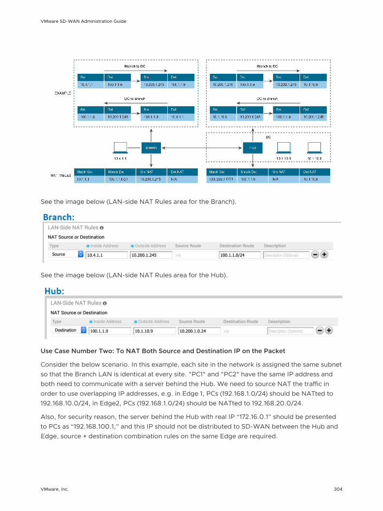
See the image below (LAN-side NAT Rules area for the Branch).
See the image below (LAN-side NAT Rules area for the Hub).
Use Case Number Two: To NAT Both Source and Destination IP on the Packet
Consider the below scenario. In this example, each site in the network is assigned the same subnet so that the Branch LAN is identical at every site. "PC1" and "PC2" have the same IP address and both need to communicate with a server behind the Hub. We need to source NAT the traffic in order to use overlapping IP addresses, e.g. in Edge 1, PCs (192.168.1.0/24) should be NATted to 192.168.10.0/24, in Edge2, PCs (192.168.1.0/24) should be NATted to 192.168.20.0/24.
Also, for security reason, the server behind the Hub with real IP “172.16.0.1” should be presented to PCs as “192.168.100.1,” and this IP should not be distributed to SD-WAN between the Hub and Edge, source + destination combination rules on the same Edge are required.
VMware SD-WAN Administration Guide
VMware, Inc. 304
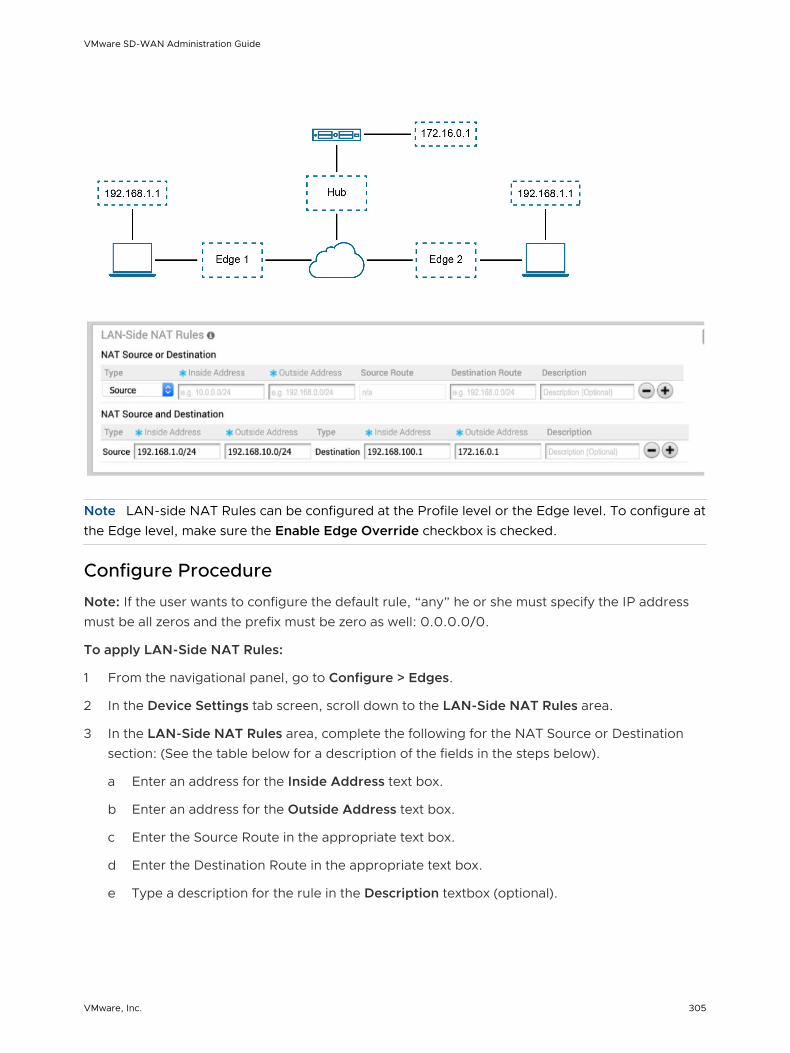
Note LAN-side NAT Rules can be configured at the Profile level or the Edge level. To configure at the Edge level, make sure the Enable Edge Override checkbox is checked.
Configure Procedure
Note: If the user wants to configure the default rule, “any” he or she must specify the IP address must be all zeros and the prefix must be zero as well: 0.0.0.0/0.
To apply LAN-Side NAT Rules:
1 From the navigational panel, go to Configure > Edges.
2 In the Device Settings tab screen, scroll down to the LAN-Side NAT Rules area.
3 In the LAN-Side NAT Rules area, complete the following for the NAT Source or Destination section: (See the table below for a description of the fields in the steps below).
a Enter an address for the Inside Address text box.
b Enter an address for the Outside Address text box.
c Enter the Source Route in the appropriate text box.
d Enter the Destination Route in the appropriate text box.
e Type a description for the rule in the Description textbox (optional).
VMware SD-WAN Administration Guide
VMware, Inc. 305

4 In the LAN-side NAT Rules area, complete the following for NAT Source and Destination: (See the table below for a description of the fields in the steps below).
a For the Source type, enter the Inside Address and the Outside Address in the appropriate text boxes.
b For the Destination type, enter the Inside Address and the Outside Address in the appropriate text boxes.
c Type a description for the rule in the Description textbox (optional).
LAN-side NAT Rule Type Description
Type drop-down menu Select either Source or Destination Determine whether this NAT rule should be applied on the source or destination IP address of user traffic.
Inside Address text box IPv4 address/prefix, Prefix must be 1-32
The "inside" or "before NAT" IP address (if prefix is 32) or subnet (if prefix is less than 32).
Outside Address text box IPv4 address/prefix, Prefix must be 1-32
The "outside" or "after NAT" IP address (if prefix is 32) or subnet (if prefix is less than 32).
Source Route text box - Optional
- IPv4 address/prefix
- Prefix must be 1-32
- Default: any
For destination NAT, specify source IP/subnet as match criteria. Only valid if the type is “Destination.”
Destination Route text box - Optional
- IPv4 address/prefix
- Prefix must be 1-32
- Default: any
For source NAT, specify destination IP/subnet as match criteria. Only valid if the type is “Source.”
Description text box Text Custom text box to describe the NAT rule.
VMware SD-WAN Administration Guide
VMware, Inc. 306
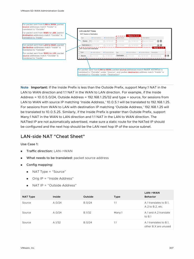
Note Important: If the Inside Prefix is less than the Outside Prefix, support Many:1 NAT in the LAN to WAN direction and 1:1 NAT in the WAN to LAN direction. For example, if the Inside Address = 10.0.5.0/24, Outside Address = 192.168.1.25/32 and type = source, for sessions from LAN to WAN with source IP matching ‘Inside Address,’ 10.0.5.1 will be translated to 192.168.1.25. For sessions from WAN to LAN with destination IP matching ‘Outside Address,’ 192.168.1.25 will be translated to 10.0.5.25. Similarly, if the Inside Prefix is greater than Outside Prefix, support Many:1 NAT in the WAN to LAN direction and 1:1 NAT in the LAN to WAN direction. The NATted IP are not automatically advertised, make sure a static route for the NATed IP should be configured and the next hop should be the LAN next hop IP of the source subnet.
LAN-side NAT "Cheat Sheet"
Use Case 1:
n Traffic direction: LAN->WAN
n What needs to be translated: packet source address
n Config mapping:
n NAT Type = “Source”
n Orig IP = “Inside Address”
n NAT IP = “Outside Address”
NAT Type Inside Outside TypeLAN->WAN Behavior
Source A.0/24 B.0/24 1:1 A.1 translates to B.1, A.2 to B.2, etc.
Source A.0/24 B.1/32 Many:1 A.1 and A.2 translate to B.1
Source A.1/32 B.0/24 1:1 A.1 translates to B.1, other B.X are unused
VMware SD-WAN Administration Guide
VMware, Inc. 307

Use Case 2:
n Traffic direction: WAN -> LAN
n What needs to be translated: packet destination address
n Config mapping:
n NAT Type = “Source”
n Orig IP = “Outside Address”
n NAT IP = “Inside Address”
NAT Type Inside Outside TypeWAN->LAN Behavior
Source A.0/24 B.0/24 1:1 B.1 translates to A.1, B.2 to A.2, etc.
Source A.0/24 B.1/32 Many:1 B.1 translates to A.1
Source A.1/32 B.0/24 1:Many B.1 and B.2 translate to A.1
Use Case 3:
n Traffic direction: LAN->WAN
n What needs to be translated: packet destination address
n Config mapping:
n NAT Type = “Destination”
n Orig IP = “Inside Address”
n NAT IP = “Outside Address”
NAT Type Inside Outside TypeLAN->WAN Behavior
Destination A.0/24 B.0/24 1:1 A.1 translates to B.1, A.1 to B.2, etc.
Destination A.0/24 B.1/32 Many:1 A.1 and A.2 translate to B.1
Destination A.1/32 B.0/24 1:Many A.1 translates to B.1
Use Case 4:
n Traffic direction: WAN->LAN
n What needs to be translated: packet source address
n Config mapping:
n NAT Type = “Destination”
n Orig IP = “Outside Address”
VMware SD-WAN Administration Guide
VMware, Inc. 308

n NAT IP = “Inside Address”
NAT Type Inside Outside TypeWAN->LAN Behavior
Destination A.0/24 B.0/24 1:1 B.1 translates to A.1, B.2 to A.2, etc.
Destination A.0/24 B.1/32 Many:1 B.1 translates to A.1
Destination A.1/32 B.0/24 1:Many B.1 and B.2 translate to A.1
VMware SD-WAN Administration Guide
VMware, Inc. 309

Object Groups 16An object group consists of a range of IP addresses or Port numbers. When you create business policies and firewall rules, you can define the rules for a range of IP addresses or a range of TCP/UDP ports, by including the object groups in the rule definitions.
You can create Address groups to save the range of valid IP addresses and Port groups for the range of port numbers. You can simplify the policy management by creating object groups of specific types and reusing them in policies and rules.
Using Object Groups, you can:
n Manage policies easily
n Modularize and reuse the policy components
n Update all referenced business and firewall policies easily
n Reduce the number of policies
n Improve the policy debugging and readability
Note You can create, update, or delete object groups if you have Create, Update, and Delete permissions on the NETWORK_SERVICE object. You can only view the object groups if you have Read permission on NETWORK_SERVICE and ENTERPRISE_PROFILE objects.
This chapter includes the following topics:
n Configure Address Groups
n Configure Port Groups
n Configure Business Policies with Object Groups
n Configure Firewall Rules with Object Groups
Configure Address Groups
Address Groups can store a range of IP addresses with different options.
Procedure
1 In the Enterprise portal, click Configure > Object Groups.
2 In the Address Groups tab, click Actions > New.
VMware, Inc. 310

3 In the Configure Address Group window, enter a Name and Description for the Address Group.
4 Enter the range of IP Addresses as required.
5 Click Create.
What to do next
You can define a business policy or a firewall rule with the Address Group, to include the range of IP addresses in the Address Group.
You can add or modify the IP addresses in an Address Group by clicking Actions > Update in the Address Groups tab.
If you want to delete an Address Group, ensure to exclude the Address Group from the business policies or firewall rules.
Configure Port Groups
Port Groups can store a range of TCP and UDP port numbers.
Procedure
1 In the Enterprise portal, click Configure > Object Groups.
2 In the Port Groups tab, click Actions > New.
3 In the Configure Port Group window, enter a Name and Description for the Port Group.
VMware SD-WAN Administration Guide
VMware, Inc. 311
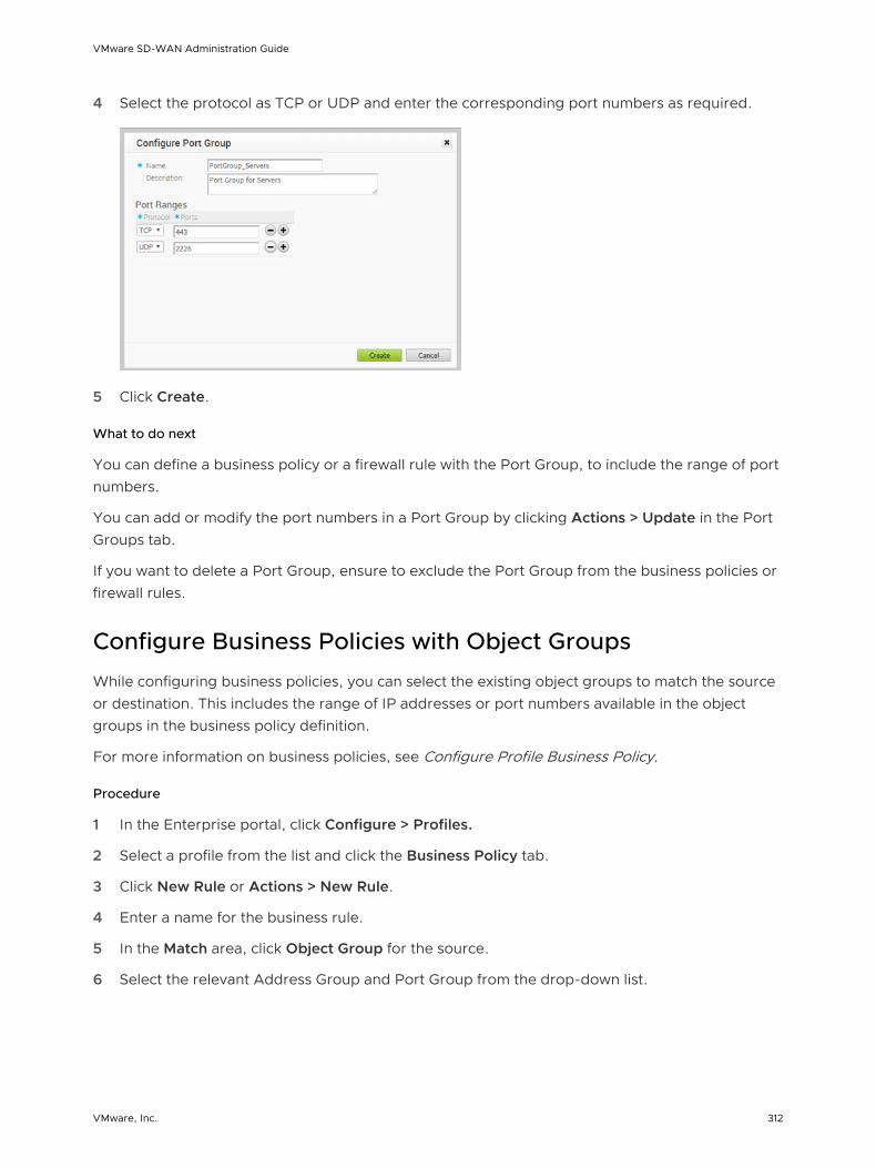
4 Select the protocol as TCP or UDP and enter the corresponding port numbers as required.
5 Click Create.
What to do next
You can define a business policy or a firewall rule with the Port Group, to include the range of port numbers.
You can add or modify the port numbers in a Port Group by clicking Actions > Update in the Port Groups tab.
If you want to delete a Port Group, ensure to exclude the Port Group from the business policies or firewall rules.
Configure Business Policies with Object Groups
While configuring business policies, you can select the existing object groups to match the source or destination. This includes the range of IP addresses or port numbers available in the object groups in the business policy definition.
For more information on business policies, see Configure Profile Business Policy.
Procedure
1 In the Enterprise portal, click Configure > Profiles.
2 Select a profile from the list and click the Business Policy tab.
3 Click New Rule or Actions > New Rule.
4 Enter a name for the business rule.
5 In the Match area, click Object Group for the source.
6 Select the relevant Address Group and Port Group from the drop-down list.
VMware SD-WAN Administration Guide
VMware, Inc. 312

7 If required, you can select the Address and Port Groups for the destination as well.
8 Choose the other actions required and click OK.
Results
The business policies that you create for a profile are automatically applied to all the Edges associated with the profile. If required, you can create additional business policies specific to the Edges.
1 Navigate to Configure > Edges, select an Edge, and click the Business Policy tab.
2 Click New Rule or Actions > New Rule.
3 Define the rule with relevant object groups and other actions.
The Business Policy tab of the Edge displays the policies from the associated profile along with the policies specific to the Edge.
VMware SD-WAN Administration Guide
VMware, Inc. 313

Note By default, the business policies are assigned to the global segment. If required, you can choose a segment from the Select Segment drop-down and create business policies specific to the selected segment.
What to do next
You can modify the object groups with additional IP addresses and port numbers. The changes are automatically included in the business policies that use the object groups.
Configure Firewall Rules with Object Groups
While configuring Firewall rules, you can select the existing object groups to match the source or destination. This includes the range of IP addresses or port numbers available in the object groups in the rules.
For more information on Firewall Rules, see Configure Firewall Rules.
Procedure
1 In the Enterprise portal, click Configure > Profiles.
2 Select a profile from the list and click the Firewall tab.
3 Click New Rule or Actions > New Rule.
4 Enter a name for the Firewall rule.
5 In the Match area, click Object Group for the source.
6 Select the relevant Address Group and Port Group from the drop-down list.
VMware SD-WAN Administration Guide
VMware, Inc. 314

7 If required, you can select the Address and Port Groups for the destination as well.
8 Choose required Action and click OK.
Results
The Firewall rules that you create for a profile are automatically applied to all the Edges associated with the profile. If required, you can create additional rules specific to the Edges.
1 Navigate to Configure > Edges, select an Edge, and click the Firewall tab.
2 Click New Rule or Actions > New Rule.
3 Define the rule with relevant object groups and other actions.
The Firewall tab of the Edge displays the Firewall rules from the associated profile along with the rules specific to the Edge.
Note By default, the firewall rules are assigned to the global segment. If required, you can choose a segment from the Select Segment drop-down and create firewall rules specific to the selected segment.
VMware SD-WAN Administration Guide
VMware, Inc. 315

What to do next
You can modify the object groups with additional IP addresses and port numbers. The changes are automatically included in the Firewall rules that use the object groups.
VMware SD-WAN Administration Guide
VMware, Inc. 316

Site Configurations 17Topologies for data centers that include a SD-WAN Hub and VMware branch configurations ( Gold, Silver, and Bronze branches) are configured using both MPLS and Internet connections. Legacy branch configurations (those without a SD-WAN Edge) are included, and hub and branch configurations are modified given the presence of the legacy branches.
The diagram below shows an example topology that includes two data center hubs and the Gold, Silver, and Bronze variations of branch topologies interconnected using MPLS and the Internet. This example will be used to describe the individual tasks required for data center and branch configurations. It is assumed that you are familiar with concepts and configuration details in earlier sections of this documentation. This section will primarily focus on configuring Networks, Profile Device Settings, and Edge configuration required for each topology.
Additional configuration steps for traffic redirection, control routing (such as for backhaul traffic and VPNs), and for Edge failover are also included.
This section primarily focuses on the configuration required for a topology that includes different types of data center and branch locations, and explains the Network, Profile/Edge Device Settings, and Profile/Edge Business Policies required to complete the configurations. Some ancillary configuration steps that may be necessary for a complete configuration – such as for Network Services, Device Wi-Fi Radio, Authentication, SNMP, and Netflow settings – are not described.
This chapter includes the following topics:
VMware, Inc. 317

n Data Center Configurations
n Configure Branch and Hub
Data Center Configurations
An SD-WAN Edge in a data center can act as a hub to direct traffic to/from branches. The SD-WAN Edge can be used to manage both MPLS and Internet traffic. The hub in a data center can be configured in a one-arm or two-arm configuration. In addition, a data center can be used as a backup.
The following describes the various designs with different options of how SD-WAN Edge can be inserted into the topology.
Option Description
Hub 1 Data Center or regional hub site with SD-WAN Edge deployed in two-arm topology.
Hub 2 Data Center or regional hub site with SD-WAN Edge deployed in one-arm topology (same interface carries multiple WAN links).
Legacy 1 and 2 Classic MPLS sites.
Silver 1 SD-WAN Edge is deployed off-path. SD-WAN Edge creates overlay across both MPLS and Internet paths. Traffic is first diverted to the SD-WAN Edge.
Silver 2 SD-WAN Edge is deployed in-path as the default gateway. It is always the default gateway. This topology is simpler but makes SD-WAN Edge a single point of failure and may require HA.
Bronze 1 Dual-Internet site (one of the links is behind a NAT router).
Configure Branch and Hub
This section provides an overview of configuring SD-WAN Edge in a two-arm configuration.
Overview
To configure the SD-WAN Edge in a two-arm configuration:
1 Configure and activate Hub 1
2 Configure and activate the Silver 1 site
3 Enable branch-to-hub tunnel (Silver 1 to Hub 1)
4 Configure and activate Bronze 1 site
5 Configure and activate Hub 2
6 Configure and activate Silver 2 site
The following sections describe the steps in more detail.
VMware SD-WAN Administration Guide
VMware, Inc. 318

Configure and Activate Hub 1
This step helps you understand the typical workflow of how to bring up SD-WAN Edge at the hub location. SD-WAN Edge is deployed with two interfaces (one interface for each WAN link).
You will use the Virtual Edge as a hub. Below is an example of the wiring and IP address information.
Configure and Activate Hub 1 SD-WAN Edge to Reach the Internet
Because this is the data center/hub site, it is unlikely that the SD-WAN Edge can get its WAN IP using DHCP. Thus, you will need to first enable the SD-WAN Edge to connect to the Internet through the data center firewall so that SD-WAN Edge can be activated.
1 Configure a PC with a static IP 192.168.2.100/24 and gateway 192.168.2.1 which is the default LAN setting for accessing a SD-WAN Edge. Connect the PC to the SD-WAN Edge LAN interface.
2 From the PC, browse to http://192.168.2.1 (the local Web interface of the SD-WAN Edge). Click the link review the configuration.
3 Configure the GE2 static WAN IP and default gateway of the SD-WAN Edge so that it can reach the Internet.
Click Save and provide login/password of admin/admin.
VMware SD-WAN Administration Guide
VMware, Inc. 319

Typically at the data center/hub site, the static IP address will be assigned to you and the enterprise IT admin will configure the firewall to translate the SD-WAN Edge WAN IP to a Public IP and also filter the appropriate traffic (outbound: TCP/443, inbound: UDP/2426, UDP/500, UDP/4500).
4 At this point, the Internet status should show Connected.
After configuration of the SD-WAN Edge static WAN IP address and associated firewall configuration is complete, the SD-WAN Edge Internet status shows "Connected".
Enable the Virtual SD-WAN Edge in Default Profile
1 Login to the SD-WAN Orchestrator.
2 The default VPN profile allows the activation of the SD-WAN Edge 500.
Activate Hub 1 SD-WAN Edge
1 Go to Configure > Edges and add a new SD-WAN Edge. Specify the correct model and the profile (we use the Quick Start VPN Profile).
2 Go to the hub SD-WAN Edge (DC1-VCE) and follow the normal activation process. If you already have the email feature set up, an activation email will be sent to that email address. Otherwise, you can go to the device setting page to get the activation URL.
3 Copy the activation URL and paste that to the browser on the PC connected to the SD-WAN Edge or just click on the activation URL from the PC browser.
4 Click on Activate button.
VMware SD-WAN Administration Guide
VMware, Inc. 320

5 Now the DC1-VCE data center hub should be up. Go to Monitor > Edges. Click the Edge Overview tab. The public WAN link capacity is detected along with the correct public IP 71.6.4.9 and ISP.
6 Go to Configure > Edges and select DC1-VCE. Go to the Device tab and scroll down to the Interface Settings.
You will see that the registration process notifies the SD-WAN Orchestrator of the static WAN IP address and gateway that was configured through the local UI. The configuration on the VMware will be updated accordingly.
7 Scroll down to the WAN Settings section. The Link Type should be automatically identified as Public Wired.
Configure the Private WAN Link on Hub 1 SD-WAN Edge
1 Configure the private MPLS Edge WAN interface directly from the SD-WAN Orchestrator. Go to Configure -> Edges and choose DC1-VCE. Go to the Device tab and scroll down to the Interface Settings section. Configure static IP on GE3 as 172.31.2.1/24 and default gateway of 172.31.2.2. Under WAN Overlay, select User Defined Overlay. This will allow us to define a WAN link manually in the next step.
2 Under WAN Settings, click the Add User Defined WAN Overlay button (see the following screen capture).
VMware SD-WAN Administration Guide
VMware, Inc. 321

3 Define the WAN overlay for the MPLS path. Select the Link Type as Private and specify the next-hop IP (172.31.2.2) of the WAN link in the IP Address field. Choose the GE3 as the interface. Click the Advanced button.
Tip: The hub site normally has more bandwidth than the branches. If we choose the bandwidth to be auto-discovered, the hub site will run a bandwidth test with its first peer, e.g. the first branch that comes up, and will end up discovering an incorrect WAN bandwidth. For the hub site, you should always define the WAN bandwidth manually, and that is done in the advanced settings.
4 The private WAN bandwidth is specified in advanced settings. The screen shot below shows an example of 5 Mbps upstream and downstream bandwidth for a symmetric MPLS link at the hub.
5 Validate that the WAN link is configured and save the changes.
You are done with configuring the SD-WAN Edge on the hub. You will not see the User Defined MPLS overlay that you just added until you enable a branch SD-WAN Edge.
(Optional) Configure the LAN Interface with Management IP
1 Go to Configure > Edges and select DC1-VCE.
2 Navigate to the Device tab and scroll down to the VLAN Settings section.
3 Click Edit and configure the IP address of the interface.
VMware SD-WAN Administration Guide
VMware, Inc. 322

Configure Static Route to LAN Network Behind L3 Switch
Add a static route to the 172.30.0.0/24 subnet through the L3 switch. You need to specify the interface GE3 to use for routing to the next hop. Make sure you enable the Advertise checkbox so other SD-WAN Edges can learn about this subnet behind L3 switch (see the following screen
capture).
Configure and Activate Silver 1 Site
This step helps you understand the typical workflow of how to insert the SD-WAN Edge at a Silver site. The SD-WAN Edge is inserted off-path and relies on the L3 switch to redirect traffic to it. Below is an example of the wiring and IP address information.
Activate the Silver 1 Site Branch SD-WAN Edge
In this example, we assume that the SD-WAN Edge gets its public IP address using DHCP, so there is no configuration required. SD-WAN Edge ships with default configuration to use DHCP on all routed interfaces.
1 Create a new Edge SILVER1-DCEand select the appropriate Model and configuration profile (see image below).
VMware SD-WAN Administration Guide
VMware, Inc. 323

2 Activate this SD-WAN Edge by connecting a PC to its LAN or Wi-Fi.
3 The SD-WAN Edge should now be active in the SD-WAN Orchestrator with one public link. We can now configure the private WAN link.
Configure the Private WAN Link on the Silver 1 Site SD-WAN Edge
At this point, we need to build the IP connectivity from the SD-WAN Edge towards the L3 switch.
1 Go to Configure > Edges, select the SILVER1-VCE and go to the Device tab and scroll down to the Interface Settings section. Configure static IP on GE3 as 10.12.1.1/24 and default gateway of 10.12.1.2. Under WAN Overlay, select User Defined Overlay. This will allow us to define a WAN link manually in the next step.
2 Under the WAN Settings section, click Add User Defined WAN Overlay.
3 Define the WAN overlay for the MPLS path. Select the Link Type as Private. Specify the next-hop IP (10.12.1.2) of the WAN link in the IP Address field. Choose the GE3 as the Interface. Click the Advanced button.
Tip: Since the hub has already been set up, it is OK to auto-discover the bandwidth. This branch will run a bandwidth test with the hub to discover its link bandwidth.
VMware SD-WAN Administration Guide
VMware, Inc. 324

4 Set the Bandwidth Measurement to Measure Bandwidth. This will cause the branch SD-WAN Edge to run a bandwidth test with the hub SD-WAN Edge just like what happens when it connects to the SD-WAN Gateway.
5 Validate that the WAN link is configured and save the changes (see the following screen capture).
(Optional) Configure the LAN Interface with Management IP
1 Go to Configure > Edges, select SILVER1-VCE. Navigate to the Device tab and scroll down to the VLAN Settings section. Click Edit. Configure the IP address of the LAN and Management
interfaces.
Configure Static Route to LAN Network Behind L3 Switch
Add a static route to 192.168.128.0/24 through the L3 switch. You need to specify the Interface GE3. Make sure you enable the Advertise checkbox so other SD-WAN Edges learn about this subnet behind L3 switch (see the following screen capture).
Enable Branch to Hub Tunnel (Silver 1 to Hub 1)
This step helps you build the overlay tunnel from the branch into hub. Note that at this point, you may see that the link is up but this is the tunnel to the SD-WAN Gateway over the Internet path and not the tunnel to the hub. We will need to enable Cloud VPN to enable the tunnel from the branch to the hub to be established.
You are now ready to build the tunnel from the branch into the hub.
Enable Cloud VPN and Edge to SD-WAN Hub tunnel
1 Step 1:Go to the Configure > Profiles, select Quick Start VPN Profile and go to the Device tab. Enable the Cloud VPN and do the following.
n Under Branch to Hubs, check the Enable checkbox.
n Under Branch to Branch VPN, check the Enable checkbox.
VMware SD-WAN Administration Guide
VMware, Inc. 325
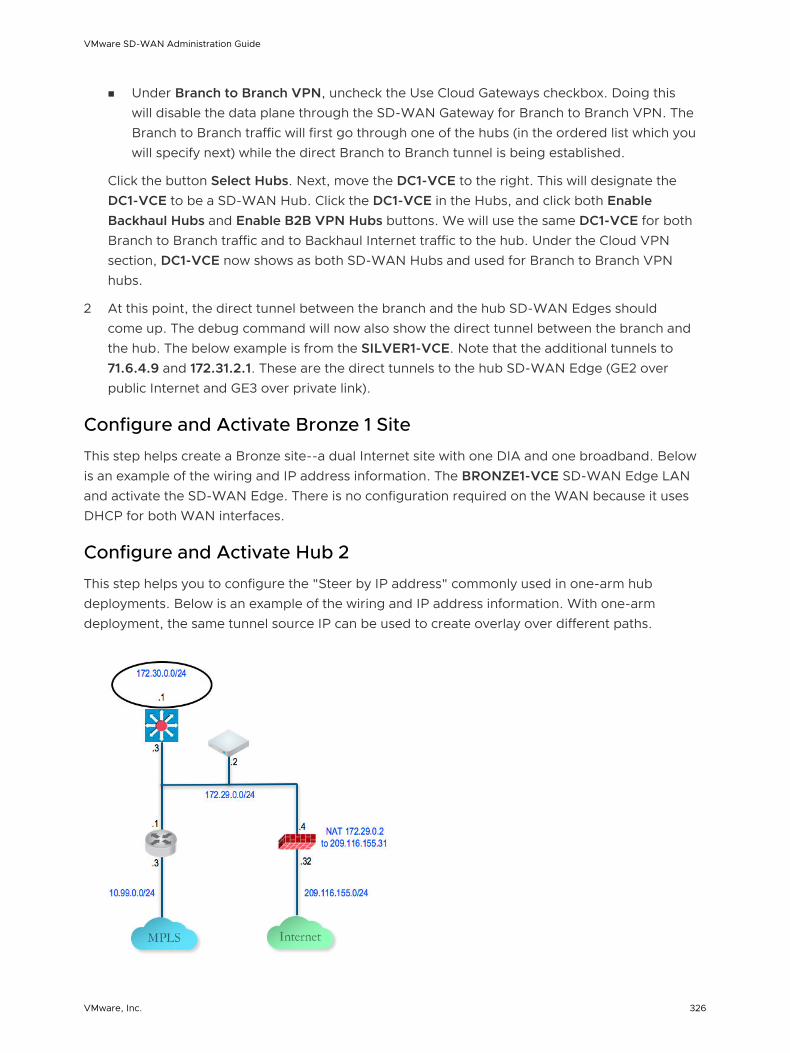
n Under Branch to Branch VPN, uncheck the Use Cloud Gateways checkbox. Doing this will disable the data plane through the SD-WAN Gateway for Branch to Branch VPN. The Branch to Branch traffic will first go through one of the hubs (in the ordered list which you will specify next) while the direct Branch to Branch tunnel is being established.
Click the button Select Hubs. Next, move the DC1-VCE to the right. This will designate the DC1-VCE to be a SD-WAN Hub. Click the DC1-VCE in the Hubs, and click both Enable Backhaul Hubs and Enable B2B VPN Hubs buttons. We will use the same DC1-VCE for both Branch to Branch traffic and to Backhaul Internet traffic to the hub. Under the Cloud VPN section, DC1-VCE now shows as both SD-WAN Hubs and used for Branch to Branch VPN hubs.
2 At this point, the direct tunnel between the branch and the hub SD-WAN Edges should come up. The debug command will now also show the direct tunnel between the branch and the hub. The below example is from the SILVER1-VCE. Note that the additional tunnels to 71.6.4.9 and 172.31.2.1. These are the direct tunnels to the hub SD-WAN Edge (GE2 over public Internet and GE3 over private link).
Configure and Activate Bronze 1 Site
This step helps create a Bronze site--a dual Internet site with one DIA and one broadband. Below is an example of the wiring and IP address information. The BRONZE1-VCE SD-WAN Edge LAN and activate the SD-WAN Edge. There is no configuration required on the WAN because it uses DHCP for both WAN interfaces.
Configure and Activate Hub 2
This step helps you to configure the "Steer by IP address" commonly used in one-arm hub deployments. Below is an example of the wiring and IP address information. With one-arm deployment, the same tunnel source IP can be used to create overlay over different paths.
VMware SD-WAN Administration Guide
VMware, Inc. 326

Configure the Hub 2 SD-WAN Edge to Reach the Internet
1 Connect a PC to the SD-WAN Edge and use the browser to point to http://192.168.2.1.
2 Configure the hub SD-WAN Edge to reach the Internet by configuring the first WAN interface, GE2.
Add the Hub 2 SD-WAN Edge to the SD-WAN Orchestrator and Activate
In this step, you will create the second hub SD-WAN Edge, called DC2.VCE.
1 On the SD-WAN Orchestrator, go to Configure > Edges, select New Edge to add a new SD-WAN Edge.
2 Go to Configure > Edges, select the SD-WAN Edge that you just created, then go to the Device tab to configure the same Interface and IP you configured in previous step.
Important Since we are deploying the SD-WAN Edge in one-arm mode (same physical interface but there will be multiple over tunnels from this interface), it is important to specify the WAN Overlay to be User Defined.
3 At this point, you need to create the overlay. Under WAN Settings, click Add User Defined WAN Overlay.
VMware SD-WAN Administration Guide
VMware, Inc. 327
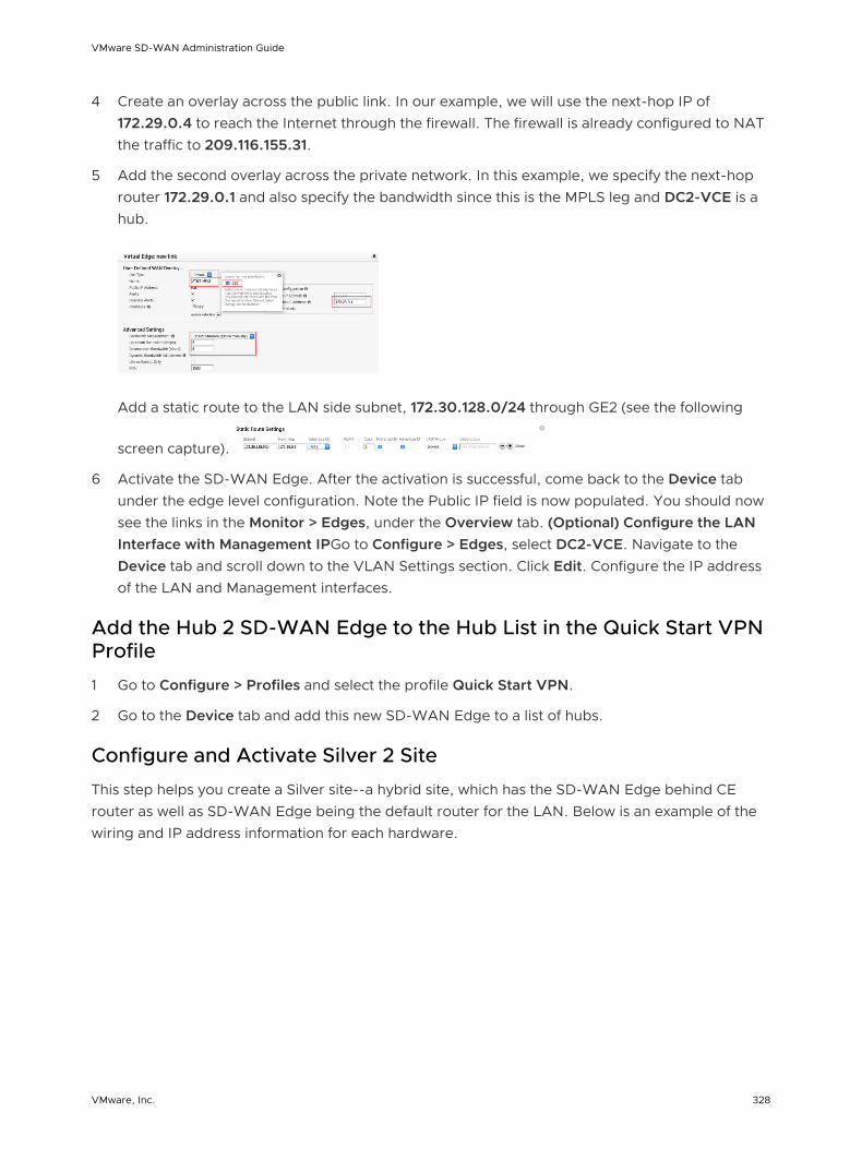
4 Create an overlay across the public link. In our example, we will use the next-hop IP of 172.29.0.4 to reach the Internet through the firewall. The firewall is already configured to NAT the traffic to 209.116.155.31.
5 Add the second overlay across the private network. In this example, we specify the next-hop router 172.29.0.1 and also specify the bandwidth since this is the MPLS leg and DC2-VCE is a hub.
Add a static route to the LAN side subnet, 172.30.128.0/24 through GE2 (see the following
screen capture).
6 Activate the SD-WAN Edge. After the activation is successful, come back to the Device tab under the edge level configuration. Note the Public IP field is now populated. You should now see the links in the Monitor > Edges, under the Overview tab. (Optional) Configure the LAN Interface with Management IPGo to Configure > Edges, select DC2-VCE. Navigate to the Device tab and scroll down to the VLAN Settings section. Click Edit. Configure the IP address of the LAN and Management interfaces.
Add the Hub 2 SD-WAN Edge to the Hub List in the Quick Start VPN Profile
1 Go to Configure > Profiles and select the profile Quick Start VPN.
2 Go to the Device tab and add this new SD-WAN Edge to a list of hubs.
Configure and Activate Silver 2 Site
This step helps you create a Silver site--a hybrid site, which has the SD-WAN Edge behind CE router as well as SD-WAN Edge being the default router for the LAN. Below is an example of the wiring and IP address information for each hardware.
VMware SD-WAN Administration Guide
VMware, Inc. 328
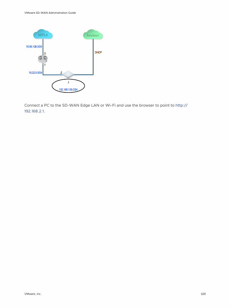
Connect a PC to the SD-WAN Edge LAN or Wi-Fi and use the browser to point to http://192.168.2.1.
VMware SD-WAN Administration Guide
VMware, Inc. 329

Configure Dynamic Routing with OSPF or BGP 18This section describes how to configure dynamic routing with OSPF or BGP.
SD-WAN Edge learns routes from adjacent routers through OSPF and BGP. It sends the learned routes to the Gateway/Controller. The Gateway/Controller acts like a route reflector and sends the learned routes to other SD-WAN Edge. The Overlay Flow Control (OFC) enables enterprise-wide route visibility and control for ease of programming and for full and partial overlay.
VMware supports Inbound/Outbound filters to OSPF neighbors, OE1/OE2 route types, MD5 authentication. Routes learned through OSPF will be automatically redistributed to the controller hosted in the cloud or on-premise. Support for BGP Inbound/Outbound filters and the filter can be set to Deny, or optionally you can Add/Change the BGP attribute to influence the path selection, i.e. RFC 1998 community, MED, and local preference.
Note For information about OSPF and BGP Redistribution, see the section titled OSPF/BGP Redistribution.
Note In the 3.2 release, both BGP and OSPF can be enabled in a SD-WAN Edge at a time.
This chapter includes the following topics:
n Enable OSPF
n Enable BGP
n OSPF/BGP Redistribution
n Overlay Flow Control
Enable OSPF
Open Shortest Path First (OSPF) can be enabled only on a LAN interface as a passive interface. The Edge will only advertise the prefix associated with that LAN switch port. To get full OSPF functionality, you must use it in routed interfaces.
To enable OSPF, perform the steps on this procedure:
1 Configure OSPF for VPN profiles.
a Go to Configure > Profile.
VMware, Inc. 330

b Click the Device icon corresponding to the VPN profile for which you want to configure OSPF.
The Configure Segments screen appears.
c In the OSPF Areas section, turn ON the OSPF Areas toggle button.
d Configure the redistribution settings for OSPF areas.
1 From the Default Route drop-down menu, choose an OSPF route type (E1 or E2) to be used for default route.
2 From the Advertise drop-down menu, choose either Always or Conditional. (Choosing Always means to Advertise the default route always. Choosing Conditional means to redistribute default route only when Edge learns via overlay or underlay). The “Overlay Prefixes” option must be checked to use the Conditional default route.
3 If applicable, check the Overlay Prefixes checkbox.
4 Optionally, to enable injection of BGP routes into OSPF, select the BGP checkbox. BGP routes can be redistributed into OSPF, so if this is applicable, enter or choose the configuration options as follows:
a In the Set Metric textbox, enter the metric. (This is the metric that OSPF would put in its external LSAs that it generates from the redistributed routes). The default metric is 20.
b From the Set Metric Type drop-down menu, choose a metric type. (This is either type E1 or E2 (OSPF External-LSA type)); the default type is E2).
5 In the ID text box, enter an OSPF Area ID.
6 In the Name textbox, enter a descriptive name for your area.
VMware SD-WAN Administration Guide
VMware, Inc. 331

7 By default, the Normal type is selected. Only Normal type is supported at this time.
8 Add additional areas, if necessary, by clicking .
2 Configure routed interface settings for the OSPF-enabled Edge device.
Note SD-WAN Orchestrator supports OSPF Point to Point network mode at the Edge and Profile level.
a In the Configure Segments screen, scroll down to the Device Settings area of the Edge device for which you want to configure interface and OSPF settings.
b Click the expand icon corresponding to the Edge.
c In the Interface Settings area, click the Edit link of your interface. The Interface Setting screen for the Edge device appears.
d Select the OSPF checkbox.
VMware SD-WAN Administration Guide
VMware, Inc. 332

e From the OSPF Area drop-down menu, select an OSPF area.
f Click the toggle advance ospf settings link to configure advanced OSPF settings.
1 Create filters for Inbound Route Learning and Route Advertisement. For more information, see Route Filters.
2 Click the Customs Settings tab and configure the following OSPF settings.
a In the Hello Timer text box, enter the OSPF Hello time interval in seconds. The allowable range is 1 through 255.
b In the Dead Timer text box, enter the OSPF Dead time interval in seconds. The allowable range is 1 through 65535.
c Select the Enable MD5 Authentication checkbox to enable MD5 authentication.
d In the Interface Path Cost text box, enter the OSPF cost for the interface path.
e In the MTU text box, enter the Maximum Transmission Unit (MTU) value of the interface.
f From the Mode drop-down menu, select Broadcast or Point to Point as the OSPF network type mode. The default OSPF mode is Broadcast.
g Select the Passive checkbox to enable OSPF Passive mode.
h Click the Update button.
3 Click Save Changes.
The Confirm Changes dialog box appears requesting you to confirm the OSPF areas you want to enable. It also displays how many Edges are affected.
Note If you have Edges that are not associated with the OSPF configuration at the Profile level, then you must configure at the Edge level from Configure > Edges > Device > Interface Settings area.
Route Filters
There are two different types of routing: inbound and outbound.
n Inbound routing includes preferences that can be learned or ignored from OSPF and installed into the Overlay Flow Control.
n Outbound Routing indicates what prefixes can be redistributed into the OSPF.
VMware SD-WAN Administration Guide
VMware, Inc. 333
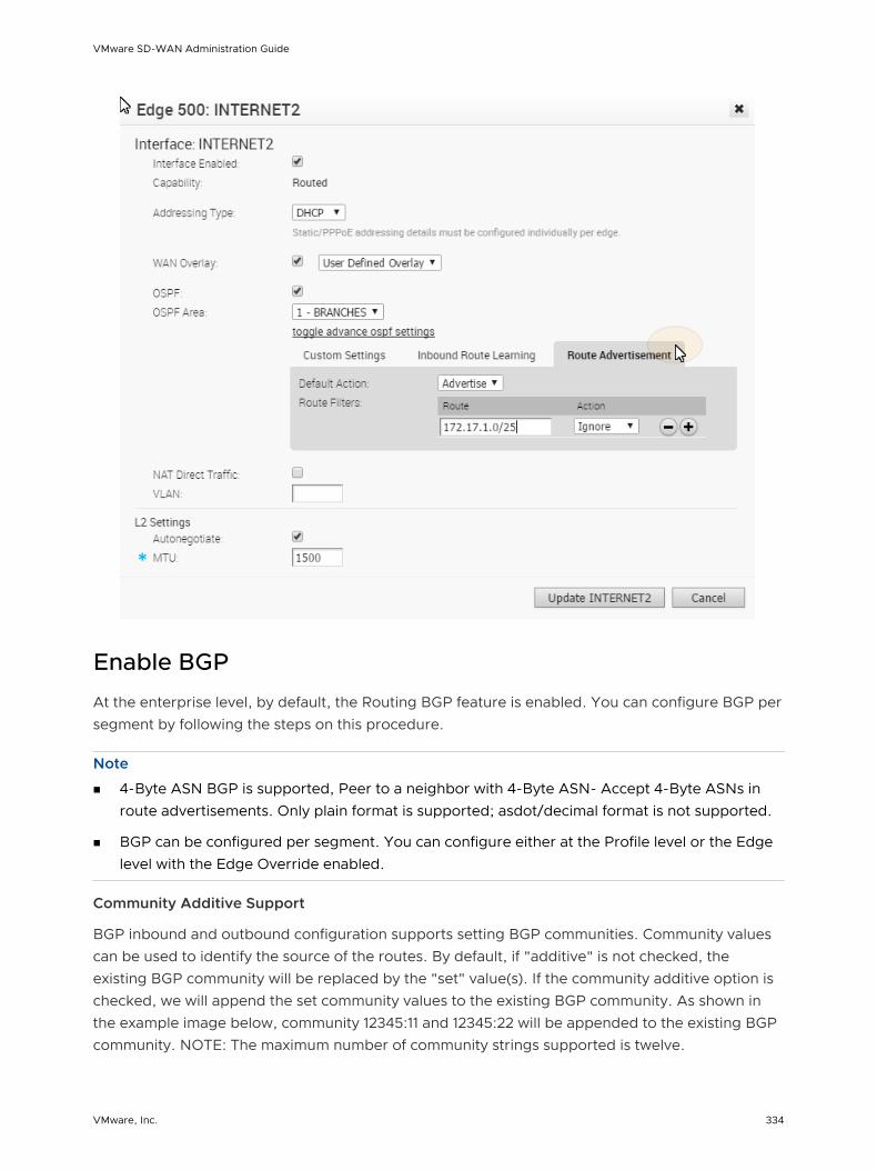
Enable BGP
At the enterprise level, by default, the Routing BGP feature is enabled. You can configure BGP per segment by following the steps on this procedure.
Note n 4-Byte ASN BGP is supported, Peer to a neighbor with 4-Byte ASN- Accept 4-Byte ASNs in
route advertisements. Only plain format is supported; asdot/decimal format is not supported.
n BGP can be configured per segment. You can configure either at the Profile level or the Edge level with the Edge Override enabled.
Community Additive Support
BGP inbound and outbound configuration supports setting BGP communities. Community values can be used to identify the source of the routes. By default, if "additive" is not checked, the existing BGP community will be replaced by the "set" value(s). If the community additive option is checked, we will append the set community values to the existing BGP community. As shown in the example image below, community 12345:11 and 12345:22 will be appended to the existing BGP community. NOTE: The maximum number of community strings supported is twelve.
VMware SD-WAN Administration Guide
VMware, Inc. 334

1 Configure BGP for VPN profiles:
a Go to Configure > Profile from the navigation panel.
The Configuration Profiles screen appears.
b Select a profile you want to enable BGP for and click the Device icon for the applicable Profile.
The Device Settings screen for the selected Profile appears.
2 Scroll down to the BGP Settings area, and turn BGP ON as shown in the image below.
3 Click the Edit button to define the BGP neighbors.
4 In the BGP Editor:
a Click the Add Filter button to create one or more filters. (These filters will be applied to the neighbor to deny or change the attributes of the route. The same filter can be used for multiple neighbors).
The Create BGP Filter dialog appears (image below).
b In the Create BGP Filter dialog:
1 Type in a name for the filter in the Filter Name textbox.
2 Set the Rules for the filter.
n Choose Prefix or Community from the Type drop-down menu.
VMware SD-WAN Administration Guide
VMware, Inc. 335

n Set the value for either the Prefix or Community in the Value textbox.
n If appliable, check the Exact Match checkbox.
n Indicate the action type (Permit or Deny) from the Type drop-down menu.
n From the Set drop-down menu, choose either None, Local Preference, Metric, AS-Path-Prepend, or Community, Community Additive checkbox. See the section above titled, Community Additive Support" for more information.
See table below for a description of these fields (see the image below the table for reference).
Rule Field Description
Match Type: Prefix or Community
Value
Exact Match checkbox
Action Type: Permit or Deny
Set Option: None
Set Option: Local Preference
Set Option: Community and Community Additive checkbox
BGP inbound and outbound configuration supports the additive configuration option. This appends incoming community attributes along with setup community values. Community values can be used to identify the source of the routes. By default, if "additive" is not checked, the community value will be replaced by the "set" value.
Set Option: Metric
Set Option: AS-Path-Prepend
c After you have set the rules for the filter, click the OK button.
d In the BGP Editor dialog box, enter the Local ASN number in the Local ASN textbox.
e In the Neighbor's area, enter the Neighbor IP and ASN in the appropriate text boxes, and specify Inbound Filters or Outbound Filters from the Filter list defined in the previous step.
VMware SD-WAN Administration Guide
VMware, Inc. 336

f Add additional options by clicking the view all button to open the drop-down menu. Apply additional options as needed. (See the table below for a description of each option and the table below for additional reference).
Additional Options Field Description
Neighbor Flag drop-down menu Used to flag the neighbor type. Choose between two options from the drop-down menu: None and Uplink. Select Uplink if it is used as the WAN overlay towards MPLS. It will be used as the flag to decide whether the site will become a transit site (e.g. hub) by propagating routes leant over SD-WAN overlay to WAN link toward MPLS. If need to make it a transit site, also check "Overlay Prefix Over Uplink" in Advanced option.
Allow AS checkbox Learn BGP routes even though the same AS is in the AS-path.
Default Route checkbox Advertise a default route to the neighbor. See step "e, ii" below for more information about using the Default Route checkbox.
Connect Interval in seconds before it tries new TCP connection with the peer if it detects the TCP session is not passive. Default value is 120 seconds.
MD5 Auth checkbox Enables BGP MD5 authentication. The MD5 Auth checkbox is used in a legacy network or federal network, and it is common that BGP MD5 is used as a security guard for BGP peering.
MD5 Password textbox A password is required when enabling MD5 Auth.
g Click the Advanced Settings button.
The Advanced Settings area appears.
VMware SD-WAN Administration Guide
VMware, Inc. 337
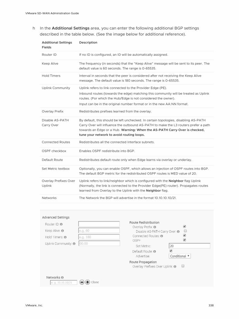
h In the Additional Settings area, you can enter the following additional BGP settings described in the table below. (See the image below for additional reference).
Additional Settings Fields
Description
Router ID If no ID is configured, an ID will be automatically assigned.
Keep Alive The frequency (in seconds) that the "Keep Alive" message will be sent to its peer. The default value is 60 seconds. The range is 0-65535.
Hold Timers Interval in seconds that the peer is considered after not receiving the Keep Alive message. The default value is 180 seconds. The range is 0-65535.
Uplink Community Uplink refers to link connected to the Provider Edge (PE).
Inbound routes (towards the edge) matching this community will be treated as Uplink routes. (For which the Hub/Edge is not considered the owner).
Input can be in the original number format or in the new AA:NN format.
Overlay Prefix Redistributes prefixes learned from the overlay.
Disable AS-PATH Carry Over
By default, this should be left unchecked. In certain topologies, disabling AS-PATH Carry Over will influence the outbound AS-PATH to make the L3 routers prefer a path towards an Edge or a Hub. Warning: When the AS-PATH Carry Over is checked, tune your network to avoid routing loops.
Connected Routes Redistributes all the connected Interface subnets.
OSPF checkbox Enables OSPF redistribute into BGP.
Default Route Redistributes default route only when Edge learns via overlay or underlay.
Set Metric textbox Optionally, you can enable OSPF, which allows an injection of OSPF routes into BGP. The default BGP metric for the redistributed OSPF routes is MED value of 20.
Overlay Prefixes Over Uplink
Uplink refers to link/neighbor which is configured with the Neighbor flag Uplink (Normally, the link is connected to the Provider Edge(PE) router). Propagates routes learned from Overlay to the Uplink with the Neighbor flag.
Networks The Network the BGP will advertise in the format 10.10.10.10/21.
VMware SD-WAN Administration Guide
VMware, Inc. 338

i Click OK to save the configurations.
Note If you checked the Default Route checkbox located in the Additional Settings area, please be aware of the following four scenarios:
n If the global Default Route option is enabled with the "Conditional” option selected, and the per BGP neighbor option Default Route is not selected, BGP will Redistribute the default route to its neighbor only when the Edge learns an explicit default route via overlay or underlay.
n If the global Default Route option is enabled with the “Conditional” option selected, and the per BGP neighbor option Default Route is selected, the Per Neighbor configuration overrides the Global configuration hence “Advertise default route to BGP peer Always.”
n If the global Default Route option is not enabled and the per BGP neighbor option Default Route is selected, Advertise default route to BGP peer Always.
n If the global Default Route option is not enabled and per the BGP neighbor option Default Route is not selected, Do not Advertise/Redistribute default route to BGP peer.
Note All the above options are available at the Edge level and can be configured with Edge override enabled for BGP settings.
OSPF/BGP Redistribution
Each of routing protocols OSPF and BGP may be enabled independently and the prior model of allowing only one routing protocol to be enabled on the system has been removed with this release. This release also allows the possibility of redistributing OSPF into BGP or BGP into OSPF (or both simultaneously), along with other possible route sources like prefixes learnt over the overlay, connected routes, static routes, etc.
In addition, with release 3.2, we are standardizing the redistribution behavior along more traditional lines (similar to that in other routing vendors). For example, if there is more than one route available for the same prefix, then only the best route for that prefix in the system RIB will be redistributed to the destination protocol if the configuration in the destination protocol allows redistribution for that route type.
Consider, as an example, redistribution of the prefix 192.168.1.0/24 into BGP. Let's say routes to the prefix 192.168.1.0/24 are locally available, learned from OSPF and separately learned as an Overlay prefix. Let's further assume that between the OFC flow ordering for the prefix, and route metrics, and route preference the OSPF route ranks above (is better than) the learned overlay route for that same prefix. Then, the OSPF route will be redistributed into BGP if OSPF redistribution has been turned on in BGP. Note that since the overlay learned prefix is not the best route for that prefix in the system RIB, it will not be redistributed into BGP even if the redistribution of overlay prefixes has been turned on in BGP.
VMware SD-WAN Administration Guide
VMware, Inc. 339
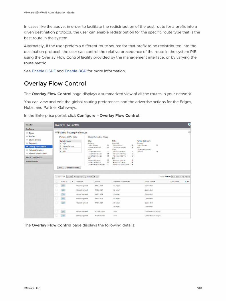
In cases like the above, in order to facilitate the redistribution of the best route for a prefix into a given destination protocol, the user can enable redistribution for the specific route type that is the best route in the system.
Alternately, if the user prefers a different route source for that prefix to be redistributed into the destination protocol, the user can control the relative precedence of the route in the system RIB using the Overlay Flow Control facility provided by the management interface, or by varying the route metric.
See Enable OSPF and Enable BGP for more information.
Overlay Flow Control
The Overlay Flow Control page displays a summarized view of all the routes in your network.
You can view and edit the global routing preferences and the advertise actions for the Edges, Hubs, and Partner Gateways.
In the Enterprise portal, click Configure > Overlay Flow Control.
The Overlay Flow Control page displays the following details:
VMware SD-WAN Administration Guide
VMware, Inc. 340

Option Description
Preferred VPN Exits Displays the priority of the destinations to where the traffic should be routed.
Global Advertise Flags Displays the advertise actions of static, connected, internal, external, and uplink routes.
n Edit – Click to update the priorities and the advertise actions. See Configure Global Routing Preferences.
n Refresh Routes – This option is available only when the Distributed Cost Calculation feature is enabled by the Operator. By default, the Orchestrator is actively involved in learning the dynamic routes. Edges and Gateways rely on the Orchestrator to calculate initial route preferences and return them to the Edge and Gateway. The Distributed Cost Calculation feature enables to distribute the route cost calculation to the Edges and Gateways.
For more information on Distributed Cost Calculation, refer to the Configure Distributed Cost Calculation section in the VMware SD-WAN Operator Guide available at: https://docs.vmware.com/en/VMware-SD-WAN/index.html.
Note To enable the Distributed Cost Calculation feature, check with your supporting partner. If you are directly supported by VMware, contact the support team.
Click Refresh Routes which makes the Edges and Gateways to recalculate learned route costs and send them to the Orchestrator. In addition, the changes in the Overlay Flow Control are applied immediately on the new and existing learned routes.
When you refresh the routes, the Customer Enterprise has the following impact on the network:
n All the local dynamic routes are refreshed, and the preference and advertise action of these routes are updated. This updated information is advertised to the Gateway, Orchestrator, and eventually across the Enterprise. As this leads to an update in the routing table, there is a brief impact on the traffic for all the sites.
n Any existing flow using these routes can potentially be affected due to the change in the routing entries.
Note It is recommended to use Refresh Routes in a maintenance window to minimize the impact on the Customer Enterprise.
The bottom panel of the Overlay Flow Control window displays the subnets. You can prioritize the preferred destinations for the subnets and pin or unpin learned route preferences. For more information, see Configure Subnets.
Configure Global Routing Preferences
In the Overlay Flow Control window, you can edit the global routing preferences, advertise actions, and modify the priorities of the destinations to where the traffic should be routed.
VMware SD-WAN Administration Guide
VMware, Inc. 341

Procedure
1 In the Enterprise portal, click Configure > Overlay Flow Control.
2 In the Overlay Flow Control page, click Edit and the Edit Global Configs window is displayed.
3 You can update the following settings:
a In the Preferred VPN Exits area, click the UP and DOWN arrows to modify the priorities.
b In the Global Advertise Flags area, select the relevant checkboxes to modify the advertise actions for the routes.
c Click Update to save the changes.
Results
The updated settings are displayed in the Overlay Flow Control page.
Configure Subnets
In the Overlay Flow Control window, you can update the priorities of the destinations for the learned routes in the subnets.
VMware SD-WAN Administration Guide
VMware, Inc. 342

Procedure
1 In the Enterprise portal, click Configure > Overlay Flow Control.
2 The bottom panel of the Overlay Flow Control window displays the subnets with the following details:
Option Description
Modify Displays the option to edit the subnet. The option displays a superscript number, which indicates the number of Edges and Gateways that learned the corresponding route.
Segment Segment name.
Subnet The network that the route corresponds to along with a list of Edges that learned the route.
Preferred VPN Exits The route through which another branch can access the subnet.
Route Type Displays the type of the route, which can be one of the following: Static, Connected, or Learned.
Last Update The last updated date and time of the preferred VPN exit.
Created On Date and time when the route was created.
Select one or more subnets and click the Actions to perform the following activities:
n Edit Subnet – Modify the preferred destinations and prioritize them.
n Pin Learned Route Preference – Pins the preferences of the selected learned route.
n Reset Learned Route Preference – Resets the preference of the selected learned route to default settings.
n Delete Learned Routes – Deletes the learned routes. This option does not delete the connected routes, static routes, routes from Overlay Flow Control, and routes from Edge Route table and is used for cleaning up stale routes. The option is available only when Configure Distributed Cost Calculation is turned off.
VMware SD-WAN Administration Guide
VMware, Inc. 343

3 Click the Edit option for a subnet to modify the priorities of the preferred destination.
a In the Subnet window, you can move the destinations from the Eligible VPN Exits to Preferred VPN Exits and vice versa.
b In the Preferred VPN Exits panel, click the UP and DOWN arrows to change the priorities and click Save.
c You can reset the cost calculation for the subnets when there are pinned routes available. Click Reset, which enables the Orchestrator to clear the pinned routes, recalculate the cost for the selected subnet based on the policy, and send the results to the Edges and Gateways.
Note The Reset option is available only when Distributed Cost Calculation is enabled.
For more information on Distributed Cost Calculation, refer to the Configure Distributed Cost Calculation section in the VMware SD-WAN Operator Guide available at: https://docs.vmware.com/en/VMware-SD-WAN/index.html.
VMware SD-WAN Administration Guide
VMware, Inc. 344

Configure Alerts 19SD-WAN Orchestrator allows to configure alerts that notify the Enterprise Administrators or other support users, whenever an event occurs.
Note If you are logged in as a user with Customer support privileges, you can view the Alerts and other objects but cannot configure them.
In the Enterprise portal, click Configure > Alerts & Notifications to configure the alerts.
Select the events for which the alerts need to be sent, and enter the notification delay time in minutes under Select Alerts.
You can use the EDIT_ALERT_CONFIGURATION event to record the changes to the enterprise alert
configurations.
VMware, Inc. 345

Under Customers, the contact details of existing admin users are displayed. You can select the checkboxes for Email and SMS to send alerts to the corresponding users.
SNMP Traps
Simple Network Management Protocol (SNMP) Traps are notifications sent to an SNMP Agent to indicate that an event has occurred. SD-WAN Orchestrator sends SNMP Traps corresponding to the existing alerts like Edge Down and Edge Up. You can select the SNMP version and enter the corresponding details under SNMP Traps.
Webhooks
Webhooks deliver data to other applications, triggered by certain alerts using HTTP POST. Whenever an alert occurs, the source sends an HTTP request to the target application configured for the webhook.
VMware SD-WAN Administration Guide
VMware, Inc. 346

SD-WAN Orchestrator supports Webhooks that automatically send messages through HTTP POST to target apps when an event occurs. You can set the target URL in the Enterprise portal and automate actions in response to the alerts triggered by SD-WAN Orchestrator. The webhook recipients must support HTTPS and must have valid certificates, to ensure the privacy of potentially sensitive alert payloads. This also prevents the tampering of payloads.
Configure Webhooks
In the Alert Configuration window, you can enter the following details under Webhooks.
Option Description
URL Enter a valid HTTPS URL. This serves as the target application for the webhooks.
Code Enter an expected HTTP response status code for each webhook recipient. By default, the SD-WAN Orchestrator expects webhook recipients to respond to HTTP POST requests with a status code as HTTP 200.
When SD-WAN Orchestrator receives an unexpected status code from a recipient server or a proxy server, it considers that the alert delivery has failed, and generates an ALERT_DELIVERY_FAILED customer event. This event
helps to identify when a webhook recipient server may fail to function as expected.
VMware SD-WAN Administration Guide
VMware, Inc. 347

Option Description
Secret Specify a secret token for each configured webhook recipient, which is used to compute an HMAC for each Webhook request sent to the corresponding recipient. The HMAC is embedded in a X-Webhook-Signature HTTP
header, along with a version parameter, which identifies the signature algorithm and a timestamp.
X-Webhook-Signature: v=<signature-version>&t=<timestamp>&s=<hmac>
The recipient interprets the components as follows:
n v: Version of the algorithm used to produce the
signature. The only supported value is 1.
n t: Millisecond-precision epoch timestamp
corresponding to the time at which the request is issued.
n s: HMAC computed by SD-WAN Orchestrator. The
HMAC is computed as follows: HMAC-SHA256(request-body + '.' + timestamp, secret).
The message used to compute the HMAC is formed by concatenating the request body, a single period, and the value of the timestamp parameter that appears in the signature header. The specific HMAC algorithm used to produce the code is HMAC-SHA256.
After receiving a Webhook request, the listening server can verify the authenticity of the request by computing its own HMAC-SHA256 signature according to the same algorithm and compare the newly-computed signature with the one generated by the SD-WAN Orchestrator.
JSON Payload Template This is a required field.
SD-WAN Orchestrator delivers alert notifications to each webhook recipient, through a JSON payload contained within the body of an outgoing HTTP POST request.
SD-WAN Orchestrator generates payload content dynamically, as notifications are sent by performing variable interpolation. The supported placeholder variables in the user-configured payload template are replaced with alert-specific values.
Webhook payload templates support the following placeholder variables:
n alertTime: Time at which the alert got triggered.
n alertType: The type of the alert, like EDGE_DOWN, LINK_UP, VNF_VM_DEPLOYED.
n customer: Name of the customer to whom the notification is sent.
n entityAffected: Name of the entity, like Edge or link or VNF, to which the alert is applied.
VMware SD-WAN Administration Guide
VMware, Inc. 348

Option Description
n lastContact: The time at which the affected Edge most recently communicated with the SD-WAN Orchestrator. This is applicable only for the Edge alerts.
n message: A brief message describing the event that triggered the alert.
n VCO: Hostname or public IP of the SD-WAN Orchestrator from which the notification is sent.
The following example shows a sample JSON payload template:
{ "alertTime": "{{alertTime}}", "alertType": "{{alertType}}", "customer": "{{customer}}", "entityAffected": "{{entityAffected}}", "lastContact": "{{lastContact}}", "message": "{{message}}", "vco": "{{vco}}"}
You can click the plus (+) Icon to add more target URLs and the corresponding details.
Click Test to check the Webhook alerts.
Whenever an alert is triggered, an alert message along with relevant information is sent to the target URL.
VMware SD-WAN Administration Guide
VMware, Inc. 349
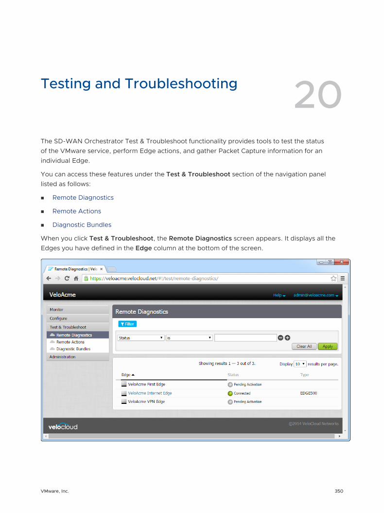
Testing and Troubleshooting 20The SD-WAN Orchestrator Test & Troubleshoot functionality provides tools to test the status of the VMware service, perform Edge actions, and gather Packet Capture information for an individual Edge.
You can access these features under the Test & Troubleshoot section of the navigation panel listed as follows:
n Remote Diagnostics
n Remote Actions
n Diagnostic Bundles
When you click Test & Troubleshoot, the Remote Diagnostics screen appears. It displays all the Edges you have defined in the Edge column at the bottom of the screen.
VMware, Inc. 350
You can use the Filter to find Edges based on connection Status, Name, IP address, Serial Number, Software Version, and Software Build. However, before you can perform any of the Test & Troubleshoot options, you must select an Edge from the Edge column. See the sections below for more information regarding each of the Test & Troubleshooting options from the navigation panel (Remote Diagnostics, Remote Actions, and Diagnostic Bundles).
This chapter includes the following topics:
n Remote Diagnostics
n Remote Actions
n Diagnostic Bundles
Remote Diagnostics
You can run tests on an Edge to obtain diagnostic information by clicking Remote Diagnostics under Test & Troubleshoot.
To run a diagnostic test on a single Edge:
Procedure
1 In the Enterprise portal, click Test & Troubleshoot and click Remote Diagnostic.
2 Search for an Edge, if needed, using the Filter, and click Apply.
3 Select a connected Edge.
The Remote Diagnostics screen appears showing all the possible tests you can run on an Edge.
VMware SD-WAN Administration Guide
VMware, Inc. 351
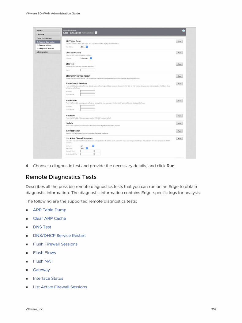
4 Choose a diagnostic test and provide the necessary details, and click Run.
Remote Diagnostics Tests
Describes all the possible remote diagnostics tests that you can run on an Edge to obtain diagnostic information. The diagnostic information contains Edge-specific logs for analysis.
The following are the supported remote diagnostics tests:
n ARP Table Dump
n Clear ARP Cache
n DNS Test
n DNS/DHCP Service Restart
n Flush Firewall Sessions
n Flush Flows
n Flush NAT
n Gateway
n Interface Status
n List Active Firewall Sessions
VMware SD-WAN Administration Guide
VMware, Inc. 352

n List Active Flows
n List Clients
n List Paths
n MIBs for Edge
n NAT Table Dump
n NTP Dump
n Ping Test
n Route Table Dump
n System Health
n Traceroute
n Troubleshoot BGP - List BGP Redistributed Routes
n Troubleshoot BGP - List BGP Routes
n Troubleshoot BGP - List Routes per Prefix
n Troubleshoot BGP - Show BGP Neighbor Advertised Routes
n Troubleshoot BGP - Show BGP Neighbor Learned Routes
n Troubleshoot BGP - Show BGP Neighbor Received Routes
n Troubleshoot BGP - Show BGP Routes per Prefix
n Troubleshoot BGP - Show BGP Summary
n Troubleshoot BGP - Show BGP Table
n Troubleshoot OSPF - List OSPF Redistributed Routes
n Troubleshoot OSPF - List OSPF Routes
n Troubleshoot OSPF - Show OSPF Database
n Troubleshoot OSPF - Show OSPF Database for E1 Self-Originate Routes
n Troubleshoot OSPF - Show OSPF Neighbors
n Troubleshoot OSPF - Show OSPF Route Table
n Troubleshoot OSPF - Show OSPF Setting
n VPN Test
n WAN Link Bandwidth Test
ARP Table Dump
Run this test to view the contents of the ARP table. The output is limited to display 1000 ARP entries.
VMware SD-WAN Administration Guide
VMware, Inc. 353

Clear ARP Cache
Run this test to clear the ARP cache entries for the specified interface.
DNS Test
Run this test to perform a DNS lookup of the specified domain name.
VMware SD-WAN Administration Guide
VMware, Inc. 354

DNS/DHCP Service Restart
Run this test to restart the DNS/DHCP service. This can serve as a troubleshooting step if DHCP or DNS requests are failing for clients.
Flush Firewall Sessions
Run this test to reset established sessions from the firewall. Running this test on an Edge not only flushes the firewall sessions, but actively send a TCP RST for the TCP-based sessions.
Flush Flows
Run this test to flush the flow table, causing user traffic to be re-classified. Use source and destination IP address filters to flush specific flows.
Flush NAT
Run this test to flush the NAT table.
Gateway
Run this test by choosing whether cloud traffic should or should not use the Gateway Service.
Note This does not affect the routing of VPN traffic.
VMware SD-WAN Administration Guide
VMware, Inc. 355

Interface Status
Run this test to view the MAC address and connection status of physical interfaces.
List Active Firewall Sessions
Run this test to view the current state of the active firewall sessions (up to a maximum of 1000 sessions). You can limit the number of sessions returned by using filters: source and destination IP address, source and destination port, and Segment.
Note You cannot see sessions that were denied as they are not active sessions. To troubleshoot those sessions you will need to check the firewall logs.
VMware SD-WAN Administration Guide
VMware, Inc. 356
The Remote Diagnostics output displays the following information: Segment name, Source IP, Source Port, Destination IP, Destination Port, Protocol, Application, Firewall Policy, current TCP state of any flows, Bytes Received/Sent, and Duration. There are 11 distinct TCP states as defined in RFC 793:
n LISTEN - represents waiting for a connection request from any remote TCP and port. (This state is not shown in a Remote Diagnostic output).
n SYN-SENT - represents waiting for a matching connection request after having sent a connection request.
n SYN-RECEIVED - represents waiting for a confirming connection request acknowledgment after having both received and sent a connection request.
n ESTABLISHED - represents an open connection, data received can be delivered to the user. The normal state for the data transfer phase of the connection.
n FIN-WAIT-1 - represents waiting for a connection termination request from the remote TCP, or an acknowledgment of the connection termination request previously sent.
n FIN-WAIT-2 - represents waiting for a connection termination request from the remote TCP.
n CLOSE-WAIT - represents waiting for a connection termination request from the local user.
n CLOSING - represents waiting for a connection termination request acknowledgment from the remote TCP.
n LAST-ACK - represents waiting for an acknowledgment of the connection termination request previously sent to the remote TCP (which includes an acknowledgment of its connection termination request).
n TIME-WAIT - represents waiting for enough time to pass to be sure the remote TCP received the acknowledgment of its connection termination request.
n CLOSED - represents no connection state at all.
List Active Flows
Run this test to list active flows in the system. Use source and destination IP address filters to view the exact flows you want to see. This output is limited to a maximum of 1000 flows.
VMware SD-WAN Administration Guide
VMware, Inc. 357

List Clients
Run this test to view the complete list of clients.
List Paths
Run this test to view the list of active paths between local WAN links and each peer.
VMware SD-WAN Administration Guide
VMware, Inc. 358

MIBs for Edge
Run this test to dump Edge MIBs.
NAT Table Dump
Run this test to view the contents of the NAT Table. Use the destination IP address filter to view the exact entries you want to see. This output is limited to a maximum of 1000 entries.
VMware SD-WAN Administration Guide
VMware, Inc. 359

NTP Dump
Run this test to view the current date and time on Edge and NTP information.
Ping Test
Run a ping test to the destination specified.
VMware SD-WAN Administration Guide
VMware, Inc. 360

Route Table Dump
Run this test to view the contents of the Route Table.
System Health
Run this test to view system information such as system load, recent WAN stability statistics, monitoring services. WAN stability statistics include the number of times individual VPN tunnels and WAN links lost connectivity for at least 700 milliseconds.
VMware SD-WAN Administration Guide
VMware, Inc. 361

Traceroute
Run a traceroute via the Gateway or directly out any of the WAN interfaces to the destination specified.
Troubleshoot BGP - List BGP Redistributed Routes
Run this test to view routes redistributed to BGP neighbors.
VMware SD-WAN Administration Guide
VMware, Inc. 362

Troubleshoot BGP - List BGP Routes
Run this test to view the specific BGP routes from neighbors, leave prefix empty to view all.
Troubleshoot BGP - List Routes per Prefix
Run this test to view all the Overlay and Underlay routes for a prefix and the related details.
VMware SD-WAN Administration Guide
VMware, Inc. 363

Troubleshoot BGP - Show BGP Neighbor Advertised Routes
Run this test to view the BGP routes advertised to a neighbor.
Troubleshoot BGP - Show BGP Neighbor Learned Routes
Run this test to view all the accepted BGP routes learned from a neighbor after filters.
Troubleshoot BGP - Show BGP Neighbor Received Routes
Run this test to view all the BGP routes learned from a neighbor before filters.
VMware SD-WAN Administration Guide
VMware, Inc. 364
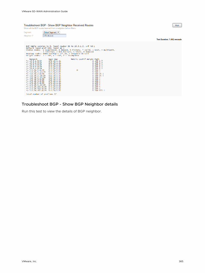
Troubleshoot BGP - Show BGP Neighbor details
Run this test to view the details of BGP neighbor.
VMware SD-WAN Administration Guide
VMware, Inc. 365

Troubleshoot BGP - Show BGP Routes per Prefix
Run this test to view all the BGP routes and their attributes for the specified prefix.
VMware SD-WAN Administration Guide
VMware, Inc. 366

Troubleshoot BGP - Show BGP Summary
Run this test to view the existing BGP neighbor and received routes.
Troubleshoot BGP - Show BGP Table
Run this test to view the BGP table.
Troubleshoot OSPF - List OSPF Redistributed Routes
Run this test to view all the routes redistributed to OSPF neighbor.
VMware SD-WAN Administration Guide
VMware, Inc. 367
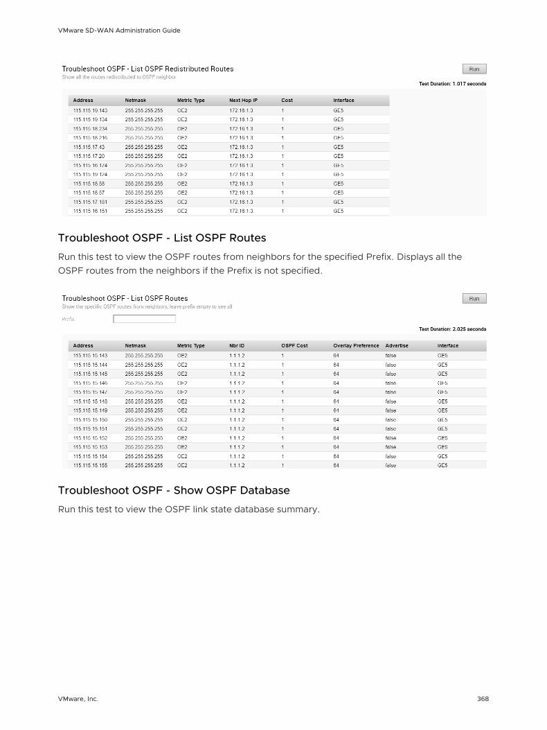
Troubleshoot OSPF - List OSPF Routes
Run this test to view the OSPF routes from neighbors for the specified Prefix. Displays all the OSPF routes from the neighbors if the Prefix is not specified.
Troubleshoot OSPF - Show OSPF Database
Run this test to view the OSPF link state database summary.
VMware SD-WAN Administration Guide
VMware, Inc. 368

Troubleshoot OSPF - Show OSPF Database for E1 Self-Originate Routes
Run this test to view the E1 LSA's self-originated routes that are advertised to OSPF router by the Edge.
Troubleshoot OSPF - Show OSPF Neighbors
Run this test to view all the OSPF neighbors and associated information.
VMware SD-WAN Administration Guide
VMware, Inc. 369
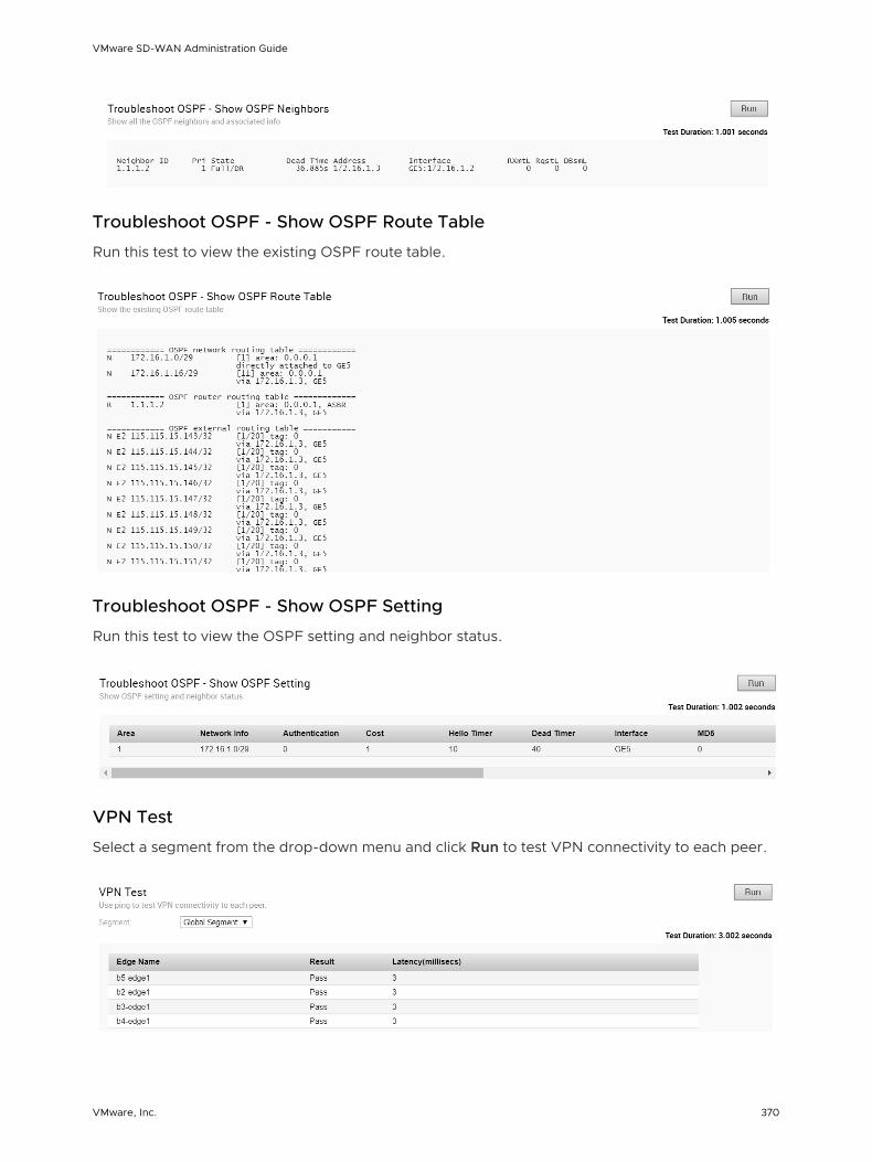
Troubleshoot OSPF - Show OSPF Route Table
Run this test to view the existing OSPF route table.
Troubleshoot OSPF - Show OSPF Setting
Run this test to view the OSPF setting and neighbor status.
VPN Test
Select a segment from the drop-down menu and click Run to test VPN connectivity to each peer.
VMware SD-WAN Administration Guide
VMware, Inc. 370

When the VPN test is run, the Edge selects the Source and Destination IP and initiates the tunnel request. The selected Source and Destination IP should meet the following criteria:
n It should be a connected route IP
n It should be reachable and the routes should be advertised
When the Edge cannot select a valid IP as the Source IP to initiate the tunnel request, the VPN Test will fail with the following error.
Branch-to-Branch vpn is disabled. Please enable it before running the test
WAN Link Bandwidth Test
Run the bandwidth test on a specified WAN link. This test has the benefit of being non-disruptive in multi-link environments. Only the link under test is blocked for user traffic. This means that you can re-run the test on a specific link and the other link(s) will continue to serve user traffic.
As the bandwidth test is run when the tunnel reconnects after a period of instability, there have been occasions in the field where the link has recovered enough for tunnel connectivity, but not enough to accurately measure the bandwidth of the WAN link. To address these scenarios, if the bandwidth test fails or measures a significantly reduced value, the last known “good” measurement will be used and a re-test of the link will be scheduled for 30 minutes after the tunnel is established to ensure a proper measurement.
Note For WAN link over 1 Gbps, it is recommended that the user define the bandwidth of the WAN link.
Remote Actions
You can perform actions like Restarting services, Rebooting, or deactivating an Edge remotely, from the Enterprise portal.
You can perform the remote actions only on Edge that are in Connected state.
1 In the Enterprise portal, click Test & Troubleshoot > Remote Actions.
2 The Remote Edge Actions page displays all the connected Edges. Search for an Edge if necessary using the Filter, and click Apply.
3 Click the link to a connected Edge.
In the Edge Remote Actions window, click the relevant action. The action is performed on the selected Edge.
VMware SD-WAN Administration Guide
VMware, Inc. 371

4 You can perform the following actions:
Action Description
Identify Randomly flash lights on the selected Edge to identify the device.
Restart Service Restarts the VMware services on the selected Edge.
Reboot Reboots the selected Edge.
Shutdown Power off the selected Edge.
Deactivate Resets the device configuration to its factory default state.
Note The actions may take up to a minute to run on the device.
Diagnostic Bundles
Diagnostic bundles allow Operator users to collect all the configuration files and log files into a consolidated Zipped file. The data available in the diagnostic bundles can be used for debugging purposes.
In the Enterprise portal, click Test & Troubleshooting > Diagnostic Bundles.
VMware SD-WAN Administration Guide
VMware, Inc. 372

The Diagnostic Bundles window allows to request for the following bundles:
n PCAP Bundle – The Packet Capture bundle is a collection of the packet data of the network. Operators, Standard Admins and Customer Support can request PCAP bundles. See Request Packet Capture.
n Diagnostic Bundle – The Diagnostic bundle is a collection of all the configuration and logs from a specific Edge. Only Operators can request Diagnostic bundles. See Request Diagnostic Bundle.
The generated bundles are displayed in the Diagnostic Bundles window. To download the bundle files, see Download Bundle.
The Diagnostic Bundles option is available only for an Operator user. If you are a Partner user or an Enterprise user, you can request for a PCAP Bundle.
In the Enterprise portal, click Test & Troubleshooting > Packet Capture.
Click Request PCAP Bundle to generate Packet Capture bundle, which is a collection of the packet data of the network. See Request Packet Capture.
Request Packet Capture
The Packet Capture function is used to collect debugging information from an Edge device.
Access Packet Capture from Test & Troubleshoot > Packet Capture.
To request a packet capture:
1 Click Packet Capture under Test & Troubleshoot.
The Packet Capture screen appears. If applicable, the status of previous requests are shown.
2 Click the Request PCAP button at the top right corner of the screen.
3 In the Request PCAP Bundle dialog box, choose your Target, Interface, and Duration. If necessary, type in a reason for the generation.
VMware SD-WAN Administration Guide
VMware, Inc. 373

4 Click Submit. A pop-up message (Successful Request) appears in the top right corner of the screen.
The Packet Capture screen updates to show the status of the request. Refresh your screen or click Packet Capture from the navigation panel to display status results. When complete, you can get detailed information (Generation Time, Bundle Size, etc.) by clicking the gray arrow located next to the last column on the far right.
Note The Packet Capture data for a particular Edge will get deleted from the system on the date displayed in the Cleanup Date column. Click the Cleanup Date link to indicate a date to remove the data or select the Keep Forever checkbox and the data will not get deleted; it will be kept until you indicate otherwise.
Click the Actions button to download or delete the bundle. See the sections below for more information.
Request Diagnostic Bundle
Only Operators can request Diagnostic Bundles. If you are an Operator, you can access the Diagnostic Bundle button in the Test & Troubleshooting > Diagnostic Bundles page.
VMware SD-WAN Administration Guide
VMware, Inc. 374

To request a diagnostic bundle:
1 Click the Request Diagnostic Bundle button located on the top right corner of the Diagnostic Bundles page.
2 In the Request Diagnostic Bundle dialog box:
a In the Target drop-down menu, select the specific Edge from which you will receive the data.
b If you want to indicate the reason for request, include that in the Reason for Generation textbox.
c For an advanced request, click the Advanced button and choose a limit from the Core Limit drop-down menu. The Core Limit is used to reduce the size of the uploaded bundle when the Internet connectivity is experiencing errors.
d Click the Submit button.
The Diagnostic Request bundle for the selected Edge is in the Pending state, as shown in the Request Status column in the Diagnostic Bundles window. When finished, the status will change to Complete. The Complete status is a link that you can click to download the bundle.
Download Bundle
When the request is complete, you can download the bundle in one of the following ways:
n Click the Download symbol next to a completed PCAP request under the Request Status column.
n Click the Complete link in the Request Status column for your selected Edge.
n Select the checkbox of one or more completed PCAP requests, and click the down arrow of the Action button (top, right corner of the screen) and choose Download.
You can forward the downloaded bundle to a VMware Networks Support representative.
VMware SD-WAN Administration Guide
VMware, Inc. 375

Delete Bundle
If you want to delete a Packet Capture, select one or more Packet Captures from the Request Status column and choose Delete from the Actions button.
Note If a Packet Capture request is pending, you can delete the request before the request is completed. Select the checkbox of the pending request you want to delete, and click the Action button, and choose Delete.
VMware SD-WAN Administration Guide
VMware, Inc. 376
Enterprise Administration 21The Administration option in the Enterprise portal allows you to configure the System settings, Authentication information, create Admin users, and manage Edge licenses.
In the Enterprise portal, click Administration to configure the following:
n System Settings– Configure the user information and enterprise authentication. See System Settings.
n Administrators– Create or modify admin users with different role privileges. See Manage Admin Users.
n Edge Licensing– View and generate a report of Edge licenses. See Edge Licensing.
This chapter includes the following topics:
n System Settings
n Manage Admin Users
n Edge Licensing
System Settings
The System Settings option allows you to configure administrator settings along with the authentication details.
In the Enterprise portal, click Administration > System Settings to configure the following:
n General Information– Configure the user details, enable Edge configuration updates, configure privacy settings, and enter the contact information. See Configure Enterprise Information.
n Authentication– Configure authentication mode and view the API tokens. See Configure Enterprise Authentication.
Configure Enterprise Information
You can configure the user information, Edge updates, privacy settings, and contact details for the users using General Information.
In the Enterprise portal, click Administration > System Settings. You can configure the following in the General Information tab.
VMware, Inc. 377
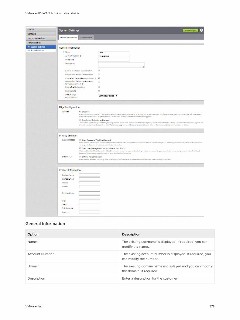
General Information
Option Description
Name The existing username is displayed. If required, you can modify the name.
Account Number The existing account number is displayed. If required, you can modify the number.
Domain The existing domain name is displayed and you can modify the domain, if required.
Description Enter a description for the customer.
VMware SD-WAN Administration Guide
VMware, Inc. 378
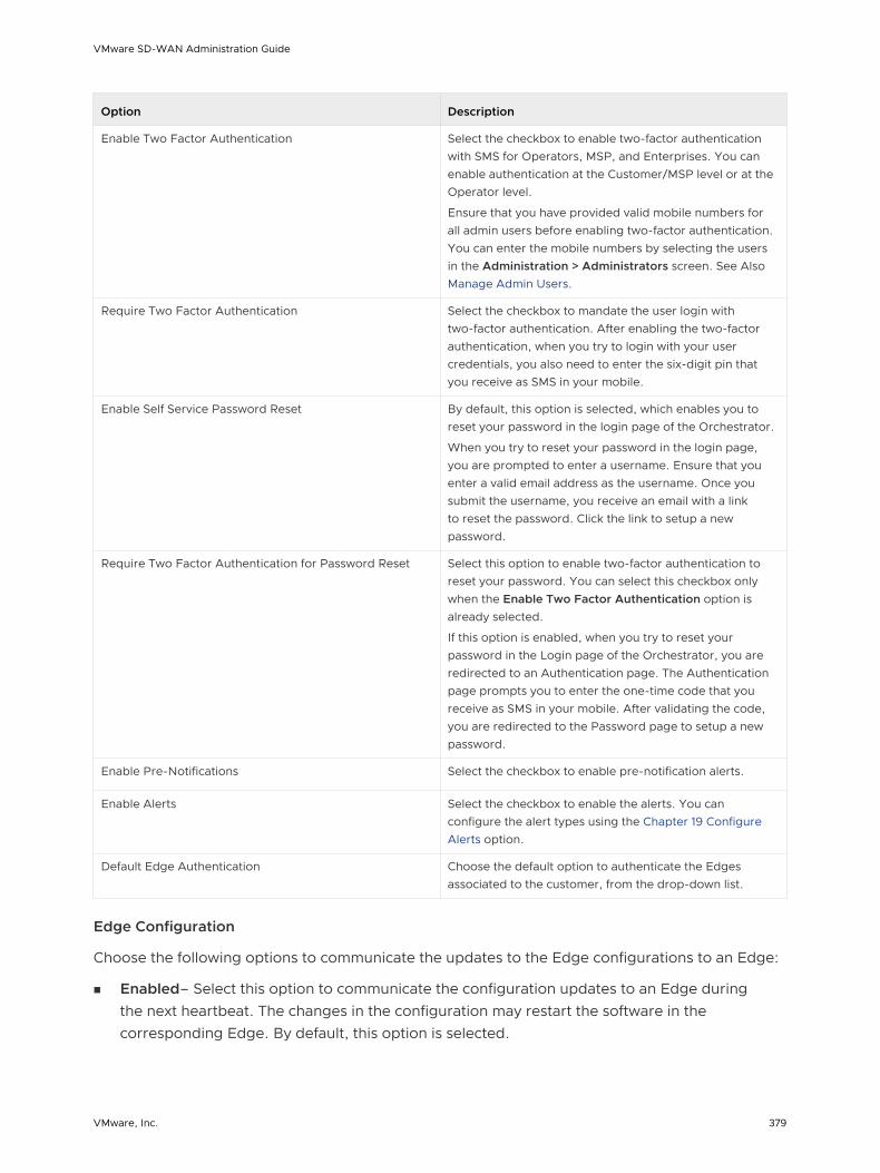
Option Description
Enable Two Factor Authentication Select the checkbox to enable two-factor authentication with SMS for Operators, MSP, and Enterprises. You can enable authentication at the Customer/MSP level or at the Operator level.
Ensure that you have provided valid mobile numbers for all admin users before enabling two-factor authentication. You can enter the mobile numbers by selecting the users in the Administration > Administrators screen. See Also Manage Admin Users.
Require Two Factor Authentication Select the checkbox to mandate the user login with two-factor authentication. After enabling the two-factor authentication, when you try to login with your user credentials, you also need to enter the six-digit pin that you receive as SMS in your mobile.
Enable Self Service Password Reset By default, this option is selected, which enables you to reset your password in the login page of the Orchestrator.
When you try to reset your password in the login page, you are prompted to enter a username. Ensure that you enter a valid email address as the username. Once you submit the username, you receive an email with a link to reset the password. Click the link to setup a new password.
Require Two Factor Authentication for Password Reset Select this option to enable two-factor authentication to reset your password. You can select this checkbox only when the Enable Two Factor Authentication option is already selected.
If this option is enabled, when you try to reset your password in the Login page of the Orchestrator, you are redirected to an Authentication page. The Authentication page prompts you to enter the one-time code that you receive as SMS in your mobile. After validating the code, you are redirected to the Password page to setup a new password.
Enable Pre-Notifications Select the checkbox to enable pre-notification alerts.
Enable Alerts Select the checkbox to enable the alerts. You can configure the alert types using the Chapter 19 Configure Alerts option.
Default Edge Authentication Choose the default option to authenticate the Edges associated to the customer, from the drop-down list.
Edge Configuration
Choose the following options to communicate the updates to the Edge configurations to an Edge:
n Enabled– Select this option to communicate the configuration updates to an Edge during the next heartbeat. The changes in the configuration may restart the software in the corresponding Edge. By default, this option is selected.
VMware SD-WAN Administration Guide
VMware, Inc. 379

n Enabled on Orchestrator Upgrade – Select this option to communicate the updates in the configurations to the Edges when the Orchestrator is upgraded. This may restart the software in the corresponding Edges.
Privacy Settings
n Support Access – Choose the following options to grant access to the Support team.
n Grant Access to VeloCloud Support – Select this option to grant access to the VMware Support to view, configure, and troubleshoot the Edges connected to the customer. For security reasons, the Support cannot access or view the user identifiable information.
n Grant User Management Access to VeloCloud Support – Select this option to enable the VMware Support to assist in user management. The user management includes options to create users, reset password, and configure other settings. In this case, the Support has access to user identifiable information.
n Enforce PCI – Select this option to prevent operations that are disallowed for PCI compliance reasons. Currently the only operation this option prevents is the ability to request PCAP Diagnostic Bundles from the Edge.
Contact Information
The existing contact details are displayed in this section. If required, you can modify the details.
Configure Enterprise Authentication
In the Authentication tab, you can setup the authentication mode for the enterprises and view the existing API tokens.
In the Enterprise portal, click Administration > System Settings > Authentication to configure the following:
Enterprise Authentication
VMware SD-WAN Administration Guide
VMware, Inc. 380

Choose one of the following from the Authentication Mode.
n NATIVE – This is the default authentication mode and you can login to the Enterprise with the native username and password. This mode does not require any configuration.
n SSO – Single Sign On (SSO) is a session and user authentication service that allows the users to log into the Enterprise with one set of login credentials to access multiple applications. For more information, see Overview of Single Sign On and Configure Single Sign On for Enterprise User.
API Tokens
You can access the Orchestrator APIs using token-based authentication, irrespective of the authentication mode. You can view the existing API tokens in this section.
The Operator Super User or the User associated with an API token can revoke the token. Select the token and click Actions > Revoke . To create and download the API tokens, see API Tokens.
Overview of Single Sign On
The SD-WAN Orchestrator supports a new type of user authentication called Single Sign On (SSO) for all Orchestrator user types: Operator, Partner, and Enterprise.
Single Sign On (SSO) is a session and user authentication service that allows SD-WAN Orchestrator users to log in to the SD-WAN Orchestrator with one set of login credentials to access multiple applications. Integrating the SSO service with SD-WAN Orchestrator improves the security of user authentication for SD-WAN Orchestrator users and enables SD-WAN Orchestrator to authenticate users from other OpenID Connect (OIDC)-based Identity Providers (IDPs). The following IDPs are currently supported:
n Okta
n OneLogin
n PingIdentity
n AzureAD
n VMwareCSP
Configure Single Sign On for Enterprise User
To setup Single Sign On (SSO) authentication for Enterprise user, perform the steps in this procedure.
Prerequisites
n Ensure that you have the Enterprise super user permission.
n Before setting up the SSO authentication, ensure you have set up roles, users, and OpenID connect (OIDC) application for SD-WAN Orchestrator in your preferred identity provider’s website. For more information, see Configure an IDP for Single Sign On.
VMware SD-WAN Administration Guide
VMware, Inc. 381

Procedure
1 Log in to a SD-WAN Orchestrator application as Enterprise super user, with your login credentials.
2 Click Administration > System Settings
The System Settings screen appears.
3 Click the General Information tab and in the Domain text box, enter the domain name for your enterprise, if it is not already set.
Note To enable SSO authentication for the SD-WAN Orchestrator, you must set up the domain name for your enterprise.
4 Click the Authentication tab and from the Authentication Mode drop-down menu, select SSO.
VMware SD-WAN Administration Guide
VMware, Inc. 382

5 From the Identity Provider template drop-down menu, select your preferred Identity Provider (IDP) that you have configured for Single Sign On.
Note If you select VMwareCSP as your preferred IDP, ensure to provide your Organization ID in the following format: /csp/gateway/am/api/orgs/<full organization ID>.
When you sign in to VMware CSP console, you can view the organization ID you are logged into by clicking on your username. A shortened version of the ID is displayed under the organization name. Click the ID to display the full organization ID.
You can also manually configure your own IDPs by selecting Others from the Identity Provider template drop-down menu.
6 In the OIDC well-known config URL text box, enter the OpenID Connect (OIDC) configuration URL for your IDP. For example, the URL format for Okta will be: https://{oauth-provider-url}/.well-known/openid-configuration.
7 The SD-WAN Orchestrator application auto-populates endpoint details such as Issuer, Authorization Endpoint, Token Endpoint, and User Information Endpoint for your IDP.
8 In the Client Id text box, enter the client identifier provided by your IDP.
9 In the Client Secret text box, enter the client secret code provided by your IDP, that is used by the client to exchange an authorization code for a token.
10 To determine user’s role in SD-WAN Orchestrator, select one of the options:
n Use Default Role – Allows user to configure a static role as default by using the Default Role text box that appears on selecting this option. The supported roles are: Enterprise Superuser, Enterprise Standard Admin, Enterprise Support, and Enterprise Read Only.
Note In a SSO configuration setup, if Use Default Role option is selected and a default user role is defined, then all the SSO user will be assigned the specified default role. Instead of assigning a user with the default role, a Standard Administrator Super User or Standard Administrator can pre-register a specific user as a Non-Native user and define a specific user role by clicking the Administration > Administrators tab in the Enterprise portal. For steps to configure a new Administrator User, see Create New Admin User.
n Use Identity Provider Roles – Uses the roles set up in the IDP.
11 On selecting the Use Identity Provider Roles option, in the Role Attribute text box, enter the name of the attribute set in the IDP to return roles.
12 In the Role Map area, map the IDP-provided roles to each of the SD-WAN Orchestrator roles, separated by using commas.
Roles in VMware CSP will follow this format: external/<service definition uuid>/<service role name mentioned during service template creation>.
VMware SD-WAN Administration Guide
VMware, Inc. 383

13 Update the allowed redirect URLs in OIDC provider website with SD-WAN Orchestrator URL (https://<Orchestrator URL>/login/ssologin/openidCallback).
14 Click Save Changes to save the SSO configuration.
15 Click Test Configuration to validate the entered OpenID Connect (OIDC) configuration.
The user is navigated to the IDP website and allowed to enter the credentials. On IDP verification and successful redirect to SD-WAN Orchestrator test call back, a successful validation message will be displayed.
Results
The SSO authentication setup is complete.
What to do next
Chapter 5 Log in to VMware SD-WAN Orchestrator Using SSO for Enterprise User.
Configure an IDP for Single Sign On
To enable Single Sign On (SSO) for SD-WAN Orchestrator, you must configure an Identity Partner (IDP) with details of SD-WAN Orchestrator. Currently, the following IDPs are supported: Okta, OneLogin, PingIdentity, AzureAD, and VMware CSP.
For step-by-step instructions to configure an OpenID Connect (OIDC) application for SD-WAN Orchestrator in various IDPs, see:
n Configure Okta for Single Sign On
n Configure OneLogin for Single Sign On
n Configure PingIdentity for Single Sign On
n Configure Azure Active Directory for Single Sign On
n Configure VMware CSP for Single Sign On
Configure Okta for Single Sign On
To support OpenID Connect (OIDC)-based Single Sign On (SSO) from Okta, you must first set up an application in Okta. To set up an OIDC-based application in Okta for SSO, perform the steps on this procedure.
Prerequisites
Ensure you have an Okta account to sign in.
Procedure
1 Log in to your Okta account as an Admin user.
The Okta home screen appears.
Note If you are in the Developer Console view, then you must switch to the Classic UI view by selecting Classic UI from the Developer Console drop-down list.
VMware SD-WAN Administration Guide
VMware, Inc. 384
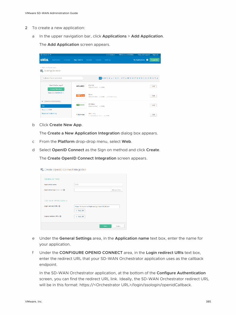
2 To create a new application:
a In the upper navigation bar, click Applications > Add Application.
The Add Application screen appears.
b Click Create New App.
The Create a New Application Integration dialog box appears.
c From the Platform drop-drop menu, select Web.
d Select OpenID Connect as the Sign on method and click Create.
The Create OpenID Connect Integration screen appears.
e Under the General Settings area, in the Application name text box, enter the name for your application.
f Under the CONFIGURE OPENID CONNECT area, in the Login redirect URIs text box, enter the redirect URL that your SD-WAN Orchestrator application uses as the callback endpoint.
In the SD-WAN Orchestrator application, at the bottom of the Configure Authentication screen, you can find the redirect URL link. Ideally, the SD-WAN Orchestrator redirect URL will be in this format: https://<Orchestrator URL>/login/ssologin/openidCallback.
VMware SD-WAN Administration Guide
VMware, Inc. 385

g Click Save. The newly created application page appears.
h On the General tab, click Edit and select Refresh Token for Allowed grant types, and click Save.
Note down the Client Credentials (Client ID and Client Secret) to be used during the SSO configuration in SD-WAN Orchestrator.
i Click the Sign On tab and under the OpenID Connect ID Token area, click Edit.
j From the Groups claim type drop-down menu, select Expression. By default, Groups claim type is set to Filter.
VMware SD-WAN Administration Guide
VMware, Inc. 386
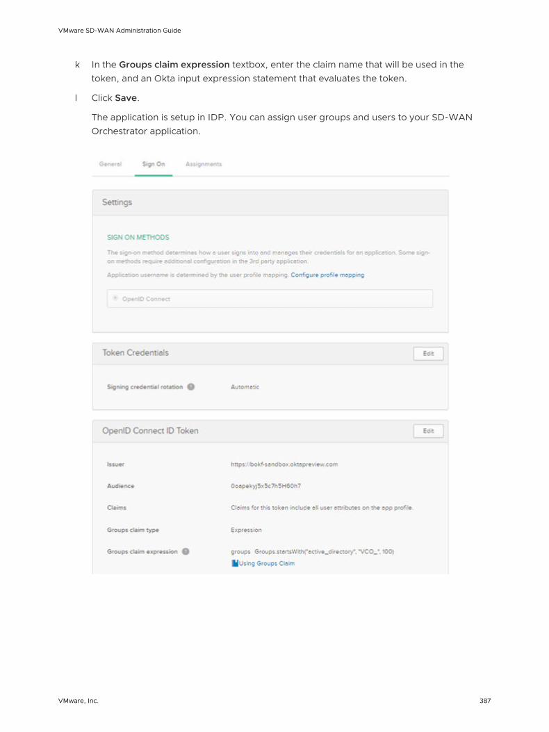
k In the Groups claim expression textbox, enter the claim name that will be used in the token, and an Okta input expression statement that evaluates the token.
l Click Save.
The application is setup in IDP. You can assign user groups and users to your SD-WAN Orchestrator application.
VMware SD-WAN Administration Guide
VMware, Inc. 387

3 To assign groups and users to your SD-WAN Orchestrator application:
a Go to Application > Applications and click on your SD-WAN Orchestrator application link.
b On the Assignments tab, from the Assign drop-down menu, select Assign to Groups or Assign to People.
The Assign <Application Name> to Groups or Assign <Application Name> to People dialog box appears.
c Click Assign next to available user groups or users you want to assign the SD-WAN Orchestrator application and click Done.
The users or user groups assigned to the SD-WAN Orchestrator application will be displayed.
Results
You have completed setting up an OIDC-based application in Okta for SSO.
What to do next
Configure Single Sign On in SD-WAN Orchestrator.
Create a New User Group in OktaTo create a new user group, perform the steps on this procedure.
Procedure
1 Click Directory > Groups.
2 Click Add Group.
The Add Group dialog box appears.
VMware SD-WAN Administration Guide
VMware, Inc. 388

3 Enter the group name and description for the group and click Save.
Create a New User in OktaTo add a new user, perform the steps on this procedure.
Procedure
1 Click Directory > People.
2 Click Add Person.
The Add Person dialog box appears.
3 Enter all the mandatory details such as first name, last name, and email ID of the user.
4 If you want to set the password, select Set by user from the Password drop-down menu and enable Send user activation email now.
5 Click Save.
An activation link email will be sent your email ID. Click the link in the email to activate your Okta user account.
Configure OneLogin for Single Sign On
To set up an OpenID Connect (OIDC)-based application in OneLogin for Single Sign On (SSO), perform the steps on this procedure.
Prerequisites
Ensure you have an OneLogin account to sign in.
Procedure
1 Log in to your OneLogin account as an Admin user.
The OneLogin home screen appears.
VMware SD-WAN Administration Guide
VMware, Inc. 389

2 To create a new application:
a In the upper navigation bar, click Apps > Add Apps.
b In the Find Applications text box, search for “OpenId Connect” or “oidc” and then select the OpenId Connect (OIDC) app.
The Add OpenId Connect (OIDC) screen appears.
c In the Display Name text box, enter the name for your application and click Save.
d On the Configuration tab, enter the redirect URI that SD-WAN Orchestrator uses as the callback endpoint and click Save.
In the SD-WAN Orchestrator application, at the bottom of the Authentication screen, you can find the redirect URL link. Ideally, the SD-WAN Orchestrator redirect URL will be in this format: https://<Orchestrator URL>/login/ssologin/openidCallback.
VMware SD-WAN Administration Guide
VMware, Inc. 390

e On the Parameters tab, under OpenId Connect (OIDC), double click Groups.
The Edit Field Groups popup appears.
f Configure User Roles with value “--No transform--(Single value output)” to be sent in groups attribute and click Save.
g On the SSO tab, from the Application Type drop-down menu, select Web.
VMware SD-WAN Administration Guide
VMware, Inc. 391

h From the Authentication Method drop-down menu, select POST as the Token Endpoint and click Save.
Also, note down the Client Credentials (Client ID and Client Secret) to be used during the SSO configuration in SD-WAN Orchestrator.
i On the Access tab, choose the roles that will be allowed to login and click Save.
3 To add roles and users to your SD-WAN Orchestrator application:
a Click Users > Users and select a user.
b On the Application tab, from the Roles drop-down menu, on the left, select a role to be mapped to the user.
c Click Save Users.
Results
You have completed setting up an OIDC-based application in OneLogin for SSO.
What to do next
Configure Single Sign On in SD-WAN Orchestrator.
VMware SD-WAN Administration Guide
VMware, Inc. 392

Create a New Role in OneLoginTo create a new role, perform the steps on this procedure.
Procedure
1 Click Users > Roles.
2 Click New Role.
3 Enter a name for the role.
When you first set up a role, the Applications tab displays all the apps in your company catalog.
4 Click an application to select it and click Save to add the selected apps to the role.
Create a New User in OneLoginTo create a new user, perform the steps on this procedure.
Procedure
1 Click Users > Users > New User.
The New User screen appears
2 Enter all the mandatory details such as first name, last name, and email ID of the user and click Save User.
Configure PingIdentity for Single Sign On
To set up an OpenID Connect (OIDC)-based application in PingIdentity for Single Sign On (SSO), perform the steps on this procedure.
Prerequisites
Ensure you have a PingOne account to sign in.
Note Currently, SD-WAN Orchestrator supports PingOne as the Identity Partner (IDP); however, any PingIdentity product supporting OIDC can be easily configured.
Procedure
1 Log in to your PingOne account as an Admin user.
The PingOne home screen appears.
VMware SD-WAN Administration Guide
VMware, Inc. 393
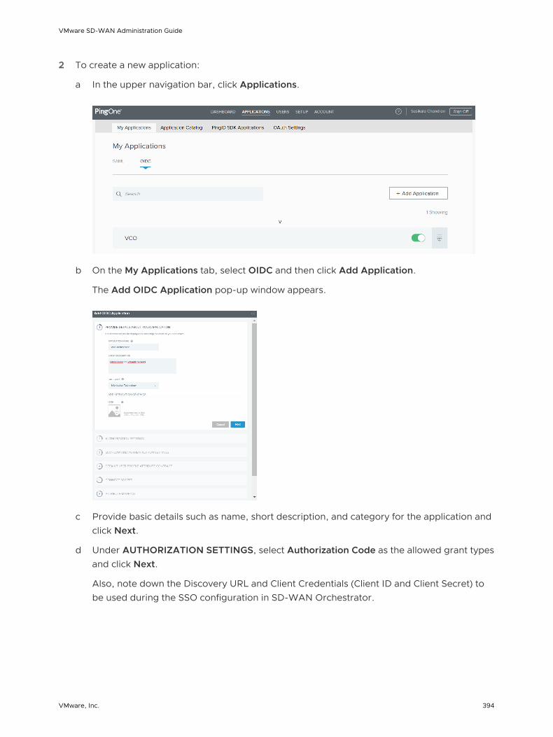
2 To create a new application:
a In the upper navigation bar, click Applications.
b On the My Applications tab, select OIDC and then click Add Application.
The Add OIDC Application pop-up window appears.
c Provide basic details such as name, short description, and category for the application and click Next.
d Under AUTHORIZATION SETTINGS, select Authorization Code as the allowed grant types and click Next.
Also, note down the Discovery URL and Client Credentials (Client ID and Client Secret) to be used during the SSO configuration in SD-WAN Orchestrator.
VMware SD-WAN Administration Guide
VMware, Inc. 394

e Under SSO FLOW AND AUTHENTICATION SETTINGS, provide valid values for Start SSO URL and Redirect URL and click Next.
In the SD-WAN Orchestrator application, at the bottom of the Configure Authentication screen, you can find the redirect URL link. Ideally, the SD-WAN Orchestrator redirect URL will be in this format: https://<Orchestrator URL>/login/ssologin/openidCallback. The Start SSO URL will be in this format: https://<Orchestrator URL>/<domain name>/login/doEnterpriseSsoLogin.
f Under DEFAULT USER PROFILE ATTRIBUTE CONTRACT, click Add Attribute to add additional user profile attributes.
g In the Attribute Name text box, enter group_membership and then select the Required checkbox, and select Next.
Note The group_membership attribute is required to retrieve roles from PingOne.
h Under CONNECT SCOPES, select the scopes that can be requested for your SD-WAN Orchestrator application during authentication and click Next.
i Under Attribute Mapping, map your identity repository attributes to the claims available to your SD-WAN Orchestrator application.
Note The minimum required mappings for the integration to work are email, given_name, family_name, phone_number, sub, and group_membership (mapped to memberOf).
j Under Group Access, select all user groups that should have access to your SD-WAN Orchestrator application and click Done.
The application will be added to your account and will be available in the My Application screen.
Results
You have completed setting up an OIDC-based application in PingOne for SSO.
What to do next
Configure Single Sign On in SD-WAN Orchestrator.
Create a New User Group in PingIdentityTo create a new user group, perform the steps on this procedure.
Procedure
1 Click Users > User Directory.
2 On the Groups tab, click Add Group
The New Group screen appears.
3 In the Name text box, enter a name for the group and click Save.
VMware SD-WAN Administration Guide
VMware, Inc. 395

Create a New User in PingIdentityTo add a new user, perform the steps on this procedure.
Procedure
1 Click Users > User Directory.
2 On the Users tab, click the Add Users drop-down menu and select Create New User.
The User screen appears.
3 Enter all the mandatory details such as username, password, and email ID of the user.
4 Under Group Memberships, click Add.
The Add Group Membership pop-up window appears.
5 Search and add the user to a group and click Save.
Configure Azure Active Directory for Single Sign On
To set up an OpenID Connect (OIDC)-based application in Microsoft Azure Active Directory (AzureAD) for Single Sign On (SSO), perform the steps on this procedure.
Prerequisites
Ensure you have an AzureAD account to sign in.
Procedure
1 Log in to your Microsoft Azure account as an Admin user.
The Microsoft Azure home screen appears.
VMware SD-WAN Administration Guide
VMware, Inc. 396

2 To create a new application:
a Search and select the Azure Active Directory service.
b Go to App registration > New registration.
The Register an application screen appears.
c In the Name field, enter the name for your SD-WAN Orchestrator application.
d In the Redirect URL field, enter the redirect URL that your SD-WAN Orchestrator application uses as the callback endpoint.
In the SD-WAN Orchestrator application, at the bottom of the Configure Authentication screen, you can find the redirect URL link. Ideally, the SD-WAN Orchestrator redirect URL will be in this format: https://<Orchestrator URL>/login/ssologin/openidCallback.
VMware SD-WAN Administration Guide
VMware, Inc. 397

e Click Register.
Your SD-WAN Orchestrator application will be registered and displayed in the All applications and Owned applications tabs. Make sure to note down the Client ID/Application ID to be used during the SSO configuration in SD-WAN Orchestrator.
f Click Endpoints and copy the well-known OIDC configuration URL to be used during the SSO configuration in SD-WAN Orchestrator.
g To create a client secret for your SD-WAN Orchestrator application, on the Owned applications tab, click on your SD-WAN Orchestrator application.
h Go to Certificates & secrets > New client secret.
The Add a client secret screen appears.
i Provide details such as description and expiry value for the secret and click Add.
The client secret will be created for the application. Note down the new client secret value to be used during the SSO configuration in SD-WAN Orchestrator.
j To configure permissions for your SD-WAN Orchestrator application, click on your SD-WAN Orchestrator application and go to API permissions > Add a permission.
The Request API permissions screen appears.
VMware SD-WAN Administration Guide
VMware, Inc. 398

k Click Microsoft Graph and select Application permissions as the type of permission for your application.
l Under Select permissions, from the Directory drop-down menu, select Directory.Read.All and from the User drop-down menu, select User.Read.All.
m Click Add permissions.
VMware SD-WAN Administration Guide
VMware, Inc. 399

n To add and save roles in the manifest, click on your SD-WAN Orchestrator application and from the application Overview screen, click Manifest.
A web-based manifest editor opens, allowing you to edit the manifest within the portal. Optionally, you can select Download to edit the manifest locally, and then use Upload to reapply it to your application.
o In the manifest, search for the appRoles array and add one or more role objects as shown
in the following example and click Save.
Sample role objects
{ "allowedMemberTypes": [ "User" ], "description": "Standard Administrator who will have sufficient privilege to manage resource", "displayName": "Standard Admin", "id": "18fcaa1a-853f-426d-9a25-ddd7ca7145c1", "isEnabled": true, "lang": null, "origin": "Application", "value": "standard" }, { "allowedMemberTypes": [ "User" ], "description": "Super Admin who will have the full privilege on SD-WAN Orchestrator", "displayName": "Super Admin", "id": "cd1d0438-56c8-4c22-adc5-2dcfbf6dee75", "isEnabled": true, "lang": null, "origin": "Application", "value": "superuser" }
VMware SD-WAN Administration Guide
VMware, Inc. 400
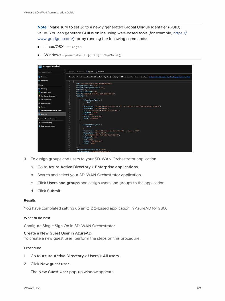
Note Make sure to set id to a newly generated Global Unique Identifier (GUID)
value. You can generate GUIDs online using web-based tools (for example, https://www.guidgen.com/), or by running the following commands:
n Linux/OSX - uuidgen
n Windows - powershell [guid]::NewGuid()
3 To assign groups and users to your SD-WAN Orchestrator application:
a Go to Azure Active Directory > Enterprise applications.
b Search and select your SD-WAN Orchestrator application.
c Click Users and groups and assign users and groups to the application.
d Click Submit.
Results
You have completed setting up an OIDC-based application in AzureAD for SSO.
What to do next
Configure Single Sign On in SD-WAN Orchestrator.
Create a New Guest User in AzureADTo create a new guest user, perform the steps on this procedure.
Procedure
1 Go to Azure Active Directory > Users > All users.
2 Click New guest user.
The New Guest User pop-up window appears.
VMware SD-WAN Administration Guide
VMware, Inc. 401
3 In the Email address text box, enter the email address of the guest user and click Invite.
The guest user immediately receives a customizable invitation that lets them to sign into their Access Panel.
4 Guest users in the directory can be assigned to apps or groups.
Configure VMware CSP for Single Sign On
To configure VMware Cloud Services Platform (CSP) for Single Sign On (SSO), perform the steps on this procedure.
Prerequisites
Sign in to VMware CSP console (staging or production environment) with your VMware account ID. If you are new to VMware Cloud and do not have a VMware account, you can create one as you sign up. For more information, see How do I Sign up for VMware CSP section in Using Vmware Cloud documentation.
Procedure
1 Contact the VMware Support Provider for receiving a Service invitation URL link to register your SD-WAN Orchestrator application to VMware CSP. For information on how to contact the Support Provider, see https://kb.vmware.com/s/article/53907 and https://www.vmware.com/support/contacts/us_support.html.
The VMware Support Provider will create and share:
n a Service invitation URL that needs to be redeemed to your Customer organization
n a Service definition uuid and Service role name to be used for Role mapping in Orchestrator
2 Redeem the Service invitation URL to your existing Customer Organization or create a new Customer Organization by following the steps in the UI screen.
You need to be a Organization Owner to redeem the Service invitation URL to your existing Customer Organization.
3 After redeeming the Service invitation, when you sign in to VMware CSP console, you can view your application tile under My Services area in the Vmware Cloud Services page.
The Organization you are logged into is displayed under your username on the menu bar. Make a note of the Organization ID by clicking on your username, to be used during Orchestrator configuration. A shortened version of the ID is displayed under the Organization name. Click the ID to display the full Organization ID.
VMware SD-WAN Administration Guide
VMware, Inc. 402

4 Log in to VMware CSP console and create an OAuth application. For steps, see Use OAuth 2.0 for Web Apps. Make sure to set Redirect URI to the URL displayed in Configure Authentication screen in Orchestrator.
Once OAuth application is created in VMware CSP console, make a note of IDP integration details such as Client ID and Client Secret. These details will be needed for SSO configuration in Orchestrator.
5 Log in to your SD-WAN Orchestrator application as Super Admin user and configure SSO using the IDP integration details as follows.
a Click Administration > System Settings
The System Settings screen appears.
b Click the General Information tab and in the Domain text box, enter the domain name for your enterprise, if it is not already set.
Note To enable SSO authentication for the SD-WAN Orchestrator, you must set up the domain name for your enterprise.
c Click the Authentication tab and from the Authentication Mode drop-down menu, select SSO.
d From the Identity Provider template drop-down menu, select VMwareCSP.
e In the Organization Id text box, enter the Organization ID (that you have noted down in Step 3) in the following format: /csp/gateway/am/api/orgs/<full organization ID>.
f In the OIDC well-known config URL text box, enter the OpenID Connect (OIDC) configuration URL (https://console.cloud.vmware.com/csp/gateway/am/api/.well-known/openid-configuration) for your IDP.
The SD-WAN Orchestrator application auto-populates endpoint details such as Issuer, Authorization Endpoint, Token Endpoint, and User Information Endpoint for your IDP.
g In the Client Id text box, enter the client ID that you have noted down from the OAuth application creation step.
h In the Client Secret text box, enter the client secret code that you have noted down from the OAuth application creation step.
i To determine user’s role in SD-WAN Orchestrator, select either Use Default Role or Use Identity Provider Roles.
j On selecting the Use Identity Provider Roles option, in the Role Attribute text box, enter the name of the attribute set in the VMware CSP to return roles.
k In the Role Map area, map the VMwareCSP-provided roles to each of the SD-WAN Orchestrator roles, separated by using commas.
Roles in VMware CSP will follow this format: external/<service definition uuid>/<service role name mentioned during service template creation>. Use the same Service definition uuid and Service role name that you have received from your Support Provider.
VMware SD-WAN Administration Guide
VMware, Inc. 403

6 Click Save Changes to save the SSO configuration.
7 Click Test Configuration to validate the entered OpenID Connect (OIDC) configuration.
The user is navigated to the VMware CSP website and allowed to enter the credentials. On IDP verification and successful redirect to SD-WAN Orchestrator test call back, a successful validation message will be displayed.
Results
You have completed integrating SD-WAN Orchestrator application in VMware CSP for SSO and can access the SD-WAN Orchestrator application logging in to the VMware CSP console.
What to do next
n Within the organization, manage users by adding new users and assigning appropriate role for the users. For more information, see the Identity & Access Management section in Using Vmware Cloud documentation.
Manage Admin Users
The Administrators page displays the existing admin users. Standard Administrator Superusers and Standard Administrators can create new admin users with different role privileges and configure API tokens for each admin user.
In the Enterprise portal, click Administration > Administrators.
VMware SD-WAN Administration Guide
VMware, Inc. 404

Click Actions to perform the following activities:
n New Admin: Creates new admin users. See Create New Admin User.
n Modify Admin: Modifies the properties of the selected admin user. You can also click the link to the username to modify the properties. See Configure Admin Users.
n Password Reset: Sends an Email to the selected user with a link to reset the password.
n Delete Admin: Deletes the selected users.
Create New Admin User
Standard Administrator Superusers and Standard Administrators can create new admin users.
In the Enterprise portal, click Administration > Administrators.
Procedure
1 You can create new admin users by clicking either New Admin, or Actions > New Admin .
2 In the New Admin window, enter the following details:
a Enter the user details like username, password, Name, Email, and Phone numbers. The username should be in the format of email address, like [email protected]. The password must meet the following requirements:
n The number of characters must be in the range of 8 to 32.
n Must have at least one lower case character.
n Must have at least one number.
b If you have chosen the authentication mode as Native in Configure Enterprise Authentication, then the type of the user is selected as Native. If you have chosen a different authentication mode, you can choose the type of the user. If you choose the user to be Non-Native, the password option is not available, as it is inherited from the authentication mode.
c Account Role: Choose the user role from the available options.
VMware SD-WAN Administration Guide
VMware, Inc. 405
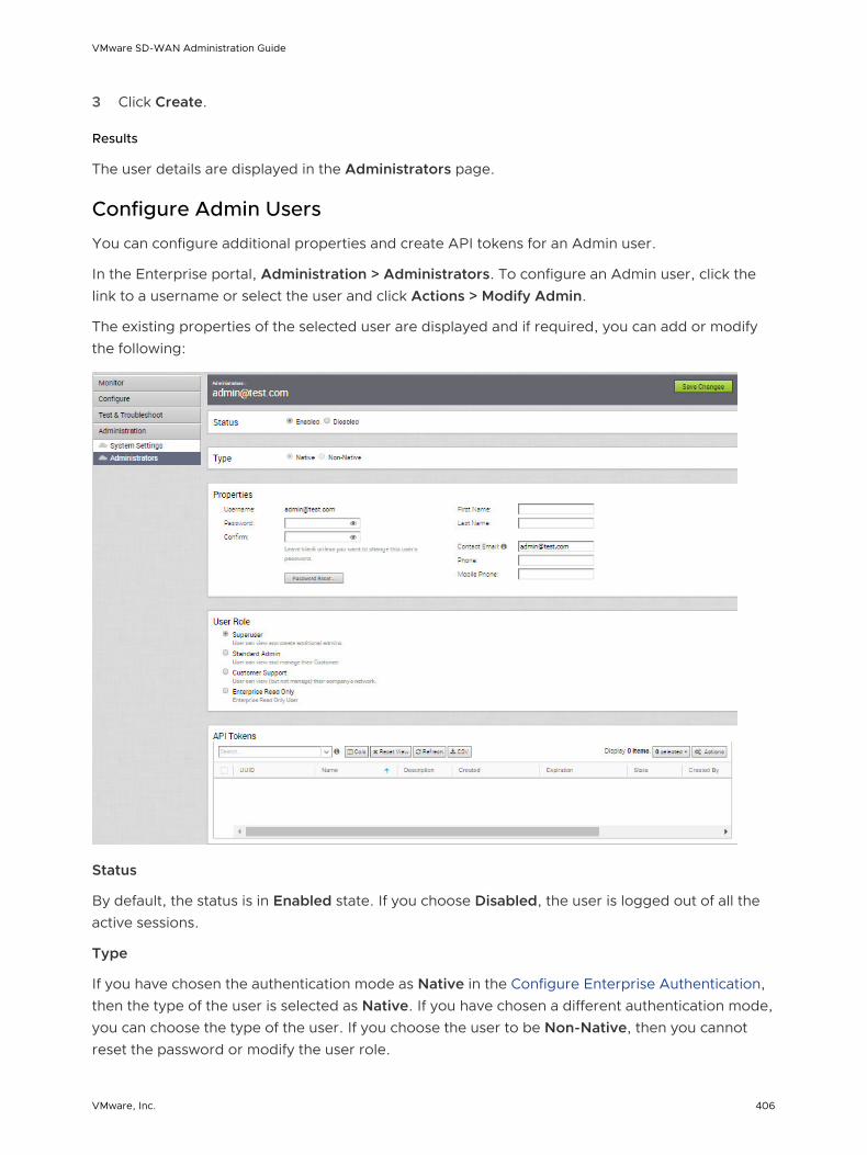
3 Click Create.
Results
The user details are displayed in the Administrators page.
Configure Admin Users
You can configure additional properties and create API tokens for an Admin user.
In the Enterprise portal, Administration > Administrators. To configure an Admin user, click the link to a username or select the user and click Actions > Modify Admin.
The existing properties of the selected user are displayed and if required, you can add or modify the following:
Status
By default, the status is in Enabled state. If you choose Disabled, the user is logged out of all the active sessions.
Type
If you have chosen the authentication mode as Native in the Configure Enterprise Authentication, then the type of the user is selected as Native. If you have chosen a different authentication mode, you can choose the type of the user. If you choose the user to be Non-Native, then you cannot reset the password or modify the user role.
VMware SD-WAN Administration Guide
VMware, Inc. 406

Properties
The existing contact details of the user are displayed. If required, you can modify the details and choose to reset the password. If you click Password Reset, an email is sent to the user with a link to reset the password.
Role
The existing type of the user role is displayed. If required, you can choose a different role for the user. The role privileges change accordingly.
API Tokens
The users can access the Orchestrator APIs using tokens instead of session-based authentication. As an Operator Super User, you can manage the API tokens for the customers. You can create multiple API tokens for a user.
For Enterprise Read Only Users and MSP Business Specialist users, token-based authentication is not enabled.
Configure API Tokens
Any user can create tokens based on the privileges they have been assigned to their user roles, except the Enterprise Read-Only users and MSP Business Specialist users.
The users can perform the following actions, based on their roles:
n Enterprise users can Create, Download, and Revoke tokens for them.
n Operator Super users can manage tokens of other Operator users and Enterprise users, if the Enterprise user has delegated user permissions to the Operator.
n Enterprise Super users can manage the tokens of all the users within that Enterprise.
n Users can download only their own tokens and cannot download other users' tokens.
n Super users can only create and revoke the tokens for other users.
To manage the API tokens:
n In the API Tokens section, click Actions > New API Token, to create a new token.
n In the New API Token window, enter a Name and Description for the token, and choose the Lifetime from the drop-down menu.
n Click Create and the new token is displayed in the API Tokens grid.
VMware SD-WAN Administration Guide
VMware, Inc. 407

n Initially, the status of the token is displayed as Pending. To download the token, select the token, and click Actions > Download API Token. The status changes to Enabled, which means that the API token can be used for API access.
n To disable a token, select the token and click Actions > Revoke API Token. The status of the token is displayed as Revoked.
n When the Lifetime of the token is over, the status changes to Expired state.
Only the user who is associated with a token can download it and after downloading, the ID of the token alone is displayed. You can download a token only once.
After downloading the token, the user can send it as part of the Authorization Header of the request to access the Orchestrator API.
The following example shows a sample snippet of the code to access an API.
curl -k -H "Authorization: Token <Token>" -X POST https://vco/portal/ -d '{ "id": 1, "jsonrpc": "2.0", "method": "enterprise/getEnterpriseUsers", "params": { "enterpriseId": 1 }}'
After modifying the settings and API Tokens, click Save Changes.
Edge Licensing
SD-WAN Orchestrator provides different types of Licenses for the Edges. Standard Administrator Superusers, Standard Administrators, Business Specialists, and Customer Support users can view and generate a report of the licenses assigned to them.
In the Enterprise portal, click Administration > Edge Licensing.
Note The Edge Licensing tab is available only when the Operator has enabled Edge Licensing and assigned the licenses to the enterprise customer.
Click Report to generate a report of the licenses and the associated Edges in MS Excel format.
To assign a license to an Edge:
n In the Enterprise portal, click Configure > Edges.
n To assign license to each Edge, click the link to the Edge and select the License in the Edge Overview page. You can also select the Edge and click Actions > Assign Edge License to assign the License.
VMware SD-WAN Administration Guide
VMware, Inc. 408

n To assign a license to multiple Edges, select the appropriate Edges, click Actions > Assign Edge License and select the License.
For more information, see Chapter 14 Edge Overview Tab.
VMware SD-WAN Administration Guide
VMware, Inc. 409

Configure SD-WAN Edge High Availability 22This section describes how to enable high availability on SD-WAN Edge.
This chapter includes the following topics:
n Overview of SD-WAN Edge HA
n Prerequisites
n High Availability Options
n Split-Brain Condition
n Split-Brain Detection and Prevention
n Failure Scenarios
n Support for BGP Over HA Link
n Selection Criteria to Determine Active and Standby Status
n VLAN-tagged Traffic Over HA Link
n Configure HA
n HA Event Details
n Deploying HA on VMware ESXi
Overview of SD-WAN Edge HA
The SD-WAN Edge is the VMware data plane component that is deployed at an end user’s branch location. SD-WAN Edges configured in High Availability (HA) mode are mirror images of each other and they show up on the SD-WAN Orchestrator as a single SD-WAN Edge.
There are two options when configuring in HA mode:
1 HA Option 1
2 HA Option 2
For a description of both options, see High Availability (HA) Options.
This document describes the steps necessary to enable High Availability (HA) and bring up a second SD-WAN Edge as a Standby device to an activated Edge.
VMware, Inc. 410
Prerequisites
This section describes HA requirements that must be met before configuring a SD-WAN Edge as a Standby.
n The two SD-WAN Edges must be the same model.
n Only one SD-WAN Edge should be provisioned on the SD-WAN Orchestrator.
n The Standby SD-WAN Edge must not have an existing configuration on it.
High Availability Options
Edges can be installed as a single standalone device or paired with another Edge to provide High Availability (HA) support. However, the HA configuration is supported only on wired WAN connections.
HA Options
When you configure the Edges in HA mode, the Edges automatically select one of the following options:
n Standard HA – This option is selected when both the Active and Standby Edges are connected to the same WAN links.
n Enhanced HA – This option is selected when the Edges are connected to different WAN links.
The HA options are supported on the following SD-WAN Edge platforms: 510, 510N, 520, 520v, 540, 610, 610N, 620, 620N, 640, 640N, 680, 680N, 840, 2000, 3400, 3800, and Virtual Edge.
Note HA is supported only between identical SD-WAN Edge platform models. For more information on the Edge platform models, see https://sdwan.vmware.com/get-started.
Note Mixing Wi-Fi capable and Non-Wi-Fi capable Edges in High Availability deployments is not supported. While the Edge models 510N, 610N, 620N, 640N, and 680N appear identical to their Wi-Fi capable counterparts, deploying a Wi-Fi capable Edge and a Non-Wi-Fi capable Edge of the same model (for example, an Edge 640 and an Edge 640N) as a High-Availability pair is not supported. Customers should ensure that the Edges deployed as a High Availability pair are of the same type: both Wi-Fi capable, or both Non-Wi-Fi capable.
HA Option 1: Standard HA
This section describes HA Option 1: Standard HA.
Topology Overview for HA Option 1
The following figure shows a conceptual overview of HA Option 1.
VMware SD-WAN Administration Guide
VMware, Inc. 411

The Edges, one Active and one Standby, are connected by L1 ports to establish a failover link. The Standby SD-WAN Edge blocks all ports except the L1 port for the failover link.
Prerequisites for HA option 1
n The LAN side switches in the following configuration descriptions must be STP capable and configured with STP.
n In addition, SD-WAN Edge LAN and WAN ports must be connected to different L2 switches. If it is necessary to connect the ports to the same switch, then the LAN and WAN ports must be isolated.
n The two SD-WAN Edges must have mirrored physical WAN and LAN connections.
Deployment Types for HA option 1
HA option 1 has two possible deployment types:
n Deployment Type One uses L2 switches
n Deployment Type 2 uses a combination of L2 and L3 switches
The following sections describe these two deployment types.
Deployment Type One: High Availability (HA) using L2 Switches
The following figure shows the network connections using only L2 switches.
VMware SD-WAN Administration Guide
VMware, Inc. 412

W1 and W2 are WAN connections used to connect to the L2 switch to provide WAN connectivity to both ISPs. The L1 link connects the two SD-WAN Edges and is used for ‘keep-alive’ and communication between the SD-WAN Edges for HA support. The SD-WAN Edge’s LAN connections are used to connect to the access layer L2 switches.
Considerations for Deployment Type One
n The same ISP link must be connected to the same port on both Edges.
n Use the L2 switch to make the same ISP link available to both Edges.
n The Standby SD-WAN Edge does not interfere with any traffic by blocking all its ports except the failover link (L1 port).
n Session information is synchronized between the Active and Standby SD-WAN Edges through the failover link.
n If the Active Edge detects a loss of a LAN link, it will also failover to the Standby if it has an Active LAN link.
Deployment Type Two: HA Availability (HA) using L2/L3 Switches
The following figure shows the network connections using L2 and L3 switches.
VMware SD-WAN Administration Guide
VMware, Inc. 413

The SD-WAN Edge WAN connections (W1 and W2) are used to connect to L2 switches to provide a WAN connection to ISP1 and ISP2 respectively. The L1 connections on the SD-WAN Edges are connected to provide a failover link for HA support. The VMware Edge LAN connections are used to connect L2 Switches, which have several end-user devices connected.
Considerations for Deployment Type Two
n HSRP/VRRP is required on the L3 switch pair.
n The SD-WAN Edge's static route points to the L3 switches’ HSRP VIP as the next hop to reach the end stations behind L2 switches.
n The same ISP link must be connected to the same port on both SD-WAN Edges. The L2 switch must make the same ISP link available to both Edges.
n The Standby SD-WAN Edge does not interfere with any traffic by blocking all of its ports except the failover link (L1 port).
n The session information is synchronized between the Active and Standby SD-WAN Edges through the failover link.
VMware SD-WAN Administration Guide
VMware, Inc. 414
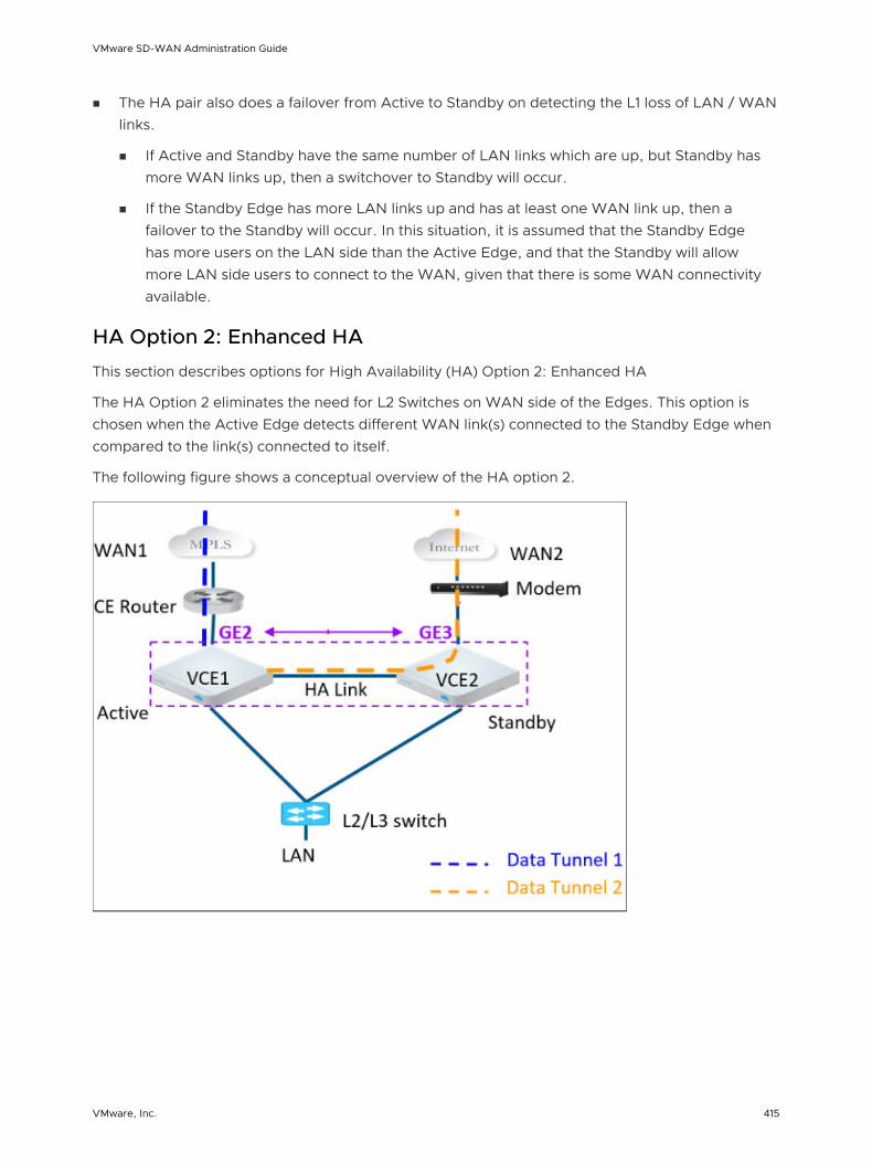
n The HA pair also does a failover from Active to Standby on detecting the L1 loss of LAN / WAN links.
n If Active and Standby have the same number of LAN links which are up, but Standby has more WAN links up, then a switchover to Standby will occur.
n If the Standby Edge has more LAN links up and has at least one WAN link up, then a failover to the Standby will occur. In this situation, it is assumed that the Standby Edge has more users on the LAN side than the Active Edge, and that the Standby will allow more LAN side users to connect to the WAN, given that there is some WAN connectivity available.
HA Option 2: Enhanced HA
This section describes options for High Availability (HA) Option 2: Enhanced HA
The HA Option 2 eliminates the need for L2 Switches on WAN side of the Edges. This option is chosen when the Active Edge detects different WAN link(s) connected to the Standby Edge when compared to the link(s) connected to itself.
The following figure shows a conceptual overview of the HA option 2.
VMware SD-WAN Administration Guide
VMware, Inc. 415

The Edges, one Active and one Standby, are connected by L1 ports to establish a failover link. The Standby SD-WAN Edge blocks all ports except the L1 port for the failover link. As shown in the figure, the Active Edge establishes overlay tunnels on both WAN links (connected to itself and the Standby Edge).
Note The two SD-WAN Edges should not have mirrored physical WAN connections. As shown in the figure, if VCE1 has GE2 as the WAN link, VCE2 cannot have GE2 as its WAN link.
In order to leverage the WAN link connected to the Standby Edge, the Active Edge establishes the overlay tunnel through the HA link. Traffic from the LAN is forwarded to the Active Edge. The business policy for the branch defines the traffic distribution across the overlay tunnels.
Split-Brain Condition
When the HA link is disconnected or when the Active and Standby Edges fail to communicate with each other, both Edges assume the Active role. As a result, both Edges start responding to ARP requests on their LAN interfaces. This causes LAN traffic to be forwarded to both Edges, which could result in spanning tree loops on the LAN.
Typically, switches run the Spanning Tree Protocol to prevent loops in the network. In such a condition, the switch would block traffic to one or both Edges. This would cause a total loss of traffic through the Edge pair.
Note Tunnel to Primary Gateway is a requirement for split-brain detection. Therefore, in WAN 2, there should be a tunnel to SD-WAN Gateway.
Split-Brain Detection and Prevention
The primary Gateway is used to prevent split-brain conditions.
The Gateway has a pre-existing connection to the Active Edge. In a split-brain condition, the Standby Edge, changes state to Active and tries to establish a tunnel with the Gateway. The Gateway will send a response back to the Standby Edge instructing it to move to Standby state, and will not allow the tunnel to be established. Gateway will always have tunnels from just the Active Edge. Only the LAN interfaces remain blocked (as long as the HA cable is down). As illustrated in the following figure, the Gateway signals VCE1 to go into Standby mode on the LAN. This will logically prevent the split-brain scenario from occurring.
Note The normal failover from Active to Standby in a split-brain scenario is not the same as the normal failover. It could take a few extra milliseconds/seconds to converge.
VMware SD-WAN Administration Guide
VMware, Inc. 416
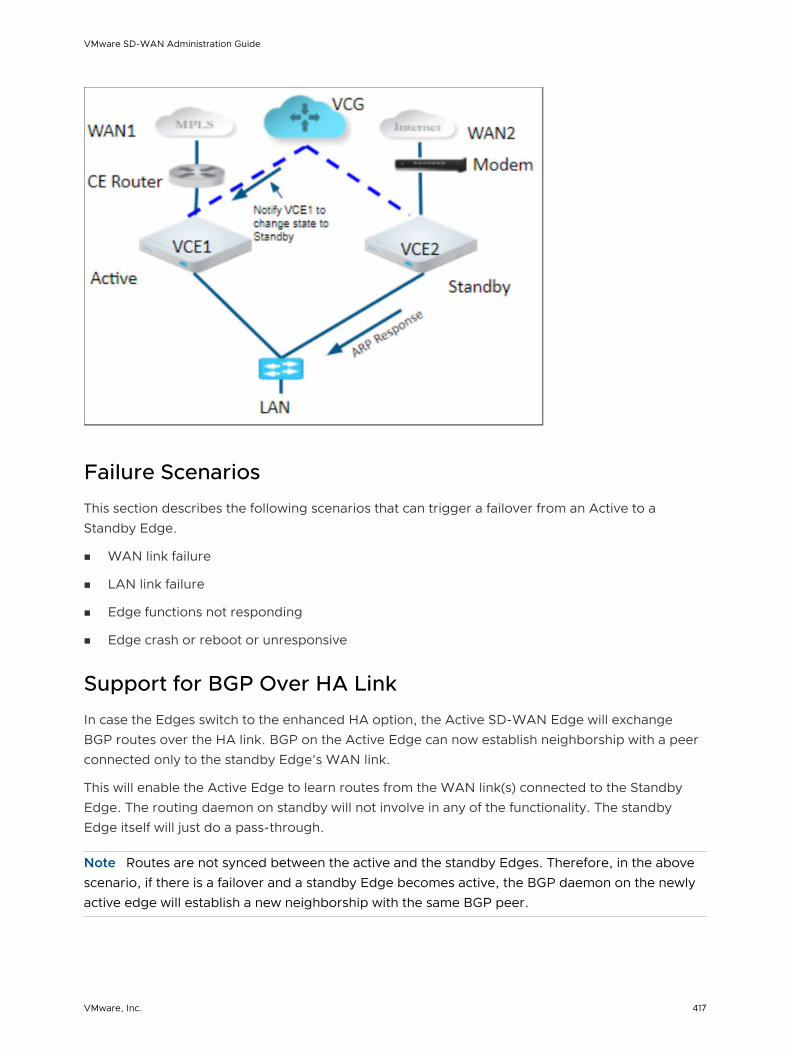
Failure Scenarios
This section describes the following scenarios that can trigger a failover from an Active to a Standby Edge.
n WAN link failure
n LAN link failure
n Edge functions not responding
n Edge crash or reboot or unresponsive
Support for BGP Over HA Link
In case the Edges switch to the enhanced HA option, the Active SD-WAN Edge will exchange BGP routes over the HA link. BGP on the Active Edge can now establish neighborship with a peer connected only to the standby Edge’s WAN link.
This will enable the Active Edge to learn routes from the WAN link(s) connected to the Standby Edge. The routing daemon on standby will not involve in any of the functionality. The standby Edge itself will just do a pass-through.
Note Routes are not synced between the active and the standby Edges. Therefore, in the above scenario, if there is a failover and a standby Edge becomes active, the BGP daemon on the newly active edge will establish a new neighborship with the same BGP peer.
VMware SD-WAN Administration Guide
VMware, Inc. 417

Selection Criteria to Determine Active and Standby Status
This section describes the selection criteria used to determine Active and Standby Status.
n Check for the Edge that has a higher number (L2 and L3) LAN interfaces. The Edge with the higher number of LAN interfaces is chosen as the Active one. Note that the interface used for the HA link is not counted as a LAN interface.
n If both Edges have the same number of LAN interfaces, the Edge with the higher number of WAN interfaces is chosen as the Active one.
Note There is no preemption if the two Edges have the same number of LAN and WAN interfaces.
n Additional Support Matrix:
n Static/DHCP/PPPoE links are supported.
n Multiple WAN links each tagged with a separate VLAN ID on a single interface (e.g. Sub-Interfaces) are supported.
n USB modems are not recommended on HA. The interface will not be used when present in the Standby Edge.
VLAN-tagged Traffic Over HA Link
This section describes the VLAN-tagged Traffic over an HA Link.
n Internet traffic from ISP2 is VLAN tagged.
n Customer will have separate VLANs for Enterprise traffic versus DIA traffic.
n The WAN link on the Standby has sub-interfaces to carry Internet traffic.
n Multi segments
VMware SD-WAN Administration Guide
VMware, Inc. 418

Configure HA
To configure High Availability, configure the Active and Standby Edges.
Enable High Availability (HA)
To enable the HA feature on the SD-WAN Orchestrator:
1 From the navigation panel, go to Configure > Edges.
2 Select your SD-WAN Edge, and then click the Device tab.
3 From the High Availability area, click Active Standby Pair.
By default, the GE1 or LAN1 interface will be used as the HA interface to connect the pair depending on the SD-WAN Edge model.
Note This is available on as an Edge Override and is not configurable at the Profile level. Do not connect the Standby SD-WAN Edge.
VMware SD-WAN Administration Guide
VMware, Inc. 419

Wait for SD-WAN Edge to Assume Active
After the High Availability feature is enabled on the SD-WAN Orchestrator, wait for the existing SD-WAN Edge to assume an Active role, and wait for the SD-WAN Orchestrator Events to display High Availability Going Active.
Connect the Standby SD-WAN Edge to the Active Edge
1 Power on the Standby SD-WAN Edge without any network connections.
2 After it boots up, connect the LAN1/GE1 interface (as indicated on the Device tab) to the same interface on the Active SD-WAN Edge.
3 Wait for the Active SD-WAN Edge to detect and activate the standby SD-WAN Edge automatically. The SD-WAN Orchestrator Events displays HA Standby Activated when the SD-WAN Orchestrator successfully activates the standby SD-WAN Edge.
The standby Edge will then begin to synchronize with the active SD-WAN Edge and reboot automatically during the process.
Note It may take up to 10 minutes for the Standby SD-WAN Edge to sync with the Active Edge and upgrade its software.
Connect LAN and WAN Interfaces on Standby SD-WAN Edge
Connect the LAN and WAN interfaces on the standby SD-WAN Edge mirroring the network connectivity on the Active Edge.
The SD-WAN Orchestrator Events will display Standby device software update completed. The HA State in the Monitor > Edges page appears green when ready.
VMware SD-WAN Administration Guide
VMware, Inc. 420

HA Event Details
This section describes HA events.
HA Event Description
HA_GOING_ACTIVE A standby SD-WAN Edge is taking over as Active because it has not heard a heartbeat from the peer.
HA_STANDBY_ACTIVATED When a new Standby is detected by the Active, the Active tries to activate the Edge by sending this event to the SD-WAN Orchestrator. On a successful response, the Active will sync the configurations and sync data.
HA_FAILED Typically happens after the HA pair has formed and the Active SD-WAN Edge no longer hears from the Standby SD-WAN Edge. For example, if the Standby SD-WAN Edge reboots, you will receive this message.
HA_READY Means the Active SD-WAN Edge now hears from the Standby SD-WAN Edge. Once the Standby SD-WAN Edge comes back up and reestablishes the heartbeat, then you will receive this message.
HA_TERMINATED When the HA configuration is disabled, and it is successfully applied on the Edges, this Event is generated.
HA_ACTIVATION_FAILURE If the SD-WAN Orchestrator is unable to verify the HA activation, it will generate this Event. Examples include:
n the SD-WAN Orchestrator is unable to generate a certificate
n the HA has been deactivated (rare)
Deploying HA on VMware ESXi
You can deploy the VMware SD-WAN HA on VMware ESXi using the supported topologies.
While deploying HA on VMware ESXi, consider the following limitations:
Limitations of VMware ESXi
n vSwitches do not support the Link Loss Forwarding feature. This feature ensures that the failures on the physical interface are propagated to the virtual interfaces of the vSwitch and thereby supporting link level failures. As vSwitches do not support this option, even if a physical adapter goes down, the VMware Edges will see the link up and they would not failover.
n vSwitches do not allow to configure specific VLANs on a port group if you want to allow more than one VLAN. Instead of the specific VLANs, you need to configure 4095, which means allowing all the VLANs.
VMware SD-WAN Administration Guide
VMware, Inc. 421

Limitations of VMware SD-WAN HA
n There is no generic way of failure detection that will work on all the hardware, virtual, and uCPE platforms.
VMware SD-WAN supports the following topologies while deploying HA on VMware ESXi:
Topology 1: Legacy HA with WAN links
The following image illustrates a topology with legacy HA along with WAN links that have been uplinked using a single physical adapter and one routed LAN or trunked LAN through single physical adapter.
WAN1VLAN 100
WAN2VLAN 200
WAN1VLAN 100
WAN2VLAN 200
br-HA Link
vSwitch 1VLAN4095
VMware SD-WAN Edge1
vSwitch3
vSwitch2
4095
vSwitch 1 VLAN4095
VMware SD-WAN Edge2
vSwitch3
vSwitch2
4095
L2 LAN Switch orL3 Switch
VLAN 30,VLAN 40
VLAN 30,VLAN 40
WAN Slide Switch
VLAN 100,VLAN 200
VLAN 100,VLAN 200
vmnic1
vmnic2
vmnic1
vmnic2
VMware SD-WAN Administration Guide
VMware, Inc. 422

Topology 2: Enhanced HA with WAN Links
The following topology shows enhanced HA with three WAN links.
br-HA Link
vSwitch 1VLAN4095
VMware SD-WAN Edge1
WAN1VLAN 100
vSwitch3
vSwitch2
VLAN 100
vSwitch 4
4095
VLAN 300
WAN3VLAN 300
vSwitch 1 VLAN4095
VMware SD-WAN Edge2
WAN2VLAN 4095
vSwitch3
vSwitch2
VLAN 200
4095
L2 LAN Switch orL3 Switch
VLAN 30,VLAN 40
VLAN 30,VLAN 40
vmnic1
vmnic2
vmnic4
vmnic2
vmnic3
Topology 3: Enhanced HA with Subinterfaces
VMware SD-WAN Administration Guide
VMware, Inc. 423

The following image shows Enhanced HA with subinterfaces on the WAN interfaces with VLAN ID as 4095 on port group.
br-HA Link
vSwitch 1VLAN4095
VMware SD-WAN Edge1
WAN1VLAN 4095
vSwitch3
vSwitch2
VLAN 100VLAN 130VLAN 135
vSwitch 4
4095
VLAN 300VLAN 304VLAN 306
WAN3VLAN 4095
vSwitch 1 VLAN4095
VMware SD-WAN Edge2
WAN2VLAN 4095
vSwitch3
vSwitch2
VLAN 200
4095
L2 LAN Switch orL3 Switch
VLAN 30,VLAN 40
VLAN 30,VLAN 40
vmnic1
vmnic2
vmnic3 vmnic4
vmnic2
Topology 4: Dell IT
The following image shows Dell IT using VEP hardware.
VMware SD-WAN Administration Guide
VMware, Inc. 424

vSwitch 1VLAN4095
LAN 4095
VMware SD-WAN Edge1
WAN1VLAN 100
WAN2VLAN 200
vSwitch1
vmnic2vmnic1
br-HA Link
VLAN4095
LAN 4095
VMware SD-WAN Edge2
WAN1VLAN 100
WAN2VLAN 200
vSwitch2
vmnic2vmnic1
vSwitch 1
active link active linkstandby link standby link
VMware SD-WAN Administration Guide
VMware, Inc. 425

VMware Virtual Edge Deployment 23The Virtual Edge is available as a virtual machine that can be installed on standard hypervisors. This section describes the prerequisites and the installation procedure for deploying a VMware Virtual Edge on KVM and VMware ESXi hypervisors.
This chapter includes the following topics:
n Deployment Prerequisites for VMware Virtual Edge
n Special Considerations for VMware Virtual Edge deployment
n Cloud-init Creation
n Install VMware Virtual Edge
Deployment Prerequisites for VMware Virtual Edge
Describes the requirements for VMware Virtual Edge deployment.
Virtual Edge Requirements
Keep in mind the following requirements before you deploy Virtual Edge:
n 2 x Intel vCPUs.
n AES-NI CPU capability must be passed to the Virtual Edge appliance.
n 4Gb of memory.
n Virtual disk (approximately 8 Gb of disk space).
n 3 to 8 vNICs (default is 2 x L2 interfaces and 6 x L3 interfaces).
Note Over-subscription of Virtual Edge resources such as CPU, memory, and storage, is not supported.
VMware, Inc. 426

Recommended Server Specifications
NIC Chipset Hardware Specification
Intel 82599/82599ES HP DL380G9 http://www.hp.com/hpinfo/newsroom/press_kits/2014/ComputeEra/HP_ProLiantDL380_DataSheet.pdf
Intel X710/XL710 Dell PowerEdge R640
https://www.dell.com/en-us/work/shop/povw/poweredge-r640
n CPU Model and Cores - Dual Socket Intel(R) Xeon(R) Gold 5218 CPU @ 2.30GHz with 16 cores each
n Memory - 384 GB RAM
Intel X710/XL710 Supermicro SYS-6018U-TRTP+
https://www.supermicro.com/en/products/system/1U/6018/SYS-6018U-TRTP_.cfm
n CPU Model and Cores - Dual Socket Intel(R) Xeon(R) CPU E5-2630 v4 @ 2.20GHz with 10 Cores each
n Memory - 256 GB RAM
Recommended NIC Specifications
Hardware ManufacturerFirmware Version
Host Driver for Ubuntu 16.04/18.04
Host Driver for ESXi 6.7
Dual Port Intel Corporation Ethernet Controller XL710 for 40GbE QSFP+
6.80 2.7.11 1.7.17
Dual Port Intel Corporation Ethernet Controller X710 for 10GbE SFP+
6.80 2.7.11 1.7.17
Quad Port Intel Corporation Ethernet Controller X710 for 10GbE SFP+
6.80 2.7.11 1.7.17
Supported Operating Systems
n Ubuntu 16.04
n VMware ESXi 6.7.0 with VMware vSphere Web Client 6.7.0
Firewall/NAT Requirements
If the VMware Virtual Edge is deployed behind the Firewall and/or a NAT device, the following requirements apply:
n The Firewall must allow outbound traffic from the VMware Virtual Edge to TCP/443 (for communication with the SD-WAN Orchestrator).
n The Firewall must allow traffic outbound to Internet on ports UDP/2426 (VCMP).
Special Considerations for VMware Virtual Edge deployment
Describes the special considerations for VMware Virtual Edge deployment.
n The SD-WAN Edge is a latency-sensitive application. Refer to the VMware documentation to adjust the Virtual Machine (VM) as a latency-sensitive application.
VMware SD-WAN Administration Guide
VMware, Inc. 427

n Recommended Host settings:
n BIOS settings to achieve highest performance:
n CPUs at 2.0 GHz or higher
n Enable Intel Virtualization Technology (Intel VT)
n Disable hyperthreading
n Virtual Edge supports paravirtualized vNIC VMXNET 3 and passthrough vNIC SR-IOV:
n When using VMXNET3, disable SR-IOV on host BIOS and ESXi
n When using SR-IOV, enable SR-IOV on host BIOS and ESXi
n To enable SR-IOV on VMware and KVM, see:
n KVM - Enable SR-IOV on KVM
n VMware - Enable SR-IOV on VMware
n Disable power savings on CPU BIOS for maximum performance
n Enable CPU turbo
n Enable AES-NI, SSE3, SSE4, and RDTSC instruction sets
n Recommend reserving 2 cores for Hypervisor workloads
For example, for a 10-core CPU system, recommend running one 8-core virtual edge or two 4-core virtual edge and reserve 2 cores for Hypervisor processes.
n For a dual socket host system, make sure the hypervisor is assigning network adapters, memory and CPU resources that are within the same socket (NUMA) boundary as the vCPUs assigned.
n Recommended VM settings:
n 2, 4, or 8 CPUs (dedicated)
n 4 GB RAM for a 2 Core VM, 8 GB RAM for a 4 or 8 Core VM
n Memory should be set to ‘100% reserved’
n The default username for the SD-WAN Edge SSH console is root.
Cloud-init Creation
Cloud-init is a Linux package responsible for handling early initialization of instances. If available in the distributions, it allows for configuration of many common parameters of the instance directly after installation. This creates a fully functional instance that is configured based on a series of inputs. The cloud-init config is composed of two main configuration files, the metadata file and the user-data file. The meta-data contains the network configuration for the Edge, and the user-data contains the Edge Software configuration. The cloud-init file provides information that identifies the instance of the VMware Virtual Edge being installed.
VMware SD-WAN Administration Guide
VMware, Inc. 428

Cloud-init's behavior can be configured via user-data. User-data can be given by the user at the time of launching the instance. This is typically done by attaching a secondary disk in ISO format that cloud-init will look for at first boot time. This disk contains all early configuration data that will be applied at that time.
The VMware Virtual Edge supports cloud-init and all essential configurations packaged in an ISO image.
Create the cloud-init metadata and user-data Files
The final installation configuration options are set with a pair of cloud-init configuration files. The first installation configuration file contains the metadata. Create this file with a text editor and name it meta-data. This file provides information that identifies the instance of the VMware
Virtual Edge being installed. The instance-id can be any identifying name, and the local-hostname should be a host name that follows your site standards.
1 Create the meta-data file that contains the instance name.instance-id: vedge1local-hostname: vedge1
2 Create the network-config file that contains the WAN configuration. Only WAN interfaces
that require static IP addressing need to be specified here. By default, all SD-WAN Edge WAN interfaces are configured for DHCP. Multiple interfaces can be specified.
root@ubuntu# cat meta-datainstance-id: Virtual-Edgelocal-hostname: Virtual-Edgenetwork-interfaces: GE1: mac_address: 52:54:00:79:19:3d GE2: mac_address: 52:54:00:67:a2:53 GE3: type: static ipaddr: 11.32.33.1 mac_address: 52:54:00:e4:a4:3d netmask: 255.255.255.0 gateway: 11.32.33.254 GE4: type: static ipaddr: 11.32.34.1 mac_address: 52:54:00:14:e5:bd netmask: 255.255.255.0 gateway: 11.32.34.254
VMware SD-WAN Administration Guide
VMware, Inc. 429

3 Create the user-data file. This file contains three main modules: SD-WAN Orchestrator,
Activation Code, and Ignore Certificates Errors.
Module Description
vco IP Address/URL of the SD-WAN Orchestrator.
activation_code Activation code for the Virtual Edge. The activation code is generated while creating an Edge instance on the SD-WAN Orchestrator.
vco_ignore_cert_errors Option to verify or ignore any certificate validity errors.
The activation code is generated while creating an Edge instance on the SD-WAN Orchestrator.
Important There is no default password in SD-WAN Edge image. The password must be provided in cloud-config:
#cloud-config password: passw0rd chpasswd: { expire: False }ssh_pwauth: Truevelocloud: vce: vco: 10.32.0.3 activation_code: F54F-GG4S-XGFI vco_ignore_cert_errors: true
Create the ISO File
Once you have completed your files, they need to be packaged into an ISO image. This ISO image is used as a virtual configuration CD with the virtual machine. This ISO image (called seed.iso in the example below), is created with the following command on Linux system:
genisoimage -output seed.iso -volid cidata -joliet -rock user-data meta-data network-config
Including network-config is optional. If the file is not present, the DHCP option will be used by default.
Once the ISO image is generated, transfer the image to a datastore on the host machine.
Install VMware Virtual Edge
You can install VMware Virtual Edge on KVM and VMware ESXi using a cloud-init config file. The cloud-init config contains interface configurations and the activation key of the Edge.
Prerequisites
Ensure you have created the cloud-init meta-data and user-data files and have packaged the files into an ISO image file. For steps, see Cloud-init Creation.
VMware SD-WAN Administration Guide
VMware, Inc. 430
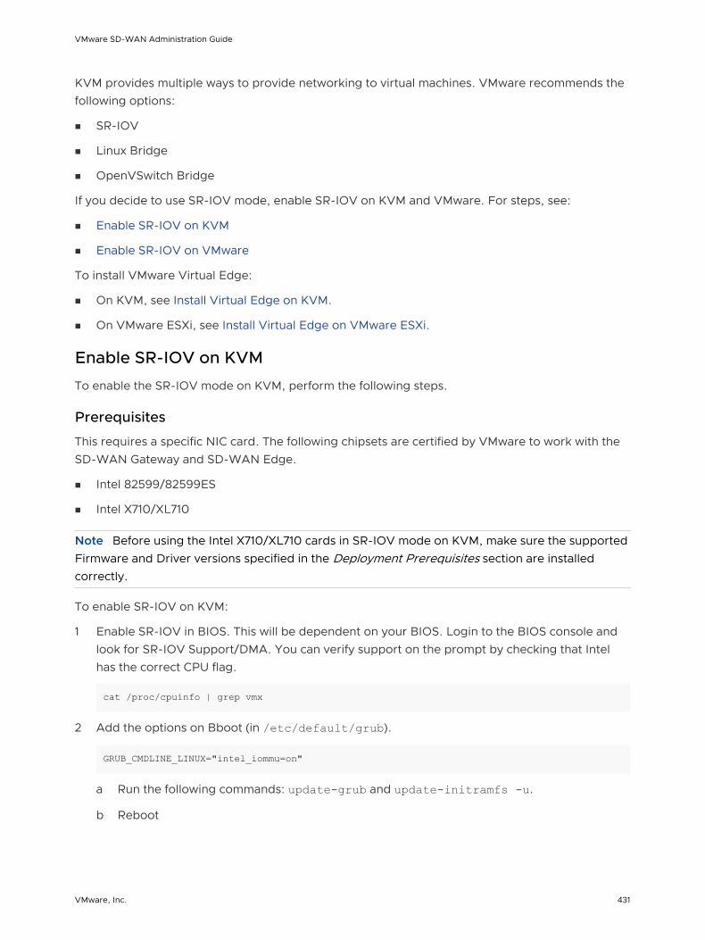
KVM provides multiple ways to provide networking to virtual machines. VMware recommends the following options:
n SR-IOV
n Linux Bridge
n OpenVSwitch Bridge
If you decide to use SR-IOV mode, enable SR-IOV on KVM and VMware. For steps, see:
n Enable SR-IOV on KVM
n Enable SR-IOV on VMware
To install VMware Virtual Edge:
n On KVM, see Install Virtual Edge on KVM.
n On VMware ESXi, see Install Virtual Edge on VMware ESXi.
Enable SR-IOV on KVM
To enable the SR-IOV mode on KVM, perform the following steps.
Prerequisites
This requires a specific NIC card. The following chipsets are certified by VMware to work with the SD-WAN Gateway and SD-WAN Edge.
n Intel 82599/82599ES
n Intel X710/XL710
Note Before using the Intel X710/XL710 cards in SR-IOV mode on KVM, make sure the supported Firmware and Driver versions specified in the Deployment Prerequisites section are installed correctly.
To enable SR-IOV on KVM:
1 Enable SR-IOV in BIOS. This will be dependent on your BIOS. Login to the BIOS console and look for SR-IOV Support/DMA. You can verify support on the prompt by checking that Intel has the correct CPU flag.
cat /proc/cpuinfo | grep vmx
2 Add the options on Bboot (in /etc/default/grub).
GRUB_CMDLINE_LINUX="intel_iommu=on"
a Run the following commands: update-grub and update-initramfs -u.
b Reboot
VMware SD-WAN Administration Guide
VMware, Inc. 431

c Make sure iommu is enabled.
velocloud@KVMperf3:~$ dmesg | grep -i IOMMU [ 0.000000] Command line: BOOT_IMAGE=/vmlinuz-3.13.0-107-generic root=/dev/mapper/qa--multiboot--002--vg-root ro intel_iommu=on splash quiet vt.handoff=7 [ 0.000000] Kernel command line: BOOT_IMAGE=/vmlinuz-3.13.0-107-generic root=/dev/mapper/qa--multiboot--002--vg-root ro intel_iommu=on splash quiet vt.handoff=7 [ 0.000000] Intel-IOMMU: enabled …. velocloud@KVMperf3:~$
3 Based on the NIC chipset used, add a driver as follows:
n For the Intel 82599/82599ES cards in SR-IOV mode:
1 Download and install ixgbe driver from the Intel website.
2 Configure ixgbe config (tar and sudo make install).
velocloud@KVMperf1:~$ cat /etc/modprobe.d/ixgbe.conf
3 If the ixgbe config file does not exist, you have to create the file as follows.
options ixgbe max_vfs=32,32options ixgbe allow_unsupported_sfp=1options ixgbe MDD=0,0blacklist ixgbevf
4 Run the update-initramfs -u command and reboot the Server.
5 Use the modinfo command to verify if the installation is successful.
velocloud@KVMperf1:~$ modinfo ixgbe and ip link filename: /lib/modules/4.4.0-62-generic/updates/drivers/net/ethernet/intel/ixgbe/ixgbe.ko version: 5.0.4 license: GPL description: Intel(R) 10GbE PCI Express Linux Network Driver author: Intel Corporation, <[email protected]> srcversion: BA7E024DFE57A92C4F1DC93
n For the Intel X710/XL710 cards in SR-IOV mode:
1 Download and install i40e driver from the Intel website.
2 Create the Virtual Functions (VFs).
echo 4 > /sys/class/net/device name/device/sriov_numvfs
3 To make the VFs persistent after a reboot, add the command from the previous step to the "/etc/rc.d/rc.local" file.
VMware SD-WAN Administration Guide
VMware, Inc. 432

4 Deny list the VF driver
echo “blacklist i40evf” >> /etc/modprobe.d/blacklist.conf
5 Run the update-initramfs -u command and reboot the Server.
Validating SR-IOV (Optional)
You can quickly verify if your host machine has SR-IOV enabled by using the following command:
lspci | grep -i Ethernet
Verify if you have Virtual Functions:
01:10.0 Ethernet controller: Intel Corporation 82599 Ethernet Controller Virtual Function(rev 01)
Install Virtual Edge on KVM
Describes how to install and activate the Virtual Edge on KVM using a cloud-init config file.
If you decide to use SR-IOV mode, enable SR-IOV on KVM. For steps, see Enable SR-IOV on KVM.
To run VMware Virtual Edge on KVM using the libvirt:
1 Use gunzip to extract the qcow2 file to the image location (for example, /var/lib/libvirt/images).
2 Create the Network pools that you are going to use for the device, using SR-IOV and OpenVswitch.
Using SR-IOV
The following is a sample network interface template specific to Intel X710/XL710 NIC cards using SR-IOV.
<interface type='hostdev' managed='yes'> <mac address='52:54:00:79:19:3d'/> <driver name='vfio'/> <source> <address type='pci' domain='0x0000' bus='0x83' slot='0x0a' function='0x0'/> </source> <model type='virtio'/> </interface>
Using OpenVSwitch
<network> <name>passthrough</name> <model type='virtio'/> <forward mode="bridge"/> <bridge name="passthrough"/>
VMware SD-WAN Administration Guide
VMware, Inc. 433
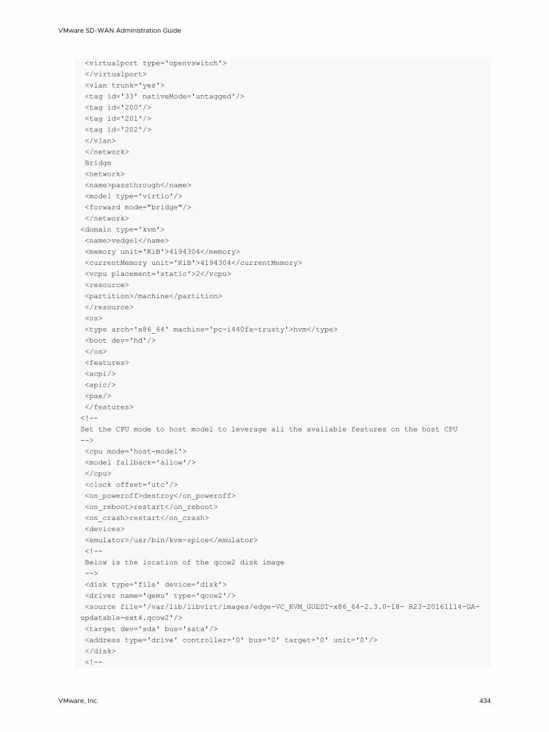
<virtualport type='openvswitch'> </virtualport> <vlan trunk='yes'> <tag id='33' nativeMode='untagged'/> <tag id='200'/> <tag id='201'/> <tag id='202'/> </vlan> </network> Bridge <network> <name>passthrough</name> <model type='virtio'/> <forward mode="bridge"/> </network> <domain type='kvm'> <name>vedge1</name> <memory unit='KiB'>4194304</memory> <currentMemory unit='KiB'>4194304</currentMemory> <vcpu placement='static'>2</vcpu> <resource> <partition>/machine</partition> </resource> <os> <type arch='x86_64' machine='pc-i440fx-trusty'>hvm</type> <boot dev='hd'/> </os> <features> <acpi/> <apic/> <pae/> </features> <!--Set the CPU mode to host model to leverage all the available features on the host CPU --> <cpu mode='host-model'> <model fallback='allow'/> </cpu> <clock offset='utc'/> <on_poweroff>destroy</on_poweroff> <on_reboot>restart</on_reboot> <on_crash>restart</on_crash> <devices> <emulator>/usr/bin/kvm-spice</emulator> <!-- Below is the location of the qcow2 disk image --> <disk type='file' device='disk'> <driver name='qemu' type='qcow2'/> <source file='/var/lib/libvirt/images/edge-VC_KVM_GUEST-x86_64-2.3.0-18- R23-20161114-GA-updatable-ext4.qcow2'/> <target dev='sda' bus='sata'/> <address type='drive' controller='0' bus='0' target='0' unit='0'/> </disk> <!--
VMware SD-WAN Administration Guide
VMware, Inc. 434

If using cloud-init to boot up virtual edge, attach the 2nd disk as CD-ROM --> <disk type='file' device='cdrom'> <driver name='qemu' type='raw'/> <source file='/home/vcadmin/cloud-init/vedge1/seed.iso'/> <target dev='sdb' bus='sata'/> <readonly/> <address type='drive' controller='1' bus='0' target='0' unit='0'/> </disk> <controller type='usb' index='0'> <address type='pci' domain='0x0000' bus='0x00' slot='0x01' function='0x2'/> </controller> <controller type='pci' index='0' model='pci-root'/> <controller type='sata' index='0'> <address type='pci' domain='0x0000' bus='0x00' slot='0x05' function='0x0'/> </controller> <controller type='ide' index='0'> <address type='pci' domain='0x0000' bus='0x00' slot='0x01' function='0x1'/> </controller> <!-- The first two interfaces are for the default L2 interfaces, NOTE VLAN support just for SR-IOV and OpenvSwitch --> < interfacetype='network'> < modeltype='virtio'/> < sourcenetwork='LAN1'/> < vlan>< tagid='#hole2_vlan#'/></ vlan> < aliasname=LAN1/> < addresstype='pci' domain='0x0000' bus='0x00' slot='0x12' function='0x0'/> </ interface> < interfacetype='network'> < modeltype='virtio'/> < sourcenetwork=LAN2/> < vlan>< tagid='#LAN2_VLAN#'/></ vlan> < aliasname='hostdev1'/> < addresstype='pci' domain='0x0000' bus=' 0x00' slot='0x13' function='0x0'/> </ interface> <!-- The next two interfaces are for the default L3 interfaces. Note that additional 6 routed interfaces are supported for a combination of 8 interfaces total --> < interfacetype='network'> < modeltype='virtio'/> < sourcenetwork=WAN1/> < vlan>< tagid='#hole2_vlan#'/></ vlan> < aliasname=LAN1/> < addresstype='pci' domain='0x0000' bus='0x00' slot='0x12' function='0x0'/> </ interface> < interfacetype='network'> < modeltype='virtio'/> < source network=LAN2/> < vlan>< tag id='#LAN2_VLAN#'/></ vlan> < aliasname='hostdev1'/> < addresstype='pci' domain='0x0000' bus='0x00' slot='0x13' function='0x0'/>
VMware SD-WAN Administration Guide
VMware, Inc. 435

</ interface> <serial type='pty'> <target port='0'/> </serial> <console type='pty'> <target type='serial' port='0'/> </console> <input type='mouse' bus='ps2'/> <input type='keyboard' bus='ps2'/> <graphics type='vnc' port='-1' autoport='yes' listen='127.0.0.1'> <listen type='address' address='127.0.0.1'/> </graphics> <sound model='ich6'> <address type='pci' domain='0x0000' bus='0x00' slot='0x04' function='0x0'/> </sound> <video> <model type='cirrus' vram='9216' heads='1'/> <address type='pci' domain='0x0000' bus='0x00' slot='0x02' function='0x0'/> </video> <memballoon model='virtio'> <address type='pci' domain='0x0000' bus='0x00' slot='0x06' function='0x0'/> </memballoon> </devices> </domain>
3 Save the domain XML file that defines the VM (for example, vedge1.xml created in step 2).
4 Launch the VM by performing the following steps:
a Create VM.
virsh define vedge1.xml
b Start VM.
virsh start vedge1
Note vedge1 is the name of the VM defined in the <name> element of the domain XML file.
Replace vedge1 with the name you specify in the <name> element.
5 If you are using SR-IOV mode, after launching the VM, set the following on the Virtual Functions (VFs) used:
a Set the spoofcheck off.
ip link set eth1 vf 0 spoofchk off
b Set the Trusted mode on.
ip link set dev eth1 vf 0 trust on
VMware SD-WAN Administration Guide
VMware, Inc. 436

c Set the VLAN, if required.
ip link set eth1 vf 0 vlan 3500
Note The Virtual Functions configuration step is not applicable for OpenVSwitch (OVS) mode.
6 Console into the VM.
virsh listId Name State----------------------------------------------------25 test_vcg runningvelocloud@KVMperf2$ virsh console 25Connected to domain test_vcgEscape character is ^]
The Cloud-init already includes the activation key, which was generated while creating a new Virtual Edge on the SD-WAN Orchestrator. The Virtual Edge is configured with the config settings from the Cloud-init file. This will configure the interfaces as the Virtual Edge is powered up. Once the Virtual Edge is online, it will activate with the SD-WAN Orchestrator using the activation key. The SD-WAN Orchestrator IP address and the activation key have been defined in the Cloud-init file.
Enable SR-IOV on VMware
Enabling SR-IOV on VMware is optional, but it is necessary to realize the full benefit of DPDK to improve packet processing performance.
Prerequisites
This requires a specific NIC card. The following chipsets are certified by VMware to work with the SD-WAN Gateway.
n Intel 82599/82599ES
n Intel X710/XL710
Note Before using the Intel X710/XL710 cards in SR-IOV mode on VMware, make sure the supported Firmware and Driver versions described in the Deployment Prerequisites section are installed correctly.
To enable SR-IOV on VMware:
1 Make sure that your NIC card supports SR-IOV. Check the VMware Hardware Compatibility List (HCL) at https://www.vmware.com/resources/compatibility/search.php?deviceCategory=io
Brand Name: Intel
I/O Device Type: Network
Features: SR-IOV
VMware SD-WAN Administration Guide
VMware, Inc. 437

The following VMware KB article provides details of how to enable SR-IOV on the supported NIC: https://kb.vmware.com/s/article/2038739
2 Once you have a support NIC card, go to the specific VMware host, select the Configure tab, and then choose Physical adapters.
3 Select Edit Settings. Change Status to Enabled and specify the number of virtual functions required. This number varies by the type of NIC card.
4 Reboot the hypervisor.
5 If SR-IOV is successfully enabled, the number of Virtual Functions (VFs) will show under the particular NIC after ESXi reboots.
Install Virtual Edge on VMware ESXi
Describes how to install Virtual Edge on VMware ESXi.
VMware SD-WAN Administration Guide
VMware, Inc. 438

If you decide to use SR-IOV mode, enable SR-IOV on VMware. For steps, see Enable SR-IOV on VMware.
To install Virtual Edge on VMware ESXi:
1 Use the vSphere client to deploy an OVF template, and then select the Edge OVA file.
2 Select an OVF template from an URL or Local file.
3 Select a name and location of the virtual machine.
4 Select a resource.
5 Verify the template details.
VMware SD-WAN Administration Guide
VMware, Inc. 439

6 Select the storage location to store the files for the deployment template.
7 Configure the networks for each of the interfaces.
Note Skip this step if you are using a cloud-init file to provision the Virtual Edge on ESXi.
VMware SD-WAN Administration Guide
VMware, Inc. 440

8 Customize the template by specifying the deployment properties. The following image highlights:
a From the SD-WAN Orchestrator UI, retrieve the URL/IP Address. You will need this address for Step c below.
b Create a new Virtual Edge for the Enterprise. Once the Edge is created, copy the Activation Key. You will need the Activation Key for Step c" below.
c On the customize template page shown in the image below, type in the Activation Code that you retrieved in Step b above, and the SD-WAN Orchestrator URL/IP Address retrieved in Step a above, into the corresponding fields.
VMware SD-WAN Administration Guide
VMware, Inc. 441
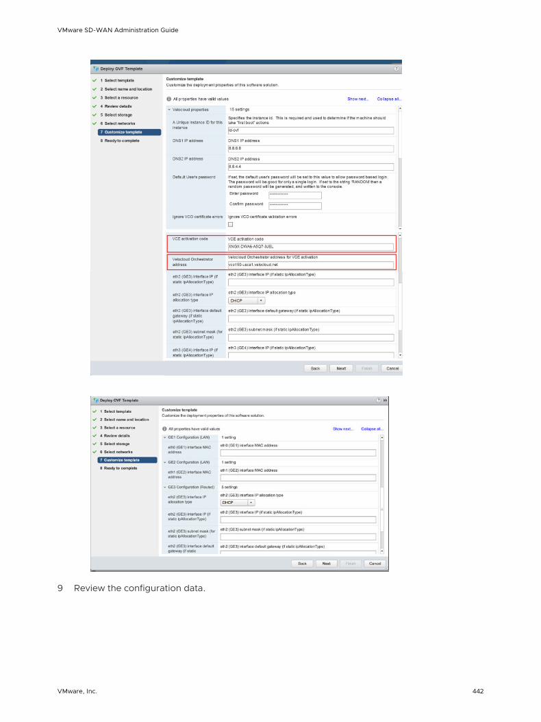
9 Review the configuration data.
VMware SD-WAN Administration Guide
VMware, Inc. 442

10 Power on the Virtual Edge.
Once the Edge powers up, it will establish connectivity to the SD-WAN Orchestrator.
VMware SD-WAN Administration Guide
VMware, Inc. 443

Azure Virtual WAN SD-WAN Gateway Automation 24SD-WAN Orchestrator supports Azure Virtual WAN and SD-WAN Gateway integration and automation to enable branch-to-VPN connectivity.
This chapter includes the following topics:
n Azure Virtual WAN SD-WAN Gateway Automation Overview
n Prerequisite Azure Configuration
n Configure Azure Virtual WAN for Branch-to-Azure VPN Connectivity
n Configure SD-WAN Orchestrator for Branch-to-Azure VPN Connectivity
Azure Virtual WAN SD-WAN Gateway Automation Overview
Azure Virtual WAN is a network service that facilitates optimized and automated Virtual Private Network (VPN) connectivity from enterprise branch locations to or through Microsoft Azure. Azure subscribers’ provision Virtual Hubs corresponding to Azure regions and connect branches (which may or may not be SD-WAN enabled) through IP security (IPSec) VPN connections.
SD-WAN Orchestrator supports Azure Virtual WAN and SD-WAN Gateway integration and automation by leveraging the Azure backbone to establish branch-to-Azure VPN connectivity through the SD-WAN Gateway as shown in the following diagram.
VMware, Inc. 444

NSX SD-WAN Orchestrator
and Controller
Azure Portal
CustomerA Azure
vWAN Hub
CustomerA Branch
NSX SD-WAN
Edge
NSX SD-WAN Gateway
Azure virtual WAN
The following sections describe the procedures for configuring the SD-WAN Orchestrator and Azure to enable branch-to-Azure VPN connectivity through the SD-WAN Gateway:
n Configure Azure Virtual WAN for Branch-to-Azure VPN Connectivity
n Configure SD-WAN Orchestrator for Branch-to-Azure VPN Connectivity
Prerequisite Azure Configuration
Enterprise network administrators must complete the following prerequisite configuration tasks at the Azure portal to ensure that the SD-WAN Orchestrator application can function as the Service Principal (identity for the application) for the purposes of Azure Virtual WAN and SD-WAN Gateway integration.
n Register SD-WAN Orchestrator Application
n Assign the SD-WAN Orchestrator Application to Contributor Role
n Register a Resource Provider
n Create a Client Secret
Register SD-WAN Orchestrator Application
Describes how to register a new application in Azure Active Directory (AD).
To register a new application in Azure AD:
VMware SD-WAN Administration Guide
VMware, Inc. 445

Prerequisites
n Ensure you have an Azure subscription. If not, create a free account.
Procedure
1 Log in to your Microsoft Azure account.
The Microsoft Azure home screen appears.
2 Click All Services and search for Azure Active Directory.
3 Select Azure Active Directory and go to App registrations > New registration.
The Register an application screen appears.
4 In the Name field, enter the name for your SD-WAN Orchestrator application.
5 Select a supported account type, which determines who can use the application.
6 Click Register.
VMware SD-WAN Administration Guide
VMware, Inc. 446

Results
Your SD-WAN Orchestrator application will be registered and displayed in the All applications and Owned applications tabs.
Make sure to note down the Directory (tenant) ID and Application (client) ID to be used during the SD-WAN Orchestrator configuration for IaaS Subscription.
What to do next
n Assign the SD-WAN Orchestrator Application to Contributor Role
n Create a Client Secret
Assign the SD-WAN Orchestrator Application to Contributor Role
To access resources in your Azure subscription, you must assign the application to a role. You can set the scope at the level of the subscription, resource group, or resource. Permissions are inherited to lower levels of scope.
To assign a Contributor role at the subscription scope:
Prerequisites
n Ensure you have an Azure subscription. If not, create a free account.
Procedure
1 Click All Services and search for Subscriptions.
2 From the list of subscriptions, select the subscription to which you want to assign your application. If you do not see the subscription you are looking for, select global subscriptions filter. Make sure the subscription you want is selected for the portal.
3 Click Access control (IAM).
VMware SD-WAN Administration Guide
VMware, Inc. 447
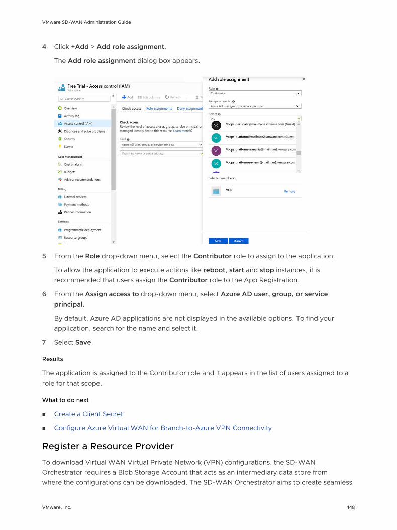
4 Click +Add > Add role assignment.
The Add role assignment dialog box appears.
5 From the Role drop-down menu, select the Contributor role to assign to the application.
To allow the application to execute actions like reboot, start and stop instances, it is recommended that users assign the Contributor role to the App Registration.
6 From the Assign access to drop-down menu, select Azure AD user, group, or service principal.
By default, Azure AD applications are not displayed in the available options. To find your application, search for the name and select it.
7 Select Save.
Results
The application is assigned to the Contributor role and it appears in the list of users assigned to a role for that scope.
What to do next
n Create a Client Secret
n Configure Azure Virtual WAN for Branch-to-Azure VPN Connectivity
Register a Resource Provider
To download Virtual WAN Virtual Private Network (VPN) configurations, the SD-WAN Orchestrator requires a Blob Storage Account that acts as an intermediary data store from where the configurations can be downloaded. The SD-WAN Orchestrator aims to create seamless
VMware SD-WAN Administration Guide
VMware, Inc. 448

user experience by provisioning a transient storage account for each of the download task. To download VPN site configurations, you must manually register the Microsoft.Storage resource provider on your Azure Subscription. By default, the Microsoft.Storage resource provider is not registered on Azure Subscriptions.
To register a resource provider for your subscription:
Prerequisites
n Ensure you have an Azure subscription. If not, create a free account.
n Ensure you have the Contributor or Owner roles permission.
Procedure
1 Log in to your Microsoft Azure account.
2 Click All Services and search for Subscriptions.
3 From the list of subscriptions, select your subscription.
4 Under the Settings tab, select Resource providers.
5 From the list of available resource providers, select Microsoft.Storage. and click Register.
Results
The resource provider is registered and also configures your subscription to work with the resource provider.
What to do next
You can create the resources in Azure, for steps, see Configure Azure Virtual WAN for Branch-to-Azure VPN Connectivity.
VMware SD-WAN Administration Guide
VMware, Inc. 449

Create a Client Secret
Describes how to create a new client secret in Azure AD for the purpose of authentication.
To create a new client secret in Azure AD:
Prerequisites
n Ensure you have an Azure subscription. If not, create a free account.
Procedure
1 Log in to your Microsoft Azure account.
The Microsoft Azure home screen appears.
2 Select Azure Active Directory > App registrations.
3 On the Owned applications tab, click on your registered SD-WAN Orchestrator application.
4 Go to Certificates & secrets > New client secret.
The Add a client secret screen appears.
5 Provide details such as description and expiry value for the secret and click Add.
Results
The client secret is created for the registered application.
Note Copy and save the new client secret value to be used during the IaaS subscription in SD-WAN Orchestrator.
What to do next
n Configure Azure Virtual WAN for Branch-to-Azure VPN Connectivity
n Configure SD-WAN Orchestrator for Branch-to-Azure VPN Connectivity
VMware SD-WAN Administration Guide
VMware, Inc. 450
Configure Azure Virtual WAN for Branch-to-Azure VPN Connectivity
This section describes the procedures to configure Azure for integrating Azure Virtual WAN and SD-WAN Gateway to enable the branch-to-Azure VPN connectivity.
Before you begin to configure the Azure Virtual WAN and the other Azure resources:
n Verify that none of the subnets of your on-premises network overlap with the existing virtual networks that you want to connect to. Your virtual network does not require a gateway subnet and cannot have any virtual network gateways. For steps to create a virtual network, see Create a Virtual Network.
n Obtain an IP address range for your Hub region and ensure that the address range that you specify for the Hub region does not overlap with any of your existing virtual networks that you connect to.
n Ensure you have an Azure subscription. If not, create a free account .
For step-by-step instructions about the various procedures that need to be completed in the Azure portal side for integrating Azure Virtual WAN and SD-WAN Gateway, see:
n Create a Resource Group
n Create a Virtual WAN
n Create a Virtual Hub
n Create a Virtual Network
n Create a Virtual Connection between VNet and Hub
Create a Resource Group
Describes how to create a resource group in Azure.
To create a resource group in Azure:
Prerequisites
n Ensure you have an Azure subscription. If not, create a free account.
Procedure
1 Log in to your Microsoft Azure account.
The Microsoft Azure home screen appears.
2 Click All Services and search for Resource groups.
VMware SD-WAN Administration Guide
VMware, Inc. 451

3 Select Resource groups and click +Add.
The Create a resource group screen appears.
4 From the Subscription drop-down menu, select your Microsoft Azure subscription.
5 In the Resource group text box, enter a unique name for your new resource group.
A resource group name can include alphanumeric characters, periods (.), underscores (_), hyphens (-), and parenthesis (), but the name cannot end with a period.
6 From the Region drop-down menu, select the location for your resource group, where the majority of your resources will reside.
7 Click Review+create and then click Create.
Results
A resource group is created and appears on the Azure portal dashboard.
VMware SD-WAN Administration Guide
VMware, Inc. 452

What to do next
Create an Azure Virtual WAN. For steps, see Create a Virtual WAN.
Create a Virtual WAN
Describes how to create a Virtual WAN in Azure.
To create a Virtual WAN in Azure:
Prerequisites
n Ensure you have an Azure subscription. If not, create a free account.
n Ensure you have a resource group created to add the Virtual WAN.
Procedure
1 Log in to your Microsoft Azure account.
The Microsoft Azure home screen appears.
2 Click All Services and search for Virtual WANs.
3 Select Virtual WANs and click +Add.
The Create WAN screen appears.
4 From the Subscription drop-down menu, select your Microsoft Azure subscription.
VMware SD-WAN Administration Guide
VMware, Inc. 453
5 From the Resource group drop-down menu, select your resource group to add the Virtual WAN.
6 From the Resource group location drop-down menu, select the location where the metadata associated with the Virtual WAN will reside.
7 In the Name text box, enter a unique name for your Virtual WAN.
8 From the Type drop-down menu, select Standard as the Virtual WAN type.
9 Click Create.
Results
A Virtual WAN is created and appears on the Azure portal dashboard.
What to do next
Create Virtual Hubs. For steps, see Create a Virtual Hub.
Create a Virtual Hub
Describes how to create a Virtual Hub in Azure.
To create a Virtual Hub in Azure:
Prerequisites
n Ensure you have an Azure subscription. If not, create a free account.
n Ensure that you have a resource group created to add the Azure resources.
Procedure
1 Log in to your Microsoft Azure account.
The Microsoft Azure home screen appears.
2 Go to All resources and from the list of available resources, select the Virtual WAN that you have created.
3 Under the Virtual WAN architecture area, click Hubs.
VMware SD-WAN Administration Guide
VMware, Inc. 454
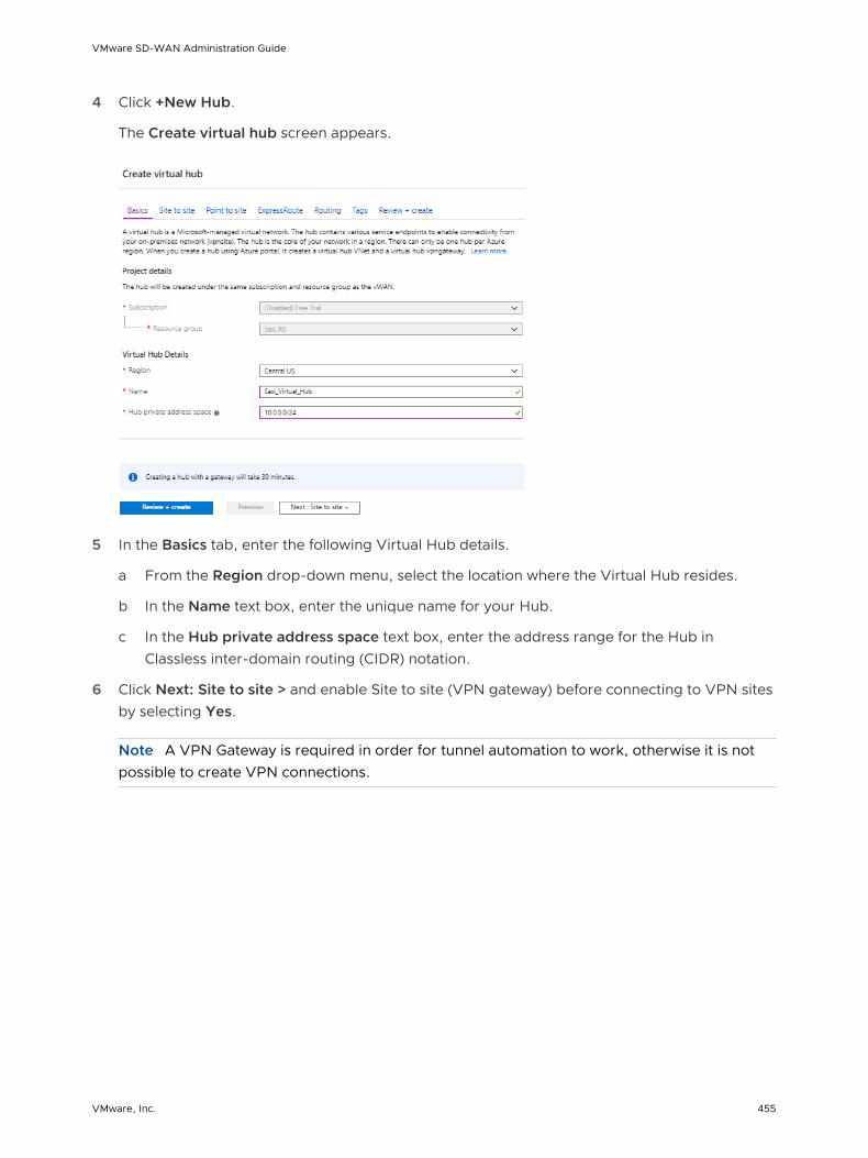
4 Click +New Hub.
The Create virtual hub screen appears.
5 In the Basics tab, enter the following Virtual Hub details.
a From the Region drop-down menu, select the location where the Virtual Hub resides.
b In the Name text box, enter the unique name for your Hub.
c In the Hub private address space text box, enter the address range for the Hub in Classless inter-domain routing (CIDR) notation.
6 Click Next: Site to site > and enable Site to site (VPN gateway) before connecting to VPN sites by selecting Yes.
Note A VPN Gateway is required in order for tunnel automation to work, otherwise it is not possible to create VPN connections.
VMware SD-WAN Administration Guide
VMware, Inc. 455

a From the Gateway scale units drop-down menu, select a scaling value.
7 Click Review + Create.
Results
A Virtual Hub is created and appears on the Azure portal dashboard.
What to do next
n Create Virtual Connection between Hubs and Virtual Networks (VNets). For steps, see Create a Virtual Connection between VNet and Hub.
n If you do not have an existing VNet, you can create one by following the steps in Create a Virtual Network.
Create a Virtual Network
Describes how to create a Virtual Network in Azure.
To create a Virtual Network in Azure:
Prerequisites
n Ensure you have an Azure subscription. If not, create a free account.
Procedure
1 Log in to your Microsoft Azure account.
The Microsoft Azure home screen appears.
2 Click All Services and search for Virtual networks.
VMware SD-WAN Administration Guide
VMware, Inc. 456

3 Select Virtual networks and click +Add.
The Create virtual network screen appears.
4 In the Name text box, enter the unique name for your virtual network.
5 In the Address space text box, enter the address range for the virtual network in Classless inter-domain routing (CIDR) notation.
6 From the Subscription drop-down menu, select your Microsoft Azure subscription.
7 From the Resource group drop-down menu, select your resource group to add the virtual network.
8 From the Location drop-down menu, select the location where the virtual network resides.
9 Under the Subnet area, enter the name and address range for the subnet.
Do not make any changes to the other default settings of DDos protection, Service endpoints, and Firewall.
10 Click Create.
VMware SD-WAN Administration Guide
VMware, Inc. 457
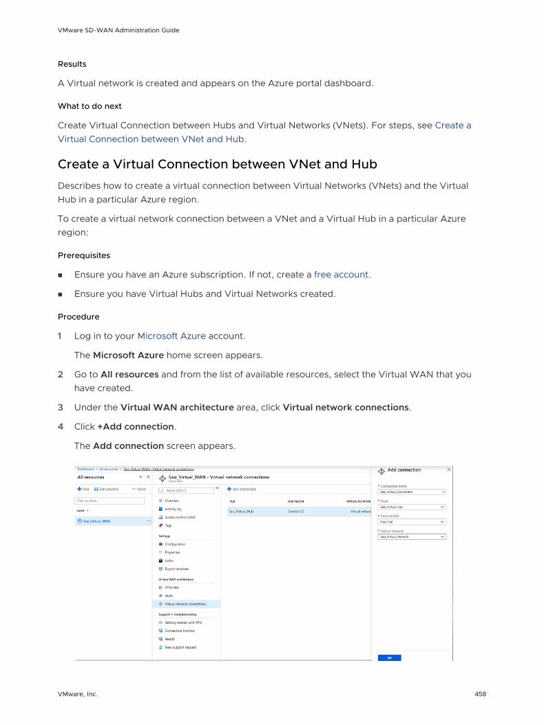
Results
A Virtual network is created and appears on the Azure portal dashboard.
What to do next
Create Virtual Connection between Hubs and Virtual Networks (VNets). For steps, see Create a Virtual Connection between VNet and Hub.
Create a Virtual Connection between VNet and Hub
Describes how to create a virtual connection between Virtual Networks (VNets) and the Virtual Hub in a particular Azure region.
To create a virtual network connection between a VNet and a Virtual Hub in a particular Azure region:
Prerequisites
n Ensure you have an Azure subscription. If not, create a free account.
n Ensure you have Virtual Hubs and Virtual Networks created.
Procedure
1 Log in to your Microsoft Azure account.
The Microsoft Azure home screen appears.
2 Go to All resources and from the list of available resources, select the Virtual WAN that you have created.
3 Under the Virtual WAN architecture area, click Virtual network connections.
4 Click +Add connection.
The Add connection screen appears.
VMware SD-WAN Administration Guide
VMware, Inc. 458

5 In the Connection name text box, enter the unique name for the virtual connection.
6 From the Hubs drop-down menu, select the Hub you want to associate with this connection.
7 From the Subscription drop-down menu, select your Microsoft Azure subscription.
8 From the Virtual network drop-down menu, select the virtual network you want to connect to this Hub.
9 Click OK.
Results
A peering connection is established between the selected Vnet and the Hub.
What to do next
n Configure SD-WAN Orchestrator for Branch-to-Azure VPN Connectivity
Configure SD-WAN Orchestrator for Branch-to-Azure VPN Connectivity
You can configure SD-WAN Orchestrator for integrating Azure Virtual WAN and SD-WAN Gateway to enable the branch-to-Azure VPN connectivity.
Note By default, the Azure Virtual WAN feature is disabled. To enable the feature, you must set the session.options.enableAzureVirtualWAN system property to true.
Before you begin the SD-WAN Orchestrator configuration for Azure Virtual WAN - SD-WAN Gateway automation, ensure you have completed all the steps explained in the Prerequisite Azure Configuration and Configure Azure Virtual WAN for Branch-to-Azure VPN Connectivity sections.
For step-by-step instructions about the various procedures that need to be completed in the SD-WAN Orchestrator side for integrating Azure Virtual WAN and SD-WAN Gateway, see:
n Configure an IaaS Subscription Network Service
n Configure a Microsoft Azure Non VMware SD-WAN Site
n Synchronize VPN Configuration
Configure an IaaS Subscription Network Service
Describes how to configure an Infrastructure as a Service Provider (IaaS) subscription in SD-WAN Orchestrator.
To configure an IaaS subscription in SD-WAN Orchestrator:
Prerequisites
Ensure you have registered the SD-WAN Orchestrator application and created Client secret in the Azure portal. For steps, see Prerequisite Azure Configuration.
VMware SD-WAN Administration Guide
VMware, Inc. 459

Procedure
1 From the navigation panel in the SD-WAN Orchestrator, go to Configure > Network Services.
The Services screen appears.
2 In the Iaas Subscriptions area, click the New button.
The Configure IaaS Subscription dialog box appears.
3 From the Subscription Type drop-down-menu, select Microsoft Azure Subscription.
4 Enter the Active Directory Tenant ID, Client ID, and Client Secret corresponding to your SD-WAN Orchestrator Application Registration.
5 Click the Get Subscriptions button to retrieve the list of Azure Subscriptions for which the App Registration has been allocated an IAM role.
6 Click Save Changes.
What to do next
Configure a Non VMware SD-WAN Site of type Microsoft Azure Virtual Hub. For more information, see Configure a Microsoft Azure Non VMware SD-WAN Site.
Configure a Microsoft Azure Non VMware SD-WAN Site
Describes how to configure a Non VMware SD-WAN Site of type Microsoft Azure Virtual Hub in SD-WAN Orchestrator.
To configure an NVS of type Microsoft Azure Virtual Hub in SD-WAN Orchestrator:
Prerequisites
n Ensure you have configured an IaaS subscription. For steps, see Configure an IaaS Subscription Network Service.
n Ensure you have created Virtual WAN and Hubs in Azure. For steps, see Configure Azure Virtual WAN for Branch-to-Azure VPN Connectivity.
VMware SD-WAN Administration Guide
VMware, Inc. 460

Procedure
1 From the navigation panel in the SD-WAN Orchestrator, go to Configure > Network Services.
The Services screen appears.
2 In the Non-VeloCloud Sites area, click the New button.
The New Non-VeloCloud Site dialog box appears.
3 In the Name text box, enter the name for the Non VMware SD-WAN Site.
4 From the Type drop-down menu, select Microsoft Azure Virtual Hub.
5 From the Subscription drop-down menu, select a subscription.
The application fetches all the available Virtual WANs dynamically from Azure.
6 From the Virtual WAN drop-down menu, select a virtual WAN.
The application auto-populates the resource group to which the virtual WAN is associated.
7 From the Virtual Hub drop-down menu, select a Virtual Hub.
The application auto-populates the Azure region corresponding to the Hub
8 Select the Enable Tunnel(s) checkbox to enable VMware VPN Gateways initiate VPN connections to the target Virtual Hub, as soon as the site is successfully provisioned.
Note VMware VPN Gateways will not initiate IKE negotiation until this Non VMware SD-WAN Site is configured on at least one profile.
Note For Microsoft Azure Non VMware SD-WAN Site, by default, the local authentication ID value used is SD-WAN Gateway Interface Public IP.
VMware SD-WAN Administration Guide
VMware, Inc. 461

9 Click Next.
The SD-WAN Orchestrator automatically initiates deployment, provisions Azure VPN Sites, and downloads the VPN Site Configuration for the newly configured sites and stores the configuration in the SD-WAN OrchestratorSD-WAN Orchestrator’s Non VMware SD-WAN Site configuration database.
Results
Once the Azure VPN sites are provisioned at the SD-WAN Orchestrator side, you can view the VPN sites (Primary and Redundant) in the Azure portal by navigating to your Virtual WAN page > Virtual WAN architecture > VPN sites.
What to do next
n Associate the Microsoft Azure Non VMware SD-WAN Site to a Profile in order to establish a tunnel between a branch and Azure Virtual Hub. For more information, see Associate a Non VMware SD-WAN Site to a Profile.
n You must add SD-WAN routes in to Azure network manually. For more information, see Edit a VPN Site.
Associate a Non VMware SD-WAN Site to a Profile
After configuring a Non VMware SD-WAN Site of type Microsoft Azure Virtual Hub in SD-WAN Orchestrator, you have to associate the Non VMware SD-WAN Site to the desired Profile in order to establish the tunnels between SD-WAN Gateways and Microsoft Azure Virtual Hub.
To associate a Non VMware SD-WAN Site to a Profile, perform the following steps:
Procedure
1 From the SD-WAN Orchestrator navigation panel, go to Configure > Profiles.
The Configuration Profiles page appears.
VMware SD-WAN Administration Guide
VMware, Inc. 462
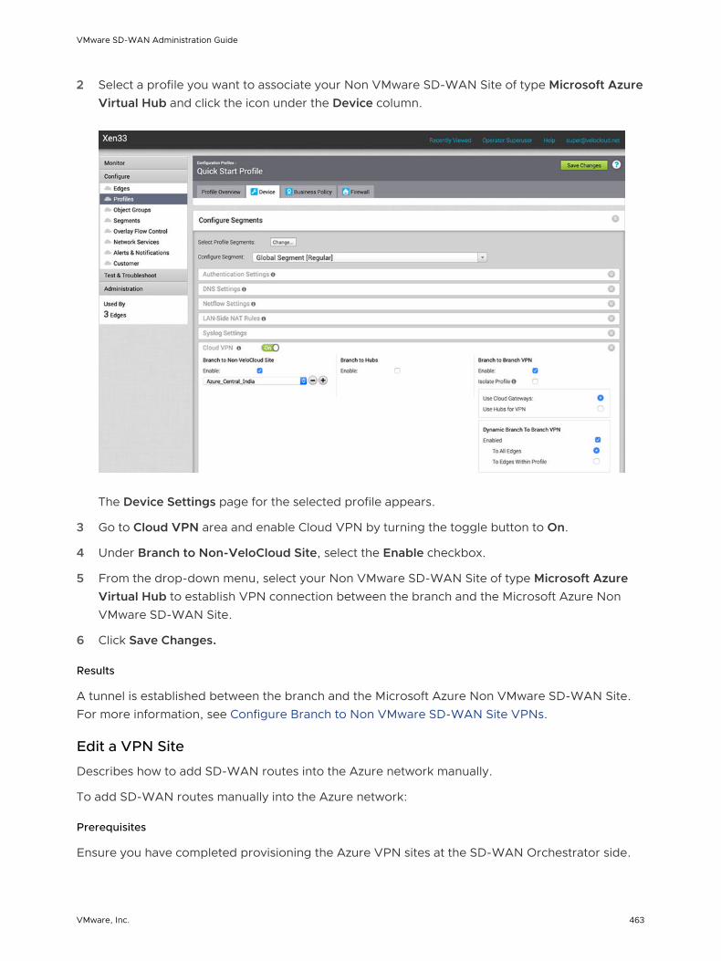
2 Select a profile you want to associate your Non VMware SD-WAN Site of type Microsoft Azure Virtual Hub and click the icon under the Device column.
The Device Settings page for the selected profile appears.
3 Go to Cloud VPN area and enable Cloud VPN by turning the toggle button to On.
4 Under Branch to Non-VeloCloud Site, select the Enable checkbox.
5 From the drop-down menu, select your Non VMware SD-WAN Site of type Microsoft Azure Virtual Hub to establish VPN connection between the branch and the Microsoft Azure Non VMware SD-WAN Site.
6 Click Save Changes.
Results
A tunnel is established between the branch and the Microsoft Azure Non VMware SD-WAN Site. For more information, see Configure Branch to Non VMware SD-WAN Site VPNs.
Edit a VPN Site
Describes how to add SD-WAN routes into the Azure network manually.
To add SD-WAN routes manually into the Azure network:
Prerequisites
Ensure you have completed provisioning the Azure VPN sites at the SD-WAN Orchestrator side.
VMware SD-WAN Administration Guide
VMware, Inc. 463
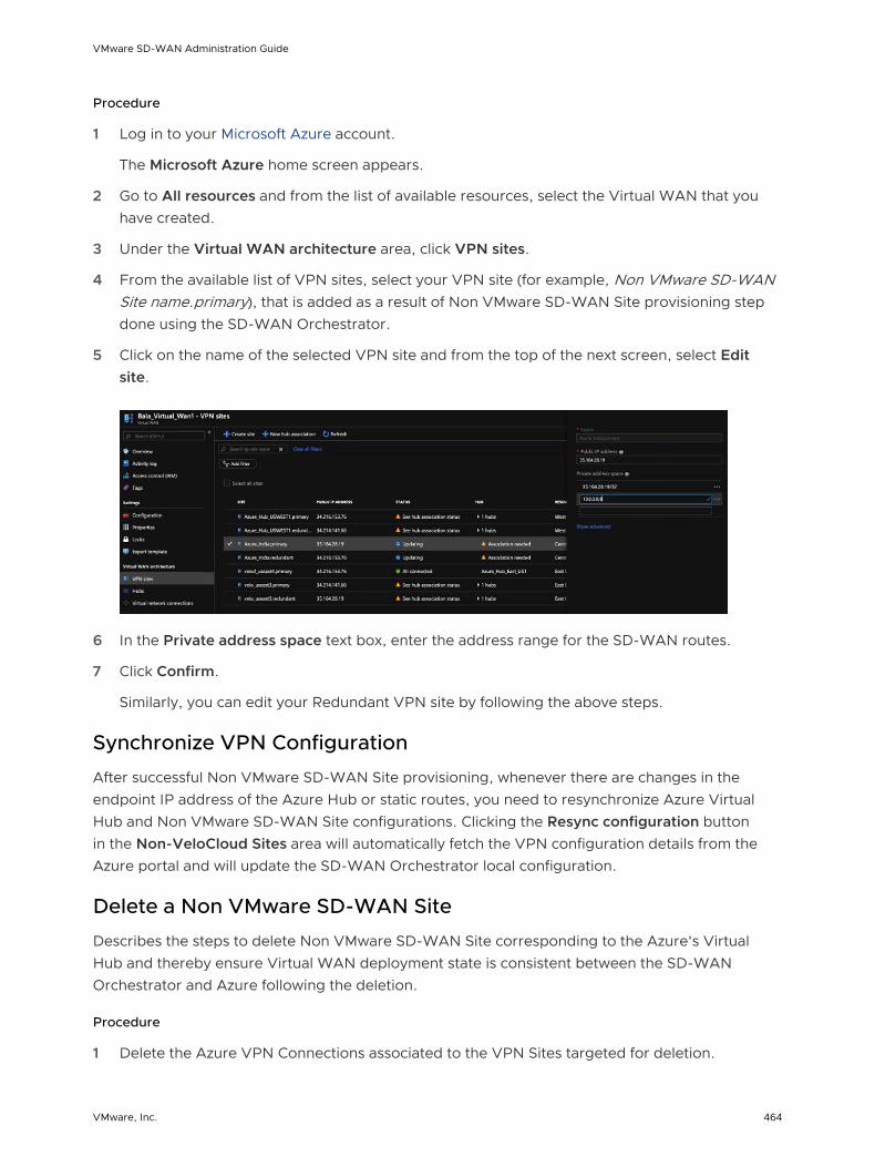
Procedure
1 Log in to your Microsoft Azure account.
The Microsoft Azure home screen appears.
2 Go to All resources and from the list of available resources, select the Virtual WAN that you have created.
3 Under the Virtual WAN architecture area, click VPN sites.
4 From the available list of VPN sites, select your VPN site (for example, Non VMware SD-WAN Site name.primary), that is added as a result of Non VMware SD-WAN Site provisioning step done using the SD-WAN Orchestrator.
5 Click on the name of the selected VPN site and from the top of the next screen, select Edit site.
6 In the Private address space text box, enter the address range for the SD-WAN routes.
7 Click Confirm.
Similarly, you can edit your Redundant VPN site by following the above steps.
Synchronize VPN Configuration
After successful Non VMware SD-WAN Site provisioning, whenever there are changes in the endpoint IP address of the Azure Hub or static routes, you need to resynchronize Azure Virtual Hub and Non VMware SD-WAN Site configurations. Clicking the Resync configuration button in the Non-VeloCloud Sites area will automatically fetch the VPN configuration details from the Azure portal and will update the SD-WAN Orchestrator local configuration.
Delete a Non VMware SD-WAN Site
Describes the steps to delete Non VMware SD-WAN Site corresponding to the Azure's Virtual Hub and thereby ensure Virtual WAN deployment state is consistent between the SD-WAN Orchestrator and Azure following the deletion.
Procedure
1 Delete the Azure VPN Connections associated to the VPN Sites targeted for deletion.
VMware SD-WAN Administration Guide
VMware, Inc. 464

2 Delete the Azure VPN Sites provisioned on behalf of the Non VMware SD-WAN Site SD-WAN Gateways selected for that Virtual Hub by using an Azure API.
Note Deletion of the Azure VPN Sites will fail if the VPN connections associated to the VPN Sites (targeted for deletion) are not removed.
VMware SD-WAN Administration Guide
VMware, Inc. 465